Wear mechanism maps for the belt finishing of steel and cast iron
6
Wear 267 (2009) 86–91 Contents lists available at ScienceDirect Wear journal homepage: www.elsevier.com/locate/wear Short communication Wear mechanism maps for the belt finishing of steel and cast iron S. Mezghani a,∗ , M. El Mansori a , E. Sura b a Arts et Métiers ParisTech, LMPF - EA 4106, Rue Saint Dominique, BP 508, 51006 Châlons-en-Champagne Cedex, France b RENAULT S.A.S., Direction de la Mécanique/Direction de l’Ingénierie Process, Rueil Malmaison, Paris, France article info Article history: Received 1 September 2008 Received in revised form 19 December 2008 Accepted 20 December 2008 Keywords: Belt finishing Wear Abrasion Energy approach abstract Belt finishing with different particles size results mainly in different thickness of the total mechanically deformed layer and surface profile projections that depend, to a great extent, on the change in the mech- anism of wear. Such a modification often represents a transition in the nature of physical mechanisms (cutting, plowing or sliding), leading to a concomitant change in the rate of material removal. Transition in wear mechanism can also be associated with a change in the abrasiveness properties of the abrasive coated belts. This paper outlines a method by which these transitional regimes can be illustrated graph- ically on plots of grit size against abrasion energy or applied pressure in connection with the produced surface state (i.e. roughness) for a given wear rate. It is supported by numerous experiments which show that the quality of the finished surfaces is dependent on the wear state of the coated abrasive belt. The “maps” showing wear rates and mechanisms suggest the existence of promising way for increasing the efficiency of abrasive technological processes. © 2009 Elsevier B.V. All rights reserved. 1. Introduction Superfinishing by abrasive belt is remarkably simple and inex- pensive [1,2]. Unfortunately, its practical development is difficult because the basic physical mechanisms of this abrasion process are still not well understood. So, in the industry, the belt finishing setup is still based on empirical rules. For each new product specification, preliminary tests are indeed necessary to achieve the optimal oper- ational configuration of the process. The setup time is made longer by the fact that the process variables are numerous and the effects of their combinations are very difficult to evaluate [3]. Moreover, the role played by each working variable depends deeply on the finishing operation type (fine or rough belt finishing). Relating to this particular abrasive finishing technology which employs a soft coated belt as a tool, an attempt is made to identify the simultaneous influences on the process efficiency of two work- ing parameters: the contact pressure and the abrasive particle size. Their effects are mainly studied by considering the most impor- tant achievements of the belt finishing process which is to reduce the workpiece surface irregularities and to improve its geometrical quality with a lower wear of the abrasive belt [4]. ∗ Corresponding author. Tel.: +33 3 26 69 91 92; fax: +33 3 26 69 91 76. E-mail address: [email protected] (S. Mezghani). 2. Experimental procedure The test rig consists on a conventional lathe, a shoe-platen belt finishing apparatus and a power transducer allowing the measure in situ of the power dissipated during the abrasive finishing pro- cess. The belt finishing apparatus is composed of two horizontal machining arms equipped with shoe-platens assisted in pressure (Fig. 1). According to this type of shoe-platens, each insert can be moved on radial direction by hydraulic cylinders pressing the abrasive belt against the periphery of the workpiece by a locally known value of the contact pressure “p”. Since the feed pressure of the hydraulic cylinders is the same, a constant pressure distribution is obtained along the abrasive belt/workpiece contact angle (approximately 320 ◦ ). The value of “p” does not change during the process and it can be easily controlled being set the feed pressure of cylinders in the shoes. Finishing tests have been realized on wet conditions varying the contact pressure “p” and the average size of Al 2 O 3 abrasive par- ticles “d”. Being all other working parameters kept constant (see Table 1), five values of contact pressure (between 0.3 and 0.8 MPa) and six abrasive belts of different grains size (9, 15, 30, 40, 60 and 80 m) have been considered. It is interesting to note that this con- tact pressure range corresponds to the rough superfinishing regime [5]. For each contact pressure/grains size combination, tests have been repeated five times and the reported results are vali- dated by a statistical analysis (Shapiro-Wilk and Aspin-Welch tests). The effects on the belt finishing performances of the pro- 0043-1648/$ – see front matter © 2009 Elsevier B.V. All rights reserved. doi:10.1016/j.wear.2008.12.113
-
Upload
independent -
Category
Documents
-
view
5 -
download
0
Transcript of Wear mechanism maps for the belt finishing of steel and cast iron

S
W
Sa
b
a
ARRA
KBWAE
1
pbsipabotfi
etiTttq
0d
Wear 267 (2009) 86–91
Contents lists available at ScienceDirect
Wear
journa l homepage: www.e lsev ier .com/ locate /wear
hort communication
ear mechanism maps for the belt finishing of steel and cast iron
. Mezghania,∗, M. El Mansoria, E. Surab
Arts et Métiers ParisTech, LMPF - EA 4106, Rue Saint Dominique, BP 508, 51006 Châlons-en-Champagne Cedex, FranceRENAULT S.A.S., Direction de la Mécanique/Direction de l’Ingénierie Process, Rueil Malmaison, Paris, France
r t i c l e i n f o
rticle history:eceived 1 September 2008eceived in revised form 19 December 2008ccepted 20 December 2008
a b s t r a c t
Belt finishing with different particles size results mainly in different thickness of the total mechanicallydeformed layer and surface profile projections that depend, to a great extent, on the change in the mech-anism of wear. Such a modification often represents a transition in the nature of physical mechanisms(cutting, plowing or sliding), leading to a concomitant change in the rate of material removal. Transitionin wear mechanism can also be associated with a change in the abrasiveness properties of the abrasive
eywords:elt finishingear
brasionnergy approach
coated belts. This paper outlines a method by which these transitional regimes can be illustrated graph-ically on plots of grit size against abrasion energy or applied pressure in connection with the producedsurface state (i.e. roughness) for a given wear rate. It is supported by numerous experiments which showthat the quality of the finished surfaces is dependent on the wear state of the coated abrasive belt. The“maps” showing wear rates and mechanisms suggest the existence of promising way for increasing the
nolo
efficiency of abrasive tech. Introduction
Superfinishing by abrasive belt is remarkably simple and inex-ensive [1,2]. Unfortunately, its practical development is difficultecause the basic physical mechanisms of this abrasion process aretill not well understood. So, in the industry, the belt finishing setups still based on empirical rules. For each new product specification,reliminary tests are indeed necessary to achieve the optimal oper-tional configuration of the process. The setup time is made longery the fact that the process variables are numerous and the effectsf their combinations are very difficult to evaluate [3]. Moreover,he role played by each working variable depends deeply on thenishing operation type (fine or rough belt finishing).
Relating to this particular abrasive finishing technology whichmploys a soft coated belt as a tool, an attempt is made to identifyhe simultaneous influences on the process efficiency of two work-ng parameters: the contact pressure and the abrasive particle size.heir effects are mainly studied by considering the most impor-ant achievements of the belt finishing process which is to reducehe workpiece surface irregularities and to improve its geometricaluality with a lower wear of the abrasive belt [4].
∗ Corresponding author. Tel.: +33 3 26 69 91 92; fax: +33 3 26 69 91 76.E-mail address: [email protected] (S. Mezghani).
043-1648/$ – see front matter © 2009 Elsevier B.V. All rights reserved.oi:10.1016/j.wear.2008.12.113
gical processes.© 2009 Elsevier B.V. All rights reserved.
2. Experimental procedure
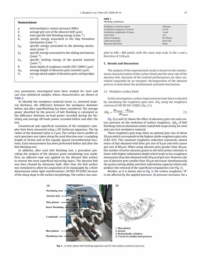
The test rig consists on a conventional lathe, a shoe-platen beltfinishing apparatus and a power transducer allowing the measurein situ of the power dissipated during the abrasive finishing pro-cess. The belt finishing apparatus is composed of two horizontalmachining arms equipped with shoe-platens assisted in pressure(Fig. 1).
According to this type of shoe-platens, each insert can be movedon radial direction by hydraulic cylinders pressing the abrasive beltagainst the periphery of the workpiece by a locally known value ofthe contact pressure “p”. Since the feed pressure of the hydrauliccylinders is the same, a constant pressure distribution is obtainedalong the abrasive belt/workpiece contact angle (approximately320◦). The value of “p” does not change during the process and itcan be easily controlled being set the feed pressure of cylinders inthe shoes.
Finishing tests have been realized on wet conditions varying thecontact pressure “p” and the average size of Al2O3 abrasive par-ticles “d”. Being all other working parameters kept constant (seeTable 1), five values of contact pressure (between 0.3 and 0.8 MPa)and six abrasive belts of different grains size (9, 15, 30, 40, 60 and80 �m) have been considered. It is interesting to note that this con-tact pressure range corresponds to the rough superfinishing regime
[5].For each contact pressure/grains size combination, tests havebeen repeated five times and the reported results are vali-dated by a statistical analysis (Shapiro-Wilk and Aspin-Welchtests). The effects on the belt finishing performances of the pro-
S. Mezghani et al. / Wear 267 (2009) 86–91 87
Nomenclature
p belt/workpiece contact pressure (MPa)d average grit size of the abrasive belt (�m)Es total specific belt finishing energy (J mm−3)Ec specific energy associated to the ship formation
mechanism (J mm−3)Epl specific energy associated to the plowing mecha-
nism (J mm−3)Esl specific energy associated to the sliding mechanism
(J mm−3)Em specific melting energy of the ground material
(J mm−3)R mean depth of roughness motifs (ISO 12085) (�m)Hm average height of abrasives grits summits (�m)
ccT
rbptit
preltb
vFtwwdo
Table 1Working conditions.
Workpiece rotation speed 100 rpmOscillation frequency of shoes 2.5 HzOscillation amplitude of shoes 1 mmCycle time 12 s
use of abrasive grits smaller than 30 �m decreases simultaneously
�s average attack angles of abrasives grits cutting edges(◦)
ess parameters investigated have been studied for steel andast iron cylindrical samples whose characteristics are shown inable 2.
To identify the workpiece material losses i.e. removed mate-ial thickness, the difference between the workpiece diameterefore and after superfinishing has been considered. The averageower absorbed by the process of belt finishing is calculated ashe difference between on-load power recorded during the fin-shing and average off-loads power recorded before and after theest.
Geometrical and superficial variations of the workpiece sam-les have been measured using a 2D Surfascan apparatus. The tipadius of the diamond stylus is 2 �m. The surface micro-profile onach specimen was taken along the axial direction over a samplingength of 16 mm and at five equally spaced circumferential loca-ions. Each measurement has been performed before and after theelt finishing test.
In addition, after each belt finishing test, a procedure pro-iding the analysis of the abrasive grain morphology was made.irst, an adhesive tape was applied on the abrasive film surfaceo remove the most superficial microchip layers. The abrasive belt
as then cleaned by ultrasonic bath. After that, the belt surfaceas metalized to allow for acquisition of its topography by a threeimensional white light interferometer (WYKO NT3300) becausef the sharp slope in the surface morphology. The surface was sam-Fig. 1. (a) Shoe-platen belt finishing apparatus
Inserts hardness 95 ShoresLubrication fluid Strict OilAbrasive belt feed None
pled in 640 × 480 points with the same step scale in the x and ydirection of 1.94 �m.
3. Results and discussions
The analysis of the experimental results is based on the simulta-neous characterization of the surface finish and the wear rate of theabrasive belt. Amounts of the evolved performances are then cor-related separately by an energetic decomposition of the abrasiveprocess to determine the predominant activated mechanism.
3.1. Workpiece surface finish
In this investigation, surface improvements have been evaluatedby calculating the roughness gain ratio �Rg using the roughnesscriterion R (NF EN ISO 12085) (Eq. (1)).
�Rg = {R}initial − {R}final
{R}initial(1)
Fig. 2(a) and (b) shows the effect of abrasives grits size and con-tact pressure on the evolution of surface roughness, �Rg, of beltfinishing with an aluminum oxide coated belt respectively, for steeland cast-iron workpiece material.
These roughness gain map show an optimal grits size of about30 �m which corresponds to the highest stable roughness gain ratio(0.85–0.9). This maximal roughness reduction represents almosttwice of that obtained with finer grit size of 9 �m and with coarsegrit size of 80 �m. When using abrasive grits greater than 30 �m,the number of active abrasive grains in the belt/surface interface islower with higher indentation depth which leads to less roughnessattenuation than this obtained with 30 �m of grit size. However, the
the grains cutting ability and their indentation capacity which onlyproduce the removal of the superficial irregularities (see Fig. 3).
Besides, as it is shown also in Fig. 2, the surface roughness “R”is not affected by the applied pressure. As pressure increases, for a
and (b) shoe-platen assisted in pressure.

88 S. Mezghani et al. / Wear 267 (2009) 86–91
Table 2Workpiece characteristics before belt finishing.
Workpiece material D38MSV5S Steel (%C 0.35/0.40) GS51 Cast iron (%C 3.4/3.8)Diameter 54.8 ± 0.005 mmAxial width 30 mmFabrication steps Turning, induction hardening, grinding Turning, grindingSuperficial hardness ≈55 HRC ≈30 HRCInitial roughness 2 < R < 4 �m 5 < R < 9 �m
or two
gratt
Fig. 2. Roughness gain ratio obtained by belt finishing f
iven abrasive grit size, steady state roughness remains constant inough superfinishing regime. Such behavior is likely to be caused,s shown in previous studies [6–8], by presence of inherent surfaceexture with roughness characterized by extreme dependence onhe stone type.
Fig. 3. 3D surface topographies of (a) original steel surface and after belt finish
workpiece materials: (a) hardened steel; (b) cast iron.
3.2. Energetic analysis
In order to better understand the influence of contact pres-sure and abrasive grains size on the activation of the fundamentalabrasion mechanisms (cutting, plowing, and sliding . . .), the total
ing with different abrasive grit size: (b) 9 �m, (c) 30 �m and (d) 80 �m.

S. Mezghani et al. / Wear 267 (2009) 86–91 89
wo wo
sc[
imttcga
tnrea
(
(
Fig. 4. Specific energy of belt finishing process for t
pecific belt finishing energy “Es” can be considered to consist ofhip formation, plowing and sliding components: Es = Ech + Esl + Epl2,9,10].
Note that only the energy component due to ship formation “Ech”s expended by material removal which corresponds to the mini-
um cutting energy required. Since the chip formation energy isypically associated with shearing which is virtually identical tohe melting energy per unit volume of ground material [2]. Thisorrelation between grinding and melting energy is valid for largerade of steels where the melting energy “Em” varies between 12nd 30 J mm−3 [2].
Indeed, Figs. 4 and 5 show respectively experimental results forhe total specific belt finishing energy and material removal thick-ess versus the grit size for a wide range of contact pressure. Similaresults are observed for the two tested workpiece material (hard-ned steel and cast iron). Moreover, two domains can be identifiedccording to the gains size variable “d”:
1) For “d” > 30 �m, the increase of both grit size and contactpressure provides higher material removal rate. However, thespecific energy remains practically constant (Es ≈ Em). Then, inthis domain, the cutting mechanism prevails largely than theplowing and sliding ones (Es → Ech).
2) For “d” < 30 �m, at the same contact pressure, the decrease ofthe grit size induces a greater specific energy with a lower mate-rial removal rate. This shows clearly that the workpiece/abrasivebelt contact is governed essentially by plowing and sliding(Es → Esl + Epl). In addition, this phenomenon is connected with
Fig. 5. Removed material thickness by belt finishing for two
rkpiece materials: (a) hardened steel; (b) cast iron.
the fact that increasing contact pressure does not affect thematerial removal rate.
Note also that the optimal surface finish is obtained for“d” = 30 �m (see Section 3.1) which corresponds to the transitionof predominant mechanism from plowing and sliding to cutting.Moreover, this critical grit size is shown to be related to the spatialmorphology of the original workpiece surface [11].
These experiment maps showing wear rates of belt finishingsuggest that the applied contact pressure modifies significantly theabrasiveness efficiency of the coated belt. This is supported by manystudies on abrasive failure of grits [12–16] which show that thegrowth rate of abrasive grits is dependent on the workpiece/toolcontact conditions. It has been particularly noted that the weight ofcontact pressure effect varies significantly with the abrasive grainssize. Now, since the wear of the coated abrasive belt modifies themagnitude of the abrasion mechanisms, an accurate study of thewear evolution of the abrasive belt was carried out. Also, since thefinishing tests were realized in wet conditions and since the adhe-sion between aluminum oxide grains/steel microchips is small, bothclogging and capping phenomena have been supposed negligible[12,13,16]. The key results of this wear assessment of coated beltare given in the following section.
3.3. Abrasive belt wear characterization
The properties assessment of coated abrasives for use in belt fin-ishing is a complex problem due to variation of grits morphology
workpiece materials: (a) hardened steel; (b) cast iron.

90 S. Mezghani et al. / Wear
Fa
famqlatisaa((w
asaitt
at
�
(d
Fr
ig. 6. Average attack angle of abrasives grits cutting edges relative to differentbrasives grits for two workpiece materials.
rom particle to particle [17,18]. A 3D assessment method providingn accurate description of the belt surface is developed. It coupleorphological image analysis with 3D topography measurement to
ualitatively evaluate the wear of the belt surface [19]. The morpho-ogical image analysis of the belt surface topography consists on thepplication of the watershed algorithm [19,20]. It allows the detec-ion of cutting edges of abrasives grits in the belt surface; it takesnto account the grain morphology by considering that an abra-ive grit usually presents multiple summits. Then, two parametersre considered for the characterization of the wear evolution of thebrasive belt: the average height of the abrasives grains summitsHm) and the average attack angle of the abrasives cutting edges�s). These two aggressiveness parameters were calculated from theorn belt surface topography and compared to the original values.
The correlation observed in Fig. 6 between the attack angle vari-tion and the increase of the removed material with higher gritizes shows the fundamental role played by the angularity of thebrasive grains in the transition from cutting to plowing and slid-ng mechanisms [15,21]. Indeed, the greater the attack angle (�s) ofhe grit cutting edges, the more it favors cutting phenomena andherefore material removal.
Fig. 7 represents the wear rate of an abrasive particle in term ofverage height reduction versus its size. This rate is quantified byhe parameter estimated from Eq. (2):
Hm = 100 × {Hm}initial − {Hm}final (2)
{Hm}initialFigs. 6 and 7 show that the identified optimal working conditiongrains size of 30 �m) separates the abrasives belt wear into twoifferent regimes in accordance with the energetic analysis. In fact,
ig. 7. Wear rate of abrasives grit height versus grains size for two workpiece mate-ials.
[
[
[
[
[
[
[
267 (2009) 86–91
for abrasive grains lower than 30 �m, when decreasing abrasivesgrits size, the specific energy becomes higher with lower removalmaterial rate (see Figs. 4 and 5). So, the exceeding energy inducesmore wearing of abrasive belt. The evolved wear process is thencharacterized for “d” < 30 �m by:
• A reduction of the height of abrasive grits and then their inden-tation capacity as shown in Fig. 7.
• A modification of the abrasive grits shape and morphology. It ismanifested by the decrease of the attack angles of finer abrasivegrits (see Fig. 6). This decrease favors the plowing mechanism[21].
On the opposite, as shown by Fig. 7, the wear rate of coarse abra-sive grit sizes, upper than 30 �m, still constant. The coarser grainsizes exhibit a greater ability to cut and remove material than thefiner sizes which results in a higher removal material.
4. Conclusion
A parametric study regarding the performance of belt finishingis conducted for cylindrical hardened steels and cast-iron work-piece. The results of numerous experiments demonstrate that thepredominant activated mechanism depend extremely to the size ofabrasive grains and the wear state of the coated belt. In addition, theparameters introduced to characterize both the abrasive finishingprocess and the coated belt properties enable the identification andthe quantification of the wear regimes. Furthermore, the correlationbetween the analysis of the workpiece surfaces and the abrasivebelt wear state provides primordial information about the acti-vated wear mechanisms for each investigated working parameters.The map’s representation showing wear rates and mechanisms sug-gests the existence of promising way for increasing the efficiencyof abrasive technological processes.
References
[1] D.M. Schibish, U. Friedrich, Technologie de superfinition: Des surfaces de hauteprécision, Verlag Moderne Industrie, Supfina Grieshaber, 2002.
[2] M.C. Shaw, Principles of Abrasive Processing, Oxford Science Publications,Clarendon Press, Oxford, 1996.
[3] M. El Mansori, E. Sura, P. Ghidossi, S. Deblaise, T. Dal Negro, H. Khanfir, Towardphysical description of form and finish performance in dry belt finishingby a tribo-energetic approach, J. Mater. Process. Technol. 182 (2007) 498–511.
[4] T.O. Mulhearn, L.E. Samuels, The abrasion of metals: a model of the process,Wear 5 (1962) 478–498.
[5] S.H. Chang, T.N. Farris, S. Chandrasekar, Experimental characterization ofsuperfinishing, Proc. Inst. Mech. Eng. B: J. Eng. Manuf. 217 (2003) 941–951.
[6] S.-H. Chang, T.N. Farris, S. Chandrasekar, Experimental analysis on evolution ofsuper finished surface texture, J. Mater. Process. Technol. 203 (2008) 365–371.
[7] B. Varghese, S. Malkin, Experimental investigation of methods to enhance stockremoval for superfinishing, Ann. CIRP 47 (1) (2003) 231–234.
[8] S. Mezghani, E. Sura, M. El Mansori, The effect of belt-finishing process variableson the topography of finished surfaces, Tribol. Trans. 51 (4) (2008) 1–9.
[9] I.D. Marinescu, W.B. Rowe, B. Dimitrov, I. Inasaki, Tribology of Abrasive Machin-ing Processes, William Andrew Publishing, 2004.
10] T.K. Puthanangady, S. Malkin, Experimental investigation of the superfinishingprocess, Wear 185 (1995) 173–182.
11] S. Mezghani, M. El Mansori, H. Zahouani, New criterion of grain size choice foroptimal surface texture and tolerance in belt finishing production, Wear 266(5–6) (2009) 578–580.
12] A.P. Mercer, I.M. Hutching, The deterioration of bonded abrasive papers duringthe wear of metals, Wear 132 (1989) 77–97.
13] S.W. Date, S. Malkin, Effects of grit size on abrasion with coated abrasives, Wear40 (1976) 223–235.
14] J. Shibata, I. Inasaki, S. Yonetsu, The relation between the wear of grain cuttingedges and their metal removal ability in coated abrasive belt grinding, Wear 55(1979) 331–344.
15] T. Kayaba, K. Hokkirigawa, K. Kato, Analysis of the abrasive wear mechanism bysuccessive observations of wear processes in a scanning electron microscope,Wear 110 (1986) 419–430.
16] R.G. Visser, R.C. Lokken, The effect of the severity of the grinding mode on thewear characteristics of grade Al2O3 – and Al2O3–ZrO2 – coated abrasive belts,Wear 65 (1981) 325–350.

Wear
[
[
[
S. Mezghani et al. /
17] A.L. Carrano, J.B. Taylor, Geometric modeling of engineered abrasive processes,J. Manuf. Process. 7 (2005) 17–27.
18] H. Hamdi, M. Dursapt, H. Zahouani, Characterization of abrasive grain’sbehaviour and wear mechanisms, Wear 254 (12) (2003) 1294–1298.
19] S. Mezghani, M. El Mansori, Abrasiveness properties assessment of coated abra-sives for precision belt grinding, Surf. Coat. Technol. 203 (5–6) (2008) 786–789.
[
[
267 (2009) 86–91 91
20] S. Mezghani, H. Zahouani, Characterization of 3D waviness and roughnessmotifs, Wear 257 (12) (2004) 1250–1256.
21] M. Ben Tkaya, H. Zahouani, S. Mezlini, Ph. Kapsa, M. Zidi, A. Dogui, The effectof damage in the numerical simulation of a scratch test, Wear 263 (2007)1533–1539.