We realize even Special Features …. - OTH Regensburg
16
1 We realize even Special Features …. LOHER a Siemens company Electric Motor Design for Special Requirements By Thomas Fladerer, Dieter Seifert Pict. 1: Typical lamination sheets for transnorm motors (left) and norm motors The designs of lamination sheets both in norm motors and transnorm motors are the basis for the realization of most requirements with regard to sufficient torque, good efficiency, high power factor (cosφ), low noise levels, and temperature limits. Apart from the standard requirements there are, however, quite a number of special requirements which can only be realized with a technically and economically optimized solution, i.e. with a special motor design. Author: Ing. Thomas Fladerer is Head of Electrical Calculation Industrial Motors in Messrs. Loher GmbH, Ruhstorf Author: Prof. Dr.-Ing. Dieter Seifert teaches electrical engineering at the University of Applied Sciences, Regensburg
-
Upload
khangminh22 -
Category
Documents
-
view
0 -
download
0
Transcript of We realize even Special Features …. - OTH Regensburg

1
We realize even Special Features …. LOHER a Siemens company
Electric Motor Design for Special Requirements By Thomas Fladerer, Dieter Seifert
Pict. 1: Typical lamination sheets for transnorm motors (left) and norm motors The designs of lamination sheets both in norm motors and transnorm motors are the basis for the realization of most requirements with regard to sufficient torque, good efficiency, high power factor (cosφ), low noise levels, and temperature limits. Apart from the standard requirements there are, however, quite a number of special requirements which can only be realized with a technically and economically optimized solution, i.e. with a special motor design. Author: Ing. Thomas Fladerer is Head of Electrical Calculation Industrial Motors in Messrs. Loher GmbH, Ruhstorf Author: Prof. Dr.-Ing. Dieter Seifert teaches electrical engineering at the University of Applied Sciences, Regensburg

2
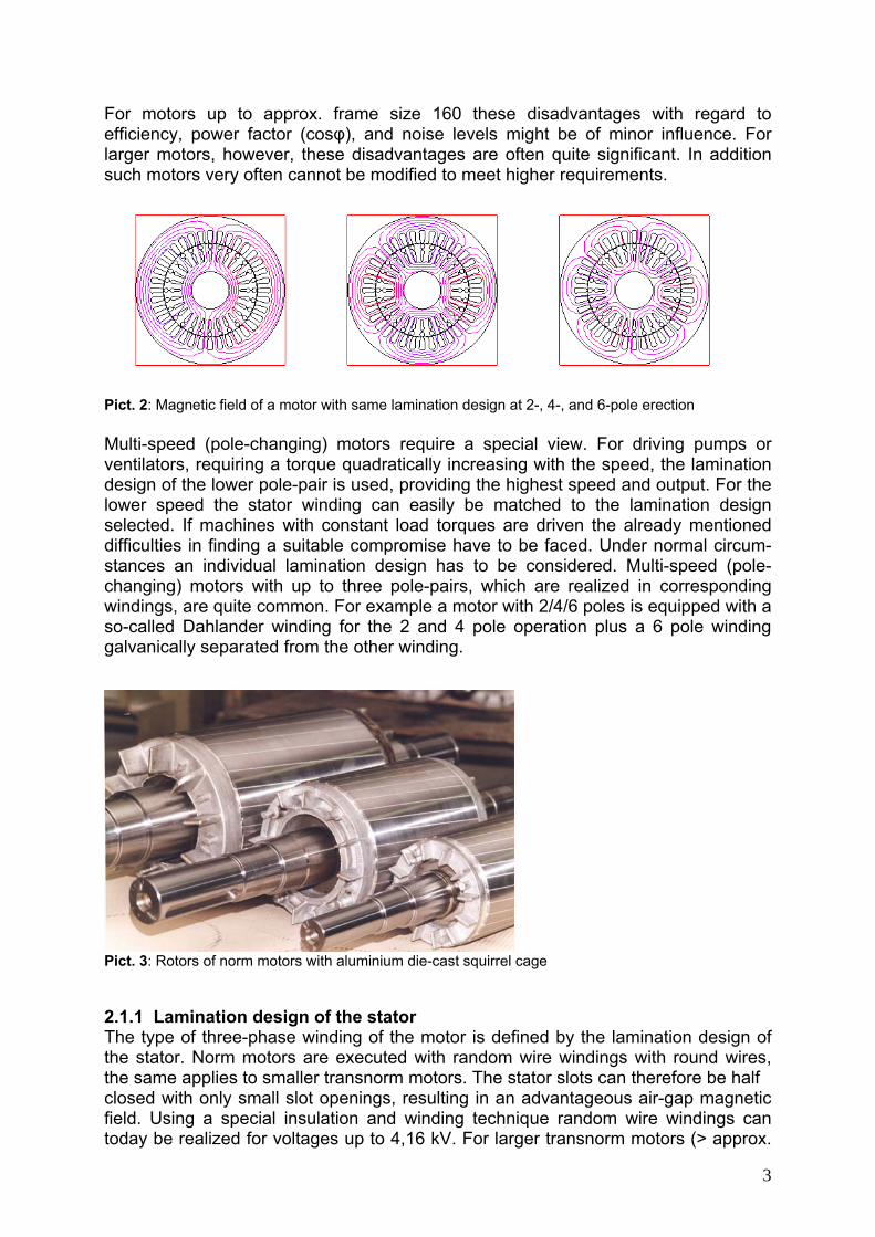
1. Introduction When designing three-phase asynchronous motors the first step is defining the shape of their magnetic active parts, i. e. the layout of the lamination sheets for both stator and rotor. Their dimensions depend to a very high degree on the following para- meters: ► Output, and duty type, ► Number of poles, and frequency, ► Cooling method (surface cooled, internally cooled, water-cooled) ► Voltage (low, medium, high voltage) ► Type of rotor (squirrel cage, slip ring = wound rotor) For their standard types the manufacturers of electric machines have developed optimized lamination designs. Pict. 1 shows a typical example for a norm motor and a transnorm motor. 2. Norm Motors and Transnorm Motors For the following considerations it is practical to differentiate between so-called norm motors and transnorm motors. Norm motors are three-phase squirrel cage motors according to DIN EN 50 347. In this standard there are defined - amongst others – the main mechanical dimensions for the frame sizes 56 till 315. In addition one frame size may be designed in two different lengths. Thus for each number of poles a motor type range with an output gradation is created. For instance the output range for surfaced-cooled 4-pole motors goes from 60 W to 132 kW. For larger motors the frame size gradation is continued in the standard IEC 60 072, i.e. beyond the standard DIN EN 50 347. Therefore these motors are called transnorm motors. 2.1 Optimizing the lamination design For their norm motors the manufacturers of electric machines have developed optimized lamination designs, providing sufficient torques for standard applications, and furthermore creating the basis for the realization of requirements regarding a good efficiency, high power factor (cosφ), low noise levels, and temperature limits required. The technical requirements can only be met in an optimum way by using individual lamination designs for each frame size, and at least for each of the pole-pairs from 2 to 8 poles. However, this means to have available quite a number of punching tools and thus increased efforts in both investments and production. Considering the product range of certain manufacturers the use of only one lamination design for several pole-pairs can be of advantage. Pict. 2 shows the magnetic fields of a motor with the same lamination design operated at 2-, 4-, and 6-poles. It clearly shows that both the stator and the rotor backs have to bear the highest magnetic stress at the 2-pole operation. Hence it makes sense to use a common lamination design only for 4- and 6-pole operations. But even for this solution a compromise acceptable for both pole-pairs have to be found. It is obvious that compared to individual lamination designs certain technical values cannot be optimum. As a consequence the result might show that in a certain efficiency classification [1] the particular type slips to the next lower grade, and thus to a disadvantage in comparison with other competitors.
3
For motors up to approx. frame size 160 these disadvantages with regard to efficiency, power factor (cosφ), and noise levels might be of minor influence. For larger motors, however, these disadvantages are often quite significant. In addition such motors very often cannot be modified to meet higher requirements.
Pict. 2: Magnetic field of a motor with same lamination design at 2-, 4-, and 6-pole erection Multi-speed (pole-changing) motors require a special view. For driving pumps or ventilators, requiring a torque quadratically increasing with the speed, the lamination design of the lower pole-pair is used, providing the highest speed and output. For the lower speed the stator winding can easily be matched to the lamination design selected. If machines with constant load torques are driven the already mentioned difficulties in finding a suitable compromise have to be faced. Under normal circum-stances an individual lamination design has to be considered. Multi-speed (pole-changing) motors with up to three pole-pairs, which are realized in corresponding windings, are quite common. For example a motor with 2/4/6 poles is equipped with a so-called Dahlander winding for the 2 and 4 pole operation plus a 6 pole winding galvanically separated from the other winding.
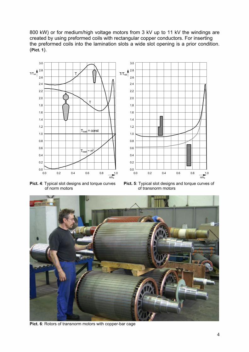
Pict. 3: Rotors of norm motors with aluminium die-cast squirrel cage 2.1.1 Lamination design of the stator The type of three-phase winding of the motor is defined by the lamination design of the stator. Norm motors are executed with random wire windings with round wires, the same applies to smaller transnorm motors. The stator slots can therefore be half closed with only small slot openings, resulting in an advantageous air-gap magnetic field. Using a special insulation and winding technique random wire windings can today be realized for voltages up to 4,16 kV. For larger transnorm motors (> approx.
4
800 kW) or for medium/high voltage motors from 3 kV up to 11 kV the windings are created by using preformed coils with rectangular copper conductors. For inserting the preformed coils into the lamination slots a wide slot opening is a prior condition. (Pict. 1).
T
T
0.0 0.2 0.4 0.6 0.8 1.0n/n0
0.0
0.4
0.8
1.2
1.6
1.4
1.0
0.6
0.2
1.8
2.0
2.2
2.4
2.6
2.8
3.0
T/Trat
Tload = const
Tload ~ n2
0.0 0.2 0.4 0.6 0.8 1.0n/n0
0.0
0.4
0.8
1.2
1.6
1.4
1.0
0.6
0.2
1.8
2.0
2.2
2.4
2.6
2.8
3.0
T/Trat
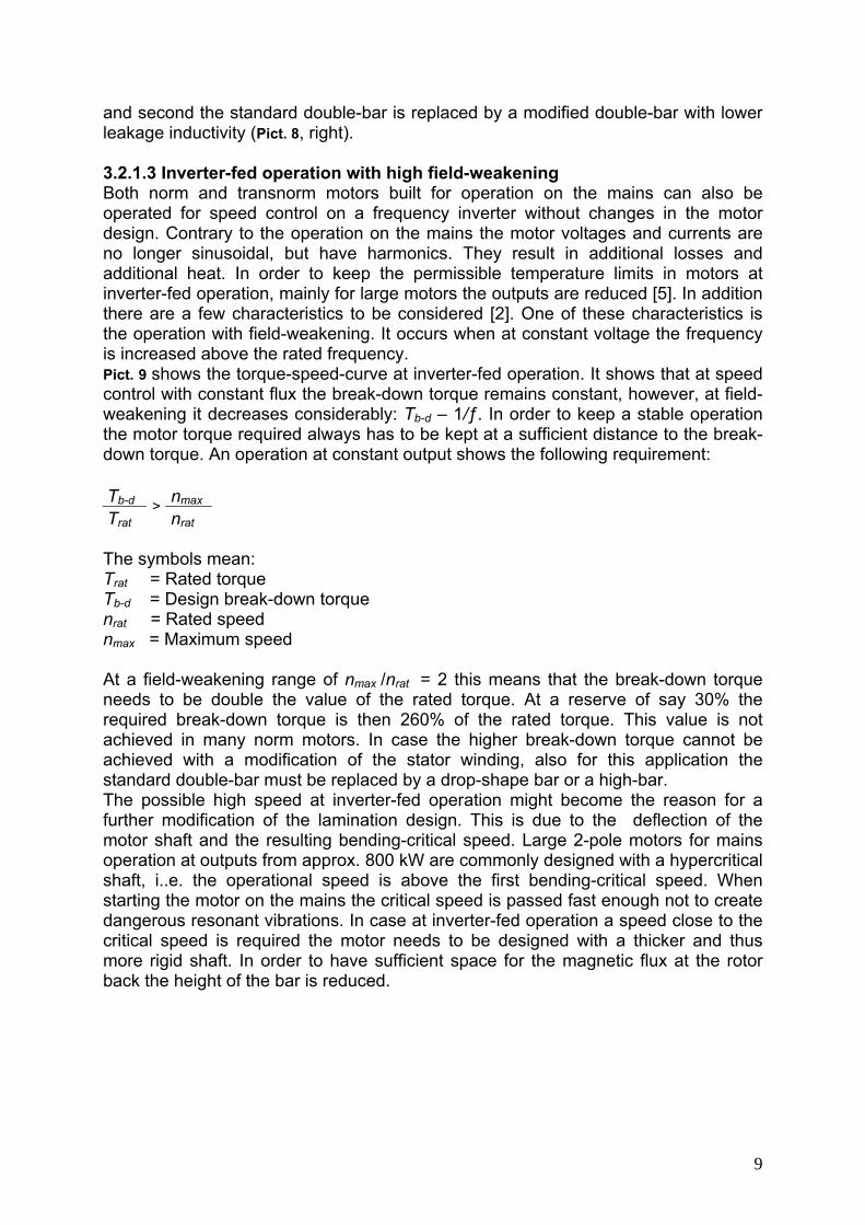
Pict. 4: Typical slot designs and torque curves Pict. 5: Typical slot designs and torque curves of of norm motors of transnorm motors
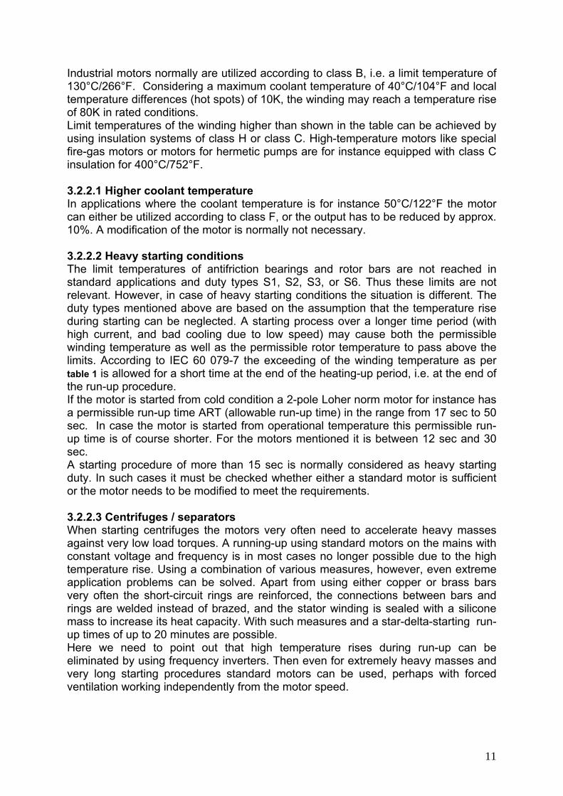
Pict. 6: Rotors of transnorm motors with copper-bar cage

5
2.1.2 Lamination design of the rotor With the selection of the rotor lamination design essential features of the motor, i.e. starting torque, starting current, and noise behaviour are fixed. The rotor slots of norm motors are die-cast filled with aluminium, and in the same manufacturing process the short-circuit rings on both front ends are made (Pict. 3). With this process a very robust squirrel cage guaranteeing a long life time of the motor without considerable maintenance efforts is produced at reasonable expenditures. In recent years a new technology has been developed allowing a die-cast filling of the rotor slots with copper. Since copper has a better electric conductivity than aluminium such motors produce lower losses and thus a better efficiency. However, with this new technology the disadvantage compared to aluminium die-cast is the fact that considerably higher temperatures are involved resulting for instance in a far shorter lifetime of the moulds. For this reason it seems to be uncertain whether this new technology will gain a considerable share against the aluminium die-cast process.
NU%80
NU%100
breakaway torque
0.0 0.2 0.4 0.6 0.8 1.0n/n0
0.0
0.4
0.8
1.2
1.6
1.4
1.0
0.6
0.2
1.8
2.0
2.2
2.4
2.6
2.8
3.0
3.2
3.4
NU%80
NU%100
0.0 0.2 0.4 0.6 0.8 1.0n/n0
0.0
0.4
0.8
1.2
1.6
1.4
1.0
0.6
0.2
1.8
2.0
2.2
2.4
2.6
2.8
3.0
3.2
3.4
T/TratT/Trat
T
T
Tload
T
T
Tload
breakaway torque
Pict. 7: Torque-speed curves at reduced motor voltage and high breakaway torque. LHS: Standard motor. RHS: Modified motor (longer leakage bridge between upper and lower bar) The rotor slots in smaller motors (up to approx. frame size 90) are designed in a drop shape. In order to achieve a sufficient starting torque larger motors are designed with a double-bar. Pict. 4 shows both these typical slot shapes and the torque curves achieved. In Pict. 4 apart from the motor torques also the important load torques of the driven machines can be seen. Cranes, hoisting machines, and agitators, for instance, have a constant load torque independent from the speed, whereas in fluid-kinetic machines like ventilators and centrifugal pumps the torque increases quadrati-cally to the speed. It demonstrates that the motor torque is up to the operational speed always higher than the load torque. When engineering a drive this behaviour

6
needs to be considered in order to achieve a safe starting followed by a perfect operation [2].
Δ-Connection
Y-Connection
0.0 0.2 0.4 0.6 0.8 1.0n/n0
0.0
0.4
0.8
1.2
1.6
1.4
1.0
0.6
0.2
1.8
2.0
2.2
2.4
2.6
2.8
3.0
T/Trat
Δ-Connection
Y-Connection
0.0 0.2 0.4 0.6 0.8 1.0n/n0
0.0
0.4
0.8
1.2
1.6
1.4
1.0
0.6
0.2
1.8
2.0
2.2
2.4
2.6
2.8
3.0
3.2
3.4
3.6
3.8
4.0
4.2
T/Trat
T
T
T
T
Tload
Tload
Pict. 8: Star-delta start against pump or ventilator. LHS: Standard motor. RHS: Modified motor (modi- fied rotor bar and stator winding) The rotor lamination designs of transnorm motors and their corresponding torque-speed-curves are shown in Pict. 5. For frame sizes up to approx. 560 the rotor cages can be manufactured in aluminium die-cast, however, the normal design nowadays is a copper-bar cage with copper short-circuit rings brazed on both ends (Pict. 6). For load torques with quadratic torque-speed-curves simple rectangular bars are sufficient. In case higher starting torques are required, or for other heavy starting conditions, e. g. for coal mills or cutters, so-called L-bars or double-bars are used. Whereas L-bars are generally made of copper, double-bars are either copper or brass or bronze [2]. 3. Matching of the Motor Design For standardized or norm motors the manufacturers make available extensive catalogues showing the important data for standard outputs [3, 4] i.e. current, cosφ, and efficiency for duty type S 1 (continuous operation) as well as starting current, starting torque, and break-down torque. These data shown are valid for either 400 V,

7
or for a voltage range of e. g. 380 – 420 V at 50 Hz. Furthermore the catalogues also show the mechanical dimensions, weight, and moment of inertia, and provide useful design information. Thus for many applications all data necessary for the solution of drive problems and the selection of suitable motors are provided. However, there are quite a few requirements which cannot be met by considering standard solutions. In such cases the motors need to be specially matched using electrical designs different to the standard design, and considering the particular drive problem. Since these special drive problems occur to a high degree within the output range of standard/norm motors, the following statements are limited to this group of motors. 3.1 Modification of the stator winding A modification of the stator winding in norm motors is a relatively simple measure resulting in only minor additional efforts. In case the requirements are different from the standard design the first attempt will be a modification of the stator winding with the same lamination design. This is sufficient for instance for different voltages, frequencies, or duty types. The necessary modifications of the motor design are the turns of the winding and the diameter of the wire. There is a further differentiation of this modification, if the magnetic relations (iron saturation) remain the same, or are different. 3.1.1 Modification of the stator winding at same iron saturation If the mains voltage or frequency is changed compared to the standard design the winding can be modified in such a way that the saturation remains the same. As a consequence other important data like cosφ, efficiency, and the relations starting torque/rated torque (Tstart/Trat), break-down torque/rated torque (Tb-d/Trat), and starting current/rated current (Istart/Irat) also remain the same. Thus the modification from 400 V to 500 V for instance is possible without any problem, the same applies to a change from 50 Hz to 60 Hz. Due to the higher speed on a 60 Hz mains supply the output available is even higher. Depending on the number of poles and the frame size this output increase varies between 12% up to 20% [3, 5]. 3.1.2 Modification of the stator winding at different saturation If the winding is modified at the same voltage and frequency, also the iron saturation and essential motor data change. For instance the decrease of turns results in an increase in magnetic inductions, in idle current, and in iron losses. Whether other important motor data like winding temperature and cosφ remain within acceptable limits depends on the particular application. Just one example is matching the stator winding to different duty types. The catalogue data of the motor manufacturers normally relate to continuous operation, i.e. duty type S1. If a motor is operated only for a short period at its rated output for duty type S1 the permissible temperature limit in the winding is not reached. Considering the thermal capability this motor can be operated for a short period with a higher output. As a reference value for norm motors it can be considered that at a short-time duty of 30 minutes (S2 – 30 min) their possible outputs compared to continuous operation can be one to two type-steps higher. Taking for instance a 4-pole Loher motor, type ANGA-250ME-04, with a rated output of 55 kW at duty type S1, the output at duty type S2 – 30 min can be increased to 75 kW. In certain cases the higher output can even be achieved without a shaft-mounted fan. This solution with a considerable noise reduction is quite welcome for instance for stage motors, and in addition even more economical. For an operation of motors in

8
duty types S2, S3, or S6 the stator winding is modified in such a way that the typical operational data cosφ, (Tstart/Trat), (Tb-d/Trat), or (Istart/Irat) remain almost unchanged. Basically these correlations are also applicable for transnorm motors. However, with increasing outputs at low numbers of poles it gets more and more difficult to determine practicable turns of the winding. As a result larger 2-pole motors may only be manufactured with higher voltages, e. g. for 690 V. 3.2 Change of the rotor lamination design In case the drive requirements can no longer be met with a modification of the stator winding, or only with considerable disadvantages, a change of the rotor lamination design becomes inevitable. The following chapters deal with some of such special requirements and describe the matching modifications of the rotor lamination design. 3.2.1 Modification of the torque-speed-curve Both the shape and the material of the rotor bars have a final influence on the torque-speed-curve. The curves of norm motors are designed to meet most standard requirements. Looking for instance at the curve of Pict. 7, left, (motor type ANGA-225SE-04, 37 kW), this motor can even run-up against a load torque of 100% of rated torque. 3.2.1.1 High breakaway torque A relatively common special requirement compared to standard motors is the starting capability at only 80% of the rated voltage. One should keep in mind that with an approximate calculation the torque depends on the voltage square. In practice the torque even decreases more due to the saturation of leakage bridges. Even this situation could still be born by the motor at constant load torque. However, when driving a loaded conveyor belt, or a crusher mill, or a screw compressor the situation deteriorates due to the high breakaway torque at standstill. In Pict. 7 it shows a value of 160% of rated torque. As can be seen the load torque is higher than the starting torque of the motor, hence a run-up is impossible. Basically this problem can be solved by using a larger norm motor with higher output and higher torque. In many applications this solution, however, is not a good choice because of larger dimensions and heavier weight of the motor. Furthermore the values of starting current and rated current increase. And since these data are determining the engineering of the complete electric installation the result is a price increase for fuses, leads, switches, etc. The better solution therefore is the extension of the leakage bridge between the upper and the lower bar in the rotor. Pict. 7, right, shows that the motor then develops a sufficient starting torque. Minor differences in cosφ and efficiency compared to the standard motor can then be accepted. 3.2.1.2 Star-delta start against pump or fan A not sufficient torque when operating pumps or fans can be the result if motors are started in star connection to reduce the starting current. In simplified theory these motors develop, compared to the delta connection, only one third of the torque, because of the saturation the value is in practice even lower. As Pict. 8 shows with a standard motor a run-up is only possible up to approx. 70% of the synchronous speed. If then the motor is switched to delta connection too high a current flows despite the start at star connection. The problem can be solved using two modifications: First the turns in the stator winding are reduced (higher saturation),
9
and second the standard double-bar is replaced by a modified double-bar with lower leakage inductivity (Pict. 8, right). 3.2.1.3 Inverter-fed operation with high field-weakening Both norm and transnorm motors built for operation on the mains can also be operated for speed control on a frequency inverter without changes in the motor design. Contrary to the operation on the mains the motor voltages and currents are no longer sinusoidal, but have harmonics. They result in additional losses and additional heat. In order to keep the permissible temperature limits in motors at inverter-fed operation, mainly for large motors the outputs are reduced [5]. In addition there are a few characteristics to be considered [2]. One of these characteristics is the operation with field-weakening. It occurs when at constant voltage the frequency is increased above the rated frequency. Pict. 9 shows the torque-speed-curve at inverter-fed operation. It shows that at speed control with constant flux the break-down torque remains constant, however, at field-weakening it decreases considerably: Tb-d – 1/ƒ. In order to keep a stable operation the motor torque required always has to be kept at a sufficient distance to the break-down torque. An operation at constant output shows the following requirement: Tb-d nmax Trat
> nrat
The symbols mean: Trat = Rated torque Tb-d = Design break-down torque nrat = Rated speed nmax = Maximum speed At a field-weakening range of nmax /nrat = 2 this means that the break-down torque needs to be double the value of the rated torque. At a reserve of say 30% the required break-down torque is then 260% of the rated torque. This value is not achieved in many norm motors. In case the higher break-down torque cannot be achieved with a modification of the stator winding, also for this application the standard double-bar must be replaced by a drop-shape bar or a high-bar. The possible high speed at inverter-fed operation might become the reason for a further modification of the lamination design. This is due to the deflection of the motor shaft and the resulting bending-critical speed. Large 2-pole motors for mains operation at outputs from approx. 800 kW are commonly designed with a hypercritical shaft, i..e. the operational speed is above the first bending-critical speed. When starting the motor on the mains the critical speed is passed fast enough not to create dangerous resonant vibrations. In case at inverter-fed operation a speed close to the critical speed is required the motor needs to be designed with a thicker and thus more rigid shaft. In order to have sufficient space for the magnetic flux at the rotor back the height of the bar is reduced.

10
4/3⋅fN 5/3⋅fN 2⋅fNfN
Tb-d ∼ 1/f2
n
breakdown torque:field weakening:
Tb-d
1/3⋅fN 2/3⋅fN
constant flux:Tb-d = constbreakdown torque:
T
Pict. 9: Torque-speed-curve, inverter-fed operation at constant flux and field-weakening 3.2.2 Temperature One of the most vital requirements for electric machines is holding the permissible temperatures at continuous operation (duty type S1, see table 1). The temperature of the winding and consequently the insulation temperature is a decisive value since it is the most important factor for the lifetime of the insulation. Table 1: Limiting Temperatures for Asynchronous Motors (duty type S1)
Insulation Rotor Bar Explosion Protection
Temperature class B F Ignition temperatures
Limiting temperature
130°C (120°C) /
266°F (248°F
155°C (130°C) /
311°F (248°F)T1 450°C / 842°F
Coolant temperature 40°C / 104°F 40°C / 104°F
Aluminium die-cast
300°C / 572°F
T2 300°C / 572°F
Limiting temperature rise 80 K (70 K) 105 K (90 K) T3 200°C / 392°F
T4 135°C / 275°F
T5 100°C / 482°F
Short-time limiting temperature at the end of heating-up period
185°C / 365°F 210°C / 410°F
Copper, hard brazed
400°C / 752°F
T6 85°C / 185°F
Temperature classes: IEC 60034-1 Method of measuring: Resistance measurement Short-time heating-up: DIN EN 60079-7 Values in brackets: Increased safety EEx e (DIN EN 60079-7)
Works standard of the manufacturer (example: Loher)
Ignition temperatures: Explosion-protection standard 94/9/EG - ATEX 100a
11
Industrial motors normally are utilized according to class B, i.e. a limit temperature of 130°C/266°F. Considering a maximum coolant temperature of 40°C/104°F and local temperature differences (hot spots) of 10K, the winding may reach a temperature rise of 80K in rated conditions. Limit temperatures of the winding higher than shown in the table can be achieved by using insulation systems of class H or class C. High-temperature motors like special fire-gas motors or motors for hermetic pumps are for instance equipped with class C insulation for 400°C/752°F. 3.2.2.1 Higher coolant temperature In applications where the coolant temperature is for instance 50°C/122°F the motor can either be utilized according to class F, or the output has to be reduced by approx. 10%. A modification of the motor is normally not necessary. 3.2.2.2 Heavy starting conditions The limit temperatures of antifriction bearings and rotor bars are not reached in standard applications and duty types S1, S2, S3, or S6. Thus these limits are not relevant. However, in case of heavy starting conditions the situation is different. The duty types mentioned above are based on the assumption that the temperature rise during starting can be neglected. A starting process over a longer time period (with high current, and bad cooling due to low speed) may cause both the permissible winding temperature as well as the permissible rotor temperature to pass above the limits. According to IEC 60 079-7 the exceeding of the winding temperature as per table 1 is allowed for a short time at the end of the heating-up period, i.e. at the end of the run-up procedure. If the motor is started from cold condition a 2-pole Loher norm motor for instance has a permissible run-up time ART (allowable run-up time) in the range from 17 sec to 50 sec. In case the motor is started from operational temperature this permissible run-up time is of course shorter. For the motors mentioned it is between 12 sec and 30 sec. A starting procedure of more than 15 sec is normally considered as heavy starting duty. In such cases it must be checked whether either a standard motor is sufficient or the motor needs to be modified to meet the requirements. 3.2.2.3 Centrifuges / separators When starting centrifuges the motors very often need to accelerate heavy masses against very low load torques. A running-up using standard motors on the mains with constant voltage and frequency is in most cases no longer possible due to the high temperature rise. Using a combination of various measures, however, even extreme application problems can be solved. Apart from using either copper or brass bars very often the short-circuit rings are reinforced, the connections between bars and rings are welded instead of brazed, and the stator winding is sealed with a silicone mass to increase its heat capacity. With such measures and a star-delta-starting run-up times of up to 20 minutes are possible. Here we need to point out that high temperature rises during run-up can be eliminated by using frequency inverters. Then even for extremely heavy masses and very long starting procedures standard motors can be used, perhaps with forced ventilation working independently from the motor speed.

12
3.2.2.4 Sole protection A drive requirement very often specified is that the limit temperatures acc. to table 1 are kept even in case of failure, e.g. at blocked rotor. This can be achieved with features like protective switch, or a direct temperature monitoring of the stator winding (thermal motor protection TMS), e.g. with PTC thermistors. However, whether with a temperature monitoring of the stator winding also the rotor can be protected (sole protection) depends on the temporary-thermal behaviour of the motor. In order to determine this behaviour in the test fields of the motor manufacturers the temperature rise at blocked rotor is measured. Pict. 10: Temperature curve of the stator winding Θ1 and the rotor Θ2 at mains operation and with blocked rotor (motor: type ANGA-132MB-04) As an example Pict. 10 shows the rise of the winding temperature Θ1, and of the rotor temperature Θ2 for a motor of frame size 132 at blocked rotor. It demonstrates that in such small motors the temperature rise of the stator winding is faster than that of the rotor bar. After approx. 17 sec the winding temperature is 145°C/293°F and thus at a coolant temperature of 40°C/104°F close to the limit of class B. The rotor shows a temperature rise of only 100K and thus far below the temperature limit for aluminium (table 1). This behaviour is described as “stator critical”. Motors with this behaviour can only be protected against inadmissible temperature rise by monitoring the winding temperature. This sole protection, however, is only possible up to approx. frame size 280. In larger motors the rotor bar reaches the temperature limit faster than the winding. These motors are “rotor critical”. But also for large motors customers are asking for sole protection. This requirement can be met by using a copper rotor instead of an aluminium rotor. The result are two advantages: First copper is capable of storing about 40% more heat than aluminium, and second the permissible temperature limit as per table 1 is 100K higher. By using a copper rotor a sole protection of for instance 2-pole motors up to frame size 315 at an output of 200 kW is possible. At higher numbers of poles the sole protection is possible even for larger motors.
Θ1
Θ2 120K
100K
80K
60K
40K
20K
0K
140K
160K
180K

13
3.2.2.5 Explosion-proof motors Since this information is dealing mainly with norm motors only explosion-proof motors in the designs II G 3 EEx nA “non-sparking“, II G 2 EEx e II “increased safety” , and II G 2 EEx d(e) II “flameproof enclosure” are considered. Loher is a leading manufacturer of explosion-proof motors. From the whole range of norm motors produced almost 80% are of explosion-proof design, more than 60% thereof are of flameproof enclosure EEx d(e). In the transnorm motor range the share of explosion-proof and flameproof motors is even higher. 3.2.2.5.1 II G 3 EEx nA non-sparking motors The electrical design of these motors is basically the same as in standard motors. For the explosion protection the temperature limits according to the EN standards need to be kept. Mechanically the motors are similar to standard motors, however, materials used must not create sparks under normal operating conditions. Certain requirements with regards to leakage paths, material strength (e.g. of fan cover), minimum dimensions (e.g. between fan and fan cover) must be kept. 3.2.2.5.2 II G 2 EEx d(e) II flameproof motors The electrical design of flameproof motors is identical to standard motors. Hence the descriptions of special electrical designs in this article also applies to flameproof motors as long as the temperature limits according to EN standards are kept, considering the temperature classes. Mechanically these motors are of special design. The flameproof enclosure needs to be capable of keeping an inside explosion within the enclosure, and not to ignite the surrounding explosive atmosphere. This request is met by using stronger housings and end shields, and at the connecting areas (e.g. between housing and end shields, and end shields and shaft) by keeping the dimensions of the so-called flame paths strictly within the limits set for the gas groups and temperature classes (e.g. IIB or IIC, and T4 – T6). 3.2.2.5.3 II G 2 EEx e increased safety motors Explosion-proof motors “increased safety” II 2 G EEx e have to keep in the first place the ignition temperatures acc. to table 1 in order to guarantee the explosion protection. This is applicable for all motor parts, in particular also for the rotor. Furthermore it applies to all operational conditions including failures like blocked rotor. The relevant standards [6] also specify that the temperature rise of the winding in rated condition is lower than defined for the applicable temperature class. This means for temperature class B a reduction of 10K, for class F a reduction of 15K (values in table 1 in brackets). Hence EEx e motors have lower rated outputs than standard motors. The reduction in output is considerable mainly in 2- and 4-pole motors and can be up to 30%. In order to keep the explosion protection either protective switches or thermal motor protection, as described in “sole protection”, can be used. An important test is here again the operation at blocked rotor (Pict. 10). From the temperature curves and the operational temperature rise the heating-up period tE , i.e. the time until the critical temperature of a motor part, either stator winding or rotor is reached, is calculated. The protection devices have to switch off the motor before reaching this temperature. In order to use standardized protection devices EEx e motors have to be designed in such a way that the tE – period is longer than a specified minimum heating-up period tE min. For these minimum heating-up periods different values exist, depending on

14
standards or specifications. Pict. 11 shows the tE min – periods according to IEC EN 60 079-7 [6] and VIK [7] and their dependency on the relation starting current to rated current Istart/Irat .
20
10
20
30
25
15
5
4 6 8 103 5 7 9
tEmins
DIN EN 60079-7
VIK
Istart/Irat Pict. 11: Minimum heating-up times tE min acc. to DIN EN 60 079-7 and VIK These requirements clearly show that EEx e motors need to be designed differently to standard motors. The changes apply to both the stator winding and the rotor. In the latter very often the standard double-bar is replaced by a drop-shape bar or a copper high-bar in order to reduce the temperature rise at blocked rotor. Pict. 12: Modification of standard motor to meet special requirements
Requirement Standard Modification Example
Matching to different mains voltage / mains frequency
440V / 60Hz
Matching to various duty types S2, S3, S6
High breakaway torque Reduced voltage
Tload(n=0) = 160% Trat U = 80% Urat
Star-delta- start at load Starting of pumps or fans

15
Inverter-fed operation at high field-weakening nmax/nrat = 2
Heavy starting Starting time ≥ 2 min
EEx e motors tE > 8sec at Istart/Irat =6,7 (acc. to VIK [6])
Sole protection 2-pole motor: frame size 315 output 132 kW
Limitation of starting current
Common request in projects: Istart/Irat ≤ 600%
Low slip (small speed variation at load, hard torque-speed-curve)
Rotating converter for independent, controllable networks
High slip (yielding, soft torque-speed-curve)
Punching/forging machines (shock load), hoisting machines, wind generators
High efficiency High-efficiency-motors, asynchronous generators
Multi-speed motors (pole-changing motors)
12/4/2-poles, winch drives for ships
High-temperature motors Canned motors for 400°C/752°F, Fire-gas motors
No aluminium allowed
Ship motors, motors for marine applications,, certain environmental conditions, gases
Special mechanical designs with extreme dimensions
Depth-vibrator (rotor length = 610mm) rotor diameter = 120mm)

16
4. Summary By using selected examples we have tried to demonstrate which changes in the motor design can lead to fulfil special requirements. In Pict. 12 these examples, and further requirements with the corresponding modifications are summarized. The modifications mentioned are to be understood as possible solutions for changing the operational behaviour of motors into the direction required. Whether the solution described is sufficient, or whether further changes and modifications become necessary needs to be checked for each individual case. References: [1] Greiner, H.; Weltweite Klassifizierung der Motorwirkungsgrade, ema 06/2006 (Worldwide classification of motor efficiencies) [2] Technische Schrift: Drehzahlverstellung von Asynchronmaschinen. Loher GmbH 2005 (Technical book: Speed control of asynchronous machines) [3] Technische Liste IM: Industriemotoren. Loher GmbH (Technical catalogue IM: Industrial motors) [4] Niederspannungsmotoren – IEC Käfigläufermotoren 0,06 – 1250 kW. Siemens AG 2006 (Low voltage motors – IEC squirrel cage motors 0,06 – 1250 kW) [5] Technische Liste UN04: Drehstrommotoren für drehzahlverstellbare Antriebe. Loher GmbH (Technical catalogue UN04: Three-phase motors for variable speed drives) [6] DIN EN 60 079-7: Elektrische Betriebmittel für explosionsgefährdete Bereiche – Teil 7: Erhöhte Sicherheit EEx e (DIN EN 60 079-7: Electrical apparatus for hazardous areas – part 7: Increased safety EEx e)