Way Transfers to Mercury and Jupiter N66-16591
310
NATIONAL AERONAUTICS AND SPACE ADMINISTRATION Technical Report No. 32-77 Design Parameters for Ballistic Interplanetary Trajectories Part II. One- Way Transfers to Mercury and Jupiter V. C. Clarke, Jr, W. E. Bollman P. H, Feitis R. Y. Roth N66-16591 (ACCESSION NUMBER) (THRU) / (PAGES) (N_A_CR OR rMX OR AD NUMBER) 0 GPO PRICE $ ,C*,,GORY, CFSTI PRICE(S) $ Hard copy (HC) Microfiche (MF) If 653 Juht 8§ in! i PROPULSION LABORATORY CALIFORNIAINSTITUTE OF TECHNOLOGY PA SA DF.J_A, CALIFORNIA Januory 15, 1966
-
Upload
khangminh22 -
Category
Documents
-
view
0 -
download
0
Transcript of Way Transfers to Mercury and Jupiter N66-16591

NATIONAL AERONAUTICS AND SPACE ADMINISTRATION
Technical Report No. 32-77
Design Parameters for Ballistic
Interplanetary Trajectories
Part II. One- Way Transfers
to Mercury and Jupiter
V. C. Clarke, Jr,
W. E. Bollman
P. H, Feitis
R. Y. Roth
N66-16591(ACCESSION NUMBER)
(THRU)
/(PAGES)
(N_A_CR OR rMX OR AD NUMBER)
0 GPO PRICE $
,C*,,GORY, CFSTI PRICE(S) $
Hard copy (HC)
Microfiche (MF)
If 653 Juht 8§
in!i
PROPULSION LABORATORY
CALIFORNIAINSTITUTE OF TECHNOLOGY
P A SA DF.J_A, CALIFORNIA
Januory 15, 1966


NATIONAL AERONAUTICS AND SPACE ADMINISTRATION
Technical Report No. 32-77
Design Parameters for Ballistic
Interplanetary Trajectories
Part II. One-Way Transfers
to Mercury and Jupiter
V. C. Clarke, Jr.
W. E. Bo//man
P. t1. Feitis
R. Y. Roth
T. W. Hamilton, Manager
Systems Analysis Section
JET PROPULSION LABORATORY
CALIFORNIA INSTITUTE OF TECHNOLOGY
PASADENA, CALIFORNIA
January 15, 1966

Copyright :_c 1966
Jet Propulsion Laboratory
California Institute of Technology
Prepared Under Contract No. NAS 7-100
National Aeronautics & Space Administration

JPL TECHNICAL REPORT NO. 32-77
CONTENTS
I.
II.
III,
Introduction. Analytical Model for Interplanetary Trajectories. 1
A. Heliocentric Motion .......... 1
1. Determination of Planar Orientation ...... 1
2. In-Plane Relations ........... 2
3. Lambert's Theorem 2
B. Launch-Planet Escape Hyperbola .......... 3
1. Assumptions ........... 3
2. Size and Shape of Escape Hyperbola ..... 3
C. Calculation of Differential Corrections . 4
Detailed Equations for Trajectory Computations .....
A. Heliocentric Phase ...........
1. Determination of Position at Launch and Arrival
2. Application of Lambert's Theorem ......
3. Calculation of Velocity Vectors for Probe and Planet .
4. Calculation of Various Trajectory Parameters
B.
C°
7
7
7
8
11
11
The Planetocentric-Conic Trajectories ...... 13
Discussion and
A. Introduction
1. Trajectory
2. Trajectory
Differential Corrections ..........
Explanation of Results.
Computations .......
Analysis ......
16
19
19
19
19
B.
C.
D.
E.
F.
Classification of Trajectories .
1. Type I and Type II ........
2. Class I and Class II ...........
3. Minimum-Energy Trajectories .......
Mission Payload ...........
Launch Period ......
General Characteristics of Trajectories .
1. Geocentric Parameters.
2. Heliocentric Parameters ..........
3. Planetocentric Parameters
Discussion of Earth-Mercury and Earth-Jupiter TrajectoryParameters ..............
1. Declination of the Geocentric Asymptote (1,,.
2. Angle Between the Sun-Earth Vector and the OutgoingGeocentric Asymptote L ..........
3.
4.
.
6.
19
19
29
29
33
33
.... 34
.... 34
34
38
38
38
38
Celestial Latitude of the Geocentric Asymptote "/i...... 39
True Anomaly at Launch and Arrival and Heliocentric
Transfer Angle ............. 39
Aphelion and Perihelion of the Transfer Orbit 39
Time of Flight ............ 39
III

JPL TECHNICAL REPORT NO. 32-77 =
CONTENTS (Cont'd)
IV.
V.
VI.
VII.
VIII.
IX.
7. Communication Distance ..........
8. Inclination of the Heliocentric Transfer Plane i and
Celestial Latitude at Arrival [3p .........
9. Asymptotic Approach Speed V_,p .........
10. Angle Between the Incoming Asymptote and theArrival Planet's Orbital Plane "/t, ..........
11. Angle Between the Arrival Planet-Sun V_ctor and the
Incoming Asymptote _r, ...........
12. Right Ascension ®j, and Declination (l,j,of the IncomingPlanet-Centered Asymptote ...........
13. Angle Between the Planet-Earth Vector and the
Incoming Asymptote _: ............
14. Angle Between the Planet-Canopus Vector and the
Incoming Asymptote _,. ............
G. Procedures for Utilization of Graphs in D_'sigl_ ot
Planetary Trajectories
X°
Mercury 1967: Trajectory-Parameter Graphs .....
Mercury 1968: Trajectory-Parameter Graphs .....
Jupiter 1968-69: Trajectory-Parameter Graphs .....
Jupiter 1969-70: Trajectory-Parameter Graphs .....
Jupiter 1970-71 : Trajectory-Parameter Graphs
Jupiter 1972: Trajectory-Parameter Graphs .......
Jupiter 1973: Trajectory-Parameter Graphs .......
Nomenclature ...............
References ................
40
40
41
41
41
41
41
43
43
47
80
113
150
182
217
251
288
289
TABLES
2-1. Mean planet elements .........
3-1. Characteristics of minimum-energy transfer
3-2. Mercury Type I and II transfer characteristics
3-3. Type I Jupiter transfer characteristics
3-4. Type II Jupiter transfer characteristics
12
....... 31
........ 35
........ 36
........ 37
IV

IPL TECHNICAL REPORT NO. 32-77
FIGURES
1--1.
1-2.
1-3.
1-4.
1-5.
1-6.
2-1.
2--2.
2-3.
2-4.
2-5.
2-6.
3--1.
3--2.
3--3.
3-4.
3m5.
3-6.
3B7.
3--8.
3--9.
3-10.
3-11.
3-12.
3-13.
Heliocentric-transfer geometry .
In-plane-transfer geometry .....
Determination of hyperbolic-excess velocity vector
Vehicle flight plane ........
Impact parameter.
The R, S, T target coordinate system
Geometrical configuration of heliocentric conic: (a) central angle
less than 180 deg; (b) central angle greater than 180 deg
Trajectory-plane-launch-site geometry
Trajectory-plane geometry .......
Ascent-trajectory geometry .........
Powered trajectory modified by coasting .....
Relation between longitude, right ascension, and time in
equatorial plane .........
Mercury 1964-1968: Minimum injection energy vs
launch date, Type I .....
Mercury 1968-1972: Minimum injection energy vs
launch date, Type I ........ 21
Mercury 1972-1976: Minimum injection energy vs
launch date, Type I ......... 22
Mercury 1964-1968: Minimum injection energy vs
launch date, Type II ...... 23
Mercury 1968-1972: Minimum injection energy vs
launch date, Type II ....... 24
Mercury 1972-1976: Minimum injection energy vs
launch date, Type II .........
Jupiter 1969-1973: Minimum injection energy vs
launch date, Type I ......... 26
Jupiter 1969-1973. Minimum injection energy vs
launch date, Type II ............. 27
Junipter 1968-1969: Time of flight vs launch date ..... 28
Jupiter 1968-1969: Minimum injection energy vs launch date . 30
Typical payload capability curves for Atlas/Centaur,
Saturn 1B, and Saturn 5 launch vehicles ...... 33
Permissible regions of the declination of the geocentric
asymptote ,1,_for Cape Kennedy launchings ...... 38
Inclination of the heliocentric orbital plane to ecliptic vs
heliocentric central angle ........ 40
9
14
14
15
15
16
2O
V

JPL TECHNICAL REPORT NO. 32-77
FIGURES (Cont'd)
3-14.
3-15.
3-16.
3-17.
4-1.
4-2.
4-3.
4-4.
4-5(I).
4-5(11).
4-6(I).
4-6(11).
4-7(I).
4-7(11).
4-8(I).
4-8(11).
4-9(I).
4-9(11).
4-10.
4-11(I).
4-11.(11).
Crescent orientations for typical trajectories to Mercury and
Jupiter as observed from approaching spacecraft
Near-Jupiter geometry for typical trajectories, viewed from
above ecliptic plane: (a} Type I trajectory, encountering
Jupiter before aphelion; (hi Type I-II trajectory, encountering
Jupiter after aphelion
Near-Mercury geometry for typical trajectories, viewed from
above ecliptic plane: (a) Type I trajectory, encountering
Mercury before perihelion; (b) Type II trajectory, encountering
Mercury after perihelion
Steps for construction of arrival date loci
Mercury 1967: Minimum injection energy vs launch date
Mercury 1967: Time of flight vs launch date ......
Mercury 1967: Heliocentric central angle vs launch date
Mercury 1967: Earth-Mercury communication distance vs
launch date
Mercury 1967: Declination of the geocentric asymptote vs
launch date, Type I
Mercury 1967: Declination of the geocentric asymptote vs
launch date, Type II .....
Mercury 1967: Right ascension of the geometric asymptote vs
launch date, Type I
Mercury 1967: Right ascension of the geocentric asymptote vs
launch date, Type II .....
Mercury 1967: Angle between outgoing geocentric asymptote
and launch planet's orbital plane vs launch date, Type I
Mercury 1967: Angle between outgoing geocentric asymptote
and launch planet's orbital plane vs launch date, Type II
Mercury 1967: Angle between Sun-Earth vector and outgoing
geocentric asymptote vs launch date, Type I
Mercury 1967: Angle between Sun-Earth vector and outgoing
geocentric asymptote vs launch date, Type II
Mercury 1967: True anomaly in transfer ellipse at launch
time vs launch date, Type I
Mercury 1967:
time vs launch
Mercury 1967:
time vs launch
Mercury 1967:
Mercury 1967:
True anomaly in transfer ellipse at launch
date, Type II
True anomaly in transfer ellipse at arrival
date
Perihelion of transfer orbit vs launch date, Type I
Perihelion of transfer orbit vs launch date, Type II .
42
43
44
46
49
50
51
52
53
54
55
56
O_
5_
59
6O
61
6z_
63
64
65
VI

JPL TECHNICAL REPORT NO. 32-77
FIGURES (Cont'd)
4-12(I).
4-12(11}.
4-13(I).
4-13(11).
4-14.
4-15(I).
4-15{11).
4-16(I).
4-16(11).
4-17.
4-18II).
4-18III).
4-19(I).
4-19111}.
5--1.
5-2.
5-3.
5-4.
5-5(I).
5-5(11).
5-6(I).
Mercury 1967: Aphelion of transfer orbit vs launch date, Type I
Mercury 1967: Aphelion of transfer orbit vs launch date, Type II
Mercury 1967: Inclination of the heliocentric transfer plane
vs launch date, Type I
Mercury 1967: Inclination of the heliocentric transfer plane
vs launch date, Type II ...........
Mercury 1967: Celestial latitude at arrival time vs launch date .
Mercury 1967: Asymptotic speed with rescept to Mercury vs
launch date, Type I .....
Mercury 1967: Asymptotic speed with respect to Mercury vs
launch date, Type II .......
Mercury 1967: Angle between incoming hermiocentric
asymptote and arrival planet's orbital plane vs
launch date, Type I
Mercury 1967: Angle between incoming hermiocentric
asymptote and arrival planet's orbital plane vs
launch date, Type II
Mercury 1967: Angle between Mercury-Sun vector and incoming
hermiocentric asymptote vs launch date
Mercury 1967: Declination of the hermiocentric asymptote vs
launch date, Type I
Mercury 1967: Declination of the hermiocentric asymptote vs
launch date, Type II .
Mercury 1967: Right ascension of hermiocentrlc asymptote vs
launch date, Type I .....
Mercury 1967: Right ascension of hermiocentric asymptote vs
launch date, Type II ..........
Mercury 1968: Minimum injection energy vs launch date
Mercury 1968: Time of flight vs launch date
Mercury 1968: Heliocentric central angle vs launch date
Mercury 1968: Earth-Mercury communication distance vslaunch date
Mercury 1968: Declination of the geocentric asymptote vs
launch date, Type I ......
Mercury 1968: Declination of the geocentric asymptote vs
launch date, Type II .......
Mercury 1968: Right ascension of the geocentric asymptote
vs launch date, Type I .....
66
67
68
69
7O
71
7:2
73
74
76
77
7S
79
8:2
83
St
85
86
87
8S
VII

JPL TECHNICAL REPORT NO. 32-77
FIGURES (Cont'd)
5-6(11).
5-7(I).
5-7(11).
5-8(I).
5-8(11).
5-9(I).
5-9(11).
5-10.
5-11 (I).
5-1 1 (11).
5-1 2(I).
5-12(11).
5-13(I).
5-13(11).
5-14.
5-15(I).
5-15III).
5-16(I).
5-16(11).
Mercury 1968: Right ascension of the geocentric asymptote
vs launch date, Type II
Mercury 1968: Angle between outgoing geocentric asymptote
and launch planet's orbital plane vs launch date, Type I
Mercury 1968: Angle between outgoing geocentric asymptote
and launch planet's orbital plane vs launch date, Type II
Mercury 1968: Angle between Sun-Earth vector and outgoing
geocentric asymptote vs launch date, Type I
Mercury 1968: Angle between Sun-Earth vector and outgoing
geocentric asymptote vs launch date, Type II
Mercury 1968: True anomaly in transfer ellipse at launch time
vs launch date, Type I
Mercury 1968: True anomaly in transfer ellipse at launch time
vs launch date, Type II
Mercury 1968: True anomaly in transfer ellipse at
launch time vs launch date
Mercury 1968: Perihelion of transfer orbit vs
launch date, Type I
Mercury 1968: Perihelion of transfer orbit vs
launch date, Type II .....
Mercury 1968: Apehelion of transfer orbit vs
launch date, Type I
Mercury 1968: Aphelion of transfer orbit vs
launch date, Type II
Mercury 1968: Inclination of the heliocentric transfer plane
vs launch date, Type I ...........
Mercury 1968: Inclination of the heliocentric transfer plane
vs launch date, Type II .....
Mercury 1968: Celestial latitude at arrival time vs launch date
Mercury 1968: Asymptotic speed with respect to Mercury vs
launch date, Type I
Mercury 1968: Asymptotic speed with respect to Mercury vs
launch date, Type II
Mercury 1968: Angle between the incoming hermiocentric
asymptote and arrival planet's orbital plane vs
launch date, Type I
Mercury 1968: Angle between the incoming hermiocentric
asymptote and arrival planet's obital plane vs
launch date, Type II .....
89
9O
91
92
9:3
94
95
96
97
98
99
100
lOl
102
103
104
105
106
107
VIII

JPL TECHNICAL REPORTNO. 32-77
FIGURES (Cont'd)
5-17.
5-18(I).
5-18(11).
5-19(I).
5-19(11).
6--1.
6-2.
6-3.
6-4(I).
6-4(11).
6-5(I).
6-5(11).
6-6(I).
6-6(11).
6-7(I).
6-7(11).
6-8(I).
6-8(11).
6-9(I).
6-9(11).
Mercury 1968: Angle between Mercury-Sun vector and incoming
hermiocentric asymptote vs launch date, Type I
Mercury 1968: Declination of the hermiocentric asymptote vs
launch date, Type I ......
Mercury 1968: Declination of the hermiocentric asymptote vs
launch date, Type II .
Mercury 1968: Right ascension of the hermiocentric asymptote
vs launch date, Type I
Mercury 1968: Right ascension of the hermiocentric asymptote
vs launch date, Type II ......
Jupiter 68-69: Minimum injection energy vs launch dale
Jupiter 68-69: Time of flight vs launch date
Jupiter 68-69: Heliocentric central angle vs launch date
Jupiter 68-69: Earth-Jupiter communication distance vs
launch date, Type I
Jupiter 68-69: Earth-Jupiter communication distance vs
launch date, Type II
Jupiter 68-69: Declination of the geocentric asymptote vs
launch date, Type I
Jupiter 68-69: Declination of the geocentric asymptote vs
launch date, Type II
Jupiter 68-69: Right ascension of the geocentric asymptote
vs launch date, Type I ......
Jupiter 68-69: Right ascension of the geocentric asymptote
vs launch date, Type II .....
Jupiter 68-69: Angle between the outgoing geocentric
asymptote and launch planet's orbital plane vs
launch date, Type I
Jupiter 68-69: Angle between the outgoing geocentric
asymptote and launch planet's orbital plane vs
launch date, Type II .
Jupiter 68-69: Angle between Sun-Earth vector and the
outgoing geocentric asymptote vs launch date, Type I
Jupiter 68-69: Angle between Sun-Earth vector and the
outgoing geocentric asymptote vs launch date, Type II
Jupiter 68-69: True anomaly in transfer ellipse at
launch time vs launch date, Type I .......
Jupiter 68-69: True anomaly in transfer ellipse at
launch time vs launch date, Type II.
10S
109
110
111
ll2
115
lI6
117
119
12O
12I
]'_
123
12.t
125
126
127
19.8
129
IX

JPL TECHNICAL REPORT NO. 32-77
FIGURES (Cont'd)
6-10. Jupiter
arrival
6-11(I). Jupiter
Type I
6-11ill). Jupiter
Type II
6-12(I). Jupiter
Type I
6-12(11). Jupiter
Type II
6-13(I).
6-13(11).
6-15(11}.
6-16.
6-17.
6-18(I).
6-18(11).
6-19{I).
6-19(11).
6-20(I).
6-20(11).
6-21 (I).
6-21 ill).
68-69: True anomaly in transfer ellipse at
time vs launch date
68-69: Perihelion of transfer orbit vs launch date,
68-69: Perihelion of transfer orbit vs launch date,
68-69: Aphelion of transfer orbit vs launch date,
68-69: Aphelion of transfer orbit vs launch date,
Jupiter 68-69: Inclination of the heliocentric transfer
plane vs launch date, Type I ....
Jupiter 68-69: Inclination of the heliocentric transfer
plane vs launch date, Type II
Jupiter 68-69: Celestial latitude at arrival time vs launch date
Jupiter 68-69: Asymptotic speed with respect to Jupiter vs
launch date, Type I .........
Jupiter 68-69: Asymptotic speed with respect to Jupiter vs
launch date, Type II
Jupiter 68-69: Angle between incoming zeocentric asymptote
and arrival planet's orbital plane vs launch date
Jupiter 68-69: Angle between Jupiter-Sun vector and incoming
zeocenlric asymptote vs launch date
Jupiter 68-69: Declination of the zeocentric asymptote vs
launch date, Type I
Jupiter 68-69: Declination of the zeocentric asymptote vs
launch date, Type II
Jupiter 68-69: Right ascension of zeocentric asymptote vs
launch date, Type I .....
Jupiter 68-69: Right ascension of zeocentric asymptote vs
launch date, Type II
Jupiter 68-69: Angle between Planet-Earth vector and
incoming asymptote vs launch date, Type I
Jupiter 68-69: Angle between Planet-Earth vector and
incoming asymptote vs launch date, Type II
Jupiter 68-69: Angle between the planet-Canopus vector
and incoming asymptote vs launch date, Type I
Jupiter 68-69: Angle between the planet-Canopus vector
and incoming asymptote vs launch date, Type 11
130
131
132
133
134
135
136
137
1:38
139
l -t0
14l
1,12
143
144
145
146
147
148
1.t9
X
JPL TECHNICAL REPORT NO. 32-77
FIGURES (Cont'd)
7--1.
7-2.
7-3.
7--4(I).
7-4(11).
7-5(I).
7-5(11).
7-6(I).
7-6(11).
7-7(I).
7-7(11).
7--8.
7--9.
7-10.
7-11 (I).
7-11 (ll}.
7-12(I).
7-1 2(11).
7-13(I).
7-13(11).
7.-14.
Jupiter 69-70: Minimum injection energy vs launch date
Jupiter 69-70: Time of flight vs launch date
Jupiter 69-70: Heliocentric central angle vs launch date
Jupiter 69-70: Earth-Jupiter communication distance vs
launch date, Type I .....
Jupiter 69-70: Earth-Jupiter communication distance vs
launch date, Type II
Jupiter 69-70: Declination of the geocentric asymptote vs
launch date, Type I
Jupiter 69-70: Declination of the geocentric asymptote vs
launch date, Type II .....
Jupiter 69-70: Right ascension of the geocentric asymptote vs
launch date, Type I
Jupiter 69-70: Right ascension of the geocentric asymptote vs
launch date, Type II .....
Jupiter 69-70: Angle between outgoing geocentric asymptote
and launch planet's orbital plane vs launch date, Type I
Jupiter 69-70: Angle between outgoing geocentric asymptote
and launch planet's orbital plane vs launch date, Type II
Jupiter 69-70: Angle between Sun-Earth vector and outgoing
geocentric asymptote vs launch date
Jupiter 69-70: True anomaly in transfer ellipse at launchtime vs launch date
Jupiter 69-70: True anomaly in transfer ellipse at arrival
time vs launch date
Jupiter 69-70: Perihelion of transfer orbit vs launch date,
Type I
Jupiter 69-70: Perihelion of transfer orbit vs launch date,
Type II .
Jupiter 69-70: Aphelion of transfer orbit vs launch date,
Type I
Jupiter 69-70: Aphelion of transfer orbit vs launch date,
Type II ..........
Jupiter 69-70: Inclination of the heliocentric transfer plane
vs launch date, Type I ....
Jupiter 69-70: Inclination of the heliocentric transfer plane
vs launch date, Type II
Jupiter 69-10: Celestial latitude at arrival time vs launch date .
152
153
15.1
155
156
157
158
159
160
161
162
16:t
164
165
166
167
168
169
170
171
172
XI

JPL TECHNICAL REPORT NO. 32-77
FIGURES (Cant'd)
7-15(I).
7-15(11}.
7-16(I).
7-16(11).
7-17.
7-18(I).
7-18(11).
7-19(I).
7-19(11).
8--1,
8-2.
8-3.
8-4(I).
8-4(11).
8-5(I).
8-5(11).
8_6.
8h7.
8-8(1l.
8-8(11).
8-9(I).
Jupiter 69-70: Asymptotic speed with respect to Jupiter
vs launch date, Type I
Jupiter 69-70: Asymptotic speed with respect to Jupiter
vs launch date, Type II ......
Jupiter 69-70: Angle between incoming zeocentric asymptote
and arrival planet's orbital plane vs launch date, Type I
Jupiter 69-70: Angle between incoming zeocentric asymptote
and arrival planet's orbital plane vs launch date, Type II
Jupiter 69-70: Angle between Jupiter-Sun vector and
incoming zeocentric asymptote vs launch date
Jupiter 69-70: Declination of the zeocentric asymptote vs
launch date, Type I
Jupiter 69-70: Declination of the zeocentric asymptote vs
launch date, Type II
Jupiter 69-70: Right ascension of the zeocentric asymptote vs
launch date, Type I
Jupiter 69-70: Right ascension of the zeocentric asymptote vs
launch date, Type II
Jupiter 70-71: Minimum injection energy vs launch date
Jupiter 70-71: Time of flight vs launch date
Jupiter 70-71: Heliocentric central angle vs launch date
Jupiter 70-71 : Earth-Jupiter communication distance vs
launch date, Type I
Jupiter 70-71 : Earth-Jupiter communication distance vs
launch date, Type II
Jupiter 70-71: Declination of the geocentric asymptote vs
launch date, Type I
Jupiter 70-71 : Declination of the geocentric asymptote vs
launch date, Type II
Jupiter 70-71: Right ascension of the geocentric asymptote vs
launch date
Jupiter 70-71: Angle between outgoing geocentric asymptote
and launch planet's orbital plane vs launch date
Jupiter 70-71: Angle between Sun-Earth vector and outgoing
geocentric asymptote vs launch date, Type !
Jupiter 70-71: Angle between Sun-Earth vector and outgoing
geocentric asymptote vs launch date, Type II
Jupiter 70-71: True anomaly in transfer ellipse at launch
time vs launch date, Type I ......
173
174
175
176
t77
178
179
180
lS1
1S.t
IS5
IS6
1,_7
18S
189
19O
191
192
193
194
195
XI!

JPL TECHNICAL REPORTNO. 32-77
FIGURES (Cont'd)
8-9(11).
8-10.
8-11(I).
8-11 (11).
8-12(I).
8-12(11).
8-13(I).
8-13(11).
8-14.
8-15(I).
8-15(11).
8-16.
8-17.
8-18(I).
8-18(11).
8-19(I).
8-19(11).
8-20(I).
8-20(11).
8-21 (I).
Jupiter
time vs
Jupiter
time vs
Jupiter
Type I
Jupiter
Type II
Jupiter
Type I
Jupiter
Type II
70-71: True Anomaly in transfer ellipse at launch
launch date, Type II
70-71 : True anomaly in transfer ellipse at arrival
launch date
70-71: Perihelion of transfer orbit vs launch date,
70-71: Perihelion of transfer orbit vs launch date,
70-71: Aphelion of transfer orbit vs launch date,
70-71: Aphelion of transfer orbit vs launch date,
Jupiter 70-71 : Inclination of the heliocentric transfer plane
vs launch date, Type I ....
Jupiter 70-71 : Inclination of the heliocentric transfer plane
vs launch date, Type II ....
Jupiter 70-71 : Celestial latitude at arrival time vs launch date
Jupiter 70-71: Asymptotic speed with respect to Jupiter vs
launch date, Type I .....
Jupiter 70-71: Asymptotic speed with respect to Jupiter vs
launch date, Type II .....
Jupiter 70-71 : Angle between incoming zeocentric asymptote
and arrival planet's orbital plane vs launch date
Jupiter 70-71 : Angle between Jupiter-Sun vector and incoming
zeocentric asymptote vs launch date
Jupiter 70-71 : Declination of zeocentric asymptote vs
launch date, Type I ......
Jupiter 70-71 : Declination of zeocentric asymptote vs
launch date, Type II ......
Jupiter 70-71: Right ascension of zeocentric asymptote vs
launch date, Type I .......
Jupiter 70-71: Right ascension of zeocentric asymptote vs
launch date, Type II ........
Jupiter 70-71 : Angle between planet-Earth vector and
incoming asymptote vs launch date, Type I ....
Jupiter 70-71 : Angle between planet-Earth vector and
incoming asymptote vs launch date, Type II ....
Jupiter 70-71: Angle between planet-Canopus vector and
incoming asymptote vs launch date, Type I ....
19(3
197
19S
199
200
2()1
202
203
201
2O5
206
207
20_%
:209
210
211
212
213
21-1
215
XIII
JPL TECHNICAL REPORTNO. 32-77
FIGURES (Cant'd)
8-21(11).
9_1.
9-2.
9-3.
9-4(I).
9-4(11).
9m5.
9m6.
9m7.
9-8(I).
9-8(11).
9-9(I).
9-9(11).
9-10.
9-11(I}.
9-11 (11).
9-12(I).
9-12(11).
9-13(I).
9-13(11).
9-14(I).
Jupiter 70-71 : Angle between planet-Canopus vector and
incoming asymptote vs launch date, Type II
Jupiter 1972: Minimum injection energy vs launch date
Jupiter 1972: Time of flight vs launch date
Jupiter 1972: Heliocentric central angle vs launch date
Jupiter 1972: Earth-Jupiter communication distance vs
launch date, Type I
Jupiter 1972: Earth-Jupiter communication distance vs
launch date, Type II
Jupiter 1972: Declination of the geocentric asymptote vs
launch date
Jupiter 1972: Right ascension of geocentric asympt,,te vs
launch date
Jupiter 1972: Angle between outgoing geocentric asymptote
and launch planet's orbital plane vs launch date
Jupiter 1972: Angle between Sun-Earth vector and outgoing
geocentric asymptote vs launch date, Type I
Jupiter 1972: Angle between Sun-Earth vector and outgoing
geocentric asymptote vs launch date, Type II
Jupiter 1972: True anomaly in transfer ellipse at launch time
vs launch date, Type I
Jupiter 1972: True anomaly in transfer ellipse at launch time
vs launch date, Type II .......
Jupiter 1972: True anomaly in transfer ellipse at arrival timevs launch date
Jupiter
Type I
Jupiter
Type II
Jupiter
Jupiter
Jupiter
launch
Jupiterlaunch
Jupiter
Type I
1972: Perihelion of transfer orbit vs launch date,
1972: Perihelion of transfer orbit vs launch date,
1972:
1972:
Aphelion of transfer orbit vs launch date, Type I
Aphelion of transfer orbit vs launch date, Type II
1972: Inclination of the heliocentric transfer plane vs
date, Type I
1972: Inclination of the heliocentric transfer plane vs
date, Type II
1972: Celestial latitude at arrival time vs launch date,
219
22O
221
223
224
225
226
227
22_
229
230
231
2:3:2
:2:33
2:3.1
2:35
236
2:37
23S
XIV

JPL TECHNICAL REPORT NO. 32-77
FIGURES (Cant'd)
9-14(11).
9-15(I).
9-15i11).
9-16.
9-17.
9-18.
9-19(I).
9-19(11).
9-20(I).
9-20(11).
9-21 (I).
9-21 fill
10-1.
10-2{I}.
I0-2(11).
10-3.
10-4(I).
10-4[11).
10-5(I).
10-5{11).
10-6(I).
Jupiter
Type II
Jupiterlaunch
Jupiter
launch
1972: Celestial latitude at arrival time vs launch date,
1972: Asymptotic speed with respect to Jupiter vs
date, Type I ......
1972: Asymptotic speed with respect to Jupiter vs
date, Type II
239
24O
241
Jupiter 1972: Angle between incoming zeocentric asymptote
and arrival planet's orbital plane vs launch date
Jupiter 1972: Angle between Jupiter-Sun vector and incoming
zeocentric asymptote vs launch date .... 243
Jupiter 1972: Declination of zeocentric asymptote vs
launch date .......... 244
Jupiter 1972: Right ascension of zeocentric asymptote vs
launch date, Type I .... 24.5
Jupiter 1972: Right ascension of zeocentric asymptote vs
launch date, Typell . 246
Jupiter 1972: Angle between planet-Earth vector and incoming
asymptote vs launch date, Type I 247
Jupiter 1972: Angle between planet-Earth vector and incoming
asymptote vs launch date, Type II 248
Jupiter 1972: Angle between planet-Canapus vector and
incoming asymptote vs launch date, Type I 249
Jupiter 1972: Angle between planet-Canopus vector and
incoming asymptote vs launch date, Type II
242
25O
253
254
255
256
257
258
Jupiter 1973: Minimum injection energy vs launch date .
Jupiter 1973: Time of flight vs launch date, Type I
Jupiter 1973: Time of flight vs launch date, Type II
Jupiter 1973: Heliocentric central angle vs launch date .
Jupiter 1973: Earth-Jupiter communication distance vs
launch date, Type I .....
Jupiter 1973: Earth-Jupiter communication distance vs
launch date, Type II ..........
Jupiter 1973: Declination of geocentric asymptote vs
launch date, Type I
Jupiter 1973: Declination of geocentric asymptote vs
launch date, Type II
Jupiter 1973: Right ascension of geocentric asymptote vs
launch date, Type I
259
260
261
XV

JPL TECHNICAL REPORT NO. 32-77
FIGURES (Cont'd)
10-6(11).
10-7.
10-8(I).
10-8(11).
10-9(I).
10-9(11).
10-10.
10-11(I).
10-11111L
10-12II).
10-12(11).
10-13(I).
10:13(11).
10-14(I).
10-14(11).
10-15(I).
10-15(11].
10-16.
10-17.
Jupiter 1973: Right ascension of geocentric asymptote vs
launch date, Type II .
Jupiter 1973: Angle between outgoing geocentric asymptote
and launch planet's orbital plane vs launch date
Jupiter 1973: Angle between Sun-Earth vector and outgoing
geocentric asymptote vs launch date, Type I ....
Jupiter 1973: Angle between Sun-Earth vector and outgoing
geocentric asymptote vs launch date, Type II ....
Jupiter 1973: True anomaly in transfer ellipse at launch time
vs launch date, Type I
Jupiter 1973: True anomaly in transfer ellipse at launch time
vs launch date, Type II
Jupiter 1973: True anomaly in transfer ellipse at arrival time
vs launch date
Jupiter 1973: Perihelion of transfer orbit vs launch date,
Type I .....
Jupiter 1973: Perihelion of transfer orbit vs launch date,
Type II .
Jupiter 1973: Aphelion of transfer orbit vs launch date,
Type I
Jupiter 1973: Aphelion of transfer orbit vs launch date,
Type II .....
Jupiter 1973: Inclination of the heliocentric transfer plane vs
launch date, Type I
Jupiter 1973: Inclination of the heliocentric transfer plane vs
launch date, Type II
Jupiter 1973: Celestial latitude at arrival time vs launch date,
Type I .....
Jupiter 1973: Celestial latitude at arrival time vs launch date,
Type II .
Jupiter 1973: Asymptotic speed with respect to Jupiter vs
launch date, Type I
Jupiter 1973: Asymptotic speed with respect to Jupiter vs
launch date, Type II .
Jupiter 1973: Angle between incoming zeocentric asymptote
and arrival planet's orbital plane vs launch date
Jupiter 1973: Angle between Jupiter-Sun vector and incoming
zeocentric asymptote vs launch date
262
263
264
265
266
267
26S
269
27O
271
272
273
274
275
276
277
278
279
280
XVI

JPL TECHNICAL REPORT NO. 32-77
FIGURES (Cont'd)
10-18.
10-19(I).
10-19(11).
10-20(I).
10-20(11).
10-21(I).
10-21 [11).
Jupiter 1973: Declination of zeocentric asymptote vslaunch date
Jupiter 1973: Right ascension of zeocentric asymptote vs
launch date, Type I
Jupiter 1973: Right ascension of zeocentric asymptote vs
launch date, Type II .....
Jupiter 1973: Angle between planet-Earth vector and incoming
asymptote vs launch date, Type I
Jupiter 1973: Angle between planet-Earth vector and incoming
asymptote vs launch date, Type II
Jupiter 1973: Angle between planet-Canopus vector and
incoming asymptote vs launch date, Type I
Jupiter 1973: Angle between planet-Canopus vector and
incoming asymptote vs launch date, Type II
281
2S2
283
2S4
285
2S6
.... 287
XVII

JPL TECHNICAL REPORTNO. 32-77
FOREWORD
This report presents, in graphical fo]'m_ the results of studies of
the characteristics of ballistic illtcrplanetarv [rztic(_'t()ries to _|el'('llrV
(launch dates: 1967-1968) and Jupiter (latH_c'h dates: 1968-1973).
Also included are a description of the physical model, the development
of the equations of the model, and a disct_ssi()l_ of the properties of
the trajectories.
XVII!
JPL TECHNICAL REPORT NO. 32-77
ABSTRACT I (.,' IThe general characteristics of ballistic interplanetary trajectories are
discussed, and detailed equations are developed for the analytical
model. Extensive data are presented ill graphical form for trajectories
to Mercury (launch dates: 1967-1968) and Jupiter (launch dates:
1968-1973). These graphs include: (1) curves of vis viva geocentric
energy vs launch date for minimmn-energy trajectories and (2) curves
of 19-21 different trajectory parameters vs launch date for various
vis viva geocentric energies. The trajectories were computed on the
IBM 7090 digital computer by numerical evaluation of the analytical
model, after which specific parameters of interest were automatically
plotted, carefully checked, and analyzed. Procedures are outlined for
use of these data by the trajectory engineer in the design and analysis
of interplanetary trajectories. _,L,It,t t_^ _t /
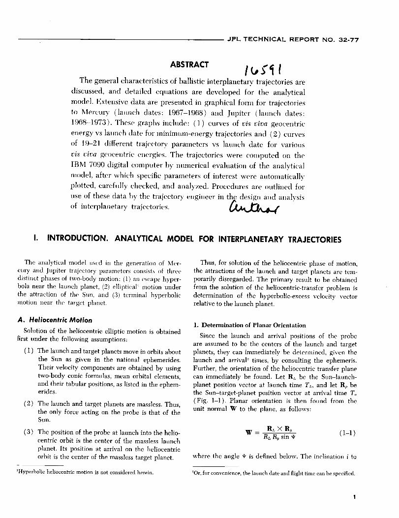
I. INTRODUCTION. ANALYTICAL MODEL FOR INTERPLANETARY TRAJECTORIES
The analytical model used in the generation of Mer-
cury and Jupiter trajectory parameters consists of three
distinct phases of two-body motion: (1) an escape hyper-
bola near the launch planet, (2) elliptical _ motion under
the attraction of the Sun, and (3) terminal hyperbolic
motion near the target planet.
A. Heliocentric Motion
Solution of the heliocentric elliptic motion is obtained
first under the following assumptions:
(1 The launch and target planets move in orbits about
the Sun as given in the national ephemerides.
Their velocity components are obtained by usingtwo-body conic formulas, mean orbital elements,
and their tabular positions, as listed in the ephem-erides.
(2 The launch and target planets are massless. Thus,
the only force acting on the probe is that of theSun.
(3 The position of the probe at launch into the helio-
centric orbit is the center of the massless launch
planet. Its position at arrival on the heliocentric
orbit is the center of the massless target planet.
_Hyperbolic heliocentric motion is not considered herein.
Thus, for solution of the heliocentric phase of motion,
the attractions of the launch and target planets are tem-
porarily disregarded. The primary result to be obtained
from the solution of the heliocentric-transfer problem is
determination of the hyperbolic-excess velocity vector
relative to the launch planet.
l. Determination of Planar Orientation
Since the launch and arrival positions of the probe
are assumed to be the centers of the launch and target
planets, they can immediately be determined, given the
launch and arrival "_times, by consulting the ephemeris.
Further, the orientation of the heliocentric transfer plane
can immediately be found. Let RL be the Sun-launch-
planet position vector at launch time TL, and let Rp be
the Sun-target-planet position vector at arrival time T,
(Fig. 1-1). Planar orientation is then found from the
unit normal W to the plane, as follows:
Rr_ X R,W - RL Rp sin ,I, ( 1-1 )
where the angle ge is defined below. The inclination i to
'Or, for convenience, the launch date and flight time can be specified.

JPL TECHNICAL REPORT NO. 32-77
the ecliptic plane _ can be found by
cos i = W" K' (1_.o)
K I
/I PLANET N _ _" _r, IPTIC /
CENTER
Fig. 1-1. Heliocentric-transfer geometry
where K' is a unit vector pointing in the direction of
the ecliptic north pole.
2. In-Plane Relations
The heliocentric central angle _I, (Fig. 1-1) is also
readily determined by utilizing the positions of the launch
and target planets. This angle may be obtained from
RL" I_ (1--3)cos,t = IRL!IRpl
sin ,I, = sgn [(RL X Rp)" K'] (1 -- cos ="I') '_ (1-4)
The velocity vector V of the spacecraft anywhere
along its path may be obtained from
V = V[(W X R) cos P + Rsin P] (1-5)
Here, R is the heliocentric position vector, R = IRI,
and V is the heliocentric speed, obtained from
qn this Report, the interest is only in transfers which have the same
rotational motion about the Sun as do the planets: thus, 0 -----i --_ _r/2.
and the path angle F is found from
[4 " ]sin 1-' = (1 -- e 2) (2a -- R) e sin v (1-7)
In Eqs. 1--6 and 1-7, GMs is the universal gravitational
constant times the mass of the Sun ( =2.959122083 X 10 -4
au_/day '-') ; a and e are the semimajor axis and eccentricity
of the transfer ellipse, respectively; and v is the true
anomaly of the probe, given by
a(1 - e =) - R(1-8)
cos v = ea
Now, there are two unknowns in Eqs. 1-5 to 1-S which
prevent th(-ir immediate evaluation: the semimajor axisa and the cc.ce]_tricity e. The determilmtion of these
quantities is the main problem. Battin (Ref. 1) has shown
that the eccentricity is actually a function of the semi-
major axis. Thus, it is first necessary to determine a.The semimajor axis is related to the time of flight Tr hy
Lambert's Theorem, which states: The transfer time be-
tween ally two l)oints on an ellipse is a fimction of the
sum of the distances of eact_ point from the [oerl.s', the
dista_ce between the points, and the semimajor axis of
the ellipse, t:nnctionally, the theorem is stated as
T,, = Tr (R,, + ap, C, a) ( 1-9 )
where the distance C between the launch planet at
launch time and the target planet at arrival time, as
shown in Fig. 1-2, is obtained from
C = IR, - R_I (1-10)
Since the time of flight Tr and the launch and arrival
positions Rr_ and Rp are known, only the semimajor axis
remains t() be found by iterative solution of Eq. 1-9.
After the semimajor axis a is obtained, the heliocentric
velocities of the probe at launch and arrival times V_
Rp
RL
Fig. 1-2. In-plane-transfer geometry
2

JPL TECHNICAL REPORTNO. 32-77
and Vp may be evaluated from Eq. 1-5 under the condi-
tions R =- RL and R = Rp. The path angles Pt,, Up and
true anomalies VL, Vp at launch and arrival times 4 may
also be evaluated from Eqs. 1-7 and 1-8 under the sameconditions.
Finally, the desired end result, the hyperbolic-excess
velocity Vhr, relative to the launch planet, may be found
( Fig. 1_3 ) by
VhL ----VL - V_ ( 1-11 )
where V1 is the velocity of the launch planet at launchtime.
Fig. 1-3. Determination of hyperbolic-excess
velocity vector
B. Launch-Planet Escape Hyperbola
The key result from tile solution of heliocentric trans-
fer is the hyperbolic-excess velocity vector VhL at launch.
The reason for the importance of this vector is that it
tells the direction in which the probe must be traveling
relative to the launch planet when on the point of leaving
the planet's gravitational influence. There are an infinite
number of escape trajectories (all hyperbolas) which can
have the same hyperbolic-excess velocity vector. How-
ever, only a portion of these are practical for use when
related to existing launch sites and boost-vehicle con-
straints. For example, it would be ridiculously costly in
payload--and impractical--to shoot a vehicle straight up.
Criteria for selection of a family of feasible escape tra-
jectories are given below.
1. Assumptions
The solution of the escape phase of motion is obtained
under the following assumptions: (1) The probe is acted
on only by the gravitational force of the launch planet,
and (2) the oblateness effects of the launch planet are
neglected.
_The details of quadrant choice for these angles are found in Ref. 3.
The direction of the asymptote of the escape hyperbola
is found by normalizing the hyperbolic-excess vector
V_L. The injection energy C3 of the escape hyperbola 5 is
found by squaring the hyperbolic-excess speed, or
C3 = V_L (1-12)
Thus, in contrast to the heliocentric problem, the launch
planet is now "massy," whereas the influence of the Sun
is neglected. However, the hyperbolic-excess velocity
vectors found by solving the heliocentric problem are
used as a starting point to solve the escape problem.
2. Size and Shape of Escape Hyperbola
As previously stated, only some of the infinite number
of escape trajectories are practical. Two of the practical
aspects of a set of trajectories are the sizes and shapes
of the hyperbolas.
Size is basically determined by the energy C._, which,
in turn, is a function of boost-vehicle capability. For
boost vehicles in use at this writing (or shortly to be
available), values of energy less than or equal to 25
km2/sec z are considered reasonable. The larger the value
of energy that the booster is required to deliver, the
smaller the payload and launch period over which the
vehicle may be fired.
The shape of the hyperbola is determined by its eccen-
tricity, which is a function of both the energy and the
perifocal distance, according to
e= 1+ RpC._ (1-13)GM
where R t, is the perifocal distance and GM is the uni-
versal gravitational constant times the mass of the lam.eh
planet. From Eq. 1-13, it can be seen that, for a fixed
perifocal distance, the eccentricity increases linearly with
the energy. The value of perifocal distance is not arbi-
trary, but depends strongly on the boost-vehicle trajec-
tory. It has been shown (Ref. 2) that, in the great
majority of cases, it is necessary and desirable to use a
circular parking orbit as part of the preinjection phase of
the escape trajectory. It is, further, an interesting fact
that the altitude of the parking orbit determines the
perifocal distance. If h is the parking-orbit altitude and
R0 is the launch planet's radius, then, to an extremely
close degree of approximation,
Rp = R0 + h (1-14)
5C_is actually twice the total energy per unit mass; i.e., the visviva
integral.
3

JPL TECHNICAL REPORT NO. 32-77
or the perifocal distance is equal to the launch-planet-centered radius of the parking orbit. In Bef. 2, it also
has been shown that the lowest possible parking orbit
(80-100 nm) allows greatest payload capability. Thus,
using 100 nm for the parking-orbit altitude, a practical
value of perifocal distance is 6560 kin. The perifocal
distance will vary only slightly about this value for other
parking-orbit altitaldes, or even for direct-ascent-typepreinjection trajectories. Therefore, both the size and
shape are essentially determined by the energy alone,which is found from Eq. 1-12.
Given the size and shape of the escape hyperbola, its
planar orientation must be determined. This can be done
by considering two vectors: (1) the direction of the
hyperbolic-excess vector, denoted by a unit vector S, and
(2) a unit vector R_ directed from the center of the
launch planet to the launch site. The vehicle's flight plane
will essentially be determined by these two vectors, as
shown in Fig. 1-4. A unit normal W to the launch-planet-
centered flight plane is determined by
Sw - × sl (1-15)
with the constraint that the Z component of W is always
positive.
Since R_ is a function of time, according to the rotationrate of the launch planet, the planar orientation must
continually change. In effect, this says that the launchazimuth is a continuous function of launch time.
A detailed description of the geometrical aspects of
the launch-planet ascent trajectory is not given here, trot
may be found in Ref. 2.
C. Calculation of Differential Corrections
The calculation of differential corrections for inter-
planetary trajectories may be accomplished in several
ways and depends on the choice of independent and de-
pendent variables. In this Report, a numerical differenc-
ing scheme is used. Basically, the independent variables--
the injection energy C_, declination _,s., and right ascen-
sion O_ of the outgoing asymptote S of the escape hyper-
bola- are varied, one at a time, to produce variations in
the dependent variables--the components of the impact
parameter B and the time-of-flight Tr.
The impact parameter B is defined as a vector origi-
nating at the center of the target planet and directed
perpendicular to the incoming asymptote of the target-
centered approach hyperbola (Fig. 1-5). The impact pa-
rameter B is resolved into two components which lie in a
plane normal to the incoming asymptote S. The orienta-
tions of the reference axes in this plane are arbitrary, but
one is usually selected to lie in a fixed plane. Thus, define
a unit vector T, lying in the ecliptic plane, according to
SXK'
T = IS X K'[ (1-16)
where K' is a unit vector normal to the ecliptic plane.
The remaining axis is then given by a unit vector R,
defined by
R = $ X T (1-17)
Figure 1-6 illustrates the orientation of the R, S, T
target coordinates.
The impact parameter B lies in the R-T plane and has
miss co,nponents B • T and B • R. The condition B" T =
B" R = 0 denotes vertical impact on the target. Thus,
B • T, B • R, and T_, are the three target dependent vari-ables. If Q_ represents a set of generalized independent
variables, such as injection position and velocity or otherconvenient wtriables, then the partial derivatives
rgB. T/OQ_, ?B" R/_Qi, _Tr/_Qi are first-order differen-
tial corrections or error coefficients relating miss at the
target and flight-time errors to the independent variables.
A convenient set of independent variables for inter-
planetary trajectories is the v/s viva injection energy C3,
the declination q,._, and the right ascension 0._ of the
asymptote of the escape hyperbola. These variables essen-
tially describe the launch hyperbolic-excess velocity vec-tor VhL.
4

JPL TECHNICAL REPORT NO. 32-77
NORTH POLE
!
LAUNCHER _--_
VERNALEQUINOX
K W
J
Fig. 1-4. Vehicle flight plane

JPL TECHNICAL REPORTNO. 32-77
PATH OF PROBE
CENTER OF
TARGET BODY S
INCOMING
ASYMPTOTE
Fig. 1-5. Impact parameter
0 T
R
i
Fig. 1-6. The R, S, T target coordinate system
6

JPL TECHNICAL REPORTNO. 32-77
II. DETAILED EQUATIONS FOR TRAJECTORY COMPUTATIONS
In Section I, a summary was given of the physical
model used to generate the parameters of Mercury and
Jupiter trajectories. The purpose of this Section is to pre-
sent, in full detail, the equations of the Jet Propulsion
Laboratory's Heliocentric Conic Trajectory Program ';, in-cluding the equations of Lambert's Theorem;, which were
developed for this investigation. The equations were
coded for the Laboratory's IBM 7090 digital computer.
This program has proved very useful over the past few
years in studying and analyzing interplanetary trajectories.
Some of the results of these studies are presented graphi-
cally in Sections III to X of this Report. The program
has been devised for calculation of trajectories from any
planet in the solar system to any other planet. In addition,
by adding the appropriate orbital elements, trajectories
to comets or to any body of known motion may becomputed.
The Heliocentric Conic Trajectory Program is divided
into four major sections:
(1) The heliocentric phase, in which basic computa-
tions are made for a unique conic trajectory, of
given flight time, that passes through the center
of two massless planets rotating around the Sun,
as defined in the national ephemerides.
(4) Computation of partial derivatives which relate
miss and time-of-flight errors at the target to vari-
ations in the hyperbolic-excess velocity vector of
the escape hyperbola near the launch planet.
A. Heliocentric Phase
I. Determination of Position at Launch and Arrival
For any given time, the positions of the planets can be
obtained from the ephemerides, referenced to a given
coordinate system and epoch. For the present purposes,
the heliocentric ephemerides of the planets, referenced
to the mean equator and equinox of 1950.0, were selected.
From these ephemerides, one may find the position vec-
tor R_. of the launch planet at lam]ch time T_., the posi-
tion vector R_, of the target planet at arrival time T,,, andthe position vector RS., of the lamach planet at arrival
time. For practical and computational purposes, it is con-venient to transform these coordinates to a heliocentric
ecliptic, mean-of-launch-date system. Thus, two rotation
matrices must be computed. First, a rotation is made from
heliocentric equatorial coordinates, mean of 1950.0, to
heliocentric equatorial, mean of launch date. This is ac-
complished by means of the matrix A, whose elements are
given below (as obtained from Ref. 3):
axl = 1 - 0.00029697T 2 - 0.0000001ST a
a12 = -- a2, = -- 0.02284988T -- 0.00000676T _ + 0.00000221T _
a,_ = - aa_ = - 0.00971711T + 0.00000207T _ + 0.00000096T a
a22 = 1 - 0.00024976T 2 - 0.00000015T a
a2a = aa2 = -- 0.00010859T 2 - 0.00000003T a
a_3 = 1 - 0.00004721T 2 + 0.00000002T s
(2-1)
(2) The near-launch-planet phase, in which a launch-
planet--centered conic is fitted to the heliocentric
conic for a given launch azimuth and launch site.
(3) The near-target-planet phase, in which the param-
eters of the planetocentric conic at the target arecalculated.
'Coded by W. J. Scholey and R. Y. Roth of the JPL Computer Appli-cations and Data Systems Section._Developed by E. Dobies, formerly of JPL, and coded by C. A. Sea-feldt, of the JPL Computer Applications and Data Systems Section.
where T is the number of Julian Centuries of 86,525 days
past the epoch 1950.0.
The second rotation transforms the coordinates from
heliocentric equatorial, mean of launch date, to helio-
centric ecliptic, mean of launch date. This is accomplishedby means of the matrix E:
1 0 0 ]
E = 0 cosE sin_] (2-2)0 -- sin E cos e
7

JPL TECHNICAL REPORT NO. 32-77
where E is the mean obliquity of the ecliptic on the launch
date and sin e and cos e are approximated by the follow-
ing equations from Re[, 4:
1 p2(T ) sin Eosin _ = sin _o + P(T) cos _o - -_-
1cos _ = cos eo - P(T) sin E0 -- _ P2(T) cos Eo
(e-a)
where
P(T) = - 0.000227111T - 0.0000000286T 2
+ 0._878T 3
and E0 is the mean obliquity of the ecliptic for 1950.0.
Now, in general, the components of the position vectors
RL, RLa, and Rp are found in mean-equinox, ecliptic-of-
launch-date coordinates by
RL
RLA = EA
Rp
11;
R;
The unit vectors R_, R_ may then be found:
R_- RL R_ = RpRL R---'_
where
(2-5)
(2-6)
RL = IRLI and R, = Ili_l (2-7)
The heliocentric central angle % i. e., the angle between
RL and Rp, is computed from
l_ L • Rpcos ,It --
RL Rp (2-8)
sin ,It = sgn [(RL × Rp)" K'] (1 - cos z ,I,) v'
where K' is the unit vector normal to the ecliptic plane
in the direction of the ecliptic north pole.
The unit vector W normal to the probe's orbit plane,
is found from the vector equation
W- RLXI_ (2-9)RL Rp sin ,It
Subsequently, the inclination of the orbit to the ecliptic
plane i may be found from
cos i = W' K' (2-10)
where 0 _-_ i _ _r/2 are the only cases of interest to this
program.
Essentially, calculation of the W vector determines the
planar orientation of the transfer conic.
2. Application of Lambert's Theorem
As shown in Section I, the semimajor axis a may be
found, given the flight time T_,, RL, and Rp. One usesLambert's Theorem, which states:
The transfer time between any two points on an
ellipse is a function of the sum of the distances
of each point from the focus, the distance be-
tween the points, and the semima/or axis of the
ellipse.
Or, functionally,
Te = Tr(RL + a,,C,a) (2-11)
where C is the chord distance from RL to Rp, or
C = II_, - l_ I (2--19.)
Now, since Tr, RL, Rp, and C are known, Lambert's The-
orem can be used to solve for a by an iterative processdescribed below.
First, the transfer time T,,, of the minimum-heliocentric-
energy tr@'ctory is computed from Eqs. 2-13 to '9..--22,
The minimum semimajor axis am for an ellipse can befound from
am = (RL + R, + C)/4 (2-18)
and e_, the eccentricity of the orbit with a minimum semi-
major axis, is expressed by
e,,, = .]_1 P" (2-14)a_
where p,, is the semilatus rectum obtained by
P- = 2(2am - RL)(2am -- R,) (2-15)C
The true anomaly at launch VL,,, is found from Eqs. 2-16
and 2-17. First, compute the angle 4:
cos q_ -- Rr. - am (1 - e_) 0_4_r (2-16)e,_ R_
where _ is an angle from the aphelion to Rz.
It can then be shown from the geometry of the mini-
mum-energy ellipse (Fig. 2-1) that
(2-17 )VL,, = _ + 4__ 7r < "_ < 2_
8

JPL TECHNICAL REPORT NO. 32-77
(a| Central angle less than 180 deg (b) Central angle greater than 180 deg
Fig. 2-1. Geometrical configuration of heliocentric conic
The true anomaly at arrival on the minimum-energy el-lipse vp,_ can be found from
v_ = VL,,, + * (2--18)
Now, the mean anomaly ML,_ at launch in the ellipse canbe found from
ML., = EL., -- e.. sin EL,,, (2--19)
where ELm, the eccentric anomaly, is given by the equations
em -t- cos t_LmCOS ELm= 1 + e,, cos vz_
and 0 _< EL,, _< 2at
sin Ez,= = _/1 -- e,J sin VLm1 + e,_ cos V_
(2-e0)
The mean anomaly at arrival M m can be obtained in a
similar manner. Then, the mean-anomaly difference is
AM,, : Mpm -- Mi.,_ (2-21)
By use of this difference, Tin, the time for a minimum-
energy trajectory from launch to target, can be found
from the equation
aras12AM,,,r. - (2-22)
where the units are years and astronomical units (au).
Next, the semimajor axis a, corresponding to the givenflight time Tr, is obtained. At this point, there can be
two types of trajectories, T_ > T,. or TF < T,_.
For TF > Tu, let a_+l : (i + 1)a,,, until TF(ai+_) > Tr
For Tr < T_, let ai+l = (i + 1)am, until TF(a,+_) < Tr
where i : 1, 2_ ... n, and al : am. Note that TF(ai) isthe time of flight corresponding to a_, and is calculated
from Eqs. 2-24 to 2-29 and 2-19 to 2-22; here, however,
the subscript i is used in place of m. When T(ai) < TF
< T(ai+_), then ai < a < ai+_, and a slope-intercept
method is used to obtain an approximation on a. Using
a_+, for a first estimate on aj, and using
a, :aj._- AaF TF- T(a"_)l[_ T(a_) - TF _J
aa = (aj.1 - a_) (2--23)
subscript j = 1, 2 .... n
for subsequent estimates, the value of a_ is used for a to
calculate a and/3.
[C 2 + RL 2- R/- 4a(Rp/3 : c°s-_ 2C(2a - a_)
IRL -- Rp cos "I'.]ct = COS-1 C
Now, the
(2-24)
linear eccentricity X can be found from
9

JPL TECHNICAL REPORT NO. 32-77
x, = 4,,, - _a_(Ca- a_) [_ + co_(i_ - #i)] (_25a)
x_ = 4a_- 2a_(_, - a_) [i + co_([_ + #i>] (Z-25b)
Equation 2--25a is used if TF > T,_, and • > rr; or if
Tp < Tin, and _z < 7r. However, Eq. 2--25b applies if
Tv > T.., and _z < 7r; or if Tr < T.., and _I. > _-.
Then, the true anomaly at launch is found from
rr -- "y
_.+ _,
a._ < a < ap
ar <a
a,,. < a < a.
Re > RL
Re < RL
Re > R_
Re < RL
a., < a < ap
a_ <a
am < a < aA
_-+_
_r--'/
(2--26)
and e is found from
X 2 + 4a RL -- 4a 2 (2-27)cos e = 2 X Rz
Also, aA and a_, the semimajor-axis limits, are found from
a A =
ap
Rp -- R_.l+Rp_ Rz, cos_zl
RL
R,_ - a_1+
RL -- Rp cos _I.
Rp > RL (2-28)
I0

JPL TECHNICAL REPORTNO. 32-77
If RL > Rp, aA and ap are interchanged. The true anomaly
at arrival vp is found from
%= vL+_I' 0<vp<2=
and the eccentricity e is found from
Xe = -- (2-29)
ga
Then, T(ai) is recalculated using Eqs. 2--19 to 2-22.
When ]TF -- T(a_)] < _, a predetermined conver-gence criterion, the conic is considered to be the one
desired, and a( = a,), e, VL, Vp are the parameters of theheliocentric transfer orbit.
At this point, the transfer orbit is completely deter-
mined. Other key quantities are calculated as shown in
the following paragraphs.
3. Calculation of Velocity Vectors for Probe and Planet
The heliocentric velocity of the probe V (with the
subscript L for launch time or p for arrival time), can be
calculated by using the equation
= V [(W X R) cos 1-' + R sin F] (2--30)Vlqt
where
The path angle F can be found by the expression
sinr = (I-- e 2)(2a- R) esinv (2--32)
where
o<r<_ if 0<v<_r
"IF
__<r_<o if ,,<v<_
The velocity vectors V1 and V2 of the launch and target
planets, respectively, are found in a similar manner. In
this calculation, however, the semimajor axis a, the path
angle r, and the eccentricity of the orbit e all refer to
the respective planet's orbit around the Sun. The true
anomaly v of the planet in its orbit at any time can be
found from Eqs. 2-33 to 2-36.
The unit vector W normal to the planers orbit plane is
given by
W = sin _ sin i, cos _ sin i, cos i 2-33)
where i is the inclination of the planet's orbital plane to
the ecliptic and f_ is the longitude of the planet's ascend-
ing node.
The unit vector P directed toward the perihelion is ex-
pressed by
Px = cos cocos f_ - sin to sin f_ cos i
Py = cos to sin f_ + sin to cos f_ cos i
Pz = sin to sin i
(2--34)
where ,o is the argument of perihelion of the planet.
The unit
from
Then
vector Q right-handed to P and W, is obtained
Q:w×P
cos v : R 1 • P_
sin v : R 1" Q l (2--85)
where, again, R 1 is the Sun-planet unit vector.
Numerical values for the planet elements a, e, i, f/, and
,,, (from Ref. 5) are presented in Table 2-1.
Finally, the hyperbolic-excess velocity vector at launchor arrival Vh can be found from
v,. = v - v,,o.., (2-,_6)
4. Calculation of Various Trajectory Parameters
To assist the trajectory engineer in selecting and de-
signing interplanetary trajectories, various key trajectory
parameters are computed. The formulas for these aregiven below.
The angle _, between the hyperbolic-excess velocity
vector and the planet's orbital plane can be found at
launch and arrival by
W JV h ./1- Tt-
sin ,/ - Vh 2 -< e _ 2 (2--87)
The right ascension 0 and the declination • of the
asymptote (launch or arrival) can be found by use of
the expressions
" (2-48)sin_= Sz --2 <'I'-<_"
!!

JPL TECHNICAL REPORT NO. 32-77
Table 2-1. Mean planet elements
Planet
Mercury
Venus
Earth
Mars
Jupiter
Saturn
Uranus
Neptune
Pluto
Semimajor axis a,
elg
0.387098
0.723331
1.000000
1.523679
5.2027
9.546
19.20
30.09
39.5
Eccenlricity •
0.205625 +0.000020T"
0.006793 -- 0.000050T
0.016729--0.000042T
0.093357 +0.000094T
0.048417q 0.000164T
0.055720 -- 0.000345T
0.0471 +0.0002T
0.00872 @0.00004T
0.247
Inclination to ecliptic i,
deg
7.003819_0.00175T
3.394264_0.00125T
0
1.849986--0.000639T
1.305875--0.005694T
2.490583--0.003889T
0.772792 _0.000639T
1.774486--0.00953T
17.140000--0.00556T
Longffude of ascending node _,
deg
47.737778+1.18500T
76.236389+0.90556T
0
49.173611+0.77389T
99.948611_1.01056T
113.226806+0.87306T
73.726528 +0.49861T
131.230833+1.09889T
109.633750_1.35806T
Argument of perihelion w,
deg
28.937778+0.36944T
54.619305 +0.50139T
102.078056+1.71667T
285.965000_1.06667T
273.577222_0.59944T
338.850694_1.08528T
96.129028_1.11250T
272.935934--0.43222T
113.860694+0.03083T
aMeasured in Julian Centuries from 1950.0
and
COS 0 --
sin 0 --
Sx
VsI: + s_,
0_<o_<2,_ (e-39)
where
v_E_ = (sx, sy, s_) (2-4o)s=G
Here, E is the rotation matrix given by Eq. 0-,--2; S is a
unit vector in the direction of the outgoing asymptote
when Vh is calculated at launch, and in the direction of
the incoming asymptote when Vh is calculated at the
target.
The angle ._I between the launch hyperbolic-excess
velocity and the Sun-launch-planet line at launch is de-
fined by
Vh_," R}. 0 G eL _< _" (2--43)cos G - Vh_
There are six other angles: _p, the Sun-probe-target
angle; 6:, the Sun-target-Earth angle; &, the probe-
target-Canopus angle; ns, the supplement of the angle
between the projection of the target-Sun veetor on the
R-T plane and the T direetion; _TE,the supplement of the
angle between the projection of the target-Earth vector
on the R-T plane and the T direction; no, the supplement
of the angle between the projection of the target--Canopus
vector on the R-T plane and the T direction. Here, T is
a unit vector lying in the ecliptic plane, given by
Other quantities which are of interest for the helio-
centric phase are given in Eqs. 9,-41 to 2-48, below.
The communication distance at arrival Rc is expressed
by
'x
a_ = IRd (Rc =Rp - RL.4
(2-41)
The arrival (or departure) angle a is obtained from
Vplanet ° Vh
COS _ -- Vplanet Vh 0 <_ a <_ _ (2--42)
and
R=SpXT
cos _p = - S_ 'R_
cos _ = -Sp" R_
cos _c = Sp" C
( 2-44 )
0_<¢<_,
(2-45)
12

JPL TECHNICAL REPORT NO. 32-77
where C is a unit vector to the star Canopus, and R_ is
obtained by normalizing Rc from Eq. 2-41.
R'R_sin 7/, -- sin _p
T.R_cos _, -- sin _p
R.R_sin_E-- sin_B
T'R_
cos_E- sin_
R.C
sin _]a = sin _e
T'C
cos _/_ -- sin _c(2-46)
The angle ap between the projection of the incoming
asymptote on the target planet's orbital plane and the
target-planet-Sun line at arrival time is defined by
cos _, = - R_"S_, t -,_ < _p < _ (2-47)
sin _p = - Sp," (W2 X R_) )
where Sp,, the projection of Sp on the target planet's
orbital plane, can be found by
s, - w_ (s,. w=) (2-48)s,, =is, w_ (s,. w.)-q
Here, Wz is a unit vector normal to the target planet's
orbital plane.
B. The Planetocentric-Conic Trajectories
The trajectory near the launch planet is found by
application of several conditions:
1) The injection energy C:, and the direction S of
the outgoing asymptote of the escape hyperbolaare obtained from the solution of the heliocentric-
transfer problem as given in Section II-A above.
2) The vehicle is launched from a given launch site,
specified by its latitude and longitude, into a
low-altitude circular parking orbit.
3) After coasting in the parking orbit for a time t,,
as determined below, the final stage ignites and
propels the spacecraft to the final injection energy.
(4) The parking-orbit altitude plus the launch planet's
radius is equal to the perifocal distance of the
escape hyperbola. This is a good practical approxi-
mation, since it is most efficient to inject the space-
craft into the escape hyperbola near the perifocus.
(5) The launch planet is assumed to be spherical in
shape.
Given these conditions, the following formulae are used
to compute the parameters of the near-launch-planet
trajectory.
The eccentricity e of the launch-planet conic can be
computed from
.a_c_ (2--49)e = 1 + GML
where Rp is the perifocal distance of the near-launch-
planet conic, and C3 is the vis viva energy, defined as
c3 = vL (2-,50)
and GML is the universal gravitational constant times the
mass of the launch planet. The radius to injection R isfound from
P (2-51)R - 1 + eeosv
where v is the true anomaly of injection on the launch-
planet escape hyperbola, and p is the semilatus rectum
given by
P = -GMz, (1 - e 2) (2--52)C_
The path angle at injection F is found from
GMLcos P - ""VR
"it
0_< P_<-_-,if0 < v <,r
- _ < F < 0, ifTr < v < 2,r2 -- --
(2-53)
where V, the injection speed, is given by
] 2GM LV = C_ + -_- (2-54)
The vector W, perpendicular to the plane of the conic,
can be found by the solution of the two vector equations
W . S = 0 _ WxSx + WrSr + WzSz = O
W.W = 1 _ W2x + W2r + W2z = 1
(2-55)
13

JPL TECHNICAL REPORT NO. 32-77
where
and
w, = -(w,s, + wzsz) (_,-56)$I
-WzSrSz Sxwy- s_+sl, ± si,+s_, #l-S_-W_
(2-57)
It should be recalled that S is a unit vector in the direc-
tion of the outgoing asymptote of the escape hyperbola.
Thus, a condition is set on Wz:
wt _< 1 - sl (z-ss)
From the geometry (Fig. 2--2) of the launch azimuthEL and the launch latitude eL, it can be shown that
Wz = cos (I,Lsin EL (2.,-59)
From Eqs. 2-58 and 2--59, the Wz _ restrictions can becalculated as a restriction on EL, since q'L and S are fixed:
sin z X5 < 1 - S_______ (2--60)COSZCbL
A vector B, orthogonal to S and W, is calculated:
B = S × W (2--61)
Now, let P be a unit vector in the direction of the peri-
focus as shown in Fig. 2--3:
P = S cos v, + B sin vs (2-62)
FLIGHT 1
PATHNORTH
POLE
Fig. 2-2. Trajectory-plane-launch-site geometry
S
EARTH'S ,//_
Fig. 2-3. Trajectory-plane geometry
Then Q is the unit vector at right angles to P:
Q = S sin v, - B cos vs ( 2--63 )
The true anomaly v_ of the outgoing asymptote S is
given by
1cos v_ - 0 _< v, _< ,_ (2-64)
e
The right asc(_nsion OL of the launcher can be found from
cos O5 = Wx sin CI,n sin XL + Wr cos XLwl - 1
0<0__<2_
sin OL = Wv sin _L sin EL -- Wx cos ELw_ - 1
(2-65)
where (t,r. is the latitude of the launcher. A unit vector R ).in the direction of the launcher can be calculated in the
vernal-equinox equatorial system by
R_ = cos (b5 cos 05, cos _5 sin 0L, sin ¢L
(2-66)
The angle cb between the launcher and the perifocus of
the conic is given by
cos,_ = R_.PI 0<_<_ (2-67)
sin,I,=R_'Q ) -- --
The angle between launch and injection _, is defined by
¢, = 2_ - _ + v (2-68)
where, again, v is the true anomaly at injection into the
escape hyperbola.
14

JPL TECHNICAL REPORT NO. 32-77
A unit vector R' toward injection is seen in Fig. 2-4 to be
R 1 = P cos v + Q sin v = ( Rx, Rr, Rz ) (2-69)
The iniection latitude q, is given by
,r _ (2--70)sin_=Rz _ < _ < -_
The right ascension of injection 0 can be found from
cos O -
sin O --RxfRr
+ 1
0 < o _<2_ (2-71)
The longitude of injection 0 can be calculated from
0 = 0 - Ot - _tb + 0L 0 < 0 < 2_ (2-72)
where
OL
O9
tb
is the longitude of the launcheris the rotational rate of the earth
is the time from launch to injection
Here,
tb=t_+tz÷ [@1- (fix+%)] k,; (2-73)
where
tl
t2
13_1
q_2
k;
is the time of first burn (into the parking orbit )
is the time of second burn (into the escape
hyperbola )
is the angle of first burn
is the angle of final burn
is the inverse parking-orbit rate = 14.689 sec/deg
for a 100-nm Earth parking orbit
The time of coast t¢ is given by
to= [%-- (¢1+%)] k; (2-74)
The relations stated above are illustrated in Fig. 2--5.
INAL BURNINGINITIAL
BURNING -k COASTING .__E C TION
\\
/
Fig. 2-5. Powered trajectory modified by coasting
The azimuth at injection _ can be computed from
Sz - ks sin q_cos 2 = k4 cos ,P 0 < _ < 7r (2-75)
where
11ka- v_ sinv---cosv
e e
_/e _ - 1 1k, -- cosv +--sinv
e e
(2-76)
The unit vector to final-stage ignition RX2can be found ina manner similar to that used for R:
Fig. 2-4. Ascent-trajectory geometry 11_ = P cos ( v - % ) + Q sin ( v - % ) (2-77)
15

JPL TECHNICAL REPORT NO. 32-77
The latitude ,I,5 of final-stage ignition is computed from
sin ¢_ = az2 - _- _<_,2< g (2--78)
The right ascension 05 of final-stage ignition is given by
COS 02 --
sin 02 --
ax2
_/RL + RL
0 < 02 _ 2r (2-79)
and the longitude 02 of final stage ignition is defined by
05 = 0 + O_ - 0 + ,ot_ (9.-80)
The angle Av between injection and the outgoing asymp-
tote is expressed as
AI) : /gs -- 1)
The launch time Tz can be found by
TL =OL - OL - CHA
0 _(OL -- OL-- GHA)< 2r
(e--Sl)
where GHA is the Greenwich Hour Angle at Oh UT of the
launch day as shown in Fig. "9.2--6and is obtained from
GHA = 100707554260
+ 0.°9856473460 T,_
+ 2°.9015 × 10 -1_ T_
0 <_ GHA < 2_ (°--82)
Here, Td = days past Oh January 1, 1950.
VERNALEQUINOX
GREENWICHMERIDIAN AT
O h UT
/N OF INJECTION
MERIDIAN OF LAUNCH SITE
GREENWICH MERIDIAN AT LAUNCH
Fig. 2-6. Relation between longitude, right ascension, and
time in equatorial plane
The injection time T is calcnlated from
T = Tz + tb (2--83)
C. Differential Corrections
As outlined in Section I-C, the calculation of differen-
tial corrections, or partial derivatives relating variations
in the impact parameter B and flight time Tr to variations
in the hyperbolic-excess velocity vector Vt,L at launch, are
performed by a numerical differencing technique)
The basic idea in this technique is to compute a varied
or perturbed trajectory and then difference it with thereference case. A small variation AV_,L in the hyperbolic-
excess velocity vector is equivalent to a small variation
±VL in the launch heliocentric-velocity vector. Letting
primed quantities denote variables on the perturbed
trajectory, the launch heliocentric velocity on this trajec-
tory is, then,
v_ = v_ + ,,v,,_ (2--84)
where
±V_, = (C:)_ Aq% [ - sin q_scos Os, - sin _._.sin Os, cos ¢P._],
( C, )!_ ±0,. [ - cos _s sin Os, cos _s cos 0,, 0],- AC,
_iC,_ [ cos q's cos Os, cos _P,s.sin 0,<, sin 4,v]
where ±q,,<, ±0._ are small angular variations (0.2 deg),
and the energy variation is ACa = 0.005 Ca.
The semimajor axis a' is obtained from
a' - RL (2-85)2 -- V_ 5RL
GMs
The radial rate R_/is given by
h_ = v,. RL (Z-S6)RL
The semilatns rectum 19' and eccentricity e' are computed
p, = a[ (y_= - Rff)GMs
(2--87)
from
_This method was developed by William Kizner, Research Specialist,Systems Analysis Section, Jet Propulsion Laboratory.
16

JPL TECHNICAL REPORT NO. 32-77
The eccentric anomaly at launch E_ is expressed by
aL_sin E/_ =
e' (a'GMs) v*
cos E L = _- 1 -
The mean anomaly at launch M_, is obtained from
M'L = E_ - e' sin E L (2-90)
The mean orbital rate n' is given by
n' - (GM'_)_a,3/_ (2-91)
The mean anomaly at the target 3l_ is stated as
M; = n' TF + M_ (2-92)
The eccentric anomaly at the target E'_ is obtained from
the expansion
, ( 1 )E_=Ep+ 1-e'eosEp AM
1[(1 6" sin Ep ]
2 AM 2--e'c_s E_)_j
- e' cos Ep) _ aM3
if
cos Ep _ 0
(2-89)
However,
E_ = Ep
( 2-93 )
+ e cos E_ - 1 + x/(e cos Ep - 1) 2 + (2e sin Ep) AMe sin Ep
if (2-94)
where
cos Ep < 0
AM = M_ -- (Ep -- e' sin Ep)
' and v;The true anomalies at launch and at the target, v Lare found from
, p' - RL (2-95)cos v L - e' R_
0 < v;, < ,r if h i is positive
• - < v_ < 2= if h_ is negative
cosy' = cosE; -e'
P 1 - e' cos Ep"
, (1 - e'2) _ sin E_sin vp =
1 - e' cos E_
(2-96)
The heliocentric central angle g,' is given by
¢ __ I
• P _ t_ _L ( 2-97 )
The angular momentum h' is expressed as
h' = RL X V_ (2--98)
The heliocentric position vector at the target is given by
, (RL if,, h')KRL )R_ =Rp _cos + h'RL sin,I_' (2-99)
where
R; = a' ( 1 - e' cos E; ) (2-100)
A vector in the direction of perihelion with magnitude e'is computed from
E' = V% X h' RLGM-----7-- n--7 (2-101)
The heliocentrie velocity at the target is defined by
h' {a,_ )V'p = V × \ Rp + e' (2-102)
The hyperbolic-excess velocity at the target is expressedby
v_ = v; -v_ (2-103)
The difference between the heliocentric position vectors
on the perturbed and reference trajectories is given by
/',R;, = a;, - R,, (2-104)
The impact parameter B is computed from
B = - (AR;" V_,. ) V_,p + ag;v_
The flight-time error is stated as
ATv -- AR_ • V_pv_ (2-105)
The partial derivatives are formed by dividing ±Os,
A%, and AC_ into the miss components B" T, B • R, and
flight-time error ATe. In addition to the component
partials, the quantity OB/OQ_ is defined by
OB_ V(OB'T_z (0B'R_ 2-Iv"(.2-106)_' L\-_-;-Q,} + \--T07-Q,} j
17

JPL TECHNICAL REPORT NO. 32-77
The three partials, DB/_Os, DB/3,I,s, _BI_C:, are im-
portant measures of the error sensitMty of a trajectory.
The effect of uncertainty in the knowledge of the
astronomical-unit-to-kilometer conversion factor on target
miss and flight time may be determined by the following
formulae:
0B.T -2C3 0B'T
Oau au OC_
0B. R -2C:_ 0B.R
Oau au OC3
(_1o7)
whence
OB 2G OB (2--108)Oa-----u- au OC3
and
OTF -2C_ OTv
Oau -- au OCa(2-109)
where au is the astronomical-unit-to-kilometer conversion
factor
The effect of solar-radiation pressure acting on the
probe may also be evaluated as follows: In Eq. 2--84, let
,XVhL 0, but in Eqs. 2--85, 2-87, 2-89, "2,--91, and 2-101,
vary G3ls by adding an increment AGMs. This procedure
gives rise to a varied trajectory from which the impact
parameter B and flight-time error _xTr may be obtained.
The partials _B/OG31s and _Tr/cG; 1._ may then be cal-culated. Since the acceleration caused by solar-radiation
pressure acts in a direction opposite to the gravitationalattraction of the Sun, radiation pressure has the effect of
decreasing the Sun's gravitational attraction or
decreasing G._I,,.. A decrease, AGM,_ = -2.4 X 10 _ km3/
see _, corresponds to the solar-radiation pressure acting on
a ,300-kg spacecraft having a perfectly reflecting area of
8,6 mL Thus the miss, always being a positive number, is
obtained by ,.XB_ = 2.4 X 10" OB/OGMs, and the cor-
responding flight-time error is ±T,.p = - 2.4 X 10':OT_,/OG, Ls, which is sign-sensitive.
18

JPL TECHNICAL REPORT NO. 32-77
III. DISCUSSION AND EXPLANATION OF RESULTS
A. Introducfion
1. Trajectory Computations
Minimum (geocentric) energy trajectories from Earthto Mercury for the period 1964-197,5 and from Earth to
Jupiter for the period 1968-1973 were computed on the
7094 digital computer by numerically evaluating theanalytical model explained in Sections I and II. This
compntation resulted in curves of C:_ (cis vica geocentric
energy) vs launch date for these trajectories.
For each target planet, several 75-day launch intervals
were analyzed in greater detail: curves of 19-21 key tra-jectory parameters vs launch date for various t_is cica
geocentric energies (C:_) were automatically plotted.
2. Trajectory Analysis
Careful analysis of the results shows that as many as
four ballistic flight paths to the target planet exist per
lmmch date for a given (is vica geocentric energy (C_),assuming trips of less than one revolution arotmd the
Sun. A more extensive analysis might reveal more than
four flight paths. Actually, feasible launchings can occur
only for small time intervals (1-3 months), when the rela-
tive positions of the Earth and target planet are such
that the velocity requirements for ballistic transfers can
be rcasonahly achieved by modern boost vehicles. These
intervals occur once during each synodic period of the
planet. A synodic period is the time interval required for
the Earth and target planet to attain successive identical
relative angular relationships in heliocentric longitude,
e.g., the time t)etween Earth and target planet align-ments (116 clays for Mercury; 390 days for Jupiter).
Figures 3-1 to 3-6 show the minimum injection energy
required for transit to Mercury vs lmmch date. The dates
()f Earth-Mercury alignment are indicated by arrows
(T). Favorahle ]mmch opportmfities (i.e., relative minima
in injection energy) and planet alignments occur about
every 116 days. Two families of conic trajectories exist
(Types I and II), and will be descrihed in detail in Sec-
tion B. After three synodic periods (348 days), Mercury
and Earth again assume approximately the same space-
fixed position. This condition is also reflected in Figs.
,3-1 to ,3-3, in which the minimum energy curve for
Type I trajectories has very pronounced minima at 348-
day intervals. Type II trajectories exhibit this periodic
behavior also, although the curves are more complicated.
Within the time period considered, the minimum injec-
tion energy reaches an absolute minimum on November
:23, 1967, for Type I trajectories, and on November 3,
1968, for Type II trajectories. Only the launch oppor-tunities centered around these elates are discussed in
detail in Sections IV and V. The results are fairly repre-
sentative for all other launch opportunities.
If the synodic period of the Earth and target planet
were a rational fraction of a year, and if their orbits
remained unchanged, the minimmn energy curves would
be exactly periodic functions of tim('.
Figures 3-7 and 3-8 show the minimum injection energy
for transits to Jupiter vs launch (late for Type I and
Type II trajectories. The dates of Earth-Jupiter alignment
are indicated by arrows (T).
Favorable latmch opportunities, planet oppositions,
and approximately the same space-fixed geometry of
Earth and J_,piter occur every synodic period (390 days).
For latmeh opportunities, the absohlte minimum injec-
tion energy occurs on December 30, 1969, for Type II
transfers, and on January .3, 1970, for Type I trajectories.The launch opporhmities centered around these dates
are discussed in detail in Section VII. In addition, be-
cause of some interesting features that were discovered,
the launch opportunity extending from November 1968to January 1969 is treated in detail in Section VI.
B. Classification of Trajectories
1. Type I and Type II
In observing the variation of any trajectory parameter
vs launch date for fixed geocentric energies C:, it is noted
that two separate groups of closed contours, rather than
one, are described (see Fig. ,%9). These two sets of energycontours are designated as Type I and Type II trajec-
tories, where Type I trajectories are defined as having
heliocentric-transfer angles less than 180 deg, and Type II
trajectories are those having heliocentric-transfer angles
greater than 180 deg. A Type I trajectory traverses less
than half-way around the Sun from launch to planetencounter, whereas a Type II trajectory would traverse
more than half-way, but less than one full revolution,
around the Sun. For a given launch day and energy, then,
Type II trajectories require greater flight times than do
Type I. The existence of these two sets of energy contourscan be attributed to the fact that the orbits of Earth and
19

JPL TECHNICAL REPORT NO. 32-77
£,9
0
0
2O

JPL TECHNICAL REPORT NO. 32-77
i: :::; III
:iit !I_i!1 I,
!i iii:-. ,: -_--_
ii _iJi''
:i :::: !!
J_ .... iiii:_ :ili 111
!i fill ;;:;_ I!irl II!
t! ....... I:
': _TFI!"
i!,, ,..tlii
!tl; "
2L 12:_L "
iJ I_1!iiit ,_i!il !!:: :iiL2:22 L _i
il rlii _i: llil ii:
ig tri! 'i! ,_+___-_-4-
r[ _::' ktL:: :i;i II1
I!1" '+
---- ii, iii
:: +_ ....
_! . 1 :.y
ttll['"
0
iiI!
.÷
21

JPL TECHNICAL REPORT NO. 32-77
© 0 © 0 0 0
d
oco
o
0
d
0
o
22

•JPL TECHNICAL REPORT NO. 32-77
' ttE4 4 ............. i_ J:i : :: . o-,_
, .... : ! _'11_,/,i i .... i i :::; _ ] : :::. :_[ !.. i:::]:::: _o-,
f _4: l ..... i . i. !.,: l ] i
........ :: I r :2 :22:¢:: r r " "-:" ' r i ] [! " " :: r_ _ ....
i_ ..... _]H}iiii I _ i _ L : _<:> ' i-"
" [., " "T i 1 r _, [ ! - [ l ..... i : _ I [ I _ _ . ; Z _
_l!':_llii_l_l_l "" l_b l i_'''l'_il!!i:i !I--I--_I ........ U'_ i:_
Ill[If [::: : fiii}[IL] j[':!:::: r l I .......t' [ "" i .... _ j, CI_Z _ ...... --
j,,;7
T 1 I" " ":_ _ . t_ [ :, . i ;l: _,Ol.l.J-'_ ..... i
• :" ; r !1 tr ! _' " "'-'l,'_l i _ , ..: , _ _ , ;il _ I
• : :..; .[ I J : : i[ i ![:. [ l:I: '': " '' i ....... : .... z.:_[];I I i i I l: .,,i ! !:: i : , : I I : '''l" " : It', .... I' ; _
1,, i1,1 .... , , .... ' i[
I I !_ ' I ' i ' i ] t / _" i _ O"l
'.:i: :i. i ,::: :::: ' .., ._...- : :!. .--_-_-._--_-m_ <-'_ .. _'_
i_1 ::: . [ .... ![i' ' _ ; ' "_ [ll,.] ....... [ 'l .... l.O.......... i,] ....... i . . I_ .:. i , i:_:i _' _!:_ .... _<.,:>
I _ ...: _ ll:_ ::: !][l_fl ti:: :r I I[:: ;;i[;ll:: :: t il_!l_::: ::::i::rl - _,
,...I [LI'_IlI: ,i, i-__ _;'Elli .... : :1 i I I" 7;7 _
L![IL!I!_U__LL__I::t:_ ]!,!!+7ti ilt!:..:rl ill: :; m__:ii[]!!i_ ,!!!t!!:: _rllll!:: 7::,LLLT__:'_'_'_ _----rrT'_7_]l! _"l!_! :+-,.,,.>.
_/! i ::it[ [ ttl!,'-rm-'TTr-m-r]::: 71[1I::: :: i_ ; 11! :L:l:i', i[::]l.: :.,:: : [ ___1_] ,.. , I I J I I I _ _ i ,I t' ,ill _,_
........... , _, []r Ill.l:::[. _ ....... 1 illtlll:t ..... t -:,! ..... I .. .i I .. _ : 'i [][li:i: r :11 i!'' '_'-
[ I _ [J [ F I ' |: " "" [ _f ....... rl ........ Ii , I: t o_-: il[tf]l! ___= _,' _ i!:!ti: ::
i rl! !.:: :;i' ! .... ! _ _ ' " " ft l _[::I::: I
o o o o o o'_ - o _ o o o o o- o d d o o c;
£,.9
23

JPL TECHNICAL REPORT NO. 32-77
o £ o o o o o_- -- o o_ co- - _ -- o o
£3
• ii! ' _l!i -r _ ++t+;i-
;:Fii ;:: -itii:i ,,,_-°t:&_L
tT _---
:if' ] _, ' " .... rl _ I._J ll,lL ........ ::::i;;:: iF_i l.-zz i:::x [' _ 0 w ::3 :--,-,--
_"::_----_-----....:If; z Ii::
iii:!if::!;_iiiii;i_;iii!i!!i " '1 " r it-.
i_.i,i;-7-_:ii:.....
I!i i! ! i lit ii_!!i
_, _i Ii bitlri: :'-
il ;. il :::I!i!;_i_:Ii!!ii
.._ ..... i! .... _ .; >.
'i _:;!: ::i!I[_;: :_ _ uJ ....
l _ _l--
_._ _,_. i _ .!: ._r-.......... _ i; ,_Z _._:
_i ':L_!_!:!!:_ ::,,_"-, i
'_ _ i_ "'_-_4,t'T ;1; :: 7 _. ....
t* I _ • i!i!_''-tf '' _1 'll'II=
..... t,..
+_+ -. +_4+ ...... i
I.....1_ !i ""' :_;:II-
.JPL TECHNICAL REPORT NO. 32-77
_J
00
0
0
0a0
oo¢.D
0
0
25

JPL TECHNICAL REPORT NO. 32-77
%
E
175
_65
155
145
135
i
i
NOTE: C 3 IS TWICE THE TOTAL ENERGY/UNIT
MASS WITH UNITS km2/sec z
l
I
I
(_) DATES OF EARTH--JUPITERALIGNMENTS
TYPE I
lIi
J
.... i ....
i 16
NOV FEB DEC MAR ,JAN APRIL FEB
1968 1969 1970 1971 1972
Fig. 3-7. Jupiter 1969-1973: Minimum injection energyvs launch date, Typel
MAY
26
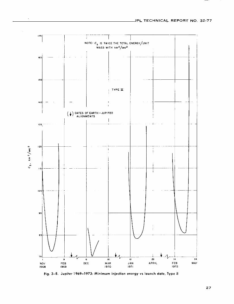
JPL TECHNICAL REPORT NO. 32-77
tM
EJ¢
175
165
155
145
135
II5 ---- -
105
95
75
NOV
1968
l 1 INOTE: C 3 IS TWICE THE TOTAL ENERGY/UNIT
MASS WITH kmZ/sec 2
TYPE
(_) DATES OF EARTH--JUPITERALIGNMENTS
I
/
i i
| I
L/
16 I0 20
FEB DEC MAR JAN APRIL
1969 1970 1971
--It\ I
K14
FEB
1972
24
MAY
Fig. 3-8. Jupiter 1969-1973: Minimum injection energyvs launch date, Typell
27

JPL TECHNICAL REPORT NO. 32-77
0 0 o0 o o_ _- r.r) 04
0 0 0
o o o_-- 0
s_[rp 'Jl /HgI-I-I -I0 ":ll_ll
©c)QD
00ID
o00
,.1=i.ic"
=1,
T ,,.l-IDz
_J EI-,-
,0e,
I
i't=1
I
M..
28

JPL TECHNICAL REPORT NO. 32-77
the destination planet are not coplanar. If the Earth and
target planet had coplanar circular orbits, only a single
group of energy" contours would exist. If the orbits ofEarth and the target planet were circular as well, this
single group of energy contours would include the well-known llohmann's transfer orbit. The ttohmann transfer
orbit is tangential to the orbits of Earth and target planet,
has a heliocentric transfer angle of 180 (leg, and requires
the least t;i.s'cica _eocentrie ('nerg_' (C:;) among all transfertraject()ries. The ttnhmann minimmn-energy trajectory
would remain constant for each synodic period, retaining
the same flight time and ci.s' cica geocentric energy. The
fact that tht" orbits of Mercury and Jupiter are slightly
inclin('d with respect to the ecliptic (7 and 1.3 deg, re-
spectively) strongly infll,ences the transfer trajectories
and causes the single group of trajectory contours to split
into two families, thus necessitating the designation of
Type I and Type 11 trajectories.
In Fig. 3-9 note the small family of closed contours
cent(red aromld January 1, 1969. This group has been
designated Type I-A. Type I-A trajectories exist for
Venus also. They are not attractive because their flight
times are longer for a given (;is t;ica geocentric energy.
2. Class I and Class II
As Fig. 3-9 shows, two trajectories usually exist for a
given type, energy, and launch (late. Trajectories corre-
sponding to the lower portions of the energy contours
are designated as (:lass I and art' connected by solid
lines and correspond to shorter flight times and smaller
heliocentric central angle. Trajectories corresponding to
the upper part of the energy contours are designated as
Class II and are collnected by dashed lines and corre-
spond to longer flight times and larger heliocentric angle.For a given Immeh (late and geocentric energy, the Type
I-Class I trajectory has the shortest flight time and the
Type I I--Class II trajectory has the longest flight time.
For example, Fig. 3-9 shows that for the launch (late
Novemlwr 26, 1969, and C: _ 12() kmVsec'-', the Type I-
Class I trajectory has a flight time of .520 days, whereas
the Type lI-Class II trajectory has a flight time of 1460
days. The flight time for the Type l-Class II trajectory is
880 days, and for the Type lI-Class I trajectory it is 982days.
3. Minimum Energy Trajectories
a. Minimum-energy loci. Further study of Fig. 3--9
shows that the geocentric energy C:, has a relative mini-
nmm of C::-::: 85.617 km:'/sec '-' on December 4, 1968,
where the flight time is 850 days. By moving away from
this point in any direction, C:_ increases. Type I trajec-
tories corresponding to C:, - 87 km'-'/sec'-' only exist from
November 29, 1968 (flight time 780 days) to December
10, 1968 (flight time 950 days). The geocentric energy
required is smaller inside the contour and larger outside
it. Consequently, the minimum possible energy on No-
vemt)er 29 and December 10, 1968, for Type I trajectories
is 87 km'-'/sec'-'. A curve of mininmm geocentric energy
vs Immch date may be constructed for Type I and Type II
trajectories by constructing the vertical tangents to the
contours of a given parameter such as launch time. By
connecting these points, a locus of minimum energy(Fig. 3-9) is obtained which separates Class 1 and Class II
trajectories within a given type.
Figure 3-10 was constructed in this way from Fig. 3-9and shows minimmn geocentric energy vs launch (late
from November 18, 1968, to January 7, 1969. The curve
corresponding to Type II trajectories was terminated on
December 28, 1968, because flight times corresponding
to later launch dates are in excess of four years. Tworelative minima, C:, - 85.617 km'-'/sec-' on December 4,
1968, and C:, --_89.410 km-'/sec'-' on January 1, 1969, exist
for Type I trajectories because of the noncoplanar and
noncircular nature of the orhits of the Earth and Jupiter.
The relative minimum for Type II trajectories is C:,77.832 km'-Tsec'-' and occurs on December 13, 1968.
b. Absolute minimum-energy traiectories. The abso-
lute minimum-energy trajectory for each type is defined
as the trajectory with the ]east geocentric energy within
each synodic period of the planet. Such trajectories are
useful as first approximations of launch dates, communi-
cation distances at planet encounter, and flight times for
missions within a given launch opportunity. Table .3-1
shows the characteristics of absolute minimum-energy
trajectories to Mercury and Jupiter. These trajectories
occur once every synodic period of the target planet, as
explained in Section III.A.2. For Mercury, a sharp de-
crease in the absolute minimum energy occurs every third
synodic period (348 days), as can be seen from Figs. 3-1
to 3-7. Table .3-1 shows that the lowest possible geo-
centric energy to Mercury is 41.2 km-'/sec: (launch date
October 31, 1968, Type II); to Jupiter it is 75.3 km'-'/see:
(launch date January 3, 1970, Type I).
Very recently Cutting and Sturms (Ref. 6) showed that
it is possible to reduce the energy requirements for a
Mercury mission by 70% by an encounter with Venus
before arrival at Mercury. The following is a typical
trajectory: Launch date August 14, 1970, injection energy13 km'-'/sec _, arrival date at Venus, November 26, 1970,
29

JPL TECHNICAL REPORT NO 32-77
51II0
105
I00
95
l L
j
NOTE: C3 IS TWICE THE TOTAL ENERGY/UNIT
MASS w/unit km z tsecZ
Li
I
II
Ii
I
16 21 26 6 II 16 21 26 31 I0 15
DECEMBER dANUARY, 1969
LAUNCH DATE
Fig. 3-10. Jupiter 1968-1969: Minimum injection energy vs launch date
3O

JPL TECHNICAL REPORT NO. 32-77
Table 3-1. Characteristics of minimum-energy-transfer
Planet Trajectorytype
Mercury I
I
I
II
II
II
I
I
I
I
II
II
II
II
I
I
I
II
II
II
I
I
I
II
II
II
I
I
I
II
II
III
I
I
I
It
I[
II
I
I
I
II
II
II
I
I
I
II
II
II
I
I
I
I
II
Launch
date
2/11/64
6/14/64
lO/6/643/1/646/_8/649/24/641/21/655/29/659/19/6512/31/652181655/27/65
911o1651111616551151669/3/66
12/_I/665/6/66
8125166
ii1816641261678117167111231674/25167
8/12/67
1117167
4/5/687/28/6811/12/684/12/68
7/28/68
11111683/15/69
7/11/69
11/I/693/27/69
7/13/69io/18/692/22/70
6/24/70
10116170
3110170
6/28/70
lOl317o2/1/71
6/7/719/29/712/23/71
6/9/7_9/19/711/13/72
5/22/77
9/11/72
12/22/72
1/27/72
Flight
time,
days
95
95
86
105
105
116
97
97
86
101
109
107
115
150
97
86
104
107
115
135
92
87
107
104
112
123
91
9O
103
102
110
115
92
92
9O
103
108
115
94
94
87
105
106
116
96
96
86
105
106
115
98
97
86
102
114
Geocentric
injection
energy,
m2/s 2 x lm
0.593
0.895
1.006
0.926
1.053
0.497
0,517
0.847
1.074
0.467
0.935
1.085
0,561
0.861
0.829
1,095
0.434
0.893
0.636
0.646
0.897
I .077
0.412
0.842
0.722
0.470
0.834
1.039
0.449
0.858
0.822
0.410
0.738
0,987
0.778
0,891
0.921
0.428
0.644
0,929
0.940
0,910
1.014
0.468
0.562
0,873
1.041
0.927
1.075
0.524
0.497
0.836
1.090
0.451
0.933
Heliocentric
central
angle/
deg
128.4
153.6
142.6
215.7
234.2
221.5
135.6
163.7
139.9
146.6
218.2
216.1
229.8
203.6
172.2
139.6
156.4
187.0
236.4
184.1
133.7
139.2
169.6
192.6
239.4
185.7
122.3
139.9
177,4
199.3
242.8
191.3
120.7
144.6
153.2
204.5
24t.9
203.0
124.7
149.4
145.9
211.4
239.2
215.6
129.9
154.4
139.9
217.0
226.6
223.9
138.8
163.7
136.0
149.8
221.8
Sun-planetdistance at
arrival,10 t_km
69.3
46.4
53.2
50.5
50.9
66.8
69.8
46.8
50.2
69.5
53.6
46.6
65.7
69.8
47.1
48.2
68.5
46.7
64.0
67.7
55.1
46.8
67.8
47.1
62.0
67.8
61.6
46.1
67.5
47.5
59.6
67.9
66.2
46.0
60.6
48.6
56.4
67.5
68.6
46.3
55.7
49.9
53.1
67.1
69.7
46.9
51.5
51.4
48.6
66.1
69.7
47.3
48.7
69.0
55.5
CelestialEaCh-planet latitudedistance at
arrival, of planet10 _ km at arrival/
deg
102 -4.69
135 1.04
126 6.70
178 --3.79
188 6.99
176 0.70
106 -3.25
142 0.43
125 7.04
112 --2.09
178 -5.52
174 5.60
184 1.40
121 -3.32
150 -0.24
126 6.65
119 --0.83
154 0.50
189 2.40
115 -0.11
120 --6.07
126 5.66
130 --0.16
161 --0.20
192 3.55
130 --0.16
108 6.98
126 4.12
143 0.10
168 --0.85
195 4.61
146 --0.24
102 --6.42
129 2.91
131 4.15
171 --2.15
193 5.86
159 0.10
101 --5.37
132 1.64
127 6.05
175 --3.24
191 6.75
171 0.38
102 --3.93
135 0.17
124 7.00
179 --4.25
182 6.73
179 1.10
108 --2.77
143 --0.46
123 6.84
114 --1.43
177 --6.16
31

JPL TECHNICAL REPORT NO. 32-77
Table 3-1 |Cant'd)
Planet
Mercury
Jupiter
Trajectory
type
I
li
I
IA
II
I
II
I
II
I
II
Launch
date
5/7/729/4/7211/121725/13/738/26/7312/3/735/4/738/20/7311/8/734/18/748/9/7411/16/744/22/748/6/7411/8/743/27/757/22/7511/13/754/5/757/24/75lo/28/75
1/2/7o12/31/6912/4/6812/31/6812/13/681/31/712/6/713/6/723/31/724/12/735/11/73
Flight
time,
days
113
114
146
93
87
105
103
113
129
91
88
108
101
111
116
92
9O
97
103
108
114
985
994
852
1349
1277
8O8
1180
744
1396
721
1404
aTwice the total energy per unit moss, or vls viva integral.
bThe angle subtended at the Sun between the Sun-Earth llne at
Measured from the ecliptic.
Geocentric
injection
energy/_
m2/s 2 x 10 _
0.961
0.592
0.782
0.858
1.098
0.423
0.858
0.672
0.555
0.874
1.067
0.412
0.842
0.762
0.419
0.798
1.023
0.555
0.873
0.862
0.414
0.752
0.753
0.856
0,884
0.778
0.777
0.833
0.812
0.857
0.841
0.839
Heliocentric
central
angle,
deg
1842
232.0
201.7
1733
140,7
161.3
188.1
237.4
183.6
128.2
139,9
176.3
194.6
241.2
184.3
121.4
139.4
177.0
200.6
243,2
195.9
178.8
181.4
165.8
180.4
191.3
167,8
194.8
162.0
198.8
159.9
196.3
Sun-planetdistance at
arrival,10_ km
46.8
65.1
69.7
47.2
47.6
68.1
46.8
63.2
67.7
57.8
46.4
67.7
47.2
61.2
67.7
63.9
46.1
67.4
48.1
58.8
67.8
779.0
778.7
804.4
779.2
784.1
767.4
750.0
751.6
742.1
741.7
754.4
Earth-planetdistance at
arrival,10 6 km
147
187
123
154
127
123
158
191
121
115
127
137
165
194
137
105
126
150
168
196
152
742
758
703
735
636
783
816
882
771
889
812
launch and the Sun-planet llne at attlval time.
Celestial
latitude
of planetat arrival,
deg
0.30
1.83
-- 2.79
.29
6.40
--0.45
0.46
2.85
--0.10
--6.66
5.18
--0.09
- 0.20
3.92
- 0.09
--6.92
3.54
0.18
-- 1.56
4.92
-0.17
!
0.00
--0.01
0.88
0.01
0.18
- 0.41
1.02
0.96
-- 1.23
-- 1.29
- 0.73
Venus perigee altitude 2676 km, .Mercury arrival dateJanuary 30, 1971, hyperbolic excess velocity at Mercury12.3 km/sec.
For transfers to Mercury, the geocentric energy issmallest if (1) Mercury is at aphelion (66.8 X 10" km) atencounter, (2) Mercury is in the ecliptic at encounter,(8) the heliocentric central angle is 180 deg, and (4) Earthis at perihelion at launch. Owl.'ng to the large inclination(i = 7 deg) and eccentricity (c := 0.2) of Mercury's orbit,
large variations in absolute minimuln geocentric energyoccur, as Table :3-1 shows: The trajectory (launch date,October 81, 1968) corresponding to the lowest geocentricenergy (C:, = 41.2 km_/see :) has a heliocentric central
angle of I-ICA 192.3 de_, the Stm-l)lanet dist_ilc'(' at
arriwd is SI)I ) : (57.9 X 10'; kin, all(1 the celestial l_ttitnth'
at arrival is I,AI ) : 0.46 deg. The trajectory \vith launch
date Nov('rnl)cr 24, 1967, has almost the same _'nergy
(41.3 kln_/_ec:), even though tilt' heliocentric transfer
angh' is sm_llt'r t)y 24 dcg (HCA 16S.6 de_). The
trajectory launched on May 15, 1966, shows the effect of
arrival near Mercury periheliml (SPP ; 47.6 X 10 '_ kin).
The geocentric energy is nearly doubled ('.C_ 84.8
km-'/see:). It is difficult to find a trajectory in Tal)le :3-1
which would show only the effect of reaching Mercury
out of the ecliptic, tlowever, several trajectories can be
found for which arrival occurs at Mercury aphelion and
when it is st]ongly inclined to the ecliptic. For example,
32
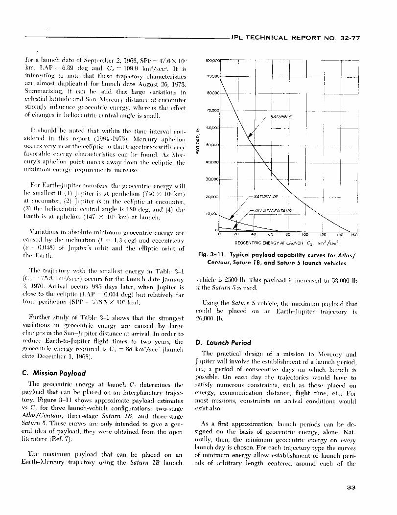
JPL TECHNICAL REPORT NO. 32-77
for a launch date of September 2, 1966, SPP - 47.6 × 10';
km, I,AP: 6.:39 deg and C:,--109.9 ktn'-'/see'-'. It is
interesting to note that these trajecto O" characteristics
are almost duplicated for launch date August 26, 1978.
Summarizing, it can he said that large variations in
celestial latitude and Sun-Mercury (tistance at encounter
strongly influence geocentric energy, whereas the effect
of changes in heliocentric central angle is small.
It should 1)e noted that within the time interval con- -_
sider('d in this report (1964-1975), Mercury aphelionoccurs very near the ec|il)tic st) that trajectories with very' ,_
(3-
favorable energy characteristics can he found. As Mer-
cnrv's apheli(m point moves away from the ecliptic, the
minimumienergy requirements incr('ase.
For Earth-Jupiter transfers, the geocentric energy, will
be smallest if (1) Jupiter is at perihelion (740 X 10 '; kin)
at encounter, (21) Jupiter is in the ecliptic at encounter,
(3) the heliocentric central angle is 180 deg, and (4) the
Earth is at aphelion (147 < 10; kin) at launch.
Variations in at)soh|te minimum geocentric energy are
caused by the inclination (i -- 1.3 (leg) and eccentricity
(e 0.048) of Jupiter's orbit an(t the elliptic orl)it of
the Earth.
The trajectory with the stnallest energy in Tahle ,3-I
(C: 75¢3 km-'/s('(,-') occurs for the launch date January
:3, 1970. Arrival occurs 985 days later, when Jupiter is
ch)se to the ecliptic (I,AP " 0.004 (leg) but relatively far
from perihelion (SPP 778.5 Y,, 10'; kin).
Further study of Table .3-1 shows that the strongest
variations in geocentric energy are caused by large
changes in the Stm-Jnpiter distance at arrival. In order to
reduce Earth-to-Jupiter flight times to two years, the
geocentric energy re(iuire(l is C:_ : 88 km"/sec-' (launch
(late December 1, 1968).
C. Mission Payload
The geocentric energy at hmnch C:_ determines the
payload that can be placed on an interplanetary trajec-
tory. Figure :3-11 shows approximate payload estimates
vs C:, for three launch-vehicle configurations: two-stage
Atlas�Centaur, three-stage Saturn 1B, and three-stage
Saturn 5. These curves arc only intended to give a gen-
eral idea of payload; they were obtained from the open
literature (Ref. 7).
The maximum payload that can be placed on an
Earth-Mercury trajectory using the Saturn 1B launch
100"000
90,000
8O'0OO
m/_oo
60,000
50,000
_.0,000
30,000
i
I
!
I SATUR/V 5
!
\ :
'x
"320,000 ..... _ /_ S,4/'U.._N Z8 - _
// /-- ATLAS/CENTAUR _1
,o,ooo 7-0-----._220 40 60 80 I00 120 140 160
GEOCENTRIC ENERGY AT LAUNCH C3, km2/sec 2
Fig. 3-1 1. Typical payload copobility curves for Atlas/
Centaur, Saturn 1B, and Saturn 5 launch vehicles
vehicle is :2500 lb. This payload is increased to 5:3,000 lh
if the Saturn .5 is used.
Using the, Saturn 5 vehich', the maxinmm payh)ad that
could be placed on an Earth-Jupiter trajectory is
26,000 ]h.
D. Launch Period
The practical design of a mission to Mercury and
Jupiter will involve the establishment of a launch period,
i.e., a period of consecutive days on which launch is
possible. On each day the trajectories would have to
satisfy numerous constraints, such as those placed on
energy, communication distance, flight time, etc. For
most missions, constraints on arrival conditions would
exist also.
As a first approximation, launch periods can be de-
signed on the basis of geocentric energy, alone. Nat-
nrally, then, the minimum geocentric energy on every
launch day is chosen. For each trajectory type the curves
of minimum energy allow establishment of launch peri-
ods of arhitrary length centered around each of the
33

JPL TECHNICAL REPORT NO. 32-77
absolute minimum-energy launch dates given in Table3-1. This selection has been carried out in Tables 3-2,
3-,3, and :3-4 for several of the Earth-Mercury and
Earth-Jupiter opportunities tabulated in Table :3-1.
For each trajectory type and class, launch periods of
15, :30, and 4.5 days were determined. Each launch period
has a maximum geocentric energy associated with it.This maximum value is reached on the first and last dav
of each launch period and results in the lowest payload.
The minimnm injection energy during the launch period
can be found from the corresponding absolute mini]num-
energy trajectory in Table ,3-1. It is of interest for orbitermissions since more fuel can be added to the retro tanks
as the geocentric energy decreases during the launch
period, resulting in closer orbits at the target planet.Table :3--2 also shows the variations, during the launch
period, of the most important trajectory characteristics
on which constraints are usually placed.
The Earth-to-target-planet flight times Tv will affect
virtually every spacecraft sul_system. The communicationdistance at arrival iq, indicates the design of the com-
munications system. The planetocentric asymptotic speedV_, is a measure of the speed of the spacecraft at the
time of closest approach to the target and is important
for both orbiter and flyby missions.
The geocentric asymptotic declination is included inTable ,3-2 because it is an important parameter in de-
termining the injection location over the Earth's surface.
Acceptable values for this parameter are estimated tolie between -,'34 and +:34 deg. Values outside this range
result in severe restrictions for Capt" Kennedy launchings.
As an example, note how the 45-day launch period
November 21, 1968 to January 5, 1969, for Type II, Class
I trajectories to Jupiter was found from the curve ofmininmm geocentric energy, Fig. :3-10. Starting with the
launch date December 1:3, 1968 (C:_- 77.8 km_/see_),
C:_ was increased until the range of lanneh dates was 45
days. These limits then defined the launch period and
the corresponding maximum energy (C; = 86.2 km_/see 2)
over the period.
Sometimes it happens that the curves of minimum
geocentric energy corresponding to Type I and Type II
trajectories intersect within the launch period for a given
type. It then becomes possible to design launch periodsduring which both Type I and Type II trajectories would
be used. The corresponding geocentric energies are lower
than if either type were used alone.
E. General Characteristics of Trajectories
In order t(_ gain further insight into the nature of
Earth-Mercury and Earth-Jupiter trajectories, plots of
several key trajectory variables were prepared for each
of the lm,nch opportunities. The relevant trajectory
parameters can be categorized into three gronps: geo-centric, heliocentric, and planetocentrie. Sections IV-XV
show detailed plots of the following trajectory param-
eters, \v]li(,h _.lrt' italicized:
1. Geocentric Parameters
During the geocentric phase, the magnitude and direc-tion of the hyperIx)lic-excess velocity vector V_,p, or the
velocity vector of the spacecraft relative to the Earth atthe time of injection into heliocentric orbit, are of prin-
cipal interest.
The magnih,de of Vh. is represented by the geocentric
energy at lain,oh, C:, = V_,. All plots of trajectory param-eters show contours of constant and integral values of C:,
The directi_m of Vh,, also called the outgoing asymptote
S, is given relative to several coordinate systems. The
right ascension 0._ and declination _.,. of the outgoing
asymptote specify its direction relative to a geocentric
equatorial coordinate system. The celestial latitude ,/1. ofS or the an_le between the geocentric asymptote and the
launch planet's orbital plane and the angle bettceen theSun-Earth vector and outgoing geocentric asymptote _j,
specify the orientation of S relative to the heliocentric
ecliptic coordinate system.
Obviously, the energy has a direct influence on space-
craft weight. The declination of the outgoing asymptote
also severely restricts the interplanetary trajectories which
are possible in a more complicated way.
2. Heliocentric Parameters
The following properties of heliocentric transfer ellipse
are presented: aphelion distance R,,, perihelion distance
Rv, and inclination i with respect to the ecliptic. The
eccentricity c and semimajor axis a of the heliocentric
ellipse can be found from these. Sections IV-XV show
graphs of true atu)maly in the transfer ellipse at launchVt, and true anomaly in the transfer ellipse at arrival Vr,,
as well as of their difference, the heliocentric central
angle %
The Earth-to-target-planet time of flight T_. and com-munication distance Re are of direct interest to designers
of all spacecraft subsystems.
34

JPL TECHNICAL REPORT NO. 32-77
_ : ._==E
.__
: ._,
3
_' ": =E
E
= .=-
om.1-
"L-- _ _
.c :E_J
v) ._v nx
_ _:E_. E
0
E •
E"== _,
E
.=
c
o _ o
I -
O o. (_.
o,0 o Ko_4 _ c5
o o o
o K
_ coe4 _
b.
_ KO
O- _ 00 O_ CO
0- _. o. o. _.
q o q _ (R.CO
I _ I I I
_r _ CO
_r_ co
d c; o
-_. - o
o,
(5 o
o
o
T TCO
o
o. -. "9.("4 /% CO
U') CO CO
,_ ,6 t<
_ u_ co
e,i N N
° 7, _.u3
O O O
f'} "_t
I
co O O
I I q
_ _ co
_ _ co
o _ _
o _ _ _. _. :I I _ I I ]
0 0 0 _ ,_ 0CO _ aO CO
o _ ,..
O- CO h,.
o c_ c_
_ o _
_ _ o
o
K. o _
c_ o c_
_ o _
0 0
35

JPL TECHNICAL REPORTNO. 32-77
_n
i.
_a
oJ=_a
e-
.I-
D.
"1
m
Q.>.
i{,1{0
mJD0
I--
=Ei
o o o
_, _ _ _ K _. co
E o
=
:'= o
E • o., -
u.. :E r_ I_
.= ® '.= -_
.c ,-: d ..-:• _ _ I
co _ _
o _.
o o o
_. _ or_ co
c_ oK co o_
_ °
.,o ,,o ,,o
o o
co K r_
_. _. o
._ ". _ _ _ _ if-._. _ _._. • _. co 0_ _ co
E_EE. _ ._ _ .
K
_-,_ _ _ _ _
o o _ _ _ oO, O,
._o _ _= g _
E®.;
.-_-
Kco _. c>o o c_
I
- o _! !
o
co o, o_
_o
I i
o o oC_. C,'-
o o -0K _ t..co c_. o
o _-, _co _
o o .:. -:. _. "!
I I I I I
o o o o oco _
K co o: _. 06
t'_ _
_ ,6 ,6 .6 .d 4
o oo, co o_ co 00 00
o _ _co
o _ oco O_ 0
o _ _o
,q. _ r,,
'; I I
_. o o
I I
_ _ ocO 0 OI
co O_ 0
_. ° _,,o .,o ,.o
i t
_!. _ o
I I I
CO 0 ¢_1
0 0 0 0 0 0
0 0 co 0 0_ o _
o
co _. o
o _ _co 0'-
(5 c_ c_
_ o _ _ o _.
o o or',. P-..
_o ,o ,,o
o (5 c5
o
F. 7-.
co? ? 7
_ o _
o _ o
o
36

JPL TECHNICAL REPORTNO. 32-77
).
° _ ._=
.- .=o_ ® _EO_
: o _Eo.E
o a 3E
';0 c
u _
._E. _
"; =E°--
°-s_
e'- o
v ,c_
-- ®E_. E0. _ E. .E
"E; o •
=
I:. o " _E =E>. _ ;oc=_,
•-_ E •
.--r _
._o_,_E®_
_ .-®'_E
=l'E 0
o o0 '_ o ,o o o o
I I I I
I I _ I I I I
o
o o. _. ,q
CO O, O, O, 0- CO cO 0_
O O O O,
"O
(_ 0 0 0 0u'l K _t
o3 cO
K
_ o _ _ _ oo0 0 O, _ _ 0
I I
,-: 0
I
t'.. _
,d ,d ,d ,d _
o -_t o _ o, 0 o o
cO o. o_ 0.. o- 0_ o, 6,
0 0
o _ ocO 0 _0h_. cO CO
d d d
o _.('_ (.1
0- o,
t'x o
o o
o
oo I_
T "r
_ o _
o o _
b.
co _ _d d d
_ o _
? 9 ?(_ -%.
oco
(-1
I
r_
co
_ o
,0 co _ co_cO cO 0-
d d d d
o _
777 ?o- K
37

JPL TECHNICAL REPORT NO. 32-77,
The celestial latitude at arrival time /3v is referred to
the ecliptic plane.
3. Planetocentric Parameters
The direction of the approach hyperbolic-excess velocity
vector V1,_, or velocity, of the spacecraft with respect to
the target planet at arrival, is described in several coor-
dinate systems.
The right ascension 01 , and declination %, of the unit
vector along VJu,, also known as the approach or incom-
ing asymptote S, are referred to the Earth's equatorial
plane. The antic between the incoming asymptote and
the arrival planet's orbital plane "/i, and the angle between
the target planet-Sun vector and the incoming-planet-
centered asymptote ¢1, relate the incoming asymptote
direction to the orbital plane of the target planet. The
angle between the planet-Earth vector and the ineomin_
asymptote _: defines the motion of the spacecraft relative
to the Earth-planet line a few days prior to encounter.
The angle between the t_lanet-Canopus vector and the
incoming asymptote _,. is of importance because Canopus
will most likely be the second attitude reference for
these missions, in addition to the Sun.
The magnitude of V_u,, the asymptotic speed with re-
spect to the target planet Vh> in of great importance for
orbiter, lander, and multiplanet missions.
F. Discussion of Earth-Mercury and
Earth-Jupiter Trajectory Parameters _
1. Declination of the Geocentric Asymptote ,I,._
Equation (2-60) defined an inequality t)etween ,1,,,
El, (the launch azimuth), and ,l,z, (the latitude of the
launch site):
._ cos e _l_sin _ "_'_,
COS" (I)L
The regions within which launch from Cape Kennedy
can occur are shown in Fig. :3-12 as a function of El,.
Usually, the launch azimuth will be restricted to lie'
within certain bounds established by range safety con-
siderations (typically 90 to 114 deg).
For the two Mercury ot)portunities considered (1967,
1968), the declination constraint does not restrict the
_'A detailed discussion of the influence of the trajectory parameters
on trajectory design is presented in R('f. 8 (Section Ill.D). The
following material is int(,n(l(,d as supph'm_'ntary to that presentedin Ref. 8 and 9.
Z
O
I--
Z
COhi0
d
rr
0rr
t--D0
9O
iRANGE SAFETY J
AZIMUTH
9c
0 90 180NORTH EAST SOUTH
LAUNCH AZIMUTH IEL, deg
Fig. 3-12. Permissible regions of the declination of the
geocentric asymptote ,I,_ for Cape Kennedy launchings
Type l-Class I trajectories, which have the shortest flight
times. The constraint does eliminate a substantial part of
the other traj,'ctories (i.e., Type l-Class I and Type lI-
Class l and I!). This can be seen from the correspondin_
plots of ,I,, vs launch date (Figs. 4-5, 5-5).
For the 1968-69, 1969-70, and 1970-71 Jupiter oppor-
tunities, the declination constraint does not restrict the
possibh' Typc l-Class I trajectories (see Figs. 6-5, 7-5,
8-5) In 1972 and 1973 it becomes almost impossible to
use tiffs kind of trajectory (see Figs. ,9--5, and 10-5). In
fact, in 1972 and 1974 only the Type II-Class I trajec-
tories are not affected by the declination constraint. All
other traject_,ry types are severely, restricted by the
constraint.
2. Angle Between the Sun-Earth Vector and the
Outgoing Geocentric Asymptote ._L
This quantity, which is of importance for spacecraft
using the Earth and Sun as attitude references, takes on
values between 80 and 130 deg for the 1967 Mercury
Type I trajectories (45 to 110 deg for Type II trajectories;
see Fig. 4_). It takes on approximately the same range
of values during the 1968 Mercury opportunity owing
to the fact that the Earth-Sun-Mercury constellation is
about the same for both opportunities. The quantity
varies between 45 and 120 deg for the five Jupiter oppor-
tunities considered herein (1968-69, 1969-70, 1970-71,
38
JPL TECHNICAL REPORT NO. 32-77
1972, 197.'3) for energies less than 120 km2/sec '2. In all
cases, it decreases with increasing launch date.
3. Celestial Latitude of the Geocentric Asymptote _,;,
This quantity, referred to in the graphs as the angle
between the outgoing geocentric asymptote and the
launch planet's orbital plane, is strongly dependent on
the celestial latitude at arrival time /3;,. (See Ref. 1, page
35. Fig. ,3-14 of Ref. 8 applies for Earth-Mercury trajec-
tories as well as for Earth-Venns trajectories.)
Employing the same reasoning, low-energy trajectories
to the outer planets (Mars, Jupiter, etc.) have perihelion
distances on the order of 1 an and aphelion distances on
the order of the Sun-target phmet distance. Figures 6-9,
7-9, 8-9, and 10-9 show that for an Earth-Jupiter tra-
jectory, the true anomaly at hmnch remains within .'30
deg of perihelion (VI, - 0 deg). Figures 6-10, 7-10,
8-10, 9-10, and 10--10 show that the Jupiter encounter
can take phtee from about 40 (leg twfore to :30 deg after
aphelion.
For the Mercury opportunities in 1967 and 1968, the
target planet is relatively close to the ecliptic at encoun-
ter, which causes "//, to take on values on the order of
10 deg. For Jupiter, ,/;, can take on values between -45
to +45 deg for the energy range considered herein. Note
that the Type I-Class I trajectories, which have the
shortest flight times, all lie very close to the ecliptic. The
Type II-Class II trajectories, which correspond to thelongest flight time, also show this characteristic.
It might be asked how ,/_, can take on such high values
in spite of the fact that Jupiter's inclination is only 2.5
deg. In Ref. 8, page :34, it is shown that
V_, cos I'_ sin i
sin yt, _ V;,;,
where V;, is the heliocentric velocity at launch, V;,;, is the
hyperbolic-excess velocity at launch, 1";, is the heliocen-
tric path angle at launch, and i is the inclination of the
trajectory. The magnification factor V;,/V;;;, is on the
order of 4 for Earth-Jupiter trajectories.
4. True Anomaly at Launch and Arrival and
Heliocentric Transfer Angle
In general, low-energy elliptic heliocentric orbits from
the Earth to the inner phmets (Mercm'y, Venus) will
have aphelion distance on the order of 1 an (astronomical
unit) and perihelion distances on the order of the distance
between the target planet at the Sin1 (0.:3 au for Mer-
cury). Consequently, launch will occur near aphelion
(true anomaly V;, -- 180 deg) and arrival near perihelion
(true anomaly Vp - 0 deg). Figures 4-9 and 5--9 show
that the variation in V_, is small, 160 to 200 deg for Type
I and Type II Me]'eury trajectories. Note that latmeh
occurs before aphelion at the t)eginning of tim launch
period, and after aphelion at the end of the launch period,
as was the case for Earth-Vemls trajectories.
Figures 4- through 10-:3 show the variation in the
heliocentric transfer angle ,1% or the difference between
the true anomalies at launch and encounter, for Earth-
Mercury and Earth-Jupiter trajectories, respectively.
Note that none of the Type I or Type II contours inter-
sect the ,v = 180 deg line.
5. Aphelion and Perihelion of the Transfer Orbit
Figures 4-12 and 5-12 show that for Earth-Mercury
trajectories the aphelion distance (point farthest fi-om the
Sun) varies from 1 an by less than 10%. The perihelion
distances show stronger variations (Figs. 4-11 and 5.11).
As mentioned in Ref. 8, the probe passes aphelion after
hmneh if the true anomaly at launch is less than 180 deg;
it passes perihelion before arrival (i.e., passes within
Mercury's orbit) if the true anomaly tit arrival is positive.
For Earth-Jupiter transfer, the perihelion distance does
not change drastically (Figs. 6- to 10.11). Note, how-
ever, that tim aphelion distances can become as large as
2400 X 10': km, or over ,'3 times the Sun-Jupiter distance
for geocentric energies C,. = 120 km:'/sec 2 (Figs. 6-
through 10-12). The plots of true anomaly show tlmt
aphelion would take place after Jupiter encounter. Owing
to the exceptionally large mass of Jupiter, it will exert a
very strong perturt)ation on the trajectory during en-counter.
6. Time of Flight
Typical Earth-Mercury flight times range from 80 to
160 days, as is shown in Figs. 4-2 and 5--2. As the launch
date progresses, it is seen that flight times are shortened
for both Type I and Type II trajectories. Type II trajec-
tories offer lower energies and larger latmeh windows
for a given energy, with onh' a slight penalty in flighttime.
39

JPL TECHNICAL REPORT NO. 32-77
Flight times to Jupiter are on the order of i to 4 years
(Figs. 6- through 10-2). ,,ks la,mch date is delayed, flight
time incr('as('s sul)stantiallv for a _i\vn em'r_y.
7. Comnumication Distance
For Nh'rcurv trajt'ctorics, the c(mm.mication distance
at ('nc'ount,2r in('r('ast's as launch dat(' i_ dclay('d, wh('r('as
flight time decreases. The c())mmmication distance can
take on values betwc('n I00 ?.: 10' km to IS(} / 10" km
(see Figs..I-4 and 5--4).
Th(" communications distanc('s at Jupitur arrival ('xtend
from 650 / 10" km to 950 / 10" kin. Since thc Sun-
Jupiter distance is
)00
9O
740 10'; km and the Earth-Sun
distancv is 151) 10'; kin, it is clear that if the communi-
cations (listanc(' at ('ncounter is around 890 < 10'; kin,
thv Su. _ill li,. x('ry close to th(' Jupiter-Earth lint' (sec
}:i_s. 6- II)r(m_.'}l 10-4).
8. Inclination of the Ileliocentric Transfer Plane i and
Celestial l,alitude at Arrival/3,
The incli],ation i of the heliocentric transf('r orbit to
tl_t' cc']iptic pJau(' is essentially a function of two param-
('ters, (1} tl,v 1,4ioccutrie central angle q,, amt (2)the
<'elcstial l:ttitu(!c ft. of the planet at arrival, sine:(:
/_p IS CELESTIAL LATITUDE OF i: "
MEASURED FROM ECLIPTIC
sini = sin,),
IO
o0 40 80 )20 160 200 240 280 520 560 400
HELIOCENTRIC CENTRAL ANGLE, deg
Ei8.3-13, In¢linolion of the helio(enlricorbifol ploneto e¢lipficvs heliocentric cenlralangle
4O

JPL TECHNICAL REPORT NO. 32-77
If thc heliocentric central angle is fixed, and the absolute
magnitu(lc of the celestial latitude at arrival is increased,the inclination also increases. If the celestial latitude of
the planet at arrival is zero, the inclination is equal to
zero, no matter what the heliocentric central angle may
be (with the exception of a central angle of 180 deg).
ttowever, as shown in Fig. :3-1:3, if the celestial latitude
fl_, of the planet at encounter is fixed at an al)solutevalue
greater than zero, and the central angle is varied, the
inclination will reach its minimum value (equal to fl,) at
central angles of 90 anti 270 deg, or its maximum value of
90 deg at the central angles equal to h_,, 180 /3_,,180 + /3,,
and :360 fl,. It is because of the fact that the inclination
increases near the central angles of 180 +-fi, that Type l-
Class II and Type II-Class I trajectories come into exist-
enee. The increasing helioccntric inclination eventually
results in it sharp increase in energy C:_as the central angle
approaches 180 dog -'-fl,, theret)y bringing the two groups
of energy contours into existence. It may now 1)ecome
apparent that the inclination of the heliocentric orbital
plane may take on values greater than the celestial lati-
tude of the planet at arrival because of the varying helio-
centric central angle.
For the Mercury and Jupiter trajectories considered
herein the inclination can be as high as 12 deg. By deft-
nition, inclination is positive, whether cncom_ter takes
phtce at)ore or 1)eh)w the ecliptic. Figures 4-1:3 and ,%1:3
show inclination vs humch date for .Mercury. Figures 6-
through 10-1:3 show this parameter for Earth-Jupitertransfers.
9. Asymptotic Approach Speed V_,_,
Figures 4-15 and 5-15 show that the variation in
asymptotic speed with respect to Mercury is from 12 to
24 km/sec for both Type I and Type II trajectories. Type
1-Class I trajectories (shortest flight times) have higher
approach speeds than Type I-Class II trajectories. It will
be recalled that approach speeds to Venus were on the
order of ,3.75-10.7 km/sec.
Approach speeds to Jupiter lie in the range of 5.5-14
km/see. The lowest asymptotic approach speeds are ob-
tained using Type I-Class II or Type II-Class I trajec-
tories, shown in Figs. 6-- through 10-15.
10. Angle Between the Incoming Asymptote and the
Arrival Planet's Orbital Plane y,
For Mercury, Type I-Class I and Type II-Class II
trajectories have values of "/i, in the range --10 to +,30
deg. This angle can hecome as large as 60 deg for the
other trajectories, as is explained in Ref. 8, page 51. (See
Figs. 4-16 and 5-16.) For Jupiter trajectories, -/_ remains
on the order of 15 deg or less for all opportunities. It
takes on values on the order of 5 deg for Type I-Class I
and Type II-Class II trajectories. (See Figs. 6- through
1(_16.)
11. Angle Between the Arrival Planet-Sun Vector and
the Incoming Asymptote G
For Mercury Type I trajectories, the angle G is acute,
whereas it varies between 60 and 160 deg for Type II
trajectories. (See Figs. 4-17 and 5-17.) This angle is of
considerable importance in the analysis of postencounter
Jupiter trajectories (see Section Ill.F). As was shown for
the Mars case in Ref. 8, page 51, G values for Type I-
Class I trajectories are obtuse at the beginning of thelaunch windows and become acute at the end of the launch
windows. The angle is smaller for the other Jupiter trajec-tories as is shown in Figs. 6 through 10-17.
Figure ,3-14 shows the illuminated crescent orientations
at arrival for various values of G. Figures 3-15a and 3-15b
show near-planet geometries for Type I and Type IIapproach trajectories to Mercury and Jupiter, respectively.
Figures 3-16a and 3-16b show these trajectories as
viewed by an observer in inertial space.
12. Right Ascension Oj, and Declination _, of the
Incoming Planet-Centered Asymptote
For Mercury trajectories, 0_, takes on values from 300
to 355 deg. Right ascension O_, -- 360 deg corresponds to
the vernal equinox direction, or direction of the Sun-Earth
vector at the beginning of spring. The declination _measured relative to the Earth's equator, varies from 40
to -t-40 deg.
For the Jupiter trajectories, there is a considerable
variation in 0t, for different launch opportunities: 160 to
185 deg (1968--69), 290 to 320 deg (1973). The correspond-
ing variations in % are -8 to 22 dug (1968-69) and -36
to -8 deg (1973), respectively.
13. Angle Between the Planet-Earth Vector and the
Incoming Asymptote _:
Plots of this parameter are not available for the Mercury
trajectories at this time. The angle eL. is equivalent to the
Earth-probe-target-planet angle a few days before arrival.
The angle _: - 180 deg corresponds to motion along the
Earth-target-planet line, away from the Earth, during the
41

JPL TECHNICAL REPORT NO. 32-77
(a) MERCURY TYPE T TRAJECTORY ( 7"p > Odeg)
ENCOUNTER BEFORE PERIHELION
(c')MERCURY TYPE l-r TRAJECTORY ( 7"p > O deg)
ENCOUNTER AFTER PERIHELION
( b) MERCURY TYPE I TRAJECTORY ( X# < Odeg)
ENCOUNTER BEFORE PERIHELION
(d) MERCURY TYPE TI TRAJECTORY ( 3Yp < O deg)
ENCOUNTER AFTER PERIHELION
(e) JUPITER TYPE I TRAJECTORY ( 7p • O deg)
ENCOUNTER BEFORE APHELION
(f) JUPITER TYPE I TRAJECTORY ( Xp < 0 deg)
ENCOUNTER BEFORE APHELION
(g) JUPITER TYPE I TRAJECTORY ( 7',0> 0 deg)
ENCOUNTER AFTER APHELION
(h) JUPITER TYPE I TRAJECTORY ( ),p
ENCOUNTER AFTER APHELION
Fig. 3-14. Crescent orientations for typical trajectories to Mercury and Jupiter
as observed from approaching spacecraft
< 0 deg)
42

JPL TECHNICAL REPORT NO. 32-77
DIRECTIONTO SUN
! ASYMPTOTE.x.x_x._ _.
DIRECTION _ _. "Y'II_TOSUN = -'%.L.IIL\ .I
cp \ "-\/ \
(a)
./
/DIRECTION DIRECTION //'_J /
TO SUN _ TO SUN ,4 _p _/'/_'_-_ /
I(b)
DIRECTIONOF APPROACHASYMPTOTE
Fig. 3-15. Near-Jupiter geometry for typical trajectories, viewed from above ecliptic plane: (a) Type I trajectory,
encountering Jupiter before aphelion; (b) Type I-II trajectory, encountering Jupiter after aphelion
last few days before target-planet encounter; (, :: 180 deg
means that the probe will t)e occulted from view of the
Earth l)('cause of bending of the trajectory by the target
planet. Figures 6- through 10-20 show that this param-
eter varies lwtween 60 and 160 deg for Earth-Jupiter
trajectories.
14. Angle Between the Planet-Canopus Vector and
the Incoming Asymptote ,L
Plots of ,L. are not available for Earth-Mercury transfers
at this time. For Earth-Jupiter transfers, the ranges of ¢,.are 75-150 deg (196S--69), 00-50 deg (1970-71), 0-20 deg
(1972), 90-118 deg (1973), respectively; ¢, - 0 deg indi-
cates that the spacecraft will approach Jupiter along the
spacecraft-Jupiter-C.anopus line. (See Figs. 6- through10-:21.)
G. Procedures for Utilization of Graphs in
Design of Planetary Trajectories
For a trajectory design, a source of information must
1)e availal)lc which can be quickly scanned to determine
the range of feasihle trajectories for a mission. The graphs
presented in Sections IV to X of this report constitute
such a source. The order and procedure for actual use of
these graphs hy the trajectory engineer in the design and
analysis of trajectories arc now reviewed.
(1) Both Type I and Type II transfers should bescanned. Those trajectories should be selected for
which the declination of the outgoing geocentric
asymptote lies roughly between -,34 and -t 34 deg.
These are the feasible trajectories for launchings
from AFETR. The algehraic value of the declina-
43

JPL TECHNICAL REPORT NO. 32-77
DIRECTIONTO SUN
DIRECTIONTO SUN
/
DIRECTIONTO SUN
(a)
\ /\ I
'\
\I
r..p
\\-i-\ \
\ \\\ \
\ DIRECTIONOF APPROACH
ASYMPTOTE
DIRECTIONTO SUN
(b)
i1 /
/t/
//"_
/ / /// / /
# // /
// //24 DIRECTION/ OF APPROACH/ ASYMPTOTE
Fig. 3-16. Near-Mercury geometry for typical trajectories, viewed from above ecliptic plane: (a) Type I trajectory,
encountering Mercury before perihelion; (hi Type II trajectory, encountering Mercury after perihelion
tion reveals vital information concerning the pre-
injection trajectory (see Section llI.E.]).
(2) For tile trajectories of paragraph (1), tile energy
requirements (C:) for various firing periods should
])e ol)served. If it is found that booster payload
capability and the desired payload weight match
the required injection energy for a given firing
1)eriod (for example, :30 days) and also satisfy para-
graph (1) for Type I and Type II trajectories, a
decision must then be mad(, to utilize either Type 1
or Type I1 trajectories or. perhaps, t)oth (see
Section Ill.D).
(3) In making the decision to utilize either the Type I
or the Type II trajectory, or }}oth, the curves of
flight time and Earth-prolw communication dis-
tance vs latmch date are most hellfful. In general,
Type I1 trajectories have longer flight times and
4)
l'7,arth-l)r,,be distances at (.llC()tlll[i.,l tlhtl) d() "l.x pc 1.
Thv a(.t,ml difl('rem:es in magnitude (h'l)t'nd ()ll the
mission mid range of injection ( '1_('_"(L_>"I Ill g,'fteral,
tt,' hmvcr the tlight time the ,_reat('r is tt,' sc,si-
tixitx _)( tllc trajectory to injt'ction errors.
Nt,x(. t].' 1)arameter C_., th(* analt' t.'lw,'('n th,'
outt_,_in_ asymptote and the Sun-Eartl, xcct,,r at
helioc,'l,tric injection, shouhl tw studied. It will 1,'
rtx'alh'd that this is equivalent to the l'_'arth-l_ro]w--
Sun angle at a few days after launch. Sim'v Ih('r(!
a]'p usually many limitations on a Sl)acccraft xxhich
is stabilb, ed and contro]h'd in attitude lw ,)plical
rt'fcr(mct'_, (such as the Earth. Sun. and CaTu)ptls).
the F,avlh-probe-Sun angle may lw restricted m'arthe Earth and. perhal)s, throughout the tli_ht. The
Ixtra]neter ¢/, is most ht'll)ful in trajectory ch'si_l
tot d,'t('rmining the constraint near the Earth.
44

JPL TECHNICAL REPORT NO. 32-77
(5) If the vahw ()f ._:, is h'ss than 9() (]('_ for Mercury
traj('('t()rics, the pr(/he is iJsually being inje('ted into
the ]l(.liot't'llhi('-trall,Sf('r orl)it l)efore aphe]ion and
will trav('l o,,tsi(h' the Earth's (irl}it before "fallinf'
in toward Xl(']cury:. To be precise, one can obs('rve
the curves ()f hue anomaly at launch. Because (if
t(,lllp(,rtltllr(,-('()lltro[ pr()l)lelns, th('rt' I/1_.1y 1)(" a
restriction ()l_ the maximum Sun-probe distance (hu-
ina flight. T(I determine this maximum distance
dming ttight, one simply trin(ls the aph('lion distance
()t: t]w pr()h(' f](m_ tlw graphs. If ,G, is greater than
,()0 (h'_ l]l('ll |]1(' nl:.tximlull distancu (hiring flight ttl
?xlcrc_nv is ,'ss('nlially the Sm_-prob(" distance at
la,mch.
(6) It th(' value of _.:, is gr('at('r than 90 (leg for .lupiter
trajectories, the prol)e is usual]v lwing injected into
the heliocentric-transf('r orl)it before perihelion and
will "fitll" inside the Earth's orbit heft)re traversin_
(rid t().lllpit('r. T('nq)('r:tturc-c(/ntrol consi(l('rati()ns
may rustrict the minimum Sml-l)rol/e distance (]ur-
hl_ flighl. To d(.t('rmin(' tht' minimum (]istam'u
simply find the p('rihelion of the l)]oli("s transfl'r
(irl)it f()r t]w (h'sir('d traj('('tory or ran_(' of traj('('-
lorius. If G. is h'ss than 90 (h'_. the minimlml S_m-
pr()])c dishmcc (hlritlL_ flight to Julfit('r is the
(]islan('(' at ]aun(']l.
(7) For a spac('craft stabilized and c,()]flr()ll('d in ;tttitu(t(,
]ly Sun and Earth optical rufu]'t'nc('s, a constraint
may exist which will rustric't th(' Earth-pr()be-Sun
angle t() a vahle g]'_'at(']" than 0 (l(' R hy a t:('\v degrees
(n ]('ss than 180 d('_ by a f('w de_r('('s. This immu-
(tiat('ly i]np]i('s that a trajectory must l)(' ('h()s('n that
has an itwlinalion ()f the heli()c('ntric m']lital 1)lan( '
to th(' ecliptic whi(.h is _ruat('r than 0 (h'_. To satisfv
th(' above constraint, th(' inclinati(m may have t()
he 0.o5, 0.50, or even ].0 (leg, depending on the
r('sh'i('titm and on t]w trajectory itself. Th(' values
of th(, ()rbital inclinations for Sl)('t'ific trajt'('torics
can t)t" t_/_l_l(] fr()m tlw graphs in Suctions IX' t(I X.
(8) F(ir ess(,ntially all ft'asil)le Type II traject(/ri('s to
Xh'r('ln'y an(l a few of Type 1, Me]('my (,n(.(luntcr
filr some missions will take place after p(,]ih('lion of
tlw transfer orbit. This means that the probe will
pass closest to the Sm_ several days or, perhaps,
s('veral weeks before encounter, depending on the
trajectory, l_;ecause of tt'nlperatm('-control require-
merits, there may 1)e a restriction on the minimum
Sun-probe distance during ttight. To dctermine_ the
value of this parameter, one finds the perihcli(m
distance of the prot)e for the desired trajectory from
(9)
(lO)
(ll)
(t o)
the _raphs. Tiffs parameter is the minimum S_m-
p,ol)c (]istan('(' dHl'ill_ flight to Nh'rcu]v if th(' trlic
ano]nalv of arrival is in the first or sc('tmd quadrant.
For Type I trajectories t(i .]upitcr. uncountt'r usually
takes place before apht'lion of the transfl'r orbit.
For those trajectories having true anomali('s at
arrival in the third or fourth quadrant, howcv('r,
encounter will take place Mter aplleli(m. This mvans
that the maximum Slm-1)rolw distance' durin( Z flight
(l('('urs })(']()r(' ('lw(/|mtt'l'. "]'('lllpt'ratur('-(.:ontr()] c()t/-
si(lurati(ms may r('strict th(' maximum S_m-pr()])('
distance during fli:aht. To dctcrmim' this maximum
for the ll('('('sStllV t]ajt'ctorit's, find th(' value (if lh{'
aphelion distance from tlw graphs in Sc(.ti(ms VI
to X.
Igor l)]ant'tary missions such its ]a_l(lcrs (w orllih'rs,
it will pr()hably h(,com(' ncc('ssarv t(/ utilize' trajec-
tories for which the h vpurholic-cxccss speed at the
plant't is m'arlv minimum. In fact, in order to
maximizu the scic],tific-1)ayhm(t weight, a "'tradcofl:'"
must l)(' made in minimizin_ the gu(/ct'ntric cncr_v
(Ir l)]ant't()c('ntric ('n('rgv,.. Such tr:tj('ctories will
alh)w the heaviest payl()ads to 1)(, ]an(h'(t ()n the
planet or inj('cted in a th'sir('d ulliptical rehit ai'o_md
the planet with the use ()f rt,tro-maneuvcrs. The
traj('t't(wv designur can fin(] tlw values of th('
hypcrbolic-cxcuss Slwcds at the planet h/r vari()us
traj('c'torit's Jrom the graphs in S('cli()_s IV to N, and
can dcturmine tlw feasibility of thc trajcctori('s from
the l)roce(hlres in paraRral)hs (1) to (9).
l:()r a spacecraft which is stabiliz('d and controlh'd
in attitude by optical rt'terenccs, there may he
ccrtain restrictions on the Sun-probe-planet ;tnRle
as the pr()l)t' apl)r()aches the planet. Such restricti()ns
may 1)(' nt'ct'ssarv ])('c'a_se ()f approach-_ui(lanc(_
consi(h'rations. The paramctt,r g:,, the an_lu tlt'-
t\v('u_, the approach ;tSVml)tOtc and th(' tare, ct-
l)]iuwt-S_m recto|, is ('(l_fiv:tl('nt to the S_ln-pr()l)t'-
planet angle a f('w da\'s he|ore ctwounter. The
parameter can 1)t' most helpful in analyzing per-
missibh' traj(,('t_)ri('s near th(' planet.
l{egar(ling the design of trajectories near the planet,
it is n('edh'ss t(I sax that, by altering the paramet('rs
in the prcinjection trajectory near Earth Iiy sma]l
in('rem('nts, the probe can ])t' made to pass on anysidc of the planet, ll(Iwever, the inclinations of the
planetcwentric ]_yperl)o]ic orbit (or ('lliptical orbit,
assuming that the r('quir('d retro-man('uv('r is made
45

JPL TECHNICAL REPORT NO. 32-77
in the orbital plan(' of the hvpurh(/ht) to the planc't's STEPS• I AND 2
orbital l)]anu dupcnds on the aiming point at the
l)lanct,as well as on flw l)aranwtur 7_i, th('an_h'
I)(_t\v(_CII the approa(']l asymptote and the planet's-o
()rl)itaIplan< The minimum inclination which can
lu' attained is u(tua] t() 7 I' 1t: "/;, is z('ro, the inclina- __b..
tion ¢)f the .rlfit to thu plallct7 nrlfita] plam, will
range fr()m () re) l_0 (h'_ dul)undin _ on the aiming o
point, hl('linati()llS {4 0 t() 90 (h'_ imply direct _-
re(Ilion (in Ill(' dir('ction of tlw phmct's orbital rota-
tion1, \%hUl'Ca_ im'lillati(m_ t]'cun 90 to 180 dc_ imply
l'ctr()i_l'ttdc motion ((}i)l)()sitc t<) t]w planet's (}rbita]
r()tati()n). If y,, '-I,5 de!& th(" inc]ilmtion may
ran_u from ,1,5 to 135 c|c_ f()r all aiming points. STEP 5
[[ -/_, ' _}() dug, the im'lilmti(m will equal 90 d('g
f()r any aimin_ point xxlfich i_ (,h()_(,n at the planet, v%LO
l" ( )1" %, i I , "_ ) (} ( ] ( ' _, t } J { ' l) I'( } I ){ ' will apl)r(xlch the planet ?:,,
h(lm a path tx,l()w tlw l)]itllct's orhita_l t)lam': for
7_,< 0 (h'_, th(" al)l)roach will h(' from al)ove. In
manv cases, it may l)(" (h'siral)h' t() design the near- 5k--
p]a.n('t trajuct(wy \_ith a 1)r('scril)cd inclination in
mind su',::h that the llr()l)( ' ",',ill pass thc target t)ody
in the l)hnwt's i)rhital (/r, l)('rhap_, (,quatl)rial plane.
It is tlnls appar('nt that the param('t('r 7_, may i)r
may not permit the s('h'ctd pass. To find th(' vil]u('
()I" ;_r t'()l" _[ _i _'('} } trai('cl{)rv, ol)_crv(' the c'm'vu o1:711
",_,hunwh date f,, llw de_ird mission.
(1_)'1"o comt)r('humt full,," the _i,_nificanc'c' oI; each
l)aramct('r and its variation \vith launch (late and
arrival dat(', it may b(' a(|'<ant;tff.t'olls to construct
the loci ()f constant arrival tt.:ttt,s on (,itc,]l pertinent
_4rat)]l ill Suctions IV to X. This lm).v I)(" done ill
thr('e st('ps, its sh()_n in Fi_. 3-17.
(ilt) Construct the loci ()t d('sir('d arrival dates (mth('
era'yes of flight tim(, vs ]aunch (late.
(b) \lark the 1ram,oh dates and _('oc'('ntric ('n('r_ics
for which int('rn('ution (){ t]w arrival loci and the
vari()Hs ('nt'rg}" ('(nit(mrs ()(:('ur.
\\
POINTS OF INTERSECTION
LOCI OF DESIRED ARRIVAL DATE_
LAUNCH DATE
................
LOCIOF DESIRED ARRIVAL DATE'Xx
OPOINTS OF INTERSECTION
TAKEN FROM LOCI ABOVE
LAUNCH DATE
Fig. 3-17. Steps for construction ofarrival date loci
(c) Tak,' the int('rsection points (ff (1)) and construct
tlw :uTival-(lat(" loc'i on the _raph of inter('st.
Exl),'rimK'u has shown that traj('c'tory parameters tend
to t'xhitfil _tl_ il_x'ariance if tlw arrival date is huld fixed
whil(, tl,' laun('h dat(' is varid. This fact has provd very
us('ful in trajectory design.
46

JPL TECHNICAL REPORT NO. 32-77
IV. MERCURY 1967: TRAJECTORY PARAMETER GRAPHS
Figure
4-1.
4-2.
4-3.
4-4.
4-5(I).
4-5(11).
4-6(I).
4-6(11).
4-7(I).
4-7111).
4-8(I).
4-8(11).
4-9(I).
4-9(11).
4-10.
4-1111).
4-11111).
4-12(I).
4-12(11).
4-13(I).
4-13(11).
4-14.
Mercury 1967: Minimum iniection energyvs launch date
Mercury 1967: Time of flight vs launch date
Mercury 1967: Heliocentric central angle vs launch date
Mercury 1967: Earth-Mercury communication distance vs
launch date
Mercury 1967: Declination of the geocentric asymptote vs
launch date, Type I
Mercury 1967: Declination of the geocentric asymptote vs
launch date, Type II
Mercury 1967: Right ascension of the geocentric asymptote vs
launch date, Type I
Mercury 1967: Right ascension of the geocentric asymptote vs
launch date, Type II
Mercury 1967: Angle between outgoing geocentric asymptote
and launch planet's orbital plane vs launch date, Type I
Mercury 1967: Angle between outgoing geocentric asymptote
and launch planet's orbital plane vs launch date, Type II
Mercury 1967: Angle between Sun-Earth vector and outgoing
geocentric asymptote vs launch date, Type I
Mercury 1967: Angle between Sun-Earth vector and outgoing
geocentric asymptote vs launch date, Type II
Mercury 1967: True anomaly in transfer ellipse at launch
time vs launch date, Type I
Mercury 1967: True anomaly in transfer ellipse at launch
time vs launch date, Type II
Mercury 1967: True anomaly in transfer ellipse at arrival
time vs launch date
Mercury 1967: Perihelion of transfer orbitvs launch date, Type I
Mercury 1967: Perihelion of transfer orbit vs launch date, Type II
Mercury 1967: Aphelion of transfer orbitvs launch date, Typel
Mercury 1967: Aphelion of transfer orbit vs launch date, Type II
Mercury 1967: Inclination of the heliocentric transfer plane
vs launch date, Type I
Mercury 1967: Inclination of the heliocentric transfer plane
vs launch date, Type II
Mercury 1967: Celestial latitude at arrival timevs launch date
47

JPL TECHNICAL REPORTNO. 32-77
IV. MERCURY 1967: TRAJECTORY PARAMETER GRAPHS (Cont'd)
Figure
4-15(I).
4-15(11).
4-16(I).
4-16(11).
4-17.
4-18(I).
4-18(11).
4-19(I).
4-19(11).
Mercury 1967: Asymptotic speed with respect to Mercury vs
launch date, Type I
Mercury 1967: Asymptotic speed with respect to Mercury vs
launch date, Type II
Mercury 1967: Angle between incoming hermiocentric
asymptote and arrival planet's orbital plane vs
launch date, Type I
Mercury 1967: Angle between incoming hermiocentric
asymptote and arrival planet's orbital plane vs
launch date, Type II
Mercury 1967: Angle between Mercury-Sun vector and incoming
hermiocentric asymptote vs launch date
Mercury 1967: Declination of the hermiocentric asymptote vs
launch date, Type I
Mercury 1967: Declination of the hermiocentric asymptote vs
launch date, Type II
Mercury 1967: Right ascension of hermiocentric asymptote vs
launch date, Type I
Mercury 1967: Right ascension of hermiocentric asymptote vs
launch date, Type II
48

JPL TECHNICAL REPORT NO. 32-77
,.2
0.8,5 ,:..i.,: I ::. i--:
082 [:; . :.::
!i;i,_!i: ..............079 i' J
:ii i\: 1 iili .......
r , l I I l
tt''t't_' " ' " _ ........
£L:+_-L*,2 :::_, ................. _L::-:-
:_;:t:''r ...._:i:? ":!'+....
:;t:i:::: _.,_.....r:X._w.xO161 lillll ! _llill I Illll i
-_!:_!: TYFiE I"1"i U_:;I::I:;_ ;i. ::: _ , - T _-
i I I j I i i i i . _ _ ,_ l:,.*_-J-t'*fi-r,-_tf-_ ,i
:I::I;::;l::::Iti:, ....
:21::[!: ;::i :_t:: :ti._!
t-T- a;_:_, : ; F;
-.*_-+f. f. _._ f...+ ;
• _ft_., c.,._.;.• ::{ :rI:? :[t!::ll;f: it:; "+J [ l 'T*?I ' '
tt l t.-r -,*- '_'t
::! !it:.,,* F_- .tl--, ......... t, ;,-+
_l_ _T_';II 21 31
OCT
0.70
0.67
0.64
0.58
0.55
0.52
0.49
0.46
0.43
0.40
ii
I I l
:i::
:T;:
I
"it
:i;
i::
V"
r,
x_
TTr
!! ............................Ii i: i::I,:•i ...........
:; :i! ::;:i::: :::: :::
I_l I I 1 i i
'ifii i;': !:fi: ::::tf:i :::: iT:?'-
; _"" l:_ :1I: ...............
.......:_ :::: :_:: ::::ti:! :::: :::,f ..... . ...... _,.. .,{ ....
' T'Tl I I , I I , I ' ' 4 " + : _
"t "?F' _I .... t' "t'''i .... *;_',**
-*;, ._.; .,_ ...... , .... ++..++.
,* ;{-_ ,.., -+4- ,l ........ ++.,++_
I! t!;; ::{: :t!: t........ :hil!_:::
.... '41 .,,.! _i'. :;:: .... ._*t_-,-_.
:t:_.... :I:: !::f.... ]!!]
:[ ,,,, ................_.. 214" -.+. .+ .......
II I II _lJ III I I I ;i li
,t,.I?;I........*__ !i :ii i !l :i*, Ii J i
+*-+
_:_ . TYPE I !ii ::;I ;i; ,_i•[
I;,4
NT 11!? :: : ....
_? -P_- lift! '+* ...... T:T :T] +........... llll
I!"1_??" _-?? 1771-.jf:-_4 ....
T: : ...... _ ( .........
:i i t!7 ::T1 :i:1 : _:, i I ,_i.i
_* +*-+ .+,t [.ti:.,_ t, .....
NOTE: C3 IS TWICE THE TOTAL
ENERGY/UNIT MASS WITH
UNITS m2/sec2 X I06
...... [ ] l [" l 4_"4-- "_'_ :
Io 20 30DEC
i
::T
9
JAN
Fig. 4-1. Mercury 1967: Minimum injection energy vs launch date
49

JPL TECHNICAL REPORT NO. 32-77
! o#[:_/w/_;:*_:_:7)i17=
" ',s/l ti !,IMI;;:_i-+:''--:'':"
// _, _ _ :_0.,_-.o :._o :.-.;/ " ::G 6 :d ::o :::o ::,d :-6 • ,,
.... 0 ..... " -- --, _. :7,, i-T]: ,,' m m _:m if: m', m - m "
;::: _; _a ca :1:_ :T_a :::a :::_ :::1
![ilii li. :
., ...... p_. ....
---.+ - _, ,-t_ _
I] " : i:::. o o _0r i I =" ....1 .....
it'"11=
,'.',,., _
i ' ill:i: ::::ii: :::! o-, _ :::
+ ............ t,:tFi :+i I_0
0 0 0 0 00 _ 1:0 r,--
s_op '#/ 1H917_-I -40 3_11
=)
_=
5_Z
_.__
O,
I[
e4i
°_11
5O

JPL TECHNICAL REPORT NO. 32-77
Bep'_ 379NV 7V_1N33 31_lN330173H
51

JPL TECHNICAL REPORT NO. 32-77
o
0 0 0 0 o o o o o o
uu_=1,osuo!ll!W '_/ 33NVIS10 NOIIVOINRIAI_O3 A_I30_t31_-H..L_I_'3
52

IPL TECHNICAL REPORT NO. 32-77
O
0 o o o o o o o_ _ ,_ ,_
Sap 't_ 3iOidMASV OI_IN3O03O 3Hi _0 NOliVNI303G
p-
0
I
53

JPL TECHNICAL REPORTNO. 32-77
0 0 0 0 0
159p '$_ 3101dlAIXSV 01_IIN30039 3H1 _-I0 NOIlVNI703(]
o
o
o
o
O.
o
C
0
oQ.E
o
D 01
0
o
4:)0,
=E
I
[a.
54

JPL TECHNICAL REPORT NO. 32-77
_ep's e 3J.O.LclltIASV OI_I.LN30039 3H.L -I0 NOISN33SV .LH91_
55

JPL TECHNICAL REPORT NO. 32-77
5_,p 'sl B 310.tdlN,kSV 31_J.N3:)O":I9 3Hi 40 NOISN3OSV IHgt_
56

JPL TECHNICAL REPORT NO. 32-77
o
o o o o o o o _, o o o
Bep ,7_( 3NV-Id -IViI8_lO S,I3NV-Id HONFIV-I C]NV 3IOldINASV 01_I±N3:3039 9NIOg±FIO N33MI3B 319NV
),f--
60
o -o
r-_a
t-
CL
o4-
.m
0
0
0.
Jcvo =
0
-oLU C
o
t-
C'3Z _a
0Gll
01C
0
r.
..Q
r-
<
,0
O"
.-2
I
o-
57

JPL TECHNICAL REPORT NO. 32-77
I °l.J
kl
o o o o lO o _o o o o oI I I I I
Bap ,7,_ 3N'_7cl 7'_'118_10 S,13NV7cl HONiTV7 0NV 3101cll/_,kSV 31EIIN30039 9NI091n0 N33M138 379NV
I'm
6
O7B
?.=l
O
t-
O
O,.
J0
O
E
O
O.
t-
O
70,
t-
O
O
O..
E
o
t...
I:
0
03
_n
t-
O
e-
!
ill
e-
<
,0
to
.....2
I
58

JPL TECHNICAL REPORT NO. 32-77
ii_ iii LL
t!!!!!!!
!!!!!!!_
l-i,,].,
!!TTF!T!
6ap '7_ :ll01d_ISV 0181N30039 9NlO91rlO ONV _IOIO3A HI8V3-NrlS N33/_138 379NV
o
9
¢i
O.
I--
o
im
t-
O
0.i-O.
E
{i
c-
o
03
0
112 "G
Z 0
o
Ir-
e-
e-
l
u
59

JPL TECHNICAL REPORT NO, 32-77
o
0 0 0 0 0 0_" _ 0 O_ 0 C) 0 0-- _ID
69p ,7_} 3101dM,kSV DIWIN3_)039 9NlO91rlo C]NV WO.L:D3A HIW_'3-N(7S N33A_138 379NV
O.>.
l,m,.
0
"0
I"
em
{}
0
O.
E>.
{-
v0
01
E
O
E
0
.C
0ilJ
I
E
!
e-
<
,00"
,.-2
I
1.1.
6O

JPL TECHNICAL REPORT NO. 32-77
OO(..j
61

JPL TECHNICAL REPORT NO. 32-77
Bap 'TA 31AI11 HONi7V7 1V 3Sci1773 _I3"ISNV_I1 NI ,k7Vi_lON'Q' 3rl_IJ.
62
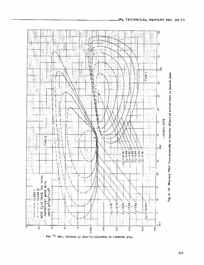
JPL TECHNICAL REPORT NO. 32-77
rr) --
5ep ' d^ 31_II.L 7VAI_EIV IV 3Sc11773 EI3_J,SNV_J. NI A7VIAIONV 3A_IJ.
o
oo
W
I--
Q
1-
o
.E
C
0
E
o
L.
o
3
Q.
E
E°-
>,,
DEoE
0
I--
c_?
°-
63

JPL TECHNICAL REPORT NO. 32-77
trr _!i' _T;11
!ifii T::I..,
it1- +_ !ftllo: [
tit "++*
,q{d
ft *!4
44_ __; 4J:;4:1
-t0 NOt73HIB3d
m
>,.I.--
0
"0
..¢
0
64

JPL TECHNICAL REPORT NO. 32-77
_o_o (_ (D (D I1_ i_1
tu_I Jo gUO!ll]UJ ,d_/ J.IENO N3--ISNV)-IJ. 30 NOl-'13Hlld3d
0
65

JPL TECHNICAL REPORTNO. 32-77
w)l _o suo!ll!LU ,o_/ I18_0 _3_-ISNVblJ- .dO NOI73HdV
66

JPL TECHNICAL REPORTNO. 32-77
D-
.C,.
tt_
_+tt_
t';
.,[
:!.
;!f
['S.L
.4.;:
/j
!:!
i J i
_÷._
rl
+,
!
,i
rl
:A
,it
iti,!*
"T
-rt_
-!!I t
f!-
t+
t'
--+
wx ,_o sUO!ll!W ,o_ J.IgSO bl3-1SNV_J. 40 NOI"I3HdV
"f[,tt
7t;
_+
i',+*
it,
-!
_r
!:
i;/
!/
::!.4 ::
i _! :i:i
[:[ :;:
... L;[-, !i;
,i, ,_
.... t,
ii: i4+_+ -.f
Ill I
T_,
_+÷i _.
tltl '[
[''1 ;[[
It_i ' li;;
I!! ::; t_: ¢.,..
::; i[: it:"tt ....
., ,i 2: t:;!,i, , ) ,,
..... t i,[
:/ [',
/! _/;
t':i! 4: II;.......... !;: .......: ;/: ...... _ + I
P , r
!ii :i ttll_ ..:i I!!!
:;[ ::_r i::
i]: ";II ;] [1
1 .... !'il
1 '
,, ii
t,, ., .... *
t4¢ ..... itII; ''ll
t! .... trt
_:: ;:i ',ill!II _'
;[I !;I ....
o_
o
,.C
e"
0
.D
w o
e-
Z '6"
__ < o•--J _
0
> ¢"
0 Q.
N"r
67

JPL TECHNICAL REPORT NO. 32-77
o _ o_ e,i
Tt
iu_
0
0 ffl
T2
' ,,+
" I !-= ;J_ "_i ':i+,
; /
:.. ] ._ :::.li _ :i_ • :/!! !i_-
i;," ii!
i_ ....... t.i!, .. 2 _?
• . _- i-i!i ::_..... i::_
i _::: I , , . ;J J;,7f1: _ "i' [
"_I'L ": i':_ ,,__i .... i:: ::i '"it 4!!" ,! I_ i!] ._ * "vC
!' ',lI_ [;_'. _,::; :[] "÷TT ]
[[! .... 1:i: : :I ;: .... :_-
TT! T717 ;A_] :A-: ;q-i _', '
iltt +< ti7
!!;:. ::: +-+x
r" :i:......... 17] ,i il,ii: ii+ ............... f,,
i lil!,I11! .........r;- _ _' '!l "r+...... FTI Ill
.... !t 'lll_++_ " +"+' - ' I::_+7 _ - I ! "'! ,,
rl _i!i ' liL. ::' ti" rrlo _ Q
6ep '/ 3NVqd I:I3-1SNVI:I1DII=IIN3DOI73H 3HI 30 NOIlVNI7DNI
_o
:il
M-
0
T_I =I
.iJ- J.-_ cii
::t ;i2 -_
:z:4V_ , "_--÷ _? T-- -- (E "--
i-r T I
+ H. ...... ::3 --
.J ,._
0
_;- .E-!_ -++;I: ....
!i:ii :>':
it_i ::ti _E, i , ,
:!:i- : m
:-::_M TI'.:;HT!'
"" t!tlD
1;ii /21 -,--UL;ti++::::
222_ i2
i_ili4.:
(DO
_q o
68

JPL TECHNICAL REPORTNO. 32-77
0 _c) 0 _ 0 _') 0 _ 0
Sap '! 3NV7d _3-1SNV_IJ. OI_IIN300173H 3HJ. 40 NOIJ.VNI7ONI
69

JPL TECHNICAL REPORTNO. 32-77
6ep 'fiSt 31till 7VAI_I_V ±V 3OnllJ.V7 7VllS373D
7O

JPL TECHNICAL REPORT NO. 32-77
m
I--
0
"0
..E_aE
0m
L.
=E0
_a
,.E
"0
Q.
.m.p.0
.I-0.
E
_0
La
(_
=E
I/3
M.
(M_D _- N 0 ao tO
N N N -- -- --
oas/w_ 'dqA A_IFI3_I31_OJ. 133dS38 HJ.IM (]33dS 31101dMISV
9
71

JPL TECHNICAL REPORT NO. 32-77
o
o
o
o
T0
O.).
I--
O
_a
o
La
=E2
_L
L.
I-
-0
O.
4-0
O.
E>.
,o
).
:3
:E
u
72

JPL TECHNICAL REPORT NO. 32-77
73

JPL TECHNICAL REPORT NO. 32-77
O
mB
O.
I--
O
-O
e"
em
{3
qJe"
.a..O
i,.O
u-i
e-
O
O.
-6:)
"__
o
noe-
a.l
O
Q.
E
O
°_
e-
O
Ee-
e-o_
EO
e-
}
Ill
t,.-
4:1
v
..-2
4O
I
74

JPL TECHNICAL REPORT NO. 32-77
O
o
75

JPL TECHNICAL REPORT NO. 32-77
o
9
0 00 0 0 0 0 0oa _ -- oJ rO
I I t
_ep ,d(_ 3/OJ.diN,i,S V OI_.i.N-:I3Oli_EI3H 3HJ. 30 NOIJ.VNI-I03(]
76
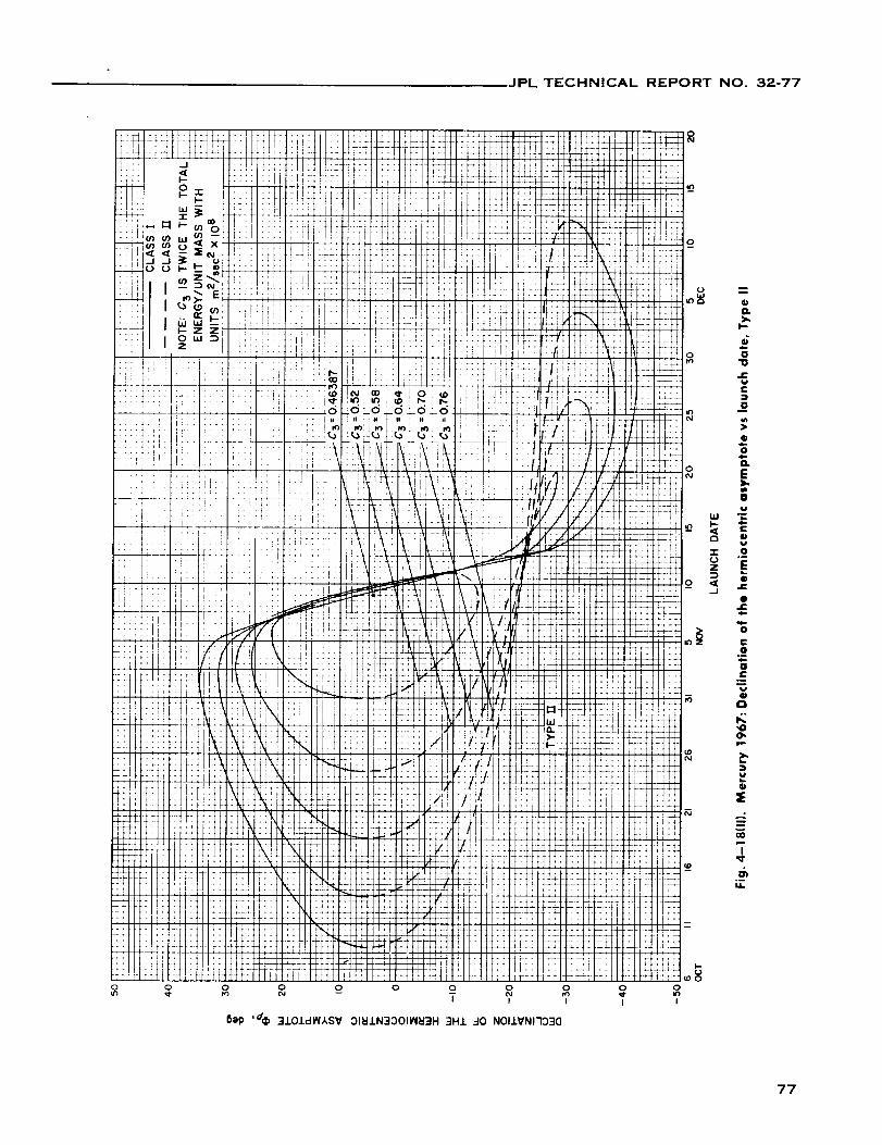
JPL TECHNICAL REPORTNO. 32-77
77

JPL TECHNICAL REPORT NO. 32-77
00 _ 0 _ 0 _ 0
BI@ 0de 3.LOldI_IASV :31_I/N33OIIN_3H :10 NOISN33SV 1H9t_
o
O
O.
>,,I-.
¢;
D
'13
?.-1
O
O
O_
E>,,
D
.m
I- =<t ¢)a u
0
J _C0
e-
ij
0
.r:o_
,0O,
Q.I
...2
0"
I
°DM.
78

JPL TECHNICAL REPORT NO. 32-77
F--
IF"
C
0
o
E
o
°-i.
_a
0
El-
t-o
_a
o
,o
°--_L
79

JPL TECHNICAL REPORT NO. 32-77
V. MERCURY 1968: TRAJECTORY PARAMETER GRAPHS
Figure
5-1.
5-2.
5-3.
5-4.
5-5(I).
5-5(11).
5-6{I).
5-6(11).
5-7(I).
5-7(11).
5-8(I).
5-8(11).
5-9(I).
5-9(11)
5-10.
5-11 (I).
5-11(11).
5-12(I).
5-12(11).
5-13(I).
Mercury 1968: Minimum injection energy vs launch date
Mercury 1968: Time of flight vs launch date
Mercury 1968: Heliocentric central angle vs launch date
Mercury 1968: Earth-Mercury communication distance vs
launch date
Mercury 1968: Declination of the geocentric asymptote vs
launch date, Type I
Mercury 1968: Declination of the geocentric asymptote vs
launch date, Type II
Mercury 1968: Right ascension of the geocentric asymptote
vs launch date, Type I
Mercury 1968: Right ascension of the geocentric asymptote
vs launch date, Type II
Mercury 1968: Angle between outgoing geocentric asymptote
and launch planet's orbital plane vs launch date, Type I
Mercury 1968: Angle between outgoing geocentric asymptote
and launch planet's orbital plane vs launch date, Type II
Mercury 1968: Angle between Sun-Earth vector and outgoing
geocentric asymptote vs launch date, Type I
Mercury 1968: Angle between Sun-Earth vector and outgoing
geocentric asymptote vs launch date, Type I!
Mercury 1968: True anomaly in transfer ellipse at launch time
vs launch date, Type I
Mercury 1968: True anomaly in transfer ellipse at launch time
vs launch date, Type II
Mercury 1968: True anomaly in transfer ellipse at
launch time vs launch date
Mercury 1968: Perihelion of transfer orbit vs
launch date, Type I
Mercury 1968: Perihelion of transfer orbit vs
launch date, Type II
Mercury 1968: Aphelion of transfer orbit vs
launch date, Type I
Mercury 1968: Aphelion of transfer orbit vs
launch date, Type f(
Mercury 1968: Inclination of the heliocentric transfer plane
vs launch date, Type I
80

JPL TECHNICAL REPORT NO. 32-77
V. MERCURY 1968: TRAJECTORY PARAMETER GRAPHS (Cont'd)
Figure
5-13(11).
5-14.
5-15(I).
5-15(11).
5-16(I).
5-16(11).
5-17.
5-18il).
5-18(11).
5-19(I).
5-19(11l.
Mercury 1968: Inclination of the heliocentric transfer plane
vs launch date, Type II
Mercury 1968: Celestial latitude at arrival time vs launch date
Mercury 1968: Asymptotic speed with respect to Mercury vs
launch date, Type I
Mercury 1968: Asymptotic speed with respect to Mercury vs
launch date, Type II
Mercury 1968: Angle between the incoming hermiocentric
asymptote and arrival planet's orbital plane vs
launch date, Type I
Mercury 1968: Angle between the incoming hermiocentric
asymptote and arrival planet's orbital plane vs
launch date, Type II
Mercury 1968: Angle between Mercury-Sun vector and incoming
hermiocentric asymptote vs launch date, Type I
Mercury 1968: Declination of the hermiocentric asymptote vs
launch date, Type I
Mercury 1968: Declination of the hermiocentric asymptote vs
launch date, Type II
Mercury 1968: Right ascension of the hermiocentricasymptote
vs launch date, Type I
Mercury 1968: Right ascension of the hermiocentric asymptote
vs launch date, Type II
81

JPL TECHNICAL REPORT NO. 32-77
0.85
0.82
0.79
0.76
0.73
0.70
0.67
0_64
0.61
0.58
0,55
0.52
0,49
0.46
0.43
0.40
Fig. 5-1. Mercury 1968: Minimum injection energy vs launch date
82

JPL TECHNICAL REPORT NO. 32-77
$,_Dp 'Jl IH917-'I .-I0 31_11
83

JPL TECHNICAL REPORTNO. 32-77
L)
o __D(M N
o _ oO4
_)ep '_ 379NV 7V_IIN30 ::)I_IIN300173H
0qr
84

JPL TECHNICAL REPORT NO. 32-77
w_ Jo $UO!ll!W
!:;: i_
'_
:i!i_
' !i
/!: -
il iii; [
'l ....
:i_ !i:!:\ ii
!i !_:!.. .i
.... _!
:tl, i,i_, it
,ii,1
iii'::i]1 .i
•:_!f
t!! i!14+.
rrr _!
,a_ 30NVJ.SIQ NOI.LVOINNININO3 _,_NO_31N-H.L_IV3
0
c-
O
t-
o-
C0
0
e-
EE0
I
otli
,oO,
M.
85

JPL TECHNICAL REPORT NO. 32-77
0
I
86
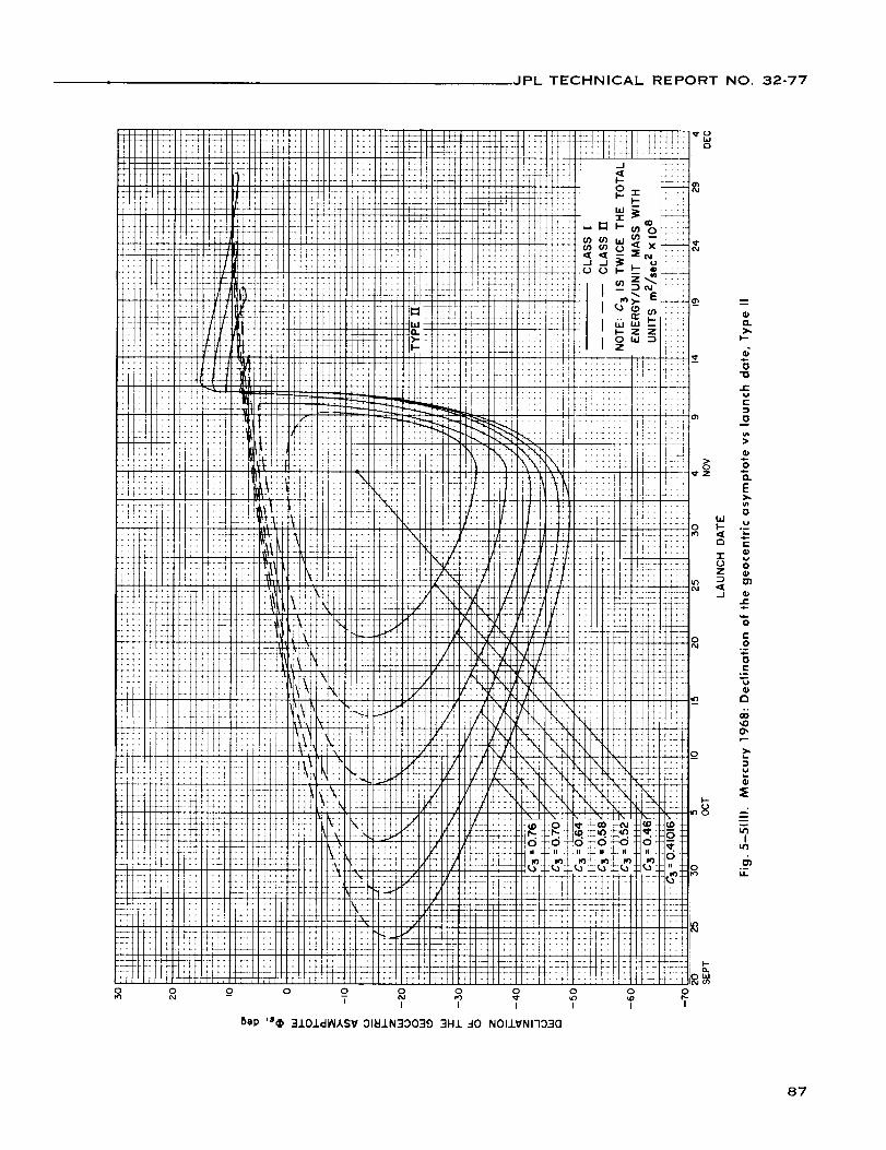
JPL TECHNICAL REPORT NO. 32-77
0 0 0 0 0 0
i I I I I
5ep '$_ 310.I.dIN,/,,SV ::)1_.LN3::)039 3H1 _-I0 NOIlVNI703(]
I--
n
I,-
61I=
0
oO.
E
0
I=
0
m
.j 0e-
E
O
0
Co--
O'
I
87

JPL TECHNICAL REPORT NO. 32-77
0,.
>.I,--
=
0
4-0
D,.
E
ov
0
i-4-
0o-
C
o
_J
...2
I
88

JPL TECHNICAL REPORT NO. 32-77
8lip 't o 3101dl_lISV ::)11=11N30039 3H.I. -10 NOISN33SV 1H91_1
9
m
O.
I'--
0
e"W
¢--
m
0
O.
E
==
c-o
r..
vu_0
01.m
"00"
=E
Iu'l
M=
89
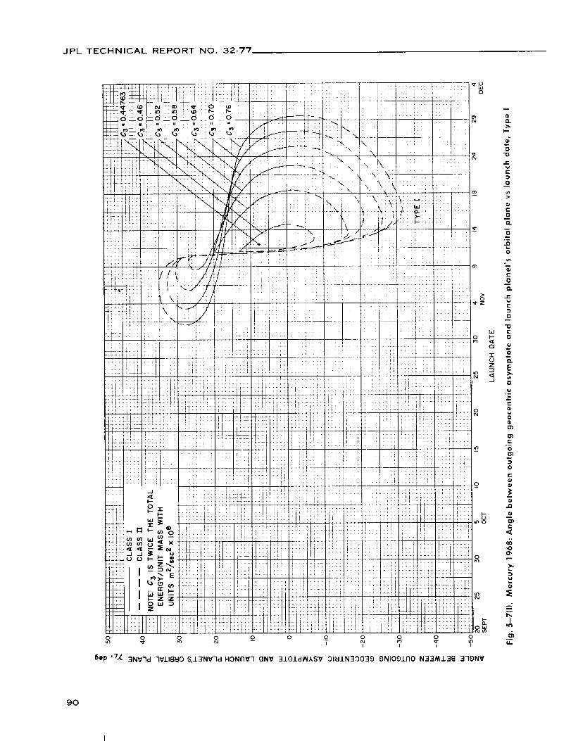
JPL TECHNICAL REPORT NO. 32-77
0 0 0 0 0 0 0 0 0 0 0
Bep 'TX 3NV7d 7Vll8_0 S,J.3NV7d HONrlY7 (]NV 310J.dl_l,kSV 01_11N3_)039 9NIOgJ.170 N33M138 379NV
9O

JPL TECHNICAL REPORT NO. 32-77
0 0 0 0 0 0 0 0 0 0 0
I I I I
6ep 'TX 3NV7d 7VlIBHO S,i3NV7d HONNV3 ONV 3iOIdMXSV 01_IN30039 ONIOOIAO N33MI3B 370NV
91

JPL TECHNICAL REPORT NO. 32-77
92

JPL TECHNICAL REPORT NO. 32-77
o o o o o o o o o o
o
o
o
o
hap ,7} 3101d_ISV 01_1N30039 9NIOg/No ONV _0103A HI_V3-NnS N33Mi3B 379NV
O.
)..
4,.0
70
I-_at-
O
0
CL
E).
v
_a
0
O_
0')
C
Q _
0I0 _
Z t,-
_ O
t-
O
Ic-
r-
!
e-
eli,o
.-2
I
°-
93
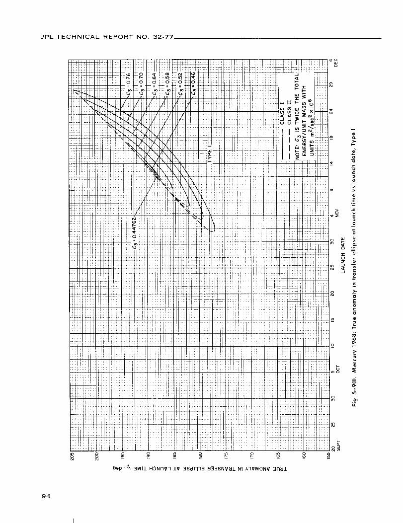
JPL TECHNICAL REPORT NO. 32-77
I_p ,7^ 31_11 HDNNV7 lV 3Sdl773 _3-.ISNV_IJ. NI A7V_ONV 3A_J.
COo
>,
0
"0
r-
t-
O
E
Q.
c-
O
e-
>,
oE0
0
:3
I--
,oo,
O'I
u-
94

JPL TECHNICAL REPORT NO. 32-77
15ep'-/^ 31NI1 HONrlV7 lV 3Sc11773 _3..-ISNXtEII NI 17VlAIONV 317_11
95

JPL TECHNICAL REPORTNO 32-77
96

JPL TECHNICAL REPORT NO. 32-77
o
bJ
Z
.-_
J
{2.>.
O
e-
C
0
i.O
i,'-
"6E0
c"
D,.
0",
,.-,2
°--u..
97

JPL TECHNICAL REPORT NO. 32-77
o
0
I--
o
uJ)I _,o sUO!ll!'" '_ 118_0 _I3_-ISNV_I -I0 NOI-13HI_J'ad
98

JPL TECHNICAL REPORT NO. 32-77
_tr
+..
l I
ii i,,:i!i
'.ii
Tttt
rlt
111
IIi
+,+
,ii
_+-+-
t!"
ii?
tltl
cu_l_.o _UO!ll!_ ,o_ 1181:10 EI3-1SNVEII -10 NOI73HdV
99

JPL TECHNICAL REPORT NO. 32-77
J,,,l"lll'llli,: !Ii"" '" 'ii Ht_ iiIlL I1[[11 I
n_j [I/IELIII[III
-J i'
o = _:b:iiiiii'_ill
,_ _ ,, Izi:tttttttt ..... ii_*,,,,..(_1 (/_ UJ - -- _'[!{;!_!!!;!!
--!_11[ ql_ -- dill ITFTIGTETF_Illi_iiii
::d, d _ _ J __'++tLJUJ',',:i[
..+ .,_>. E _ i]liiiiiiii,
,_- I.- Z Z J-_ _ .... _! .....
P -- I 0 _ _ t_ ; --, --i --i --, _ I : : : II
r-_ I Z ]JJi/L_ ' H I -_--- 1T'F1qq_qT-,Ill,<!! ii
...... 7-:: _:::: __,. _-'-
,,Jill I, ,[Ui,J .;_1] i i i i_i i__ _ _ ;_:. i_
....... -t4-1-_ !/fH_, i-H- 'iIIiil JIl[ll [I '_ ' i i i
-- I lllll[lllllllllll IIII11111i!llii_/_il,........ ,,,s-H
Illl I11 I III!lllllll![/[/I
ii IIIII I] II/l_.Jlll I1_11 IIIi II I]l],/
I I IIIIIIIItllllllllll Iii[ I- LL Illlllll]ill IIII[1 i_ ,
:,:,_i , ......_-_
-_._-!H!_ .r++H.ii-fi. t_-:; .-.,i'
I[II l-t_bftH-l+ffr II]LIILViiiii_iIII,,I _llll]ilb[
IIIIIIIllll]l]ll_[
_1::1: ,a_,_,[,l[]L-I
Illl]]lll[llll#l
I'- [ IIIIIlill_lllli_il
_ -___T_EITIII.KII.i*"I#IiI
ILIl[lll._.dr'lJ[llli t
II I A,_'FI'_'ll ...... If11111t"'II ........ IIIIII[
L ....... iiI....... ,II llllllI lIITIlILll IILILI
llljlltIllllililll,,,,_,llltllilllll
IIII ..........
_ _ _
ii #is4 !ii'I7 iIITFTTltTm , :_
¢_._ L 2j.4 ] j_ l I L.4_'T i I I I I I flkllll,[
!¢4k¢;!i_!-i_ 4g_I',IU_Li!! !ii!_',!i!i lJ,44 4LL +_-FTqTI-FrTr_
I:?;::. "1;_[![1 I_r!?711_ ![!!Y_'1_
.... .4 .,-{2J_-'J *j_''_ ! LA,4"'_! !" !!Ik _II
: : ', : ; _ : ', ', f ',= _ , r i ; i i _ ;;11li;ii flail i: _lI i ttt _ i;Z, i ;_
::llllll!lllllll I I 1711ii i ih_li 'i iiiiiii, ,_ffL_Lr : 77--;d;'.r_ I lIi_GJr-r-H-JI I lilT[ ! 7i] #1!J i T!II L# "[ /
:!:i ..... l[4+_ +T-4# !' ; ; i ,-"I_I" _,_ !!+._+ t - - . • _+t_i_f-,-,-.-.-:-¢tt_.-.- : :_ : I '_ t : f ._,t
li_¢ri_i; j _(f 4 ; :t {,'i i i i_',i',', :*-: :I :I bb_ g 4 + - t _i I ; i ' i71 ii t_f
I , '+F. t, ' f _,'i _: -Jr:' ; --fL-
.°" +o_,, .... ,,.... _- +_
: i]i
_'_ "-- i ] r r_l-I ]_,l-P I-- T- ..
i _ rill I I I I I v __,__
Li _,::L',_, ...... :_ ,it ,r.i l_rTi rTt'-t 2::_!£ la._ 0
I/ll[i fJlT _ 811_[
i ' ,i:t i_ q i,: :t ___:LL_L N t ...... <[
,i,._,+_-.- _"_!t _- -*'_ .......... <_7!::;i! ..;j o-
',_' >,i, )i:J [12_-: ..... ;
"TI,,¢1
+--
:!t!
.... ii!i I iTTI'_*T:I:
_, : i!
' ii -i_ _ _ o
ulN to lUO!ll!UJ 'oH .LIEEIO tt3..-ISNVEI.L ..40 NOI-13HdV
I
i,
I00

JPL TECHNICAL REPORT NO. 32-77
O
!i! !i!tiiii ]!It :::
]
_ _u_!t: iil
' '!1":;: '_I _:'/ _222' : r "b!'l
ili : I::/_ __.....,, . ! ' .j
I i: ;iii ........ /'
:N ...........
!i/ :!! ..
.. ._4r X !::
.... 2,_'12_2L ' , :
ili _i_-:i!!!!!! ii!5) _;-:-I ....ii_i_ il I!::: ' ri
I !l !
iii::., !::41!1i; i]iltt !!:
4: .... I_iill _-.
' rfittrlt! "
... 12 tl! .... :![::: ;:i iI tli! ;_i+-4--4-4-_ ' , ;
!L_ it_l:i::l ..... !!r'r
;!} !:i i:::1 .......:!: !!! ?ili i!i
!I r •
.:; t!iIl:_:l .... if!
• '_ *_} .... I'r'! 'it
;ii 1,2" 'iiii _.,
i i i 4, t _ i _ i i i i i , , ,
_*1_,,,,!litfifttlti!
!_ tc:!tttt!!T¢ • ;;
'_ !?itf{Ftt......._j; ,f_._tt.tft]_: : ttti
!!J
t,! : !iTi _{_
I',,.-
t,"
2A_
i.sk
ii.
'i.1
I ; J ,
!f:!i iii_ i_::I li i, ....!!1. t t! :;.;: r ,.......
_i, ii!i :!ii
ii!i . ,:ii ::i:
:::: !, :
.... _i]! tii:tl,l ' iili ,_-+4+_ ;4*"
:::: ti!i
.... ii _" ::::::T! ::it"": t 1]:: .-;i:::: [ i!:: ::::
" t ];!_ ::iif;+i tf_: "_t!
iii ..... !;:it:,r t ];ii ':!:_ m
4
i :! ': ::i ! _;': ......
-4-
..4_ffT:
\: _!_,} ,
...... -t
_o o:d d u,_r :]
e,')_ li_ l_"eq l_I! eq 0 -
i I .... ii:_i.,
i ,, I1,,! g..... ifi:l::;." ::
........... r t ]I:::!L: i ;..
l:i i
!!!!iii ft fl .._
it][I .--
4,4i ...
iJ!: '_
• ti!
:::.i t!t
i ÷+÷
iil!t -,..... !
t11ili :::
i;_ii ._-
:;;::]i :::
_i; _'rtt_l! ....
ttl';_:li:T': o_
_ep '/ 3NV7d _338NV_1 OlBIN3OOI73H 3H1 40 NOI±VNI3ONI
I
O.
>.,I--
0
e-
r"
0
r"
0
O.
o=< .__
r-
¢-,,=.
oe-
o
¢3
E
Ei
o_,oo',
o_ >,
'Tu'3
M.
101

JPL TECHNICAL REPORT NO. 32-77
_ep '/ ":lNV7d _I3_-ISNY_IJ. OI_1N330173H 3H1-I0 NOI.LVNI73NI
102

JPL TECHNICAL REPORT NO. 32-77
103

JPL TECHNICAL REPORT NO. 32-77
oe$/w_ 'dq/lA_IFI3_I31_I01 133dS3_I HZIM (333dS 31101dl_IASV
104

tPL TECHNICAL REPORT NO. 32-77
I
105

JPL TECHNICAL REPORT NO. 32-77
o
_o
).-
0 0 0 0 0 0 0 0 0 0 0
Bep ,d_. 3NV7d 7V118_10 S,.L3NV7d 7VAI_IaV QNV 3101dINASV 31_lN3301tN_3H 9NIINO:)NI N33M138 379NV
106

JPL TECHNICAL REPORT NO, 32-77
0 0 0 0 0 0 0 0 0 0 0
o_p ,d_. 3NV7d 7V118_10 S,±3NV7cl 7VAI_I_IV (]NV 3101¢IINISV OI_I±N3OOIIN_I3H 9NIINO::)NI N33_138 379NV
107

JPL TECHNICAL REPORT NO. 32-77
o o o o o o g o o oo _ _ __ _ _ _ N
bep 'd_ 3101dI_ASV 31_1N3DOI_I_I3H 9NIItIOONI ONV EIOID3A NI7S-A_n_I31tl N33M1.38 379NV
m
O.
I-,-
O
E
0
O.
E
0
v
E
0
E
,,, EI-- 0
,r-
U ,r'
Z 0'7
>
I
E
iI/
..{2
E
,<
O"
L.
h.
"7
u.
108

JPLTECHNICAL REPORT NO. 32-77
0 O
109

JPL TECHNICAL REPORT NO. 32-77
-t;l ;
r_ff
t i__l !
_ !!i!:i
"+- T" L.,,
ti .... .
..... \:
_+_
,t .....
, i,
• \[ : -
::._4 [
Y''_ !-- _2-i x
! .... !
ii[
} ::::t%:::
1 •
] ''
;&li t
:i_i ",Xjt
• N
• _!
]i f,i-
: 221: iO_J
O O
ili': iT:-:;;14;, i :::,i :-
rll "_iii i ....
............. l:::: :!i\ t___.ill . _:T',_ ! ::
!1i !, : ,r.:',;,:',: . •!
:"[ :::;:; " r):',!!ii : .i: =
:il :_:_ _----...:::i _ : "'_]ii i_
,i, _
;'' .1_ ; _ '_ _"'" :t:.r/ttt1
........ 4;! .... _;f+
:_ii .... Jil :-.:Ii:;:
-rt
'" ....... _" : .... '• 1!i i!!ifit!ii
it_: !_tli :_ _,_ ,, ,, :;;itu"i} _ ....... ! _t, *;_i i_.-:
'!!:: ::::::t ]!! i :-_i; ..... ill ' !'!; ":_t i*; TTfit_ffi*"
i! ' :::: "''T !'' tt4%f!ff?
i.-- 'tti ...... :_ J!: ';;_+; ....
i, 4+_" ::::_T:" T!1 it: TTriT!:"
5 .....'"' :i................................... II]I!:iT! i]ii ........,,, ,ii i:1 _,
!t:_ i :!:I i:::::: t I1 !*'1-
::: , : .... :it ::-0 0 0 0
i I I
0_,00,
o >,-.i
¢1
"T
I.L
I--
0
I
Oep 'd@ 3101dI_11S_ 91_I.LN39011aI_BH 3H1 _-I0NOIIVNI70=IO
110

JPL TECHNICAL REPORTNO. 32-77
111
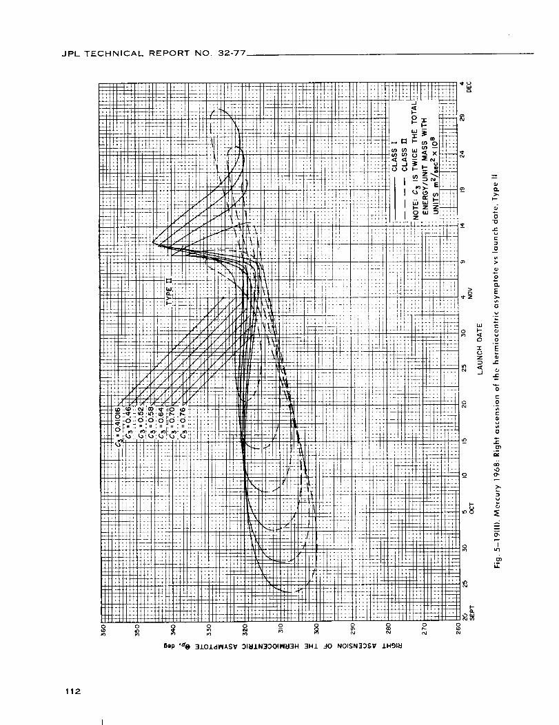
JPL TECHNICAL REPORT NO. 32-77
0 0
112

JPL TECHNICAL REPORT NO. 32-77
Vl. JUPITER 1968-69: TRAJECTORY PARAMETER GRAPHS
Figure
6-1. Jupiter
6--2. Jupiter
6-3. Jupiter
6-4(I). Jupiter
launch
6-4(11).
6-5(I).
6-5(11).
6-6(I).
6-6(11).
6-7(I).
6-7(11).
6-8(11.
6-8(11).
6-9(I).
6-9{11).
6-10.
6-11(I).
6-11(ILL
6-12(I).
68-69: Minimum injection energyvs launch date
68-69: Time of flight vs launch date
68-69: Heliocentric central angle vs launch date
68-69: Earth-Jupiter communication distance vs
date, Type I
Jupiter 68-69: Earth-Jupiter communication distance vs
launch date, Type II
Jupiter 68-69: Declination of the geocentric asymptote vs
launch date, Type I
Jupiter 68-69: Declination of the geocentric asymptote vs
launch date, Type II
Jupiter 68-69: Right ascension of the geocentric asymptote
vs launch date, Type I
Jupiter 68-69: Right ascension of the geocentric asymptote
vs launch date, Type II
Jupiter 68-69: Angle between the outgoing geocentric
asymptote and launch planet's orbital plane vs
launch date, Type I
Jupiter 68-69: Angle between the outgoing geocentric
asymptote and launch planet's orbital plane vs
launch date, Type II
Jupiter 68-69: Angle between Sun-Earth vector and the
outgoing geocentric asymptote vs launch date, Type I
Jupiter 68-69: Angle between Sun-Earth vector and the
outgoing geocentric asymptote vs launch date, Type II
Jupiter
launch
Jupiter
launch
Jupiter
arrival
Jupiter
Type I
Jupiter
Type II
Jupiter
Type I
68-69:
time vs
68-69:
time vs
68-69:
time vs
68-69:
True anomaly in transfer ellipse at
launch date, Type I
True anomaly in transfer ellipse at
launch date, Type II
True anomaly in transfer ellipse at
launch date
Perihelion of transfer orbit vs launch date,
68-69: Perihelion of transfer orbit vs launch date,
68-69: Aphelion of transfer orbit vs launch date,
113

JPL TECHNICAL REPORTNO. 32-77
Vl. JUPITER 1968-69: TRAJECTORY PARAMETER GRAPHS (Conrd)
Figure
6-12(11).
6-13(I).
6-13(11).
6-14.
6-15(I).
6-15(11).
6-16.
6-17.
6-18(I).
6-18(11).
6-19{I).
6-19(11).
6-20{I).
6-20(11).
6-21(I].
6-21 (11).
Jupiter 68-69: Aphelion of transfer orbit vs launch date,
Type II
Jupiter 68-69: Inclination of the heliocentric transfer
plane vs launch date, Type I
Jupiter 68-69: Inclination of the heliocentric transfer
plane vs launch date, Type II
Jupiter 68-69: Celestial latitude at arrival time vs launch date
Jupiter 68-69: Asymptotic speed with respect to Jupiter vs
launch date, Type I
Jupiter 68-69: Asymptotic speed with respect to Jupiter vs
launch date, Type II
Jupiter 68-69: Angle between incoming zeocentric asymptote
and arrival planet's orbital plane vs launch date
Jupiter 68-69: Angle between Jupiter-Sun vector and incoming
zeocentric asymptote vs launch date
Jupiter 68-69: Declination of the zeocentric asymptotevs
launch date, Type I
Jupiter 68-69: Declination of the zeocentric asymptote vs
launch date, Type II
Jupiter 68-69: Right ascension of zeocentric asymptote vs
launch date, Type I
Jupiter 68-69: Right ascension of zeocentric asymptote vs
launch date, Type II
Jupiter 68-69: Angle between Planet-Earth vector and
incoming asymptote vs launch date, Type I
Jupiter 68-69: Angle between Planet-Earth vector and
incoming asymptote vs launch date, Type II
Jupiter 68-69: Angle between the planet-Canopus vector
and incoming asymptote vs launch date, Type I
Jupiter 68-69: Angle between the planet-Canopus vector
and incoming asymptote vs launch date, Type II
114

JPL TECHNICAL REPORT NO. 32-77
103
I01
99
97
93
91
89
87
85
79
77
7518 23NOVEMBER
Fig. 6-1.
28 3 8 15 _8 25 28DECEMBER
LAUNCH DATE
Jupiter 68-69: Minimum injection energy vs launch date
2 7JANUARY
115

JPL TECHNICAL REPORT NO. 32-77
0
o0
o
116

JPL TECHNICAL REPORT NO. 32-77
':_ I _ t_¸ i_
0 ........... _
(n _ =EN ::: ]:: ii:i :
: (!ill ,,l``;il _!;_fill!;_,; 't ; x_
i i ! 1 _ !t \
i: 1 Ix \ \1 \:i _ !\ +:\ _L::i-_-i::t
0 0 0 0 0
('J I'M
_ilp '._ 3-19NV -lV_IJ.N:I3 311:IJ.N3::)OI-13H
(p
{3
13
JE
(-
{3
01
(-
0
z(3 @
"r v
=o -i.(-
vo
-$-r
6_,o
I
,0
D.
{,iI
,o
6_I,l.
117

JPL TECHNICAL REPORT NO 32-77
uJ_l Io suo!ll!W ' 3_ 30NV.LSIQ NOI.LVOINA_It_tO0 _3.Lldrlf'-H.L_IV3
118

JPL TECHNICAL REPORTNO. 32-77
o _ o o o o o o o o o0 0o _ o _ o _ o _ o_P _D uO u_
uJ'_ Jo UO!ll!UJ ' "9(V 33NVISIC) NOIJ.VOINAI/_I,_03 EI3J.IdnP- HI&IV3
119

JPL TECHNICAL REPORT NO. 32-77
Oap ,s@ 310J.dl_l,kSV 91_J.N30039 3H1 30 NOIlVNt7930
120

JPL TECHNICAL REPORTNO. 32-77
0 0 0
Lf
7_
+i
i[
4_
r_r
t_
i
it[
i
]'
:i
:il
tll
!!;
!'!
i:!i,i
_t
Bep '$,@ 310.LdI_IASV OlbllN330_O 3HJ. 40 NOII_'NI70_Q
121

JPL TECHNICAL REPORT NO. 32-77
t i l,i.,,i, 1 -.._ _,_,.....,.......,_ _,_ ......, ........._ ...........:: i [ • _#i _--. _i _ I !! ..... :'+ _:-- ;i_i 4 - -: ... l:il Ttt7 ::.. :!'1:i .... ;_ .....
; ''i '; . . ! :_ _ _ i: i., ..' _ .. : : _J.. .L i : ' i _ :
ii:i,:::_t!i_ iill if:: _!! iii! _t i:: ! i:i i:__:_:
ill[ : ! i : : : : : ! ; : [ '_f_ '_l_f) l_'_ i t_:: :t_ t; :!I:/::_X i _4" ,:_ :::t::::_::::t ii ]i_:: _
: ' ": _i ' ...........
t,:qI IIli.... J .J_ ::3_- .... ; ...... r : ................ I _ " 1 " f" : ":_::_ < _ _ _ ::: ::::: : : : :::: :::: ::: :::: :::: : _,:',: ::: :: I_*,i::7:
.... O0 _o _" E .... " " ........ .... r ..............
_Iiiif:il' _t'1tli:,t1 It I I_t, ".iii_;;:ti_:_:_iii:_I i!ii)it?t_,1I :t::: i it ;0 O 0 0 O 0 O
Oap's e 3.LO.,LdlNASV 318±N33039 _-I0 NOISN33SV IHglkl
m
>.I,,,.-
0
E
0
>
0
E
0
{::
0_a
o
..L:
c-o
e-ill
o
e-
N'0
I
,0
°_
..-2
I,0
122
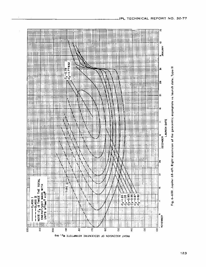
JPL TECHNICAL REPORT NO. 32-77
6ep 'S'IBI 3101dlN,KSV 01_1N33039 _-I0N01SN33SV 1H91_1
123

JPL TECHNICAL REPORT NO. 32-77
o O_
>.k-.
0
"O
J:
r-:}
0
OJ{-
0
O.
"5.el
0
C0
0..
.E_ai-
0
"13
C
0tlJ
"6
0
i,a
¢:
0
O_
01
C
D0
¢..
E
!
C
,<
,0I
,0
O.
..-.2
I,0
M.
124

JPL TECHNICAL REPORT NO. 32-77
(D
t_
O_Z
o o o o o o o o o o oi I I i
6;)P '7'X- 3NV7d 7VI18_0 S..L3NV7d HONRV7 ONV 3.LOIdI_ASSV :31_J.N30039 9NIOQJ.FIO N33M138 379NV
125

JPL TECHNICAL REPORT NO. 32-77
o o 8 _ o _ o-- aO {D 0 0
6ap ,7._ 3101dlNLSV 31_1N33039 9NlOglno (]NV _IOJ.O3A HJ._V3- NtIS N33,_I3E :ITONV
126
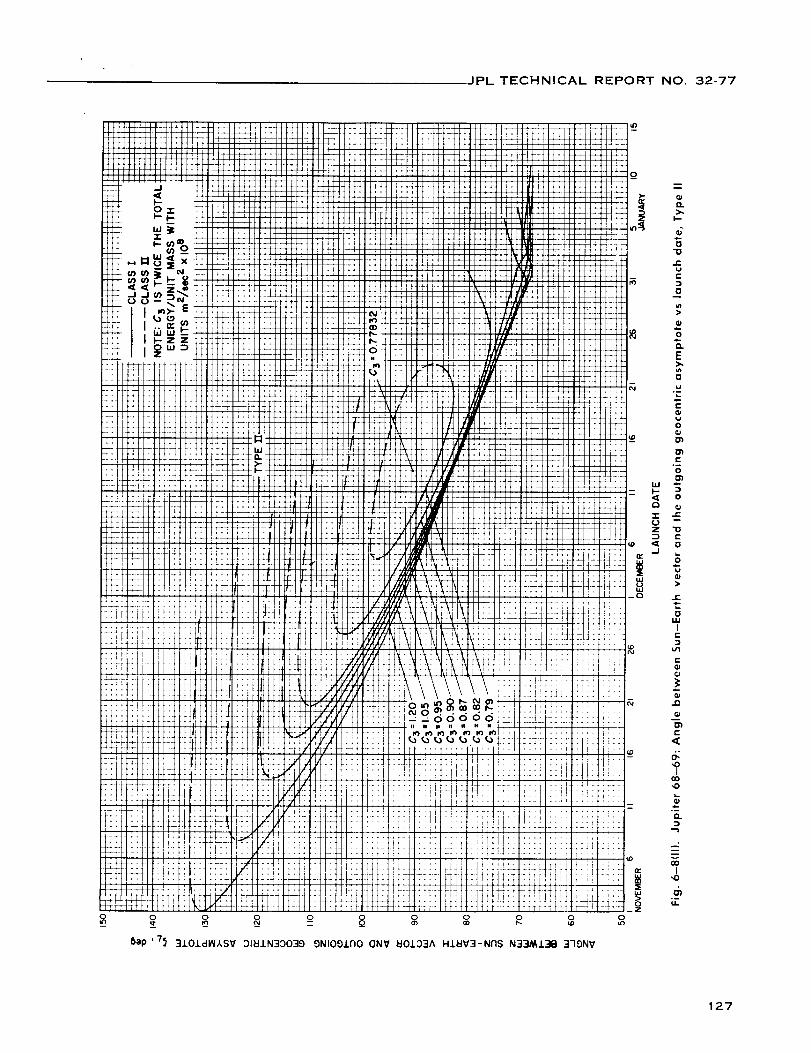
JPL TECHNICAL REPORT NO. 32-77
O.>..
I,--
o"
0
r.v
l=.-m
0
,$m0
"1.
E>.Ill
0
w
e-
v0
E
001
._ 0
Z "O
.J
u
>
i11
IE
e-
r"
<
,0I
,0
Q.
I,0
u.
127

JPL TECHNICAL REPORTNO. 32-77
:!:i
it*
,,.
{)ep ' 7^ 3MII H_)NNV7 IV 3Sdl773 63:ISNV_Jl NI A7VI_IONV 3n_11
td
Td
ii
L.-
sL;i
Tt
b
-4
+t
t±
:÷
4_
4_Ii
T o-
, ÷÷
_+
I[
¢-4
1¢!;
''t
!!;
I
!*
+.
44
tl
_-.I:1+++-i
14 "1
_dd:Izl
*;4
;' NI
I --
";I--
_xz_:zZ:;L li e
:/t:
":: g
tL];
¢i::42L2
i l
4-.
::a gill _Z
e_
o
e-
c-
O
E
¢-
W
OZ
c-
O
@
D..
e-
c-
O
EO
e-
k-
,OI
t
....2
O"I
,o
128
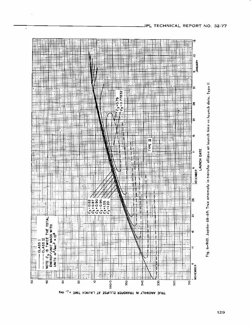
JPL TECHNICAL REPORT NO. 32-77
Bap ,7^ 31_II1 H3NNV7 £V 3Sdl773 EI3.-ISNV_J. NI A7V_IONV 3Flail
129

JPL TECHNICAL REPORT NO 32-77
130

JPL TECHNICAL REPORT NO. 32-77
g
]1]][IIIIifill IIittIIII III ......
llll IIIIIII]IIIIIIII III,.,1tt
IIII I]111II11
IIII III '_ .....IEi_lll
II:I IIIIII_],,....Jiii_
li,, :I:: I:I:II ''''_,,,,_1 ilil iiliIJlili_
" i!!!.,II IIIIII ;ilil lillii _
iJ.... II IIIIIII,,,,....H-_IIII IIIIIII,.,_....
EIl_lI f_l_iliJr_
fl,,,ll,,,, lllllll,,,,,,,i....
II1_ ,,Jiiil_|il
I]]]I]ll
] I I [1111IIIIllllllIIIFIIEIIlll[l
[IlI:Ill]lillII El
÷_t_IIII
+J_44I III[111
IlllIIIIt111
IIIIIltl
IIIIIIII
I1[
IllIllIII
FHH
I
I
h .............
i ¸ .... <__
i I_ ..... LJ
0
[2 ...... m -
._
Ii
i
' i
i I
.... li,,,,IIIIIIIII Itllttiliiiii
........... IIIII
..... IIIIIi:II..... i II,,,,,.IIIII
[lll[I
ii ........II IIIllll]lll
Illl O II11II1111
I]11 o_{o!!.. III.,,,,.............. litlt**ii....°°"II II I1 III t
t_ t_:l I:I ..... IlllIIIIIi _l_ll]lJ i........... III,,..,,I]I I [ ] i I I I ]l_JrM/ ll[llfllll]llll Ill[Ill11tlllllIi/_-4 IIIIllglllllllIiIilll_l
l{{"_,h,l,,, l_llttt'] .... !i
I I ] ]i_M'l i
.... ;i{iiiiiIIIII]I ..... I,l :l.,tI Villi [ 1,4 _l_
[[[l[]illili][I
II II _11 I ]1111bl....... [ I II _ III I IT11 .
#']#1 [1 i
H-_t-Ft...... II " "oIIIlllllllll]ll II :ii_
.... il !I °II1...... lll llll _"_ II I]tl! ...... !1,.,......... _ iii il_t -Ilff::l r ] Ill [[I i --
INI/II I i I I II [ [J_ ."l_i
.... IIIitl t_j...... !!!!!! "/1'1 _11 I I [,4'-!11 J I I,, ' I I i..rl-[ fl [ [_'1 11 ] I I L_ IAJ i II 0
_'[/i I g,_r] I III ] IJ,,'_r] I_1
,,............. _- , _"'*:'_""ii Illl '.'.............. : IIIIiii .... =
'........... " !!iiiiii°_111_! I ]_F] I I I , :
.... ]iiilIlll _= "_.... ii II ''_[11 _
0'_[ III I I I
_j "! [1 l] I1 II I L
,_,_,H_ ijl_-.--.--.-.-.,-,r r::il_ _.,-,,-,-..-_::_._:.,, _,l,llllllliL_!lllllllllllll J o=............. !_:::-:;:-;-:-!! +=----.... !!i! """!111[I-I_H_H_FHFH_HJ_! p ............ , T_- _ :m_-,, "
Ill ]1 :::[ [.
..... _ -:4 ;....... ' ;4
ill i i , i / , [..T-T.I T • ] --L _'_
,,, ,-_, __
i l_ ,ft:{_ _:: t_Ttt TT7Pt-.t' ' :l : : : r,,.,%_ ?: :!_!;
l_ I- i.- . _4:::F::: :_:-_z_-l-- ,_j' _N _: _::_ : I:_
F-ZZ _ _r-,
zo"'= ff +_
",D
I1:
ltl:f
_90
1_1 io sUO!ll!tU 'dt;i .Lli]klO H3-1SNV_IJ. 30 NOrl3HIH3d
131

JPL TECHNICAL REPORTNO. 32-77
Jill]111II1tIIIII[11[Ill
M44:ill
!!!!
!!ii
JJJ!
JJJi
iiliilll!!!!
!!!!!!!!
!!!!
!!!!
iiii
!!!!
iiii
!E!!11:i
iiii
!!!i
Ji!!
iiii!!!!
iiil
!!!!
iiii
!!!!
iiii
JiiJiiii11:l
Jiii
iiiiiiii
i!!!
iiii
!!!
iiiiii
iii
Jii
iii
0
Ill[lIIII1II1(IIllllII111IIIII
H+H-IIIIIIIIllIIIIIIIIliIIIII
!!!!!
iiiiiiiiiiiiiii
iiiii
!!!!]!!!!!
i_i!!
iiiii:::ii:::..
_!!!!::::i;;;;,
!iNi
i!!! _
iiJ!!
iiJJ::ii
:::..
!!!!
iiii
!!!!
iiiii!!!!!
::iii:::!!
_iiii
!!!!?
IIIII "11
IIIII IIIIIII "
I_ .I(a _ x:
W W L'_-"
iiii iiiii
IIII IIIII
IIII IIIIIIIIIIIIJl
I|'''
"JiiI|
"lllI|
"lllI|
I,ll II|
"IIII|I!,,III!!!!!
!!!!!IIIII
|1111I1111IlfllIITII
IIII
IIIIIIIIIIIIIIII1[1[IIIII
:::::
!!!J!
iiiii!!!ii
ii.iii11|11
iilll!!!!!lllll
!!_!!
IIl|ll
!!!!!!
IIIII
!!!!!
illll
!!!!!
lilt]
!!!!!!
]lIllIII[III
IIII'I
]fill
IIIII
11111
lllll
IIIII
4444&ilii i!!...
II[liJ|ffl
!!!!Y
IIIII
!!!!!
IIIII
IIIII
IIIII
lllll
IIIII
IIiiii
IIII'I
lllbl
IIIII
III_IIIIII
IIAIII#III
ill_lII[li
II--
II
IIII
4-1
-+-t
1:[!
11
!!
:!!
!!11
II1111
ii w
ilII
" _
II
_J
il-
ilI|I|I|III|III|
I|
i_i
¢-
t-
0
E
e"
0
%e-
l
,0
....2
m
"T"0
ix
132

JPL TECHNICAL REPORTNO, 32-77
o
ooa
oO
oa0 8 0 0o o o
o
0_Z
o _ oo o
0_
-0
_C
r-
D
0
.Qb.0
E
0
r_
N,0
I
n
,,0
u.
133

JPL TECHNICAL REPORT NO. 32-77
O O O NO O
'"_IJ,osUO!ll!i.u,e_ .I.18UO _I3..-ISNVU.L..I0NOII3H(:IV
134

JPL TECHNICAL REPORTNO. 32-77
-J
Eep './ 3NV-ld EI3_-ISNV_I10I_IN3C)OI-13H 3H1 30 NOIIVNI-IONI
135

JPL TECHNICAL REPORT NO, 32-77
NOIIVNI"IONI
136

JPL TECHNICAL REPORT NO. 32-77
o
6ap ,d_ 31_1117VAI_V IV 3(]rtlllV7 7V11S3733
0
0I
137

JPL TECHNICAL REPORT NO. 32-77
iiii
_L::''i
__+
i t
++
_m
.;_J
-I
3eSl uJ_
.... ;T
":'-:'T ....
1[_ ttt'
__i! !, :
ii! !k '_
! 'I
1:1 :!_
_+ fH
,i: :lit
Xi: :i!+,';,: :7;:
iii iiii
i-!!llfP
, ijl
:!i
:: I: ::_::_'_<'I "
.... L t
_L : .: _i!_,,,q i!
iil[ii!i!i::i/:/._:xti
!ii :_-<
< .-"T" _ *_ 4 i::: ............. iI_ t!
t:: ,,,rlj_;1tti!T :][_:, .,i.- _- :I_TJ]TT]Z;:: H+
.......I....I.......::._i.: Iiii '_ f'_J.*_71:ii:: :i:.'TT :ii
'+:i .......... :+'+ :-+!:i:t- !fill:; lriil!I: .+,,....: -
t+,t [tXt _:-t :4-
' dqA _311dnr Oi J.93clS3_ HIIM a33dS 91ZO.Ldl/4ASV
'!-
!:!_T:z
:V TT
7._.T
{!::
i,
_:::
::::
:!1!
: ::
4--i
:
u_
0
: !
_: 7::
..... (.o
i::i
i ....
!:!:! =
t4.._,I
i_! _§
'TL)Z
_J
iI
o
t-
0
>
Q.
t-
e_
E>,
,oI
,0
....2
"7,o
u
138
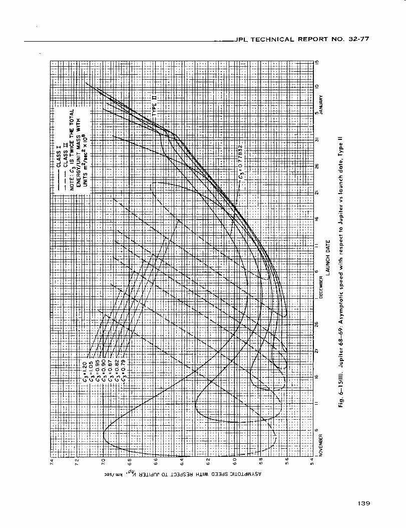
JPL TECHNICAL REPORT NO. 32-77
9
Q.
0
712
v
r-
;2
,-Q.
o
Q.u_
t,o.m
0.
E
I
,0
"r,0
o-u
139
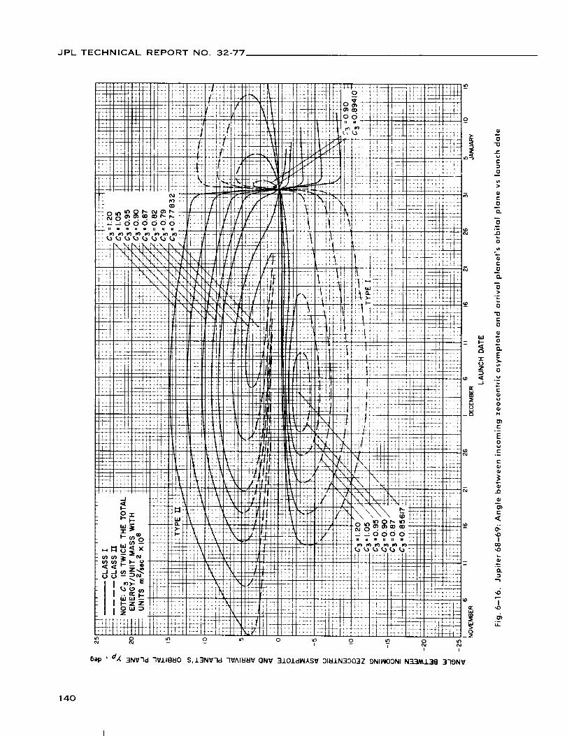
JPL TECHNICAL REPORTNO. 32-77
9
i II I
bep ' d,( 3NV7d 7V.1.18_10 S,.L3NV']d 7V^I_I_V ONV 3.1.OJ.d_,SV 31_.I.N3303Z 5NIINO:)NI N_]/_.L38 3"IgNV
0
0"0
¢-.
C
0m
0,.
"5o-..0
0
t_
t-
O
O.
0>
0
r"
0
E)..
¢.-
O_w0
N
r-.m
E0
E.-
E
!
C
<
,oI
,0
4I
,0
u
140

.IPL TECHNICAL REPORT NO. 32-77
O
141

JPL TECHNICAL REPORT NO. 32-77
I
6ap 'dl_ 310±dl_kSV :)I_J.N3:303Z 3HI -I0 NOtIVNI7:)3(]
142

JPL TECHNICAL REPORT NO. 32-77
J
i
i;
ii
I!
ii
HI_k
iiI1II
!
i
i
&
:t
1
2
I--i--4-
z_+_
2
_2
Z
i,
N_ri i
_,ep ,d_ 3J.O/(:IiNXSV 31_.LN3303Z 3HJ. 40 NOI.I.VNI-I::)3(]
143
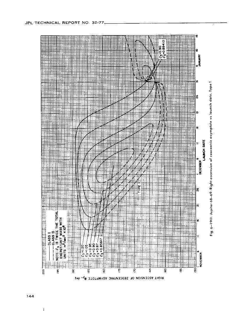
JPL TECHNICAL REPORT NO. 32-77
Z
0
flap ,de 310J.d_XSV :)IUJ.N3OO3Z .-I0 NOISN3Z)SV IHglU
144

JPL TECHNICAL REPORT NO. 32-77
9
o _ o
6ap 'd e 3J.01di/_,kSV :31_IIN3003Z _J,0 N01SN3::)SV /HglEI
145

JPL TECHNICAL REPORT NO. 32-77
4
T:
L
I!
f
:4
:i
i
:!
hap ,3_ 3101dl_IASV 9NIIAIOONI (]NV _0193A HlI:IV3-13NVqd N33M13B 379NV
146

JPL TECHNICAL REPORTNO. 32-77
50p' "4,_ 3101dI_ASV 9NII,'WOONI ONV EIOIO3A Hl_V3-13NV7d N3_J.38 379NV
147
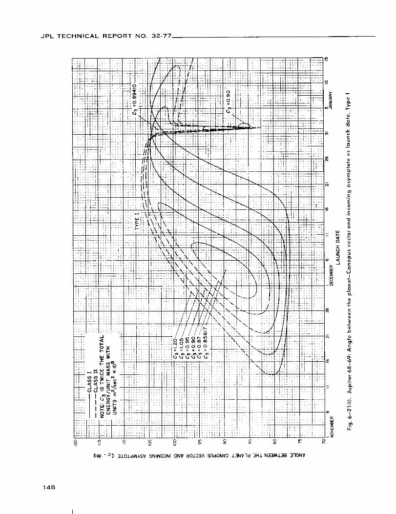
JPL TECHNICAL REPORTNO. 32-77
::7: "'_
i i:i:: _>i!+
'L::
:lti _
il/i_:;.
_-f::" "1
]i['
Tr_
: L _I
.-!:
ii
ii"
ii
if: ir:i
iii!
[21',
-f!: _ir
''r! ; i:Ttl
8
i_-' "i :iN" z:_[ , ,
.... " i! "_ " -
:[ ii:ii :- :Ix : i: :
'..... i!i4,:__:!: .... !:: "
.i:..o ko_ot.. , _--
.:r_._'dodo :::: :i._:_-ii:L! ............ " Tr_: " -.,, f_.
i]::! :;ii ::':7:::1 :! :::: :: : \I:++,+ ,+ - f1:..... i:', !:
:!!i:!i::_!:::__:LL. Ii:-- _ • , r ....... l::: ::':'_:.:: : ',:7:! :!:1!:: :i .........,.,r ..... ;":" :: !::: • l::....7::!, :!i:i:;4'-.,, ,.- I:::i :: ::::i :: ..... , '
:f_::::!!:! ]1:7[777:7:,::777.... 1-_:jr::: _ ...... :: ......::ii::l:::::I:i :iri':i: I::
o _, o0 '_
:l I
ii
!=-÷-
._._
.44_-
_T
:;X;
I '
I _ ? T-
:,_:_
:V:
i/
"T!-
"!11
- ::
;::7i:::
ii{:o
1' _
r_
F_
_2
"__ 22-.:
:t- ::I::
i
L-.__:c
f:- if+.
[+I:
:f::;:::
::_,_ ,.
: ;LLI
., ::-j
i: !+.-
"it
:2: ::it+...... r
::: :::i-- ;- r
::: ;:.:
-rt -
6ep , ,3} 3±01dtNASV 9NIINOgNI ON'(/ EtOIO3A Si7dON_O 13N_/7d 3H1 N33M138 379NV
:z:j "2
:"Z:2J
---]o_
-?i:l _:_4J
t-']
771
.... Z
t ....
":-i[.
i .
::11
!i)
iii:_o
i
do
e-
c-
O
m>
0
o
E>.
0
l-
E0
e-
e-
0
>
0c-
O
uI
c-
O
I1.
_A..E
E
e-
l
,,0
°_o
.-2
NI
°_
148

JPL TECHNICAL REPORT NO. 32-77
Bap ' _} 3101clIRXSV 9NIIAIOONI(]NV EIO/D3A srldONVD J.3NV-'Id 3HJ. N33MJ.3E] 3-19NV
9
)-
J D..
I..-
"0
e.
c-
O
0
Q.
E>.,
0
e-
E0
E
"0E
0
U
0
I1.
e"
..0
0";
e.
,<
,0
I
,,0
O.
..-g
I,0
149

JPL TECHNICAL REPORTNO. 32-77
VII. JUPITER 1969-70: TRAJECTORY PARAMETER GRAPHS
Figure
7-1. Jupiter 69-70:
7-2. Jupiter 69-70:
7-3. Jupiter 69-70:
7-4(I). Jupiter 69-70:
7--4(11).
7-5(I).
7-5(11}.
7-6(I).
7-6(11).
7-7(I).
7-7(11).
7--8.
7--9.
7-10.
7-11 (I).
7-11(11).
7-12(I).
7-12(11).
7-13(I).
7-13(11).
Minimum injection energy vs launch date
Time of flight vs launch date
Heliocentric central angle vs launch date
Earth-Jupiter communication distance vs
launch date, Type I
Jupiter 69-70: Earth-Jupiter communication distancevs
launch date, Type II
Jupiter 69-70: Declination of the geocentric asymptotevs
launch date, Type I
Jupiter 69-70: Declination of the geocentric asymptotevs
launch date, Type II
Jupiter 69-70: Right ascension of the geocentric asymptotevs
launch date, Type I
Jupiter 69-70: Right ascension of the geocentric asymptote vs
launch date, Type II
Jupiter 69-70: Angle between outgoing geocentric asymptote
and launch planet's orbital plane vs launch date, Type I
Jupiter 69-70: Angle between outgoing geocentric asymptote
and launch planet's orbital plane vs launch date, Type II
Jupiter 69-70: Angle between Sun-Earth vector and outgoing
geocentric asymptote vs launch date
Jupiter 69-70: True anomaly in transfer ellipse at launch
time vs launch date
Jupiter 69-70: True anomaly in transfer ellipse at arrival
time vs launch date
Jupiter 69-70: Perihelion of transfer orbit vs launch date,
Type I
Jupiter 69-70: Perihelion of transfer orbit vs launch date,
Type II
Jupiter 69-70: Aphelion of transfer orbitvs launch date,
Type I
Jupiter 69-70: Aphelion of transfer orbit vs launch date,
Type II
Jupiter 69-70: Inclination of the heliocentric transfer plane
vs launch date, Type I
Jupiter 69-70: Inclination of the heliocentric transfer plane
vs launch date, Type II
150

JPL TECHNICAL REPORT NO. 32-77
VII. JUPITER 1969-70: TRAJECTORY PARAMETER GRAPHS (Cont'd)
Figure
7-14.
7-15(I).
7-15(11).
7-16(I).
7-16(11).
7-17.
7-18(I).
7-18(11).
7-19(I).
7-19(11).
Jupiter69-70: Celestial latitude at arrival timevslaunch date
Jupiter 69-70: Asymptotic speed with respect to Jupiter
vs launch date, Type I
Jupiter 69-70: Asymptotic speed with respect to Jupiter
vs launch date, Type II
Jupiter 69-70: Angle between incoming zeocentric asymptote
and arrival planers orbital plane vs launch date, Type I
Jupiter 69-70: Angle between incoming zeocentric asymptote
and arrival planet's orbital plane vs launch date, Type II
Jupiter 69-70: Angle between Jupiter-Sun vector and
incoming zeocentric asymptote vs launch date
Jupiter
launch
Jupiterlaunch
Jupiterlaunch
Jupiter
launch
69-70: Declination of the zeocentric asymptote vs
date, Type I
69-70: Declination of the zeocentric asymptote vs
date, Type II
69-70: Right ascension of thezeocentricasymptotevs
date, Type I
69-70: Right ascension of thezeocentricasymptotevs
date, Type II
151

JPL TECHNICAL REPORT NO 32-77
0.105
0103
0J01
099
0.97
0.95
0.93
0.91
0.89
0.87
0.85
0.83
0.81
0.79
Q77
0.75
t
t
• i
L
IO 15 20 25 30 4 9DEC ,JAN
LAUNCH DATE
14 19 24 29
Fig. 7-1. Jupiter 69-79: Minimum injection energyvs launch date
152
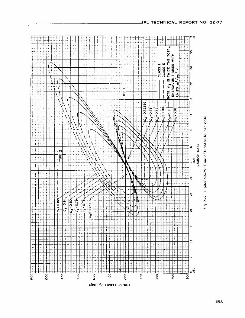
JPL TECHNICAL REPORT NO. 32-77
o
0 0 0 0 0 0 0 0 0 0
0 0 0 0 0 0 0 0 0
=,(op '_1 1H91-1"1 .-I0 31_111
153

JPL TECHNICAL REPORTNO. 32-77
o
"0
1-
{-
0i
f-
0
,4-e-
r-
O
-r
I
.--Q.D
I
°_
_ep '_k 370NV 7V_IIN33 31_IN330173H
154

JPL TECHNICAL REPORT NO. 32-77
el
>,I--
0"0
r-_a
D
0
Q;_ae-
ou_
e-
0°-
0_a
C
EE0_a
._el,-h
7e-
L.
Ul
I0__0
4-.-elD
I,l.
uJ_l#o iUO!ll!W '_ 30NVIStO NOIIVOINNINI_OO EI311dnpmHIEIV3
155

JPL TECHNICAL REPORTNO. 32-77
OOO
• _i!i
i
!:I"?
+i
:!i.L
/;i
;-4
i!"!!"i!
i,
i:
:÷
.+
0 0 0 0
q" 0 m
t,t
_+
..!
t.+
+'t
'T"'T
"_t
1..
[[:
i I,
'It'
t''"
ii
:_!!!
;ttt0
_u_lJ.osUO!ll!CU";'_ 30NVISIO NOIIVC)INniNI_OC) EI3.LIdFIf'-HI_V3
156

JPL TECHNICAL REPORT NO. 32-77
0 o ._ o _ 9 _- oi I I
6ep '#_ 3101dlN,I, SV ::)11:11N30039 ":IH1 _-I0 NOIIVNI-1030
I
157

JPL TECHNICAL REPORT NO. 32-77
O(_1 N --
0
3101dMASV 31_1N33039 3HI _0 NOliVNI]D3_
k,-
I-
t-
0
E
0
o_
e,
0
¢,.
c-O
0e,
6b_
I
I
o_
158

JPL TECHNICAL REPORTNO. 32-77
159

JPL TECHNICAL REPORT NO. 32-77
Bep ,sty 3J.OldI,'4ASV ::)1_.LN30039 3HJ. -I0 NOISN33SV 1H91_1
160

JPL TECHNICAL REPORT NO. 32-77
_3
(._ U3 u3 O tO
F,ep ,7,,( 3NV7d 7VJ.IBBO S,13NV7d HONAV7 ONV 3J.OldlN,_SV 31_LLN30039 0N1091170 N33MJ.38 379NV
m
O.>,
I,--
0
r-
¢-D
0
e-
0
O.
0
.D
0
c-
O
O.
e-vr-D
0
"13e-
0
0
0..
E
=.
c-
¢..
0
01
D
0
E
.I1
C
<
c5b,
I0,
,0
.-1
....2
b,
Ib,
o-
161

JPL TECHNICAL REPORT NO. 32-77
8ep '7_C 3NV7d 7VllB_O S,13NV7d HONflV7 ONV 3101dlAI1SV 31_11N33039 9N1001170 N33M13B 379NV
O.>-
I--
=-0
"10
t.'-
r.=,
0
e,-
0
0..
m0
16L.0
VI
t'-
0
O.
r"V
0
"10
¢-
0
oO.
E
.DL.
,r'
f-
0
O)
0
C
!
C
<
(5b,
I
o-fl.
,-2
Ib_
UL
162
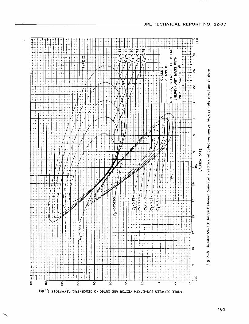
JPL TECHNICAL REPORTNO. 32-77
6ap '"/_ 3101(:11_1SV :)1_11N30039 9N1091170 ONV _101::)3A HIEIV3-Nr'IS N33/_J.38 379NV
163

JPL TECHNICAL REPORTNO. 32-77
i
i
Blip,7^ 3_11 HONI7V7 1V 3Sci1773 I:I]-ISNV_I NI A7V_ONV 3nuJ_
¢) .
C D7ii ii
! .!r ''
i4+
It
++
il
" ti: ii! rt
;i:!"I
t ""
• 1!_f
+,
1 !:i' il
!!iI
U
.++.
::Tii
+,. _.1H_
1:7
fii -
"*+ O
IS!
ti"
+4,
li
:!i;;2
-4+
_ _+
!:7
:i:!, i,
I!rl m
_'- I,l') 13
if)
m
e-
e"
@
E
c-
o
W _
o m
T
e"
EOe-
@
O
6I
,O
Ib_
M.
164

JPL TECHNICAL REPORT NO. 32-77
_+E,
i;i;
i!r!:_
!,!2+2
ii;+1 ,
rJ:!11
i,!
2
• t_I !i_ ........ Iiii ++_i l .......: :: :ili iri:t.... r_ , !llt_/t ¸ ]I!
' i'. _'\, ' ',' '
,[+ ri !+ ; ........ ;, . _
i'I, i!! !it; '::ii i :::i : : ; i '!i i::: ri:i ;I:', t:!; ::::
it]! i!ii !!_ :::: :\_;d;i\;+,_,_t+,.,i,ui;_ i"_ i_+
.... +;++ +++++++.... :il
t]:! .... ;- _,_i.: r, '_
_,,:l ::i: Ii+];
:::: !_ :_o19 P :_ !; :,l_ _
:!"! : I" !",,.:..... ,, :r-.: :. .:_: '._
.... :::il i:il::::l:lil][!l; :::
0 _ 0 C,£ - _.
+..+._.,+-itii!
4 •
t'
+r;
%: -,4
2::
:%i
t_
ii
+!r't
::: ;]iiil :;; i,fi
,i .+. ::!:;i ::: +_il
=+,li ii;
i[ :::
[1 !:::
t_
ii ,,!I!i:: !_i
x ' i_i
\
:+ Xi?
-- l\ti
_L2r
+: ++++
+tL i_,Ji •:: .::
:;_ Iiiiil i 5J:l
!i ii: :iii
_i: i21 i_i ....
6ep ,o'^ 3_11 7VAI_I_IV lV 3Sc11773 _I3_-ISNV_I NI X7VI,_ONV 3r1_1
:?:
_+_ mm
i+1
, _oi!!
:_ : "Ei:: _<2 o
:::;il .1- ,._
+++ - =+;+
::; 7
1,i ,oJJi:::
tll I
.i r.
1it =_4
S
165

JPL TECHNICAL REPORTNO. 32-77
z z
Ua_l j,o sUOlll!W ,d_ J.IBEIO _3-1SNVEIJ. 30 NOI"I3HIEI3d
166

JPL TECHNICAL REPORTNO. 32-77
(J
m_l jo SUOllllW ,d_ J.IBtlO _3.-ISNV_I.L .-I0 NOI'I3HIEI3d
167

JPL TECHNICAL REPORT NO. 32-77
hiU.
o
W_l _o $UO!lllW 'oH -i.18UO EI3.-ISNVEII 30 NOI"I3HdV
168

JPL TECHNICAL REPORT NO. 32-77
OD OD
mm
I,,,-
e.
0
L.0
e-
E
0o--
Q.
Io,,0
o-
..-2
"r
°-
169

JPL TECHNICAL REPORT NO. 32-77
O
Q.
I--
0
JE_aE
D
0
>
i-
0
t--
_a°-
¢-
O
t-
JE
¢.0
".=
0t,,.
wC
db.
IO,
°-
Q.
,.-2
"r
6
_ 0 _ 0 _ 0 _ 0_ ._ _ N N - -
Bep '/ 3NV7d _I3..'ISNVEII OI_IIN300173H 3HI 30 NOtlVNI73NI
0
170

JPL TECHNICAL REPORTNO, 32-77
0 _ 0 _ 0 _ 0 _o 0 _o
Bep '/ ":lNV'ld EI3.-ISNVEI/ C)IEIIN3OOI-13H 3H.L 40 NOIJ.VNN3NI
0
171
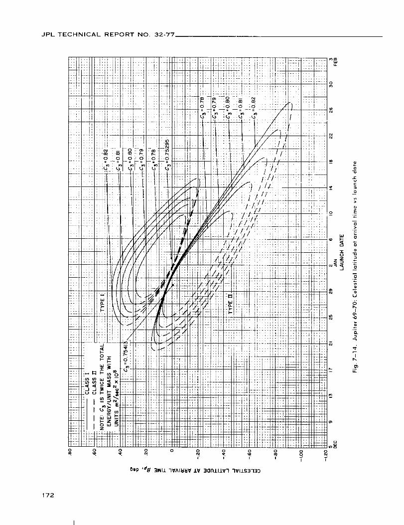
JPL TECHNICAL REPORTNO. 32-77,
O
4_ .:_
++ II
ii iI
! :i
j [1 :
_ il 2[1
i l ;:
L L,' il if:
2 i !!i :It ;i:
i
> • ,"f" I |I
., _/' i1,,rr r j,,j.
/ ,,/ I_:
• t tiL_'
?T- ,*+
!_4'
I [ I I i
T qf
:- 4; 4: L
42 j'iq_L +.,
t- i.- 1!:_- 41L _ •
L _ ÷+-
,, .,,
0
Oep '_d ]I_III 7_A161_I¥ J.V ]017111_7 7VI1S37:IO
172

JPL TECHNICAL REPORT NO. 32-77
4 _-_ + _.
I1!!
+4--_--.
l!::
!l.
11!i
ii""
Yt'l
:!;!
:t!l
I
!i L,
!Z
, ?
T!;:
IJ:.
+++*
tilt
K
-L_
Yt_
l'r
.21
''f
i,I
i.!!'
t_ "-2_'
,il
T_
::t
:ii
I
11
tli
:Ill:ill
,!flii!!
OX/WN 'dqA _FIJ.ldrlP 01 .l.O3dS':ltl HII_ O33dS ::)ll01dlN1SV
173

JPL TECHNICAL REPORT NO. 32-77
oas/w_l 'dqA _I311dNP 01 103clS3_I HZIM C133dS 31101dMISV
174

JPL TECHNICAL REPORT NO. 32-77
I
I--
"i@
¢-
@
C
0
2._..0
0
E
@
@>
0
"0
E
0
E
@
E
N
@IE
E0
I=
¢,,
!
e-
<
(5b,
I
,o
_2
,o
"Tb.
u
175

JPL TECHNICAL REPORTNO. 32-77
i:: !i:
iiiI_i!
$''! t"
!ii:t_i:
111;tl i:_ t!14
!:,!;:iii!iiIf;!!r---
11: iiii i::
iiii _!!i I_
_::: _:_ _, !!i i i_i
_i i_iiiii '!i
i i_-(=, _(_ -.,", _F,: :-. 16,0 0 iO to_ ,+-
,_.-_i-itii i _';tl I .....
:_i i: +"1
5ep 'dX. 3NV7d 7V118_I0 SI13NV7d 7VAI_I_'O' ONV 3101dM_,SV 31_lN3OO3Z 9NIINOONI N33MJ.38 3-19NV
176

JPL TECHNICAL REPORT NO. 32-77
_iiii
I1!!
!!ii
!ii;ij!:
:i!)i
:iii
!i!:
i
ti"
_L,,,,'f 4
..'t_li V
ili/
iiii
tt?T
i::I[
,iii
t-t'_
:;Tro03
..... :T:[
!i_ 5:::
! ......
":: T'I}.... II /
!!:/,7//.-.
,!!/.,f.!-_
i!t::.F Ii:l
.... ;:.,t
/:7T I: I
:V: ....
;iii_ii::2:2
:NII INI:
;T'_I :?_:;filet ::_:1
.... t
'! Tr r 't.r t ri
!_,!! !Ut!
i + •., .... _1
' tic T_a
oT;; _ ,i'. !._ > , t! ,":
:Tt VTfTI
tt_ :Tit1
:iii _lill
6ep '#} 3101d_LSV 01_1N3OO3Z 9NItNOONI (]NV _01D3A Nt7S-_311d(7P N33/_13B 379NV
70,.¢
¢..
O
q)
O
O.,
E>..
¢,-
O
N
olE
EO
c-
7Dt-
O
>
E
:=1Vl
.__
e-
t
e.
6b,
I
,0
'3"
o-
177

JPL TECHNICAL REPORT NO. 32-77
o
Bip '#¢_ 31OldRASV 31_IN3003Z 3HJ. JO NOI±VNI733G
178

JPL TECHNICAL REPORT NO. 32-77
179

JPL TECHNICAL REPORTNO. 32-77
Bep '_/e 3101¢:IINISV 01_11N':1303| ":IHI ..-I0NOISN3OSV 1H91_1
180

JPL TECHNICAL REPORTNO. 32-77
T11:
I •
+;ii
L, W
I
!. --
::li
_4_
,1+_ I --
,i
!
0
mm
I--
r-
E
0
0
n
E
0
e-
0
N
c-
c-
O
¢-
0
I
Q.
"7b..
._
181

JPL TECHNICAL REPORTNO. 32-77
VIII. JUPITER 1970-71: TRAJECTORY PARAMETER GRAPHS
Figure
8-1. Jupiter
8-2. Jupiter
8-3. Jupiter
8-4(I). Jupiter
launch
8-4(11). Jupiter
launch
8-5(I). Jupiter
launch
8-5(11). Jupiter
launch
8-6. Jupiter
launch
8--7.
8-8(I).
8-8(11).
8-9(I).
8-9(11).
8-10.
8-1 1 (11.
8-I I(II}.
8-12(I).
8-12(11).
8-13(I].
8-13(11).
70-71: Minimum injection energy vs launch date
70-71: Time of flight vs launch date
70-71: Heliocentric central angle vs launch date
70-71: Earth-Jupiter communication distancevs
date, Type I
70-71: Earth-Jupiter communication distancevs
date, Type II
70-71: Declination of the geocentric asymptotevs
date, Type I
70-71: Declination of the geocentric asymptotevs
date, Type II
70-71: Right ascension of the geocentric asymptotevs
date
Jupiter 70-71: Angle between outgoing geocentric asymptote
and launch planet's orbital plane vs launch date
Jupiter 70-71: Angle betweenSun-Earth vector and outgoing
geocentric asymptote vs launch date, Type I
Jupiter 70-71: Angle between Sun-Earth vector and outgoing
geocentric asymptote vs launch date, Type II
Jupiter 70-71 : True anomaly in transfer ellipse at launch
time vs launch date, Type I
Jupiter 70-71: True anomaly in transfer ellipse at launch
time vs launch date, Type II
Jupiter 70-71: True anomaly in transfer ellipse at arrival
time vs launch date
Jupiter 70-71: Perihelion of transfer orbit vs launch date,
Type I
Jupiter 70-71: Perihelion of transfer orbit vs launch date,
Type II
Jupiter 70-71: Aphelion of transfer orbitvs launch date,
Type I
Jupiter 70-71: Aphelion of transfer orbit vs launch date,
Type II
Jupiter 70-71: Inclination of the heliocentric transfer plane
vs launch date, Type I
Jupiter 70-71: Inclination of the heliocentric transfer plane
vs launch date, Type II
182

JPL TECHNICAL REPORT NO. 32-77
VIII. JUPITER 1970-71: TRAJECTORY PARAMETER GRAPHS (Cont'd)
Figure
8-14.
8-15(I).
8-15(111.
8-16.
8-17.
8-18(I).
8-18(11).
8-19(I).
8-19(11).
8-2011).
8-20(11].
8-21(I).
8-21 (11).
Jupiter 70-71: Celestial latitude at arrival time vs launch date
Jupiter 70-71: Asymptotic speed with respect to Jupitervs
launch date, Type I
Jupiter 70-71: Asymptotic speed with respect to Jupitervs
launch date, Type II
Jupiter 70-71: Angle between incoming zeocentricasymptote
and arrival planet's orbital plane vs launch date
Jupiter 70-71: Angle between Jupiter-Sun vector and incoming
zeocentric asymptote vs launch date
Jupiter 70-71: Declination of zeocentricasymptotevs
launch date, Type I
Jupiter 70-71: Declination of zeocentricasymptotevs
launch date, Type II
Jupiter 70-71: Right ascension ofzeocentric asymptote vs
launch date, Type I
Jupiter 70-71: Right ascension of zeocentricasymptote vs
launch date, Type II
Jupiter 70-71: Angle between planet-Earth vector and
incoming asymptote vs launch date, Type I
Jupiter 70-71: Angle between planet-Earth vector and
incoming asymptote vs launch date, Type II
Jupiter 70-71: Angle between planet-Canopusvector and
incoming asymptote vs launch date, Type I
Jupiter 70-71: Angle between planet-Canopus vector and
incoming asymptote vs launch date, Type II
183

JPL TECHNICAL REPORT NO. 32-77
105 4
i:
,o3 il
IOl !
!
97
t,
t
93
91
!!
89 i!
_+,
i!t87
2L-F
B_ t:::L- LL
83 ...
-+,-:- t,.
81 ,t!
• il
79 i] ,I
77 ; l'r
75 't]ioJANUARY
"!' _!"; "_I ¸ _!
, .,t It
"+ ........ t' T-
"t_ rl .... ;I '
'li" _'_' "L• 1"T--- "?- I " ,
" !iii :!:_ii 'i
_'[ t''!
_- -H i i _!..... Tr- ':'r +'
:_f :!!: ti;! !i"+_" t:" tr
,MI' i,
i1:t I,1[ _ i _ i
'_'t" []
:[i: ...... I
• li i" i _
+L4. !;.! .:'t
..... t ....
:ii: I:...... i- i:
! : i!.I !-II ;i
.!.. :::[ :[,$,- 4_ii ÷_
LAUNCH DATE
Fig. 8-1, Jupiter 70-71: Minimum injection energyvs launch date
184

JPL TECHNICAL REPORTNO. 32-77
Iorv
0 0 0 0
o o o o_ z
0 0
185

JPL TECHNICAL REPORTNO. 32-77
^_O_
=ddddii ii ii |1 ii
8ep ',,1_ 3-19NV -'IV_J.N39 OI_tlN3901-13H
! !il:0)
ii_iili::i
t, if;i:: I_
11,*
HTT__
.... _M2_: :
:1-!
J, i
l
:_:
i"'!
i::: _,2
!:
i!;! _:
!,!*
i:!i N
!!: o.lr_
0
0
t-
t-
O
e-
c-
O
-r
b,I
o
(4I
NL
186

JPL TECHNICAL REPORT NO. 32-77
0 00 Lo0 O_
0 0 0 0 0 0 0 0o _ g _ o _ o
WZl ,I,OlUO!ll!W ,.9_/ 33NVJ.SIQ NOIJ.V_)INrllNINO:3 EI311drlP-HI_IV =1
Z
0
o
i
Q.
>,
,0-0
"a
r-
-j
0
o°--"U
.9
0
o-
EE0
o-
-?i.
0I,I,I
°.
I0
°--
I
°--
187

JPL TECHNICAL REPORT NO. 32-77
Oo oO c_
::3Z
&0
7O
r-v¢..
0
E
_o
:5
W 0
.m
E_ E
0
Q.
-?L.
0tu
o,
Io
D..
...2
'I
°-u.
188
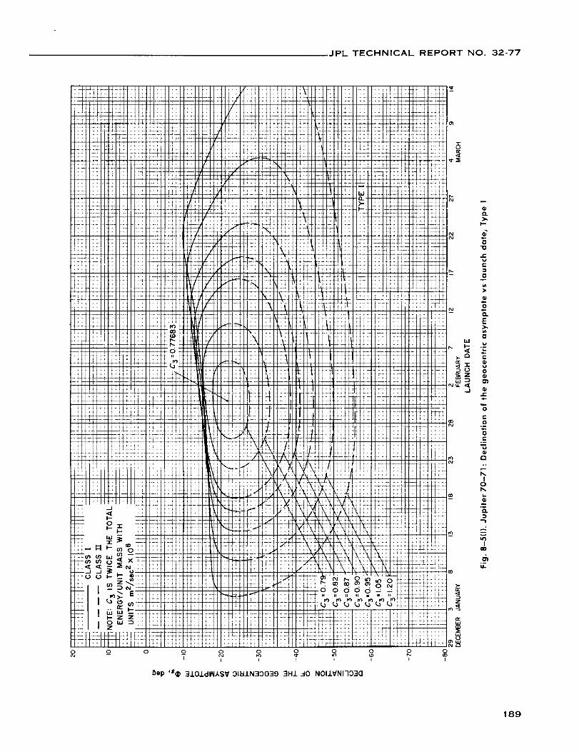
JPL TECHNICAL REPORT NO. 32-77
-rOr_
o O
I I I I i I I
I_ep '$_ 310J.dI_IASV OI_IJ.N30039 3HJ.-_0 NOIlVNI703(]
189
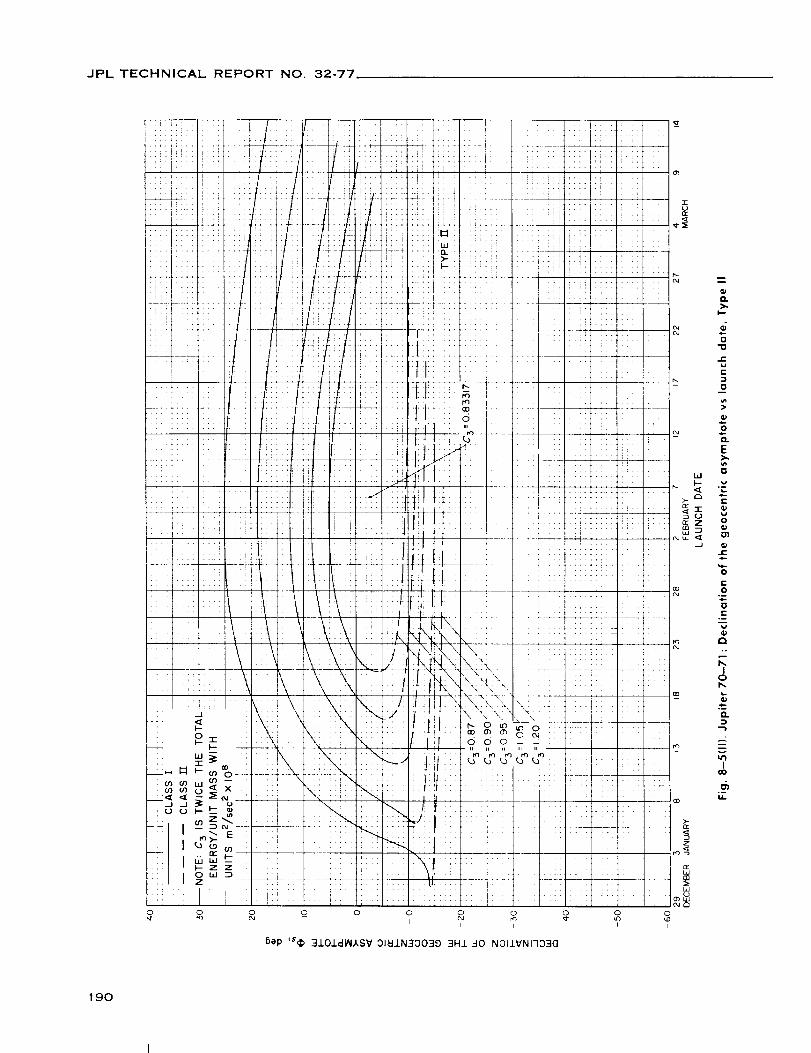
JPL TECHNICAL REPORT NO 32-77
oI
m
O.
I'--
0
I"W
I"
0
O--
E
{}hl
vL..
e"
"1-
O
.J (pJE,I.-
C
0.--,l-.
E
m
P,.°
Io14.
-W.*--O.
l
m_I
_5I,L
190
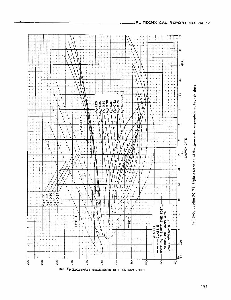
JPL TECHNICAL REPORT NO. 32-77
o
-, 110 •
dddddd:ii ii ii II ii ii ii ii
_)op '&'@ 3J.O.L(:IINASV 31_1.LN30039 40 NOISN'_OSV 1H91_
o
¢-
0
ooE
o
ii
_" ._ o
.£
o
.__.°
ob,.
Q.
191

JPL TECHNICAL REPORT NO. 32-77
z
Bep ,7.,( 3NV7d 7VJ.I8_IO S,.L3NV7d HONnV7 QNV 3J.O.LdltlkSV 31_IJ.N30039 9NlO91no N33Mx38 379NV
192
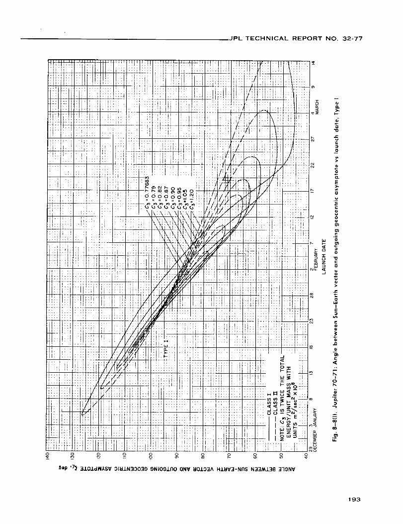
JPL TECHNICAL REPORT NO. 32-77
_ep ,7_ :i.LOIdlNASV 31H.LN:IO039 9NIOgJ.RO ONV HOJ.O3A H.LHV3-NRS N33NLL3B 3-19NV
193

JPL TECHNICAL REPORTNO. 32-77
8ep ,7_ '4J.O.LdlN,/,SV 3181N30039 ONIOO.LFIO (]NV l:10103A HJ._IV3-NnS N33M138 379NV
O.>,.
I--
"670
J{:wI==1
0
,i-.0
E>.i#}0
t,a
m..
t-
O
E
0
E
0
g>
¢-
"20
wJ
Ir-
¢..
Ill
E
<.°
Iob.
°-0.
...-.2'
I
o-
194

JPL TECHNICAL REPORT NO. 32-77
!!!
N
TrT
',r
'f0
5ap ,7^ 31NI1 HONFIV7 lV 3Sdl773 _B-ISNVt::tl NI X7VINONV 3FI_IJ.
.t
.+ ....
iF :ii!
:! ::]i
...... _
i!It =!11
_ _ii --D.
tliIIII _ -,-
1tl m' 0
,.
,J i:J: ._
"i!_i _"-_
,, 'rr _
..::: l_
T
n_
195

JPL TECHNICAL REPORT NO. 32-77
L
i:!,tl
H
T[_t
:!
tt
+_
tF
t]:
:F_!T
iJJ:J
_iJ H ;_t,t
:4.4_L$44+_+_
!!
JPL TECHNICAL REPORT NO. 32-77
rr
197

JPL TECHNICAL REPORT NO. 32-77
uuq /,o $UO!ll!W ,d_/ J.li]_O ).I33SNV_.L _.-I0 NOI73HI_3d
198

JPL TECHNICAL REPORTNO. 32-77
OLt3 _ _ _ o_ _ __ _ __
tu_l _o $UO!ll!tU ,d_ 118,610 bl3.-ISNV_J..-I0 NOI7BHI_I3cl
w
199

JPL TECHNICAL REPORT NO. 32-77
o
iI-
0
t'-
c.
0
0
c-
Oi.
t"-0
O_
I0
.__
"7
200
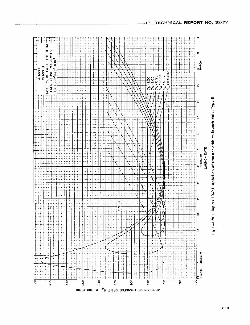
IPL TECHNICAL REPORT NO. 32-77
OO
0 0
n,..
0,.
I.-
_D"0
t=l¢-
0
I=.
u,t
¢,-0
o-
lD.
o,
Io
°_O.
gl
¢'N
'TGO
d_UL
201

JPL TECHNICAL REPORT NO. 32-77
-r
6ep '/ 3NV7d _I3-1SNV_I1 01_IIN300173H 3H1 30 N011VNI7_)NI
hi
a
Z
_Jb-.-J
CO_J
rr
0_W
O
m
D.).
0
.E_ae"
DO
E
O
CL
E
E_a
b.
r-
tJ0
r-4-
E
0
0e'-
c-
o.
b,,I
o
°--
...,2
o--U.
202

JPL TECHNICAL REPORTNO. 32-77
Bep'/ 3NV7d _3.-ISNVEI.L 31_I.LN3OOI73H 3HJ. 30 NOI.J.VNI7ONI
0
203

JPL TECHNICAL REPORT NO. 32-77
0
_i !!i ii i i :W_-::-7-,:
: !:; J ........
ili!i : _-:::_ ::: :_ _ _ _ _l',--i"-- ::
::! :: :.:. oo, o,-o,,o,o,.::::: :!i :¢¢<2,2¢¢¢¢22:1
_!ii!! :i;.::.!i(\_li::! _\lZ:
ii! ii::
- _f! ii!'l iriltlPttt ]: !t/-,i.... ;_ ti : I ,i i .. li_ r
::: i.--7 'i_il :: ' !
_" d_ i'.i .:i 'ii .. : ...
i! ::i +'4: i\¢k:\: :_:t7;:/.;
'" _ .... t ¢- 'i: _ ": !:+'A:
,,, _ 9 7 utft!Utt:;4it_'ttll
•' _ o_,,,<,,xi F_L'p,ttI !tfgVt Ijt;i i_
'y-_)_; r!!i :;;_ {i ![]i!7!:
I'_lwl-: ;: :I :: !: !fill......... :: i{:ti ]_i l::+ii:_,_+,:o
o 0i
Sap ,dg 31_III 7V^II:IldV IV 311"IIIIV7 7VlIS313D
•;Tt : .... ::
i_!: !i :I: i?
.....
. :: " f
,;,- I,;L _X +4
+ ! 4!i:; i +';
!!:i _
ii :
.... t:--r:: !__ I::::1::::1 •
-: >-
:_:_- _:t:ltt::l w
:-'L "+ "
.... _l;ii!l g
+_ _ :',_ !,i' tI
:f'+11'!il_I7:] ::::I::::I:?:: 1'::;::.:I,iS:,LL!LI ;: :. 1
ffff ::::l:!:il_
1-_ L:-:: ++: ::, I
--7" t:; I::;I
::': tT::!rt:!l_
:2++:
: dr: i::i
_tL: _T..... W
i +]" _ i¢-4-Ii:_0
, T
O
i-
O
E
O>
o_
O
'6¢1
.,i-O
Oo_
t_
1,J
Io
,.I,-
O.-11
'-I
q"
ki.
204

JPL TECHNICAL REPORTNO. 32-77
!It! !It_Ft! _
[1:: , _Jl:
H:i :_ e i![i[_ii ""
........... I
.... 222 '5!i
ii'i .... :12:
fill ....
iii[ _i
' 'ii
J'It" !_!t
!_ iiil i;i!
i::i :::i ili12:2 :::
........ 12:i
_':" :._T: """
_t't ........
,i!r + i, ._i-
ttit ]itf__ =
oas/uJ_ 'd{/A _1311dnP 01 193dS38 HIlM C]33dS 91101dI_IASV
205

JPL TECHNICAL REPORT NO. 32-77
o0
0.
4-0
"0
.E_ac-
O
>
._Q.
0
_a
hi
u_
E3
z/ -o
D.
4-
oO.
Eul
<
Io
O.
L/3
CO
M.
206

JPL TECHNICAL REPORTNO. 32-77
8lip , a). :INV-ld -IVJ.IettO S,13NV"Id -IV^ll::l)-IV QNV 3101dlN),,SV OI_IN3OO3Z 9NIINOONI N33NLL3e 3-19NV
207

JPL TECHNICAL REPORTNO. 32-77
O 0 0 O 0 0 O
_ ,d_ _ml0j.dlNjk$ v 31t:LI.N3303Z 9NIIN03NI QNV I:JOJ.O3A
O O O
Nns-_3J.IdFIP N33MJ.3B 3"IgNV
00
aJ
O"O
J:
E
0
bJ
r,
T
J
0J
Q.
E>.u_O
E
O0_N
t:
O
E
"ID¢,-
O
>
E
e-
!
¢..
b.
I0
Q.
£
"r
E
208
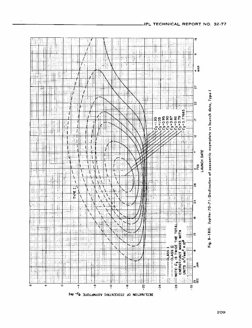
JPL TECHNICAL REPORTNO. 32-77
:If+.
+F
It
IL11
ttff
:;t_LL
tt
trtt:2
.!
:i
ii
2:+,
iJ
4a4
['!
i
Ytr
;11
'![.÷.
.L;
*11
..... i
..... i, +
ii!i:_i/ii!,IL ,
:!:: :::: ;
t!:: !itir:::: :t;;_.... 7;!!:!ii!i _il_ !:
Tiii i,LI[- LI_ _
_i:: ::::l:i
;V;t';ivl• -._[
-I.LI ...... '_i
..... 'Vl I _ i
..... i
:72: +r
it:" t:l
.........i!222 2:22_':....... ti;
. _F i4_
....... +;i
--- its,
I
:.: : : : : .',; : i_
.... :Ii.: :
:rtr-r,r il._++ +++
),_. i,.... ,:f1_2. +L2 Z
"''+ <
I::; ::: if.... ;tr,, :i
";*,; 12 "_l;+t
ii!' i:z ._
i'(3;;:: ::ii_i ..
:" %- "X" It
iNi i;_ v
:::- L:_ 2:........ f!
+.+-.tT+
_+f, +-',tt Tf: _"Li_ -
_+÷F 1+-- -:
....... i........ 2;
!: -
Li ti
is -i
tt
ZN
..+
NN
i: \
:_t
!!-t X2
4_
il :'
i ?T
_X
m_
_ TJ
1-22 ,: : ::5
r-T I i
l-r Ii
:L "
I
+.
_f
i:!.°
_4
t\
tt
i:!
D
:::J
rL-
71
Ft
I!
7i
O
I
..+
-F"
,L;
.+,
!t:
+T"
r""I''
_5
_._1,.-
a!
-=
H!?i
II
+rr ......
Tittlt tt_ -7-- _--q_-r_
, !,1 ,i
....i ' .;;L, a_;i4 _---r r- _r;
T"!!t+it! TTT" t_-TTl,_T'-'q
• .;:i ...._ ........ J : _;
Tt_ +_ -- J bt*
:::::I : :; o
(#-iil +_-::"ti!_ _ (,, 9--:-:T-.
i_:'L :l! (__) i • %--IL; (/) 't"/) t-- P o .....
' !_ J J (#):3_ -'+
.... +:_: I , b.lI.Ll_---¢'_
.... ,_+" I I Z
:' Lit7
Bap ,d_ 3iO±dWASV 31_lN3303Z 40 NOI.I.VNI"I030
......... _ ....... _ J!J!
iiiii!i i '" ' lttl (:,,2 "t*r .... ; +4+,
..... ,+.
-..t-_iL i!': _''_ +_+" @:
..... ,i t ;4_ ......... '_.... '_t_
"_ ' !:i.:-.11_.!; .... :...
:::_]::i: ;::: :7:: 77::":'!I];IT ........ :'r" _.
_: !!_::::: :::: ii
:H,t .... f>-
gg, gg_g_!:::_-.. . _ g- --,o,9,o ?,? o _:>mm iI 14 --I111,_, lil I_ I,'11_ 1,0 I_ ....
. . t!71 ,, +:'_ E
.........:,ii. _ ......::_:_::: ,., o.... 44-- :..... ._
O
_ or
.o
Io
_- "T
209

JPL TECHNICAL REPORTNO. 32-77
z
I I I I I
6ep 'd(;I} 310J.dINXSV 01_IJ.N3DO3Z 40 N011VNI7330
O.
>,I--
ono
c-
O
o
o_
E
o
t,a
c-
O
N
'6c-
o
o
"I--
¢)
Io
o.
*iI
II
o0
"ToO
210

JPL TECHNICAL REPORTNO. 32-77
Q.
6
e.
E
E
r,
_ o
e-
._oc-
O
.r:
Iob_
,,..2
%
z
211

JPL TECHNICAL REPORT NO. 32-77
;:_ +! it+t;-: t
fT?i !i rtttt_:I
-*tt _ .... +'''+
:::: :i::;:::..... ff ............ lT ......
TI::_TT'
,.,4
:::7
.... ;,+ ......
i --.,+_ + ::,_L .....:T_ ' ::-.L::L:: :': i:''if [ ..............
L12: _ ...........71_T # JI:-L'_'L'Z_:'+ " 1
U7<--::, -:- :[11, + :_-T ..
, i ,q ,
f +-÷-i,,!!1!>: .
• _+-: ......
:_ .........
:'+- :.2
LZ! ::.:'
:t:: >'._ 11,-7
:2 !!!!+'::: : :: :
LX.LZ:: :: _.--
i:
ii ....:........
T-: ::77-
f*ft
-TTT
2:2 i
:T:T
-rift
i!::11
S
,+
.iT 1::"
ili ::i:::t_
:!;i!:.::
"''1 l,!, I
.t ......., I I ,
..... ili '""' f!it ....
TT: :ili!
_T!].... fffi: --_.... T:i: --!!
.... L!!, T'_"
"i !1]" ,!-. - ;i4, i --+
...... s; H++
" _' !HI
......... ,+-+
i ,i i i ,
.... ¢!Ti ....
....... _ +...:::" :::i l:L:
.::: :::: :IT:
L: _ ..... 'I'
_.. :. 7. --%....
: --:C T: ::,i,
-: ...... ;TTI
: :7:L ---........ { f _- 7T-;1- - :!:m
:.:: LL-I_7 i : : ' _ !T
--## :T .... *t
/ :L _ "_f+t !:':
...... , T1 +_
, !i
. . :::r !:T:
•_._- .... +_
:::: ::::
o _ o<',1
6ep 'dift 3101clI/M*SV OI_.LN3OO':IZ 30 NOISN33SV .LHglEI
z
>,I--
c-
e-
0
>
0
E
i.
c-
O
N
e"
0
c-
O
,--
Io
...2'
I
212

,JPL TECHNICAL REPORT NO. 32-77
t0 0 0 0 0 0
:t,l -¸-++ _+
i J_i
_li!il!I; 'L
;+ +.
.... J
' tlt
tbt _t
_4
+4+ ++_4! H
tTt _T _
ili!_!'.i: ii
++t++:E:
d-- Tt:_.tL 25:
; ; I I
÷+÷ -÷.-
0co
i_} 1TiII i
i!! !i!i !i:i:il.i....... 1._-: T
...... TI:"D_
:ti _tl :ii
t l!
:,_ _i,IIitli
•-. _+i-titi!lHX 2t/2ti i:iill
"T: ::_+t?. Tit,. "'
Iz
::: ::(kILL. <{
ia i;J 1;I;ii
7-
i I I"+ +_''1 .....
:t:: !!Itltlirl_T
"t :!Ttlt+!il__
.i: _'
L" 1"+,4¢4; i/--
: :tI*+tttt F1+it I++_ ,!
: i li;il;
_+ i_-;!ii_+++Li+_t +++. l+it+im++ _+t tf+++
,i i!" • i +:+
?_ +-+: ,+_+
++ , +. + _Jr+ L (J++ +++-tli+P:_
o o
":I.LOJ.dlNASV9NIINO:)NI(:]NV_(:II.3_H.LI:IV3-.L3NV'IdN'_138 379NV
O.
emo
"0
J=
f..
0
.oQ.
E>,
0
?..-
E0,,a?.
"0t-
O
>
rm
.,=oLLI
iC
0
tm
¢.l
..0
0'It"
<,o
.I-
Q.
,mI
..--.:
o
I
d_Elm
213

JPL TECHNICAL REPORTNO. 32-77
0 0 0 0 0 0 C) 0 0
6ep ,3_ 3101dlAIASV 9NI_OC)NI (]NV _OJ.O3A HI_VR-13NV-ld N33N_I38 379NV
m
O.
>.
{}
70
e-
{}
6h>
"6Q.
E
0
f.
E0_a
e-
70
r
0
vqJ>
r
[}I.LI
Je-
o
o.
e-
0j_p
.Jo
Cm
f-
h.
Io
O.
-m--I
('4
I
214

JPL TECHNICAL REPORT NO. 32-77
o
hap ,0_ 3101d_ASV ONI_OONI tiNY _0103A SfldONV3 13NV7d N33M138 379NV
0
215

JPL TECHNICAL REPORTNO. 32-77
z
m
O.
>,I--
6
{}70
t:
{}
0
O.
E
0
E06,E
.-
70
e-
b.i 0
C:m ...
>
a.0
0U
I
E
0
e-
!
t,-
<°.
Io
Q.
p2
NI
216

. JPL TECHNICAL REPORT NO. 32-77
IX. JUPITER 1972: TRAJECTORY PARAMETER GRAPHS
Figure
9-1.
9-2.
9-3.
9-4(I).
9-4(11).
9_5.
9_6o
9_7.
9-8(I}.
9-8(11).
9-9(I).
9-9(11).
9-10.
9-11(I).
9-11(11).
9-12(I).
9-12(11).
9-13(I).
9-13(11).
9-14(I}.
9-14(11).
Jupiter 1972:
Jupiter 1972:
Jupiter 1972:
Minimum injection energy vs launch date
Time of flight vs launch date
Heliocentric central angle vs launch date
Jupiter 1972: Earth-Jupiter communication distancevs
launch date, Type I
Jupiter 1972: Earth-Jupiter communication distancevs
launch date, Type II
Jupiter 1972: Declination of the geocentric asymptotevs
launch date
Jupiter 1972: Right ascension of geocentric asymptotevs
launch date
Jupiter 1972: Angle between outgoing geocentric asymptote
and launch planet's orbital plane vs launch date
Jupiter 1972: Angle between Sun-Earth vector and outgoing
geocentric asymptote vs launch date, Type I
Jupiter 1972: Angle between Sun-Earth vector and outgoing
geocentric asymptote vs launch date, Type II
Jupiter 1972: True anomaly in transfer ellipse at launch time
vs launch date, Type I
Jupiter 1972: True anomaly in transfer ellipse at launch time
vs launch date, Type II
Jupiter 1972: True anomaly in transfer ellipse at arrival time
vs launch date
Jupiter 1972: Perihelion of transfer orbit vs launch date,
Type I
Jupiter
Type II
Jupiter
Jupiter
Jupiter
launch
Jupiter
launch
Jupiter
Type I
Jupiter
Type II
1972: Perihelion of transfer orbit vs launch date,
1972: Aphelion of transfer orbit vs launch date, Typel
1972: Aphelion of transfer orbit vs launch date, Typell
1972: Inclination of the heliocentric transfer planevs
date, Type I
1972: Inclination of the heliocentric transfer planevs
date, Type II
1972: Celestial latitude at arrival time vs launch date,
1972: Celestial latitude at arrival time vs launch date,
217

JPL TECHNICAL REPORTNO. 32-77
IX. JUPITER 1972: TRAJECTORY PARAMETER GRAPHS (Cont'd)
Figure
9-15(I).
9-15(11).
9-16.
9-17.
9-18.
9-19(I).
9-19(11).
9-20(I).
9-20(11).
9-21 (I).
9-21(11).
Jupiter 1972: Asymptotic speed with respect to Jupiter vs
launch date, Type I
Jupiter 1972: Asymptotic speed with respect to Jupitervs
launch date, Type II
Jupiter 1972: Angle between incoming zeocentric asymptote
and arrival planet's orbital plane vs launch date
Jupiter 1972: Angle between Jupiter-Sun vector and incoming
zeocentric asymptote vs launch date
Jupiter 1972: Declination of zeocentric asymptote vs
launch date
Jupiter 1972: Right ascension ofzeocentricasymptotevs
launch date, Type I
Jupiter 1972: Right ascension ofzeocentric asymptotevs
launch date, Type II
Jupiter 1972: Angle between planet-Earth vector and incoming
asymptote vs launch date, Type I
Jupiter 1972: Angle between planet-Earth vector and incoming
asymptote vs launch date, Type II
Jupiter 1972: Angle between planet-Canopus vector and
incoming asymptote vs launch date, Type I
Jupiter 1972: Angle between planet-Canopusvector and
incoming asymptote vs launch date, Type II
218

JPL TECHNICAL REPORT NO. 32-77
105
IOi
99
97
95
93
9i
89
87
85
BI
77
_6FEBRUARY
26 2 7 12 17MARCH
LAUNCH DATE
22 27 I 6APRIL
Fig. 9-1. Jupiter 1972: Minimum injection energyvs launch date
219

JPL TECHNICAL REPORT NO. 32-77
S,_Op 'J/ .LH917._ ,:10 31_11
_o2
QD
{_<_
2o
7D
O_ _a-- e"
:3
_o
J El--
.--_L
o,
co
r_
co
rOLL
220

IPL TECHNICAL REPORT NO. 32-77
o o o o o o g o o oo __ _ __ __ _ __ __ _
5ep '_ 379NV 7V_IJ.N30 31_IN300173H
221

JPL TECHNICAL REPORTNO. 32-77
o o0 Lo0
o o oo ® o o o o or,o _C,
tU)l to sUO!ll!UJ ,0_ 33NVLSIG NOIIVOINNINiNO3 _311dNP-HZEIV3
222

JPL TECHNICAL REPORT NO. 32-77
::[:_::i{o{o _{..}bb{o b
::;. :::: 77--!: 1.:: : 2,:'-,..: :
!::', :::i :.._ ::'_ _:: ,_.:1 i ....-- ..... _._:_ .... _ i1Ll: iL!
::: !i.:i ii: ....
i! i:._ _-4
"! • LJ
:r_ ,. [.![
" ' i:-
4 '._, ::]::2[::
if: ..... ;:1[ T ] i.l_ .
o o o
'"_1 J.osuo!ll!UJ ''o<V30NVISIC] NOIIVOINnlNINO0 _311dnP-Hl_dV3
iii iiii_ii'iiii
' _L :.f L "] L: LLL
_,.t, .....
7::-_177:7
::i :ii:l:i::[ ....l, :i::i:i '' _
,.]] ........[:: i::21:::i :2:i
i: :I::I r: _
o
¸_{:2}
{I0
0O.
>.
_ d0
e-
-- C
0
.__
-- 0
0
8 .-_e-
g -
0
5'
0ul
Nb.
O,
I
223

JPL TECHNICAL REPORT NO. 32-77
o Q
:I:
o"o
l,'-i,ti,'-
0
0
E
0
i,,-,
-r 0
Z D_
.j e-
e-
o-
e"
/4b,
_4I
o_u
224

JPLTECHNICAL REPORTNO 32-77
.j e-
O O0 0 0 0 0 0
Od N og N
_ep "5'e 3J.O.I.dWASV 01_1.1.N30039 ..-I0 NOISN3OSY J.HgI_
o0a
_o(M
225
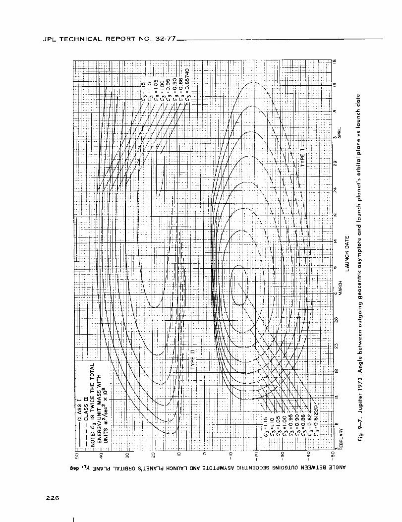
JPL TECHNICAL REPORTNO. 32-77
o o o _ o_ o o_ _ _ o o._
5ep ,7,_ 3NV7d 7VJ.I8_O S,13NV-Id HONNV7 QNV 310.LdlN)_SV 31_IJ.N33039 9NlOgll_O N33MJ.3e 379NV
"0
f-
0
E
0
O.
0
JO
0
u_
C0
Q.
0
¢-
0
bJ
,., oO.
EZ >',
0
u
h.
0OJ
¢-
0
O3
:3
0
E
a;
e.
NO,
IO,
226
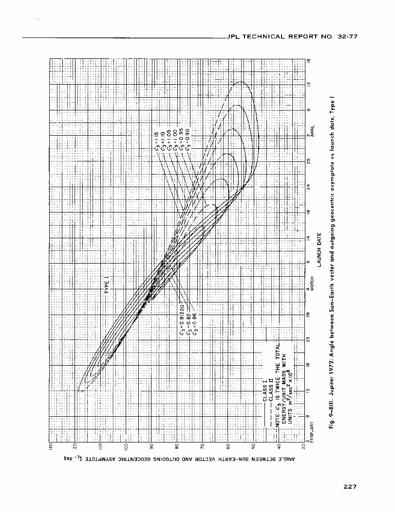
JPL TECHNICAL REPORTNO. 32-77
I.!
_rTi:!i
,!,
:!!
_ri
-rr
it
i!
i,+,
+,÷,
+,
+,
L_
r_t_
Tr:r
T_
tr0 0 0 0 0
- o _ r-.-
,7_ 3101dlAIISV 01_11N30039 9NIOglNo ONV _IOI03A H±EIV3-NI7S N33/_138 379NV
m
),
.Eg
e-
{}
O.
E),
0
e-
_a0
0')
0')
r,
J
e-
oILlIe-
e-
C
e_
o_
..-2
I0,
.1i1
227

JPL TECHNICAL REPORT NO. 32-77
228

JPL TECHNICAL REPORT NO. 32-77
Bop .7^
t
; [I
J
i
\
,t
!;
r _
rt;F
__ _o
31_11 HONr_V-I IV 3Sdl773 _3_-ISNV_I NI _,7VI_IONV 3n_11
229

JPL TECHNICAL REPORT NO. 32-77
hap ,7^ 3t/411 HgN£1V7 lV 3Sd1-1"13 EI3_-ISNVEI..!_NI ,k7VMONV 3NEI.L
0
r,-
>
E
,0
-1- .o..(..)z "$
t-
9C
0
E0C
0
).-
Q.
I
_r
230

JPL TECHNICAL REPORT NO. 32-77
0 0
1
1
Bap ,d^ 31_111 7VAIl:It:IV IV :1Sdl77:1 _':L-ISNVt:I1 NI 17VlAIONV 3rlt::11
0
..£
c-
O
E
0>
0
._ _--O
_J ._
e-
>.
0
E0_..
0
O)
==I--
Q.
7
231

JPL TECHNICAL REPORT NO. 32-77
-H-
:t;[
OLo
_1 j.o suo!ll!_
:..- _:ff::: m : 7t:t
4, :- 1i14t_. _ , +.+.+
' -d _<7:.; -_7+!t.: ; ti;:; i t!t!11: :+"-7it .... ,r
!1-! 2ii+_-- ff177: +tit
i11:.2 2I]2
i i,
!!!; ::::!ff
Itl .....
I! i ++-Tt-£ -
T_: .-7:r
1i1! ....
Ill! ....
!T,, ,_
41: ...
!r: ....
t ......! i l iI ; i $ ....
il_! ....,,,,
i
!,i: ....
i I ....I,t:
ii!: ....!,!; ....
!liz
!_:! ::/
¢1
I--
d0
E
3
0
>
W 0
t',,
8 "0z
JE0
%f-
.<-
_q
0"
0..
"-'l
mv
TO"
Ill-
232

JPL TECHNICAL REPORT NO 32-77
I_ CO _ _r rt)
,,,_ jo sUO!ll!"' ,d_ 118EI0 EI3:ISNV_I1 __0 N0173HI_I3d
CO
>-
<I
O
O.
70
_EvE
O
u_>
_O
O
r-
oZ
"J E
0
e
JE
h.
O.
Nb,0",
n
....2
O"
u-
233

JPL TECHNICAL REPORT NO. 32-77
:H
_T
2
÷+
I1
I!+.
t.
t'
t:
I:
i
,,,_ j.o SUO!II!LU 'Od ±le_lO _I3dSNVSJ. dO NOI-3HclV
_t++
--+
.f
"t-7
-: 7-i
.r
.f
-i_t-t
"r
Z
:z',z:
.4.:
X!
• i
-t
:t
,.4
":2/¢,
:[
:i:t
.r
.t
_t:!
:iOO
Tt_ :_
i. i:i_,- ::t
i: f! f
_" t:T
:£ _ - r
f- t;t
il T1:
ii !:!
4. ;,.
! ....
i:: :-ii:
i!i:: t_:J ....i: t-
::: :: :
>- ÷
:: ::i
,i.... I
*t
,, 'I
.... J
:i ::]:i;
i 'i
o
o
tt
!:7 _
:-f
7i!
°.1
__.
--4 -- <1[
::: ,-.,
..f '_
::: Dm <[
_N--t÷,i
-.!
:i! -
-.i
*+I i._
'[1 '_
,;,, rob _A
O
I
4O
-O
t-
e-
.D
O
e.
O
E
0
J:
<
/4
O,
t.-
..,.2
7
°-
234

JPL TECHNICAL REPORT NO. 32-77
O 0
n
I.--
o
t-
O
n
LIJ 0
*/1
0
O
r"
n
.¢
O,
.-CL
I
"T(3'
14.
235

JPL TECHNICAL REPORT NO. 32-77
,£_ _N o 0o
{)tp '.1 ":lNV7d _':I-,ISNV_I OI_I.LN300173H 3H.L ..40 NOI.LVNI73NI
kE::: _-_
fi
11
i i+_
i i
41
ii m
I I
(I)
0
"II
t-
e-
ll
e-
W _
r, -'-e-
.o
..I ¢-
_A¢.
c-
O
0
e-o-Dvc"
c_
Q.
c_
236
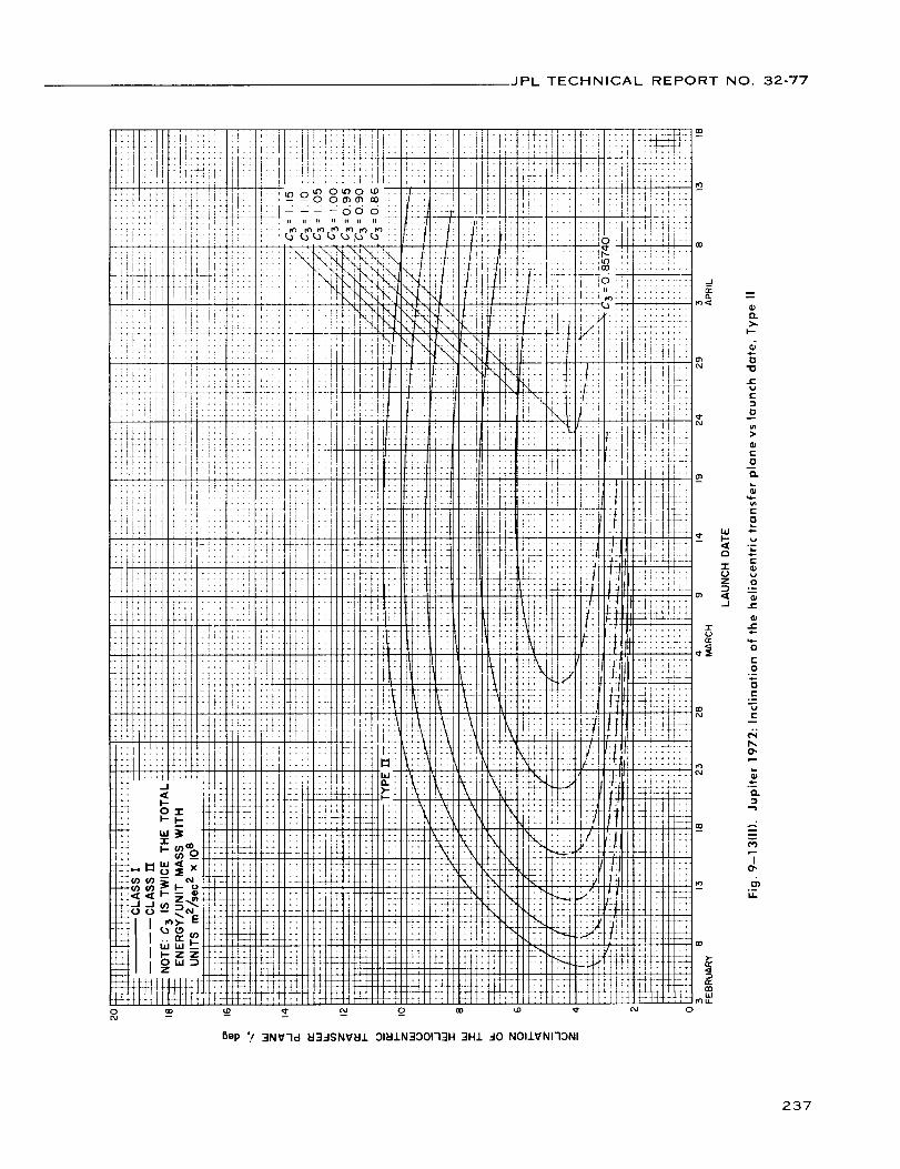
]PL TECHNICAL REPORT NO. 32-77
o
_t
i
i:ir..
,!
-!
.÷
rf
l
Sap '/ 3NV7cl _3_-ISNV_I10I_1N300173H 3H± _-I0 NOIIVNI73NI
237

JPL TECHNICAL REPORT NO. 32-97
O o OI I I
r-- _ m o
o o d T TI I t
Oap ,ag ":INI1 7VAINSV 1V 31n1Izv7 7VliS3730
I
w
O_
>.I--
O
"O
c-
O
>
E".,T.
DbJ >j-- .-
C3 O
T(J
Z
.-,1
0
0
m
%U
/4b,,0",
O.
...1
I0",
°_
238
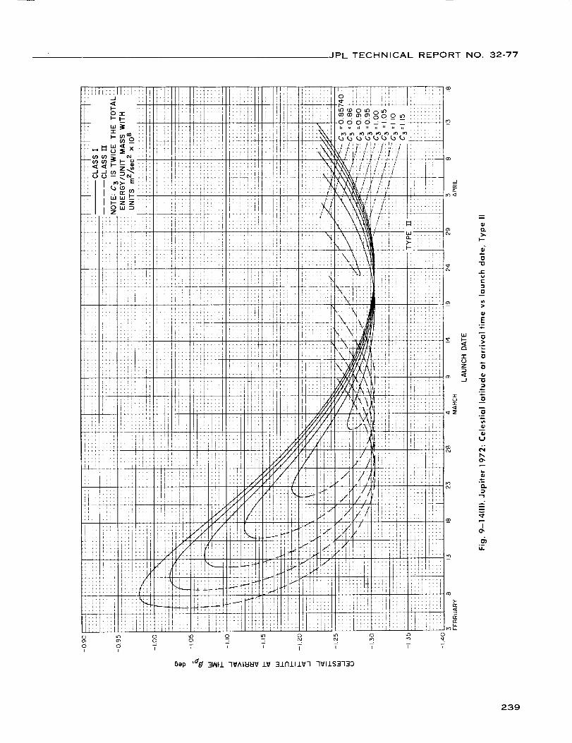
JPL TECHNICAL REPORT NO. 32-77
_J
Er_<_
o o TI I
NX! i::Ttitilti::::
::vi'::t:/_ i i::i i i!:/ ;_,_;' I . #Ill. _.; +.ii .;..
• il_ ..,_, _i.-_ ..... ii-!.Z- : : : :: i:-'. :: ',
,.7 *i.... i i
;._tt "*t'_ i t _i+!!tEi iii!! !i: ii_it,,i!
:i: ii! iiii i! iii..,.... _
T T T T T T ? T
{)aP '_t/ 31_11 7_'AIHH_ 1V 31r1111_7 7_11S373:)
O.
I--
0
"0
i-
{..
:3
0
E".=
0
i.i.
0
0
0
0
%U
°_O.
I04
la.
239

JPL TECHNICAL REPORT NO. 32-77
3as/W_l ,dqA 1:13ilclnP Oi 133dS3_ HIIM 033dS DIJ.OIdl/_,SV
1!t"i:'-
4_.
::i[
; II)
-_f-* _J..s_ --
; 2 :::
1iIT
"L:- "Z
+__
ii, I GI
i;_: g
TU;
T+It
iiii
!i!i
.,++-+÷÷
;!1 m_ttt
"'i+ <
1*:f mE
if}
O"13
e-_ae"
O
O
W •
"T
u ._
"6
E>.
<
di
"T
°-
240

JPL TECHNICAL REPORT NO. 32-77
O.
0
70
vel
0
O.
0
Ld
aL.
O.
°--
0
O.
E3__fl
O"
O.
04
o--
241

JPL TECHNICAL REPORT NO 32-77
242

JPL TECHNICAL REPORT NO. 32-77
o o o o o o o o o
51p 'd_ 3IOldM_,SV 31_IIN3::)O_IZ 9NII_IOONI ONV _IO.LO3A Nns-_13J.idrlr N33MI38 379NV
0
243

JPL TECHNICAL REPORT NO. 32-77
ii ii ii ii ii ii ii r
: ::_}} -----
6ep ,a_ 3101dlNASV OI_IIN3303Z __0 NOIIVNI73":I(]
UJ
-'r(,)Z
o
0
>
ft.
E
r,
i.
0
N
t-
O
0
v
O"
7o,
244

JPL TECHNICAL REPORT NO. 32-77
245
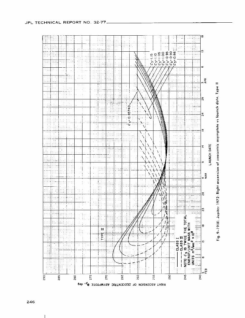
JPL TECHNICAL REPORT NO. 32-77
D.
I,--
=-
o'1oJE
c-
hi
a
"I"
ZD
(I.J
0
o.E>,
{}
e-
0
N
E0
E
{}
C_o-
r,,
o-
O.
O"
u.
246

JPL TECHNICAL REPORTNO. 32-77
o o o o _o _o o o _o
flap ,3_ 310J.dlNASV 9NIINOONI QNV t:IO.LO3A Hl_V3-13NV7cl N33M138 379NV
247

JPL TECHNICAL REPORT NO. 32-77
o o o o o o o o__ _ _ o _ = ® o o
6op ,3_ 3101dMASV 9NIMOONI GNV _0±33A Hi_V3-i3NV]d N33MI3B 3_gNV
248

JPL TECHNICAL REPORTNO. 32-77
6ep '-_ 3101dM,kSV 9NII/4100NI ONV _I01:)3^ SrldONVO 13NV7d N33M138 379NV
Z
249

JPL TECHNICAL REPORT NO. 32-77,
I,--
d
i-
e-
-1
O
o
E
O
e-
EO
E
c-
OE
13
U
00
c-
O
t-e
!
e--
N
o
..-,2
I
o_u.
250

JPL TECHNICAL REPORT NO. 32-77
X. JUPITER 1973: TRAJECTORY PARAMETER GRAPHS
Figure
10-1.
10-2(I).
10-2(11).
10-3.
10-4(I).
10-4(11).
10-5(I).
10-5(11}.
10-6(I).
10-6(11).
10-7.
10-8(I).
10-8(11).
10-9(I}.
10-9(11).
10-10.
10-11(I).
10-1 1(11).
10-12(I).
10-12(11).
Jupiter
Jupiter
Jupiter
Jupiter
Jupiter
launch
Jupiter
launch
Jupiter
launch
Jupiter
launch
Jupiter
1973:
1973:
1973:
1973:
1973:
Minimum injection energy vs launch date
Time of flight vs launch date, Type I
Time of flight vs launch date, Type II
Heliocentric central angle vs launch date
Earth-Jupiter communication distance vs
date, Type I
1973: Earth-Jupiter communication distance vs
date, Type II
1973: Declination of geocentric asymptotevs
date, Type I
1973: Declination of geocentric asymptotevs
date, Type II
1973: Right ascension of geocentric asymptotevs
launch date, Type I
Jupiter 1973: Right ascension of geocentric asymptote vs
launch date, Type II
Jupiter 1973: Angle between outgoing geocentric asymptote
and launch planet's orbital plane vs launch date
Jupiter 1973: Angle between Sun-Earth vector and outgoing
geocentric asymptote vs launch date, Type I
Jupiter 1973: Angle between Sun-Earth vector and outgoing
geocentric asymptote vs launch date, Type II
Jupiter 1973: True anomaly in transfer ellipse at launch time
vs launch date, Type I
Jupiter 1973: True anomaly in transfer ellipse at launch time
vs launch date, Type II
Jupiter1973: True anomaly in transfer ellipse at arrival time
vs launch date
Jupiter
Type I
Jupiter
Type II
Jupiter
Type I
Jupiter
Type II
1973: Perihelion of transfer orbit vslaunchdate,
1973: Perihelion of transfer orbit vs launch date,
1973: Aphelion of transfer orbit vs launch date,
1973: Aphelion of transfer orbitvs launch date,
251
JPL TECHNICAL REPORTNO. 32-77
X. JUPITER 1973: TRAJECTORY PARAMETER GRAPHS (Cont'd)
Figure
10-13(I).
10-13(11).
10-14(I).
10-14(11). Jupiter
Type II
10-15(1). Jupiter
launch
10-15(11). Jupiter
launch
10-16.
10-17.
10-18. Jupiter 1973:
launch date
10-19(11. Jupiter 1973:
launch date,
10-19(11). Jupiter 1973:
launch date,
10-20(I). Jupiter 1973:
asymptote vs
10-20(11}. Jupiter 1973:
asymptote vs
10-21 (11.
10-21 (11).
Jupiter 1973: Inclination of the heliocentric transfer planevs
launch dale, Type I
Jupiter 1973: Inclination of the heliocentric transfer planevs
launch date, Type II
Jupiter 1973: Celestial latitude at arrival time vs launch date,
Type I
1973" Celestial latitude at arrival time vs launch date,
1973: Asymptotic speed with respect to Jupitervs
date, Type I
1973: Asymptotic speed with respect to Jupitervs
date, Type II
Jupiter 1973: Angle between incoming zeocentricasymptote
and arrival planet's orbital plane vs launch date
Jupiter 1973: Angle between Jupiter-Sun vector and incoming
zeocentric asymptote vs launch date
Declination of zeocentric asymptote vs
Right ascension of zeocentric asymptote vs
Type I
Right ascension of zeocentric asymptote vs
Type II
Angle between planet-Earth vector and incoming
launch date, Type I
Angle between planet-Earth vector and incoming
launch date, Type II
Jupiter 1973: Angle between planet-Canopus vector and
incoming asymptote vs launch date, Type I
Jupiter 1973: Angle between planet-Canopus vector and
incoming asymptote vs launch date, Type II
252

JPL TECHNICAL REPORT NO. 32-77
103
i01
99
97
95
91
89
87
85
83
81
79
77
7526MARCH
31 5 IO 15 2O 25APRIL
LAUNCH DATE
30 5 _0 _5MAY
Fig. 10-1. Jupiter 1973: Minimum injection energy vs launch date
253

JPL TECHNICAL REPORT NO 32-77
° ° 8 8 o 8 ° § °o 8o o _ o _ co o o
;,_Dp 'Jl J.HglT-I -'10 3_II
I
W
0
o
254

JPL TECHNICAL REPORT NO. 32-77
I IIJ .......I Ii!!_ v
1111 IIi1_
Iil i_rl
++ ii ,,+, j_, l]_lLlr'
! l+Jir_llJl1'I+i
i I111 IIIflI',INI
J _ J llli]lI[l_
FIll i.... III
_.+ .... rl!I I ['%J1_ ii11 it]
[ !11, ,,,IPtlll[l.... !,!j!l_---4 iIii ,,:III'INII; I'_',',I IN ]
L
t_
+i +ii+,:+,!+pp+,, _:i,+ +++_ mo -_:t- • '".++-_ i x 2+ii
_o ' +; +i ' '
o,,+,,o,,.+,,_,,,0_......... ,,+_++_+?_? _++-_+it+,p, XI_[-p,,,,' , ,
"" + i/ [XI'_'"_ ' :I,,,_ ] Y] i + r _'A ,_ I IA ] l/] I £/J
:++,xi t_it..o : ......... :+_i' ixl l_ I IA I .... 1+ +- .....
l "_llIIIl[
I%[IF[IIP_ ! kkllll[lil !]! !!!]!!lJlJili_ +_; 4i_"_Jllll[l ::!!!!!]!!+!! [ _1! .};1 ....+r_-_-f+_k _ _I'"'"
"J- _ urn,, ..... , ,,:i !+i + ] + t 11 i i : t-+T" "-,+_+..+._+_._* -:-X ++_._-'_+f¢ _ .... __,+,u +_-_ ++-+++-++- ::: ==: ++:= i::+
+ .... ....+++t ++-!',+-_1_+-_++++_t ::,: +-r,,_, +: - .-+_ _-,.-:+++-,_,+_-+_+_,,.++., ..... +
+'...... +'+ ....+"....++ +++++++'_1_[ i +M + mlX+Xi
. _ ,,, ,',,,t_._!: _ . ++ -.-+4-_4_-_-@, - ....4-
+,LI_ ; :,_+_ii _+. i i, ,_,_,_, ............... .r_ ................ [1 ..... i +
-- I I P I I I i { III ]'A .... +_]_,Lr+ _ j [][-_ _ .u_ I I i li,.I I P. --"Y_ ] M+
+ / Ill[i+ltlt T ,
lips .[];[J lllJlllll
r i ill ! ! i: _i l]{{ll{i _
]_ _-'_ .... ! Ill Ir I+_,_}¢-_+ - ,+Pilllit',', _- +_*:
J
"r
Z
3
mI
Oi
O.
i.I,
lO
I,,-i.t
t"-
O
OI
EI,-,,-
I l
Io
+-u
00
I_Drr
0 0 0 _ 0 0 0 0 0 0
o o o _ o o o o o 0-- _ _ _ = 0 o_ oo ,_
s$op ,.4/ 1H917-140 31_1±
255

JPL TECHNICAL REPORTNO. 32-77
tTl
iL1
ti"
Ill
IIIt ?T
_tt _
7Y
LJ,!
[i :-4
i!i!
::t!!
:!:t
+!"
iLi
.++
o
_ _
• +t
t:! _" ::7_
4! 1! !*
L_t t! li• ; it
LL ...
!: _: F+4++
t_
!; i :i: i'
4
[_ ÷ 'i:
il-- & _i
_I _ _
i t ii_" ;T ,
O
7!
L_;_
!i_ii
!i,
ttT:!!!
i iT
2!!
li:
!.
I:
N'"
tL
li i:i
O
Bep '_ 379NV 7V_IIN30 C)I_IIN3OOI73H
G-o
E
0
G
Z ',_°-
-r
6_I"4O"
O.
I0
IJ.
256

JPL TECHNICAL REPORT NO. 32-77
OOO
W
-r
Z
_J
m
0"0
t-
r'.
c-
O
.m
E0
e"
EE0
0.
-?
0w
b_
o_Q.
....g
I0
257

JPL TECHNICAL REPORT NO. 32-77
0 000
LL_ :4:_-Ti?
[Td-T =
tV::_
!! I' _j44-4- __
_i: _(_
!:---t ....
I:
t_,-!i!
0
Q.
c-
O
>
t,-
e-
_ E5 E
O
°_n
7
o
b..
°--
.,.2
Io
.--
258

JPL TECHNICAL REPORT NO. 32-77
Ttl+tl
4rr!1
_J'it l
tY
"4
./
TF
tr,+
X
N.
, f
!.
i;
I I
_ap 'E_ :I.L0/dI_IASV
T 11 'r_ i:;
F!_c ::" :ii_ !:!t !]:i
............... :_ .t.
r;i: i::i 111!::::! !i_:
,-¢] i;]" +']' 'r;r _:'
.... 1 ...... '::_:i !:T:!!T _ !T ......
':i: ;i:: ;:::;.i:: i: ]
• *-+' *+_, ,rtr ,.;T ;.-.
-tf_ :-'::t-; cl-T1 _r:-'_; .....
::_ ........ ::::: _-,!J_
:::: :::: :;_;::::: i:::........ T_ _T "'_ T
+4:: TTL_ i !r[i , ,,: T!¢! tb!t :I
ii!' i '!f4 4 1 ii:_
:7: .... ,,,t ":: itf;.' ..... I_. , ..... i;.
I-- - .... :i i "
r'T it:
i;i ;itt _j_!
' :rt4 'T_t '_ ....' ':iT r'tt -tr'- ''-
;ii iiii!_if!!II ;_:; ....I i :i ' '
it: TJTr Till ii : ;]:]
t,: _,]_ Tttt
_DI I I
911::IJ.N:IOO':I9 -10 NOIJ.VNI-I03(]

JPL TECHNICAL REPORT NO, 32-77
o o o o o o o o
5ap ' $_ 3/OId_ASV 01_iN33039 50 NOI±VNIq33Q
0
I
260

JPL TECHNICAL REPORT NO 32-77
0 0 0 0
Bep '$e 310.LclIAI_,SV 01_1.1.N30039 30 NOISN3OSV 1HglEI
261

JPL TECHNICAL REPORT NO. 32-77
OoooJ
O
262

JPL TECHNICAL REPORT NO. 32-77
0 0 0 0 0 0 0 0=_ _ _ _ _ _, _ _ _ oI I I I
Bep ,7). :3NV7d 7V.LIBEIO S,13NVTd HONrlV7 CINV 310.LdltiASV ::)IN.LN3C)039 9NlOOlrlO N33MJ.38:179NV
263

JPL TECHNICAL REPORTNO. 32-77
0 0co if)
i ...._'__t_:__, i .... tilii't :i'
! i!i il''
, _:!l!i iii _if4 t4iii i4
ll't _tl I i ;
t/ ! Ir :; ;Ill ;[::I:
: i
/t: t "_:
i'i.... 7 : ] :_ ._,,..+.
> . _ --
i,:_i.,I_"I4Z::
S£ flt *;_ >'i+,+-i!4: i ii "
[i:: ; :-" [ '. : .2 L!i .... _iL_.. ;
i _ !ii! ii!!?! il
i " rt .... : :;i:; i::2:.:L
i ............
ill:.! i!::. i:
!l:t rt I r
i tt ....... _! ""
'2:i!i:t :I i_: +. _"_:_ --
i i 'tt •1 ....
i _-_:: ::::i! !!!..::-:!:i:
0 0
6ep ,7_ 3101d_ASV 0181N33039 9NIOOIRO ONV _O±O3A HI_V3-NRS N33_138 370NV
I
O.
I'm
o
JE
:)
0
.$.0
o.E
{,..q)
o
01
0'1C:
0b.l iI_
C3 C;
"r '-_
°
>
,.E
i=.
oIll
I,r-3
1E
..o
t:
(5i'4,.O"
o_o.
O0I
o
d_o_I.L
264

JPL TECHNICAL REPORT NO. 32-77
Bep ,7_ 3101dlN,kSV 01_11N30039 9NlOg/no ONV _IO.LO3A H.I._V3-NnS N33MJ.38 379NV
265

JPL TECHNICAL REPORT NO. 32-77
;I 2-T-_
i •:11 ++,it" 1i I
-- " tt tt' " "
., , . :::
/....-t ........ T
.! .......
........ ÷
........... i
i :!:. ;.: 7;: :T_"
, ! ii ÷_ +__.
i i"tt tl _i-
"'r ' " + '-
bl---+t "-++ r_ r]'"
-:1 : U ,. ....
: i i !tl tt .......
._1. f ...., , ,.,,
+_- ;_-" t ::',r
, 77f-" +
H: ;!-ii ttt- r"Ti '+_
T:- J 7:1_: < !:
(_C .•.
tlmmi '
- )_l -I!
I t l_i
I_- "- !!:ZZ _ ;
2 TLL
i
'T +
N%
'T['
.t
rl-
ii
:q'rl
44,
!!:11:
.!T/i.l
-?t i-
+.,1
'IT',! t .
!I::i;..
[:::
!:
,1
il.
i]-
:i:
?hi
1-r'
;!i.
f!-.
!i77
47Li
U::
i:r _
::7o8
"' --I -
;i !iiiiii!i :ill _ii:_!: I: l+i!!!:l:iJ! :41-
4 i.I_. !,,
• i ! _ ili: _!i
....i!i/L_.i!:;::'_"_.... i_:2[::i _:TTTI!I::: ''_•
} ]::!:
1 I
.............. i
i ........"_r" LL:__ "'t
iii:tii:i!i;:: :7:1
..... i
I!i tilJit",[ .ll:.ili .... !:H]l_.il
+!;1!-!1
11-rl .....
.... 4+ ....
.... #i- !: :ii....
:i:I -Ii ....
"::' 'i " : 7i:' i' [
__ 2-LL:_::::7:T
.........?ii
i:! 'N :
.i:1 a::z_ k::I ...' ' "...... i2:
7}] '.4:-i:: ,!:i
," #!'_t
.... !ti _..+t
T_F 77771
Oil) ,7^ _1411 HDNI"IV-I IV _Sdl773 i:I3.-ISNVI:II NI A7VlliiONV 3FI_LL
i_-!,+.+ -2;it!'i "-
Yi"''i •'["2 ] .72
.... ;ii:._ .,+
.... i;
't! -7!I''T] ':,
--t .....
iii ::.
:111 iiiiT- T 7_::
:: " ::::
!7:: :::!
"::! ::::i
"'1: i:
_I.. 4!::11 .....
.11 i"
ffl
i_-
_:_I -: . .
1 ._+.+
N
i 21
.2 __
ii
rr,-T'
ii:
:1:11
O
i
h-
G
o
t-
o
ill
E
e-
e-
Om
"r i
e-
c-
O
E0
0
:3h.
d4o,
Io
266

JPL TECHNICAL REPORTNO. 32-77
o o o o o o o o o
Sap ,7^ 31_lld. H3NNV7 IV 3Sdl773 _I:J:ISNV_II NI A7VI61ONV 3N_LL
267

JPL TECHNICAL REPORTNO. 32-77.
o 8 o o o o o o
5ap ,d^ 31,_11 7VAIS_IV lV 3Sdl773 I_I':I.-ISNV'_I NI A7V'I_IONV 3hal
i'-
0
E
o>
°_
0
e_°_
¢-
E
0
E0c-
O
b,O,
I0
i1
268

JPL TECHNICAL REPORTNO. 32-77
U_l=1,o_UO!ll!W ,d_ J.18_O 1:t3.-ISNVEI1 -I0 NOI73HII:I3d
269

JPL TECHNICAL REPORTNO. 32-77
!: ¸
+,
1T
i4,,&_
i
2_; -! 4
222
T::
::_ 41: d
.... _+..
:: "_:::
iTg:
44.-
:t: :-
;__+_.--
;T::
TT*I
, __
711T
:22 : _
,@441-
_D
;;:; __J, O:
i ,
i i
b.-
I1.
I--
o-o
e-
o
."2-
0
E
-J e-
0
O)e-
h.
P_
°-
..-2
To
u
270

JPL TECHNICAL REPORT NO. 32-77
Oo 8 oo_rO (M
(M (M
0 0 0 0 00 0 0 0 0
uJ_t_o suo!ll!W ,o_ 118_10 _:I-ISNV_I1 .:10 NOI73HdV
5
0 0 0
o o o0_
271

JPL TECHNICAL REPORT NO 32-77
¢)CL
>.l--
rid
i-
{,.
{}
.oUJ 0
e-
z
E
0
(_
..E
Q.
0"
....,2
N"ro
272

JPL TECHNICAL REPORTNO. 32-77
5ep '/ 3NV7d _34SNV_I OI_IN300133H 3HI _-I0 NOIIVNI7ONI
273

JPL TECHNICAL REPORTNO, 32-77
Bap '] 3NVlcl EI3.-ISNV_J. 01_.LN3C)Orl3H 3HJ..dO N01.LVNI1ONI
T
O
274

JPL TECHNICAL REPORTNO. 32-77
0I
0i
275

JPL TECHNICAL REPORTNO 32-77
T
D.
I--
D
_a
D
Emo>
LLI ".--F- _-
= "6
.j ._-
D
D
u_
u
o,
0.
la.
276

JPL TECHNICAL REPORTNO. 32-77
277

JPL TECHNICAL REPORT NO. 32-77
Q;0.
>.I--
I-0
JEwe-
m
°_O.
O.b-
_o
hi D.
r_ L.J=
"I" ._
Q;
D.
_a.D
2D.
E
<
0"
O.
o
278

JPL TECHNICAL REPORT NO. 32-77
t_+i
i-li
;[i!
4_. ,
-4|
[i:lj
L;!_I
f_til_1
,i
.... i
I
5op ' dx 3NVTd 7V118610 S,13NV7cl 7VAlidlY (]NV 3101dINASV OI_IN3OO3Z 9NIINOONI N33_138 379NV
hi
1"0Z
.I
,c-O
"O
¢-t.If-
0
f-
o.
J0i..0
t-
O
n
o).
o-
o
=or.
D
zo.E
o,=,
i..e.-t-
O
N
O3C
°_
E0
°-
..0
o)t.-
,¢
h,.0,,
.=o.
d,°--LL
279

JPL TECHNICAL REPORTNO, 32-77
.... +_.
t ! i t ,
II I
+_
+,/;i_T ;;• +. ,_
I!'T
4_4;! ;
',l tj
/7!!,#,
+,,,
- + ,tt J
- - IPIr,,
:tff
#'f'[Iii+, t.
ii;i
! !,
:/
/
/;
/
//7!:
• "i"
"'IT
; ;141:
f* itf_
/ '-T?
++ 4#, ,
11+,ii t44 ,
! ,,it.
F+T-
" :;7
4 +414#!tL/f
7:!iili
i_;!i_ i4i!r,!,
l '1+
i ;:ii,f r i ,t#
I ;i/,_
• /Itili
tZ/
I
7ii
7:--
o o o o oLO _--
Jll;_,,i,+ ......
, ........ _J
::::: ::::
O O
Sap ,d_ 310icll_kSV 3181N330:IZ 9NIIAIOONI QNV _IOJ.O3A NnS-w:llldrlP N33_13B 370NV
':3
J
,,.E
E
O
O
E>,
o
i.
,z-
O
N
E
EOi.aI"-
C
E
L
°-
e-
!
e-
b.O"
°-
Io
o-
280

JPL TECHNICAL REPORTNO. 32-77
t ? TI I I I
bep ,d@ 3J.0.LdlN_SV 31HIN':IO03Z 40 N01.LVNI-1::)3G
T
<_
I
281

JPL TECHNICAL REPORTNO. 32-77
oJ
0
282

<7JPL TECHNICAL REPORT NO. 32-77 /}7
/
41
f-ff_t?ff-
!:ii
qH
qH
.... -o ....7
L? J- _ ill- + - __t+IH b -f-!'" --4 ............ 4 ,,,, ...... _................. "+....
+Ifft: _ !÷i- .... H: ............. .iHH+ . ._:I:..:._._...... :,:,x,,_..... _t_
t 111 ...... :{:-- -H_ ..... \..- ,Z-.-.T-._Ii, _,'*T,,XF,_, d tt¢
_D II'i'-I}-t{-X-X-X-XXI-J!HI-_H iii'::-- "w D$_"+ !+i_' '_t_+ i _t__+ j ..... _,-- ,, a r • T I _" , -'±_
7DH : " i- [........... , ' ," ...... _ ' _X -_ -" r : ' ]r ,+
rm:q_x; .........___q)!"._.......::::::;-.... :,_-tt i bKf::, i: {-":q-:::::fl_::::,::4_:4::_-11t_l ''_.' :- '"mr:m_:7Xi+tj :f : ::_:::" '[' :; :{_:!¢i4-_+_-ij_}
H_: - _ - - ;'_ _"" b_-fftt_f+_ y,,,,t :mr
I I t +t)/_J / !Hi ' 'i!
_TVI l#
H!............. ._ ........ ,_-o . . 7_H_"_f___+.... : :::::::_,.::::::::-- _.o ,o 41trd
Ii ii ii ii '
b _- rF ====================== "::'_:t/:,,_ : !i_i_] [r _k. _t,- -_' ...... ttr±:_ tt i_ti1 ;, ;;;':,7::, >-
' *4_+_-zx:::::--: :X-r_t:_t_, J-bi-,,li: -,-!_-t i,. i_ ___ L
Ltf b L{ Z [
-_- " f ::? F_
7t77,I--!i7! ;o-I=
,)=@
_=
E
i,ao-
I_1 L.
e"
T 0
7 _
e"
0
e"
@
°--
...g
"To
112o
o _ o 8 o _ o _ o
5itp 'd o 310.LdtlASV OlI:IIN3OO3Z 40 NOISN3OSV .LHOIU
283
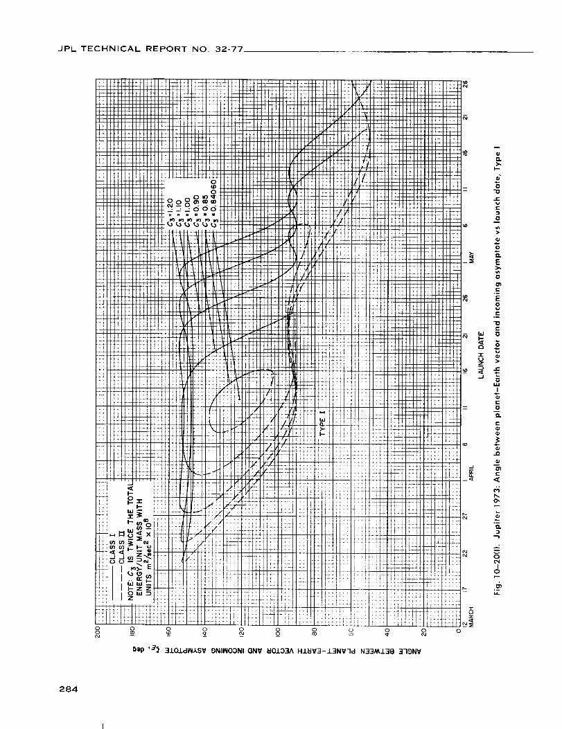
JPL TECHNICAL REPORT NO. 32-77
Bap ,3_ 3J.OJ.dlN,kSV 9NIINOONI GNV _10£33A HJ._V3-13NV-ld N33MJ.3B 3-19NV
m
O.
I--
0
0
O.
E
_n
0
E
E0
E
E
"' 0
w
I
E
0
D.
E
E
,<
O"
.,-1
0
IO
°_t,L
284

, JPL TECHNICAL REPORT NO, 32-77
6ep ,3_ 3.LOJ.clI_I,A,SV 9NIINOONI GN'¢ _IOJ.O3A HJ._IV3-J.3NV-ld N33M.L3B 3-19NV
285

JPL TECHNICAL REPORT NO. 32-77
286

JPL TECHNICAL REPORT NO. 32-77
5ap ' a_
(((
_rX)(
o(n
rO_(
FFLl
+;
!ti*H
|i
'] .I
lfit
tt •IL
t!|iilF
i,
|I L'_J 4
Ii :l
Ili
it):
!
i+
T_
4_
_L
_t
_+
i:!;!,+
.i
•i
il:[
;rTF
tr
_L
:F
i
t_00
.1:i
L
ii:4
!
)
!
2
r
_4 _[
:_ !!
F!! _+L!. _!
ri i.
F_
I
[i I
.... +,
: : T_.
;,I
LI:: 21
i;
!r
it!;I
!r!
:rT_;/': !\
!t' ''
!!! :_.
2:::::
:2T :2
i ' ',t- _-
L ....! .....
, , _'
!;: :
3101dI_IASV ONII_IOONI ONV _0133A SrldONVO 13NV7d N33_138 379NV
W
Z
J
D
o
uC
..o
E
G
EO
Co_
C
0
>
O
C
0U
I
O
C
C
o_
y-.,,
.m
287

JPL TECHNICAL REPORT NO. 32-77
NOMENCLATURE
C:_ vis viva energy (injection energy, ()f escape
hyperbola)
i inclination of heliocentric transfer orbit, deg
R,, aphelion of transfer orbit, millions of km
R(_ Earth-Mercury (or-Jupiter) communicationdistance, millions of km
R_, perihelion of transfer orbit, millions of km
T_, time of flight, days
vL true anomaly in transfer ellipse at launch time,
deg
v_ true anomaly in transfer ellipse at arrival time,
deg
Vhp asymptotic speed (or hyperbolic-excess speed)
with respect to Mercury (or Jupiter), km/see
13_, celestial latitude of Mercury (or Jupiter) at
arrival time, deg
yL angle between outgoing geocentric asymptote
and launch planet's orbital plane, deg (also
defined as celestial latitude of outgoingasymptote)
yp angle between incoming hermiocentric t_or
zeocentric" asymptote and arrival planet's
orbital plane, deg
{_ angle between Sun-Earth vector and outgoing
geocentric asymptote, deg (also defined as
Earth-probe-Sun angle)
_, angle between Mercury-Sun (or Jupiter-Sun)
vector and incoming hermiocentric (or
zeocentric) asymptote, deg (also defined as
Sun-probe-target angle)
0_, right ascension of hermiocentrie (or zeocentric)
asymptote, deg
0,_ right ascension of geocentric asymptote, deg
• _, declination of hermiocentric (or zeocentrie)
asymptote, deg
qb_ declination of geocentric asymptote, deg
,I, heliocentric central angle, deg
aThis table of Nomenclature presents only the notation used in thegraphs of Sections IV to X. All other terms are defined at pointof first mention in Sections I to III.
6Hermiocentrie refers to Mercury.
"Zeocentric refers to Jupiter.
288

IPL TECHNICAL REPORT NO. 32-77
REFERENCES
1. Battin, R. H., "The Determination of Round-Trip Planetary Reconnaissance Trajec-
tories," Journal of the Aero/Space Sciences, Vol. 26, No. 9, September 1959.
2. Clarke, V. C., Jr., Design of Lunar and Interplanetary Ascent Trajectories, Technical
Report No. 32-30, Rev. 1, Jet Propulsion Laboratory, Pasadena, March 15, 1962.
3. Holdbriclge, D. B., Space Trajectories Program for the IBM Computer, Technical
Report No. 32-223, Rev. 1, Jet Propulsion Laboratory, Pasadena, September 1,
1962.
4. The American Ephemeris and Nautical Almanac for the year 1960, p. 498, U. S.
Government Printing Office, Washington.
5. Allen, C. W., Astrophysical Quantities, The Athlone Press, University of London,
London, 1955.
6. Cutting, E., and Sturms, F. M., "Trajectory Analysis of a 1970 Mission to Mercury
via a Close Encounter with Venus," AIAA Paper 60-90, AIAA 2nd Annual Aero-
space Sciences Meeting, New York, New York, January 25-27, 1965.
7. Baker, A. B., "Approximate Payload Capabilities of Boosters for Planetary
Missions," Journal of Spacecraft and Rockets, Vol. 1, No. 4, p. 439, 1964, RCA,
Princeton, New Jersey.
8. Clarke, V. C., Jr., Bollman, W. E., Roth, R. Y., and Scholey, W. J.,Design Param-
eters for Ballistic Interplanetary Trajectories, Part I. One-way Transfers to Mars
and Venus, Technical Report No. 32-77, Jet Propulsion Laboratory, Pasadena,
California, January 16, 1963.
9. W. E. Bollman, One-way Type-II Transfers to Mars, Addendum 1 to Ref. 8, Jet
Propulsion Laboratory, Pasadena, California (to be published).
ACKNOWLEDGMENT
Tile authors wish to acknowledge the valuable assistance of
M. Beckwith, who carried out the production of tile computations and
automatic ph)tting of the graphs.
289