War Memorial Cistern System - Save The Rain
559
Bid Documents War Memorial Cistern System Onondaga County Technical Specifications Project No. 381098 June 2011
-
Upload
khangminh22 -
Category
Documents
-
view
5 -
download
0
Transcript of War Memorial Cistern System - Save The Rain

B i d D o c u m e n t s
War Memorial Cistern System
Onondaga County
Technical Specifications
Project No. 381098
June 2011


TC-1
6/11
TABLE OF CONTENTS
FOR
WAR MEMORIAL CISTERN SYSTEM
ONONDAGA COUNTY
TECHNICAL SPECIFICATIONS
Section 01 31 13 Project Coordination
Section 01 45 33 Special Inspection and Testing
Section 02 41 00 Demolition
Section 03 30 01 Reinforced Concrete
Section 03 62 00 Nonshrink Grouting
Section 03 63 00 Concrete Doweling
Section 04 22 00 Concrete Unit Masonry
Section 05 05 23 Welding
Section 05 50 00 Metal Fabrications
Section 07 84 00 Firestopping
Section 07 92 00 Joint Sealants
Section 08 06 01 Door and Hardware Schedule
Section 08 11 16 Aluminum Doors and Frames
Section 09 06 00 Schedules for Finishes
Section 09 90 00 Painting
Section 10 14 00 Signage
Section 10 44 00 Fire Protection Specialties
Section 22 07 00 Plumbing Piping Insulation
Section 22 10 01 Plumbing Piping and Accessories
Section 22 10 01.01 Plumbing Piping Schedule
Section 22 30 00 Plumbing Equipment
Section 22 32 01 Sump Pump
Section 23 07 00 HVAC Insulation
Section 23 21 13 Hydronic Piping-General
Section 23 21 13.01 Hydronic Piping Schedule Data Sheet
Section 23 21 14 Hydronic Specialties

TC-2
6/11
TABLE OF CONTENTS
Section 26 05 04 Basic Electrical Materials and Methods
Section 26 05 05 Conductors
Section 26 05 26 Grounding and Bonding for Electrical Systems
Section 26 05 33 Raceway and Boxes
Section 26 08 00 Commissioning of Electrical Systems
Section 26 20 00 Low-Voltage AC Induction Motors
Section 26 24 16 Panelboards
Section 26 24 19 Low-Voltage Motor Control
Section 26 27 26 Wiring Devices
Section 26 29 23 Low-Voltage Adjustable Frequency Drive System
Section 26 50 00 Lighting
Section 31 09 19 Static Load Tests
Section 32 31 00 Access Gates
Section 40 05 15 Piping Support Systems
Section 40 27 00 Process Piping-General
Section 40 27 00.08 Stainless Steel Pipe – General Service Data Sheet
Section 40 27 00.11 Chlorinated Polyvinyl Chloride Pipe and Fittings Data Sheet
Section 40 27 00.13 Copper and Copper Alloy Pipe Tubing and Fittings Data Sheet
Section 40 27 01 Process Piping Specialties
Section 40 27 02 Process Valves and Operators
Section 40 42 13 Process Piping Insulation
Section 40 80 01 Process Piping Leakage Testing
Section 40 90 01 Instrumentation and Control for Process Systems
Supplement – Components
Supplement – Functional Descriptions
Section 40 99 90 Package Control Systems
Section 43 40 01 Polyethylene Storage Tanks
Section 43 40 02 Fiberglass Reinforced Pressure Tank
Section 44 42 56.10 Horizontal End Suction Centrifugal Pumps
Section 44 42 57 Pump Filter Skid System
Section 44 43 29 Pressure Filter System
Section 46 66 20 Ultraviolet Disinfection Equipment for Water

ONONDAGA COUNTY
WAR MEMORIAL CISTERN SYSTEM
381098 Project Coordination
27 May 2011 01 31 13 - 1
©Copyright 2011 CH2M HILL
SECTION 01 31 13
PROJECT COORDINATION
PART 1 GENERAL
1.1 RELATED WORK AT SITE
A. General:
1. Other work that is either directly or indirectly related to scheduled
performance of the Work under these Contract Documents, listed
henceforth, is anticipated to be performed at Site by others.
2. Coordinate the Work of these Contract Documents with work of others as
specified in General Conditions.
3. Include sequencing constraints specified herein as a part of Progress
Schedule.
B. Applications Software Development:
1. Engineer will perform programming of applications software for certain
portions of Process Instrumentation and Control Subsystem. Refer to
Section 40 90 00, Instrumentation and Control for Process Systems, for
detailed information pertaining to Engineer programming.
a. Coordinate and deliver to Engineer’s office and staging site hardware
and standard software components, as specified for PICS.
b. Sequencing: Include sequencing constraints specified herein as part of
Progress Schedule.
c. Engineer will confirm delivery date with Contractor 10 days prior to
scheduled delivery, and within 24 hours of expected delivery time.
2. Deliver hardware specified to Engineer within constraints detailed in
Section 40 90 00, Instrumentation and Control for Process Systems.
3. Return delivery of hardware to Project Site within constraints detailed in
Section 40 90 00, Instrumentation and Control for Process Systems.
4. Allowance for interruptions to the Work because of testing by Engineer of
Engineer developed applications software:
a. During Functional Testing and Performance Testing, Contractor shall
plan for interruption of testing of the Work to allow Engineer to
investigate software problems, make software configuration
changes, and conduct additional testing.
b. Allowance for Interruptions: 10 days total.
c. When applications software testing is delayed because of altered
equipment interfaces or receipt of incorrect Shop Drawing
information, duration of delay will be excluded from interruption
allowance, unless notified otherwise by Engineer.

ONONDAGA COUNTY
WAR MEMORIAL CISTERN SYSTEM
381098 Project Coordination
27 May 2011 01 31 13 - 2
©Copyright 2011 CH2M HILL
1.2 UTILITY NOTIFICATION AND COORDINATION
A. Coordinate the Work with Owner for all utilities within Project limits. Notify the
Owner prior to commencing Work, if damage occurs, or if conflicts or
emergencies arise during Work.
B. Obtain a Burn Permit issued by On-Site Representative or Owner prior to
commencing with welding, torching or soldering.
1.3 PROJECT MILESTONES
A. General: Include the Milestones specified herein as a part of the Progress
Schedule.
B. Project Milestones: Generally described in the Agreement Form. Following is a
detailed description of each:
1. September 9, 2011 - Phase I: the following milestones, as generally
indicated on the instrumentation and control P&ID drawings, shall be met:
a. Plumbing contract Work, including provision of the following:
1) Three-way valves associated with Zones 15, 21 and 23 as
indicated on the drawings. Three way valves shall be
statically positioned to permit flow to enter the connected
rainwater receiver tank’s inlet.
2) Retrofit provision of reduced pressure zone backflow preventer
into existing Cold feed to existing steam to hot water heat
exchanger.
b. General Contract Work, including provision of the following:
1) Roof collector (RC) process drain piping connecting three way-
valves to the Northeast Rainwater Receiver Tank
(RWRT-NE).
2) In-line basket strainer feeding RWRT-NE.
3) RWRT-NE, respective equipment bases and appurtenances.
4) Temporary Phase I Northeast Rainwater Receiver Pump and
filtration skid with bladder pressure tank and
interconnecting piping and valves (TP-1,2).
5) Rainwater Force main connections of untreated rainwater from
TP-1,2 to the existing steam to hot water heat exchanger,
hot water recirculation loop and existing ice resurfacing
machine fill stations.
c. Electrical Contract’s Work, including installation and commissioning
of the following components:
1) Instrumentation associated with Phase I Work described herein.
2) Power associated with all Phase I Work.

ONONDAGA COUNTY
WAR MEMORIAL CISTERN SYSTEM
381098 Project Coordination
27 May 2011 01 31 13 - 3
©Copyright 2011 CH2M HILL
d. Rink Ice: 1-1/2 inches of 40 percent treated rainwater based ice
surface built up and subsequently maintained in hockey arena. The
Contractor shall maintain accurate and detailed dated volumetric
records of the quantities and sources of rain water and Cold water
utilized for this purpose. Only rainwater from the sources pre-
approved by the Engineer may be utilized.
e. Temporary equipment, storage and power may be used by the
Contractor, as necessary and as approved by the Engineer, in order
to achieve this Phase I project milestone.
2. February 1, 2012 - Phase II: Treated pressurized rainwater delivered to Ice
resurfacing machine fill stations, including all work indicated in the
Contract:
a. Plumbing Contract Work, including:
1) Substantial completion of all work in Contract.
b. General Contract Work, including:
1) Substantial completion of all work in Contract.
c. Electrical Contract Work, including:
1) Substantial Completion of all work in Contract.
d. HVAC Contract Work, including:
1) Substantial Completion of all work in Contract.
3. March 1, 2012 - Overall Substantial Completion.
1.4 WORK SEQUENCING/CONSTRAINTS
A. Include the following work sequences in the Progress Schedule:
1. Comply with the work sequencing constraints as described in the project
milestones section of this specification section.
1.5 FACILITY OPERATIONS
A. Continuous operation of Owner’s facilities is of critical importance. Schedule and
conduct activities to enable existing facilities to operate continuously, unless
otherwise specified.
B. Perform Work continuously during critical connections and changeovers, and as
required to prevent interruption of Owner’s operations.
C. When necessary, plan, design, and provide various temporary services, utilities,
connections, temporary piping and heating, access, and similar items to maintain
continuous operations of Owner’s facility.
D. Do not close lines, open or close valves, or take other action which would affect
the operation of existing systems, except as specifically required by the Contract

ONONDAGA COUNTY
WAR MEMORIAL CISTERN SYSTEM
381098 Project Coordination
27 May 2011 01 31 13 - 4
©Copyright 2011 CH2M HILL
Documents and after authorization by Owner and Engineer. Such authorization
will be considered within 48 hours after receipt of Contractor’s written request.
E. Construct Work in the following stages to allow for Owner’s continuous
occupancy and for uninterrupted operation during construction.
1. Comply with the work sequencing constraints as described in the project
milestones section of this specification section.
F. During the Work sequencing Phase I: Existing plant facilities will remain in
operation except for during Owner approved cut-ins.
G. Prior to proceeding with Phase II, the following Work described in the project
milestones section of this specification shall be completed.
H. Process or Facility Shutdown:
1. Provide 7 days advance written request for approval of need to shut down a
process or facility to Owner and Engineer.
2. Power outages will be considered upon 48 hours written request to Owner
and Engineer. Describe the reason, anticipated length of time, and areas
affected by the outage. Provide temporary provisions for continuous
power supply to critical facility components.
I. Install and maintain bypass facilities and temporary connections required to keep
Owner’s operations on line. Sequences other than those specified will be
considered upon written request to Owner and Engineer, provided they afford
equivalent continuity of operations.
J. Do not proceed with Work affecting a facility’s operation without obtaining
Owner’s and Engineer’s advance approval of the need for and duration of such
Work.
K. Relocation of Existing Facilities:
1. During construction, it is expected that minor relocations of Work will be
necessary.
2. Provide complete relocation of existing structures and Underground
Facilities, including piping, utilities, equipment, structures, electrical
conduit wiring, electrical duct bank, and other necessary items.
3. Use only new materials for relocated facility. Match materials of existing
facility, unless otherwise shown or specified.
4. Perform relocations to minimize downtime of existing facilities.
5. Install new portions of existing facilities in their relocated position prior to
removal of existing facilities, unless otherwise accepted by Engineer.

ONONDAGA COUNTY
WAR MEMORIAL CISTERN SYSTEM
381098 Project Coordination
27 May 2011 01 31 13 - 5
©Copyright 2011 CH2M HILL
1.6 ADJACENT FACILITIES AND PROPERTIES
A. Examination:
1. After Effective Date of the Agreement and before Work at Site is started,
Contractor, Engineer, and affected property owners and utility owners
shall make a thorough examination of pre-existing conditions including
existing buildings, structures, and other improvements in vicinity of Work,
as applicable, which could be damaged by construction operations.
2. Periodic reexamination shall be jointly performed to include, but not limited
to, cracks in structures, settlement, leakage, and similar conditions.
B. Documentation:
1. Record and submit documentation of observations made on examination
inspections in accordance with paragraph Construction Photographs and
Audio-Video Recordings.
2. Upon receipt, Engineer will review, sign, and return one record copy of
documentation to Contractor to be kept on file in field office.
3. Such documentation shall be used as indisputable evidence in ascertaining
whether and to what extent damage occurred as a result of Contractor’s
operations, and is for the protection of adjacent property owners,
Contractor, and Owner.
1.7 CONSTRUCTION PHOTOGRAPHS
A. Photographically document all phases of the Project including preconstruction,
construction progress, and post-construction.
B. Photography shall be by a professional commercial photographer, experienced in
shooting interior/exterior construction photos, in daylight and nighttime
conditions, and in good and inclement weather.
C. Film handling and development shall be done by a commercial laboratory.
D. Engineer shall have the right to select the subject matter and vantage point from
which photographs are to be taken.
E. Preconstruction and Post-Construction:
1. After Effective Date of the Agreement and before Work at Site is started,
and again upon issuance of Substantial Completion, take a minimum of
48 exposures of Construction Site and property adjacent to perimeter of
Construction Site.
2. Particular emphasis shall be directed to structures both inside and outside
the Site.

ONONDAGA COUNTY
WAR MEMORIAL CISTERN SYSTEM
381098 Project Coordination
27 May 2011 01 31 13 - 6
©Copyright 2011 CH2M HILL
3. Format: Digital, minimum resolution of 756 by 504 pixels and 24-bit,
millions of color.
F. Construction Progress Photos:
1. Photographically demonstrate progress of construction, showing every
aspect of Site and adjacent properties as well as interior and exterior of
new or impacted structures.
2. Weekly: Take 48 exposures using Digital, minimum resolution of 756 by
504 pixels and 24-bit, millions of color.
3. Monthly: Take 50 exposures using Digital, minimum resolution of 756 by
504 pixels and 24-bit, millions of color.
G. Color Prints:
1. Minimum Size: 3 inches by 5 inches.
2. Finish: Glossy.
3. Label Each Print:
a. Project name.
b. Date and time photo was taken.
c. Photographer’s name.
d. Caption (maximum 30 characters).
e. Location and area designation.
f. Schedule activity number, as appropriate.
4. Assemble in bound albums in clear plastic sleeves that facilitate viewing
both front and back of each photograph.
5. Assemble negatives in their corresponding album in clear plastic sleeves
made for the purpose.
H. Digital Images:
1. Archive using a commercially available photo management system.
2. Label each disk with Project and Owner’s name, and week and year images
were produced.
1.8 AUDIO-VIDEO RECORDINGS
A. Prior to beginning Work on Construction Site or of a particular area of the Work,
10 days following date of Substantial Completion, videograph Construction Site
and property adjacent to Construction Site.
B. In the case of preconstruction recording, no Work shall begin in the area prior to
Engineer’s review and approval of content and quality of video for that area.
C. Particular emphasis shall be directed to physical condition of existing vegetation,
structures, and pavements within pipeline alignment and areas adjacent to and
within the right-of-way or easement, and on Contractor storage and staging areas.

ONONDAGA COUNTY
WAR MEMORIAL CISTERN SYSTEM
381098 Project Coordination
27 May 2011 01 31 13 - 7
©Copyright 2011 CH2M HILL
D. Engineer shall have right to select subject matter and vantage point from which
videos are to be taken.
E. Video taping shall be by a professional commercial videographer, experienced in
shooting interior construction videos.
F. Video Format and Quality:
1. VHS format, with sound.
2. Video:
a. Produce bright, sharp, and clear images with accurate colors, free of
distortion and other forms of picture imperfections.
b. Electronically, and accurately display the month, day, year, and time
of day of the recording.
3. Audio:
a. Audio documentation shall be done clearly, precisely, and at a
moderate pace.
b. Indicate date, project name, and a brief description of the location of
taping, including:
1) Facility name.
2) Street names or easements.
3) Addresses of private property.
4) Direction of coverage, including engineering stationing, if
applicable.
G. Documentation:
1. Video Tape Label:
a. Tape number (numbered sequentially, beginning with 001).
b. Project name.
c. Name of street(s) or easement(s) included.
d. Applicable location by engineering stationing.
e. Date and time of coverage.
2. Project Video Log: Maintain an ongoing log that incorporates above noted
label information for videotapes on Project.
1.9 REFERENCE POINTS AND SURVEYS
A. Owner’s Responsibilities:
1. Establish horizontal reference points or coordinate system with bench
marks and reference points for Contractor’s use as necessary to lay out
Work.
2. Establish centerlines of principal structures, roads, and pipelines and a
baseline from which facilities may be located.
3. Establish location at all poles and anchors.

ONONDAGA COUNTY
WAR MEMORIAL CISTERN SYSTEM
381098 Project Coordination
27 May 2011 01 31 13 - 8
©Copyright 2011 CH2M HILL
B. Location and elevation of bench marks are shown on Drawings.
C. Contractor’s Responsibilities:
1. Provide additional survey and layout required to layout the Work.
2. Notify Engineer at least 3 working days in advance of time when grade and
line to be provided by Owner will be needed.
3. Check and establish exact location of existing facilities prior to construction
of new facilities and any connections thereto.
4. In event of discrepancy in data or staking provided by Owner, request
clarification before proceeding with Work.
5. Retain professional land surveyor or civil engineer registered in state of
Project who shall perform or supervise engineering surveying necessary
for additional construction staking and layout.
6. Maintain complete accurate log of survey Work as it progresses as a Record
Document.
7. On request of Engineer, submit documentation.
8. Provide competent employee(s), tools, stakes, and other equipment and
materials as Engineer may require to:
a. Establish control points, lines, and easement boundaries.
b. Check layout, survey, and measurement Work performed by others.
c. Measure quantities for payment purposes.
PART 2 PRODUCTS (NOT USED)
PART 3 EXECUTION
3.1 SALVAGE OF MATERIALS
A. Materials to be salvaged include:
1. Existing heat exchanger.
2. Existing hot water recirculation pump.
3. Existing hot water system’s instruments.
4. Temporary equipment utilized during Phase I milestone Work.
B. Salvage materials for Owner’s use where identified.
1. Remove material with extreme care so as not to damage for future use.
2. Promptly remove from Work area salvaged materials.
3. Store materials offsite.
C. Meet with Engineer prior to starting to dismantle equipment or piping designated
to be salvaged. Engineer will indicate locations where equipment is to be
disconnected.

ONONDAGA COUNTY
WAR MEMORIAL CISTERN SYSTEM
381098 Project Coordination
27 May 2011 01 31 13 - 9
©Copyright 2011 CH2M HILL
D. Provide new or repair damaged equipment or material specified or indicated to be
salvaged. Clean and protect equipment from dust, dirt, natural elements, and store
as directed.
3.2 CUTTING, FITTING, AND PATCHING
A. Cut, fit, adjust, or patch Work and work of others, including excavation and
backfill as required, to make Work complete.
B. Obtain prior written authorization of Engineer before commencing Work to cut or
otherwise alter:
1. Structural or reinforcing steel, structural column or beam, elevated slab,
trusses, or other structural member.
2. Weather- or moisture-resistant elements.
3. Efficiency, maintenance, or safety of element.
4. Work of others.
C. Refinish surfaces to provide an even finish.
1. Refinish continuous surfaces to nearest intersection.
2. Refinish entire assemblies.
3. Finish restored surfaces to such planes, shapes, and textures that no
transition between existing work and Work is evident in finished surfaces.
D. Restore existing work, Underground Facilities, and surfaces that are to remain in
completed Work including concrete-embedded piping, conduit, and other utilities
as specified and as shown.
E. Make restorations with new materials and appropriate methods as specified for
new Work of similar nature; if not specified, use recommended practice of
manufacturer or appropriate trade association.
F. Fit Work airtight to pipes, sleeves, ducts, conduit, and other penetrations through
surfaces and fill voids.
G. Remove specimens of installed Work for testing when requested by Engineer.
END OF SECTION


ONONDAGA COUNTY
WAR MEMORIAL CISTERN SYSTEM
381098 Special Inspection and Testing
19 May 2011 01 45 33 - 1
©Copyright 2011 CH2M HILL
SECTION 01 45 33
SPECIAL INSPECTION AND TESTING
PART 1 GENERAL
1.1 SUMMARY
A. This section covers requirements for Special Inspection and Testing required in accordance with Chapter 17 of the 2010 Building Code of New York State and is in addition to and supplements requirements included in Statement of Special Inspections (Plan) shown on Drawings.
1.2 REFERENCES
A. The following is a list of standards which may be referenced in this section: 1. International Code Council (ICC):
a. 2010 Building Code of New York Stateb. Evaluation Service (ICC-ES) Reports and Legacy Reports.
2. American Society of Civil Engineers (ASCE): 7-05, Minimum Design Loads for Buildings and Other Structures.
1.3 DEFINITIONS
A. Agencies and Personnel: 1. Approved Agency: An established and recognized agency regularly
engaged in conducting tests or furnishing inspection services, when such agency has been approved.
2. Registered Design Professional in Responsible Charge: An individual who is registered or licensed to practice their respective design profession as defined by the statutory requirements of the professional registration laws of the state or jurisdiction in which the Project is to be constructed.
3. Special Inspector: Qualified person employed by Owner who will demonstrate competence to the satisfaction of the building official for inspection of a particular type of construction or operation requiring Special Inspection.
B. Special Inspection: 1. Special Inspection: Inspection required of materials, installation,
fabrication, erection, or placement of components and connections requiring special expertise to ensure compliance with approved Contract Documents and referenced standards.
2. Special Inspection, Continuous: Full-time observation of work requiring Special Inspection by an approved Special Inspector who is present in the area where the Work is being performed.

ONONDAGA COUNTY
WAR MEMORIAL CISTERN SYSTEM
381098 Special Inspection and Testing
19 May 2011 01 45 33 - 2
©Copyright 2011 CH2M HILL
3. Special Inspection, Periodic: Part-time or intermittent observation of work requiring Special Inspection by an approved Special Inspector who is present in the area where the Work has been or is being performed, and at the completion of the Work.
C. Nonstructural Components: 1. Architectural Component Supports: Structural members or assemblies of
members which transmit loads and forces from architectural systems or components to the structure, including braces, frames, struts, and attachments.
2. Electrical Component Supports: Structural members or assemblies which transmit loads and forces from electrical equipment to the structure, including braces, frames, legs, pedestals, and tethers, as well as elements forged or cast as part of component for anchorage.
3. Mechanical Component Supports: Structural members or assemblies which transmit loads and forces from mechanical equipment to the structure, including braces, frames, skirts, legs, saddles, pedestals, snubbers, and tethers, as well as elements forged or cast as part of component for anchorage.
D. Professional Observation: 1. Does not include or waive responsibility for required Special Inspection or
inspections by building official. 2. Requirements are indicated on Statement of Special Inspections (Plan)
provided on Drawings. 3. Statement of Special Inspections (Plan): Detailed written procedure
contained on Drawings establishing systems and components subject to Special Inspection and Testing during construction, type and frequency of testing, extent and duration of Special Inspection, and reports to be completed and distributed by Special Inspector.
1.4 STATEMENT OF SPECIAL INSPECTIONS (PLAN) REQUIREMENTS
A. Designated Systems for Inspection: 1. Seismic-force-resisting systems designated under 2010 Building Code of
New York State Section 1705 and subject to Special Inspection under Section 1707: None required.
2. Wind-force-resisting systems designated under 2010 Building Code of New York State Section 1705: None required.
3. Architectural, Mechanical, and Electrical Components subject to Special Inspection and testing under 2010 Building Code of New York State Section 1707 for Seismic Resistance: None required.

ONONDAGA COUNTY
WAR MEMORIAL CISTERN SYSTEM
381098 Special Inspection and Testing
19 May 2011 01 45 33 - 3
©Copyright 2011 CH2M HILL
B. Statement of Special Inspections (Plan): 1. As included in Drawings and in support of the building permit application,
the Project specific plan was prepared by the registered design professional in responsible charge. The following identifies elements of the inspection and testing program to be followed in construction of the Work: a. Special Inspection and testing required by 2010 Building Code of
New York State Section 1704 and Section 1708, and other applicable sections and referenced standards therein.
b. Type and frequency of Special Inspection required. c. Type and frequency of testing required. d. Required frequency and distribution of testing and Special Inspection
reports to be distributed by Special Inspector to Engineer, Contractor, building official, and Owner.
C. Special Inspection and associated testing of shop fabrication and field construction will be performed by an approved accredited independent agency. Owner will secure and pay for the services of the agency to perform Special Inspection and associated testing.
D. Owner’s plan for code required Special Inspection with associated testing, as provided in Statement of Special Inspections (Plan) on Drawings and further provided in this section, is for the sole benefit of Owner and does not: 1. Relieve Contractor of responsibility for providing adequate quality control
measures. 2. Relieve Contractor of responsibility for damage to or loss of material before
acceptance. 3. Constitute or imply acceptance. 4. Affect continuing rights of Owner after acceptance of completed Work.
E. The presence or absence of code required Special Inspector does not relieve Contractor from Contract requirements.
F. Contractor is responsible for additional costs associated with Special Inspection and Testing when Work is not ready at time identified by Contractor, and Special Inspectors are on Site but not able to provide contracted services.
G. Contractor is responsible for associated costs for additional Special Inspection and Testing by Special Inspectors required because of rejection of materials of in place Work that cannot be made compliant to Contract Document without additional Site visits or testing.

ONONDAGA COUNTY
WAR MEMORIAL CISTERN SYSTEM
381098 Special Inspection and Testing
19 May 2011 01 45 33 - 4
©Copyright 2011 CH2M HILL
PART 2 PRODUCTS (NOT USED)
PART 3 EXECUTION
3.1 GENERAL
A. Provide access to shop or Site for Special Inspection and Testing.
B. Notify Engineer in advance of required Special Inspection no later than 48 hours prior to date of Special Inspection.
C. Materials and systems, inclusive, shall be inspected during placement where Continuous Special Inspection is required.
D. Materials and systems shall be inspected during or at completion of their placement where Periodic Special Inspection is allowed. 1. Periodic Special Inspection shall be performed so that Work inspected after,
but not during, its placement can be corrected prior to other related Work proceeding and covering inspected Work.
2. Periodic Special Inspection does not allow sampling of a portion of the Work. All Work shall be inspected.
3.2 SUPPLEMENTS
A. The supplements listed below, following “End of Section,” are a part of this Specification: 1. Contractor’s Statement of Responsibility.
END OF SECTION

ONONDAGA COUNTY
WAR MEMORIAL CISTERN SYSTEM
381098 Special Inspection and Testing
19 May 2011 01 45 33 Supplement - 1
©Copyright 2011 CH2M HILL
CONTRACTOR’S STATEMENT OF RESPONSIBILITY
(Project)
(Name of Contracting Company)
(Business Address)
(_____) (_____) (Telephone) (Fax)
I, (We) hereby certify that I am (we are) aware of the Special Inspection and Testing requirements contained in Contract Documents for this Project for components including architectural, mechanical, and electrical components, as listed in Statement of Special Inspections (Plan) on Drawings, and that:
1. Control of this Work will be exercised to obtain conformance with the Contract Documents approved by the building official.
2. Procedures to be used for exercising control of the Work, the method and frequency of reporting, and distribution of reports required under the [Quality Assurance Plan] [Statement of Special Inspections (Plan)] for this Project are attached.
3. I, (We) will provide 48-hour notification to Engineer and approved agency as required for structural tests and Special Inspection for this Project.
4. The following person is hereby identified as exercising control over the requirements of this section for the Work designated above:
Name:
Qualifications:
(Print name and official title of person signing this form)
Signed by:
Date:
Project Name:


ONONDAGA COUNTY
WAR MEMORIAL CISTERN SYSTEM
381098 Demolition
19 May 2011 02 41 00 - 1
©Copyright 2011 CH2M HILL
SECTION 02 41 00
DEMOLITION
PART 1 GENERAL
1.1 REFERENCES
A. The following is a list of standards which may be referenced in this section:
1. Air-Conditioning, Heating, and Refrigeration Institute (AHRI):
Guideline K, Containers for Recovered Non-flammable Fluorocarbon
Refrigerants.
2. American National Standards Institute (ANSI): A10.6, Safety Requirements
for Demolition Operations.
3. Occupational Safety and Health Administration (OSHA), U.S. Code of
Federal Regulations (CFR) Title 29 Part 1926—Occupational Safety and
Health Regulations for Construction.
4. Environmental Protection Agency (EPA), U.S. Code of Federal Regulations
(CFR), Title 40:
a. Part 61—National Emission Standards for Hazardous Air Pollutants.
b. Part 82—Protection of Stratospheric Ozone.
c. Part 273—Standards for Universal Waste Management.
1.2 DEFINITIONS
A. ACM: Asbestos-containing material.
B. Demolition: Dismantling, razing, destroying, or wrecking of any fixed building or
structure or any part thereof.
C. Modify: Provide all necessary material and labor to modify an existing item to the
condition indicated or specified.
D. Relocate: Remove, protect, clean and reinstall equipment, including electrical,
instrumentation, and all ancillary components required to make the equipment
fully functional, to the new location identified on the Drawings.
E. Renovation: Altering a facility or one or more facility components in any way.
F. Salvage/Salvageable: Remove and deliver, to the specified location(s), the
equipment, building materials, or other items so identified to be saved from
destruction, damage, or waste; such property to remain that of Owner. Unless

ONONDAGA COUNTY
WAR MEMORIAL CISTERN SYSTEM
381098 Demolition
19 May 2011 02 41 00 - 2
©Copyright 2011 CH2M HILL
otherwise specified, title to items identified for demolition shall revert to
Contractor.
G. Universal Waste Lamp: In accordance with 40 CFR 273, the bulb or tube portion
of an electric lighting device, examples of which include, but are not limited to,
fluorescent, high-intensity discharge, neon, mercury vapor, high-pressure sodium,
and metal halide lamps.
H. Universal Waste Thermostat: A temperature control device that contains metallic
mercury in an ampule attached to a bimetal sensing element, and mercury-
containing ampules that have been removed from these temperature control
devices in compliance with the requirements of 40 CFR 273.
1.3 SUBMITTALS
A. Informational Submittals:
1. Submit proposed Demolition/Renovation Plan, in accordance with
requirements specified herein, for approval before such Work is started.
2. Submit copies of any notifications, authorizations and permits required to
perform the Work.
3. Submit a shipping receipt or bill of lading for all universal waste shipped.
1.4 REGULATORY AND SAFETY REQUIREMENTS
A. When applicable, demolition Work shall be accomplished in strict accordance
with 29 CFR 1926-Subpart T.
B. Comply with federal, state, and local hauling and disposal regulations. In addition
to the requirements of the General Conditions, Contractor’s safety requirements
shall conform to ANSI A10.6.
C. Furnish timely notification of this demolition and renovation project to applicable
federal, state, regional, and local authorities in accordance with
40 CFR 61-Subpart M.
1.5 DEMOLITION/RENOVATION PLAN
A. Demolition/Renovation Plan shall provide for safe conduct of the Work and shall
include:
1. Detailed description of methods and equipment to be used for each
operation;
2. The Contractor’s planned sequence of operations, including coordination
with other work in progress;

ONONDAGA COUNTY
WAR MEMORIAL CISTERN SYSTEM
381098 Demolition
19 May 2011 02 41 00 - 3
©Copyright 2011 CH2M HILL
3. Procedures for removal and disposition of materials specified to be
salvaged.
4. Disconnection schedule of utility services.
B. Include statements affirming Contractor inspection of the existing roof deck,
floors, walls, and framing members, and their suitability to perform as a safe
working platform or, if inspection reveals a safety hazard to workers, state
provisions for securing the safety of the workers throughout the performance of
the Work.
1.6 SEQUENCING AND SCHEDULING
A. The Work of this Specification shall not commence until Contractor’s
Demolition/Renovation Plan has been approved by Engineer.
B. Include the Work of this Specification in the progress schedule.
C. The Contractor shall obtain a Burn Permit prior to welding in accordance with
Section 01 31 13, Project Coordination.
PART 2 PRODUCTS (NOT USED)
PART 3 EXECUTION
3.1 EXISTING FACILITIES TO BE DEMOLISHED OR RENOVATED
A. Facilities: Portions of buildings and other areas scheduled for selective
demolition, partial demolition, and renovation Work include as shown throughout
the drawings.
B. Structures:
1. Existing above-grade structures indicated shall be removed to grade.
2. Interior walls, other than retaining walls and partitions, shall be removed to
top of concrete slab on ground.
3. Partition walls shall be removed as shown.
4. Core drill concrete slabs and other concrete improvements scheduled to
remain in place below ground, or break holes at the structure’s lowest
point to allow water to freely migrate through.
5. Sidewalks, curbs, gutters and street light bases shall be removed as
indicated.
C. Substructure: Extract conflicting existing pilings prior to driving new piles.

ONONDAGA COUNTY
WAR MEMORIAL CISTERN SYSTEM
381098 Demolition
19 May 2011 02 41 00 - 4
©Copyright 2011 CH2M HILL
D. Utilities and Related Equipment:
1. Notify Owner or appropriate utilities to turn off affected services at least
48 hours before starting demolition or renovation activities.
2. Remove existing utilities as indicated and terminate in a manner
conforming to the nationally recognized code covering the specific utility
and approved by Engineer.
3. When utility lines are encountered that are not indicated on the Drawings,
notify Owner prior to further work in that area.
4. Remove meters and related equipment and deliver to a location as
determined by the Owner.
5. Excavate and remove utility lines serving buildings to be demolished to a
distance of 5 feet beyond the outside perimeter of the demolition.
6. Provide a permanent leak-proof closure for water and gas lines.
E. Paving and Slabs:
1. Grind concrete and slabs to a depth below existing adjacent grade.
2. Provide neat sawcuts at limits of removal as indicated.
F. Masonry: Sawcut and remove masonry so as to prevent damage to surfaces to
remain and to facilitate the installation of new Work. Where new masonry adjoins
existing, the new Work shall abut or tie into the existing construction as indicated.
G. Concrete: Saw concrete along straight lines to a depth of not less than 2 inches.
Make each cut in walls perpendicular to the face and in alignment with the cut in
the opposite face. Break out the remainder of the concrete provided that the
broken area is concealed in the finished Work, and the remaining concrete is
sound. At locations where the broken face cannot be concealed, grind smooth or
saw cut entirely through the concrete. Where new concrete adjoins existing, the
new Work shall abut or tie into the existing construction as indicated.
H. Patching:
1. Where removals leave holes and damaged surfaces exposed in the finished
Work, patch and repair to match adjacent finished surfaces as to texture
and finish.
2. Where new Work is to be applied to existing surfaces, perform removals
and patching in a manner to produce surfaces suitable for receiving new
Work.
3. Patching shall be as specified and indicated, and shall include:
a. Fill holes and depressions left as a result of removals in existing
masonry, concrete walls with an approved patching material,
applied in accordance with the manufacturer’s printed instructions.

ONONDAGA COUNTY
WAR MEMORIAL CISTERN SYSTEM
381098 Demolition
19 May 2011 02 41 00 - 5
©Copyright 2011 CH2M HILL
I. Tile Flooring: Where existing partitions have been removed leaving damaged or
missing resilient tile flooring, patch to match existing floor tile.
J. Ceilings: Patch acoustic lay-in ceiling where partitions have been removed. The
transition between the different ceiling heights shall be effected by continuing the
higher ceiling level over to the first runner on the lower ceiling and closing the
vertical opening with a painted sheet metal strip.
K. Door Locksets: Remove all locksets from all doors indicated to be removed and
disposed of. Turn locksets over to Owner immediately after their removal.
L. Electrical:
1. Cut off concealed or embedded conduit, boxes, or other materials a
minimum of 3/4 inch below final finished surface.
2. When removing designated equipment, conduit and wiring may require
rework to maintain service to other equipment.
3. Rework existing circuits, or provide temporary circuits as necessary during
renovation to maintain service to existing lighting and equipment not
scheduled to be renovated. Existing equipment and circuiting shown are
based upon limited field surveys. Verify existing conditions, make all
necessary adjustments, and record the Work on the Record Drawings. This
shall include, but is not limited to, swapping and other adjustments to
branch circuits and relocation of branch circuit breakers within
panelboards as required to accomplish the finished work.
4. Reuse of existing luminaires, devices, conduits, boxes, or equipment will be
permitted only where specifically indicated.
5. Raceways and cabling not scheduled for reuse.
6. Inaccessibly Concealed: Cut off and abandon in place.
7. Exposed or Concealed Above Accessible Ceilings: Remove.
8. Raceways and Cabling Scheduled for Future Use: Cap/seal and tag.
9. Relocating Equipment: Extend existing wiring or run new wiring from the
source.
10. Where the existing raceway is concealed, the outlet box shall be cleaned,
and a blank cover plate installed.
11. Where the concealed raceway is uncovered remove raceway (or extended to
new location if appropriate).
12. Provide new typewritten panelboard circuit directory cards.
M. Universal Waste Lamps and Thermostats: Manage, contain, package, and label in
strict accordance with 40 CFR 273.

ONONDAGA COUNTY
WAR MEMORIAL CISTERN SYSTEM
381098 Demolition
19 May 2011 02 41 00 - 6
©Copyright 2011 CH2M HILL
3.2 PROTECTION
A. Building Occupancy: Refer to Section 01 31 13, Project Coordination, for specific
requirements related to concurrent occupancy of facilities to be partially
demolished.
B. Dust and Debris Control:
1. Prevent the spread of dust and debris to occupied portions of the building
and avoid the creation of a nuisance or hazard in the surrounding area. Do
not use water if it results in hazardous or objectionable conditions such as,
but not limited to, ice, flooding, or pollution.
2. Vacuum and dust the Work area daily.
3. Sweep pavements as often as necessary to control the spread of debris that
may result in foreign object damage potential to vehicular traffic.
C. Traffic Control Signs: Where pedestrian and driver safety is endangered in the
area of removal Work, use traffic barricades with flashing lights.
D. Existing Work:
1. Survey the site and examine the Drawings and Specifications to determine
the extent of the Work before beginning any demolition or renovation.
2. Take necessary precautions to avoid damage to existing items scheduled to
remain in place, to be reused, or to remain the property of Owner; any
Contractor-damaged items shall be repaired or replaced as directed by
Engineer.
3. Provide temporary weather protection during interval between removal of
existing exterior surfaces and installation of new to ensure that no water
leakage or damage occurs to structure or interior areas of existing
building.
4. Ensure that structural elements are not overloaded as a result of or during
performance of the Work. Responsibility for additional structural elements
or increasing the strength of existing structural elements as may be
required as a result of any Work performed under this Contract shall be
that of the Contractor. Repairs, reinforcement, or structural replacement
must have Engineer approval.
5. Do not overload pavements to remain.
E. Weather Protection: For portions of the building scheduled to remain, protect
building interior and materials and equipment from weather at all times. Where
removal of existing roofing is necessary to accomplish the Work, have materials
and workmen ready to provide adequate and temporary covering of exposed areas
so as to ensure effectiveness and to prevent loss.

ONONDAGA COUNTY
WAR MEMORIAL CISTERN SYSTEM
381098 Demolition
19 May 2011 02 41 00 - 7
©Copyright 2011 CH2M HILL
F. Trees: Protect trees within the Site that might be damaged during demolition and
are indicated to be left in place, by a 6-foot-high fence. The fence shall be
securely erected a minimum of 5 feet from the trunk of individual trees or follow
the outer perimeter of branches or clumps of trees. Any tree designated to remain
that is damaged during the Work shall be replaced in kind, as approved by the
Engineer.
G. Facilities:
1. Protect electrical and mechanical services and utilities. Where removal of
existing utilities and pavement is specified or indicated, provide approved
barricades, temporary covering of exposed areas, and temporary services
or connections for electrical and mechanical utilities.
2. Floors, roofs, walls, columns, pilasters, and other structural elements that
are designed and constructed to stand without lateral support or shoring,
and are determined by Contractor to be in stable condition, shall remain
standing without additional bracing, shoring, or lateral support until
demolished, unless directed otherwise by the Engineer.
3. Protect all facility elements not scheduled for demolition.
4. Provide interior shoring, bracing, or support to prevent movement,
settlement, or collapse of structure or element to be demolished and
adjacent facilities.
H. Protection of Personnel:
1. During demolition, continuously evaluate the condition of the structure
being demolished and take immediate action to protect all personnel
working in and around the demolition site.
2. Provide temporary barricades and other forms of protection to protect
Owner’s personnel and the general public from injury due to demolition
Work.
3. Provide protective measures as required to provide free and safe passage of
Owner’s personnel and the general public to occupied portions of the
structure.
3.3 BURNING
A. The use of burning at the Site for the disposal of refuse and debris will not be
permitted.
3.4 RELOCATIONS
A. Perform the removal and reinstallation of relocated items as indicated with
workmen skilled in the trades involved. Clean all items to be relocated prior to
reinstallation, to the satisfaction of Engineer. Repair items to be relocated which

ONONDAGA COUNTY
WAR MEMORIAL CISTERN SYSTEM
381098 Demolition
19 May 2011 02 41 00 - 8
©Copyright 2011 CH2M HILL
are damaged or replace damaged items with new undamaged items as approved
by Engineer.
3.5 BACKFILL
A. Do not use demolition debris as backfill material.
B. Fill excavations, open basements and other hazardous openings to existing ground
level or foundation level of new construction.
3.6 TITLE TO MATERIALS
A. All salvaged equipment and materials will remain the property of Owner.
B. With the exception of the following listed salvaged equipment and materials, all
items designated to be removed shall become the property of Contractor:
C. Title to equipment and materials resulting from demolition and renovation is
vested in the Contractor upon approval by Engineer of Contractor’s
Demolition/Renovation Plan, and the resulting authorization by Engineer to begin
demolition and renovation.
3.7 DISPOSITION OF MATERIAL
A. Do not remove equipment and materials without approval of Contractor’s
Demolition/Renovation Plan by Engineer.
B. Salvage equipment and material to the maximum extent possible.
C. Repair or replace, at the discretion of Engineer, items damaged during removal or
storage.
D. Remove salvaged items designated as the property of Owner in a manner to
prevent damage.
E. Deliver salvaged items that are designated as the property of Owner to a storage
site as directed on the Site.
F. Owner will not be responsible for the condition or loss of, or damage to, property
scheduled to become Contractor’s property after Engineer’s authorization to begin
demolition and/or renovation. Materials and equipment shall not be viewed by
prospective purchasers or sold on the Site.
G. Owner will not be responsible for the condition or loss of, or damage to, such
property after Engineer’s authorization to begin demolition and/or renovation.
ONONDAGA COUNTY
WAR MEMORIAL CISTERN SYSTEM
381098 Demolition
19 May 2011 02 41 00 - 9
©Copyright 2011 CH2M HILL
H. Store salvaged items as approved by Engineer and remove them from Owner’s
property before completion of the Contract. Materials and equipment shall not be
either viewed by prospective purchasers or sold on the Site.
3.8 REUSE OF MATERIALS AND EQUIPMENT
A. Remove and store materials and equipment listed to be reused or relocated to
prevent damage, and reinstall as the Work progresses.
B. Properly store and maintain equipment and materials in same condition as when
removed.
C. Store equipment and material designated to be reused in a location designated by
Owner.
D. Equipment and material designated to be reused shall be cleaned, serviced and
checked for proper operability before being put back into service.
E. Engineer will determine condition of equipment and materials prior to removal.
3.9 SPECIALIZED SALVAGE
A. Historical Items: Remove in a manner to prevent damage.
B. Fire Suppression Containers: Fire suppression system cylinders and canisters with
electrical charges or initiators shall be deactivated prior to shipment. Also, safety
caps shall be used to cover exposed actuation mechanisms and discharge ports on
these special cylinders.
3.10 UNSALVAGEABLE MATERIAL
A. Concrete, masonry, and other noncombustible material, except concrete permitted
to remain in place, shall be disposed of.
B. Combustible material shall be disposed of in the sanitary fill area located off the
Site.
C. Universal Waste Lamps and Thermostats: Dispose of in strict accordance with
40 CFR 273.

ONONDAGA COUNTY
WAR MEMORIAL CISTERN SYSTEM
381098 Demolition
19 May 2011 02 41 00 - 10
©Copyright 2011 CH2M HILL
3.11 CLEANUP
A. Debris and rubbish shall be removed from basement and similar excavations.
Debris and rubbish shall be removed and transported in a manner that prevents
spillage on streets or adjacent areas. Local regulations regarding hauling and
disposal shall apply.
END OF SECTION

ONONDAGA COUNTY
WAR MEMORIAL CISTERN SYSTEM
381098 Reinforced Concrete
20 May 2011 03 30 01 - 1
©Copyright 2011 CH2M HILL
SECTION 03 30 01
REINFORCED CONCRETE
PART 1 GENERAL
1.1 REFERENCES
A. The following is a list of standards which may be referenced in this section:
1. American Concrete Institute (ACI):
a. 301, Specifications for Structural Concrete for Buildings.
b. 305R, Hot Weather Concreting.
c. 306R, Cold Weather Concreting.
d. 318/318R, Building Code Requirements for Structural Concrete and
Commentary.
e. 347, Formwork for Concrete.
2. ASTM International (ASTM):
a. A615, Standard Specification for Deformed and Plain Billet-Steel
Bars for Concrete Reinforcement.
b. A767/767M, Standard Specification for Zinc-Coated (Galvanized)
Steel Bars for Concrete Reinforcement.
c. C31, Standard Practice for Making and Curing Concrete Test
Specimens in the Field.
d. C39, Standard Test Method for Compressive Strength of Cylindrical
Concrete Specimens.
e. C94, Standard Specification for Ready-Mixed Concrete.
f. C150, Standard Specification for Portland Cement.
g. C192/C192M, Standard Practice for Making and Curing Concrete
Test Specimens in the Laboratory.
h. C260, Standard Specification for Air-Entraining Admixtures for
Concrete.
i. C309, Standard Specification for Liquid Membrane-Forming
Compounds for Curing Concrete.
j. C494, Standard Specification for Chemical Admixtures for Concrete.
k. C618, Standard Specification for Fly Ash and Raw or Calcined
Natural Pozzolan for Use as a Mineral Admixture in Portland
Cement Concrete.
l. D994, Standard Specification for Preformed Expansion Joint Filler
for Concrete (Bituminous Type).
3. Concrete Reinforcing Steel Institute (CRSI):
a. Manual of Standard Practice.
b. Recommended Practice for Placing Reinforcing Bars.

ONONDAGA COUNTY
WAR MEMORIAL CISTERN SYSTEM
381098 Reinforced Concrete
20 May 2011 03 30 01 - 2
©Copyright 2011 CH2M HILL
1.2 SUBMITTALS
A. Action Submittals:
1. Reinforcing steel in accordance with CRSI Manual of Standard Practice.
2. Curing compound data.
3. Complete data on the concrete mix, including aggregate gradations and
admixtures, in accordance with ASTM C94.
4. Detailed plan for hot weather placements including curing and protection
for concrete placed in ambient temperatures over 90 degrees F.
5. Manufacturers’ Certificate of Compliance:
a. Portland cement.
b. Admixtures.
c. Fly ash.
d. Slag cement
e. Aggregates.
f. Patching materials.
B. Informational Submittals:
1. Manufacturer’s application instructions for curing compound.
2. Ready-mix delivery tickets for each truck in accordance with ASTM C94.
1.3 QUALITY ASSURANCE
A. Formwork: Unless otherwise specified, follow the recommendations of ACI 347.
B. Concrete and Reinforcement: Unless otherwise specified, meet the requirements
of ACI 301 and ACI 318/318R.
C. Hot Weather Concreting: Conform to ACI 305R.
1.4 ENVIRONMENTAL REQUIREMENTS
A. Do not place Concrete when the ambient temperature is below 40 degrees F or
approaching 40 degrees F and air temperature less than 40 degrees F for the first
7 days, without special protection to keep Concrete above 40 degrees F.
B. Do not use curing compound where solvents in the curing compounds are
prohibited by state or federal air quality laws. Use only water curing methods.
PART 2 PRODUCTS
2.1 CONCRETE
A. Ready-mixed meeting ASTM C94, Option A and C.

ONONDAGA COUNTY
WAR MEMORIAL CISTERN SYSTEM
381098 Reinforced Concrete
20 May 2011 03 30 01 - 3
©Copyright 2011 CH2M HILL
B. Cementitious Materials:
1. Cement:
a. Portland Cement:
1) Unless otherwise specified, portland cement shall conform to
the requirements of ASTM C 150.
b. Blended Hydraulic Cement:
1) Unless otherwise specified, blended hydraulic cements shall
conform to the requirements of ASTM C 595.
2) Portland cement used in blended hydraulic cement shall
conform to the requirements of ASTM C 150.
c. Furnish from one source.
2. Supplementary Cementitious Materials (SCM):
a. Fly Ash (Pozzolan): Class F and Class C fly ash in accordance with
ASTM C 618, except as modified herein:
1) ASTM C 618, Table 1, Loss on Ignition: Unless permitted
otherwise, maximum 3 percent.
b. Slag Cement: In accordance with ASTM C 989, Grades 100 or 120.
C. Admixtures:
1. Air-Entraining: ASTM C260.
2. Water-Reducing: ASTM C494, Type A or Type D.
3. Superplasticizers: ASTM C494, Type F or Type G.
D. Aggregates: Furnish from one source.
1. Natural Aggregates:
a. Free from deleterious coatings and substances in accordance with
ASTM C33, except as modified herein.
b. Free of materials and aggregate types causing popouts, discoloration,
staining, or other defects on surface of concrete.
2. Nonpotentially Reactive: In accordance with ASTM C33, Appendix XI,
Paragraph X1.1.
3. Aggregate Soundness: Test for fine and coarse aggregates in accordance
with ASTM C33 and ASTM C88 using sodium sulfate solution.
4. Fine Aggregates:
a. Clean, sharp, natural sand.
b. ASTM C33.
c. Materials Passing 200 Sieve: 4 percent maximum.
d. Limit deleterious substances in accordance with ASTM C33, Table 1
with material finer than 200 sieve limited to 3 percent, coal and
lignite limited to 0.5 percent.
5. Coarse Aggregate:
a. Natural gravels, combination of gravels and crushed gravels, crushed
stone, or combination of these materials containing no more than

ONONDAGA COUNTY
WAR MEMORIAL CISTERN SYSTEM
381098 Reinforced Concrete
20 May 2011 03 30 01 - 4
©Copyright 2011 CH2M HILL
15 percent flat or elongated particles (long dimension more than
five times the short dimension).
b. Materials Passing 200 Sieve: 0.5 percent maximum.
c. Limit deleterious substances in accordance with ASTM C33, Table 3
for exposed concrete.
E. Mix Design:
1. Minimum Allowable 28-day Compressive Field Strength: 4,000 psi when
cured and tested in accordance with ASTM C31 and ASTM C39.
2. Water-cement Ratio: 0.50, maximum.
3. Slump Range: Prior to submitting the mix design, Contractor shall consult with
concrete producer and select a target slump value at point of delivery, for each
application of each design mix. Unless otherwise permitted, the target slump
value will then be enforced for the duration of Project.
4. Air Entrainment: Do not entrain air into concrete receiving hardener or hard
trowel finish.
5. Water Reducers: Use in all concrete.
6. Superplasticizers: Use at Contractor’s option except required for wall
concrete.
F. Mixing: Minimum 70 and maximum 270 revolutions of mixing drum.
Nonagitating equipment is not allowed.
2.2 REINFORCING STEEL
A. Deformed Bars: ASTM A615, Grade 60.
2.3 ANCILLARY MATERIALS
A. Expansion Joint Filler: ASTM D994, 1/2-inch thick, or as shown.
B. Nonshrink Grout:
1. Color: To match concrete.
2. Manufacturers and Products:
a. Master Builder Co., Cleveland, OH; Master Flow 928.
b. Euclid Chemical Co., Cleveland, OH; Hi-flow Grout.
C. Curing Compound:
1. Water-based, high solids content nonyellowing curing compound meeting
requirements of ASTM C309 and ASTM C1315.
a. Moisture Loss: 0.40 kg/square meter/72 hours maximum.
b. Capable of meeting moisture retention at manufacturer’s specified
application rate.
2. Manufacturers and Products:
a. Chemrex, Inc., Shakopee, MN; Masterkure.

ONONDAGA COUNTY
WAR MEMORIAL CISTERN SYSTEM
381098 Reinforced Concrete
20 May 2011 03 30 01 - 5
©Copyright 2011 CH2M HILL
b. Euclid Chemical Co., Cleveland, OH; Super Diamond Clear VOX.
c. WR Meadows, Inc., Hampshire, IL; VOCOMP-30.
d. Vexcon Chemical, Inc.; Philadelphia, PA; Starseal 1315.
e. Dayton Superior; Safe Cure and Seal 30 percent.
f. Or equal approved by Engineer.
D. Sealer / Hardener:
1. Colorless, aqueous solution of zinc and magnesium fluorosilicate.
2. Each gallon of solution shall contain a minimum of 2 pounds of
fluorosilicate compound.
3. Manufacturers:
a. Master Builders Co., Cleveland, OH.
b. Sonneborn, Minneapolis, MN.
c. Euclid Chemical Co., Cleveland, OH.
E. Repair Material:
1. Contain only trace amounts of chlorides and other chemicals that can
potentially cause steel to oxidize.
2. Repair mortar specifically mixed at job site.
3. Where repairs of exposed concrete are required, prepare a mock-up using
proposed repair materials and methods, for confirmation of appearance
compatibility prior to use.
4. Obtain Letter of Certification from manufacturer’s technical representative,
that products selected are appropriate for the specific applications.
5. Prepare concrete substrate and mix, place, and cure repair material in
accordance with manufacturer’s written recommendations.
6. Manufacturers and Products:
a. BASF Building Systems Inc., Shakopee, MN; EMACO S-Series
products.
b. Sika Chemical Corp., Lyndhurst, NJ; SikaTop-Series.
PART 3 EXECUTION
3.1 FORMWORK
A. Form Materials:
1. Use hard plastic finished plywood for exposed areas, and new shiplap or
plywood for unexposed areas.
2. Earth cuts may be used for forming footings.
B. Form Ties:
1. Fixed conical or spherical type inserts that remain in contact with forming
material and allow for dry packing of form tie holes.

ONONDAGA COUNTY
WAR MEMORIAL CISTERN SYSTEM
381098 Reinforced Concrete
20 May 2011 03 30 01 - 6
©Copyright 2011 CH2M HILL
2. Ties shall withstand pressures and limit deflection of forms to acceptable
limits.
3. Wire ties are not acceptable.
C. Construction:
1. In accordance with ACI 347.
2. Make joints tight to prevent escape of mortar and to avoid formation of fins.
3. Brace as required to prevent distortion during concrete placement.
4. On exposed surfaces locate form ties in uniform pattern.
5. Construct so ties remain embedded in the wall with no metal within 1 inch
of concrete surface when forms, inserts, and tie ends are removed.
D. Form Removal:
1. Remove after concrete has attained 28-day strength, or approval is obtained
in writing from Engineer.
2. Remove forms with care to prevent scarring and damaging the surface.
3.2 PLACING REINFORCING STEEL
A. Unless otherwise specified, place reinforcing steel in accordance with CRSI
Recommended Practice for Placing Reinforcing Bars.
B. Splices and Laps:
1. Top Bars: Horizontal bars placed such that 12 inches of fresh concrete is
cast below in single placement.
2. Horizontal wall bars are considered top bars.
3. Tie splices with 18-gauge annealed wire as specified in CRSI Standard.
4. Provide splice lengths as indicated on the general structural note sheet on
the Drawings.
3.3 PLACING CONCRETE
A. Place concrete in accordance with ACI 301.
B. Prior to placing concrete, remove water from excavation and debris and foreign
material from forms. Check reinforcing steel for proper placement and correct
discrepancies.
C. Before depositing new concrete on old concrete, clean surface using sandblast or
bushhammer or other mechanical means to obtain a 1/4-inch rough profile, and
pour a cement-sand grout to minimum depth of 1/2 inch over surface. Proportion
1 part cement to 2.5 parts sand by weight.

ONONDAGA COUNTY
WAR MEMORIAL CISTERN SYSTEM
381098 Reinforced Concrete
20 May 2011 03 30 01 - 7
©Copyright 2011 CH2M HILL
D. Place concrete as soon as possible after leaving mixer, without segregation or loss
of ingredients, without splashing forms or steel above, and in layers not over
2 feet deep. Place within 1-1/2 hours after adding cement to mix.
E. Eight feet maximum vertical drop to final placement, when not guided with
chutes or other devices to prevent segregation due to impact with reinforcing.
3.4 COMPACTION
A. Vibrate concrete as follows:
1. Apply approved vibrator at points spaced not farther apart than vibrator’s
effective radius.
2. Apply close enough to forms to vibrate surface effectively but not damage
form surfaces.
3. Vibrate until concrete becomes uniformly plastic.
4. Vibrator must penetrate fresh placed concrete and into previous layer of
fresh concrete below.
3.5 CONSTRUCTION JOINTS
A. Locate as shown or as approved.
B. Maximum Spacing Between Construction Joints: 40 feet unless shown otherwise.
3.6 FINISHING
A. Slabs:
1. Screed surfaces to true level planes.
2. After initial water has been absorbed, float with wood float and trowel with
steel trowel to smooth finish free from trowel marks.
3. Do not absorb wet spots with neat cement.
B. Unexposed Slab Surfaces: Screed to true surface, bull float with wood float, and
wood trowel to seal surface.
C. Tolerances: Floors shall not vary from level or true plane more than 1/4 inch in
10 feet when measured with a straightedge.
D. Sealer / Hardener:
1. Before application, thoroughly cure floors to receive treatment for
minimum 28 days, keep clean, unpainted, free from membrane curing
compounds, and perfectly dry with all Work above them completed.

ONONDAGA COUNTY
WAR MEMORIAL CISTERN SYSTEM
381098 Reinforced Concrete
20 May 2011 03 30 01 - 8
©Copyright 2011 CH2M HILL
2. Apply hardener evenly to surface, using three coats, allowing 24 hours
between coats.
a. First coat 1/3 strength, second coat 1/2 strength, and third coat
2/3 strength, mix with water.
b. Apply each coat so as to remain wet on surfaces for 15 minutes.
c. Apply approved treatment in accordance with manufacturer’s
instructions.
d. After final coat is completed and dry, remove surplus hardener from
surface by scrubbing and mopping with water.
3.7 FINISHING AND PATCHING FORMED SURFACES
A. Cut out honeycombed and defective areas.
B. Cut edges perpendicular to surface at least 1 inch deep. Do not feather edges.
Soak area with water for 24 hours.
C. Develop repair techniques with material manufacturer on a surface that will not
be visible in final construction prior to starting actual repair work and show how
finish color will blend with adjacent surfaces. Obtain approval from Engineer.
D. Obtain quantities of repair material and manufacturer’s detailed instructions for
use to provide repair with finish to match adjacent surface or apply sufficient
repair material adjacent to repair to blend finish appearance.
E. Repair of concrete shall provide structurally sound surface finish, uniform in
appearance or upgrade finish by other means until acceptable to Engineer.
F. Keep patches damp for minimum 7 days or spray with curing compound to
minimize shrinking.
3.8 PROTECTION AND CURING
A. Protect fresh concrete from loss of moisture due to air conditioners or heaters.
B. Keep concrete slabs continuously wet for a 7-day period. Intermittent wetting is
not acceptable.
C. Use curing compound only where approved by Engineer. Cure formed surfaces
with curing compound applied in accordance with manufacturer’s directions as
soon as forms are removed and finishing is completed.
D. Evaporation control measures are required when the estimated evaporation rate
exceeds 0.2 lb/ft2/hr.

ONONDAGA COUNTY
WAR MEMORIAL CISTERN SYSTEM
381098 Reinforced Concrete
20 May 2011 03 30 01 - 9
©Copyright 2011 CH2M HILL
3.9 FIELD TESTS
General:
1. Provide adequate facilities for safe storage and proper curing of concrete
test specimens onsite for first 24 hours, and for additional time as may be
required before transporting to test lab.
2. Sample concrete for testing for making test specimens, from the point of
delivery.
a. For Each Concrete Mixture: Provided results of air content tests for
first load of the day are within specified limits. Repeat this test
procedure every four hours.
3. Evaluation will be in accordance with ACI 301 and Specifications.
4. Test specimens shall be made, cured, and tested in accordance with
ASTM C 31/C 31M and ASTM C 39/C 39M.
5. Frequency of testing may be changed at discretion of Engineer.
6. Pumped Concrete: Take concrete samples for slump (ASTM C 143/C
143M) and test specimens (ASTM C 31/C 31M and ASTM C 39/C 39M).
7. If measured air content at delivery is greater than the specified limit, a
check test of air content will be performed immediately on a new sample
from delivery unit. If check test fails, the concrete has failed to meet
requirements of Contract Documents. If measured air content is less than
the lower specified limit, adjustments will be permitted in accordance with
ASTM C94/C94M, unless otherwise specified. If the check test of the
adjusted mixture fails, the concrete has failed to meet requirements of
Contract Documents. Concrete that has failed to meet requirements of
Contract Documents shall be rejected.
B. Concrete Strength Test:
1. Unless otherwise specified, one specimen at age of 7 days for information,
and two 6-inch diameter or when permitted three 4-inch diameter test
specimen at age of 28 days for acceptance.
2. Provide a minimum of one spare test specimen per sample. Spare cylinder
shall be tested as directed by Engineer.
END OF SECTION


ONONDAGA COUNTY
WAR MEMORIAL CISTERN SYSTEM
381098 Nonshrink Grouting
20 May 2011 03 62 00 - 1
©Copyright 2011 CH2M HILL
SECTION 03 62 00
NONSHRINK GROUTING
PART 1 GENERAL
1.1 REFERENCES
A. The following is a list of standards which may be referenced in this section:
1. ASTM International (ASTM):
a. C230, Standard Specification for Flow Table for Use in Tests of
Hydraulic Cement.
b. C621, Standard Specification for Packaged Dry, Hydraulic-Cement
Grout (Nonshrinkable).
c. C939, Standard Test Method for Flow of Grout for Preplaced-
Aggregate Concrete (Flow Cone Method).
d. C1107/C1107M, Standard Specification for Packaged Dry,
Hydraulic-Cement Grout (Nonshrink).
1.2 SUBMITTALS
A. Action Submittals:
1. Product data of grouts.
2. Proposed method for keeping existing concrete surfaces wet prior to placing
grout.
3. Forming method for fluid grout placements.
4. Curing method for grout.
B. Informational Submittals:
1. Manufacturer’s Written Instructions:
a. Adding fiber reinforcing to batching.
b. Mixing of grout.
2. Manufacturer’s proposed training schedule for grout work.
3. Manufacturer’s Certificate of Compliance:
a. Grout free from chlorides and other corrosion-causing chemicals.
b. Nonshrink grout properties of Category II and Category III, verifying
expansion at 3 days or 14 days will not exceed the 28-day
expansion and nonshrink properties are not based on gas or
gypsum expansion.
4. Manufacturer’s Certificate of Proper Installation.
5. Statements of Qualification: Nonshrink grout manufacturer’s representative.
6. Test Reports:
a. Test report for 24-hour evaluation of nonshrink grout.

ONONDAGA COUNTY
WAR MEMORIAL CISTERN SYSTEM
381098 Nonshrink Grouting
20 May 2011 03 62 00 - 2
©Copyright 2011 CH2M HILL
b. Test results and service report from demonstration and training
session.
c. Field test reports and laboratory test results for field-drawn Samples.
1.3 QUALIFICATIONS
A. Nonshrink Grout Manufacturer’s Representative: Authorized and trained
representative of grout manufacturer. Minimum of 1-year experience that has
resulted in successful installation of grouts similar to those for this Project.
B. For grout suppliers not listed herein, provide completed 24-hour Evaluation of
Nonshrink Grout Test Form, attached at the end of this section. Independent
testing laboratory to certify that testing was conducted within last 18 months.
1.4 GUARANTEE
A. Manufacturer’s guarantee shall not contain disclaimer on the product data sheet,
grout bag, or container limiting responsibility to only the purchase price of
products and materials furnished.
B. Manufacturer guarantees participation with Contractor in replacing or repairing
grout found defective as a result of faulty materials, as determined by industry
standard test methods.
PART 2 PRODUCTS
2.1 NONSHRINK GROUT SCHEDULE
A. Furnish nonshrink grout for applications in grout category in the following
schedule:
Application
Temperature
Range Max. Placing Time
40 deg F to
100 deg F 20 Min.
Greater Than
20 Min.
Machine bases 25 hp or
less
II II II
Through-bolt openings II II II
Baseplates and/or
soleplates with vibration,
thermal movement, etc.
III III III

ONONDAGA COUNTY
WAR MEMORIAL CISTERN SYSTEM
381098 Nonshrink Grouting
20 May 2011 03 62 00 - 3
©Copyright 2011 CH2M HILL
2.2 NONSHRINK GROUT
A. Category II:
1. Nonmetallic, nongas-liberating.
2. Prepackaged natural aggregate grout requiring only the addition of water.
3. Aggregate shall show no segregation or settlement at fluid consistency at
specified times or temperatures.
4. Test in accordance with ASTM C1107/C1107M:
a. Fluid consistency 20 seconds to 30 seconds in accordance with
ASTM C939.
b. Temperatures of 40 degrees F, 80 degrees F, and 100 degrees F.
5. 1 hour after mixing, pass fluid grout through flow cone with continuous
flow.
6. Minimum strength of fluid grout, 3,500 psi at 1 day, 4,500 psi at 3 days, and
7,500 psi at 28 days.
7. Maintain fluid consistency when mixed in 1 to 9 yard loads in ready-mix
truck.
8. Manufacturers and Products:
a. BASF Building Systems, Inc., Shakopee, MN; Master Flow 928.
b. Five Star Products Inc., Fairfield, CT; Five Star Fluid Grout 100.
c. Euclid Chemical Co., Cleveland, OH; Hi Flow Grout.
d. Dayton Superior Corp., Kansas City, KS; Sure Grip High
Performance Grout.
e. L & M Construction Chemicals, Inc., Omaha, NE; Crystex.
B. Category III:
1. Metallic and nongas-liberating.
2. Prepackaged aggregate grout requiring only the addition of water.
3. Aggregate shall show no segregation or settlement at fluid consistency at
specified times or temperatures.
4. Test in accordance with ASTM C1107/C1107M:
a. Fluid consistency 20 seconds to 30 seconds in accordance with
ASTM C939.
b. Temperatures of 40 degrees F and 100 degrees F.
5. 1 hour after mixing, pass fluid grout through flow cone with continuous
flow.
6. Minimum strength of fluid grout, 4,000 psi at 1 day, 5,000 psi at 3 days, and
9,000 psi at 28 days.
7. Maintain fluid consistency when mixed in 1 to 9 yard loads in ready-mix
truck.
8. Manufacturer and Product:
a. BASF Building Systems, Inc., Shakopee, MN; EMBECO 885.
b. L & M Construction Chemicals, Inc., Omaha, NE; Ferrogrout.

ONONDAGA COUNTY
WAR MEMORIAL CISTERN SYSTEM
381098 Nonshrink Grouting
20 May 2011 03 62 00 - 4
©Copyright 2011 CH2M HILL
PART 3 EXECUTION
3.1 NONSHRINK GROUT
A. General: Mix, place, and cure nonshrink grout in accordance with grout
manufacturer’s representative’s training instructions.
B. Grouting Machinery Foundations:
1. Block out original concrete or finish off at distance shown below bottom of
machinery base with grout. Prepare concrete surface by sandblasting,
chipping, or by mechanical means to remove any soft material.
2. Set machinery in position and wedge to elevation with steel wedges, or use
cast-in leveling bolts.
3. Form with watertight forms at least 2 inches higher than bottom of plate.
4. Fill space between bottom of machinery base and original concrete in
accordance with manufacturer’s representative’s training instructions.
3.2 FIELD QUALITY CONTROL
A. Evaluation and Acceptance of Nonshrink Grout:
1. Provide a flow cone and cube molds with restraining plates onsite. Continue
tests during Project as demonstrated by grout manufacturer’s
representative.
2. Perform flow cone and bleed tests, and make three 2-inch by 2-inch cubes
for each 25 cubic feet of each type of nonshrink grout used. Use
restraining caps for cube molds in accordance with
ASTM C1107/C1107M.
3. For large grout applications make three additional cubes and one more flow
cone test. Include bleed test for each additional 25 cubic feet of nonshrink
grout placed.
4. Consistency: As specified in Article Nonshrink Grout. Grout with
consistencies outside range requirements shall be rejected.
5. Segregation: As specified in Article Nonshrink Grout. Grout when
aggregate separates shall be rejected.
6. Nonshrink grout cubes shall test equal to or greater than minimum strength
specified.
7. Strength Test Failures: Nonshrink grout work failing strength tests shall be
removed and replaced.
8. Perform bleeding test to demonstrate grout will not bleed.
9. Store cubes at 70 degrees F.
10. Independent testing laboratory shall prepare, store, cure, and test cubes in
accordance with ASTM C1107/C1107M.

ONONDAGA COUNTY
WAR MEMORIAL CISTERN SYSTEM
381098 Nonshrink Grouting
20 May 2011 03 62 00 - 5
©Copyright 2011 CH2M HILL
3.3 MANUFACTURER’S SERVICES
A. General:
1. Coordinate demonstrations, training sessions, and applicable Site visits with
grout manufacturer’s representative.
2. Provide and conduct onsite, demonstration and training sessions for bleed
tests, mixing, flow cone measurement, cube testing, application, and
curing for each category and type of nonshrink grout.
3. Necessary equipment and materials shall be available for demonstration.
B. Training:
1. Training is required for all Type II and Type III grout installations.
2. Grout manufacturer’s representative shall train Contractor to perform grout
work.
3. Establish location at Site and schedule time for grout manufacturer’s
demonstration and training session of proposed nonshrink grouts. Mix
nonshrink grouts to required consistency, test, place, and cure on actual
Project, such as, baseplates and tie holes to provide actual on-the-job
training.
4. Use minimum of five bags for each grout Category II and Category III. Mix
grout to fluid consistency and conduct flow cone and two bleed tests,
make a minimum of six cubes for testing of two cubes at 1 day, 3 days,
and 28 days. Use remaining grout for final Work.
5. Training shall include methods for curing grout.
6. Mix and demonstrate patching through-bolt holes and blockouts for gate
guides, and similar items.
7. Transport test cubes to independent test laboratory and obtain test reports.
3.4 SUPPLEMENTS
A. The supplement listed below, following “End of Section,” is part of this
Specification.
1. 24-hour Evaluation of Nonshrink Grout Test Form and Grout Testing
Procedures.
END OF SECTION

ONONDAGA COUNTY
WAR MEMORIAL CISTERN SYSTEM
381098 Nonshrink Grouting
20 May 2011 03 62 00 SUPPLEMENT - 1
©Copyright 2011 CH2M HILL
SUPPLEMENT 1
(Test Lab Name)
(Address)
(Phone No.)
24-HOUR EVALUATION OF NONSHRINK GROUT TEST FORM
OBJECTIVE: Define standard set of test procedures for an independent testing laboratory to
perform and complete within a 24-hour period.
SCOPE: Utilize test procedures providing 24-hour results to duplicate field grouting
demands. Intent of evaluation is to establish grout manufacturer’s
qualifications.
PRIOR TO TEST: Obtain five bags of each type of grout.
1. From intended grout supplier for Project.
2. Five bags of grout shall be of same lot number.
ANSWER THE FOLLOWING QUESTIONS FOR GROUT BEING TESTED FROM
LITERATURE, DATA, AND PRINTING ON BAG:
A. Product data and warranty information contained in company
literature and data? Yes_____ No_____
B. Literature and bag information meet specified requirements? Yes_____ No_____
C. Manufacturer guarantees grout as specified in Article Guarantee? Yes_____ No_____
D. Guarantee extends beyond grout replacement value and allows participation
with Contractor in replacing and repairing defective areas? Yes_____ No_____
E. Water demands and limits printed on bag? Yes_____ No_____
F. Mixing information printed on the bag? Yes_____ No_____
G. Temperature restrictions printed on bag? Yes_____ No_____
*Rejection of a grout will occur if one or more answers are noted NO.

ONONDAGA COUNTY
WAR MEMORIAL CISTERN SYSTEM
381098 Nonshrink Grouting
20 May 2011 03 62 00 SUPPLEMENT - 2
©Copyright 2011 CH2M HILL
GROUT TESTING PROCEDURES
A. Bagged Material:
1. List lot numbers.
2. List expiration date.
3. Weigh bags and record weight.
Owner’s Representative will disqualify grout if bag weights have misstated measure plus
or minus 2 pounds by more than one out of five bags. (Accuracy of weights is required to
regulate amount of water used in mixing since this will affect properties.)
B. Mixing and Consistency Determination:
1. Mix full bag of grout in 10 gallon pail.
2. Use electric drill with a paddle device to mix grout (jiffy or jiffler type paddle).
3. Use maximum water allowed per water requirements listed in bag instructions.
4. Mix grout to maximum time listed on bag instructions.
5. In accordance with ASTM C939 (flow cone) determine time of mixed grout
through the flow cone. ________ seconds.
6. Add water to attain 20 to 30 second flow in accordance with ASTM C939.
7. Record time of grout through cone at new water demand. ________ seconds
8. Record total water needed to attain 20 to 30 second flow. ________ pounds
9. Record percent of water. ________ percent
C. When fluid grout is specified and additional water is required beyond grout
manufacturer’s listed maximum water, ASTM C1107/C1107M will be run at new water
per grout ratio to determine whether grout passes using actual water requirements to be
fluid. Use new water per grout ratio on remaining tests.
D. Bleed Test:
1. Fill two gallon cans half full of freshly mixed grout at ambient temperatures for
each category and at required consistency for each.

ONONDAGA COUNTY
WAR MEMORIAL CISTERN SYSTEM
381098 Nonshrink Grouting
20 May 2011 03 62 00 SUPPLEMENT - 3
©Copyright 2011 CH2M HILL
2. Place one can of grout in tub of ice water and leave one can at ambient
temperature.
3. Cover top of both cans with glass or plastic plate preventing evaporation.
4. Maintain 38 degrees F to 42 degrees F temperature with grout placed in ice and
maintain ambient temperature for second container for 1 hour.
5. Visually check for bleeding of water at 15-minute intervals for 2 hours.
6. Perform final observation at 24 hours.
If grout bleeds a small amount at temperatures specified, grout will be rejected.
E. Extended Flow Time and Segregation Test (for Category II and Category III):
1. Divide the remaining grout into two 3 gallon cans. Place the cans into the
40-degree F and 100-degree F containers and leave for 20, 40, and 60 minutes.
Every 20 minutes remove and check for segregation or settlement of aggregate.
Use a gloved hand to reach to the bottom of the can, if more than 1/4-inch of
aggregate has settled to the bottom or aggregate has segregated into clumps reject
the grout.
2. Right after the settlement test mix the grout with the drill mixer for 10 seconds.
Take ASTM C939 flow cone test of grout and record flow time. Maintain this
process for 1 hour at ambient temperatures of 40 degrees F and 100 degrees F.
a. 20 min ________, sec. @ 40 degrees F.
b. 40 min ________, sec. @ 40 degrees F.
c. 60 min ________, sec. @ 40 degrees F.
d. 20 min ________, sec. @ 100 degrees F.
e. 40 min ________, sec. @ 100 degrees F.
f. 60 min ________, sec. @ 100 degrees F.
All Category II and Category III grout that will not go through the flow cone with
continuous flow after 60 minutes will be disqualified.
____________ ____________
Qualified Disqualified

ONONDAGA COUNTY
WAR MEMORIAL CISTERN SYSTEM
381098 Nonshrink Grouting
20 May 2011 03 62 00 SUPPLEMENT - 4
©Copyright 2011 CH2M HILL
F. 24-hour Strength Test:
1. Using grout left in mixing cans in accordance with ASTM C1107/C1107M for
mixing and consistency determination test and for extended time flow test, make
minimum of nine cube samples.
2. Store cubes at 70 degrees F for 24 hours.
3. Record average compressive strength of nine cubes at 24 hours.
Grout will be disqualified if 24-hour compressive strengths are less than 2,500 psi for
grouts claiming fluid placement capabilities.
Grouts that have not been disqualified after these tests are qualified for use on the Project
for the application indicated in Nonshrink Grout Schedule.
Signature of Independent Testing Laboratory Date Test Conducted


ONONDAGA COUNTY
WAR MEMORIAL CISTERN SYSTEM
381098 Concrete Doweling
20-MAY-11 03 63 00 - 1
©COPYRIGHT 2011 CH2M HILL
SECTION 03 63 00
CONCRETE DOWELING
PART 1 GENERAL
1.1 REFERENCES
A. The following is a list of standards which may be referenced in this section:
1. American National Standards Institute (ANSI).
2. ASTM International (ASTM): C881/C881M, Standard Specification for
Epoxy-Resin-Base Bonding Systems for Concrete.
3. International Code Council (ICC): Evaluation Services Report.
1.2 DEFINITIONS
A. ICC Evaluation Services Report for concrete anchor manufacturers.
B. Special Inspection: Observation of Work by Special Inspector for conformance to
approved design Drawings and Specifications.
C. Special Inspector: Qualified person who shall demonstrate competence, to
satisfaction of building official, for inspection of Work specified within this
section.
1.3 SUBMITTALS
A. Action Submittals:
1. Product Data: Manufacturer’s catalog information.
2. Samples: Two random Samples of each batch of products delivered to Site,
for independent testing.
B. Informational Submittals:
1. Manufacturer’s qualifications; include client name, address, contact person,
phone number, project location, and description of work.
2. Manufacturer’s instructions for preparation, placement, drilling of holes,
installation of anchors and adhesive, and handling of cartridges, nozzles,
and equipment.
3. Manufacturer’s written letter of certification identifying installer’s
qualifications to install products.
4. ICC Evaluation Services Report:
a. Doweling system manufacturer.
b. Detailed step-by-step instructions for Special Inspection procedure.
5. Special Inspection report.

ONONDAGA COUNTY
WAR MEMORIAL CISTERN SYSTEM
381098 Concrete Doweling
20-MAY-11 03 63 00 - 2
©COPYRIGHT 2011 CH2M HILL
6. Manufacturer’s Certificate of Proper Installation, in accordance with
Section 01 43 33, Manufacturers’ Field Services.
1.4 QUALITY ASSURANCE
A. Qualifications:
1. Manufacturer: At least three similar projects with same products within last
3 years.
2. Installer: Trained and certified by manufacturer.
B. Regulatory Requirements: Adhesive shall be acceptable to EPA and health
agencies for use in potable water structures.
1.5 DELIVERY, STORAGE, AND HANDLING
A. Store adhesive cartridges and adhesive components on pallets or shelving in a
covered storage area.
B. Store at temperatures as indicated in manufacturer’s literature and ICC Evaluation
Services Report.
C. Dispose of When:
1. Shelf life has expired.
2. Stored other than per manufacturer’s instructions.
D. Container Markings: Include manufacturer’s name, product name, batch number,
mix ratio by volume, product expiration date, ANSI hazard classification, and
appropriate ANSI handling precautions.
PART 2 PRODUCTS
2.1 ADHESIVE
A. Disposable, self-contained cartridge system capable of dispensing both
components in the proper mixing ratio and that fit into manually or pneumatically
operated caulking gun.
B. Meet requirements of ASTM C881/C881M.
C. Two-component, insensitive to moisture, designed to be installed in adverse
freeze/thaw environments.
D. Cure Temperature, Pot Life, and Workability: Compatible for intended use and
anticipated environmental conditions.

ONONDAGA COUNTY
WAR MEMORIAL CISTERN SYSTEM
381098 Concrete Doweling
20-MAY-11 03 63 00 - 3
©COPYRIGHT 2011 CH2M HILL
E. Mixed Adhesive: Nonsag light paste consistency with ability to remain in a 1-inch
diameter overhead drilled hole without runout.
F. Adhesive anchor system used in concrete shall be approved by ICC Evaluation
Services Report for use in cracked concrete and for short and long-term loads
including wind and earthquake, and shall be approved for use with IBC 2006.
G. Manufacturers and Products:
1. Hilti, Inc., Tulsa, OK; HIT Doweling Anchor System, HIT RE 500 SD.
2. Simpson Strong-Tie Co., Inc., Pleasanton, CA; SET-XP Epoxy Adhesive
Anchors.
2.2 MIXING NOZZLES
A. Disposable, manufactured in several sizes to accommodate size of reinforcing
dowels.
2.3 REINFORCING DOWELS
A. As specified in Section 03 30 01, Reinforced Concrete.
PART 3 EXECUTION
3.1 GENERAL
A. Install in accordance with manufacturer’s recommended instructions.
B. Dispense components through specially designed static mixing nozzle that
thoroughly mixes components and places mixed adhesive at base of predrilled
hole.
3.2 DOWEL SIZING AND INSTALLATION
A. Install per adhesive manufacturer’s instructions.
B. Drilling Equipment:
1. Drilling Hammers for Dowel Holes: Electric or pneumatic rotary type with
medium or light impact.
2. Hollow drills with flushing air systems are preferred.
3. Where edge distances are less than 2 inches, use lighter impact equipment
to prevent microcracking and concrete spalling during drilling process.
C. Hole Diameter: Use drill bit diameter meeting ICC Evaluation Services Report
requirements and as recommended by the manufacturer.

ONONDAGA COUNTY
WAR MEMORIAL CISTERN SYSTEM
381098 Concrete Doweling
20-MAY-11 03 63 00 - 4
©COPYRIGHT 2011 CH2M HILL
D. Obstructions in Drill Path:
1. When existing reinforcing steel is encountered during drilling and when
approved by Engineer, enlarge hole by 1/8 inch, core through existing
reinforcing steel at the larger diameter, and resume drilling at original hole
diameter; or redrill hole 1 inch from original location, beginning in same
line at surface, redirecting drill to miss reinforcing steel.
2. Place dowels in both the misdrilled hole and the new one.
3. When using epoxy anchors, dowels may be prebent prior to installation to
15 degrees to align with other bars. Do not heat dowels to bend.
4. If bars have fused epoxy coating and coating is damaged, recoat damaged
area with epoxy.
5. Bent Bar Dowels: Where edge distances are critical, and striking
reinforcing steel is likely, drill hole at 10-degree angle or less and use
prebent reinforcing bars.
3.3 FIELD QUALITY CONTROL
A. Special Inspection:
1. Special Inspector will be onsite during dowel installation.
2. Special Inspector will observe installation in accordance with requirements
of the ICC Evaluation Services Report and will submit report containing
the following:
a. Drill bit compliance.
b. Hole depth and cleanliness.
c. Product Description: Product name, rod diameter and length.
d. Adhesive expiration date.
e. Verification of dowel installation in accordance with manufacturer’s
published instructions.
B. Manufacturer’s Field Services: Provide manufacturer’s representative at Site in
accordance with Section 01 43 33, Manufacturers’ Field Services, for installation
assistance, inspection, and certification of proper installation.
END OF SECTION

ONONDAGA COUNTY
WAR MEMORIAL CISTERN SYSTEM
381098 Concrete Unit Masonry
20 May 2011 04 22 00 - 1
©Copyright 2011 CH2M HILL
SECTION 04 22 00
CONCRETE UNIT MASONRY
PART 1 GENERAL
1.1 REFERENCES
A. The following is a list of standards which may be referenced in this section:
1. American Concrete Institute (ACI): 530.1/ASCE 6/TMS 602, Building
Code Requirements for Masonry Structures and Specifications for
Masonry Structures and Related Commentaries.
2. ASTM International (ASTM):
a. A82/A82M, Standard Specification for Steel Wire, Plain, for
Concrete Reinforcement.
b. A153/A153M, Standard Specification for Zinc Coating (Hot-Dip) on
Iron and Steel Hardware.
c. C33, Standard Specification for Concrete Aggregates.
d. C90, Standard Specification for Loadbearing Concrete Masonry
Units.
e. C140, Standard Test Methods for Sampling and Testing Concrete
Masonry Units and Related Units.
f. C144, Standard Specification for Aggregate for Masonry Mortar.
g. C150, Standard Specification for Portland Cement.
h. C207, Standard Specification for Hydrated Lime for Masonry
Purposes.
i. C216, Standard Specification for Facing Brick (Solid Masonry Units
Made from Clay or Shale).
j. C270, Standard Specification for Mortar for Unit Masonry.
k. C404, Standard Specification for Aggregates for Masonry Grout.
l. C476, Standard Specification for Grout for Masonry.
m. C652, Standard Specification for Hollow Brick (Hollow Masonry
Units Made from Clay or Shale).
n. C744, Standard Specification for Prefaced Concrete and Calcium
Silicate Masonry Units.
o. C1314, Standard Test Method for Compressive Strength of Masonry
Prisms.
p. E514, Standard Test Method for Water Penetration and Leakage
through Masonry.
3. Brick Institute of America (BIA).
4. International Code Council (ICC):
a. 2010 Building Code of New York State, Chapter 21.
b. ICC Evaluation Service (ICC-ES) Reports.

ONONDAGA COUNTY
WAR MEMORIAL CISTERN SYSTEM
381098 Concrete Unit Masonry
20 May 2011 04 22 00 - 2
©Copyright 2011 CH2M HILL
5. National Concrete Masonry Association (NCMA).
1.2 SUBMITTALS
A. Action Submittals:
1. Shop Drawings:
a. Information illustrating horizontal joint reinforcement and preformed
control joint materials proposed.
b. Grout proportions.
c. Letter of certification stating grout aggregates and mortar sand meet
requirements of ASTM C33, including nonreactivity.
B. Informational Submittals:
1. Method of placing grout.
2. Certified field test results within 5 days of performing specified tests.
3. Letter of certification from masonry unit manufacturer stating that units
comply with 2010 Building Code of New York State Table 2105.2.2.1.2.
4. Statement of acknowledgement of Quality Assurance Plan in accordance
with 2010 Building Code of New York State Section 1705.3
5. Method and materials for removal of efflorescence.
1.3 QUALITY ASSURANCE
A. Mockups:
1. Lay up Sample panel for each type of masonry at Site.
2. Dimensions: Minimum 4 feet high by 4 feet long.
3. May be part of permanent construction.
4. Approved panels shall serve as basis of color, texture, bond, quality of
finished joints, and for acceptance of permanent construction.
5. Demonstrate ability to keep insulation and grout isolated and in certain cells
during any sequence of placement, and to demonstrate materials will be
restricted to cells and bond beams intended to receive each material.
6. Construction shall show areas required to receive mortar, including webs on
each side of each cell to prevent insulation from entering cells to receive
grout or to prevent grout from entering cells to receive insulation.
7. Where bond beams are to be used, demonstrate proper placement of both
insulation and grout to bond beam level, and proper placement of bond
beam prior to placement of insulation and grout above bond beam level.
8. Demonstrate proper use of running bond or stacked bond.
B. Comply with the requirements and criteria of the NCMA, BIA, ASTM C90,
ASTM C216, and ACI 530.1 for masonry finish and appearance, dimension
tolerances, tolerances of construction, joint tolerances, and wall plumb tolerances.

ONONDAGA COUNTY
WAR MEMORIAL CISTERN SYSTEM
381098 Concrete Unit Masonry
20 May 2011 04 22 00 - 3
©Copyright 2011 CH2M HILL
1.4 DELIVERY, STORAGE, AND HANDLING
A. Storage and Protection: Keep lime and other ingredients dry.
1.5 ENVIRONMENTAL REQUIREMENTS
A. Temperature: Do not lay masonry when ambient temperature is below
32 degrees F on a rising temperature, or below 40 degrees F on a falling
temperature, or when there is a probability of such conditions occurring within
48 hours, unless written approval of procedures for protection from freezing is
obtained from Engineer.
B. Moisture Protection: Protect masonry construction from loss of moisture during
curing period of 7 days when ambient air temperature is 90 degrees F or greater
and when relative humidity is less than 50 percent.
PART 2 PRODUCTS
2.1 COMPRESSIVE STRENGTH OF MASONRY
A. Minimum 28-Day Compressive Field Strength (f’m) of Completed Assemblage:
1,500 psi.
2.2 MASONRY UNITS
A. General:
1. Furnish or cut special shapes for corners, jambs, lintels, and other areas
shown or required.
2. Special units shall match color and texture of standard units.
3. Where units are placed so end of unit is exposed, such as at a corner or
intersection, exposed end of that block shall have surface to match color
and texture of sides of other units.
4. Furnish sound, dry, clean units free of cracks, prior to placing in structure.
5. Vertical Cells to be Grouted: Capable of alignment sufficient to maintain
clear, unobstructed continuous vertical cell dimensions in accordance with
ACI 530.1, Table 7.
6. Masonry unit size and shape shall allow for all placement patterns to
prevent materials, such as grout or poured insulation, from escaping from
cell being filled to adjacent cells where material is not intended to be
placed.
B. Concrete Masonry Units (CMU):
1. ASTM C90: Light weight.

ONONDAGA COUNTY
WAR MEMORIAL CISTERN SYSTEM
381098 Concrete Unit Masonry
20 May 2011 04 22 00 - 4
©Copyright 2011 CH2M HILL
2. Nominal Size: 16 inches long by 8 inches high by thickness shown on
Drawings.
3. Compressive Strength: 1,900 psi minimum, in accordance with ASTM C90,
Table 2.
4. Color of Units: Natural.
5. Surface Texture on Exposed Surfaces: Smooth.
6. Surface Texture: Smooth on interior, concealed exterior, and surface 1 foot
below finished grade.
2.3 MORTAR AND GROUT MATERIALS
A. Cement: ASTM C150, Type I, portland cement.
B. Lime: ASTM C207, Type S hydrated.
C. Aggregates:
1. Mortar: ASTM C144, sand.
2. Grout: ASTM C404.
D. Water: Fresh, clean, and potable.
E. Mortar Plasticizer Admixture:
1. May be used instead of lime.
2. Manufacturer and Product: American Colloid Co.; Easy/Spred Plasticizer.
F. Grout Admixture:
1. Controlled expansion additive.
2. Manufacturer and Product: Sika Corporation, Lyndhurst, NJ; Grout Aid.
2.4 REINFORCEMENT
A. Horizontal Joint Reinforcement:
1. Two parallel, ASTM A82/A82M, No. 9 wires, galvanized in accordance
with ASTM A153/A153M, weld connected to No. 9 perpendicular cross
wire at 16 inches, maximum, on center.
2. Reinforcement: Clean and free from loose rust, scale, and coatings that
reduce bond.
3. Furnish special manufactured corner and wall intersection pieces.
4. Manufacturer: Dur-O-Wal, Inc., Aurora, IL.
B. Deformed Bars: As specified in Section 03 30 01, Reinforced Concrete.

ONONDAGA COUNTY
WAR MEMORIAL CISTERN SYSTEM
381098 Concrete Unit Masonry
20 May 2011 04 22 00 - 5
©Copyright 2011 CH2M HILL
2.5 PREMOLDED JOINT FILLER
A. Sponge Rubber:
1. Neoprene, closed-cell, expanded; ASTM D1056, Type 2C5, with
compression deflection, 25 percent deflection (limits), 119 kPa to 168 kPa
(17 psi to 24 psi) minimum.
2. Manufacturer and Product: Rubatex Corp.; R_451_N.
2.6 MORTAR MIXES
A. Minimum average mortar 28-day compressive strength 1,800 psi.
B. Proportions:
1. In accordance with ASTM C270, Type S.
2. Mortar plasticizer admixture may be substituted for lime. Batch in
accordance with ICC, ICBO, BOCA, or Standard Building Code Current
Reports for specified mortar type and strength.
C. Mixing:
1. Machine mix in approved mixers.
2. Keep mixer drums clean and free of debris and dried mortar.
3. Mix by placing 1/2 water and 1/2 aggregate in operating mixer.
4. Add cement.
5. Add remaining aggregate and water and mix for at least 2 minutes.
6. Add lime and continue mixing as long as needed to secure a uniform mass,
but no less than 3 minutes after addition of lime.
7. Time addition of admixture in accordance with manufacturer’s instructions.
Procedure used for adding it to mix shall provide good dispersion.
8. Follow manufacturer’s instructions for mortar plasticizer admixture.
9. Review compatibility with other mortar admixture.
2.7 GROUT MIXES
A. Proportions: Conform to ASTM C476 for coarse grout and as follows:
1. Compressive Strength: Minimum 2,000 psi at 28 days.
2. For Pouring:
a. Fluid consistency (suitable for pouring without segregation) meeting
requirements of ASTM C476.
b. Conform to 2010 Building Code of New York State Table 2103.10,
except as noted.
3. For Pumping: Fluid consistency with minimum seven sacks of cement in
each cubic yard.

ONONDAGA COUNTY
WAR MEMORIAL CISTERN SYSTEM
381098 Concrete Unit Masonry
20 May 2011 04 22 00 - 6
©Copyright 2011 CH2M HILL
B. Mixing:
1. Onsite: Follow procedure specified in Article Mortar Production.
2. Transit-Mixed Grout: Meet requirements of ASTM C476.
3. Add approved grout expansion admixture in accordance with
manufacturer’s recommendations. Premix admixture with water and add
resulting solution to grout mix and thoroughly mix. Do not exceed
quantity of admixture recommended by manufacturer.
PART 3 EXECUTION
3.1 GENERAL
A. Protect masonry construction to prevent efflorescence. Provide measures to
prevent moisture from entering incomplete walls.
3.2 PREPARATION
A. Prepare surface contact area of foundation concrete for initial mortar placement
by one of following methods:
1. Sandblasting foundation and reinforcing dowels after concrete has fully
cured to remove laitance and spillage and to expose sound aggregate.
2. Water blasting foundation and reinforcing dowels after concrete has
partially cured to remove laitance and spillage and to expose sound
aggregate.
3. Green cutting fresh concrete with high pressure water and hand tools to
remove laitance and spillage from foundation and reinforcing dowels and
to expose sound aggregate.
B. Clean surfaces of loose material prior to initial mortar placement.
C. Prevent surface damage to foundation concrete that will be exposed to view
outside of contact area.
3.3 LAYING MASONRY UNITS
A. General:
1. Conform to building code applicable to this Project and as supplemented by
these Specifications.
2. Do not start laying masonry units unless foundation wall is plumb within
1/4 inch in 10 feet or not straight within 5/16 inch in 10 feet.
3. Finish Tolerances (Measured on Interior Surfaces):
a. Maximum permissible variation from plumb of masonry wall or of
line of joints in masonry wall: 1/16 inch per foot of height and
1/4 inch in total height of wall.

ONONDAGA COUNTY
WAR MEMORIAL CISTERN SYSTEM
381098 Concrete Unit Masonry
20 May 2011 04 22 00 - 7
©Copyright 2011 CH2M HILL
b. Maximum permissible variation from horizontal line along base of
wall or for lines of horizontal joints: 1/16 inch per block and
1/4 inch per 50 feet of wall with proportionately greater tolerance
for longer walls up to 1/2 inch in total length of wall.
4. Place units with chipped edges or corners such that chipped area is not
exposed to view.
B. Wall Units:
1. General:
a. If necessary to move a unit after once set in-place, remove from wall,
clean, and set in fresh mortar.
b. Toothing of masonry units is not permitted.
2. Running Bond:
a. Unless otherwise shown, lay up walls in straight, level, and uniform
courses using a running bond pattern.
b. Place units for continuous vertical cells and mortar joints to prevent
materials, such as grout or poured insulation, from escaping from
cell being filled to adjacent cells where material is not intended to
be placed.
3. Corners: Lay standard masonry bond for overlapping units and grout solid.
4. Intersecting Walls: Bond with reinforcement, not with masonry bond.
C. Special Shapes:
1. Provide and place such special units as corner block, doorjamb block, lintel
block fillers, and similar blocks as may be required.
2. Use required shapes and sizes to work to corners and openings, maintaining
proper bond throughout wall.
3.4 BUILT-IN ITEMS
A. Position door frames, windows, vents, louvers, and other items to be built in wall,
and construct wall around them.
B. Install masonry anchors to secure items to wall.
C. Fill spaces around items with mortar or grout.
D. Do not place electrical, instrumentation, or water conduits in a cell containing
reinforcement, unless approved in writing by Engineer. Pipes, sleeves, and
conduits shall not be placed closer than three diameters, center-to-center, nor shall
they impair strength of construction.

ONONDAGA COUNTY
WAR MEMORIAL CISTERN SYSTEM
381098 Concrete Unit Masonry
20 May 2011 04 22 00 - 8
©Copyright 2011 CH2M HILL
3.5 MORTAR JOINTS
A. General:
1. Straight, clean, with uniform thickness of 3/8 inch.
2. Horizontal and vertical mortar joints shall have full mortar coverage on face
shells.
3. Vertical Head Joints:
a. Butter well on each unit for a width equal to face shell of unit, shove
tightly so mortar bonds well to both units.
b. Solidly fill joints from face of block to at least depth of face shell.
4. As units are laid, remove excess mortar from grout space of cells to be
filled.
5. Place mortar before initial setting of cement takes place. Do not retemper
mortar that has started to set or is not used within one hour. Retempering
of colored mortar is not allowed.
B. Exposed Joints:
1. Tool joints exposed to view after final construction, unless otherwise noted
or shown.
2. Cut joints flush and as mortar takes its initial set tool to provide a concave
joint.
3. Perform tooling with tool that compacts mortar, pressing excess mortar out
4. Perform tooling when mortar is partially set but still sufficiently plastic to
bond rather than dragging it out.
5. Rake out joints that are not tight at time of tooling, point, and then tool.
6. Rake and tool joints at split-face surfaces, interior and exterior.
C. Concealed Joints: Strike flush with no further treatment required.
3.6 CONTROL JOINTS
A. Preformed Control Joints:
1. Omit mortar from vertical joints.
2. Place rubber control joint material as wall is built.
3. After wall is grouted, cured, and cleaned, install backing rod and sealant as
specified in Section 07 92 00, Joint Sealants.
4. Place and tool sealant to match depth of typical joint.
3.7 REINFORCING
A. Foundation Dowels:
1. Size, number, and location of dowels shall match vertical wall reinforcing,
unless otherwise noted.

ONONDAGA COUNTY
WAR MEMORIAL CISTERN SYSTEM
381098 Concrete Unit Masonry
20 May 2011 04 22 00 - 9
©Copyright 2011 CH2M HILL
2. When dowel does not line up as intended, with vertical core, do not slope
more than 1 horizontal to 6 vertical to bring it into alignment.
B. Vertical Reinforcing:
1. Use deformed bars.
2. Hold in position near the ends of bars by wire ties to dowels or by
reinforcing positioners.
3. Lap reinforcing bars as shown, where spliced and wire tie together.
4. Minimum Bar Clearance: One bar diameter from masonry and from
additional parallel bars in same grout space.
C. Horizontal Joint Reinforcement:
1. Use for stack bond.
2. Provide in addition to typical wall reinforcing steel.
3. Space maximum 16 inches apart, vertically.
4. Lap ends 6 inches minimum.
5. At control joints make reinforcement discontinuous.
6. Use manufactured corner and other wall intersection pieces.
3.8 MORTAR PRODUCTION
A. General:
1. Mix ingredients 3 minutes to 5 minutes after all ingredients are introduced.
2. Provide volumetric control by using batching box or similar measuring
device. Do not use shovel to introduce materials directly into batch.
3. Keep sand damp and loose.
4. Use cool mix water.
3.9 GROUTING
A. General:
1. Do not mix, convey, or place with equipment constructed of aluminum.
2. Secure vertical and horizontal reinforcement, ties, bolts, anchors, and other
required embedments in place; inspect and verify before placing grout.
3. Grout beams over openings in one continuous operation.
4. Maintain vertical alignment in ACI 530.1, Table 7 cells to provide a clear,
unobstructed, continuous vertical cell measuring not less than 2 inches by
3 inches.
5. Place grout as soon as possible after mortar has set to reduce shrinkage
cracking of vertical joints.
6. Vertical Reinforcement:
a. First wire tie to foundation dowels, then build wall around it.
b. Provide reinforcing positioners or approved cross bracing to secure
top of steel in place.

ONONDAGA COUNTY
WAR MEMORIAL CISTERN SYSTEM
381098 Concrete Unit Masonry
20 May 2011 04 22 00 - 10
©Copyright 2011 CH2M HILL
c. Do not drop in vertical steel after block is laid, unless reinforcing
positioners are provided in the course above previously grouted
course.
B. Grouting Requirements:
1. Slump: 8 inches to 11 inches.
2. Do not start grouting until wall has cured for 24 hours, minimum.
3. Partial Grouting Requirements:
a. Walls Not Requiring Solid Grouting: Fill cells containing reinforcing
steel, anchor bolts, and other embedded items as shown with grout.
b. Construct cells to be filled to confine grout within cell.
c. Cover tops of unfilled vertical cells under a bond beam with metal
lath to confine grout fill to bond beam section.
4. Form horizontal construction joints between pours by stopping grout pour
1-1/2 inches below a mortar joint, except at a bond beam; stop pour
1/2 inch below top of masonry unit.
5. Partial Grouting with Insulation Fill:
a. Where cells of masonry units are to receive masonry fill insulation in
some cells and to receive grout in some cells, provide continuous
mortar on block webs on each side of cells to be filled with grout
to ensure insulation will not enter grout cells.
b. Where bond beams are required with masonry fill insulation and
grout, limit pours to less than 6 feet in height.
6. Fully embed horizontal steel with grout in an uninterrupted pour.
7. Do not construct wall more than one course above top of grout pour prior to
placing grout.
8. Vibration:
a. Use internal “pencil” type, low energy vibrator to thoroughly
consolidate grout and reduce amount of air voids. Do not use
concrete vibrators.
b. After waiting sufficient time to permit grout to become plastic, but
before it has taken any set, reconsolidate grout.
c. Waiting period will vary depending upon weather conditions and
block absorption rates, but under “normal” weather conditions
with average masonry units the waiting period should be between
30 minutes to 60 minutes.
9. Cleanouts:
a. Provide for grout pours over 5 feet in height.
b. Provide sufficient size to permit cleaning of cell, positioning of
reinforcing, and inspection at bottom of every vertical cell
containing reinforcing.
c. Location: Concealed from view after final construction, unless
otherwise approved by Engineer.

ONONDAGA COUNTY
WAR MEMORIAL CISTERN SYSTEM
381098 Concrete Unit Masonry
20 May 2011 04 22 00 - 11
©Copyright 2011 CH2M HILL
d. After wall has been inspected and approved and prior to grouting, cap
cleanouts in a manner that will seal them from grout leakage and
provide a flush finish.
3.10 FIELD QUALITY CONTROL
A. Special Inspection of masonry in accordance with 2010 Building Code of New
York State Section 1704.5.
B. Masonry shall be tested by testing agency retained by Owner, in accordance with
ASTM C1314, Method B, as modified by ACI 530.1/ASCE 6.
C. Masonry test prisms, when required, shall be constructed onsite with same
materials and workmanship to be used for Project.
D. Provide adequate facilities for safe storage and proper curing of masonry prisms,
mortar samples, and grout samples, as applicable, onsite for first 24 hours, and for
additional time as may be required before transporting to test lab.
E. Masonry Testing:
1. Unit Strength Method:
a. Method and frequency for mortar, grout, and masonry unit sampling
and testing in accordance with 2010 Building Code of New York
State 2105.2.2.1.
b. Provide masonry units for test samples required.
F. Corrective Action:
1. If compressive strength tests made prior to construction of permanent
structure fail to meet Specifications, adjustments shall be made to mix
designs for mortar, or grout, or both, as needed to produce specified
strength. Masonry units shall also be tested to verify compliance to
requirements of ASTM C90, Type 1.
2. If strength tests performed on materials representative of in-place
construction fail to meet Specifications, prisms or cores shall be cut from
constructed walls in sufficient locations to adequately determine strength
in accordance with 2010 Building Code of New York State 2105.3.
3.11 CLEANING
A. Immediately after completion of grouting, clean masonry surfaces of excess
mortar, grout spillage, scum, stains, dirt, and other foreign substances using clean
water and fiber brushes.
B. Clean walls not requiring painting or sealing so there are no visible stains.

ONONDAGA COUNTY
WAR MEMORIAL CISTERN SYSTEM
381098 Concrete Unit Masonry
20 May 2011 04 22 00 - 12
©Copyright 2011 CH2M HILL
3.12 PROTECTION OF INSTALLED WORK
A. Do not allow grout and mortar stains to dry on face of exposed masonry.
B. Protect tops of walls at all times. Cover tops of walls with waterproof paper when
rain or snow is imminent and when the Work is discontinued.
C. Adequately brace walls until walls and roof are completed.
D. Provide sufficient bracing to protect walls against damage from elements,
including wind and snow.
E. Protect masonry against freezing for minimum 72 hours after being laid.
F. Protect masonry from damage until final acceptance of the Work. Damaged units
will not be accepted.
END OF SECTION

ONONDAGA COUNTY
WAR MEMORIAL CISTERN SYSTEM
381098 Welding
19 MAY 2011 05 05 23 - 1
©Copyright 2011 CH2M HILL
SECTION 05 05 23
WELDING
PART 1 GENERAL
1.1 REFERENCES
A. The following is a list of standards that may be referenced in this section:
1. American Society of Mechanical Engineers (ASME):
a. BPVC SEC V, Nondestructive Examination.
b. BPVC SEC IX, Welding and Brazing Qualifications.
2. American Society of Nondestructive Testing (ASNT): SNT-TC-1A,
Personnel Qualification and Certification in Nondestructive Testing.
3. ASTM International (ASTM): A370, Standard Test Methods and
Definitions for Mechanical Testing of Steel Products.
4. American Welding Society (AWS):
a. A2.4, Standard Symbols for Welding, Brazing, and Nondestructive
Examination.
b. A3.0, Standard Welding Terms and Definitions.
c. D1.1/D1.1M, Structural Welding Code - Steel.
d. D1.2/D1.2M, Structural Welding Code - Aluminum.
e. D1.3/1.3M, Structural Welding Code - Sheet Steel.
f. D1.4/D1.4M, Structural Welding Code - Reinforcing Steel.
g. D1.6/D1.6M, Structural Welding Code - Stainless Steel.
h. QC1, Standard for AWS Certification of Welding Inspectors.
1.2 DEFINITIONS
A. CJP: Complete Joint Penetration.
B. CWI: Certified Welding Inspector.
C. MT: Magnetic Particle Testing.
D. NDE: Nondestructive Examination.
E. NDT: Nondestructive Testing.
F. PJP: Partial Joint Penetration.
G. PQR: Procedure Qualification Record.
H. PT: Liquid Penetrant Testing.

ONONDAGA COUNTY
WAR MEMORIAL CISTERN SYSTEM
381098 Welding
19 MAY 2011 05 05 23 - 2
©Copyright 2011 CH2M HILL
I. RT: Radiographic Testing.
J. UT: Ultrasonic Testing.
K. VT: Visual Testing.
L. WPQ: Welder/Welding Operator Performance Qualification.
M. WPS: Welding Procedure Specification.
1.3 SUBMITTALS
A. Shop Drawings:
1. Shop and field WPSs and PQRs.
2. NDT procedure specifications prepared in accordance with ASME
BPVC SEC V.
3. Welding Data (Shop and Field): Submit welding data together with shop
drawings as a complete package.
a. Show on Shop Drawings or a weld map complete information
regarding base metal specification designation, location, type, size,
and extent of welds with reference called out for WPS and NDE
numbers in tails of combined welding and NDE symbols as
indicated in AWS A2.4.
b. Distinguish between shop and field welds.
c. Indicate, by welding symbols or sketches, details of welded joints and
preparation of base metal. Provide complete joint welding details
showing bevels, groove angles, and root openings for welds.
d. For pipe fittings, provide a joint weld beveling diagram. Refer to
AWS D1.1/D1.1M, Annex P Local Dihedral Angle that can be
used to calculate bevels for weld joint details of intersecting pipes.
e. Welding and NDE symbols shall be in accordance with AWS A2.4.
f. Welding terms and definitions shall be in accordance with
AWS A3.0.
B. Informational Submittals:
1. WPQs.
2. CWI credentials.
3. Testing agency personnel credentials.
4. CWI reports.
5. Welding Documentation: Submit on forms in referenced welding codes.

ONONDAGA COUNTY
WAR MEMORIAL CISTERN SYSTEM
381098 Welding
19 MAY 2011 05 05 23 - 3
©Copyright 2011 CH2M HILL
1.4 QUALIFICATIONS
A. WPSs: In accordance with AWS D1.1/D1.1M (Annex N Forms) for shop or field
welding; or ASME BPVC SEC IX (Forms QW-482 and QW-483) for shop
welding only.
B. WPQs: In accordance with AWS D1.1/D1.1M (Annex N Forms).
C. CWI: Certified in accordance with AWS QC1, and having prior experience with
specified welding codes. Alternate welding inspector qualifications require
approval by Engineer.
D. Testing Agency: Personnel performing tests shall be NDT Level II certified in
accordance with ASNT SNT-TC-1A.
1.5 SEQUENCING AND SCHEDULING
A. Unless otherwise specified, Submittals required in this section shall be submitted
and approved prior to commencement of welding operations.
B. Obtain Burn Permit prior to welding in accordance with Section 01 31 13, Project
Coordination.
PART 2 PRODUCTS
2.1 SOURCE QUALITY CONTROL
A. CWI shall be present whenever shop welding is performed. CWI shall perform
inspection, as necessary, prior to assembly, during assembly, during welding, and
after welding. CWI shall perform inspections as required in AWS D1.1/D1.1M or
referenced welding code and as follows:
1. Verifying conformance of specified job material and proper storage.
2. Monitoring conformance with approved WPS.
3. Monitoring conformance of WPQ.
4. Inspecting weld joint fit-up and performing in-process inspection.
5. Providing 100 percent visual inspection of welds.
6. Supervising nondestructive testing personnel and evaluating test results.
7. Maintaining records and preparing report confirming results of inspection
and testing comply with the Work.

ONONDAGA COUNTY
WAR MEMORIAL CISTERN SYSTEM
381098 Welding
19 MAY 2011 05 05 23 - 4
©Copyright 2011 CH2M HILL
PART 3 EXECUTION
3.1 GENERAL
A. Welding and Fabrication by Welding: Conform to governing welding codes
referenced in attached Welding and Nondestructive Testing Table.
3.2 NONDESTRUCTIVE WELD TESTING REQUIREMENTS
A. Weld Inspection Criteria:
1. Selection of welds to be tested, unless 100 percent NDT is specified herein,
shall be as agreed upon between Engineer and Contractor.
2. Unless otherwise specified, perform NDT of welds at a frequency as shown
below and in the attached Table in accordance with referenced welding
codes as follows. Perform UT on CJP groove welds that cannot be readily
radiographed. In case there is a conflict, higher frequency level of NDT
shall apply.
a. CJP Groove, Butt Joint Welds: 10 percent random RT.
b. All other CJP Groove Welds: 10 percent random UT.
c. Fillet Welds and PJP Groove Welds: 10 percent random PT or MT.
d. All Welds: 100 percent VT.
3. Weld Acceptance:
a. VT:
1) Structural Pipe and Tubing: AWS D1.1/D1.1M, Paragraph 6.9,
Visual Inspection, Tubular Connections.
2) All Other Structural Steel: AWS D1.1/D1.1M, Paragraph 6.9,
Visual Inspection, Statically Loaded Nontubular
Connections.
3) Stud Connections: AWS D1.1/D1.1M, Paragraph 7.8.1.
b. UT: Perform on CJP groove welds in accordance with
AWS D1.1/D1.1M, Paragraph 6.13.3, Class R Indications.
c. RT: Perform on CJP butt joint welds in accordance with
AWS D1.1/D1.1M, Paragraph 6.12.1.
d. PT or MT:
1) Perform on fillet and PJP groove welds in accordance with
AWS D1.1/D1.1M, Paragraph 6.10.
2) Acceptance shall be in accordance with VT standards specified
above.
3.3 FIELD QUALITY CONTROL
A. CWI shall be present whenever field welding is performed. CWI shall perform
inspection, as necessary, prior to assembly, during assembly, during welding, and
after welding. CWI shall perform inspections as required in AWS D1.1/D1.1M or
referenced welding code and as follows:

ONONDAGA COUNTY
WAR MEMORIAL CISTERN SYSTEM
381098 Welding
19 MAY 2011 05 05 23 - 5
©Copyright 2011 CH2M HILL
1. Verify conformance of specified job material and proper storage.
2. Monitor conformance with approved WPS.
3. Monitor conformance of WPQ.
4. Inspect weld joint fit-up and perform in-process inspection.
5. Provide 100 percent visual inspection of all welds.
6. Supervise nondestructive testing personnel and evaluating test results.
7. Maintain records and prepare report confirming results of inspection and
testing comply with the Work.
3.4 WELD DEFECT REPAIR
A. Repair and retest rejectable weld defects until sound weld metal has been
deposited in accordance with appropriate welding codes.
3.5 SUPPLEMENTS
A. The supplement listed below, following “End of Section,” is a part of this
Specification.
1. Welding and Nondestructive Testing Table.
END OF SECTION

ONONDAGA COUNTY
WAR MEMORIAL CISTERN SYSTEM
381098 Welding
19 MAY 2011 05 05 23 Supplement - 1
©Copyright 2011 CH2M HILL
Welding and Nondestructive Testing
Specification
Section
Governing Welding
Codes or Standards
Submit
WPS
Submit
WPQ
Onsite
CWI
Req’d
Submit
Written NDT
Procedure
Specifications
NDT
Requirements
05 50 00
Metal
Fabrications
AWS D1.1/D1.1M,
Structural Welding
Code–Steel or
AWS D1.2/D1.2M,
Structural Welding
Code - Aluminum
or
AWS D1.6/D1.6M,
Structural Welding
Code - Stainless
Steel
Yes Yes Yes Yes 100% VT; also see
Section 05 50 00

ONONDAGA COUNTY
WAR MEMORIAL CISTERN SYSTEM
381098 Metal Fabrications
20 May 2011 05 50 00 - 1
©Copyright 2011 CH2M HILL
SECTION 05 50 00
METAL FABRICATIONS
PART 1 GENERAL
1.1 REFERENCES
A. The following is a list of standards which may be referenced in this section:
1. The Aluminum Association, Inc. (AA): The Aluminum Design Manual.
2. American Galvanizers Association (AGA): Inspection of Products Hot-Dip
Galvanized After Fabrication.
3. American Institute of Steel Construction (AISC): S329, Allowable Stress
Design Specification for Structural Joints using ASTM A325 or A490
Bolts.
4. American Iron and Steel Institute (AISI): Stainless Steel Types.
5. American Ladder Institute (ALI): A14.3, Ladders - Fixed - Safety
Requirements.
6. American National Standards Institute (ANSI).
7. American Society of Mechanical Engineers (ASME): B1.1, Unified-inch
Screw Threads (UN and UNR Thread Form).
8. American Society of Safety Engineers (ASSE): A10.11, Safety
Requirements for Personnel and Debris Nets.
9. American Welding Society (AWS):
a. D1.1, Structural Welding Code - Steel.
b. D1.2, Structural Welding Code - Aluminum.
c. D1.6, Structural Welding Code - Stainless Steel.
10. ASTM International (ASTM):
a. A36/A36M, Specification for Carbon Structural Steel.
b. A48, Specification for Gray Iron Castings.
c. A53/A53M, Specification for Pipe, Steel, Black and Hot-Dipped,
Zinc-Coated, Welded and Seamless.
d. A108, Specification for Steel Bars, Carbon, Cold-Finished, Standard
Quality.
e. A123/A123M, Specification for Zinc (Hot-Dip Galvanized) Coatings
on Iron and Steel Products.
f. A143, Practice for Safeguarding Against Embrittlement of Hot-Dip
Galvanized Structural Steel Products and Procedure for Detecting
Embrittlement.
g. A153/A153M, Specification for Zinc Coating (Hot-Dip) on Iron and
Steel Hardware.
h. A193/A193M, Specification for Alloy-Steel and Stainless Steel
Bolting Materials for High-Temperature Service.

ONONDAGA COUNTY
WAR MEMORIAL CISTERN SYSTEM
381098 Metal Fabrications
20 May 2011 05 50 00 - 2
©Copyright 2011 CH2M HILL
i. A194/A194M, Specification for Carbon and Alloy Steel Nuts for
Bolts for High-Pressure or High-Temperature Service, or Both.
j. A240/A240M, Specification for Heat-Resisting Chromium and
Chromium-Nickel Stainless Steel Plate, Sheet, and Strip for
Pressure Vessels.
k. A276, Specification for Stainless Steel Bars and Shapes.
l. A278, Specification for Gray Iron Castings for Pressure-Containing
Parts for Temperatures Up to 650 Degree.
m. A283/A283M, Specification for Low and Intermediate Tensile
Strength Carbon Steel Plates.
n. A307, Specification for Carbon Steel Bolts and Studs, 60,000 PSI
Tensile.
o. A325, Specification for Structural Bolts, Steel, Heat Treated
120/105 ksi Minimum Tensile Strength.
p. A380, Practice for Cleaning, Descaling, and Passivation of Stainless
Steel Parts, Equipment, and Systems.
q. A384, Practice for Safeguarding Against Warpage and Distortion
During Hot-Dip Galvanizing of Steel Assemblies.
r. A385, Practice for Providing High-Quality Zinc Coatings (Hot-Dip).
s. A489, Specification for Carbon Steel Lifting Eyes.
t. A500, Specification for Cold-Formed Welded and Seamless Carbon
Steel Structural Tubing in Rounds and Shapes.
u. A501, Specification for Hot-Formed Welded and Seamless Carbon
Steel Structural Tubing.
v. A563, Specification for Carbon and Alloy Steel Nuts.
w. A653, Specification for Steel Sheet, Zinc-Coated (Galvanized) or
Zinc-Iron Alloy-Coated (Galvannealed) by the Hot-Dip Process.
x. A780, Practice for Repair of Damaged and Uncoated Areas of Hot-
Dip Galvanized Coatings.
y. A786/A786M, Specification for Hot-Rolled Carbon, Low-Alloy,
High-Strength Low-Alloy, and Alloy Steel Floor Plates.
z. A793, Specification for Rolled Floor Plate, Stainless Steel.
aa. A967, Specification for Chemical Passivation Treatments for
Stainless Steel Parts.
bb. A992/A992M, Specification for Steel for Structural Shapes for Use in
Building Framing
cc. B209, Specification for Aluminum and Aluminum-Alloy Sheet and
Plate.
dd. B308/B308M, Specification for Aluminum-Alloy 6061-T6 Standard
Structural Profiles.
ee. B429, Specification for Aluminum-Alloy Extruded Structural Pipe
and Tube.
ff. B632/B632M, Specification for Aluminum-Alloy Rolled Tread Plate.

ONONDAGA COUNTY
WAR MEMORIAL CISTERN SYSTEM
381098 Metal Fabrications
20 May 2011 05 50 00 - 3
©Copyright 2011 CH2M HILL
gg. D1056, Specification for Flexible Cellular Materials - Sponge or
Expanded Rubber.
hh. F436, Specification for Hardened Steel Washers.
ii. F468, Specification for Nonferrous Bolts, Hex Cap Screws, and Studs
for General Use.
jj. F593, Specification for Stainless Steel Bolts, Hex Cap Screws, and
Studs.
kk. F594, Specification for Stainless Steel Nuts.
ll. F844, Specification for Washers, Steel, Plain (Flat), Unhardened for
General Use.
mm.F1554, Specification for Anchor Bolts, Steel, 36, 55, and 105-ksi
Yield Strength.
11. International Code Council (ICC): Evaluation Reports for Concrete and
Masonry Anchors.
12. NSF International (NSF).
13. Occupational Safety and Health Administration (OSHA):
a. 29 CFR 1910.27, Fixed Ladders.
b. 29 CFR 1926.105, Safety Nets.
c. 29 CFR 1926.502, Fall Protection Systems Criteria and Practices.
14. Specialty Steel Industry of North America (SSINA):
a. Specifications for Stainless Steel.
b. Design Guidelines for the Selection and Use of Stainless Steel.
c. Stainless Steel Fabrication.
d. Stainless Steel Fasteners.
1.2 DEFINITIONS
A. Exterior Area: Location not protected from the weather by a building or other
enclosed structure.
B. Interior Dry Area: Location inside building or structure where floor is not subject
to liquid spills or washdown, nor where wall or roof slab is common to a water-
holding or earth-retaining structure.
C. Interior Wet Area: Location inside building or structure where floor is sloped to
floor drains or gutters and is subject to liquid spills or washdown, or where wall,
floor, or roof slab is common to a water-holding or earth-retaining structure.
1.3 SUBMITTALS
A. Action Submittals:
1. Shop Drawings:
a. Metal fabrications, including welding and fastener information.

ONONDAGA COUNTY
WAR MEMORIAL CISTERN SYSTEM
381098 Metal Fabrications
20 May 2011 05 50 00 - 4
©Copyright 2011 CH2M HILL
b. Specific instructions for concrete anchor installation, including drilled
hole size, preparation, placement, procedures, and instructions for
safe handling of anchoring systems.
B. Informational Submittals:
1. Concrete and Masonry Drilled Anchors:
a. Manufacturer’s product description and installation procedures.
b. Current test data or ICC Evaluation Report.
c. Adhesive Anchor Installer Certification.
2. Ladders: Certification of load and fatigue tests.
3. Passivation method for stainless steel members.
4. Hot-Dip Galvanizing: Certificate of compliance signed by galvanizer, with
description of material processed and ASTM standard used for coating.
1.4 QUALITY ASSURANCE
A. Qualifications:
1. Adhesive Anchor Installers: Trained and certified by manufacturer.
2. Galvanized Coating Applicator: Company specializing in hot-dip
galvanizing after fabrication and following procedures of Quality
Assurance Manual of the American Galvanizers Association.
1.5 DELIVERY, STORAGE, AND HANDLING
A. Insofar as practical, factory assemble items specified herein. Assemblies that due
to necessity have to be shipped unassembled shall be packaged and tagged in
manner that will protect materials from damage and will facilitate identification
and field assembly.
B. Package stainless steel items in a manner to provide protection from carbon
impregnation.
C. Protect painted coatings and hot-dip galvanized finishes from damage due to
metal banding and rough handling. Use padded slings and straps.
D. Store fabricated items in dry area, not in direct contact with ground.
1.6 SPECIAL GUARANTEE
A. Manufacturer’s extended guarantee or warranty, with Owner named as
beneficiary, in writing, as special guarantee. Duties and obligations for correction
or removal and replacement of defective Work as specified in General
Conditions.

ONONDAGA COUNTY
WAR MEMORIAL CISTERN SYSTEM
381098 Metal Fabrications
20 May 2011 05 50 00 - 5
©Copyright 2011 CH2M HILL
PART 2 PRODUCTS
2.1 GENERAL
A. For hot-dip galvanized steel that is exposed to view and does not receive paint,
limit the combined phosphorus and silicon content to 0.04 percent. For steels that
require a minimum of 0.15 percent silicon (such as plates over 1.5 inches thick for
A36 steel), limit the maximum silicon content to 0.21 percent and the
phosphorous content to 0.03 percent.
B. Unless otherwise indicated, meet the following requirements:
Item ASTM Reference
Steel Shapes and Plates A36/A36M
Steel Pipe A501 or A53/A53M, Type E or S,
Grade B
Structural Steel Tubing A500, Grade B
Stainless Steel:
Bars and Angles A276, AISI Type 316 (316L for
welded connections)
Shapes A276, AISI Type 304 (304L for
welded connections)
Steel Plate, Sheet, and
Strip
A240/A240M, AISI Type 316 (316L
for welded connections)
Bolts, Threaded Rods,
Anchor Bolts, and
Anchor Studs
F593, AISI Type 316, Condition CW
Nuts F594, AISI Type 316, Condition CW
Steel Bolts and Nuts:
Carbon Steel A307 bolts, with A563 nuts
High-Strength A325, Type 1 bolts, with A563 nuts
Anchor Bolts and Rods F1554, Grade 55, with weldability
supplement S1.
Eyebolts A489
Threaded Rods A36/A36M
Flat Washers
(Unhardened)
F844
Flat and Beveled
Washers (Hardened)
F436

ONONDAGA COUNTY
WAR MEMORIAL CISTERN SYSTEM
381098 Metal Fabrications
20 May 2011 05 50 00 - 6
©Copyright 2011 CH2M HILL
Item ASTM Reference
Thrust Ties for Steel Pipe:
Threaded Rods A193/A193M, Grade B7
Nuts A194/A194M, Grade 2H
Plate A283/A283M, Grade D
Welded Anchor Studs A108, Grades C-1010 through C-1020
Aluminum Plates and Structural
Shapes
B209 and B308/B308M,
Alloy 6061-T6
Aluminum Bolts and Nuts F468, Alloy 2024-T4
Cast Iron A48, Class 35
C. Bolts, Washers, and Nuts: Use stainless steel, hot-dip galvanized steel, zinc-plated
steel, and aluminum material types as indicated in Fastener Schedule at end of
this section.
2.2 ANCHOR BOLTS AND ANCHOR BOLT SLEEVES
A. Cast-In-Place Anchor Bolts:
1. Headed type, unless otherwise shown on Drawings.
2. Material type and protective coating as shown in Fastener Schedule at end
of this section.
B. Anchor Bolt Sleeves:
1. Plastic:
a. Single unit construction with corrugated sleeve.
b. Top of sleeve shall be self-threading to provide adjustment of
threaded anchor bolt projection.
c. Material: High density polyethylene.
d. Manufacturer: Sinco Products, Inc., Middletown, CT,
(800) 243-6753.
2. Fabricated Steel: ASTM A36/A36M.
2.3 CONCRETE AND MASONRY DRILLED ANCHORS
A. General:
1. AISI Type 316 stainless, hot-dip galvanized, or zinc-plated steel, as shown
in Fastener Schedule at end of this section.
2. Current evaluation and acceptance reports by ICC or other similar code
organization.
3. Acceptable for use in potable water structures by EPA and local health
agencies or NSF.

ONONDAGA COUNTY
WAR MEMORIAL CISTERN SYSTEM
381098 Metal Fabrications
20 May 2011 05 50 00 - 7
©Copyright 2011 CH2M HILL
B. Wedge Anchors:
1. Manufacturers and Products:
a. Hilti, Inc., Tulsa, OK;
1) Kwik Bolt TZ Anchor
2) Kwik-Bolt-3 (KB-3) Anchor.
b. Simpson Strong-Tie Co., Inc., Pleasanton, CA;
1) Strong Bolt 2 Anchor
2) Wedge-All Anchor.
C. Expansion Anchors:
1. Self-drilling anchors, snap-off or flush type, zinc-plated.
2. Nondrilling Anchors: Flush type for use with zinc-plated or stainless steel
bolt, or stud type with projecting threaded stud.
3. Manufacturers and Products:
a. ITW Ramset/Red Head, Addison, IL; Multi-Set II Drop-In and Self
Drill Anchor.
b. Hilti, Inc., Tulsa, OK; Hilti HDI Drop-In Anchor.
c. Powers Fasteners, New Rochelle, NY; Steel Drop-In Anchor.
d. Simpson Strong-Tie Co., Inc., Pleasanton, CA; Drop-In Anchor.
D. Undercut Anchors:
1. Manufacturers and Products:
a. USP Structural Connectors; DUC Undercut Anchor.
b. Hilti, Inc., Tulsa OK; HDA Undercut Anchor.
E. Sleeve Anchors:
1. Manufacturers and Products:
a. ITW Ramset/Red Head, Addison, IL; Dynabolt Hex Nut Sleeve
Anchor.
b. Powers Fasteners, New Rochelle, NY; Hex Head Power-Bolt Anchor.
c. Simpson Strong-Tie Co., Inc., Pleasanton, CA; Sleeve-All Hex Head
Anchor.
d. Wej-It Corp., Tulsa, OK; Wej-It Sleeve Anchor.
e. Hilti, Inc., Tulsa, OK; HSL-3 Heavy Duty Sleeve Anchor.
F. Adhesive Anchors:
1. Threaded Rod:
a. ASTM F593 stainless steel threaded rod, diameter as shown on
Drawings.
b. Length as required, to provide minimum depth of embedment.
c. Clean and free of grease, oil, or other deleterious material.
d. For hollow-unit masonry, provide galvanized or stainless steel wire
cloth screen tube to fit threaded rod.

ONONDAGA COUNTY
WAR MEMORIAL CISTERN SYSTEM
381098 Metal Fabrications
20 May 2011 05 50 00 - 8
©Copyright 2011 CH2M HILL
2. Adhesive:
a. Two-component, designed to be used in adverse freeze/thaw
environments, with gray color after mixing.
b. Cure Temperature, Pot Life, and Workability: Compatible for
intended use and environmental conditions.
c. Nonsag, with selected viscosity base on installation temperature and
overhead application where applicable.
3. Packaging and Storage:
a. Disposable, self-contained cartridge system capable of dispensing
both components in the proper mixing ratio and fitting into a
manually or pneumatically operated caulking gun.
b. Store adhesive cartridges on pallets or shelving in covered storage
area, in accordance with manufacturer’s written instructions.
c. Cartridge Markings: Include manufacturer’s name, product name,
material type, batch or serial number, and adhesive expiration date.
d. Dispose of cartridges if shelf life has expired.
4. Manufacturers and Products:
a. Hilti, Inc., Tulsa, OK; HIT HY 150 MAX-SD Adhesive Anchor
System, (use HIT HY 20 for hollow masonry).
b. Simpson Strong-Tie Co., Inc., Pleasanton, CA; SET-XP Adhesive
G. Adhesive Threaded Inserts:
1. Stainless steel, internally threaded insert.
2. Manufacturer and Product: Hilti, Inc., Tulsa, OK; HIS-R Insert with HIT
HY 150 MAX-SD adhesive.
2.4 STEEL LINTELS AND SHELF ANGLES
A. ASTM A36/A36M, hot-dip galvanize after fabrication in accordance with
ASTM A123/A123M.
2.5 LADDERS
A. Fabricate ladders with rails, rungs, landings, and cages to meet applicable
requirements of OSHA, CFR Part 1910.27, and ALI A14.3.
1. Concentrated load of 250 pounds plus 30 percent impact on rungs.
2. Maximum rung deflection of l/360.
3. Concentrated load of 250 pounds plus 30 percent impact between
consecutive attachments.
4. Self-closing gates at landings.
B. Flat Bar Ladders:
1. Punch rails, pass rungs through rails, and weld on outside.
2. Weld brackets to the ladder for fastening ladder to wall.

ONONDAGA COUNTY
WAR MEMORIAL CISTERN SYSTEM
381098 Metal Fabrications
20 May 2011 05 50 00 - 9
©Copyright 2011 CH2M HILL
3. Hot-dip galvanize steel after fabrication in accordance with
ASTM A123/A123M and ASTM A385.
C. Aluminum Pre-engineered Pipe Ladders:
1. Rungs:
a. Aluminum extrusions of Alloy 6063-T6.
b. Nonslip grip surface, 1-inch wide flat top, and semicircular bottom
with mill finish.
2. Side Rails: ASTM B429, Alloy 6063-T6, 1-1/2 inches, Schedule 40 pipe
with anodized finish, AA M32-C22-A41.
3. Fasteners for Ladder Attachments and Cage Assembly: Stainless steel.
4. Welded, pop riveted, or glued construction is not acceptable.
5. Fabricate to longest length as practical but not to exceed 24 feet.
6. Furnish support attachments to side rails at 6 feet maximum spacing.
7. Manufacturer: Thompson Fabricating Co. Inc., Tarrant, AL.
D. Ladder Safety Post:
1. Telescoping tubular, spring balanced and automatically locking in raised
position, with release lever for unlocking.
2. Post: Aluminum.
3. Spring Mechanism: Stainless steel.
4. Furnish dissimilar metal protective coatings at connections.
5. Manufacturer and Product: Bilco Co., New Haven, CT; “Ladder Up” to fit
ladder rungs.
2.6 ACCESSORIES
A. Antiseizing Lubricant for Stainless Steel Threaded Connections:
1. Suitable for potable water supply.
2. Resists washout.
3. Manufacturers and Products:
a. Bostik, Middleton, MA; Neverseez.
b. Saf-T-Eze Div., STL Corp., Lombard, IL; Anti-Seize.
2.7 FABRICATION
A. General:
1. Finish exposed surfaces smooth, sharp, and to well-defined lines.
2. Furnish necessary rabbets, lugs, and brackets so work can be assembled in
neat, substantial manner.
3. Conceal fastenings where practical; where exposed, flush countersink.
4. Drill metalwork and countersink holes as required for attaching hardware or
other materials.

ONONDAGA COUNTY
WAR MEMORIAL CISTERN SYSTEM
381098 Metal Fabrications
20 May 2011 05 50 00 - 10
©Copyright 2011 CH2M HILL
5. Grind cut edges smooth and straight. Round sharp edges to small uniform
radius. Grind burrs, jagged edges, and surface defects smooth.
6. Fit and assemble in largest practical sections for delivery to Site.
B. Materials:
1. Use steel shapes, unless otherwise noted.
2. Steel to be hot-dip galvanized: Limit silicon content to less than
0.04 percent or to between 0.15 and 0.25 percent.
3. Fabricate aluminum in accordance with AA Specifications for Aluminum
Structures – Allowable Stress Design.
C. Welding:
1. Weld connections and grind exposed welds smooth. When required to be
watertight, make welds continuous.
2. Welded fabrications shall be free from twisting or distortion caused by
improper welding techniques.
3. Steel: Meet fabrication requirements of AWS D1.1, Section 5.
4. Aluminum: Meet requirements of AWS D1.2.
5. Stainless Steel: Meet requirements of AWS D1.6.
6. Welded Anchor Studs: Prepare surface to be welded and weld with stud
welding gun in accordance with AWS D1.1, Section 7, and manufacturer’s
instructions.
7. Complete welding before applying finish.
D. Painting:
1. Shop prime with rust-inhibitive primer as specified in Section 09 90 00,
Painting and Coating, unless otherwise indicated.
2. Coat surfaces of galvanized steel and aluminum fabricated items to be in
direct contact with concrete, grout, masonry, or dissimilar metals, as
specified in Section 09 90 00, Painting and Coating, unless indicated
otherwise.
3. Do not apply protective coating to galvanized steel anchor bolts or
galvanized steel welded anchor studs, unless indicated otherwise.
E. Galvanizing:
1. Fabricate steel to be galvanized in accordance with ASTM A143,
ASTM A384, and ASTM A385. Avoid fabrication techniques that could
cause distortion or embrittlement of the steel.
2. Provide venting and drain holes for tubular members and fabricated
assemblies in accordance with ASTM A385.
3. Remove welding slag, splatter, burrs, grease, oil, paint, lacquer, and other
deleterious material prior to delivery for galvanizing.

ONONDAGA COUNTY
WAR MEMORIAL CISTERN SYSTEM
381098 Metal Fabrications
20 May 2011 05 50 00 - 11
©Copyright 2011 CH2M HILL
4. Remove by blast cleaning or other methods surface contaminants and
coatings not removable by normal chemical cleaning process in the
galvanizing operation.
5. Hot-dip galvanize steel members, fabrications, and assemblies after
fabrication in accordance with ASTM A123/A123M.
6. Hot-dip galvanize bolts, nuts, washers, and hardware components in
accordance with ASTM A153/A153M. Oversize holes to allow for zinc
alloy growth. Shop assemble bolts and nuts.
7. Galvanized steel sheets in accordance with ASTM A653.
8. Galvanize components of bolted assemblies separately before assembly.
Galvanizing of tapped holes is not required.
F. Fitting: Where movement of fabrications is required or shown, cut, fit, and align
items for smooth operation. Make corners square and opposite sides parallel.
G. Accessories: Furnish as required for a complete installation. Fasten by welding or
with stainless steel bolts or screws.
2.8 SOURCE QUALITY CONTROL
A. Visually inspect all fabrication welds and correct any deficiencies.
1. Steel: AWS D1.1, Section 6 and Table 6.1, Visual Inspection Acceptance
Criteria.
2. Aluminum: AWS D1.2.
3. Stainless Steel: AWS D1.6.
B. Hot-Dip Galvanizing:
1. An independent testing agency will be retained by Owner to inspect and test
hot-dip galvanized fabricated items in accordance with
ASTM A123/A153M and ASTM A153/A153M.
2. Visually inspect and test for thickness and adhesion of zinc coating for
minimum of three test samples from each lot in accordance with
ASTM A123/A123M and ASTM A153/A153M.
3. Reject and retest nonconforming articles in accordance with
ASTM A123/A123M and ASTM A153/A153M.
PART 3 EXECUTION
3.1 INSTALLATION OF METAL FABRICATIONS
A. General:
1. Install metal fabrications plumb or level, accurately fitted, free from
distortion or defects.
2. Install rigid, substantial, and neat in appearance.

ONONDAGA COUNTY
WAR MEMORIAL CISTERN SYSTEM
381098 Metal Fabrications
20 May 2011 05 50 00 - 12
©Copyright 2011 CH2M HILL
3. Install manufactured products in accordance with manufacturer’s
recommendations.
4. Obtain Engineer approval prior to field cutting steel members or making
adjustments not scheduled.
B. Aluminum:
1. Do not remove mill markings from concealed surfaces.
2. Remove inked or painted identification marks on exposed surfaces not
otherwise coated after installed material has been inspected and approved.
3. Fabrication, mechanical connections, and welded construction shall be in
accordance with the AA Aluminum Design Manual.
C. Steel Lintels and Shelf Angles: Provide as required for support of masonry and
other construction not attached to structural steel framing, unless otherwise shown
on Drawings.
3.2 CAST-IN-PLACE ANCHOR BOLTS
A. Accurately locate and hold anchor bolts in place with templates at the time
concrete is placed.
B. Use anchor bolt sleeves for location adjustment and provide two nuts and one
washer per bolt of same material as bolt.
C. Minimum Bolt Size: 1/2-inch diameter by 12 inches long, unless otherwise
shown.
3.3 CONCRETE AND MASONRY DRILLED ANCHORS
A. Begin installation only after concrete or masonry to receive anchors has attained
design strength.
B. Install in accordance with manufacturer’s instructions.
C. Provide minimum embedment, edge distance, and spacing as follows, unless
indicated otherwise by anchor manufacturer’s instructions or shown otherwise on
Drawings:
Anchor Type
Min. Embedment
(bolt diameters)
Min. Edge
Distance
(bolt diameters)
Min. Spacing
(bolt diameters)
Wedge 9 6 12
Expansion and
Sleeve
4 6 12

ONONDAGA COUNTY
WAR MEMORIAL CISTERN SYSTEM
381098 Metal Fabrications
20 May 2011 05 50 00 - 13
©Copyright 2011 CH2M HILL
Anchor Type
Min. Embedment
(bolt diameters)
Min. Edge
Distance
(bolt diameters)
Min. Spacing
(bolt diameters)
Undercut 9 12 16
Adhesive 9 9 13.5
D. Use only drill type and bit type and diameter recommended by anchor
manufacturer. Clean hole of debris and dust with brush and compressed air.
E. For undercut anchors, use special undercutting drill bit and rotary hammer drill
and apply final torque as recommended by anchor manufacturer.
F. When embedded steel or rebar is encountered in the drill path, slant drill to clear
obstruction. If drill must be slanted more than 10 degrees to clear obstruction,
notify Engineer for direction on how to proceed.
G. Adhesive Anchors:
1. Do not install adhesive anchors when temperature of concrete is below
40 degrees F (25 degrees F for Simpson Strong-Tie Acrylic-Tie Adhesive)
or above 100 degrees F.
2. Remove any standing water from hole with oil-free compressed air. Inside
surface of hole shall be dry where required by manufacturer’s instructions.
3. For hollow-unit masonry, install screen tube in accordance with
manufacturer’s instructions.
4. Do not disturb anchor during recommended curing time.
5. Do not exceed maximum torque as specified in manufacturer’s instructions.
3.4 ELECTROLYTIC PROTECTION
A. Aluminum and Galvanized Steel:
1. Coat surfaces of galvanized steel and aluminum fabricated items to be in
direct contact with concrete, grout, masonry, or dissimilar metals, as
specified in Section 09 90 00, Painting and Coating, unless indicated
otherwise.
2. Do not apply protective coating to galvanized steel anchor bolts or
galvanized steel welded anchor studs, unless indicated otherwise.
3. Allow coating to dry before installation of the material.
4. Protect coated surfaces during installation.
5. Should coating become marred, prepare and touch up in accordance with
paint manufacturer’s written instructions.

ONONDAGA COUNTY
WAR MEMORIAL CISTERN SYSTEM
381098 Metal Fabrications
20 May 2011 05 50 00 - 14
©Copyright 2011 CH2M HILL
B. Stainless Steel:
1. During handling and installation, take necessary precautions to prevent
carbon impregnation of stainless steel members.
2. After installation, visually inspect stainless steel surfaces for evidence of
iron rust, oil, paint, and other forms of contamination.
3. Remove contamination in accordance with requirements of ASTM A380
and ASTM A967.
4. Brushes used to remove foreign substances shall utilize only stainless steel
or nonmetallic bristles.
5. After treatment, visually inspect surfaces for compliance.
3.5 PAINTING AND REPAIR OF GALVANIZED STEEL
A. Painted Galvanized Surfaces: Prepare as specified in Section 09 90 00, Painting
and Coating.
B. Repair of Damaged Hot-Dip Galvanized Coating:
1. Conform to ASTM A780.
2. For minor repairs at abraded areas, use sprayed zinc conforming to
ASTM A780.
3. For flame cut or welded areas, use zinc-based solder, or zinc sticks,
conforming to ASTM A780.
4. Use magnetic gauge to determine that thickness is equal to or greater than
the base galvanized coating.
3.6 FIELD QUALITY CONTROL
A. Concrete and Masonry Drilled Anchors: Special inspection and testing will be
provided by Owner where indicated on Drawings.
3.7 MANUFACTURER’S SERVICES
A. Adhesive Anchors: Conduct site training of installation personnel for proper
installation, handling, and storage of adhesive anchor system. Notify Engineer of
time and place for sessions.

ONONDAGA COUNTY
WAR MEMORIAL CISTERN SYSTEM
381098 Metal Fabrications
20 May 2011 05 50 00 - 15
©Copyright 2011 CH2M HILL
3.8 FASTENER SCHEDULE
A. Unless indicated otherwise on the Drawings, provide fasteners as follows:
Service Use and
Location Product Remarks
1. Anchor Bolts Cast Into Concrete for Structural Steel, Metal Fabrications and
Castings
Interior Dry Areas Hot-dip galvanized steel
headed anchor bolts,
unless indicated
otherwise.
Exterior and Interior
Wet Areas
Stainless steel headed
anchor bolts.
2. Anchor Bolts Cast Into Concrete for Equipment Bases
Interior Dry Areas Stainless steel headed
anchor bolts, unless
otherwise specified with
equipment
Exterior and Interior
Wet Areas
Stainless steel headed
anchor bolts with fusion
bonded coating, unless
otherwise specified with
equipment
See Section 09 90 00,
Painting and Coating
3. Drilled Anchors for Metal Components to Cast-in-Place Concrete (e.g.,
Ladders, Handrail Posts, Electrical Panels, and Equipment)
Interior Dry Areas Zinc-plated or stainless
steel wedge or
expansion anchors
Use zinc-plated
undercut anchors for
overhead and ceiling
installations.
Exterior and Interior
Wet Areas
Adhesive stainless steel
anchors
Use stainless steel
undercut anchors for
overhead and ceiling
installations.

ONONDAGA COUNTY
WAR MEMORIAL CISTERN SYSTEM
381098 Metal Fabrications
20 May 2011 05 50 00 - 16
©Copyright 2011 CH2M HILL
Service Use and
Location Product Remarks
4. Anchors in Grout-Filled Concrete Masonry Units
Exterior and Interior
Wet and Dry Areas
Hot-dip galvanized steel
headed anchor bolts,
zinc-plated or stainless
steel sleeve anchors, or
stainless steel adhesive
anchors
5. Anchors in Hollow Concrete Masonry Units
Exterior and Interior
Wet and Dry Areas
Zinc-plated or stainless
steel sleeve anchors, or
stainless steel adhesive
anchors with screen tube
6. Connections for Structural Steel Framing
Exterior and Interior
Wet and Dry Areas
High-strength steel
bolted connections
Use hot-dipped
galvanized high-strength
bolted connections for
galvanized steel framing
members
7. Connections for Steel Fabrications and Wood Components
Exterior and Interior
Wet and Dry Areas
Hot-dip galvanized
carbon or Stainless steel
bolted connections
8. Connections of Aluminum Components
Exterior and Interior
Wet and Dry Areas
Stainless steel bolted
connections, unless
otherwise specified with
equipment
9. All Others
Exterior and Interior
Wet and Dry Areas
Stainless steel fasteners
B. Antiseizing Lubricant: Use on all stainless steel threads.
C. Do not use adhesive anchors to support fire-resistive construction or where
ambient temperature will exceed 120 degrees F.
END OF SECTION

ONONDAGA COUNTY
WAR MEMORIAL CISTERN SYSTEM
381098 Firestopping
24 May 2011 07 84 00 - 1
©Copyright 2011 CH2M HILL
SECTION 07 84 00
FIRESTOPPING
PART 1 GENERAL
1.1 REFERENCES
A. The following is a list of standards that may be referenced in this section:
1. ASTM International (ASTM): E814, Test Method for Fire Tests of
Through-Penetration Firestops.
2. Underwriters Laboratory, Inc. (UL):
a. 1479, Fire Tests of Through-Penetration Firestops.
b. 2079, Tests for Fire Resistance of Building Joint Systems.
1.2 SYSTEM DESCRIPTION
A. Provide systems of material or combination of materials used to fill openings
around penetrating items to prevent the spread of fire and retain integrity of fire
rated construction by maintaining an effective barrier against spread of flame,
smoke, water, and hot gases through penetrations in fire rated wall and floor
assemblies.
B. Provide Fire Safing:
1. At slot gaps between edge of floor slabs and exterior walls.
2. Gaps between top of walls and structure above.
3. Expansion joints in walls, floors, and ceilings.
C. Performance Requirements: Provide firestop systems with materials that have
been manufactured and installed to maintain performance criteria stated by
manufacturer without defects, damage, or failure.
D. Regulatory Requirements:
1. Firestop Systems: Meet requirements of ASTM E814, UL 1479, or UL 2079
tested assemblies that provide a fire rating equal to that of construction
being penetrated.
2. Proposed Firestop Materials and Methods: Conform to applicable governing
codes having local jurisdiction.
3. Meet F and T ratings of ASTM E814 for a period equal to construction
penetrated.
4. Underwriters Laboratories classified as fill, void, or cavity materials under
UL 1479.

ONONDAGA COUNTY
WAR MEMORIAL CISTERN SYSTEM
381098 Firestopping
24 May 2011 07 84 00 - 2
©Copyright 2011 CH2M HILL
1.3 SUBMITTALS
A. Action Submittals:
1. Shop Drawings: Show layout, profiles, and product components; include
UL Systems Number on Shop Drawings and diagram of UL approved
assembly.
2. Product Data: Include manufacturer’s SPEC-DATA! product sheet for
products selected for use.
B. Informational Submittals:
1. Manufacturer’s installation instructions.
2. Test Reports: Certified test reports showing compliance with specified
performance characteristics and physical properties.
3. Certificates:
a. Product certificates signed by manufacturer certifying that materials
comply with specified performance characteristics and physical
requirements.
b. Certificate indicating installer qualifications.
c. Certificate of Proper Installation.
4. Special Guarantee documents specified below.
1.4 QUALITY ASSURANCE
A. Installer Qualifications: Experienced in performing Work of this section and
specialized in the installation of work similar to that required for this Project.
B. Preinstallation Meetings: Conduct preinstallation meeting to identify where seals
are required and verify Project requirements, substrate conditions, manufacturer’s
installation instructions, and manufacturer’s warranty requirements.
1.5 DELIVERY, STORAGE, AND HANDLING
A. Coordinate delivery of materials with scheduled installation date to allow
minimum storage time at Project Site.
B. Deliver materials in manufacturer’s original, unopened, undamaged containers
with identification and UL listing mark intact.
C. Store materials under cover and protect from weather and damage in compliance
with manufacturer’s requirements.
D. Follow recommended procedures, precautions, or remedies described in Material
Safety Data Sheets as applicable.

ONONDAGA COUNTY
WAR MEMORIAL CISTERN SYSTEM
381098 Firestopping
24 May 2011 07 84 00 - 3
©Copyright 2011 CH2M HILL
1.6 SEQUENCING AND SCHEDULING
A. Firestopping requirements may be created by mechanical and electrical portions of
the Work:
1. Identify locations requiring firestopping.
2. Schedule installation of firestopping after completion of penetrating item
installation but prior to covering or concealing of openings.
1.7 SPECIAL GUARANTEE
A. Provide manufacturer’s extended guarantee or warranty, with Owner named as
beneficiary, in writing, as special guarantee. Special guarantee shall provide for
correction, or at the option of the Owner, removal and replacement of Work
specified in this section found defective during a period of 2 years after the date of
Substantial Completion. Duties and obligations for correction or removal and
replacement of defective Work shall be as specified in the General Conditions.
PART 2 PRODUCTS
2.1 GENERAL
A. Furnish firestop system products from a single manufacturer.
2.2 MANUFACTURERS
A. 3M Corp.; Firestopping Products.
B. Hilti Construction Chemicals; High Performance Firestop Systems.
C. International Protective Coatings Corp. (IPC); Flamesafe Firestop Products.
D. Isolatek International (Cafco); TPS.
E. Specified Technologies; Inc. (STI).
F. United States Gypsum Co. (USG); Firestop Systems and Thermafiber Safing
Insulation.
2.3 MIXES
A. For those products requiring mixing prior to application, follow firestopping
manufacturer’s directions for accurate proportioning of materials, water (if
required), type of mixing equipment, selection of mixer speeds, mixing
containers, mixing time, and other procedures needed to produce firestopping

ONONDAGA COUNTY
WAR MEMORIAL CISTERN SYSTEM
381098 Firestopping
24 May 2011 07 84 00 - 4
©Copyright 2011 CH2M HILL
products of uniform quality with optimum performance characteristics for
application indicated.
PART 3 EXECUTION
3.1 EXAMINATION
A. With manufacturer’s representative, examine substrates and conditions for
compliance with requirements for opening configurations, penetrating items,
substrates, and other conditions affecting performance of firestopping. Do not
proceed with installation until unsatisfactory conditions have been corrected.
3.2 PREPARATION
A. Surface Cleaning: Clean openings and joints immediately prior to installing
firestopping in accordance with firestop manufacturer recommendations and the
following requirements:
1. Remove foreign materials from surfaces of opening and joint substrates and
from penetrating items that could interfere with adhesion of firestopping.
2. Clean opening and joint substrates and penetrating items to produce clean,
sound surfaces capable of developing optimum bond with firestopping.
Remove loose particles remaining from cleaning operation.
3. Remove laitance and form release agents from concrete.
B. Priming: Prime substrates where recommended by firestopping manufacturer
using that manufacturer’s recommended products and methods. Confine primers
to areas of bond; do not allow spillage and migration onto exposed surfaces.
C. Masking Tape: Use masking tape to prevent firestopping from contacting
adjoining surfaces that will remain exposed upon completion of Work and that
would otherwise be permanently stained or damaged by such contact or by
cleaning methods used to remove smears from firestopping materials. Remove
tape as soon as it is possible to do so without disturbing firestopping seal with
substrates.
3.3 INSTALLATION
A. Manufacturer’s Instructions: Follow manufacturer’s instructions for installation of
through-penetration systems selected for use.
1. Seal holes or voids made by penetrations for pipes, conduits and ducts
through fire-rated floors, walls, and roofs and to ensure air and water
resistant seals.

ONONDAGA COUNTY
WAR MEMORIAL CISTERN SYSTEM
381098 Firestopping
24 May 2011 07 84 00 - 5
©Copyright 2011 CH2M HILL
2. Receive Engineer’s approval prior to installation of UL firestop systems that
might hamper the performance of fire dampers as it pertains to duct work.
B. Fire Safing: Install, following manufacturer’s instructions, to completely fill gaps
between tops of fire-rated walls and floor or roof deck above, between edge of
floors and walls, and other locations indicated on Drawings.
C. Meet Underwriters Laboratories and Factory Mutual requirements.
3.4 FIELD QUALITY CONTROL
A. Examine sealed penetration areas to ensure proper installation before concealing
or enclosing areas.
B. Keep areas of Work accessible until inspection by applicable code authorities.
C. Perform patching and repairing of firestopping caused by cutting or penetrating
existing firestop systems.
3.5 MANUFACTURER’S SERVICES
A. Provide manufacturer’s representative at Site in accordance with
Section 01 43 33, Manufacturers’ Field Services, for installation assistance,
inspection and certification of proper installation, and training of installer’s
personnel in proper installation procedures.
3.6 PROTECTION
A. Protect installed product from contact with contaminating substances and from
damage during construction.
END OF SECTION


ONONDAGA COUNTY
WAR MEMORIAL CISTERN SYSTEM
381098 Joint Sealants
24 May 2011 07 92 00 - 1
©Copyright 2011 CH2M HILL
SECTION 07 92 00
JOINT SEALANTS
PART 1 GENERAL
1.1 REFERENCES
A. The following is a list of standards which may be referenced in this section:
1. ASTM International (ASTM):
a. C661, Standard Test Method for Indentation Hardness of Elastomeric
Type Sealants by Means of a Durometer.
b. C920, Standard Specification for Elastomeric Joint Sealants.
c. C1193, Standard Guide for Use of Joint Sealants.
1.2 SUBMITTALS
A. Action Submittals:
1. Shop Drawings: Surface preparation instructions. Indicate where each
product is proposed to be used.
2. Samples: Material proposed for use showing color range available.
B. Informational Submittals:
1. Installation instructions.
2. Documentation showing applicator qualifications.
1.3 QUALITY ASSURANCE
A. Applicator Qualifications: Minimum of 5 years’ experience installing sealants in
projects of similar scope.
1.4 ENVIRONMENTAL REQUIREMENTS
A. Ambient Temperature: Between 40 degrees F and 80 degrees F (4 degrees C and
27 degrees C) when sealant is applied. Consult manufacturer when sealant cannot
be applied within these temperature ranges.
PART 2 PRODUCTS
2.1 SEALANT MATERIALS
A. Characteristics:
1. Uniform, homogeneous.

ONONDAGA COUNTY
WAR MEMORIAL CISTERN SYSTEM
381098 Joint Sealants
24 May 2011 07 92 00 - 2
©Copyright 2011 CH2M HILL
2. Free from lumps, skins, and coarse particles when mixed.
3. Nonstaining, nonbleeding.
4. Hardness of 15 minimum and 50 maximum, measured by ASTM C661
method.
5. Immersible may be substituted for nonimmersible.
B. Color: Unless specifically noted, match color of the principal wall material
adjoining area of application.
C. One-Part Polyurethane, Nonimmersible:
1. Polyurethane base, single-component, moisture curing; ASTM C920,
Type S, Grade NS, Class 25.
2. Manufacturers and Products:
a. Pecora Corp.; Dynatrol 1 XL.
b. Tremco; Dymonic.
c. BASF; Sonneborn, NP-I.
2.2 BACKUP MATERIAL
A. Nongassing, extruded, closed-cell round polyurethane foam or polyethylene foam
rod, compatible with sealant used, and as recommended by sealant manufacturer.
B. Size: As shown or as recommended by sealant material manufacturer. Provide for
joints greater than 3/16 inch wide.
C. Manufacturers and Products:
1. Sonneborn; Sonolastic Closed-cell Backing Rod.
2. Tremco; Closed-cell Backing Rod.
3. Pecora Corporation; Green Rod.
2.3 ANCILLARY MATERIALS
A. Bond Breaker: Pressure sensitive tape as recommended by sealant manufacturer to
suit application.
B. Joint Cleaner: Noncorrosive and nonstaining type, recommended by sealant
manufacturer; compatible with joint forming materials.
C. Primer: Nonstaining type recommended by sealant manufacturer to suit
application.

ONONDAGA COUNTY
WAR MEMORIAL CISTERN SYSTEM
381098 Joint Sealants
24 May 2011 07 92 00 - 3
©Copyright 2011 CH2M HILL
PART 3 EXECUTION
3.1 GENERAL
A. Use of more than one material for the same joint is not allowed unless approved
by sealant manufacturer.
B. Install joint sealants in accordance with ASTM C1193.
C. Use joint sealant as required by manufacturer for joints greater than 1 inch.
3.2 PREPARATION
A. Verify that joint dimensions, and physical and environmental conditions, are
acceptable to receive sealant.
B. Surfaces to be sealed shall be clean, dry, sound, and free of dust, loose mortar, oil,
and other foreign materials.
1. Mask adjacent surfaces where necessary to maintain neat edge.
2. Starting of work will be construed as acceptance of subsurfaces.
3. Apply primer to dry surfaces as recommended by sealant manufacturer.
C. Verify joint shaping materials and release tapes are compatible with sealant.
D. Examine joint dimensions and size materials to achieve required width/depth
ratios.
3.3 INSTALLATION
A. Use joint filler to achieve required joint depths, to allow sealants to perform
intended function.
1. Install backup material as recommended by sealant manufacturer.
2. Where possible, provide full length sections without splices; minimize
number of splices.
B. Use bond breaker where recommended by sealant manufacturer.
C. Seal joints around window, door and louver frames, expansion joints, control
joints, and elsewhere as indicated.
D. Joint Sealant Materials: Follow manufacturer’s recommendation and instructions,
filling joint completely from back to top, without voids.
E. Joints: Tool slightly concave after sealant is installed.
1. When tooling white or light color sealant, use a water wet tool.

ONONDAGA COUNTY
WAR MEMORIAL CISTERN SYSTEM
381098 Joint Sealants
24 May 2011 07 92 00 - 4
©Copyright 2011 CH2M HILL
2. Finish joints free of air pockets, foreign embedded matter, ridges, and sags.
3.4 CLEANING
A. Clean surfaces next to the sealed joints of smears or other soiling resultant of
sealing application.
B. Replace damaged surfaces resulting from joint sealing or cleaning activities.
END OF SECTION

ONONDAGA COUNTY
WAR MEMORIAL CISTERN SYSTEM
381098 Door and Hardware Schedule
24 May 2011 08 06 01 - 1
©Copyright 2011 CH2M HILL
SECTION 08 06 01
DOOR AND HARDWARE SCHEDULE
PART 1 GENERAL
1.1 SUBMITTALS
A. Submittal requirements are specified in appropriate product sections.
PART 2 PRODUCTS
2.1 GENERAL
A. Products and materials referred to in this section are specified in the appropriate
product sections.
PART 3 EXECUTION
3.1 GENERAL
A. Requirements for incorporation of scheduled products into the Work are specified
in the appropriate product sections.
3.2 SUPPLEMENTS
A. The supplements listed below, following “End of Section,” are a part of this
Specification.
1. Door and Hardware Schedule: A tabulation of door, frame, and finish
hardware characteristics for each opening numbered on Drawings. Provide
items as scheduled.
END OF SECTION

ONONDAGA COUNTY
WAR MEMORIAL CISTERN SYSTEM
381098 Door and Hardware Schedule
24 May 2011 08 06 01 - 1
©Copyright 2011 CH2M HILL
DOOR AND HARDWARE SCHEDULE
ABBREVIATIONS: NOTES:
AL Aluminum GSTL Galvanized Steel No. 1 For door and frame types, see Detail on Drawing No. SA-5.
COL Color MATL Material No. 2 For door details, see Drawing No. SA-5.
DB Dark Bronze OHC Overhead Coiling Door No. 3 Numbers in “Fnsh” column refer to paint systems in Specification
EXST Existing S Single Door Frame Section 09 90 00.
F Flush Door SD Double Door Frame No. 4 Field verify existing door sizes.
FCTY Factory SIM Similar
FNSH Finish SOHS Overhead Coiling Door Frame
FV Field Verify
Door
No.
Size Door Frame DetailsDoor Hardware
Fire
Protection
RatingWidth Height Matl Type Glass Fnsh Col Matl Type Fnsh Col Head Jamb Sill
R02A FV FV EXST F --- 107 DB EXST SD 107 DB --- --- ---REPLACE
LOCKSET---
R02B 3’-0” 7’-2” AL F --- FCTY DB AL S FCTY DB 2 2 SIM 3 AS SPECIFIED ---
R03A FV FV EXST OHC --- 107 DB EXST SOHS 107 DB --- --- --- --- ---
R03B FV FV EXST F --- 107 DB EXST S 107 DB --- --- ---REPLACE
LOCKSET---

ONONDAGA COUNTY
WAR MEMORIAL CISTERN SYSTEM
381098 Aluminum Doors and Frames
24 May 2011 08 11 16 - 1
©Copyright 2011 CH2M HILL
SECTION 08 11 16
ALUMINUM DOORS AND FRAMES
PART 1 GENERAL
1.1 REFERENCES
A. The following is a list of standards which may be referenced in this section:
1. The Aluminum Association, Incorporated (AA): Designation System for
Aluminum Finishes.
2. ASTM International (ASTM): B209/B209M, Specification for Aluminum
and Aluminum-Alloy Sheet and Plate.
1.2 SUBMITTALS
A. Action Submittals: Applicable information for each type of door and frame,
including:
1. Frame conditions and complete anchorage details, supplemented by suitable
schedules covering doors and frames.
2. Relate to door numbers used in Contract Drawings.
1.3 DELIVERY, STORAGE, AND HANDLING
A. Properly identify each item with number used in Contract Drawings.
B. Store doors upright, in protected dry area, at least 1 inch off ground or floor and at
least 1/4 inch between individual pieces.
PART 2 PRODUCTS
2.1 MANUFACTURERS
A. Cline Aluminum Doors, Inc., Bradenton, FL; Series 100BE.
B. United States Metals and Manufacturing Corp., South Bend, IN; D9 Series.
2.2 MATERIALS
A. Aluminum Frames:
1. Extruded from 6063-T5 aluminum alloy meeting ASTM B209.
2. Minimum Wall Thickness: 0.125 inch.
3. Mechanically fastened corners.

ONONDAGA COUNTY
WAR MEMORIAL CISTERN SYSTEM
381098 Aluminum Doors and Frames
24 May 2011 08 11 16 - 2
©Copyright 2011 CH2M HILL
4. Reinforcements: 6061-T6 aluminum of 1/4-inch minimum thickness.
5. Size and Profile: 5 inches by 1-3/4 inches, with open or closed back and
applied stop with integral weatherstripping.
6. Concealed fasteners or welding are preferred to through-the-face fasteners.
B. Flush Aluminum Doors: 6063-T5 extrusions and 5005-H14, smooth face sheets.
1-3/4-inch door thickness. Minimum component thicknesses as follows:
1. Base Sheets: 0.090 inch.
2. Beveled Lock Rail Edge: 0.125 inch.
3. Hinge Rail Edge: 0.190 inch.
4. Internal Grid Sections: 0.080 inch.
2.3 MISCELLANEOUS ITEMS
A. Furnish manufacturer’s standard core filler, anchors, fasteners, and other ancillary
items.
2.4 FACTORY FINISHING REQUIREMENTS
A. Aluminum Door and Frame Finish: Class I dark bronze anodized
AA-M12C22A44.
2.5 DOOR HARDWARE
A. Heavy duty commercial grade door hardware.
B. Hinges: Dark bronze anodized aluminum continuous hinges.
C. Locksets: Stainless steel key-in-lever handle cylindrical entrance locksets. Key
locks into existing key system as directed by Owner. Provide new locksets at
existing doors where scheduled.
D. Closers: Parallel arm closers with integral stop and hold-open, manufacturer’s
standard finish with special rust inhibiting treatment.
E. Kickplates: Stainless steel kickplates, 10 inches high by 0.05 inch thick.
PART 3 EXECUTION
3.1 INSTALLATION
A. Frames:
1. Installation: Maintain scheduled dimensions, hold head level, and maintain
jambs plumb and square.

ONONDAGA COUNTY
WAR MEMORIAL CISTERN SYSTEM
381098 Aluminum Doors and Frames
24 May 2011 08 11 16 - 3
©Copyright 2011 CH2M HILL
2. Secure anchorages and connections to adjacent construction.
3. Wherever possible, leave frame spreader bars intact until frames are set
perfectly square and plumb and anchors are securely attached.
4. Install following manufacturer’s recommendations.
5. Coordinate installation of sealants and backing materials at frame perimeter
as specified in Section 07 92 00, Joint Sealants.
B. Doors:
1. Follow manufacturer’s recommendations.
2. Hardware: In accordance with manufacturer’s templates and instructions.
a. Adjust operable parts for correct function.
3.2 PROTECTION
A. Protect installed doors and frames against damage from other construction work.
3.3 SCHEDULES
A. For tabulation of door and frame characteristics, such as size, type, detail, and
finish hardware requirements, see Section 08 06 01, Door and Hardware
Schedule.
END OF SECTION


ONONDAGA COUNTY
WAR MEMORIAL CISTERN SYSTEM
381098 Schedules for Finishes
24 May 2011 09 06 00 - 1
©Copyright 2011 CH2M HILL
SECTION 09 06 00
SCHEDULES FOR FINISHES
PART 1 GENERAL
1.1 SUBMITTALS
A. Submittal requirements are specified in appropriate product sections.
PART 2 PRODUCTS
2.1 GENERAL
A. Products and materials referred to in this section are specified in appropriate
product sections.
PART 3 EXECUTION
3.1 INSTALLATION
A. Requirements for incorporation of scheduled products into the Work are specified
in appropriate product sections.
3.2 SUPPLEMENTS
A. The supplements listed below, following “End of Section,” are a part of this
Specification.
1. Interior Finish Schedule: A tabulation of surface materials, finishes, and
colors for each interior space numbered on the Drawings.
END OF SECTION

ONONDAGA COUNTY
WAR MEMORIAL CISTERN SYSTEM
381098 Schedules for Finishes
24 May 2011 09 06 00 Supplement - 1
©Copyright 2011 CH2M HILL
INTERIOR FINISH SCHEDULE
ABBREVIATIONS: NOTES:
CMU Concrete Masonry Units No. 1 Numbers in FNSH column refer to paint systems in Specification Section 09 90 00.
CONC Concrete No. 2 Finish closets and alcoves the same as the space into which they open.
EXP Exposed Structure No. 3 Wall surfaces behind casework and other built-in items need not be painted.
EXST Existing No. 4 For door and frame finishes, see Door and Hardware Schedule in Specification Section 08 06 01.
No. 5 Refer to Specification Section 03 30 00 for schedule of concrete finishes.
Room Floor Typical Wall Ceiling
Number Name Material Finish Color Material Finish Color Height Material Finish Color
R01NORTHWEST RAINWATER
STORAGE
NEW CONC SEALER CLEAR CMU 109/113 WHITE15’ +/- EXP EXST ---
EXST CONC EXST --- CONC 113 ---
R02NORTHEAST RAINWATER
STORAGE
NEW CONC SEALER CLEAR CMU 109/113 WHITE15’ +/- EXP EXST ---
EXST CONC EXST --- CONC 113 ---
R03SOUTHEAST RAINWATER
STORAGE
NEW CONC SEALER CLEAR CMU 109/113 WHITE15’ +/- EXP EXST ---
EXST CONC EXST --- CONC 113 ---
R04 RAINWATER PROCESS ROOMNEW CONC SEALER CLEAR CMU 109/113 WHITE
15’ +/- EXP EXST ---EXST CONC EXST --- CONC 113 ---
10 EXHIBITION HALL CONC EXST ---
NEW CMU 109 MATCH EXST
15’ +/- EXP EXST ---EXST
CONC/CMU--- ---

ONONDAGA COUNTY
WAR MEMORIAL CISTERN SYSTEM
381098 Painting
19 May 2011 09 90 00 - 1
©Copyright 2011 CH2M HILL
SECTION 09 90 00
PAINTING
PART 1 GENERAL
1.1 DEFINITIONS
A. Terms used in this section:
1. Coverage: Total minimum dry film thickness in mils, or square feet per
gallon.
2. FRP: Fiberglass Reinforced Plastic.
3. HCl: Hydrochloric Acid.
4. MDFT: Minimum Dry Film Thickness.
5. MDFTPC: Minimum Dry Film Thickness Per Coat.
6. mil: Thousandth of an inch.
7. Military Specification-Paint.
8. PSDS: Paint System Data Sheet.
9. SFPG: Square Feet Per Gallon.
10. SFPGPC: Square Feet Per Gallon Per Coat.
11. SP: Surface Preparation.
12. Existing: Those coated surfaces that are cut into, connected to, or otherwise
changed or affected by the work of this contract.
B. Paint Terms: Conform to ASTM D16.
1.2 SUBMITTALS
A. Action Submittals:
1. Product Data: Manufacturer’s descriptive literature for coating materials
and coating application accessories.
a. For each paint system used, furnish a Paint System Data Sheet
(PSDS) and technical data sheet for each product used in the paint
system. PSDS form is appended to the end of this section.
b. Submit required information on a system by system basis.
c. Provide copies of paint system submittals to applicator.
2. Verification Samples: Two samples, minimum size 6 inches square,
representing actual color and finish of each finish coating type, color, and
finish to be applied.
B. Informational Submittals:
1. List of references substantiating applicator’s experience.
2. Manufacturer’s printed application instructions for each product, including
product storage requirements and surface preparation requirements.

ONONDAGA COUNTY
WAR MEMORIAL CISTERN SYSTEM
381098 Painting
19 May 2011 09 90 00 - 2
©Copyright 2011 CH2M HILL
1.3 QUALITY ASSURANCE
A. Applicator’s Experience: Minimum 5 years’ practical experience in application of
specified products and approved by the paint manufacturer.
1.4 DELIVERY, STORAGE, AND HANDLING
A. Store products of this section in manufacturer’s unopened packaging until
installation.
B. Establish and maintain storage area conditions for products of this Section in
accordance with manufacturer’s instructions until installation.
C. Store and dispose of solvent-based materials, and materials used with solvent-
based materials, in accordance with requirements of local authorities having
jurisdiction over project.
1.5 PROJECT CONDITIONS
A. Do not apply coatings to exterior surfaces except under environmental conditions
recommended by coating manufacturer.
B. Establish and maintain environmental conditions recommended by coating
manufacturer before, during, and after application of coatings to interior surfaces.
C. During application of coating materials, post “WET PAINT” signs.
D. During application of solvent-based materials, post “NO SMOKING” signs.
1.6 SEQUENCING
A. Do not allow application of finish coats in an area until moisture-producing
construction activities, dust-producing construction activities, and other
construction activities which could impair performance or appearance of finish
coatings, have been completed in that area.
1.7 EXTRA MATERIALS
A. Supply for each finish coating material, color, and finish specified 2 gallons of
paint material, in sealed 1-gallon containers, marked with color and finish
identification.
B. Custom Colors: Provide details of color formulae and product availability.

ONONDAGA COUNTY
WAR MEMORIAL CISTERN SYSTEM
381098 Painting
19 May 2011 09 90 00 - 3
©Copyright 2011 CH2M HILL
PART 2 PRODUCTS
2.1 MANUFACTURERS
A. Manufacturers: Products of the following manufacturers, meeting these
specifications, may be used on this Project:
1. Behr Process Corporation.
2. Benjamin Moore Paint Company.
3. Sherwin Williams.
B. Unless otherwise specified for an individual product or material, supply products
specified in this section from the same manufacturer.
2.2 MATERIALS
A. General:
1. Unless otherwise indicated, furnish factory-mixed paints. When required,
mix coatings to correct consistency in accordance with manufacturer’s
instructions before application. Do not dilute or thin paints, except as
instructed.
2. Do not add additives, except as instructed or recommended by paint
manufacturer.
3. Furnish each coating material in quantity required for this section from a
single production run.
4. Colors: Indicated in Interior Finish Schedule or to be selected by Engineer
from manufacturer’s full range of available colors.
5. Provide low VOC paints and primers
B. Paint Application Accessories: As specified in this section or as recommended by
paint manufacturer’s application instructions, including but not limited to
thinners, sealers, primers, cleaning agents, etching agents, cleaning cloths,
sanding materials, and clean-up materials.
C. Acrylic Semigloss: Sherwin-Williams; Sher-Cryl HPA Semi-Gloss B66-350
Series
D. Rust-Inhibitive Primer: Sherwin-Williams; Pro-Cryl Universal Primer B66 Series.
E. Block Filler: Sherwin-Williams; Heavy Duty Block Filler B42W46.
F. Bonding Primer: Sherwin-Williams; DTM Bonding Primer B66A50.

ONONDAGA COUNTY
WAR MEMORIAL CISTERN SYSTEM
381098 Painting
19 May 2011 09 90 00 - 4
©Copyright 2011 CH2M HILL
PART 3 EXECUTION
3.1 EXAMINATION
A. Immediately prior to coating application, ensure that surfaces to receive coatings
are dry.
B. Ensure that moisture-retaining substrates to receive coatings have moisture
content within tolerances allowed by coating manufacturer, using moisture
measurement techniques recommended by coating manufacturer.
C. Immediately prior to coating application, examine surfaces to receive coatings for
surface imperfections and for contaminants which could impair performance or
appearance of coatings, including but not limited to, loose primer, rust, scale, oil,
grease, mildew, algae, or fungus, stains or marks, cracks, indentations, or
abrasions.
D. Correct the above conditions and other conditions that could impair performance
or appearance of coatings in accordance with specified surface preparation
procedures before proceeding with coating application.
3.2 PREPARATION
A. Do not start work until surfaces to be finished are in proper condition to produce
finished surfaces of uniform, satisfactory appearance.
B. Stains and Marks: Remove completely, if possible, using materials and methods
recommended by coating manufacturer; cover stains and marks which cannot be
completely removed with isolating primer or sealer recommended by coating
manufacturer to prevent bleed-through.
C. Mildew, Algae, and Fungus: Remove, using materials and methods recommended
by coating manufacturer.
D. Remove dust and loose particulate matter from surfaces to receive coatings
immediately prior to coating application.
E. Remove or protect hardware, electrical plates, mechanical grilles and louvers,
lighting fixture trim, and other items not indicated to receive coatings that are
adjacent to surfaces to receive coatings.
F. Existing Painted Surfaces: Remove loose and peeling paint. Degloss surface if
recommended by manufacturer. Sand smooth. Clean entire surface prior to
painting.

ONONDAGA COUNTY
WAR MEMORIAL CISTERN SYSTEM
381098 Painting
19 May 2011 09 90 00 - 5
©Copyright 2011 CH2M HILL
G. Concrete and Concrete Masonry: Clean surfaces free of loose particles, sand,
efflorescence, laitance, form oil, curing compounds, and other substances which
could impair coating performance or appearance.
H. Galvanized Surfaces: Remove surface contamination and oils by solvent cleaning
(SSPC-SP1) and allow to dry. Apply Galvanized Metal Primer in accordance with
manufacturer instructions.
I. Metal Doors: Seal top and bottom edges with specified primer.
J. Uncoated Steel and Iron Surfaces: Remove grease, rust, scale, and dust from steel
and iron surfaces in accordance with Solvent Cleaning SSPC-SP1. Where heavy
coatings of scale or contaminants are evident, clean in accordance with Hand Tool
Cleaning SSPC-SP2 or other approved SSPC-SP method as needed.
K. Shop Primed Steel Surfaces: Remove loose primer and dust. Sand and feather
edges to smooth surface. Clean areas with solvent and spot prime bare metal
surfaces with appropriate primer recommended by manufacturer.
3.3 APPLICATION
A. Apply paint where indicated in Interior Finish Schedule.
B. Apply each coat to uniform coating thickness following manufacturer’s
instructions, not exceeding manufacturer’s specified maximum spread rate for
indicated surface; thins, brush marks, roller marks, orange-peel, or other
application imperfections are not permitted.
C. For opaque finishes, tint each coat, including primer coat and intermediate coats,
one-half shade lighter than succeeding coat, with final finish coat as base color.
D. Allow manufacturer’s specified drying time, and ensure correct coating adhesion,
for each coat before applying next coat.
E. Inspect each coat before applying next coat; touch-up surface imperfections with
coating material, feathering, and sanding if required; touch-up areas to achieve
flat, uniform surface without surface defects visible from 5 feet.
F. Do not apply succeeding coat until previous coat has been approved by Engineer;
only Engineer-approved coats will be considered in determining number of coats
applied.
G. Remove dust and other foreign materials from substrate immediately prior to
applying each coat.

ONONDAGA COUNTY
WAR MEMORIAL CISTERN SYSTEM
381098 Painting
19 May 2011 09 90 00 - 6
©Copyright 2011 CH2M HILL
H. Where coating application abuts other materials or other coating color, terminate
coating, making clean sharp termination line without coating overlap.
I. Where color changes occur between adjoining spaces, through framed openings
that are of same color as adjoining surfaces, change color at outside stop corner
nearest to face of closed door.
J. Re-prepare and recoat unsatisfactory finishes; refinish entire area to corners or
other natural terminations.
3.4 ITEMS NOT TO BE PAINTED
A. Do not paint the following:
1. Items specified or provided with factory finish.
2. Items indicated to receive other finishes.
3. Items indicated to remain unfinished.
4. Brick, precast concrete, integrally colored plaster.
5. Concrete masonry in utility, mechanical, and electrical spaces.
6. Stainless steel, anodized aluminum, bronze, terne, or lead.
7. Equipment nameplates, fire rating labels, and operating parts of equipment.
8. Acoustical materials.
9. Concealed piping, ductwork, and conduit.
B. Materials and products having factory-applied primer are not considered factory
finished.
3.5 PAINT SYSTEMS
A. System No. 106 Galvanized Metal:
Surface Prep. Paint Material Min. Coats, Cover
In accordance with
Paragraph Galvanized
Surfaces
Manufacturer’s
Recommended Primer
1 coat, as recommended
by manufacturer
Acrylic Semigloss 2 coats, 5 MDFT
B. System No. 107 Ferrous Metal:
Surface Prep. Paint Material Min. Coats, Cover
Abrasive Blast, or
Centrifugal Wheel
Blast (SP 6)
Rust-Inhibitive Primer 1 coat, 2 MDFT
Acrylic Semigloss 2 coats, 5 MDFT

ONONDAGA COUNTY
WAR MEMORIAL CISTERN SYSTEM
381098 Painting
19 May 2011 09 90 00 - 7
©Copyright 2011 CH2M HILL
C. System No. 109 Masonry, Semigloss:
Surface Prep. Paint Material Min. Coats, Cover
New Masonry Block Filler 1 coat, 10 MDFT
Acrylic Semigloss 2 coats, 5 MDFT
D. System No. 113 Concrete and Masonry, Semigloss:
Surface Prep. Paint Material Min. Coats, Cover
Painted Concrete and
Masonry
Bonding Primer 1 coat, 2 MDFT
Acrylic Semigloss 2 coats, 5 MDFT
3.6 SUPPLEMENTS
A. The supplements listed below, following “End of Section,” are a part of this
Specification.
1. Paint System Data Sheet.
END OF SECTION

ONONDAGA COUNTY
WAR MEMORIAL CISTERN SYSTEM
381098 Painting
19 May 2011 09 90 00 - 1
©Copyright 2011 CH2M HILL
PAINT SYSTEM DATA SHEET
Complete and attach manufacturer’s Technical Data Sheet to this PSDS for each coating system.
Paint System Number (from Spec.):
Paint System Title (from Spec.):
Coating Supplier:
Representative:
Surface Preparation:
Paint Material
(Generic)
Product Name/Number
(Proprietary) Min. Coats, Coverage

ONONDAGA COUNTY
WAR MEMORIAL CISTERN SYSTEM
381098 Signage
24 May 2011 10 14 00 - 1
©Copyright 2011 CH2M HILL
SECTION 10 14 00
SIGNAGE
PART 1 GENERAL
1.1 REFERENCES
A. The following is a list of standards that may be referenced in this section:
1. American National Standards Institute (ANSI): A117.1, American Standard
for Building and Facilities Providing Accessibility and Usability for
Physically Handicapped People.
2. American Society of Mechanical Engineers (ASME): A13.1, Scheme for the
Identification of Piping Systems.
3. International Fire Code (IFC): Chapter 27, Hazardous Materials-General
Provisions.
4. National Fire Protection Association (NFPA):
a. 704, Standard System for the Identification of the Hazards of
Materials for Emergency Response.
b. HAZ-01, Fire Protection Guide to Hazardous Materials.
5. Occupational Safety and Health Act (OSHA).
1.2 SUBMITTALS
A. Action Submittals:
1. Shop Drawings:
a. Drawings showing layouts, actual letter sizes and styles, and Project-
specific mounting details.
b. Manufacturer’s literature showing letter sizes and styles, sign
materials, and standard mounting details.
2. Samples: One full size for each type of nameplate, sign, and label specified.
B. Informational Submittals: Manufacturer’s installation instructions.
PART 2 PRODUCTS
2.1 DOOR NAMEPLATES
A. Tactile sign with raised characters for with room name and number and Braille in
accordance with ANSI A117.1.
B. Material: Plastic with square corners to match existing.
ONONDAGA COUNTY
WAR MEMORIAL CISTERN SYSTEM
381098 Signage
24 May 2011 10 14 00 - 2
©Copyright 2011 CH2M HILL
C. Thickness: 1/8 inch.
D. Size: 6 x 6 inches.
E. Finish: Nondirectional matte.
F. Background: Match existing tan color.
G. Letters: Engraved:
1. Size: Match existing, but 5/8 inch high minimum.
2. Color: White.
3. Style: Helvetica medium upper case.
4. Message Text: Room name and number as shown on Room Finish
Schedule, Specification Section 09 06 00. Final text to be determined by
Engineer.
H. Manufacturers and Products:
1. Best Sign Systems; Graphic Blast.
2. Andco Industries Corp.; PME 1000-8.
2.2 SIGNS
A. Metal Signs (Type B):
1. Material: Baked enamel finished 18-gauge (minimum) aluminum signs.
2. Manufacturers:
a. Brady Signmark.
b. Seton Identification Products.
B. Hazardous Material Signals (Type H):
1. Conform to NFPA 704 and NFPA HAZ-01.
2. Material: Reflective sheeting applied to 0.040-inch thick aluminum.
3. Background, Letters, and Numbers: Die-cut vinyl with pressure sensitive
adhesive.
4. Manufacturers:
a. Brady Signmark.
b. Emed Co., Inc.
2.3 IDENTIFICATION LABELS
A. Pipe Labels:
1. Labels: Self-adhesive tape, with separate directional flow arrow banding
tape.
2. Material: Pressure sensitive vinyl.
3. Letters and Arrows: Black on OSHA safety yellow background.

ONONDAGA COUNTY
WAR MEMORIAL CISTERN SYSTEM
381098 Signage
24 May 2011 10 14 00 - 3
©Copyright 2011 CH2M HILL
4. Color Field and Letter Height: ASME A13.1.
5. Message: Piping system name as indicated on Piping Schedule.
6. Manufacturers and Products:
a. Brady Signmark; B-946 Self-Sticking Vinyl Pipe Markers and
Directional Flow Arrow Tape.
b. Seton Identification Products; Opti-Code Markers and Arrows-On-A-
Roll Tape.
B. Equipment Labels:
1. Applies to equipment with assigned tag numbers, where specified.
2. Letters: White engraved, 3/4 inch minimum high.
3. Background: Black.
4. Materials: Aluminum with a baked-on finish suitable for use on wet, oily,
exposed, abrasive, and corrosive areas.
5. Furnish 1-inch margin with holes at each end of label, for mounting.
6. Size:
a. 2 inches minimum and 3 inches maximum high, by 14 inches
minimum and 18 inches maximum long.
b. Furnish same size base dimensions for all labels.
7. Message: Equipment names and tag numbers as used in sections where
equipment is specified.
8. Manufacturers:
a. Brady Signmark.
b. Seton Identification Products.
2.4 ANCILLARY MATERIALS
A. Fasteners: Stainless steel screws or bolts of appropriate sizes.
PART 3 EXECUTION
3.1 INSTALLATION—GENERAL
A. In accordance with manufacturer’s recommendations.
B. Mount securely, plumb, and level.
3.2 DOOR NAMEPLATES AND PICTORIAL SYMBOLS
A. Attach to walls adjacent to doors with self-sticking permanent adhesive. See
Interior Finish Schedule for locations and messages.
B. Mount with bottom of nameplate at 5 feet 6 inches above floor.

ONONDAGA COUNTY
WAR MEMORIAL CISTERN SYSTEM
381098 Signage
24 May 2011 10 14 00 - 4
©Copyright 2011 CH2M HILL
3.3 SIGNS
A. Fasten to walls or posts or hang as scheduled. Anchor in place for easy removal
and reinstallation with ordinary hand tools.
B. Information and Safety Signs:
1. Install facing traffic. Locate for high visibility with minimum restriction of
working area around walkways and equipment.
2. Install as scheduled.
3. Removable with ordinary hand tools without leaving scars on structure or
equipment.
C. Hazardous Material Signals:
1. Install where required by NFPA No. 704 and IFC, Chapter 27.
2. Install at entrances to spaces where hazardous materials are stored,
dispensed, used, or handled and on sides of stationary tanks.
3. Specific Materials:
Hazardous Materials
Mark Material
Health
Hazard
(Blue)
Flammability
Hazard
(Red)
Instability
Hazard
(Yellow)
Special Hazard
(White)
H-1 Trichloroisocyanuric
Acid (100% solid)
3 0 2 OX, COR, W
3.4 IDENTIFICATION LABELS
A. Pipe Labels:
1. Locate at connections to equipment, valves, or branching fittings at wall
boundaries.
2. At intervals along piping not greater than 18 feet on center with at least one
label applied to each exposed horizontal and vertical run of pipe.
3. At exposed piping not normally in view, such as above suspended ceilings
and in closets and cabinets.
4. Supplementary Labels: Provide to Owner those listed on Piping Schedule
that do not receive arrows.
5. Application: To pipe only after painting in vicinity is complete or as
approved by Engineer.
6. Installation: In accordance with manufacturer’s instructions.
B. Equipment Labels:
1. Locate and install on equipment or concrete equipment base.

ONONDAGA COUNTY
WAR MEMORIAL CISTERN SYSTEM
381098 Signage
24 May 2011 10 14 00 - 5
©Copyright 2011 CH2M HILL
2. Anchor to equipment or base for easy removal and replacement with
ordinary hand tools.
3.5 SUPPLEMENTS
A. The supplement listed below, following “End of Section,” is a part of this
Specification.
1. Sign Schedule: A tabulation of characteristics and mounting information for
each sign on the Project. Provide items as scheduled. Meet requirements of
Occupational Safety and Health Act (OSHA).
END OF SECTION

ONONDAGA COUNTY
WAR MEMORIAL CISTERN SYSTEM
381098 Signage
24 May 2011 10 14 00 SUPPLEMENT - 1
©Copyright 2011 CH2M HILL
SIGN SCHEDULE
Sign
Lettering Locations
No. Type1
Format2
Size Color Mounting
Width Height Location Method
Height to
Top Height Style Color Message Faces
C-1 B OSHA
standard
caution
sign
20" 14" Yellow Wall Screws or
Bolts
5'-6" 1" min. Helvetica Black CAUTION
Equipment Starts
Automatically
1 One in each
Rainwater Storage
Room and Process
Room
D-1 B OSHA
standard
danger
sign
20" 14" White Wall Screws or
Bolts
3'-6" 1" min. Helvetica Black DANGER
Nonpotable Water
Not for Drinking
1 One in each
Rainwater Storage
Room and Process
Room and at hose
and rainwater
valves
D-2 B3
OSHA
standard
danger
sign
20" 14" White Near tank
opening
Screws of
Bolts
As required 1" min. Helvetica Black DANGER
Confined Space
Authorized
Employees Only
1 One at entry to
each Rainwater
Tank
W-1 B OSHA
standard
warning
sign
20" 14" Orange Cabinet
Door and
Wall
Screws or
Bolts
3'-6" 1" min. Helvetica Black WARNING
Corrosive Materials
Wear Required
Protection
1 Chemical Storage
Cabinet Door and
at Chlorinator
I-1 B As
required
As required White Wall Screws or
Bolts
5'-6" 1" min. Helvetica Black MAXIMUM LIVE
LOAD = 50 PSF
1 One in each
Rainwater Storage
Room and Process
Room

ONONDAGA COUNTY
WAR MEMORIAL CISTERN SYSTEM
381098 Signage
24 May 2011 10 14 00 SUPPLEMENT - 2
©Copyright 2011 CH2M HILL
SIGN SCHEDULE
Sign
Lettering Locations
No. Type1
Format2
Size Color Mounting
Width Height Location Method
Height to
Top Height Style Color Message Faces
I-2 B Arrow
pointing
down
As required White
or Red
Wall Screws or
Bolts
Above fire
extinguishers
1" min. Helvetica Red or
White
FIRE
EXTINGUISHER
1 One at each new
fire extinguisher
H-* H NFPA 704 10" min. 10" min. NFPA
704
Cabinet
Door and
Wall
Screws or
Bolts
3'-6" 4" Block Black See Hazardous
Materials Schedule
1 Chemical Storage
Cabinet Door and
at Chlorinator
1Numbers refer to a particular sign type with a particular message.
2Letters refer to sign types specified in this section.
3Verify requirements for this sign with New York and local laws and regulations.


ONONDAGA COUNTY
WAR MEMORIAL CISTERN SYSTEM
381098 Fire Protection Specialties
24 May 2011 10 44 00 - 1
©Copyright 2011 CH2M HILL
SECTION 10 44 00
FIRE PROTECTION SPECIALTIES
PART 1 GENERAL
1.1 REFERENCES
A. The following is a list of standards which may be referenced in this section:
1. National Fire Protection Association (NFPA): 10, Standard for Portable Fire
Extinguishers.
2. Underwriters Laboratories Inc. (UL): Fire Protection Equipment Directory.
1.2 PERFORMANCE REQUIREMENTS
A. Conform to NFPA 10.
B. Provide extinguishers classified and labeled by Underwriters Laboratories Inc. for
purpose specified and indicated.
1.3 SUBMITTALS
A. Action Submittals:
1. Shop Drawings:
a. Fire Extinguishers: Manufacturer’s product data for each item,
including sizes, ratings, UL listings, or other certifications, and
mounting information.
b. Product Data: Extinguisher operational features, color and finish, and
anchorage details.
B. Informational Submittals:
1. Manufacturer’s Installation Instructions:
a. Special criteria and wall opening coordination requirements.
2. Operation and Maintenance Data: Submit test, refill or recharge schedules
and recertification requirements.
1.4 ENVIRONMENTAL REQUIREMENTS
A. Section 01 61 00, Common Product Requirements: Environmental conditions
affecting products onsite.
B. Do not install extinguishers when ambient temperatures are capable of freezing
extinguisher ingredients.

ONONDAGA COUNTY
WAR MEMORIAL CISTERN SYSTEM
381098 Fire Protection Specialties
24 May 2011 10 44 00 - 2
©Copyright 2011 CH2M HILL
PART 2 PRODUCTS
2.1 PORTABLE FIRE EXTINGUISHERS
A. Manufacturers:
1. JL Industries.
2. Larsen’s Manufacturing Co.
3. Nystrom Products Co.
4. Potter Roemer.
B. General:
1. Conform to NFPA 10 for fire extinguishers.
2. Furnish fire extinguishers from one manufacturer.
3. UL listed, charged and ready for service.
C. Multipurpose Hand Extinguisher (F. Ext):
1. Tri-class dry chemical extinguishing agent.
2. Pressurized, red enameled steel shell cylinder.
3. Activated by top squeeze handle.
4. Agent propelled through hose or opening at top of unit.
5. For use on A, B, and C class fires.
6. Minimum UL Rating: 4A-60B:C, 10-pound capacity.
7. Environmentally friendly, with zero ozone depletion potential, containing
no chlorofluorocarbons, hydrochlorofluorocarbons, or halon.
8. For use on Class A, B, or C fires.
7. Minimum UL Rating: 2A-10B:C, 13-pound capacity.
2.2 CHEMICAL STORAGE CABINET
A. General: 30-gallon FM approved storage cabinet with blue epoxy finish and
“CAUTION CORROSIVES” in white lettering.
B. Manufacturer and Product: Denios, Inc.; M31-5410.
2.3 ACCESSORIES
A. Extinguisher Brackets: Furnish heavy-duty brackets with clip-together strap for
wall mounting.
B. Fasteners: Furnish necessary screws, bolts, brackets, and other fastenings of
suitable type and size to secure items of fire and safety equipment in position.
1. Metal expansion shields for machine screws at concrete and masonry.
2. Rust-resistant.

ONONDAGA COUNTY
WAR MEMORIAL CISTERN SYSTEM
381098 Fire Protection Specialties
24 May 2011 10 44 00 - 3
©Copyright 2011 CH2M HILL
PART 3 EXECUTION
3.1 EXAMINATION
A. Verify cabinets are correctly sized for fire extinguisher type.
B. Verify rough openings for cabinet are correctly sized and located.
3.2 INSTALLATION
A. Install where indicated or directed and in accordance with manufacturer’s
recommendations.
B. Secure brackets rigidly to structure.
C. Provide adequate backing for mounting surfaces.
D. Place extinguishers on wall brackets.
3.3 PORTABLE FIRE EXTINGUISHERS
A. Provide at locations shown or as directed by Engineer.
B. Mount hangers securely in position, following manufacturer’s recommendations.
C. Top of Extinguisher: No more than 54 inches above floor.
END OF SECTION


ONONDAGA COUNTY
WAR MEMORIAL CISTERN SYSTEM
381098 Plumbing Piping Insulation
20 May 2011 22 07 00 - 1
©Copyright 2011 CH2M HILL
SECTION 22 07 00
PLUMBING PIPING INSULATION
PART 1 GENERAL
1.1 REFERENCES
A. The following is a list of standards which may be referenced in this section:
1. American Society of Heating, Refrigerating & Air-Conditioning Engineers
Inc. (ASHRAE): 90.1, Energy-Efficient Design of New Buildings except
Low-Rise Residential Buildings.
2. ASTM International (ASTM):
a. B209, Standard Specification for Aluminum and Aluminum-Alloy
Sheet and Plate.
b. C533, Standard Specification for Calcium Silicate Block and Pipe
Thermal Insulation.
c. C534, Standard Specification for Preformed Flexible Elastomeric
Cellular Thermal Insulation in Sheet and Tubular Form.
d. C547, Standard Specification for Mineral Fiber Pipe Insulation.
3. National Fire Protection Association (NFPA): 255, Standard Method of
Test of Surface Burning Characteristics of Building Materials.
4. Underwriters Laboratories, Inc. (UL).
1.2 SUBMITTALS
A. Action Submittals: Product description, include list of materials, thickness for
each service scheduled, and locations.
B. Informational Submittals:
1. Proof of compliance for test of products for fire rating, corrosiveness, and
compressive strength.
2. Manufacturer’s installation instructions.
1.3 QUALITY ASSURANCE
A. Materials furnished under this Specification shall be standard, cataloged products,
new and commercially available, suitable for service requiring high performance
and reliability with low maintenance, and free from all defects.
B. Provide materials by firms engaged in the manufacture of insulation products of
the types and characteristics specified herein, whose products have been in use for
not less than 5 years.

ONONDAGA COUNTY
WAR MEMORIAL CISTERN SYSTEM
381098 Plumbing Piping Insulation
20 May 2011 22 07 00 - 2
©Copyright 2011 CH2M HILL
C. UL Listing or satisfactory certified test report from an approved testing laboratory
is required to indicate fire hazard ratings for materials proposed for use do not
exceed those specified.
1.4 DELIVERY, STORAGE, AND HANDLING
A. Manufacturer’s Stamp or Label:
1. Every package or standard container of insulation, jackets, cements,
adhesives and coatings delivered to Site shall have manufacturer’s stamp
or label attached, giving name of manufacturer, brand, and description of
material.
2. Insulation packages and containers shall be marked “asbestos-free.”
PART 2 PRODUCTS
2.1 GENERAL
A. Insulation exterior shall be cleanable, grease-resistant, nonflaking, and
nonpeeling.
B. Insulation shall conform to referenced publications and specified temperature
ranges and densities in pounds per cubic foot.
C. Insulation for fittings, flanges, and valves shall be premolded, precut, or job-
fabricated insulation of same thickness and conductivity as used on adjacent
piping.
D. Fire Resistance:
1. Insulation, adhesives, vapor barrier materials and other accessories, except
as specified herein, shall be noncombustible.
2. Use no fugitive or corrosive treatments to impart flame resistance.
3. Flame proofing treatments subject to deterioration due to effects of moisture
or high humidity are not acceptable.
4. Materials including facings, mastics, and adhesives, shall have fire hazard
rating not to exceed 25 for flame spread without evidence of continued
progressive combustion, and 50 for smoke, developed as per tests
conducted in accordance with NFPA 255 methods.
5. Materials exempt from fire-resistant rating:
a. Nylon anchors.
b. Treated wood inserts.
6. Materials exempt from fire-resistant rating when installed in outside
locations, buried, or encased in concrete:
a. Polyurethane insulation.
b. PVC casing.

ONONDAGA COUNTY
WAR MEMORIAL CISTERN SYSTEM
381098 Plumbing Piping Insulation
20 May 2011 22 07 00 - 3
©Copyright 2011 CH2M HILL
c. Fiberglass-reinforced plastic casing.
2.2 PIPE INSULATION
A. Type P1—Fiberglass (ASTM C547, Type 1 (Minus 20 Degrees F to
500 Degrees F):
1. Fiberglass, UL-rated, preformed, sectional rigid, minimum 4 pounds per
cubic foot (PCF) density, K factor 0.23 maximum at 75 degrees F mean,
with factory-applied all-service jacket (ASJ) composed of reinforced kraft
paper and aluminum foil laminate. Jacket shall have self-sealing lap to
facilitate closing longitudinal and end joints.
2. Manufacturers and Products:
a. CertainTeed; Preformed Pipe Insulation.
b. Johns Manville; Micro-Lok AP-T.
c. Owens/Corning Fiberglas Pipe Insulation.
d. Knauf Pipe Insulation; Crown Pipe Insulation.
2.3 INSULATION FINISH SYSTEMS
A. Type F1—PVC:
1. Polyvinyl chloride (PVC) jacketing, white, for straight run piping and
fitting locations, temperatures to 159 degrees F.
2. Manufacturers and Products:
a. Johns Manville; Zeston.
b. Ceel-Co; 550.
PART 3 EXECUTION
3.1 INSTALLATION OF INSULATION
A. Install insulation products in accordance with manufacturer’s written instructions,
and in accordance with recognized industry practices.
B. Apply insulation over clean, finish painted, and dry surfaces.
C. Install insulation after piping system has been pressure tested and leaks corrected.
D. Use insulating cements, lagging adhesives, and weatherproof mastics
recommended by insulation manufacturer.
E. Install insulation materials with smooth and even surfaces. Insulate each
continuous run of piping with full-length units of insulation, with a single cut
piece to complete the run. Do not use cut pieces of scraps abutting each other.

ONONDAGA COUNTY
WAR MEMORIAL CISTERN SYSTEM
381098 Plumbing Piping Insulation
20 May 2011 22 07 00 - 4
©Copyright 2011 CH2M HILL
F. Butt insulation joints firmly together to ensure a complete and tight fit over
surfaces to be covered.
G. Maintain integrity of vapor-barrier jackets on pipe insulation, and protect to
prevent puncture or other damage. Seal open ends of insulation with mastic.
Sectionally seal butt ends of chilled water and condensate drain piping insulation
at fittings with white vapor barrier coating.
H. Cover valves, flanges, fittings, and similar items in each piping system with
equivalent thickness and composition of insulation as applied to adjoining pipe
run. Install factory molded, precut or job-fabricated units. Finish cold pipe fittings
with white vapor barrier coating and hot piping with white vinyl acrylic mastic,
both reinforced with glass cloth.
I. Extend piping insulation without interruption through walls, floors, and similar
piping penetrations, except where otherwise indicated.
J. Install protective metal shields and foamglass inserts where pipe hangers bear on
outside of insulation.
K. Insulation on piping that is to be heat traced shall be installed after installation of
heat tape.
L. Insulate valve bodies, flanges, and pipe couplings.
M. Insulate and vapor seal hangers, supports, anchors, and other piping
appurtenances that are secured directly to cold surfaces.
N. Do not insulate flexible pipe couplings and expansion joints.
O. Do not allow insulation to cover nameplates or code inspection stamps.
P. Install removable insulation sections on devices that require access for
maintenance of equipment or removal, such as unions and strainer end plates.
Q. Connection to Existing Piping: Cut back existing insulation to remove portion
damaged by piping revisions. Install new insulation.
R. Cold Surfaces: Provide continuous vapor seal on insulation on cold surfaces
where vapor barrier jackets are used.
S. Placement:
1. Slip insulation on pipe or tubing before assembly, when practical, to avoid
longitudinal seams.
2. Insulate valves and fittings with sleeved or cut pieces of same material.

ONONDAGA COUNTY
WAR MEMORIAL CISTERN SYSTEM
381098 Plumbing Piping Insulation
20 May 2011 22 07 00 - 5
©Copyright 2011 CH2M HILL
3. Seal and tape joints.
T. Insulation at Hangers and Supports: Install under piping, centered at each hanger
or support.
U. Roof Drains: Insulate vertical drops from roof drain to horizontal pipe, exposed
and concealed horizontal piping, and 2 feet down on vertical risers from
horizontal pipe.
V. Roof and Overflow Drain Sumps: Insulate underside.
W. Vapor Barrier:
1. Provide continuous vapor barrier at joints between rigid insulation and pipe
insulation.
2. Install vapor barrier jackets with pipe hangers and supports outside jacket.
3. Do not use staples and screws to secure vapor sealed system components.
3.2 INSTALLATION OF INSULATION FINISH SYSTEMS
A. Use a continuous friction type joint to hold jacket in-place, providing positive
weatherproof seal over entire length of jacket.
B. Secure circumferential joints with preformed snap straps containing weatherproof
sealant.
C. On exterior piping, apply coating over insulation and vapor barrier to prevent
damage when aluminum fitting covers are installed.
D. Do not use screws or rivets to fasten the fitting covers.
E. Install removable prefabricated aluminum covers on exterior flanges and unions.
F. Caulk and seal exterior joints to make watertight.
3.3 INSULATION APPLICATIONS
A. Potable Cold Water:
1. Type P1, fiberglass.
2. 1-inch thickness for all pipe sizes.
B. Potable Hot Water:
1. Type P1, fiberglass.
2. 1-inch thickness for all pipe sizes.

ONONDAGA COUNTY
WAR MEMORIAL CISTERN SYSTEM
381098 Plumbing Piping Insulation
20 May 2011 22 07 00 - 6
©Copyright 2011 CH2M HILL
C. Roof Drain Piping:
1. Type P1, fiberglass.
2. 1-inch thickness for all pipe sizes.
D. Pipe Hangers:
1. Type P1, Fiberglass: UL-rated, preformed rigid pipe insulation inserts of
thickness equal to adjoining insulation, 10 inches in length, with factory-
applied, vinyl-coated and embossed vapor barrier jacket with self-sealing
lap.
2. Type P3, Elastomeric: Rigid insulation section with 9-inch-long, 16-gauge
galvanized steel saddle.
3.4 INSULATION FINISH APPLICATIONS
A. Piping Insulation (Concealed Areas): Factory finish.
B. Piping Insulation (Exposed to View, Indoors):
1. Type F1, PVC.
C. Apply coating of insulating cement where needed to obtain smooth and
continuous appearance.
3.5 FIELD QUALITY CONTROL
A. Test factory-applied materials assembled. Field-applied materials may be tested
individually.
END OF SECTION

ONONDAGA COUNTY
WAR MEMORIAL CISTERN SYSTEM
381098 Plumbing Piping and Accessories
25 May 2011 22 10 01 - 1
©Copyright 2011 CH2M HILL
SECTION 22 10 01
PLUMBING PIPING AND ACCESSORIES
PART 1 GENERAL
1.1 REFERENCES
A. The following is a list of standards which may be referenced in this Section:
1. American National Standards Institute (ANSI).
2. American Society of Sanitary Engineering (ASSE):
a. 1010, Performance Requirements for Water Hammer Arresters.
b. 1050, Performance Requirements for Stack Air Admittance Valves
for Sanitary Drainage Systems.
3. ASTM International (ASTM):
a. A47/A47M, Standard Specification for Ferritic Malleable Iron
Castings.
b. A53/A53M, Standard Specification for Pipe, Steel, Black and Hot-
Dipped, Zinc-Coated, Welded and Seamless.
c. A74, Standard Specification for Cast Iron Soil Pipe and Fittings.
d. A105/A105M, Standard Specification for Carbon Steel Forgings for
Piping Applications.
e. A126, Standard Specification for Gray Iron Castings for Valves,
Flanges, and Pipe Fittings.
f. A179/A179M, Standard Specification for Seamless Cold-Drawn
Low-Carbon Steel Heat-Exchanger and Condenser Tubes.
g. A181/A181M, Standard Specification for Carbon Steel Forgings, for
General-Purpose Piping.
h. A197/A197M, Standard Specification for Cupola Malleable Iron.
i. A234/A234M, Standard Specification for Piping Fittings of Wrought
Carbon Steel and Alloy Steel for Moderate and High Temperature
Service.
j. A307, Standard Specification for Carbon Steel Bolts and Studs,
60,000 psi Tensile Strength.
k. B32, Standard Specification for Solder Metal.
l. B61, Standard Specification for Steam or Valve Bronze Castings.
m. B62, Standard Specification for Composition Bronze or Ounce Metal
Castings.
n. B75, Standard Specification for Seamless Copper Tube.
o. B88, Standard Specification for Seamless Copper Water Tube.
p. B98/B98M, Standard Specification for Copper-Silicon Alloy Rod,
Bar, and Shapes.

ONONDAGA COUNTY
WAR MEMORIAL CISTERN SYSTEM
381098 Plumbing Piping and Accessories
25 May 2011 22 10 01 - 2
©Copyright 2011 CH2M HILL
q. B127, Standard Specification for Nickel-Copper Alloy (UNS
N04400) Plate, Sheet, and Strip.
r. B139/B139M, Standard Specification for Phosphor Bronze Rod, Bar,
and Shapes.
s. B164, Standard Specification for Nickel-Copper Alloy Rod, Bar, and
Wire.
t. B194, Standard Specification for Copper-Beryllium Alloy Plate,
Sheet, Strip, and Rolled Bar.
u. B306, Standard Specification for Copper Drainage Tube (DWV).
v. C564, Standard Specification for Rubber Gaskets for Cast Iron Soil
Pipe and Fittings.
w. C1277, Standard Specification for Shielded Couplings Joining
Hubless Cast Iron Soil Pipe and Fittings.
x. D1784, Standard Specification for Rigid Poly(Vinyl Chloride) (PVC)
Compounds and Chlorinated Poly(Vinyl Chloride) (CPVC)
Compounds.
y. D1785, Standard Specification for Poly(Vinyl Chloride) (PVC)
Plastic Pipe, Schedules 40, 80, and 120.
z. D2000, Standard Classification System for Rubber Products in
Automotive Applications.
aa. D2466, Standard Specification for Poly(Vinyl Chloride) (PVC)
Plastic Pipe Fittings, Schedule 40.
bb. D2564, Standard Specification for Solvent Cements for Poly(Vinyl
Chloride) (PVC) Plastic Piping Systems.
cc. D2855, Standard Practice for Making Solvent-Cemented Joints with
Poly(Vinyl Chloride) (PVC) Pipe and Fittings.
dd. E438, Standard Specification for Glasses in Laboratory Apparatus.
ee. F656, Standard Specification for Primers for Use in Solvent Cement
Joints of Poly(Vinyl Chloride) (PVC) Plastic Pipe and Fittings.
ff. F1412, Standard Specification for Polyolefin Pipe and Fittings for
Corrosive Waste Drainage Systems.
4. American Water Works Association (AWWA):
a. C104/A21.4, Standard for Cement-Mortar Lining for Ductile-Iron
Pipe and Fittings for Water.
b. C110/A21.10, Standard for Ductile-Iron and Gray-Iron Fittings, 3-In.
Through 48-In. (76 mm Through 1219 mm) for Water.
c. C111/A21.11, Standard for Rubber-Gasket Joints for Ductile-Iron
Pressure Pipe and Fittings.
d. C115/A21.15, Standard for Flanged Ductile-Iron Pipe with Ductile-
Iron or Gray-Iron Threaded Flanges.
e. C151/A21.51, Standard for Ductile-Iron Pipe, Centrifugally Cast, for
Water.

ONONDAGA COUNTY
WAR MEMORIAL CISTERN SYSTEM
381098 Plumbing Piping and Accessories
25 May 2011 22 10 01 - 3
©Copyright 2011 CH2M HILL
f. C203, Coal-Tar Protective Coatings and Linings for Steel Water
Pipelines, Enamel and Tape, Hot-Applied.
g. C207, Steel Pipe Flanges for Waterworks Service - Sizes 4 In.
Through 144 In (100 mm Through 3,600 mm).
h. C606, Grooved and Shouldered Joints.
i. C651, Disinfecting Water Mains.
5. Plumbing and Drainage Institute (PDI): WH 201, Water Hammer Arrester
Standard.
1.2 DESIGN REQUIREMENTS
A. Where pipe diameter, thickness, pressure class, pressure rating, or thrust restraint
is not shown or specified, design piping system in accordance with the following:
1. ICC International Plumbing Code. Local plumbing code.
1.3 SUBMITTALS
A. Action Submittals:
1. Product data sheets.
2. Shop Drawings:
a. Showing changes in location of fixtures or equipment that are
advisable in the opinion of Contractor.
B. Informational Submittals:
1. Changes in location of equipment or piping that affect connecting or
adjacent work, before proceeding with the work.
2. Complete list of products proposed for installation.
3. Test records produced during testing.
PART 2 PRODUCTS
2.1 PIPING
A. Piping Schedule: Refer to Section 40 27 00, Process Piping—General.
B. Piping Material: Refer to Piping Data Sheet(s), Article Supplements and
Section 40 27 00, Process Piping—General.
2.2 HOSE VALVES AND HYDRANTS
A. HV-1, Hose Valve:
1. Stainless steel with integral wall mounting plate, hose valve, dial
thermometer, 1/4 turn on/off valve and 25-foot hose with a plain end.
Hose valve to be full port. Refer to drawings for size of valve/hose.

ONONDAGA COUNTY
WAR MEMORIAL CISTERN SYSTEM
381098 Plumbing Piping and Accessories
25 May 2011 22 10 01 - 4
©Copyright 2011 CH2M HILL
2. Rated 150-pound service water pressure at minimum 200 deg.
3. Manufacturers and Products:
a. Charland Thermojet Inc L-553-BV
b. Armstrong International Model 1032
2.3 PIPE HANGERS AND SUPPORTS
A. Hangers:
1. Clevis Type: MSS SP 58 and SP 69, Type 1 or 6.
a. Anvil; Figure 104 or 260, sizes 1/2 inch through 30 inches.
b. B-Line; Figure B3198H or B3100, sizes 3/8 inch through 30 inches.
2. Hinged Split-Ring Pipe Clamp: MSS SP 58 and SP 69, Type 6 or 12.
a. Anvil; Figure 104, sizes 3/4 inch through 8 inches.
b. B-Line; Figure B3198H, sizes 3/8 inch through 3 inches.
3. Hanger Rods, Clevises, Nuts, Sockets, and Turnbuckles: In accordance with
MSS SP 58.
4. Attachments:
a. I-Beam Clamp: Concentric loading type, MSS SP 58 and SP 69,
Type 21, 28, 29, or 30, which engage both sides of flange.
b. Concrete Insert: MSS SP 58 and SP 69, Type 18, continuous channel
insert with load rating not less than that of hanger rod it supports.
B. Saddle Supports:
1. Pedestal Type: Schedule 40 pipe stanchion, saddle, and anchoring flange.
a. Nonadjustable Saddle: MSS SP 58 and SP 69, Type 37 with U-bolt.
1) Anvil; Figure 259, sizes 4 inches through 36 inches.
2) B-Line; Figure B3090, sizes 2-1/2 inches through 36 inches.
b. Adjustable Saddle: MSS SP 58 and SP 69, Type 38 without clamp.
1) Anvil; Figure 264, sizes 2-1/2 inches through 36 inches.
2) B-Line; Figure B3093, sizes 2-1/2 inches through 36 inches.
C. Wall Brackets:
1. Welded Steel Bracket: MSS SP 58 and SP 69, Type 33 (heavy-duty).
a. Anvil; Figure 199, 3,000-pound rating.
b. B-Line; Figure B3067, 3,000-pound rating.
2. One-Hole Clamp: Anvil; Figure 126, sizes 3/8 inch through 4 inches.
3. Channel Type:
a. Unistrut.
b. Anvil; Power-Strut.
c. B-Line; Strut System.
d. Aickinstrut (FRP).

ONONDAGA COUNTY
WAR MEMORIAL CISTERN SYSTEM
381098 Plumbing Piping and Accessories
25 May 2011 22 10 01 - 5
©Copyright 2011 CH2M HILL
D. Pipe Clamps:
1. Riser Clamp: MSS SP 58 and SP 69, Type 8.
a. Anvil; Figure 261, sizes 3/4 inch through 24 inches.
b. B-Line; Figure B3373, sizes 1/2 inch through 30 inches.
E. Accessories:
1. Insulation Shields:
a. Type: Galvanized steel or stainless steel, MSS SP 58 and SP 69,
Type 40.
b. Manufacturers and Products:
1) Anvil; Figure 167, sizes 1/2 inch through 24 inches.
2) B-Line; Figure B3151, sizes 1/2 inch through 24 inches.
2. Welding Insulation Saddles:
a. Type: MSS SP 58 and SP 69, Type 39.
b. Manufacturers and Products:
1) Anvil; Figure Series 160, sizes 1 inch through 36 inches.
2) B-Line; Figure Series B3160, sizes 1/2 inch through 24 inches.
F. Galvanize hangers, rods, clamps, protective shields, and hanger accessories.
G. Trapeze Hangers:
1. Assembly consisting of structure attachments with rod size dependent upon
total weight supported, and spacing of assemblies determined by minimum
pipe size included in group supported.
2. Trapeze Horizontal: Structural angle or channel section of sufficient size to
prevent measurable sag between rods.
3. Manufacturers:
a. Unistrut.
b. B-Line; Strut System.
c. Anvil; Power-Strut.
d. Aickinstrut (FRP System).
2.4 INSULATION
A. General:
1. Furnish complete with necessary operating hand wheels, chain wheels,
extension stems, floor stands, worm and gear operators, operating nuts,
chains, and wrenches.
2. Renewable Parts Including Discs, Packing, and Seats: Types as
recommended by valve manufacturer for intended service.
3. Units shall have name of manufacturer and size of valve cast on body or
bonnet or shown on a permanently attached plate in raised letters.
4. Water backflow preventer to be all stainless steel.

ONONDAGA COUNTY
WAR MEMORIAL CISTERN SYSTEM
381098 Plumbing Piping and Accessories
25 May 2011 22 10 01 - 6
©Copyright 2011 CH2M HILL
B. Valve Operators:
1. Open by turning counterclockwise.
2. Worm and Gear Operators On Manually Operated Valves: Totally enclosed
design, proportioned as to permit operation of valve under full operating
head with maximum pull of 40 pounds on handwheel or crank.
3. Self-locking type to prevent the disc or plug from creeping.
4. Self-Locking Worm Gears:
a. One-piece design of gear bronze material, accurately machine cut.
b. Worm: Hardened alloy steel, with thread ground and polished.
c. Reduction gearing shall run in a proper lubricant.
5. Galvanize handwheels.
C. Ball Valves:
1. 2 Inches and Smaller for General Water and Air Service:
a. Three-piece body type, stainless steel body and end pieces, stainless
steel ball, full bore port, blowout-proof stem, stainless steel hand
lever operator with vinyl grip.
b. Rated minimum 600-pound WOG, 150-psi SWP.
c. Manufacturers and Products:
1) Threaded Ends:
a) Milwaukee; 30 series
b) Nibco; TM-595
2. Thermoplastic Ball Valves 2 Inches and Smaller for Water Service:
a. Rated 150 psi at 105 degrees F, with ASTM D1784, Type I, Grade 1
polyvinyl chloride (PVC) body, ball, and stem.
b. End entry, double union design, with replaceable Teflon seats and
Viton or Teflon O-ring stem seals.
c. Furnish with hand lever operator.
d. Single union ball valves with flanged ends drilled to 150-pound ANSI
Standard are acceptable.
e. Manufacturers:
1) Asahi/America.
2) R&G Sloane Manufacturing Co., Inc.
D. Check Valves 3 Inches and Smaller:
1. Stainless steel body, wye pattern, threaded ends and cap, regrinding seat,
and swing type disc.
2. Rated 125-pound SWP, 200-pound WOG.
3. Manufacturers and Products:
a. Aloyco 370 or 377.
b. Ward series 816.
E. Water Pressure Reducing Valves 1/2 Inch Through 2-1/2 Inches:
1. All wetted parts to be stainless steel type 304 or 316.

ONONDAGA COUNTY
WAR MEMORIAL CISTERN SYSTEM
381098 Plumbing Piping and Accessories
25 May 2011 22 10 01 - 7
©Copyright 2011 CH2M HILL
2. Spring controlled, with a neoprene diaphragm.
3. Sizes and Ratings:
a. As scheduled on drawings.
4. Manufacturers and Products:
a. Fisher; Type 95.
b. Or equivalent
2.5 MISCELLANEOUS PIPING SPECIALTIES
A. Strainers for Water Service:
1. Stainless steel body, Y-pattern, minimum 125-pound rated, with screwed
stainless or bolted stainless cap.
2. Screen: Heavy-gauge stainless steel or monel, 30 mesh.
3. Manufacturers and Products:
a. Armstrong CF8M
b. Mueller; No. 751.
B. Insulating Dielectric Unions and Flanges:
1. Galvanically compatible with piping to which attached and pressure ratings
suitable for system working pressures.
2. Unions 2 Inches and Smaller: Screwed
3. Unions 2-1/2 Inches and Larger: Flanged type, complete with bolt
insulators, dielectric gasket, bolts, and nuts.
4. Manufacturers:
a. Epco Sales, Inc., Cleveland, OH.
b. Capitol Insulation Unions.
C. Joint Solder: 95-5 wire solder, ASTM B32, Grade 95 TA. Do not use cored
solder.
D. Pipe Joint Sealer: Compound insoluble in water or Teflon tape; approved by NFS
for use in potable water.
E. Rubber Gaskets: ASTM C564.
2.6 MEASURING DEVICES
A. Thermometers:
1. Adjustable angle, red reading mercury type with 9-inch case and scale range
in degrees F, as shown.
2. Furnish with 3-1/2-inch stem length and separable NPT brass thermowell.
3. Manufacturers:
a. Trerice Co.; Model A005.
b. Weksler.

ONONDAGA COUNTY
WAR MEMORIAL CISTERN SYSTEM
381098 Plumbing Piping and Accessories
25 May 2011 22 10 01 - 8
©Copyright 2011 CH2M HILL
B. Pressure Gauges:
1. Construction: 3-1/2-inch gauge size, 0 to 690 kPa, 0 to 160 psi range, steel
case, glass crystal, brass movement, and 1/4-inch NPT lower connection.
2. Furnish with 1/4-inch brass gauge cock.
3. Manufacturers and Products:
a. Ashcroft; Type 1008.
b. Marsh; J80.
c. Marshalltown.
2.7 THREE WAY MOTORIZED VALVES
A. Plug Valves:
1. Type V410 Three-Way, Nonlubricated, Tapered Plug Valve 3 Inches to
16 Inches:
a. Cast-iron body with 316 stainless steel plug, multiple V-rings or
U-cups with O-ring seals, lubricated stainless steel bearings, and
nickel- or epoxy-coated seat, rated 125 psi CWP minimum,
flanged to ASME B16.1.
b. Operator: Each three-way plug valve shall be provided with an
electric motor actuator with manual handwheel override.
c. Manufacturers and Products:
1) DeZurik; Style PTW.
2) Milliken; Millicentric Series 600.
B. Electric Motor Actuators:
1. General:
a. Comply with latest version of AWWA C542.
b. Size to 1-1/2 times required operating torque. Motor stall torque not
to exceed torque capacity of valve.
c. Stem protection for rising stem valves.
2. Actuator Operation—General:
a. Suitable for full 90-degree rotation of quarter-turn valves or for use
on multiturn valves, as applicable.
b. Manual override handwheel.
c. Valve position indication.
d. Operate from FULL CLOSED to FULL OPEN positions or the
reverse in the number of seconds given in the Electric Motor
Actuator Schedule.
e. Integral mounted reversing contactor with built-in overload
protection.
f. Torque sensor.
g. Status feedback outputs.

ONONDAGA COUNTY
WAR MEMORIAL CISTERN SYSTEM
381098 Plumbing Piping and Accessories
25 May 2011 22 10 01 - 9
©Copyright 2011 CH2M HILL
3. Open-Close(O/C)/Throttling(T) Service:
a. Size motors for one complete OPEN-CLOSE-OPEN cycle no less
than once every 10 minutes.
b. Actuator suitable for throttling operation of valve at intermediate
positions.
c. The 3-way motorized valves (a.k.a., rainwater diverter valves) will be
operated via a remote mounted control panel furnished under
Division 26, Electrical. Refer to Division 26 specifications for
panel details and interface with the operator.
4. Actuator Power Supply:
a. Electric power volts and phase shall be as indicated on the electrical
drawings.
b. Control power transformer, 120-volt secondary.
c. Externally operable power disconnect switch.
5. Enclosure:
a. As defined in NEMA 250, Type 4, unless otherwise indicated.
b. Contain 120-volt space heaters, if required to prevent condensation.
6. Limit Switch:
a. Single-pole, double-throw (SPDT) type, field adjustable, with
contacts rated for 5 amps at 120 volts ac.
b. Each valve actuator to have a minimum of four auxiliary transfer
contacts at end position, two for valve FULL OPEN and two for
valve FULL CLOSED.
c. Housed in actuator control enclosure.
7. Provide a contact for power loss to valve.
8. Control Features: Electric motor actuators with features as noted above, and
as modified/supplemented in the Electric Motor Actuator Schedule.
9. Manufacturers and Products:
a. Rotork Controls.
b. Flowserve Limitorque.
2.8 REDUCED PRESSURE PRINCIPLE BACKFLOW PREVENTION ASSEMBLY
A. Type V642 Reduced-Pressure Principle Backflow Prevention Assembly 3/4 Inch
to 10 Inches:
1. Two resilient seated check valves with an independent relief valve between
the valves, two nonrising stem resilient-seated isolation valves, test cocks,
in accordance with AWWA C511, rated 175 psi maximum working
pressure, meets requirements of USC Foundation For Cross-Connection
Control and Hydraulic Research.
2. Manufacturers and Products:
a. FEBCO; Model 860.
b. Danfoss Flomatic; Model RPZE/RPZ.
c. Watts; Series 009/909.

ONONDAGA COUNTY
WAR MEMORIAL CISTERN SYSTEM
381098 Plumbing Piping and Accessories
25 May 2011 22 10 01 - 10
©Copyright 2011 CH2M HILL
PART 3 EXECUTION
3.1 GENERAL
A. Install plumbing systems to meet the applicable plumbing code.
B. Field Obstructions:
1. Drawings do not attempt to show exact details of piping. Provide offsets
around obstructions.
2. Do not modify structural components, unless approved by Engineer.
C. Sleeves:
1. Pipe sizes shown are nominal sizes, unless shown or specified otherwise.
2. Provide piping passing through walls, floors, or ceilings with standard-
weight pipe sleeves.
3. Provide pipes passing through finished walls with chrome-plated canopy
flanges.
4. Dry pack sleeves in existing work in-place and provide finished appearance.
5. Pack holes left by removal of existing piping with grout and finish to match
adjacent surface.
D. Provide unions in piping systems at connections to equipment.
E. Provide insulating dielectric unions and flanges between ferrous and nonferrous
piping and where otherwise required for electrically insulated connection.
F. Pipe air release valves, water-lubricated bearings, and other appurtenances having
water effluent with copper tubing to nearest drain.
3.2 INSTALLATION
A. Steel Pipe:
1. Ream, clean, and remove burrs and mill scale from piping before making
up.
2. Seal joints with pipe joint sealer or Teflon tape.
B. Copper Tubing:
1. Cut tubing square and remove burrs.
2. Clean both inside of fittings and outside of tubing with steel wool and
hydrochloric acid before soldering.
3. Prevent annealing of fittings and hard-drawn tubing when making
connections.
4. Do not use mitered joints for elbows or notching of straight runs of pipe for
tees.

ONONDAGA COUNTY
WAR MEMORIAL CISTERN SYSTEM
381098 Plumbing Piping and Accessories
25 May 2011 22 10 01 - 11
©Copyright 2011 CH2M HILL
C. Rigid PVC or CPVC:
1. Cut, make up, and install in accordance with pipe manufacturer’s
recommendations.
2. Ream, clean, and remove burrs from cut ends before joining pipe.
3. Lay in trench by snaking pipe from one side to other.
4. Offset: As recommended by manufacturer for maximum temperature
variation between time of solvent welding and final use.
5. Do not lay pipe when temperature is below 40 degrees F or above
90 degrees F when exposed to direct sunlight.
6. Shield ends to be joined from direct sunlight prior to and during laying
operation.
7. Use strap wrenches only for tightening threaded plastic joints. Do not over
tighten fittings.
D. Water System Balancing: Provide a qualified registered engineer or firm
specializing in testing and balancing to adjust domestic water system. Balance
system for required water flows at each plumbing fixture, terminal device, and
recirculating hot water loop.
E. Water Hammer Arresters:
1. Install in piping systems where shown on Drawings and adjacent to pieces
of equipment where quick closing valves are installed.
2. Install at all emergency safety showers and eyewashes.
3. Size and install in accordance with Plumbing and Drainage Institute
Standard PDI-WH201.
4. Shock arresters to have access panels or to be otherwise accessible.
F. Valves: Install in accordance with manufacturer’s recommendations.
G. Miscellaneous Piping Specialties: Install in accordance with manufacturer’s
recommendations.
H. Measuring Devices: Install in accordance with manufacturer’s recommendations.
3.3 HVAC CONDENSATE PIPING
A. Set piping true and plumb.
B. Slope piping 1/8 inch per foot minimum.
3.4 WATER SUPPLY PIPING
A. Water supply piping includes potable W1, hot water (HW), return hot water
(RHW), systems and nonpotable W2 systems.

ONONDAGA COUNTY
WAR MEMORIAL CISTERN SYSTEM
381098 Plumbing Piping and Accessories
25 May 2011 22 10 01 - 12
©Copyright 2011 CH2M HILL
B. Flush water piping systems clean of internal debris, clean faucet aerators, and
adjust plumbing fixture valves for manufacturer’s recommended flow.
C. Do not run water piping through electrical rooms, stairwells, or immediately over
or within a 3-foot horizontal clearance of electrical panels, motor starters, or
environmental control panels.
D. Provide valve operators with position indicators, where indicated, to show
position of valve disc or plug.
E. Provide bypass with globe valve for emergency throttling around each reducing
valve.
F. Protect buried copper and steel pipe and fittings with a single wrap of coal-tar
saturated felt in accordance with AWWA C203.
G. Vacuum Breakers 2 Inches and Smaller: Install minimum 6 inches above flood
line of equipment they serve.
H. Provide manual air vents at high points in domestic hot water system.
3.5 INSULATION
A. As specified in Section 22 07 00 Building Mechanical Thermal Insulation.
3.6 HANGERS AND SUPPORTS
A. Install pre-engineered support equipment in accordance with manufacturer’s
recommendations.
B. Hanger Rod Sizing and Spacing for:
1. Steel Pipe:
Pipe Size
Max. Hanger
Spacing Min. Rod Size
1 inch and smaller 6' 1/4"
1-1/4 through
2-1/2 inches
8' 1/4"
3 and 4 inches 10' 3/8"
6 inches 12' 3/8"
8 inches 12' 1/2"

ONONDAGA COUNTY
WAR MEMORIAL CISTERN SYSTEM
381098 Plumbing Piping and Accessories
25 May 2011 22 10 01 - 13
©Copyright 2011 CH2M HILL
2. Copper Pipe:
a. Rod Size: Same as for steel pipe.
b. Spacing: 2 feet less per size than for steel pipe, except pipe
1-1/4 inches and smaller shall be supported every 6 feet.
3. Cast Iron Pipe:
a. Rod Size: Same as for steel pipe.
b. Spacing: Locate hanger rods at each pipe joint and change of
direction, 10-foot maximum spacing.
4. Plastic Pipe:
a. Rod Size: Same as for steel pipe.
b. Spacing: As recommended by manufacturer and required by
applicable plumbing code for flow and temperature in pipe.
c. No metal portion of hanger shall contact pipe directly.
C. Attach Support Rods For Horizontal Piping:
1. To steel beams with I-clamps.
2. To concrete with inserts or with flanges fastened with flush shells.
3. To wood with thickness of 2-1/2 inches or more with bolts or angle clips.
D. Trapeze Hangers:
1. Trapeze hangers may be used in lieu of individual hangers where horizontal
piping is arranged with two or more parallel lines.
2. Attach lines to horizontal with U-bolts or one-hole clamps.
E. Vertical Piping:
1. Support by channel type support system and pipe clamps on 10-foot
maximum centers.
2. Copper, and Plastic Piping: Isolate from channels and pipe clamps with pipe
isolators.
F. Insulated Piping: Furnish galvanized protection shield and oversized hangers
under insulated piping.
3.7 INTERIM CLEANING
A. Prevent accumulation of weld rod, weld spatter, pipe cuttings and filings, gravel,
cleaning rags, and other foreign material within piping during fabrication and
assembly.
B. Examine piping to assure removal of foreign objects prior to assembly.
C. Shop cleaning may employ conventional commercial cleaning method if it does
not corrode, deform, swell, or otherwise alter physical properties of material
being cleaned.

ONONDAGA COUNTY
WAR MEMORIAL CISTERN SYSTEM
381098 Plumbing Piping and Accessories
25 May 2011 22 10 01 - 14
©Copyright 2011 CH2M HILL
3.8 TESTING
A. General:
1. Conduct pressure and leakage tests on newly installed pipelines.
2. Provide necessary equipment and material, and make taps in pipe, as
required.
3. Owner will monitor tests. Provide 24-hour advance notice of start of testing.
4. Test Pressures: As specified herein and in Piping Schedule.
5. Test Records: Make records of each piping system installation during test to
document the following:
a. Date of test.
b. Description and identification of piping tested.
c. Test fluid.
d. Test pressure.
e. Remarks, including:
1) Leaks (type, location).
2) Repairs made on leaks.
f. Certification by Contractor and signed acknowledgment by _owner
that tests have been satisfactorily completed.
B. Testing New Pipe Connected to Existing Pipe: Isolate new pipe with grooved end
pipe caps, spectacle blinds, or blind flanges.
C. Preparation and Execution:
1. Exposed Piping: Conduct tests after piping has been completely installed
including supports, hangers, and anchors, but prior to insulation.
D. Hydrostatic Leak Tests:
1. Equipment: Provide the following:
Amount Description
2 Graduated containers
2 Pressure gauges
1 Hydraulic force pump
Suitable hose and suction pipe as required
2. Procedure:
a. Use water as the hydrostatic test fluid.
b. Provide clean test water of such quality as to minimize corrosion of
the materials in the piping system.
c. Open vents at high points of the piping system to purge air pockets
while the piping system is filling.

ONONDAGA COUNTY
WAR MEMORIAL CISTERN SYSTEM
381098 Plumbing Piping and Accessories
25 May 2011 22 10 01 - 15
©Copyright 2011 CH2M HILL
d. Venting during filling of system may also be provided by loosening
flanges with a minimum of four bolts or by the use of equipment
vents.
e. Test piping systems at test pressure specified in Piping Schedule.
f. Maintain hydrostatic test pressure continuously for 30 minutes
minimum and for such additional time as necessary to conduct
examinations for leakage.
g. Examine joints and connections for leakage.
h. Piping system, exclusive of possible localized instances at pump or
valve packing, shall show no visual evidence of weeping or
leaking.
i. Correct visible leakage and retest to satisfaction of owner.
3.9 CLEANING AND DISINFECTION
A. Prior to final acceptance, following assembly and testing, flush pipelines with
water, except for plant process air lines and instrument air lines, and remove
accumulated construction debris and other foreign matter.
B. Minimum Flushing Velocity: 5 feet per second.
C. Insert cone strainers in the connections to attached equipment and leave until
cleaning has been accomplished.
D. Remove accumulated debris through drains 2 inches and larger or by dropping
spools and valves.
E. Immediately following drainage of flushed lines, dry piping with compressed air.
F. Plant process air and instrument air piping shall be blown clean of loose debris
with compressed air.
G. Disinfect pipelines intended to carry potable water before placing in service:
1. Meet the requirements of AWWA C651, unless otherwise specified.
2. Disinfecting Mixture:
a. A chlorine-water solution having a free chlorine residual of 40 ppm to
50 ppm.
b. Prepare by injecting one of the following:
1) Liquid chlorine gas-water mixture.
2) Dry chlorine gas.
3) Calcium or sodium hypochlorite and water mixture.
c. Inject mixture into pipeline at a measured rate while freshwater is
allowed to flow through the pipeline at a measured rate so the

ONONDAGA COUNTY
WAR MEMORIAL CISTERN SYSTEM
381098 Plumbing Piping and Accessories
25 May 2011 22 10 01 - 16
©Copyright 2011 CH2M HILL
combined mixture of freshwater and chlorine solution or gas is of
the specified strength.
d. Apply liquid chlorine gas-water mixture by means of a chlorinating
device.
e. Feed dry chlorine gas through proper devices for regulating the rate of
flow and providing effective diffusion of gas into water within
pipe being treated.
f. Chlorinating devices for feeding solutions of chlorine gas or gas itself
must prevent backflow of water into chlorine cylinder.
g. Calcium Hypochlorite: If this procedure is used, first mix dry powder
with water to make a thick paste, then thin to approximately a
1 percent solution (10,000 ppm chlorine).
h. Sodium Hypochlorite: If this procedure is used, dilute liquid with
water to obtain a 1 percent solution.
i. The following proportions of hypochlorite to water will be required:
Product Quantity Water
Calcium Hypochlorite1
(65 - 70 percent C1)
1 lb. 7.5 gal.
Sodium Hypochlorite2
(5.25 percent C1)
1 gal. 4.25 gal.
1Comparable to commercial products known as HTH, Perchloron,
and Pittchlor. 2 Known as liquid laundry bleach, Clorox, and Purex.
H. Point of Application:
1. Inject chlorine mixture into pipeline to be treated at the beginning of the
line through a corporation stop or suitable tap in the top of pipeline.
2. Control clean water from existing system or another source so it flows
slowly into newly installed piping during chlorine application.
3. Manipulate valves so the strong chlorine solution in the line being treated
will not flow back into line supplying the water. Use check valves, if
necessary.
I. Retention Period:
1. Retain treated water in pipeline for a minimum of 24 hours or long enough
to destroy nonspore-forming bacteria.
2. At the end of the retention period, the disinfecting mixture shall have
strength of at least 10 ppm of chlorine.
3. Operate valves, hydrants, and other appurtenances during disinfection to
assure disinfecting mixture is dispersed into all parts of the pipeline
including dead ends, new services, and similar areas that otherwise may
not receive the disinfecting solution.

ONONDAGA COUNTY
WAR MEMORIAL CISTERN SYSTEM
381098 Plumbing Piping and Accessories
25 May 2011 22 10 01 - 17
©Copyright 2011 CH2M HILL
4. Do not place concentrated quantities of commercial disinfectants in pipeline
before filling with water.
5. After chlorination, flush water from permanent source of supply until water
through pipeline is equal chemically and bacteriologically to permanent
source of supply.
J. Disposal of Disinfecting Water:
1. Dispose of disinfecting water in an acceptable manner that will protect the
public and receiving waters from harmful or toxic concentrations of
chlorine.
2. Do not allow disinfecting water to flow into a waterway without adequate
dilution or other satisfactory method of reducing chlorine concentrations
to a safe level.
3.10 PROTECTION OF INSTALLED WORK
A. Protective Covers:
1. Provide over floor and shower drains during construction, to prevent
damage to drain strainers and keep foreign material from entering
drainage system.
2. Cover roof drains and emergency overflow drains during roofing process so
roofing material and gravel do not enter drain piping.
3. Remove at time of Substantial Completion.
B. The supplements listed below, following “End of Section,” are part of this
Specification.
1. Plumbing Piping Data Sheets.
2. Copper Piping Data Sheet
3. For Stainless Piping Data Sheet See 40 27 00
END OF SECTION


ONONDAGA COUNTY
WAR MEMORIAL CISTERN SYSTEM
381098 Plumbing Piping and Accessories
25 May 2011 22 10 01 Supplement - 1
©Copyright 2011 CH2M HILL
ELECTRIC MOTOR ACTUATOR SCHEDULE
Tag
Number Valve Type
Valve Size
(inches)
Process
Fluid
Maximum
Operating
Flow
(gpm)
Maximum
!P
(psi) Service
Travel
Time
(Seconds)
Control
Feature
Modifications/
Supplements
FCV-3-102 V410 6 RC 70 25 N/D <60 A, J
FCV-3-103 V410 4 RC 20 25 N/D <60 A, J
FCV-3-104 V410 4 RC 20 25 N/D <60 A, J
FCV-3-105 V410 6 RC 70 25 N/D <60 A, J
FCV-3-113 V410 4 RC 10 25 N/D <60 A, J
FCV-3-114 V410 6 RC 70 25 N/D <60 A, J
FCV-3-115 V410 4 RC 30 25 N/D <60 A, J
FCV-3-121 V410 6 RC 70 25 N/D <60 A, J
Service: O/C = Open-Close, T = Throttling, M = Modulating, N/D = Normal-Divert
Control Feature Modifications/Supplements:
A = Actuator shall open valve upon loss of signal. In the case of Three-way motorized plug valves, actuator shall position to divert
flow upon loss of signal.
B = Actuator shall remain in last position upon loss of signal.
C = Local OPEN-CLOSE momentary pushbuttons that must be continuously depressed to initiate/maintain valve travel; travel stops
when pushbutton is released or when end of travel limit is reached.
D = Remote OPEN-CLOSE maintained dry contacts; travel stops when remote contact opens, or when end of travel limit is reached.
E = Three 24-volt dc interposing relays for remote OPEN-STOP-CLOSE control. Relays powered
externally, thereby permitting valve control from greater distances.
F = Motor and control enclosure(s) NEMA 250, Type 6 (IP 68).
G = Motor and control enclosure(s) NEMA 250, Type 7.
H = Valve position output converter that generates an isolated 4 to 20 mA dc signal in proportion to valve position, and is capable
of driving into loads of up to 500 ohms at 24 volts dc.
I= Operation from 120-volt, single-phase power.
J = Operation from 208 volt, three-phase power.

ONONDAGA COUNTY
WAR MEMORIAL CISTERN SYSTEM
381098 Plumbing Piping and Accessories
25 May 2011 22 10 01 Supplement - 1
©Copyright 2011 CH2M HILL
MANUALLY ACTUATED VALVE SCHEDULE
Tag
Number Valve Type
Valve Size
(inches)
Process
Fluid
Maximum
!P
(psi) Service
Actuator
Type
Control
Features Notes
NA VARIES,
SEE DWGS
VARIES,
SEE DWGS
VARIES,
SEE DWGS
150 VARIES,
SEE DWGS
Manual NA
Service: O/C = Open-Close, T = Throttling, M = Modulating
NA = NOT APPLICABLE

ONONDAGA COUNTY
WAR MEMORIAL CISTERN SYSTEM
381098 Plumbing Piping Schedule
20 May 2011 22 10 01.01 Supplement - 1
©Copyright 2011 CH2M HILL
SECTION 22 10 01.01
PLUMBING PIPING SCHEDULE
Legend Service
Size(s)
(in.) Exposure
Piping
Material
Specification
Section
Operating
Pressure
(psig)
Test
Type
Test
Pressure
(psig)
Pipe
Colors
and
Labels Notes
D
HW, RHW Hot Water, Potable All EXP/BUR CPVC 40 27 00.11 H
HW, RHW Hot Water, Potable All EXP/BUR COP 40 27 00.13 H
HS, LS High Pressure Steam
Low Pressure Steam
All EXP/BUR STL
SCH 40
HS= 15PS or less
LS = Above 15 PSI
H 125 PSI Note 1
HC, LC High Pressure Condensate
Low Pressure Condensate
All EXP/BUR STL
SCH 80
H 125 PSI Note 2
Ice Surface Machine Hot All EXP/BUR SS 304 H 125
Ice Surface Machine Fill All EXP/BUR Ss 304 H 125
W1 Cold Water, Potable All EXP/BUR COP 40 27 00.13 H 125 Copper Inside
W2 Cold Water, Potable
Downstream of Backflow
Preventer.
All EXP/BUR CPVC 40 27 00.11 H 125 CPVC Inside
Building,
Notes:
1. All steam piping to be Schedule 40 Black Steel Pipe.
2. All condensate pipe to be Schedule 80 Black Steel Pipe.

ONONDAGA COUNTY
WAR MEMORIAL CISTERN SYSTEM
381098 Plumbing Piping Schedule
20 May 2011 22 10 01.01 Supplement - 2
©Copyright 2011 CH2M HILL
Legend
Exposure Pressure Test Material
BUR Buried H Hydrostatic ACR Air-Conditioning and Refrigeration
EXP Exposed I In Service CISP Cast Iron Soil Pipe
SUB Submerged P Pneumatic CLDI Cement-Lined Ductile Iron
ENC Concrete Encased NA Not Applicable CMP Corrugated Metal Pipe
COP Copper
CPVC Chlorinated PVC
DI Ductile Iron
DWV Drain Waste and Vent
GSP Galvanized Steel Pipe
HDPE High Density Polyethylene
PP Polypropylene Pipe
PSTL PVDF-Lined Steel
PVC Polyvinyl Chloride
PVDF Polyvinylidene Fluoride
RCP Reinforced Concrete Pipe
RSTL Rubber-Lined Steel
SST Stainless Steel
STL Steel
VC Vitrified Clay Pipe
END OF SECTION

ONONDAGA COUNTY
WAR MEMORIAL CISTERN SYSTEM
381098 Plumbing Equipment
20 May 2011 22 30 00 - 1
©Copyright 2011 CH2M HILL
SECTION 22 30 00
PLUMBING EQUIPMENT
PART 1 GENERAL
1.1 REFERENCES
A. The following is a list of standards which may be referenced in this section:
1. American Gas Association (AGA).
2. American Society of Heating, Refrigerating & Air-Conditioning Engineers,
Inc. (ASHRAE): 90.1, Energy Standard for Buildings Except Low-Rise
Residential Buildings.
3. American Society of Mechanical Engineer’s (ASME).
4. American Society of Sanitary Engineering (ASSE):
a. 1013, Performance Requirements for Reduced Pressure Principle
Backflow Preventers and Reduced Pressure Fire Protection
Backflow Preventers.
b. 1015, Performance Requirements for Double Check Backflow
Prevention Assemblies and Double Check Backflow Fire
Protection Assemblies.
5. American Water Works Association (AWWA):
a. C510, Double Check Valve Backflow Prevention Assembly.
b. C511, Reduced-Pressure Principle Backflow Prevention Assembly.
c. C550, Protective Interior Coatings for Valves and Hydrants.
6. ASTM International (ASTM):
a. A48/A48M, Standard Specification for Gray Iron Castings.
b. D4101, Standard Specification for Polypropylene Injection and
Extrusion Materials.
7. Canadian Standards Association (CSA):
a. B64.4, Backflow Preventers, Reduced Pressure Principle Type (RP).
b. B64.5, Backflow Preventers, Double Check Valve Type (DCVA).
8. FM Global (FM).
9. Food and Drug Administration (FDA).
10. Foundation for Cross-Connection Control and Hydraulic Research at
University of Southern California (FCCHR): Manual of Cross-Connection
Control.
11. International Code Council (ICC): International Plumbing Code (IPC).
12. National Electrical Code (NEC).
13. National Electrical Manufacturers Association, (NEMA): MG 1, Motors
and Generators.
14. NSF International (NSF).
15. Underwriters Laboratories Inc. (UL).

ONONDAGA COUNTY
WAR MEMORIAL CISTERN SYSTEM
381098 Plumbing Equipment
20 May 2011 22 30 00 - 2
©Copyright 2011 CH2M HILL
1.2 SUBMITTALS
A. Action Submittals:
1. Manufacturer’s product data.
1.3 SPECIAL GUARANTEE
A. Where note below, provide manufacturer’s extended guarantee in writing with
Owner named as beneficiary. Special guarantee shall provide for correction, or at
the option of the Owner, removal and replacement of products found defective
during the stated period after date of Substantial Completion.
PART 2 PRODUCTS
2.1 BACKFLOW PREVENTERS
A. Reduced-Pressure Backflow Preventers (3/4 Inch Through 2 Inches):
1. Description:
a. Regulatory Compliance: AWWA C511, CSA B64.4, FCCHR of USC
Section 10, ASSE 1013, ICC (IPC).
b. Valve Body: Bronze.
c. End Connections: Threaded, NPT.
d. Maximum Working Pressure: 175 psi (350 psi test).
e. Temperature Range: 32 degrees F to 140 degrees F.
f. Shutoff Valve: Full port, resilient seated, bronze ball valve with
bronze ball valve test cock.
g. Inlet Strainer: Bronze wye strainer, 40-mesh perforated, Type 304
stainless steel.
h. Accessories: Drainline air gap fitting.
i. Backflow preventer shall be compliant with the New York State
Plumbing Code.
2. Manufacturers and Products:
a. Febco; Model 860.
b. Watts; Model 009 & 909.
B. Reduced Pressure Backflow Preventers (2-1/2 Inches Through 10 Inches):
1. Description:
a. Regulatory Compliance: AWWA C511, CSA B64.4, FCCHR of
USC Section 10, ASSE 1013, IAPMO (UPC), SBCCI.
b. Valve Body: Ductile or cast iron, Class 125, epoxy-coated
(FDA approved).
c. End Connections: Flanged.
d. Maximum Working Pressure: 175 psi (350 psi test).

ONONDAGA COUNTY
WAR MEMORIAL CISTERN SYSTEM
381098 Plumbing Equipment
20 May 2011 22 30 00 - 3
©Copyright 2011 CH2M HILL
e. Temperature Range: 32 degrees F to 140 degrees F.
f. Shutoff Valve: Nonrising stem, resilient seated gate valve with
bronze ball valve test cock.
g. Inlet Strainer: cast-iron wye strainer, Class 125 flanged, fusion
epoxy AWWA C550 coated, perforated stainless steel screen
(1/16-inch perforations on 2-1/2 inches to 4 inches; 1/8-inch
perforation on 6 inches to 10 inches), threaded cap plug blowout
opening.
h. Accessories: Drainline air gap fitting.
i. Backflow preventer shall be compliant with the New York State
Plumbing Code.
2. Manufacturers and Products:
a. Febco; Model 860.
b. Watts; Model 909.
PART 3 EXECUTION
3.1 INSTALLATION
A. Install, arrange, and connect equipment as shown on Drawings and in accordance
with manufacturer’s recommendations.
3.2 FIELD QUALITY CONTROL
A. Pumps: Do not hydrostatic test pumps with mechanical seals.
B. Startup:
1. In accordance with Section 01 91 14, Equipment Testing and Facility
Startup, and Section 23 05 93, Testing, Adjusting, and Balancing for
HVAC.
2. Piping Systems: Verify that flushing, cleaning, and testing has been
completed prior to startup.
END OF SECTION


ONONDAGA COUNTY
WAR MEMORIAL CISTERN SYSTEM
381098 Sump Pump
27 May 2011 22 32 01.18 - 1
©Copyright 2011 CH2M HILL
SECTION 22 32 01
SUMP PUMP
PART 1 GENERAL
1.1 REFERENCES
A. The following is a list of standards that may be referenced in this section:
1. American Bearing Manufacturers Association (ABMA):
a. 9, Load Ratings and Fatigue Life for Ball Bearings.
b. 11, Load Rating and Fatigue Life for Roller Bearings.
2. American Society of Mechanical Engineers (ASME): B16.1, Cast Iron
Pipe Flanges & Flanged Fittings, Class 125.
3. ASTM International (ASTM):
a. A48, Standard Specification for Gray Iron Castings.
b. A576, Standard Specification for Steel Bars, Carbon, Hot-
Wrought, Special Quality.
4. Hydraulic Institute Standards (HIS).
5. National Electrical Manufacturers Association (NEMA).
6. National Fire Protection Association (NFPA):
a. 70, National Electrical Code.
b. 497, Recommended Practice for the Classification of
Flammable Liquids, Gases or Vapors and of Hazardous
(Classified) Locations for Electrical Installations in Chemical
Process Areas.
7. Underwriters Laboratories Inc. (UL).
1.2 DEFINITIONS
A. Terminology pertaining to pumping unit performance and construction shall
conform to ratings and nomenclature of Hydraulic Institute Standards.
1.3 SUBMITTALS
A. In accordance with Division 1, General Requirements
B. Action Submittals:
1. Make, model, weight, and horsepower of each equipment assembly.
2. Complete catalog information, descriptive literature, specifications, and
identification of materials of construction, including cable seal details.
3. Performance data curves showing head, capacity, horsepower demand,
and pump efficiency over entire operating range of pump, from shutoff

ONONDAGA COUNTY
WAR MEMORIAL CISTERN SYSTEM
381098 Sump Pump
27 May 2011 22 32 01.18 - 2
©Copyright 2011 CH2M HILL
to maximum capacity. Indicate separately head, capacity, horsepower
demand, overall efficiency, and minimum submergence required at
guarantee point.
4. Complete wiring diagrams for all electrical and control equipment
including detail wiring for power, signal and control. Differentiate
between manufacturer-installed and field-installed wiring
5. Instrumentation and Control System Submittals:
a. Shop Drawings: Refer to Section 40 99 90, Package Control
Systems; Article 1.4, Submittals; for submittal requirements
related to Panel Construction Drawings, Panel Control
Diagrams, Panel Wiring Diagrams, Loop Diagrams,
Interconnect Wiring Diagrams, Catalog Cuts and Component
Data Sheets. The System Package Supplier shall coordinate
with the Contractor for work external to their package.
b. Programming/configuration files for programmable equipment,
if applicable.
6. Electrical power requirements.
7. Electrical schematic wiring diagrams.
8. Motor data, in accordance with the requirements of Section 26 20 00,
Low-Voltage AC Induction Motors.
9. Factory-finish system.
10. L-10 bearing life calculations per ABMA.
11. Seismic anchorage and bracing drawings and cut sheets, as required by
Section 01 88 15, Seismic Anchorage and Bracing.
C. Quality Control Submittals:
1. Seismic anchorage and bracing calculations as required by
Section 01 88 15, Seismic Anchorage and Bracing.
2. Special shipping, storage and protection, and handling instructions.
3. Manufacturer’s printed installation instructions.
4. Factory and Field Performance Test Reports and Log.
5. Manufacturer’s Certification of Compliance that factory finish system
meets requirements specified herein.
6. Suggested spare parts list to maintain equipment in service for period of
1 year. Include list of special tools required for checking, testing, parts
replacement, and maintenance with current price information.
7. List special tools, materials, and supplies furnished with equipment for
use prior to and during startup and for future maintenance.
8. Operation and Maintenance Data as specified in Section 01 78 23,
Operation and Maintenance Data. Refer to Section 40 99 90, Package
Control Systems; Article 1.4, Submittals; for additional Operations
and Maintenance Manuals requirements relative to I&C System

ONONDAGA COUNTY
WAR MEMORIAL CISTERN SYSTEM
381098 Sump Pump
27 May 2011 22 32 01.18 - 3
©Copyright 2011 CH2M HILL
9. Manufacturer’s Certificate of Proper Installation, in accordance with
Section 01 43 33, Manufacturers’ Field Services.
1.4 WARRANTY
A. Manufacturer shall provide a 2-year full warranty for the replacement of
defective equipment, including the material (parts, equipment) and labor
needed to repair the equipment. Changes shall be made within 48 hours of
notification.
PART 2 PRODUCTS
2.1 SUBMERSIBLE CENTRIFUGAL SUMP PUMPS
A. Duplex, Submersible Sump Pump:
1. General:
a. Furnish and install, as shown on the plans and described in
these specifications, duplex submersible non-clog wastewater
system with free standing pumps and motors mounted inside
the existing concrete basin. The contractor shall also furnish
all fittings, piping, and controls necessary to provide the owner
with a fully operational system to replace the existing system.
b. Pump motor and sensor cables shall be suitable for submersible
pump application and cable sizing shall conform to NFPA 70
specifications for pump motors. Cables shall be of sufficient
length to reach junction boxes without strain or splicing.
c. Cable Entry System:
1) Junction chamber and motor separated by stator lead
sealing gland or terminal board that prevents foreign
material entering through pump top.
2) Utilize cable with factory-installed sealing gland with
nonshrink epoxy seal system.
3) O-ring compression seal between sealing gland and
cable entry point shall also be acceptable.
2. Construction:
a. Impeller and Volute: Nonclog grinder style design,
ASTM A48/A48M, Class 30, cast iron capable of passing
3-inch spherical solid.
b. Electrical: Water-resistant, UL listed and CSA approved
electrical power cord.
c. Motor: Sealed, oil-filled, NEMA B design with winding
thermal sensors.

ONONDAGA COUNTY
WAR MEMORIAL CISTERN SYSTEM
381098 Sump Pump
27 May 2011 22 32 01.18 - 4
©Copyright 2011 CH2M HILL
d. Bearings and Shaft: Upper and lower thrust bearings, solid
Type 303 stainless steel shaft.
e. Seals: Two mechanical seals, carbon rotating seal face and
ceramic stationary seal face, and lower seal failure sensor and
warning device.
f. Power Cord: Power cord shall be a minimum of 50’ long.
Coordinate the final length of the power cord with existing
conditions.
3. Quick Removal System:
a. Fittings: Stainless Steel baseplate with stainless steel stationary
fitting, removable discharge fitting, and gasket material for
positive locking. Unit to be guided by no less than two guide
bars, system, and pressed tightly against discharge connection
elbow with metal-to-metal contact or through use of profile-
type gasket, provided gasket is attached to pump’s flange and
can be easily accessed for inspection when pump is lifted out
of wetwell.
b. Rails: Stainless steel guide rails and base plate with stainless
steel lifting chain.
c. Coordinate the exact configuration of the lift rails with the
existing piping and sump conditions.
4. Capacity: See drawing schedule.
5. Manufacturers:
a. Hydromatic Pumps.
b. Paco Pump.
c. Weil Pump Company, Inc.
B. Control System
1. The Supplier shall provide all instrumentation and controls necessary
for a safe, functional, and operable system. The specific control system
proposed shall be subject to the approval of the Engineer. The design,
construction, and installation of the Control System shall be in
accordance with Section 40 99 90, Package Control Systems.
2. Control Panels: Provide the following control panels:

ONONDAGA COUNTY
WAR MEMORIAL CISTERN SYSTEM
381098 Sump Pump
27 May 2011 22 32 01.18 - 5
©Copyright 2011 CH2M HILL
Tag
Numbers Name Material NEMA Rating
PS1.LCP PS1 Sump Pumps
Local Control
Panel
316 SS NEMA 4X
PS2.LCP PS2 Sump Pumps
Local Control
Panel
316 SS NEMA 4X
PS1.LCP PS3 Sump Pumps
Local Control
Panel
316 SS NEMA 4X
a. Control panels shall utilize relay logic. All lights, switches and
pushbuttons shall be accessible at the panel face.
b. The panel shall be furnished as complete integrated control
system with all instrumentation, motor starters, wiring, and
other devices required. The panel shall be delivered to the site
as pre-wired coordinated unit ready for external field wiring.
c. The panel shall be manufactured and assembled in a UL registered
shop. Prior to shipment, all control panels shall be inspected,
approved and labeled in accordance with UL 508A
requirements.
3. Controls and Indications:
a. Control panel shall be equipped with the following:
1) Main Disconnect with an External Pad Lockable Operating
Handle.
2) Motor Overload Protection.
3) Control Power On Indication.
4) Emergency Stop Pushbutton.
5) 1/2/Alternate Pump Selector Switch.
6) On-Off-Auto Selector Switch for each Pump.
7) On Status for each pump.
8) Moisture Alarm for Each Pump.
9) High Temperature Alarm for Each Pump.
10) High High Sump Level Audible and Flashing Light
Visual Alarm
11) Alarm Reset Pushbuttons.
12) Connections to High High, High, Medium, and Low
Level float switches provided by others.

ONONDAGA COUNTY
WAR MEMORIAL CISTERN SYSTEM
381098 Sump Pump
27 May 2011 22 32 01.18 - 6
©Copyright 2011 CH2M HILL
b. Pumps shall operate as follows:
1) In On mode, the pumps shall start immediately and shall be
stopped only when the level in the sump reaches Low
Level.
2) In Auto mode, the pumps shall operate in Lead/Lag
configuration.
a) The Lead pump shall start when the level in the
sump reaches Medium Level.
b) The Lag pump shall start if the level in the sump
reaches High Level.
c) Both pumps shall turn off when the level in the
sump reaches Low Level.
d) If the sump rises to a High High Level, activate
an alarm.
e) If the 1 / 2 / Alternate switch is in Alternate
position, the Lead/Lag pump status shall be
alternated after each Start/Stop cycle.
3) Provide a contact output to the motor starter to inhibit
operation of a pump, in either On or Auto mode, upon
detection of moisture or high temperature.
c. Control panel shall interface with the Plant PLC. The following
hardwired interface shall be provided:
1) On status feedback for each pump to the Plant PLC.
2) Auto status feedback for each pump to the Plant PLC.
3) Fail alarm (overload, moisture, or high temp) for each pump
to the Plant PLC.
4) High High Level alarm signal to the Plant PLC.
5) Control Power Fail alarm to the Plant PLC
4. Electrical:
a. 208 VAC, 3-Phase, power will be supplied to the Package
Control Panel.
b. The Package Control Panel shall be equipped with a control
power transformer and a distribution panel to distribute
power to the devices furnished under this Section. Refer to
Division 26, Electrical, for electrical design and installation
requirements.
5. Control Panel Manufacturer:
a. Vanton
b. Or equal

ONONDAGA COUNTY
WAR MEMORIAL CISTERN SYSTEM
381098 Sump Pump
27 May 2011 22 32 01.18 - 7
©Copyright 2011 CH2M HILL
2.2 ACCESSORIES
A. Provide moisture and high temperature sensors and associate relays. The
relays shall be installed in the package control panel.
PART 3 EXECUTION
3.1 INSTALLATION
A. Install in accordance with manufacturer’s printed instructions.
B. Connect discharge piping without imposing strain to pump flanges.
C. No portion of pump shall bear directly on floor of sump.
3.2 FIELD QUALITY CONTROL
A. General:
1. Provide all instrumentation and connections necessary to accurately
monitor all parameters specified.
2. If units do not meet test requirements specified, adjust or modify and
re-test as necessary. Units that cannot be adjusted or modified to
conform as specified shall be replaced.
B. Functional Test:
1. Alignment: Test complete assemblies for correct rotation, proper
alignment, removal and quiet operation.
2. Test for a continuous 2-hour period.
3. Test Report Requirements: In accordance with Hydraulic Institute
Standards for submersible pump tests HIS 1.6 and 11.6.
C. Performance Test:
1. Confirm operation at rated design point.
2. Record the following:
a. Total head.
b. Flow.
c. Horsepower.
d. Driving motor voltage and amperage measured for each phase.
3.3 MANUFACTURER’S SERVICES
A. Manufacturer’s Representative: Present at Site or classroom designated by
Owner, for minimum person-days listed below, travel time excluded:
1. 1/2 person-day for installation assistance and inspection.

ONONDAGA COUNTY
WAR MEMORIAL CISTERN SYSTEM
381098 Sump Pump
27 May 2011 22 32 01.18 - 8
©Copyright 2011 CH2M HILL
2. 1/2 person-day for functional and performance testing and completion of
Manufacturer’s Certificate of Proper Installation.
3. 1/2 person-day for prestartup classroom or Site training.
4. 1/2 person-day for facility startup.
B. See Section 01640, Manufacturers’ Services and Section 01810, Equipment
Testing and Facility Startup.
END OF SECTION

ONONDAGA COUNTY
WAR MEMORIAL CISTERN SYSTEM
381098 HVAC Insulation
20 May 2011 23 07 00 - 1
©Copyright 2011 CH2M HILL
SECTION 23 07 00
HVAC INSULATION
PART 1 GENERAL
1.1 REFERENCES
A. The following is a list of standards which may be referenced in this section:
1. American Society of Heating, Refrigerating & Air-Conditioning Engineers
Inc. (ASHRAE): 90.1, Energy Standard for Buildings Except Low-Rise
Residential Buildings.
2. ASTM International (ASTM):
a. B209, Standard Specification for Aluminum and Aluminum-Alloy
Sheet and Plate.
b. C547, Standard Specification for Mineral Fiber Pipe Insulation.
c. C553, Standard Specification for Mineral Fiber Blanket Thermal
Insulation for Commercial and Industrial Applications.
d. C1071, Standard Specification for Fibrous Glass Duct Lining
Insulation (Thermal and Sound Absorbing Material).
e. C1139, Standard Specification for Fibrous Glass Thermal Insulation
for Sound Absorbing Blanket and Board for Military Applications.
f. E84, Standard Test Method for Surface Burning Characteristics of
Building Materials.
g. G21, Standard Practice for Determining Resistance of Synthetic
Polymeric Materials to Fungi.
h. G22, Standard Practice for Determining Resistance of Plastics to
Bacteria.
3. Association of the Nonwoven Fabric Industry (INDA). IST 80.6, Water
Resistance (Hydrostatic Pressure).
4. National Fire Protection Association (NFPA):
a. 90A, Standard for the Installation of Air Conditioning and Ventilating
Systems.
b. 255, Standard Method of Test of Surface Burning Characteristics of
Building Materials.
c. 259, Standard Test Method for Potential Heat of Building Materials.
5. Underwriters’ Laboratories, Inc. (UL).
1.2 DEFINITIONS
A. Cold Air Ductwork: Designed to convey mechanically cooled air or return ducts
in such systems.

ONONDAGA COUNTY
WAR MEMORIAL CISTERN SYSTEM
381098 HVAC Insulation
20 May 2011 23 07 00 - 2
©Copyright 2011 CH2M HILL
B. Warm Air Ductwork: Designed to convey mechanically heated air or return ducts
in such systems.
1.3 SUBMITTALS
A. Action Submittals: Product description, list of materials and thickness for each
service or equipment scheduled, locations, and manufacturer’s installation
instructions.
B. Informational Submittals:
1. Proof of compliance for test of products for fire rating, corrosiveness, and
compressive strength.
2. Operation and Maintenance Data.
1.4 QUALITY ASSURANCE
A. Materials furnished under this specification shall be standard, cataloged products,
new and commercially available, suitable for service requiring high performance
and reliability with low maintenance, and free from all defects.
B. Provide materials by firms engaged in the manufacture of insulation products of
the types and characteristics specified herein, whose products have been in use for
not less than 5 years.
C. UL listing or satisfactory certified test report from an approved testing laboratory
is required to indicate fire hazard ratings for materials proposed for use do not
exceed those specified.
1.5 DELIVERY, STORAGE, AND HANDLING
A. Manufacturer’s Stamp or Label:
1. Every package or standard container of insulation, jackets, cements,
adhesives and coatings delivered to Project Site for use must have
manufacturer’s stamp or label attached, giving name of manufacturer,
brand, and description of material.
2. Insulation packages and containers shall be marked “asbestos-free.”
PART 2 PRODUCTS
2.1 GENERAL
A. Insulation exterior shall be cleanable, grease-resistant, nonflaking, and
nonpeeling.

ONONDAGA COUNTY
WAR MEMORIAL CISTERN SYSTEM
381098 HVAC Insulation
20 May 2011 23 07 00 - 3
©Copyright 2011 CH2M HILL
B. Insulation shall conform to referenced publications and specified temperature
ranges and densities in pounds per cubic foot.
C. Insulation for fittings, flanges, and valves shall be premolded, precut, or job-
fabricated insulation of same thickness and conductivity as used on adjacent
piping.
D. Fire Resistance:
1. Insulation, adhesives, vapor barrier materials and other accessories, except
as specified herein, shall be noncombustible.
2. Use no fugitive or corrosive treatments to impart flame resistance.
3. Flame proofing treatments subject to deterioration resulting from the effects
of moisture or high humidity are not acceptable.
4. Materials including facings, mastics, and adhesives, shall have fire hazard
rating not to exceed 25 for flame spread without evidence of continued
progressive combustion, and 50 for smoke, developed as per tests
conducted in accordance with ASTM E84 (NFPA 255) methods.
E. Materials exempt from fire-resistant rating:
1. Nylon anchors.
2. Treated wood inserts.
F. Materials exempt from fire-resistant rating when installed in outside locations,
buried, or encased in concrete:
1. Polyurethane insulation.
2. PVC casing.
3. Fiberglass-reinforced plastic casing.
2.2 PIPE INSULATION
A. Type P1—Fiberglass (ASTM C547, Type 1 (Minus 20 Degrees F to
500 Degrees F):
1. Fiberglass, UL-rated, preformed, sectional rigid, minimum 4 pounds per
cubic foot (pcf) density, K factor 0.23 maximum at 75 degrees F mean,
with factory-applied all-service jacket (ASJ) composed of reinforced kraft
paper and aluminum foil laminate. Jacket shall have self-sealing lap to
facilitate closing longitudinal and end joints.
2. Manufacturers and Products:
a. CertainTeed; Preformed Pipe Insulation.
b. Johns Manville; Micro-Lok AP-T.
c. Owens/Corning; Fiberglas Pipe Insulation.
d. Knauf; Crown Pipe Insulation.

ONONDAGA COUNTY
WAR MEMORIAL CISTERN SYSTEM
381098 HVAC Insulation
20 May 2011 23 07 00 - 4
©Copyright 2011 CH2M HILL
B. Type P2—Calcium Silicate (ASTM C533, 1,200 Degrees F, Maximum):
1. Calcium silicate, minimum 12 pcf density, K factor 0.46 maximum at
300 degrees F mean, without factory-applied jacket.
2. Manufacturers and Products:
a. Owens/Corning Fiberglass; Kaylo 10.
b. Johns Manville; Thermo-12 Gold.
c. Calsilite; 1,200-degree thermal insulation.
2.3 EQUIPMENT INSULATION
A. Type E2—Board:
1. Fiberglass, minimum 2.75 pcf density board, K factor 0.23 maximum at
75 degrees F mean, with factory-applied FSK (foil-scrim-kraft) vapor
barrier jacket, for temperatures from 100 degrees F to 850 degrees F.
2. Manufacturers and Products:
a. CertainTeed; CertaPro Commercial Board.
b. Knauf; Duct Slab.
c. Owens/Corning Fiberglass; TIW.
d. Johns Manville; 1000 Series Spin-Glass.
2.4 INSULATION FINISH SYSTEMS
A. Type F3—Aluminum:
1. Aluminum Roll Jacketing: For straight run piping, wrought aluminum Alloy
3003, 5005, 1100 or 3105 to ASTM B209 with H-14 temper, minimum
0.016-inch thickness, with smooth mill finish.
2. Moisture Barrier: Provide factory applied moisture barrier, consisting of
40-pound kraft paper with 1-mil-thick low-density polyethylene film, heat
and pressure bonded to inner surface of the aluminum jacketing.
3. Fitting Covers: Material as for aluminum roll jacketing, premolded, one or
two piece covers, which includes elbows, tee/valves, end caps, mechanical
line couplings, specialty fittings, etc.
4. Manufacturer and Product: RPR Products; INSUL-MATE.
PART 3 EXECUTION
3.1 APPLICATION OF PIPING INSULATION
A. Install insulation products in accordance with manufacturer’s written instructions,
and in accordance with recognized industry practices.
B. Apply insulation over clean, finish painted, and dry surfaces.
C. Install insulation after piping system has been pressure tested and leaks corrected.

ONONDAGA COUNTY
WAR MEMORIAL CISTERN SYSTEM
381098 HVAC Insulation
20 May 2011 23 07 00 - 5
©Copyright 2011 CH2M HILL
D. Use insulating cements, lagging adhesives, and weatherproof mastics
recommended by insulation manufacturer.
E. Install insulation materials with smooth and even surfaces. Insulate each
continuous run of piping with full-length units of insulation, with a single cut
piece to complete the run. Do not use cut pieces of scraps abutting each other.
F. Butt insulation joints firmly together to ensure a complete and tight fit over
surfaces to be covered.
G. Maintain integrity of vapor-barrier jackets on pipe insulation, and protect to
prevent puncture or other damage. Seal open ends of insulation with mastic.
Sectionally seal all butt ends of chilled water and condensate drain piping
insulation at fittings with white vapor barrier coating.
H. Cover valves, flanges, fittings, and similar items in each piping system with
equivalent thickness and composition of insulation as applied to adjoining pipe
run. Install factory molded, precut or job-fabricated units. Finish cold pipe fittings
with white vapor barrier coating and hot piping with white vinyl acrylic mastic,
both reinforced with glass cloth.
I. Extend piping insulation without interruption through walls, floors, and similar
piping penetrations, except where otherwise indicated.
J. Install protective metal shields and foamglass inserts where pipe hangers bear on
outside of insulation.
K. Insulation on piping that is to be heat traced shall be installed after installation of
heat tape.
L. Insulate valve bodies, flanges, and pipe couplings.
M. Insulate and vapor seal hangers, supports, anchors, and other piping
appurtenances that are secured directly to cold surfaces.
N. Do not insulate flexible pipe couplings and expansion joints.
O. Do not allow insulation to cover nameplates or code inspection stamps.
P. Install removable insulation sections on devices that require access for
maintenance of equipment or removal, such as unions and strainer end plates.
Q. Connection to Existing Piping: Cut back existing insulation to remove portion
damaged by piping revisions. Install new insulation.

ONONDAGA COUNTY
WAR MEMORIAL CISTERN SYSTEM
381098 HVAC Insulation
20 May 2011 23 07 00 - 6
©Copyright 2011 CH2M HILL
R. Cold Surfaces: Provide continuous vapor seal on insulation on cold surfaces
where vapor barrier jackets are used.
S. Placement:
1. Slip insulation on pipe or tubing before assembly, when practical, to avoid
longitudinal seams.
2. Insulate valves and fittings with sleeved or cut pieces of same material.
3. Seal and tape joints.
T. Insulation at Hangers and Supports: Install under piping, centered at each hanger
or support.
U. Vapor Barrier:
1. Provide continuous vapor barrier at joints between rigid insulation and pipe
insulation.
2. Install vapor barrier jackets with pipe hangers and supports outside jacket.
3. Do not use staples and screws to secure vapor sealed system components.
3.2 INSTALLATION OF EQUIPMENT INSULATION
A. Application Requirements: Insulate where external surface temperature of
equipment is below ambient temperature in the space, including surfaces that
have a recognized possibility for condensation.
B. Install equipment thermal insulation products in accordance with manufacturer’s
written instructions and in compliance with recognized industry practices to
ensure that insulation serves intended purpose.
C. Install insulation materials with smooth and even surfaces and on clear and dry
surfaces. Redo poorly fitted joints. Do not use mastic or joint sealer as filler for
gaping joints and excessive voids resulting from poor workmanship.
D. Maintain integrity of vapor-barrier on equipment insulation and protect it to
prevent puncture and other damage.
E. Provide removable insulation sections to cover parts of equipment that must be
opened periodically for maintenance; include metal vessel covers, fasteners,
flanges, frames, and accessories.
F. Replace damaged insulation that cannot be repaired satisfactorily, including units
with vapor barrier damage and moisture-saturated units.
G. Avoid using scrap pieces of insulation where larger sheets will fit.

ONONDAGA COUNTY
WAR MEMORIAL CISTERN SYSTEM
381098 HVAC Insulation
20 May 2011 23 07 00 - 7
©Copyright 2011 CH2M HILL
3.3 INSTALLATION OF INSULATION FINISH SYSTEMS
A. Use a continuous friction type joint to hold jacket in-place, providing positive
weatherproof seal over entire length of jacket.
B. Secure circumferential joints with preformed snap straps containing weatherproof
sealant.
C. On exterior piping, apply coating over insulation and vapor barrier to prevent
damage when aluminum fitting covers are installed.
D. Do not use screws or rivets to fasten the fitting covers.
E. Install removable prefabricated aluminum covers on exterior flanges and unions.
F. Caulk and seal all exterior joints to make watertight.
3.4 PIPING INSULATION REQUIREMENTS
A. Steam Condensate (to 250 Degrees F):
1. Type P1, fiberglass.
2. 1-1/2-inch thickness for pipe sizes up to 2-1/2 inches.
3. 2-inch thickness for pipe sizes over 2-1/2 inches.
B. Low and Medium Pressure Steam (212 Degrees F to 300 Degrees F):
1. Type P1, fiberglass.
2. 2-1/2-inch thickness for pipe sizes up to 5 inches.
3. 3-inch thickness for pipe sizes over 5 inches.
C. Pipe Hangers:
1. Type P1, Fiberglass: UL-rated, preformed rigid pipe insulation inserts of
thickness equal to adjoining insulation, 10 inches in length, with factory-
applied, vinyl-coated and embossed vapor barrier jacket with self-sealing
lap.
3.5 INSULATION FINISH REQUIREMENTS
A. Piping, Duct, and Equipment Insulation (Concealed Areas): Factory finish.
B. Piping Insulation (Exposed to View, Indoors):
1. Type F3, aluminum.
C. Apply coating of insulating cement where needed to obtain smooth and
continuous appearance.

ONONDAGA COUNTY
WAR MEMORIAL CISTERN SYSTEM
381098 HVAC Insulation
20 May 2011 23 07 00 - 8
©Copyright 2011 CH2M HILL
3.6 FIELD QUALITY CONTROL
A. Test factory-applied materials assembled. Field-applied materials may be tested
individually.
END OF SECTION

ONONDAGA COUNTY
WAR MEMORIAL CISTERN SYSTEM
381098 Hydronic Piping—General
20 May 2011 23 21 13 - 1
©Copyright 2011 CH2M HILL
SECTION 23 21 13
HYDRONIC PIPING—GENERAL
PART 1 GENERAL
1.1 REFERENCES
A. The following is a list of standards which may be referenced in this section:
1. American Gas Association (AGA).
2. American Petroleum Institute (API): SPEC 5L, Specification for Line Pipe.
3. American Society of Mechanical Engineer’s (ASME):
a. B1.20.1, Pipe Threads General Purpose (Inch).
b. B16.3, Malleable Iron Threaded Fittings Classes 150 and 300.
c. B16.4, Gray Iron Threaded Fittings.
d. B16.5, Pipe Flanges and Flanged Fittings NPS 1/2 Through NPS 24.
e. B16.9, Factory-Made Wrought Buttwelding Fittings.
f. B16.21, Nonmetallic Flat Gaskets for Pipe Flanges.
g. B16.22, Wrought Copper and Copper Alloy Solder Joint Pressure
Fittings.
h. B16.24, Cast Copper Alloy Pipe Flanges and Flanged Fittings:
Class 150, 300, 400, 600, 900, 1500, and 2500.
i. B31.1, Power Piping.
j. B31.3, Process Piping.
k. B31.9, Building Services Piping.
l. Boiler and Pressure Vessel Code (BPVC), Section I, Rules for
Construction of Power Boilers.
m. Boiler and Pressure Vessel Code (BPVC), Section IX, Welding and
Brazing Qualifications.
4. American Water Works Association (AWWA): C105/A21.5, Polyethylene
Encasement for Ductile-Iron Pipe Systems.
5. American Welding Society (AWS):
a. Brazing Handbook.
b. Soldering Handbook.
c. A5.8/A5.8M, Specification for Filler Metals for Brazing and Braze
Welding.
d. D1.1/D1.1M, Structural Welding Code—Steel.
6. ASTM International (ASTM):
a. A47/A47M, Standard Specification for Ferritic Malleable Iron
Castings.
b. A53/A53M, Standard Specification for Pipe, Steel, Black and Hot-
Dipped, Zinc-Coated, Welded and Seamless.

ONONDAGA COUNTY
WAR MEMORIAL CISTERN SYSTEM
381098 Hydronic Piping—General
20 May 2011 23 21 13 - 2
©Copyright 2011 CH2M HILL
c. A105/A105M, Standard Specification for Carbon Steel Forgings for
Piping Applications.
d. A106/A106M, Standard Specification for Seamless Carbon Steel Pipe
for High-Temperature Service.
e. A183, Standard Specification for Carbon Steel Track Bolts and Nuts.
f. A197/A197M, Standard Specification for Cupola Malleable Iron.
g. A234/A234M, Standard Specification for Piping Fittings of Wrought
Carbon Steel and Alloy Steel for Moderate and High Temperature
Service.
h. A307, Standard Specification for Carbon Steel Bolts and Studs,
60,000 psi Tensile Strength.
i. A395/A395M, Standard Specification for Ferritic Ductile Iron
Pressure-Retaining Castings for Use at Elevated Temperatures.
j. A536, Standard Specification for Ductile Iron Castings.
k. A563, Standard Specification for Carbon and Alloy Steel Nuts.
l. A733, Standard Specification for Welded and Seamless Carbon Steel
and Austenitic Stainless Steel Nipples.
m. B32, Standard Specification for Solder Metal.
n. B88, Standard Specification for Seamless Copper Water Tube.
o. B813, Standard Specification for Liquid and Paste Fluxes for
Soldering of Copper and Copper Alloy Tube.
p. D2000, Standard Classification System for Rubber Products in
Automotive Applications.
q. D2672, Standard Specification for Joints for IPS PVC Pipe Using
Solvent Cement.
r. F402, Standard Practice for Safe Handling of Solvent Cements,
Primers, and Cleaners Used for Joining Thermoplastic Pipe and
Fittings.
7. Manufacturers Standardization Society of the Valve and Fittings Industry,
Inc. (MSS):
a. SP-25, Standard Marking System for Valves, Fittings, Flanges and
Unions.
b. SP-95, Swage (d) Nipples and Bull Plugs.
c. SP-97, Integrally Reinforced Forged Branch Outlet Fittings—Socket
Welding, Threaded, and Buttwelding Ends.
8. NSF International (NSF).
9. Underwriters Laboratories (UL).
1.2 DEFINITIONS
A. The following is a list of abbreviations which may be used in this section:
1. ID: Inside Diameter.
2. WOG: Water, Oil, Gas.

ONONDAGA COUNTY
WAR MEMORIAL CISTERN SYSTEM
381098 Hydronic Piping—General
20 May 2011 23 21 13 - 3
©Copyright 2011 CH2M HILL
1.3 SUBMITTALS
A. Action Submittals:
1. Shop Drawings:
a. Coordination Drawings: Provide 1/4-scale drawings of mechanical
rooms, showing relationship between piping and other trades.
b. Name of system.
c. Pipe: ASTM number, grade if known, type, wall thickness, and
material.
d. Fittings: ASTM number, grade if known, class, type, wall thickness,
and material.
e. Joint type.
f. Flanges: ASTM number, grade, class, type, and material.
g. Bolt and nut material.
h. Thread joint sealant material.
i. Flange gasket material and rating.
j. Unions: ASTM number, type, material, and rating.
k. Type of welding.
B. Informational Submittals:
1. Manufacturer’s Certificate of Compliance, in accordance with
Section 01 43 33, Manufacturers’ Field Services.
2. Piping Certificates: Provide manufacturer’s piping submittal information
including dimensional information.
3. Welding Certificates: Copies of Certificates for welding procedures and
personnel.
4. Field test reports; test pressure and media for each piping system.
5. Cleaning:
a. Piping system flushing procedures.
b. Piping system cleaning method.
1.4 QUALITY ASSURANCE
A. Regulatory Requirements:
1. Piping materials, products and installation shall comply with ASME B31.9,
ASME B31.1, and local codes.
2. Boiler external piping shall comply with ASME BPVC, Section I.
B. Qualifications:
1. Welding: Welding processes and operators shall be qualified in accordance
with ASME BPVC, Section IX.
C. Manufacturer, pressure class, size, and heat code of each fitting and flange shall
be permanently identified on its body in accordance with MSS SP-25.

ONONDAGA COUNTY
WAR MEMORIAL CISTERN SYSTEM
381098 Hydronic Piping—General
20 May 2011 23 21 13 - 4
©Copyright 2011 CH2M HILL
1.5 DELIVERY, STORAGE, AND HANDLING
A. In accordance with Section 01 61 00, Common Product Requirements.
B. Piping:
1. Free of rust and scale.
2. Install plastic end caps/plugs on each end of pipe.
3. Maintain end caps/plugs through shipping, storage, and handling to prevent
pipe end damage, and to eliminate dirt and construction debris from
accumulating inside of pipe.
a. Flanges: Securely attach metal, hardboard, or wood protectors over
entire gasket surface.
b. Threaded or Socket Welding Ends: Fit with metal, wood, or plastic
plugs or caps.
c. Linings and Coatings: Prevent excessive drying.
d. Cold Weather Storage: Locate products to prevent coating from
freezing to ground.
e. Handling: Use heavy canvas or nylon slings to lift pipe and fittings.
C. Storage:
1. Where possible, store materials inside and protect from weather.
2. Where necessary to store outside, elevate above grade and enclose with
durable, waterproof wrapping.
PART 2 PRODUCTS
2.1 MATERIALS
A. Piping and Fittings:
1. Refer to Pipe Data Sheet(s), Article Supplements.
2. In accordance with ASME B31.9 and ASME B31.1, as applicable.
3. Unless otherwise indicated, fittings and accessories connected to pipe shall
be of same material as pipe.
4. Bullhead tees are not permitted.
B. Piping System Cleaner:
1. Detergent cleaning compound similar to Nalco 2567.
2. Suitable for removal of organic soil, hydrocarbons, flux, pipe mill varnish,
pipe compounds, iron oxide, and like deleterious substances, with or
without inhibitor.
3. Suitable for system metals without deleterious effects.
4. Cleaner shall not contain phosphate.

ONONDAGA COUNTY
WAR MEMORIAL CISTERN SYSTEM
381098 Hydronic Piping—General
20 May 2011 23 21 13 - 5
©Copyright 2011 CH2M HILL
2.2 COMPONENTS
A. Supports: In accordance with Section 40 05 15, Piping Support Systems.
B. Insulation: In accordance with Section 22 07 00, Building Mechanical Thermal
Insulation.
C. Valves:
1. Asbestos packing is not acceptable.
2. All valves of the same type shall be products of a single manufacturer.
a. Gate Valves:
1) 2 inches and smaller: MSS-SP80, Steel or Ductile Iron
150 lb., wedge disc, rising stem, union bonnet.
2) 2-1/2 inches and larger: Flanged, outside screw and yoke. Cast
steel body, ASTM A216 grade WCB, 150 psig at 500 F,
11-1/2 to 13 percent chrome stainless steel solid disc and
seats.
b. Globe Valves:
1) 2 inches and smaller: MSS-SP 80, steel or ductile iron 150 lb.
Globe valves shall be union bonnet with metal plug type
disc.
2) 2-1/2 inches and larger:
3) Cast steel body, ASTM A216 grade WCB, flanged, OS&Y,
150 psig at 500 degrees F, 11-1/2 to 13 percent chrome
stainless steel disc and renewable seat rings.
c. Swing Check Valves:
1) 2 inches and smaller: steel or ductile iron MSS-SP 80,
150 psig, 45 degree swing disc.
2) 2-1/2 inches and Larger:
3) Cast steel body, ASTM A216 grade WCB, flanged, OS&Y,
150 psig 500 degrees F, 11-1/2 to 13 percent chrome
stainless steel disc and renewable seat rings.
d. Strainers:
1) Basket or Y Type.
2) Rated 150 psig saturated steam.
3) 2 inches and smaller: Iron, ASTM A116 Grade B, or bronze,
ASTM B-62 body with screwed connections (250 psig).
4) 2-1/2 inches and larger: Flanged cast steel or 250 psig cast
iron.
5) Screens: Monel metal or 18-8 stainless steel, free area not less
than 2-1/2 times pipe area, with perforations as follows:
6) 3 inches and smaller: 20 mesh for steam and 1.1 mm
(0.045 inch) diameter perforations for liquids.

ONONDAGA COUNTY
WAR MEMORIAL CISTERN SYSTEM
381098 Hydronic Piping—General
20 May 2011 23 21 13 - 6
©Copyright 2011 CH2M HILL
7) 4 inches and larger: 1.1 mm (0.045) inch diameter
perforations for steam and 3.2 mm (0.125 inch) diameter
perforations for liquids.
D. Hydronic Specialties: In accordance with Section 23 21 14, Hydronic Specialties.
2.3 FINISHES
A. Factory prepare, prime, and finish coat in accordance with Pipe Data Sheet(s) and
Piping Schedule.
PART 3 EXECUTION
3.1 EXAMINATION
A. Verify size, material, joint types, elevation, horizontal location, and pipe service
of pipelines to be connected to new equipment or existing pipe.
B. Inspect size and location of structure penetrations to verify adequacy of wall
pipes, sleeves, and other openings.
C. Welding Electrodes: Verify proper grade and type, free of moisture and
dampness, and that coating is undamaged.
3.2 PREPARATION
A. Notify Engineer at least 2 weeks prior to field fabrication of pipe or fittings.
B. Inspect pipe and fittings before installation, clean ends thoroughly, and remove
foreign matter and dirt from inside.
C. Damaged Coatings and Linings: Repair using original coating and lining
materials in accordance with manufacturer’s instructions.
D. Refer to Piping Schedule and Section 09 90 00, Painting and Coating, for
additional requirements.
3.3 INSTALLATION
A. In accordance with ASME B31.9, ASME B31.1, and these Specifications.
B. General:
1. Install piping to allow adequate service space for equipment.
2. Install vertical piping plumb.

ONONDAGA COUNTY
WAR MEMORIAL CISTERN SYSTEM
381098 Hydronic Piping—General
20 May 2011 23 21 13 - 7
©Copyright 2011 CH2M HILL
3. Where interferences develop in field, offset or reroute piping as required to
clear such interferences.
4. Install valves, control valves and piping specialties, including items
furnished by others, as specified and detailed.
5. Make connections to equipment installed by others where that equipment
requires piping services indicated in this section.
6. Protect piping from weather and paint promptly to prevent corrosion.
7. Pitch horizontal mains up at 1 inch per 40 feet in direction of flow.
8. Provide straight lengths of pipe upstream and downstream of flow
measuring devices as required for accurate flow measurement.
C. Piping Expansion: Provide anchors, expansion joints, swing joints and expansion
loops so piping may expand and contract without damage to itself, equipment, or
building.
D. Aboveground Piping:
1. Group piping wherever practical at common elevations.
2. Install piping to conserve building space and to not interfere with use of
space and other work.
3. Run piping parallel to building or column lines and perpendicular to floor,
unless shown otherwise.
4. Install piping at such heights not to obstruct any portion of window,
doorway, stairway, or passageway.
5. Install piping so no load or movement in excess of that stipulated by
equipment manufacturer will be imposed upon equipment connection.
6. Do not install nonmetallic piping in occupied spaces and ventilation plenum
spaces.
7. Piping Clearance (unless otherwise shown):
a. Over Walkway and Stairs: Minimum of 7 feet 6 inches, measured
from walking surface or stair tread to lowest extremity of piping
system including flanges, valve bodies or mechanisms, insulation,
or hanger/support systems.
b. Between Equipment or Equipment Piping and Adjacent Piping:
Minimum 3 feet, measured from equipment extremity and
extremity of piping system including flanges, valve bodies or
mechanisms, insulation, or hanger/support systems.
c. Do not route piping in front of or to interfere with access ways,
ladders, stairs, platforms, walkways, openings, doors, or windows.
8. Do not install piping containing liquids or liquid vapors in transformer
vaults or electrical equipment rooms.
9. Do not route piping over, around, in front of, in back of, or below electrical
equipment including controls, panels, switches, terminals, boxes, or other
similar electrical work.

ONONDAGA COUNTY
WAR MEMORIAL CISTERN SYSTEM
381098 Hydronic Piping—General
20 May 2011 23 21 13 - 8
©Copyright 2011 CH2M HILL
E. Fittings:
1. Mitered ells, welded branch connections, notched tees and “orange peel”
reducers are not allowed.
2. Unless specifically indicated, reducing flanges and reducing bushings are
not allowed, except reducing bushings may be used for air vents and
instrumentation connections.
3. Unless otherwise indicated, for upfeed risers use top or top 45-degree
connection to main, and for downfeed risers use side or bottom 45-degree
connection to main.
4. Do not use mechanically formed tee fittings.
F. Joints:
1. General:
a. Refer to Piping Data Sheet(s) for acceptable joint methods for each
piping system.
b. Make piping joints in accordance with ASME B31.9 and
ASME B31.1, and these Specifications.
2. Preparation:
a. Ream ends of pipes and tubes and remove burrs.
b. Bevel plain ends of steel pipe.
c. Remove scale, slag, dirt and debris from inside and outside of pipe
and fittings before assembly.
3. Threaded Joints:
a. Thread pipe with tapered pipe threads in accordance with
ASME B1.20.1.
b. Cut threads full and clean using sharp dies.
c. Cut threads so no more than three threads remain exposed after joint
is made.
d. Ream threaded pipe ends to remove burrs and restore full ID.
e. Apply thread sealants to cleaned male threads.
f. Assemble joint to appropriate depth and remove excess pipe joint
compound from tightened joint.
4. Flanged Joints:
a. Clean flange surfaces and align flange surfaces parallel.
b. Select appropriate gasket material, size, type and thickness for service
application.
c. Bolt holes of gaskets shall be cut slightly larger than bolt diameter
and gasket ID shall be slightly larger than flange ID.
d. Position gasket concentrically so compression is equally distributed
over entire gasket surface.
e. Lubricate bolts and run nuts down by hand.

ONONDAGA COUNTY
WAR MEMORIAL CISTERN SYSTEM
381098 Hydronic Piping—General
20 May 2011 23 21 13 - 9
©Copyright 2011 CH2M HILL
f. Tighten nuts in proper sequence so gasket is compressed evenly, and
to torque specified by bolt manufacturer.
g. Retorque bolts 12 hours to 24 hours after startup.
5. Welded Joints: Construct joints in accordance with ASME B31.1 and
ASME B31.9, using qualified processes and welding operators.
G. Unions and Flanges:
1. Provide at each equipment connection or instrumentation connection to
facilitate installation and removal without cutting of piping.
2. Install at each automatic control valve and at each piping specialty or piece
of equipment that requires tube pull or removal for maintenance, repair, or
replacement.
3. If required, provide additional unions or flanges in order to facilitate
removal of piping sections that interfere with tube pulls or equipment
removal.
4. Required for line sizes 1 inch and larger.
5. Where valve is located at piece of equipment, provide flange or union
connection on equipment side of valve.
6. Concealed unions or flanges are not allowed.
H. Vents and Drains:
1. Vents and drains that are required for completed piping system may or may
not be shown on Drawings.
2. Install vents and drains throughout piping systems to permit complete
venting and drainage of entire system.
3. Install drains on low points of pipelines.
I. Pipe Size Changes:
1. Use eccentric fittings to maintain the bottom of steam piping level.
2. Concentric fittings may be used for changes in vertical pipe sizes.
3. Where size of pipe segment is not indicated, pipe segment size shall be
equal to largest pipe segment to which it is connected. Transition to
smaller size shall occur on side of fitting where smaller size is indicated.
J. Piping Branch Connections:
1. Refer to Piping Data Sheet(s) for branch connection applications.
2. Do not install branch connections smaller than 1/2-inch nominal pipe size,
including instrument connections, unless shown otherwise.
3. Threaded taps in pipe barrel are unacceptable.
4. Materials of branch connections shall match material of piping.
K. Insulation: In accordance with Section 22 07 00 Building Mechanical Thermal
Insulation.

ONONDAGA COUNTY
WAR MEMORIAL CISTERN SYSTEM
381098 Hydronic Piping—General
20 May 2011 23 21 13 - 10
©Copyright 2011 CH2M HILL
L. Hangars and Supports: In accordance with Section 40 05 15, Piping Support
Systems.
3.4 APPLICATION
A. Piping and Fittings: When piping of lower pressure connects to piping of higher
pressure, requirements of Piping Data Sheet for higher pressure rating prevails up
to and including first isolation valve in line carrying the lower pressure, unless
otherwise shown.
B. Valves: Refer to Drawings for application of each valve type.
3.5 IDENTIFICATION
A. Aboveground Piping: As specified in Section 10 14 00, Signage and Section..
3.6 FIELD QUALITY CONTROL
A. Pressure Leakage Testing:
1. Inspect all joints and connections for leaks and workmanship and make
corrections as necessary, to the satisfaction of the owner in accordance
with the specified requirements. Testing shall be performed in accordance
with the specification requirements.
2. Hydrostatic test at 1.5 times design pressure. Avoid excessive pressure on
mechanical seals and safety devices. Pressure shall be maintained on the
piping for a minimum of 30 minutes.
3. If leaks are found in the system remake the joint and retest the system until
no leaks are found.
B. Required Weld Examinations:
1. Perform examinations in accordance with ASME B31.1 and ASME B31.9
2. Perform examinations for every pipe thickness and for each welding
procedure, progressively, for piping covered by this section.
3. Examine at least one of each type and position of weld made by each
welder or welding operator.
4. Defects:
a. For each weld found to be defective under the acceptance standards or
limitations on imperfections contained in applicable piping
standards, examine two additional welds made by same welder that
produced defective weld.
b. Such additional examinations are in addition to the minimum required
above.
c. Examine, progressively, two additional welds for each tracer
examination found to be unsatisfactory.

ONONDAGA COUNTY
WAR MEMORIAL CISTERN SYSTEM
381098 Hydronic Piping—General
20 May 2011 23 21 13 - 11
©Copyright 2011 CH2M HILL
3.7 CLEANING
A. Piping System:
1. General:
a. Before installation of piping insulation, wash piping exterior surfaces
to remove construction dirt, loose scale, and flux.
b. Internally clean piping systems before they are used, except conduct
pressure test before cleaning.
2. System Flush:
a. Flush piping systems with water thoroughly, for 15 minutes or longer,
as required to ensure removal of dirt and foreign matter from
piping system.
b. Bypass pumps and equipment, and remove strainers from strainer
bodies.
c. Provide temporary piping or hose to bypass coils, control valves,
other factory cleaned equipment, and any component which may
be damaged, unless acceptable means of protection are provided
and subsequent inspection of hide-out areas takes place.
d. Sectionalize system to obtain minimum velocity of 6 feet per second.
e. Provide temporary piping to connect dead-end supply and return
headers as necessary.
f. Flush bottoms of risers.
3. System Cleaning:
a. After initial flushing of system, use portable pumping apparatus for
continuous 24-hour, minimum, circulation of cold water detergent.
b. Add cleaner to closed systems at concentrations as recommended by
cleaner manufacturer.
c. Flush detergent clear with continuous draining and raw water fill for
additional 12 hours or until cleaner is removed from system.
d. Inspect, remove sludge, and flush low points with clean water after
cleaning process is completed.
e. Replace strainers and reconnect permanent pumping apparatus and
bypassed apparatus.
f. Drain cleaning water to sanitary sewer] or to other location required
by the local jurisdiction.

ONONDAGA COUNTY
WAR MEMORIAL CISTERN SYSTEM
381098 Hydronic Piping—General
20 May 2011 23 21 13 - 12
©Copyright 2011 CH2M HILL
3.8 SUPPLEMENTS
A. The supplements listed below, following “End of Section,” are part of this
Specification.
1. Pipe Data Sheets.
2. Branch Connection Table.
Section
Number Title
23 21 13.01 Hydronic Piping Schedule.
23 21 13.02 Carbon Steel Pipe and Fittings–Steam and Condensate
Service
END OF SECTION

ONONDAGA COUNTY
WAR MEMORIAL CISTERN SYSTEM
381098 Hydronic Piping Schedule
20 May 2011 23 21 13.01 Data Sheet - 1
©Copyright 2011 CH2M HILL
SECTION 23 21 13.01
HYDRONIC PIPING SCHEDULE
Legend Service
Size(s)
(In.) Exposure
Piping
Material
Specification
Section
Operating
Pressure
(psig)
Test
Type
Test
Pressure
(psig)
Pipe Colors
and Labels Notes
SL STEAM, LOW
PRESSURE
ALL EXP/BUR STL 23 21 13.02 0-15 H 50 Note 1.
SM STEAM, MEDIUM
PRESSURE
ALL EXP/BUR STL 23 21 13.02 16-100 H 125 Note 2.
SC STEAM CONDENSATE ALL EXP/BUR STL 23 21 13.02 H 50
NOTES:
1. Steam piping to be Schedule 40 Black Steel.
2. Condensate piping to be Schedule 80 Black Steel.

ONONDAGA COUNTY
WAR MEMORIAL CISTERN SYSTEM
381098 Hydronic Piping Schedule
20 May 2011 23 21 13.01 Data Sheet - 2
©Copyright 2011 CH2M HILL
LEGEND
Exposure Pressure Test Material
BUR Buried H Hydrostatic
EXP Exposed I In Service
P Pneumatic
NA Not Applicable
GSP Galvanized Steel Pipe
SST Stainless Steel
STL Carbon Steel
END OF SECTION

ONONDAGA COUNTY
WAR MEMORIAL CISTERN SYSTEM
381098 Hydronic Specialties
20 May 2011 23 21 14 - 1
©Copyright 2011 CH2M HILL
SECTION 23 21 14
HYDRONIC SPECIALTIES
PART 1 GENERAL
1.1 REFERENCES
A. The following is a list of standards which may be referenced in this section:
1. American National Standards Institute (ANSI).
2. American Society of Mechanical Engineers (ASME).
a. B15.1, Safety Standard for Mechanical Standard Transmission
Apparatus.
b. B40.100 Pressure Gauges and Gauge Instruments.
c. B40.200, Thermometers, Direct Reading and Remote Reading.
d. BPVC Section VIII, Rule for Construction of Pressure Vessels.
3. National Electrical Manufacturers Association (NEMA).
4. Occupational Safety and Health Act (OSHA).
1.2 SUBMITTALS
A. Action Submittals:
1. Shop Drawings:
a. Seismic anchorage and bracing drawings and data sheets, as required
by Section 01 88 15, Seismic Anchorage and Bracing.
2. Provide for products specified, as follows:
a. Identify as referenced in Contract Documents.
b. Manufacturer’s name and model number.
c. Descriptive specifications, literature and drawings.
d. Dimensions and weights.
e. Pump Curves:
1) Performance Curves Indicating:
a) Relationship of flow rate to static pressure for
various pump speeds.
b) Brake horsepower curves.
c) Acceptable selection range.
d) Static pressure, capacity, horsepower demand and
overall efficiency required at the duty point.
f. Capacities and ratings.
g. Construction materials.
h. Pump type, size, drive arrangement, and bearings.
i. Impeller type, diameter.
j. Motor data.

ONONDAGA COUNTY
WAR MEMORIAL CISTERN SYSTEM
381098 Hydronic Specialties
20 May 2011 23 21 14 - 2
©Copyright 2011 CH2M HILL
k. Power and control wiring diagrams, including terminals and numbers.
l. Vibration isolation.
m. Factory finish system.
n. Color selection charts where applicable.
o. [Corrosion protection coating product data.]
3. Where submitted equipment results in change to piping and equipment
configuration shown on Drawings, submit detailed information on
structural, mechanical, electrical, or other modifications necessary to
adapt arrangement to equipment furnished.
B. Informational Submittals:
1. Recommended procedures for protection and handling of equipment and
materials prior to installation.
2. Manufacturer’s installation instructions.
3. Test reports.
4. Operation and Maintenance Data: As specified in Section 01 43 33,
Operation and Maintenance Data; including as-built version of equipment
schedules.
PART 2 PRODUCTS
2.1 EQUIPMENT SCHEDULES
A. Some specific equipment requirements are listed in Equipment Schedules. Refer
to Drawings.
2.2 EQUIPMENT
A. Bimetallic Industrial Thermometer:
1. Precision calibrated bimetallic sensing element.
2. Silicone dampened coil.
3. Adjustable angle type with swivel union connection.
4. 3–inch diameter face.
5. Hermetically sealed stainless steel case.
6. Weatherproof case when thermometer will be located in exterior location.
7. Double strength glass window.
8. External recalibrator.
9. Stem:
a. Stainless steel.
b. Length as recommended by manufacturer for pipe or duct size and
insulation thickness at installed thermometer location.
10. When installed in piping, install with thermowell furnished by same
manufacturer as thermometer.
ONONDAGA COUNTY
WAR MEMORIAL CISTERN SYSTEM
381098 Hydronic Specialties
20 May 2011 23 21 14 - 3
©Copyright 2011 CH2M HILL
11. When installed in ductwork, install with mounting flange and adapter hub
furnished by same manufacturer as thermometer.
12. Maximum 2 degrees per scale division for Fahrenheit scale, maximum
1 degree per scale division of Celsius scale.
13. Accurate to plus or minus 1 percent of full scale in accordance with
ASME B40.200.
14. Hot Water System Range: 20 degrees F to 240 degrees F
15. Ranges for other uses not listed shall be selected so system operating
temperature range falls approximately in the middle of the scale range
16. Manufacturers and Products:
a. H. O. Trerice; B8.
b. Ashcroft.
c. Weksler Glass Thermometer Company.
B. Pressure Gauge:
1. Bourdon tube sensing element.
2. Range:
a. 0 psig to 100 psig.
b. Indelibly mark ranges with black figures on a white background.
3. Connection: 0.25-inch male NPT.
4. Case:
a. Painted steel, stainless steel, fiberglass reinforced polypropylene, or
aluminum.
b. Weatherproof case when gauge will be located in exterior location.
5. Wetted Parts: Bronze, brass, stainless steel, or monel.
6. Ring: Stainless steel or fiberglass reinforced polypropylene.
7. Window: Acrylic or glass.
8. Dial Face:
a. 4-inch diameter, minimum.
b. White with black figures.
9. Accuracy: Plus or minus 1 percent of full scale in accordance with
ASME B40.100.
10. Temperature Rating: 250 degrees F, minimum.
11. Manufacturers:
a. H. O. Trerice.
b. Ashcroft.
c. Weksler.
2.3 Duplex Condensate Pump:
1. Condensate receiver shall consist of a duplex unit, with integral mounted
controls all mounted on a cast iron receiver.
2. The condensate pumps shall be a centrifugal design, permanently aligned
and driven by vertical close coupled drip proof premium efficient motor
with drip covers. The motor and rotating parts shall be removable without

ONONDAGA COUNTY
WAR MEMORIAL CISTERN SYSTEM
381098 Hydronic Specialties
20 May 2011 23 21 14 - 4
©Copyright 2011 CH2M HILL
disturbing suction or discharge pipe. Pumps shall be bronze fitted with
enclosed bronze centrifugal impellers, stainless steel shaft, renewable
bronze wearing ring, dripless mechanical seals suitable for 250 degrees F,
mechanical seal face flushing line with vent.
3. The receiver shall be manufactured of close grained cast iron. Receiver
shall be equipped with water level gauge glass, a suction isolation valve
for each pump with bronze trim between pump and receiver, inlet strainer
with stainless steel screen shall be provided and shall be easily cleanable.
A vent connection shall be provided for the
4. The unit shall come completely wired from the factory suitable for single
point electrical connection. Controls shall as a minimum include, a float
mechanism, an audible alarm with a push button silence switch,
disconnect and a mechanical alternator and magnetic starters for each
pump with HOA switches for each pump.
a. Upon a rise in the water level to a preset high level, the lead pump
shall be started and shall run until the tank drops to a preset level at
which point the lead pump will shut down. At this point the
alternator shall switch positions to be prepared to start the lag
pump on the next call by the float system.
b. If the water level rises above the preset high level the lag pump shall
be started and an alarm issued.
c. If the water level falls below the preset level an alarm shall be issued.
5. Manufactures:
a. Skidmore model 10MX
b. Armstrong International
c. Spirax Sarco
2.4 HOSE VALVES AND HYDRANTS
A. HV-1, Hose Valve:
1. Stainless steel with integral wall mounting plate, hose valve, dial
thermometer, ¼ turn on/off valve and 25 foot hose with a plain end. Hose
valve to be full port. Refer to drawings for size of valve/hose.
2. Rated 150-pound service water pressure at minimum 200 deg.
3. Manufacturers and Products:
a. Charland Thermojet Inc L-553-BV
b. Armstrong International Model 1032
2.5 WATER HEATERS
A. Instantaneous Steam to Water Heater:
1. Heater shall be of the vertical, cross-flow, 2-pass, Semi-Instantaneous
design, having service water in the shell and steam in the coils.

ONONDAGA COUNTY
WAR MEMORIAL CISTERN SYSTEM
381098 Hydronic Specialties
20 May 2011 23 21 14 - 5
©Copyright 2011 CH2M HILL
2. All wetted parts of the heat exchanger shall be stainless steel type 304
or 316.
3. Provide condensate sub-cooling so condensate temperature shall not exceed
140 degrees F when incoming domestic water temperature is
110 degrees F or lower.
4. Provide complete with a stainless steel swing check valve on the condensate
outlet connection.
5. Each heater shall be supplied by the manufacturer ready to accept existing
60 psi steam, condensate and water lines, and furnished with the following
accessories:
a. Minimum 1-1/2-inch thick resilient insulation having "K" value of
0.25 BTU-in/hr-ft2-°F, meeting or exceeding ANSI/ASHRAE/IES
standard 90.1-1989.
b. Stainless Steel T & P relief valve, conforming to ANZI Z21.22, set at
150 PSIG/210 degrees F.
c. Inlet steam-side compound vacuum/pressure gauge, condensate outlet
union orifice and swing check valve, and 2-inch bronze ball type
shell drain valve.
6. The heat exchanger shall be constructed of multiple, individually
replaceable, helically wound coils, capable of withstanding up to 30-inch
WC internal vacuum and having no baffles that could interfere with the
natural expansion and contraction of the copper.
7. The coil and riser assembly shall be designed and manufactured in
accordance with ASME Section VIII, Div. 1 for not less than 250 PSIG @
400 degrees F working pressure and temperature.
8. Total domestic water pressure drop through the heater shall not exceed
4 PSI at design flow.
9. The water pressure vessel shall be designed and manufactured in
accordance with ASME section VIII, Div. 1 for not less than 235 PSIG @
400 degrees F working pressure and temperature.
10. All pressure vessel and heat exchanger surfaces in contact with the
domestic water shall be stainless steel type 304 or 316.
11. Materials of construction shall be 3/16-inch carbon steel shell lined with
stainless steel type 304 or 316 and stainless steel type 304 or 316 top and
bottom heads.
B. Electronic Control System:
1. The heater shall maintain +/- 2 degrees F Max temperature fluctuation from
temperature setpoint at 0 percent to 100 percent load at a constant load
and +/- 4 degrees F under normal diversified load conditions.
2. The system shall consist of an electronic control valve, control panel
enclosure housing a PID temperature controller with digital indication of
shell outlet water temperature, digital over-temperature limit switch, flow

ONONDAGA COUNTY
WAR MEMORIAL CISTERN SYSTEM
381098 Hydronic Specialties
20 May 2011 23 21 14 - 6
©Copyright 2011 CH2M HILL
meter for feed-forward sensing, and feedback sensor. The limit switch
shall close the control valve and open a solenoid valve to function as a
secondary water relief valve in an over-temperature condition.
3. The system shall have the following additional characteristics:
a. Controller temperature setpoint range between 50 degrees F to
205 degrees F maximum
b. Configured for 120V/1 Phase/60 Hz
c. Easy start-up. Dial in setpoint & walk away.
4. The electronic steam control valve shall be manufactured by water heater
manufacturer and be of the balanced, pilot-operated type, having a soft
seat for ANSI Class VI bubble tight shut-off and equal percentage flow
characteristics. Valves shall be applied directly for specified steam
pressure without the need for extraneous PRV's. The valve shall have the
following performance characteristics:
a. 50 to 1 Turndown.
b. Electronic Actuator with Fail Closed Design-particularly on loss of
power
c. Time to Full Open Position: 7 seconds on 1 to 2-Inch; 9 seconds on
2-1/2 to 4-inch
d. Time to Full Closed Position: 7 seconds on 1 to 2-Inch; 9 seconds on
2-1/2 to 4-inch, including failsafe mode.
5. The PID temperature controller shall incorporate a feed-forward function
and be password protected.
6. The controller either shall be capable of remote communications via an
optional add-in board that shall be capable of interfacing with BACnet,
Lonworks, or Johnson N2.
7. Non-volatile backup of all point mappings and programs shall be internally
provided as standard.
8. Connection between Gateway and individual water heaters shall be “daisy
chain” with shielded, twisted pair, low voltage wiring for ease of
installation.
9. The following information shall be accessible locally at the controller or
remotely via the communications port:
a. Setpoint – can be changed remotely
b. Outlet Temperature
c. Over Temperature Alarm
d. Control Output Signal to valve
e. Water Flow through the heater
10. Refer to drawing for capacity information.
C. Manufacturers:
1. Aerco B+
2. Or Equal

ONONDAGA COUNTY
WAR MEMORIAL CISTERN SYSTEM
381098 Hydronic Specialties
20 May 2011 23 21 14 - 7
©Copyright 2011 CH2M HILL
2.6 ICE SURFACE MACHINE WATER EXPANSION TANK
A. Description:
1. Type: Prepressurized diaphragm type vertical expansion tank.
2. Shell: Welded steel.
3. Diaphragm: FDA-approved, heavy-duty butyl with polypropylene liner.
4. Working Pressure: 125 PSI minimum.
5. Maximum Operating Temperature: 180 degrees F.
6. Finish: Shall be an NSF listed 2-part epoxy coating.
B. Capacity: Refer to drawings. .
C. Manufacturer:
1. Wessels Model EPFXA .
2. Or equivalent
2.7 ICE SURFACE MACHINE HOT WATER CIRCULATING PUMP
A. Description:
1. Type: In-line, direct-drive, close-coupled centrifugal pump.
2. Construction: 100 percent Stainless Steel for all wetted parts. Impeller may
be glass-filled noryl.
3. Motor: Permanent split-capacitor with thermal overload protection.
4. Accessories: Automatic timer kit.
B. Capacity: Refer to drawings.
C. Manufacturers:
1. Bell & Gossett.
2. Taco, Inc.
3. Grundfos Pump Corporation.
PART 3 EXECUTION
3.1 EQUIPMENT INSTALLATION
A. Thermometer:
1. Install in strict accordance with manufacturer’s recommendations.
2. Install in location that allows easy access for reading thermometer in safe
fashion.
3. When located in piping install with a thermowell and heat transfer gel.
B. Pressure Gauge:
1. Install in strict accordance with manufacturer’s recommendations.

ONONDAGA COUNTY
WAR MEMORIAL CISTERN SYSTEM
381098 Hydronic Specialties
20 May 2011 23 21 14 - 8
©Copyright 2011 CH2M HILL
2. Install in location that allows easy access for reading gauge in safe fashion.
3.2 ACCESS AND CLEARANCE CONSIDERATIONS
A. Obstructions: Drawings do not attempt to show exact details of piping. Anticipate
and work around obstructions.
B. Cover piping installed across aisles or other main access walkways with a
protective checkered plate steel ramp, pitched a maximum of 2:12 to allow safe
wheeled or foot traffic, and paint with a prime coat and two finish coats of Safety
Yellow. Support ramp from floor and do not rest ramp directly on pipe.
C. Install specialties with suitable access clearances for maintenance or removal of
replaceable components. Provide necessary couplings or flanges to maintain or
remove specialties without removing connecting appurtenances.
D. Do not install water or steam piping immediately over or within a 3-foot
horizontal clearance of any electrical panel, motor starter, or environmental
control panel (ECP). Where piping is located within these zones, install piping
inside a PVC conduit or shield electrical device to protect it from direct water
access.
E. Provide an alternate safe means of access where equipment requiring periodic
maintenance cannot be reached by walkways because of substitution of
equipment or interference with ductwork, piping, or other mechanical conflicts
resulting from construction. These may include:
1. Overhead platform with stairway or ladder access and safety railings or
handholds.
2. Walk-through duct plenums with hinged access doors.
3. Other means as necessary to meet OSHA standards for safe maintenance
procedures.
3.3 CLEANING AND ADJUSTING
A. Cleanup:
1. Thoroughly clean parts of the installation and remove refuse material at
completion of the Work.
2. Check belt-drive tensions and alignments.
3. Lubricate motors and bearings in accordance with manufacturer’s service
manuals prior to equipment startup.
B. Repair Work: Perform repair work of existing facilities affected by mechanical
work performed under this section. Include such items as:
1. Replacement of ceiling tiles or plaster removed or damaged for access to
ceiling.

ONONDAGA COUNTY
WAR MEMORIAL CISTERN SYSTEM
381098 Hydronic Specialties
20 May 2011 23 21 14 - 9
©Copyright 2011 CH2M HILL
2. Patching walls and ceilings for piping and ductwork penetrations.
3. Repair of concrete or asphalt paving removed for pipe access.
4. Other repairs as a result of extension and remodeling of existing mechanical
systems.
END OF SECTION


ONONDAGA COUNTY
WAR MEMORIAL CISTERN SYSTEM
381098 Basic Electrical Materials
20 MAY 2011 and Methods
©Copyright 2011 CH2M HILL 26 05 04 - 1
SECTION 26 05 04
BASIC ELECTRICAL MATERIALS AND METHODS
PART 1 GENERAL
1.1 REFERENCES
A. The following is a list of standards which may be referenced in this section:
1. ASTM International (ASTM):
a. A167, Standard Specification for Stainless and Heat-Resisting
Chromium-Nickel Steel Plate, Sheet, and Strip.
b. A1011/A1011M, Standard Specification for Steel, Sheet, and Strip,
Hot-Rolled, Carbon, Structural, High-Strength Low Alloy and
High-Strength Low Alloy Formability.
c. E814, Method of Fire Tests of Through-Penetration Fire Stops.
2. Canadian Standards Association (CSA).
3. Institute of Electrical and Electronics Engineers, Inc. (IEEE):
4. National Electrical Manufacturers Association (NEMA):
a. 250, Enclosures for Electrical Equipment (1,000 Volts Maximum).
b. AB 1, Molded Case Circuit Breakers, Molded Case Switches, and
Circuit-Breaker Enclosures.
c. C12.1 Code for Electricity Metering.
d. C12.6 Phase-Shifting Devices Used in Metering, Marking and
Arrangement of, Terminals for.
e. ICS 2, Industrial Control and Systems: Controllers, Contactors, and
Overload Relays Rated 600 Volts.
f. ICS 5, Industrial Control and Systems: Control Circuit and Pilot
Devices.
g. KS 1, Enclosed and Miscellaneous Distribution Switches (600 Volts
Maximum).
5. National Fire Protection Association (NFPA): 70, National Electrical Code
(NEC).
6. Underwriters Laboratories Inc. (UL):
a. 98, Standard for Enclosed and Dead-Front Switches.
b. 248, Standard for Low Voltage Fuses.
c. 486E, Standard for Equipment Wiring Terminals for use with
Aluminum and/or Copper Conductors.
d. 489, Standard for Molded-Case Circuit Breakers, Molded-Case
Switches, and Circuit Breaker Enclosures.
e. 508, Standard for Industrial Control Equipment.
f. 943, Standard for Ground-Fault Circuit-Interrupters.
g. 1059, Standard for Terminal Blocks.
h. 1479, Fire Tests of Through-Penetration Fire Stops.

ONONDAGA COUNTY
WAR MEMORIAL CISTERN SYSTEM
381098 Basic Electrical Materials
20 MAY 2011 and Methods
©Copyright 2011 CH2M HILL 26 05 04 - 2
1.2 SUBMITTALS
A. Action Submittals:
1. Provide manufacturers’ data for the following:
a. Control devices.
b. Control relays.
c. Circuit breakers.
d. Fused switches.
e. Nonfused switches.
f. Timers.
g. Fuses.
h. Magnetic contactors and Motor Starters
i. Intrinsic safety barriers.
j. Firestopping.
k. Enclosures: Include enclosure data for products having enclosures.
2. Seismic anchorage and bracing drawings and cut sheets, as required by
Section 01 88 15, Seismic Anchorage and Bracing.
B. Informational Submittals:
1. Seismic anchorage and bracing calculations as required by
Section 01 88 15, Seismic Anchorage and Bracing.
1.3 EXTRA MATERIALS
A. Furnish, tag, and box for shipment and storage the following spare parts and
special tools:
1. Fuses, 0 to 600 Volts: Six of each type and each current rating installed.
PART 2 PRODUCTS
2.1 MOLDED CASE CIRCUIT BREAKER THERMAL MAGNETIC, LOW VOLTAGE
A. General:
1. Type: Molded case.
2. Trip Ratings: 15-800 amps.
3. Voltage Ratings: 120, 240, 277, 480, and 600V ac.
4. Suitable for mounting and operating in any position.
5. NEMA AB 1 and UL 489.
B. Operating Mechanism:
1. Overcenter, trip-free, toggle type handle.
2. Quick-make, quick-break action.
3. Locking provisions for padlocking breaker in open position.
4. ON/OFF and TRIPPED indicating positions of operating handle.

ONONDAGA COUNTY
WAR MEMORIAL CISTERN SYSTEM
381098 Basic Electrical Materials
20 MAY 2011 and Methods
©Copyright 2011 CH2M HILL 26 05 04 - 3
5. Operating handle to assume a center position when tripped.
C. Trip Mechanism:
1. Individual permanent thermal and magnetic trip elements in each pole.
2. Variable magnetic trip elements with a single continuous adjustment 3X to
10X for frames greater than 100 amps.
3. Two and three pole, common trip.
4. Automatically opens all poles when overcurrent occurs on one pole.
5. Test button on cover.
6. Calibrated for 40 degrees C ambient, unless shown otherwise.
7. Do not provide single-pole circuit breakers with handle ties where multi-
pole circuit breakers are shown.
D. Short Circuit Interrupting Ratings:
1. Equal to rating of existing equipment.
2. Not less than the following RMS symmetrical currents for the indicated trip
ratings:
a. Up to 100A, less than 250V ac: 22,000 amps minimum.
E. Ground Fault Circuit Interrupter (GFCI): Where indicated, equip breaker as
specified above with ground fault sensor and rated to trip on 5-mA ground fault
within 0.025 second, UL 943, Class A sensitivity, for protection of personnel.
1. Ground fault sensor shall be rated same as circuit breaker.
2. Push-to-test button.
F. Magnetic Only Type Breakers: Where shown; instantaneous trip adjustment
which simultaneously sets magnetic trip level of each individual pole
continuously through a 3X to 10X trip range, for motor starters.
G. Connections:
1. Supply (line side) at either end.
2. Mechanical wire lugs, except crimp compression lugs where shown.
3. Lugs removable/replaceable for breaker frames greater than 100 amperes.
4. Suitable for 75 degrees C rated conductors without derating breaker or
conductor ampacity.
5. Use bolted bus connections, except where bolt-on is not compatible with
existing breaker provisions.
2.2 FUSED SWITCH, INDIVIDUAL, LOW VOLTAGE
A. UL 98 listed for use and location of installation.
B. NEMA KS 1.

ONONDAGA COUNTY
WAR MEMORIAL CISTERN SYSTEM
381098 Basic Electrical Materials
20 MAY 2011 and Methods
©Copyright 2011 CH2M HILL 26 05 04 - 4
C. Short Circuit Rating: 200,000 amps RMS symmetrical with Class R, Class J, or
Class L fuses installed as indicated on the contract drawings.
D. Quick-make, quick-break, motor rated, load-break, heavy-duty (HD) type with
external markings clearly indicating ON/OFF positions. Lockable in the off
position.
E. Connections:
1. Mechanical lugs, except crimp compression lugs where shown.
2. Lugs removable/replaceable.
3. Suitable for 75 degrees C rated conductors at NEC 75 degrees C ampacity.
F. Fuse Provisions:
1. 30-amp to 600-amp rated shall incorporate rejection feature to reject all
fuses except Class R.
2. 601-amp rated and greater shall accept Class L fuses, unless otherwise
shown.
G. Enclosures: See Article Enclosures.
H. Interlock: Enclosure and switch to prevent opening cover with switch in ON
position. Provide bypass feature for use by qualified personnel.
2.3 NONFUSED SWITCH, INDIVIDUAL, LOW VOLTAGE
A. NEMA KS 1.
B. Quick-make, quick-break, motor rated, load-break, heavy-duty (HD) type with
external markings clearly indicating ON/OFF positions.
C. Lugs: Suitable for use with 75 degrees C wire at NEC 75 degrees C ampacity.
D. Enclosures: See Article Enclosures.
E. Interlock: Enclosure and switch to prevent opening cover with switch in ON
position. Provide bypass feature for use by qualified personnel.
F. Micro switch for interlock feature to prevent unintentional open circuit on VFD
operation only. Refer to contract drawings for details.
2.4 FUSE, 250-VOLT AND 600-VOLT
A. Power Distribution, General:
1. Current-limiting, with 200,000 ampere rms interrupting rating.
2. Provide to fit mountings specified with switches.
3. UL 248.

ONONDAGA COUNTY
WAR MEMORIAL CISTERN SYSTEM
381098 Basic Electrical Materials
20 MAY 2011 and Methods
©Copyright 2011 CH2M HILL 26 05 04 - 5
B. Power Distribution, Ampere Ratings 1 Amp to 600 Amps:
1. Class: RK-1.
2. Type: Dual element, with time delay.
3. Manufacturers and Products:
a. Bussmann; Types LPS-RK (600 volts) and LPN-RK (250 volts).
b. Littelfuse; Types LLS-RK (600 volts) and LLN-RK (250 volts).
C. Power Distribution, Ampere Ratings 601 Amps to 6,000 Amps:
1. Class: L.
2. Double O-rings and silver links.
3. Manufacturers and Products:
a. Bussmann; Type KRP-C.
b. Littelfuse, Inc.; Type KLPC.
D. Ferrule:
1. 600V or less, rated for applied voltage, small dimension.
2. Ampere Ratings: 1/10 amp to 30 amps.
3. Dual-element time-delay, time-delay, or nontime-delay as required.
4. Provide with blocks or holders as indicated and suitable for location and
use.
5. Manufacturers:
a. Bussmann.
b. Littlefuse, Inc.
2.5 PUSHBUTTON, INDICATING LIGHT, AND SELECTOR SWITCH
A. Contact Rating: 7,200VA make, 720VA break, at 600V, NEMA ICS 5
Designation A600.
B. Selector Switch Operating Lever: Gloved hand.
C. Indicating Light: LED, full voltage.
D. Pushbutton Color:
1. ON or START:
2. OFF or STOP:
3. As indicated on the contract drawings.
E. Pushbutton and selector switch lockable in OFF position where indicated on the
contract drawings.
F. Legend Plate:
1. Material: Aluminum.
2. Engraving: Enamel filled in high contrasting color.

ONONDAGA COUNTY
WAR MEMORIAL CISTERN SYSTEM
381098 Basic Electrical Materials
20 MAY 2011 and Methods
©Copyright 2011 CH2M HILL 26 05 04 - 6
3. Text Arrangement: 11-character/spaces on one line, 14-character/spaces on
each of two lines, as required, indicating specific function.
4. Letter Height: 7/64-inch.
G. Manufacturers and Products:
1. Heavy-Duty, Oil-Tight Type:
a. General Electric Co.; Type CR 104P.
b. Square D Co.; Type T.
c. Eaton/Cutler-Hammer; Type 10250T.
2. Heavy-Duty, Watertight, and Corrosion-Resistant Type:
a. Square D Co.; Type SK.
b. General Electric Co.; Type CR 104P.
c. Eaton/Cutler-Hammer; Type E34.
d. Crouse-Hinds; Type NCS.
2.6 TERMINAL BLOCK, 600 VOLTS
A. UL 486E and UL 1059.
B. Size components to allow insertion of necessary wire sizes.
C. Capable of termination of control circuits entering or leaving equipment, panels,
or boxes.
D. Screw clamp compression, dead front barrier type, with current bar providing
direct contact with wire between compression screw and yoke.
E. Yoke, current bar, and clamping screw of high strength and high conductivity
metal.
F. Yoke shall guide all strands of wire into terminal.
G. Current bar shall ensure vibration-proof connection.
H. Terminals:
1. Capable of wire connections without special preparation other than
stripping.
2. Capable of jumper installation with no loss of terminal or rail space.
3. Individual, rail mounted.
I. Marking system, allowing use of preprinted or field-marked tags.
J. Manufacturers:
1. Weidmuller, Inc.
2. Ideal.
3. Electrovert USA Corp.

ONONDAGA COUNTY
WAR MEMORIAL CISTERN SYSTEM
381098 Basic Electrical Materials
20 MAY 2011 and Methods
©Copyright 2011 CH2M HILL 26 05 04 - 7
2.7 MAGNETIC CONTROL RELAY
A. Industrial control with field convertible contacts rated 10 amps continuous,
7,200VA make, 720VA break.
B. NEMA ICS 2, Designation: [A300 (300 volts)] [A600 (600 volts)].
C. Time Delay Relay Attachment:
1. Pneumatic type, timer adjustable [from 0.2 second to 60 seconds
(minimum)] [from 5 seconds to 200 seconds (minimum)] [as shown].
2. Field convertible from ON delay to OFF delay and vice versa.
D. Latching Attachment: Mechanical latch, having unlatching coil and coil clearing
contacts.
E. Manufacturers and Products:
1. Eaton/Cutler-Hammer; Type. Coil voltage as indicated on the contract
drawings.
2. General Electric Co.; Type [CR120A] [CR120B]. Coil voltage as indicated
on the contract drawings.
3. Allen- Bradley! Type 700N. Coil Voltage as indicated on the contract
drawings.
2.8 TIME DELAY RELAY
A. Industrial relay with contacts rated 5 amps continuous, 3,600VA make, 360VA
break.
B. NEMA ICS 2 Designation: B150 (150 volts).
C. Solid-state electronic, field convertible ON/OFF delay.
D. One normally open and one normally closed contact (minimum).
E. Repeat accuracy plus or minus 2 percent.
F. Timer adjustment from 1 second to 60 seconds, unless otherwise indicated on
Drawings.
G. Manufacturers and Products:
1. Square D Co.; Type F.
2. Eaton/Cutler-Hammer.
3. General Electric Co.

ONONDAGA COUNTY
WAR MEMORIAL CISTERN SYSTEM
381098 Basic Electrical Materials
20 MAY 2011 and Methods
©Copyright 2011 CH2M HILL 26 05 04 - 8
2.9 RESET TIMER
A. Drive: Synchronous motor, solenoid-operated clutch.
B. Mounting: Semiflush panel.
C. Contacts: 10 amps, 120 volts.
D. Manufacturers and Products:
1. Eagle Signal Controls; Bulletin 125.
2. Automatic Timing and Controls; Bulletin 305.
2.10 ELAPSED TIME METER
A. Drive: Synchronous motor.
B. Range: 0 hour to 99,999.9 hours, nonreset type.
C. Mounting: Semiflush panel.
D. Manufacturers and Products:
1. General Electric Co.; Type 240, 2-1/2-inch Big Look.
2. Eagle Signal Controls; Bulletin 705.
2.11 MAGNETIC CONTACTOR
A. UL listed.
B. Electrically operated, electrically held.
C. Main Contacts:
1. Power driven in one direction with mechanical spring dropout.
2. Silver alloy with wiping action and arc quenchers.
3. Continuous-duty, rated: As shown.
4. Poles: As shown.
D. Control: As shown.
E. Auxiliary Contacts: [Quantity as shown,] rated 7200VA make, 720VA break, at
600V, A600 per NEMA ICS 5.
F. Enclosures: See Article Enclosures.
G. Manufacturers and Products:
1. Eaton/Cutler-Hammer; Class A201.
2. General Electric Co.; CR 353.

ONONDAGA COUNTY
WAR MEMORIAL CISTERN SYSTEM
381098 Basic Electrical Materials
20 MAY 2011 and Methods
©Copyright 2011 CH2M HILL 26 05 04 - 9
3. Square D Co.; Class 8910.
2.12 PHASE MONITOR RELAY
A. Features:
1. Voltage and phase monitor relay shall drop out on low voltage, voltage
unbalance, loss of phase, or phase reversal.
2. Contacts: Single-pole, double-throw, 10 amperes, 120/240V ac. Where
additional contacts are shown or required, provide magnetic control relays.
3. Adjustable trip and time delay settings.
4. Transient Protection: 1,000V ac.
5. Mounting: Multipin plug-in socket base.
B. Manufacturer and Product: Automatic Timing and Controls; SLD Series.
2.13 SUPPORT AND FRAMING CHANNELS
A. Carbon Steel Framing Channel:
1. Material: Rolled, mild strip steel, 12-gauge minimum,
ASTM A1011/A1011M, Grade 33.
2. Finish: Hot-dip galvanized after fabrication.
B. Manufacturers:
1. B-Line Systems, Inc.
2. Unistrut Corp.
3. Aickinstrut.
2.14 FIRESTOPS
A. General:
1. Provide UL 1479 classified hourly fire-rating equal to, or greater than, the
assembly penetrated.
2. Prevent the passage of cold smoke, toxic fumes, and water before and after
exposure to flame.
3. Sealants and accessories shall have fire-resistance ratings as established by
testing identical assemblies in accordance with ASTM E814, by
Underwriters Laboratories Inc., or other testing and inspection agency
acceptable to authorities having jurisdiction.
B. Comply with Section 07 84 00, Firestopping.
C. Firestop System:
1. Formulated for use in through-penetration firestopping around cables,
conduit, pipes, and duct penetrations through fire-rated walls and floors.

ONONDAGA COUNTY
WAR MEMORIAL CISTERN SYSTEM
381098 Basic Electrical Materials
20 MAY 2011 and Methods
©Copyright 2011 CH2M HILL 26 05 04 - 10
2. Fill, Void, or Cavity Material: 3M Brand Fire Barrier Caulk CP25,
Putty 303, Wrap/Strip FS195, Composite Sheet CS195 and Penetration
Sealing Systems 7902 and 7904 Series.
3. Two-Part, Foamed-In-Place, Silicone Sealant: Dow Corning Corp. Fire Stop
Foam, General Electric Co. Pensil 851.
4. Fire Stop Devices: See Section 26 05 33, Raceway and Boxes, for raceway
and cable fittings.
2.15 ENCLOSURES
A. Finish: Sheet metal structural and enclosure parts shall be completely painted
using an electrodeposition process so interior and exterior surfaces as well as
bolted structural joints have a complete finish coat on and between them.
B. Color: Manufacturer’s standard color (gray) baked-on enamel, unless otherwise
shown.
C. Barriers: Provide metal barriers within enclosures to separate wiring of different
systems and voltage.
D. Enclosure Selections: Except as shown otherwise, provide electrical enclosures
according to the following table:
Enclosures
Location Finish Environment NEMA 250 Type
Indoor Finished Dry 1
Indoor Unfinishe
d
Dry 1
Indoor Unfinishe
d
Industrial Use 12
Indoor and
Outdoor
Any Wet 4
Indoor and
Outdoor
Any Denoted “WP” 3R
Indoor and
Outdoor
Any Wet and
Corrosive
4X [304 Stainless Steel]
[316 Stainless Steel]
[FRP]
Indoor and
Outdoor
Any Wet, Dust or Oil 13
Indoor and
Outdoor
Any Hazardous Gas 7

ONONDAGA COUNTY
WAR MEMORIAL CISTERN SYSTEM
381098 Basic Electrical Materials
20 MAY 2011 and Methods
©Copyright 2011 CH2M HILL 26 05 04 - 11
Enclosures
Location Finish Environment NEMA 250 Type
Indoor and
Outdoor
Any Hazardous Dust 9
PART 3 EXECUTION
3.1 GENERAL
A. Install equipment in accordance with manufacturer’s recommendations.
3.2 PUSHBUTTON, INDICATING LIGHT, AND SELECTOR SWITCH
A. Unless otherwise shown, install heavy-duty, oil-tight type in nonhazardous,
indoor, dry locations, including motor control centers, control panels, and
individual stations.
B. Unless otherwise shown, install heavy-duty, watertight and corrosion-resistant
type in nonhazardous, outdoor, or normally wet areas.
3.3 SUPPORT AND FRAMING CHANNEL
A. Install where required for mounting and supporting electrical equipment, raceway,
and cable tray systems.
B. Channel Type:
1. Interior, Wet or Dry (Noncorrosive) Locations:
a. Aluminum Raceway: Extruded aluminum.
b. PVC-Coated Conduit: PVC coated.
c. Steel Raceway and Other Systems Not Covered: Carbon steel or hot
dipped galvanized.
C. Paint cut ends prior to installation with the following:
1. Hot dipped Galvanized Carbon Steel Channel: Galvalume spray paint.
2. Painted Channel: Rust-inhibiting epoxy or acrylic paint.
3. Nonmetallic Channel: Epoxy resin sealer.
4. PVC-Coated Channel: PVC patch.
3.4 FIRESTOPS
A. Install in strict conformance with manufacturer’s instructions. Comply with
installation requirements established by testing and inspecting agency.

ONONDAGA COUNTY
WAR MEMORIAL CISTERN SYSTEM
381098 Basic Electrical Materials
20 MAY 2011 and Methods
©Copyright 2011 CH2M HILL 26 05 04 - 12
B. Sealant: Install sealant, including forming, packing, and other accessory materials,
to fill openings around electrical services penetrating floors and walls, to provide
firestops with fire-resistance ratings indicated for floor or wall assembly in which
penetration occurs.
END OF SECTION

ONONDAGA COUNTY
WAR MEMORIAL CISTERN SYSTEM
381098 Conductors
20 MAY 2011 26 05 05 - 1
©Copyright 2011 CH2M HILL
SECTION 26 05 05
CONDUCTORS
PART 1 GENERAL
1.1 REFERENCES
A. The following is a list of standards which may be referenced in this section:
1. ASTM International (ASTM):
a. B3, Standard Specification for Soft or Annealed Copper Wire.
b. B8, Standard Specification for Concentric-Lay-Stranded Copper Conductors,
Hard, Medium-Hard, or Soft.
c. B496, Standard Specification for Compact Round Concentric-Lay-Stranded
Copper Conductors.
2. Insulated Cable Engineer’s Association, Inc. (ICEA):
a. S-58-679, Standard for Control Cable Conductor Identification.
b. S-73-532, Standard for Control Thermocouple Extensions and
Instrumentation Cables.
c. T-29-520, Conducting Vertical Cable Tray Flame Tests with Theoretical
Heat Input of 210,000 Btu/hour.
3. National Electrical Manufacturers’ Association (NEMA):
a. CC 1, Electric Power Connectors for Substations.
b. WC 57, Standard for Control, Thermocouple Extension, and Instrumentation
Cables.
c. WC 70, Standard for Power Cables Rated 2000 Volts or Less for the
Distribution of Electrical Energy.
4. National Fire Protection Association (NFPA):
a. 70, National Electrical Code (NEC).
b. 262, Standard Method of Test for Flame Travel and Smoke of Wires and
Cables for Use in Air-Handling Spaces.
5. Telecommunications Industry Association (TIA): TIA-568-C, Commercial
Building Telecommunications Cabling Standard.
6. Underwriters Laboratories Inc. (UL):
a. 13, Standard for Safety for Power-Limited Circuit Cables.
b. 44, Standard for Safety for Thermoset-Insulated Wires and Cables.
c. 62, Standard for Safety for Flexible Cord and Cables.
d. 486A-486B, Standard for Safety for Wire Connectors.
e. 486C, Standard for Safety for Splicing Wire Connectors.
f. 510, Standard for Safety for Polyvinyl Chloride, Polyethylene, and Rubber
Insulating Tape.
g. 854, Standard for Safety for Service-Entrance Cables.

ONONDAGA COUNTY
WAR MEMORIAL CISTERN SYSTEM
381098 Conductors
20 MAY 2011 26 05 05 - 2
©Copyright 2011 CH2M HILL
h. 1277, Standard for Safety for Electrical Power and Control Tray Cables with
Optional Optical-Fiber Members.
i. 1581, Standard for Safety for Reference Standard for Electrical Wires,
Cables, and Flexible Cords.
1.2 SUBMITTALS
A. Action Submittals:
1. Product Data:
a. Wire and cable.
b. Wire and cable accessories.
B. Informational Submittals:
1. Certified Factory Test Report for conductors 600 volts and below.
1.3 QUALITY ASSURANCE
A. Authority Having Jurisdiction (AHJ):
1. Provide the Work in accordance with NFPA 70. Where required by the AHJ,
material and equipment shall be labeled or listed by a nationally recognized
testing laboratory or other organization acceptable to the AHJ in order to
provide a basis for approval under NEC.
2. Materials and equipment manufactured within the scope of standards published
by Underwriters Laboratories Inc. shall conform to those standards and shall
have an applied UL listing mark.
PART 2 PRODUCTS
2.1 CONDUCTORS 600 VOLTS AND BELOW
A. Conform to applicable requirements of NEMA WC 70.
B. Conductor Type:
1. 120-Volt and 277-Volt Lighting, 10 AWG and Smaller: Solid copper.
2. 120-Volt Receptacle Circuits, 10 AWG and Smaller: Solid copper.
3. All Other Circuits: Stranded copper.
C. Insulation: Type THHN/THWN-2.
D. Flexible Cords and Cables:
1. Type SOW-A/50 with ethylene propylene rubber insulation in accordance with
UL 62.
2. Conform to physical and minimum thickness requirements of NEMA WC 70.

ONONDAGA COUNTY
WAR MEMORIAL CISTERN SYSTEM
381098 Conductors
20 MAY 2011 26 05 05 - 3
©Copyright 2011 CH2M HILL
E. Type 1, 16 AWG, Twisted, Shielded Pair, Instrumentation Cable: Single pair,
designed for noise rejection for process control, computer, or data log applications
meeting NEMA WC 57 requirements.
1. Outer Jacket: 45-mil nominal thickness.
2. Individual Pair Shield: 1.35-mil, double-faced aluminum/synthetic polymer
overlapped to provide 100 percent coverage.
3. Dimension: 0.31-inch nominal OD.
4. Conductors:
a. Bare soft annealed copper, Class B, seven-strand concentric, meeting
requirements of ASTM B8.
b. 20 AWG, seven-strand tinned copper drain wire.
c. Insulation: 600VAC, Refer to Drawings for details.
d. Jacket: 4-mil nominal nylon.
e. Color Code: Pair conductors, black and red.
5. Manufacturers:
a. Okonite Co.
b. Alpha Wire Corp.
c. Belden.
F. Type 2, 16 AWG, Twisted, Shielded Triad Instrumentation Cable: Single triad,
designed for noise rejection for process control, computer, or data log applications
meeting NEMA WC 57 requirements.
1. Outer Jacket: 45-mil nominal.
2. Individual Pair Shield: 1.35-mil, double-faced aluminum/synthetic polymer,
overlapped to provide 100 percent coverage.
3. Dimension: 0.32-inch nominal OD.
4. Conductors:
a. Bare soft annealed copper, Class B, seven-strand concentric, meeting
requirements of ASTM B8.
b. 20 AWG, seven-strand, tinned copper drain wire.
c. Insulation: 600VAC, Refer to Drawings for details.
d. Jacket: 4-mil nylon.
e. Color Code: Triad conductors black, red, and blue.
5. Manufacturers:
a. Okonite Co.
b. Alpha Wire Corp.
c. Belden.
G. Type 3, Multiconductor Adjustable Frequency Drive Power Cable:
1. Conductors:
a. Class B, stranded coated copper.
b. Insulation: 600-volt cross-linked polyethylene, UL Type XHHW-2.
c. Grounding Conductors: Insulated stranded copper.

ONONDAGA COUNTY
WAR MEMORIAL CISTERN SYSTEM
381098 Conductors
20 MAY 2011 26 05 05 - 4
©Copyright 2011 CH2M HILL
2. Sheath:
a. UL 1277 Type TC, 90 degrees C.
b. Continuous shield, A1/polyester foil, drain wires, overall copper braid.
3. Outer Jacket: Polyvinyl chloride (PVC) per UL 1569.
4. Cable Sizes:
Conductor
Size
Minimum
Ground Wire
Size
(AWG)
No. of
Insulated
Conductors
Max. Outside
Diameter
(Inches)
Minimum
Jacket
Thickness
(Mils)
12 AWG 12 4 0.655 50
10 AWG 10 4 0.769 50
8 AWG 8 4 0.940 50
6 AWG 6 4 1.038 50
4 AWG 4 4 1.180 50
2 AWG 2 4 1.351 50
5. Manufacturers and Products:
a. Alpha Wire; Series V.
b. Belden; Series 29500.
c. LAPP USA; OLFLEX VFD Slim.
2.2 SPECIAL CABLES
A. Type 4, Unshielded Twisted Pair (UTP) Telephone and Data Cable, 300V:
1. Category 6 UTP, UL listed, and third party verified to comply with
TIA/EIA 568-C Category 6 requirements.
2. Suitable for high speed network applications including gigabit Ethernet and
video. Cable shall be interoperable with other standards compliant products
and shall be backward compatible with Category 5 and Category 5e.
3. Provide four each individually twisted pair, 23 AWG conductors, with FEP
insulation and blue PVC jacket.
4. NFPA 70 Plenum (CMP) rated; comply with flammability plenum requirements
of NFPA 70 and NFPA 262.
5. Cable shall withstand a bend radius of 1-inch minimum at a temperature of minus
20 degrees C maximum without jacket or insulation cracking.
6. Manufacturer and Product: Belden; 7852A.
2.3 GROUNDING CONDUCTORS
A. Equipment: Stranded copper with green, Type USE/RHH/RHW-XLPE or
THHN/THWN, insulation.

ONONDAGA COUNTY
WAR MEMORIAL CISTERN SYSTEM
381098 Conductors
20 MAY 2011 26 05 05 - 5
©Copyright 2011 CH2M HILL
2.4 ACCESSORIES FOR CONDUCTORS 600 VOLTS AND BELOW
A. Tape:
1. General Purpose, Flame Retardant: 7-mil, vinyl plastic, Scotch Brand 33+, rated
for 90 degrees C minimum, meeting requirements of UL 510.
2. Flame Retardant, Cold and Weather Resistant: 8.5-mil, vinyl plastic, Scotch
Brand 88.
3. Arc and Fireproofing:
a. 30-mil, elastomer.
b. Manufacturers and Products:
1) 3M; Scotch Brand 77, with Scotch Brand 69 glass cloth tapebinder.
2) Plymouth; 53 Plyarc, with 77 Plyglas glass cloth tapebinder.
B. Identification Devices:
1. Sleeve:
a. Permanent, PVC, yellow or white, with legible machine-printed black
markings.
b. Manufacturers and Products:
1) Raychem; Type D-SCE or ZH-SCE.
2) Brady, Type 3PS.
C. Connectors and Terminations:
1. Nylon, Self-Insulated Crimp Connectors:
a. Manufacturers and Products:
1) Thomas & Betts; Sta-Kon.
2) Burndy; Insulug.
3) ILSCO.
2. Nylon, Self-Insulated, Crimp Locking-Fork, Torque-Type Terminator:
a. Suitable for use with 75 degrees C wire at full NFPA 70, 75 degrees C
ampacity.
b. Seamless.
c. Manufacturers and Products:
1) Thomas & Betts; Sta-Kon.
2) Burndy; Insulink.
3) ILSCO; ILSCONS.
3. Self-Insulated, Freespring Wire Connector (Wire Nuts):
a. UL 486C.
b. Plated steel, square wire springs.
c. Manufacturers and Products:
1) Thomas & Betts.
2) Ideal; Twister.
4. Self-Insulated, Set Screw Wire Connector:
a. Two piece compression type with set screw in brass barrel.
b. Insulated by insulator cap screwed over brass barrel.

ONONDAGA COUNTY
WAR MEMORIAL CISTERN SYSTEM
381098 Conductors
20 MAY 2011 26 05 05 - 6
©Copyright 2011 CH2M HILL
c. Manufacturers:
1) 3M Co.
2) Thomas & Betts.
3) Marrette.
D. Cable Lugs:
1. In accordance with NEMA CC 1.
2. Rated 600 volts of same material as conductor metal.
3. Uninsulated Crimp Connectors and Terminators:
a. Suitable for use with 75 degrees C wire at full NFPA 70, 75 degrees C
ampacity.
b. Manufacturers and Products:
1) Thomas & Betts; Color-Keyed.
2) Burndy; Hydent.
3) ILSCO.
4. Uninsulated, Bolted, Two-Way Connectors and Terminators:
a. Manufacturers and Products:
1) Thomas & Betts; Locktite.
2) Burndy; Quiklug.
3) ILSCO.
E. Cable Ties:
1. Nylon, adjustable, self-locking, and reusable.
2. Manufacturer and Product: Thomas & Betts; TY-RAP.
F. Heat Shrinkable Insulation:
1. Thermally stabilized cross-linked polyolefin.
2. Single wall for insulation and strain relief.
3. Dual Wall, adhesive sealant lined, for sealing and corrosion resistance.
4. Manufacturers and Products:
a. Thomas & Betts; SHRINK-KON.
b. Raychem; RNF-100 and ES-2000.
2.5 PULLING COMPOUND
A. Nontoxic, noncorrosive, noncombustible, nonflammable, water-based lubricant; UL
listed.
B. Suitable for rubber, neoprene, PVC, polyethylene, hypalon, CPE, and lead-covered
wire and cable.
C. Approved for intended use by cable manufacturer.

ONONDAGA COUNTY
WAR MEMORIAL CISTERN SYSTEM
381098 Conductors
20 MAY 2011 26 05 05 - 7
©Copyright 2011 CH2M HILL
D. Suitable for zinc-coated steel, aluminum, PVC, bituminized fiber, and fiberglass
raceways.
E. Manufacturers:
1. Ideal Co.
2. Polywater, Inc.
3. Cable Grip Co.
2.6 WARNING TAPE
A. As specified in Section 26 05 33, Raceway and Boxes.
2.7 SOURCE QUALITY CONTROL
A. Conductors 600 Volts and Below: Test in accordance with UL 44 and UL 854.
PART 3 EXECUTION
3.1 GENERAL
A. Conductor installation shall be in accordance with manufacturer’s recommendations.
B. Conductor and cable sizing shown is based on copper conductors, unless noted
otherwise.
C. Do not exceed cable manufacturer’s recommendations for maximum pulling tensions
and minimum bending radii.
D. Terminate conductors and cables, unless otherwise indicated.
E. Tighten screws and terminal bolts in accordance with UL 486A-486B for copper
conductors .
F. Cable Lugs: Provide with correct number of holes, bolt size, and center-to-center
spacing as required by equipment terminals.
G. Bundling: Where single conductors and cables in manholes, handholes, vaults, cable
trays, and other indicated locations are not wrapped together by some other means,
bundle conductors from each conduit throughout their exposed length with cable ties
placed at intervals not exceeding 12-18 inches on center.
H. Ream, remove burrs, and clear interior of installed conduit before pulling wires or
cables.

ONONDAGA COUNTY
WAR MEMORIAL CISTERN SYSTEM
381098 Conductors
20 MAY 2011 26 05 05 - 8
©Copyright 2011 CH2M HILL
3.2 POWER CONDUCTOR COLOR CODING
A. Conductors 600 Volts and Below:
1. 6 AWG and Larger: Apply general purpose, flame retardant tape at each end, and
at accessible locations wrapped at least six full overlapping turns, covering
area 1-1/2 inches to 2 inches wide.
2. 8 AWG and Smaller: Provide colored conductors.
3. Colors:
System Conductor Color
All Systems Equipment Grounding Green
240/120 Volts, Single-
Phase, Three-Wire
Grounded Neutral
One Hot Leg
Other Hot Leg
White
Black
Red
208Y/120 Volts, Three-
Phase, Four-Wire
Grounded Neutral
Phase A
Phase B
Phase C
White
Black
Red
Blue
NOTE: Phase A, B, C implies direction of positive phase rotation.
4. Tracer: Outer covering of white with identifiable colored strip, other than green,
in accordance with NFPA 70.
3.3 CIRCUIT IDENTIFICATION
A. Identify power, instrumentation, and control conductor circuits at each termination,
and in accessible locations such as panels, motor control centers, pull boxes, and
terminal boxes.
B. Circuits Appearing in Circuit Schedules: Identify using circuit schedule designations.
C. Circuits Not Appearing in Circuit Schedules:
1. Assign circuit name based on device or equipment at load end of circuit.
2. Where this would result in same name being assigned to more than one circuit,
add number or letter to each otherwise identical circuit name to make it unique.
D. Method:
1. Conductors 3 AWG and Smaller: Identify with sleeves or heat bond markers.
2. Cables and Conductors 2 AWG and Larger:
a. Identify with marker plates or tie-on cable marker tags.
b. Attach with nylon tie cord.
3. Taped-on markers or tags relying on adhesives not permitted.

ONONDAGA COUNTY
WAR MEMORIAL CISTERN SYSTEM
381098 Conductors
20 MAY 2011 26 05 05 - 9
©Copyright 2011 CH2M HILL
3.4 CONDUCTORS 600 VOLTS AND BELOW
A. Install 10 AWG or 12 AWG conductors for branch circuit power wiring in lighting
and receptacle circuits.
B. Do not splice incoming service conductors and branch power distribution conductors
6 AWG and larger, unless specifically indicated or approved by Engineer.
C. Connections and Terminations:
1. Install wire nuts only on solid conductors. Wire nuts are not allowed on stranded
conductors.
2. Install nylon self-insulated crimp connectors and terminators for instrumentation
and control, circuit conductors.
3. Install self-insulated, set screw wire connectors for two-way connection of power
circuit conductors 12 AWG and smaller.
4. Install uninsulated crimp connectors and terminators for instrumentation, control,
and power circuit conductors 4 AWG through 2/0 AWG.
5. Install uninsulated, bolted, two-way connectors and terminators for power circuit
conductors 3/0 AWG and larger.
6. Install uninsulated terminators bolted together on motor circuit conductors
10 AWG and larger.
7. Place no more than one conductor in any single-barrel pressure connection.
8. Install crimp connectors with tools approved by connector manufacturer.
9. Install terminals and connectors acceptable for type of material used.
10. Compression Lugs:
a. Attach with a tool specifically designed for purpose. Tool shall provide
complete, controlled crimp and shall not release until crimp is complete.
b. Do not use plier type crimpers.
D. Do not use soldered mechanical joints.
E. Splices and Terminations:
1. Insulate uninsulated connections.
2. Indoors: Use general purpose, flame retardant tape or single wall heat shrink.
3. Outdoors, Dry Locations: Use flame retardant, cold- and weather-resistant tape or
single wall heat shrink.
4. Below Grade and Wet or Damp Locations: Use dual wall heat shrink.
F. Cap spare conductors with UL listed end caps.
G. Cabinets, Panels, and Motor Control Centers:
1. Remove surplus wire, bridle and secure.

ONONDAGA COUNTY
WAR MEMORIAL CISTERN SYSTEM
381098 Conductors
20 MAY 2011 26 05 05 - 10
©Copyright 2011 CH2M HILL
2. Where conductors pass through openings or over edges in sheet metal, remove
burrs, chamfer edges, and install bushings and protective strips of insulating
material to protect the conductors.
H. Control and Instrumentation Wiring:
1. Where terminals provided will accept such lugs, terminate control and
instrumentation wiring, except solid thermocouple leads, with insulated,
locking-fork compression lugs.
2. Terminate with methods consistent with terminals provided, and in accordance
with terminal manufacturer’s instructions.
3. Locate splices in readily accessible cabinets or junction boxes using terminal
strips.
4. Where connections of cables installed under this section are to be made under
Section 40 90 00, Instrumentation and Control for Process Systems, leave
pigtails of adequate length for bundled connections.
5. Cable Protection:
a. All Other Areas: Install individual wires, pairs, or triads in flex conduit.
b. Maintain integrity of shielding of instrumentation cables.
c. Ensure grounds do not occur because of damage to jacket over shield.
I. Extra Conductor Length: For conductors to be connected by others, install minimum
6 feet of extra conductor in freestanding panels and minimum 2 feet in other
assemblies.
END OF SECTION

ONONDAGA COUNTY
WAR MEMORIAL CISTERN SYSTEM
381098 Grounding and Bonding
20 May 2011 for Electrical Systems
©Copyright 2011 CH2M HILL 26 05 26 - 1
SECTION 26 05 26
GROUNDING AND BONDING FOR ELECTRICAL SYSTEMS
PART 1 GENERAL
1.1 REFERENCES
A. The following is a list of standards which may be referenced in this section:
1. Institute of Electrical and Electronics Engineers (IEEE): C2, National
Electrical Safety Code (NESC).
2. National Fire Protection Association (NFPA): 70, National Electrical Code.
(NEC).
1.2 SUBMITTALS
A. Action Submittals:
1. Shop Drawings: Product data for the following:
a. Exothermic weld connectors.
b. Mechanical connectors.
c. Compression connectors.
1.3 QUALITY ASSURANCE
A. Authority Having Jurisdiction (AHJ):
1. Provide the Work in accordance with NFPA 70, National Electrical Code
(NEC). Where required by the AHJ, material and equipment shall be
labeled or listed by a nationally recognized testing laboratory or other
organization acceptable to the AHJ in order to provide a basis for approval
under NEC.
2. Materials and equipment manufactured within the scope of standards
published by Underwriters Laboratories, Inc. shall conform to those
standards and shall have an applied UL listing mark.
PART 2 PRODUCTS
2.1 GROUND CONDUCTORS
A. As specified in Section 26 05 05, Conductors.

ONONDAGA COUNTY
WAR MEMORIAL CISTERN SYSTEM
381098 Grounding and Bonding
20 May 2011 for Electrical Systems
©Copyright 2011 CH2M HILL 26 05 26 - 2
2.2 CONNECTORS
A. Exothermic Weld Type:
1. Outdoor Weld: Suitable for exposure to elements or direct burial.
2. Indoor Weld: Utilize low-smoke, low-emission process.
3. Manufacturers:
a. Erico Products, Inc.; Cadweld and Cadweld Exolon.
b. Thermoweld.
B. Compression Type:
1. Compress-deforming type; wrought copper extrusion material.
2. Single indentation for conductors 6 AWG and smaller.
3. Double indentation with extended barrel for conductors 4 AWG and larger.
4. Barrels prefilled with oxide-inhibiting and antiseizing compound and
sealed.
5. Manufacturers:
a. Burndy Corp.
b. Thomas and Betts Co.
c. ILSCO.
C. Mechanical Type: Split-bolt, saddle, or cone screw type; copper alloy material.
1. Manufacturers:
a. Burndy Corp.
b. Thomas and Betts Co.
PART 3 EXECUTION
3.1 GENERAL
A. Grounding shall be in compliance with NFPA 70 and IEEE C2.
B. Ground each separately derived system neutral to nearest effectively grounded
building structural steel member or separate grounding electrode.
C. Bond together system neutrals, service equipment enclosures, exposed
noncurrent-carrying metal parts of electrical equipment, metal raceways, ground
conductor in raceways and cables, receptacle ground connections, and metal
piping systems.
D. Shielded Power Cables: Ground shields at each splice or termination in
accordance with recommendations of splice or termination manufacturer.
E. Shielded Instrumentation Cables:
1. Ground shield to ground bus at power supply for analog signal.

ONONDAGA COUNTY
WAR MEMORIAL CISTERN SYSTEM
381098 Grounding and Bonding
20 May 2011 for Electrical Systems
©Copyright 2011 CH2M HILL 26 05 26 - 3
2. Expose shield minimum 1 inch at termination to field instrument and apply
heat shrink tube.
3. Do not ground instrumentation cable shield at more than one point.
3.2 WIRE CONNECTIONS
A. Ground Conductors: Install in conduit containing power conductors and control
circuits above 50 volts.
B. Nonmetallic Raceways and Flexible Tubing: Install equipment grounding
conductor connected at both ends to noncurrent-carrying grounding bus.
C. Connect ground conductors to raceway grounding bushings.
D. Extend and connect ground conductors to ground bus in all equipment containing
a ground bus.
E. Connect enclosure of equipment containing ground bus to that bus.
F. Bolt connections to equipment ground bus.
G. Bond grounding conductors to metallic enclosures at each end, and to
intermediate metallic enclosures.
H. Junction Boxes: Furnish materials and connect to equipment grounding system
with grounding clips mounted directly on box, or with 3/8-inch machine screws.
3.3 MOTOR GROUNDING
A. Extend equipment ground bus via grounding conductor installed in motor feeder
raceway; connect to motor frame.
B. Nonmetallic Raceways and Flexible Tubing: Install an equipment grounding
conductor connected at both ends to noncurrent-carrying grounding bus.
C. Motors Less Than 10 hp: Furnish compression, spade-type terminal connected to
conduit box mounting screw.
D. Motors 10 hp and Above: Tap motor frame or equipment housing; furnish
compression, one-hole, lug type terminal connected with minimum 5/16-inch
brass threaded stud with bolt and washer.
E. Circuits 20 Amps or Above: Tap motor frame or equipment housing; install
solderless terminal with minimum 5/16-inch diameter bolt.

ONONDAGA COUNTY
WAR MEMORIAL CISTERN SYSTEM
381098 Grounding and Bonding
20 May 2011 for Electrical Systems
©Copyright 2011 CH2M HILL 26 05 26 - 4
3.4 CONNECTIONS
A. General:
1. Abovegrade Connections: Install exothermic weld, mechanical, or
compression-type connectors; or brazing.
2. Remove paint, dirt, or other surface coverings at connection points to allow
good metal-to-metal contact.
B. Exothermic Weld Type:
1. Wire brush or file contact point to bare metal surface.
2. Use welding cartridges and molds in accordance with manufacturer’s
recommendations.
3. Avoid using badly worn molds.
4. Mold to be completely filled with metal when making welds.
5. After completed welds have cooled, brush slag from weld area and
thoroughly clean joint.
C. Compression Type:
1. Install in accordance with connector manufacturer’s recommendations.
2. Install connectors of proper size for grounding conductors and ground rods
specified.
3. Install using connector manufacturer’s compression tool having proper
sized dies.
D. Mechanical Type:
1. Apply homogeneous blend of colloidal copper and rust and corrosion
inhibitor before making connection.
2. Install in accordance with connector manufacturer’s recommendations.
3. Do not conceal mechanical connections.
3.5 METAL STRUCTURE GROUNDING
A. Bond electrical equipment supported by metal platforms to the platforms.
B. Provide electrical contact between metal frames and railings supporting
pushbutton stations, receptacles, and instrument cabinets, and raceways carrying
circuits to these devices.
3.6 SURGE PROTECTION EQUIPMENT GROUNDING
A. Connect surge arrestor ground terminals to equipment ground bus.
END OF SECTION

ONONDAGA COUNTY
WAR MEMORIAL CISTERN SYSTEM
381098 Raceway and Boxes
20 MAY 2011 26 05 33 - 1
©Copyright 2011 CH2M HILL
SECTION 26 05 33
RACEWAY AND BOXES
PART 1 GENERAL
1.1 REFERENCES
A. The following is a list of standards which may be referenced in this section:
1. American Association of State Highway and Transportation Officials (AASHTO):
HB, Standard Specifications for Highway Bridges.
2. ASTM International (ASTM):
a. A123/123M, Standard Specification for Zinc (Hot-Dipped Galvanized)
Coatings on Iron and Steel Products.
b. A167, Standard Specification for Stainless and Heat-Resisting Chromium-
Nickel Steel Plate, Sheet, and Strip.
c. A240/A240M, Standard Specification for Chromium and Chromium-Nickel
Stainless Steel Plate, Sheet, and Strip for Pressure Vessels and for General
Applications.
d. C857, Standard Practice for Minimum Structural Design Loading for
Underground Precast Concrete Utility Structures.
e. D149, Standard Test Method for Dielectric Breakdown Voltage and
Dielectric Strength of Solid Electrical Insulating Materials at Commercial
Power Frequencies.
3. Telecommunications Industry Association (TIA): 569B, Commercial Building
Standard for Telecommunications Pathways and Spaces.
4. National Electrical Contractor’s Association, Inc. (NECA): Installation standards.
5. National Electrical Manufacturers Association (NEMA):
a. 250, Enclosures for Electrical Equipment (1000 Volts Maximum).
b. C80.1, Electrical Rigid Steel Conduit (ERSC).
c. C80.3, Steel Electrical Metallic Tubing (EMT).
d. C80.5, Electrical Rigid Aluminum Conduit (ERAC).
e. C80.6, Electrical Intermediate Metal Conduit (EIMC).
f. RN 1, Polyvinyl Chloride (PVC) Externally Coated Galvanized Rigid Steel
Conduit and Intermediate Metal Conduit.
g. TC 2, Electrical Polyvinyl Chloride (PVC) Conduit.
h. TC 3, Polyvinyl Chloride (PVC) Fittings for Use with Rigid PVC Conduit
and Tubing.
i. TC 6, Polyvinyl Chloride (PVC) Plastic Utilities Duct for Underground
Installation.
j. TC 14, Reinforced Thermosetting Resin Conduit (RTRC) and Fittings.
k. VE 1, Metallic Cable Tray Systems.
6. National Fire Protection Association (NFPA): 70, National Electrical Code
(NEC).

ONONDAGA COUNTY
WAR MEMORIAL CISTERN SYSTEM
381098 Raceway and Boxes
20 MAY 2011 26 05 33 - 2
©Copyright 2011 CH2M HILL
7. Underwriters Laboratories Inc. (UL):
a. 1, Standard for Safety for Flexible Metal Conduit.
b. 5, Standard for Safety for Surface Metal Raceways and Fittings.
c. 6, Standard for Safety for Electrical Rigid Metal Conduit – Steel.
d. 6A, Standard for Safety for Electrical Rigid Metal Conduit – Aluminum, Red
Brass and Stainless.
e. 360, Standard for Safety for Liquid-Tight Flexible Steel Conduit.
f. 514B, Standard for Safety for Conduit, Tubing, and Cable Fittings.
g. 651, Standard for Safety for Schedule 40 and 80 Rigid PVC Conduit and
Fittings.
h. 651A, Standard for Safety for Type EB and A Rigid PVC Conduit and HDPE
Conduit.
i. 797, Standard for Safety for Electrical Metallic Tubing – Steel.
j. 870, Standard for Safety for Wireways, Auxiliary Gutters, and Associated
Fittings.
k. 1242, Standard for Safety for Electrical Intermediate Metal Conduit – Steel.
l. 1660, Standard for Safety for Liquid-Tight Flexible Nonmetallic Conduit.
m. 1684, Standard for Safety for Reinforced Thermosetting Resin Conduit
(RTRC) and Fittings.
n. 2024, Standard for Safety for Optical Fiber and Communication Cable
Raceway.
1.2 SUBMITTALS
A. Action Submittals:
1. Manufacturer’s Literature:
a. Rigid galvanized steel conduit.
b. Flexible metal, liquid-tight conduit.
c. Conduit fittings.
d. Junction and pull boxes used at or below grade.
e. Large junction and pull boxes.
f. Terminal junction boxes.
g. Layout drawings and list of accessories being provided.
2. Equipment and machinery proposed for bending metal conduit.
3. Seismic anchorage and bracing drawings and cut sheets, as required by
Section 01 88 15, Seismic Anchorage and Bracing.
4. Conduit Layout:
a. Provide drawings for conduit installations including, but not limited to
working drawing for equipment installations.
b. Provide plan and section showing arrangement and location of conduit
required for:
1) Low voltage feeder wiring
2) Instrumentation and control systems.
c. Electronic CAD; scale not greater than 1 inch equals 20 feet.

ONONDAGA COUNTY
WAR MEMORIAL CISTERN SYSTEM
381098 Raceway and Boxes
20 MAY 2011 26 05 33 - 3
©Copyright 2011 CH2M HILL
B. Informational Submittals:
1. Seismic anchorage and bracing calculations as required by Section 01 88 15,
Seismic Anchorage and Bracing.
2. Component and attachment testing seismic certificate of compliance as required
by Section 01 45 33, Special Inspection [, Observation,] and Testing.
3. Manufacturer’s certification of training for PVC-coated rigid galvanized steel
conduit installer.
1.3 QUALITY ASSURANCE
A. Authority Having Jurisdiction (AHJ):
1. Provide the Work in accordance with NFPA 70, National Electrical Code (NEC).
Where required by the AHJ, material and equipment shall be labeled or listed by
a nationally recognized testing laboratory or other organization acceptable to the
AHJ in order to provide a basis for approval under NEC.
2. Materials and equipment manufactured within scope of standards published by
Underwriters Laboratories, Inc. shall conform to those standards and shall have
an applied UL listing mark.
PART 2 PRODUCTS
2.1 CONDUIT AND TUBING
A. Rigid Galvanized Steel Conduit (RGS):
1. Meet requirements of NEMA C80.1 and UL 6.
2. Material: Hot-dip galvanized with chromated protective layer.
B. Flexible Metal, Liquid-Tight Conduit:
1. UL 360 listed for 105 degrees C insulated conductors.
2. Material: Galvanized steel with extruded PVC jacket.
2.2 FITTINGS
A. Rigid Galvanized Steel and Intermediate Metal Conduit:
1. General:
a. Meet requirements of UL 514B.
b. Type: Threaded, galvanized. Set screw and threadless compression fittings
not permitted.
2. Bushing:
a. Material: Malleable iron with integral insulated throat, rated for
150 degrees C.
b. Manufacturers and Products:
1) Appleton; Series BU-I.
2) O-Z/Gedney; Type HB.

ONONDAGA COUNTY
WAR MEMORIAL CISTERN SYSTEM
381098 Raceway and Boxes
20 MAY 2011 26 05 33 - 4
©Copyright 2011 CH2M HILL
3. Grounding Bushing:
a. Material: Malleable iron with integral insulated throat rated for
150 degrees C, with solderless lugs.
b. Manufacturers and Products:
1) Appleton; Series GIB.
2) O-Z/Gedney; Type HBLG.
4. Conduit Hub:
a. Material: Malleable iron with insulated throat with bonding screw.
b. UL listed for use in wet locations.
c. Manufacturers and Products:
1) Appleton, Series HUB-B.
2) O-Z/Gedney; Series CH.
3) Meyers; ST Series.
5. Conduit Bodies:
a. Sized as required by NFPA 70.
b. Manufacturers and Products (For Normal Conditions):
1) Appleton; Form 35 threaded unilets.
2) Crouse-Hinds; Form 7 or Form 8 threaded condulets.
3) Killark; Series O electrolets.
4) Thomas & Betts; Form 7 or Form 8.
c. Manufacturers (For Hazardous Locations):
1) Appleton.
2) Crouse-Hinds.
3) Killark.
6. Couplings: As supplied by conduit manufacturer.
7. Unions:
a. Concrete tight, hot-dip galvanized malleable iron.
b. Manufacturers and Products:
1) Appleton; Series SCC bolt-on coupling or Series EC three-piece union.
2) O-Z/Gedney; Type SSP split coupling or Type 4 Series, three-piece
coupling.
8. Drain Seal:
a. Manufacturers and Products:
1) Appleton; Type EYD.
2) Crouse-Hinds; Type EYD or Type EZD.
9. Drain/Breather Fitting:
a. Manufacturers and Products:
1) Appleton; Type ECDB.
2) Crouse-Hinds; ECD.
10. Expansion Fitting:
a. Manufacturers and Products:
1) Deflection/Expansion Movement:
a) Appleton; Type DF.
b) Crouse-Hinds; Type XD.

ONONDAGA COUNTY
WAR MEMORIAL CISTERN SYSTEM
381098 Raceway and Boxes
20 MAY 2011 26 05 33 - 5
©Copyright 2011 CH2M HILL
2) Expansion Movement Only:
a) Appleton; Type XJ.
b) Crouse-Hinds; Type XJ.
c) Thomas & Betts; XJG-TP.
2.3 OUTLET AND DEVICE BOXES
A. Cast Metal:
1. Box: Malleable iron
2. Cover: Gasketed, weatherproof with stainless steel screws.
3. Hubs: Threaded.
4. Lugs: Cast Mounting.
5. Manufacturers and Products, Nonhazardous Locations:
a. Crouse-Hinds; Type FS or Type FD.
b. Appleton; Type FS or Type FD.
c. Killark.
6. Manufacturers and Products, Hazardous Locations:
a. Crouse-Hinds; Type GUA or Type EAJ.
b. Appleton; Type GR.
B. Cast Aluminum:
1. Material:
a. Box: Cast, copper-free aluminum.
b. Cover: Gasketed, weatherproof, cast copper-free aluminum with stainless
steel screws.
2. Hubs: Threaded.
3. Lugs: Cast mounting.
4. Manufacturers and Products, Nonhazardous Locations:
a. Crouse-Hinds; Type FS-SA or Type FD-SA.
b. Appleton; Type FS or Type FD.
c. Killark.
2.4 JUNCTION AND PULL BOXES
A. Outlet Box Used as Junction or Pull Box: As specified under Article Outlet and
Device Boxes.
B. Conduit Bodies Used as Junction Boxes: As specified under Article Fittings.
C. Large Sheet Steel Box:
1. NEMA 250, Type 1.
2. Box: Code-gauge, galvanized steel.
3. Cover: Full access, screw type.
4. Machine Screws: Corrosion-resistant.

ONONDAGA COUNTY
WAR MEMORIAL CISTERN SYSTEM
381098 Raceway and Boxes
20 MAY 2011 26 05 33 - 6
©Copyright 2011 CH2M HILL
D. Large Stainless Steel Box:
1. NEMA 250 Type 4X
2. Box: 14-gauge, ASTM A240/A240M, Type 316 stainless steel, with white enamel
painted interior mounting panel.
3. Cover: Hinged with screws.
4. Hardware and Machine Screws: ASTM A167, Type 316 stainless steel.
5. Manufacturers:
a. Hoffman Engineering Co.
b. Robroy Industries.
c. Wiegman.
2.5 TELEPHONE AND DATA OUTLET
A. Provide outlet boxes and cover plates meeting requirements of TIA 569B.
2.6 TERMINAL JUNCTION BOX
A. Cover: Hinged, unless otherwise shown.
B. Interior Finish: Paint with white enamel or lacquer.
C. Terminal Blocks:
1. Separate connection point for each conductor entering or leaving box.
2. Spare Terminal Points: 25 percent, minimum.
2.7 METAL WIREWAYS
A. Meet requirements of UL 870.
B. Type: Steel-enclosed, lay-in type.
C. Cover: Removable, screw type.
D. Rating: Indoor
E. Finish: Rust inhibiting phosphatizing primer and gray baked enamel.
F. Hardware: Plated to prevent corrosion; screws installed toward the inside protected by
spring nuts or otherwise guarded to prevent wire insulation damage.
G. Knockouts: Without knockouts, unless otherwise indicated.
H. Manufacturers:
1. Circle AW.
2. Hoffman.
3. Square D.

ONONDAGA COUNTY
WAR MEMORIAL CISTERN SYSTEM
381098 Raceway and Boxes
20 MAY 2011 26 05 33 - 7
©Copyright 2011 CH2M HILL
PART 3 EXECUTION
3.1 GENERAL
A. Conduit and tubing sizes shown are based on use of copper conductors.
B. Comply with NECA Installation Standards.
C. Crushed or deformed raceways not permitted.
D. Maintain raceway entirely free of obstructions and moisture.
E. Immediately after installation, plug or cap raceway ends with watertight and dust-tight
seals until time for pulling in conductors.
F. Sealing Fittings: Provide drain seal in vertical raceways where condensate may collect
above sealing fitting.
G. Avoid moisture traps where possible. When unavoidable in exposed conduit runs,
provide junction box and drain fitting at conduit low point.
H. Group raceways installed in same area.
I. Proximity to Heated Piping: Install raceways minimum 12 inches from parallel runs.
J. Follow structural surface contours when installing exposed raceways. Avoid
obstruction of passageways.
K. Run exposed raceways parallel or perpendicular to walls, structural members, or
intersections of vertical planes.
L. Block Walls: Do not install raceways in same horizontal course or vertical cell with
reinforcing steel.
M. Paint threads and cut ends, before assembly of fittings, galvanized conduit.
N. Metal conduit shall be reamed, burrs removed, and cleaned before installation of
conductors, wires, or cables.
O. Do not install raceways in concrete equipment pads, foundations, or beams without
Engineer approval.
P. Install conduits for fiber optic cables, telephone cables, and Category 6 data cables in
strict conformance with the requirements of TIA 569B.

ONONDAGA COUNTY
WAR MEMORIAL CISTERN SYSTEM
381098 Raceway and Boxes
20 MAY 2011 26 05 33 - 8
©Copyright 2011 CH2M HILL
3.2 CONDUIT APPLICATION
A. Diameter: Minimum 3/4 inch.
B. Interior, Exposed:
1. Rigid galvanized steel.
C. Interior, Concealed (Not Embedded in Concrete):
1. Rigid galvanized steel.
D. Under Equipment Mounting Pads: Rigid galvanized steel conduit.
3.3 FLEXIBLE CONNECTIONS
A. For motors, wall or ceiling mounted fans and unit heaters, dry type transformers,
electrically operated valves, instrumentation, and other locations approved by
Engineer where flexible connection is required to minimize vibration:
1. Conduit Size 4 Inches or Less: Flexible, liquid-tight conduit.
2. Conduit Size Over 4 Inches: Nonflexible.
B. Suspended Lighting Fixtures in Dry Areas: Flexible steel, nonliquid-tight conduit.
C. Outdoor Areas, Process Areas Exposed to Moisture, and Areas Required to be Oiltight
and Dust-Tight: Flexible metal, liquid-tight conduit.
D. Flexible Conduit Length: 18 inches minimum, 60 inches maximum; sufficient to allow
movement or adjustment of equipment.
3.4 PENETRATIONS
A. Make at right angles, unless otherwise shown.
B. Notching or penetration of structural members, including footings and beams, not
permitted.
C. Fire-Rated Walls, Floors, or Ceilings: Firestop openings around penetrations to
maintain fire-resistance rating as specified in Section 07 84 00, Firestopping.
D. Apply heat shrinkable tubing or single layer of wraparound duct band to metallic
conduit protruding through concrete floor slabs to a point 2 inches above and 2 inches
below concrete surface.
E. Concrete Walls, Floors, or Ceilings Aboveground: Provide nonshrink grout dry-pack,
or use watertight seal device.

ONONDAGA COUNTY
WAR MEMORIAL CISTERN SYSTEM
381098 Raceway and Boxes
20 MAY 2011 26 05 33 - 9
©Copyright 2011 CH2M HILL
3.5 SUPPORT
A. Support from structural members only, at intervals not exceeding NFPA 70
requirements. Do not support from piping, pipe supports, or other raceways.
B. Multiple Adjacent Raceways: Provide ceiling trapeze.
C. Application/Type of Conduit Strap:
1. Rigid Steel or EMT Conduit: Zinc coated steel, pregalvanized steel or malleable
iron.
D. Provide and attach wall brackets, strap hangers, or ceiling trapeze as follows:
1. Wood: Wood screws.
2. Hollow Masonry Units: Toggle bolts.
3. Concrete or Brick: Expansion shields, or threaded studs driven in by powder
charge, with lock washers and nuts.
4. Steelwork: Machine screws.
5. Location/Type of Hardware:
a. Dry, Noncorrosive Areas: Galvanized.
b. Wet, Noncorrosive Areas: Stainless steel.
c. Corrosive Areas: Stainless steel.
E. Nails or wooden plugs inserted in concrete or masonry for attaching raceway not
permitted. Do not weld raceways or pipe straps to steel structures. Do not use wire in
lieu of straps or hangers.
3.6 BENDS
A. Install concealed raceways with a minimum of bends in the shortest practical distance.
B. Make bends and offsets of longest practical radius. Bends in conduits and ducts being
installed for fiber optic cables shall be not less than 20 times cable diameter, 15 inches
minimum.
C. Install with symmetrical bends or cast metal fittings.
D. Avoid field-made bends and offsets, but where necessary, make with acceptable
hickey or bending machine. Do not heat metal raceways to facilitate bending.
E. Make bends in parallel or banked runs from same center or centerline with same
radius so that bends are parallel.
F. Factory elbows may be installed in parallel or banked raceways if there is change in
plane of run, and raceways are same size.

ONONDAGA COUNTY
WAR MEMORIAL CISTERN SYSTEM
381098 Raceway and Boxes
20 MAY 2011 26 05 33 - 10
©Copyright 2011 CH2M HILL
G. Flexible Conduit: Do not make bends that exceed allowable conductor bending radius
of cable to be installed or that significantly restricts conduit flexibility.
3.7 EXPANSION/DEFLECTION FITTINGS
A. Provide on raceways at structural expansion joints and in long tangential runs.
B. Provide expansion/deflection joints for 50 degrees F maximum temperature variation.
C. Install in accordance with manufacturer’s instructions.
3.8 WIREWAYS
A. Install in accordance with manufacturer’s instructions.
B. Locate with cover on accessible vertical face of wireway, unless otherwise shown.
C. Applications:
1. Metal wireway in indoor dry locations.
3.9 TERMINATION AT ENCLOSURES
A. Cast Metal Enclosure: Install manufacturer’s premolded insulating sleeve inside
metallic conduit terminating in threaded hubs.
B. Sheet Metal Boxes, Cabinets, and Enclosures:
1. General:
a. Install insulated bushing on ends of conduit where grounding is not required.
b. Provide insulated throat when conduit terminates in sheet metal boxes having
threaded hubs.
c. Utilize sealing locknuts or threaded hubs on sides and bottom of NEMA 3R
and NEMA 12 enclosures.
d. Terminate conduits at threaded hubs at the tops of NEMA 3R and NEMA 12
boxes and enclosures.
e. Terminate conduits at threaded conduit hubs at NEMA 4 and NEMA 4X
boxes and enclosures.
2. Rigid Galvanized Conduit:
a. Provide one lock nut each on inside and outside of enclosure.
b. Install grounding bushing at source enclosure.
c. Provide bonding jumper from grounding bushing to equipment ground bus or
ground pad.
C. Motor Control Center and Free-Standing Enclosures:
1. Terminate metal conduit entering bottom with grounding bushing; provide
grounding jumper extending to equipment ground bus or grounding pad.

ONONDAGA COUNTY
WAR MEMORIAL CISTERN SYSTEM
381098 Raceway and Boxes
20 MAY 2011 26 05 33 - 11
©Copyright 2011 CH2M HILL
3.10 OUTLET AND DEVICE BOXES
A. General:
1. Install plumb and level.
2. Install suitable for conditions encountered at each outlet or device in wiring or
raceway system, sized to meet NFPA 70 requirements.
3. Install galvanized mounting hardware in industrial areas.
B. Size:
1. Depth: Minimum 2 inches, unless otherwise required by structural conditions.
Box extensions not permitted.
2. Ceiling Outlet: Minimum 4-inch octagonal device box, unless otherwise required
for installed fixture.
3. Switch and Receptacle: Minimum 2-inch by 4-inch device box.
C. Locations:
1. Drawing locations are approximate.
2. To avoid interference with mechanical equipment or structural features, relocate
outlets as directed by Engineer.
3. Light Fixture: Install in symmetrical pattern according to room layout, unless
otherwise shown.
D. Mounting Height:
1. General:
a. Dimensions given to centerline of box.
b. Where specified heights do not suit building construction or finish, adjust up
or down to avoid interference.
c. Do not straddle CMU block or other construction joints.
2. Light Switch:
a. 48 inches above floor.
b. When located next to door, install on lock side of door.
3. Telephone Outlet:
a. 15 inches above floor.
b. 6 inches above counter tops.
c. Wall Mounted: 52 inches above floor.
4. Convenience Receptacle:
a. General Interior Areas: 15 inches above floor.
5. Switch, Motor Starting: 48 inches above floor, unless otherwise indicated on
Drawings.
E. Supports:
1. Support boxes independently of conduit by attachment to building structure or
structural member.
2. Install bar hangers in frame construction or fasten boxes directly as follows:
a. Wood: Wood screws.

ONONDAGA COUNTY
WAR MEMORIAL CISTERN SYSTEM
381098 Raceway and Boxes
20 MAY 2011 26 05 33 - 12
©Copyright 2011 CH2M HILL
b. Concrete or Brick: Bolts and expansion shields.
c. Hollow Masonry Units: Toggle bolts.
d. Steelwork: Machine screws.
3. Threaded studs driven in by powder charge and provided with lock washers and
nuts are acceptable in lieu of expansion shields.
4. Provide plaster rings where necessary.
5. Boxes embedded in concrete or masonry need not be additionally supported.
F. Boxes Supporting Fixtures: Provide means of attachment with adequate strength to
support fixture.
3.11 JUNCTION AND PULL BOXES
A. General:
1. Install plumb and level.
2. Installed boxes shall be accessible.
3. Do not install on finished surfaces.
4. Use outlet boxes as junction and pull boxes wherever possible and allowed by
applicable codes.
5. Use conduit bodies as junction and pull boxes where no splices are required and
allowed by applicable codes.
6. Install pull boxes where necessary in raceway system to facilitate conductor
installation.
7. Install where shown and where necessary to terminate, tap-off, or redirect
multiple conduit runs.
8. Install in conduit runs at least every 150 feet or after the equivalent of three right-
angle bends.
B. Flush Mounted:
1. Install with concealed conduit.
2. Holes in surrounding surface shall be no larger than required to receive box.
3. Make edges of boxes flush with final surface.
C. Mounting Hardware:
1. Noncorrosive Dry Areas: Galvanized.
2. Noncorrosive Wet Areas: Stainless steel.
3. Corrosive Areas: Stainless steel.
D. Supports:
1. Support boxes independently of conduit by attachment to building structure or
structural member.
2. Install bar hangers in frame construction or fasten boxes directly as follows:
a. Wood: Wood screws.
b. Concrete or Brick: Bolts and expansion shields.
c. Hollow Masonry Units: Toggle bolts.

ONONDAGA COUNTY
WAR MEMORIAL CISTERN SYSTEM
381098 Raceway and Boxes
20 MAY 2011 26 05 33 - 13
©Copyright 2011 CH2M HILL
d. Steelwork: Machine screws.
3. Threaded studs driven in by powder charge and provided with lock washers and
nuts are acceptable in lieu of expansion shields.
4. Boxes embedded in concrete or masonry need not be additionally supported.
3.12 TELEPHONE AND DATA OUTLET
A. Provide blank single gang raised device cover if cables are not installed.
3.13 IDENTIFICATION DEVICES
A. Raceway Tags:
1. Identify Raceway Schedule designation.
2. For exposed raceways, install tags at each terminus, near midpoint, and at
minimum intervals of every 50 feet, whether in ceiling space or surface
mounted.
3. Install tags at each terminus for concealed raceways.
4. Provide nylon strap for attachment.
3.14 PROTECTION OF INSTALLED WORK
A. Protect products from effects of moisture, corrosion, and physical damage during
construction.
B. Provide and maintain manufactured watertight and dust-tight seals over conduit
openings during construction.
C. Touch up painted conduit threads after assembly to cover nicks or scars.
END OF SECTION


ONONDAGA COUNTY
WAR MEMORIAL CISTERN SYSTEM
381098 Commissioning of
20 MAY 2011 Electrical Systems
©Copyright 2011 CH2M HILL 26 08 00 - 1
SECTION 26 08 00
COMMISSIONING OF ELECTRICAL SYSTEMS
PART 1 GENERAL
1.1 REFERENCES
A. The following is a list of standards which may be referenced in this section:
1. ASTM International (ASTM):
a. D877, Standard Test Method for Dielectric Breakdown Voltage of Insulating
Liquids Using Disk Electrodes.
b. D923, Standard Practice for Sampling Electrical Insulating Liquids.
c. D924, Standard Test Method for Dissipation Factor (or Power Factor) and
Relative Permittivity (Dielectric Constant) of Electrical Insulating Liquids.
d. D971, Standard Test Method for Interfacial Tension of Oil Against Water by
the Ring Method.
e. D974, Standard Test Method for Acid and Base Number by Color-Indicator
Titration.
f. D1298, Standard Test Method for Density, Relative Density (Specific
Gravity), or API Gravity of Crude Petroleum and Liquid Petroleum
Products by Hydrometer Method.
g. D1500, Standard Test Method for ASTM Color of Petroleum Products
(ASTM Color Scale).
h. D1524, Standard Test Method for Visual Examination of Used Electrical
Insulating Oils of Petroleum Origin in the Field.
i. D1533, Standard Test Method for Water in Insulating Liquids by
Coulometric Karl Fischer Titration.
j. D1816, Standard Test Method for Dielectric Breakdown Voltage of
Insulating Oils of Petroleum Origin Using VDE Electrodes.
2. Institute of Electrical and Electronics Engineers (IEEE):
a. 43, Recommended Practice for Testing Insulating Resistance of Rotating
Machinery.
b. 81, Guide for Measuring Earth Resistivity, Ground Impedance, and Earth
Surface Potentials of a Ground System.
c. 400, Guide for Field Testing and Evaluation of the Insulation of Shielded
Power Cable Systems.
d. C2, National Electrical Safety Code.
e. C37.20.1, Standard for Metal-Enclosed Low Voltage Power Circuit Breaker
Switchgear.
3. National Electrical Manufacturers Association (NEMA):
a. AB 4, Guidelines for Inspection and Preventive Maintenance of Molded Case
Circuit Breakers Used in Commercial and Industrial Applications.

ONONDAGA COUNTY
WAR MEMORIAL CISTERN SYSTEM
381098 Commissioning of
20 MAY 2011 Electrical Systems
©Copyright 2011 CH2M HILL 26 08 00 - 2
b. PB 2, Deadfront Distribution Switchboards.
4. InterNational Electrical Testing Association (NETA): ATS, Acceptance Testing
Specifications for Electrical Power Distribution Equipment and Systems.
5. National Fire Protection Association (NFPA):
a. 70, National Electrical Code (NEC).
b. 70B, Recommended Practice for Electrical Equipment Maintenance.
c. 70E, Standard for Electrical Safety in the Workplace.
d. 101, Life Safety Code.
6. National Institute for Certification in Engineering Technologies (NICET).
7. Occupational Safety and Health Administration (OSHA): CFR 29, Part 1910,
Occupational Safety and Health Standards.
1.2 SUBMITTALS
A. Informational Submittals:
1. Submit 30 days prior to performing inspections or tests:
a. Schedule for performing inspection and tests.
b. List of references to be used for each test.
c. Sample copy of equipment and materials inspection form(s).
d. Sample copy of individual device test form.
e. Sample copy of individual system test form.
2. Submit test or inspection reports and certificates for each electrical item tested
within 30 days after completion of test:
3. Operation and Maintenance Data:
a. In accordance with Section 01 78 23, Operation and Maintenance Data.
b. After test or inspection reports and certificates have been reviewed by
Engineer and returned, insert a copy of each in Operation and Maintenance
Manual.
1.3 QUALITY ASSURANCE
A. Testing Firm Qualifications:
1. Corporately and financially independent organization functioning as an unbiased
testing authority.
2. Professionally independent of manufacturers, suppliers, and installers of electrical
equipment and systems being tested.
3. Employer of engineers and technicians regularly engaged in testing and
inspecting of electrical equipment, installations, and systems.
4. Supervising engineer accredited as Certified Electrical Test Technologist by
NICET or NETA and having a minimum of 5 years’ testing experience on
similar projects.
5. Technicians certified by NICET or NETA.
6. Assistants and apprentices assigned to Project at ratio not to exceed two certified
to one noncertified assistant or apprentice.

ONONDAGA COUNTY
WAR MEMORIAL CISTERN SYSTEM
381098 Commissioning of
20 MAY 2011 Electrical Systems
©Copyright 2011 CH2M HILL 26 08 00 - 3
7. Registered Professional Engineer to provide comprehensive Project report
outlining services performed, results of such services, recommendations, actions
taken, and opinions.
8. In compliance with OSHA CFR 29, Part 1910.7 criteria for accreditation of
testing laboratories or a full member company of NETA.
B. Test equipment shall have an operating accuracy equal to or greater than requirements
established by NETA ATS.
C. Test instrument calibration shall be in accordance with NETA ATS.
1.4 SEQUENCING AND SCHEDULING
A. Perform inspection and electrical tests after equipment listed herein has been installed.
B. Perform tests with apparatus de-energized whenever feasible.
C. Inspection and electrical tests on energized equipment shall be:
1. Scheduled with [Engineer] [Owner] prior to de-energization.
2. Minimized to avoid extended period of interruption to the operating plant
equipment.
D. Notify Engineer at least 48 hours prior to performing tests on energized electrical
equipment.
PART 2 PRODUCTS (NOT USED)
PART 3 EXECUTION
3.1 GENERAL
A. Perform tests in accordance with requirements of Section 01 91 14, Equipment
Testing and Facility Startup.
B. Tests and inspections shall establish:
1. Electrical equipment is operational within industry and manufacturer’s tolerances
and standards.
2. Installation operates properly.
3. Equipment is suitable for energization.
4. Installation conforms to requirements of Contract Documents and NFPA 70,
NFPA 70E, NFPA 101, and IEEE C2.

ONONDAGA COUNTY
WAR MEMORIAL CISTERN SYSTEM
381098 Commissioning of
20 MAY 2011 Electrical Systems
©Copyright 2011 CH2M HILL 26 08 00 - 4
C. Perform inspection and testing in accordance with NETA ATS, industry standards,
and manufacturer’s recommendations.
D. Adjust mechanisms and moving parts of equipment for free mechanical movement.
E. Adjust and set electromechanical electronic relays and sensors to correspond to
operating conditions, or as recommended by manufacturer.
F. Verify nameplate data for conformance to Contract Documents and approved
Submittals.
G. Realign equipment not properly aligned and correct unlevelness.
H. Properly anchor electrical equipment found to be inadequately anchored.
I. Tighten accessible bolted connections, including wiring connections, with calibrated
torque wrench/screw driver to manufacturer’s recommendations, or as otherwise
specified in NETA ATS.
J. Clean contaminated surfaces with cleaning solvents as recommended by manufacturer.
K. Provide proper lubrication of applicable moving parts.
L. Inform Engineer of working clearances not in accordance with NFPA 70.
M. Investigate and repair or replace:
1. Electrical items that fail tests.
2. Active components not operating in accordance with manufacturer’s instructions.
3. Damaged electrical equipment.
N. Electrical Enclosures:
1. Remove foreign material and moisture from enclosure interior.
2. Vacuum and wipe clean enclosure interior.
3. Remove corrosion found on metal surfaces.
4. Repair or replace, as determined by Engineer door and panel sections having
dented surfaces.
5. Repair or replace, as determined by Engineer poor fitting doors and panel
sections.
6. Repair or replace improperly operating latching, locking, or interlocking devices.
7. Replace missing or damaged hardware.
8. Finish:
a. Provide matching paint and touch up scratches and mars.
b. If required due to extensive damage, as determined by Engineer, refinish
entire assembly.

ONONDAGA COUNTY
WAR MEMORIAL CISTERN SYSTEM
381098 Commissioning of
20 MAY 2011 Electrical Systems
©Copyright 2011 CH2M HILL 26 08 00 - 5
O. Replace fuses and circuit breakers that do not conform to size and type required by the
Contract Documents or approved Submittals.
3.2 CHECKOUT AND STARTUP
A. Voltage Field Test:
1. Check voltage at point of termination of power company supply system to Project
when installation is essentially complete and is in operation.
2. Check voltage amplitude and balance between phases for loaded and unloaded
conditions.
3. Record supply voltage all three phases simultaneously on same graph for 24 hours
during normal working day.
a. Submit Voltage Field Test Report within 5 days of test.
4. Unbalance Corrections:
a. Make written request to power company to correct condition if balance (as
defined by NEMA) exceeds 1 percent, or if voltage varies throughout the
day and from loaded to unloaded condition more than plus or minus
4 percent of nominal.
b. Obtain written certification from responsible power company official that
voltage variations and unbalance are within their normal standards if
corrections are not made.
B. Equipment Line Current Tests:
1. Check line current in each phase for each piece of equipment.
2. Make line current check after power company has made final adjustments to
supply voltage magnitude or balance.
3. If phase current for a piece of equipment is above rated nameplate current,
prepare Equipment Line Phase Current Report that identifies cause of problem
and corrective action taken.
3.3 PANELBOARDS
A. Visual and Mechanical Inspection: Include the following inspections and related
work:
1. Inspect for defects and physical damage, labeling, and nameplate compliance with
requirements of up-to-date drawings and panelboard schedules.
2. Exercise and perform operational tests of mechanical components and other
operable devices in accordance with manufacturer’s instruction manual.
3. Check panelboard mounting, area clearances, and alignment and fit of
components.
4. Check tightness of bolted electrical connections with calibrated torque wrench.
Refer to manufacturer’s instructions for proper torque values.
5. Perform visual and mechanical inspection for overcurrent protective devices.
ONONDAGA COUNTY
WAR MEMORIAL CISTERN SYSTEM
381098 Commissioning of
20 MAY 2011 Electrical Systems
©Copyright 2011 CH2M HILL 26 08 00 - 6
B. Electrical Tests: Include the following items performed in accordance with
manufacturer’s instruction:
1. Insulation Resistance Tests:
a. Applied megohmmeter dc voltage in accordance with NETA ATS,
Table 100.1.
b. Each phase of each bus section.
c. Phase-to-phase and phase-to-ground for 1 minute.
d. With [switches] [and] [breakers] open.
e. With [switches] [and] [breakers] closed.
f. Control wiring except that connected to solid state components.
g. Insulation resistance values equal to, or greater than, ohmic values
established by manufacturer.
2. Ground continuity test ground bus to system ground.
3.4 LOW VOLTAGE CABLES, 600 VOLTS MAXIMUM
A. Visual and Mechanical Inspection:
1. Inspect each individual exposed power cable
a. Physical damage.
b. Proper connections in accordance with single-line diagram.
c. Cable bends not in conformance with manufacturer’s minimum allowable
bending radius where applicable.
d. Color coding conformance with specification.
e. Proper circuit identification.
2. Mechanical Connections For:
a. Proper lug type for conductor material.
b. Proper lug installation.
c. Bolt torque level in accordance with NETA ATS, Table 100.12, unless
otherwise specified by manufacturer.
3. Shielded Instrumentation Cables For:
a. Proper shield grounding.
b. Proper terminations.
c. Proper circuit identification.
4. Control Cables For:
a. Proper termination.
b. Proper circuit identification.
5. Cables Terminated Through Window Type CTs: Verify neutrals and grounds are
terminated for correct operation of protective devices.
B. Electrical Tests for Conductors
1. Insulation Resistance Tests:
a. Utilize 1,000-volt dc megohmmeter for 600-volt insulated conductors [and
500-volt dc megohmmeter for 300-volt insulated conductors].

ONONDAGA COUNTY
WAR MEMORIAL CISTERN SYSTEM
381098 Commissioning of
20 MAY 2011 Electrical Systems
©Copyright 2011 CH2M HILL 26 08 00 - 7
b. Test each conductor with respect to ground and to adjacent conductors for
1 minute.
c. Evaluate ohmic values by comparison with conductors of same length and
type.
d. Investigate values less than 50 megohms.
2. Continuity test by ohmmeter method to ensure proper cable connections.
C. Low-voltage cable tests may be performed by installer in lieu of independent testing
firm.
3.5 SAFETY SWITCHES, 600 VOLTS MAXIMUM
A. Visual and Mechanical Inspection:
1. Proper blade pressure and alignment.
2. Proper operation of switch operating handle.
3. Adequate mechanical support for each fuse.
4. Proper contact-to-contact tightness between fuse clip and fuse.
5. Cable connection bolt torque level in accordance with NETA ATS, Table 100.12.
6. Proper phase barrier material and installation.
7. Verify fuse sizes and types correspond to one-line diagram or approved
Submittals.
8. Perform mechanical operational test and verify [electrical] [and] [mechanical]
interlocking system operation and sequencing.
B. Electrical Tests:
1. Insulation Resistance Tests:
a. Applied megohmmeter dc voltage in accordance with NETA ATS,
Table 100.1.
b. Phase-to-phase and phase-to-ground for 1 minute on each pole.
c. Insulation resistance values equal to, or greater than, ohmic values
established by manufacturer.
2. Contact Resistance Tests:
a. Contact resistance in microhms across each switch blade and fuse holder.
b. Investigate deviation of 50 percent or more from adjacent poles or similar
switches.
3.6 MOLDED AND INSULATED CASE CIRCUIT BREAKERS
A. General: Inspection and testing for circuit breakers:
B. Visual and Mechanical Inspection:
1. Proper mounting.
2. Proper conductor size.
3. Feeder designation according to nameplate and one-line diagram.

ONONDAGA COUNTY
WAR MEMORIAL CISTERN SYSTEM
381098 Commissioning of
20 MAY 2011 Electrical Systems
©Copyright 2011 CH2M HILL 26 08 00 - 8
4. Cracked casings.
5. Connection bolt torque level in accordance with NETA ATS, Table 100.12.
6. Operate breaker to verify smooth operation.
7. Compare frame size and trip setting with circuit breaker schedules or one-line
diagram.
8. Verify that terminals are suitable for 75 degrees C rated insulated conductors.
C. Electrical Tests:
1. Insulation Resistance Tests:
a. Utilize 500-volt dc megohmmeter for 240-volt circuit breakers.
b. Pole-to-pole and pole-to-ground with breaker contacts opened for 1 minute.
c. Pole-to-pole and pole-to-ground with breaker contacts closed for 1 minute.
d. Test values to comply with NETA ATS, Table 100.1.
2. Contact Resistance Tests:
a. Contact resistance in microhms across each pole.
b. Investigate deviation of 50 percent or more from adjacent poles and similar
breakers.
3. Primary Current Injection Test to Verify:
a. Long-time minimum pickup and delay.
b. Short-time pickup and delay.
c. Ground fault pickup and delay.
d. Instantaneous pickup by run-up or pulse method.
e. Trip characteristics of adjustable trip breakers shall be within manufacturer’s
published time-current characteristic tolerance band, including adjustment
factors.
f. Trip times shall be within limits established by NEMA AB 4, Table 5-3.
Alternatively, use NETA ATS, Table 100.7.
g. Instantaneous pickup value shall be within values established by
NEMA AB 4, Table 5-4. Alternatively, use NETA ATS, Table 100.8.
3.7 LOW VOLTAGE POWER CIRCUIT BREAKERS
A. Visual and Mechanical Inspection:
1. Proper mounting, cell fit, and element alignment.
2. Proper operation of racking interlocks.
3. Check for damaged arc chutes.
4. Proper contact condition.
5. Bolt torque level in accordance with NETA ATS, Table 100.12.
6. Perform mechanical operational and contact alignment tests in accordance with
manufacturer’s instructions.
7. Check operation of closing and tripping functions of trip devices by activating
ground fault relays, undervoltage shunt relays, and other auxiliary protective
devices.

ONONDAGA COUNTY
WAR MEMORIAL CISTERN SYSTEM
381098 Commissioning of
20 MAY 2011 Electrical Systems
©Copyright 2011 CH2M HILL 26 08 00 - 9
8. Verify primary and secondary contact wipe, gap setting, and other dimensions
vital to breaker operation are correct.
9. Check charging motor, motor brushes, associated mechanism, and limit switches
for proper operation and condition.
10. Check operation of electrically operated breakers in accordance with
manufacturer’s instructions.
11. Check for adequate lubrication on contact, moving, and sliding surfaces.
B. Electrical Tests:
1. Insulation Resistance Tests:
a. Utilize 500-volt dc megohmmeter for 240VAC circuit breakers.
b. Pole-to-pole and pole-to-ground with breaker contacts opened for 1 minute.
c. Pole-to-pole and pole-to-ground with breaker contacts closed for 1 minute.
d. Test values to comply with NETA ATS, Table 100.1.
2. Contact Resistance Tests:
a. Contact resistance in microhms across each pole.
b. Investigate deviation of 50 percent or more from adjacent poles and similar
breakers.
3.8 GROUNDING SYSTEMS
A. Visual and Mechanical Inspection:
1. Equipment and circuit grounds in [motor control center,] [panelboard,]
[switchboard,] [and] [switchgear] assemblies for proper connection and
tightness.
2. Ground bus connections in motor control center, panelboard, and assemblies for
proper termination and tightness.
3. Effective equipment grounding.
4. Accessible connections to grounding electrodes for proper fit and tightness.
5. Accessible exothermic-weld grounding connections to verify that molds were
fully filled and proper bonding was obtained.
B. Electrical Tests:
1. Neutral Bus Isolation:
a. Test each neutral bus individually with neutral bonding jumper removed at
service entrance or separately derived system.
b. Evaluate ohmic values by measuring resistance between ground bus and
neutral bus.
c. Investigate values less than 50 megohms.
3.9 AC INDUCTION MOTORS
A. General: Inspection and testing motors ;

ONONDAGA COUNTY
WAR MEMORIAL CISTERN SYSTEM
381098 Commissioning of
20 MAY 2011 Electrical Systems
©Copyright 2011 CH2M HILL 26 08 00 - 10
B. Visual and Mechanical Inspection:
1. Proper electrical and grounding connections.
2. Shaft alignment.
3. Blockage of ventilating air passageways.
4. Operate motor and check for:
a. Excessive mechanical and electrical noise.
b. Overheating.
c. Correct rotation.
d. Check vibration detectors, resistance temperature detectors, or motor
inherent protectors for functionability and proper operation.
e. Excessive vibration, in excess of values in NETA ATS, Table 100.10.
5. Check operation of space heaters.
C. Electrical Tests:
1. Insulation Resistance Tests:
a. In accordance with IEEE 43 at test voltages established by NETA ATS,
Table 100.1 for:
1) Motors 200 horsepower and less for 1-minute duration with resistances
tabulated at 30 seconds and 60 seconds.
b. Insulation resistance values equal to, or greater than, ohmic values
established by manufacturers.
3.10 LOW-VOLTAGE MOTOR CONTROL
A. Visual and Mechanical Inspection:
1. Proper barrier and shutter installation and operation.
2. Proper operation of indicating and monitoring devices.
3. Proper overload protection for each motor.
4. Improper blockage of air-cooling passages.
5. Proper operation of drawout elements.
6. Integrity and contamination of bus insulation system.
7. Check door and device interlocking system by:
a. Closure attempt of device when door is in [OFF] [or] [OPEN] position.
b. Opening attempt of door when device is in [ON] [or] [CLOSED] position.
8. Check key interlocking systems for:
a. Key captivity when device is in [ON] [or] [CLOSED] position.
b. Key removal when device is in [OFF] [or] [OPEN] position.
c. Closure attempt of device when key has been removed.
d. Correct number of keys in relationship to number of lock cylinders.
e. Existence of other keys capable of operating lock cylinders; destroy duplicate
sets of keys.
9. Check nameplates for proper identification of:
a. Equipment title and tag number with latest one-line diagram.
b. Pushbuttons.

ONONDAGA COUNTY
WAR MEMORIAL CISTERN SYSTEM
381098 Commissioning of
20 MAY 2011 Electrical Systems
©Copyright 2011 CH2M HILL 26 08 00 - 11
c. Control switches.
d. Pilot lights.
e. Control relays.
f. Circuit breakers.
g. Indicating meters.
10. Verify fuse and circuit breaker sizes and types conform to Contract Documents.
11. Check operation and sequencing of electrical and mechanical interlock systems
by:
a. Closure attempt for locked open devices.
b. Opening attempt for locked closed devices.
c. Key exchange to operate devices in OFF-NORMAL positions.
12. Verify performance of each control device and feature furnished as part of motor
control center modification. Refer to Contract Drawings.
13. Control Wiring:
a. Compare wiring to local and remote control, elementary diagrams.
b. Check for proper conductor lacing and bundling.
c. Check for proper conductor identification.
d. Check for proper conductor lugs and connections.
14. Exercise active components.
15. Inspect contactors for:
a. Correct mechanical operations.
b. Correct contact gap, wipe, alignment, and pressure.
c. Correct torque of connections.
16. Compare overload heater rating with full-load current for proper size.
17. Compare motor protector and circuit breaker with motor characteristics for
proper size.
B. Electrical Tests:
1. Insulation Resistance Tests:
a. Applied megohmmeter dc voltage in accordance with NETA ATS,
Table 100.1.
b. Bus section phase-to-phase and phase-to-ground for 1 minute on each phase.
c. Contactor phase-to-ground and across open contacts for 1 minute on each
phase.
d. Starter section phase-to-phase and phase-to-ground on each phase with
starter contacts closed and protective devices open.
e. Test values to comply with NETA ATS, Table 100.1.
2. Current Injection through Overload Unit at 300 Percent of Motor Full-Load
Current and Monitor Trip Time:
a. Trip time in accordance with manufacturer’s published data.
b. Investigate values in excess of 120 seconds.
3. Control Wiring Tests:
a. Apply secondary voltage to control power and potential circuits.

ONONDAGA COUNTY
WAR MEMORIAL CISTERN SYSTEM
381098 Commissioning of
20 MAY 2011 Electrical Systems
©Copyright 2011 CH2M HILL 26 08 00 - 12
b. Check voltage levels at each point on terminal board and each device
terminal.
c. Insulation resistance test at 1,000 volts dc on control wiring, except that
connected to solid state components; 1 megohm minimum insulation
resistance.
4. Operational test by initiating control devices to affect proper operation.
3.11 LOW VOLTAGE SURGE ARRESTORS
A. Visual and Mechanical Inspection:
1. Adequate clearances between arrestors and enclosures.
2. Ground connections to ground [bus] [electrode].
B. Electrical Tests:
1. Varistor Type Arrestors:
a. Clamping voltage test.
b. Rated RMS voltage test.
c. Rated dc voltage test.
d. Varistor arrestor test values in accordance with IEEE C62.33, Section 4.4
and Section 4.9.
END OF SECTION

ONONDAGA COUNTY
WAR MEMORIAL CISTERN SYSTEM
381098 Low-Voltage
20 MAY 2011 AC Induction Motors
©Copyright 2011 CH2M HILL 26 20 00 - 1
SECTION 26 20 00
LOW-VOLTAGE AC INDUCTION MOTORS
PART 1 GENERAL
1.1 RELATED SECTIONS
A. This section applies only when referenced by a motor-driven equipment specification.
Application, horsepower, enclosure type, mounting, shaft type, synchronous speed,
and deviations from this section will be listed in the equipment specification. Where
such deviations occur, they shall take precedence over this section.
1.2 REFERENCES
A. The following is a list of standards which may be referenced in this section:
1. American Bearing Manufacturers Association (ABMA):
a. 9, Load Ratings and Fatigue Life for Ball Bearings.
b. 11, Load Ratings and Fatigue Life for Roller Bearings.
2. Institute of Electrical and Electronics Engineers, Inc. (IEEE):
a. 112, Standard Test Procedure for Polyphase Induction Motors and
Generators.
b. 620, Guide for the Presentation of Thermal Limit Curves for Squirrel Cage
Induction Machines.
c. 841, Standard for Petroleum and Chemical Industry—Premium Efficiency
Severe Duty Totally Enclosed Fan-Cooled (TEFC) Squirrel Cage
Induction Motors—Up to and Including 370 kW (500 hp).
3. National Electrical Manufacturers Association (NEMA):
a. 250, Enclosures for Electrical Equipment (1,000 Volts Maximum).
b. C50.41, Polyphase Induction Motors for Power Generating Stations.
c. MG 1, Motors and Generators.
4. National Fire Protection Association (NFPA): 70, National Electrical Code
(NEC).
5. Underwriters Laboratories (UL):
a. 83, Standard for Safety for Thermoplastic-Insulated Wire and Cables.
b. 674, Standard for Safety for Electric Motors and Generators for Use in
Division 1 Hazardous (Classified) Locations.
c. 2111, Standard for Safety for Overheating Protection for Motors.
1.3 DEFINITIONS
A. CISD-TEFC: Chemical industry, severe-duty enclosure.
B. DIP: Dust-ignition-proof enclosure.

ONONDAGA COUNTY
WAR MEMORIAL CISTERN SYSTEM
381098 Low-Voltage
20 MAY 2011 AC Induction Motors
©Copyright 2011 CH2M HILL 26 20 00 - 2
C. EXP: Explosion-proof enclosure.
D. Inverter Duty Motor: Motor meeting applicable requirements of NEMA MG 1,
Section IV, Parts 30 and 31.
E. Motor Nameplate Horsepower: That rating after any derating required to allow for
extra heating caused by the harmonic content in the voltage applied to the motor by its
controller.
F. ODP: Open drip-proof enclosure.
G. TEFC: Totally enclosed, fan-cooled enclosure.
H. TENV: Totally enclosed, nonventilated enclosure.
I. WPI: Open weather protected enclosure, Type I.
J. WPII: Open weather protected enclosure, Type II.
1.4 SUBMITTALS
A. Action Submittals:
1. Descriptive information.
2. Nameplate data in accordance with NEMA MG 1.
3. Additional Rating Information:
a. Service factor.
b. Locked rotor current.
c. No load current.
d. Adjustable frequency drive motor load classification (for example, variable
torque) and minimum allowable motor speed for that load classification.
e. Guaranteed minimum full load efficiency and power factor.
f. Enclosure type and mounting (such as, horizontal, vertical).
4. Dimensions and total weight.
5. Conduit box dimensions and usable volume as defined in NEMA MG 1 and
NFPA 70.
6. Bearing type.
7. Bearing lubrication.
8. Bearing life.
9. Space heater voltage and watts if applicable.
10. Description, ratings, and wiring diagram of motor thermal protection.
11. Motor sound power level in accordance with NEMA MG 1.
12. Maximum brake horsepower required by the equipment driven by the motor.

ONONDAGA COUNTY
WAR MEMORIAL CISTERN SYSTEM
381098 Low-Voltage
20 MAY 2011 AC Induction Motors
©Copyright 2011 CH2M HILL 26 20 00 - 3
13. mal capability during starting. motor moisture sensing system. Seismic anchorage
and bracing data sheets and drawings as required by Section 01 88 15, Seismic
Anchorage and Bracing.
B. Informational Submittals:
1. Seismic anchorage and bracing calculations as required by Section 01 88 15,
Seismic Anchorage and Bracing.
2. Factory test reports, certified.
3. Component and attachment testing seismic certificate of compliance as required
by Section 01 45 33, Special Inspection and Testing.
4. Operation and Maintenance Data: As specified in Section 01 78 23, Operation
and Maintenance Data.
5. Manufacturer’s Certificate of Proper Installation in accordance with
Section 01 43 33, Manufacturers’ Field Services.
PART 2 PRODUCTS
2.1 MANUFACTURERS
A. Materials, equipment, and accessories specified in this section shall be products of:
1. General Electric.
2. Reliance Electric.
3. MagneTek.
4. Siemens Energy and Automation, Inc., Motors and Drives Division.
5. Bal
6. U.S. Electrical Motors.
7. TECO-Westinghouse Motor Co.
8. Toshiba International Corp., Industrial Division.
9. WEG Electric Motors Corp.
2.2 GENERAL
A. For multiple units of the same type of equipment, furnish identical motors and
accessories of a single manufacturer.
B. In order to obtain single source responsibility, utilize a single supplier to provide drive
motor, its driven equipment, and specified motor accessories.
C. Meet requirements of NEMA MG 1.
D. For motors used in hazardous (classified) locations, Class I, Division 1, Groups B, C,
and D, and Class II, Division 1, Groups E, F, and G provide motors that conform to
UL 674 and have an applied UL listing mark.

ONONDAGA COUNTY
WAR MEMORIAL CISTERN SYSTEM
381098 Low-Voltage
20 MAY 2011 AC Induction Motors
©Copyright 2011 CH2M HILL 26 20 00 - 4
E. Motors shall be specifically designed for the use and conditions intended, with a
NEMA design letter classification to fit the application.
F. Lifting lugs on motors weighing 100 pounds or more.
G. Operating Conditions:
1. Maximum ambient temperature not greater than 40 degrees C.
2. Motors shall be suitable for operating conditions without reduction being required
in nameplate rated horsepower or exceeding rated temperature rise.
3. Overspeed in either direction in accordance with NEMA MG 1.
2.3 HORSEPOWER RATING
A. As designated in motor-driven equipment specification.
B. Constant Speed Applications: Brake horsepower of driven equipment at any operating
condition shall not exceed motor nameplate horsepower rating, excluding service
factor.
C. Adjustable Frequency and Adjustable Speed Applications (Inverter Duty Motor):
Driven equipment brake horsepower at any operating condition shall not exceed motor
nameplate horsepower rating, excluding service factor.
2.4 SERVICE FACTOR
A. Inverter-duty Motors: 1.0 at rated ambient temperature, unless otherwise noted.
B. Other Motors: 1.15 minimum at rated ambient temperature, unless otherwise noted.
2.5 VOLTAGE AND FREQUENCY RATING
A. System Frequency: 60 Hz.
B. Voltage Rating: Unless otherwise indicated in motor-driven equipment specification:
Voltage Rating
Size Voltage Phase
1/2 hp and smaller 115 1
3/4 hp through 20 hp 200 3
C. Suitable for full voltage starting.
D. Suitable for accelerating the connected load with supply voltage at motor starter
supply terminals dipping to 90 percent of motor rated voltage.

ONONDAGA COUNTY
WAR MEMORIAL CISTERN SYSTEM
381098 Low-Voltage
20 MAY 2011 AC Induction Motors
©Copyright 2011 CH2M HILL 26 20 00 - 5
2.6 EFFICIENCY AND POWER FACTOR
A. For all motors except single-phase, under 1 hp, multispeed, short-time rated and
submersible motors, or motors driving gates, valves, elevators, cranes, trolleys, and
hoists:
1. Efficiency:
a. Tested in accordance with NEMA MG 1, Paragraph 12.59.
b. Guaranteed minimum at full load in accordance with NEMA MG 1
Table 12-12, Full-load Efficiencies for NEMA Premium Efficiency
Electric Motors Rated 600 Volts or Less (Random Wound), or as
indicated in motor-driven equipment specification.
2. Power Factor: Guaranteed minimum at full load shall be manufacturer’s standard
or as indicated in motor-driven equipment specification.
2.7 LOCKED ROTOR RATINGS
A. Locked rotor kVA Code F, or lower, if motor horsepower not covered by
NEMA MG 1 tables.
B. Safe Stall Time: 12 seconds or greater.
2.8 INSULATION SYSTEMS
A. Single-Phase, Fractional Horsepower Motors: Manufacturer’s standard winding
insulation system.
B. Three-phase and Integral Horsepower Motors: Unless otherwise indicated in motor-
driven equipment specification, with Class B rise at nameplate horsepower and
designated operating conditions shall be Class B with Class B rise.
C. Motors With Form-Wound Coils: Locked coil bracing system in accordance with
NEMA C50.41.
2.9 ENCLOSURES
A. Enclosures to conform to NEMA MG 1.
B. TEFC and TENV: Furnish with drain hole with porous drain/weather plug.
C. Chemical Industry, Severe-Duty (CISD-TEFC): In accordance with Article Special
Motors.
2.10 TERMINAL (CONDUIT) BOXES
A. Oversize main terminal boxes for all motors.

ONONDAGA COUNTY
WAR MEMORIAL CISTERN SYSTEM
381098 Low-Voltage
20 MAY 2011 AC Induction Motors
©Copyright 2011 CH2M HILL 26 20 00 - 6
B. Diagonally split, rotatable to each of four 90-degree positions. Threaded hubs for
conduit attachment.
C. Terminal for connection of equipment grounding wire in each terminal box.
2.11 BEARINGS AND LUBRICATION
A. Horizontal Motors:
1. 3/4 hp and Smaller: Permanently lubricated and sealed ball bearings, or
regreasable ball bearings in labyrinth sealed end bells with removable grease
relief plugs.
2. 1 hp through 400 hp: Regreasable ball bearings in labyrinth sealed end bells with
removable grease relief plugs.
B. Regreasable Antifriction Bearings:
1. Readily accessible, grease injection fittings.
2. Readily accessible, removable grease relief plugs.
C. Inverter Duty Rated Motors, Bearing Isolation: Motors larger than 50 hp shall have
electrically isolated bearings to prevent stray current damage.
2.12 NOISE
A. Measured in accordance with NEMA MG 1.
B. Motors controlled by adjustable frequency drive systems shall not exceed sound levels
of 3 dBA higher than NEMA MG 1.
2.13 BALANCE AND VIBRATION CONTROL
A. In accordance with NEMA MG 1, Part 7.
2.14 EQUIPMENT FINISH
A. Protect Motor for Service Conditions:
1. Enclosures: Indoor industrial atmospheres, including moisture and corrosion
exposure.
B. Internal Finish: Bore and end turns coated with clear polyester or epoxy varnish.
2.15 SPECIAL MOTORS
A. Requirements in this article take precedence over conflicting features specified
elsewhere in this section.

ONONDAGA COUNTY
WAR MEMORIAL CISTERN SYSTEM
381098 Low-Voltage
20 MAY 2011 AC Induction Motors
©Copyright 2011 CH2M HILL 26 20 00 - 7
B. Chemical Industry, Severe-Duty (CISD-TEFC):
1. In accordance with IEEE 841.
2. TEFC in accordance with NEMA MG 1.
3. Suitable for indoor or outdoor installation in severe-duty applications including
high humidity, chemical (corrosive), dirty, or salty atmospheres.
4. Motor Frame, End Shields, Terminal Box, and Fan Cover: Cast iron.
5. Ventilating Fan: Corrosion-resistant, nonsparking, external.
6. Drain and Breather Fittings: Stainless steel.
7. Nameplate: Stainless steel.
8. Gaskets between terminal box halves and terminal box and motor frame.
9. Extra slinger on rotor shaft to prevent moisture seepage along shaft into motor.
10. Double shielded bearings.
11. 125,000 hours minimum L-10 bearing life for direct-connected loads.
12. External Finish: Double-coated epoxy enamel.
13. Coated rotor and stator air gap surfaces.
14. Insulation System, Windings, and Connections:
a. Class F insulation, Class B rise or better at 1.0 service factor.
b. Multiple dips and bakes of nonhygroscopic polyester varnish.
15. Service Factor:
a. At 40 Degrees C Ambient: 1.15.
b. At 65 Degrees C Ambient: 1.00.
16. Safe Stall Time Without Injurious Heating: 20 seconds minimum.
C. Inverter Duty Motor:
1. Motor supplied power by adjustable voltage and adjustable frequency drives shall
be inverter duty rated.
2. Suitable for operation over entire speed range indicated.
3. Provide forced ventilation where speed ratio is greater than published range for
motor provided.
4. When installed in Division 1 hazardous (classified) location shall be identified as
acceptable for variable speed when used in Division 1 location.
5. Shaft Grounding Device: Motors larger than 20 hp shall be provided with shaft
grounding brush or conductive micro fiber shaft grounding ring. Shaft
grounding device shall be solidly bonded to grounded motor frame per
manufacturer’s recommendations.
a. Manufacturers:
1) Grounding Brush: Sohre Turbomachinery, Inc.
2) Grounding Ring: EST-Aegis.
2.16 FACTORY TESTING
A. Tests:
1. In accordance with IEEE 112 for polyphase motors.

ONONDAGA COUNTY
WAR MEMORIAL CISTERN SYSTEM
381098 Low-Voltage
20 MAY 2011 AC Induction Motors
©Copyright 2011 CH2M HILL 26 20 00 - 8
2. Routine (production) tests in accordance with NEMA MG 1. Test multispeed
motors at all speeds.
3. For energy efficient motors, test efficiency and power factor at 50 percent,
75 percent, and 100 percent of rated horsepower:
a. In accordance with IEEE 112, Test Method B, and NEMA MG 1,
Paragraph 12.59. and Paragraph 12.60.
b. On motors of 100 hp and smaller, furnish certified copy of motor efficiency
test report on an identical motor.
B. Test Report Forms:
1. Routine Tests: IEEE 112, Form A-1.
2. Efficiency and power factor by Test Method B, IEEE 112, Form A-2, and
NEMA MG 1, Table 12-11
3. Efficiency and power factor by Test Method F, IEEE 112, Forms F-1, F-2, and
F-3.
4. Temperature Test: IEEE 112, Form A-2.
PART 3 EXECUTION
3.1 INSTALLATION
A. In accordance with manufacturer’s instructions and recommendations.
B. Align motor carefully and properly with driven equipment.
C. Secure equipment to mounting surface with anchor bolts.
END OF SECTION

ONONDAGA COUNTY
WAR MEMORIAL CISTERN SYSTEM
381098 Panelboards
20 May 2011 26 24 16 - 1
©Copyright 2011 CH2M HILL
SECTION 26 24 16
PANELBOARDS
PART 1 GENERAL
1.1 REFERENCES
A. The following is a list of standards which may be referenced in this section:
1. Institute of Electrical and Electronics Engineers (IEEE):
a. C62.1, Surge Arresters for Alternating Current Power Circuits.
b. C62.11, Standards for Metal-Oxide Surge Arrestors for AC Power
Circuits.
2. National Electrical Contractor’s Association (NECA): 407, Recommended
Practice for Installing and Maintaining Panelboards.
3. National Electrical Manufacturers Association (NEMA):
a. 250, Enclosures for Electrical Equipment (1000 Volts Maximum).
b. 289, Application Guide for Ground Fault Circuit Interrupters.
c. AB 1, Molded-Case Circuit Breakers, Molded-Case Switches, and
Circuit-Breaker Enclosures.
d. KS 1, Enclosed Switches
e. LA 1, Surge Arrestors.
f. PB 1, Panelboards.
g. PB 1.1, General Instructions for Proper Installation, Operation and
Maintenance of Panelboards Rated 600 Volts or Less.
4. National Fire Protection Association (NFPA): 70, National Electrical Code
(NEC).
5. Underwriters Laboratories Inc. (UL):
a. 67, Standard for Panelboards.
b. 98, Standard for Enclosed and Dead-Front Switches.
c. 486E, Standard for Equipment Wiring Terminals for use with
Aluminum and/or Copper Conductors.
d. 489, Standard for Molded-Case Circuit Breakers, Molded-Case
Switches, and Circuit Breaker Enclosures.
e. 508, Standard for Industrial Control Equipment.
f. 870, Wireways, Auxiliary Gutters and Associated Fittings.
g. 943, Standard for Ground-Fault Circuit-Interrupters.
1.2 SUBMITTALS
A. Action Submittals:
1. Manufacturer’s data sheets for each type of panelboard, protective device,
accessory item, and component.

ONONDAGA COUNTY
WAR MEMORIAL CISTERN SYSTEM
381098 Panelboards
20 May 2011 26 24 16 - 2
©Copyright 2011 CH2M HILL
2. Manufacturer’s shop drawings including dimensioned plan, section, and
elevation for each panelboard type, enclosure, and general arrangement.
3. Tabulation of features for each panelboard to include the following:
a. Protective devices with factory settings.
b. Provisions for future protective devices.
c. Space for future protective devices.
d. Voltage, frequency, and phase ratings.
e. Enclosure type.
f. Bus and terminal bar configurations and current ratings.
g. Provisions for circuit terminations with wire range.
h. Short circuit current rating of assembled panelboard at system
voltage.
i. Features, characteristics, ratings, and factory settings of auxiliary
components.
j. Seismic anchorage and bracing drawings and cut sheets, as required
by Section 01 88 15, Seismic Anchorage and Bracing.
B. Informational Submittals:
1. Seismic anchorage and bracing calculations as required by
Section 01 88 15, Seismic Anchorage and Bracing.
2. Manufacturer’s recommended installation instructions.
3. Component and attachment testing seismic certificate of compliance as
required by Section 01 45 33, Special Inspection [, Observation,] and
Testing.
1.3 QUALITY ASSURANCE
A. Listing and Labeling: Provide products specified in this Section that are listed and
labeled as defined in NEC Article 100.
1.4 EXTRA MATERIALS
A. Extra Materials: Furnish, tag, and box for shipment and storage the following
spare parts:
Item Quantity
Touch-up paint for panelboards One half-pint container

ONONDAGA COUNTY
WAR MEMORIAL CISTERN SYSTEM
381098 Panelboards
20 May 2011 26 24 16 - 3
©Copyright 2011 CH2M HILL
PART 2 PRODUCTS
2.1 MANUFACTURERS
A. Materials, equipment, and accessories specified in this section shall be products
of:
1. Eaton/Cutler-Hammer.
2. General Electric Co.
3. Square D Co.
B. No “or-equal” or substitute products will be considered.
2.2 GENERAL
A. Provide low voltage panelboards for application at 600V or less in accordance
with this Section
B. Provide equipment in accordance with NEMA PB 1, NFPA 70, and UL 67.
C. Wire Terminations:
1. Panelboard assemblies, including protective devices, shall be suitable for
use with 75 degrees C or greater wire insulation systems at NEC
75 degrees C conductor ampacity.
2. In accordance with UL 486E.
D. Load Current Ratings:
1. Unless otherwise indicated, load current ratings for panelboard assemblies,
including bus and circuit breakers, are noncontinuous as defined by NEC.
Continuous ratings shall be 80 percent of noncontinuous rating.
2. Where indicated “continuous”, “100 percent”, etc., selected components and
protective devices shall be rated for continuous load current at value
shown.
E. Short Circuit Current Rating (SCCR): Integrated equipment short circuit rating for
each panelboard assembly shall be no less than the indicated SCCR. as follows:
1. Minimum SCCR at 208Y/120 or 120/240 volts shall be 22,000 amperes
rms symmetrical.
F. Overcurrent Protective Devices:
1. In accordance with NEMA AB 1, NEMA KS 1, UL 98, and UL 489.
2. Protective devices shall be adapted to panelboard installation.
a. Capable of device replacement without disturbing adjacent devices
and without removing main bus.
b. Spaces: Cover openings with easily removable cover.

ONONDAGA COUNTY
WAR MEMORIAL CISTERN SYSTEM
381098 Panelboards
20 May 2011 26 24 16 - 4
©Copyright 2011 CH2M HILL
G. Circuit Breakers:
1. General: Thermal-magnetic unless otherwise indicated, quick-make, quick-
break, molded case, of indicating type showing ON/OFF and TRIPPED
positions of operating handle.
2. Noninterchangeable: In accordance with NEC.
3. Bus Connection: Bolt-on circuit breakers in all panelboards.
4. Trip Mechanism:
a. Individual permanent thermal and magnetic trip elements in each
pole.
b. Variable magnetic trip elements with a single continuous adjustment
3X to 10X for frames greater than 100 amps.
c. Two and three pole, common trip.
d. Automatically opens all poles when overcurrent occurs on one pole.
e. Test button on cover.
f. Calibrated for 40 degrees C ambient, unless shown otherwise.
5. Unacceptable Substitution:
a. Do not substitute single-pole circuit breakers with handle ties for
multi-pole breakers.
b. Do not use tandem or dual circuit breakers in normal single-pole
spaces.
6. Ground Fault Circuit Interrupter (GFCI): Where indicated, equip breaker as
specified above with ground fault sensor and rated to trip on 5-mA ground
fault within 0.025 second (UL 943, Class A sensitivity, for protection of
personnel).
a. Ground fault sensor shall be rated same as circuit breaker.
b. Push-to-test button.
c. Reset button.
7. Equipment Ground Fault Interrupter (EGFI): Where indicated, equip
breaker specified above with ground fault sensor and rated to trip on
30-mA ground fault (UL listed for equipment ground fault protection).
H. Enclosures:
1. Provide as specified in Section 26 05 04, Basic Electrical Materials and
Methods
2. Material: Type 1, Type 3R, and Type 3S shall be code-gauge, hot-dip
galvanized sheet steel with reinforced steel frame.
3. Finish: Rust inhibitor prime followed by manufacturer’s standard gray
baked enamel or lacquer.
I. Bus:
1. Material: tin-plated copper full sized throughout length.
2. Provide for mounting of future protective devices along full length of bus
regardless of number of units and spaces shown. Machine, drill, and tap as
required for current and future positions.

ONONDAGA COUNTY
WAR MEMORIAL CISTERN SYSTEM
381098 Panelboards
20 May 2011 26 24 16 - 5
©Copyright 2011 CH2M HILL
J. Feeder Lugs: Main, feed-through, and neutral shall be replaceable, bolted
mechanical.
K. Equipment Ground Terminal Bus: Copper with suitably sized provisions for
termination of ground conductors, and bonded to box.
1. Provide individual mechanical termination points no less than the quantity
of breaker pole positions.
2. Provide individual termination points for all other grounding conductors
such as feeder, grounding electrode, etc.
L. Termination points shall be bolted crimp compression lugs for conductors 6 AWG
and larger. Neutral Terminal Bus: Copper with suitably sized provisions for
termination of neutral conductors, and isolated from box.
1. Provide individual mechanical termination points no less than the quantity
of breaker pole positions.
2. Provide individual termination points for all other neutral conductors.
3. Termination points shall be bolted crimp compression lugs for conductors
6 AWG and larger.
M. Provision for Future Devices: Equip with mounting brackets, bus connections,
and necessary appurtenances for future protective device ampere ratings
indicated.
2.3 POWER DISTRIBUTION PANELBOARDS
A. Branch Protective Devices:
1. Locking: Furnish devices with provisions for handle padlocking.
2. Load Connections: Wire lugs shall be mechanical removable/replaceable,
and suitable for 75 degrees C rated conductors without derating switch nor
conductor ampacity.
3. Provide a nameplate for each circuit, blanks for spares.
PART 3 EXECUTION
3.1 GENERAL
A. Install in accordance with NECA 407, NEMA PB 1.1 and manufacturers’ written
installation instructions.
B. Install securely, plumb, in-line and square with walls.
C. Install top of cabinet trim 78 inches above floor, unless otherwise shown. Install
cabinet so tops of protective device operating handles are no more than 78 inches
above the floor.

ONONDAGA COUNTY
WAR MEMORIAL CISTERN SYSTEM
381098 Panelboards
20 May 2011 26 24 16 - 6
©Copyright 2011 CH2M HILL
D. Ground Fault Protection: Install panelboard ground fault circuit interrupter
devices in accordance with installation guidelines of NEMA 289.
E. Install filler plates in unused spaces.
F. Wiring in Panel Gutters: Train conductors neatly in groups; bundle, and wrap
with nylon wire ties.
3.2 POWER DISTRIBUTION PANELBOARD
A. Provide engraved identification for each protective device.
B. Panelboard Schedules, Provide type written accurate schedule indicating each
circuits designation as shown on the Drawings and place in door pocket.
Contractor shall update existing Panelboard Schedules with added circuit
designations as indicated on the Drawings.
END OF SECTION

ONONDAGA COUNTY
WAR MEMORIAL CISTERN SYSTEM
381098 Low-Voltage Motor Control
20 MAY 2011 26 24 19 - 1
©Copyright 2011 CH2M HILL
SECTION 26 24 19
LOW-VOLTAGE MOTOR CONTROL
PART 1 GENERAL
1.1 REFERENCES
A. The following is a list of standards which shall be followed for this section:
1. Institute of Electrical and Electronics Engineers (IEEE): C2, National Electrical
Safety Code (NESC).
2. National Electrical Contractors Association (NECA): 402, Standard for Installing
and Maintaining Motor Control Centers.
3. National Electrical Manufacturers Association (NEMA):
a. 250, Enclosures for Electrical Equipment (1,000 volts maximum).
b. ICS 1, Industrial Control and Systems: General Requirements.
c. ICS 2, Controllers, Contactors, and Overload Relays Rated 600 Volts.
d. ICS 2.3, Instructions for the Handling, Installation, Operation, and
Maintenance of Motor Control Centers Rated Not More Than 600V.
e. ICS 18, Motor Control Centers.
f. KS 1, Enclosed and Miscellaneous Distribution Equipment Switches
(600 Volts Maximum).
4. National Fire Protection Association (NFPA): 70, National Electrical Code
(NEC).
5. Underwriters Laboratories, Inc. (UL):
a. 98, Enclosed and Dead-Front Switches.
b. 489, Molded-Case Circuit Breakers, Molded-Case Switches, and Circuit
Breaker Enclosures.
c. 845, Motor Control Centers.
d. 508, Control Panels
1.2 DEFINITIONS
A. CT: Current Transformer.
B. LCD: Liquid Crystal Display.
C. N.C.: Normally Closed.
D. N.O.: Normally Open.
E. THD: Total Harmonic Distortion.
F. VT: Voltage Transformer.

ONONDAGA COUNTY
WAR MEMORIAL CISTERN SYSTEM
381098 Low-Voltage Motor Control
20 MAY 2011 26 24 19 - 2
©Copyright 2011 CH2M HILL
1.3 SUBMITTALS
A. Action Submittals:
1. Descriptive information.
2. Itemized Bill of Material (BOM).
3. All Component Items Listed on BOM
4. Dimensional drawings.
5. Typed tabulation:
a. Circuit Breaker current rating
6. Control diagrams.
7. One-line diagrams.
8. Schematic (elementary) diagrams.
9. Outline diagrams.
B. Informational Submittals:
1. Manufacturer’s installation instructions.
2. Factory test reports, certified.
3. Operation and Maintenance Data as specified in Section 01 78 23, Operation and
Maintenance Data.
1.4 QUALITY ASSURANCE
A. Provide products manufactured within scope of Underwriters Laboratories that
conform to UL Standards and have applied UL Listing Mark.
1.5 DELIVERY, STORAGE, AND HANDLING
A. Shipping and storage instructions per manufacturer’s recommendation.
PART 2 PRODUCTS
2.1 MANUFACTURERS
A. Materials, equipment, and accessories specified in this section shall be products of:
1. Eaton Electrical/Cutler-Hammer (For existing MCC’s, no substitution).
2. Automation Controls Inc. for Duplex Pump Motor Controllers or approved equal.
2.2 GENERAL
A. Like Items of Equipment: End product of one manufacturer.
B. Make adjustments necessary to wiring, conduit, disconnect devices, motor starters,
branch circuit protection, and other affected material or equipment to accommodate
motors actually provided under this Contract.

ONONDAGA COUNTY
WAR MEMORIAL CISTERN SYSTEM
381098 Low-Voltage Motor Control
20 MAY 2011 26 24 19 - 3
©Copyright 2011 CH2M HILL
C. Suitable for use with 75 degrees C wire at full NFPA 70, 75 degrees C ampacity.
D. Seismic Zone and Importance Factor shall be as specified in Section 01 61 00,
Common Product Requirements.
E. Operating Conditions:
1. Ambient Temperature: Maximum 40 degrees C .
2. Altitude: above sea level.
3. Equipment to be fully rated.
F. Enclosures: In accordance with NEMA 250.
G. Equipment Finish:
1. Electrocoating process applied over rust-inhibiting phosphated base coating.
2. Match existing Eaton Electric MCC
2.3 SEPARATELY MOUNTED, THREE WAY( RAIN WATER DIVERTER) VALVE
CONTROL PANEL
A. NEMA panel equipped with the following features:
1. Forty (40) point terminal strip suitable for #14 AWG wiring.
2. Pushbuttons for ‘Normal and Divert’ valve positions.
3. Maintained contact (Push – Pull) ‘Stop’ pushbutton.
4. Three (3) position selector switch ‘Local – Off – PLC’ equipped with key lock
operator.
5. Control: As shown on Drawings.
6. Disconnect Type: Three (3) Pole Circuit breaker.
7. Enclosure: NEMA 4X
8. Pilot Lights: GREEN—NORMAL, RED- DIVERT
9. Padlockable Door operating handle, capable of up to three locks for circuit
breaker.
10. Manufacturers: Automation Controls Inc., SquareD, Allen – Bradley or approved
equal.
2.4 EXISTING MOTOR CONTROL CENTERS (Eaton Cutler – Hammer)
A. General:
1. In accordance with NEMA ICS 1, NEMA ICS 2, NEMA ICS 18, and UL 845.
2. Voltage Rating: As shown.
3. Short Circuit Rating: 42,000 amperes rms symmetrical at 208 volts for entire
motor control center as a complete assembly.
4. Main and branch circuit breakers, controllers, wire connections, and other devices
shall be U.L. labeled, front mounted and accessible, and match existing Eaton
Electric Equipment no substitution.

ONONDAGA COUNTY
WAR MEMORIAL CISTERN SYSTEM
381098 Low-Voltage Motor Control
20 MAY 2011 26 24 19 - 4
©Copyright 2011 CH2M HILL
5. NEMA ICS 18, Part 3.
a. Class: II.
b. Type: B.
B. Enclosure: Existing Eaton MCC as indicated on Contract Drawings,
1. Type: As shown on Drawings.
a. Nominal, 90 inches high, 20 inches wide, 21 inches deep.
C. Feeder Unit:
1. Provide indicated individual components as specified in Section 26 05 04, Basic
Electrical Materials and Methods and on Contract Drawings.
2. Construction:
a. Drawout combination type with stab connections for feeder units designated
on Drawings. Provide new doors as required to accommodate the new feeder
breaker units.
b. Readily interchangeable with feeder units of similar size.
3. Feeders:
a. Provide circuit breaker feeder units with ratings as indicated on the Contract
Drawings.
D. Nameplates:
1. Laminated plastic; white, engraved to black core.
2. Provide for each modified motor control center unit.
3. Engrave with inscription shown on Contract Drawings
4. Attach with stainless steel panhead screws on face of control center.
2.5 SOURCE QUALITY CONTROL
A. Field Testing:
1. Actual operation shall be performed wherever possible. Otherwise, inspect and
perform continuity checks.
2. Verify component devices operated correctly in circuits as shown on diagrams or
as called for in Specification.
3. Perform dielectric tests on primary circuits and equipment, except potential
transformers. Tests shall be made phase-to-phase and phase-to-around with
60-cycle test voltages applied for 1 second at 2,640 volts.
4. Verify equipment passed tests and inspection.

ONONDAGA COUNTY
WAR MEMORIAL CISTERN SYSTEM
381098 Low-Voltage Motor Control
20 MAY 2011 26 24 19 - 5
©Copyright 2011 CH2M HILL
PART 3 EXECUTION
3.1 INSTALLATION
A. General:
1. Install equipment in accordance with NEMA ICS 2.3, IEEE C2, NECA 402,
Submittals, and manufacturer’s written instructions and recommendations.
2. Coordinate terminal connections with installation of secondary feeders.
3. Retighten current-carrying bolted connections and enclosure support framing and
panels to manufacturer’s recommendations.
B. Circuit Breakers: Install per Drawings and Manufacturers’ recommendations
END OF SECTION


ONONDAGA COUNTY
WAR MEMORIAL CISTERN SYSTEM
381098 Wiring Devices
20 MAY 2011 26 27 26 - 1
©COPYRIGHT 2011 CH2M HILL
SECTION 26 27 26
WIRING DEVICES
PART 1 GENERAL
1.1 REFERENCES
A. The following is a list of standards which may be referenced in this section:
1. ASTM International (ASTM): A167, Standard Specification for Stainless and
Heat-Resisting Chromium-Nickel Steel Plate, Sheet, and Strip.
2. Federal Specifications (FS):
a. W-C-596G, General Specification for Connector, Electrical, Power.
b. W-S-896F, Switches, Toggle (Toggle and Lock), Flush Mounted (General
Specification).
3. Institute of Electrical and Electronic Engineers, Inc. (IEEE):
a. C62.41.2, Recommended Practice on Characterization of Surges in Low-
Voltage (1000V and less) AC Power Circuits.
b. C62.45, Recommended Practice on Surge Testing for Equipment Connected
to Low-Voltage (1000V and less) AC Power Circuits.
4. National Electrical Contractors Association (NECA): 1, Standard Practice of
Good Workmanship in Electrical Contracting.
5. National Electrical Manufacturers Association (NEMA):
a. 250, Enclosures for Electrical Equipment (1000 Volts Maximum).
b. WD 1, General Color Requirements for Wiring Devices.
c. WD 6, Wiring Devices – Dimensional Specifications.
6. National Fire Protection Association (NFPA): 70, National Electrical Code
(NEC).
7. Underwriters Laboratories Inc. (UL):
a. 498, Standard for Safety for Attachment Plugs and Receptacles.
b. 508, Standard for Safety for Industrial Control Equipment.
c. 943, Standard for Safety for Ground-Fault Circuit-Interrupters.
d. 1010, Standard for Safety for Receptacle-Plug Combinations for Use in
Hazardous (Classified) Locations.
e. 1436, Standard for Safety for Outlet Circuit Testers and Similar Indicating
Devices.
f. 1449, Standard for Safety for Surge Protective Devices (SPD).
1.2 SUBMITTALS
A. Action Submittals: Manufacturer’s product data for wiring devices.

ONONDAGA COUNTY
WAR MEMORIAL CISTERN SYSTEM
381098 Wiring Devices
20 MAY 2011 26 27 26 - 2
©COPYRIGHT 2011 CH2M HILL
PART 2 PRODUCTS
2.1 SWITCHES
A. Switch, General Purpose:
1. NEMA WD 1 and FS W-S-896F.
2. Totally enclosed, ac type, with quiet tumbler switch and screw terminal.
3. Rivetless one-piece brass or copper alloy contact arm with silver alloy contact.
4. Capable of controlling 100 percent tungsten filament and fluorescent lamp loads.
5. Rating: 20 amps, 120/277 volts.
6. Automatic grounding clip and integral grounding terminal on mounting strap.
7. Manufacturers and Products, Industrial Grade:
a. Bryant; 4901 Series.
b. Hubbell; 1221 Series.
c. Leviton; 1221 Series.
B. Switch, Motor Rated:
1. Type: Two-pole or three-pole, manual motor starting/disconnect switch without
overload protection.
2. UL 508 listed.
3. Totally enclosed snap-action switch. Quick-make, slow-break design with silver
alloy contacts.
4. Minimum General Purpose Rating: 30 amperes, 600V ac.
5. Minimum Motor Ratings:
a. 2 horsepower for 120V ac, single-phase, two-pole.
b. 3 horsepower for 240V ac, single-phase, two-pole.
6. Screw-type terminal.
7. Manufacturers and Products:
a. Cooper Arrow Hart.
b. Hubbell Bryant: HBL78 Series.
c. Leviton.
2.2 RECEPTACLES
A. Receptacle, General Purpose:
1. NEMA WD 1 and FS W-C-596G.
2. Duplex, two-pole, three-wire grounding type with screw type wire terminals.
3. Impact resistant nylon cover and body, with finder grooves in face, unless
otherwise indicated.
4. One-piece mounting strap with integral ground contact (rivetless construction).
5. Contact Arrangement: Contact to be made on two sides of each inserted blade
without detent.
6. Rating: 125 volts, NEMA WD 1, Configuration 5-20R, 20 amps, unless otherwise
indicated.
7. Size: For 2-inch by 4-inch outlet box.

ONONDAGA COUNTY
WAR MEMORIAL CISTERN SYSTEM
381098 Wiring Devices
20 MAY 2011 26 27 26 - 3
©COPYRIGHT 2011 CH2M HILL
8. Industrial Grade Manufacturers and Products:
a. Cooper Arrow Hart; 5362 Series.
b. Hubbell Bryant; HBL5362 Series.
c. Leviton; 5362 Series.
B. Receptacle, Ground Fault Circuit Interrupter:
1. Meet requirements of general-purpose receptacle.
2. Listed Class A to UL 943, tripping at 5 mA.
3. Rectangular smooth face with push-to-test and reset buttons.
4. Listed weather-resistant per NEC 406.8.
5. Feed-through Capability: 20 amps.
6. Manufacturers and Products:
a. Hubbell Bryant; GFTR20 Series.
b. Cooper Arrow Hart WRVGF20 Series.
c. Leviton; 7899 Series.
2.3 DEVICE PLATES
A. Sectional type plate not permitted.
B. Metal:
1. Material: Specification grade, one-piece, 0.040-inch nominal thickness stainless
steel.
2. Finish: ASTM A167, Type 302/304, satin.
3. Mounting Screw: Oval-head, finish matched to plate.
C. Cast Metal:
1. Material: Copper-free aluminum, with gaskets.
2. Screw: Oval-head stainless steel.
2.4 FINISHES
A. Wiring device catalog numbers specified in this section do not designate device color.
Unless otherwise indicated, or required by code, provide colors as specified below.
B. Wiring Device Connected to Normal Power System:
1. Office Areas:
PART 3 EXECUTION
3.1 INSTALLATION, GENERAL
A. Comply with NECA 1.

ONONDAGA COUNTY
WAR MEMORIAL CISTERN SYSTEM
381098 Wiring Devices
20 MAY 2011 26 27 26 - 4
©COPYRIGHT 2011 CH2M HILL
B. Coordination with Other Trades:
1. Ensure device and its box are protected. Do not place wall finish materials over
device box and do not cut holes for box with router that is guided by riding
against outside of box.
2. Keep outlet box free of plaster, drywall joint compound, mortar, cement, concrete,
dust, paint, and other material that may contaminate raceway system,
conductors, and cables.
3. Install device box in brick or block wall such that cover plate does not cross a
joint, unless otherwise indicated. Where indicated or directed to cross joint,
trowel joint flush with face of wall.
4. Install wiring device after wall preparation, including painting, is complete.
C. Conductors:
1. Do not strip insulation from conductors until just before they are spliced or
terminated on devices.
2. Strip insulation evenly around conductor using tools designed for the purpose.
Avoid scoring or nicking of solid wire or cutting strands from stranded wire.
3. Length of free conductors at outlets for devices shall meet provisions of
NFPA 70, Article 300, without pigtails.
4. Existing Conductors:
a. Cut back and pigtail, or replace damaged conductors.
b. Straighten conductors that remain and remove corrosion and foreign matter.
c. Pigtailing existing conductors is permitted provided outlet box is large
enough.
D. Device Installation:
1. Replace devices that have been in temporary use during construction or that show
signs they were installed before building finishing operations were complete.
2. Keep each wiring device in its package or otherwise protected until it is time to
connect conductors.
3. Do not remove surface protection, such as plastic film and smudge covers, until
last possible moment.
4. Connect devices to branch circuits using pigtails that are not less than 6 inches
(150 mm) in length.
5. Use torque screwdriver when a torque is recommended or required by
manufacturer.
6. When conductors larger than 12 AWG are installed on 15-amp or 20-amp circuits,
splice 12 AWG pigtails for device connections.
7. Tighten unused terminal screws on device.
8. Device Plates:
a. Do not use oversized or extra deep plate.
b. Repair wall finishes and remount outlet box when standard device plate does
not fit flush or does not cover rough wall opening.

ONONDAGA COUNTY
WAR MEMORIAL CISTERN SYSTEM
381098 Wiring Devices
20 MAY 2011 26 27 26 - 5
©COPYRIGHT 2011 CH2M HILL
3.2 SWITCH INSTALLATION
A. Switch, General Purpose:
1. Mounting Height: See Section 26 05 33, Raceway and Boxes.
2. Install with switch operation in vertical position.
3. Install single-pole, two-way switch such that toggle is in up position when switch
is on.
B. Switch, Motor Rated:
1. Mounting Height: See Section 26 05 33, Raceway and Boxes.
2. Install with switch operation in vertical position such that toggle is in up position
when ON.
3. Install within sight of motor when used as disconnect switch.
3.3 RECEPTACLE INSTALLATION
A. Duplex Receptacle:
1. Install with grounding slot up except where horizontal mounting is shown, in
which case install with neutral slot up.
2. Ground receptacle to box with grounding wire only.
3. Ground Fault Interrupter: Install feed-through model at locations where ground
fault protection is specified for “downstream” conventional receptacles.
3.4 DEVICE PLATE INSTALLATION
A. Securely fasten to wiring device; ensure tight fit to box.
B. Surface Mounted: Plate shall not extend beyond sides of box, unless plate has no sharp
corners or edges.
C. Install with alignment tolerance to box of 1/16 inch.
D. Type (Unless Otherwise Shown):
1. Process Areas: Metal.
E. Interior:
1. Surface Mounted, Metal Box:
a. General Purpose Areas: Cast
2. Surface Mounted, Aluminum Box:
a. General Purpose Areas: Stamped.
b. Other Areas: Cast.
3.5 IDENTIFICATION
A. Identify conductors with durable wire markers or tags inside outlet boxes.

ONONDAGA COUNTY
WAR MEMORIAL CISTERN SYSTEM
381098 Wiring Devices
20 MAY 2011 26 27 26 - 6
©COPYRIGHT 2011 CH2M HILL
3.6 FIELD QUALITY CONTROL
A. Perform tests and inspections, and prepare test reports.
B. Test Instrument for 125-Volt 20-Amp Receptacle: Digital wiring analyzer with digital
readout or illuminated LED indicators of measurement.
C. Using test plug, verify device and its outlet box are securely mounted.
D. Line Voltage Range: 105 volts to 132 volts.
E. Percent Voltage Drop under 15-Amp Load: Less than 6 percent; 6 percent or higher is
not acceptable.
F. Ground Impedance: 2 ohms, maximum.
G. GFCI Trip: Test for tripping values specified in UL 1436 and UL 943.
H. Tests shall be diagnostic, indicating damaged conductors, high resistance at circuit
breaker, poor connections, inadequate fault current path, defective devices, or similar
problems. Correct circuit conditions, remove malfunctioning units and replace with
new ones, and retest as specified above.
END OF SECTION

ONONDAGA COUNTY
WAR MEMORIAL CISTERN SYSTEM
381098 Low-Voltage Adjustable Frequency Drive System
20 May 2011 26 29 23 - 1
©Copyright 2011 CH2M HILL
SECTION 26 29 23
LOW-VOLTAGE ADJUSTABLE FREQUENCY DRIVE SYSTEM
PART 1 GENERAL
1.1 REFERENCES
A. The following is a list of standards which may be referenced in this section:
1. Electronic Industries Alliance (EIA): 359-A-1, Special Colors.
2. Hydraulic Institute Standards (HIS).
3. Institute of Electrical and Electronics Engineers (IEEE):
a. 112, Standard Test Procedure for Polyphase Induction Motors and
Generators.
b. 519, Recommended Practices and Requirements for Harmonic Control
in Electrical Power Systems.
c. C62.41, Recommended Practice on Surge Voltages in Low-Voltage AC
Power Circuits.
4. National Electrical Manufacturer’s Association (NEMA):
a. 250, Enclosures for Electrical Equipment (1,000 Volts Maximum).
b. CP 1, Shunt Capacitors.
c. MG 1, Motors and Generators.
d. WC 57, Standard for Control, Thermocouple Extensions, and
Instrumentation Cables.
5. National Fire Protection Association (NFPA): 79, Electrical Standard for
Industrial Machinery.
1.2 DEFINITIONS
A. Terms that may be used in this section:
1. AFD: Adjustable frequency drive.
2. CMOS: Complementary metal oxide semiconductor.
3. CSI: Current source inverter.
4. EMU: Energy monitoring unit.
5. GTO: Gate turn-off thyristor.
6. MPR: Motor protection relay.
7. MTBF: Mean time between failure.
8. PWM: Pulse width modulation.
9. ROM: Read only memory.
10. RTD: Resistance temperature detector.
11. RTU: Remote Telemetry Unit.
12. Rated Load: Load specified for equipment.
13. Rated Speed: Nominal rated (100 percent) speed specified for equipment.
14. TDD: Total demand distortion.

ONONDAGA COUNTY
WAR MEMORIAL CISTERN SYSTEM
381098 Low-Voltage Adjustable Frequency Drive System
20 May 2011 26 29 23 - 2
©Copyright 2011 CH2M HILL
15. THD: Total harmonic distortion.
16. TTL: Transistor transistor logic.
1.3 SYSTEM DESCRIPTION
A. Performance Requirements:
1. Composite drive/motor efficiency (CE) is defined as ratio of motor shaft kW
to drive input kW. AFD system minimum requirements:
a. At 60-Hz drive output and 100 percent load, CE equals 92 percent.
b. At 50-Hz drive output and 60 percent load CE equals 89 percent.
c. At 40-Hz drive output and 30 percent load CE equals 84 percent.
d. At 30-Hz drive output and 12.5 percent load CE equals 77 percent.
2. Rated Continuous Operation Capacity: Not less than 1.15 times full load
current rating of driven motor, as indicated on motor nameplate, and
suitable for continuous operation at continuous overload which may be
imposed on motor by driven pump operating over specified speed range.
3. Basis for Harmonic Computations: Using Plant One-Line Diagram (Refer
to Drawings) for current and voltage distortion computations, furnish
harmonic filters, line reactors, isolation transformers, or higher pulse
converter arrangements required to meet current/voltage distortion and
line notching limits.
4. Normal Source Current Harmonic Distortion:
a. Compute normal source individual and total current harmonic distortion
at location identified as shown on the drawings in accordance with
IEEE 519.
5. Normal Source Voltage Harmonic Distortion: Compute normal source
voltage harmonic distortion at location identified on Drawings. THD shall
not exceed 5 percent, and individual voltage harmonic distortion shall not
exceed 3 percent.
6. Furnish isolating transformers or series reactors, harmonic filters, or other
devices necessary for proper system operation. Furnish necessary devices
and circuits to prevent operation of one drive from adversely affecting
operation of other drives supplied from same transformer or same bus.
7. When isolation transformers are used, design to meet K-factor requirements
of drive(s) connected.
B. Design Requirements:
1. Drive system consisting of adjustable frequency controller, drive motor,
auxiliary items, and components necessary for complete operating system.
2. Other equipment is being powered from same bus as adjustable frequency
drives. Ensure proper operation of drives and other loads under normal
and emergency conditions.
3. Furnish AFDs rated on basis of actual motor full load nameplate current
rating times the service factor.

ONONDAGA COUNTY
WAR MEMORIAL CISTERN SYSTEM
381098 Low-Voltage Adjustable Frequency Drive System
20 May 2011 26 29 23 - 3
©Copyright 2011 CH2M HILL
4. Drive System: Convert incoming three-phase, 60-Hz ac power to variable
voltage, adjustable frequency output for adjustable speed operation of a
standard ac induction squirrel-cage motor, using pulse-width-modulation
(PWM) technique to produce adjustable frequency output.
5. System rated for continuous industrial duty and suitable for use with
NEMA MG 1, Design B motors.
6. Incoming Line Circuit Breaker: Provide positive means of disconnecting
incoming power, and overcurrent protection for drive system.
7. Incoming Line Reactor: Design to minimize harmonic distortion on
incoming power feeder.
1.4 SUBMITTALS
A. Action Submittals:
1. Overall drive system operating data, including efficiencies, input currents,
and power factors, at driven equipment actual load and rated system input
voltage, at 0, 40, 60, 80, 100, and 110 percent of rated speed.
2. Individual and total harmonic content (voltage and current) reflected in
system normal source supply at driven equipment actual load at 70 percent
and 100 percent of rated speed at locations specified on drawings and load
conditions specified. Normal source system short-circuit available at drive
shall be calculated from data furnished in Supplements to this section. Use
TDD and THD factors as defined in IEEE 519 to designate total harmonic
content.
3. AFD output pulse maximum peak voltage, pulse rise time, and pulse rate of
rise including justification for proposed deviation from specified values.
Include motor manufacturer’s certification motor insulation will withstand
long-term overvoltages caused at motor terminals due to specified output
pulse data or proposed deviation from this data.
4. Data on shelf life of “dc link” capacitor.
5. Complete system rating, including nameplate data, continuous operation
load capability throughout speed range of 0 percent to 120 percent of rated
speed.
6. Complete adjustable frequency controller rating coordinated with motor full
load nameplate current rating; list controller special features being
supplied.
7. Controller, reactor, harmonic filter, and isolating transformer (if applicable)
dimensional drawings; information on size and location of space for
incoming and outgoing conduit.
8. Maximum heat dissipation from enclosure.
9. Should separate enclosures and equipment be necessary for filter elements
or power factor correction equipment, provide complete dimensional
information including location of space for incoming and outgoing

ONONDAGA COUNTY
WAR MEMORIAL CISTERN SYSTEM
381098 Low-Voltage Adjustable Frequency Drive System
20 May 2011 26 29 23 - 4
©Copyright 2011 CH2M HILL
conduit, weight, maximum heat loss, and minimum current carrying
capacity and recommended wire size for required interconnecting circuits.
10. Layout of controller face showing pushbuttons, switches, instruments, and
indicating lights.
11. Complete system operating description.
12. Complete system schematic (elementary) wiring diagrams.
13. Complete system interconnection diagrams between controller, drive motor,
and related components or controls external to system, including wire
numbers and terminal board point identification.
14. One-line diagram of system, including component ratings.
15. Description of diagnostic features being provided.
16. Descriptive literature for control devices such as relays and timers.
17. Itemized bill-of-materials listing system components.
18. Specific description of provisions, such as filtering and harmonic
suppression, being made to ensure proper system operation when power
factor correction capacitors are included in system and system is supplied
from standby engine generator.
19. Seismic anchorage and bracing drawings and cut sheets, as required by
Section 01 88 15, Seismic Anchorage and Bracing.
B. Informational Submittals:
1. Statement of Supplier qualifications.
2. Seismic anchorage and bracing calculations as required by Section 01 88 15,
Seismic Anchorage and Bracing.
3. Special shipping, storage and protection, and handling instructions.
4. Manufacturer’s printed installation instructions.
5. Factory functional test reports.
6. Certified copy of test report for identical motor tested in accordance with
NEMA MG 1-12.53a and IEEE 112, Test Method B, showing rated load,
rated speed efficiency meeting or exceeding specified values; motors not
as specified will be rejected.
7. Field test reports.
8. Suggested spare parts list to maintain equipment in service for period of
5 years. Include list of special tools required for checking, testing, parts
replacement, and maintenance with current price information.
9. List special tools, materials, and supplies furnished with equipment for use
prior to and during startup and for future maintenance.
10. Operation and Maintenance Data: As specified in Section 01 78 23,
Operation and Maintenance Data.
11. Manufacturer’s Certificate of Proper Installation, in accordance with
Section 01 43 33, Manufacturers’ Field Services.

ONONDAGA COUNTY
WAR MEMORIAL CISTERN SYSTEM
381098 Low-Voltage Adjustable Frequency Drive System
20 May 2011 26 29 23 - 5
©Copyright 2011 CH2M HILL
1.5 QUALITY ASSURANCE
A. Supplier: Minimum 5 years’ experience in furnishing similar size and type
adjustable frequency, controlled speed, drive systems.
1.6 EXTRA MATERIALS
A. Furnish for each drive unit:
1. Complete set of components likely to fail in normal service.
PART 2 PRODUCTS
2.1 MANUFACTURERS
A. Components and accessories specified in this section shall be products of:
1. Eaton Cutler Hammer.
2. Danfoss.
3. Siemens Robicon.
4. Allen-Bradley.
5. ABB.
6. Toshiba.
7. Square D.
B. Some specific requirements are attached to this section as supplements.
2.2 SERVICE CONDITIONS
A. Ambient Operating Temperature: 32 degrees F to 104 degrees F.
B. Storage Temperature: Minus 40 degrees F to 158 degrees F.
C. Humidity: 0 percent to 95 percent relative (noncondensing).
D. Altitude: 3,300 feet.
E. Frequency Stability: Plus or minus 0.1 percent of maximum frequency.
2.3 COMPONENTS
A. Drive Units:
1. Incorporate switching power supply operating from dc bus, to produce
PWM output waveform simulating sine wave and providing power loss
ride through of 2 milliseconds at full load, full speed.
2. Current-limiting semiconductor fuses for protection of internal power
semiconductors.

ONONDAGA COUNTY
WAR MEMORIAL CISTERN SYSTEM
381098 Low-Voltage Adjustable Frequency Drive System
20 May 2011 26 29 23 - 6
©Copyright 2011 CH2M HILL
3. Employ diode bridge rectifier providing constant displacement power factor
of 0.95 minimum at all operating speeds and loads.
4. Use transistors for output section, providing a minimum 97 percent drive
efficiency at full speed, full load.
5. Employ dc power discharge circuit so that after removal of input power dc
link capacitor voltage level will decay below 50 volts dc within 1 minute
after de-energizing following NEMA CP 1 and NFPA 79. Design dc link
capacitor for a MTBF of 5 years.
6. Operate with open circuited output.
7. Input Voltage: 208 ac plus or minus 10 percent.
8. Output Voltage: 0 to 208 volts, three-phase, 0 to 66-Hz, minimum.
9. Maximum peak voltage of PWM AFD output pulse of 1,000 volts, with
pulse rise time of not less than 2 microseconds, and maximum rate of rise
of 500 volts per microsecond. Maximum frequency of PWM AFD output
pulse (carrier) frequency of 3,000-Hz. Should magnitudes of these
characteristics be more stressful to motor insulation than specified values,
furnish insulation systems on motors suitable for proposed values.
10. Motor Audible Noise Level: When operating throughout speed range of
PWM AFD, no more than 3 dBA above that designated in NEMA MG 1
for same motor operated at constant speed with a 60-Hz supply voltage.
11. Short-Time Overload Capacity: 125 percent of rated load in rms current for
1 minute following full load, full speed operation.
12. Equipment Short-Circuit Rating: Suitable for connection to system with
maximum source three-phase, bolted fault, short-circuit available of
65,000 amps rms symmetrical at 208 volts.
13. Furnish drives with output current-limiting reactors mounted within
equipment enclosure.
14. Diagnostics: Comprehensive for drive adjustment and troubleshooting:
a. Memory battery backup; 100-hour minimum during power loss.
b. Status messages will not stop drive from running but will prevent it from
starting.
c. Fault Condition Messages and History: First fault protection function to
be activated, ability to store six successive fault occurrences in order.
Minimum faults numerically:
1) Overcurrent (time and instantaneous).
2) Overvoltage.
3) Undervoltage (dc and ac).
4) Overtemperature (drive, motor windings, motor bearing, pump
bearing).
5) Serial communication fault.
6) Short-circuit/ground fault (motor and drive).
7) Motor stalled.
8) Semiconductor fault.
9) Microprocessor fault.

ONONDAGA COUNTY
WAR MEMORIAL CISTERN SYSTEM
381098 Low-Voltage Adjustable Frequency Drive System
20 May 2011 26 29 23 - 7
©Copyright 2011 CH2M HILL
10) Single-phase voltage condition.
15. Drive Protection:
a. Fast-acting semiconductor fuses.
b. Overcurrent, instantaneous overcurrent trip.
c. Dc undervoltage protection, 70 percent dropout.
d. Dc overvoltage protection, 130 percent pickup.
e. Overtemperature, drive, inverter, converter, and dc link components.
f. Overtemperature, motor, and pump.
g. Single-phase protection.
h. Reset overcurrent protection (manual or automatic reset).
i. Active current limit/torque limit protection.
j. Semiconductor fault protection.
k. Short-circuit/ground fault protection.
l. Serial communication fault protection.
m. Microprocessor fault.
n. Surge protection for transient overvoltage (6,000 volts, 80 joule surge,
tested per IEEE C62.41).
o. Visual display of specific fault conditions.
16. Operational Features:
a. Use manufacturer’s standard unless otherwise indicated.
b. Sustained power loss.
c. Momentary power loss.
d. Power interruption.
e. Power loss ride through (0.1 second).
f. Start on the fly.
g. Electronic motor overload protection.
h. Stall protection.
i. Slip compensation.
j. Automatic restart after power return (ability to enable/disable function).
k. Critical frequency lockout (three selectable points minimum, by 1.5-Hz
steps in 10-Hz bands, to prevent resonance of system).
l. Drive maintenance system software for complete programming and
diagnostics.
m. Ground fault protection, drive, and motor.
n. Operate with no motor connected to output terminals.
17. Cable termination compartment door interlocked main circuit breaker,
defeatable (lockable in the open position), emergency stop pushbutton,
alphanumeric keypad and display, and operator’s controls. Components
and controls specified in Section 26 05 04, Basic Electrical Materials and
Methods.
18. Wire drive from below and above for power and control wiring.
19. Size forced-ventilation for periodic operation to cool each unit with
maximum room ambient temperature of 95 degrees F. Furnish redundant
fans such that if one fan fails remaining fans furnish adequate ventilation

ONONDAGA COUNTY
WAR MEMORIAL CISTERN SYSTEM
381098 Low-Voltage Adjustable Frequency Drive System
20 May 2011 26 29 23 - 8
©Copyright 2011 CH2M HILL
for drive when operating at maximum capacity. Furnish filters on
ventilation intakes.
20. Wiring:
a. Bundle stranded copper wiring neatly with nylon tie wraps or with
continuous plastic spiral binding.
b. Label each terminal for permanent identification of leads.
c. Identify each wire at each end with imprinted mylar adhesive-back wire
markers.
d. Incorporate in as-installed wiring diagrams for wire and terminal
numbers shown.
e. Wiring across door hinge, use 19-strand, NEMA WC 57 Class C
stranding looped for proper twist rather than bending at hinge.
f. Wire connections internal to panels by crimp-on terminal types.
g. For multiple enclosure systems, complete interconnection wiring with
gasketed enclosure openings for wiring.
h. Multipoint plug receptacles for control wiring crossing equipment
shipping splits.
21. Selector switches, indicating lights, potentiometers, instruments, protective
devices, and major system components identified by means of
mechanically attached, engraved, laminated nameplates.
B. Operator Interface:
1. Controls: Mount drive local control on front door of enclosure and include
control switch and membrane type keypad for the following operator
functions:
a. Start (when in local mode).
b. Stop (when in local mode).
c. Speed increase (when in local mode).
d. Speed decrease (when in local mode).
e. Parameter mode selection (recall programmed parameters).
f. LOCAL/OFF/REMOTE control selection (in remote, furnish for remote
RUN command digital input and speed increase/decrease via remote
4 mA to 20 mA analog signal).
g. Fault reset, manual for faults, except loss of ac voltage which is
automatic upon return.
h. RUN/preset speed.
i. Parameter lock, password or key switch lockout of changes to
parameters.
j. Start disable, key switch or programmed code.
2. Control circuit disconnect shall de-energize circuits in units that are not
de-energized by main power disconnect device as required by California
Administrative Code.

ONONDAGA COUNTY
WAR MEMORIAL CISTERN SYSTEM
381098 Low-Voltage Adjustable Frequency Drive System
20 May 2011 26 29 23 - 9
©Copyright 2011 CH2M HILL
3. 120 volts, single-phase, 60-Hz circuits for control power and operator
controls from internal control power transformer. Furnish power for motor
space heaters rated 120 volts.
4. Arrange component and circuit such that failure of a single component
cannot cause cascading failure(s) of other component(s).
5. Alphanumeric Display: During normal operation and routine test, the
following parameters shall be available:
a. Motor current (percent of drive rated current).
b. Output frequency (Hertz).
c. Output voltage.
d. Running time.
e. Local/remote indicator.
f. Status of digital inputs and outputs.
g. Analog input and output values.
h. Output motor current per leg.
i. All test points.
6. Adjustable Parameters: Set drive operating parameters and indicate in
numeric form. Potentiometers may not be used for parameter adjustment.
Minimum setup parameters available:
a. Frequency range, minimum, maximum.
b. Adjustable acceleration/deceleration rate.
c. Volts per Hertz (field weakening point).
d. Active current limit/torque limit, 0 percent to 140 percent of drive rating.
e. Adjustable voltage boost (IR compensation).
f. Preset speed (adjustable, preset operating point).
g. Provision for adjustment of minimum and maximum pump speed to be
furnished as function of 4 mA to 20 mA remote speed signal.
C. Signal Interface:
1. Digital Input:
a. Accept a remote RUN command contact closure input.
b. High temperature contact closure input from field mounted motor
temperature monitoring relay.
2. Digital Output: Furnish three discrete output dry contact closures rated
5 amps at 120 volts ac.
a. DRIVE RUNNING.
b. DRIVE FAULT (with common contact closure for all fault conditions).
c. DRIVE IN REMOTE MODE.
3. Analog Input: When LOCAL/OFF/REMOTE switch is in REMOTE,
control drive speed from remote 4 mA to 20 mA dc signal.
a. Make provisions for adjustment of minimum and maximum motor speed
which shall result from this signal.
b. Factory set this adjustment to comply with operating speed range
designated in driven equipment specifications.

ONONDAGA COUNTY
WAR MEMORIAL CISTERN SYSTEM
381098 Low-Voltage Adjustable Frequency Drive System
20 May 2011 26 29 23 - 10
©Copyright 2011 CH2M HILL
c. Frequency resolution shall be 0.1 percent of base speed.
d. Accept second analog input from speed transmitter located on motor
shaft.
4. Analog Output: Furnish two 4 mA to 20 mA dc signals for actual frequency,
actual load.
5. Serial Communication Interface: RS232/RS 422, compatible with
MODBUS as an RTU.
D. Accessories:
1. Equipment Identification Plate: 16-gauge stainless steel with 1/4-inch die-
stamped equipment tag number securely mounted in readily visible
location.
2. Lifting Lugs: Equipment weighing over 100 pounds.
3. Anchor Bolts: Type 316 stainless steel, sized by equipment manufacturer,
1/2-inch minimum diameter, and as specified in Section 05 50 00, Metal
Fabrications.
4. Motor Protection Relay (MPR): For each drive include a MPR as specified
in Section 26 05 04, Basic Electrical Materials and Methods, or furnish
functions within drive system. Communications protocol and signal
compatibility shall be as required for MPRs.
2.4 FACTORY FINISHING
A. Enclosure:
1. Primer: One coat of rust-inhibiting coating.
2. Finish:
a. Interior: One coat white enamel.
b. Exterior: One coat manufacturer’s standard gray enamel or
EIA 359-A-1, No. 61.
3. Manufacturer’s standard baked enamel finish.
4. Minimum NEMA 12 construction or as indicated on the Drawings.
2.5 SOURCE QUALITY CONTROL
A. Factory Inspections: Inspect control panels for required construction, electrical
connection, and intended function.
B. Factory Tests and Adjustments: Test all control panels actually furnished.
C. Record test data for report.
D. Functional Test: Perform manufacturer’s standard.
E. Motor Test: See Section 26 20 00, Low-Voltage AC Induction Motors.

ONONDAGA COUNTY
WAR MEMORIAL CISTERN SYSTEM
381098 Low-Voltage Adjustable Frequency Drive System
20 May 2011 26 29 23 - 11
©Copyright 2011 CH2M HILL
PART 3 EXECUTION
3.1 INSTALLATION
A. Install in accordance with manufacturer’s printed instructions.
3.2 FIELD QUALITY CONTROL
A. Functional Test:
1. Conduct on each controller.
2. Inspect controller for electrical supply termination connections,
interconnections, proper installation, and quiet operation.
3. Vibration Test:
a. Complete assembly, consisting of motor, load, and flexible shafting,
connected and in normal operation shall not develop amplitudes of
vibration exceeding limits recommended by HIS.
b. Where loads and drives are separated by intermediate flexible shafting,
measure vibration both at top motor bearing and at two points on top
pump bearing, 90 degrees apart.
4. Record test data for report.
B. Performance Test:
1. Conduct on each controller.
2. Perform under actual or approved simulated operating conditions.
3. Test for continuous 12-hour period without malfunction.
4. Demonstrate performance by operating continuous period while varying
application load, as input conditions allow, to verify system performance.
5. With plant load connected to normal utility source, measure the following to
show parameters within specified limits:
a. Total and individual current harmonic distortion, up to and including
35th harmonic, at location identified as PCC1 in Simplified Plant
One-Line Diagram, under following load conditions:
1) AFDs running at full load and half load.
2) Half of specified AFDs running at full load and half load.
b. Power factor at input side of each drive. Documented verification that
power factor is maintained at 95 percent as speed of drive goes down
from 100 percent to 33 percent.
c. THD at location identified as PCC3 under following conditions:
1) AFDs running at full load and half load.
2) Half of specified AFDs running at full load and half load.
d. Total and individual current harmonic distortion, up to and including
35th harmonic, at location identified as PCC2 in Simplified Plant
One-Line Diagram, with both drives running at:
1) Full load.

ONONDAGA COUNTY
WAR MEMORIAL CISTERN SYSTEM
381098 Low-Voltage Adjustable Frequency Drive System
20 May 2011 26 29 23 - 12
©Copyright 2011 CH2M HILL
2) Half load.
6. Record test data for report.
C. Test Equipment:
1. Use Dranetz, Model No. 626-PA, harmonic distortion monitor and
Series 626 disturbance analyzer or equivalent instrument to document
results.
2. Provide diagnostic plug-in test card complete with instructions,
multiposition selector switch, and meters or built-in diagnostic control
panel or ROM-based processor for monitoring ac, dc, and digital signals to
assist in troubleshooting and startup of drive.
3.3 MANUFACTURERS’ SERVICES
A. Manufacturer’s Representative: Present at Site or classroom designated by Owner,
for minimum person-days listed below, travel time excluded:
1. 1 person-day for installation assistance and inspection.
END OF SECTION

ONONDAGA COUNTY
WAR MEMORIAL CISTERN SYSTEM
381098 Lighting
20 MAY 2011 26 50 00 - 1
©Copyright 2011 CH2M HILL
SECTION 26 50 00
LIGHTING
PART 1 GENERAL
1.1 REFERENCES
A. The following is a list of standards which may be referenced in this section:
1. Canadian Standards Association (CSA).
2. Certified Ballast Manufacturer (CBM).
3. Federal Communications Commission (FCC).
4. Illuminating Engineering Society of North America (IESNA).
5. Institute of Electrical and Electronics Engineers (IEEE): C62.41,
Recommended Practice on Surge Voltages in Low-Voltage AC Power
Circuits.
6. National Electrical Manufacturers Association (NEMA): 250, Enclosures
for Electrical Equipment (1,000 Volts Maximum).
7. National Fire Protection Association (NFPA): 70, National Electrical Code
(NEC) – Softbound Version.
8. Underwriters Laboratories, Inc. (UL):
a. 924, Emergency Lighting and Power Equipment.
1.2 SUBMITTALS
A. Action Submittals:
1. Shop Drawings:
a. Interior Luminaires:
1) Catalog data sheets and pictures.
2) Luminaire finish and metal gauge.
3) Lens material, pattern, and thickness.
4) Candle power distribution curves in two or more planes.
5) Candle power chart 0 degree to 90 degrees.
6) Lumen output chart.
7) Average maximum brightness data in foot lamberts.
8) Coefficients of utilization for zonal cavity calculations.
9) Mounting or suspension details.
10) Heat exchange and air handling data.
b. Lamps:
1) Voltages.
2) Colors.
3) Approximate life (in hours).
4) Approximate initial lumens.

ONONDAGA COUNTY
WAR MEMORIAL CISTERN SYSTEM
381098 Lighting
20 MAY 2011 26 50 00 - 2
©Copyright 2011 CH2M HILL
5) Lumen maintenance curve.
6) Lamp type and base.
7) Copy of lamp order, including individual quantities, for Project.
c. Ballasts:
1) Type.
2) Wiring diagram.
3) Nominal watts and input watts.
4) Input voltage and power factor.
5) Starting current, line current, and restrike current values.
6) Sound rating.
7) Temperature rating.
8) Efficiency ratings.
9) Low temperature characteristics.
10) Emergency ballasts rating and capacity data.
d. Seismic anchorage and bracing drawings and cut sheets, as required
by Section 01 88 15, Seismic Anchorage and Bracing.
2. Samples: Submit Samples of each substituted luminaire if requested by
Engineer.
B. Informational Submittals:
1. Seismic anchorage and bracing calculations as required by
Section 01 88 15, Seismic Anchorage and Bracing.
1.3 QUALITY ASSURANCE
A. Authority Having Jurisdiction (AHJ):
1. Provide the Work in accordance with NFPA 70, National Electrical Code
(NEC). Where required by the AHJ, material and equipment shall be
labeled or listed by a nationally recognized testing laboratory or other
organization acceptable to the AHJ in order to provide a basis for approval
under NEC.
2. Materials and equipment manufactured within the scope of standards
published by Underwriters Laboratories, Inc. shall conform to those
standards and shall have an applied UL listing mark.
PART 2 PRODUCTS
2.1 LUMINAIRES
A. Ballasts: Rapid Start, Two-lamp, T8, 32 Watt.
B. Wire Leads: Minimum 18 AWG.

ONONDAGA COUNTY
WAR MEMORIAL CISTERN SYSTEM
381098 Lighting
20 MAY 2011 26 50 00 - 3
©Copyright 2011 CH2M HILL
C. Component Access: Accessible and replaceable without removing luminaire from
ceiling.
D. Fluorescent Lighting Fixture:
1. Suitable for wet / damp locations.
2. Two (2) T8 lamps per fixture.
3. Refer to Drawings for details.
4. Manufacturer: Lithonia or equal
E. Emergency Lighting Fixture:
1. Power Pack: Self-contained, 120 -volt transformer, inverter/charger, sealed
lead calcium battery, and indicator switch in accordance with UL 924.
2. Lighted, push-to-test indicator.
3. Capable of providing full illumination for 1-1/2 hours in emergency mode.
4. Capable of full recharge in 24 hours, automatically upon resumption of
normal line voltage.
5. Capable of protecting against excess charging and discharging.
6. Manufacturer: Lithonia or equal
2.2 LAMPS
A. Fluorescent:
1. Type Efficiency: Energy. Standard.
2. Color: Cool white. Type T8
B. Manufacturers:
1. General Electric Co.
2. Osram Sylvania.
3. Phillips Lighting Company.
2.3 BALLASTS
A. General:
1. Meet requirements for fixture light output, reliable starting, radio
interference, total harmonic distortion, electromagnetic interference, and
dielectric rating.
2. Certified by electrical testing laboratory to conform to CBM specifications.
B. Fluorescent (Electronic):
1. Provide in 1 lamp, 2 lamp, or 3 lamp models.
2. High frequency ballast of 20k Hz or greater; rapid-start.
3. Meets FCC Part 18.
4. UL listed, Class P, sound rating A.
5. Power factor of 98 percent or greater.

ONONDAGA COUNTY
WAR MEMORIAL CISTERN SYSTEM
381098 Lighting
20 MAY 2011 26 50 00 - 4
©Copyright 2011 CH2M HILL
6. Total harmonic distortion THD shall be less than 10 percent.
7. Shall withstand line transients per IEEE C62.41, Cat A.
8. Shall not contain PCB’s and shall carry a minimum 3-year manufacturer’s
warranty.
9. Ballast shall start lamp at a minimum temperature of 0 degree F.
PART 3 EXECUTION
3.1 LUMINAIRES
A. General:
1. Install in accordance with manufacturer’s recommendations.
2. Provide proper hangers, pendants, and canopies as necessary for complete
installation and meeting specified seismic requirements.
3. Provide additional ceiling bracing, hanger supports, and other structural
reinforcements to building and to concrete pole bases required to safely
mount.
4. Install plumb and level.
5. Install each luminaire outlet box with galvanized stud.
B. Mounting:
1. General:
a. Mounting, fastening, and environmental conditions shall be
coordinated with Section 26 05 02, Basic Electrical Requirements.
b. Refer to Fastener Schedule in Section 05 50 00, Metal Fabrications.
2. Pendant Mounted:
a. Provide twin-stem hangers on single luminaires.
b. Measure mounting heights from bottom of luminaire to finished floor
or finished grade, whichever is applicable.
C. Unfinished Areas: Locate luminaires to avoid conflict with other building systems
or blockage of luminaire light output.
1. Fixture Suspension: Provide 3/8-inch threaded steel hanger rods. Scissor
type hangers not permitted.
2. Attachment to Steel Beams: Provide flanged beam clips and straight or
angled hangers.
3.2 LAMPS
A. Provide in each fixture, number and type for which fixture is designed, unless
otherwise noted.

ONONDAGA COUNTY
WAR MEMORIAL CISTERN SYSTEM
381098 Lighting
20 MAY 2011 26 50 00 - 5
©Copyright 2011 CH2M HILL
3.3 BALLASTS
A. Install in accordance with manufacturer’s recommendations.
B. Utilize all ballast mounting holes to fasten securely within luminaire.
C. Replace noisy or defective ballasts.
3.4 EMERGENCY LIGHTING UNIT
A. Install in accordance with manufacturer’s recommendations.
B. Provide permanent circuit connections with conduit and wire.
C. Connect to branch circuit feeding normal lighting in area ahead of all local
switches.
D. Provide separate circuit wiring to luminaire.
3.5 CLEANING
A. Remove labels and markings, except UL listing mark.
B. Wipe luminaires inside and out to remove construction dust.
C. Clean luminaire plastic lenses with antistatic cleaners only.
D. Touch up painted surfaces of luminaires and poles with matching paint ordered
from manufacturer.
E. Replace all lamps at time of Substantial Completion.
END OF SECTION


ONONDAGA COUNTY
WAR MEMORIAL CISTERN SYSTEM
381098 Static Load Tests
20 May 2011 31 09 19 - 1
©Copyright 2011 CH2M HILL
SECTION 31 09 19
STATIC LOAD TESTS
PART 1 GENERAL
1.1 WORK INCLUDED
A. The Work consists of furnishing all load test equipment, labor, and material to perform
the static load test as described herein.
1.2 SUMMARY
A. Section Includes:
1. Static load testing.
2. Documented test results.
B. Related Sections:
1. Section 03 30 01 - Reinforced Concrete.
C. ASTM International:
1. ASTM C825 – Standard Specification for Precast Concrete Barriers.
1.3 SUBMITTALS
A. Prepare and submit static load test plan, working drawings and relevant calculations
for the static load test.
B. Submit a detailed description of the load test system, equipment, and test procedures.
This shall include the method for applying dead load in accordance with loading
schedule, slab deflection monitoring plan, survey equipment, access, and safe work
area details.
1.4 QUALIFICATIONS
A. Load test and survey monitoring shall be performed under direct supervision of a
Professional Engineer licensed in State of New York.
PART 2 PRODUCTS
2.1 DEAD LOAD (JERSEY BARRIERS)
A. 10-foot long by 2-foot wide New Jersey Barriers constructed in accordance with
ASTM C825 with a minimum dead load of 3.9 kips each.

ONONDAGA COUNTY
WAR MEMORIAL CISTERN SYSTEM
381098 Static Load Tests
20 May 2011 31 09 19 - 2
©Copyright 2011 CH2M HILL
B. Jersey barriers shall all be identical in size, shape, and weight.
C. Jersey barriers shall be clean (i.e., no dirt, welding, etc.) and free from internal and
external damages.
2.2 EQUIPMENT
A. Survey Device: Capable of measuring vertical elevation with an accuracy of
0.01 inches under low light condition.
B. Laser Survey Device: Capable of measuring vertical elevation with an accuracy of
0.01 inches under low light condition.
2.3 SURVEY POINTS
A. Survey points shall consist of either survey prisms, reflectors, or scales to be used in
conjunction with a survey level.
B. These survey points shall be pre-mounted on the first tier Jersey barriers to prevent
any delay during the load test.
C. For redundancy, a scale shall be setup on the two outer Jersey barriers to be used in
conjunction with the laser level.
PART 3 EXECUTION
3.1 PRE-TEST SURVEY AND PREPARATION
A. Clean the test location and vicinity for static load. Remove all debris and trash within
the test area.
B. Verify and record all existing cracks on the slabs, columns, and walls located within
30 feet from the planned test location with a written report along with photographic
evidence.
C. Establish survey location at following locations.
1. Setup survey level and laser level within 3 feet of Column Line K’6.7.
2. Setup survey level and laser level within 3 feet of Column Line G’5.
D. Measure elevation of the center of the proposed load test location coincident to the
center of the proposed tank prior to applying any load for the Static Load Test. Make a
mark on the floor with paint of this survey location.

ONONDAGA COUNTY
WAR MEMORIAL CISTERN SYSTEM
381098 Static Load Tests
20 May 2011 31 09 19 - 3
©Copyright 2011 CH2M HILL
3.2 TESTING
A. Locate the area for the first tier of five (5) Jersey barriers on the existing slab.
B. The first tier of Jersey barriers shall be oriented with the individual barriers pointing
northwest to southeast adjacent to each other with the center barrier centered at the
proposed tank center location.
1. One survey point shall be mounted on each end of the outside Jersey barriers as
well as the center barrier, for a total of six (6) survey points.
2. One scale shall also be mounted on both ends of the center Jersey barrier to be
used as a backup system in conjunction with the laser level.
C. Load Test Procedure:
1. Place five (5) Jersey barriers as stated above to construct the first tier.
2. Measure each survey point once the first tier of barriers are in place and then after
30 minutes.
3. Place five (5) Jersey barriers oriented 90 degrees on top of the first tier.
4. Maintain safe working conditions during placement of elevated Jersey barriers
and for duration of load test.
5. Measure each survey point once the second tier of barriers are in place and then
after 30 minutes.
6. Perform visual inspections on the existing slab around the loaded area for any
signs of distress to the slab.
7. Place an additional three (3) Jersey barriers oriented 90 degrees to the second tier
and centered on the second tier.
8. Measure each survey point once the third tier of barriers are in place and then
after 6, 10, 30, and 60 minutes.
9. Perform visual inspections on the existing slab around the loaded area for any
signs of distress to the slab.
10. Remove the third and second tier Jersey barriers.
11. Measure each survey point once the first tier of barriers are in place and then after
30 minutes.
12. Remove the first tier Jersey barriers.
13. Survey deflections of the slab at center point of proposed tank where Pre-Test
Survey was performed.
D. Discontinue load test and remove all Jersey barriers if any distress to the slab is noted
during the test.
E. Verify and record all existing and new cracks on the slabs, columns, and walls located
within 30 feet of the test location.
F. The acceptance criteria for the static load test are:
1. The existing slab shall sustain the maximum dead load with no visible distress.

ONONDAGA COUNTY
WAR MEMORIAL CISTERN SYSTEM
381098 Static Load Tests
20 May 2011 31 09 19 - 4
©Copyright 2011 CH2M HILL
2. Test pile shall have a creep rate at the maximum load which is not greater than
0.01 inches per hour for the first 60 minutes.
3. The maximum deflection of the survey points shall not exceed 0.5 inches.
3.3 REPAIRS OF THE EXISTING SLAB
A. If failure occurs, stop load test, remove load, and clean the slab.
B. Repair shall be performed in accordance with Section 03 30 01, Reinforced Concrete
3.4 FIELD QUALITY CONTROL
A. Document test equipment used, method of calibration and recording, test results,
recommendations or modification of piling method used.
B. Accurately record actual dimensions and locations of Jersey barrier and movement or
distortion caused by testing.
3.5 EQUIPMENT REMOVAL
A. Remove test and temporary load equipment from site upon successful completion of
test.
END OF SECTION

ONONDAGA COUNTY
WAR MEMORIAL CISTERN SYSTEM
381098 Access Gates
18 May 2011 32 31 00 - 1
©Copyright 2011 CH2M HILL
SECTION 32 31 00
ACCESS GATES
PART 1 GENERAL
1.1 REFERENCES
A. ASTM International (ASTM):
1. ASTM B221, Standard Specification for Aluminum and Aluminum-Alloy
Extruded Bars, Rods, Wire, Profiles and Tubes.
1.2 SUBMITTALS
A. Action Submittals:
1. Product data for components and accessories.
2. Shop Drawings: Include construction details, material descriptions,
dimensions of individual components, and finishes.
1.3 WARRANTY
A. Provide 10-year warranty for factory finish against cracking, peeling, and
blistering under normal use.
PART 2 PRODUCTS
2.1 MANUFACTURER AND PRODUCT
A. Ameristar Fence Products, Inc.; Echelon Plus.
2.2 MATERIALS
A. Aluminum: ASTM B221.
2.3 GATES
A. Provide gates of type and size indicated on Drawings. Equip gates with
manufacturer's standard hardware as required for complete functional operation.
B. Type: Hinged swinging single and double gate.
1. Construction: Welded frame fabricated from 1-3/4-inch square minimum
gate frame with 3/4-inch square vertical pickets and 3-1/2-inch square
minimum gate posts.

ONONDAGA COUNTY
WAR MEMORIAL CISTERN SYSTEM
381098 Access Gates
18 May 2011 32 31 00 - 2
©Copyright 2011 CH2M HILL
2. Tube frame member design and sizes determined by gate manufacturer.
3. Size and configuration as shown on Drawings.
4. Hardware:
a. Extra Heavy Duty Stainless Steel Hinges: Size and type as determined
by gate manufacturer. Provide two hinges for each leaf up to 6 feet
high and one additional hinge for each additional 24 inches in
height or fraction thereof.
b. Latch: 3/4-inch diameter slide bolt to accommodate padlock.
c. For double gates, provide padlockable, 5/8-inch diameter center cane
bolt assembly and strike.
5. Padlocks:
a. Shackle protected padlocks with full body cover for extra cut and pry
resistance.
b. Manufacturer and Product: Master Lock; EX Series, or approved
equal.
c. Keying: Per Owner.
2.4 ACCESSORIES
A. Fasteners: Stainless steel bolts of type, size, and spacing as recommended by
fence manufacturer for specific condition.
B. For exposed locations, provide anti-intruder bolts consisting of cup head bolt and
nut with clamping hexagon such that tightening shears hexagon and render bolt
impossible to release.
2.5 FACTORY FINISH
A. Finish: Manufacturer’s standard polyester powder coating. Color: bronze.
PART 3 EXECUTION
3.1 PREPARATION
A. Prior to fabrication, field verify required dimensions.
3.2 INSTALLATION
A. Gates:
1. Install gates and adjust hardware for smooth operation.
2. Provide concrete center foundation depth and drop rod retainers at center of
double swinging gate openings.
3. After installation, test gate. Open and close a minimum of five times.
Correct deficiencies and adjust.

ONONDAGA COUNTY
WAR MEMORIAL CISTERN SYSTEM
381098 Access Gates
18 May 2011 32 31 00 - 3
©Copyright 2011 CH2M HILL
B. Touch up damaged finish with paint supplied by manufacturer and matching
original coating.
END OF SECTION


ONONDAGA COUNTY
WAR MEMORIAL CISTERN SYSTEM
381098 Piping Support Systems
20 May 2011 40 05 15 - 1
©Copyright 2011 CH2M HILL
SECTION 40 05 15
PIPING SUPPORT SYSTEMS
PART 1 GENERAL
1.1 REFERENCES
A. The following is a list of standards which may be referenced in this section:
1. American Society of Civil Engineers (ASCE): 7, Minimum Design Loads for
Buildings and Other Structures.
2. American Society of Mechanical Engineers (ASME): B31.1, Power Piping.
3. ASTM International (ASTM):
a. A123/A123M, Standard Specification for Zinc (Hot-Dip Galvanized)
Coatings on Iron and Steel Products.
b. A653/A653M, Standard Specification for Steel Sheet, Zinc-Coated
(Galvanized) or Zinc-Iron Alloy-Coated (Galvanealed) by the Hot-Dip
Process.
c. E84, Standard Test Method for Surface Burning Characteristics of Building
Materials.
4. International Code Council (ICC):
5. International Building Code (IBC).
6. International Mechanical Code (IMC).
7. Manufacturers’ Standardization Society (MSS):
a. SP 58, Pipe Hangers and Supports—Materials, Design and Manufacture.
b. SP 127, Bracing for Piping Systems Seismic-Wind-Dynamic Design,
Selection, and Application.
1.2 DEFINITIONS
A. Wetted or Submerged: Submerged, less than 1 foot above liquid surface, below top of
channel wall, under cover or slab of channel or tank, or in other damp locations.
1.3 SUBMITTALS
A. Action Submittals:
1. Catalog information, make and model number of the piping support system for
piping with less than or equal to 4 inches in diameter.
2. Catalog information and drawings of piping support system, locating each
support, sway brace, seismic brace, hanger, guide, component, and anchor for
piping larger than 4 inches in diameter. Identify support, hanger, guide, and
anchor type by catalog number and Shop Drawing detail number.

ONONDAGA COUNTY
WAR MEMORIAL CISTERN SYSTEM
381098 Piping Support Systems
20 May 2011 40 05 15 - 2
©Copyright 2011 CH2M HILL
3. Calculations sealed and signed by a Professional Engineer registered in the State
of New York for each type of pipe support, attachment and anchor for piping
larger than 4 inches in diameter
4. Revisions to support systems resulting from changes in related piping system
layout or addition of flexible joints.
5. Seismic anchorage and bracing drawings and cut sheets, as required by
Section 01 88 15, Seismic Anchorage and Bracing.
B. Informational Submittals:
1. Seismic anchorage and bracing calculations as required by Section 01 88 15,
Seismic Anchorage and Bracing.
2. Component and attachment testing seismic certificate of compliance as required
by Section 01 45 33, Special Inspection and Testing.
3. Maintenance information on piping support system.
1.4 QUALIFICATIONS
A. Piping support systems for pipe sizes greater than 4 inches shall be designed, and Shop
Drawings prepared and sealed by a Registered Professional Engineer in the state of
New York.
1.5 DESIGN REQUIREMENTS
A. General:
1. Piping larger than 4 inches:
a. Design, size, and locate piping support systems throughout facility for piping
with diameters larger than 4 inches.
b. Meet the requirements of MSS SP 58 and ASME B31.1.
2. Piping 4 inches and smaller: Support types are specified.
B. Pipe Support Systems:
1. Existing Support System: Use of existing supports systems to support new piping
is not permissible.
2. Vertical Sway Bracing: As required.
3. Piping larger than 4 inches:
a. Design pipe support systems for gravity and thrust loads imposed by weight
of pipes or internal pressures, including insulation and weight of fluid in
pipes.
b. Seismic loads in accordance with governing codes and as shown on
Structural General Drawings.
c. Anchoring Devices: Design, size, and space support anchoring devices,
including anchor bolts, inserts, and other devices used to anchor support, to
withstand shear and pullout loads imposed by loading and spacing on each
particular support.

ONONDAGA COUNTY
WAR MEMORIAL CISTERN SYSTEM
381098 Piping Support Systems
20 May 2011 40 05 15 - 3
©Copyright 2011 CH2M HILL
4. Piping 4 inches and smaller:
a. Maximum Support Spacing and Minimum Rod Size:
Pipe Size Maximum Support/
Hanger Spacing
Minimum Rod Size
Single Rod Hangers
1" & smaller 6 feet 1/2"
1-1/2" 8 feet 1/2"
2" through 2-1/2" 8 feet 5/8"
3" & 4" 10 feet 5/8"
b. Vertical Sway Bracing: As required to eliminate vertical movement of the
piping.
PART 2 PRODUCTS
2.1 GENERAL
A. When specified items are not available, fabricate pipe supports of correct material and
to general configuration indicated by catalogs.
B. Special support and hanger details may be required for cases where standard catalog
supports are not applicable.
C. Materials: In accordance with Table 1, attached as Supplements at end of section.
2.2 HANGERS
A. Clevis: MSS SP 58, Type 1: Refer to design detail 4005-557A and 4005-557B at the
end of this section.
1. Anvil; Figure 260 for steel pipe
2. Insulated Steel Pipe: Anvil; Figure 260 with insulated saddle system (ISS), sizes
1/2 inch through 16 inches.
3. B-Line; Figure B3100, sizes 1/2 inch through 30 inches.
2.3 WALL BRACKETS, SUPPORTS, AND GUIDES
A. Welded Steel Wall Bracket: MSS SP 58, Type 33 (heavy-duty): Refer to design detail
4005-508 at the end of this section.
1. Anvil; Figure 199, 3,000-pound rating.
2. B-Line; Figure B3067, 3,000-pound rating.
B. Offset Pipe Clamp: Refer to design detail 4005-505 at the end of this section.
1. Anvil; Figure 103, sizes 3/4 inch through 8 inches.

ONONDAGA COUNTY
WAR MEMORIAL CISTERN SYSTEM
381098 Piping Support Systems
20 May 2011 40 05 15 - 4
©Copyright 2011 CH2M HILL
2.4 PIPE SADDLES
A. Provide 90-degree to 120-degree pipe saddle for pipe 6 inches and larger with
baseplates drilled for anchors bolts.
1. In accordance with Standard Detail 4005-515.
B. Saddle Supports, Pedestal Type:
1. Minimum standard weight pipe stanchion, saddle, and anchoring flange.
2. Adjustable Saddle: MSS SP 58, Type 38 without clamp. Refer to design detail
4005-500 at the end of this section.
a. Anvil; Figure 264, sizes 2-1/2 inches through 36 inches with Figure 62C
base.
b. B-Line; Figure B3092, sizes 3/4 inch through 36 inches with Figure B3088S
base.
2.5 CHANNEL TYPE SUPPORT SYSTEMS
A. Channel Size: 12-gauge, 1-5/8-inch wide minimum steel, or 1-1/2-inch wide,
minimum FRP.
B. Fasteners: Vinyl ester fiber, polyurethane base composite nuts and bolts, or
encapsulated steel fasteners.
C. In accordance with design detail 4055-525 provided at the end of this section as
required.
D. Manufacturers and Products:
1. B-Line; Strut System.
2. Unistrut.
3. Anvil; Power-Strut.
4. Aickinstrut (FRP System).
5. Enduro-Durostrut (FRP Systems).
2.6 PIPE ANCHORS
A. Type: Anchor chair with U-bolt strap.
B. Manufacturer and Product: B-Line; Figure B3147A or Figure B3147B.
2.7 SEISMIC RESTRAINTS
A. Solid pipe bracing attachment to pipe clevis with clevis cross brace and angle rod
reinforcement.

ONONDAGA COUNTY
WAR MEMORIAL CISTERN SYSTEM
381098 Piping Support Systems
20 May 2011 40 05 15 - 5
©Copyright 2011 CH2M HILL
B. Manufacturers:
1. Mason Industries.
2. B-Line.
3. Anvil.
2.8 ACCESSORIES
A. Anchor Bolts:
1. Size and Material: Sized by Contractor for required loads, and as specified in
Section 05 50 00, Metal Fabrications.
2. Bolt Length (Extension Above Top of Nut):
a. Minimum Length: Flush with top of nut preferred. If not flush, shall be no
more than one thread recessed below top of nut.
b. Maximum Length: No more than a full nut depth above top of nut.
B. Dielectric Barriers:
1. Plastic coated hangers, isolation cushion, or tape.
2. Manufacturer and Products:
a. B-Line; B1999 Vibra Cushion.
b. B-Line; Iso Pipe, Isolation Tape.
C. Insulation Saddles:
1. Type: MSS SP 58, Type 39.
2. Manufacturers and Products:
a. Anvil; Figure Series 160, sizes 1 inch through 36 inches.
b. B-Line; Figure Series B3160, sizes 1/2 inch through 24 inches.
PART 3 EXECUTION
3.1 INSTALLATION
A. General:
1. Install support systems in accordance with MSS SP 58.
2. Install pipe hanger rods plumb, within 4 degrees of vertical during shut down,
start up or operations.
3. Support piping connections to equipment by pipe support and not by equipment.
4. Support large or heavy valves, fittings, and appurtenances independently of
connected piping.
5. Support no pipe from pipe above it.
6. Support pipe at changes in direction or in elevation, adjacent to flexible joints and
couplings.
7. Do not use adhesive anchors for attachment of supports to ceiling or walls.
8. Do not install pipe supports and hangers in equipment access areas or bridge
crane runs.

ONONDAGA COUNTY
WAR MEMORIAL CISTERN SYSTEM
381098 Piping Support Systems
20 May 2011 40 05 15 - 6
©Copyright 2011 CH2M HILL
9. Brace hanging pipes against horizontal movement by both longitudinal and lateral
sway bracing and to reduce movement after startup.
10. Install lateral supports for seismic loads at changes in direction.
11. Install pipe anchors where required to withstand expansion thrust loads and to
direct and control thermal expansion.
12. Repair mounting surfaces to original condition after attachments are completed.
B. Standard Pipe Supports:
1. Horizontal Suspended Piping:
a. Single Pipes: Clevis hangers
2. Horizontal Piping Supported from Walls:
a. Single Pipes: Wall brackets
3. Horizontal Piping Supported from Floors:
a. Saddle Supports: Pedestal Type
b. Floor Mounted Channel Supports:
1) Use for pipe smaller than 3-inch running along floors and in trenches at
pipe elevations lower than can be accommodated using pedestal pipe
supports and up to 48 inches.
2) Attach pipe to channel with clips or pipe clamps.
4. Insulated Pipe:
a. Pipe hanger and support shall be on outside of insulation. Do not enclose
within insulation.
b. Provide saddle system for insulated pipe supports.
c. Wall-mounted pipe clips not acceptable for insulated piping.
5. Vertical Pipe: Support with wall bracket or riser clamp on floor penetration.
C. Standard Attachments:
1. Existing Concrete Ceilings: Channel type support with minimum of two anchor
points, concrete attachment plates or concrete anchors as limited below:
a. Single point attachment to ceiling is allowed only for 3/4-inch rod and
smaller (8 inches and smaller pipe).
b. Where there is vibration or bending considerations do not connect a single
pipe support hanger rod directly to a drilled concrete anchor (single point
attachment) regardless of size.
2. Steel Beams: I-beam clamp or welded attachments.
3. Concrete Walls: Brackets or clip angles with concrete anchors.
4. Concrete Beams: Concrete inserts, or if inserts are not used attach to vertical
surface similar to concrete wall. Do not drill into beam bottom.
D. Accessories:
1. Insulation Saddle: Install on insulated steel pipe with oversize rollers and
supports.

ONONDAGA COUNTY
WAR MEMORIAL CISTERN SYSTEM
381098 Piping Support Systems
20 May 2011 40 05 15 - 7
©Copyright 2011 CH2M HILL
2. Dielectric Barrier:
a. Provide between painted or galvanized carbon steel members and copper or
stainless steel pipe or between stainless steel supports and nonstainless
steel ferrous metal piping.
b. Install rubber wrap between submerged metal pipe and oversized clamps.
3.2 FIELD FINISHING
A. Paint atmospheric exposed surfaces hot-dip galvanized steel components as specified
in Section 09 90 00, Painting and Coating.
3.3 SUPPLEMENTS
A. The supplements listed below, following “End of Section,” are a part of this
specification:
1. Table 1: Nonchemical Areas.
2. Pipe Supports Standard Details
END OF SECTION

ONONDAGA COUNTY
WAR MEMORIAL CISTERN SYSTEM
381098 Piping Support Systems
20 May 2011 40 -5 15 Supplement - 1
©Copyright 2011 CH2M HILL
Table 1
Nonchemical Areas
Exposure Conditions Support Material
Office Areas Galvanized steel or precoated steel, plastic
coat hangers for uninsulated copper or
stainless steel piping
Shops and Warehouse Areas Galvanized steel or precoated steel, plastic
coat hangers for uninsulated copper or
stainless steel piping
Pipe Galleries Galvanized steel or precoated steel, plastic
coat hangers for uninsulated copper or
stainless steel piping
Notes:
1. Precoated steel to be fusion bonded epoxy or vinyl copolymer (Plastisol).
2. Galvanized steel to be per ASTM A653/A653M, Class G90, or hot-dip galvanized after
fabrication to ASTM A123/A123M.
3. Do not use galvanized steel or aluminum where lime dust can accumulate on these
surfaces.

ONONDAGA COUNTY
WAR MEMORIAL CISTERN SYSTEM
381098 Process Piping—General
25 May 2011 40 27 00 - 1
©Copyright 2011 CH2M HILL
SECTION 40 27 00
PROCESS PIPING—GENERAL
PART 1 GENERAL
1.1 REFERENCES
A. The following is a list of standards which may be referenced in this section and
any supplemental Data Sheets:
1. Air Force: A-A-58092, Tape Antiseize, Polytetrafluorethylene.
2. American Association of State Highway and Transportation Officials
(AASHTO): HB-17, Standard Specifications for Highway Bridges.
3. American Petroleum Institute (API): SPEC 5L, Specification for Line Pipe.
4. American Society of Mechanical Engineers (ASME):
a. Boiler and Pressure Vessel Code, Section VIII, Rules for
Construction of Pressure Vessels.
b. Boiler and Pressure Vessel Code, Section IX, Qualification Standard
for Welding and Brazing Procedures, Welders, Brazers, and
Welding and Brazing Operators.
c. B1.20.1, Pipe Threads, General Purpose (Inch).
d. B16.1, Gray Iron Pipe Flanges and Flanged Fittings (Classes 25, 125,
and 250).
e. B16.3, Malleable Iron Threaded Fittings Classes 150 and 300.
f. B16.5, Pipe Flanges and Flanged Fittings NPS 1/2 through NPS 24
Metric/Inch Standard.
g. B16.9, Factory-Made Wrought Buttwelding Fittings.
h. B16.11, Forged Fittings, Socket-Welding and Threaded.
i. B16.15, Cast Bronze Threaded Fittings Classes 125 and 250.
j. B16.21, Nonmetallic Flat Gaskets for Pipe Flanges.
k. B16.22, Wrought Copper and Copper Alloy Solder Joint Pressure
Fittings.
l. B16.24, Cast Copper Alloy Pipe Flanges and Flanged Fittings: Class
150, 300, 400, 600, 900, 1500, and 2500.
m. B16.25, Butt Welding Ends.
n. B16.42, Ductile Iron Pipe Flanges and Flanged Fittings Classes 150
and 300.
o. B31.1, Power Piping.
p. B31.3, Process Piping.
q. B31.9, Building Services Piping.
r. B36.10M, Welded and Seamless Wrought Steel Pipe.
s. B36.19M, Stainless Steel Pipe.

ONONDAGA COUNTY
WAR MEMORIAL CISTERN SYSTEM
381098 Process Piping—General
25 May 2011 40 27 00 - 2
©Copyright 2011 CH2M HILL
5. American Society for Nondestructive Testing (ASNT): SNT-TC-1A,
Personnel Qualification and Certification in Nondestructive Testing.
6. American Water Works Association (AWWA):
a. C104/A21.4, Cement-Mortar Lining for Ductile-Iron Pipe and
Fittings for Water.
b. C105/A21.5, Polyethylene Encasement for Ductile-Iron Pipe
Systems.
c. C110/A21.10, Ductile-Iron and Gray-Iron Fittings for Water.
d. C111/A21.11, Rubber-Gasket Joints for Ductile-Iron Pressure Pipe
and Fittings.
e. C115/A21.15, Flanged Ductile-Iron Pipe with Ductile-Iron or Gray-
Iron Threaded Flanges.
f. C116/A21.16, Protective Fusion-Bonded Epoxy Coatings for the
Interior and Exterior Surfaces of Ductile-Iron and Gray-Iron
Fittings for Water Supply Service.
g. C151/A21.51, Ductile-Iron Pipe, Centrifugally Cast, for Water.
h. C153/A21.53, Ductile-Iron Compact Fittings for Water Service.
i. C207, Steel Pipe Flanges for Waterworks Service, Sizes 4 In.
Through 144 In. (100 mm Through 3,600 mm).
j. C606, Grooved and Shouldered Joints.
7. American Welding Society (AWS):
a. Brazing Handbook.
b. A5.8/A5.8M, Specification for Filler Metals for Brazing and Braze
Welding.
c. QC1, Standard for AWS Certification of Welding Inspectors.
8. ASTM International (ASTM):
a. A47/A47M, Standard Specification for Ferritic Malleable Iron
Castings.
b. A53/A53M, Standard Specification for Pipe, Steel, Black and Hot-
Dipped, Zinc-Coated, Welded and Seamless.
c. A105/A105M, Standard Specification for Carbon Steel Forgings for
Piping Applications.
d. A106/A106M, Standard Specification for Seamless Carbon Steel Pipe
for High-Temperature Service.
e. A126, Standard Specification for Gray Iron Castings for Valves,
Flanges, and Pipe Fittings.
f. A135/A135M, Standard Specification for Electric-Resistance-Welded
Steel Pipe.
g. A139/A139M, Standard Specification for Electric-Fusion (Arc)-
Welded Steel Pipe (NPS 4 and Over).
h. A153/A153M, Standard Specification for Zinc Coating (Hot-Dip) on
Iron and Steel Hardware.

ONONDAGA COUNTY
WAR MEMORIAL CISTERN SYSTEM
381098 Process Piping—General
25 May 2011 40 27 00 - 3
©Copyright 2011 CH2M HILL
i. A181/A181M, Standard Specification for Carbon Steel Forgings, for
General-Purpose Piping.
j. A182/A182M, Standard Specification for Forged or Rolled Alloy and
Stainless Steel Pipe Flanges, Forged Fittings, and Valves and Parts
for High-Temperature Service.
k. A183, Standard Specification for Carbon Steel Track Bolts and Nuts.
l. A193/A193M, Standard Specification for Alloy-Steel and Stainless
Steel Bolting Materials for High Temperature or High Pressure
Service and Other Special Purpose Applications.
m. A194/A194M, Standard Specification for Carbon and Alloy Steel
Nuts for Bolts for High Pressure or High Temperature Service, or
Both.
n. A197/A197M, Standard Specification for Cupola Malleable Iron.
o. A216/A216M, Standard Specification for Steel Castings, Carbon,
Suitable for Fusion Welding, for High-Temperature Service.
p. A234/A234M, Standard Specification for Piping Fittings of Wrought
Carbon Steel and Alloy Steel for Moderate and High Temperature
Service.
q. A240/A240M, Standard Specification for Chromium and Chromium-
Nickel Stainless Steel Plate, Sheet, and Strip for Pressure Vessels
and for General Applications.
r. A276, Standard Specification for Stainless Steel Bars and Shapes.
s. A269, Standard Specification for Seamless and Welded Austenitic
Stainless Steel Tubing for General Service.
t. A307, Standard Specification for Carbon Steel Bolts and Studs,
60,000 psi Tensile Strength.
u. A312/A312M, Standard Specification for Seamless, Welded, and
Heavily Cold Worked Austenitic Stainless Steel Pipes.
v. A320/A320M, Standard Specification for Alloy-Steel and Stainless
Steel Bolting Materials for Low-Temperature Service.
w. A351/A351M, Standard Specification for Castings, Austenitic, for
Pressure-Containing Parts.
x. A395/A395M, Standard Specification for Ferritic Ductile Iron
Pressure-Retaining Castings for Use at Elevated Temperatures.
y. A403/A403M, Standard Specification for Wrought Austenitic
Stainless Steel Piping Fittings.
z. A409/A409M, Standard Specification for Welded Large Diameter
Austenitic Steel Pipe for Corrosive or High-Temperature Service.
aa. A536, Standard Specification for Ductile Iron Castings.
bb. A563, Standard Specification for Carbon and Alloy Steel Nuts.
cc. A587, Standard Specification for Electric-Resistance-Welded Low-
Carbon Steel Pipe for the Chemical Industry.

ONONDAGA COUNTY
WAR MEMORIAL CISTERN SYSTEM
381098 Process Piping—General
25 May 2011 40 27 00 - 4
©Copyright 2011 CH2M HILL
dd. A743/A743M, Standard Specification for Castings, Iron-Chromium,
Iron-Chromium-Nickel, Corrosion Resistant, for General
Application.
ee. A744/A744M, Standard Specification for Castings, Iron-Chromium-
Nickel, Corrosion Resistant, for Severe Service.
ff. A774/A774M, Standard Specification for As-Welded Wrought
Austenitic Stainless Steel Fittings for General Corrosive Service at
Low and Moderate Temperatures.
gg. A778, Standard Specification for Welded, Unannealed Austenitic
Stainless Steel Tubular Products.
hh. B32, Standard Specification for Solder Metal.
ii. B43, Standard Specification for Seamless Red Brass Pipe, Standard
Sizes.
jj. B61, Standard Specification for Steam or Valve Bronze Castings.
kk. B62, Standard Specification for Composition Bronze or Ounce Metal
Castings.
ll. B75, Standard Specification for Seamless Copper Tube.
mm.B88, Standard Specification for Seamless Copper Water Tube.
nn. B98/B98M, Standard Specification for Copper-Silicon Alloy Rod,
Bar and Shapes.
oo. B462, Standard Specification for Forged or Rolled UNS N06030,
UNS N06022, UNS N06035, UNS N06200, UNS N06059, UNS
N06686, UNS N08020, UNS N08024, UNS N08026, UNS
N08367, UNS N10276, UNS N10665, UNS N10675, UNS
N10629, UNS N08031, UNS N06045, UNS N06025, and UNS
R20033 Alloy Pipe Flanges, Forged Fittings, and Valves and Parts
for Corrosive High-Temperature Service.
pp. B464, Standard Specification for Welded UNS N08020, N08024, and
N08026 Alloy Pipe.
qq. B474, Standard Specification for Electric Fusion Welded Nickel and
Nickel Alloy Pipe.
rr. C582, Standard Specification for Contact-Molded Reinforced
Thermosetting Plastic (RTP) Laminates for Corrosion-Resistant
Equipment.
ss. D412, Standard Test Methods for Vulcanized Rubber and
Thermoplastic Elastomers Tension.
tt. D413, Standard Test Methods for Rubber Property Adhesion to
Flexible Substrate.
uu. D543, Standard Practices for Evaluating the Resistance of Plastics to
Chemical Reagents.
vv. D1248, Standard Specification for Polyethylene Plastics Extrusion
Materials for Wire and Cable.
ww.D1330, Standard Specification for Rubber Sheet Gaskets.

ONONDAGA COUNTY
WAR MEMORIAL CISTERN SYSTEM
381098 Process Piping—General
25 May 2011 40 27 00 - 5
©Copyright 2011 CH2M HILL
xx. D1784, Standard Specification for Rigid Poly(Vinyl Chloride) (PVC)
Compounds and Chlorinated Poly(Vinyl Chloride) (CPVC)
Compounds.
yy. D2000, Standard Classification System for Rubber Products in
Automotive Applications.
zz. D2310, Standard Classification for Machine-Made “Fiberglass”
(Glass-Fiber-Reinforced Thermosetting-Resin) Pipe.
aaa. D2837, Standard Test Method for Obtaining Hydrostatic Design
Basis for Thermoplastic Pipe Materials or Pressure Design Basis
for Thermoplastic Pipe Products.
bbb.D2996, Standard Specification for Filament-Wound “Fiberglass”
(Glass-Fiber-Reinforced Thermosetting-Resin) Pipe.
ccc. D3222, Standard Specification for Unmodified Poly(Vinylidene
Fluoride) (PVDF) Molding Extrusion and Coating Materials.
ddd.D3350, Standard Specification for Polyethylene Plastics Pipe and
Fittings Materials.
eee. D4101, Standard Specification for Polypropylene Injection and
Extrusion Materials.
fff. D4894, Standard Specification for Polytetrafluoroethylene (PTFE)
Granular Molding and Ram Extrusion Materials.
ggg. D4895, Standard Specification for Polytetrafluoroethylene (PTFE)
Resin Produced from Dispersion.
hhh.F436, Standard Specification for Hardened Steel Washers.
iii. F437, Standard Specification for Threaded Chlorinated Poly(Vinyl
Chloride) (CPVC) Plastic Pipe Fittings, Schedule 80.
jjj. F439, Standard Specification for Chlorinated Poly(Vinyl Chloride)
(CPVC) Plastic Pipe Fittings, Schedule 80.
kkk.F441/F441M, Standard Specification for Chlorinated Poly(Vinyl
Chloride) (CPVC) Plastic Pipe, Schedule 80.
lll. F493, Standard Specification for Solvent Cements for Chlorinated
Poly(Vinyl Chloride) (CPVC) Plastic Pipe and Fittings.
mmm. F593, Standard Specification for Stainless Steel Bolts, Hex Cap
Screws, and Studs.
9. Manufacturers Standardization Society of the Valve and Fittings Industry,
Inc. (MSS): SP-43, Wrought Stainless Steel Butt-Welding Fittings.
10. NSF International (NSF): 61 Drinking Water System Components—Health
Effects.
11. National Electrical Manufacturers Association (NEMA): LI 1, Industrial
Laminating Thermosetting Products.
12. National Fire Protection Association (NFPA): 24, Standard for the
Installation of Private Fire Service Mains and Their Appurtenances.

ONONDAGA COUNTY
WAR MEMORIAL CISTERN SYSTEM
381098 Process Piping—General
25 May 2011 40 27 00 - 6
©Copyright 2011 CH2M HILL
1.2 DESIGN REQUIREMENTS
A. Where pipe diameter, thickness, pressure class, pressure rating, or thrust restraint
is not shown or specified, design piping system in accordance with the following:
1. Boiler and Steam Piping: ASME B31.1.
2. Process Piping: ASME B31.3, normal fluid service unless otherwise
specified.
3. Building Service Piping: ASME B31.9, as applicable.
4. Sanitary Building Drainage and Vent Systems: ICC International Plumbing
Code and Plumbing Code of New York State.
5. Thrust Restraints:
a. Design for test pressure shown in Piping Schedule.
b. Allowable Soil Pressure: 1,000 pounds per square foot.
c. Low Pressure Pipelines:
1) When bearing surface of the fitting against soil provides an area
equal to or greater than area required for thrust restraint,
concrete thrust blocks will not be required.
2) Determine bearing area for fittings without thrust blocks by
projected area of 70 percent of internal diameter multiplied
by chord length for fitting centerline curve.
1.3 SUBMITTALS
A. Action Submittals:
1. Pipe Wall Thickness: Identify wall thickness and rational method or
standard applied to determine wall thickness for each size of each different
service including exposed, submerged, and concrete-encased installations
for Contractor-designed piping.
2. Hydraulic Thrust Restraint for Restrained Joints: Details including
materials, sizes, assembly ratings, and pipe attachment methods.
3. Pipe Corrosion Protection: Product data.
B. Informational Submittals:
1. Manufacturer’s Certification of Compliance:
a. Pipe and fittings.
b. Welding electrodes and filler materials.
c. Factory applied resins and coatings.
2. Qualifications:
a. Weld Inspection and Testing Agency: Certification and qualifications.
b. Welding Inspector: Certification and qualifications.
c. Welders:
1) List of qualified welders and welding operators.
2) Current test records for qualified welder(s) and weld type(s) for
factory and field welding.

ONONDAGA COUNTY
WAR MEMORIAL CISTERN SYSTEM
381098 Process Piping—General
25 May 2011 40 27 00 - 7
©Copyright 2011 CH2M HILL
3. Weld Procedures: Records in accordance with ASME Boiler and Pressure
Vessel Code, Section IX for weld type(s) and base metal(s).
4. Nondestructive inspection and testing procedures.
5. Test logs.
6. Pipe coating applicator certification.
7. Laboratory Testing Equipment: Certified calibrations, manufacturer’s
product data, and test procedures.
8. Certified welding inspection and test results.
1.4 QUALITY ASSURANCE
A. Qualifications:
1. Independent Inspection and Testing Agency:
a. Ten years’ experience in field of welding and welded pipe and
fittings’ testing required for this Project.
b. Calibrated instruments and equipment, and documented standard
procedures for performing specified testing.
c. Certified in accordance with ASNT SNT-TC-1A for testing
procedures required for this Project.
d. Testing Personnel: Qualified for nondestructive test methods to be
performed.
e. Inspection Services: Qualified welding inspector.
2. Welding Inspector: AWS certified, AWS QC1 qualified, with prior
inspection experience of welds specified.
3. Welder and Welding Operator Qualifications:
a. Qualified by accepted inspection and testing agency before starting
Work in accordance with Section IX, Article III of the ASME
Boiler and Pressure Vessel Code.
b. Qualified to perform groove welds in Positions 2G and 5G for each
welding process and pipe material specified.
c. Qualification tests may be waived by Engineer based on evidence of
prior qualification.
d. Retesting: Upon Engineer’s written request, retest qualified welder(s).
4. Solvent Welder For Double Wall Containment Piping: Qualified in
accordance with Chapter VII of the ASME B31.3 Code, Part 9,
Paragraph A328.
1.5 DELIVERY, STORAGE, AND HANDLING
A. In accordance with Section 01 61 00, Common Product Requirements, and:
1. Flanges: Securely attach metal, hardboard, or wood protectors over entire
gasket surface.
2. Threaded or Socket Welding Ends: Fit with metal, wood, or plastic plugs or
caps.

ONONDAGA COUNTY
WAR MEMORIAL CISTERN SYSTEM
381098 Process Piping—General
25 May 2011 40 27 00 - 8
©Copyright 2011 CH2M HILL
3. Linings and Coatings: Prevent excessive drying.
4. Cold Weather Storage: Locate products to prevent coating from freezing to
ground.
5. Handling: Use heavy canvas or nylon slings to lift pipe and fittings.
PART 2 PRODUCTS
2.1 PIPING
A. As specified on Piping Data Sheet(s) and Piping Schedule located at the end of
this section as Supplement.
B. Diameters Shown:
1. Standardized Products: Nominal size.
2. Fabricated Steel Piping (Except Cement-Lined): Outside diameter,
ASME B36.10M.
2.2 JOINTS
A. Grooved End System:
1. Rigid type.
2. Use of flexible grooved joints will only be allowed where shown on
Drawings or with prior approval by Engineer.
3. Flanges: When required, furnish with grooved type flange adapters of same
manufacturer as grooved end couplings.
B. Flanged Joints:
1. Flat-faced, carbon steel, or alloy flanges when mating with flat-faced cast or
ductile iron flanges.
2. Higher pressure rated flanges as required to mate with equipment when
equipment flange is of higher pressure rating than required for piping.
C. Threaded Joints: NPT taper pipe threads in accordance with ASME B1.20.1.
D. Mechanical Joint Anchor Gland Follower:
1. Ductile iron anchor type, wedge action, with breakoff tightening bolts.
Thrust rated to 250 psi minimum. Rated operating deflection not less than
2-1/2 degrees. UL and FMG approved.
2. Manufacturers and Products:
a. EBAA Iron Inc.; Megalug.
b. Romac Industries, Inc.; RomaGrip.
c. Ford Meter Box Co.; Series 1400.

ONONDAGA COUNTY
WAR MEMORIAL CISTERN SYSTEM
381098 Process Piping—General
25 May 2011 40 27 00 - 9
©Copyright 2011 CH2M HILL
E. Flexible Mechanical Compression Joint Coupling:
1. Stainless steel, ASTM A276, Type 305 bands.
2. Manufacturers:
a. Pipeline Products Corp.
b. Fernco Joint Sealer Co.
F. Mechanical connections of high-density polyethylene pipe to auxiliary equipment
such as valves, pumps, tanks, and other piping systems shall be through flanged
connections consisting of the following:
1. A polyethylene stub end thermally butt-fused to end of pipe.
2. ASTM A240/A240M, Type 304 stainless steel backing flange, 125-pound,
ASME B16.1 standard. Insulating flanges shall be used where shown.
3. Bolts and nuts of sufficient length to show a minimum of three complete
threads when the joint is made and tightened to manufacturer’s standard.
Retorque nuts after 4 hours.
4. Gaskets as specified on Data Sheet.
2.3 GASKET LUBRICANT
A. Lubricant shall be supplied by pipe manufacturer and no substitute or “or-equal”
will be allowed.
2.4 PIPE CORROSION PROTECTION
A. Coatings: See Section 09 90 00, Painting and Coating, for details of coating
requirements.
B. Heat Shrink Wrap:
1. Type: Cross-linked polyolefin wrap or sleeve with mastic sealant.
2. Manufacturer and Product: Raychem; WPC or TPS.
C. Polyethylene Encasement (Bagging):
1. Encasement Tube: Black polyethylene encasement tube, 8 mils minimum
thickness, conforming to AWWA C105/A21.5, Class C, free of gels,
streaks, pinholes, foreign matter, undispersed raw materials, and visible
defects such as tears, blisters, and thinning at folds.
2. Securing Tape: Thermoplastic tape, 8 mils minimum thickness, 1 inch wide,
pressure sensitive adhesive face capable of bonding to metal, bituminous
coating, and polyethylene encasement tube.

ONONDAGA COUNTY
WAR MEMORIAL CISTERN SYSTEM
381098 Process Piping—General
25 May 2011 40 27 00 - 10
©Copyright 2011 CH2M HILL
D. Insulating Flanges, Couplings, and Unions:
1. Materials:
a. In accordance with applicable piping material specified in Pipe Data
Sheet. Complete assembly shall have ASME B31.3 working
pressure rating equal to or higher than that of joint and pipeline.
b. Galvanically compatible with piping.
c. Resistant for intended exposure, operating temperatures, and products
in pipeline.
2. Union Type, 2 Inches and Smaller:
a. Screwed or solder-joint.
b. O-ring sealed with molded and bonded insulation to body.
3. Flange Type, 2-1/2 Inches and Larger: Flanged, complete with bolt
insulators, dielectric gasket, bolts, and nuts. Bolt insulating sleeves shall
be provided full length between insulating washers. Contractor shall be
responsible for fit-up of all components of insulated flange assembly to
provide a complete functioning installation. AWWA C207 steel flanges
may be drilled oversize up to 1/8-inch to accommodate insulating sleeves.
No less than minimum thread engagement in accordance with specified
bolting standards will be permitted to accommodate thicknesses of all
required washers, flanges and gasket.
4. Flange Insulating Kits:
a. Gaskets: Full-face, Type E with elastomeric sealing element. Sealing
element shall be retained in a groove within retainer portion of
gasket.
b. Insulating Sleeves: Full-length fiberglass reinforced epoxy
(NEMA LI-1, G-10 grade).
c. Insulating Washers: Fiberglass reinforced epoxy (NEMA LI-1, G-10
grade).
d. Steel Washers: Plated, hot-rolled steel, 1/8 inch thick.
1) Provide two washers per bolt for flange diameters equal to or
less than 36-inch.
2) Provide four washers per bolt for flange diameters larger than
36-inch.
5. Manufacturers and Products:
a. Dielectric Flanges and Unions:
1) PSI, Houston, TX.
2) Advance Products and Systems, Lafayette, LA.
b. Insulating Couplings:
1) Dresser; STAB-39.
2) Baker Coupling Company, Inc.; Series 216.

ONONDAGA COUNTY
WAR MEMORIAL CISTERN SYSTEM
381098 Process Piping—General
25 May 2011 40 27 00 - 11
©Copyright 2011 CH2M HILL
2.5 THRUST TIES
A. Steel Pipe: Joint harness as specified in Section 40 27 01, Process Piping
Specialties.
2.6 VENT AND DRAIN VALVES
A. Pipeline 2-Inch Diameter and Smaller: 1/2-inch vent, 1-inch drain, unless shown
otherwise.
B. Pipelines 2-1/2-Inch Diameter and Larger: 3/4-inch vent, 1-inch drain, unless
shown otherwise.
2.7 FABRICATION
A. Mark each pipe length on outside with the following:
1. Size or diameter and class.
2. Manufacturer’s identification and pipe serial number.
3. Location number on laying drawing.
4. Date of manufacture.
B. Code markings according to approved Shop Drawings.
C. Flanged pipe shall be fabricated in the shop, not in the field, and delivered to the
Site with flanges in place and properly faced. Threaded flanges shall be
individually fitted and machine tightened on matching threaded pipe by the
manufacturer.
2.8 FINISHES
A. Factory prepare, prime, and finish coat in accordance with Pipe Data Sheet(s) and
Piping Schedule.
B. Galvanizing:
1. Hot-dip applied, meeting requirements of ASTM A153/A153M.
2. Electroplated zinc or cadmium plating is unacceptable.
3. Stainless steel components may be substituted where galvanizing is
specified.

ONONDAGA COUNTY
WAR MEMORIAL CISTERN SYSTEM
381098 Process Piping—General
25 May 2011 40 27 00 - 12
©Copyright 2011 CH2M HILL
PART 3 EXECUTION
3.1 EXAMINATION
A. Verify size, material, joint types, elevation, horizontal location, and pipe service
of existing pipelines to be connected to new pipelines or new equipment.
B. Inspect size and location of structure penetrations to verify adequacy of wall
pipes, sleeves, and other openings.
C. Welding Electrodes: Verify proper grade and type, free of moisture and
dampness, and coating is undamaged.
3.2 PREPARATION
A. See Piping Schedule and Section 09 90 00, Painting and Coating, for additional
requirements.
B. Notify Engineer at least 2 weeks prior to field fabrication of pipe or fittings.
C. Inspect pipe and fittings before installation, clean ends thoroughly, and remove
foreign matter and dirt from inside.
D. Damaged Coatings and Linings: Repair using original coating and lining
materials in accordance with manufacturer’s instructions.
3.3 WELDING
A. Perform in accordance with Section IX, ASME Boiler and Pressure Vessel Code
and ASME B31.3 for Pressure Piping, as may be specified on Piping Data
Sheets, and if recommended by piping or fitting manufacturer.
B. Weld Identification: Mark each weld with symbol identifying welder.
C. Pipe End Preparation:
1. Machine Shaping: Preferred.
2. Oxygen or Arc Cutting: Smooth to touch, true, and slag removal by
chipping or grinding.
3. Beveled Ends for Butt Welding: ASME B16.25.
D. Surfaces:
1. Clean and free of paint, oil, rust, scale, slag, or other material detrimental to
welding.
2. Clean stainless steel joints with stainless steel wire brushes or stainless steel
wool prior to welding.

ONONDAGA COUNTY
WAR MEMORIAL CISTERN SYSTEM
381098 Process Piping—General
25 May 2011 40 27 00 - 13
©Copyright 2011 CH2M HILL
3. Thoroughly clean each layer of deposited weld metal, including final pass,
prior to deposition of each additional layer of weld metal with a power-
driven wire brush.
E. Alignment and Spacing:
1. Align ends to be joined within existing commercial tolerances on diameters,
wall thicknesses, and out-of-roundness.
2. Root Opening of Joint: As stated in qualified welding procedure.
3. Minimum Spacing of Circumferential Butt Welds: Minimum four times
pipe wall thickness or 1 inch, whichever is greater.
F. Climatic Conditions:
1. Do not perform welding if there is impingement of any rain, snow, sleet, or
high wind on the weld area, or if the ambient temperature is below
32 degrees F.
2. Stainless Steel and Alloy Piping: If the ambient is less than 32 degrees F,
local preheating to a temperature warm to the hand is required.
G. Tack Welds: Performed by qualified welder using same procedure as for
completed weld, made with electrode similar or equivalent to electrode to be used
for first weld pass, and not defective. Remove those not meeting requirements
prior to commencing welding procedures.
H. Surface Defects: Chip or grind out those affecting soundness of weld.
I. Weld Passes: As required in welding procedure.
J. Weld Quality: Free of cracks, incomplete penetration, weld undercutting,
excessive weld reinforcement, porosity slag inclusions, and other defects in
excess of limits shown in applicable piping code.
3.4 INSTALLATION—GENERAL
A. Join pipe and fittings in accordance with manufacturer’s instructions, unless
otherwise shown or specified.
B. Remove foreign objects prior to assembly and installation.
C. Flanged Joints:
1. Install perpendicular to pipe centerline.
2. Bolt Holes: Straddle vertical centerlines, aligned with connecting
equipment flanges or as shown.
3. Use torque-limiting wrenches to ensure uniform bearing and proper bolt
tightness.

ONONDAGA COUNTY
WAR MEMORIAL CISTERN SYSTEM
381098 Process Piping—General
25 May 2011 40 27 00 - 14
©Copyright 2011 CH2M HILL
4. Plastic Flanges: Install annular ring filler gasket at joints of raised-face
flange.
5. Grooved Joint Flange Adapters: Include stainless steel washer plates as
required for mating to serrated faces and lined valves and equipment.
6. Raised-Face Flanges: Use flat-face flange when joining with flat-faced
ductile or cast iron flange.
7. Verify compatibility of mating flange to adapter flange gasket prior to
selecting grooved adapter flanging.
8. Flange fillers are to be avoided, but if necessary, may be used to make up
for small angles up to 6 degrees and for filling gaps up to 2 inches
between flanges. Stacked flange fillers shall not be used.
9. Threaded flanged joints shall be shop fabricated and delivered to Site with
flanges in-place and properly faced.
10. Manufacturer: Same as pipe manufacturer or grooved joint flange adapter
manufacturer.
D. Threaded and Coupled Joints:
1. Conform to ASME B1.20.1.
2. Produce sufficient thread length to ensure full engagement when screwed
home in fittings.
3. Countersink pipe ends, ream and clean chips and burrs after threading.
4. Make connections with not more than three threads exposed.
5. Lubricate male threads only with thread lubricant or tape as specified on
Piping Data Sheets.
E. Grooved-End Joints:
1. Piping shall be grooved in accordance with the manufacturer’s latest
published instructions and shall be accurately cut with tools conforming to
coupling manufacturer’s standards and to AWWA C606.
2. Install grooved joint couplings and gaskets in accordance with
manufacturer’s latest published installation instructions.
F. Soldered Joints:
1. Use only solder specified for particular service.
2. Cut pipe ends square and remove fins and burrs.
3. After thoroughly cleaning pipe and fitting of oil and grease using solvent
and emery cloth, apply noncorrosive flux to the male end only.
4. Wipe excess solder from exterior of joint before hardened.
5. Before soldering, remove stems and washers from solder joint valves.
G. Pipe Connections at Concrete Structures: As specified in Article Piping
Flexibility Provisions in Section 40 27 01, Process Piping Specialties.

ONONDAGA COUNTY
WAR MEMORIAL CISTERN SYSTEM
381098 Process Piping—General
25 May 2011 40 27 00 - 15
©Copyright 2011 CH2M HILL
H. PVC and CPVC Piping:
1. Provide Schedule 80 threaded nipple where necessary to connect to
threaded valve or fitting.
2. Use strap wrench for tightening threaded plastic joints. Do not overtighten
fittings.
3. Do not thread Schedule 40 pipe.
I. Ductile Iron Piping:
1. Cutting Pipe: Cut pipe with milling type cutter, rolling pipe cutter, or
abrasive blade cutter. Do not flame cut.
2. Dressing Cut Ends:
a. General: As required for the type of joint to be made.
b. Rubber Gasketed Joints: Remove sharp edges or projections.
c. Push-On Joints: Bevel, as recommended by pipe manufacturer.
d. Flexible Couplings, Flanged Coupling Adapters, and Grooved End
Pipe Couplings: As recommended by the coupling or adapter
manufacturer.
3.5 INSTALLATION—EXPOSED PIPING
A. Piping Runs:
1. Parallel to building or column lines and perpendicular to floor, unless
shown otherwise.
2. Piping upstream and downstream of flow measuring devices shall provide
straight lengths as required for accurate flow measurement.
B. Supports: As specified in Section 40 05 15, Piping Support Systems.
C. Group piping wherever practical at common elevations; install to conserve
building space and not interfere with use of space and other work.
D. Unions or Flanges: Provide at each piping connection to equipment or
instrumentation on equipment side of each block valve to facilitate installation
and removal.
E. Install piping so that no load or movement in excess of that stipulated by
equipment manufacturer will be imposed upon equipment connection; install to
allow for contraction and expansion without stressing pipe, joints, or connected
equipment.
F. Piping clearance, unless otherwise shown:
1. Over Walkway and Stairs: Minimum of 7 feet 6 inches, measured from
walking surface or stair tread to lowest extremity of piping system

ONONDAGA COUNTY
WAR MEMORIAL CISTERN SYSTEM
381098 Process Piping—General
25 May 2011 40 27 00 - 16
©Copyright 2011 CH2M HILL
including flanges, valve bodies or mechanisms, insulation, or
hanger/support systems.
2. Between Equipment or Equipment Piping and Adjacent Piping: Minimum
3 feet, measured from equipment extremity and extremity of piping
system including flanges, valve bodies or mechanisms, insulation, or
hanger/support systems.
3. From Adjacent Work: Minimum 1 inch(es) from nearest extremity of
completed piping system including flanges, valve bodies or mechanisms,
insulation, or hanger/support systems.
4. Do not route piping in front of or to interfere with access ways, ladders,
stairs, platforms, walkways, openings, doors, or windows.
5. Headroom in front of openings, doors, and windows shall not be less than
the top of the opening.
6. Do not install piping containing liquids or liquid vapors in transformer
vaults or electrical equipment rooms.
7. Do not route piping over, around, in front of, in back of, or below electrical
equipment including controls, panels, switches, terminals, boxes, or other
similar electrical work.
3.6 PIPE CORROSION PROTECTION
A. Ductile Iron Pipe:
1. Exposed: As specified in Section 09 90 00, Painting and Coating, and as
shown in Piping Schedule.
2. Submerged or Embedded: Coat with coal-tar epoxy as specified in
Section 09 90 00, Painting and Coating. If in potable water service, use
NSF 61 approved epoxy.
B. Carbon Steel Pipe:
1. Exposed: As specified in Section 09 90 00, Painting and Coating.
2. Submerged or Embedded: Shop coat with coal-tar epoxy as specified in
Section 09 90 00, Painting and Coating. If in potable water service, use
NSF 61 approved epoxy.
C. Copper Pipe:
1. Exposed: As specified in Section 09 90 00, Painting and Coating.
D. PVC and CPVC Pipe, Exposed: As specified in Section 09 90 00, Painting and
Coating.

ONONDAGA COUNTY
WAR MEMORIAL CISTERN SYSTEM
381098 Process Piping—General
25 May 2011 40 27 00 - 17
©Copyright 2011 CH2M HILL
E. Piping Accessories:
1. Exposed:
a. Field paint black and galvanized steel, brass, copper, and bronze
piping components as specified in Section 09 90 00, Painting and
Coating, as applicable to base metal material.
b. Accessories include, but are not limited to, pipe hangers, supports,
expansion joints, pipe guides, flexible couplings, vent and drain
valves, and fasteners.
F. Polyethylene Encasement: Install in accordance with AWWA C105/A21.5 and
manufacturer’s instructions.
G. Tape Coating System: As specified in Section 09 90 00, Painting and Coating.
H. Heat Shrink Wrap: Apply in accordance with manufacturer’s instructions to
surfaces that are cleaned, prepared, and primed.
I. Insulating Flanges, Couplings, and Unions:
1. Applications:
a. Dissimilar metal piping connections.
b. Cathodically protected piping penetration to buildings and watertight
structures.
c. Submerged to unsubmerged metallic piping connections.
d. Connections to existing metallic pipe.
e. Where required for electrically insulated connection.
2. Pipe Installation:
a. Insulating joints connecting immersed piping to nonimmersed piping
shall be installed above maximum water surface elevation.
b. Submerged carbon steel, ductile iron, or galvanized piping in
reinforced concrete shall be isolated from the concrete
reinforcement steel.
c. Align and install insulating joints as shown n the Drawings and
according to manufacturer’s recommendations. Bolt lubricants that
contain graphite or other metallic or electrically conductive
components that can interfere with the insulating capabilities of the
completed flange shall not be used.
3.7 THRUST RESTRAINT
A. Location:
1. Exposed Piping: At all joints in piping.

ONONDAGA COUNTY
WAR MEMORIAL CISTERN SYSTEM
381098 Process Piping—General
25 May 2011 40 27 00 - 18
©Copyright 2011 CH2M HILL
B. Thrust Ties:
1. Steel Pipe: joint harness specified in Section 40 27 01, Process Piping
Specialties.
2. Ductile Iron Pipe: Attach with socket clamps anchored against a grooved
joint coupling or flange.
3. Flanged Coupling Adapters: For exposed installations, install
manufacturer’s anchor studs through the coupling sleeve or use
dismantling joints.
C. Mechanical Joint Valve Restraint in Proprietary Restrained Joint Piping: Install
pipe joint manufacturer’s adapter gland follower and pipe end retainer, or
mechanical joint anchor gland follower.
3.8 SLAB, FLOOR, WALL, AND ROOF PENETRATIONS
A. Application and Installation: As specified in Section 40 27 01, Process Piping
Specialties.
3.9 BRANCH CONNECTIONS
A. Do not install branch connections smaller than 1/2-inch nominal pipe size,
including instrument connections, unless shown otherwise.
B. When line of lower pressure connects to a line of higher pressure, requirements of
Piping Data Sheet for higher pressure rating prevails up to and including the first
block valve in the line carrying the lower pressure, unless otherwise shown.
C. Threaded Pipe Tap Connections:
1. Ductile Iron Piping: Connect only with service saddle or at a tapping boss
of a fitting, valve body, or equipment casting.
2. Welded Steel or Alloy Piping: Connect only with welded threadolet or half-
coupling as specified on Piping Data Sheet.
3. Limitations: Threaded taps in pipe barrel are unacceptable.
3.10 VENTS AND DRAINS
A. Vents and drains at high and low points in piping required for completed system
may or may not be shown. Install vents on high points and drains on low points of
pipelines at all low and high point locations.
3.11 INSULATION
A. See Section 40 42 13, Process Piping Insulation.

ONONDAGA COUNTY
WAR MEMORIAL CISTERN SYSTEM
381098 Process Piping—General
25 May 2011 40 27 00 - 19
©Copyright 2011 CH2M HILL
3.12 DISINFECTION
A. See Section 33 13 00, Disinfecting of Water Utility Distribution.
3.13 FIELD FINISHING
A. Notify Engineer at least 3 days prior to start of any surface preparation or coating
application work.
B. As specified in Section 09 90 00, Painting and Coating.
3.14 PIPE IDENTIFICATION
A. As specified in Section 09 90 00, Painting and Coating and Section 10 14 00,
Signage.
3.15 FIELD QUALITY CONTROL
A. Pressure Leakage Testing: As specified in Section 40 80 01, Process Piping
Leakage Testing.
B. Minimum Duties of Welding Inspector:
1. Job material verification and storage.
2. Qualification of welders.
3. Certify conformance with approved welding procedures.
4. Maintenance of records and preparation of reports in a timely manner.
5. Notification to Engineer of unsatisfactory weld performance within
24 hours of weld test failure.
C. Required Weld Examinations:
1. Perform examinations in accordance with Piping Code ASME B31.3.
2. Perform examinations for every pipe thickness and for each welding
procedure, progressively, for all piping covered by this section.
3. Examine at least one of each type and position of weld made by each
welder or welding operator.
4. For each weld found to be defective under the acceptance standards or
limitations on imperfections contained in the applicable Piping Code,
examine two additional welds made by the same welder that produced the
defective weld. Such additional examinations are in addition to the
minimum required above. Examine, progressively, two additional welds
for each tracer examination found to be unsatisfactory.

ONONDAGA COUNTY
WAR MEMORIAL CISTERN SYSTEM
381098 Process Piping—General
25 May 2011 40 27 00 - 20
©Copyright 2011 CH2M HILL
3.16 CLEANING
A. Following assembly and testing, and prior to final acceptance, flush pipelines
(except as stated below) with water at 2.5 fps minimum flushing velocity until
foreign matter is removed.
B. Immediately after cleaning service piping, dry to minus 40 degrees F dew point
with dry compressed instrument air or compressed commercial grade nitrogen.
C. If impractical to flush large diameter pipe at 2.5 fps or blow at 4,000 fpm
velocity, clean in-place from inside by brushing and sweeping, then flush or blow
line at lower velocity.
D. Insert cone strainers in flushing connections to attached equipment and leave in-
place until cleaning is complete.
E. Remove accumulated debris through drains 2 inches and larger or by removing
spools and valves from piping.
3.17 SUPPLEMENTS
A. The supplements listed below, following “End of Section,” are a part of this
Specification:
1. Piping Schedule.
2. Data Sheets.
Number Title
40 27 00.02 Carbon Steel Pipe and Fittings—Special Service
40 27 00.03 Carbon Steel Pipe and Fittings—General Service
40 27 00.08 Stainless Steel Pipe and Fittings—General Service
40 27 00.09 Stainless Steel Pipe and Fittings—Special Service
40 27 00.11 Chlorinated Polyvinyl Chloride (CPVC) Pipe and Fittings
40 27 00.13 Copper and Copper Alloy Pipe, Tubing, and Fittings
END OF SECTION

ONONDAGA COUNTY
WAR MEMORIAL CISTERN SYSTEM
381098 Process Piping—General
25 May 2011 40 27 00 - 1
©Copyright 2011 CH2M HILL
PIPING SCHEDULE LEGEND
SERVICE
A Air
AHP Air-High Pressure
ALP Air-Low Pressure
RD Roof Drain
RC Roof Connector
SD Storm Drain
SS Sanitary Sewer
V Vents
W1 Water-Potable (a.k.a., Cold)
W2 Water-Non-Potable
RW Rain Water
HRWR Hot Rain Water Return
HRWS Hot Rain Water Supply
EXPOSURE
ALL All
BUR Buried
EXP Exposed
SUB Submerged
ENC Concrete Encased

ONONDAGA COUNTY
WAR MEMORIAL CISTERN SYSTEM
381098 Process Piping—General
25 May 2011 40 27 00 - 2
©Copyright 2011 CH2M HILL
MATERIAL
CLDI Cement-Lined Ductile Iron
CMP Corrugated Metal Pipe
COP Copper
CPVC Chlorinated PVC
DI Ductile Iron
FRPX Fiberglass Reinforced Plastic Pipe Type (X = 1 to 3)
GLDI Glass-Lined Ductile Iron
GSP Galvanized Steel Pipe
HDPE High-Density Polyethylene
PCCP Prestressed Concrete Cylinder Pipe
PSTL PVDF-Lined Steel
PVC Polyvinyl Chloride
PVDF Polyvinylidene Fluoride
RCP Reinforced Concrete Pipe
RSTL Rubber-Lined Steel
SST Stainless Steel
STL Steel
VC Vitrified Clay Pipe
WS Fabricated Welded Steel

ONONDAGA COUNTY
WAR MEMORIAL CISTERN SYSTEM
381098 Process Piping—General
25 May 2011 40 27 00 - 3
©Copyright 2011 CH2M HILL
JOINT TYPE
FL Flanged
GR Grooved
HU Hub and spigot
PRJ Proprietary Restrained
RM Restrained Mechanical
S Screwed
W Welded (including solvent and fusion)
PRESSURE TEST
G Gravity Service: Test pressure is not shown on gravity services. Test to highest
liquid
level that pipe can be subject to.
H Hydrostatic
I In Service
P Pneumatic
PC Test per Uniform Plumbing Code
NA Not Applicable


ONONDAGA COUNTY
WAR MEMORIAL CISTERN SYSTEM
381098 Process Piping—General
25 May 2011 40 27 00 Supplement - 1
©Copyright 2011 CH2M HILL
Piping Schedule
Service Legend
Size(s)
(In.)1 Exposure
Piping
Material
Specificatio
n Section
Joint
Type
Lining/
Coating2
Test Pressure
and Type
(psig-x),
x = Type
indicated in
Legend
Pipe
Color and
Label Remarks
AR Air Release All EXP See
Remarks
40 27 00.08
40 27 00.09
S, W,
FL
None 150 PSI None Match Connecting
Piping
BWW Backwash
Waste
All EXP CPVC
SCH 80
40 27 00 FL, S,
W
None 150 PSI, H
COLD Domestic
Cold, City
Water,
Potable
All EXP COP 40 27 00.13 FL, S,
W
None 150 PSI, H Copper
W1 Potable
D Process Drain >=
1 1/2”
EXP CPVC
SCH 80
40 27 00
40 27 00.11
FL, S,
W
None 150 PSI, H
D Process Drain < 1 1/2” EXP 304 SS 40 27 00.08
40 27 00.09
S, W,
FL
None 150 PSI, H
EOF Emergency
Overflow
All EXP CPVC
SCH 80
40 27 00
40 27 00.11
FL, S,
W
None PC, G Purple Non-Potable
“PC” = Test per
Uniform Plumbing
Code
HPR High Pressure
Return
(Condensate)
All EXP STL
SCH 80
40 27 00.02 S, W,
FL, GR
150 PSI, H Note 2
HPR High Pressure
Return
(Condensate)
All EXP STL
SCH 80
40 27 00.02 S, W,
FL, GR
150 PSI, H Note 2

ONONDAGA COUNTY
WAR MEMORIAL CISTERN SYSTEM
381098 Process Piping—General
25 May 2011 40 27 00 Supplement - 2
©Copyright 2011 CH2M HILL
Piping Schedule
Service Legend
Size(s)
(In.)1 Exposure
Piping
Material
Specificatio
n Section
Joint
Type
Lining/
Coating2
Test Pressure
and Type
(psig-x),
x = Type
indicated in
Legend
Pipe
Color and
Label Remarks
HPS High Pressure
Steam
All EXP STL
SCH 40
40 27 00.02 W, FL 150 PSI, H Operating Pressure:
> 60 PSI
Note 1
HWR Heating
Water Return
All EXP COP 40 27 00.13 FL, G,
S, W
150 PSI, H Purple Dielectrically
Insulate dissimilar
metals
HWS Heating
Water Supply
All EXP COP 40 27 00.11 FL, G,
S, W
150 PSI, H Purple Dielectrically
Insulate dissimilar
metals
HRWR Heating Rain
Water Return
All EXP 304 SS 40 27 00.08
40 27 00.09
FL, G,
S, W
None 150 PSI, H Purple Non-potable
HRWS Heating Rain
Water Supply
All EXP 304 SS 40 27 00.08
40 27 00.09
FL, G,
S, W
None 150 PSI, H Purple Non-Potable
LPR Low Pressure
Return
(Condensate)
All BUR STL-PRE
SCH 80
40 27 00.24 FL, S,
W
150 PSI, H Note 2
LPR Low Pressure
Return
(Condensate)
All EXP STL
SCH 80
40 27 00.02 S, W,
FL, GR
150 PSI, H Note 2
LPS Low Pressure
Steam
All BUR STL-PRE
SCH 40
40 27 00.24 FL, S,
W
None 150 PSI, H Operating Pressure:
< 15 PSI
Note 1
LPS Low Pressure
Steam
All EXP STL SCH
40
40 27 00.02 S, W,
FL, GR
150 PSI, H Operating Pressure:
< 15 PSI
Note 1

ONONDAGA COUNTY
WAR MEMORIAL CISTERN SYSTEM
381098 Process Piping—General
25 May 2011 40 27 00 Supplement - 3
©Copyright 2011 CH2M HILL
Piping Schedule
Service Legend
Size(s)
(In.)1 Exposure
Piping
Material
Specificatio
n Section
Joint
Type
Lining/
Coating2
Test Pressure
and Type
(psig-x),
x = Type
indicated in
Legend
Pipe
Color and
Label Remarks
MPR Medium
Pressure
Return
(Condensate)
All BUR STL-PRE
SCH 80
40 27 00.24 FL, S,
W
150 PSI, H Note 2
MPR Medium
Pressure
Return
(Condensate)
All EXP STL
SCH 80
40 27 00.02 S, W,
FL, GR
150 PSI, H Note 2
MPS Medium
Pressure
Steam
All BUR STL-PRE
SCH 40
40 27 00.24 FL, S,
W
None 150 PSI, H Operating Pressure:
> 16 PSI, < 60 PSI.
Note 1
MPS Medium
Pressure
Steam
All EXP STL
SCH 40
40 27 00.02 S, W,
FL, GR
150 PSI, H Operating Pressure:
> 16 PSI, < 60 PSI.
Note 1
RC Roof
Connector
All EXP CPVC
SCH 80
40 27 00
40 27 00.11
FL, S,
W, HU
None 4.33 H Non-Potable
SPD Sump Pump
Discharge
All EXP CPVC
SCH 80
40 27 00
40 27 00.11
FL, S,
W
None 150 PSI, H Non-Potable
RW Rain Water <=1
1/2”
EXP 304 SS 40 27 00.08
40 27 00.09
FL, S,
W,
None 150 PSI, H Purple Schedule 10
Non-Potable

ONONDAGA COUNTY
WAR MEMORIAL CISTERN SYSTEM
381098 Process Piping—General
25 May 2011 40 27 00 Supplement - 4
©Copyright 2011 CH2M HILL
Piping Schedule
Service Legend
Size(s)
(In.)1 Exposure
Piping
Material
Specificatio
n Section
Joint
Type
Lining/
Coating2
Test Pressure
and Type
(psig-x),
x = Type
indicated in
Legend
Pipe
Color and
Label Remarks
RW Rain Water >1 1/2” EXP CPVC
SCH 80
40 27 00.11
40 27 00.13
FL, S,
W
None 150 PSI, H Purple Non-Potable
W2 Non-potable
Water
<=1 ½” EXP 304 SS 40 27 00.08
40 27 00.09
None 150 PSI, H Downstream of
Backflow Preventer
Dielectrically
Insulate dissimilar
metals
Non-Potable
W2 Non-potable
Water
>1 ½” EXP CPVC 40 27 00.08
40 27 00.09
None 150 PSI, H Downstream of
Backflow Preventer
Dielectrically
Insulate dissimilar
metals
Non-Potable

ONONDAGA COUNTY
WAR MEMORIAL CISTERN SYSTEM
381098 Process Piping—General
25 May 2011 40 27 00 Supplement - 5
©Copyright 2011 CH2M HILL
Piping Schedule
Service Legend
Size(s)
(In.)1 Exposure
Piping
Material
Specificatio
n Section
Joint
Type
Lining/
Coating2
Test Pressure
and Type
(psig-x),
x = Type
indicated in
Legend
Pipe
Color and
Label Remarks
1“>” Greater Than
“<” Less Than
“<=” Less Than or Equal To
“>=” Greater Than or Equal To
“All” All Sizes
2Coating system number as specified in Section 09 90 00, Painting and Coating, and as specified in Article Pipe Corrosion Protection.
PART 4 Notes:
1. All steam piping to be Schedule 40 Black Steel Pipe.
2. All condensate pipe to be Schedule 80 Black Steel Pipe.

ONONDAGA COUNTY
WAR MEMORIAL CISTERN SYSTEM
381098 Process Piping—General
25 May 2011 40 27 00 Supplement - 6
©Copyright 2011 CH2M HILL
Legend
Exposure Pressure Test Material
BUR Buried H Hydrostatic ACR Air-Conditioning and Refrigeration
EXP Exposed I In Service CISP Cast Iron Soil Pipe
SUB Submerged P Pneumatic CLDI Cement-Lined Ductile Iron
ENC Concrete Encased NA Not Applicable CMP Corrugated Metal Pipe
COP Copper
CPVC Chlorinated PVC
DI Ductile Iron
DWV Drain Waste and Vent
GSP Galvanized Steel Pipe
HDPE High Density Polyethylene
PP Polypropylene Pipe
PSTL PVDF-Lined Steel
PVC Polyvinyl Chloride
PVDF Polyvinylidene Fluoride
RCP Reinforced Concrete Pipe
RSTL Rubber-Lined Steel
SST Stainless Steel
STL Steel
VC Vitrified Clay Pipe

ONONDAGA COUNTY
WAR MEMORIAL CISTERN SYSTEM
381098 Stainless Steel Pipe And Fittings—General Service
25 May 2011 40 27 00.08 - 1
©Copyright 2011 CH2M HILL
SECTION 40 27 00.08
STAINLESS STEEL PIPE AND FITTINGS—GENERAL SERVICE
Item Size Description
Pipe 2-1/2" & smaller Schedule 40S: ASTM A312/A312M, Type 304
seamless, pickled and passivated.
Tubing All ASTM A269, Type 316 stainless steel, seamless,
fully annealed hydraulic tubing, 0.065-inch wall
thickness minimum.
Joints 1-1/2" & smaller Threaded or flanged at equipment as required or
shown.
Tubing Joints All Flareless compression fitting
Fittings 1-1/2" & smaller Threaded: Forged 1,000 CWP minimum,
ASTM A182/A182M, Grade F304 or cast
Class 150, ASTM A351/A351M,
Grade CF8/304.
Tubing Fittings All Flareless Compression Type Forged:
ASTM A182/A182M, Grade F316, Parker-
Hannifin Ferulok, Flodar BA Series.
Branch Connections 1-1/2" & smaller Tee or reducing tee in conformance with fittings
above.
Tubing Branch
Connections
All Compression type tees or reducing tees in
accordance with Tubing Fittings above.
Flanges All Forged Stainless Steel: ASTM A182/A182M,
Grade F304L, ASME B16.5 Class 150 or
Class 300, slip-on weld neck or raised face.
Cast Carbon Steel: ASTM A216/A216M
Grade WCA, drilled, ASME B16.5 Class 150 or
Class 300 Van Stone Type with stainless steel
stub ends, ASTM A240 Type 304L “as-welded
grade”, conforming to MSS SP 43, wall thickness
same as pipe.
Blind Flanges, exposed to the atmosphere and
not buried nor immersed in liquid, may be either
stainless steel or Class 125 ductile iron or
Class 150 carbon steel with gaskets as specified
herein.

ONONDAGA COUNTY
WAR MEMORIAL CISTERN SYSTEM
381098 Stainless Steel Pipe And Fittings—General Service
25 May 2011 40 27 00.08 - 2
©Copyright 2011 CH2M HILL
SECTION 40 27 00.08
STAINLESS STEEL PIPE AND FITTINGS—GENERAL SERVICE
Item Size Description
Unions 2" & smaller Threaded Forged: ASTM A182/A182M,
Grade F304, 2,000-pound or 3,000-pound WOG,
integral ground seats, AAR design meeting the
requirements of ASME B16.11, bore to match
pipe.
Bolting All Forged Flanges: Type 304 stainless steel,
ASTM A320/A320M Grade B8M hex head bolts
and ASTM A194/A194M Grade 8M hex head
nuts.
Van Stone Flanges: Carbon steel ASTM A307
Grade B hex head bolts and ASTM A563
Grade A hex head nuts. Provide same on mating
cast iron flange on valve or equipment with flat
ring gasket.
Flanged Joints in Sumps, Wet Wells, and
Submerged and Wetted Installations: Type 316
stainless steel, ASTM A320/A320M, Grade B8M
hex head bolts and ASTM A194/A194M,
Grade 8M hex nuts.
Gaskets All Flanges Flanged, Water and Sewage Service: 1/8 inch
thick, unless otherwise specified, red rubber
(SBR), hardness 80 (Shore A), rated to
200 degrees F, conforming to ASME B16.21,
AWWA C207, and ASTM D1330, Grade 1 and
Grade 2.
Flanged, Hot Air and Fuel Gas Service: 1/8-inch
thick, unless otherwise specified, homogeneous
black rubber (EPDM), hardness 60 (Shore A),
rated to 300 degrees F, conforming to
ASME B16.21 and ASTM D1330 Steam Grade.
Blind flanges shall be gasketed covering entire
inside face with gasket cemented to blind flange.

ONONDAGA COUNTY
WAR MEMORIAL CISTERN SYSTEM
381098 Stainless Steel Pipe And Fittings—General Service
25 May 2011 40 27 00.08 - 3
©Copyright 2011 CH2M HILL
SECTION 40 27 00.08
STAINLESS STEEL PIPE AND FITTINGS—GENERAL SERVICE
Item Size Description
Thread Lubricant 2" & smaller General Service: 100% virgin PTFE Teflon tape.
Nickel pigmented PTFE, designed for stainless
steel pipe, Air Force A-A-58092, AA Thread
Seal Tape, Inc.
END OF SECTION


ONONDAGA COUNTY
WAR MEMORIAL CISTERN SYSTEM
381098 Chlorinated Polyvinyl
25 May 2011 Chloride (CPVC) Pipe and Fittings
©Copyright 2011 CH2M HILL 40 27 0.11 Data Sheet - 1
SECTION 40 27 00.11
CHLORINATED POLYVINYL CHLORIDE (CPVC) PIPE AND FITTINGS
Item Size Description
Pipe All Schedule 80 CPVC: Type IV, Grade I or Class 23447-B
conforming to ASTM D1784 and ASTM F441. Pipe
shall be manufactured with titanium dioxide for
ultraviolet protection.
Threaded nipples shall be Schedule 80.
Fittings All Schedule to Match Pipe Above: Conforming to the
requirements of ASTM F439 for socket weld type and
Schedule 80 ASTM F437 for threaded type. Fittings
shall be manufactured with titanium dioxide for
ultraviolet protection.
Joints All Solvent socket weld except where connection to threaded
valves and equipment may require future disassembly.
Flanges All One piece, molded hub Type CPVC flat face flange in
accordance with Fittings above; 125-pound
ASME B16.1 drilling.
Bolting All Flat Face Mating Flange and In Corrosive Areas:
ASTM A193/A193M, Type 316 stainless steel
Grade B8M hex head bolts and ASTM A194/A194M
Grade 8M hex head nuts.
Raised Face Mating Flange: Carbon steel ASTM A307
Grade B square head bolts and ASTM A563 Grade A
heavy hex head nuts.
Gaskets All Flat Face Mating Flange: Full faced 1/8-inch-thick
ethylene propylene (EPR) rubber.
Raised Face Mating Flange: Flat ring 1/8-inch ethylene
propylene (EPR) rubber, with filler gasket between OD
of raised face and flange OD to protect the flange from
bolting moment.

ONONDAGA COUNTY
WAR MEMORIAL CISTERN SYSTEM
381098 Chlorinated Polyvinyl
25 May 2011 Chloride (CPVC) Pipe and Fittings
©Copyright 2011 CH2M HILL 40 27 0.11 Data Sheet - 2
SECTION 40 27 00.11
CHLORINATED POLYVINYL CHLORIDE (CPVC) PIPE AND FITTINGS
Item Size Description
Solvent Cement All All socket type joints shall be made employing primer
and solvent cements that meet or exceed the
requirements of ASTM F493 and primers that meet or
exceed the requirements of ASTM F656 and as
recommended by the pipe and fitting manufacturer,
except solvent weld cement for CPVC pipe joints in
sodium hypochlorite service shall be free of silica filler
and shall be certified by the manufacturer to be suitable
for that service. Certification shall be submitted. Solvent
cement and primer shall be listed by NSF for use with
potable water.
Thread Lubricant All Teflon tape.
END OF SECTION

ONONDAGA COUNTY
WAR MEMORIAL CISTERN SYSTEM
381098 Copper and Copper Alloy Pipe, Tubing, and Fittings
20 May 2011 40 27 00.13 Data Sheet - 1
©Copyright 2011 CH2M HILL
SECTION 40 27 00.13
COPPER AND COPPER ALLOY PIPE, TUBING, AND FITTINGS
Item Description
General Materials in contact with potable water shall conform to NSF 61
acceptance.
Pipe Oxygen Service: Red brass, seamless, standard wall thickness,
conforming to ASTM B43.
Tubing Seamless, conforming to ASTM B88 as follows:
Water (exposed) Type L, hard drawn
Domestic hot water Type L, hard drawn
Fittings Commercially pure wrought copper, socket joint, conforming to
ASTM B75, dimensions conforming to ASME B16.22.
Flanges Commercially pure wrought copper, socket joint, conforming to
ASTM B75, faced and drilled 150-pound ASME B16.24 standard.
Bolting ASTM A307, carbon steel, Grade A hex head bolts, and ASTM A563
Grade A hex head nuts.
Gaskets 1/16-inch thick nonasbestos compression type, full face, Cranite,
John Manville.
Solder Joints 2-1/2 Inch and Smaller: Wire solder (95 percent tin),
conforming to ASTM B32 Alloy Grade Sn95. Do not use cored solder.
Joints Larger Than 2-1/2 Inch: Wire solder, melt range approximately
440 degrees F to 660 degrees F, conforming to ASTM B32 Alloy
Grade HB or HN. Do not use cored solder.
END OF SECTION


ONONDAGA COUNTY
WAR MEMORIAL CISTERN SYSTEM
381098 Process Piping Specialties
20 May 2011 40 27 01 - 1
©Copyright 2011 CH2M HILL
SECTION 40 27 01
PROCESS PIPING SPECIALTIES
PART 1 GENERAL
1.1 REFERENCES
A. The following is a list of standards which may be referenced in this section:
1. American Society of Mechanical Engineers (ASME):
a. B16.1, Gray Iron Pipe Flanges and Flanged Fittings (Classes 25, 125, and
250).
b. B16.5, Pipe Flanges and Flanged Fittings: NPS 1/2 through NPS 24
Metric/Inch Standard.
2. American Water Works Association (AWWA):
a. C110/A21.10, Ductile-Iron and Gray-Iron Fittings.
b. C153/A21.53, Ductile-Iron Compact Fittings for Water Service.
c. C210, Liquid-Epoxy Coating Systems for the Interior and Exterior of Steel
Water Pipelines.
d. C213, Fusion-Bonded Epoxy Coating for the Interior and Exterior of Steel
Water Pipelines.
e. C219, Bolted, Sleeve-Type Couplings for Plain-End Pipe.
f. Manual M11, Steel Pipe—A Guide for Design and Installation.
3. ASTM International (ASTM):
a. A153/A153M, Standard Specification for Zinc Coating (Hot-Dip) on Iron
and Steel Hardware.
b. A276, Standard Specification for Stainless Steel Bars and Shapes.
4. National Fire Protection Association (NFPA): 24, Standard for the Installation of
Private Fire Service Mains and Their Appurtenances.
5. NSF International (NSF): NSF 61, Drinking Water System Components—Health
Effects.
1.2 SUBMITTALS
A. Action Submittals:
1. Manufacturer’s data on materials, construction, end connections, ratings, overall
lengths, and live lengths (as applicable).
B. Informational Submittals:
1. Basket Strainer:
a. Manufacturer’s written/printed installation instructions.
b. Manufacturer’s Certificate of Proper Installation as specified in
Section 01 43 33, Manufacturers’ Field Services.

ONONDAGA COUNTY
WAR MEMORIAL CISTERN SYSTEM
381098 Process Piping Specialties
20 May 2011 40 27 01 - 2
©Copyright 2011 CH2M HILL
2. Operation and Maintenance Data as specified in Section 01 78 23, Operation and
Maintenance Data.
1.3 EXTRA MATERIALS
A. Furnish, tag, and box for shipment and storage the following spare parts and special
tools for basket strainer:
Item Quantity
Spare parts One set of manufacturer recommended
spare parts for each strainer
Special tools required to maintain or
dismantle
One complete set for each type of
strainer
PART 2 PRODUCTS
2.1 GENERAL
A. Provide required piping specialty items, whether shown or not shown on Drawings, as
required by applicable codes and standard industry practice.
B. Rubber ring joints, mechanical joints, flexible couplings, and proprietary restrained
ductile iron pipe joints are considered flexible joints; welded, screwed, and flanged
pipe joints are not considered flexible.
2.2 CONNECTORS
A. Elastomer Bellows Connector:
1. Type: Fabricated spool, with single filled arch.
2. Materials: Nitrile tube and wrap-applied neoprene cover.
3. End Connections: Flanged, drilled Class 125 ASME B16.1 standard, with full
elastomer face and steel retaining rings.
4. Working Pressure Rating: 140 psig, minimum, at 82 degrees C [180 degrees F]
for sizes 300 mm and smaller.
5. Thrust Restraint: Control rods to limit travel of elongation and compression.
6. Manufacturers and Products:
a. Goodall Rubber Co.; Specification E-1462.
b. Garlock; Style 204.
c. Unisource Manufacturing, Inc.; Style 1501.
d. Proco Products, Inc.; Series 230/220.
e. Senior Flexonics Pathway; Style 200.
B. Flexible Metal Hose Connector:
1. Type: Close pitch, annular corrugated with single braided jacket.

ONONDAGA COUNTY
WAR MEMORIAL CISTERN SYSTEM
381098 Process Piping Specialties
20 May 2011 40 27 01 - 3
©Copyright 2011 CH2M HILL
2. Material: 300 Series stainless steel.
3. End Connections: Female copper solder joint.
4. Minimum Burst Pressure: 3450 kPa at 20 degrees C.
5. Length: Minimum manufacturer recommendation for vibration isolation.
6. Manufacturers:
a. Senior Flexonics.
b. Anamet Industrial, Inc.
c. Unisource Manufacturing, Inc.
d. Proco Products, Inc.
2.3 COUPLINGS
A. General:
1. Coupling linings for use in potable water systems shall be in conformance with
NSF 61.
2. Couplings shall be rated for working pressure not less than indicated in Piping
Schedule for the service and not less than 150 psi.
3. Unless thrust restraint is provided by other means, couplings shall be harnessed in
accordance with requirements of AWWA Manual M11, and restrained with
retainer bar or ring welded to pipe end, or as shown on Drawings.
4. Sleeve type couplings shall conform to AWWA C219 and shall be hydraulically
expanded beyond minimum yield for accurate sizing and proofing of tensile
strength.
B. Flexible Sleeve Type Coupling:
1. Manufacturers and Products:
a. Steel Pipe:
1) Dresser Piping Specialties; Style 38
2) Smith-Blair, Inc.; Style 411
2.4 EXPANSION JOINTS
A. Elastomer Bellows:
1. Type: Reinforced molded wide arch.
2. End Connections: Flanged, drilled Class 125 ASME B16.1 standard, with split
galvanized steel retaining rings.
3. Washers: Over retaining rings to help provide leak-proof joint under test pressure.
4. Thrust Protection: Control rods to protect the bellows from overextension.
5. Bellows Arch Lining: Buna-N, nitrile, or butyl.
6. Rated Temperature: 120 degrees C.
7. Rated Deflection and Pressure:
a. Lateral Deflection: 19 mm, minimum.
b. Burst Pressure: Four times the working pressure.

ONONDAGA COUNTY
WAR MEMORIAL CISTERN SYSTEM
381098 Process Piping Specialties
20 May 2011 40 27 01 - 4
©Copyright 2011 CH2M HILL
c. Compression deflection and minimum working pressure as follows:
Size
(mm)
Deflection
(mm)
Pressure
(kPa)
65 to 300 27 1035
35 42 837
400 to 500 42 759
8. Manufacturers and Products:
a. General Rubber Corp.; Style 1015 Maxijoint.
b. Mercer; Flexmore Style 450.
c. Goodall Rubber Co.; Specification E-711.
d. Unisource Manufacturing, Inc.; Series 1500.
e. Proco Products, Inc.; Series 251.
2.5 PIPE SLEEVES
A. Steel Pipe Sleeve:
1. Minimum Thickness: 3/16 inch.
2. Seep Ring:
a. Center steel flange for water stoppage on sleeves in exterior or water-bearing
walls, 4.7 mm 3/16-inch minimum thickness.
b. Outside Diameter: Unless otherwise shown, 80 mm 3 inches greater than
pipe sleeve outside diameter.
c. Continuously fillet weld on each side all around.
3. Factory Finish:
a. Galvanizing:
1) Hot-dip applied, meeting requirements of ASTM A153/A153M.
2) Electroplated zinc or cadmium plating is unacceptable.
b. Shop Lining and Coating: Factory prepare, prime, and finish coat in
accordance with Section 09 90 00.
B. Insulated and Encased Pipe Sleeve:
1. Manufacturer and Product: Pipe Shields, Inc.; Models WFB, WFB-CS and -CW
Series, as applicable.
C. Modular Mechanical Seal:
1. Type: Interconnected synthetic rubber links shaped and sized to continuously fill
annular space between pipe and wall sleeve opening.
2. Fabrication:
a. Assemble interconnected rubber links with ASTM A276, Type 316 stainless
steel bolts and nuts.
b. Pressure plates shall be reinforced nylon polymer.

ONONDAGA COUNTY
WAR MEMORIAL CISTERN SYSTEM
381098 Process Piping Specialties
20 May 2011 40 27 01 - 5
©Copyright 2011 CH2M HILL
3. Size: According to manufacturer’s instructions for size of pipes shown to provide
a watertight seal between pipe and wall sleeve opening.
4. Manufacturer: Thunderline Corp., Link-Seal Division.
2.6 SLAB, FLOOR, WALL AND ROOF PENETRATIONS
A. Steel or Stainless Steel Wall Pipe:
1. Same material and thickness as connecting pipe, except 1/4-inch minimum
thickness.
2. Lining: Same as connecting pipe.
3. Thrust Collar:
a. Outside Diameter: Unless otherwise shown, 3 inches greater than outside
diameter of wall pipe.
b. Continuously fillet welded on each side all around.
2.7 MISCELLANEOUS SPECIALTIES
A. Basket Strainer:
1. Service Conditions:
a. Material Handled: Rain Water (RW)
b. Temperature of Material Handled: 60 degrees F, minimum to 75 degrees F,
maximum.
c. pH Range of Material Handled: 4 to 5.
2. Minimum open area ratio shall be 6:1 or better.
3. Screen: Capable of removing material larger than 1/32 inch in diameter.
4. Strainer: Single chamber design of heavy bodied PVC construction with screwed
PVC quick opening cover.
5. Process Connections: 150 pound ASME B16.5 as shown on the drawings.
6. Factory Finishing: Prepare, prime, and finish coat in accordance with
Section 09 90 00, Painting and Coating.
B. Manufacturer: Spears Mfg. Co. Water Hose:
1. Furnish 50-foot lengths of 25 mm 1-inch and 50-foot lengths of 1-1/2-inch rubber
hose. EPDM black cover and EPDM tube, reinforced with two textile braids.
Provide each length with brass male and female NST hose thread couplings to
fit hose nozzle and hose valve.
2. Rated minimum working pressure of 200 psi.
3. Manufacturers:
a. Goodyear.
b. Boston.

ONONDAGA COUNTY
WAR MEMORIAL CISTERN SYSTEM
381098 Process Piping Specialties
20 May 2011 40 27 01 - 6
©Copyright 2011 CH2M HILL
C. Hose Nozzles:
1. Furnish 1-inch and 1-1/2-inch cast brass, satin finish, nozzles with adjustable fog,
straight-stream, and shut-off feature and rubber bumper. Provide nozzles with
female NST hose thread.
2. Manufacturers:
a. Croker.
b. Elkhart.
D. Rodent Screens:
1. Each tank emergency overflow pipe shall be equipped with a rodent screen.
2. Type: 20 mesh screened hemispherical cage.
3. Style: Self-gasketing wafer. Contractor shall provide a PVC mating flange.
4. Open area shall equal 100 percent of pipe area.
5. Material:
a. Body: PVC.
b. Screen: 304 stainless steel.
6. Ends: Flanged.
7. Manufactures:
a. Val-Matic, VM-1600 Series.
b. Or Equal.
2.8 ACCESSORIES
A. Corrosion Test Coupon Assembly:
1. Complete with housing, holder, piping, valves, and mild steel and copper
coupons.
2. Coupon Holder: Type 316 stainless steel.
3. Locate copper coupon downstream from mild steel coupon in the test coupon
assembly.
4. The coupon shall be attached to the Teflon rod with a nylon screw and nut. No
metal parts shall be acceptable.
5. Two-station rack for closed-loop systems.
6. Four-station rack for open condenser water systems.
PART 3 EXECUTION
3.1 GENERAL
A. Provide accessibility to piping specialties for control and maintenance.

ONONDAGA COUNTY
WAR MEMORIAL CISTERN SYSTEM
381098 Process Piping Specialties
20 May 2011 40 27 01 - 7
©Copyright 2011 CH2M HILL
3.2 PIPING FLEXIBILITY PROVISIONS
A. General:
1. Thrust restraint shall be provided as specified in Section 40 27 00, Process
Piping—General.
2. Install flexible couplings to facilitate piping installation, in accordance with
approved shop drawings.
B. Flexible Joints at Concrete Structures:
1. Install 18 inches or less from face of structures; joint may be flush with face.
3.3 PIPING TRANSITION
A. Applications:
1. Provide complete closure assembly where pipes meet other pipes or structures.
2. Pressure Pipeline Closures: Plain end pieces with double flexible couplings,
unless otherwise shown.
3. Gravity Pipe Closures: As specified for pressure pipelines, or concrete closures.
4. Concrete Closures: Use to make connections between dissimilar pipes where
standard rubber gasketed joints or flexible couplings are impractical, as
approved.
5. Elastomer sleeves bonded to pipe ends are not acceptable.
B. Installation:
1. Flexible Transition Couplings: Install in accordance with coupling manufacturer’s
instructions to connect dissimilar pipe and pipes with a small difference in
outside diameter.
2. Concrete Closures:
a. Locate away from structures so there are at least two flexible joints between
closure and pipe entering structure.
b. Clean pipe surface before placing closure collars.
c. Wet nonmetallic pipe thoroughly prior to pouring collars.
d. Prevent concrete from entering pipe.
e. Extend collar a minimum of 12 inches on each side of joint with minimum
thickness of 6 inches around outside diameter of pipe.
f. Make entire collar in one placement.
g. After concrete has reached initial set, cure by covering with well-moistened
earth.
3.4 PIPING EXPANSION
A. Piping Installation: Allow for thermal expansion due to differences between
installation and operating temperatures.

ONONDAGA COUNTY
WAR MEMORIAL CISTERN SYSTEM
381098 Process Piping Specialties
20 May 2011 40 27 01 - 8
©Copyright 2011 CH2M HILL
B. Expansion Joints:
1. Grooved Joint and Flanged Piping Systems: Elastomer bellows expansion joint.
2. Nonmetallic Pipe: Teflon bellows expansion joint.
3. Air and Water Service above 120 Degrees F: Metal bellows expansion joint.
4. Pipe Run Offset: Flexible metal hose.
C. Anchors: Install as specified in Section 40 05 15, Piping Support Systems, to
withstand expansion joint thrust loads and to direct and control thermal expansion.
3.5 COUPLINGS
A. General:
1. Install in accordance with manufacturer’s written instructions.
2. Before coupling, clean pipe holdback area of oil, scale, rust, and dirt.
3. Remove pipe coating if necessary to present smooth surface. Do not remove pipe
coating. If damaged, repair before joint is made.
4. Application:
a. Metallic Piping Systems: Flexible couplings.
b. Concrete Encased Couplings: Flexible coupling.
3.6 SLAB, FLOOR, WALL AND ROOF PENETRATIONS
A. Applications:
1. Watertight and Below Ground Penetrations:
a. Wall pipes with thrust collars.
b. Provide taps for stud bolts in flanges to be set flush with wall face.
2. Nonwatertight Penetrations: Pipe sleeves with seep ring.
3. Existing Walls: Rotary drilled holes.
4. Fire-Rated or Smoke-Rated Walls, Floors or Ceilings: Insulated and encased pipe
sleeves.
B. Wall Pipe Installation:
1. Isolate embedded metallic piping from concrete reinforcement [using coated pipe
penetrations as specified in Section 09 90 00, Painting and Coating].
2. Support wall pipes securely by formwork to prevent contact with reinforcing steel
and tie-wires.
3.7 FLEXIBLE PIPE CONNECTIONS TO EQUIPMENT
A. Install to prevent piping from being supported by equipment, for vibration isolation,
and where shown.
B. Product Applications Unless Shown Otherwise:
1. Nonmetallic Piping: Teflon bellows connector.
2. Copper Piping: Flexible metal hose connector.

ONONDAGA COUNTY
WAR MEMORIAL CISTERN SYSTEM
381098 Process Piping Specialties
20 May 2011 40 27 01 - 9
©Copyright 2011 CH2M HILL
3. Compressor and Blower Discharge: Metal bellows connector.
4. All Other Piping: Elastomer bellows connector.
C. Limit Bolts and Control Rods: Tighten snug prior to applying pressure to system.
3.8 MISCELLANEOUS SPECIALTIES
A. Basket Strainers:
1. Install in accordance with manufacturer’s instructions.
2. Field Quality Control:
a. Conduct test on each basket strainer.
3. Manufacturer’s Services: Provide manufacturer’s representative at Site in
accordance with Section 01 43 33, Manufacturers’ Field Services, and
Section 01 91 14, Equipment Testing and Facility Startup for installation
assistance, inspection and certification of proper installation, equipment testing,
startup assistance, and training of Owner’s personnel for specified component,
subsystem, equipment, or system.
END OF SECTION


ONONDAGA COUNTY
WAR MEMORIAL CISTERN SYSTEM
381098 Process Valves and Operators
20 MAY 2011 40 27 02 - 1
©Copyright 2011 CH2M HILL
SECTION 40 27 02
PROCESS VALVES AND OPERATORS
PART 1 GENERAL
1.1 REFERENCES
A. The following is a list of standards which may be referenced in this section:
1. American National Standards Institute (ANSI): Z21.15, Manually Operated
Gas Valves for Appliances, Appliance Connector Valves and Hose End
Valves.
2. American Society of Mechanical Engineers (ASME):
a. B16.1, Gray Iron Pipe Flanges and Flanged Fittings (Classes 25, 125,
and 250).
b. B16.44, Manually Operated Metallic Gas Valves for Use in
Aboveground Piping Systems up to 5 PSI.
3. American Society of Sanitary Engineers (ASSE): 1011, Performance
Requirements for Hose Connection Vacuum Breakers.
4. American Water Works Association (AWWA):
a. C111/A21.11, Rubber-Gasket Joints for Ductile-Iron Pressure Pipe
and Fittings.
b. C500, Metal-Seated Gate Valves for Water Supply Service.
c. C504, Rubber-Seated Butterfly Valves.
d. C508, Swing-Check Valves for Waterworks Service, 2-in. through
24-in. (50 mm Through 600 mm) NPS.
e. C509, Resilient-Seated Gate Valves for Water Supply Service.
f. C510, Double Check Valve, Backflow Prevention Assembly.
g. C511, Reduced-Pressure Principle Backflow Prevention Assembly.
h. C540, Power-Actuating Devices for Valves and Slide Gates.
i. C550, Protective Interior Coatings for Valves and Hydrants.
j. C606, Grooved and Shouldered Joints.
5. ASTM International (ASTM):
a. A276, Standard Specification for Stainless Steel Bars and Shapes.
b. A351/A351M, Standard Specification for Castings, Austenitic, for
Pressure-Containing Parts.
c. A564/A564M, Standard Specification for Hot-Rolled and Cold-
Finished Age-Hardening Stainless Steel Bars and Shapes.
d. B61, Standard Specification for Steam or Valve Bronze Castings.
e. B62, Standard Specification for Composition Bronze or Ounce Metal
Castings.
f. B98/B98M, Standard Specification for Copper-Silicon Alloy Rod,
Bar, and Shapes.

ONONDAGA COUNTY
WAR MEMORIAL CISTERN SYSTEM
381098 Process Valves and Operators
20 MAY 2011 40 27 02 - 2
©Copyright 2011 CH2M HILL
g. B127, Standard Specification for Nickel-Copper Alloy
(UNS N04400) Plate, Sheet, and Strip.
h. B139, Standard Specification for Phosphor Bronze Rod, Bar and
Shapes.
i. B164, Standard Specification for Nickel-Copper Alloy Rod, Bar, and
Wire.
j. B194, Standard Specification for Copper-Beryllium Alloy Plate,
Sheet, Strip, and Rolled Bar.
k. B584, Standard Specification for Copper Alloy Sand Castings for
General Applications.
l. D429, Standard Test Methods for Rubber Property-Adhesion to Rigid
Substrates.
m. D1784, Standard Specification for Rigid Poly(Vinyl Chloride) (PVC)
Compounds and Chlorinated Poly(Vinyl Chloride) (CPVC)
Compounds.
6. FM Global (FM).
7. Food and Drug Administration (FDA).
8. International Association of Plumbing and Mechanical Officials (IAPMO).
9. Manufacturers Standardization Society (MSS):
a. SP-80, Bronze Gate, Globe, Angle and Check Valves.
b. SP-81, Stainless Steel, Bonnetless, Flanged Knife Gate Valves.
c. SP-85, Gray Iron Globe & Angle Valves, Flanged and Threaded
Ends.
d. SP-88, Diaphragm Valves.
e. SP-110, Ball Valves Threaded, Socket-Welding, Solder Joint,
Grooved and Flared Ends
10. Underwriters Laboratories (UL).
11. USC Foundation for Cross-Connection Control and Hydraulic Research.
1.2 SUBMITTALS
A. Action Submittals:
1. Shop Drawings:
a. Product data sheets for each make and model. Indicate valve Type
Number, applicable Tag Number, and facility name/number or
service where used.
b. Complete catalog information, descriptive literature, specifications,
and identification of materials of construction.
c. Power and control wiring diagrams, including terminals and numbers.
d. For each power actuator provided, Manufacturer’s standard data
sheet, with application specific features and options clearly
identified.
e. Sizing calculations for open-close/throttle and modulating valves.

ONONDAGA COUNTY
WAR MEMORIAL CISTERN SYSTEM
381098 Process Valves and Operators
20 MAY 2011 40 27 02 - 3
©Copyright 2011 CH2M HILL
B. Informational Submittals:
1. Manufacturer’s Certificate of Compliance, in accordance with
Section 01 43 33, Manufacturers’ Field Services for:
a. Electric actuators; full compliance with AWWA C540.
b. Butterfly valves; full compliance with AWWA C504.
2. Tests and inspection data.
3. Operation and Maintenance Data as specified in Section 01 78 23,
Operation and Maintenance Data.
4. Manufacturer’s Certificate of Proper Installation, in accordance with
Section 01 43 33, Manufacturers’ Field Services.
PART 2 PRODUCTS
2.1 GENERAL
A. Valves to include operator, actuator, handwheel, chain wheel, extension stem,
floor stand, operating nut, chain, wrench, and accessories to allow a complete
operation from the intended operating level.
B. Valve to be suitable for intended service. Renewable parts not to be of a lower
quality than specified.
C. Valve same size as adjoining pipe, unless otherwise called out on Drawings or in
Supplements.
D. Valve ends to suit adjacent piping.
E. Resilient seated valves shall have no leakage (drip-tight) in either direction at
valve rated design pressure. All other valves shall have no leakage (drip-tight) in
either direction at valve rated design pressure, unless otherwise allowed for in this
section or in stated valve standard.
F. Size operators and actuators to operate valve for the full range of pressures and
velocities.
G. Valve to open by turning counterclockwise, unless otherwise specified.
H. Factory mount operator, actuator, and accessories.
2.2 SCHEDULE
A. Additional requirements relative to this section are scheduled at the end of this
section.

ONONDAGA COUNTY
WAR MEMORIAL CISTERN SYSTEM
381098 Process Valves and Operators
20 MAY 2011 40 27 02 - 4
©Copyright 2011 CH2M HILL
2.3 MATERIALS
A. Bronze and brass valve components and accessories that have surfaces in contact
with water to be alloys containing less than 16 percent zinc and 2 percent
aluminum.
1. Approved alloys are of the following ASTM designations: B61, B62,
B98/B98M (Alloy UNS No. C65100, C65500, or C66100), B139 (Alloy
UNS No. C51000), B584 (Alloy UNS No. C90300 or C94700), B164,
B194, and B127.
2. Stainless steel Alloy 18-8 may be substituted for bronze.
2.4 FACTORY FINISHING
A. Epoxy Lining and Coating:
1. Use where specified for individual valves described herein.
2. In accordance with AWWA C550 unless otherwise specified.
3. Either two-part liquid material or heat-activated (fusion) material except
only heat-activated material if specified as “fusion” or “fusion bonded”
epoxy.
4. Minimum 7-mil dry film thickness except where limited by valve operating
tolerances.
B. Exposed Valves:
1. In accordance with Section 09 90 00, Painting and Coating.
2. Safety isolation valves and lockout valves with handles, handwheels, or
chain wheels “safety yellow.”
2.5 VALVES
A. Globe Valves:
1. Type V298 Stainless steel construction.
a. Style: single seated, top guided control valve.
b. Body, Bonnet, Plug, Stem, Seat, Packing: Type 316 stainless steel.
c. Rating: ANSI Class 300.
d. Ends: Threaded, unless shown otherwise shown or specified.
e. Gasket: 316 stainless steel/graphite.
f. Packing: Braided graphite/TFE.
g. Manufacturer:
1) Neles-Jamesbury.
2) Or equal.
2. Type V299 CPVC Construction.
a. Type: Union bonnet, integral seat, rising stem and slip-on disc.
b. Body and Bonnet: CPVC.
c. Disc: Polypropylene.

ONONDAGA COUNTY
WAR MEMORIAL CISTERN SYSTEM
381098 Process Valves and Operators
20 MAY 2011 40 27 02 - 5
©Copyright 2011 CH2M HILL
d. Packing: EPDM.
e. Ends: Flanged.
f. Manufacturer:
1) Asahi/America.
2) Or equal.
B. Ball Valves:
1. Type V306 Stainless Steel Ball Valve 2 Inches and Smaller:
a. Two-piece, full port, ASTM A276 GR 316 or ASTM A351/A351M
GR CF8M stainless steel body and end piece, NPT threaded ends,
ASTM A276 Type 316 stainless steel ball, reinforced PTFE seats,
seals, and packing, adjustable packing gland, blowout proof
stainless steel stem, stainless steel lever operator with vinyl grip,
rated 1,000 psig CWP, complies with MSS SP-110.
b. Manufacturers and Products:
1) Conbraco Apollo; 76F-100 Series.
2) Nibco; T-585-S6-R-66-LL.
2. Type V307 Stainless Steel Ball Valve 2 Inches and Smaller:
a. Three-piece, full port, ASTM A276 GR 316 or ASTM A351/A351M
GR CF8M stainless steel body and end pieces, Type 316 stainless
steel ball, NPT threaded ends, reinforced PTFE seats, seals, and
packing, adjustable packing gland, blowout-proof stainless steel
stem, stainless steel lever operator with vinyl grip, rated 800 psig
to 1,000 psig CWP, complies with MSS SP-110.
b. Manufacturers and Products:
1) Conbraco Apollo; 86R-100/86-500 Series.
2) Nibco; T-595-S6-R-66-LL.
3. Type V308 Stainless Steel Ball Valve 2 Inches and Smaller:
a. Two-piece, standard port, NPT threaded ends, ASTM A351/A351M
GR CF8M stainless steel body and end pieces, actuator mounting
pad, Type 316 stainless steel ball and stem, vented ball, reinforced
PTFE seats and seals, adjustable packing nut, blowout-proof stem,
rated 1,500 psig WOG minimum, 150 psi SWP, complies with
MSS SP-110.
b. Manufacturers and Products:
1) Conbraco Apollo; 76-100.
2) Nibco; T-580-S6-R-66-LL.
3) Milwaukee; 20SSOR-02.
4. Type V335 CPVC Ball Valve 2 Inches and Smaller:
a. Rated 150 psi at 100 degrees F, 80 psi at 140 degrees, with
ASTM D1784, Type IV, Grade 1 chlorinated polyvinyl chloride
(CPVC) body, ball, and stem, end entry, double union design, with
solvent-weld socket ends or single union ball with flanged ends

ONONDAGA COUNTY
WAR MEMORIAL CISTERN SYSTEM
381098 Process Valves and Operators
20 MAY 2011 40 27 02 - 6
©Copyright 2011 CH2M HILL
drilled to ASME B16.1, replaceable Teflon seat, Viton or Teflon
O-ring stem seals, to block flow in both directions.
b. Manufacturers and Products:
1) Nibco; Chemtrol Tru-Bloc.
2) ASAHI/America; Type 21.
3) Spears; True Union.
C. Butterfly Valves:
1. General:
a. In full compliance with AWWA C504 and following requirements:
1) Suitable for throttling operations and infrequent operation after
periods of inactivity.
2) Elastomer seats which are bonded or vulcanized to the body
shall have adhesive integrity of bond between seat and
body assured by testing, with minimum 75-pound pull in
accordance with ASTM D429, Method B.
3) Bubble-tight with rated pressure applied from either side. Test
valves with pressure applied in both directions.
4) No travel stops for disc on interior of body.
5) Self-adjusting V-type or O-ring shaft seals.
6) Isolate metal-to-metal thrust bearing surfaces from flowstream.
7) Provide traveling nut or worm gear actuator with handwheel.
Valve actuators to meet the requirements of AWWA C504.
8) Buried service operators shall withstand 450 foot-pounds of
input torque at fully open and fully closed positions.
9) Provide linings and coatings per AWWA, unless otherwise
indicated on the Drawings or specified herein.
10) Valves to be in full compliance with NSF 61. [Provide NSF 61
certificate for each valve.]
b. Non-AWWA butterfly valves to meet the following actuator
requirements:
1) For above ground installations, provide handle and notch plate
for valves 6 inches and smaller and heavy-duty, totally
enclosed gearbox type operators with handwheel, position
indicator and travel stops for valves 8 inches and larger,
unless otherwise indicated on Drawings or specified herein.
2. Type V520 Solid Polyvinyl Chloride Butterfly Valve 1-1/2 Inches to
8 Inches:
a. Wafer body type, pressure rated 150 psi at 70 degrees F CWP, solid
ASTM D1784, Type I, Grade 1, PVC body and contoured PVC or
polypropylene valve disc, stainless steel valve stem, Viton seat,
lever operator.

ONONDAGA COUNTY
WAR MEMORIAL CISTERN SYSTEM
381098 Process Valves and Operators
20 MAY 2011 40 27 02 - 7
©Copyright 2011 CH2M HILL
b. Manufacturers and Products:
1) ASAHI/America; Type 56.
2) Spears.
D. Check and Flap Valves:
1. Type V631 CPVC Ball Check Valve 4 Inches and Smaller:
a. ASTM D1784 Cell Class 23477B CPVC body, single or dual union
socket weld ends, rated 150 psi at 73 degrees F, 110 psi at
140 degrees F, Viton seat and seal.
b. Manufacturers and Products:
1) Nibco; Chemtrol Tru Union.
2) ASAHI/America.
3) Spears; True Union.
2. Type V699 Stainless steel construction horizontal swing check valve, top
entry:
a. Body: Disc, Nut, Pin, Cover: 316 stainless steel.
b. Gasket: Teflon.
c. Ends: Threaded or flanged as shown or specified.
d. Manufacturer:
1) Crane.
2) Sharpe Valves.
3) Or equal.
3. Type V694 Check Valve 1 Inch to 48 Inches:
a. Elastomer type flanged or slip-on as shown on Drawings, round entry
area to match pipe, contoured duckbilled shaped exit, flat bottom
and off-set bill design, curved bill for 18 inches and larger, valve
open with approximately 2 inches of line pressure and return to
CLOSED position under zero flow condition, rated for 50 psi
minimum operating pressure; flanges steel backing flange type,
drilled to ASME B16.1, Class 125, plain-end valve attached with
two Type 316 stainless steel adjustable bands, elastomer nylon-
reinforced neoprene or Buna-N.
b. Manufacturer and Product: Red Valve Co.; Tideflex Check Valve
Series TF-1, 35-1 or 37.
4. Type 698 Check Valves, PVC or CPVC Construction, Horizontal swing
check valve, top entry.
a. Construction:
1) Body: PVC or CPVC.
2) Disc: PVC or CPVC.
3) Shaft: PVC or CPVC.
4) Seat: Viton.
5) Seal: Viton.
6) Ends: Flanged.

ONONDAGA COUNTY
WAR MEMORIAL CISTERN SYSTEM
381098 Process Valves and Operators
20 MAY 2011 40 27 02 - 8
©Copyright 2011 CH2M HILL
7) Pressure Rating:
a) 3/4-inch through 4-inch: 150 psi.
b) 6-inch: 100 psi.
c) 8-inch: 70 psi.
b. Manufacturer:
1) Spears.
2) Simtech.
3) Asahi/America.
4) Or equal.
E. Self-Regulated Automatic Valves:
1. Type V798 Stainless steel Pressure-Reducing Valve.
a. Style: Self operated, single disc pressure reducing regulating valves.
b. Construction:
1) Body and Spring Case: Stainless steel.
2) Orifice: 416 stainless steel.
3) Seating Surface: 416 stainless steel.
4) Diaphragm: 302 stainless steel.
5) End Connections: Flanged.
c. Required Features:
1) Maximum Inlet Pressure: 300 psi.
2) Pressure Adjustment: Nut operated.
d. Outlet Pressure Range: 5-75 psi.
e. Manufacturer:
1) Fischer Controls.
2) Or equal.
2. Type V799 CPVC Pressure-Reducing Valve
a. Style: Self operated.
b. Construction:
1) Body: PVC or CPVC.
2) Seal: Viton.
3) Bolt: Stainless steel.
c. Required Features:
1) Maximum Inlet Pressure: 150 psi.
2) Pressure Adjustment: Nut operated.
d. Outlet Pressure Range: 5-75 psi.
e. Manufacturer:
1) Plast-O-Matic Valves, Inc.
2) Or equal.
3. Type V725 Automatic Degassing Valve, 1/2 Inch to 3/4 Inch:
a. PVC or CPVC construction with Viton seals, NPT threaded inlet and
outlet, float designed to automatically vent gases, 150 psi design
pressure.
ONONDAGA COUNTY
WAR MEMORIAL CISTERN SYSTEM
381098 Process Valves and Operators
20 MAY 2011 40 27 02 - 9
©Copyright 2011 CH2M HILL
b. Manufacturers and Products:
1) Plast-O-Matic; Series DGV.
2) Primary Fluid Systems, Inc.; Accu-Vent.
4. Type V730 Pressure-Relief Valve 2 Inches and Smaller:
a. Direct diaphragm, spring controlled, stainless steel body, spring case,
nitrile seat, neoprene diaphragm, stainless steel valve stem, NPT
threaded ends, 200 psi rated.
b. Opens when upstream pressure reaches a maximum set point.
c. Size/Rating: As shown and/or scheduled.
d. Manufacturer and Product: Fisher; 98 Series.
5. Type V732 Pressure-Relief Valve 3 Inches and Larger:
a. Hydraulically operated, diaphragm actuated, pilot controlled globe
valve, ductile iron body, ANSI Class 150 flanged ends, rated
250 psi, bronze or stainless steel trim, stainless steel stem,
externally mounted strainers with cocks, to open when upstream
pressure reaches a maximum set point.
b. Size/Rating: As shown and/or scheduled.
c. Manufacturers and Products:
1) Cla-Val.
2) Singer.
6. Type V797 CPVC, hand adjustable, 150 psi rating.
a. Body: CPVC.
b. Seals: Viton.
c. Ends: Threaded with Type 316 stainless steel outer reinforcing.
d. Settings: 5-75 psi.
e. Manufacturer:
1) Hayward.
2) Or equal.
7. Type V744 Air Release Valve 1/2 Inch to 2 Inches:
a. Suitable for water service, automatically exhaust small amounts of
entrained air that accumulates in a system. In CLOSED position,
seat against resilient seat to prevent water leakage.
b. Rated 150 psi working pressure, cast-iron or ductile iron body and
cover, stainless steel float and trim, NPT threaded inlet and outlet,
built and tested to AWWA C512.
c. Manufacturers and Products:
1) APCO Valve and Primer Corp.; Series 50, 200, and 200A.
2) Val-Matic Valve; Series 15A to 45.6.
8. Type V745 Air Release Valve 1/2 Inch to 1 Inch:
a. Suitable for water service, automatically exhaust small amounts of
entrained air that accumulates in a system. In CLOSED position,
seat against resilient seat to prevent water leakage.

ONONDAGA COUNTY
WAR MEMORIAL CISTERN SYSTEM
381098 Process Valves and Operators
20 MAY 2011 40 27 02 - 10
©Copyright 2011 CH2M HILL
b. Rated 230-psi working pressure, reinforced nylon body, foamed
polypropylene float, EPDM rolling seal, Buna-N O-ring, NPT
threaded inlet.
c. Manufacturer and Product: ARI Valves;.
9. Type V746 Combination Air Release Valve 1 Inch to 16 Inches:
a. Suitable for water service, combines the operating features of both an
air and vacuum valve and air release valve. Air and vacuum
portion to automatically exhaust air during filling of system and
allow air to re-enter during draining or when vacuum occurs. The
air release portion to automatically exhaust entrained air that
accumulates in system.
b. Valve single body or dual body, air release valve mounted on air and
vacuum valve, isolation valve mounted between the dual valves.
1-inch through 3-inch valves with NPT threaded inlet and outlet,
4-inch and larger valves with ASME B16.1 Class 125 flanged inlet
and cover outlet.
c. Rated 150 psi working pressure, cast-iron or ductile iron body and
cover, stainless steel float and trim, built and tested to
AWWA C512.
d. Manufacturers and Products:
1) APCO Valve and Primer Corp.; Series 143C to 147C or 1804 to
1816.
2) Val-Matic Valve; Series 201C to 203C or 104/22 to 116/38.
10. Type V747 Rolling Seal Combination Air Valve 3/4 Inch to 2 Inches:
a. Designed for water service and uses rolling seal to allow smaller and
larger amounts of air to automatically exhaust under pressure and
air to enter when a vacuum occurs all in a single valve body.
b. Reinforced nylon body with polypropylene discharge elbow, NPT
inlet, 230 psi working pressure.
c. Foamed polypropylene float, EPDM rubber rolling seal mechanism
with reinforced nylon plug, plug cover, and clamping stem,
Buna-N O-ring.
d. Manufacturer and Product: ARI Valves; D-040 or D-040-C.
F. Miscellaneous Valves:
1. Type V940 Solenoid Valve 1/4 Inch to 2 Inches:
a. Two-way internal pilot operated diaphragm type, brass body, resilient
seat suitable for air or water, solenoid coil molded epoxy, NEMA
insulation Class F, 120 volts ac, 60-Hz, unless otherwise indicated.
Solenoid enclosure NEMA 250, Type 4 unless otherwise indicated.
Size and normal position CLOSED (when de-energized) as
indicated.
b. Minimum operating pressure differential no greater than 5 psig,
maximum operating pressure differential not less than 125 psig.

ONONDAGA COUNTY
WAR MEMORIAL CISTERN SYSTEM
381098 Process Valves and Operators
20 MAY 2011 40 27 02 - 11
©Copyright 2011 CH2M HILL
c. Manufacturers and Products:
1) ASCO;
2) Skinner;
2. Type V999 HV-1, Hose Valve:
a. Stainless steel with integral wall mounting plate, hose valve, dial
thermometer, 1/4 turn on/off valve and 25-foot hose with a plain
end. Hose valve to be full port. Refer to drawings for size of
valve/hose.
b. Rated 150-pound service water pressure at minimum 200 deg.
c. Manufacturers and Products:
1) Charland Thermojet Inc L-553-BV
2) Armstrong International Model 1032
3. Type 998 Conservation Vents (pressure vacuum relief valve):
a. Designed for tank service. Allows smaller and larger amounts of air
to automatically exhaust under pressure and air to enter when a
vacuum occurs all in a single valve body.
b. Materials of Construction:
1) Body: Fiberglass.
2) External Hardware: 316 stainless steel.
3) Internal Stem & Guides: Same material as body.
4) Diaphragm: Teflon.
c. Ends: Flanged.
d. Pressure & Vacuum Settings:
1) Standard: 0.5 ounces per square inch.
2) Maximum: 8 ounces per square inch.
e. Manufacturer and Product:
1) Shand & Jurs; 94060.
2) Or Equal.
2.6 OPERATORS AND ACTUATORS
A. Manual Operators:
1. General:
a. For AWWA valves, operator force not to exceed the requirements of
the applicable valve standard. Provide gear reduction operator
when force exceeds requirements.
b. For non-AWWA valves, operator force not to exceed applicable
industry standard or 80 pounds, whichever is less, under any
operating condition, including initial breakaway. Provide gear
reduction operator when force exceeds requirements.
c. Operator self-locking type or equipped with self-locking device.
d. Position indicator on quarter-turn valves.
e. Worm and gear operators one-piece design, worm-gears of gear
bronze material. Worm of hardened alloy steel with thread ground

ONONDAGA COUNTY
WAR MEMORIAL CISTERN SYSTEM
381098 Process Valves and Operators
20 MAY 2011 40 27 02 - 12
©Copyright 2011 CH2M HILL
and polished. Traveling nut type operator’s threaded steel reach
rod with internally threaded bronze or ductile iron nut.
2. Exposed Operator:
a. Galvanized and painted handwheel.
b. Cranks on gear type operator.
c. Chain wheel operator with tieback, extension stem, floor stand, and
other accessories to permit operation from normal operation level.
d. Valve handles to take a padlock, and wheels a chain and padlock.
B. Electric Motor Actuators:
1. General:
a. Comply with latest version of AWWA C542.
b. Size to 1-1/2 times required operating torque. Motor stall torque not
to exceed torque capacity of valve.
c. Controls integral with the actuator and fully equipped as specified in
AWWA C542.
d. Stem protection for rising stem valves.
2. Actuator Operation—General:
a. Suitable for full 90-degree rotation of quarter-turn valves or for use on
multiturn valves, as applicable.
b. Manual override handwheel.
c. Valve position indication.
d. Operate from FULL CLOSED to FULL OPEN positions or the
reverse in the number of seconds given in the Electric Motor
Actuator Schedule.
3. Open-Close(O/C)/Throttling(T) Service:
a. Size motors for one complete OPEN-CLOSE-OPEN cycle no less
than once every 10 minutes.
b. Actuator suitable for throttling operation of valve at intermediate
positions.
c. LOCAL-OFF-REMOTE Selector Switch, padlockable in each
position:
1) Integral OPEN-STOP-CLOSE momentary pushbuttons with
seal-in circuits to control valve in LOCAL position.
2) Remote OPEN-STOP-CLOSE momentary control dry contact
inputs in REMOTE position. Integral seal-in circuits for
remote OPEN and CLOSE commands; valve travel stops
when remote STOP contact opens.
3) Auxiliary contact that closes in REMOTE position.
d. OPEN and CLOSED indicating lights.
e. Integral reversing motor starter with built-in overload protection.
f. Valve shall remain in last position on loss of operator power.
4. Modulating (M) Service:
a. Size motors for continuous duty.

ONONDAGA COUNTY
WAR MEMORIAL CISTERN SYSTEM
381098 Process Valves and Operators
20 MAY 2011 40 27 02 - 13
©Copyright 2011 CH2M HILL
b. Feedback potentiometer, or equivalent, and integral electronic
positioner/comparator circuit to maintain valve position.
c. HAND-OFF-AUTO (Local-Off-Remote) Selector Switch,
padlockable in each position:
1) Integral OPEN-STOP-CLOSE momentary pushbuttons with
seal-in circuits to control valve in HAND (Local) position.
2) 4 to 20 mA dc input signal to control valve in AUTO (Remote)
position.
3) Auxiliary contact that closes in AUTO (Remote) position.
d. Valve shall close upon loss of signal, unless otherwise indicated.
e. OPEN and CLOSED indicating lights.
f. Ac motor with solid state reversing starter or dc motor with solid state
reversing controller, and built-in overload protection. Controller
capable of 1,200 starts per hour.
g. Duty cycle limit timer and adjustable band width, or equivalent, to
prevent actuator hunting.
h. Valve position output converter that generates an isolated 4 to 20 mA
dc signal in proportion to valve position, and is capable of driving
into loads of up to 500 ohms at 24 volts dc.
5. Actuator Power Supply:
a. Electric power volts and phase shall be as indicated on the electrical
drawings.
b. Control power transformer, 120-volt secondary.
c. Externally operable power disconnect switch.
6. Enclosure:
a. As defined in NEMA 250, Type 4, unless otherwise indicated.
b. Contain 120-volt space heaters, if required to prevent condensation.
7. Limit Switch:
a. Single-pole, double-throw (SPDT) type, field adjustable, with
contacts rated for 5 amps at 120 volts ac.
b. Each valve actuator to have a minimum of two auxiliary transfer
contacts at end position, one for valve FULL OPEN and one for
valve FULL CLOSED.
c. Housed in actuator control enclosure.
8. Control Features: Electric motor actuators with features as noted above, and
as modified/supplemented in the Electric Motor Actuator Schedule.
9. Manufacturers and Products:
a. Rotork Controls.
b. Flowserve Limitorque.

ONONDAGA COUNTY
WAR MEMORIAL CISTERN SYSTEM
381098 Process Valves and Operators
20 MAY 2011 40 27 02 - 14
©Copyright 2011 CH2M HILL
2.7 ACCESSORIES
A. Tagging: 1-1/2-inch diameter heavy brass or stainless steel tag attached with
No. 16 solid brass or stainless steel jack chain for each valve, bearing valve tag
number shown on schedules and/or drawings.
B. Limit Switch:
1. Factory installed NEMA 4X limit switch by actuator manufacturer.
2. SPST, rated at 5 amps, 120 volts ac.
C. Extension Bonnet for Valve Operator: Complete with enclosed stem, extension,
support brackets, and accessories for valve and operator.
1. Manufacturers and Products:
a. Pratt.
b. DeZurik.
D. Chain Wheel and Guide:
1. Handwheel direct-mount type.
2. Complete with chain.
3. Galvanized or cadmium-plated.
4. Manufacturers and Products:
a. Clow Corp.; Figure F-5680.
b. Walworth Co.; Figure 804.
c. DeZurik Corp.; Series W or LWG.
E. Chain Retaining Device:
1. Use: Provide each chain wheel actuator with a retaining device to hold
chain above pathway or walking area.
2. Type: Tubular unit with integral retaining device with handle to release the
retaining device which allows chain to unfold from the tubular unit down
into its original position.
3. Material: Polypropylene, safety orange color.
4. Manufacturer:
a. Babbitt Steam Specialty Co., Chain Retaining Device - Chain Away.
b. Or equal.
PART 3 EXECUTION
3.1 INSTALLATION
A. Flange Ends:
1. Flanged valve bolt holes shall straddle vertical centerline of pipe.

ONONDAGA COUNTY
WAR MEMORIAL CISTERN SYSTEM
381098 Process Valves and Operators
20 MAY 2011 40 27 02 - 15
©Copyright 2011 CH2M HILL
2. Clean flanged faces, insert gasket and bolts, and tighten nuts progressively
and uniformly.
B. Screwed Ends:
1. Clean threads by wire brushing or swabbing.
2. Apply joint compound.
C. PVC and CPVC Valves: Install using solvents approved for valve service
conditions.
D. Valve Installation and Orientation:
1. General:
a. Install valves so handles operate from fully open to fully closed
without encountering obstructions.
b. Install valves in location for easy access for routine operation and
maintenance.
c. Install valves per manufacturer’s recommendations.
2. Gate, Globe, and Ball Valves:
a. Install operating stem vertical when valve is installed in horizontal
runs of pipe having centerline elevations 4 feet 6 inches or less
above finished floor, unless otherwise shown.
b. Install operating stem horizontal in horizontal runs of pipe having
centerline elevations greater than 4 feet 6 inches above finish floor,
unless otherwise shown.
3. Eccentric Plug Valves:
a. Unless otherwise restricted or shown on Drawings, install valve as
follows:
1) Liquids with suspended solids service with horizontal flow:
Install valve with stem in horizontal position with plug up
when valve is open. Install valve with seat end upstream
(flow to produce unseating pressure).
2) Liquids with suspended solids service with vertical flow: Install
valve with seat in highest portion of valve (seat up).
3) Clean Liquids and Gas Service: Install valve with seat end
downstream of higher pressure when valve is closed
(higher pressure forces plug into seat).
4. Butterfly Valves:
a. Unless otherwise restricted or shown on Drawings, install valve a
minimum of 8 diameters downstream of a horizontal elbow or
branch tee with shaft in horizontal position.
b. For vertical elbow or branch tee immediately upstream of valve,
install valve with shaft in vertical position.
c. For horizontal elbow or branch tee immediately upstream of valve,
install valve with shaft in horizontal position.

ONONDAGA COUNTY
WAR MEMORIAL CISTERN SYSTEM
381098 Process Valves and Operators
20 MAY 2011 40 27 02 - 16
©Copyright 2011 CH2M HILL
d. When installed immediately downstream of a swing check, install
valve with shaft perpendicular to swing check shaft.
e. For free inlet or discharge into basins and tanks, install valve with
shaft in vertical position.
5. Check Valves:
a. Install valve in horizontal or vertical flow (up) flow piping only for
liquid services.
b. Install valve in vertical flow (up) piping only for gas services.
c. Install swing check valve with shaft in horizontal position.
E. Install a line size ball valve and union upstream of each solenoid valve, in-line
flow switch, or other in-line electrical device, excluding magnetic flowmeters, for
isolation during maintenance.
F. Install safety isolation valves on medium pressure steam and medium pressure
condensate return.
G. Locate valve to provide accessibility for control and maintenance. Install access
doors in finished walls and plaster ceilings for valve access.
H. Chain Wheel and Guide: Install chain wheel and guide assemblies or chain lever
assemblies on manually operated valves over 6 feet 9 inches above finish floor.
Install chain to within 3 feet 0 inch of finish floor. Where chains hang in normally
traveled areas, use appropriate “L” type tie-back anchors. Install chains to within
operator horizontal reach of 2 feet 6 inches maximum, measured from normal
operator standing location or station.
3.2 TESTS AND INSPECTION
A. Valve may be either tested while testing pipelines, or as a separate step.
B. Test that valves open and close smoothly under operating pressure conditions.
Test that two-way valves open and close smoothly under operating pressure
conditions from both directions.
C. Inspect air and vacuum valves as pipe is being filled to verify venting and seating
is fully functional.
D. Count and record number of turns to open and close valve; account for any
discrepancies with manufacturer’s data.
E. Set, verify, and record set pressures for relief and regulating valves.

ONONDAGA COUNTY
WAR MEMORIAL CISTERN SYSTEM
381098 Process Valves and Operators
20 MAY 2011 40 27 02 - 17
©Copyright 2011 CH2M HILL
F. Automatic valves to be tested in conjunction with control system testing. Set
opening and closing speeds, limit switches, as required or recommended by
Engineer.
G. Test hydrostatic relief valve seating; record leakage. Adjust and retest to
maximum leakage of 0.1 gpm per foot of seat periphery.
3.3 MANUFACTURER’S SERVICES
A. The valve(s) as listed below require manufacturer’s field services:
1. V410.
B. Manufacturer’s Representative: Present at Site for minimum person-days listed
below, travel time excluded:
1. 2 person-days for installation assistance and inspection.
2. 2 person-days for functional and performance testing and completion of
Manufacturer’s Certificate of Proper Installation.
C. See Section 01 43 33, Manufacturers’ Field Services, and Section 01 91 14,
Equipment Testing and Facility Startup.
3.4 SUPPLEMENTS
A. The supplements listed below, following “End of Section,” are part of this
Specification.
1. Electric Motor Actuator Schedule.
2. Self-Regulated Valve Schedule.
END OF SECTION


ONONDAGA COUNTY
WAR MEMORIAL CISTERN SYSTEM
381098 Process Valves and Operators
20 May 2011 40 27 02 Supplement - 1
©Copyright 2011 CH2M HILL
ELECTRIC MOTOR ACTUATOR SCHEDULE
Tag
Number Valve Type
Valve Size
(inches)
Process
Fluid
Maximum
Operating
Flow
(gpm)
Maximum
!P
(psi) Service
Travel
Time
(Seconds)
Control
Feature
Modifications/
Supplements
FCV-4-219 V335 2 W2 25 25 O/C 60 B, I
FCV-4-
214A
V335 2 RW 25 25 O/C 60 B, I
FCV-4-
214B
V335 2 RW 25 25 O/C 60 B, I
FCV-4-
214C
V335 2 RW 25 25 O/C 60 B, I
FCV-4-
214D
V335 2 RW 25 25 O/C 60 B, I

ONONDAGA COUNTY
WAR MEMORIAL CISTERN SYSTEM
381098 Process Valves and Operators
20 May 2011 40 27 02 Supplement - 2
©Copyright 2011 CH2M HILL
ELECTRIC MOTOR ACTUATOR SCHEDULE
Tag
Number Valve Type
Valve Size
(inches)
Process
Fluid
Maximum
Operating
Flow
(gpm)
Maximum
!P
(psi) Service
Travel
Time
(Seconds)
Control
Feature
Modifications/
Supplements
Service: O/C = Open-Close, T = Throttling, M = Modulating
Control Feature Modifications/Supplements:
A = Actuator shall open valve upon loss of signal.
B = Actuator shall remain in last position upon loss of signal.
C = Local OPEN-CLOSE momentary pushbuttons that must be continuously depressed to initiate/maintain valve travel; travel stops
when pushbutton is released or when end of travel limit is reached.
D = Remote OPEN-CLOSE maintained dry contacts; travel stops when remote contact opens, or when end of travel limit is reached.
E = Three 24-volt dc interposing relays for remote OPEN-STOP-CLOSE control. Relays powered
externally, thereby permitting valve control from greater distances.
F = Motor and control enclosure(s) NEMA 250, Type 6 (IP 68).
G = Motor and control enclosure(s) NEMA 250, Type 7.
H = Valve position output converter that generates an isolated 4 to 20 mA dc signal in proportion to valve position, and is capable of
driving into loads of up to 500 ohms at 24 volts dc.
I= Operation from 120-volt, single-phase power.
J = Operation from 208-volt, three-phase power.

ONONDAGA COUNTY
WAR MEMORIAL CISTERN SYSTEM
381098 Process Valves and Operators
20 May 2011 40 27 02 Supplement - 1
©Copyright 2011 CH2M HILL
SELF-REGULATED VALVE SCHEDULE
Tag No.
Valve Type
No.
Size
(inches)
Inlet*
Pressure
Outlet*
Pressure
Maximum
psig
Flow
(gpm) Fluid
FCV-4-210 V799 2 100 SEE DWGS 150 60 W2
FCV-4-216 V799 2 100 20 150 30 W2
FCV-4-221A V730 SEE DWGS 50 50 150 0 RW, W2
FCV-4-221B V730 SEE DWGS 50 50 150 0 RW, W2
*Inlet Pressure = Set pressure for pressure relief valve or downstream set pressure for pressure reducing valve.

ONONDAGA COUNTY
WAR MEMORIAL CISTERN SYSTEM
381098 Process Valves and Operators
20 May 2011 40 27 02 Supplement - 1
©Copyright 2011 CH2M HILL
MANUALLY ACTUATED VALVE SCHEDULE
Tag
Number Valve Type
Valve Size
(inches)
Process
Fluid
Maximum
!P
(psi) Service
Actuator
Type
Control
Features Notes
NA VARIES,
SEE
DWGS
VARIES,
SEE
DWGS
VARIES,
SEE
DWGS
150 VARIES,
SEE
DWGS
Manual NA
Service: O/C = Open-Close, T = Throttling, M = Modulating
NA = NOT APPLICABLE

ONONDAGA COUNTY
WAR MEMORIAL CISTERN SYSTEM
381098 Process Piping Insulation
20 May 2011 40 42 13 - 1
©Copyright 2011 CH2M HILL
SECTION 40 42 13
PROCESS PIPING INSULATION
PART 1 GENERAL
1.1 REFERENCES
A. The following is a list of standards which may be referenced in this section:
1. American Society of Heating, Refrigerating and Air Conditioning Engineers Inc.
(ASHRAE): 90.1, Energy Standard for Buildings Except Low-Rise Residential
Buildings.
2. ASTM International (ASTM):
a. B209, Standard Specification for Aluminum and Aluminum-Alloy Sheet and
Plate.
b. C165, Standard Test Method for Measuring Compressive Properties of
Thermal Insulations.
c. C177, Standard Test Method for Steady-State Heat Flux Measurements and
Thermal Transmission Properties by Means of the Guarded-Hot-Plate
Apparatus.
d. C518, Standard Test Method for Steady-State Thermal Transmission
Properties by Means of the Heat Flow Meter Apparatus.
e. C534/C534M, Standard Specification for Preformed Flexible Elastomeric
Cellular Thermal Insulation in Sheet and Tubular Form.
f. C547, Standard Specification for Mineral Fiber Pipe Insulation.
g. C552, Standard Specification for Cellular Glass Thermal Insulation.
h. C585, Standard Practice for Inner and Outer Diameters of Thermal Insulation
for Nominal Sizes of Pipe and Tubing.
i. C1136, Standard Specification for Flexible, Low Permeance Vapor Retarders
for Thermal Insulation.
j. E84, Standard Test Method for Surface Burning Characteristics of Building
Materials.
k. E96/E96M, Standard Test Methods for Water Vapor Transmission of
Materials.
3. International Code Council (ICC): International Energy Conservation Code
(IECC).
4. Manufacturers Standardization Society (MSS): SP 58, Pipe Hangers and
Supports-Materials, Design, Manufacture, Selection, Application, and
Installation.
5. Underwriters Laboratories Inc. (UL).

ONONDAGA COUNTY
WAR MEMORIAL CISTERN SYSTEM
381098 Process Piping Insulation
20 May 2011 40 42 13 - 2
©Copyright 2011 CH2M HILL
1.2 SUBMITTALS
A. Action Submittals: Manufacturer’s descriptive literature.
B. Informational Submittals: Maintenance information.
PART 2 PRODUCTS
2.1 PIPE INSULATION
A. Type 1—Elastomeric:
1. Material: Flexible elastomeric pipe insulation, closed-cell structure in accordance
with ASTM C534/C534M.
2. Temperature Rating: Minus 40 degrees F to 180 degrees F.
3. Nominal Density: 3 pcf to 6 pcf.
4. Conductivity in accordance with ASHRAE 90.1 and maximum numerical value
of 0.25 Btu-in / hr-square foot degrees F at 75 degrees F per ASTM C177 or
ASTM C518.
5. Minimum water vapor transmission of 0.08 perm-inch per ASTM E96/E96M,
Procedure A.
6. Joints: Manufacturer’s adhesive.
7. Flame Spread Rating: Less than 25 per ASTM E84.
8. Smoke Developed Index: Less than 50 per ASTM E84.
9. Manufacturers and Products:
a. Rubatex; Insul-Tube 180 or Insul-Sheet 1800.
b. Armacell; AP Armaflex.
B. Type 2—Fiberglass:
1. Material: UL rated, preformed, sectional bonded fiberglass per ASTM C585 with
factory applied, Kraft paper with aluminum foil vapor barrier jacket with
pressure-sensitive, self-sealing lap.
2. Insulation Temperature Rating: Zero to 850 degrees F.
3. Conductivity in accordance with ASHRAE 90.1 and maximum numerical value
of 0.23 Btu-in / hr-square foot degrees F at 75 degrees F.
4. Jacketing per ASTM C1136 with minimum water vapor transmission for jacket of
0.02 perm-inch per ASTM E96/E96M. Furnish with no jacket if field finish
system specified.
5. Joints: Matching pressure-sensitive butt strips for sealing circumferential joints.
6. Flame Spread Rating: Less than 25 per ASTM E84.
7. Smoke Developed Index: Less than 50 per ASTM E84.
8. Manufacturers and Products:
a. Owens Corning Fiberglass; ASJ/SSL-11.
b. John Manville; Micro-Lok with Jacket.

ONONDAGA COUNTY
WAR MEMORIAL CISTERN SYSTEM
381098 Process Piping Insulation
20 May 2011 40 42 13 - 3
©Copyright 2011 CH2M HILL
C. Type 3—Foamglass:
1. Material: Cellular glass per ASTM C552.
2. Nominal Density: 7.5 pcf.
3. Compressive Strength: 90 psi per ASTM C165.
4. Temperature Rating: Minus 450 to 900 degrees F.
5. Conductivity in accordance with ASHRAE 90.1 and maximum numerical value
of 0.29 Btu-in / hr-square foot degrees F.
6. Minimum water vapor transmission for insulation of 0.00 perm-inch per
ASTM E96/E96M.
7. Joints: Matching pressure-sensitive butt strips for sealing circumferential joints.
8. Flame Spread Rating: 0 per ASTM E84.
9. Smoke Developed Index: 0 per ASTM E84.
10. Follow manufacturer’s recommendation, based upon temperature of piping to be
insulated.
11. Manufacturer and Product: Pittsburgh Corning; Foamglas.
2.2 FITTING INSULATION
A. Type 1: Same as pipe.
B. Type 2:
1. Wired in-place premolded insulation or mitered segments, or soft fiberglass
insulation inserts covered with premolded 20-mil minimum thickness PVC fitting
covers.
2. Manufacturers:
a. Manville Zeston.
b. Speedline.
c. Proto.
d. Ceel-Co.
C. Type 3: Same as pipe.
2.3 INSULATION AT PIPE HANGERS AND SUPPORTS
A. Refer to Section 40 05 15, Piping Support Systems.
B. Nonmetallic Pipe: High-density inserts, thickness equal to adjoining insulation of
Type 3 or other rigid insulation or manufactured pre-insulated pipe hangers and
insulation shields per MSS SP 58 Table A3. Extend inserts beyond shields.
C. Steel Pipe: Insulation saddles or high-density inserts, thickness equal to adjoining
insulation of Type 3 or other rigid insulation or manufactured pre-insulated pipe
hangers and insulation shields per MSS SP 58 Table A3 at support locations. Extend
inserts beyond shields.
ONONDAGA COUNTY
WAR MEMORIAL CISTERN SYSTEM
381098 Process Piping Insulation
20 May 2011 40 42 13 - 4
©Copyright 2011 CH2M HILL
2.4 INSULATION FINISH SYSTEMS
A. Type F1—PVC:
1. Polyvinyl chloride (PVC) jacketing, minimum 20 mils indoors and 30 mils
outdoors, for straight run piping and fitting locations, temperatures to
140 degrees F.
2. Color: PVC jacketing shall be color coded to match colors listed in pipe schedule
where suitable matching colors are available. If no suitable colors are available
jacketing shall be white.
3. Flame Spread Rating: 25 per ASTM E84.
4. Smoke Developed Index: 50 per ASTM E84.
5. Manufacturers and Products:
a. Knauf; Proto 1000.
b. Johns Manville; Zeston 2000.
B. Type F2 – Paint NOT USED
C. Type F3—Aluminum:
1. Aluminum Roll Jacketing: For straight run piping, wrought aluminum
Alloy 3003, 5005, 1100, or 3105 to ASTM B209 with H-14 temper, minimum
0.016 inch thickness, with smooth mill finish.
2. Vapor Barrier: Provide factory applied vapor barrier, consisting of 40-pound kraft
paper with 1-mil thick low density polyethylene film, heat and pressure bonded to
inner surface of aluminum jacketing.
3. Fitting Covers: Material as for aluminum roll jacketing, premolded, one or two
piece covers, which includes elbows, tee/valves, end caps, mechanical line
couplings, and specialty fittings.
4. Manufacturers:
a. RPR Products; Insul-Mate.
b. Childers.
c. Pabco.
D. Type F4—Foamglass Jacketing:
1. Type 3 Insulation—Buried and Up to 1 Foot Above Grade: 70-mil bituminous
resin with woven, glass fabric, aluminum foil layer, and plastic film coating, heat-
sealed at overlap; Pittsburgh Corning Pittwrap SS.
2. Type 3 Insulation—Greater that 1 Foot Above Grade: 30-mil modified
bituminous membrane with manual jacket pressure seals; Pittsburgh Corning
Pittwrap CW30.

ONONDAGA COUNTY
WAR MEMORIAL CISTERN SYSTEM
381098 Process Piping Insulation
20 May 2011 40 42 13 - 5
©Copyright 2011 CH2M HILL
PART 3 EXECUTION
3.1 APPLICATION
A. General:
1. Insulate valve bodies, flanges, and pipe couplings.
2. Insulate and vapor seal hangers, supports, anchors, and other piping
appurtenances that are secured directly to cold surfaces.
3. Do not insulate flexible pipe couplings and expansion joints.
4. Service and Insulation Thickness: Refer to Supplement Service and Insulation
Thickness table following “End of Section” and to Piping Schedule in
Section 40 27 00, Process Piping—General.
3.2 INSTALLATION
A. General:
1. Install in accordance with manufacturer’s instructions and as specified herein.
2. Install after piping system has been pressure tested and leaks corrected.
3. Install over clean dry surfaces.
4. Use insulating cements, lagging adhesives, and weatherproof mastics
recommended by insulation manufacturer.
5. Do not allow insulation to cover nameplates or code inspection stamps.
6. Run insulation or insulation inserts continuously through pipe hangers and
supports, wall openings, ceiling openings, and pipe sleeves, unless otherwise
shown.
7. Install removable insulation sections on devices that require access for
maintenance of equipment or removal, such as unions and strainer end plates.
8. Personnel Protection: Install on pipes from floor to 8 feet high. Install on pipes
within 4 feet of platforms and to 8 feet high above platforms.
B. Connection to Existing Piping: Cut back existing insulation to remove portion
damaged by piping revisions. Install new insulation.
C. Cold Surfaces: Provide continuous vapor seal on insulation on cold surfaces where
vapor barrier jackets are used.
D. Placement:
1. Insulate valves and fittings with sleeved or cut pieces of same material.
2. Seal and tape joints.
E. Heat Traced Piping: Apply insulation after heat-tracing work is completed and
inspected.

ONONDAGA COUNTY
WAR MEMORIAL CISTERN SYSTEM
381098 Process Piping Insulation
20 May 2011 40 42 13 - 6
©Copyright 2011 CH2M HILL
F. Roof Drains and Overflow Drains: Insulate entire pipe runs. Where roof and overflow
drains exist through an exterior wall ensure annular space between pipes and walls are
properly sealed prior to insulating.
G. Vapor Barrier:
1. Provide continuous vapor barrier at joints between rigid insulation and pipe
insulation.
2. Install vapor barrier jackets with pipe hangers and supports outside jacket.
3. Do not use staples and screws to secure vapor sealed system components.
H. Aluminum Jacket:
1. Use continuous friction type joint to hold jacket in place, providing positive
weatherproof seal over entire length of jacket.
2. Secure circumferential joints with preformed snap straps containing weatherproof
sealant.
3. On exterior piping, apply coating over insulation and vapor barrier to prevent
damage when aluminum fitting covers are installed.
4. Do not use screws or rivets to fasten fitting covers.
5. Install removable prefabricated aluminum covers on exterior flanges and unions.
6. Caulk and seal exterior joints to make watertight.
3.3 FIELD FINISHING
A. Apply coating of insulating cement where needed to obtain smooth and continuous
appearance.
B. Where pipe labels or banding are specified, apply to finished insulation, not to pipe.
C. Painting Piping Insulation (Exposed to View):
1. Aluminum or color coded PVC jacketing does not require painting.
2. If an insulated piping system is indicated to be painted in Section 40 27 00,
Process Piping—General, piping shall receive the following:
a. Prime coat in accordance with Section 09 90 00, Painting and Coating.
b. Finished insulation (and not pipe) shall be painted in accordance with
Section 09 90 00, Painting and Coating.
3.4 SUPPLEMENTS
A. The supplement listed below, following “End of Section,” is a part of this
specification:
1. Service and Insulation Thickness table.
END OF SECTION

ONONDAGA COUNTY
WAR MEMORIAL CISTERN SYSTEM
381098 Process Piping Insulation
20 May 2011 40 42 13 Supplement - 1
©Copyright 2011 CH2M HILL
Service and Insulation Thickness
Service Type
Pipe
Legend Thickness
Fluid
Temperature
(degrees F)* Insulation
Finish Systems
Concealed
from View
Indoors
Exposed Outdoors Buried
Backwash Waste BWW ASHRAE 90.1 or
IECC whichever
results in thickest
insulation.
65 F Type 2 None F1 below 8'
none above 8'
F3 NA
Heating Water
Return
HWR For pipes w/ nom.
dia. !1.5” – 1.5”
For pipes w/ nom.
dia. > 1.5” – 2”
95 F Type 2 None F3 below 8'
F3 above 8'
F3 NA
Domestic Cold,
City Water,
Potable
COLD For pipes w/ nom.
dia. !1.5” – 1.5”
For pipes w/ nom.
dia. > 1.5” – 1.5”
45 F Type 1 None F3 below 8'
none above 8'
F3 NA
Heating Rain
Water Supply
HRWS ASHRAE 90.1 or
IECC whichever
results in the
thickest insulation.
95 F Type 2 None F3 below 8’
none above 8’
F3 NA
Medium Pressure
Return
(Condensate)
MPR ASHRAE 90.1 or
IECC whichever
results in the
thickest insulation.
80 F Type 3 None F3 below 8’
None above 8’
F3 F4
Medium Pressure
Steam
MPS ASHRAE 90.1 or
IECC whichever
results in the
thickest insulation.
80 F Type 3 None F3 below 8’
None above 8’
F3 F4

ONONDAGA COUNTY
WAR MEMORIAL CISTERN SYSTEM
381098 Process Piping Insulation
20 May 2011 40 42 13 Supplement - 2
©Copyright 2011 CH2M HILL
Service and Insulation Thickness
Service Type
Pipe
Legend Thickness
Fluid
Temperature
(degrees F)* Insulation
Finish Systems
Concealed
from View
Indoors
Exposed Outdoors Buried
Rain Water RW ASHRAE 90.1 or
IECC whichever
results in the
thickest insulation.
70 F Type 2 None F3 below 8’
none above 8’
F3 NA
Non-potable
Water
W2 ASHRAE 90.1 or
IECC whichever
results in the
thickest insulation.
70 F Type 2 None F3 below 8’
none above 8’
F3 NA
*Use these fluid temperatures unless otherwise noted in the Piping Schedule.
Inchesa: Based upon insulation with glass fiber per ASTM C547, outdoors with 20 mph wind with 10 percent safety and no value assigned to cladding or air
space at cladding. Matches the watts per foot in Section 40 05 33, Pipe Heat Tracing

ONONDAGA COUNTY
WAR MEMORIAL CISTERN SYSTEM
381098 Process Piping Leakage Testing
20 May 2011 40 80 01 - 1
©Copyright 2011 CH2M HILL
SECTION 40 80 01
PROCESS PIPING LEAKAGE TESTING
PART 1 GENERAL
1.1 SUBMITTALS
A. Informational Submittals:
1. Testing Plan: Submit prior to testing and include at least the information
that follows.
a. Testing dates.
b. Piping systems and section(s) to be tested.
c. Test type.
d. Method of isolation.
e. Calculation of maximum allowable leakage for piping section(s) to be
tested.
2. Certifications of Calibration: Testing equipment.
3. Certified Test Report.
PART 2 PRODUCTS (NOT USED)
PART 3 EXECUTION
3.1 PREPARATION
A. Notify Engineer in writing 5 days in advance of testing. Perform testing in
presence of Engineer.
B. Pressure Piping:
1. Install temporary thrust blocking or other restraint as necessary to protect
adjacent piping or equipment and make taps in piping prior to testing.
2. Wait 5 days minimum after concrete thrust blocking is installed to perform
pressure tests. If high-early strength cement is used for thrust blocking,
wait may be reduced to 2 days.
3. Prior to test, remove or suitably isolate appurtenant instruments or devices
that could be damaged by pressure testing.
4. New Piping Connected to Existing Piping:
a. Isolate new piping with grooved-end pipe caps, spectacle blinds, blind
flanges, or as acceptable to Engineer.

ONONDAGA COUNTY
WAR MEMORIAL CISTERN SYSTEM
381098 Process Piping Leakage Testing
20 May 2011 40 80 01 - 2
©Copyright 2011 CH2M HILL
b. Test joint between new piping and existing piping by methods that do
not place entire existing system under test load, as approved by
Engineer and Owner.
5. Items that do not require testing include: tank overflows to atmospheric
vented drains, tank atmospheric vents, and as indicated on piping
schedule.
6. Test Pressure: As indicated on Piping Schedule.
C. Test section may be filled with water and allowed to stand under low pressure
prior to testing.
D. Gravity Piping:
1. Perform testing after service connections, manholes, and backfilling have
been completed between stations to be tested.
2. Determine groundwater level at time of testing by exploratory holes or other
method acceptable to Engineer and Owner.
3.2 HYDROSTATIC TEST FOR PRESSURE PIPING
A. Fluid: Clean water of such quality to prevent corrosion of materials in piping
system.
B. Exposed Piping:
1. Perform testing on installed piping prior to application of insulation.
2. Maximum Filling Velocity: 0.25 foot per second, applied over full area of
pipe.
3. Vent piping during filling. Open vents at high points of piping system or
loosen flanges, using at least four bolts, or use equipment vents to purge
air pockets.
4. Maintain hydrostatic test pressure continuously for 30 minutes, minimum,
and for such additional time as necessary to conduct examinations for
leakage.
5. Examine joints and connections for leakage.
6. Correct visible leakage and retest as specified.
7. Leave pipe full of water after repair of leaks. Empty pipe of water prior to
final cleaning or disinfection.
3.3 HYDROSTATIC TEST FOR GRAVITY PIPING
A. Testing Equipment Accuracy: Plus or minus 1/2-gallon water leakage under
specified conditions.
B. Maximum Allowable Leakage: 0.16 gallons per hour per inch diameter per
100 feet. Include service connection footage in test section, subjected to minimum
head specified.

ONONDAGA COUNTY
WAR MEMORIAL CISTERN SYSTEM
381098 Process Piping Leakage Testing
20 May 2011 40 80 01 - 3
©Copyright 2011 CH2M HILL
C. Gravity Sanitary and Roof Drain Piping: Test with 15 feet of water to include
highest horizontal vent in filled piping. Where vertical drain and vent systems
exceed 15 feet in height, test systems in 15-foot vertical sections as piping is
installed.
D. Exfiltration Test:
1. Hydrostatic Head:
a. At least 6 feet above maximum estimated groundwater level in
section being tested.
b. No less than 6 feet above inside top of highest section of pipe in test
section, including service connections.
2. Length of Pipe Tested: Limit length such that pressure on invert of lower
end of section does not exceed 30 feet of water column.
E. Infiltration Test:
1. Groundwater Level: At least 6 feet above inside top of highest section of
pipe in test section, including service connections.
F. Piping with groundwater infiltration rate greater than allowable leakage rate for
exfiltration will be considered defective even if pipe previously passed a pressure
test.
G. Defective Piping Sections: Repair/replace and retest as specified.
3.4 FIELD QUALITY CONTROL
A. Test Report Documentation:
1. Test date.
2. Description and identification of piping tested.
3. Test fluid.
4. Test pressure.
5. Remarks, including:
a. Leaks (type, location).
b. Repair/replacement performed to remedy excessive leakage.
6. Signed by Contractor and Engineer to represent that test has been
satisfactorily completed.
END OF SECTION


ONONDAGA COUNTY
WAR MEMORIAL CISTERN SYSTEM
381098 Instrumentation & Control for Process Systems
20 May 2011 40 90 01 - 1
©Copyright 2011 CH2M HILL
SECTION 40 90 01
INSTRUMENTATION AND CONTROL FOR PROCESS SYSTEMS
PART 1 GENERAL
1.1 REFERENCES
A. The following is a list of standards which may be referenced in this section:
1. American National Standards Institute (ANSI).
2. ASTM International (ASTM):
a. A182/A182M, Standard Specification for Forged or Rolled Alloy and
Stainless Steel Pipe Flanges, Forged Fittings, and Valves and Parts
for High-Temperature Service.
b. A276, Standard Specification for Stainless Steel Bars and Shapes.
c. A312/A312M, Standard Specification for Seamless, Welded, and
Heavily Cold Worked Austenitic Stainless Steel Pipes.
3. Deutsche Industrie-Norm (DIN): VDE 0611, Specification for modular
terminal blocks for connection of copper conductors up to 1,000V ac and
up to 1,200V dc.
4. Institute of Electrical and Electronics Engineers, Inc. (IEEE): C62.41,
Recommended Practice on Surge Voltages in Low-Voltage AC Power
Circuits.
5. The Instrument, Systems, and Automation Society (ISA):
a. RP12.06.01, Recommended Practice for Wiring Methods for
Hazardous (Classified) Locations Instrumentation Part 1: Intrinsic
Safety.
b. S5.1, Instrumentation Symbols and Identification.
c. S5.4, Instrument Loop Diagrams.
d. S50.1, Compatibility of Analog Signals for Electronic Industrial
Process Instruments.
e. TR20.00.01, Specification Forms for Process Measurement and
Control Instruments, Part 1: General.
6. International Conference on Energy Conversion and Application (ICECA).
7. National Electrical Code (NEC).
8. National Electrical Manufacturers Association (NEMA):
a. 250, Enclosures for Electrical Equipment (1,000 Volts Maximum).
b. ICS 1, Industrial Control and Systems General Requirements.
9. National Fire Protection Association (NFPA): 820, Standard for Fire
Protection in Wastewater Treatment and Collection Facilities.
10. Underwriters Laboratory, Inc. (UL): 508A, Standard for Safety, Industrial
Control Panels.

ONONDAGA COUNTY
WAR MEMORIAL CISTERN SYSTEM
381098 Instrumentation & Control for Process Systems
20 May 2011 40 90 01 - 2
©Copyright 2011 CH2M HILL
1.2 SUMMARY
A. Work Includes:
1. Engineering, furnishing, installing, storing, protecting, unpacking,
integrating, calibrating, adjusting, testing, application programming,
documenting, starting up, and operations and maintenance training for a
complete Process Instrumentation and Control System (PICS) for the
Project.
2. Major parts are:
a. Primary elements, transmitters, and control devices.
b. A wall mounted NEMA 4, Stainless Steel, control panel equipped
with a Programmable Logic Controller (PLC) and an Operator
Interface Terminal (OIT).
c. Application programming for the PLC and OIT per the functional
requirements described herein and as shown on the Process and
Instrumentation Diagrams (P&IDs)
d. Interfaces with package control systems furnished by equipment
vendors. Application programming for the package control
systems will be furnished by the equipment vendors.
B. Detailed Design: PICS as shown and specified includes functional and
performance requirements and component specifications. Complete the detailed
PICS design for a complete and functional control system, including interfaces
with package control systems as described herein.
1.3 DEFINITIONS
A. Abbreviations:
1. I&C: Instrumentation and Control.
2. I/O: Inputs and Outputs.
3. LCP: Local Control Panel.
4. MCC: Motor Control Center.
5. OIT: Operator Interface Terminal
6. ORT: Operational Readiness Test.
7. PAT: Performance Acceptance Test.
8. P&ID: Process and Instrumentation Diagrams.
9. PICS: Process Instrumentation and Control System.
10. PLC: Programmable Logic Controller.
B. Rising/Falling: Terms used to define actions of discrete devices about their set
points.
1. Rising: Contacts close when an increasing process variable rises through set
point.

ONONDAGA COUNTY
WAR MEMORIAL CISTERN SYSTEM
381098 Instrumentation & Control for Process Systems
20 May 2011 40 90 01 - 3
©Copyright 2011 CH2M HILL
2. Falling: Contacts close when a decreasing process variable falls through set
point.
C. Signal Types:
1. Analog Signals, Current Type:
a. 4 to 20 mA dc signals conforming to ISA S50.1.
b. Unless otherwise indicated, use fully isolated transmitters and
receivers.
2. Analog Signals, Voltage Type: 1 to 5 volts dc within panels where a
common high precision dropping resistor is used.
3. Discrete signals, two-state logic signals using dc or 120V ac sources as
indicated.
4. Special Signals: Other types of signals used to transmit analog and digital
information between field elements, transmitters, receivers, controllers,
and digital devices.
D. Types of Software:
1. Standard Software: Software packages that are independent of project on
which they are used. Standard software includes:
a. System Software: Application independent software developed by
digital equipment manufacturers and software companies.
Includes, but is not limited to, operating systems; programming
languages (C, C++, Visual C++, BASIC, Visual BASIC, etc);
office suites (word processor, spreadsheet, database, etc), e-mail,
security (firewalls, antivirus, spam, spyware, etc), file management
utilities; debugging aids; and diagnostics.
b. PLC and OIT Programming Software: Software packages
independent of specific process control project on which they are
used. Includes, but not limited to, providing capability for, data
acquisition, monitoring, alarming, human-machine interface, data
collection, data retrieval, trending, report generation, control, and
diagnostics.
2. Application Software:
a. Software to provide functions unique to this Project and that are not
provided by standard software alone.
b. Configuring data bases, tables, displays, reports, parameter lists
ladder logic, and control strategies required to implement functions
unique to this Project.
1.4 SUBMITTALS
A. In accordance with Section 01 33 00, Submittal Procedures, unless otherwise
specified in this section.

ONONDAGA COUNTY
WAR MEMORIAL CISTERN SYSTEM
381098 Instrumentation & Control for Process Systems
20 May 2011 40 90 01 - 4
©Copyright 2011 CH2M HILL
B. Shop Drawings:
1. General:
a. Shop Drawings, full-scaled details, wiring diagrams, catalog cuts, and
descriptive literature.
b. Identify proposed items and options. Identify installed spares and
other provisions for future work (e.g., reserved panel space;
unused components, wiring, and terminals).
c. Legends and Abbreviation Lists: Complete definition of symbols and
abbreviations used on this Project (e.g., engineering units, flow
streams, instruments, structures, and other process items used in
nameplates, legends, and data sheets).
2. Bill of Materials: For all equipment, including I&C Components, Electrical
Devices, Mechanical Devices, and PLC/OIT Components.
a. Group equipment items as follows:
1) By component identification code
2) By equipment type
b. Data Included:
1) Equipment tag number.
2) Description.
3) Manufacturers’ complete model number, and all options not
defined by model number.
4) Physical, electrical, and environmental requirements
5) Quantity supplied.
6) Component identification code where applicable.
3. Catalog Cuts: For all equipment, including I&C Components, Electrical
Devices, Mechanical Devices, and PLC/OIT Components:
a. Catalog information, mark to identify proposed items and options.
b. Descriptive literature.
c. External power and signal connections.
d. Scaled drawings showing exterior dimensions and locations of
electrical and mechanical interfaces.
4. Component Data Sheets: Data sheets for I&C Components, Electrical
Devices, Mechanical Devices, and PLC/OIT Components:
a. Format and Level of Detail: In accordance with ISA-S20.
b. Include component type identification code and tag number on data
sheet.
c. Specific features and configuration data for each component:
1) Location or service.
2) Manufacturer and complete model number.
3) Size and scale range, if applicable.
4) Set points, if applicable.
5) Materials of construction.
6) Options included.

ONONDAGA COUNTY
WAR MEMORIAL CISTERN SYSTEM
381098 Instrumentation & Control for Process Systems
20 May 2011 40 90 01 - 5
©Copyright 2011 CH2M HILL
d. Name, address, and telephone number of manufacturer’s local office,
representative, distributor, or service facility.
5. Sizing and Selection Calculations:
a. Primary Elements: Complete calculations plus process data used.
Example, for flow elements, minimum and maximum values,
permanent head loss, and assumptions made.
6. Panel Construction Drawings
a. Scale Drawings: Show dimensions and location of all panel mounted
devices and control system components, doors, louvers, and
subpanels, internal and external.
b. Panel Legend: List front of panel devices by tag numbers, nameplate
inscriptions, service legends.
c. Bill of Materials: List devices mounted within panels that are not
listed in the panel legend. Include tag number, description,
manufacturer, and model number.
d. Construction Details: NEMA rating, materials, material thickness,
structural stiffeners and brackets, lifting lugs, mounting brackets
and tabs, door hinges and latches, and welding and other
connection callouts and details.
e. Construction Notes: Finishes, wire color schemes, wire ratings, wire
and terminal block, numbering and labeling scheme.
7. Panel Control Diagrams for Discrete Control and Power Circuits:
a. Ladder diagrams including devices related to discrete functions,
which are mounted in or on the panel and that require electrical
connections. Show unique rung numbers on left side of each rung.
b. Item Identification: Identify each item with attributes listed.
1) Wires: Wire number and color. Cable number if part of multi-
conductor cable.
2) Terminals: Location (enclosure number, terminal junction box
number, or MCC number), terminal strip number, and
terminal block number.
3) Discrete Components:
a) Tag number, terminal numbers, and location (“FIELD”,
enclosure number, or MCC number).
b) Switching action (open or close on rising or falling
process variable), set point value and units, and
process variable description (e.g. Sump Level
High).
4) Relay Coils:
a) Tag number and its function.
b) On right side of run where coil is located, list contact
location by ladder number and sheet number.
Underline normally closed contacts.

ONONDAGA COUNTY
WAR MEMORIAL CISTERN SYSTEM
381098 Instrumentation & Control for Process Systems
20 May 2011 40 90 01 - 6
©Copyright 2011 CH2M HILL
5) Relay Contacts: Coil tag number, function, and coil location
(ladder rung number and sheet number).
6) I/O Points: I/O tag number, terminal number, and terminal strip
number.
c. Show each circuit individually. No “typical” diagrams or “typical”
wire lists will be permitted.
d. Ground wires, surge protectors, and connections.
8. Panel Wiring Diagrams:
a. Show point-to-point and terminal-to-terminal wiring within panel.
9. Panel Plumbing Diagrams: For each panel containing piping and tubing.
Show type and size for:
a. Pipes and Tubes: Thickness, pressure rating, and materials.
b. Components: Valves, regulators, and filters.
c. Connections to panel mounted devices.
d. Panel interface connections.
10. Loop Diagrams: Furnish individual wiring diagram for each analog loop.
a. Conform to the minimum requirements of ISA S5.4.
b. Under paragraph 5.3 of ISA S5.4, include the information listed under
subparagraphs 2 and 6.
c. Drawing Size: Individual 11-inch by 17-inch sheet for each loop.
d. Divide each loop diagram into areas for panel face, back-of-panel,
and field.
e. Show:
1) Terminal numbers, location of dc power supply, and location of
common dropping resistors.
2) Switching contacts in analog loops and output contacts of
analog devices. Reference specific control diagrams where
functions of these contacts are shown.
3) Tabular summary on each diagram:
a) Transmitting Instruments: Output capability.
b) Receiving Instruments: Input impedance.
c) Loop Wiring Impedance: Estimate based on wire sizes
and lengths shown.
d) Total loop impedance.
e) Reserve output capacity.
4) Circuit and Raceway Schedule names.
11. Interconnecting Wiring Diagrams:
a. Diagrams, device designations, and symbols in accordance with
NEMA ICS 1.
b. Diagrams shall bear PICS Subcontractor’s signature attesting
diagrams have been coordinated with Division 26, ELECTRICAL.

ONONDAGA COUNTY
WAR MEMORIAL CISTERN SYSTEM
381098 Instrumentation & Control for Process Systems
20 May 2011 40 90 01 - 7
©Copyright 2011 CH2M HILL
c. Show:
1) Electrical connections between equipment, consoles, panels,
terminal junction boxes, and field mounted components.
2) Component and panel terminal board identification numbers,
and external wire and cable numbers.
3) Circuit names.
4) Intermediate terminations between field elements and panels
for, e.g., to terminal junction boxes and pull boxes.
5) Pull boxes.
12. Installation Details: Include modifications or further details required to
adequately define installation of I&C components.
13. List of spares, expendables, test equipment and tools.
C. Submittals for Programmable Equipment:
1. Control System Block Diagram: A diagram showing all control system
components. Identify components by manufacturer and model number.
Show interconnecting cables. Show terminations to all interfacing
subsystems.
2. Complete set of user manuals for all hardware and software.
3. I/O list including the following fields for each input/output point:
a. I/O type (DI, DO, AI, AO).
b. Internal point numbers.
c. A description of the I/O point (e.g. Tank 1 Level).
d. I/O point address including processor number, rack number, I/O
module, slot, address, field interface terminal strip number and
terminals.
e. Field wire number.
4. PLC and OIT Programming Software: Provide development licenses as
specified herein.
5. Application Software: Develop application software using the approved
programming software listed hereinafter. All application software will be
reviewed by the Engineer and Owner. Provide documentation for review
at least 4 weeks prior to the start of the Performance Acceptance Testing.
Final, as installed application software and associated documentation shall
be submitted at the end of the contract. Include one (1) copy of all
application software on CD. In addition to native files, include:
a. Operator Interface Terminal (OIT) Application Software:
1) Layouts of graphics and/or displays.
2) Alarm priorities.
3) Lists of monitored points and controlled points.
4) Listings of templates; configuration listings, tables and
descriptions.
5) A complete set of machine generated color copies of displays.

ONONDAGA COUNTY
WAR MEMORIAL CISTERN SYSTEM
381098 Instrumentation & Control for Process Systems
20 May 2011 40 90 01 - 8
©Copyright 2011 CH2M HILL
b. PLC Application Software:
1) English language functional description or control narrative.
Describe in general, and in detail, all aspects of the devices
controlled, the operations or actions performed by the
controlled devices, the devices monitored, the sensors, and
the logic performed. Include any assumptions made in
developing the program.
2) System startup considerations including the impact of power
failure.
3) Listing of operator inputs/selections to the control strategy.
4) Fully documented control logic listing including cross reference
listing and listing of functional blocks used. Include
comments that describe the function of rungs/blocks.
D. Information Submittals:
1. For PICS equipment, provide Manufacturer’s Certificate of Proper
Installation and readiness for operation.
2. Owner Training Plan: Reference Section 01 43 33, Manufacturers’ Field
Services.
3. Operation and Maintenance (O&M) Manuals: In accordance with
Section 01 78 23, Operations and Maintenance Data, unless otherwise
specified in this section.
a. Content:
1) Complete sets O&M manuals.
2) Sufficient detail to allow operation, removal, installation,
adjustment, calibration, maintenance and purchasing
replacements for each PICS component.
3) Final versions of Legend and Abbreviation Lists.
b. Include:
1) Process and Instrumentation Diagrams: One reproducible copy
and an electronic file on disk of revised P&IDs to reflect
as-built PICS design.
2) A reproducible copy of
a) Bill of Materials.
b) Catalog Cuts.
c) Component Data Sheets.
3) Panel Control Diagrams, Wiring Diagrams, Plumbing
Diagrams, and Loop Diagrams: One reproducible copy and
an AutoCAD or Microstation compatible electronic file on
disk.
4) Interconnect Wiring Diagrams: One reproducible copy and an
AutoCAD or Microstation compatible electronic file on
disk.

ONONDAGA COUNTY
WAR MEMORIAL CISTERN SYSTEM
381098 Instrumentation & Control for Process Systems
20 May 2011 40 90 01 - 9
©Copyright 2011 CH2M HILL
5) Device O&M manuals for I&C Components, Electrical
Devices, Mechanical Devices, and PLC/OIT Components.
Include:
a) Operations procedures.
b) Installation requirements and procedures.
c) Maintenance requirements and procedures.
d) Troubleshooting procedures.
e) Calibration procedures.
f) Internal schematic and wiring diagrams.
g) Component Calibration Sheets from field quality
control calibrations.
6) List of spares, expendables, test equipment and tools provided.
7) List of additional spares, expendables, test equipment and tools
recommended.
4. Performance Acceptance Tests (PAT) Submittals:
a. Preliminary Test Procedures: Outlines of proposed tests, forms, and
checklists.
b. Final Test Procedures: Proposed test procedures, forms, and
checklists.
c. Test Documentation: Copy of signed off test procedures when tests
are completed.
1.5 QUALITY ASSURANCE
A. Calibration Instruments: Each instrument used for calibrating PICS equipment
shall bear the seal of a reputable laboratory certifying that instrument has been
calibrated within the previous 12 months to a standard endorsed by the NIST.
B. Coordination Meetings:
1. In accordance with Section 01 31 19, Project Meetings
2. Location: Site.
3. Attended By: Engineer, Owner, Contractor, and PICS Subcontractor.
4. Minimum of three are required. Specific dates will be established as the
project progresses.
5. First Meeting: Within 30 days after Notice to Proceed.
C. PICS Subcontractor's Qualifications:
1. PICS Subcontractor: Minimum of 5 years' experience providing,
integrating, installing, and starting up similar systems as required for this
Project.
2. PICS Subcontractor's Site Representative: Minimum of 5 years' experience
installing systems similar to PICS as required for this Project.
3. Owner acceptance of PICS Subcontractor does not exempt PICS
Subcontractor or Contractor from meeting all Contract Document

ONONDAGA COUNTY
WAR MEMORIAL CISTERN SYSTEM
381098 Instrumentation & Control for Process Systems
20 May 2011 40 90 01 - 10
©Copyright 2011 CH2M HILL
requirements nor does it give prior acceptance of subsystems, equipment,
materials, or services.
1.6 DELIVERY, STORAGE, AND HANDLING
A. Provide storage facilities for PICS equipment.
B. Prior to shipment, include corrosive-inhibitive vapor capsules in shipping
containers, and related equipment as recommended by the capsule manufacturer.
C. Prior to installation, store items in dry indoor locations. Provide heating in storage
areas for items subject to corrosion under damp conditions.
D. Cover panels and other elements that are exposed to dusty construction
environments.
1.7 ENVIRONMENTAL REQUIREMENTS
A. Standard Environmental Requirements: Unless otherwise noted, design
equipment for continuous operation in these environments:
1. Panels and Consoles:
a. Inside, Air Conditioned: NEMA 12.
b. Inside: NEMA 4.
c. Outside (and all other environments): NEMA 4X.
B. Environmental Design Requirements: Following defines the types of
environments referred to in the above.
1. Inside, Air Conditioned:
a. Temperature:
1) Normal: 60 to 80 degrees F.
2) With Up to 4-Hour HVAC System Interruptions: 40 to
105 degrees F.
b. Relative Humidity:
1) Normal: 10 percent (winter) to 70 percent (summer).
2) With Up to 4-Hour HVAC System Interruption: 10 to
100 percent.
2. Inside:
a. Temperature: 20 to 104 degrees F.
b. Relative Humidity: 10 to 95 percent noncondensing.
3. Outside:
a. Temperature: Minus 20 to 104 degrees F.
b. Relative Humidity: 10 to 100 percent, rain, snow, freezing rain.
4. Design panels for the NEC classification as shown on the Electrical
Drawings.

ONONDAGA COUNTY
WAR MEMORIAL CISTERN SYSTEM
381098 Instrumentation & Control for Process Systems
20 May 2011 40 90 01 - 11
©Copyright 2011 CH2M HILL
1.8 SEQUENCING AND SCHEDULING
A. Activity Completion: The following is a list of key activities and their completion
criteria:
1. Shop Drawings: Reviewed and approved.
2. Submittals: Reviewed and accepted.
3. Hardware Delivery: Hardware delivered to site and inventoried.
4. PAT: Completed and required test documentation accepted.
B. PICS Substantial Completion: When Engineer issues Certificate of Substantial
Completion.
1. Prerequisites:
a. All PICS Submittals have been completed.
b. PICS has successfully completed PAT.
c. Owner training plan is on schedule.
d. All spares, expendables, and test equipment have been delivered.
C. PICS Acceptance: When Engineer issues a written notice of Final Payment and
Acceptance.
1. Prerequisites:
a. Certificate of Substantial Completion issued for PICS.
b. Punch-list items completed.
c. Final revisions to O&M manuals accepted.
D. Prerequisite Activities and Lead Times: Do not start the following key project
activities until prerequisite activities and lead times listed below have been
completed and satisfied:
1. Submittal Reviews by Engineer: Engineer acceptance of Submitted
Breakdown and Schedule.
2. Hardware Purchasing, Fabrication, and Assembly: Associated Shop
Drawing Submittals completed.
3. Application Software Programming: Submittal requirements for
Programmable Equipment completed.
4. Training: Associated training plan Submittal completed.
5. ORT:
a. PICS installation completed.
b. Application programming completed
6. PAT:
a. Operational Readiness Test completed.
b. PAT procedures approved by Engineer.
c. Four (4) week notice required prior to start of test.

ONONDAGA COUNTY
WAR MEMORIAL CISTERN SYSTEM
381098 Instrumentation & Control for Process Systems
20 May 2011 40 90 01 - 12
©Copyright 2011 CH2M HILL
E. Partial Payment Limits: Following table gives partial payment limits for certain
PICS work items:
PICS Work Item Limit As a Percent of Lump
Sum Item Amount
Administrative and Shop
Drawing Submittals
15 percent, maximum
Operational Readiness Tests 10 percent, minimum
Performance Acceptance Test 15 percent, minimum
Training 5 percent, minimum
PICS O&M Manuals 5 percent, minimum
PART 2 PRODUCTS
2.1 GENERAL
A. PICS generally functions as shown on Drawings and as required for each Loop.
Furnish equipment items as required. Furnish all materials, equipment, and
software, necessary to affect required System and Loop performance.
B. First Named Manufacturer: PICS design is based on first named manufacturers of
equipment and materials.
1. If an item is proposed from other than first named manufacturer, obtain
approval from Engineer for such changes.
2. If alternate item requires different installation, wiring, raceway, enclosures,
intrinsically safe barriers, and accessories; furnish equipment and work at
no additional cost.
3. For some products, as specified herein, the use of alternate manufacturers
will not be permitted.
C. Like Equipment Items:
1. Use products of one manufacturer and of the same series or family of
models to achieve standardization for appearance, operation, maintenance,
spare parts, and manufacturer’s services.
2. Implement all same or similar functions in same or similar manner. For
example, control logic, sequence controls, and display layouts.

ONONDAGA COUNTY
WAR MEMORIAL CISTERN SYSTEM
381098 Instrumentation & Control for Process Systems
20 May 2011 40 90 01 - 13
©Copyright 2011 CH2M HILL
2.2 PLC INPUT/OUTPUT (I/O)
A. The PLC I/O interface is shown on the P&IDs. The PICS Subcontractor shall
furnish final I/O list per the submittal requirements included in this section
2.3 I&C COMPONENTS
A. Components for Each Loop: Major I&C components are shown on the P&IDs.
Furnish all equipment that is necessary to achieve required Loop performance.
B. Component Specifications: Generalized specifications for each type of component
are located in Article SUPPLEMENTS.
2.4 UPS
A. General:
1. Furnish UPS for the Plant Control Panel containing PLC and OIT
equipment.
2. In the panel, as a minimum, feed UPS power to PLC, I/O racks, OIT,
network components (if applicable), 24 VDC power supplies, and digital
input excitation to ensure that the control panel can continue to perform
communications, data manipulation, calculations, monitoring, and process
data archiving during a complete or partial interruption of incoming line
power.
3. UPS may be installed inside the panel on a dedicated shelf above the
bottom of the panel, or in a separate enclosure rated for the environment.
Provide interconnecting wiring between the UPS and the control panel
4. Type: true-online, double conversion type. Line-interactive or stand-by type
is not acceptable
5. Capacity: 150% of connected load
6. Features: User replaceable batteries
7. Performance:
a. Input Power:
1) 120 Vac single phase, 60-Hz, unless otherwise noted.
2) Connections: Manufacturer’s standard, unless otherwise noted.
b. Output Power:
1) 120 Vac single phase, 60-Hz, unless otherwise noted.
2) Connections: Manufacturer’s standard, unless otherwise noted.
c. Backup Runtime: 15 minutes runtime at 150% of connected load.
8. Enclosure:
a. Tower or rack mounted.
b. If rack-mount noted, unit to be suitable for mounting in a 19-inch
rack.

ONONDAGA COUNTY
WAR MEMORIAL CISTERN SYSTEM
381098 Instrumentation & Control for Process Systems
20 May 2011 40 90 01 - 14
©Copyright 2011 CH2M HILL
9. Manufacturer:
a. Eaton: Powerware 9 series
b. TrippLite: SmartOnline series
c. APC: SmartUPS RT series
2.5 PROGRAMMABLE LOGIC CONTROLLERS (PLC)
A. Manufacturer:
1. Allen-Bradley ControlLogix model 1756-L61 PLC, I/O, mounting chassis,
power supplies, communication modules, and other hardware, as required
for a complete and functional system. All PLC hardware to be installed in
a NEMA 4 Plant Control Panel.
2. Programming Software: RSLogix 5000. Provide one development license.
3. All PLCs shall support Ethernet communication.
4. No substitutes will be permitted.
B. General Requirements:
1. Furnish card slot fillers for vacant slots.
2. Design the system to accommodate a minimum of two additional cards.
3. Provide in original factory carton, 1 spare power supply module, and one of
each type of I/O module used in the system.
4. Furnish PLCs with non volatile user memory. Furnish backup battery
where available.
5. Provide minimum of 25 percent installed excess I/O points for each type of
I/O used, but no less than one (2) of each type.
6. Control strategies: Perform in PLCs. Do not perform control strategies and
calculations in OITs.
2.6 OPERATOR INTERFACE TERMINAL (OIT)
A. General Requirements:
1. Interface: Touchscreen.
2. Display: Color.
3. Communications: Ethernet and RS-232.
4. Memory Configuration: 128MB RAM/128MB CF.
5. Quantity: One. Installed on the Plant Control Panel face.
B. Manufacturer:
1. Allen-Bradley PanelView Plus 1000.
2. Programming Software: FactoryTalk View ME. Provide one development
license.
3. No substitutes will be permitted

ONONDAGA COUNTY
WAR MEMORIAL CISTERN SYSTEM
381098 Instrumentation & Control for Process Systems
20 May 2011 40 90 01 - 15
©Copyright 2011 CH2M HILL
2.7 NETWORK COMPONENTS
A. Ethernet Switch
1. General
a. Function: Connect 10/100BT Ethernet devices via high performance,
packet switching technology.
b. Quantity: One. DIN rail mounted in the Plant Control Panel for
connection to the OIT and the Pressure Filter System PLC.
2. Performance
a. Technology: Speed sensing to support 10/100Mbps Ethernet speeds.
Unit shall be a true switch, hub technology is not acceptable.
b. Capacity: No fewer than 4 ports.
c. Auto negotiation.
d. Auto crossing at 100Mbps.
e. Additional: Contractor shall be responsible for providing all cabling
to connect devices to switch.
3. Manufacturers
a. Phoenix Contact, FLSwitch 4TX.
b. Or equal.
B. Provide interconnection cabling of all Ethernet devices internal to the control
panel. CAT6/CAT5E patch cables are to be factory made, ruggedized with a
protective connector boot
2.8 NAMEPLATES AND TAGS
A. Panel Nameplates: Enclosure identification located on the enclosure face.
1. Materials: Laminated plastic attached to panel with stainless steel screws.
2. Letters: 1/2-inch white on black background, unless otherwise noted.
B. Component Nameplates—Panel Face: Component identification located on panel
face under or near component.
1. Materials: Laminated plastic attached to panel with stainless steel screws.
2. Letters: 3/16-inch white on black background, unless otherwise noted.
C. Component Nameplates—Back of Panel: Component identification located on or
near component inside of enclosure.
1. Materials: Adhesive backed, laminated plastic.
2. Letters: 3/16-inch white on black background, unless otherwise noted.
D. Service Legends: Component identification nameplate located on face of
component.
1. Materials: Adhesive backed, laminated plastic.

ONONDAGA COUNTY
WAR MEMORIAL CISTERN SYSTEM
381098 Instrumentation & Control for Process Systems
20 May 2011 40 90 01 - 16
©Copyright 2011 CH2M HILL
2. Letters: 3/16-inch white on black background, unless otherwise noted.
E. Nametags: Component identification for field devices.
1. Materials: 16-gauge, Type 304 stainless steel.
2. Letters: 3/16-inch imposed.
3. Mounting: Affix to component with 16- or 18-gauge stainless steel wire or
stainless steel screws.
2.9 ELECTRICAL REQUIREMENTS
A. In accordance with Division 26, ELECTRICAL.
B. I&C and electrical components, terminals, wires, and enclosures: UL recognized
or UL listed.
C. Wires within Enclosures:
1. ac Circuits:
a. Type: 600-volt, Type MTW stranded copper.
b. Size: For current to be carried, but not less than No. 14 AWG.
2. Analog Signal Circuits:
a. Type: 300-volt, Type 2 stranded copper, twisted shielded pairs.
b. Size: No. 18 AWG, minimum.
3. Other dc Circuits.
a. Type: 600-volt, Type MTW stranded copper.
b. Size: For current carried, but not less than No. 18 AWG.
4. Special Signal Circuits: Use manufacturer’s standard cables.
5. Wire Identification: Numbered and tagged at each termination.
a. Wire Tags: Snap-on or slip-on PVC wire markers with legible
machine printed markings and numbers. Adhesive or taped-on tags
are not acceptable.
D. Wires entering or leaving enclosures, terminate and identify as follows:
1. Analog and discrete signal, terminate at numbered terminal blocks.
2. Special signals, terminated using manufacturer’s standard connectors.
3. Identify wiring in accordance with Division 26, ELECTRICAL.
E. Terminal Blocks for Enclosures:
1. Quantity:
a. Accommodate present and spare indicated needs.
b. Wire spare PLC I/O points to terminal blocks.
c. One wire per terminal.
d. Spare Terminals: 20 percent of all connected terminals, but not less
than 5 per terminal block.

ONONDAGA COUNTY
WAR MEMORIAL CISTERN SYSTEM
381098 Instrumentation & Control for Process Systems
20 May 2011 40 90 01 - 17
©Copyright 2011 CH2M HILL
2. General:
a. Connection Type: Screw compression clamp.
b. Compression Clamp:
1) Complies with DIN-VDE 0611.
2) Hardened steel clamp with transversal groves that penetrate
wire strands providing a vibration-proof connection.
3) Guides strands of wire into terminal.
c. Screws: Hardened steel, captive and self-locking.
d. Current Bar: Copper or treated brass.
e. Insulation:
1) Thermoplastic rated for minus 55 to plus 110 degree C.
2) Two funneled shaped inputs to facilitate wire entry.
f. Mounting:
1) Standard DIN rail.
2) Terminal block can be extracted from an assembly without
displacing adjacent blocks.
3) End Stops: Minimum of one at each end of rail.
g. Wire preparation: Stripping only permitted.
h. Jumpers: Allow jumper installation without loss of space on terminal
or rail.
i. Marking System:
1) Terminal number shown on both sides of terminal block
2) Allow use of preprinted and field marked tags.
3) Terminal strip numbers shown on end stops.
4) Fuse Marking for Fused Terminal Blocks: Fuse voltage and
amperage rating shown on top of terminal block.
j. Test Plugs: Soldered connections for No. 18 AWG wire.
1) Pin Diameter: 0.079 inch.
2) Quantity 2.
3) Manufacturer and Product: Entrelec; Type FC2.
3. Terminal Block, General-Purpose:
a. Rated Voltage: 600V ac.
b. Rated Current: 30 amp.
c. Wire Size: No. 22 to 10 AWG.
d. Rated Wire Size: No. 10 AWG.
e. Color: Grey body.
f. Spacing: 0.25 inch, maximum.
g. Test Sockets: One screw test socket 0.079-inch diameter.
h. Manufacturer and Product: Entrelec; Type M4/6.T.
4. Terminal Block, Ground:
a. Wire Size: No. 22 to 12 AWG.
b. Rated Wire Size: No. 12 AWG.
c. Color: Green and yellow body.

ONONDAGA COUNTY
WAR MEMORIAL CISTERN SYSTEM
381098 Instrumentation & Control for Process Systems
20 May 2011 40 90 01 - 18
©Copyright 2011 CH2M HILL
d. Spacing: 0.25 inch, maximum.
e. Grounding: Ground terminal blocks electrically grounded to the
mounting rail.
f. Manufacturer and Product: Entrelec; Type M4/6.P.
5. Terminal Block, Blade Disconnect Switch:
a. Rated Voltage: 600V ac.
b. Rated Current: 10-amp.
c. Wire Size: No. 22 to 12 AWG.
d. Rated Wire Size: No. 12 AWG.
e. Color: Grey body, orange switch.
f. Spacing: 0.25 inch, maximum.
g. Manufacturer and Product: Entrelec; Type M4/6.SN.T.
6. Terminal Block, Knife Disconnect:
a. Manufacturer and Product: Phoenix Contact; MTK/UDMTK, or
equal.
7. Terminal Block, Fused, 24V dc:
a. Rated Voltage: 600V dc.
b. Rated Current: 16-amp.
c. Wire Size: No. 22 to 10 AWG.
d. Rated Wire Size: No. 10 AWG.
e. Color: Grey body.
f. Fuse: 0.25 inch by 1.25 inch.
g. Indication: LED diode 24V dc.
h. Spacing: 0.512 inch, maximum.
i. Manufacturer and Product: Entrelec; Type M10/13T.SFL.
8. Terminal Block, Fused, 120V ac:
a. Rated Voltage: 600V ac.
b. Rated Current: 16-amp.
c. Wire Size: No. 22 to 10 AWG.
d. Rated Wire Size: No. 10 AWG.
e. Color: Grey body.
f. Fuse: 0.25 inch by 1.25 inch.
g. Indication: Neon Lamp 110V ac.
h. Leakage Current: 1.8 mA, maximum.
i. Spacing: 0.512 inch, maximum
j. Manufacturer and Product: Entrelec; Type M10/13T.SFL.
9. Terminal Block, Fused, 120V ac, High Current:
a. Rated Voltage: 600V ac.
b. Rated Current: 35 amps.
c. Wire Size: No. 18 to 8 AWG.
d. Rated Wire Size: No. 8 AWG.
e. Color: Grey.
f. Fuse: 13/32 inch by 1.5 inch.

ONONDAGA COUNTY
WAR MEMORIAL CISTERN SYSTEM
381098 Instrumentation & Control for Process Systems
20 May 2011 40 90 01 - 19
©Copyright 2011 CH2M HILL
g. Spacing: 0.95 inch, maximum.
h. Manufacturer and Product: Entrelec; Type MB10/24.SF.
F. Grounding of Enclosures:
1. Furnish isolated copper grounding bus for signal and shield ground
connections.
2. Ground bus grounded at a common signal ground point in accordance with
National Electrical Code requirements.
3. Single Point Ground for Each Analog Loop:
a. Locate at dc power supply for loop.
b. Use to ground wire shields for loop.
c. Group and connect shields.
4. Ground terminal block rails to ground bus.
5. Connect the isolated ground bus, the electrical safety ground, and the surge
suppressor grounds together at a single ground bus to create a single point
to a driven grounding within the panel enclosures. Connect this single
point ground to a driven ground rod.
G. Analog Signal Isolators: Furnish signal isolation for analog signals that are sent
from one enclosure to another. Do not wire in series instruments on different
panels, cabinets, or enclosures.
H. Power Distribution within Panels:
1. Feeder Circuits:
a. One or more 120V ac, 60-Hz feeder circuits as required.
b. Make provisions for feeder circuit conduit entry.
c. Furnish terminal board for termination of wires.
2. Power Panel: Furnish main circuit breaker and a circuit breaker on each
individual branch circuit distributed from power panel.
a. Locate to provide clear view of and access to breakers when door is
open.
b. Breaker sizes: Coordinate such that fault in branch circuit will blow
only branch breaker but not trip the main breaker.
1) Branch Circuit Breaker: 15 amps at 250V ac.
c. Breaker Manufacturers and Products: Refer to Division 26,
ELECTRICAL.
3. Circuit Wiring: Use following rules for circuit wiring:
a. Devices on Single Circuit: 20, maximum.
b. Multiple Units Performing Parallel Operations: To prevent failure of
any single branch circuit from shutting down entire operation, do
not group all units on same branch circuit.
c. Branch Circuit Loading: 12 amperes continuous, maximum.
d. Panel Lighting and Service Outlets: Put on separate 15-amp, 120V ac
branch circuit.

ONONDAGA COUNTY
WAR MEMORIAL CISTERN SYSTEM
381098 Instrumentation & Control for Process Systems
20 May 2011 40 90 01 - 20
©Copyright 2011 CH2M HILL
e. Provide 120-volt ac plugmold for panel components with line cords.
I. Control Panels with Three Phase Power Supplies and Motor Starters:
1. Interlock main circuit breaker with panel door.
a. Mount logic controls, branch circuit breakers, overload reset switches,
and other control circuit devices.
b. Mount operator controls and indications on front access door.
2. Circuit Breakers:
a. In accordance with NEMA AB 1.
b. Breakers, except Motor Branch Breakers: Molded case thermal
magnetic.
c. Motor Branch Circuit Breakers:
1) 50 Horsepower and Less: Magnetic.
2) Larger than 50 Horsepower: Thermal magnetic with adjustable
magnetic trip units.
3) Ratings: Recommended by manufacturer for maximum motor
protection.
4) Padlock Provisions: OFF position.
d. Tripping: Indicate with operator handle position.
3. Magnetic Motor Starters:
a. Full voltage, NEMA ICS 2, Class A, Size 1 minimum.
b. Include three-pole bimetallic, eutectic alloy, or electronic thermal
overload relays sized for each motor.
c. Manual reset type with reset button mounted on panel door.
4. Motor Control: 120V ac (except intrinsically safe circuits where
applicable).
a. Power Control Transformer:
1) Sufficient capacity to serve connected load, including 200VA
for duplex outlet plus 100VA (minimum).
2) Limit voltage variation to 15 percent during contact pickup.
3) Fuse one side of secondary winding and ground the other.
4) Furnish primary winding fuses in ungrounded conductors.
5. Power Monitoring Relay:
a. Protect three-phase equipment from single phasing, phase imbalance,
or phase reversal.
b. Separate, isolated contact outputs to stop motors and activate alarm
light during abnormal conditions.
c. Transient Voltage Protection: 10,000 volts.
d. Manufacturer and Product: Furnace; Class 47.
6. Power Distribution Blocks: Furnish to parallel feed tap on branch circuit
protective devices. Do not “leap frog” power conductors.
7. Terminations for Power Conductors: Suitable for use with 75 degrees C
wire at full NFPA 70, 75 degrees C ampacity.
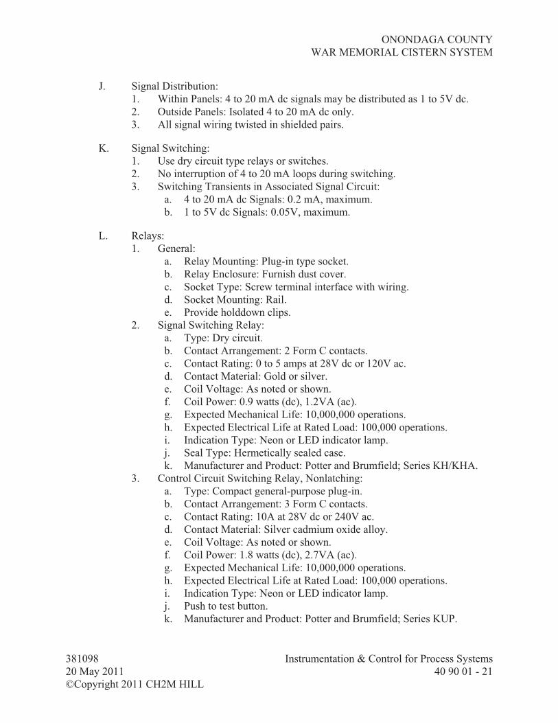
ONONDAGA COUNTY
WAR MEMORIAL CISTERN SYSTEM
381098 Instrumentation & Control for Process Systems
20 May 2011 40 90 01 - 21
©Copyright 2011 CH2M HILL
J. Signal Distribution:
1. Within Panels: 4 to 20 mA dc signals may be distributed as 1 to 5V dc.
2. Outside Panels: Isolated 4 to 20 mA dc only.
3. All signal wiring twisted in shielded pairs.
K. Signal Switching:
1. Use dry circuit type relays or switches.
2. No interruption of 4 to 20 mA loops during switching.
3. Switching Transients in Associated Signal Circuit:
a. 4 to 20 mA dc Signals: 0.2 mA, maximum.
b. 1 to 5V dc Signals: 0.05V, maximum.
L. Relays:
1. General:
a. Relay Mounting: Plug-in type socket.
b. Relay Enclosure: Furnish dust cover.
c. Socket Type: Screw terminal interface with wiring.
d. Socket Mounting: Rail.
e. Provide holddown clips.
2. Signal Switching Relay:
a. Type: Dry circuit.
b. Contact Arrangement: 2 Form C contacts.
c. Contact Rating: 0 to 5 amps at 28V dc or 120V ac.
d. Contact Material: Gold or silver.
e. Coil Voltage: As noted or shown.
f. Coil Power: 0.9 watts (dc), 1.2VA (ac).
g. Expected Mechanical Life: 10,000,000 operations.
h. Expected Electrical Life at Rated Load: 100,000 operations.
i. Indication Type: Neon or LED indicator lamp.
j. Seal Type: Hermetically sealed case.
k. Manufacturer and Product: Potter and Brumfield; Series KH/KHA.
3. Control Circuit Switching Relay, Nonlatching:
a. Type: Compact general-purpose plug-in.
b. Contact Arrangement: 3 Form C contacts.
c. Contact Rating: 10A at 28V dc or 240V ac.
d. Contact Material: Silver cadmium oxide alloy.
e. Coil Voltage: As noted or shown.
f. Coil Power: 1.8 watts (dc), 2.7VA (ac).
g. Expected Mechanical Life: 10,000,000 operations.
h. Expected Electrical Life at Rated Load: 100,000 operations.
i. Indication Type: Neon or LED indicator lamp.
j. Push to test button.
k. Manufacturer and Product: Potter and Brumfield; Series KUP.

ONONDAGA COUNTY
WAR MEMORIAL CISTERN SYSTEM
381098 Instrumentation & Control for Process Systems
20 May 2011 40 90 01 - 22
©Copyright 2011 CH2M HILL
4. Control Circuit Switching Relay, Latching:
a. Type: Dual coil mechanical latching relay.
b. Contact Arrangement: 2 Form C contacts.
c. Contact Rating: 10A at 28V dc or 120V ac.
d. Contact Material: Silver cadmium oxide alloy.
e. Coil Voltage: As noted or shown.
f. Coil Power: 2.7 watts (dc), 5.3VA (ac).
g. Expected Mechanical Life: 500,000 operations.
h. Expected Electrical Life at Rated Load: 50,000 operations.
i. Manufacturer and Product: Potter and Brumfield; Series KB/KBP.
5. Control Circuit Switching Relay, Time Delay:
a. Type: Adjustable time delay relay.
b. Contact Arrangement: 2 Form C contacts.
c. Contact Rating: 10A at 240V ac.
1) Contact Material: Silver cadmium oxide alloy.
d. Coil Voltage: As noted or shown.
e. Operating Temperature: Minus 10 to 55 degrees C.
f. Repeatability: Plus or minus 2 percent.
g. Delay Time Range: Select range such that time delay set point fall
between 20 to 80 percent of range.
h. Time Delay Set Point: As noted or shown.
i. Mode of Operation: As noted or shown.
j. Adjustment Type: Integral potentiometer with knob external to dust
cover.
k. Manufacturer and Products: Potter and Brumfield:
1) Series CB for 0.1 second to 100 minute delay time ranges.
2) Series CK for 0.1 to 120 second delay time ranges.
M. Intrinsic Safety Barriers:
1. Intrinsically Safe Relays: Monitor discrete signals that originate in
hazardous area and are used in a safe area.
a. Manufacturer and Product: MTL, Inc.; Series MTL 5000.
2. Intrinsically Safe Barriers: Interface analog signals as they pass from
hazardous area to safe area.
a. Manufacturer and Product: MTL, Inc.; Series MTL 5000.
N. Power Supplies:
1. Furnish to power instruments requiring external dc power, including two-
wire transmitters and dc relays.
2. Convert 120V ac, 60-Hz power to dc power of appropriate voltage(s) with
sufficient voltage regulation and ripple control to assure that instruments
being supplied can operate within their required tolerances.
3. Provide output over voltage and over current protective devices to:
a. Protect instruments from damage due to power supply failure.

ONONDAGA COUNTY
WAR MEMORIAL CISTERN SYSTEM
381098 Instrumentation & Control for Process Systems
20 May 2011 40 90 01 - 23
©Copyright 2011 CH2M HILL
b. Protect power supply from damage due to external failure.
4. Enclosures: NEMA 1 in accordance with NEMA 250.
5. Mount such that dissipated heat does not adversely affect other components.
6. Fuses: For each dc supply line to each individual two-wire transmitter.
a. Type: Indicating.
b. Mount so fuses can be easily seen and replaced.
O. Front-of-Panel Devices in Conjunction with NEMA 250, Type 12 Panels:
1. Indicating Lights:
a. Heavy-duty, push-to-test type, oiltight, industrial type with integral
transformer for 120V ac applications.
b. LED lenses in colors noted and factory engraved legend plates for
service legend.
c. Manufacturers and Products:
1) Cutler-Hammer; Model 10250T.
2) General Electric; CR2940U.
2. Pushbutton, Momentary:
a. Heavy-duty, oiltight, industrial type with full guard and momentary
contacts rated for 10 amperes continuous at 120V ac.
b. Standard size legend plates with black field and white markings for
service legend.
c. Manufacturers and Products:
1) Square D; Class 9001, Type K.
2) Cutler-Hammer; Type T.
3) General Electric; Type CR-2940.
3. Selector Switch:
a. Heavy-duty, oiltight, industrial type with contacts rated for 120V ac
service at 10 amperes continuous.
b. Standard size, black field, legend plates with white markings, for
service legend.
c. Operators: Black knob type.
d. Single-hole mounting, accommodating panel thicknesses from 1/16 to
1/4 inch.
e. Manufacturers and Products for Units with up to Four Selection
Positions:
1) Cutler-Hammer; Type T.
2) Square D; Type K.
f. Manufacturers and Products for Units with up to Twelve Selection
Positions:
1) Rundel-Idec; Standard Cam Switch.
2) Electroswitch; 31.

ONONDAGA COUNTY
WAR MEMORIAL CISTERN SYSTEM
381098 Instrumentation & Control for Process Systems
20 May 2011 40 90 01 - 24
©Copyright 2011 CH2M HILL
P. Front-of-Panel Devices Used in Conjunction with NEMA 250, Type 4 and 4X
Panels:
1. Indicating Lights, Watertight:
a. Heavy-duty, push-to-test type, NEMA 250, Type 4X watertight,
industrial type with integral transformer for 120V ac applications
and corrosion-resistant service.
b. LED lenses in colors noted and factory engraved legend plates for
service legend.
c. Manufacturers and Products:
1) Square D; Type SK.
2) Allen Bradley; Type 800H.
2. Pushbutton, Momentary, Watertight:
a. Heavy-duty NEMA 250, Type 4X watertight, industrial type with
momentary contacts rated for 120V ac service at 10 amperes
continuous and corrosion-resistant service.
b. Standard size, black field, legend plates with white markings for
service legend.
c. Manufacturers and Products:
1) Square D; Type SK.
2) Allen Bradley; Type 800H.
3. Selector Switch, Watertight:
a. Heavy-duty, NEMA 250, Type 4X watertight, industrial type with
contacts rated for 120V ac service at 10 amperes continuous and
corrosion-resistant service.
b. Standard size, black field, legend plates with white markings, for
service legend.
c. Operators: Black knob type.
d. Single-hole mounting, accommodating panel thicknesses from 1/16 to
1/4 inch.
e. Manufacturers and Products:
1) Square D; Class 9001, Type SK.
2) Allen Bradley; Type 800H.
Q. Internal Panel Lights:
1. Type: Fluorescent.
2. Quantity: Minimum of one hand switch controlled internal 120-volt 40-watt
fluorescent light.
3. Mounting: Top of back-of-panel area.
R. Service Outlets for Panels:
1. Type: Breaker protected, three-wire, 120-volt, 2-ampere, duplex
receptacles.

ONONDAGA COUNTY
WAR MEMORIAL CISTERN SYSTEM
381098 Instrumentation & Control for Process Systems
20 May 2011 40 90 01 - 25
©Copyright 2011 CH2M HILL
2. Quantity:
a. For panels 4 feet wide and smaller: One.
b. For panels wider than 4 feet: One for every 4 feet of panel width, two
minimum per panel.
3. Mounting: Evenly spaced along back-of-panel area.
S. Standard Pushbutton Colors and Inscriptions: Use following color code and
inscriptions for pushbuttons:
Tag Function Inscription(s) Color
OO ON
OFF
Red
Green
OC OPEN
CLOSE
Red
Green
OCR OPEN
CLOSE
REMOTE
Red
Green
White
OOR ON
OFF
REMOTE
Red
Green
White
SS START
STOP
Red
Green
RESET RESET Red
EMERGENCY STOP EMERGENCY STOP Red
T. Standard Light Colors and Inscriptions: Use following color code and inscriptions
for service legends and lens colors for indicating lights:
Tag Function Inscription(s) Color
ON ON Red
OFF OFF Green
OPEN OPEN Red
CLOSED CLOSED Green
LOW LOW Green
FAIL FAIL Amber
HIGH HIGH Red
AUTO AUTO White
MANUAL MANUAL Yellow

ONONDAGA COUNTY
WAR MEMORIAL CISTERN SYSTEM
381098 Instrumentation & Control for Process Systems
20 May 2011 40 90 01 - 26
©Copyright 2011 CH2M HILL
Tag Function Inscription(s) Color
LOCAL LOCAL White
REMOTE REMOTE Yellow
2.10 SPARE PARTS
Description
Percent of Each
Type and Size Used No Less Than
dc power supplies 20 1
Fuses 20 5
Indicating light bulb 20 5
Relays 20 3
Terminal Blocks 10 10
Hand Switches 10 2
2.11 ELECTRICAL TRANSIENT PROTECTION
A. General:
1. Function: Protect elements of PICS against damage due to electrical
transients induced in interconnecting lines by lightning and nearby
electrical systems.
2. Implementation: Provide, install, coordinate, and inspect grounding of surge
suppressors at:
a. Connection of ac power to PICS equipment including panels,
consoles assembles, and field mounted transmitters and receivers.
b. At the field and at the panel connection of signal and communication
circuits that have portions of the circuit extending outside of a
protective building.
3. Construction shall be Bipolar silicon avalanche device. MOV or hybrid
devices are not acceptable. Includes grounding wire, stud, or terminal.
4. Response: 5 nanoseconds maximum.
5. Recovery: Automatic.
6. Temperature Range: -20 to 85 degrees C.
B. Suppressors on 120V ac Power Supply Connections:
1. Occurrences: Tested and rated for a minimum of 50 occurrences of
IEEE 587 Category B test waveform.
2. Clamping Voltage: 350 volts or less.
3. Transtector ACP-100 series. No equal.

ONONDAGA COUNTY
WAR MEMORIAL CISTERN SYSTEM
381098 Instrumentation & Control for Process Systems
20 May 2011 40 90 01 - 27
©Copyright 2011 CH2M HILL
C. Suppressors on Analog Signal Lines:
1. Test Waveform: Linear 8 microsecond rise in current form 0 amps to a peak
current value followed by an exponential decay of current reaching one
half the peak value in 20 microseconds.
2. Surge Rating: Tested and rated for 50 occurrences of 2,000-amp peak test
waveform.
a. dc Clamping Voltage: 20 to 40 percent above operating voltage for
circuit.
b. dc Clamping Voltage Tolerance: Less than !10 percent.
c. Maximum Loop Resistance: 18 ohms per conductor.
D. Physical Characteristics:
1. Mounted in Enclosures: Encapsulated inflame retardant epoxy.
2. For Analog Signals Lines: EDCO PC-642 or SRA-64 series.
3. For 120V ac Lines: EDCO HSP-121.
4. Field Mounted at Two-Wire Instruments: Encapsulated in stainless steel
pipe nipples. EDCO SS64 series.
5. Field Mounted at Four-Wire Instruments: With 120V ac outlet, ac circuit
breaker, and 10-ohm resistors on signal lines, all in enclosure.
a. Enclosure: NEMA 4X fiberglass or Type 316 stainless steel with
door.
1) Maximum Size: 12 inches by 12 inches by 8 inches deep.
b. Manufacturer and Product: EDCO; SLAC series.
E. Installation and Grounding of Suppressors: All surge suppressors and related
enclosures shall be furnished by the PICS and installed under Division 26,
ELECTRICAL. Grounding equipment, installation of grounding equipment, and
terminations for field mounted devices are provided under Division 26,
ELECTRICAL.
2.12 FABRICATION
A. General:
1. Panel Construction and Interior Wiring: In accordance with the National
Electrical Code, state and local codes, NEMA, ANSI, UL, and ICECA.
2. Fabricate panels, install instruments, wire, and plumb, at the PICS factory.
No fabrication other than correction of minor defects or minor transit
damage shall be done on panels at site
3. Electrical Work: In accordance with Division 26, ELECTRICAL.
B. UL Listing Mark for Enclosures: Mark stating “Listed Enclosed Industrial
Control Panel” per UL 508A

ONONDAGA COUNTY
WAR MEMORIAL CISTERN SYSTEM
381098 Instrumentation & Control for Process Systems
20 May 2011 40 90 01 - 28
©Copyright 2011 CH2M HILL
C. Wiring Within PICS Panels:
1. Restrain by plastic ties or ducts or metal raceways.
2. Hinge Wiring: Secure at each end so that bending or twisting will be around
longitudinal axis of wire. Protect bend area with sleeve.
3. Run 480V, 120V and control (low voltage) wiring in separate conduits
within the panel.
4. Arrange wiring neatly, cut to proper length, and remove surplus wire.
5. Abrasion protection for wire bundles which pass through holes or across
edges of sheet metal.
6. Connections to Screw Type Terminals:
a. Locking-fork-tongue or ring-tongue lugs.
b. Use manufacturer’s recommended tool with required sized anvil to
make crimp lug terminations.
c. Wires terminated in a crimp lug, maximum of one.
d. Lugs installed on a screw terminal, maximum of two.
7. Connections to Compression Clamp Type Terminals:
a. Strip, prepare, and install wires in accordance with terminal
manufacturer’s recommendations.
b. Wires installed in a compression screw and clamp, maximum of one
for field wires entering enclosure, otherwise maximum of two.
8. Use knife disconnect terminal blocks for analog signals.
9. Splicing and tapping of wires, allowed only at device terminals or terminal
blocks.
10. Terminate 24V dc and analog signal circuits on separate terminal block
from ac circuit terminal blocks.
11. Separate analog and dc circuits by at least 6 inches from ac power and
control wiring, except at unavoidable crossover points and at device
terminations.
12. Arrange wiring to allow access for testing, removal, and maintenance of
circuits and components.
13. Plastic wire ducts fill: Do not exceed manufacturer’s recommendation.
D. Temperature Control:
1. Size panels to adequately dissipate heat from equipment mounted inside
panel or on panel, or provide louvers and forced ventilation for adequate
heat dissipation.
2. Space Heaters:
a. Thermostatically controlled to maintain internal panel temperatures
above dew point.
b. Required for all panels.

ONONDAGA COUNTY
WAR MEMORIAL CISTERN SYSTEM
381098 Instrumentation & Control for Process Systems
20 May 2011 40 90 01 - 29
©Copyright 2011 CH2M HILL
E. Freestanding Panel Construction:
1. Materials: Aluminum for NEMA 12, stainless steel for NEMA 4, and
Type 316 Stainless Steel for NEMA 4X, with minimum thickness of
12-gauge.
2. Panel Fronts:
a. Fabricated from a single piece.
b. No seams or bolt heads visible when viewed from front.
c. Panel Cutouts: Smoothly finished with rounded edges.
d. Stiffeners: Angle or plate stiffeners or both on back of panel face to
prevent panel deflection under instrument loading or operation.
3. Internal Framework:
a. Provide instrument support and panel bracing as required.
b. Permit panel lifting without racking or distortion.
4. Lifting rings to allow simple, safe rigging and lifting of panel during
installation.
5. Adjacent Panels: Securely bolted together so front faces are parallel.
6. Doors:
a. Full height, fully gasketed access doors.
b. Latches: Three-point, Southco Type 44.
c. Handles: “D” ring, foldable type.
d. Hinges: Full length, continuous, piano type, steel hinges with
stainless steel pins.
e. Rear Access Doors (if required): Extend no further than 24 inches
beyond panel when opened to 90-degree position.
f. Front and Side Access Doors: Sized to suit the space.
7. Floor Mounting Kit shall be provided for all free standing panels:
a. Legs: Provide legs to elevate bottom of panel above equipment pad,
minimum 8 inches.
b. Skirt: Provide if conduit and electrical wiring is present in panel
bottom:
1) Provide clear Plexiglass skirt between legs to prevent accidental
contact with electrical wiring.
2) Plexiglass shall be 0.5 inch thick, minimum, and shall be
attached to panel legs using stainless steel screws, secured
with wing nuts and rubber-cushioned washers.
3) When attached, provide space between bottom of Plexiglass and
equipment pad of 1-inch.
4) Method of attachment shall be such that Plexiglass panels may
easily be removed and reattached once panel is installed in
field.
c. Field Wiring:
1) Install conduit stubs in panel bottom to accommodate existing
field wiring.

ONONDAGA COUNTY
WAR MEMORIAL CISTERN SYSTEM
381098 Instrumentation & Control for Process Systems
20 May 2011 40 90 01 - 30
©Copyright 2011 CH2M HILL
2) Offset conduit stubs so no conduit stub is directly over an
existing conduit stub when panel is installed.
3) Provide water tight seal in panel conduit stubs. Grommet-style
seal or approved chemical filler in conduit stubs are both
acceptable.
F. Non Freestanding Panel Construction:
1. Materials: Aluminum for NEMA 12, Stainless Steel for NEMA 4, and
Type 316 Stainless Steel for NEMA 4X panels.
2. Metal Thickness: 14-gauge, minimum.
3. Doors:
a. Rubber-gasketed with continuous hinge.
b. Stainless steel lockable quick-release clamps.
4. Manufacturers:
a. Hoffman Engineering Co.
b. Rittal.
2.13 MECHANICAL SYSTEMS
A. ON/OFF Valves:
1. Type: Ball valve.
2. Materials: Stainless steel.
3. Manufacturers and Products:
a. Whitey; Series 41 through Series 43.
b. Hoke; Flomite 7100 Series.
B. Valve, Needle:
1. Materials: Brass, stainless steel, PVC, or CPCV, as recommended by
manufacturer for designated service, unless otherwise shown on
Drawings.
2. Size: 0.020-inch orifice.
3. Manufacturers and Products:
a. Whitey; Model 21RF2
b. Hoke: 3700 Series.
C. Regulating Valves:
1. Type: Needle valves, with regulating stems and screwed bonnets.
2. Materials: Brass, stainless steel, PVC, or CPCV, as recommended by
manufacturer for designated service, unless otherwise shown on
Drawings.
3. Manufacturers and Products:
a. Whitey; Catalog No. RF or No. RS
b. Hoke; 3100 through 3300 Series.

ONONDAGA COUNTY
WAR MEMORIAL CISTERN SYSTEM
381098 Instrumentation & Control for Process Systems
20 May 2011 40 90 01 - 31
©Copyright 2011 CH2M HILL
D. Valve, Three-Way:
1. Type: Ball valve.
2. Materials: Brass or stainless steel with nylon handle as recommended by
manufacturer for designated service, unless otherwise shown on
Drawings.
3. Manufacturers and Products:
a. Whitey; Series 41 through Series 43.
b. Hoke; Selecto-Mite Series.
E. Pressure Regulator, Air:
1. Provide air at reduced pressures, as shown, constant to within plus or minus
10 percent for flows from 0 scfh to 300 scfh with 100 psi supply pressure.
2. Setscrew for outlet pressure adjustment.
3. Integral filter and relief valve.
4. Manufacturers and Products:
a. Masoneilan; Series 77-4.
b. Fisher; Series 67FR.
F. Pressure Regulator, Water:
1. Materials:
a. Body: Bronze.
b. Spring Case: Cast iron.
c. Seat Rings: Brass.
d. Valve Disk and Holder: Buna-N and bronze.
e. Diaphragm: Buna-N diaphragm.
2. Sizing: For maximum of 7 psi offset pressure.
3. Manufacturers and Products:
a. Fisher; Controls Type 95H or 95L.
b. Masoneilan; Series 17.
G. Test Tap:
1. Manufacturers and Products:
a. Imperial-Eastman; quick-disconnect couplings No. 292-P and caps
No. 259-P.
b. Crawford Fitting Co.; Swagelok quick-connects Series QC4 and caps
QC4-DC.
c. Parker; CPI Series precision quick couplings.
H. Plastic Tubing and Fittings:
1. Tubing: Polyethylene capable of withstanding 190 psig at 175 degrees F.
a. Manufacturers and Products:
1) Dekoron; Type P.
2) Imperial Eastman; Poly-Flo black instrument tubing.

ONONDAGA COUNTY
WAR MEMORIAL CISTERN SYSTEM
381098 Instrumentation & Control for Process Systems
20 May 2011 40 90 01 - 32
©Copyright 2011 CH2M HILL
2. Fittings:
a. Type: Brass compression.
b. Manufacturers and Products:
1) Imperial Eastman; Poly-Flo tube fittings.
2) Dekoron; E-Z fittings.
I. Stainless Steel Tubing: ASTM A312, Type 316, seamless, soft annealed, as
shown on Drawings, 0.065-inch wall.
J. Stainless Steel Fittings:
1. Compression Type:
a. Materials: Stainless steel, ASTM A182 forged bodies or ASTM A276
barstock bodies, Type 316, flareless.
b. Manufacturers and Products:
1) Parker Flodar; BA Series.
2) Swagelok tube fittings.
3) Parker CPI tube fittings; Parker A-LOK dual ferrule tube
fittings.
2. Socket Weld Type:
a. Materials: Stainless steel, ASTM A182 forged bodies or ASTM A276
barstock bodies, Type 316 for 3,000 psi maximum working
pressure, safety factor 4:1.
b. Manufacturers:
1) Cajon.
2) Swagelok.
3) Parker WELDLOK.
2.14 CORROSION PROTECTION
A. Corrosion-Inhibiting Vapor Capsule Manufacturers:
1. Northern Instruments; Model Zerust VC.
2. Hoffmann Engineering Co; Model A-HCI.
2.15 SOURCE QUALITY CONTROL
A. Scope: Inspect and test entire PICS to ensure it is ready for shipment, installation,
and operation. Test panels and panel assemblies for proper operation prior to
shipment.
B. Location: Manufacturer’s factory or Engineer approved staging site.
C. Test: Exercise and test all functions.

ONONDAGA COUNTY
WAR MEMORIAL CISTERN SYSTEM
381098 Instrumentation & Control for Process Systems
20 May 2011 40 90 01 - 33
©Copyright 2011 CH2M HILL
PART 3 EXECUTION
3.1 EXAMINATION
A. For equipment not provided by PICS, but that directly interfaces with the PICS
(e.g., valve actuators), verify the following conditions:
1. Proper installation.
2. Calibration and adjustment.
3. Correct control action.
4. Switch settings and dead bands.
5. Opening and closing speeds and travel stops.
6. Input and output signals.
3.2 INSTALLATION
A. Material and Equipment Installation: Retain a copy of manufacturers’ instructions
at site, available for review at all times.
B. Electrical Wiring: As specified in Division 26, ELECTRICAL.
C. Mechanical Systems:
1. Base materials and installations on field measurements.
2. Copper and Stainless Steel Tubing Support: Continuously supported by an
aluminum tubing raceway system.
3. Plastic Tubing Supports: Provide continuous support in conduits or by
aluminum tubing raceway system.
4. Install tubing conduit for plastic tubing and tubing raceways parallel with,
or at right angles to, structural members of buildings. Make vertical runs
straight and plumb.
5. Tubing and Conduit Bends:
a. Tool-formed without flattening, and all of same radius.
b. Bend Radius: Equal to or larger than conduit and tubing
manufacturer’s recommended minimum bend radius.
c. Slope instrument connection tubing in accordance with installation
details.
d. Do not run liquid filled instrument tubing immediately over or within
a 3-foot plan view clearance of electrical panels, motor starters, or
mechanical mounting panel without additional protection. Where
tubing must be located in these zones, shield electrical device to
prevent water access to electrical equipment.
e. Straighten coiled tubing by unrolling on flat surface. Do not pull to
straighten.
f. Cut tubing square with sharp tubing cutter. Deburr cuts and remove
chips. Do not gouge or scratch surface of tubing.

ONONDAGA COUNTY
WAR MEMORIAL CISTERN SYSTEM
381098 Instrumentation & Control for Process Systems
20 May 2011 40 90 01 - 34
©Copyright 2011 CH2M HILL
g. Blow debris from inside of tubing.
h. Make up and install fittings in accordance with manufacturer’s
recommendations. Verify makeup of tube fittings with
manufacturer’s inspection gauge.
i. Use lubricating compound or TFE tape on stainless steel threads to
prevent seizing or galling.
j. Run tubing to allow, for example, clear access to doors, controls, and
control panels; and to allow for easy removal of equipment.
k. Provide separate support for components in tubing runs.
l. Supply expansion loops and use adapters at pipe, valve, or component
connections for proper orientation of fitting.
m. Keep tubing and conduit runs at least 12 inches from hot pipes.
n. Locate and install tubing raceways in accordance with manufacturer’s
recommendations. Locate tubing to prevent spillage, overflow, or
dirt from above.
o. Securely attach tubing raceways to building structural members.
6. Enclosure Lifting Rings: Remove rings following installation and plug
holes.
D. Removal or relocation of Materials and Equipment:
1. Repair affected surfaces to conform to type, quality, and finish of
surrounding surface.
3.3 FIELD FINISHING
A. Field touch up panels and enclosures for a professional finish.
3.4 FIELD QUALITY CONTROL
A. Startup and Testing:
1. Thoroughly inspect installation, termination, and adjustment for
components and systems.
2. Complete onsite tests.
3. Complete onsite training.
4. Provide startup assistance.
B. Operational Readiness Tests (ORTs): Prior to startup, inspect, test, and document
that associated PICS equipment, including application software, is ready for
operation.
1. Loop/Component Inspections and Tests:
a. Check PICS for proper installation, calibration, and adjustment on a
loop-by-loop and component-by-component basis.

ONONDAGA COUNTY
WAR MEMORIAL CISTERN SYSTEM
381098 Instrumentation & Control for Process Systems
20 May 2011 40 90 01 - 35
©Copyright 2011 CH2M HILL
b. Use loop status report to organize and track inspection, adjustment,
and calibration of each loop and include the following:
1) Project name.
2) Loop number.
3) Tag number for each component.
4) Checkoffs/Signoffs for Each Component:
a) Tag/identification.
b) Installation.
c) Termination wiring.
d) Termination tubing.
e) Calibration/adjustment.
5) Checkoffs/Signoffs for the Loop:
a) Panel interface terminations.
b) I/O interface terminations with PLCs.
6) I/O Signals for PLC are Operational: Received/sent, processed,
and adjusted.
7) Total loop operational.
8) Space for comments.
9) Example Loop Status Report form is included in Article
SUPPLEMENTS.
c. Component calibration sheet for each active component (except
simple handswitches, lights, gauges, and similar items). Include
the following:
1) Project name.
2) Loop number.
3) Component tag number.
4) Component code number.
5) Component manufacturer.
6) Component model number/serial number.
7) Summary of Functional Requirements, for Example:
a) Indicators scale ranges.
b) Transmitters/converters, input and output ranges.
c) Controllers, action (direct/reverse) and control modes.
d) Switching elements, unit range, differential
(fixed/adjustable), reset (auto/manual).
8) Calibrations, for Example, but not Limited to:
a) Analog Devices: Actual inputs and outputs at 0, 10, 50,
and 100 percent of span, rising and falling.
b) Discrete Devices: Actual trip points and reset points.
9) Space for comments.
10) Example instrument calibration sheet is included in Article
SUPPLEMENTS.

ONONDAGA COUNTY
WAR MEMORIAL CISTERN SYSTEM
381098 Instrumentation & Control for Process Systems
20 May 2011 40 90 01 - 36
©Copyright 2011 CH2M HILL
d. Maintain loop status reports, and component calibration sheets at site
and make them available to Engineer at all times.
e. These inspections and tests will be spot checked by Engineer.
C. Performance Acceptance Tests (PAT): These are the activities that
Section 01 91 14, Equipment Testing and Facility Startup, refers to as
Performance Testing.
1. General:
a. Test all PIC elements to demonstrate that PIC satisfies all
requirements.
b. Test Format: Cause and effect.
1) Person conducting test initiates an input (cause).
2) Specific test requirement is satisfied if correct result (effect)
occurs.
c. Procedures, Forms, and Checklists:
1) Conduct tests in accordance with, and documented on, Engineer
accepted procedures, forms, and checklists.
2) Describe each test item to be performed.
3) Have space after each test item description for sign off by
appropriate party after satisfactory completion.
d. Required Test Documentation: Test procedures, forms, and checklists.
All signed by Engineer and Contractor.
e. Conducting Tests:
1) Provide special testing materials, equipment, and software.
2) Wherever possible, perform tests using actual process variables,
equipment, and data.
3) If it is not practical to test with real process variables,
equipment, and data; provide suitable means of simulation.
4) Define simulation techniques in test procedures.
2. Test Requirements:
a. Once facility has been started up and is operating, perform a
witnessed PAT on complete PICS to demonstrate that it is
operating as required. Demonstrate each required function on a
paragraph-by-paragraph and loop-by-loop basis.
b. Perform local and manual tests for each loop before proceeding to
remote and automatic modes.
c. Where possible, verify test results using visual confirmation of
process equipment and actual process variable. Unless otherwise
directed, exercise and observe devices supplied by others, as
needed to verify correct signals to and from such devices and to
confirm overall system functionality. Test verification by means of
disconnecting wires or measuring signal levels is acceptable only
where direct operation of plant equipment is not possible.

ONONDAGA COUNTY
WAR MEMORIAL CISTERN SYSTEM
381098 Instrumentation & Control for Process Systems
20 May 2011 40 90 01 - 37
©Copyright 2011 CH2M HILL
d. Make updated versions of documentation required for PAT available
to Engineer at Site, both before and during tests.
e. Make one copy of O&M manuals available to Engineer at the Site
both before and during testing.
f. Refer to referenced examples of PAT procedures and forms in Article
SUPPLEMENTS.
3.5 MANUFACTURER’S SERVICES
A. For equipment furnished under this Section, provide the services of a qualified
manufacturer’s representative as required to provide Manufacturer’s Certificate of
Proper Installation and assistance during installation, startup, demonstration
testing, and training.
B. See Section 01 43 33, Manufacturer’s Field Services, and Section 01 91 14,
Equipment Testing and Facility Startup, for additional requirements.
3.6 TRAINING
A. General:
1. Provide an integrated training program to meet specific needs of Operations
and Maintenance personnel.
2. Include training sessions, classroom and field, for managers, engineers,
operators, and maintenance personnel.
3. Provide instruction to accommodate the Owner personnel schedule.
4. Owner reserves the right to make and reuse video tapes of training sessions.
B. Operations and Maintenance Training:
1. General:
a. Include a review of O&M manuals and survey of spares, expendables,
and test equipment.
b. Use equipment similar to that provided.
c. Provide training suitable for instrument technicians with at least a
2-year associate engineering or technical degree, or equivalent
education and experience in electronics or instrumentation.
2. Operations Training:
a. Training Sessions Duration: Two 8-hour instructor days (not counting
travel time).
b. Number of training Sessions: Two.
c. Content: Conduct training on loop-by-loop basis.
1) Loop Functions: Understanding of loop functions, including
interlocks for each loop.
2) Loop Operation: For example, adjusting process variable set
points, AUTO/MANUAL control transfer, AUTO and

ONONDAGA COUNTY
WAR MEMORIAL CISTERN SYSTEM
381098 Instrumentation & Control for Process Systems
20 May 2011 40 90 01 - 38
©Copyright 2011 CH2M HILL
MANUAL control, annunciator acknowledgement and
resetting.
3) Interfaces with other control systems.
3. Maintenance Training:
a. Training Session Duration: Two 8-hour instructor day (not counting
travel).
b. Number of Sessions: Two.
c. Content: Provide training for each type of component provided,
including PLC system components.
1) Component calibration.
2) Adjustments: For example, changing range on a level
transmitter.
3) Troubleshooting and diagnosis for components.
4) Replacing lamps, fuses, etc.
5) Component removal and replacement.
6) Periodic maintenance.
3.7 CLEANING/ADJUSTING
A. Repair affected surfaces to conform to type, quality, and finish of surrounding
surface.
B. Cleaning:
1. Prior to closing system using tubing, clear tubing of interior moisture and
debris.
2. Upon completion of Work, remove materials, scraps, and debris from
interior and exterior of equipment.
3.8 PROTECTION
A. Protect enclosures and other equipment containing electrical, instrumentation and
control devices, including spare parts, from corrosion through the use of
corrosion-inhibiting vapor capsules.
B. Periodically replace capsules in accordance with capsule manufacturer’s
recommendations. Replace capsules just prior to Final Payment and Acceptance.
3.9 SUPPLEMENTS
A. Supplements listed below, following “END OF SECTION,” are part of this
Specification.
1. Component Specifications.
2. Functional Descriptions.
3. Loop Status Report.

ONONDAGA COUNTY
WAR MEMORIAL CISTERN SYSTEM
381098 Instrumentation & Control for Process Systems
20 May 2011 40 90 01 - 39
©Copyright 2011 CH2M HILL
4. Instrument Calibration Sheet: Provides detailed information on each
instrument (except simple hand switches, lights, and similar items).
5. Performance Acceptance Test Sheet: Describes the PAT for a given loop.
The format is mostly free form.
a. Lists the requirements of the loop.
b. Briefly describes the test.
c. Cites expected results.
d. Provides space for check off by witness.
END OF SECTION

ONONDAGA COUNTY
WAR MEMORIAL CISTERN SYSTEM
381098 Instrumentation & Control for Process Systems -
20 May 2011 Component Specifications
©Copyright 2011 CH2M HILL 40 90 01 Supplement - 40
PART 4 COMPONENT SPECIFICATIONS
A. A1-Water Quality Monitoring Panel
1. General:
a. Furnish a water quality monitoring panel with the analyzers,
transmitters, and accessories described herein.
2. Panel:
a. The panel shall include a 3/8-inch PVC mounting plate, cut to
accommodate the specified analyzers, transmitters, and
accessories.
b. The panel shall include integral stainless steel mounting inserts
for all analyzers, flow cells, inlet pressure regulators, flow
regulators, valves, strainers, etc. Provide all accessories as
required. The sample flows will be conveyed to the panel via
1/2-inch lines.
c. Provide a rack to mount the panel.
d. Manufacture:
1) Analytical Technology Inc; Model Q45WQ.
2) No substitutes permitted.
3. Service: Rainwater with a pH of 4.8. All furnished components shall be
compatible with the low pH.
4. pH Sensor and Transmitter:
a. Quantity: One
b. Range
1) Pre Filtration (AE/AIT-211): 0-14 pH units.
c. Sensor:
1) 1-inch NPT, dual electrode design. The reference electrode
shall be fully sealed in a glass to prevent contamination
of the reference element
2) Sensor shall include a titanium ground electrode to improve
signal stability and to enable electrode breakage
diagnostic functions.
3) The sensor shall include a pt1000 RTD for high accuracy
temperature measurement
4) The sensor shall include a integral preamplifier
5) Mounting: Flow through for insertion in a flow cell.
d. Transmitter:
1) High contrast, STN, dual display format, capable of
selectively displaying pH, process temperature, and
sensor millivolts.
2) Transmitter shall accept pt1000 RTD temperature element
and provide temperature compensation.

ONONDAGA COUNTY
WAR MEMORIAL CISTERN SYSTEM
381098 Instrumentation & Control for Process Systems -
20 May 2011 Component Specifications
©Copyright 2011 CH2M HILL 40 90 01 Supplement - 41
3) Power Supply: 120V ac, 50-60 Hz
4) The transmitter shall be microprocessor based instrument in
a fully enclosed, NEMA 4X, polycarbonate enclosure,
suitable for DIN rail mounting on the panel.
5) Signal Interface: Two isolated 4 mA to 20 mA dc analog
outputs (pH and temperature).
6) Cabling: As required.
e. Expendables (for each unit provided):
1) Chemicals: 1 pint each of buffer solution for pH 4, pH 7,
and pH 9.
f. Manufacturers and Products:
1) Element: Analytical Technology Inc; Model Q25P
2) Transmitter: Analytical Technology - Inc; Model Q45P
3) No substitutes permitted.
5. Turbidity Monitor:
a. Quantity: Two
b. Range:
1) Pre Filtration (AE/AIT-209): 0-30 NTU
2) Post Filtration (AE/AIT-212): 0-5 NTU
c. Sensor:
1) The sensor shall employ bright light source producing a
white light beam (US EPA Method)
2) Light scatter detection measurement using a 90-degree
scatter
3) Provide sensor flow cell to be mounted on the panel.
d. Monitor:
1) Compact 1/4-inch DIN size instrument suitable for panel
mounting.
2) The display shall be alphanumeric LCD capable of
indicating turbidity in NTUs and alarm conditions.
3) NEMA 4X enclosure with clear hinged door to allow tool-
less access to controls and for viewing the LCD
display.
4) Diagnostic functions for optical fouling
5) Signal Interface: An isolated 4-20 mA analog signal for
loads up to 600 ohms.
6) Power supply: 120V ac, 50-60-Hz.
7) Cabling: As required.
e. Expendables:
1) Stablcal Verification Standards:
a) 1 liter of 20 NTU calibration standard.
b) 1 liter of 1 NTU verification standard.
c) Quantity: One each for each turbidimeter.
d) Two Stablcal calibration cylinders, minimum.

ONONDAGA COUNTY
WAR MEMORIAL CISTERN SYSTEM
381098 Instrumentation & Control for Process Systems -
20 May 2011 Component Specifications
©Copyright 2011 CH2M HILL 40 90 01 Supplement - 42
f. Manufacturer and Product:
1) Analytical Technology Inc: Model A15/76
2) No substitutes permitted
6. Chlorine Analyzer:
a. Quantity: one
b. Type: Free Chlorine
c. Range:
1) Pre Filtration (AE/AIT-213): 0-5 mg/l
d. Sensor:
1) Direct measuring polarographic sensor utilizing polymeric
membrane to isolate sensing electrodes from the
sample.
2) The sensor assembly shall include a precision RTD
temperature sensor to allow temperature compensation.
3) Provide a pH sensor to allow automatic correction of
chlorine value for changes in sample pH.
4) The sensor shall slide into the side of the flow cell, with a
double o-ring seal to prevent leakage.
5) The flow to the sensor shall be regulated automatically
e. Monitor:
1) Ac powered instrument for operation on 115 V ac, single
phase line power.
2) The monitor shall provide two isolated 4-20 mA outputs
configurable for chlorine, pH, or temperature. The
monitor shall also include two SPDT relays.
3) Suitable for panel mounting
f. Manufacturer and Product:
1) Analytical Technology Inc: Model Q45H-62/63
2) No substitutes permitted
B. A2- UVT Meter, Portable:
1. General:
a. Function: A portable instrument that can measure UV
transmittance (UVT) and UV absorbance (UVA) at 254 nm
wavelength in the field.
b. Parts: Meter and accessories as specified
c. Quantity: One. AI-214
2. Range:
a. 0-100% UVT
b. 0-2 Absorbance
3. UV Wavelength: 253.7 nm
4. Source: Low pressure germicidal UV lamp
5. Sample Cell: 10 mm X 10 mm quartz cuvette

ONONDAGA COUNTY
WAR MEMORIAL CISTERN SYSTEM
381098 Instrumentation & Control for Process Systems -
20 May 2011 Component Specifications
©Copyright 2011 CH2M HILL 40 90 01 Supplement - 43
6. Path Length: 1 cm
7. Accuracy: Plus or minus 0.5% UVT
8. Resolution:
a. 0.1% Transmittance
b. 0.001 Absorbance
9. Operating Temperature: 0-50 Degree C
10. Response Time:
a. Warm Up: 90 sec
b. Calibration: 2 sec
c. Computation: 2 sec
11. Built in fault detection system
12. Display: 32 character back-lit LCD digital display with on screen
instruction and system messages
13. Case: Rugged, compact, watertight, and dustproof.
14. Power Supply:
a. Wall adapter – 110 V ac (UL approved)
b. Provide battery powered option
15. Manufacturers and Products:
a. Real Tech Inc; Real UVT Meter
b. Or equal
C. F4- Flow Element and Transmitter, Electromagnetic:
1. General:
a. Function: Measure, indicate, and transmit the flow of a conductive
process liquid in a full pipe.
b. Type:
1) Electromagnetic flowmeter, with operation based on
Faraday’s Law, utilizing the pulsed dc type coil
excitation principle with high impedance electrodes.
2) Full bore meter with magnetic field traversing entire
flow-tube cross section.
3) Unacceptable are insert magmeters or multiple single point
probes inserted into a spool piece.
c. Parts: Flow element, transmitter, interconnecting cables, and
mounting hardware. Other parts as noted.
2. Service:
a. Stream Fluid:
1) FE/FIT-214 & FE-FIT-225: rainwater with a pH of 4.8
2) FED/FIT-218: Potable water.
3. Operating Temperature:
a. Element:
1) Ambient: Minus 5 to 140 degrees F, typical.
2) Process: Minus 5 to 140 degrees F, typical.

ONONDAGA COUNTY
WAR MEMORIAL CISTERN SYSTEM
381098 Instrumentation & Control for Process Systems -
20 May 2011 Component Specifications
©Copyright 2011 CH2M HILL 40 90 01 Supplement - 44
b. Transmitter:
1) Ambient: Minus 5 to 140 degrees F.
2) Storage: 15 to 120 degrees F.
4. Performance:
a. Flow Range:
1) FIT-214: 0-40 gpm
2) FIT-218: 0-20 gpm.
3) FIT-225: 0-40 gpm.
b. Accuracy: Plus or minus 0.5 percent of flow rate.
c. Turndown Ratio: Minimum of 10 to 1 when flow velocity at
minimum flow is at least 1 foot per second.
5. Features:
a. Zero stability feature to eliminate the need to stop flow to check
zero alignment.
b. No obstructions to flow.
c. Very low pressure loss.
6. Process Connection:
a. Meter Size (diameter inches): As shown on drawings.
b. Connection Type: 150-pound ANSI raised-face flanges;
AWWA C207, Table 2 Class D; or wafer style depending on
meter size.
c. Flange Material: Carbon steel.
7. Power (Transmitter): 120V ac, 60-Hz, unless otherwise noted.
8. Element:
a. Meter Tube Material: Type 304 or 316 stainless steel.
b. Liner Material: Teflon. For FE-214 and FE-225, confirm with
manufacturer, the compatibility of Teflon liner with 4.8 pH
rainwater and provide recommended liner.
c. Liner Protectors: Covers (or grounding rings) on each end to
protect liner during shipment.
d. Electrode Type: Flush or bullet nose as recommended by the
manufacturer for the noted stream fluid.
e. Electrode Material: Type 316 stainless steel.
f. Grounding Ring:
1) Required.
2) Quantity: Two
3) Material: Type 316 stainless steel.
g. Enclosure: NEMA 4X.
h. Submergence: Temporary.
9. Transmitter:
a. Mounting: Wall or Stanchion, as shown on drawings. Provide all
necessary mounting hardware.
b. Display: Required.
1) Digital LCD display, indicating flow rate and total.

ONONDAGA COUNTY
WAR MEMORIAL CISTERN SYSTEM
381098 Instrumentation & Control for Process Systems -
20 May 2011 Component Specifications
©Copyright 2011 CH2M HILL 40 90 01 Supplement - 45
c. Parameter Adjustments: By keypad or non-intrusive means.
d. Enclosure: NEMA 4X.
e. Empty Pipe Detection: Drive display and outputs to zero when
empty pipe detected.
10. Signal Interface (at Transmitter):
a. Analog Output:
1) Isolated 4 mA to 20 mA dc for load impedance from 0 ohm
to at least 500 ohms minimum for 24V dc supply.
2) Supports Superimposed Digital HART protocol: If noted.
11. Cables:
a. Type: As recommended by manufacturer.
b. Length: As required to accommodate device locations.
12. Built-in Diagnostic System:
a. Features:
1) Field programmable electronics.
2) Self-diagnostics with troubleshooting codes.
3) Ability to program electronics with full scale flow,
engineering units, meter size, zero flow cutoff, desired
signal damping, totalizer unit digit value, etc.
4) Initial flow tube calibration and subsequent calibration
checks.
13. Factory Calibration:
a. Calibrated in an ISO 9001 and NIST certified factory.
b. Factory flow calibration system must be certified by volume or
weight certified calibration devices.
c. Factory flow calibration system shall be able to maintain
calibration flow rate for at least 5 minutes for repeatability
point checks.
14. Manufacturers:
a. ABB Automation MagMaster (includes Transmitter):
1) 10D1475 Mini-Mag (size: 1/10 to 4 inches).
2) MFE (size: 1/2 to 24 inches).
b. Emerson Process Management, Rosemount Division:
1) Model 8705 (flanged) and Model 8711(wafer) flow tubes.
2) Model 8712 (surface) and Model 8732 (integral)
transmitters.
c. Invensys Foxboro (includes IMT 25 Series Intelligent Magnetic
Flow Transmitter):
1) 8000A Series Wafer Body (size: 1/16 to 16 inches).
2) 9100A Series Flanged Body Flow Tubes (size: 1 to
78 inches).

ONONDAGA COUNTY
WAR MEMORIAL CISTERN SYSTEM
381098 Instrumentation & Control for Process Systems -
20 May 2011 Component Specifications
©Copyright 2011 CH2M HILL 40 90 01 Supplement - 46
D. L5- Level Element and Transmitter, Ultrasonic:
1. General:
a. Function: Continuous non-contacting level measurement.
b. Type: Ultrasonic.
c. Parts: Element, transmitter, interconnecting cable, and accessories
as noted.
2. Service:
a. Application: Rain Water.
b. Vapor Space Pressure: Atmospheric.
c. Operating Temperature Range:
1) Element: Sensor dependent; at least minus 4 degrees F to
plus 149 degrees F.
2) Transmitter: Minus 4 degrees F to 122 degrees F.
3. Performance:
a. Range:
1) LIT-203: 0-10 ft
b. Zero Reference: 6-inches above the pump suction line.
c. Accuracy: Plus or minus 0.25 percent of maximum range or
6 mm, whichever is greater.
d. Resolution: 0.1 percent of range or 2 mm, whichever is greater.
e. Blanking Distance: Sensor dependent; 1 foot for up to 50-foot
range.
4. Element:
a. Quantity: One.
b. IP 68, fully submersible.
c. Housing: PVDF.
d. Facing: None, unless otherwise noted.
e. Integral Flange: Required.
1) Face: PTFE.
2) Size: 6-inches.
f. Beam Angle: 6 degrees.
g. Integral temperature compensation.
5. Transmitter/Controller:
a. Display: 4 inches wide by 1.5 inches high, multiblock LCD with
backlighting.
b. Enclosure: NEMA 4X polycarbonate.
c. Mounting: Wall or Stanchion, as shown on drawings.
d. Power Supply: 115 volts, 50/60-Hz, unless otherwise noted.
e. Isolated Analog Output: 4 mA to 20 mA dc for load impedance of
0 to 750 ohms.
f. Discrete Outputs:
1) Six relays rated for 5 amps continuous at 230V ac.
2) Four SPDT Form A plus two SPDT Form C.
3) Assignable.

ONONDAGA COUNTY
WAR MEMORIAL CISTERN SYSTEM
381098 Instrumentation & Control for Process Systems -
20 May 2011 Component Specifications
©Copyright 2011 CH2M HILL 40 90 01 Supplement - 47
g. External Temperature Sensor: Required.
h. False-echo suppression for fixed obstruction avoidance.
i. Antigrease ring/tide buildup
j. Programming: Via handheld programmer.
6. Interconnecting Cable: Weatherproof, UV protected, length as required,
and type as recommended by manufacturer.
7. Handheld Programmer: One per lot of level devices furnished.
8. Manufacturer and Product:
a. Siemens; SITRANS L Model HydroRanger 200 and sensor
b. Or equal.
E. L18- Level Switch, Non-Mercury, Wet Well:
1. General:
a. Function: Actuate contact at preset liquid level.
b. Type:
1) Direct-acting, stainless steel float with enclosed,
encapsulated switch and integral cable.
2) Mercury free.
2. Service (Liquid): Rainwater.
3. Performance:
a. Setpoint: The sumps are 7 ft deep. The noted setpoints shall be
field adjustable via slack in cable.
1) LSL/LSM/LSH/LSHH-107: 3-ft/4-ft/6-ft/6.5-ft from the
bottom of the sump.
2) LSL/LSM/LSH/LSHH-116: 3-ft/4-ft/6-ft/6.5 ft from the
bottom of the sump.
3) LSL/LSM/LSH/LSHH-122: 3-ft/4-ft/6-ft/6.5-ft from the
bottom of the sump.
b. Differential: 8 inches maximum.
c. Temperature: 32 degrees F (nonfreezing) to 160 degrees F.
4. Features:
a. Entire Assembly: Watertight and impact-resistant.
b. Float
1) Material and Size: 5.5-inch diameter polymer-coated,
Type 316 stainless steel float.
2) Buoyancy: 2 pounds.
c. Cable:
1) Length as necessary per mounting requirements. Provide
20% slack in cable length to allow elevation adjustment
in field.
2) Plastic-jacketed cable, oil-resistant, and suitable for
continuous service.

ONONDAGA COUNTY
WAR MEMORIAL CISTERN SYSTEM
381098 Instrumentation & Control for Process Systems -
20 May 2011 Component Specifications
©Copyright 2011 CH2M HILL 40 90 01 Supplement - 48
d. Mounting:
1) Pipe Mounting: For the switches in the sumps
a) Cable clamp, suitable for connection to 1-inch pipe.
b) Pipe-to-wall bracket, suitable for connection to
1-inch pipe.
5. Signal Interface:
a. Switch Type: Magnetic reed.
b. Switch Contacts:
1) Isolated, rated at least 0.8 amp continuous at 120V ac.
2) Contact Type: Either NO or NC, as required by application
or as noted.
6. Connection Junction box:
a. Fiberglass
b. Connects up to 4 floats
7. Manufacturers and Products:
a. Siemens Water Technologies; Model 9G-EF Direct Acting Float
Switch (B100).
b. Contegra; Model FS90.
c. Anchor Scientific: Roto-Float SST-NM.
F. L118- Level Switch, Float, Nonmercury, Tank:
1. General:
a. Function: Actuate contact at preset liquid level.
b. Type:
1) Direct-acting float with enclosed switch and integral cable.
2) Mercury-free.
2. Service (Liquid): Rainwater.
3. Performance:
a. Setpoint: The tanks are approximately 8 ft high. The noted
setpoints shall be field adjustable via slack in cable.
1) LSL/LSH/LSHH-108: 6-inch above the centerline of the
pump suction/6-inch above LSL/6-inch below the tanks
overflow.
2) LSL/LSH/LSHH-109: 6-inch above the centerline of the
pump suction/6-inch above LSL/6-inch below the tanks
overflow.
3) LSL/LSH/LSHH-117: 6-inch above the centerline of the
pump suction/6-inch above LSL/6-inch below the tanks
overflow.
4) LSL/LSH/LSHH-123: 6-inch above the centerline of the
pump suction/6-inch above LSL/6-inch below the tanks
overflow.
5) LSL/LSHH-202: 6-inch above the centerline of the pump
suction/6-inch below the tanks overflow.

ONONDAGA COUNTY
WAR MEMORIAL CISTERN SYSTEM
381098 Instrumentation & Control for Process Systems -
20 May 2011 Component Specifications
©Copyright 2011 CH2M HILL 40 90 01 Supplement - 49
b. Differential: 3.5 inches for suspended internal weight
configuration.
c. Temperature: 140 degrees F, maximum.
4. Features:
a. Entire Assembly: Watertight and impact-resistant.
b. Float Material and Size: Polypropylene body; 3.0-inch diameter
and 4.5-inch length.
c. Cable:
1) Combination support and signal.
2) Length as necessary per mounting requirements. Provide
sufficient slack for field adjustment.
3) Plastic-jacketed cable.
d. Mounting:
1) Suspended Mounting with internal weight.
2) The floats will be suspended inside the tanks via a 8-inch
flanged nozzle. Provide 1-inch thick companion flange
drilled to accommodate passage of the cables. Stagger
the openings for the cables. Provide liquid tight, strain
relief cable connectors with NPT threads to hold the
cables such that the switch is at the desired elevation.
5. Connection Junction box: Fiber glass, wall mounted.
6. Signal Interface:
a. Switch Type: Snap-action actuated by rolling steel ball within
float.
b. Switch Contacts:
1) Isolated, rated 7A continuous at 120V ac.
2) Form C contact (one NO, one NC), unless otherwise noted.
7. Manufacturer and Product: Anchor Scientific; Eco-Float, Model G.
G. P4-Pressure Gauge, Large:
1. General:
a. Function: Pressure indication.
b. Type: Bourdon tube actuated.
2. Performance:
a. Range:
1) PI-110: 0-20 psig
2) PI-111: 0-20 psig
3) PI-118: 0-40 psig
4) PI-119: 0-40 psig
5) PI-124: 0-20 psig
6) PI-125: 0-20 psig
7) PI-220: 0-40 psig
b. Accuracy: Plus or minus 0.5 percent of span.

ONONDAGA COUNTY
WAR MEMORIAL CISTERN SYSTEM
381098 Instrumentation & Control for Process Systems -
20 May 2011 Component Specifications
©Copyright 2011 CH2M HILL 40 90 01 Supplement - 50
3. Features:
a. Mounting: Lower stem
b. Dial: 4-1/2-inch diameter
c. Case Material: Phenolic plastic
d. Element Material: Phosphor-bronze.
e. Dampening: Pulsation dampener, piston type with multiple choice
of piston placement to vary the desired amount of dampening.
f. Case Type: Solid front design with solid wall between window
and element. Rear of case, gasketed pressure relief.
g. Pointer: Micrometer pointer with self-locking adjustment.
h. Movement: Stainless steel, rotary geared.
4. Process Connection:
a. Line Size: 1/2 inch (for Steel or SST pipe installation) or 3/4 inch
(for PVC, CPVC, or FRP pipe installation).
b. Connection Type: Threaded.
5. Manufacturers:
a. Ashcroft Duragauge Model 1279/Model 1279 Plus!
b. Ametek U.S. Gauge; Solfrunt Model 19XX/1981 Advantage
H. P5 -Pressure Gauge, Small:
1. Function: Pressure indication.
2. Performance:
a. Range:
1) PI-215: 0-160 psig
2) PI-217: 0-40 psig
3) PI-226: 0-160 psig
b. Accuracy: Plus or minus 2 percent of span.
3. Features:
a. Dial Size: 3-1/2 inch minimum.
b. Stainless steel case, glass crystal
c. Connection: 1/4 inch NPT lower connection.
d. Furnish with 1/4 inch gauge cock
4. Manufacturers:
a. Ashcroft: Type 1008
b. Marsh: J80
I. P7-Pressure Switch, Adjustable Dead Band:
1. General:
a. Function: Monitor pressure, activate switch at setpoint, and
deactivate switch at reset point.
b. Type:
1) Piston-actuated.
2) Both setpoint and deadband (the differential between
setpoint and reset point) adjustable.

ONONDAGA COUNTY
WAR MEMORIAL CISTERN SYSTEM
381098 Instrumentation & Control for Process Systems -
20 May 2011 Component Specifications
©Copyright 2011 CH2M HILL 40 90 01 Supplement - 51
2. Performance:
a. Setpoint:
1) PSL-222: 18 psig.
2) Repeatability: Plus or minus 1 percent of range.
b. Range: The noted setpoint shall fall between 20 percent and
80 percent of the range.
c. Deadband: Adjustable within nominally 25 percent and 85 percent
of range.
d. Overpressure Proof Pressure:
1) Pressure psi Ranges: At least 400 percent of rated maximum
static pressure.
2) Pressure Inches of Water Ranges: 20 psig.
e. Operating Temperature Range:
1) Dependent on actuator seal materials.
2) For Buna-N seal, 0 degrees F to 150 degrees F.
3. Features:
a. Actuator Seal: Suitable for 4.8 pH rainwater.
b. Adjustable deadband.
4. Process Connection:
a. 1/4-inch NPT female connections.
b. Materials: Type 316 stainless steel.
5. Enclosure: NEMA 4X.
6. Signal Interface:
a. Contact Type:
1) SPDT.
2) Rated for 10 amps minimum at 120V ac.
b. Hermetically Sealed Switch: If noted.
7. Manufacturers and Products:
a. Ashcroft; L or P Series.
b. United Electric; J6 Series.
J. P9-Pressure Transmitter:
1. General:
a. Function: Measure pressure and transmit signal proportional to
pressure.
b. Type:
1) Electronic variable capacitance or silicon strain gauge.
2) Two-wire transmitter; “smart electronics”.
c. Parts: Transmitter and accessories.
2. Performance:
a. Range:
1) PIT-223: 0-40 psig.
2) Select transmitter’s factory upper range limit (URL) such
that upper boundary of noted range is as close as

ONONDAGA COUNTY
WAR MEMORIAL CISTERN SYSTEM
381098 Instrumentation & Control for Process Systems -
20 May 2011 Component Specifications
©Copyright 2011 CH2M HILL 40 90 01 Supplement - 52
possible to 80 percent of factory URL, but does not
exceed it.
b. Accuracy: Plus or minus 0.075 percent of span.
c. Ambient Operating Temperature: Minus 40 degrees F to plus
175 degrees F.
d. Process Operating Temperature: Minus 40 degrees F to plus
250 degrees F.
e. Humidity: 0 to 100 percent relative humidity.
3. Features:
a. Type: Gauge pressure
b. Adjustable damping.
c. LCD indicator:
1) Display in either percent or engineering units, field
configurable.
d. Wetted Metallic Parts: Type 316 stainless steel
1) Includes drain/vent valves; process flanges and adapters,
and process isolating diaphragm.
e. Wetted O-Rings: Graphite filled PTFE.
f. Bolts and Nuts (if required): Type 316 stainless steel.
g. Fill Fluid: Silicone.
4. Process Connections:
a. Line Size: 1/2 inch.
b. Connection Type: FNPT.
5. Signal Interface:
a. 4-20 mA dc output with digital signal based on HART protocol.
1) Nominal Maximum Loop Resistance with External 24V dc
Power Supply: 550 ohms.
6. Enclosure:
a. Type: NEMA 4X.
b. Materials: Coated aluminum.
c. Mounting: Integral or pipe. Provide all necessary mounting
hardware.
7. Accessories:
a. Two-valve (isolate and vent) Stainless Steel Manifold.
8. Manufacturers and Products:
a. Gauge Pressure Units:
1) Rosemount; Model 3051 TG.
2) Foxboro; Model IGP20.
K. X1- Rain Detector:
1. General:
a. Function: Detect the onset of rainfall.
b. Parts: Sensor, Controller, mounting hardware, interconnecting
cable, and accessories as noted

ONONDAGA COUNTY
WAR MEMORIAL CISTERN SYSTEM
381098 Instrumentation & Control for Process Systems -
20 May 2011 Component Specifications
©Copyright 2011 CH2M HILL 40 90 01 Supplement - 53
c. Quantity: Two. XS-101A, and B.
d. Refer to Drawings E-11 for further details.
2. Sensor:
a. Hardwired to controller
b. Weather resistant cover
c. Mounting: Roof. Provide all necessary mounting hardware to
mount the sensor above the normal snow cover on the roof.
3. Controller:
a. With hardwired input from the sensor and hardwired
communication to the Plant PLC.
b. Enclosure: Controller enclosure shall be NEMA 1, pad lockable,
gasketed, with hinged door.
c. Mounting: Wall, under the roof.
4. Power: 120 VAC. Provide 120/24 VAC transformer in the controller
enclosure.
5. Manufacturers and Products:
a. Irritrol, RainSensor, Model RS500.
b. Or equal.
END OF COMPONENT SPECIFICATIONS


ONONDAGA COUNTY
WAR MEMORIAL CISTERN SYSTEM
381098 Instrumentation & Control for Process Systems
20 May 2011 40 90 01 Supplement - 1
©Copyright 2011 CH2M HILL
CH2M HILL LOOP STATUS REPORT Rev.06.05.92
Project Name: Project No.
FUNCTIONAL REQUIREMENTS:
COMPONENT STATUS (Check & initial each item when complete)
Tag Number Delivered Tag ID Checked Installation Termination
Wiring
Termination
Tubing
Calibration
REMARKS:
Loop Ready for Operation By: Date: Loop No.:

ONONDAGA COUNTY
WAR MEMORIAL CISTERN SYSTEM
381098 Instrumentation & Control for Process Systems
20 May 2011 40 90 01 Supplement - 2
©Copyright 2011 CH2M HILL
CH2M HILL LOOP STATUS REPORT Rev.06.05.92
EXAMPLE FORMAT
Project Name: Newport News WTP Project No. WDC23456.C1
FUNCTIONAL REQUIREMENTS:
1. Measure, locally indicate, and transmit RAS flow to LP-10.
2. At LP-10 indicate flow and provide flow control by modulation of FCV-10-2.
3. Provide high RAS flow alarm on LP-10.
COMPONENT STATUS (Check & initial each item when complete)
Tag Number Delivered Tag ID Checked Installation Termination
Wiring
Termination
Tubing
Calibration
FE/FIT-10-2 Jan-12-90 DWM Jan-12-90 DWM Feb-7-90 DWM Mar-5-90 DWM N.A. May-6-90 VDA
FIC-10-2 Jan-12-90 DWM Jan-12-90 DWM Mar-5-90 DWM Apr-4-90 DWM May-4-90 VDA
FSH-10-2 Jan-12-90 DWM Jan-12-90 DWM Mar-5-90 DWM Apr-4-90 DWM May-7-90 VDA
FAH-10-2 Jan-12-90 DWM Jan-12-90 DWM Mar-5-90 DWM Apr-4-90 DWM May-7-90 VDA
FCV-10-2 Mar-2-90 DWM Mar-2-90 DWM Apr-20-90 DWM Apr-30-90 DWM May-16-90 VDA
REMARKS: None.
Loop Ready for Operation By: D.W. Munzer Date: May-18-90 Loop No.: 10-2

ONONDAGA COUNTY
WAR MEMORIAL CISTERN SYSTEM
381098 Instrumentation & Control for Process Systems
20 May 2011 40 90 01 Supplement - 1
©Copyright 2011 CH2M HILL
CH2M HILL INSTRUMENT CALIBRATION SHEET Rev.06.05.92
COMPONENT MANUFACTURER PROJECT
Code: Name: Number:
Name: Model: Name:
Serial #:
FUNCTIONS
RANGE VALUE UNITS COMPUTING FUNCTIONS? Y / N CONTROL? Y / N
Indicate? Y / N Chart: Describe: Action? direct / reverse
Modes? P / I / D
Record? Y / N Scale: SWITCH? Y / N
Unit Range:
Transmit/ Input: Differential: fixed/adjustable
Convert? Y / N Output: Reset? automatic / manual
ANALOG CALIBRATIONS DISCRETE CALIBRATIONS Note
REQUIRED AS CALIBRATED REQUIRED AS CALIBRATED No.
Input Indicated Output Increasing Input Decreasing Input Number Trip Point Reset Pt. Trip Point Reset Pt.
Indicated Output Indicated Output (note rising or falling) (note rising or falling)
1.
2.
3.
4.
5.
6.
CONTROL MODE SETTINGS: P: I: D: 7.
# NOTES: Component Calibrated and Ready
for Startup
By:
Date:
Tag No.:

ONONDAGA COUNTY
WAR MEMORIAL CISTERN SYSTEM
381098 Instrumentation & Control for Process Systems
20 May 2011 40 90 01 Supplement - 2
©Copyright 2011 CH2M HILL
CH2M HILL INSTRUMENT CALIBRATION SHEET Rev.06.05.92
EXAMPLE - ANALYZER/TRANSMITTER
COMPONENT MANUFACTURER PROJECT
Code: A7 Name: Leeds & Northrup Number: WDC30715.B2
Name: pH Element & Analyzer/Transmitter Model: 12429-3-2-1-7 Name: UOSA AWT PHASE 3
Serial #: 11553322
FUNCTIONS
RANGE VALUE UNITS COMPUTING FUNCTIONS? N CONTROL? N
Indicate? Y
Record? N
Chart: Describe: Action? direct / reverse
Modes? P / I / D
Scale: 1-14 pH units SWITCH? N
Unit Range:
Transmit/ Input: 1-14 pH units Differential: fixed/adjustable
Convert? Y Output: 4-20 mA dc Reset? automatic / manual
ANALOG CALIBRATIONS DISCRETE CALIBRATIONS Note
REQUIRED AS CALIBRATED REQUIRED AS CALIBRATED No
Input Indicated Output Increasing Input Decreasing Input Number Trip Point Reset Pt. Trip Point Reset Pt.
Indicated Output Indicated Output (note rising or falling) (note rising or falling)
1.0 1.0 4.0 1.0 4.0 1.0 3.9 1. N.A. N.A.
2.3 2.3 5.6 2.2 5.5 2.3 5.6 2. 1.
7.5 7.5 12.0 7.5 11.9 7.5 12.0 3.
12.7 12.7 18.4 12.7 18.3 12.6 18.3 4.
14.0 14.0 20.0 14.0 20.0 14.0 20.0 5.
6.
CONTROL MODE SETTINGS: P: N.A. I: D: 7.
# NOTES: Component Calibrated and Ready for
1. Need to recheck low pH calibration solutions. Startup
By: J.D. Sewell
Date: Jun-6-92
Tag No.: AIT-12-6[pH]

ONONDAGA COUNTY
WAR MEMORIAL CISTERN SYSTEM
381098 Instrumentation & Control for Process Systems
20 May 2011 40 90 01 Supplement - 1
©Copyright 2011 CH2M HILL
CH2M HILL PERFORMANCE ACCEPTANCE TEST SHEET Rev.06.05.92
Project Name: Project No.:
Demonstration Test(s): For each functional requirement of the loop:
(a) List and number the requirement. (b) Briefly describe the demonstration test.
(c) Cite the results that will verify the required performance. (d) Provide space for signoff.
Forms/Sheets Verified By Date Loop Accepted By Owner
Loop Status Report By:
Instrument Calibration Sheet Date:
I&C Valve Calibration Sheet
Performance Acceptance Test By Date
Performed
Witnessed Loop No.:

ONONDAGA COUNTY
WAR MEMORIAL CISTERN SYSTEM
381098 Instrumentation & Control for Process Systems
20 May 2011 40 90 01 Supplement - 2
©Copyright 2011 CH2M HILL
CH2M HILL PERFORMANCE ACCEPTANCE TEST SHEET Rev.06.05.92
EXAMPLE
Project Name: SFO SEWPCP Plant Expansion Project No.: SFO12345.C1
Demonstration Test(s): For each functional requirement of the loop: (a) List and number the requirement. (b) Briefly describe the demonstration test. (c) Cite the results that will verify the required performance. (d) Provide space for signoff.
1. MEASURE EFFLUENT FLOW
1.a With no flow, water level over weir should be zero and
FIT indicator should read zero. Jun-20-92 BDG
2. FLOW INDICATION AND TRANSMISSION TO LP & CCS
With flow, water level and FIT indicator should be related by expression
Q(MGD) = 429*H**(2/3) (H = height in inches of water over weir).
Vary H and observe that following.
2.a Reading of FIT indicator. Jun-6-92 BDG
2.b Reading is transmitted to FI on LP-521-1. Jun-6-92 BDG
2.c Reading is transmitted and displayed to CCS. Jun-6-92 BDG
H(measured) 0 5 10 15
Q(computed) 0 47.96 135.7 251.7
Q(FIT indicator) 0 48.1 137 253
Q(LI on LP-521-1) 0 48.2 138 254
Q(display by CCS) 0 48.1 136.2 252.4
Forms/Sheets Verified By Date Loop Accepted By Owner
Loop Status Report J.D. Sewell May-18-92 By: J.D. Smith
Instrument Calibration Sheet J.D. Sewell May-18-92 Date: Jun-6-92
I&C Valve Calibration Sheet N.A.
Performance Acceptance Test By Date
Performed J. Blow MPSDC Co. Jun-6-92
Witnessed B.deGlanville Jun-6-92 Loop No.: 30-12

ONONDAGA COUNTY
WAR MEMORIAL CISTERN SYSTEM !
381098 Instrumentation and Control for Process Systems -
25 May 2011 Functional Descriptions
©Copyright 2011 CH2M HILL 40 90 01 Supplement - 1
FUNCTIONAL DESCRIPTIONS 1.0 OverviewThe purpose of this document is to describe the operation of the War Memorial Rainwater Reuse (WMRR) Project.
Rainwater and snowmelt from the arena roof will be collected in four (4) decentralized raw Rainwater Receiver Tanks (RWRTs). The northwest collection system will have two RWRTs and the northeast and southeast collection systems will each have one RWRT. Each collection system will be equipped with two constant speed pumps, identified as Rainwater Receiver Pumps (RWRPs).
The RWRPs will pump the raw rainwater into a force main that will convey the rainwater to a centralized Rainwater Storage Tank (RWST). The RWST will be equipped with two variable speed transfer pumps, identified as TP-1 and TP-2. From the RWST, the transfer pumps will convey the raw rainwater through the treatment system, prior to use in the facility.
A control panel will be provided for the collection/treatment system. The Plant Control Panel will be equipped with a Programmable Logic Controller (PLC) and an Operator Interface Terminal (OIT). 2.0 Rainwater Receiver Tank Operation This section describes the operation of the RWRT-NW-1/2. The operation of the RWRT-NE and RWRT-SE is similar.
Under normal conditions (prior to the start of a rain event), the plant PLC will position the three way rainwater diverter valves (XV-102/103/104/105) in the divert position, directing flow to each existing roof connector’s (RC’s) respective manhole (one existing manhole for each existing RC).
The start of a rain event will be detected by the Rain Detectors (XS-101A and XS-101B). The signals from the Rain Detectors will be input to the plant PLC. After receiving the signal from either Rain Detector, the plant PLC will execute a time delay (range of 1 to 10 minutes, with initial setting of 3 minutes), and then position the rainwater diverter valves in the inlet position, directing flow into the RWRTs. The time delay reduces the probability of debris being transferred to the RWRTs by allowing the initial surge of rainwater to flush down the manholes. Basket strainers will also be provided in the RC lines to further reduce the transfer of debris into the RWRTs.
The level in the RWRTs will be monitored by top mounted level switches (LSL-108 and LSL-109, LSH-108 and LSH-109, LSHH-108 and LSHH-109). The signals from these level switches will be wired to the plant PLC. The plant PLC will continue to direct the flow into the RWRTs until the level in the RWRTs reaches High High Level (LSHH-108 or LSHH-109) for 1 minute, or the

ONONDAGA COUNTY
WAR MEMORIAL CISTERN SYSTEM !
381098 Instrumentation and Control for Process Systems -
25 May 2011 Functional Descriptions
©Copyright 2011 CH2M HILL 40 90 01 Supplement - 2
interstitial leak detector is activated (XS-129 or XS-130), or the end of the rain event is detected by the Rain Detectors (XS-101A and XS-101B).
The diverter valves can also be operated manually using local pushbutton stations with valve position indicating lights, provided in the area of each diverter valve, but mounted remotely at the operator’s eye level.
The RWRPs will transfer rainwater from RWRTs to the Rainwater Storage Tank (RWST).
A local duplex pump controller panel will be provided for the two constant speed RWRPs. The panel will be equipped with an On/Off/Remote switch for each pump. When the On/Off/Remote selector switches for the pumps are in the Remote position, the plant PLC will start the primary RWRP upon actuation of the High Level switch (LSH-108 or LSH-109) in the RWRT. Actuation of the High High Level switch (LSHH-106 or LSHH-109) will start the secondary RWRP. As described earlier, if the High High Level condition persists for 1 minute, the plant PLC will also switch the diverter valves to the divert position. The plant PLC will stop the RWRPs upon actuation of the Low Level switch (LSL-106 or LSL-109) in the RWRT or when the RWST is full, as signaled by its High High Level switch (LSHH-202).
A 1/2/Alternate switch will be provided in the plant PLC. If alternation is selected, the primary RWRP will be alternated by the plant PLC after each start/stop cycle. Each RWRP is sized for peak flow. During normal operation, the switch will be in the Alternate position. The 1 and 2 positions will only be used if a pump is taken out of service. The plant PLC will automatically start the secondary RWRP in place of primary RWRP if the primary RWRP fails to start, fails during operation, or is not available (selector switch at the local panel is not in Remote position). The secondary pump operation at High High Level is a third line of defense. The High High Level condition in RWRTs will be alarmed at the plant PLC. The On status, Remote status, and Fail alarm for each pump will be transmitted to the plant PLC. The plant PLC will also receive Control Power Fail alarm from the local control panel.
For troubleshooting purposes, either RWRP can be turned on locally by placing its On/Off/Remote switch in the On position. In On mode, the pump will only be stopped at Low level in the RWRT. The process interlock to shut off the pump at High Level in RWST will not be active in this mode of operation.
The RWRTs will be provided with an overflow line which will divert the contents to the existing Sanitary Pump Station-3 (PS3) wet well in the event of an overfill condition. PS3 will relay received flow to the combined sewer via duplex submersible transfer pumps SP-3A and SP-3B.
New Low, Medium, High, and High High level switches (LSL-107, LSM-107, LSH-107, and LSHH-107) will be installed in the wet well. The switches will be wired to a local duplex pump controller panel. The panel will be equipped with an On/Off/Auto switch for each pump, and a 1/2/Alternate switch for primary pump selection. When the On/Off/Auto selector switches for the pumps are in the Auto position, the selected primary pump will start when the water in the wet well rises to Medium Level (LSM-107). If the level continues to rise and activates the

ONONDAGA COUNTY
WAR MEMORIAL CISTERN SYSTEM !
381098 Instrumentation and Control for Process Systems -
25 May 2011 Functional Descriptions
©Copyright 2011 CH2M HILL 40 90 01 Supplement - 3
High Level switch (LSH-107), the secondary pump will be started. Both pumps will stop after the level in the wet well falls to Low Level (LSL-107).
If the 1/2/Alternate switch is in the Alternate position, the primary pump will be alternated after each start/stop cycle. During normal operation, the switch will be in the Alternate position. The 1 and 2 positions will only be used if a pump is taken out of service.
The sump pumps can be operated manually by placing their On/Off/Auto switch in the On position. In On mode, the pumps will be stopped when the level in the sump reaches low level. The On status, Auto status, and Fail alarm for each pump will be transmitted to the plant PLC. The plant PLC will also receive Control Power Fail alarm and High High wet well level alarm from the local control panel. 3.0 Rainwater Storage Tank Operation The centralized Rainwater Storage Tank (RWST) will be located in the basement of the arena. The level in RWST will be monitored by a continuous level transmitter (LIT-203). The level signal will be input to the plant PLC. The RWST will also be equipped with a High High Level switch (LSHH-202) to prevent overfilling the tank. As described in Section 2, upon receiving the signal from this switch, the plant PLC will stop the RWRPs. The tank will be equipped with an emergency overflow to dispose excess rainwater to the existing Sanitary Pump Station-1 (PS1) via the East Ice Dump and the interconnecting drain that connects the East Ice Dump and PS1. PS1 will relay received flow to the combined sewer via duplex submersible transfer pumps SP-1A and SP-1B (same operation as PS-3 described in Section 2). The RWST will also be equipped with a 1-inch drain to allow the tank contents to be slowly bled back to PS1, and subsequently relayed to the combined sewer during periods low finished water demand.
Transfer pumps (TP-1 and TP-2) will convey rainwater from the RWST, through the treatment system, and subsequently to the East and West Ice Resurfacing Machine Fill Stations. A recycle line will also be provided to continuously recycle rainwater through the sand filters and the UV disinfection units, back to the RWST.
The transfer pumps will be furnished as a skid mounted package with a bag filter, a hydro pneumatic tank, and a local control panel. The package control panel will be equipped with an On/Off/Auto selector switch for each pump. Each transfer pump is sized for peak flow, so the pumps will be operated in duty/standby mode. When the transfer pumps are selected to be in the Auto mode at the package panel, the duty transfer pump will turn on when the level in RWST rises above Low Level (LSL-202) for a preset duration (the package control panel will receive this signal via the plant PLC). Each pump will be furnished with an integral VFD and a discharge pressure transmitter. The duty transfer pump speed will be modulated to maintain a constant discharge pressure.
The design discharge pressure for the transfer pumps will be selected so that a pressure of 20 psig can be obtained for up to 30 gpm flow at the point of use (ice machine fill stations). Each pump is sized to provide the design flow (30 gpm) plus the recycle flow. The pressure sensors will slow the duty pump during periods of no demand to maintain only the recycle flow through the sand filter and UV systems. A pressure switch will also be furnished in the

ONONDAGA COUNTY
WAR MEMORIAL CISTERN SYSTEM !
381098 Instrumentation and Control for Process Systems -
25 May 2011 Functional Descriptions
©Copyright 2011 CH2M HILL 40 90 01 Supplement - 4
common discharge header of the two transfer pumps. If this pressure switch is activated, the transfer pumps will not be allowed to operate. As mentioned above, the duty transfer pump will normally operate continuously, recycling water back to the RWST when there is no demand. The high pressure switch is only a safety interlock. The high discharge pressure alarm will be transmitted from the package control panel to the Plant PLC.
The standby transfer pump will be automatically started if the duty transfer pump fails to start, fails during operation, or is not available (selector switch at the local control panel is not in the Auto position). The pump alternation will be controlled via a timer in the local control panel to balance the pump run times. The On status, Auto status, and Fail alarm for each pump will be transmitted to the Plant PLC. The plant PLC will also receive a Control Power Fail alarm from the local control panel. For troubleshooting purposes, either transfer pump can be turned on locally by placing its On/Off/Remote switch in the On position. The process interlocks to shut off the pump at Low Level in RWST or on High Discharge Pressure in the header will remain active in this mode of operation.
The transfer pumps will convey the raw rainwater through a pressurized filtration system for treatment. Two sand filters will be provided to remove suspended solids from the rainwater. The backwash sequence for a filter will be initiated when a high differential pressure threshold is reached across the filter’s influent and effluent headers. The duration of the backwash will be dictated by a timer. Motor actuated valves will permit operation of the filter in backwash mode when required. Backwash will be accomplished with W2 (city water) following a pressure regulating valve and a reduced pressure zone backflow preventer. The system will be designed to allow one filter to backwash while the other filter is on-line. The spent backwash water will be disposed to Sanitary Pump Station -1 (SP1). SP1 will relay the spent backwash water to the combined sewer system via duplex submersible transfer pumps SP-1A and SP-1B.
The pressure filter system will be controlled by a vendor supplied package control panel. The package control panel will include a PLC and an OIT for operator interface. Selected alarms will be transmitted from the package control panel to the plant PLC via an Ethernet link. All instrumentation and valves required for filter system operation will be furnished by the equipment vendor.
An on-line turbidimeter will be provided upstream of the filtration system to monitor pre-filtered influent water quality. A pH meter (with temperature output), a residual chlorine meter, and a turbidimeter will be provided downstream of the filtration system to monitor filtered water quality.
An ultraviolet disinfection system will be provided downstream of the filters to disinfect the filtered water before it is conveyed to the finished water pressure tanks (PT-1 and PT-2). Two UV units (UV-1 and UV-2) will be provided. The UV units will be controlled by vendor supplied controllers. System failure alarms will be transmitted from each unit’s package controller to the plant PLC. The plant PLC will also control the inlet (XV-214A and XV-214C) and discharge (XV-214B and XV-214D) valves of each unit. Since each unit is sized for peak flow, the plant PLC will operate the two units in duty/standby mode by placing the valves for the duty unit in the open position, and the valves for the standby unit in the closed position.

ONONDAGA COUNTY
WAR MEMORIAL CISTERN SYSTEM !
381098 Instrumentation and Control for Process Systems -
25 May 2011 Functional Descriptions
©Copyright 2011 CH2M HILL 40 90 01 Supplement - 5
The plant PLC will send a System Run command to the duty unit’s controller. Upon receiving this command, the unit’s controller will turn on the lamps. To maintain continuous disinfection, if a failure alarm is received for the duty unit, the plant PLC will automatically switch the flow to the standby unit and send a System Run command to its controller. The System Run command for the duty unit will be deactivated.
Total flow downstream of the UV disinfection system will be monitored (FIT-214) and transmitted to the plant PLC. The signal from this flow meter will be totalized to calculate the quantity of rainwater consumed. As described earlier, a recycle line with a manually operated throttle vale will be provided to recycle flow back to RWST. A flow meter (FIT-225) will be provided in the recycle stream. The recycle line will also be equipped with an in-line puck chlorinator.
The disinfected water will be conveyed to the finished water pressure tanks (PT-1 and PT-2) that will supply the water to the Ice Surface Machine Fill Stations. The supply line will be equipped with a pressure indicating transmitter (PIT-223). The signal from this transmitter will be input to the plant PLC for supply pressure monitoring, and to make manual adjustment to the transfer pump discharge pressure setpoint, if necessary.
Provisions will be made to add W2 (city water) to the finished water pressure tanks, following a pressure reducing valve, in the event that the centralized rainwater storage tank (RWST) is empty while a simultaneous finished water demand is placed on the system. A motorized valve (XV-219) in the city water line will open if the pressure in the supply line drops below a predetermined minimum (PSL-222). A backflow preventer will be installed on the City Water line to prevent backflow of treated rainwater in the potable water distribution system. Furthermore, a flowmeter will be installed in the city water line. The signal from this flow meter will be totalized to calculate the quantity of potable water used.
The treated rain water in the finished water pressure tanks can be used cold, or can be heated prior to use. Each ice resurfacing machine fill station will be equipped with both hot and cold manual fill valves. A water heater will be provided to heat the water. The water heater will be equipped with a package controller. A failure signal will be transmitted from the package controller to the plant PLC for alarming. Pressure and temperature indicators will be supplied in the hot and cold lines of the water heater to monitor performance.
The rainwater has a pH of between 4.7 and 5.0 and will, therefore, be corrosive in nature. The treatment system will be equipped with corrosion coupons to periodically monitor and measure the degree of corrosion. 4.0 Phase I Operation During Phase I, the skid mounted, adjustable speed, transfer pump package will be piped to the RWRT-NE. The rainwater will be directly pumped to the existing heat exchanger to produce hot water for use in the facility (ice resurfacing machines fill stations). As described in Section 3.0, this system will be equipped with a bladder tank and a bag filter, and will be controlled from the skid mounted package control panel. The pumps will operate in active/standby configuration to maintain a constant discharge pressure. During Phase I, the signal from the

ONONDAGA COUNTY
WAR MEMORIAL CISTERN SYSTEM !
381098 Instrumentation and Control for Process Systems -
25 May 2011 Functional Descriptions
©Copyright 2011 CH2M HILL 40 90 01 Supplement - 6
Low Level Switch in RWRT-NE (LSL-117) will be wired directly to the package panel for pump control. The Plant PLC will not be active during Phase I. If rainwater is not available, the system will be operated by using the city water. A new backflow preventer and a manual valve will be provided to bring in the city water into the existing heat exchanger.

ONONDAGA COUNTY
WAR MEMORIAL CISTERN SYSTEM
381098 Package Control Systems
20 May 2011 40 99 90 - 1
©Copyright 2011 CH2M HILL
SECTION 40 99 90
PACKAGE CONTROL SYSTEMS
PART 1 GENERAL
1.1 SUMMARY
A. This section provides general requirements for the package control systems that
are being furnished by the equipment suppliers. It expands on the requirements
listed in each individual equipment specification section.
B. The following sections expand on the requirements of this section:
1. Section 40 90 01, Instrumentation and Control for Process Systems.
1.2 REFERENCES
A. Comply with the latest edition of the codes and standards referenced in the
contract documents and following statutes and all amendments thereto.
B. Refer to Section 40 90 01, Instrumentation and Control for Process Systems for
the list of standards which may be referenced in this section:
1.3 SYSTEM DESCRIPTION
A. Assemble panels and install instruments, plumbing, and wiring in equipment
manufacturer’s factories.
B. Provide application programming and configuration for all programmable
components being furnished with the package.
C. Test panels and panel assemblies for proper operation prior to shipment from
equipment manufacturer’s factory.
1.4 SUBMITTALS
A. Action Submittals:
1. Bill of material, catalog information, and descriptive literature for all
components of the control system, including electrical devices,
mechanical devices, I&C components.
2. Component data sheets for all instrumentation, control, electrical, and
mechanical devices.
3. Panel construction diagrams, control diagrams, and wiring diagrams, for
control panels and enclosures.

ONONDAGA COUNTY
WAR MEMORIAL CISTERN SYSTEM
381098 Package Control Systems
20 May 2011 40 99 90 - 2
©Copyright 2011 CH2M HILL
4. Loop diagrams and interconnect wiring diagrams.
5. Plumbing diagrams of preplumbed panels and interconnecting plumbing
diagrams.
6. Refer to Section 40 90 01, Instrumentation and Control for Process
Systems, Article 1.4, Submittals; for the specific requirements of the
above submittals
B. Informational Submittals:
1. Manufacturer’s list of proposed spares, expendables, and test equipment.
2. Manufacturer’s Certificate of Proper Installation in accordance with
Section 01 43 33, Manufacturers’ Field Services.
3. Operation & Maintenance (O&M) Manuals: Refer to Section 40 90 01,
Instrumentation and Control for Process Systems, Article 1.4, Submittals;
for the specific requirements of the O&M manuals.
C. Submittals for Programmable Equipment:
1. Control System Block Diagram: A diagram showing all control system and
network components. Identify components by manufacturer and model
number. Show interconnecting cables. Show terminations to all interfacing
subsystems.
2. Complete set of user manuals for all hardware and software.
3. I/O list including the following fields for each input/output point:
a. I/O type (DI, DO, AI, AO)
b. Internal point numbers.
c. A description of the I/O point (e.g. Weep Water Pump).
d. I/O point address including processor number, rack number, I/O
module, slot, address, field interface terminal strip number and
terminals.
e. Field wire number.
4. Application Software: Develop application software using the programming
software listed hereinafter. All application software will be reviewed by
the Engineer and Owner. Provide documentation for review at least 4
weeks prior to the start of the functional testing described in the associated
equipment section. Final, as installed application software and associated
documentation shall be submitted at the end of the contract. Include one
(1) copy of all application software on CD.
a. Operator Interface Terminal (OIT) Application Software:
1) Layouts of graphics and/or displays.
2) Alarm priorities.
3) Lists of monitored points and controlled points.
4) Listings of templates; configuration listings, tables and
descriptions.
5) A complete set of machine generated color copies of displays.

ONONDAGA COUNTY
WAR MEMORIAL CISTERN SYSTEM
381098 Package Control Systems
20 May 2011 40 99 90 - 3
©Copyright 2011 CH2M HILL
b. PLC Application Software:
1) English language functional description or control narrative.
Describe in general, and in detail, all aspects of the devices
controlled, the operations or actions performed by the
controlled devices, the devices monitored, the sensors, and
the logic performed. Include any assumptions made in
developing the program.
2) System startup considerations including the impact of power
failure.
3) Listing of operator inputs/selections to the control strategy.
4) Fully documented control logic listing including cross reference
listing and listing of functional blocks used. Include
comments that describe the function of rungs/blocks.
5) For package PLCs with Ethernet communication with Plant
Control System PLC, submit Memory Maps that define
PLC register locations for each analog and discrete data
transferred between the package PLC and the plant PLC.
Memory map submittal shall include memory address,
description of what information is in the register and
register format for all registers. For analog values, the
memory map submittal shall also include the register
units/span. For discrete values, the memory map submittal
shall also define what each register state represents. The
package PLC registers location shall not be changed once
the Memory Map document has been reviewed and
approved.
1.5 DELIVERY, STORAGE, AND HANDLING
A. Prior to shipment, include corrosive-inhibitive vapor capsules in shipping
containers and related equipment as recommended by capsule manufacturer.
1.6 EXTRA MATERIALS
A. Spares, Expendables, and Test Equipment:
1. Selector Switch, Pushbutton, and Indicating Light: 20 percent, one
minimum, of each type used.
2. Light Bulb: 100 percent, 2 minimum, of each type used.
3. Fuse: 100 percent, 5 minimum, of each type used.
4. Surge Suppressors: 20 percent, one minimum, of each type used.

ONONDAGA COUNTY
WAR MEMORIAL CISTERN SYSTEM
381098 Package Control Systems
20 May 2011 40 99 90 - 4
©Copyright 2011 CH2M HILL
PART 2 PRODUCTS
2.1 SIGNAL CHARACTERISTICS
A. As defined in Section 40 90 01, Instrumentation and Control for Process Systems.
2.2 CORROSION PROTECTION
A. Corrosion-Inhibiting Vapor Capsule Manufacturers:
1. Northern Instruments; Model Zerust VC.
2. Hoffmann Engineering; Model A-HCI.
2.3 PROGRAMMABLE LOGIC CONTROLLERS (PLC)
A. Manufacturer:
1. Allen-Bradley ControlLogix model 1756-L61 PLC, I/O, power supplies,
communication modules, and other hardware, as required for a complete
and functional system.
2. Programming Software: RSLogix 5000. The package system suppliers shall
use their own software package for programming.
3. All PLCs shall support Ethernet communication.
4. No substitutes will be permitted without prior approval by the Engineer. If a
substitute product is approved, provide one development license for the
programming software for the substitute product.
B. General Requirements:
1. Furnish card slot fillers for vacant slots.
2. Design the system to accommodate a minimum of two additional cards.
3. Provide in original factory carton, 1 spare power supply module, and one of
each type of I/O module used in the system.
4. Furnish PLCs with non volatile user memory. Furnish backup battery
where available.
5. Provide minimum of 25 percent installed excess I/O points for each type of
I/O used, but no less than one (2) of each type.
6. Control strategies: Perform in PLCs. Do not perform control strategies and
calculations in OITs.
7. Data Exchange with Plant Control System:
a. The package PLC shall be configured to allow remote monitoring and
control of the equipment from the Plant Control System via
Ethernet.
b. Provide equipment (Ethernet switch, communication cards, etc) to
connect the Package Control System to the Plant Control System.

ONONDAGA COUNTY
WAR MEMORIAL CISTERN SYSTEM
381098 Package Control Systems
20 May 2011 40 99 90 - 5
©Copyright 2011 CH2M HILL
c. Configure the package PLC so its data is exchanged with the plant
PLC. Reserve two independent files in the package PLC for
exclusive use as data exchange portals:
1) Package PLC Outputs (Plant PLC Read):
a) The package PLC shall write monitoring signal
values to a single and independent “Output File”
resident in the package PLC for monitoring by plant
PLC. Data shall be contiguous in this file.
b) The Plant Control System PLC will read the
monitoring signals from the independent “Output
File” resident in the package PLC. Normally the
entire contiguous data will be read in a single
action.
2) Package PLC Inputs (Plant PLC Write):
a) The Plant Control System PLC will write control
values to a single and independent “Input File”
resident in the package PLC. Data shall be
contiguous in this file.
b) The package PLC shall read the control values from
the independent “Input File” resident in the package
PLC and move this data into other logic files
resident in the package PLC. The package PLC
shall perform its control strategies, alarm logic and
other functions in the other files; not in the “Input
File”.
3) General: This data exchange protocol is intended to optimize
the communication performance and also to avoid reading
or writing directly to/from the main working logic file(s) in
the package PLC.
d. The data exchange requirements between the package PLC and the
Plant Control System will be further developed during the
submittal review and commissioning process. As a minimum, data
exchange shall include:
1) Equipment status and mode.
2) Alarm/Fail conditions.
3) Operating modes.
4) Operating status values; discrete and analog
5) Control and permissive signals.
e. Develop a data exchange table/map. Data table shall include:
1) For each data point, its name, register location, and tag number.
2) Group data by type; e.g., discrete inputs, discrete outputs,
analog inputs, analog outputs.

ONONDAGA COUNTY
WAR MEMORIAL CISTERN SYSTEM
381098 Package Control Systems
20 May 2011 40 99 90 - 6
©Copyright 2011 CH2M HILL
2.4 OPERATOR INTERFACE TERMINAL (OIT)
A. Manufacturer:
1. Provide Allen-Bradley PanelView Plus 1000.
2. Programming Software: FactoryTalk View ME. The package system
suppliers shall use their own software package (or rented copy) for
programming.
3. No substitutes will be permitted without prior approval by the Contractor. If
a substitute product is approved, provide one development license for the
programming software.
2.5 NETWORK COMPONENTS
A. Ethernet Switch
1. General
a. Function: Connect 10/100BT Ethernet devices via high performance,
packet switching technology.
b. DIN rail mounted in the Package Control Panel for connection to the
Plant Control System.
2. Performance
a. Technology: Speed sensing to support 10/100Mbps Ethernet speeds.
Unit shall be a true switch, hub technology is not acceptable.
b. Capacity: No fewer than 4 ports.
c. Auto negotiation.
d. Auto crossing at 100Mbps.
e. Additional: Contractor shall be responsible for providing all cabling
to connect devices to switch.
3. Manufacturers
a. Phoenix Contact, FLSwitch 4TX.
b. Or equal.
B. Provide interconnection cabling of all Ethernet devices internal to the Package
Control Panel. CAT6/CAT5E patch cables are to be factory made, ruggedized
with a protective connector boot.
C. Interconnect cabling for the Ethernet network external to the Package Control
Panel will be provided by the Contractor. Package control system supplier shall
coordinate with Contractor for the connectivity requirements.
2.6 UPS
A. General:
1. Package control panels having a PLC system shall have a UPS. As a
minimum, feed UPS power to PLCs, I/O racks, OITs, network

ONONDAGA COUNTY
WAR MEMORIAL CISTERN SYSTEM
381098 Package Control Systems
20 May 2011 40 99 90 - 7
©Copyright 2011 CH2M HILL
components, 24 VDC power supplies, and digital input excitation to
ensure that the control panel can continue to perform communications,
data manipulation, calculations, monitoring, and process data archiving
during a complete or partial interruption of incoming line power.
2. UPS may be installed inside the panel on a dedicated shelf above the
bottom of the panel, or in a separate enclosure rated for the environment.
Provide interconnecting wiring between the UPS and the control panel.
3. Type: true-online, double conversion type. Line-interactive or stand-by type
is not acceptable
4. Capacity: 150% of connected load
5. Features: User replaceable batteries
6. Performance:
a. Input Power:
1) 120 Vac single phase, 60-Hz, unless otherwise noted.
2) Connections: Manufacturer’s standard, unless otherwise noted.
b. Output Power:
1) 120 Vac single phase, 60-Hz, unless otherwise noted.
2) Connections: Manufacturer’s standard, unless otherwise noted.
c. Backup Runtime: 15 minutes runtime at 150% of connected load.
7. Enclosure:
a. Tower or rack mounted.
b. If rack-mount noted, unit to be suitable for mounting in a 19-inch
rack.
8. Manufacturer:
a. Eaton: Powerware 9 series
b. TrippLite: SmartOnline series
c. APC: SmartUPS RT series
2.7 CONTROL PANEL
A. Panel Fabrication and Interior Wiring: In accordance with the National Electrical
Code (NEC), UL 508, state and local codes, and applicable sections of NEMA,
ANSI, and ICECA.
B. Refer to Section 40 90 01, Instrumentation and Control for Process Systems, Part
2, Products; for the detailed panel fabrication and wiring requirements.
2.8 CONTROL PANEL ELECTRICAL
A. UL Listing Mark for Enclosures: Mark stating “Listed Enclosed Industrial
Control Panel” per UL 508A.
B. I&C and electrical components, terminals, wires, and enclosures: UL recognized
or UL listed.
ONONDAGA COUNTY
WAR MEMORIAL CISTERN SYSTEM
381098 Package Control Systems
20 May 2011 40 99 90 - 8
©Copyright 2011 CH2M HILL
C. Refer to Section 40 90 01, Instrumentation and Control for Process Systems,
Part 2, Products, for the detailed control panel electrical requirements, including
panel mounted devices, power distribution, and grounding requirements.
2.9 INSTRUMENT TAG NUMBERS
A. Follow the numbering scheme shown on the P&IDs.
2.10 NAMEPLATES, NAMETAGS, AND SERVICE LEGENDS
A. Per requirements specified in Section 40 90 01, Instrumentation and Control for
Process Systems, Part 2, Products.
2.11 ELECTRICAL SURGE AND TRANSIENT PROTECTION
A. Per requirements specified in Section 40 90 01, Instrumentation and Control for
Process Systems, Part 2, Products.
PART 3 EXECUTION
3.1 PROTECTION
A. Protect enclosures and other equipment containing electrical, instrumentation and
control devices, including spare parts, from corrosion through the use of
corrosion-inhibiting vapor capsules.
B. During Work, periodically replace capsules in accordance with capsule
manufacturer’s recommendations. Replace capsules at Substantial Completion.
END OF SECTION

ONONDAGA COUNTY
WAR MEMORIAL CISTERN SYSTEM
381098 Polyethylene Storage Tank
20 May 2011 43 40 01 - 1
©Copyright 2011 CH2M HILL
SECTION 43 40 01
POLYETHYLENE STORAGE TANK
PART 1 GENERAL
1.1 WORK INCLUDED
A. This section covers the work necessary to furnish and install bulk double wall
storage tanks for water storage.
1.2 REFERENCES
A. The following is a list of standards which may be referenced in this section:
1. American Society of Mechanical Engineers (ASME): B16.1, Cast Iron Pipe
Flanges and Flanged Fittings.
2. ASTM International (ASTM):
a. C177, Test Method for Steady-State Heat Flux Measurements and
Thermal Transmission Properties by Means of the Guarded-Hot-
Plate Apparatus.
b. D638, Test Method for Tensile Properties of Plastics.
c. D648, Test Method for Deflection Temperature of Plastics Under
Flexural Load.
d. D746, Test Method for Brittleness Temperature of Plastics and
Elastomers by Impact.
e. D790, Test Methods for Flexural Properties of Unreinforced and
Reinforced Plastics and Electrical Insulating Materials.
f. D833, Standard Definitions of Terms Relating to Plastics.
g. D1505, Test Method for Density of Plastics by the Density-Gradient
Technique.
h. D1525, Test Method for Vicat Softening Temperature of Plastics.
i. D1621, Test Method for Compressive Properties of Rigid Cellular
Plastics.
j. D1622, Test Method for Apparent Density of Rigid Cellular Plastics.
k. D1623, Test Method for Tensile and Tensile Adhesion Properties of
Rigid Cellular Plastics.
l. D1693, Test Method for Environmental Stress-Cracking of Ethylene
Plastics.
m. D1940, Method of Test for Porosity of Rigid Cellular Plastics.
n. D1998, Specification for Polyethylene Upright Storage Tanks.
o. E84, Test Method for Surface Burning Characteristics of Building
Materials.

ONONDAGA COUNTY
WAR MEMORIAL CISTERN SYSTEM
381098 Polyethylene Storage Tank
20 May 2011 43 40 01 - 2
©Copyright 2011 CH2M HILL
1.3 DEFINITIONS
A. XLHDPE: Cross-linked high-density polyethylene.
1.4 DESIGN REQUIREMENTS
A. Manufacturer shall design bulk chemical storage tanks, including wall thickness
and methods and locations of support and anchorage. Design shall be prepared
and sealed by designer meeting requirements of Article Quality Assurance.
B. Tank manufacturer must be capable of providing Underwriters Laboratories
Listing for Nonmetallic Aboveground Tanks for Chemicals.
1.5 SUBMITTALS
A. Action Submittals:
1. Shop Drawings:
a. Fabricator’s catalog information, descriptive literature, specifications,
and identification of materials of construction. Provide catalog cuts
for all off-the-shelf items.
b. Detailed fabrication drawings shall be scale drawings showing the
relative size, configuration, location, materials of construction, and
details of all equipment and materials to be furnished including the
tanks, fittings, access ladders, supports, and tank holddown and
support systems. Both plan and elevation views shall be provided.
All piping terminal points shall be clearly shown and fully
dimensioned.
c. Resin used for each tank and all supporting specifications for resins.
d. Foundation and Anchor Bolt Drawings: Drawings shall be provided
that show all data and details required for design of the tank
foundations including locations and dimensions for knockouts and
embedded items, and the size, type, location, embedment and
projection of anchor bolts.
e. Complete design calculations for tanks, supports and appropriate
accessories. Diagrams and calculations shall be provided that
indicate all static and dynamic loads. Reactions (uplift, shear,
gravity loads, etc.) shall be indicated for each of the applicable
loading combinations. Calculations for anchor bolt type, size, and
location shall be indicated for the controlling load condition.
f. Tank data indicating pressure rating, diameter, straight shell lengths,
overall lengths, wall thickness, and details of nozzle designs.
g. Tank capacity chart indicating gallons for each inch of depth and
cumulative total from bottom.

ONONDAGA COUNTY
WAR MEMORIAL CISTERN SYSTEM
381098 Polyethylene Storage Tank
20 May 2011 43 40 01 - 3
©Copyright 2011 CH2M HILL
h. Certified test data on representative samples of standard materials
which demonstrate compliance with the physical properties
specified herein.
i. Certified copy of all factory test results including gel tests, impact
tests, and hydrostatic tests. Provide a listing of procedures used in
testing.
j. Installation instructions shall be completed, detailed, and sequenced
instructions for original installation. Recommended methods for
assembly and adjustment including all bolt torques shall be
provided along with special precautions and the sequence of work.
Rigging and lifting details shall also be included for all factory-
fabricated assemblies and individual components weighing over
100 pounds.
k. All exceptions and any proposed revisions to the requirements of the
Specifications shall be included with the Submittals.
2. Samples: Representative Samples of the high density cross-linked
polyethylene with anti-oxidant resistant linear low density polyethylene
liner tank shall be provided.
B. Informational Submittals:
1. Fabricator’s Certificate of Compliance with fabrication requirements.
2. Quality Assurance Inspection:
a. Initial QA Inspection Report.
b. Certification of Factory Testing.
3. Special shipping, storage and protection, and handling instructions.
4. Fabricator’s written/printed installation and tank support instructions.
5. Manufacturer’s Certificate of Proper Installation.
6. Operation and Maintenance Data: As specified in Section 01 78 23,
Operation and Maintenance Data.
1.6 QUALITY ASSURANCE
A. Fabricator’s Quality Assurance Supervisor: Minimum of 5 years’ experience in
the fabrication of polyethylene storage tanks of similar size and usage.
B. Tanks shall be manufactured by a firm with a nationally accepted quality standard
(i.e., ISO9001).
1.7 DELIVERY, STORAGE, AND HANDLING
A. All materials fabricated to this Specification must be packaged, crated, or
protected in such manner so as to prevent damage in handling and while in transit.
Details of these procedures shall be the responsibility of manufacturer.

ONONDAGA COUNTY
WAR MEMORIAL CISTERN SYSTEM
381098 Polyethylene Storage Tank
20 May 2011 43 40 01 - 4
©Copyright 2011 CH2M HILL
B. In addition, prepare and protect the tanks for shipment as follows:
1. Mount tanks on padded cradles if shipped horizontally or on a suitable skid
if shipped vertically.
2. Protect all flanged nozzles with wooden blinds bolted to the flange and
having a diameter of 2 inches greater than the outside diameter of the
flange.
3. Provide either rigid plugs inside the ends to prevent deflection or wooden
boxes for all unflanged components. Brace the open ends of tanks with a
suitable stiffening member to prevent deflection.
4. Do not ship components or other pieces loose inside the tanks.
5. Load tanks with at least 2 inches clearance between the tank (including
fittings) and the bulkheads or bed of the vehicle.
6. Regardless of the mode of transportation, firmly fasten and pad all
components to prevent shifting of the load or flexing of components while
in transit.
7. Nozzles or other fittings shall not be used for lifting.
1.8 SPECIAL GUARANTEE
A. Tanks shall have a minimum 2-year guarantee from the tank manufacturer,
covering the complete cost of repair and replacement of the tanks (not including
any costs associated with altering, removing, or demolishing the existing facility
structure for such removal which shall be borne by Contractor) during the first
2 years of service, should leakage occur through the tank or the tank fittings, or
should the tank or tank fittings show signs of fatigue or failure as determined by
Engineer.
PART 2 PRODUCTS
2.1 GENERAL
A. All equipment specified herein shall be factory fabricated and assembled to the
maximum extent possible requiring a minimum of field assembly. Field
installation shall be limited to anchoring the tanks and making external piping
connections.
B. All equipment specified herein shall be suitable for contact with the stored
chemicals.
C. Like items of materials and equipment shall be the end products of one
manufacturer in order to provide standardization for appearance operation,
maintenance spare parts, and manufacturer’s service.

ONONDAGA COUNTY
WAR MEMORIAL CISTERN SYSTEM
381098 Polyethylene Storage Tank
20 May 2011 43 40 01 - 5
©Copyright 2011 CH2M HILL
2.2 MANUFACTURERS
A. Poly Processing Company SAFE Tank.
B. Or equal.
2.3 SERVICE CONDITIONS
A. Location: Indoors.
B. Ambient Air Temperature Range: 40 to 100 degrees F.
C. Relative Humidity: Up to 100 percent.
D. Operating Pressure: Atmospheric.
E. Stored Materials:
Stored Material pH
Rain Water 4
2.4 TANK DESIGN CRITERIA
A. Seismic Load: Zone 1.
B. Live Load: 200 pounds per square foot.
C. Concentrated Load: 300 pounds.
D. Special Loads: Design tanks for dead loads from all attached piping.
E. Hydrostatic Load: For specific gravities of stored materials specified herein.
Tanks shall be designed to withstand the hydrostatic pressure resulting from a full
tank.
2.5 TANK CONSTRUCTION
A. Tanks specified herein shall be cross linked high-density polyethylene
construction with interior anti-oxidant resistant linear HDPE liner and integrally
mounted flanged outlet (IMFO) and shall meet or exceed all requirements of
ASTM D1998. Tank shall be double walled.
B. Tanks shall be vertical, flat bottom, dome top construction with translucent
materials to allow observation of liquid level.

ONONDAGA COUNTY
WAR MEMORIAL CISTERN SYSTEM
381098 Polyethylene Storage Tank
20 May 2011 43 40 01 - 6
©Copyright 2011 CH2M HILL
C. Tank manufacturer must be capable of issuing gel test results with 1/8-inch inner
wall reading no less than 65 percent and outer wall no less than 90 percent gel.
Entire thickness must be at least 80 percent gelled.
D. The XLHDPE tanks shall be constructed using the rotational molding process.
E. Tanks shall be fabricated to the dimensions shown on the Drawings and as listed
in the Tank Data Sheets:
F. Materials shall meet or exceed the following properties:
Parameter ASTM Test Requirement
Density D1505 0.944-0.946 gm/cc
Environmental Stress, Cracking Resistance
(F50)
D1693 1,000 hrs
Tensile Strength, Ultimate (2" min.) D638 2,600-3,000 psi
Elongation at Break (2" min.) D638 400%
Vicat Softening Point D1525 240 degrees F
Flexural Modulus D790 100,000 psi
Brittleness Temperature D746 -130 degrees F
Heat Distortion Temp D648 67 degrees C
Polyethylene Notch Test (PENT) F1473 >1,000 hours
2.6 TANK SUPPORT AND RESTRAINT SYSTEM
A. Each tank and its associated attachments shall be structurally adequate for all tank
design criteria specified herein.
B. Provide a minimum of four Type 316 stainless steel holddown lugs, complete
with plate, anchor bolts, nuts, and washers for proper anchoring of the tank.
Actual number of holddown lugs shall be calculated with the tank full.
C. All exposed metal surfaces not constructed of stainless steel shall be painted in
accordance with and as specified in Section 09 90 00, Painting.
2.7 FITTINGS
A. Tank fittings and openings shall be provided as listed in the Fitting/Opening
Schedule and located as shown on the Drawings and attached Data Sheets. All
fittings shall be flanged.
B. Provide fill pipe drop leg inside tank connecting to fill connection. Pipe drop leg
shall extend down into tank interior and shall have a 45 degree elbow installed on

ONONDAGA COUNTY
WAR MEMORIAL CISTERN SYSTEM
381098 Polyethylene Storage Tank
20 May 2011 43 40 01 - 7
©Copyright 2011 CH2M HILL
its end to discharge to interior sidewall of tank. Drop leg shall be supported
internally by a pipe support. Pipe support shall be a bolted fitting at tank sidewall.
C. Fittings shall be CPVC compressive type, with long shank, deep cut threaded with
dual wide nut assembly. End type of fittings for connection to facility piping shall
be as shown in the Fitting/Opening Schedule.
D. All flanged fittings shall be gasketed with materials compatible with the chemical
service.
E. Bolted fittings shall use Hastelloy C bolts with polyethylene-encapsulated heads
and CPVC external flanges.
F. All materials used in tank fitting assemblies shall be resistant to the stored
chemicals. No wetted fittings or appurtenances shall be of metallic construction.
2.8 ACCESSORIES AND APPURTENANCES
A. All tank accessories and appurtenances shall be chemically compatible with the
stored materials and shall be designed to withstand the hydrostatic pressure
resulting from a full tank.
B. Calibration Tape: Calibration tape shall be self-adhesive, translucent tape
calibrated in multiples of 50 gallons or less. Strips shall use black numerals and
tick marks to denote gallonage.
C. Gaskets:
1. Material compatible with chemical service, low torque, full face,
ASME B16.1 dimensions, two concentric, convex, molded rings between
center hole and bolt hole circle.
2. Type: 1/4-inch thick, low torque, full face, ASME B16.1 dimensions.
D. Pipe Supports:
1. Provide pipe supports for the fill pipe, overflow pipe, and discharge pipe
attached to the tank.
2. Spacing of pipe supports shall be as recommended by the fabricator, but
shall not be greater than 5 feet on center.
3. Pipe supports shall allow removal of supported pipes.
4. Complete with Hastelloy C bolts, nuts, washers, and other necessary
hardware for easy field assembly.
E. Lifting Lugs: Provide suitably attached for all tanks weighing over 100 pounds.
Lifting lugs shall be bolted fittings in sidewall of tank. Bolted fittings shall be as
specified herein.

ONONDAGA COUNTY
WAR MEMORIAL CISTERN SYSTEM
381098 Polyethylene Storage Tank
20 May 2011 43 40 01 - 8
©Copyright 2011 CH2M HILL
F. Anchor Bolts: Type 316, stainless steel bolts, sized by fabricator and at least
3/4-inch diameter, or as shown and as specified in Section 05 50 00, Metal
Fabrications.
2.9 SOURCE QUALITY CONTROL
A. General: The tank fabricators shall have a quality control procedure adequate to
ensure that all fabrication complies with these Specifications.
B. Factory Tests:
1. Impact Tests: A representative sample from each tank shall undergo a
factory impact test. Impact test must meet the requirements of
ASTM D1998.
2. Gel Tests: A representative sample from each tank provided shall undergo a
factory gel test, as prescribed by ASTM D1998.
3. Hydrostatic Leak Tests:
a. Perform on each tank.
b. Fill to overflow nozzle; allow to stand for 24 hours with no visible
leakage.
4. Wall Thickness: Each tank shall have an actual wall thickness measurement
taken at every 90 degrees, at each one foot elevation, up to three feet from
the bottom of the tank.
5. Reports: Certify, by signature, the results of the factory testing.
PART 3 EXECUTION
3.1 INSTALLATION
A. In accordance with the manufacturer’s written instructions.
B. Contractor shall provide all supervision, labor, tools, construction equipment,
incidental materials, and the necessary services required to complete the
installation and testing of the equipment.
C. Accurately place anchor bolts using templates furnished by the manufacturer or as
otherwise recommended by manufacturer and as specified in Section 05 50 00,
Metal Fabrications.
D. Tanks shall be installed in such a manner that no stresses shall be applied to
flanged outlet as per manufacturer’s installation instructions.
E. Uniform and level surface contact shall be made between all tank bottoms and the
support foundations by means of grouting. Tanks shall be set in wet grout tapered
from a point 1 inch higher at tank center to the foundation edges. Initially,

ONONDAGA COUNTY
WAR MEMORIAL CISTERN SYSTEM
381098 Polyethylene Storage Tank
20 May 2011 43 40 01 - 9
©Copyright 2011 CH2M HILL
grouting shall be finished to leave no voids. Tanks shall be settled down
squeezing out excess grout in such a manner as to leave no voids in the tank
bottom/foundation interface. The grout shall not be used to support any load, only
to fill irregularities in the tank bottoms and foundations. The in-place tanks shall
not be exposed to any loads until the grout has hardened.
F. Bolt torques on gaskets shall be as recommended by the equipment manufacturer.
3.2 FIELD QUALITY CONTROL
A. Field Tests:
1. Hydrostatic Test: Storage tanks shall be filled with clean water to the
overflow level after all connections have been made. There shall be no
leakage, no signs of weeping, and no signs of capillary action over a
period of 48 hours.
2. Quality control shall include a final inspection by Contractor and a written
record of this final inspection.
3. After testing, the tanks shall be thoroughly cleaned and dried.
3.3 MANUFACTURER’S SERVICES
A. A manufacturer’s representative for the equipment specified herein shall be
present at the Job Site and/or classroom designated by Owner for the minimum
person-days listed for the services hereunder, travel time excluded:
1. 1 person-day for inspection and certification of the installation.
B. Manufacturer shall Certify in Writing:
1. Equipment has been provided in accordance with this Specification.
2. Equipment has been installed in accordance with the manufacturer’s
recommendations and inspected by a manufacturer’s authorized
representative.
3. Proper mechanical connections have been made.
4. Equipment is ready for startup and operation.
3.4 SUPPLEMENTS
A. The following supplements are part of this Specification:
1. Tank Data Sheet RWRT-NW-1, Rainwater Receiver Tank Northwest 1
2. Tank Data Sheet RWRT-NW-2, Rainwater Receiver Tank Northwest 2
3. Tank Data Sheet RWRT-NE, Rainwater Receiver Tank Northeast
4. Tank Data Sheet RWRT-SE, Rainwater Receiver Tank Southeast
5. Tank Data Sheet RWST-1, Rainwater Storage Tank
6. Tank Data Sheet PT-1, PT-2, Rainwater Pressure Tanks
END OF SECTION


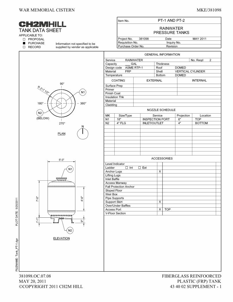

ONONDAGA COUNTY
WAR MEMORIAL CISTERN SYSTEM
381098 Fiberglass Reinforced
20 May 2011 Pressure Tank
©Copyright 2011 CH2M HILL 43 40 02 - 1
SECTION 43 40 02
FIBERGLASS REINFORCED PRESSURE TANK
PART 1 GENERAL
1.1 REFERENCES
A. The following is a list of standards which may be referenced in this section:
1. American Society of Mechanical Engineers (ASME):
a. B16.5, Pipe Flanges and Flanged Fittings: NPS 1/2 through 24.
b. RTP-1, Reinforced Thermoset Plastic Corrosion Resistant
Equipment.
2. ASTM International (ASTM):
a. C582, Standard Specification for Contact-Molded Reinforced
Thermosetting Plastic (RTP) Laminates for Corrosion-Resistant
Equipment.
b. D2583, Standard Test Method for Indentation Hardness of Rigid
Plastics by Means of a Barcol Impressor.
c. D2584, Standard Test Method for Ignition Loss of Cured Reinforced
Resins.
d. D3299, Standard Specification for Filament-Wound Glass-Fiber-
Reinforced Thermoset Resin Corrosion-Resistant Tanks.
e. E84, Standard Test Method for Surface Burning Characteristics of
Building Materials.
f. E1067, Standard Practice for Acoustic Emission Examination of
Fiberglass Reinforced Plastic Resin (FRP) Tanks/Vessels.
1.2 DEFINITIONS
A. FRP: Fiberglass reinforced plastic.
1.3 DESIGN REQUIREMENTS
A. Design Loads: In accordance with Section 01 61 00, Common Product
Requirements.
B. Tanks specified to be fabricated to ASME RTP-1 requirements shall be designed,
fabricated, and code stamped. ASME RTP-1 shall be all inclusive for tanks so
specified.
C. The User’s Basic Requirements Specification (UBRS) for RTP-1 tanks is a part of
this Specification.

ONONDAGA COUNTY
WAR MEMORIAL CISTERN SYSTEM
381098 Fiberglass Reinforced
20 May 2011 Pressure Tank
©Copyright 2011 CH2M HILL 43 40 02 - 2
D. Design tank, including resin selection (unless specified), wall thickness, methods
and locations of support, and stiffener requirements. Design shall be prepared and
sealed by designer meeting requirements of Article Quality Assurance.
1.4 SUBMITTALS
A. Action Submittals:
1. Shop Drawings:
a. Fabricators catalog information, descriptive literature, specifications,
and identification of materials of construction, including
complete resin system information.
b. Letter from resin manufacturer stating that selected resin is suitable
for intended service.
c. Detailed fabrication drawings.
d. Tank data indicating equipment number, pressure rating, diameter,
straight shell lengths, overall lengths, wall thickness, corrosion
barrier thickness, and details of nozzle designs.
e. Tank capacity chart indicating gallons for each 6 inches of depth and
cumulative total from bottom.
f. Fabricator’s detailed requirements for tank foundations.
g. Recommended bolt torque for bolted FRP connections.
h. Seismic anchorage and bracing drawings and cut sheets, as required
by Section 01 88 15, Seismic Anchorage and Bracing.
2. Samples: Laminate sample representative of production quality of surface
finish and visual imperfections.
B. Informational Submittals:
1. Complete design calculations for tanks, supports and accessories.
2. Seismic anchorage and bracing calculations as required by
Section 01 88 15, Seismic Anchorage and Bracing.
3. Certification to ASME RTP-1.
4. Manufacturer’s Certificate of Proper Installation.
5. Fabricator’s Certificate of Compliance with fabrication requirements.
6. Qualifications of Fabricator’s Quality Assurance Supervisor.
7. Copy of fabricator’s Quality Assurance Program.
8. Quality Assurance Inspection:
a. Qualifications of Independent FRP Quality Assurance Inspector.
b. Initial QA Inspection Report.
c. Certification of Factory Testing.
9. Certification that access nozzles have been coordinated with actual
equipment being furnished.
10. Component and attachment testing seismic certificate of compliance as
required by Section 01 45 33, Special Inspection and Testing.
11. Special shipping, storage and protection, and handling instructions.

ONONDAGA COUNTY
WAR MEMORIAL CISTERN SYSTEM
381098 Fiberglass Reinforced
20 May 2011 Pressure Tank
©Copyright 2011 CH2M HILL 43 40 02 - 3
12. Fabricator’s printed installation and tank support instructions.
13. Manufacturer’s Certificate of Proper Installation in accordance with
Section 01 43 33, Manufacturers’ Field Services.
14. Qualifications of Acoustic Emission Testing Agency.
C. Contract Closeout Submittals: Service records for repairs performed during
construction.
1.5 QUALITY ASSURANCE
A. Fabricator’s Quality Assurance Supervisor: Minimum of 5 years’ experience in
fabrication of fiberglass structures.
B. Designer: Registered professional engineer licensed in the state of New York. .
C. Acoustic Emission Testing Agency: Minimum 5 years’ experience in acoustic
emission testing of fiberglass structures.
1.6 DELIVERY, STORAGE, AND HANDLING
A. In accordance with Section 01 61 00, Common Product Requirements. In
addition, prepare and protect tank for shipment as follows:
1. Mount tank on padded cradles if shipped horizontally or on a suitable skid
if shipped vertically.
2. Protect flanged nozzles with wooden blinds bolted to flange and having a
diameter of 2 inches greater than outside diameter of flange.
3. Provide either rigid plugs inside ends to prevent deflection or wooden
boxes for unflanged components. Brace open end of tank with suitable
stiffening member to prevent deflection.
4. Do not ship components or other pieces loose inside tank.
5. Load tank with at least 2 inches of clearance between tank (including
fittings) and bulkheads, or bed of vehicle.
6. Regardless of mode of transportation, firmly fasten and pad components to
prevent shifting of load or flexing of components while in transit.
1.7 SEQUENCING AND SCHEDULING
A. Do not ship tank from factory until Engineer’s review of Certification of Factory
Testing is completed.

ONONDAGA COUNTY
WAR MEMORIAL CISTERN SYSTEM
381098 Fiberglass Reinforced
20 May 2011 Pressure Tank
©Copyright 2011 CH2M HILL 43 40 02 - 4
PART 2 PRODUCTS
2.1 SUPPLEMENTS
A. Some specific requirements relative to this section are attached as supplements at
the end of section.
2.2 SERVICE CONDITIONS
A. Operating Pressure: 150 psi
2.3 MATERIALS
A. Filament-Wound: Fabricate in accordance with ASTM D3299, Type I, Grade 1
and ASME RTP-1.
B. Resin:
1. Suitable for intended service.
2. Premium grade and corrosion resistant, such as chlorendic polyester, vinyl
ester, or bisphenol A fumarate polyester.
3. Use same resin throughout entire tank shell.
4. Add ultraviolet absorbers to surfacing resin to improve weather resistance.
5. No dyes, pigments, or colorants, except in exterior gel coat.
6. No fillers or thixotropic agents.
7. Additives may be added to achieve fire retardancy. The Flame-Spread
Rating of finish laminate shall be less than 25, as determined by
ASTM E84. Additives shall not be added to interior layer, unless
specifically required.
8. Curing System:
a. As recommended by resin manufacturer or as specified herein.
b. Cure products as specified in ASTM D3299 and ASME RTP-1.
c. Measure Barcol hardness according to ASTM D2583.
C. Reinforcements:
1. Surfacing Veil: Chemical surfacing mat, Type C (chemical) glass, 10 mils
thick, with a finish and a binder compatible with the lay-up resin.
2. Other Reinforcements: In accordance with ASTM D3299 and ASME
RTP-1.
D. Laminate:
1. Consists of inner surface (corrosion barrier), interior layer, and exterior
layer (structural layer).
2. Meet visual acceptance criteria in ASME RTP-1.
3. Meet requirements of mechanical properties in ASME RTP-1.
4. Reinforce inner surface with resin-rich surfacing veil as specified herein.

ONONDAGA COUNTY
WAR MEMORIAL CISTERN SYSTEM
381098 Fiberglass Reinforced
20 May 2011 Pressure Tank
©Copyright 2011 CH2M HILL 43 40 02 - 5
5. Apply a natural color coat after inspection of laminate has been
completed.
E. Marking:
1. Identify each tank with fabricator’s name, capacity in gallons, maximum
temperature, design pressure/vacuum, specific gravity, pH, resin,
minimum thickness, tank number, tank name, and date of manufacture.
2. Provide permanent marking. Seal decals, labels, etc., into laminate exterior
with clear resin.
3. Calibration Strips:
a. Translucent, 6 inches wide.
b. Calibration: Multiples of 10 gallons or less.
c. Stencil gallonage in 2-inch-high numerals.
F. Nozzles:
1. Gusset 4-inch or smaller nozzles with conical or plate type gussets. Larger
nozzles shall be gusseted, if noted.
2. Finish flush with inside surface of tank, unless otherwise indicated.
3. Gaskets:
a. Provide two per nozzle, 1/8-inch-thick, full-face elastomeric material
having a hardness of Shore A60 plus or minus 5.
b. Material shall be suitable for intended service.
4. Flanged Nozzles: Rated at 100 psi, with other dimensions and bolting
corresponding to ASME B16.5 for 150-pound steel flanges.
5. Back face of flanges shall be spot-faced, flat and parallel to flange face of
sufficient diameter to accept SAE metal washer under bolthead or nut.
2.4 APPURTENANCES
A. Sight Glass (Type 2):
1. Calibrate in 100-gallon increments.
2. Abrasion and corrosion resistant.
3. Mount using 1/2-inch Tygon tubing, PVC fittings, PVC isolation ball
valve, and stainless steel hose clamps.
B. Supports:
1. Pipe Supports:
a. Provide for tank overflow pipes, loading pipes and recirculation
pipes.
b. Spacing of supports shall be as recommended by fabricator, but shall
not be greater than 4 feet on center.
c. As shown on Drawings, shall allow removal of pipe.
d. Type 316 stainless steel complete with necessary bolts, nuts, and
washers.
2. Level Probe Supports: stainless steel.

ONONDAGA COUNTY
WAR MEMORIAL CISTERN SYSTEM
381098 Fiberglass Reinforced
20 May 2011 Pressure Tank
©Copyright 2011 CH2M HILL 43 40 02 - 6
C. Lifting Lugs: Provide suitably attached for tank weighing over 100 pounds.
D. Anchor Bolts: Type 316 stainless steel bolts, sized by fabricator, and 1/2 -inch
minimum diameter and as specified in Section 05 50 00, Metal Fabrications.
E. Manway Bolts: Type 316 stainless steel bolts and nuts per manufacturer’s
recommendations. .
2.5 SOURCE QUALITY CONTROL
A. Identify and retain cutouts. Engineer may select certain cutouts for testing for
physical properties of laminate.
B. Acoustic Emission Test:
1. Provide services of acoustic emission test agency to conduct test.
2. Test completed tank in accordance with ASTM E1067.
C. Factory Test Reports: Certify results, by signature, of the following:
1. Inspections.
2. Results of hydrostatic testing.
3. Test reports of physical properties of standard laminates.
4. Test results and report for acoustic emission test.
PART 3 EXECUTION
3.1 INSTALLATION
A. In accordance with fabricator’s written instructions.
B. Accurately place anchor bolts using templates furnished by fabricator, and as
specified in Section 05 50 00, Metal Fabrications.
3.2 FIELD QUALITY CONTROL
A. Functional Test:
1. Conduct on each tank.
2. Hydrostatic leak test with tank full of clean water. Allow water to stand
for 24 hours to verify no leakage.
3.3 MANUFACTURER’S FIELD SERVICES
A. Provide fabricator’s representative at Site in accordance with Section 01 43 33,
Manufacturers’ Field Services, and Section 01 91 14, Equipment Testing and
Facility Startup for installation assistance, inspection and certification of proper
installation for specified component, subsystem, equipment, or system.

ONONDAGA COUNTY
WAR MEMORIAL CISTERN SYSTEM
381098 Fiberglass Reinforced
20 May 2011 Pressure Tank
©Copyright 2011 CH2M HILL 43 40 02 - 7
3.4 SUPPLEMENTS
A. The supplements listed below, following “End of Section,” are part of this
specification.
1. FRP Tank Schedule.
END OF SECTION

ONONDAGA COUNTY
WAR MEMORIAL CISTERN SYSTEM
381098 Fiberglass Reinforced
20 May 2011 Pressure Tank
©Copyright 2011 CH2M HILL 43 40 02 - 1
FRP Tank Schedule
Name of Tank* Finished Water
Pressure Tank
1
Finished Water
Pressure Tank
2
Equipment Numbers PT-1 PT-2
Filament-wound or Contact-molded Filament
Wound
Filament
Wound
Maximum Capacity Measured to High
Solution Level (gallons)
900 900
Installation (Vertical/Horizontal) Vertical Vertical
Diameter (feet) 5 5
Straight Shell Height (feet) 8 8
Support (saddles, flat pad, legs) Flat pad +
tripod base
Flat pad +
tripod base
Type of Bottom Head Domed Domed
Type of Top Head Domed Domed
Ladder Required (Yes/No) No No
Tank Location (indoor/outdoor) Indoor Indoor
Ambient Temperature Range
(degrees F)
75 75
Exterior Loading (psf):
Platforms
Pipe Supports
Operating Contents: RainWater RainWater
Temperature (degrees F,
not to exceed 180)
40 – 90 40 – 90
Specific Gravity 1.0 1.0
pH Range 4-5 4-5
Sight Glass Type (1 or 2) 2 2
Sight Glass Tube Length Full length of
the tank
Full length of
the tank
Insulation/Heat Tracing (Yes/No) No No

ONONDAGA COUNTY
WAR MEMORIAL CISTERN SYSTEM
381098 Horizontal End Suction Centrifugal Pumps
27 May 2011 44 42 56.10 - 1
©Copyright 2011 CH2M HILL
SECTION 44 42 56.10
HORIZONTAL END SUCTION CENTRIFUGAL PUMPS
PART 1 GENERAL
1.1 REFERENCES
A. The following is a list of standards which may be referenced in this section:
1. American Bearing Manufacturers’ Association (ABMA).
2. Hydraulic Institute Standards (HIS).
3. National Electrical Manufacturer’s Association (NEMA): MG 1, Motors
and Generators.
4. Occupational Safety and Health Administration (OSHA).
1.2 DEFINITIONS
A. Terminology pertaining to pumping unit performance and construction shall
conform to the ratings and nomenclature of the Hydraulic Institute Standards.
1.3 SUBMITTALS
A. In accordance with Division 1, General Requirements
B. Action Submittals:
1. Shop Drawings:
a. Make, model, weight, and horsepower of each equipment assembly.
b. Complete catalog information, descriptive literature, specifications,
and identification of materials of construction.
c. Performance data curves showing head, capacity, horsepower
demand, and pump efficiency over entire operating range of pump
from shutoff to maximum capacity. Indicate separately the head,
capacity, horsepower demand, overall efficiency, and minimum
submergence required at guarantee point.
d. Detailed structural, mechanical, and electrical drawings showing
equipment dimensions, size, and locations of connections and
weights of associated equipment.
2. Complete wiring diagrams for all electrical and control equipment
including detail wiring for power, signal and control. Differentiate
between manufacturer-installed and field-installed wiring
3. Instrumentation and Control System Submittals:
a. Shop Drawings: Refer to Section 40 99 90, Package Control Systems;
Article 1.4, Submittals; for submittal requirements related to Panel
Construction Drawings, Panel Control Diagrams, Panel Wiring

ONONDAGA COUNTY
WAR MEMORIAL CISTERN SYSTEM
381098 Horizontal End Suction Centrifugal Pumps
27 May 2011 44 42 56.10 - 2
©Copyright 2011 CH2M HILL
Diagrams, Loop Diagrams, Interconnect Wiring Diagrams, Catalog
Cuts and Component Data Sheets. The System Package Supplier
shall coordinate with the Contractor for work external to their
package.
b. Programming/configuration files for programmable equipment, if
applicable.
4. Electrical power requirements.
5. Electrical schematic wiring diagrams.
6. Complete motor nameplate data, as defined by NEMA, motor manufacturer.
7. Factory finish system.
C. Informational Submittals:
1. Factory Functional Test Reports.
2. Special shipping, storage and protection, and handling instructions.
3. Manufacturer’s printed installation instructions.
4. Suggested spare parts list to maintain the equipment in service for a period
of 1 year and 5 years. Include a list of special tools required for checking,
testing, parts replacement, and maintenance with current price
information.
5. List special tools, materials, and supplies furnished with equipment for use
prior to and during startup and for future maintenance.
6. Operation and Maintenance Data: As specified in Section 01 78 23,
Operation and Maintenance Data. Refer to Section 40 99 90, Package
Control Systems; Article 1.4, Submittals; for additional Operations and
Maintenance Manuals requirements relative to I&C System
7. Manufacturer’s Certificate of Proper Installation, in accordance with
Section 01 43 33, Manufacturers’ Field Services.
1.4 EXTRA MATERIALS
A. Furnish for each pump.
1. Complete set bearings.
2. Complete set gaskets and O-ring seals.
3. Complete set of shaft sleeves.
4. Complete set keys, dowels, pins, etc.
5. Complete mechanical seal.
6. One complete set of special tools required to dismantle pump.
PART 2 PRODUCTS
2.1 GENERAL
A. Coordinate pump requirements with drive manufacturer and be responsible for
pump and drive requirements.

ONONDAGA COUNTY
WAR MEMORIAL CISTERN SYSTEM
381098 Horizontal End Suction Centrifugal Pumps
27 May 2011 44 42 56.10 - 3
©Copyright 2011 CH2M HILL
2.2 SUPPLEMENTS
A. Some specific requirements are attached to this section as supplements.
2.3 CONTROL PANELS
A. The design, construction, and installation of the control panels shall be in
accordance with Section 40 99 90, Package Control Systems.
1. Provide the following control panels:
Tag
Numbers Name Material NEMA Rating
RWRP-
NE.LCP
Rainwater receiver
Pumps-NE Local
Control Panel
316 SS NEMA 4X
RWRP-
SE.LCP
Rainwater receiver
Pumps-SE Local
Control Panel
316 SS NEMA 4X
RWRP-
NW.LCP
Rainwater receiver
Pumps-NW Local
Control Panel
316 SS NEMA 4X
2. Control panels shall utilize relay logic. All lights, switches and pushbuttons
shall be accessible at the panel face.
3. The panel shall be furnished as complete integrated control system with all
instrumentation, motor starters, wiring, and other devices required. The
panel shall be delivered to the site as pre-wired coordinated unit ready for
external field wiring.
4. The panel shall be manufactured and assembled in a UL registered shop.
Prior to shipment, all control panels shall be inspected, approved and
labeled in accordance with UL 508A requirements.
B. Controls and Indications:
1. Control panel shall be equipped with the following:
a. Main Disconnect with an External Pad Lockable Operating Handle.
b. Motor Overload Protection.
c. Control Power On indication
d. Emergency Stop Pushbutton.
e. On-Off-Remote Selector Switch for each Pump.
f. On Status for each pump.
g. Fail Alarm for Each Pump.

ONONDAGA COUNTY
WAR MEMORIAL CISTERN SYSTEM
381098 Horizontal End Suction Centrifugal Pumps
27 May 2011 44 42 56.10 - 4
©Copyright 2011 CH2M HILL
h. Alarm Reset Pushbuttons.
i. Connection to tank low level float switch provided by others.
2. Pumps shall be provided with all the controls and instrumentation necessary
for operation as described herein.
a. In On mode, the pumps shall start immediately and shall only be
stopped when the level in the associated tank(s) reaches low level.
b. In Remote mode, the pumps shall receive a Run command from the
Plant PLC. The plant PLC will operate the pumps based on tank
level.
3. Control panel shall interface with the Plant PLC. The following hardwired
interface shall be provided:
a. On status feedback for each pump to the Plant PLC.
b. Remote status feedback for each pump to the Plant PLC.
c. Fail alarm (overload) for each pump to the Plant PLC.
d. Control power fail alarm to the plant PLC.
e. Tank low level alarm(s) to Plant PLC
f. Run command for each pump from the Plant PLC.
4. Electrical:
a. 208 VAC, 3-Phase, power will be supplied to the Package Control
Panel.
b. The Package Control Panel shall be equipped with a control power
transformer and a distribution panel to distribute power as
necessary.
c. Refer to Division 26, Electrical, for electrical design and installation
requirements.
2.4 ACCESSORIES
A. Equipment Identification Plate: 16-gauge stainless steel with 1/4-inch die-stamped
equipment tag number securely mounted in a readily visible location.
B. Lifting Lugs: Equipment weighing over 100 pounds.
C. OSHA-approved coupling guard.
D. Anchor Bolts: Type 316 stainless steel, sized by equipment manufacturer,
1/2-inch minimum diameter, and as specified in Section 05 50 00, Metal
Fabrications.
2.5 FACTORY FINISHING
A. Manufacturer’s standard enamel finish.

ONONDAGA COUNTY
WAR MEMORIAL CISTERN SYSTEM
381098 Horizontal End Suction Centrifugal Pumps
27 May 2011 44 42 56.10 - 5
©Copyright 2011 CH2M HILL
2.6 SOURCE QUALITY CONTROL
A. Factory Inspections: Inspect control panels for required construction, electrical
connection, and intended function.
B. Factory Tests and Adjustments: Test all equipment and control panels actually
furnished.
C. Factory Test Report: Include test data sheets and curve test results, certified
correct by manufacturer.
D. Perform manufacturer’s standard test on equipment and Hydrostatic Test.
E. Motor Test: See Section 26 20 00, Low-Voltage AC Induction Motors.
F. Hydrostatic Tests: Pump casing(s) tested at 150 percent of shutoff head. Test
pressure maintained for not less than 5 minutes.
PART 3 EXECUTION
3.1 INSTALLATION
A. Install in accordance with manufacturer’s printed instructions.
B. Level base by means of steel wedges (steel plates and steel shims). Wedge taper
not greater than 1/4 inch per foot. Use double wedges to provide a level bearing
surface for pump and driver base. Accomplish wedging so there is no change of
level or springing of baseplate when anchor bolts are tightened.
C. Adjust pump assemblies such that the driving units are properly aligned, plumb,
and level with the driven units and all interconnecting shafts and couplings. Do
not compensate for misalignment by use of flexible couplings.
D. After pump and driver have been set in position, aligned, and shimmed to proper
elevation, grout the space between the bottom of the baseplate and the concrete
foundation with a poured, nonshrinking grout of the proper category, as specified
in Section 03 62 00, Nonshrink Grouting. Remove wedges after grout is set and
pack void with grout.
E. Connect suction and discharge piping without imposing strain to pump flanges.
F. Anchor Bolts: Accurately place using equipment templates and as specified in
Section 05 50 00, Metal Fabrications.

ONONDAGA COUNTY
WAR MEMORIAL CISTERN SYSTEM
381098 Horizontal End Suction Centrifugal Pumps
27 May 2011 44 42 56.10 - 6
©Copyright 2011 CH2M HILL
3.2 FIELD QUALITY CONTROL
A. Functional Tests: Conduct on each pump.
1. Alignment: Test complete assemblies for correct rotation, proper alignment
and connection, and quiet operation.
2. Vibration: If installed units exhibit vibration under normal operation rates in
excess of 80 percent of the limits specified in HIS 9.6.4, adjust or modify
as necessary. Units which cannot be adjusted or modified to conform as
specified shall be replaced.
B. Operating Temperatures: Monitor motor bearing areas for abnormally high
temperatures.
C. Performance Test:
1. Conduct on each pump.
2. Perform under simulated operating conditions.
3. Test for a continuous 1-hour period without malfunction.
4. Test Log: Record the following:
a. Total head.
b. Capacity, measured by either manufacturer’s instrumentation or
storage volumes.
c. Horsepower requirements.
d. Average distance from suction tank water surface to pump discharge
centerline for duration of test.
e. Pump discharge pressure converted to feet of liquid pumped and
corrected to pump discharge centerline.
f. Calculated velocity head at the discharge flange.
g. Static head.
h. Driving motor voltage and amperage measured for each phase.
3.3 MANUFACTURER’S SERVICES
A. Manufacturer’s Representative: Present at Site or classroom designated by Owner
for minimum person-days listed below, travel time excluded:
1. 3 person-days for installation assistance and inspection.
2. 3 person-days for functional and performance testing and completion of
Manufacturer’s Certificate of Proper Installation.
3. 3 person-days for facility startup.
4. 1 person-day for training of Owner’s personnel. Training shall not
commence until an accepted detailed lesson plan for each training activity
has been reviewed by Engineer.
B. See Section 01 43 33, Manufacturers’ Field Services and Section 01 91 14,
Equipment Testing and Facility Startup.

ONONDAGA COUNTY
WAR MEMORIAL CISTERN SYSTEM
381098 Horizontal End Suction Centrifugal Pumps
27 May 2011 44 42 56.10 - 7
©Copyright 2011 CH2M HILL
3.4 SUPPLEMENTS
A. The supplements listed below, following “End of Section,” are a part of this
Specification.
1. Pump Data Sheets:
a. Section 44 42 56.10-01, Rainwater Receiver Pumps Northwest
(RWRP-NW-1, RWRP-NW-2).
b. Section 44 42 56.10-02, Rainwater Receiver Pumps Northeast
(RWRP-NE-1, RWRP-NE-2).
c. Section 44 42 56.10-03, Rainwater Receiver Pumps Southeast
(RWRP-SE-1, RWRP-SE-2).
END OF SECTION

ONONDAGA COUNTY
WAR MEMORIAL CISTERN SYSTEM
381098 Horizontal End Suction Centrifugal Pumps
27 May 2011 44 42 56.10-01 Supplement - 1
©Copyright 2011 CH2M HILL
HORIZONTAL END SUCTION CENTRIFUGAL PUMP DATA SHEET, 44 42 56.10-01
Tag Numbers: RWRP-NW-1, RWRP-NW-2
Pump Name: Rainwater Receiver Pumps Northwest No. 1 and 2
Manufacturer and Model Number: (1) ITT Goulds, Model 3657
(2)
SERVICE CONDITIONS
Liquid Pumped (Material and Percent): Rain water
Pumping Temperature (Fahrenheit): Normal: 60_____ Max 100 Min 32
Specific Gravity at 60 Degrees F: 1.0 Viscosity Range: 1 cP @ 68°F
Vapor Pressure at 60 Degrees F: 0.256 psi pH: 4.5
Abrasive (Y/N) N Possible Scale Buildup (Y/N): N
Min. NPSH Available (Ft. Absolute): 42
Suction Pressure (Ft): Max 6 Rated 3.5
PERFORMANCE REQUIREMENTS AT PRIMARY DESIGN POINT
Capacity (US gpm): Rated: 170, ±5%
Total Dynamic Head (Ft): Rated: 17, ±5%
Min. Hydraulic Efficiency (%): 60, ±3%
Maximum Shutoff Pressure (Ft): 30
Max. Pump Speed at Design Point (rpm): 1750
Constant (Y/N): Y Adjustable (Y/N): N
DESIGN AND MATERIALS
ANSI (Y/N) N Standard (Y/N) N Design: Frame-mounted (Y/N) N
Close-Coupled Casing (Y/N) Y Back Pullout (Y/N) Y
Discharge Orientation: See drawings Rotation (view from end coupling): Clockwise
Casing Materials: 316 stainless steel
Case Wear Ring (Y/N):Y Material: 316 stainless steel
Impeller: Type: Enclosed Material: 316 stainless steel
Impeller Wear Ring (Y/N): N Material:
Shaft Material: Steel Shaft Sleeve Material: 316 stainless steel
Shaft Seal: O-ring Packing (Y/N) N Material:
Mechanical (Y/N) Y Type: Flowserve Type 31
Lubrication: Pumped Liquid

ONONDAGA COUNTY
WAR MEMORIAL CISTERN SYSTEM
381098 Horizontal End Suction Centrifugal Pumps
27 May 2011 44 42 56.10-01 Supplement - 2
©Copyright 2011 CH2M HILL
ABMA L-10 Bearing Life (Hrs): 50,000 Lubrication: Grease
Coupling: Falk (Y/N) N Fast (Y/N) N
Spring-Grid (Y/N) N
Gear Type (Y/N) N Spacer (Y/N) N Manufacturer
Standard (Y/N)
Baseplate: Design: Material: Steel
Drive Type: Direct-Coupled: Y Belt Adjustable Speed
Other:
DRIVE MOTOR See Section 26 20 00, Low-Voltage AC Induction Motors.
Horsepower: 1.5 Voltage: 200 Phase: 3 Synchronous Speed (rpm): 1800
Service Factor: 1.15 Inverter Duty (Y/N) N
Motor nameplate horsepower shall not be exceeded at any head-capacity point on the
pump curve.
Enclosure: DIP ____ EXP ____ ODP _X___ TEFC ____ CISD-TEFC ____ TENV ____
WPI ____ WPII ____ SUBM ____
Mounting Type: Horizontal X Nonreverse Ratchet (Y/N) N
REMARKS Premium Efficiency Motor

ONONDAGA COUNTY
WAR MEMORIAL CISTERN SYSTEM
381098 Horizontal End Suction Centrifugal Pumps
27 May 2011 44 42 56.10-02 Supplement - 1
©Copyright 2011 CH2M HILL
HORIZONTAL END SUCTION CENTRIFUGAL PUMP DATA SHEET, 44 42 56.10-02
Tag Numbers: RWRP-NE-1, RWRP-NE-2
Pump Name: Rainwater Receiver Pumps Northeast No. 1 and 2
Manufacturer and Model Number: (1) ITT Goulds, Model SSH/7SH
(2)
SERVICE CONDITIONS
Liquid Pumped (Material and Percent): Rain water
Pumping Temperature (Fahrenheit): Normal: 60_____ Max 100 Min 32
Specific Gravity at 60 Degrees F: 1.0 Viscosity Range: 1 cP @ 68°F
Vapor Pressure at 60 Degrees F: 0.256 psi pH: 4.5
Abrasive (Y/N) N Possible Scale Buildup (Y/N): N
Min. NPSH Available (Ft. Absolute): 42
Suction Pressure (Ft): Max 6 Rated 3.5
PERFORMANCE REQUIREMENTS AT PRIMARY DESIGN POINT
Capacity (US gpm): Rated: 82, ±5%
Total Dynamic Head (Ft): Rated: 35, ±5%
Min. Hydraulic Efficiency (%): 55, ±3%
Maximum Shutoff Pressure (Ft): 50
Max. Pump Speed at Design Point (rpm): 1750
Constant (Y/N): Y Adjustable (Y/N): N
DESIGN AND MATERIALS
ANSI (Y/N) N Standard (Y/N) N Design: Frame-mounted (Y/N) N
Close-Coupled Casing (Y/N) Y Back Pullout (Y/N) Y
Discharge Orientation: See drawings Rotation (view from end coupling): Clockwise
Casing Materials: 316 stainless steel
Case Wear Ring (Y/N): Y Material: 316 stainless steel
Impeller: Type: Enclosed Material: 316 stainless steel
Impeller Wear Ring (Y/N): N Material:
Shaft Material: Steel Shaft Sleeve Material: 316 stainless steel
Shaft Seal: O-ring Packing (Y/N) N Material:
Mechanical (Y/N) Y Type: John Crane Type 21
Lubrication: Pumped Liquid

ONONDAGA COUNTY
WAR MEMORIAL CISTERN SYSTEM
381098 Horizontal End Suction Centrifugal Pumps
27 May 2011 44 42 56.10-02 Supplement - 2
©Copyright 2011 CH2M HILL
ABMA L-10 Bearing Life (Hrs): 50,000 Lubrication: Grease
Coupling: Falk (Y/N) N Fast (Y/N) N
Spring-Grid (Y/N) N
Gear Type (Y/N) N Spacer (Y/N) N Manufacturer
Standard (Y/N)
Baseplate: Design: Material: Steel
Drive Type: Direct-Coupled: Y Belt Adjustable Speed
Other:
DRIVE MOTOR See Section 26 20 00, Low-Voltage AC Induction Motors.
Horsepower: 1.5 Voltage: 200 Phase: 3 Synchronous Speed (rpm): 1800
Service Factor: 1.15 Inverter Duty (Y/N) N
Motor nameplate horsepower shall not be exceeded at any head-capacity point on the
pump curve.
Enclosure: DIP ____ EXP ____ ODP _X___ TEFC ____ CISD-TEFC ____ TENV ____
WPI ____ WPII ____ SUBM ____
Mounting Type: Horizontal X Nonreverse Ratchet (Y/N) N
REMARKS Premium Efficiency Motor

ONONDAGA COUNTY
WAR MEMORIAL CISTERN SYSTEM
381098 Horizontal End Suction Centrifugal Pumps
27 May 2011 44 42 56.10-03 Supplement - 1
©Copyright 2011 CH2M HILL
HORIZONTAL END SUCTION CENTRIFUGAL PUMP DATA SHEET, 44 42 56.10-03
Tag Numbers: RWRP-SE-1, RWRP-SE-2
Pump Name: Rainwater Receiver Pumps Southeast No. 1 and 2
Manufacturer and Model Number: (1) ITT Goulds, Model SSH/4SH
(2)
SERVICE CONDITIONS
Liquid Pumped (Material and Percent): Rain water
Pumping Temperature (Fahrenheit): Normal: 60_____ Max 100 Min 32
Specific Gravity at 60 Degrees F: 1.0 Viscosity Range: 1 cP @ 68°F
Vapor Pressure at 60 Degrees F: 0.256 psi pH: 4.5
Abrasive (Y/N) N Possible Scale Buildup (Y/N): N
Min. NPSH Available (Ft. Absolute): 42
Suction Pressure (Ft): Max 6 Rated 3.5
PERFORMANCE REQUIREMENTS AT PRIMARY DESIGN POINT
Capacity (US gpm): Rated: 55, ±5%
Total Dynamic Head (Ft): Rated: 21, ±5%
Min. Hydraulic Efficiency (%): 60, ±3%
Maximum Shutoff Pressure (Ft): 34
Max. Pump Speed at Design Point (rpm): 1750
Constant (Y/N): Y Adjustable (Y/N): N
DESIGN AND MATERIALS
ANSI (Y/N) N Standard (Y/N) N Design: Frame-mounted (Y/N) N
Close-Coupled Casing (Y/N) Y Back Pullout (Y/N) Y
Discharge Orientation: See drawings Rotation (view from end coupling): Clockwise
Casing Materials: 316 stainless steel
Case Wear Ring (Y/N): Y Material: 316 stainless steel
Impeller: Type: Enclosed Material: 316 stainless steel
Impeller Wear Ring (Y/N): N Material:
Shaft Material: Steel Shaft Sleeve Material: 316 stainless steel
Shaft Seal: O-ring Packing (Y/N) N Material:
Mechanical (Y/N) Y Type: John Crane Type 21
Lubrication: Pumped Liquid

ONONDAGA COUNTY
WAR MEMORIAL CISTERN SYSTEM
381098 Horizontal End Suction Centrifugal Pumps
27 May 2011 44 42 56.10-03 Supplement - 2
©Copyright 2011 CH2M HILL
ABMA L-10 Bearing Life (Hrs): 50,000 Lubrication: Grease
Coupling: Falk (Y/N) N Fast (Y/N) N
Spring-Grid (Y/N) N
Gear Type (Y/N) N Spacer (Y/N) N Manufacturer
Standard (Y/N)
Baseplate: Design: Material: Steel
Drive Type: Direct-Coupled: Y Belt Adjustable Speed
Other:
DRIVE MOTOR See Section 26 20 00, Low-Voltage AC Induction Motors.
Horsepower: 0.75 Voltage: 200 Phase: 3 Synchronous Speed (rpm): 1800
Service Factor: 1.15 Inverter Duty (Y/N) N
Motor nameplate horsepower shall not be exceeded at any head-capacity point on the
pump curve.
Enclosure: DIP ____ EXP ____ ODP _X___ TEFC ____ CISD-TEFC ____ TENV ____
WPI ____ WPII ____ SUBM ____
Mounting Type: Horizontal X Nonreverse Ratchet (Y/N) N
REMARKS Premium Efficiency Motor

ONONDAGA COUNTY
WAR MEMORIAL CISTERN SYSTEM
381098 Pump Filter Skid System
25 May 2011 44 42 57 - 1
©Copyright 2011 CH2M HILL
SECTION 44 42 57
PUMP FILTER SKID SYSTEM
PART 1 GENERAL
1.1 GENERAL
A. All items of equipment specified herein shall be furnished by one supplier. This
Supplier shall have the responsibility of providing the equipment, accessories, and
installation supervision required to provide a fully functional system.
B. Like items of equipment provided hereunder shall be the end products of one
manufacturer in order to achieve standardization for appearance, operation,
maintenance, spare parts, and Supplier's service.
1.2 QUALITY ASSURANCE:
A. Reference Standards: Comply with all Federal and State Laws or ordinances, as
well as all applicable codes, standards, regulations and/or regulatory agency
requirements including the partial listing below:
1. NEC, National Electric Code.
2. NEMA, Standards of National Electrical Manufacturers Association.
3. ANSI, American National Standards Institute.
4. ASME, American Society of Mechanical Engineers.
5. ASTM, American Society for Testing and Materials.
6. AISI, American Iron and Steel Institute.
7. OSHA, Occupational Safety and Health Act.
8. UL, Underwriters Laboratory.
9. HI, Hydraulic Institute.
10. NSF Standard: Comply with NSF 61, "Drinking Water System
Components--Health Effects," for fixture materials that will be in contact
with potable water.
1.3 EQUIPMENT
A. Note that where specific dimensions, mechanical or structural features,
descriptions of mounting requirements, or basic equipment layout and
configuration are listed in these Specifications, it shall be understood that this is
for purposes of describing the base system only. It is not intended that all
manufacturers of competing equipment be required to match the dimensions,
geometry, or construction details precisely. Rather, features described will be
used as a basis for determining equivalency of competing systems to the base
system. Due to space limitations, the system supplier shall closely coordinate the

ONONDAGA COUNTY
WAR MEMORIAL CISTERN SYSTEM
381098 Pump Filter Skid System
25 May 2011 44 42 57 - 2
©Copyright 2011 CH2M HILL
design of the equipment with the Facility Layout Drawings included in the
Contract Documents.
1.4 SUBMITTALS
A. In accordance with Division 1, General Requirements.
B. Shop Drawings
1. Comply with Division 01, Division 40, and Division 26 submittal
requirements.
2. Drawings showing dimensions, weights and details of components, piping
connections, and wiring for installation and operation.
3. Drawing showing anchor bolt locations.
4. Anchor bolt sizing calculations.
5. Double line piping drawings (piping schematics will not be acceptable)
showing all piping, valves, and accessories furnished with the system and
interconnections with piping and services provided by others.
6. Manufacturer's literature, illustrations, specifications and engineering data
for equipment, components and accessories including: dimensions,
materials, sizes, weights, curves showing overall pump efficiencies, flow
rates, head, brake horsepower, motor horsepower, speed and shut-off head
and performance data for all equipment to be furnished under this Section.
7. Layout drawings for all equipment showing overall dimensions, fabrication,
assembly, wiring, typical and specific installation details.
8. Complete wiring diagrams for all electrical and control equipment including
detail wiring for power, signal and control. Differentiate between
manufacturer-installed and field-installed wiring.
9. Furnish standard operating procedures.
10. Instrumentation and Control System Submittals:
a. P&ID: System Process & Instrumentation Diagram.
b. Shop Drawings: Refer to Section 40 99 90, Package Control Systems;
Article 1.4, Submittals; for submittal requirements related to Panel
Construction Drawings, Panel Control Diagrams, Panel Wiring
Diagrams, Loop Diagrams, Interconnect Wiring Diagrams, Catalog
Cuts and Component Data Sheets. The System Package Supplier
shall coordinate with the Contractor for work external to their
package.
c. Programming/configuration files for programmable equipment, if
applicable.
11. Electrical power requirements.
12. Electrical schematic wiring diagrams.

ONONDAGA COUNTY
WAR MEMORIAL CISTERN SYSTEM
381098 Pump Filter Skid System
25 May 2011 44 42 57 - 3
©Copyright 2011 CH2M HILL
C. Quality Control Submittals:
1. Supplier's Certificate of Proper Installation for filter and accessories.
2. Supplier's written installation instructions
3. Operation and maintenance manual.
4. Test Reports :
a. Factory inspections.
b. Factory tests and adjustments.
c. Field Tests: Provide test results showing that systems demonstrate
and operate as specified, and are installed as submitted.
D. Contract Closeout Submittals: Operation and maintenance manual and Supplier's
warranty. Refer to Section 40 99 90, Package Control Systems; Article 1.4,
Submittals; for additional Operations and Maintenance Manuals requirements
relative to I&C System.
1.5 MAINTENANCE
A. Extra Materials:
1. Equipment manufacturer shall submit a listing of spare parts, including
price list, sufficient for 1 year's operation.
2. Contractor will furnish water for performance testing.
1.6 WARRANTY
A. Manufacturer shall warrant specified product to be free from defects in materials
and workmanship for one (1) year from date of substantial completion.
B. Warranties and guarantees by the suppliers of various components in lieu of a
single-source responsibility by the system supplier will not be accepted. The
supplier shall be solely responsible for the guaranty of the system and all its
components.
PART 2 PRODUCTS
2.1 MANUFACTURERS
A. Materials, equipment, and accessories specified in this section shall be products
of:
1. Siemens Water Technologies Corp, RWR-M1E Series.
2. Or Equal.

ONONDAGA COUNTY
WAR MEMORIAL CISTERN SYSTEM
381098 Pump Filter Skid System
25 May 2011 44 42 57 - 4
©Copyright 2011 CH2M HILL
2.2 SERVICE CONDITIONS
A. Exposure: All equipment shall be installed inside a building maintained at 45 to
105 degrees F.
2.3 PERFORMANCE AND DESIGN REQUIREMENTS
A. The System shall be a duplex variable speed system to provide a constant
pressure, filtered water feed.
B. The System shall be furnished as a complete factory assembled skid mounted unit
including a hydro-pneumatic tank, bag filter housing and bags, duplex in-line
pumps, variable frequency drives, motors, guards, control equipment, piping,
valves, gauges, and sensors, wiring, and a singular electric power connection, all
shop mounted and aligned on a common frame. System shall be mounted as
shown on the Drawings.
C. The System shall be fully automatic, and designed for continuous 24 hours /
7 days a week operation.
D. The overall dimensions of the System shall enable it to be installed in the space
provided, with all fixtures specified herein and shown on the Drawings.
E. The System shall be capable of automatically providing a flow from zero to the
design flow rate while maintaining a constant pressure set point, with a minimum
suction pressure of zero PSIG.
F. Design requirements are as follows:
1. The equipment shall be designed based on the requirements as detailed in
Table 1: Design Requirements.
Table 1
Design Requirements
Fluid pH 4
Fluid Temperature 32 – 100 degrees Fahrenheit
Specific Gravity 1.0
Largest Solid Passing 1/8 inch
Erosion Factor Non-abrasive
Pump Design Point (Phase I), P1P-1, P1P-2 30-GPM @ 22-FT TDH
Pump Design Point (Phase II), TP-1, TP-2 30-GPM @ 60-FT TDH
Total Suspended Solids 50 mg/L

ONONDAGA COUNTY
WAR MEMORIAL CISTERN SYSTEM
381098 Pump Filter Skid System
25 May 2011 44 42 57 - 5
©Copyright 2011 CH2M HILL
2.4 EQUIPMENT DESCRIPTION
A. Except as otherwise indicated, all equipment and accessories shall be provided as
required for proper functioning systems based on Siemens RWR-M1E
distribution pump-filter skid.
1. Pumps:
a. Variable speed vertical or horizontal centrifugal type pumps shall be
provided.
b. Pumps shall be a duplex arrangement, with two equal-size, vertical or
horizontal close-coupled, in-line centrifugal pumps.
c. Pumps shall be back pull-out (in-line) design with registered fit
between the pull-out assembly and the casing permitting removal
of the complete rotating assembly without disconnection of suction
or discharge connections.
d. The pump envelope dimensions shall conform in all respects to ANSI
Specification B73.2M, latest edition.
e. Pumps shall be equipped with integral pressure sensors.
f. Pumps shall be provided with integral VFDs.
g. Materials of Construction: All wetted parts shall be 304 or 316
stainless steel.
h. Pump Performance:
1) Pump motors shall be non-overloading at any point on the pump
curve.
2) Minimum pump hydraulic efficiency shall be 52 percent and
maximum pump shutoff pressure shall be 30 feet (±5%) for
the P1P-1, P1P-2 pumps.
3) Minimum pump hydraulic efficiency shall be 37 percent and
maximum pump shutoff pressure shall be 76 feet (±5%) for
the TP-1, TP-2 pumps.
4) See Table 1 for pump design points.
i. Pump Motor:
1) Motor enclosure shall be ODP, 2 hp for the TP-1 and TP-2
pumps, and 0.5 hp for the P1P-1 and P1P-2 pumps.
2) Motors shall be premium efficiency type.
3) Electric power: Pump motors shall be 200V/3PH/60Hz.
4) Pumps shall comply with section 26 20 0, Low-Voltage AC
Induction Motors.
5) Motors shall comply with division 26 requirements.
j. Pump Manufacturer: Goulds or equal.
2. Bag Filter:
a. Type: Single bag filter with single length bag.

ONONDAGA COUNTY
WAR MEMORIAL CISTERN SYSTEM
381098 Pump Filter Skid System
25 May 2011 44 42 57 - 6
©Copyright 2011 CH2M HILL
b. Filter Bags:
1) Bag type: polyester felt.
2) A quantity of ten (10) ~50 micron bags shall be provided.
c. Materials of construction: 304 or 316 stainless steel.
d. Maximum bag filter pressure rating shall be at least 150 PSIG.
e. Ends: Threaded.
f. Closure: bolted.
g. Gages:
1) Bag filter shall be provided inlet and outlet pressure indicator
gages to allow for the determination of differential
pressure.
2) Gage range: Twice the system operating pressure.
3) Material of construction: stainless steel.
4) Ends: 1/2-inch (minimum) Threaded.
5) Manufacturer: Ametek, or equal.
h. Bag filter shall include an integral drain.
i. Bag filter shall include an integral vent.
j. Manufacturer: Fil-Trek, Size P1, or equal.
3. Hydro-pneumatic Tank:
a. Type: Pre-charged hydro-pneumatic bladder type.
b. Volume: 21 gallons, minimum.
c. Maximum hydro-pneumatic tank pressure rating shall be at least
125 PSIG.
d. Maximum temperature rating shall be at least 160 degrees F.
e. Ends:
1) Ends shall be threaded.
2) Ends shall include a union ended isolation ball valve.
f. Materials of construction:
1) Tank: Epoxy coated steel.
2) Bladder/diaphragm: Butyl rubber.
3) Interior tank lining: Polypropylene.
g. Manufacturer: Dayton, or equal.
4. Valves:
a. Isolation valves shall be CPVC ball valves, GF Type 375, or equal.
b. Check Valves shall be ball type check valves, GF Type 360, or equal.
c. Valves shall comply with specification Section 40 27 02.
5. Piping:
a. Piping material shall be schedule 80 CPVC.
b. Piping shall comply with specification Section 40 27 00.
6. Mounting Skid:
a. Overall physical dimensions: 5 feet-0 inch long by 3 feet-6 inches
wide by 5 feet-10 inches high.
b. Mounting skid shall be of carbon steel construction.
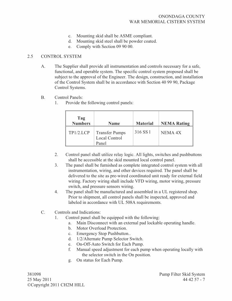
ONONDAGA COUNTY
WAR MEMORIAL CISTERN SYSTEM
381098 Pump Filter Skid System
25 May 2011 44 42 57 - 7
©Copyright 2011 CH2M HILL
c. Mounting skid shall be ASME compliant.
d. Mounting skid steel shall be powder coated.
e. Comply with Section 09 90 00.
2.5 CONTROL SYSTEM
A. The Supplier shall provide all instrumentation and controls necessary for a safe,
functional, and operable system. The specific control system proposed shall be
subject to the approval of the Engineer. The design, construction, and installation
of the Control System shall be in accordance with Section 40 99 90, Package
Control Systems.
B. Control Panels:
1. Provide the following control panels:
Tag
Numbers Name Material NEMA Rating
TP1/2.LCP Transfer Pumps
Local Control
Panel
316 SS l NEMA 4X
2. Control panel shall utilize relay logic. All lights, switches and pushbuttons
shall be accessible at the skid mounted local control panel.
3. The panel shall be furnished as complete integrated control system with all
instrumentation, wiring, and other devices required. The panel shall be
delivered to the site as pre-wired coordinated unit ready for external field
wiring. Factory wiring shall include VFD wiring, motor wiring, pressure
switch, and pressure sensors wiring.
4. The panel shall be manufactured and assembled in a UL registered shop.
Prior to shipment, all control panels shall be inspected, approved and
labeled in accordance with UL 508A requirements.
C. Controls and Indications:
1. Control panel shall be equipped with the following:
a. Main Disconnect with an external pad lockable operating handle.
b. Motor Overload Protection.
c. Emergency Stop Pushbutton..
d. 1/2/Alternate Pump Selector Switch.
e. On-Off-Auto Switch for Each Pump.
f. Manual speed adjustment for each pump when operating locally with
the selector switch in the On position.
g. On status for Each Pump.

ONONDAGA COUNTY
WAR MEMORIAL CISTERN SYSTEM
381098 Pump Filter Skid System
25 May 2011 44 42 57 - 8
©Copyright 2011 CH2M HILL
h. Low Feeder Tank Level Alarm.
i. Fail Alarm for Each Pump.
j. Alarm Reset Pushbuttons.
k. Timer with Alternating Function.
l. Connection to tank low level float switch provided by others
2. Pumps shall be provided with all the controls and instrumentation necessary
for self contained operation as described herein:
a. Pumps shall operate one at a time with the alternate pump in standby.
b. Pumps shall shutdown on low feeder tank level in both On and Auto
modes.
c. The inline pumps and controls are to be designed to maintain a
constant discharge pressure set point.
d. An operator adjustable high pressure switch shall de-energize the
pumps at a high operating pressure in both On and Auto modes.
e. In the On mode, the pumps shall start immediately and run
continuously at the speed set manually at the panel.
f. In the Auto mode, the duty pump shall start when the level in the
feeder tank is above a certain minimum, and the high pressure
switch is not active. The duty pump’s speed shall be automatically
varied to maintain a constant system discharge pressure that is
sensed by a continuously sensing pressure sensor. During the
periods of no demand, the duty pump shall slow down to maintain
only the recycle flow back to the feeder tank. A timer shall be
provided to alternate the pumps. If the duty pump fails to start or
fails while running, the standby pump shall be automatically
operated in its place.
3. Control panel shall interface with the Plant PLC. The following hardwired
interface shall be provided:
a. On status feedback for each pump to the Plant PLC.
b. Auto status feedback for each pump to the Plant PLC.
c. Fail alarm for each pump to the Plant PLC.
d. Control power fail alarm to the Plant PLC.
e. Run permissive (based on feeder tank level) signal:
1) Phase I: Directly wired to the feeder tank level switch
2) Phase II: Signal from the Plant PLC.
f. High pressure shutoff signal to the Plant PLC.
g. Feeder tank low level alarm to the Plant PLC.
4. Electrical:
a. 208 VAC, 3-Phase, power will be supplied to the Package System
Control Panel.
b. The Package System Control Panel shall be equipped with a control
power transformer and a distribution panel to distribute power as
necessary. All power and control wiring and conduit between the

ONONDAGA COUNTY
WAR MEMORIAL CISTERN SYSTEM
381098 Pump Filter Skid System
25 May 2011 44 42 57 - 9
©Copyright 2011 CH2M HILL
control panel and remote devices furnished under this section shall
be furnished and installed by the System Supplier.
c. Refer to Division 26, Electrical, for electrical design and installation
requirements.
2.6 ACCESSORIES
A. Equipment Identification Plates:
1. An engraved Gravoply laminated identification plate shall be securely
mounted on the equipment in a readily visible location. The plate shall
bear the 1/4-inch minimum identification number indicated in this
Specification and/or as shown on the Drawings.
2. Individual system components shall be provided with the manufacturer’s
standard nameplate including manufacturer’s name, model number,
serial number and rating.
B. Anchor Bolts: Provide anchor bolts. Submit size, material, and design.
C. Instrumentation: All instruments, as necessary, to meet the functional
requirements.
PART 3 EXECUTION
3.1 SOURCE QUALITY CONTROL
A. Factory Inspections:
1. Inspect control panel for required construction, electrical connection, and
intended function.
2. Inspect welds on vessels to ASME.
B. Factory Tests and Adjustments:
1. Test the control panel actually furnished.
2. Hydrostatically pressure test filter pressure vessel per ASME Code.
3.2 INSTALLATION
A. Equipment shall be installed in accordance with approved shop drawings and
Supplier's instructions.
3.3 PAINTING
A. Exposed metal surfaces of equipment and accessories specified herein shall be
field or shop prepared and primed as specified herein. Field apply finish coat per
09 90 00.

ONONDAGA COUNTY
WAR MEMORIAL CISTERN SYSTEM
381098 Pump Filter Skid System
25 May 2011 44 42 57 - 10
©Copyright 2011 CH2M HILL
B. Nonferrous and corrosion-resistant ferrous alloys such as copper, bronze, monel,
aluminum, chromium plate, and stainless steel need not be coated at the Supplier's
discretion subject to the Engineer's review.
3.4 FIELD QUALITY CONTROL
A. The Contractor, assisted by the equipment Supplier's or Supplier's representative,
shall conduct field tests as described below.
1. Functional Test: Prior to plant startup, all equipment shall be inspected for
proper alignment, proper connection, and vibration. If installed pumps
exhibit vibration under normal operation rates, in excess of 80 percent of
the limits specified in HIS 9.6.4, adjust or modify as necessary. Units
which cannot be adjusted or modified to conform as specified shall be
replaced.
2. Field Test: Confirm proper performance of controls and automatic valves.
3. Hydrostatically test vessels and related piping.
B. Operating Temperatures: Monitor motor bearing areas for abnormally high
temperatures.
C. Performance Test: Complete testing to demonstrate compliance to performance
criteria detailed herein this specification.
1. Conduct on each pump.
2. Perform under simulated operating conditions.
3. Test for a continuous 1-hour period without malfunction.
4. Test Log: Record the following:
a. Total head.
b. Capacity, measured by either manufacturer’s instrumentation or
storage volumes.
c. Horsepower requirements.
d. Average distance from suction tank water surface to pump discharge
centerline for duration of test.
e. Pump discharge pressure converted to feet of liquid pumped and
corrected to pump discharge centerline.
f. Calculated velocity head at the discharge flange.
g. Static head.
h. Driving motor voltage and amperage measured for each phase.
3.5 MANUFACTURER’S SERVICES
A. Furnish manufacturer’s representative for the following services at job site or
classroom, as designated by The Engineer, for minimum person-days listed
below, travel time excluded:
1. 2 person-days for installation assistance and inspection.

ONONDAGA COUNTY
WAR MEMORIAL CISTERN SYSTEM
381098 Pump Filter Skid System
25 May 2011 44 42 57 - 11
©Copyright 2011 CH2M HILL
2. 2 person-day for functional and performance testing and completion of
manufacturer's Certificates of Proper Installation.
3. 1 person-day for pre-startup classroom or site training of Operations
Subcontract personnel.
4. 2 person-day for startup.
B. Furnish startup services and training at such times as requested by the Owner.
END OF SECTION


ONONDAGA COUNTY
WAR MEMORIAL CISTERN SYSTEM
381098 Pressure Filter System
20 May 2011 44 43 29 - 1
©Copyright 2011 CH2M HILL
SECTION 44 43 29
PRESSURE FILTER SYSTEM
PART 1 GENERAL
1.1 GENERAL
A. All items of equipment specified herein shall be furnished by one supplier. This
Supplier shall have the responsibility of providing the equipment, accessories, and
installation supervision required to provide a fully functional filtration system.
B. Like items of equipment provided hereunder shall be the end products of one
manufacturer in order to achieve standardization for appearance, operation,
maintenance, spare parts, and Supplier's service.
1.2 EQUIPMENT
A. Note that where specific dimensions, mechanical or structural features,
descriptions of mounting requirements, or basic equipment layout and
configuration are listed in these Specifications, it shall be understood that this is
for purposes of describing the base system only. It is not intended that all
manufacturers of competing equipment be required to match the dimensions,
geometry, or construction details precisely. Rather, features described will be
used as a basis for determining equivalency of competing systems to the base
system. Due to space limitations, the filter system supplier shall closely
coordinate the design of the equipment with the Facility Layout Drawings
included in the Contract Documents.
1.3 SUBMITTALS
A. In accordance with Division 1, General Requirements.
B. Shop Drawings
1. Drawings showing dimensions, weights, and details of components, piping
connections, and wiring for installation and operation.
2. Double line piping drawings (piping schematics will not be acceptable)
showing all piping, valves, and accessories furnished with the filters and
interconnections with piping and services provided by others.
3. Furnish standard operating procedures.
4. Product data for equipment, components, and accessories.
5. Instrumentation and Control System Submittals:
a. P&ID: Pressure Filter System Process & Instrumentation Diagram

ONONDAGA COUNTY
WAR MEMORIAL CISTERN SYSTEM
381098 Pressure Filter System
20 May 2011 44 43 29 - 2
©Copyright 2011 CH2M HILL
b. Submittals for Programmable Equipment: Refer to Section 40 99 90,
Package Control Systems; Article 1.4, Submittals; for submittal
requirements related to control system hardware and software
c. Shop Drawings: Refer to Section 40 99 90, Package Control Systems;
Article 1.4, Submittals; for submittal requirements related to Panel
Construction Drawings, Panel Control Diagrams, Panel Wiring
Diagrams, Loop Diagrams, Interconnect Wiring Diagrams, Catalog
Cuts and Component Data Sheets. The Pressure Filter System
Package Supplier shall coordinate with the Contractor for work
external to their package.
C. Quality Control Submittals:
1. Supplier's Certificate of Proper Installation for filter and accessories.
2. Supplier's written installation instructions
3. Operation and maintenance manual.
4. Test Reports :
a. Factory inspections.
b. Factory tests and adjustments.
c. Factory pressure test for the filter vessel actually provided.
D. Contract Closeout Submittals: Operation and maintenance manual and Supplier's
warranty. Refer to Section 40 99 90, Package Control Systems; Article 1.4,
Submittals; for additional Operations and Maintenance Manuals requirements
relative to I&C System.
1.4 MAINTENANCE
A. Extra Materials:
1. Equipment manufacturer shall submit a listing of spare parts, including
price list, sufficient for 1 year's operation.
2. Contractor will furnish water and pretreatment chemicals (if necessary) for
performance testing.
1.5 WARRANTY
A. Manufacturer shall warrant specified product to be free from defects in materials
and workmanship for one (1) year from date of substantial completion.

ONONDAGA COUNTY
WAR MEMORIAL CISTERN SYSTEM
381098 Pressure Filter System
20 May 2011 44 43 29 - 3
©Copyright 2011 CH2M HILL
PART 2 PRODUCTS
2.1 MANUFACTURERS
A. Materials, equipment, and accessories specified in this section shall be products
of:
1. Siemens Water Technologies Corp, PTIM-P-D-A-24 x 48 Series.
2. Or Equal.
2.2 SERVICE CONDITIONS
A. Exposure: All equipment shall be installed inside a building maintained at 45 to
105 degrees F.
2.3 PERFORMANCE AND DESIGN REQUIREMENTS
A. The filter system shall consist of one (1) set of, single-cell pressure filters
arranged in duplex parallel, and equipped with air scour. The filter media shall
consist of anthracite and sand. All piping, filter housing and wetted parts shall be
constructed of stainless steel – compatible with a water with pH of 4.
B. Design requirements are as follows:
1. The pressure filter equipment shall be designed based on the requirements
as detailed in Table 1: Water Quality & Design Requirements.
2. The pressure filter backwash water source is to be W2 water as indicated on
the drawings.
Table 1
Water Quality & Design Requirements
pH 4
Temperature 32 – 100 degrees Fahrenheit
Flowrate 0 – 30 gpm per filter
Total Suspended Solids 50 mg/L
Turbidity 20 NTU
Number of Vessels 2 in total, arranged in 1 set of 2
(duplex parallel)
Filter Loading Rate 7.0 gpm/ft2
Filter Run Time >17 hours

ONONDAGA COUNTY
WAR MEMORIAL CISTERN SYSTEM
381098 Pressure Filter System
20 May 2011 44 43 29 - 4
©Copyright 2011 CH2M HILL
Table 1
Water Quality & Design Requirements
Backwash Rate 15 - 20 gpm/ft2
Maximum Working Pressure 90 psi
Clean Bed Maximum Headloss
Across Filter System (including
face piping and clean media)
7 psi
Dirty Bed Maximum Headloss
Across Filter System (including
face piping and media at terminal
headloss)
17 psi
Minimum allowable filter run
time (before terminal headloss)
10 hours
Media Losses !5 percent per year
2.4 EQUIPMENT DESCRIPTION
A. All equipment and accessories shall be provided as required for proper
functioning systems based on Siemens 24-inch diameter PTI series multimedia
filters.
1. Filter Tanks: System will consist of a vertical pressure filter, 24-inch
diameter.
2. Filters shall be equipped with all necessary face and interconnecting piping,
valves, and controls, for a complete and operable system, including air
scour operation.
3. Gravel Supporting Bed:
a. A gravel support bed shall be incorporated in the bottom of each
vessel, consisting of the following tabulated layers of graded
gravel, with the following ground size and thickness:
Ground Size and Layer Thickness
Gravel Layer Layer Thickness
(inches) Size Limit
Bottom 2 over laterals 1/4" x 1/8" quartz
Top 3 # 8 – 12 garnet
b. The gravel shall be washed and screened, and shipped in clearly
marked 100-pound bags. The gravel must meet the requirements of

ONONDAGA COUNTY
WAR MEMORIAL CISTERN SYSTEM
381098 Pressure Filter System
20 May 2011 44 43 29 - 5
©Copyright 2011 CH2M HILL
the American Water Works Association (AWWA) Specification
No. B-100-80.
c. All gravel is to be field installed by the Contractor.
4. Filtration Media:
a. The equipment supplier shall provide sufficient graded anthracite to
form an 18-inch bed depth. The anthracite is to meet the following
criteria:
1) Specific Gravity: Approximately 1.6.
2) Effective Size: 0.85 - 0.95 mm.
3) Uniformity Coefficient: !1.40.
b. The equipment supplier shall also provide sufficient graded silica
sand to form a 8-inch bed depth. The silica sand is to meet the
following criteria:
1) Specific Gravity: Approximately 2.6.
2) Effective Size: 0.45 - 0.55 mm.
3) Uniformity Coefficient: !1.50.
c. The equipment supplier shall also provide sufficient graded silica
sand to form a 4-inch bed depth. The silica sand is to meet the
following criteria:
1) Specific Gravity: Approximately 3.8.
2) Effective Size: #30 – #40 garnet.
3) Uniformity Coefficient: !1.4.
d. The anthracite and silica sand bed depth shall total 30 inches.
e. All filtration media shall be shipped in bundles of 1 cubic foot volume
bags on pallets.
f. Silica sand fines must be removed from the filter by skimming and
controlled backwashing in accordance with the Supplier's written
recommendations prior to loading the anthracite. Anthracite fines
must then be removed by skimming and controlled backwashing in
accordance with the Supplier's written recommendations.
g. All filter media is to be field installed by the Contractor.
5. Air Scour Blower:
a. The equipment supplier shall provide air scour blower package
system capable of delivering air at the pressure and flow required
for air scouring.
b. The equipment supplier shall supply a pressure gauge and a high
temperature switch to shut the blower down if this temperature is
exceeded.
c. Equipment shall be skid mounted and pre-wired to control panel.
2.5 CONTROL SYSTEM
A. The Supplier shall provide all instrumentation and controls necessary for a safe,
functional, and operable system. The specific control system proposed shall be

ONONDAGA COUNTY
WAR MEMORIAL CISTERN SYSTEM
381098 Pressure Filter System
20 May 2011 44 43 29 - 6
©Copyright 2011 CH2M HILL
subject to the approval of the Engineer. The design, construction, and installation
of the Control System shall be in accordance with Section 40 99 90, Package
Control Systems.
B. Control Panels:
1. Provide the following control panels:
Tag
Numbers Name Material NEMA Rating
SF.LCP Sand Filter Local
Control Panel
316 SST NEMA 4X
2. Filter Control System shall utilize Allen-Bradley ControlLogix
programmable logic controller (PLC) installed inside the LCP. All filter
function displays, lights, switches and pushbuttons shall be accessed
through an Allen-Bradley PanelView Plus 1000 color touch screen
Operator Interface Terminal (OIT) mounted on the panel front. The PLC
and OIT shall be UPS powered. Provide appropriately sized UPS in the
panel. Refer to Section 40 99 90, Package Control Systems, for detailed
specifications relative to PLC, OIT, and UPS.
3. The Filter Control System shall interface with the Plant Control System via
an Ethernet link. With the Ethernet connection, all package system data
will be available to the Plant Control System for performing supervisory
control and monitoring functions.
4. The panel shall be mounted inside the process area at the location shown on
the Drawings. Panel shall be constructed with front access only, suitable
for installation with side and back surfaces adjacent to, and in contact
with, other surfaces. Refer to Section 40 99 90, Package Control Systems;
Part 2, Products; for panel construction requirements.
5. The panel shall be furnished as complete integrated control system with all
instrumentation, wiring and other devices required, and delivered to the
site as pre-wired coordinated unit ready for external field wiring.
6. The panel shall be manufactured and assembled in a UL registered shop.
Prior to shipment, all control panels shall be inspected, approved and
labeled in accordance with UL 508A requirements.
C. Controls and Indications:
1. In general, both filters will operate continually.
2. Backwash sequence for a filter will be initiated automatically by the Filter
System PLC when a high differential pressure signal is received from the
differential pressure transmitter installed across the filter’s influent and
effluent lines. Manual initiation of backwash sequence for each filter will

ONONDAGA COUNTY
WAR MEMORIAL CISTERN SYSTEM
381098 Pressure Filter System
20 May 2011 44 43 29 - 7
©Copyright 2011 CH2M HILL
also be permitted via the local OIT. The manual initiation will override
and reset the run time and filtered volume calculations for the filter.
3. The backwash supply water for the filter that is backwashing will be
provided by the W2 water line regulated to the manufacturer
recommended pressure.
4. The Filter System PLC will directly control the Air Scour Blower and
monitor its status and alarms.
5. During the sequencing of backwash events, the Filter System PLC will
monitor the filter valves to ensure proper valve actuation. Should a valve
not actuate properly, a backwash failure alarm will be locally indicated at
the OIT. The signal will also be transmitted to the plant PLC for remote
alarm.
6. Upon backwash sequence failure, the filter will be placed back on-line. The
failure condition will be latched to let the operator know the exact step at
which the backwash failed. The operator will need to reinitiate the
backwash sequence manually after fixing the problem.
7. The Filter System PLC will provide both manual and automatic control for
each filter. When a filter is placed in manual mode, the operator will be
able to open/close its valves individually. This mode will only be used for
trouble shooting, or to recover from a failure condition. Automatic or
manual initiation of backwash sequence will not be permitted when the
filter is in manual mode.
8. When a filter is in automatic mode, the Filter System PLC will determine
the position of its valves based on programmed algorithms. The operator
will be able to select online/offline mode for the filter or initiate a
backwash sequence for the filter.
9. The overall system status and alarms during online and backwash operation
will be displayed at the OIT and transmitted to the plant PLC via the
Ethernet link.
10. Electrical:
a. 120 VAC power will be supplied to the Filter System control panel.
b. The Filter System control panel shall be equipped with a distribution
panel to distribute power to the valves as necessary. All power and
control wiring and conduit between the control panel and remote
devices furnished under this section, including field elements and
valves shall be furnished and installed by the Filter System
Supplier.
c. Refer to Division 26, Electrical, for electrical design and installation
requirements.

ONONDAGA COUNTY
WAR MEMORIAL CISTERN SYSTEM
381098 Pressure Filter System
20 May 2011 44 43 29 - 8
©Copyright 2011 CH2M HILL
2.6 ACCESSORIES
A. Equipment Identification Plates:
1. An engraved Gravoply laminated identification plate shall be securely
mounted on the equipment in a readily visible location. The plate shall
bear the 1/4-inch minimum identification number indicated in this
Specification and/or as shown on the Drawings.
B. Lifting Lugs:
1. Individual equipment and/or each field disassemble part over 100 pounds in
weight shall be provided with lifting lugs for easy handling.
2. Pipe, fittings, valves, and valve operators shall not require lifting lugs.
C. Anchor Bolts: Provide anchor bolts. Submit size, material, and design.
D. Pressure Monitoring Equipment:
1. Provide pressure gauges with isolation valves in the influent and effluent
line of each filter.
2. Provide capacitance based transmitters for monitoring differential pressure
across the filters. One differential pressure transmitter per filter.
PART 3 EXECUTION
3.1 SOURCE QUALITY CONTROL
A. Factory Inspections:
1. Inspect control panel for required construction, electrical connection, and
intended function.
2. Inspect welds on vessels to ASME.
B. Factory Tests and Adjustments:
1. Test the control panel actually furnished.
2. Hydrostatically pressure test filter pressure vessel per ASME Code.
3.2 INSTALLATION
A. Equipment shall be installed in accordance with Supplier's instructions.
3.3 PAINTING
A. Exposed metal surfaces of equipment and accessories specified herein shall be
field or shop prepared and primed as specified herein. Finish coat shall be field
applied by the Contractor. Interior surfaces of the filter vessels shall be epoxy
coated by the manufacturer.

ONONDAGA COUNTY
WAR MEMORIAL CISTERN SYSTEM
381098 Pressure Filter System
20 May 2011 44 43 29 - 9
©Copyright 2011 CH2M HILL
B. Nonferrous and corrosion-resistant ferrous alloys such as copper, bronze, monel,
aluminum, chromium plate, and stainless steel need not be coated at the Supplier's
discretion subject to the Engineer's review.
3.4 FIELD QUALITY CONTROL
A. The Contractor, assisted by the equipment Supplier's or Supplier's representative,
shall conduct field tests as described below.
1. Functional Test: Prior to plant startup, all equipment shall be inspected for
proper alignment, proper connection, and satisfactory performance.
2. Field Test: Confirm proper performance of controls and automatic valves.
3. Hydrostatically test filter vessels and related piping.
4. Performance Test: Complete testing to demonstrate compliance to
performance criteria detailed herein this specification.
3.5 MANUFACTURER’S SERVICES
A. Furnish manufacturer’s representative for the following services at job site or
classroom, as designated by CONTRACTOR, for minimum person-days listed
below, travel time excluded:
1. 2 person-days for installation assistance and inspection.
2. 1 person-day for functional and performance testing and completion of
manufacturer's Certificates of Proper Installation.
3. 1 person-day for pre-startup classroom or site training of Operations
Subcontract personnel.
4. 2 person-days for PLC programming and troubleshooting assistance as
needed. Plan for not less than two trips. Person shall be personnel
responsible for systems programming.
5. 2 person-days for startup
B. Furnish startup services and training of Operations Subcontractor personnel at
such times as requested by Contractor.
END OF SECTION


ONONDAGA COUNTY
WAR MEMORIAL CISTERN SYSTEM
381098 Ultraviolet Disinfection Equipment for Water
20 MAY 2011 46 66 20 - 1
©Copyright 2011 CH2M HILL
SECTION 46 66 20
ULTRAVIOLET DISINFECTION EQUIPMENT FOR WATER
PART 1 GENERAL
1.1 WORK INCLUDED
A. The Work of this section includes design, fabrication, factory testing, delivery, installation, and onsite services during construction and commissioning of a pressurized vessel ultraviolet (UV) disinfection system complete with accessories necessary for an operating system.
B. Unit Responsibility: The Work requires UV disinfection system, complete with accessories and control equipment, be end product of one responsible system supplier. Supplier shall furnish components and accessories of the system to enhance compatibility, ease of operation and maintenance, and to place equipment in operation in conformance with performance, features, and functions specified.
C. UV Supplier Scope of Supply: 1. Furnish UV disinfection system complete with:
a. Validated UV reactors. b. UV reactor Power/Control Panels with Operator Interface. c. Power supply line filters, if required. d. Transient voltage surge suppressors, if required. e. Lamp power ballasts. f. Power supply transformers, if required. g. Lamps. h. Quartz sleeves. i. Calibrated duty and reference UV sensors. j. Automatic cleaning system. k. Cleaning chemicals, if applicable. l. Electrical and control wiring within UV reactor. m. Extra materials. n. Shipping components to Site.
D. Contractor Scope of Supply: Provide materials, equipment, and appurtenances not supplied as part of UV Supplier scope of supply, but required for complete, functional, and operational UV System including, but not limited to: 1. Unloading and storing UV equipment at Site in accordance with manufacturer’s
instructions. 2. Structural supports required to install UV reactors that are not supplied by UV
Supplier; supports not directly connected to UV Reactors, for example pipe supports for upstream and downstream piping whether it supports UV reactor or not. Provide structural calculations to UV Supplier and Engineer.

ONONDAGA COUNTY
WAR MEMORIAL CISTERN SYSTEM
381098 Ultraviolet Disinfection Equipment for Water
20 MAY 2011 46 66 20 - 2
©Copyright 2011 CH2M HILL
3. Hardware, fasteners, gaskets, anchor bolts, nuts, plates, and angles necessary for installation of UV System.
4. Air relief valves, drain valves, and associated piping necessary for proper operation of UV reactor.
5. Conduit, fittings, supports, hubs, wiring including wire terminations and terminators for installation of UV reactors, power/control panels with operator interface instruments, and devices supplied as part of UV System.
6. Equipment supports, U-bolts, and hardware to install ancillary equipment supplied by UV Supplier. Ancillary equipment shall include power/control panels, and other equipment needed for a fully functional and validated UV system.
7. Onsite assistance to UV Supplier during functional testing and performance testing as defined in paragraph Field Quality Control.
8. Refer to UV Supplier’s Shop Drawings for additional requirements.
1.2 REFERENCES
A. The following is a list of references which may be found in this section: 1. American National Standards Institute (ANSI). 2. National Fire Protection Association (NFPA): 70, National Electrical Code
(NEC).3. U.S. Environmental Protection Agency (USEPA): Final UV Disinfection
Guidance Manual (UVDGM) - 2006 UVDGM.
1.3 DEFINITIONS
A. UV Dose (Fluence): Shall indicate the UV energy per unit area incident on a surface, typically reported in millijoules per square centimeter (mJ/cm
2). The UV dose
received by a waterborne organism in a reactor vessel accounts for the effects on UV intensity of the absorbance of the water, absorbance of the quartz sleeves, reflection and refraction of light from the water surface and reactor walls, and the germicidal effectiveness of the UV wavelengths transmitted.
B. UV Transmittance (UVT): Shall indicate the transmittance of ultraviolet light at a wavelength of 254 nanometers through the water across a path length of 1 centimeter. UVT shall be expressed as a percentage.
C. Intensity: Shall indicate the power passing through a unit area perpendicular to the direction of propagation. UV describes the magnitude of UV light measured by UV sensors in a reactor and with a radiometer in bench-scale UV experiments. The units of intensity are milliwatts per square centimeter (mW/cm
2).
D. Reduction Equivalent Dose (RED): The UV dose derived by entering the log inactivation measured during full-scale reactor validation testing into the UV dose-response curve that was derived through collimated beam testing. RED values are always specific to the challenge microorganism used during experimental testing and

ONONDAGA COUNTY
WAR MEMORIAL CISTERN SYSTEM
381098 Ultraviolet Disinfection Equipment for Water
20 MAY 2011 46 66 20 - 3
©Copyright 2011 CH2M HILL
the validation test conditions for full-scale reactor testing. Shall indicate the dose necessary, with the full-scale UV System to provide a level of inactivation of a specific organism (e.g. MS-2 bacteriophage) equivalent to the level of inactivation for the same organism achieved in a laboratory, using a collimated beam apparatus with a low-pressure lamp producing UV energy at a wavelength of 254 nanometers, on a water sample collected at the same time.
E. Validation Factor (VF): As defined by the UVDGM, an uncertainty term that accounts for the uncertainty and bias associated with validation testing and the full-scale installation.
F. Validated Dose (Dval): RED divided by VF as described in the UVDGM.
G. UV Equipment Process Controller (UVEPC): A Programmable Logic Controller or microprocessor based control unit specifically programmed and configured to control and monitor UV equipment as specified herein.
1.4 SYSTEM DESCRIPTION
A. UV System will be located in a rain water treatment facility downstream of dual-media filtration. Facility will be in a basement area with a temperature range from 45 to 85 degrees F.
B. The UV System shall be validated in compliance with 2006 Final UVDGM to provide a minimum of 3.0-log inactivation of Cryptosporidium and 3.0-log inactivation of Giardia at the full range of flows, minimum UVT, and water characteristics as described below with one reactor out of service with fouled sleeves and at the end of lamp life.
C. Provide UV System meeting the following design basis.1. Number of UV Reactors: 2 (1duty, 1 standby) 2. Flow Per Reactor:
a. Minimum: 5 gpm b. Average: 25 gpm c. Maximum: 30 gpm
3. Total UV System Flow: 25 4. pH – 4 to 6 5. Water Temperature Range: 0.5 degrees C to 30 degrees C.6. Hardness (mg/L as CaCO3): < 10 7. Iron (mg/L as Fe): Average: 0.05 mg/L 8. Manganese (mg/L as Mn): Average: 0.05 mg/L. 9. Turbidity (NTU): Average: <5
10. Design UV Dose (mJ/cm2): As required to meet pathogen performance UV Transmittance at 254 nm: a. Minimum: 60 percent at 25 gpm b. Average: 80 percent at 25 gpm.

ONONDAGA COUNTY
WAR MEMORIAL CISTERN SYSTEM
381098 Ultraviolet Disinfection Equipment for Water
20 MAY 2011 46 66 20 - 4
©Copyright 2011 CH2M HILL
c. Maximum: 90 percent at 25 gpm 11. Pathogen Performance:
a. 3LOG Inactivation (min) Cryptosporidium.b. 3 LOG Inactivation (min) Giardia.
12. The UV System shall be selected and sized such that the validated reactor capacity at UVT of 80 percent, achieving a minimum of 3-log Cryptosporidium inactivation and 3-log Giardia inactivation at the Design Fouling-Aging Factor, shall be no more than three (3) times the UV System Design average flow.
1.5 AUTHORITY HAVING JURISDICTION APPROVAL
A. Provide the Work in accordance with NFPA 70, National Electrical Code (NEC). Material and equipment shall be labeled or listed by a nationally recognized testing laboratory or other organization acceptable to State of New York, in order to provide a basis for approval under the NEC.
B. Materials and equipment manufactured within the scope of standards published by Underwriters Laboratories (UL), Inc. shall conform to those standards and shall have an applied UL listing mark or label.
1.6 WARRANTY
A. Manufacturer shall provide a 2-year full warranty for the replacement of defective equipment, including the material (parts, equipment) and labor needed to repair the equipment. Changes shall be made within 48 hours of notification.
1.7 GUARANTEES
A. UV System Performance: Supplier shall guarantee that the system will perform, providing the design level of inactivation to the design flowrate, minimum UVT, fouled sleeves, and aged lamps, as stated in Technical Specifications. After installation, the Supplier will conduct Performance Testing to confirm performance as described in Technical Specifications.
B. Average Life of Lamps: Supplier shall guarantee average life as listed in Attachment F, Life Cycle Cost Evaluation. If the original or replacement parts do not last for the guaranteed life, Supplier shall pay Owner for the cost of replacement, adjusted proportional to the actual life. For example, if a lamp fails after 4,000 hours of use (or the intensity declines below the guaranteed end of lamp life output at the design conditions) but the lamp is guaranteed for 5,000 hours, 1,000 hours remain on the lamp guarantee and the cost for a replacement lamp shall be (5,000 – 1,000)/ 5,000 times the replacement cost. If the lamps last less than 20 percent of the guaranteed life, the Supplier shall replace the parts at no cost to the Owner. Supplier’s not to exceed cost shall include receiving and disposing of spent lamps.

ONONDAGA COUNTY
WAR MEMORIAL CISTERN SYSTEM
381098 Ultraviolet Disinfection Equipment for Water
20 MAY 2011 46 66 20 - 5
©Copyright 2011 CH2M HILL
C. Intensity Sensors (duty sensors). All duty intensity sensors that fail a calibration check shall be returned to the manufacturer for re-calibration. If this occurs in the first year of operation, the Owner will not be charged for the sensor re-calibration.
PART 2 PRODUCTS
2.1 UV SYSTEM MANUFACTURER (SUPPLIER)
A. The UV System Supplier shall be: 1. Trojan Technologies. 2. Aquionics.3. Ozonia UV Products. 4. Atlantium. 5. Or Approved Equal.
B. UV Dose: The UV design dose shall be based on end of lamp life aging factor (ELAF) and quartz sleeve fouling factor (QSFF). The maximum ELAF shall be 0.80, if no 3
rd
party certification is submitted. The QSFF shall be 0.90 for system with automatic cleaning and 0.80 for systems without automatic cleaning. Therefore, the fouling-aging factor equal to the product of the ELAF multiplied by QSFF shall be used for system design to account for sleeve fouling, lamp aging and wear. If an alternate end of lamp aging factor is used, third-party certification (signed by a registered professional engineer) of the factor and the conditions under which it was determined shall be provided in the proposal.
C. UV Reactor Headloss: Maximum of 36 inches measured from inlet to outlet flange.
D. Input Voltage: 120VAC.
E. All reactor components shall be designed to handle pressures of up to 150 psig and shall be fully assembled and hydrotested at 1.5 times the design pressure at the factory prior to shipment.
F. The UV System installed shall be comprised of the following components: 1. UV Reactors: Two (1 online + 1 redundant), 2. Local Power/Control Panel with operator interface: One per UV reactor. 3. Number of duty UV Intensity sensor(s):
a. Per 2006 UVDGM requirements. 4. Reference UV Intensity Sensors: Two (2). 5. Quartz sleeve and Duty UV Intensity Sensor Cleaning System: 1 per reactor.
a. Manual or automatic cleaning systems are acceptable, but system must provide on-line cleaning.
b. The UV System shall be able to continue providing disinfection while the automatic cleaning system is in operation.

ONONDAGA COUNTY
WAR MEMORIAL CISTERN SYSTEM
381098 Ultraviolet Disinfection Equipment for Water
20 MAY 2011 46 66 20 - 6
©Copyright 2011 CH2M HILL
G. General:1. Products that will be in contact with potable water shall have NSF 61
certification. 2. Equipment shall fully comply with OSHA standards. 3. Electrical material and equipment shall have UL listing or be labeled or listed by a
nationally recognized testing laboratory or other organization acceptable to State of New York. Complete electrical assembly shall meet requirements of National Electrical Code (NEC), National Electrical Manufactures Association (NEMA), and National Fire Protection Association (NFPA).
4. Components, including equipment, coatings and other parts of system, shall comply with AWWA standards.
H. Terminal point connections for piping shall be ANSI standard flanges.
I. Physical UV System Dimensions: 1. The complete UV System must fit in the space allocated, as follows:
Footprint (inside
dimensions)
Finished Floor to
Ceiling Clearance
6-ft by 12-ft 10-ft
2. UV System layout must include allowances for:a. All UV reactors, configured in parallel b. Minimum straight run pipe length of 5 pipe diameters (based on UV reactor
flange size) upstream of the UV reactor, and 3 straight run pipe diameters downstream of the reactor
c. Butterfly isolation valves located upstream and downstream of the UV reactor.
d. Influent and effluent header pipes. Influent header pipe diameters are indicated in table below.
e. Minimum clearance between and around UV reactors for proper operation and maintenance, and clearance between reactors and walls, header pipes
f. Clearance for lamp removal g. Power/control panels.
3. The layout must meet the requirements of the UVDGM , Section 3.6.2, for the installation at the facility compared to the validated configuration.
4. No space considerations are needed for stairs, doors and storage room. 5. At a minimum, 2 feet spacing should be provided between the reactors when
access is required for routine maintenance; and, clearance of 3 feet between the reactor and wall.
6. At a minimum, 3 feet clearance shall be provided for access to electrical cabinets.

ONONDAGA COUNTY
WAR MEMORIAL CISTERN SYSTEM
381098 Ultraviolet Disinfection Equipment for Water
20 MAY 2011 46 66 20 - 7
©Copyright 2011 CH2M HILL
2.2 UV SYSTEM SUPPLIER SCOPE OF SUPPLY
A. The UV System shall be furnished by the Supplier, complete with all validated UV reactors, power supplies, line filters, transient voltage surge suppressors, ballasts/ transformers, lamps, quartz sleeves, calibrated duty and reference UV sensors (validated per the 2006 UVDGM), manual or automatic on-line cleaning system, cleaning chemicals (if applicable), electrical interconnect wiring and control systems, air release valves, drain valves (if applicable), for a complete and operable system.
B. UV Reactor: 1. General Requirements:
a. Materials of Construction: The UV reactor shall be welded Type 316L stainless steel, pickled, passivated, and bead blasted for uniform external finish. Each reactor shall be supplied with 150-pound ANSI flanged inlet/outlet connections. All metal parts in the reactor shall be constructed of Type 316L, pickled and passivated stainless steel. All nonmetallic materials in the reactor shall be suitable for continuous exposure to UV light.
b. Quartz sleeves shall be high purity, rated for maximum possible UV transmittance.
c. Each lamp shall be enclosed in an individual quartz sleeve, sealed with compressed O-rings.
d. Each quartz sleeve shall be independently sealed within the reactor. e. The UV reactor shall be designed such that operating personnel at the plant
can change the lamps without draining the reactor. f. The UV reactor shall be provided with access ports for easy maintenance of
the quartz sleeves, cleaning system, and sensor calibration and maintenance. 2. UV Lamps:
a. The UV lamps shall be low-pressure high-output (LPHO). b. The filament shall be rugged to withstand shock and vibration. c. The lamp bases shall be resistant to UV. d. The lamps shall be operated by electronic or electromagnetic ballasts with
constant or variable power. For variable power ballast, multiple power settings ranging from at least 50 percent to 100 percent maximum power using at least 5 power steps as validated conditions.
e. The UV lamps shall be guaranteed for a minimum number of operation hours. The guarantee shall be included on the Life Cycle Cost Evaluation Form. At the end of guaranteed lamp life, lamp output weighted for the germicidal emission spectrum (using a weighting equivalent to that used by the Supplier’s intensity sensor), shall be greater than or equal to 80 percent of new lamp output, as measured in the field by the Owner using the system’s UV intensity sensors. Thus, lamp life shall be determined by field tests based on intensity sensor readings. At the highest power setting, if the intensity reference sensor reading (or average of all reference sensors) for a clean lamp is less than or equal to 80 percent of the intensity sensor reading(s) for a new lamp, then the end of lamp life shall be considered to have been achieved. If

ONONDAGA COUNTY
WAR MEMORIAL CISTERN SYSTEM
381098 Ultraviolet Disinfection Equipment for Water
20 MAY 2011 46 66 20 - 8
©Copyright 2011 CH2M HILL
the Supplier submits an alternative ELAF, then the submitted value shall replace “80 percent” in the previous text.
3. UV Lamp Sleeves: a. The UV lamp sleeves shall be manufactured from General Electric Type 214,
fully annealed clear fused quartz tubing, or equal. b. The open end(s) of the lamp sleeve shall be sealed by means of an O-ring and
Type 316 stainless steel compression plate. c. The UV lamp sleeves shall be guaranteed for a number of operation hours.
The guarantee shall be included on the Bid Form. At the end of guaranteed sleeve life, sleeve output shall be greater than or equal to 90 percent of new sleeve output.
4. Duty UV Intensity Sensor(s): a. Only germicidal sensors, as defined in the 2006 UVDGM, shall be allowed. b. Number of sensors shall be per UDVGM requirements. A minimum of one
sensor per bank of lamps shall be provided. The variation in sensor readings within each reactor shall be validated and within the requirements of the 2006 UVDGM.
c. Submittal for UV intensity sensors shall include details of sensor calibration and traceability, as well as information on uncertainty from linearity, temperature response, spectral response, angular response, and long-term drift, in compliance with the 2006 UVDGM.
d. Include the sensor life and sensor calibration interval in compliance with the 2006 UVDGM. The sensor calibration interval shall be the time from installation into the operating facility until a sensor check versus a reference sensor requires sensor replacement.
e. “Wet” Intensity Sensors shall not be used. 5. Cleaning System:
a. Each UV reactor shall be equipped with a manual or automatic quartz sleeve cleaning system, where a manual system is operated by hand by the operator while the operator is present by the UV units, and automatic system would be set to perform cleaning functions without operator assistance.
b. The cleaning system shall provide cleaning abilities for the lamp sleeves and UV intensity sensor.
c. Automatic cleaning systems shall be: 1) Fully operational while UV System provides disinfection 2) Complete with an automatically initiated and controlled cleaning cycle. 3) Field adjustable via the operator interface. 4) Manual cleaning system control shall be available through the operator
interface. d. The system shall be provided with the cleaning reagents and solutions
required for initial equipment testing and equipment startup. Cleaning reagents and solutions used shall be NSF 60 approved.

ONONDAGA COUNTY
WAR MEMORIAL CISTERN SYSTEM
381098 Ultraviolet Disinfection Equipment for Water
20 MAY 2011 46 66 20 - 9
©Copyright 2011 CH2M HILL
C. Power/Control Panels: 1. UV Reactor Power/Control Panels (PCP):
a. Power distribution and control for each UV reactor shall be through the associated PCP. The PCP shall house all power supplies and control hardware for the reactor.
b. Each UV reactor PCP shall have an operator interface for local control. 1) The PCP shall be interconnected to a Plant Control Panel, provided by
others. The Plant Control Panel shall monitor hardwired alarm signals from the UV reactor PCP. The Plant Control Panel shall also send SYSTEM RUN command to the UV reactor PCP based on the total flow. If the SYSTEM RUN output from the Plant Control Panel is not active, the UV reactor PCP shall turn off all lamps.
c. Reactor to its Associated PCP Cables: Supplier shall supply the cables of appropriate length and terminator for connecting the UV reactor to its associated PCP. Cable shall be installed by the Installing Contractor in either PVC Coated RGS conduit or liquid-tight flexible metallic conduit. Cable shall be rated for the proper power and temperature operating conditions. The PCP shall include all control power transformers for all required voltages. The Supplier shall provide a complete power distribution system for the ballasts/lamps and ancillary equipment associated with each reactor. The electrical system shall comply with all requirements of NFPA 70, the National Electrical Code (NEC).
d. The PCPs of each UV system will be powered at 120VAC, single-phase. e. The PCP enclosure will be located indoors and shall be minimum NEMA 4.
The room will be ventilated and kept lower than 90 degrees F during summer.
D. Functional Requirements: 1. The UV transmittance signal will be manually entered via the operator interface at
each UV reactor’s PCP.2. UV intensity sensors located within the UV reactor shall accurately sense any
change in lamp power and detect reduction in the UV-C output due to sleeve fouling and lamp aging. Each intensity sensor reading shall be sent to the UV reactor PCP.
3. The UV reactor PCP shall provide control and monitoring of a constant output UV reactor. If variable output reactors are provided, the UVEPC shall have the following features: a. Capable of flow based reactor output control. b. UV reactor PCP shall receive a flow signal from the Plant Control Panel.
4. The UV reactor PCP shall monitor for equipment failure or malfunction and shut down the reactor in response to such a failure. Hardwired alarm signals shall communicate to the Plant Control Panel. Upon receiving the alarm signal, the Plant control panel will actuate flow control valves to prevent untreated water from passing through the UV reactor.

ONONDAGA COUNTY
WAR MEMORIAL CISTERN SYSTEM
381098 Ultraviolet Disinfection Equipment for Water
20 MAY 2011 46 66 20 - 10
©Copyright 2011 CH2M HILL
5. Operating modes selectable from PCP operator interface: a. Local: Reactor is controlled locally from the operator interface. b. Remote: Reactor responds to hardwired SYSTEM RUN signals from the
Plant Control Panel. .6. Control and monitoring of the valves, pumps, and other devices external to the
UV reactor PCP will be provided by the Contractor. UV supplier shall coordinate details of external interfacing and communications with them.
7. As a minimum, the UV reactor PCP shall provide the following hardwired process monitoring and control signals to and from the Plant Control Panel: a. ONLINE: Indicates that reactor is warmed up and ready to treat water. This
signal shall indicate to the Plant Control Panel that the inline flow control valve may be opened.
b. CRITICAL ALARM: Indicates that the UV system is about to be shutdown and go offline. This signal shall indicate to the Plant Control Panel that the inline flow control valve must be closed immediately and the standby reactor activated.
c. COMMON ALARM: Indicates that a CRITICAL ALARM, MAJOR ALARM or other alarm not necessarily affecting disinfection has occurred.
d. SYSTEM RUN: The UV system shall receive a discrete signal from the Plant Control Panel that shall command the reactor to go online.
2.3 EXTRA MATERIALS
A. Spare Parts: Provide two (2) lots of spare parts, one (1) lot for each installed UV System. Each lot to consist of the following: 1. UV Lamps: Two lamps. 2. Sleeves: Two sleeves. 3. Ballasts: One unit. 4. Ballast Cooling Fan: One unit. 5. Duty UV Intensity Sensor: One (1). 6. Complete set of cleaning system wiper rings for one reactor. 7. Complete set of special tools to disassemble or adjust the UV System. 8. Complete set of O-rings seals for one reactor. 9. One year’s supply of cleaning chemicals, (if applicable). 10. Spare parts for 1 year’s operation of the UVT analyzer for each WTP.
2.4 ACCESSORIES
A. Lifting Lugs: For all pieces of equipment weighing over 100 pounds.
2.5 SOURCE QUALITY CONTROL
A. All UV System equipment and unit specific controls shall be factory tested at the Supplier’s testing facility before shipping. Factory Test Report must be approved by the Engineer before shipping UV equipment to the site.

ONONDAGA COUNTY
WAR MEMORIAL CISTERN SYSTEM
381098 Ultraviolet Disinfection Equipment for Water
20 MAY 2011 46 66 20 - 11
©Copyright 2011 CH2M HILL
PART 3 EXECUTION
3.1 TESTING
A. The UV System Supplier shall be required to complete several required tests. These tests shall include: 1. Factory Test. 2. Functional Test. 3. Performance Test.
B. Factory Test: 1. The UV System Supplier shall be responsible for the Factory Test that shall be
conducted by the UV System Supplier, after the shop drawings are approved and before system is shipped to the site.
2. The UV System Supplier shall factory test all major system components of the UV System during a single test session for compliance with the construction and functional requirements specified herein.
3. The UV System Supplier shall submit a Factory Test Report discussing the tests performed, and the results for the approval of the Engineer and Owner upon conclusion of the Factory Test.
4. The UV System shall not be shipped until the Factory Test Report is approved.
C. Functional Testing: 1. The first on-site element of the required testing shall consist of Functional Testing
for all UV reactors. For the Functional Testing, the Installing Contractor and the UV System Supplier shall verify operation of all system components; all control system functions, all system alarms, and communication links.
2. The UV System Supplier shall inspect the installed UV System for proper alignment, proper equipment supports, correct operation, proper connection, and satisfactory function of all components. All signals shall be verified, and all alarms shall be tested.
3. Functional testing shall demonstrate all functional requirements as specified in Part 2 Paragraph, 2.02D
4. The functional test shall demonstrate the effectiveness of all UV System components and control features in all modes of control. a. START/STOP of UV reactors in local and remote operating mode b. Automatic shutoff and alarms for various failure modes for each UV reactor,
including but not limited to lamp or ballast failure, low water level in reactor (if applicable), high temperature (if applicable), cleaning system failure (if applicable), etc.
c. Monitoring of operating data. d. Operation of UV reactor cleaning systems. e. Operation of all monitoring instruments. f. All control functions, both in local and remote operating modes.

ONONDAGA COUNTY
WAR MEMORIAL CISTERN SYSTEM
381098 Ultraviolet Disinfection Equipment for Water
20 MAY 2011 46 66 20 - 12
©Copyright 2011 CH2M HILL
g. Modifying lamp output to verify that UV intensity sensors can detect changes in UV intensity.
h. Verifying the accuracy of the reference sensors against the other reference sensors, and each duty sensor checked against a reference sensor. Any sensor not in compliance with UVDGM requirements shall be replaced.
5. The UV System Supplier shall approve the installation and provide written certification that the system components have been installed properly, and are ready for operation.
6. The Installing Contractor shall notify the System Supplier, Engineer and Owner of Functional Testing schedule to allow the Engineer and Owner to witness testing.
7. The Installing Contractor shall ensure all ancillary systems (valves, control system, etc.) required for Functional Testing are available for use.
8. UV System Supplier shall coordinate with plant control system operation during functional test and shall lead the testing.
9. The proposed Functional Testing procedure shall be developed by the UV System Supplier, submitted to the Engineer and Owner, and reviewed by the Owner and Engineer before scheduling and performing Functional Testing. In the case of a nonconforming system, as determined by the Engineer and Owner, advancement to Performance Testing shall not commence until the UV System Supplier has made, at no additional cost to the Owner or Installing Contractor, such adjustments and modifications as are necessary to correct the system, and has demonstrated this by repeating the Functional Testing until satisfactory.
10. The UV System Supplier shall prepare a Functional Testing Report and shall submit two electronic and two hard copies of the report to the Engineer within 14 days of completion of the Functional Testing.
11. Both the UV System Supplier and the Installing Contractor shall be onsite for the duration of the Functional Testing.
D. Performance Testing: Performance testing shall be completed on UV System installed at each Domestic Water System. 1. The Performance Testing shall include the following:
a. Headloss tests. b. UV intensity sensor calibration checks. c. UV System dose (based on UV System control panel readings and
calculations.) d. Operation in remote mode.
2. The UV System Supplier shall develop performance test procedures, which shall be approved by the Engineer prior to testing.
3. The Performance Testing shall proceed for a minimum of 72 hours continuous operation.
4. Performance testing shall verify system operation without malfunction for a period of 72 continuous hours. Any malfunction during this period shall be addressed and the test shall be restarted until full system performance is approved by the Owner and Engineer.

ONONDAGA COUNTY
WAR MEMORIAL CISTERN SYSTEM
381098 Ultraviolet Disinfection Equipment for Water
20 MAY 2011 46 66 20 - 13
©Copyright 2011 CH2M HILL
5. Performance testing shall be completed on all UV reactors. The system must operate for all 72 hours, but individual reactors may go in and out of service as needed.
6. No off-specification operations shall be allowed during the 72-hour Performance Test.
7. The test will be conducted by the UV System Supplier and Installing Contractor under the observation of the Engineer. The Owner may obtain the services of an independent consultant or testing laboratory to observe and verify procedures and test results at the option and cost of the Owner.
8. Owner will provide power and process water required to operate the system during the performance test.
9. At least 30 days prior to the proposed testing date, Installing Contractor shall notify the Engineer and UV System Supplier of the testing date and shall submit a report from the UV System Supplier detailing the proposed performance testing equipment and schedule. This submission shall include the following: a. Instruments to be used for measurements. b. Relative precision of the instruments, and methods of calibration. c. Data sheets for recording measurements. d. Procedures for making calculations, including example calculations. e. Procedures for documenting compliance.
10. UV System Supplier shall provide all instruments and other supplies necessary for conducting the tests.
11. UV System Supplier shall collect all data and compile the performance test results, including the calibration data, and submit four copies of the report to the Engineer. Within 14 days after completion of the performance test, two hard copies and two electronic copies of the raw data shall be provided to the Engineer.
12. UV System Supplier shall use portable, factory calibrated kilowatt hour meters with accuracy of 0.25 percent of reading. Factory calibration reports shall be provided to the Engineer for all power meters not less than 10 days prior to the scheduled performance tests.
13. Except as specifically required, herein, the system shall be operated during the performance tests as intended for normal, long-term operation under the conditions specified.
14. UV System Supplier and Installing Contractor shall observe the requirements of the Operation and Maintenance Manual, the Plant Safety and OSHA rules at all times.
15. The power draw and power factor of the system shall include all reactors, sensors, control panels, and other appurtenances.
16. Power draw shall be measured for each reactor individually and shall be based on each individual reading.
17. Perform sensor calibration checks of duty and reference sensors and provide uncertainty calculations based on field evaluations. Compare sensor uncertainty based on field evaluations with that provided in the third-party validation report and compliance with the 2006 UVDGM requirements.
ONONDAGA COUNTY
WAR MEMORIAL CISTERN SYSTEM
381098 Ultraviolet Disinfection Equipment for Water
20 MAY 2011 46 66 20 - 14
©Copyright 2011 CH2M HILL
18. Both the UV System Supplier and the Installing Contractor shall be onsite for the duration of the Performance Testing.
3.2 TRAINING
A. UV System Supplier shall provide a minimum of the following training classes to the Owner at the Owner’s project site (note the times stated below exclude travel time): 1. 1 person-day (8 hours) of operational and maintenance training, exclusive of
travel time.
B. UV System Supplier shall provide the Owner with written training course outlines 1 month before the first training session. Owner shall be able to comment on course material, and UV System Supplier shall revise as requested.
C. Training times shall be as determined by Owner. Session schedules shall be adjusted to account for interruptions in operability of equipment.
D. The Owner may choose have the training sessions video recorded at the owner’s discretion and expense.
3.3 INSTALLATION ASSISTANCE AND TESTING
A. UV System Supplier shall provide a minimum of 5 days on-site, exclusive of travel time; as required for inspection of installation, Functional and Performance Testing.
B. UV System Supplier shall coordinate the site visits with the Installing Contractor. Owner will approve schedule for all trips.
C. UV System Supplier shall provide a Manufacturer’s Certificate of Proper Installation.
END OF SECTION
CH2M HILL
Addendum1 - General.doc06/10/11
COUNTY OF ONONDAGA, NEW YORK
DEPARTMENT OF WATER ENVIRONMENT PROTECTION
GREEN INFRASTRUCTURE PROGRAM
CISTERN SYSTEM PROJECT AT THE
WAR MEMORIAL
CONTRACT NUMBER: 1 – GENERAL
BID REFERENCE NUMBER: 7256
ADDENDUM 1
DATE ISSUED: JUNE 10, 2011
The attention of Bidders is called to the following changes and additions to the original Contract
Documents and they shall be taken into account in the preparation of Bid, and shall be a part of
the Contract Documents.
PROJECT MANUAL
Section Description
Table of
Contents
Page 2, REVISE the identified specification section number and title, from
“Section 43 40 02 Fiberglass Reinforced Pressure Tank” to “Section 43 40 03
Hydropneumatic Tanks”
01 31 13 Page 3, paragraph 1.3.B.1.a.1): ADD “14,” before “15, 21 and 23”.
01 45 33 Supplement – 1, Contractors Statement of Responsibility, Page 1, Paragraph 2,
DELETE “[Quality Assurance Plan]”. REVISE “[Statement of Special
Inspections (Plan)]” as noted (i.e., deleting the brackets only).
03 30 01 Page 9, paragraph 3.9: REVISE paragraph 3.9 FIELD TESTS numbering to
paragraph number 3.10.
ADD (i.e., insert) a new paragraph 3.9 before the existing paragraph 3.9. New
paragraph 3.9 shall read as follows:
“3.9 REPAIRING CONCRETE
A. General:
1. Repair defective areas of concrete.
2. Repair concrete surfaces using specified
materials. Select system, submit for review, and
obtain approval from Engineer prior to use.

CH2M HILL
Addendum1 - General.doc06/10/11
3. Develop repair techniques with material
manufacturer on a surface that will not be visible
in final construction or on mockup panels prior to
starting actual repair work and show how finish
color will blend with adjacent surfaces. Obtain
approval from Engineer.
4. Obtain quantities of repair material and
manufacturer’s detailed instructions for use to
provide repair with finish to match adjacent
surface or apply sufficient repair material
adjacent to repair to blend finish appearance.
5. Repair of concrete shall provide structurally
sound surface finish, uniform in appearance or
upgrade finish by other means until acceptable to
Engineer.
B. Tie Holes:
1. Unless otherwise specified, fill with specified
repair material.
a. Prepare substrate and mix, place, and cure
repair material per manufacturer’s written
recommendations.
C. Exposed Metal Objects:
1. Metal objects not intended to be exposed in as-
built condition of structure including wire, nails,
and bolts, shall be removed by chipping back
concrete to depth of 1 inch and then cutting or
removing metal object.
2. Repair area of chipped-out concrete as specified
for defective areas.
D. Blockouts at Pipes or Other Penetrations:
1. Where shown install in accordance with
requirements of Drawings.”
04 22 00 Page 2, paragraph 1.2.B.4. DELETE “Quality Assurance”. ADD “Statement
of Special Inspections” Revised paragraph shall read, “Statement of
acknowledgement of Statement of Special Inspections Plan in accordance with
2010 Building Code of New York State Section 1705”
40 27 00
Supplement
Page 4 of Supplement, Piping Schedule, Last Row: Following “CPVC”
ADD “SCH 80”.
40 27 01 Page 6, paragraph 2.8.B. ADD paragraph to read as follows:
B. In-Line Chlorinator:

CH2M HILL
Addendum1 - General.doc06/10/11
1. Type: In-line bulk erosion style chlorine feeder.
2. Features of Construction:
a. Materials of Construction: PVC.
b. Ends: FPT threaded.
c. Dual regulating dial control valve: An integral
manually adjustable dial shall actuate a dual
regulating valve allowing the adjustment of the
rate of chemical feed.
d. Chlorine chamber: Chlorine chamber shall have a
9-pound chlorine capacity, minimum.
e. Cover: Cover shall be threaded to permit addition
of chlorine tablets.
f. Feeder tube: A feeder tube shall be integral with
the housing and shall serve to outlet chlorinated
water. The feeder tube shall also serve the dual
purpose of expelling entrapped air from the
chlorine chamber.
3. In-line chlorinator manufacturers:
a. Hayward, CL 200 series.
b. Or Equal.
4. Chlorine tablets:
a. In-line chlorinator shall be provided pre-charged
with full reservoir of chlorine tablets.
b. In-line chlorinator shall be provided with a
100-pound container of spare tablets for feeder
replenishment.
c. Chlorine shall be the 3-inch sized slow dissolving
type of Trichloro-S-Triazinetrione tablets.
d. Chlorine tablet manufacturers:
1. In the Swim, Series C3100”
2. Or Equal.”
40 27 01 Page 6, ADD paragraph 2.7.E as follows:
E. Calmed Inlet:
1. Each rainwater receiver tank (RWST) shall be equipped
with a calmed inlet located at the bottom of the tank.
2. Calmed inlet shall:
a. Smooth the flow of the entering water.
b. Direct the flow of the entering water upwards,
away from the bottom of the tank.
c. Prevent the water’s flow from disturbing the fine
particulate matter on the bottom of the tank.
d. Reduce the inflow speed of the water.
e. Prevent water from whirling in the tank.

CH2M HILL
Addendum1 - General.doc06/10/11
3. Calmed Inlet shall be provided with CPVC piping to
interconnect the calmed inlet with the influent RC piping.
4. Calmed inlet connection size shall match the influent
piping size.
5. Calmed inlet shall be provided with all necessary piping
adapters required.
6. Material: Polyethylene.
7. Manufacturers:
a. Wisy AG.
b. Graf.
c. Or Equal.
40 27 02 –
Supplement
Supplement, Electric Motor Actuator Schedule:
REVISE the following Tag Numbers and respective Control Features
Modifications/Supplements:
From “FCV-4-219” to “XV-219”; “I” to “J”
From “FCV-4-214A” to “XV-214A” ; “I” to “J”
From “FCV-4-214B” to “XV-214B” ; “I” to “J”
From “FCV-4-214C” to “XV-214C” ; “I” to “J”
From “FCV-4-214D” to “XV-214D” ; “I” to “J”
40 27 02 –
Supplement
Self Regulated Valve Schedule:
REVISE the following Tag Nos.:
From “FCV-4-210” to “PCV-210”
From “FCV-4-216” to “PCV-216”
From “FCV-4-221A” to “PSV-221A”
From “FCV-4-221B” to “PSV-221B”
43 40 02 DELETE specification section 43 40 02, “Fiberglass Reinforced Pressure
Tank” and REPLACE with the attached section 43 40 03, “Hydro-Pneumatic
Tanks”.
40 90 01 –
Supplement
Page 50, Part 4 – Component Specifications, Paragraph H.2.a.2) REVISE
“PI-217” to read “PI-217A”. ADD Paragraph H.2.a.4) as follows, “PI-17B:
0-100 psig”

CH2M HILL
Addendum1 - General.doc06/10/11
40 90 01 –
Supplement
Functional
Descriptions
Page 3, fourth paragraph: Following the sixth sentence of the paragraph that
reads “The tank will be equipped with an emergency overflow to dispose
excess rainwater to the existing Sanitary Pump Statin-1 (PS1) via the East Ice
Dump and interconnecting drain that connects the East Ice Dump and PS1.”
ADD “The RWST will also be equipped with a 1-inch drain, equipped with a
manually-activated isolation valve, to allow the tank contents to be slowly
bled back to PS1 and subsequently relayed to the combined sewer during
periods of low finished water demand.”

CH2M HILL
Addendum1 - General.doc06/10/11
DRAWINGS
Sheet Description
SA-4 Drawing SA-4, Process Area Plan, near Column Line H'7: ADD “See
drawing D-6 for In-Line Puck Chlorinator”. To the end of drawing
note that reads “Chlorine Tablets Trichlorisacynuric acid solid, class 2
oxidizer, class 2 unstable reactive class 1 water reactive, corrosive and
toxic. 100 lbs maximum quantity”.
SA-5 Drawing SA-5, Detail 8: To each instance where drawing note “GATE
POST, TYP” occurs, ADD Detail 8. See attached sketch.
SA-5 Drawing SA-5, Detail 7: REPLACE Detail 7 with the attached
revised Detail 7. See attached sketch.
D-1 Generic Piping Notes: ADD Note No. 10 as follows: “Where piping
elevations and/or piping routes are not explicitly identified on the
Drawings and where minor pipe route deviations are absolutely
required, the Contractor shall field verify clear pipe routes that comply
with the pipe routes identified on the drawings as closely as
practicable. Contractor shall submit the proposed clear pipe routes for
Engineer approval. Proposed pipe routes shall be annotated with pipe
centerline (or invert elevation for gravity drain piping) elevations and
lateral dimensions taken from the pipe centerline to the nearest
building column lines in order to clearly illustrate the exact location of
the proposed route of each length of pipe at each elevation.”
D-1 Generic Piping Notes: ADD Note No. 11. “Provide combination
automatic air/vacuum release valve at the high point in the line of each
force main pipe (TYP). The Contractor shall assume a minimum
quantity of 8 combination air/vacuum release valves will be required.”
D-3 ADD the following general sheet note No. 2: “Provide each rainwater
receiver tank’s (RWRT’s) inlet with a calming inlet and
interconnecting RC piping.”
D-8 Detail 5 on Drawing D-8, Rainwater Storage Tank: ADD Sheet
Keynote No. 3: “Provide Dresser type flexible coupling just
downstream from in-line duckbill check valve”. Key this note to the
drawing note that says “6”-D”
D-9 REVISE pressure indicator instrument identification tag “PI 217” to
read “PI 217A”.

CH2M HILL
Addendum1 - General.doc06/10/11
REVISE pressure indicator instrument identification tag “PI 215”
located on the 2”-W2 line CL EL 26.67 to read “PI 217B”. Coordinate
tag revision using pipe CL elevation information shown on Drawing
D-8.
D-9 ADD General Sheet Note No. 2 as follows: “Instrument tags
associated with the 2”-W2 line’s electric motor actuated ball valve
(instrument tag 219) is not shown on this sheet. See drawing E-6 and
drawing N-4 for this instrument’s tags.”
D-9 ADD the following General Sheet Note No. 3: “UV-1,2 valve electric
actuators are not depicted on this drawing. For electric motor actuator
instrument information, see drawings N-4 and E-6. The Contractor
shall coordinate the installation to ensure ample clearances will exist
for installation, operation and maintenance. The Contractor shall
submit shop drawings demonstrating clearances for Engineer
approval.”
D-10 ADD the following Sheet Keynote 16: “Verify in field. The ice
resurfacing machine fill station RW, HWRS and HWR piping routes
shall be verified in the field by the Contractor, then submitted for
Engineering approval prior to provision of the Work. Comply with
generic piping Note 10 on Drawing D-1.”

CH2M HILL
Addendum1 - General.doc06/10/11
SKETCHES

CH2M HILL
Addendum1 - General.doc06/10/11
+ + END OF ADDENDUM 1 + +

CH2M HILL
Addendum1 - General.doc06/10/11
QUESTIONS AND ANSWERS
Q: Not Used
A: Not Used

CH2M HILL
Addendum1 - Electrical.doc06/10/11
COUNTY OF ONONDAGA, NEW YORK
DEPARTMENT OF WATER ENVIRONMENT PROTECTION
GREEN INFRASTRUCTURE PROGRAM
CISTERN SYSTEM PROJECT AT THE
WAR MEMORIAL
CONTRACT NUMBER: 1 – ELECTRICAL
BID REFERENCE NUMBER: 7256
ADDENDUM 1
DATE ISSUED: JUNE10, 2011
The attention of Bidders is called to the following changes and additions to the original Contract
Documents and they shall be taken into account in the preparation of Bid, and shall be a part of
the Contract Documents.
DRAWINGS
Sheet Description
E-3 ADD the following sheet Keynote No. 1, “Sump pump PS3 control panel’s control
power transformer shall be oversized to accommodate automatic trap primer (240-
Watts maximum load). Contractor shall provide conduit and wiring from control
panel to the equipment (3/4” C, 3#12).”. Key this note to the drawing note
identifying the PS3 Control Panel.
E-4 ADD the following sheet Keynote No. 3, “Sump pump PS2 control panel’s control
power transformer shall be oversized to accommodate automatic trap primer (240-
Watts maximum load). Contractor shall provide conduit and wiring from control
panel to the equipment (3/4” C, 3#12).”. Key this note to the drawing note
identifying the PS2 Control Panel.
E-5 ADD the following sheet Keynote No. 1, “Sump pump PS1 control panel’s control
power transformer shall be oversized to accommodate automatic trap primer (240-
Watts maximum load). Contractor shall provide conduit and wiring from control
panel to the equipment (3/4” C, 3#12).”. Key this note to the drawing note
identifying the PS1 Control Panel.
E-9 MCC incoming lines – single line diagram, bucket 3A: REVISE each of the stated
motor horsepower associated with RWRP-NE-1,2 from “0.75” to “1.5”.
N-3 ADD the following general sheet note No. 3: “Except as otherwise noted, each
p-trap shall be provided with an automatic trap primer. Comply with specification
section 22 10 01.”
N-3 ADD the following general sheet note No. 4: “Provide each rainwater receiver

CH2M HILL
Addendum1 - Electrical.doc06/10/11
tank’s (RWRT’s) inlet with a calming inlet and interconnecting RC piping.”
+ + END OF ADDENDUM 1 + +

CH2M HILL
Addendum1 - Electrical.doc06/10/11
QUESTIONS AND ANSWERS
Q: Not Used.
A: Not Used.

CH2M HILL
Addendum1 - Plumbing.doc06/10/11
COUNTY OF ONONDAGA, NEW YORK
DEPARTMENT OF WATER ENVIRONMENT PROTECTION
GREEN INFRASTRUCTURE PROGRAM
CISTERN SYSTEM PROJECT AT THE
WAR MEMORIAL
CONTRACT NUMBER: 1 – PLUMBING
BID REFERENCE NUMBER: 7256
ADDENDUM 1
DATE ISSUED: JUNE 10, 2011
The attention of Bidders is called to the following changes and additions to the original Contract
Documents and they shall be taken into account in the preparation of Bid, and shall be a part of
the Contract Documents.
PROJECT MANUAL
Section Description
22 10 01 Page 8, Paragraph 2.7.B.2.d: REVISE “..FULL CLOSED to FULL OPEN…” to
read “…FULL DIVERT to FULL INLET…”.
22 10 01 Page #9, ADD
“
Paragraph 2.9 as follows:
1.1 AUTOMATIC TRAP PRIMER
A. Type: Solenoid-actuated timer-controlled automated trap primer.
B. Pre-set timer shall open once for a period of 10-seconds every 24-
hours. A minimum of 2-ounces of water at 20-PSIG shall be
discharged by the automatic trap primer.
1. Features of Construction:
a. Solenoid valve: Automatic trap primer shall be equipped
with an integral solenoid valve and a 6-foot solenoid
cord.
b. Air Gap: Automatic trap primer shall be equipped with
an integral 1” air gap between the solenoid valve and
the outlet connection.
c. Ends: 1/2-inch male NPT inlet with integral stainless
steel screen. 1/2-inch NPT female outlet. The
Contractor shall provide interconnecting piping/tubing
between the automatic trap primer outlet and the
associated p-trap assembly.
d. Valves: Each automatic trap primer shall be equipped
with an integral supply side isolation valve.
e. Enclosure:

CH2M HILL
Addendum1 - Plumbing.doc06/10/11
1) Size: 12-inches wide x 12-inches high x 4-inches
deep.
2) Enclosure shall be equipped with an integral door.
3) Material: Painted steel.
4) Rating: NEMA-1.
5) Mounting: Enclosure shall be wall mounted
adjacent to each sump pumps’ respective local
control panel. The bottom of the enclosure
shall be set at the same bottom elevation as the
adjacent sump pump’s respective local control
panel.
f. Timer box: Timer box shall be furnished integrally pre-
installed and pre-wired within the enclosure.
g. Electrical:
1) Power feed: 115-volts, single phase.
2) Each automatic trap primer shall be equipped with
an integral 2-Ampere fuse.
3) Each automatic trap primer shall be equipped with
a manual over ride switch/test button.
2. Operating range:
a. Minimum Operating Pressure: 20-PSIG.
b. Maximum Operating Pressure: 150-PSIG.
c. Minimum Operating Temperature: 32-degrees
Fahrenheit.
d. Maximum Operating Temperature: 125-degrees
Fahrenheit.
3. Manufacturers and Products:
a. Precision Plumbing Products, Mini-Prime with box,
MPB-500 series.
b. Or Equal.”
22 10 01 –
Supplement
Supplement-1, Electric Motor Actuator Schedule:
REVISE
“FCV-3-102” to “XV-102”
the following tag numbers:
“FCV-3-103” to “XV-103”
“FCV-3-104” to “XV-104”
“FCV-3-105” to “XV-105”
“FCV-3-113” to “XV-113”
“FCV-3-114” to “XV-114”
“FCV-3-115” to “XV-115”
“FCV-3-121” to “XV-121”

CH2M HILL
Addendum1 - Plumbing.doc06/10/11
DRAWINGS
Sheet
P-1
Description
Plumbing General Note No. 9: To the end of the note, ADD “Where piping
elevations and/or piping routes are not explicitly identified on the Drawings and
where minor pipe route deviations are absolutely required, the Contractor shall field
verify clear pipe routes that comply with the pipe routes identified on the drawings
as closely as practicable. Contractor shall submit the proposed clear pipe routes for
Engineer approval. Proposed pipe routes shall be annotated with pipe centerline (or
invert elevation for gravity drain piping) elevations and lateral dimensions taken
from the pipe centerline to the nearest building column lines in order to clearly
illustrate the exact location of the proposed route of each length of pipe at each
elevation.”
P-3 View A: ADD Sheet Keynote No. 3 as follows: “Continuously slope line in order
to provide positive drainage to floor drain”. Key the note to the existing drawing
note that says “1” WASTE TO EXST FLOOR DRAIN”.
P-5 Detail 11 – Duplex Sump Pump Detail: ADD the following Detail Note 4: “Each
p-Trap shall be provided with automatic trap primer. Comply with section 22 10
01.”
+ + END OF ADDENDUM 1 + +

CH2M HILL
Addendum1 - Plumbing.doc06/10/11
QUESTIONS AND ANSWERS
Q: Not Used
A: Not Used

ONONDAGA COUNTY
WAR MEMORIAL CISTERN SYSTEM
381098 Hydro-Pneumatic Tanks [Add 1]
June 8, 2011 43 40 03 - 1
©Copyright 2011 CH2M HILL
SECTION 43 40 03
HYDRO-PNEUMATIC TANKS
[Addendum 1]
PART 1 GENERAL
1.1 REFERENCES
A. The following is a list of standards which may be referenced in this section:
1. American Gas Association (AGA).
2. American Society of Mechanical Engineer’s (ASME).
3. American Water Works Association (AWWA):
a. C550, Protective Interior Coatings for Valves and Hydrants.
4. ASTM International (ASTM):
a. D4101, Standard Specification for Polypropylene Injection and
Extrusion Materials.
5. FM Global (FM).
6. Food and Drug Administration (FDA).
7. International Code Council (ICC): International Plumbing Code (IPC).
8. NSF International (NSF).
9. Underwriters Laboratories Inc. (UL).
1.2 SUBMITTALS
A. Action Submittals:
1. Manufacturer’s product data.
B. Informational Submittals:
1. Component and attachment testing seismic certificate of compliance as
required by Section 01 45 33, Special Inspection and Testing.
1.3 SPECIAL GUARANTEE
A. Where note below, provide manufacturer’s extended guarantee in writing with
Owner named as beneficiary. Special guarantee shall provide for correction,
or at the option of the Owner, removal and replacement of products found
defective during the stated period after date of Substantial Completion.
PART 2 PRODUCTS
1.4 Hydro-Pneumatic Pressure Tanks:
A. Description:
1. Type: Prepressurized diaphragm type; vertical per expansion tank data
sheet at end of section.
2. Shell: Welded steel.
3. Diaphragm: FDA-approved, heavy-duty butyl with polypropylene liner.

ONONDAGA COUNTY
WAR MEMORIAL CISTERN SYSTEM
Hydro-Pneumatic Tanks [Add 1] 381098
43 40 03 - 2 June 8, 2011
©Copyright 2011 CH2M HILL
4. Connection Size: See drawings for connecting line size.
5. Maximum Operating Pressure: Per expansion tank data sheet at end of
section.
6. Maximum Operating Temperature: Per expansion tank data sheet at end
of section.
7. Finish: Manufacturer’s standard finish. Contractor shall comply with
section 09 90 00.
B. Capacity: see data sheet at end of section.
C. Manufacturer: See hydro-pneumatic pressure tanks table below.
PART 3 EXECUTION
1.5 INSTALLATION
A. Install, arrange, and connect equipment as shown on Drawings and in
accordance with manufacturer’s recommendations.
1.6 FIELD QUALITY CONTROL
A. Startup:
1. In accordance with Section 01 91 14, Equipment Testing and Facility
Startup, and Section 23 05 93, Testing, Adjusting, and Balancing for
HVAC.
2. Piping Systems: Verify that flushing, cleaning, and testing has been
completed prior to startup.
3. Contractor shall field adjust hydro-pneumatic tank air charge pressure to
achieve target flow rates to the ice resurfacing machine fill station
both while pumps are in service and while pumps are in the OFF
position.
4. Contractor shall coordinate the hydro-pneumatic tank air charge with
the air charge pressure in the pump filter skid system’s bladder tank.
1.7 SUPPLEMENTS
A. Supplements listed below, following “End of Section,” are a part of this
Specification.
1. Data Sheet: Domestic Water Expansion Tank.
END OF SECTION

ONONDAGA COUNTY
WAR MEMORIAL CISTERN SYSTEM
381098 Hydro-Pneumatic Tanks [Add 1]
June 8, 2011 43 40 03 Supplement - 1
©Copyright 2011 CH2M HILL
Hydro-pneumatic Pressure Tanks
Tag Number
Configuration
(horiz/vert)
Total
Volume
(gallons)
Acceptance
Volume
(gallons)
Air Pre-charge
(psi)
Diameter
(inches)
Height
(inches) Manufacturer, Model No.
PT-1 Vertical 420,
minimum
225,
minimum
30, field
adjustable
5'-4",
maximum
7'-0",
maximum
AA Tanks, Model FXA
1600, Or Approved Equal
PT-2 Vertical 420,
minimum
225,
minimum
30, field
adjustable
5'-4",
maximum
7'-0",
Maximum
AA Tanks, Model FXA
1600, Or Approved Equal