Wall Mounted Multi-Split System Air Conditioning/Heat Pump
87
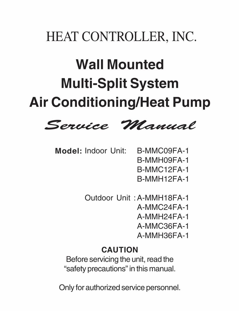
Wall Mounted Multi-Split System Air Conditioning/Heat Pump Indoor Unit: B-MMC09FA-1 B-MMH09FA-1 B-MMC12FA-1 B-MMH12FA-1 Outdoor Unit : A-MMH18FA-1 A-MMC24FA-1 A-MMH24FA-1 A-MMC36FA-1 A-MMH36FA-1 Before servicing the unit, read the “safety precautions” in this manual. Only for authorized service personnel. HEAT CONTROLLER, INC.
-
Upload
khangminh22 -
Category
Documents
-
view
3 -
download
0
Transcript of Wall Mounted Multi-Split System Air Conditioning/Heat Pump
Wall MountedMulti-Split System
Air Conditioning/Heat Pump
Indoor Unit: B-MMC09FA-1B-MMH09FA-1B-MMC12FA-1B-MMH12FA-1
Outdoor Unit : A-MMH18FA-1A-MMC24FA-1A-MMH24FA-1A-MMC36FA-1A-MMH36FA-1
Before servicing the unit, read the“safety precautions” in this manual.
Only for authorized service personnel.
HEAT CONTROLLER, INC.
2 Multi type Air Conditioner
Multi type Air Conditioner Service Manual
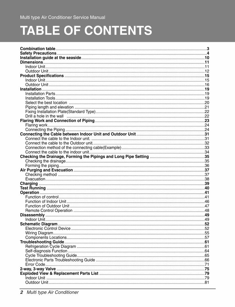
TABLE OF CONTENTSCombination table.......................................................................................................................................3Safety Precautions......................................................................................................................................4Installation guide at the seaside..............................................................................................................10Dimensions................................................................................................................................................11
Indoor Unit..............................................................................................................................................11Outdoor Unit ...........................................................................................................................................12
Product Specifications .............................................................................................................................15Indoor Unit..............................................................................................................................................15Outdoor Unit ...........................................................................................................................................16
Installation .................................................................................................................................................19Installation Parts.....................................................................................................................................19Installation Tools.....................................................................................................................................19Select the best location .........................................................................................................................20Piping length and elevation ....................................................................................................................21Fixing Installation Plate(Standard Type).................................................................................................22Drill a hole in the wall ...........................................................................................................................22
Flaring Work and Connection of Piping..................................................................................................23Flaring work............................................................................................................................................24Connecting the Piping ............................................................................................................................24
Connecting the Cable between Indoor Unit and Outdoor Unit .............................................................31Connect the cable to the Indoor unit. .....................................................................................................31Connect the cable to the Outdoor unit....................................................................................................32Connection method of the connecting cable(Example) ..........................................................................33Connect the cable to the indoor unit.......................................................................................................34
Checking the Drainage, Forming the Pipings and Long Pipe Setting .................................................35Checking the drainage............................................................................................................................35Forming the piping..................................................................................................................................36
Air Purging and Evacuation .....................................................................................................................37Checking method ...................................................................................................................................37Evacuation..............................................................................................................................................38
Charging ....................................................................................................................................................39Test Running .............................................................................................................................................40Operation ...................................................................................................................................................41
Function of control..................................................................................................................................41Function of Indoor Unit ...........................................................................................................................46Function of Outdoor Unit ........................................................................................................................47Remote Control Operation .....................................................................................................................48
Disassembly ..............................................................................................................................................49Indoor Unit..............................................................................................................................................49
Schematic Diagram...................................................................................................................................52Electronic Control Device .......................................................................................................................52Wiring Diagram.......................................................................................................................................55Components Locations...........................................................................................................................57
Troubleshooting Guide .............................................................................................................................61Refrigeration Cycle Diagram ..................................................................................................................61Self-diagnosis Function ..........................................................................................................................64Cycle Troubleshooting Guide..................................................................................................................65Electronic Parts Troubleshooting Guide .................................................................................................66Error Code..............................................................................................................................................71
2-way, 3-way Valve ....................................................................................................................................75Exploded View & Replacement Parts List ..............................................................................................79
Indoor Unit .............................................................................................................................................79Outdoor Unit ...........................................................................................................................................81
Service Manual 3
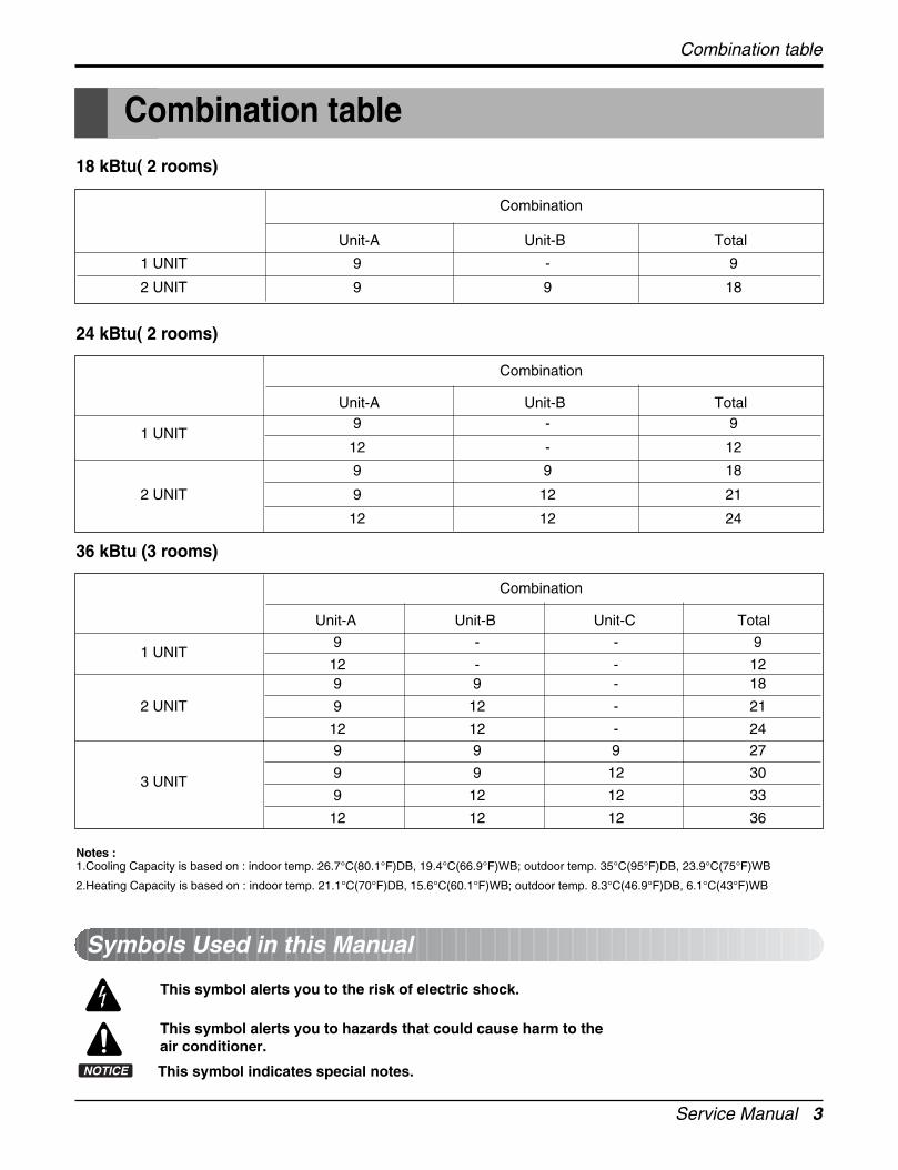
Notes :1.Cooling Capacity is based on : indoor temp. 26.7°C(80.1°F)DB, 19.4°C(66.9°F)WB; outdoor temp. 35°C(95°F)DB, 23.9°C(75°F)WB
2.Heating Capacity is based on : indoor temp. 21.1°C(70°F)DB, 15.6°C(60.1°F)WB; outdoor temp. 8.3°C(46.9°F)DB, 6.1°C(43°F)WB
This symbol alerts you to the risk of electric shock.
This symbol alerts you to hazards that could cause harm to theair conditioner.
This symbol indicates special notes.NOTICE
Symbols Used in this Manual
Combination table
Combination table
18 kBtu( 2 rooms)
Combination
Unit-A Unit-B Total
1 UNIT 9 - 9
2 UNIT 9 9 18
24 kBtu( 2 rooms)
Combination
Unit-A Unit-B Total
1 UNIT9 - 9
12 - 12
9 9 18
2 UNIT 9 12 21
12 12 24
36 kBtu (3 rooms)
Combination
Unit-A Unit-B Unit-C Total
1 UNIT9 - - 9
12 - - 129 9 - 18
2 UNIT 9 12 - 21
12 12 - 24
9 9 9 27
3 UNIT9 9 12 30
9 12 12 33
12 12 12 36
4 Multi type Air Conditioner
Safety Precautions
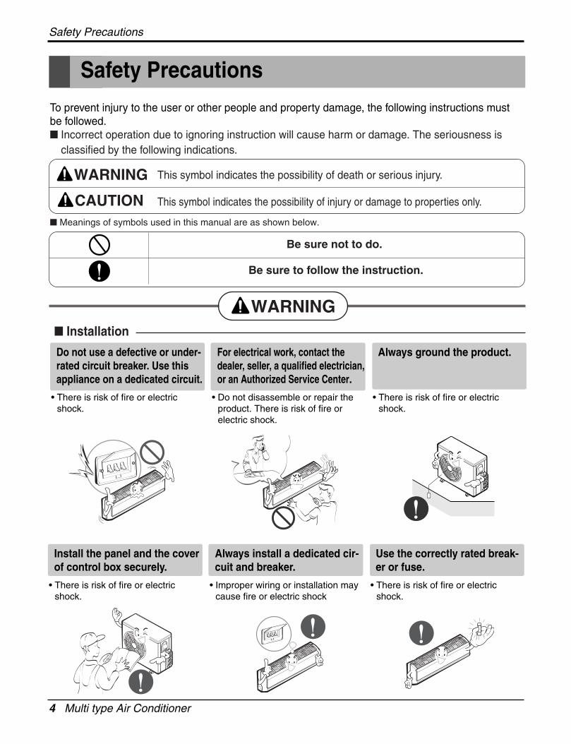
Safety Precautions
To prevent injury to the user or other people and property damage, the following instructions mustbe followed. Incorrect operation due to ignoring instruction will cause harm or damage. The seriousness is
classified by the following indications.
Meanings of symbols used in this manual are as shown below.
WARNING
CAUTION
This symbol indicates the possibility of death or serious injury.
This symbol indicates the possibility of injury or damage to properties only.
WARNING Installation
Be sure not to do.
Be sure to follow the instruction.
Do not use a defective or under-rated circuit breaker. Use thisappliance on a dedicated circuit.
• There is risk of fire or electricshock.
For electrical work, contact thedealer, seller, a qualified electrician,or an Authorized Service Center.
• Do not disassemble or repair theproduct. There is risk of fire orelectric shock.
Always ground the product.
• There is risk of fire or electricshock.
Install the panel and the coverof control box securely.
• There is risk of fire or electricshock.
Always install a dedicated cir-cuit and breaker.
• Improper wiring or installation maycause fire or electric shock
Use the correctly rated break-er or fuse.
• There is risk of fire or electricshock.
Service Manual 5
Safety Precautions
Do not install, remove, or re-install the unit by yourself(customer).
• There is risk of fire, electric shock,explosion, or injury.
Be cautious when unpackingand installing the product.
• Sharp edges could cause injury.Be especially careful of the caseedges and the fins on the con-denser and evaporator.
For installation, always con-tact the dealer or anAuthorized Service Center.
• There is risk of fire, electric shock,explosion, or injury.
Do not install the product on adefective installation stand.
• It may cause injury, accident, ordamage to the product.
Be sure the installation areadoes not deteriorate with age.
• If the base collapses, the air condi-tioner could fall with it, causingproperty damage, product failure,and personal injury.
Do not let the air conditionerrun for a long time when thehumidity is very high and adoor or a window is left open.
• Moisture may condense and wet ordamage furniture.
Do not allow water to run intoelectric parts.
• It may cause There is risk of fire,failure of the product, or electricshock.
Do not store or use flammablegas or combustibles near theproduct.
• There is risk of fire or failure ofproduct.
Do not use the product in atightly closed space for a longtime.
• Oxygen deficiency could occur.
Gasolin
6 Multi type Air Conditioner
Safety Precautions
Do not open the inlet grill of the productduring operation. (Do not touch the elec-trostatic filter, if the unit is so equipped.)
• There is risk of physical injury,electric shock, or product failure.
When the product is soaked(flooded or submerged), contactan Authorized Service Center.
• There is risk of fire or electricshock.
Be cautious that water couldnot enter the product.
• There is risk of fire, electric shock,or product damage.
Ventilate the product from time to time whenoperating it together with a stove, etc.
• There is risk of fire or electric shock.
Turn the main power off when cleaning ormaintaining the product.
• There is risk of electric shock.
When flammable gas leaks,turn off the gas and open awindow for ventilation beforeturn the product on.
• Do not use the telephone or turnswitches on or off. There is risk ofexplosion or fire
If strange sounds, or smokecomes from product. Turn thebreaker off.
• There is risk of electric shock orfire.
Stop operation and close thewindow in storm or hurricane.If possible, remove the prod-uct from the window beforethe hurricane arrives.
• There is risk of property damage,failure of product, or electric shock.
Service Manual 7
Safety Precautions
When the product is not to be used for a long time,disconnect the power by turning off the breaker.
• There is risk of product damage or failure, or unintend-ed operation.
Take care to ensure that nobody could step onor fall onto the outdoor unit.
• This could result in personal injury and product dam-age.
Always check for gas (refrigerant) leak-age after installation or repair of product.
• Low refrigerant levels may causefailure of product.
Install the drain hose to ensure thatwater is drained away properly.
• A bad connection may cause waterleakage.
Keep level even wheninstalling the product.
• To avoid vibration or water leak-age.
Do not install the productwhere the noise or hot airfrom the outdoor unit couldoftend neighbors.
• It may cause a problem for yourneighbors.
Use two or more people to liftand transport the product.
• Avoid personal injury.
Do not install the productwhere it will be exposed tosea wind (salt spray) directly.
• It may cause corrosion on theproduct. Corrosion, particularly onthe condenser and evaporator fins,could cause product malfunction orinefficient operation.
CAUTION Installation
90°
8 Multi type Air Conditioner
Safety Precautions
Do not expose the skin direct-ly to cool air for long periodsof time. (Don't sit in the draft.)
• This could harm to your health.
Do not use the product forspecial purposes, such aspreserving foods, works ofart, etc. It is a consumer airconditioner, not a precisionrefrigeration system.
• There is risk of damage or loss ofproperty.
Do not block the inlet or outletof air flow.
• It may cause product failure.
Use a soft cloth to clean. Donot use harsh detergents, sol-vents, etc.
• There is risk of fire, electric shock,or damage to the plastic parts ofthe product.
Do not touch the metal parts ofthe product when removing theair filter. They are very sharp!
• There is risk of personal injury.
Do not step on or put anytingon the product. (outdoorunits)
• There is risk of personal injury andfailure of product.
Always insert the filter secure-ly. Clean the filter every twoweeks or more often if neces-sary.
• A dirty filter reduces the efficiency ofthe air conditioner and could causeproduct malfunction or damage.
Do not insert hands or otherobjects through the air inlet oroutlet while the product isoperated.
• There are sharp and moving partsthat could cause personal injury.
Do not drink the water drainedfrom the product.
• It is not sanitary and could causeserious health issues.
Operational
Wax Thinner
Service Manual 9
Safety Precautions
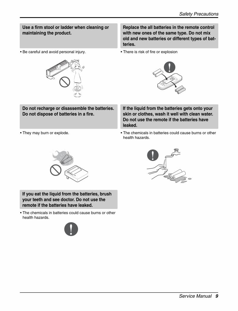
Do not recharge or disassemble the batteries.Do not dispose of batteries in a fire.
• They may burn or explode.
If the liquid from the batteries gets onto yourskin or clothes, wash it well with clean water.Do not use the remote if the batteries haveleaked.
• The chemicals in batteries could cause burns or otherhealth hazards.
Use a firm stool or ladder when cleaning ormaintaining the product.
• Be careful and avoid personal injury.
Replace the all batteries in the remote controlwith new ones of the same type. Do not mixold and new batteries or different types of bat-teries.
• There is risk of fire or explosion
If you eat the liquid from the batteries, brushyour teeth and see doctor. Do not use theremote if the batteries have leaked.
• The chemicals in batteries could cause burns or otherhealth hazards.
10 Multi type Air Conditioner
Installation guide at the seaside
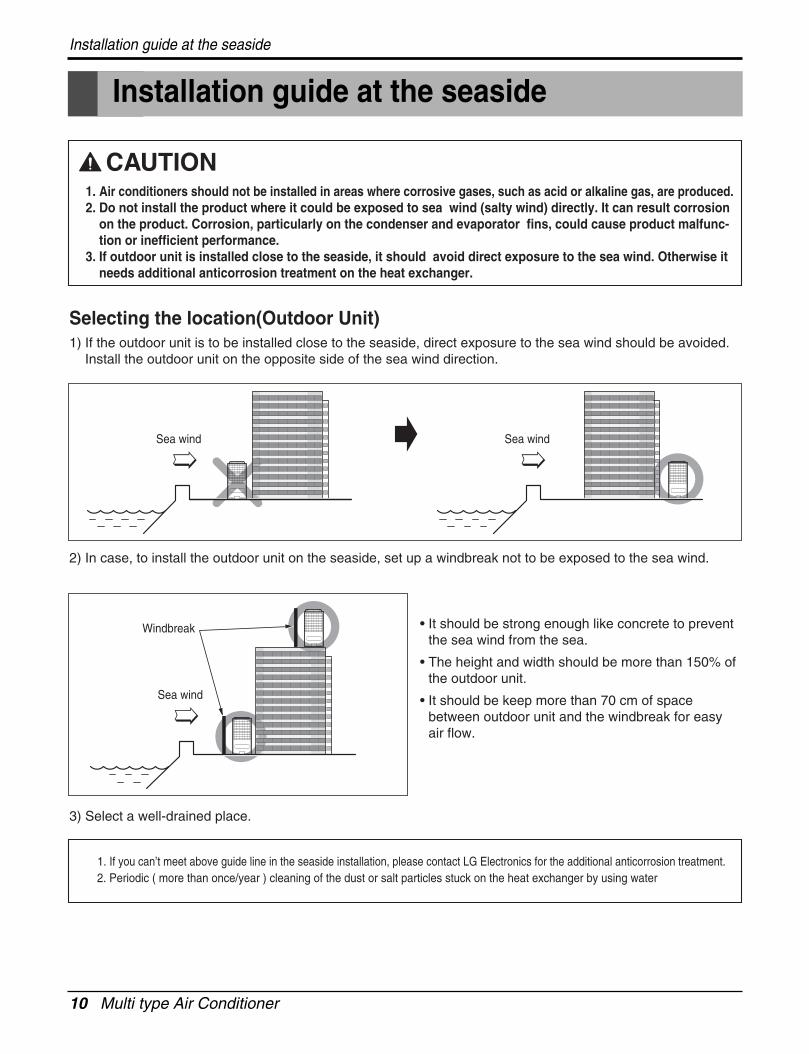
Installation guide at the seaside
1. Air conditioners should not be installed in areas where corrosive gases, such as acid or alkaline gas, are produced.2. Do not install the product where it could be exposed to sea wind (salty wind) directly. It can result corrosion
on the product. Corrosion, particularly on the condenser and evaporator fins, could cause product malfunc-tion or inefficient performance.
3. If outdoor unit is installed close to the seaside, it should avoid direct exposure to the sea wind. Otherwise itneeds additional anticorrosion treatment on the heat exchanger.
1. If you can’t meet above guide line in the seaside installation, please contact LG Electronics for the additional anticorrosion treatment.2. Periodic ( more than once/year ) cleaning of the dust or salt particles stuck on the heat exchanger by using water
Selecting the location(Outdoor Unit)1) If the outdoor unit is to be installed close to the seaside, direct exposure to the sea wind should be avoided.
Install the outdoor unit on the opposite side of the sea wind direction.
2) In case, to install the outdoor unit on the seaside, set up a windbreak not to be exposed to the sea wind.
3) Select a well-drained place.
• It should be strong enough like concrete to preventthe sea wind from the sea.
• The height and width should be more than 150% ofthe outdoor unit.
• It should be keep more than 70 cm of spacebetween outdoor unit and the windbreak for easyair flow.
Sea wind Sea wind
Sea wind
Windbreak
Service Manual 11
Dimensions
Dimensions
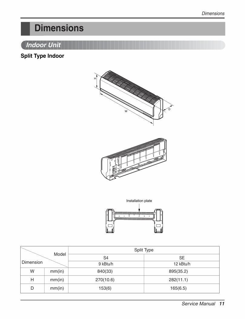
Indoor Unit
Split Type Indoor
Installation plate
D
H
W
W mm(in) 840(33) 895(35.2)
H mm(in) 270(10.6) 282(11.1)
D mm(in) 153(6) 165(6.5)
Model
Dimension
Split Type
S49 kBtu/h
SE12 kBtu/h
12 Multi type Air Conditioner
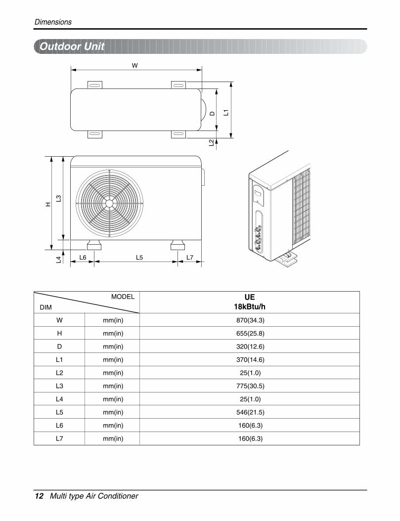
Outdoor Unit
W
D L1
L2
L4L3
H
L7L5L6
W mm(in) 870(34.3)
H mm(in) 655(25.8)
D mm(in) 320(12.6)
L1 mm(in) 370(14.6)
L2 mm(in) 25(1.0)
L3 mm(in) 775(30.5)
L4 mm(in) 25(1.0)
L5 mm(in) 546(21.5)
L6 mm(in) 160(6.3)
L7 mm(in) 160(6.3)
UE18kBtu/h
MODEL
DIM
Dimensions
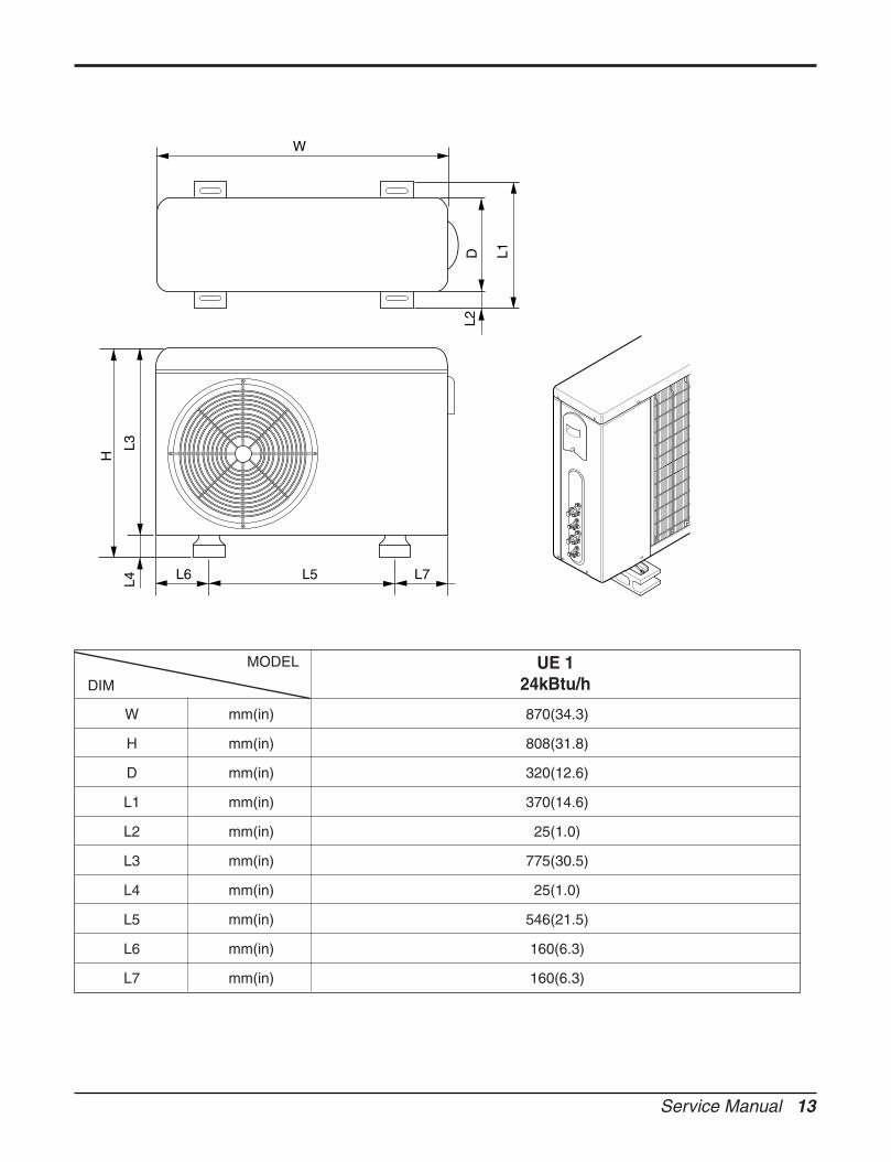
Service Manual 13
W
D L1
L2
L4L3
H
L7L5L6
W mm(in) 870(34.3)
H mm(in) 808(31.8)
D mm(in) 320(12.6)
L1 mm(in) 370(14.6)
L2 mm(in) 25(1.0)
L3 mm(in) 775(30.5)
L4 mm(in) 25(1.0)
L5 mm(in) 546(21.5)
L6 mm(in) 160(6.3)
L7 mm(in) 160(6.3)
UE 124kBtu/h
MODEL
DIM
14 Multi type Air Conditioner
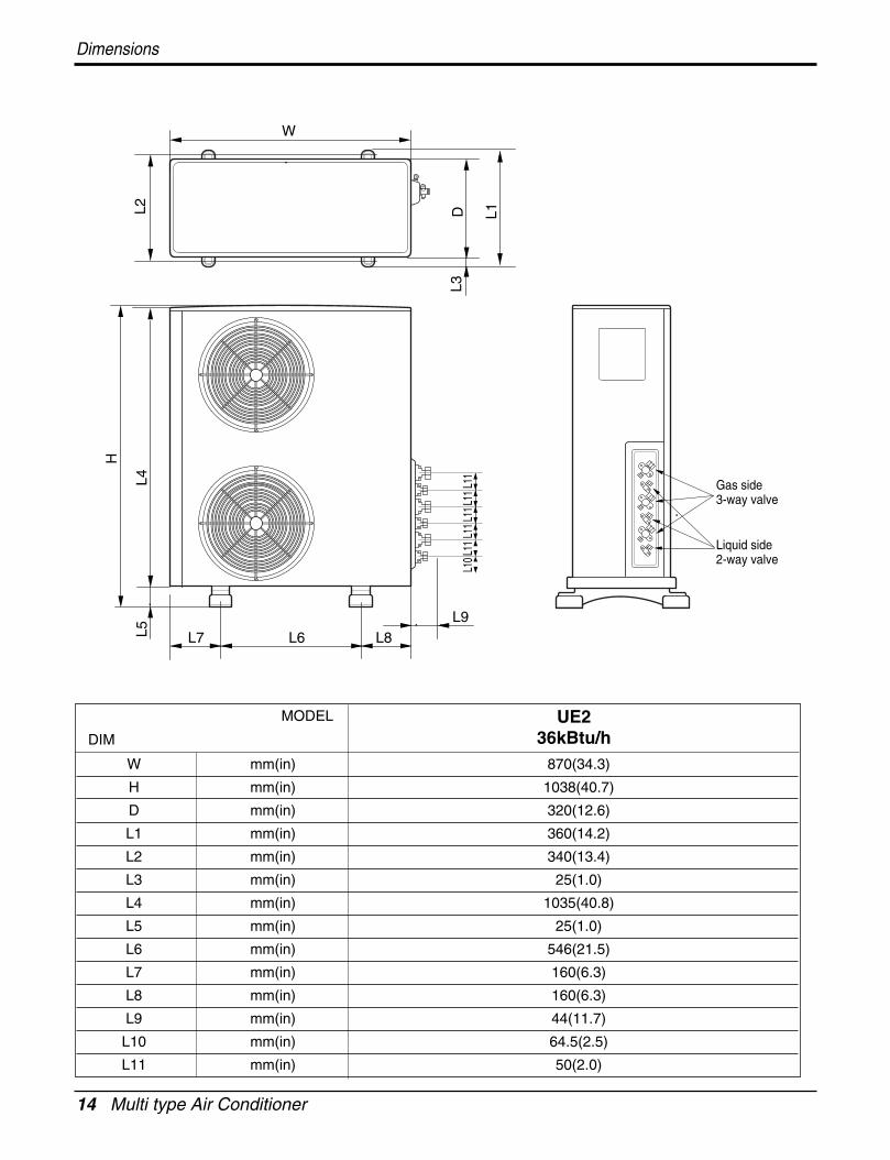
Dimensions
L6L7 L8L9
L4
H
L5W
D L1
L3
L2
L10
L11L
11L1
1L1
1L1
1
Gas side3-way valve
Liquid side2-way valve
UE236kBtu/h
MODEL
DIM
W mm(in) 870(34.3)
H mm(in) 1038(40.7)
D mm(in) 320(12.6)
L1 mm(in) 360(14.2)
L2 mm(in) 340(13.4)
L3 mm(in) 25(1.0)
L4 mm(in) 1035(40.8)
L5 mm(in) 25(1.0)
L6 mm(in) 546(21.5)
L7 mm(in) 160(6.3)
L8 mm(in) 160(6.3)
L9 mm(in) 44(11.7)
L10 mm(in) 64.5(2.5)
L11 mm(in) 50(2.0)
Service Manual 15
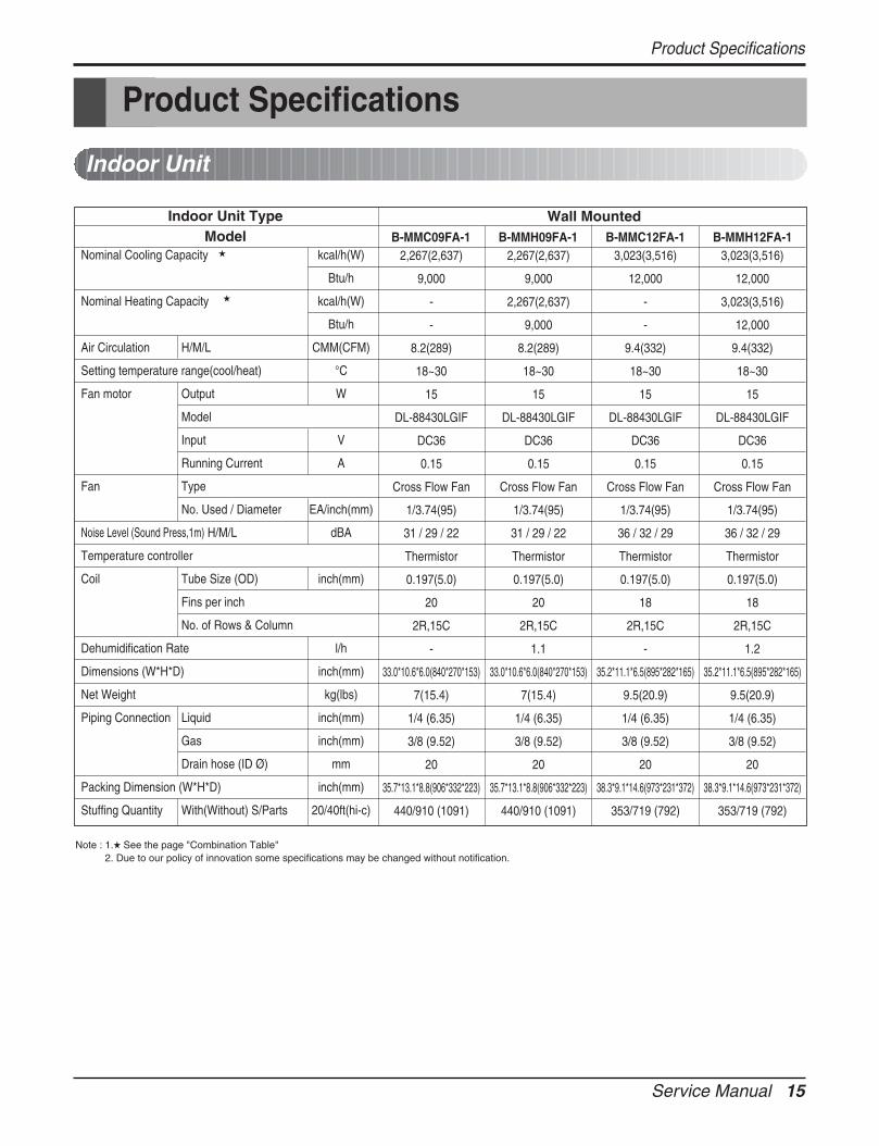
Product Specifications
Product Specifications
Indoor Unit
Nominal Cooling Capacity kcal/h(W)
Btu/h
Nominal Heating Capacity kcal/h(W)
Btu/h
Air Circulation H/M/L CMM(CFM)
Setting temperature range(cool/heat) °C
Fan motor Output W
Model
Input V
Running Current A
Fan Type
No. Used / Diameter EA/inch(mm)
Noise Level (Sound Press,1m) H/M/L dBA
Temperature controller
Coil Tube Size (OD) inch(mm)
Fins per inch
No. of Rows & Column
Dehumidification Rate l/h
Dimensions (W*H*D) inch(mm)
Net Weight kg(lbs)
Piping Connection Liquid inch(mm)
Gas inch(mm)
Drain hose (ID Ø) mm
Packing Dimension (W*H*D) inch(mm)
Stuffing Quantity With(Without) S/Parts 20/40ft(hi-c)
Wall MountedB-MMC09FA-1 B-MMH09FA-1 B-MMC12FA-1 B-MMH12FA-1
Indoor Unit TypeModel
Note : 1. See the page "Combination Table"2. Due to our policy of innovation some specifications may be changed without notification.
2,267(2,637) 2,267(2,637) 3,023(3,516) 3,023(3,516)
9,000 9,000 12,000 12,000
- 2,267(2,637) - 3,023(3,516)
- 9,000 - 12,000
8.2(289) 8.2(289) 9.4(332) 9.4(332)
18~30 18~30 18~30 18~30
15 15 15 15
DL-88430LGIF DL-88430LGIF DL-88430LGIF DL-88430LGIF
DC36 DC36 DC36 DC36
0.15 0.15 0.15 0.15
Cross Flow Fan Cross Flow Fan Cross Flow Fan Cross Flow Fan
1/3.74(95) 1/3.74(95) 1/3.74(95) 1/3.74(95)
31 / 29 / 22 31 / 29 / 22 36 / 32 / 29 36 / 32 / 29
Thermistor Thermistor Thermistor Thermistor
0.197(5.0) 0.197(5.0) 0.197(5.0) 0.197(5.0)
20 20 18 18
2R,15C 2R,15C 2R,15C 2R,15C
- 1.1 - 1.2
33.0*10.6*6.0(840*270*153) 33.0*10.6*6.0(840*270*153) 35.2*11.1*6.5(895*282*165) 35.2*11.1*6.5(895*282*165)
7(15.4) 7(15.4) 9.5(20.9) 9.5(20.9)
1/4 (6.35) 1/4 (6.35) 1/4 (6.35) 1/4 (6.35)
3/8 (9.52) 3/8 (9.52) 3/8 (9.52) 3/8 (9.52)
20 20 20 20
35.7*13.1*8.8(906*332*223) 35.7*13.1*8.8(906*332*223) 38.3*9.1*14.6(973*231*372) 38.3*9.1*14.6(973*231*372)
440/910 (1091) 440/910 (1091) 353/719 (792) 353/719 (792)
16 Multi type Air Conditioner
Model
Cooling Capacity Btu/hrW
kcal/hrHeating Capacity Btu/hr
Wkcal/hr
Input Cooling WHeating W
Running Current(208/230V) Cooling AHeating A
Power Supply Ø,V,HzMax. Number of Connectable Indoor UnitsCompressor Type(Constant) Model
Motor TypeQuantity EaMotor Input WOil Charge ccOil TypeCapacitor µF/VacO.L.P Type(model name)
Compressor Type(Constant) Model
Motor TypeQuantity EaMotor Input WOil Charge ccOil TypeCapacitor µF/VacO.L.P Type(model name)
Refrigerant charge Charge g(oz)TypeControl
Coil Tube Size (OD) inch(mm)Fins per inchNo. of Rows & Column/No.
Fan motor ModelOutput WCapacitor µF/Vac
Fan TypeNo. Used / Diameter EA/inch(mm)Discharge Side / Top
Air Circulation Outdoor CMM(CFM)Noise Level(H/L) at 230V Sound Press,1m dB(A) 1DefrostingSVC Valve Liquid inch(mm)
GasDimensions W*H*D inch(mm)Net Weight Outdoor kg(lbs)Max. Interunit Piping Length Total of Each Room m
For One Room mMax. Installation Indoor Unit~Outdoor Unit mHeight Difference Indoor Unit~Indoor Unit mPacking Dimension W*H*D inch(mm)Testing CombinationsStuffing Quantity 20/40ft
9,000~18,0002637~52752267~4536
9,000~18,0002637~52752267~45361070~19801040~1960
4.9~8.84.6~8.6
1,208/230,602
RotaryGK094KHermetic
1955
330±10 FVC68D 30 / 370
External Type(MRA98996-12026)Rotary
GK113KHermetic
11,120
330±10 FVC68D35 / 370
External Type(MRA12124-12026)1400(49)R410AEEV
0.276(7.0)18
2R,28CIC-1640LG GE
906/370
Propeller1 / 460Side
50(1765.7)51
Invertion Cycle1/4 (6.35) * 2EA3/8 (9.52) * 2EA
34.3*25.8*12.6 (870*655*320)57(125.7)
30157.57.5
40.2*28.2*17.2 (1020*716*437)S4 9k + S4 9k
81/171
A-MMH18FA-1
Product Specifications
Outdoor Unit - Multiple piping models
Note:1. Capacities are based on the following conditions:
Cooling: - Indoor Temperature 26.7˚C(80˚F) DB/19.4˚C(67˚F) WB- Outdoor Temperature 35˚C(95˚F) DB/23.9˚C(75˚F) WB
Heating: - Indoor Temperature 21.1˚C(70˚F) DB/15.6˚C(60˚F) WB- Outdoor Temperature 8.3˚C(47˚F) DB/6.1˚C(43˚F) WB
Piping Length - Interconnecting Piping Length 7.5m- Level Difference of Zero
2. Wiring cable size must comply with the applicable local and national code.3. Capacities are Net Capacities.4. : See the page "Combination Table"5. The specification may be subject to change without prior notice for purposeof improvement.
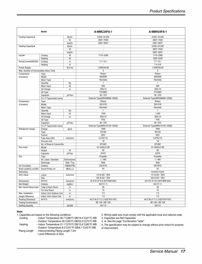
Service Manual 17
Model
Cooling Capacity Btu/hrW
kcal/hrHeating Capacity Btu/hr
Wkcal/hr
Input Cooling WHeating W
Running Current(208/230V) Cooling AHeating A
Power Supply Ø,V,HzMax. Number of Connectable Indoor UnitsCompressor Type(Constant) Model
Motor TypeQuantity EaMotor Input WOil Charge ccOil TypeCapacitor µF/VacO.L.P Type(model name)
Compressor Type(Constant) Model
Motor TypeQuantity EaMotor Input WOil Charge ccOil TypeCapacitor µF/VacO.L.P Type(model name)
Refrigerant charge Charge g(oz)TypeControl
Coil Tube Size (OD) inch(mm)Fins per inchNo. of Rows & Column/No.
Fan motor ModelOutput WCapacitor µF/Vac
Fan TypeNo. Used / Diameter EA/inch(mm)Discharge Side / Top
Air Circulation Outdoor CMM(CFM)Noise Level(H/L) at 230V Sound Press,1m dB(A) 1DefrostingSVC Valve Liquid inch(mm)
GasDimensions W*H*D inch(mm)Net Weight Outdoor kg(lbs)Max. Interunit Piping Length Total of Each Room m
For One Room mMax. Installation Indoor Unit~Outdoor Unit mHeight Difference Indoor Unit~Indoor Unit mPacking Dimension W*H*D inch(mm)Testing CombinationsStuffing Quantity 20/40ft
9,000~24,000 9,000~24,0002637~7033 2637~70332267~6037 2267~6037
- 9,000~24,000- 2637~7033- 2267~6037
1170~2390 1170~2390- 1220~2440
7.7~10.1 7.7~10.1- 7.4~9.8
1,208/230,60 1,208/230,602 2
Rotary RotaryGK094K GK094KHermetic Hermetic
1 1955 955
330±10 330±10 FVC68D FVC68D 30 / 370 30 / 370
External Type(MRA98996-12026) External Type(MRA98996-12026)Rotary Rotary
GK141K GK141KHermetic Hermetic
1 11430 1,430
350±10 350±10 FVE FVE
35 / 370 35 / 370External Type(MRA12105-12026) External Type(MRA12105-12026)
1600 1600R410A R410AEEV EEV
0.276(7.0) 0.276(7.0)18 18
2R,36C 2R,36CIC-1640LG GE IC-1640LG GE
90 906/370 6/370
Propeller Propeller1 / 460 1 / 460Side Side
53(1872) 53(1872)54 54- Invertion Cycle
1/4 (6.35) * 2EA 1/4 (6.35) * 2EA3/8 (9.52) * 2EA 3/8 (9.52) * 2EA
34.3*31.8*12.6 (870*808*320) 34.3*31.8*12.6 (870*808*320)64(141.1) 64(141.1)
30 3015 157.5 7.57.5 7.5
40.2*34.3*17.2 (1022*870*437) 40.2*34.3*17.2 (1022*870*437)SE 12K +SE 12K SE 12K +SE 12K
54/114 54/114
A-MMC24FA-1 A-MMH24FA-1
Product Specifications
Note:1. Capacities are based on the following conditions:
Cooling: - Indoor Temperature 26.7˚C(80˚F) DB/19.4˚C(67˚F) WB- Outdoor Temperature 35˚C(95˚F) DB/23.9˚C(75˚F) WB
Heating: - Indoor Temperature 21.1˚C(70˚F) DB/15.6˚C(60˚F) WB- Outdoor Temperature 8.3˚C(47˚F) DB/6.1˚C(43˚F) WB
Piping Length - Interconnecting Piping Length 7.5m- Level Difference of Zero
2. Wiring cable size must comply with the applicable local and national code.3. Capacities are Net Capacities.4. : See the page "Combination Table"5. The specification may be subject to change without prior notice for purposeof improvement.
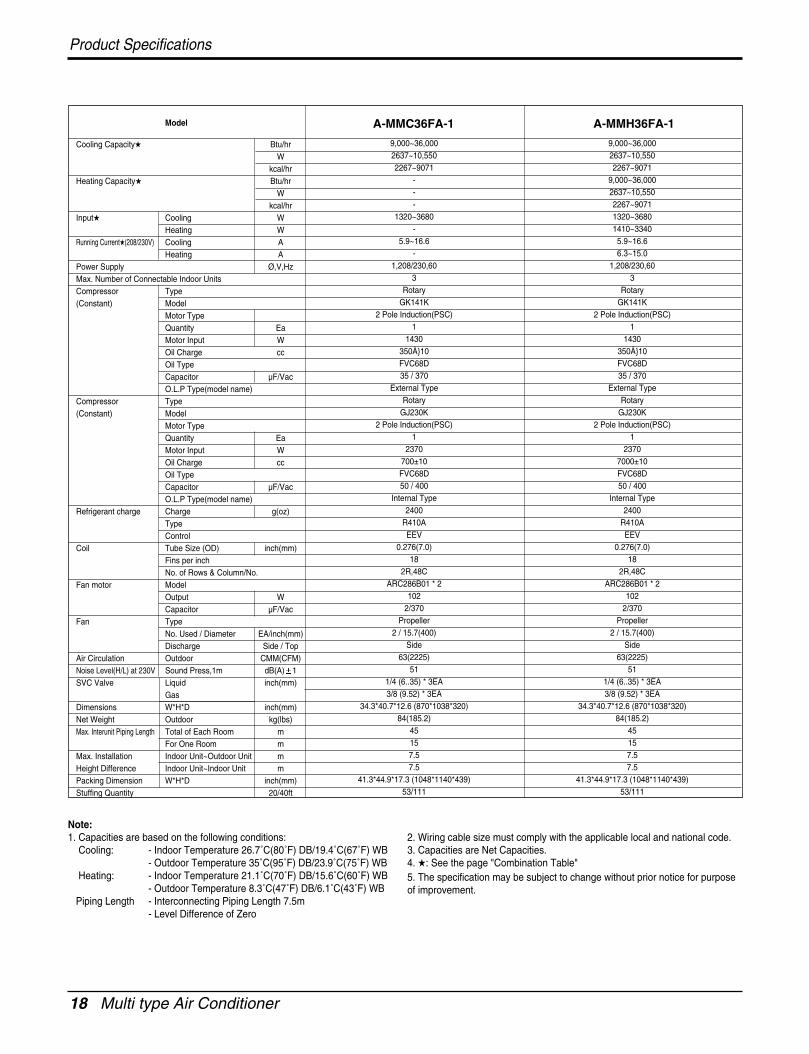
18 Multi type Air Conditioner
Product Specifications
Model
Cooling Capacity Btu/hrW
kcal/hrHeating Capacity Btu/hr
Wkcal/hr
Input Cooling WHeating W
Running Current(208/230V) Cooling AHeating A
Power Supply Ø,V,HzMax. Number of Connectable Indoor UnitsCompressor Type(Constant) Model
Motor TypeQuantity EaMotor Input WOil Charge ccOil TypeCapacitor µF/VacO.L.P Type(model name)
Compressor Type(Constant) Model
Motor TypeQuantity EaMotor Input WOil Charge ccOil TypeCapacitor µF/VacO.L.P Type(model name)
Refrigerant charge Charge g(oz)TypeControl
Coil Tube Size (OD) inch(mm)Fins per inchNo. of Rows & Column/No.
Fan motor ModelOutput WCapacitor µF/Vac
Fan TypeNo. Used / Diameter EA/inch(mm)Discharge Side / Top
Air Circulation Outdoor CMM(CFM)Noise Level(H/L) at 230V Sound Press,1m dB(A) 1SVC Valve Liquid inch(mm)
GasDimensions W*H*D inch(mm)Net Weight Outdoor kg(lbs)Max. Interunit Piping Length Total of Each Room m
For One Room mMax. Installation Indoor Unit~Outdoor Unit mHeight Difference Indoor Unit~Indoor Unit mPacking Dimension W*H*D inch(mm)Stuffing Quantity 20/40ft
9,000~36,000 9,000~36,0002637~10,550 2637~10,5502267~9071 2267~9071
- 9,000~36,000- 2637~10,550- 2267~9071
1320~3680 1320~3680- 1410~3340
5.9~16.6 5.9~16.6- 6.3~15.0
1,208/230,60 1,208/230,603 3
Rotary RotaryGK141K GK141K
2 Pole Induction(PSC) 2 Pole Induction(PSC)1 1
1430 1430350Å10 350Å10 FVC68D FVC68D 35 / 370 35 / 370
External Type External TypeRotary Rotary
GJ230K GJ230K2 Pole Induction(PSC) 2 Pole Induction(PSC)
1 12370 2370
700±10 7000±10 FVC68D FVC68D 50 / 400 50 / 400
Internal Type Internal Type2400 2400
R410A R410AEEV EEV
0.276(7.0) 0.276(7.0)18 18
2R,48C 2R,48CARC286B01 * 2 ARC286B01 * 2
102 1022/370 2/370
Propeller Propeller2 / 15.7(400) 2 / 15.7(400)
Side Side63(2225) 63(2225)
51 511/4 (6..35) * 3EA 1/4 (6..35) * 3EA3/8 (9.52) * 3EA 3/8 (9.52) * 3EA
34.3*40.7*12.6 (870*1038*320) 34.3*40.7*12.6 (870*1038*320)84(185.2) 84(185.2)
45 4515 157.5 7.57.5 7.5
41.3*44.9*17.3 (1048*1140*439) 41.3*44.9*17.3 (1048*1140*439)53/111 53/111
A-MMC36FA-1 A-MMH36FA-1
Note:1. Capacities are based on the following conditions:
Cooling: - Indoor Temperature 26.7˚C(80˚F) DB/19.4˚C(67˚F) WB- Outdoor Temperature 35˚C(95˚F) DB/23.9˚C(75˚F) WB
Heating: - Indoor Temperature 21.1˚C(70˚F) DB/15.6˚C(60˚F) WB- Outdoor Temperature 8.3˚C(47˚F) DB/6.1˚C(43˚F) WB
Piping Length - Interconnecting Piping Length 7.5m- Level Difference of Zero
2. Wiring cable size must comply with the applicable local and national code.3. Capacities are Net Capacities.4. : See the page "Combination Table"5. The specification may be subject to change without prior notice for purposeof improvement.
Service Manual 19
Installation
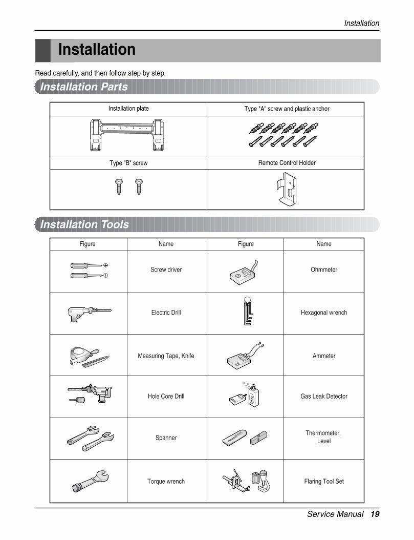
Installation
Type "A" screw and plastic anchor
Type "B" screw Remote Control Holder
Installation plate
Figure FigureName
Screw driver
Electric Drill
Measuring Tape, Knife
Hole Core Drill
Spanner
Torque wrench
Ohmmeter
Hexagonal wrench
Ammeter
Gas Leak Detector
Thermometer, Level
Flaring Tool Set
Name
Installation Parts
Installation Tools
Read carefully, and then follow step by step.
20 Multi type Air Conditioner
Installation
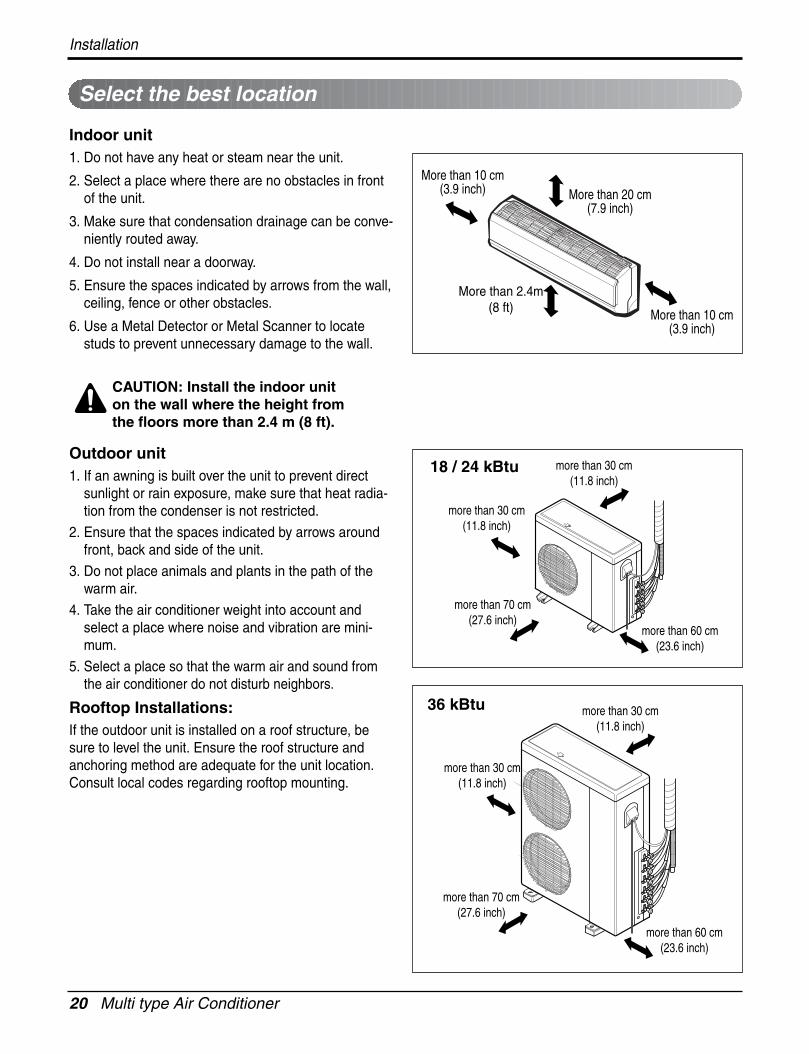
Select the best location
Indoor unit1. Do not have any heat or steam near the unit.
2. Select a place where there are no obstacles in frontof the unit.
3. Make sure that condensation drainage can be conve-niently routed away.
4. Do not install near a doorway.
5. Ensure the spaces indicated by arrows from the wall,ceiling, fence or other obstacles.
6. Use a Metal Detector or Metal Scanner to locatestuds to prevent unnecessary damage to the wall.
Outdoor unit1. If an awning is built over the unit to prevent direct
sunlight or rain exposure, make sure that heat radia-tion from the condenser is not restricted.
2. Ensure that the spaces indicated by arrows aroundfront, back and side of the unit.
3. Do not place animals and plants in the path of thewarm air.
4. Take the air conditioner weight into account andselect a place where noise and vibration are mini-mum.
5. Select a place so that the warm air and sound fromthe air conditioner do not disturb neighbors.
Rooftop Installations:If the outdoor unit is installed on a roof structure, besure to level the unit. Ensure the roof structure andanchoring method are adequate for the unit location.Consult local codes regarding rooftop mounting.
More than 20 cm(7.9 inch)
More than 10 cm(3.9 inch)
More than 10 cm(3.9 inch)
More than 2.4m(8 ft)
more than 70 cm(27.6 inch)
more than 30 cm(11.8 inch)
more than 30 cm(11.8 inch)
more than 60 cm(23.6 inch)
more than 70 cm(27.6 inch)
more than 60 cm(23.6 inch)
more than 30 cm(11.8 inch)
more than 30 cm(11.8 inch)
CAUTION: Install the indoor uniton the wall where the height fromthe floors more than 2.4 m (8 ft).
18 / 24 kBtu
36 kBtu
Service Manual 21
Installation
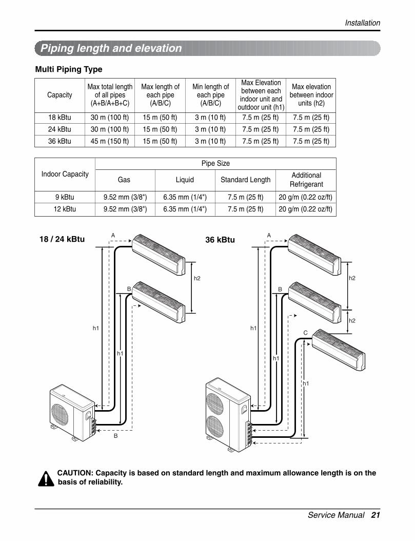
Piping length and elevation
CAUTION: Capacity is based on standard length and maximum allowance length is on thebasis of reliability.
Multi Piping Type
18 kBtu 30 m (100 ft) 15 m (50 ft) 3 m (10 ft) 7.5 m (25 ft) 7.5 m (25 ft)
24 kBtu 30 m (100 ft) 15 m (50 ft) 3 m (10 ft) 7.5 m (25 ft) 7.5 m (25 ft)
36 kBtu 45 m (150 ft) 15 m (50 ft) 3 m (10 ft) 7.5 m (25 ft) 7.5 m (25 ft)
CapacityMax total length
of all pipes(A+B/A+B+C)
Max length ofeach pipe(A/B/C)
Min length ofeach pipe(A/B/C)
Max Elevationbetween eachindoor unit and
outdoor unit (h1)
Max elevationbetween indoor
units (h2)
h2
h2h1
A
BB
C
h2
h1
A
B
h1
h1
h1
9 kBtu 9.52 mm (3/8") 6.35 mm (1/4") 7.5 m (25 ft) 20 g/m (0.22 oz/ft)
12 kBtu 9.52 mm (3/8") 6.35 mm (1/4") 7.5 m (25 ft) 20 g/m (0.22 oz/ft)
Gas Liquid Standard LengthAdditional
RefrigerantIndoor Capacity
Pipe Size
18 / 24 kBtu 36 kBtu
22 Multi type Air Conditioner
Installation
The wall you select should be strong and solid enough toprevent vibration
1. Mount the installation plate on the wall with type "A" screws. If mounting the unit on a concrete wall,use anchor bolts.
• Mount the installation plate horizontally by aligning thecenterline using a level.
2. Measure the wall and mark the centerline. It is alsoimportant to use caution concerning the location of theinstallation plate-routing of the wiring to power outlets isthrough the walls typically. Drilling the hole through thewall for piping connections must be done safely.
Fixing Installation Plate(Standard Type)
Installation Plate
Type "A" screw
ChassisHook
Installation plate
Left rear piping Right rear pipingØ70mm Ø70mm
D B
AC
• Drill the piping hole with a Ø 70 mm (Ø 2.75 inch) hole core drill. Drill the piping hole at either the right or the leftwith the hole slightly slanted to the outdoor side.
Drill a hole in the wall
5-7
mm
(0.2
"~0.
3")
Indoor
WALL
Outdoor
A B C D
S4 50 105 59 105
SE 65 110 85 110
CHASSIS(Grade)
Distance (mm)
Service Manual 23
Flaring Work and Connection of Piping
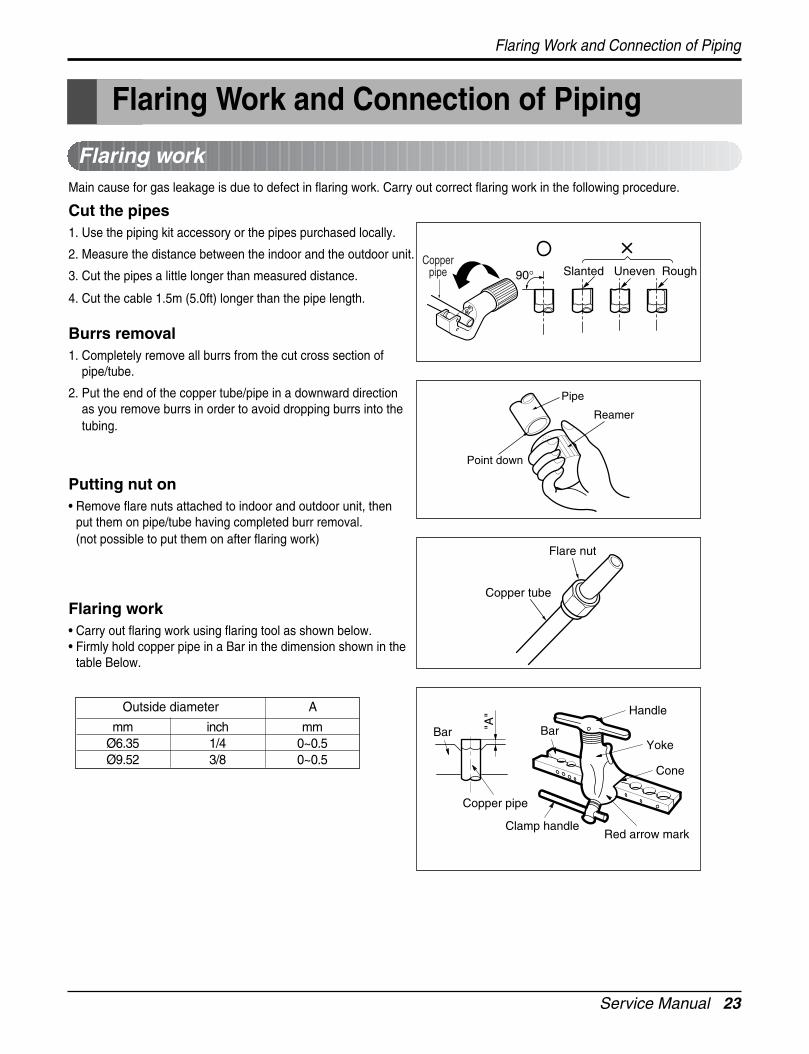
Flaring workMain cause for gas leakage is due to defect in flaring work. Carry out correct flaring work in the following procedure.
Cut the pipes 1. Use the piping kit accessory or the pipes purchased locally.
2. Measure the distance between the indoor and the outdoor unit.
3. Cut the pipes a little longer than measured distance.
4. Cut the cable 1.5m (5.0ft) longer than the pipe length.
Burrs removal1. Completely remove all burrs from the cut cross section of
pipe/tube.
2. Put the end of the copper tube/pipe in a downward directionas you remove burrs in order to avoid dropping burrs into thetubing.
Putting nut on• Remove flare nuts attached to indoor and outdoor unit, then
put them on pipe/tube having completed burr removal.(not possible to put them on after flaring work)
Flaring work• Carry out flaring work using flaring tool as shown below.• Firmly hold copper pipe in a Bar in the dimension shown in the
table Below.
Copperpipe 90° Slanted Uneven Rough
Pipe
Reamer
Point down
Flare nut
Copper tube
mm inch mmØ6.35 1/4 0~0.5Ø9.52 3/8 0~0.5
Outside diameter A
Bar
Copper pipe
Clamp handleRed arrow mark
Cone
Yoke
Handle
Bar"A"
Flaring Work and Connection of Piping
24 Multi type Air Conditioner
Flaring Work and Connection of Piping
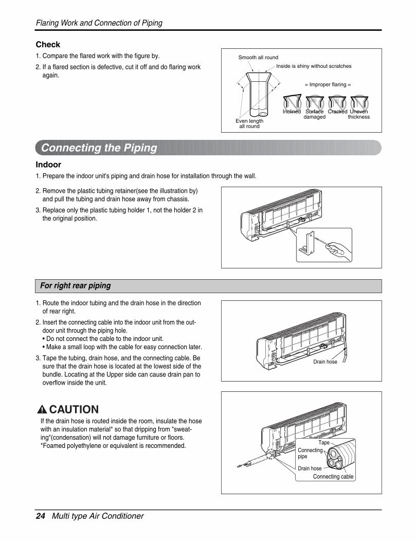
Check1. Compare the flared work with the figure by.
2. If a flared section is defective, cut it off and do flaring workagain.
Indoor1. Prepare the indoor unit's piping and drain hose for installation through the wall.
2. Remove the plastic tubing retainer(see the illustration by)and pull the tubing and drain hose away from chassis.
3. Replace only the plastic tubing holder 1, not the holder 2 inthe original position.
1. Route the indoor tubing and the drain hose in the directionof rear right.
2. Insert the connecting cable into the indoor unit from the out-door unit through the piping hole.• Do not connect the cable to the indoor unit.• Make a small loop with the cable for easy connection later.
3. Tape the tubing, drain hose, and the connecting cable. Besure that the drain hose is located at the lowest side of thebundle. Locating at the Upper side can cause drain pan tooverflow inside the unit.
If the drain hose is routed inside the room, insulate the hosewith an insulation material* so that dripping from "sweat-ing"(condensation) will not damage furniture or floors.*Foamed polyethylene or equivalent is recommended.
Inclined
Inside is shiny without scratches
Smooth all round
Even lengthall round
Surfacedamaged
Cracked Uneventhickness
= Improper flaring =
Connecting the Piping
For right rear piping
Drain hose
Connecting pipe
Connecting cable
Tape
Drain hose
Service Manual 25
Flaring Work and Connection of Piping
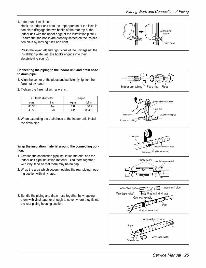
4. Indoor unit installationHook the indoor unit onto the upper portion of the installa-tion plate.(Engage the two hooks of the rear top of theindoor unit with the upper edge of the installation plate.)Ensure that the hooks are properly seated on the installa-tion plate by moving it left and right.
Press the lower left and right sides of the unit against theinstallation plate until the hooks engage into theirslots(clicking sound).
Connecting the piping to the indoor unit and drain hoseto drain pipe.
1. Align the center of the pipes and sufficiently tighten theflare nut by hand.
2. Tighten the flare nut with a wrench.
3. When extending the drain hose at the indoor unit, installthe drain pipe.
Wrap the insulation material around the connecting por-tion.
1. Overlap the connection pipe insulation material and theindoor unit pipe insulation material. Bind them togetherwith vinyl tape so that there may be no gap.
2. Wrap the area which accommodates the rear piping hous-ing section with vinyl tape.
3. Bundle the piping and drain hose together by wrappingthem with vinyl tape for enough to cover where they fit intothe rear piping housing section.
Drain hose
Connectingcable
Indoor unit tubing Flare nut Pipes
Wrench
Indoor unit tubing
Open-end wrench (fixed)
Connection pipe
Flare nut
Vinyl tape(narrow)Adhesive
Drain pipe
Indoor unit drain hose
Plastic bands Insulation material
Vinyl tape(narrow)
Connection pipe
Connecting cableVinyl tape (wide) Wrap with vinyl tape
Indoor unit pipe
Pipe
Wrap with vinyl tape
Drain hose
Pipe
Vinyl tape(wide)
mm inch kg.m lbf.inØ6.35 1/4 1.8 156.2Ø9.52 3/8 4.2 364.5
Outside diameter Torque
26 Multi type Air Conditioner
Flaring Work and Connection of Piping
1. Route the indoor tubing and the drain hose to the requiredpiping hole position.
2. Insert the piping, drain hose, and the connecting cable intothe piping hole.
3. Insert the connecting cable into the indoor unit.• Don't connect the cable to the indoor unit.• Make a small loop with the cable for easy connection
later.
4. Tape the drain hose and the connecting cables.
5. Indoor unit installation• Hang the indoor unit from the hooks at the top of the
installation plate.• Insert the spacer etc. between the indoor unit and the
installation plate and separate the bottom of the indoorunit from the wall.
Connecting the piping to the indoor unit and the drainhose to drain pipe.1. Align the center of the pipes and sufficiently tighten the
flare nut by hand.
2. Tighten the flare nut with a wrench.
3. When extending the drain hose at the indoor unit, installthe drain pipe.
For left rear piping
Drain pipe
Connectingcable
Installation plate
SpacerIndoor unit
8cm
Indoor unit tubing Flare nut Pipes
Wrench
Indoor unit tubing
Connection pipe
Flare nut
Open-end wrench (fixed)
Vinyl tapeAdhesive
Drain hose
Indoor unit drain hose
(narrow)
mm inch kg.m lbf.inØ6.35 1/4 1.8 156.2Ø9.52 3/8 4.2 364.5
Outside diameter Torque

Service Manual 27
Wrap the insulation material around the connecting por-tion.1. Overlap the connection pipe heat insulation and the indoor
unit pipe heat insulation material. Bind them together withvinyl tape so that there may be no gap.
2. Wrap the area which accommodates the rear piping hous-ing section with vinyl tape.
3. Bundle the piping and drain hose together by wrappingthem with cloth tape over the range within which they fitinto the rear piping housing section.
Reroute the pipings and the drain hose across the backof the chassis.
Indoor unit installation 1. Remove the spacer.
2. Ensure that the hooks are properly seated on the installa-tion plate by moving it left and right.
3. Press the lower left and right sides of the unit against theinstallation plate until the hooks engage into theirslots(clicking sound).
Flaring Work and Connection of Piping
Plastic bands Insulation material
Vinyl tape(narrow)
Connectionpipe
Connecting cable
Indoor unit piping
Pipe
Vinyl tape(wide)
Wrap with vinyl tape
Drain hoseVinyl tape(narrow)
Pipe
Wrap with vinyl tape(wide)
Piping forpassage throughpiping hole
Drain hose
Connectingcable
28 Multi type Air Conditioner
Flaring Work and Connection of Piping
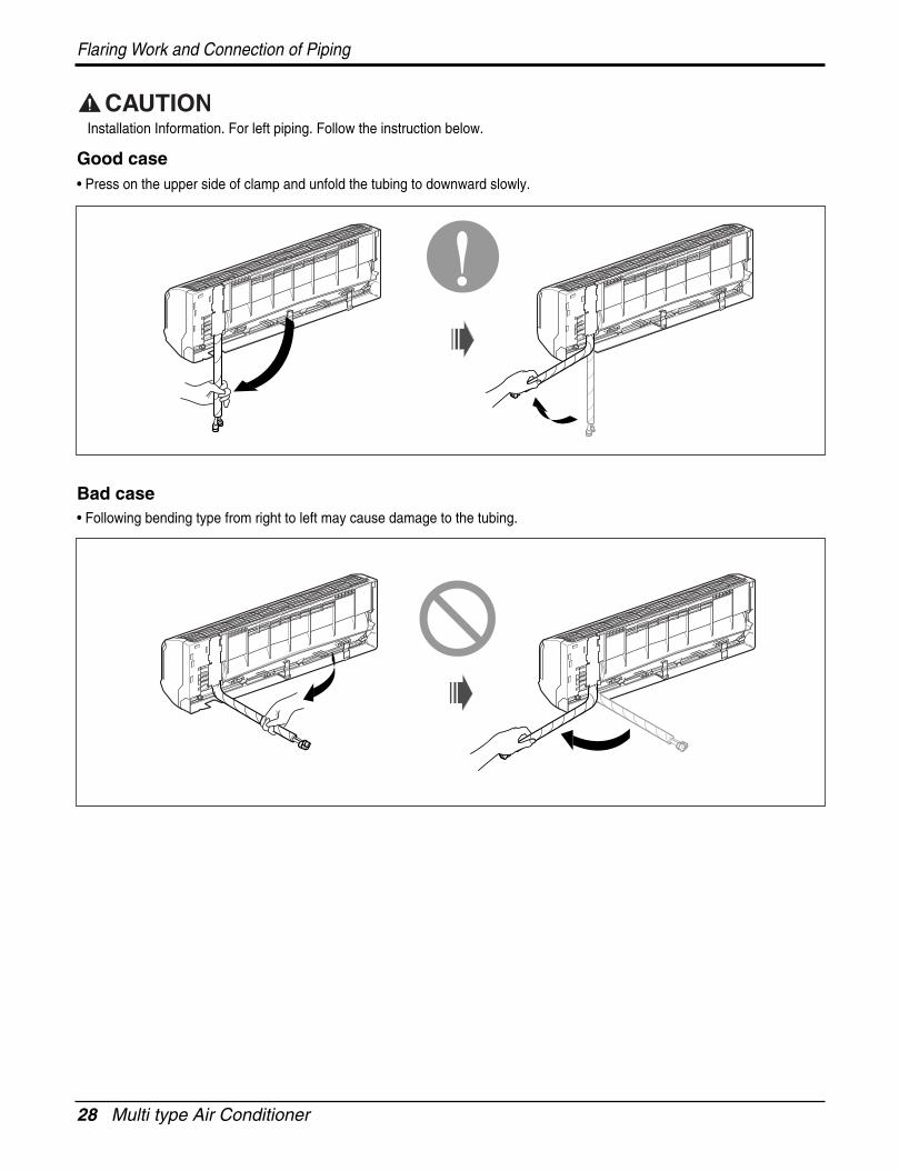
Installation Information. For left piping. Follow the instruction below.
Good case• Press on the upper side of clamp and unfold the tubing to downward slowly.
Bad case• Following bending type from right to left may cause damage to the tubing.
Service Manual 29
Flaring Work and Connection of Piping
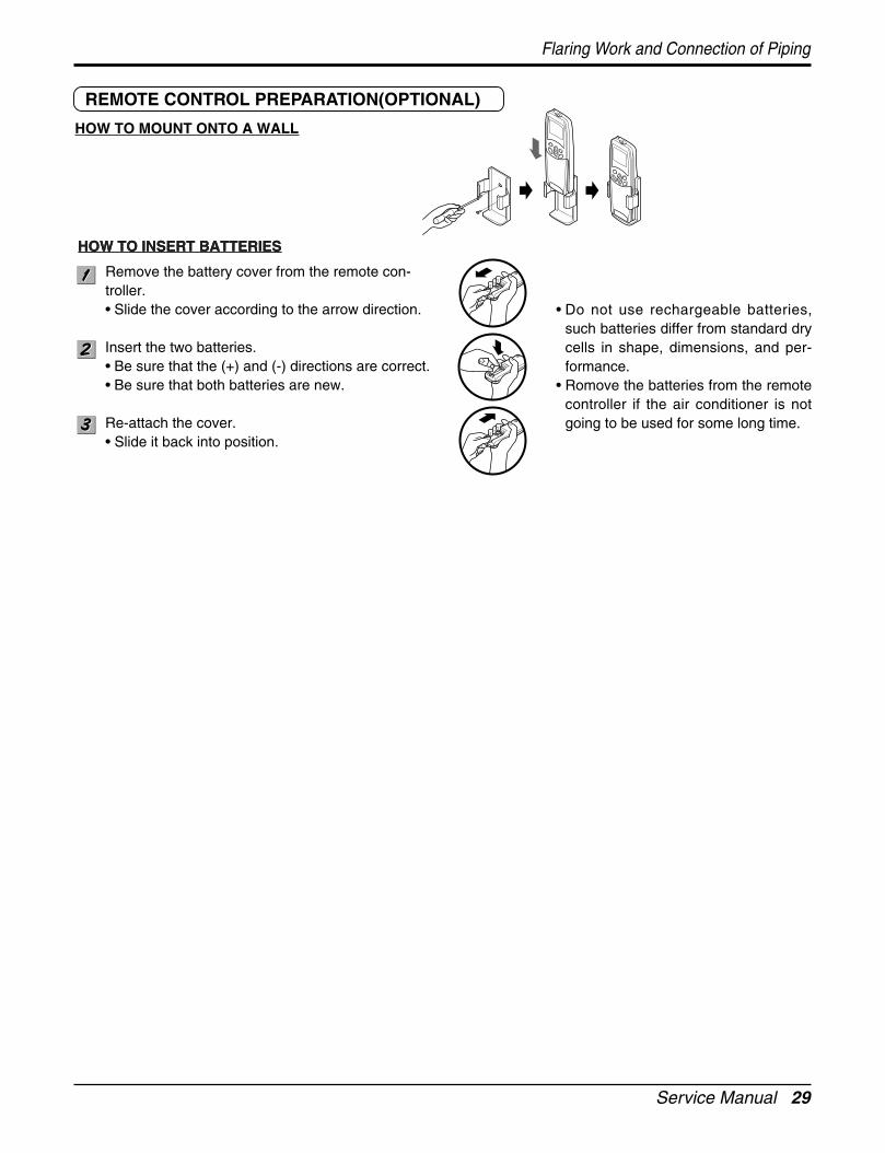
Remove the battery cover from the remote con-troller.• Slide the cover according to the arrow direction.
Insert the two batteries.• Be sure that the (+) and (-) directions are correct.• Be sure that both batteries are new.
Re-attach the cover.• Slide it back into position.
REMOTE CONTROL PREPARATION(OPTIONAL)
HOW TO MOUNT ONTO A WALL
HOW TO INSERT BATTERIES
• Do not use rechargeable batteries,such batteries differ from standard drycells in shape, dimensions, and per-formance.
• Romove the batteries from the remotecontroller if the air conditioner is notgoing to be used for some long time.
HOW TO INSERT BATTERIES
30 Multi type Air Conditioner
Flaring Work and Connection of Piping
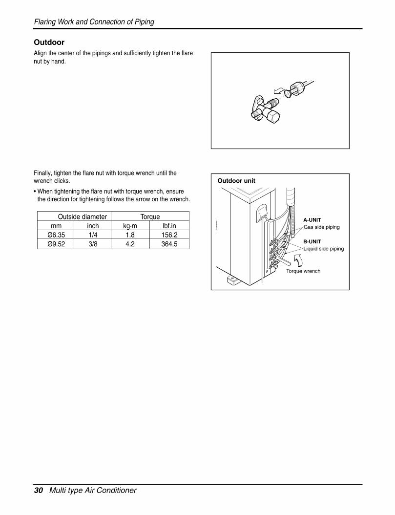
OutdoorAlign the center of the pipings and sufficiently tighten the flarenut by hand.
Finally, tighten the flare nut with torque wrench until thewrench clicks.
• When tightening the flare nut with torque wrench, ensurethe direction for tightening follows the arrow on the wrench.
Liquid side piping
Torque wrench
B-UNIT
A-UNITGas side piping
Outdoor unit
Outside diameter Torquemm inch kg.m lbf.in
Ø6.35 1/4 1.8 156.2Ø9.52 3/8 4.2 364.5
Service Manual 31
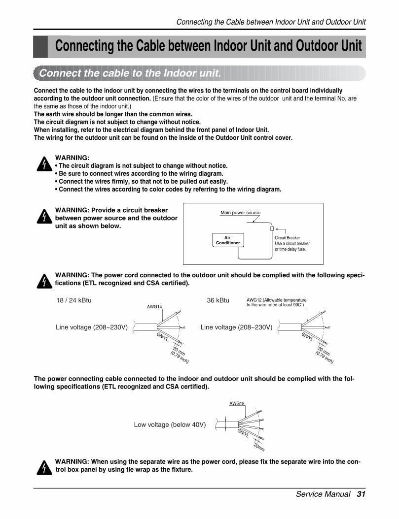
Connect the cable to the indoor unit by connecting the wires to the terminals on the control board individuallyaccording to the outdoor unit connection. (Ensure that the color of the wires of the outdoor unit and the terminal No. arethe same as those of the indoor unit.)The earth wire should be longer than the common wires.The circuit diagram is not subject to change without notice.When installing, refer to the electrical diagram behind the front panel of Indoor Unit. The wiring for the outdoor unit can be found on the inside of the Outdoor Unit control cover.
Connect the cable to the Indoor unit.
WARNING: • The circuit diagram is not subject to change without notice. • Be sure to connect wires according to the wiring diagram.• Connect the wires firmly, so that not to be pulled out easily.• Connect the wires according to color codes by referring to the wiring diagram.
WARNING: Provide a circuit breakerbetween power source and the outdoorunit as shown below.
WARNING: The power cord connected to the outdoor unit should be complied with the following speci-fications (ETL recognized and CSA certified).
The power connecting cable connected to the indoor and outdoor unit should be complied with the fol-lowing specifications (ETL recognized and CSA certified).
Air Conditioner
Main power source
Circuit BreakerUse a circuit breakeror time delay fuse.
GN/YL
20mm
AWG18
Low voltage (below 40V)
WARNING: When using the separate wire as the power cord, please fix the separate wire into the con-trol box panel by using tie wrap as the fixture.
Connecting the Cable between Indoor Unit and Outdoor Unit
Connecting the Cable between Indoor Unit and Outdoor Unit
GN/YL
20 mm(0.79 inch)
Line voltage (208~230V)
18 / 24 kBtu 36 kBtu
GN/YL
20 mm(0.79 inch)
Line voltage (208~230V)
AWG14AWG12 (Allowable temperature to the wire rated at least 90C˚)
32 Multi type Air Conditioner
Connecting the Cable between Indoor Unit and Outdoor Unit
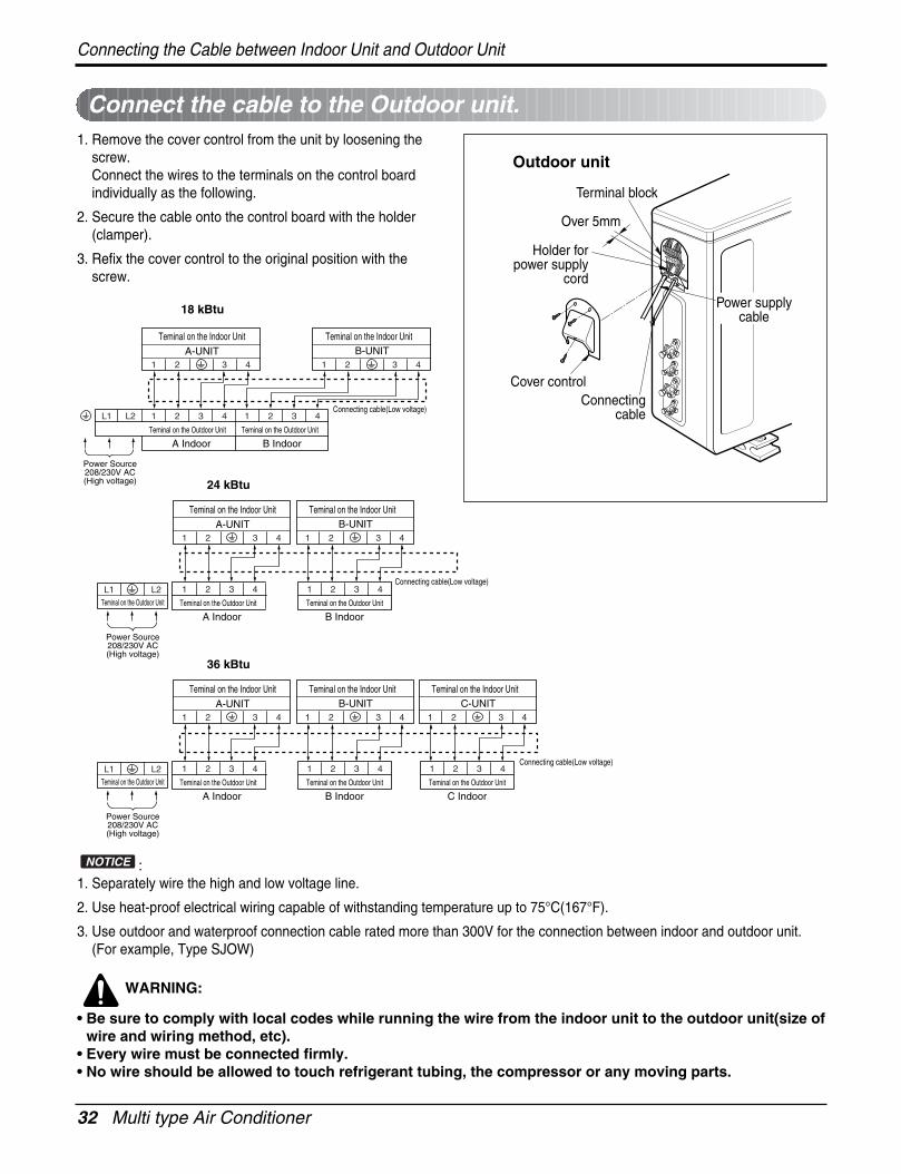
Connect the cable to the Outdoor unit.1. Remove the cover control from the unit by loosening the
screw.Connect the wires to the terminals on the control boardindividually as the following.
2. Secure the cable onto the control board with the holder(clamper).
3. Refix the cover control to the original position with thescrew.
: 1. Separately wire the high and low voltage line.
2. Use heat-proof electrical wiring capable of withstanding temperature up to 75°C(167°F).
3. Use outdoor and waterproof connection cable rated more than 300V for the connection between indoor and outdoor unit.(For example, Type SJOW)
WARNING:
• Be sure to comply with local codes while running the wire from the indoor unit to the outdoor unit(size ofwire and wiring method, etc).
• Every wire must be connected firmly.• No wire should be allowed to touch refrigerant tubing, the compressor or any moving parts.
NOTICE
Outdoor unit
Over 5mm
Holder forpower supply
cord
Connectingcable
Cover control
Terminal block
Power supplycable
A-UNIT
A Indoor B Indoor
Teminal on the Indoor Unit
Teminal on the Outdoor Unit Teminal on the Outdoor Unit
43
43
21
21 4321L1 L2
B-UNITTeminal on the Indoor Unit
4321
Power Source208/230V AC(High voltage)
18 kBtu
24 kBtu
Connecting cable(Low voltage)
A-UNIT
B IndoorA Indoor
Teminal on the Indoor Unit
Teminal on the Outdoor UnitTeminal on the Outdoor Unit Teminal on the Outdoor Unit
43
43
21
21 4321
B-UNITTeminal on the Indoor Unit
4321
Power Source208/230V AC(High voltage)
L2L1Connecting cable(Low voltage)
36 kBtu
A-UNIT
B IndoorA Indoor
Teminal on the Indoor Unit
Teminal on the Outdoor UnitTeminal on the Outdoor Unit Teminal on the Outdoor Unit
43
43
21
21 4321
B-UNITTeminal on the Indoor Unit
4321
Power Source208/230V AC(High voltage)
L2L1
C IndoorTeminal on the Outdoor Unit
4321
C-UNITTeminal on the Indoor Unit
4321
Connecting cable(Low voltage)
Service Manual 33
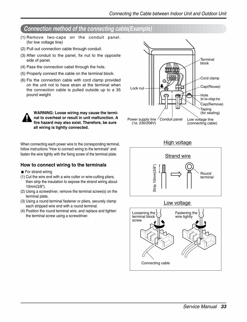
(1) Remove two-caps on the conduit panel.(for low voltage line)
(2) Pull out connection cable through conduit.
(3) After conduit to the panel, fix nut to the oppositeside of panel.
(4) Pass the connection cabel through the hole.
(5) Properly connect the cable on the terminal block.
(6) Fix the connection cable with cord clamp providedon the unit not to have strain at the terminal whenthe connection cable is pulled outside up to a 35pound weight
WARNING: Loose wiring may cause the termi-nal to overheat or result in unit malfunction. Afire hazard may also exist. Therefore, be sureall wiring is tightly connected.
When connecting each power wire to the corresponding terminal,follow instructions "How to connect wiring to the terminals" andfasten the wire tightly with the fixing screw of the terminal plate.
How to connect wiring to the terminalsFor strand wiring
(1) Cut the wire end with a wire cutter or wire-cutting pliers,then strip the insulation to expose the strand wiring about10mm(3/8").
(2) Using a screwdriver, remove the terminal screw(s) on theterminal plate.
(3) Using a round terminal fastener or pliers, securely clampeach stripped wire end with a round terminal.
(4) Position the round terminal wire, and replace and tightenthe terminal screw using a screwdriver.
Connection method of the connecting cable(Example)
High voltage
Low voltage
Str
ip 1
0mm
(3/8
")
Roundterminal
Connecting cable
Loosening theterminal blockscrew
Fastening the wire tightly
Strand wire
G
Terminalblock
Lock nut
Power supply line(1ø, 230/208V)
Conduit panel
Cap(Reuse)
Cord clamp
Hole(for low voltage line)Cap(Remove)Taping(for sealing)
Low voltage line(connecting cable)
Connecting the Cable between Indoor Unit and Outdoor Unit
34 Multi type Air Conditioner
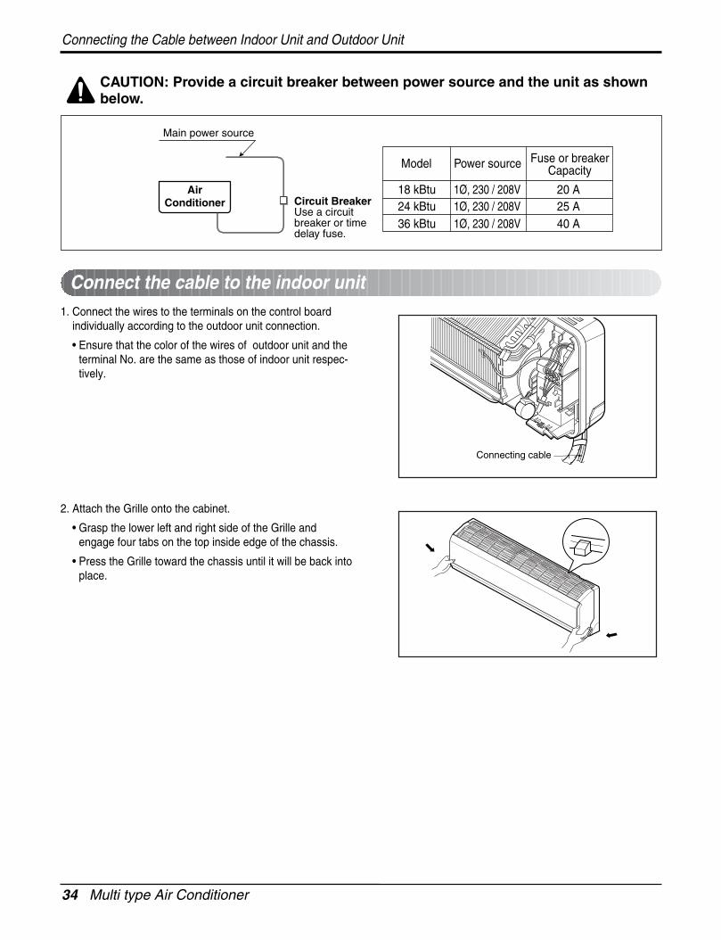
Connecting the Cable between Indoor Unit and Outdoor Unit
Connect the cable to the indoor unit
CAUTION: Provide a circuit breaker between power source and the unit as shownbelow.
AirConditioner Circuit Breaker
Use a circuitbreaker or timedelay fuse.
Main power source
Model Power source Fuse or breakerCapacity
1Ø, 230 / 208V 20 A1Ø, 230 / 208V 25 A1Ø, 230 / 208V 40 A
18 kBtu24 kBtu36 kBtu
1. Connect the wires to the terminals on the control boardindividually according to the outdoor unit connection.
• Ensure that the color of the wires of outdoor unit and theterminal No. are the same as those of indoor unit respec-tively.
2. Attach the Grille onto the cabinet.
• Grasp the lower left and right side of the Grille andengage four tabs on the top inside edge of the chassis.
• Press the Grille toward the chassis until it will be back intoplace.
Connecting cable
Service Manual 35
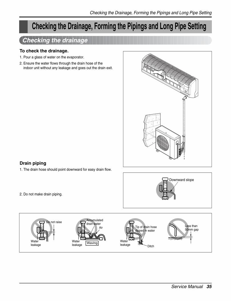
Checking the drainage
To check the drainage.1. Pour a glass of water on the evaporator.
2. Ensure the water flows through the drain hose of theindoor unit without any leakage and goes out the drain exit.
Drain piping1. The drain hose should point downward for easy drain flow.
2. Do not make drain piping.
Downward slope
Do not raiseAccumulateddrain water
Tip of drain hose dipped in water
Air
WavingWaterleakage
Waterleakage Ditch
Less than 50mm gap
Waterleakage
Checking the Drainage, Forming the Pipings and Long Pipe Setting
Checking the Drainage, Forming the Pipings and Long Pipe Setting
36 Multi type Air Conditioner
Checking the Drainage, Forming the Pipings and Long Pipe Setting
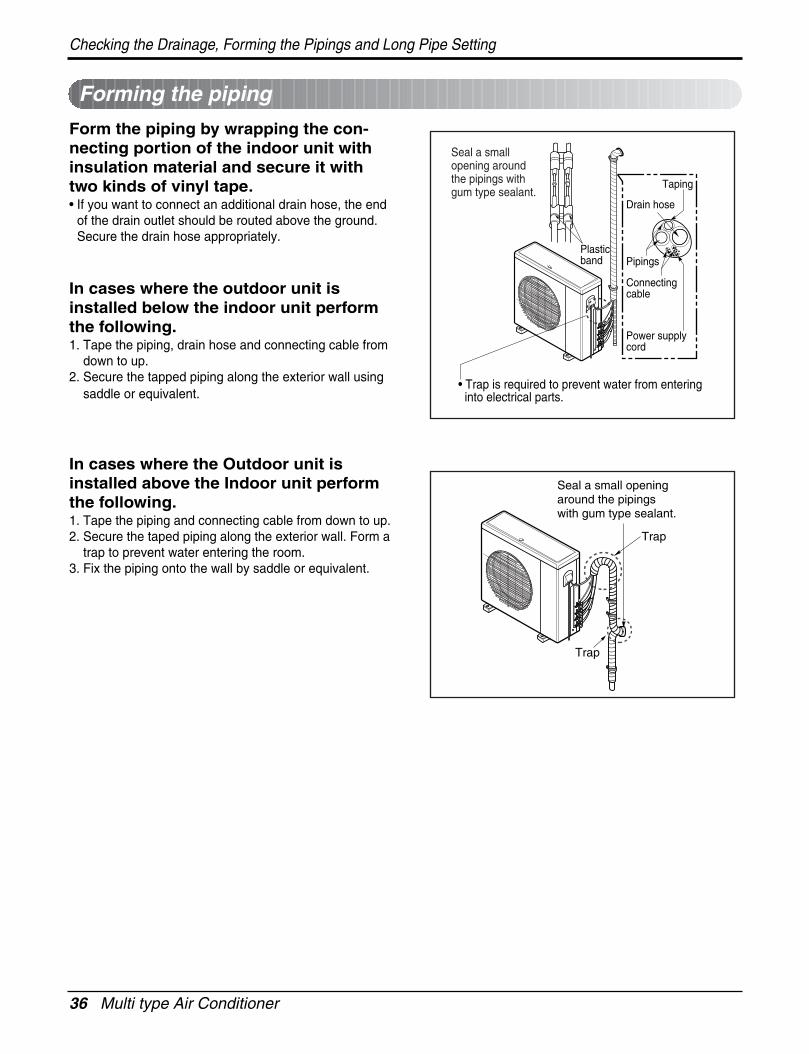
Forming the piping
Form the piping by wrapping the con-necting portion of the indoor unit withinsulation material and secure it withtwo kinds of vinyl tape.• If you want to connect an additional drain hose, the end
of the drain outlet should be routed above the ground.Secure the drain hose appropriately.
In cases where the outdoor unit isinstalled below the indoor unit performthe following.1. Tape the piping, drain hose and connecting cable from
down to up.2. Secure the tapped piping along the exterior wall using
saddle or equivalent.
In cases where the Outdoor unit isinstalled above the Indoor unit performthe following.1. Tape the piping and connecting cable from down to up.2. Secure the taped piping along the exterior wall. Form a
trap to prevent water entering the room.3. Fix the piping onto the wall by saddle or equivalent.
Seal a small opening around the pipings with gum type sealant.
Trap
Trap
• Trap is required to prevent water from enteringinto electrical parts.
Plasticband
Taping
Drain hose
Pipings
Connectingcable
Power supplycord
Seal a small opening around the pipings with gum type sealant.
Service Manual 37
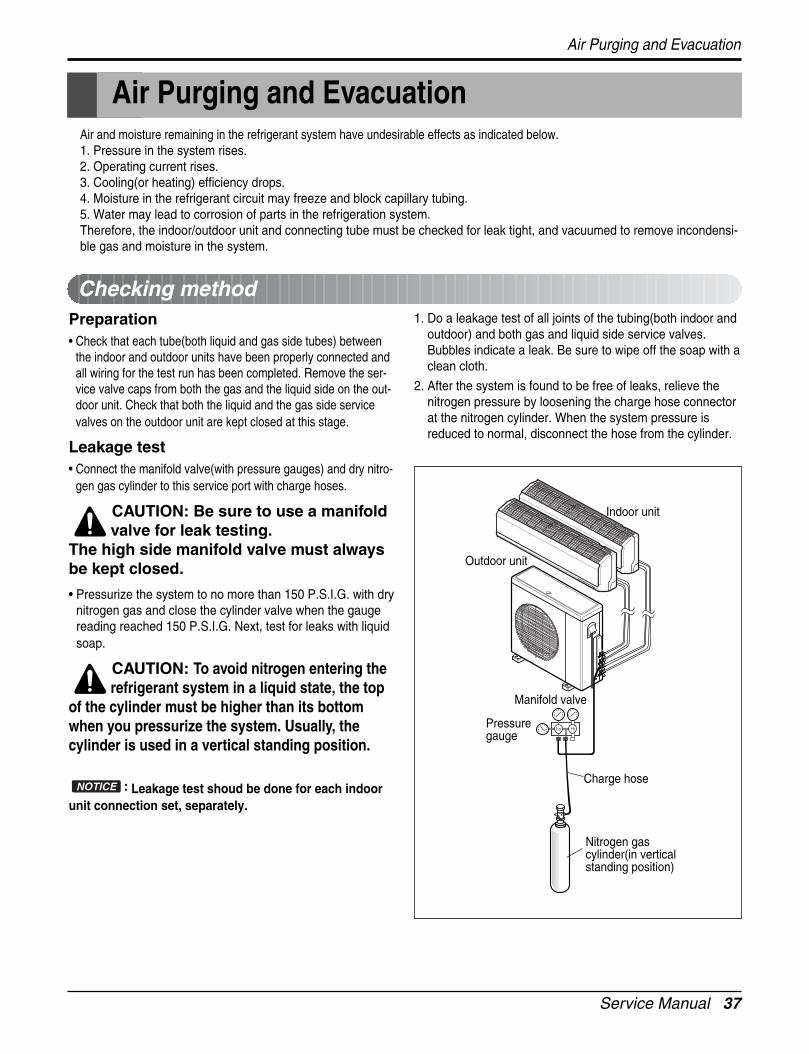
Air and moisture remaining in the refrigerant system have undesirable effects as indicated below.1. Pressure in the system rises.2. Operating current rises.3. Cooling(or heating) efficiency drops.4. Moisture in the refrigerant circuit may freeze and block capillary tubing.5. Water may lead to corrosion of parts in the refrigeration system.Therefore, the indoor/outdoor unit and connecting tube must be checked for leak tight, and vacuumed to remove incondensi-ble gas and moisture in the system.
Preparation• Check that each tube(both liquid and gas side tubes) between
the indoor and outdoor units have been properly connected andall wiring for the test run has been completed. Remove the ser-vice valve caps from both the gas and the liquid side on the out-door unit. Check that both the liquid and the gas side servicevalves on the outdoor unit are kept closed at this stage.
Leakage test• Connect the manifold valve(with pressure gauges) and dry nitro-
gen gas cylinder to this service port with charge hoses.
CAUTION: Be sure to use a manifoldvalve for leak testing.
The high side manifold valve must alwaysbe kept closed.
• Pressurize the system to no more than 150 P.S.I.G. with drynitrogen gas and close the cylinder valve when the gaugereading reached 150 P.S.I.G. Next, test for leaks with liquidsoap.
CAUTION: To avoid nitrogen entering therefrigerant system in a liquid state, the top
of the cylinder must be higher than its bottomwhen you pressurize the system. Usually, thecylinder is used in a vertical standing position.
: Leakage test shoud be done for each indoorunit connection set, separately.
1. Do a leakage test of all joints of the tubing(both indoor andoutdoor) and both gas and liquid side service valves.Bubbles indicate a leak. Be sure to wipe off the soap with aclean cloth.
2. After the system is found to be free of leaks, relieve thenitrogen pressure by loosening the charge hose connectorat the nitrogen cylinder. When the system pressure isreduced to normal, disconnect the hose from the cylinder.
NOTICE
Checking method
Charge hose
Nitrogen gascylinder(in verticalstanding position)
Indoor unit
Outdoor unit
Lo Hi
Manifold valve
Pressure gauge
Air Purging and Evacuation
Air Purging and Evacuation
38 Multi type Air Conditioner
Air Purging and Evacuation
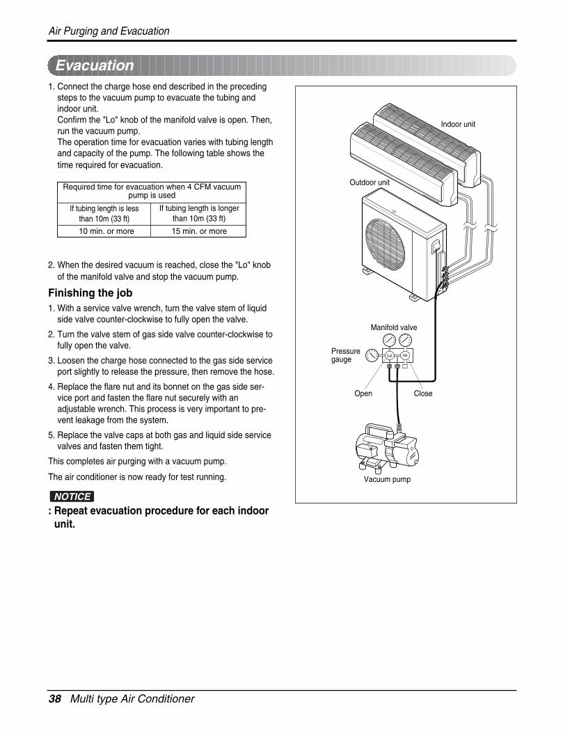
1. Connect the charge hose end described in the precedingsteps to the vacuum pump to evacuate the tubing andindoor unit.Confirm the "Lo" knob of the manifold valve is open. Then,run the vacuum pump.The operation time for evacuation varies with tubing lengthand capacity of the pump. The following table shows thetime required for evacuation.
2. When the desired vacuum is reached, close the "Lo" knobof the manifold valve and stop the vacuum pump.
Finishing the job1. With a service valve wrench, turn the valve stem of liquid
side valve counter-clockwise to fully open the valve.
2. Turn the valve stem of gas side valve counter-clockwise tofully open the valve.
3. Loosen the charge hose connected to the gas side serviceport slightly to release the pressure, then remove the hose.
4. Replace the flare nut and its bonnet on the gas side ser-vice port and fasten the flare nut securely with anadjustable wrench. This process is very important to pre-vent leakage from the system.
5. Replace the valve caps at both gas and liquid side servicevalves and fasten them tight.
This completes air purging with a vacuum pump.
The air conditioner is now ready for test running.
: Repeat evacuation procedure for each indoorunit.
NOTICE
Required time for evacuation when 4 CFM vacuumpump is used
10 min. or more 15 min. or more
If tubing length is lessthan 10m (33 ft)
If tubing length is longerthan 10m (33 ft)
Indoor unit
Outdoor unit
Lo Hi
Manifold valve
Vacuum pump
Pressure gauge
Open Close
Evacuation
Service Manual 39
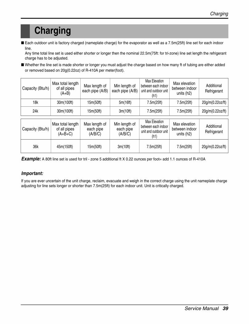
Each outdoor unit is factory charged (nameplate charge) for the evaporator as well as a 7.5m(25ft) line set for each indoorline. Any time total line set is used either shorter or longer then the nominal 22.5m(75ft: for tri-zone) line set length the refrigerantcharge has to be adjusted.
Whether the line set is made shorter or longer you must adjust the charge based on how many ft of tubing are either addedor removed based on 20g(0.22oz) of R-410A per meter(foot).
Example: A 80ft line set is used for tril - zone 5 additional ft X 0.22 ounces per foot= add 1.1 ounces of R-410A
Important:If you are ever uncertain of the unit charge, reclaim, evacuate and weigh in the correct charge using the unit nameplate chargeadjusting for line sets longer or shorter than 7.5m(25ft) for each indoor unit. Unit is critically charged.
18k 30m(100ft) 15m(50ft) 5m(16ft) 7.5m(25ft) 7.5m(25ft) 20g/m(0.22oz/ft)
24k 30m(100ft) 15m(50ft) 3m(10ft) 7.5m(25ft) 7.5m(25ft) 20g/m(0.22oz/ft)
Capacity (Btu/h)Max total length
of all pipes(A+B)
Max length ofeach pipe (A/B)
Min length ofeach pipe (A/B)
Max Elevationbetween each indoorunit and outdoor unit
(h1)
Max elevationbetween indoor
units (h2)
AdditionalRefrigerant
Charging
Charging
36k 45m(150ft) 15m(50ft) 3m(10ft) 7.5m(25ft) 7.5m(25ft) 20g/m(0.22oz/ft)
Capacity (Btu/h)Max total length
of all pipes(A+B+C)
Max length ofeach pipe(A/B/C)
Min length ofeach pipe(A/B/C)
Max Elevationbetween each indoorunit and outdoor unit
(h1)
Max elevationbetween indoor
units (h2)
AdditionalRefrigerant
40 Multi type Air Conditioner
Test Running
1. Check that all tubing and wiring have been properly con-nected.
2. Check that the gas and liquid side service valves arefully open.
1) Prepare remote controller
Remove the battery cover by pulling it according tothe arrow direction.Insert new batteries making sure that the (+) and (–)of battery are installed correctly.Reattach the cover by pushing it back into position.
NOTE:• Use 2 AAA(1.5volt) batteries. Do not use rechargeable
batteries.• Remove the batteries from the remote controller if the sys-
tem is not going to be used for a long time.
2) Precautions in test run
The initial power supply must provide at least 90% ofthe rated voltage.Otherwise, the air conditioner should not be operated.
For test run, carry out the cooling operation firstlyeven during heating season. If heating operation iscarried out firstly, it leads to the trouble of compres-sor. Then attention must be paid.
Carry out the test run more than 5 minutes withoutfail. (Test run will be cancelled 18 minutes later auto-matically)
The test run is started by pressing timer cancel buttonfive times continuously. (Room type)
To cancel the test run, press any button.
3) Settlement of outdoor unit
Anchor the outdoor unit with a bolt and nut(ø10mm)tightly and horizontally on a concrete or rigid mount.
When installing on the wall, roof or rooftop, anchor themounting base securely with a nail or wire assuming theinfluence of wind and earthquake.
In the case when the vibration of the unit is conveyed tothe hose, secure the unit with an anti-vibration rubber.
4) Evaluation of the performance
Operate unit for 15~20 minutes, then check the systemrefrigerant charge:1. Measure the pressure of the gas side service valve.2. Measure the temperature of the intake and discharge of
air.3. Ensure the difference between the intake temperature
and the discharge is more than 8°C(14.4°F) (Cooling) orreversely (Heating).
Bolt
Tubing connection
Split Type
Discharge temperature
Discharge air
Intake temperature
R-410A 35°C (95°F) 8.5~9.5kg/cm2G(120~135 P.S.I.G.)
Outside ambientTEMP.Refrigerant The pressure of the gas side
service valve.
Test Running
Service Manual 41
1. MAIN UNIT FUNCTION • DISPLAYOperation Indicator
• On while in appliance operation, off while in appliance pause• Flashing while in disconnection or short in Thermistor (3 sec off / 0.5 sec on)
Sleep Timer Indicator• On while in sleep timer mode, off when sleep timer cancel or appliance operation pause
Timer Indicator• On while in timer mode (on/off), off when timer mode is completed or canceled
Defrost Indicator• Off except when hot start during heating mode operation or while in defrost control
Cooling Mode Operation• When the intake air temperature reaches 0.5°C(0.9°F) below the setting temp, the compressor and the outdoor
fan stop.• When it reaches 0.5°C(0.9°F) above the setting temp, they start to operate again.
Compressor ON Temp Setting Temp+0.5°C(0.9°F)Compressor OFF Temp Setting Temp-0.5°C(0.9°F)
• While in compressor running, operating with the airflow speed set by the remote control. While compressor isoff fan operates at low speed regardless of the setting.
Soft Dry Operation Mode• When the dehumidification operation input by the remote control is received, the intake air temperature is
detected and the setting temp is automatically set according to the intake air temperature.26°C(78.8°F) ≤ Intake Air Temp 25°C(77°F)24°C(75.2°F) ≤ Intake Intake Air Temp<26°C(78.8°F) Intake Air Temp-1°C(30.2°F)18°C(64.4°F) ≤ Intake Intake Air Temp<24°C(75.2°F) Intake Air Temp-0.5°C(31.1°F)Intake Air Temp<18°C(64.4°F) 18°C(64.4°F)
• While compressor off, the indoor fan repeats low airflow speed and stop.• While the intake air temp is between compressor on temp. and compressor off temp., 10-min dehumidification
operation and 4-min compressor off repeat.Compressor ON Temp. Setting Temp+0.5°C(0.9°F)Compressor OFF Temp. Setting Temp-0.5°C(0.9°F)
• In 10-min dehumidification operation, the indoor fan operates with the low airflow speed.
Heating Mode Operation• When the intake air temp reaches +3°(37.4°F)…above the setting temp, the compressor is turned off. When
below the setting temp, the compressor is turned on.Compressor ON Temp. Setting Temp.Compressor OFF Temp. Setting Temp.+3°C(37.4°F)
• While compressor on, the indoor fan is off when the indoor pipe temp. is below 20°C(68°F), when above27°C(80.6°F) , it operates with the low or setting speed. When the indoor pipe temp is between 20°C(68°F) and
Function of control
Operation
Operation
42 Multi type Air Conditioner
Operation
27°C(80.6°F), it operates with Super-Low(while in sleep mode, with the medium airflow speed).• While compressor off, the indoor fan is off when the indoor pipe temp is below 33°C(91.4°F), when above
35°C(95°F) , it operates with the low airflow speed.• While in defrost control, the indoor is outdoor fans are turned off.
Defrost Control(Heating)• Defrost operation is controlled by timer and sensing temperature of outdoor pipe.• The first defrost starts only when the outdoor pipe temperature falls below -6°C(21.2°F) after 35 minutes
passed from starting of heating operation and more than 4 minutes operation of compressor.• Defrost ends after 12 minutes passed from starting of defrost operation when the outdoor pipe temperature
rises over 15°C(59°F) even before 12 minutes.• The second defrost starts only when the outdoor pipe temperature falls below -6°C(21.2°F) after 35 minutes
passed from ending of the first defrost and more than 4 minutes operation of compressor.
Fuzzy Operation• When any of operation mode is not selected like the moment of the power on or when 3 hrs has passed since
the operation off, the operation mode is selected.• When determining the operation mode, the compressor, the outdoor fan, and the 4 way valve are off and only
the indoor fan is operated for 15 seconds. Then an operation mode is selected according to the intake airtemp at that moment as follows.24°C(75.2°F) ≤ Intake Air Temp Fuzzy Operation for Cooling21°C(69.8°F) ≤ Intake Air Temp<24°C(75.2°F) Fuzzy Operation for DehumidificationIntake Air Temp<21°C(69.8°F) Fuzzy Operation for Heating
• If any of the operation modes among cooling / dehumidification / heating mode operations is carried out for 10sec or longer before Fuzzy operation, the mode before Fuzzy operation is operated.
1) Fuzzy Operation for Cooling
• According to the setting temperature selected by Fuzzy rule, when the intake air temp is 0.5°C(0.9°F) or morebelow the setting temp, the compressor is turned off. When 0.5°C(0.9°F) or more above the setting temp, thecompressor is turned on.Compressor ON Temp Setting Temp +0.5°C(0.9°F)Compressor OFF Temp Setting Temp + 0.5°C(0.9°F)
• At the beginning of Fuzzy mode operation, the setting temperature is automatically selected according to theintake air temp at that time.26°C(78.8°F)≤ Intake Air Temp 25°C(77°F)24°C(75.2°F)≤ Intake Air Temp<26°C(78.8°F) Intake Air Temp + 1°C(1.8°F)22°C(71.6°F)≤ Intake Air Temp<24°C(75.2°F) Intake Air Temp + 0.5°C(0.9°F)18°C(64.4°F)≤ Intake Air Temp<22°C(71.6°F) Intake Air TempIntake Air Temp<18°C(64.4°F) 18°C(64.4°F)
• When the Fuzzy key (Temperature Control key) is input after the initial setting temperature is selected, theFuzzy key value and the intake air temperature at that time are compared to select the setting temperatureautomatically according to the Fuzzy rule.
• While in Fuzzy operation, the airflow speed of the indoor fan is automatically selected according to the temper-ature.
Service Manual 43
2) Fuzzy Operation for Dehumidification• According to the setting temperature selected by Fuzzy rule, when the intake air temp is 0.5°C(0.9°F) or more
below the setting temp, the compressor is turned off. When 0.5°C(0.9°F) or more above the setting temp, thecompressor is turned on.Compressor ON Temp Setting Temp + 0.5°C(0.9°F)Compressor OFF Temp Setting Temp+0.5°C(0.9°F)
• At the beginning of Fuzzy mode operation, the setting temperature is automatically selected according to theintake air temp at that time.26°C(78.8°F) ≤ Intake Air Temp 25°C(77°F)24°C(75.2°F) ≤ Intake Air Temp<26°C(78.8°F) Intake Air Temp+1°C(1.8°F)22°C(71.6°F) ≤ Intake Air Temp<24°C(75.2°F) Intake Air Temp+0.5°C(0.9°F)18°C(64.4°F) ≤ Intake Air Temp<22°C(71.6°F) Intake Air TempIntake Air Temp<18°C(64.4°F) 18°C(64.4°F)
• When the Fuzzy key (Temperature Control key) is input after the initial setting temperature is selected, theFuzzy key value and the intake air temperature at that time are compared to select the setting temperatureautomatically according to the Fuzzy rule.
• While in Fuzzy operation, the airflow speed of the indoor fan repeats the low airflow speed or pause as indehumidification operation.
3) Fuzzy Operation for Heating
• According to the setting temperature selected by Fuzzy rule, when the intake air temp is 3°C(37.4°F) or moreabove the setting temp, the compressor is turned off. When below the setting temp, the compressor is turnedon.Compressor ON Temp Setting TempCompressor OFF Temp Setting Temp + 3°C(5.4°F)
• At the beginning of Fuzzy mode operation, the setting temperature is automatically selected according to theintake air temp at that time.20°C(68°F)≤Intake Air Temp Intake Air Temp + 0.5°C(0.9°F)Intake Air Temp<20°C(68°F) 20°C(68°F)
• When the Fuzzy key (Temperature Control key) is input after the initial setting temperature is selected, theFuzzy key value and the intake air temperature at that time are compared to select the setting temperatureautomatically according to the Fuzzy rule.
• While in Fuzzy operation, the airflow speed of the indoor fan is set to the high or the medium according to theintake air temperature and the setting temperature.
Airflow Speed Selection• The airflow speed of the indoor fan is set to high, medium, low, or power (auto) by the input of the airflow
speed selection key on the remote control.
On-Timer Operation• When the set time is reached after the time is input by the remote control, the appliance starts to operate.• The timer LED is on when the on-timer is input. It is off when the time set by the timer is reached.• If the appliance is operating at the time set by the timer, the operation continues.While in Fuzzy operation, the airflow speed of the indoor fan is automatically selected according to the temperature.
Off-Timer Operation• When the set time is reached after the time is input by the remote control, the appliance stops operating.• The timer LED is on when the off-timer is input. It is off when the time set by the timer is reached.
Operation
44 Multi type Air Conditioner
Operation
• If the appliance is on pause at the time set by the timer, the pause continues. Off-Timer <=> On-Timer Operation
• When the set time is reached after the on/off time is input by the remote control, the on/off-timer operation iscarried out according to the set time.
Sleep Timer Operation• When the sleep time is reached after <1,2,3,4,5,6,7,0(cancel) hr> is input by the remote control while in appli-
ance operation, the operation of the appliance stops.• While the appliance is on pause, the sleep timer mode cannot be input.• While in cooling mode operation, 30 min later since the start of the sleep timer, the setting temperature
increases by 1°C(33.8°F). After another 30 min elapse, it increases by 1°C(1.8°F) again.• When the sleep timer mode is input while in cooling cycle mode, the airflow speed of the indoor fan is set to
the low.• When the sleep timer mode is input while in heating cycle mode, the airflow speed of the indoor fan is set to
the medium.
Chaos Swing Mode• By the Chaos Swing key input, the upper/lower vane automatically operates with the Chaos Swing or they are
fixed to the desired direction.• While in Chaos Swing mode, the angles of cooling and heating cycle operations are different.
Chaos Natural Wind Mode• When the Chaos Natural Wind mode is selected and then operated, the high, medium, or low speed of the air-
flow mode is operated for 2~15 sec. randomly by the Chaos Simulation.
Jet Cool Mode Operation • While in heating mode or Fuzzy operation, the Jet Cool key cannot be input. When it is input while in theother mode operation (cooling, dehumidification, ventilation), the Jet Cool mode is operated.• In the Jet Cool mode, the indoor fan is operated at super-high speed for 30 min at cooling mode operation.• In the Jet Cool mode operation, the room temperature is controlled to the setting temperature, 18°C(64.4°F).• When the sleep timer mode is input while in the Jet Cool mode operation, the Jet Cool mode has the priority.• When the Jet Cool key is input, the upper/lower vanes are reset to those of the initial cooling mode and then
operated in order that the air outflow could reach further.
Auto Restarting Operation• When the power is restored after a sudden power failure while in appliance operation, the mode before the
power failure is kept on the memory and the appliance automatically operates in the mode on the memory.
Service Manual 45
Forced Operation • To operate the appliance by force in case that the remote control is lost, the forced operation selection switch
is on the main unit of the appliance to operate the appliance in the standard conditions.• When the power is supplied while the slide switch is on the forced operation position, or when the slide switch
position is switched to the Auto Restarting (or test operation) position or switched from the remote controlposition to the forced operation position while the power is on, the forced operation is carried out.
• When the slide switch position is switched from the forced operation position to the Auto Restarting position orthe remote control position, the forced operation is canceled and the appliance stops operating.
• In the forced operation mode, the indoor fan is operated at low speed for around 15 sec and then the opera-tion condition is set according to the intake air temperature as follows.24°C(43.2°F)≤Intake Air Temp Cooling Mode Operation, 22°C(39.6°F), High Speed21°C(37.8°F)≤Intake Air Temp<24°C(43.2°F) Dehumidification Operation, 23°C(41.4°F), High SpeedIntake Air Temp<21°C(37.8°F) Heating Mode Operation, 24°C(43.2°F), High Speed
Buzzer Sounding Operation• When the appliance-operation key is input by the remote control, the short "beep-beep-" sounds.• When the appliance-pause key is input by the remote control, the long "beep—" sounds.
Operation
46 Multi type Air Conditioner
Operation
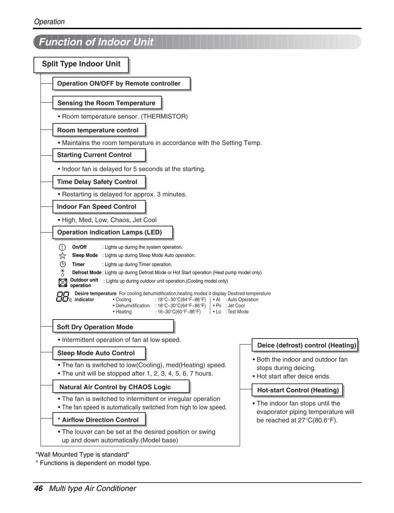
"Wall Mounted Type is standard"* Functions is dependent on model type.
Function of Indoor Unit
On/Off : Lights up during the system operation.
Sleep Mode : Lights up during Sleep Mode Auto operation.
Timer : Lights up during Timer operation.
Defrost ModeOutdoor unit operation
: Lights up during Defrost Mode or Hot Start operation (Heat pump model only)
: Lights up during outdoor unit operation.(Cooling model only)
Desire temperature For cooling,dehumidification,heating modes it display Destired temperatureindicator • Cooling : 18°C~30°C(64°F~86°F) • AI : Auto Operation
• Dehumidification : 18°C~30°C(64°F~86°F) • Po : Jet Cool• Heating : 16~30°C(60°F~86°F) • Lo : Test Mode
• Room temperature sensor. (THERMISTOR)
• Maintains the room temperature in accordance with the Setting Temp.
• Indoor fan is delayed for 5 seconds at the starting.
• Restarting is delayed for approx. 3 minutes.
• High, Med, Low, Chaos, Jet Cool
• Intermittent operation of fan at low speed.
• The fan is switched to low(Cooling), med(Heating) speed.• The unit will be stopped after 1, 2, 3, 4, 5, 6, 7 hours.
• The fan is switched to intermittent or irregular operation• The fan speed is automatically switched from high to low speed.
• The louver can be set at the desired position or swing up and down automatically.(Model base)
Split Type Indoor Unit
Operation ON/OFF by Remote controller
Sensing the Room Temperature
Room temperature control
Starting Current Control
Time Delay Safety Control
Indoor Fan Speed Control
Operation indication Lamps (LED)
Soft Dry Operation Mode
• Both the indoor and outdoor fanstops during deicing.
• Hot start after deice ends.
• The indoor fan stops until the evaporator piping temperature willbe reached at 27°C(80.6°F).
Sleep Mode Auto Control
Natural Air Control by CHAOS Logic
* Airflow Direction Control
Deice (defrost) control (Heating)
Hot-start Control (Heating)
Service Manual 47
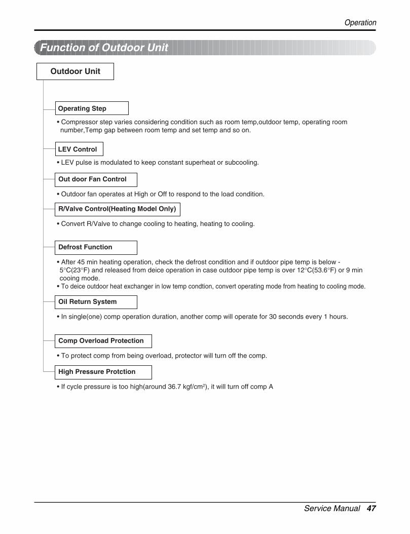
Function of Outdoor Unit
Outdoor Unit
Operating Step
LEV Control
Out door Fan Control
• Compressor step varies considering condition such as room temp,outdoor temp, operating room number,Temp gap between room temp and set temp and so on.
• LEV pulse is modulated to keep constant superheat or subcooling.
• Outdoor fan operates at High or Off to respond to the load condition.
R/Valve Control(Heating Model Only)
• Convert R/Valve to change cooling to heating, heating to cooling.
Defrost Function
• After 45 min heating operation, check the defrost condition and if outdoor pipe temp is below -5°C(23°F) and released from deice operation in case outdoor pipe temp is over 12°C(53.6°F) or 9 min cooing mode.
• To deice outdoor heat exchanger in low temp condtion, convert operating mode from heating to cooling mode.
Oil Return System
• In single(one) comp operation duration, another comp will operate for 30 seconds every 1 hours.
Comp Overload Protection
• To protect comp from being overload, protector will turn off the comp.
High Pressure Protction
• If cycle pressure is too high(around 36.7 kgf/cm2), it will turn off comp A
Operation
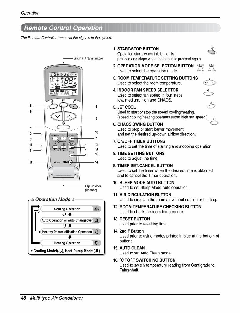
48 Multi type Air Conditioner
Operation
Remote Control Operation
ON OFF
CANCEL
AUTO CLEANSET
1
3
5
4
9
10
12
14
16
72
8
13
11
6
Cooling Operation
Auto Operation or Auto Changeover
Healthy Dehumidification Operation
Flip-up door(opened)
Heating Operation
Signal transmitter
• Cooling Model( ), Heat Pump Model( )
15
Operation Mode
The Remote Controller transmits the signals to the system.
1. START/STOP BUTTONOperation starts when this button is pressed and stops when the button is pressed again.
2. OPERATION MODE SELECTION BUTTONUsed to select the operation mode.
3. ROOM TEMPERATURE SETTING BUTTONSUsed to select the room temperature.
4. INDOOR FAN SPEED SELECTORUsed to select fan speed in four stepslow, medium, high and CHAOS.
5. JET COOLUsed to start or stop the speed cooling/heating.(speed cooling/heating operates super high fan speed.)
6. CHAOS SWING BUTTONUsed to stop or start louver movement and set the desired up/down airflow direction.
7. ON/OFF TIMER BUTTONSUsed to set the time of starting and stopping operation.
8. TIME SETTING BUTTONSUsed to adjust the time.
9. TIMER SET/CANCEL BUTTONUsed to set the timer when the desired time is obtainedand to cancel the Timer operation.
10. SLEEP MODE AUTO BUTTONUsed to set Sleep Mode Auto operation.
11. AIR CIRCULATION BUTTONUsed to circulate the room air without cooling or heating.
12. ROOM TEMPERATURE CHECKING BUTTONUsed to check the room temperature.
13. RESET BUTTONUsed prior to resetting time.
14. 2nd F ButtonUsed prior to using modes printed in blue at the bottom ofbuttons.
15. AUTO CLEANUsed to set Auto Clean mode.
16. ˚C TO ˚F SWITCHING BUTTONUsed to switch temperature reading from Centigrade toFahrenheit.
(Heat Pump) (Cooling Only)
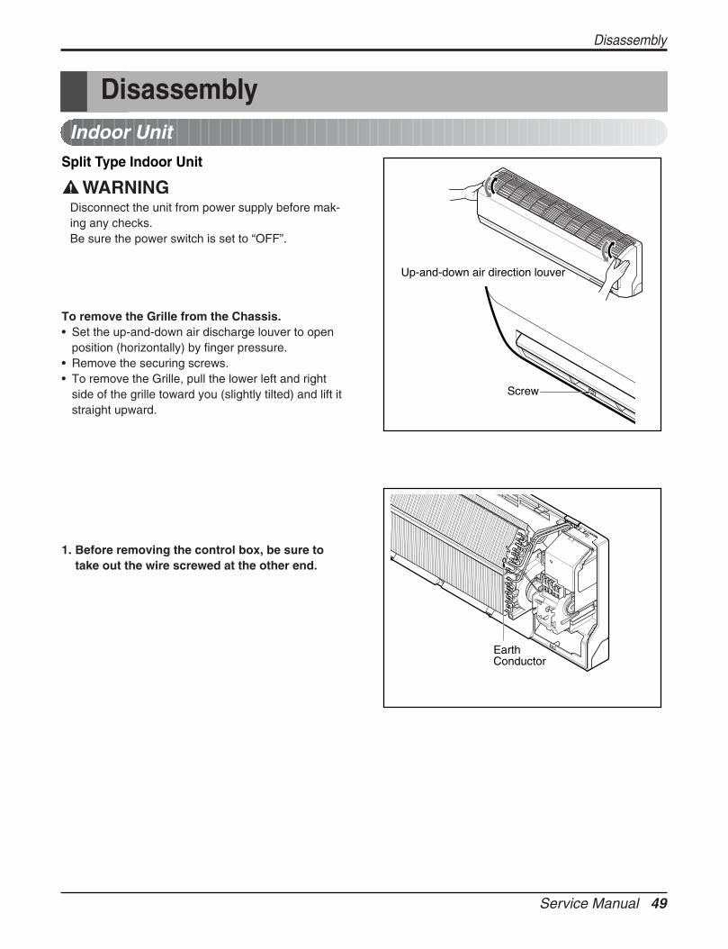
Service Manual 49
Disassembly
DisassemblyIndoor Unit
Split Type Indoor Unit
Disconnect the unit from power supply before mak-ing any checks.Be sure the power switch is set to “OFF”.
To remove the Grille from the Chassis. • Set the up-and-down air discharge louver to open
position (horizontally) by finger pressure.• Remove the securing screws.• To remove the Grille, pull the lower left and right
side of the grille toward you (slightly tilted) and lift itstraight upward.
1. Before removing the control box, be sure totake out the wire screwed at the other end.
EarthConductor
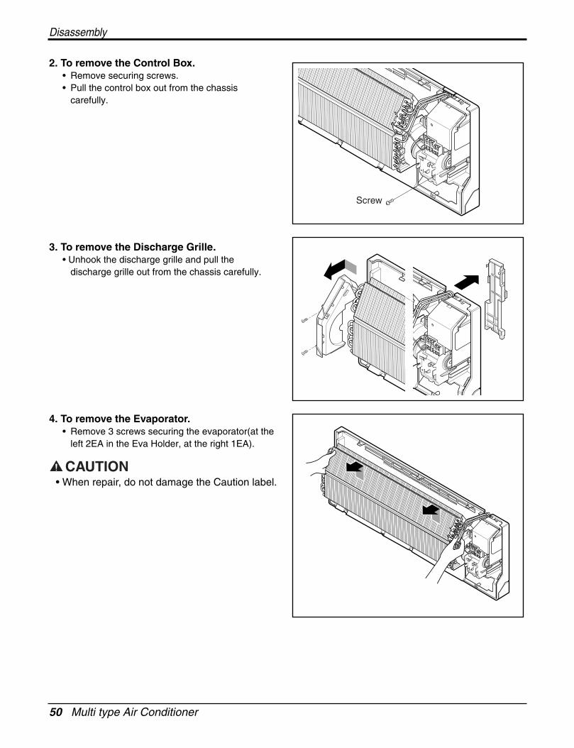
50 Multi type Air Conditioner
Disassembly
2. To remove the Control Box.• Remove securing screws. • Pull the control box out from the chassis
carefully.
3. To remove the Discharge Grille.• Unhook the discharge grille and pull the
discharge grille out from the chassis carefully.
4. To remove the Evaporator. • Remove 3 screws securing the evaporator(at the
left 2EA in the Eva Holder, at the right 1EA).
Screw
• When repair, do not damage the Caution label.
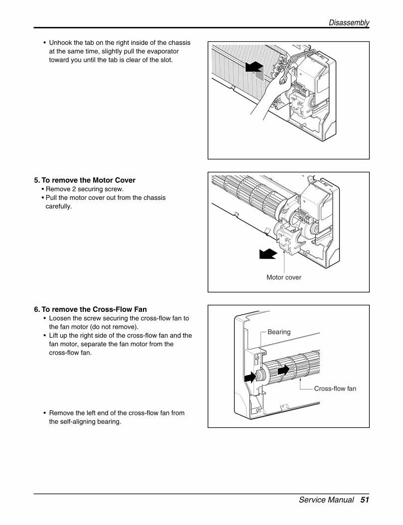
Service Manual 51
• Unhook the tab on the right inside of the chassisat the same time, slightly pull the evaporatortoward you until the tab is clear of the slot.
5. To remove the Motor Cover• Remove 2 securing screw.• Pull the motor cover out from the chassis
carefully.
6. To remove the Cross-Flow Fan• Loosen the screw securing the cross-flow fan to
the fan motor (do not remove).• Lift up the right side of the cross-flow fan and the
fan motor, separate the fan motor from thecross-flow fan.
• Remove the left end of the cross-flow fan fromthe self-aligning bearing.
Motor cover
Bearing
Cross-flow fan
Disassembly

52 Multi type Air Conditioner
Disassembly
Schematic DiagramElectronic Control Device
1. Indoor Unit1) Split Type
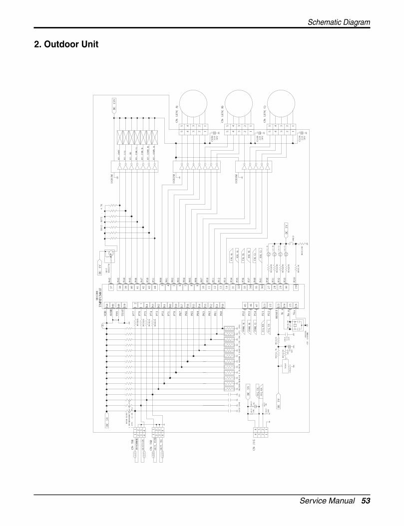
Service Manual 53
2. Outdoor Unit
P07
SW01
F
OR2
H,O
R7H,
OR1
0H:9
1K,O
R3H-
4H,
OR8
H-9H
,OR1
1H-1
2H:1
5K(E
TC:
20K)
R03T
11
DC 5
V
56K
R04
T1K
1 2
7036
P
IC01
A
CN-J
IG
3434
22
JIG
_RX
JIG
_TX
DC 5
V
10K
R01T
1KR02T
C01H
-C04
H : 1
03
P21
21JI
G_R
X
26
OSC
01B
CST
-8.0
0MG
W
JIG
_TX
+3
C02A 10
R03A
,100 50
V
25V
0.01
C01A
R02A
,4.7
KR0
1A,1
K
Xin
Vss
Xou
tR0
1B,1
M2524
P22
RESE
T2322
P20
19R0
1F,1
K
R02F
,10K
R02G
,10K
R01G
,10K
R04
G,1
0K
R03G
,10K
P32
29 30P3
3
2827
P31
P30
L4(C
)
L3(C
)
L1(A
)
L2(B
)
PWM
(A)
PWM
(C)
PWM
(B)
P53
P54
46
47
P52
45
51
P60
50
P62
P63
P61
5253
31
P37
34 35 36P4
1
P40
3332
P36
P35
RX(C
)
RX(B
)
TX
(C)
RX(A
)
TX
(B)
1413
P13
P12
P34
1110 12
P10
P11
TX
(A)
CN-L
EV(C
)
CN-L
EV(B
)
DC 5
V
+C5
2M 220
50V
23 1
23 1
5 4
5 4
IC03
M4
4
220
50V
+C5
1M
11
3 2
3 2
50V
55
1 +22
0C5
0M
1
22
11
OUT
_PIP
E
OUT
_TH
22
33
44
CN-T
H2
SUCT
ION
33
44
DC 5
V
R05H
-R20
H
(ET
C: 1
2.1K
1%
)(R
05H,
R06H
,R07
H:6.
2K 1
%)
DISC
HARG
E
CN-T
H11
14
1R0
1H,1
K
60P7
1
P66
P65
P64
5556 54
P70
P67
59 5763
P73
P72
R04
H,1K
62 61
P76
P74
P75
R02H
,1K
R03H
,1K
1 64
7 8 9
P05
P06
5 6
P02
P04
P03
P51
44
4 3P0
0
P01
42
43
P47
P50
MIC
OM
TM
P87C
M4
1F
58
TES
T
P77
20 2
VSS
AV
DD4
9
48
VDD
Q01
ZKR
A10
7M
39 40
P44
P46
P45
3837P4
2
P43
DC 5
V
CN-L
EV(A
)IC
02M
4 23
4 23
55
RY-C
OM
P(A
)
RY-F
AN
(H)
RY-C
OM
P(B)
IC01
M
R01Z
-R07
Z :
4.7
K
RY-L
IQ
RY-F
AN
(L)
RY-G
AS
RY-4
WA
Y
DC 1
5V
Schematic Diagram
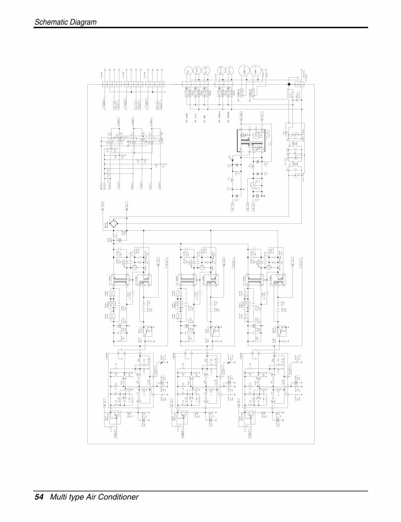
54 Multi type Air Conditioner
Schematic Diagram
23.2
K
8.06
K
8.06
K
23.2
K
23.2
K
8.06
K
1% 1%
51.1
K
102
100V
C25M
1%9.1k
R27M
100u
fC2
4M
+2
5 46
100u
F25
V
C26M
R28M
13K
1%
15
+
R29M
,2K,
1%4
22
51.1
K
10K
1
2.94
K
67
4.7
K
PWM
(C)
35.7
K
4.3
K
R26M
10.2
K
3 2121
.5K
6.04
K
KRA
101M
Q07
MDC
5V
7
3K5.
23K
39.2
K13
K
2020
9 8
R04
S
20K14
51.1
K
102
C14
M
100V
R15M
C13M
+
1%10
0uf
9.1k
25 4
6
C15M
25V
100u
FR1
6M
15
+
1%13K
R17M
,2K,
1%4
2210
K1
51.1
K
2.94
K
67
4.7
K
PWM
(B)
35.7
K
4.3
K
10.2
KR1
4M
23121
.5K
6.04
K
Q04
MKR
A10
1M
DC 5
V
7
3K5.
23K
39.2
K13
K
208
209
R04
S
14
20K
51.1
K
102
100V
C02M
R02M
9.1k
1%10
0uf
C01M
+2
5 46
100u
F25
V
C03M
15
R03M
13K
1%
+
R04
M,2
K,1%
4
2210
K1
51.1
K
67 2.94
K
PWM
(A)4.7
K
35.7
K
4.3
K
R01M
10.2
K1%
23121
.5K
6.04
K
KRA
101M
Q01
M
7
DC 5
V
3K5.
23K
39.2
K13
K
R04
S
820
209
14
20K
51.1
K
RY-C
OM
P(B)
RY-C
OM
P(A
)
51.1
K
2SD2
220
Q08
M
51.1
K
R31M
220
334
K
100K
R33M
1.5K
103K
100V
R34
MC3
1M
Vm
(C)
MT
15V
94S/
W T
RAN
S6
2 37
Q09
M
30,1
WR3
7M
ZD0
3M12
V20
0R3
6M
472
/250
VC3
0M
100V
473
KC2
7M
28
10K
R32M
IC06
M
63V
680u
FC2
8M
+
821K
C29M
1KV
L10M
L09M
FMX
12S
D05M
Q05
M2S
D222
0
R19M
51.1
K22
0
334
KR2
1M10
0K
1.5K
103K
100V
R22M
C21M
Vm
(B)
ERB-
44
-08
D06M
84
6
S/W
TRA
NS5
L12M
L11M
112
1KV
222K
C33M
3W68K
R35M
C32M
MT
15V
94S/
W T
RAN
S4
2 37
Q06
M
R25M
30,1
W
12V
200
R24
MZ
D02M
u-PO
WER
MO
DULE
NF0
2J
C09J
~C1
0J
1uF
C08J
222*2
25V
ZN
R01J
~Z
NR0
2J
uRM
1515
-2B
302
D01J
C04
J
1M
C06J
~C0
7J C05J
9mH
472*3
R01J
1mH
NF0
1J
1uF
1uF
C03J
35V
C10D
102M
561*2
C04
D
35V
470
UF
12uH
L01D
1000
UF
35V
220u
FC0
5D 10V
220u
FC0
3D
DC 5
V
DC 1
5V
IC04
D
C06D
50V
10378
05
C07D
50V
++
103
C02D
470
uF
+
2K
R02D
1/2W
MT
15V
C08D 10
3
50V
L02D
12uH
D101 FB
12
OUT
R202
9 7
+
C01D
GN
D
PC20
1
D201
R201
D202
268
C102BPTN
Y
S
D
13
+
C101
R102
OUT
GN
D
3N
C
DC 0
V65
PC20
1
GN
D
NC
DC 3
10V
1IN
R101
D01D
1N4
937
RY-F
AN
(L)
RY-F
AN
(H)
RY-G
AS
LIV
E1
33
CN-P
OW
ERN
EUT
RAL
1
FUSE
ZN
R01J
250V
/T5A
INR1
4D4
71K
SVC5
61D-
14A
1
COM
P B
COM
P A
43
LIV
E2
43
NF0
1M
HOT
GA
S
FAN
LO
W
FAN
HI
1 1
NF0
2M
1 1
1
NF0
4M
NF0
3M
1
CN-F
AN
COM
(A)
COM
(B)
COM
(C)
DKS-
10D-
22 1/2W
560K
R11M
51.1
K
472
/250
VC1
9M
C16M
100V
473
K
8 210
KR2
0M
IC05
M
63V
C17M
680u
F
+
C18M
821K
1KV
L06M
L05M
FMX
12S
D03M
Q02
M2S
D222
0
51.1
K
R06M
220
334
KR0
8M10
0K
1.5K
103K
100V
R09M
C09M
Vm
(A)
ERB-
44
-08
D04
M
84
6
S/W
TRA
NS3
L08M
L07M
112
C23M
1KV
222K
R23M
3W68K
C22M
MT
15V
94S/
W T
RAN
S2
32
7Q
03M
30,1
WR1
3M
ZD0
1M12
V20
0R1
2M
472
/250
VC0
7M
C04
M4
73K
100V
8 2
R07M
10K
IC04
M
C05M
+
63V
680u
FC0
6M82
1K1K
V
L02M
L01M
D01M
FMX
12S
ERB-
44
-08
D02M
84
6
S/W
TRA
NS1
L03M
L04
M
112
1KV
C11M
222K
3W68K
R10M
C10M
+N
TC
450
V33
0UF
C12M
COM
(B)
320
TX
(B)
1KR1
4K
102
C03K
TX
(C)
RX(C
)
RX(B
)
RY-L
IQ
RY-4
WA
Y
R15K10
KR1
2K
10K
R16K
3 21
8 4
20
8 4
75 6
R10K 1K
C02K
102
21
4
IC03
K
4
75 6
8
COM
(C)
DC 1
5V
Vm
(C)
Vm
(B)
DC 1
5V
DC 0
V
BD01
MD1
5XB6
0
DC 3
10V
RX(A
)
DC 1
5V
TX
(A)
DC 5
V
R13K 1K
1KR0
1K1K
R09K
10K
R07K
R05K
R11K
10K
C01K1K
102
8 4
75 6
10K
R06K
IC02
K
10K
R08K
8
R02K
R04
K
10K
R03K
IC01
K 231
8 4
20
COM
(A)
Vm
(A)
DC 1
5V
LIQ
UID
1
NF0
5M
1
1 1
4W
AY
32 4
32 4
3 14
3 1
CN-C
OM
3
4
4 1 2
4 1 2
CN-C
OM
2
2 31
CN-C
OM
1
2 31
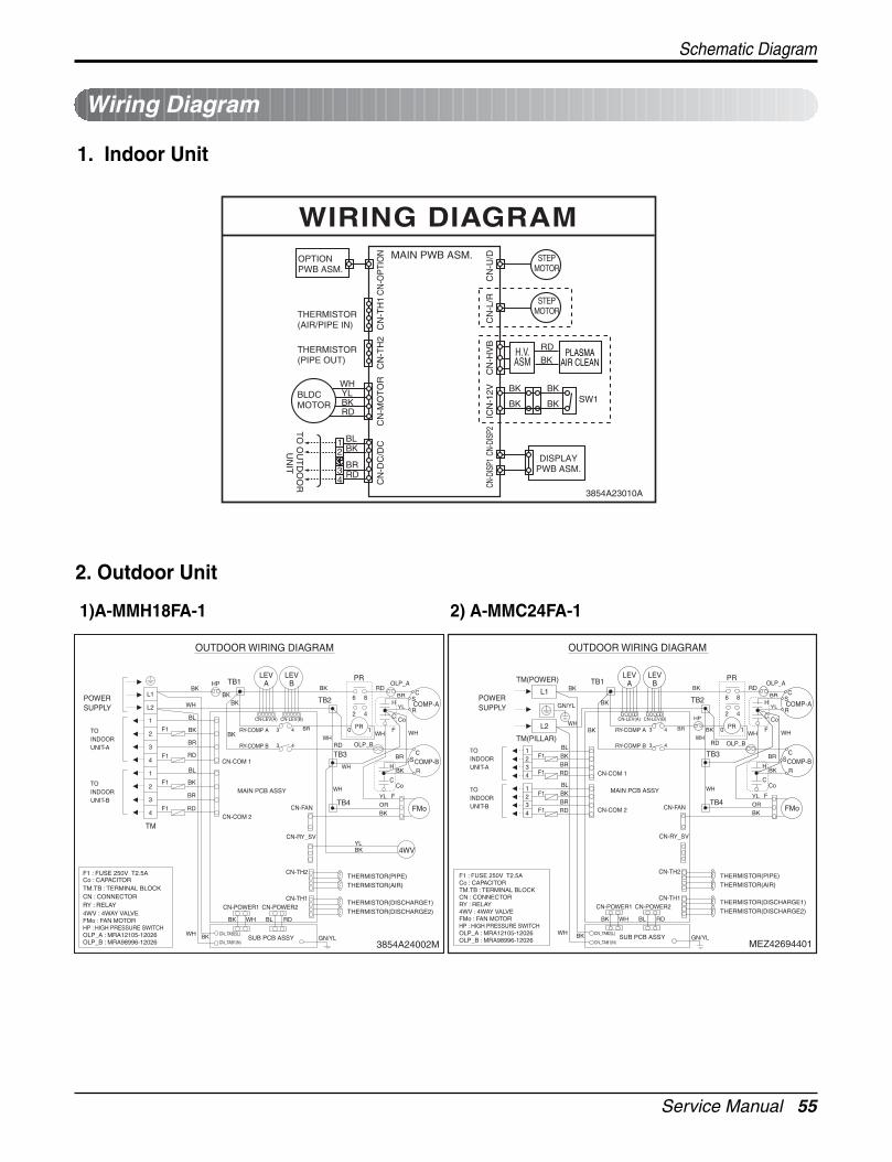
Service Manual 55
1. Indoor Unit
Wiring Diagram
2. Outdoor Unit
1)A-MMH18FA-1 2) A-MMC24FA-1
Schematic Diagram
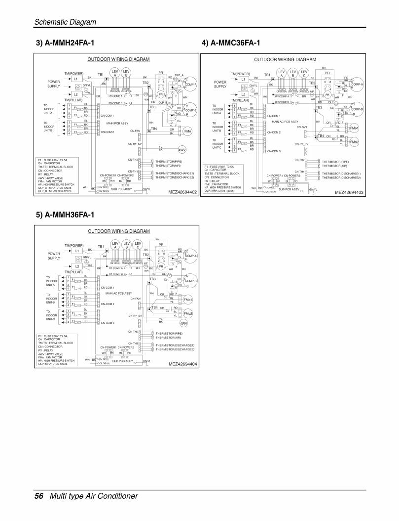
56 Multi type Air Conditioner
Schematic Diagram
3) A-MMH24FA-1 4) A-MMC36FA-1
5) A-MMH36FA-1
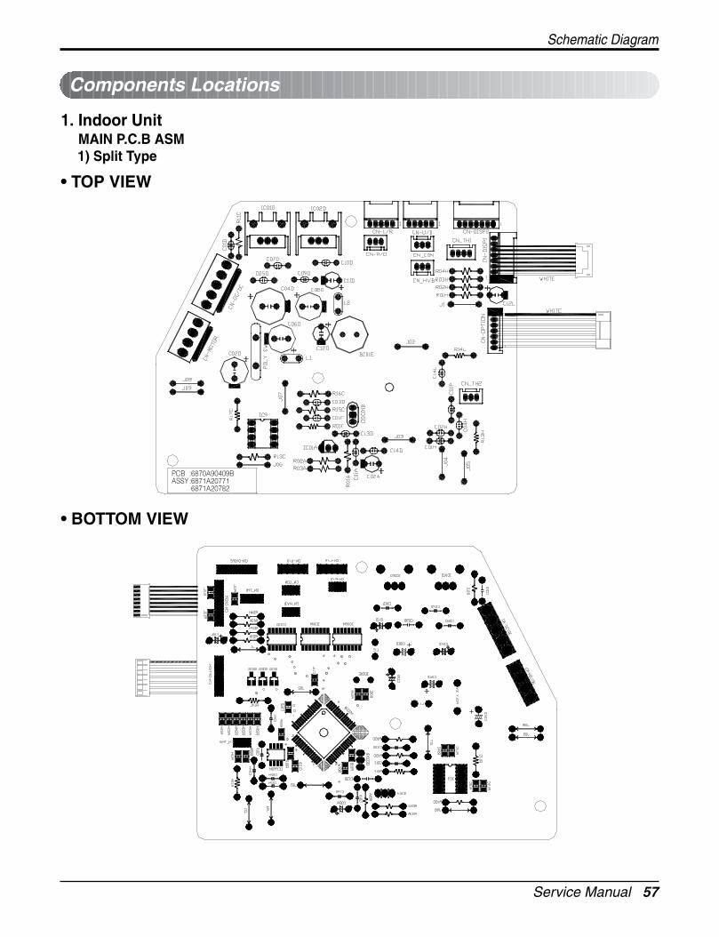
Service Manual 57
Schematic Diagram
1. Indoor UnitMAIN P.C.B ASM1) Split Type
Components Locations
• TOP VIEW
• BOTTOM VIEW
PCB :6870A90409BASSY:6871A20771
6871A20782
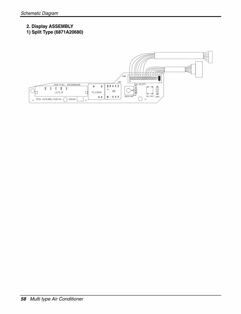
58 Multi type Air Conditioner
Schematic Diagram
2. Display ASSEMBLY1) Split Type (6871A20680)
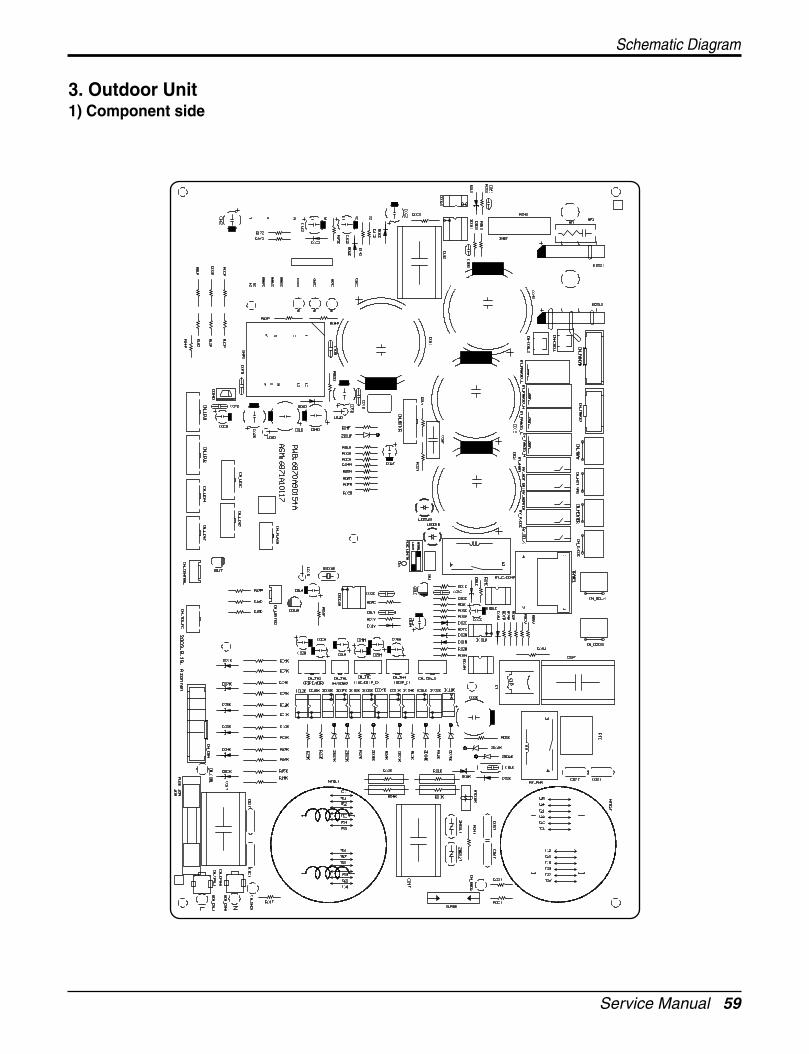
Service Manual 59
Schematic Diagram
3. Outdoor Unit1) Component side
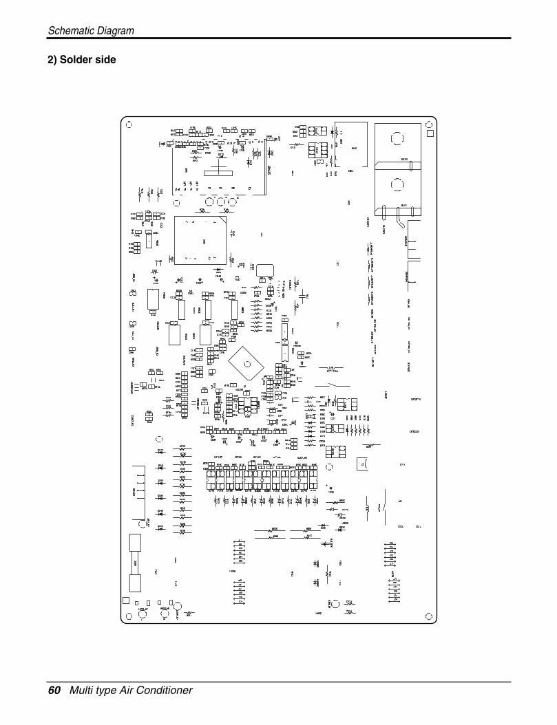
60 Multi type Air Conditioner
Schematic Diagram
2) Solder side
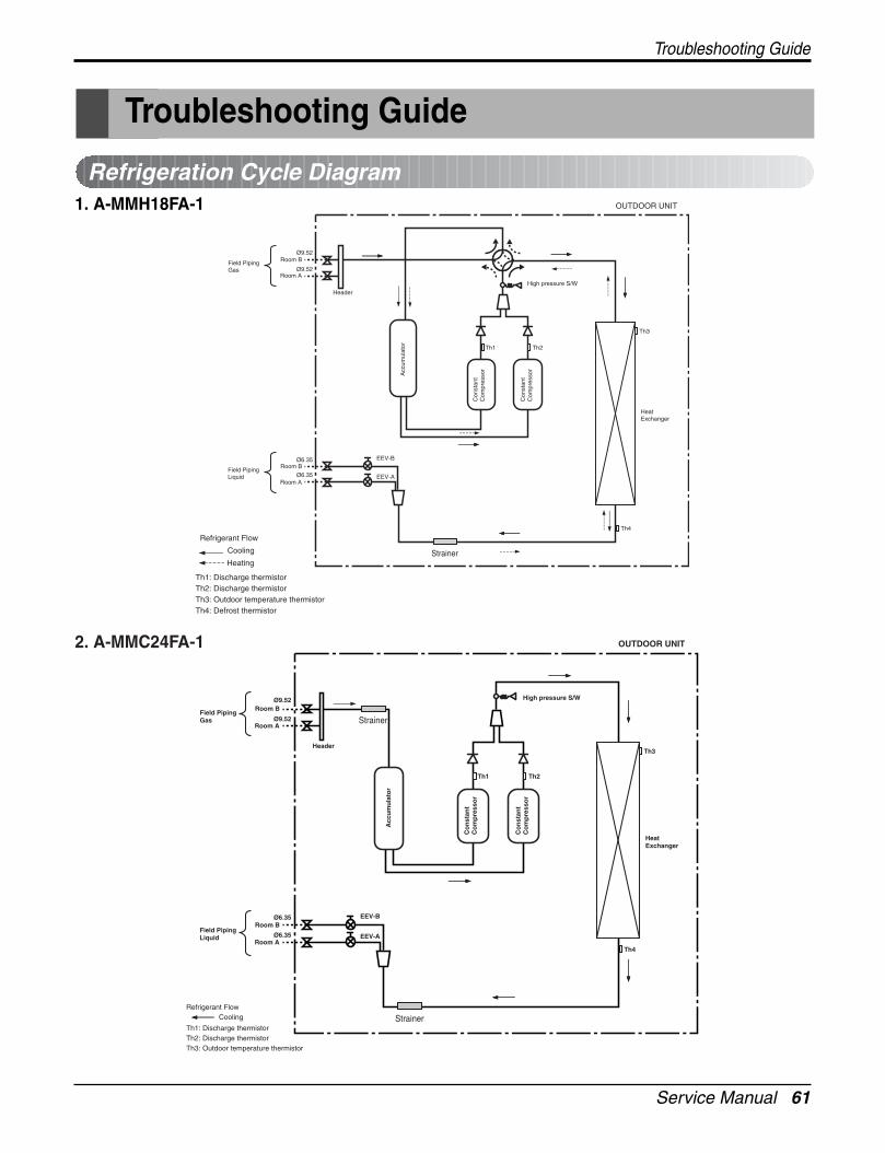
Service Manual 61
Troubleshooting Guide
Troubleshooting Guide
Refrigeration Cycle Diagram
Refrigerant Flow
Cooling
Heating
Th1: Discharge thermistorTh2: Discharge thermistorTh3: Outdoor temperature thermistorTh4: Defrost thermistor
Field PipingGas
Field PipingLiquid
Room A
EEV-B
EEV-A
HeatExchanger
Header
OUTDOOR UNIT
Room BØ9.52
Room A
Room BØ6.35
Ø6.35
Ø9.52
Th2
High pressure S/W
Th3
Th4
Th1
Con
stan
tC
ompr
esso
r
Con
stan
tC
ompr
esso
r
Acc
umul
ator
Strainer
1. A-MMH18FA-1
Field PipingGas
Field PipingLiquid
Refrigerant Flow
Th1: Discharge thermistorTh2: Discharge thermistorTh3: Outdoor temperature thermistor
Room A
Cooling
EEV-B
EEV-A
HeatExchanger
Header
OUTDOOR UNIT
Room BØ9.52
Room A
Room BØ6.35
Ø6.35
Ø9.52
Th2
High pressure S/W
Th3
Th4
Th1
Co
nst
ant
Co
mp
ress
or
Co
nst
ant
Co
mp
ress
or
Acc
um
ula
tor
Strainer
Strainer
2. A-MMC24FA-1
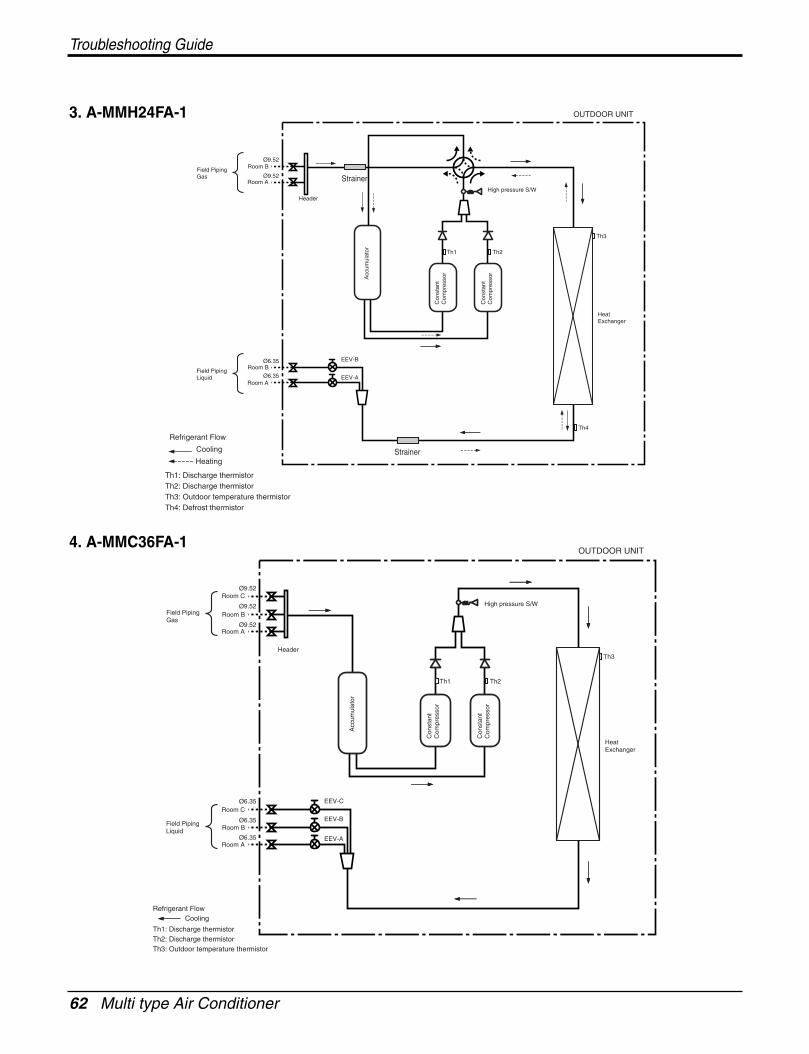
62 Multi type Air Conditioner
Troubleshooting Guide
Refrigerant Flow
Cooling
Heating
Th1: Discharge thermistorTh2: Discharge thermistorTh3: Outdoor temperature thermistorTh4: Defrost thermistor
Field PipingGas
Field PipingLiquid
Room A
EEV-B
EEV-A
HeatExchanger
Header
OUTDOOR UNIT
Room BØ9.52
Room A
Room BØ6.35
Ø6.35
Ø9.52
Th2
High pressure S/W
Th3
Th4
Th1
Con
stan
tC
ompr
esso
r
Con
stan
tC
ompr
esso
r
Acc
umul
ator
Strainer
Strainer
3. A-MMH24FA-1
Field PipingGas
Field PipingLiquid
Refrigerant Flow
Th1: Discharge thermistorTh2: Discharge thermistorTh3: Outdoor temperature thermistor
Room A
Cooling
EEV-B
EEV-A
HeatExchanger
Header
OUTDOOR UNIT
Room BØ9.52
Room A
Room BØ6.35
Ø6.35
Ø6.35
Ø9.52
Room CØ9.52
Th2
High pressure S/W
Th3
Th1
EEV-CRoom C
Con
stan
tC
ompr
esso
r
Con
stan
tC
ompr
esso
r
Acc
umul
ator
4. A-MMC36FA-1
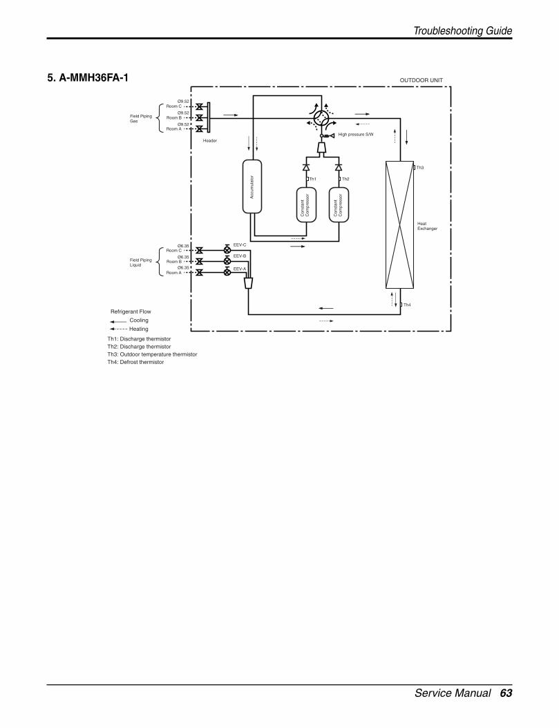
Service Manual 63
Troubleshooting Guide
Refrigerant Flow
Cooling
Heating
Th1: Discharge thermistorTh2: Discharge thermistorTh3: Outdoor temperature thermistorTh4: Defrost thermistor
Field PipingGas
Field PipingLiquid
Room A
EEV-B
EEV-A
HeatExchanger
Header
OUTDOOR UNIT
Room BØ9.52
Room A
Room BØ6.35
Ø6.35
Ø9.52
Room CØ9.52
Th2
High pressure S/W
Th3
Th4
Th1
EEV-CRoom C
Ø6.35
Con
stan
tC
ompr
esso
r
Con
stan
tC
ompr
esso
r
Acc
umul
ator
5. A-MMH36FA-1
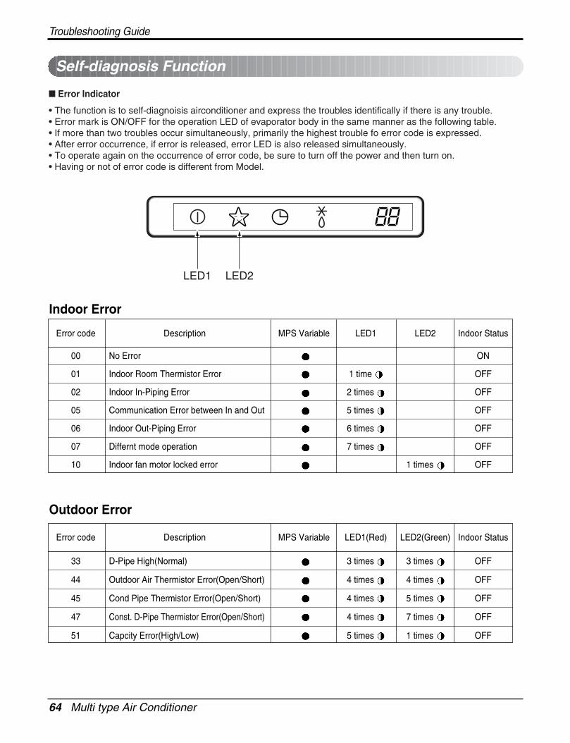
64 Multi type Air Conditioner
Troubleshooting Guide
Error Indicator
• The function is to self-diagnoisis airconditioner and express the troubles identifically if there is any trouble.• Error mark is ON/OFF for the operation LED of evaporator body in the same manner as the following table.• If more than two troubles occur simultaneously, primarily the highest trouble fo error code is expressed.• After error occurrence, if error is released, error LED is also released simultaneously.• To operate again on the occurrence of error code, be sure to turn off the power and then turn on.• Having or not of error code is different from Model.
Self-diagnosis Function
00 No Error ON
01 Indoor Room Thermistor Error 1 time OFF
02 Indoor In-Piping Error 2 times OFF
05 Communication Error between In and Out 5 times OFF
06 Indoor Out-Piping Error 6 times OFF
07 Differnt mode operation 7 times OFF
10 Indoor fan motor locked error 1 times OFF
Error code Description MPS Variable LED1 LED2 Indoor Status
33 D-Pipe High(Normal) 3 times 3 times OFF
44 Outdoor Air Thermistor Error(Open/Short) 4 times 4 times OFF
45 Cond Pipe Thermistor Error(Open/Short) 4 times 5 times OFF
47 Const. D-Pipe Thermistor Error(Open/Short) 4 times 7 times OFF
51 Capcity Error(High/Low) 5 times 1 times OFF
Error code Description MPS Variable LED1(Red) LED2(Green) Indoor Status
Indoor Error
Outdoor Error
LED1 LED2

Service Manual 65
Troubleshooting Guide
Trouble analysis1. Check temperature difference between intake and discharge air, and operating current.
All amount of refrigerant leaked out. Check refrigeration cycle.
Refrigerant leakageClog of refrigeration cycleDefective compressor
Excessive amount of refrigerant
Normal
Notice:Temperature difference between intake and discharge air depends on room air humidity. When the room airhumidity is relatively higher, temperature difference is smaller. When the room air humidity is relatively lowertemperature difference is larger.
2. Check temperature and pressure of refrigeration cycle.
Notice:1. The suction pressure is usually 4.5~6.0 kg/cm2G at normal condition.2. The temperature can be measured by attaching the thermometer to the low pressure tubing and wrap it with
putty.
Temp. difference : approx. 0°C(0°F)Current : less than 80% of
rated current
Temp. difference : approx. 8°C(14.4°F)Current : less than 80% of
rated current
Temp. difference : less than 8°C(14.4°F)Current : near the rated cur-
rent
Temp. difference : over 8°C(14.4°F)
Temp. Difference
Operating Current
Suction pressure Temperature(Compared with (Compared with Cause of Trouble Description
the normal value) the normal value)
High Defective compressor Current is low.
Normal Excessive amount of High pressure does not quickly refrigerant rise at the beginning of operation.
Insufficient amount of Current is low.Lower Higher refrigerant(Leakage)
Clogging
Higher
Cycle Troubleshooting Guide
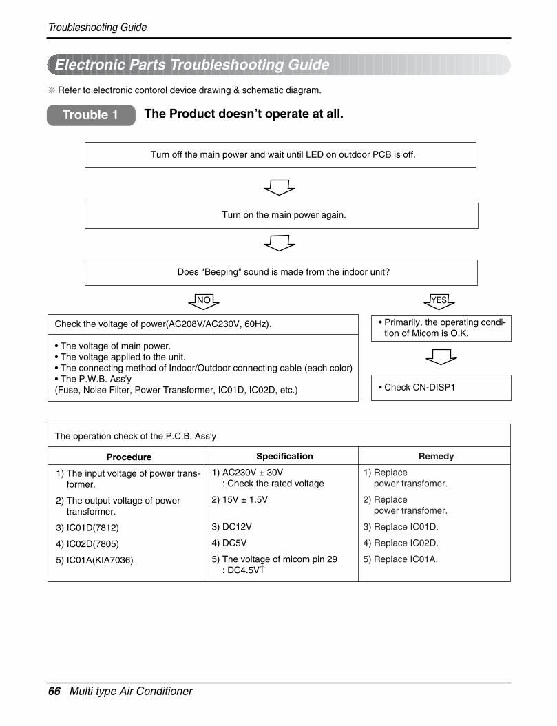
66 Multi type Air Conditioner
Troubleshooting Guide
Electronic Parts Troubleshooting Guide
Refer to electronic contorol device drawing & schematic diagram.
The Product doesn’t operate at all.
Turn off the main power and wait until LED on outdoor PCB is off.
Turn on the main power again.
Does "Beeping" sound is made from the indoor unit?
• Primarily, the operating condi-tion of Micom is O.K.
• Check CN-DISP1
Check the voltage of power(AC208V/AC230V, 60Hz).
• The voltage of main power.• The voltage applied to the unit.• The connecting method of Indoor/Outdoor connecting cable (each color)• The P.W.B. Ass'y(Fuse, Noise Filter, Power Transformer, IC01D, IC02D, etc.)
Trouble 1
NO YES
The operation check of the P.C.B. Ass'y
Procedure
1) The input voltage of power trans-former.
2) The output voltage of powertransformer.
3) IC01D(7812)
4) IC02D(7805)
5) IC01A(KIA7036)
Specification
1) AC230V ± 30V: Check the rated voltage
2) 15V ± 1.5V
3) DC12V
4) DC5V
5) The voltage of micom pin 29 : DC4.5V↑
Remedy
1) Replace power transfomer.
2) Replace power transfomer.
3) Replace IC01D.
4) Replace IC02D.
5) Replace IC01A.
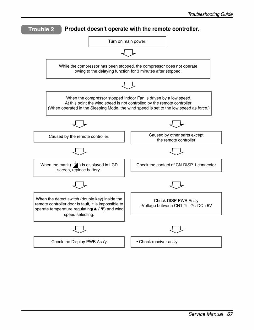
Service Manual 67
Troubleshooting Guide
Turn on main power.
While the compressor has been stopped, the compressor does not operate owing to the delaying function for 3 minutes after stopped.
When the compressor stopped Indoor Fan is driven by a low speed.At this point the wind speed is not controlled by the remote controller.
(When operated in the Sleeping Mode, the wind speed is set to the low speed as force.)
Caused by the remote controller. Caused by other parts except the remote controller
When the mark ( ) is displayed in LCDscreen, replace battery.
Check the contact of CN-DISP 1 connector
When the detect switch (double key) inside theremote controller door is fault, it is impossible tooperate temperature regulating( / ) and wind
speed selecting.
Check DISP PWB Ass'y -Voltage between CN1 ➀ - ➆ : DC +5V
Check the Display PWB Ass'y • Check receiver ass'y
Product doesn't operate with the remote controller.Trouble 2
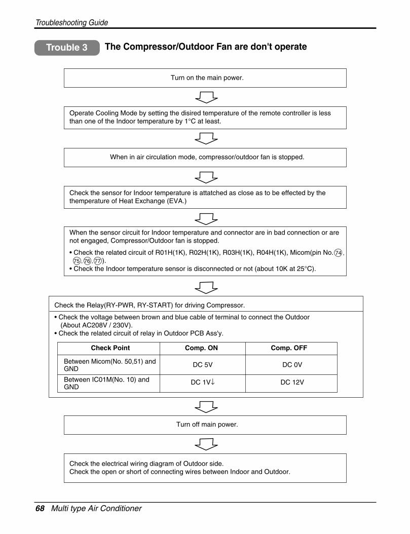
68 Multi type Air Conditioner
Troubleshooting Guide
Turn on the main power.
When in air circulation mode, compressor/outdoor fan is stopped.
Turn off main power.
Check the electrical wiring diagram of Outdoor side.Check the open or short of connecting wires between Indoor and Outdoor.
Check the sensor for Indoor temperature is attatched as close as to be effected by thethemperature of Heat Exchange (EVA.)
When the sensor circuit for Indoor temperature and connector are in bad connection or arenot engaged, Compressor/Outdoor fan is stopped.
• Check the related circuit of R01H(1K), R02H(1K), R03H(1K), R04H(1K), Micom(pin No. 74 ,
75 , 76 , 77 ).• Check the Indoor temperature sensor is disconnected or not (about 10K at 25°C).
Check the Relay(RY-PWR, RY-START) for driving Compressor.
• Check the voltage between brown and blue cable of terminal to connect the Outdoor(About AC208V / 230V).
• Check the related circuit of relay in Outdoor PCB Ass'y.
Operate Cooling Mode by setting the disired temperature of the remote controller is lessthan one of the Indoor temperature by 1°C at least.
The Compressor/Outdoor Fan are don't operateTrouble 3
Check Point
Between Micom(No. 50,51) andGND
DC 5V DC 0V
DC 12VDC 1V↓Between IC01M(No. 10) andGND
Comp. ON Comp. OFF
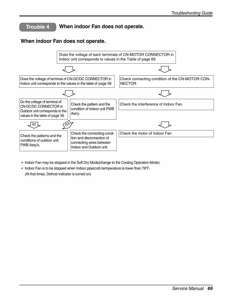
Service Manual 69
Troubleshooting Guide
When indoor Fan does not operate.
Check connecting condition of the CN-MOTOR CON-NECTOR
Does the voltage of terminal of CN-DC/DC CONNECTOR inIndoor unit corresponds to the values in the table of page 56
Do the voltage of terminal ofCN-DC/DC CONNECTOR inOutdoor unit corresponds to thevalues in the table of page 56
Check the patterns and theconditions of outdoor unitPWB Assy's.
Check the connecting condi-tion and disconnection ofconnecting wires betweenIndoor and Outdoor unit.
Check the pattern and thecondition of Indoor unit PWBAss'y.
Check the interference of Indoor Fan.
Does the voltage of each terminals of CN-MOTOR CONNECTOR inIndoor unit corresponds to values in the Table of page 69
Check the motor of Indoor Fan
Indoor Fan may be stopped in the Soft Dry Mode(change to the Cooling Operation Mode).
Indoor Fan is to be stopped when Indoor pipe(coil) termperature is lower than 79°F.
(At that times, Defrost indicator is turned on)
NO YES
When indoor Fan does not operate.Trouble 4
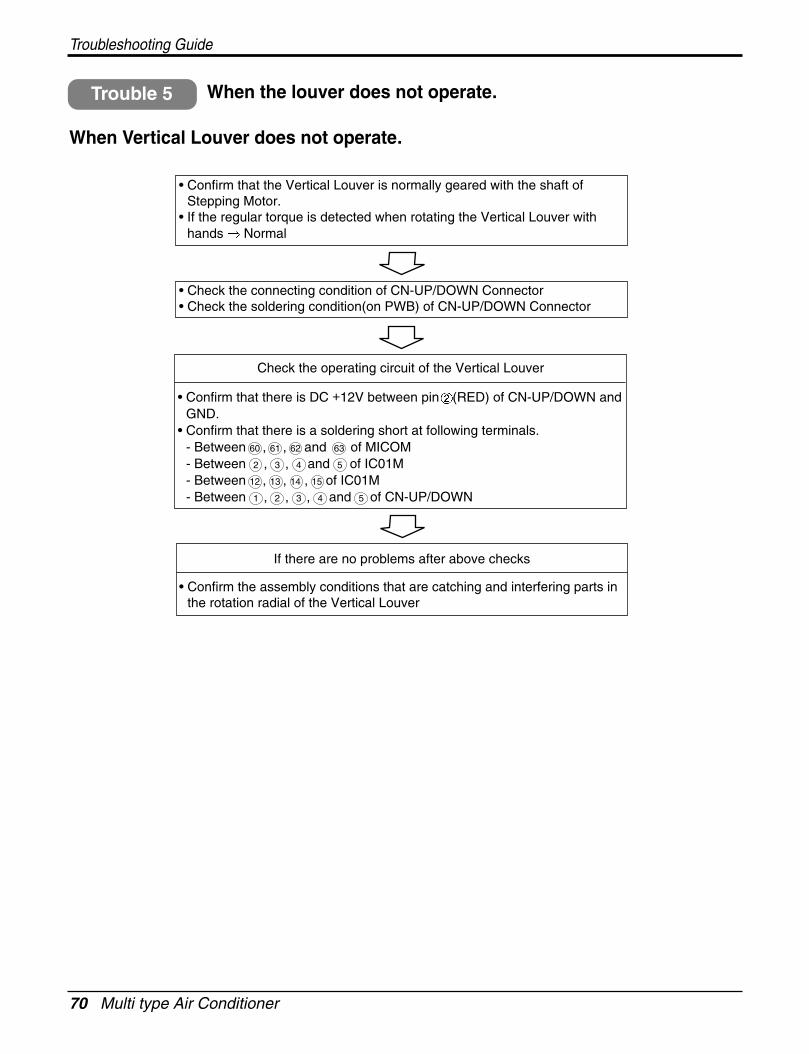
70 Multi type Air Conditioner
Troubleshooting Guide
When the louver does not operate.Trouble 5
When Vertical Louver does not operate.
• Confirm that the Vertical Louver is normally geared with the shaft ofStepping Motor.
• If the regular torque is detected when rotating the Vertical Louver withhands Normal
• Check the connecting condition of CN-UP/DOWN Connector• Check the soldering condition(on PWB) of CN-UP/DOWN Connector
Check the operating circuit of the Vertical Louver
• Confirm that there is DC +12V between pin (RED) of CN-UP/DOWN andGND.
• Confirm that there is a soldering short at following terminals.- Between 60 , 61 , 62 and 63 of MICOM- Between 2 , 3 , 4 and 5 of IC01M- Between 12 , 13 , 14 , 15 of IC01M- Between 1 , 2 , 3 , 4 and 5 of CN-UP/DOWN
If there are no problems after above checks
• Confirm the assembly conditions that are catching and interfering parts inthe rotation radial of the Vertical Louver
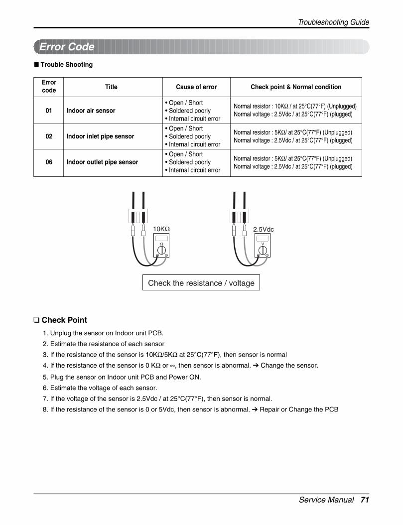
Service Manual 71
Troubleshooting Guide
Error Code
Trouble Shooting
ErrorTitle Cause of error Check point & Normal conditioncode
01 Indoor air sensor
02 Indoor inlet pipe sensor
06 Indoor outlet pipe sensor
• Open / Short• Soldered poorly• Internal circuit error
• Open / Short• Soldered poorly• Internal circuit error
• Open / Short• Soldered poorly• Internal circuit error
Normal resistor : 10KΩ / at 25°C(77°F) (Unplugged)Normal voltage : 2.5Vdc / at 25°C(77°F) (plugged)
Normal resistor : 5KΩ/ at 25°C(77°F) (Unplugged)Normal voltage : 2.5Vdc / at 25°C(77°F) (plugged)
Normal resistor : 5KΩ/ at 25°C(77°F) (Unplugged)Normal voltage : 2.5Vdc / at 25°C(77°F) (plugged)
Ω
10KΩ 2.5Vdc
Check the resistance / voltage
V
Check Point
1. Unplug the sensor on Indoor unit PCB.
2. Estimate the resistance of each sensor
3. If the resistance of the sensor is 10KΩ/5KΩ at 25°C(77°F), then sensor is normal
4. If the resistance of the sensor is 0 KΩ or ∞, then sensor is abnormal. Change the sensor.
5. Plug the sensor on Indoor unit PCB and Power ON.
6. Estimate the voltage of each sensor.
7. If the voltage of the sensor is 2.5Vdc / at 25°C(77°F), then sensor is normal.
8. If the resistance of the sensor is 0 or 5Vdc, then sensor is abnormal. Repair or Change the PCB
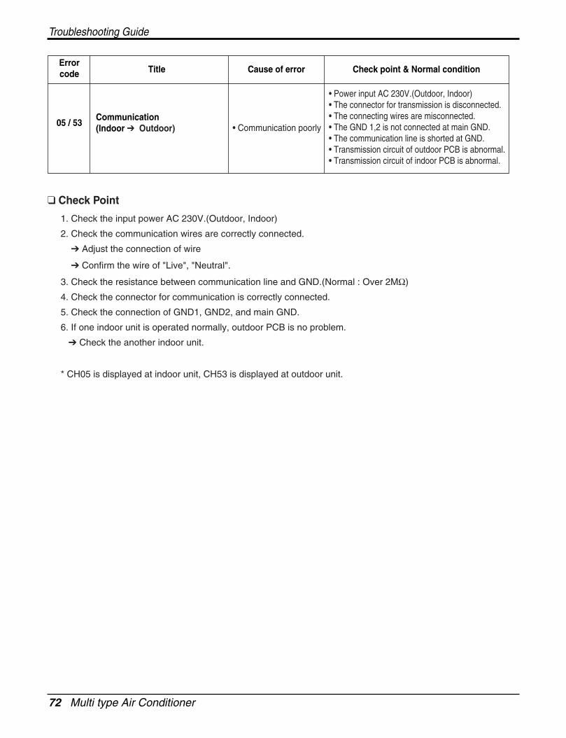
72 Multi type Air Conditioner
Troubleshooting Guide
ErrorTitle Cause of error Check point & Normal conditioncode
05 / 53Communication (Indoor Outdoor) • Communication poorly
• Power input AC 230V.(Outdoor, Indoor)• The connector for transmission is disconnected.• The connecting wires are misconnected.• The GND 1,2 is not connected at main GND.• The communication line is shorted at GND.• Transmission circuit of outdoor PCB is abnormal.• Transmission circuit of indoor PCB is abnormal.
Check Point
1. Check the input power AC 230V.(Outdoor, Indoor)
2. Check the communication wires are correctly connected.
Adjust the connection of wire
Confirm the wire of "Live", "Neutral".
3. Check the resistance between communication line and GND.(Normal : Over 2MΩ)
4. Check the connector for communication is correctly connected.
5. Check the connection of GND1, GND2, and main GND.
6. If one indoor unit is operated normally, outdoor PCB is no problem.
Check the another indoor unit.
* CH05 is displayed at indoor unit, CH53 is displayed at outdoor unit.
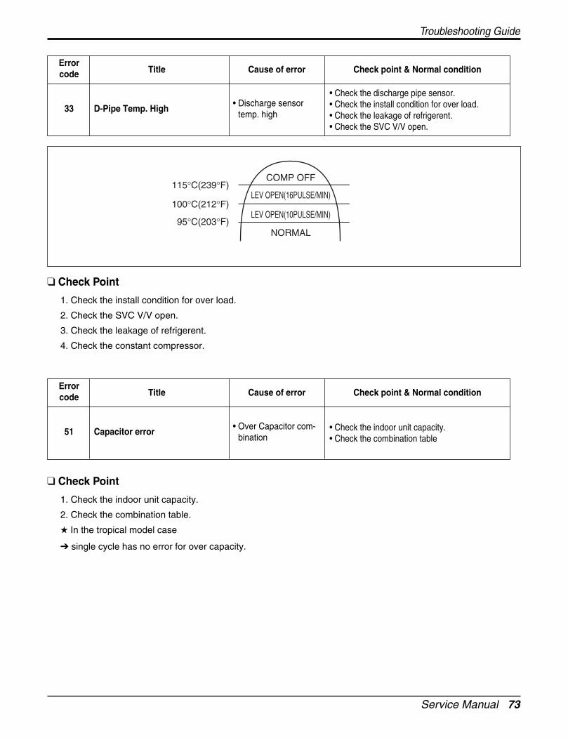
Service Manual 73
Troubleshooting Guide
ErrorTitle Cause of error Check point & Normal conditioncode
33 D-Pipe Temp. High • Discharge sensortemp. high
• Check the discharge pipe sensor.• Check the install condition for over load.• Check the leakage of refrigerent.• Check the SVC V/V open.
ErrorTitle Cause of error Check point & Normal conditioncode
51 Capacitor error • Over Capacitor com-bination
• Check the indoor unit capacity.• Check the combination table
Check Point
1. Check the indoor unit capacity.
2. Check the combination table.
In the tropical model case
single cycle has no error for over capacity.
Check Point
1. Check the install condition for over load.
2. Check the SVC V/V open.
3. Check the leakage of refrigerent.
4. Check the constant compressor.
COMP OFF
LEV OPEN(16PULSE/MIN)
LEV OPEN(10PULSE/MIN)
NORMAL
115°C(239°F)
100°C(212°F)
95°C(203°F)
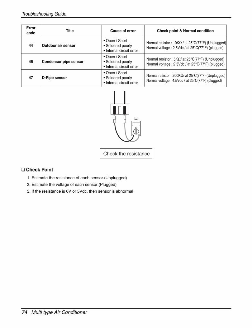
74 Multi type Air Conditioner
Troubleshooting Guide
ErrorTitle Cause of error Check point & Normal conditioncode
44 Outdoor air sensor
45 Condensor pipe sensor
47 D-Pipe sensor
• Open / Short• Soldered poorly• Internal circuit error
• Open / Short• Soldered poorly• Internal circuit error
• Open / Short• Soldered poorly• Internal circuit error
Normal resistor : 10KΩ / at 25°C(77°F) (Unplugged)Normal voltage : 2.5Vdc / at 25°C(77°F) (plugged)
Normal resistor : 5KΩ/ at 25°C(77°F) (Unplugged)Normal voltage : 2.5Vdc / at 25°C(77°F) (plugged)
Normal resistor : 200KΩ/ at 25°C(77°F) (Unplugged)Normal voltage : 4.5Vdc / at 25°C(77°F) (plugged)
Check Point
1. Estimate the resistance of each sensor.(Unplugged)
2. Estimate the voltage of each sensor.(Plugged)
3. If the resistance is 0V or 5Vdc, then sensor is abnormal
Check the resistance
Ω
Ω
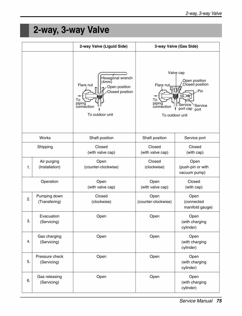
Service Manual 75
2-way, 3-way Valve
2-way, 3-way Valve
2-way Valve (Liguid Side) 3-way Valve (Gas Side)
Works Shaft position Shaft position Service port
Shipping Closed Closed Closed(with valve cap) (with valve cap) (with cap)
Air purging Open Closed Open(Installation) (counter-clockwise) (clockwise) (push-pin or with
vacuum pump)
Operation Open Open Closed(with valve cap) (with valve cap) (with cap)
Pumping down Closed Open Open(Transfering) (clockwise) (counter-clockwise) (connected
manifold gauge)
Evacuation Open Open Open(Servicing) (with charging
cylinder)
Gas charging Open Open Open(Servicing) (with charging
cylinder)
Pressure check Open Open Open(Servicing) (with charging
cylinder)
Gas releasing Open Open Open(Servicing) (with charging
cylinder)
3.
2.
1.
4.
5.
6.
Flare nut
To piping connection
Open positionClosed position
Flare nut
Valve cap
To piping connection
Open positionClosed position
Hexagonal wrench(4mm)
To outdoor unit
Pin
Service port
Service port cap
To outdoor unit
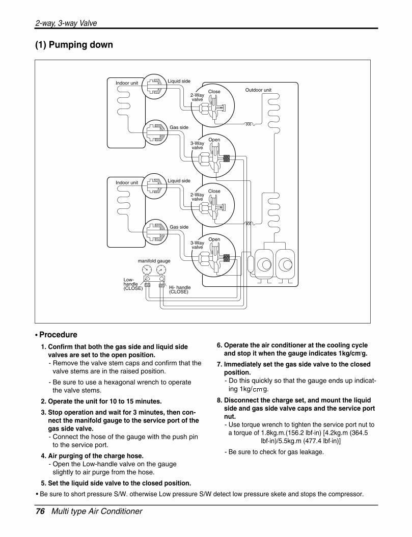
76 Multi type Air Conditioner
2-way, 3-way Valve
• Be sure to short pressure S/W. otherwise Low pressure S/W detect low pressure skete and stops the compressor.
(1) Pumping down
• Procedure1. Confirm that both the gas side and liquid side
valves are set to the open position.- Remove the valve stem caps and confirm that the
valve stems are in the raised position.
- Be sure to use a hexagonal wrench to operatethe valve stems.
2. Operate the unit for 10 to 15 minutes.
3. Stop operation and wait for 3 minutes, then con-nect the manifold gauge to the service port of thegas side valve.- Connect the hose of the gauge with the push pin
to the service port.
4. Air purging of the charge hose.- Open the Low-handle valve on the gauge
slightly to air purge from the hose.
5. Set the liquid side valve to the closed position.
6. Operate the air conditioner at the cooling cycleand stop it when the gauge indicates 1kg/cm2g.
7. Immediately set the gas side valve to the closedposition.- Do this quickly so that the gauge ends up indicat-
ing 1kg/ g.
8. Disconnect the charge set, and mount the liquidside and gas side valve caps and the service portnut.- Use torque wrench to tighten the service port nut to
a torque of 1.8kg.m.(156.2 lbf·in) [4.2kg.m (364.5lbf·in)/5.5kg.m (477.4 lbf·in)]
- Be sure to check for gas leakage.
Indoor unit
Outdoor unit
Liquid side
Close
Gas side
2-Wayvalve
Open3-Wayvalve
manifold gauge
Indoor unit Liquid side
Close
Gas side
2-Wayvalve
Open3-Wayvalve
Hi- handle(CLOSE)
Low-handle(CLOSE)
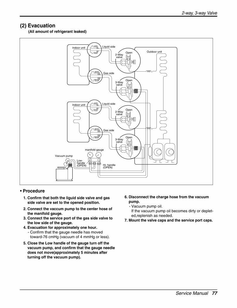
Service Manual 77
2-way, 3-way Valve
(2) Evacuation(All amount of refrigerant leaked)
• Procedure1. Confirm that both the liguid side valve and gas
side valve are set to the opened position.
2. Connect the vaccum pump to the center hose ofthe manifold gauge.
3. Connect the service port of the gas side valve tothe low side of the gauge.
4. Evacuation for approximately one hour.- Confirm that the gauge needle has moved
toward-76 cmHg (vacuum of 4 mmHg or less).
5. Close the Low handle of the gauge turn off thevacuum pump, and confirm that the gauge needledoes not move(approximately 5 minutes afterturning off the vacuum pump).
6. Disconnect the charge hose from the vacuumpump.- Vacuum pump oil.
If the vacuum pump oil becomes dirty or deplet-ed,replenish as needed.
7. Mount the valve caps and the service port caps.
Indoor unit
Outdoor unit
Liquid side
Open
Gas side
2-Wayvalve
Open3-Wayvalve
manifold gauge
Indoor unit Liquid side
Open
Gas side
2-Wayvalve
Open3-Wayvalve
Vacuum pump
Hi- handle(OPEN)
Low-handle(OPEN)
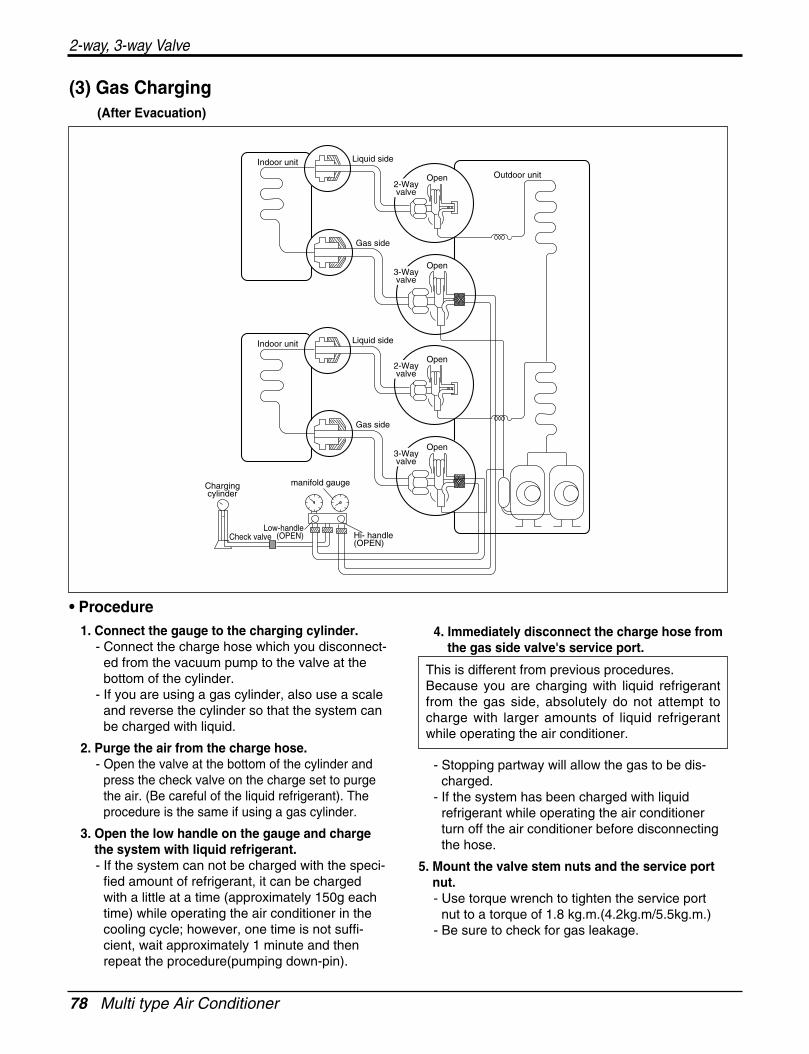
78 Multi type Air Conditioner
2-way, 3-way Valve
(3) Gas Charging(After Evacuation)
• Procedure1. Connect the gauge to the charging cylinder.
- Connect the charge hose which you disconnect-ed from the vacuum pump to the valve at thebottom of the cylinder.
- If you are using a gas cylinder, also use a scaleand reverse the cylinder so that the system canbe charged with liquid.
2. Purge the air from the charge hose.- Open the valve at the bottom of the cylinder and
press the check valve on the charge set to purgethe air. (Be careful of the liquid refrigerant). Theprocedure is the same if using a gas cylinder.
3. Open the low handle on the gauge and chargethe system with liquid refrigerant.- If the system can not be charged with the speci-
fied amount of refrigerant, it can be chargedwith a little at a time (approximately 150g eachtime) while operating the air conditioner in thecooling cycle; however, one time is not suffi-cient, wait approximately 1 minute and thenrepeat the procedure(pumping down-pin).
4. Immediately disconnect the charge hose fromthe gas side valve's service port.
- Stopping partway will allow the gas to be dis-charged.
- If the system has been charged with liquidrefrigerant while operating the air conditionerturn off the air conditioner before disconnectingthe hose.
5. Mount the valve stem nuts and the service portnut.- Use torque wrench to tighten the service port
nut to a torque of 1.8 kg.m.(4.2kg.m/5.5kg.m.)- Be sure to check for gas leakage.
manifold gaugeChargingcylinder
Hi- handle(OPEN)
Low-handle(OPEN)Check valve
Indoor unit
Outdoor unit
Liquid side
Open
Gas side
2-Wayvalve
Open3-Wayvalve
Indoor unit Liquid side
Open
Gas side
2-Wayvalve
Open3-Wayvalve
This is different from previous procedures.Because you are charging with liquid refrigerantfrom the gas side, absolutely do not attempt tocharge with larger amounts of liquid refrigerantwhile operating the air conditioner.
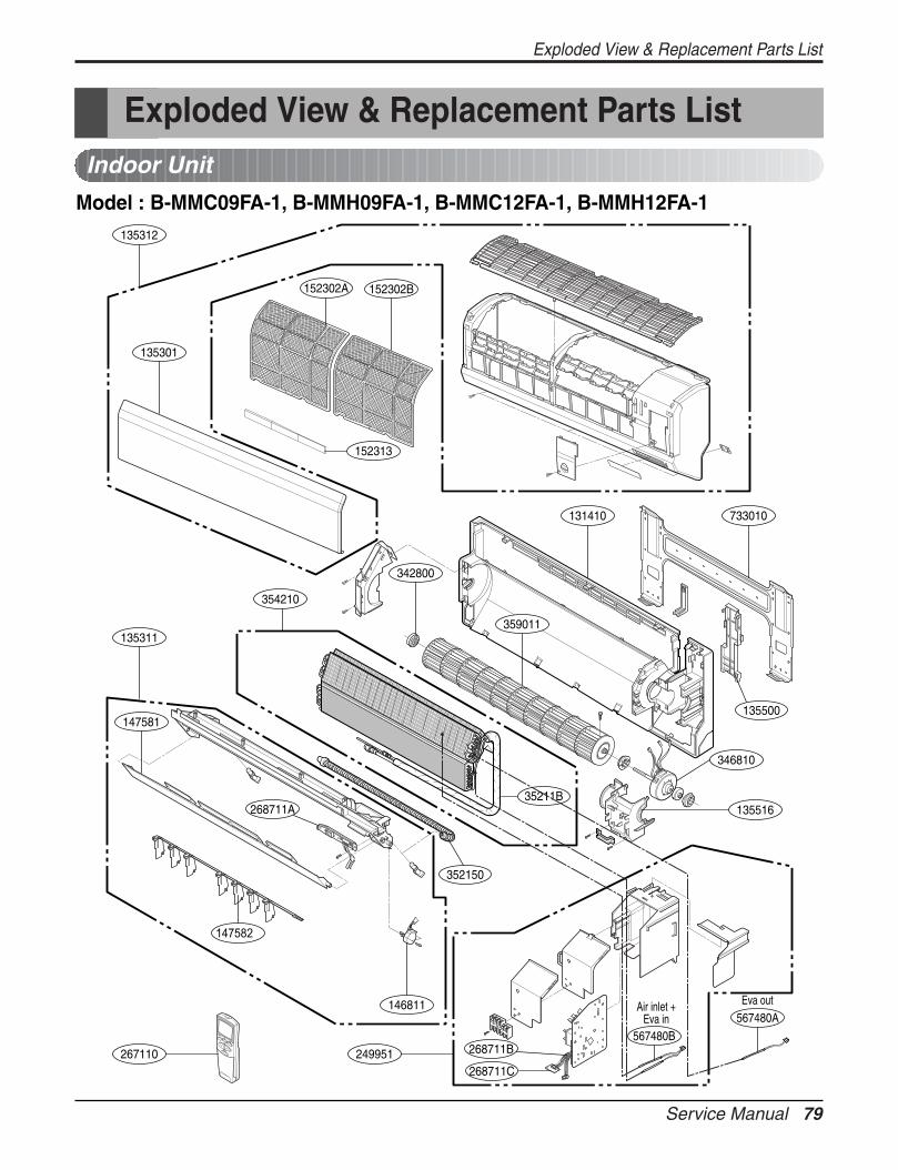
Service Manual 79
135301
152302B152302A
342800
567480B
Air inlet +Eva in
Eva out567480A
359011
131410 733010
135312
135311
147581
268711A
146811
147582
346810
13551635211B
354210
249951
352150
268711B
268711C267110
135500
152313
Exploded View & Replacement Parts List
Exploded View & Replacement Parts ListIndoor Unit
Model : B-MMC09FA-1, B-MMH09FA-1, B-MMC12FA-1, B-MMH12FA-1
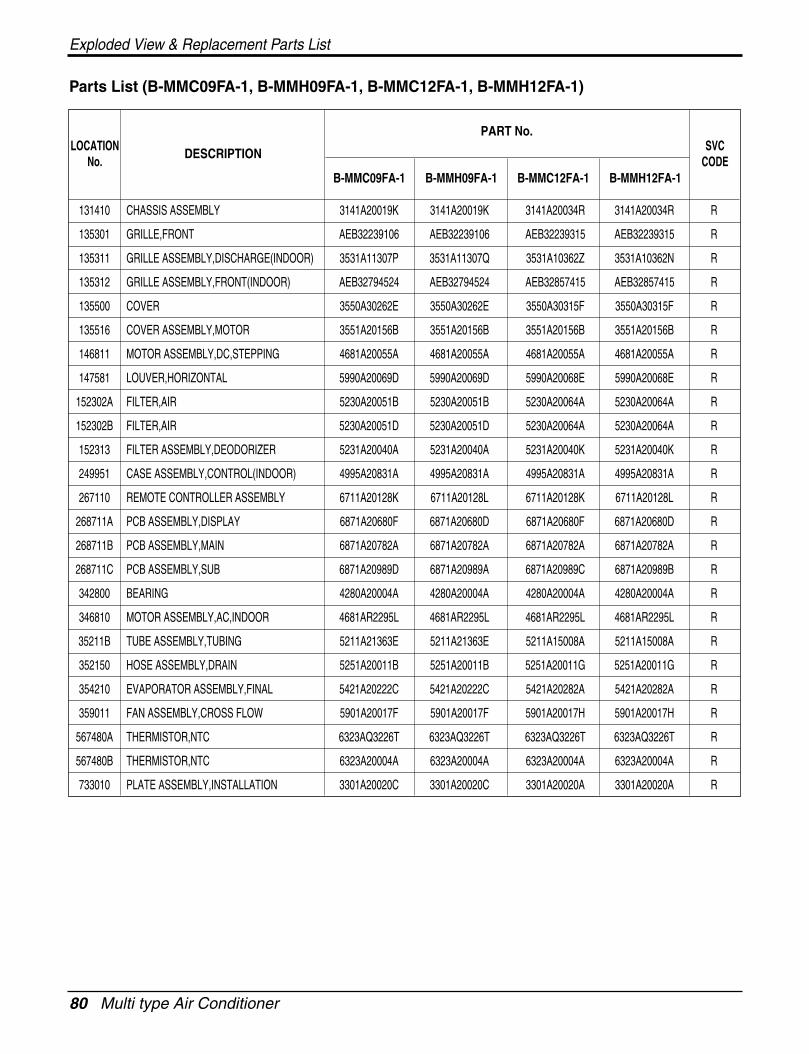
80 Multi type Air Conditioner
Exploded View & Replacement Parts List
Parts List (B-MMC09FA-1, B-MMH09FA-1, B-MMC12FA-1, B-MMH12FA-1)
PART No.
B-MMC09FA-1 B-MMH09FA-1 B-MMC12FA-1 B-MMH12FA-1
131410 CHASSIS ASSEMBLY 3141A20019K 3141A20019K 3141A20034R 3141A20034R R
135301 GRILLE,FRONT AEB32239106 AEB32239106 AEB32239315 AEB32239315 R
135311 GRILLE ASSEMBLY,DISCHARGE(INDOOR) 3531A11307P 3531A11307Q 3531A10362Z 3531A10362N R
135312 GRILLE ASSEMBLY,FRONT(INDOOR) AEB32794524 AEB32794524 AEB32857415 AEB32857415 R
135500 COVER 3550A30262E 3550A30262E 3550A30315F 3550A30315F R
135516 COVER ASSEMBLY,MOTOR 3551A20156B 3551A20156B 3551A20156B 3551A20156B R
146811 MOTOR ASSEMBLY,DC,STEPPING 4681A20055A 4681A20055A 4681A20055A 4681A20055A R
147581 LOUVER,HORIZONTAL 5990A20069D 5990A20069D 5990A20068E 5990A20068E R
152302A FILTER,AIR 5230A20051B 5230A20051B 5230A20064A 5230A20064A R
152302B FILTER,AIR 5230A20051D 5230A20051D 5230A20064A 5230A20064A R
152313 FILTER ASSEMBLY,DEODORIZER 5231A20040A 5231A20040A 5231A20040K 5231A20040K R
249951 CASE ASSEMBLY,CONTROL(INDOOR) 4995A20831A 4995A20831A 4995A20831A 4995A20831A R
267110 REMOTE CONTROLLER ASSEMBLY 6711A20128K 6711A20128L 6711A20128K 6711A20128L R
268711A PCB ASSEMBLY,DISPLAY 6871A20680F 6871A20680D 6871A20680F 6871A20680D R
268711B PCB ASSEMBLY,MAIN 6871A20782A 6871A20782A 6871A20782A 6871A20782A R
268711C PCB ASSEMBLY,SUB 6871A20989D 6871A20989A 6871A20989C 6871A20989B R
342800 BEARING 4280A20004A 4280A20004A 4280A20004A 4280A20004A R
346810 MOTOR ASSEMBLY,AC,INDOOR 4681AR2295L 4681AR2295L 4681AR2295L 4681AR2295L R
35211B TUBE ASSEMBLY,TUBING 5211A21363E 5211A21363E 5211A15008A 5211A15008A R
352150 HOSE ASSEMBLY,DRAIN 5251A20011B 5251A20011B 5251A20011G 5251A20011G R
354210 EVAPORATOR ASSEMBLY,FINAL 5421A20222C 5421A20222C 5421A20282A 5421A20282A R
359011 FAN ASSEMBLY,CROSS FLOW 5901A20017F 5901A20017F 5901A20017H 5901A20017H R
567480A THERMISTOR,NTC 6323AQ3226T 6323AQ3226T 6323AQ3226T 6323AQ3226T R
567480B THERMISTOR,NTC 6323A20004A 6323A20004A 6323A20004A 6323A20004A R
733010 PLATE ASSEMBLY,INSTALLATION 3301A20020C 3301A20020C 3301A20020A 3301A20020A R
DESCRIPTIONSVC
CODELOCATION
No.
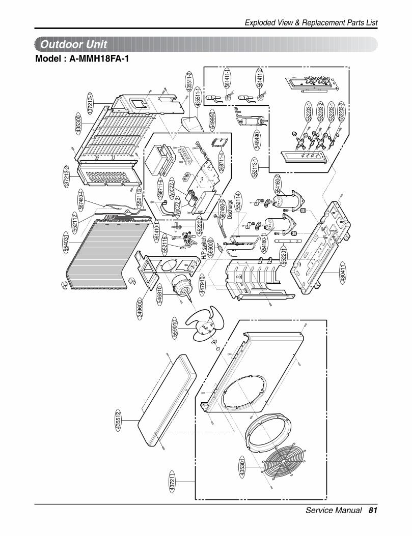
Service Manual 81
Exploded View & Replacement Parts List
4355
12
4353
01
4372
11
4304
11
5590
10
4479
10
5468
10
3496
00
5540
3113
7213
-2
1372
13-1
4353
0056
7480
-455
2112
5521
13
5484
90
4355
11-1
5522
03-1
5522
03-2
5522
03-1
5522
03-2
5541
60-1
5541
60-2
5614
11-1
5660
00H/
P sw
itch
5521
13-1
5521
14
5522
01
5614
11-2
6499
50
W0C
ZZ-2
W0C
ZZ-1
2687
11-6
5614
10-1
5674
80-5
Disc
harg
e
5521
16
4355
11-2
2687
11-4
5522
02
Model : A-MMH18FA-1Outdoor Unit
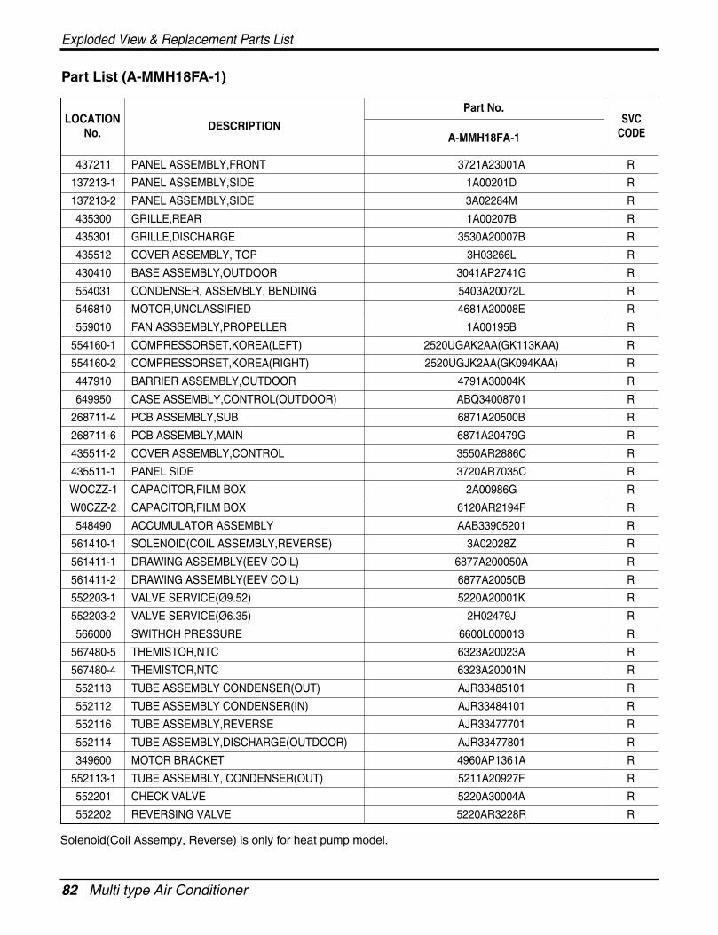
82 Multi type Air Conditioner
Exploded View & Replacement Parts List
437211 PANEL ASSEMBLY,FRONT 3721A23001A R
137213-1 PANEL ASSEMBLY,SIDE 1A00201D R
137213-2 PANEL ASSEMBLY,SIDE 3A02284M R
435300 GRILLE,REAR 1A00207B R
435301 GRILLE,DISCHARGE 3530A20007B R
435512 COVER ASSEMBLY, TOP 3H03266L R
430410 BASE ASSEMBLY,OUTDOOR 3041AP2741G R
554031 CONDENSER, ASSEMBLY, BENDING 5403A20072L R
546810 MOTOR,UNCLASSIFIED 4681A20008E R
559010 FAN ASSSEMBLY,PROPELLER 1A00195B R
554160-1 COMPRESSORSET,KOREA(LEFT) 2520UGAK2AA(GK113KAA) R
554160-2 COMPRESSORSET,KOREA(RIGHT) 2520UGJK2AA(GK094KAA) R
447910 BARRIER ASSEMBLY,OUTDOOR 4791A30004K R
649950 CASE ASSEMBLY,CONTROL(OUTDOOR) ABQ34008701 R
268711-4 PCB ASSEMBLY,SUB 6871A20500B R
268711-6 PCB ASSEMBLY,MAIN 6871A20479G R
435511-2 COVER ASSEMBLY,CONTROL 3550AR2886C R
435511-1 PANEL SIDE 3720AR7035C R
WOCZZ-1 CAPACITOR,FILM BOX 2A00986G R
W0CZZ-2 CAPACITOR,FILM BOX 6120AR2194F R
548490 ACCUMULATOR ASSEMBLY AAB33905201 R
561410-1 SOLENOID(COIL ASSEMBLY,REVERSE) 3A02028Z R
561411-1 DRAWING ASSEMBLY(EEV COIL) 6877A200050A R
561411-2 DRAWING ASSEMBLY(EEV COIL) 6877A20050B R
552203-1 VALVE SERVICE(Ø9.52) 5220A20001K R
552203-2 VALVE SERVICE(Ø6.35) 2H02479J R
566000 SWITHCH PRESSURE 6600L000013 R
567480-5 THEMISTOR,NTC 6323A20023A R
567480-4 THEMISTOR,NTC 6323A20001N R
552113 TUBE ASSEMBLY CONDENSER(OUT) AJR33485101 R
552112 TUBE ASSEMBLY CONDENSER(IN) AJR33484101 R
552116 TUBE ASSEMBLY,REVERSE AJR33477701 R
552114 TUBE ASSEMBLY,DISCHARGE(OUTDOOR) AJR33477801 R
349600 MOTOR BRACKET 4960AP1361A R
552113-1 TUBE ASSEMBLY, CONDENSER(OUT) 5211A20927F R
552201 CHECK VALVE 5220A30004A R
552202 REVERSING VALVE 5220AR3228R R
A-MMH18FA-1
LOCATIONNo.
DESCRIPTION
Part No.SVC
CODE
Part List (A-MMH18FA-1)
Solenoid(Coil Assempy, Reverse) is only for heat pump model.
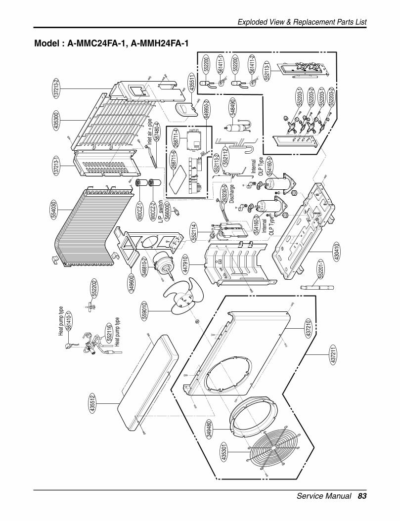
Service Manual 83
Exploded View & Replacement Parts List
5484
90
5522
02
5614
10-1
Heat
pum
p typ
e
Heat
pum
p typ
e
6499
50-2
2687
11-6
2687
11-4
4355
11
5522
03-1
5522
03-2
5522
03-1
5522
03-2
5541
60-3
5541
60-5
Inte
rnal
OLP
Type
Inte
rnal
OLP
Type
5614
11-1
5522
00
5522
00
5674
80-4
Inlet
air
+ pip
e
2632
30-5
Disc
harg
e
W0C
CZ-1
3496
00
W0C
CZ-2
5540
30
4355
12
5590
10
4353
01
3494
80
5468
10-2
4479
10
4372
10
4304
1043
7211
5522
01-1
1372
13-2
1372
13-1
4353
00
5660
00L/
P s
witc
h
5521
13-1
5521
14
5521
16
5521
13-2
5521
12
5614
11-2
Model : A-MMC24FA-1, A-MMH24FA-1
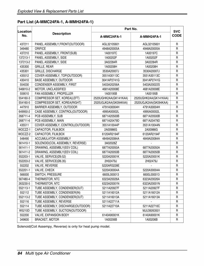
84 Multi type Air Conditioner
Exploded View & Replacement Parts List
437211 PANEL ASSEMBLY,FRONT(OUTDOOR) AGL32105601 AGL32105601 R349480 ORIFICE 4948A20005A 4948A20005A R437210 PANEL ASSEMBLY, FRONT(SUB) 1A00197C 1A00197C R
137213-1 PANEL ASSEMBLY, SIDE 1A00202F 1A00202F R137213-2 PANEL ASSEMBLY, SIDE 3A02284R 3A02284R R435300 GRILLE, REAR 1A00208H 1A00208H R435301 GRILLE, DISCHARGE 3530A20007J 3530A20007J R435512 COVER ASSEMBLY, TOP(OUTDOOR) 3551A30113C 3551A30113C R430410 BASE ASSEMBLY, OUTDOOR 3041AP2741G 3041AP2741G R554030 CONDENSER ASSEMBLY, FIRST 5403A20256A 5403A20022S R
546810-2 MOTOR, UNCLASSIFIED 4681A20008E 4681A20008E R559010 FAN ASSEMBLY, PROPELLER 1A00195B 1A00195B R
554160-3 COMPRESSOR SET, KOREA(LEFT) 2520UGHK2AA(GK141KAA) 2520UGHK2AA(GK141KAA) R554160-5 COMPRESSOR SET, KOREA(RIGHT) 2520UGJK2AA(GK094KAA) 2520UGJK2AA(GK094KAA) R447910 BARRIER ASSEMBLY, OUTDOOR 4791A30004H 4791A30004H R
649950-2 CASE ASSEMBLY, CONTROL(OUTDOOR) 4995A00002L 4995A00002L R268711-4 PCB ASSEMBLY, SUB 6871A20500B 6871A20500B R268711-6 PCB ASSEMBLY, MAIN 6871A20479D 6871A20479D R435511 COVER ASSEMBLY, CONTROL(OUTDOOR) 3551A10044P 3551A10044N R
WOCZZ-1 CAPACITOR, FILM,BOX 2A00986G 2A00986G RWOCZZ-2 CAPACITOR, FILM,BOX 6120AR2194F 6120AR2194F R
548490 ACCUMULATOR ASSEMBLY 4849A20084A 4849A20084A R561410-1 SOLENOID(COIL ASSEMBLY, REVERSE) 3A02028Z - R561411-1 DRAWING, ASSEMBLY(EEV COIL) 6877A20050A 6877A20050A R561411-2 DRAWING, ASSEMBLY(EEV COIL) 6877A20050B 6877A20050B R552203-1 VALVE, SERVICE(Ø9.52) 5220A20001K 5220A20001K R552203-2 VALVE, SERVICE(Ø6.35) 2H02479J 2H02479J R552202 VALVE, REVERSE 5220AR3228E - R
552201-1 VALVE, CHECK 5220A30004A 5220A30004A R566000 SWITCH, PRESSURE 6600L000013 6600L000013 R
567480-4 THERMISTOR, NTC 6323A20026A 6323A20026A R263230-5 THERMISTOR, NTC 6323A20001N 6323A20001N R552113-1 TUBE ASSEMBLY, CONDENSER(OUT) 5211A20927F 5211A20927F R552112 TUBE ASSEMBLY, CONDENSER(IN) 5211A16012A 5211A16012A R
552113-2 TUBE ASSEMBLY, CONDENSER(OUT) 5211A16013A 5211A16013A R552116 TUBE ASSEMBLY, REVERSE 5211A22711A - R552114 TUBE ASSEMBLY, DISCHARGE(OUTDOOR) 5211A22710A 5211A22710C RW5210D TUBE ASSEMBLY, SUCTION(OUTDOOR) - MJU39263501 R552200 VALVE, EXPANSION BODY 6140A90001K 6140A90001K R349600 BRACKET, MOTOR 1A00206B 1A00206B R
LocationNo. Description
Part No.
A-MMC24FA-1 A-MMH24FA-1
SVCCODE
Part List (A-MMC24FA-1, A-MMH24FA-1)
Solenoid(Coil Assempy, Reverse) is only for heat pump model.
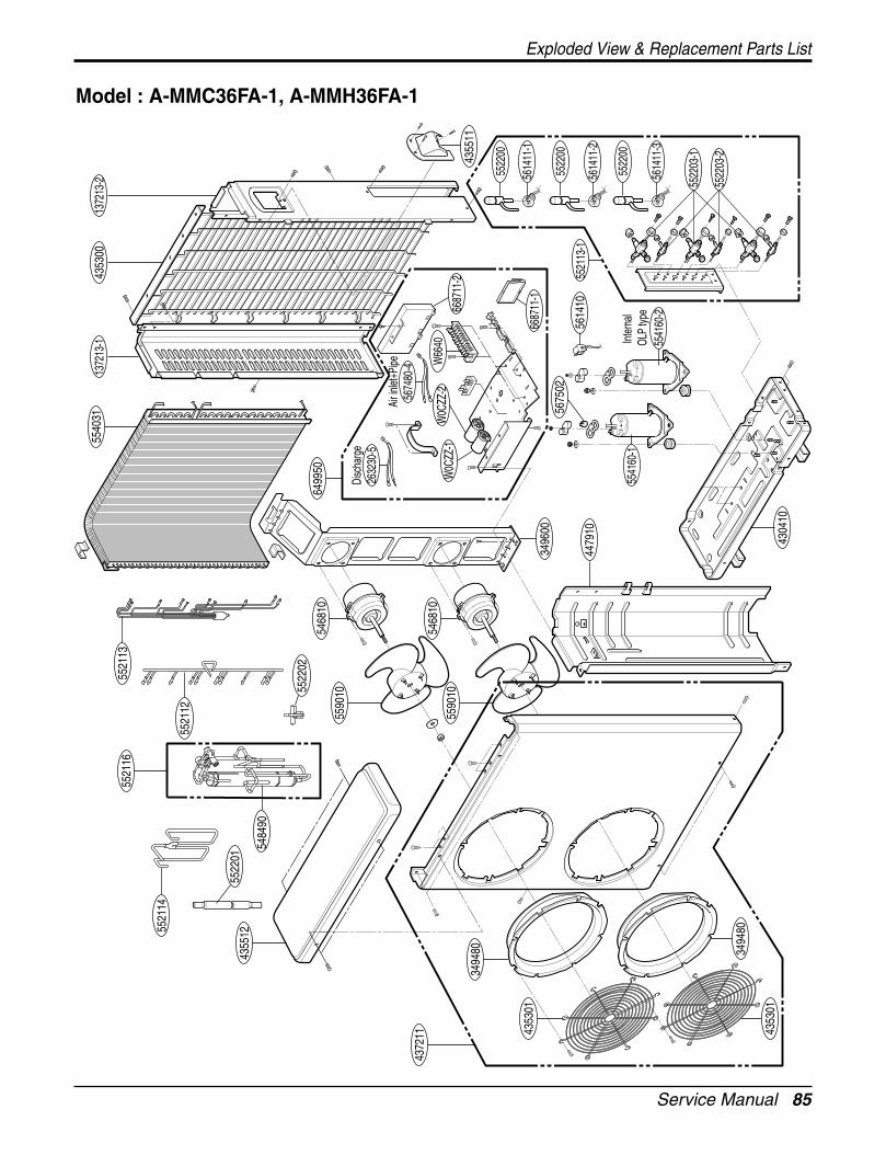
Service Manual 85
Exploded View & Replacement Parts List
5468
10
5468
10
3496
00
5521
13-1
5590
10
5590
10
5521
16
5522
03-1
5522
03-2
5541
60-2
Inte
rnal
OLP
type
5541
60-1
5675
02
5540
31
4479
10
4304
10
4355
12
4353
01
3494
80
4353
01
3494
80
4372
11
1372
13-2
1372
13-1
4353
00
5484
90
5521
12
5521
13
5521
14
5674
80-4
Air i
nlet+
Pipe W
6640
2632
30-5
Disc
harg
e
6499
50
6687
11-2
6687
11-1
W0C
ZZ-1
W0C
ZZ-2
4355
11
5614
10
5522
01
5522
02
5614
11-1
5522
00
5522
00
5522
00
5614
11-2
5614
11-3
Model : A-MMC36FA-1, A-MMH36FA-1
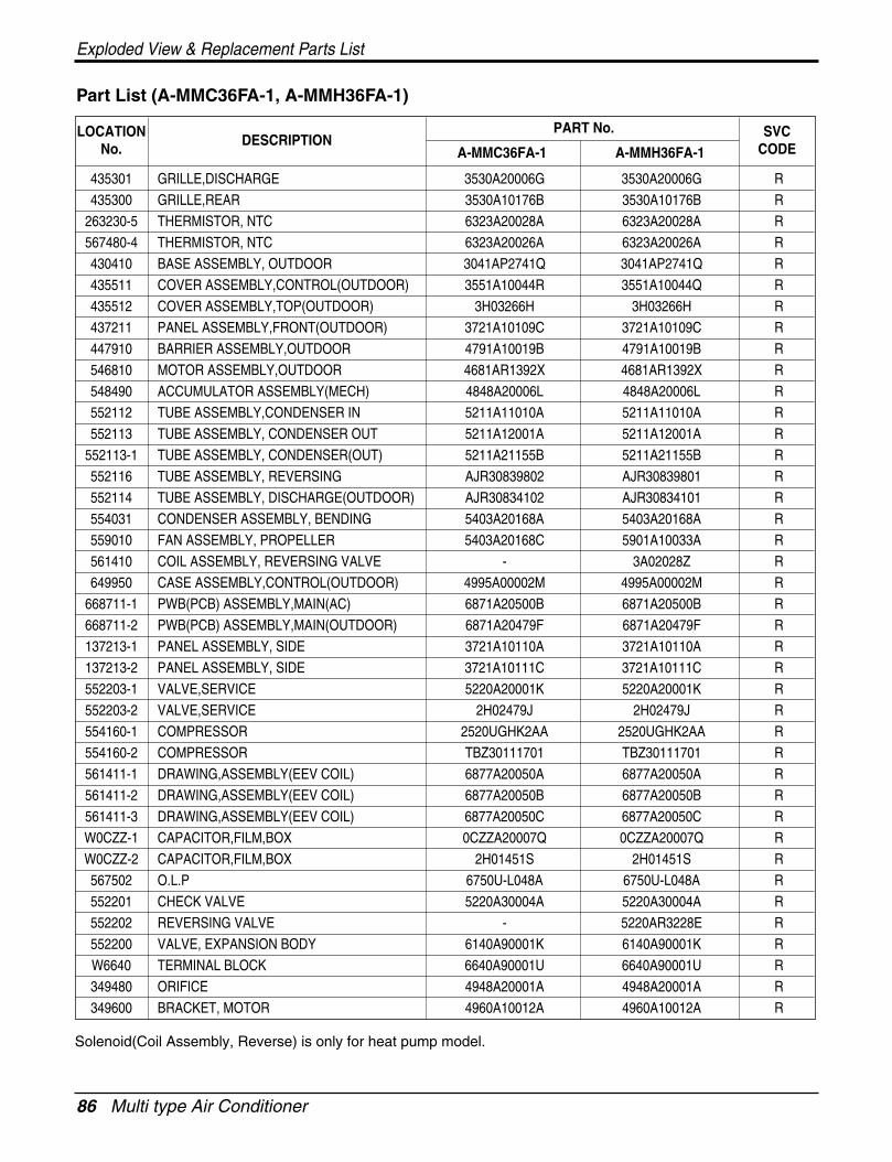
86 Multi type Air Conditioner
Exploded View & Replacement Parts List
Part List (A-MMC36FA-1, A-MMH36FA-1)
Solenoid(Coil Assembly, Reverse) is only for heat pump model.
PART No.
A-MMC36FA-1 A-MMH36FA-1
435301 GRILLE,DISCHARGE 3530A20006G 3530A20006G R
435300 GRILLE,REAR 3530A10176B 3530A10176B R
263230-5 THERMISTOR, NTC 6323A20028A 6323A20028A R
567480-4 THERMISTOR, NTC 6323A20026A 6323A20026A R
430410 BASE ASSEMBLY, OUTDOOR 3041AP2741Q 3041AP2741Q R
435511 COVER ASSEMBLY,CONTROL(OUTDOOR) 3551A10044R 3551A10044Q R
435512 COVER ASSEMBLY,TOP(OUTDOOR) 3H03266H 3H03266H R
437211 PANEL ASSEMBLY,FRONT(OUTDOOR) 3721A10109C 3721A10109C R
447910 BARRIER ASSEMBLY,OUTDOOR 4791A10019B 4791A10019B R
546810 MOTOR ASSEMBLY,OUTDOOR 4681AR1392X 4681AR1392X R
548490 ACCUMULATOR ASSEMBLY(MECH) 4848A20006L 4848A20006L R
552112 TUBE ASSEMBLY,CONDENSER IN 5211A11010A 5211A11010A R
552113 TUBE ASSEMBLY, CONDENSER OUT 5211A12001A 5211A12001A R
552113-1 TUBE ASSEMBLY, CONDENSER(OUT) 5211A21155B 5211A21155B R
552116 TUBE ASSEMBLY, REVERSING AJR30839802 AJR30839801 R
552114 TUBE ASSEMBLY, DISCHARGE(OUTDOOR) AJR30834102 AJR30834101 R
554031 CONDENSER ASSEMBLY, BENDING 5403A20168A 5403A20168A R
559010 FAN ASSEMBLY, PROPELLER 5403A20168C 5901A10033A R
561410 COIL ASSEMBLY, REVERSING VALVE - 3A02028Z R
649950 CASE ASSEMBLY,CONTROL(OUTDOOR) 4995A00002M 4995A00002M R
668711-1 PWB(PCB) ASSEMBLY,MAIN(AC) 6871A20500B 6871A20500B R
668711-2 PWB(PCB) ASSEMBLY,MAIN(OUTDOOR) 6871A20479F 6871A20479F R
137213-1 PANEL ASSEMBLY, SIDE 3721A10110A 3721A10110A R
137213-2 PANEL ASSEMBLY, SIDE 3721A10111C 3721A10111C R
552203-1 VALVE,SERVICE 5220A20001K 5220A20001K R
552203-2 VALVE,SERVICE 2H02479J 2H02479J R
554160-1 COMPRESSOR 2520UGHK2AA 2520UGHK2AA R
554160-2 COMPRESSOR TBZ30111701 TBZ30111701 R
561411-1 DRAWING,ASSEMBLY(EEV COIL) 6877A20050A 6877A20050A R
561411-2 DRAWING,ASSEMBLY(EEV COIL) 6877A20050B 6877A20050B R
561411-3 DRAWING,ASSEMBLY(EEV COIL) 6877A20050C 6877A20050C R
W0CZZ-1 CAPACITOR,FILM,BOX 0CZZA20007Q 0CZZA20007Q R
W0CZZ-2 CAPACITOR,FILM,BOX 2H01451S 2H01451S R
567502 O.L.P 6750U-L048A 6750U-L048A R
552201 CHECK VALVE 5220A30004A 5220A30004A R
552202 REVERSING VALVE - 5220AR3228E R
552200 VALVE, EXPANSION BODY 6140A90001K 6140A90001K R
W6640 TERMINAL BLOCK 6640A90001U 6640A90001U R
349480 ORIFICE 4948A20001A 4948A20001A R
349600 BRACKET, MOTOR 4960A10012A 4960A10012A R
DESCRIPTIONSVC
CODELOCATION
No.
Specifications and performance data subject to change without notice.
HEAT CONTROLLER, INC.1900 WELLWORTH AVENUE • JACKSON, MICHIGAN 49203
THE QUALITY LEADER IN CONDITIONING AIR
P/No.:3828A20390X