WALL HUNG SPLIT SYSTEM - CNW Electrical Wholesale
6
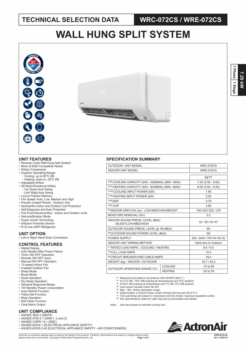
7.20 kW 1 Phase 1 Stage ActronAir is constantly seeking ways to improve the design of its products. Therefore, specifications are subject to change without notice, please check prior to purchase. Copyright © 2020 Actron Engineering Pty. Ltd. 9590-0016-04 Ver. 5 220119 Page 1 of 6 WRC-072CS / WRE-072CS TECHNICAL SELECTION DATA SPECIFICATION SUMMARY OUTDOOR UNIT MODEL WRC-072CS INDOOR UNIT MODEL WRE-072CS NETT (1)(2) COOLING CAPACITY (kW) - NOMINAL (MIN - MAX) 7.20 (2.95 - 9.00) (1) (3) HEATING CAPACITY (kW) - NOMINAL (MIN - MAX) 8.00 (3.50 - 9.50) (1) (4) COOLING INPUT POWER (kW) 1.90 (1) (4) HEATING INPUT POWER (kW) 2.05 (1)(2) EER 3.79 (1)(3) COP 3.90 (5) INDOOR AIRFLOW (l/s) - LOW/MED/HIGH/BOOST 190 / 230 / 320 / 370 MOISTURE REMOVAL (l/hr) 2.3 INDOOR SOUND PRESS. LEVEL dB(A) - SILENT/LOW/MED/HIGH 32 / 36 / 42 / 47 OUTDOOR SOUND PRESS. LEVEL @ 1M dB(A) 60 (6) OUTDOOR SOUND POWER LEVEL dB(A) 69 POWER SUPPLY 220 - 240V / 1Ph+N / 50 Hz INDOOR UNIT WIRING METHOD Hard wire to Outdoor (1) RATED LOAD AMPS - COOLING / HEATING 8.5 / 9.0 (7) FULL LOAD AMPS 14.0 (8) CIRCUIT BREAKER AND CABLE AMPS 16.0 WEIGHT (kg) - INDOOR / OUTDOOR 19.7 / 43.3 OUTDOOR OPERATING RANGE ( O C) COOLING -15 to 60 HEATING -25 to 30 (1) Measured and tested in accordance with AS/NZS 3823.1.1. (2) At 27 o C DB / 19 o C WB entering air temperatures and 35 o C ambient. (3) At 20 o C DB entering air temperature and 7 o C DB / 6 o C WB ambient. (4) input power includes indoor fan kW. (5) Max. - Min. airflow application range. (6) Determination of Sound Power Levels of Noise Sources per AS1217.2. (7) Full Load Amps are based on compressor and fan motors’ maximum expected current. (8) See Specifications sheet for cable size and circuit breaker size details. Note: Use input power to estimate running cost. WALL HUNG SPLIT SYSTEM UNIT FEATURES • Reverse Cycle Wall Hung Split System • Mono & Multi Compatible Heads • Rotary Compressor • Superior Operating Range: ◦ Cooling: up to 60 o C DB ◦ Heating: down to -25 o C DB • Adjustable Airflow • 3D Multi-Directional Airflow ◦ Up / Down Auto Swing ◦ Left / Right Auto Swing • Louvre Position Memory • Fan Speed: Auto, Low, Medium and High • Powder Coated Panels - Outdoor Unit • Hydrophilic Indoor and Outdoor Coil Protection • Self-Diagnosis and Auto Protection • Fire Proof Electrical Box - Indoor and Outdoor Units • Dehumidification Mode • Super Ionizer Technology • Intitutive Proximity Sensor • R-32 low GWP Refrigerant UNIT OPTION • Left or Right Hand Drain Connection CONTROL FEATURES • Digital Display • Auto Restart After Power Failure • Timer ON / OFF Operation • Remote ON / OFF Input • Manual ON / OFF Operation • 12-speed Indoor Fan • 5-speed Outdoor Fan • Sleep Mode • Boost Mode • Quiet Operation • Dry Mode Operation • Demand Response Ready • 1W Standby Power Consumption • Auto Defrost Function • Follow Me Function • Mute Operation • Self Clean Function • Fault Alarm Output UNIT COMPLIANCE • AS/NZS 3823.2 (MEPS) • AS/NZS 4755.3.1 (DRM 1, 2 and 3) • AS/NZS CISPR 14.1 (EMC) • AS/NZS 60335.1 (ELECTRICAL APPLIANCE SAFETY) • AS/NZS 60335.2.40 (ELECTRICAL APPLIANCE SAFETY - AIR CONDITIONERS)
-
Upload
khangminh22 -
Category
Documents
-
view
2 -
download
0
Transcript of WALL HUNG SPLIT SYSTEM - CNW Electrical Wholesale
7.20 kW1 Phase
1 Stage
ActronAir is constantly seeking ways to improve the design of its products. Therefore, specifications are subject to change without notice,please check prior to purchase. Copyright © 2020 Actron Engineering Pty. Ltd.
9590-0016-04 Ver. 5 220119 Page 1 of 6
R
WRC-072CS / WRE-072CSTECHNICAL SELECTION DATA
SPECIFICATION SUMMARYOUTDOOR UNIT MODEL WRC-072CSINDOOR UNIT MODEL WRE-072CS
NETT(1)(2) COOLING CAPACITY (kW) - NOMINAL (MIN - MAX) 7.20 (2.95 - 9.00)(1) (3) HEATING CAPACITY (kW) - NOMINAL (MIN - MAX) 8.00 (3.50 - 9.50)(1) (4) COOLING INPUT POWER (kW) 1.90(1) (4) HEATING INPUT POWER (kW) 2.05(1)(2) EER 3.79(1)(3) COP 3.90(5) INDOOR AIRFLOW (l/s) - LOW / MED / HIGH/BOOST 190 / 230 / 320 / 370MOISTURE REMOVAL (l/hr) 2.3
INDOOR SOUND PRESS. LEVEL dB(A) - SILENT/LOW / MED / HIGH 32 / 36 / 42 / 47
OUTDOOR SOUND PRESS. LEVEL @ 1M dB(A) 60(6) OUTDOOR SOUND POWER LEVEL dB(A) 69POWER SUPPLY 220 - 240V / 1Ph+N / 50 HzINDOOR UNIT WIRING METHOD Hard wire to Outdoor(1) RATED LOAD AMPS - COOLING / HEATING 8.5 / 9.0(7) FULL LOAD AMPS 14.0(8) CIRCUIT BREAKER AND CABLE AMPS 16.0WEIGHT (kg) - INDOOR / OUTDOOR 19.7 / 43.3
OUTDOOR OPERATING RANGE (OC)COOLING -15 to 60HEATING -25 to 30
(1) Measured and tested in accordance with AS/NZS 3823.1.1.(2) At 27oC DB / 19oC WB entering air temperatures and 35oC ambient.(3) At 20oC DB entering air temperature and 7oC DB / 6oC WB ambient.(4) input power includes indoor fan kW.(5) Max. - Min. airflow application range.(6) Determination of Sound Power Levels of Noise Sources per AS1217.2.(7) Full Load Amps are based on compressor and fan motors’ maximum expected current.(8) See Specifications sheet for cable size and circuit breaker size details.
Note: Use input power to estimate running cost.
WALL HUNG SPLIT SYSTEM
UNIT FEATURES• Reverse Cycle Wall Hung Split System• Mono & Multi Compatible Heads• Rotary Compressor• Superior Operating Range:
◦ Cooling: up to 60oC DB ◦ Heating: down to -25oC DB
• Adjustable Airflow• 3D Multi-Directional Airflow
◦ Up / Down Auto Swing ◦ Left / Right Auto Swing
• Louvre Position Memory• Fan Speed: Auto, Low, Medium and High• Powder Coated Panels - Outdoor Unit• Hydrophilic Indoor and Outdoor Coil Protection• Self-Diagnosis and Auto Protection• Fire Proof Electrical Box - Indoor and Outdoor Units• Dehumidification Mode• Super Ionizer Technology• Intitutive Proximity Sensor• R-32 low GWP Refrigerant
UNIT OPTION • Left or Right Hand Drain Connection
CONTROL FEATURES
• Digital Display• Auto Restart After Power Failure• Timer ON / OFF Operation• Remote ON / OFF Input• Manual ON / OFF Operation• 12-speed Indoor Fan• 5-speed Outdoor Fan• Sleep Mode • Boost Mode• Quiet Operation• Dry Mode Operation• Demand Response Ready• 1W Standby Power Consumption• Auto Defrost Function• Follow Me Function• Mute Operation• Self Clean Function• Fault Alarm Output
UNIT COMPLIANCE • AS/NZS 3823.2 (MEPS)• AS/NZS 4755.3.1 (DRM 1, 2 and 3)• AS/NZS CISPR 14.1 (EMC)• AS/NZS 60335.1 (ELECTRICAL APPLIANCE SAFETY)• AS/NZS 60335.2.40 (ELECTRICAL APPLIANCE SAFETY - AIR CONDITIONERS)

7.20
kW
1 Ph
ase
1 St
age
ActronAir is constantly seeking ways to improve the design of its products. Therefore, specifications are subject to change without notice,please check prior to purchase. Copyright © 2020 Actron Engineering Pty. Ltd.
9590-0016-04 Ver. 5 220119 Page 2 of 6
R
WRC-072CS / WRE-072CSCAPACITY SELECTION DATA
HEATING PERFORMANCE
INDOORCONDITIONS
OUTDOOR TEMPERATURE
-15oC D-16oC W
-7oC D-8oC W
-5oC D-6oC W
0oC D-1oC W
4oC D3oC W
7oC D6oC W
12oC D11oC W
24oC D18oC W
15oC - DBNett Capacity, kW 3.14 5.69 6.27 6.94 7.39 8.96 9.86 8.27Power Input, kW 1.15 1.88 1.65 2.03 2.27 2.25 2.48 2.07
18oC - DBNett Capacity, kW 2.99 5.44 5.99 6.63 7.06 8.56 9.42 7.89Power Input, kW 1.11 1.81 1.59 1.95 2.19 2.17 2.39 1.99
20oC - DBNett Capacity, kW 2.80 5.08 5.60 6.19 6.59 8.00 8.80 7.38Power Input, kW 1.05 1.71 1.50 1.85 2.07 2.05 2.26 1.89
22oC - DBNett Capacity, kW 2.72 4.93 5.43 6.01 6.40 7.76 8.54 7.16Power Input, kW 1.07 1.74 1.54 1.88 2.11 2.09 2.30 1.93
27oC - DBNett Capacity, kW 2.44 4.42 4.87 5.39 5.74 6.96 7.66 6.42Power Input, kW 1.08 1.75 1.54 1.89 2.12 2.09 2.31 1.93
COOLING PERFORMANCE
OUTDOORTEMPERATURE
(DB)
INDOOR CONDITIONS (oC - DB)
WBoC 17.0 18.0 19.0 22.0
DBoC 24.0 25.0 27.0 29.0 24.0 25.0 27.0 29.0 24.0 25.0 27.0 29.0 24.0 25.0 27.0 29.0
18oCNett Capacity, kW 7.99 7.99 7.99 8.07 8.22 8.22 8.22 8.22 8.45 8.45 8.45 8.45 9.08 9.08 9.08 9.08 Sensible Capacity, kW 5.75 6.15 6.95 7.75 5.26 5.67 6.41 7.23 4.82 5.15 5.91 6.76 3.54 4.00 4.72 5.54 Power Input, kW 1.37 1.37 1.37 1.37 1.36 1.36 1.36 1.36 1.36 1.36 1.36 1.36 1.35 1.35 1.35 1.35
25oCNett Capacity, kW 7.50 7.50 7.59 7.67 7.70 7.70 7.70 7.79 7.93 7.93 7.93 7.93 8.53 8.53 8.53 8.53 Sensible Capacity, kW 5.47 5.92 6.75 7.52 5.01 5.39 6.16 7.01 4.52 4.92 5.71 6.50 3.33 3.75 4.52 5.29 Power Input, kW 1.58 1.58 1.58 1.58 1.58 1.58 1.58 1.58 1.58 1.58 1.58 1.58 1.58 1.58 1.58 1.58
30oCNett Capacity, kW 7.13 7.13 7.18 7.27 7.36 7.36 7.36 7.44 7.59 7.59 7.59 7.59 8.16 8.16 8.16 8.16 Sensible Capacity, kW 5.34 5.70 6.54 7.27 4.85 5.22 6.03 6.85 4.40 4.78 5.54 6.37 3.18 3.59 4.32 5.14 Power Input, kW 1.72 1.72 1.72 1.72 1.73 1.73 1.73 1.73 1.73 1.73 1.73 1.73 1.73 1.73 1.73 1.73
35oCNett Capacity, kW 6.78 6.78 6.84 6.90 7.01 7.01 7.01 7.07 7.21 7.21 7.20 7.20 7.79 7.79 7.79 7.79 Sensible Capacity, kW 5.15 5.56 6.36 6.90 4.70 5.12 5.89 6.64 4.26 4.62 5.47 6.19 3.04 3.43 4.20 4.98 Power Input, kW 1.89 1.89 1.89 1.89 1.89 1.89 1.89 1.89 1.90 1.90 1.90 1.90 1.91 1.91 1.91 1.91
40oCNett Capacity, kW 6.34 6.34 6.40 6.46 6.56 6.56 6.58 6.64 6.76 6.76 6.82 6.78 7.30 7.30 7.30 7.30 Sensible Capacity, kW 5.01 5.39 6.21 6.46 4.52 4.92 5.73 6.57 4.05 4.46 5.32 6.04 2.85 3.21 4.02 6.57 Power Input, kW 2.09 2.09 2.09 2.09 2.09 2.09 2.09 2.09 2.10 2.10 2.10 2.10 2.11 2.11 2.11 2.11
46oCNett Capacity, kW 5.87 5.87 5.93 5.99 6.07 6.07 6.13 6.19 6.27 6.27 6.27 6.27 6.79 6.79 6.79 6.79 Sensible Capacity, kW 4.70 5.11 5.87 5.99 4.25 4.68 5.46 6.19 3.83 4.20 4.96 5.77 2.65 3.05 3.80 6.24 Power Input, kW 2.32 2.32 2.32 2.32 2.33 2.33 2.33 2.33 2.33 2.33 2.33 2.33 2.35 2.35 2.35 2.35
60oCNett Capacity, kW 4.45 4.51 4.56 4.62 4.62 4.62 4.68 4.73 4.79 4.79 4.85 4.90 5.22 5.22 5.22 5.22 Sensible Capacity, kW 4.07 4.46 4.56 4.62 3.65 4.02 4.68 4.73 3.16 3.55 4.36 4.90 2.04 2.45 3.18 5.06 Power Input, kW 3.10 3.10 3.10 3.10 3.11 3.11 3.11 3.11 3.11 3.11 3.11 3.11 3.13 3.13 3.13 3.13
PIPE LENGTH CORRECTION MULTIPLIER
**
* COOLING PIPE LENGTH (m)5 10 20 30
H = HeightDifference
(m)
Indoor UnitHigher Than
Outdoor Unit*
30 --- --- --- 0.84520 --- --- 0.903 0.85810 --- 0.985 0.916 0.8715 0.995 0.995 0.926 0.8800 1.000 1.000 0.930 0.884
Indoor UnitLower Than
Outdoor Unit**
-5 1.000 1.000 0.930 0.884-10 --- 1.000 0.930 0.884-20 --- --- 0.930 0.884-30 --- --- --- 0.884
HEATING PIPE LENGTH (m)5 10 20 30
H = HeightDifference
(m)
Indoor UnitHigher Than
Outdoor Unit*
30 --- --- --- 0.97020 --- --- 0.982 0.97010 --- 1.000 0.982 0.9705 1.000 1.000 0.982 0.9700 1.000 1.000 0.972 0.953
Indoor UnitLower Than
Outdoor Unit**
-5 0.992 0.992 0.974 0.962-10 --- 0.984 0.966 0.955-20 --- --- 0.959 0.947-30 --- --- --- 0.939
7.20 kW1 Phase
1 Stage
ActronAir is constantly seeking ways to improve the design of its products. Therefore, specifications are subject to change without notice,please check prior to purchase. Copyright © 2020 Actron Engineering Pty. Ltd.
9590-0016-04 Ver. 5 220119 Page 3 of 6
R
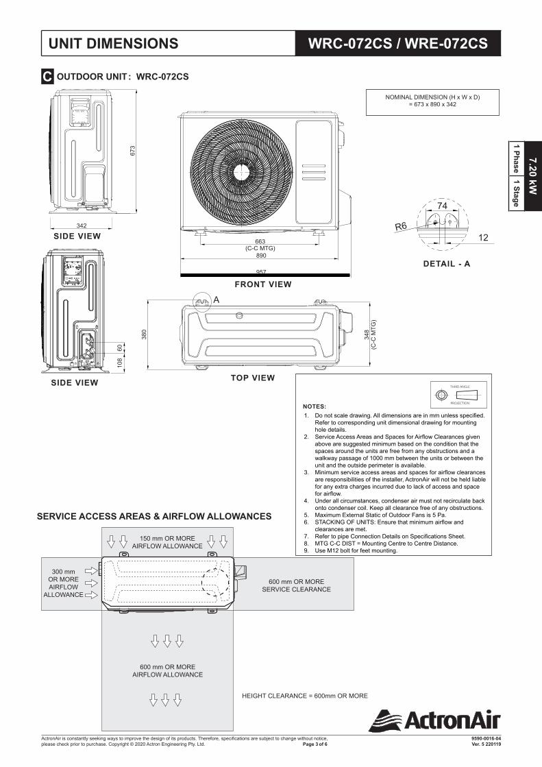
NOTES: 1. Do not scale drawing. All dimensions are in mm unless specified.
Refer to corresponding unit dimensional drawing for mounting hole details.
2. Service Access Areas and Spaces for Airflow Clearances given above are suggested minimum based on the condition that the spaces around the units are free from any obstructions and a walkway passage of 1000 mm between the units or between the unit and the outside perimeter is available.
3. Minimum service access areas and spaces for airflow clearances are responsibilities of the installer, ActronAir will not be held liable for any extra charges incurred due to lack of access and space for airflow.
4. Under all circumstances, condenser air must not recirculate back onto condenser coil. Keep all clearance free of any obstructions.
5. Maximum External Static of Outdoor Fans is 5 Pa.6. STACKING OF UNITS: Ensure that minimum airflow and
clearances are met.7. Refer to pipe Connection Details on Specifications Sheet.8. MTG C-C DIST = Mounting Centre to Centre Distance. 9. Use M12 bolt for feet mounting.
THIRD ANGLE
PROJECTION
WRC-072CS / WRE-072CSUNIT DIMENSIONS
OUTDOOR UNIT : WRC-072CS C
SERVICE ACCESS AREAS & AIRFLOW ALLOWANCES
HEIGHT CLEARANCE = 600mm OR MORE
150 mm OR MOREAIRFLOW ALLOWANCE
300 mmOR MOREAIRFLOW
ALLOWANCE
600 mm OR MORESERVICE CLEARANCE
600 mm OR MOREAIRFLOW ALLOWANCE
� Outdoor Unit Disassembly 19 �
10. Panel Plate�X430
663(C-C MTG)
890
957
60
108
380
348
(C-C
MT
G)
673
DETAIL A
12R6
74
A
AEPRO service manual - most recent.PDF30/09/2020 p75
342
NOMINAL DIMENSION (H x W x D) = 673 x 890 x 342
FRONT VIEW
SIDE VIEW
SIDE VIEW TOP VIEW
DETAIL - A
� Outdoor Unit Disassembly 19 �
10. Panel Plate�X430
663(C-C MTG)
890
957
60
108
380
348
(C-C
MT
G)
673
DETAIL A
12R6
74
A
AEPRO service manual - most recent.PDF30/09/2020 p75
342
7.20
kW
1 Ph
ase
1 St
age
ActronAir is constantly seeking ways to improve the design of its products. Therefore, specifications are subject to change without notice,please check prior to purchase. Copyright © 2020 Actron Engineering Pty. Ltd.
9590-0016-04 Ver. 5 220119 Page 4 of 6
R
UNIT DIMENSIONS WRC-072CS / WRE-072CS
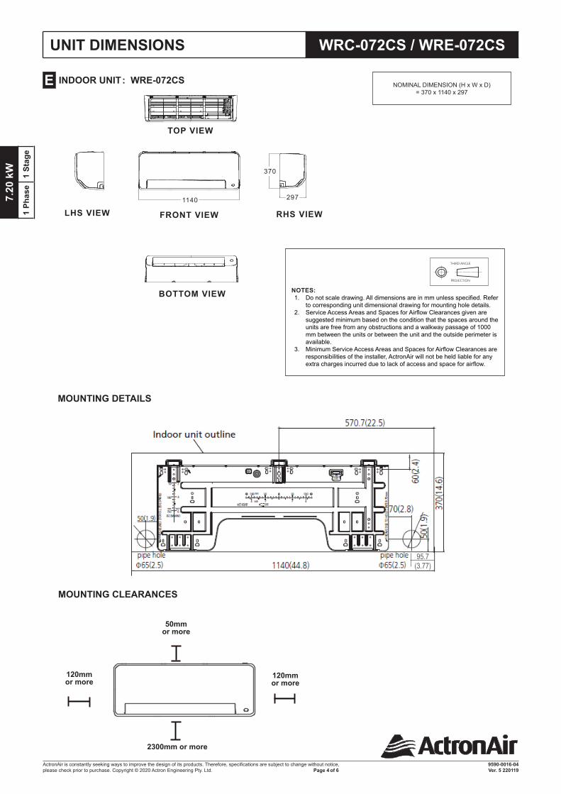
INDOOR UNIT : WRE-072CS E NOMINAL DIMENSION (H x W x D) = 370 x 1140 x 297
MOUNTING DETAILS
120mmor more
2300mm or more
120mmor more
Distance from ceiling is determinded by the installation method.
120mm or more
120mm or more
2300mm or more
50mm or more
FRONT VIEW
TOP VIEW
BOTTOM VIEW
LHS VIEW RHS VIEW
297
370
1140
NOTES: 1. Do not scale drawing. All dimensions are in mm unless specified. Refer
to corresponding unit dimensional drawing for mounting hole details.2. Service Access Areas and Spaces for Airflow Clearances given are
suggested minimum based on the condition that the spaces around the units are free from any obstructions and a walkway passage of 1000 mm between the units or between the unit and the outside perimeter is available.
3. Minimum Service Access Areas and Spaces for Airflow Clearances are responsibilities of the installer, ActronAir will not be held liable for any extra charges incurred due to lack of access and space for airflow.
THIRD ANGLE
PROJECTION
MOUNTING CLEARANCES
95.7(3.77)
7.20 kW1 Phase
1 Stage
ActronAir is constantly seeking ways to improve the design of its products. Therefore, specifications are subject to change without notice,please check prior to purchase. Copyright © 2020 Actron Engineering Pty. Ltd.
9590-0016-04 Ver. 5 220119 Page 5 of 6
R
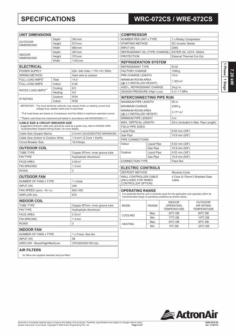
WRC-072CS / WRE-072CSSPECIFICATIONS
COMPRESSORNUMBER PER UNIT x TYPE 1 x Rotary CompressorSTARTING METHOD DC Inverter StarterINPUT (W) 2045REFRIGERANT OIL (TYPE / CHARGE) ESTER OIL VG74 / 620mlPROTECTION External Thermal Cut-Out
REFRIGERATION SYSTEMREFRIGERANT TYPE R-32FACTORY CHARGE 1500 gPRE-CHARGE LENGTH 15 mMINIMUM ROOM AREA (@ 2.3 INSTALLED HEIGHT) 1.303 m2
ADD’L. REFRIGERANT CHARGE 24 g / mDESIGN PRESSURE (High / Low) 4.3 / 1.7 MPa
INTERCONNECTING PIPE RUNMAXIMUM PIPE LENGTH 50 mMAXIMUM CHARGE 2340 gMINIMUM ROOM AREA (@ 2.3 INSTALLED HEIGHT) 3.171 m2
MINIMUM PIPE LENGHT 3 mMAX. VERTICAL LENGTH 25 m (Included in Max. Pipe Length)FIELD PIPE SIZESLiquid Pipe 9.52 mm (3/8”)Gas Pipe 15.9 mm (5/8”)PIPE CONNECTIONSIndoor Liquid Pipe 9.52 mm (3/8”)
Gas Pipe 15.9 mm (5/8”)Outdoor Liquid Pipe 9.52 mm (3/8”)
Gas Pipe 15.9 mm (5/8”)CONNECTION TYPE Flare Nut
ELECTRIC CONTROLSDEFROST METHOD Reverse CycleWALL CONTROLLER CABLE (INCLUDED FOR WIRED CONTROLLER OPTION)
4 Core (0.75mm2) Shielded Data Cable
OPERATING RANGEIt is essential that the unit is correctly sized for the application and operates within its recommended range of operating conditions as shown below.
MODE RANGEINDOOR
OPERATING TEMPERATURE
OUTDOOR AIR INTAKE
TEMPERATURE
COOLINGMax. 32oC DB 60oC DBMin. 17oC DB -15oC DB
HEATINGMax. 30oC DB 30oC DBMin. 0oC DB -25oC DB
UNIT DIMENSIONS
OUTDOOR DIMENSIONS
Depth 342 mmHeight 673 mmWidth 890 mm
INDOOR DIMENSIONS
Depth 297 mmHeight 370 mmWidth 1140 mm
ELECTRICALPOWER SUPPLY 220 - 240 Volts / 1 Ph + N / 50HzWIRING METHOD Hard wire to outdoorFULL LOAD AMPS* Total 14.0FULL LOAD AMPS Indoor 0.40
RATED LOAD AMPS** Cooling 8.5Heating 9.0
IP RATINGOutdoor IP24Indoor IP20
IMPORTANT - The local electricity authority may require limits on starting current and voltage drop, please check prior to purchase.
*Full Load Amps are based on Compressor and Fan Motor’s maximum expected current.
**Rated Load Amps are measured and tested in accordance with AS/NZS3823.1.1.
CABLE SIZE & CIRCUIT BREAKER SIZESuggested minimum cable size should be used as a guide only, refer to AS/NZS 3000 “Australian/New Zealand Wiring Rules” for more details.
Cable Size (Supply Mains) 2.5 mm2 (SUGGESTED MINIMUM)Cable Size (Indoor to Outdoor Wire) 1.5 mm2 (3 Core + Earth)Circuit Breaker Size 16.0 Amps
OUTDOOR COILTUBE TYPE Copper Ø7mm, inner groove tubeFIN TYPE Hydrophylic AluminiumFACE AREA 0.55 m2
FIN SPACING 1.3 mmROWS 2
OUTDOOR FANNUMBER OF FANS x TYPE 1 x AxialINPUT (W) 340FAN SPEED (rpm) - Hi / Lo 800 / 550AIRFLOW (l/s) 970
INDOOR COILTUBE TYPE Copper Ø7mm, inner groove tubeFIN TYPE Hydrophylic AluminiumFACE AREA 0.33 m2
FIN SPACING 1.3 mmROWS 3
INDOOR FANNUMBER OF FANS x TYPE 1 x Cross- flow fanINPUT (W) 58AIRFLOW - Boost/High/Med/Low 370/320/230/190 (l/s)
AIR FILTERS Air filters are supplied standard and pre-fitted.
7.20
kW
1 Ph
ase
1 St
age
ActronAir is constantly seeking ways to improve the design of its products. Therefore, specifications are subject to change without notice,please check prior to purchase. Copyright © 2020 Actron Engineering Pty. Ltd.
9590-0016-04 Ver. 5 220119 Page 6 of 6
R
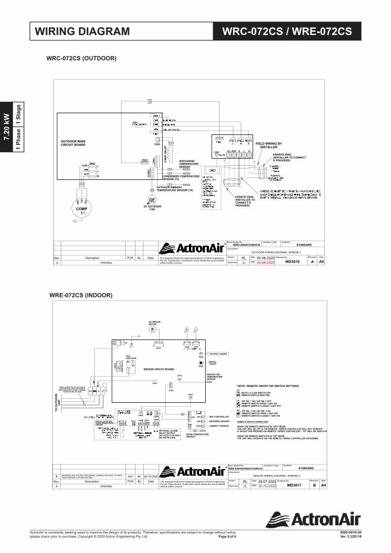
WRC-072CS / WRE-072CSWIRING DIAGRAM
WRC-072CS (OUTDOOR)
WRE-072CS (INDOOR)
R
This drawing remains the intellectual property of Actron EngineeringPty Ltd. Reproduction, modification and/or distribution are prohibitedwithout written consent.
28-07-2020RLWD3017
Rev.
B
Description
RENAMED MULTI-FUNCTION BOARD, CONNECTOR CN32 TO CN43,CN29 CHANGE TO PUSH BUTTON
Date
30-10-2020
By
RL
PCR
N/A
CN12 CN19CN22
CN26OPTIONAL IONISER
MANUALON/OFF
CN29
CN32
CN18
CN15
N_IN P2
RUNINDICATOR
CN31
P_1
FUSE 1
RY1
S1(L)
CN4
CN3
CN5
CN21
CN40CN43
CN
46
CN45CN41CN42CN1
INDOOR CIRCUIT BOARD
BLACK
RED
YELLOW
BRO
WN
DC INDOORMOTOR
ROOM TEMPERATURESENSOR
WiFi CONTROLLER
INFRARED SENSOR
HUMIDITY SENSOR
INDOOR COILTEMPERATURESENSOR
T3.15A/250V
TO O
UTD
OO
RU
NIT
ENC3
F1 F2
IF
OPTIONAL ALARMRELAY OUTPUT24V AC/DC 0.5A MAX(BY INSTALLER)
F2
F2
F2
BOTH 1 & 2 DIP SWITCH OFFREMOTE SWITCH INACTIVE
DIP SW. 1 ON / DIP SW. 2 OFFREMOTE SWITCH OPEN = UNIT ONREMOTE SWITCH CLOSED = UNIT OFF
DIP SW. 1 ON / DIP SW. 2 ONREMOTE SWITCH OPEN = UNIT OFFREMOTE SWITCH CLOSED = UNIT ON
REMOTE SWITCH OPERATION
WHEN THE REMOTE SWITCH IS IN "OFF" MODETHE UNIT WILL BE OFF & THE REMOTE / WIRED CONTROLLER WILL NOT OPERATEIF ON BUTTON PRESSED VIA REMOTE / WIRED CONTROLLER - "CP" WILL BE DISPLAYED
WHEN THE REMOTE SWITCH IS IN "ON" MODETHE UNIT WILL OPERATE VIA THE REMOTE / WIRED CONTROLLER AS NORMAL
* NOTE: REMOTE ON/OFF DIP SWITCH SETTINGS
REMOVE JUMPER WIRETO USE "REMOTE ON/OFF" FUNCTION
CABLE, (S) MUST BE 14/0.20 (0.44mm2)SHIELDED DATA CABLE WITH SHIELD
WIRE CONNECTED TO EARTH TERMINALON INDOOR AND OUTDOOR
Description:
INDOOR WIRING DIAGRAM - SERENE 2
Revision
B A4Size:Drawing No:Drawn: Date:
Approved: JL Date: 30-10-2020
Base Model No: Variation:Variation Code:
ORIGINALA
STANDARDWRE-026/035/050/072/085CS
R
This drawing remains the intellectual property of Actron EngineeringPty Ltd. Reproduction, modification and/or distribution are prohibitedwithout written consent.
05-08-2020RLWD3019
Rev. Description DateByPCR
CN414
OFDC OUTDOOR
FAN
OUTDOOR MAINCIRCUIT BOARD
COMP1
CN60
CN17
CN23
CN3 NLS2(N)1(L)
L N S
OUTDOOR AMBIENT TEMPERATURE SENSOR (T4)
CONDENSER TEMPERATURESENSOR (T3)
DISCHARGETEMPERATURESENSOR
4-W
AY V
ALV
E
FIELD WIRING BYINSTALLER
FERRITE RING(INSTALLER TOCONNECT IFPROVIDED)
FERRITE RING(INSTALLER TO CONNECTIF PROVIDED)
(U)
(W)
(V)
Description:
OUTDOOR WIRING DIAGRAM - SERENE 2
Revision
A A4Size:Drawing No:Drawn: Date:
Approved: JL Date: 24-08-2020
Base Model No: Variation:Variation Code:
ORIGINALA
STANDARDWRC-050/072/085CS