Wall architecture with high porosity is established at the tip and maintained in growing pollen...
12
Wall architecture with high porosity is established at the tip and maintained in growing pollen tubes of Nicotiana tabacum Jan Derksen 1 , Geert-Jan Janssen 2 , Mieke Wolters-Arts 1,* , Irene Lichtscheidl 3 , Wolfram Adlassnig 3 , Miroslav Ovecka 4 , Fiona Doris 5 and Martin Steer 5 1 Department of Plant Cell Research, Institute for Wetland and Water Research (IWWR), Radboud University Nijmegen, Heyendaalseweg 135, NL-6525 AJ Nijmegen, The Netherlands, 2 Department of General Instrumentation, Faculty of Sciences, Radboud University Nijmegen, Heyendaalseweg 135, NL-6525 AJ Nijmegen, The Netherlands, 3 Department of Cell Imaging and Ultrastructure Research, University of Vienna, Althanstraße 14, A-1090 Vienna, Austria, 4 Institute of Botany, Slovak Academy of Sciences, Dubravska Cesta 9, SK-84523, Bratislava, Slovakia, and 5 School of Biology and Environmental Science, University College Dublin, Dublin 4, Ireland Received 19 May 2011; revised 29 June 2011; accepted 7 July 2011; published online 13 September 2011. *For correspondence (fax + 31 243652490; e-mail [email protected]). SUMMARY A major question in pollen tube growth in planta remains: do the pollen tube walls form a barrier to interaction with the environment? Using cryo-FESEM, we directly assessed the 3D construction and porosity of tobacco pollen tube walls. Fractured mature primary walls showed a 40–50 nm spaced lattice of continuous fibers interconnected by short rods in the primary wall. These observations agree with TEM observations of sectioned walls. In the secondary callose wall, for which no structure is visible using TEM, cryo-FESEM also revealed a 50 nm lattice consisting of longer fibers, approximately 10–15 nm wide, with rod-like, thinner interconnections at angles of approximately 90° with the longer fibers. Such architecture may reflect functional needs with respect to porosity and mechanical strength. The wall does not form a mechanical barrier to interaction with the environment and is gained at low cost. Cryo-FESEM additionally revealed another special feature of the wall: the tubes were tiled with scales or rings that were highly conspicuous after pectin extraction with EDTA. These rings cause the typical banding patterns of pectin that are commonly seen in pollen tubes during oscillatory growth, as confirmed by staining with toluidine blue as well as by DIC microscopy. Growth analysis by VEC-LM showed that the ring- or scale-like structures of the primary wall consist of material deposited prior to the growth pulses. The alternating band pattern seen in the callose wall is probably imposed by constrictions resulting from the rings of the primary wall. Keywords: pollen tubes, cell wall, tip growth, cryo-electron microscopy, video microscopy. INTRODUCTION Pollen tubes, the active part of the male gametophytes of seed plants, grow through female flower parts to carry sperm cells to the egg apparatus in the ovules. Their cyto- architecture is highly polarized, and growth occurs exclu- sively at the tip by exocytosis of Golgi-derived vesicles that provide new plasma membrane and wall material (Hepler et al., 2006; Krichevsky et al., 2007; Moscatelli and Idilli, 2009). At the tip, the wall must meet the rheological requirements for tip growth: it must be strong enough to resist turgor pressure (the driving force for expansion), but with plastic properties that allow the tip to expand while maintaining its form (Derksen et al., 1995a; Derksen et al., 1995b Dumais et al., 2006; Geitmann and Steer, 2006; Chebli and Geitmann, 2007). The freshly deposited wall in the tip, the precursor of the primary wall, appears to be amorphous. Behind the tip, it is thinner and layered (Lancelle and Hepler, 1992; Derksen et al., 1995a,b) and loses material, at least in vitro (Derksen et al., 1995a,b). The freshly deposited wall is mainly composed of esterified pectin that is subsequently de-esterified and becomes more acidic (Li et al., 1994), while at the same time cellulose is deposited (Helsper et al., 1977; Ferguson et al., 1998; Geitmann and Steer, 2006). Depending ª 2011 The Authors 495 The Plant Journal ª 2011 Blackwell Publishing Ltd The Plant Journal (2011) 68, 495–506 doi: 10.1111/j.1365-313X.2011.04703.x
-
Upload
independent -
Category
Documents
-
view
4 -
download
0
Transcript of Wall architecture with high porosity is established at the tip and maintained in growing pollen...

Wall architecture with high porosity is establishedat the tip and maintained in growing pollen tubes ofNicotiana tabacum
Jan Derksen1, Geert-Jan Janssen2, Mieke Wolters-Arts1,*, Irene Lichtscheidl3, Wolfram Adlassnig3, Miroslav Ovecka4,
Fiona Doris5 and Martin Steer5
1Department of Plant Cell Research, Institute for Wetland and Water Research (IWWR), Radboud University Nijmegen,
Heyendaalseweg 135, NL-6525 AJ Nijmegen, The Netherlands,2Department of General Instrumentation, Faculty of Sciences, Radboud University Nijmegen, Heyendaalseweg 135,
NL-6525 AJ Nijmegen, The Netherlands,3Department of Cell Imaging and Ultrastructure Research, University of Vienna, Althanstraße 14, A-1090 Vienna, Austria,4Institute of Botany, Slovak Academy of Sciences, Dubravska Cesta 9, SK-84523, Bratislava, Slovakia, and5School of Biology and Environmental Science, University College Dublin, Dublin 4, Ireland
Received 19 May 2011; revised 29 June 2011; accepted 7 July 2011; published online 13 September 2011.
*For correspondence (fax + 31 243652490; e-mail [email protected]).
SUMMARY
A major question in pollen tube growth in planta remains: do the pollen tube walls form a barrier to interaction
with the environment? Using cryo-FESEM, we directly assessed the 3D construction and porosity of tobacco
pollen tube walls. Fractured mature primary walls showed a 40–50 nm spaced lattice of continuous fibers
interconnected by short rods in the primary wall. These observations agree with TEM observations of
sectioned walls. In the secondary callose wall, for which no structure is visible using TEM, cryo-FESEM also
revealed a 50 nm lattice consisting of longer fibers, approximately 10–15 nm wide, with rod-like, thinner
interconnections at angles of approximately 90� with the longer fibers. Such architecture may reflect functional
needs with respect to porosity and mechanical strength. The wall does not form a mechanical barrier to
interaction with the environment and is gained at low cost. Cryo-FESEM additionally revealed another special
feature of the wall: the tubes were tiled with scales or rings that were highly conspicuous after pectin
extraction with EDTA. These rings cause the typical banding patterns of pectin that are commonly seen in
pollen tubes during oscillatory growth, as confirmed by staining with toluidine blue as well as by DIC
microscopy. Growth analysis by VEC-LM showed that the ring- or scale-like structures of the primary wall
consist of material deposited prior to the growth pulses. The alternating band pattern seen in the callose wall is
probably imposed by constrictions resulting from the rings of the primary wall.
Keywords: pollen tubes, cell wall, tip growth, cryo-electron microscopy, video microscopy.
INTRODUCTION
Pollen tubes, the active part of the male gametophytes of
seed plants, grow through female flower parts to carry
sperm cells to the egg apparatus in the ovules. Their cyto-
architecture is highly polarized, and growth occurs exclu-
sively at the tip by exocytosis of Golgi-derived vesicles that
provide new plasma membrane and wall material (Hepler
et al., 2006; Krichevsky et al., 2007; Moscatelli and Idilli,
2009). At the tip, the wall must meet the rheological
requirements for tip growth: it must be strong enough to
resist turgor pressure (the driving force for expansion), but
with plastic properties that allow the tip to expand while
maintaining its form (Derksen et al., 1995a; Derksen et al.,
1995b Dumais et al., 2006; Geitmann and Steer, 2006; Chebli
and Geitmann, 2007). The freshly deposited wall in the tip,
the precursor of the primary wall, appears to be amorphous.
Behind the tip, it is thinner and layered (Lancelle and Hepler,
1992; Derksen et al., 1995a,b) and loses material, at least
in vitro (Derksen et al., 1995a,b). The freshly deposited wall
is mainly composed of esterified pectin that is subsequently
de-esterified and becomes more acidic (Li et al., 1994), while
at the same time cellulose is deposited (Helsper et al., 1977;
Ferguson et al., 1998; Geitmann and Steer, 2006). Depending
ª 2011 The Authors 495The Plant Journal ª 2011 Blackwell Publishing Ltd
The Plant Journal (2011) 68, 495–506 doi: 10.1111/j.1365-313X.2011.04703.x
on the growth conditions, pollen tubes may show oscillatory
growth, resulting in conspicuous banding patterns of acidic
pectin (Li et al., 1994, 1996). The secondary wall is mainly
composed of callose, with some cellulose and other glucans
and proteins (Ferguson et al., 1998; Geitmann and Steer,
2006). The amounts of protein and acid pectin are minimal,
as determined from the almost complete absence of heavy
metal binding in preparations for transmission electron
microscopy (Sassen, 1964; Steer and Steer, 1989; Lancelle
and Hepler, 1992; Derksen et al., 1995a,b).
The secondary wall is formed at varying distances (30–
100 lm) behind the tip and may become very thick in vitro as
well as in vivo (Sassen, 1964; Stone and Clarke, 1992; Derksen
et al., 1995a,b; Ferguson et al., 1998; Geitmann and Steer,
2006). Callose walls are regarded a permeability barrier
between gametophytes and their sporophytic environment
(Heslop-Harrison, 1964; Stone and Clarke, 1992; Parre and
Geitmann, 2005). However, directionally growing pollen
tubes must respond to external cues, such as proteins, from
sporophytic tissues (Cheung and Wu, 2008; Moscatelli and
Idilli, 2009). Translocation of proteins from the environment
to the pollen tube has been demonstrated for the TTS
glycoprotein from tobacco (Nicotiana tabacum) (Wu et al.,
1995), S-RNAse of petunia (Petunia hybrida) (Luu et al., 2000),
the extensin-like protein Pex-1 from maize (Zea mays)
(Rubinstein et al., 1995) and the 120 kDa glycoprotein of
Nicotiana alata (Lind et al., 1994). The PELPIII protein of
tobacco has been detected in the callose wall (De Graaf et al.,
2003), but how this precisely relates to wall porosity remains
unknown. Here we addressed the following questions:
(i) what is the architecture of the wall, and how does it
allow passage of external cues, especially proteins, for
directional growth?
(ii) is wall deposition affected by oscillatory growth and
does oscillatory growth cause the banded patterns in the
wall?
(iii) do banded patterns occur in the secondary wall and
how do they relate to those in the primary wall?
The architecture and porosity of both primary and
secondary wall were directly assessed by high-resolution
cryo-field emission scanning electron microscopy (cryo-
FESEM) of pollen tubes grown both in vitro and in vivo, and
compared with the results from transmission electron
microscopy (TEM) of sections from freeze-fixed and freeze-
substituted (FF/FS) pollen tubes (Lancelle and Hepler, 1992;
Derksen et al., 1995a). Banding patterns in the pollen tube
wall were studied using the JIM5 antibody (Li et al., 1994)
and the basic dye toluidine blue (Gurr, 1965) as probes for
partially de-methylated pectin and pectin derived carboxylic
groups, respectively, and by differential interference con-
trast (DIC) microscopy. Video-enhanced contrast light
microscopy (VEC-LM) and DIC microscopy (Lichtscheidl
and Foissner, 1996) were used to study wall deposition
and wall expansion during growth. The distribution of
callose was studied using the callose-intercalating fluores-
cent dye aniline blue (Linskens and Esser, 1957). The results
show consistent and coherent patterns in architecture that
fulfil the poromechanic demands of pollen tube walls.
RESULTS
FESEM and TEM
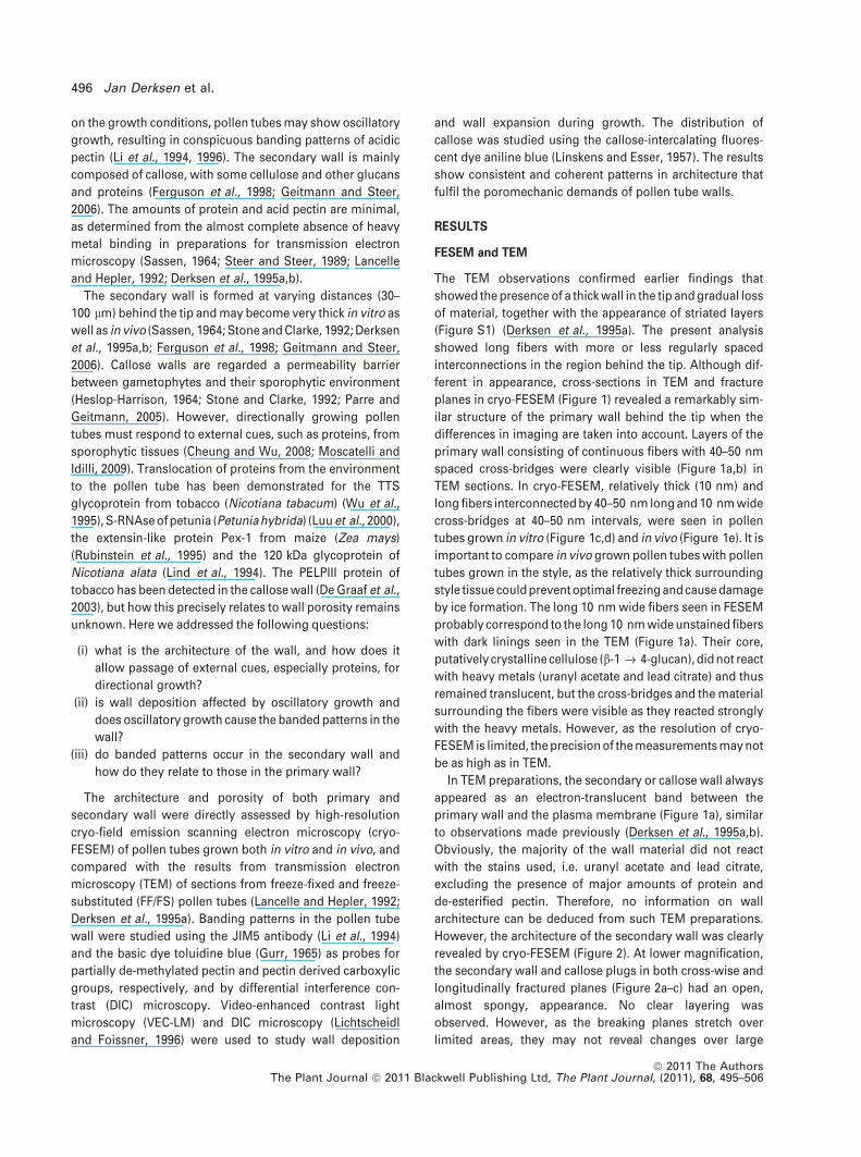
The TEM observations confirmed earlier findings that
showed the presence of a thick wall in the tip and gradual loss
of material, together with the appearance of striated layers
(Figure S1) (Derksen et al., 1995a). The present analysis
showed long fibers with more or less regularly spaced
interconnections in the region behind the tip. Although dif-
ferent in appearance, cross-sections in TEM and fracture
planes in cryo-FESEM (Figure 1) revealed a remarkably sim-
ilar structure of the primary wall behind the tip when the
differences in imaging are taken into account. Layers of the
primary wall consisting of continuous fibers with 40–50 nm
spaced cross-bridges were clearly visible (Figure 1a,b) in
TEM sections. In cryo-FESEM, relatively thick (10 nm) and
long fibers interconnected by 40–50 nm long and 10 nm wide
cross-bridges at 40–50 nm intervals, were seen in pollen
tubes grown in vitro (Figure 1c,d) and in vivo (Figure 1e). It is
important to compare in vivo grown pollen tubes with pollen
tubes grown in the style, as the relatively thick surrounding
style tissue could prevent optimal freezing and cause damage
by ice formation. The long 10 nm wide fibers seen in FESEM
probably correspond to the long 10 nm wide unstained fibers
with dark linings seen in the TEM (Figure 1a). Their core,
putatively crystalline cellulose (b-1 fi 4-glucan), did not react
with heavy metals (uranyl acetate and lead citrate) and thus
remained translucent, but the cross-bridges and the material
surrounding the fibers were visible as they reacted strongly
with the heavy metals. However, as the resolution of cryo-
FESEM is limited, the precision of the measurements may not
be as high as in TEM.
In TEM preparations, the secondary or callose wall always
appeared as an electron-translucent band between the
primary wall and the plasma membrane (Figure 1a), similar
to observations made previously (Derksen et al., 1995a,b).
Obviously, the majority of the wall material did not react
with the stains used, i.e. uranyl acetate and lead citrate,
excluding the presence of major amounts of protein and
de-esterified pectin. Therefore, no information on wall
architecture can be deduced from such TEM preparations.
However, the architecture of the secondary wall was clearly
revealed by cryo-FESEM (Figure 2). At lower magnification,
the secondary wall and callose plugs in both cross-wise and
longitudinally fractured planes (Figure 2a–c) had an open,
almost spongy, appearance. No clear layering was
observed. However, as the breaking planes stretch over
limited areas, they may not reveal changes over large
496 Jan Derksen et al.
ª 2011 The AuthorsThe Plant Journal ª 2011 Blackwell Publishing Ltd, The Plant Journal, (2011), 68, 495–506

distances. At high magnifications, the fine structure of the
secondary wall could be discerned, showing approximately
40 · 50 nm lattices (Figure 2d) that appeared to consist of
approximately 10–15 nm wide, parallel fibers, with rod-like
and thinner interconnections at approximately 90� angles to
the long fibers. Clear, regular lattices were only seen on
fracture surfaces that are more or less parallel to the long
fibers. Non-parallel fracture planes cause an uneven and
often fragmented appearance of the lattice (Figure 2e). In
some instances, the fracture surface appeared smooth and
amorphous. This probably results from extremely steep
fracture planes (>40�), in which the elements of the lattice
can no longer be seen separately (Figure S2).
For conventional FESEM, pollen tubes were freeze-fixed
and either freeze-dried or freeze-substituted and critical
point-dried. In both cases (Figure 3), the wall surface
appeared rather smooth (Figure 3a). Higher magnifications
revealed a granular texture (Figure 3b). However, after
removal of loose surface material by flushing with double-
distilled water, the wall showed a more porous and scaly
structure (Figure 3c). Ridges (Figure 3c,d) appeared on the
surface that matched the ring- or scale-like structures seen
after further extraction (Figure 3e–g). No differences were
observed between critical point- and freeze-dried prepara-
tions. The results indicate a scaly or ring-like structure of a
further porous wall that is covered with loose and rather
amorphous material. Cryo-FESEM after pectin extraction
with EDTA showed the banded, scaly structure of the
primary wall, with loose long fibrils (Figure 3e–g). Short
gentle extractions with EDTA (6 h at 4�C without agitation)
showed pollen tubes with long fibers (Figure 3f). Longer and
more severe extractions (12 h at room temperature, while
shaking at 1 rpm) resulted in almost complete loss of the
primary wall, but some scalar material remained at the base
(Figure 3g). The arrangement of the scales or rings strongly
resembles the patterns seen under light microscopy (Fig-
ure 4) the spatial frequency and size of the rings are the
same as those seen under light microscopy and the scale-
like structures always point towards the tip. In EDTA-
extracted pollen tubes, the structure of the secondary wall
remained intact, although the wall appeared somewhat
swollen and the lattice was disturbed (Figure S3). When the
wall was stabilized by incubation with CaCl2, both the
primary and secondary wall remained intact but were
somewhat more compact (Figure S4).
These results show a rather porous primary and second-
ary wall, the first often consisting of rings that may overlap
(as tiles on a roof) and whose integrity depends on EDTA-
extractable material, i.e. acid pectin.
Light microscopy and immunohistochemistry
Partly de-esterified pectin was detected by labeling with
JIM5 antibodies. Most pollen tubes showed the same char-
acteristic pattern (Figure 4a) as described by Li et al. (1994).
However, up to 20% of the pollen tubes showed only weak
fluorescence, irregular banding patterns or even no bands at
all. Irregular patterns were found often near the pollen grain.
Patterns of partly de-esterified pectin, like those detected by
(a)
(b)
(c)
(d) (e)
Figure 1. Structure of the pollen tube’s primary
wall seen under TEM and cryo-FESEM.
(a) TEM image of a cross-section of a rapidly
frozen and freeze-substituted pollen tube show-
ing the layered appearance of the wall. Long,
bright fibers (arrows), putatively cellulose micro-
fibrils, are lined by darker stained material, with
approximately 40 nm long interconnections at
approximately 50 nm distances. The asterisks
indicate the secondary wall (approximately
60 lm behind the tip).
(b) Higher magnification of part of (a). The cross-
bridges between the fibrils are indicated by pairs
of dots. Only part of the cross-bridges are fully
visible.
(c) Cryo-FESEM image of a rapidly frozen and
transversely fractured pollen tube grown in vitro.
The image shows a remarkably similar pattern to
that seen under TEM (a). The thick fibrils (arrows)
correspond to the fibers indicated in (a). Inter-
connections at approximately 50 nm distances
are clearly visible.
(d) Higher magnification of part of (c). The cross-
bridges between the fibrils are indicated by pairs
of dots. In fracture planes, only a few cross-
bridges are visible.
(e) Cryo-FESEM image as in (c), but from a pollen
tube grown in vivo. The image shows a similar
pattern as in (c) and (d). with long interconnected
fibers. Scale bars = 200 nm.
Wall architecture in tobacco pollen tubes 497
ª 2011 The AuthorsThe Plant Journal ª 2011 Blackwell Publishing Ltd, The Plant Journal, (2011), 68, 495–506

JIM5, were observed in greater detail using basic dye tolui-
dine blue that detects carboxylic acid groups. Staining of
both living and fixed pollen tubes was limited to the primary
wall, with constrictions at the site of the rings (Figure 4b,c).
Especially in older parts of the tube, scale-like protrusions
were seen that coincided with the edge of the bands (Fig-
ure 4c,d). Under DIC microscopy, the primary and secondary
walls could be clearly distinguished, and the scalar or ring-
like construction of the primary wall was clearly visible
(Figure 4e–g). Pectin extraction of fixed pollen tubes with
50 mM EDTA for 8 h caused the rings to become more dif-
fuse and they seemed to open up. The edges at the side of
the basis of the tube, the base-side, remained attached to the
tube, whereas the edges at the side of the tip, the tip-side,
became wider (Figure 4h). Prolonged incubation caused al-
most complete loss of the primary wall and thus the banding
pattern disappeared. Control incubations in double-distilled
water, potassium phosphate buffer or 0.1 M NaCl appeared
not to affect the banded structures. Incubation in CaCl2 to
stabilize the wall resulted in a more compact appearance
(Figure 4i). The protrusions always pointed towards the tip
of the tube (Figure 4h,i), with the bands that represent ring-
or scale-like structures apparently opening up towards the
tip. Pollen tubes removed from the transmitting tissue of
styles did not show intact primary walls (data not shown)
and therefore were not used further.
(a) (b)
(c)
(d) (e)
Figure 2. Cryo-FESEM of the secondary pollen
tube wall in vitro and in vivo.
(a, b) Surfaces of cross-wise fractured pollen
tubes grown in vitro for 6 h (a) and 12 h. (b) The
secondary wall has an almost spongy character.
The structure of the callose plug in (b) is similar
to that of the secondary wall shown in (a), but
coarser and more irregular. Scale bars = 3 lm.
(c) Oblique to longitudinal fracture surface of a
pollen tube grown in vitro for 8 h. The wall
shows the same appearance as in (a) and (b).
Scale bar = 3 lm.
(d) At higher magnifications, a lattice consisting
of long, 10–15 nm thick fibers at 40–50 nm
distances (double-headed arrows), with approx-
imately 10 nm wide interconnections at
40–60 nm distances, becomes visible. Scale
bar = 100 nm.
(e) Irregular fracture plane, showing seemingly
distorted lattices. At the right of the image, the
fracture plane and consequently its fibril pattern
is outwardly distorted or even obscured. In the
lower left corner, the breaking plane, and corre-
spondingly the fibril pattern, is more regular.
Scale bar = 100 nm.
498 Jan Derksen et al.
ª 2011 The AuthorsThe Plant Journal ª 2011 Blackwell Publishing Ltd, The Plant Journal, (2011), 68, 495–506

Callose staining with aniline blue revealed a banded
pattern of the secondary wall with clear constrictions
(Figure 5a). However, the banding pattern was easily
concealed by application of an excess of aniline blue. The
bands in the secondary wall alternated with those of the
primary wall (Figure 5b,c). EDTA extraction did not affect the
aniline blue banding patterns (Figure 5d). Comparison of the
observations after toluidine blue, DIC and aniline blue
imaging (Figures 4 and 5) revealed that the bands in the
secondary wall resulted from constrictions in the primary
wall. Pollen tubes from styles did not show intact primary
walls (data not shown) after removal from the style, but
banded patterns occasionally appeared in the secondary
wall after aniline blue staining. The results from the in vitro
grown pollen tubes in particular indicate that the banding
patterns in the callose wall result from constrictions
imposed on it by the primary wall.
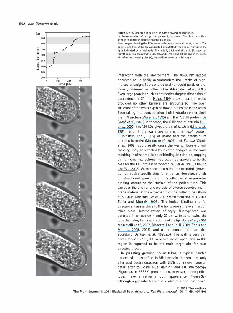
VEC microscopy
To understand band formation in more detail, we analyzed
alternating periods of growth and growth arrest by real-time
imaging using VEC microscopy (Figure S5). During growth
arrest (Figure 6a–e), the wall in the tip became very thick as
wall material continued to be secreted. During the sudden
growth pulse, the tip broke through this thick layer, pushing
it aside and giving rise to the band in the tube. Occasionally,
even the protruding edge of the newly formed band became
visible. Although the tips often expanded asymmetrically,
they ultimately became symmetric again. The thin wall that
formed during and shortly after the fast growth phase gave
rise to the interband regions of the pollen tube. The results
of the combined light microscopic observations show that
the ring- or scale-like structures of the primary wall comprise
material deposited prior to the growth pulses, with the
interband regions containing much less material being
deposited during the growth pulses.
DISCUSSION
Communication between pollen tubes and the surrounding
style tissue requires a specific architecture to ensure both
porosity and strength. However, only limited information
was available regarding the primary walls, and no information
(a) (b)
(e)
(c) (d)
(f) (g)
Figure 3. Scanning electron microscopy of pol-
len tubes grown in vitro.
(a, b) Pollen tube grown on a membrane, frozen
in liquid propane, freeze-substituted and freeze-
dried. The surface of the pollen tube is smooth
(a) but appears to be more granular at high
magnifications (b). Scale bars = 10 lm (a) and
10 nm (b).
(c, d) After flushing of fixed pollen tubes with
double-distilled water, rapid freezing in propane
and critical point drying, the wall’s surface has a
more open appearance, showing a layered struc-
ture (arrows) (c). In (d), ridges with approxi-
mately 3 lm spacing are observed (arrows). The
distance between the ridges on the images
shown is shortened due the steep optical angle.
The arrows correspond to the outer edges of the
scales seen in (g). Scale bars = 500 nm.
(e–g) Fixed pollen tubes after extraction of pectin
with EDTA, revealing ring-like structures in a
pattern resembling that of the ridges or scale-like
structures shown in (c) and (d). (e) Extraction for
8 h under slow agitation shows ring-like struc-
tures at approximately 3 lm distance pointing
towards the tip (right). The distances between
the ring-like structures vary. (f) Structure of the
wall after 6 h extraction without agitation. A
dense network of long fibers, putatively cellulose
microfibrils, is present. (g) Wall after extraction
for 12 h and 1 rpm agitation. Most material,
including the long fibers, has disappeared; the
scalar appearance of the ring-like structures is
obvious. Scale bars = 10 lm.
Wall architecture in tobacco pollen tubes 499
ª 2011 The AuthorsThe Plant Journal ª 2011 Blackwell Publishing Ltd, The Plant Journal, (2011), 68, 495–506

was available on the construction of the secondary walls of
pollen tubes. Using TEM and cryo-FESEM, we were able to
directly assess the construction and porosity of tobacco
pollen tube walls. The primary walls is deposited in the tip as
an amorphous, plastic, irregularly bordered layer (Derksen
et al., 1995a,b) with a large amount of esterified pectin (Li
et al., 1994). Behind the tip, the wall is rapidly converted into
a more rigid, (partly de-esterified) pectin/cellulose wall
(Sassen, 1964; Kroh and Knuiman, 1982; Ferguson et al.,
1998) by the activity of pectin methyl esterases (Li et al.,
1994, 2002) and (presumably) intra-membrane cellulose
synthases (Helsper et al., 1977; Southworth, 1992). Thus, the
architecture of the primary wall appears to be the result of
self-assembly, with its final structure depending on the
composition of the secreted material, the enzyme activity
therein, and the activity of cellulose-synthesizing complexes
in the membrane.
Using both TEM and cryo-FESEM, this wall appears to
consist of layers with long, approximately 10 nm thick,
putative cellulose fibers that are interconnected by approx-
imately 10 nm thick and 40–50 nm long rods at 40–50 nm
intervals (Figure 1a,b). The layered and striated appearance
of the primary wall agrees with previous observations on a
variety of pollen tubes, such as tobacco (Kroh and Knuiman,
1982; Derksen et al., 1995a,b), Lilium longiflorum (Lancelle
and Hepler, 1992; Lancelle et al., 1997) and Arabidopsis
(Derksen et al., 2002). The difference in appearance between
TEM and cryo-FESEM is probably due to the imaging
methods: SEM reveals all structures irrespective of their
composition, whereas TEM imaging relies on binding of
stains by reactive components such as proteins and
de-esterified pectin, and does not detect cellulose. However,
shadow casting of pollen tube walls extracted using H2O2/
glacial acetic acid showed the presence of a fibrous network
of cellulose fibrils throughout the wall of tobacco and
petunia pollen tubes (Sassen, 1964; Kroh and Knuiman,
1982). In vegetative cell walls, these crystalline cellulose
fibers are probably covered with less crystalline or other
inert and non-inert glucans (e.g. McCann et al., 1990), which
(a)
(b)
(c)
(d)
(e)
(f)
(g)
(h)
(i)
Figure 4. Light microscopy and immunohistochemistry of N. tabacum pollen
tubes grown in vitro.
(a) Labelling of pollen tubes for pectin with JIM5 antibody shows ring-like
areas or bands with partially de-esterified pectin in the wall.
(b) Staining of living pollen tubes using the cationic dye toluidine blue shows
the same pattern as in (a).
(c) Below-surface optical section of a fixed and toluidine blue-stained pollen
tube, showing dense and discrete accumulations of toluidine blue-stained
material in the primary wall (arrowheads).
(d) Under the DIC microscope, median optical sections of a fixed and less
intensely toluidine blue-stained pollen tube show the stained areas in the
primary wall as dense rings or bands that protrude inwards (arrowheads).
The unstained secondary wall bends outwards (arrows) between the bands of
the primary wall.
(e, f) Using DIC, ring-like or banded structures (arrowheads) of the primary
wall are clearly visible in living pollen tubes grown for 16 h. The tip of the
pollen tube is on the right. In median optical sections (e), an equally thick
secondary wall (arrows) and callose plug (asterisk) are present. The ring-like
appearance and outward protrusions of the primary wall (arrowheads) are
clearly visible, especially in surface optical sections. The lines indicated in (f)
represent the tip-side edge of the ring- or scale-like structures.
(g) High-resolution images of living pollen tubes (8 h) examined with DIC
clearly show the scale-like structure. Two individual scales are indicated. The
base of the scale corresponds with the bands (arrowheads) in (c)–(f). The
pollen tube is slightly plasmolyzed. The scales always point towards the tip
(right).
(h) Toluidine blue-stained pollen tube grown for 12 h, fixed and extracted with
50 mM EDTA for 8 h. The ring- or scale-like structures appear to open up at the
tip side of the pollen tube and become diffuse (arrowheads). The cytoplasm
stains dark blue. (i) Toluidine blue-stained pollen tube from the same batch as
in (h), but incubated for 8 h in 50 mM CaCl2 after fixation. The ring- or scale-
like structures are very compact (arrowheads), and their orientation towards
the tip is visible.
Scale bar = 10 lm for all sections, except (g), for which it indicates 30 lm.
500 Jan Derksen et al.
ª 2011 The AuthorsThe Plant Journal ª 2011 Blackwell Publishing Ltd, The Plant Journal, (2011), 68, 495–506

may explain the low cellulose content (Schlupmann et al.,
1994) of tobacco pollen tube walls. Consequently, cellulose
fibers in TEM show up as translucent structures with a dark
lining, as indicated in Figure 1(a). The rods interconnect-
ing the fibers (Figure 1b) may consist of hemicellulose,
hydroxyproline-rich proteins (McCann et al., 1990) or even
other unidentified proteins (Geitmann and Steer, 2006).
However, as the integrity of the primary pollen tube wall
depends on EDTA-extractable material and as the rods are
stained in TEM, the rods are probably largely made up of at
least partly de-esterified pectin. The pivotal role of de-
esterified pectin in pollen tube wall integrity has also been
shown for the pollen tube-specific pectin methyl esterase
mutant Vanguard 1 (Jiang et al. 2005) and by the effect of
pectin methyl esterase inhibition (Zhang et al., 2010) in
Arabidopsis pollen tubes.
The secondary callose wall is essentially devoid of stain-
ing in TEM preparations, which indicates that acidic pectins
and proteins may be hardly present or even absent. In cryo-
FESEM, 40–50 nm long and approximately 10 nm wide
cross-bridges are seen at 40–50 nm intervals between the
long, approximately 10 nm wide, fibers (Figure 2d,e). In
contrast to the primary wall, the secondary callose wall is not
layered. Fibrous cellulose residues were observed in petunia
(Sassen, 1964) and tobacco pollen tubes after extraction with
H2O2/glacial acetic acid (Kroh and Knuiman, 1982), and
cellulose was also detected in the secondary wall (Ferguson
et al., 1998). As in the primary wall, the long 10 nm wide
fibers are probably cellulose microfibrils or fibers with a
mixed cellulose/non-cellulose nature. In lily, in addition to
cellulose microfibrils (b-1 fi 4 polymers), fibrous b-1 fi 3
polymers (callose) occur that may become fibrillar in vitro.
Mixed b-1 fi 3/b-1 fi 4 polymers, probably in the form of
cellulose-associated callose, also occur (Herth et al., 1974). If
similar complexes occur in tobacco, the 40–50 nm long rods
that cross bridge the fibers may be covalently linked b-1 fi 3
polymers (callose). In addition to callose, non-acidic pectin,
hemicellulose, arabinogalactan proteins and callose–arabi-
nogalactan protein complexes that occur in the wall (Geit-
mann and Steer, 2006) may contribute to the network, albeit
to a minor extent. Such construction may combine strength
and flexibility with low cost, meeting stress and load-
bearing requirements (e.g. Chebli and Geitmann, 2007) for
growth through the narrow intercellular spaces of the
transmitting tissue of tobacco. The remarkable similarity in
architecture, but not in composition, of the two walls in our
view reflects functional needs regarding porosity while
maintaining mechanical strength. This similarity may result
from use of the primary wall as a template for the secondary
wall or similar constraints regarding deposition of longer
fibers in both walls.
Wall porosity has been measured in numerous studies on
vegetative cells, mostly from cell cultures, and, depending
on species and culture conditions, pore sizes ranged
between 2.4 and 3.8 nm (e.g. Titel et al., 1997; Hensel et al.,
2002). In planta, pore size appears to depend greatly on the
tissue and the developmental stage (Rondeau-Mouro, 2008).
As these studies concerned isolated and often extensively
treated cell walls, they may not be fully representative of
living cells. The apoplastic transport of up to 40 kDa
fluorescently labeled dextrans in Zea mays roots (Sivaguru
et al., 2006) may indicate a rather open wall structure.
However, these studies concern walls that differ greatly from
pollen tube walls in both composition and deposition. In
addition to geometric pore size, additional factors, such as
surface to volume ratio, solutes, wall composition and
thickness, and hydration must be considered. Therefore,
only direct estimates (O’Driscoll et al., 1993) should be used
to determine actual geometric pore size and transport
through walls. The porous primary and secondary pollen
tube wall in tobacco, in addition to allowing easy passage of
any metabolite, does not form an impenetrable mechanical
barrier for proteins or other molecules that are involved in
(a)
(b)
(c)
(d)
Figure 5. Aniline blue labeling of callose in the secondary wall of N. tabacum
pollen tubes. Scale bar = 10 lm (applies to all sections).
(a) Aniline blue staining reveals a banded pattern in the wall of the pollen
tube. The denser areas appear to bend outwards (arrows). The tip (indicated
by a white dot) remains unstained.
(b, c) Aniline blue staining (b) compared with observations by DIC (c). Both
show outward-bending areas (arrows) of the secondary wall.
(d) Overnight extraction of fixed pollen tubes in 50 mM EDTA did not affect the
banded pattern. The unstained tip is indicated by a white dot. Aniline blue
staining, indicating callose deposition, first occurs only 20 lm behind the tip.
Wall architecture in tobacco pollen tubes 501
ª 2011 The AuthorsThe Plant Journal ª 2011 Blackwell Publishing Ltd, The Plant Journal, (2011), 68, 495–506
interacting with the environment. The 40–50 nm lattices
observed could easily accommodate the uptake of high-
molecular-weight fluorophores and nanogold particles pre-
viously observed in pollen tubes (Moscatelli et al., 2007).
Even large proteins such as antibodies (largest dimension of
approximately 24 nm; Roux, 1999) may cross the walls,
provided no other barriers are encountered. The open
structure of the walls explains how proteins cross the walls.
Even taking into consideration their hydration water shell,
the TTS protein (Wu et al., 1995) and the PELPIII protein (De
Graaf et al., 2003) in tobacco, the S-RNAse of petunia (Luu
et al., 2000), the 120 kDa glycoprotein of N. alata (Lind et al.,
1994), and, if the walls are similar, the Pex-1 protein
(Rubinstein et al., 1995) of maize and the defensin-like
proteins in maize (Marton et al., 2005) and Torenia (Okuda
et al., 2009), could easily cross the walls. However, wall
crossing may be affected by electric charges in the wall,
resulting in either repulsion or binding. In addition, trapping
by non-ionic interactions may occur, as appears to be the
case for the TTS protein of tobacco (Wu et al., 1995; Cheung
and Wu, 2008). Substances that stimulate or inhibit growth
do not require specific sites for entrance. However, signals
for directional growth are only effective if asymmetric
binding occurs at the surface of the pollen tube. This
excludes the site for endocytosis of excess secreted mem-
brane material at the extreme tip of the pollen tubes (Bove
et al., 2008; Moscatelli et al., 2007; Moscatelli and Idilli, 2009,
Zonia and Munnik, 2008). The logical binding site for
directional cues is close to the tip, where all relevant action
takes place. Internalization of styryl fluorophores was
detected in an approximately 20 lm wide zone, twice the
tube diameter, flanking the dome of the tip (Bove et al., 2008;
Moscatelli et al., 2007, Moscatelli and Idilli, 2009, Zonia and
Munnik, 2009, 2008), and clathrin-coated pits are also
abundant (Derksen et al., 1995a,b). The wall is very thin
here (Derksen et al., 1995a,b) and rather open, and so this
region is expected to be the main target site for cues
directing growth.
In pulsating growing pollen tubes, a typical banded
pattern of de-esterified (acidic) protein is seen, not only
after acid pectin detection with JIM5 but in even greater
detail after toluidine blue staining and DIC microscopy
(Figure 4). In FESEM preparations, however, these pollen
tubes have a rather smooth appearance (Figure 3a),
although a granular texture is visible at higher magnifica-
(a)
(b)
(c)
(d)
(e)
Figure 6. VEC real-time imaging of in vitro growing pollen tubes.
(a) Representation of two growth pulses (gray areas). The first pulse (I) is
stronger and faster than the second pulse (II).
(b–e) Images showing the differences in the apical cell wall during a pulse. The
original position of the tip is indicated by a dotted white line. The wall in the
tip is indicated by arrowheads. The initially thick wall at the tip (b) becomes
very thin during the growth pulse (c), and remains so till the end of the pulse
(d). After the growth pulse (e), the wall becomes very thick again.
502 Jan Derksen et al.
ª 2011 The AuthorsThe Plant Journal ª 2011 Blackwell Publishing Ltd, The Plant Journal, (2011), 68, 495–506
tions (Figure 3b). Removal of water-soluble material reveals
a more porous and layered structure (Figure 3c) with ridges
or scales. The water-soluble material probably represents
material that in vitro dissipates spontaneously into the
medium (Derksen et al., 1995b). Extraction of non-covalently
bound pectin shows the scales to be part of ring-like
structures with loosened long fibrils. This pattern is dramat-
ically revealed by the caterpillar-like appearance of pollen
tubes after EDTA extraction (Figure 3e), with the opened
side of the rings always pointing towards the tip of the
pollen tube. The dimensions and arrangement of the scalar
structures seen in cryo-FESEM strongly resemble the ring-
or scale-like structures seen in the light microscopic prep-
arations (Figure 4), which are similarly affected by EDTA
extraction. The similar dimensions, spatial distribution,
sensitivity for pectin removal and staining with toluidine
blue in our view proves that the scales or rings observed
here represent the band with galacturonic acid as detected
by the JIM5 antibody (Li et al., 1994). The rings open up with
the tip-side, wider edges pointing towards the tip (Fig-
ures 3e and 4h,i) and with the bases forming the constric-
tions (Figure 4c,d,h,i). The relatively sharp lines seen in DIC
(Figure 4e,f) appear to represent the tip-side edge of the
scaly stuctures, seen as ridges in Figure 3(c,d).
VEC–LM confirmed the observations of Li et al. (1996) that
periods of slow growth coincide with the formation of a thick
wall. High rates of exocytosis preceding periods of fast
growth were observed in tobacco (McKenna et al., 2009),
and the rate of exocytosis appears to predict the rate and
extent of growth. According to Zonia and Munnik (2008), a
strong growth pulse coincides with a defined region of new
growth and continued exocytosis, leaving a relatively thick
wall behind the dome. The present observations link wall
deposition with growth dynamics: during slow growth, a
thick wall is formed that remains largely intact during the
following growth pulse but is pushed aside, giving rise to the
rings or scale-like structures observed in DIC and FESEM
(Figure 3a–e). Occasionally even the protrusions at the
band’s edges became immediately visible. Although exocy-
tosis of vesicles containing wall material was observed
almost throughout the dome of the tip in electron micro-
scopic images of tobacco pollen tubes (Derksen et al.,
1995a,b), such static images cannot be quantified, and
current evidence shows that most, if not almost all, exocy-
tosis occurs in the flanks of the dome (Bove et al., 2008;
Zonia and Munnik, 2008). If the extreme tip completely
lacked exocytosis, expansion would be limited to the flanks
of the dome, or, to allow expansion there, plastic wall
material would have to flow from the flanks of the dome into
the extreme tip. The driving force for the flow could be
endocytosis in the extreme tip and plasma streaming. As the
primary wall behind the dome gradually loses material and
becomes layered (Derksen et al., 1995a,b), similar behavior
must occur in the extreme tip, but has not been reported. A
complete absence of exocytosis and expansion in the very
tip therefore seems unlikely. The present VEC–LM observa-
tions suggest that at least some expansion occurs in the
upper part of the dome (Figure 3 and Movie S1), and this is
also indicated by the behavior of the wall at the onset of a
growth pulse. The thickened wall in the flank of the dome is
pushed aside, giving rise to the band in the tube, and the thin
wall that is formed during and shortly after the pulse in the
upper part of the dome gives rise to the interband regions of
the pollen tube. The thick wall that is pushed aside during
the fast growth phase may rupture, with the edge towards
the tip giving rise to the forward-pointed side of the scale.
Although the tips often expanded asymmetrically, they
ultimately became symmetric again, which may indicate a
response of the flexible wall to turgor pressure, resulting in a
catenary dome. All models of pollen tube growth must
consider a balance between turgor pressure and wall
expansion (Derksen, 1996; Fayant et al., 2010), whatever the
underlying mechanisms or forces, oscillating or not, may be.
A banded pattern was also observed in the callose wall
after staining with decolorized aniline blue (Figure 5). The
pattern is similar to that of the rings in the primary wall but
the patterns are alternating, and may be the result of
constrictions imposed by the primary wall.
In conclusion, tobacco pollen tube walls are highly
porous, consisting of approximately 50 nm lattices that do
not form a mechanical barrier to molecules of substantial
size. The banded patterns seen in oscillatory growing cells
result from deposition during a period of slow growth.
EXPERIMENTAL PROCEDURES
Plant material
Plants of Nicotiana tabacum L. cv. Petit Havana from the BotanicalGarden in Leiden (The Netherlands) (Nijmegen accession number904750309) were grown under standardized greenhouse conditions[19–22�C; photoperiod 18 h/6 h (light/dark)]. Pollen was collected atanther dehiscence and used either as fresh material or air-dried andstored in a desiccator for use within a few days. Pollen tubes weregrown in suspension cultures: 20–30 mg pollen in 2 ml sucrose(10%) with 0.01% boric acid at 25�C for 1–4 h on a rotary shaker at50 rpm. In addition, cultures were prepared in 5 or 15% sucrose with0.01% boric acid. Alternatively, pollen tubes were grown for 3–16 hon a solid agar/sucrose/boric acid (1%:10%:0.1%) medium. Forelectron microscopy, pollen tubes were also grown on disks ofdialysis membrane (Serva, http://www.serva.de) placed on top ofthe solid medium, as described by Derksen et al. (1995a). To studypollen tubes grown in vivo, pistils were pollinated with an excess ofpollen and used after 12 or 40 h when they had grown halfway orcompletely through the pistil, respectively.
Chemicals and antibodies
Unless stated otherwise, all chemicals (PA grade) were from Merck(http://www.merck-chemicals.com). The agar used was a low-tem-perature gelling agar (SeaPlaque; FMC Bioproducts, http://www.cambrex.com) or Bacto-Agar (Difco, http://www.bacteria.us.com). Commercial antibodies were from Nordic ImmunologicalLaboratories (http://www.nordiclabs.nl), and the monoclonal JIM5
Wall architecture in tobacco pollen tubes 503
ª 2011 The AuthorsThe Plant Journal ª 2011 Blackwell Publishing Ltd, The Plant Journal, (2011), 68, 495–506

antibody was kindly provided by Dr K. Roberts (John Innes Institute,Norwich, UK).
Wall extraction
Preliminary experiments showed that pollen tube walls would notwithstand the extraction methods used by McCann et al. (1990) forother cell types. Therefore, we used the gentlest possible handlingwith the least possible intervention. To prevent malformation, pol-len tubes were fixed before extraction by adding an equal amount offixative to the suspension culture. The fixative consisted of 6%paraformaldehyde in 50 mM PIPES or 50 mM potassium phosphateat pH 6.8, supplemented with 9% sucrose to prevent osmotic shock.Pollen tubes on a solid surface were fixed by addition of 2 ml 3%paraformaldehyde in the same buffer. After 5–10 min, the pollentubes were transferred to 10 ml polypropylene tubes. The fixativewas diluted by dropwise addition of 5 ml buffer under slow agita-tion. Pollen tubes were collected by centrifugation at 200 g for a fewseconds (left to run out without brake). After removal of the dilutedfixative, pollen tubes were quickly washed in buffer before furtheruse. No centrifugation was required as pollen tubes sedimentedquickly without sucrose.
To remove loose material from the wall surface, pollen tubesamples were placed in a 25 mm sterile syringe filter (0.8 lm poresize; Nalge Nunc International) and gently flushed with 10 mldouble-distilled water 5–10 times. The filters were then broken andused. Pectin was extracted using 50 mM EDTA, pH 6.3 (Redgwelland Selvendran, 1986). Preliminary experiments showed no differ-ence between the use of EDTA and CDTA, another calcium chelatingagent that is often claimed to be more effective and less detrimentalto the wall. Samples of fixed pollen tubes were quickly washed,re-suspended in extraction medium, and incubated at 4�C for8–12 h. Alternatively, extraction was performed at room tempera-ture for 6–12 h while gently stirring on a rotary shaker at not morethan 1 rpm. After incubation, the pollen tubes were carefullywashed for 2 min in double-distilled water. Incubations in eitherdouble-distilled water, potassium phosphate buffer or 0.1 M NaClserved as a control. Incubations with 50 mM CaCl2 to stabilize thewall served as an additional control.
Conventional FESEM
Membrane discs or filters containing pollen tubes were frozen byplunging into a nitrogen slush using a custom-built plunger (Derk-sen et al., 1995a), then freeze-substituted and critical point-dried in aBalzers CP 020 critical-point dryer (http://www.oerlikon.com/bal-zers), mounted on a carrier and covered with 1 nm Au-Pt using aCressington 208 HR sputter coater (Cressington Scientific Instru-ments Ltd, http://www.cressington.com). In addition, part of thefrozen membranes was freeze-dried at )80�C and 0.1 atmosphericpressure (101.325 kPa) overnight.
Cryo-FESEM preparations
For cryo-FESEM, samples were transferred to a 3 mm aluminumstub or small brass rivets (Cryotech, http://www.cryotech.co.th;internal diameter 1.0 mm, thickness 0.25 mm). The rivets wereplugged with copper wire or 40% polyethylene-glycol to preventleakage of the pollen suspension. Stubs and rivets were rapidlyplunged into nitrogen slush ()210�C) or liquid propane ()170�C;Air Liquide, http://www.airliquide.com). Styles containing pollentubes were cut near to the presumed front of pollen tube growth,put through the central opening of the rivet, and quickly plungedinto the nitrogen slush, cut side ahead. The stigma was broken offin the nitrogen. As pollen tubes grow more than 50 lm deepinside the style, the limit for optimal freezing, the quality of the
in vivo preparations is below optimal. Next, the samples weretransferred into a preparation cryo-unit (Alto 2500 HF high-resolution transfer system; Oxford Instruments Ltd, http://www.oxinst.com) at )180�C.
Sample surfaces were scraped or chafed, and then sublimatedat–85 to –90�C with the anti-contaminator at )120�C for 4–8 min,resulting in a sublimation depth of 3–5 lm. Varying the sublimationtime had little effect on fibers or rods. Prolonged sublimation formore than 6 min caused the sample surface to collapse duringscanning. The samples were then cooled to )120�C and coated with1 nm Au-Pt using the internal sputter-coater (Denton Vacuum Inc.,http://www.dentonvacuum.com) of the cryo-unit, and transferredinto a Jeol JSM 6330F cryo-FESEM (http://www.jeol.com) andexamined. The cryo-FESEM was operated at an acceleration voltageof 3 kV and a working distance of 15 mm. These conditions allowresolutions of at least 10 nm. The preparations do not vitrify underthese conditions, but the pollen tubes were sufficiently preservedclose to the sample surface to show the general structure of thecytoplasm (Figure S5). Various aspects of freezing techniques forbiological preparations have been extensively discussed by Stein-brecht and Zierold (1987).
Transmission electron microscopy
TEM samples were prepared as described previously (Derksen et al.,1995a). Briefly, membranes bearing pollen tubes were plunged intoliquid propane at )170�C, transferred into liquid nitrogen, freeze-substituted in a Reichert-Jung CS freeze-substitution apparatus(Reichert, http://www.leica-microsystems.com) at )90�C for 36 h,and then the temperature was slowly raised (4�C/h) to room tem-perature. The substitution medium was dried acetone or methanolwith 1% uranyl acetate and 0.1% OsO4. In some experiments, 8% 2.2-dimethoxypropane was added for best preservation. As no differ-ences were obvious, we subsequently omitted 2.2-dimethoxypro-pane. Disks bearing pollen tubes were embedded in LR White(London Resin Company, http://www.polysciences.com) and curedat 60�C. Sections were cut using a Sorvall MT-2 ultra-microtome(Thermo Scientific, http://www.thermoscientific.com), and mountedon 100-mesh Formvar-covered copper grids (Sigma-Aldrich, http://www.sigmaaldrich.com). After staining with uranyl acetate and leadcitrate, preparations were examined using Jeol 100 CX (http://www.jeol.com) or Philips EM 301 (http://www.fei.com) electronmicroscopes.
Light microscopy
For light microscopy, 30 ll drops of a suspension culture werecarefully placed on an object slide, covered with a 24 · 24 mmcover slip, and used directly. Pollen tubes grown on dialysis mem-brane were gently washed off using a 50 ll drop of medium.In these preparations, most pollen tubes continued growth andcytoplasmic streaming for at least 20 min. For staining with tolui-dine blue, 1–5 ll 0.1–0.01% toluidine blue in medium was added.Cytoplasmic streaming continued for another 5–10 min in mostcells. The walls of living pollen tubes stained pink to light purple, butthe cytoplasm remained unstained. In dead pollen tubes, the cyto-plasm was dark blue, sometimes obscuring the staining of the wall.Below pH 4.5, no coloration of the wall occurred, which indicatespure carboxylic acid-mediated binding (Gurr, 1965). To detect cal-lose (b-1 fi 3 glucan), 5 ll of a tenfold diluted decolorized anilineblue solution in potassium phosphate buffer (Linskens and Esser,1957) was added to the pollen tube culture sample. Preparationswere examined within 20 min. The dye did not enter the cytoplasmduring these observations. Similar treatments were performed onfixed and extracted material. Simultaneous staining with toluidine
504 Jan Derksen et al.
ª 2011 The AuthorsThe Plant Journal ª 2011 Blackwell Publishing Ltd, The Plant Journal, (2011), 68, 495–506

blue and aniline blue was impossible as toluidine blue quenched allfluorescence.
Immunolabeling of pollen tubes
Pectin detection by JIM5 antibody was performed as described byLi et al. (1994). Pollen tubes were fixed in PIPES or 50 mM sodiumphosphate buffer at pH 7.4 with 9% sucrose for 30 min to 2 h atroom temperature and washed three times for not more than 1 minin buffer. No pre-extractions or enzyme treatments were performedfor regular staining. The samples were blocked with 1% BSA inbuffer for 10 min, washed twice in buffer for not more than 1 min,and incubated in undiluted antibody for 2 h at room temperature.After three further washes for 10 min in buffer, the samples wereincubated with FITC-labeled goat anti-rat IgG (1:400 dilution inbuffer containing 1% BSA) for at least 8 h at 4�C. After three addi-tional washes (not more than 1 min each), the preparations weremounted in 1:1 v/v glycerol/water. Omission of the first antibody(JIM5) served as control. In addition, pollen tubes were treated withpectinase (0.2 mg/ml) in PIPES buffer for 30 min. In both controls,no staining (JIM5 omission) or almost no staining (pectinase treat-ment) was observed, confirming pectin staining by the JIM5 anti-body. No differences between the various buffers or fixationmethods were observed.
Microscopic examination and photography
For bright-field, differential interference contrast (DIC) and fluores-cence microscopy, preparations were examined using a LeitzOrtholux microscope or a Zeiss Axiovert TV135 microscope (http://www.zeiss.com/). Observations were made using 40 · dry objec-tives or a Zeiss 100· Fluotar oil immersion objective (NA 1.30).Images were captured using a Coolsnap fx camera (http://www.iseeimaging.com/cameras/roper) and Metafluor or Metamorphsoftware (Molecular Devices, http://www.moleculardevices.com).
Live cell imaging by video-enhanced contrast light microscopy(VEC-LM) was prepared as described by Lichtscheidl and Foissner(1996). Drops (30 ll) of a suspension culture were carefully placedon an object slide, covered with a 24 · 24 mm cover slip, and useddirectly. Examination and recording were performed using standardprocedures. Briefly, a Univar microscope (Reichert) equipped with40 · and 100 · Planapo objectives, additional magnification(1.25 ·), and a 16 · eyepiece was used for bright-field and DICmicroscopy. The images were collected using a high-resolutionvideo camera (Chalnicon C 1000.1, Hamamatsu, http://www.hama-matsu.com), digitally processed using a Hamamatsu Polyprocessorframe memory unit (DVS 3000) at video rate (25 full frames persecond), observed on a monitor, and recorded on a Sony digitalvideo cassette recorder (http://www.sony.com). Videos wereimported into the computer using Adobe Premiere (http://www.adobe.com/), and processed as .avi files and .tif images.
ACKNOWLEDGEMENTS
The work was supported by European Union TMR grant HPRN-CT-2002-00265 (TIPNET) and by a grant from the Jubilaumsfondsder Stadt Wien to I.L. We thank Ings B. Knuiman and H. Geurts(Department of General Instrumentation, Radboud University,Nijmegen, The Netherlands) for help with the electron micro-scopes, and Dr E.S. Pierson (Department of General In-strumentation, Radboud University, Nijmegen, The Netherlands)for help with the microscopes, image processing and for criticaldiscussions. We are indebted to Dr K. Roberts (John InnesInstitute, Norwich, UK) for his generous gift of the JIM5 anti-body. We thank Professor C. Mariani (Department of Plant Cell
Biology, University of Nijmegen, The Netherlands) for continuingsupport.
SUPPORTING INFORMATION
Additional Supporting Information may be found in the onlineversion of this article:Figure S1. Longitudinal section of a pollen tube tip under TEM.Figure S2. Fractured surface of a pollen tube tip showing theprimary wall.Figure S3. Oblique fractured surface of the wall of a pollen tube afterEDTA extraction.Figure S4. Cross-wise fractured surface of the wall of a pollen tubeafter incubation in medium with calcium.Figure S5. Cross-wise fractured pollen tube showing an intactcytoplasm.Movie S1. Growth pulse in a tobacco pollen tube.Please note: As a service to our authors and readers, this journalprovides supporting information supplied by the authors. Suchmaterials are peer-reviewed and may be re-organized for onlinedelivery, but are not copy-edited or typeset. Technical supportissues arising from supporting information (other than missingfiles) should be addressed to the authors.
REFERENCES
Bove, J., Vaillancourt, B., Kroeger, J., Hepler, P.K., Wiseman, P.W. and Geit-
mann, A. (2008) Magnitude and direction of vesicle dynamics in growing
pollen tubes using spatiotemporal image correlation spectroscopy and
fluorescence recovery after photobleaching. Plant Physiol. 147, 1646–1658.
Chebli, Y. and Geitmann, A. (2007) Mechanical principles governing pollen
tube growth. Funct. Plant Sci. Biotechnol. 1, 232–245.
Cheung, A.Y. and Wu, H. (2008) Structural and signaling networks for the polar
cell growth machinery in pollen tubes. Annu. Rev. Plant Biol. 59, 547–572.
De Graaf, B.H.J., Knuiman, B.A., Derksen, J. and Mariani, C. (2003) Charac-
terization and localization of the transmitting tissue-specific PELPIII pro-
teins of Nicotiana tabacum. J Exp Bot. 54, 55–63.
Derksen, J. (1996) Pollen tubes: a model system for plant growth. Bot. Acta.
109, 341–342.
Derksen, J., Rutten, T., Lichtscheidl, I.K., de Win, A.H.N., Pierson, E.S. and
Rongen, G. (1995a) Quantitative analysis of the distribution of organelles in
tobacco pollen tubes: implications for exocytosis and endocytosis. Pro-
toplasma, 188, 267–276.
Derksen, J., Rutten, T., van Amstel, T., de Win, A., Doris, F. and Steer, M.
(1995b) Regulation of pollen tube growth. Acta Bot. Neerl. 44, 93–119.
Derksen, J., Knuiman, B., Hoedemaekers, K., Guyon, A., Bonhomme, S. and
Pierson, E.S. (2002) Growth and cellular organization of Arabidopsis pollen
tubes in vitro. Sex. Plant Reprod. 15, 133–139.
Dumais, J., Shaw, S.L., Steele, C.R., Long, S.R. and Ray, P.M. (2006)
An anisotropic viscoplasmic model of plant cell morphogenesis by tip
growth. Int. J. Dev. Biol. 52, 209–222.
Fayant, P., Cheblib, Y., Aubina, C.-E., Villemura, I. and Geitmann, A. (2010)
Finite element model of polar growth in pollen tubes. Plant Cell, 22, 2579–
2593.
Ferguson, C., Teeri, T.T., Siika-aho, M., Read, S.M. and Bacic, A. (1998)
Location of cellulose and callose in pollen tubes and pollen grains of
Nicotiana tabacum. Planta, 206, 452–460.
Geitmann, A. and Steer, M.W. (2006) The architecture and properties of the
pollen tube cell wall. In The Pollen Tube: A Cellular and Molecular Per-
spective (Malho, R., ed.). Berlin: Springer-Verlag, pp. 177–200.
Gurr, E. (1965) Rational Use of Dyes in Biology and General Staining Methods.
London: Leonard Hill.
Helsper, J.P., Veerkamp, F.G. and Sassen, M.M.A. (1977) b–Glucan synthetase
activity in Golgi vesicles of Petunia hybrida. Planta, 133, 303–308.
Hensel, G., Kunze, G. and Kunze, I. (2002) The influence of 2,4-dichloro-
phenoxyacetic acid on localisation of the PR-proteins CBP20 and class I
chitinase in tobacco suspension cell cultures. Plant Sci. 163, 1099–1106.
Hepler, P.K., Lovy-Wheeler, A., McKenna, S.T. and Kunkel, J.G. (2006) Ions
and pollen tube growth. In The Pollen Tube: A Cellular and Molecular
Perspective (Malho, R., ed.). Berlin: Springer-Verlag, pp. 47–69.
Wall architecture in tobacco pollen tubes 505
ª 2011 The AuthorsThe Plant Journal ª 2011 Blackwell Publishing Ltd, The Plant Journal, (2011), 68, 495–506
Herth, W., Franke, W.W., Bittiger, H., Kuppel, A. and Keilich, G. (1974) Alkali-
resistant fibrils of b-1,3- and b-1,4-glucans: structural polysaccharides in the
pollen tube wall of Lilium longiflorum. Cytobiology, 9, 344–367.
Heslop-Harrison, J. (1964) Cell walls, cell membranes and protoplasmic
connections during meiosis and pollen development. In Pollen Physiology
and Fertilization (Linskens, H.F., ed.). Amsterdam: North Holland Publish-
ing Co, pp. 29–47.
Jiang, L., Yang, S.L., Xie, L.F., Puah, C.S., Xhang, X.Q., Yang, W.C., Sundar-
esan, V. and Ye, D.E. (2005) VANGUARD 1 encodes a pectin methylesterase
that enhances pollen tube growth in the Arabidopsis style and transmitting
tract. The Plant Cell, 17, 584–596.
Krichevsky, A., Kozlovsky, S.V., Tian, G.W., Chen, M.H., Zaltsman, A. and
Citovsky, V. (2007) How pollen tubes grow. Dev. Biol. 303, 405–420.
Kroh, M. and Knuiman, B. (1982) Ultrastructure of cell walls and plugs after
chemical extraction of polysaccharides. Planta, 154, 241–250.
Lancelle, S.A. and Hepler, P.K. (1992) Ultrastructure of freeze-substituted
pollen tubes of Lilium longiflorum. Protoplasma, 167, 215–230.
Lancelle, S.A., Cresti, M. and Hepler, P.K. (1997) Growth inhibition and
recovery in freeze substituted Lilium longiflorum pollen tubes: structural
effects of caffeine. Protoplasma, 196, 21–33.
Li, Y.-Q., Chen, F., Linskens, H.F. and Cresti, M. (1994) Distribution of une-
sterified and esterified pectins in cell walls of pollen tubes of flowering
plants. Sex. Plant Reprod. 7, 145–152.
Li, Y.-Q., Zang, H.-Q., Pieron, E.S., Huang, F.-Y., Linskens, H.F., Hepler, P.K. and
Cresti, M. (1996) Enforced growth-rate fluctuation causes pectin ring for-
mation in the cell wall of Lilum longiflorum pollen tubes. Planta, 200, 41–49.
Li, Y.-Q., Mareck, A., Faleri, C., Moscatelli, A., Liu, Q. and Cresti, M. (2002)
Detection and localization of pectin methylesterase isoforms in pollen
tubes of Nicotiana tabacum L. Planta, 214, 734–740.
Lichtscheidl, I.K. and Foissner, I. (1996) Video microscopy of dynamic plant
cell organelles: principles of the technique and practical application.
J. Microsc. 181, 117–128.
Lind, J.L., Bonig, I., Clarke, A.E. and Anderson, M.A. (1994) A style-specific
120 kDa glycoprotein enters pollen tubes of Nicotiana alata in vivo. Sex.
Plant Reprod. 9, 75–86.
Linskens, H.F. and Esser, K. (1957) Uber eine spezifische Afarbung der Poll-
enschlauche im Griffel and die Zahl der Kallosepropfen nach Selbstung and
Fremdung. Naturwissenschaften, 44, 16–17.
Luu, D.-T., Qin, X., Morse, D. and Cappadocia, M. (2000) S–RNase uptake by
compatible pollen tubes in gametophytic self-incompatibility. Nature, 407,
649–651.
Marton, M.L., Cordts, S., Broadhvest, J. and Dresselhaus, T. (2005) Micropylar
pollen tube guidance by egg apparatus 1 of maize. Science, 307, 573–576.
McCann, M.C., Wells, B. and Roberts, K. (1990) Direct visualization of cross-
links in the primary plant cell wall. J. Cell Sci. 96, 323–334.
McKenna, S.T., Kunkel, J.G., Bosch, M., Rounds, C.M., Vidali, L., Winship, L.J.
and Hepler, P.K. (2009) Exocytosis precedes and predicts the increase in
growth in oscillating pollen tubes. Plant Cell, 21, 3026–3040.
Moscatelli, A. and Idilli, A.I. (2009) Pollen tube growth: a delicate equilibrium
between secretory and endocytic pathways. J. Integr. Plant Biol. 51, 727–
739.
Moscatelli, A., Ciampolini, F., Rodighiero, S., Onelli, E., Cresti, M., Santo, N.
and Idilli, A. (2007) Distinct endocytotic pathways identified in tobacco
pollen tubes using charged nanogold. J. Cell Sci. 120, 3804–3819.
O’Driscoll, D., Read, S.M. and Steer, M.W. (1993) Determination of cell wall
porosity by microscopy: walls of cultured cells and pollen tubes. Acta Bot.
Neerl. 42, 237–244.
Okuda, S., Tsutsiu, H., Shiina, K. et al. (2009) Defensin-like polypeptide LUREs
are pollen tube attractants secreted from synergid cells. Nature, 458, 357–
361.
Parre, E. and Geitmann, A. (2005) More than a leak sealant – the physical
properties of callose in pollen tubes. Plant Physiol. 137, 274–286.
Redgwell, R.J. and Selvendran, R.R. (1986) Structural features of cell wall
polysaccharides of onion Allium cepa. Carbohydr. Res. 157, 183–199.
Rondeau-Mouro, C. (2008) Assessment of cell porosity in Arabidopsis thaliana
by NMR spectroscopy. Int. J. Biol. Macromol. 42, 83–92.
Roux, K. (1999) Immunoglobulin structure and function as revealed by elec-
tron microscopy. Int. Arch. Allergy Immunol. 120, 85–99.
Rubinstein, A.L., Marquez, J., Suarez-Cervera, M. and Bedinger, P.A. (1995)
Extensin-like glycoproteins in the maize pollen tube wall. Plant Cell, 7,
2211–2225.
Sassen, M.M.A. (1964) Fine structure of Petunia pollen grain and pollen tube.
Acta Bot. Neerl. 23, 354–355.
Schlupmann, H., Bacic, A. and Read, S.M. (1994) Uridine diphosphate glucose
metabolism and callose synthesis in cultures pollen tubes of Nicotiana
alata Link et Otto. Plant Physiol. 105, 659–670.
Sivaguru, M., Horst, W.J., Eticha, D. and Matsumoto, H. (2006) Aluminum
inhibits apoplastic flow of high molecular weight solutes in root apices of
Zea mays. Plant Nutr. Soil Sci. 169, 679–698.
Southworth, D. (1992) Freeze fracture of male reproductive cells. In Repro-
duction in Flowering Plants (Russell, S.D. and Dumas, C., eds). San Diego,
CA: Academic Press, pp. 187–203.
Steer, M.W. and Steer, J.L. (1989) Pollen tube tip growth. New Phytol. 111,
323–358.
Steinbrecht, R.A. and Zierold, K. (1987) Cryotechniques in Biological
Microscopy. Berlin: Springer-Verlag, pp. 187–203.
Stone, B.A. and Clarke, A.E. (1992) Chemistry and Biology of (1 fi 3)-b–Glu-
cans. Melbourne, Australia: La Trobe University Press.
Titel, C., Woehlecke, H., Afifi, I. and Ehwald, R. (1997) Dynamics of limiting cell
wall porosity in plant suspension cultures. Planta, 203, 320–326.
Wu, H.M., Wang, H. and Cheung, A.Y. (1995) A pollen tube growth stimulatory
glycoprotein is deglycosylated by pollen tubes and displays a glycosylation
gradient in the flower. Cell, 82, 395–403.
Zhang, G.Y., Feng, J., Wu, J. and Wang, X.W. (2010) BoPMEI1, a pollen spe-
cific pectin methylesterase inhibitor, has an essential role in pollen tube
growth. Planta, 231, 1323–1334.
Zonia, L. and Munnik, T. (2008) Vesicle trafficking dynamics and visualization
zones of exocytosis and endocytosis in tobacco pollen tubes. J Exp Bot. 59,
861–873.
Zonia, L. and Munnik, T. (2009) Uncovering hidden treasures in pollen tube
growth mechanics. Trends Plant Sci. 14, 318–327.
506 Jan Derksen et al.
ª 2011 The AuthorsThe Plant Journal ª 2011 Blackwell Publishing Ltd, The Plant Journal, (2011), 68, 495–506