
WAC 296-24 Walking-Working Surfaces Draft Updates
100
WAC 296-24-735 Walking-working surfaces. WAC 296-24-73501 Scope. General requirementsScope. This section applies to all permanent places of employment, except where domestic, mining, or agricultural work only is performed. Construction work is not to be deemed as a permanent place of employment. Measures for the control of toxic materials are considered to be outside the scope of this section. This section covers all walking- working surfaces unless specifically excluded by an individual paragraph of this section. Where used in Part J of this rule (WAC 296-24). WAC 296-24-73502 Definitions. As used in Part J of this rule (WAC 296-24), the following definitions apply: Alternating tread-type stair. A type of stairway consisting of a series of treads that are usually attached to a center support in an alternating manner such that an employee typically does not have both feet on the same level while using the stairway. Authorized. An employee who the employer assigns to perform a specific type of duty, or allows in a specific location or area. WAC (6/15/2018 02:58 PM) [ 1 ] NOT FOR FILING
-
Upload
khangminh22 -
Category
Documents
-
view
3 -
download
0
Transcript of WAC 296-24 Walking-Working Surfaces Draft Updates

WAC 296-24-735 Walking-working surfaces.
WAC 296-24-73501
Scope. General requirementsScope. This section applies to all
permanent places of employment, except where domestic, mining,
or agricultural work only is performed. Construction work is
not to be deemed as a permanent place of employment. Measures
for the control of toxic materials are considered to be outside
the scope of this section. This section covers all walking-
working surfaces unless specifically excluded by an individual
paragraph of this section. Where used in Part J of this rule
(WAC 296-24).
WAC 296-24-73502
Definitions. As used in Part J of this rule (WAC 296-24),
the following definitions apply:
Alternating tread-type stair. A type of stairway consisting
of a series of treads that are usually attached to a center
support in an alternating manner such that an employee typically
does not have both feet on the same level while using the
stairway.
Authorized. An employee who the employer assigns to perform
a specific type of duty, or allows in a specific location or
area.
WAC (6/15/2018 02:58 PM) [ 1 ] NOT FOR FILING

Combination ladder. A portable ladder that can be used as a
stepladder, extension ladder, trestle ladder, or stairway
ladder. The components of a combination ladder also may be used
separately as a single ladder.
Dangerous equipment. Equipment, such as vats, tanks,
electrical equipment, machinery, equipment or machinery with
protruding parts, or other similar units, that, because of their
function or form, may harm an employee who falls into or onto
the equipment.
Designated area. A distinct portion of a walking-working
surface delineated by a warning line in which employees may
perform work without additional fall protection.
Dockboard. A portable or fixed device that spans a gap or
compensates for a difference in elevation between a loading
platform and a transport vehicle. Dockboards include, but are
not limited to, bridge plates, dock plates, and dock levelers.
Equivalent. Alternative designs, equipment, materials, or
methods, that the employer can demonstrate will provide an equal
or greater degree of safety for employees compared to the
designs, equipment, materials, or methods specified in this
subpart.
Failure. A load refusal, breakage, or separation of
component parts. A load refusal is the point at which the
ultimate strength of a component or object is exceeded.
Grab bar. An individual horizontal or vertical handhold
installed to provide access above the height of the ladder.
WAC (6/15/2018 02:58 PM) [ 2 ] NOT FOR FILING

Guardrail system. A barrier erected along an unprotected or
exposed side, edge, or other area of a walking-working surface
to prevent employees from falling to a lower level.
Handrail. means a rail used to provide employees with a
handhold for support.
Handrail. A single bar or pipe supported on brackets from a
wall or partition to provide a continuous handhold for persons
using a stair. For dimension requirements (rail heights, etc.),
see the unified fall protection rule (WAC 296-880. (WAC 296-
XXX).
Hoist area. Any elevated access opening to a walking-
working surface through which equipment or materials are loaded
or received.
Hole. A gap or open space in a floor, roof, horizontal
walking-working surface, or similar surface that is at least 2
inches (5 cm) in its least dimension.
Low-slope roof. A roof that has a slope less than or equal
to a ratio of 4 in 12 (vertical to horizontal).
Lower level. A surface or area to which an employee could
fall. Such surfaces or areas include, but are not limited to,
ground levels, floors, roofs, ramps, runways, excavations, pits,
tanks, materials, water, equipment, and similar surfaces and
structures, or portions thereof.
Manhole steps. Steps that are individually attached to, or
set into, the wall of a manhole structure.
Maximum intended load. The total load (weight and force) of
all employees, equipment, vehicles, tools, materials, and other
WAC (6/15/2018 02:58 PM) [ 3 ] NOT FOR FILING

loads the employer reasonably anticipates to be applied to a
walking-working surface at any one time.
Nose, nosing. That portion of a tread projecting beyond the
face of the riser immediately below.
Open riser. The gap or space between treads of stairways
that do not have upright or inclined members (risers).
Opening. A gap or open space in a wall, partition, vertical
walking-working surface, or similar surface that is at least 30
inches (76 cm) high and at least 18 inches (46 cm) wide, through
which an employee can fall to a lower level.
Platform. A walking-working surface that is elevated above
the surrounding area.
Qualified. Describes a person who, by possession of a
recognized degree, certificate, or professional standing, or who
by extensive knowledge, training, and experience has
successfully demonstrated the ability to solve or resolve
problems relating to the subject matter, the work, or the
project.
Ramp. An inclined walking-working surface used to access
another level.
Railing. A vertical barrier erected along exposed sides of
stairways and platforms to prevent falls of persons. The top
member of railing usually serves as a handrail.
Rise. The vertical distance from the top of a tread to the
top of the next higher tread.
Riser. The upright (vertical) or inclined member of a stair
that is located at the back of a stair tread or platform and
WAC (6/15/2018 02:58 PM) [ 4 ] NOT FOR FILING

connects close to the front edge of the next higher tread,
platform, or landing.
Runway. An elevated walking-working surface, such as a
catwalk, a foot walk along shafting, or an elevated walkway
between buildings.
Ship stair (ship ladder). A stairway that is equipped with
treads, stair rails, and open risers, and has a slope that is
between 50 and 70 degrees from the horizontal.
Spiral stairs. A series of treads attached to a vertical
pole in a winding fashion, usually within a cylindrical space.
Stair rail or stair rail system. A barrier erected along
the exposed or open side of stairways to prevent employees from
falling to a lower level.
Stair Platform. An extended step or landing breaking a
continuous run of stairs.
Stairway (stairs). Risers and treads that connect one level
with another, and includes any landings and platforms in between
those levels. Stairways include standard, spiral, alternating
tread-type, and ship stairs.
Standard stairs. A fixed or permanently installed stairway.
Ship, spiral, and alternating tread-type stairs are not
considered standard stairs.
Toeboard. A low protective barrier that is designed to
prevent materials, tools, and equipment from falling to a lower
level, and protect employees from falling.
Tread. A horizontal member of a stair or stairway, but does
not include landings or platforms.
WAC (6/15/2018 02:58 PM) [ 5 ] NOT FOR FILING

Unprotected sides and edges. Mean any side or edge of a
walking-working surface (except at entrances and other points of
access) where there is no wall, guardrail system, or stair rail
system to protect an employee from falling to a lower level.
Walking-working surface. Any horizontal, vertical, and
inclined or angled surface on or through which an employee
walks, works, or gains access to a work area or workplace
location. This includes, but is not limited to, floors, ladders,
stairways, steps, roofs, ramps, runways, aisles, scaffolds,
dockboards, and step bolts.
WAC 296-24-73505
WAC 296-24-73505
Aisles and passageways. (1) You must ensure that where
mechanical handling equipment is used, sufficient safe
clearances are allowed for aisles, at loading docks,
through doorways and wherever turns or passage must be
made. You must keep aisles and passageways clear and in
good repairs, with no obstruction across or in aisles that
could create a hazard.
(2) You must ensure that permanent aisles and passageways
are appropriately marked. "Appropriate" does not limit the
marking to printed lines on the floor only. Other
WAC (6/15/2018 02:58 PM) [ 6 ] NOT FOR FILING
appropriate methods may be marked pillars, powder
stripping, flags, traffic cones, or barrels, provided they
are maintained in good repair and the recognition of such
markings are included in the training programs for vehicle
operators and employees.
(3) You must ensure that all trestles in connection with
industrial plants on which cars run, which are also used as
walkways for workers, are equipped with a walkway on the
outer edge, so located as to give safe minimum clearance of
3 feet to cars. Such walkways must be equipped with
standard rails. Where a trestle crosses a driveway or
passageway the trestle over such points must be solidly
boarded over.
WAC 296-24-73507 Covers and guardrails. (1) You must
ensure that all open vats and tanks into which workers may
fall are guarded with railings or screen guards.
(2) You must ensure that all open vats and tanks where
workers are employed have a platform or walkway 36 to 42
inches below the top of vat or tank or where walkway is
WAC (6/15/2018 02:58 PM) [ 7 ] NOT FOR FILING

flush with top of vat or tank, a standard safeguard of 36
to 42 inches high must be constructed.
(3) You must ensure that every tank over 5 feet deep,
excepting where agitators are used or where products may be
damaged by ladders, has a ladder fixed on the inside so
placed as to connect with means of access from the outside.
Rungs must have a clearance of at least 6 inches measured
between the rung and the side of the tank.
WAC 296-24-73511 Steam pipes. (1) You must ensure that
all steam pipes or pipes heated by any other means to a
sufficient temperature to burn a person (other than coil
pipes, radiators, for heating rooms or buildings, or pipes
on portable steam engines and boilers) and which are within
seven feet of a floor or platform, if exposed to contact,
are guarded with a standard safeguard.
(2) Protection from hot pipes. You must cover all exposed
hot pipes within 7 feet of the floor or working platform,
or within 15 inches measured horizontally from stairways,
ramps or fixed ladders, with an insulating material or be
guarded in such a manner as to prevent contact.
WAC (6/15/2018 02:58 PM) [ 8 ] NOT FOR FILING

General Requirements
(1) Surface Conditions; you must ensure
a. All places of employment, passageways, storerooms,
service rooms, and walking-working surfaces are kept
in a clean, orderly, and sanitary condition.
b. The floor of each workroom is maintained in a clean
and, to the extent feasible, in a dry condition.
When wet processes are used, drainage must be
maintained and, to the extent feasible, dry standing
places, such as false floors, platforms, and mats
must be provided.
c. Walking-working surfaces are maintained free of
hazards such as sharp or protruding objects, loose
boards, corrosion, leaks, spills, snow, and ice.
(2) You must ensure that each walking-working surface can
support the maximum intended load for that surface.
(3) You must provide, and ensure each employee uses, a
safe means of access and egress to and from walking-
working surfaces.
(4) Inspection, maintenance, and repair. You must ensure:
WAC (6/15/2018 02:58 PM) [ 9 ] NOT FOR FILING

a. Walking-working surfaces are inspected, regularly
and as necessary, and maintained in a safe
condition;
b. Hazardous conditions on walking-working surfaces are
corrected or repaired before an employee uses the
walking-working surface again. If the correction or
repair cannot be made immediately, the hazard must
be guarded to prevent employees from using the
walking-working surface until the hazard is
corrected or repaired; and.
a.c. When any correction or repair involves the
structural integrity of the walking-working surface,
a qualified person performs or supervises the
correction or repair.
WAC 296-24-750 Guarding floor and wall openings and holes.
296-24-75001
Terms.
The following terms shall have the meaning ascribed in this
section, when referred to in WAC 296-24-75003 through 296-24-
75011, unless the context requires otherwise.
WAC (6/15/2018 02:58 PM) [ 10 ] NOT FOR FILING

(1) Floor hole. An opening measuring less than 12 inches
but more than 1 inch in its least dimension, in any floor,
platform, pavement, or yard, through which materials but not
persons may fall; such as a belt hole, pipe opening, or slot
opening.
(2) Floor opening. An opening measuring 12 inches or more
in its least dimension, in any floor, platform, pavement, or
yard, through which persons may fall; such as a hatchway, stair
or ladder opening, pit, or large manhole. Floor openings
occupied by elevators, dumb waiters, conveyors, machinery, or
containers are excluded from this part.
(3) Handrail. A single bar or pipe supported on brackets
from a wall or partition, as on a stairway or ramp, to furnish
persons with a handhold in case of tripping.
(4) Platform. A working space for persons, elevated above
the surrounding floor or ground; such as a balcony or platform
for the operation of machinery and equipment.
(5) Runway. A passageway for persons, elevated above the
surrounding floor or ground level, such as a footwalk along
shafting or a walkway between buildings.
WAC (6/15/2018 02:58 PM) [ 11 ] NOT FOR FILING

(6) Standard railing. A vertical barrier erected along
exposed edges of a floor opening, wall opening, ramp, platform,
or runway to prevent falls of person.
(7) Standard strength and construction. Any construction of
railings, covers, or other guards that meets the requirements of
WAC 296-24-750 through 296-24-75011.
(8) Stair railing. A vertical barrier erected along exposed
sides of a stairway to prevent falls of persons.
(9) Toeboard. A vertical barrier at floor level erected
along exposed edges of a floor opening, wall opening, platform,
runway, or ramp to prevent falls of materials.
(10) Wall hole. An opening less than 30 inches but more
than 1 inch high, of unrestricted width, in any wall or
partition; such as a ventilation hole or drainage scupper.
(11) Wall opening. An opening at least 30 inches high and
18 inches wide, in any wall or partition, through which persons
may fall; such as a yard-arm doorway or chute opening.
296-24-75003
Protection for floor openings.
WAC (6/15/2018 02:58 PM) [ 12 ] NOT FOR FILING

(1) You must ensure that every ladderway floor opening or
platform is guarded by a standard railing with standard toeboard
on all exposed sides (except at entrance to opening), with the
passage through the railing either provided with a swinging gate
or so offset that a person cannot walk directly into the
opening.
(2) You must ensure that every hatchway and chute floor
opening is guarded by one of the following:
(a) Hinged floor opening cover of standard strength and
construction equipped with standard railings or permanently
attached thereto so as to leave only one exposed side. When the
opening is not in use, the cover must be closed or the exposed
side must be guarded at both top and intermediate positions by
removable standard railings.
(b) A removable railing with toeboard on not more than two
sides of the opening and fixed standard railings with toeboards
on all other exposed sides. The removable railings must be kept
in place when the opening is not in use and should preferably be
hinged or otherwise mounted so as to be conveniently
replaceable.
WAC (6/15/2018 02:58 PM) [ 13 ] NOT FOR FILING

Where operating conditions necessitate the feeding of
material into any hatchway or chute opening, protection must be
provided to prevent a person from falling through the opening.
(c) The area under floor openings must, where practical, be
fenced off. When this is not practical, the areas must be
plainly marked with yellow lines and telltales shall be
installed to hang within 5 1/2 feet of ground or floor level.
(d) Where floor openings are used to drop materials from
one level to another, audible warning systems must be installed
and used to indicate to employees on the lower level that
material is to be dropped.
(3) You must ensure that every skylight opening and hole is
guarded by a standard skylight screen or a fixed standard
railing on all exposed sides.
(4) You must ensure that every pit and trapdoor floor
opening, infrequently used, is guarded by a floor opening cover
of standard strength and construction which should be hinged in
place. While the cover is not in place, the pit or trap opening
must be constantly attended by someone or must be protected on
all exposed sides by removable standard railings.
WAC (6/15/2018 02:58 PM) [ 14 ] NOT FOR FILING

(5) You must ensure that every manhole floor opening is
guarded by a standard manhole cover which need not be hinged in
place. While the cover is not in place, the manhole opening must
be constantly attended by someone or must be protected by
removable standard railings.
296-24-75005
Protection for wall openings and holes.
(1) You must ensure that every wall opening from which
there is a drop of more than 4 feet is guarded by one of the
following:
(a) Rail, roller, picket fence, half door, or equivalent
barrier.
The guard may be removable but should preferably be hinged
or otherwise mounted so as to be conveniently replaceable. Where
there is exposure below to falling materials, a removable
toeboard or the equivalent must also be provided. When the
opening is not in use for handling materials, the guard must be
kept in position regardless of a door on the opening. In
addition, a grab handle must be provided on each side of the
WAC (6/15/2018 02:58 PM) [ 15 ] NOT FOR FILING

opening with its center approximately 4 feet above floor level
and of standard strength and mounting.
(b) Extension platform onto which materials can be hoisted
for handling, and which must have side rails or equivalent
guards of standard specifications.
(2) You must ensure that every chute wall opening from
which there is a drop of more than 4 feet is guarded by one or
more of the barriers specified in WAC 296-24-75005 (1)(a) and
(b), or as required by the conditions.
(3) You must ensure that every window wall opening at a
stairway landing, floor, platform, or balcony, from which there
is a drop of more than 4 feet, and where the bottom of the
opening is less than 3 feet above the platform or landing, is
guarded by standard slats, standard grill work (as specified in
WAC 296-24-75011(11)), or standard railing.
(4) You must ensure that where the window opening is below
the landing, or platform, a standard toeboard is provided.
(5) You must ensure that every temporary wall opening has
adequate guards but these need not be of standard construction.
WAC (6/15/2018 02:58 PM) [ 16 ] NOT FOR FILING

(6) You must ensure that where there is a hazard of
materials falling through a wall hole, and the lower edge of the
near side of the hole is less than 4 inches above the floor, and
the far side of the hole more than 5 feet above the next lower
level, the hole is protected by a standard toeboard, or an
enclosing screen either of sold construction, or as specified in
WAC 296-24-75011(11).
296-24-75007
Protection of open-sided runways.
(1) You must provide railings with a toeboard wherever,
beneath the open sides:
(a) Person can pass;
(b) There is moving machinery; or
(c) There is equipment with which falling materials could
create a hazard.
(2) You must guard every runway by a standard railing (or
the equivalent as specified in WAC 296-24-75011(3) on all open
sides 4 feet or more above floor or ground level. Wherever
WAC (6/15/2018 02:58 PM) [ 17 ] NOT FOR FILING

tools, machine parts, or materials are likely to be used on the
runway, you must also provide a toeboard on each exposed side.
Runways used exclusively for special purposes (such as
oiling, shafting, or filling tank cars) may have the railing on
one side omitted where operating conditions necessitate such
omission, providing the falling hazard is minimized by using a
runway of not less than 18 inches wide. Where persons entering
upon runways become thereby exposed to machinery, electrical
equipment, or other danger not a falling hazard, additional
guarding than is here specified may be essential for protection.
(3) You must ensure that regardless of height, runways
above or adjacent to dangerous equipment, pickling or
galvanizing tanks, degreasing units, and similar hazards are
guarded with a standard railing and toeboard.
296-24-75011
Railing, toeboards, and cover specifications.
(1) You must ensure that a standard railing consists of top
rail, intermediate rail, and posts, and has a vertical height of
WAC (6/15/2018 02:58 PM) [ 18 ] NOT FOR FILING

forty-two inches, plus or minus three inches, from upper surface
of top rail to floor, platform, runway, or ramp level and:
(a) The top rail must be smooth-surfaced throughout the
length of the railing.
(b) The intermediate rail must be approximately halfway
between the top rail and the floor, platform, runway, or ramp.
(c) The ends of the rails must not overhang the terminal
posts except where such overhang does not constitute a
projection hazard.
(d) Guardrails with heights greater than 42 inches are
permissible provided the extra height does not create a
dangerous situation for employees and that additional mid-rails
were installed so that openings beneath the top rail would not
permit the passage of a 19-inch or larger spherical object.
(2) You must ensure that a stair railing is of construction
similar to a standard railing but the vertical height is not
more than 34 inches nor less than 30 inches from upper surface
of top rail to surface of tread in line with face of riser at
forward edge of tread.
WAC (6/15/2018 02:58 PM) [ 19 ] NOT FOR FILING

(3) Minimum requirements for standard railings under
various types of construction are specified in this subsection.
Dimensions specified are based on the U.S. Department of
Agriculture Wood Handbook, No. 72, 1955 (No. 1 (S4S) Southern
Yellow Pine (Modulus of Rupture 7,400 p.s.i.)) for wood; ANSI G
41.5-1970, American National Standard Specifications for
Structural Steel, for structural steel; and ANSI B 125.1-1970,
American National Standard Specifications for Welded and
Seamless Steel Pipe, for pipe.
(a) For wood railings, the posts must be of at least 2-inch
by 4-inch nominal stock spaced not to exceed 6 feet; the top and
intermediate rails must be of at least 2-inch by 4-inch nominal
stock. If top rail is made of two right-angle pieces of 1-inch
by 4-inch stock, posts may be spaced on 8-foot centers, with 2-
inch by 4-inch intermediate rail.
(b) For pipe railings, posts and top and intermediate
railings must be at least 1 1/2 inches nominal diameter (outside
diameter) with posts spaced not more than 8 feet on centers.
(c) For structural steel railings, posts and top and
intermediate rails must be of 2-inch by 2-inch by 3/8-inch
WAC (6/15/2018 02:58 PM) [ 20 ] NOT FOR FILING

angles or other metal shapes of equivalent bending strength with
posts spaced not more than 8 feet on centers.
(d) The anchoring of posts and framing of members for
railings of all types shall be of such construction that the
completed structure must be capable of withstanding a load of at
least 200 pounds applied in any direction at any point on the
top rail.
(e) Other types, sizes, and arrangements of railing
construction are acceptable provided they meet the following
conditions:
(i) A smooth-surfaced top rail at a height above floor,
platform, runway, or ramp level of from 36 to 42 inches nominal;
(ii) A strength to withstand at least the minimum
requirement of 200 pounds top rail pressure;
(iii) Protection between top rail and floor, platform,
runway, ramp, or stair treads, equivalent at least to that
afforded by a standard intermediate rail;
(iv) Elimination of overhang of rail ends unless such
overhang does not constitute a hazard; such as, baluster
railings, scrollwork railings, paneled railings.
WAC (6/15/2018 02:58 PM) [ 21 ] NOT FOR FILING

(4) You must ensure that a standard toeboard is a minimum
of 4 inches nominal in vertical height from its top edge to the
level of the floor, platform, runway, or ramp. It must be
securely fastened in place and with not more than 1/4-inch
clearance above floor level. It may be made of any substantial
material either solid or with openings not over one inch in
greatest dimension.
Where material is piled to such height that a standard
toeboard does not provide protection, paneling from floor to
intermediate rail, or to top rail must be provided.
(5) You must ensure that a handrail consists of a
lengthwise member mounted directly on a wall or partition by
means of brackets attached to the lower side of the handrail so
as to offer no obstruction to a smooth surface along the top and
both sides of the handrail. The handrail must be of rounded or
other section that will furnish an adequate handhold for anyone
grasping it to avoid falling. The ends of the handrail should be
turned in to the supporting wall or otherwise arranged so as not
to constitute a projection hazard.
WAC (6/15/2018 02:58 PM) [ 22 ] NOT FOR FILING

(a) The height of handrails must be not more than 34 inches
nor less than 30 inches from upper surface of handrail to
surface of tread in line with face of riser or to surface of
ramp.
(b) The size of handrails must be: When of hardwood, at
least 2 inches in diameter; when of metal pipe, at least 1 1/2
inches in diameter. The length of brackets must be such as will
give a clearance between handrail and wall or any projection
thereon of at least 1 1/2 inches. The spacing of brackets shall
not exceed 8 feet.
(c) The mounting of handrails must be such that the
completed structure is capable of withstanding a load of at
least 200 pounds applied in any direction at any point on the
rail.
(6) You must ensure that all handrails and railings are
provided with a clearance of not less than 1 1/2 inches between
the handrail or railing and any other object.
(7) Floor opening covers may be of any material that meets
the following strength requirements:
WAC (6/15/2018 02:58 PM) [ 23 ] NOT FOR FILING

(a) Trench or conduit covers and their supports, when
located in plant roadways, must be designed to carry a truck
rear-axle load of at least twenty thousand pounds.
(b) Manhole covers and their supports, when located in
plant roadways, must comply with local standard highway
requirements if any; otherwise, they must be designed to carry a
truck rear-axle of at least twenty thousand pounds.
(c) The construction of floor opening covers may be of any
material that meets the strength requirements. Covers projecting
not more than one inch above the floor level may be used
providing all edges are chamfered to an angle with the
horizontal of not over thirty degrees. All hinges, handles,
bolts, or other parts must set flush with the floor or cover
surface.
(8) You must ensure that skylight screens are of such
construction and mounting that they are capable of withstanding
a load of at least 200 pounds applied perpendicularly at any one
area on the screen. You must also ensure that they are of such
construction and mounting that under ordinary loads or impacts,
they will not deflect downward sufficiently to break the glass
WAC (6/15/2018 02:58 PM) [ 24 ] NOT FOR FILING
below them. The construction must be of grillwork with openings
not more than 4 inches long or of slatwork with openings not
more than 2 inches wide with length unrestricted.
(9) You must ensure that wall opening barriers (rails,
rollers, picket fences, and half doors) are of such construction
and mounting that, when in place at the opening, the barrier is
capable of withstanding a load of at least 200 pounds applied in
any direction (except upward) at any point on the top rail or
corresponding member.
(10) You must ensure that wall opening grab handles are not
less than 12 inches in length and are so mounted as to give 1
1/2 inches clearance from the side framing of the wall opening.
The size, material, and anchoring of the grab handle must be
such that the completed structure is capable of withstanding a
load of at least 200 pounds applied in any direction at any
point of the handle.
(11) You must ensure that wall opening screens are of such
construction and mounting that they are capable of withstanding
a load of at least 200 pounds applied horizontally at any point
on the near side of the screen. They may be of solid
WAC (6/15/2018 02:58 PM) [ 25 ] NOT FOR FILING

construction, of grillwork with openings not more than 8 inches
long, or of slatwork with openings not more than 4 inches wide
with length unrestricted.
WAC 296-24-740 Stairways74065 Fixed industrial
Sstairways.
296-24-76501
Terms.
The following terms must have the meaning ascribed in this
section when referred to in WAC 296-24-76503 through 296-24-
76523 unless the context requires otherwise.
(1) Handrail. A single bar or pipe supported on brackets
from a wall or partition to provide a continuous handhold for
persons using a stair.
(2) Nose, nosing. That portion of a tread projecting beyond
the face of the riser immediately below.
(3) Open riser. The air space between the treads of
stairways without upright members (risers).
WAC (6/15/2018 02:58 PM) [ 26 ] NOT FOR FILING

(4) Platform. An extended step or landing breaking a
continuous run of stairs.
(5) Railing. A vertical barrier erected along exposed sides
of stairways and platforms to prevent falls of persons. The top
member of railing usually serves as a handrail.
(6) Rise. The vertical distance from the top of a tread to
the top of the next higher tread.
(7) Riser. The upright member of a step situated at the
back of a lower tread and near the leading edge of the next
higher tread.
(8) Stairs, stairway. A series of steps leading from one
level or floor to another, or leading to platforms, pits, boiler
rooms, crossovers, or around machinery, tanks, and other
equipment that are used more or less continuously or routinely
by employees, or only occasionally by specific individuals. A
series of steps and landings having three or more risers
constitutes stairs or stairway.
(9) Tread. The horizontal member of a step.
(10) Tread run. The horizontal distance from the leading
edge of a tread to the leading edge of an adjacent tread.
WAC (6/15/2018 02:58 PM) [ 27 ] NOT FOR FILING

(11) Tread width. The horizontal distance from front to
back of tread including nosing when used.
296-24-74003
Scope and Application.
This section contains specifications for the safe design
and construction of fixed general industrial stairs. This
classification includes interior and exterior stairs around
machinery, tanks, and other equipment, and stairs leading to or
from floors, platforms, or pits. This section does not apply to
stairs used for fire exit purposes, to construction operations,
to private buildings or residences, or to articulated stairs,
such as may be installed on floating roof tanks or on dock
facilities, the angle of which changes with the rise and fall of
the base support.
When stairs of public and private buildings are located at
loading or receiving docks, in maintenance areas, etc., or are
used exclusively by employees, the term "fixed industrial steps"
will apply and be evaluated accordingly.
296-24-74005
General Requirements for All Stairs.
WAC (6/15/2018 02:58 PM) [ 28 ] NOT FOR FILING

You must ensure:
(1) Handrails, stair rail systems, and guardrail systems
are provided in accordance with WAC 296-XXX
(2) Vertical clearance above any stair tread to any
overhead obstruction is at least 6 feet, 8 inches (203
cm), as measured from the leading edge of the tread.
Spiral stairs must meet the vertical clearance
requirements in paragraph (d)(3) of this section WAC
296-24-7406515.
(3) Stairs have uniform riser heights and tread depths
between landings
(4) Stairway landings and platforms are at least the width
of the stair and at least 30 inches (76 cm) in depth;
as measured in the direction of travel.
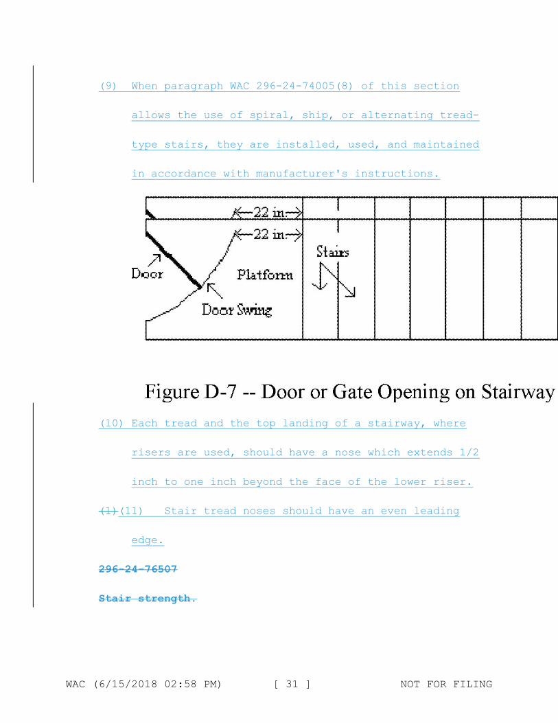
(5) When a door or a gate opens directly on a stairway, a
platform is provided, and the swing of the door or
gate does not reduce the platform's effective usable
depth to:
a. Less than 20 inches (51 cm) for platforms installed
before January 17, 2017; and
WAC (6/15/2018 02:58 PM) [ 29 ] NOT FOR FILING

b. Less than 22 inches (56 cm) for platforms installed
on or after January 17, 2017 (see Figure D-7 at the
end of this section);
(6) Each stair can support at least five times the normal
anticipated live load, but never less than a
concentrated load of 1,000 pounds (454 kg) applied at
any point.
(7) Standard stairs are used to provide access from one
walking-working surface to another when operations
necessitate regular and routine travel between levels,
including access to operating platforms for equipment.
Winding stairways may be used on tanks and similar
round structures when the diameter of the tank or
structure is at least 5 feet (1.5 m).
(8) Spiral, ship, or alternating tread-type stairs are
used only when the employer can demonstrate that it is
not feasible to provide standard stairs.
WAC (6/15/2018 02:58 PM) [ 30 ] NOT FOR FILING
(9) When paragraph WAC 296-24-74005(8) of this section
allows the use of spiral, ship, or alternating tread-
type stairs, they are installed, used, and maintained
in accordance with manufacturer's instructions.
(10) Each tread and the top landing of a stairway, where
risers are used, should have a nose which extends 1/2
inch to one inch beyond the face of the lower riser.
(1)(11) Stair tread noses should have an even leading
edge.
296-24-76507
Stair strength.
WAC (6/15/2018 02:58 PM) [ 31 ] NOT FOR FILING

You must ensure that fixed stairways are designed and
constructed to carry a load of five times the normal live
load anticipated but never of less strength than to carry
safely a moving concentrated load of 1,000 pounds.
296-24-76509
Stair width.
Fixed stairways must have a minimum width of 22 inches.
296-24-74010
Standard Stairs.
In addition to paragraph WAC 296-24-74005 of this chapter,
you must also ensure standard stairs:
(1) Are installed at angles between 30 to 50 degrees from
the horizontal
(2) Have a maximum riser height of 9.5 inches (24 cm)
(3) Have a minimum tread depth of 9.5 inches (24 cm)
(4) Have a minimum width of 22 inches (56 cm) between
vertical barriers (see Figure D-8 of this section).
Exception: Paragraphs (2) and (3) of this section do not apply
to standard stairs installed prior to January 17, 2017, provided
those stairs meet the dimension requirements specified in Table
WAC (6/15/2018 02:58 PM) [ 32 ] NOT FOR FILING

D-1 of this section or they use a combination that achieves the
angle requirements of paragraph WAC 296-24-74010(1) of this
section.
TABLE D-1 Angle to Rise Tread Run
Horizontal (in inches) (in inches) 30°35' . . . . 6 1/2 11 32°08' . . . . 6 3/4 10 3/4 33°41' . . . . 7 10 1/2 35°16' . . . . 7 1/4 10 1/4 36°52' . . . . 7 1/2 10 38°29' . . . . 7 3/4 9 3/4 40°08' . . . . 8 9 1/2 41°44' . . . . 8 1/4 9 1/4 43°22' . . . . 8 1/2 9 45°00' . . . . 8 3/4 8 3/4 46°38' . . . . 9 8 1/2 48°16' . . . . 9 1/4 8 1/4 49°54' . . . . 9 1/2 8
WAC (6/15/2018 02:58 PM) [ 33 ] NOT FOR FILING
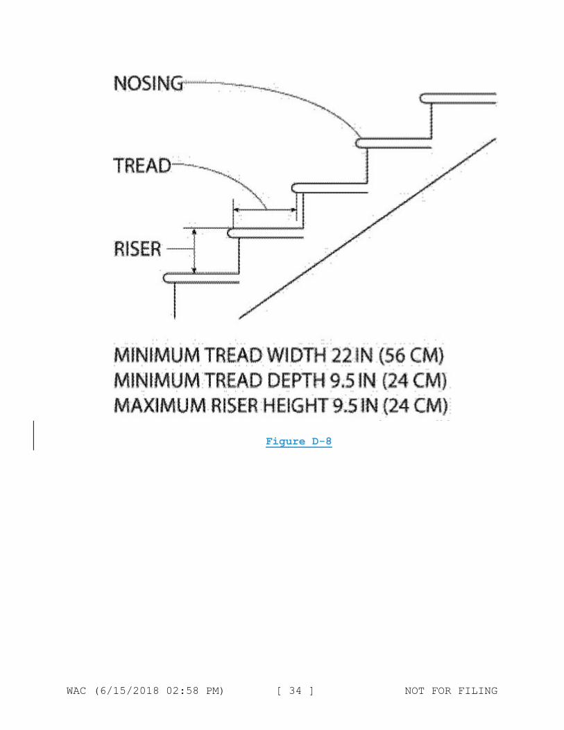
Figure D-8
WAC (6/15/2018 02:58 PM) [ 34 ] NOT FOR FILING

WAC (6/15/2018 02:58 PM) [ 35 ] NOT FOR FILING

296-24-76511
Angle of stairway rise.
(1) You must ensure that fixed stairs are installed at
angles to the horizontal of between 30 degrees and 50 degrees.
Any uniform combination of rise/tread dimensions may be used
that will result in a stairway at any angle to the horizontal
within the permissible range. Table D-1 gives rise/tread
WAC (6/15/2018 02:58 PM) [ 36 ] NOT FOR FILING

dimensions which will produce a stairway within the permissible
range, stating the angle to the horizontal produced by each
combination. However, the rise/tread combinations are not
limited to those given in Table D-1.
(2) Because of space limitations a permanent stairway
sometimes has to be installed at an angle above the 50 degree
critical angle. Such installations are commonly called inclined
ladders or ship's ladders, which you must ensure have handrails
on both sides and open risers. You must ensure that they are
capable of sustaining a live load of 100 pounds per square foot
with a safety factor of 4. The following preferred and critical
angles from the horizontal must be considered for inclined
ladders and ship's ladders:
(a) 35 to 60 degrees - Preferred angle from horizontal.
(b) 60 to 70 degrees - Critical angle from horizontal.
TABLE D-1 Angle to Rise Tread Run
Horizontal (in inches) (in inches) 30°35' . . . . 6 1/2 11 32°08' . . . . 6 3/4 10 3/4 33°41' . . . . 7 10 1/2 35°16' . . . . 7 1/4 10 1/4 36°52' . . . . 7 1/2 10 38°29' . . . . 7 3/4 9 3/4 40°08' . . . . 8 9 1/2 41°44' . . . . 8 1/4 9 1/4 43°22' . . . . 8 1/2 9 45°00' . . . . 8 3/4 8 3/4
WAC (6/15/2018 02:58 PM) [ 37 ] NOT FOR FILING

46°38' . . . . 9 8 1/2 48°16' . . . . 9 1/4 8 1/4 49°54' . . . . 9 1/2 8
296-24-76513
Stair treads.
Each tread and the top landing of a stairway, where risers
are used, should have a nose which extends 1/2 inch to one
inch beyond the face of the lower riser. Noses should have
an even leading edge. You must ensure that all treads are
reasonably slip-resistant and the nosings are of nonslip
finish. Welded bar grating treads without nosings are
acceptable providing the leading edge can be readily
identified by personnel descending the stairway and
provided the tread is serrated or is of definite nonslip
design. You must ensure that rise height and tread width
are uniform throughout any flight of stairs including any
foundation structure used as one or more treads of the
stairs.
296-24-74015
Spiral7406515
Length of stairwaysSpiral Stairs.
Long flights of stairs, unbroken by landings or
intermediate platforms, should be avoided. Consideration should
be given to providing intermediate platforms where practical and
where such stairways are in frequent use. You must ensure that
stairway platforms are no less than the width of a stairway and
WAC (6/15/2018 02:58 PM) [ 38 ] NOT FOR FILING

a minimum of 30 inches in length measured in the direction of
travel.
In addition to paragraph WAC 296-24-74005 of this chapter,
you must also ensure spiral stairs:
(1) Have a minimum clear width of 26 inches (66 cm)
(2) Have a maximum riser height of 9.5 inches (24 cm)
(3) Have a minimum headroom above spiral stair treads of
at least 6 feet, 6 inches (2 m), measured from the
leading edge of the tread
(4) Have a minimum tread depth of 7.5 inches (19 cm),
measured at a point 12 inches (30 cm) from the
narrower edge
(5) Have a uniform tread size
296-24-76519
Vertical clearance.
You must ensure that vertical clearance above any stair
tread to an overhead obstruction is at least 7 feet measured
from the leading edge of the tread.
296-24-74020
Ship Stairs.
In addition to paragraph WAC 296-24-74005 of this chapter,
you must also ensure ship stairs (see figure D-9 of this
section):
(1) Are installed at a slope of 50 to 70 degrees from the
horizontal
(2) Have open risers with a vertical rise between tread
surfaces of 6.5 to 12 inches (17 to 30 cm)
WAC (6/15/2018 02:58 PM) [ 39 ] NOT FOR FILING

(3) Have minimum tread depth of 4 inches (10 cm)
(4) Have a minimum tread width of 18 inches (46 cm)
296-24-7402576521
Open risers.
Stairs having treads of less than 9-inch width should have
open risers.
296-24-76523
General.
Open grating type treads are desirable for outside stairs.
WAC (6/15/2018 02:58 PM) [ 40 ] NOT FOR FILING
296-24-7655574025
Alternating tread-type stairs.
Alternating tread-type stairs have a series of steps
between 50 and 70 degrees from horizontal, attached to a center
support rail in an alternating manner so that a user of the
stairs never has both feet at the same level at the same time.
(See Figure D-11112 of this section)..). You must ensure
alternating tread-type stairs are:
(1) DesignedYou must ensure that alternating tread-type
stairs are Ddesigned, installed, used, and maintained in
accordance with approved manufacturer's specifications, and have
the following:
(a) Stair rails on all open sides;
(b) Handrails on both sides of enclosed stairs;
(c) Stair rails and handrails of such configuration as to
provide an adequate handhold for a user grasping it to avoid a
fall;
(d) A minimum distance of 17 to 24 inches between
handrails;
(e) A minimum width of 22 inches overall;
(f) A minimum tread depth of 8.5 inches;
(g) A minimum tread width of 7 inches; and
(h) A maximum rise of 9 1/2 inches to the tread surface of
the next alternating tread; and.
(i) Open risers if the tread depth is less than 9.5 inches
(24 cm).
WAC (6/15/2018 02:58 PM) [ 41 ] NOT FOR FILING

(2) You must ensure that alternating tread-type stairs have
not more than a 20-foot continuous rise. You must provide one or
more intermediate platforms in accordance with WAC 296-24-76515
296-24-74005 where more than a 20-foot rise is necessary to
reach the top of a required stair.
WAC (6/15/2018 02:58 PM) [ 42 ] NOT FOR FILING

6/15/2018 02:58 PM) [ 43 ] NOT FOR FILINGWAC (

Figure D-11(3) You must ensure that stairs and platforms
are installed so the top landing of the alternating tread stair
is flush with the top of the landing platform.
(4) You must ensure that stair design and construction
sustains a load of not less than 5 times the normal live load,
but never less strength than to carry safely a moving
concentrated load of 1,000 pounds.
(5) You must ensure that treads are equipped with slip-
resistant surfaces.
WAC (6/15/2018 02:58 PM) [ 44 ] NOT FOR FILING

(6) You must ensure that where a platform or landing is
used, the width is not less than the width of the stair nor less
than 30-inch depth in the direction of travel. You must ensure
that stairs are flush with the top of the landing
platform.Figure D-11
WAC 296-24-855 750 Other working surfaces.
296-24-755058550175505
Dockboards (bridge plates).
WAC (6/15/2018 02:58 PM) [ 45 ] NOT FOR FILING

(1) (1) You must ensure:
(2) Portable and powered dockboards are strong enough to
carry the load imposed on them.
(3) Dockboards put into initial service on or after
January 17, 2017 are designed, constructed, and
maintained to prevent employees from running off the
dockboard edge.
Exception: When the employer demonstrates there is no hazard of
employees running off the dockboard edge, WAC 296-24-85501(2)
does not apply.
(4) Portable dockboards are secured by anchoring them in
place or using equipment or devices that prevent the
dockboard from moving out of a safe position. When the
employer demonstrates that securing the dockboard is
not feasible, the employer must ensure there is
sufficient contact between the dockboard and the
surface to prevent the dockboard from moving out of a
safe position.
(5) Powered dockboards are designed and constructed in
accordance with Commercial Standard CS202-56 (1961)
"Industrial Lifts and Hinged Loading Ramps" published
by the U.S. Department of Commerce, or newer standards
as effective as the code such as:
a. American National Standards Institute
(ANSI)/Industrial Truck Standards Development
Foundation (ITSDF) B56.1-2012, Trucks, Low and High
Lift, Safety Standard (B56.1-2012)
WAC (6/15/2018 02:58 PM) [ 46 ] NOT FOR FILING
b. ASME/ANSI MH14.1-1987, Loading Dock Levelers and
Dockboards (MH14.1-1987) (Ex. 371)
c. ANSI MH30.1-2007, National Standard for the Safety
Performance, and Testing of Dock Loading Devices
(MH30.1-2007) (Ex. 372)
d. ANSI MH30.2-2005, Portable Dock Loading Devices:
Standards, Performance, and Testing (MH30.2-2005)
(Ex. 20)
(6) Measures, such as wheel chocks or sand shoes, are used
to prevent the transport vehicle (e.g. a truck, semi-
trailer, trailer, or rail car) or container on which a
dockboard is placed, from moving while employees are
on the dockboard.
(1) You must ensure that handholds, or other effective
means, are provided on portable dockboards to permit
safe handling.
(2) You must ensure that portable dockboards are secured in
position, either by being anchored or equipped with devices
which will prevent their slipping.
(3) You must ensure that powered dockboards are
designed and constructed in accordance with Commercial Standard
CS202-56 (1961) "Industrial Lifts and Hinged Loading Ramps"
published by the U.S. Department of Commerce.
(4) You must ensure that handholds, or other effective
means, are provided on portable dockboards to permit safe
handling.
WAC (6/15/2018 02:58 PM) [ 47 ] NOT FOR FILING

(5) You must ensure that positive protection is provided to
prevent railroad cars from being moved while dockboards or
bridge plates are in position.
296-24-85503
Forging machine area.
(1) You must ensure that machines are locate so as to give
(a) enough clearance between machines so that the movement of
one operator will not interfere with the work of another, (b)
ample room for cleaning machines and handling the work,
including material and scrap. The arrangement of machines must
be such that operators will not stand in aisles.
(2) You must ensure that aisles are provided of sufficient
width to permit the free movement of employees bringing and
removing material. This aisle space is to be independent of
working and storage space and should be defined by marking.
(3) You must ensure that wood platforms used on the floor
in front of machines are substantially constructed with nonslip
surfaces.
296-24-85505
Veneer machinery.
(1) You must ensure that sides of steam vats extend to a
height of not less than 36 inches above the floor, working
platform, or ground.
(2) You must ensure that large steam vats divided into
sections are provided with substantial walkways between
sections. Each walkway must be provided with a standard handrail
WAC (6/15/2018 02:58 PM) [ 48 ] NOT FOR FILING

on each exposed side. These handrails may be removable, if
necessary.
(3) You must ensure that covers are removed only from that
portion of steaming vats on which people are working and a
portable railing is placed at this point to protect the
operators.
(4) You must ensure that workers do not ride or step on
logs in steam vats.
296-24-862
Nonmandatory appendices.
Nonmandatory Appendix A to Part J-2, Scaffold
Specifications.
This Appendix provides nonmandatory guidelines to assist
employers in complying with the requirements of Part J-2 of this
chapter. An employer may use these guidelines and tables as a
starting point for designing scaffold systems. However, the
guidelines do not provide all the information necessary to build
a complete system, and the employer is still responsible for
designing and assembling these components in such a way that the
completed system will meet the requirements of WAC 296-24-
86010(1). Scaffold components which are not selected and loaded
in accordance with this Appendix, and components for which no
specific guidelines or tables are given in this Appendix (e.g.,
joints, ties, components for wood pole scaffolds more than 60
feet in height, components for heavy-duty horse scaffolds,
components made with other materials, and components with other
dimensions, etc.) must be designed and constructed in accordance
WAC (6/15/2018 02:58 PM) [ 49 ] NOT FOR FILING

with the capacity requirements of WAC 296-24-86010(1), and
loaded in accordance with WAC 296-24-86010 (4)(a).
Index to Appendix A for Part J-2
1. General guidelines and tables.
2. Specific guidelines and tables.
(a) Pole scaffolds:
Single-pole wood pole scaffolds.
Independent wood pole scaffolds.
(b) Tube and coupler scaffolds.
(c) Fabricated frame scaffolds.
(d) Plasterers', decorators' and large area scaffolds.
(e) Bricklayers' square scaffolds.
(f) Horse scaffolds.
(g) Form scaffolds and carpenters' bracket scaffolds.
(h) Roof bracket scaffolds.
(i) Outrigger scaffolds (one level).
(j) Pump jack scaffolds.
(k) Ladder jack scaffolds.
(l) Window jack scaffolds.
(m) Crawling boards (chicken ladders).
(n) Step, platform and trestle ladder scaffolds.
(o) Single-point adjustable suspension scaffolds.
(p) Two-point adjustable suspension scaffolds.
(q)(1) Stonesetters' multipoint adjustable suspension
scaffolds.
(q)(2) Masons' multipoint adjustable suspension scaffolds.
(r) Catenary scaffolds.
WAC (6/15/2018 02:58 PM) [ 50 ] NOT FOR FILING

(s) Float (ship) scaffolds.
(t) Interior hung scaffolds.
(u) Needle beam scaffolds.
(v) Multilevel suspension scaffolds.
(w) Mobile scaffolds.
(x) Repair bracket scaffolds.
(y) Stilts.
(z) Tank builders' scaffolds.
1. General guidelines and tables.
(a) The following tables, and the tables in Part 2—Specific
guidelines and tables, assume that all load-carrying timber
members (except planks) of the scaffold are a minimum of 1,500
lb-f/in(2) (stress grade) construction grade lumber. All
dimensions are nominal sizes as provided in the American
Softwood Lumber Standards, dated January 1970, except that,
where rough sizes are noted, only rough or undressed lumber of
the size specified will satisfy minimum requirements.
(b) Solid sawn wood used as scaffold planks must be
selected for such use following the grading rules established by
a recognized lumber grading association or by an independent
lumber grading inspection agency. Such planks must be identified
by the grade stamp of such association or agency. The
association or agency and the grading rules under which the wood
is graded must be certified by the Board of Review, American
Lumber Standard Committee, as set forth in the American Softwood
Lumber Standard of the U.S. Department of Commerce.
WAC (6/15/2018 02:58 PM) [ 51 ] NOT FOR FILING

(i) Allowable spans must be determined in compliance with
the National Design Specification for Wood Construction
published by the National Forest Products Association; paragraph
5 of ANSI A10.8-1988 Scaffolding-Safety Requirements published
by the American National Standards Institute; or for 2 x 10 inch
(nominal) or 2 x 9 inch (rough) solid sawn wood planks, as shown
in the following table:
Maximum
permissible Maximum
span using permissible
Maximum full span using
intended thickness nominal
nominal load undressed thickness
(lb/ft2) lumber (ft) lumber (ft)
25
50
10
8
8
6
75 6
(ii) The maximum permissible span for 1 1/4 x 9-inch or
wider wood plank of full thickness with a maximum intended load
of 50 lb/ft.(2) must be 4 feet.
(c) Fabricated planks and platforms may be used in lieu of
solid sawn wood planks. Maximum spans for such units must be as
recommended by the manufacturer based on the maximum intended
load being calculated as follows:
WAC (6/15/2018 02:58 PM) [ 52 ] NOT FOR FILING

Rated
load
capacity Intended load
Light- *25 pounds per
duty square foot applied
uniformly over the
entire span area.
Medium- *50 pounds per
duty square foot applied
uniformly over the
entire span area.
Heavy- *75 pounds per
duty square foot applied
uniformly over the
entire span area.
One- *250 pounds
person placed at the center
of the span (total
250 pounds).
Two- *250 pounds
person placed 18 inches to
the left and right
of the center of the
span (total 500
pounds).
WAC (6/15/2018 02:58 PM) [ 53 ] NOT FOR FILING
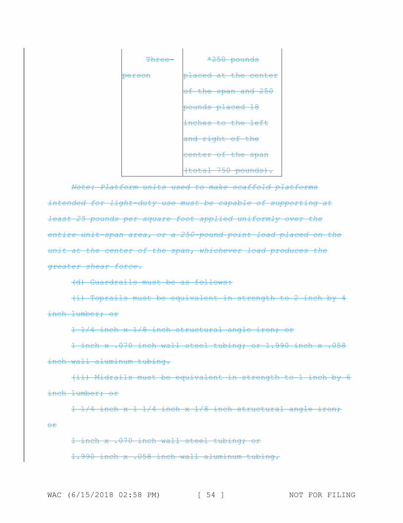
Three-
person
*250 pounds
placed at the center
of the span and 250
pounds placed 18
inches to the left
and right of the
center of the span
(total 750 pounds).
Note: Platform units used to make scaffold platforms
intended for light-duty use must be capable of supporting at
least 25 pounds per square foot applied uniformly over the
entire unit-span area, or a 250-pound point load placed on the
unit at the center of the span, whichever load produces the
greater shear force.
(d) Guardrails must be as follows:
(i) Toprails must be equivalent in strength to 2 inch by 4
inch lumber; or
1 1/4 inch x 1/8 inch structural angle iron; or
1 inch x .070 inch wall steel tubing; or 1.990 inch x .058
inch wall aluminum tubing.
(ii) Midrails must be equivalent in strength to 1 inch by 6
inch lumber; or
1 1/4 inch x 1 1/4 inch x 1/8 inch structural angle iron;
or
1 inch x .070 inch wall steel tubing; or
1.990 inch x .058 inch wall aluminum tubing.
WAC (6/15/2018 02:58 PM) [ 54 ] NOT FOR FILING

(iii) Toeboards must be equivalent in strength to 1 inch by
4 inch lumber; or
1 1/4 inch x 1 1/4 inch structural angle iron; or
1 inch x .070 inch wall steel tubing; or
1.990 inch x .058 inch wall aluminum tubing.
(iv) Posts must be equivalent in strength to 2 inch by 4
inch lumber; or
1 1/4 inch x 1 1/4 inch x 1/8 structural angle iron; or
1 inch x .070 inch wall steel tubing; or
1.990 inch x .058 inch wall aluminum tubing.
(v) Distance between posts must not exceed 8 feet.
(e) Overhead protection must consist of 2 inch nominal
planking laid tight, or 3/4-inch plywood.
(f) Screen installed between toeboards and midrails or
toprails must consist of No. 18 gauge U.S. Standard wire one
inch mesh.
2. Specific guidelines and tables.
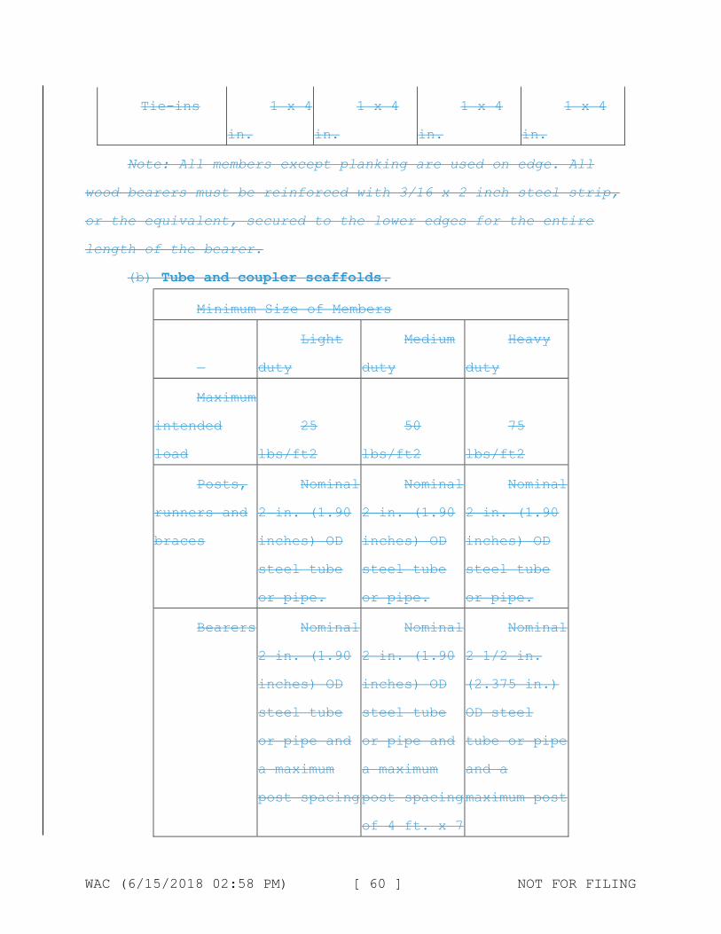
(a) Pole scaffolds.
Single Pole Wood Pole Scaffolds
Light
duty up to Light
20 feet duty up to
high 60 feet high
Medium
duty up to
60 feet
high
Heavy
duty up to
60 feet
high
Maximum
intended load
(lbs/ft2) 25 25 50 75
WAC (6/15/2018 02:58 PM) [ 55 ] NOT FOR FILING
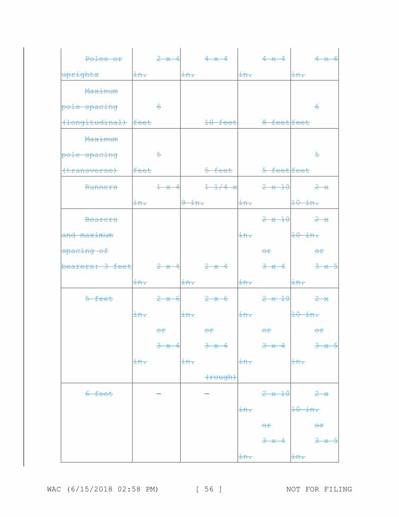
Poles or
uprights in.
2 x 4 4 x 4
in. in.
4 x 4 4 x
in.
6
Maximum
pole spacing
(longitudinal) feet
6
10 feet
6
8 feet feet
Maximum
pole spacing
(transverse) feet
5
5 feet
5
5 feet feet
Runners
in.
1 x 4 1 1/4 x
9 in. in.
2 x 10 2 x
10 in.
Bearers
and maximum
spacing of
bearers: 3 feet
in.
2 x
in.
4 2 x 4
in. in.
2 x 10 2 x
10 in.
or or
3 x 4 3 x
in.
5
5 feet
in.
in.
2 x
or
3 x
6 2 x 6
in. in.
or
4 3 x 4
in. in.
(rough)
2 x 10 2 x
10 in.
or or
3 x 4 3 x
in.
5
6 feet — —
in.
in.
2 x 10
or
3 x 4
2 x
10 in.
or
3 x
in.
5
WAC (6/15/2018 02:58 PM) [ 56 ] NOT FOR FILING

8 feet — —
in.
in.
2 x 10
or
3 x 4
Planking 1 1/4
x 9 in. in.
Maximum
vertical
spacing of
horizontal 7
members feet
Bracing
horizontal
1 x 4
in. in.
Bracing 1 x 4
diagonal in. in.
2
9
1
1
x 10
feet
x 4
x 4
in.
in.
x 4
in.
2 x 10 2
10 in.
6
7 feet 6 in.
1 x 6
or
1 1/4 2
in. in.
1 x 4 2
in.
x
ft.
x 4
x 4
Tie-ins 1 x 4
in. in.
1 x 4
in.
1 x 4 1
in.
x 4
Note: All members except planking are used on edge. All
wood bearers must be reinforced with 3/16 x 2 inch steel strip,
or the equivalent, secured to the lower edges for the entire
length of the bearer.
Independent Wood Pole Scaffolds
WAC (6/15/2018 02:58 PM) [ 57 ] NOT FOR FILING

Light
duty up to
Light
duty up to
60 feet high
Medium
duty up to
60 feet high
Heavy
duty up to
60 feet high 20 feet
high
Maximum
intended load
25
lbs/ft2
25
lbs/ft2
50
lbs/ft2
75
lbs/ft2
Poles or
uprights
2 x 4
in.
4 x 4
in.
4 x 4
in.
4 x 4
in.
Maximum
pole spacing
(longitudinal)
6
feet 10 feet 8 feet 6 feet
Maximum
(transverse)
6
feet 10 feet 8 feet 8 feet
Runners 1 1/4
x 4 in.
1 1/4 x
9 in.
2 x 10
in.
2 x 10
in.
Bearers
and maximum
spacing of
bearers: 3 feet
2 x 4
in.
2 x 4
in.
2 x 10
in.
(rough)
2 x 10
in.
6 feet 2 x 6
in.
or
3 x 4
in.
2 x 10
in.
(rough)
or
3 x 8
in.
2 x 10
in.
2 x 10
in.
(rough)
WAC (6/15/2018 02:58 PM) [ 58 ] NOT FOR FILING

8 feet 2 x 6
in.
or
3 x 4
in.
in.
in.
2 x 10
(rough)
or
3 x 8
2 x 10
in.
10 feet 3 x 4
in. in.
in.
Planking 1 1/4
x 9 in. in.
Maximum
vertical
spacing of
horizontal 7
members feet
Bracing
horizontal
1 x 4
in. in.
2 x 6 2 x 10
in.
(rough)
or
3 x 3
2 x 10 2 x 10
in. in.
7 feet 6 feet
1 x 6
in.
or
1 x 4 1 1/4 x
4 in. in.
2
6
2
x 10
feet
x 4
Bracing
diagonal
1 x 4
in. in.
1 x 4 1 x 4
in. in.
2 x 4
WAC (6/15/2018 02:58 PM) [ 59 ] NOT FOR FILING
Tie-ins
in.
1 x 4
in.
1 x 4
in.
1 x 4
in.
1 x 4
Note: All members except planking are used on edge. All
wood bearers must be reinforced with 3/16 x 2 inch steel strip,
or the equivalent, secured to the lower edges for the entire
length of the bearer.
(b) Tube and coupler scaffolds.
Minimum
Maximum
intended
load
Posts,
runners and
braces
Size of Members
Light Medium
duty duty
25 50
lbs/ft2 lbs/ft2
Nominal Nominal
2 in. (1.90 2 in. (1.90
inches) OD inches) OD
steel tube steel tube
or pipe. or pipe.
Heavy
duty
75
lbs/ft2
Nominal
2 in. (1.90
inches) OD
steel tube
or pipe.
Bearers Nominal
2 in. (1.90
inches) OD
steel tube
or pipe and
a maximum
post spacing
Nominal
2 in. (1.90
inches) OD
steel tube
or pipe and
a maximum
post spacing
Nominal
2 1/2 in.
(2.375 in.)
OD steel
tube pipe or
and a
maximum post
of 4 ft. 7 x
WAC (6/15/2018 02:58 PM) [ 60 ] NOT FOR FILING

of 4 ft. x
10 ft.
ft. or
Nominal 2
1/2 in.
(2.375 in.)
OD steel
tube pipe
spacing of 6
ft. x 6 ft.
or
and a
maximum post
spacing of 6
ft. x 8 ft.
(*).
Maximum
runner
spacing
vertically
6 ft. 6
in.
6 ft. 6
in.
6
in.
ft. 6
(*) Bearers must be installed in the direction of the
shorter dimension.
Note: Longitudinal diagonal bracing must be installed at an
angle of 45 deg. (+/- 5 deg.).
Maximum Number of Planked Levels
Maximum number of
additional planked levels
Light
duty
Medium
duty
Heavy
duty
Maximum
height of
scaffold (in
feet)
WAC (6/15/2018 02:58 PM) [ 61 ] NOT FOR FILING

Duty Number of Working Levels:
1 16 11 6 125
2 11 1 0 125
3 6 0 0 125
4 1 0 0 125
(c) Fabricated frame scaffolds. Because of their
prefabricated nature, no additional guidelines or tables for
these scaffolds are being adopted in this Appendix.
(d) Plasterers', decorators', and large area scaffolds. The
guidelines for pole scaffolds or tube and coupler scaffolds
(Appendix A (a) and (b)) may be applied.
(e) Bricklayers' square scaffolds.
Maximum intended load: 50 lb/ft.(2)(*)
Footnote(*): The squares must be set not more than 8 feet
apart for light duty scaffolds and not more than 5 feet apart
for medium duty scaffolds.
Maximum width: 5 ft.
Maximum height: 5 ft.
Gussets: 1 x 6 in.
Braces: 1 x 8 in.
Legs: 2 x 6 in.
Bearers (horizontal members): 2 x 6 in.
(f) Horse scaffolds.
Maximum intended load (light duty): 25 lb/ft.(2)(**)
WAC (6/15/2018 02:58 PM) [ 62 ] NOT FOR FILING

Footnote(**): Horses must be spaced not more than 8 feet
apart for light duty loads, and not more than 5 feet apart for
medium duty loads.
Maximum intended load (medium duty): 50 lb/ft.(2)(**)
Footnote(**): Horses must be spaced not more than 8 feet
apart for light duty loads, and not more than 5 feet apart for
medium duty loads.
Horizontal members or bearers:
Light duty: 2 x 4 in.
Medium duty: 3 x 4 in.
Legs: 2 x 4 in.
Longitudinal brace between legs: 1 x 6 in.
Gusset brace at top of legs: 1 x 8 in.
Half diagonal braces: 2 x 4 in.
(g) Form scaffolds and carpenters' bracket scaffolds.
(1) Brackets must consist of a triangular-shaped frame made
of wood with a cross-section not less than 2 inches by 3 inches,
or of 1 1/4 inch x 1 1/4 inch x 1/8 inch structural angle iron.
(2) Bolts used to attach brackets to structures must not be
less than 5/8 inches in diameter.
(3) Maximum bracket spacing must be 8 feet on centers.
(4) No more than two employees must occupy any given 8 feet
of a bracket or form scaffold at any one time. Tools and
materials must not exceed 75 pounds in addition to the
occupancy.
(5) Wooden figure-four scaffolds:
Maximum intended load: 25 lb/ft.(2)
WAC (6/15/2018 02:58 PM) [ 63 ] NOT FOR FILING

Uprights: 2 x 4 in. or 2 x 6 in.
Bearers (two): 1 x 6 in.
Braces: 1 x 6 in.
Maximum length of bearers (unsupported): 3 ft. 6 in.
(i) Outrigger bearers must consist of two pieces of 1 x 6
inch lumber nailed on opposite sides of the vertical support.
(ii) Bearers for wood figure-four brackets must project not
more than 3 feet 6 inches from the outside of the form support,
and must be braced and secured to prevent tipping or turning.
The knee or angle brace must intersect the bearer at least 3
feet from the form at an angle of approximately 45 degrees, and
the lower end must be nailed to a vertical support.
(6) Metal bracket scaffolds:
Maximum intended load: 25 lb/ft.(2)
Uprights: 2 x 4 inch
Bearers: As designed.
Braces: As designed.
(7) Wood bracket scaffolds:
Maximum intended load: 25 lb/ft.(2)
Uprights: 2 x 4 in. or 2 x 6 in.
Bearers: 2 x 6 in.
Maximum scaffold width: 3 ft. 6 in.
Braces: 1 x 6 in.
(h) Roof bracket scaffolds. No specific guidelines or
tables are given.
(i) Outrigger scaffolds (single level). No specific
guidelines or tables are given.
WAC (6/15/2018 02:58 PM) [ 64 ] NOT FOR FILING

(j) Pump jack scaffolds. Wood poles must not exceed 30 feet
in height. Maximum intended load — 500 lbs between poles;
applied at the center of the span. Not more than two employees
must be on a pump jack scaffold at one time between any two
supports. When 2 x 4's are spliced together to make a 4 x 4 inch
wood pole, they must be spliced with "10 penny" common nails no
more than 12 inches center to center, staggered uniformly from
the opposite outside edges.
(k) Ladder jack scaffolds. Maximum intended load — 25
lb/ft(2). However, not more than two employees must occupy any
platform at any one time. Maximum span between supports must be
8 feet.
(l) Window jack scaffolds. Not more than one employee must
occupy a window jack scaffold at any one time.
(m) Crawling boards (chicken ladders). Crawling boards must
be not less than 10 inches wide and 1 inch thick, with cleats
having a minimum 1 x 1 1/2 inch cross-sectional area. The cleats
must be equal in length to the width of the board and spaced at
equal intervals not to exceed 24 inches.
(n) Step, platform, and trestle ladder scaffolds. No
additional guidelines or tables are given.
(o) Single-point adjustable suspension scaffolds. Maximum
intended load — 250 lbs. Wood seats for boatswains' chairs must
be not less than 1 inch thick if made of nonlaminated wood, or
5/8 inches thick if made of marine quality plywood.
(p) Two-point adjustable suspension scaffolds.
WAC (6/15/2018 02:58 PM) [ 65 ] NOT FOR FILING

(1) In addition to direct connections to buildings (except
window cleaners' anchors) acceptable ways to prevent scaffold
sway include angulated roping and static lines. Angulated roping
is a system of platform suspension in which the upper wire rope
sheaves or suspension points are closer to the plane of the
building face than the corresponding attachment points on the
platform, thus causing the platform to press against the face of
the building. Static lines are separate ropes secured at their
top and bottom ends closer to the plane of the building face
than the outermost edge of the platform. By drawing the static
line taut, the platform is drawn against the face of the
building.
(2) On suspension scaffolds designed for a working load of
500 pounds, no more than two employees must be permitted on the
scaffold at one time. On suspension scaffolds with a working
load of 750 pounds, no more than three employees must be
permitted on the scaffold at one time.
(3) Ladder-type platforms. The side stringer must be of
clear straight-grained spruce. The rungs must be of straight-
grained oak, ash, or hickory, at least 1 1/8 inches in diameter,
with 7/8 inch tenons mortised into the side stringers at least
7/8 inch. The stringers must be tied together with tie rods not
less than 1/4 inch in diameter, passing through the stringers
and riveted up tight against washers on both ends. The flooring
strips must be spaced not more than 5/8 inch apart, except at
the side rails where the space may be 1 inch. Ladder-type
WAC (6/15/2018 02:58 PM) [ 66 ] NOT FOR FILING
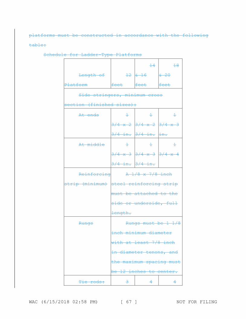
platforms must be constructed in accordance with the following
table:
Schedule for Ladder-Type Platforms
14 18
Length of 12 & 16 & 20
Platform feet feet feet
Side stringers, minimum cross
section (finished sizes):
At ends 1
3/4 x 2
3/4 in.
1
3/4 x 2
3/4 in.
1
3/4 x 3
in.
At middle 1
3/4 x 3
3/4 in.
1
3/4 x 3
3/4 in.
1
3/4 x 4
Reinforcing
strip (minimum)
A 1/8 x 7/8 inch
steel reinforcing strip
must be attached to the
side or underside, full
length.
Rungs Rungs must be 1 1/8
inch minimum diameter
with at least 7/8 inch
in diameter tenons, and
the maximum spacing must
be 12 inches to center.
Tie rods: 3 4 4
WAC (6/15/2018 02:58 PM) [ 67 ] NOT FOR FILING

Number
(minimum)
Diameter 1/4 1/4 1/4
(minimum) inch inch inch
Flooring, 1/2 1/2 1/2
minimum finished x 2 3/4 x 2 3/4 x 2 3/4
size in. in. in.
Length of 22 28
Platform & 24 ft. & 30 ft.
Side stringers, minimum cross
section (finished sizes):
At ends 1
3/4 x 3
in.
1
3/4 x 3
1/2 in.
At middle 1
3/4 x 4
1/4 in.
1
3/4 x 5
in.
Reinforcing A 1/8 x 7/8 inch
strip (minimum) steel reinforcing strip
must be attached to the
side or underside, full
length.
Rungs Rungs must be 1 1/8
inch minimum diameter
with at least 7/8 inch
in diameter with at
WAC (6/15/2018 02:58 PM) [ 68 ] NOT FOR FILING

least 7/8 inch in
diameter tenons, and the
maximum spacing must be
12 inches to center.
Tie rods:
Number
(minimum) 5 6
Diameter 1/4
(minimum) in.
1/4
in.
Flooring, 1/2 1/2
minimum finished x 2 3/4 x 2 3/4
size in. in.
(4) Plank-type platforms. Plank-type platforms must be
composed of not less than nominal 2 x 8 inch unspliced planks,
connected together on the underside with cleats at intervals not
exceeding 4 feet, starting 6 inches from each end. A bar or
other effective means must be securely fastened to the platform
at each end to prevent the platform from slipping off the
hanger. The span between hangers for plank-type platforms must
not exceed 10 feet.
(5) Beam-type platforms. Beam platforms must have side
stringers of lumber not less than 2 x 6 inches set on edge. The
span between hangers must not exceed 12 feet when beam platforms
are used. The flooring must be supported on 2 x 6 inch cross
beams, laid flat and set into the upper edge of the stringers
with a snug fit, at intervals of not more than 4 feet, securely
WAC (6/15/2018 02:58 PM) [ 69 ] NOT FOR FILING

nailed to the cross beams. Floor-boards must not be spaced more
than 1/2 inch apart.
(q)(1) Multipoint adjustable suspension scaffolds and
stonesetters' multipoint adjustable suspension scaffolds. No
specific guidelines or tables are given for these scaffolds.
(q)(2) Masons' multipoint adjustable suspension
scaffolds. Maximum intended load — 50 lb/ft(2). Each outrigger
beam must be at least a standard 7 inch, 15.3 pound steel I-
beam, at least 15 feet long. Such beams must not project more
than 6 feet 6 inches beyond the bearing point. Where the
overhang exceeds 6 feet 6 inches, outrigger beams must be
composed of stronger beams or multiple beams.
(r) Catenary scaffolds.
(1) Maximum intended load — 500 lbs.
(2) Not more than two employees must be permitted on the
scaffold at one time.
(3) Maximum capacity of come-along must be 2,000 lbs.
(4) Vertical pickups must be spaced not more than 50 feet
apart.
(5) Ropes must be equivalent in strength to at least 1/2
inch (1.3 cm) diameter improved plow steel wire rope.
(s) Float (ship) scaffolds.
(1) Maximum intended load — 750 lbs.
(2) Platforms must be made of 3/4 inch plywood, equivalent
in rating to American Plywood Association Grade B-B, Group I,
Exterior.
WAC (6/15/2018 02:58 PM) [ 70 ] NOT FOR FILING

(3) Bearers must be made from 2 x 4 inch, or 1 x 10 inch
rough lumber. They must be free of knots and other flaws.
(4) Ropes must be equivalent in strength to at least 1 inch
(2.5 cm) diameter first grade manila rope.
(t) Interior hung scaffolds.
Bearers (use on edge): 2 x 10 in.
Maximum intended load: Maximum span
25 lb/ft.(2): 10 ft.
50 lb/ft.(2): 10 ft.
75 lb/ft.(2): 7 ft.
(u) Needle beam scaffolds.
Maximum intended load: 25 lb/ft.(2)
Beams: 4 x 6 in.
Maximum platform span: 8 ft.
Maximum beam span: 10 ft.
(1) Ropes must be attached to the needle beams by a
scaffold hitch or an eye splice. The loose end of the rope must
be tied by a bowline knot or by a round turn and a half hitch.
(2) Ropes must be equivalent in strength to at least 1 inch
(2.5 cm) diameter first grade manila rope.
(v) Multilevel suspension scaffolds. No additional
guidelines or tables are being given for these scaffolds.
(w) Mobile scaffolds. Stability test as described in the
ANSI A92 series documents, as appropriate for the type of
scaffold, can be used to establish stability for the purpose of
WAC 296-24-86015 (23)(f)(ii).
WAC (6/15/2018 02:58 PM) [ 71 ] NOT FOR FILING

(x) Repair bracket scaffolds. No additional guidelines or
tables are being given for these scaffolds.
(y) Stilts. No specific guidelines or tables are given.
(z) Tank builder's scaffold.
(1) The maximum distance between brackets to which
scaffolding and guardrail supports are attached must be no more
than 10 feet 6 inches.
(2) Not more than three employees must occupy a 10 feet 6
inch span of scaffold planking at any time.
(3) A taut wire or synthetic rope supported on the scaffold
brackets must be installed at the scaffold plank level between
the innermost edge of the scaffold platform and the curved plate
structure of the tank shell to serve as a safety line in lieu of
an inner guardrail assembly where the space between the scaffold
platform and the tank exceeds 12 inches (30.48 cm). In the event
the open space on either side of the rope exceeds 12 inches
(30.48 cm), a second wire or synthetic rope appropriately
placed, or guardrails in accordance with WAC 296-24-
86010 (7)(d), must be installed in order to reduce that open
space to less than 12 inches (30.48 cm).
(4) Scaffold planks of rough full-dimensioned 2-inch (5.1
cm) x 12-inch (30.5 cm) Douglas Fir or Southern Yellow Pine of
Select Structural Grade must be used. Douglas Fir planks must
have a fiber stress of at least 1900 lb/in(2) (130,929 n/cm(2))
and a modulus of elasticity of at least 1,900,000 lb/in(2)
(130,929,000 n/cm(2)), while Yellow Pine planks must have a
fiber stress of at least 2500 lb/in(2) (172,275 n/cm(2)) and a
WAC (6/15/2018 02:58 PM) [ 72 ] NOT FOR FILING
modulus of elasticity of at least 2,000,000 lb/in(2)
(137,820,000 n/cm(2)).
(5) Guardrails must be constructed of a taut wire or
synthetic rope, and must be supported by angle irons attached to
brackets welded to the steel plates. These guardrails must
comply with WAC 296-24-86010 (7)(d) guardrail supports must be
located at no greater than 10 feet 6 inch intervals.
Nonmandatory Appendix C to Part J-2, List of National
Consensus Standards.
ANSI/SIA A92.2-1990 Vehicle-Mounted Elevating and Rotating
Aerial Devices
ANSI/SIA A92.3-1990 Manually Propelled Elevating Aerial
Platforms
ANSI/SIA A92.5-1990 Boom Supported Elevating Work Platforms
ANSI/SIA A92.6-1990 Self-Propelled Elevating Work Platforms
ANSI/SIA A92.7-1990 Airline Ground Support Vehicle-Mounted
Vertical Lift Devices
ANSI/SIA A92.8-1993 Vehicle-Mounted Bridge Inspection and
Maintenance Devices
ANSI/SIA A92.9-1993 Mast-Climbing Work Platforms
Nonmandatory Appendix D to Part J-2, List of Training
Topics for Scaffold Erectors and Dismantlers.
This Appendix D is provided to serve as a guide to assist
employers when evaluating the training needs of employees
erecting or dismantling supported scaffolds.
The Agency believes that employees erecting or dismantling
scaffolds should be trained in the following topics:
WAC (6/15/2018 02:58 PM) [ 73 ] NOT FOR FILING

*General Overview of Scaffolding
*regulations and standards
*erection/dismantling planning
*PPE and proper procedures
*fall protection
*materials handling
*access
*working platforms
*foundations
*guys, ties and braces
*Tubular Welded Frame Scaffolds
*specific regulations and standards
*components
*parts inspection
*erection/dismantling planning
*guys, ties and braces
*fall protection
*general safety
*access and platforms
*erection/dismantling procedures
*rolling scaffold assembly
*putlogs
*Tube and Clamp Scaffolds
*specific regulations and standards
*components
*parts inspection
*erection/dismantling planning
WAC (6/15/2018 02:58 PM) [ 74 ] NOT FOR FILING

*guys, ties and braces
*fall protection
*general safety
*access and platforms
*erection/dismantling procedures
*buttresses, cantilevers, & bridges
*System Scaffolds
*specific regulations and standards
*components
*parts inspection
*erection/dismantling planning
*guys, ties and braces
*fall protection
*general safety
*access and platforms
*erection/dismantling procedures
*buttresses, cantilevers, & bridges
Scaffold erectors and dismantlers should all receive the
general overview, and, in addition, specific training for the
type of supported scaffold being erected or dismantled.
Nonmandatory Appendix E to Part J-2, Drawings and
Illustrations.
This Appendix provides drawings of particular types of
scaffolds and scaffold components, and graphic illustrations of
bracing patterns and tie spacing patterns.
WAC (6/15/2018 02:58 PM) [ 75 ] NOT FOR FILING

This Appendix is intended to provide visual guidance to
assist the user in complying with the requirements of Part J-2,
chapter 296-24 WAC.
BRACING-TUBE & COUPLER SCAFFOLDS
SUSPENDED SCAFFOLD PLATFORM WELDING PRECAUTIONS
MAXIMUM VERTICAL
MAXIMUM VERTICAL
SYSTEM SCAFFOLD
TIE
TIE
SPACING
SPACING
WIDER
3'-0"
THAN 3'-0" BASES
AND NARROWER BASES
TUBE AND COUPLER SCAFFOLD
SCAFFOLDING WORK SURFACES
OUTRIGGER SCAFFOLD
296-24-88050
Appendix C—Personal fall arrest system (Part I—Mandatory;
Parts II and III—Nonmandatory).
(1) Use of the Appendix.
WAC (6/15/2018 02:58 PM) [ 76 ] NOT FOR FILING
Part I of Appendix C sets out the mandatory criteria for
personal fall arrest systems used by all employees using powered
platforms. Part II sets out nonmandatory test procedures which
may be used to determine compliance with applicable requirements
contained in Part I of this Appendix. Part III provides
nonmandatory guidelines which are intended to assist employers
in complying with these provisions.
PART I
Personal fall arrest systems (mandatory)—(1) Scope and
application. This section establishes the application of and
performance criteria for personal fall arrest systems which are
required for use by all employees using powered platforms under
chapter 296-870 WAC, Powered platforms.
(2) Definitions.
Anchorage. A secure point of attachment for lifelines,
lanyards, or deceleration devices which is capable of
withstanding the forces specified in the applicable sections of
chapter 296-24 WAC, and independent of the means of supporting
or suspending the employee.
Buckle. Any device for holding the body harness closed
around the employee's body.
Competent person. An individual knowledgeable of fall
protection equipment, including the manufacturers
recommendations and instructions for the proper use, inspection,
and maintenance; and who is capable of identifying existing and
potential fall hazards; and who has the authority to take prompt
corrective action to eliminate those hazards; and who is
WAC (6/15/2018 02:58 PM) [ 77 ] NOT FOR FILING

knowledgeable of the rules contained in this section regarding
the erection, use, inspection, and maintenance of fall
protection equipment and systems.
Connector. A device which is used to couple (connect) parts
of the personal fall arrest system and positioning device
systems together. It may be an independent component of the
system, such as a carabiner, or it may be an integral component
of part of the system (such as a buckle or dee-ring sewn into a
body belt or body harness, or a snap-hook spliced or sewn to a
lanyard or self-retracting lanyard).
Deceleration device. Any mechanism, such as a rope grab,
ripstitch lanyard, specially woven lanyard, tearing or deforming
lanyards, automatic self retracting-lifeline/lanyard, etc.,
which serves to dissipate a substantial amount of energy during
a fall arrest, or otherwise limit the energy imposed on an
employee during fall arrest.
Deceleration distance. The additional vertical distance a
falling employee travels, excluding lifeline elongation and free
fall distance, before stopping, from the point at which the
deceleration device begins to operate. It is measured as the
distance between the location of an employee's full body harness
attachment point at the moment of activation (at the onset of
fall arrest forces) of the deceleration device during a fall,
and the location of that attachment point after the employee
comes to a full stop.
Equivalent. Alternative designs, materials or methods to
protect against a hazard which the employer can demonstrate will
WAC (6/15/2018 02:58 PM) [ 78 ] NOT FOR FILING
provide an equal or greater degree of safety for employees than
the methods, materials or designs specified in the standard.
Free fall. The act of falling before a personal fall arrest
system begins to apply force to arrest the fall.
Free fall distance. The vertical displacement of the fall
arrest attachment point on the employee's body harness between
onset of the fall and just before the system begins to apply
force to arrest the fall. This distance excludes deceleration
distance, and lifeline lanyard elongation, but includes any
deceleration device slide distance or self-retracting
lifeline/lanyard extension before they operate and fall arrest
forces occur.
Full body harness. A configuration of connected straps to
distribute a fall arresting force over at least the thighs,
shoulders and pelvis, with provisions for attaching a lanyard,
lifeline, or deceleration device.
Lanyard. A flexible line of webbing, rope, or cable used to
secure a body belt or harness to a lifeline or an anchorage
point usually 2, 4, or 6 feet long.
Lifeline. A vertical line from a fixed anchorage or between
two horizontal anchorages, independent of walking or working
surfaces, to which a lanyard or device is secured. Lifeline as
referred to in this text is one which is part of a fall
protection system used as back-up safety for an elevated worker.
Personal fall arrest system. A system used to arrest an
employee in a fall from a working level. It consists of an
anchorage, connectors, body harness and may include a lanyard,
WAC (6/15/2018 02:58 PM) [ 79 ] NOT FOR FILING

deceleration device, lifeline, or suitable combinations of
these.
Qualified. One who, by possession of a recognized degree,
certificate, or professional standing, or who by extensive
knowledge, training, and experience, has successfully
demonstrated his/her ability to solve or resolve problems
related to the subject matter, the work, or the project.
Rope grab. A fall arrester that is designed to move up or
down a lifeline suspended from a fixed overhead or horizontal
anchorage point, or lifeline, to which the belt or harness is
attached. In the event of a fall, the rope grab locks onto the
lifeline rope through compression to arrest the fall. The use of
a rope grab device is restricted for all restraint applications.
Self-retracting lifeline/lanyard. A deceleration device
which contains a drum-wound line which may be slowly extracted
from, or retracted onto, the drum under slight tension during
normal employee movement, and which after onset of a fall,
automatically locks the drum and arrests the fall.
Snap-hook. A self-closing connecting device with a
gatekeeper latch or similar arrangement that will remain closed
until manually opened. This includes single action snap hooks
that open when the gatekeeper is depressed and double action
snap hooks that require a second action on a gatekeeper before
the gate can be opened.
Tie-off. The act of an employee, wearing personal fall
protection equipment, connecting directly or indirectly to an
WAC (6/15/2018 02:58 PM) [ 80 ] NOT FOR FILING

anchorage. It also means the condition of an employee being
connected to an anchorage.
(3) Design for system components.
(a) Connectors must be drop forged, pressed or formed
steel, or made of equivalent materials.
(b) Connectors must have a corrosion-resistant finish, and
all surfaces and edges must be smooth to prevent damage to
interfacing parts of the system.
(c) Lanyards and vertical lifelines which tie-off one
employee must have a minimum breaking strength of 5,000 pounds
(22.2 kN).
(d) Self-retracting lifelines and lanyards which
automatically limit free fall distance to 2 feet (0.61 m) or
less must have components capable of sustaining a minimum static
tensile load of 3,000 pounds (13.3 kN) applied to the device
with the lifeline or lanyard in the fully extended position.
(e) Self-retracting lifelines and lanyards which do not
limit free fall distance to 2 feet (0.61 m) or less, ripstitch
lanyards, and tearing and deforming lanyards must be capable of
sustaining a minimum tensile load of 5,400 pounds (23.9 kN)
applied to the device with the lifeline or lanyard in the fully
extended position.
(f) Dee-rings and snap-hooks must be capable of sustaining
a minimum tensile load of 5000 pounds (22.2 N).
(g) Dee-rings and snap-hooks must be 100% proof-tested to a
minimum tensile load of 3600 pounds (16 kN) without cracking,
breaking, or taking permanent deformation.
WAC (6/15/2018 02:58 PM) [ 81 ] NOT FOR FILING

(h) Snap-hooks must be sized to be compatible with the
member to which they are connected so as to prevent
unintentional disengagement of the snap-hook by depression of
the snap-hook keeper by the connected member, or must be a
locking type snap-hook designed and used to prevent
disengagement of the snap-hook by the contact of the snap-hook
keeper by the connected member.
(i) Horizontal lifelines, where used, must be designed, and
installed as part of a complete personal fall arrest system,
which maintains a safety factor of at least 2, under the
supervision of a qualified person.
(j) Anchorages to which personal fall arrest equipment is
attached must be capable of supporting at least 5,000 pounds
(22.2 kN) per employee attached, or must be designed, installed,
and used as part of a complete personal fall arrest system which
maintains a safety factor of at least two, under the supervision
of a qualified person.
(k) Ropes and straps (webbing) used in lanyards, lifelines,
and strength components of body harnesses, must be made from
synthetic fibers or wire rope.
(4) System performance criteria.
(a) Personal fall arrest systems must, when stopping a
fall:
(i) Limit maximum arresting force on an employee to 1,800
pounds (8 kN) when used with a body harness;
WAC (6/15/2018 02:58 PM) [ 82 ] NOT FOR FILING

(ii) Bring an employee to a complete stop and limit maximum
deceleration distance an employee travels to 3.5 feet (1.07 m);
and
(iii) Must have sufficient strength to withstand twice the
potential impact energy of an employee free falling a distance
of 6 feet (1.8 m), or the free fall distance permitted by the
system, whichever is less.
(b)(i) When used by employees having a combined person and
tool weight of less than 310 pounds (140 kg), personal fall
arrest systems which meet the criteria and protocols contained
in subsections (2), (3), and (4) in Part II of this Appendix
must be considered as complying with the provisions of (a) of
this subsection.
(ii) When used by employees having a combined tool and body
weight of 310 pounds (140 kg) or more, personal fall arrest
systems which meet the criteria and protocols contained in
subsections (2), (3), and (4) of Part II may be considered as
complying with the provisions of (a) of this subsection provided
that the criteria and protocols are modified appropriately to
provide proper protection for such heavier weights.
(5) Care and use.
(a) Snap-hooks, unless of a locking type designed and used
to prevent disengagement from the following connections, must
not be engaged:
(i) Directly to webbing, rope or wire rope;
(ii) To each other;
WAC (6/15/2018 02:58 PM) [ 83 ] NOT FOR FILING

(iii) To a dee-ring to which another snap-hook or other
connector is attached;
(iv) To a horizontal lifeline; or
(v) To any object which is incompatibly shaped or
dimensioned in relation to the snap-hook such that the connected
object could depress the snap-hook keeper a sufficient amount to
release itself.
(b) Devices used to connect to a horizontal lifeline which
may become a vertical lifeline must be capable of locking in
either direction on the lifeline.
(c) Personal fall arrest systems must be rigged such that
an employee can neither free fall more than 6 feet (1.8 m), nor
contact any lower level.
(d) The attachment point of the body harness must be
located in the center of the wearer's back near shoulder level,
or above the wearer's head.
(e) When vertical lifelines are used, each employee must be
provided with a separate lifeline.
(f) Personal fall arrest systems or components must be used
only for employee fall protection.
(g) Personal fall arrest systems or components subjected to
impact loading must be immediately removed from service and must
not be used again for employee protection unless inspected and
determined by a competent person to be undamaged and suitable
for reuse.
WAC (6/15/2018 02:58 PM) [ 84 ] NOT FOR FILING

(h) The employer must provide for prompt rescue of
employees in the event of a fall or must assure the self-rescue
capability of employees.
(i) Before using a personal fall arrest system, and after
any component or system is changed, employees must be trained in
accordance with the requirements of WAC 296-24-88030(1), in the
safe use of the system.
(6) Inspections. Personal fall arrest systems must be
inspected prior to each use for mildew, wear, damage and other
deterioration, and defective components must be removed from
service if their strength or function may be adversely affected.
PART II
Test methods for personal fall arrest systems
(nonmandatory)
(1) General. Subsections (2), (3), (4) and (5) of this Part
II set forth test procedures which may be used to determine
compliance with the requirements in subsection (4) of Part I of
this Appendix.
(2) General conditions for all tests in Part II.
(a) Lifelines, lanyards and deceleration devices should be
attached to an anchorage and connected to the body harness in
the same manner as they would be when used to protect employees.
(b) The anchorage should be rigid, and should not have a
deflection greater than .04 inches (1 mm) when a force of 2,250
pounds (10 kN) is applied.
(c) The frequency response of the load measuring
instrumentation should be 120 Hz.
WAC (6/15/2018 02:58 PM) [ 85 ] NOT FOR FILING

(d) The test weight used in the strength and force tests
should be a rigid, metal, cylindrical or torso-shaped object
with a girth of 38 inches plus or minus 4 inches (96 cm plus or
minus 10 cm).
(e) The lanyard or lifeline used to create the free fall
distance should be supplied with the system, or in its absence,
the least elastic lanyard or lifeline available to be used with
the system.
(f) The test weight for each test should be hoisted to the
required level and should be quickly released without having any
appreciable motion imparted to it.
(g) The system's performance should be evaluated taking
into account the range of environmental conditions for which it
is designed to be used.
(h) Following the test, the system need not be capable of
further operation.
(3) Strength test.
(a) During the testing of all systems, a test weight of 300
pounds plus or minus 5 pounds (135 kg plus or minus 2.5 kg)
should be used. (See subsection (2)(d) of this part.)
(b) The test consists of dropping the test weight once. A
new unused system should be used for each test.
(c) For lanyard systems, the lanyard length should be 6
feet plus or minus 2 inches (1.83 m plus or minus 5 cm) as
measured from the fixed anchorage to the attachment on the body
belt or body harness.
WAC (6/15/2018 02:58 PM) [ 86 ] NOT FOR FILING

(d) For rope-grab-type deceleration systems, the length of
the lifeline above the centerline of the grabbing mechanism to
the lifeline's anchorage point should not exceed 2 feet (0.61
m).
(e) For lanyard systems, for systems with deceleration
devices which do not automatically limit free fall distance to 2
feet (0.61 m) or less, and for systems with deceleration devices
which have a connection distance in excess of one foot (0.3 m)
(measured between the centerline of the lifeline and the
attachment point to the body harness), the test weight should be
rigged to free fall a distance of 7.5 feet (2.3 m) from a point
that is 1.5 feet (46 cm) above the anchorage point, to its
hanging location (6 feet below the anchorage). The test weight
should fall without interference, obstruction, or hitting the
floor or ground during the test. In some cases a nonelastic wire
lanyard of sufficient length may need to be added to the system
(for test purposes) to create the necessary free fall distance.
(f) For deceleration device systems with integral lifelines
or lanyards which automatically limit free fall distance to 2
feet (0.61 m) or less, the test weight should be rigged to free
fall a distance of 4 feet (1.22 m).
(g) Any weight which detaches from the harness should
constitute failure for the strength test.
(4) Force test.
(a) General. The test consists of dropping the respective
test weight specified in (b)(i) or (c)(i) of this subsection
once. A new, unused system should be used for each test.
WAC (6/15/2018 02:58 PM) [ 87 ] NOT FOR FILING

(b) For lanyard systems.
(i) A test weight of 220 pounds plus or minus three pounds
(100 kg plus or minus 1.6 kg) should be used. (See subsection
(2)(d) above.)
(ii) Lanyard length should be 6 feet plus or minus 2 inches
(1.83 m plus or minus 5 cm) as measured from the fixed anchorage
to the attachment on the body harness.
(iii) The test weight should fall free from the anchorage
level to its hanging location (a total of 6 feet (1.83 m) free
fall distance) without interference, obstruction, or hitting the
floor or ground during the test.
(c) For all other systems.
(i) A test weight of 220 pounds plus or minus 3 pounds (100
kg plus or minus 1.6 kg) should be used. (See subsection (2)(d)
above.)
(ii) The free fall distance to be used in the test should
be the maximum fall distance physically permitted by the system
during normal use conditions, up to a maximum free fall distance
for the test weight of 6 feet (1.83 m), except as follows:
(A) For deceleration systems which have a connection link
or lanyard, the test weight should free fall a distance equal to
the connection distance (measured between the centerline of the
lifeline and the attachment point to the body harness).
(B) For deceleration device systems with integral lifelines
or lanyards which automatically limit free fall distance to 2
feet (0.61 m) or less, the test weight should free fall a
distance equal to that permitted by the system in normal use.
WAC (6/15/2018 02:58 PM) [ 88 ] NOT FOR FILING
(For example, to test a system with a self-retracting lifeline
or lanyard, the test weight should be supported and the system
allowed to retract the lifeline or lanyard as it would in normal
use. The test weight would then be released and the force and
deceleration distance measured).
(d) A system fails the force test if the recorded maximum
arresting force exceeds 2,520 pounds (11.2 kN) when using a body
harness.
(e) The maximum elongation and deceleration distance should
be recorded during the force test.
(5) Deceleration device tests.
(a) General. The device should be evaluated or tested under
the environmental conditions, (such as rain, ice, grease, dirt,
type of lifeline, etc.), for which the device is designed.
(b) Rope-grab-type deceleration devices.
(i) Devices should be moved on a lifeline 1,000 times over
the same length of line a distance of not less than one foot
(30.5 cm), and the mechanism should lock each time.
(ii) Unless the device is permanently marked to indicate
the type(s) of lifeline which must be used, several types
(different diameters and different materials), of lifelines
should be used to test the device.
(c) Other self-activating-type deceleration devices. The
locking mechanisms of other self-activating-type deceleration
devices designed for more than one arrest should lock each of
1,000 times as they would in normal service.
PART III
WAC (6/15/2018 02:58 PM) [ 89 ] NOT FOR FILING

Additional nonmandatory guidelines for personal fall arrest
systems. The following information constitutes additional
guidelines for use in complying with requirements for a personal
fall arrest system.
(1) Selection and use considerations. The kind of personal
fall arrest system selected should match the particular work
situation, and any possible free fall distance should be kept to
a minimum. Consideration should be given to the particular work
environment. For example, the presence of acids, dirt, moisture,
oil, grease, etc., and their effect on the system, should be
evaluated. Hot or cold environments may also have an adverse
affect on the system. Wire rope should not be used where an
electrical hazard is anticipated. As required by the standard,
the employer must plan to have means available to promptly
rescue an employee should a fall occur, since the suspended
employee may not be able to reach a work level independently.
Where lanyards, connectors, and lifelines are subject to
damage by work operations such as welding, chemical cleaning,
and sandblasting, the component should be protected, or other
securing systems should be used. The employer should fully
evaluate the work conditions and environment (including seasonal
weather changes) before selecting the appropriate personal fall
protection system. Once in use, the system's effectiveness
should be monitored. In some cases, a program for cleaning and
maintenance of the system may be necessary.
(2) Testing considerations. Before purchasing or putting
into use a personal fall arrest system, an employer should
WAC (6/15/2018 02:58 PM) [ 90 ] NOT FOR FILING

obtain from the supplier information about the system based on
its performance during testing so that the employer can know if
the system meets this standard. Testing should be done using
recognized test methods. Part II of this Appendix C contains
test methods recognized for evaluating the performance of fall
arrest systems. Not all systems may need to be individually
tested; the performance of some systems may be based on data and
calculations derived from testing of similar systems, provided
that enough information is available to demonstrate similarity
of function and design.
(3) Component compatibility considerations. Ideally, a
personal fall arrest system is designed, tested, and supplied as
a complete system. However, it is common practice for lanyards,
connectors, lifelines, deceleration devices, and body harnesses
to be interchanged since some components wear out before others.
The employer and employee should realize that not all components
are interchangeable. For instance, a lanyard should not be
connected between a body harness and a deceleration device of
the self-retracting type since this can result in additional
free fall for which the system was not designed. Any
substitution or change to a personal fall arrest system should
be fully evaluated or tested by a competent person to determine
that it meets the standard, before the modified system is put in
use.
(4) Employee training considerations. Thorough employee
training in the selection and use of personal fall arrest
systems is imperative. As stated in the standard, before the
WAC (6/15/2018 02:58 PM) [ 91 ] NOT FOR FILING

equipment is used, employees must be trained in the safe use of
the system. This should include the following: Application
limits; proper anchoring and tie-off techniques; estimation of
free fall distance, including determination of deceleration
distance, and total fall distance to prevent striking a lower
level; methods of use; and inspection and storage of the system.
Careless or improper use of the equipment can result in serious
injury or death. Employers and employees should become familiar
with the material in this Appendix, as well as manufacturer's
recommendations, before a system is used. Of uppermost
importance is the reduction in strength caused by certain tie-
offs (such as using knots, tying around sharp edges, etc.) and
maximum permitted free fall distance. Also, to be stressed are
the importance of inspections prior to use, the limitations of
the equipment, and unique conditions at the worksite which may
be important in determining the type of system to use.
(5) Instruction considerations. Employers should obtain
comprehensive instructions from the supplier as to the system's
proper use and application, including, where applicable:
(a) The force measured during the sample force test;
(b) The maximum elongation measured for lanyards during the
force test;
(c) The deceleration distance measured for deceleration
devices during the force test;
(d) Caution statements on critical use limitations;
(e) Application limits;
WAC (6/15/2018 02:58 PM) [ 92 ] NOT FOR FILING

(f) Proper hook-up, anchoring and tie-off techniques,
including the proper dee-ring or other attachment point to use
on the body harness for fall arrest;
(g) Proper climbing techniques;
(h) Methods of inspection, use, cleaning, and storage; and
(i) Specific lifelines which may be used. This information
should be provided to employees during training.
(6) Inspection considerations. As stated in WAC 296-24-
88050(6), personal fall arrest systems must be regularly
inspected. Any component with any significant defect, such as
cuts, tears, abrasions, mold, or undue stretching; alterations
or additions which might affect its efficiency; damage due to
deterioration; contact with fire, acids, or other corrosives;
distorted hooks or faulty hook springs; tongues unfitted to the
shoulder of buckles; loose or damaged mountings; nonfunctioning
parts; or wearing or internal deterioration in the ropes must be
withdrawn from service immediately, and should be tagged or
marked as unusable, or destroyed.
(7) Rescue considerations. As required by WAC 296-24-88050
(5)(h) when personal fall arrest systems are used, the employer
must assure that employees can be promptly rescued or can rescue
themselves should a fall occur. The availability of rescue
personnel, ladders or other rescue equipment should be
evaluated. In some situations, equipment which allows employees
to rescue themselves after the fall has been arrested may be
desirable, such as devices which have descent capability.
(8) Tie-off considerations.
WAC (6/15/2018 02:58 PM) [ 93 ] NOT FOR FILING

(a) One of the most important aspects of personal fall
protection systems is fully planning the system before it is put
into use. Probably the most overlooked component is planning for
suitable anchorage points. Such planning should ideally be done
before the structure or building is constructed so that
anchorage points can be incorporated during construction for use
later for window cleaning or other building maintenance. If
properly planned, these anchorage points may be used during
construction, as well as afterwards.
(b) Employers and employees should at all times be aware
that the strength of a personal fall arrest system is based on
its being attached to an anchoring system which does not
significantly reduce the strength of the system (such as a
properly dimensioned eye-bolt/snap-hook anchorage). Therefore,
if a means of attachment is used that will reduce the strength
of the system, that component should be replaced by a stronger
one, but one that will also maintain the appropriate maximum
arrest force characteristics.
(c) Tie-off using a knot in a rope lanyard or lifeline (at
any location) can reduce the lifeline or lanyard strength by 50%
or more. Therefore, a stronger lanyard or lifeline should be
used to compensate for the weakening effect of the knot, or the
lanyard length should be reduced (or the tie-off location
raised) to minimize free fall distance, or the lanyard or
lifeline should be replaced by one which has an appropriately
incorporated connector to eliminate the need for a knot.
WAC (6/15/2018 02:58 PM) [ 94 ] NOT FOR FILING

(d) Tie-off of a rope lanyard or lifeline around an "H" or
"I" beam or similar support can reduce its strength as much as
70% due to the cutting action of the beam edges. Therefore, use
should be made of a webbing lanyard or wire core lifeline around
the beam; or the lanyard or lifeline should be protected from
the edge; or free fall distance should be greatly minimized.
(e) Tie-off where the line passes over or around rough or
sharp surfaces reduces strength drastically. Such a tie-off
should be avoided or an alternative tie-off rigging should be
used. Such alternatives may include use of a snap-hook/dee-ring
connection, wire rope tie-off, an effective padding of the
surfaces, or an abrasion-resistance strap around or over the
problem surface.
(f) Horizontal lifelines may, depending on their geometry
and angle of sag, be subjected to greater loads than the impact
load imposed by an attached component. When the angle of
horizontal lifeline sag is less than 30 degrees, the impact
force imparted to the lifeline by an attached lanyard is greatly
amplified. For example, with a sag angle of 15 degrees, the
force amplification is about 2:1 and at 5 degrees sag, it is
about 6:1. Depending on the angle of sag, and the line's
elasticity, the strength of the horizontal lifeline and the
anchorages to which it is attached should be increased a number
of times over that of the lanyard. Extreme care should be taken
in considering a horizontal lifeline for multiple tie-offs. The
reason for this is that in multiple tie-offs to a horizontal
lifeline, if one employee falls, the movement of the falling
WAC (6/15/2018 02:58 PM) [ 95 ] NOT FOR FILING

employee and the horizontal lifeline during arrest of the fall
may cause other employees to also fall. Horizontal lifeline and
anchorage strength should be increased for each additional
employee to be tied-off. For these and other reasons, the design
of systems using horizontal lifelines must only be done by
qualified persons. Testing of installed lifelines and anchors
prior to use is recommended.
(g) The strength of an eye-bolt is rated along the axis of
the bolt and its strength is greatly reduced if the force is
applied at an angle to this axis (in the direction of shear).
Also, care should be exercised in selecting the proper diameter
of the eye to avoid accidental disengagement of snap-hooks not
designed to be compatible for the connection.
(h) Due to the significant reduction in the strength of the
lifeline/lanyard (in some cases, as much as a 70% reduction),
the sliding hitch knot should not be used for lifeline/lanyard
connections except in emergency situations where no other
available system is practical. The "one-and-one" sliding hitch
knot should never be used because it is unreliable in stopping a
fall. The "two-and-two," or "three-and-three" knot (preferable),
may be used in emergency situations; however, care should be
taken to limit free fall distance to a minimum because of
reduced lifeline/lanyard strength.
(9) Vertical lifeline considerations. As required by the
standard, each employee must have a separate lifeline when the
lifeline is vertical. The reason for this is that in multiple
tie-offs to a single lifeline, if one employee falls, the
WAC (6/15/2018 02:58 PM) [ 96 ] NOT FOR FILING

movement of the lifeline during the arrest of the fall may pull
other employees' lanyards, causing them to fall as well.
(10) Snap-hook considerations.
(a) Required by this standard for all connections, locking
snap-hooks incorporate a positive locking mechanism in addition
to the spring loaded keeper, which will not allow the keeper to
open under moderate pressure without someone first releasing the
mechanism. Such a feature, properly designed, effectively
prevents roll-out from occurring.
(b) As required by the standard WAC 296-24-88050 (5)(a) the
following connections must be avoided (unless properly designed
locking snap-hooks are used) because they are conditions which
can result in roll-out when a nonlocking snap-hook is used:
• Direct connection of a snap-hook to a horizontal
lifeline.
• Two (or more) snap-hooks connected to one dee-ring.
• Two snap-hooks connected to each other.
• A snap-hook connected back on its integral lanyard.
• A snap-hook connected to a webbing loop or webbing
lanyard.
• Improper dimensions of the dee-ring, rebar, or other
connection point in relation to the snap-hook dimensions which
would allow the snap-hook keeper to be depressed by a turning
motion of the snap-hook.
(11) Free fall considerations. The employer and employee
should at all times be aware that a system's maximum arresting
force is evaluated under normal use conditions established by
WAC (6/15/2018 02:58 PM) [ 97 ] NOT FOR FILING

the manufacturer, and in no case using a free fall distance in
excess of 6 feet (1.8 m). A few extra feet of free fall can
significantly increase the arresting force on the employee,
possibly to the point of causing injury. Because of this, the
free fall distance should be kept at a minimum, and, as required
by the standard, in no case greater than 6 feet (1.8 m). To help
assure this, the tie-off attachment point to the lifeline or
anchor should be located at or above the connection point of the
fall arrest equipment to harness. (Since otherwise additional
free fall distance is added to the length of the connecting
means (i.e. lanyard).) Attaching to the working surface will
often result in a free fall greater than 6 feet (1.8 m). For
instance, if a 6 foot (1.8 m) lanyard is used, the total free
fall distance will be the distance from the working level to the
body harness attachment point plus the 6 feet (1.8 m) of lanyard
length. Another important consideration is that the arresting
force which the fall system must withstand also goes up with
greater distances of free fall, possibly exceeding the strength
of the system.
(12) Elongation and deceleration distance
considerations. Other factors involved in a proper tie-off are
elongation and deceleration distance. During the arresting of a
fall, a lanyard will experience a length of stretching or
elongation, whereas activation of a deceleration device will
result in a certain stopping distance. These distances should be
available with the lanyard or device's instructions and must be
added to the free fall distance to arrive at the total fall
WAC (6/15/2018 02:58 PM) [ 98 ] NOT FOR FILING

distance before an employee is fully stopped. The additional
stopping distance may be very significant if the lanyard or
deceleration device is attached near or at the end of a long
lifeline, which may itself add considerable distance due to its
own elongation. As required by the standard, sufficient distance
to allow for all of these factors must also be maintained
between the employee and obstructions below, to prevent an
injury due to impact before the system fully arrests the fall.
In addition, a minimum of 12 feet (3.7 m) of lifeline should be
allowed below the securing point of a rope grab type
deceleration device, and the end terminated to prevent the
device from sliding off the lifeline. Alternatively, the
lifeline should extend to the ground or the next working level
below. These measures are suggested to prevent the worker from
inadvertently moving past the end of the lifeline and having the
rope grab become disengaged from the lifeline.
(13) Obstruction considerations. The location of the tie-
off should also consider the hazard of obstructions in the
potential fall path of the employee. Tie-offs which minimize the
possibilities of exaggerated swinging should be considered.
(14) Other considerations. Because of the design of some
personal fall arrest systems, additional considerations may be
required for proper tie-off. For example, heavy deceleration
devices of the self-retracting type should be secured overhead
in order to avoid the weight of the device having to be
supported by the employee. Also, if self-retracting equipment is
connected to a horizontal lifeline, the sag in the lifeline
WAC (6/15/2018 02:58 PM) [ 99 ] NOT FOR FILING

should be minimized to prevent the device from sliding down the
lifeline to a position which creates a swing hazard during fall
arrest. In all cases, manufacturer's instructions should be
followed.
WAC (6/15/2018 02:58 PM) [ 100 ] NOT FOR FILING