Vostro 15 3510 Service Manual - Dell
112
Vostro 15 3510 Service Manual Regulatory Model: P112F Regulatory Type: P112F001/P112F002/P112F003 June 2021 Rev. A00
-
Upload
khangminh22 -
Category
Documents
-
view
0 -
download
0
Transcript of Vostro 15 3510 Service Manual - Dell

Vostro 15 3510Service Manual
Regulatory Model: P112FRegulatory Type: P112F001/P112F002/P112F003June 2021Rev. A00

Notes, cautions, and warnings
NOTE: A NOTE indicates important information that helps you make better use of your product.
CAUTION: A CAUTION indicates either potential damage to hardware or loss of data and tells you how to avoid
the problem.
WARNING: A WARNING indicates a potential for property damage, personal injury, or death.
© 2021 Dell Inc. or its subsidiaries. All rights reserved. Dell, EMC, and other trademarks are trademarks of Dell Inc. or its subsidiaries. Othertrademarks may be trademarks of their respective owners.

Chapter 1: Working inside your computer...................................................................................... 7Safety instructions.............................................................................................................................................................. 7
Before working inside your computer....................................................................................................................... 7Safety precautions........................................................................................................................................................ 8Electrostatic discharge—ESD protection............................................................................................................... 8ESD field service kit ..................................................................................................................................................... 9Entering Service Mode............................................................................................................................................... 10Exiting Service Mode.................................................................................................................................................. 10Transporting sensitive components.........................................................................................................................10After working inside your computer........................................................................................................................ 10
Chapter 2: Removing and installing components...........................................................................11Recommended tools...........................................................................................................................................................11Screw List............................................................................................................................................................................. 11Major components of Vostro 15 3510........................................................................................................................... 13Secure Digital Card............................................................................................................................................................ 15
Removing the Secure Digital card............................................................................................................................15Installing the Secure Digital card.............................................................................................................................. 17
Base cover........................................................................................................................................................................... 18Removing the base cover...........................................................................................................................................18Installing the base cover............................................................................................................................................ 20
Battery.................................................................................................................................................................................. 21Lithium-ion battery precautions............................................................................................................................... 21Removing the 3-cell battery......................................................................................................................................21Installing the 3-cell battery....................................................................................................................................... 22Removing the 4-cell battery..................................................................................................................................... 23Installing the 4-cell battery....................................................................................................................................... 24Disconnecting the battery cable..............................................................................................................................25Disconnecting the battery.........................................................................................................................................26
Memory modules............................................................................................................................................................... 27Removing the memory module.................................................................................................................................27Installing the memory module...................................................................................................................................28
WLAN card..........................................................................................................................................................................29Removing the WLAN card.........................................................................................................................................29Installing the WLAN card...........................................................................................................................................30
Solid-state drive................................................................................................................................................................ 32Removing the M.2 2230 solid-state drive............................................................................................................. 32Installing the M.2 2230 solid-state drive............................................................................................................... 32Removing the M.2 2280 solid-state drive............................................................................................................. 33Installing the M.2 2280 solid-state drive............................................................................................................... 34
Hard drive............................................................................................................................................................................35Removing the hard drive........................................................................................................................................... 35Installing the hard drive..............................................................................................................................................36
System fan.......................................................................................................................................................................... 38
Contents
Contents 3

Removing the system fan..........................................................................................................................................38Installing the system fan............................................................................................................................................38
Heat sink..............................................................................................................................................................................39Removing the heat sink - UMA................................................................................................................................39Installing the heat sink - UMA.................................................................................................................................. 40Removing the heat sink - Discrete...........................................................................................................................41Installing the heat sink - Discrete............................................................................................................................ 42
Speakers.............................................................................................................................................................................. 43Removing the speakers..............................................................................................................................................43Installing the speakers................................................................................................................................................ 44
IO board............................................................................................................................................................................... 45Removing the I/O board............................................................................................................................................45Installing the I/O board.............................................................................................................................................. 46
Touchpad.............................................................................................................................................................................47Removing the touchpad assembly...........................................................................................................................47Installing the touch pad assembly........................................................................................................................... 48
Display assembly................................................................................................................................................................50Removing the display assembly............................................................................................................................... 50Installing the display assembly..................................................................................................................................52
Hinge caps.......................................................................................................................................................................... 54Removing the hinge caps.......................................................................................................................................... 54Installing the hinge caps ........................................................................................................................................... 55
Display bezel....................................................................................................................................................................... 57Removing the display bezel.......................................................................................................................................57Installing the display bezel ....................................................................................................................................... 58
Hinges.................................................................................................................................................................................. 59Removing the hinges.................................................................................................................................................. 59Installing the hinges ....................................................................................................................................................61
Display panel.......................................................................................................................................................................62Removing the display panel.......................................................................................................................................62Installation display panel............................................................................................................................................ 64
Camera.................................................................................................................................................................................66Removing the camera................................................................................................................................................ 66Installing the camera...................................................................................................................................................67
Display eDP cable.............................................................................................................................................................. 67Removing the eDP cable............................................................................................................................................67Installing the eDP cable..............................................................................................................................................68
Display back-cover............................................................................................................................................................70Removing the display back-cover........................................................................................................................... 70Installing the display back-cover..............................................................................................................................70
Power button...................................................................................................................................................................... 71Removing the power button......................................................................................................................................71Installing the power button....................................................................................................................................... 72
Power button with fingerprint reader.......................................................................................................................... 73Removing the power-button with fingerprint reader......................................................................................... 73Installing the power-button with fingerprint reader............................................................................................74
System board..................................................................................................................................................................... 76System board connectors..........................................................................................................................................76Removing the system board..................................................................................................................................... 76Installing the system board....................................................................................................................................... 78
4 Contents

Power-adapter port..........................................................................................................................................................80Removing the power-adapter port......................................................................................................................... 80Installing the power-adapter port............................................................................................................................ 81
Palm-rest and keyboard assembly.................................................................................................................................82Removing the palm-rest and keyboard assembly................................................................................................ 82Installing the palm-rest and keyboard assembly.................................................................................................. 83
Chapter 3: Drivers and downloads............................................................................................... 84
Chapter 4: System setup.............................................................................................................85Entering BIOS setup program........................................................................................................................................ 85Navigation keys..................................................................................................................................................................85One time boot menu.........................................................................................................................................................86One time boot menu.........................................................................................................................................................86Boot Sequence...................................................................................................................................................................86Navigation keys..................................................................................................................................................................87System setup options.......................................................................................................................................................87
Boot menu..................................................................................................................................................................... 87Overview........................................................................................................................................................................87Boot Configuration......................................................................................................................................................89Integrated Devices...................................................................................................................................................... 90Storage........................................................................................................................................................................... 91Display............................................................................................................................................................................ 92Connection....................................................................................................................................................................92Power............................................................................................................................................................................. 93Security..........................................................................................................................................................................94Passwords.....................................................................................................................................................................96Update Recovery......................................................................................................................................................... 97System Management..................................................................................................................................................98Keyboard........................................................................................................................................................................98Pre-boot Behavior.......................................................................................................................................................99Virtualization............................................................................................................................................................... 100Performance................................................................................................................................................................ 101System Logs................................................................................................................................................................102
Updating the BIOS.......................................................................................................................................................... 102Updating the BIOS in Windows.............................................................................................................................. 102Updating the BIOS in Linux and Ubuntu.............................................................................................................. 102Updating the BIOS using the USB drive in Windows........................................................................................ 103Updating the BIOS from the F12 One-Time boot menu................................................................................... 103
System and setup password......................................................................................................................................... 104Assigning a system setup password......................................................................................................................104Deleting or changing an existing system setup password............................................................................... 105Clearing BIOS (System Setup) and System passwords...................................................................................105
Chapter 5: Troubleshooting....................................................................................................... 106Handling swollen Lithium-ion batteries...................................................................................................................... 106Dell SupportAssist Pre-boot System Performance Check diagnostics.............................................................. 106
Running the SupportAssist Pre-Boot System Performance Check.............................................................. 107Built-in self-test (BIST)..................................................................................................................................................107
Contents 5

M-BIST......................................................................................................................................................................... 107LCD Power rail test (L-BIST)................................................................................................................................. 108LCD Built-in Self Test (BIST)................................................................................................................................. 108
System diagnostic lights................................................................................................................................................ 108Recovering the operating system................................................................................................................................ 110Real Time Clock—RTC reset.........................................................................................................................................110Backup media and recovery options............................................................................................................................ 110WiFi power cycle............................................................................................................................................................... 111Drain residual flea power (perform hard reset)......................................................................................................... 111
Chapter 6: Getting help and contacting Dell............................................................................... 112
6 Contents

Working inside your computer
Safety instructionsUse the following safety guidelines to protect your computer from potential damage and to ensure your personal safety. Unlessotherwise noted, each procedure included in this document assumes that you have read the safety information that shippedwith your computer.
WARNING: Before working inside your computer, read the safety information that is shipped with your
computer. For more safety best practices, see the Regulatory Compliance home page at www.dell.com/
regulatory_compliance.
WARNING: Disconnect your computer from all power sources before opening the computer cover or panels.
After you finish working inside the computer, replace all covers, panels, and screws before connecting your
computer to an electrical outlet.
CAUTION: To avoid damaging the computer, ensure that the work surface is flat, dry, and clean.
CAUTION: To avoid damaging the components and cards, handle them by their edges, and avoid touching the
pins and the contacts.
CAUTION: You should only perform troubleshooting and repairs as authorized or directed by the Dell technical
assistance team. Damage due to servicing that is not authorized by Dell is not covered by your warranty. See the
safety instructions that is shipped with the product or at www.dell.com/regulatory_compliance.
CAUTION: Before touching anything inside your computer, ground yourself by touching an unpainted metal
surface, such as the metal at the back of the computer. While you work, periodically touch an unpainted metal
surface to dissipate static electricity which could harm internal components.
CAUTION: When you disconnect a cable, pull it by its connector or its pull tab, not the cable itself. Some cables
have connectors with locking tabs or thumbscrews that you must disengage before disconnecting the cable.
When disconnecting cables, keep them evenly aligned to avoid bending the connector pins. When connecting
cables, ensure that the ports and the connectors are correctly oriented and aligned.
CAUTION: Press and eject any installed card from the media-card reader.
CAUTION: Exercise caution when handling Lithium-ion batteries in laptops. Swollen batteries should not be used
and should be replaced and disposed properly.
NOTE: The color of your computer and certain components may appear differently than shown in this document.
Before working inside your computer
Steps
1. Save and close all open files and exit all open applications.
2. Shut down your computer. Click Start > Power > Shut down.
NOTE: If you are using a different operating system, see the documentation of your operating system for shut-down
instructions.
3. Disconnect your computer and all attached devices from their electrical outlets.
4. Disconnect all attached network devices and peripherals, such as keyboard, mouse, and monitor from your computer.
1
Working inside your computer 7

5. Remove any media card and optical disc from your computer, if applicable.
6. After the computer is unplugged, press and hold the power button for 5 seconds to ground the system board.
CAUTION: Place the computer on a flat, soft, and clean surface to avoid scratches on the display.
7. Place the computer face down.
Safety precautions
The safety precautions chapter details the primary steps to be taken before performing any disassembly instructions.
Observe the following safety precautions before you perform any installation or break/fix procedures involving disassembly orreassembly:● Turn off the system and all attached peripherals.● Disconnect the system and all attached peripherals from AC power.● Disconnect all network cables, telephone, and telecommunications lines from the system.● Use an ESD field service kit when working inside any to avoid electrostatic discharge (ESD) damage.● After removing any system component, carefully place the removed component on an anti-static mat.● Wear shoes with non-conductive rubber soles to reduce the chance of getting electrocuted.
Standby power
Dell products with standby power must be unplugged before you open the case. Systems that incorporate standby power areessentially powered while turned off. The internal power enables the system to be remotely turned on (wake on LAN) andsuspended into a sleep mode and has other advanced power management features.
Unplugging, pressing and holding the power button for 20 seconds should discharge residual power in the system board.
Bonding
Bonding is a method for connecting two or more grounding conductors to the same electrical potential. This is done throughthe use of a field service electrostatic discharge (ESD) kit. When connecting a bonding wire, ensure that it is connected to baremetal and never to a painted or non-metal surface. The wrist strap should be secure and in full contact with your skin, andensure that you remove all jewelry such as watches, bracelets, or rings prior to bonding yourself and the equipment.
Electrostatic discharge—ESD protection
ESD is a major concern when you handle electronic components, especially sensitive components such as expansion cards,processors, memory DIMMs, and system boards. Very slight charges can damage circuits in ways that may not be obvious, suchas intermittent problems or a shortened product life span. As the industry pushes for lower power requirements and increaseddensity, ESD protection is an increasing concern.
Due to the increased density of semiconductors used in recent Dell products, the sensitivity to static damage is now higher thanin previous Dell products. For this reason, some previously approved methods of handling parts are no longer applicable.
Two recognized types of ESD damage are catastrophic and intermittent failures.● Catastrophic – Catastrophic failures represent approximately 20 percent of ESD-related failures. The damage causes
an immediate and complete loss of device functionality. An example of catastrophic failure is a memory DIMM that hasreceived a static shock and immediately generates a "No POST/No Video" symptom with a beep code emitted for missing ornonfunctional memory.
● Intermittent – Intermittent failures represent approximately 80 percent of ESD-related failures. The high rate ofintermittent failures means that most of the time when damage occurs, it is not immediately recognizable. The DIMMreceives a static shock, but the tracing is merely weakened and does not immediately produce outward symptoms related tothe damage. The weakened trace may take weeks or months to melt, and in the meantime may cause degradation of memoryintegrity, intermittent memory errors, etc.
The more difficult type of damage to recognize and troubleshoot is the intermittent (also called latent or "walking wounded")failure.
Perform the following steps to prevent ESD damage:
8 Working inside your computer

● Use a wired ESD wrist strap that is properly grounded. The use of wireless anti-static straps is no longer allowed; they do notprovide adequate protection. Touching the chassis before handling parts does not ensure adequate ESD protection on partswith increased sensitivity to ESD damage.
● Handle all static-sensitive components in a static-safe area. If possible, use anti-static floor pads and workbench pads.● When unpacking a static-sensitive component from its shipping carton, do not remove the component from the anti-static
packing material until you are ready to install the component. Before unwrapping the anti-static packaging, ensure that youdischarge static electricity from your body.
● Before transporting a static-sensitive component, place it in an anti-static container or packaging.
ESD field service kit
The unmonitored Field Service kit is the most commonly used service kit. Each Field Service kit includes three main components:anti-static mat, wrist strap, and bonding wire.
Components of an ESD field service kit
The components of an ESD field service kit are:● Anti-Static Mat – The anti-static mat is dissipative and parts can be placed on it during service procedures. When using an
anti-static mat, your wrist strap should be snug and the bonding wire should be connected to the mat and to any bare metalon the system being worked on. Once deployed properly, service parts can be removed from the ESD bag and placed directlyon the mat. ESD-sensitive items are safe in your hand, on the ESD mat, in the system, or inside a bag.
● Wrist Strap and Bonding Wire – The wrist strap and bonding wire can be either directly connected between your wristand bare metal on the hardware if the ESD mat is not required, or connected to the anti-static mat to protect hardware thatis temporarily placed on the mat. The physical connection of the wrist strap and bonding wire between your skin, the ESDmat, and the hardware is known as bonding. Use only Field Service kits with a wrist strap, mat, and bonding wire. Neveruse wireless wrist straps. Always be aware that the internal wires of a wrist strap are prone to damage from normal wearand tear, and must be checked regularly with a wrist strap tester in order to avoid accidental ESD hardware damage. It isrecommended to test the wrist strap and bonding wire at least once per week.
● ESD Wrist Strap Tester – The wires inside of an ESD strap are prone to damage over time. When using an unmonitoredkit, it is a best practice to regularly test the strap prior to each service call, and at a minimum, test once per week. Awrist strap tester is the best method for doing this test. If you do not have your own wrist strap tester, check with yourregional office to find out if they have one. To perform the test, plug the wrist-strap's bonding-wire into the tester while it isstrapped to your wrist and push the button to test. A green LED is lit if the test is successful; a red LED is lit and an alarmsounds if the test fails.
● Insulator Elements – It is critical to keep ESD sensitive devices, such as plastic heat sink casings, away from internal partsthat are insulators and often highly charged.
● Working Environment – Before deploying the ESD Field Service kit, assess the situation at the customer location. Forexample, deploying the kit for a server environment is different than for a desktop or portable environment. Servers aretypically installed in a rack within a data center; desktops or portables are typically placed on office desks or cubicles. Alwayslook for a large open flat work area that is free of clutter and large enough to deploy the ESD kit with additional space toaccommodate the type of system that is being repaired. The workspace should also be free of insulators that can cause anESD event. On the work area, insulators such as Styrofoam and other plastics should always be moved at least 12 inches or30 centimeters away from sensitive parts before physically handling any hardware components
● ESD Packaging – All ESD-sensitive devices must be shipped and received in static-safe packaging. Metal, static-shieldedbags are preferred. However, you should always return the damaged part using the same ESD bag and packaging that thenew part arrived in. The ESD bag should be folded over and taped shut and all the same foam packing material should beused in the original box that the new part arrived in. ESD-sensitive devices should be removed from packaging only at anESD-protected work surface, and parts should never be placed on top of the ESD bag because only the inside of the bag isshielded. Always place parts in your hand, on the ESD mat, in the system, or inside an anti-static bag.
● Transporting Sensitive Components – When transporting ESD sensitive components such as replacement parts or partsto be returned to Dell, it is critical to place these parts in anti-static bags for safe transport.
ESD protection summary
It is recommended that all field service technicians use the traditional wired ESD grounding wrist strap and protective anti-staticmat at all times when servicing Dell products. In addition, it is critical that technicians keep sensitive parts separate from allinsulator parts while performing service and that they use anti-static bags for transporting sensitive components.
Working inside your computer 9

Entering Service Mode
Service Mode allows users to immediately cut off electricity from the computer and conduct repairs without disconnecting thebattery cable from the system board.
To enter Service Mode:
1. Shut down your computer and disconnect the AC adapter.2. Hold <B> key on the keyboard and press the power button for 3 seconds or until the Dell logo appears on the screen.3. Press any key to continue.
NOTE: If the power adapter has not been disconnected, a message prompting you to remove the AC adapter appears
on the screen. Remove the AC adapter and then press any key to continue the Service Mode procedure.
NOTE: The Service Mode procedure automatically skips the following step if the Owner Tag of the computer is not
set up in advance by the manufacturer.
4. When the ready-to-proceed message appears on the screen, press any key to proceed. The computer emits three shortbeeps and shuts down immediately.
Once the computer shuts down, you may perform the replacement procedures without disconnecting the battery cable fromthe system board.
Exiting Service Mode
Service Mode allows users to immediately cut off electricity from the computer and conduct repairs without disconnecting thebattery cable from the system board.
To exit Service Mode:
1. Connect the AC adapter to the power-adapter port on your computer.2. Press the power button to turn on the computer. Your computer will automatically return to normal functioning mode.
Transporting sensitive components
When transporting ESD sensitive components such as replacement parts or parts to be returned to Dell, it is critical to placethese parts in anti-static bags for safe transport.
After working inside your computer
About this task
NOTE: Leaving stray or loose screws inside your computer may severely damage your computer.
Steps
1. Replace all screws and ensure that no stray screws remain inside your computer.
2. Connect any external devices, peripherals, or cables you removed before working on your computer.
3. Replace any media cards, discs, or any other parts that you removed before working on your computer.
4. Connect your computer and all attached devices to their electrical outlets.
5. Turn on your computer.
10 Working inside your computer

Removing and installing components
NOTE: The images in this document may differ from your computer depending on the configuration you ordered.
Recommended toolsThe procedures in this document may require the following tools:● Phillips #0 screwdriver● Phillips #1 screwdriver● Plastic scribe-Recommended for field technician
Screw ListThe following table shows the screw list and the images for different components.
Table 1. Screw Size List
Component Screw type Quantity Image
Base cover M2x5
Captive screw
6
2
Battery 3-cell M2x3 3
Battery 4-cell M2x3 4
WLAN M2x3 1
M.2 2230 SSD M2x2 1
M.2 2280 SSD M2x2 1
2
Removing and installing components 11

Table 1. Screw Size List (continued)
Component Screw type Quantity Image
Hard drive M2x3 4
Hard Drive Bracket M3x3 4
Touchpad M2x2 2
Touchpad bracket M2x2 3
System fan M2x5 2
Heatsink - Integrated graphics M2x3 4
Heatsink - Discrete graphics M2x3 7
System board M2.5x5
M2x3
M2x2
2
3
1
Power button M2x2
M2.5x5
2
12 Removing and installing components

Table 1. Screw Size List (continued)
Component Screw type Quantity Image
I/O board M2x3 3
Display assembly M2.5x5 4
Display hinge M2.5x3.8 6
Major components of Vostro 15 3510The following image shows the major components of Vostro 15 3510.
Removing and installing components 13

1. Base cover2. Battery3. Speaker4. Power button with optional fingerprint reader
14 Removing and installing components

5. Trackpad6. Trackpad bracket7. DC-in port8. SSD thermal bracket9. Solid-state drive(SSD)10. Palm-rest and keyboard assembly11. Display assembly12. Memory modules13. WLAN card14. IO daughter-board15. System board16. Heatsink17. System fan18. IO daughter-board FFC19. Hard-drive assembly
Secure Digital Card
Removing the Secure Digital card
Prerequisites
1. Follow the procedure in Before working inside your computer.
Removing and installing components 15

About this task
Steps
1. Push the secure digital card to release it from the computer.
2. Slide the secure digital card out of the computer.
16 Removing and installing components

Installing the Secure Digital card
Prerequisites
If you are replacing a component, remove the existing component before performing the installation procedure.
About this task
Removing and installing components 17

Steps
Slide the secure digital into the slot until it clicks into place.
Next steps
1. Follow the procedure in after working inside your computer.
Base cover
Removing the base cover
Prerequisites
1. Follow the procedure in before working inside your computer.2. Remove the SD card.3. Enter service mode.
About this task
18 Removing and installing components

Steps
1. Remove the six screws (M2x5) that secure the base cover to the palm-rest and keyboard assembly.
2. Loosen the two captive screws that secure the base cover to the palm-rest and keyboard assembly.
3. Pry open the base cover starting from the recesses located in the U-shaped indents at the top edge of the base cover nearthe hinges.
4. Lift and slide the base cover off the palm-rest and keyboard assembly.
Removing and installing components 19

Installing the base cover
Prerequisites
If you are replacing a component, remove the existing component before performing the installation procedure.
About this task
20 Removing and installing components

Steps
1. Align and place the base cover on the computer, press the edges and sides of the base cover until it snaps into place.
2. Tighten the two captive screws that secure the base cover to the palm-rest and keyboard assembly.
3. Replace the six screws (M2x5) that secure the base cover to the palm-rest and keyboard assembly.
Next steps
1. Exit service mode.2. Replace the SD card3. Follow the procedure in after working inside your computer
Battery
Lithium-ion battery precautions
CAUTION:
● Exercise caution when handling Lithium-ion batteries.
● Discharge the battery completely before removing it. Disconnect the AC power adapter from the system and
operate the computer solely on battery power—the battery is fully discharged when the computer no longer
turns on when the power button is pressed.
● Do not crush, drop, mutilate, or penetrate the battery with foreign objects.
● Do not expose the battery to high temperatures, or disassemble battery packs and cells.
● Do not apply pressure to the surface of the battery.
● Do not bend the battery.
● Do not use tools of any kind to pry on or against the battery.
● Ensure any screws during the servicing of this product are not lost or misplaced, to prevent accidental
puncture or damage to the battery and other system components.
● If the battery gets stuck inside your computer as a result of swelling, do not try to release it as puncturing,
bending, or crushing a lithium-ion battery can be dangerous. In such an instance, contact Dell technical
support for assistance. See www.dell.com/contactdell.
● Always purchase genuine batteries from www.dell.com or authorized Dell partners and resellers.
● Swollen batteries should not be used and should be replaced and disposed properly. For guidelines on how to
handle and replace swollen Lithium-ion batteries, see Handling swollen Lithium-ion batteries.
Removing the 3-cell battery
Prerequisites
1. Follow the procedure in before working inside your computer.2. Remove the SD card.3. Remove the base cover.
About this task
The following image indicate the location of the battery and provides a visual representation of the removal procedure.
Removing and installing components 21

Steps
1. Disconnect the battery cable from the connector on the system board.
2. Fold back the hard-drive FFC from over the battery.
3. Remove the three (M2x3) screws that secure the battery to the palm-rest and keyboard assembly.
4. Lift and move the battery away from the computer.
Installing the 3-cell battery
Prerequisites
If you are replacing a component, remove the existing component before performing the installation process.
About this task
The following images indicate the location of the battery and provides a visual representation of the installation procedure.
22 Removing and installing components

Steps
1. Place the battery on the palm-rest and keyboard assembly.
2. Fold back the hard-drive FFC over the battery.
3. Align the screw holes on the battery to the screw holes on the palm-rest and keyboard assembly.
4. Replace the three screws (M2x3) that secure the battery to the palm-rest and keyboard assembly.
5. Connect the battery cable to the connector on the system board.
Next steps
1. Install the base cover.2. Install the SD card.3. Follow the procedure in after working inside your computer.
Removing the 4-cell battery
Prerequisites
1. Follow the procedure in before working inside your computer.2. Remove the SD card.3. Remove the base cover.
About this task
The following images indicate the location of the battery and provides a visual representation of the installation procedure.
Removing and installing components 23

Steps
1. Disconnect the battery cable from the connector on the system board.
2. Remove the four (M2x3) screws that secure the battery to the palmrest.
3. Lift and move the battery away from the computer.
Installing the 4-cell battery
Prerequisites
If you are replacing a component, remove the existing component before performing the installation process.
About this task
The following images indicate the location of the battery and provides a visual representation of the installation procedure.
24 Removing and installing components

Steps
1. Place the battery on the palm-rest and keyboard assembly.
2. Align the screw holes on the battery to the screw holes on the palmrest and keyboard assembly.
3. Replace the three screws (M2x3) that secure the battery to the palmrest and keyboard assembly.
4. Connect the battery cable to the connector on the system board.
Next steps
1. Install the base cover.2. Install the SD card.3. Follow the procedure in after working inside your computer.
Disconnecting the battery cable
Prerequisites
1. Follow the procedure in before working inside your computer.2. Remove the SD card.3. Remove the base cover.
Removing and installing components 25

About this task
Steps
1. Lift the latch on the battery cable.
2. Disconnect the battery cable from the connector on the battery.
Disconnecting the battery
Prerequisites
1. Follow the procedure in before working inside your computer.2. Remove the SD card.3. Remove the base cover.
26 Removing and installing components
About this task
Steps
1. Connect the battery cable to the connector on the battery.
2. Close the latch on the battery cable connector to secure it to the battery.
Memory modules
Removing the memory module
Prerequisites
1. Follow the procedure in before working inside your computer.2. Remove the SD card.3. Enter service mode.4. Remove the base cover.
About this task
The following images indicate the location of the memory module and provides a visual representation of the removal procedure.
NOTE: Depending on the configuration ordered your computer may come shipped with one or two memory module
installed.
Removing and installing components 27

Steps
1. Use your fingertips to carefully spread apart the securing-clips on each end of the memory-module slot until the memorymodule pops up.
2. Lift at an angle and remove the memory module from its slot on the system board.
3. Repeat the procedure above for the second memory module, if applicable.
Installing the memory module
Prerequisites
If you are replacing a component, remove the existing component before performing the installation procedure.
About this task
The following images indicate the location of the memory module and provides a visual representation of the installationprocedure.
28 Removing and installing components

Steps
1. Align the notch on the memory module with the tab on the memory module slot and slide the memory module firmly into theslot at an angle.
2. Press down on the memory module to snap it into place.
NOTE: If you do not hear the click, remove the memory module and reinstall it.
3. Ensure that the securing clips have locked the memory module into place.
NOTE: If the securing clips are not locking the memory module into place remove the memory module from the slot and
repeat steps 1 and 2.
4. Repeat the procedure above for the second memory module, if applicable.
Next steps
1. Install the base cover.2. Exit service mode.3. Install the SD card.4. Follow the procedure in after working inside your computer.
WLAN card
Removing the WLAN card
Prerequisites
1. Follow the procedure in before working inside your computer.2. Remove the SD card.3. Enter service mode.4. Remove the base cover.
Removing and installing components 29

About this task
The following images indicate the location of the wireless card and provides a visual representation of the removal procedure.
Steps
1. Remove the single (M2x3) screw that secures the WLAN-card bracket to the system board.
2. Slide and remove the WLAN-card bracket that secures the WLAN-antenna cables.
3. Disconnect the WLAN-antenna cables from the connectors on the WLAN card.
4. Slide and remove the wireless card from the M.2 card slot on the system board.
Installing the WLAN card
Prerequisites
If you are replacing a component, remove the existing component before performing the installation procedure.
About this task
The following images indicate the location of the wireless card and provides a visual representation of the installation procedure.
30 Removing and installing components

Steps
1. Connect the antenna cables to the wireless card.
The following table provides the antenna-cable color scheme for the wireless card supported by your computer.
Table 2. WLAN Antenna Cables
Connectors on the wireless card Antenna-cable color
Main(white triangle) White
Auxiliary(black triangle) Black
2. Slide the wireless card into the M.2 card slot on the system board.
3. Place the wireless-card bracket on the wireless card.
4. Replace the single (M2x3) screw to secure the wireless-card bracket and the wireless card to the system board.
Next steps
1. Install the base cover.2. Exit service mode.3. Install the SD card.4. Follow the procedure in after working inside your computer.
Removing and installing components 31

Solid-state drive
Removing the M.2 2230 solid-state drive
Prerequisites
1. Follow the procedure in before working inside your computer.2. Remove the SD card.3. Enter service mode.4. Remove the base cover.
About this task
The following images indicate the location of the M.2 2230 solid-state drive and provides a visual representation of the removalprocedure.
Steps
1. Remove the single (M2x2) screw that secures the thermal plate to the palm-rest and keyboard assembly.
2. Lift the M.2 2230 solid-state drive thermal pate from over the M.2 2230 solid-state drive.
3. Slide and remove the M.2 2230 solid-state drive from the M.2 card slot on the system board.
Installing the M.2 2230 solid-state drive
Prerequisites
If you are replacing a component, remove the existing component before performing the installation procedure.
About this task
The following images indicate the location of the M.2 2230 solid-state drive and provide a visual representation of theinstallation procedure.
32 Removing and installing components

Steps
1. Align the notch on the M.2 2230 solid-state drive with the tab on the M.2 card slot on the system board.
2. Slide the M.2 2230 solid-state drive into the M.2 card slot on the system board
3. Place the thermal plate on the solid-state drive.
NOTE:
When installing the M.2 2230 SSD on the system, tuck the tabs on the thermal plate under the hooks on the palm rest.
4. Align the screw hole on the thermal plate to the screw hole on the palm-rest and keyboard assembly.
5. Replace the screw (M2x2) that secures the thermal plate to the palm-rest and keyboard assembly.
Next steps
1. Install the base cover.2. Exit service mode.3. Install the SD card.4. Follow the procedure in after working inside your computer.
Removing the M.2 2280 solid-state drive
Prerequisites
1. Follow the procedure in before working inside your computer.2. Remove the SD card.3. Enter service mode.4. Remove the base cover.
About this task
The following images indicate the location of the M.2 2280 solid-state drive and provides a visual representation of the removalprocedure.
Removing and installing components 33

Steps
1. Remove the screw (M2x2) that secures the thermal plate to the palm-rest and keyboard assembly.
2. Lift the thermal plate from the palm-rest and keyboard assembly.
3. Slide and remove the M.2 2280 solid-state drive from the M.2 card slot on the system board.
Installing the M.2 2280 solid-state drive
Prerequisites
If you are replacing a component, remove the existing component before performing the installation procedure.
About this task
The following images indicate the location of the M.2 2280 solid-state drive and provides a visual representation of theinstallation procedure.
34 Removing and installing components

Steps
1. Align the notch on the M.2 2280 solid-state drive with the tab on the M.2 card slot on the system board.
2. Slide the M.2 2280 solid-state drive into the M.2 card slot on the system board.
3. Place the thermal plate on the M.2 2280 solid-state drive.
NOTE: While installing the M.2 2280 solid-state drive on the system, tuck the tabs on the thermal plate under the hooks
on the palm rest.
4. Replace the screw (M2x2) that secures the thermal plate to the palm-rest and keyboard assembly.
Next steps
1. Install the base cover.2. Exit service mode.3. Install the SD card.4. Follow the procedure in after working inside your computer.
Hard drive
Removing the hard drive
Prerequisites
1. Follow the procedure in before working inside your computer.2. Remove the SD card.3. Enter service mode.4. Remove the base cover.5. Remove the battery.
About this task
The following images indicate the location of the hard drive and provides a visual representation of the removal procedure.
Removing and installing components 35
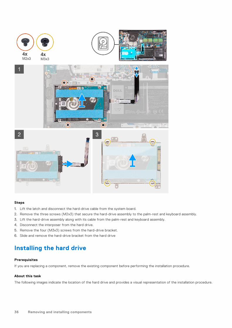
Steps
1. Lift the latch and disconnect the hard-drive cable from the system board.
2. Remove the three screws (M2x3) that secure the hard-drive assembly to the palm-rest and keyboard assembly.
3. Lift the hard-drive assembly along with its cable from the palm-rest and keyboard assembly.
4. Disconnect the interposer from the hard drive.
5. Remove the four (M3x3) screws from the hard-drive bracket.
6. Slide and remove the hard-drive bracket from the hard drive
Installing the hard drive
Prerequisites
If you are replacing a component, remove the existing component before performing the installation procedure.
About this task
The following images indicate the location of the hard drive and provides a visual representation of the installation procedure.
36 Removing and installing components

Steps
1. Slide and install the hard-drive into the hard-drive bracket.
2. Install the four (M3x3) screws to secure the hard drive to the hard-drive bracket.
3. Connect the interposer to the hard drive.
4. Align and place the hard-drive assembly on to the palm-rest and keyboard assembly.
5. Replace the four (M2x3) screws to secure the hard drive assembly to the palm-rest.
6. Connect the hard drive cable to the system board and close the latch to secure the cable.
Next steps
1. Install the battery.2. Install the base cover.3. Exit service mode.4. Install the SD card.5. Follow the procedure in after working inside your computer.
Removing and installing components 37
System fan
Removing the system fan
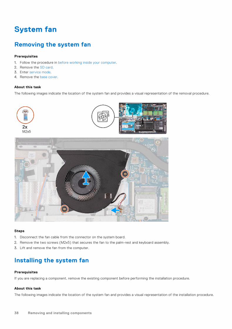
Prerequisites
1. Follow the procedure in before working inside your computer.2. Remove the SD card.3. Enter service mode.4. Remove the base cover.
About this task
The following images indicate the location of the system fan and provides a visual representation of the removal procedure.
Steps
1. Disconnect the fan cable from the connector on the system board.
2. Remove the two screws (M2x5) that secures the fan to the palm-rest and keyboard assembly.
3. Lift and remove the fan from the computer.
Installing the system fan
Prerequisites
If you are replacing a component, remove the existing component before performing the installation procedure.
About this task
The following images indicate the location of the system fan and provides a visual representation of the installation procedure.
38 Removing and installing components

Steps
1. Align and place the fan on the palm-rest and keyboard assembly.
2. Replace the two screws (M2x5) to secure the fan to the palm-rest and keyboard assembly.
3. Connect the fan cable to the connector on the system board .
Next steps
1. Replace the base cover.2. Exit service mode.3. Replace the SD card.4. Follow the procedure in after working inside your computer.
Heat sink
Removing the heat sink - UMA
Prerequisites
1. Follow the procedure in before working inside your computer.2. Remove the SD card.3. Enter service mode.4. Remove the base cover.
About this task
The following images indicate the location of the heat sink and provides a visual representation of the removal procedure.
Removing and installing components 39

Steps
1. Loosen the four captive screws that secure the heat sink to the system board.
2. Lift the heat sink off the system board.
Installing the heat sink - UMA
Prerequisites
If you are replacing a component, remove the existing component before performing the installation procedure.
About this task
The following images indicate the location of the heat sink and provides a visual representation of the installation procedure.
40 Removing and installing components

Steps
1. Place the heat sink on the system board and align the captive screws on the heat sink with the screw holes on the systemboard.
2. Tighten the four (M2x3) screws to secure the heat sink to the system board.
Next steps
1. Install the base cover.2. Exit service mode.3. Install the SD card.4. Follow the procedure in after working inside your computer.
Removing the heat sink - Discrete
Prerequisites
1. Follow the procedure in before working inside your computer.2. Remove the SD card.3. Enter service mode.4. Remove the base cover.
About this task
The following images indicate the location of the discrete heat sink and provides a visual representation of the removalprocedure.
Removing and installing components 41

Steps
1. Rremove the seven (M2x3) screws that secure the heat sink to the system board.
2. Lift the heat sink off the system board.
Installing the heat sink - Discrete
Prerequisites
If you are replacing a component, remove the existing component before performing the installation procedure.
About this task
The following images indicate the location of the discrete heat sink and provides a visual representation of the installationprocedure.
42 Removing and installing components

Steps
1. Place the heat sink on the system board and align the screw holes with the ones on the system board.
2. Replace the seven (M2x3) screws to secure the heat sink to the system board.
Next steps
1. Install the base cover.2. Exit service mode.3. Install the SD card.4. Follow the procedure in after working inside your computer.
Speakers
Removing the speakers
Prerequisites
1. Follow the procedure in before working inside your computer.2. Remove the SD card.3. Enter service mode.4. Remove the base cover.
About this task
The following images indicate the location of the speakers and provides a visual representation of the removal procedure.
Removing and installing components 43

Steps
1. Disconnect the speaker cable from the system board.
2. Unroute and remove the speaker cable from the routing guides on palm-rest and keyboard assembly.
3. Lift the speakers, along with the cable, off the computer.
Installing the speakers
Prerequisites
If you are replacing a component, remove the existing component before performing the installation procedure.
About this task
The following images indicate the location of the speakers and provides a visual representation of the installation procedure.
NOTE: If the rubber grommets are pushed out when removing the speakers, push them back in before replacing the
speakers.
44 Removing and installing components

Steps
1. Using the alignment posts and rubber grommets, place the speakers in the slots on the palm-rest and keyboard assembly.
2. Route the speaker cable through the routing guides on the palm-rest and keyboard assembly..
3. Connect the speaker cable to the connector on the system board .
Next steps
1. Install the base cover.2. Exit service mode.3. Install the SD card.4. Follow the procedure in after working inside your computer.
IO board
Removing the I/O board
Prerequisites
1. Follow the procedure in before working inside your computer.2. Remove the SD card.3. Enter service mode.4. Remove the base cover.
About this task
The following images indicate the location of the I/O board and provides a visual representation of the removal procedure.
Removing and installing components 45

Steps
1. Open the latch and disconnect the fingerprint-reader board cable from the I/O board, if applicable.
2. Open the latch and disconnect the I/O-board power cable from the I/O board.
3. Remove the two (M2x3) screws that secure the I/O board to the palm-rest and keyboard assembly, and remove the I/Oboard from the system.
4. Remove the three (M2x3) screws that secure the I/O board to the palm-rest and keyboard assembly, and remove the I/Oboard from the system.
Installing the I/O board
Prerequisites
If you are replacing a component, remove the existing component before performing the installation procedure.
About this task
The following images indicate the location of the I/O board and provides a visual representation of the installation procedure.
46 Removing and installing components

Steps
1. Align and place the I/O board under the left hinge assembly and on to the palm-rest and keyboard assembly.
2. Replace the two (M2x3) screws to secure the I/O daughter board to the palm-rest and keyboard assembly.
3. Replace the three (M2x3) screws to secure the I/O daughter board to the palm-rest and keyboard assembly.
4. Connect the fingerprint-reader board cable to the connector on the I/O board and close the latch, if applicable.
5. Connect the I/O-board power cable to the connector on the I/O board and close the latch.
Next steps
1. Install the base cover.2. Exit service mode.3. Install the SD card.4. Follow the procedure in after working inside your computer.
Touchpad
Removing the touchpad assembly
Prerequisites
1. Follow the procedure in before working inside your computer.2. Remove the SD card.3. Remove the base cover.4. Remove the battery.
About this task
The following images indicate the location of the touchpad and provides a visual representation of the removal procedure.
Removing and installing components 47

Steps
1. Disconnect the hard-drive FFC from the system board.
2. Remove the three (M2x2) screws securing the touchpad bracket to the palm-rest and keyboard assembly.
3. Remove the touchpad bracket from the computer.
4. Remove the two (M2x2) screws securing the touchpad module in palm-rest and keyboard assembly.
5. Diconnect the touchpad FFC from the system board.
6. Remove the touchpad module with touchpad FFC from the computer.
Installing the touch pad assembly
About this task
The following images indicate the location of the touchpad and provides a visual representation of the installation procedure.
NOTE: Ensure that the touch pad is aligned with the guides available on the palm-rest and keyboard assembly, and the gap
on either sides of the touch pad is equal.
48 Removing and installing components

Steps
1. Align and place the touchpad module onto the computer.
2. Reconnect the touchpad FFC to the touchpad module.
3. Install the two (M2x2) screws to secure the touchpad module to the palm-rest and keyboard assembly.
4. Install the touchpad bracket on the touchpad and secure it using the three (M2x2) screws.
5. Reconnect the hard-drive FFC to the system board.
Next steps
1. Install the battery.2. Install the base cover.3. Install the SD card.4. Follow the procedure in after working inside your computer.
Removing and installing components 49

Display assembly
Removing the display assembly
Prerequisites
1. Follow the procedure in before working inside your computer.2. Remove the SD card.3. Enter service mode.4. Remove the base cover.5. Remove the WLAN card.
About this task
The following images indicate the location of the display assembly and provides a visual representation of the removalprocedure.
50 Removing and installing components
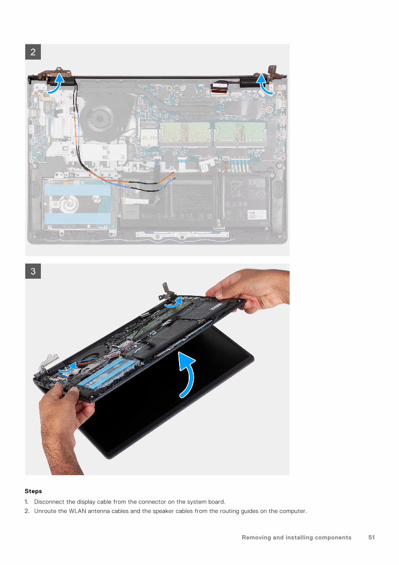
Steps
1. Disconnect the display cable from the connector on the system board.
2. Unroute the WLAN antenna cables and the speaker cables from the routing guides on the computer.
Removing and installing components 51

3. Remove the six (M2.5x5) screws that secure the display hinges to the palm-rest and keyboard assembly.
4. Fold the left and right hinges away from the palm-rest and keyboard assembly.
5. Lift the palm-rest and keyboard assembly at an angle to free it from the hinges and remove it from the display assembly.
Installing the display assembly
Prerequisites
If you are replacing a component, remove the existing component before performing the installation procedure.
About this task
NOTE: Ensure that the hinges are opened to the maximum before replacing the display assembly on the palmrest and
keyboard assembly.
52 Removing and installing components

Steps
1. Align and place the system under the hinges on the display assembly.
2. Fold the hinges back and install the four (M2.5x5) screws to secure the display assembly.
Removing and installing components 53

3. Re-route the speaker and WLAN antenna cables through the routing channels on the palmrest.
4. Reconnect the display cable to the connector on the system board.
Next steps
1. Install the WLAN card.2. Install the base cover.3. Exit service mode.4. Install the SD card.5. Follow the procedure in after working inside your computer.
Hinge caps
Removing the hinge caps
Prerequisites
1. Follow the procedure in Before working inside your computer.2. Remove the SD card.3. Enter service mode.4. Remove the base cover.5. Remove the WLAN card.6. Remove the display assembly.
About this task
The following images indicate the location of the hinge caps and provides a visual representation of the installation procedure.
54 Removing and installing components

Steps
NOTE: Before removing the display hinge caps, open the display hinges to at least 90 degrees.
1. Pinch the left-hinge cap in the center.
2. Use the scribe to pry open the left-hinge cap from the openings on its inner side.
3. Lift the inner side of the left-hinge cap and remove it from the left hinge.
4. Pinch the right hinge cap in the center.
5. Use the scribe to pry open the right-hinge cap from the openings on itsinner side.
6. Lift the inner side of the right-hinge cap and remove it from the right hinge.
Installing the hinge caps
Prerequisites
If you are replacing a component, remove the existing component before performing the installation procedure.
About this task
The following images indicate the location of the hinge caps and provides a visual representation of the installation procedure.
Removing and installing components 55

Steps
1. Align the rib inside the left-hinge cap to the outer sides.
2. Push the left-hinge cap down until it clicks in place.
3. Align the rib inside the right-hinge cap to the outer sides.
4. Push the right-hinge cap down until it clicks in place.
Next steps
1. Install the display assembly.2. Install the WLAN card.3. Install the base cover.4. Exit service mode.5. Install the SD card.6. Follow the procedure in after working inside your computer.
56 Removing and installing components

Display bezel
Removing the display bezel
Prerequisites
1. Follow the procedure in before working inside your computer.2. Remove the SD card.3. Enter service mode.4. Remove the base cover.5. Remove the display assembly.
About this task
The following images indicate the location of the display bezel and provide a visual representation of the removal procedure.
Steps
1. Use a plastic scribe to pry open the display bezel from the outer edge at the left and right sides of the display hinges.
NOTE: The display bezel is adhered to the display panel with adhesive. Insert a plastic scribe into the recesses near both
hinge caps to start the prying process to release the display bezel. Pry along the outside edge of the display bezel and
work your way around the entire display bezel until the display bezel is separated from the display cover.
Removing and installing components 57

2. Carefully pry the bezel along the edges with your fingers.
NOTE: Do not use a scribe or any other objects, and apply pressure to the display panel to avoid damaging the display
panel.
3. Work around the edge of the display assembly to pry the display bezel from the display assembly.
4. Lift and remove the display bezel from the display assembly.
Installing the display bezel
Prerequisites
If you are replacing a component, remove the existing component before performing the installation procedure.
About this task
The following images indicate the location of the display bezel and provides a visual representation of the installation procedure.
58 Removing and installing components

Steps
1. Place the display panel and display assembly on a clean and flat surface.
2. Place the display bezel on the display assembly.
3. Align the tabs on the display bezel to the slots on the display assembly.
4. Press down on the display bezel and snap the display bezel in place.
Next steps
1. Install the display assembly.2. Install the base cover.3. Exit service mode.4. Install the SD card.5. Follow the procedure in after working inside your computer.
Hinges
Removing the hinges
Prerequisites
1. Follow the procedure in Before working inside your computer.2. Remove the SD card.
Removing and installing components 59

3. Enter service mode.4. Remove the base cover.5. Remove the WLAN card.6. Remove the display assembly.7. Remove the hinge caps.8. Remove the display bezel.
About this task
The following images indicate the location of the hinge caps and provides a visual representation of the installation procedure.
Steps
1. Remove the three (M2.5x3.8) from the left hinge.
2. Lift and remove the left hinge from the display assembly.
3. Remove the three (M2.5x3.8) from the right hinge.
4. Lift and remove the right hinge from the display assembly.
60 Removing and installing components

Installing the hinges
Prerequisites
If you are replacing a component, remove the existing component before performing the installation procedure.
About this task
The following images indicate the location of the hinges and provides a visual representation of the installation procedure.
Steps
1. Align and place the left hinge on the display assembly.
2. Install the three (M2.5x3.8) screws to secure the hinge to the display panel and back cover.
3. Align and place the right hinge on the display assembly.
4. Install the three (M2.5x3.8) screws to secure the hinge to the display panel and back cover.
Next steps
1. Install the display bezel.2. Install the hinge caps.3. Install the display assembly.
Removing and installing components 61

4. Install the WLAN card.5. Install the base cover.6. Exit service mode.7. Install the SD card.8. Follow the procedure in after working inside your computer.
Display panel
Removing the display panel
Prerequisites
1. Follow the procedure in before working inside your computer.2. Remove the SD card.3. Enter service mode.4. Remove the base cover.5. Remove the WLAN card.6. Remove the display assembly.7. Remove the hinge caps.8. Remove the display bezel.
About this task
The following images indicate the location of the display panel and provides a visual representation of the removal procedure.
62 Removing and installing components

Steps
1. Use a plastic scribe to pry the display panel from the bottom-right corner.
2. Gently start prying the display panel along the left and right sides of the display back-cover using your hands.
3. Lift the bottom side of the display panel and slide it downward to release the display brackets from the slots at the top sideof the display cover.
4. Gently flip the display panel assembly forward, peel back the Mylar tape securing the display cable on the rear of the displaypanel.
Removing and installing components 63
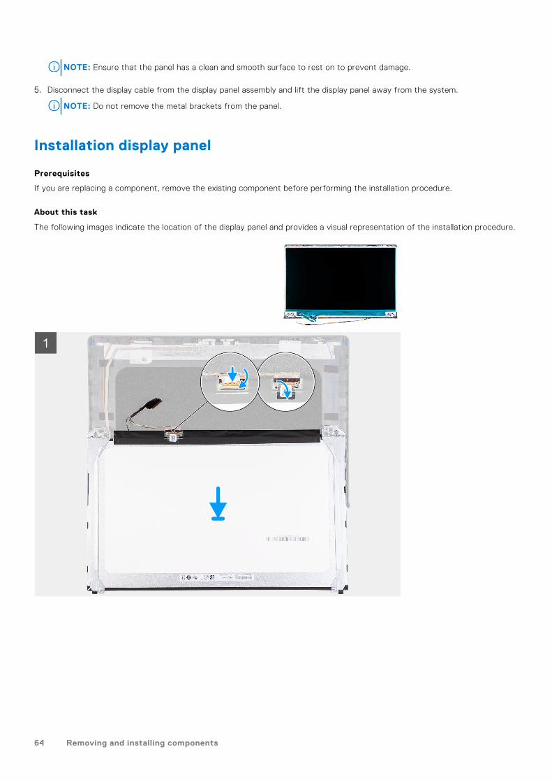
NOTE: Ensure that the panel has a clean and smooth surface to rest on to prevent damage.
5. Disconnect the display cable from the display panel assembly and lift the display panel away from the system.
NOTE: Do not remove the metal brackets from the panel.
Installation display panel
Prerequisites
If you are replacing a component, remove the existing component before performing the installation procedure.
About this task
The following images indicate the location of the display panel and provides a visual representation of the installation procedure.
64 Removing and installing components

Steps
1. Place the display panel on a flat and clean surface .
2. Connect the display cable to the connector at the back of the display panel and close the latch to secure the cable .
3. Adhere the tape that secures the display cable to the back of the display panel .
4. Turn the display panel over and place it on the display back-cover.
5. Lift the bottom side of the display panel and slide the top side into the slots at the top of the display back-cover.
6. Gently push down on the edges of the display panel until it clicks into the tabs on the display back-cover.
Removing and installing components 65

Next steps
1. Install the display bezel.2. Install the hinge caps.3. Install the display assembly.4. Install the WLAN card.5. Install the base cover.6. Exit service mode.7. Install the SD card.8. Follow the procedure in after working inside your computer.
Camera
Removing the camera
Prerequisites
1. Follow the procedure in before working inside your computer.2. Remove the SD card.3. Enter service mode.4. Remove the base cover.5. Remove the WLAN card.6. Remove the display assembly.7. Remove the hinge caps.8. Remove the display bezel.9. Remove the display panel.
About this task
Steps
1. Disconnect the camera cable from the camera module.
2. Using a plastic scribe, gently pry the camera off the display back-cover and antenna assembly.
66 Removing and installing components

Installing the camera
Prerequisites
If you are replacing a component, remove the existing component before performing the installation procedure.
About this task
Steps
1. Using the alignment post, adhere the camera module on the display back-cover and antenna assembly.
2. Connect the camera cable to the camera module.
Next steps
1. Install the display panel.2. Install the display bezel.3. Install the hinge caps.4. Install the display assembly.5. Install the WLAN card.6. Install the base cover.7. Exit service mode.8. Install the SD card.9. Follow the procedure in after working inside your computer.
Display eDP cable
Removing the eDP cable
Prerequisites
1. Follow the procedure in before working inside your computer.2. Remove the SD card.3. Enter service mode.4. Remove the base cover.5. Remove the WLAN card.6. Remove the display assembly.
Removing and installing components 67
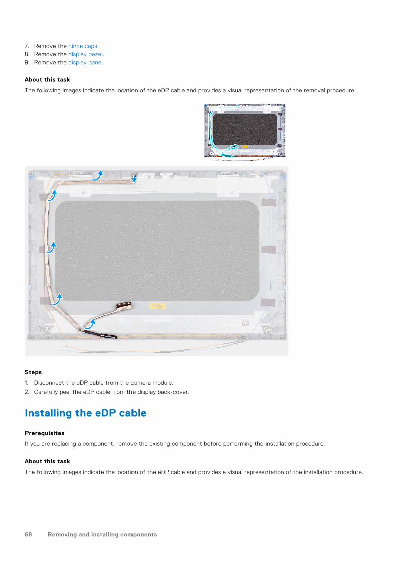
7. Remove the hinge caps.8. Remove the display bezel.9. Remove the display panel.
About this task
The following images indicate the location of the eDP cable and provides a visual representation of the removal procedure.
Steps
1. Disconnect the eDP cable from the camera module.
2. Carefully peel the eDP cable from the display back-cover.
Installing the eDP cable
Prerequisites
If you are replacing a component, remove the existing component before performing the installation procedure.
About this task
The following images indicate the location of the eDP cable and provides a visual representation of the installation procedure.
68 Removing and installing components

Steps
1. Adhere the eDP cable to the display back cover.
2. Connect the eDP cable to the camera module.
Next steps
1. Install the display panel.2. Install the display bezel.3. Install the hinge caps.4. Install the display assembly.5. Install the WLAN card.6. Install the base cover.7. Exit service mode.8. Install the SD card.9. Follow the procedure in after working inside your computer.
Removing and installing components 69

Display back-cover
Removing the display back-cover
Prerequisites
1. Follow the procedure in before working inside your computer.2. Remove the SD card.3. Enter service mode.4. Remove the base cover.5. Remove the WLAN card.6. Remove the display assembly.7. Remove the hinge caps.8. Remove the display bezel.9. Remove the display panel.10. Remove the camera.
About this task
The following images indicate the location of the display back-cover and provides a visual representation of the removalprocedure.
Steps
After performing all the preceding steps, you are left with the display back-cover.
Installing the display back-cover
About this task
The following images indicate the location of the display back-cover and provides a visual representation of the installationprocedure.
70 Removing and installing components

Steps
Place the display back-cover on a clean surface and perform the post-requisites to install the display back-cover.
Next steps
1. Install the camera.2. Install the display panel.3. Install the display bezel.4. Install the hinge caps.5. Install the display assembly.6. Install the WLAN card.7. Install the base cover.8. Exit service mode.9. Install the SD card.10. Follow the procedure in after working inside your computer.
Power button
Removing the power button
Prerequisites
1. Follow the procedure in before working inside your computer.2. Remove the SD card.3. Enter service mode.4. Remove the base cover.5. Remove the IO board.
About this task
The following images indicate the location of the power button and provides a visual representation of the removal procedure.
Removing and installing components 71

Steps
1. Remove the single (M2x2) screws securing the power button to the palm-rest and keyboard assembly.
2. Remove the power button from the computer.
Installing the power button
Prerequisites
If you are replacing a component, remove the existing component before performing the installation procedure.
About this task
The following images indicate the location of the power button and provides a visual representation of the installationprocedure.
72 Removing and installing components

Steps
1. Place the power-button board into the slot on the palm-rest and keyboard assembly.
2. Install the single (M2x2) screws to secure the power button to the palm-rest and keyboard assembly.
Next steps
1. Install the IO board.2. Install the base cover.3. Exit service mode.4. Install the SD card.5. Follow the procedure in after working inside your computer.
Power button with fingerprint reader
Removing the power-button with fingerprint reader
Prerequisites
1. Follow the procedure in before working inside your computer.2. Remove the SD card.3. Enter service mode.4. Remove the base cover.5. Remove the IO board.
About this task
The following images indicate the location of the power-button with fingerprint reader and provides a visual representation ofthe removal procedure.
Removing and installing components 73

Steps
1. Remove the two (M2.5x5) screws securing the left hinge to the palm-rest and keyboard assembly.
2. Fold back the hinge to access the power-button with fingerprint reader.
3. Remove the single (M2x3) screw securing the power-button with fingerprint reader to the palm-rest and keyboard assembly.
4. Peel back the tape holding the fingerprint-reader FFC to the palm-rest and keyboard assembly.
5. Remove the power-button with fingerprint reader and FFC from the computer.
Installing the power-button with fingerprint reader
Prerequisites
If you are replacing a component, remove the existing component before performing the installation procedure.
About this task
The following images indicate the location of the power-button with fingerprint reader and provides a visual representation ofthe installation procedure.
74 Removing and installing components

Steps
1. Place the power-button with fingerprint reader into the slot on the palm-rest and keyboard assembly.
2. Install the single (M2x2) screws to secure the power-button with fingerprint reader to the palm-rest and keyboard assembly.
NOTE:
For models shipped with a fingerprint reader, when installing the power-button, fold and align the fingerprint-reader FPC
to the mark at the right of the power button. Then align the white line on the FPC to the mark on the palm rest.
3. Re-adhere the tape to secure the fingerprint-reader FFC to the palm-rest and keyboard assembly.
4. Fold back the left hinge and install two single (M2.5x5) screws to secure the hinge to the palm-rest and keyboard assembly.
Removing and installing components 75

Next steps
1. Install the IO board.2. Install the base cover.3. Exit service mode.4. Install the SD card.5. Follow the procedure in after working inside your computer.
System board
System board connectors
The following image shows the different connectors on the system board.
1. Fan connector2. IO board FFC connector3. eDP connector4. DC-in port connector5. Keyboard FFC connector6. Backlit FFC connector7. Memory module connectors8. Battery connector9. Touchpad FFC connector10. Hard-drive FFC connector11. WLAN connector12. Speaker cable connector13. SSD connector
Removing the system board
Prerequisites
1. Follow the procedure in before working inside your computer.2. Remove the SD card.
76 Removing and installing components

3. Remove the base cover.4. Remove the battery.5. Remove the WLAN card.6. Remove the memory modules7. Remove the display assembly.8. Remove the SSD.9. Remove the system fan.10. Remove the heatsink.
NOTE: The system board can be removed along with the heat sink.
About this task
The following images indicate the location of the system board and provides a visual representation of the removal procedure.
Removing and installing components 77

Steps
1. Remove the two (M2.5x5) screws from the right hinge and fold the right hinge up.
2. Disconnect the following cables from the system board:
a. Fan cableb. IO board FFCc. Power- adapter port cabled. Fingerprint-reader cable, if applicablee. Keyboard FFCf. Keyboard backlight FFC, if applicableg. Touchpad FFCh. Hard drive FFCi. Speaker cable
3. Remove the three (M2x3) screws and the single (M2x2) screw that secures the system board to the palm-rest andkeyboard assembly.
4. Carefully lift the system board away from the palm-rest and keyboard assembly.
Installing the system board
Prerequisites
If you are replacing a component, remove the existing component before performing the installation procedure.
About this task
The following images indicate the location of the system board and provides a visual representation of the installation procedure.
78 Removing and installing components

Steps
1. Align and place the system board on the palm-rest and keyboard assembly.
2. Replace the single (M2x4) screw that secures the system board to the palm-rest and keyboard assembly.
3. Connect the following cables to the system board:
a. Fan cableb. IO board FFCc. Power-adapter port cabled. Fingerprint-reader cable, if applicablee. Keyboard FFCf. Keyboard backlight FFC, if applicableg. Touchpad FFCh. Hard drive FFCi. Speaker cable
Removing and installing components 79

4. Fold back the right hinge and install the two (M2.5x5) screws to secure it to the palm-rest and keyboard assembly.
Next steps
1. Install the display assembly.2. Install the heatsink.3. Install the system fan.4. Install the memory modules.5. Install the SSD.6. Install the WLAN card.7. Install the battery.8. Install the base cover.9. Install the SD card.10. Follow the procedure in after working inside your computer.
Power-adapter port
Removing the power-adapter port
Prerequisites
1. Follow the procedure in before working inside your computer.2. Remove the SD card.3. Enter service mode.4. Remove the base cover.
About this task
The following images indicate the location of the power-adapter port and provides a visual representation of the installationprocedure.
Steps
1. Remove the two (M2.5x5) screws from the right hinge and fold the hinge up.
2. Disconnect the power-adapter port cable from the system board.
80 Removing and installing components

3. Remove the power-adapter port module from the computer.
NOTE: The power-adapter port is secured in place only by the right display hinge. Ensure that the power-adapter port
does not fall off from the slot after the right hinge is removed.
Installing the power-adapter port
Prerequisites
If you are replacing a component, remove the existing component before performing the installation procedure.
About this task
The following images indicate the location of the power-adapter port and provides a visual representation of the installationprocedure.
Steps
1. Place the power adapter port module into the slot provided on the palmrest.
2. Connect the power adapter cable to the connector on the system board.
3. Fold the right hinge back down and install the two (M2.5x5) screws to secure it.
Next steps
1. Install the base cover.2. Exit service mode.3. Install the SD card.4. Follow the procedure in after working inside your computer.
Removing and installing components 81

Palm-rest and keyboard assembly
Removing the palm-rest and keyboard assembly
Prerequisites
1. Follow the procedure in before working inside your computer.2. Remove the SD card.3. Remove the base cover.4. Remove the battery.5. Remove the WLAN card.6. Remove the memory modules7. Remove the display assembly.8. Remove the SSD.9. Remove the hard drive assembly.10. Remove the speakers.11. Remove the system fan.12. Remove the heatsink.
NOTE: The system board can be removed along with the heat sink.
13. Remove the IO board.14. Remove the touchpad.15. Remove the power adapter port.16. Remove the system board.
About this task
The following images indicate the location of the palm-rest and keyboard assembly, and provides a visual representation of theinstallation procedure.
Steps
After performing the preceding steps, you are left with the palmrest and keyboard assembly.
82 Removing and installing components

Installing the palm-rest and keyboard assembly
Prerequisites
If you are replacing a component, remove the existing component before performing the installation process.
About this task
The following images indicate the location of the palm-rest and keyboard assembly and provides a visual representation of theinstallation procedure.
Steps
Place the palm-rest and keyboard assembly on a flat and clean surface, and perform the post-requisites to install the palm-restand keyboard assembly.
Next steps
1. Install the system board.2. Install the power adapter port.3. Install the touchpad.4. Install the IO board.5. Install the heatsink.6. Install the system fan.7. Install the speakers.8. Install the hard drive assembly.9. Install the SSD.10. Install the display assembly.11. Install the memory modules12. Install the WLAN card.13. Install the battery.14. Install the base cover.15. Install the SD card.16. Follow the procedure in after working inside your computer.
Removing and installing components 83

Drivers and downloadsWhen troubleshooting, downloading, or installing drivers, it is recommended that you read the Dell knowledge base article,Drivers and Downloads FAQs .
3
84 Drivers and downloads

System setupCAUTION: Unless you are an expert computer user, do not change the settings in the BIOS Setup program.
Certain changes can make your computer work incorrectly.
NOTE: Depending on the computer and its installed devices, the items listed in this section may or may not be displayed.
NOTE: Before you change BIOS Setup program, it is recommended that you write down the BIOS Setup program screen
information for future reference.
Use the BIOS Setup program for the following purposes:● Get information about the hardware installed in your computer, such as the amount of RAM and the size of the hard drive.● Change the system configuration information.● Set or change a user-selectable option, such as the user password, type of hard drive installed, and enabling or disabling
base devices.
Entering BIOS setup program
Steps
1. Turn on your computer.
2. Press F2 immediately to enter the BIOS setup program.
NOTE: If you wait too long and the operating system logo appears, continue to wait until you see the desktop. Then,
turn off your computer and try again.
Navigation keysNOTE: For most of the System Setup options, changes that you make are recorded but do not take effect until you restart
the system.
Table 3. Navigation keys
Keys Navigation
Up arrow Moves to the previous field.
Down arrow Moves to the next field.
Enter Selects a value in the selected field (if applicable) or followthe link in the field.
Spacebar Expands or collapses a drop-down list, if applicable.
Tab Moves to the next focus area.
NOTE: For the standard graphics browser only.
Esc Moves to the previous page until you view the main screen.Pressing Esc in the main screen displays a message thatprompts you to save any unsaved changes and restarts thesystem.
4
System setup 85

One time boot menuTo enter one time boot menu, turn on your computer, and then press F2 immediately.
NOTE: It is recommended to shutdown the computer if it is on.
The one-time boot menu displays the devices that you can boot from including the diagnostic option. The boot menu optionsare:
● Removable Drive (if available)● STXXXX Drive (if available)
NOTE: XXX denotes the SATA drive number.
● Optical Drive (if available)● SATA Hard Drive (if available)● Diagnostics
NOTE: Choosing Diagnostics, will display the ePSA diagnostics screen.
The boot sequence screen also displays the option to access the System Setup screen.
One time boot menuTo enter one time boot menu, turn on your computer, and then press F12 immediately.
NOTE: It is recommended to shutdown the computer if it is on.
The one-time boot menu displays the devices that you can boot from including the diagnostic option. The boot menu optionsare:
● Removable Drive (if available)● STXXXX Drive (if available)
NOTE: XXX denotes the SATA drive number.
● Optical Drive (if available)● SATA Hard Drive (if available)● Diagnostics
The boot sequence screen also displays the option to access the System Setup screen.
Boot SequenceBoot Sequence allows you to bypass the System Setup–defined boot device order and boot directly to a specific device (forexample: optical drive or hard drive). During the Power-on Self Test (POST), when the Dell logo appears, you can:● Access System Setup by pressing F2 key● Bring up the one-time boot menu by pressing F12 key
The one-time boot menu displays the devices that you can boot from including the diagnostic option. The boot menu optionsare:
● Removable Drive (if available)● STXXXX Drive (if available)
NOTE: XXX denotes the SATA drive number.
● Optical Drive (if available)● SATA Hard Drive (if available)● Diagnostics
The boot sequence screen also displays the option to access the System Setup screen.
86 System setup

Navigation keysNOTE: For most of the System Setup options, changes that you make are recorded but do not take effect until you restart
the system.
Keys Navigation
Up arrow Moves to the previous field.
Down arrow Moves to the next field.
Enter Selects a value in the selected field (if applicable) or follow the link in the field.
Spacebar Expands or collapses a drop-down list, if applicable.
Tab Moves to the next focus area.
Esc Moves to the previous page until you view the main screen. Pressing Esc in the main screen displays amessage that prompts you to save any unsaved changes and restarts the system.
System setup options
NOTE: Depending on the laptop and its installed devices, the items listed in this section may or may not appear.
Boot menu
Press <F12> when the Dell logo appears to initiate a one-time boot menu with a list of the valid boot devices for the system.Diagnostics and BIOS Setup options are also included in this menu. The devices that are listed on the boot menu depend on thebootable devices in the system. This menu is useful when you are attempting to boot to a particular device or to bring up thediagnostics for the system. Using the boot menu does not make any changes to the boot order stored in the BIOS.
Table 4. UEFI Boot options
Options
Windows Boot Manager
UEFI hard drive
Table 5. Other Options
Options Description
BIOS SETUP Allows the user to configure the BIOS and control systemfunctions
Diagnostics Allows the user to run system tests to identify issues
BIOS Update Allows the user to search and install the latest BIOS updates
SupportAssist OS Recovery Used to analyze, repair, and restore the operating system onthe system
BIOS Flash Update - Remote
Device Configuration
Overview
This section provides hardware specification for the system and contains no modifiable settings.
System setup 87

Table 6. BIOS Overview Page
Options Description
Series and system model number This field shows the following information:● BIOS Version - The version of the BIOS installed on the
computer.● Service tag - The unique 7 digit hexadecimal identification
number for the computer.● Asset tag● Manufacture Date - The date for when the unit was
manufactured.● Ownership Date - The date for when the unit's ownership
was transferred to the end user.● Express Service Code - An alternative to Service Tag, 11-
digit numerical identification number for the computer.● Ownership Tag● Signed Firmware Update - This helps to verify that only
Dell Signed and released BIOS can be installed on thecomputer.
Battery The Battery field provides battery and adapter relatedinformation:● Primary battery - This helps identify if the system is
running on the primary battery.● Battery level - This gives the percentage of battery
backup remaining for the computer.● Battery state - This helps identify if the battery is in
charging or active use state.● Health - This helps identify the health of the battery.
It would show one of the following states based on thebattery life remaining:○ Excellent○ Good○ Fair○ Poor
● AC Adapter - This helps identify if the charger is pluggedin and mentions the wattage of the charger connected.
Processor The Processor field provides information related to the CPUon the computer:● Processor Type - This field mentions the CPU model and
generation information.● Maximum Clock Speed - This field mentions the maximum
clock speed that the CPU is capable of reaching.● Minimum Clock Speed - This field mentions the minimum
clock speed that the CPU is capable of reaching.● Current Clock Speed - This field mentions the clock speed
that the CPU is running at currently.● Core Count - This field gives the count of the physical
cores on the CPU.● Processor ID● Processor L3 Cache - This field shows the amount of
cache storage available on the CPU.● Microcode Version● Intel Hyper-Threading Capable - This field helps identify if
the CPU is capable of Hyper-Threading.● 64-bit Technology - This field helps identify the CPU
architecture.
88 System setup

Table 6. BIOS Overview Page (continued)
Options Description
Memory The Memory field provides information related to the memoryon the computer:● Memory Installed - This field gives the amount of memory
installed on the computer.● Memory Available - This field gives the amount of memory
available for use on the computer.● Memory Speed - This field mentions the speed at which
the memory runs on the computer.● Memory Channel Mode - This field helps us identify if the
computer has Dual-Channel memory utilization capability.● DIMM_SLOT 1 - This field shows the capacity of the
memory installed in the first DIMM slot.● DIMM_SLOT 2 - This field shows the capacity of the
memory installed in the second DIMM slot.
Devices The Devices field provides information related to the memoryon the computer:● Panel Type - This field mentions the type of display panel
used on the computer.● Video controller - This field mentions the type of video
controller used on the computer.● Video Memory - This field gives the capacity of the video
memory available for use on the computer.● Wi-Fi Device - This field mentions the type of wireless
device available for use on the computer.● Native Resolution - This field mentions the native video
resolution supported on the computer.● Video BIOS Version - The version of the BIOS installed on
the computer.● Audio Controller - This field mentions the type of audio
controller used on the computer.● Bluetooth Device - This field mentions the type of
Bluetooth device available for use on the computer.● LOM MAC Address - This field provides the unique MAC
address for the computer.● Pass Through MAC Address - This field provides the MAC
address used to override the dock or dongle MAC addressevery time it's connected to the network.
Boot Configuration
This section provides Boot Configuration related details and settings.
Table 7. Boot Configuration:
Options Description
Boot Sequence
Boot Mode: UEFI only This section allows the user to choose the first bootabledevice that the computer should use to boot the system. Itlists all potential bootable devices.● Windows Boot Manager (Enabled by default)● UEFI Boot Drive (Enabled by default)● ONBOARD NIC(IPV4)● ONBOARD NIC(IPV5)
System setup 89

Table 7. Boot Configuration: (continued)
Options Description
● Add Boot option - Allows the user to manually add a Bootpath.
Secure Boot
Enable Secure Boot This section contains a toggle switch that allows the user toenable or disable Secure Boot. (OFF by default)
Secure Boot Mode This section allows the user to select one of the two SecureBoot options available on the computer:● Deployed Mode - This mode checks the integrity of UEFI
drivers and bootloaders before allowing execution. Thisoption allows for full Secure Boot protections (Enabled bydefault.)
● Audit Mode - This mode performs a signature check butnever does a block execution of all UEFI drivers andbootloaders. This mode is only used when making changesto Secure Boot Keys.
Expert Key Management
Enable Custom Mode This section contains a toggle switch that allows the user toenable or disable Custom Mode. This mode allows the PK,KEK, db and dbx security key databases to be manipulated.(OFF by default)
Custom Mode Key Management This section helps the user to select the Key Database toallow modification. The options available are as below:● PK (Selected by default)● KEK● db● dbx
Integrated Devices
This section provides Integrated Devices details and settings.
Table 8. Integrated Devices
Options Description
Date/Time
Date This section allows the user to change the date which takeseffect immediately. The format used is MM/DD/YYYY
Time This section allows the user to change the time which takeseffect immediately. The format used is HH/MM/SS in 24 hourformat. The user also has an option to switch between 12-hours or 24-hours clock.
Camera
Enable Camera This section contains a toggle switch that allows the user toenables/disable the internal webcam (Enabled by default).
Audio
90 System setup

Table 8. Integrated Devices (continued)
Options Description
Enable Audio This section contains a toggle switch that allows the user toenable or disable the audio on the computer. It also allows theuser to:● Enable Microphone (Enabled by default.)● Enable Internal Speakers (Enabled by default.)
USB Configuration This section helps the user to make changes to the USBsettings on the computer. The options available are as follows:● Enable USB Boot Support - Allows the system to boot
from an external USB device (Enabled by default.)● Enable External USB Ports - Allows the user to enable
or disable the USB ports on the computer (Enabled bydefault)
Storage
This section provides storage details and settings.
Table 9. Storage
Options Description
SATA Operation
SATA Operation This section allows the user to select the operating modeof the integrated SATA hard drive controller. The followingoptions are available:● Disabled - SATA controllers are disabled.● AHCI - SATA is configured in AHCI mode.● RAID On - SATA is setup to support RAID (Intel Rapid
Storage Technology). (Selected by default)
Storage Interface
Port Enablement This section allows the user to enable or disable the onboarddrives on the computer. The following options is available:● M.2 PCIe SSD-0 (ON by default)● SATA-0 (ON by default)
SMART Reporting
Enable SMART Reporting This section contains a toggle switch that allows the userto enable or disable the S.M.A.R.T(Self-Monitoring, Analysis,and Reporting Technology) option on the system (OFF bydefault).
Drive Information This section provides information about the connected andactive drives on the computer. The following options areavailable:● M.2 PCIe SSD-0
○ Type○ Device
Enable MediaCard This section allows the user to switch all media cards On/Off, or enable/disable the media card in read-state only. Theoptions are as follows:● Secure Digital (SD) Card (Enabled by default).
System setup 91

Table 9. Storage (continued)
Options Description
● Secure Digital (SD) Card Read-Only Mode (Disabled bydefault).
Display
This section provides display details and settings.
Table 10. Display
Options Description
Display Brightness
Brightness on battery power This section has a scroll bar which allows the user to set thebrightness level on battery power (lowest setting by default).
Brightness on AC power This section has a scroll bar which allows the user to set thebrightness level when system is connected to the AC adapter(highest setting by default).
EcoPower This section contains a toggle switch which allows theuser to enable/disable EcoPower feature that can increasethe battery life by reducing the display brightness whenappropriate.
Full Screen Logo
Full Screen Logo This section contains a toggle switch which allows the user toenable/disable the option to view a full screen logo (disabledby default).
Connection
This section provides connection details and settings.
Table 11. Connection
Options Description
Integrated NIC This section contains options to enable/disable the UEFInetworking protocols, allowing pre-OS and early OSnetworking features to use any enabled NICs.
The options are as follows:● Disabled● Enabled● Enabled with PXE(Selected by default)
Wireless Device Enable This section contains a toggle switch that allows the user toenable or disable WLAN and Bluetooth on the computer. Theoptions are as follows:● WLAN (Enabled by default).● Bluetooth (Enabled by default).
Enable UEFI Network Stack This section contains a toggle switch that allows the user toenable or disable installation of UEFI networking protocols.(ON by default)
92 System setup

Table 11. Connection (continued)
Options Description
Wireless Radio Control This section contains a toggle switch that allows the userto enable or disable a feature where the system will sensea connection to a wired network and disable the WLAN orWWAN connection (OFF by default).
Power
This section provides power details and settings.
Table 12. Power
Options Description
Battery configuration This section provides options to enable different power modeson the computer. The options are as follows:● Adaptive - battery settings are adaptively optimized based
on the users typical battery usage patterns (selected bydefault).
● Standard - Fully charge the battery at a standard rate.● ExpressCharge - The battery may be charged over a
shorter period using Dell's fast charging technology.● Primarily AC use - The battery lifespan for users who
primarily operate their system while plugged in to anexternal power source.
● Custom - Custom select when the battery starts and stopscharging.○ Custom Charge Start○ Custom Charge Stop
Advanced Configuration
Enable Advanced Battery Charge Configuration This feature maximizes battery health while still supportingheavy use during the work day. The section contains a toggleswitch that allows the user to enable or disable this featureand set the daily times and work time periods (OFF bydefault).
Peak Shift This feature allows the computer to run on battery duringpeak usage hours. The section contains a toggle switch thatallows the user to enable or disable this feature and set thePeak Shift Start/End times and Peak Shift Charge Start/End(OFF by default).
USB PowerShare This setting contains a toggle switch which allows the user toenable or disable this feature. It allows for any external USBdevices to charge via the designated USB PowerShare port,even when the computer is on sleep mode (ON by default).
Thermal Management This setting allows for cooling fan and processor heatmanagement to adjust system performance, noise andtemperature. The options available are as below:● Optimized - Standard setting for cooling fan and processor
heat management (selected by default).● Cool - Processor and cooling fan speed are adjusted for a
cooler system surface temperature.● Quiet - Processor and cooling fan speed are adjusted to
reduce fan noise.
System setup 93

Table 12. Power (continued)
Options Description
● Ultra Performance - Processor and cooling fan speed areincreased for more performance.
USB Wake Support
Block Sleep
Block Sleep This section contains a toggle switch to allow the user toenable or disable the system from entering Sleep(S3) mode inthe operating system (OFF by default).
NOTE: When enabled, it will not allow the system to go tosleep, IRST is disabled and power options in the operatingsystem will be blank.
LID Switch
Enable Lid Switch This section contains a toggle switch to allow the user toenable or disable the lid switch (ON by default).
Power On Lid Open This section contains a toggle switch to allow the user toenable or disable the system from powering on when the lid isopen (ON by default).
Intel Speed Shift Technology
Intel Speed Shift Technology This section contains a toggle switch to allow the user toenable or disable Intel Speed Shift Technology support. Thisfeature enables the operating system to select appropriateprocessor performance automatically (ON by default).
Security
This section provides security details and settings.
Table 13. Security
Options Description
TPM 2.0 Security
TPM 2.0 Security On This section contains a toggle switch to select whetherTrusted Platform Module(TPM) is visible to the OperatingSystem(OS). (ON by default)
Attestation Enable This section contains a toggle switch which lets the usercontrol whether the TPM Endorsement Hierarchy is availableto the operating system (OFF by default).
Key Storage Enable This section contains a toggle switch that allows the user tocontrol whether TPM Storage Hierarchy is available to theoperating system (ON by default).
SHA-256 This section contains a toggle switch that when enabled,allows the BIOS and the TPM to use the SHA-256 hashalgorithm to extend measurements into the TPM PCRs duringBIOS boot (ON by default).
94 System setup

Table 13. Security (continued)
Options Description
Clear This section contains a toggle switch which clears the TPMowner information, and returns the TPM to the default state(OFF by default).
PPI Bypass for Clear Commands This section contains a toggle switch which controls the TPMPhysical Presence Interface(PPI). When enabled, this settingwill allow the OS to skip BIOS PPI user prompts when issuingthe clear command (OFF by default).
TPM State This section allows the user to enable or disable the TPM. Thisis the default operating state for the TPM when you want touse its complete arrays of capabilities (enabled by default).
Intel Total Memory Encryption
Total Memory Encryption(TME) This section allows the user to enable/disable TME to protectmemory from physical attachs including freeze spray, probingDDR to read the cycles etc. All of the system memoryis encrypted by the TME block attached to the memorycontroller
Chassis Intrusion
Chassis Intrusion This field controls the chassis intrusion feature● Disabled - Will not report intrusions during POST● Enabled - Will report intrusions during POST● On-silent - Detects intrusions but does not display any
detected intrusions during POST (Selected by default)
Clear Intrusion Warning This section contains a toggle switch to enable/disablewarnings on intrusion (OFF by default).
SMM Security Mitigation This section allows the user to enable or disable UEFI SMMsecurity Mitigation protections (ON by default).
Data Wipe on Next Boot
Start Data Wipe This section contains toggle switch which when enabledensures that the BIOS will queue up a data wipe cycle forstorage device(s) connected to the system board on the nextreboot (OFF by default).
Absolute
Absolute This section lets the user enable, disable or permanentlydisable the BIOS module interface of the optional AbsolutePersistence Module service from Absolute Software. Theoptions available are as follows:● Enable Absolute - Enables Absolute Persistence and load
the firmware Persistence Module (Selected by default)● Disable Absolute - Disables Absolute Persistence. The
firmware Persistence Module is not installed.● Permanently Disable Absolute - Permanently disables
Absolute Persistence module interface from further use.
UEFI Boot Path Security
UEFI Boot Path Security This section lets the user control whether the system willprompt the user to enter the admin password(if set) when
System setup 95

Table 13. Security (continued)
Options Description
booting to a UEFI booth path device from F12 boot menu. Theoptions available are as below:● Never● Always● Always Except Internal HDD (Selected by default)● Always Except Internal HDD&PXE
SafeShutter
SafeShutter This section allows the user to choose between dynamic andmanual shutter control:● Dynamic Shutter - Camera shutter will automatically open
when user grants application permission and close whenpermission ends. Can be disabled by using the F9 cameramute key(LED on). This is the default selected option.
● Manual Shutter Control - Shutter opens when F9 key ispressed(LED off) and closes when F9 key is pressed(LEDon)
Passwords
This section provides details on password settings.
Table 14. Passwords
Options Description
Admin Password This field allows the user to set, change, or delete theadministrator password.
System Password This field allows the user to set, change, or delete the systempassword.
NVMe SSD0 This field allows the user to set, change, or delete the storagedrive password.
Password Configurator
Upper Case Letter Enable or disable reinforced use of upper case letters (OFF bydefault).
Lower Case Letter Enable or disable reinforced use of lower case letters (OFF bydefault).
Digit Enable or disable reinforced use of at least one digit (OFF bydefault).
Special Character Enable or disable reinforced use of at least one specialcharacter (OFF by default).
Minimum Character Allows the user to select the number of characters allowed fora password (4 is the default value).
Password Bypass
Password Bypass When enabled, this always prompts for system and internalhard drive passwords when powered on from Off state.Options available are as below:
96 System setup

Table 14. Passwords (continued)
Options Description
● Disabled (selected by default)● Reboot Bypass
Password Changes
Enable Non-Admin Password Changes This section contains a toggle switch which when on, user canchange system and hard drive password without the need foradmin password (OFF by default).
Admin Setup Lockout
Enable Admin Setup Lockout This section contains a toggle switch which allows theadministrator to control how users can or cannot access BIOSsetup (OFF by default).
Active Password Lockout
Enable Active Password Lockout This section contains a toggle switch which allows the user todisable active password support (OFF by default).
Update Recovery
This section provides details on Update Recovery settings.
Table 15. Update Recovery
Options Description
UEFI capsule Firmware Updates
Enable UEFI Capsule Firmware Updates This field contains a toggle switch which allows the user toenable or disable BIOS updates through UEFI capsule updatepackages (ON by default).
BIOS Recovery from Hard Drive
BIOS Recovery from Hard Drive This field contains a toggle switch which allows the userto enable or disable recovery from certain corrupted BIOSconditions from a recovery file on the user's primary harddrive or an external USB key (ON by default).
BIOS Downgrade
Allow BIOS Downgrade This field contains a toggle switch which allows the user toenable or disable flashing of the system firmware to previousrevisions.
SupportAssist OS Recovery
SupportAssist OS Recovery This field contains a toggle switch which allows the userto enable or disable the boot flow for SupportAssist OSRecovery tool in the events of certain system errors (ON bydefault).
BIOSConnect
BIOSConnect This field contains a toggle switch which allows the user toenable or disable BIOSConnect setup to attempt cloud ServiceOS recovery if the main operating system fails to boot with aset number of failures (ON by default).
Dell Auto OS Recovery Threshold
System setup 97

Table 15. Update Recovery (continued)
Options Description
Dell Auto OS Recovery Threshold This field allows the user to select the number of failed bootattempts by the system before SupportAssist OS Recovery istriggered. The options here are as below:● Off● 1● 2 (selected by default)● 3
System Management
This section provides System Management settings.
Table 16. System Management
Options Description
Service Tag
Service Tag This field provides the unique Service Tag of the computer.
Asset Tag
Asset Tag This field provides the asset tag which is a unique and upto 64-character identification that can be set by the ITadministrator.
AC Behavior
Wake on AC This field contains a toggle switch which allows the user toenable or disable the feature where the system boots whencharger is detected (OFF by default).
Auto On Time
Auto On Time This field allows the user to set defined days/time when thesytem can automatically power on. The options here are asfollows:● Disabled (selected by default)● Everyday● Weekdays● Select Days
First Power On Date This field contains a toggle switch which sets the ownershipdate when the system is powered on first (OFF by default).
Keyboard
This section provides keyboard settings.
Table 17. Keyboard
Options Description
Numlock Enable This field contains a toggle switch to enable Numlock functionwhen the system boots (ON by default).
Fn Lock Options
98 System setup

Table 17. Keyboard (continued)
Options Description
Fn Lock Options This field contains a toggle switch to change the mode of thefunction keys (ON by default). The options are as follows:● Lock Mode Standard - Traditional F1-F12 functions● Lock Mode Secondary - Enables secondary functions on
the Fn keys (selected by default)
Keyboard Illumination
Keyboard Illumination This field allows the user to set the keyboard illuminationsettings. The options available are as follows:● Disabled - The keyboard illumination will be off● Dim - Enable the keyboard illumination feature at 50%
brightness level● Bright - Enable the keyboard illumination feature at 100%
brightness level (selected by default)
Keyboard Backlight Timeout on AC
Keyboard Backlight Timeout on AC This field allows the user to define the timeout value for thebacklight when the AC adapter is connected to the computer.The options here are as follows:● 5 seconds● 10 seconds (selected by default)● 15 seconds● 30 seconds● 1 minute● 5 minutes● 15 minutes● Never
Keyboard Backlight Timeout on Battery
Keyboard Backlight Timeout on Battery This field allows the user to define the timeout value for thebacklight when the battery is powering to the computer. Theoptions here are as follows:● 5 seconds● 10 seconds (selected by default)● 15 seconds● 30 seconds● 1 minute● 5 minutes● 15 minutes● Never
Pre-boot Behavior
This section provides Pre-boot Behavior details and settings.
Table 18. Pre-boot Behavior
Options Description
Adapter Warnings
Enable Adapter Warnings This field contains a toggle switch to enable or disable warningmessages during boot when adapters with low power capacityare detected (enabled by default).
System setup 99

Table 18. Pre-boot Behavior (continued)
Options Description
Warning and Errors
Warning and Errors This field allows the user to enable or disable boot processto be paused only when warnings or errors are detected. Theoptions are as follows:● Prompt on Warnings and Errors - Stop, prompt and wait
for user input when warnings or errors are detected(selected by default)
● Continue on Warnings - Continue when warnings aredetected but pause on errors
● Continue on Warnings and Errors - Continue when eitherwarnings or errors are detected during POST
USB-C Warnings
Enable Dock Warning Messages This field contains a toggle switch to enable or disable dockwarning messages (enabled by default).
Fastboot
Fastboot This field allows the user to configure the speed of the UEFIboot process. The options here are as follows:● Minimal - reduces boot time by skipping certain hardware
and configuration initialization during boot (selected bydefault)
● Thorough - Performs complete hardware and configurationinitialization during boot
● Auto - Allows the BIOS to decide configurationinitialization performed during boot
Extend BIOS POST Time
Extend BIOS POST Time This field allows the user to configure the BIOS POST loadtime. The options are as follows:● 0 seconds (selected by default)● 5 seconds● 10 seconds
MAC Address Pass-Through
MAC Address Pass-Through This field allows the user to configure the MAC address pass-through replacing the external NIC MAC address.:● System Unique MAC Address (selected by default)● Integrated NIC 1 MAC Address● Disabled
Virtualization
This section provides details on Virtualization settings.
Table 19. Virtualization
Options Description
Intel Virtualization Technology
Enable Intel Virtualization Technology(VT) This field contains a toggle switch to enable or disableVirtualization to run Virtual machine monitor(VMM) (enabledby default).
100 System setup

Table 19. Virtualization (continued)
Options Description
VT for Direct I/O
Enable Intel VT for Direct I/O This field allows the user to enable or disable the system frombeing able to perform VT for Direct I/O (enabled by default).
Performance
This section provides Performance settings.
Table 20. Performance
Options Description
Multi-Core Support
Active Cores This field allows the user to configure the number of activecores on the computer. The options are as follows:● All Cores (selected by default)● 1● 2● 3
Intel SpeedStep
Enable Intel SpeedStep Technology This field contains a toggle switch to enable or disableIntel SpeedStep Technology which allows the computer todynamically adjust processor voltage and core frequency,decreasing average power consumption and heat production(enabled by default).
C-States Control
Enable C-States Control This field contains a toggle switch to enable or disable C-States Control that configures the CPU's ability to enterand exit low power states. When off, it disables all C-States(enabled by default).
Intel Turbo Boost Technology
Enable Intel Turbo Boost Technology This field allows the user to enable or disable Intel TurboBoost Technology (enabled by default).● Disabled - Does not allow the Intel Turbo Boost
Technology driver to increase the performance state ofthe processor above the standard performance.
● Enabled - Allows the Intel Turbo Boost Technologyto increase the performance of the CPU or graphicsprocessor.
Intel Hyper-Threading Technology
Enable Intel Hyper-Threading Technology This field allows the user to configure this feature wherethe processor resources are used more effectively, enablingmultiple threads to run on each core (enabled by default).
Dynamic Tuning: Machine Learning
Enable Dynamic Tuning: Machine Learning This field allows the user to configure the OS' capability toenhance dynamic power tuning capabilities based on detectedworkloads (disabled by default)
System setup 101

System Logs
This section contains BIOS, Thermal and Power event logs.
Table 21. System Logs
Options Description
BIOS Event Log
Clear BIOS Event log This field contains a toggle switch to Keep or Clear BIOSEvent logs. It also lists all saved events(Date, Time, Message)- ("Keep" selected by default).
Thermal Event Log
Clear Thermal Event Log This field contains a toggle switch to Keep or Clear ThermalEvent logs. It also lists all saved events(Date, Time, Message)- ("Keep" selected by default).
Power Event Log
Clear Power Event Log This field contains a toggle switch to Keep or Clear PowerEvent logs. It also lists all saved events(Date, Time, Message)- ("Keep" selected by default).
Updating the BIOS
Updating the BIOS in Windows
About this task
CAUTION: If BitLocker is not suspended before updating the BIOS, the next time you reboot the system it
will not recognize the BitLocker key. You will then be prompted to enter the recovery key to progress and the
system will ask for this on each reboot. If the recovery key is not known this can result in data loss or an
unnecessary operating system re-install. For more information on this subject, see Knowledge Article: https://
www.dell.com/support/article/sln153694
Steps
1. Go to www.dell.com/support.
2. Click Product support. In the Search support box, enter the Service Tag of your computer, and then click Search.
NOTE: If you do not have the Service Tag, use the SupportAssist feature to automatically identify your computer. You
can also use the product ID or manually browse for your computer model.
3. Click Drivers & Downloads. Expand Find drivers.
4. Select the operating system installed on your computer.
5. In the Category drop-down list, select BIOS.
6. Select the latest version of BIOS, and click Download to download the BIOS file for your computer.
7. After the download is complete, browse the folder where you saved the BIOS update file.
8. Double-click the BIOS update file icon and follow the on-screen instructions.
For more information, see knowledge base article 000124211 at www.dell.com/support.
Updating the BIOS in Linux and Ubuntu
To update the system BIOS on a computer that is installed with Linux or Ubuntu, see the knowledge base article 000131486 atwww.dell.com/support.
102 System setup

Updating the BIOS using the USB drive in Windows
About this task
CAUTION: If BitLocker is not suspended before updating the BIOS, the next time you reboot the system it
will not recognize the BitLocker key. You will then be prompted to enter the recovery key to progress and the
system will ask for this on each reboot. If the recovery key is not known this can result in data loss or an
unnecessary operating system re-install. For more information on this subject, see Knowledge Article: https://
www.dell.com/support/article/sln153694
Steps
1. Follow the procedure from step 1 to step 6 in Updating the BIOS in Windows to download the latest BIOS setup program file.
2. Create a bootable USB drive. For more information, see the knowledge base article 000145519 at www.dell.com/support.
3. Copy the BIOS setup program file to the bootable USB drive.
4. Connect the bootable USB drive to the computer that needs the BIOS update.
5. Restart the computer and press F12 .
6. Select the USB drive from the One Time Boot Menu.
7. Type the BIOS setup program filename and press Enter.The BIOS Update Utility appears.
8. Follow the on-screen instructions to complete the BIOS update.
Updating the BIOS from the F12 One-Time boot menu
Update your computer BIOS using the BIOS update.exe file that is copied to a FAT32 USB drive and booting from the F12One-Time boot menu.
About this task
CAUTION: If BitLocker is not suspended before updating the BIOS, the next time you reboot the system it
will not recognize the BitLocker key. You will then be prompted to enter the recovery key to progress and the
system will ask for this on each reboot. If the recovery key is not known this can result in data loss or an
unnecessary operating system re-install. For more information on this subject, see Knowledge Article: https://
www.dell.com/support/article/sln153694
BIOS Update
You can run the BIOS update file from Windows using a bootable USB drive or you can also update the BIOS from the F12One-Time boot menu on the computer.
Most of the Dell computers built after 2012 have this capability, and you can confirm by booting your computer to the F12One-Time Boot Menu to see if BIOS FLASH UPDATE is listed as a boot option for your computer. If the option is listed, then theBIOS supports this BIOS update option.
NOTE: Only computers with BIOS Flash Update option in the F12 One-Time boot menu can use this function.
Updating from the One-Time boot menu
To update your BIOS from the F12 One-Time boot menu, you need the following:
● USB drive formatted to the FAT32 file system (key does not have to be bootable)● BIOS executable file that you downloaded from the Dell Support website and copied to the root of the USB drive● AC power adapter that is connected to the computer● Functional computer battery to flash the BIOS
Perform the following steps to perform the BIOS update flash process from the F12 menu:
CAUTION: Do not turn off the computer during the BIOS update process. The computer may not boot if you turn
off your computer.
System setup 103

Steps
1. From a turn off state, insert the USB drive where you copied the flash into a USB port of the computer.
2. Turn on the computer and press F12 to access the One-Time Boot Menu, select BIOS Update using the mouse or arrow keysthen press Enter.The flash BIOS menu is displayed.
3. Click Flash from file.
4. Select external USB device.
5. Select the file and double-click the flash target file, and then click Submit.
6. Click Update BIOS. The computer restarts to flash the BIOS.
7. The computer will restart after the BIOS update is completed.
System and setup passwordTable 22. System and setup password
Password type Description
System password Password that you must enter to log in to your system.
Setup password Password that you must enter to access and make changes tothe BIOS settings of your computer.
You can create a system password and a setup password to secure your computer.
CAUTION: The password features provide a basic level of security for the data on your computer.
CAUTION: Anyone can access the data that is stored on your computer if it is not locked and left unattended.
NOTE: System and setup password feature is disabled.
Assigning a system setup password
Prerequisites
You can assign a new System or Admin Password only when the status is in Not Set.
About this task
To enter the system setup, press F12 immediately after a power-on or reboot.
Steps
1. In the System BIOS or System Setup screen, select Security and press Enter.The Security screen is displayed.
2. Select System/Admin Password and create a password in the Enter the new password field.
Use the following guidelines to assign the system password:● A password can have up to 32 characters.● The password can contain the numbers 0 through 9.● Only lower case letters are valid, upper case letters are not valid.● Only the following special characters are valid: Space, (”), (+), (,), (-), (.), (/), (;), ([), (\), (]), (`).
3. Type the system password that you entered earlier in the Confirm new password field and click OK.
4. Press Esc and a message prompt's you to save the changes.
5. Press Y to save the changes.The computer restarts.
104 System setup

Deleting or changing an existing system setup password
Prerequisites
Ensure that the Password Status is Unlocked (in the System Setup) before attempting to delete or change the existingSystem and/or Setup password. You cannot delete or change an existing System or Setup password, if the Password Status isLocked.
About this task
To enter the System Setup, press F12 immediately after a power-on or reboot.
Steps
1. In the System BIOS or System Setup screen, select System Security and press Enter.The System Security screen is displayed.
2. In the System Security screen, verify that Password Status is Unlocked.
3. Select System Password, update, or delete the existing system password, and press Enter or Tab.
4. Select Setup Password, update, or delete the existing setup password, and press Enter or Tab.
NOTE: If you change the System and/or Setup password, reenter the new password when prompted. If you delete the
System and/or Setup password, confirm the deletion when prompted.
5. Press Esc and a message prompts you to save the changes.
6. Press Y to save the changes and exit from System Setup.The computer restarts.
Clearing BIOS (System Setup) and System passwords
About this task
To clear the system or BIOS passwords, contact Dell technical support as described at www.dell.com/contactdell.NOTE: For information on how to reset Windows or application passwords, refer to the documentation accompanying
Windows or your application.
System setup 105

Troubleshooting
Handling swollen Lithium-ion batteriesLike most laptops, Dell laptops use lithium-ion batteries. One type of lithium-ion battery is the lithium-ion polymer battery.Lithium-ion polymer batteries have increased in popularity in recent years and have become standard in the electronics industrydue to customer preferences for a slim form factor (especially with newer ultra-thin laptops) and long battery life. Inherent tolithium-ion polymer battery technology is the potential for swelling of the battery cells.
Swollen battery may impact the performance of the laptop. To prevent possible further damage to the device enclosure orinternal components leading to malfunction, discontinue the use of the laptop and discharge it by disconnecting the AC adapterand letting the battery drain.
Swollen batteries should not be used and should be replaced and disposed of properly. We recommend contacting Dell productsupport for options to replace a swollen battery under the terms of the applicable warranty or service contract, including optionsfor replacement by a Dell authorized service technician.
The guidelines for handling and replacing Lithium-ion batteries are as follows:● Exercise caution when handling Lithium-ion batteries.● Discharge the battery before removing it from the system.
To discharge the battery, unplug the AC adapter from the system and operate the system only on battery power. When thesystem will no longer power on when the power button is pressed, the battery is fully discharged.
● Do not crush, drop, mutilate, or penetrate the battery with foreign objects.● Do not expose the battery to high temperatures, or disassemble battery packs and cells.● Do not apply pressure to the surface of the battery.● Do not bend the battery.● Do not use tools of any type to pry on or against the battery.● If a battery gets stuck in a device as a result of swelling, do not try to free it as puncturing, bending, or crushing a battery
can be dangerous.● Do not attempt to reassemble a damaged or swollen battery into a laptop.● Swollen batteries should be returned to Dell in an approved shipping container (provided by Dell), to comply with
transportation regulations or disposed at an approved recycling center.
Contact Dell product support at https://www.dell.com/support for assistance and further instructions.
● Using a non-Dell or incompatible battery may increase the risk of fire or explosion. Replace the battery only with acompatible battery purchased from Dell that is designed to work with your Dell computer. Do not use a battery from othercomputers with your computer. Always purchase genuine batteries from https://www.dell.com or otherwise directly fromDell.
Lithium-ion batteries can swell for various reasons such as age, number of charge cycles, or exposure to high heat. For moreinformation on how to improve the performance and lifespan of the laptop battery and to minimize the possibility of occurrenceof the issue, see Dell Laptop Battery - Frequently Asked Questions.
Dell SupportAssist Pre-boot System PerformanceCheck diagnostics
About this task
SupportAssist diagnostics (also known as system diagnostics) performs a complete check of your hardware. The DellSupportAssist Pre-boot System Performance Check diagnostics is embedded with the BIOS and is launched by the BIOSinternally. The embedded system diagnostics provides a set of options for particular devices or device groups allowing you to:● Run tests automatically or in an interactive mode● Repeat tests
5
106 Troubleshooting

● Display or save test results● Run thorough tests to introduce additional test options to provide extra information about the failed device(s)● View status messages that inform you if tests are completed successfully● View error messages that inform you of problems encountered during testing
NOTE: Some tests for specific devices require user interaction. Always ensure that you are present at the computer
terminal when the diagnostic tests are performed.
For more information, see https://www.dell.com/support/kbdoc/000180971.
Running the SupportAssist Pre-Boot System Performance Check
Steps
1. Turn on your computer.
2. As the computer boots, press the F12 key as the Dell logo appears.
3. On the boot menu screen, select the Diagnostics option.
4. Click the arrow at the bottom left corner.Diagnostics front page is displayed.
5. Click the arrow in the lower-right corner to go to the page listing.The items detected are listed.
6. To run a diagnostic test on a specific device, press Esc and click Yes to stop the diagnostic test.
7. Select the device from the left pane and click Run Tests.
8. If there are any issues, error codes are displayed.Note the error code and validation number and contact Dell.
Built-in self-test (BIST)
M-BIST
M-BIST (Built In Self-Test) is the system board's built-in self-test diagnostics tool that improves the diagnostics accuracy ofsystem board embedded controller (EC) failures.
NOTE: M-BIST can be manually initiated before POST (Power On Self Test).
How to run M-BIST
NOTE: M-BIST must be initiated on the system from a power-off state either connected to AC power or with battery only.
1. Press and hold both the M key on the keyboard and the power button to initiate M-BIST.2. With both the M key and the power button held down, the battery indicator LED may exhibit two states:
a. OFF: No fault detected with the system boardb. AMBER: Indicates a problem with the system board
3. If there is a failure with the system board, the battery status LED will flash one of the following error codes for 30 seconds:
Table 23. LED error codes
Blinking Pattern Possible Problem
Amber White
2 1 CPU Failure
2 8 LCD Power Rail Failure
1 1 TPM Detection Failure
2 4 Unrecoverable SPI Failure
Troubleshooting 107

4. If there is no failure with the system board, the LCD will cycle through the solid color screens described in the LCD-BISTsection for 30 seconds and then power off.
LCD Power rail test (L-BIST)
L-BIST is an enhancement to the single LED error code diagnostics and is automatically initiated during POST. L-BIST will checkthe LCD power rail. If there is no power being supplied to the LCD (i.e., the L-BIST circuit fails), the battery status LED will flasheither an error code [2,8] or an error code [2,7].
NOTE: If L-BIST fails, LCD-BIST cannot function as no power will be supplied to the LCD.
How to invoke L-BIST Test:
1. Press the power button to start the system.2. If the system does not start up normally, look at the battery status LED:
● If the battery status LED flashes an error code [2,7], the display cable may not be connected properly.● If the battery status LED flashes an error code [2,8], there is a failure on the LCD power rail of the system board, hence
there is no power supplied to the LCD.3. For cases, when a [2,7] error code is shown, check to see if the display cable is properly connected.4. For cases when a [2,8] error code is shown, replace the system board.
LCD Built-in Self Test (BIST)
Dell laptops have a built-in diagnostic tool that helps you determine if the screen abnormality you are experiencing is an inherentproblem with the LCD (screen) of the Dell laptop or with the video card (GPU) and PC settings.
When you notice screen abnormalities like flickering, distortion, clarity issues, fuzzy or blurry image, horizontal or vertical lines,color fade etc., it is always a good practice to isolate the LCD (screen) by running the Built-In Self Test (BIST).
How to invoke LCD BIST Test
1. Power off the Dell laptop.2. Disconnect any peripherals that are connected to the laptop. Connect only the AC adapter (charger) to the laptop.3. Ensure that the LCD (screen) is clean (no dust particles on the surface of the screen).4. Press and hold D key and Power on the laptop to enter LCD built-in self test (BIST) mode. Continue to hold the D key, until
the system boots up.5. The screen will display solid colors and change colors on the entire screen to white, black, red, green, and blue twice.6. Then it will display the colors white, black and red.7. Carefully inspect the screen for abnormalities (any lines, fuzzy color or distortion on the screen).8. At the end of the last solid color (red), the system will shut down.
NOTE: Dell SupportAssist Pre-boot diagnostics upon launch, initiates an LCD BIST first, expecting a user intervention
confirm functionality of the LCD.
System diagnostic lightsPower and battery-status light
Indicates the power and battery-charge status.
Solid white—Power adapter is connected and the battery has more than 5% charge.
Amber—Computer is running on battery and the battery has less than 5% charge.
Off● Power adapter is connected, and the battery is fully charged.● Computer is running on battery, and the battery has more than 5% charge.● Computer is in sleep state, hibernation, or turned off.
108 Troubleshooting

The power and battery-status light blinks amber along with beep codes indicating failures.
For example, the power and battery-status light blinks amber two times followed by a pause, and then blinks white three timesfollowed by a pause. This 2,3 pattern continues until the computer is turned off indicating no memory or RAM is detected.
The following table shows different power and battery-status light patterns and associated problems.
Table 24. LED codes
Diagnostic light codes Problem description Recommended solutions
1,1 TPM detection failure Replace the system board.
1,3 Short in hinge cable tripped OCP1 Check if the display cable (EDP) is seatedproperly or pinched at the hinges. If problempersists, replace either display cable (EDP) ordisplay assembly (LCD).
1,4 Short in hinge cable tripped OCP2 Check if the display cable (EDP) is seatedproperly or pinched at the hinges. If problempersists, replace either display cable (EDP) ordisplay assembly (LCD).
2,1 Processor failure Run the Intel CPU diagnostics tools. Ifproblem persists, replace the system board.
2,2 System board: BIOS or ROM (Read-OnlyMemory) failure
Flash latest BIOS version. If problem persists,replace the system board.
2,3 No memory or RAM (Random-Access Memory)detected
Confirm that the memory module is installedproperly. If problem persists, replace thememory module.
2,4 Memory or RAM (Random-Access Memory)failure
Reset and swap memory modules amongstthe slots. If problem persists, replace thememory module.
2,5 Invalid memory installed Reset and swap memory modules among theslots. If problem persists, replace the memorymodule.
2,6 System-board or chipset error Flash latest BIOS version. If problem persists,replace the system board.
2,7 LCD failure - SBIOS message Replace display vable (EDP) if possible,otherwise replace the display assembly(LCD).
2,8 LCD failure - EC detection of power rail failure Replace the system board.
3,1 Coin-cell battery failure Reset the CMOS battery connection. Ifproblem persists, replace the RTC battery.
3,2 PCI, video card/chip failure Replace the system board.
3,3 Recovery image not found Flash latest BIOS version. If problem persists,replace the system board.
3,4 Recovery image found but invalid Flash latest BIOS version. If problem persists,replace the system board.
3,5 Power-rail failure EC ran into power sequencing failure. Ifproblem persists, replace the system board.
3,6 System BIOS Flash incomplete Flash corruption detected by SBIOS. Ifproblem persists, replace the system board.
3,7 Management Engine (ME) error Timeout waiting on ME to reply to HECImessage. If problem persists, replace thesystem board.
4,1 Memory DIMM power rail failure Replace the system board.
Camera status light: Indicates whether the camera is in use.
Troubleshooting 109

● Solid white—Camera is in use.● Off—Camera is not in use.
Caps Lock status light: Indicates whether Caps Lock is enabled or disabled.
● Solid white—Caps Lock enabled.● Off—Caps Lock disabled.
Recovering the operating systemWhen your computer is unable to boot to the operating system even after repeated attempts, it automatically starts DellSupportAssist OS Recovery.
Dell SupportAssist OS Recovery is a standalone tool that is preinstalled in all Dell computers installed with Windows operatingsystem. It consists of tools to diagnose and troubleshoot issues that may occur before your computer boots to the operatingsystem. It enables you to diagnose hardware issues, repair your computer, back up your files, or restore your computer to itsfactory state.
You can also download it from the Dell Support website to troubleshoot and fix your computer when it fails to boot into theirprimary operating system due to software or hardware failures.
For more information about the Dell SupportAssist OS Recovery, see Dell SupportAssist OS Recovery User's Guide atwww.dell.com/serviceabilitytools. Click SupportAssist and then, click SupportAssist OS Recovery.
Real Time Clock—RTC resetThe Real Time Clock (RTC) reset function allows you or the service technician to recover the recently launched model DellLatitude and Precision systems from No POST/No Boot/No Power situations. You can initiate the RTC reset on the systemfrom a power-off state only if it is connected to AC power. Press and hold the power button for 25 seconds. The system RTCreset occurs after you release the power button.
NOTE: If AC power is disconnected from the system during the process or the power button is held longer than 40
seconds, the RTC reset process gets aborted.
The RTC reset will reset the BIOS to Defaults, un-provision Intel vPro and reset the system date and time. The following itemsare unaffected by the RTC reset:● Service Tag● Asset Tag● Ownership Tag● Admin Password● System Password● HDD Password● Key Databases● System Logs
NOTE: The IT administrator's vPro account and password on the system will be un-provisioned. The system needs to go
through the setup and configuration process again to reconnect it to the vPro server.
The below items may or may not reset based on your custom BIOS setting selections:
● Boot List● Enable Legacy Option ROMs● Secure Boot Enable● Allow BIOS Downgrade
Backup media and recovery optionsIt is recommended to create a recovery drive to troubleshoot and fix problems that may occur with Windows. Dell proposesmultiple options for recovering Windows operating system on your Dell PC. For more information. see Dell Windows BackupMedia and Recovery Options.
110 Troubleshooting

WiFi power cycle
About this task
If your computer is unable to access the internet due to WiFi connectivity issues a WiFi power cycle procedure may beperformed. The following procedure provides the instructions on how to conduct a WiFi power cycle:
NOTE: Some ISPs (Internet Service Providers) provide a modem/router combo device.
Steps
1. Turn off your computer.
2. Turn off the modem.
3. Turn off the wireless router.
4. Wait for 30 seconds.
5. Turn on the wireless router.
6. Turn on the modem.
7. Turn on your computer.
Drain residual flea power (perform hard reset)
About this task
Flea power is the residual static electricity that remains in the computer even after it has been powered off and the battery isremoved.
For your safety, and to protect the sensitive electronic components in your computer, you are requested to drain residual fleapower before removing or replacing any components in your computer.
Draining residual flea power, also known as a performing a "hard reset", is also a common troubleshooting step if your computerdoes not power on or boot into the operating system.
To drain residual flea power (perform a hard reset)
Steps
1. Turn off your computer.
2. Disconnect the power adapter from your computer.
3. Remove the base cover.
4. Remove the battery.
5. Press and hold the power button for 20 seconds to drain the flea power.
6. Install the battery.
7. Install the base cover.
8. Connect the power adapter to your computer.
9. Turn on your computer.
NOTE: For more information about performing a hard reset, see the knowledge base article SLN85632 at
www.dell.com/support.
Troubleshooting 111

Getting help and contacting Dell
Self-help resourcesYou can get information and help on Dell products and services using these self-help resources:
Table 25. Self-help resources
Self-help resources Resource location
Information about Dell products and services www.dell.com
My Dell app
Tips
Contact Support In Windows search, type Contact Support, and pressEnter.
Online help for operating system www.dell.com/support/windows
Access top solutions, diagnostics, drivers and downloads, andlearn more about your computer through videos, manuals anddocuments.
Your Dell computer is uniquely identified by a Service Tag orExpress Service Code. To view relevant support resources foryour Dell computer, enter the Service Tag or Express ServiceCode at www.dell.com/support.
For more information on how to find the Service Tag for yourcomputer, see Locate the Service Tag on your computer.
Dell knowledge base articles for a variety of computerconcerns
1. Go to www.dell.com/support.2. On the menu bar at the top of the Support page, select
Support > Knowledge Base.3. In the Search field on the Knowledge Base page, type the
keyword, topic, or model number, and then click or tap thesearch icon to view the related articles.
Contacting DellTo contact Dell for sales, technical support, or customer service issues, see www.dell.com/contactdell.
NOTE: Availability varies by country/region and product, and some services may not be available in your country/region.
NOTE: If you do not have an active Internet connection, you can find contact information about your purchase invoice,
packing slip, bill, or Dell product catalog.
6
112 Getting help and contacting Dell