
Volumetric Vector-Based Representation for Indirect Illumination Caching
16
apport de recherche ISSN 0249-6399 ISRN INRIA/RR--6983--FR+ENG INSTITUT NATIONAL DE RECHERCHE EN INFORMATIQUE ET EN AUTOMATIQUE Volumetric Vector-Based Representation for Indirect Illumination Caching Romain Pacanowski — Xavier Granier — Pierre Poulin — Christophe Schlick N° 6983 July 2009 inria-00402817, version 1 - 8 Jul 2009
Transcript of Volumetric Vector-Based Representation for Indirect Illumination Caching

appor t de r ech er ch e
ISS
N02
49-6
399
ISR
NIN
RIA
/RR
--69
83--
FR+E
NG
INSTITUT NATIONAL DE RECHERCHE EN INFORMATIQUE ET EN AUTOMATIQUE
Volumetric Vector-Based Representationfor Indirect Illumination Caching
Romain Pacanowski — Xavier Granier — Pierre Poulin — Christophe Schlick
N° 6983
July 2009
inria
-004
0281
7, v
ersi
on 1
- 8
Jul 2
009

inria
-004
0281
7, v
ersi
on 1
- 8
Jul 2
009

Centre de recherche INRIA Bordeaux – Sud OuestDomaine Universitaire - 351, cours de la Libération 33405 Talence Cedex
Téléphone : +33 5 40 00 69 00
Volumetric Vector-Based Representationfor Indirect Illumination Caching
Romain Pacanowski ∗†‡ , Xavier Granier ∗‡ , Pierre Poulin †§ ,Christophe Schlick ∗‡
Thème : Perception, cognition, interaction - Interaction et visualisationÉquipes-Projets IPARLA
Rapport de recherche n° 6983 — July 2009 — 13 pages
Abstract: This report extends the work of introduced by Pacanowski et al. [PRG+08,PRL+08]. It presents a volumetric representation that captures low-frequency indirectillumination, structure intended for efficient storage and manipulation of illuminationcaching and on graphics hardware. It is based on a 3D texture that stores a fixed setof irradiance vectors. This texture is built during a preprocessing step by using almostany existing global illumination software. Then during the rendering step, the indirectillumination within a voxel is interpolated from its associated irradiance vectors, and isused by the fragment shader as additional local light sources.
The technique can thus be considered as following the same trend as ambient oc-clusion or precomputed radiance transfer techniques, as it tries to include visual effectsfrom global illumination into real-time rendering engines. But its 3D vector-based rep-resentation offers additional robustness against local variations of geometric of a scene.We also demonstrate that our technique may also be employed as an efficient and highquality caching data structure for bidirectional rendering techniques.
Key-words: Caching for Global Illumination, Photon Mapping, Particle Tracing
∗ IPARLA Project (INRIA Bordeaux Sud-Ouest - LaBRI)† LIGUM, Dept. I.R.O., Université de Montréal‡ pacanows|granier|[email protected]§ [email protected]
inria
-004
0281
7, v
ersi
on 1
- 8
Jul 2
009

Representation volumique et vectoriellepour la mise en cache de l’éclairement indirect
Résumé : Ce rapport étend les travaux introduits par Pacanowski et al. [PRG+08,PRL+08]. Il présente une représentation volumique pour capturer les détails de faiblesfréquences induits par l’éclairement indirect. Les buts de cette structure sont une ef-ficacité de stockage et la possibilité d’utilisation pour une mise en cache utilisable surles cartes graphiques. Elle est basée sur une texture 3D qui stocke un nombre fixé devecteurs d’irradiance. Cette texture est construite lors d’une étape de précalcul pouvantse baser sur la plupart des techniques d’éclairement global. Dans la phase de rendu quisuit, l’éclairement indirect dans un voxel est estimé par interpolation de ses vecteursd’irradiance, créant ainsi une source de lumière locale additionnelle.
Cette technique peut être considérée comme de la même famille que l’occultationambiante et que les méthodes de précalcul des transferts de radiance. En effet, elleessaie d’inclure des effets issus de l’éclairement global dans des moteurs de rendutemps-réel. Mais sa représentation basée sur des vecteurs 3D offre de plus une certainerobustesse aux variations locales de géométrie d’une scène. Nous démontrons ainsique cette technique peut être aussi utilisée comme une structure efficace de cache dehaute qualité pour du rendu bi-directionel.
Mots-clés : Struture de cache pour l’éclairement global, carte de photons, tracé departicules
inria
-004
0281
7, v
ersi
on 1
- 8
Jul 2
009

Volumetric Vector-Based Representation 3
1 MotivationDesigning an appropriate representation for global illumination effects is a very dif-ficult task since the range of possible phenomena widely varies between low spatialfrequencies (diffuse reflections) to extremely high spatial frequencies (sharp shadows,specular reflections, and caustics).
The cost for accurate estimation of indirect illumination of a given 3D scene isorders of magnitude more expensive than the computation of direct illumination gen-erated by the (usually) small number of light sources in that scene. A natural trend isthus to perform this expensive computation only at a limited number of locations in thescene during a preprocessing stage, store the results as a set of textures, and interpolatebetween these stored values during the final rendering step. This general principle hasbeen used since the early years of global illumination.
According to the radiometric quantities that are stored (e.g. radiosity, radiance,irradiance) and the way these values are later used in the final rendering step, many dif-ferent flavors of this basic principle have been developed during the last twenty years.In this report, we will use indirect illumination caching as a generic name for them. Agreat amount of work has been performed on that research topic to find efficient datastructures and accurate mathematical representations for this caching process. The re-cent introduction of programmable graphics hardware, has renewed the interest on thattopic, which has led to the introduction of GPU-friendly techniques such as ambientocclusion [Pha04, KL05] and precomputed radiance transfer [SKJ02].
However, while caching of indirect illumination may be envisaged for low-frequencyeffects, memory requirements explode when extended to high-frequency effects. Forthese latter ones stochastic approaches (see [DBB06] for an overview) have provedtheir accuracy. They can produce high-quality images but are generally time consum-ing.
To get best of both worlds, state-of-the-art techniques employ an hybrid combi-nation where view independent caching is used for low-frequency phenomena andview dependent computation is performed for high-frequency ones. Among these tech-niques, Photon Mapping [Jen01] has become very popular, thanks to its optimized datastructures and its ability to deal in an integrated manner with various complex lightingeffects.
Basically, two main features are desirable for caching strategies: The first one in-volves photometric robustness which means that the cached values should be able totrack local variations of radiometric quantities, such as the reflectance of the surface.The second one involves geometric robustness as the cached values should also beable to track local variations of geometric quantities, such as the position or the normalof the surface.
As pointed out by Christensen et al. [CB04] and Tabellion et al. [TL04], the effi-ciency of indirect illumination caching decreases when the geometric complexity of thescene augments. Small scale geometric details, especially high-frequency variations ofnormal vectors, require a densely sampled cache structure in order to capture the subtlechanges of illumination. Ten years ago, with low geometric complexity of 3D scenes,photometric robustness was obviously the main concern when designing cache struc-ture, but nowadays, when even a moderately complex scene contains several hundredthousands of polygons, geometric robustness has become a major concern for cachingstructures.
As a partial answer to this problem, this report introduces a volumetric vector-baseddata structure for caching indirect illumination that is based on the irradiance vector,
RR n° 6983
inria
-004
0281
7, v
ersi
on 1
- 8
Jul 2
009

4 Pacanowski & Granier & Poulin & Schlick
introduced by Arvo [Arv94]. This caching structure, called Irradiance Vector Gridis only intended for low-frequency indirect illumination, as we suppose that direct il-lumination as well as high-frequency indirect illumination are dealt with more specifictechniques (e.g. soft shadow maps, specular or glossy environment maps, view depen-dent ray casting, etc). This representation offers the following features:
1. Robustness against local variations of diffuse reflectance
2. Robustness against local variations of normal vectors
3. Smoothness everywhere in the 3D scene
4. Low memory requirements.
Features 1 and 2 increase the efficiency of the cache structure, as diffuse reflectance andnormal vector variations are the most important elements involved in low-frequencyindirect phenomena, feature 3 guarantees smooth reconstruction of the indirect illumi-nation from the cache, and feature 4 increases scalability of the technique.
This report is organized as follows. After having recalled some related work inSection 2 we detail how to construct the irradiance vector grid in Section 3, and howto interpolate local irradiance at any point in the scene in Section 4. Finally we presentand analyze some results, and conclude with potential improvements.
2 Existing Caching Techniques
2.1 With Photometric IndependenceClassical caching structures [WRC88, Chr99, CB04]) store irradiance as it allows tochange the diffuse albebo of materials without having to recompute the cached val-ues. To overcome the limitation to diffuse reflectance or at best, low-frequency BRDFsimposed by irradiance caching, new schemes based on incident radiance caching havebeen introduced. Encoding incident radiance by spherical harmonics [KBPv06, AFO05]or wavelets [SSG+00] is more accurate than constant basis [GSHG92], but with bothrepresentations, the number of coefficients quickly explodes for high-frequency BRDFs,thus still limiting the method to moderately glossy BRDFs.
2.2 With Geometric IndependenceWhile the irradiance is a geometric dependent quantity, the radiance is not. Thus theradiance caching theoretically offers geometric robustness. Unfortunately, the usualstrategy [WRC88] used to place the precomputed samples depends on the underlyinggeometry. Therefore, radiance caching cannot be applied in the case of highly de-tailed surfaces, because the number of samples quickly becomes huge. While lightvectors [ZSP98] are also geometrically robust, they are not photometric independent,and therefore are less interesting to our application.
2.3 With Continuous ReconstructionAnother issue with caching involves the interpolation scheme used during the render-ing pass. Irradiance and radiance caching schemes need to store their samples in an
INRIA
inria
-004
0281
7, v
ersi
on 1
- 8
Jul 2
009

Volumetric Vector-Based Representation 5
efficient structure (kd-tree or octree) in order to quickly retrieve them when interpola-tion is needed. However, due to the combined facts that these samples are not placedon specific positions and only an interpolation on local neighborhood is performed,these schemes cannot ensure a continuous reconstruction of the stored radiometricquantity. On the contrary, with volumetric representations, such as irradiance vol-umes [GSHG92], the continuous interpolation is easier to perform. Unfortunately asthe irradiance volumes cache incident radiance, an integration is required at the render-ing step.
Regarding those three issues, we propose an alternative volumetric data structurebased on irradiance vectors that offers improved geometric robustness and similar pho-tometric robustness as other comparable methods. To provide a smooth reconstructionof indirect illumination, we use a continuous interpolation scheme which does not de-pend on surface geometry. Furthermore, our representation is easy to adapt on GPUand has low memory consumption.
3 Building the Irradiance Vector Grid
3.1 Grid of Irradiance VectorsOur structure is based on an axis-aligned uniform rectangular 3D grid, divided intoNi ×N j ×Nk voxels. At each vertex vvvi jk of the grid (where i ∈ [0,Ni], j ∈ [0,N j], k ∈[0,Nk]), six irradiance vectors are stored, one for each main direction (±xxx| ± yyy| ± zzz).Note that we actually store an irradiance matrix, as one vector is used for each colorchannel. In the remaining of this paper, we will note IIIi jk
δδδ, the irradiance vector stored
at vertex vvvi jk in the direction δδδ where δδδ = ±xxx| ±yyy| ±zzz.
3.2 Irradiance VectorFor a given wavelength, the irradiance vector IIInnn(ppp), as introduced by Arvo [Arv94], isdefined for a point ppp with normal nnn as
IIInnn(ppp) =
∫Ωnnn
L(ppp←ωωωi)ωωωi dωωωi
where L(ppp←ωωωi) represents the incident radiance at ppp from directionωωωi, dωωωi the differ-ential solid angle sustained byωωωi and Ωnnn the hemisphere centered at ppp oriented towardnnn. The irradiance vector stores a radiometric and geometric information and is directlyrelated to the diffusely reflected radiance:
Lr(ppp→ωωωo) =ρD(ppp)π〈IIInnn(ppp),nnn〉 (1)
where ρD is the diffuse BRDF and 〈, 〉 denotes a dot product. The main benefits ofirradiance vectors compared to irradiance is that for a local variation of the normal,the reflected radiance can be adjusted, making this representation more geometricallyrobust.
3.3 Estimating the Irradiance VectorAny global illumination technique may be used to estimate the irradiance vectors storedin the grid. In our implementation, we use Photon Tracing by propagating photons
RR n° 6983
inria
-004
0281
7, v
ersi
on 1
- 8
Jul 2
009

6 Pacanowski & Granier & Poulin & Schlick
x xx
y y
y
voxel (i,j+1)
voxel (i,j) voxel (i,j) voxel (i+1,j)
A
A
-
+
+ x+
y+
-
-
-
I-i,j+1x
I+i+1,jyI+
i,jy
I-i,jx
x
yv i,j+1
v i,j v i,j v i+1,j
Figure 1: Irradiance Vector computation in 2D. When a photon hits a voxel’s face, itscontribution is added to the irradiance vector associated with the nearest vertex. Photoncontribution added to Ii, j
−x−x−x (Left) and Ii, j+1+y+y+y (Right).
from the light sources through the grid. Every time a photon traverses a voxel face, itscontribution is added to the irradiance vector IIIi jk
δδδassociated with the nearest vertex vvvi jk
and the direction δδδ provided by the normal of the face (see Figure 1). When a photonhits some scene geometry, a classical stochastic reflection is applied according to thelocal BRDF.
The photon propagation is accomplished in two steps. First, using a ray tracingacceleration structure, we find the closest intersection with the scene. Then, we propa-gate the photon into the Irradiance Vector Grid without any intersection test. Once allphotons have been treated, a normalization step is performed on the irradiance vectors:
IIIi jkδδδ
=1
Ai jkδδδ
Ni jkδδδ∑
n=1
φnωωωn
where Ni jkδδδ
is the number of photons that have contributed to the irradiance vector atvertex vvvi jk in direction δδδ, and Ai jk
δδδis the area of the rectangular cell centered at vvvi jk
in direction δδδ. As we are using a uniform rectangular 3D grid, the area of such cellis simply the area of the voxel face oriented in the same direction, except for gridboundary vertices, where the area is divided by two, and for grid corner vertices, whereit is divided by four.
Note that our approach does not suffer from the classical boundary bias of PhotonMapping (where spheres with large radii are used to collect photons, such as in roomcorners and along contours of flat surfaces) as our density estimation correctly accountsfor the intersection of the photons with the grid. Unlike the strategy of Havran etal. [HBHS05], our approach does not need to store all the rays generated from thephoton propagation.
INRIA
inria
-004
0281
7, v
ersi
on 1
- 8
Jul 2
009

Volumetric Vector-Based Representation 7
4 Using the Irradiance Vertex Grid
4.1 Interpolation of Irradiance VectorsIn order to compute smooth indirect illumination, we interpolate an irradiance vectorfor each point ppp with normal nnn that needs to be shaded. This interpolation is performedin two successive steps: a spatial interpolation according to ppp and then a directionalinterpolation according to nnn.
In the first step, the irradiance vector IIIδδδ(ppp) is obtained by spatial interpolation ofthe irradiance vectors IIIi jk
δδδstored at the grid vertices surrounding point ppp. The interpo-
lation is only done for three out of the six possible directions of δδδ. The choice between±x±x±x (resp. ±y±y±y and ±z±z±z) is done according to the sign of nx (resp. ny and nz). Trilinearor tricubic interpolation approximate satisfactory smooth results for spatial interpola-tion. In the second step, the final interpolated irradiance vector IIInnn(ppp) is obtained byremapping the three spatially interpolated irradiance vectors according to the normaldirection nnn at point ppp:
IIInnn(ppp) = IIIxxx(ppp)n2x + IIIyyy(ppp)n2
y + IIIzzz(ppp)n2z .
4.2 Irradiance Vertex Grid for GPU RenderingThe great benefit of using a 3D regular grid is that the data structure can be straight-forwardly uploaded on GPU as a 3D texture. Then, in the same spirit as environmentmapping, precomputed radiance transfer or ambient occlusion fields [KL05], this tex-ture can be used to provide global illumination effects in real-time GPU rendering. Inour case, the interpolated irradiance vectors are simply used by the fragment shaderas additional light sources that are meant to encode indirect illumination. Rememberthat each grid vertex holds one irradiance vector IIIλ per color channel for each of thesix δδδ directions, i.e., 3× 3× 6 = 54 floating point numbers. To reduce the number oftexture fetches which may be costly in current graphics hardware, we compress the 3irradiance vectors as one color and one direction:
r = ‖IIIR‖ g = ‖IIIG‖ b = ‖IIIB‖ ddd =IIIR + IIIG + IIIB
‖IIIR + IIIG + IIIB‖.
These two vectors are encoded in two 16 bit 3D textures, and therefore the informationfor the six δδδ directions require 12 3D textures. To efficiently perform tricubic interpo-lation in hardware, we adapted the technique of Sigg and Hadwiger [SH05].
4.3 Irradiance Vertex Grid for Software RenderingEven if it has been initially intended for real-time GPU rendering, the Irradiance VertexGrid is also interesting in software global illumination environment. As it provides asmooth spatial and directional reconstruction of irradiance vectors, it can be directlyused for diffuse indirect illumination, without propagating secondary rays for finalgather. Direct use of cached values could be done using existing techniques [WRC88,KBPv06] but they do not guarantee a continuous reconstruction of the indirect illumi-nation. Moreover, as they do not offer geometry robustness, these techniques requirea large number of samples for highly-detailed geometry, in order to provide accurateestimation.
A final usage of our Irradiance Vector Grid is to be employed as an efficient cachingstructure for stochastic approaches. For instance, as done with Photon Mapping, our
RR n° 6983
inria
-004
0281
7, v
ersi
on 1
- 8
Jul 2
009

8 Pacanowski & Granier & Poulin & Schlick
Figure 2: Geometric robustness when using direct access.(Left) The precomputationis performed in 58s on a low detailed geometry (24K triangles) and (Center) and in180s high detailed geometry (2M triangles). (Right) The difference color-coded RGBimage (maximum pixel difference is ε = 1.5%).
grid may be accessed indirectly by shooting secondary rays from points being shaded.The main advantage is that high-frequency details such as indirect soft shadows arewell preserved, and that reconstruction errors are masked since a diffuse or low-glossyreflection is similar to a low-pass filter [DHS+05]. So, a simple trilinear spatial inter-polation provides a good compromise between speed and quality.
5 ResultsAll the results have been computed on an AMD 64bit 3500+ processor with 2GB ofmemory and a Nvidia 7950 GTX. Images in Figures 4 and 5 have a 640×480 resolu-tion.
5.1 Geometric RobustnessDue to its robustness against geometric details, it is possible with our approach to pre-compute the volumetric irradiance vectors on a low resolution version of the objects,similarly to the approach developed by Tabellion and Lamorlette [TL04]. In Figure 2,the same grid resolution (20 × 22 × 20) and the same number of photons (8 M) areused during the precomputation. The resulting illuminations recomputed over the twoimages are extremely similar, less than 1% maximum pixel difference for a precompu-tation time divided by three. Changing the geometry refines the curvature of the objectsand therefore modifies the photon reflection, explaining the small differences locatedon the two objects as well as on the ceiling.
5.2 For GPU RenderingFigure 3 shows the quality and framerates of our reconstruction when using 3D tex-tures on the GPU (at a 600×600 resolution with no antialiasing). We precomputed a16×16×16 compressed grid (288 KB) without the dragon inside a color modified Cor-nell box. The two images show the indirect illumination (i.e., interpolated irradiancemultiplied by the diffuse albedo) on the whole scene, using either a trilinear (left) or atricubic (right) interpolation. This approach is mostly geometry independent since the
INRIA
inria
-004
0281
7, v
ersi
on 1
- 8
Jul 2
009
Volumetric Vector-Based Representation 9
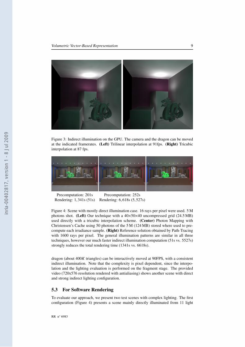
Figure 3: Indirect illumination on the GPU. The camera and the dragon can be movedat the indicated framerates. (Left) Trilinear interpolation at 91fps. (Right) Tricubicinterpolation at 87 fps.
Precomputation: 201s Precomputation: 252sRendering: 1,341s (51s) Rendering: 6,618s (5,527s)
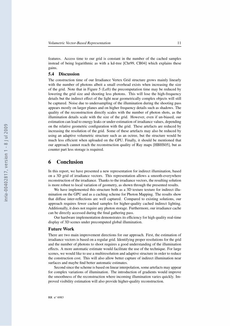
Figure 4: Scene with mostly direct illumination case. 16 rays per pixel were used. 5 Mphotons shot. (Left) Our technique with a 40×50×40 uncompressed grid (24.5 MB)used directly with a tricubic interpolation scheme. (Center) Photon Mapping withChristensen’s Cache using 50 photons of the 5 M (124 MB) stored where used to pre-compute each irradiance sample. (Right) Reference solution obtained by Path-Tracingwith 1600 rays per pixel. The general illumination patterns are similar in all threetechniques, however our much faster indirect illumination computation (51s vs. 5527s)strongly reduces the total rendering time (1341s vs. 6618s).
dragon (about 400K triangles) can be interactively moved at 90FPS, with a consistentindirect illumination. Note that the complexity is pixel dependent, since the interpo-lation and the lighting evaluation is performed on the fragment stage. The providedvideo (720x576 resolution rendered with antialiasing) shows another scene with directand strong indirect lighting configuration.
5.3 For Software RenderingTo evaluate our approach, we present two test scenes with complex lighting. The firstconfiguration (Figure 4) presents a scene mainly directly illuminated from 11 light
RR n° 6983
inria
-004
0281
7, v
ersi
on 1
- 8
Jul 2
009

10 Pacanowski & Granier & Poulin & Schlick
Precomputation: 2,270s Precomputation: 466s Precomputation: 150sRendering: 41s (13s) Rendering: 47,505s (10,050s) Rendering: 37,692s (2,376s)
Figure 5: Scene with mostly indirect illumination. (Left) Our technique using directlya 30×20×92 an uncompressed grid (11.4 MB) constructed with 80 M photons. (Cen-ter) Christensen’s method reference image with 3200 rays to sample the hemisphereand 5 M photons stored (124 MB). (Right) Our technique using indirectly a 12×8×20uncompressed grid (590 KB) with the same number of photons shot and the same num-ber of rays to sample the hemisphere.
sources. The second one (Figure 5) is a classical two-room configuration where oneroom is indirectly illuminated by a light source placed in the other room. Both sceneshave more than 8 million polygons due the highly detailed objects. They illustrate thegeometric robustness of our approach.
We compare our technique to Photon Mapping combined with Christensen’s [Chr99]precomputed samples. Precomputation time for our technique involves shooting pho-tons and accumulating their contribution in the grid, and for Christensen’s it involvesshooting photons, balancing the kd-tree, and precomputing irradiance. For all imagesgenerated with Christensen’s method, we set the number of precomputed samples tobe one fourth of the total number of photon hits, as originally suggested [Chr99].
Figure 4 compares the results obtained with our technique and Christensen’s fordirect lighting configuration. For fair comparison, a reference solution has been com-puted with a high density (1600 rays per pixel) Path-Tracing algorithm. For equivalentprecomputation times, our technique allows a much faster computation (51s vs. 5527s)of the indirect component of the illumination due to direct access to the cached val-ues. In our technique, the final gathering step spends most of its time computing ray-geometry intersections and direct illumination, while Christensen’s cache requires tocast a large number of additional gathering rays, since direct access produces very ob-jectionable illumination patterns with zones of constant irradiance similar to Voronoidiagrams. This is a well-known artefact [Chr99] preventing direct access to cachedirradiance.
For the indirect lighting configuration presented at Figure 5 we have also tried adirect access to our structure but to capture finer shadows cast by the columns, a higher-resolution grid (30× 20× 92) was built and consequently a larger number of photonsneeded to be shot. This resulted in a much larger precomputation time but our methodwith direct access is still much faster (2,311s vs. 47,971s) than Christensen’s cachingtechnique for a similar quality. Alternatively, we have also tested our technique with anindirect access (cf. Figure 5) to the cached values by using a lower resolution grid (12×8× 20) traversed by the same number of photons as with Christensen’s method. Ourtechnique reduces both precomputation time (150s vs. 466s) and reconstruction timeof the indirect illumination (2,376s vs. 10,050s), while retaining similar illumination
INRIA
inria
-004
0281
7, v
ersi
on 1
- 8
Jul 2
009
Volumetric Vector-Based Representation 11
features. Access time to our grid is constant in the number of the cached samplesinstead of being logarithmic as with a kd-tree [Chr99, CB04] which explains thesegains.
5.4 DiscussionThe construction time of our Irradiance Vertex Grid structure grows mainly linearlywith the number of photons albeit a small overhead exists when increasing the sizeof the grid. Note that in Figure 5 (Left) the precomputation time may be reduced bylowering the grid size and shooting less photons. This will lose the high-frequencydetails but the indirect effect of the light near geometrically complex objects will stillbe captured. Noise due to undersampling of the illumination during the shooting passappears mostly on larger planes and on higher frequency details such as shadows. Thequality of the reconstruction directly scales with the number of photon shots, as theillumination details scale with the size of the grid. However, even if un-biased, ourestimation can lead to energy leaks or under-estimation of irradiance values, dependingon the relative geometric configuration with the grid. These artefacts are reduced byincreasing the resolution of the grid. Some of these artefacts may also be reduced byusing an adaptive volumetric structure such as an octree, but the structure would bemuch less efficient when uploaded on the GPU. Finally, it should be mentioned thatour approach cannot reach the reconstruction quality of Ray maps [HBHS05], but ascounter part less storage is required.
6 ConclusionIn this report, we have presented a new representation for indirect illumination, basedon a 3D grid of irradiance vectors. This representation allows a smooth-everywherereconstruction of the irradiance. Thanks to the irradiance vectors, the resulting solutionis more robust to local variation of geometry, as shown through the presented results.
We have implemented this structure both as a 3D texture texture for indirect illu-mination on the GPU and as a caching scheme for Photon Mapping. The results showthat diffuse inter-reflections are well captured. Compared to existing solutions, ourapproach requires fewer cached samples for higher-quality cached indirect lighting.Additionally, it does not require any photon storage. Furthermore, our irradiance cachecan be directly accessed during the final gathering pass.
Our hardware implementation demonstrates its efficiency for high quality real-timedisplay of 3D scenes under precomputed global illumination.
Future WorkThere are two main improvement directions for our approach. First, the estimation ofirradiance vectors is based on a regular grid. Identifying proper resolutions for the gridand the number of photons to shoot requires a good understanding of the illuminationeffects. A more automatic estimate would facilitate the use of the technique. For largescenes, we would like to use a multiresolution and adaptive structure in order to reducethe construction cost. This will also allow better capture of indirect illumination nearsurfaces and maybe find better automatic estimates.
Second since the scheme is based on linear interpolation, some artefacts may appearfor complex variations of illumination. The introduction of gradients would improvethe smoothness of the reconstruction where incoming illumination varies quickly. Im-proved visibility estimation will also provide higher-quality reconstruction.
RR n° 6983
inria
-004
0281
7, v
ersi
on 1
- 8
Jul 2
009
12 Pacanowski & Granier & Poulin & Schlick
References[AFO05] O. Arikan, D.A. Forsyth, and J.F. O’Brien. Fast and Detailed Approximate
Global Illumination by Irradiance Decomposition. In Proc. SIGGRAPH2005, pages 1108–1114. ACM, 2005.
[Arv94] J. Arvo. The irradiance Jacobian for partially occluded polyhedral sources.In Proc. SIGGRAPH’94, pages 343–350. ACM, 1994.
[CB04] P.H. Christensen and D. Batali. An Irradiance Atlas for Global Illumina-tion in Complex Production Scenes. In Proc. Eurographics Symposium onRendering, pages 133–141, 2004.
[Chr99] P.H. Christensen. Faster global photon map global illumination. Journal ofGraphics Tools, 4(3):1–10, 1999.
[DBB06] Philip Dutré, Kavita Bala, and Philippe Bekaert. Advanced Global Illumi-nation. A. K. Peters, Ltd., 2006.
[DHS+05] F. Durand, N. Holzschuch, C. Soler, E. Chan, and F.X. Sillion. A frequencyanalysis of light transport. ACM Trans. on Graph., 24(3), 2005.
[GSHG92] G. Greger, P. Shirley, P.M. Hubbard, and D.P. Greenberg. Irradiance vol-ume. IEEE Computer Graphics and Applications, 18(2):32–43, 1992.
[HBHS05] V. Havran, J. Bittner, R. Herzog, and H.-P. Seidel. Ray Maps for GlobalIllumination. In Proc. Eurographics Symposium on Rendering 2005, pages43–54, 2005.
[Jen01] Henrik Wann Jensen. Realistic Image Synthesis using Photon Mapping.A.K. Peters, 2001.
[KBPv06] J. Krivánek, K. Bouatouch, S.N. Pattanaik, and J. Žára. Making radianceand irradiance caching practical: Adaptive caching and neighbor clamp-ing. In Proc. Eurographics Symposium on Rendering 2006, pages 127–138,2006.
[KL05] Janne Kontkanen and Samuli Laine. Ambient occlusion fields. In Proceed-ings of ACM SIGGRAPH 2005 Symposium on Interactive 3D Graphics andGames, pages 41–48. ACM Press, 2005.
[Pha04] M. Pharr. GPU Gems, chapter Ambient occlusion. Addison-Wesley, 2004.
[PRG+08] Romain Pacanowski, Mickaël Raynaud, Xavier Granier, Patrick Reuter,Christophe Schlick, and Pierre Poulin. Efficient Streaming of 3D Sceneswith Complex Geometry and Complex Lighting. In Web3D ’08: Proc.international symposium on 3D web technology , 2008.
[PRL+08] Romain Pacanowski, Mickaël Raynaud, Julien Lacoste, Xavier Granier,Patrick Reuter, Christophe Schlick, and Pierre Poulin. Compact Structuresfor Interactive Global Illumination on Large Cultural Objects. In Interna-tional Symposium on Virtual Reality, Archaeology and Cultural HeritageVAST 2008: Short and Project Paper , 2008.
INRIA
inria
-004
0281
7, v
ersi
on 1
- 8
Jul 2
009
Volumetric Vector-Based Representation 13
[SH05] Christian Sigg and Markus Hadwiger. GPU Gems 2, chapter Fast Third-Order Texture Filtering. Addison-Wesley, 2005.
[SKJ02] P. Sloan, J. Kautz, and J.Snyder. Precomputed radiance transfer for real-time rendering in dynamic, low-frequency lighting environments. In Proc.SIGGRAPH 2002, pages 527–536, New York, NY, USA, 2002. ACM Press.
[SSG+00] M. Stamminger, A. Scheel, X. Granier, F. Perez-Cazorla, G. Drettakis, andF. Sillion. Efficient glossy global illumination with interactive viewing.Computer Graphics Forum, 19(1):13–25, 2000.
[TL04] E. Tabellion and A. Lamorlette. An approximate global illumination systemfor computer generated films. ACM Trans. on Graphics, 23(3):469–476,2004.
[WRC88] G.J. Ward, F.M. Rubinstein, and R.D. Clear. A ray tracing solution fordiffuse interreflection. In Proc. SIGGRAPH’88, pages 85–92, 1988.
[ZSP98] J. Zaninetti, X. Serpaggi, and B. Péroche. A vector approach for globalillumination in ray tracing. In Proc. Eurographics 1998, pages 149–158,1998.
RR n° 6983
inria
-004
0281
7, v
ersi
on 1
- 8
Jul 2
009

Centre de recherche INRIA Bordeaux – Sud OuestDomaine Universitaire - 351, cours de la Libération - 33405 Talence Cedex (France)
Centre de recherche INRIA Grenoble – Rhône-Alpes : 655, avenue de l’Europe - 38334 Montbonnot Saint-IsmierCentre de recherche INRIA Lille – Nord Europe : Parc Scientifique de la Haute Borne - 40, avenue Halley - 59650 Villeneuve d’Ascq
Centre de recherche INRIA Nancy – Grand Est : LORIA, Technopôle de Nancy-Brabois - Campus scientifique615, rue du Jardin Botanique - BP 101 - 54602 Villers-lès-Nancy Cedex
Centre de recherche INRIA Paris – Rocquencourt : Domaine de Voluceau - Rocquencourt - BP 105 - 78153 Le Chesnay CedexCentre de recherche INRIA Rennes – Bretagne Atlantique : IRISA, Campus universitaire de Beaulieu - 35042 Rennes Cedex
Centre de recherche INRIA Saclay – Île-de-France : Parc Orsay Université - ZAC des Vignes : 4, rue Jacques Monod - 91893 Orsay CedexCentre de recherche INRIA Sophia Antipolis – Méditerranée : 2004, route des Lucioles - BP 93 - 06902 Sophia Antipolis Cedex
ÉditeurINRIA - Domaine de Voluceau - Rocquencourt, BP 105 - 78153 Le Chesnay Cedex (France)
http://www.inria.frISSN 0249-6399
inria
-004
0281
7, v
ersi
on 1
- 8
Jul 2
009