Volume 2 of 2 Specifications - Ministry of Education And Sports
49
1 THE REPUBLIC OF UGANDA MINISTRY OF EDUCATION AND SPORTS ALBERTINE REGION SUSTAINABLE DEVELOPMENT PROJECT (ARSDP) SUPPLY, DELIVERY, INSTALLATION, TRAINING OF USERS AND COMMISSIONING OF EQUIPMENT AND ACCESSORIES FOR UGANDA PETROLEUM INSTITUTE KIGUMBA- ELETRICAL, PERSONNEL PROTECTION AND INSTRUMENTATION EQUIPMENT Volume 2 of 2 Specifications
-
Upload
khangminh22 -
Category
Documents
-
view
1 -
download
0
Transcript of Volume 2 of 2 Specifications - Ministry of Education And Sports

1
THE REPUBLIC OF UGANDA
MINISTRY OF EDUCATION AND SPORTS
ALBERTINE REGION SUSTAINABLE DEVELOPMENT
PROJECT (ARSDP)
SUPPLY, DELIVERY, INSTALLATION, TRAINING OF USERS AND
COMMISSIONING OF EQUIPMENT AND ACCESSORIES FOR UGANDA
PETROLEUM INSTITUTE KIGUMBA- ELETRICAL, PERSONNEL
PROTECTION AND INSTRUMENTATION EQUIPMENT
Volume 2 of 2
Specifications

2
TECHNICAL SPECIFICATIONS
Electrical Equipment and Tools
Generators UOM QTY
A1 DC Generator Direct current motor compound excitation - Didactic
equipment
it must be also used as generator.
Technical features:
- Power: C1.1 kW
- Voltage: 220 V
- Speed: 3000 rpm
- Excitation: 160 V / 0.25 A
It must be possible to couple the electrical machine with
other electrical machines through a hub and spider
elastic gear ring in polyurethane. It must be supplied
with a hooked module in aluminum with PVC label and
safety terminals for the electrical connection. A
schematic diagram must be shown on the hooked
module.
Each machine must be mounted on a base and must be
provided with:
- Plate that brings its axis height to the standard
measure (112 mm).
- Plates for fixing to the base of the machine
- Four screws for fixing of the machine
Inter Rail Distance of the plates: 160mm
Coupling Joint: Diameter: 40mm, length 40mm
Supplied with:
Starting rheostat - Didactic equipment - Step-variable
rheostat for the half torque starting of the DC motors of
the laboratory.
Excitation rheostat - Didactic equipment - Suitable for
the shunt excitation of the DC machines and of the
synchronous machines of the laboratory
pc 1
A1.1 Three phase AC Generator 3 Phase 40kW Super Silenced Electric Diesel
Generator for educational purposes
Direct injection internal combustion engine
(diesel);
Output Sockets 400V 63-32A-230V 16A
AC synchronous generator
Cooling system: WATER
Digital control screen;
Base mounted with canopy and engine accessible
Dry air filter, fuel filter, oil filter
Starter battery and start connection cable;
Supervised / 90 dB LWA
Molded case circuit breaker
Rated Voltage: 400/230V
Rated frequency (Hz): 50
Rated Speed: 1500rpm
Fuel Capacity approx. 215ltrs
Engine Power approx. 75.0 Hp
pc 1
A1.2 Single phase AC Generator 12.1 kW Air Cooled Diesel Generator, Voltage:
220-240 V
Super Silenced Canopy
Cooling system : AIR
Fuel type: Diesel
Frequency: 50Hz
AVR Controlled
pc 1

3
Output Sockets 63-32-16A 230V
Number of cylinder: 2
Rated speed: 3000rpm
Fuel capacity: 23l
Engine power: 20HP
Rotating Equipment
A2 Three phase AC motors Three‐phase 2 ‐ speed squirrel cage asynchronous motor
- Didactic equipment
2 or 4 pole induction motor with Dahlander‐type three‐phase stator winding and squirrel cage rotor.
Technical features:
- Power: 0,9/C1.1 kW
- Voltage: 380 V
- Current: C2.5/C3.3 A
- Speed: 1420/2830 rpm, 50 Hz.
It must be possible to couple the electrical machine with
other electrical machines through a hub and spider
elastic gear ring in polyurethane. It must be supplied
with a hooked module in aluminum with PVC label and
safety terminals for the electrical connection. A
schematic diagram must be shown on the hooked
module.
Each machine must be mounted on a base and must be
provided with:
- Plate that brings its axis height to the standard
measure (112 mm).
- Plates for fixing to the base of the machine
- Four screws for fixing of the machine
Inter Rail Distance of the plates: 160mm
Coupling Joint: Diameter: 40mm, length 40mm
Supplied with:
Pole changing unit – It must be used to change the
number of poles in Dahlander type motors.
pc 1
A3 Single phase AC motor 2-Pole, High-Speed Type: 40 W∼150 W (1/19 HP∼1/5
HP), Single-Phase 220/230 VA
pc 1
A4 DC motor The DC Motor Drive package should include a
permanent-magnet dc motor, a pulse-width modulated
(PWM) dc motor drive, various electrical components
(single-pole safety switch, fuse holder, start/stop switch,
potentiometer, terminal blocks, etc.), and a motor
control enclosure. The package also should include all
the conduits, electric wire, fittings, and hardware
required to install the dc motor drive
pc 1
Consumables
A5 LV ( Low voltage) aM
Fuse 6A 10A 20A
motor protection
V :400V 6A 10A 20 A size 10x38
at least 1 should be ATEX/IECex certified
Nr 3
A6 LV ( Low voltage) gG
Fuse 2A 10A 20 A
general protection
V:220V , 400V size 10x38 size 10x38
Make: Schneider Electric, ABB Legrand, Hager or
equivalent
at least 1 should be ATEX/IECex certified
Nr 3
4
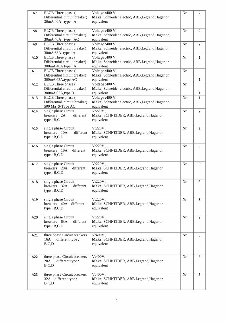
A7 ELCB Three phase (
Differential circuit breaker)
30mA 40A type : A
Voltage :400 V,
Make: Schneider electric, ABB,Legrand,Hager or
equivalent
Nr 2
A8 ELCB Three phase (
Differential circuit breaker)
30mA 40A type : AC
Voltage :400 V,
Make: Schneider electric, ABB,Legrand,Hager or
equivalent
Nr 2
A9 ELCB Three phase (
Differential circuit breaker)
30mA 63A type : A
Voltage :400 V,
Make: Schneider electric, ABB,Legrand,Hager or
equivalent
Nr 2
A10 ELCB Three phase (
Differential circuit breaker)
300mA 40A type : A
Voltage :400 V,
Make: Schneider electric, ABB,Legrand,Hager or
equivalent
Nr 1
A11 ELCB Three phase (
Differential circuit breaker)
300mA 63A,type AC
Voltage :400 V,
Make: Schneider electric, ABB,Legrand,Hager or
equivalent
Nr
1
A12 ELCB Three phase (
Differential circuit breaker)
300mA 63A,type B
Voltage :400 V,
Make: Schneider electric, ABB,Legrand,Hager or
equivalent
Nr
1
A13 ELCB Three phase (
Differential circuit breaker)
500 Ma S-Type AC
Voltage :400 V,
Make: Schneider electric, ABB,Legrand,Hager or
equivalent
Nr 1
A14 single phase Circuit
breakers 2A different
type : B,C
V:220V ,
Make: SCHNEIDER, ABB,Legrand,Hager or
equivalent
Nr 2
A15 single phase Circuit
breakers 10A different
type : B,C,D
V:220V ,
Make: SCHNEIDER, ABB,Legrand,Hager or
equivalent
Nr 3
A16 single phase Circuit
breakers 16A different
type : B,C,D
V:220V ,
Make: SCHNEIDER, ABB,Legrand,Hager or
equivalent
Nr 3
A17 single phase Circuit
breakers 20A different
type : B,C,D
V:220V ,
Make: SCHNEIDER, ABB,Legrand,Hager or
equivalent
Nr 3
A18 single phase Circuit
breakers 32A different
type : B,C,D
V:220V ,
Make: SCHNEIDER, ABB,Legrand,Hager or
equivalent
Nr 3
A19 single phase Circuit
breakers 40A different
type : B,C,D
V:220V ,
Make: SCHNEIDER, ABB,Legrand,Hager or
equivalent
Nr 3
A20 single phase Circuit
breakers 63A different
type : B,C,D
V:220V ,
Make: SCHNEIDER, ABB,Legrand,Hager or
equivalent
Nr 3
A21 three phase Circuit breakers
16A different type :
B,C,D
V:400V ,
Make: SCHNEIDER, ABB,Legrand,Hager or
equivalent
Nr 3
A22 three phase Circuit breakers
20A different type :
B,C,D
V:400V,
Make: SCHNEIDER, ABB,Legrand,Hager or
equivalent
Nr 3
A23 three phase Circuit breakers
32A different type :
B,C,D
V:400V ,
Make: SCHNEIDER, ABB,Legrand,Hager or
equivalent
Nr 3
5
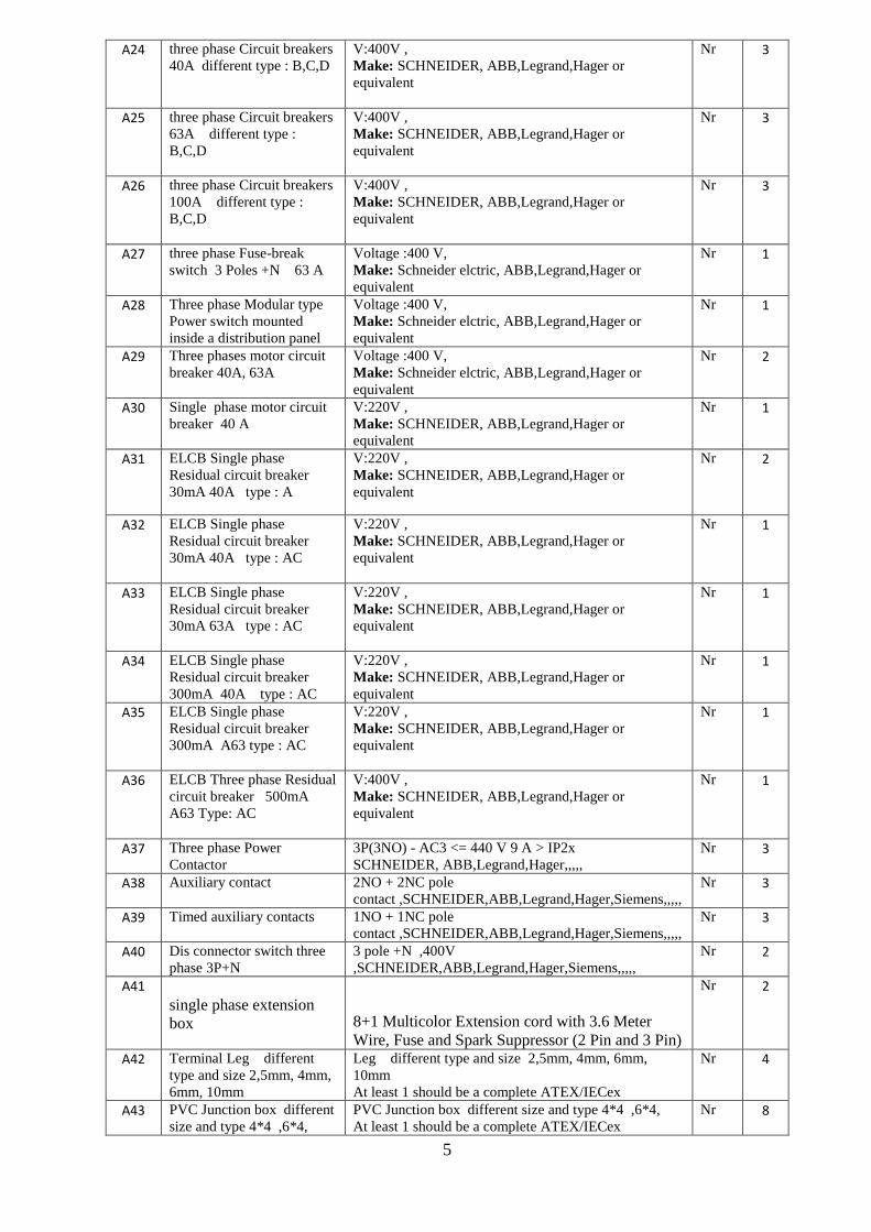
A24 three phase Circuit breakers
40A different type : B,C,D
V:400V ,
Make: SCHNEIDER, ABB,Legrand,Hager or
equivalent
Nr 3
A25 three phase Circuit breakers
63A different type :
B,C,D
V:400V ,
Make: SCHNEIDER, ABB,Legrand,Hager or
equivalent
Nr 3
A26 three phase Circuit breakers
100A different type :
B,C,D
V:400V ,
Make: SCHNEIDER, ABB,Legrand,Hager or
equivalent
Nr 3
A27 three phase Fuse-break
switch 3 Poles +N 63 A
Voltage :400 V,
Make: Schneider elctric, ABB,Legrand,Hager or
equivalent
Nr 1
A28 Three phase Modular type
Power switch mounted
inside a distribution panel
Voltage :400 V,
Make: Schneider elctric, ABB,Legrand,Hager or
equivalent
Nr 1
A29 Three phases motor circuit
breaker 40A, 63A
Voltage :400 V,
Make: Schneider elctric, ABB,Legrand,Hager or
equivalent
Nr 2
A30 Single phase motor circuit
breaker 40 A
V:220V ,
Make: SCHNEIDER, ABB,Legrand,Hager or
equivalent
Nr 1
A31 ELCB Single phase
Residual circuit breaker
30mA 40A type : A
V:220V ,
Make: SCHNEIDER, ABB,Legrand,Hager or
equivalent
Nr 2
A32 ELCB Single phase
Residual circuit breaker
30mA 40A type : AC
V:220V ,
Make: SCHNEIDER, ABB,Legrand,Hager or
equivalent
Nr 1
A33 ELCB Single phase
Residual circuit breaker
30mA 63A type : AC
V:220V ,
Make: SCHNEIDER, ABB,Legrand,Hager or
equivalent
Nr 1
A34 ELCB Single phase
Residual circuit breaker
300mA 40A type : AC
V:220V ,
Make: SCHNEIDER, ABB,Legrand,Hager or
equivalent
Nr 1
A35 ELCB Single phase
Residual circuit breaker
300mA A63 type : AC
V:220V ,
Make: SCHNEIDER, ABB,Legrand,Hager or
equivalent
Nr 1
A36 ELCB Three phase Residual
circuit breaker 500mA
A63 Type: AC
V:400V ,
Make: SCHNEIDER, ABB,Legrand,Hager or
equivalent
Nr 1
A37 Three phase Power
Contactor
3P(3NO) - AC3 <= 440 V 9 A > IP2x
SCHNEIDER, ABB,Legrand,Hager,,,,,
Nr 3
A38 Auxiliary contact 2NO + 2NC pole
contact ,SCHNEIDER,ABB,Legrand,Hager,Siemens,,,,,
Nr 3
A39 Timed auxiliary contacts 1NO + 1NC pole
contact ,SCHNEIDER,ABB,Legrand,Hager,Siemens,,,,,
Nr 3
A40 Dis connector switch three
phase 3P+N
3 pole +N ,400V
,SCHNEIDER,ABB,Legrand,Hager,Siemens,,,,,
Nr 2
A41
single phase extension
box 8+1 Multicolor Extension cord with 3.6 Meter
Wire, Fuse and Spark Suppressor (2 Pin and 3 Pin)
Nr 2
A42 Terminal Leg different
type and size 2,5mm, 4mm,
6mm, 10mm
Leg different type and size 2,5mm, 4mm, 6mm,
10mm
At least 1 should be a complete ATEX/IECex
Nr 4
A43 PVC Junction box different
size and type 4*4 ,6*4,
PVC Junction box different size and type 4*4 ,6*4,
At least 1 should be a complete ATEX/IECex
Nr 8

6
A44 PVC Tube Different size
20 32
PVC Tube Different size 20 32 Nr 4
A45 Accessories
elbow,tee,bend
Consisting of elbow,tee,bend Nr 3
A46 Apparent and recessed
double switch
1 way 2 gang switch - apparent 5No
1 way 2gang switch- recessed 5No
Make: complete ATEX/IECex set or equivalent
At least 1 should be a complete ATEX/IECex set
Nr 2
A47 Apparent and recessed light
switch
1 way 1 gang switch - apparent 10No
1 way 1gang switch- recessed 10No
Make: complete ATEX/IECex set or equivalent
Nr 4
A48 Digital time switch Time Switch with – 24 hours + 7 days + year Nr 1
A48 Electric sheath ( flexible
wiring tube) different size
16,20,32
Electric sheath ( flexible wiring tube) different size
16,20,32
Nr 1
A50 Plastic cables gland
different size
Assorted PG7- PG48 Nr 30
A51 METAL cables gland
different size
For XLPE, PVC, SWA- BS4567 for 1.5mmsq. –
16mmsq
Nr 8
A52 Heat gun 2-stage switch for one-handed operation
Two air flow and temperature stages
Thermal protection
Rated input power: 1,600W
Working temperature: 300 - 500 °C
Airflow: 240 - 450 l/min
Nr 4
A53 special glue for pvc Solvent cement /Tangit Nr 1
A54 3-row electrical panel Enclosure for circuit breakers with 3 DIN rails (35mm) Nr 2
A55 lamps 60 w 100w Standard LED Lamps 60W , 100W ( 20 pcs of each)
At least 1 should be a complete ATEX/IECex set
Nr 1
A56 straight holder Lamp holder – straight batten
At least 1 should be a complete ATEX/IECex set
Nr 8
A57 angle holder Lamp holder- Angle batten
At least 1 should be a complete ATEX/IECex set
Nr 6
A58 apparent electrical outlet 16
A 32 A
Socket outlet 16A 15 pcs
Socket outlets 32A 15pcs
Hanging entry.
Nr 6
A59 electric cable duct Self-adhesive white, 25mm x 16mm Nr 6
A60 Push buttons green Push buttons green
At least 1 should be ATEX/IECex
Nr 20
A61 Push buttons red Push buttons red
At least 1 should be ATEX/IECex
Nr 4
A62 Push buttons black Push buttons black
At least 1 should be ATEX/IECex
Nr 4
A63 indicator light red indicator light red
At least 1 should be ATEX/IECex
Nr 4
A64 indicator light green indicator light green
At least 1 should be ATEX/IECex
Nr 4
A65 indicator light white indicator light white
At least 1 should be ATEX/IECex
Nr 4
A66 indicator light yellow indicator light yellow or orange
At least 1 should be ATEX/IECex
Nr 4
A67 indicator light Bleu indicator light Bleu
At least 1 should be ATEX/IECex
Nr 4
A68 emergency stop button with
punch
emergency stop button with punch
At least 1 should be ATEX/IECex
Nr 4
A69 emergency stop button with
key
emergency stop button with key
At least 1 should be ATEX/IECex
Nr 4
7
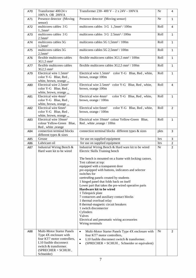
A70 Transformer 400/24 v
100VA OR 200VA
Transformer 230- 400 V – 2 x 24V - 100VA Nr 4
A71 Presence detector (Moving
sensor)
Presence detector (Moving sensor) Nr 1
A72 multicores cables 3 G
1.,5mm²
multicores cables 3 G 1.,5mm² / 100m Roll 4
A73 multicores cables 3 G
2.5mm²
multicores cables 3 G 2.5mm² / 100m Roll 1
A74 multicores cables 5G
1,5mm²
multicores cables 5G 1,5mm² / 100m Roll 1
A75 multicores cables 5G
2,5mm²
multicores cables 5G 2,5mm² / 100m Roll 1
A76 flexible multicores cables
3G1,5 mm²
flexible multicores cables 3G1,5 mm² / 100m Roll 1
A77 flexible multicores cables
3G2,5 mm²
flexible multicores cables 3G2,5 mm² / 100m Roll 1
A79 Electrical wire 1.5mm²
color Y-G Blue, Red ,
white, brown, orange ,,,
Electrical wire 1.5mm² color Y-G Blue, Red , white,
brown, orange 100m
Roll 1
A80 Electrical wire 2.5mm²
color Y-G Blue, Red ,
white, brown, orange ,,,
Electrical wire 2.5mm² color Y-G Blue, Red , white,
brown, orange 100m
Roll 4
A81 Electrical wire 4mm²
color Y-G Blue, Red ,
white, brown, orange ,,,
Electrical wire 4mm² color Y-G Blue, Red , white,
brown, orange / 100m
Roll 1
A82 Electrical wire 6mm²
color Y-G Blue, Red ,
white, brown, orange ,,,
Electrical wire 6mm² color Y-G Blue, Red , white,
brown, orange / 100m
Roll 2
A83 Electrical wire 10mm²
colour Yellow-Green Blue,
Red , white ,orange
Electrical wire 10mm² colour Yellow-Green Blue,
Red , white ,orange / 100m
Roll 1
A84 connection terminal blocks
different types & sizes
connection terminal blocks different types & sizes pkts 3
A85 Grease for use on supplied equipment ltrs 3
A86 Lubricant oil for use on supplied equipment ltrs 2
A87 Industrial Wiring Bench &
Hard ware kit to be wired
Industrial Wiring Bench & Hard ware kit to be wired
Electric Skills Training bench
The bench is mounted on a frame with locking castors.
Test cabinet at top:
equipped with a transparent door
pre-equipped with buttons, indicators and selector
switches for
controlling panels created by students
1 hinged panel that folds back on itself
Lower part that takes the pre-wired operative parts
Hardware kit to be wired
1 Telequick plate
7 contactors and auxiliary contact blocks
1 thermal overload relay
8 thermal-magnetic circuit breakers
1 switch disconnector
Cylinders
Valves
Electrical and pneumatic wiring accessories
Wiring terminals
Nr 2
A88 Multi-Motor Starter Panels
Type 4X enclosure with
four KT7 motor controllers,
L10 fusible disconnect
switch & transformer.
(SPRECHER + SCHUH ,
Schneider)
Multi-Motor Starter Panels Type 4X enclosure with
four KT7 motor controllers,
L10 fusible disconnect switch & transformer.
(SPRECHER + SCHUH , Schneider or equivalent)
Nr 2

8
Measuring Instruments
A89 Three-phase Power Meter Three-phase electrical network analyzer with phase
sequence analysis
Voltage and Current recording
Range: 110-480V / 10-3000A
Active, Reactive and Apparent Power
Harmonics and THD
Flicker
Transient waveforms
Unbalance
USB connectivity
GSM (optional)
IP-65 enclosure
Nr 1
A90 Multimeter clamps
Remote Display True RMS AC/DC Clamp Meter with iFlex current Probe
Key features
Wireless technology allows the display to be
carried up to 30 ft. away from the point of
measurement
The removable magnetic display can be
conveniently mounted where it is easily seen
iFlex® Flexible Current Probe expands the
measurement range to 2500 A AC
Integrated low pass filter and state-of-the-art signal
processing allows for use in noisy electrical
environments while providing stable readings
Supplied with carrying case
Nr 1
A91 DIGITAL MULTIMETER
DMM 600V - AC/DC Large, easy-to-read displays
Low battery indicator
Measures at least frequency, capacitance, duty
cycle, temperature
Amperage Rating : 10
Capacitance : approx. 10 nF - 10000 μF
Counts : 5999
Diode Test : Yes
Display : Digital
Resistance : 0 Ω to 49 MΩ
Type : Auto/Manual Ranging
Voltage Rating : at least 600
should be ATEX / IECex certified
Nr 1
A92 Earthing and short-
circuiting systems
Earthing and Short-Circuit kit is phase earthing
equipment to be used on high voltage overhead lines.
The set is designed to protect against an accidental
commissioning or voltage returns during maintenance.
Contents:
3 x Aluminium alloy clamps lockable by a screw
for use on cylindrical conductors with diameter
between 5 and 45 mm, flat bars max. 45 mm,
bending bus-bars max. 45 mm and fixing points
between 20 and 25 mm
Nr 1

9
3 x PVC insulated copper cables
3 x milling earthing lathe
3 x nylon bag for storage
A93
Auto-transformer 220 v
3 Amp Variac Variable Transformer 500VA Max 0-240
AC Volt Output regulator
Nr 2
Hand Tools
A94 Cord less drill machine
18V Cordless Hammer Drill Driver
Battery charge indicator
Enhanced dust and drip-proof performance
Higher power and productivity
Ergonomic design for fatigue free use
21 Torque settings in clutch mode
Drilling capacities; 13mm(
steel),65mm(Wood),16mm( concrete)
No Load speed: 0-2,000rpm (Hi) , 0-400rpm( Lo)
Max fastening torque; 91Nm
supplied with 2x 4.0Ah batteries & charger with
carry case
Nr 1
A95 Sprit level 8";12", 18" Sprit level 8";12", 18" Nr 3
A96 Measuring Tap 5 Meter 8
Meter
Measuring Tape 5 Meter (5) and 8 Meter(5) Nr 6
A97 Insulated Pliers set
3 pc Basic Plier Set
Pliers set designed for grasping, bending and
cutting
Oil-resistant dipped handle allows for a
comfortable grip
Drop-forged steel is strong and durable
Includes: 6" Slip Joint Pliers 6" Diagonal Pliers 6"
Long Nose Pliers
set 2
A98 Insulated Cutting Pliers
4-Piece Pliers Set
four-piece pliers set with rubberized slip-resistant
grips
Machined jaws help grip items securely
Cutting pliers feature induction-hardened cutting
edges for long life
Includes 8-inch slip joint, 7-inch diagonal, .8-inch
lineman, and 8-inch long nose
set 2
A99 Cable Shears and Cutters Bi-material handle with secure grip grooving
Curved jaw design cuts coaxial and other soft
cables up to 1/2" diameter
Hand ground, induction hardened blade
Heat treated high chrome steel forging
Interlocking joint assembly for smooth cutting
set 2
10
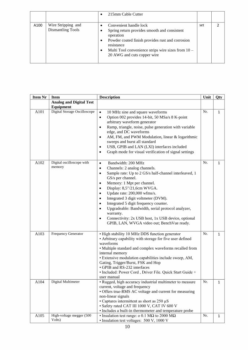
215mm Cable Cutter
A100 Wire Stripping and
Dismantling Tools Convenient handle lock
Spring return provides smooth and consistent
operation
Powder coated finish provides rust and corrosion
resistance
Multi Tool convenience strips wire sizes from 10 –
20 AWG and cuts copper wire
set 2
Item Nr Item Description Unit Qty
Analog and Digital Test
Equipment
A101 Digital Storage Oscilloscope 10 MHz sine and square waveforms
Option 002 provides 14-bit, 50 MSa/s 8 K-point
arbitrary waveform generator
Ramp, triangle, noise, pulse generation with variable
edge, and DC waveforms
AM, FM, and PWM Modulation, linear & logarithmic
sweeps and burst all standard
USB, GPIB and LAN (LXI) interfaces included
Graph mode for visual verification of signal settings
Nr. 1
A102 Digital oscilloscope with
memory Bandwidth: 200 MHz
Channels: 2 analog channels.
Sample rate: Up to 2 GS/s half-channel interleaved, 1
GS/s per channel.
Memory: 1 Mpt per channel.
Display: 8,5"/21,6cm WVGA.
Update rate: 200,000 wfms/s.
Integrated 3 digit voltmeter (DVM).
Integrated 5 digit frequency counter.
Upgradeable: Bandwidth, serial protocol analyzer,
warranty.
Connectivity: 2x USB host, 1x USB device, optional
GPIB, LAN, WVGA video out; BenchVue ready.
Nr. 1
A103 Frequency Generator • High stability 10 MHz DDS function generator
• Arbitrary capability with storage for five user defined
waveforms
• Multiple standard and complex waveforms recalled from
internal memory
• Extensive modulation capabilities include sweep, AM,
Gating, Trigger/Burst, FSK and Hop
• GPIB and RS-232 interfaces
• Included: Power Cord , Driver File. Quick Start Guide +
user manual
Nr. 1
A104 Digital Multimeter • Rugged, high accuracy industrial multimeter to measure
current, voltage and frequency
• Offers true-RMS AC voltage and current for measuring
non-linear signals
• Captures intermittent as short as 250 µS
• Safety rated CAT III 1000 V, CAT IV 600 V
• Includes a built-in thermometer and temperature probe
Nr. 1
A105 High-voltage megger (500
Volts) • Insulation test range: o 0.1 MΩ to 2000 MΩ
• Insulation test voltages: 500 V, 1000 V
Nr. 1

11
• With the remote test probe for repetitive or hard-to- reach
testing
• Auto-discharge of capacitive voltage for added user
protection
• AC/DC voltage: 0.1 V to 600 V
• 200 mA Continuity
• Resistance: 0.01 Ω to 20.00 kΩ
• with auto power off
• with large, backlit display
• CAT IV 600 V overvoltage category rating for added
user protection
• Remote probe, test leads, probes and alligator clips
included with each tester
• Four AA alkaline batteries (NEDA 15 A or IEC LR6) for
at least 1000 insulation tests
A106 Digital Multimeter • Digital multimeter
• True-RMS AC, AC + DC, dBm, dBV
• 100 kHz AC bandwidth
• MIN/MAX/AVG record with real time clock
• Frequency 0.5 Hz to 1 MHz
• Duty cycle & pulse width measurement
• Infrared port for data capture to a PC with
• Rugged, over molded case
• Cat IV 600 V / Cat III 1000 V
Nr. 1
A107 Digital Multimeter • 0.025% basic DC accuracy
• 50,000-count resolution with instant readings enables
detailed analyses
• 100 kHz ac bandwidth opens the possibilities of modern
applications not possible with less capable DMMs
• Internal memory allows for stand-alone logging of
measurement changes (up to 3 days) identifying stable and
unstable periods with a real-time stamp.
• MIN MAX to record and timestamp values in real-time.
• 250 µS Fast MIN MAX for peak transient capture.
• Temperature readings in ºC or ºF using optional K-type
thermocouple
• Enhanced ranges, such as dc voltage measurements down
to 10 µV, and capacitance up to 50,000 µF
• Multiple reading display with bar graph has two-level
backlight
• On-line logging capabilities when connected to a PC and
additional capability of logging 995 readings in a stand-
alone application for later download to a PC.
Nr. 1
A108 Clamp on meter • True RMS Clamp Meter
• Rugged, reliable True-RMS clamp meter with dc current
and frequency measurements
• Measures AC and DC current to 400 A
• Measures AC voltage and DC voltage to 600 V
• Provides True RMS AC voltage and current for accurate
measurements on non-linear signals
• Measures resistance to 40 kΩ with continuity detection
• Measures frequency to 500 Hz
Nr. 1
A109 Variable DC Power supply
unit (0 - 30 V) • Bench System DC Power Supply, Linear Regulation,
Smart Analog Controls Single Output, 30V/3A, No
Interfaces
• Single Precision DC Bench Power Supplies, 0-30V/0-3A
• Linear regulation
• Ultra-compact design
• True Analog controls
• Low current range and current meter averaging
Nr. 1
A110 Variable AC Power supply
unit(0 - 120v) • Variable AC Power Supply: 0-150V, 10A
• Designed to provide isolated AC output variable from 0
to approximately 150 volts.
Nr. 1
12
Instrumentation Equipment
Pressure Test
Equipment
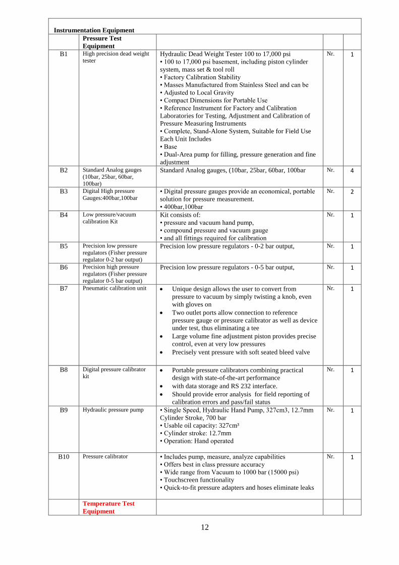
B1 High precision dead weight
tester Hydraulic Dead Weight Tester 100 to 17,000 psi
• 100 to 17,000 psi basement, including piston cylinder
system, mass set & tool roll
• Factory Calibration Stability
• Masses Manufactured from Stainless Steel and can be
• Adjusted to Local Gravity
• Compact Dimensions for Portable Use
• Reference Instrument for Factory and Calibration
Laboratories for Testing, Adjustment and Calibration of
Pressure Measuring Instruments
• Complete, Stand-Alone System, Suitable for Field Use
Each Unit Includes
• Base
• Dual-Area pump for filling, pressure generation and fine
adjustment
Nr. 1
B2 Standard Analog gauges
(10bar, 25bar, 60bar,
100bar)
Standard Analog gauges, (10bar, 25bar, 60bar, 100bar Nr. 4
B3 Digital High pressure
Gauges:400bar,100bar • Digital pressure gauges provide an economical, portable
solution for pressure measurement.
• 400bar,100bar
Nr. 2
B4 Low pressure/vacuum
calibration Kit Kit consists of:
• pressure and vacuum hand pump,
• compound pressure and vacuum gauge
• and all fittings required for calibration
Nr. 1
B5 Precision low pressure
regulators (Fisher pressure
regulator 0-2 bar output)
Precision low pressure regulators - 0-2 bar output,
Nr. 1
B6 Precision high pressure
regulators (Fisher pressure
regulator 0-5 bar output)
Precision low pressure regulators - 0-5 bar output,
Nr. 1
B7 Pneumatic calibration unit Unique design allows the user to convert from
pressure to vacuum by simply twisting a knob, even
with gloves on
Two outlet ports allow connection to reference
pressure gauge or pressure calibrator as well as device
under test, thus eliminating a tee
Large volume fine adjustment piston provides precise
control, even at very low pressures
Precisely vent pressure with soft seated bleed valve
Nr. 1
B8 Digital pressure calibrator
kit Portable pressure calibrators combining practical
design with state-of-the-art performance
with data storage and RS 232 interface.
Should provide error analysis for field reporting of
calibration errors and pass/fail status
Nr. 1
B9 Hydraulic pressure pump • Single Speed, Hydraulic Hand Pump, 327cm3, 12.7mm
Cylinder Stroke, 700 bar
• Usable oil capacity: 327cm³
• Cylinder stroke: 12.7mm
• Operation: Hand operated
Nr. 1
B10 Pressure calibrator • Includes pump, measure, analyze capabilities
• Offers best in class pressure accuracy
• Wide range from Vacuum to 1000 bar (15000 psi)
• Touchscreen functionality
• Quick-to-fit pressure adapters and hoses eliminate leaks
Nr. 1
Temperature Test
Equipment

13
B11 Digital thermometer Digital Thermometer VIP Kit
• Dual input digital thermometer can log up to 500 points
of data to internal memory.
• Fast response and laboratory accuracy (0.05% + 0.3°C).
• Take contact temperature for checking motors, insulation,
breakers, pipes, corroded connections, liquids, and wires
with industrial standard J, K, T, E, N, R, and S type
thermocouple • Two bead probe thermocouples
• Holster
• ToolPak Strap and Magnet Hanging Kit
• Soft Carry Case
Nr. 2
B12 Infrared Thermometer • High temperature infrared thermometer that measuring
from -30°C to 900°C (-22°F to 1652°F)
• Offers an ultra-high 60:1 distance-to-spot ratio with dual
laser sighting for fast, accurate targeting
• Features a user-selectable multi-language interface
• Displays the temperature plus MAX, MIN, DIF, AVG
temperature
• Provides adjustable emissivity and a predefined
emissivity table
Nr. 1
B13 Precision variable resistance
(Decade box) • Range : 10mΩ to 12kΩ
• Resolution: 10mΩ steps
• Number of decades:
• 0.01% accuracy: 6, each decade settable from 0 to 11
Nr. 2
B14 Set of glass thermometers 1set: glass thermometer (straight and 90°), size 150mm
and Thermometer, Bourdon tube principle, size 100mm
set 1
B15 Standard thermocouples(0-
100, 0-150,0-200) Standard thermocouples(0-100, 0-150,0-200) Nr. 3
B16 Temperature bath calibrator Temperature calibrator feature active dual- and triple-
zone temperature control
• Temperature range from 32 to 699°C (90 to 1291°F)
• Stability to ± 0.007°C
• Dry block and liquid bath / dry block combined
• Time saving fast cooling and heating times
• Contamination free calibration of clamp sensors
• “Plug and Play” intelligent reference sensors
• Easy-to-read color display with User-friendly navigation
• Lightweight and easy to carry
• Multi-hole insert kits
Nr. 1
B17 RTD simulator Process
Calibrator, 4000 ohms
Resistance)
• Process Calibrator, 4000 ohms Resistance
• Measure temperature from RTD output; simulate RTD
output
Nr. 2
B18 Thermocouple
(Thermocouple Calibrator,) • Measure temperature from TC output
• Simulate TC output
• Operable with nine types of thermocouples
• Calibrate linear TC transmitter with mV source function
• Selectable °F or °C
• Thermocouple mini-jack termination
Nr. 2
B19 Milli-ap loop calibrator • The loop calibrator will check, calibrate and measure all
current signal instruments in a 4 to 20 milliamp DC loop
• All 4 to 20 mA Loop Functions
Source 0.00 to 24.00 mA or % FS reading , simulate 2-
wire transmitters, measure 0-44 volts DC power & read 2-
wire transmitters.
Nr. 2
Vibration sensor
calibration
B20 Vibration calibration kits -
complete Kit Portable Stroboscope Kit
Specifications;
Flash rate range: 30 to 50,000FPM, 0.5 TO 830Hz
Flash rate accuracy: +or- 0.002% of reading
Flash duration: 8 tp20 microseconds
Nr. 1

14
Flash rate resolution: 0.01 to C1.0 FPM, selectable
Virtual RPM 0 tp 200VPM
External Input: Input pulse, 0.5microseconds minimum, TTL to 24V maximum
with NIST Certificate of Calibration
B21 Micrometer • Micrometer Type: Electronic Interchangeable Anvil
Outside Micrometer
• Range (mm): 0-100mm
• Anvil/Spindle Material: Steel
• Anvil Type: Flat
• Spindle Type: Flat
Nr. 1
B22 Vibration meter • Hand held vibration meter
• Reliable, repeatable, accurate device for checking
bearings and overall vibration
• Features innovative sensor design that minimizes
measurement variations caused by device angle or contact
pressure
• Measures overall vibration (10 Hz to 1,000 Hz)
Nr. 1
B23 Vernier Caliper • Digimatic Caliper with Nib Style Jaws
• Measuring range of 0(0.4)-12"/0(10)-300mm with
.0005"/ 0.01mm resolution.
• Includes IP67 level protection.
• Features rounded face jaws that are ideal for accurate
Inside Diameter measurement.
Nr. 1
B24 Vibration sensor Probe 50mm proximitor with extension cable and Proximitor
sensor
Ideal for measuring the differential expansion (DE) or
rotor expansion (RX) of large steam turbine generators
those results from the difference in growth rates between
the turbine rotor and the machine stator (casing).
Nr. 1
B25 Acceleration sensor Probe • Monarch Sensor Pak with Accelerometer, Integral Cable,
Magnetic Base, Stringer Probe and Connecting Stud
Nr. 1
B26 Proximitor Proximity sensor, 3300 xl5, 8mm, 7.87v/mm, 24vdc Nr. 1
Fire & Gas Test
Equipment
B27 Hydro carbon sensor Sensor, IR, Hydro Carbons
Power Input: 18-30VDC at 5 watts
Max Current: Average: 210 mA, peak 400 mA at 24VDC
Sensor Technology: Reliable infrared sensing technology with patented self-compensating optics and easy-to-clean
Standard Output: Standard 3-wire 4-20mA current source.
Nr. 1
B28 Gas detection sensor • Combustible (Low Voltage) Fixed Gas Detector
Controller Transducer
• Low level Meter capable of displaying from 0-50 percent
leg
• Selectable target gas - methane(ng), propane) or
hydrogen(h2)
• Selectable fan and alarm relay activation
Nr. 1
B29 H2S Sensor Gas Clip Technologies and CO Dual-Tox Sensor, Dual
Tox Sensor
Nr. 1
B30 H2S detector test kit with
30% This calibration kit includes: 34AL cyl 100ppm of
Isobutylene/H2S/CO/CH4/O2 calibration gas, a demand
flow regulator, a case and tubing. Suitable monitoring
device included.
Nr. 1

15
B31 H2S detector test kit with
50% 4-gas confined space kit,LEL/Oxy/H2S/CO,w/AC charger
and small padded case
Nr. 1
B32 Flame Detector • Explosion- proof combined Ultraviolet and Infrared
Flame detector
• Built-in high speed, low power consumption, high
performance 16-bit high-precision data processing chip.
• Using patent narrow-band IR sensor and solar blind UV
sensor.
• Explosion-proof design is suitable for the hazardous
locations of industrial site.
• Multistage sensitivity for more occasions.
• Can detect small fire much earlier.
• Low maintenance cost, easy to update and improvement.
• Detection Angle of 120 degrees.
• Detection range up to 60 meters
• suitable for a variety of fuel.
Nr. 1
B33 Smoke detector (Infra-red
and optical) • Conventional infrared optical beam smoke detector
• LED indicators to aid the beam alignment process
• Kit includes an optical beam detector transceiver and a
reflective prism
Nr. 1
B34 Heat sensor Detector using an optical sensing chamber. Used with most
conventional fire alarm control panel.
Nr. 1
B35 Smoke detector test kit Smoke Detector Kit with Bag, Cartridge, Battery pack Nr. 1 B36 Heat detector test kit Heat Detector Kit with Bag, Heat tester, Battery charger Nr. 1
Emergency & Safety
control System
B37 Emergency shutdown skid Didactic equipment
System for the study of the topics related to the theme of
basic industrial installations. This trainer must have
modular structure and it must consist of didactic panels
that shall be installed on a vertical frame.
The modularity of this didactic system must grant to the
students a direct and immediate approach to the topic,
offering the opportunity to study various subjects
performing different experiments as:
Single-pole control auxiliaries
Contactor
Logic operators
Contactor self-supply
Interlock between contactors
Sequentially controlled contactors
Exclusive-OR operator
Excitation delayed timer
De-excitation delayed timer
Static timer
The system must be composed of the following elements:
SINGLE-PHASE TRANSFORMER
this module must have insulated panel and safety
terminals.
Single-phase transformer for low voltage modules.
Primary: mains voltage
Secondary: 2 x 12 V
Rated power: 100 VA
THREE-PHASE POWER SUPPLY
this module must have insulated panel
It must be suitable for a three-phase supply at the mains
voltage and frequency.
Output: three-phase + N + T at safety terminals.
Protection through differential magneto-thermal switch
and pilot lamp.
Key operated switch for the three-phase supply and pilot
lamps for the three phases.
EMERGENCY PUSHBUTTON
this module must have insulated panel
Nr. 1

16
It shall be mushroom type red emergency pushbutton for
the manual control and the fast opening of the circuit in
case of emergency. It shall be provided with 1 NO and 1
NC contacts.
Isolating rated voltage: 660 Vac
Thermal rated current 10 A
THREE PUSHBUTTONS
this module must have insulated panel
This item shall include three pushbuttons, red, yellow and
green, complete with 1 NO and 1 NC contacts, suitable for
the manual control of electric circuits in direct and
alternate current.
These three pushbuttons with pulse control shall
automatically come back to the standard position.
Red pushbutton shall be for stop or de-insertion
Yellow pushbutton shall work as interval to cancel
undesired conditions
Green pushbutton shall be for start or insertion
Isolating rated voltage: 660 Vac
Thermal rated current 10 A
THREE PILOT LAMPS
this module must have insulated panel
This item shall include three signalling LED lamps, red,
yellow and green.
Red lamp shall indicate danger or alarm of a potential
ranger or of a situation that requires an immediate action
Yellow lamp shall indicate warning and a change or
imminent change of operating conditions
Green lamp shall indicate safety condition or of an
authorization to proceed.
CONTACTOR – 2 pcs
this module must have insulated panel and safety
terminals.
It shall operate as a three-pole power switch through the
use of an electromagnet.
It shall be provided with 3 NO power contacts and 1 NO
auxiliary contact, the module also shall contain 4
additional auxiliary contacts, 2 NO and 2 NC.
Coils voltage: 24 Vac, 50/60 Hz
Isolating rated voltage: 660 V
Thermal rated current: 20 A
Thermal rated current of the auxiliary contacts: 10 A
TIME RELAY
this module must have insulated panel
This item shall refer to a multi-voltage and multifunction
electronic timer, delayed at the excitation and at the de-
excitation
Power supply: from 12 to 240 Vac, 50/60 Hz
Timer selection from: 0.1 to 2 sec.,1 to 20 sec., 0.1 to 2
min., 1 to 20 min.
Resettlement time: less than 50 milliseconds
Full scale adjustment accuracy: ± 5%
THREE-LEVEL FRAME
Metal frame with three levels for fitting the modules of the
laboratory
CONNECTING LEADS
This item must consist of a set of leads for the connection
of the experiment modules of the panel system.
B38 Valve Actuator control
panel Didactic equipment. This system refers to a manufacturing
method where the entire production process should be
controlled by a computer. It must rely on closed-loop
control processes built on real-time input from sensors.
Students should be able to study the theory and work with
the system to get a sound knowledge of the computer-
integrated manufacturing, which allows for transversal
Nr. 1
17
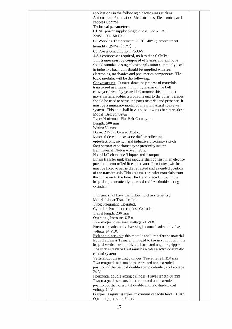
applications in the following didactic areas such as
Automation, Pneumatics, Mechatronics, Electronics, and
Process Control.
Technical parameters:
C1.AC power supply: single-phase 3-wire , AC
220V±10% 50 Hz;
C2.Working Temperature: -10 ~40;environment
humidity: ≤90%(25);
C3.Power consumption: <500W;
4.Air compressor required, no less than 0.6MPa
This trainer must be composed of 3 units and each one
should simulate a single basic application commonly used
in industry. Each unit should be supplied with real
electronics, mechanics and pneumatics components. The
basic modules will be the following:
Conveyor unit: It must show the process of materials
transferred in a linear motion by means of the belt
conveyor driven by geared DC motors; this unit must
move materials/objects from one end to the other. Sensors
should be used to sense the parts material and presence. It
must be a miniature model of a real industrial conveyor
system. This unit shall have the following characteristics:
Model: Belt conveyor
Type: Horizontal Flat Belt Conveyor
Length: 500 mm
Width: 51 mm
Drive: 24VDC Geared Motor.
Material detection sensors: diffuse reflection
optoelectronic switch and inductive proximity switch
Stop sensor: capacitance type proximity switch
Belt material: Nylon woven fabric
No. of I/O elements: 3 inputs and 1 output
Linear transfer unit: this module shall consist in an electro-
pneumatic controlled linear actuator. Proximity switches
must be fixed to sense the retracted and extended position
of the transfer unit. This unit must transfer materials from
the conveyor to the linear Pick and Place Unit with the
help of a pneumatically operated rod less double acting
cylinder.
This unit shall have the following characteristics:
Model: Linear Transfer Unit
Type: Pneumatic Operated.
Cylinder: Pneumatic rod less Cylinder
Travel length: 200 mm
Operating Pressure: 6 Bar
Two magnetic sensors: voltage 24 VDC
Pneumatic solenoid valve: single control solenoid valve,
voltage 24 VDC
Pick and place unit: this module shall transfer the material
from the Linear Transfer Unit end to the next Unit with the
help of vertical arm, horizontal arm and angular gripper.
The Pick and Place Unit must be a total electro-pneumatic
control system.
Vertical double acting cylinder: Travel length 150 mm
Two magnetic sensors at the retracted and extended
position of the vertical double acting cylinder, coil voltage
24 V
Horizontal double acting cylinder, Travel length 80 mm
Two magnetic sensors at the retracted and extended
position of the horizontal double acting cylinder, coil
voltage 24 V
Gripper: Angular gripper; maximum capacity load : 0.5Kg.
Operating pressure: 6 bars

18
Pneumatic solenoid valve: three single control solenoid
valve, voltage 24 VDC
Push button unit: The button unit must be provided with
two lighted self-reset buttons and one emergency stop
button for controlling the operation of the device.
Green button: LED voltage 24 V, self-reset
Red button: LED voltage 24 V self-reset
Emergency stop button
PLC: The system must include a PLC and its software. It
must have the following features:
I/O : 20 (12 inputs)
Input logic: sink or source
24 VDC voltage input
10 outputs: 8 for relay and 2 for transistor (source)
Air source processing unit: Air filter with pressure
regulator for drying gas and pressure regulation, 1pc
Gas source:≥0.6MPa
The trainer must be supplied with manual in English
language.
B39 Pneumatic valve control
panel PNEUMATIC TRAINER – didactic equipment
Trainer for demonstrations and experiments in the
pneumatic field.
The trainer must include a metal frame supporting the
following modules:
A pneumatic board, where all the components must be
mounted and identified through a clear symbol. They must
include: 2 double-acting cylinders with 3 return orifice
check valves, 4 roller lever and 1 lever 3/2 valves, 2 stable
and 2 unstable 5/2 valves, 2 AND, 2 OR and 1 NOT, 1
throttle valve, 1 capacity, 1 fast relief valve and 1 splitter.
Supplied with 75 m of ø4 and 3 m of ø6 plastic tube, 10
tees and 10 plugs, as well as 1 pipe cutter, service manual
and exercise book with experiments.
An air supply vertical board, providing 1 lever main
switch, 1 filter, 2 pressure regulators with 2 pressure
gauges, 1 mushroom and 3 digital 3/2 push-buttons, 1 lever
5/2 selector and 1 digital 5/2 push-button.
With this trainer it must be possible to perform the
following exercises:
CIRCUITS WITH ONLY ONE CYLINDER
C1. Unstable direct control of an S.E. cylinder - A+/A-
sequence
C2. Unstable direct control of an S.E. cylinder - A-/A+
sequence
C3. Stable direct control of an S.E. cylinder - A+/A-
sequence
4. Stable direct control of a D.E. cylinder - A+/A-
sequence
5. Unstable indirect control of a D.E. cylinder - A+/A-
sequence
6. Stable indirect control of a D.E. cylinder - A+/A-
sequence
7. Single Cycle (SEMIAUTOMATIC) of a D.E. cylinder-
A+/A-sequence
8. Continuous Cycle (AUTOMATIQUE) of a D.E.
cylinder -A+/A- sequence
CIRCUITS WITH SPEED ADJUSTMENT
9. Speed adjustment of the two strokes of a D.E cylinder
A+/A- sequence
10. Speed adjustment for only a section of the stroke of a
D.E cylinder A+/A- sequence
CIRCUITS WITH LOGIC ELEMENTS
1C1. Unstable direct control with two independent starting
valves of an S.E. cylinder - A+/A- sequence
Nr. 1

19
1C2. Unstable direct control with two dependent starting
valves of an S.E.cylinder - A+/A- sequence
1C3. Single cycle with stroke end safety starting of a
D.E.cylinder A+/A- sequence
14. Single cycle without mechanical stroke end of a D
.E.cylinder A+/A- sequence
15. Applications on the ET-OU logic functions
16. Applications on the ET-OU-NON logic functions
17. Stable indirect control with only one unstable valve of
a D.E. cylinder A+/A- sequence
CIRCUITS WITH DELAY SYSTEMS
18. Unstable indirect control with delay at the starting of
an S.E. cylinder A+/A- sequence
19. Pulse Generator
20. Extension of a short duration signal
2C1. Bimanual control with concurrency safety
CIRCUITS WITH TWO CYLINDERS - SEQUENCES
WITHOUT BLOCKING SIGNALS
2C2. Single cycle with several D.E. cylinders A+/B+/A-
/B- sequence
2C3. Continuous cycle with several D.E. cylinders A-
/B+/A+/B- sequence
24. Continuous cycle with contemporary strokes of D.E.
cylinders A+/B+/A-B- sequence
25. Continuous cycle with repetitive and contemporary
strokes A+/A-B+/A+/A-B-sequence
INTEGRATIVE CONTROLS OF THE CIRCUITS
26. Continuous cycle with separated control of start and
end cycle of a D.E. cycle A+/A- sequence
27. Continuous cycle with single cycle control - automatic
of a D.E. cylinder A+/A- sequence
28. Continuous cycle with manual - automatic control of a
D.E. cylinder A+/A- sequence
29. Continuous cycle with manual - automatic control of
D.E. cylinders A+/B+/A-/B- sequence
30. Continuous cycle with emergency control with stop at
the rejoined phase of a D.E. cylinderA+/A-sequence
3C1. Cycle with emergency control immediate return to
the starting position of D.E. cylinders A+/B-/A-/B+
sequence
The trainer must be supplied with manual in English
language.
B40 Alarm Panel( Annunciator
panel) Alarm Annunciator Panels designed to fulfill all the
requirements of all industrial plants. In this system, display
and electronic controllers are separate. The modular
construction allows for systems of almost any size.
Installed depth of display is approximately ly 68mm
(controllers are separate).
System Features: Modular Multi-point Design
Split Logic Controllers (separate display and electronics)
One Logic Controller for each Alarm point
Any number of windows
Window Size: 75X50 mm (Each window can be divided
into 2 or 4)
Mounting: Panel mount (flush) display
Illumination: 120 degree high bright, long life backlit
Standard LED Colour: Yellow, Red, Green
Standard Lens Colour: White, Red
Installed depth (Display only): 68mm
Alarm sequence to ISA-S18.1
Each Channel configurable individually
Supports 4 built-in pushbuttons: Acknowledge, Reset,
Nr. 1
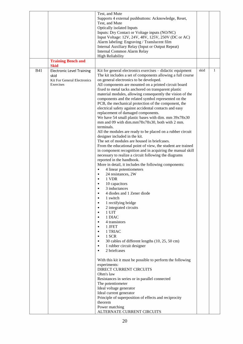
20
Test, and Mute
Supports 4 external pushbuttons: Acknowledge, Reset,
Test, and Mute
Optically isolated Inputs
Inputs: Dry Contact or Voltage inputs (NO/NC)
Input Voltage: 12V, 24V, 48V, 125V, 250V (DC or AC)
Alarm labeling: Engraving / Translucent film
Internal Auxiliary Relay (Input or Output Repeat)
Internal Common Alarm Relay
High Reliability
Training Bench and
Skid
B41 Electronic Level Training skid Kit For General Electronics
Exercises
Kit for general electronics exercises – didactic equipment
The kit includes a set of components allowing a full course
on general electronics to be developed.
All components are mounted on a printed circuit board
fixed to metal tacks anchored on transparent plastic
material modules, allowing consequently the vision of the
components and the related symbol represented on the
PCB, the mechanical protection of the component, the
electrical safety against accidental contacts and easy
replacement of damaged components.
We have 54 small plastic bases with dim. mm 39x78x30
mm and 09 with dim.mm78x78x30, both with 2 mm.
terminals.
All the modules are ready to be placed on a rubber circuit
designer included in the kit.
The set of modules are housed in briefcases.
From the educational point of view, the student are trained
in component recognition and in acquiring the manual skill
necessary to realize a circuit following the diagrams
reported in the handbook.
More in detail, it includes the following components:
• 4 linear potentiometers
• 24 resistances, 2W
• 1 VDR
• 10 capacitors
• 3 inductances
• 4 diodes and 1 Zener diode
• 1 switch
• 1 rectifying bridge
• 2 integrated circuits
• 1 UJT
• 1 DIAC
• 4 transistors
• 1 JFET
• 1 TRIAC
• 1 SCR
• 30 cables of different lengths (10, 25, 50 cm)
• 1 rubber circuit designer
• 2 briefcases
With this kit it must be possible to perform the following
experiments:
DIRECT CURRENT CIRCUITS
Ohm's law
Resistances in series or in parallel connected
The potentiometer
Ideal voltage generator
Ideal current generator
Principle of superposition of effects and reciprocity
theorem
Power matching
ALTERNATE CURRENT CIRCUITS
skid 1

21
Alternating current network: purely resistive, purely
inductive and purely capacitive circuits
Alternating current network. Circuit with resistance,
inductance and capacitance
Study of a CR and RC network in sinusoidal condition
Compensated divider
Series resonant circuit
Parallel resonant circuit
Study in transient condition of a circuit with resistance and
capacitance
Study of a low-pass filter realized with L and C
Study of a high-pass filter realized with L and C
CIRCUITS WITH DIODES
Semiconductor diode
Half-wave rectifier
Double half-wave rectifier
Filtering cells for a power supply unit
Study of a power supply unit with capacitive filter
Voltage doubler circuit
Zener diode
Measuring the differential resistance of a Zener diode
Stabilizing circuit with Zener diode
TRANSISTOR
Output characteristics of a transistor connected in common
emitter configuration
Output characteristics of a transistor mounted in the
common base configuration
Measurement of hie, hfe, hoe, hre parameters of a
transistor
Study of a common emitter signal amplifier
Measurement of the response curve of a common emitter
small signal R - C amplifier
Common base amplifier
Common collector amplifier
Constant current generator
Voltage stabilizer circuit with Zener and power transistor
Study of Field Effect Transistor (FET)
THYRISTORS
Silicon controlled rectifier
Study of TRIAC
Study of DIAC
Unijunction transistor (UJT)
UJT blocking oscillator
Power control through an SCR supplied with a sinusoidal
voltage
OPERATIONAL AMPLIFIER
Operational amplifier
Adder and integrator
DIGITAL LOGIC
Study of OR-AND-NOR-NAND gates
Realization of logic units through a 7400 integrated circuit
NON-LINEAR RESISTANCE
Study of VDR
The kit is supplied with relevant manual in English
language.
Supplied with:
Power supply and function generator – didactic equipment
Designed for use in electronics laboratories.
The outputs are protected against overload and short
circuits.
Technical Features:
Power Supply Section:
dc output :

22
± 0 ÷ 15V, 300 mA
5V, 1A
ac output: 2 x 12V, 1A
Function Generator section:
waveforms : Sine, Square, Triangle
frequency : from 10Hz to 100KHz (4 ranges)
On the front panel, it includes the following elements:
General switch with warning light
AC magnetothermic protection
AC variac
Fixed DC output (5V, 1A) switch
DC output (5 V) warning light
Variable DC output from 0 to 15V positive switch
Variable DC output from 0 to 15V positive potentiometer
Variable DC output from 0 to 15V negative switch
Variable DC output from 0 to 15V negative potentiometer
Frequency commutator
Frequency variation potentiometer
Sinusoidal level potentiometer
AC output terminals
Ground terminal
Signal generator output terminals
Variable DC output terminals
Fixed DC output terminals
On the back side, it includes:
Power supply socket with fuse
The kit is supplied with relevant manual in English
language.
B42 Flow instruments Training skid
Automatic Control Technology Laboratory – Complete
Configuration
This laboratory must be designed for the study of the
Automatic Control Technology to allow the student a
practical training, based on the performance of guided
experiments. Industrial type components must be
educationally adapted by using a modular panel system to
permit the step by step assembling from the simplest
circuit to the most complex system. With this laboratory
must be possible to perform the following experiments.
Fundamentals of Automatic Control Technology :
•Automatic Control Theory
•Processes
•Controllers
•Continuous Automatic Control
•Discontinuous Automatic Control
Applications:
•Control of a DC Motor
•Temperature Control
•Light Control
•Level Control
•Flow Control
The laboratory must be supplied complete with a
theoretical and practical manual in English language.
The laboratory must be composed of the following
modules:
DC POWER SUPPLY
Didactic equipment
Technical features:
•Output voltages: +15 V / 0 V / - 15 V
•Output current: C2.4 A (3 A for a short time)
•Power supply: Single-phase from mains
•Complete with two LEDs and a mains switch with pilot
lamp
skid 1

23
It must be mounted on an insulated didactic module, this
module must show a schematic diagram and 2 mm
terminals for the electrical connection; Laboratory power
supply with two outputs, fixed voltage; protection from
short circuit. It must include also a bus for the supply that
allows the connection between the panels.
VOLTAGE REFERENCE GENERATOR
Didactic equipment
This module must be suitable for the generation of a
reference signal through an internal potentiometer or for
transferring an external reference signal.
Technical features:
•Output voltage: 0...+10 V or -10 V ...+10 V
•Power supply: +15 V / 0 V / - 15 V
It must be mounted on an insulated didactic module, it
must show a schematic diagram and 2 mm terminals for
the electrical connection; two switches and one
potentiometer with scale graduated knob. It must include
also a bus for the supply that allows the connection
between the panels.
PID CONTROLLER
Didactic equipment
This module must simulate a standard industrial
controller for use as P, PI, PD or PID regulator in
automatic closed-loop control systems.
Technical features:
•Power supply: -15 V/0 V/+15 V
•Input summing point for two different reference variables
•UR and UC and one controlled variable UA.
•Signal voltage range: -10 V . . . + 10 V
•Controller continuously adjustable parameters:
proportional gain Kp = 0 . . . 1000
integral action time TI = 1 ms . . . 100 s
differential action time TD = 0.2 ms . . . 20 s
•Separate input for integral element reset.
•Output summing point for adding or subtracting
disturbance variables
It must be mounted on an insulated didactic module, it
must show a schematic diagram and 2 mm terminals for
the electrical connection; six selectors, two switches, two
trimmers and three leds. It must include also a bus for the
supply that allows the connection between the panels.
P CONTROLLER
Didactic equipment
This module must simulate the proportional action
controller that shall be suitable for the closed loop
continuous control systems.
Technical features
•Power supply: +15 V ; 0 V ; -15 V
•Signal voltage range: -10V, .... , +10V
•Proportional gain Kp = 0 ... 100
It must be mounted on an insulated didactic module, it
must show a schematic diagram and 2 mm terminals for
the electrical connection; three position switch coarse
setting, one potentiometer and one led indicator of over-
range. It must include also a bus for the supply that allows
the connection between the panels.
INTEGRAL-ACTION ELEMENT
Didactic equipment
This module must be suitable for closed loop continuous
control systems.
Technical features:
•Power supply: +15 V ; 0 V ; -15 V
•Signal voltage range: -10V, ..., +10V
• Coefficient of the integral action KI = 0.1 .... 100 s-1

24
It must be mounted on an insulated didactic module, it
must show a schematic diagram and 2 mm terminals for
the electrical connection; three position switch coarse
setting, one potentiometer , one integral action reset input,
one switch for inclusion/exclusion of the integral action
and one led indicator of over-range. It must include also a
bus for the supply that allows the connection between the
panels.
DERIVATIVE-ACTION ELEMENT
Didactic equipment
This module must be suitable for closed loop continuous
control systems.
Technical features
•Power supply: +15 V ; 0 V ; -15 V
•Signal voltage range: -10V, ..., +10V
•Coefficient of the derivative action KD = 2 ms .... 2 s
It must be mounted on an insulated didactic module, it
must show a schematic diagram and 2 mm terminals for
the electrical connection; three position switch coarse
setting, one potentiometer , one integral action reset input,
one switch for inclusion/exclusion of the derivative action
and one led indicator of over-range. It must include also a
bus for the supply that allows the connection between the
panels.
SUMMING POINT – 2 INPUTS
Didactic equipment
This module must consist in a two input summing point,
one non inverting input and one inverting input.
Technical features
•Power supply: +15 V ; 0 V ; -15 V
•Signal voltage range: -10V, ..., +10V
•Gain factor = 1
It must be mounted on an insulated didactic module, it
must show a schematic diagram and 2 mm terminals for
the electrical connection; one led indicator of over-range.
It must include also a bus for the supply that allows the
connection between the panels.
SUMMING POINT – 5 INPUTS
Didactic equipment
This module must consist in a five input summing point;
three of them, non inverting; it shall be used in the
realization of particular configurations of the controller,
using separately the elements P, I and D; the remaining
inputs, one inverting and one non inverting, shall be used
to add the noise variables.
Technical features:
•Power supply: +15 V ; 0 V ; -15 V
•Signal voltage range: -10V, ..., +10V
•Gain factor = 1
It must be mounted on an insulated didactic module, it
must show a schematic diagram and 2 mm terminals for
the electrical connection; one led indicator of over-range.
It must include also a bus for the supply that allows the
connection between the panels.
SIMULATED CONTROLLED SYSTEM
Didactic equipment - 2 pcs
This module must allow the simulation of different
processes, such as 1st and 2nd order processes,
proportional ( P ) action processes, integral ( I ) action
processes, double integral ( I2 ) action processes.
Technical features:
•Power supply: +15 V ; 0 V ; -15 V
•Input summing point for controlling variable (y) and noise
variable (z).
•Signal voltage range: -10V, ..., +10V

25
•Coefficient of the proportional action of the process KP =
0.2 (attenuation) ....C1.5 (amplification)
•Time constant T1 = 0.1 .... 1000 s
•Time constant T2 = 0.1 .... 1000 s
It must be mounted on an insulated didactic module, it
must show a schematic diagram and 2 mm terminals for
the electrical connection; one reset input for the
restoration of the initial conditions, two selectors, three
potentiometers, two rotary switches for coarse setting, one
push-button, two led indicators of over-range. It must
include also a bus for the supply that allows the connection
between the panels.
DEAD TIME ELEMENT
Didactic equipment
This module must allow the insertion of an adjustable real
dead time in those processes which are characterized by it.
Technical features:
•Power supply: +15 V ; 0 V ; -15 V
•Signal voltage range: -10V, ..., +10V
•Proportional coefficient of the module KS = 1
•Dead time Tt = 10 ms .... 100 ms / 100 ms .... 1 s
It must be mounted on an insulated didactic module, it
must show a schematic diagram and 2 mm terminals for
the electrical connection; one selector, one potentiometer,
three switches for coarse setting for coarse setting and
exclusion of the dead time, one led indicator of over-range.
It must include also a bus for the supply that allows the
connection between the panels.
SECOND ORDER TRANSFER ELEMENT
Didactic equipment
This module must allow the analysis of the behavior of an
element with proportional transfer function able to
oscillate, with a delay of the second order, both in the time
domain and in the frequency domain.
Technical features:
•Power supply: +15 V ; 0 V ; -15 V
•Signal voltage range: -10V, ..., +10V
•Gain factor = 1
•Time constant T = 10 ms .... 30 s, selectable through two
rotary switches
•Damping coefficient d = 0 .... 3, with potentiometer
setting
It must be mounted on an insulated didactic module, it
must show a schematic diagram and 2 mm terminals for
the electrical connection;two selectors, one potentiometer,
one reset input for the restoration of the initial conditions,
one led indicator of over-range. It must include also a bus
for the supply that allows the connection between the
panels.
MANUAL/AUTOMATIC SWITCH
Didactic equipment
This module must allow to close the control loop, without
oscillations, after a suitable setting of the system.
It must be composed of a summing point to which the
signal coming from a potentiometer (manual mode) and
the signal coming from the controller (automatic mode),
inserted through switch, will be connected.
Technical features:
•Power supply: +15 V ; 0 V ; -15 V
•Signal voltage range: -10V, ..., +10V
It must be mounted on an insulated didactic module, it
must show a schematic diagram and 2 mm terminals for
the electrical connection; one manual mode potentiometer,
one manual mode/automatic mode switch, one output

26
summing point. It must include also a bus for the supply
that allows the connection between the panels.
TWO POSITION CONTROLLER
Didactic equipment – 2 pcs
This module must consist in a two position controller for
discontinuous closed loop control systems and it must be
provided with an input summing point to which the
reference variable (non inverting input) and the controlled
variable (inverting input) will be connected.
The binary state of the controller , whose hysteresis can be
changed, must be visualized by means of two led; the
controller shall be provided with two binary outputs at
different voltages.
Technical features:
•Power supply: +15 V ; 0 V ; -15 V
•Input summing point
•Signal voltage range: -10V, ..., +10V
•Output voltages: 0/+5 V ; 0/+10 V
•Adjustable hysteresis: 0 .... ± C2.5 V
It must be mounted on an insulated didactic module, it
must show a schematic diagram and 2 mm terminals for
the electrical connection; one potentiometer, one reset
input for the restoration of the initial conditions, one led
indicator of over-range. It must include also a bus for the
supply that allows the connection between the panels.
SAMPLE AND HOLD ELEMENT
Didactic equipment
This module must be used to discontinuously sample the
behaviour of a continuous control on a process.
The sampling frequency shall be provided by the generator
which will be integrated in the module or by an external
signal.
Technical features:
•Power supply: +15 V ; 0 V ; -15 V
•Signal voltage range: -10 V, ..., +10 V
•Sampling frequency: 0,2 .... 20 Hz
It must be mounted on an insulated didactic module, it
must show a schematic diagram and 2 mm terminals for
the electrical connection; one potentiometer. It must
include also a bus for the supply that allows the connection
between the panels.
MOTOR-GENERATOR SET
Didactic equipment
This module must simulate a process for the control of the
speed of a dc motor.
In this module must be possible to couple an electric
motor and a generator through a flywheel in order to
increase the momentum of inertia of the whole system.
A motor speed transducer shall provide a feedback digital
signal; through a D/A converter such signal shall be
available also in analogue form.
Technical features:
•Power supply: +15 V ; 0 V ; -15 V
•Electric power of the motor: about 10 W
•Maximum speed of the motor: 3000 min-1
•Output power from the generator: about 4 W
•Output voltage from the generator: 0 .... 20 Vdc
•Digital output from the speed transducer: 60
pulses/rotation
•Analogue output from the speed transducer: 1V/1000
min-1
It must be mounted on an insulated didactic module, it
must show a schematic diagram and 2 mm terminals for
the electrical connection; and it must include a real

27
component. It must include also a bus for the supply that
allows the connection between the panels.
LOAD SWITCH
Didactic equipment
This module must be developed in order to apply a load to
the two pole output electric machines and it shall be
controlled both manually and automatically.
Technical features:
•Power supply: +15 V ; 0 V ; -15 V
•Input voltage: max. 220 Vac
•Load: 3 incandescent lamps
It must be mounted on an insulated didactic module, it
must show a schematic diagram and 4 mm safety
terminals for the electrical connection; three switches for
the manual control of the load, electronic control relay for
the automatic control of the load, safety junctions both for
the connection of the input voltage and for the connection
of the rectified output voltage and three real incandescent
lamps. It must include also a bus for the supply that allows
the connection between the panels.
MATCHING AMPLIFIER - didactic equipment
This module must operate as matching element between
signal voltage levels and standard voltages used in
automatic control systems.
Technical features:
•Power supply: -15 V/0 V/+15 V
•Input signal range Ui: -50 V . . . + 50 V
•Coarse and fine gain setting: 0÷1/0÷10/0÷100
•Connectable low pass filter with coarse and fine time
constant setting: 0/ 1÷10 ms / 10÷100 ms
•Connectable output offset voltage: -10 V . . . +10 V
It must be mounted on an insulated didactic module, it
must show a schematic diagram and 2 mm terminals for
the electrical connection; three potentiometers, two
selectors plus one switch. It must include also a bus for the
supply that allows the connection between the panels.
TRUE RMS METER
Didactic equipment
Instrument used to measure the RMS value of the voltage,
current on a single circuit branch in AC and DC. The
values must be visualized on the LCD display. A digital
bar graph must make it easy to monitor the RMS values
and a dedicated function button allows the adjustment of
its scale.
The user can communicate with the device through the
RS485 serial port using Modbus protocol, to collect data
using a supervision software such as SCADA or Labview.
Technical features:
• Automatic Scaling • Voltage:
0 .. 1000V DC 0 .. 1000VACpp 0 .. 750VACrms
• Current: 0 .. 20 A • Accuracy: +/- 0.5% • Resolution: 16bits • Refresh rate: 0.5s • Power supply: 90-260 Vac 50/60Hz • Power consumption: 3 VA • Communication: Modbus (RS485) These didactic panels must be installed on a vertical frame.
This module must have insulated front panel, 4 mm. safety
terminals.
TEMPERATURE CONTROL SYSTEM

28
Didactic equipment
This module must represent a process for the control of the
temperature, suitable for analyzing continuous and
discontinuous closed loop control systems. A halogen
lamp shall represent the heating element; a PTC sensor
shall provide the feedback signal; a fan and a shutter valve
shall allow, besides the reaching of a uniform temperature
within given safety limits, also the insertion of noise
variables.
Technical features:
•Power supply: +15 V ; 0 V ; -15 V
•Max. temperature: 100 °C
Temperature for the intervention of the bimetallic safety
switch:
90 ....100°C
•Feedback signal:
2 mA / 10 °C
1 V / 10 °C
•Apparent dead time TU: about 10 s
•Compensation time TG: about 120 s
It must be mounted on an insulated didactic module, it
must show a schematic diagram and 2 mm terminals for
the electrical connection; one potentiometer, one switch.
This panel must include also a bus for the supply that
allows the connection between the panels.
LIGHT CONTROL SYSTEM
Didactic equipment
This module must represent a process for the control of the
light.
In this module an incandescent lamp shall represent the
opto-transmitter element, while a phototransistor shall be
the opt-receiver element. There shall be different
possibilities for generating noise variables.
Technical features:
•Power supply: +15 V ; 0 V ; -15 V
•Signal voltage range: 0 ... 20 V
•Output signal: 0 .... 10 V
•Maximum power: 10 W
It must be mounted on an insulated didactic module, it
must show a schematic diagram and 2 mm safety
terminals for the electrical connection; one potentiometer
and one switch. This panel must include also a bus for the
supply that allows the connection between the panels.
TEST FUNCTION GENERATOR
Didactic equipment
This module shall consist in a generator of functions such
as: Dirac pulse, square wave and triangular wave
selectable through selection switch.
At some terminals the output signal shall have a fixed
amplitude; at other terminals the amplitude shall be
continuously adjusted, from 0 V to 10 V, through a
potentiometer. The frequency shall be continuously
adjusted, from 0.02 Hz to 10 Hz, through a potentiometer.
For what concerns the square wave, it shall be possible to
set the ratio between high signal and period, by choosing
between 1/2 and 9/10.
Technical features:
•Power supply: +15 V ; 0 V ; -15 V
•Output wave forms:
•Dirac pulse function: 0 .... +10 VP
•Triangular wave function: 0 .... 20 VPP balanced with
respect to ground
•Square wave function: 0 .... 20 VPP with "high
signal/period" ratio = 1/2

29
•Square wave function: 0 .... +10 VP with "high
signal/period" ratio = 9/10
•Frequency of the output signal: 0.02 .... 10 Hz
•Signal Ioff for resetting the integral controllers
It must be mounted on an insulated didactic module, it
must show a schematic diagram and 2 mm safety
terminals for the electrical connection; one potentiometer
and one switch, two potentiometers, one selector and one
switch. This panel must include also a bus for the supply
that allows the connection between the panels.
RECEPTACLE WITH PUMP
Didactic equipment
This module must be used in conjunction with the filling
tank and it shall consist in a water storage tank and a gear
pump.
Technical features:
•Power supply: +15 V ; 0 V ; -15 V
• vessel capacity: C1.5 l minimum
•Signal voltage range: 0 . . . +10 V
•Power consumption of the pump: 10 W maximum
•Maximum pump capacity: 60 l/h minimum
•Maximum absorbed power: 25 W
•Two hose connections: 8/10 mm diameter
•Three meters transparent rubber hose: 8/10 mm Ø
•8/10 mm Ø hose connection for the electric pump drain
•8/10 mm Ø hose connection for the storage return
•Transparent slot for the liquid control contained in the
water storage tank
It must be mounted on an insulated didactic module, it
must show a schematic diagram and 2 mm terminals for
the electrical connection.
FILLING TANK
Didactic equipment
This module must be used for the demonstration of
controlled system characteristics. Slide valves must allow
changing the various features of the controlled system.
This module must be complete with plug-in device for
sensors used to detect the liquid level and it must include a
set of 10 transparent foils, printed with a vertical and a
horizontal scale with graduation marks. It shall be suitable
for labeling with water-soluble markers
Technical features:
•Vessel capacity: C1.5 l minimum
•Three guides for the insertion of sliding valves
• Two hose connections: 8/10 mm Ø
• Three meters transparent rubber hose: 8/10 mm Ø
•Six sliding valves with different opening characteristics
and with the same orifice for maximum level
•Connection for 8/10 hose for water entry
•Connection for 8/10 hose for water drain
It must be mounted on an insulated didactic module.
DIFFERENTIAL PRESSURE TRANSDUCER
Didactic equipment
This module must be used for connecting to the immersion
tube for measuring the liquid level and to the measurement
orifice gauge for flow measurement.
Technical features:
•Power supply: ± 15 V
•Signal voltage range: O . . . +10 V
•Scale conversion selector: 0,2V/mbar – 0,66 V/mbar
•Differential pressure: ± 70 mbar
•2 hose connections
•Differential pressure transducers with hose connections:
6/8 mm Ø
• Three meters transparent rubber hose: 8/10 mm Ø

30
It must be mounted on an insulated didactic module, it
must show a schematic diagram and 2 mm terminals for
the electrical connection.
TURBINE FLOW METER
Didactic equipment
This module must be used for measuring the flow
according to the volumetric principle.
Technical features:
• Power supply: ± 15 V
•Measurement range: 10 ... 100 l/h
•Measurement temperature: 20°C
•Measurement medium: water
•Flow: 3-90 l/h
•TTL output: 175Hz for a 90 l/h flow
•Analog output: 1 V for each 10 l/h
•2 hose connections: 8/10 mm Ø
•Three meters transparent rubber hose: 8/10 mm Ø
It must be mounted on an insulated didactic module, it
must show a schematic diagram and 2 mm terminals for
the electrical connection. This panel must include real
component such as a turbine flow meter.
SOLENOID VALVE
Didactic equipment
This module must consist in a two-way valve with
switching amplifier.
It must consist in a single-solenoid valve, normally closed,
with two ways and two positions. This module shall be
used to control the On/Off level of for variations in the
flow control.
Technical features:
• Power supply: + 15V
• Control voltage: > 1
•Single-solenoid valve voltage: 12 VDC
•Manual control through the switch
•Possibility of automatic control
•2 hose connections: 8/10 mm Ø
• Three meters transparent rubber hose: 8/10 mm Ø
It must be mounted on an insulated didactic module, it
must show a schematic diagram and 2 mm terminals for
the electrical connection This panel must include real
component such as a single-solenoid valve.
POWER METER UNIT
Didactic equipment
This demonstration meter shall be suitable to measure the
true rms of voltages and currents.
Technical features:
•Voltage 3/10/30/100/300/1000 V (input resistance 10
MΩ)
•Current 0.1/0.3/1/3/10/30 A
•Continuous overload protection in all ranges.
•Auxiliary supply: single-phase from mains
Measurement modes:
RMS: AC+DC, total true r.m.s. value
RMS: AC, true r.m.s. value of alternating part
AV: AC+DC, arithmetical average value, with 2 leds
polarity indication
Switchover must be possible for all ranges and
measurements modes at any time.
This module must have insulated type front panel with the
electrical scheme and safety terminals. One selector and
three switches shall be included in this panel.
SINGLE POLE SWITCH
Didactic equipment

31
This item shall consist in a plug-in element, normally
open, with switch load 2 A, 250 V. It shall be contained in
a plastic box and with a switch.
SINGLE POLE PUSHBUTTON
Didactic equipment
This item shall consist in a plug-in element, normally
open, with switch load 2 A, 250 V. It shall be contained in
a plastic box and with a push-button.
INTERFACE UNIT
Didactic equipment
Data acquisition unit with 8 analogue channels. Equipped
with 2 relays and 2 analogue outputs. It must be possible to
acquire continuous signals or slowly variable up to 100Hz.
Description: robust metal construction, USB interface for
maximum PC compatibility
Clear interface for easy connection understanding
Technical Features
Direct power supply from USB, total consumption less
than 120mA.
Nr. 2 relay outputs.
Nr. 2 analogue outputs, with:
12 bit D/A converter
Output levels: -10/+10 V
Nr. 8 analogue inputs, with:
Input levels: -10/+10 V
High impedance input amplifier: > 1MOhm
12 bit A/D converter
zero autotuning
Max sample rate: 10 kHz
Driver for Windows 2000, XP, Vista, 7
The unit must be supplied with a manual in English
language.
SOFTWARE providing the tools to generate the control
signs for the modules and to acquire and visualize the
signals and the wave forms to be analyzed.
LEADS for the connection of the terminals of the modules.
THREE-LEVEL FRAME - Metal frame with three levels
for fitting the modules of the laboratory.
B43 Temperature instruments Training skid
This system has been designed for the study of a model of
a temperature industrial control. It is composed of two
boards: Temperature Basic Control and Advanced
Temperature Control
Temperature Basic Control
This board includes a small oven with a heating element
and three temperature sensors (thermocouple, thermistor,
and thermo-resistance) with relevant interface circuits.
Complete with error amplifier that can be configured for
on-off or proportional control, and with a piloting circuit
of the power stage with triac. The board is supplied
complete with a set of stackable, plug-in cables of suitable
lengths and colors and with a training manual. Power
supply: 24Vac, 1A, 50/60Hz and ± 15Vdc, 100mA
Experiments
V = f(t°) characteristics of a thermocouple, with relevant
linearization, of the thermistor and of the thermo-resistance
Analysis of the operation of an on-off control
Analysis of the operation of a proportional control
Advanced Temperature Control – PID Controller
This board includes two reference signal generators, a
comparison node and the three terms network
(proportional, integral and derivative).Complete with
digital temperature indicator100mV/°C. This board is an
skid 1

32
option to the board “Temperature Basic Control” since it
uses its oven, the heating element and the temperature
transducers. The board is supplied complete with a set of
stackable, plug-in cables of suitable lengths and colors and
with a training manual. Power supply: ± 15Vdc, 100mA
and +5Vdc, 150mA
Experiments
Analysis of the operation of a proportional, proportional-
derivative and proportional-integral control
PID control circuits
PID controllers calibration
B44 Pneumatic Instruments Training Skid (Level and Flow)
Didactic trainer - Trainer for demonstrations and
experiments in the pneumatic field.
The trainer must include a metal frame supporting the
following modules:
A pneumatic board, where all the components must be
mounted and identified through a clear symbol. They must
include: 2 double-acting cylinders with 3 return orifice
check valves, 4 roller lever and 1 lever 3/2 valves, 2 stable
and 2 unstable 5/2 valves, 2 AND, 2 OR and 1 NOT, 1
throttle valve, 1 capacity, 1 fast relief valve and 1 splitter.
Supplied with 75 m of ø4 and 3 m of ø6 plastic tube, 10
tees and 10 plugs, as well as 1 pipe cutter, service manual
and exercise book with experiments.
An air supply vertical board, providing 1 lever main
switch, 1 filter, 2 pressure regulators with 2 pressure
gauges, 1 mushroom and 3 digital 3/2 push-buttons, 1 lever
5/2 selector and 1 digital 5/2 push-button.
With this trainer it must be possible to perform the
following exercises:
CIRCUITS WITH ONLY ONE CYLINDER
C1. Unstable direct control of an S.E. cylinder - A+/A-
sequence
C2. Unstable direct control of an S.E. cylinder - A-/A+
sequence
C3. Stable direct control of an S.E. cylinder - A+/A-
sequence
4. Stable direct control of a D.E. cylinder - A+/A-
sequence
5. Unstable indirect control of a D.E. cylinder - A+/A-
sequence
6. Stable indirect control of a D.E. cylinder - A+/A-
sequence
7. Single Cycle (SEMIAUTOMATIC) of a D.E. cylinder-
A+/A-sequence
8. Continuous Cycle (AUTOMATIC) of a D.E. cylinder -
A+/A- sequence
CIRCUITS WITH SPEED ADJUSTMENT
9. Speed adjustment of the two strokes of a D.E cylinder
A+/A- sequence
10. Speed adjustment for only a section of the stroke of a
D.E cylinder A+/A- sequence
CIRCUITS WITH LOGIC ELEMENTS
1C1. Unstable direct control with two independent starting
valves of an S.E. cylinder - A+/A- sequence
1C2. Unstable direct control with two dependent starting
valves of an S.E.cylinder - A+/A- sequence
1C3. Single cycle with stroke end safety starting of a
D.E.cylinder A+/A- sequence
14. Single cycle without mechanical stroke end of a D
.E.cylinder A+/A- sequence
15. Applications on the ET-OU logic functions
16. Applications on the ET-OU-NON logic functions
skid 1
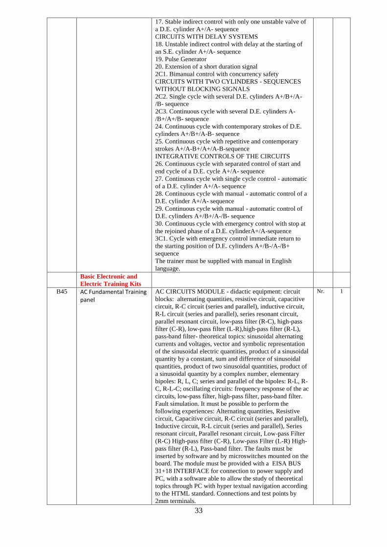
33
17. Stable indirect control with only one unstable valve of
a D.E. cylinder A+/A- sequence
CIRCUITS WITH DELAY SYSTEMS
18. Unstable indirect control with delay at the starting of
an S.E. cylinder A+/A- sequence
19. Pulse Generator
20. Extension of a short duration signal
2C1. Bimanual control with concurrency safety
CIRCUITS WITH TWO CYLINDERS - SEQUENCES
WITHOUT BLOCKING SIGNALS
2C2. Single cycle with several D.E. cylinders A+/B+/A-
/B- sequence
2C3. Continuous cycle with several D.E. cylinders A-
/B+/A+/B- sequence
24. Continuous cycle with contemporary strokes of D.E.
cylinders A+/B+/A-B- sequence
25. Continuous cycle with repetitive and contemporary
strokes A+/A-B+/A+/A-B-sequence
INTEGRATIVE CONTROLS OF THE CIRCUITS
26. Continuous cycle with separated control of start and
end cycle of a D.E. cycle A+/A- sequence
27. Continuous cycle with single cycle control - automatic
of a D.E. cylinder A+/A- sequence
28. Continuous cycle with manual - automatic control of a
D.E. cylinder A+/A- sequence
29. Continuous cycle with manual - automatic control of
D.E. cylinders A+/B+/A-/B- sequence
30. Continuous cycle with emergency control with stop at
the rejoined phase of a D.E. cylinderA+/A-sequence
3C1. Cycle with emergency control immediate return to
the starting position of D.E. cylinders A+/B-/A-/B+
sequence
The trainer must be supplied with manual in English
language.
Basic Electronic and
Electric Training Kits
B45 AC Fundamental Training panel
AC CIRCUITS MODULE - didactic equipment: circuit
blocks: alternating quantities, resistive circuit, capacitive
circuit, R-C circuit (series and parallel), inductive circuit,
R-L circuit (series and parallel), series resonant circuit,
parallel resonant circuit, low-pass filter (R-C), high-pass
filter (C-R), low-pass filter (L-R),high-pass filter (R-L),
pass-band filter- theoretical topics: sinusoidal alternating
currents and voltages, vector and symbolic representation
of the sinusoidal electric quantities, product of a sinusoidal
quantity by a constant, sum and difference of sinusoidal
quantities, product of two sinusoidal quantities, product of
a sinusoidal quantity by a complex number, elementary
bipoles: R, L, C; series and parallel of the bipoles: R-L, R-
C, R-L-C; oscillating circuits: frequency response of the ac
circuits, low-pass filter, high-pass filter, pass-band filter.
Fault simulation. It must be possible to perform the
following experiences: Alternating quantities, Resistive
circuit, Capacitive circuit, R-C circuit (series and parallel),
Inductive circuit, R-L circuit (series and parallel), Series
resonant circuit, Parallel resonant circuit, Low-pass Filter
(R-C) High-pass filter (C-R), Low-pass Filter (L-R) High-
pass filter (R-L), Pass-band filter. The faults must be
inserted by software and by microswitches mounted on the
board. The module must be provided with a EISA BUS
31+18 INTERFACE for connection to power supply and
PC, with a software able to allow the study of theoretical
topics through PC with hyper textual navigation according
to the HTML standard. Connections and test points by
2mm terminals.
Nr. 1

34
Dimensions of the module: 297x260mm.
The module must be supplied with a theoretical and
practical manual.
B46 DC Fundamental Training panel
DC FUNDAMENTALS - didactic equipment - circuit
blocks: batteries, switches, Ohm’s Law, series circuit,
parallel circuit, series/parallel circuit, power, linear/Non-
Linear variable resistor, voltage divider,
voltmeter/ammeter/Ohmmeter - theoretical topics: DC
power sources, batteries, conventional directions of
voltages, e.m.f. and currents, Ohm's law, circuit with linear
resistance and non linear resistance, series/parallel resistive
circuits, power in dc circuits, linear/non linear variable
resistor, voltage/current divider circuits, direct current
meters. Fault simulation. It must be possible to perform the
following experiences: Batteries, Switches, Ohm's law,
Series circuit, Parallel circuit, Series/Parallel circuit,
Power, Linear/Non linear variable resistor, Voltage
divider, Voltmeter/Ammeter/Ohmmeter. The faults must
be inserted by software and by microswitches mounted on
the board. The module must be provided with a EISA
BUS 31+18 INTERFACE for connection to power supply
and PC, with a software able to allow the study of
theoretical topics through PC with hyper textual navigation
according to the HTML standard. Connections and test
points by 2mm terminals.
Dimensions of the module: 297x260mm.
The module must be supplied with a theoretical and
practical manual.
ELECTRIC NETWORKS
Didactic equipment - circuit blocks: Kirchoff ’s current
law,Kirchoff ’s voltage law, Kirchoff ’s laws combined,
Kirchoff ’s solution with two sources, superposition,
Thevenin circuits, Thevenizing a bridge circuit, Thevenin /
Norton Conversion, delta to Y or Y to delta - theoretical
topics: elements of an electrical network: node, arm,
mesh, first Kirchoff principle, second Kirchoff principle,
series resistances, parallel resistances, series-parallel
connection, voltage dividers, theorem of the effect
superposition, Thevenin theorem, Norton theorem,
Millman theorem. Fault simulation. It must be possible to
perform the following experiences: Series resistors and
Kirchhoff Voltage Law verification, Parallel resistors and
Kirchhoff Current Law verification, Series-parallel
resistors, Effect superposition, Thevenin theorem, Norton
theorem, Millman theorem, Voltage divider. The faults
must be inserted by software and by microswitches
mounted on the board. The module must be provided with
a EISA BUS 31+18 INTERFACE for connection to power
supply and PC, with a software able to allow the study of
theoretical topics through PC with hyper textual navigation
according to the HTML standard. Connections and test
points by 2mm terminals.
Dimensions of the module: 297x260mm.
The module must be supplied with a theoretical and
practical manual.
Nr. 1
B47 Logic Fundamental Training panel
LOGIC CIRCUITS - didactic equipment: - circuit blocks:
logic gates, Boolean Algebra, Karnaugh’s maps and
combinatory networks, encoder and decoder, multiplexer
and demultiplexer, electric characteristics of the TTL logic
gates,the TTL logic family, the CMOS logic family -
theoretical topics: binary system, logic functions, the
algebraic description of the logic gates, the truth tables,the
theorems of the Boolean Algebra, techniques for the
minimization of the logic functions through the application
Nr. 1
35
of the theorems, fundamental logic operators,NOT, AND
and OR logic operators, use of the AND and OR operators
as control devices for the transfer of logic signals, OR-
exclusive logic operator, classic form of a function,
graphic representation of the functions, AND-OR-NOT
function, NAND and NOR logic operators, use of the
NAND and NOR operators as control devices for the
transfer of logic signals,the TTL family, the CMOS family,
characteristic parameters of the logic gates, definition and
characteristics of a combinatory logic network, the
Karnaugh' maps, the BCD code, encoders, decoders,
multiplexer and demultiplexer, fault simulation.It must be
possible to perform the following experiences: NOT logic
gate and verification of the double negation property, AND
logic gate, OR logic gate, EX-OR (exclusive OR) logic
gate, NAND logic gate, NOR logic gate, EX-NOR
(exclusive NOR) logic gate, Verification of the associative
property for the AND operator, Carrying out of a four
input AND operator, Verification of the associative
properties for the OR operator, Verification of operation of
the AND and OR operators as control devices in the data
transfer, Verification of the Boolean algebra theorems:
theorems for one variable, theorems between one variable
and one constant, absorption theorems, Morgan's theorem,
Functional verification of the canonical forms of the EX-
OR operator, Functional verification of the first canonical
form of a function assigned by means of its truth table,
Functional verification of a logic circuit by means of the
comparison with the truth table of its logic function,
Functional verification of the minimization of logic
functions by means of the Karnaugh's maps, Control of a
lamp with control combinatory logic circuit, Automatic
selection of events, BCD decimal-binary code converter
circuit, BCD - 7 segments binary code converter circuit, 4
to 1 line multiplexer or data selector switch, 1 to 4 line de
multiplexer, Electric characteristics of the TTL logic gates,
TTL logic family, CMOS logic family. The faults must be
inserted by software and by microswitches mounted on the
board. The module must be provided with a EISA BUS
31+18 INTERFACE for connection to power supply and
PC, with a software able to allow the study of theoretical
topics through PC with hyper textual navigation according
to the HTML standard. Connections and test points by
2mm terminals.
Dimensions of the module: 297x260mm.
The module must be supplied with a theoretical and
practical manual.
DIGITAL CIRCUITS - didactic equipment - circuit
blocks: Flip-flops: to keep unchanged for given time
intervals the logic state of the output; to define the
synchronous and the asynchronous input of a flip-flop; to
understand the operation of type D and type T flip-flops
and to be able to realize them starting from a J-K flip-flop;
Counters, to understand the operating principles of the
frequency dividers, to understand analogies and
differences between a synchronous and an asynchronous
counter, application 4 bit full adder, application 9 bit parity
generator, shift registers:to understand the operating
principle of the most common shift registers;to be able to
understand the state tables and the time diagrams of the
registers - theoretical topics: Flip-flop S-R, Flip-flop S-R
with NOR operators, Flip-flop S-R with NAND operators,
Flip-flop J-K, Flip-flop J-K Master-Slave, Flip-flop T,
Flip-flop D, asynchronous 4 bit binary counter,

36
synchronous 4 bit binary counter, asynchronous decimal
counter, synchronous decimal counter, parity generator,
adders, definition, classification and operating principle of
the most common shift registers, fault simulation. It must
be possible to perform the following experiences:
Verification of the logic operation of an S – R flip-flop,
Verification of the logic operation of a J – K flip-flop of
Master-Slate type, Verification of the logic operation of a
D flip-flop, Verification of the logic operation of a T type
flip-flop, 4 bit asynchronous binary counter , asynchronous
decimal counter , forward/backward synchronous 4-bit
binary counter, BCD/Decade Up/Down counter, Bit
Odd/Even Parity Generator, 4-bit Binary Adder, Parallel-
serial shift registers, Serial-parallel shift registers. The
faults must be inserted by software and by microswitches
mounted on the board. The module must be provided with
a EISA BUS 31+18 INTERFACE for connection to power
supply and PC, with a software able to allow the study of
theoretical topics through PC with hyper textual navigation
according to the HTML standard. Connections and test
points by 2mm terminals.
Dimensions of the module: 297x260mm.
The module must be supplied with a theoretical and
practical manual.
Base frame with power supply, connection to pc and
virtual instrumentation with the following characteristics:
0/+15 Vdc, 1 A
0/-15 Vdc, 1 A
+15 Vdc, 1 A
-15 Vdc, 1 A
+5 Vdc, 1 A
-5 Vdc, 1 A
6 - 0 -6 Vac, 1 A
• Interface board for connection to PC.
• Robust structure and modern design.
• Voltage regulation and protection against over voltage or
short circuit.
• The base frame must be supplied complete with a set of
connecting cables, terminals must be 2mm. It must be
supplied with Interface EISA 31+18 - USB HID managed
by microcontroller C805C1.Control of 12 relays interfaced
on the BUS output and managed by software, 12 NO and 6
NC relays.
Dimensions: 380 x300x110 mm
MAIN BLOCKS
Virtual instrumentation
Multimeter
• 3 and 3/4 digits
• dc/ac voltage 400mV, 4 V, 40 V, 400 V
• resistance: 400 Ohm, 4 kOhm, 40 kOhm, 400 kOhm,40
MOhm
• dc/ac current: 200 mA, 8A
Function Generator
• sinusoidal, square , triangular, dc
• frequency: 0.1Hz - 200 kHz
• output: ± 10 V
• attenuator: 0 dB, -10 dB, -20dB
• frequency, amplitude, offset, duty-cycle regulation
Digital oscilloscope
• dual trace oscilloscope
• input: dc/ac, 1 MOhm
• measurement ranges: 20/50/100/200/500 mV, 1/2/5V per
division
• sampling frequency: 100 Hz to 10MHz

37
Digital Pattern Generator
TTL Output, output rate from 200ms to 10s between each
sample
Output 2048 steps
Pattern selection
normal or automatic
It displays 20 states of the patterns
Logic Wave Analyzer
TTL IN, 8 inputs
The display shows a window of 20 states of the inputs.
B48 Hand held communicator
(HART) • Wireless handheld Hart Communicator,
• Supports more than fifty transmitter’s advanced
parameters,
• Remote assistance, built-in loop power supply,
• Built-in milliammeter,
Nr. 1
General Equipment
B49 Digital weighing balance 200 / 0.001g 1mg Digital Analytical Balance Weighing
Precision Lab Scale 220-240V
Nr. 1
B50 Grinding machine (Bench
type Bench Grinders & Buffers Machine Type: Grinder Wheel
Diameter (Inch): 6
Nr. 1
B51 Soldering/ Disordering
Station • Soldering Iron & desoldering Tweezers
• 1 Soldering Iron & 1 desoldering Tweezers Separately
Controlled With PID Programmable Control Technology
• Complete Digital Control for Both The Soldering Iron &
desoldering Tweezers
• 10 Solder Tips, Brass Tip Cleaner
• Functions: Soldering Iron Standby-Time, Adjustable Shut
Down, Temp Correction, set degree °C or °F
Nr. 1
B52 Heat Gun • 4 main applications can be stored permanently, so that
airflow and temperature are at the correct setting instantly
• Working temperature 50 – 660°C
• Airflow and temperature control in steps of ten for
precise working; data is shown on an LCD display /
Ergonomic design and soft grip
• Heating automatically switches off and cools when
overheating, for long lifetime
Nr. 1
B53 Hand Drill machine • Brushless Cordless Drill Set with Case, Compact Electric
Hand Drill with Rechargeable 18V Li-Ion Lithium Battery,
variable Speeds
Nr. 1
B54 Portable Crane Digital Hanging Crane Scale Portable Heavy Duty Scale
660Lb/300KG
Nr. 1
B55 Drilling machine (pedestal
type Mini Bench Drill Press Compact Drill Wood/steel Drilling
1-10mm. Height adjustment via crank.
Nr. 1
B56 Tool Cabinets Tool cabinet (180pcs) with 7 drawers (filled with assorted
tools)
Nr. 1
B57 Tool Boards 775mm High Static Rack 1000w x 550d mm Single Sided
With 40 Piece Hook Kit
Nr. 1
Digital Instrumentation
Laboratory
B58 Basic PLC Training Kit with software
This modular trainer must allow the study of the PLC and
HMI. The modular frame must be made of a tubular steel
structure, treated with electrostatic painting. It should be
composed of 4 fast fixation lines of modules without the
need for tools. The components, as well as their terminals
and access points, must be identified clearly with the
printed symbols in silk-screen. All terminals and
connection points must be available through 2 or 4 mm
terminals (according to the voltage).
Features:
Touch screen module
kit 1

38
Resolution 800x480
Color 16bit
Touch screen 4 wires.
Serial communication RS232/RS485/RS422
Display 7 inch
Input power module
With protection switch and lights
Circuit breaker with leakage protection - rated current
16A
Power input indicator
Power output indicator
DC power supply module
Polarity inversion and over-current protection.
Output: fixed power supply 12Vdc,24Vdc
Variable power supply 0-10Vdc
Digital voltmeter: range 0~20Vdc with 0.01V
resolution
Digital input module (Retentive)
Module with switches for digital input signals
simulation.
8 fixed contact switches with retention NC/NO, for
simulating the logic levels.
Digital input module(Pulse)
Module with switches for digital input signals
simulation.
8 contact pulse switches, NC/NO.
Digital input module (Retentive, Pulse)
Module with switches for digital input signals
simulation.
4 contact pulse switches, NC/NO
4 contact retention switches, NC/NO.
Digital indication module
Module with 8 leds for light indication of output
digital signals
Suitable for PLC with NPN or PNP outputs.
Potentiometers module
Module with linear potentiometers for simulation of
voltage or current signals.
Resistance 10 K 2pc
Measurement module
Possibility to measure 2 signals simultaneously.
For current signals from 4 to 20 mA and the other for
voltage signals from 0 to 10 Vdc.
Digital voltmeter: range 0~20Vdc with 0.01V
resolution
Digital ammeter: range 0~200mA with 0.01mA
resolution
Step motor module
4 bits electronic driver
4 phase 5 wires deceleration stepper motor,5Vdc
4 indication lights
Code wheel display rotation
Relay module
Module with 4 relays for 3 A and 24 Vdc coil
Suitable for PLC with NPN or PNP outputs
Independent of each other
DC motor module
DC motor,24Vdc input,60rpm,stepless speed
regulation。
Encoder,24Vdc input,T-slot structure, infrared
detection
0-10V analog speed control

39
Suitable for PLC with NPN or PNP inputs
A/D converter module
Module with Analogue/Digital converter
8 bits A/D converter
Analogue signals input from 0 to 10 Vdc or from 4 to
20 mA.
Channel selection for 0 to 10 Vdc and 4 to 20mA
8 Indicator lights
D/A converter module
Module for Digital/Analogue converter
8 bits D/A converter
With maximum analogue output signals adjustable
from 0 to 10 Vdc or from 4 to 20 mA.
8 Indicator lights
Accessories to be supplied:
Data DVD: source code, developing software for both
HMI and PLC
Experimental cable
Experimental manual
Topics should cover
Motor forward & reversal control experiment
Three-phase synchronous motor Y-Δ start control
experiment
Motor sequence start and stop control experiment
Stepping motor control experiment
Touching Screen Experiment
D/A Conversion experiment
A/D Conversion experiment
PLC Analog input experiment
PROGRAMMABLE LOGIC CONTROLLER MODULE
The module should embed a Siemens PLC and expansion
AI AO modules. All input/output pins of PLC should be
introduced to the panel. User can connect the IO pins to
other application modules with 2mm test leads.
The module must include:
Panel and back cover
PLC and expansion AO modules
DC Power input
DC Power switch
2mm terminals for IO interface
Features:
Power supply: DC 24V
Digital Input terminals with COM: 7 pcs
Digital output terminals with COM: 6 pcs
Analog input terminals with COM: 3 pcs
Analog output terminals with COM: 2 pcs
PLC CPU1211C details:
The CPU should be provided with a PROFINET port
for communication over a PROFINET network.
Embedded digital I/O points: Inputs, 24VDC 6 points.
Outputs, 24V DC Solid state - MOSFET (sourcing) 4
points.
PTO/PWM Support: 2 (PTO/PWM)
Embedded HSC Support:3
Analog inputs:2 inputs. Full-scale range, 0 to 10 V
Number of plug-in modules: Communication module
expansion -3CMs max. .SB, CB, BB expansion-1max.
Basic instruction speed: 0.08 μs/instruction per
Boolean
Minimum scan/cycle time: Maximum scan cycle time
1 to 6000ms. Minimum scan cycle time 1 to maximum
scan cycle time

40
User memory: Work, 50 Kbytes. Load, 1 Mbyte
internal, expandable up to SD card size. Retentive, 10
Kbytes
IEC 61131-3 languages: Ladder diagram, function
block diagram, structured text
Operating temperature: -20…60 °C
Analog output module SB 1232 details:
Number of outputs: 1 output,
Voltage range: ±10V
Current range: 0…20 mA
Power consumption:C1.5W
Input impedance: ≥1000Ω for voltage mode, ≤600 Ω
for current mode.
CM1241 RS232 details:
RS232(full-duplex)
Transmitter output voltage,+/-5V min.at RL=3KΩ
Transmit output voltage, +/-15VDC max.
Receiver input impedance,3KΩ min
Receiver threshold/sensitivity, 0.8 V min. low, C2.4
max. high 0.5 V typical hysteresis
Receiver input voltage, +/- 30 VDC max.
B59 Virtual system for plc study
(SIMATIC S7-1200) This system must be a didactic tool for the learning of PLC
programming.
This trainer must show five virtual industrial processes in
order permit to the student to learn how to program a PLC.
These processes must simulate real situations as sorting,
batching, palletizing, pick & place and automatic storage;
the aim must be to program the PLC in order to control all
these virtual processes as real systems. The system must be
composed of the above mentioned automation processes
based on settings that represents industrial realities. This
trainer must permit also the faults simulation for sensors
and actuators in open or short-circuit.
Thanks to this virtual system, it must be possible to
interact with the system as it is a real system, add or
remove products from the production line in every moment
of the simulation, create faults and jamming of the system.
Main features:
SIMATIC S7-1200
CPU 1212C (AC/DC/RLY)
Signals Module 1223 (8DI/8DO)
16 digital inputs
14 digital outputs
Ethernet port
STEP 7 Professional SW
Hardware key secured inside
3D realistic graphics
Real-time physics that closely emulates what happens in
real life
3D real-time sound
Total interactivity with the systems
Friendly user interface
Easy and fast to setup
The information shall be exchanged between the PLC and
the virtual system through a data acquisition board
provided with 32 I/O isolated channels and USB interface:
16 channels with input voltage: Logic 0: 2V max., Logic 1:
5V min (60V max.) or dry contact
16 channels with output voltage: 5 ~ 40Vdc - sink current
type 100mA max/channel and 1,1 A/total max.
Based on the latest PC technology, this trainer shall make
PLC training easy and fun. The result shall correspond to
an immersive simulated environment that allows highly
Nr. 1

41
realistic training processes, without any risk of injury to
man or damage to machines.
The automation tasks shall be presented with increasing
levels of difficulty, so that users can progress to more
advanced exercises as they improve their skill.
This trainer shall reproduce five training processes based
on real world industrial scenarios. Each process shall offer
standard problems found in PLC programming, presented
in order of increasing level of difficulty.
These training processes shall consist in:
SORTING: transport cases from the entry bay to the
elevators, sorting them by height
BATCHING: mix three primary colors (red, green and
blue) in order to obtain a desired color
PALLETIZER: palletize cases up to three layers
PICK & PLACE: place parts inside boxes through a three
axes manipulator
AUTOMATIC WAREHOUSE: transport, store and
retrieve boxes from a rack
The system shall be inserted in a didactic panel with 2 mm
terminals for the digital inputs/outputs.
The PLC must be supplied with applications in LADDER
language for the control of the five simulation processes.
The trainer must be supplied with manual in English
language.
B60 SCADA Training kit HMI Training Course (Human Machine Interface -
SCADA
• This HMI Training Course (Human Machine Interface -
SCADA)- is a introductory HMI SCADA course for
automation engineering on scada systems.
• Uses AB Rockwell's automation and controls HMI
SCADA system (RSView 32) as an example•
WIN 10, 8 7 and XP
kit 1
B61 PLC Ladder logic training
software • PLC Programmable Logic Controller Programming
Ladder and Function Block Software in CD
• CD with Software package with instructions and manuals
• Programming, Simulation and Monitoring
• Easy to learn training section -Basic and Advanced
Nr. 1
B62 Digital-To-Analogue
Converter Kit Digital-To-Analogue Converters
This board must allow the study of the operating principle
and of the main characteristics of a digital-to-analogue
converter.
The board must be composed of 3 independent sections:
• a weighed resistances discrete components D/A
converter
• a discrete components D/A converter in a R-2R
network
• a monolithic 11 bit D/A converter
While the first two sections are used to highlight the
operating principle of two different D/A converters, the
third one is used to analyse the operating modes and the
characteristics of the converters that are commercially
available. The board must be supplied complete with a set
of stackable, plug-in cables of suitable lengths and colours
and with a training manual.
Power supply: ± 15 Vdc, 200 mA and + 5Vdc, 200mA
Experiments:
• Analysis of the operation of a weighed resistances
converter
• Analysis of the operation of a converter in a R-2R
network
• Analysis of the conversion errors
kit 1

42
• Analysis of the operation and of the main
characteristics of a monolithic converter
B63 Analog to Digital Converter
Kit This board must allow the study of the operating principle
and of the main characteristics of analogue-to-digital
converters. The board must be divided in 2 sections: in the
first one a discrete component realization is provided of a
ramp A/D counter converter, while in the second section
there is a monolithic converter. The first section must be
used to highlight the operating principle of an A/D
converter, while the second one is mainly used to analyze
the operating modes and the characteristics of the
converters that are commercially available. The board must
be supplied complete with a set of stackable, plug-in
cables of suitable lengths and colours and with a training
manual.
Power supply: ± 15 Vdc, 100 mA and + 5Vdc, 200mA
Experiments
• Analysis of the operation of a counter converter
• Analysis of the operation and of the main
characteristics of a monolithic converter
• Analysis of the conversion errors
kit 1
B64 Displacer Level Transmitter,
Fisher or equivalent Designed to measure liquid level, interface level, or
density/specific gravity inside a vessel
Nr 1
Process Equipment
B65 Electromagnetic Flow
Transmitter
Electromagnetic Flow Transmitter is a flow measurement
device relying on the conductive properties of liquids
traveling across a magnetic field to measure the flow in a
pipe
Nr. 1
B67 Coriolis Flow
Transmitter
The Coriolis Flow Transmitter is a flow measurement
device using the Coriolis forces generated when a fluid
goes through the flowmeter to measure the mass flow of
liquid in a pipe
Nr. 1
B68 Vortex Flow Transmitter Vortex Flow Transmitter. To measure the flow of high or
low temperature fluids.
Nr. 1
B69 Pressure Transmitter
(HART)
The Pressure Transmitter is a gauge pressure measurement
device for fluids. Parameter Value Ceramic Sensor
Operating Range -100 to 1000 kPa (-15 to 150 psi)
Nr. 1
B70 Guided wave Radar level
transmitter • The Guided-Radar Level Transmitter is a level
measurement device using electromagnetic waves to detect
the level of liquid in the column. Transmitter includes a
rod probe to guide the signal in the column and a
transmitter.
Ratings
Power Input 24 V dc
Operating Frequency 100 MHz to 1.5 GHz
Measured Variable Level (via time-of-flight)
Accuracy ±2 mm
Sensor Operating Temperature -40°C to 80°C (-40°F to
176°F)
Process Temperature -40°C to 200°C (-40°F to 392°F)
Nr. 1

43
Sensor Operating Pressure Vacuum to 4000 kPa (Vacuum
to 580 psi)
Blocking Distance 200 mm (7.9 in)
Probe Length 1.03 m (40.6 in)
B71 Differential pressure level
transmitter A differential pressure transmitter is an instrument that
senses a pressure difference between two points and
converts the pressure to a standardized electronic signal
which can be sent to a control element. The transmitter can
be configured so that its signal is either proportional to a
pressure differential, a flow rate, or a level. High Range
and low range.
Nr. 1
B72 Ultrasonic Level
Transmitter The Ultrasonic Level Transmitter is a level measurement
device that uses sound waves to detect the level of liquid.
The Ultrasonic Level Transmitter includes an ultrasonic
sensor/emitter.
Nr. 1
B73 Capacitance type level
transmitter The Capacitive Level Transmitter (HART) is a level
measurement device based on the change in the
capacitance of a capacitor.
Nr. 1
B74 Paddle Wheel Flow
Transmitter
The Paddle Wheel Flow Transmitter provides a
measurement of the flow rate by inserting a simple paddle
wheel into the flow stream. And the Ultrasonic Flow
Transmitter is a device inferring the flow rate by
measuring the transit-time differential between an
ultrasonic pulse traveling upstream with one traveling
downstream.
Nr. 1
B75 Magnetic level switch Conductivity Level Switch is a level limit switch made of
three probe rods of different lengths.
Nr. 1
B76 Vibrating level switch The Vibrating Fork Level Switch is a level limit switch
used to detect whether or not the level of water in the
column has reached a set level
Nr. 1
B77 Float switch The Float Switch is a level limit switch triggered when a
float is raised by buoyancy forces as the level of liquid
in the column reaches the float
Nr. 1
B78 Electronic Pressure
Transmitter Range 0-16 Bar Range 0 - 16bar Nr. 1
B79 Electronic Pressure
Transmitter Range 0-25 Bar Range 0 - 25bar Nr. 1
B80 Electronic Pressure switch
Range 0-2 Bar Range 0 - 2bar Nr. 1
B81 Electronic Pressure switch
Range 0-7 Bar Range 0 - 7bar Nr. 1
B82 Electronic Pressure Switch
Range 0-12 Bar Range 0 -12bar Nr. 1
B83 Pneumatic Pressure switch
Range 0-10 Bar Range 0 - 10bar Nr. 1
B84 Pneumatic Pressure switch
Range 0-16 Bar Range 0 - 16bar Nr. 1
B85 Pneumatic Pressure switch
Range 0-20 Bar Range 0 - 25bar Nr. 1
B86 Pneumatic Pressure
Transmitter Range 0-10 Bar Range 0 - 2bar Nr. 1
B87 Pneumatic Pressure
Transmitter Range 0-16
Bar
Range 0 - 7bar Nr. 1
B88 Pneumatic Pressure
Transmitter Range 0-20
Bar
Range 0 -12bar Nr. 1

44
B89 Pneumatic control valve Pneumatic Control Valve. Designed for pressure, flow,
level, and temperature control applications. Includes a
current-topressure converter which transforms a
4-20 mA input signal into a pneumatic output signal sent
to the actuator of the control valve
Nr. 1
B90 Control Valve with positioner (complete set) (HART)2”
Pneumatic Control Valve with Digital Positioner (HART).
The controller has a high-performance positioner.
Nr. 1
B91 Control Valve with positioner (complete set) FC 2”
Pneumatic Control Valve with Digital Positioner
(FISHER). The control valve also features a rugged
pneumatic positioner.
Nr. 1
B92 Control valve with positioner actuator FO 2”
Electric Control Valve. Transforms a 4-20 mA input signal
directly into a specific opening of the control valve. A
0-10 V dc output is used as a feedback signal to monitor
the position of the valve.
Nr. 1
B93 Delete
B94 Solenoid valve (electric) The Solenoid Valve is a simple unidirectional, direct-
acting, normally closed valve made of brass which can
be used to effect on/off control on a process. The Solenoid
Valve fully opens when a 24 V dc signal is applied to the
electrical connectors wired to the solenoid.
set 1
B95 Single well control panel
(Baker Huges) • Panel Supply: 100 to 150 psig (689 kPa to 1 MPa) [6.89
to 10.3 bar] clean, dry, filtered, instrument quality gas or
air
• Enclosure: 25w x 20d x 30h in. (635 x 508 x 762 mm);
12 ga. 316L stainless steel.
• Tubing: 316L stainless steel, welded and drawn.
• Tube Fittings: 316 stainless steel
• Pressure Pilots:, panel mounted, 500 to 2000 psig range
• Hydraulic Pump: (with hand pump).
• Hydraulic Circuit Working Pressure: 6000 psi (41 MPa)
[413 bar].
• Hydraulic Reservoir: 5 gallon (C1.892 m3) capacity
Nr. 1
B96 Thermocouple Temperature
Transmitter (0-100°C (K-
type)
0-1000C (K-type) Nr. 4
B97 Thermocouple Temperature
Transmitter ((0-200°C (K-
type)
0-2000C(k-type) Nr. 4
B98 RTD Temperature
Transmitter ((0-100°C PT-
100)
0-1000C(PT-100) Nr. 4
B99 RTD Temperature
Transmitter (0-200°C,PT-
100)
0-2000C(PT-100) Nr. 4
B100 Capillary tube temperature
gauge (0-100°C (Bimetallic
thermometer)
0-1000C Bimatalic thermometer Nr. 4
B101 Capillary tube temperature
gauge (0-200°C (Bimetallic
thermometer)
0-2000C Bimatalic thermometers Nr. 4
B102 Capillary tube temperature
gauge (0-100°C (Gas filled
thermometer)
0-1000C Gas filled thermometers Nr. 4
B103 Capillary tube temperature
gauge (0-200°C (Gas filled
thermometer)
0-2000C Gas filled thermometers Nr. 4
B104 Capillary tube temperature
switch (0-100°C (Bimetallic
)
0-1000C Bimatalic Nr. 4
B105 Capillary tube temperature
switch (0-200°C Bimetallic) 0-2000C Bimatalic Nr. 4
B106 Capillary tube temperature
switch(0-100°C Gas filled) 0-1000C Gas filled Nr. 4
B107 Capillary tube temperature
switch(0-200°C Gas filled) 0-2000C Gas filled Nr. 4

45
B108 Thermocouple Temperature
sensor (0-1000C (K-type) 0-1000C (K-type) Nr. 4
B109 Thermocouple Temperature
sensor (0-2000C (K-type) 0-2000C(k-type) Nr. 4
B110 RTD Temperature sensor
(0-1000C (PT100, 3-wire)3 0-1000C(PT-100) 3 wire Nr. 4
B111 RTD Temperature sen4or
(0-2000C (PT100, 3-wire) 0-2000C(PT-100) 3 wire Nr. 4
B112 RTD Temperature sen5or
(0-1000C (PT100, 4-wire) 0-1000C(PT-100) 4 wire Nr. 4
B113 RTD Temperature sen6or
(0-2000C (PT100,4-wire) 0-2000C(PT-100) 4 wire Nr. 4
B114 Thermo well Platinum RTD and J-Type Thermocouple including
connector and thermowell
Nr. 1
B115 Differential Pressure
transmitter (Analog) Pressure Switch with Analog Output is a digital pressure
gauge ranging from 0 kPa (0 psi) to 1000 kPa (145 psi).
Nr. 1
B116 Turbine flow meters Flow meter Trainer to examine different principles of
operation of flow meters. including turbine wheel
flowmeter and the meters mentioned hereunder.
Nr. 1
B117 Paddle wheel flow meter Paddle wheel flow meter for Trainer Nr. 1
B118 Magnetic flow meters Electromagnetic flow meter for trainer Nr. 1
B119 Vortex flow meters Vortex flow meter for trainer Nr. 1
B120 Bypass flow meter Bypass flow meter for trainer Nr. 1
B121 Ultrasonic flow meter Ultrasonic and orifice plate flow meter for trainer Nr. 1
B122 Rota meter Rota meter for trainer Nr. 1
B123 Set of orifice plate
(different types) Orifice Plate. Includes three different plates. Requires the
use of a differential-pressure transmitter
Nr. 1
Accessories
B124 Insulation Tape Self adhesive PVC Electrical Insulation Tape 4metres -box
of 100 , Extremely flexible , Ideal for cable insulation and
marking
Box 2
B125 Teflon tape Teflon Laminated Tapes, Usage: Sealing, Heat Transfer
,single sided, size 3” pack of 100
Box 2
B126 SS Tube fittings All types
and size Assorted (Nipples, elbows, end plugs, adapters, unions -
1/8", 1/4",3/8",1/2"
set 50
B127 Copper tube fittings all
types and size Assorted (Nipples, elbows, end plugs, adapters, unions -
1/8", 1/4",3/8",1/2"
set 30
B128 PVC Tube (1/8",
1/4",3/8",1/2") 1/8", 1/4",3/8",1/2" set 8
B129 SS Tube-(1/4",3/8",1/2")
(1 length 5 meter ) 1/8", 1/4",3/8",1/2" set 6
B130 SS Ball Valve ½”, ¼” (0.5sqr.mm,1sqr.mm, C1.5sqr.mm, 2sqr.mm,C2.5sqr.mm set 8 B131 Needle Valve ½”, ¼” C1.5 sq. mm set 8 B132 Electrical wire
(0.5sqr.mm,1sqr.mm,
C1.5sqr.mm,
2sqr.mm,C2.5sqr.mm)
Electrical wire, one roll (100mtrs) of each
of(0.5sqr.mm,1sqr.mm, C1.5sqr.mm,
2sqr.mm,C2.5sqr.mm)
set 2
B133 PVC 2pair cable (C1.5mm) C1.5mm TWE PVC cable , grey colour rolls 2 B134 Copper tube-1/4" Copper tube-1/4", white pce 10 B135 Grease- Gray Grease- Gray tins 6 B136 Grease- white Grease- white tins 2
B137 Lubricant oil Lubricant oil tins 10 B138 Solder led and wax Soldering gun and Wax set 10 B139 Resistos (50,100,200)Ω,
(.5,C1.C2.C3.4.5.6.7.8.)KΩ set of resistors (50,100,200)Ω,
(.5,C1.C2.C3.4.5.6.7.8.)KΩ
set 100
B140 Capacitors (pF and µf)
(different values ) Assorted - 1 µf, 100 µf,500 µf,1000 µf, 1 pf
set 50
B141 Inductors (different values ) Assorted set 20

46
B142 General purpose PCB Heavy duty (16A) set 20 B143 Extension cable 16ams 1,5mm, C2.5mm Nr. 20 B144 Terminal strip
(C1.5sqmm,C2.5sqmm) Terminal strip (C1.5sqmm,C2.5sqmm) set 40
B145 Terminal Leg (U-type, pin-
type), (C1.5sqmm,
C2.5sqmm)
Terminal Leg (U-type, pin-type), (C1.5sqmm, C2.5sqmm) set 8
B146 Plug and socket 4mm,6mm,8mm,10mm,12mm set 20 B147 Metallic Cable Gland
20mm,25mm and 32mm 4mm,6mm,8mm,10mm,12mm set 50
B148 Armed Cable 20mm,25mm,
and 32mm Heavy duty (16A) Roll
@ 6
B149 Diode IN4001,4002,4003 Diode IN4001,4002,4003 set 100 B150 Zener diode (IN47) Zener diode (IN47) set 100 B151 Transistor(NPN(9575GJ) Transistor(NPN(9575GJ) set 50 B152 Transistor PNP Transistor PNP set 50 B153 Gates IC (AND, OR, NOR,
NOT, NAND) AND, OR, NOR, set 80
B154 Hydraulic oil Standard grade ltrs 20 B155 Soap solution Standard grade ltrs 20 B156 Cotton waste Cotton waste 2 B157 Goggles • Concealer Clear Anti-Fog Dual Mold Safety Goggle Top
of Form with Elastic Headband
prs 50
B158 Hand gloves Made from cotton and polyester fibers with a latex coated
palm
prs 50
B159 Helmet • Helmet- Hard hat with attached face shield and ear muffs Nr. 50 B160 Oil Can PE material, 5 ltr capacity pce 10 B161 Transmitter Clamping
Bracket • Bracket for mounting Transmitter
• L type supplied with all necessary bolts
set 10
B162 ‘U’ clamp 2”, 1”, ‘U’ clamp 2”, 1”, required for Transmitter bracket
set 24
Technicians tool box
B163 Each technician tool box
contains the following items 3-tray metal tool box
• • Useful load: 20 kg.
• Volume: 13 dm³.
• Dimensions Should be big enough to contain the
following:
Contents
1 Combination
Pliers
• Moulded plastic handles and slip guards.
• Tempered, curved jaws with induction
hardened cutting edges. • Length (mm) 160
• Type Combination
1
2 Side cutter • Side cutting pliers
• Width 2C1.5 mm - Length 160 mm
1
3 Wire striper • Wire Stripper 20-30 Awg 1
4 Long nose
plier
• Long nose pliers
• Jaw capacity: 14AWG
• Overall length: 200mm
1
5 Water pump
plier
• Water Pump Pliers 12 Groove Joint
• 300mm Plumbers Wrench
1
6 Circle clip
tool Circle clip pliers 24mm 1
7 Tweezers • Stainless Steel Anti-Magnetic Economy
Tweezers with Curved Fine Point Tips,
• 4-1/2" Long
1
8 Grip plier • Grip pliers • Size: 11”
1
9 Sprit Level
(8”)
• Spirit Level:
• Size: 8” • Material: Aluminum Frame and, Steel
Colour: Yellow, red
1
10 Ring spanner (4mm -
24mm)
Ring spanner (4mm - 24mm) 1
set 5
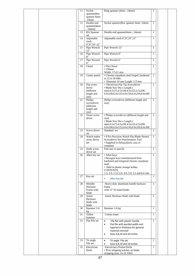
47
11 Socket spanner(Box
spanner 6mm
-24mm
Ring spanner (4mm - 24mm) 1
12 Double end
spanner(4mm
- 24mm)
Socket spanner(Box spanner 6mm -24mm 1
13 BA Spanner set
Double end spanner(4mm - 24mm) 1
14 Adjustable
rinch 6'',8",10",12"
Adjustable rinch 6'',8",10",12" 1
15 Pipe Wrench
12"
Pipe Wrench 12" 1
16 Pipe Wrench 8"
Pipe Wrench 8" 1
17 Pipe Wrench
6"
Pipe Wrench 6" 1
18 Chisel • Flat Chisel • 150mm
Width: 17x11 mm
1
19 Center punch • Chrome-vanadium steel forged, hardened
to 52 to 58 HRc.
• Diameter 10 mm Lenght 115 mm
1
20 Flat screw
driver (different
length and
size)
• Electrician Flat Tip Screwdriver
• Blade Size Dia x Length ( mm):4.5x75,4.5x100,4.5x125,4.5x200,
6.0x100,6.0x125,6.0x150,6.0x250,6.0x300
1
21 Philips
screwdriver
(different length and
size)
Philips screwdriver (different length and
size)
1
22 Tester screw
driver
• Philips screwdriver (different length and
size) • Blade Size Dia x Length (
mm):4.5x75,4.5x100,4.5x125,4.5x200,
6.0x100,6.0x125,6.0x150,6.0x250,6.0x300
1
23 Screw driver
set
Standard set 1
24 Watch maker screw driver
set
• 9 Pcs Precision Watch Flat Blade Slotted Screwdriver Set Watchmakers Tool
• Supplied in fitting plastic case or
container
1
25 Snabi screw driver set
End user to specify 1
26 Allen key set • Allen keys
• Hexagon keys manufactured from hardened and tempered chrome vanadium
steel.
• Held in plastic storage holder. CONTENTS:
1.5, 2.0, 2.5,C3.0, 4.0, 5.0, 5.5 and 6.0 mm
1
27 Key set Allen Key Set
1
28 Metallic
Hacksaw Frame with
blade
Heavy-duty aluminum handle hacksaw
frame with 12” bi-metal blade
1
29 Junior Hacksaw
blade with
blade
Junior Hacksaw blade with blade 1
30 Hammer 1/4 kg
Hammer 1/4 kg 1
31 Teflon
hammer
Cotton waste 1
32 Flat File set File flat with plastic handle
Flat file with parallel width and tapered in thickness for general material removal
Sizes 6,8,10 and 10 inches
1
33 Tri angle
File set Tri angle File set
Sizes 6,8,10 and 10 inches
1
35 Electrician
Knife
Electrician's Pocket Knife
• Wire stripping notches on blade, stripping sizes 14-10 AWG
1

48
• Satin 440A stainless steel drop point blade
• wooden handle for corrosion resistance
• Liner lock secures blade in open position • Approximate dimensions: 9.5 x 4.5 x 0.7
inches
35 Sesser Cotton waste 1
36 Tube Bender 1/2"
Tube Bender 1/2" 1
37 Tube Bender
3/8"
Tube Bender 3/8" 1
38 Tube Bender 1/4"
Tube Bender 1/4" 1
39 Tube Bender
1/8"
Tube Bender 1/8" 1
40 Tube cutter Stainless Steel Tubing Cutter
Cutting capacity: 1/4-inch to
1-3/8-inch (6 mm to 35 mm)
cutting capacity
1
41 Tube cutter
blade 1/4-inch to 1-3/8-inch (6 mm
to 35 mm)
Ideal for cutting copper,
aluminum, brass or plastic
tubing
1
42 Mallet Soft and hard faced, wood
handle. Weight 650g
1
43 Measuring
Tape 2M locking taper measure 1
44 Steel Scale Steel Scale 1
45 Soldering iron kit Soldering iron with iron
stand
Rating [W] 30
Peak temp ± 10% [°] 420
Voltage\Volt 230
1
46 Right Angle Steel Scale 1
C PERSONNEL PROTECTIVE EQUIPMENT (PPE)
C1 Helmets, set of various sizes Hard hat with attached face shield and ear muffs
Set of various standard sizes
Pc 300
C2
Gloves, set of various sizes Made from cotton and polyester fibers with a latex coated palm
Set of various standard sizes
Pr 300
C3 Thermal gloves, set of various sizes For keeping hands warm
Set of various standard sizes
set Delete
C4 Overalls, set of various sizes Overalls for adults- men, various standard sizes(40)
Overall for adults- Ladies, various standard sizes(20)
set 300
C5
Safety googles Concealer Clear Anti-Fog Dual Mold Safety Goggle Top of Form with Elastic Headband
Pr 300
C6
Safety shoes Men's Slip Resistant Buster Steel Toe Boots –
Different sizes (40)
Ladies Slip Resistant Buster Steel Toe Boots – Different sizes (20)
Pr 300
C7
Aprons Men's aprons – Different sizes (40)
Ladies aprons – Different sizes (20)
Pc 300

49
C8
Ear plugs An earplug is a device that is meant to be inserted in the ear canal to protect the user's ears against water, dust etc.
Pr 300