
Visual modelling with Logo: a structural approach to seeing James Clayson
408
Visual Modeling with Logo
Transcript of Visual modelling with Logo: a structural approach to seeing James Clayson

Visual Modeling with Logo

Exploring with LogoE. Paul Goldenberg, editor
1. Exploring Language with Logo by E. Paul Goldenberg and Wallace Feurzeig2. Visual Modeling with Logo by James Clayson
A Structured Approach to Seeing
Visual Modeling with Logo
James Clayson
The MIT PressCambridge , MassachusettsLondon , England

Library of Congress Cataloging -in-Publication Data
JamesVisual
language) 2. Computer
IIIIIIIIIIIIIICLAYSONVIS MOOLWITHLOGO
@ 1988 by the Massachusetts Institute of Technology
All rights reserved. No part of this book may be reproduced in any form or byany electronic or mechanical means (including photocopying , recording , orinformation storage and retrieval ) without permission in writing from thepublisher .
This book was printed and bound by Halliday Lithograph in the United Statesof America .
Clayson,modeling with Logo.
(Exploring with Logo; 2)Includes index.
1. LOGO (Computer programgraphics. I. Title. II . Series.QA76.73.L63C52 1987 006.6'6ISBN 0-262-53069-4 (pbk.)
87-3894
MIT Press

To L.A.


Introduction 1
Contents
Series Foreword ix
Preface xi
Acknowledgments xiii
1
2 Visual Modeling 34
3 Visual Discovery 63
4 Circular Grids 115
5 Rectangular and Random Grids 163
6 Islamic Designs 235
7 Organic Designs 286
8 Space 337
9 Closure 379
Index 389
Series Foreword
The aim of this series is to enhance the study of topics in the arts, humanities ,mathematics , and sciences with ideas and techniques drawn from the world ofartificial intelligence --specifically , the notion that in building a computermodel of a construct, one gains tremendous insight into the construct. Each volumein the series represents a penetrating yet playful excursion through a singlesubject area such as linguistics , visual modeling , music , number theory , orphysics, written for a general audience.
Preface
'What is the use of a book: ' thought Alice,Lewis Carroll
"without pictures . . . ."
In the fall of 1982 I started to teach a course called " Problems in Visual
Thinking ." It was offered jointly by Parsons School of Design in Paris and the
American College in Paris . Looking back now , perhaps I should have replaced
the word Problems with something less pathological - Explorations maybe . But
that original title really indicated my reason for inventing the course in the
first place . I taught courses in statistics and operations research in which I
encouraged my students to add a bit of visual thinking to their quantitative
analysis , but each semester I was disappointed .
I continued my pleas for visualization because I saw that the few students
who could introduce a little of it into their work discovered - more often than
not - the most surprisingly useful things . These visualizers seemed to me less
intimidated by vagueness because their picture -making abilities gave them
concrete starting points , and they seemed to enjoy playing around with the
painted pieces of complex problems . Perhaps , I thought , their visual play
encouraged them to see where more analytic approaches might usefully beapplied .
My problem was to discover how to teach visual thinking to those students
who had problems doing it naturally . It was obvious that most of my students
lacked visual vocabulary and few of them had ever been in an art or drawing
studio . How was I to cancel out this liability ? Luckily I had managed an art
school and knew a bit about people who had design experience. Professional artstudents certainly have the visual baggage, but most are severely lacking inanalytical skills . " Let 's put these two groups together , " I thought , "and setthem a series of tasks." The art students can show their colleagues a bit aboutcolor and design, while the non-art crew can gently introduce the art students toa little quantitative model building . The Logo computer language struck me as anappropriate medium of instruction - just enough of the visual and just enough ofthe analytical . Problems in Visual Thinking was born .
There were no suitable texts , so I set out to write one , and this book is the
most recent set of class notes . It is structured around a series of exercises that
encourage visual thinking in students from a variety of different backgrounds .I wish that I could claim total success in turning my students into better
problem -solvers by first turning them into more effective visualizers . But I fearthat my record is mixed . I am convinced , however , that for some people ,certainly not all , visual model building is an enormously enjoyable activity thatleads them in new and surprising directions . And since that activity falls nicelywithin the terms of reference of a liberal arts education , I am quite pleasedwith the classroom results I have seen .
Most thanks are due to my students because this book was realized with
their help . You will find quotes and illustrations from them scatteredthroughout the text . Thanks, too, go to Roger Shepherd, the first Director ofParsons in Paris, who not only encouraged me to start this project but helped toteach it for the first year . Were it not for Frank Satlow of MIT Press , this book
would still be in a basement Xerox room . I also benefited from his readers '
reports .
The final construction of the manuscript , however , was a solo affair ;
what ,ever opacities, inconsistencies, or mistakes remain are mine .
Preface
xii
James ClaysonParis, 1987
Ackn owl edg me nts
I wish to thank the following for granting permission to reproduce illustrations
Piet Mondrian , Composition with red yellow and blue, Tate Gallery , London ,
in this book :
Musee d 'art moderne de la ville de Paris , courtesy of
David Hackney , Sunbather, courtesy of the artist .
courtesy of SP ADEM and ARS.
Robert Delaunay , Disque,ADAGP and ARS.
Wassily Kandinsky , Several Circles, No. 323 (1926), Solomon R. GuggenheimMuseum , New York . Photograph by Robert E. Mates.
Wassily Kandinsky , First study for Several Circles (1926), Collections du MuseeNational d'art moderne, Paris, courtesy of ADAGP and ARS.
Gustav Klimt , Poissons rouges, courtesy Giraudon / Art Resources, New York .
Gustav Klimt , Rosiers sous les arbres, courtesy Giraudon / Art Resource, NewYork .
Piet Mondrian , Compositie met kleurvlakjes no. 3, Collection HaagsGemeentemuseum, the Hague, courtesy of Beeldrecht, The Netherlands / V AGA ,New York .
Abteiberg M6nchengladbach , photo by Ruth Kaiser.
Acknowledgments
Brussels .
Jean Tinguely , Homage Ii Marcel Duchamp , courtesy of the Stadtisches Museum
Henry van de Velde , Faits du village VII - La ravaudeuse , Musees royaux desBeaux-Arts , Brussels.
Vincent van Gogh , Van Gogh's bedroom, courtesy Giraudon / Art Resources , NewYork .
Andy Warhol , Marilyn Monroe, courtesy Giraudon / Art Resource, New York .
Architectural trees reproduced from Bob Greenstreet , Graphics Sourcebook
(Prentice-Hall, Englewood Cliffs, NJ, 1984).
Celtic knots reproduced from George Bain , Celtic art : the methods of construction(Dover, New York, 1973).
Graphics (Dover, New York, 1975).
Farkas
forms :" Impossible
Leonardo, volume
Islamic tile designs reproduced from J. Bourgoin , Arabic geometrical pattern anddesign (Dover , New York , 1973), and from Keith Critchlow , Islamic patterns(Schocken Books, New York , 1976).
xiv
Computer - generated globes reproduced from Melvin L . Prueitt , Computer
grids reproduced from Tamas F . Farkas and Peter Erdi ,
experimental graphics and theoretical associations , "
18 , number 3 ( 1985 ) , pages 179 - 183 , copyright @ 1985 ISAST .
Piet Mondrian, New York City 1, Collections du Musee National d'art moderne,Paris, courtesy of Beeldrecht, The Netherlands/ V AGA, New York.
Georges Seurat, La Seine a la Grande-Jatte, Musees royaux des Beaux-Arts,

Acknowledgments
Lattice designs reproduced from Daniel Sheets Dye , Chinese lattice designs(Dover , New York , 1974).
Stone mason marks reproduced from Matila Ghyka , The geometry of art and life(Dover , New York , 1977), and Charles Bouleau , Charpentes, La Geometriesecrete des peintres (Editions du Seuil, Paris, 1963).
Tree silhouettes reproduced from Derrick Boatman , Fields and Lowlands
(Hodder & Stoughton, London , 1979), courtesy of the Rainbird Publishing Group .
xv

Visual Modeling with Logo

Chapter 1Introduction
"Skill to do comes of doing."Ralph Waldo Emerson
" Chance favors the prepared mind ."Louis Pasteur
Who I hope you are
You might be interested in the
photography - or in architecture .
commercial , or industrial design .
studio arts - painting , drawing , sculpture ,
You may have had experience in graphic ,
Then again , you might be a liberal arts type
with a background in language , literature , music , or science . Or perhaps you are
a professional type educated in the field of business , law , medicine , or theology .You could be a student or a teacher or neither or both .
You may have spent long hours in art studios and possess an exceptionally
rich , visual vocabulary . Then again , your graphic abilities , both verbal and
physical , may be very much on the thin side . Instead , your vocabulary might be
skewed toward logic and mathematical terms because your background is in the
sciences , philosophy , law , or mathematics . Perhaps you are that much sought
after , well -rounded person whose vocabulary is rich without being specialized .
Chapter 1
You may not be able to describe every phase that Picasso went through , but
you enjoy looking at art , and you can differentiate a Picasso from , say , a Pissarro
when you see them side by side . You probably have a favorite artist or a
favorite period , and you have paintings or reproductions of them in your own
home . While you may not be able to sketch the Acropolis using 3 - point
perspective , you do have some idea of what perspective means . You would be
intrigued by the suggestion that , in fact , there are dozens of different ways to
illustrate objects in space .
At some time in your past , you must have taken a course in geometry .
( Everybody has taken a course in geometry . It is one of the few bits of liberal
education that we still share . ) What about trigonometry ? You may have
forgotten everything , but you aren ' t brought to the edge of coronary arrest by
hearing the words geometry and trigonometry .
Finally , and most important , whatever your curriculum vitae says , and
whatever type of intellectual or visual baggage you carry , I hope that you are
excited by looking at things and by thinking about how things look .
This book will show you how to increase this kind of excitement by encour -
aging you to build a special , visual variety of computer models . If you are
stimulated by this idea , then you are exactly who I hope you are .
Your computer baggage
This chapter gives a very quick summary of basic Logo . It is brief , not just because
I hope that you already know a little Logo but because I expect that you are
willing to use the manual that came with your copy of Logo . In other words , I
expect that you are willing to do some learning about Logo mechanics on your
own .
If you have never met Logo before , probably you have been introduced to
some other computer language and most likely this other language was BASIC .
( I am saddened to think of you learning BASIC before Logo , and this book will
2
Introduction
give you the chance to right that terrible wrong .) If you do know somethingabout one computer language, you should be able to plunge happily into themanual of a second language - Logo. I will give you some directional help ,though , by suggesting what questions you need answered in your manual . Then itwill be up to you to learn the specifics.
I assume, too, that you have played around with personal computers andknow how they "feel." You may like or dislike these machines, but your feelingsare based on personal experience. You are familiar with disks, disk drives , key-boards, and program editors .
No baggage
3
If you have had no experience with personal computers , and have never tried to
learn acorn puter language - - on your own or in a course - - you may find this book
rough going . If , on the other hand , you have access to a teacher , tutor , or friend
who is willing to give you help when you ask for it - and if you are patient ,
curious , and tenacious - I think you should stick around .
Programming as craft
Learning to program in Logo is very much like learning a craft . You can read
about " doing Logo " as you can read about making furniture , and you can talk to
others about doing it as well . But in order to develop the individual talents and
skills needed for effective Logo or furniture craftsmanship , you must physically
do it yourself .
For the newcomer to a craft , a master artisan can certainly be of help . The
old timer can suggest small , beginning projects that are reasonably taxing but not
overly intimidating . And by offering encouragement , he can keep the novice ' s
spirits high .
This chapter is designed to reinitiate you into the excitement of Logo craft;all the exercises within the chapter have been fashioned by an experiencedcraftsman . These initial projects should be copied . All artisans begin learningtheir craft by copying what others have done . This is not to deny theircreativity but rather to allow for a strengthening of the basic skills that supportindividual creativity . Good craftsmanship , of course, requires both skill andcrea ti ve flair .
For my purposes, skills are as much frames of mind as forms of physicaldexterity . For example, in this chapter I will stress the usefulness of three such
skills : first , an ability to break down big problems into smaller problems; second,a willingness to imagine yourself as "walking " shapes into existence; and third ,a propensity to tinker with your Logo machinery . Very soon (starting with theexercises at the end of this chapter, in fact) you will be asked to apply theseskills to support your own kind of invention .
Craft is about building things by hand, and that is what you will be doingwith Logo.
Copying computer programs is so widespread that I had better give you my
opinion about the usefulness of it all . In the previous paragraph I said that
copying was a good thing at the start of one 's apprenticeship . As you go through
this chapter , I hope you will want to try out my procedures . That 's OK . But if
you simply type my procedures into your computer , you will only reproduce what
I have done . And that will bore us both . The book shows what I have done ; it
doesn 't show what you can do . My procedures offer you a starting place , so that
you don 't have to build from zero . But it is up to you to go beyond that start .
So please do copy the ideas of any procedure that strike your fancy . But ,
once you have made those ideas work on the screen , play rough with them . Give
the copied procedure funny and outlandish arguments . (Very big or very small
4
Chapter 1
Copying and tinkering
Introduction
5
numbers could be outlandish , but what is a funny argument ? ) What happens
then ? Does your copied procedure still work ? Can you explain how ? Go on to
make a few changes inside the body of the procedure ; change some of the com -
mands just a little . Can you guess what might happen before you experiment on
these changes ?
Get into the habit of tinkering , just a little . Whenever you write , or copy , a
nice procedure , make a few changes to it so that it does something else .
Equipment
Your most important piece of equipment is a notebook . It is far more important
than the computer you work on and all the technical manuals at your disposal .
Select a notebook with large , unlined , and bound - in pages . I want you to keep
track of your work in this notebook . That means everything : the little sketches ,
word portraits , diagrams , procedure listings , the printed images . Stick in any
magazine and newspaper illustrations that strike your fancy , whenever you find
them ; don ' t worry about organization . You will be mixing the good with the less
than good , the things that worked well with those that never will .
I suggest that a large format notebook is best . That means plenty of room for
a lot of stuff . Small notebooks encourage crabbed handwriting and get messy ; you
will need a lot of space . Also , unlined paper is better . Since there is no need to
write carefully , lines will get in the way . If you need graph paper for a careful
diagram , glue a piece in . And , finally , the bound - in pages will not let you
reorganize the book . The notebook may organize you .
Glue . Rubber cement is the Queen of Glues and the world ' s best notebook ad -
hesive . Get a lot of it . Be careful using this glue , though ; it is very flammable .
Don ' t smoke and glue at the same time .
Chapter 1
Dialects
Unfortunately , there is not just one Logo. While some Logos are more alike thanothers, most have quirks . 1 I use Terrapin MacLogo throughout this book . All theprocedures have been written in this dialect using an Apple Macintosh Plus.Most of the images were generated by Logo procedures and printed on an AppleImagewriter II printer . The rest were done by hand, mine .
You may have a different machine and a different Logo . To make life aseasy as possible, and to eliminate the need to talk about dialects, I have triedhard to avoid using those components that vary most between Logos. The badnews: this is a book about graphics and graphics is the area in which Logosdiffer most . So I skirt any graphics razzle-dazzle that might work in one Logoand not in another . I don 't use funny pen patterns , polygons filled with patternsthat look like brick walls or tile roofs, or automatic mirrors that reverse images.There are no sprites or multiple turtles . The only colors I use are white , black,and (very occasionally ) a reversing pen color . All the line drawings have beendone with a standard , narrow -width pen.
Caveat emptor
6
This is a little late for a warning , but here it is anyway : This is not a book aboutLogo. You will end up knowing a lot about Logo, and that is no bad thing . But thegoal of the book is to get you to build visual models, and Logo is only a means tothat end. God knows , we could have used Pascal. But it just so happens that Logois easier to learn and easier to use than most of the other languages that we
1. Appendix A in Brian Harvey 's Computer Science Logo Style, volume 1:Intermediate Programming (Cambridge , MA : MIT Press, 1985), gives a nicesummary of the syntactic differences between Logos. It gives no help withdifferences in graphics , though .

We will concentrate on the graphic parts of Logo . And that means " turtle
graphics." The intent of Logo's turtle metaphor was to inspire young children toexplore shapes. The turtle is a tiny triangle of light that is moved about thescreen via Logo commands . As the turtle moves, it leaves a trace of light .Children are encouraged to imagine themselves in the turtle 's place and to draw
a shape by walking through it , as the turtle would walk through it .Children have the necessary body knowledge to walk a circle, even though
they cannot express their circle drawing rules before walking them . Walkingthe turtle around an invisible circle translates the body 's knowledge into wordcommands: " I'm walking him forward a little bit , now I' ll turn him a little , I 'm
walking him forward a little bit , now I'll turn him a little . . . I 'll keep doingthis until until he's finished . Yes, that 's it ; I 'm back where I started ." Once
said, the words are available to be transformed into Logo commands.
Because adult bodies may be more spatially intuitive than children 's, yourturtle visualizations can be far more effective than a child 's. There is a problem
with adults , though ; they aren't used to playing imagination games as adultsand must be coaxed into it . Children are happy to play silly games; adults may
be embarrassed to try . I will be asking you , after all , to imagine yourself as anelectronic turtle . And what would that feel like , I mean physically ? Use your
turtle body and walk around a bit .Don 't reject visualization and muscular thinking before you try it . What
was good enough for Uncle Albert should be good enough for you . Listen to whathe said: "The physical entities which seem to serve as elements in thought arecertain signs and more or less clear images which can be 'voluntarily ' reproduced
7
Introduction
could have selected. Logo notation is neat and tidy ; it looks nice on the page andthat encourages visual thinking . But most important , because Logo is so easy to
play around with , it won 't get in the way .
Turtles are us
Making
commands .
like the turtle to draw a square box located at the center of the screen (usually
Chapter 1
and combined . . . this combinatory play seems to be the essential feature of
productive thought . The above elements are, in my case, of the visual and someof the muscular type ." - Albert Einstein
Turtle space
shapes
Suppose you wouldLet's draw a simple shape using turtle reference
8
Turtles live on your computer screen . Make sure you know the size of yours , since
different computer screens have different dimensions . Screen dimensions are
generally stated in vertical (the y -axis direction ) and horizontal (the x -axis
direction ) measurements . Pinpoint the x = 0 and y = 0 point on your screen .
The turtle can be moved about the screen using cartesian x-y coordinates or
turtle coordinates . Cartesian commands send the turtle to a specific xy position
on the screen , without regard to the turtle 's current position .
Various SET commands move the turtle through cartesian space . Reviewthem .
In the turtle reference system , all commands refer to the turtle 's current
position , not its final position . The turtle is moved forward , backward , turned
left or right in relation to where it is now .Review the turtle reference commands : FD , BK , PU, PD, RT LT .
In the cartesian system , the destination is the important thing ; in the turtle
reference system , it 's the trip .
the origin of the xy coordinate system). Here are the three steps you would take:First , you would clear the screen by typing CG (clear graphics ). The turtle
now sits at 0,0 and faces straight up .
1. "OK turtle ? Go forward 50 steps and turn right by 90 degrees. That completes
Introduction
Second , you would think about the commands needed to walk the turtle
through the shape . Use the turtle metaphor .
the left side of the box."
2. "Now , go forward another SO steps and turn right by 90 degrees. That com-pletes the top of the box."
3. "Go forward yet another 50 steps and turn right again by 90 degrees. Thatcompletes the right side of the box."
4. "Go forward another 50 units and turn right 90 degrees. That completes thebottom edge of the box."
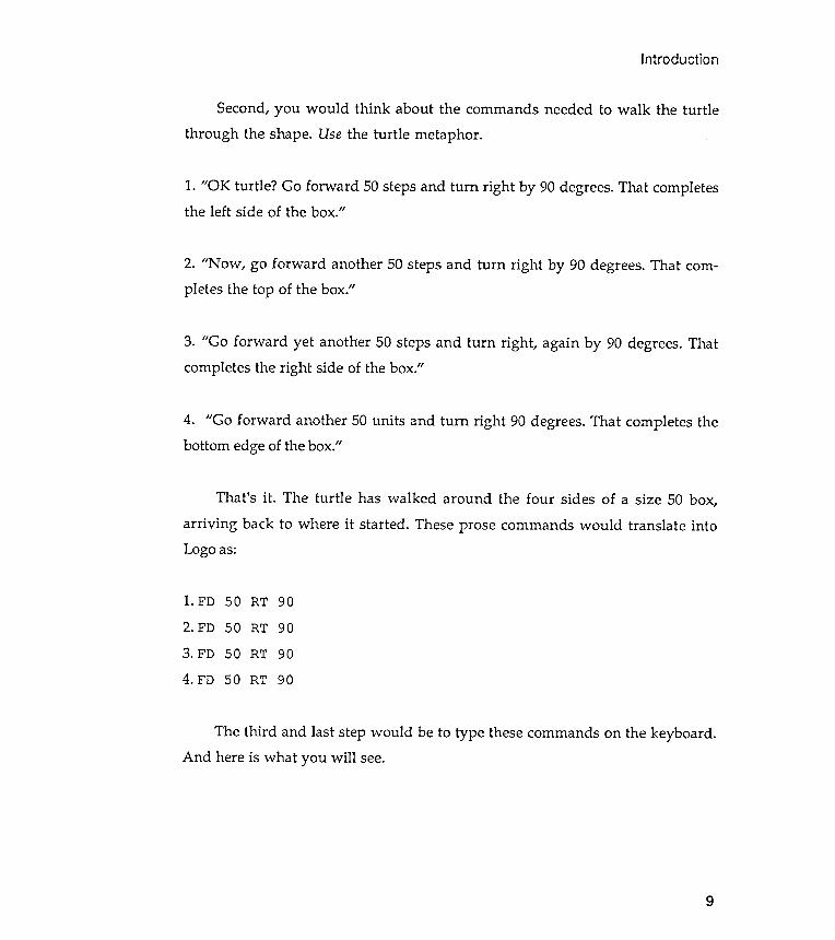
That 's it . The turtle has walked around the four sides of a size 50 box,arriving back to where it started . These prose commands would translate intoLogo as:
1. FD 50 RT 902. FD 50 RT 903. FD 50 RT 904. FD 50 RT 90
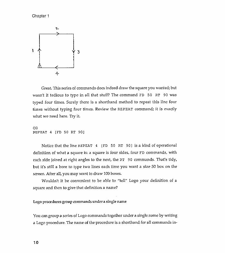
The third and last step would be to type these commands on the keyboard .And here is what you will see.
9
Chapter 1
" 2-
J
4-
,
10
Great . This series of commands does indeed draw the square you wanted ; but
wasn 't it tedious to type in all that stuff ? The command FD 50 RT 90 was
typed four times . Surely there is a shorthand method to repeat this line fourtimes without typing four times . Review the REPEAT command ; it is exactlyw ha t we need here. Try it .
CG
REPEAT 4 [ FD 50 RT 90 ]
Notice that the line REPEAT 4 [FD 50 RT 90 ] is a kind of operational
definition of what a square is : a square is four sides , four FD commands , with
each side joined at right angles to the next, the RT 90 commands . That 's tidy ,but it 's still a bore to type two lines each time you want a size 50 box on the
screen . After all , you may want to draw 100 boxes .
Wouldn 't it be convenient to be able to " tell " Logo your definition of a
square and then to give that definition a name ?
Logo procedures group commands under a single name
You can group a series of Logo commands together under a single name by writinga Logo procedure . The name of the procedure is a shorthand for all commands in-
defined
Introduction
cluded in it . Typing the name of the procedure tells Logo to automatically
execute each line of the procedure in turn , just as if you had typed them , one after
another , on the keyboard .
You can " tell " Logo your definition of a square by creating a procedure
called SQUARE. Logo will " remember " your definition until you either erase it or
turn off your computer .
Review the defining and editing procedures in your Logo manual .
Shapes . and drawn by procedures
Let 's get on with writing the necessary procedure . Here it is :
[FD 50 RT 90]
REPEAT 25 [PD BOX50 PU RT 15 FD 60 LT 15 ]
11
END
Logo will add BOXSO to all its other commands . Each time you type BOXSO, the
turtle will draw a square of size 50. The figure will be drawn at the turtle 's cur-
rent position on the screen . Unless you move the turtle to a different starting
point , each time you type BOXSO, the square produced will be on top of thepreviously drawn figure . So move the turtle around to new positions and drawsome more boxes .
But you can certainly be more imaginative than that . Create an interestingdesign on the screen using only the BOXSO procedure and move commands. If youhave a color screen, you might want to investigate the effects of changing thescreen's background color and the color of the pen. Keep track of what you aredoing in your notebook so that you can reconstruct your successful designs.
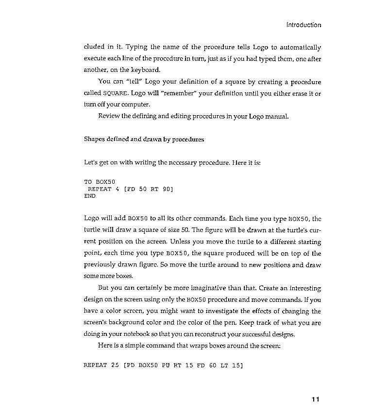
Here is a simple command that wraps boxes around the screen:
TO BOXSOREPEAT 4
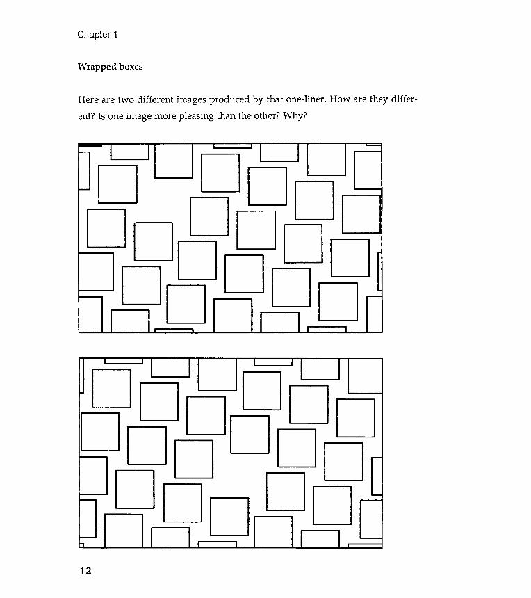
Here are two different images produced by that one -liner . How are they differ -
ent ? Is one image more pleasing than the other ? Why ?
Chapter 1
Wrapped boxes
12
Introduction
Generalizing procedures
Adding an argument to a procedure
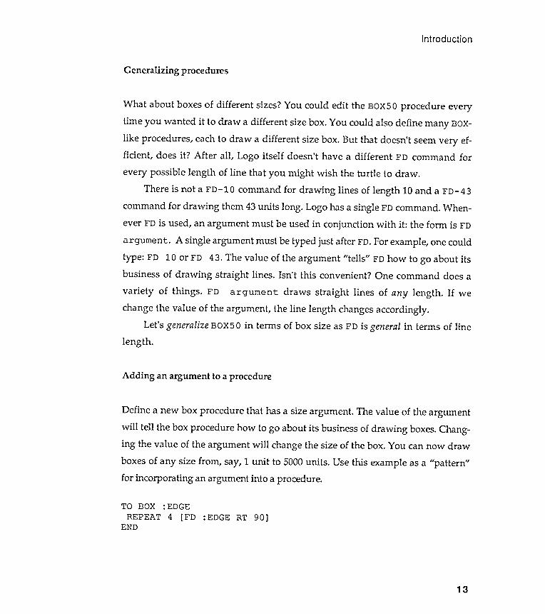
Define a new box procedure that has a size argument . The value of the argumentwill tell the box procedure how to go about its business of drawing boxes. Chang-ing the value of the argument will change the size of the box. You can now draw
boxes of any size from , say, 1 unit to 5000 units . Use this example as a "pattern "for incorporating an argument into a procedure.
TO BOX : EDGEREPEAT 4 [FD :EDGE RT 90]
13
END
What about boxes of different sizes? You could edit the BOX5 0 procedure everytime you wanted it to draw a different size box. You could also define many BOX-like procedures, each to draw a different size box. But that doesn't seem very ef-ficient , does it ? After all , Logo itself doesn't have a different FD command forevery possible length of line that you might wish the turtle to draw .
There is not a FD- 1O command for drawing lines of length 10 and a FD- 43command for drawing them 43 units long . Logo has a single FD command . When-ever FD is used, an argument must be used in conjunction with it : the form is FD
argument . A single argument must be typed just after FD. For example, one couldtype: FD 10 or FD 43. The value of the argument " tells" FD how to go about itsbusiness of drawing straight lines. Isn't this convenient ? One command does a
variety of things . FD argument draws straight lines of any length . If wechange the value of the argument , the line length changes accordingly .
Let's generalize BOX5 0 in terms of box size as FD is general in terms of linelength .
Putting a demonsuation procedure together
Chapter 1
I am sure that by this time you have already designed some interesting patternswith various BOX procedures. Some of these patterns you probably liked enoughto print and glue into your notebook. Remember to include a few written commentson what you were trying to achieve.
Perhaps you would like to show off your designs. You could show your palsthe images in your notebook . But seeing an image is not the same as seeing howthe image is drawn , the order in which the pieces are visually assembled. Howwould you go about demonstrating this? You could retype all the Logo commandsneeded for your screen collage. What else could you do?
Remember that Logo procedures can group a series of commands togetherunder one name. So let 's define a new Logo procedure that will run all thenecessary steps to demonstrate your design. Once defined , you will only have totype the demonstration procedure 's name to have your designs redrawn on thescreen. Your demonstration procedure will have no arguments; it will only do onething : generate a specific design that you want to show to your friends . If youwish to show off with several designs, you could design specific Logo proceduresto reproduce each design.
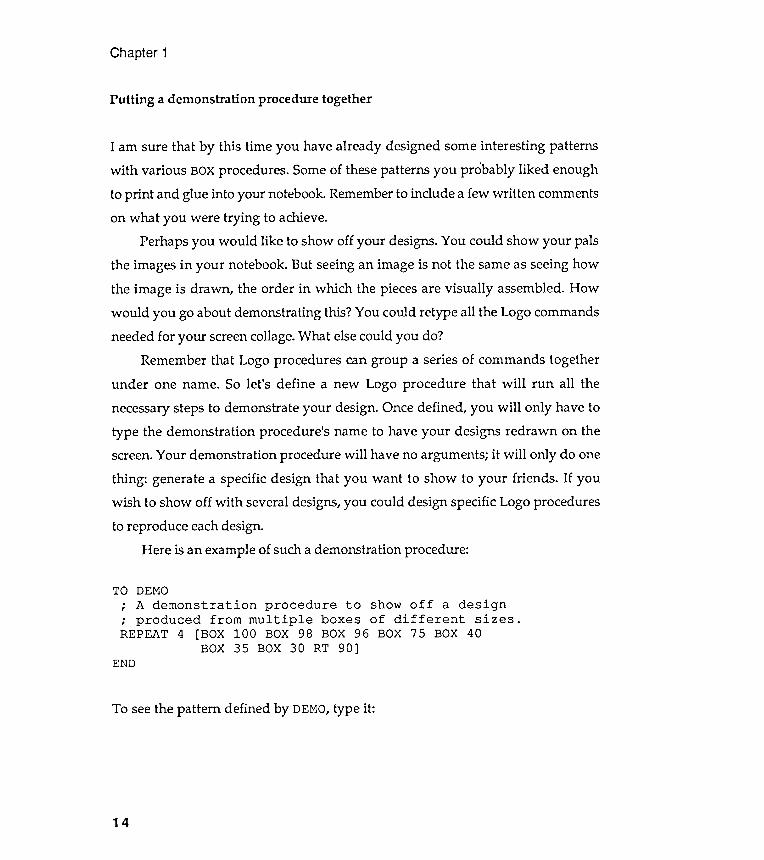
Here is an example of such a demonstration procedure :
END
To see the pattern defined by DEMO, type it :
14
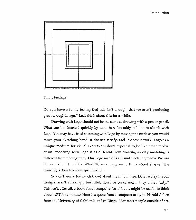
TO DEMO; A demonstration procedure to show off a design; produced from multiple boxes of different sizes .REPEAT 4 [BOX 100 BOX 98 BOX 96 BOX 75 BOX 40
BOX 35 BOX 30 RT 90]
Funny feelings
Introduction
Do you have a funny feeling that this isn't enough, that we aren't producinggreat enough images? Let's think about this for a while .
Drawing with Logo should not be the same as drawing with a pen or pencil .What can be sketched quickly by hand is unbearably tedious to sketch withLogo. You may have tried sketching with Logo by moving the turtle as you wouldmove your sketching hand . It doesn't satisfy , and it doesn't work . Logo is aunique medium for visual expression; don 't expect it to , be like other media .Visual modeling with Logo is as different from drawing as clay modeling isdifferent from photography . Our Logo media is a visual modeling media . We useit best to build models . Why ? To encourage us to think about shapes. Thedrawing is done to encourage thinking .
So don 't worry too much (now ) about the final image. Don 't worry if yourdesigns aren't amazingly beautiful ; don 't be concerned if they aren't "arty ."This isn't, after all , a book about computer "art ," but it might be useful to thinkabout ART for a minute . Here is a quote from a computer art type, Harold Cohenfrom the University of California at San Diego: "For most people outside of art ,
15

Chapter 1
16
probably , art is directed primarily at the production of beautiful objects and
interesting images ; and who is to argue that a complicated Lissajou figure is less
beautiful than an Elsworth Kelly painting or a Jackson Pollock ; or that a
machine simulation of Mondrian is less interesting than the original it
plagiarizes ? To talk of beauty or of interest is to talk of taste , and matters of
taste cannot be argued with much profit . The fact is that art is not , and never
has been , concerned primarily with the making of beautiful or interesting
patterns . The real power , the real magic , which remains still in the hands of
the elite , rests not in the making of images , but in the conjuring of meaning ."
A little professorial , this . But do you think he has a point ?
Go back to your demonstration procedures , the ones that have no arguments
so they do only one thing . A procedure that does only one thing is like a box
drawing procedure that draws only one size of box . One box doesn 't encourage
much thinking about the nature of boxes , does it ? Can you use your demonstration
procedures to explore the nature of a collage that intrigues you ? Play around
with the collage demonstration procedure that draws it . Tinker a bit .
Maybe you could generalize the demonstration procedure by adding an
argument . To generalize a procedure is to stretch your thinking about what it
does ; and that 's our appropriate work , too , because it respects the uniqueness of
the Logo art medium . " It 's the tinkering that counts , not the artiness ." Pin that
phrase over your computer screen .
Generalizing a procedure with arguments
Let 's go back to that BOX procedure . Can we generalize it so that it draws
triangle " boxes " as well as square ones? While we are at it , let 's ask BOX to draw
boxes with any number of equal sides . These shapes will be regular polygons
with n sides . Why not call the generalized procedure NGON for n-sided polygon ?
Look again at the procedure BOX and decide what needs to be changed to turnBOX into NGON.
Introduction
TO BOX :EDGEREPEAT 4 [FD :EDGE RT 90]
END
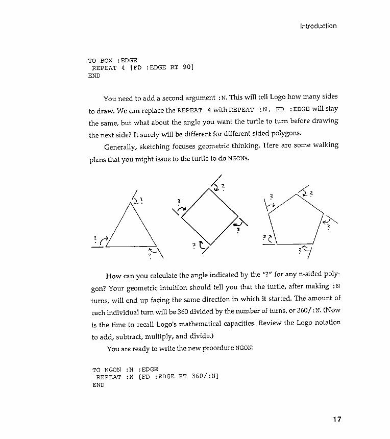
plans that you might issue to the turtle to do NGONs.
7. ~ 2
\ A~
.
1 '1
- \
<.
!
TO NGON :N :EDGEREPEAT :N [FD :EDGE RT 360/ :N]
17
END
You need to add a second argument : N. This will tell Logo how many sidesto draw. We can replace the REPEAT 4 with REPEAT: N. FD : EDGE will staythe same, but what about the angle you want the turtle to turn before drawingthe next side? It surely will be different for different sided polygons.
Generally, sketching focuses geometric thinking . Here are some walking
How can you calculate the angle indicated by the "?" for any n-sided poly -
gon? Your geometric intuition should tell you that the turtle , after making : Nturns , will end up facing the same direction in which it started . The amount ofeach individual turn will be 360 divided by the number of turns , or 360/ : N. (Now
is the time to recall Logo 's mathematical capacities. Review the Logo notationto add , subtract , multiply , and divide .)
You are ready to write the new procedure NGON:

Chapter 1
Try it out . Notice that when : N becomes large , the drawn figure becomes a
circle (almost ). Carry out some clever visual experiments with NGONs.
Some observations
Making the simple more complete
What next? How can we make these simple polygons more interesting ? Maybewe can add another polygon characteristic to NGON.
Sometime in your life you were probably given an exercise like the follow -ing . "Cut out some different sized squares from a sheet of colored paper and thinkabout placing the squares on a large piece of white paper . First , try to arrangethe squares so that your design feels unbalanced and looks wonky . Next ,rearrange the squares to create a balanced design."
What kinds of changes did you make? What about creating an arrangementthat looks sad and another that looks euphoric ? Each design used the same
squares. What made them different ? Their placement .Make NGON draw a bunch of NGONs and put them on the screen according to
some placement rule . Take out your notebook and doodle . Here are some resultsfrom my doodling . Your approach will be different . I 'll explain mine , and I 'llexpect that your plans will go into your notebook.
18
Look back carefully at what we have done so far with procedure writing . Westarted with a list of commands that drew a box of a single size. Next , wegrouped these commands into procedures that could draw boxes of severaldifferent sizes. Next , we generalized the BOX procedure with an argument sothat it could draw boxes of any size. Finally , we produced a still more generalprocedure , NGON, that can draw any regular , polygonal "box" - triangles ,squares, pentagons, hexagons, and so on- of whatever size we wanted .
(r.G, -r-"JC::r SMA Ll . En-
Introduction
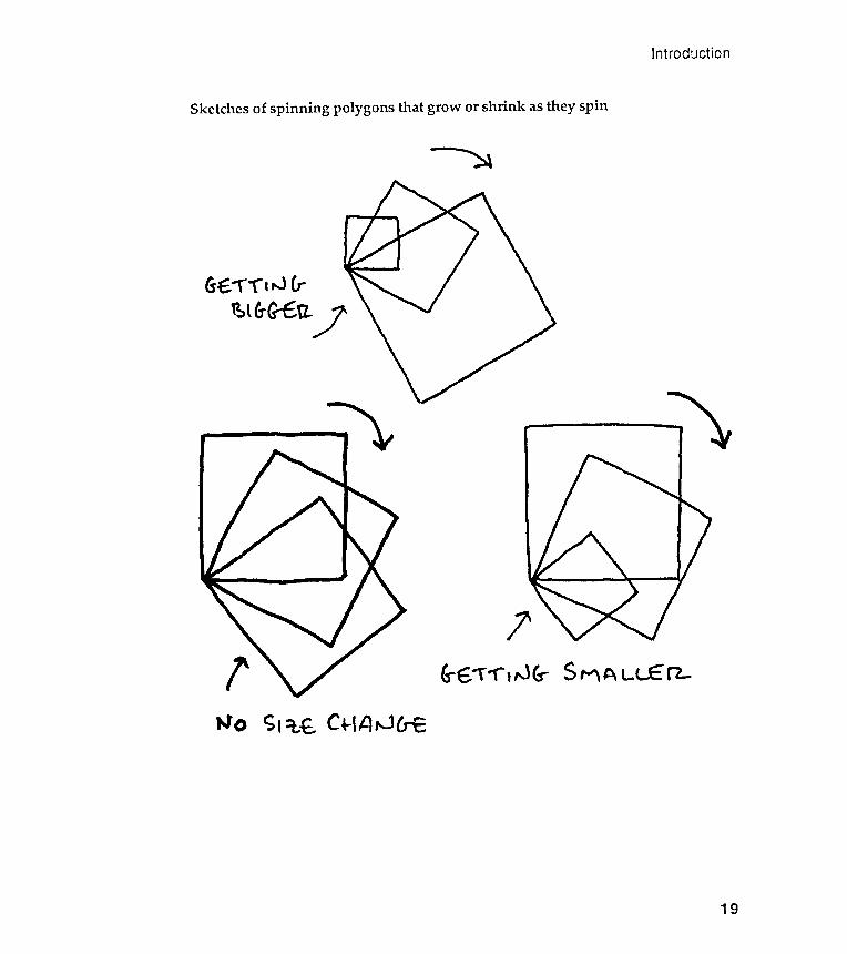
Sketches of spinning polygons that grow or shrink as they spin
- - _..~~ ~
/
l'
S I =iit C+-, p, ~ CrE
19
(s :e ..,.. "'('", ,.J (,.~ l (,. G--c: 12.
Word description of sketched ideas
Chapter 1
90% shrinkage I would use : GROWTH = .9."
A procedure to spin polygons
Will SP INGON ever stop? Try it out .
20
" I want Logo to draw a series of polygons rotating around a common point , and Iwant each successive polygon to get bigger, or maybe get smaller .
" I don 't know what angle to turn between one polygon and the next, so I 'llinclude an argument called : ANGLE that I can vary , to see what happens.
"1 don 't know how big the growth should be between one polygon and thenext, so I 'll define another argument called : GROWTH. I 'll play with differentvalues of : GROWTH to see what looks best.
"How do I make : GROWTH work ? Growth can be of two sorts: growth by aconstant amount , or growth by a constant percentage. I 'll try the latter . Thatmeans that if I want polygons to grow by 10%, I define : GROWTH to be 1.10. For a
TO SPINGON :N : EDGE :ANGLE : GROWTHNGON :N : EDGERT :ANGLESPINGON :N ( : EDGE* : GROWTH) :ANGLE : GROWTH; Here is the recursion .
END
What is new here? First , there are more arguments than you have seenbefore. Every time you use SPINGON, you must remember to type four numbersafter it . Second, this procedure is recursive : the last line in the S PI NGON
procedure asks that SPINGON be done again, but with some arguments changed.For example, ( : EDGE) becomes ( : EDGE* : GROWTH) the first time recursion iscalled; and then ( : EDGE* : GROWTH) becomes ( : EDGE* : GROWTH) * : GROWTH the
second time recursion is called. A recursive procedure is a procedure that usesitself as one of its parts .
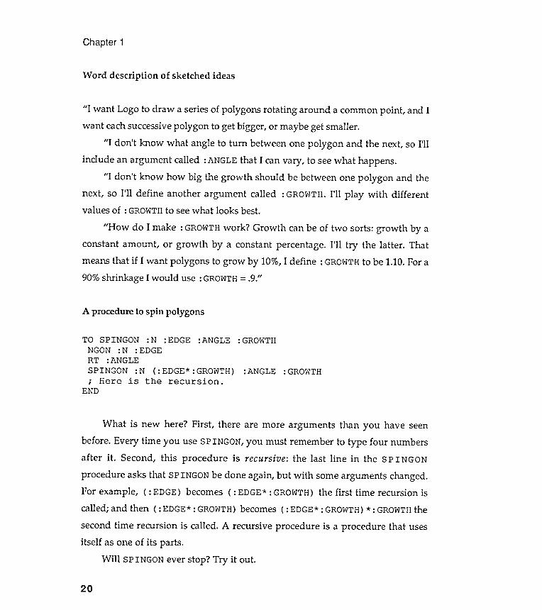
HOME CG REPEAT 3SPINGON 4 120 0
Introduction
Some spingons
SPINGON 30 2 10 1. 02 95
. 95 50 RT 90][SPINGON 4 120 0. 95 19
21
Chapter 1
Stopping recursive procedures
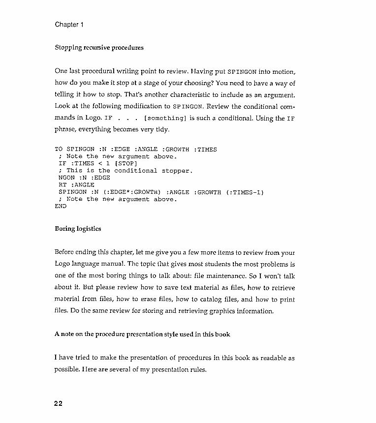
One last procedural writing point to review . Having put SPINGON into motion ,
how do you make it stop at a stage of your choosing? You need to have a way oftelling it how to stop . That 's another characteristic to include as an argument .Look at the following modification to SPINGON. Review the conditional com-
mands in Logo. IF . . . [ something ] is such a conditional . Using the IFphrase, everything becomes very tidy .
A note on the procedure presentation style used in this book
I have tried to make the presentation of procedures in this book as readable as
possible . Here are several of my presentation rules .
22
TO SPINGON : N : EDGE : ANGLE : GROWTH : TIMES
; Note the new argument above .
IF : TIMES < 1 [ STOP ]
; This is the conditional stopper .NGON : N : EDGE
RT : ANGLE
SPINGON : N ( : EDGE * : GROWTH ) : ANGLE : GROWTH ( : TIMES - l )
; Note the new argument above .END
Boring logistics
Before ending this chapter , let me give you a few more items to review from your
Logo language manual . The topic that gives most students the most problems is
one of the most boring things to talk about : file maintenance . So I won ' t talk
about it . But please review how to save text material as files , how to retrieve
material from files , how to erase files , how to catalog files , and how to print
files . Do the same review for storing and retrieving graphics information .

Third , the body structuring rule . Procedures should be laid out nicely on the
page without too much information on anyone line . Long procedure statements
should be divided up between lines to make them more readable . The special
character " - " is used to indicate when a single Logo statement has been
continued from one line to the next . Here is an example . Notice that the Logo
material within the [repeat brackets ] would have been difficult to read if the
long statement had not been divided into several short lines .
Introduction
RT :ANGLESPINGON : N ( : EDGE* : GROWTH) :ANGLE : GROWTH ( :TIMES- l ); Note the new argument above .
END
00t:r:1~
hj~hj~
~o-C:jHo-C:j
H
: B : N: A130: A50
: B ]END
23
TO SQUIGGLEREPEAT :N [
First, the many comments rule . I have included wordy explanations in someof my procedures. These comments begin with the Logo command " ; " . There is, of
course, no need for you to include these comments in your own version of my proce-dures. However , it is a good idea for you to put comments in your own procedures.
Second, the meaningful cluster rule . I often include extra parentheses togroup like elements into a cluster. This is useful , for example, when an argumentis composed of a collection of Logo material , but you want to see it as a singlecluster of information . Here is an example from this chapter. Notice the use ofcomments, too.
TO SPINGON :N : EDGE :ANGLE : GROWTH : TIMES; Note the new argument above .IF : TIMES < 1 [ STOP]; This is the conditional stopper .NGON : N : EDGE
-
-
-
-
The symbol " - " indicates, of course, that the return key should not be usedbecause the Logo statement continues. Consult your ov-m Logo manual for handlingthe problem of procedure layout .
Chapter 1
Exercises
Exercise 1.1
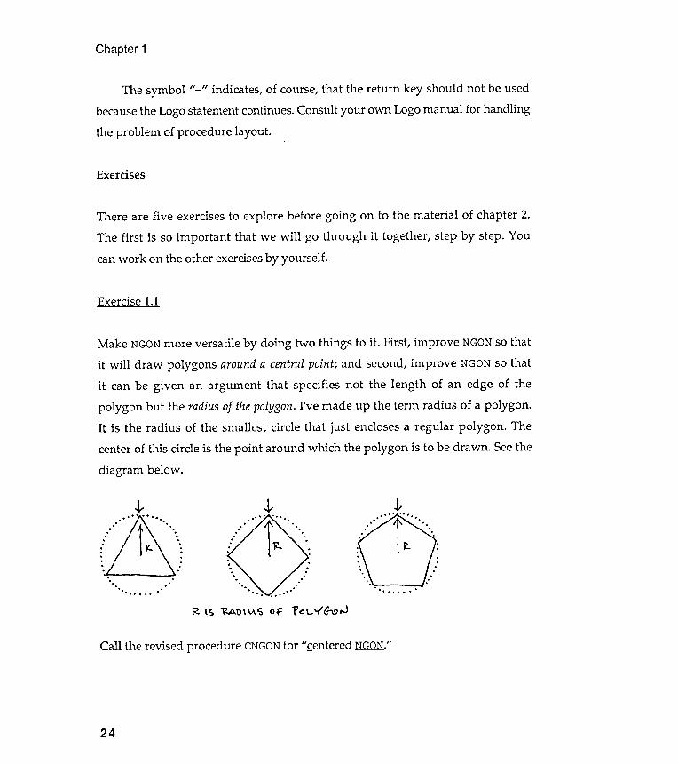
Make NGON more versatile by doing two things to it . First, improve NGON so thatit will draw polygons around a central point; and second, improve NGON so thatit can be given an argument that specifies not the length of an edge of thepolygon but the radius of the polygon. I' ve made up the term radius of a polygon .It is the radius of the smallest circle that just encloses a regular polygon . Thecenter of this circle is the point around which the polygon is to be drawn . See the
diagram below .
~
R lS ~ t>\ ~ S 0 ;:: 1' ~ l...vG-l.?, J
t. " " ' 0
. fr..o. ' . " . '
.J,.
. . .
. .
. .
. .
. .
. .
. .
. .
. .
. .
. .
. .
. .
' " . .
. . . . . . '
Call the revised procedure CNGON for " entered NGON./I
24
There are five exercises to explore before going on to the material of chapter 2.The first is so important that we will go through it together , step by step. Youcan work on the other exercises by yourself .
Diagram A: Getting read~ to draw the ~ol~gon.
Introduction
Two hints : First , ask yourself what arguments CNGON will need. This isanother way to ask yourself what information must be given to CNGON so that itcan go about its business of drawing centered NGONs. CNGON needs only two piecesof information , or two arguments: the number of sides of the polygon to be drawnand the radius of that polygon . That means that the first line of the newprocedure will look like this :
CNGON :N :RAD
Second, imagine yourself as the turtle . How would you walk through the designthat CNGON must make? Draw a simple diagram to describe such a " turtlewalk ." You might want to divide the diagram up into individual scenes. Lateryou can translate each scene in words and then into Logo notation . Here is thefirst instance where this turtle visualization is really needed. Let yourself go;talk out loud ; get on with it without too much thinking .
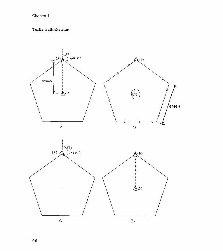
Word description of the turtle walk (see sketches on next page)
You, as the turtle , begin your journey from position (1), the center of the proposedpolygon . You are facing straight up .
Pick up your pen and move forward by the amount of the polygon 's radius .This is : RAD. This puts you in position (2).
You now need to turn right by an amount that is labeled (angle) on thesketch (3). What will (angle ) be related to? Will (angle ) be different fordifferently shaped polygons , that is, polygons with different numbers of sides?Yes. Will (angle) be related to the overall size of polygons ? No . Don 't worryabout how to calculate (angle), yet; you can work that out later .
25
Turtle walk sketches
Chapter 1
.
.
: ( 3 ).
.
.
.
.
.
.
.
~ A \) II .I.~ :.
.
.
.
.
e
A ::B
tt:~ (+). ~ ) AIIJ6-tE ~
.
(b)
~ c..~)
, ] )c
26
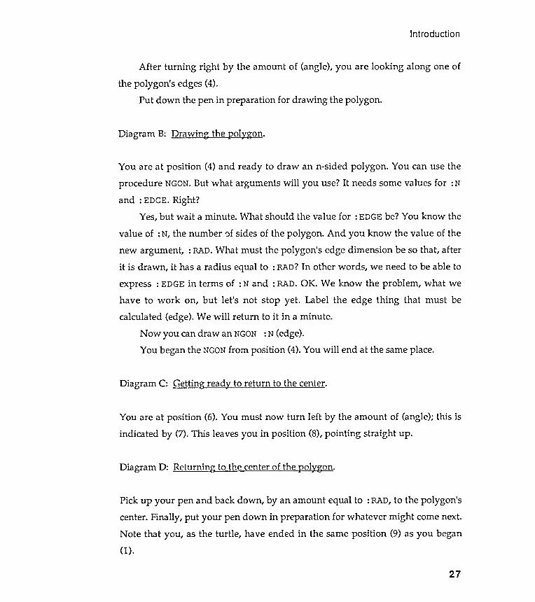
Diagram C: Getting read~ to return to the center.
Diagram D: Returning to the center of the ~ol~gon.
Introduction
You are at position (6). You must now turn left by the amount of (angle); this isindicated by (7). This leaves you in position (8), pointing straight up .
Pick up your pen and back down, by an amount equal to : RAD, to the polygon'scenter. Finally, put your pen down in preparation for whatever might come next.Note that you, as the turtle, have ended in the same position (9) as you began(1).
27
After turning right by the amount of (angle), you are looking along one ofthe polygon 's edges (4).
Put down the pen in preparation for drawing the polygon .
Diagram B: Drawing the I2o1~gon.
You are at position (4) and ready to draw an n-sided polygon . You can use theprocedure NGON. But what arguments will you use? It needs some values for : Nand : EDGE. Right?
Yes , but wait a minute . What should the value for : EDGE be ? You know the
value of : N, the number ')f sides of the polygon . And you know the value of thenew argument , : RAD. What must the polygon 's edge dimension be so that, afterit is drawn , it has a radius equal to : RAD? In other words , we need to be able toexpress : EDGE in terms of : Nand : RAD. OK. We know the problem , what wehave to work on, but let 's not stop yet . Label the edge thing that must becalculated (edge). We will return to it in a minute .
Now you can draw an NGON : N (edge).You began the NGON from position (4). You will end at the same place.
Chapter 1
A turtle walk transfonned into a Logo procedure (almost )
No more words are necessary. Here it is.
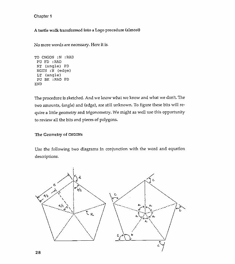
The procedure is sketched. And we know what we know and what we don't. Thetwo amounts, (angle) and (edge), are still unknown . To figure these bits will re-quire a little geometry and trigonometry . We might as well use this opportunityto review all the bits and pieces of polygons .
The Geometry of CNGONs
with the word and equationUse the following two diagrams in conjunctiondescriptions .
,
.
.
.
/ ' :: ! ~ d.-e ~~ /2.- 6 ~\ :/ - " :
\ .
e/ 2. ' : . ..\ , . . .. . ., ' . 'f . . .6. , ' 2. . . . .
.-...-. ~ \ . .'t.. . ' . . . .
- " . " , - . . ' D. ' . . ' . . Iv
- - . ., .
. - -, .
, .
, .
- . .
. .
. .
. - .
. .
- . .
. .. .
. . .
. ,
. ,
. . .- .
' .
.
-
,
,
k:..
.
.
..
.
.
.
.
.
.
.
.
.
. . '." " ,., D.,~ :~ o... . ...., ~~. . . . '
' . . . '
" . . . . ' , .. . . . . v
' . . . '
. \"'..*.' ..' 7'Q.. .' ' .. .tIt' ~. r " ~ .
. ' - - ' .. .
, IJ.., '. .
. .
. .
. .
. ' .. .
. .
. .
. .
" " ...
c.128
TO CNGON :N :RADPU FD : RADRT (angle ) PDNGON :N (edge )LT (angle )PU BK :RAD PD
END
The first problem we face is to find an expression for angle d in terms of n ,
the number of sides of the polygon . The second problem is to find an expression
for the length of a polygon 's edge , e, in terms of its radius , R, and n, the number ofsides .
In preparation for these two acts , let 's look at all the angles associated
with polygons . The central angles, labeled a, are easy . They are each equal to
360/ n . The external angles, labeled c, are also equal to 360 / n . The external angle
is the turning angle used in NGON. What about the internal angles , labeled b . Weneed some work here :
Introduction
(1) c = 360jn,(2) c + b = 180.
29
Putting (7) and (6) together and solving for e gives
:? Draw some diagramsarctangenton the inside cover of your notebook.
geometryInstalling
Chapter 1
(8) e = 2*R*sin (180/ n) <---Second l2roblern solved.
Review the following trig functions : sine , cosine , and tangent . What is an
to explain each of these functions . Glue them
into CNGONthe necessary
Here's how far we have gotten with CNGON:
Now we can replace (angle ) and (edge ) with the needed expressions .Here is the finished CNGON:
30
TO CNGON :N :RADPU FD :RADRT (angle ) PDNGON :N (edge )LT (angle )PU BK : RAD PD
END
TO CNGON :N :RADPU FD : RADRT 180 - (90* ( : N- 2) / : N) PDNGON :N (2* :RAD* SIN (180 / :N LT 180 - (90* ( :N- 2 ) / :N)PU BK :RAD PD
END
Introduction
31
Lessons and tips
When solving visual problems , like this CNGON thing , try to break the single big
problem down into several smaller problems . Solve each of the small problems
in turn , and then plug the little solutions together to form one big solution .
Exercise 1 . 2
Put together one or more DEMO procedures that make imaginative use of the
ideas presented and reviewed in this chapter . Modify every procedure in the
chapter . Make them act more strangely .
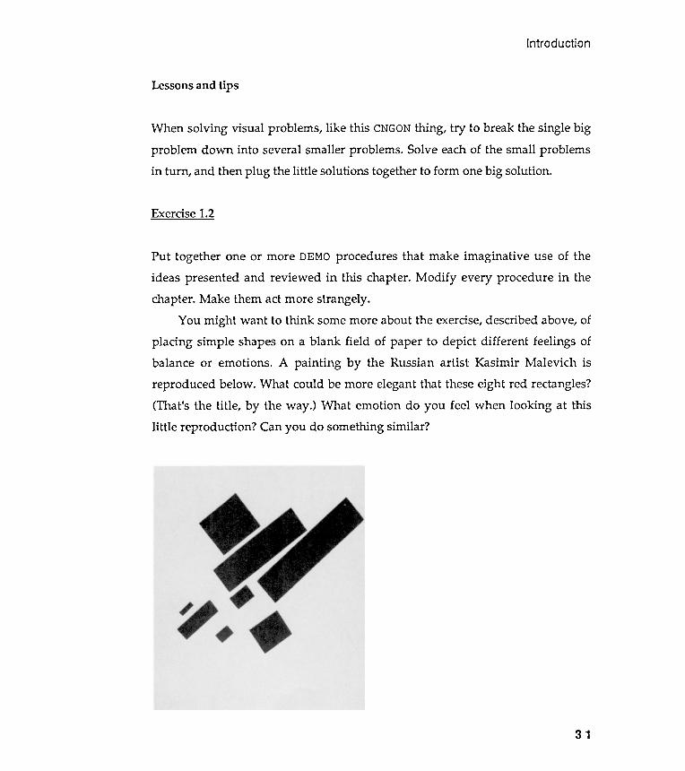
You might want to think some more about the exercise , described above , of
placing simple shapes on a blank field of paper to depict different feelings of
balance or emotions . A painting by the Russian artist Kasimir Malevich is
reproduced below . What could be more elegant that these eight red rectangles ?
( That ' s the title , by the way . ) What emotion do you feel when looking at this
little reproduction ? Can you do something similar ?
Chapter 1
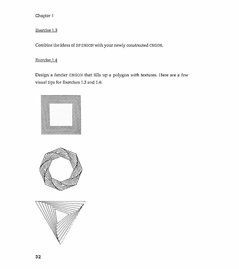
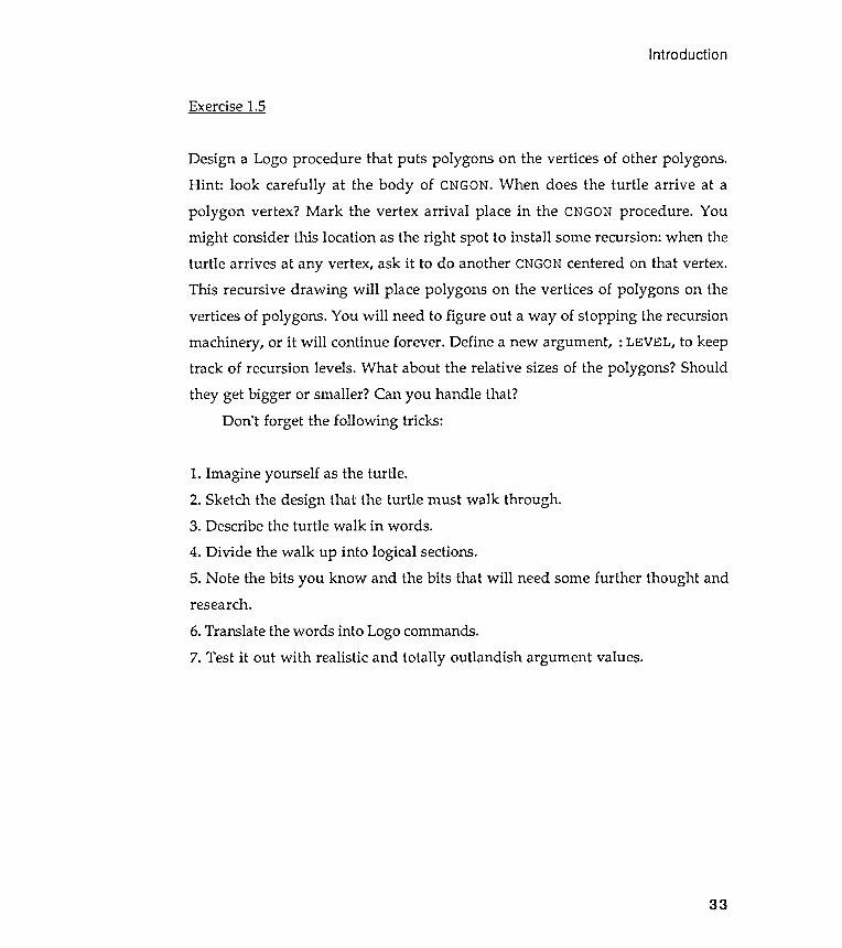
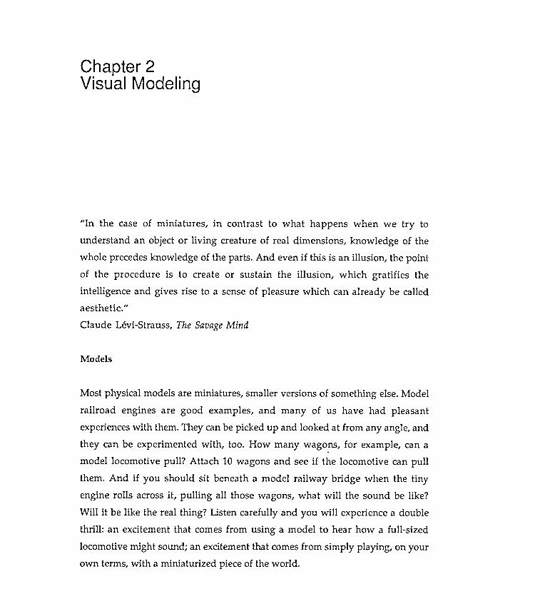
Exercise 1.3
Combine the ideas of SPINGON with your newly constructed CNGON.
Exercise 1.4
Design a fancier CNGON that fills up a polygon with textures. Here are a fewvisual tips for Exercises 1.3 and 1.4:
32
6. Translate the words into Logo commands .
Introduction
Exercise 1.5
1. Imagine yourself as the turtle .
research .
7. Test it out with realistic and totally outlandish argument values.
33
Design a Logo procedure that puts polygons on the vertices of other polygons .Hint : look carefully at the body of CNGON. When does the turtle arrive at apolygon vertex ? Mark the vertex arrival place in the CNGON procedure . Youmight consider this location as the right spot to install some recursion : when theturtle arrives at any vertex, ask it to do another CNGON centered on that vertex .This recursive drawing will place polygons on the vertices of polygons on thevertices of polygons . You will need to figure out a way of stopping the recursionmachinery , or it will continue forever . Define a new argument , : LEVEL, to keeptrack of recursion levels. What about the relative sizes of the polygons ? Shouldthey get bigger or smaller? Can you handle that?
Don 't forget the following tricks :
2. Sketch the design that the turtle must walk through .3. Describe the turtle walk in words .
4. Divide the walk up into logical sections .
5. Note the bits you know and the bits that will need some further thought and
Chapter 2Visual Modeling
Models
Most physical models are miniatures , smaller versions of something else. Modelrailroad engines are good examples , and many of us have had pleasantexperiences with them. They can be picked up and looked at from any angle, andthey can be experimented with , too. How many wagons , for example, can amodel locomotive pull ? Attach 10 wagons and see if the locomotive can pullthem . And if you should sit beneath a model railway bridge when the tinyengine rolls across it , pulling all those wagons, what will the sound be like ?Will it be like the real thing ? Listen carefully and you will experience a doublethrill : an excitement that comes from using a model to hear how a full -sized
locomotive might sound; an excitement that comes from simply playing , on yourown terms, with a miniaturized piece of the world .
" In the case of miniatures , in contrast to what happens when we try tounderstand an object or living creature of real dimensions , knowledge of thewhole precedes knowledge of the parts . And even if this is an illusion , the pointof the procedure is to create or sustain the illusion , which gratifies theintelligence and gives rise to a sense of pleasure which can already be calleda es the tic ."
Claude Levi -Strauss, The Savage Mind
Visual Modeling
35
I believe that this kind of play , because it encourages us to look more
closely at our world , is very useful enjoyment . In addition , I am convinced that
the clarity of vision developed by such play is best pursued by involving
ourselves , not in just the manipulation of models but in their design and
construction as well .
This book is about a special kind of modeling that explores patterns and
visual images . Sometimes we will create designs using visual models of
machines that are very much from the real world . Other times , images will be
produced by more abstract or imaginary machinery . All our models though ,
whatever they represent , will be constructed from Logo procedures . Logo is the
raw material , but this book is not about Logo . In fact , you must try hard not to let
Logo get in the way of your model building craft . Models first . OK ?
OK . No more introduction . Let ' s build an image - producing machine using
Logo . But first . . .
An important pause in the narrative
What comes next requires that you have a fair understanding of the Logo
language . But what , you ask , does fair mean ? If you haven ' t yet looked at the
material in Chapter 1 , now is the time . Chapter 1 will let you compare your
current knowledge of Logo mechanics with what you will need to build the
visual model described in the next section . Don ' t just scan Chapter 1 ; go through
the examples in the text , and try out the exercises at the chapter ' s end .
Even if you already know some Logo , a review probably would be helpful .
Chapter 1 describes much of the geometry and trigonometry used throughout the
book , so now is a good time to review that material . Try to apply some geometry
to a few of my exercises . In addition , Chapter 1 will introduce you to my Logo -
talking style ; maybe you should get used to that style right away . Be sure to
spend some time working on the centered polygon assignment . This exercise com -
bines a review of Logo , the introduction of turtle walks , and simple geometry .
Chapter 2
Go back and take at peek at Chapter 1 right now . Have a good read andtake your time with it . If you are a real Logo high -flier , test your flair by doingthe exercises at the end of Chapter I , before you glance through the hints giventhere. After having a go at these problems, compare your Logo style with mine .
On to modeling
I have decided to begin this work with something concrete , something selected
from the world of things . We can do some abstract modeling of ideas or emotions
later on . The example that follows is a description of a device that I vaguely
remember seeing described in an old Scientific American magazine . I 've called it
a pipe - and -roller machine . I never built the thing , but I always wanted to seehow it worked .
Pipes and rollers
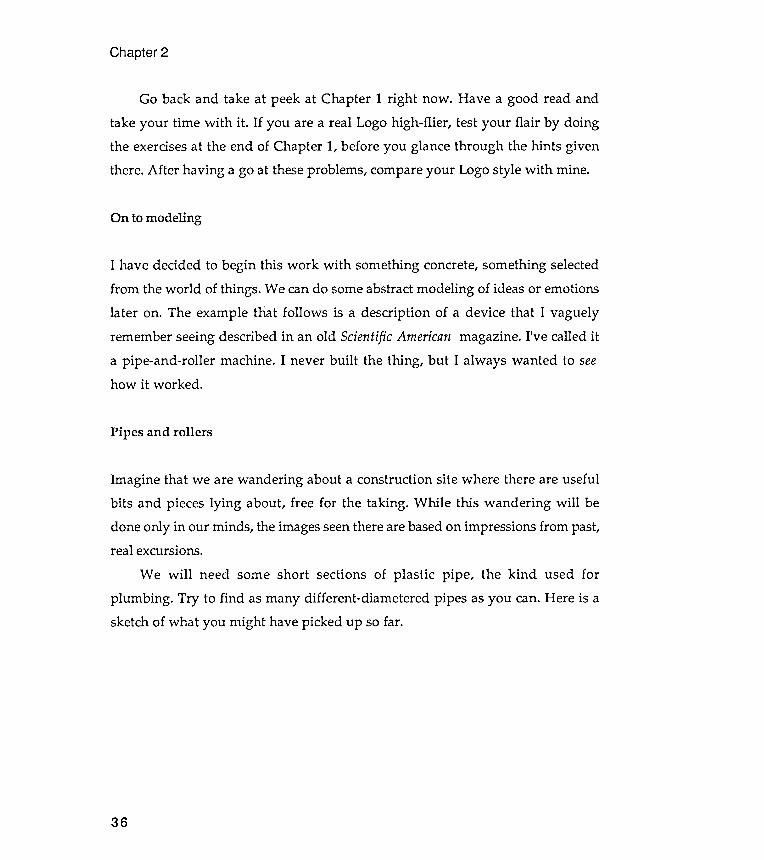
Imagine that we are wandering about a construction site where there are usefulbits and pieces lying about , free for the taking . While this wandering will bedone only in our minds , the images seen there are based on impressions from past,real excursions.
We will need some short sections of plastic pipe , the kind used forplumbing . Try to find as many different -diametered pipes as you can. Here is asketch of what you might have picked up so far.
36

Assemblin
Visual Modeling
Next , let 's assemble a collection of wooden dowels of various diameters ,
from very small diameters to very large ones . Dowels , or rounded wooden pegs ,
are used to join together adjacent parts by fitting tightly into two corresponding
holes . Dowels are used by cabinetmakers to assemble fine pieces of furniture
when nails or screws would be unsightly ; and large dowel -pegs are still used to
fit together wooden beams when aesthetics are more important than cost . Call
the dowels that you have assembled " rollers " ; you will see why in just a minute .
Here is a sketch of my dowel collection . (Sketches are models , too .) 19 the pipe -and-roller machine
Now , imagine that one section of pipe is floating in the air at eye level ; one endof the pipe is clearly visible to us, and the pipe 's length is parallel to the
37
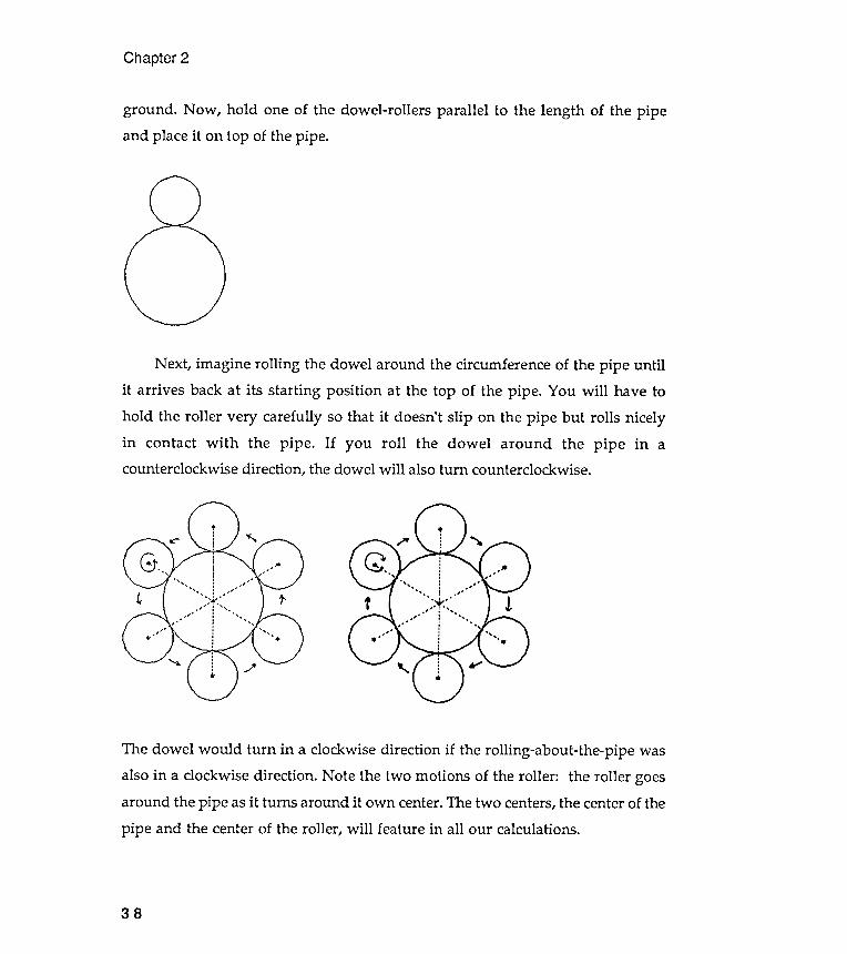
Next , imagine rolling the dowel around the circumference of the pipe untilit arrives back at its starting position at the top of the pipe . You will have to
hold the roller very carefully so that it doesn't slip on the pipe but rolls nicelyin contact with the pipe . If you roll the dowel around the pipe in acounterclockwise direction , the dowel will also turn counterclockwise .
The dowel would turn in a clockwise direction if the rolling -about -the- pipe was
also in a clockwise direction . Note the two motions of the roller : the roller goes
around the pipe as it turns around it own center . The two centers , the center of the
pipe and the center of the roller , will feature in all our calculations .
Chapter 2
ground . Now , hold one of the dowel -rollers parallel to the length of the pipeand place it on top of the pipe .
- ' -
38
" ' , . . "
Visual Modeling
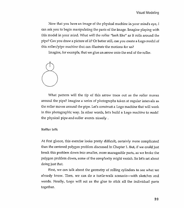
Now that you have an image of the physical machine in your mind 's eye, Ican ask you to begin manipulating the parts of the image. Imagine playing withthis model in your mind . What will the roller " look like " as it rolls around thepipe ? Can you draw a picture of it ? Or better still , can you create a Logo model ofthis roller / pipe machine that can illustrate the motions for us?
Imagine , for example, that we glue an arrow onto the end of the roller .
Roller talk
At first glance , this exercise looks pretty difficult .! certainly more complicated
than the centered polygon problem discussed in Chapter 1. But , if we could just
break this problem down into smaller , more manageable parts , as we broke the
polygon problem down , some of the complexity might vanish . So let 's set about
doing just that .
First , we can talk about the geometry of rolling cylinders to see what we
already know . Then , we can do a turtle -walk scenario - with sketches and
words . Finally , Logo will act as the glue to stick all the individual parts
together .
39
What pattern will the tip of this arrow trace out as the roller movesaround the pipe ? Imagine a series of photographs taken at regular intervals asthe roller moves around the pipe . Let's construct a Logo machine that will workin this photographic way . In other words , let 's build a Logo machine to modelthe physical pipe -and-roller events visually .
Chapter 2
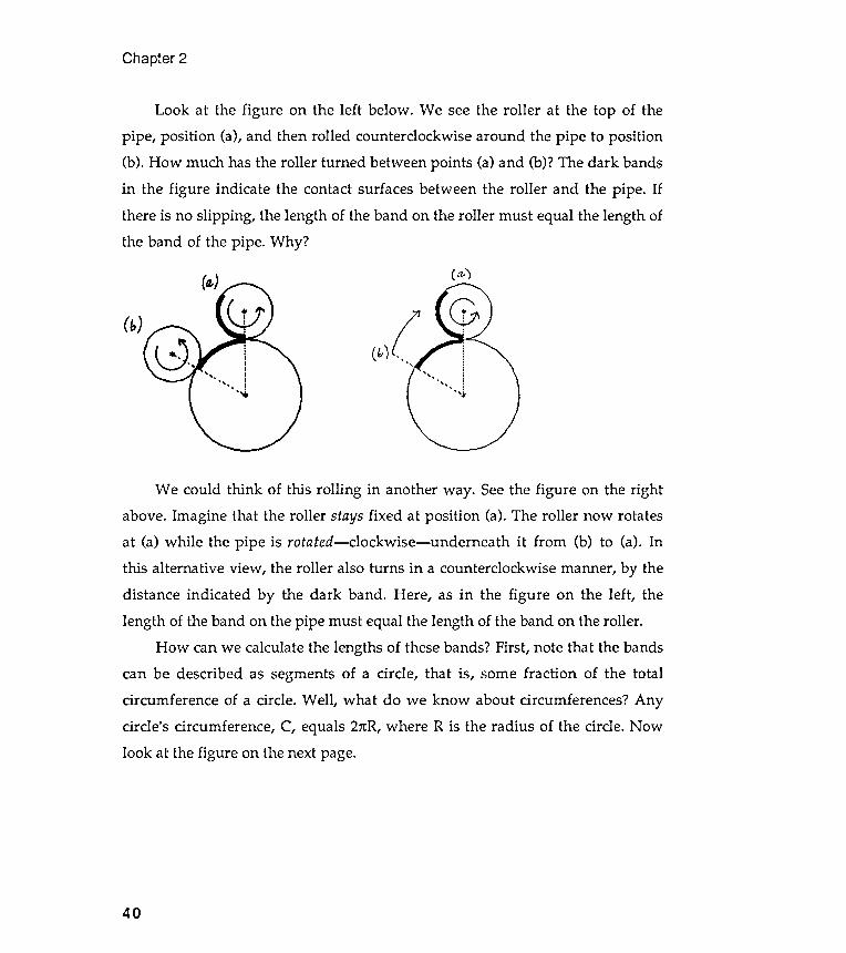
Look at the figure on the left below . We see the roller at the top of thepipe , position (a), and then rolled counterclockwise around the pipe to position(b). How much has the roller turned between points (a) and (b)? The dark bandsin the figure indicate the contact surfaces between the roller and the pipe . Ifthere is no slipping , the length of the band on the roller must equal the length ofthe band of the pipe . Why ?
a -
(b)(.
40
We could think of this rolling in another way . See the figure on the rightabove. Imagine that the roller stays fixed at position (a). The roller now rotatesat (a) while the pipe is rotated- clock wise- underneath it from (b) to (a). Inthis alternative view , the roller also turns in a counterclockwise manner, by thedistance indicated by the dark band . Here, as in the figure on the left , thelength of the band on the pipe must equal the length of the band on the roller .
How can we calculate the lengths of these bands? First, note that the bandscan be described as segments of a circle , that is, some fraction of the totalcircumference of a circle . Well , what do we know about circumferences ? Anycircle 's circumference , C, equals 2nR, where R is the radius of the circle . Nowlook a t the figure on the next page.
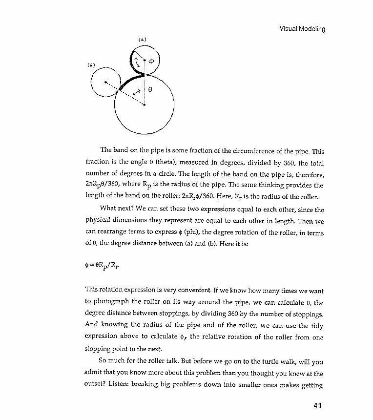
Visual Modeling ( a. )
- ' - -
41
The band on the pipe is some fraction of the circumference of the pipe . This
fraction is the angle 8 ( theta ) , measured in degrees , divided by 360 , the total
number of degrees in a circle . The length of the band on the pipe is , therefore ,
27tRp8 / 360 , where Rp is the radius of the pipe . The same thinking provides the
length of the band on the roller : 27tRr4 > / 360 . Here , Rr is the radius of the roller .
What next ? We can set these two expressions equal to each other , since the
physical dimensions they represent are equal to each other in length . Then we
can rearrange terms to express <I> ( phi ) , the degree rotation of the roller , in terms
of 8 , the degree distance between ( a ) and ( b ) . Here it is :
CP = 8Rp / Rr
This rotation expression is very convenient . If we know how many times we want
to photograph the roller on its way around the pipe , we can calculate 8 , the
degree distance between stoppings , by dividing 360 by the number of stoppings .
And knowing the radius of the pipe and of the roller , we can use the tidy
expression above to calculate <P , the relative rotation of the roller from one
stopping point to the next .
So much for the roller talk . But before we go on to the turtle walk , will you
admit that you know more about this problem than you thought you knew at the
outset ? Listen : breaking big problems down into smaller ones makes getting
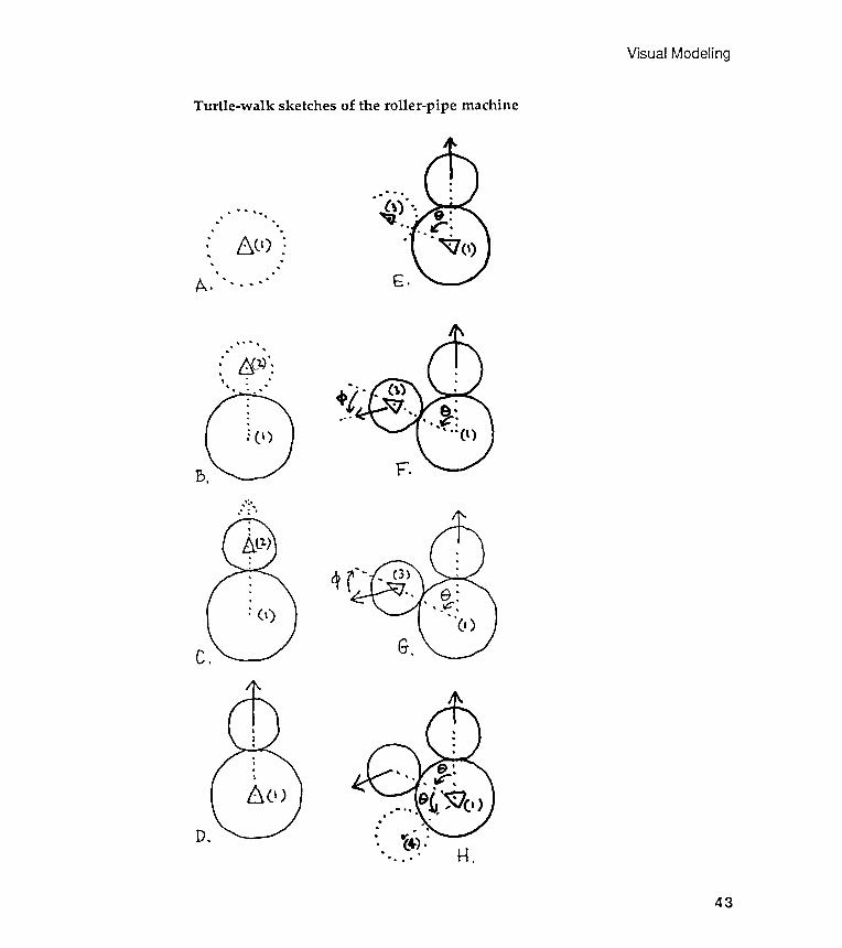
Remember that a turtle -walk scenario describes in words and sketches how you
want the turtle to walk through a design . Let yourself go, but be specific .
Addressing your instructions to the turtle and talking out loud may be helpful .Let's use the sketches on the next page as the focal point of this scenario. I have
divided my turtle walk into small scenes and have given each a letterdesigna tion .
The previous shapes in this section were drawn with Logo procedures, but Ihave intentionally left the following figures in freehand form ; they are takenfrom my own Logo notebook . I wanted to remind you that sketches come beforeLogo procedures that draw rounder circles. The following sketches record myvisual doodling about this particular problem . But to appreciate the usefulnessof sketches, you must do some yourself . Don 't just look at my examples.
Because sketches can be effective visual aids for careful thinking , they
need to be drawn carefully . I occasionally use rulers and a compass, but not
always . Of course, the small diagrams on the next page are final sketches, notbeginning ones. Final drawings , like final Logo procedures , are the results ofmany preliminary studies, many of which did not "work out properly ."
Begin at position (1) facing straight up. Draw a circle around point (1) withradius Rp. This will be easy to do using CNGON. (This procedure is listed below,but see Chapter 1 for a full description of it . Think of it as a black-box procedure
Chapter 2
A turtle walk around the pipe
Word description of the turtle walk
Diagram A: Qrawing the ~i~e
42
started easier. And once you get started moving in any direction , you willdiscover that you are already familiar with much of the scenery.
Visual Modeling
Turtle -walk sketches of the roller -pipe machine
.'-'
J>"
. ,
'.
',
. .
..,
..
. ,
..,
',
, .
" .
, ~
' D>
.
. .:.
. .
..
' "
.'
"'
""
' ,
I""
\ ....
" .
~ '
- "
v,
, -
,'-
../
. .
"-
' .
. ,
"
, ,
. ,
. .
'E.
F.
qG.
D.H.
43
G
Jeld
E4~
(
.UM
Elp
aq
Plno
M
uo~
Alod
a1
l1
qJrq
M
pun
OlE
JJ
1U3
:J a
1l1
sau
!Jap
UO
!1!s
od
1Ual
lnJ
s.a
Nlm
al
l1-
.09
Sn!p
El
Jo-
uO~
Alod
pa
p!s
-oz
: E
-aI
Jl!J
E
MEl
p Pl
noM
09
O
Z NO
~N
:)
:ald
wExa
la
d .u
O~
Alod
a1
l1
saq
!lJS
WnJ
l!J
1E
1l1
aIJl
!J
a1l1
Jo
Sn!p
El
a1l1
'a
v~
PUE
'UM
ElP
aq
01
UO~
Alod
a1
l1
Jo
sap
!s
Jo
laqw
nu
a1l1
'N
:
s1ua
wn~
lE
OM
} Sa
){E1
NO
~N
:)
1U!o
d IE
l:J
uaJ
E pu
nolE
su
o~
Alod
lE
ln~
al
SMEl
p 1E
1l1
aa
!a
a4~
JD
aD~
a4~
liD
liD!1
!SDa
~S
l!J
S
~!
li!
lanD
l a4
~ ~
U!M
Ela
:g
WEl
2E!O
'
lanO
l a1
.I~
a~
t?l
~snl
n
o
~ (Z
) uo
!~!s
od
uo
pala
~Ua
;)
l~
Sn!p
t?l
JO
apl
!;)
t? M
t?l
p M
oN
,l~
+ d
~ S
! a
;)ut
?~s
!P
S
!1.I
.L
'lallo
l a1
.I~
Jo
la~U
a;)
a1.I
~ I (
Z)
uo!~
!sod
o
~ aA
OW
pu
t?
dn
uad
a1.I
~ ~
;)!d
'~
xa
NM
Olle
al{~
~U
!Mel
p lO
] UO
!~el
eaal
a U
! la
llol
al{~
~U
!~Ua
!lO
::)
ruel
'Je
!G
'
pal
{S!U
!J
ale
nOA
ual
{M
UO!1
!sod
S
!l{1
01
~Je
q ~a
2
pue
(Z)
UO!1
!sod
ur
OlJ
2u!1
le~S
M
OllE
al
{1 M
elO
'2
u!J
eJ
ale
nOA
l{J
!l{M
U
! UO
!1Ja
l!p
al
{1
S!
1el
{1
pue
'dn
1l{2
!el1
S 2U
!1U
!od
UMel
p aq
ue
J M
Olle
al
{1
'aJu
aH
'2U
!IIO
l
Aue
auop
~
Iuse
l{
1!
'UO
!1!s
od
2u!1
le1S
al
{1
urO
lJ pa
Aour
1a
A 10
U se
ll la
IIol
al{1
aJ
u!s
.
Iarr
.I
all
} }
O
Uo!}
!soa
~
u!a
ao~s
}x
au
all
} O
} 2u
!}}a
~ :H
ru
e.I2
e!Q
.(
1)
uo!}
!sod
'a
d!d
at
{}
Jo
.Ia}u
aJ
at{}
O
} ){
Jeq
ai\o
ru
pue
uad
at{}
dn
){
J!d
aa
!a
all
} Jo
.Ia
}uaJ
al
l}
O}
){Je
q ~
u!}
~a~
:Q
rue
.I2e
!Q
l~u
nOUl
e UO
!~e
~Ol
dq~
d~
elro
le;)
o~
~uno
;);)
e O
~U!
d){
e~
nOA
~SnU
l ~
eqM
.~
! Jo
~J
dI
dq~
O
~ ~U
nOUl
e dU
lOS
pdUl
n~
dq
II!M
~I
.(
)
o~
(1)
:d
U!I
dq
~ se
UO
!~;)
dl!P
al
lieS
dq~
U!
~u!o
d
ld2u
oI
OU
II!M
M
Olle
dq
~ '(
Z)
~e
uo!~
!sod
2U
!~le
~S
S~
! Jo
~J
dI
dq~
o~
~!q
e
Pdllo
l
MO
U
sell
ldIIO
l dq
~ dS
ne;)
dH
.MO
lle
dq~
2U!M
elp
dlO
Jdq
ldIIo
l dq
~ ~U
d!l
O
AI~;
)dllO
;)
~
snUl
no
A (
) ~u
!od
~V
.(
) UO
!1!s
od
o~
pleM
loJ
02
pue
'e
dI2u
e Aq
~J
dI
Ulnl
.
1111
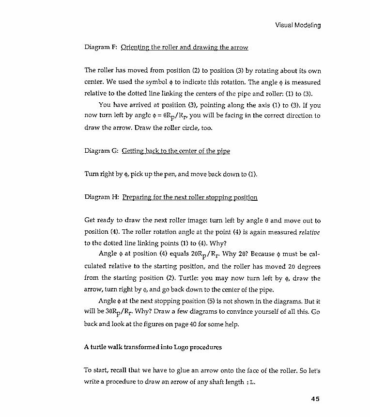
Orienting the roller and drawing the arrow
Visual Modeling
Diagram F:
Diagram G: Getting back to the center of the 12i12e
Turn right by 4>, pick up the pen, and move back down to (1).
Diagram H: Pre~aring for the next roller sto~~ing ~osition
45
The roller has moved from position (2) to position (3) by rotating about its owncenter. We used the symbol <I> to indicate this rotation . The angle <I> is measuredrelative to the dotted line linking the centers of the pipe and roller : (1) to (3).
You have arrived at position (3), pointing along the axis (1) to (3). If younow turn left by angle <I> = 8Rp/ Rr, you will be facing in the correct direction todraw the arrow . Draw the roller circle, too.
Get ready to draw the next roller image : turn left by angle 8 and move out to
position ( 4 ) . The roller rotation angle at the point ( 4 ) is again measured relative
to the dotted line linking points ( 1 ) to ( 4 ) . Why ?
Angle cj> at position ( 4 ) equals 28Rp / Rr Why 28 ? Because cj> must be cal -
culated relative to the starting position , and the roller has moved 28 degrees
from the starting position ( 2 ) . Turtle : you may now turn left by cj>, draw the
arrow , turn right by cj>, and go back down to the center of the pipe .
Angle cj> at the next stopping position ( 5 ) is not shown in the diagrams . But it
will be 38Rp / Rr Why ? Ora w a few diagrams to convince yourself of all this . Go
back and look at the figures on page 40 for some help .
A turtle walk transfonned into Logo procedures
To start , recall that we have to glue an arrow onto the face of the roller . So let ' s
write a procedure to draw an arrow of any shaft length : L .
Let 's call the procedure that will carry out this turtle walk P IPEGON . What
will be the arguments ? Certainly the radius of the pipe and the radius of the
roller will be needed . We will also need to know e and how many stopping points
we would like to photograph . Here is the list of arguments so far :
stopping places
Chapter 2
SHAFT
:L . The length of
PIPEGONs
: RP, the radius of the pipe: RR, the radius of the roller: THETA, the angle distance between: N, the number of stopping places
Let's add one more, : CUM, that will keep track of the total of the angleturned from the starting roller position . We can now write the first line ofPIPEGON:
TO PIPEGON : RP : RR : THETA : CUM : N
46
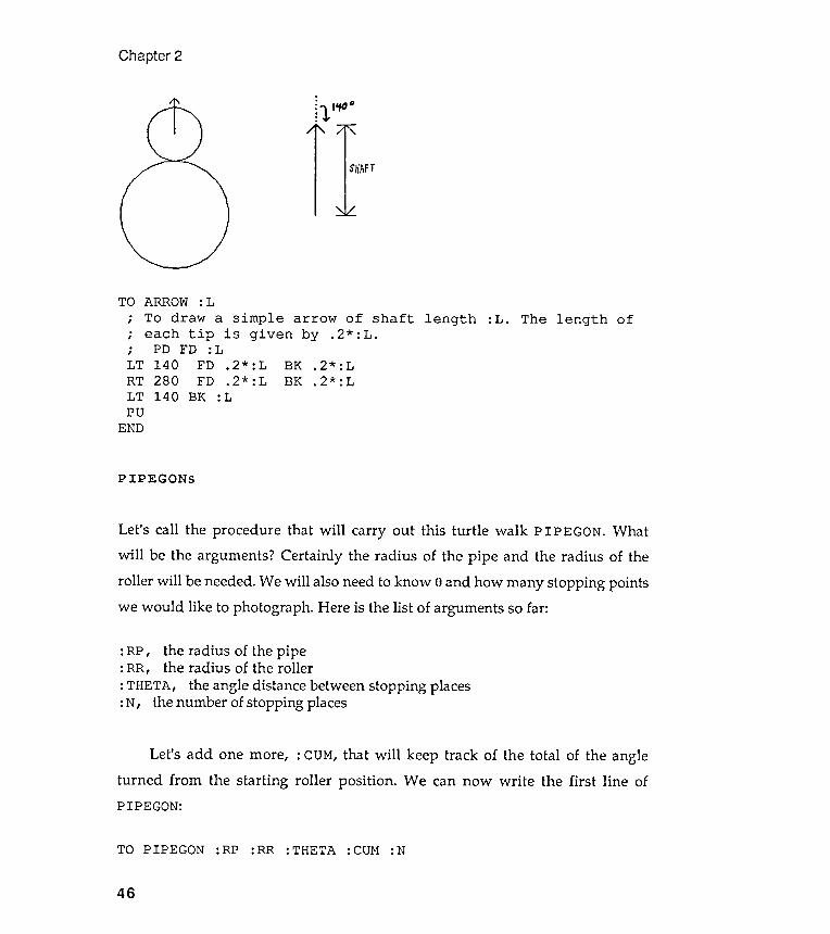
TO ARROW : L
; To draw a simple arrow of shaft length
; each tip is given by . 2 * : L .
; PD FD : L
LT 140 FD . 2 * : L BK . 2 * : L
RT 280 FD . 2 * : L BK . 2 * : L
LT 140 BK : L
PU
END

Supporting procedures
Visual Modeling
How do you feel about rushing right into doing the rest ? The following is
not my first " rush " or even the second . My first few attempts had bugs in them ,
and they didn 't work as I had planned . But procedures almost never work the
first time . That 's OK as long as your energy is up to fixing them .
TO PIPEGON :RP :RR :THETA :CUM :N
PU BK :RP + :RRLT :THETAPIPEGON :RP :RR :THETA
END( : CUM+ : THETA) ( :N- l )
TO.
,
.
,
.
,
.
,
47
IF :N < 1PU FD :RP
[CNGON 20+ :RR PD
:RP STOP]
TO NGON : N
; To draw
; drawn from
; is given by
REPEAT : N [ FD
END
Some pip . egon productions
LT : CUM* : RP/ : RRARROW :RR* 1 . 5CNGON 20 : RRRT =CUM* =RP/ =RR
CNGON : N : RAD
To draw an N - sided polygon centered on the turtle ' s
current position . RAD is the radius of the circle that
would pass through all of the polygon ' s vertices .
See Chapter 1 for a full description of CNGON .
PU FD : RAD
RT 180 - ( 90 * ( : N - 2 ) / : N ) PD
NGON : N ( 2 * : RAD * SIN ( 180 / : N
LT 180 - ( 90 * ( : N - 2 ) / : N )
PU BK : RAD PD
END
: EDGE
an N - sided polygon . The first edge will be
the turtle ' s current position , and its length
EDGE .
: EDGE RT 360 / : N ]
I typed PIPEGON 60 30 60 0 6 . This models , in a visual way , the rolling of a
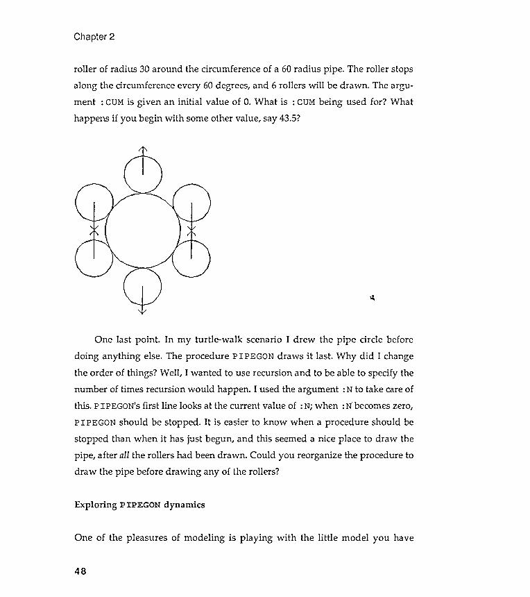
roller of radius 30 around the circumference of a 60 radius pipe . The roller stopsalong the circumference every 60 degrees, and 6 rollers will be drawn . The argu-ment : CUM is given an initial value of o. What is : CUM being used for ? Whathappens if you begin with some other value, say 43.5?
Chapter 2
~
One last point .doing anything else.
Exploring P IPEGON dynamics
One of the pleasures of modeling is playing with the little model you have
48
In my turtle-walk scenario I drew the pipe circle beforeThe procedure P IPEGON draws it last. Why did I change
the order of things? Well , I wanted to use recursion and to be able to specify thenumber of times recursion would happen. I used the argument : N to take care ofthis. PIPEGON's first line looks at the current value of :N; when :N"becomes zero,
PIPEGON should be stopped . It is easier to know when a procedure should bestopped than when it has just begun, and this seemed a nice place to draw thepipe , after all the rollers had been drawn . Could you reorganize the procedure todraw the pipe before drawing any of the rollers ?
Visual Modeling
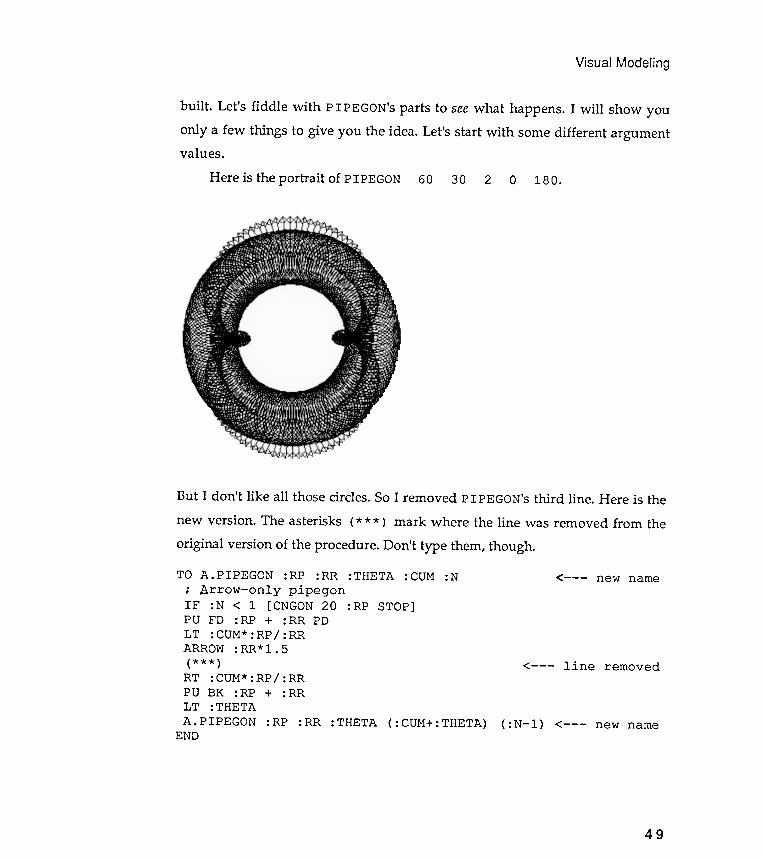
But I don 't like all those circles. So I removed PIPEGON's third line . Here is thenew version . The asterisks ( * * * ) mark where the line was removed from the
new name
line removed< - - -
PU BK : RP + : RRLT : THETAA . PIPEGON : RP : RR : THETA ( : CUM+ : THETA)
END( :N- l ) < - - - new name
49
IF :N < 1 [CNGON 20 :RP STOP]PU FD :RP + :RR PDLT :CUM* :RP/ :RRARROW:RR* 1. 5( * * * )RT :CUM* :RP/ :RR
built . Let 's fiddle with PIPEGON's parts to see what happens . I will show youonly a few things to give you the idea. Let's start with some different argumentvalues .
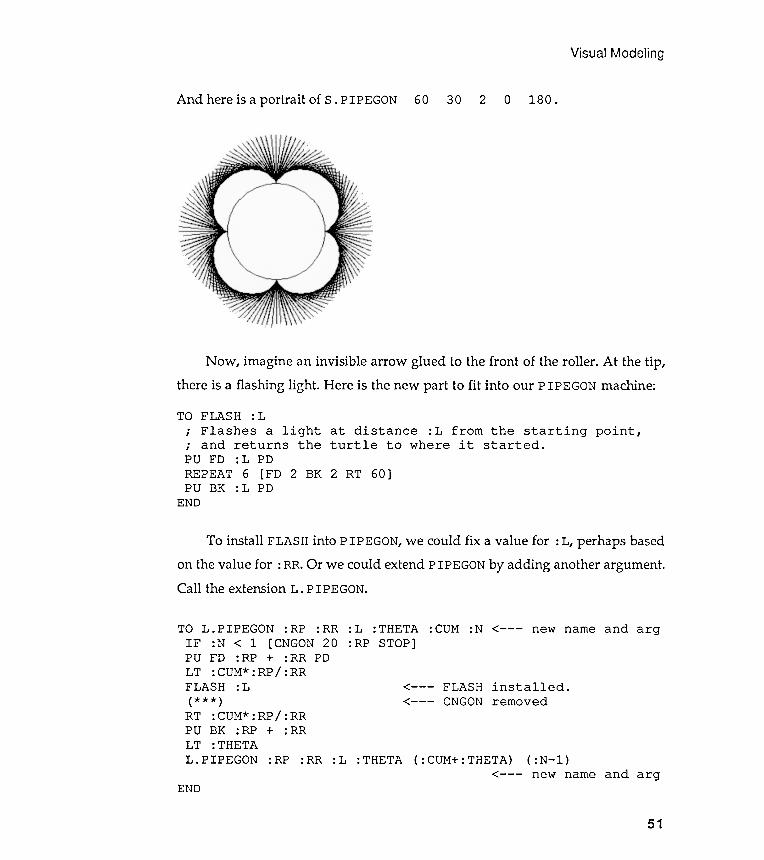
Here is the portrait of PIP EGaN 60 30 2 0 180 .
original version of the procedure . Don 't type them, though .
TO A .PIPEGON :RP :RR : THETA : CUM :N; Arrow - only pipegon

Chapter 2
Now this is a portrait of A . PIPEGON 60 30 2 0 180 .
50
Instead of drawing an arrow on the roller , let 's draw a stripe along adiameter . We can use CNGON to draw a two-sided polygon with radius equal tothe roller . We take out the ARROW procedure and insert CNGON. Here it is:
TO S . PIPEGON : RP : RR : THETA : COM : N < - - - new name
; .s..triped pipegonIF : N < 1 [ CNGON 20 : RP STOP ]PO FD : RP + : RR PD
LT : COM * : RP / : RR( * * * ) < - - - ARROW removed
CNGON 2 : RR < - - - 2 - sided CNGON installed hereRT : COM * : RP / : RRPO BK : RP + : RRLT : THETA
S . PIPEGON : RP : RR : THETA ( : COM + : THETA ) ( : N - l ) < - - - new nameEND
Visual
And here is a portrait of s . PIPEGON 60 30 2 0 180 .
: THETA
Modeling
Call the extension L . PIPEGON .
TO L . PIPEGON : RP : RR : L : THETA : CUM : N
IF : N < 1 [ CNGON 20 : RP STOP ]PU FD : RP + : RR
LT : CUM * : RP / : RRFLASH : L
( * * * )RT : CUM * : RP / : RRPU BK : RP + : RRLT : THETAL . PIPEGON : RP
<- - - new name and arg
< - - -
< - - -
: RR : L ( : CUM+ : THETA) ( : N - l )new name and arg
END
51
PD
< - - -
Now , imagine an invisible arrow glued to the front of the roller . At the tip ,there is a flashing light . Here is the new part to fit into our P IPEGON machine:
TO FLASH : L; Flashes a light at distance : L from the starting point ,; and returns the turtle to where it started .PU FD : L PDREPEAT 6 [FD 2 BK 2 RT 60]PU BK : L PD
END
To install FLASH into PIPEGON, we could fix a value for : L, perhaps basedon the value for : RR. Or we could extend PIPEGON by adding another argument .
FLASHCNGON
installed .removed
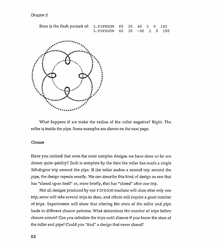
Chapter 2
Here is the flash portrait of : L .PIPEGONL .PIPEGON
6060
3030
40 2 0 180- 40 2 0 180
~ . ~ * " ' * . ~ -* - - .
. - ~ ~
. . * * . .* *
~ . , . - ~ * . . . . * ' * * " ~ " . ~J "' " "' ~
* . * * ~ . .- * os -
- . , . . . *~ . * ' .
. . . ~~ ' " * *
.. 1 ,: .." " . .
. ~~ .
, . . .* *
- *~ .
. ~
~ :' t ..** ' " * *
~ . . . .~ ~ . . .
, . . . . . . . .* . . - * *
- - * * ~ ~
" ' * ~ . * r~ " tt ~ * ~ o ' \ W* * " ~ ' " ~
" . . . . " "" " . .
. tt ~ ~- * * -
" . ~ . . * , , " . ~ "
Cosure
52
Have you noticed that even the most complex designs we have done so far aredrawn quite quickly ? Each is complete by the time the roller has made a single360-degree trip around the pipe . If the roller makes a second trip around thepipe, the design repeats exactly. We can describe this kind of design as one thathas "closed upon itself " or, more briefly , that has "closed" after one trip .
Not all designs produced by our PIPEGON machine will close after only onetrip ; some will take several trips to close, and others will require a great numberof trips . Experiments will show that altering the sizes of the roller and pipeleads to different closure patterns . What determines the number of trips beforeclosure occurs? Can you calculate the trips until closure if you know the sizes ofthe roller and pipe? Could you "find " a design that never closed?
What happens if we make the radius of the roller negative ? Right . Theroller is inside the pipe . Some examples are shown on the next page.
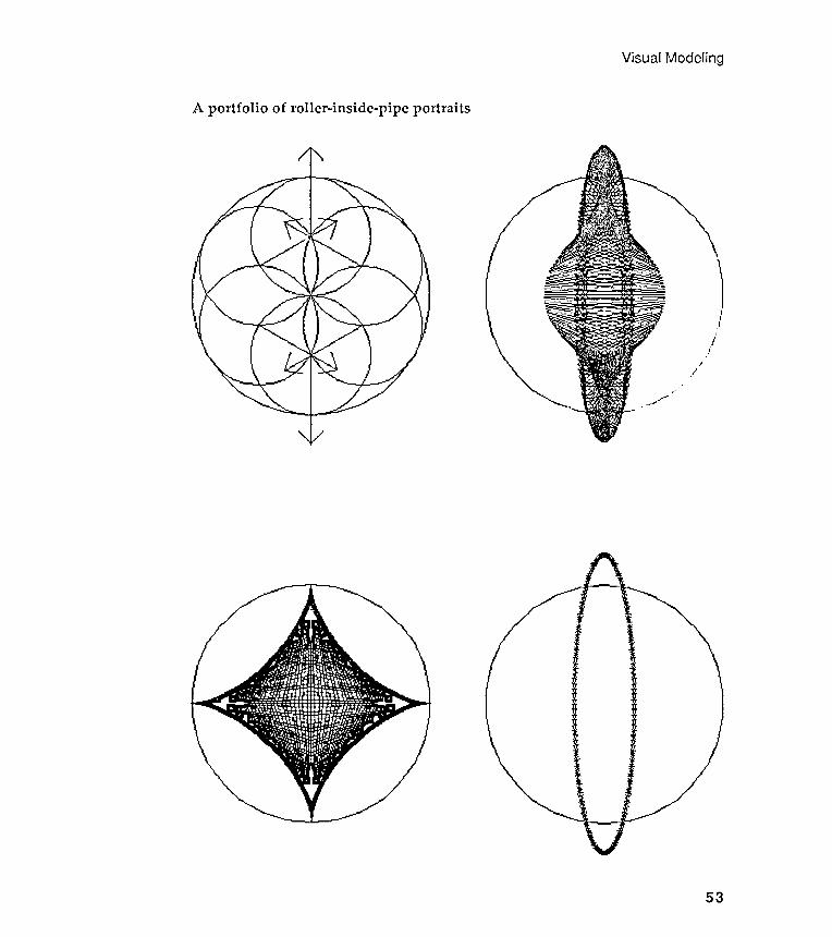
Visual Modeling
A portfolio of roller -inside -pipe portraits
53
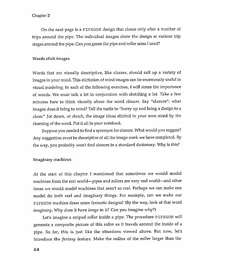
Words that are visually descriptive , like closure, should call up a variety ofimages in your mind . This elicitation of mind -images can be enormously useful invisual modeling . In each of the following exercises, I will stress the importanceof words . We must talk a lot in conjunction with sketching a lot . Take a fewminutes here to think visually about the word closure. Say " closure" : whatimages does it bring to mind ? Tell the turtle to "hurry up and bring a design to aclose." Jot down , or sketch, the image ideas elicited in your own mind by the
chanting of the word . Put it all in your notebook.Suppose you needed to find a synonym for closure. What would you suggest?
Any suggestion must be descriptive of all the image work we have completed. Bythe way , you probably won 't find closure in a standard dictionary . Why is this?
machines
Chapter 2
On the next page is a PIPEGON design that closes only after a number oftrips around the pipe . The individual images show the design at various tripstages around the pipe . Can you guess the pipe and roller sizes I used?
Words elicit images
Imaginary
54
At the start of this chapter I mentioned that sometimes we would model
machines from the real world - pipes and rollers are very real world - and other
times we would model machines that aren 't so real . Perhaps we can make one
model do both real and imaginary things . For example , can we make our
P IPEGON machine draw some fantastic designs ? (By the way , look at that word
imaginary . Why does it have image in it ? Can you imagine why ?)
Let 's imagine a striped roller inside a pipe . The procedure PIPEGON will
generate a composite picture of this roller as it travels around the inside of a
pipe . So far , this is just like the situations viewed above . But now , let 's
introduce the fantasy feature . Make the radius of the roller larger than the
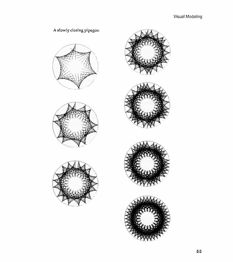
pipegon
Visual Modeling
A slowly closing
55

Let 's summarize what has happened in the last few pages. We have built a
Logo model that can produce a large variety of images, some of them verysurprising . But more important , we have seen how the act of modeling canfacilitate the visual exploration of some of the characteristics of a real-worldmachine. Once we began to tinker with our model , we wanted to tinker further .Some of our designs posed difficult questions whose answers were not at allobvious . Closure was such a question . We needed to do more tinkering and moreexperimenting to come to grips with what was going on.
Could we have predicted the directions this tinkering and experimentationwould take before we started? I don 't think so. Once we begin to model parts ofour world , the act of modeling takes on a life of its own . I think we have touched
what Levi -Strauss said happens when one plays with miniatures . Model play"gratifies the intelligence and gives rise to a sense of pleasure which canalready be called aesthetic." I hope you would also describe visual modeling asfun .
Why pipes and rollers ?
Chapter 2
radius of the pipe in which it " rolls ." Is this possible? Can it be done? I askedPIP E GON to do it , and the results are shown on the next page. What ishappening ? Are these pictures of real or imaginary machines? How can youwork out your answer? Can you sketch it?
Reca pitula lion
I started with this particular machine because I was interested in it . I could
have used any number of alternative illustrations , but this was my own
direction . I will show you , in the chapters to come , dozens of other examples
that illustrate the ways in which visual modeling encourages the modeler to
look at the world differently .
56

Visual Modeling
Imaginary PIPEGONs?
:11,/Ill
I
S //
/ I]
57
G
J8ld
E4~
.
){ooq
S!l{
1 01 a
A!1E
Ula1
It? lit?
a1!lM
01 n
oA 1
Ut?M
I 1J
aJJa
UI
.sald
illt?x
a liM
O ln
OA
l{~no
ll{1 '
l{Jt?o
lddt
? liM
O ln
OA
PU!J
01 p
a~t?ln
OJU
a aq
II!M
noA
SnO!A
qo o
s aq
II!M
s!l[
1 Jo
ssau
lnJa
sn al
{11t?
l{1 ad
ol{ I
.SJ!l
[dt?l
~ pu
t? 2u
!Iapo
ill
It
?ns!
A 01
l{Jt
?old
dt?
dUO
' Ala
S!Ja
ld A
laA
'nO
A M
Ol{S
01
S! u
O!1u
a1u!
AW
.
ZU1J
JS 01
1f.Jv
oJ.ddv
pJJ
.n1.J
nJ.Is
V S
! ){o
oq a
l{1 Jo
aN!
1qns
al{1
1El{
1 IIt
?Ja~
.UO
!l{st?
J pa
ln1J
nl1S
f..1
aA
t
? U! s
la1d
t?l{J
asal{
1 paJ
npO
l1u!
put
? pal
aplo
aAt
?l{ I
put?
sla1
dEtp
J!J!
Jads
U!l{
1!M
SaS
!Jla
Xa A
ill pa
Jt?Id
Alln
Jalt?
J aA
t?l{ I
. Al
t?l1!
qlt?
IOU
S! ){o
oq S
!l{1 U
! Sa
S!Jla
Xaasal
{1 Jo
~U!
lapl
O a
l{1 'la
AaM
oH .
s1ua
pmS A
ill Jo
s1S
ala1
u! al{1
put?
s1Sa
la1u!
liM
O
Aill
UO pa
st?q
alt?
SaS!J
laXa
al{1
JO IIV
.pU!
ill U!
~U!
MO
IIoJ a
\.{1 da
a){ a
st?al
d 1n
g
Ana
)! a~
.loa~
Jo '
I.lOM
alII
:S1S!
1ua!J
S S'C
aldo
aJ89
l{~!
M ~
Ua~S
!SUO
J 'a~
ElnJ
!~lEu
! AIla
~~n
lO p
assa
ldxa
An
Eqla
A '~n
o pa
~JE
AI~!J
!Idw
!lO
pa~E
lnwl
oJ
AI~!
J!Id
xa
'lO!A
El{a
q JO
aSl
nOJ
E ~lE
llJ
o~ 'O
O~ S
IEW
!UE
laM
oI
al
{~ P
UE 'U
EW sa
lqEu
a ~E
llM a
lE A
all].
'PIlO
M a
ll~ 2u
!nl~
suO
J Jo
SA EM
alE
,,-sI
apow
lO
-S~
Jnl~
SUO
J asa
ll].
'S]3
POUl
sula
~~Ed
asa
l{~ p
aIIE
J aA
El{
naM
SE
~snf
Pln
oJ
aH
'
az!s
lOJ
uo i
Cl~
aldo
ad
~El{~
sula
~~Ed
al{~
o~
SlJn
.llSUO
J aW
EU a
l{~ sa
A!2
Ana)
!
,
,'nE
~E 2u
!l{~o
u UE
l{~ In
Jdla
l{ a
lOW
S! ~
!J lo
ad
E ua
AH '~
! JO
asua
s AU
E
a
){EW
o~ a
lqEu
n S!
UEW
~El{~
~!a
ua20
wol
{ pa~
E!~U
alaJ
J!pU
n UE
l{Jn
s aq
o~ S
lEad
dE
PIlO
M
al{~
sula
~~Ed
l{Jn
s ~n
Ol{~
!M ~
aA 'p
o02
iCla
A SA
EMIE
~ou
S! ~
!J a
lI.1
'pas
odwo
J
S
! PI
lOM
al
{~ l{
J!l{M
JO
sa!
~!IE
ol
al{~
laAO
~!J
o~
s~dw
a~~
E ua
l{~
PUE
Sa~E
alJ
all
l{J!l{
M s
~ald
wa~ l
O s
ula
~~Ed
~ual
Edsu
El~ l
{2no
llI~ P
IloM
s!
l{ ~E
S){O
OI U
EW"
's~
s!~u
a!Js
SE
aldo
ad
lIE p
aMa
!A A
na)!
'
~JEJ
UI '
s~s!
~ua!
Js A
q pa
sn a
sol{~
o~ l
EI!W
!S al
E ~E
l{~ sa
nb!u
l{Ja~
2u!s
n PI
lOM
S!l{
JO
asua
s
a){E
W o
~ Sa
!l~ u
osla
d l{J
Ea ~E
l{~ M
a!A
S!l{
wall
saW
OJ
awEJ
o~
W!E
IJ S
,Ana
)!
'
A20I
Ol{
JAsd
PU
E 'A
20IO
!JO
S 'S
J!SA
lld
'SJ!~
Ewal
{~Ew
U!
paU
!El~
SEM
5'0
61 u
!
SESU
E
)! U!
UlO
q 'A
na)!
a2lo
a~
'2u
!PI!n
q Ia
pow
~noq
E 2u
!){U
!l{~ U
MO
AW
paJ
uanu
u!
AI
~Eal
2 SE
ll O
l{M ~
s!20
IOl{J
Asd
UEJ!l
awy
UE J
o ){l
OM
al{~
noA
o~
2U!J
npO
l~U!
Aq
lall
~lnJ
02 a
w ~a
I '~u
awnJ
op
IEuo
slad
AlaA
E S
! ){o
oq s
!l{~ ~
El{~
pa~~
!WpE
2U
!AEH
other courses of behavior or inconsistent with them, intellectually reasoned orvegetatively sensed."
Each person's scientist aspect encourages him to " improve his constructs byincreasing his repertory , by altering them to provide better fits , and bysubsuming them with subordinate constructs or systems." For Kelly , humanbehavior is the application of scientific method in making sense of a particularenvironment . Rather than merely responding to surroundings , people use anexperimental approach to test and extend their system of personal constructs .Each person 's goal , in Kelly 's view , is to build explanatory models thateffectively explain and predict personal environments .
Kelly suggested shortcuts for improving construct systems. Kelly 's shortcutwas to encourage individuals to make their own constructs verbally explicit . Hismost famous method for eliciting and verbalizing personal constructs is known asthe repertory grid technique . Using slightly different words , Kelly 's techniquesencouraged individuals to build verbal models of their own constructs . Oncebuilt , these verbal models could be analyzed in much the same way as we haveanalyzed our pipe -and-roller model . Tinkering with constructs would occurnaturally , and this would encourage further tinkering . And as a result of thisplay, construct models might become more general and more powerful .
Kelly worked with verbal rather than visual models, but many of his ideascan be extended to the latter . My interest , as was Kelly 's, is to suggest how todescribe our inner models . While Kelly was interested in the verbal descriptionof models , I am interested in more graphical descriptions . My goal is toencourage you to look at your own visual baggage. Obviously , I need words , too,to help in my form of elicitation . Sometimes, you may think that I rely on wordstoo much . Too much chat, you might say. . .
If you are intrigued by this very brief account of George Kelly 's work , findhis book A Theory of Personality: the psychology of personal constructs (W. W.Norton , New York , 1963). All the Kelly quotes were taken from it .
Visual Modeling
59

Exercises
How do you feel about carnivals and amusement parks ? Do you enjoy theirmechanical rides? I 'm not talking about tame rides, like the merry -go- round orcarousel, but wild rides that yank the rider through space. On the next page is asketch of a machine that gave me a dose of healthy terror .
Suppose that we are watching this machine from a safe distance. A bravefriend is sitting inside it and pointing a very bright flashlight at us. What
pattern will this light trace out as the machine grinds into life ?The pulls and pushes on the rider of this machine change suddenly and
unexpectedly . Can you make a picture of this? Can you describe visually whythis kind of machine is so scary?
Chapter 2
Exercise 2.1
Can you come up with some rules about P IPEGON closure ? Specifically , can you
characterize a final pipegon image in terms of the dimensions of its parts ?
Experiment a bit . Try to make some generalizations . Do the generalizations hold
up after more experimenting ? Whether you feel successful in this activity or not ,
find the following book in your local library : E. H . Lockwood , A Book of Curves
(Cambridge University Press, Cambridge , 1963).
This book may help you think about closure . It may also suggest other
image ideas to think about visually . Don 't worry too much about the book 's
math . Look at the diagrams , and read the chapter names . Listen to these
chapters : cardioids , limac ;ons , astroids , right strophoids , tractrices , roulettes ,
and glissettes . What images do these names dredge up ? Sketch them before youfind the book .
Exercise 2.2
60
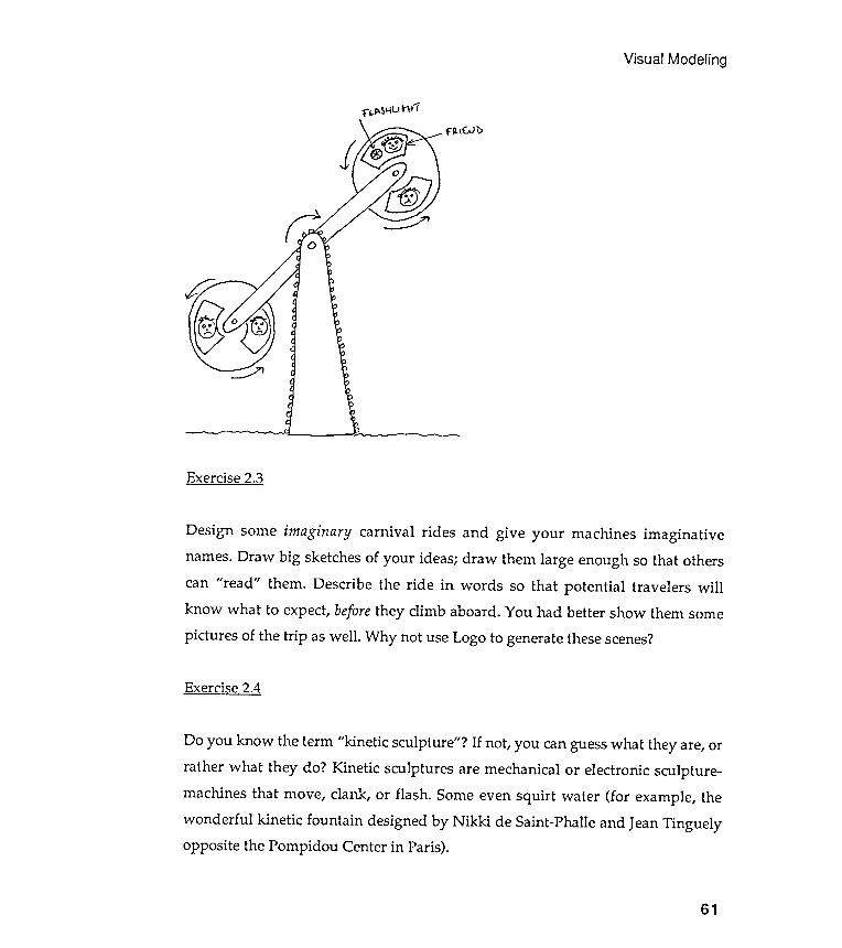
Design some imaginary carnival rides and give your machines imaginativenames. Draw big sketches of your ideas; draw them large enough so that otherscan "read" them. Describe the ride in words so that potential travelers willknow what to expect, before they climb aboard. You had better show them somepictures of the trip as well. Why not use Logo to generate these scenes?
Exercise 2.4
Do you know the term "kinetic sculpture " ? If not, you can guess what they are, orrather what they do? Kinetic sculptures are mechanical or electronic sculpture -machines that move, clank, or flash . Some even squirt water (for example, the
wonderful kinetic fountain designed by Nikki de Saint-Phalle and Jean Tinguelyopposite the Pompidou Center in Paris).
Visual Modeling
f "t..~5HUhf ' T
, . . . . . ~ - - - - - - - - - . . . -
Exercise 2.;2
61
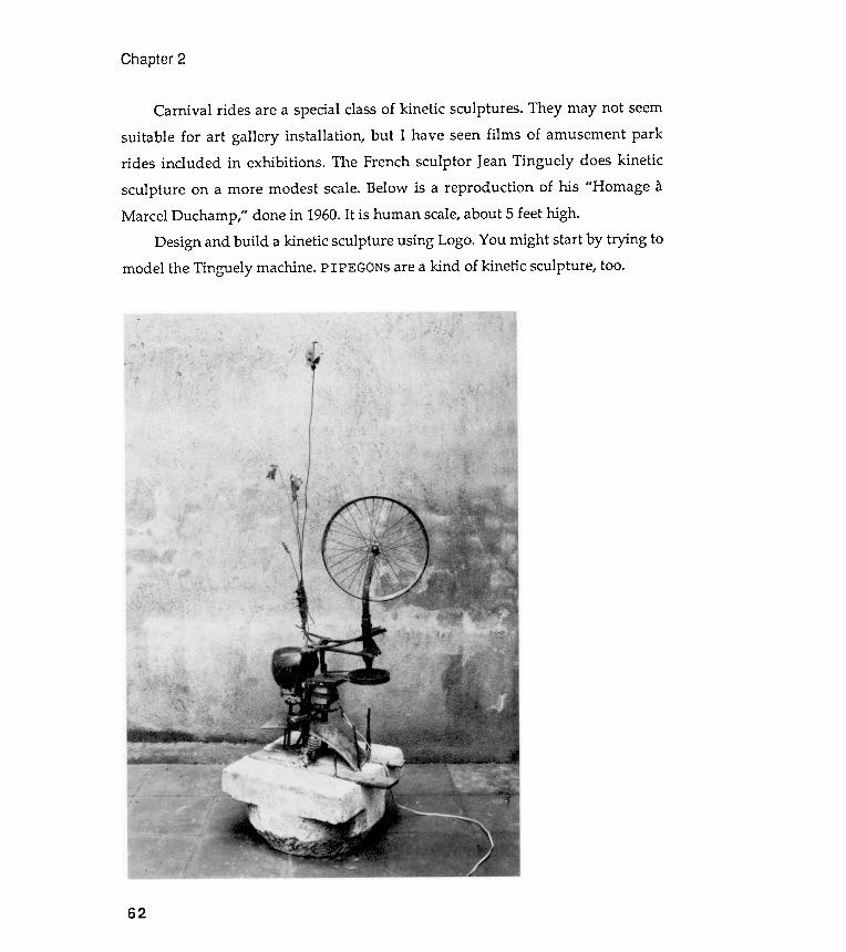
Chapter 2
Carnival rides are a special class of kinetic sculptures . They may not seemsuitable for art gallery installation , but I have seen films of amusement parkrides included in exhibitions . The French sculptor Jean Tinguely does kinetic
sculpture on a more modest scale. Below is a reproduction of his " Homage aMarcel Duchamp ," done in 1960. It is human scale, about 5 feet high .
Design and build a kinetic sculpture using Logo. You might start by trying tomodel the Tinguely machine. PIPEGONs are a kind of kinetic sculpture , too.
62
Chapter 3Visual Discovery
The style of discovery
This chapter continues the exploration of visual models and how they canstretch your mind -and-eye's vision into areas unfamiliar to you . The style ofpresenta tion remains the exercise form . Exercises will encourage you toexperiment dynamically with the simplest of shapes. I hope to convince you ,through illustrations , that playing experimentally with familiar and plainobjects can lead you into a space filled with objects that are not only unfamiliarbut surprisingly different from what you expected.
"The discoverer is the [ person ] who sees in familiar objects what no one else has
seen before . "
Norwood Russell Hansen
" In order to think productively about the nature of a fact or problem , whether in
the realm of physical objects or that of abstract theory , one needs a medium of
thought in which the properties of the situation to be explored can be
represented . "
Rudolf Arnheim

CNGON
Chapter 3
Problem -solving style
This book is structured around two kinds of exercises . First , there are many
exercises described in the text to illustrate what I consider to be good problem -
solving style . You don 't have to do it my way , but I want you to see one person 's
way . Second , the exercise section at the end of each chapter offers several open -
ended problems that demand originality and flamboyance . These exercises
generally are not illustrated in the text ; I don 't want to influence your creativity
by showing you how anybody else did them .
Let 's begin this chapter , therefore , by finishing up some of the more specific
exercises at the end of Chapter 1. From now on , at least one assigned problem
from the previous chapter will be discussed in detail at the start of each
chapter As I have already mentioned , much of the learning of a craft is ac-
quired by watching and copying someone who is used to doing it . Constructive
copying can lessen your programming anxiety by providing a firm support for
personal exploration . (I' ve said that before , but it is worth repeating .)
Centered polygons with
Let's begin with a final look a t Exercise 1.1. This problem asked you to refashionNGON. The new procedure, CNGON, should draw an n-sided polygon around acentral point. CNGON, named for entered NGONs, will take two arguments: first,the radius of the circle circumscribed on the polygon, and second, the number ofpolygonal edges. Here is the completed version with plenty of comment lines,each introduced by a semicolon:
TO CNGON :N :RADPU FD :RAD; Move out to the circumference of circumscribed circle .RT 180 - (90* ( :N- 2) / :N) PD; Turn right to face along one of the edges of the polygon .NGON :N (2* :RAD*SIN 180/ :N); Draw an NGON with edge expressed in terms of the radius .
64
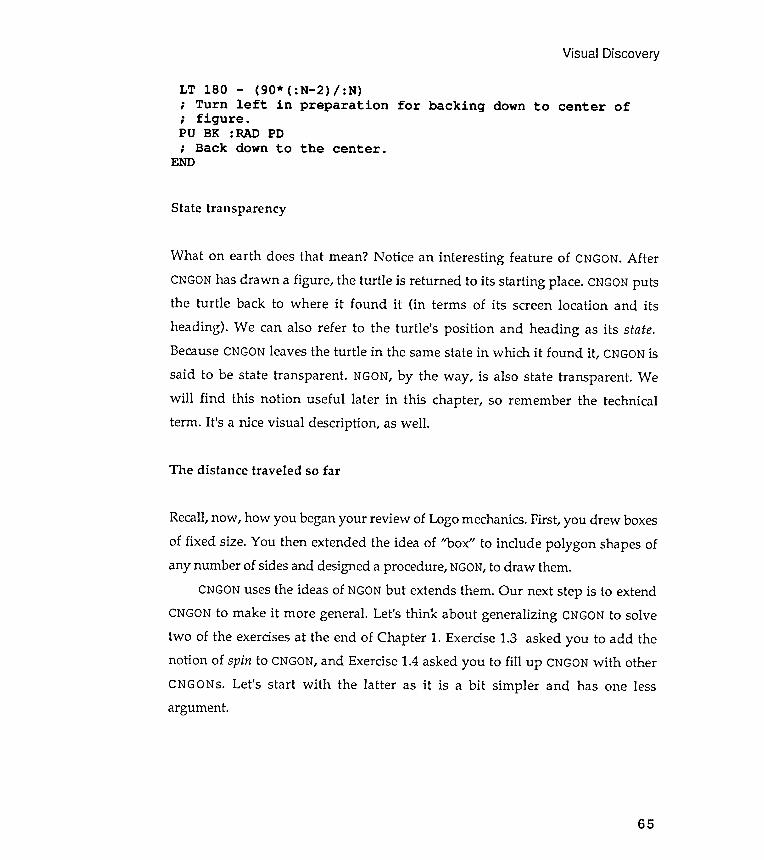
State transparency
What on earth does that mean? Notice an interesting feature of CNGON. AfterCNGON has drawn a figure , the turtle is returned to its starting place. CNGON putsthe turtle back to where it found it (in terms of its screen location and its
heading ). We can also refer to the turtle 's position and heading as its state.Because CNGON leaves the turtle in the same state in which it found it , CNGON is
said to be state transparent . NGON, by the way , is also state transparent . Wewill find this notion useful later in this chapter , so remember the technicalterm . It 's a nice visual description , as well .
Recall, now , how you began your review of Logo mechanics. First, you drew boxesof fixed size. You then extended the idea of '~ ox" to include polygon shapes ofany number of sides and designed a procedure, NGON, to draw them.
CNGON uses the ideas of NGON but extends them. Our next step is to extendCNGON to make it more general. Let's think about generalizing CNGON to solvetwo of the exercises at the end of Chapter 1. Exercise 1.3 asked you to add thenotion of spin to CNGON, and Exercise 1.4 asked you to fill up CNGON with otherCNGONs. Let 's start with the latter as it is a bit simpler and has one lessargument .
Visual Discovery
The distance traveled so far
65
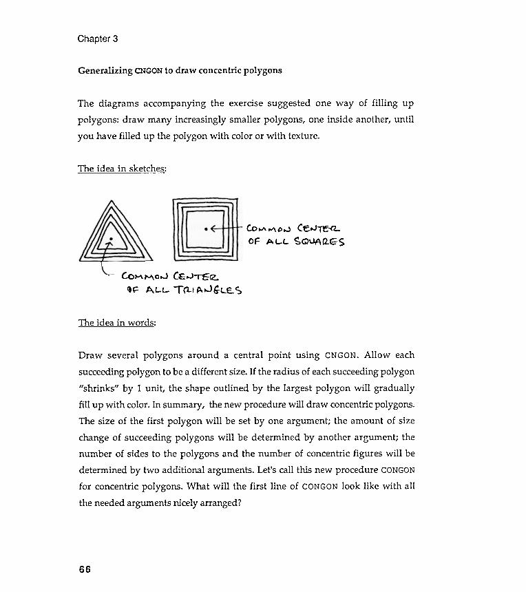
The idea in words:
Chapter 3
Generalizing CNGON to draw concentric polygons
The diagrams accompanying the exercise suggested one way of filling uppolygons : draw many increasingly smaller polygons , one inside another , untilyou have filled up the polygon with color or with texture .
The idea in sketches:
C -e. ,..) ~~ Q\JAQ..GS
Draw several polygons around a central point using CNGON. Allow eachsucceeding polygon to be a different size. If the radius of each succeeding polygon"shrinks " by 1 unit , the shape outlined by the largest polygon will graduallyfill up with color . In summary , the new procedure will draw concentric polygons .The size of the first polygon will be set by one argument ; the amount of sizechange of succeeding polygons will be determined by another argument ; thenumber of sides to the polygons and the number of concentric figures will bedetermined by two additional arguments . Let's call this new procedure CONGONfor concentric polygons . What will the first line of CONGON look like with allthe needed arguments nicely arranged?
66
c. o ~ M 0 ...J CE .oJ " TC C2.II~ At -L- T (1.t p. ..JG:LE. ~
Co ~ ~ DijOF A C- L
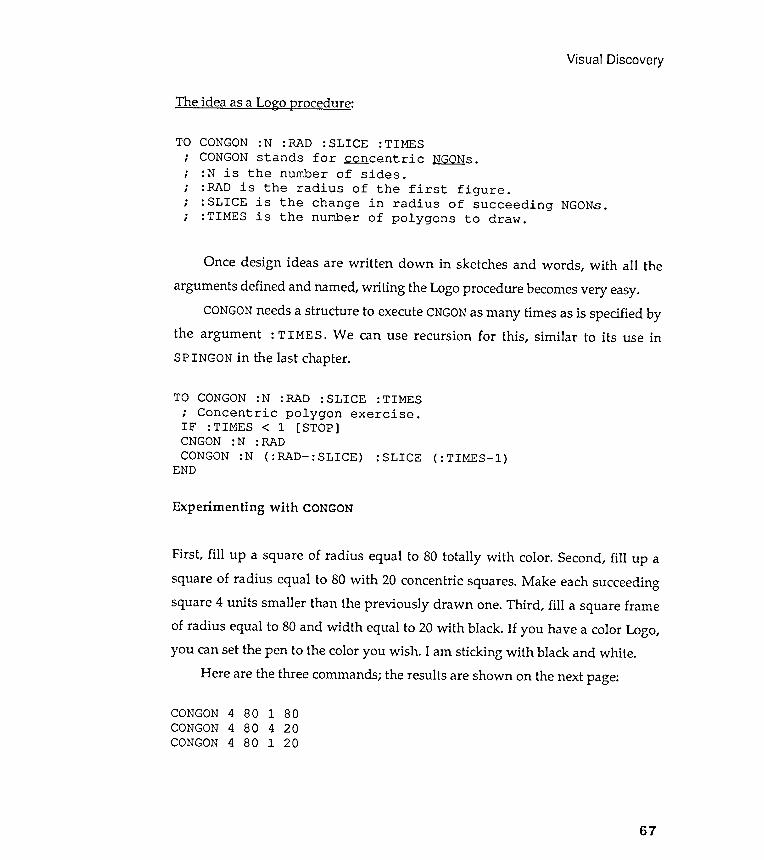
Visual
Experimenting with CONGON
Discovery
CNGON : N :RADCONGON :N ( :RAD- : SLICE )
END: SLICE ( :TIMES- l )
CONGONCONGONCONGON
4 80 1 804 80 4 204 80 1 20
67
First, fill up a square of radius equal to 80 totally with color . Second, fill up asquare of radius equal to 80 with 20 concentric squares. Make each succeedingsquare 4 units smaller than the previously drawn one. Third , fill a square frameof radius equal to 80 and width equal to 20 with black . If you have a color Logo,you can set the pen to the color you wish . I am sticking with black and white .
Here are the three commands ; the results are shown on the next page :
The idea as a Lo~o procedure:
TO CONGON :N :RAD : SLICE :TIMES; CONGON stands for ~ centric NGONs.; :N is the number of sides .; :RAD is the radius of the first figure .; : SLICE is the change in radius of succeeding NGONs.; :TIMES is the number of polygons to draw .
Once design ideas are written down in sketches and words, with all thearguments defined and named, writing the Logo procedure becomes very easy.
CONGON needs a structure to execute CNGON as many times as is specified bythe argument : TIME S. We can use recursion for this, similar to its use inSPINGON in the last chapter.
TO CONGON :N :RAD : SLICE :TIMES; Concentric polygon exercise .IF :TIMES < 1 [STOP]
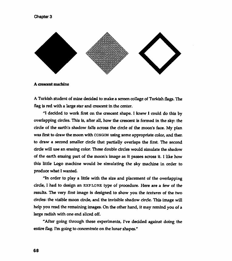
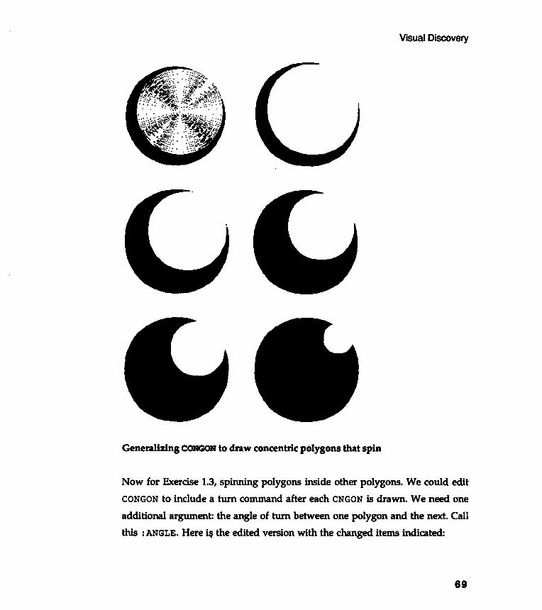
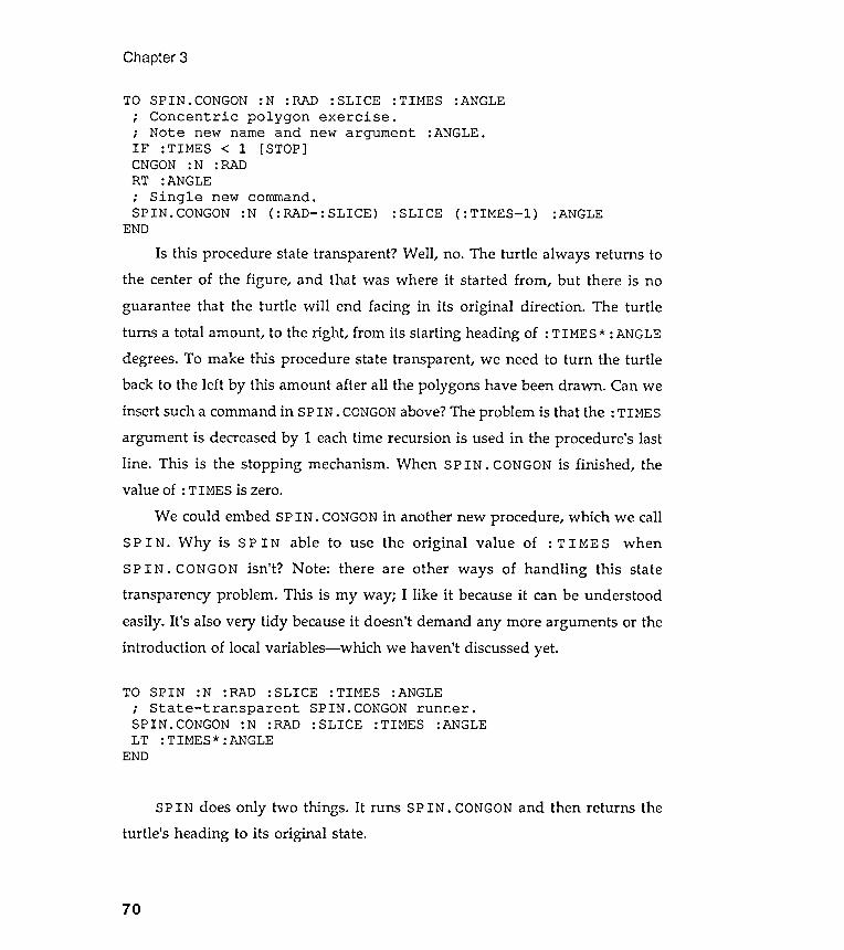
Chapter 3
: SLICE ( : TIMES- l ) :ANGLE
Is this procedure state transparent ? Well , no.the center of the figure , andguarantee that the turtle will end facing
The turtle always returns tothat was where it started from , but there is no
in its original direction . The turtleturns a total amount , to the right , from its starting heading of : TIMES * : ANGLEdegrees. To make this procedure state transparent , we need to turn the turtleback to the left by this amount after all the polygons have been drawn . Can weinsert such a command in SPIN . CONGON above? The problem is that the : TIMESargument is decreased by 1 each time recursion is used in the procedure 's lastline . This is the stopping mechanism . When SPIN . CONGON is finished , thevalue of : TIMES is zero.
We could embed SP IN . CONGON in another new procedure , which we callSPIN . Why is SPIN able to use the original value of : TIMES whenSP IN . CONGON isn 't? Note : there are other ways of handling this statetransparency problem . This is my way ; I like it because it can be understoodeasily. It 's also very tidy because it doesn't demand any more arguments or theintroduction of local variables- which we haven't discussed yet .
TO SPIN :N :RAD :SLICE :TIMES :ANGLE; State - transparent SPIN.CONGON runner .SPIN.CONGON :N :RAD : SLICE :TIMES :ANGLELT :TIMES* :ANGLE
END
SP IN does only two things . It runs SP IN . CONGON and then returns theturtle 's heading to its original state.
70
TO SPIN . CONGON : N : RAD : SLICE : TIMES : ANGLE
; Concentric polygon exercise .
; Note new name and new argument : ANGLE .
IF : TIMES < 1 [ STOP ]
CNGON : N : RAD
RT : ANGLE
; Single new command .
SPIN . CONGON : N ( : RAD - : SLICE )
END
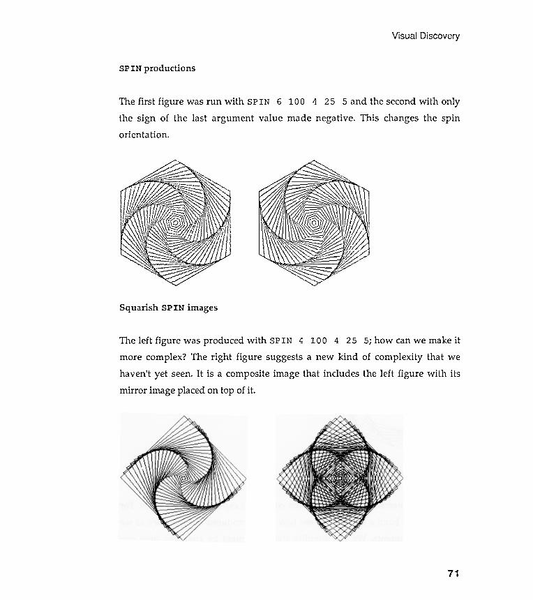
Squarish SPIN images
Visual Discovery
SPIN productions
The first figure was run with SPIN 6 100 4 25 5 and the second with onlythe sign of the last argument value made negative . This changes the spinorienta tion .
71
The left figure was produced with SPIN 4 100 4 25 5; how can we make itmore complex ? The right figure suggests a new kind of complexity that wehaven't yet seen. It is a composite image that includes the left figure with itsmirror image placed on top of it .

More squares
experiments
It might be interesting to set up a more controlled experiment with SP IN . For
example, let 's build a structure to see how SPIN -produced designs vary as wealter the arguments . We can simplify the experiment by changing only one
Chapter 3
SPIN 4 120 2 60 5 SPIN 4 120 1 120 5
A winter holiday wreath
Visual
72

variable at a time
: ANGLE argument .
Visual Discovery
I have decided to look first at the effect of an altered
I thought it would be nice to see a number of SPIN . CONGONS on the screen atthe same time , so that I can compare the effect of the single changed argument .By looking at the size of my screen, and deciding that my individual figureswould be about 50, I decided where (the cartesian x-y addresses) on the screen Iwould put them. Here is my visual simulation machine.
:A5screen at once .
:TIMES:TIMES:TIMES: "rIMES:TIMES
:Al:A2:A3:A4:A5
turtle -reference moving la ter .
Four experiments with EXPLORE
73
EXPLORE : N : SLICE : TIMES : Al : A2 : A3 : A4
To explore five different figures on the
Only the angle variable will be changed .
SETXY ( 0 0 ) PD SPIN : N 50 : SLICE
SETXY ( 70 60 ) PD SPIN : N 50 : SLICE
SETXY ( 70 - 60 ) PD SPIN : N 50 : SLICE
SETXY ( - 70 - 60 ) PD SPIN : N 50 : SLICE
SETXY ( - 70 60 ) PD SPIN : N 50 : SLICE
TO.
,
.
,
POPOPOPOPO
END
I don 't much like using the cartesian system to move the turtle around the
screen , but this seemed an easy and quick way to start experimenting . I 'll do
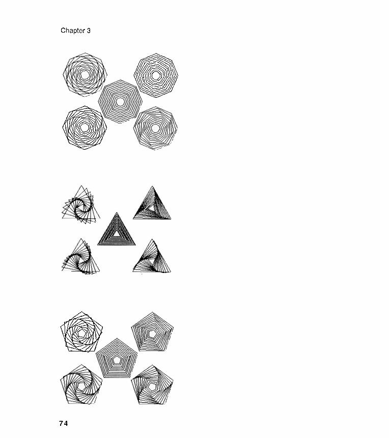
Chapter
U)
......
~
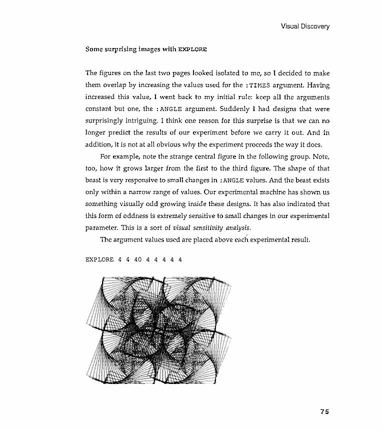
VisualDiscovery
Some surprising images with EXPLORE
The figures on the last two pages looked isolated to me, so I decided to makethem overlap by increasing the values used for the : TIMES argument . Havingincreased this value , I went back to my initial rule : keep all the argumentsconstant but one, the : ANGLE argument . Suddenly I had designs that weresurprisingly intriguing . I think one reason for this surprise is that we can nolonger predict the results of our experiment before we carry it out . And inaddition , it is not at all obvious why the experiment proceeds the way it does.
For example, note the strange central figure in the following group . Note,too, how it grows larger from the first to the third figure . The shape of thatbeast is very responsive to small changes in : ANGLE values. And the beast existsonly within a narrow range of values. Our experimental machine has shown ussomething visually odd growing inside these designs. It has also indicated thatthis form of oddness is extremely sensitive to small changes in our experimentalparameter . This is a sort of visual sensitivity analysis.
The argument values used are placed above each experimental result .
EXPLORE 4 4 40 4 4 444
75
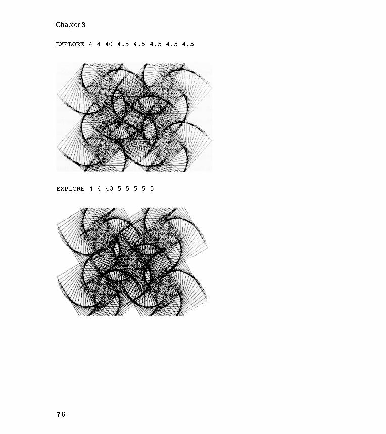
Chapter 3
EXPLORE 4 4 40 4.5 4 . 5 4 .5 4. 5 4 . 5
EXPLORE 4 4 40 5 5 555
76
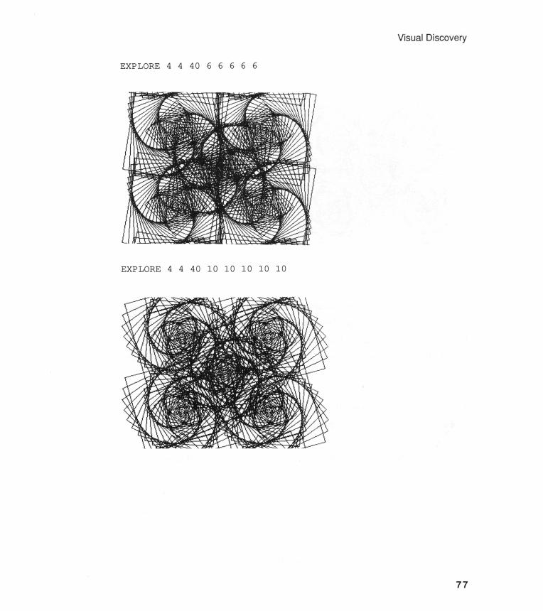
Visual Discovery
EXPLORE44 4066666
EXPLORE 4 4 40 10 10 10 10 10
77
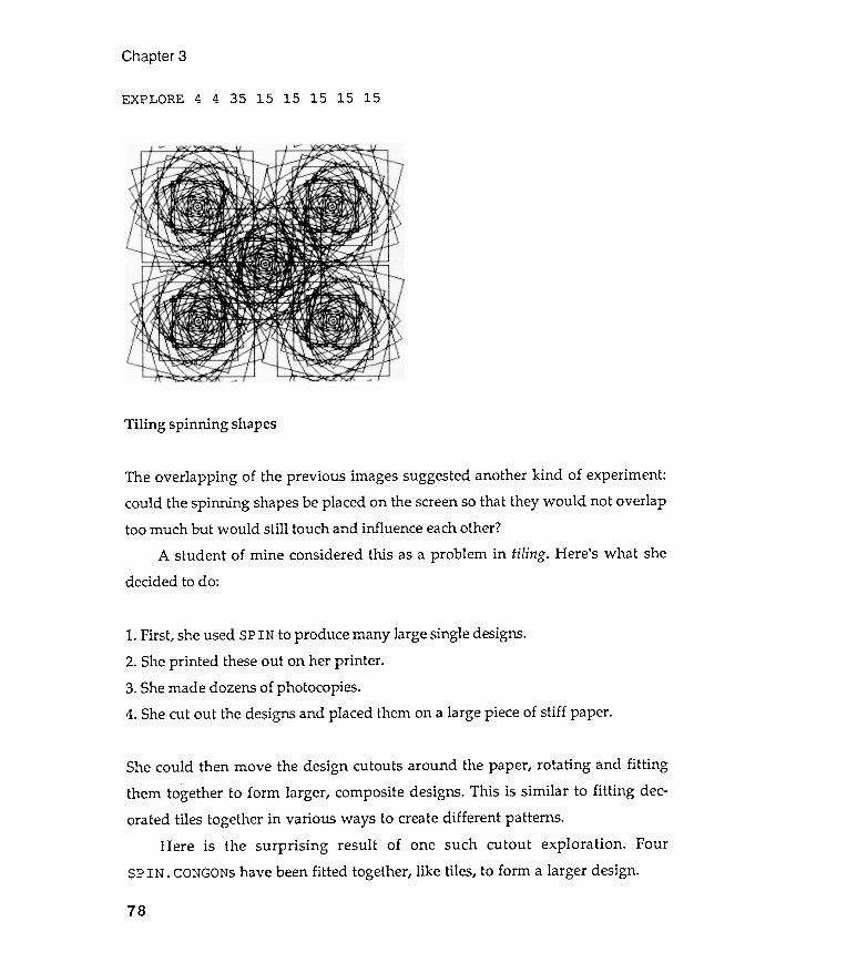
She could then move the design cutouts around the paper, rotating and fitting
them together to form larger , composite designs. This is similar to fitting dec-orated tiles together in various ways to create different patterns .
Here is the surprising result of one such cutout exploration . FourSPIN . CONGONS have been fitted together, like tiles, to form a larger design.
Chapter 3
15 15 15EXPLORE 4 4 35 15 15
Tiling spinning shapes
1. First , she used SPIN to produce many large single designs .
2. She printed these out on her printer .
3. She made dozens of photocopies .
4. She cut out the designs and placed them on a large piece of stiff paper .
78
The overlapping of the previous images suggested another kind of experiment :
could the spinning shapes be placed on the screen so that they would not overlaptoo much but would still touch and influence each other ?
A student of mine considered this as a problem in tiling . Here 's what shedecided to do :

Visual
You probably detected that the above composite design could be done with aLogo procedure far more easily than with scissors and glue . I designed thefollowing procedure to tile four square designs together . Any idea what thatargument called : ALT is for ? : ALT is short for alternating . If it is set to 1, allfour of the tiles will spin to the right ; that is, there will be no alternation ofspin direction . However , if : ALT is set to -1, the odd tiles will spin to the leftwhile the even tiles will spin to the right .
Notice the use here of the MAKE command to alternate the sign of theturning angle. If you have forgotten the MAKE command , review it now in yourLogo manual .
Discovery
Logo-laid tiles
: TIMES :ANGLE
"ANGLE:ANGLE * :ALT]
79
TO LAY. SQ. TILES :RAD : SLICE : TIMES :ANGLE :ALTREPEAT 4 [PU FD : RAD PD -
SPIN 4 : RAD : SLICEPU BK : RAD -RT 90MAKE
END
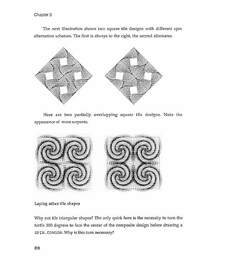
--~ ..
~k '~ff
Chapter 3
Here are two partially overlapping square tile designs . Note theappearance of more serpents.
Laying other tile shapes
Why not tile triangular shapes? The only quirk here is the necessity to turn theturtle 180 degrees to face the center of the composite design before drawing aSPIN . CONGON. Why is this turn necessary?
80
The next illustration shows two square tile designs with different spin
alternation schemes . The first is always to the right , the second alternates .

Hexagonal tiling patterns
Visual Discovery
-
END
Why not? The procedure is straightforward . Note that the angle turned betweentiles is now 120 degrees.
81
LT 180
TO LAY . TR . TILES : RAD : SLICE : TIMES : ANGLE : ALT
REPEAT 6 [ PO FD : RAD PD -
; Orientation of turtle to face center .
SPIN 3 : RAD : SLICE : TIMES : ANGLE
RT 180
; Reorientation of turtle .PU BK : RAD -RT 60 -MAKE "ANGLE : ANGLE * : ALT ]
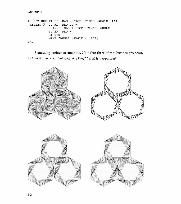
~ ~ (j~..", .~ " , ~ " ". . #f~.... \~~~ ,~ . u " ,\,,-,, ' " ..
", 1 ; I "S~-";'~'", I : I ' ' \ ,: ' I I \ ' ,, , , . : \ . "~ , lil ,. 1 " 1 .\ . , ! I I ,
i;5j. lilii.. t J" t~!I, I' II;!x, "'- '\ ( . !,~~~~~ Iff! I
~ ~..,"'-';'~ ~ ~' . . ~ ' .
" . . , , ' - " .~ ':' ' ,," " , " / " ' / .~~~ "~~~:::: ~~~~~~~ ~ ~~'::-....,/.;/1; '~~~~~~' J. ( i i ~ "'::::l'\ " \ ' ' il , ',:"i I . \' . Ii ~ ~
! t.t 'ttilij 1"\'; If ! bi, , "I '1. ; 1\" I ., ,:,ltl ' "~"i. ;;111:~! I. Ii': 07 " . . . , N, . I I . '
~.~' IJ!I'1~, Il}t" . tt , " "" : : 1~"'~,~ 11'11[ ',," , fIll !" ' " . , . " " . " ' , \ I ' .'",-,,\ ~~~V'.. """"l \ V"
' .." , ...,....." ~ ~~ ~\~~ -~ff~ "~\~:, ,,"~ .f!J~;~ p- ...,::, ~~ ~./
Chapter 3
: TIMES :ANGLE :ALTTO LAY . HEX . TILES : RAD : SLICEREPEAT 3 [ PU FD : RAD PD -
SPIN 6 : RAD : SLICEPU BK : RAD -RT 120 -MAKE " ANGLE : ANGLE *
:TIMES :ANGLE
: ALT ]END
Something curious occurs now . Note that three of the four designs belowlook as if they are interlaced . Are they? What is happening ?
82
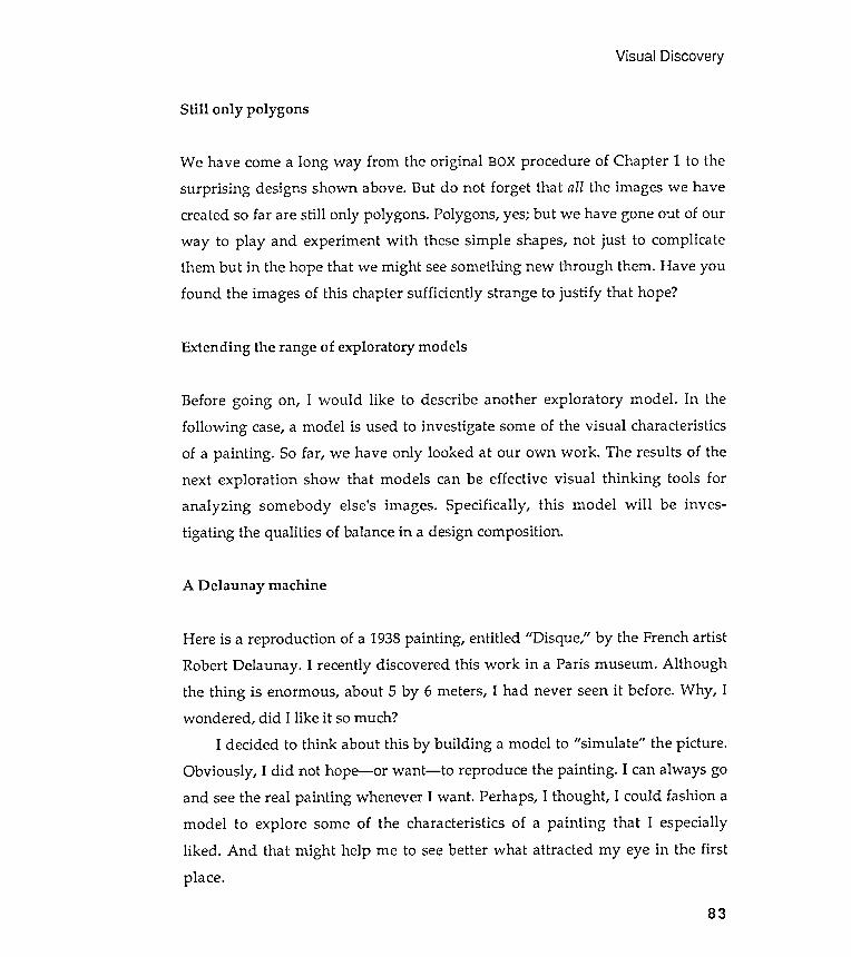
Visual Discovery
Still only polygons
We have come a long way from the original BOX procedure of Chapter 1 to thesurprising designs shown above. But do not forget that all the images we havecreated so far are still only polygons . Polygons, yes; but we have gone out of ourway to play and experiment with these simple shapes, not just to complicatethem but in the hope that we might see something new through them. Have youfound the images of this chapter sufficiently strange to justify that hope?
Extending the range of exploratory models
Before going on, I would like to describe another exploratory model . In thefollowing case, a model is used to investigate some of the visual characteristicsof a painting . So far , we have only looked at our own work . The results of thenext exploration show that models can be effective visual thinking tools foranalyzing somebody else's images . Specifically , this model will be inves -tigating the qualities of balance in a design composition .
A Delaunay machine
Here is a reproduction of a 1938 painting , entitled "Disque," by the French artistRobert Delaunay . I recently discovered this work in a Paris museum . Althoughthe thing is enormous , about 5 by 6 meters, I had never seen it before. Why , Iwondered , did I like it so much?
I decided to think about this by building a model to "simulate " the picture .Obviously , I did not hope - or want - to reproduce the painting . I can always goand see the real painting whenever I want . Perhaps, I thought , I could fashion amodel to explore some of the characteristics of a painting that I especiallyliked . And that might help me to see better what attracted my eye in the firstplace .
83
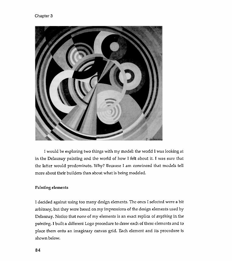
Chapter 3
I decided against using too many design elements. The ones I selected were a bitarbitrary , but they were based on my impressions of the design elements used byDelaunay . Notice that none of my elements is an exact replica of anything in thepainting . I built a different Logo procedure to draw each of these elements and toplace them onto an imaginary canvas grid . Each element and its procedure isshown below .
I would be exploring two things with my model : the world I was looking atin the Delaunay painting and the world of how I felt about it . I was sure thatthe latter would predominate . Why ? Because I am convinced that models tellmore about their builders than about what is being modeled .
Painting elements
84
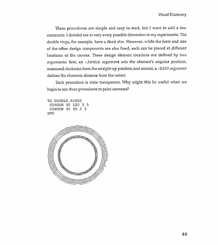
Visual Discovery
TO DOUBLE.RINGSCONGON 40 120 5 5CONGON 40 80 2 5
END
85
These procedures are simple and easy to read, but I want to add a fewcomments. I decided not to vary every possible dimension in my experiments. Thedouble rings , for example, have a fixed size. However , while the form and sizeof the other design components are also fixed , each can be placed at differentlocations of the canvas. These design element locations are defined by twoarguments : first , an : ANGLE argument sets the element 's angular position ,measured clockwise from the straight -up position ; and second, a : DIST argumentdefines the elements distance from the center.
Each procedure is state transparent . Why might this be useful when webegin to use these procedures to paint canvases?
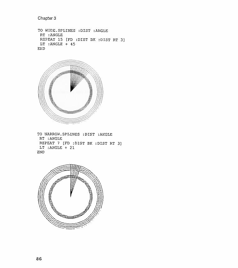
Chapter
I
3
86
TO WIDE. SPLINES :DIST :ANGLERT :ANGLEREPEAT 15 [FD :DIST BK :DIST RT 3]LT :ANGLE + 45
END
TO NARROW . SPLINES : DIST : ANGLERT : ANGLEREPEAT 7 [ FD : DIST BK : DIST RT 3 ]LT : ANGLE + 21
END
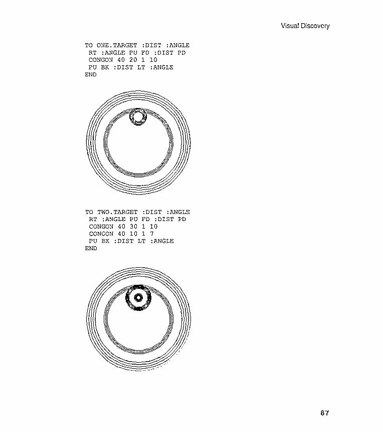
tIj
1-3
tIj
1-3
ZtUO
O~
O
ZtUO
~O
0000
1-3
00
01-3
ZZ
1-3
Z 0
t:i:'
G)
G)
..
~ t:i
:' G)
..
Z~
oo~
o ~
O~
tIjzz
z.
zz.
..
G)
1-3
..
G)
1-3
O~
~to!
~ O
~to!
~HO
OtIj
~ HO
tIj~
C/)
G)
C/)
G)I-
3I-'
WtU
tIj
I-3N
tUtIj
0001
-3
001
-3to
! to
!1-
3 I-
' I-
' hj
..
1-
3 I-
' hj
..
00
00.
. -.
J I-
' H
..
I-'
H~
0..
C/
) ~
0..
C/
)Z
01-3
Z
01-3
G)
H G)
H
to!
C/)
..
to!
C/)
..tIj
1-3
~ tIj
1-3
~Z
ZtU
G)
tUG
)0
to!
0 to
!tIj
tIj
Visual Discovery
87
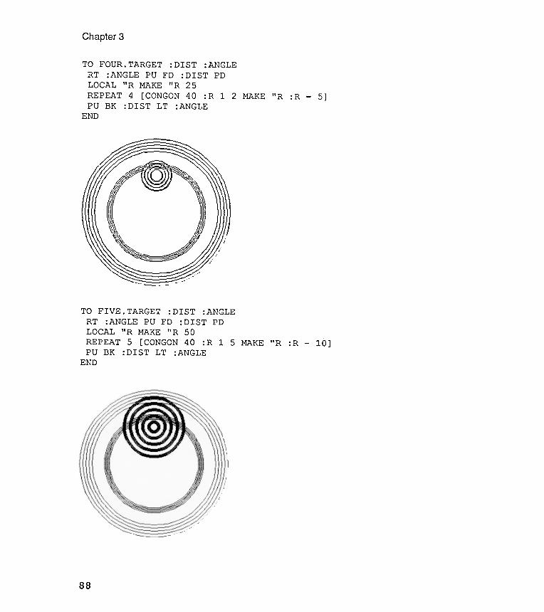
Chapter 3
~~r:;;:;~~~o .,. ~/(,r '~ , )~ )1'~~~~ ~~~~i~~'
TO FOUR. TARGET : DIST :ANGLE
1 2 MAKE "R :R 5]
TO FIVE . TARGET : DIST :ANGLE
1 5 MAKE " R : R - 1 0 ]
88
RT :ANGLE PU FD :DISTLOCAL "R MAKE "R 25REPEAT 4 [CONGON 40 :RPU BK :DIST LT :ANGLE
END
PD
RT : ANGLE PU FD : DIST
LOCAL " R MAKE " R 5 0
5 [ CONGON 40 : R
: DIST LT : ANGLE
PO
REPEATPO BK
END
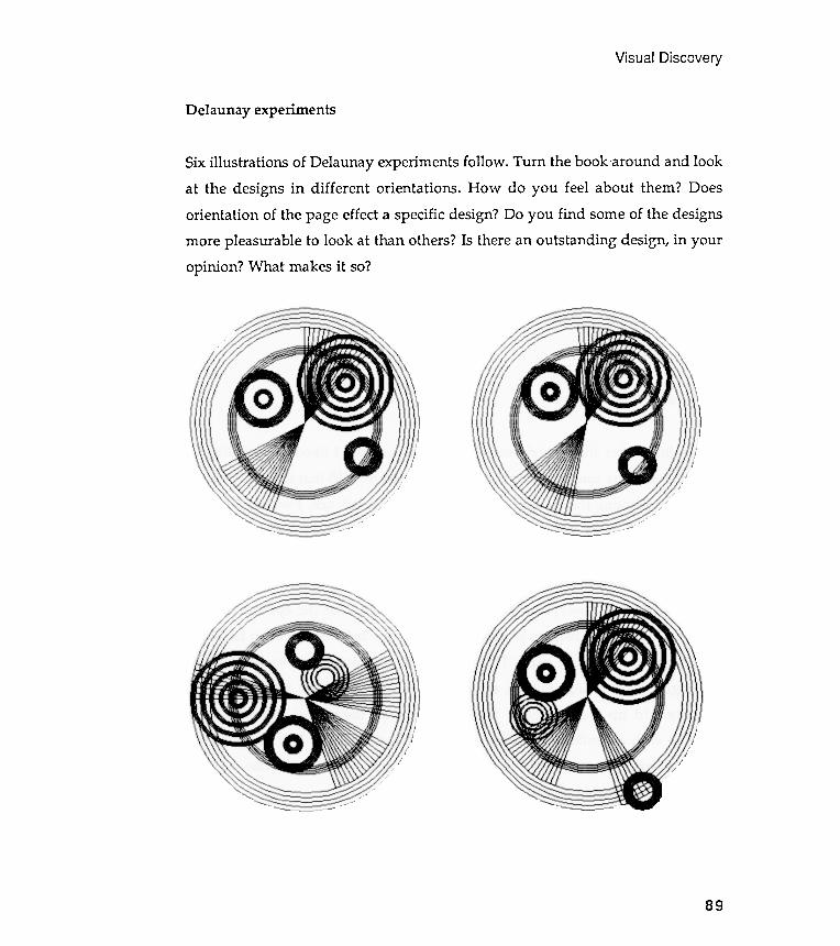
Visual
experimentsDelaunay
Discovery
89
Six illustrations of Delaunay experiments follow . Turn the book 'around and look
at the designs in different orientations . How do you feel about them ? Does
orientation of the page effect a specific design ? Do you find some of the designs
more pleasurable to look at than others ? Is there an outstanding design , in your
opinion ? What makes it so ?
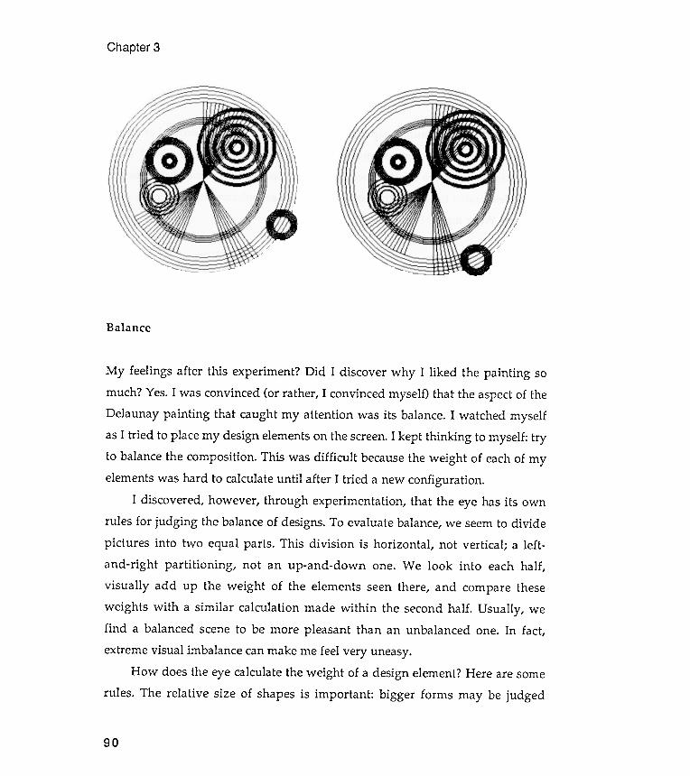
ement ? Here are some
forms may be judged
Chapter 3
Balance
How does the eye calculate the weight of a design elrules . The relative size of shapes is important : bigger
90
My feelings after this experiment ? Did I discover why I liked the painting somuch? Yes. I was convinced (or rather , I convinced myself ) that the aspect of theDelaunay painting that caught my attention was its balance. I watched myselfas I tried to place my design elements on the screen. I kept thinking to myself : tryto balance the composition . This was difficult because the weight of each of myelements was hard to calculate until after I tried a new configuration .
I discovered , however , through experimentation , that the eye has its ownrules for judging the balance of designs. To evaluate balance, we seem to dividepictures into two equal parts . This division is horizontal , not vertical ; a left -and -right partitioning , not an up -and -down one. We look into each half ,
visually add up the weight of the elements seen there, and compare theseweights with a similar calculation made within the second half . Usually , wefind a balanced scene to be more pleasant than an unbalanced one. In fact,
extreme visual imbalance can make me feel very uneasy.
Visual Discovery
heavier than smaller ones. But relative color value is also important . Forexample, white against black, because it attracts our attention , has more weightthan gray against black, which attracts less attention . Thus a small black objectmight be heavier than a large gray one, if both were on a white background .
Variety of shape is also important in weight calculations . A more complexshape, because it attracts the eye, may be judged heavier than a boring shape.For example , a small asterisk may have more weight than a larger circle .Relative position is important , too. For example, a small shape in an extremeposition can sometimes balance heavy shapes that are more centrally located.
When all the elements of a scene seem to radiate from a central point , akind of balance known as radial balance occurs.
Because the eye seems to be concerned with horizontal rather than verticalbalance, rotating a picture can destroy its balance. Why ? Or, on the other hand,a rotation can fix an unbalanced picture .
Now go back and look at the Delaunay painting . I see a calming imagemade from disparate elements, finely balanced into a single design. Turn it on itsside and what happens? Now go back and look at the Delaunay simulations . Dothey halance? How would you change each of them to make them more bal-anced? Try some balancing exercises yourself with a design machine of your owninvention .
Polygons placed on the vertices of other polygons
There is one remaining exercise to discuss from Chapter 1. Exercise 1.5 asked youto design a Logo procedure that will draw polygons centered on the vertices ofother polygons . You need to have a good feeling for what this problem is reallyabout before you rush off and try to solve it . As always, small drawings can helpby making problems easier to visualize and to manipulate .
Even the simple sketches below should make the problem clearer. You willsee the pattern required . Start by drawing one polygon . Now draw a series, or a
91
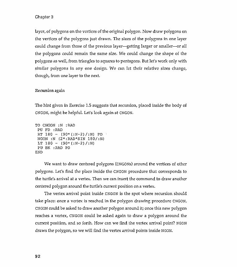
Chapter 3
92
layer , of polygons on the vertices of the original polygon . Now draw polygons on
the vertices of the polygons just drawn . The sizes of the polygons in one layer
could change from those of the previous layer - getting larger or smaller - or all
the polygons could remain the same size . We could change the shape of the
polygons as well , from triangles to squares to pentagons . But let 's work only with
similar polygons in anyone design . We can let their relative sizes change ,
though , from one layer to the next .
Recursion again
The hint given in Exercise 1 .5 suggests that recursion , placed inside the body of
CNGON , might be helpful . Let 's look again at CNGON .
TO CNGON : N : RADPU FD : RAD
RT 180 - ( 90 * ( : N - 2 ) / : N ) PD .NGON : N ( 2 * : RAD * SIN 180 / : N )LT 180 - ( 90 * ( : N - 2 ) / : N )PU BK : RAD PD
END
We want to draw centered polygons ( CNGONS ) around the vertices of other
polygons . Let 's find the place inside the CNGON procedure that corresponds to
the turtle 's arrival at a vertex . Then we can insert the command to draw another
centered polygon around the turtle 's current position on a vertex .
The vertex arrival point inside CNGON is the spot where recursion should
take place : once a vertex is reached in the polygon drawing procedure CNGON ,
CNGON could be asked to draw another polygon around it ; once this new polygon
reaches a vertex , CNGON could be asked again to draw a polygon around the
current position , and so forth . How can we find the vertex arrival point ? NGON
draws the polygon , so we will find the vertex arrival points inside NGON .
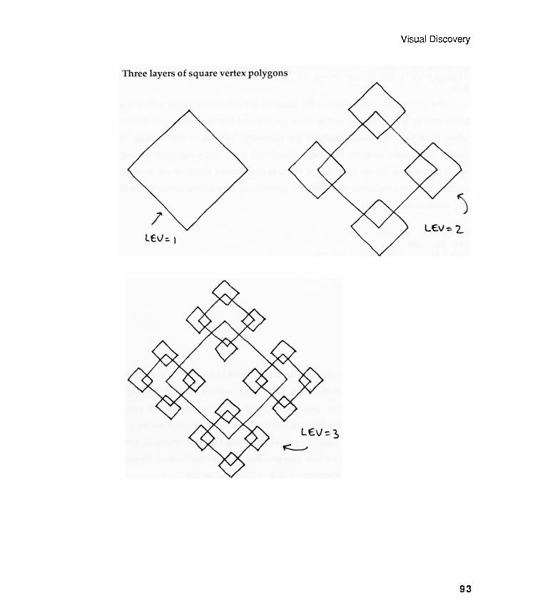
Visual Discovery
93

Chapter 3
TO NGON :N :EDGEREPEAT :N [ FD :EDGE (* * * ) RT 360/ :N ]
TO CNGON :N :RADPU FD :RADRT 180 - (90* ( :N- 2) / :N) PDREPEAT :N [ FD (2* :RAD*SIN
RT 360/ :N ]LT 180 - (90* ( :N- 2) / :N)PU BK :RAD PD
END
180/ :N) (* * * )
Vertex arrival point
94
Now try saying in words what you would like to insert at the (* * * ) above and
what arguments the insertion requires . Here is an sample of such "wordy "thinking : "OK, turtle : whenever you find yourself at the vertex arrival point(the place between drawing an edge and turning in preparation for drawing thenext edge), draw another polygon . As you are drawing that next polygon , stopafter each edge and plan to do another polygon . But don't do this forever . To stopyourself , you will need a new argument ; call it : LEV, for recursion level .
"You also will need to know if each succeeding layer of polygons is to getbigger or smaller in terms of of the preceding layer . So, define another argument ;call it : F AC for growth factor . This will define for you whether to shrink orenlarge polygons from one layer to the next.
"Give the new procedure a new name, RECGON, for illursing polygQnS.
END
The ( * * * ) symbol indicates the place in the procedure NGON where theturtle arrives at a polygonal vertex. How can we find this location inside CNGONwhen it uses NGON? Look closely at the following . How does this version ofCNGON differ from what we have been using? Not at all . NGON has been openedup so that we can see its parts. All of NGON is now placed inside of the body ofCNGON; there are no longer two separate procedures . The vertex arrival point isstill marked with ( * * * ) .
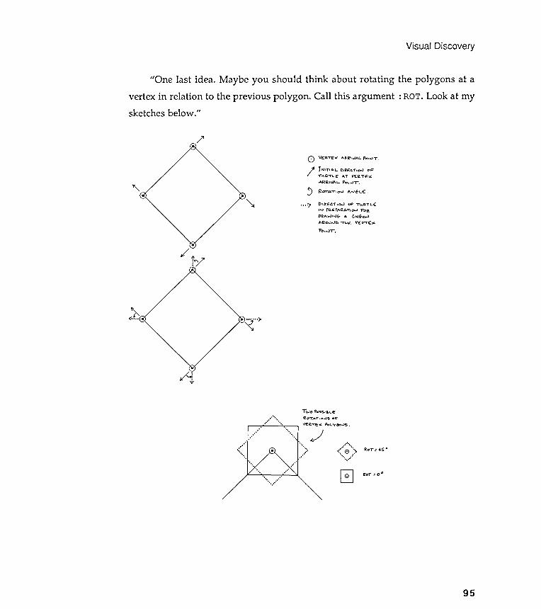
Visual Discovery
/ '
"\ ~
/
<::) v(:~~ ,.. Ae.e'vAl. PO"' T .
/ 1" 'T' ~L j),E c....,o.J o~T" aT'-E AT V€Q.TE"AI2~I~ L f'o..JT .Ro-rAT.O.J " oJ6l.~ .~
. . . =,
iy
~ .......)~.f... ~
-..,:,;,
Two PO~o;.' e. ,- e
' . . " " ." eOTAT , ~ " $ 00 :. ' . ' , ~ a. " 1" E " ~ ' - v60 ' ) s .
.' " )..,.,.." . '..""" . ~
. . . " ,
. " .. . . '
. . . " . . . ,
."...." .....:. 0 .">...'. ....,,G
2oT"=4S.
~oT = 00
95
"One last idea. Maybe you should think about rotating the polygons at avertex in relation to the previous polygon . Call this argument : ROT. Look at mysketches below ."
DI2ECTlo..I OF -n. a.TL~,' " Pfl-E1'AC1.ATlo..I FolZ.D~" wlo.lr,. ~ t ",G-o..>Aeo.J..J[) T"IE: VE:~T~"p" ,. . rr .

assembled RECGON
Chapter 3
The
Now we need to convert CNGON into RECGON based on these words and sketches.
recursion to another. Can you see how these two arguments control the scaling ofthe RECGON design as well as its complexity (that is, level of recursion ) ?
Recursion is a tricky business, but it is also very elegant. Many art studentshave told me that they find recursion aesthetically pleasing ; they like its"shape," somehow .
96
Here it is , with plenty of comments .
TO RECGON : N : RAD : FAC : ROT : LEV
; Recursing polygons on vertices of polygons .
IF : LEV < 1 [ STOP ]
; Stops the recursion at proper level .
PU FD : RAD
RT 180 - ( 90 * ( : N - 2 ) / : N ) PD
REPEAT : N [ FD ( 2 * : RAD * SIN 180 / : N ) -
LT : ROT -
; Orients turtle before drawing next figure .
RECGON : N : FAC * : RAD : FAC : ROT : LEV - 1 -
; Here is the inserted recursion apparatus .
; Note how the : RAD argument is scaled by : FAC .
RT : ROT -
; Reorients turtle by removing rotation angle .
; Is state transparency an issue here ?
RT 360 / : N ]
LT 180 - ( 90 * ( : N - 2 ) / : N )
PU BK : RAD PD
END
Note that RECGON has five arguments . Therefore , each time RECGON is
used , five values must be supplied to it . These values control the characteristics
of the figures drawn . Only : RAD and : LEV change their values from one level of

Visual Discovery
Understanding recursion experimentally
97
Recursion is the most elusive concept in this book . I believe it is also one of themost powerful because it provides you with an entirely new metaphor for visualthinking . Working and thinking about recursion will encourage you to look -thinkat your world differently . In a strange way , recursive thinking gives you thepower to make the world look different .
You may not understand recursion at all in the beginning , until you haveexperimented , over and over again, with recursive procedures written by others.If you can understand one recursive procedure well , you are on your way to usingrecursion on your own terms. Toward the goal of understanding a recursiveprocedure, you must design your own experimental apparatus to test it out .
Let's playa bit with RECGON. Watch how RECGON directs the screen turtlefrom one part of the design to another ; the turtle is walking through recursionspace. Try to get an intuitive feeling for how recursion "does it ." At the end ofthis series of design experiments, we will talk more about the mechanical natureof RECGON and introduce you to a kind of visual model of recursion . For themoment , though , just play about with RECGON.
For example, ask RECGON to place squares at the vertices of other squaresdown to four levels of recursion . Four levels means that there will be squares onsquares on squares on squares. The value that we will type for the argument : LEVwill be 4. Now , what about scaling the design? If we make : FAC equal to .5, thesquares will get smaller as recursion progresses. Finally , what about the rotationangle, : ROT? Let's try 45 degrees to start . To make this rotation idea less cryptic ,we will experiment with different values to see what happens. One last item :set the beginning : RAD to 50 units .
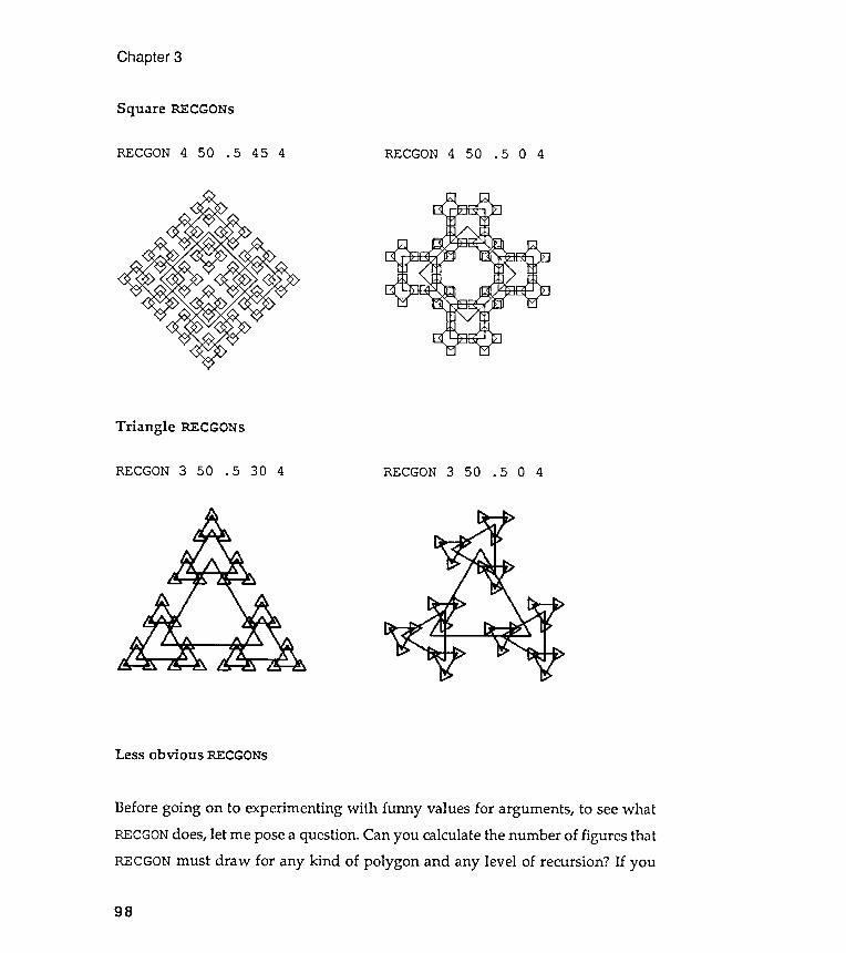
Less obvious RECGONs
Chapter 3
Square RECGONs
RECGON 4 50 . 5 45 4 RECGON 4 50 . 5 0 4 RECGON 3 50 . 5 0 4
Before going on to experimenting with funny values for arguments , to see what
RECGON does , let me pose a question . Can you calculate the number of figures that
RECGON must draw for any kind of polygon and any level of recursion ? If you
98
Triangle RECGONs
RECGON 3 50 . 5 30 4
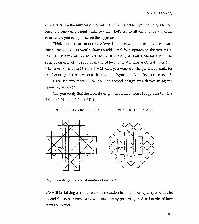
Visual Discovery
RECGON 4 50 (l / SQRT 2) 0 4
99
could calculate the number of figures that must be drawn , you could guess howlong anyone design might take to draw . Let 's try to attack this for a specificcase. Later, you can generalize the approach .
Think about square RECGONs. A level 1 RECGON would draw only one square,but a level 2 RECGON would draw an additional four squares on the vertices of
the first : that makes five squares for level 2. Now , at level 3, we must put four
squares on each of the squares drawn at level 2 . That means another 4 times 4 . In
total , level 3 includes 16 + 4 + 1 = 21. Can you work out the general formula fornumber of figures in terms of n, the kind of polygon , and L, the level of recursion?
Here are two more RECGONs. The second design was drawn using thereversing pen color .
Can you verify that the second design was formed from 341 squares? (1 + 4 +4 *4 + 4 *4 *4 + 4 *4*4 *4 = 341 .)
RECGON 4 10 ( SQRT 2 ) 0 5
<,,/ ,,/ ,,/ >/ " / , , / , ,
A" , , // / "" , , // / "" , , // / "
V
<,,/ ,,/ ,,/ >/ " / , , / , ,
Recursion diagrams: visual models of recursion
We will be talking a lot more about recursion in the following chapters. But letus end this exploratory work with RECGON by presenting a visual model of howrecursion works .
Before you read on , I need to show you my visual license . What follows is a
visual rather than a technical description of recursion . What I describe as
" happening " on the diagrams does not necessarily coincide with what is
" happening " inside your computer . However , I have found that graphical
recursion models are often far more useful in encouraging an intuitive recursion
sense than technical ones . This is almost always true for art and liberal arts
students , though my results are mixed with science students . But if you hanker
after technical truth , take a computer scientist to dinner .
It is a little difficult to visualize how a procedure can be defined in terms of
itself , so let ' s try the following . When a procedure asks to be run again , imagine
that Logo makes a copy of the original procedure and locates this copy below the
first . This copy is where the turtle goes in search of its next instructions . If the
copy asks to be run again , a third copy is created and located under the second .
The third copy is where the turtle goes in search of further instructions .
If the third copy does not call itself , the recursion goes no deeper and no
more copies of the original procedure are made . The turtle climbs up from the
third copy to the second copy and continues on the second copy looking fof
instructions . If the secol ". d copy does not call itself again , the turtle climbs up to
where it left the first copy .
Think of these copies as sheets of paper on which the identical procedure is
written . The turtle reads instructions from whatever sheet it is currently on .
Suppose the turtle is reading instructions from the top sheet . Suddenly the top
sheet calls itself . The turtle drops from the top sheet down to the sheet just
below it and begins to read the instructions there . If this procedure ends without
recursion , the turtle climbs back to the place on the top sheet where it had left
off . The turtle , of course , carries the values of arguments along with it .
Here is a recursion diagram that sketches the path of operation after we
type RECGON 4 50 45 3 . Notice that the diagram shows two things . First ,
arrows indicate the path the turtle takes from one level to another ; and , second ,
the values are indicated for the 5 arguments at each level .
Chapter 3
100
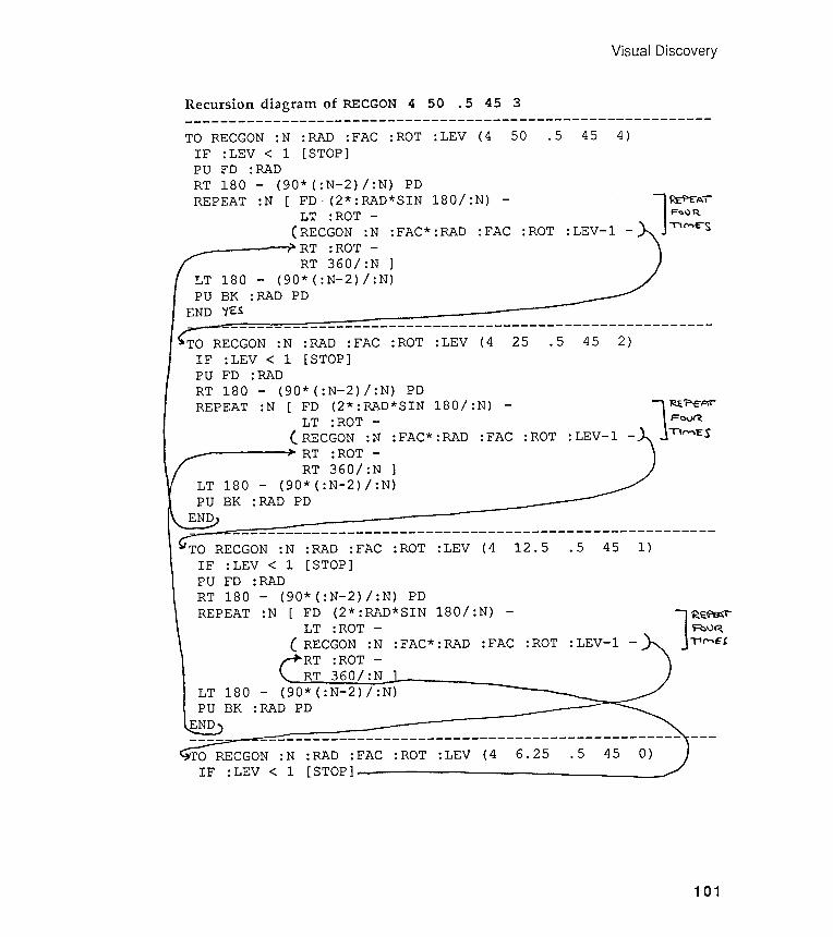
Visual Discovery
Recursion diagram of RECGON 4 50 . 5 45 3- - - - - - - - - - - - - - - - - - - - - - - - - - - - - - - - - - - - - - - - - - - - - - - - - - - - - - - - - - - -
50 .5 45 4 ): LEV (4TO RECGON :N :RAD :FAC :ROTIF :LEV < 1 [STOP]PO FD :RADRT 180 - (90*(:N-2)/ :N) PDREPEAT :N [ FD. (2*:RAD*SIN 180/ :N) - l ~ AILT : ROT - F~O~(RECGON :N :FAC*:RAD :FAC :ROT :LEV-1 - mM~SRT :ROT -RT 360/ :N ]LT 180 - (90*(:N-2)/ :N)PO BK :RAD PDEND 'itS--------------------------------------------------------
TO RECGON :N :RAD :FAC :ROT :LEV (4 25 .5 45 2)IF :LEV < 1 [STOP]PO FD :RADRT 180 - (90*(:N-2)/ :N) PDREPEAT :N [ FD (2*:RAD*SIN 180/ :N) - l ~?tP LT :ROT - FaVf'?( RECGON :N :FAC*:RAD :FAC :ROT :LEV-1 - II('O"\'ESRT :ROT -RT 360/ :N ]LT 180 - (90*(:N-2)/ :N)PO BK :RAD PDEND--------------------------------------------------------
TO RECGON :N :RAD :FAC :ROT :LEV (4 12.5 .5 45 1)IF :LEV < 1 [STOP]PO FD :RADRT 180 - (90*(:N-2)/ :N) PD
REPEAT :N [ FD (2*:RAD*SIN 180/ :N) - lR~ TLT :ROT - ~v~C RECGON :N :FAC*:RAD :FAC :ROT :LEV-1 - ~~E{RT :ROT -RT 360/ :NLT 180 - (90*(:N-2)/ :N)PO BK .: RAD PDEND ------------------------------------------------ ---
0 RECGON :N :RAD :FAC :ROT :LEV (4 6.25 .5 45 0)IF :LEV < 1 [STOP]
101
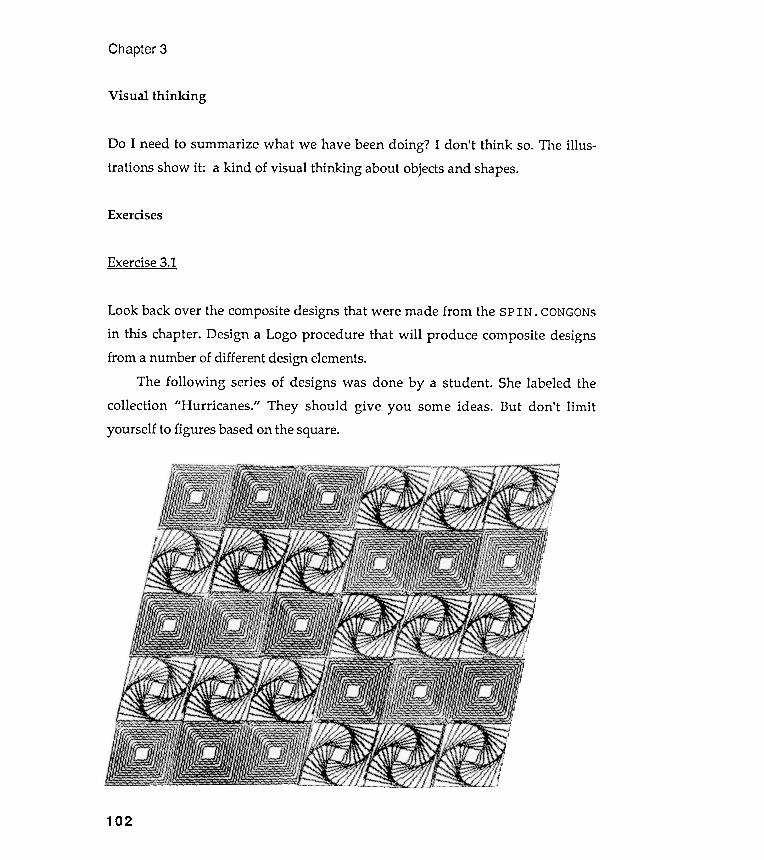
Exercise 3.1
Chapter 3
Visual thinking
Do I need to summarize what we have been doing ? I don 't think so.
trations show it : a kind of visual thinking about objects and shapes .
The illus-
Exercises
102
Look back over the composite designs that were made from the SPIN . CONGONS
in this chapter . Design a Logo procedure that will produce composite designsfrom a number of different design elements.
The following series of designs was done by a student . She labeled thecollection "Hurricanes ." They should give you some ideas. But don 't limityourself to figures based on the square.
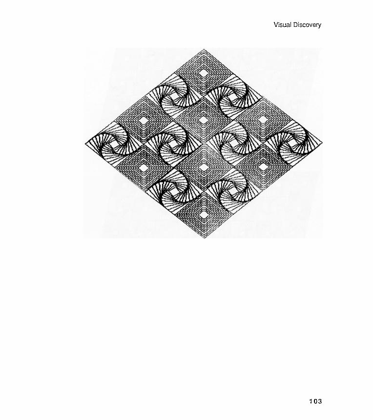
Visual Discovery
103
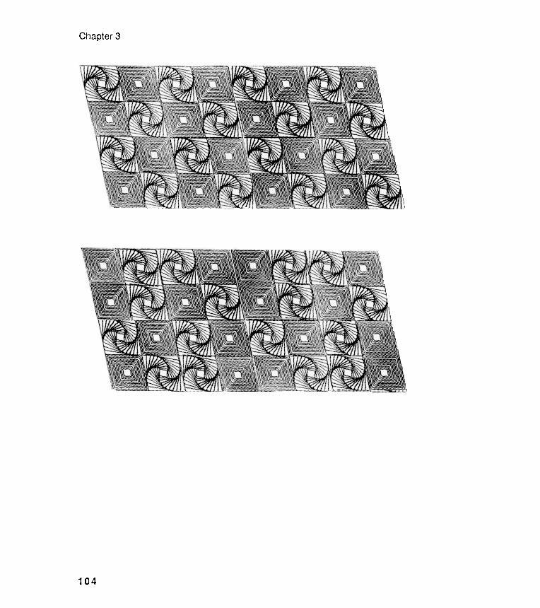
Chapter 3
104
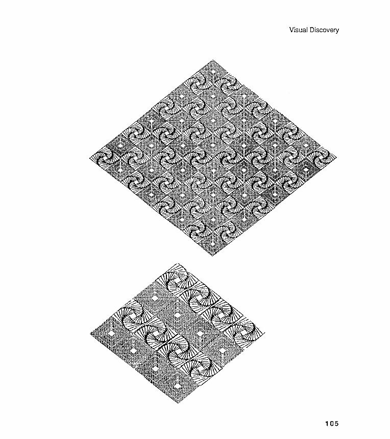
Visual Discovery
105
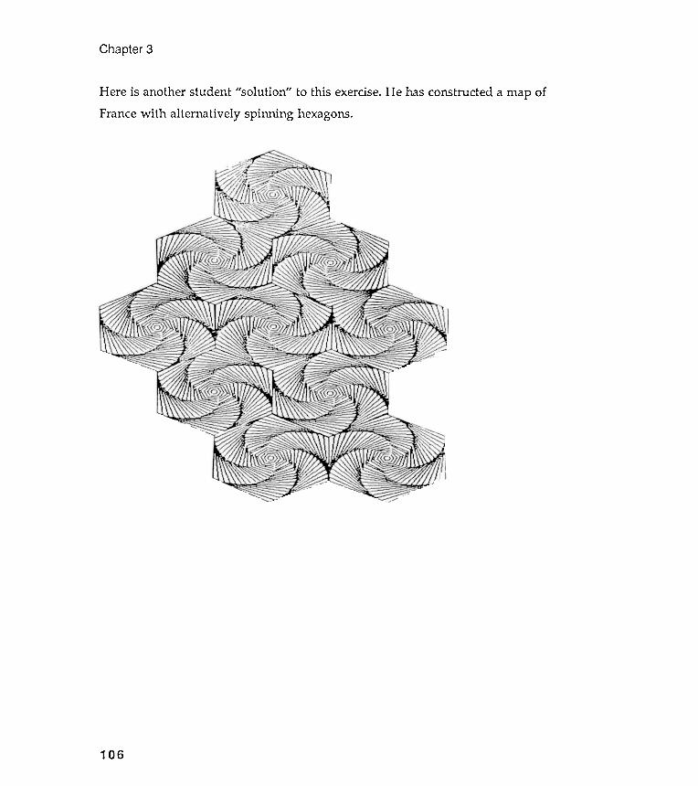
Chapter 3
Here is another student "solution " to this exercise. He has constructed a map ofFrance with alternatively spinning hexagons.
106
Exercise 3.5
Visual Discovery
Exercise 3.2
Design a procedure that combines the ideas of SPIN . CONGONs with the ideas ofRECGONS.
Exercise 3.3
Look back at the Delaunay machine . Invent a queasy machine that produces the
most unbalanced designs imaginable . Try to characterize in words what your
designs are doing and what you were doing .
Exercise 3.4
Build an exploratory model of a painting that interests you . Make sure you have
a reproduction of the painting to carry around with you . Postcard images are the
best . Go out to your local museum and buy a collection of reproductions by
different artists . Don 't limit yourself to geometric painters ; include realistic
work , even photographs . Select as large a variety of work as you can .
Inspiration may strike from comparing two quite different pictures . Don 't start
doing any Logo until your painting collection is pinned up over your desk . Spend a
lot of time looking at those postcards .
After you have finished this exercise , describe clearly what char -
acteristics you have tried to simulate . Remember that you can simulate the
characteristics of a painting without copying the image . Have your feelings
changed toward your painting ?
107
Study the following several pages of figures . Bring out your visual thinkinggear; can you decompose these composites into their components?
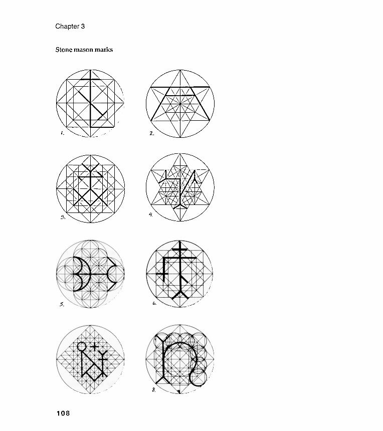
Chapter 3
Stone mason marks ,.
b.5.
3.
108
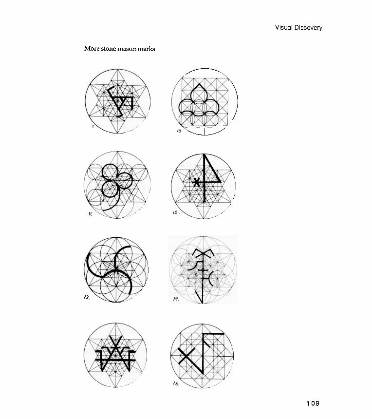
More stone mason marks
Visual Discovery
/ --- --...
"---
------"""
......_~J_=~/10.
II.
13.
109
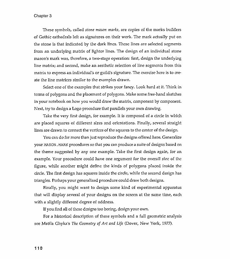
Chapter 3
These symbols , called stone mason marks, are copies of the marks buildersof Gothic cathedrals left as signatures on their work . The mark actually put onthe stone is that indicated by the dark lines . These lines are selected segmentsfrom an underlying matrix of lighter lines . The design of an individual stonemason's mark was, therefore, a two -stage operation : first , design the underlyingline matrix ; and second , make an aesthetic selection of line segments from this
matrix to express an individual 's or guild 's signature . The exercise here is to cre-ate the line matrices similar to the examples drawn .
Select one of the examples that strikes your fancy. Look hard at it . Think interms of polygons and the placement of polygons . Make some free-hand sketchesin your notebook on how you would draw the matrix , component by component .Next , try to design a Logo procedure that parallels your own drawing .
Take the very first design, for example. It is composed of a circle in whichare placed squares of different sizes and orientations . Finally , several straightlines are drawn to connect the vertices of the squares to the center of the design.
You can do far more than just reproduce the designs offered here. Generalizeyour MASON. MARK procedures so that you can produce a suite of designs based onthe theme suggested by anyone example . Take the first design again, for anexample. Your procedure could have one argument for the overall size of thefigure , while another might define the kinds of polygons placed inside thecircle. The first design has squares inside the circle, while the second design hastriangles . Perhaps your generalized procedure could draw both designs.
Finally , you might want to design some kind of experimental apparatusthat will display several of your designs on the screen at the same time , eachwith a slightly different degree of oddness.
If you find all of these designs too boring , design your own .For a historical description of these symbols and a full geometric analysis
see Matila Ghyka 's The Geometry of Art and Life (Dover , New York , 1977).
110
Visual Discovery
Exercise 3.6
111
Design a personal mark in the manner of, but not limited to, the approach usedby the Gothic stone masons. This mark should be a visual model of severalaspects of your personality . This exercise will require a combination of
introspection and Logo designing . You may find that your Logo designs actuallyhelp the looking within yourself .
Start this exercise by doodling in your notebook before you write anyprocedures. Without thinking too much about what you are doing , write down alist of your own personality quirks . Do this as fast as possible. Now go back overyour list and make small sketches of whatever images come into your mind . Tryto make a sketch for each word . But if one word doesn't cause an image to popinto your mind quickly , leave it and go on to the next. Finally , combine some ofyour best sketches into a single design theme and design a Logo procedure toexplore it . Don 't intellectualize what you are doing . Do everything as quickly aspossible. Think about what you have done only when you have generated somepersonality images.
You may find that you will produce many personal marks that you aren'thappy with . That 's OK . Put them all in your notebook and write a short note onwhat you were trying to accomplish with each. This is important : keep a traceof what you are thinking and doing .
Finally , select one or two individual marks . These images are to be includedin your published biography . This is the only authorized biography of your lifeand you may wish to write a few words of description . Don 't worry about beingtoo personal in your description : the book 's production run will be very , verysmall . And since few people will read your comments, you can be totally candid .
The next page shows an example of a mark designed by one of my students.He found a basic theme that he presents in various configurations . Following theimages is his description of what he was trying to say with the mark .

Chapter 3
112
The student's 12ersonal mark ex12lained in words~
Visual Discovery
113
"I liked the idea of using circles in my personal mark. I wanted to show that Ihave many interests and that no one single interest is most impor.tant to me. I tryto be a well-rounded person (sorry about that). I get a lot of personal satisfactionfrom seeing how a number of different disciplines interact with each other.Math and art are two examples of my interests.
"I wanted the circles not to overlap in the design- I found that Gothic stonemason marks get too busy when too many lines overlap; I try to get my life prettyorganized, so I wanted to show the circles in my head all touching- but in a niceneat way. I like being clever with math, so I was pleased to be able to work outthe math in this design. I wanted the balls to get bigger and to fit nicelytogether. They do look a bit like ball bearings, I'm afraid. Maybe I come acrossto people as a bit of a machine. I don't know.
"I like the top mark because the turtle overlapped on the screen turning twoof the circles into little moon shapes. These moons have rather soft outlines, andthey would never work as ball bearings. The moons gave me the idea of softeningup the entire mark- making it more organic and less geometric. I figured out howto have my printer make the first two designs look squashed; I liked thecomparison with the nonsquashed third design. The bottom mark is done withCONGON. It looks like Greek jewelry that is made from those washer-like things.
"These three marks illustrate how I try to apply my mathematical mind tosoft, organic (human) problems. And Greek jewelry? I think it is an example ofmath-inspired designs that serve humanistic ends."
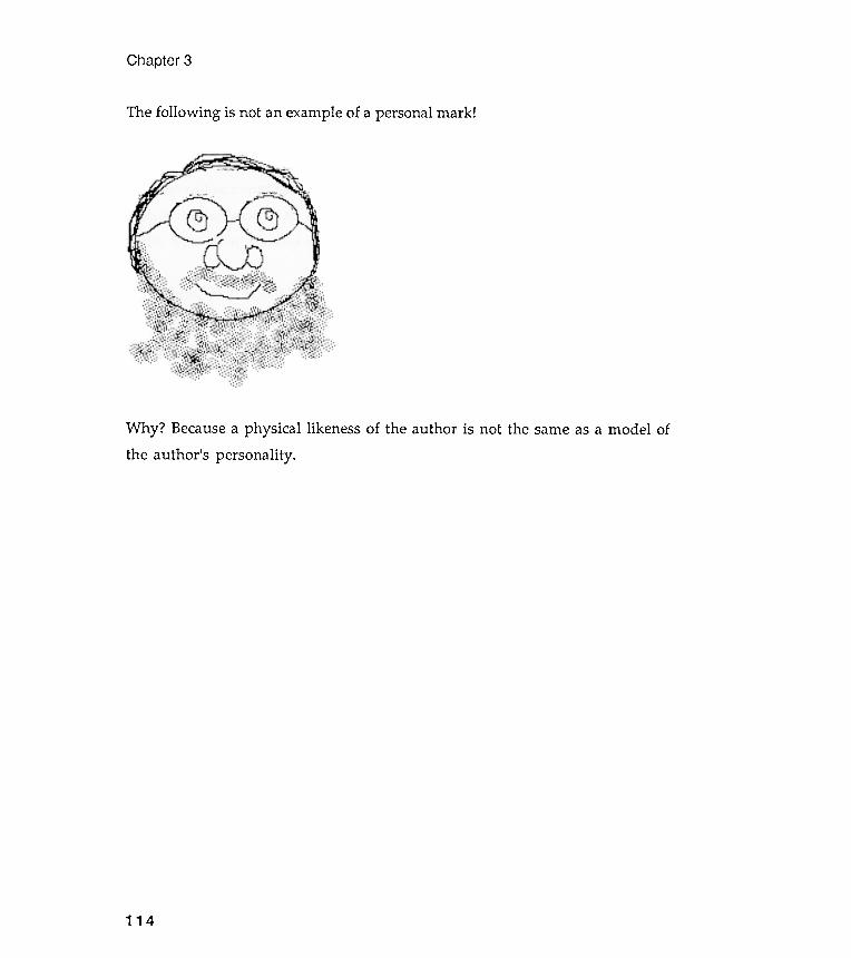
Chapter 3
The following is not an example of a personal mark !
Why ? Because a physical likeness of the author is not the same as a model ofthe author 's personality .
114
cchapter 4
i rcu I ar Grids
Modeling for communication and thought
Like algebra, geometry , or any other language, the language of modeling is botha medium for communication and a notation system that helps structure thought .You can crystallize an idea about a shape or complex of shapes into Logoprocedures. Logo gives you a language both to name the shape and to define howto go about drawing the shape. Once the shape is named in a procedure , thatname can be used as a shorthand for the method of constructing and exploring thevisual implications of the shape's definition .
In the preceding chapters you have seen that our visual intuitive sense islimited in many cases. That explains why some of the images are so surprising .Most people 's visual vocabulary is fairly rudimentary , even when it comes tosomething as commonplace as polygons . Visual exploration with models can
" Language is an instrument of human reason and not merely a medium for the
expression of thought . . . . "
George Boole
" By relieving the brain of all unnecessary work , a good notation sets it free to
concentrate on more advanced problems . . . . "
Alfred North Whitehead
Circular grids
Chapter 4
116
Having explored polygons extensively , are you beginning to see the world
packed with them ? Were you able to spot and recreate in procedure forms the
polygons hidden inside the stone mason marks of Exercise 3.5? I want to use this
mason mark exercise as an example of how to go about the unpacking and
repacking of complicated , composite images . The mason marks are good ex-
amples , too , of a special kind of composite shape organization . The component
elements are all arranged around a central point . I call this class of designs
circular grids .
help increase your visual vocabulary by forcing it to describe unexpected shapes.Have you felt visually stretched?
Unpacking and repacking shape packages
The goal of this chapter is to encourage you to take complicated designs apart inorder to find their basic elements, the building blocks. Once unpacked , a complexdesign can be explored by modeling each of the component parts in turn . And oncethe small -part models are completed and named, you are free to concentrate onhow to put the parts back together again, that is, how to repack the packagewith which we started . Along the way , you may be able to find severalalternative ways to repack the pieces.
Do you remember the first time you took a small machine apart ? I remember
happily attacking a large , mechanical alarm clock . The pleasure came fromsolving two puzzles : to separate the pieces and then to put them back togetheragain. And because I had seen through those puzzles , and had arranged all thesmall parts carefully on a carpet, I knew that the reassembled clock was not thesame as the original .
Circular Grids
Analyzing mason marks
Let 's go through the exercise of analyzing the mason mark designs to illustratethe usefulness of Logo shape and placement notation . The following discussion isnot the only description of what one can see in stone mason marks ; don 't be
alarmed if the work you did yourself doesn't correspond exactly to the followingillustrations . There is no single " correct" answer . But there is a proper style ofapproach . The following examples are designed to show you that style.
Go back and look carefully at all the stone mason marks at the end of thelast chapter . Think about the following questions:
117
1. What shapes are used?2. What shapes are not used?3. Wha t shapes are used together?4. What shapes are not used together?
5. Are individual marks symmetric ? If yes, can you see the point of symmetry ?Are some marks partially symmetric ? (Be sure that you have a definition ofsymmetry at your fingertips . Are there different kinds of symmetries ?)6. Within any individual mark , is anyone shape repeated over and over againin a way that might suggest recursion?7. What are the characteristics that make all the marks alike ?
8. What are the characteristics that make each mark unique ?9. What already written Logo procedures could be used to produce parts of themarks ?
10. What new Logo procedures need to be designed?
Now look back over the marks and quickly jot down your answers to these
questions . Don 't mull over the words ; write them down as they come to you .
Chapter 4
Written observations
You probably noticed that
1. All the designs are composed from a few basic shapes: circles, squares, andtriangles . You can produce all of these easily with CNGON.
2. All the marks reveal a common characteristic: the orientation of the polygonsaround a center. Each mark has a design symmetry "around " the center of thistheme circle. Each mark uses a limited combination of polygons . For example,squares and circles occur together in the same mark , but triangles and squares donot. Excepting the circle, no polygon beyond the 4-gon level is used. There are, forexample, no pentagons or octagons. For polygons centered on the circle 's center,CNGON can be used.
3. Two polygons of the same size and shape are often overlapped to form stars .
For example , one triangle in Mark 2 is rotated 60 degrees from another , to form a
six -pointed star , while one square , in Mark 1, is rotated 45 degrees from another
to form an eight -pointed star . This is easy: use a combination of CNGONs and RTs.
4 . There are two special kinds of polygon placements within the marks that
require special attention . First , the grid placement of squares in Marks 7 and 10 ;
and second , the placement of polygons at the vertices of other polygons : for
example , the circles at the vertices of the smallest triangle in Mark 13 . You will
need two new procedures here .
5 . There are two forms of recursion that appear in the group of marks , and each
of the marks has at least one of them operating : first , the grid placement of
boxes already mentioned might be structured with a recursive procedure - the
fact that Mark 7 has twice as many boxes as Mark 10 is " very suggestive " of
118
Let's start with the recursion while your energy is high . Until recursion becomessecond nature to you , you will need a lot of concentration to understand how itdoes what it does. But believe me, recursion will soon become as natural to you as
using any other form of shape description .Look at the following four designs. Then look back at Mark 1 and 2. See how
natural some of these shape descriptors are becoming ? Do you see the kind ofrecursive procedure that is needed, just by looking at these pictures?
Put your ideas into words , though , just to be on the safe side. Remember torecord your thoughts and doodles in your notebook.
Circular Grids
recursion ; and second, notice the occurrence of polygons nesting inside circlesnesting inside polygons . This nesting is called " inscribed " polygons . That is, apolygon is inscribed , or drawn , to fit within another shape. You will see thisnested-shapes recursion in many of the marks : note the two smaller squaresnested inside the larger squares in Mark 1; also note the same kind of nesting inthe triangles of Mark 2. New procedures will be required here.
You will need new procedures for the last three points :
1. Placement of polygons at the vertices of other polygons .2. Two kinds of recursion: nested/ inscribed polygons and grids .3. Some special line drawers to connect certain polygon vertices.
Recursive design features
119
6. Straight lines are sometimes used to join the vertices of some of the basic
polygons - the diagonal cross inside a square - or the polygons formed by the
overlap of the basic shapes - the lines joining the intersection points of the two
triangles . New procedures here , too .
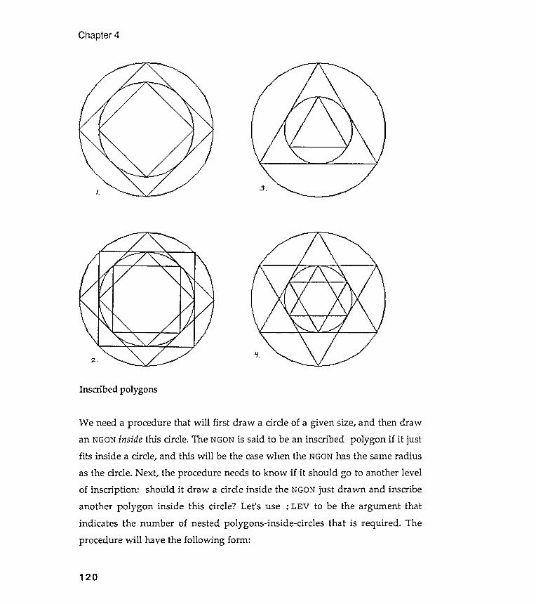
Inscribed polygons
Chapter 4
3 .J.
If.:2;.
We need a procedure that will first draw a circle of a given size, and then drawan NGON inside this circle. The NGON is said to be an inscribed polygon if it justfits inside a circle , and this will be the case when the NGON has the same radius
as the circle. Next , the procedure needs to know if it should go to another levelof inscription : should it draw a circle inside the NGON just drawn and inscribeanother polygon inside this circle ? Let 's use : LEV to be the argument thatindicates the number of nested polygons -inside -circles that is required . Theprocedure will have the following form :
120

Notice that a polygon has been drawn inside a circle of radius R. What isthe radius of the circle inscribed inside this polygon ? To answer this question,we must find an expression for r in terms of R. Then we can handle the (???)term in the INGON procedure .
Do you see that the angle e (theta) equals one-half of 360/ n, where n is thenumber of sides of the polygon ? Using the definition of the cosine, we have cos e= r / R. By putting these two expressions together and rearranging terms, we findthe needed expression:
Circular Grids
e : l (3~o/~) :; 18olvvJ1 .
(..ose :. ~
C.oSl\C()o/",,) =- ~
121
TO INGON : N : RAD : C ? : LEV
; INGON stands for ~ nscribed NGON .
; : N is the number of sides of the inscribed polygon , and
; : RAD is its radius .
; Set : C ? = 1 if you want the circles to be drawn .
; If : C ? * 1 , no circles will be drawn .
; : LEV is the level of recursion .
IF : LEV < 1 [ STOP ]
; To stop recursion , as usual .
IF : C ? = 1 [ CNGON 30 : RAD ]
; Do you want the circumscribing circle drawn ?
CNGON : N : RAD
; Inscribe a polygon inside the circle .
INGON : N ( ? ? ? ) : C ? ( : LEV - 1 )
; Do INGON again with the correctly calculated : RAD and
; decremented : LEV .
END
The only problem is , what should go in the place of the ( ? ? ? ) . This is the
radius value of the next smaller inscribed polygon in terms of the polygon just
drawn . The following little diagram should be useful as you think through this
calculation .

ultirn2
Now for the grid of squares that appears in Marks 3, 6, 7, 10, and 16. Let's gothrough a turtle -walk exercise similar to that introduced to solve the CNGON
problem at the end of Chapter 1. Imagine that you are at the center of a circle ofradius : RAD and that you want to fill up an inscribed square with other squares .
How would you go about doing it?
Chapter 4
180 / nR* cosr =
lte line becomes :
:C? ( : LEV- l )
The underlined expression has replaced the (???) . OK? Let's try it out .
INGON 4 100 1 21 on page 120 .
100 1 2 RT 45100 a 2design 2 on page 120..
,
CG
INGON 3 100 1 2 RT 60INGON 3 100 a 2
; Gives design 4 on page 120 .
Grid -of-squares turtle walk
122
designGives
We can now finish up INGON. The pen
INGON :N (:RAD*COS 180/ :N)
CGINGON 4INGON 4
Gives
CGINGON 3 100 1 2; Gives design 3 on page 120 .
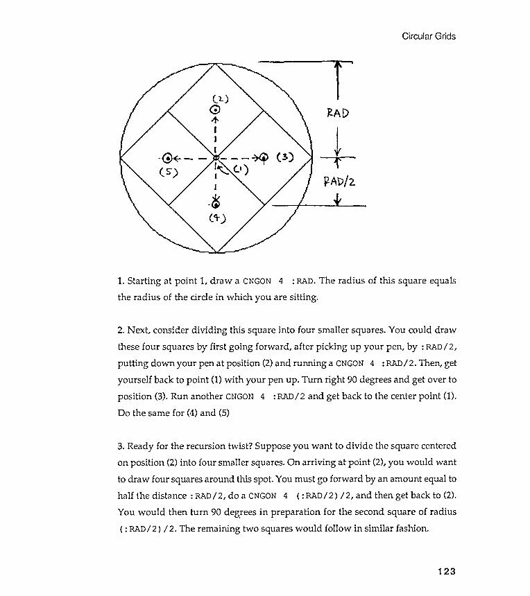
Circular Grids
~AD
+~AD/2
The radius of this square equals
2. Next , consider dividing this square into four smaller squares. You could drawthese four squares by first going forward , after picking up your pen, by : RAD/ 2,putting down your pen at position (2) and running a CNGON 4 : RAD/ 2. Then, getyourself back to point (1) with your pen up . Turn right 90 degrees and get over toposition (3). Run another CNGON 4 : RAD/ 2 and get back to the center point (1).Do the same for (4) and (5)
3. Ready for the recursion twist ? Suppose you want to divide the square centered
on position (2) into four smaller squares . On arriving at point (2), you would want
to draw four squares around this spot . You must go forward by an amount equal to
half the distance : RAD/ 2, do a CNGON 4 ( : RAD/ 2 ) / 2, and then get back to (2).
You would then turn 90 deg! ees in preparation for the second square of radius
( : RAD/ 2 ) / 2. The remaining two squares would follow in similar fashion .
123
1. Starting at point 1, draw a CNGON 4 : RAD.
the radius of the circle in which you are sitting .
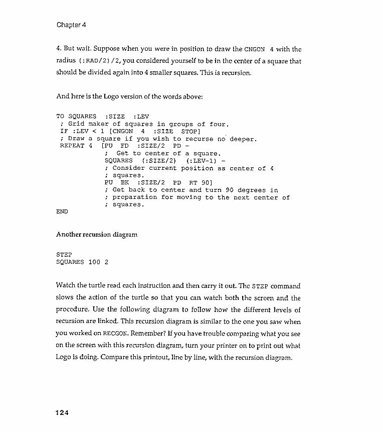
Watch the turtle read each instruction and then carry it out . The STEP command
slows the action of the turtle so that you can watch both the screen and the
procedure . Use the following diagram to follow how the different levels of
recursion are linked . This recursion diagram is similar to the one you saw when
you worked on RECGON. Remember ? If you have trouble comparing what you see
on the screen with this recursion diagram , turn your printer on to print out what
Logo is doing . Compare this printout , line by line , with the recursion diagram .
Chapter 4
4. But wait . Suppose when you were in position to draw the CNGON 4 with the
radius ( : RAD / 2) / 2, you considered yourself to be in the center of a square thatshould be divided again into 4 smaller squares. This is recursion .
And here is the Logo version of the words above :
deeper .
END
Another recursion diagram
STEPSQUARES100 2
124
TO SQUARES : SIZE : LEV; Grid maker of squares in groups of four .IF : LEV < 1 [CNGON 4 : SIZE STOP]; Draw a square if you wish to recurse noREPEAT 4 [PU FD : SIZE / 2 PD -
; Get to center of a square .SQUARES ( : SIZE / 2 ) ( : LEV - l ) -
; Consider current position as center of 4
; squares .
PU BK : SIZE / 2 PO RT 90 ]
; Get back to center and turn 90 degrees in
; preparation for moving to the next center of
; squares .
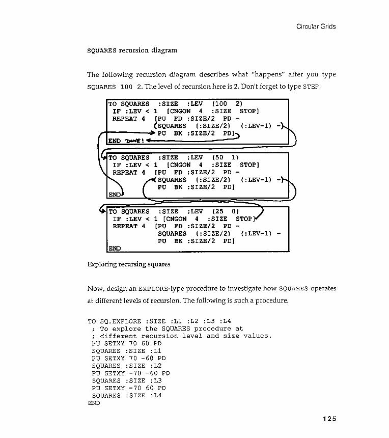
Exploring recursing; squares
different
Circular Grids
SQUARES recursion diagram
Now , design an EXPLORE-type procedure to investigate how SQUARES operates: levels of recursion . The following is such a procedure .at
125
PU SETXYSQUARES
END
- 70:SIZE
The following recursion diagram describes what "happens " after you typeSQUARES 100 2. The level of recursion here is 2. Don 't forget to type STEP.
TO SQ . EXPLORE : SIZE : Ll : L2 : L3 : L4
; To explore the SQUARES procedure at
; different recursion level and size values .
PU SETXY 70 60 PD
SQUARES : SIZE : Ll
PU SETXY 70 - 60 PD
SQUARES : SIZE : L2
PU SETXY - 70 - 60 PD
SQUARES : SIZE : L3
60 PD
: L4
TO SQUARES : SIZE :LEV (100 2)IF :LEV < 1 [CNGON 4 : SIZE STOP]REPEAT 4 [PU FO :SIZE/ 2 PO -
( SQUARES ( : SIZE/ 2) ( : LEV- 1) -- - PU BK :SIZE/ 2 PO]")
ENO '"J)a'f./E ~ "f= - - - -
TO SQUARES : SIZE :LEV (50 1)IF :LEV < 1 [CNGON 4 : SIZE STOP]REPEAT 4 [PU FO :SIZE/ 2 PO -
SQUARES ( :SIZE/ 2) ( : LEV- 1) -PU BK :SIZE/ 2 PO]
TO SQUARES : SIZE :LEV (25 0)IF :LEV < 1 [CNGON 4 : SIZE STOP]REPEAT 4 [PU FO :SIZE/ 2 PO -
SQUARES ( : SIZE/ 2) ( : LEV- 1) -PU BK :SIZE/ 2 PO]
ENO
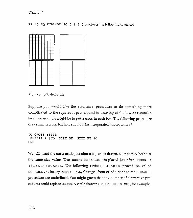
Chapter 4
2 3 produces the following diagram :RT 45 SQ. EXPLORE 80 0 1
More complicated grids
Suppose you would like the SQUARES procedure to do something more
complicated to the squares it gets around to drawing at the lowest recursion
level . An example might be to put a cross in each box . The following procedure
draws such a cross, but how should it be incorporated into SQUARES?
TO CROSS : SIZEREPEAT 4 [FD : SIZE BK : SIZE RT 90
We will want the cross made just after a square is drawn , so that they both usethe same size value . That means that CROSS is placed just after CNGON 4: SIZE in SQUARES. The following revised SQUARES procedure , calledSQUARES. x , incorporates CROSS. Changes from or additions to the SQUARESprocedure are underlined . You might guess that any number of alternative pro -cedures could replace CROSS. A circle drawer (CNGON 30 : SIZE ) , for example.
126
END
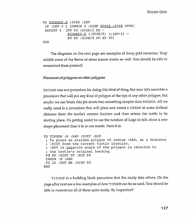
Circular Grids
TIPGON is a building block procedure that fits nicely into others . On the
page after next are a few examples of how TIPGON can be so used . You should be
able to reconstruct all of these quite easily. By inspection ?
STOP]-
( : LEV- l )
END
: DIST RT :ROT PD: N :RAD: ROT BK : DIST PD
127
CROSS :SIZE
90]
turtle ' s original heading .
TO SOUARES . X : SIZE : LEV
IF : LEV < 1 [ CNGON 4 : SIZEREPEAT 4 [ PU FO : SIZE / 2 PO
SQUARES . X ( : SIZE / 2 )PU BK : SIZE / 2 PO RT
TO.
,
.
,
.
,
; thePU FDCNGONPU LT
END
TIPGON :N :RAD :DIST :ROTTo place an n- sided polygon of radius :RAD, at a distance:DIST from the current turtle location .:ROT is ~ ation angle of the polygon is relation to
The diagrams on the next page are examples of fancy grid recursion . They
exhibit some of the flavor of stone mason marks as well . You should be able to
reconstruct them yourself .
Placement of polygons on other polygons
RECGON was one procedure for doing this kind of thing , but now let ' s assemble a
procedure that will put any kind of polygon at the tips of any other polygon . But
maybe we can break this job down into something simpler than RECGON . All we
really need is a procedure that will place and orient a CNGON at some defined
distance from the turtle ' s current location and then return the turtle to its
starting place . It ' s getting easier to use the notation of Logo to talk about a new
shape placement than it is to use words . Here it is :

Mason mark designs from squares
/ / - - - - - ~
" " ......._ ~- - - --...../
Chapter 4
,...------.
...,..
128
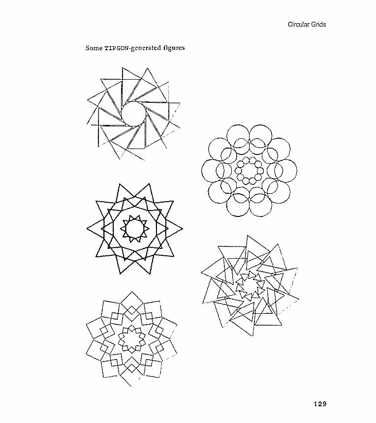
Circular Grids
Some TIPGON-generated figures
129
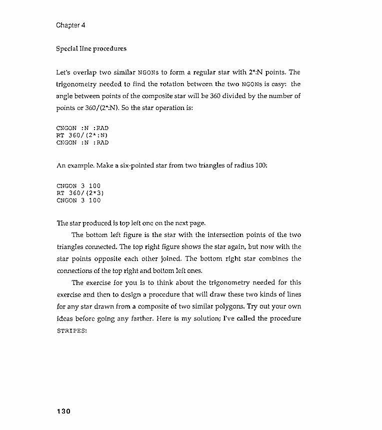
Chapter 4
Special line procedures
Let 's overlap two similar NGONs to form a regular star with 2*:N points . The
trigonometry needed to find the rotation between the t \.A1O NGONs is easy : the
angle between points of the composite star will be 360 divided by the number of
points or 360 / (2*:N ). So the star operation is :
CNGON :N :RADRT 360/ (2* :N)CNGON :N :RAD
An example . Make a six -pointed star from two triangles of radius 100:
CNGON 3 100RT 360 / (2* 3)CNGON 3 100
The star produced is top left one on the next page.The bottom left figure is the star with the intersection points of the two
triangles connected. The top right figure shows the star again, but now with thestar points opposite each other joined . The bottom right star combines theconnections of the top right and bottom left ones.
The exercise for you is to think about the trigonometry needed for thisexercise and then to design a procedure that will draw these two kinds of linesfor any star drawn from a composite of two similar polygons . Try out your ownideas before going any farther . Here is my solution ; I 've called the procedureSTRIPES:
130
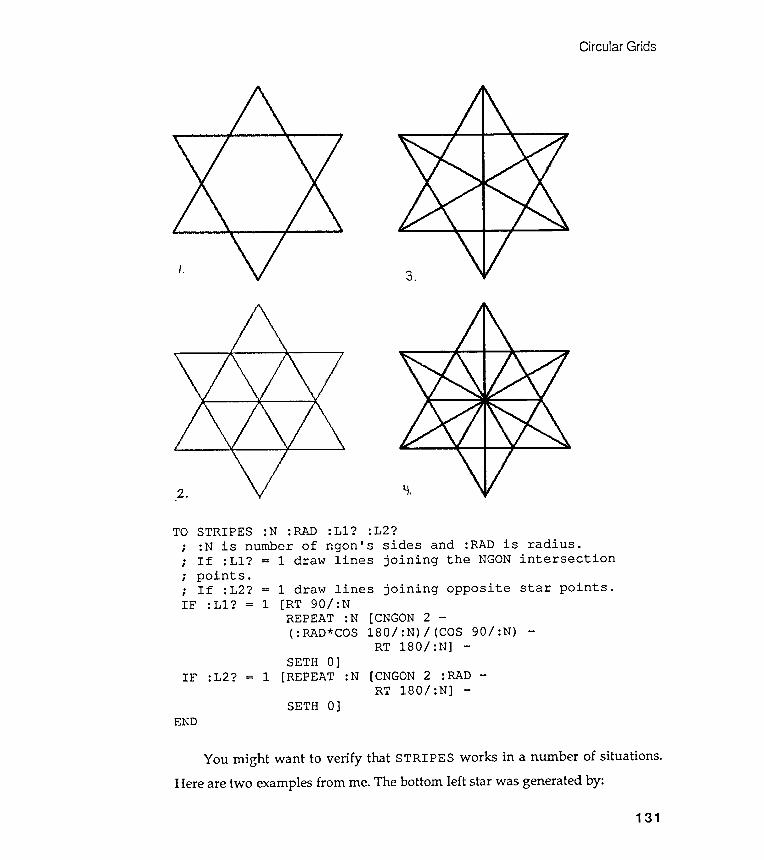
Circular Grids
bottomexamples
3.
Y.2.
TO
IF :L2? =
END
left star was generated by :from me. TheHere are two
131
STRIPES : N : RAD : Ll ? : L2 ?
; : N is number of ngon ' s sides and : RAD is radius .
; If : Ll ? = 1 draw lines joining the NGON intersection
; points .
; If : L2 ? = 1 draw lines joining opposite star points .
IF : Ll ? = 1 [ RT 90 / : N
REPEAT : N [ CNGON 2 -
( : RAD * COS 180 / : N ) / ( COS 90 / : N ) -
RT 180 / : N ] -
SETH 0 ]
1 [ REPEAT : N [ CNGON 2 : RAD -
RT 180 / : N ] -
SETH 0 ]
You might want to verify that STRIPES works in a number of situations .
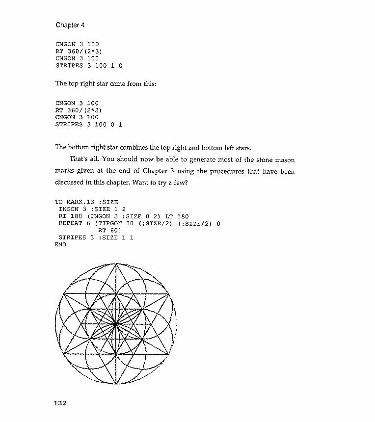
Chapter 4
CNGON 3 100RT 360/ (2* 3)CNGON 3 100STRIPES 3 100 1 0
The top right star came from this :
CNGON 3 100RT 360 / (2* 3)CNGON 3 100STRIPES 3 100 0 1
The bottom right star combines the top right and bottom left stars.That 's all . You should now be able to generate most of the stone mason
marks given at the end of Chapter 3 using the procedures that have beendiscussed in this chapter. Want to try a few ?
TO MARK. 13 : SIZEINGON 3 : SIZE 1 2RT 180 (INGON 3 : SIZE 0 2) LTREPEAT 6 [TIPGON 30 ( :SIZE/ 2)
RT 60]STRIPES 3 : SIZE 1 1
180( :SIZE/ 2) 0
132
END
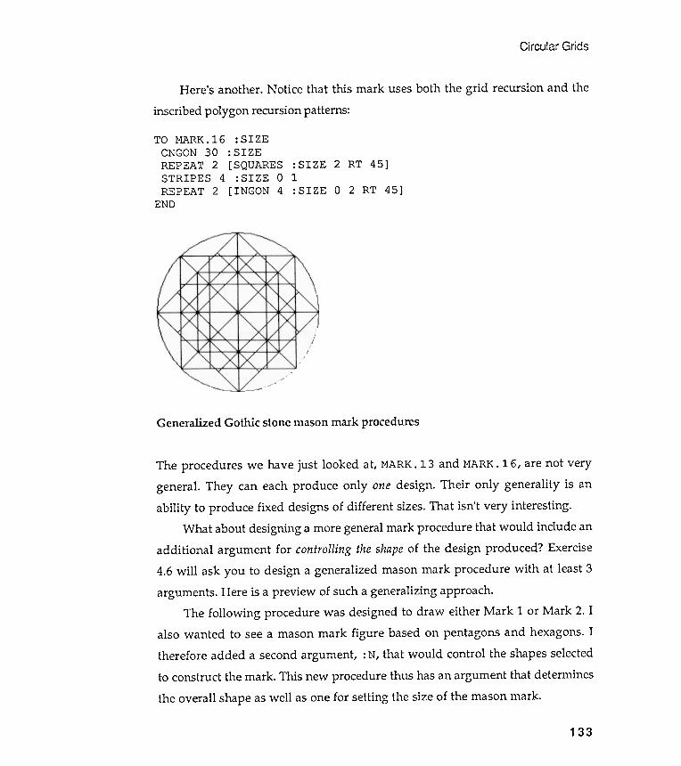
Circular
Here's another . Notice that this mark uses both the grid recursion and the
inscribed polygon recursion patterns:
The procedures we have just looked at, MARK. 13 and MARK. 16 , are not verygeneral . They can each produce only one design . Their only generality is anability to produce fixed designs of different sizes. That isn't very interesting .
What about designing a more general mark procedure that would include anadditional argument for controlling the shape of the design produced ? Exercise4.6 will ask you to design a generalized mason mark procedure with at least 3arguments . Here is a preview of such a generalizing approach.
The following procedure was designed to draw either Mark 1 or Mark 2. Ialso wanted to see a mason mark figure based on pentagons and hexagons. Itherefore added a second argument , : N, that would control the shapes selectedto construct the mark . This new procedure thus has an argument that determines
the overall shape as well as one for setting the size of the mason mark .
'Grids
: SIZE: SIZE[SQUARES : SIZE 2 RT 45]: SIZE 0 1
[ INGON 4 : SIZE 0 2 RT 45]
Generalized Gothic stone mason mark procedures
133
TO MARK. 16CNGON 30REPEAT 2STRIPES 4REPEAT 2
END
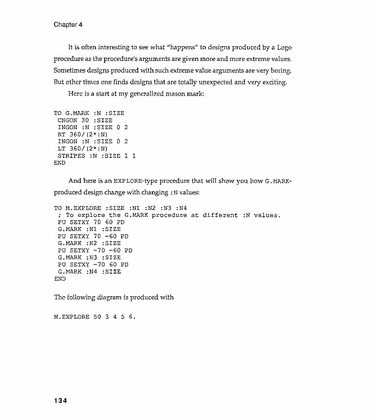
Chapter 4
It is often interesting to see what "happens" to designs produced by a Logoprocedure as the procedure 's arguments are given more and more extreme values.
Sometimes designs produced with such extreme value arguments are very boring .But other times one finds designs that are totally unexpected and very exciting .
Here is a start at my generalized mason mark :
1
And here is an EXPLORE-type procedure that will show you how G. MARK-produced design change with changing : N values:
TO M . EXPLORE : SIZE : Nl : N2 : N3 : N4
; To explore the G . MARK procedure at different : N values .PU SETXY 70 60 PDG . MARK : Nl : SIZEPU SETXY 70 - 60 PDG . MARK : N2 : SIZE
PU SETXY - 70 - 60 PDG . MARK : N3 : SIZEPU SETXY - 70 60 PDG . MARK : N4 : SIZE
END
The following diagram is produced with
M.EXPLORE 50 3 456 .
134
TO G.MARK :N : SIZECNGON 30 : SIZEINGON :N : SIZE 0 2RT 360/ (2* : N)INGON :N : SIZE 0 2LT 360/ (2* :N)STRIPES :N :SIZE 1
END
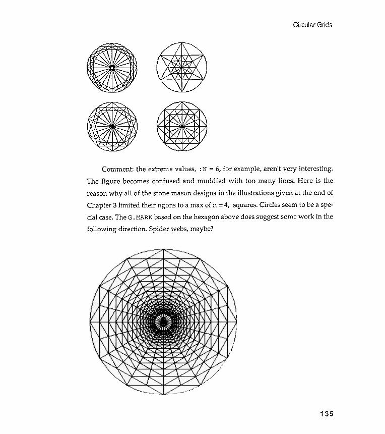
Circular Grids
135
Comment : the extreme values, : N = 6, for example, aren't very interesting .
The figure becomes confused and muddied with too many lines . Here is thereason why all of the stone mason designs in the illustrations given at the end ofChapter 3 limited their ngons to a max of n = 4, squares. Circles seem to be a spe-cial case. The G . MARK based on the hexagon above does suggest some work in thefollowing direction . Spider webs, maybe?
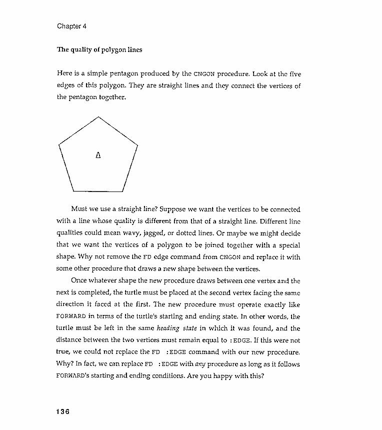
Must we use a straight line ? Suppose we want the vertices to be connected
with a line whose quality is different from that of a straight line . Different line
qualities could mean wavy , jagged , or dotted lines . Or maybe we might decide
that we want the vertices of a polygon to be joined together with a special
shape . Why not remove the FD edge command from CNGON and replace it with
some other procedure that draws a new shape between the vertices .
Once whatever shape the new procedure draws between one vertex and the
second vertex facing the same
The new procedure must operate exactly like
ending state . In other words , the
state in which it was found , and the
next is completed, the turtle must be placed at thedirection it faced at the first .
FORWARD in terms of the turtle 's starting andturtle must be left in the same headingdistance between the two vertices must remain equal to : EDGE. If this were nottrue , we could not replace the FD : EDGE command with our new procedure .Why ? In fact, we can replace FD : EDGE with any procedure as long as it followsFORWARD's starting and ending conditions . Are you happy with this?
Chapter 4
The quality of polygon lines
Here is a simple pentagon produced by the CNGON procedure . Look at the fiveThey are straight lines and they connect the vertices of
11
136
edges of this polygon .
the pentagon together .
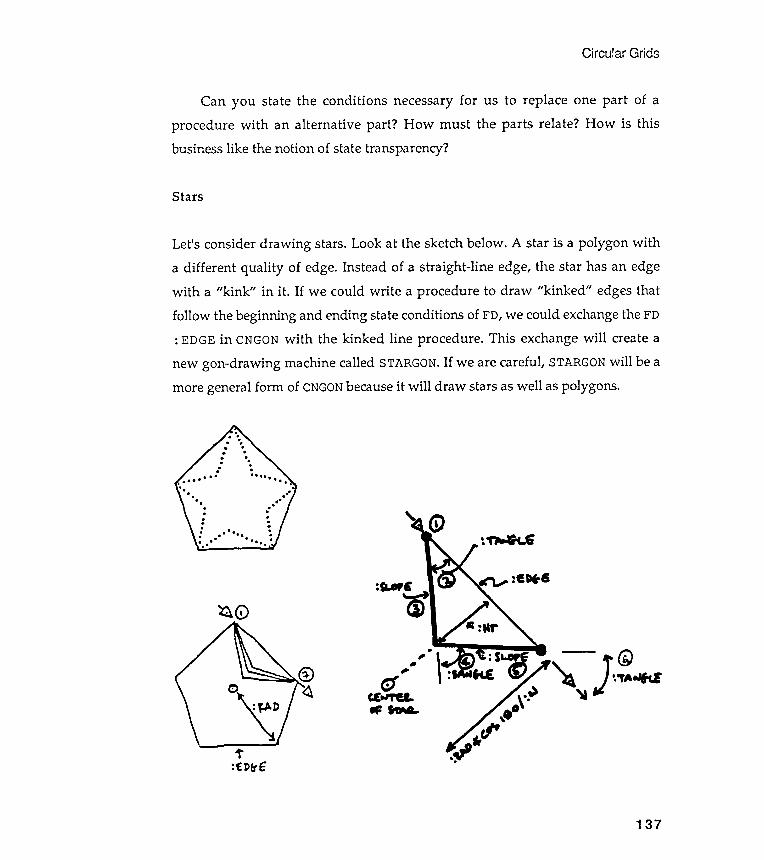
Circular Grids
Stars
Let's consider drawing stars. Look at the sketch below . A star is a polygon witha different quality of edge. Instead of a straight -line edge, the star has an edgewith a "kink " in it . If we could write a procedure to draw "kinked " edges thatfollow the beginning and ending state conditions of FD, we could exchange the FD: EDGE in CNGON with the kinked line procedure . This exchange will create a
new gon-drawing machine called STARGON. If we are careful, STARGON will be amore general form of CNGON because it will draw stars as well as polygons .
~
Can you state the conditions necessary for us to replace one part of a
the parts relate ? How is this
~ 0
0
"\:' t
:~ P&' ~
137
procedure with an alternative part ? How must
business like the notion of state transparency ?
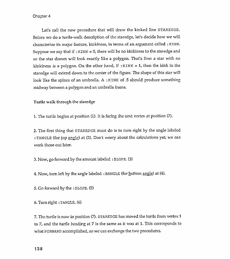
begins
2. The first thing that STAREDGE must do is to turn right by the angle labeled: TANGLE (for lop ~ngk ) at (2). Don 't worry about the calculations yet; we canwork those out later .
Chapter 4
Turtle walk through the staredge
1. The turtle
138
Let 's call the new procedure that will draw the kinked line STAREDGE.Before we do a turtle -walk description of the staredge, let 's decide how we willcharacterize its major feature, kinkiness , in terms of an argument called : KINK .Suppose we say that if : KINK = 0, there will be no kinkiness to the staredge andso the star drawn will look exactly like a polygon . That 's fine : a star with nokinkiness is a polygon . On the other hand, if : KINK = 1, then the kink in thestaredge will extend down to the center of the figure . The shape of this star willlook like the spines of an umbrella . A : KINK of .5 should produce something
midway between a polygon and an umbrella frame.
at position (1). It is facing the next vertex at position (7).
3. Now, go forward by the amount labeled : SLOPE. (3)
4. N ow, turn left by the angle labeled : BANGLE (for Qottom @g1g) at (4).
5. Go forward by the : SLOPE. (5)
6. Turn right : TANGLE. (6)
7. The turtle is now in position (7). STAREDGE has moved the turtle from vertex 1to 7, and the turtle heading at 7 is the same as it was at 1. This corresponds towhat FORWARD accomplished, so we can exchange the two procedures.
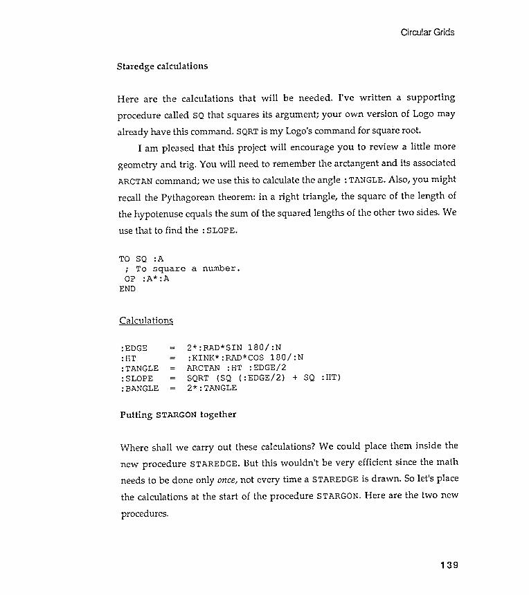
Circular Grids
.. ..
.. ..
.. n
tIjc/)
I-3:I:
tx:J
~:l;.rt
-t:l;.r1
-31:J
nZO
Z G)
I::::G)
t"CJG)
tx:J
......t-tt
x:Jt-t
~tx:J
tx:J
:::r. 0 :='
II II
II II
II cn
Where shall we carry out these calculations ? We could place them inside thenew procedure STAREDGE. But this wouldn 't be very efficient since the mathneeds to be done only once, not every time a STAREDGE is drawn . So let 's placethe calculations at the start of the procedure STARGON. Here are the two new
procedures.
Staredge calculations
2* :RAD*SIN 180/ :N:KINK* :RAD*COS 180/ :NARCTAN :HT :EDGE/ 2SQRT (SQ ( :EDGE/ 2) +2* :TANGLE
SQ :HT)
Putting STARGON together
139
Here are the calculations that will be needed . I 've written a supporting
procedure called SQ that squares its argument ; your own version of Logo mayalready have this command. SQRT is my Logo's command for square root .
I am pleased that this project will encourage you to review a little moregeometry and trig . You will need to remember the arctangent and its associatedARCTAN command ; we use this to calculate the angle : TANGLE. Also , you might
recall the Pythagorean theorem : in a right triangle , the square of the length ofthe hypotenuse equals the sum of the squared lengths of the other two sides. Weuse that to find the : SLOPE.
TO SQ :A; To square a number .OP :A* :A
END

Chapter 4
TO STAREDGERT :TANGLEFD :SLOPE
:TANGLE: SLOPE
SQ : HT )the values that STAREDGE
LT 2* : TANGLEFD : SLOPERT : TANGLE
END
TO STARGON :N : RAD :NOTCH; Centered star exercise .(LOCAL " EDGE " HT " TANGLE " SLOPE)MAKE " EDGE 2* :RAD* SIN 180 / :NMAKE " HT :NOTCH* : RAD* COS 180 / :NMAKE " TANGLE ARCTAN : HT : EDGE/ 2MAKE " SLOPE SQRT (SQ ( : EDGE/ 2) +; These MAKE commands calculate; will use below .PU FD :RAD PDRT 180 - (90* ( : N- 2) / : N)REPEAT :N [ (STAREDGE : TANGLELT 180 - (90* ( : N- 2 ) / :N)PU BK : RAD PD
END
: SLOPE) RT 360/ :N]
Global and local variables
Notice that I have made the staredge variables all local variables . We don 't
need the value of these staredge calculations outside of STARGON. Do youremember the difference between local and global variables ? Global variables
have an existence outside as well as inside the body of the procedure thatcreated them. These variables never go away, in fact, until they are erased. Thecommand NAMES lists all global variables currently in your workspace andEDNAME allows you to edit a specific variable . Check your Logo language manualto verify these commands in your own Logo dialect.
Local variables , on the other hand , exist only inside the procedure thatdefines them . A local variable is, however , available to any procedure that isused within the body of the procedure that defined the variable .l
1. Most traditional Logos, including the dialect used in this book , apply thisapproach, but some recent implementations such as Coral Object Logo favor an
140
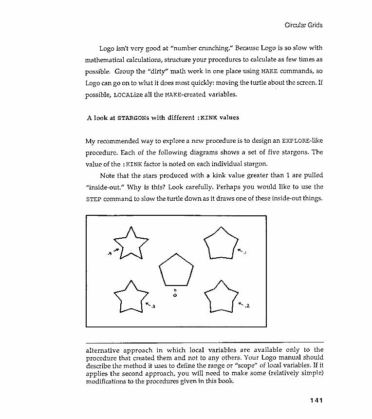
Circular Grids
alternative approach in which local variables are available only to theprocedure that created them and not to any others. Your Logo manual shoulddescribe the method it uses to define the range or "scope" of local variables . If itapplies the second approach , you will need to make some (relatively simple )modifications to the procedures given in this book.
Logo isn't very good at "number crunching ." Because Logo is so slow withmathematical calculations, structure your procedures to calculate as few times aspossible. Group the "dirty " math work in one place using MAKE commands, soLogo can go on to what it does most quickly : moving the turtle about the screen. Ifpossible, LOCALize all the MAKE-created variables .
A look at STARGONs with different : KINK values
My recommended way to explore a new procedure is to design an EXPLORE-like
procedure . Each of the following diagrams shows a set of five stargons . The
value of the : KINK factor is noted on each individual stargon .
Note that the stars produced with a kink value greater than 1 are pulled
" inside -out ." Why is this ? Look carefully . Perhaps you would like to use the
STEP command to slow the turtle down as it draws one of these inside - out things .
141

Chapter 4
142
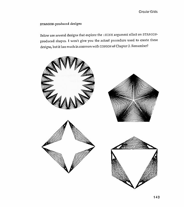
STARGON-produced designs
Below are several designs that explore the : KINK argument effect on STARGON -
produced shapes . I won ' t give you the actual procedure used to create these
designs , but it has much in common with CONGON of Chapter 3 . Re ~ ember ?
Circular Grids
143
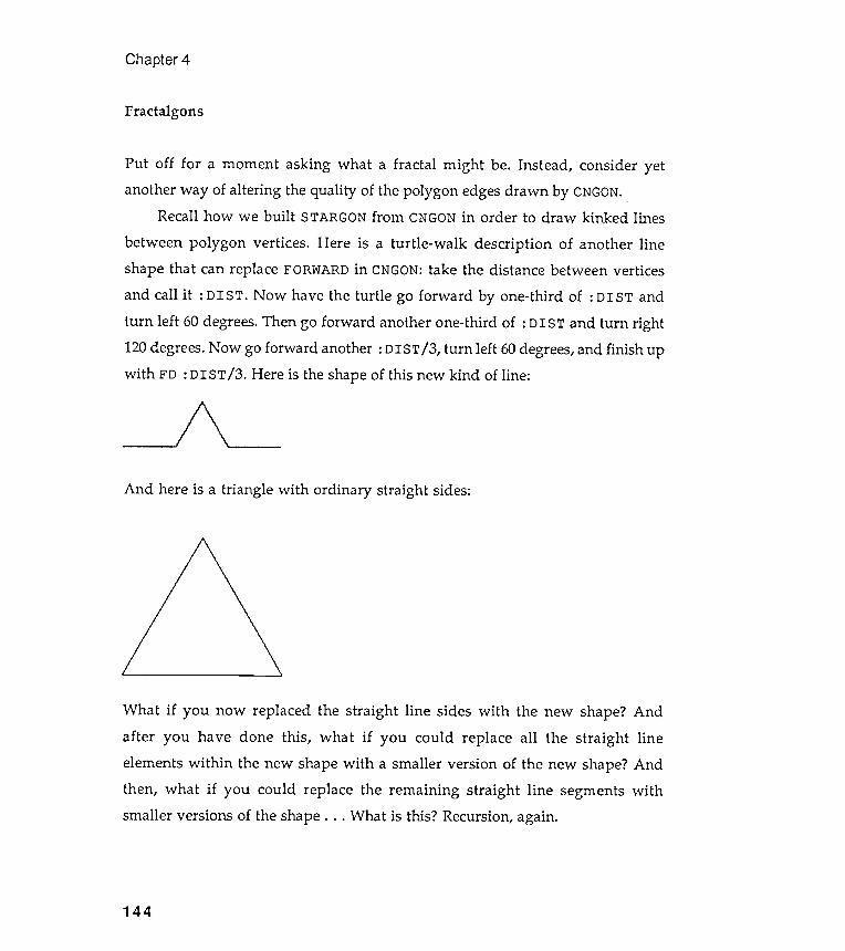
Fractalgons
Chapter 4
- - _/ ! \ \ _----
And here is a triangle with ordinary straight sides:
What if you now replaced the straight line sides with the new shape? Andafter you have done this , what if you could replace all the straight lineelements within the new shape with a smaller version of the new shape? Andthen, what if you could replace the remaining straight line segments withsmaller versions of the shape . . . What is this? Recursion, again.
144
Put off for a moment asking what a fractal might be. Instead , consider yet
another way of altering the quality of the polygon edges drawn by CNGON. .Recall how we built STARGON from CNGON in order to draw kinked lines
between polygon vertices . Here is a turtle -walk description of another lineshape that can replace FORWARD in CNGON: take the distance between vertices
and call it : D IS T. Now have the turtle go forward by one-third of : D IS T andturn left 60 degrees. Then go forward another one- third of : D IS T and turn right120 degrees. Now go forward another : DIST / 3, turn left 60 degrees, and finish upwith FD : DIST / 3. Here is the shape of this new kind of line :

Circular Grids
145
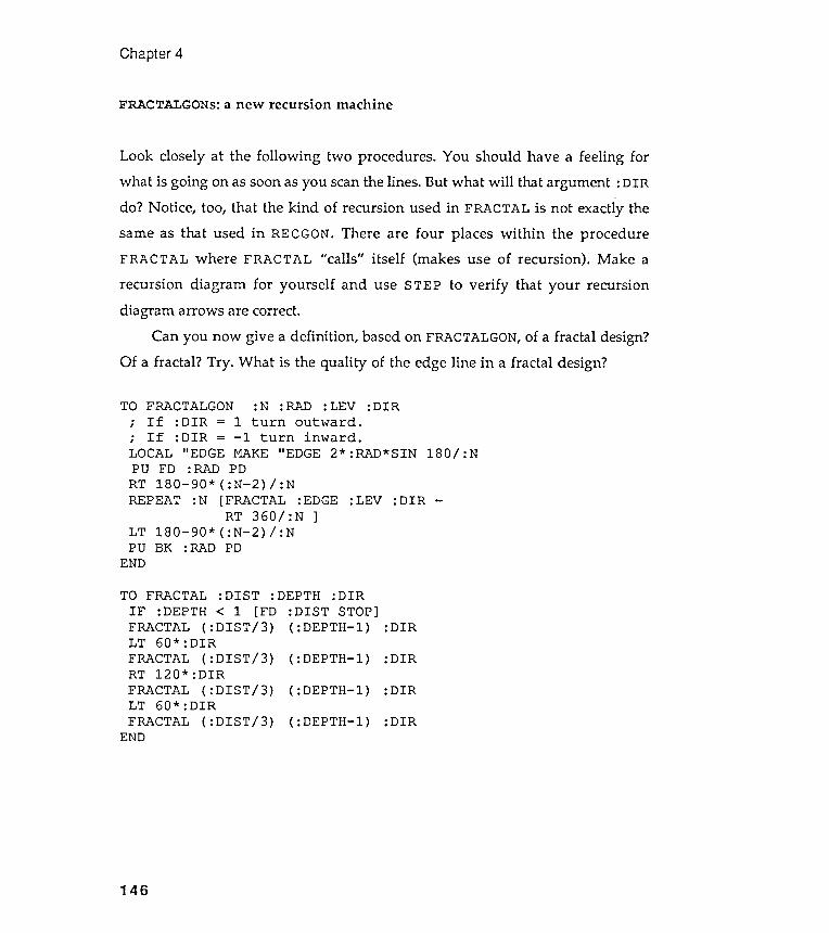
Chapter 4
FRACTALGONS: a new recursion machine
180/ :N
REPEAT :N [FRACTAL :EDGE :LEV :DIRRT 360 / : N ]
LT 180- 90* ( :N- 2) / :NPU BK : RAD PD
END
:DIR
:DIR
:DIR
:DIR
146
TO FRACTALGON : N : RAD : LEV :DIR; If : DIR = 1 turn outward .; If :DIR = - 1 turn inward .LOCAL " EDGE MAKE " EDGE 2* : RAD* SINPU FD : RAD PDRT 180- 90* ( :N- 2) / : N
Look closely at the following two procedures . You should have a feeling for
what is going on as soon as you scan the lines . But what will that argument : DIR
do ? Notice , too , that the kind of recursion used in FRACTAL is not exactly the
same as that used in RECGON . There are four places within the procedureFRACT AL where FRACTAL " calls " itself (makes use of recursion ) . Make a
recursion diagram for yourself and use STEP to verify that your recursion
diagram arrows are correct .
Can you now give a definition , based on FRACTALGON , of a fractal design ?
Of a fractal ? Try . What is the quality of the edge line in a fractal design ?
TO FRACTAL : DIST : DEPTH : DIR
IF : DEPTH < 1 [ FD : DIST STOP ]FRACTAL ( : DIST / 3 ) ( : DEPTH - l )LT 60 * : DIR
FRACTAL ( : DIST / 3 ) ( : DEPTH - l )RT 120 * : DIR
FRACTAL ( : DIST / 3 ) ( : DEPTH - l )LT 60 * : DIR
FRACTAL ( : DIST / 3 ) ( : DEPTH - l )END
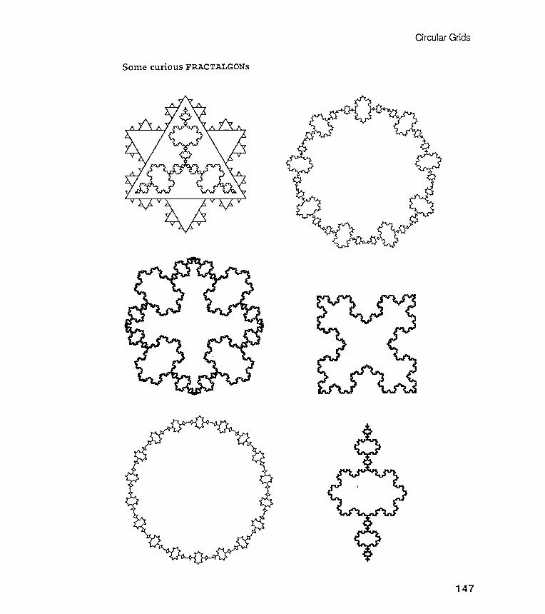
Circular Grids
SomecuriousFRACTALGONS
147

Chapter 4
Observations
Have you noticed that most of the designs in the first three chapters have been
"circular " ? These circular patterns reveal a symmetry based on a central point ,and that 's why I 've called them circular grids.
There is one final example of circular grids in the chapter . It is anotherexample of how a complicated figure can be unpacked into its components andthen restructured . This example shows how a generalized model of the basiccomponent can lead to a wide variety of recomposed images based on the themeof the original . While all the images share the same original characteristics ,they are surprisingly different in feeling .
Nephroids
"Nephroid " means kidney -shaped. It is a nice example of a complex circulargrid .
148
Look carefully at the following diagram . Can you decompose the designinto its polygonal components as you did with the stone mason marks? Could youdraw a nephroid on a drawing board with a straight edge and compass? Mostimportant , could you do a turtle -walk scenario? That walk might begin to formin your mind as soon as you start scanning the design with your eyes. . .
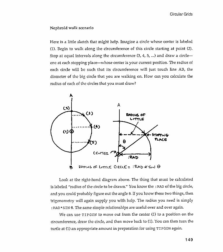
Circular Grids
Nephroid walk scenario
A
tEroJTErz.
Av(",~ ()~ u ' TTL:!E: CI ~c.LE: = : ~ D *" <; ,.J 9
Look at the right -hand diagram above. The thing that must be calculatedis labeled " radius of the circle to be drawn ." You know the : RAD of the big circle,
and you could probably figure out the angle 8. If you know these two things , thentrigonometry will again supply you with help . The radius you need is simply: RAD* SIN e. The same simple relationships are useful over and over again.
We can use TIPGON to move out from the center (1) to a position on thecircumference, draw the circle, and then move back to (1). You can then turn the
turtle at (1) an appropriate amount in preparation for using TIPGON again.
149
Here is a little sketch that might help . Imagine a circle whose center is labeled
(1). Begin to walk along the circumference of this circle starting at point (2) .
Stop at equal intervals along the circumference (3, 4, 5, ...) and draw a circle -
one at each stopping place - whose center is your current position . The radius of
each circle will be such that its circumference will just touch line AB , the
diameter of the big circle that you are walking on . How can you calculate the
radius of each of the circles that you must draw ?
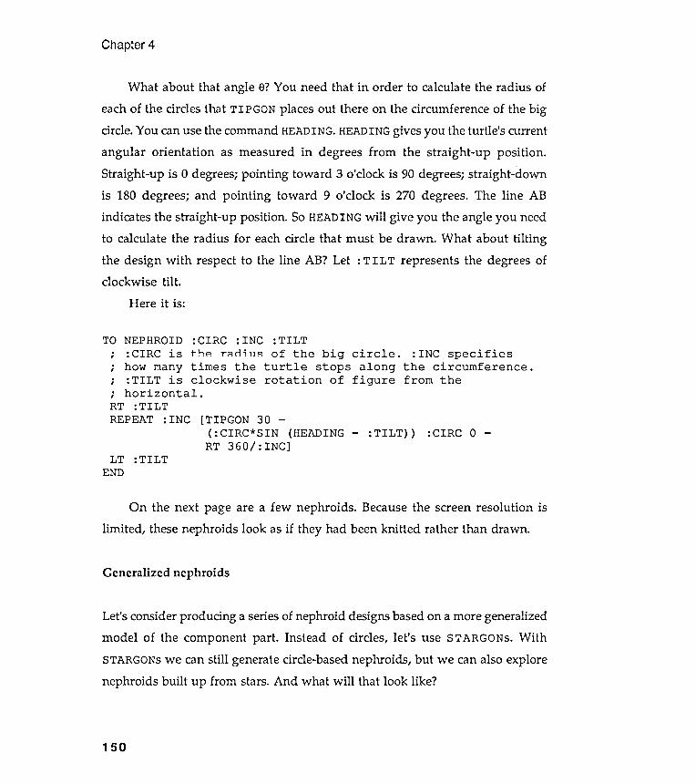
What about that angle e? You need that in order to calculate the radius ofeach of the circles that TIPGON places out there on the circumference of the bigcircle. You can use the command HEADING. HEADING gives you the turtle 's currentangular orientation as measured in degrees from the straight -up position .Straight -up is 0 degrees; pointing toward 3 o'clock is 90 degrees; straight -downis 180 degrees; and pointing toward 9 o'clock is 270 degrees. The line ABindicates the straight -up position . SO HEADING will give you the angle you needto calculate the radius for each circle that must be drawn . What about tiltingthe design with respect to the line AB? Let : TILT represents the degrees ofclockwise tilt .
Here it is:
stars .
Chapter 4
TO NEPHROID
; : CIRC is
; how many; : TILT is; horizontal .RT : TILT
REPEAT : INC
: TILT
of the big circle .turtle stops alongrotation of figure
: INC specifiesthe circumference .from the
[TIPGON 30 -( :CIRC*SIN (HEADINGRT 360/ : INC]
:TILT :CIRC 0
LT :TILTEND
Generalized nephroids
nephroids built up from And what will that look like ?
150
: CIRC : INCt-hp r ~rl ; ' ]~times theclockwise
Let's consider producing a series of nephroid designs based on a more generalizedmodel of the component part . Instead of circles, let 's use STARGONs. WithSTARGONs we can still generate circle-based nephroids , but we can also explore
On the next page are a few nephroids . Because the screen resolution islimited , these nephroids look as if they had been knitted rather than drawn .
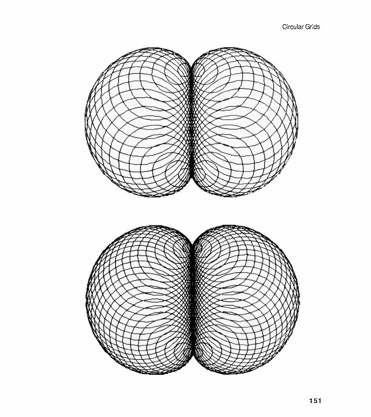
Circular Grids
151

Chapter 4
Unpacking and repacking image packages
First, let 's extend TIPGON to manipulate STARGONS instead of CNGONs. Callthe extension TIP . STARGON.
TO TIP . STARGON :N :RAD :KINK :DIST :ROT; To place an n- sided stargon of radius :RAD and; kink :KINK, at a distance :DIST from the current; turtle location . :ROT is ~ ation angle of the; in relation to the turtle ' s original heading .PU FD :DIST RT :ROT PDSTARGON :N :RAD :KINKPU LT :ROT BK :DIST PD
END
Now , we can insert TIP . STARGON into an extended NEPHROID, calledSTAR.NEPHROID.
TO STAR. NEPHROID:CIRC is the
: N : KINK : TILT
big circle .stops alonq
: INC specifiesthe circumference .
.
,
.
,
.
,
: TILT
LT :TILTEND
The images of this chapter illustrate the power of decomposing complex
patterns into simpler ones , and these images recapitulate the ideas of the
chapter better than words . Now it 's your chance to extend these notions into
more challenging areas .
152
how: N is numberkink
timesmany
: CIRC : INCradius of the
the turtle
of sides of component stargons with; TILT is clockwise rotation of figure:KINK ..
,
; from the horizontal .RT : TILT
REPEAT : INC [ TIP . STARGON -: N ( : CIRC * SIN ( HEADING: KINK : CIRC 0 -
RT 360 / : INC ]
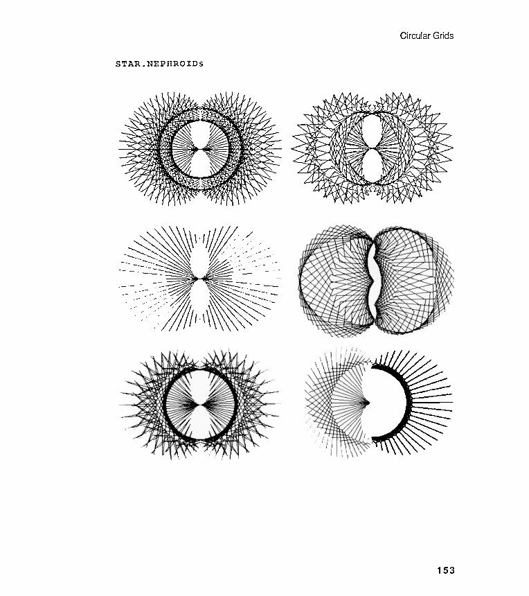
-
Circular Grids
STAR . NEPHROIDs
153
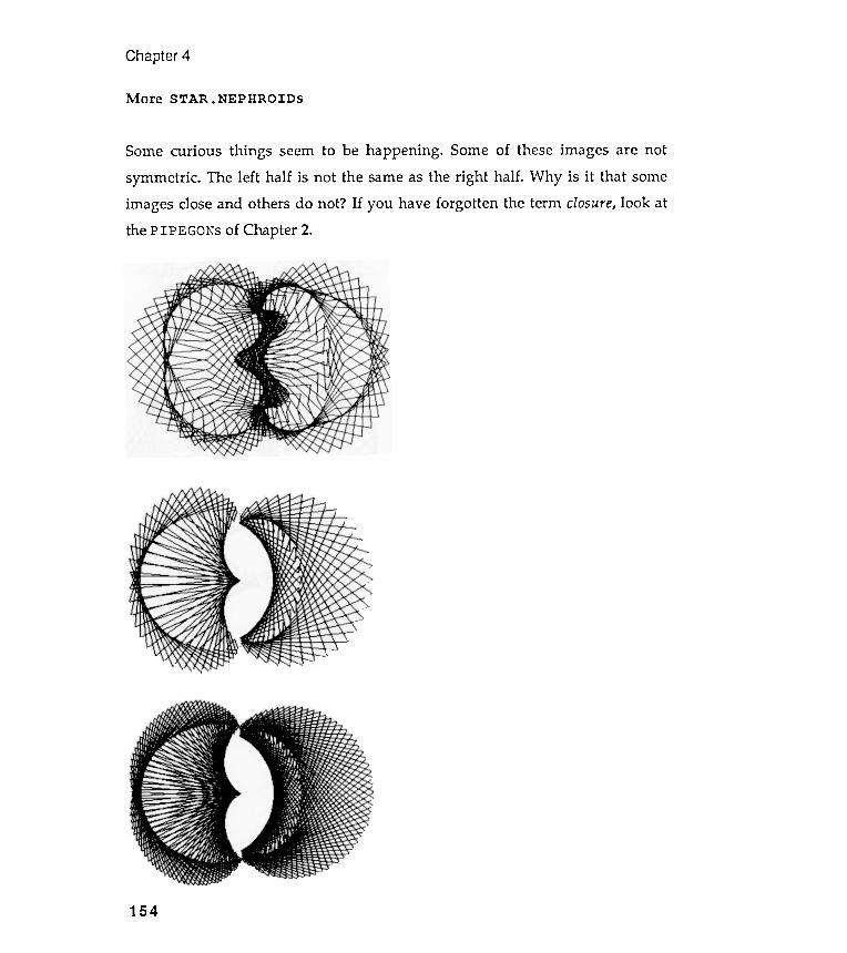
More STAR . NEPHROIDS
Some curious things seem to be happening . Some of these images are not
symmetric . The left half is not the same as the right half . Why is it that some
images close and others do not ? If you have forgotten the term closure , look at
the PIPEGONs of Chapter 2 .
Chapter 4
154
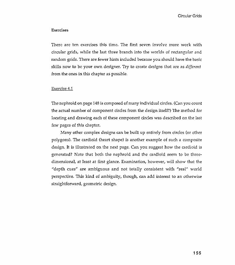
The nephroid on page 148 is composed of many individual circles. (Can you countthe actual number of component circles from the design itself ?) The method forlocating and drawing each of these component circles was described on the lastfew pages of this chapter.
Many other complex designs can be built up entirely from circles (or otherpolygons ). The cardioid (heart shape) is another example of such a compositedesign. It is illustrated on the next page. Can you suggest how the cardioid isgenerated ? Note that both the nephroid and the cardioid seem to be three-dimensional , at least at first glance. Examination , however , will show that the" depth cues" are ambiguous and not totally consistent with " real" worldperspective . This kind of ambiguity , though , can add interest to an otherwisestraightforward , geometric design.
Circular Grids
Exercises
There are ten exercises this time . The first seven involve more work with
circular grids , while the last three branch into the worlds of rectangular andrandom grids . There are fewer hints included because you should have the basicskills now to be your own designer . Try to create designs that are as differentfrom the ones in this chapter as possible.
Exercise 4.1
155

Chapter 4
Cardioids
156
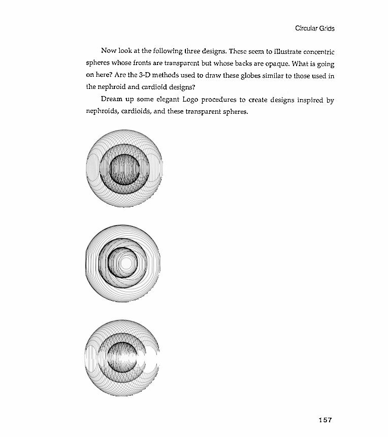
Circular Grids
157
Now look at the following three designs . These seem to illustrate concentric
spheres whose fronts are transparent but whose backs are opaque . What is going
on here ? Are the 3 - D methods used to draw these globes similar to those used in
the nephroid and cardioid designs ?
Dream up some elegant Logo procedures to create designs inspired by
nephroids , cardioids , and these transparent spheres .
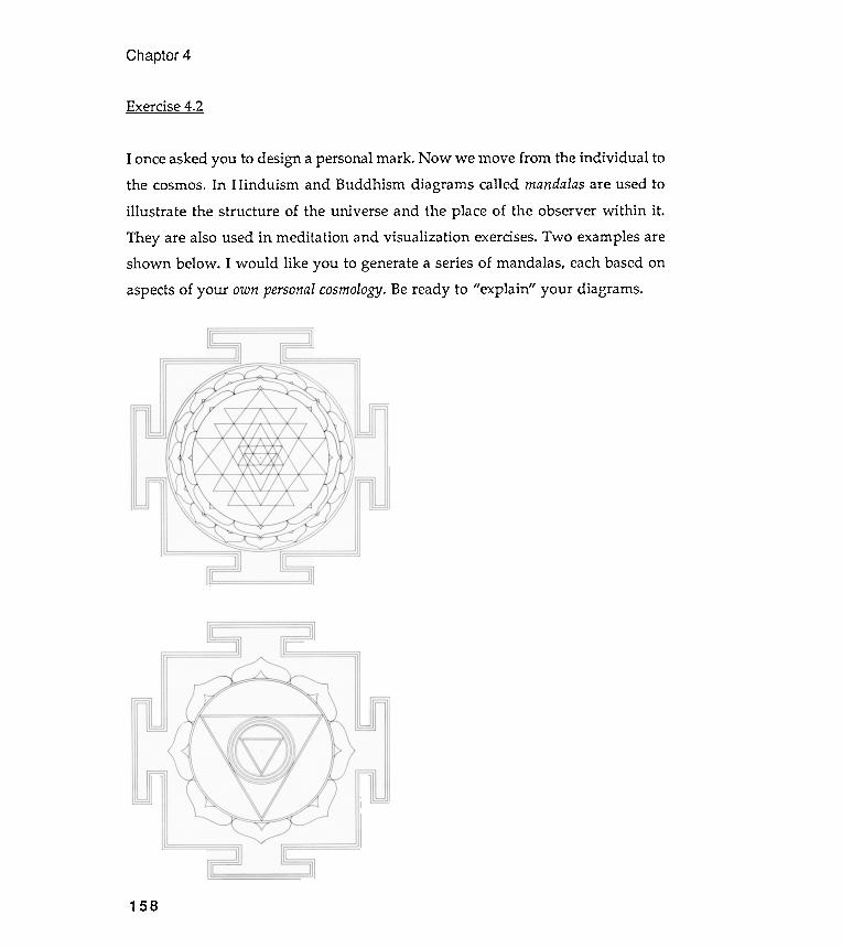
the cosmos. In Hinduism and Buddhism diagrams called mandalas are used toillustrate the structure of the universe and the place of the observer within it .
They are also used in meditation and visualization exercises. Two examples areshown below . I would like you to genera te a series of mandalas, each based onaspects of your own personal cosmology. Be ready to "explain " your diagrams .
Chapter 4
Exercise 4 .2
I once asked you to design a personal mark . Now we move from the individual to
158
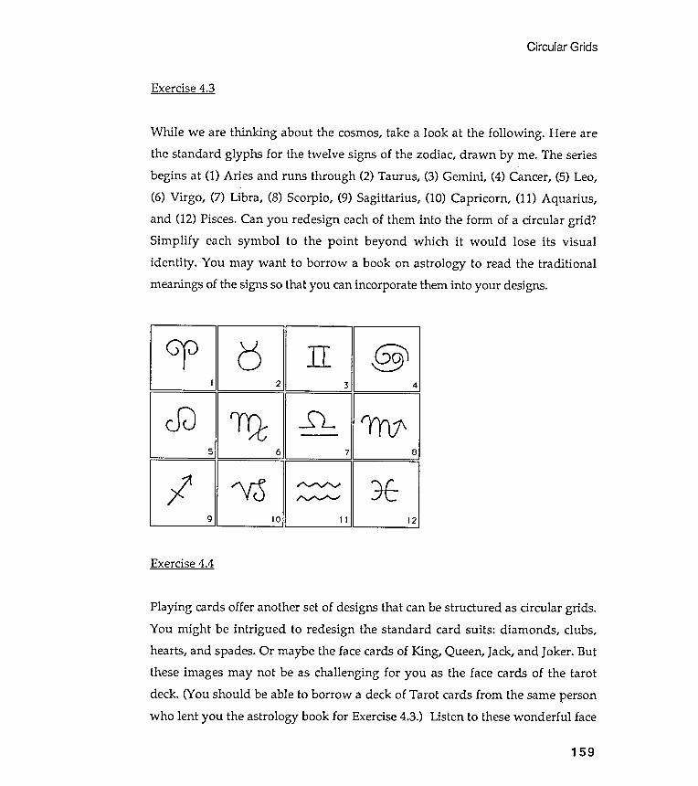
Circular Grids
Exercise 4.3
Exercise 4.4
159
While we are thinking about the cosmos , take a look at the following . Here are
the standard glyphs for the twelve signs of the zodiac , drawn by me . The series
begins at ( 1 ) Aries and runs through ( 2 ) Taurus , ( 3 ) Gemini , ( 4 ) Cancer , ( 5 ) Leo ,
( 6 ) Virgo , ( 7 ) Libra , ( 8 ) Scorpio , ( 9 ) Sagittarius , ( 10 ) Capricorn , ( 11 ) Aquarius ,
and ( 12 ) Pisces . Can you redesign each of them into the form of a circular grid ?
Simplify each symbol to the point beyond which it would lose its visual
identity . You may want to borrow a book on astrology to read the traditional
meanings of the signs so tha t you can incorpora te them into your designs .
cP b n @
1 2 3 4
cfJ rrQ ~ ( YY ) 1 \
5 6 7 8
I ' V ; 5 ; : ~ : : : ~ *
9 10 11 12
Playing cards offer another set of designs that can be structured as circular grids .
You might be intrigued to redesign the standard card suits : diamonds , clubs ,
hearts , and spades . Or maybe the face cards of King , Queen , Jack , and Joker . But
these images may not be as challenging for you as the face cards of the tarot
deck . ( You should be able to borrow a deck of Tarot cards from the same person
who lent you the astrology book for Exercise 4 . 3 . ) Listen to these wonderful face
Design a generalized Gothic stone mason mark that has three arguments . One ofthese arguments should control the size of the design and the other two shouldcontrol the shape. Don 't limit yourself to the examples already shown ; producea series of designs that could be used for late-twentieth -century cathedralbuilding .
Exercise 4.7
Exercise 4.6
We didn 't spend much time on fractals in this chapter . Go back and look at theFRACTALGONs. Can you dream up some fractals of your own ? We will look atfractals again in the exercise section of Chapter 7.
160
Chapter 4
card names : Magician , High Priestess , Empress , Emperor , Hierophant , Lovers ,
Chariot , Strength , Hermit , Wheel of Fortune , Justice , Hanged Man , Death ,
Temperance , Devil , Tower , Star , Moon , Sun , Last Judgment , World , and finally ,
The Fool .
Can you design a circular grid icon for one or more of these cards ? Keep each
of your designs as sim pIe as possible .
Exercise 4 . 5
The standard clock face is a circular grid . Redesign it with symbols rather than
numbers . Remember to keep track of seconds , minutes , and hours . But you may
want to change the whole system of reckoning time . . .
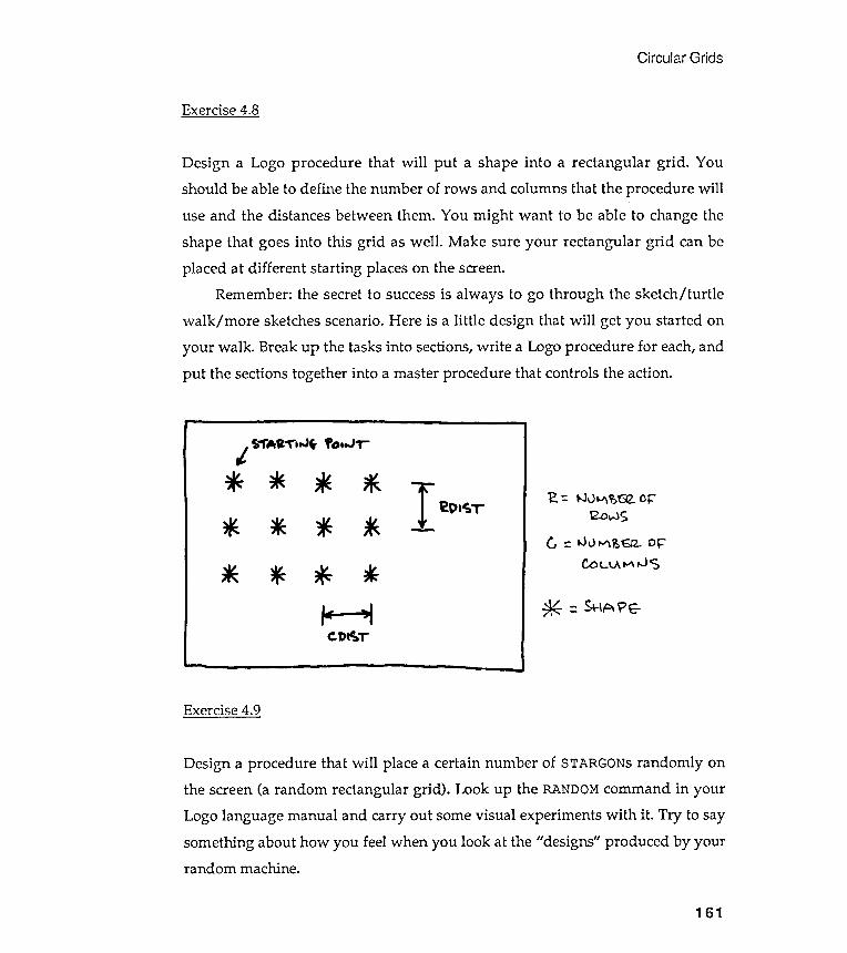
Circular Grids
Exercise 4.8
Design a Logo procedure that will put a shape into a rectangular grid . You
should be able to define the number of rows and columns that the procedure will
use and the distances between them . You might want to be able to change the
shape that goes into this grid as well . Make sure your rectangular grid can be
placed at different starting places on the screen .
Remember : the secret to success is always to go through the sketch / turtle
walk / more sketches scenario . Here is a little design that will get you started on
your walk . Break up the tasks into sections , write a Logo procedure for each, and
put the sections together into a master procedure that controls the action .
*- =. Sr\APE-
Exercise 4.9
Design a procedure that will place a certain number of STARGONs randomly onthe screen (a random rectangular grid ). Look up the RANDOM command in yourLogo language manual and carry out some visual experiments with it . Try to saysomething about how you feel when you look at the "designs" produced by yourrandom machine.
161
'2. =. tJv~ ?>~ or::2.owS
G :: .JlJ ~ ~'6l2- Dr:CoL\.At-"\ ,JS
Chapter 4
Exercise 4.10
The end of the chapter at last
Sometimes people think that Logo procedures must be complicated to be good.Wrong . Go back and look at NEPHROID; it really has only one line . Here are tworectangular grid procedures that are short and surprising . They should get youinto shape for Chapter 5.
color ,
REPEAT 2 [ FD : SIZE RT 90 ]
162
ZIP : SIZE* :GROWTHEND
: GROWTH
Piet Mondrian was a painter who specialized in rectangular grids . Find one ortwo postcards, or small reproductions , of Mondrian 's work that you like . Theportability is important because I want you to pin them up over your desk orwork space. Now , spend a lot of time looking at these Mondrians . Can youcharacterize, very roughly , the grid themes of your Mondrian examples?
Can you translate your characterization of Mondrian grid themes into aMondrian model?
TO ZIP : SIZE : GROWTH; Set your pen to the reversing; and try ZIP 10 5 .REPEAT 2 [ FD : SIZE RT 90 ]ZIP : SIZE + : GROWTH : GROWTH
END
TO ZIPM : SIZE : GROWTH; Set your pen to the reversing color ,; and try ZIPM 10 1 . 05 .
Chapter 5Rectangular and Random Grids
"Teased by the crisscross of the world ."John Galsworthy
Placement, motif , and symmetry
By now you should have an appreciation for the power of visual models to aidyour thinking about shapes. Simulating stone mason marks encouraged you tothink about clusters of shapes and their relative placement . In these masonmark designs, placement was carried out in reference to a single point thatbecame the center of the final composition . Often , an arrangement of objectsaround the center was repeated to create a special kind of balanced figure , asymmetric one. But what is symmetry ?
Let 's be as simple as possible about this notion . To say that a design issymmetric means that each part of the design has the same organization as someother part . It is the repetition of parts that creates a certain balanced quality inthe whole . All balanced designs, however , are not necessarily symmetric . Lookback at the Delaunay machine in Chapter 3 for an example of balance withoutsymmetry . Can you imagine a design that is partially symmetric or partiallynot?
Specifically , symmetry describes a correspondence in size, shape, andrelative position of parts in reference to a dividing line , or median plane, or
Chapter 5
A small review of list mechanics
The first example of rectangular symmetry will be taken from Exercise 4.8. Thisproblem asked you to design a generalized rectangular -grid machine . But firstwe will need to review some Logo list -handling mechanics in preparation for theapproach I would like to take to this problem . Please read the list section in
your Logo manual , and I 'll quickly go over the most important list operations .
164
about a center or axis.
Circular symmetry is a special form of design balance in which thecorrespondence of parts is about a central point . Look back at the stone mason
marks you produced in Chapter 4. How would you describe the nature .of thecircular symmetry exhibited in them? Look , too, at the designs you made torepresent your own character in the personal mark excursion, Exercise 3.6. How
much symmetry do you find there? We know something of balanced per-sonalities, but what would a symmetric character be? Put your comments in yournotebook.
This chapter will investigate another form of balance- rectangularsymmetry . Here the correspondence of elements will be relative to the rows and
columns of a rectangular grid rather than to a central point .
Let me have one last word about symmetry before we move on to modeling itexplicitly . Symmetric designs can be viewed on two levels . We can divide the
composite design into the motif and the rule of repetition. For example , lookback at two symmetric images in the last chapter- STARGONS and NEPHROIDs.
The STARGON motif is the kinked line and the repetition rule is the machineryof CNGON. In the nephroids , the motif is the circle and the repetition rule isstated as the last line of the NEPHROID procedure (see Chapter 4).
Lists are collections of Logo elements enclosed by square brackets [ ]. Be carefulnot to confuse these square brackets with two other kinds of brackets availableon most computers : round brackets ( ) and curly brackets { }. Round brackets areusually called parentheses.
emen
Rectangular and Random Grids
List definition
Here are some examples of lists that contain one or more elements that arenot themselves lists :
[ JIM][JIM CLAYSON]rlOO 200 3 - 201
Lists may contain elements that are themselves lists . That sounds a bitrecursive, doesn't it ?
[REPEAT[ [ [MIT]
4 [FD 25 RT 90] ][ [AMERICAN COLLEGE IN PARIS]
Lists may also contain no elements. These "empty lists " are very specialbeasts, and we may find them useful later on:
[
.....
The following list is not empty.empty list :
It has two el .ts, each of which is an
[ [
L-.I
] ]
165
[CHICAGO][PARSONS] ] ]
[LONDON] ]
-[JIM LOOKS 85 BUT ACTS 16][STARGON 4 40 . 5][FD 100 RT 45 FD 100]
Chapter 5
The value of a variable can be a list as well as a number or a word .
Values of variables can be lists
is a list .
Let 's design a procedure to carry out the following tasks :
Ask the user to type a special x-y screen location on the keyboard .
TO GIVE . PT; To create a global variable named; : POINT whose value will be a list; containing the x and y values typed .PRINT [ Give the x and y values of theMAKE " POINT READLIST
END
point ] ]
Notice that the PRINT command can be used to print a message on thescreen. The message to be printed must be a list , but the outer brackets will not beprinted .
Type GIVE . PT and it will talk to you by printing the message: "Give the xand y values of the point ."
You will notice another new command , READ LIS T, on the line after the
PRINT statement . When Logo arrives at a line that contains a READLIST
command , Logo will wait until something is typed on the keyboard . Whatever
166
MAKE " JIM 21
; Variable ' s valueMAKE " JIM " HAPPY
; Variable ' s value
MAKE " JIM [ STARGON; Variable ' s values
Th ~ READLIST construct
Put the two numbers typed into a list .Make this list be the value of a global variable .
is a number .
is a word .5 50 . 5]

Rectangular and Random Grids
Taking individual elements out of a list
it .
There are many list manipulation commands in Logo, and you should reviewthem in your own language manual . We will discuss only a few of thesecommands here . FIRS T list returns the first element of that list ; LAS T list
returns the last element; BUTFIRST list returns the list with its first element
gone; and BUTLAST list returns the list with its last element missing . Some quickexamples :
is typed is placedlocation of the word READLIST .
The line MAKE " POINT
to be carried out :
within a single list , and this list is made available at the
READLIST, causes the following three operations
SETXY : POINT
167
No . We have to take the numbers out of the list before the SETXY command is
happy . SETXY needs two arguments, not a single list that has two numbers inside
1. Logo waits until something is typed (for example, 100 200 ).2. Logo puts whatever has been typed into a list (for example, [ 100 200 ] ).3. Logo creates a global variable named : POINT and makes its value equal tothe list made available by READLIST (for example, typing : POINT would nowgive [ 100 200 ] ).
Try the procedure . Type GIVE . PT, type in two numbers, and check to see if avariable called : POINT has been created and given the values you typed .
Now , let 's send the turtle to the screen address that is now stored within the list
named : POINT. You might think that the following should work :

Chapter 5
These commands can be used in combination :
FIRST [ALAST [A BBUTFIRSTBUTLAST
B C ] returns AC ] returns C
returnsreturns
[A B C][A B C]
[B C][A B]
FIRST BUTFIRST [A B C] returns BLAST BUTLAST [A B C] returns B
168
Two final commands before we send the turtle off to : POINT . Sometimes you
don ' t know how many elements there are in a list named : JIM . COUNT : JIM
returns the number of elements in the list .
Finally , suppose you have a list with many elements and you want the
fifth one . You could say : FIRST BF BF BF BF : JIM . But there is a more
concise command : ITEM 5 : JIM returns the fifth element of : JIM . Be careful
you don ' t do something like this , though : ITEM 10 [ PARIS ] . Why ?
So let ' s send the turtle off to that location stored as the list : POINT .
TO GO . PT
; To send the turtle to the x - y position
; stored as the list value of : POINT .
PU
SETXY FIRST : POINT LAST : POINT
PD
END
Putting several Logo elements into a list
A single example will make the point .
SENTENCE [ A B ] [ N M ] returns [ A B N M ]
SENTENCE 100 - 50 returns [ 100 - 50 ]
Look up SENTENCE in your manual and compare it with the command LIST .
Carry out a few experiments to see for yourself how they are different .
used the story board approach to structure the rectangular grid exercise.
Rectangular and Random Grids
169
While you have the manual in front of you , take a peek at LPUT and FPUT .
How are they different from SENTENCE and LIST ? These list manipulators may
seem a bit ponderous at first , but you will soon get a firm , visual sense of how
they work . And that will help you decide when they are useful .
Regular rectangular grids
Now we can get on with Exercise 4.8. " Design a Logo procedure that will put a
shape into a rectangular grid . You should be able to define the number of rows
and columns that the procedure will use and the distances between them . You
might want to be able to change the shape that goes into the grid as well . Make
sure your rectangular grid can be placed at different starting places on thescreen ."
Turtle - walk sto ~ boarding
As usual , the best way to approach a complicated Logo problem is to do a turtle -
walk diagram . A turtle -walk diagram is similar to the story boards used to plan
TV and cinema advertisements . The story board is a series of small , sketched
cartoons that illustrate the major events to be covered in the film . Each
individual cartoon is accompanied by a few written comments . Sounds like what
we have done with turtle walks : sketch the important " events " and comment onthem in words .
On the next page is an example of how an illustration and design student
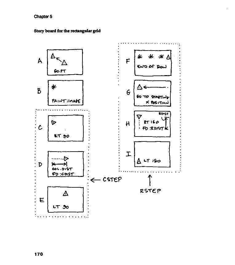
Rectangular and Random Grids
Descriptions of the story board cartoon screens
171
" Cartoon A indicates the preparation that must be carried out before the grid is
started . The screen must be cleared and the GET . PT procedure run to define the
upper -left -hand-corner starting point of the grid . Somehow, the shape notationof the little figure that will make up the grid needs to be done here, too. I don 't
yet know how to do that, though , so I 'll just assume that something , maybe avariable called : MOTIF, 'holds ' the necessary shape notation . GO. PT puts theturtle at the first grid position .
"Cartoon B shows the drawing of one individual figure at any point in the
grid . I 'll assume that this can be done by using whatever is inside : MOT IF . Mynotation will be : PAINT : MOTIF . (Still don 't know how .) PAINT will take the
turtle from its current grid location , draw the little shape inside : MOTIF, andthen return the turtle to the grid location on which PAINT found it . So some kind
of state transparency must be respected by PAINT ." Cartoons C, D , and E sketch the movement of the turtle from one column to
the next. The turtle must move over to the next column until it has completed allthe columns of anyone row . To do this, the turtle needs to pick up its pen, turnright 90, move forward the between-columns distance, turn left 90, and put downits pen. I 'll call this procedure CSTEP, for olumn ~ ping . CSTEP's singleargument will be the distance between columns .
" Cartoons F , G, H , and I sketch the movement of the turtle from the end of a
finished row to the beginning of the next row , if an additional row is required .Cartoon G shows the turtle , after lifting its pen, moving left to the x value of the
starting point , : POINT . The turtle then turns right 180 and goes forward by anamount equal to the between-row distance. The turtle turns another right 180 and
puts down its pen. The name of this procedure will be RSTEP, for row ill2ping .RSTEP's single argument will be the distance between rows ."
Story
Everything that the illustration student said above is correct. Her intuition wasvery good and her idea about PAINT : MOTIF (before she knew about lists) isvery elegant. Let's use her story board "characters" and translate them intoformal Logo notation.
The procedure to set up the upper-left-hand starting point has already beenwritten . It 's GIVE . PT. Our procedure GO. PT sends the turtle to the startingplace.
What about PAINT :MOTIF? What is :MOTIF?
Painting the :MOTIF list
We are already familiar with the REPEAT n [ Logo commands ] construct . This
command could be used to get the MOTIF list painted - or drawn - on the screen .
We could simply say : REPEAT 1 : MOTIF . A shorter way of saying REPEAT 1
[ something ] is RUN [ something ] . So we can answer the question of how to paint
the list as follows : Make sure the turtle is where you want the motif to be , and
Chapter 5
board cartoons into Logo notation
MAKERUN
"MOTIF:MOTIF
[STARGON 7 10 . 5]
172
Let's think of : MOTIF as being a list of the Logo commands that will drawthe needed figure. For example, suppose we want a grid made from individualstars with 7 points. We could make the value of : MO T I F be a list like[STARGON 7 10 .5] . How do we then "paint" this list?
then RUN the list that defines the motif .
Here is an example of RUNning a : MOTIF list :
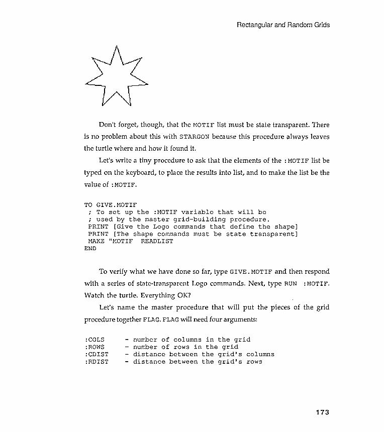
Rectangular and Random Grids
: COLS: ROWS: CDIST:RDIST
number of columns in the gridnumber of rows in the griddistance between the grid ' s columnsdistance between the grid ' s rows
173
To verify what we have done so far , type GIVE . MOTIF and then respond
with a series of state -transparent Logo commands . Next , type RUN : MOTIF .
Watch the turtle . Everything OK ?
Let 's name the master procedure that will put the pieces of the grid
procedure together FLAG. FLAG will need four arguments :
Don ' t forget , though , that the MOTIF list must be state transparent . There
is no problem about this with STARGON because this procedure always leaves
the turtle where and how it found it .
Let 's write a tiny procedure to ask that the elements of the : MOTIF list be
typed on the keyboard , to place the results into list , and to make the list be the
value of : MOTIF .
TO GIVE . MOTIF; To set up the : MOTIF variable that will be; used by the master grid - building procedure .PRINT [ Give the Logo commands that define the shape ]PRINT [ The shape commands must be state transparent ]MAKE " MOTIF READLIST
END
-
-
-
-
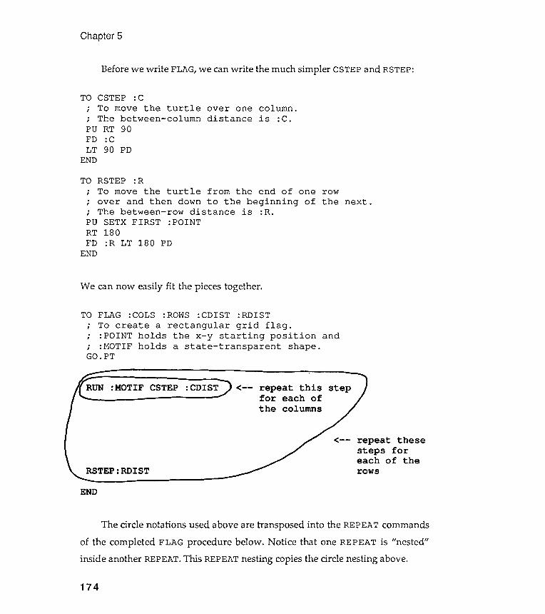
TO CSTEP : C; To move the turtle over one column .; The between - column distance is : C.
The circle notations used above are transposed into the REPEAT commandsof the completed FLAG procedure below . Notice that one REPEAT is "nested"inside another REPEAT. This REPEAT nesting copies the circle nesting above.
Chapter 5
Before we write FLAG, we can write the much simpler CSTEP and RSTEP:
TO RSTEP : R; To move the turtle from the end of one row; over and then down to the beginning of the next .; The between - row distance is :R.PU SETX FIRST : POINT
We can now easily fit the pieces together .
TO FLAG : COLS : ROWS : CDIST : RDIST; To create a rectangular grid flag .; : POINT holds the x - y starting position and; : MOTIF holds a state - transparent shape .GO. PT
174
PO RT 90FD :CLT 90 PD
END
RT 180FD :R LT 180 PD
END
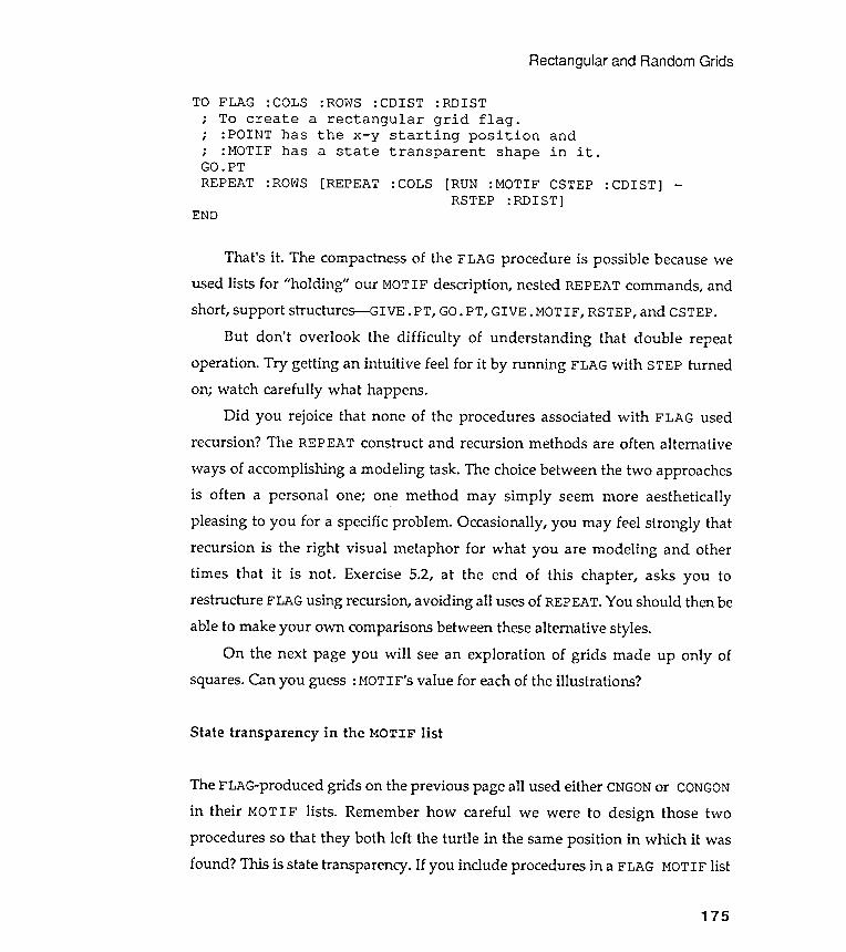
Rectangular and Random Grids
TO : ROWS : CDIST : RDISTa rectangular grid flag .
the x - y starting position anda state transparent shape in it .
[REPEAT :COLS [RUN :MOTIF CSTEP :CDIST] -END
State transparency in the MOTIF list
175
RSTEP : RDIST ]
That 's it . The compactness of the FLAG procedure is possible because weused lists for "holding" our MOTIF description , nested REPEAT commands, andshort , support structures - GIVE . PT, GO. PT, GIVE .MOTIF, RSTEP, and CSTEP.
But don 't overlook the difficulty of understanding that double repeatoperation . Try getting an intuitive feel for it by running FLAG with STEP turnedon; watch carefully what happens.
Did you rejoice that none of the procedures associated with FLAG usedrecursion ? The REPEAT construct and recursion methods are often alternative
ways of accomplishing a modeling task. The choice between the two approachesis often a personal one; one method may simply seem more aestheticallypleasing to you for a specific problem . Occasionally , you may feel strongly thatrecursion is the right visual metaphor for what you are modeling and othertimes that it is not . Exercise 5.2, at the end of this chapter , asks you torestructure FLAG using recursion, avoiding all uses of REPEAT. You should then be
able to make your own comparisons between these alternative styles.On the next page you will see an exploration of grids made up only of
squares. Can you guess : MOTIF's value for each of the illustrations ?
FLAG : COLS
; To create; : POINT has
; : MOTIF hasGO . PT
REPEAT : ROWS
The FLAG-produced grids on the previous page all used either CNGON or CONGONin their MO T I F lists . Remember how careful we were to design those twoprocedures so that they both left the turtle in the same position in which it wasfound ? This is state transparency. If you include procedures in a FLAG MOTIF list
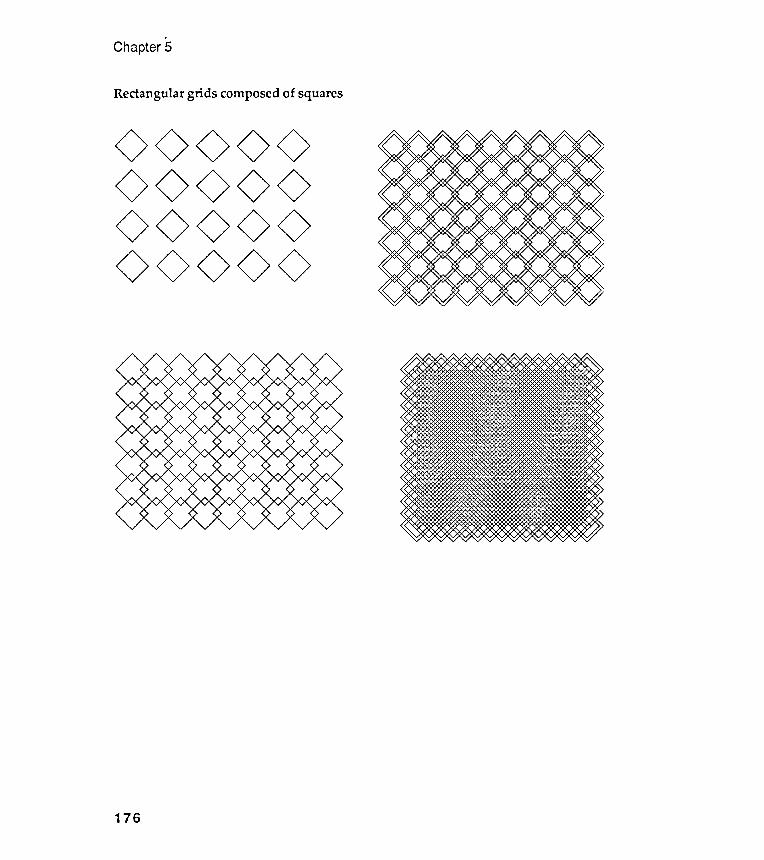
,Chapter 5
Rectangular grids composed of squares
000000000000 <><>
00<>00 0
176
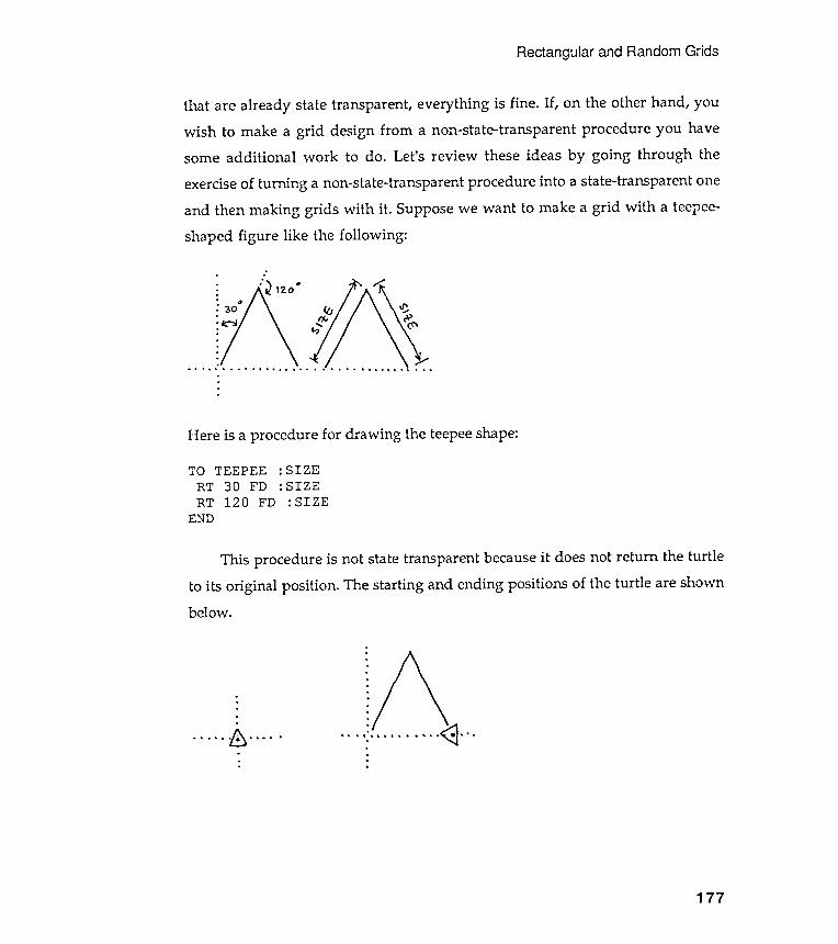
Rectangular
that are already state transparent , everything is fine . If , on the other hand, youwish to make a grid design from a non-state-transparent procedure you havesome additional work to do. Let 's review these ideas by going through the
exercise of turning a non-state-transparent procedure into a state-transparent oneand then making grids with it . Suppose we want to make a grid ' with a teepee-shaped figure like the following :
and Random Grids
. .
. : .
.
.
. . . . ' . . .
Here is a procedure for drawing the teepee shape:
: SIZE: SIZE
: SIZE
TO TEEPEERT 30 FDRT 120 FD
END
below .
.
.
.
.
.
.
.. . .~.... . . .,. .<:]....
.
.
.
.
. . . . . b " . "
177
This procedure is not state transparent because it does not return the turtleto its original position . The starting and ending positions of the turtle are shown
Chapter 5
There are two simple ways to make TEEPEE state transparent . The first isthe most obvious : simply move the turtle backward to where it began. Call thisprocedure TPI .
to making TP state transparent .
This method doubles the length of the procedure, and the additionallength obscures the procedure's design. Procedures should be as short and asdescriptive as possible; that's good modeling style. Perhaps there is anotherway to make the state transparency of the procedure more obvious.
We really want to say something quite simple to the turtle : "Rememberwhere you started from- and in which direction you were heading- and then goback to that position after you have finished drawing the teepee." The secondapproach does this explicitly; but we need two new supporting procedures tomake it work nicely.
The procedure RECORD. pS assembles the turtle's current x-y position andheading into a three-element list called : Ps . The operation of RESTORE. pSshould be obvious.
state .
178
TO RECORD.POS; Records the turtle ' s current positionMAKE "pS ( SE XCOR YCOR HEADING)END
Note : when the command SE has more than two arguments , as in the
situation above, parentheses must be placed before SE and after a space leftbehind the last argument . Verify this in your own Logo manual .
TO TP1 : SIZE; First approachRT 30 FD : SIZERT 120 FD : SIZEBK : SIZE LT 120BK : SIZE LT 30
END

Rectangular and Random Grids
TO TP2 : SIZERECORD.POSTEEPEE :SIZERESTORE.POS
END
179
the turtle to the position state
: POS .
: POS FIRST BF : POS
: POS
state - transparent teepee maker :
TO RESTORE . POS
; To restore; recorded inPU SETXY FIRSTSETHEADING LASTPD
END
Here, then, is an obviously
You will find many more uses for RECORD . POS and RESTORE . POS .
A Mayan -inspired grid that vibrates
I hope the square and teepee grids make you think about rectangular sym-metries and that you are now impressed with the help Logo models give us inexploring visual ideas. I will admit , though , that these grids are not the mostexciting images to look at. They lack surprise and "quirkiness ." They are, in fact,too balanced and too symmetric . So I am pleased to present a student -designed
grid that exhibits an odd , surprising quality - within a symmetric framework .I' ll let the student describe his own work .
" I wanted to make a grid from square-ish spirals that wrapped back onthemselves. I needed to use the RECORD. POS and RESTORE. POS procedures
because I wasn't sure where my spiral would end up, and I had to make them
state transparent . I came up with the Mayan description of the grid only after Ilooked at my results . I was surprised about the vibrating quality of the grid ; Itried to explore the source of the vibration by changing the arguments that Iga ve to my procedures."
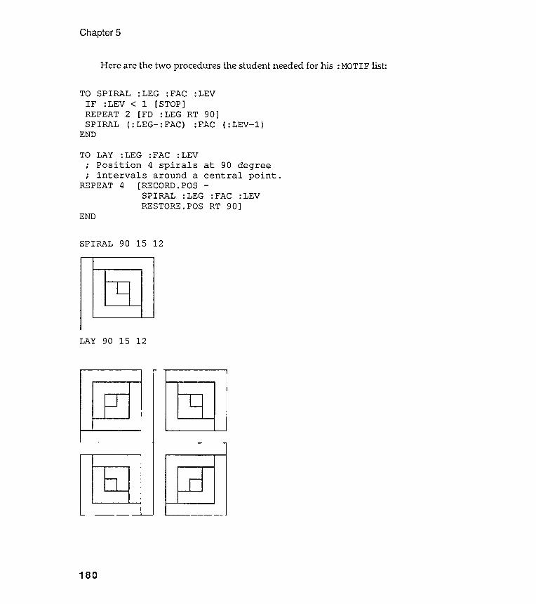
Chapter 5
. .J L
I I
Here are the two procedures the student needed for his : MOTIF list :
( : LEV- l )
TO
:FAC :LEVRT 90]
END
SPIRAL 90 15 12
LAY 90 15 12
180
REPEAT
.,.,
TO SPIRAL : LEG : FAC : LEV
IF : LEV < 1 [ STOP ]
REPEAT 2 [ FD : LEG RT 90 ]
SPIRAL ( : LEG - : FAC ) : FAC
END
LAY : LEG : FAC : LEV
Position 4 spirals at 90 degree
intervals around a central point .
4 [ RECORD . POS -
SPIRAL : LEG
RESTORE . POS
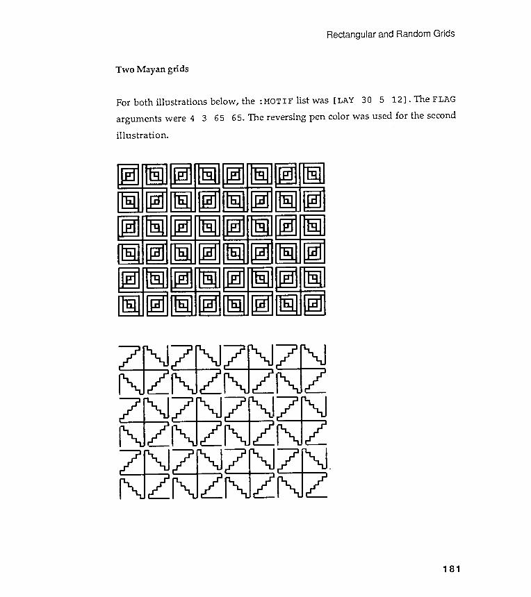
Rectangular and Random Grids
Two Mayan grids
For both illustrations below, the : MOTIF list was [LAY 30 5 12] . The FLAGarguments were 4 3 65 65. The reversing pen color was used for the secondillustration .
181
One effective way to make rectangular designs more visually entertaining is toadd limited amounts of randomness to them . I would like to introduce this idea
by exploring Exercise 4.9: " Design a procedure that will place a certain number of
STARGONs randomly on the screen (a random rectangular grid )."
How did you approach this ? No doubt you looked up the RANDOM command
in your Logo manual and found that it could produce " random numbers " ; but what
are those ? The exercise of generating random grids will give you a visual model
of what these random things actually look like . You need a good feel for these
random numbers because we will be using the idea of randomness for the rest of
this chapter and in several future chapters .
Random
The Logo command RANDOM requires a single , integer argument . Logo thenproduces an integer in the range from 0 to the argument minus 1. For example,RANDOM 4 would produce a single number that could be 0, 1, 2, or 3. Each of these
numbers is equally likely to be returned by Logo, and it is very unlikely that youcould correctly guess what Logo would respond every time you type RANDOM argo
Guessing a single RANDOM 4 outcome correctly is tough . It is even tougher topredict correctly the pattern of the numbers given by Logo if you should typeRANDOM 4 over and over again. There may indeed be a pattern , but it cannot beguessed easily before it occurs. Unless, of course, you are exceptionally lucky ,have ESP, or know the model that your version of Logo uses to generate randomnumbers.
Chapter 5
Adding random components to rectangular grids
numbers
182
Let's design a Logo procedure to generate a series of random numbers so that
we can look at them. Here is an example of such an exploratory tool .
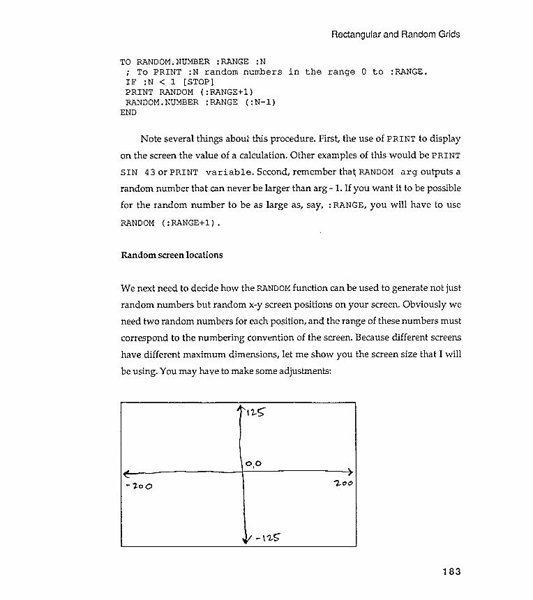
Rectangular and Random Grids
TO RANDOM. NUMBER: RANGE : N; To PRINT :N random numbers in the range 0 to :RANGE.IF :N < 1 [ STOP]PRINT RANDOM ( : RANGE+l )RANDOM. NUMBER : RANGE ( : N- l )
END
"2..r;-
0 , 0
- , " 00 '"2.. 00
- \ '2..5""
183
Note several things about this procedure . First , the use of PRINT to display
on the screen the value of a calculation . Other examples of this would be PRINT
SIN 43 or PRINT variable . Second , remember tha ~ RANDOM arg outputs a
random number that can never be larger than arg - I . If you want it to be possible
for the random number to be as large as , say , : RANGE , you will have to use
RANDOM ( : RANGE + l ) .
Random screen locations
We next need to decide how the RANDOM function can be used to generate not just
random numbers but random x - y screen positions on your screen . Obviously we
need two random numbers for each position , and the range of these numbers must
correspond to the numbering convention of the screen . Because different screens
have different maximum dimensions , let me show you the screen size that I will
be using . You may have to make some adjustments :
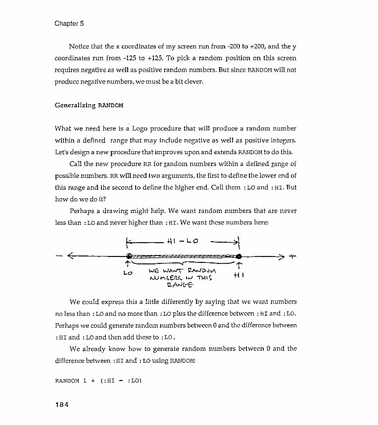
Chapter 5
RANDOM 1 ( : HI : La )+
184
Notice that the x coordinates of my screen run from - 200 to + 200 , and the y
coordinates run from - 125 to + 125 . To pick a random position on this screen
requires negative as well as positive random numbers . But since RANDOM will not
produce negative numbers , we must be a bit clever .
Generalizing RANDOM
What we need here is a Logo procedure that will produce a random number
within a defined range that may include negative as well as positive integers .
Let 's design a new procedure that improves upon and extends RANDOM to do this .
Call the new procedure RR for random numbers within a defined range of
possible numbers . RR will need two arguments , the first to define the lower end of
this range and the second to define the higher end . Call them : LO and : HI . But
how do we do it ?
Perhaps a drawing might help . We want random numbers that are never
less than : LO and never higher than : HI . We want these numbers here :
f - ' +\ t - LO - - ~ \
- +
l...o W (: ; WArJ " \ ~ i > " v \ l '/ I . .JJ n ,. / tc . . I ...J ' TtJ, t ~ ti 1
t ! . AiJ ( rf ; -
We could express this a little differently by saying that we want numbers
no less than : LO and no more than : LO plus the difference between : HI and : LO .
Perhaps we could generate random numbers between 0 and the difference between
: H I and : LO and then add these to : LO .
We already know how to generate random numbers between 0 and the
difference between : H I and : LO using RANDOM :
smaller than 0 and never biggerThis expression will produce numbers neverthan ( : HI - : La ) . The random number we want , the numbers that fall in the
range between : La and : HI , could be found with :
ure :
use this SET idea to send the turtle
Rectangular and Random Grids
: LO + RANDOM 1 + ( : HI : La )
We thus have the idea we need to write the proced
TO.
,
.
,
OPEND
RR : LO : HITo generate a single random numberin the range defined by : LO and : HI .
( : LO + RANDOM 1 + ( : HI - : LO
Note the appearance of the new command OP, short for OUTPUT. Look it upin your Logo manual . Why do we need OP in the procedure RR?
Experiment with RR. Notice that it works fine for negative numbers . Forexample :
- 100- 100
- 5050
RRRR
But what 's wrong with the following ?
RR 100 - 100
Using RR to generate random screen locations
We can easily generate a random screen location for my screen with the
following :
SETXY (RR - 200 200) (RR - 125 125)
to a random position on my screen.Let's
185
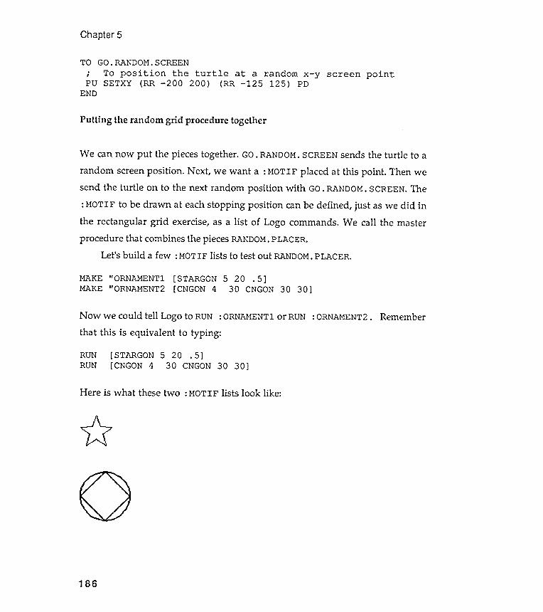
MAKE "ORNAMENTl [STARGON 5 20 . 5]MAKE "ORNAMENT2 [CNGON 4 30 CNGON 30 30]
Chapter 5
TO GO. RANDOM. SCREEN
: ORNAMENT 1 or RUN:ORNAMENT2. Remember
30 30]
Here is what these two : MOTIF lists look like :
""i:?
186
Now we could tell Logo to RUNthat this is equivalent to typing:
RUN [STARGON 5 20 . 5]RUN [CNGON 4 30 CNGON
; To position the turtle at a random x - y screen pointPU SETXY (RR - 200 200 ) (RR - 125 125 ) PD
END
Putting the random grid procedure together
We can now put the pieces together. GO. RANDOM. SCREEN sends the turtle to a
random screen position . Next , we want a : MOTIF placed at this point . Then wesend the turtle on to the next random position with GO. RANDOM. SCREEN. The
: MOTIF to be drawn at each stopping position can be defined , just as we did inthe rectangular grid exercise, as a list of Logo commands . We call the masterprocedure that combines the pieces RANDOM. PLACER.
Let's build a few : MOTIF lists to test out RANDOM. PLACER.
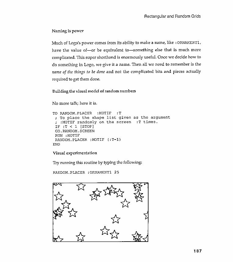
Rectangular and Random Grids
Naming is power
Much of Logo's power comes from its ability to make a name, like : ORNAMENT 1,have the value of- or be equivalent to- something else that is much morecomplicated . This super shorthand is enormously useful . Once we decide how todo something in Logo, we give it a name. Then all we need to remember is thename of the things to be done and not the complicated bits and pieces actuallyrequired to get them done.
Building the visual model of random numbers
Visual experimentation
Try running this routine by typing the following :
RANDOM. PLACER : ORNAMENTl 25
187
No more talk ; here it is .
TO RANDOM . PLACER : MOTIF : T
; To place the shape list given as the argument
; : MOTIF randomly on the screen : T times .
IF : T < 1 [ STOP ]
GO . RANDOM . SCREEN
RUN : MOTIF
RANDOM . PLACER : MOTIF ( : T - l )
END
~ * ~ u Wu {:? ~
~
~ Uu
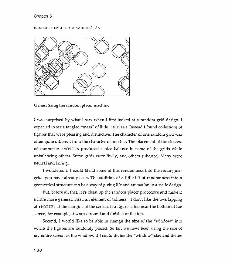
( )
Chapter 5
RANDOM. PLACER : ORNAMENT2 25
188
Generalizing the random placer machine
I was surprised by what I saw when I first looked at a random grid design . I
expected to see a tangled " mess " of little : MOTIFs . Instead I found collections of
figures that were pleasing and distinctive . The character of one random grid was
often quite different from the character of another . The placement of the clusters
of composite : MOTIFs produced a nice balance in some of the grids while
unbalancing others . Some grids were lively , and others subdued . Many were
neutral and boring .
I wondered if I could blend some of this randomness into the rectangular
grids you have already seen . The addition of a little bit of randomness into a
geometrical structure can be a way of giving life and animation to a static design .
But , before all that , let ' s clean up the random placer procedure and make it
a little more general . First , an element of tidiness : I don ' t like the overlapping
of : MOTIFs at the margins of the screen . If a figure is too near the bottom of the
screen , for example , it wraps around and finishes at the top .
Second , I would like to be able to change the size of the " window " into
which the figures are randomly placed . So far , we have been using the size of
my entire screen as the window . If I could define the " window " size and define
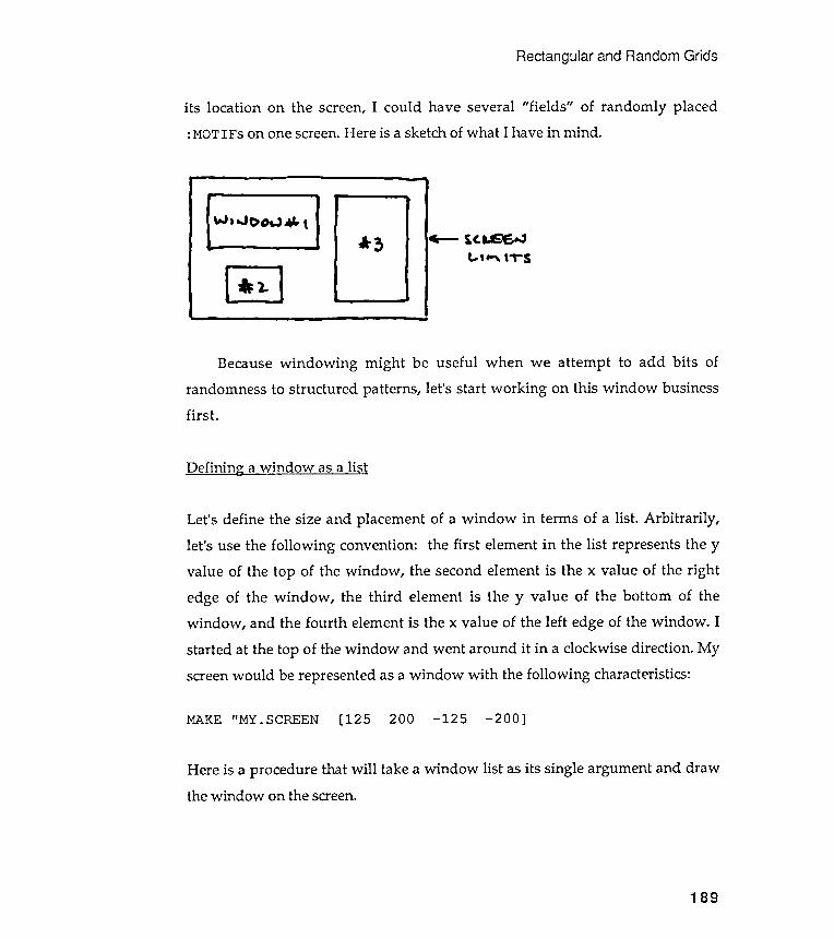
Defining a window as a list
Rectangular and Random Grids
first .
Let 's define the size and placement of a window in terms of a list . Arbitrarily ,
let 's use the following convention : the first element in the list represents the y
value of the top of the window , the second element is the x value of the right
edge of the window , the third element is the y value of the bottom of the
window , and the fourth element is the x value of the left edge of the window . I
started at the top of the window and went around it in a clockwise direction . My
screen would be represented as a window with the following characteristics :
MAKE "MY.SCREEN [125 200 - 125 - 200]
Here is a procedure that will take a window list as its single argument and drawthe window on the screen.
189
its location on the screen, I could have several " fields " of randomly placed: MOTIFs on one screen. Here is a sketch of what I have in mind .
Because wind owing might be useful when we attempt to add bits of
randomness to structured patterns , let 's start working on this window business
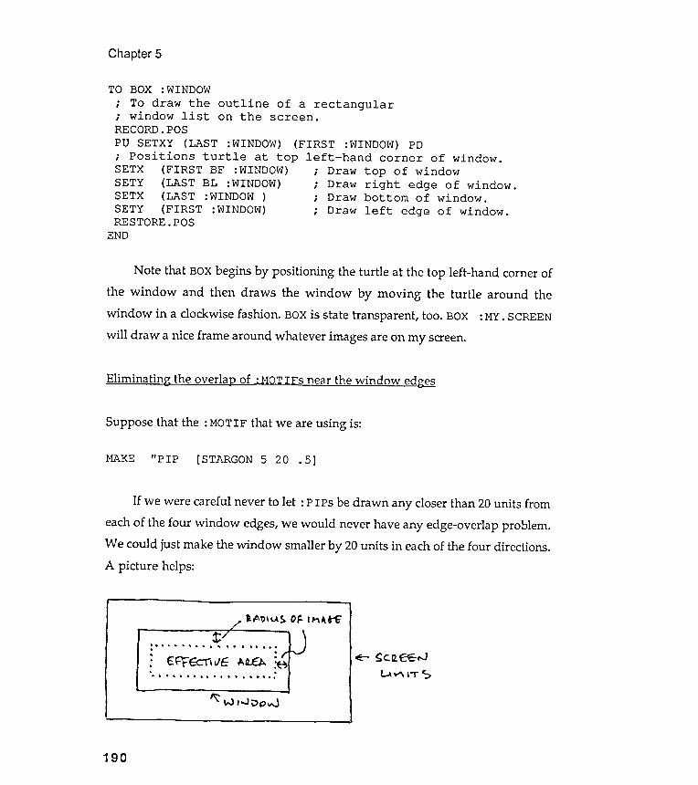
Chapter
Eliminating the overlat2 of : MOTIFs near the window edge~
If we were careful never to let : PIPs be drawn any closer than 20 units fromeach of the four window edges, we would never have any edge-overlap problem .We could just make the window smaller by 20 units in each of the four directions .A picture helps:
~ ~ t '
. t. . . ~ . . " . ~ "
. ' . . . . '
. .
: E~ ; cI, vc: I-.a..tA :~ ~ ~c.a. ff "J'. . . . . . . . . . . . . . . . . . : ~ ~ ,.,.. ~
"::: W 1.oJ ' V 0 voJ
5
TO BOX :WINDOW; To draw the outline of a rectangular; window list on the screen .RECORD. POSPU SETXY (LAST :WINDOW) (FIRST :WINDOW) PD; Positions turtle at top left - hand corner of window .SETX (FIRST BF :WINDOW) ; Draw top of windowSETY (LAST BL :WINDOW) ; Draw right edge of window .SETX (LAST :WINDOW ) ; Draw bottom of window .SETY (FIRST :WINDOW) ; Draw left edge of window .RESTORE. POS
END
Suppose that the : MOTIF that we are using is:
MAKE " PIP [STARGON 5 20 . 5]
190
Note that BOX begins by positioning the turtle at the top left -hand comer ofthe window and then draws the window by moving the turtle around thewindow in a clockwise fashion . BOX is state transparent , too. BOX : MY. SCREENwill draw a nice frame around whatever images are on my screen.
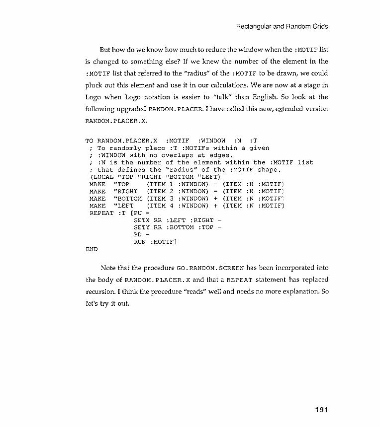
Rectangular and Random Grids
But how do we know how much to reduce the window when the : MOTIF list
is changed to something else? If we knew the number of the element in the: MOTIF list that referred to the " radius " of the : MOTIF to be drawn , we could
pluck out this element and use it in our calculations . We are now at a stage in
Logo when Logo notation is easier to " talk " than English . So look at the
following upgraded RANDOM. PLACER . I have called this new , extended versionRANDOM. PLACER . X.
:N : T
a given:MOTIF :WINDOW
: T :MOTIFs withinoverlaps at edges .
of the element within the :MOTIF list" radius " of the" BOTTOM " LEFT)1 : WINDOW) - (ITEM2 : WINDOW) - ( ITEM3 :WINDOW) + (ITEM4 : WINDOW) + (ITEM
: N: N: N: N
:LEFT :RIGHT: BOTTOM :TOP -
:MOTIF]
Note that the procedure GO. RANDOM. SCREEN has been incorporated intothe body of RANDOM. PLACER. X and that a REPEAT statement has replacedrecursion . I think the procedure " reads" well and needs no more explanation . Solet 's try it out .
191
:MOTIF
J,J
,
J
TO RANDOM . PLACER . X
; To randomly place; : WINDOW with no; : N is the number
; that defines the( LOCAL " TOP " RIGHT
MAKE " TOP ( ITEMMAKE " RIGHT ( ITEMMAKE " BOTTOM ( ITEMMAKE " LEFT ( ITEMREPEAT : T [ PU -
SETX RRSETY RRPD -
RUNEND
-
shape .
:MOTIF:MOTIF:MOTIF:MOTIF
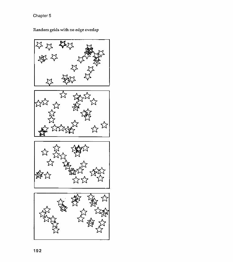
Chapter 5
Random grids willi no edge overlap
192
Rectangular and Random Grids
Kandinsky grids
Wassily Kandinsky (1866-1944) was born in Moscow but trained in Munich . Hetotally abandoned realistic art for the abstract, a form he consid~red to be morespiritual . He made great use of simple geometric forms placed withinframeworks that could be labeled "randomish ."
A good example of such work is "Several Circles, No 323," reproduced onthe next page. The original painting is 1.4 meters square, and the circles glowwith translucent light , not at all like this tiny and opaque reproduction . It isenormous and transparent . I have also included Kandinsky 's pen-and-ink studyfor this painting .
Stare at this poor reproduction for some time or, far better, go out and findyourself some Kandinsky reproductions on postcards.
On the page following the reproductions , you will see a few of my Logoattempts to simulate Kandinsky 's "Several Circles ." They are, of course, paleimitations , but that is not the point . Now it 's your turn . Look at this paintingand try your best to simulate several of the visual ideas expressed within it .There is more going on than just randomly placing circles.
193

Kandinsky circles
Chapter 5
194
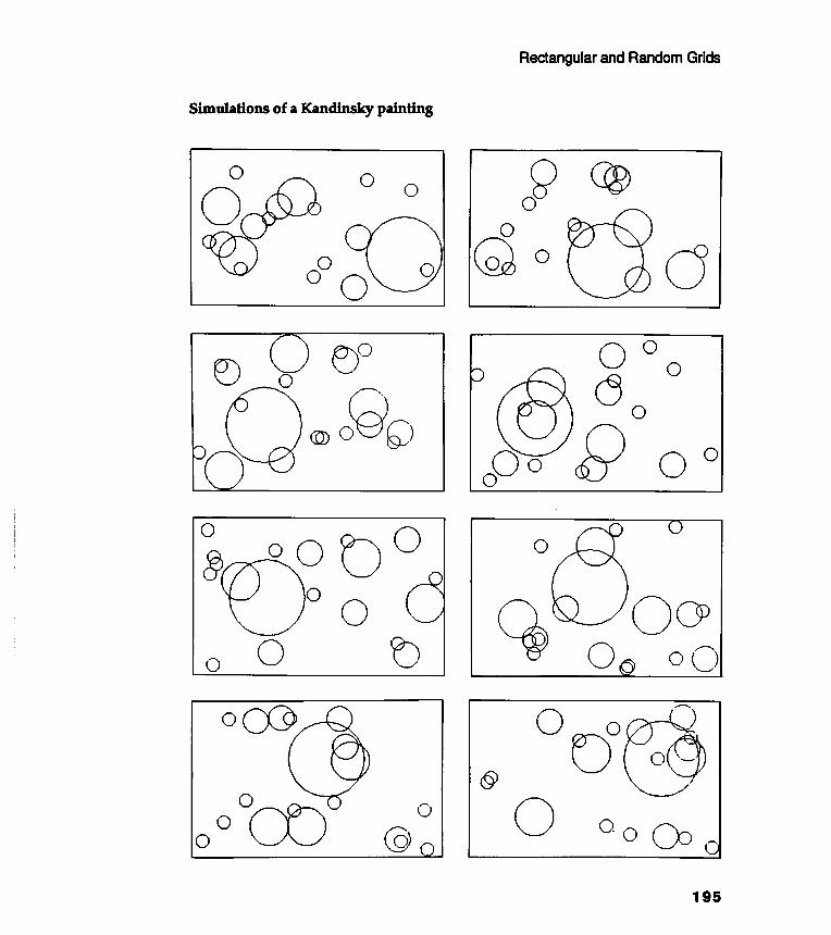
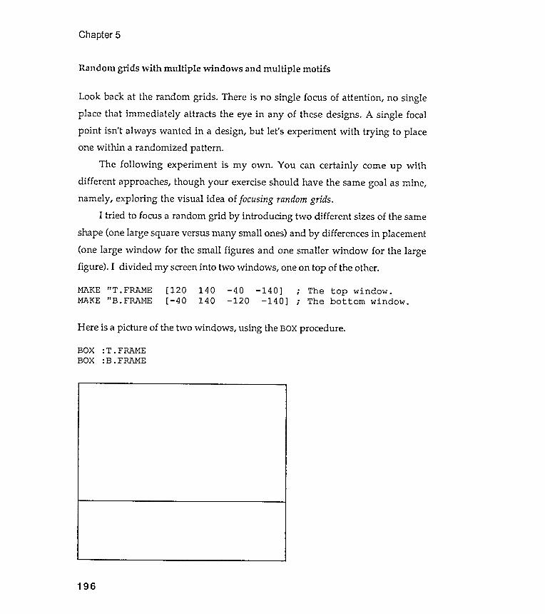
Look back at the random grids .
place that immediately attracts
using
Chapter 5
Random grids with multiple windows and multiple motifs
There is no single focus of attention , no singlethe eye in any of these designs. A single focal
Here is a picture of the two windows , the BOX procedure .
BOX :T.FRAMEBOX :B.FRAME
196
point isn't always wanted in a design, but let 's experiment with trying to placeone within a randomized pattern .
The following experiment is my own . You can certainly come up withdifferent approaches, though your exercise should have the same goal as mine,namely , exploring the visual idea of focusing random grids.
I tried to focus a random grid by introducing two different sizes of the same
shape (one large square versus many small ones) and by differences in placement(one large window for the small figures and one smaller window for the largefigure ). I divided my screen into two windows , one on top of the other.
MAKE " T . FRAME [ 120 140 - 40 - 140 ] ; The top window .MAKE " B . FRAME [ - 40 140 - 120 - 140 ] ; The bottom window .
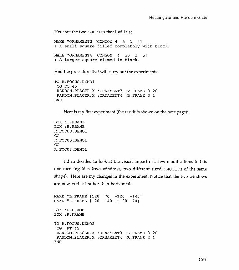
I then decided to look at the visual impact of a few modifications to this
one focusing idea (two windows , two different sized : MOTIFs of the same
shape ). Here are my changes in the experiment . Notice that the two windowsare now vertical rather than horizontal .
Rectangular and Random Grids
And the procedure that will carry out the experiments :
:T.FRAME 3 20:B.FRAME 3 1
Here is my first experiment (the result is shown on the next page):
MAKE " L . FRAME [ 120MAKE " R. FRAME [ 120
70 - 120 - 140 ]140 - 120 70 ]
BOX :L .FRAMEBOX :R.FRAME
TO R.FOCUS.DEMO2CG RT 45RANDOM.PLACER.XRANDOM.PLACER.X
END
: ORNAMENT 3: ORNAMENT 4
:L .FRAME:R.FRAME
3 203 1
197
END
BOX :T.FRAMEBOX :B.FRAMER.FOCUS.DEMOlCGR.FOCUS.DEMOlCGR.FOCUS.DEMOl
TO R.FOCUS. DEMOlCG RT 45RANDOM. PLACER. XRANDOM. PLACER. X
: ORNAMENT 3: ORNAMENT 4
Here are the two : MOT IFs that I will use :
MAKE " ORNAMENT3 [ CONGON 4 5 1 4 ]
; A small square filled completely with black .
MAKE " ORNAMENT4 [ CONGON 4 30 1 5 ]
; A larger square rimmed in black .

Chapter 5
Focused random grids #1
aa a. aa -a
.a
aa. a a.a
a a
Daaa
aa
aaa ~aa
. a a.aa
a
D198
aa aa a
a a
a a
. a aa a a
a
D
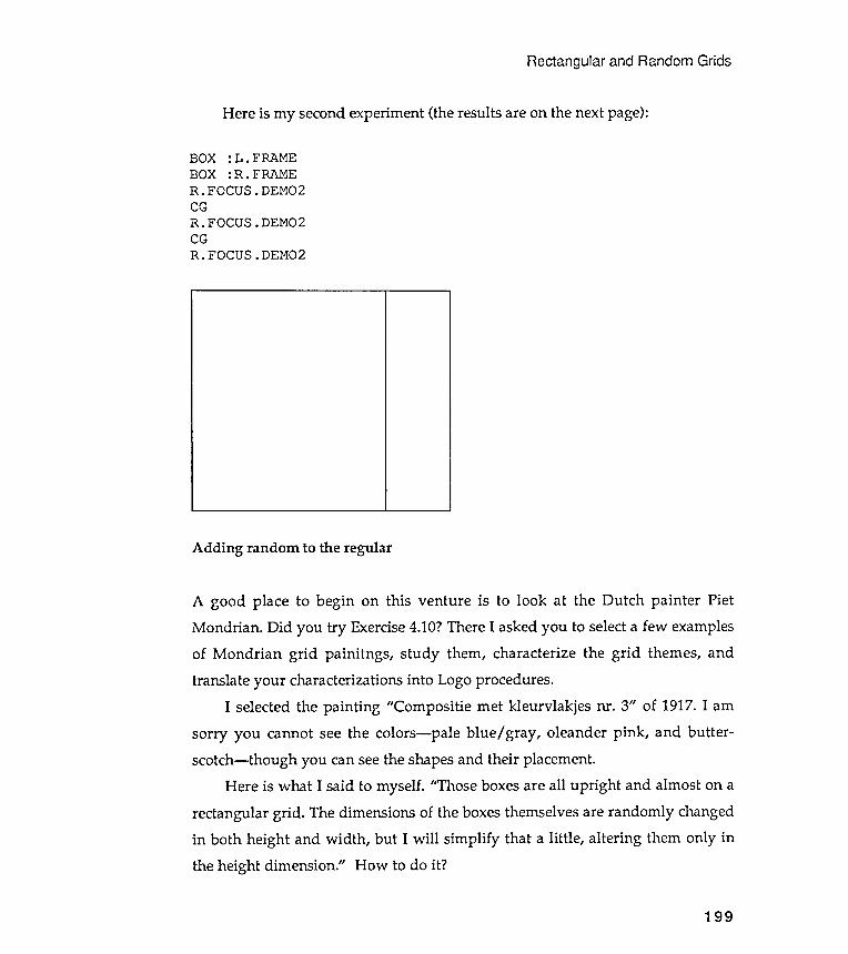
Adding
Rectangular and Random Grids
Here is my second experiment (the results are on the next page ) :
BOX :L .FRAMEBOX :R.FRAMER.FOCUS.DEMO2CGR.FOCUS.DEMO2CGR.FOCUS.DEMO2
random to the regular
A good place to begin on this venture is to look at the Dutch painter PietMondrian . Did you try Exercise 4.10? There I asked you to select a few examplesof Mondrian grid painitngs , study them, characterize the grid themes, andtranslate your characterizations into Logo procedures.
I selected the painting "Compositie met kleurvlakjes ill . 3" of 1917. I amsorry you cannot see the colors- pale blue / gray , oleander pink , and butter -scotch- though you can see the shapes and their placement.
Here is what I said to myself . "Those boxes are all upright and almost on arectangular grid . The dimensions of the boxes themselves are randomly changedin both height and width , but I will simplify that a little , altering them only inthe height dimension ." How to do it ?
199
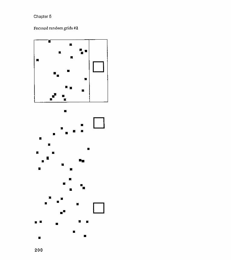
. .
Chapter 5
Focused random grids #2
.
D... a..
..
.. .
...
. .
.. ...
. ...
D
.
.. . ..
...
200
.
...
..
.
..
..
..
.
..
. .
.
D
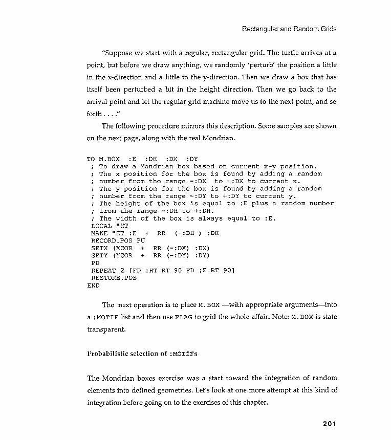
Rectangular and Random Grids
"Suppose we start with a regular , rectangular grid . The turtle arrives at apoint , but before we draw anything , we randomly 'perturb ' the position a littlein the x-direction and a little in the y-direction . Then we draw a box that hasitself been perturbed a bit in the height direction . Then we go back to thearrival point and let the regular grid machine move us to the next point , and soforth . . . ."
The following procedure mirrors this description . Some samples are shownon the next page, along with the real Mondrian .
TO.
,
.
,
.
,
.
,
on current x - y position .
found by adding a random
+ : DX to current x .
found by adding a random
+ : DY to current y .
to : E plus a random number
equal to : E .
~.
~.
~.
~.
RR (- :DX)RR (- :DY)
: DX):DY)+
REPEAT 2 [FD : HT RT 90 FD : E RT 90 ]RESTORE.POS
END
The next operation is to place M. BOX - with appropriate arguments - intoa : MOTIF list and then use FLAG to grid the whole affair . Note : M. BOX is statetransparent .
Probabilistic selection of :MQTIFs
The Mondrian boxes exercise was a start toward the integration of random
elements into defined geometries . Let 's look at one more attempt at this kind of
integration before going on to the exercises of this chapter .
201
M . BOX : E : DH : DX : DY
To draw a Mondrian box based
The x position for the box is
number from the range - : DX to
The y position for the box is
number from the range - : DY to
The height of the box is equal
from the range - : DH to + : DH .
The width of the box is always
LOCAL " HT
MAKE " HT : E + RR ( - : DH ) : DH
RECORD . POS PU
SETX ( XCOR +
SETY ( YCOR
PD
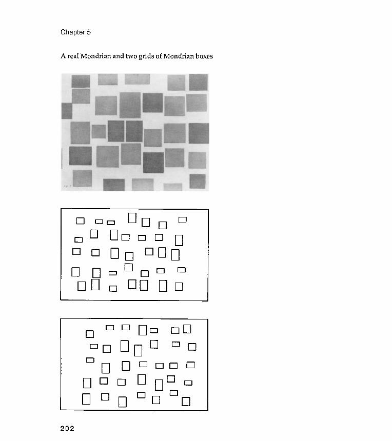
Chapter 5
A real Mondrian and two grids of Mondrian boxes
202
00
DO D
DO D
DO
DO O
DD0
DD 0
DDO
ODD
DO O
DDDO
DD
0
0 DD 00 DOooDDO DOD 0 DDDDD
0000 DO DD 00 DODD
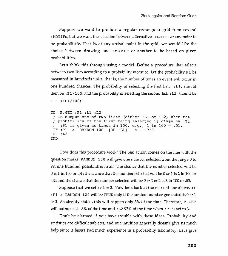
Rectangular and Random Grids
203
Suppose we want to produce a regular rectangular grid from several: MOTIFS, but we want the selection between alternative : MOTIFs at any point tobe probabilistic . That is, at any arrival point in the grid , we would like thechoice between drawing one : MO T I F or another to be based on givenprobabilities .
Let 's think this through using a model . Define a procedure that selectsbetween two lists according to a probability measure. Let the probability P 1 bemeasured in hundreds units , that is, the number of times an event will occur in
one hundred chances. The probability of selecting the first list , : L 1, shouldthen be : P 1 / 1 0 0, and the probability of selecting the second list , : L2, should be1 - ( : Pl / 1OO) .
TO P. GET : P1 : L1 : L2; To output one of two lists (either : L1 or : L2 ) when the; probability of the first being selected is given by :P1 .; : P1 is given as times in 100 , e . g . , 1 in 100 = . 01 .IF : P1 > RANDOM 100 [OF :L1 ] <- - - ???OP : L2
END
How does this procedure work ? The real action comes on the line with thequestion marks . RANDOM 100 will give one number selected from the range 0 to99, one hundred possibilities in all . The chance that the number selected will be0 is 1 in 100 or .01; the chance that the number selected will be 0 or 1 is 2 in 100 or.02; and the chance that the number selected will be 0 or 1 or 2 is 3 in 100 or .03.
Suppose that we set : P1 = 3. Now look back at the marked line above. IF: P1 > RANDOM 100 will be TRUE only if the random number generated is 0 or 1or 2. As already stated, this will happen only 3% of the time . Therefore, P . GETwill output : L1 3% of the time and : L2 97% of the time when : P1 is set to 3.
Don 't be alarmed if you have trouble with these ideas. Probability andstatistics are difficult subjects, and our intuition generally doesn't give us muchhelp since it hasn't had much experience in a probability laboratory . Let's give
your intuition a little education on how the probabilistic P . GET operates. Hereis a procedure to run P . GET 1000 times to "see" what happens.
The interpretation : VERIFY had to run P . GET 40 times before [YES] wasselected. It wasn 't until the 114th time that [YES] was selected again . The
third [ YE S] occurred on the 143rd time , and so on. In summary , 10 [ Y E S ]selections were made in 988 runs of P . GET. That indicates a probability of 10/ 988
= .01012, very close to 1 in 100. That was just what we wanted to happen.
Chapter 5
TO VERIFY :P1 :A; To test out P.GET for any value of :P1.; :P1 is measured in hundreds. So :P1 = 1; would mean a probability of .01 or 1%.; Always give :A a value of 1 to start .
[PRINT :A] ???[NO] ) = [YES] )
40114143234300545838850950988
204
IF :A >IF P.GETVERIFY :Pl
END
Look at the line with the question marks . If P . GET selects the first list ,
[ YE S] , then : A is printed out . If P . GET selects the second list , [ NO] , then
nothing is printed out . : A is the index that keeps track of the number of timesVERIFY has run P . GET. Here is the first experiment . I typed VERIFY 1 1 and
the following was printed . Don't be alarmed when you get different numbers forthe same experiment . They should be different , shouldn 't they?
1000 [STOP]:P1 [YES]( :A + 1)
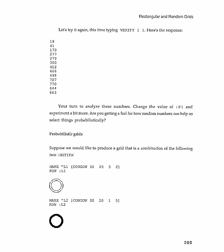
Your turn to analyze these numbers . Change the value of
experiment a bit more . Are you getting a feel for how random numbers
select things probabilistically ?
Rectangular and Random Grids
Let's try it again, this time typing VERIFY 1 1. Here's the response:
1841170277279300412466498707770844863
Probabilistic grids
Suppose we would like to produce a grid that is a combination of the followingtwo : MOTIFS:
MAKE " LlRUN :Ll
[CONGON 30 20 5 2]
0MAKE "L2 [CONGON 30RUN :L2
20 1 5]
0205
: Pl and
can help us
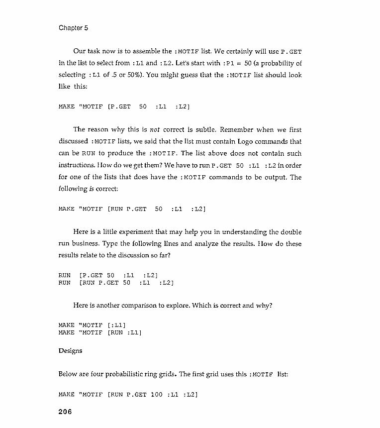
Designs
ds. The first grid uses this : MOT IF list :
Chapter 5
Our task now is to assemble the : MOTIF list . We certainly will use P . GETin the list to select from : Ll and : L2 . Let's start with : Pl = 50 (a probability ofselecting : Ll of .5 or 50%). You might guess that the : MOTIF list should looklike this :
MAKE " MOTIF [P . GET 50 :Ll : L2]
The reason why this is not correct is subtle . Remember when we first
discussed : MOTIF lists , we said that the list must contain Logo commands that
can be RUN to produce the : MOTIF . The list above does not contain such
instructions . How do we get them ? We have to run P . GET 50 : Ll : L2 in order
for one of the lists that does have the : MOT I F commands to be output . The
following is correct :
MAKE " MOTIF [RUN P. GET 50 :Ll :L2]
Here is a little experiment that may help you in understanding the doublerun business. Type the following lines and analyze the results . How do theseresul ts rela te to the discussion so far?
[P.GET 50 :Ll[RUN P.GET 50
:L2]RUNRUN :L2]
Here is another comparison to explore . Which is correct and why ?
MAKE "MOTIFMAKE "MOTIF
[ :Ll ][RUN :Ll ]
Below are four probabilistic ring gri
MAKE "MOTIF [RUN P.GET 100
206
:Ll : L2]
:Ll
The third and fourth grids blend the two : MOTIFs according to the list :
Rectangular and Random Grids
The second grid uses the same list but with the value of0:
: P 1 changed from 100 to
MAKE "MOTIF [RUN P.GET 0 :Ll : L2]
MAKE " MOTIF [RUN P. GET 30 :Ll : L2]
What is important ?
207
This is the longest chapter in the book . We have spent perhaps too much time
discussing the machinery needed to build rectangular grids and to generate
random numbers . Don ' t forget , though , that the real goal of this book is to
encourage you to use Logo machinery parts to explore the images , patterns , and
objects that strike your fancy . Why ? Because visual models can extend and
amplify your vision , and I am certain that this will give you an enormous
amount of aesthetic satisfaction . Be careful , though , not to get too involved with
only the model parts ; the model , after all , is always to be aimed at the object of
your visual fancy .
Think about what ideas are being illustrated here . What doesprobabilistic mixing of : MOTIFs mean in this context? We are introducing someamount of randomness into a geometric design. What exactly does randomnessmean? On the page after next are some samples that illustrate these ideas usingsquare grids , while those on the page following introduce a new design, a tinyspiral , into probabilistic grids .
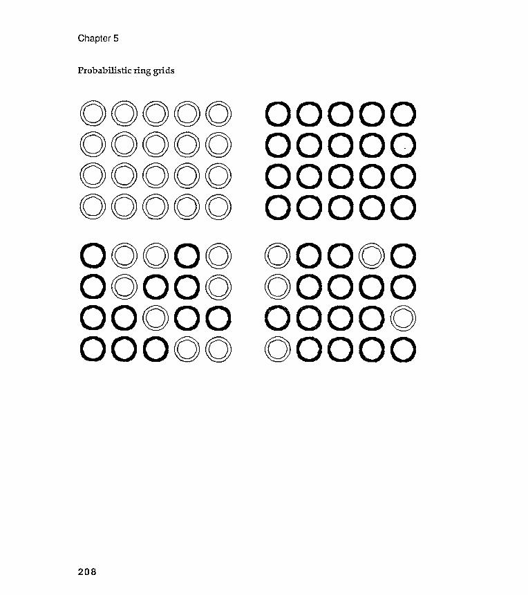
Chapter 5
Probabilistic ring grids
00000000000000000000
0000
000000
00000000000000000000
208
0000
000000
00000000000000000000

O/(:);;.(>/(:)t()<>.o~ <>()<) /(><) () .(><>OI ()<:!I<)
Rectangular and Random Grids
Probabilistic square grids
00000000 <><>0000000000<} .I( ..o.o <>.().()<><>'<'>'<) .00 <>.0.<>-<><>.0.0
209
<><><>:.0.<><><><><>~.0.<><>-0><>'<>(>-<><>.0.
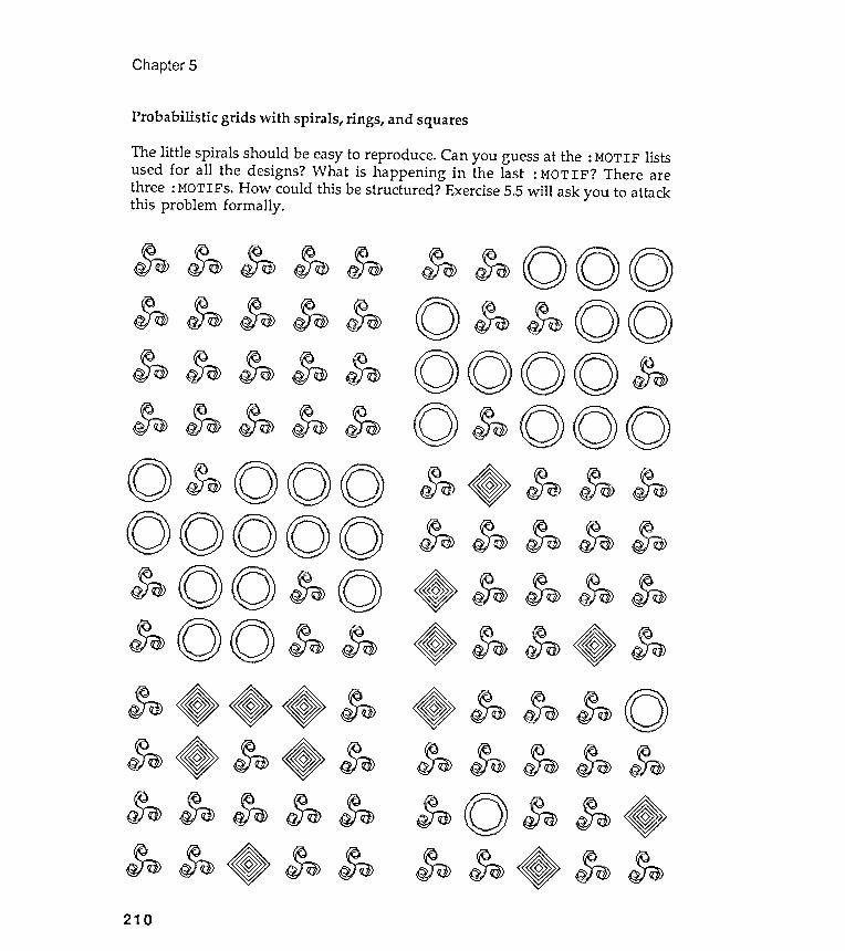
Probabilistic grids with spirals, rings, and squares
~~~~00~~..~~
Chapter 5
$ii >
$ w
~
~
~~
210
~~$0>$0>$0>~\ 0\0)(0)..$0>$0>
The little spirals should be easy to reproduce . Can you guess at the : MOTIF listsused for all the designs? What is happening in the last : MOTIF ? There arethree : MOTIFs . How could this be structured ? Exercise 5 .5 will ask you to attackthis problem formally . .
$0>~~~(OJ(OJ~~~~~~
~ ~ ooo00o ~
00$0>$0>$0>. .$0>
$0>$0>$0>$0>({:I)('0)00.$0>$0>.
(0)(0)0~~...~~~
~~CO)~.~
0~.$;a>$;a>$;a>$;a>$;a>(0)$;a>
~10OJ$0>$0>(l~$0>$0>$0>$0>.
$w$w$w$w\ 0(00~~~~~
Rectangular and Random Grids
Exercise 5.1
Exercise 5.2
Exercises
There are eighteen exercises this time . They are not so easy , but you will be
surprised , I hope , by how quickly ways to start will pop into your head . Don 't
forget the turtle - walk / story -board approaches to developing intuitive brain -
pops , though . '
Go back and look at the circular grids you produced in Chapter 4. Review, aswell , the personal mark that you created for Exercise 3.6. Add some randomnessto these designs.
Restructure the FLAG procedure using recursion techniques. A void any use of theREPEAT command . Compare the two methods on aesthetic grounds . You mightwant to define carefully in words exactly what you mean by "aesthetic."
Exercise 5.3
The rectangular grid procedures that we have studied so far place one row
directly below another . Design a more general FLAG procedure that allows the
even -numbered rows to be indented by some given amount . Use either repeat orrecursive methods .
211
Exercise 5.4
Although we have designed a procedure called FLAG, we haven't designed anyflags yet . Redesign your own country 's flag so that it better represents current lifethere - as you see it . You might want to find a book on heraldry so that you canbreak all the established rules and traditions . Or not . Either way , keep theiconography simple . Describe your heraldic symbols and symbolism in yournotebook.
Exercise 5.7
Chapter 5
Produce a super, razzle-dazzle demonstration of designs never seen before byEarthlings using the ideas of this chapter: motif descriptions with lists,placement of these motifs using variations of geometrical repetition rules,random number generation, and probabilistic list selection.
During the preparation of this exercise, jot down any design rules that youdiscover. llIustrate your rules with examples of designs that "work well" andones that IIdon't work at all.1I
Exercise 5.5
Generalize P . GET so that it can select any number of lists . Extend the definitionof :Pl so that it can specify the probability of selecting each of the possible lists .Use your generalized P . GET to produce a number of multiple - : MOTIF designs.
Exercise 5.6
If you have a flair for flag modeling , design a generalized , multiple - argument ,
flag - machine that will design a flag for any country once the appropriate
argument values are established for the country .
212
Rectangular and Random Grids
Exercise 5.8
I found this exercise pinned to the wall of a classroom used for a Color and
Design course : " Channel 8 is preparing for an eventual slot on French television .
One of the first pieces of artwork they need is a TV test pattern . The main
function of a test pattern is to show technicians the quality of picture resolution
and the fidelity of the colors being broadcast .
" Test patterns usually contain some kind of black and white value scale
composed of varied linear patterns of thick and thin lines , as well as letters or
numbers to provide detail in judging the broadcast image . Of course , another role
of a test pattern is to tell the viewer that he has tuned into Channel 8 even
though they ' re not broadcasting at the time . So , include three character call
number & - cH8 - in the design , but not as the major design element .
" Traditionally , test patterns have been designed around a central circular
format , but there is no need to follow this tradition . Be sure to fill the
rectangular screen , too . "
What can you do with this ? Take advantage of the strengths of Logo and
design a test pattern that could not have been realized in any other medium .
Exercise 5 . 9
The illustration on the next page is Andy Warhol ' s " Marilyn Monroe , " done in
1962 during the Pop Art movement . You may recall Warhol ' s rectangular grid of
tomato soup cans . Each of the images of Marilyn , and each soup can , is exactly
the same ; this sameness was the message of Warhol ' s design .
I want you , however , to produce a grid of stylized faces , whose
characteristics ( openness of eyes , openness of mouths , tiltiness of eyebrows , etc . )
are randomly perturbed from one face to the next . ( Recall the Mondrian box
exercise . ) Your faces will exhibit a series of different expressions . Don ' t use too
many characteristics - maybe two or three - before you visually experiment .
213

Exercise 5.10
This kind of exercise in no way trivializes the work of a Mondrian . Rather,you should have a better sense of his artistic genius after you have tried to copypaintings like these.
Chapter 5
214
I love Mondrian . We simulated several of the characteristics of one of his
paintings in this chapter . I want you to do more analysis of this sort . I include
several examples of Mondrian ' s use of vertical and horizontal bars to articulate
a canvas . Some of the rectangles produced by these bars are colored in , and
others are not . I want you to select several characteristics from these paintings
and simulate them with Logo procedures . Clearly state , in words , the
characteristics you are studying .
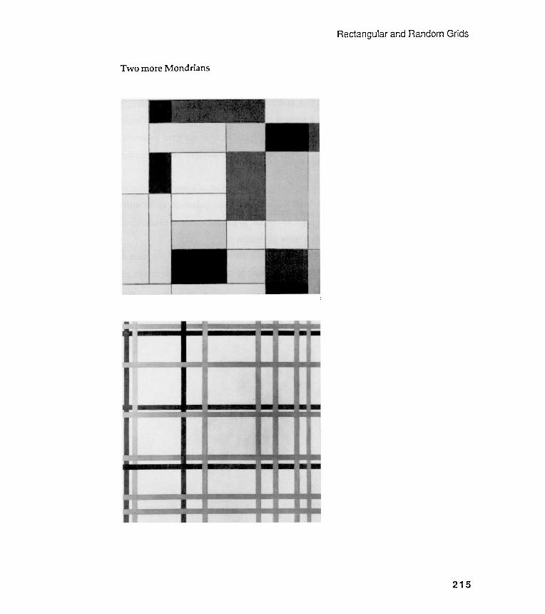
Rectangular and Random Grids
MondriansTwo more
I
215
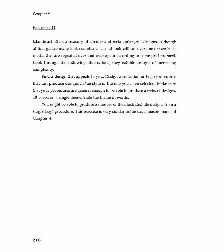
Islamic art offers a treasury of circular and rectangular grid designs. Althoughat first glance many look complex, a second look will uncover one or two basicmotifs that are repeated over and over again according to some grid protocol .Look through the following illustrations ; they exhibit designs of increasingcomplexity .
Find a design that appeals to you . Design a collection of Logo proceduresthat can produce designs in the style of the one you have selected. Make surethat your procedures are general enough to be able to produce a series of designs,all based on a single theme. State the theme in words .
You might be able to produce a number of the illustrated tile designs from asingle Logo procedure . This exercise is very similar to the stone mason marks ofChapter 4.
Chapter 5
Exercise 5.11
216
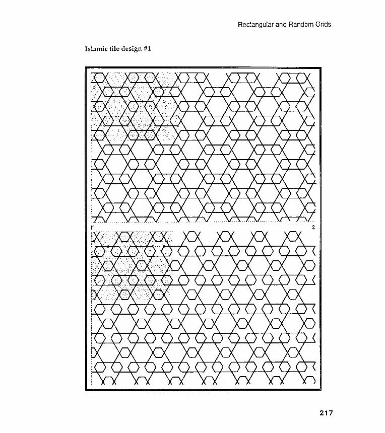
Rectangular and Random Grids
Islamic tile design #1
217
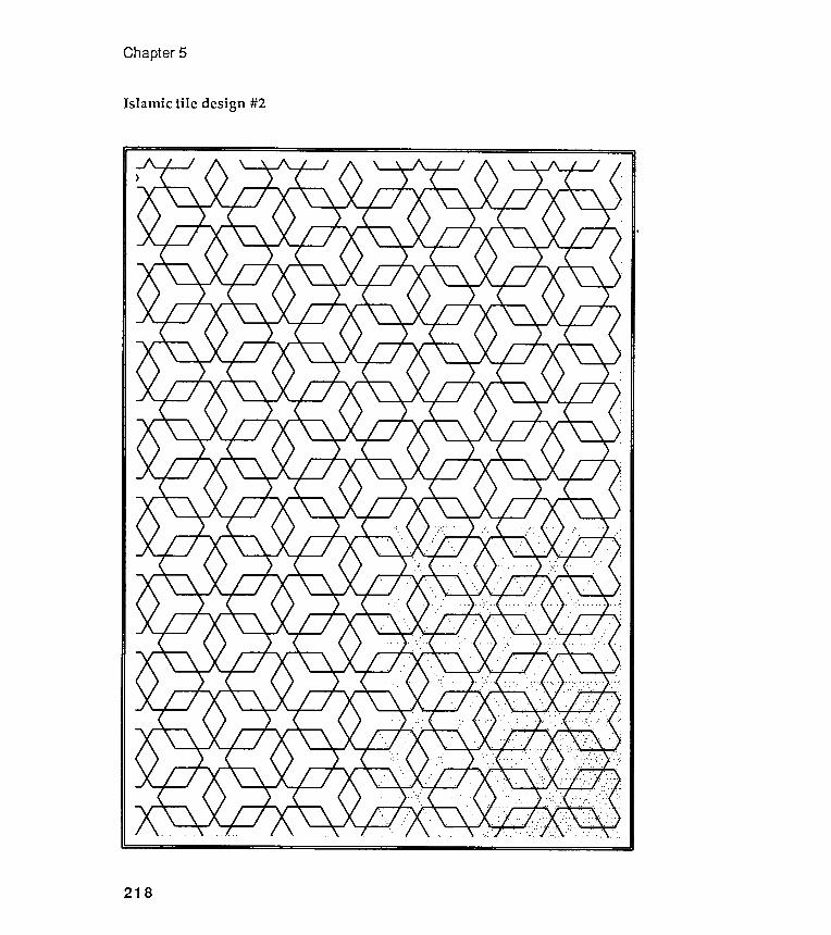
Chapter 5
Islamic tile design #2
218
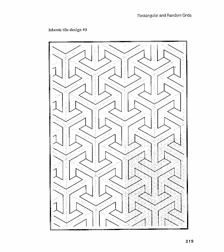
ectangularand Random GridsR
Islamic tile design #3
219
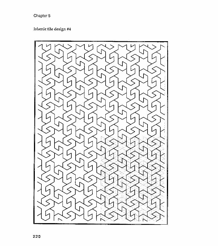
Chapter 5
Islamic tile design #4
220
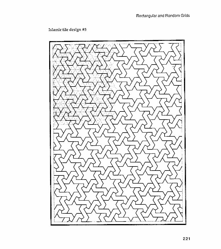
Rectangular and Random Grids
Islamic tile design #5
221

Islamic
Chapter 5
tile design #6
222
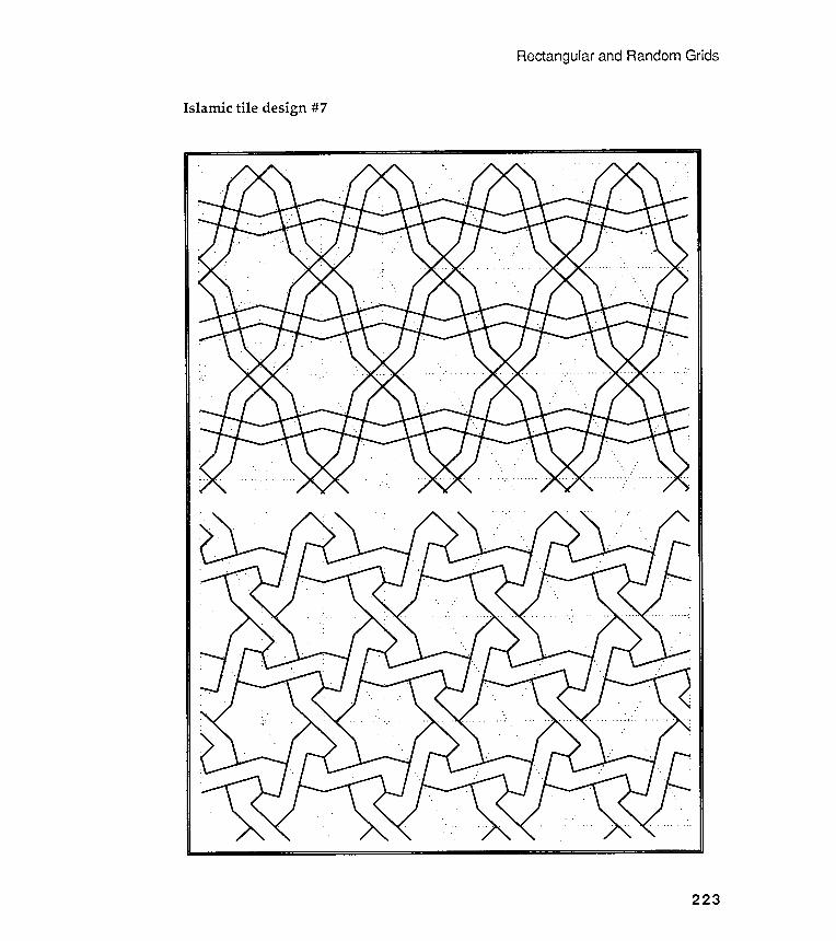
Rectangular and Random Grids
Islamic tile design #7
223
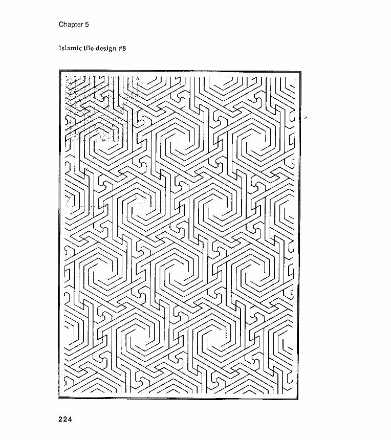
Chapter 5
#8
224
Islamic tile design

Rectangular and Random Grids
Islamic tile design #9
225
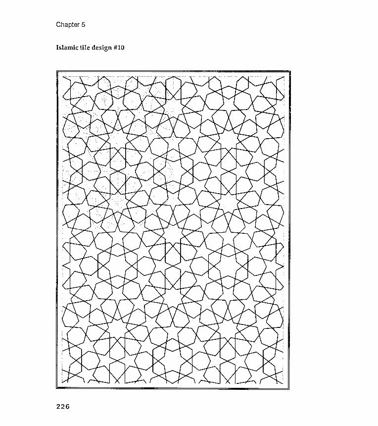
Chapter 5
Islamic tile design #10
226

Rectangular and Random Grids
Islamic tile design #11
227
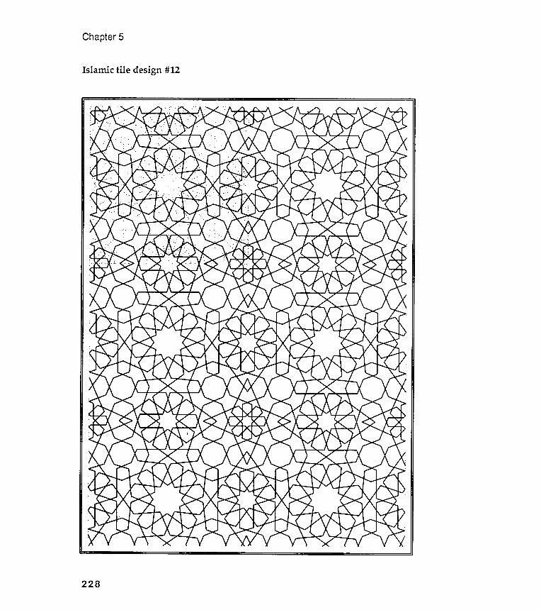
Chapter 5
Islamic tile design #12
228
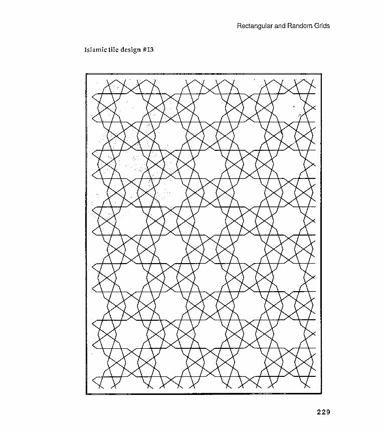
Rectangular and Random Grids
Islamic tile design #13
229
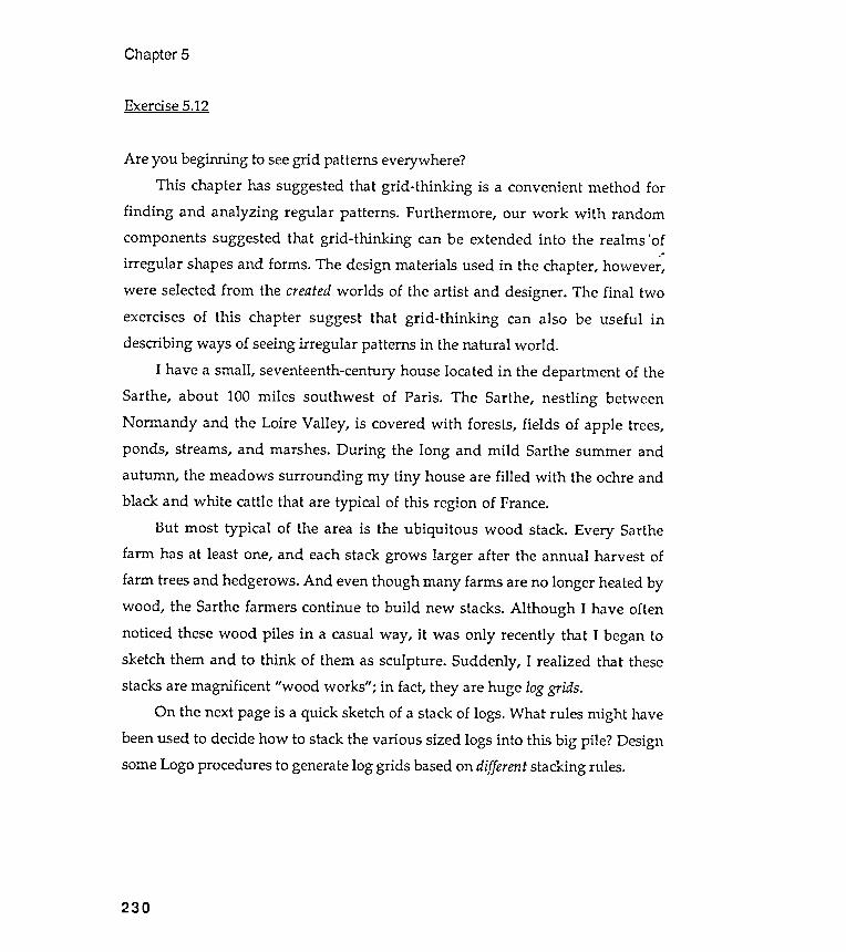
Chapter 5
Exercise 5.12
230
Are you beginning to see grid patterns everywhere?This chapter has suggested that grid -thinking is a convenient method for
finding and analyzing regular patterns . Furthermore , our work with randomcomponents suggested that grid -thinking can be extended into the realms 'of
irregular shapes and forms . The design materials used in the chapter, however ,were selected from the created worlds of the artist and designer . The final twoexercises of this chapter suggest that grid -thinking can also be useful indescribing ways of seeing irregular patterns in the natural world .
I have a small , seventeenth-century house located in the department of theSarthe, about 100 miles southwest of Paris. The Sarthe, nestling betweenNormandy and the Loire Valley , is covered with forests, fields of apple trees,ponds , streams, and marshes. During the long and mild Sarthe summer andautumn , the meadows surrounding my tiny house are filled with the ochre andblack and white cattle that are typical of this region of France.
But most typical of the area is the ubiquitous wood stack. Every Sarthefarm has at least one, and each stack grows larger after the annual harvest of
farm trees and hedgerows. And even though many farms are no longer hea ted bywood , the Sarthe farmers continue to build new stacks. Although I have oftennoticed these wood piles in a casual way , it was only recently that I began tosketch them and to think of them as sculpture . Suddenly , I realized that thesestacks are magnificent "wood works " ; in fact, they are huge log grids.
On the next page is a quick sketch of a stack of logs. What rules might havebeen used to decide how to stack the various sized logs into this big pile ? Designsome Logo procedures to generate log grids based on different stacking rules.
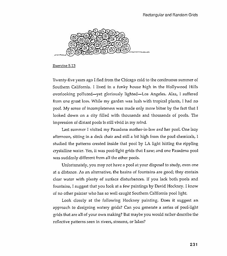
Rectangular and Random Grids
' - - - -- ~ ~ - - -
Exercise 5.13
231
Twenty -five years ago I fled from the Chicago cold to the continuous summer ofSouthern California . I lived in a funky house high in the Hollywood Hillsoverlooking polluted - yet gloriously lighted - Los Angeles . Alas , I sufferedfrom one great loss. While my garden was lush with tropical plants , I had nopool . My sense of incompleteness was made only more bitter by the fact that Ilooked down on a city filled with thousands and thousands of pools . Theimpression of distant pools is still vivid in my mind .
Last summer I visited my Pasadena mother -in-law and her pool . One lazyafternoon , sitting in a deck chair and still a bit high from the pool chemicals, Istudied the patterns created inside that pool by LA light hitting the ripplingcrystalline water . Yes, it was pool -light grids that I saw; and one Pasadena poolwas suddenly different from all the other pools.
Unfortunately , you may not have a pool at your disposal to study , even oneat a distance. As an alternative , the basins of fountains are good; they containclear water with plenty of surface disturbances . If you lack both pools andfountains , I suggest that you look at a few paintings by David Hockney . I knowof no other painter who has so well caught Southern California pool light .
Look closely at the following Hockney painting . Does it suggest anapproach to designing watery grids ? Can you generate a series of pool -lightgrids that are all of your own making ? But maybe you would rather describe thereflective patterns seen in rivers , streams , or lakes ?
Exercise 5.14
Chapter 5
232
If you attempted the Hackney grid exercise, you may have found yourselfneeding an arc drawing procedure. We can draw circles, but what about arcs?Design a left and right drawing arc machine that takes two arguments: theradius of the circle of which the arc is part, and the angle of the arc. Hint : thecircumference of any circle is equal to 2nR, where R is the radius of the circle.The length of an arc is equal to the circumference of the circle from which it istaken times the angle turned by the arc divided by 360 degrees.
Exercise 5.15
Exercise 5.16
Rectangular and Random Grids
Every season of the year has some major festival . Use Logo to help you design anappropriate greeting card for a fete that is coming soon. Don 't forget theenvelope; your card and envelope designs must complement each other.
The only rule for this exercise is this : produce a card that could not havebeen easily or appropriately realized in any other medium . You can combineLogo designs with other materials , however , and collages are fine . You mightwant to add visual remarks with paint , inks , photographs , glitter , whatever , to
your Logo-produced images. Or you may want to cut away parts with an Exactoknife . You can photocopy your prints onto different colors and strengths of paper,and you can build cards into the third dimension . But whatever you create, itmust reflect the style and flavor of Logobuilt visual models .
We have worked only with rectangular windows in this chapter . Suppose you
wanted to place a motif randomly into a triangular or circular window . How
could you do it ?
Exercise 5.17
Suppose you wanted to place a motif randomly into a rectangular window , butsuppose, too, that you did not want the motifs to overlap within the window .Any ideas?
233
Chapter 5
Exercise 5.18
234
Are you exhausted by all this? Or excited, uplifted , depressed, furious ? I thinkit 's time for you to do some visual modeling of your moods and subjective feelings.Pick an emotion from the list that follows and design a Logo machine to produce
images that correspond to your idea of this particular state of being : Love, lust~.greed, enthusiasm, envy, jealousy, happiness, joy , aggressiveness, lethargy,alertness, hunger , guilt , fury , anger, compassion, generosity , arrogance,passivity .
In preparation , you may want to jot down the ideas, shapes, colors, textures,and images that come to mind as you freely associate this emotion with thecontents of your mind 's baggage. As you think about your selected emotion , try toimagine how you feel about its opposite . Thinking about an opposite or reversestate can often focus your vision of the original state.
Let yourself go with this exercise, but be concrete; capture your ideas andfeelings graphically . Sketch fast; grab the images as they float by . Don 't worryabout how you will explain to others what you have done. Describe simplywhat you see inside yourself with Logo procedures.
Consider the following . Include a two -way switch on your emotion modelingmachine . One switch position should direct your machine to illustrate thepositive side of an emotion , while the other position will show the negative orreverse side of it . Instead of a switch , you might be happier with a dial thatwould let you illustrate a series of emotional states between, say, love at oneextreme and hate at the other .
"Know , oh brother . . . that the study of sensible geometry leads to skill in the
Islamic designs combine circular and rectangular grids
In the last two chapters, we have been working on circular and rectangular grids .Within these chapters, the major exercise was to decompose given designs intotheir basic components so that these parts could be modeled as generally aspossible. We then went on to build models to place these parts into forms thatwere either circular or rectangular . We referred to these two design aspects asthe motif and the repetition rule .
The goal of this work was to build models that produced not just a singledesign but a suite of designs all based on one or more themes. The exercises at theends of these chapters encouraged you to take your design apparatus outdoors ,into distant fields , to find and sketch more exotic subjects. Now we turn to
Islamic art , an exceptionally rich source of sophisticated geometric designs. Wewill use a selection of these fascinating patterns to test your modeling style andthen to extend it into new dimensions . Indeed, we will end the chapter with
three-dimensional designs.
Chapter 6Islamic Designs
leads to skill in thepractical arts , while the study of intelligible geometryintellectual arts . . . . "
From the "Rasa'il ," translated by S. H . Nasr .
Chapter 6
236
Much of the complexity sensed in Islamic designs is created by a
combination of circular and rectangular repetitions of several design motifs . In
fact , these combinations are often multilayered and recursive : circular grids are
ordered into rectangular patterns that are in turn combined into larger
rectangular designs . Our job is to make this geometric complexity intelligible ,
and modeling is our most useful tool . '.
The ability to place individual images and clusters of images into
rectangular patterns is crucial to effective Islamic design work with Logo . We
need , therefore , a really general and easily manipulated grid machine . Toward
this end let ' s begin this chapter by generalizing the FLAG procedure of Chapter
5 . We will be using this procedure for the rest of this book , so we had best make
it as useful as possible .
Exercise 5 . 2 asked you to restructure the FLAG procedure using recursive
rather than REPEAT methods . Exercise 5 . 3 asked you to design a more general
FLAG procedure that would allow each row to be indented in relation to the
starting x position of the first row . Let ' s combine these two exercises into one .
Additionally , let ' s allow each row of the FLAG to have a different number of
columns and a different indent amount . But first we need a few more list
manipulators . They will be useful in the refashioned FLAG .
Rotating a list
We need another list manipulator to refashion FLAG , and here it is . Suppose you
have a list of items . How might you form a new list whose last element was the
first element of the original list , whose first element was the second element of
the original list , whose second element was the third element of the original
list , and so on ? You could think of this change as a kind of rotation . Rotate the
first element of the original list to become the list ' s last element ; keep all the
remaining elements as they are , and then output the list . Here is a procedure to
accomplish this list rotation :
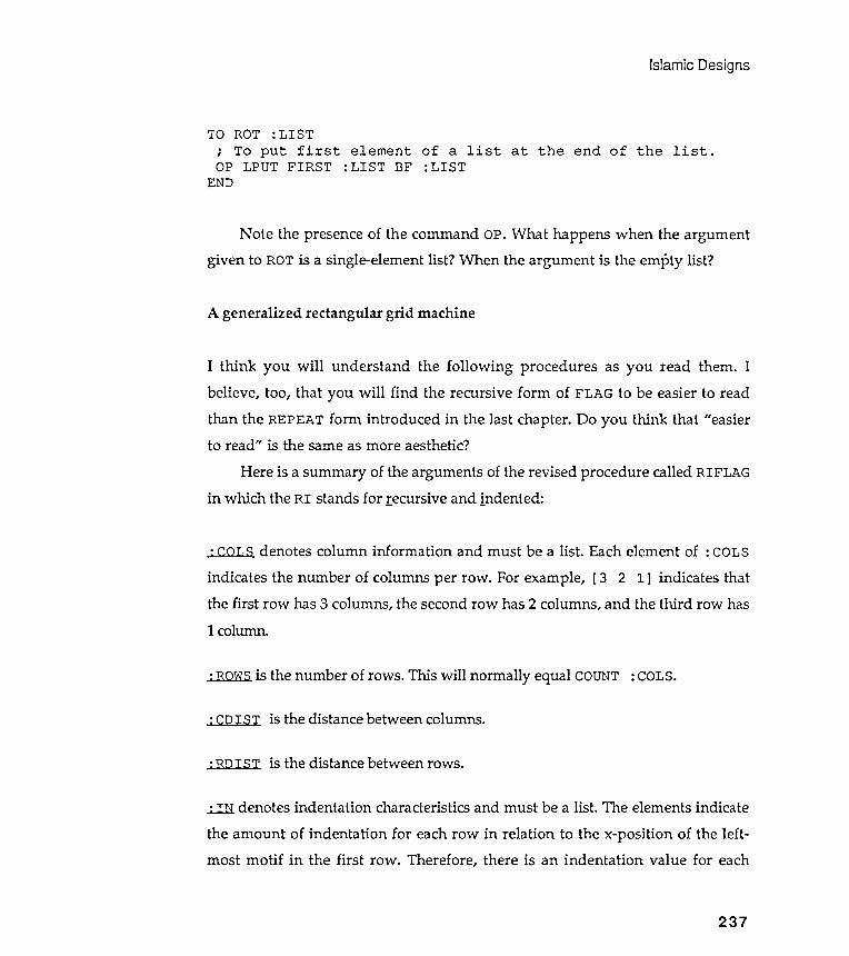
Islamic Designs
TO ROT :LISTa list at the end of the list .
A generalized rectangular grid machine
I think you will understand the following procedures as you read them . Ibelieve, too, that you will find the recursive form of FLAG to be easier to readthan the REPEAT fonn introduced in the last chapter. Do you think that "easierto read" is the same as more aesthetic?
Here is a summary of the arguments of the revised procedure called RIFLAGin which the RI stands for recursive and indented :
1 column.
237
: COLS denotes column information and must be a list . Each element of : COLS
indicates the number of columns per row . For example, [ 3 2 1] indicates thatthe first row has 3 columns, the second row has 2 columns, and the third row has
; To put first element ofOP LPUT FIRST : LIST BF : LIST
END
Note the presence of the command OP. What happens when the argumentgiven to ROT is a single-element list ? When the argument is the empty list ?
: ROWS is the number of rows . This will normally equal COUNT : COLS.
: CD I S T is the distance between columns.
: RDIST is the distance between rows .
:J. lI denotes indentation characteristics and must be a list . The elements indicate
the amount of indentation for each row in relation to the x-position of the left -most motif in the first row . Therefore , there is an indentation value for each

Chapter 6
row- except the first. Positive indent numbers mean that the indentation is tothe right, and negative ones indicate leftward indenting. For example, suppose: IN is [20 10 - 10] . This indicates that the second row is indented 20 units tothe right of the start of the first row, the third row is indented 10 units to theright of the first row, and the fourth row 20 units to the left of the first row.
COUNT: IN should normally be equal to (COUNT: ROWS) - 1. Why? If we,.want no indentation on any row, set indent to [0] . Verify this after you haveread through the procedures below. Suppose that we want the odd rows indentedby 10 and the even rows by O? Set: I N to [10 0] .
The completed RIFLAG
TO ROWER : C : N
; To paint a row of : N; by the between - columnIF : N < 1 [ STOP ]RUN : MOTIFCSTEP : CROWER : C
END( :N- l )
238
TO RIFLAG :COLS :ROWS :CDIST :RDIST : IN; Indented FLAG procedure with different; number of columns per row possible .IF :ROWS < 1 [STOP]ROWER :CDIST (FIRST :COLS)
images separateddistance : C .
; Do a row of the proper column number of images .IRSTEP : RDIST : IN
; Move down to next row and indent , if necessary .RIFLAG (ROT : COLS ) ( : ROWS - l ) : CDIST : RDIST ( ROT : IN )END

Islamic Designs
(ITEMof the startingrow ' s
the indent amount for the next row .
180 PO
TO CSTEP : C
; This is the same as used for FLAG in ChapterPO RT 90FD : CLT 90 PD
END
5 .
GO.PTSETXY
TOPO
END(FIRST :POINT) (LAST :POINT)
Do you understand why ROT and EVAL were used in the RIFLAG procedures ?Why must GO . PT be executed before RIFLAG?
Some RIFLAG examples
The following examples used the motif list MAKE " MOTIF [CNGON 4 20 ] .
[4 3 2 1] 4 50 50 [0]
0000
0 00
00
0
239
TO IRSTEP : R : IN
PU SETX ( FIRST; Move back to
; point , thenRT 180FD : R LT
END
: POINT ) +x - position
move over
GO.PTRIFLAG
1 : IN )first
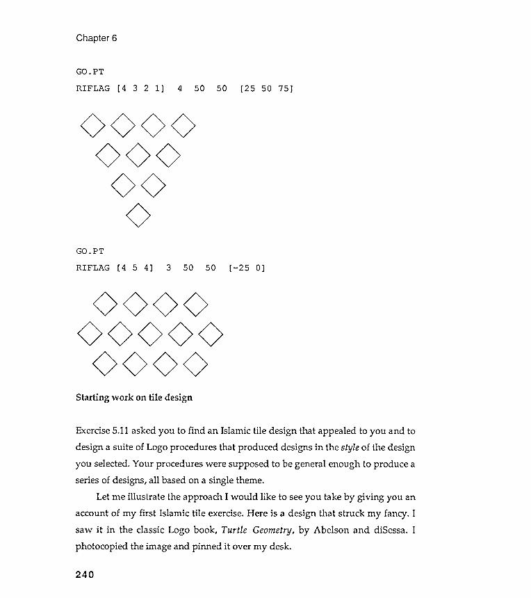
Exercise 5.11 asked you to find an Islamic tile design that appealed to you and todesign a suite of Logo procedures that produced designs in the style of the designyou selected. Your procedures were supposed to be general enough to produce aseries of designs, all based on a single theme.
Let me illustrate the approach I would like to see you take by giving you anaccount of my first Islamic tile exercise. Here is a design that struck my fancy. Isaw it in the classic Logo book , Turtle Geometry, by Abelson and diSessa. Iphotocopied the image and pinned it over my desk.
Chapter 6
GO.PTRIFLAG [4 321 ] 4 50 50 [25 50 75]
00
000
GO. PT
RIFLAG [ 4 5 4] 3 50 50 [- 25 0]
0 000000000 <>0 <>
Starting work on tile design
240
00000
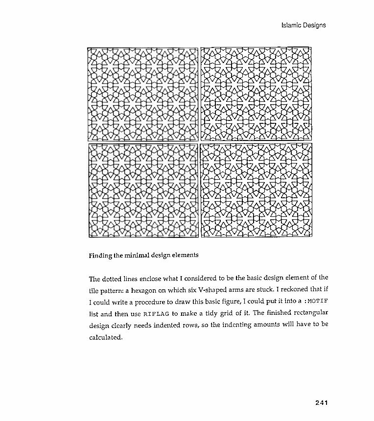
Islamic
Designs
Finding the minimal design elements
241
The dotted lines enclose what I considered to be the basic design element of the
tile pattern: a hexagon on which six V-shaped arms are stuck. I reckoned that ifI could write a procedure to draw this basic figure, I could put it into a : MOTIFlist and then use RIFLAG to make a tidy grid of it . The finished rectangulardesign clearly needs indented rows, so the indenting amounts will have to becalculated.
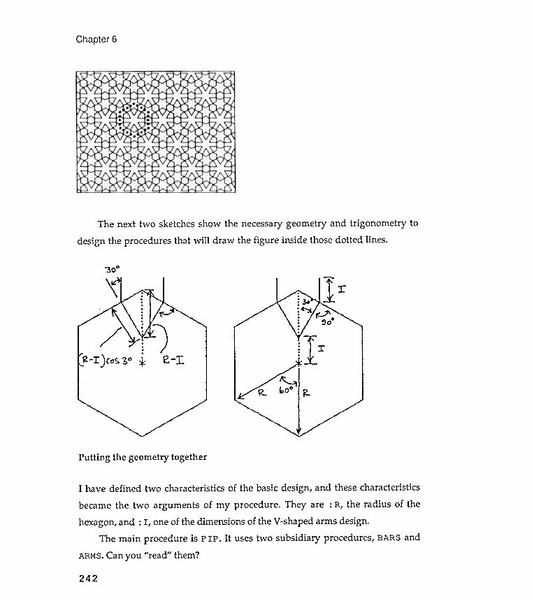
Chapter 6
~ oo
.
.
.
-1' )co~ ~o i
Putting the geometry together
The next two sketches show the necessary geometry and trigonometry to
design the procedures that will draw the figure inside those dotted lines .
-
~I :rA ~
I have defined two characteristics of the basic design, and these characteristics
became the two arguments of my procedure . They are : R, the radius of thehexagon, and : I , one of the dimensions of the V-shaped arms design.
The main procedure is PIP . It uses two subsidiary procedures , BARS andARMS . Can you " read " them ?
242
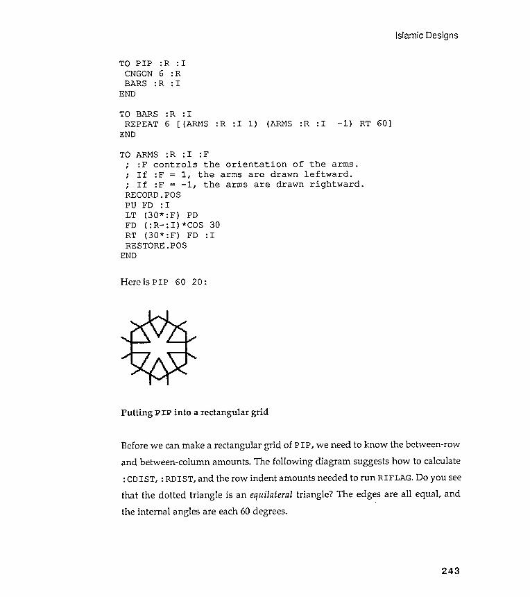
Islamic Designs
TO PIP :R : ICNGON 6 :RBARS :R : I
END
TO BARS :R : 1REPEAT 6 [ (ARMS :R - 1) RT 60]1) (ARMS :R : I: I
TO ARMS : R : I : F
; : F controls the orientation of the arms .; If : F = 1 , the arms are drawn leftward .; If : F = - 1 , the arms are drawn rightward .RECORD . POSPO FD : I
LT ( 30 * : F ) PDFD ( : R - : I ) * COS 30RT ( 30 * : F ) FD : IRESTORE . POS
END
Here is PIP 60 20 :
Putting PIP into a rectangular grid
Before we can make a rectangular grid of PIP, we need to know the between-rowand between-column amounts. The following diagram suggests how to calculate: CDIST, : RDIST, and the row indent amounts needed to run RIFLAG. Do you seethat the dotted triangle is an equilateral triangle? The edges are all equal, andthe internal angles are each 60 degrees.
243
END
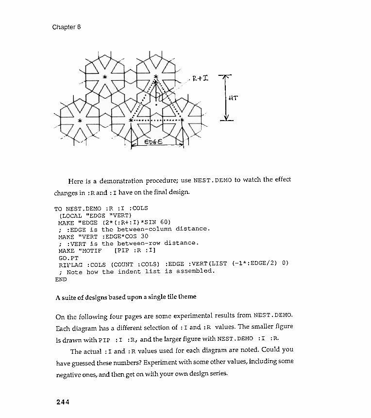
Chapter 6
~
~+T.
Here is a demonstration procedure ; use NEST . DEMO to watch the effect
changes in : Rand : I have on the final design.
244
TO NEST . DEMO : R : I : COLS
( LOCAL " EDGE " VERT )MAKE " EDGE ( 2 * ( : R + : I ) * SIN 60 ); : EDGE is the between - column distance .MAKE " VERT : EDGE * COS 30
; : VERT is the between - row distance .MAKE " MOTIF [ PIP : R : I ]GO . PT
RIFLAG : COLS ( COUNT : COLS ) : EDGE : VERT ( LIST ( - 1 * : EDGE / 2 ) 0 ); Note how the indent list is assembled .
END
A suite of designs based upon a single tile theme
On the following four pages are some experimental results from NEST. DEMO.Each diagram has a different selection of : I and: R values. The smaller figureis drawn with PIP : I : R, and the larger figure with NEST. DEMO: I : R.
The actual: I and: R values used for each diagram are noted. Could youhave guessed these numbers? Experiment with some other values, including somenegative ones, and then get on with your own design series.
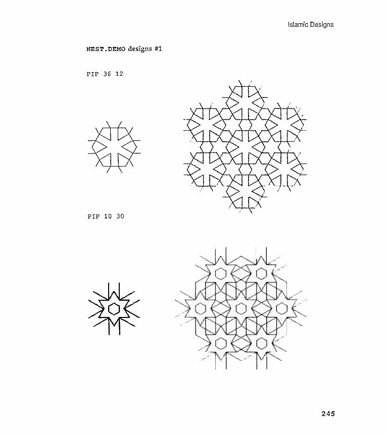
Islamic Designs
NEST . DEMO designs #1
36 12PIP
PIP 10 30
245

Chapter 6
NEST . DEMO designs #2
PIP 30 15
PIP 25 20
246
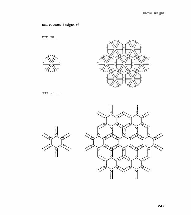
DesignsIslamic
~ u ;~;><~~ u ~
yy~ M~~:~~~M~
NEST. DEMO designs #3
PIP 30 5
PIP 20 30
~ \b( /j \\
247
~ u~~o~M

Chapter 6
NEST. DEMO designs #4
Can you guess the arguments used for these two designs?
248
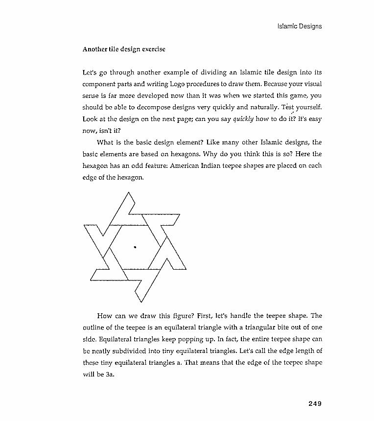
exercise
side. Equilateral triangles keep popping up . In fact, the entire teepee shape canbe neatly subdivided into tiny equilateral triangles . Let 's call the edge length ofthese tiny equilateral triangles a. That means that the edge of the teepee shape
Islamic Designs
Another tile design
Let 's go through another example of dividing an Islamic tile design into its
component parts and writing Logo procedures to draw them . Because your visual
sense is far more developed now than it was when we started this game , you
should be able to decompose designs very quickly and naturally . Test yourself .
will be 3a.
249
" #
Look at the design on the next page ; can you say quickly how to do it ? It ' s easy
now , isn ' t it ?
What is the basic design element ? Like many other Islamic designs , the
basic elements are based on hexagons . Why do you think this is so ? Here the
hexagon has an odd feature : American Indian teepee shapes are placed on each
edge of the hexagon .
*
How can we draw this figure ? First , let ' s handle the teepee shape . The
outline of the teepee is an equilateral triangle with a triangular bite out of one
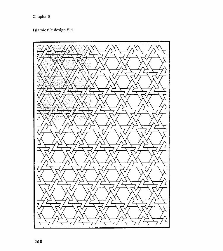
Chapter 6
Islamic tile design #14
250
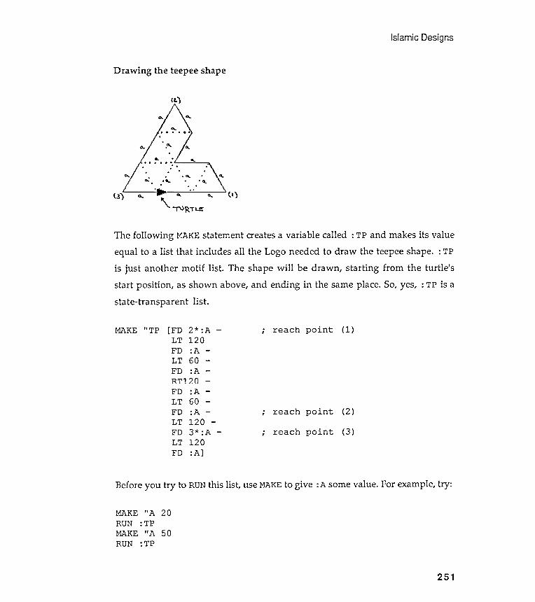
Islamic Designs
Drawing the teepee shape
Before
MAKE "A 20RUN :TPMAKE "A 50RUN : TP
( l .
.
. 0. . .
. ' Q. .. .
. .
l .1) 0.. 0... ( I )
\ . ~ RT~
MAKE " TP
r-1;ljh
1t-ih1t-ih
1-30
1-301-30
.... !\).. 0'\.. I
-' N~~O
~N* 0 ..
J I I I
~
reach point (1 )
reach
reach
tQ tQ 0 0 1-'- 1-'- ~ ~ rt rt
-
-
you try to RUN this list , use MAKE to give : A some value. For example, try :
251
FDLTFDLTFDLTFD
:A60:A1203* :A120:A]
The following MAKE statement creates a variable called : TP and makes its valueequal to a list that includes all the Logo needed to draw the teepee shape. : TPis just another motif list . The shape will be drawn , starting from the turtle 'sstart position , as shown above, and ending in the same place. So, yes, : TP is astate-transparent list .
(2)
(3)
.
,

Chapter 6
TO TPGON :RADPU FD :RAD PDRT 120REPEAT 6 [FDLT 120PU BK :RAD
END
:RAD RT 60]
252
How can we modify this procedure so that those teepee shapes are placedon the edges of the hexagon? We could express this another way . Remember,back in Chapter 3, when we spoke about changing the quality of the edges ofpolygons ? There we changed the straight line quality of a polygon 's edge into akinked star edge. Later in the chapter , we installed a fractal edge. Now wewant to change the straight line quality of hexagon edges into " teepee edge
quality ."
Did you make any mistakes when you typed the value for : TP? If so, youcan edit_what you typed instead of starting allover again . Consult your Logolanguage manual for the commands to edit names. Editing names is similar toediting procedures.
Now let 's put the teepee shape on the edges of a hexagon. Look at thefollowing procedure . TPGON is a very simplified CNGON; it only draws six-sidedpolygons . It is easy to see that the edge of a hexagon is equal to its radiusbecause hexagons are made from six equilateral triangles .
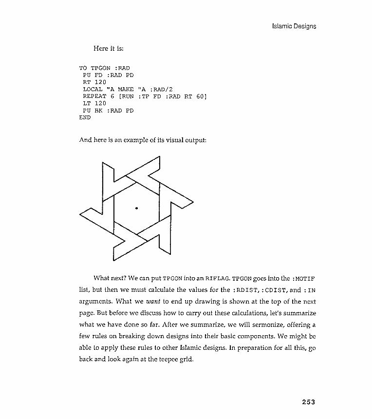
Islamic Designs
Here it is:
itA :RAD/ 2:TP FD :RAD RT 60]
And here is an example of its visual output :
What next? We can put TPGON into an RIFLAG. TPGON goes into the : MOTIFlist , but then we must calculate the values for the : RDIST , : CDIST , and : IN
arguments . What we want to end up drawing is shown at the top of the nextpage. But before we discuss how to carry out these calcula tions, let 's summarizewhat we have done so far . After we summarize , we will sermonize , offering afew rules on breaking down designs into their basic components . We might beable to apply these rules to other Islamic designs. In preparation for all this, goback and look again at the teepee grid .
253
TO TPGON :RADPU FD :RAD PDRT 120LOCAL "A MAKEREPEAT 6 [RUNLT 120PU BK :RAD PD
END
*
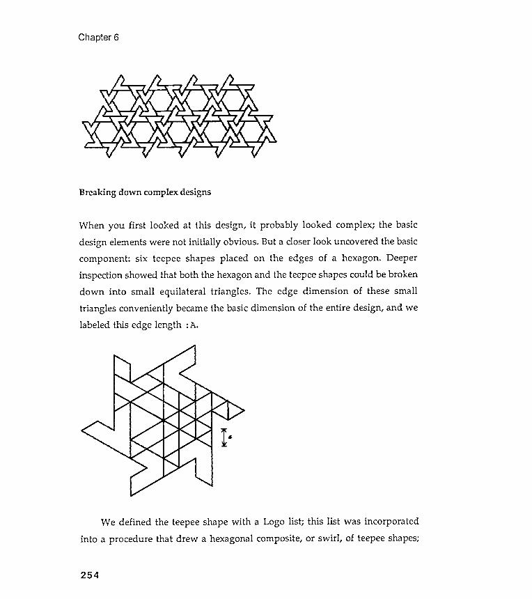
When you first looked at this design, it probably looked complex ; the basicdesign elements were not initially obvious . But a closer look uncovered the basiccomponent : six teepee shapes placed on the edges of a hexagon . Deeperinspection showed that both the hexagon and the teepee shapes could be brokendown into small equilateral triangles . The edge dimension of these smalltriangles conveniently became the basic dimension of the entire design, and welabeled this edge length : A.
Chapter 6
Breaking down complex designs
We defined the teepee shape with a Logo list ; this list was incorporated
into a procedure that drew a hexagonal composite, or swirl , of teepee shapes;
254
Islamic Designs
and finally , we wanted to make the name of this swirl -drawing procedure thevalue of the variable : MOTIF . We also planned to use RIFLAG to draw teepeeswirl grids .
A small review and a few lessons
Once we name a method , we can forget how its inner mechanism operates. Wecan concentrate our energies on the next problem.
Now for the rules for finding the smallest design elements of a complexfigure . Keep your eye open for simple polygonal structures . Triangles / hexagonsand squares/ octagons are ubiquitous because they fit , or " tile," together so well .Look carefully , though . You may not see the basic polygons because their edge"qualities " have been altered .
Finally , let 's work out the necessary row and column dimensions of theseteepee swirl grids .
The three diagrams on the following page illustrate the calculationsneeded. We are again manipulating the elements of equilateral triangles .
Do you see that the edge of the large equilateral triangles linking thecenters of the teepee swirls equals six small equilateral triangle edges?
We called the edge of the small equilateral triangle : A. Recall that theheight of any equilateral triangle is equal to either : EDGE* SIN 60 or : EDGE*cas 30. Why are these two forms equivalent ?
255
Note the style of problem solving that we followed above . A complex visual
problem was broken down into smaller design elements . Each was structured
with either a Logo procedure or a Logo list . The final design was constructed by
putting the individual Logo pieces together .
Note the usefulness of the concept of naming in all this . Once we know how
to do something in Logo - like drawing the shape of a teepee using a list of Logo
drawing commands - we give the method a short name , like : TP . The name of
the method now represents all the features of the method but is short and tidy .
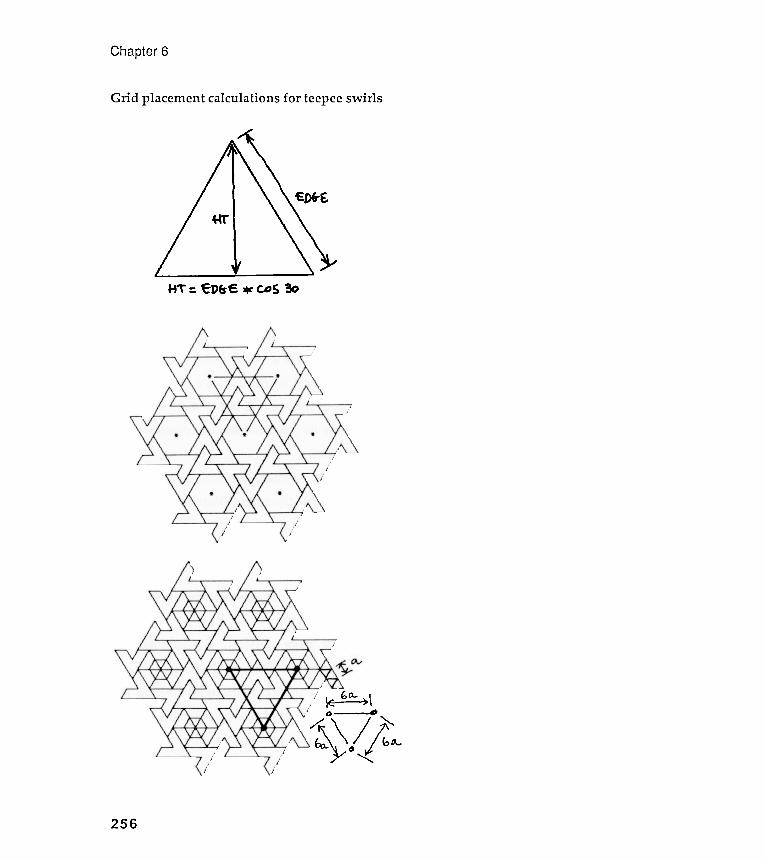
Chapter 6
Grid placement calculations for teepee swirls
\E- .~\0 -.~/j~256
Let's try your eye on Islamic Tile Design #4 from Exercise 5.11. Note severalthings . First , note where the turtle starts drawing the saw blade . This is notarbitrary . The turtle begins at the vertex in the saw blade that will touch eachof the vertices of the underlying hexagon. (Go back and look at the STARGONdiscussion in Chapter 4 where we talked about polygon edge qualities and therules that govern the replacement of one kind of edge with another .) Look at the
Islam]c Designs
Let 's use this geometry to write a demonstration procedure that will fit the
teepee figures together . This routine should work for any size teepees .
TO
.
,
A star and saw blade design
257
.
,
TP . DEMO : SIZE : COLS: SIZE is the radius of the hexagon on which the teepeeswill be placed . Remember that : A is : SIZE / 2 . : COLS mustbe a list whose elements define the columns per row .
MAKE " MOTIF [ LT 30 TPGON : SIZE RT 30 ]GO. PTRIFLAG : COLS (COUNT : COLS) : EDGE : VERT (LIST (- 1 * : EDGE/ 2 ) 0 ); Note how the indent list is assembled .
END
Compare TP . DEMO with NEST . DEMO. Why are they so alike ? Because both
demonstration procedures place design elements at the vertices of equilateral
triangles .
TP . DEMO can produce designs similar to those on the next page . TP . DEMO is
generalized only in terms of the size of the design , the number of rows , and the
number of columns per row . That 's not as interesting as the designs shown at the
beginning of the chapter , is it ? How could TP . DEMO be further generalized , more
in the spirit of the NEST . DEMO designs shown earlier ?
(LOCAL " EDGE "VERT)MAKE " EDGE 6* : SIZE / 2; : EDGE is the between - column distance .MAKE "VERT : EDGE* COS 30; :VERT is the between - row distance .
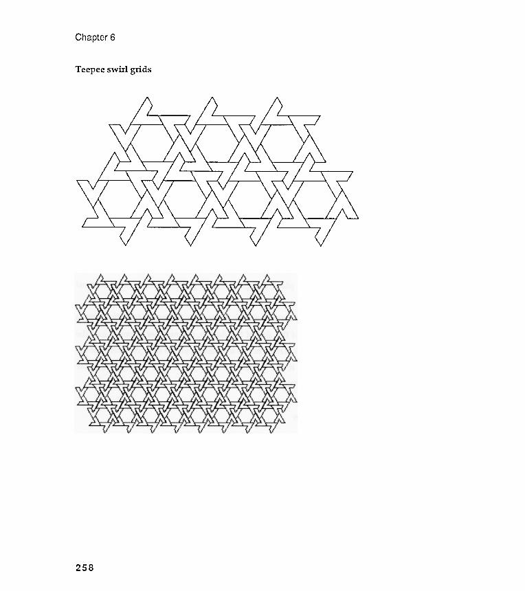
Teepee swirl grids
Chapter 6
258
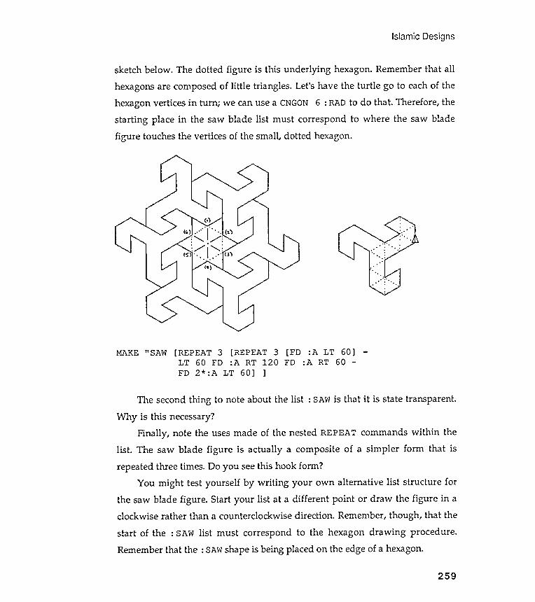
Islamic
sketch below . The dotted figure is this underlying hexagon . Remember that all
hexagons are composed of little triangles . Let 's have the turtle go to each of the
hexagon vertices in turn ; we can use a CNGON 6 : RAD to do that . Therefore , the
starting place in the saw blade list must correspond to where the saw blade
figure touches the vertices of the small , dotted b.exagon .
Designs
MAKE " SAW [REPEAT 3 [REPEAT 3 [FD :A LT 60]LT 60 FD :A RT 120 FD :A RT 60 -
The second thing to note about the list : SAW is that it is state transparent .
Why is this necessary?Finally , note the uses made of the nested REPEAT commands within the
list . The saw blade figure is actually a composite of a simpler form that isrepeated three times. Do you see this hook form ?
You might test yourself by writing your own alternative list structure forthe saw blade figure . Start your list at a different point or draw the figure in aclockwise rather than a counterclockwise direction . Remember, though , that the
start of the : SAW list must correspond to the hexagon drawing procedure .Remember that the : SAW shape is being placed on the edge of a hexagon.
259
LT 60] ]FD 2* :A
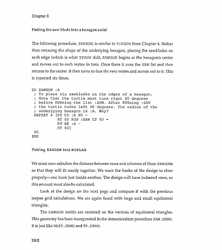
The following procedure , SAWGON, is similar to TIPGON from Chapter 4. Ratherthan retracing the shape of the underlying hexagon, placing the sawblades oneach edge (which is what TPGON did ), SAWGON begins at the hexagon's centerand moves out to each vertex in turn . Once there it runs the SAW list and thenreturns to the center. It then turns to face the next vertex and moves out to it . This
is repeated six times.
Chapter 6
Putting the saw blade into a hexagon swirl
TO SAWGON :ATo place six sawblades on the edges of a hexagon .Note that the turtle must turn right 60 degreesbefore RUNning the list : SAW. After RUNning : SAWthe turtle turns left 60 degrees . The radius of theunderlying hexagon is :A . Why?
REPEAT 6 [PU FD :A PD -RT 60 RUN : SAW LT 60PU BK :ART 60]
-
PDEND
Putting SAWGON into RIFLAG
We must now calculate the distance between rows and columns of these SAWGONs
so that they will fit neatly together . We want the hooks of the design to closeproperly - one hook just inside another . The design will have indented rows, sothis amount must also be calculated.
Look at the design on the next page and compare it with the previousteepee grid calculations . We are again faced with large and small equilateraltriangles .
The SAWGON swirls are centered on the vertices of equilateral triangles .This geometry has been incorporated in the demonstration procedure SAW. DEMO.It is just like NEST. DEMO and TP. DEMO.
260
.
,
.
,
.
,
.
,
.
,

DesignsIslamic
261
TO SAW . DEMO : SIZE : COLS; : SIZE is the dimension of the small; equilateral triangle a .( LOCAL " EDGE " VERT )
MAKE " EDGE 5 * : SIZE; : EDGE is the between - column distance .MAKE " VERT : EDGE * COS 30; : VERT is the between - row distance .MAKE " MOTIF [ LT 30 SAWGON : SIZE RT 30 ]; Why the 30 degrees tilting of SAWGON?GO . PTRIFLAG : COLS (COUNT : COLS ) : EDGE : VERT { LIST ( - I * : EDGE / 2 ) 0 ); Note how the indent list is assembled .
END
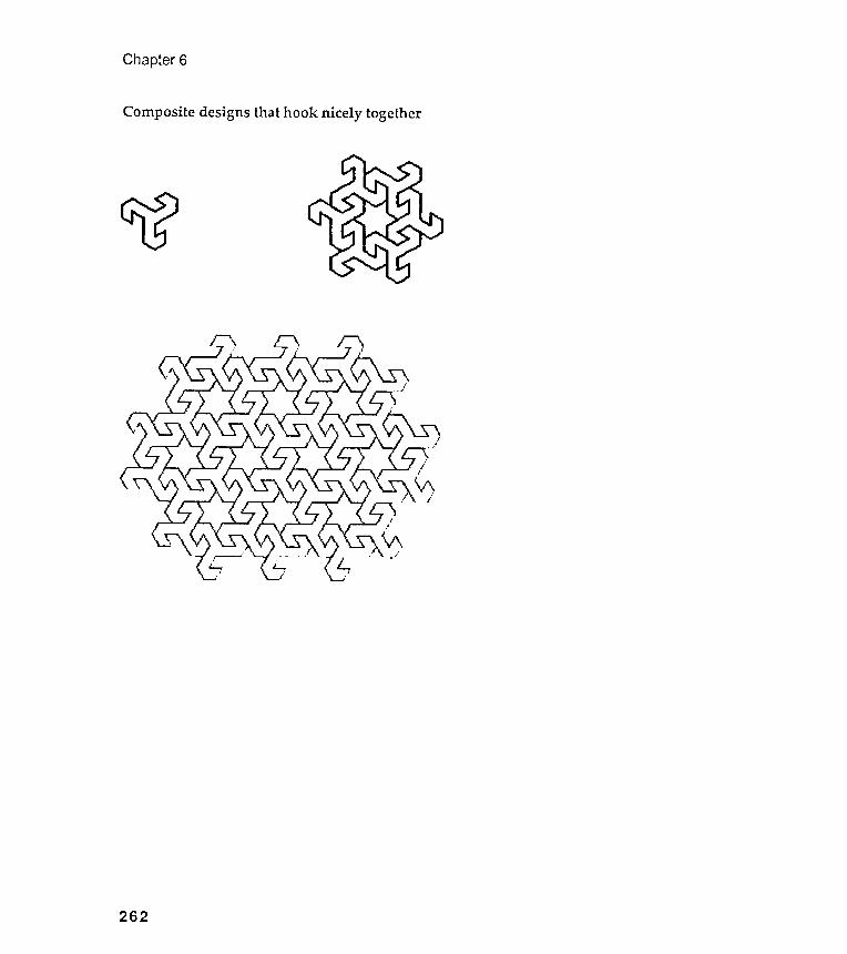
Composite designs that hook nicely together
Chapter 6
262
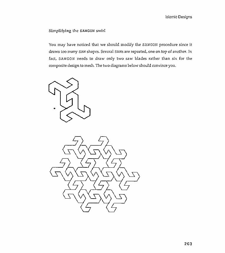
Islamic Designs
Simplifying the SAWGON swirl
You may have noticed that we should modify the SAWGON procedure since it
draws too many SAW shapes . Several SAWs are repeated , one on top of another . In
fact , SAWGON needs to draw only two saw blades rather than six for the
composite design to mesh . The two diagrams below should convince you .
*
263
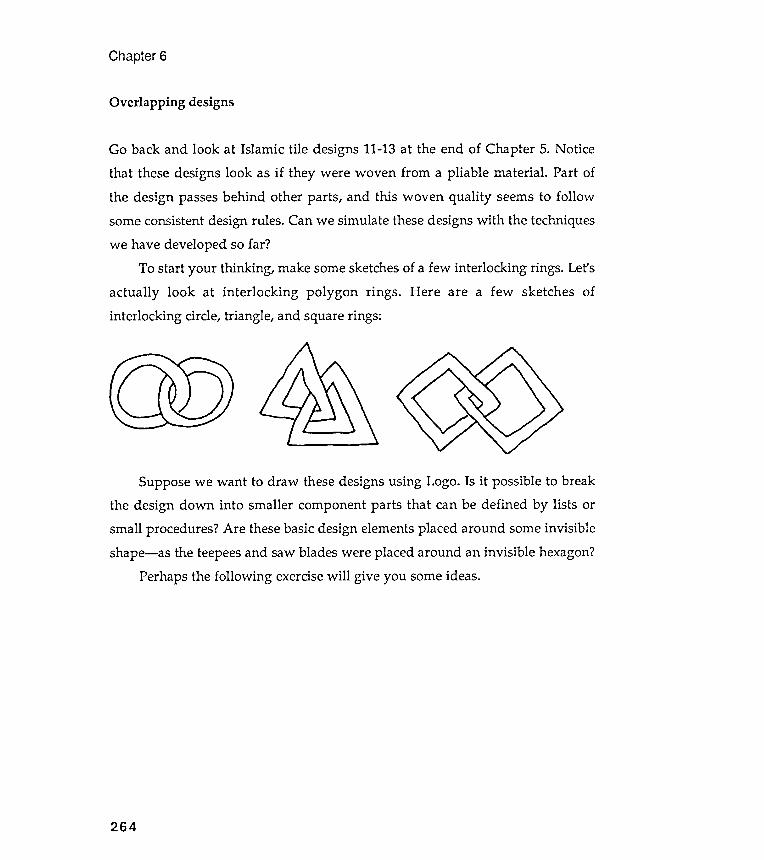
consistent rules .
Chapter 6
Overlapping designs
design
Suppose we want to draw these designs using Logo. Is it possible to breakthe design down into smaller component parts that can be defined by lists orsmall procedures? Are these basic design elements placed around some invisibleshape- as the teepees and saw blades were placed around an invisible hexagon?
Perhaps the following exercise will give you some ideas.
264
Go back and look at Islamic tile designs 11-13 at the end of Chapter 5. Noticethat these designs look as if they were woven from a pliable material . Part ofthe design passes behind other parts , and this woven quality seems to follow
Can we simulate these designs with the techniquessome
we have developed so far ?
To start your thinking , make some sketches of a few interlocking rings . Let 's
actually look at interlocking polygon rings . Here are a few sketches of
interlocking circle , triangle , and square rings :
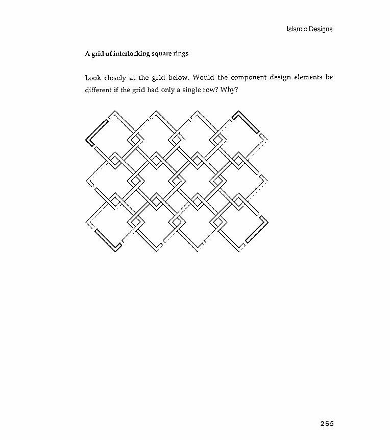
Islamic Designs
A grid of interlocking square rings
Look closely at the grid below . Would the component design elements be
different if the grid had only a single row ? Why ?
265
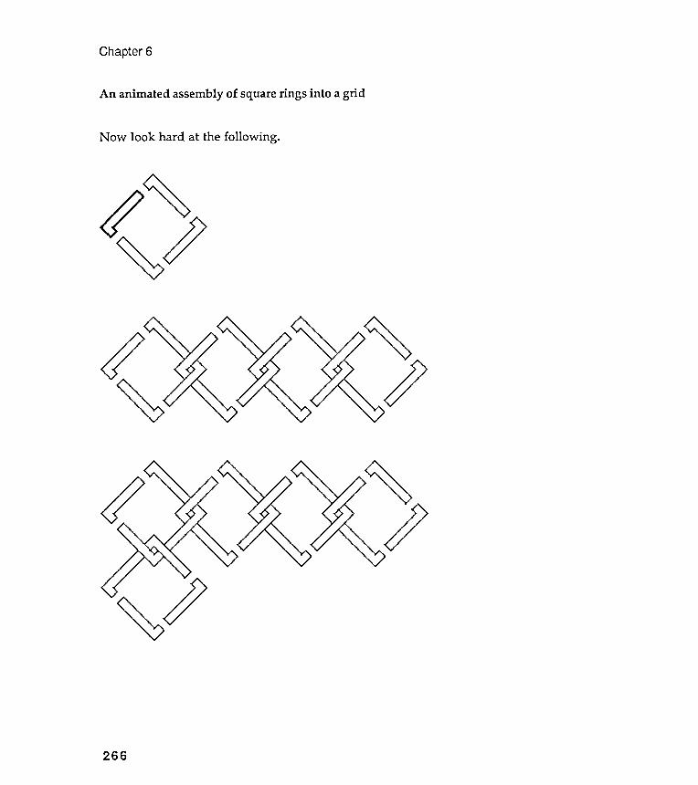
Chapter 6
An animated assembly of square rings into a grid
Now look hard at the following .
~
266

Islamic Designs
The basic design components
*
*
267
The following two diagrams illustrate what we want . The first shows the basicelement and the second shows the element placed around a square.
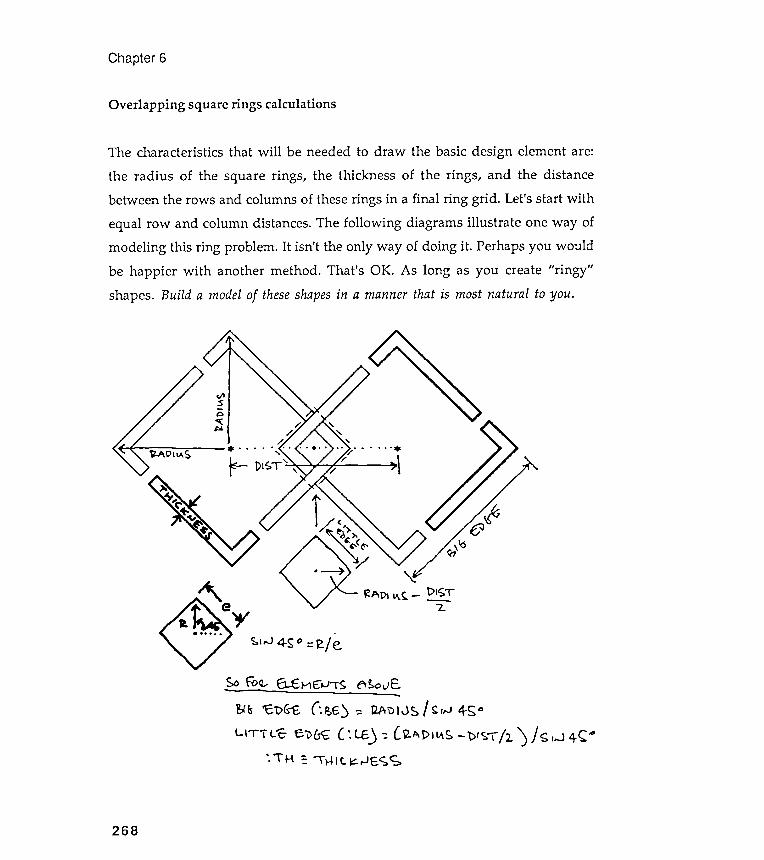
Overlapping square rings calculations
r -
Chapter 6
()~\ "<>
~
t >IST-
" 2.
,~IiJ 4$0 = .je
s.o rc~ E1..E:"""t ~1S ~!:.oJE,- - - - - ~ - ::.&~ 'C'\)&"f, (:~6) ':: ~ 'DIJ~ I ~"J 4-SoL.\"rTL-t;- e.v~ C: LE.) ': l ~~PIl.\~ - 't>'ST 12') J <; ,-J 4-C.o
'. \' H =. -r Hit ~ ,JE,S ~
268
The characteristics that will be needed to draw the basic design element are :
the radius of the square rings , the thickness of the rings , and the distance
between the rows and columns of these rings in a final ring grid . Let 's start with
equal row and column distances . The following diagrams illustrate one way of
modeling this ring problem . It isn 't the only way of doing it . Perhaps you would
be happier with another method . That 's OK . As long as you create " ringy "
shapes . Build a model of these shapes in a manner that is most natural to you .

Islamic Designs
Overlapping square rings procedures
TO.
,
.
,
RTFD
FDFD
RTLT
END
TO
PDEND
TO RING. DEMOMAKE " MOTIFGO.PTRIFLAG : COLS
END(COUNT :COLS) :DIST :DIST ( [ 0] )
269
:RAD/ (SIN 45)
The procedures below follow the diagrams on the previous page . WING draws the
individual component , and RINGS places this component around an invisible
square . You should see the similarity between RINGS and TPGON . RINGS places
an element around a square , while TPGON places an element around a hexagon .
WING : BE : LE : TH
State - transparent element that is
used by RINGS procedure .135
( : BE - : LE ) RT 90 FD : TH RT 90( : BE - : LE - : TH ) It 90( : LE - 2 * : TH ) RT 90 FD : TH90 FD ( : LE - : TH )45
RINGS : RAD : TH : DIST
; Interlocking square rings . : RAD is radius of squares ,; : TH the thickness of the rings , and : DIST the; horizontal and vertical distance between the
; centers of square rings in a grid .( LOCAL " BE " LE )
MAKE " BE . .MAKE "LE ( :RAD- ( :DIST/ 2) ) / (SIN 45)REPEAT 4 [PU FD :RAD PD -
WING :BE :LE :TH -PU BK :RAD RT 90]
:RAD :TH :DIST :COLS[RINGS :RAD :TH :DIST]
An alternative structuring of WING and RINGS
same pproaches.
Chapter 6
END
The procedure RING. DEMO is the for both of the a
270
(LOCAL "BE "LE)MAKE "BE :RAD/ (SIN 45). .MAKE " LE ( :RAD- ( :DIST/ 2 / (SIN 45)REPEAT 4 [PO FD :RAD PD -
RUN :WING -PO BK :RAD RT 90]
You probably compared the design element WING with SAW and TP . The two
latter elements were designed as lists , while WING is structured as a procedure .
You will come to realize that lists and procedures are often interchangeable in
Logo . Below is the list alternative to the procedures on the previous page . Take
some time to think about the differences between the two approaches . Do you
find one more aesthetic than the other ? Why ?
MAKE " WING [ RT 135 -FD ( : BE - : LE ) RT 90 FD : TH RT 90 -FD ( : BE - : LE - : TH ) LT 90 -FD ( : LE - 2 * : TH ) RT 90 FD : TH -RT 90 FD ( : LE - : TH ) -LT 45 ]
TO RINGS : RAD : TH : DIST; Interlocking square rings . : RAD is radius of squares ,; : TH the thickness of the rings , and : DIST the; horizontal and vertical distance between the; centers of square rings in a grid .

Designs
differen
Islamic
It thicknesses, with all other characteristics fixedThree ring grids of
271
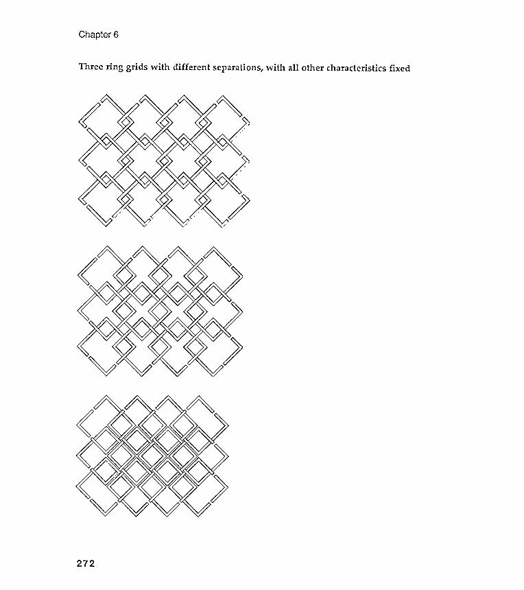
Three ring grids with different separations, with all other characteristics fixed
Chapter 6
272
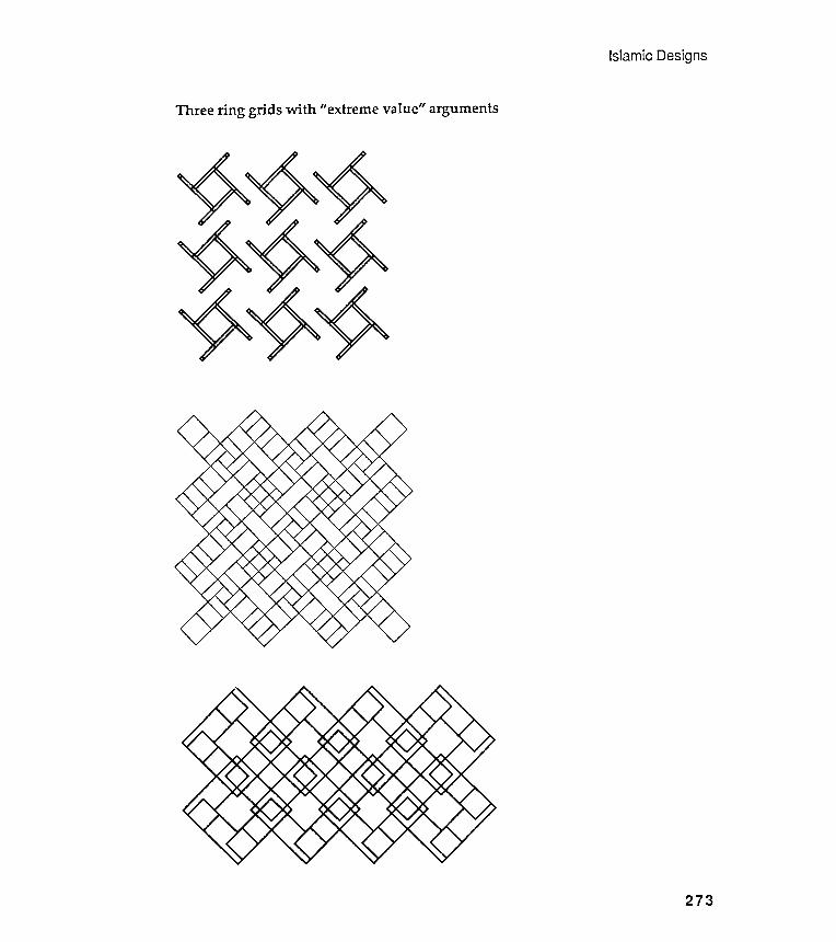
Three ring grids with extreme
Islamic Designs
II value" arguments
273
Chapter 6
Exercises
Exercise 6.1
The TP and saw blade designs were composed of tiny equilateral triangles . Can
you design a single Logo procedure that could produce either of these designs ?
You would have to find characteristics that describe the placement of
equilateral triangles in a basic design element . Then , by changing the values of
these characteristics , your procedures could draw either design . And they could
also draw a series of alternative designs , all based on triangles and all fitting
nicely together in a grid .
Start by designing a procedure to draw a large rectangular grid of small ,
interlocking , equilateral triangles . Print this grid onto a good grade of heavy
paper . You may want to consider blowing up your triangle - grid image with an
enlarging photocopy machine . Find a pad of translucent tracing paper and place
a sheet over the triangular grid . Trace out new tile designs on the translucent
paper , structuring the components with tiny triangle properties . Translate your
designs into procedures .
Carry out the same experiment with other shapes that tile together .
Which polygons do ?
Exercise 6 .2
I recently discovered Daniel Sheets Dye 's book , Chinese Lattice Designs ,
republished by Dover in 1974 . This book has 1200 illustrations ; I offer you only
several here . Can you use the design methods of this chapter to analyze these
images ? Can you design procedures that are generalized enough so that they can
produce several of the designs shown ? See if you can combine some of the Islamic
tile designs we have studied with the lattice designs below . Can you express in
words the difference in feeling between Islamic designs and those shown below ?
274
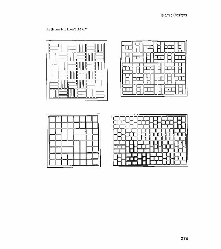
Islamic Designs
Lattices for Exercise 6.2
DDD DDD DDD D D D D D DDDD DDD DDD D8D~ D8D~ D8D~ DDD DDD DDD ~ ~ ~ ~ ~ [ffiDDD DDD DDD D8D~ D8D~ DBD~ DDD DDD DDD 8 ~ 8 ~ 8CUJDDD DDD DDD ~ DBD~ DBD~ DBD
275

Chapter 6
More lattices
O ~ OOODOOOOOOOOO L - =~~
B Qon nOQQ -O[=== ~U U~ o
01 1 I 10 ~01 I 1 10 ~
01 I~ I 10 DoD~01 1 ~ I 10 ~01 I 1 ~ D01 I I ID
O~ n n[=::::===~ OooDu uD~ DODDODDDDDDDDc = JD
CJDDCJDDCJDDDDD DD DD Do oDD ODD DDDbJDDbJDDbJDD00000000000000000000DDDDDDDDDDDDDDD DD DD Do ODD ODD DDDDDDDDDDDDDCJ DCJ DCJ
~ O[:==~ JC=: ~ 0 Dc::=J 0 d c::=J 0 0DO[~:=~~:: ] 01--------14[ ~::= ] 0O[~~~~~~: JL- ~ O[~=~=~ ]D 0 d c:::::::J 0 DD c::]CJoDc::::::Jo d c::::::J 0 DDO[~~~~~:= ] 01--------14[==] 001 II 101 I
for Exercise 6.2
276

Exercise 6.3
Every city has oriental rug merchants. Visit one of these vendors , but rememberto take your sketchbook along with you . Record several rug designs that strikeyour fancy. Explore these designs with a suite of Logo procedures. Hand color theresults and place them in your notebook.
Islamic Designs
Exercise 6.4
Exercise 6.5
tile designs at the end of Chapter 5.Go back and look at the overlapping Islamic
Work on one of these or on a design of your own .
To encourage you , I have included here an overlapping design ( inspired by
design # 12 of Chapter 5 ) done by a French architectural student at Parsons
School of Design in Paris. It is the most elegant Islamic design done in Logo Ihave seen. The student never showed me his procedures; he wanted to keep them"secret." He did show me a few illustrations of the component parts he isolatedin his design. I have also included his visual investigation of the effect ofvarying the width of these basic design elements.
277
Most large cities, anywhere in the world, now have at least one mosque that canbe visited by non-Moslems. Visit a local mosque, taking along your sketchbook,and record several motifs that strike your fancy. Later, over a glass of mint tea,explore your sketches with Logo procedures. Hand color your results and placethem in your notebook.
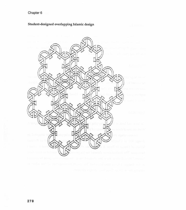
C) V CD 0)
E CD Cl ) CD C Cl) CD o .
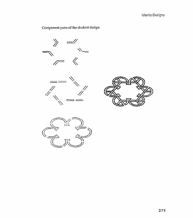
Islamic Designs
Component parts of the student design
~,~'- -==:=~ "
/~:=
""~
-
== ~I'
/ // /
/ // / ~
""
-~ ~'l---'" '. ,,'. ---:-~/ , \. ," /' "'.. .. .. . )\; cl'~ //.....:=0....;=: -~~ .- "" \-,.;,,- '"~( Jl- -=~..).. /~~:::~~./~ ' A_~\.LJ7~
279
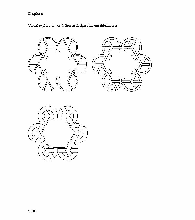
Chapter 6
Visual exploration of different design element thicknesses
280
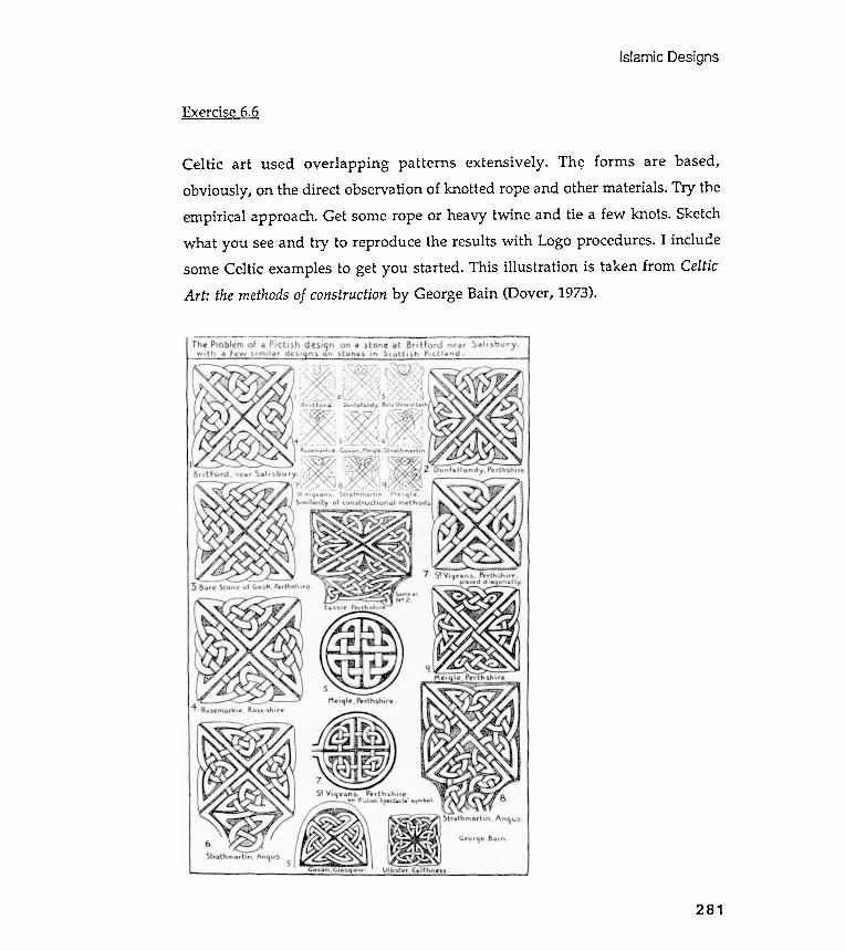
Islamic Designs
Exercise 6.6
281
Celtic art used overlapping patterns extensively. Th~ forms are based,obviously, on the direct observation of knotted rope and other materials. Try theempirical approach. Get some rope or heavy twine and tie a few knots. Sketchwhat you see and try to reproduce the results with Logo procedures. I includesome Celtic examples to get you started. This illustration is taken from CelticArt: the methods of construction by George Bain (Dover, 1973).
Chapter 6
Exercise 6.7
One could characterize most of the work illustrated in this book so far as totallygeometric . Some of you might go so far as to claim that these designs- althoughvisually surprising and intellectually interesting - are excessively geometric ,that they lack " life " and have no organic qualities .
You might be ready to ask whether the shape notation capability of Logocan produce designs that share visual characteristics with pieces of the livingworld . Chapter 7 will argue that this question can be answered "yes."
This exercise introduces a tree-drawing problem that will be developed atlength in the next chapter. I want you to think about it on your own , though ,before you see my presentation; so don't read ahead into the next chapter.
A recursive definition: a tree is a branch attached to a tree- ~ ~~ ~ - ~ ~- --
Branching is not the only characteristic that make trees trees ; there are many
others , and we will eventually investigate some of them . But branching is
perhaps the most noticeable feature of trees . Look at the sketches on the next
page , taken from a nature guide book .
282
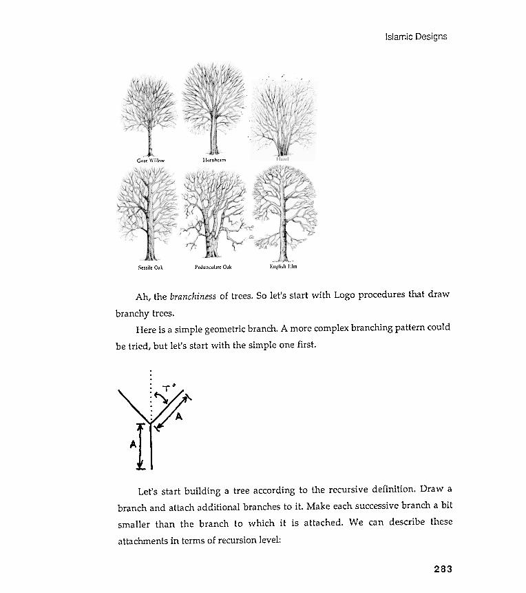
IslamicDesigns
of trees . So let 's start with Logo procedures that drawAh , the branchiness
branchy trees .
Here is a simple geometric branch . A more complex branching pattern could
be tried , but let 's start with the simple one first .
Let 's start building a tree according to the recursive definition . Draw abranch and attach additional branches to it . Make each successive branch a bitsmaller than the branch to which it is attached . We can describe theseattachments in terms of recursion level :
" . ,
, (\ ' .,
'\"\' , \
' .
IlornhcamGoat " 'illo'"
. - . -_.-)':ngli,;h 1.:1111Pcduncul31C 03kScssilc Oak
T4
283
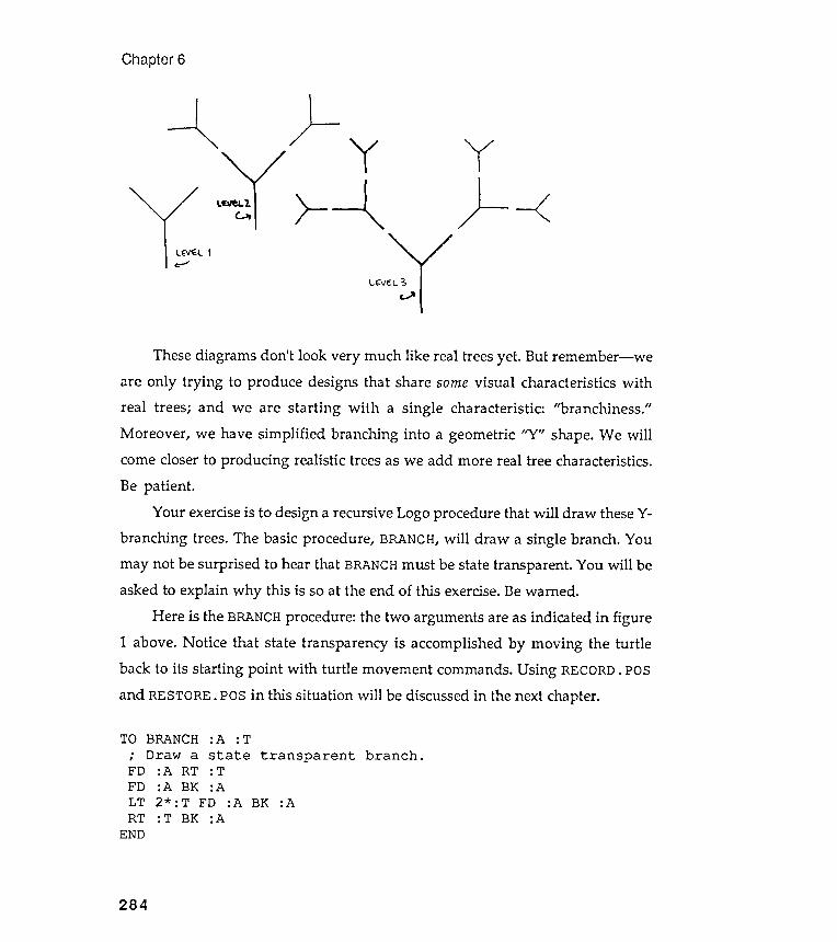
Chapter 6
) -~ y}-- -<
L ( \l'E: L It : """"
LCI/E::L 3
These diagrams don't look very much like real trees yet . But remember- weare only trying to produce designs that share some visual characteristics withreal trees; and we are starting with a single characteristic : "branchiness ."
Moreover , we have simplified branching into a geometric "Y " shape. We willcome closer to producing realistic trees as we add more real tree characteristics.Be patient .
Your exercise is to design a recursive Logo procedure that will draw these Y-branching trees. The basic procedure , BRANCH, will draw a single branch. Youmay not be surprised to hear that BRANCH must be state transparent . You will beasked to explain why this is so at the end of this exercise. Be warned .
Here is the BRANCH procedure: the two arguments are as indicated in figure1 above. Notice that state transparency is accomplished by moving the turtleback to its starting point with turtle movement commands. Using RECORD. pSand RESTORE. pS in this situation will be discussed in the next chapter.
BRANCH : A : TDraw a state
: A RT : T: A BK : A2 * : T FD : A: T BK : A
branch .transparent
BK :A
284
TO.,FDFDLTRT
END
Expand BRANCH into a recursive procedure that can draw the Y-shaped treessketched in figure 2. Allow for an argument that scales succeeding branch sizeand another that controls the levels of branch attachments, that is, the level or
depth of recursion .Hint : find the places within the BRANCH procedure where you would like
an additional BRANCH created.
Finally , why must state transparency be respected in this tree drawingdesign? Be specific.
Islamic Designs
Yourwork
285

Chapter 7Organic Designs
"Painting is a science and should be pursued as an inquiry into the laws of na ture.Why , then, may not landscape painting be considered as a branch of naturalphilosophy , of which pictures are but the experiments?"John Constable
Tree experiments
I will use Constable 's words to state this chapter 's goal . He suggested thatmaking pictures of our natural environment is an effective way to to see it moreclearly . Although I would substitute the term visual modeling for Constable'slandscape painting , I seek the same end and suggest similar means: visual
experimentation with segments of our personal world can school our eyes thebetter to enjoy the richness of the larger world .
In this chapter I will offer you an essay on several characteristics of trees:first , their "branchiness ," and second, their quality of randomness -within -a-structure . The illustrations should suggest other tree signatures to model . Theexercises at the end of the chapter will ask you to justify the title of thischapter by looking at some nontree plants and beasts.
As you read through this chapter, please remember that I am showing youmy experiments with trees; this is the way I did it . Why trees? Every Logo bookhas at least one recursive tree design, but few books play with the visual idea of
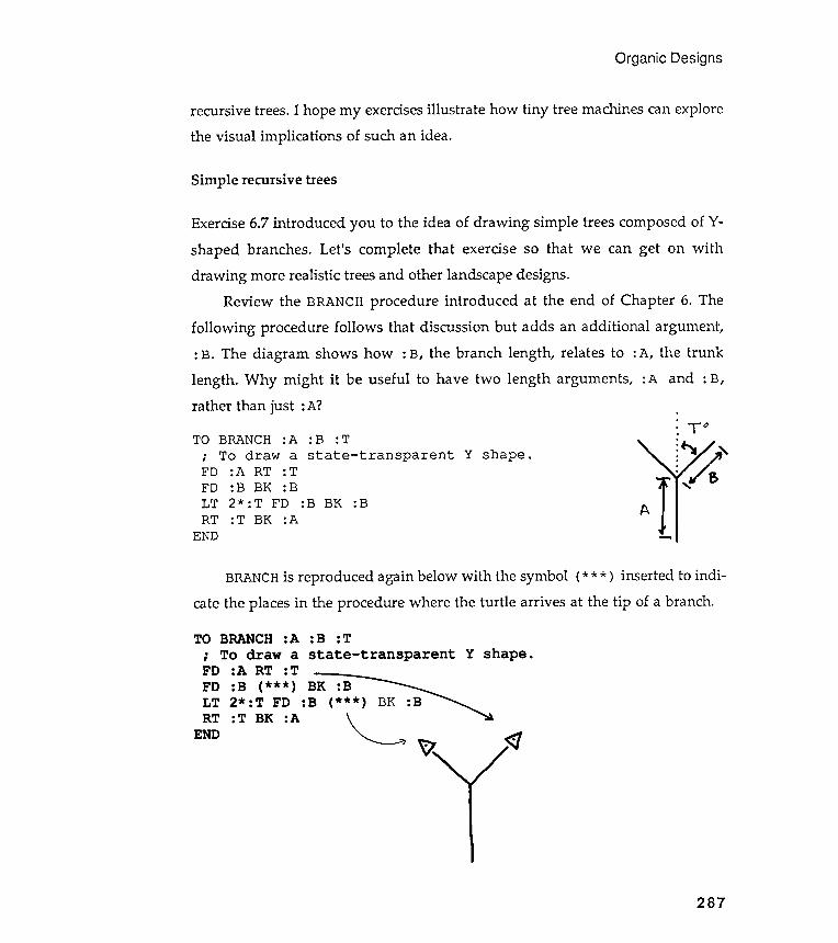
recursive trees . I hope my exercises illustrate
the visual implications of such an idea .
Organic Designs
how tiny tree machines can explore
Simple recursive trees
Exercise 6.7 introduced you to the idea of drawing simple trees composed of Y-shaped branches. Let 's complete that exercise so that we can get on withdrawing more realistic trees and other landscape designs.
Review the BRANCH procedure introduced at the end of Chapter 6. Thefollowing procedure follows that discussion but adds an additional argument ,: B. The diagram shows how : B, the branch length , relates to : A, the trunklength . Why might it be useful to have two length arguments , : A and : B,rather than just : A?
ToTO BRANCH :ATo draw a Y shape .
:A RT : T: B BK : B2* : T FD :B BK :B: T BK : A
: B : T
state - transparent.
,
FD
FDLTRT
END
A
BRANCH is reproduced again below with the symbol (* * * ) inserted to indi -cate the places in the procedure where the turtle arrives at the tip of a branch.
BK
~
287
FD :B (S.TREELT 2* :T FD :BRT :T BK :A
END
That 's it . But to use it creatively will take some imagination and play . You
might even be tempted to look at a few trees before you start your exploration .
Two pages of tree experiments follow . My intent was to present a series of designs
that folded and unfolded . I began with an unfolded design , a Mondrian -ish tree,
and proceeded toward a more folded -up one , a cypruslike tree . Compare these
designs with the folding / unfolding RECGONs of Chapter 3.
Chapter 7
( :A* :F)(S.TREE
( : B* : F)( :A* : F)
BK :B( : L- l ) ) BK :B
288
These are the two turtle positions where we would like to place another branch.This is , therefore , the position to insert some recursion apparatus . Remember
that recursion only means that a procedure uses itself in its own definition . Inother words , a recursive procedure asks that it be run again. You might want torefer back to the recursion diagrams of previous chapters .
Once we have made BRANCH recursive , we will want to stop the recursion at
an appropriate level . We can do this by adding an argument to control the depthof recursion . Because we may also want the branches to decrease , or increase ,
with the level of recursion , we will need another argument to scale the : A and
: B arguments as they are passed from one level of recursion to another . To keepthe names short , call the level argument :L and the scale factor argument : F.
You should find the following procedure easily understandable in terms ofLogo syntax . But you may not be able to guess exactly how Logo will draw theshape on the screen until you do some experimenting . Since we are making .:?imple~ s from individual branches, let 's rename our procedure S. TREE. Here it is:
TO S.TREE :A :B :T :F :L; To draw a simple , recursive Y- branched tree .IF :L < 1 [STOP]FD :A RT :T
: T : F( : B* : F )
( : L- l ) ):T :F
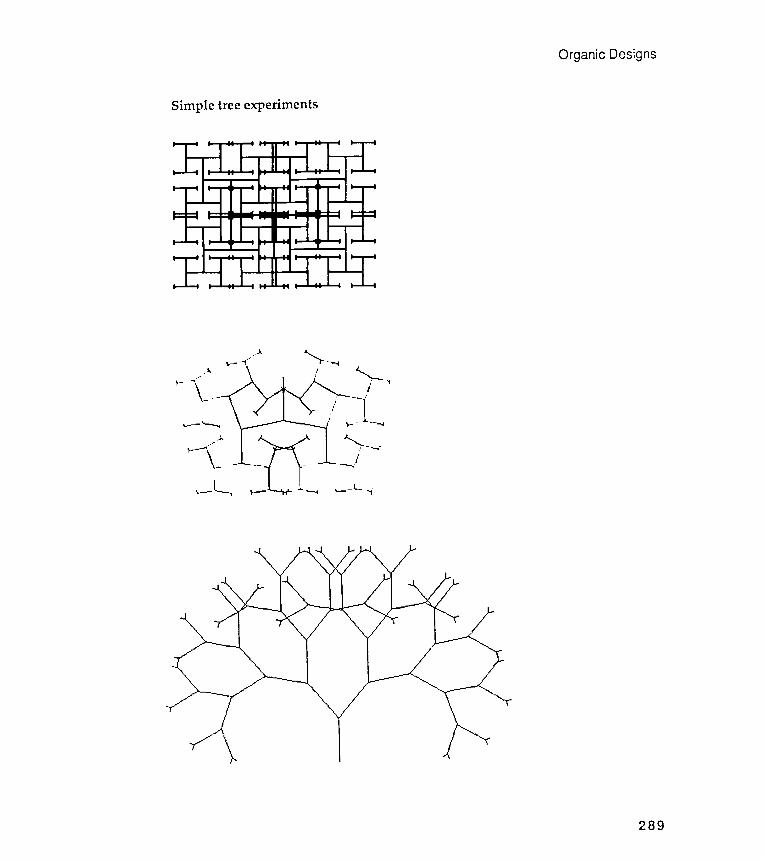
Simple tree experiments
~ . . ) .
" ~. , . -
' t -
. . . -
~
. . . -
' t -
Organic Designs
-
289

Chapter 7
More simple tree experiments
290

Organic Designs
State transparency
Let ' s go back to the last question of Exercise 6 . 7 : " Why must state transparency
be respected in the tree drawing procedure ? " Watching the turtle as it climbs up
and down the branches of your trees should supply you with an answer . If the
turtle moves too fast , slow it down using the STEP command . This command lets
you step through a procedure one line at a time , and you control the speed of the
stepping . STEP is called TRACE in some Logo dialects . If you are not familiar
with this command , review it in your Logo manual .
Another way to slow S . TREE down is to insert a time lag procedure at one or
more places inside it . You might want this time lag procedure to print out the
current recursion level . Would printing : L accomplish this for you ?
The idea of state transparency has been useful in many of the design
exercises that we have explored so far . We introduced state transparency during
one of the very first exercises in this book , the centered NGON affair . State
transparency was reintroduced when we began to use design recursion . Recall
RECGON from Chapter 3 and the exercises dealing with the Gothic stone mason
marks in Chapter 4 . Later , in Chapter 5 , we saw that state transparency was
needed when we placed list - defined shapes within rectangular grids .
State transparency is needed here again because we are drawing trees
recursively . But why does that follow ? And what does the term really mean ?
Why state and why transparency ? Here is a good place to come to grips with
this concept . Can you draw a sketch of it ? Would making a sketch of a concept
make any sense ?
Multiply branched trees
So far our trees have had a simple Y - shaped pattern ; each branch forked once ,
producing two new branches . Why not expand this single forking design into a
multiply forking one ? To do so , let ' s add to S . TREE an additional argument that
defines the number of branches leaving a fork .
291
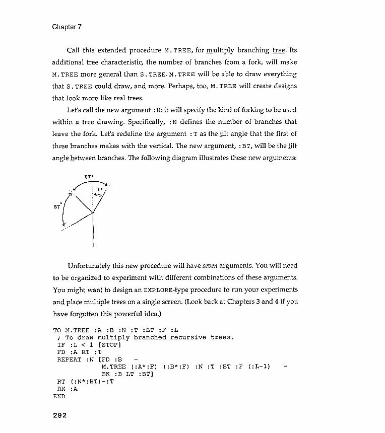
Chapter 7
Call this extended procedure M. TREE, for .m..ultiply branching ~ . Itsadditional tree characteristic , the number of branches from a fork , will make
M. TREE more general than S . TREE. M. TREE will be able to draw everythingthat S . TREE could draw , and more. Perhaps, too, M. TREE will create designsthat look more like real trees.
Let's call the new argument : N; it will specify the kind of forking to be usedwithin a tree drawing . Specifically , : N defines the number of branches thatleave the fork . Let's redefine the argument : T as the .tilt angle that the first ofthese branches makes with the vertical . The new argument , : BT, will be the tiltangle Qetween branches. The following diagram illustrates these new arguments:
~ iO
" . : : "
~T
Unfortunately this new procedure will have seven arguments . You will needto be organized to experiment with different combinations of these arguments .You might want to design an EXPLORE-type procedure to run your experimentsand place multiple trees on a single screen. (Look back at Chapters 3 and 4 if youhave forgotten this powerful idea.)
TO M. TREE :A :B :N : T : BT : F : L; To draw multiply branched recursive trees .IF : L < 1 [ STOP]FD :A RT : TREPEAT :N [FD : B -
M. TREE ( :A* : F) ( :B* :F) : N : T : BT : F ( : L- l )BK : B LT : BT]
RT ( :N* :BT) - : TBK :A
END
292

Organic Designs
A few examples of multiply branched trees
293
Chapter 7
Placing fruit at the branch tips
TO FRUIT : SIZETEXTURE.ONREPEAT 6 [FD : SIZE BK : SIZE RT 60]TEXTURE.OFF
END
.
,
IF
The expanded procedure is a multiply branched , fruiting ~ .
TO MF . TREE
; To drawIF : L < 1FD : A RTREPEAT : N
: A : D : N
multiply[ FRUIT : D
: T
[ FD : A / 2MF . TREE
BK : A / 2( : N * : BT ) - : T: A
:T :BT :Fbranched
STOP]
:Lwith fruit .recursive trees
( :A* :F)LT :BT]
: F ( : L- l ): D : N : T : BT
RTBK
END
294
:L
Suppose we want to put small colored shapes ( fruit ? ) at the tips of the figures
drawn by M . TREE . Lacking color , I will need a textured fruit . I ' ll invent two
procedures , TEXTURE . ON and TEXTURE . OFF , that set the pen color to a fruity
texture and then change it back to nontextured black . Because pen textures are
dependent upon machine and Logo dialect , you will have to write your own
texture - setters . Here ' s a little fruit machine :
Where should we insert this fruit machine into M . TREE ? Where does the
turtle reach the tips of the branches ? Another way to ask this question is :
Where does the turtle decide not to draw more branches ? Or : When does the
turtle decide that it has recursed enough ? You should find this spot easily ; it is
located in the first line of M . TREE and is marked with the ( * * * ) symbol .
TO M . TREE : A : B : N : T : BT : F : L
To draw multiply branched recursive trees .
< 1 [ ( * * * ) STOP ]
.END
Organic Designs
Notice a few of the changes. First, I have removed : B, the second branchsize argument , and replaced it- within the procedure- with :A/ 2. I found thatI really didn 't need : B. Second, I have introduced a new argument , : D, the size ofthe asterisk -shaped fruit .
Different fruit shapes
We can change the fruit shapes placed at the tree tips by altering the FRUI T
procedure . But in fact, we can be more elegant than this . Recall our work withrectangular grids in Chapter 5. We broke grids down into two elements: anunderlying placement mechanism that structures a grid , and the image motif tobe placed within this grid . We defined the image with a list . We could considerthe current exercise to be tree grids . The M. TREE procedure is the underlying
placement mechanism, and FRUIT is the image to be placed by it . This suggeststhe following restructuring of MF. TREE. : FRUIT is now an argument that must bea state-transparent image list .
: N : T : BT : F : Lrecursive trees withat the branch tips .
TO:FRUIT,.
,
( :A* :F)
295
FRUIT.LIST .TREE:FRUIT :N :T :BTBK :A/ 2 LT :BT]
RT ( : N* : BT) - : TBK :A
END
: F ( : L- l )
FRUIT . LIST . TREE : A : FRUIT
To draw multiply branched; defined by a list , placedIF : L < 1 [ RUN : FRUIT STOP ]; Note the change here .FD : A RT : T
REPEAT : N [ FD : A / 2
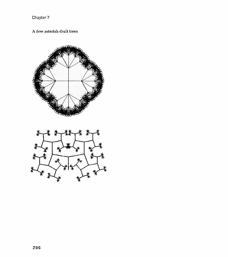
Chapter 7
A few asterisk -fruit trees
296
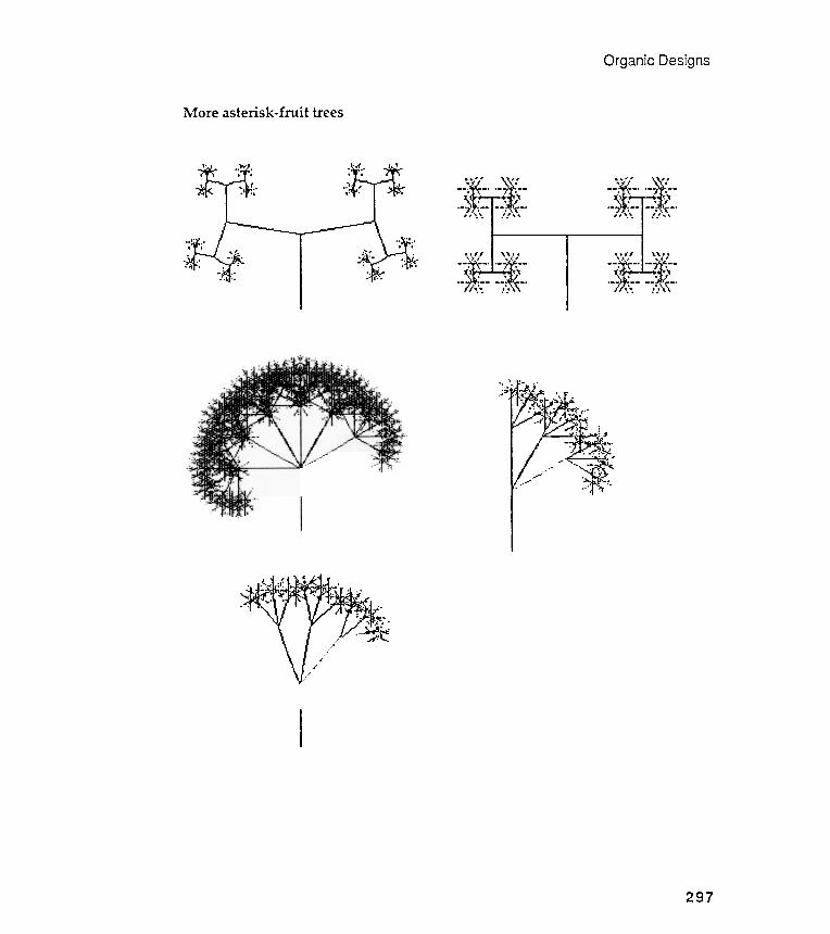
Organic Designs
More asterisk -fruit trees
- - - -
. - - . . - - .
" . . . . " " . . . . "
" " " " " " " "" "
- - - - -
. . . - .
297

<:,
-- ~
(... -.L
.
I
Chapter 7
> - ...
..
(t)
~ ~ ~ ....
.~
.
-< (t)
~ 2 ~.
....
.
(/)
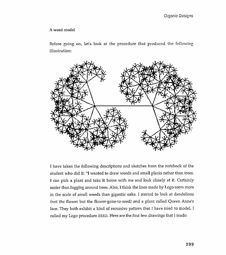
(") ......
.......
. .....
ro
-
C/) -
.....
OJ
.,.,..~
~ ~
~ ~
(") 2"
~ ::=
ro
~~
~ Q.
~ ~.
~
p..
~ c7:
0"
~p..
o-J.-to
ro
'"1
~ ~
~ .-to
'"1
~1::1
~
~ .-to
'ij
.... '"1
ro
~ ~
ro
C/) ~
.....
.-to .
-to
~ p.
'-< .
!J; ....--
Q
~
c. ~
~ ';1'.
O'Q
S
'-"""'
~ "'
~'"
0 0
b g
~ ro
~
~ 0
~
S'
8-O'Q
o :::::.
ro
g.
O'Q 'i
j p..
:::::.
O'Q
~
.... '"1
O'Q
"""""'
....'ij
C/) .....
~
p..
ro
0'"1
ro
x s-
S ~
~ .....
'"""'
~
0 ~
~ O'Q
.-to
':"':
0 "
(") 2:
.-to .
.....
~ ~
......
......ro
cr'
.-to ..
.... '"1
H
~......
ro
p..
.....
::J""
~ 0
.... -
0 ~
~ .-to
ro
<; ~
p..
~ ~
C/)~
~ ~
~ ~
@" ~
S.
......~
O
p..p..
~~
O'Q
0U)
.....
~ C/)
.-to r
o .-to
0
tIj
~ <;
'"1
ro
p..
~tIj
p..
ro
~
ro
:::;:
p..
ro0
? ~
rn
.-to C
/) ~
. g.
O'Q
~.
~O
Q
.-to
:r:
'"1
0 O'Q
>
g p..
~.
.-toro
ro
~
.....
~ ~
~ .-to
::J""
'"1
(") . r
O'Q
0 ro
~
O'
roro
~
.-to ~
" <;
~ U1
0
~ -
~ ~
'ij'"1
.....
~
';1'.
.-to ~
~
'"1ro
<:
ro
(") ~
.....,.ro
~
0.-to
ro
ro
~.....
ro
~ (")
~'ij
.e::
g ~
S ~
p..
~'"""'
~
~.-to
ro
'" C/)
~.....
::+
~
C/)::J""
10
M ~
'"1U1
ro
~ .
ro
~ ~
ro
ro.-to
!1
p..-
......~
p..';)
,",,",;:J
C/)
"".
p..
C/) ::J""
~
ro
.-to ~
.-to
~
1::1
ro
~~
~'ij
~ rn
o
~ C/)
.-to~
.......-to
0
......p..
.-to ~
ro
S
~......
~ 'ij
~ -
~ p..
~ 'ij
0 '"1
~~
.-to
p..(")
......1::1
0
<; ~
(") '0
ro
0
~ ~
p..~.
....
~ C/)
~ .-to
~
....""
""""""
cr'ro
ur
~
(")O'Q
ro
ro
0 ,-<
......
ro
roC/)
.-to
0 '-<
'"1
'""'
.-to '
"1 p..
~~
~ H
~ A
~.....
'"
0 ~
.-to .
...~
ro
.0
~ O'Q
.-to
::J""
Q.
.-to
cO.-to
p..
~ .-to
0
.....
ro
ro
::J""
p)-
.-to r
o p..
C/)
~ '"1
cr'
ro
::J1::1
0
ro
~ ro
~
~ 0
'"""'
_0.~
1::1
~ H
ro
IJ
0 0
~ ~
.... 1::1
ro
~
~ ......
0
'""' .,.,..
p..~
'"1
~ ......
~O
""'ro
.-to
0
0 CD
'" ~
p..
~ :=:
S
~.
q '"""'
~
~.(0
~
~ 0
0 ~
ro
.-to
.....
(Q.
ro
~ '"1
......
ro
::J""
~
::J(0
-
C/)-
V>
ro '
-<
~ ro
O'Q
U>
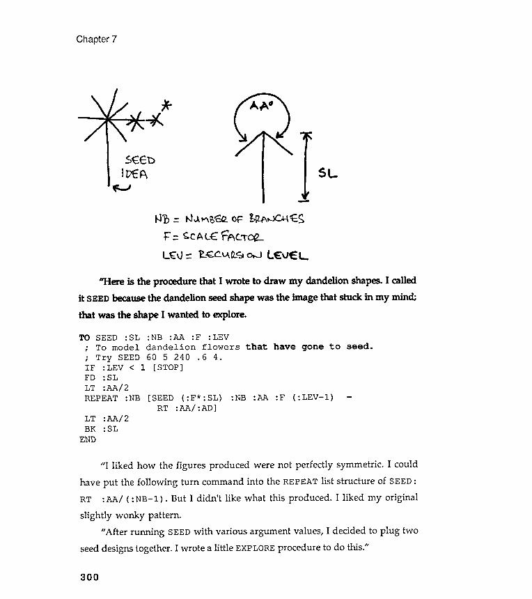
: NB : AA : Fdandelion605240
[ STOP ]
: LEVflowers
. 6 4.
Chapter 7
SEE'DIvEA
N ~ = tJ IJ. t"\ ; EQ.. OF bflA..JC.+-\ 't. SF = ~c A L ffic .~~L'f:v :: ~~ ~ fL~ 0t0..J
[SEEDRT
( : F* : SL):AA/ :AD]
:NB :AA :F ( :LEV- l )
:AA/ 2:SL
LTBK
END
300
.
,
.
,
IFFDLT
" I liked how the figures produced were not perfectly symmetric . I could
have put the following turn command into the REPEAT list structure of SEED:RT : AA/ ( : NB- l ) . But I didn 't like what this produced . I liked my original
slightly wonky pattern ./I After running SEED with various argument values, I decided to plug two
seed designs together. I wrote a little EXPLORE procedure to do this ./l
SEED : SLTo model
Try SEED: LEV <: SL
: AA / 2REPEAT : NB
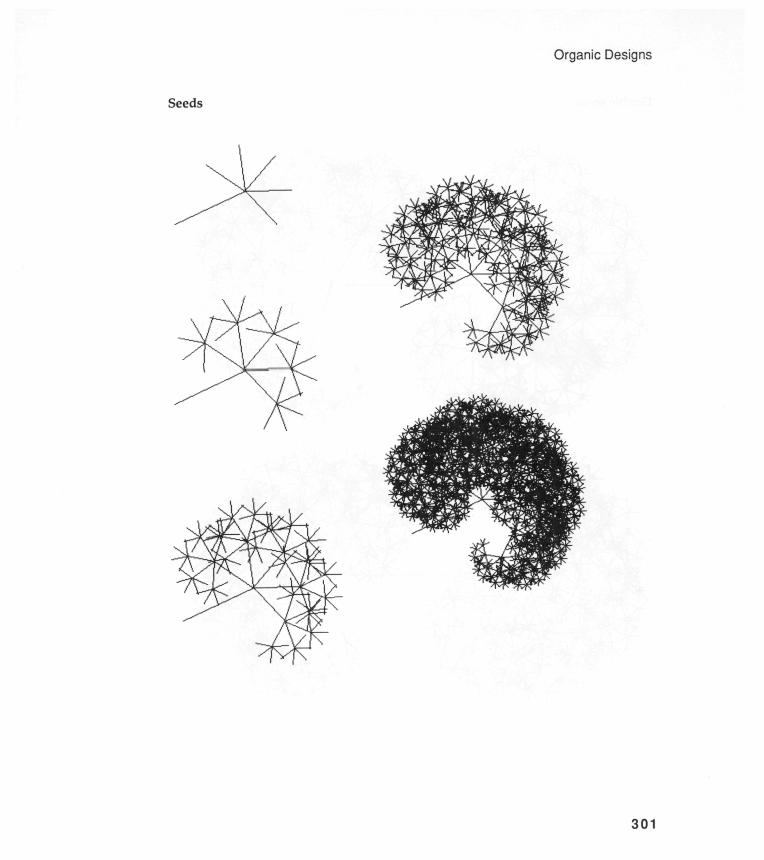
0 - (0 £ 1) C) ci CD C l ) (0 (I)
Cl) CD CD

Chapter 7
Double seeds
302
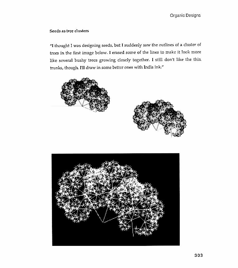
Organic Designs
Seeds as tree clusters
" I thought I was designing seeds, but I suddenly saw the outlines of a cluster oftrees in the first image below . I erased some of the lines to make it look morelike several bushy trees growing closely together . I still don 't like the thintrunks , though . I' ll draw in some better ones with India ink ."
303
Chapter 7
" these trees are interesting , but they still lack a feeling of
Introducing random components into trees
" OK , " I hear you say ,
life . Real trees are not as regular as the ones presented above .1I
Let 's introduce some randomness into these designs and see if that produces
more lifelike shapes . How can we do this ? We want to introduce a random
component into the drawing of the : A lengths , and perhaps into the turning
angle : T and the between - branch angle : BT .
What happens if : La and : HI are not integers ? Try some funny numbers .FD RR ( . 5 * : A ) ( 1 . 5 * : A ) would add some randomness into one of the
tree components . The actual branch length drawn would range from .5 to 1.5 times
the original value of the argument . Obviously , .5 and 1.5 are arbitrary ; you can
experiment with other values when we put everything together .
The problem now is how to insert RR into M. TREE. A first guess might be to
put RR after every FD, BK, and RT command . Would this be correct ?
We can answer this question by posing another : Is the following state
transparent ?
FD RR 5 10BK RR 5 10
304
We might be able to use the procedure RR that was developed in Chapter 5to generate random grids . Recall that RR takes two arguments, : La and : HI , andoutputs a random number that falls in the range defined by these two arguments.
TO RR :LO :HI; To output a random number in the range :LO to :HI .OP :LO + RANDOM (1 + :HI - :LO)
END
It certainly isn 't. RR 5 10 will probably give a different value in the twosituations . But we must move backward the same amount that we moved
Organic Designs
305
forward . Otherwise , we don ' t get back to the starting point , and state
transparency demands that we always get back to where we started from . We
require that the same random number be used for the FD and the BK command .
There are several ways of doing this :
MAKE " 0 RR 5 10FO : 0BK : 0
RECORD . POSFD RR 5 10RESTORE . POS
Let 's use the first method to handle the FD : A BK : A situations within
the REPEAT list structure . The RECORD . POS and RESTORE . POS can handle the
getting back to the base of the branch after all the other movements have been
completed . RR will be used in conjunction with the FD : A command , the RT : T
command , and the LT commands within the REPEAT list structure .
But be careful . The value for : D and : PO S ( created inside the
RESTORE . POS procedure and needed by RESTORE . POS ) must be unique for each
level of recursion . Why is this ? We can make these two variables unique and
tied to each recursion level by making : D and : POS local variables . ( Review
local and global variables in your Logo manual . ) Local variables exist only
within the lifetime of the procedure that gave them their value . Are you
happy about this ?
Notice , again , that I have removed the : B variable . It doesn ' t appear in
the following procedure . As I have said previously , I found that two size
arguments are not needed , and I also wanted to cut down on the number of
arguments . I have replaced the : B with : AI 2 as I did in the MF . TREE procedure .
Chapter 7
It H
- CD
00
I CD
t-i
cnI ..... -
reasons .
: N
( 1 . 5 * : BT ) ]
306
Randomized trees
TO RAND . TREE : A : N : T : BT : F : L
; To draw multiply branched recursive
; with randomized components .
IF : L < 1 [ STOP ]
( LOCAL " POS " D )
; For state transparency
RECORD . POS
FD RR ( . 5 * : A ) ( 1 . 5 * : A )
RT FD RR ( . 5 * : T ) ( 1 . 5 * : T )
REPEAT : N [ MAKE " D RR ( . 5 * : A / 2 )
FD : D -
RAND . TREE ( : A * : F )
BK : D -
LT RR ( . 5 * : BT )
RESTORE . POS
END
(1 . 5* :A/ 2)
: T :BT :F
Again , please notice the use of the LOCAL command in the procedure 's secondline . We must have a value for : POS and : D for each level of recursion . These
variables will not , typically , be the same for each of the branches that make upthe tree. LOCAL tells Logo to keep the variable indicated tied to each level ofrecursion . There will be a different : POS for each level , and there will be a
different : D for each level . Logo then uses the proper value for : POS and : Daccording to the turtle 's recursion status. This application of local variables is
extremely important , but not obviously so. How do you feel about it ? Can you setup an experiment to test out the logic of its use?
You might want to run RAND. TREE with line two removed (the line that
makes : POS and : D local variables ). What happens to the turtle and why ?Make a print of the result and put it in your notebook .
Organic Designs
Three series of random component crees
How will the random machinery introduced into the procedure RAND. TREE
actually work ? What will the designs look like ? In order to see the effect of thisrandomizing , we must produce a series of designs, with the arguments fixed . Thedifferences between the individual designs will be due solely to the randomeffects.
This exercise is similar to the random grid work we did in Chapter 5.
Remember the random placement of stars? Go back and take a look .I 've written an EXPLORE-type procedure to produce a series of designs. I
have indicated the arguments used at the start of each of the series.
What have we done new in this chapter? I believe we have caught some of the
mystery of a living form when we mixed a little randomness into some strictgeometry . What are the implications of these tree machines? Whether or notyou choose to be philosophical about all this , I hope you can extend the imageideas of this chapter to simulate the shapes of some other organic shapes.
Recapitulation
307


Organic Designs
RAND . TREE series lb
309

Chapter 7
RAND. TREE series 2a
RAND.TREE 30 3 30 30 . 75 5
310

Designs
I
Organic
RAND . TREE series 2b
311

RAND . TREE series 3
Chapter 7
RAND.TREE 30 3 30 15 . 9 5
312
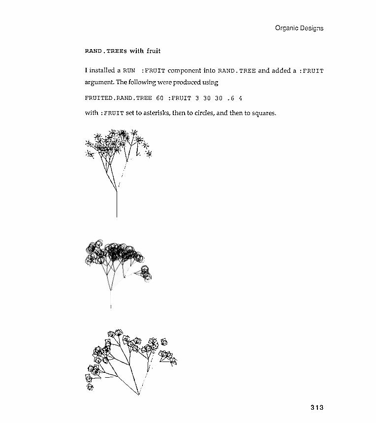
.-
' :hOJ
; -~~ .- - J- .
~
Organic Designs
RAND. TREES with fruit
: FRUIT
313
I installed a RUN : FRUIT component into RAND. TREE and added aargument. The following were produced using
FRUITED.RAND. TREE 60 : FRUIT 3 30 30 . 6 4
with : FRUIT set to asterisks, then to circles, and then to squares.
Our randomized trees look more like weeds than trees because the branches are
so thin . In " real " trees , the branches become thinner as they become shorter .
Design a Logo tree procedure that draws branches that exhibit thickness .
Make sure that this thickness decreases as the level of recursion changes . Here
are two examples of changing trunk thickness in nonrandomized trees . The first
example was consciously planned by a student , and you are given two designs
produced by it . The second design was " a mistake ," according to its designer .
Your job is to design either randomized or nonrandomized trees that
illustrate interesting variations in trunk / branch thickness . Try to do something
as different from the examples as possible .
Exercise 7.2
How about creating some tropical vegetation ? So far , even the sticklike weeds
and trees explored in this chapter are distinctively northern European . Let ' s try
designing a " leafy something " that you might expect to find in a tropical rain
forest or in a desert oasis . Here is a palm tree essay done by Paul , a computer
scientist . He selected palms because they " reminded him of holidays , blue skies ,
blue seas , and exotic countries . "
Paul characterized a palm tree in terms of the number of segments in its
trunk ; the rate at which these segments changed in size as the trunk lengthened
( see Exercise 7 . 1 ) ; the length of the trunk ; the " curviness " of the trunk and its
tendency to bend left or right ; the number of palm fronds in the tree ' s head , their
orientation , length , and composition . The procedure structure was made
recursive , and the arguments could be either fixed or random . Below are five
examples of Paul ' s palms . You may notice that the second cluster of three trees
has begun to flower !
Chapter 7
Exercises
Exercise 7,1
314
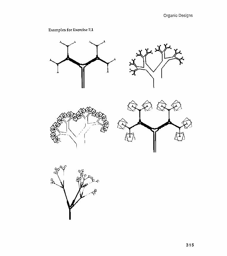
Organic Designs
Examples for Exercise 7.1
~
315

Chapter 7
Paul's palms for Exercise 7.2
316
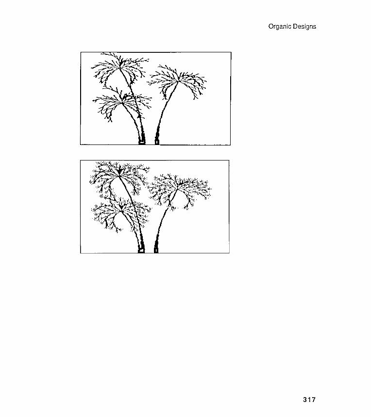
. .
Organic Designs
317
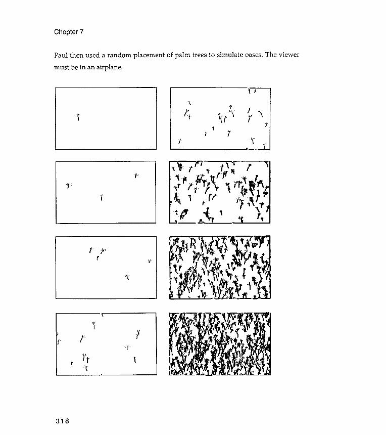
' I
] ,;.: 'y.;:
'f"
Chapter 7
Paul then used a random placement of palm trees to simulate oases. The viewer
must be in an airplane .
;1,
\,
it;. ! :.. (',. "\;"i' ~,. ~ J..~ .. .
-:Ij' .~ (' )''r 1.
~I .. ."."
. \ j'r _ ....
J'" ';111':I I
r ~'.
h;..\
~i'
I!. f : , :' ;'1:-
.
-j';!;, 'I'i-i " '\
. . .
318
Design a Logo tree -drawing procedure that prints a message on the screen to
indicate the level of recursion currently being drawn . Make sure that your tree -
drawing procedure has been slowed down , if necessary , so that the message can
be easily read . You may want to use different pen colors to indicate the differentlevels of recursion .
Produce a complete graphic package that visually illustrates one kind of
recursion ; your package could be an effective teaching tool for introducing
recursion to those with no previous knowledge of it .
Exercise 7.4
Organic Designs
Exercise 7.3
What about leaves? One interesting way to try capturing the color and texturecharacteristics of " leafiness" is to design pointillist trees. What are these? ThePenguin Dictionary of Art and" Artists tells us that "According to the color theoryof neo-impressionism , it is possible to obtain brighter secondary colors, such asgreen, by making a series of tiny blobs of both primaries (which in the case ofgreens would be blue and yellow ) so that the blue and yellow blobs are veryclosely intermingled but are not actually mixed . In this way , the colors mix inthe spectator's eye at a certain distance from the picture , giving a much brighterand clearer green than is possible by actually mixing the pigments on thepalette ."
At least two other sensations are felt by the "spectator" when he or shelooks at a pointillist painting . First, the clouds of dots give the impression thata surface texture exists; the eyes can feel it . And second, the individual dotsfloat in space, giving an illusion of depth . This floating occurs partially becauseof the natural tendency of reds and yellows to move forward and blues to recedefrom the viewer .
319
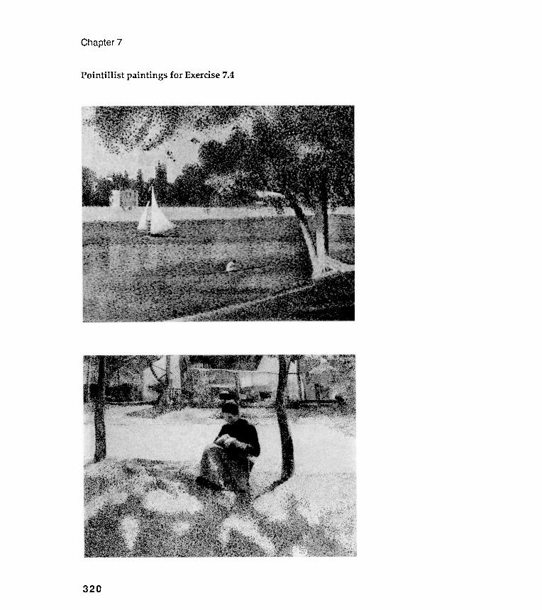
Pointillist paintings for Exercise
Chapter 7
7.4
320
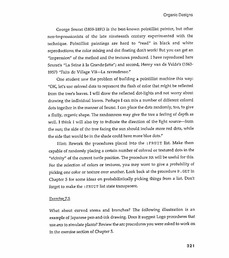
Exercise 7.5
Organic Designs
What about curved sterns and branches? The following illustration is an
example of Japanese pen-and-ink drawing . Does it suggest Logo procedures thatuse arcs to simulate plants? Review the arc procedures you were asked to work onin the exercise section of Chapter 5.
321
George Seurat (1859-1891) is the best-known pointillist painter , but otherneo-impressionists of the late nineteenth century experimented with thetechnique . Pointillist paintings are hard to " read " in black and whitereproductions ; the color mixing and dot floating don't work ! But you can get an"impression " of the method and the textures produced . I have reproduced hereSeurat's "La Seine a la Grande-Jatte" ; and second, Henry van de Velde 's (1863-
1957) "Faits de Village VII - La ravaudeuse."One student saw the problem of building a pointillist machine this way :
"OK, let 's use colored dots to represent the flash of color that might be reflectedfrom the tree's leaves. I will draw the reflected dot -lights and not worry about
drawing the individual leaves. Perhaps I can mix a number of different coloreddots together in the manner of Seurat. I can place the dots randomly , too, to givea fluffy , organic shape. The randomness may give the tree a feeling of depth aswell . I think I will also try to indicate the direction of the light source - fromthe sun; the side of the tree facing the sun should include more red dots, whilethe side that would be in the shade could have more blue dots."
Hint : Rework the procedures placed into the : FRUI T list . Make them
capable of randomly placing a certain number of colored or textured dots in the"vicinity " of the current turtle position . The procedure RR will be useful for this .For the selection of colors or textures, you may want to give a probability of
picking one color or texture over another . Look back at the procedure P . GET inChapter 5 for some ideas on probabilistically picking things from a list . Don 'tforget to make the : FRUIT list state transparent .
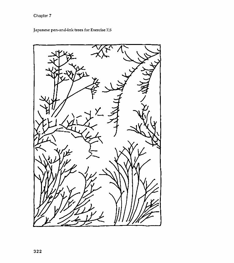
Chapter 7
Japanese pen-and-ink trees for Exercise 7.5
322
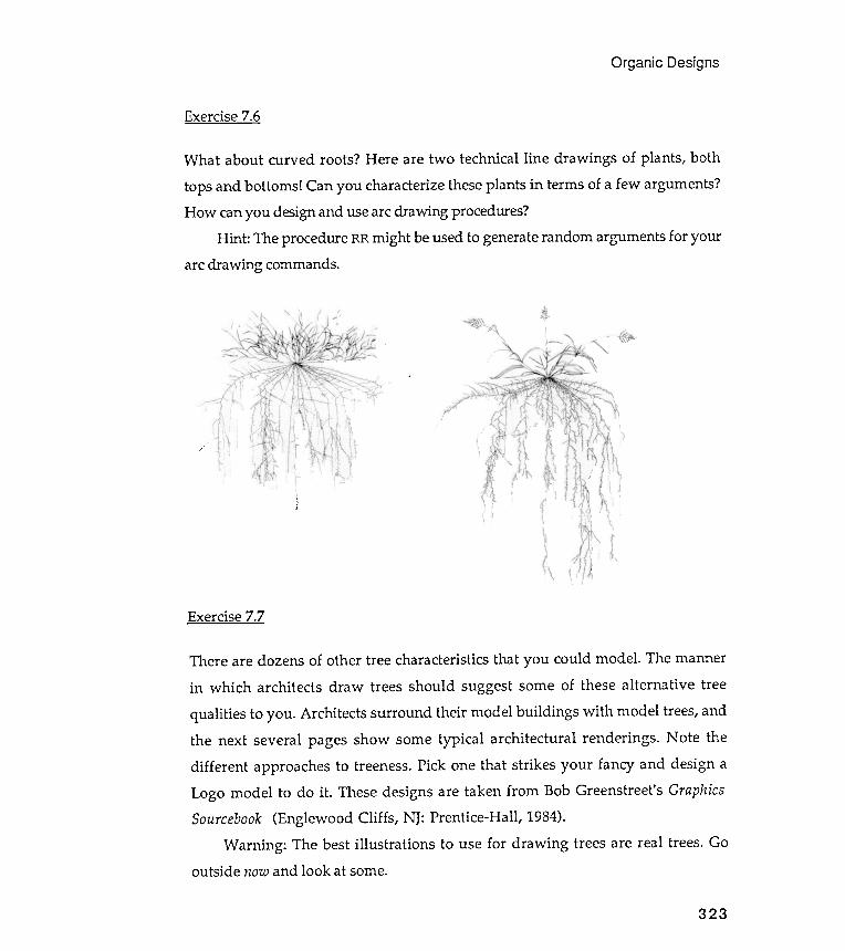
Organic Designs
Exercise 7.6
What about curved roots? Here are two technical line drawings of plants , both
tops and bottoms ! Can you characterize these plants in terms of a few arguments?How can you design and use arc drawing procedures?
Hint : The procedure RR might be used to generate random arguments for yourarc drawing commands.
/'
323
Exercise 7.7
There are dozens of other tree characteristics that you could model . The mannerin which architects draw trees should suggest some of these alternative tree
qualities to you . Architects surround their model buildings with model trees, andthe next several pages show some typical architectural renderings . Note thedifferent approaches to treeness. Pick one that strikes your fancy and design aLogo model to do it . These designs are taken from Bob Greenstreet's GraphicsSourcebook (Englewood Cliffs , NJ: Prentice-Hall , 1984).
Warning : The best illustrations to use for drawing trees are real trees. Gooutside now and look at some.
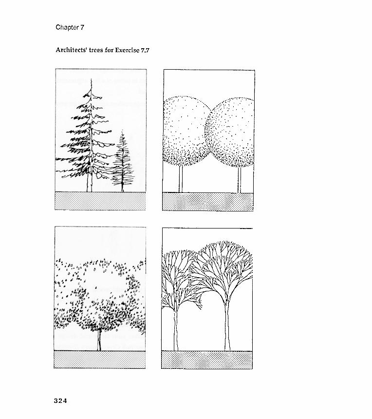
Chapter 7
Architects ' trees for Exercise 7.7
324
:;~.: -:':'., . , \ . " ,
:,'.:' .' . ' . .'ff;.;;::."':...,::.,'.' .' ,'. , " " . ' . . . .
~::~,'.:~.... ,.:,:.::,:.3}~~~~,~~::',::::..' :',. ' , . " vl ' ~( . " " ' . ' . . ' -. .. . ' . . " ~ ., ~" , ., ' . . ' , ' , . 1: , . - ' . . , ,... .tit . ' " . . ~ ,. " , . , 1, . , ' . " ". ' . ' . " " . " ' , . . ' . - . , . . ~ , ,.t" . " " . " " ~." '(o\ "."' "" ." " " ," . . ' . .. . " / : - ~ . ' . . . , . " " . , " - ," " . , ' . . , ' : , I " ' ~J , ~ ' ; ? ' " ' . " ' . . , , , . , , ' . .[!:"A( .! .... ;";";'l "t :!;~ ~,' -'):.~ ~ ~.:'; .: ~ >::::::.,\.'.'
i "~ " " " ;;" " "" V ':..." " . ..." ..' ~ . ' .. ' ...")o: ;. .\ " '-:...." ! " .~ .o;o; " ' ~ ...,,","<--1':""_ .

Exercise 7.9
Former students have done some very interesting " Logo jobs" on fruit and
vegetables. Some vegetables literally cry out for recursive techniques. You don'tbelieve me? Go look at some artichokes, cauliflower , broccoli , asparagus! Othersscream for the " oid " treatment introduced in Chapter 4 with nephrQi.d.s and
cardiQi.d.s: go look at apples, pineapples , oranges, carrots, bananas, carrots,radishes, leeks, and turnips .
Design Logo procedures to produce a suite of designs based on thecharacteristics of a single favorite (or hated) fruit or vegetable. No visual hints
here: go look at the real thing .
Organic Designs
Exercise 7.8
Imagine yourself looking across a small lake. A single tree is growing on theshore just opposite you. It is night, but a full moon illuminates the tree and thisimage is reflected in the water. A breeze agitates the surface of the water.Design a Logo model that draws both the tree and its reflection in the lake.Include an argument for the velocity of the breeze.
Exercise 7.10
Pick two different fruits , vegetables, or trees. Show how a single Logo procedurecan draw either of the two items, as well as shapes exhibiting characteristics ofboth .
For example, suppose you picked a pine tree and a cauliflower . Your Logo
procedures must be capable of drawing both a pine tree and a cauliflower . Butyour procedures must also draw figures (" caulipines " ?) that are transitionalbetween a pine tree and a cauliflower (a pine tree on its way to becoming acauliflower ). Or a cauliflower metamorphosing into a pine tree.
325
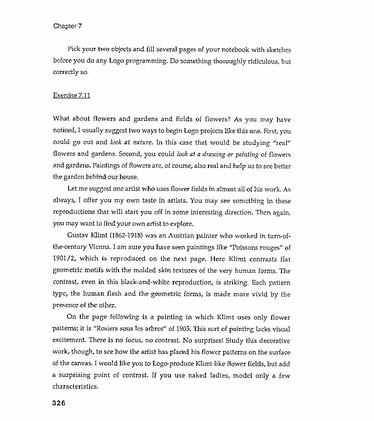
Chapter 7
Pick your two objects and fill several pages of your notebook with sketches
before you do any Logo programming . Do something thoroughly ridiculous , but
correctly so.
Exercise 7.11
326
What about flowers and gardens and fields of flowers ? As you may havenoticed, I usually suggest two ways to begin Logo projects like this one. First, youcould go out and look at nature. In this case that would be studying "real"flowers and gardens. Second, you could look at a drawing or painting of flowersand gardens. Paintings of flowers are, of course, also real and help us to see betterthe garden behind our house.
Let me suggest one artist who uses flower fields in almost all of his work . As
always , I offer you my own taste in artists . You may see something in thesereproductions that will start you off in some interesting direction . Then again,you may want to find your own artist to explore.
Gustav Klimt (1862-1918) was an Austrian painter who worked in turn -of-the-century Vienna . I am sure you have seen paintings like "Poissons rouges" of1901/ 2, which is reproduced on the next page. Here Klimt contrasts flatgeometric motifs with the molded skin textures of the very human forms . Thecontrast , even in this black-and-white reproduction , is striking . Each patterntype, the human flesh and the geometric forms , is made more vivid by thepresence of the other.
On the page following is a painting in which Klimt uses only flowerpatterns; it is "Rosiers sous les arbres" of 1905. This sort of painting lacks visualexcitement . There is no focus, no contrast. No surprises ! Study this decorativework , though , to see how the artist has placed his flower patterns on the surfaceof the canvas. I would like you to Logo-produce Klimt -like flower fields , but add
a surprising point of contrast . If you use naked ladies , model only a fewcharacteristics .
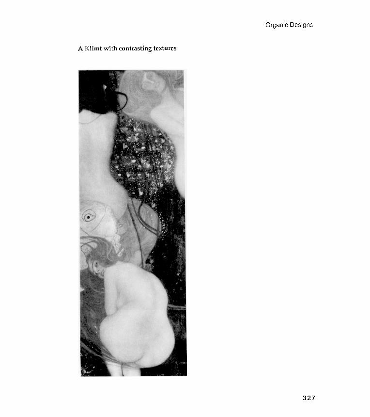
Organic Desig
Klimt
:) U>
~ ..... - ~ n 0 ~ - ~ ~ U1 - ..... ~ OQ - r'J ~ = ~ r'J U1>
CoA)
~ "'..J
Chapter 7
A decorative Klimt~ N Q)
Try modeling one specific flower . Pickpersonality , one that can be easily identifiedsunflowers , hollyhocks , iris , daffodils , tulips ,
Exercise 7.14
Organic Designs
Exercise 7.12
Exercise 7.13
Surround your plants with a few insects . Butterflies , moths , ladybugs ,dragonflies , beetles, and fireflies might be nice.
Exercise 7.15
What could be more organic and more relevant to visual modeling than the
human eyeball? Take a close look at your own eyes in the mirror . Make specialnote of the colors and patterns in your irises. Usually , on close inspection , youwill find that your two eyes are different from each other and quite irregular inthemselves. Design a Logo model of your own eyeballs. Generalize it to simulatea wide range of eyes that include those of your cat and tropical fish .
329
a flower that has a vivid visual
from a distance . Some suggestions :
daisies , lilies .
We 've avoided animals so far . But what about some odd sea creatures ? There is
a snail -like creature among the imaginary P IPEGONS of Chapter 2. Find an
illustrated text on sea creatures and model something like squids , jelly fish , sea
urchins , or sea anemones . Something living inside shells might be a challenge ,
too . Keep the modeled sea creature characteristics few in number - at the start .

Chapter 7
Exercise 7.16
"l W
2
85330
Recall the FRACTALGONs of Chapter 4. We changed polygons into FRACTALGONsby changing the nature of their edges. We replaced the polygon 's single ,straight -line edge with an edge composed of four straight -line segments. Wethen replaced each of these four straight -line segment with a smaller , four -segment edge. And then each of these segments was replaced with smaller, four -segment sections. We continued to break down - or fractal- single line segmentsinto multiple line segments until we arrived at the odd, fuzzy shapes illustratedunder the heading "Some curious FRACTALGONs" in Chapter 4.
There was nothing special about replacing the straight polygonal edgewith a four -segment shape; we could have used other pattern combinations ofstraight -line segments. But no matter what edge shape we selected, we wouldhave followed the fractal scheme of replacing the parts of an edge withminiaturized versions of the overall edge pattern .
Let's experiment with an alternative edge pattern , and let 's also introducesome randomness into fractal designing . Take a look at the following figures .Can you guess what is happening before reading the description below?
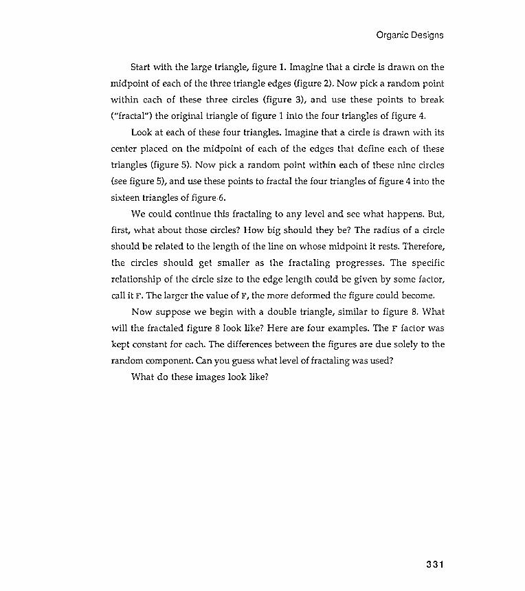
Organic Designs
331
Start with the large triangle , figure 1. Imagine that a circle is drawn on themidpoint of each of the three triangle edges (figure 2). Now pick a random pointwithin each of these three circles (figure 3), and use these points to break("fractal " ) the original triangle of figure 1 into the four triangles of figure 4.
Look at each of these four triangles . Imagine that a circle is drawn with itscenter placed on the midpoint of each of the edges that define each of thesetriangles (figure 5). Now pick a random point within each of these nine circles(see figure 5), and use these points to fractal the four triangles of figure 4 into thesixteen triangles of figure 6.
We could continue this fractaling to any level and see what happens. But,first , what about those circles? How big should they be? The radius of a circleshould be related to the length of the line on whose midpoint it rests. Therefore,the circles should get smaller as the fractaling progresses . The specificrelationship of the circle size to the edge length could be given by some factor,call it F. The larger the value of F, the more deformed the figure could become.
Now suppose we begin with a double triangle , similar to figure 8. Whatwill the fractaled figure 8 look like ? Here are four examples. The F factor waskept constant for each. The differences between the figures are due solely to therandom component. Can you guess what level of fractaling was used?
What do these images look like ?
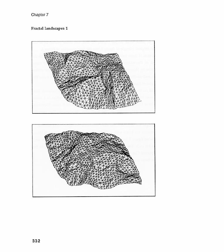
Chapter 7
Fractallandscapes 1
332
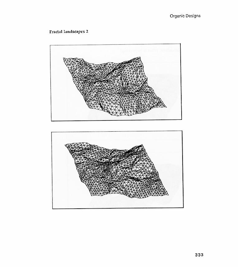
Organic Designs
Fractallandscapes 2
333
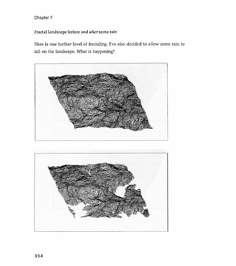
Chapter 7
I' ve also decided to allow some rain to
334
Fractallandscape before and after some rain
Here is one further level of fractaling .fall on the landscape. What is happening ?
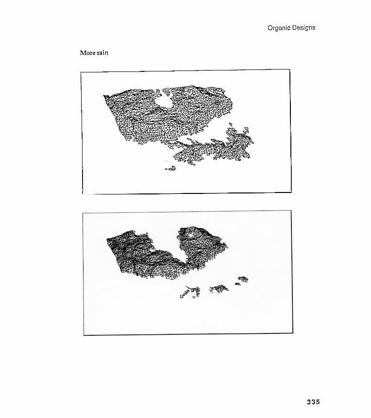
Organic Designs
More rain
(..)
(..) U1
, ~
Chapter 7
What 's going on here? Are these scenes really mountainous ? The last figurelooks like a scene you might see flying into Hong Kong . Why does the eye readthese figures as three-dimensional ? Where is the eye in relation to these scenes?
How would you color in all those little triangles so that they won 't look somuch like chicken wire ? How many triangles are there, by the way , in those
figures? Recursion is obviously being used; can you give the number of triangles interms of recursion level?
Can you put together a plan for experimenting with these visual ideas?What about a fractal mountain machine; would that be possible? What do you
think the major problems would be? Put together some exploratory buildingplans .
336
Chapter 8Space
"The question [is] whether space is real apart from space-filling objects."W. T. Harris
Reading objects in space
Most of our work so far has been flat and two -dimensional . Our only realexcursion into planning depth characteristics was the overlapping Islamic tiledesigns of Chapter 6. But even this was really only two -dimensional motifmanipulation . However , even though we haven't been much concerned withspatial modeling , some of our line drawings occasionally seemed to float intothree dimensions : recall some of the lacy, random tree shapes of Chapter 7and- especially- the nephroid designs of Chapter 4.
Take a look at the series of circle-based nephroids below . Even though youknow that these are perfectly flat figures , do you have the impression that theyare also three-dimensional and that one nephroid can actually be placed insideanother? Why is this? Nephroids are ambiguous shapes (flat and rounded ), butbecause the brain lives and works in a three-dimensional world , it resolves the
two -dimensional ambiguity of nephroids by placing them fully into 3D space;nephroids are good examples of the brain adding space in order to read an objectbetter. Spend some time following the lines of these odd images.
Chapter 8
Intentional depth cues
338
This chapter will concentrate on some of the ways in which depthcharacteristics can be explicitly designed into object scenes. Art students alreadyknow how two -dimensional paper and canvas can be made to simulate spacethrough a wide variety of methods and systems, many quite arbitrary . Theyknow this because they have played with alternative spatial systems andconventions . If you are not an art student , you may be coming upon these ideaswithout such first -hand experience. So, before you are ready to incorporatedepth cues into modeled scenes, you need to explore how your eyes read andinterpret different forms of depth information .
We will be looking at several depth cues in this chapter : placement ,shading , size variation , shape overlapping , and vanishing point perspective .The models of the chapter provide environments in which you can watchyourself reacting to messages from things in space.
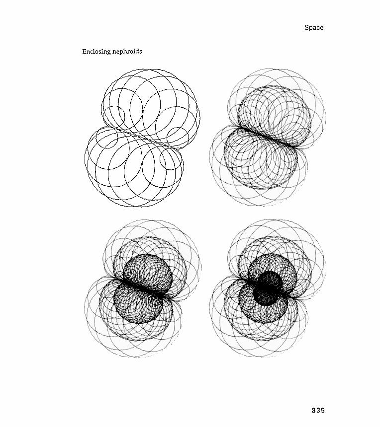
Space
Enclosing nephroids
339
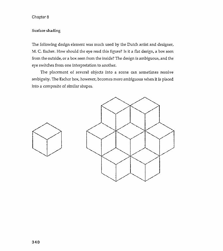
Chapter 8
Surface shading
The following design element was much used by the Dutch artist and designer,M . C. Escher. How should the eye read this figure ? Is it a flat design, a box seenfrom the outside, or a box seen from the inside? The design is ambiguous, and theeye switches from one interpretation to another.
The placement of several objects into a scene can sometimes resolveambiguity . The Escher box, however , becomes more ambiguous when it is placedinto a composite of similar shapes.
340
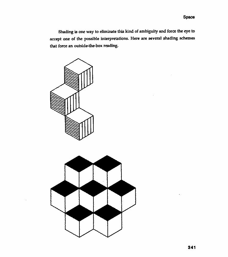
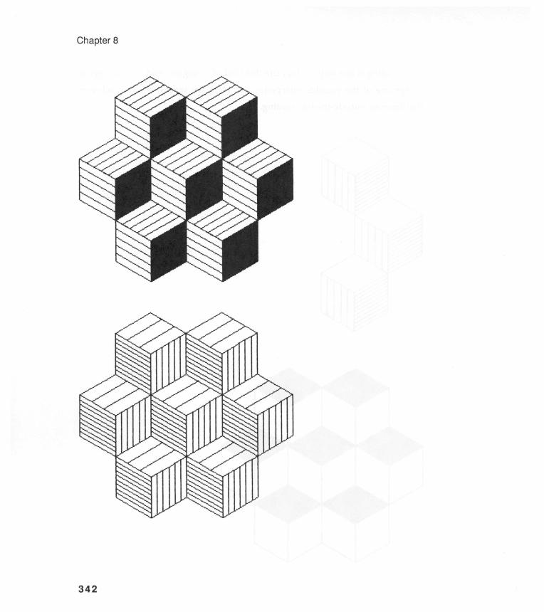
C) CD co
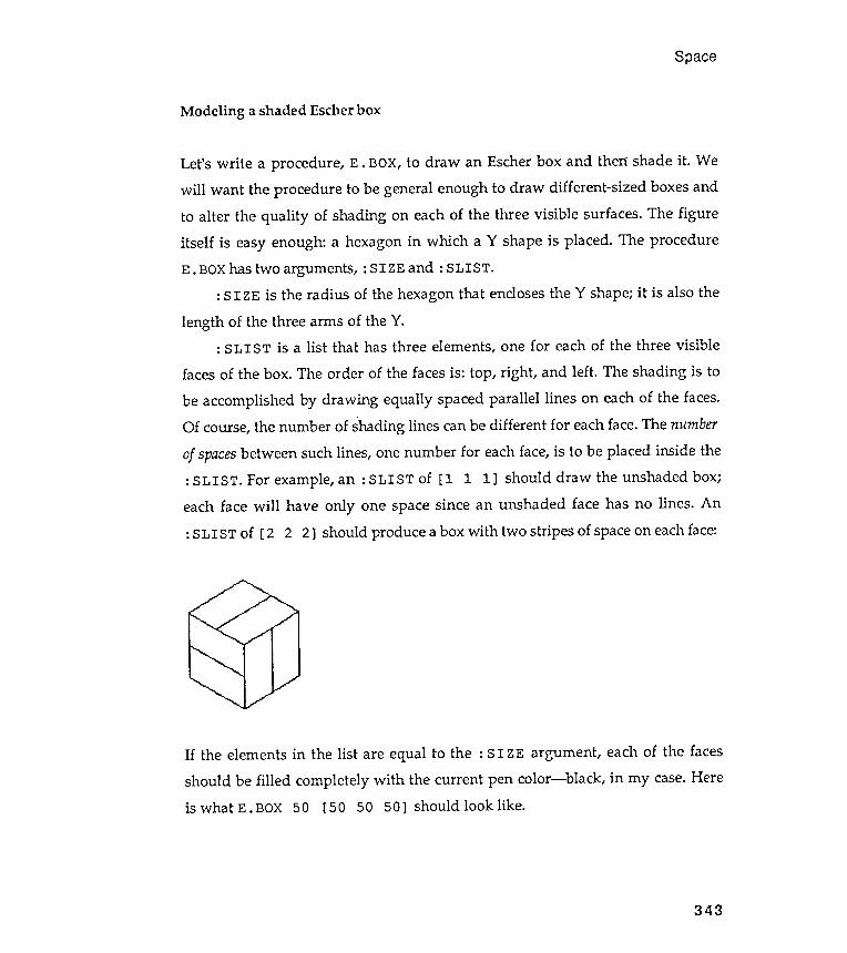
Modeling
Space
a shaded Escher box
343
Let's write a procedure , E . BOX, to draw an Escher box and then shade it . Wewill want the procedure to be general enough to draw different -sized boxes andto alter the quality of shading on each of the three visible surfaces. The figureitself is easy enough: a hexagon in which a Y shape is placed. The procedureE . BOX has two arguments , : SIZE and : SLIST .
: SIZE is the radius of the hexagon that encloses the Y shape; it is also the
length of the three arms of the Y.: SLI ST is a list that has three elements , one for each of the three visible
faces of the box. The order of the faces is: top, right , and left . The shading is to
be accomplished by drawing equally spaced parallel lines on each of the faces.Of course, the number of shading lines can be different for each face. The number
of spaces between such lines, one number for each face, is to be placed inside the: SLI ST. For example, an : SLI ST of [ 1 1 1] should draw the unshaded box;each face will have only one space since an unshaded face has no lines . An: SLIST of [ 2 2 2] should produce a box with two stripes of space on each face:
If the elements in the list are equal to the : SIZE argument , each of the facesshould be filled completely with the current pen color- black, in my case. Hereis what E . BOX 50 [ 50 50 50 ] should look like .
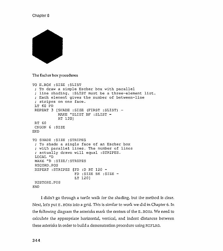
The Escher box procedures
Chapter 8
TO E .BOX : SIZE : SLIST; To draw a simple Escher box with parallel; line shading . : SLIST must be a three - element list .; Each element gives the number of between - line; stripes on one face .LT 60 PDREPEAT 3 [ SHADE : SIZE (FIRST : SLIST ) -
RT 60CNGON6 : SIZE
TO SHADE : SIZE : STRIPES; To shade a single face of an Escher box
RESTORE.POS
I didn 't go through a turtle walk for the shading , but the method is clear.Next, let 's put E . BOXs into a grid . This is similar to work we did in Chapter 6. Inthe following diagram the asterisks mark the centers of the E . BOXS. We need tocalculate the appropriate horizontal , vertical , and indent distances betweenthese asterisks in order to build a demonstration procedure using RIFLAG.
344
MAKE "SLIST BF :SLISTRT 120]
END
; with parallel lines . The; actually drawn will equalLOCAL liDMAKE liD : SIZE / : STRIPES
number of: STRIPES .
lines
END
RECORD.POSREPEAT :STRIPES [FD :D RT 120 -
FD : SIZE BK :SIZELT 120]
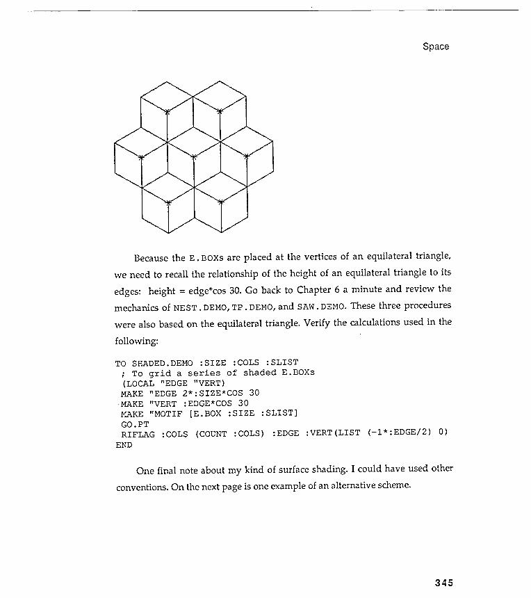
Space
345
Because the E . BOXs are placed at the vertices of an equilateral triangle ,we need to recall the relationship of the height of an equilateral triangle to its
edges: height = edge*cos 30. Go back to Chapter 6 a minute and review themechanics of NEST. DEMO, TP . DEMO, and SAW. DEMO. These three procedures
were also based on the equilateral triangle . Verify the calculations used in thefollowing :
TO SHADED . DEMO : SIZE : COLS : SLIST
; To grid a series of shaded E . BOXs( LOCAL " EDGE " VERT )
MAKE " EDGE 2 * : SIZE * COS 30-MAKE " VERT : EDGE * COS 30MAKE " MOTIF [ E . BOX : SIZE : SLIST ]GO . PT
RIFLAG : COLS ( COUNT : COLS ) : EDGE : VERT ( LIST ( - 1 * : EDGE / 2 ) 0 )END
One final note about my kind of surface shading . I could have used otherconventions. On the next page is one example of an alternative scheme.
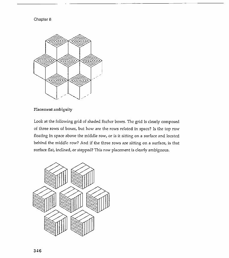
- .- - " ~
Look at the following grid of shaded Escher boxes . The grid is clearly composed
of three rows of boxes , but how are the rows related in space ? Is the top row
floating in space above the middle row , or is it sitting on a surface and located
behind the middle row ? And if the three rows are sitting on a surface , is that
surface flat , inclined , or stepped ? This row placement is clearly ambiguous .
.
Chapter 8
Placement ambiguity
346
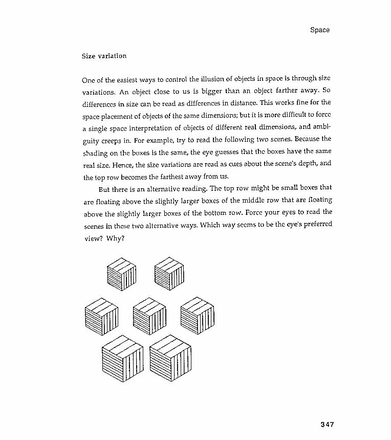
Space
Size variation
C> e
347
One of the easiest ways to control the illusion of objects in space is through sizevariations . An object close to us is bigger than an object farther away . Sodifferences in size can be read as differences in distance. This works fine for the
space placement of objects of the same diIriensions; but it is more difficult to forcea single space interpretation of objects of different real dimensions , and ambi-guity creeps in . For example, try to read the following two scenes. Because theshading on the boxes is the same, the eye guesses that the boxes have the samereal size. Hence, the size variations are read as cues about the scene's depth, and
the top row becomes the farthest away from us.But there is an alternative reading . The top row might be small boxes that
are floating above the slightly larger boxes of the middle row that are floatingabove the slightly larger boxes of the bottom row . Force your eyes to read thescenes in these two alternative ways. Which way seems to be the eye's preferred
view ? Why ?

~ ~Chapter 8
Multiple motif grids
Can you guess how the last scenes were produced ? I tinkered with the gen-eralized grid machine RIFLAG so that it could draw grids of multiple motifs . Iwanted to have a different motif on each row . Then I could draw rows of
different -sized (or shaded) E . BOXs to explore the illusion of receding objects . . .or whatever . I include my modified procedure to remind you about the usefulnessof tinkering with the machinery you already possess, to make procedures dotheir jobs a little differently .
The modified machine is called RIM . FLAG for recursive , indented ,
multiple -motif flag . It expects a composite motif list that is composed of severallist elements: there must be one motif list for each row . For example, this wasthe motif list used for one of the previous scenes.
MAKE "MOTIF [ [E.BOX . 5* : SIZE [3 6 9] ][E.BOX . 7* : SIZE [3 6 9] ][E.BOX :SIZE [3 6 9] ] ]
-
-
Here is RIM . FLAG and its supporting procedures.
348
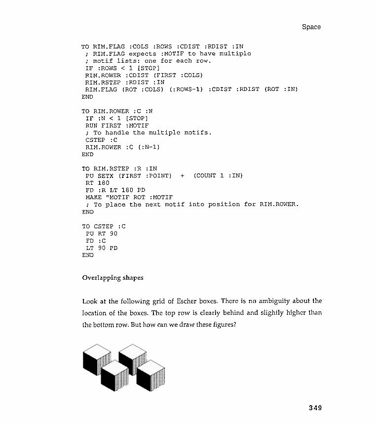
TO RIM . ROWER : C :NIF :N < 1 [ STOP]RUN FIRST :MOTIF; To handle the multipleCSTEP : CRIM .ROWER : C ( :N- l )
END
Overlapping shapes
figures?
Space
TO RIM . FLAG : COLS : ROWS : CDIST : RDIST : IN; RIM . FLAG expects : MOTIF to have multiple; motif lists : one for each row .
:CDIST : RDIST (ROT : IN )
motifs .
TO RIM.RSTEP :R : INPU SETX (FIRST :POINT) + (COUNT 1 : IN )RT 180FD :R LT 180 PDMAKE "MOTIF ROT : MOTIF; To place the next motif into position for RIM.ROWER.
END
TO CSTEPPO RT 90FD :CLT 90 PD
END
: c
There is no ambiguity about thebehind and slightly higher than
349
IF :ROWSRIM.ROWERRIM.RSTEPRIM.FLAG
END
Look at the following grid of Escher boxes .
location of the boxes . The top row is clearly
the bottom row . But how can we draw these
< 1 [ STOP ]
: CDIST ( FIRST : COLS )
: RDIST : IN
( ROT : COLS ) ( : ROWS - l )
Chapter 8
The painter's algorithm
RTEND
60
TO NIGHT . SHADE : SIZE
RECORD . POS
PENERASE
; Depending on your computer and Logo dialect , you may
; you may have to increase the pen width
; to erase the box space
REPEAT : SIZE [ FD 1 RT 120
FD : SIZE BK
LT 120 ]
RESTORE . POS
PENPAINT
350
END
fully .: SIZE
What we need is the so- called painter 's algorithm . Why so-called? Because themethod was dreamed up by computer scientists; this is how they think paintershandle overlapping scenes. Hence the algorithm 's instructions for the painter -turtle . First , determine which objects are farthest from the viewer and paintthese onto the canvas. Then determine the objects just in front of the painted
objects and paint those onto the canvas. Continue with this layering until youhave included everything in the scene up to the viewer 's nose. Use opaque paint ,though , so that no object appears peeking through a layer of paint . Is this howhuman painters really work ? Could they do it this way if they wanted to?
Whether or not this is the method real painters use , let 's build a visual
model using it and then draw some overlapping shapes. The first problem weencounter is how to make the turtle paint shapes that are totally opaque. Hereis one way . Select the screen position where you want to draw a shape. Eraseeverything within the outline of the shape and then draw the shape onto this"opaque spot." The following procedures handle these tasks for E. BOXs.
TO BLACK . BOX : SIZE
; To erase everything within the outline of an E . BOX .LT 60
REPEAT 3 [ NIGHT . SHADE : SIZE -RT 120 ]
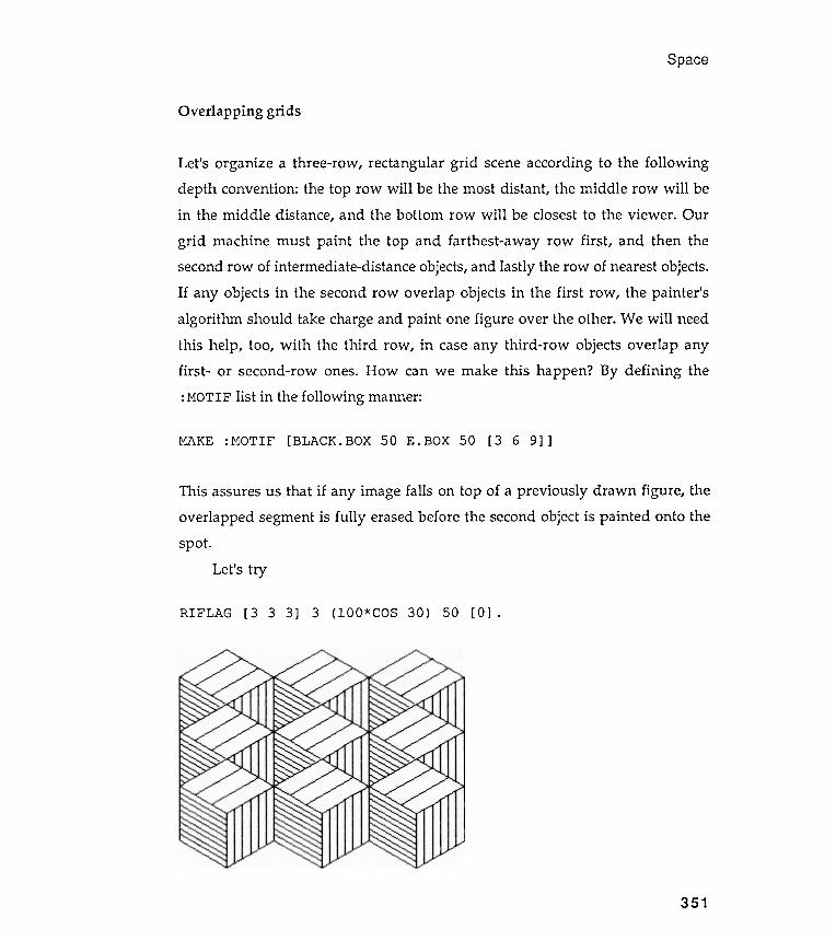
This assures us that if any image falls on top of a previously drawn figure , theoverlapped segment is fully erased before the second object is painted onto thespot .
Let's try
Space
Overlapping grids
RIFLAG [3 3 3] 3 (lOO*COS 30) 50 [0] .
351
Let's organize a three-row , rectangular grid scene according to the followingdepth convention : the top row will be the most distant , the middle row will bein the middle distance , and the bottom row will be closest to the viewer . Our
grid machine must paint the top and farthest -away row first , and then thesecond row of intermediate -distance objects, and lastly the row of nearest objects.If any objects in the second row overlap objects in the first row , the painter 'salgorithm should take charge and paint one figure over the other . We will needthis help , too, with the third row , in case any third -row objects overlap anyfirst - or second-row ones. How can we make this happen ? By defining the: MOTIF list in the following manner:
MAKE : MOTIF [ BLACK . BOX 50 E . BOX 50 [ 3 6 9 ] ]
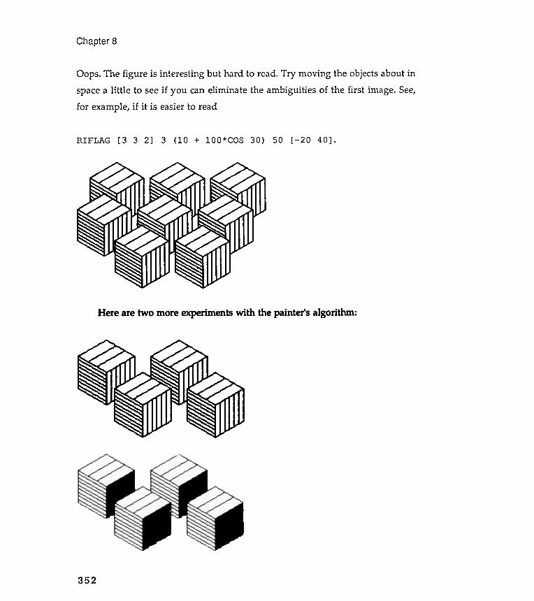
Chapter 8
RIFLAG [3 3 2] 3 (10 + 100*COS 30) 50 [- 20 40] .
352
Oops. The figure is interesting but hard to read. Try moving the objects about inspace a little to see if you can eliminate the ambiguities of the first image. See,for example, if it is easier to read
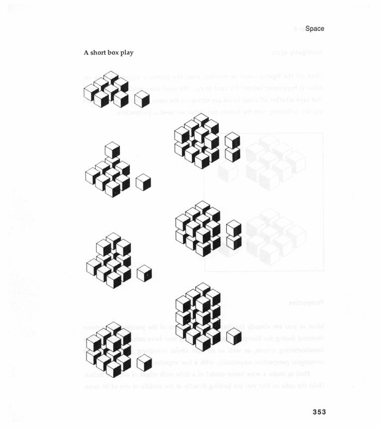
Space
A short box play
353
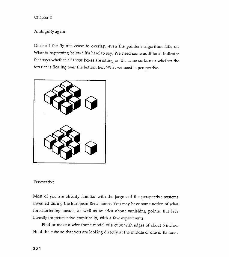
Once all the figures cease to overlap , even the painter 's algorithm fails us.What is happening below ? It 's hard to say. We need some additional indicatorthat says whether all those boxes are sitting on the same surface or whether the
top tier is floating over the bottom tier . What we need is perspective.
Perspective
Most of you are already familiar with the jargon of the perspective systemsinvented during the European Renaissance. You may have some notion of whatforeshortening means, as well as an idea about vanishing points . But let 'sinvestigate perspective empirically , with a few experiments .
Find or make a wire frame model of a cube with edges of about 6 inches.Hold the cube so that you are looking directly at the middle of one of its faces.
Chapter 8
Ambiguity again
354
(0
lS:J
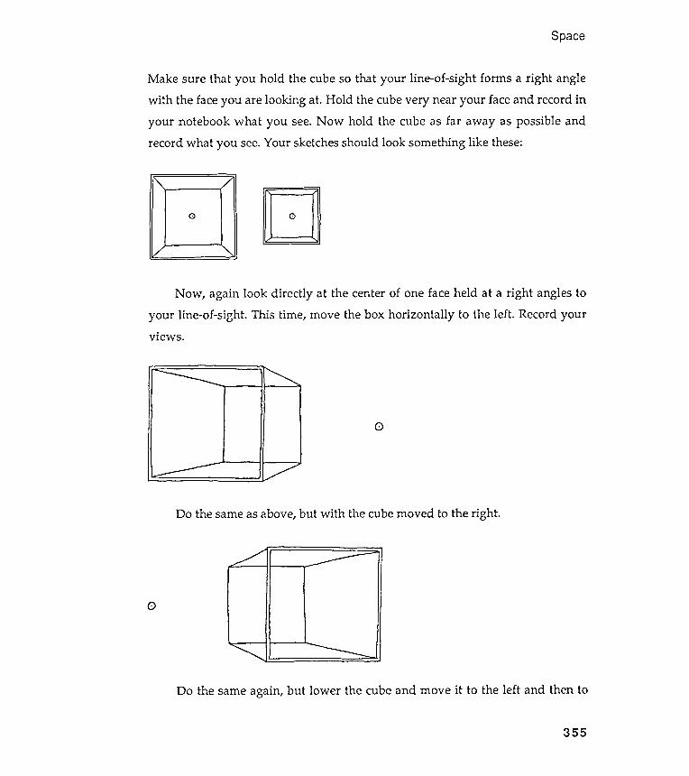
Space
Make sure that you hold the cube so that your line -of -sight forms a right angle
with the face you are looking at . Hold the cube very near your face and record in
your notebook what you see. Now hold the cube as far away as possible and
record what you see. Your sketches should look something like these :
0 D
0
Do the same as above, but with the cube moved to the right .
0
Do the same again, but lower the cube and move it to the left and then to
355
Now , again look directly at the center of one face held at a right angles to
your line -of -sight . This time , move the box horizontally to the left . Record yourviews .

Chapter 8
the right :
356
0 0
0 ~ (D I
~ 0 ~.
~ - ~ (D ~ ~ (D
n - ~.
< (D
0
0
0
You have just been witness to the operation of one-point perspective. Thefollowing sketches indicate the construction of a cube drawn with one-pointperspective. Where is the viewer in each of these drawings?
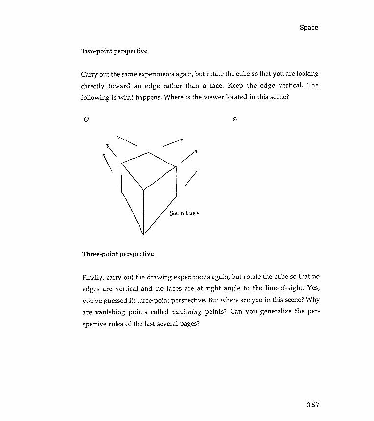
Three-point perspective
Space
Two -point perspective
Carry out the same experiments again , but rotate the cube so that you are looking
directly toward an edge rather than a face . Keep the edge vertical . The
following is what happens . Where is the viewer located in this scene?
G <:)
' " .........~/ '\ / "
50 \.10 Cu BE
\/
357
Finally , carry out the drawing experiments again, but rotate the cube so that noedges are vertical and no faces are at right angle to the line -of-sight . Yes,you 've guessed it : three-point perspective. But where are you in this scene? Whyare vanishing points called vanishing points ? Can you generalize the per-spective rules of the last several pages?
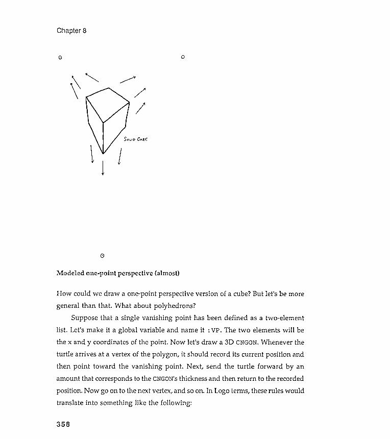
How could we draw a one-point perspective version of a cube? But let 's be moregeneral than that . What about polyhedrons ?
Suppose that a single vanishing point has been defined as a two -elementlist . Let 's make it a global variable and name it : VP. The two elements will bethe x and y coordinates of the point . Now let's draw a 3D CNGON. Whenever theturtle arrives at a vertex of the polygon , it should record its current position andthen point toward the vanishing point . Next , send the turtle forward by anamount that corresponds to the CNGON's thickness and then return to the recordedposition . Now go on to the next vertex, and so on. In Logo terms, these rules wouldtranslate into something like the following :
Chapter 8
00
' "
~ / ' "
//
SOl-It> CI-\&E:
~
~
1
0
Modeled one-point perspective (almost)
358
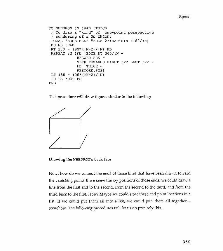
paces
TO NHEDRON :N :RAD : THICK; To draw a " kind " of one - point perspective; rendering of a 3D CNGON.LOCAL " EDGE MAKE " EDGE 2* : RAD* SIN (180 / :N)
(90* ( :N- 2) / :N) PD-
REPEAT :N [FD :EDGE RT 360/ :N-
SETH TOWARDS FIRST :VP LAST :VP-
RESTORE.POS]LT 180 - (90* ( :N- 2) / :N)PU BK :RAD PD
END
This procedure will draw figures similar to the following :
Drawing the NHEDRON'S back face
Now , how do we connect the ends of those lines that have been drawn toward
the vanishing point ? If we knew the x-y positions of those ends, we could draw aline from the first end to the second, from the second to the third , and from the
third back to the first . How ? Maybe we could store these end point locations in alist . If we could put them all into a list , we could join them all together -somehow. The following procedures will let us do precisely this.
359
PU FDRT 180
: RAD
RECORD. POS
FD : THICK
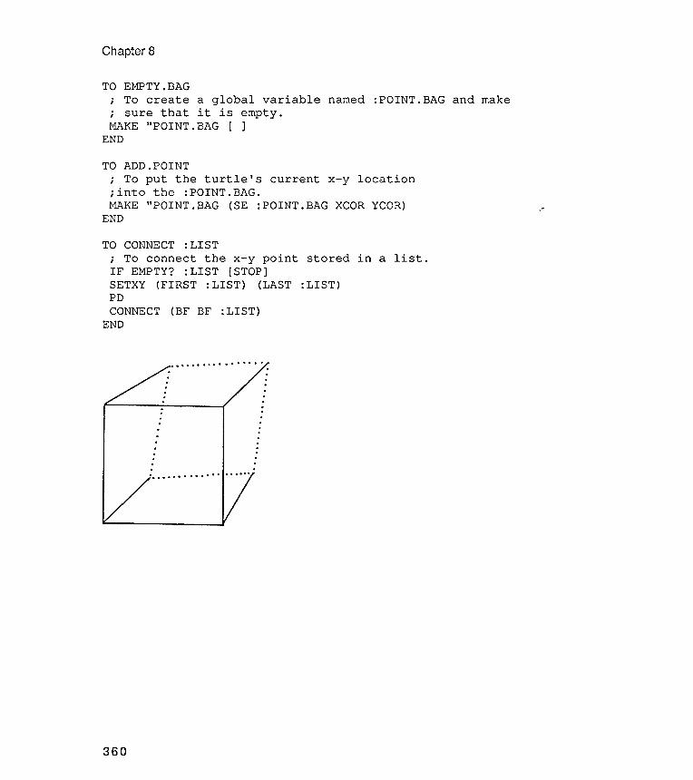
TO EMPTY.BAG; To create a global variable named :POINT.BAG and make; sure that it is empty .MAKE "POINT. BAG [ ]
END
MAKE "POINT. BAG (SE : POINT. BAG XCOR YCOR) ,-END
Chapter 8
TO ADD. POINTi To put the turtle ' s current x - y location
TO CONNECT : LIST; To connect the x - y point stored in a list .IF EMPTY? : LIST [STOP]SETXY (FIRST : LIST ) (LAST : LIST )PDCONNECT (BF BF : LIST )
END
..
..
..
..
..
..
.
. . . . . . . . . . . . . .
..
..
..
.
360
: into the :POINT.BAG.
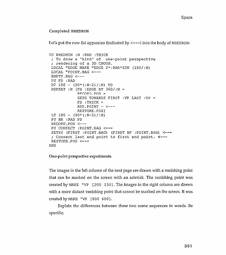
Space
Completed NHEDRON
Let's put the new list apparatus (indicated by <- - - ) into the body of NHEDRON:
TO
SETH TOWARDS FIRST :VP LAST :VP
< - - -
< - - -
The images in the left column of the next page are drawn with a vanishing pointthat can be marked on the screen with an asterisk . The vanishing point wascreated by MAKE "VP [ 2 0 0 150 ] . The images in the right column are drawnwith a more distant vanishing point that cannot be marked on the screen. It was
created by MAKE "VP [ 800 600 ] .Explain the differences between these two scene sequences in words . Be
specific .
361
RECORD. PO.'>
FD :THICK -ADD.POINT -RESTORE.POS]
LT 180 - (90* ( :N- 2) / :N)PU BK :RAD PDRECORD. POSPU CONNECT < - - -
; Connect lastRESTORE . POS < - - -
END
NHEDRON : N : RAD : THICK
; To draw a " kind " of one - point perspective
; rendering of a 3D CNGON .
LOCAL " EDGE MAKE " EDGE 2 * : RAD * SIN ( 180 / : N )
LOCAL " POINT . BAG < - - -
EMPTY . BAG < - - -
PU FD : RAD
RT 180 - ( 90 * ( : N - 2 ) / : N ) PD
REPEAT : N [ FD : EDGE RT 360 / : N
(FIRST BF :POINT . BAG)to first end point .
< - - -
: POINT . BAG
SETXY ( FIRST : POINT . BAG )
end point
One - point perspective experiments
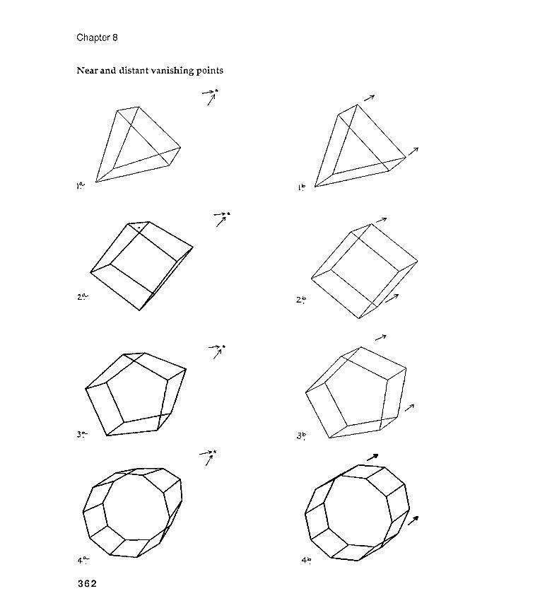
distan
Chapter 8
Near and It vanishing points
~\ *
,..;'1
?
-:,.~/
l ~
~
2.~
,....;"
~\
~i--
--
..;"
4-0:-
362
It :"
2..~
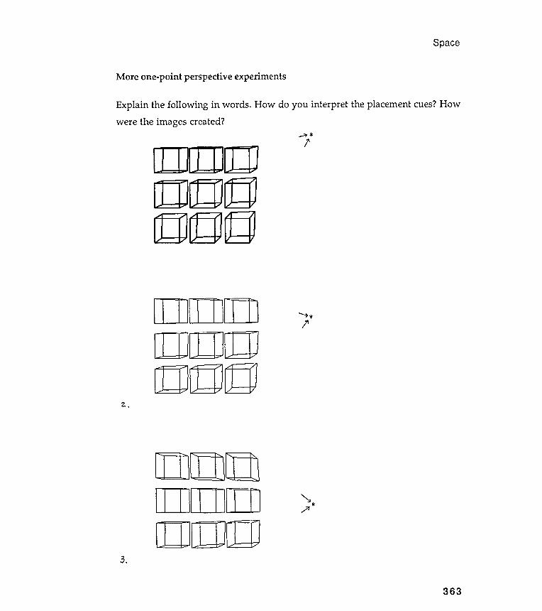
Space
More one -point perspective experiments
Explain the following in words . How do you interpret the placement cues? How
were the images created ?~
f,).
.
~ *.,,?I
363
[IIJ[ ] [ ][IJ[ ] [I][ ] [J][Q
[]][IJILIJ[ ] [ ] [ ][ ] [ ] []J]
--,, *l '
~ *l '

(2)c00
Chapter 8
Tumbling NHEDRONs
~~~~~
'<2>tl:ll!]:J)
~~~~~
~tl:l;{t:JJ
~~~~~
~~
~ ~ 0a000
~~~~~
00~~~~
Q000
364
~!l:JJ~lDJ~ ~ ~1lJJ[] Q; ~
~~~~
Qa000
<q]~"'<tl~~~<cD~~~
NHEDRON doesn 't really draw correctly , does it ? The one -point perspective
system that NHEDRON uses is not classical one -point perspective . The line
lengths aren 't correct , and shapes near the vanishing point are badly deformed .
But does this matter if you can read the placement message ? NHEDRON 'S
deformations are space data , after all , and rather more expressionistic than
" correct " foreshortenings .
What is most important : to draw a scene exactly as it would look on a
photograph or to express the quality of its space relationships in a way that
might be understandably original ? You know my answer . If you want a
photograph of cubes , that 's OK . If you want to think about cubes in space, then
consider building a space-cube model with a bizarre perspective system .
Recapitulation
This chapter introduced the idea of adding depth cues to images. We modeled
Space
NHEDRON " mistakes "
365
several varieties of such cues so that you could see how your eyes responded to
them . I hope you were surprised , and pleased , to be able to watch yourself doing
something about which you probably had little previous knowledge . Visual
modeling can be very tricky and very revealing .
And now that you have learned something about your eye 's conception of
space, work with your new colleague on the exercises that follow .
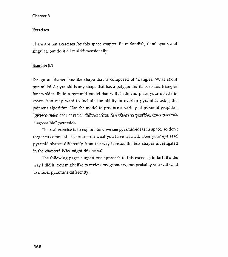
Chapter 8
Exercises
366
There are ten exercises for this space chapter. Be outlandish , flamboyant , andsingular , but do it all multidimensionally .
Exercise 8 .1
Design an Escher box-like shape that is composed of triangles . What aboutpyramids ? A pyramid is any shape that has a polygon for its base and trianglesfor its sides. Build a pyramid model that will shade and place your objects inspace. You may want to include the ability to overlap pyramids using thepainter 's algorithm . Use the model to produce a variety of pyramid graphics .~ fnve to m ~ f<e eaTh ~~elle ~s tl )~~e' te! l\ ' troTh \' :ne <Ij& eY~ d ~ 1>' lf~~}ull'"t:", ~ ' U7{\ "\Jv<t::i \Wf ..
" jrnnossjbIe " nvramids .. . .. . .. ."
The real exercise is to explore how we see pyramid -ideas in space, so don 'tforget to comment- in prose - on what you have learned . Does your eye readpyramid shapes differently from the way it reads the box shapes investigatedin the chapter? Why might this be so?
The following pages suggest one approach to this exercise; in fact, it 's theway I did it . You might like to review my geometry , but probably you will wantto model pyramids differently .
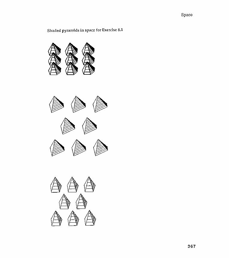
Space
Shaded pyramids in space for Exercise 8.1
367
~ ~ ~. ~
~ ~ ~~ ~ ~~ ~
(/!}~ ~
Study the following figures . Imagine that the pyramid is hung , like aChristmas tree ornament , from its apex. See figure 1 on the next page. Image theturtle to be at position (1), pointing downward . If we can tell the turtle how todraw the leftmost triangular face of the pyramid , it will know how to draw theremaining ones.
But first , how shall we define the shape characteristics of the pyramidthat we want the turtle to draw ? See figure 2. I have selected the lengths of thevisible edges of the pyramid (the "a" s) and the angles that separate theseedges (the "a"s).
Second, how shall we indicate the kind of shading we want on each face?See figure 3. I will want shading lines tha t are parallel to the base of each face(the "c" s), and I will tell the turtle the number of such lines I want per face.
OK, let 's get back to structuring the turtle 's walk through the first face.Figure 4 shows the bits we need to rela te. We know a, b and a, and we will need
to calculate the rest. The page after next gets on with it . If you can't follow mymethod , or if you don 't want to, you are ready to find your own approach. Pickwhatever comes naturally to you , but try to be as simple and straightforward aspossible .
Chapter 8
Geornetr~ and trig for rn~ shaded ~~rarnids
368
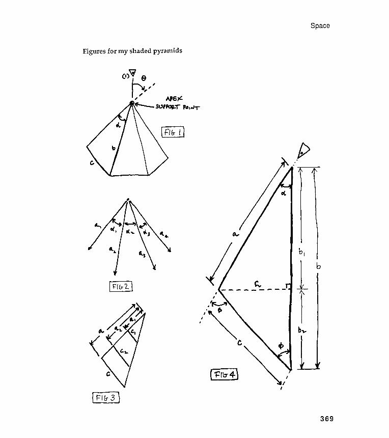
Figures for my shaded pyramids
Space
M
b ,
b
[ i~I}
[ }I~J369

calculate
angles of any triangle sum to 180 degrees
Chapter 8
Calculation of the parts
Suppose we know a, b, and a.. We need to ~ c and ~:
1. h is the height of the triangle . It meets side b at a right angle dividing it intotwo segments: bland b2.
2. SIN a = h/ a--- > h =
- - >
5. TAN <I>= h/ b2---> 4> = arctangent h / b2
(180 - ~ )= 0
<I>< - - - -
Now look back at figure 3. How do we calculate cl and c2? The parallel "c" sdivide the large triangular face into smaller but similar triangles . Rememberthe business about parts of similar triangles from geometry?
Using the idea of similar triangles , we can say that cl is to c as al is to a(cl / c = al / a). So cl = (al / a)*c.
Finally , note that the turtle (already pointing downward ) must turn rightby the angle e before drawing the "a" edge of the first triangular face.
370
a*SIN a.
b2 = b - b 1
= 1806 . The interior
- - - > a. + <t> +
- - > a. + <t> - ~
- - - > ~ = a. +
This gives us ~
7 . SIN <t> = hI c
- - - > c = hlSIN <t>
This gives us c < - - - -
3. cas a. = bI / a---> bI = a*CaS a.
4.b = bI +b2
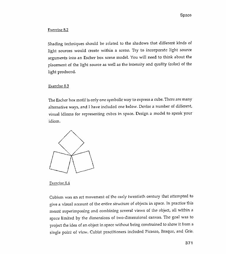
Exercise 8.4
Space
Exercise 8.2
Cubism was an art movement of the early twentieth century that attempted to
give a visual account of the entire structure of objects in space. In practice thismeant superimposing and combining several views of the object, all within aspace limited by the dimensions of two -dimensional canvas. The goal was toproject the idea of an object in space without being constrained to show it from asingle point of view . Cubist practitioners included Picasso, Braque, and Gris .
371
Shading techniques should be related to the shadows that different kinds of
light sources would create within a scene . Try to incorporate light source
arguments into an Escher box scene model . You will need to think about the
placement of the light source as well as the intensity and quality ( color ) of the
light produced .
Exercise 8 .3
The Escher box motif is only one symbolic way to express a cube . There are many
alternative ways , and I have included one below . Devise a number of different ,
visual idioms for representing cubes in space . Design a model to speak your
idiom .
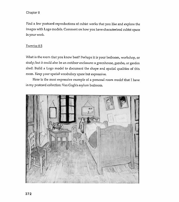
Find a few postcard reproductions of cubist works that you like and explore theimages with Logo models. Comment on how you have characterized cubist spacein your work .
Exercise 8.5
What is the room that you know best? Perhaps it is your bedroom, workshop , orstudy ; but it could also be an outdoor enclosure: a greenhouse, gazebo, or gardenshed. Build a Logo model to document the shape and spatial qualities of thisroom. Keep your spatial vocabulary spare but expressive.
Here is the most expressive example of a personal room model that I havein my postcard collection: Van Gogh's asylum bedroom.
Chapter 8
372
Exercise 8 .6
Produce a shaded sphere, cylinder , or prism . Be innovative . Don 't rely on the
shading ideas of the chapter; invent some new ones never seen by Earthlings .
Exercise 8 .7
Produce a landscape of a variety of shapes, all consistently shaded and
perspected. Explain what you mean by consistently, though .
Exercise 8.8
Space
373
What about two - and three - point perspective ? Can this be done easily with
Logo ? Can it be done at all with Logo ? Try to explain how you would go about
doing it . Then do it .
Exercise 8 . 9
How about designing your own space ? On the following pages you will see some
space creations by the Hungarian artist Tamas Farkas . Don ' t believe the claim
that they are " impossible . " Compete with Farkas by designing your own
impossible space grids .
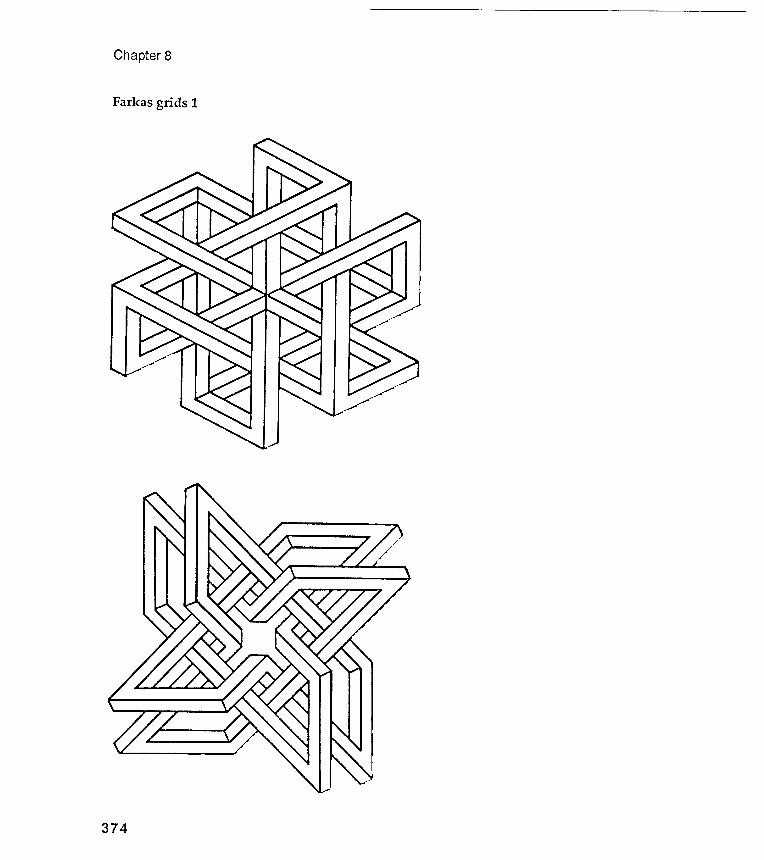
Chapter 8
Farkas grids 1
374
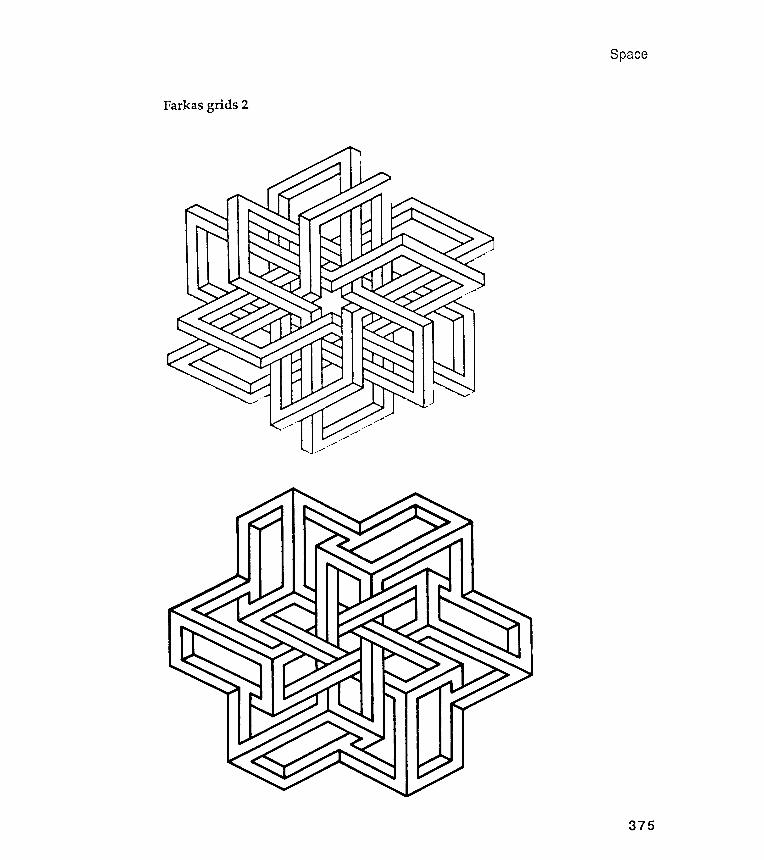
Space
Farkas grids 2
375

Chapter 8
Farkas grids 3
376
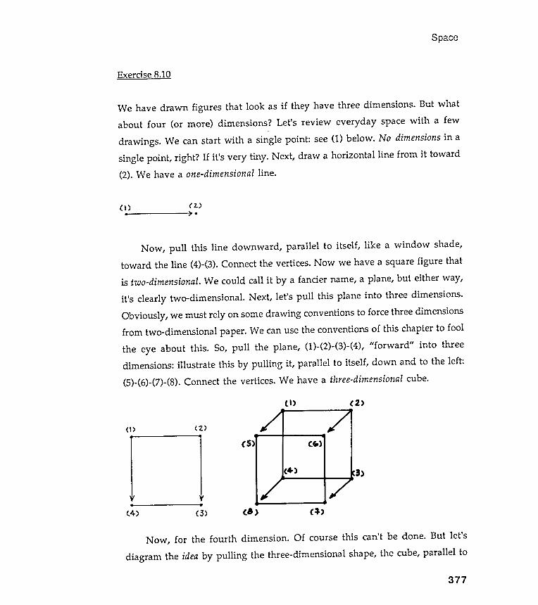
pace
Exercise 8.10
We have drawn figures that look as if they have three dimensions . But whatabout four (or more ) dimensions ? Let 's review everyday space with a few
drawings . We can start with a single point : see (I ) below . No dimensions in asingle point , right ? If it 's very tiny . Next , draw a horizontal line from it toward(2). We have a one-dimensional line .
s
C, ) ( 2. ). ) .
Now , pull this line downward , parallel to itself , like a window shade ,
toward the line (4)- (3 ) . Connect the vertices . Now we have a square figure that
is two -dimensional . We could call it by a fancier name , a plane , but either way ,
it 's clearly two - dimensional . Next , let 's pull this plane into three dimensions .
Obviously , we must rely on some drawing conventions to force three dimensions
from two - dimensional paper . We can use the conventions of this chapter to fool
the eye about this . So , pull the plane , (1) - (2)- (3) - (4 ) , " forward " into three
dimensions : illustrate this by pulling it , parallel to itself , down and to the left :
(5)- (6) - (7)- (8) . Connect the vertices . We have a three -dimensional cube .
< \ > ( ' 2. )
. .
( 4- ) ( 3 )
377
Now, for the fourth dimension. Of course this can't be done. But let'sdiagram the idea by pulling the three-dimensional shape, the cube, parallel to
( \ ) ( 2 )
( 5 ) ( ~ )
( 4- ) 3 )
( 8 ) ( ~ )
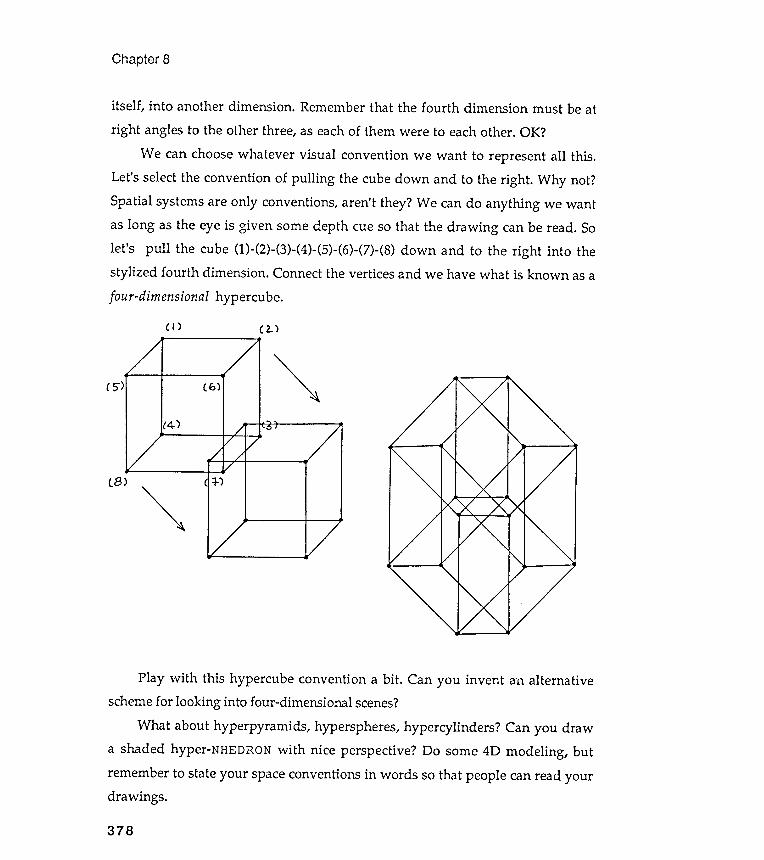
Chapter 8
378
itself , into another dimension . Remember that the fourth dimension must be at
right angles to the other three , as each of them were to each other . OK ?
We can choose whatever visual convention we want to represent all this .
Let ' s select the convention of pulling the cube down and to the right . Why not ?
Spatial systems are only conventions , aren ' t they ? We can do anything we want
as long as the eye is given some depth cue so that the drawing can be read . So
let ' s pull the cube ( 1 ) - ( 2 ) - ( 3 ) - ( 4 ) - ( 5 ) - ( 6 ) - ( 7 ) - ( 8 ) down and to the right into the
stylized fourth dimension . Connect the vertices and we have what is known as a
four - dimensional hypercube .
( I ) ( 2 - )
' 5" ) ( 6 ) ~
( 4 - )
lB )
" " -
Play with this hypercube convention a bit . Can you invent an alternative
scheme for looking into four - dimensional scenes ?
What about hyperpyramids , hyperspheres , hypercylinders ? Can you draw
a shaded hyper - NHEDRON with nice perspective ? Do some 4D modeling , but
remember to state your space conventions in words so that people can read your
dra wings .
Chapter 9Closu re
" Purpose shapes process . Discovery depends not on special processes but on
special purposes . Creating occurs when ordinary mental processes in an able
person are marshaled by creative or appropriately ' unreasonable ' intentions . "
D . N . Perkins
Unreasonable intentions
Fifteen years ago , soon after I arrived in Paris , I signed up for a poetry workshop
at the Center for Students and Artists on boulevard Raspail . There were five of
us in the class - plus the teacher . I liked the woman but questioned her teaching
methods . She assigned a specific exercise each week , and we were to return the
next to read our solution . I found the exercises overly structured and ridiculous ,
and I planned to show her how silly they were by slavishly following her tasks .
My results , I was convinced , would vindicate my feelings . And then she gave the
" accident " assignment ; I remember it vividly .
We were to write a short poem on a local accident . How trite , I thought . On
the late afternoon of the " accident " class , I returned to my section of the city
grimly determined to find and report on some street mishap . I wandered around
my shopping spot , the rue Lepic , hoping that something would happen . And
something did , horns blew , and I rushed down the street only to slip on some ice ,
fallen from a bin of fish . I slammed into a table of fish - covered ice : an
Chapter 9
accidental meeting with fish . That was the title I found on the street. I wenthome and got on easily with the exercise.
I am no poet , but I wrote the best poetry that I have ever written in that
class . The reason for my success was , I think , that I passionately sought out my
own form for each given problem . Although I wasn 't sure what the form would
be , I knew that I would have to explore before I found it . Very unreasonableintentions .
Problem finders
Jacob Getzels and Mihaly Csikszentmihalyi studied the ways male art students
at the Art Institute of Chicago explored the problems that were assigned to
them ; the results were published in a book called The creative vision : a
longitudinal study of problem finding in art (John Wiley , New York , 1976 ). For
example , these students were asked to select a set of objects from a number
provided and arrange them in preparation for drawing a still life . The qualities
of the drawings were compared with the methods the students used to approach
and structure the exercise . The researchers followed the students for seven years
after graduation to track their success . The form of their success , or lack of it ,
was then compared with what the authors called their " problem finding styles "
while in art school . Can you guess the results ?
Getzels and Csikszentmihalyi found a relationship between a student 's
working procedures and both the quality of his student work and his
professional success seven years later . The most effective work - in art school
and later - came from students who selected the most unusual objects and who
spent most time arranging and manipulating these objects before they started to
draw . They began their work without having any specific conception of the
organizational structure they wanted to capture in their arrangement of objects ;
in fact , they seemed to discover a structure that they liked through handling
the objects and moving them about . As their drawings progressed , the more
380
Closure
Exploratory facility
381
imaginative students tended to rearrange their objects, to introduce new elementsor to eliminate others . They changed paper , switched drawing media , andchanged their drawing position more often than their less successful classmates.And when they were finished , these students said that elements in their finaldrawings still might be changed without destroying its character.
In addition to working styles, these researchers found that a concern forfundamentals also affected creative production . The effective problem finders-Getzels and Csikszentmihalyi 's label for those students who found andstructured their own problems - tended to describe their work as being based onmatters of deep personal concern to them, even when these themes were notvisually present . It seemed as if the energy for the realization of the problemfinders ' exploratory style was funded by their passions.
I wrote this book with the conviction that a personal problem -finding ability is
necessary for real creativity . But how can this ability be encouraged in therealm of visual problems when most students suffer from a lack of exploratory
facility ? They may have the passions , but they lack a sufficient visualvocabulary and the most basic artistic skills and will that could have helpedthem start fashioning a personal vision language. I am convinced tha t visualmodeling can substitute for these lacks. How ?
Visual modeling is an environment in which you can offer yourself the gift
of seeing on your own terms. The attendant luxuries - design skills , rich visualword -images and metaphors - are all there, inside that space. The substance ofthis book is to offer you sight of this kind of environment . But you must not stophere. You must extend modeling into your own worlds .
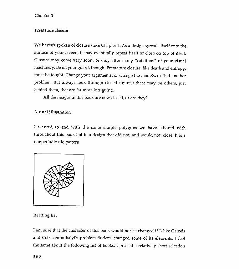
A final illustration
I wanted
throughoutnonperiodic
Chapter 9
Premature closure
We haven't spoken of closure since Chapter 2. As a design spreads itself onto thesurface of your screen, it may eventually repeat itself or close on top of itself .Closure may come very soon, or only after many " rotations " of your visualmachinery . Be on your guard , though . Premature closure, like dea th and entropy ,must be fought . Change your arguments, or change the models, or find another
problem . But always look through closed figures ; there may be others, justbehind them, that are far more intriguing .
All the images in this book are now closed, or are they?
Reading list
to end with the same simple polygons we have labored withthis book but in a design that did not, and would not, close. It is atile pattern .
I am sure that the character of this book would not be changed if I, like Getzelsand Csikszentmihalyi 's problem -finders , changed some of its elements. I feel
the same about the following list of books. I present a relatively short selection
382
Closure
Visual thinking, University of California Press, Berkeley and Los Angeles, 1969.
383
the third book .
Harold Abelson and Andrea diSessa , Turtle geometry : the computer as a medium
for exploring mathematics , The MIT Press , Cambridge , 1981 .
Brian Harvey , Computer science Logo style , 3 volumes , The MIT Press ,
Cambridge , 1985 , 1986 , 1987 .
Seymour Papert , Mindstorms ; children , computers and powerful ideas , Basic
Books , New York , 1980 .
Ps ~ cholog )::
Read anything by Rudolf Arnheim . Here is a short selection :
of some of the books that I found useful . Each of them encouraged me to think
differently about visual modeling . Like everything else that I have offered you ,
it is a personal selection . I have not repeated the books I mentioned in the text .
Turtle gra ~ hics and the Logo language
To my mind , most Logo books are useless . There are three exceptions , however ,
that are quite wonderful - each for quite different reasons . The first uses the
notion of turtle geometry to explore mathematics , while the second
investigates - through Logo programming - the ideas of computer science . Both
books require familiarity with mathematics and are not easy reads . However ,
most of your work on the exercises in this book could be aided by selected reading
in the Abelson and diSessa book , while your Logo programming style would be
extended and enriched by a careful study of Brian Harvey ' s books .
Finally , if you have never read about the philosophy behind the invention
of Logo , you should read the word from Seymour Papert , the inventor himself , in
Chapter 9
Entropy and art, University of California Press, Berkeley and Los Angeles, 1971.
Press,
New essays on the psychology of art , University of California Press, Berkeley
Art and visual perception: a psychology of the creative eye, University ofCalifornia Press, Berkeley and Los Angeles, 1974.
The power of the center: a study of composition in the visual arts, University ofCalifornia Berkeley and Los Angeles, 1982.
and Los Angeles, 1986.
Next , a hodgepodge of titles that I found of interest . They will lead you to othersources.
Carl Jung, editor , Man and his symbols, Doubleday & Company , New York , 1964.
and experimental
of graphic production processes, Cambridge University Press, Cambridge ,
thinking,
Ellen Winner , Invented worlds: the psychology of the arts, Harvard University
the development of creative capacity , Harper &
384
E . H . Gombrich , Art and illusion : a study in the psychology of pictorial
representation , Princeton University Press , Princeton , New Jersey , 1960 .
Ned Block , editor , Imagery , The MIT Press , Cambridge , 1981 .
Peter van Sommers , Drawing and cognition : descriptive
studies
1984 .
D. N . Perkins , The mind 's best work: a new psychology of creativeHarvard University Press, Cambridge , 1981.
Press, Cambridge, 1982.
William J. J. Gordon, Synectics:Row, New York, 1961.
Closure
Liam Hudson , Contrary imaginations: a psychological study of the Englishschoolboy, Methuen , London , 1966.
Other design books I like :
introduction to symmetry inPeter S. Stevens, Handbook of regular patterns: antwo dimensions, The MIT Press, Cambridge , 1984.
385
Mildred L. G. Shaw, On becoming a personal scientist: interactive computerelicitation of personal models of the world, Academic Press, London , 1980.
Chapter 9
Charles Bouleau , The painter 's secret geometry: a study of compositionHarcourt , Brace & World , New York , 1963.
in art ,
Magnus J. Wenninger , Polyhedron models, Cambridge University Press,Cambridge, 1971.
Magnus J. Wenninger , Spherical models, Cambridge University Press,Cambridge, 1979.
D'Arcy Wentworth Thompson , On growth and form, Cambridge UniversityPress, Cambridge, 1961.
Dover press publications are a treasure trove of design ideas . They are located at
180 Varick Street, New York, NY 10014. Write them for their catalogue.
Finally , find a library that takes the following journal . It is quirky and quitewonderful : Leonardo: journal of the international society for the arts, sciences,and technology.
Art his t ! : X
Go to museums and galleries and buy lots of postcard reproductions .
A mixed bag of things
Judith Wechsler , editor , On aesthetics in science, The MIT Press, Cambridge ,1978 .
Benoit Mandelbrot , The fractal geometry of nature, W. H . Freeman andCompany, San Francisco, 1977.
Douglas R. Hofstadter , Cadel, Escher, Bach, Basic Books, New York , 1979.
386
Closure
Douglas R. Hofstadter , Metamagical themas: questing for the essence of mindand pattern, Basic Books, New York , 1985.
Rudy Rucker, The fourth dimension, and how to get there, Rider and Company ,London, 1985.
Press, Oxford, 1986.
Edward R. Tufte, The visual display of quantitative information, GraphicsPress, Cheshire, Connecticut, 1983.
Christopher Alexander , Sara Ishikawa , and Murray Silverstein , A patternlanguage: towns, building, and construction, Oxford University Press, New York ,1977.
387
William Poundstone , The recursive universe: cosmic complexity and the limits of
scientific knowledge, William Morrow and Company , New York , 1985.
Istvan Hargittai , editor , Symmetry: unifying human understanding, Pergamon


Index
ADD.POINT, 360A.PIPEGON, 49
copying, 4crescent machine , 68
CROSS , 126
Csikszentmihalyi , Mihaly , 380CSTEP , 174
cubist space , 371
Delaunay , Robert, 83Delaunay experiments, 89Delaunay machine, 83depth cues, 156, 338dialects of Logo , 6DOUBLE . RINGS , 85
E . BOX , 344
emotion grid , 234EMPTY . BAG , 360
enclosing nephroids , 339equipment, 5Escher , M . C ., 340
Escher box , 340 , 343 , 366
EVAL , 239
exploratory facility , 381EXPLORE , 73
eye's conception of space, 366
Farkas , Tamas , 373

Index
FIVE . TARGET, 88FLAG, 174, 175flag modeling, 212FLAS H, 51
390
hyperpyramid , 378hypersphere , 378
imaginary machines, 54impossible space grids , 373INGON , 121
IRSTEP , 239
Islamic art , 216 , 235
Japanese pen -and -ink trees , 321
Kandinsky , Wassily , 193Kandinsky grids , 193Kelly , George, 58Klimt , Gustav , 326
LAY , 180
LAY . HEX . TILES , 82
LAY . SQ . TILES , 79
LAY . TR . TILES , 81
light source arguments, 371lists , 165 - 169 , 172 - 173 , 189 , 236 -237 ,
295 , 321 , 359 -361
local variables , 140
log grids , 230Logo mechanics, 2L . PIPEGON , 51
mandalas , 158
MARK . 13 , 132
MARK . 16 , 133
mason mark designs, 128Mayan -inspired grid , 179
focusing random grids, 196FOUR. TARGET, 88fractal, 144, 146FRACTALGON, 146, 330fractal landscapes, 330-336fractal mountain machine, 336FRUIT, 294FRUIT.LIST .TREE, 295
generalize, 164, 212generalized Gothic stone mason
mark, 133-135, 160generalized nephroids, 150generalizing, 12, 16, 69, 133, 184, 188Getzels, Jacob, 380GIVE. MOTIF, 173GIVE.PT, 166global variables, 140G.MARK, 134GO.PT, 168GO. RANDOM. SCREEN, 186grid machine, 237grid of stylized faces, 213
Hackney, David, 231hypercube, 378hypercylinder, 378

Index
M.BOX, 201M.EXPLORE, l34MF . TREE, 294
391
PIP , 243
PIPEGON , 46 , 47
placement (as perspective device),163
placement ambiguity , 346pointillist trees, 319pool -light grids , 231premature closure , 382
probabilistic grids , 205probabilistic selection, 201problem finders, 380problem -solving style, 64procedure presentation style, 22procedures, 10programming as craft, 3pyramid graphics, 366
quality of edges, 255quality of polygon lines, 136
random components , 182
randomized trees , 306
randomness - within - a - structure , 286
RANDOM . NUMBER , 183
random numbers , 182
RANDOM . PLACER , 187 , 188
RANDOM . PLACER . X , 191
random rectangular grid , 182random screen locations , 183
RAND. TREE, 3q6reading objects in space, 337
minimal design elements, 241modeled one-point perspective, 358modeling, 115models, 34Mondrian, Piet, 162, 199, 214motif, 164MOTIF list, 172M.TREE, 294
NARROW. SPLINES, 86NEPHROID, 150nephroids, 148NEST.DEMO, 244NGON, 17, 47NHEDRON, 359, 361NIGHT. SHADE, 350
one-point perspective, 356one-point perspective experiments,
361ONE. TARGET, 87overlapping designs, 264overlapping grids, 351overlapping shapes, 349
painter's algorithm, 350personal mark, 111-114perspective, 354P.GET, 203

Index
RECGON, 94, 96RECORD.Pos, 178rectangular grids, 169recursing polygons, 94recursing squares, 125recursing trees, 287recursion, 20, 92, 97, 119, 124, 144,
288
recursion diagram, 99-101, 124-125recursive design features, 119RESTORE.POS, 179RIFLAG, 238RIM. FLAG, 349RIM. ROWER, 349RIM. RSTEP, 349RING. DEMO, 269RINGS, 269, 270ROT, 237ROWER, 238RR, 185, 304RSTEP, 174rug designs, 277
SAW. DEMO, 261SAWGON, 260SEED, 300Seurat, George, 321SHADE, 344SHADED.DEMO, 345shaded pyramids, 366shading schemes, 340
392
size variation (as perspective
device ), 347
stone mason marks , 107 - 110 , 117
SPIN , 70
SPIN . CONGON, 70
SPINGON , 20
S . PIPEGON , 50
SPIRAL , 180
SQ, 139
SQ . EXPLORE , 125
SQUARES , 124 , 125
star and saw blade , 257
STAREDGE , 140
STARGON , 140
STAR . NEPHROID , 152
stars , 137
state transparency , 65 , 70 , 175 - 179 ,
287 , 291
stopping recursive procedures , 22
story boards , 169 - 171
S . TREE , 288
STRIPES , 131
surface shading , 340
symmetry , 163 -164
tarot deck , 159 - 160
TEEPEE , 177
teepee sha pe , 177
Terrapin MacLogo , 6
three - point perspective , 357
tile design , 240

Index
: shapes, 78 zodiac, 159
393
tiling spinningtinkering , 4TIPGON, 127TIP . STARGON , 152
TP1 , 178
TP2 , 179
TP . DEMO , 257
TPGON , 252 , 253
tree experiments , 288-290
turtle reference commands , 8
turtle space , 7
turtle walk , 25 , 41 - 46 , 122 - 124 , 138 ,
149 , 169
TV test pattern , 213
two-point perspective, 357TWO . TARGET , 87
unreasonable intentions , 379
van de Velde, Henry , 321vanishing points , 361VERIFY , 204
visual experiments , 72-73
visual sensitivity analysis, 75
Warhol , Andy , 213weed model , 299
WIDE . SPLINES , 86
windowing , 188-189WING , 269
ZIP , 162
ZIPM , 162

The MIT Press, with Peter Denning, general consulting editor , andBrian Randell, European consulting editor , publishes computer sci-ence books in the following series:
ACM Doctoral Dissertation Award and Distinguished Dissertation Series
Artificial Intelligence, Patrick Winston and Michael Brady , editors
Charles Babbage Institute Reprint Series for the History of Computing,Martin Campbell-Kelly , editor
Computer Systems, Herb Schwetman, editor
Exploring with Logo, E. Paul Goldenberg, editor
Foundations of Computing, Michael Garey, editor
History of Computing, I . Bernard Cohen and William Aspray , editors
Information Systems, Michael Lesk , editor
Logic Programming, Ehud Shapiro, editor ; Fernando Pereira, KoichiFurukawa, and D . H . D. Warren, associate editors
The MIT Electrical Engineering and Computer Science Series
Scientific Computation, Dennis Gannon, editor