VIRTOPSY: Minimally Invasive, Imaging-guided Virtual Autopsy
30
EDUCATION EXHIBIT 1305 VIRTOPSY: Minimally Invasive, Imaging- guided Virtual Autopsy Richard Dirnhofer, MD ● Christian Jackowski, MD ● Peter Vock, MD Kimberlee Potter, PhD ● Michael J. Thali, MD Invasive “body-opening” autopsy represents the traditional means of postmortem investigation in humans. However, modern cross-sec- tional imaging techniques can supplement and may even partially re- place traditional autopsy. Computed tomography (CT) is the imaging modality of choice for two- and three-dimensional documentation and analysis of autopsy findings including fracture systems, pathologic gas collections (eg, air embolism, subcutaneous emphysema after trauma, hyperbaric trauma, decomposition effects), and gross tissue injury. Various postprocessing techniques can provide strong forensic evi- dence for use in legal proceedings. Magnetic resonance (MR) imaging has had a greater impact in demonstrating soft-tissue injury, organ trauma, and nontraumatic conditions. However, the differences in morphologic features and signal intensity characteristics seen at ante- mortem versus postmortem MR imaging have not yet been studied systematically. The documentation and analysis of postmortem find- ings with CT and MR imaging and postprocessing techniques (“vir- topsy”) is investigator independent, objective, and noninvasive and will lead to qualitative improvements in forensic pathologic investigation. Future applications of this approach include the assessment of morbid- ity and mortality in the general population and, perhaps, routine screening of bodies prior to burial. © RSNA, 2006 Abbreviations: AFIP Armed Forces Institute of Pathology, H-E hematoxylin-eosin, IVC inferior vena cava, MIP maximum intensity pro- jection, RARE rapid acquisition with relaxation enhancement, 3D three-dimensional, VR volume rendered RadioGraphics 2006; 26:1305–1333 ● Published online 10.1148/rg.265065001 ● Content Codes: 1 From the Institute of Forensic Medicine, University of Bern, Buehlstrasse 20, CH-3012 Bern, Switzerland (R.D., C.J., M.J.T.); the Institute of Diag- nostic Radiology, Inselspital, University of Bern, Bern, Switzerland (P.V.); and the Armed Forces Institute of Pathology, MRM Facility, Washington, DC (K.P.). Presented as an education exhibit at the 2003 RSNA Annual Meeting. Received January 3, 2006; revision requested January 30 and re- ceived March 23; accepted March 24. All authors have no financial relationships to disclose. Address correspondence to M.J.T. (e-mail: michael [email protected]). © RSNA, 2006 RadioGraphics See last page TEACHING POINTS
-
Upload
independent -
Category
Documents
-
view
0 -
download
0
Transcript of VIRTOPSY: Minimally Invasive, Imaging-guided Virtual Autopsy

EDUCATION EXHIBIT 1305
VIRTOPSY: MinimallyInvasive, Imaging-guided Virtual AutopsyRichard Dirnhofer, MD ● Christian Jackowski, MD ● Peter Vock, MDKimberlee Potter, PhD ● Michael J. Thali, MD
Invasive “body-opening” autopsy represents the traditional means ofpostmortem investigation in humans. However, modern cross-sec-tional imaging techniques can supplement and may even partially re-place traditional autopsy. Computed tomography (CT) is the imagingmodality of choice for two- and three-dimensional documentation andanalysis of autopsy findings including fracture systems, pathologic gascollections (eg, air embolism, subcutaneous emphysema after trauma,hyperbaric trauma, decomposition effects), and gross tissue injury.Various postprocessing techniques can provide strong forensic evi-dence for use in legal proceedings. Magnetic resonance (MR) imaginghas had a greater impact in demonstrating soft-tissue injury, organtrauma, and nontraumatic conditions. However, the differences inmorphologic features and signal intensity characteristics seen at ante-mortem versus postmortem MR imaging have not yet been studiedsystematically. The documentation and analysis of postmortem find-ings with CT and MR imaging and postprocessing techniques (“vir-topsy”) is investigator independent, objective, and noninvasive and willlead to qualitative improvements in forensic pathologic investigation.Future applications of this approach include the assessment of morbid-ity and mortality in the general population and, perhaps, routinescreening of bodies prior to burial.©RSNA, 2006
Abbreviations: AFIP � Armed Forces Institute of Pathology, H-E � hematoxylin-eosin, IVC � inferior vena cava, MIP � maximum intensity pro-jection, RARE � rapid acquisition with relaxation enhancement, 3D � three-dimensional, VR � volume rendered
RadioGraphics 2006; 26:1305–1333 ● Published online 10.1148/rg.265065001 ● Content Codes:
1From the Institute of Forensic Medicine, University of Bern, Buehlstrasse 20, CH-3012 Bern, Switzerland (R.D., C.J., M.J.T.); the Institute of Diag-nostic Radiology, Inselspital, University of Bern, Bern, Switzerland (P.V.); and the Armed Forces Institute of Pathology, MRM Facility, Washington,DC (K.P.). Presented as an education exhibit at the 2003 RSNA Annual Meeting. Received January 3, 2006; revision requested January 30 and re-ceived March 23; accepted March 24. All authors have no financial relationships to disclose. Address correspondence to M.J.T. (e-mail: [email protected]).
©RSNA, 2006
Radio
Gra
phic
s
See last page
TEACHING POINTS

IntroductionThe main objectives of forensic medicine are todocument, analyze, and elucidate scientific medi-cal findings in both living and deceased persons ina comprehensible way for courtroom presenta-tion. In deceased persons, the main goals are todetermine the cause and manner of death, toevaluate the vitality of the sustained injuries, andto develop a forensic reconstruction based on thefindings. Other than in forensic genetics (in whichDNA is used) and forensic toxicology—areas inwhich “high-tech” methods have already beenincorporated into the daily routine—the docu-mentation of forensic pathologic findings is stillpredominantly based on the same autopsy tech-niques and protocols that have been used for cen-turies. The most commonly used tools are a scal-pel, verbal description, and conventional two-dimensional photography (1). Forensic findingsare thereby documented in an unintentionallysubjective (observer-dependent) way, and find-ings that have not been documented are irrevo-cably destroyed if the body has been sent to thecrematory. For many years, the application ofimaging methods for objective nondestructivedocumentation of relevant forensic findings haslagged far behind the technical development ofthe imaging methods themselves. There are onlya few textbooks available that deal with forensicradiology, most of which concentrate on conven-tional radiography and do not discuss newer sec-tional imaging techniques such as computed to-mography (CT) and magnetic resonance (MR)imaging in detail. Brogdon (2), in his book Foren-sic Radiology, makes the following statement:“The sad truth is that a century after the first x-ray was introduced as evidence in a law court,there is no general appreciation of the extent ofthe radiology potential in the forensic sciences.”In principle, all clinical applications of radiologicmethods can also be used for forensic purposes(Table). Diagnostic imaging is still underused inforensics, mainly due to unawareness of its poten-tial and the lack of teaching and experience(2–4).
The first forensic application of CT was a de-scription of the pattern of gunshot injury to thehead by Wullenweber et al in 1977 (5). Becauseof limited image quality and resolution and poorpostprocessing results in the early years, only afew studies correlated pathologic findings at full-body postmortem CT with forensic autopsy find-ings (6–9). Even the introduction of spiral CT byKalender et al in 1989 (10), which opened the
door for three-dimensional (3D) data acquisitionand processing, did not significantly increase theinterest of forensic scientists in this new modality.
The use of full-body postmortem MR imagingin nonforensic cases for the detection of gross cra-nial, thoracic, and abdominal disease has beendescribed by a number of different groups (11–22). Limited single-organ studies have been per-formed by some forensic groups, mainly for thevisualization of gunshot wound tracks in the brain(17,23,24). None of these groups performed sys-tematic whole-body examinations using a combi-nation of multisection CT and MR imaging.
It was suggested that conventional autopsy,nowadays often rejected by family members ornot tolerated by religions in a multicultural soci-ety, might be replaced by noninvasive imagingdocumentation and, when required, by minimallyinvasive imaging-guided tissue sampling and byangiography to address vascular questions. Thedigitally acquired data could be reconsultedwhenever new questions arose or could be sentto other experts for a second opinion.
The concept of objective, noninvasive docu-mentation of the body surface for forensic pur-poses arose in the early 1990s with the develop-ment of forensic photogrammetry (25). As isusual in forensic science, this idea was born ofand stimulated by a pressing need—in this case, avery high-profile homicide in Switzerland. Thecase required that a possible murder weapon becompared with an impression on the skull of thevictim to identify the weapon with a high degreeof certainty. In 2000, it was suggested that ob-server-independent documentation of the bodysurface be combined with observer-independentdocumentation of the interior of the body.
The Virtopsy project of the Institutes of Foren-sic Medicine, Diagnostic Radiology, and Neuro-radiology at the University of Bern, Switzerland,attempts to achieve this combined documenta-tion. Through close collaboration between theseinstitutes, modern cross-sectional techniques
Purposes of Forensic Radiology
IdentificationGenderBody lengthIndividual features (dental, intracorporeal)
DocumentationForeign material (bullets, inserted foreign bodies)Injuries and organ disease (to determine cause
and manner of death)Vitality of sustained injuriesForensic reconstruction
EducationResearch
1306 September-October 2006 RG f Volume 26 ● Number 5
Radio
Gra
phic
s

were performed for forensic purposes. The term“virtopsy” was created from the terms “virtual”and “autopsy.” The former term is derived fromthe Latin word virtus, which means “useful, effi-cient, and good.” The term “autopsy” is a combi-nation of the classical Greek terms autos (“self”)and opsomei (“I will see”). Thus, autopsy means“to see with one’s own eyes.” Because our goalwas to eliminate the subjectivity implied by autos,we merged the terms “virtual” and “autopsy”—deleting autos—to create the term “virtopsy” (26).
Virtopsy basically consists of (a) body volumedocumentation and analysis using CT, MR imag-ing, and microradiology; and (b) 3D body surfacedocumentation using forensic photogrammetryand 3D optical scanning. The resulting data setcontains high-resolution 3D color-encoded docu-mentation of the body surface and 3D volumedocumentation of the interior of the body (Fig 1).By manipulating the data set with volume-render-ing (VR) tools at a workstation, one can performa virtual autopsy anytime, in any place. No foren-sic findings are disturbed, as they would be by thedestructive techniques used in traditional au-topsy. The aim of the Virtopsy project is to vali-date this new approach by systematically compar-ing the radiologic and surface scanning findingswith those obtained at traditional autopsy. Thenew method should be able to help determinewhether death was the result of natural causes,accident, suicide, or homicide. This determina-tion needs to be based on the forensic investiga-tion of the circumstances and of the body. Fur-thermore, the sustained injuries must be assessedin terms of their vitality and, based on the find-ings, a forensic reconstruction of the incident de-veloped. The basic Virtopsy study, in which post-mortem whole-body imaging findings are corre-
lated with the findings obtained at traditionalautopsy, was first described in 2003 (27).
In this article, we discuss and illustrate the useof 3D optical and photogrammetric surface scan-ning combined with CT and MR imaging forpostmortem investigation. We also discuss thecorrelation of these imaging findings with the fo-rensic findings obtained at traditional autopsy.
Clinical Experience
Case SamplesThe study was approved by the local departmentof justice and the Ethics Committee of the Uni-versity of Bern and, as of this writing, includes120 forensic cases involving persons whose age atdeath ranged from 22 weeks gestation to 94 years.
Each body was wrapped in two artifact-freebody bags to avoid contaminating the radiologyequipment and to protect the identity of the de-ceased person during clinical scanning. Becausethe Institute of Forensic Medicine owns a six–detector row scanner (Emotion 6; Siemens Medi-cal Systems, Erlangen, Germany), only contami-nated or putrefied bodies are wrapped for CT.
Imaging Considerations
Multisection CT.—CT was performed on afour– or six–detector row scanner. Whole-bodyscans were performed with a collimation of 1 or1.25 mm. Up to 1200 axial images were obtained,with a section thickness of 1.25 mm and an incre-ment of 0.7 mm in soft-tissue and osseous ker-nels. For areas of special forensic importance
Figure 1. Chart illustrates the Virtopsy project, in which forensic information isacquired with various radiologic methods.
RG f Volume 26 ● Number 5 Dirnhofer et al 1307
Radio
Gra
phic
s
TeachingPoint
Teaching Point The aim of the Virtopsy project is to validate this new approach by systematically comparing the radiologic and surface scanning findings with those obtained at traditional autopsy.

(special fracture systems, teeth, foreign bodies),additional raw data were acquired with a collima-tion of 0.5 mm and 0.625-mm-thick sectionswere calculated. Acquisition time was approxi-mately 10 minutes.
MR Imaging.—MR imaging of the head, thorax,and abdomen was performed on a 1.5-T system(Signa v5.8; GE Medical Systems, Milwaukee,Wis), and further areas of interest (eg, the neck incases of strangulation, extremities when injured)were added. We acquired coronal, sagittal, andaxial images with different contrast weighting(T1-weighted spin-echo and T2-weighted fastspin-echo sequences with and without fat satura-tion, turbo inversion recovery sequences, gradi-ent-echo sequences). Occasionally, when cardiacfindings were expected or observed on axial im-ages, short-axis, horizontal long-axis, and verticallong-axis images were acquired. Acquisition timeranged from 1.5 to 3.5 hours.
Data analysis and postprocessing of CT andMR imaging data were performed on a Leonardo(Siemens) workstation.
Micro-CT.—In special situations, bone-tissuespecimens were examined on a micro-CT systemdeveloped and built at the Institute of MedicalPhysics in Erlangen, Germany. This scanner canimage a 3D volume with an isotropic resolutionranging from 10 to 100 �m (28). The system al-lows the examination of samples with diametersranging from 4 to 40 mm.
MR Microscopy.—MR microscopic studieswere performed at room temperature on a BrukerDMX spectrometer (Bruker Biospin MRI, Bil-lerica, Mass) coupled to a wide-bore magnet op-erating at 9.4 T (400 MHz for protons). Forma-lin-fixed eyeballs were washed in phosphate-buff-ered saline solution, blotted dry, and placed in a25-mm glass tube filled with Fluorinert (Oak-wood Products, West Columbia, SC) prior toimaging. Three-dimensional anatomic imageswere acquired with a fat-suppressed rapid acquisi-tion with relaxation enhancement (RARE) T1-weighted imaging sequence (repetition time msec/echo time msec � 200/8, number of signals ac-quired � 16, acquisition time � 9.5 hours).Voxels were typically 78 �m in size (3). After im-aging was completed, the eyeballs were cut in halfand prepared for paraffin embedding. Histologicsections 6 �m thick were cut and then stainedwith hematoxylin-eosin (H-E) stain to help distin-guish hemorrhage from eye tissue.
Photogrammetry-based 3D Optical Scan-ning.—At present, the standard for the docu-mentation of injuries in forensic medicine is stillphotography with exact measurements. However,like conventional radiography, the photographicprocess displays a 3D wound in only two dimen-sions.
With the TRITOP/ATOS II system (GOM,Braunschweig, Germany), the 3D color-encodedsurface can be documented by means of detectionof the distortion of light stripes projected onto thesurface. In this way, the system can recalculatethe 3D surface that caused the distortion. Thissystem is usually used when high precision is re-quired, since it is accurate to less than 20 �m.This accuracy allows more detailed surface docu-mentation compared with 3D reconstructed im-ages from high-resolution CT data.
The color information is acquired using TRI-TOP software, which combines digital photo-graphs of the surface taken from many differentangles to create a single 3D color image of theobject that can be matched up with the digital 3Dsurface image of the object with use of coded anduncoded markers placed on the object. With thistechnology, documentation ranging from that offine details (eg, skin lesion) to overview documen-tation (whole body or entire vehicle) is possible.
LogisticsMost of the cross-sectional imaging of bodies per-formed on the clinical scanners at the Institutes ofDiagnostic Radiology and Neuroradiology wasperformed during evening hours or weekends. Alocal mortician worked out the necessary logisticsbetween the two institutes.
Correlation of Cross-Sectionalwith Traditional Autopsy FindingsAfter forensic autopsy had been performed byboard-certified forensic pathologists with detaileddigital photographic documentation of all find-ings, a correlation was performed according to theArmed Forces Institute of Pathology (AFIP) de-sign (29,30).
ResultsThe cases illustrated in this article are predomi-nantly of special interest in the forensic domain.The postmortem imaging appearance of traumaand organ disease does not differ markedly fromtheir clinical appearances except for overlyingpostmortem alterations.
IdentificationPrior to any postmortem investigation, the iden-tity of the body must be clarified and proved; oth-erwise, the postmortem investigation has as one
1308 September-October 2006 RG f Volume 26 ● Number 5
Radio
Gra
phic
s

of its goals the reestablishment of the identity ofthe unidentified body. Multi–detector row CTcan be of great help in this regard. Secure post-mortem identification is possible only on the basisof dental status, DNA profiles, or fingerprinting.Because DNA is the most expensive and time-consuming method, fingerprinting and dentalidentification are more commonly used. Withcranial CT data obtained in a corpse, it is possibleto reconstruct any antemortem radiographic pro-jection for comparison (31). Even panoramic im-ages can be created that are comparable to ante-mortem orthopantograms (32). In addition, therestoration material that was used can be ascer-tained on the basis of postmortem CT data andcorrelated with the antemortem dental records ofsuspected missing persons (33).
In addition to gross morphologic findings suchas an endoprosthesis of the shoulder, hip, orknee—findings that are often already expectedon the basis of an efficient external inspection—whole-body CT of the corpse reveals numerousfindings that can be used for positive identifica-tion as well as for exclusion of an assumed iden-tity, conclusions that could not be reached withroutine autopsy (Fig 2) (34,35). These applica-tions of CT technology in the forensic domainsuggested that mobile machines could be used forpostmortem data acquisition in cases of mass ca-sualties such as airplane crashes or natural disas-ters (eg, the recent tsunami catastrophe in Asia).In these incidents, identification of bodies is the
Figure 2. Corpse identification with CT in four different cases. (a) Oblique VR bone image obtained in a com-pletely burned corpse shows a helical wire in the left humerus representing a rare technique of humeral osteosynthe-sis. (b) Anteroposterior view of the pelvis shows two screws in the left femur. (c) Anteroposterior view of the kneesshows replacement of the right anterior cruciate ligament with screws in the femur and tibia. (d) Anteroposteriorview of the lumbar spine shows percutaneous vertebroplasty with cement in the vertebral bodies, a finding that can beused for identification. Routine forensic autopsy would be incapable of demonstrating the findings in a–d.
RG f Volume 26 ● Number 5 Dirnhofer et al 1309
Radio
Gra
phic
s

major issue to be addressed, and CT can be ofinestimable value in disaster victim identification.
Another discipline in which postmortem cross-sectional imaging is of inestimable value is paleo-radiology. The human or animal remains of pastcultures can be investigated without disturbingthem (as would traditional autopsy), thereby pro-viding information regarding the age and genderof, as well as any injuries or diseases suffered by,the deceased person or animal (36–38).
Cause and Manner of DeathRegardless of the manner of death (ie, naturalcauses, accident, suicide, homicide, or iatrogeniccauses), death can have a variety of causes. Someof these causes are specific to certain organs suchas the brain, heart, and lungs. Various systemicfindings can also indicate the cause of death.
Brain.—Typical trauma findings at clinical radi-ology are equally well visualized at postmortemimaging. Increased intracranial pressure as a re-sult of trauma or ischemia typically manifests at
Figures 3, 4. (3) Increased intracranial pressure as the cause of death. (a) Coronal T2-weighted MR imageshows herniation of basilar parts of the cerebellum into the foramen magnum. (b) Autopsy photograph showsthe cerebellum, with swelling of the tonsils (solid arrows) and a pressure mark caused by the foramen magnum(dashed arrows). (4) Traumatic intraaxial bleeding. (a) Axial gradient-recalled acquisition in the steady stateimage shows local hypointense areas (arrow) in the left temporal lobe that reach the subarachnoidal space.These areas represent degenerative products of hemoglobin and indicate trauma. (b) Autopsy photograph of aslice through the temporal lobe of the formalin-fixed brain shows trauma-related bleeding, predominantly inthe cortex and subcortex (arrow).
1310 September-October 2006 RG f Volume 26 ● Number 5
Radio
Gra
phic
s

autopsy as transtentorial herniation of the tempo-ral lobe or herniation of the cerebellum into theforamen magnum, with impressions at the base ofthe cerebellum corresponding to the foramenmagnum (Fig 3) (39). If there is a gross patho-logic finding within the brain responsible for theincreased intracranial pressure, postmortem im-aging allows detailed visualization (Fig 4). Thiscapacity is especially helpful when advancedstages of putrefaction make impracticable an au-topsy investigation of the remaining brain struc-tures when the skull is opened. In such cases,postmortem MR imaging provides an adequateanatomic overview of the brain in situ and allowsexclusion of gross pathologic alterations withinthe brain (40). Recent studies have investigatedthe sensitivity and significance of postmortemMR imaging for discrete brain alterations. Initial3-T MR imaging examinations of bodies indicate
that the lack of sufficient sensitivity for brain le-sions smaller than 5 mm on 1.5-T systems can beovercome by increasing the field strength, with apossible image matrix up to 1024. Furthermore,initial postmortem diffusion tensor imaging stud-ies promise to overcome present cross-sectionalimaging limitations in the visualization of smallbrain lesions within vitally important regions(41).
Heart.—The majority of natural deaths arecaused by cardiac insufficiency. Chronic cardiacdiseases (eg, cardiomyopathies) or acute ischemicsituations (Fig 5) can induce cardiac insufficiencyby means of (a) acute reduction in the number ofcontractible fibers or (b) arrhythmias (42). In ad-dition, the heart is often the target of injury in
Figure 5. Natural cardiac death. (a) Short-axis T2-weighted MR image shows local hypointense areas (ar-row) in the left lateral wall, with areas of hyperintensity in the surrounding myocardial tissue. (b) Photographof the corresponding autopsy specimen shows hemorrhagic myocardial infarction (arrow) in the lateral wall ofthe left ventricle. (c) Short-axis T2-weighted MR image obtained in a patient with chronic uremic cardiomyop-athy shows massive eccentrically hypertrophic ventricles in a so-called cor bovinum. (d) Photograph of the cor-responding autopsy specimen helps confirm biventricular eccentric hypertrophy (heart weight, 1070 g). On allscales shown in the figures, the smallest units are millimeters.
RG f Volume 26 ● Number 5 Dirnhofer et al 1311
Radio
Gra
phic
s

suicides as well as homicides. Injuries to the hearttypically manifest at postmortem imaging as peri-cardial tamponade and hematothoraces (Fig 6).Furthermore, right ventricular failure after venousair embolism in cranial trauma (eg, gunshotwounds to the head, stab wounds to the neck) is avery common heart-related cause of death. Incontrast to traditional autopsy techniques, post-
mortem CT allows detailed 3D visualization ofthe embolized structures, with quantification ofthe embolized air (Fig 7) (43,44).
Lungs.—Postmortem investigation can be usedto assess the lungs in determining the cause ofdeath (45,46). For example, pneumothoraces areeasily detected at postmortem imaging (27). Pul-monary edema (Fig 8), which is often seen in car-diac or toxicologic deaths, has postmortem imag-ing features comparable to clinical cross-sectional
Figures 6, 7. (6) Cardiac trauma (stab wound to the heart). (a) Short-axis T2-weighted MR imagethrough the cardiac apex shows a myocardial injury (solid white arrow). Subsequent pericardial tampon-ade manifests as sedimented cellular components (dashed white arrows) with medium signal intensityand an upper layer of serum (black arrows) with increased signal intensity. (b) Photograph of the corre-sponding autopsy specimen demonstrates transmural laceration of the left ventricle in the apical region(arrow). (7) Lethal air embolism of the pulmonary artery in the victim of a gunshot wound to the head.(a) Anteroposterior 3D VR image shows the air-filled right ventricle and pulmonary artery. CT-basedvolumetry showed 59 mL of gas within these two structures. 1 � cranial veins, 2 � trachea, 3 � mainpulmonary artery, 4 � right ventricular outflow tract, 5 � intrahepatic veins. (b) Autopsy photographdemonstrates the procedure used to confirm the presence of an air embolism. After the pericardium hasbeen opened, the pericardial space is filled with clear water to totally cover the heart. The right ventricleis then punctured with a scalpel, and turning the scalpel produces ascending air bubbles (arrow).
1312 September-October 2006 RG f Volume 26 ● Number 5
Radio
Gra
phic
s
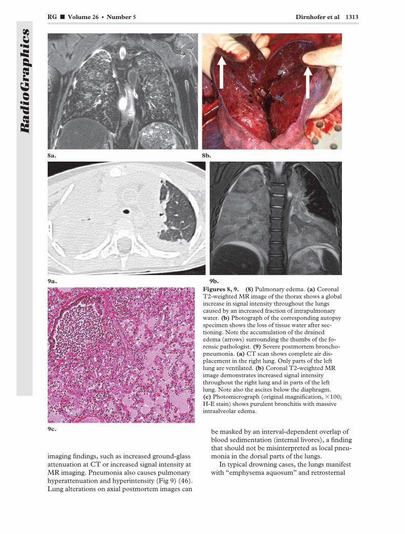
imaging findings, such as increased ground-glassattenuation at CT or increased signal intensity atMR imaging. Pneumonia also causes pulmonaryhyperattenuation and hyperintensity (Fig 9) (46).Lung alterations on axial postmortem images can
be masked by an interval-dependent overlap ofblood sedimentation (internal livores), a findingthat should not be misinterpreted as local pneu-monia in the dorsal parts of the lungs.
In typical drowning cases, the lungs manifestwith “emphysema aquosum” and retrosternal
Figures 8, 9. (8) Pulmonary edema. (a) CoronalT2-weighted MR image of the thorax shows a globalincrease in signal intensity throughout the lungscaused by an increased fraction of intrapulmonarywater. (b) Photograph of the corresponding autopsyspecimen shows the loss of tissue water after sec-tioning. Note the accumulation of the drainededema (arrows) surrounding the thumbs of the fo-rensic pathologist. (9) Severe postmortem broncho-pneumonia. (a) CT scan shows complete air dis-placement in the right lung. Only parts of the leftlung are ventilated. (b) Coronal T2-weighted MRimage demonstrates increased signal intensitythroughout the right lung and in parts of the leftlung. Note also the ascites below the diaphragm.(c) Photomicrograph (original magnification, �100;H-E stain) shows purulent bronchitis with massiveintraalveolar edema.
RG f Volume 26 ● Number 5 Dirnhofer et al 1313
Radio
Gra
phic
s

Figure 10. Emphysema aquosum. (a) Thoracic CT scan (lung windowing) demonstrates emphysema aquo-sum caused by drowning, with anterior contact between the lungs. Note the postmortem sedimentation phe-nomenon with an increase in attenuation from ventral to dorsal, a finding that is especially visible in the rightupper lobe. (b) Anteroposterior 3D VR lung image allows correlation with the traditional autopsy findings (cfc). (c) On an autopsy photograph, the ventral parts of the lungs overlap retrosternally. (d) Anteroposteriormaximum-intensity-projection (MIP) image from coronal T2-weighted MR imaging data shows hyperintensecontents in the stomach (solid arrow) and duodenum (dashed arrow), findings that indicate active swallowingof drowning fluid. (e) Autopsy photograph shows a distinctively fluid-filled stomach (solid arrow) and duode-num (dashed arrow). The organs were opened to sample the fluid.
1314 September-October 2006 RG f Volume 26 ● Number 5
Radio
Gra
phic
s

touching of the upper lobes (Fig 10). In combi-nation with actively swallowed drowning fluidwithin the gastrointestinal tract, this finding indi-cates a conscious (vital) drowning process (47).
Systemic Findings.—Various systemic findingsindicate different causes of death. In hypother-mia, for example, areas of bleeding within themusculature of the body core are a typical andindicative finding; however, the mechanism is stillunclear (Fig 11) (48).
In cases of sharp-force trauma, the cause ofdeath is fatal hemorrhage, in which subjectivecharacteristics such as major blood loss at the site
of injury, pale internal organs, and subendocar-diac areas of bleeding indicate that the hemor-rhage was lethal. Postmortem measurements ofthe cross-sectional areas of the major vessels allowquantification of the volume of blood remainingin the body, thereby facilitating the diagnosis incases of fatal hemorrhage (Fig 12) (49).
Furthermore, with use of cross-sectional vol-ume imaging, the weight of the organs can beestimated similar to the way organs are alwaysweighed at autopsy. The radiologically measured
Figure 11. Hypothermia. (a) Coronal reformatted short inversion time inversion-recovery image of the lowerabdomen shows areas of bleeding (arrow) within the body core (left psoas muscle) with no causative trauma.(b) Autopsy photograph shows the left psoas muscle with a local intramuscular hematoma (arrow) and no in-jury to the surrounding tissue.
Figure 12. Fatal hemorrhage. 1 � superior vena cava, 2 � ascending aorta, 3 � main pulmonary artery.(a) Postmortem CT scan obtained at the level of the right pulmonary artery in a case in which elevated intra-cranial pressure was the cause of death shows normal vessel dimensions. (b) Postmortem CT scan obtained atthe level of the right pulmonary artery in a different case demonstrates fatal hemorrhage with collapsed thoracicvessels.
RG f Volume 26 ● Number 5 Dirnhofer et al 1315
Radio
Gra
phic
s

volume of an organ is multiplied by the tissuedensity factor of the organ (eg, 1.05 g/mL for theliver and spleen) (50).
Vitality of Sustained InjuriesVital reactions elucidate the sequence of injuryand death in forensic pathologic investigations.The question of whether an injury was sustainedbefore or after death can be an important forensicmatter. The answer is provided by forensic find-ings that occur only with intact circulation (eg,fatal hemorrhage, air and fat embolism), respira-tion (eg, aspiration, cutaneous emphysema), me-tabolism, or consciousness. These findings areknown as forensic vital reactions.
Trauma.—Aspirated material, whether blood,gastric contents, or soot, reveals ongoing ventila-
tion after trauma (Fig 13), just as extensive soft-tissue emphysema does in blunt trauma (Fig 14).After soft-tissue emphysema is palpated, it ishardly visible at autopsy because the air disap-pears when the overlying skin is incised. Activeswallowing of foreign material can also demon-strate that the victim was still alive when the inci-dent happened (Figs 10, 15).
Hanging.—To exclude simulated suicidal hang-ing covering some kind of homicide, forensicsexperts search for vital reactions. Bleeding intothe insertions of the sternocleidomastoid muscleor soft-tissue structures of the neck prove thatcirculation was ongoing at the onset of strangula-tion (Fig 16), and strong breathing attemptsagainst the occluded airways cause alveolar rup-tures with subsequent pneumomediastinum (51)and soft-tissue emphysema ascending into theneck (Fig 16c).
Figure 13. Aspiration as a postmortem sign of vitality of sustained injuries in a man who was killed inan airplane crash. (a) Thoracic CT scan shows a local hyperattenuating area (arrow) in the right lowerlobe. (b) Autopsy photograph of a lung specimen reveals aspirated blood (arrows), a finding that indi-cates that the victim was still alive when he sustained the injuries.
1316 September-October 2006 RG f Volume 26 ● Number 5
Radio
Gra
phic
s

Figure 14. Soft-tissue em-physema as a vital sign oftrauma in a pedestrian whohad been rolled over by a car.Abdominal CT scan demon-strates massive soft-tissue em-physema (arrowheads). Dis-tinctive air collections be-tween the subcutis and themuscle as well as within thesoft tissues indicate that venti-lation continued for sometime after the accident.
Figure 15. Swallowed foreign bodies as a vital sign in a person who died in an automobile accident. (a) ThoracicCT scan shows a foreign body (arrow) in the esophagus. The image fails to demonstrate any traumatic injury to theesophagus that might represent an entry wound, a finding that indicates active swallowing of the foreign body. (b) Au-topsy photograph of the opened esophagus shows multiple small pieces of windshield (arrows) that have partly lacer-ated the mucosa.
RG f Volume 26 ● Number 5 Dirnhofer et al 1317
Radio
Gra
phic
s

Forensic Reconstruction
Impact Direction.—The direction of the forcecausing bone fracture can be assessed by analyz-ing the fracture system. Thus, the base of awedge-shaped fracture piece (Messerer wedge)
indicates the direction of the force (Fig 17). Thegrade of contusion of the fatty subcutaneous tis-sue indicates the force of the impact (52) andsometimes also the direction. In particular, if thedestruction of fatty tissue is so pronounced that asubcutaneous cavity is formed in which blood andliquefied fat collect, the impact was more likely to
Figure 16. Vital signs in a case of suicide by hanging. (a) Sagittal T2-weighted MR image shows areas of hyperin-tensity (arrow) around the sternoclavicular insertions of the sternocleidomastoid muscle. (b) Autopsy photographreveals areas of bleeding (arrow) around the insertions of the sternocleidomastoid muscle, findings that indicate on-going circulation at the onset of strangulation. (c) CT scan of the neck demonstrates massive soft-tissue emphysemabelow the strangulation mark. The air ascends from a pneumomediastinum that was caused by a rupture of alveolesduring breathing attempts against occluded airways, thereby serving as a vital sign. Demonstration at autopsy isnearly impossible because the first incision allows the air to escape; therefore, the air must be palpated at autopsy.(d) Coronal T2-weighted MR image demonstrates a hyperintense lymph node (arrow) on the left side of the neck.(e) Autopsy photograph of the formalin-fixed specimen shows the lymph node with hemorrhage.
1318 September-October 2006 RG f Volume 26 ● Number 5
Radio
Gra
phic
s

be in a tangential direction. This is a typical find-ing in persons who were rolled over by a car, sincethe rotating wheel of the car does not have an or-thogonal impact as the fixed structures of the carhave. This subcutaneous cavity is usually easy todetect on axial images because the sedimentationof blood within the cavity causes layering, with adistinctive upper layer of high-signal-intensityserum (Fig 18) (53).
In injuries to the head, determining whetherthe injury was caused by a fall to the ground or ablow to the head is an important forensic assess-ment when the deceased person was initiallyfound lying injured on the ground. This determi-nation can be made on the basis of typical skull
Figure 17. Assessment of impact direction in a pedes-trian who was struck by an automobile. Anteroposterior3D VR image shows fractures of the left tibia and fibula,with a wedge-shaped fracture piece (white arrow). Thebase of the wedge indicates the direction of the force thatcaused the fracture (red arrow).
Figure 18. Fat contusion with formation of a subcutaneous cavity in a person who was rolled over by a car. (a) Co-ronal fat-saturated MR image of the thigh displays high-signal-intensity areas (arrow) within the subcutaneous tissue,findings that represent a fat contusion at the site of impact. (b) Axial T2-weighted MR image of the left lateral glutealarea shows contusion and disconnection between the muscle fascia and the subcutaneous fat (decollement injury)(arrow). The formed wound cavity is filled with liquefied fat and blood, and the sedimentation of the cellular bloodcomponents has resulted in an upper layer of hyperintense serum. (c) Autopsy photograph shows a typical decolle-ment injury, with subcutaneous fat disconnected from the fascia.
RG f Volume 26 ● Number 5 Dirnhofer et al 1319
Radio
Gra
phic
s

fracture systems (Fig 19), the morphologic fea-tures of the crush wound, and contre-coup lesionswithin the brain.
Entrance and Exit Wounds.—To assess thedirection from which gunshot wounds were cre-ated, different characteristics are used. For ex-
ample, in bone injuries, cone-shaped (outwardbeveling) defects show the direction in which theprojectile passed through the bone (Fig 20). Thisfinding is especially helpful when the soft-tissueinjuries are not meaningful for whatever reason.Furthermore, Puppe’s rule can help assess thechronologic order in which fractures were formed,since later fractures will typically stop at previ-ously formed ones (Fig 20c) (54).
Figure 19. (a) In-jury caused by blowsto the head. Obliqueleft lateral 3D VR CTimage shows a typi-cal local impressionand ring fracture ofthe occipital skulldue to blows with ahammer. (b) Headinjury due to a fallfrom a great height.Oblique left lateral3D VR CT imageshows comminutedburst fractures start-ing at the posteriorprominent part ofthe skull (point ofimpact).
Figure 21. Pilot injury sustained in a plane crash. (a) Coronal T2-weighted MR image ofthe hand and forearm demonstrates local hyperintense palmar regions (solid arrow). Notealso the fracture hematoma (dashed arrow) resulting from fracture of the ulna. (b) Autopsyphotograph reveals palmar soft-tissue bleeding (arrow) caused by the control lever of theplane. This and other hemorrhages indicated that the blood circulation of the pilot was on-going when the plane crashed.
1320 September-October 2006 RG f Volume 26 ● Number 5
Radio
Gra
phic
s

Determination of Automobile Driver or Air-plane Pilot.—In traffic or airplane accidents, it issometimes unclear but nonetheless importantwho the driver or pilot was. In such cases, specificinjuries on the victims’ bodies can be used to de-termine the person who was steering the vehicle.In automobile accidents, cutaneous marks from aseat belt or dashboard injuries on the lower legscan help ascertain the person who was sitting infront. In airplane crashes, specific palmar injuries
can indicate who was flying the plane when itcrashed (Fig 21).
Medical-Legal Issues.—Postmortem CT canhelp document the correct or incorrect position oftubes, catheters, probes, and so on prior to anyautopsy procedure and is, therefore, of great valuewhen medical-legal issues are raised. Especially incases of persons who died during or after invasive
Figure 20. Direction of the creation of a gunshot wound to the head. (a) Anteroposterior 3DVR CT image shows an entrance wound with sharp external margins and a cone-shaped bone de-fect that enlarges from external to internal. (b) Autopsy photograph shows findings similar to thoseseen in a. (c) Left posterior oblique 3D VR CT image shows the exit wound and a cone-shapeddefect that enlarges from internal to external. The formed fracture lines can also help determinethe order in which the wounds occurred. From the entrance wound, large fracture lines coursealong the skull, the result of increased pressure within the water-filled (incompressible) skullcaused by the projectile. The short fracture lines from the exit wound stop at the previously formedentrance wound fractures (Puppe’s rule). (d) Autopsy photograph reveals findings similar to thoseseen in c.
RG f Volume 26 ● Number 5 Dirnhofer et al 1321
Radio
Gra
phic
s

Figure 22. Use of postmortem imaging to address medical-legal issues. (a) Anteroposterior MIP im-age displays vertebroplasty cement in the inferior vena cava (IVC) (solid arrows) and pulmonary arterybranches (dashed arrows). (b) Coronal reformatted CT image shows foreign body embolism of the rightpulmonary artery (arrow) as the cause of death. (c) Autopsy photograph shows cement in the IVC (ar-rows). The cement reached the IVC via lumbar veins into which the cement had been injected as part ofthe minimally invasive treatment.
Figure 23. Heat epidural in a burned corpse. (a) CT scan shows a soft-tissue-attenuation epiduralmass (arrows). (b) Autopsy photograph reveals coagulated blood masses (arrows) in the epidural space,an unimportant but common finding in burned corpses.
1322 September-October 2006 RG f Volume 26 ● Number 5
Radio
Gra
phic
s

or minimally invasive treatments, postmortemCT can provide and help document valuablecase-dependent information (Fig 22).
Specific Forensic Findings
Heat Epidural.—In burned corpses, the so-called heat epidural is similar to an epidural he-matoma with a postmortem heat-caused forma-tion (Fig 23). Peripheral heat pushes the bloodfrom extracranial to intracranial locations. Thus,heat epidural is often seen in burned corpses butdoes not indicate an antemortem injury andshould not be misinterpreted as such (55).
Putrefaction.—With the postmortem passage oftime, the investigation of a corpse becomes moreand more complicated. Putrefaction processesbeginning 2–3 days after death can destroy foren-sic findings obtained at autopsy as well as at post-mortem imaging. Putrefaction, having first givenan olfactory impression, can also be recognized atpostmortem imaging due to massive gas accumu-lation within the vascular system, body cavities,and soft tissues (Fig 24) (42,44,56). When cere-bral disease cannot be assessed at autopsy (eg, incases in which completely decomposed, liquefied
Figure 24. Putrefaction. (a) Preautopsy photograph shows the gross appearance of the body, which was in an ad-vanced state of putrefaction. Red lines indicate the section planes of the CT scans shown in b (top line), c (middleline), and d (bottom line). (b) Thoracic CT scan shows putrefaction gas within the heart, the vascular system, andthe interstitial spaces of the soft tissues. Note also the bilateral pleural putrefaction fluid. (c) CT scan shows intralu-minal and peritoneal gaseous ballooning of the abdomen as well as putrefaction gas within the intrahepatic vessels,liver, and spleen. (d) CT scan shows gaseous ballooning of the scrotum, gas accumulation within the testicles, andmassive gas accumulation within the soft tissues.
RG f Volume 26 ● Number 5 Dirnhofer et al 1323
Radio
Gra
phic
s

Figure 25. Putrefaction at postmortem MR imaging in a body that had been underwater for more than 1year. (a) Sagittal T2-weighted MR image depicts intracerebral structures in the putrefied brain, thereby allow-ing cross-sectional exclusion of gross pathologic cerebral findings. (b) Autopsy photograph fails to allow cere-bral assessment, since the liquefied intracranial structures became indistinguishable when the skull was opened.A further sectional preparation was not possible.
Figure 26. Experimentalpostmortem angiography in adog that had died 2 days ear-lier. Lateral 3D reconstructedwhole-body multisection CTangiographic image shows theaorta (solid yellow arrow), ar-teries of the head and neck(carotid arteries) (solid redarrow), the hepatic vasculature(dashed red arrow), and themesenteric vasculature(dashed yellow arrow).
Figure 27. Minimally inva-sive postmortem CT angiogra-phy in a human corpse. Obliqueposterior 3D VR image showsthe cranial arterial system, in-cluding both vertebral arteries,the basilar artery, the circle ofWillis, the middle cerebral ar-teries, the anterior cerebralarteries, and parts of the lefttemporal artery. The imagerepresents the cranial portionof a whole-body angiographicstudy performed using a rightfemoral artery approach.
1324 September-October 2006 RG f Volume 26 ● Number 5
Radio
Gra
phic
s

brain structures flow out of the opened skull),MR imaging can supply additional information.In such cases, MR imaging can still depict theintracranial structures sufficiently well to allowexclusion of gross pathologic findings such as ma-jor intraaxial bleeding (Fig 25).
Application ofMinimally Invasive TechniquesTo counter the lack of a sufficient vascular diag-nosis based on cross-sectional imaging findings, aminimally invasive angiographic technique wasimplemented (57,58) that allows visualization ofstenosis, occlusion, or minor vessel injuries forforensic purposes (Figs 26, 27). Various postmor-tem phenomena complicate the use of clinicallyapproved contrast agents. First, the standstill ofthe circulation disallows a venous injection withsubsequent arterial distribution of contrast mate-rial. Consequently, pumps are needed to supportpostmortem angiographic techniques. Further-more, the sedimentation of the cellular bloodcomponents influences postmortem contrastagent distribution, as does postmortem clotting(53). Later stages of decay disallow a systemic,minimally invasive angiographic examination fortwo reasons: (a) the putrefied and vulnerable ves-sels of the intestine and pancreas cannot with-
stand the needed injection pressures (57), and(b) the putrefaction gas within the vascular sys-tem (Fig 24) causes filling defects (56).
To allow tissue specimens to be obtained forhistologic analysis, a minimally invasive, imaging-guided biopsy technique was implemented forforensic use in corpses (Fig 28). This techniquemakes it possible to obtain not only tissue speci-mens but also samples of urine, bile, or blood fortoxicologic or DNA investigations. Thus, a com-plete, minimally invasive autopsy examination ispossible in selected cases in which traditional au-topsy is impracticable for whatever reason.
Application ofMicroradiologic TechniquesIn some cases, the spatial resolution of the clinicalCT scans and MR images is not sufficient to helpanswer questions relevant to forensic wound anal-ysis. Emerging technologies such as high-resolu-tion CT (micro-CT) and MR microscopy (mi-cro–MR imaging) provide images with high spa-tial resolution. Micro-CT, introduced to themedical field in the mid-1990s, is used today inareas such as osteoporosis research or follow-up
Figure 28. Postmortem imaging-guided biopsy. (a) Left lateral 3D CT image clearly de-picts a biopsy needle that was inserted into the brain through a hole bored into the skull. Thelinear blue object on the left side of the image represents a metallic part of a denture. (b) Photo-graph shows extracted brain specimens that were used for histologic staining.
RG f Volume 26 ● Number 5 Dirnhofer et al 1325
Radio
Gra
phic
s

studies on transgenic mice (28,59). The useful-ness of micro-CT in the evaluation of bone inju-ries has already been demonstrated (Fig 29) (60).With submillimeter resolution, MR microscopy isa promising technique in the study of injury pat-terns in soft tissues. MR microscopy was first de-scribed in the early 1990s, and its first applicationwas in the nondestructive examination of humanembryos. MR microscopy has evolved into a ma-ture technology that is enhancing the efficacy ofbasic studies in areas such as phenotyping, pa-thology, and toxicology (61). A variety of forensicquestions can be addressed with micro–cross-sectional imaging. For example, MR microscopycan be used to analyze electrical injury patternson human skin (62) or to document specific oph-thalmologic findings that might indicate shakenbaby syndrome when the circumstances excludean alternative explanation (Fig 30). MR micro-scopic images do not yield maps of cellular struc-tures, but rather, maps of tissue morphologic fea-tures and tissue composition.
CT and MR imaging are expected to transformroutine autopsy into minimally invasive imaging-guided virtual autopsy in that micro-CT and mi-cro–MR imaging might be used to perform mi-crovirtopsy on forensic tissue specimens prior todestructive sectioning (62). Routine histologicanalysis can then be applied to various regions ofinterest that have been identified on images ac-quired prior to sectioning. This approach is ex-pected to reduce sampling errors and tissue pro-cessing times. Whereas standard histologic analy-sis displays only the isolated plane of tissue thathas been physically sectioned, microimaging canbe used to obtain images of any plane of tissuethrough the specimen. With nondestructive imag-ing, the tissue architecture is preserved and thetissue distortions that accompany normal histo-logic preparations do not occur. With the help ofadvanced graphic software, 3D data sets collectedfrom intact specimens can be postprocessed toshow different views (multiplanar reformattedimages, 3D displays), digitally isolate (segment)3D structures, and quantify volumes and surfaceareas for morphometry.
Figure 29. Forensic micro-CT in a case of sharp-force injury. (a) Photograph shows a bone defect that wasto be investigated and compared with a knife that was suspected to have caused the injury. (b) Photographshows the knife. (c) On a micro-CT scan obtained orthogonal to the bone lesion, the knife’s dimensions aresuperimposed, allowing inclusion of the knife in the group of possible injury-causing instruments.
1326 September-October 2006 RG f Volume 26 ● Number 5
Radio
Gra
phic
s

3D Color-encoded Surface ScanningSkin and bone injuries are 3D. With conventionaldocumentation methods like photography, 3Dobjects are unfortunately displayed in only twodimensions, which can sometimes be insufficientfor forensic and scientific analysis. The forensicapplication of the TRITOP/ATOS II system(GOM) consists of 3D documentation of the
formed injury on the body (skin, bone) and of theweapon (injury-causing instrument) that was pre-sumably used (63). This 3D data set is a so-calledpatterned injury or “morphologic fingerprint”(Fig 31b). This kind of documentation is inde-pendent of the perishability of the wound findings
Figure 30. Forensic MR microscopy in a case of suspected shaken baby syndrome. (a) RARE T1-weighted MR image (9.4 T) of an isolated eyeball shows retinal hemorrhages (arrows) that are dark com-pared with the bright subjacent choroid layer. Retinal detachment is also seen. (b) Photograph of a sec-tion through the eyeball shows no distinctive alterations. (c) Photomicrograph (H-E stain) shows areasof hemorrhage (arrow and box) containing deposits of the breakdown products of hemoglobin (cf a).(d) Photomicrograph (original magnification, �10; H-E stain) of the area indicated by the box in c moreclearly depicts the hemorrhage (arrows). The observed retinal detachment (cf a) was an artifact that mayhave been introduced upon removal of the eyeball from the skull and exacerbated during the dehydrationof the eyeball prior to paraffin embedding.
RG f Volume 26 ● Number 5 Dirnhofer et al 1327
Radio
Gra
phic
s

(eg, healing in living persons, natural biologic de-composition in deceased persons). The suspectedweapon can be documented three dimensionallyin the same way. Both 3D models are real data–based, and their sizes and dimensions are cali-brated. Subsequently, the use of the suspectedweapon can be confirmed or excluded on the ba-sis of the correspondence between the weaponand the formed injury. Thus, a weapon that turnsup months or even years after autopsy has beenperformed can be linked to patterned injuries onthe body (63). After the weapon is scanned, at-tempts at correlation are made in a virtual 3Dspace. Possible morphologic correlations rangefrom that between small bite wounds and thedentition of possible offenders (Fig 32) to thatbetween patterned injuries on the body of a trafficaccident victim and the possible involved vehicle(63).
Fusion of Cross-Sectionaland 3D Surface Scanning DataIn preparation for the fusion of surface and cross-sectional volume data sets, additional “radiologiclandmarks” (multi-modality markers for CT orMR imaging) (IZI Medical Products, Baltimore,Md) were placed on the bodies in our study(63,64). These markers serve as fixed points tohelp correlate surface injuries with underlyinginjuries, which are visible at cross-sectional imag-ing (Fig 33). For measurement reasons, at leastone marker was placed on the sole of the foot toserve as a reference point. The merging or fusionprocess is actually carried out with specific 3Dsoftware programs. To date, our research group
has validated the following methods of fully merg-ing surface data sets with radiologic internal bodydata sets in 3D:
1. The photogrammetric data set for a smallerinjury can be merged with the radiologic 3D re-constructed image of the skin or soft tissue. Vis-ible radiologic landmarks are useful for correlat-ing the data sets. If the wound is located in ananatomically stable region, a fusion process basedon geometric anatomic fusion is possible evenwithout radiologic markers.
2. The 3D optical surface scan, acquired withthe TRITOP/ATOS II system (GOM), can bematched (merged) with the radiologic data set.This new approach holds promise for the analysis
Figure 31. Color-encoded 3D surface scanning of a corpse. (a) Photograph shows the scanning arrangementin the autopsy room. Multimodality markers on the body allow the fusion of 3D surface data with cross-sec-tional volume data. (b) Lateral color-encoded 3D surface image clearly depicts the entrance wound and the“face imprint” or “muzzle imprint” of the weapon that was used.
Figure 32. Three-dimensional analysis of a bitewound. Color-encoded 3D surface image of a bitemark on the victim’s skin is correlated with a 3D sur-face image of the dentition of the suspected offender.The analysis in this case allowed a positive match be-tween the bite mark and the injury-causing dentitionbased on the specific positions of several teeth.
1328 September-October 2006 RG f Volume 26 ● Number 5
Radio
Gra
phic
s

of large, widespread, or complex injuries on thebody surface or for cases in which whole-bodydocumentation is necessary (63,64).
Real Data–based 3D Foren-sic Reconstruction of IncidentsWith CT data concerning skeletal joints and frac-tures in the deceased person, it becomes possibleto rearrange the position of the extremities and,indeed, of the entire body. Thus, an incident canbe investigated on the basis of real data and re-constructed with animation to address various
questions (Fig 34). With these data fusion possi-bilities, it is possible to answer questions regard-ing the dynamic development of patterned inju-ries (morphologic fingerprints) and to evaluatetheir matchability with or linkability to suspectedinjury-causing instruments even years after thebody has been interred. These methods can beused for forensic purposes in both living and de-ceased persons (63).
Figure 33. Fusion of 3D surface data with cross-sectional body volume data. (a) Thoracic CT scan demonstrates agunshot channel. The CT data set has been fused with the surface data obtained at the entrance wound. (b) Imagedemonstrates how a virtual autopsy can be performed with 3D postprocessing tools on a surface–cross-sectional dataset even years after the death of the victim.
Figure 34. Real data–based forensic reconstruction in a pedestrian who was struck by a car. (a) Three-dimensionalCT images show how information about joints can be used to define movable extremity models with surface details.(b) Image illustrates how correlation of the 3D surface image of the car (including the damage to the car) with theinjuries of the victim allows forensic reconstruction of the accident. In this case, the victim was working with his leftknee on the ground when the car hit him.
RG f Volume 26 ● Number 5 Dirnhofer et al 1329
Radio
Gra
phic
s
TeachingPoint
Teaching Point With these data fusion possibilities, it is possible to answer questions regarding the dynamic development of patterned injuries (morphologic fingerprints) and to evaluate their matchability with or linkability to suspected injury-causing instruments even years after the body has been interred.

Real 3D data–based documentation opens upnew vistas for scientific reconstruction and dy-namic animation. It improves the quality of foren-sic science in terms of accuracy, precision, vari-ability, and objectivity. In contrast to computer-generated animations in computer games and thefilm industry, which are not based on real data,the added value of virtopsy may qualify it as thevisualization method of choice for courtroom pro-ceedings.
Forensic Assessment of Living PersonsForensic medicine is used not only in the investi-gation of deceased persons; surviving victims of
any kind of assault may also undergo forensic as-sessment. Thus, the severity of an assault can bemedically determined, thereby facilitating ad-equate sentencing of the offender. Especially insurvivors of strangulation, the knowledge gleanedfrom postmortem MR imaging of the neck (65)can help assess whether the assault was life threat-ening. This is why in Bern, forensically indicatedMR imaging of the head and neck is performed inthe surviving victims of a strangulation assault tolook for findings seen in known lethal strangula-tion cases. This imaging allows assessment of themortal danger of the strangulation attempt wheninternal findings such as major bleeding into themuscles of the neck, the salivary glands, or thelymph nodes are present (Fig 35). Until westarted performing forensically indicated MR im-
Figure 35. Forensic MR imaging in a survivor of manual strangulation. (a) Axial T2-weighted MRimage demonstrates a hyperintense left sternocleidoid muscle (box), a finding that reflects traumatichemorrhage in the muscle tissue. (b) Axial T2-weighted MR image shows subcutaneous hemorrhage onthe left side (box).
Figure 36. (a) Drawing illustrates how Virtobot will combine all currently implemented technologies in a singleinvestigative unit. The machine will allow 3D color-encoded surface documentation, CT- and MR imaging–basedbody volume documentation, tissue and body fluid extraction (using robotic arm guidance with the CT or MR imag-ing data), and, when necessary, microradiologic investigations. (b) Photograph shows forensic equipment that is cur-rently in use at our institution: a new six–detector row CT scanner (Emotion 6, Siemens), a 3D surface scanner(TRITOP/ATOS II, GOM), a navigation system for imaging guidance, and an angiographic perfusion unit.
1330 September-October 2006 RG f Volume 26 ● Number 5
Radio
Gra
phic
s
TeachingPoint
Teaching Point Especially in survivors of strangulation, the knowledge gleaned from postmortem MR imaging of the neck (65) can help assess whether the assault was life threatening.

aging in living persons, the term “life threatening”was predominantly based on subjective anamnes-tic information about temporary loss of con-sciousness, unconscious urination, or an in-creased pressure sensitivity of the neck. The onlyobjective finding considered to indicate a life-threatening situation was the presence of pete-chial hemorrhages within the conjunctiva or oralmucosa due to congestion.
Future TrendsAt present, there are only a few institutionsworldwide that have recognized the feasibility andpossible impact of cross-sectional imaging inpostmortem investigation and that have investedefforts in its implementation. For example, theOffice of the Armed Forces Medical Examiner(Washington, DC; Dover, Del), the Institute ofForensic Medicine (Copenhagen, Denmark), andthe Victorian Institute of Pathology (Sydney,Australia) have already installed their own CTscanners, and in Japan, the Society for AutopsyImaging was founded in 2003 (66). In the yearsto come, the use of CT technology will undoubt-edly become more widespread at institutions offorensics and pathology.
An “all-in-one” machine called Virtobot (Fig36) will allow the forensic use of all the tech-niques discussed in this article. This machine willallow combined surface and body volume dataacquisition within a single 3D space, makingpresent-day data fusion techniques dispensable.Robotic arms will allow precise and automaticplacement of injection tools (for minimally inva-sive angiography) or biopsy needles (for imaging-guided biopsy). A version mounted on a trailer(“Virtomobile”) can be envisioned that could beused to conduct investigations near the crimescene or to facilitate the work of disaster victimidentification teams at the disaster site.
Recent developments in MR imaging technol-ogy such as whole-body or parallel imaging (totalimaging matrix) will also significantly reduce ex-amination times for forensic MR imaging exami-nations, which can still require 3 hours or moreper corpse.
ConclusionsCT is the tool of choice for two-dimensional and3D documentation and analysis of fracture sys-tems, pathologic gas collections (air embolism,subcutaneous emphysema after trauma, hyper-baric trauma, decomposition effects), and grosstissue injury. The CT scanning times are short(whole-body documentation takes 5–10 minutes),depending on the section thickness and the vol-ume to be covered. Postprocessing techniquessuch as multiplanar reformation, MIP, and 3D
VR can provide strong visual evidence for use incourtroom proceedings.
MR imaging has clearly had a greater impact indemonstrating soft-tissue injury, neurologic aswell as nonneurologic organ trauma, and non-traumatic conditions. However, the differences inmorphologic features and signal intensity charac-teristics seen at antemortem versus postmortemMR imaging have yet to be studied systematically.If the results of clinical MR imaging can increas-ingly be transferred to postmortem analysis, thereis the real possibility of more diagnostic power fornondestructive analysis of visceral disease, such ascardiac and coronary disease.
The method of documenting forensic findingspresented in this article is investigator indepen-dent, objective, and noninvasive and will lead toqualitative improvements in forensic pathologicinvestigation, since the digitally stored data maybe recalled at any time to provide fresh, intacttopographic and anatomic-clinical information.
Greater degrees of quality control and expert su-pervision become possible, as do image transmis-sion and forensic “telemedicine” consultation.The two-dimensional–3D methods of reconstruc-tion are superior to the older descriptive and pho-tographic techniques in comprehensively demon-strating findings to laypersons in a courtroom set-ting.
With the expansion of data acquisition, thedata and the resulting information can be used asan epidemiologic basis for assessing morbidityand mortality in the general population, therebyaiding in the planning of further research projects.A virtopsy screening procedure prior to burial isconceivable. Traditional autopsy rates are de-creasing for several reasons, so that autopsy pro-vides only limited data. Virtual autopsy providean alternative means of acquiring relevant post-mortem data for further research.
Acknowledgments: The authors are grateful to theentire Virtopsy team and their research partners (seewww.virtopsy.com), who made this study possible due totheir exceptional commitment. Special thanks go toUrs Koenigsdorfer, Roland Dorn, and Therese Perinat(Institute of Forensic Medicine, Bern, Switzerland) fortheir expertise and support during autopsy and histo-logic analysis. Furthermore, we thank the team ofhighly motivated radiology technicians—Karin Zwy-gart, Verena Beutler, Elke Spielvogel, Christoph Lae-ser, and Carolina Dobrowolska (Inselspital, Universityof Bern, Switzerland)—for performing scans during theevening and at night. We also thank William R. Oliver,MD (AFIP, Bethesda, Md), for his assistance in inter-preting MR microscopic images, and Marcel Braun(Scientific Service, Zurich City Police, Zurich, Switzer-land) for his ongoing support over the past 10 years.
RG f Volume 26 ● Number 5 Dirnhofer et al 1331
Radio
Gra
phic
s
TeachingPoint
TeachingPoint
Teaching Point The method of documenting forensic findings presented in this article is investigator independent, objective, and noninvasive and will lead to qualitative improvements in forensic pathologic investigation, since the digitally stored data may be recalled at any time to provide fresh, intact topographic and anatomic-clinical information.
Teaching Point Greater degrees of quality control and expert supervision become possible, as do image transmission and forensic “telemedicine” consultation.

References1. Lundberg GD. Low-tech autopsies in the era of
high-tech medicine: continued value for qualityassurance and patient safety. JAMA 1998;280:1273–1274.
2. Brogdon BG. Forensic radiology. Boca Raton, Fla:CRC, 1998.
3. Vogel H. Gewalt im Rontgenbild: Befunde beiKrieg, Folter und Verbrechen. Echomed 1997;41:13–42.
4. Kleinman PK. Diagnostic imaging of child abuse.London, England: Mosby, 1990.
5. Wullenweber R, Schneider V, Grumme T. A com-puter-tomographical examination of cranial bulletwounds [in German]. Z Rechtsmed 1977;80:227–246.
6. Donchin Y, Rivkind AI, Bar-Ziv J, Hiss J, Almog J,Drescher M. Utility of postmortem computed to-mography in trauma victims. J Trauma 1994;37:552–555.
7. Farkash U, Scope A, Lynn M, et al. Preliminaryexperience with postmortem computed tomogra-phy in military penetrating trauma. J Trauma2000;48:303–308.
8. Oliver WR, Chancellor AS, Soltys M, et al. Three-dimensional reconstruction of a bullet path: vali-dation by computed radiography. J Forensic Sci1995;40:321–324.
9. Schumacher M, Oehmichen M, Konig HG, Ein-ighammer H. Intravital and postmortal CT exami-nations in cerebral gunshot injuries [in German].Rofo 1983;139:58–62.
10. Kalender WA, Seissler W, Klotz E, Vock P. Spiralvolumetric CT with single-breath-hold technique,continuous transport, and continuous scanner ro-tation. Radiology 1990;176:181–183.
11. Berry PJ, Keeling JW, Wigglesworth JS. Perinatalnecropsy by magnetic resonance imaging. Lancet1997;349:55–56.
12. Bisset R. Magnetic resonance imaging may be al-ternative to necropsy [letter]. BMJ 1998;317:1450.
13. Bisset RA, Thomas NB, Turnbull IW, Lee S.Postmortem examinations using magnetic reso-nance imaging: four year review of a working ser-vice. BMJ 2002;324:1423–1424.
14. Blamire AM, Rowe JG, Styles P, McDonald B.Optimising imaging parameters for post mortemMR imaging of the human brain. Acta Radiol1999;40:593–597.
15. Brookes JA, Hall-Craggs MA, Sams VR, LeesWR. Non-invasive perinatal necropsy by magneticresonance imaging. Lancet 1996;348:1139–1141.
16. Brookes JA, Hall-Craggs M, Lees WR. Magneticresonance necropsy is offered routinely in univer-sity college London hospitals. BMJ 1999;319:56–57.
17. Hart BL, Dudley MH, Zumwalt RE. Postmortemcranial MRI and autopsy correlation in suspectedchild abuse. Am J Forensic Med Pathol 1996;17:217–224.
18. Langer B, Choquet P, Ravier S, Gasser B, Schlae-der G, Constantinesco A. Low-field dedicatedmagnetic resonance imaging: a potential tool forassisting perinatal autopsy. Ultrasound Obstet Gy-necol 1998;12:271–275.
19. Niermeijer MF. Perinatal necropsy by magneticresonance imaging [letter]. Lancet 1997;349:56.
20. Woodward PJ, Sohaey R, Harris DP, et al. Post-mortem fetal MR imaging: comparison with find-ings at autopsy. AJR Am J Roentgenol 1997;168:41–46.
21. Ros PR, Li KC, Vo P, Baer H, Staab EV. Preau-topsy magnetic resonance imaging: initial experi-ence. Magn Reson Imaging 1990;8:303–308.
22. Patriquin L, Kassarjian A, Barish M, et al. Post-mortem whole-body magnetic resonance imagingas an adjunct to autopsy: preliminary clinical expe-rience. J Magn Reson Imaging 2001;13:277–287.
23. Harris LS. Postmortem magnetic resonance im-ages of the injured brain: effective evidence in thecourtroom. Forensic Sci Int 1991;50:179–185.
24. Oehmichen M, Gehl HB, Meissner C, et al. Fo-rensic pathological aspects of postmortem imagingof gunshot injury to the head: documentation andbiometric data. Acta Neuropathol (Berl) 2003;105:570–580.
25. Brueschweiler W, Braun M, Fuchser HJ, Dirn-hofer R. Photogrammetrische Auswertung vonHaut- und Weichteilwunden sowie Knochenver-letzungen zur Bestimmung des Tatwerkzeuges:grundlegende Aspekte. Rechtsmedizin 1997;7:1976–1983.
26. Virtopsy home page. Available at: http://www.virtopsy.com. Accessed June 2006.
27. Thali MJ, Yen K, Schweitzer W, et al. Virtopsy, anew imaging horizon in forensic pathology: virtualautopsy by postmortem multislice computed to-mography (MSCT) and magnetic resonance imag-ing (MRI)—a feasibility study. J Forensic Sci2003;48:386–403.
28. Engelke K, Karolczak M, Lutz A, Seibert U,Schaller S, Kalender W. Micro-CT: technologyand application for assessing bone structure [inGerman]. Radiologe 1999;39:203–212.
29. Woodward PJ, Sohaey R, Kennedy A, KoellerKK. From the archives of the AFIP: a comprehen-sive review of fetal tumors with pathologic correla-tion. RadioGraphics 2005;25:215–242.
30. Koeller KK, Rushing EJ. From the archives of theAFIP: oligodendroglioma and its variants: radio-logic-pathologic correlation. RadioGraphics 2005;25:1669–1688.
31. Jackowski C, Aghayev E, Sonnenschein M, Dirn-hofer R, Thali MJ. Maximum intensity projectionof cranial computed tomography data for dentalidentification. Int J Legal Med 2006;120(3):165–167.
32. Thali MJ, Markwalder T, Jackowski C, Sonnen-schein M, Dirnhofer R. Dental CT imaging as ascreening tool for dental profiling: advantages andlimitations. J Forensic Sci 2006;51:113–119.
33. Jackowski C, Lussi A, Classens M, et al. ExtendedCT scale overcomes restoration caused streak arti-facts—3D color encoded automatic discriminationof dental restorations for identification. J ComputAssist Tomogr 2006;30(3):510–513.
34. Sidler M, Jackowski C, Dirnhofer R, Vock P,Thali M. Use of multislice computed tomographyin disaster victim identification: advantages andlimitations. Forensic Sci Int (in press).
35. Hayakawa M, Yamamoto S, Motani H, Yajima D,Sato Y, Iwase H. Does imaging technology over-come problems of conventional postmortem ex-amination? a trial of computed tomography imag-ing for postmortem examination. Int J Legal Med2006;120(1):24–26.
1332 September-October 2006 RG f Volume 26 ● Number 5
Radio
Gra
phic
s

36. Magid D, Bryan BM, Drebin RA, Ney D, Fish-man EK. Three-dimensional imaging of an Egyp-tian mummy. Clin Imaging 1989;13:239–240.
37. Notman DN, Tashjian J, Aufderheide AC, et al.Modern imaging and endoscopic biopsy tech-niques in Egyptian mummies. AJR Am J Roent-genol 1986;146:93–96.
38. zur Nedden D, Knapp R, Wicke K, et al. Skull ofa 5,300-year-old mummy: reproduction and inves-tigation with CT-guided stereolithography. Radi-ology 1994;193:269–272.
39. Aghayev E, Yen K, Sonnenschein M, et al. Vir-topsy post-mortem multi-slice computed tomogra-phy (MSCT) and magnetic resonance imaging(MRI) demonstrating descending tonsillar hernia-tion: comparison to clinical studies. Neuroradiol-ogy 2004;46:559–564.
40. Jackowski C, Thali M, Sonnenschein M, AghayevE, Yen K, Dirnhofer R. Adipocere in postmortemimaging using multislice computed tomography(MSCT) and magnetic resonance imaging (MRI).Am J Forensic Med Pathol 2005;26(4):360–364.
41. Yen K, Weis J, Kreis R, et al. Line scan diffusiontensor imaging of post-traumatic cervical spinalcord changes with neuropathological correlation.AJNR Am J Neuroradiol 2006;27(1):70–73.
42. Jackowski C, Schweitzer W, Thali M, et al. Vir-topsy: postmortem imaging of the human heart insitu using MSCT and MRI. Forensic Sci Int 2005;149:11–23.
43. Jackowski C, Thali M, Sonnenschein M, et al. Vi-sualization and quantification of air embolismstructure by processing postmortem MSCT data. JForensic Sci 2004;49:1339–1342.
44. Jackowski C, Sonnenschein M, Thali M, et al. In-trahepatic gas at postmortem CT: forensic experi-ence as a potential guide for in vivo trauma imag-ing. J Trauma (in press).
45. Shiotani S, Kohno M, Ohashi N, et al. Non-trau-matic postmortem computed tomographic(PMCT) findings of the lung. Forensic Sci Int2004;139:39–48.
46. Jackowski C, Dirnhofer S, Thali M, Aghayev E,Dirnhofer R, Sonnenschein M. Postmortem diag-nostics using MSCT and MRI of a lethal strepto-coccus group A infection at infancy: a case report.Forensic Sci Int 2005;151:157–163.
47. Aghayev E, Thali MJ, Sonnenschein M, et al.Fatal steamer accident: blunt force injuries anddrowning in post-mortem MSCT and MRI. Fo-rensic Sci Int 2005;152:65–71.
48. Aghayev E, Thali MJ, Jackowski C, SonnenscheinM, Dirnhofer R, Yen K. Post-mortem MSCT andMRI in hypothermia: benefits, limitations and newfinding of hemorrhages in muscles of back. Foren-sic Sci Int (in press).
49. Aghayev E, Sonnenschein M, Jackowski C, et al.Fatal hemorrhage in postmortem radiology: mea-surements of cross-sectional areas of major bloodvessels and volumes of aorta and spleen by MSCTand volumes of heart chambers by MRI. AJR Am JRoentgenol 2006;187:209–215.
50. Jackowski C, Thali M, Buck U, et al. Non-invasiveestimation of organ weights by postmortem MRIand MSCT imaging in consideration of intrahe-patic gas due to putrefaction and air due to venousair embolism. Invest Radiol 2006;41(7):572–578.
51. Aghayev E, Yen K, Sonnenschein M, et al. Pneu-momediastinum and soft tissue emphysema of the
neck in postmortem CT and MRI: a new vital signin hanging? Forensic Sci Int 2005;153:181–188.
52. Yen K, Vock P, Tiefenthaler B, et al. Virtopsy:forensic traumatology of the subcutaneous fattytissue: multislice computed tomography (MSCT)and magnetic resonance imaging (MRI) as diag-nostic tools. J Forensic Sci 2004;49:799–806.
53. Jackowski C, Thali M, Aghayev E, et al. Postmor-tem imaging of blood and its characteristics usingMSCT and MRI. Int J Legal Med 2006;120(4)233–240.
54. Madea B, Henssge C, Lockhoven HB. Priority ofmultiple gunshot injuries of the skull [in German].Z Rechtsmed 1986;97:213–218.
55. Thali MJ, Yen K, Plattner T, et al. Charred body:virtual autopsy with multi-slice computed tomog-raphy and magnetic resonance imaging. J ForensicSci 2002;47:1326–1331.
56. Thali MJ, Yen K, Schweitzer W, Vock P, OzdobaC, Dirnhofer R. Into the decomposed body: foren-sic digital autopsy using multislice-computed to-mography. Forensic Sci Int 2003;134:109–114.
57. Jackowski C, Sonnenschein M, Thali MJ, et al.Virtopsy: postmortem minimally invasive angiog-raphy using cross section techniques—implemen-tation and preliminary results. J Forensic Sci 2005;50:1175–1186.
58. Grabherr S, Djonov V, Friess A, et al. Post-mor-tem angiography after vascular perfusion with die-sel oil and a lipophilic contrast agent. AJR Am JRoentgenol (in press).
59. Ruegsegger P, Koller B, Muller R. A microtomo-graphic system for the nondestructive evaluationof bone architecture. Calcif Tissue Int 1996;58:24–29.
60. Thali MJ, Taubenreuther U, Karolczak M, et al.Forensic microradiology: micro-computed tomog-raphy (Micro-CT) and analysis of patterned inju-ries inside of bone. J Forensic Sci 2003;48:1336–1342.
61. Johnson GA, Benveniste H, Black RD, HedlundLW, Maronpot RR, Smith BR. Histology by mag-netic resonance microscopy. Magn Reson Q 1993;9:1–30.
62. Thali MJ, Dirnhofer R, Becker R, Oliver W, Pot-ter K. Is ‘virtual histology’ the next step after the‘virtual autopsy’? magnetic resonance microscopyin forensic medicine. Magn Reson Imaging 2004;22:1131–1138.
63. Thali MJ, Braun M, Buck U, et al. VIRTOPSY:scientific documentation, reconstruction and ani-mation in forensics: individual and real 3D databased geometric approach including optical body/object surface and radiological CT/MRI scanning.J Forensic Sci 2005;50:428–442.
64. Thali MJ, Braun M, Wirth J, Vock P, Dirnhofer R.3D surface and body documentation in forensicmedicine: 3-D/CAD Photogrammetry mergedwith 3D radiological scanning. J Forensic Sci2003;48:1356–1365.
65. Yen K, Thali M, Aghayev E, et al. Strangulationsigns: initial correlation of MRI, MSCT and fo-rensic neck findings. J Magn Reson Imaging 2005;22(4):501–510.
66. The Japan Society of Autopsy Imaging home page.Available at: http://plaza.umin.ac.jp/%7Eai-ai/english.htm. Accessed June 2006.
RG f Volume 26 ● Number 5 Dirnhofer et al 1333
Radio
Gra
phic
s

RG Volume 26 • Volume 5 • September-October 2006 Dirnhofer et al
VIRTOPSY: Minimally Invasive, Imaging-guided Virtual Autopsy
Richard Dirnhofer, MD et al
Page 1307 The aim of the Virtopsy project is to validate this new approach by systematically comparing the radiologic and surface scanning findings with those obtained at traditional autopsy. Page 1329 With these data fusion possibilities, it is possible to answer questions regarding the dynamic development of patterned injuries (morphologic fingerprints) and to evaluate their matchability with or linkability to suspected injury-causing instruments even years after the body has been interred. Page 1330 Especially in survivors of strangulation, the knowledge gleaned from postmortem MR imaging of the neck (65) can help assess whether the assault was life threatening. Page 1331 The method of documenting forensic findings presented in this article is investigator independent, objective, and noninvasive and will lead to qualitative improvements in forensic pathologic investigation, since the digitally stored data may be recalled at any time to provide fresh, intact topographic and anatomic-clinical information. Page 1331 Greater degrees of quality control and expert supervision become possible, as do image transmission and forensic “telemedicine” consultation.
RadioGraphics 2006; 26:1305–1333 ● Published online 10.1148/rg.265065001 ● Content Codes:
Radio
Gra
phic
s