Analytic Scaling Functions Applicable to Dispersion Measurements
Upload
khangminh22Category
view
0download
0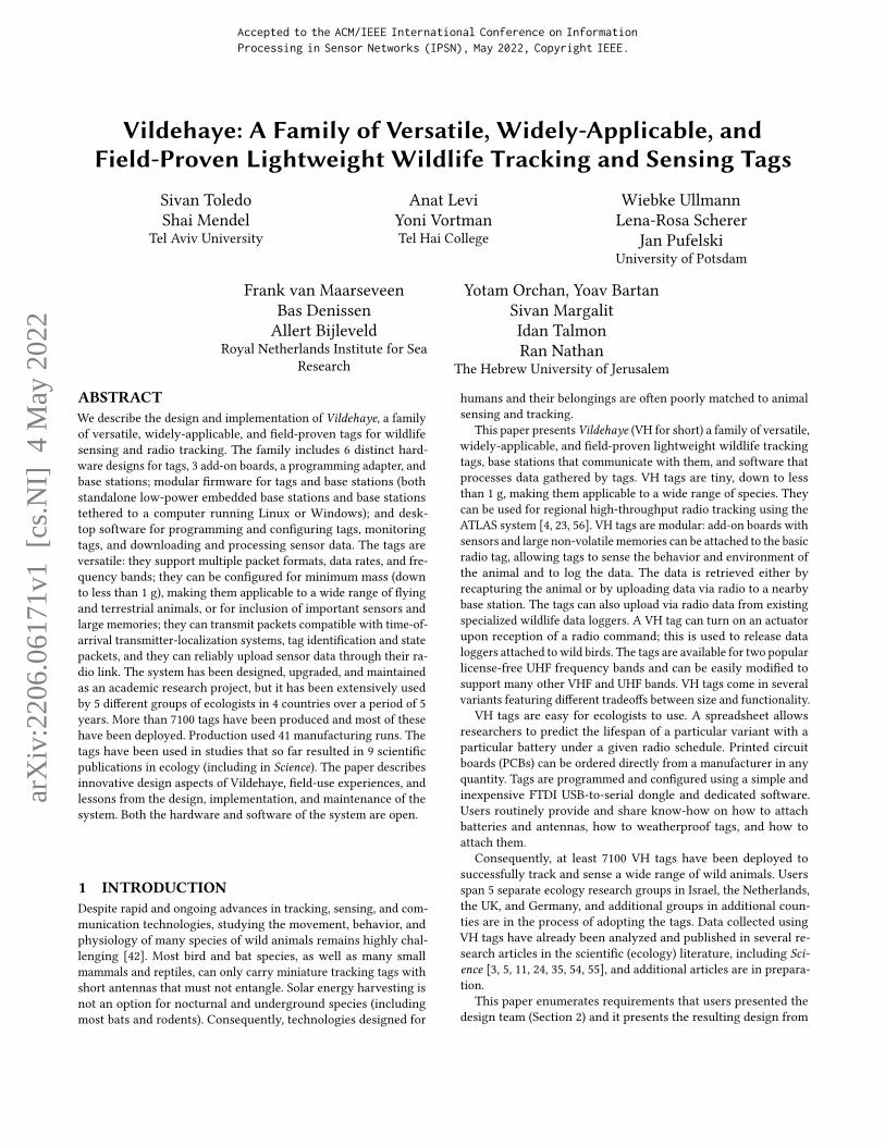
Vildehaye: A Family of Versatile, Widely-Applicable, andField-Proven Lightweight Wildlife Tracking and Sensing Tags
Sivan ToledoShai Mendel
Tel Aviv University
Anat LeviYoni VortmanTel Hai College
Wiebke UllmannLena-Rosa Scherer
Jan PufelskiUniversity of Potsdam
Frank van MaarseveenBas DenissenAllert Bijleveld
Royal Netherlands Institute for SeaResearch
Yotam Orchan, Yoav BartanSivan MargalitIdan TalmonRan Nathan
The Hebrew University of Jerusalem
ABSTRACTWe describe the design and implementation of Vildehaye, a familyof versatile, widely-applicable, and field-proven tags for wildlifesensing and radio tracking. The family includes 6 distinct hard-ware designs for tags, 3 add-on boards, a programming adapter, andbase stations; modular firmware for tags and base stations (bothstandalone low-power embedded base stations and base stationstethered to a computer running Linux or Windows); and desk-top software for programming and configuring tags, monitoringtags, and downloading and processing sensor data. The tags areversatile: they support multiple packet formats, data rates, and fre-quency bands; they can be configured for minimum mass (downto less than 1 g), making them applicable to a wide range of flyingand terrestrial animals, or for inclusion of important sensors andlarge memories; they can transmit packets compatible with time-of-arrival transmitter-localization systems, tag identification and statepackets, and they can reliably upload sensor data through their ra-dio link. The system has been designed, upgraded, and maintainedas an academic research project, but it has been extensively usedby 5 different groups of ecologists in 4 countries over a period of 5years. More than 7100 tags have been produced and most of thesehave been deployed. Production used 41 manufacturing runs. Thetags have been used in studies that so far resulted in 9 scientificpublications in ecology (including in Science). The paper describesinnovative design aspects of Vildehaye, field-use experiences, andlessons from the design, implementation, and maintenance of thesystem. Both the hardware and software of the system are open.
Accepted to the ACM/IEEE International Conference on InformationProcessing in Sensor Networks (IPSN), May 2022, Copyright IEEE.
1 INTRODUCTIONDespite rapid and ongoing advances in tracking, sensing, and com-munication technologies, studying the movement, behavior, andphysiology of many species of wild animals remains highly chal-lenging [42]. Most bird and bat species, as well as many smallmammals and reptiles, can only carry miniature tracking tags withshort antennas that must not entangle. Solar energy harvesting isnot an option for nocturnal and underground species (includingmost bats and rodents). Consequently, technologies designed for
humans and their belongings are often poorly matched to animalsensing and tracking.
This paper presents Vildehaye (VH for short) a family of versatile,widely-applicable, and field-proven lightweight wildlife trackingtags, base stations that communicate with them, and software thatprocesses data gathered by tags. VH tags are tiny, down to lessthan 1 g, making them applicable to a wide range of species. Theycan be used for regional high-throughput radio tracking using theATLAS system [4, 23, 56]. VH tags are modular: add-on boards withsensors and large non-volatile memories can be attached to the basicradio tag, allowing tags to sense the behavior and environment ofthe animal and to log the data. The data is retrieved either byrecapturing the animal or by uploading data via radio to a nearbybase station. The tags can also upload via radio data from existingspecialized wildlife data loggers. A VH tag can turn on an actuatorupon reception of a radio command; this is used to release dataloggers attached to wild birds. The tags are available for two popularlicense-free UHF frequency bands and can be easily modified tosupport many other VHF and UHF bands. VH tags come in severalvariants featuring different tradeoffs between size and functionality.
VH tags are easy for ecologists to use. A spreadsheet allowsresearchers to predict the lifespan of a particular variant with aparticular battery under a given radio schedule. Printed circuitboards (PCBs) can be ordered directly from a manufacturer in anyquantity. Tags are programmed and configured using a simple andinexpensive FTDI USB-to-serial dongle and dedicated software.Users routinely provide and share know-how on how to attachbatteries and antennas, how to weatherproof tags, and how toattach them.
Consequently, at least 7100 VH tags have been deployed tosuccessfully track and sense a wide range of wild animals. Usersspan 5 separate ecology research groups in Israel, the Netherlands,the UK, and Germany, and additional groups in additional coun-ties are in the process of adopting the tags. Data collected usingVH tags have already been analyzed and published in several re-search articles in the scientific (ecology) literature, including Sci-ence [3, 5, 11, 24, 35, 54, 55], and additional articles are in prepara-tion.
This paper enumerates requirements that users presented thedesign team (Section 2) and it presents the resulting design from
arX
iv:2
206.
0617
1v1
[cs
.NI]
4 M
ay 2
022
IPSN, May 2022, Milan, Italy Toledo et al.
the users’ viewpoint (Section 3). Section 4 presents the detaileddesign of the tags and their associated software. The discussionemphasizes innovative aspects related to energy efficiency andeffective use of miniature batteries, to the radio protocol, and toeffective logging of sensor data to flash. Section 5 discusses certainfeatures that we decided not to implement. Section 6 describesfour distinct use cases of the tags, three of which have been usedin the field, to demonstrate the versatility and robustness of thedesign. We conclude the paper with a discussion of related work inSection 7 and with our conclusions from the project in Section 8.
2 REQUIREMENTSThe requirements for VH tags were largely defined by users. Theinitial motivation came from user feedback on the first generationof tags designed for the first ATLAS tracking system [52]. Theseusers expressed a set of needs and desires that led to the initiationof the Vildehaye project in the spring of 2016. As the project pro-gressed, additional requirements came up as users imagined newapplications for the tags.
Requirements whose importance was ranked high by users in-clude:
• Compatibility with ATLAS; tags must be able to transmit uniquepseudo-random data packets at high data rates at an accurateping-repetition interval [56].
• Mass that is as low as possible, ideally down to 1 g or less, forwide applicability; ecologists typically limit the mass of a tag toaround 3% of the mass of the animal, and many species of interestare small (and thus challenging to track and sense). The effectsof tracking and sensing tags have been extensively investigated;in general, tags cause some detrimental effects [6, 25], but theiruse is nonetheless ethically and scientifically justified in manycases. Smaller tags have smaller effects, so they are preferable.
• On-board sensors, especially accelerometers and altimeters, toprovide additional information on the location, environment, andbehavior of the animal.
• Modular hardware and/or multiple hardware variants, to allowproduction of both very lightweight tags with limited functional-ity and lifespan, and heavier tags with sensors, large memories,and long lifespans; in particular, multiple battery configurationsmust be supported.
• Upload of sensor measurements from tags to base stations via aradio link, to avoid the need to retrieve the tag in order to collectthe data. Users understand that radio data transfer uses batteryenergy and shortens the lifespan of tags powered by primarybatteries.
• Easy programming and configuration (ping-repetition intervals,switching between intervals, sensing schedules, etc.).
• Low-cost manufacturing in both small and large batches.
Over time, users came up with a few additional requests. Therequests were examined; some were addressed but not all:
• Transmitting tag-identification packets that can be received by abase station (ideally a low-power base station that can be poweredby a primary battery) to indicate proximity of the tag to the basestation at distances of up to a few or even tens of kilometers;accepted and implemented at ranges of up to a few kilometers.
0 1 2 3 4 5 6 70.5s
ATLAS_433_92transmit
DATA_433_92transmit-receive
con
fig
ura
tio
n 0
0 1 2 3
con
fig
ura
tio
n 1
wakeup 1 command
wakeup 0 commandor no response for 10s
0 1 2 3 4 5 6 71s
1
25Hz
air pressure& temperature
3Dacceleration
Figure 1: A sample definition of the behavior of a tag.The first two rows show two radio configurations, 0 and1, each with two radio setups called ATLAS_433_92 andDATA_433_92. Configurations are states in a finite-state ma-chine; arrows indicate transition rules. Red squares repre-sent transmit-only slots. Red/green squares represent a slotin which the tag transmits and then listens for a reply froma base station. Acceleration is sensed in bursts, at 25 Hz for2 seconds every 4 s; air pressure and temperature are sensedonce every 2 s. The width of colored squares is not to scale.
• The ability to transmit a command to a tag to either changeits operational schedule (e.g., change ping-repetition interval,attempt data upload) and/or to activate an actuator; implemented.
• The ability to detect close-range encounters between tags evenoutside the range of an ATLAS tracking system.
• The ability to interoperate with other wildlife radio tracking andsensing systems; implemented with respect to one such system;there are plans to expand.At a high level, the design of VH tags aims to be as widely-
applicable and as versatile as possible in the sense that it shouldaddress as many use cases that require lightweight radio tags as pos-sible. The design does not aim to address use cases that can toleratehigh weights, high power consumption, or completely differenttracking modalities [42], such as GNSS localization [26], underwa-ter ultrasound localization [14], underground magneto-inductivelocalization [38, 43], or data upload through cellular networks; theseuse cases require different hardware and firmware architectures sotrying to support them would defocus the project.
3 USER-FACING DESIGN
Defining Tag Behavior . Users define the radio behavior and sen-sor behavior of a tag using abstractions shown graphically in Fig-ure 1. The radio behavior is defined in terms of a user-specifiedperiod, here 0.5 s, a set of predefined radio setups, which define thefrequency, modulation, symbol rate, packet format, etc. (here AT-LAS_433_92 and DATA_433_92), and a set of configurations. Each
Vildehaye: A Family of Versatile, Widely-Applicable, and Field-Proven Lightweight Wildlife Tracking and Sensing Tags IPSN, May 2022, Milan, Italy
define tag id &
template in a
configuration
file
write firmware
and
configuration
block
solder battery
and antenna
test radio
pings and
current
consumption
apply coating
& attach
harness
place into
shipping mode
turn on, test
radio pings,
and deploy
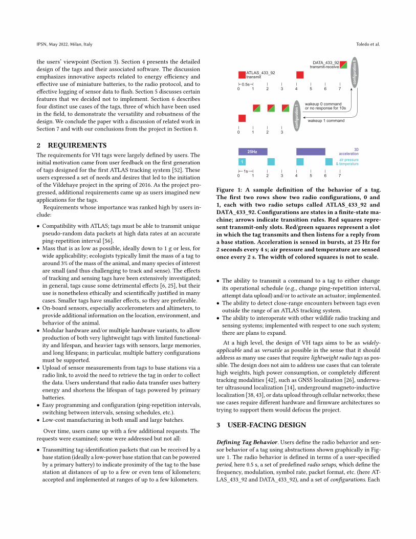
Figure 2: The steps of preparing a VH tag.
configuration defines a schedule for the radio in terms of a fixednumber of slots spaced one period apart. Slots are allocated to radiosetups using a cyclic allocation with a given starting slot. In ourexample, configuration 1 repeats every 8 slots; ATLAS_433_92 isallocated every 4th slot starting at slot 0; DATA_433_92 is allo-cated every 8th slot, starting at 7. The slots of the ATLAS setup aretransmit-only slots. The slots of the DATA setup are marked as slotsthat transmit and then listen for a reply from a base station. Thedefinition of the tag also specifies the state machine that controlstransitions between configurations. Here, transition from configura-tion 0, defined as the initial configuration, to configuration 1 occurswhen the tag receives a wakeup command with argument 1 from abase station. The transition back occurs either when a wakeup 0command is received, or when the tag has not heard any replyfrom a base station for 10 s. The actual transmission and receptionperiods are short, typically a few milliseconds long.
The sensing schedule is defined using a fixed 1 Hz grid. Foreach available sensor, the user defines how often it is sampledand whether the samples are one-shot or repetitive. For repetitivesampling the user specifies the length of the sampling period andthe sampling rate. The user can also specify the configuration ofeach sensor (what quantities a multimodal sensor should sense,full-scale, etc). The definition in Figure 1 specifies sampling airpressure and temperature once every 2 s and acceleration every 4 sat in bursts of 25 Hz for 2 s.
Users can define the behavior of specific tags as well as generaltemplates applied to tags. Tags have unique individual identificationnumbers even when defined from templates. All the definitions arestored in version-controlled text files.
Preparing Tags for Deployment. Figure 2 summarizes the processof preparing a VH tag. The user assigns a unique ID to the tag anddefines its behavior, usually using an existing template. The userattaches a blank assembled tag PCB to an inexpensive USB-to-serialdongle and invokes software on a Windows computer to programsthe appropriate firmware onto the tag, as well as a block of binarydata that defines the behavior of the tag. Tags can be programmedover and over again. Physical preparation starts with soldering anantenna and a primary battery (single Lithium cell or 2 Silver Oxidecells) to the tag and testing that it transmits. Testing is done eitherusing a VH base station or using a low-cost software-defined radioreceiver (SDR) capable of detecting ATLAS transmissions. Next, thetag is coated with insulating varnish [1] and optionally protectedfrom physical damage (biting, scratching) using epoxy ([28, 29],sometimes mixed with glass bubbles to reduce weight, or [2]); forother options for coating and protecting tags, see [14]. If the tag isdeployed (attached to an animal) soon after production, it is oftenleft active between production and deployment. Otherwise, the tag
is put into a shipping mode in which it consumes little or no power;see below for the mechanisms.. When an add-on memory boardis attached to a tag, the memory board must be formatted prior toattaching to the tag. Formatting the memory board is done usingthe same USB-to-serial dongle. The two PCBs are then mated usingstacking board-to-board connectors, usually glued, and are coatedtogether.Collecting Data from Tags. Deployed tags can be tracked by AT-LAS and VH base stations (ATLAS produces accurate localizations,VH base stations only a record of detecting the tag). Data collectedby onboard sensors is retrieved in one of two ways. The tag canupload the data to a VH base station via a radio link, or the tag isphysically retrieved and the data is downloaded either using theUSB-to-serial dongle or by attachment of the memory board tothe SPI bus of a Rasberry Pi (this is faster). Physical retrieval canbe achieved either by recapturing the animal, or by locating andcollecting a tag that was detached from the animal. Detachmentcan be achieved with both passive release mechanisms (an attach-ment mechanism that disintegrates over time) or using an activemechanism that is turned on by sending a command from a basestation.Processing Collected Sensor Data. Sensor data is stored on tagsusing a data structure called a log, which represents a sequence ofpieces of data called log items. Data collected from tags is transferredan SQL database in raw form, each row storing a log item as a binaryblob. Software running on Linux or Windows reads the log itemsassociated with a particular tag and produces binary numeric filescontaining time-stamped sensor measurements. These files are readby Matlab or R software that performs further processing, such asconverting air-pressure data to altitude, classifying behavior basedon accelerometer data, and so on. Similar Matlab and R softwareis used to process location information from ATLAS tracking [23].This analysis software is not part of the VH system and will not befurther discussed in the paper.
4 TECHNICAL DESIGN ANDIMPLEMENTATION
4.1 HardwareOverall Design. VH tags are based on the low-power Texas In-struments CC1310 or CC1350 radio-frequency microcontroller (RFMCU; CC13X0 for short) chip. The chips contain an ARM Cortex-M3 processor, a VHF/UHF data transceiver, an ARM Cortex-M0processor dedicated to the radio stack (not user programmable), alow-power processor called a sensor controller that can eliminaterelatively slow (and hence power hungry) wakeups of the M3 pro-cessor, and a range of peripherals, including timers, UART, I2C, andSPI. The chips come in 4-by-4, 5-by-5, and 7-by-7 mm packages;our tags use the 4-by-4 mm package.
All tags contain a number of additional components, includingan RF matching network, to match the RF MCU to the antennaand to filter harmonics, decoupling capacitors and passives for theswitching and linear regulators, a fairly large (330 `F) reservoir ca-pacitor, a 32 kHz crystal for the real-time clock, a 24 MHz crystalfor the radio, and a miniature male 14-pin board-to-board connec-tor from the Molex SlimStack series. This connector is used for
IPSN, May 2022, Milan, Italy Toledo et al.
sensor
connector
groundpad
reservoircapacitor
antennapad
RF matchingand filter
VDDSpad
RF MCU
redLED
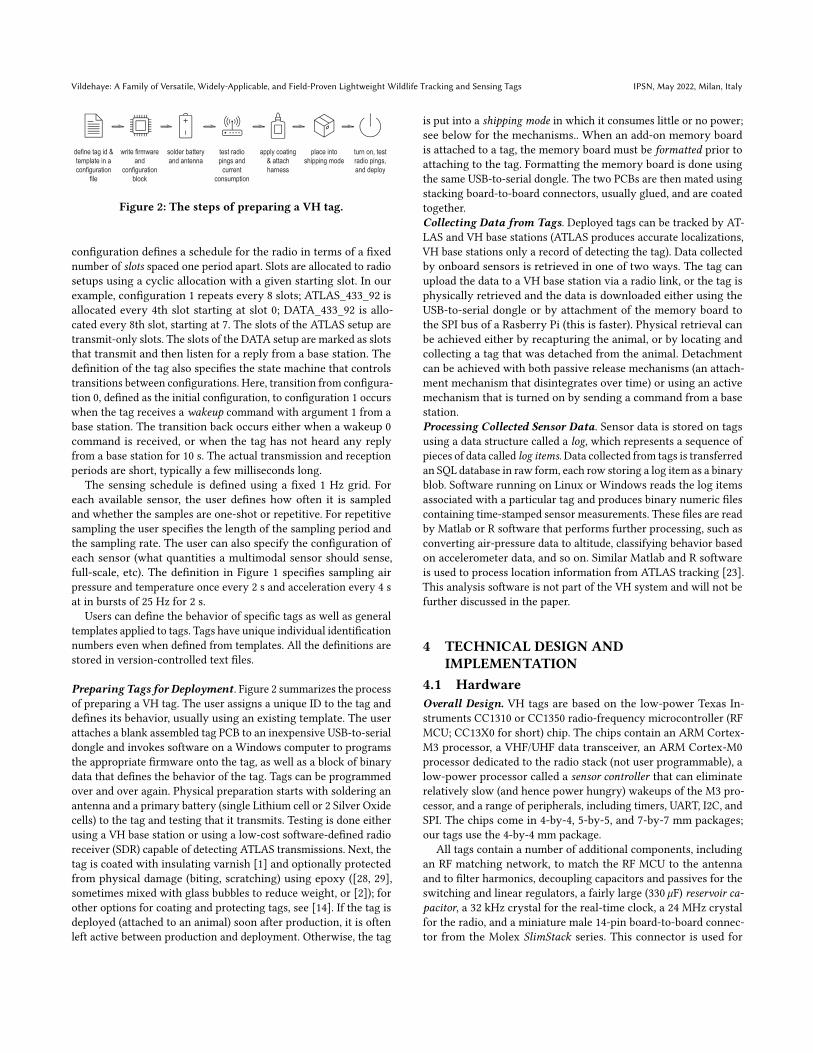
Figure 3: The main components of a tag (version 2.6.3).
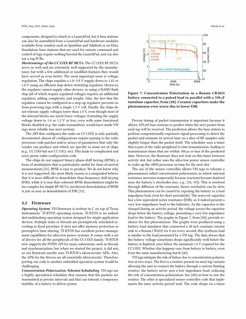
programming and configuring tags, as well as for attachment ofadd-on boards. Figure 3 shows the parts of a typical tag.Hardware Variants. Some tag designs include additional compo-nents, as shown in Figure 6. Most versions include an LED that helpsusers verify that tags function correctly. Version 2.6.3 includes anon-board air-pressure, temperature, and humidity sensor (BME280).Versions 2.8 and 2.9 include perforations between the connectorand the rest of the tag, allowing the connector to be snapped offafter programming, to save weight. Their 14-pin connector doesnot carry the I2C and SPI buses, to make the boards more compact.Version 3.10 includes a separate transmitter, AX5043, to supportphase modulation [31].
The RF matching networks of the most tag designs are tunedfor the 434 MHz band, but version 2.10 is tuned to the 868 and915 MHz bands. Some variants (2.6.1, 2.6.2f, 2.8, 2.9) use a discretebalanced-to-unbalanced network (BALUN) and an integrated low-pass filter, but we also have all-discrete designs and designs (2.6.3,3.10) that rely on a single integrated passive component (IPC) forall the matching and filtering (2.6.3, 2.10). Most of our tag designsare shown in Figure 6, along with some of our add-on boards.
The firmware for both tags and base stations runs on CC13X0LaunchPads and on newer CC13X2 LaunchPads, in which the MCUhas a stronger processor (Cortex-M4F) and optionally a 20 dBmRF power amplifier, as well as on low-cost CC1310 and CC1352modules from a Ebyte, a Chinese manufacturer.Batteries and Voltage Regulation. VH tags are powered by pri-mary batteries including LithiumManganese Dioxide coin cells [18–20, 44], pairs of Silver Oxide cells [21, 22], and Lithium ThionylChloride batteries [49]. Zinc Air batteries, which appear effectivein laboratory testing [51] proved so far unreliable in the field. Allof these batteries can directly power CC13XX chips, which requirea supply voltage and I/O voltage of 1.8-3.8 V (the Lithium ThionylChloride batteries must be drained a bit before connecting to a tag,to bring their voltage down to 3.8 V). The chips regulate the supplyvoltage down to 1.65 V or 1.8 V (allowing transmission at 10 or14 dBm, respectively) using either a linear or a switching regulator.We use the more power-efficient switching regulator. Most of theinternal functional blocks require even lower voltages generatedby internal linear regulators from the 1.65 or 1.8 V rail.
Miniature batteries cannot provide the instantaneous currentrequired during transmission; this current must be supplied byreservoir capacitors [15, 51, 52]. We usually use a 330 `F tanta-lum capacitor. Physically small high-capacitance capacitors areleaky [30, F95 Series]; their leakage current far exceeds the approx-imately 1 `A that the MCU consumes in sleep mode. This has two
2.2M
1µ
reservoircapacitor
330µ
VDD
battery
batteryinternalresistance
GPIO
capacitorleakage
drain
gate
GPIO
firmware
Hallsensor
0 5 10 20 25 30time (s)
0
3
vo
lta
ge
(V
)
VDD
gate voltage GPIO
drain voltage
reservoir capacitor charges
reservoir capacitor is charged
reservoircapacitor
disconnected,leaks
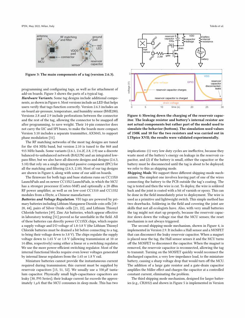
Figure 4: Slowing down the charging of the reservoir capac-itor. The leakage resistor and battery’s internal resistor arenot actual components but rather part of the model used tosimulate the behavior (bottom). The simulation used valuesof 250K and 10 for the two resistors and was carried out inLTSpice XVII; the results were validated experimentally.
implications: (1) very low duty cycles are ineffective, because theywaste most of the battery’s energy on leakage in the reservoir ca-pacitor, and (2) if the battery is small, either the capacitor or thebattery must be disconnected until the tag is about to be deployed;we refer to this as shipping mode.Shipping Mode. We support three different shipping-mode mech-anisms. The simplest one involves leaving part of one of the wiresconnecting the battery to the PCB outside the tag’s coating. Thetag is tested and then the wire is cut. To deploy, the wire is solderedback and the joint is coated with a bit of varnish or epoxy. This canbe done in the field immediately prior to deployment. The wire isused as a primitive and lightweight switch. This simple method hastwo drawbacks. Soldering in the field and covering the joint areskills that not all ecologists have. Also, with very small batteriesthe tag might not start up properly, because the reservoir capac-itor slows down the voltage rise that the MCU senses; the resetmechanism is not always triggered.
The second shipping-mode mechanism, shown in Figure 4, isimplemented in Version 2.9. It includes a Hall sensor and a MOSFETthat can disconnect the leaky reservoir capacitor. When a magnetis placed near the tag, the Hall sensor senses it and the MCU turnsoff the MOSFET to disconnect the capacitor. When the magnet isremoved, the reservoir capacitor is reconnected, allowing the tagto transmit. Turning on the MOSFET quickly would reconnect thedischarged capacitor, a very low-impedance load, to the miniaturebattery, causing a sharp voltage drop that would turn off the MCU.The addition of a large gate resistor and a gate-drain capacitoramplifies the Miller effect and charges the capacitor at a controlledconstant current, eliminating the problem.
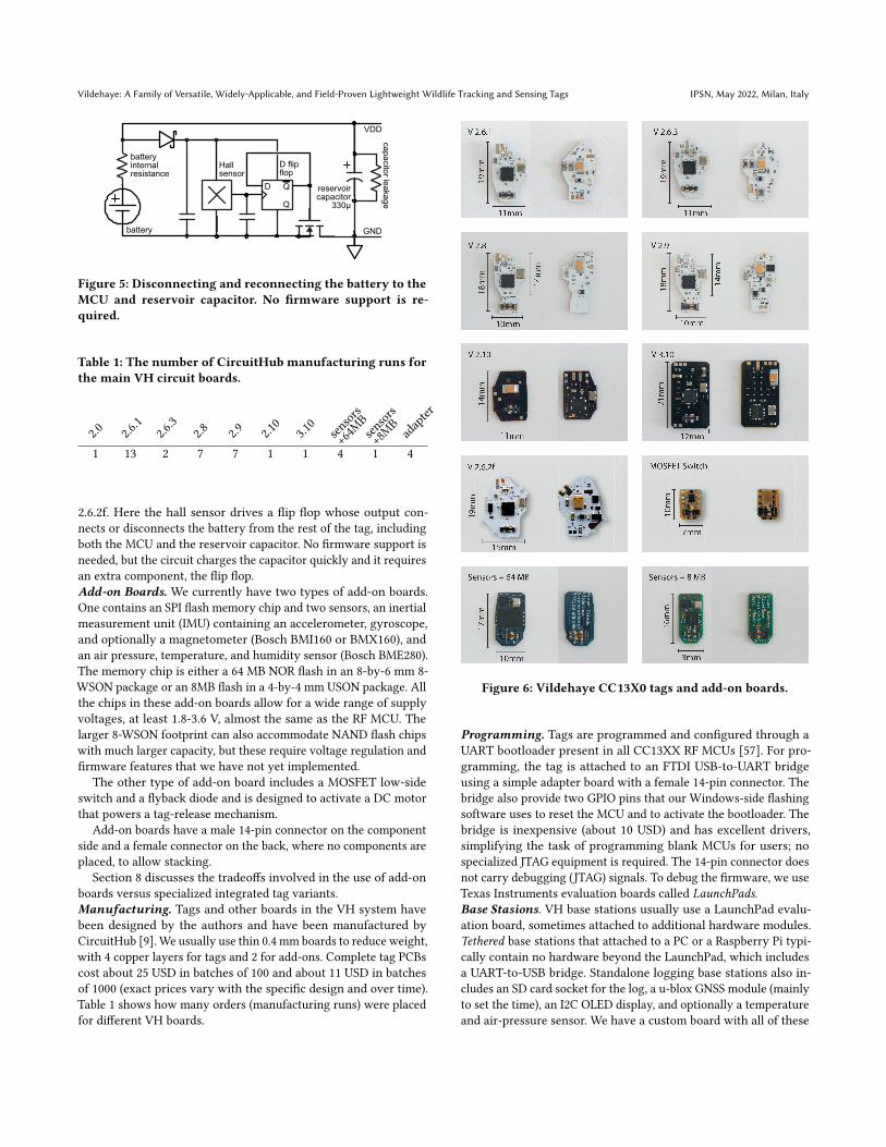
The third shipping mode mechanism, designed for larger batter-ies (e.g., CR2032) and shown in Figure 5 is implemented in Version
Vildehaye: A Family of Versatile, Widely-Applicable, and Field-Proven Lightweight Wildlife Tracking and Sensing Tags IPSN, May 2022, Milan, Italy
reservoircapacitor
330µ
VDD
battery
batteryinternalresistance
ca
pa
cito
r lea
ka
ge
Hall sensor
Q
QD
D flipflop
GND
Figure 5: Disconnecting and reconnecting the battery to theMCU and reservoir capacitor. No firmware support is re-quired.
Table 1: The number of CircuitHub manufacturing runs forthe main VH circuit boards.
2.0 2.6.1
2.6.3
2.8 2.9 2.10
3.10
sensors
+64MBsensors
+8MB ada
pter
1 13 2 7 7 1 1 4 1 4
2.6.2f. Here the hall sensor drives a flip flop whose output con-nects or disconnects the battery from the rest of the tag, includingboth the MCU and the reservoir capacitor. No firmware support isneeded, but the circuit charges the capacitor quickly and it requiresan extra component, the flip flop.Add-on Boards. We currently have two types of add-on boards.One contains an SPI flash memory chip and two sensors, an inertialmeasurement unit (IMU) containing an accelerometer, gyroscope,and optionally a magnetometer (Bosch BMI160 or BMX160), andan air pressure, temperature, and humidity sensor (Bosch BME280).The memory chip is either a 64 MB NOR flash in an 8-by-6 mm 8-WSON package or an 8MB flash in a 4-by-4 mm USON package. Allthe chips in these add-on boards allow for a wide range of supplyvoltages, at least 1.8-3.6 V, almost the same as the RF MCU. Thelarger 8-WSON footprint can also accommodate NAND flash chipswith much larger capacity, but these require voltage regulation andfirmware features that we have not yet implemented.
The other type of add-on board includes a MOSFET low-sideswitch and a flyback diode and is designed to activate a DC motorthat powers a tag-release mechanism.
Add-on boards have a male 14-pin connector on the componentside and a female connector on the back, where no components areplaced, to allow stacking.
Section 8 discusses the tradeoffs involved in the use of add-onboards versus specialized integrated tag variants.Manufacturing. Tags and other boards in the VH system havebeen designed by the authors and have been manufactured byCircuitHub [9]. We usually use thin 0.4 mm boards to reduce weight,with 4 copper layers for tags and 2 for add-ons. Complete tag PCBscost about 25 USD in batches of 100 and about 11 USD in batchesof 1000 (exact prices vary with the specific design and over time).Table 1 shows how many orders (manufacturing runs) were placedfor different VH boards.
Figure 6: Vildehaye CC13X0 tags and add-on boards.
Programming. Tags are programmed and configured through aUART bootloader present in all CC13XX RF MCUs [57]. For pro-gramming, the tag is attached to an FTDI USB-to-UART bridgeusing a simple adapter board with a female 14-pin connector. Thebridge also provide two GPIO pins that our Windows-side flashingsoftware uses to reset the MCU and to activate the bootloader. Thebridge is inexpensive (about 10 USD) and has excellent drivers,simplifying the task of programming blank MCUs for users; nospecialized JTAG equipment is required. The 14-pin connector doesnot carry debugging (JTAG) signals. To debug the firmware, we useTexas Instruments evaluation boards called LaunchPads.Base Stasions. VH base stations usually use a LaunchPad evalu-ation board, sometimes attached to additional hardware modules.Tethered base stations that attached to a PC or a Raspberry Pi typi-cally contain no hardware beyond the LaunchPad, which includesa UART-to-USB bridge. Standalone logging base stations also in-cludes an SD card socket for the log, a u-blox GNSS module (mainlyto set the time), an I2C OLED display, and optionally a temperatureand air-pressure sensor. We have a custom board with all of these
IPSN, May 2022, Milan, Italy Toledo et al.
components, designed to attach to a LaunchPad, but it base stationscan also be assembled from a LaunchPad and hardware modulesavailable from vendors such as Sparkfun and Adafruit or on Ebay.Standalone base stations that are used for remote command andcontrol of tags require nothing beyond the LaunchPad, and can alsouse a tag PCBs.Shortcomings of the CC13XX RF MCUs. The CC13XX RF MCUsserve us well and are extremely well supported by the manufac-turer, but with a few additional or modified features they wouldhave served us even better. The most important issue is voltageregulation. The chips regulate a 1.8–3.8 V supply down to 1.65 or1.8 V using an efficient step-down switching regulator. However,the regulator cannot supply other devices, so using a NAND flashchip (all of which require regulated voltage) requires an additionalregulator, adding complexity and weight. Also, the fact that theregulator cannot be configured as a step-up regulator prevents usfrom powering tags with a single 1.5 V cell. Finally, the chips donot tolerate supply voltages lower than 1.8 V, even though most ofthe internal blocks use much lower voltages. Extending the supplyvoltage down to 1.4 or 1.2 V or less, even with some functionalblocks disabled (e.g. the radio transmitter), would have made VHtags more reliable (see next section).
The API that configures the radio on CC13XX is only partiallydocumented; almost all configurations require passing to the radioprocessor code patches and/or arrays of parameters that only thevendor can produce and which are specific to some set of chips(e.g., CC13X0 but not CC13X2, etc). This leads to complicated anderror-prone radio-configuration code.
The chips do not support binary phase-shift keying (BPSK), aform of modulation that is particularly useful for time-of-arrivalmeasurements [31]. BPSK is easy to produce. We do not know whyit is not supported; the most likely reason is a misguided believethat it is more difficult to demodulate than frequency-shift keying(FSK); while it is true that coherent BPSK demodulation might betoo complex for simple RFMCUs, incoherent demodulation of BPSKis just as easy as demodulation of FSK [31].
4.2 FirmwareOperating System. VH firmware is written in C on top of TexasInstruments’ TI-RTOS operating system. TI-RTOS is an embed-ded multitasking operating system designed for single-applicationdevices. Multiple tasks or threads are preemptively scheduled ac-cording to fixed priorities. It does not offer memory protection orpreemptive time-sharing. TI-RTOS has excellent power manage-ment capabilities for ultra low-power systems. It comes with a setof drivers for all the peripherals of the CC13XX family. TI-RTOSnow supports the POSIX API for many subsystems, such as threadsand synchronization, but when we started the project, it did not,so our firmware mostly uses TI-RTOS’s idiosyncratic APIs. Also,the APIs for the drivers are all essentially idiosyncratic. Therefore,porting our code to another embedded operation system would bechallenging.Concentration-Polarization Tolerant Scheduling. VH tags usea highly specialized scheduler that ensures that the packets aretransmitted at precise intervals and that can tolerate a temporaryinability of a battery to deliver power.
time (s)
0
1
2
3
vo
lta
ge
(V
)
0
20
40
60
80
100
cu
rre
nt (m
A)
400k 800k0
max current during pulse
max voltage at rest
minvoltage during pulses 1.8V
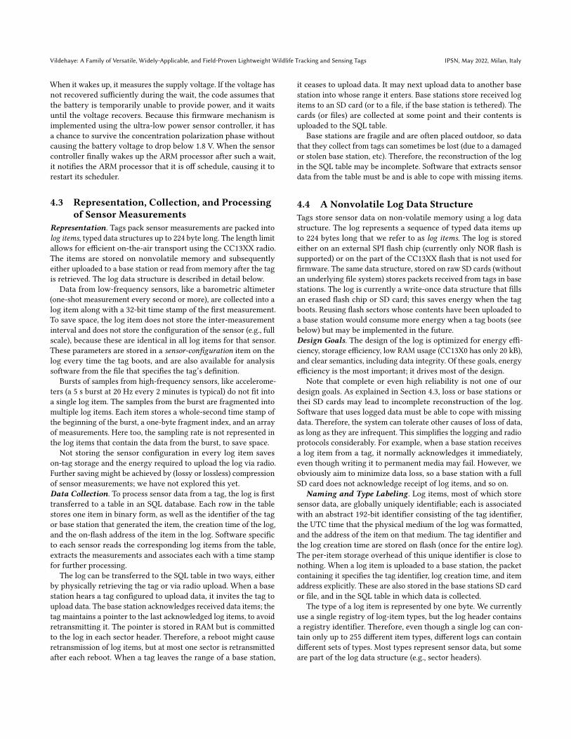
Figure 7: Concentration Polarization in a Renata CR1025battery connected to a pulsed load in parallel with a 330 `Ftantalum capacitor, from [40]. Ceramic capacitors make thephenomenon even worse due to lower ESR.
Precise timing of packet transmission is important because itallows ATLAS base stations to predict when the next packet fromeach tag will be received. The prediction allows the base station toperform computationally-expensive signal-processing to detect thepacket and estimate its arrival time on a slice of RF samples onlyslightly longer than the packet itself. The scheduler uses a timerthat is part of the radio peripheral to time transmissions, leading totransmission times that are within 100 `s or less of the predictedtime. However, the firmware does not wait on this timer betweenactivity slot, but rather uses the ultra-low power sensor controllerto wake up the ARM processor in time for the next slot.
The use of the sensor controller allows VH tags to tolerate aphenomenon called concentration polarization, in which internalresistance increases temporarily because reactants become depletednear the battery’s electrodes (see, e.g., [36, 39]). This is resolvedthrough diffusion of the reactants, hence resolution can be slow.This phenomenon can be caused by exposing the battery to a loadimpedance load, even for short periods[46]. The reservoir capacitorhas a low equivalent series resistance (ESR), so it indeed present avery low-impedance load to the batteries. As the capacitor is dis-charged during an activity period, the voltage across the capacitordrops below the battery voltage, presenting a very low impedanceload to the battery. The graphs in Figure 7, from [40], provide ev-idence for this phenomenon. The graphs were produced using abattery load simulator that connected a 20 mA constant currentsink to a Renata CR1025 for 8 ms every second; this synthesis loadis similar to the load presented by a VH tag. The data shows thatthe battery voltage sometimes drops significantly well below thebattery is depleted, once below the minimum 1.8 V required for theCC13XX. Whether this happens vary from battery to battery, evenfrom the same manufacturing batch [40].
VH tags mitigate the risk of failure due to concentration polariza-tion in two ways. The first is a resistor present on most tag variantsallowing the user to connect the battery through a current-limitingresistor; the battery never sees a low impedance load, reducingthe risk of concentration polarization. See [40] on how to size theresistor. The other is specialized sensor-controller code that imple-ments the inter activity-period wait. The code sleeps on a timer.
Vildehaye: A Family of Versatile, Widely-Applicable, and Field-Proven Lightweight Wildlife Tracking and Sensing Tags IPSN, May 2022, Milan, Italy
When it wakes up, it measures the supply voltage. If the voltage hasnot recovered sufficiently during the wait, the code assumes thatthe battery is temporarily unable to provide power, and it waitsuntil the voltage recovers. Because this firmware mechanism isimplemented using the ultra-low power sensor controller, it hasa chance to survive the concentration polarization phase withoutcausing the battery voltage to drop below 1.8 V. When the sensorcontroller finally wakes up the ARM processor after such a wait,it notifies the ARM processor that it is off schedule, causing it torestart its scheduler.
4.3 Representation, Collection, and Processingof Sensor Measurements
Representation. Tags pack sensor measurements are packed intolog items, typed data structures up to 224 byte long. The length limitallows for efficient on-the-air transport using the CC13XX radio.The items are stored on nonvolatile memory and subsequentlyeither uploaded to a base station or read from memory after the tagis retrieved. The log data structure is described in detail below.
Data from low-frequency sensors, like a barometric altimeter(one-shot measurement every second or more), are collected into alog item along with a 32-bit time stamp of the first measurement.To save space, the log item does not store the inter-measurementinterval and does not store the configuration of the sensor (e.g., fullscale), because these are identical in all log items for that sensor.These parameters are stored in a sensor-configuration item on thelog every time the tag boots, and are also available for analysissoftware from the file that specifies the tag’s definition.
Bursts of samples from high-frequency sensors, like accelerome-ters (a 5 s burst at 20 Hz every 2 minutes is typical) do not fit intoa single log item. The samples from the burst are fragmented intomultiple log items. Each item stores a whole-second time stamp ofthe beginning of the burst, a one-byte fragment index, and an arrayof measurements. Here too, the sampling rate is not represented inthe log items that contain the data from the burst, to save space.
Not storing the sensor configuration in every log item saveson-tag storage and the energy required to upload the log via radio.Further saving might be achieved by (lossy or lossless) compressionof sensor measurements; we have not explored this yet.Data Collection. To process sensor data from a tag, the log is firsttransferred to a table in an SQL database. Each row in the tablestores one item in binary form, as well as the identifier of the tagor base station that generated the item, the creation time of the log,and the on-flash address of the item in the log. Software specificto each sensor reads the corresponding log items from the table,extracts the measurements and associates each with a time stampfor further processing.
The log can be transferred to the SQL table in two ways, eitherby physically retrieving the tag or via radio upload. When a basestation hears a tag configured to upload data, it invites the tag toupload data. The base station acknowledges received data items; thetag maintains a pointer to the last acknowledged log items, to avoidretransmitting it. The pointer is stored in RAM but is committedto the log in each sector header. Therefore, a reboot might causeretransmission of log items, but at most one sector is retransmittedafter each reboot. When a tag leaves the range of a base station,
it ceases to upload data. It may next upload data to another basestation into whose range it enters. Base stations store received logitems to an SD card (or to a file, if the base station is tethered). Thecards (or files) are collected at some point and their contents isuploaded to the SQL table.
Base stations are fragile and are often placed outdoor, so datathat they collect from tags can sometimes be lost (due to a damagedor stolen base station, etc). Therefore, the reconstruction of the login the SQL table may be incomplete. Software that extracts sensordata from the table must be and is able to cope with missing items.
4.4 A Nonvolatile Log Data StructureTags store sensor data on non-volatile memory using a log datastructure. The log represents a sequence of typed data items upto 224 bytes long that we refer to as log items. The log is storedeither on an external SPI flash chip (currently only NOR flash issupported) or on the part of the CC13XX flash that is not used forfirmware. The same data structure, stored on raw SD cards (withoutan underlying file system) stores packets received from tags in basestations. The log is currently a write-once data structure that fillsan erased flash chip or SD card; this saves energy when the tagboots. Reusing flash sectors whose contents have been uploaded toa base station would consume more energy when a tag boots (seebelow) but may be implemented in the future.Design Goals. The design of the log is optimized for energy effi-ciency, storage efficiency, low RAM usage (CC13X0 has only 20 kB),and clear semantics, including data integrity. Of these goals, energyefficiency is the most important; it drives most of the design.
Note that complete or even high reliability is not one of ourdesign goals. As explained in Section 4.3, loss or base stations orthei SD cards may lead to incomplete reconstruction of the log.Software that uses logged data must be able to cope with missingdata. Therefore, the system can tolerate other causes of loss of data,as long as they are infrequent. This simplifies the logging and radioprotocols considerably. For example, when a base station receivesa log item from a tag, it normally acknowledges it immediately,even though writing it to permanent media may fail. However, weobviously aim to minimize data loss, so a base station with a fullSD card does not acknowledge receipt of log items, and so on.
Naming and Type Labeling. Log items, most of which storesensor data, are globally uniquely identifiable; each is associatedwith an abstract 192-bit identifier consisting of the tag identifier,the UTC time that the physical medium of the log was formatted,and the address of the item on that medium. The tag identifier andthe log creation time are stored on flash (once for the entire log).The per-item storage overhead of this unique identifier is close tonothing. When a log item is uploaded to a base station, the packetcontaining it specifies the tag identifier, log creation time, and itemaddress explicitly. These are also stored in the base stations SD cardor file, and in the SQL table in which data is collected.
The type of a log item is represented by one byte. We currentlyuse a single registry of log-item types, but the log header containsa registry identifier. Therefore, even though a single log can con-tain only up to 255 different item types, different logs can containdifferent sets of types. Most types represent sensor data, but someare part of the log data structure (e.g., sector headers).
IPSN, May 2022, Milan, Italy Toledo et al.
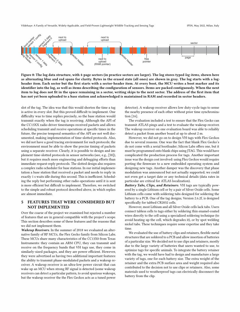
Data Integrity. Data integrity is achieved by identifying itemsthat might have been only partially written to flash due to a poweroutage. Whenever the tag boots, it logs a boot marker. We ensurethat an item has been fully written by verifying that another itemwas written later but and before the system lost power or crashed.Therefore, a data item that is either the last (highest address) onflash or that is followed by a boot marker is suspect as being par-tially written and is not used; other data items have been writtencompletely and are used by clients. (Enforcing this rule is morecomplicated than it seems, since the boot marker may be lost intransport, but we can identify potential loss of boot markers.).On-Flash Representation of the Log. Flash devices are parti-tioned into sectors, which are the smallest erasable blocks, whichare further partitioned into pages. VH logs are currently not erased,but we still partition the log into logical sectors (whose size may dif-fer from that of physical sectors). Pages are 256-byte long on NORflash and 512-byte long on SD cards. The implementation neveruses byte-write operations, only more energy efficient page-writes.Each log item is stored with a two-byte header specifying its lengthand type. Items are packed without gaps, except when the next itemdoes not fit within the space left in a sector, as shown in Figure 8.
Because sectors are not erased and rewritten, sectors are filledmonotonically from low to high addresses. This allow code to findthe first erased sector using a binary search, saving energy relativeto a linear search of a large flash chip. The code then scans linearlywithin the previous sector to find the first free flash address.
Write amplification, which costs both storage and energy, isminimal. Total write amplification consists of the two-byte header(3.2% for items 64-byte or longer), sector headers (9 bytes, 0.2%overhead for 4 kB sectors), and erased gaps at the end of a sector(at most 225 bytes, 5.5%). The overhead of the log header and bootmarker are negligible.
Tags upload items to base stations in address order and keeptrack of the highest acknowledged address. The tag retransmitsthe next item until it is acknowledged. To minimize writes, the tagdoes not record each acknowledgment to flash, only when loggingoperations start a new sector (when the previous has been filled).
4.5 Radio ProtocolRadio Setups. VH tags communicate with base stations using asimple protocol that uses variable-length radio packets. The lengthis encoded in one byte, so the payload is up to 255 bytes long. Theprotocol supports a wide range of radio setups, but we normallyuse just two: a short-range setup, with symbol rate and data ratesof 500 kb/s and with an error detection code (CRC) but no errorcorrection, and a long-range setup with the same symbol rate butwith spreading and error-correction codes that reduce the data rateto 31.5 kb/s. The former is effective in ranges of meters to tensof meters, allowing energy-efficient data upload to a nearby basestation. The latter was shown to be effective at distances of up toof several kilometers [53] but is only intended for short messages,mostly to identify the tag and announce its presence in the area.Data Representation. The payload consists of a sequence of typeddata items, allowing a message to carry multiple data items. Eachdata item starts with a variable-length header that specifies its 16-bit type and length. The header is highly compressed; if the item is
short and the type index low, the header fits in one byte. Longerdata items and high type indexes require longer headers. Commondata types are given low indexes and are kept short, so their headerfits in one byte.
Packets from tags always carry at least two data items, a tag statedata structure and the unique 64-bit tag identifier. The tag-statestructure specifies whether the tag will listen to a reply after thispacket is transmitted, whether it has a significant amount of data toupload to a base station (the current threshold is 4 KB), and in whatconfiguration it is. Tags that log sensor data also send every minutea data item that describes the state of the log, to allow monitoringthe progress of uploads to a base station. Logging tags also sendperiodically the time shown by their real-time clock; base stationsreply with the correct time if the advertised time is incorrect (this ishow the clock is set after a tag is powered). Tags in configurationsintended to upload data to a base station, like configuration 1 inFigure 1, include at most one log item in each packet.Replies. Base stations sometimes reply to packets from tags. Repliesalways specify the identifier of the tag the reply is sent to. Repliesare produced by objects called intents; as their name suggests, theyencapsulate an intent of the user with respect to a particular tag orto all tags. Every base station that has a valid real-time clock (eitherfrom a GNSS receiver or from NTP) acts on an intent to adjustthe clocks of tags: upon reception of a packet advertising a localclock that is more than 2 s off from a tag that will listen next, thebase station replies with the correct time. Similarly, a logging basestation that receives a log item acknowledges it; the tag will moveto transmit the next log item. A base station with a user-specifiedintent to switch a particular tag to a particular radio configurationreplies to its packet with an appropriate wakeup command dataitem if the tag’s state is not in the intended configuration.Uploading Data. Logging base stations that hear a packet indi-cating that the tag has data to upload but not carrying a log itemreplies with a wakeup command telling the tag to go to its highest-indexed configuration (without specifying this index, which thebase station does not know). This configuration should be the onein which data upload occurs (like configuration 1 in Figure 1). Thisstarts a data-upload phase in which the tag sends a log item almostevery period. The base station replies with an acknowledgment thatcause the tag to advance to the next data item. Unacknowledgeditems are retransmitted.Discussion. Many features of the protocol are designed to saveenergy and to limit the duration of transmit-receive slots, to al-low the the radio to be powered by a reservoir capacitor. Theseinclude the highly compressed headers and the variable-encodingof some types of data and the transmission of log items only ifa base station that might acknowledge them was recently heard.Other features are designed for flexibility. These intents, whichmake it relatively easy to add protocol features (e.g., channel orfrequency-band switching), and the structuring of all messages aslists of typed data items. These goals are sometimes conflicting. Forexample, a single fixed message structure would make the protocolmore energy efficient, because no explicit data types would need tobe transmitted, but also much less flexible. We treated flexibility asa constraint and optimized energy use subject to it.A Discarded Design. In our initial design replies did not immedi-ately follow packets from tags but rather occupied the next activity
Vildehaye: A Family of Versatile, Widely-Applicable, and Field-Proven Lightweight Wildlife Tracking and Sensing Tags IPSN, May 2022, Milan, Italy
log header
tag id
boot
mar
ker
sens
or 1
con
fig
sensor 2 config
sens
or 2
dat
a
fr
agm
ent 0
sensor 2 data
fragment 1
sensor 1 data
sector header
sector header
freepointer
page
sector
next toupload
next toupload
next toupload
(RAM pointer)
Figure 8: The log data structure, with 4-page sectors (in practice sectors are larger). The log stores typed log items, shown hereas alternating blue and red spans for clarity. Bytes in the erased state (all ones) are shown in gray. The log starts with a log-header item. Each sector but the first starts with a sector-header item. At every boot, the MCU writes a boot marker and itsidentifier into the log, as well as items describing the configuration of sensors. Items are packed contiguously. When the nextitem to log does not fit in the space remaining in a sector, writing skips to the next sector. The address of the first item thathas not yet been uploaded to a base station and acknowledged is maintained in RAM and recorded in sector headers.
slot of the tag. The idea was that this would shorten the time a tagis active in every slot. But this proved difficult to implement. Onedifficulty was to time replies precisely, so the base station wouldtransmit exactly when the tag is receiving. Although the API ofthe CC13XX radio driver timestamps received packets and allowsscheduling transmit and receive operations at specific times in thefuture, the precise temporal semantics of the API are not well doc-umented, making implementation of time-slotted protocols. Also,we did not have a good tracing environment for such protocols; theenvironment must be able to show the precise timing of packetsusing a separate receiver. Clearly, it is possible to design and im-plement time-slotted protocols in sensor networks (see, e.g., [58]),but it requires much more engineering and debugging efforts thanimmediate request-reply protocols. The slotted design also requiresa complex radio scheduler for base stations. In our initial implemen-tation a base station that received a packet and needs to reply inexactly 1 s waits idle during this second. This is inefficient. Schedul-ing the reply but performing other radio operations until it is sentis more efficient but difficult to implement. Therefore, we switchedto the simple and robust protocol described above, in which repliesare almost immediate.
5 FEATURES THATWERE CONSIDERED BUTNOT IMPLEMENTED
Over the coarse of the project we examined but rejected a numberof features that are in general compatible with the project’s scope.This section describes some of these features and the reasons thatwe did not implement them.Wakeup Receivers. In the summer of 2018 we evaluated an alter-native family of RF MCUs, the Flex Gecko family from Silicon Labs.These MCUs share many characteristics of the CC13X0 from TexasInstruments: they contain an ARM CPU, they can transmit andreceive on the frequency bands that VH tags use, they come insimilarly-sized packages, and they are power efficient. However,they were advertised as having two additional important features:the ability to transmit phase-modulated packets and a wakeup re-ceiver. A wakeup receiver is an ultra-low power circuit that canwake up an MCU when strong RF signal is detected (some wakeupreceivers can detect a particular pattern, to avoid spurious wakeups,but the wakeup receiver the the Flex Geckos acts as a tuned power
detector). A wakeup receiver allows low duty-cycle tags to sensethe nearby presence of each other without prior time synchroniza-tion [16].
The evaluation included a test to ensure that the Flex Gecko cantransmit ATLAS pings and a test to evaluate the wakeup receiver.The wakeup receiver on one evaluation board was able to reliablydetect a packet from another board at up to about 2 m.
However, we did not go on to design VH tags with Flex Geckosdue to several reasons. One was the fact that blank Flex Gecko’sdo not come with a serial bootloader; Silicon Labs offers one, but itmust be programmed onto blank chips using JTAG. This would havecomplicated the production process for tags. Another importantissue was the design cost involved: using Flex Geckos would requireporting the firmware to a new embedded operating system anddesigning new tags. Another damper was the discovery that phasemodulation was announced but not actually supported; we couldnot even get a target date or any technical details (data rates inparticular are critical for ATLAS localization).Battery Tabs, Clips, and Retainers. VH tags are typically pow-ered by a single Lithium cell or by a pair of Silver Oxide cells. SomeLithium cells come with soldering tabs designed for soldering thebattery to a PCB. One of the tag designs, Version 2.6.2f, is designedspecifically for tabbed CR2032 cells.
However, most Lithium and all Silver Oxide cells lack tabs. Usersconnect tabless cells to tags either by soldering thin enamel-coatedwires directly to the cell using a specialized soldering technique (toavoid heating up the cell, which degrades it), or by spot weldingnickel tabs. These techniques require some expertise and they taketime.
We evaluated the use of battery clips and retainers, flexible metalstructures that are soldered to a PCB and allow insertion of batteriesof a particular size. We decided not to use clips and retainers, mostlydue to the large variety of batteries that users wanted to use, tooptimize tags for specific animals. To integrate the battery retainerwith the tag, we would have had to design and manufacture a largevariety of tags, one for each battery size. The extra weight of theretainer and the extra PCB surface area and weight required alsocontributed to the decision not to use clips or retainers. Also, somematerials used to weatherproof tags can electrically disconnect thebattery from the clip.
IPSN, May 2022, Milan, Italy Toledo et al.
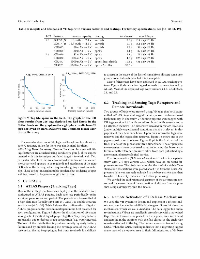
Table 2: Weights and lifespans of VH tags with various batteries and coatings. For battery specifications, see [18–22, 44, 49].
PCB battery energy capacity coating total mass max lifespan2.8 SO337 (2) 8.3mAh → 2.4V varnish 0.8 g 10.4 d @ 1/8 Hz
SO317 (2) 11.5mAh → 2.4V varnish 0.9 g 13.1 d @ 1/8 HzCR1025 30mAh → 2V varnish 1.2 g 32 d @ 1/8 HzCR1025 30mAh → 2V epoxy 1.4 g 32 d @ 1/8 Hz
2.6 CR1620 81mAh → 2V epoxy 2.4 g 79 d @ 1/8 HzCR2032 235mAh → 2V epoxy 4.2 g 226 d @ 1/6 HzCR2477 1000mAh → 2V epoxy, heat shrink 10.5 g 431 d @ 1/8 HzTL4920 8500mAh → 2V epoxy & collar 90.0 g
0 50 100 150 200
tracking duration (days)
0
50
100
150
200
nu
mb
er
of ta
gs
4.2g, 1/6Hz, CR2032, 2019
0 50 100 150 200
tracking duration (hours)
0
5
10
15
20
25
30
nu
mb
er
of ta
gs
0.9g, 1/8Hz, SO337 (2), 2020
Figure 9: Tag life spans in the field. The graph on the leftplots results from 226 tags deployed on Red Knots in theNetherlands and the graph on the right plots results from 29tags deployed on Barn Swallows and Common House Mar-tins in Germany.
The modular structure of VH tags enables add-on boards with abattery retainer, but so far there was not demand for them.Attaching Batteries using Conductive Glue. In some wildlifetags batteries are attached using conductive glue [14].We experi-mented with this technique but failed to get it to work well. Twoparticular difficulties that we encountered were smears that causedshorts (a stencil appears to be required) and attachment of the non-PCB side of the battery, which requires designing a custom metalclip. These are not insurmountable problems but soldering or spotwelding proved to be good-enough alternatives.
6 USE CASES6.1 ATLAS Pingers (Tracking Tags)Most of the VH tags that have been deployed in the field have beenconfigured as ATLAS pingers. Each such tag periodically emitsa unique pseudo-random packet. The packets are transmitted ata high data rate (usually 8192 bits at 1 Mb/s), to enable accuratelocalization [4, 31, 56]. Table 2 shows the configuration of typicalATLAS pingers and the maximum lifespan in the field recorded foreach configuration. Figure 9 shows the distribution of life spansamong sets of identical tags deployed together. Very early failuresare usually due to defects in tag preparation (e.g. water ingress).The rest of the distribution is produced mostly by early batteryfailures and by animals leaving the coverage area of the ATLASsystem (i.e., the tag keeps pinging but is not received). It is difficult
to ascertain the cause of the loss of signal from all tags; some usergroups collected such data, but it is incomplete.
Most of these tags have been deployed in ATLAS tracking sys-tems. Figure 10 shows a few tagged animals that were tracked byATLAS. Most of the deployed tags were versions 2.6.1, 2.6.2f, 2.6.3.,2.8, and 2.9.
6.2 Tracking and Sensing Tags: Recapture andRemote Downloads
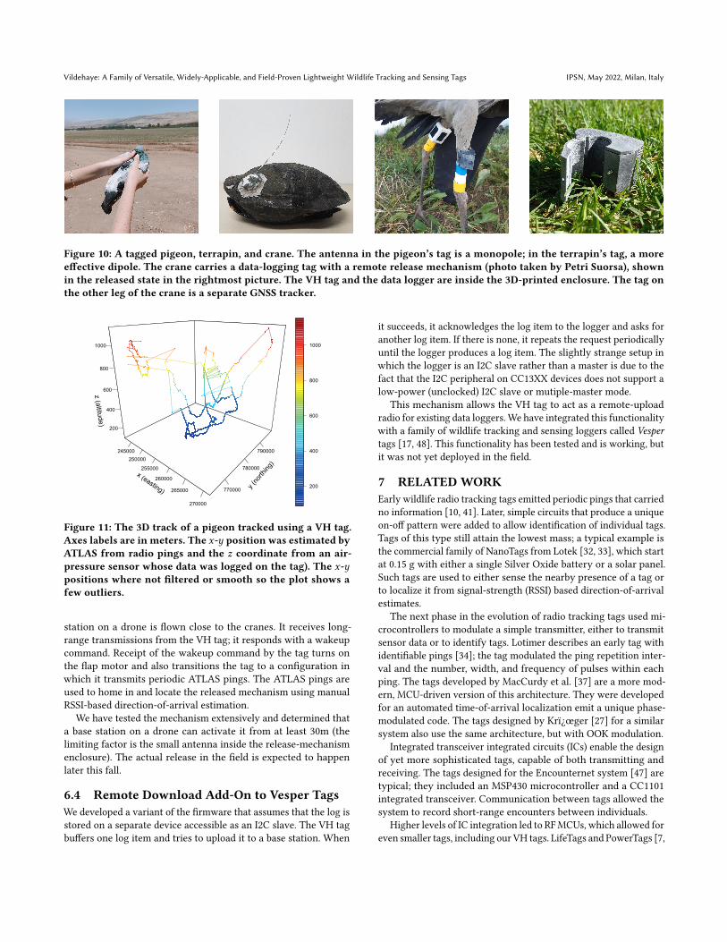
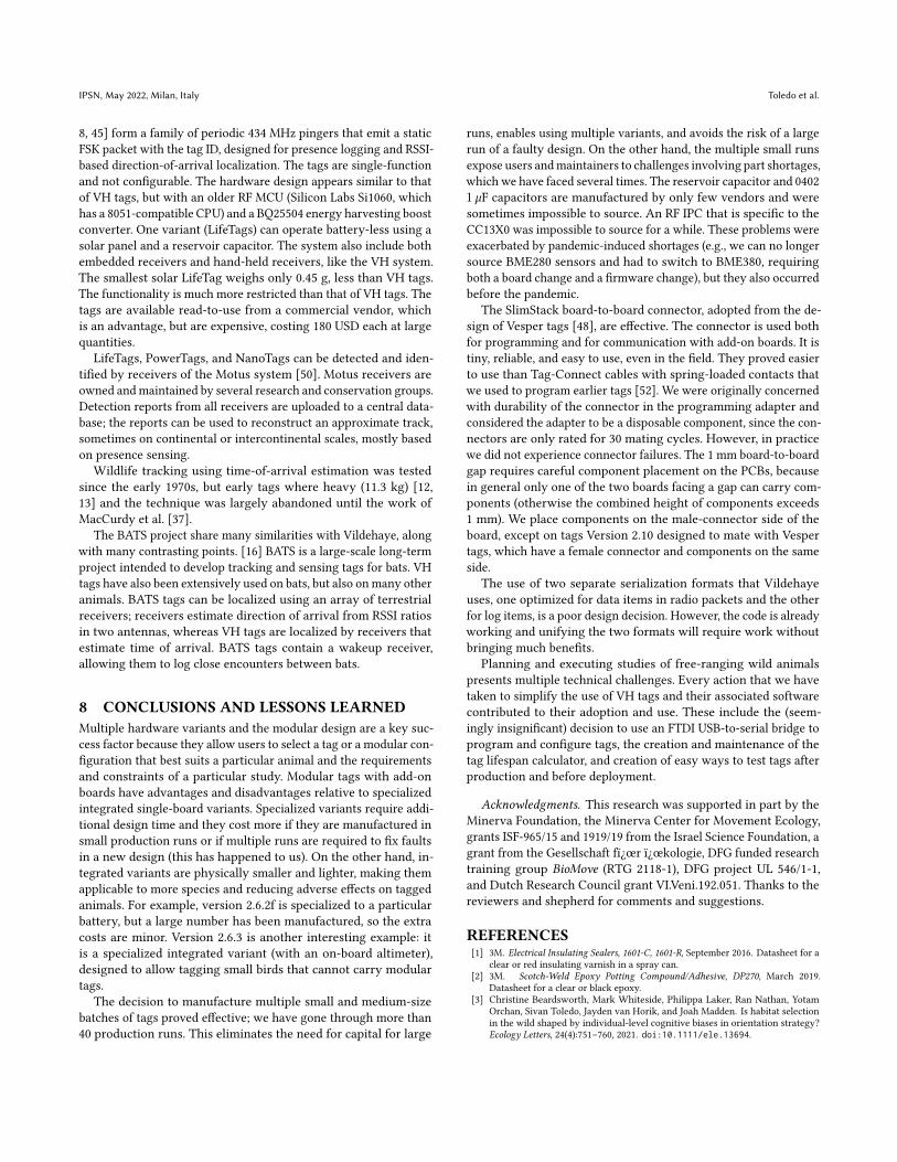
Two groups of birds were tracked using VH tags that both trans-mitted ATLAS pings and logged the air-pressure onto on-boardflash memory. In one study, 27 homing pigeons were tagged withVH tags version 2.6.1 with an add-on board with sensors and a64 MB flash memory. The birds were released in remote locations(under multiple experimental conditions that are irrelevant in thispaper) and they flew back home. Upon their return the tags wereremoved and the logged data retrieved. Figure 10 shows one of thepigeons just prior to release. Figure 11 plots the first part of thetrack of one of the pigeons in three dimensions. The air pressuremeasurements were converted to altitude using the barometricformula, with reference pressure taken from data published by agovernmental meteorological service.
Five house martins (Delichon urbicum) were tracked in a separatestudy with VH tags version 2.6.3, which have an on-board air-pressure sensor. The birds nested under the roof of a stable. Twostandalone basestations were placed about 3 m from the nests. Air-pressure data was remotely uploaded to the base stations and thentransferred to an SQL database for further processing.
We verified the calibration and accuracy of the air-pressure sen-sor and the correctness of the estimation of altitude from air pres-sure using a drone; we omit the details.
6.3 Remote Activation of a Release MechanismWe used the VH system to design and implement a release-and-retrieval mechanism for wildlife data loggers. Figure 10 show themechanism, which we call a Krukhya. The data logger (an audiorecorder) and a VH tag are installed in an enclosurewith amotorizedflap. The enclosures were placed on the legs a cranes in Finlandand Estonia in the summer with the flap closed, so the enclosureremains attached to the leg. The cranes were also tracked usingGNSS. When the GNSS tracking indicates that a migrating taggedcrane reached a stopover area in their fall migration, a VH base
Vildehaye: A Family of Versatile, Widely-Applicable, and Field-Proven Lightweight Wildlife Tracking and Sensing Tags IPSN, May 2022, Milan, Italy
Figure 10: A tagged pigeon, terrapin, and crane. The antenna in the pigeon’s tag is a monopole; in the terrapin’s tag, a moreeffective dipole. The crane carries a data-logging tag with a remote release mechanism (photo taken by Petri Suorsa), shownin the released state in the rightmost picture. The VH tag and the data logger are inside the 3D-printed enclosure. The tag onthe other leg of the crane is a separate GNSS tracker.
x (easting)
245000
250000
255000
260000
265000
270000
y (n
orth
ing)
770000
780000
790000
z (a
ltitude)
200
400
600
800
1000
200
400
600
800
1000
Figure 11: The 3D track of a pigeon tracked using a VH tag.Axes labels are in meters. The 𝑥-𝑦 position was estimated byATLAS from radio pings and the 𝑧 coordinate from an air-pressure sensor whose data was logged on the tag). The 𝑥-𝑦positions where not filtered or smooth so the plot shows afew outliers.
station on a drone is flown close to the cranes. It receives long-range transmissions from the VH tag; it responds with a wakeupcommand. Receipt of the wakeup command by the tag turns onthe flap motor and also transitions the tag to a configuration inwhich it transmits periodic ATLAS pings. The ATLAS pings areused to home in and locate the released mechanism using manualRSSI-based direction-of-arrival estimation.
We have tested the mechanism extensively and determined thata base station on a drone can activate it from at least 30m (thelimiting factor is the small antenna inside the release-mechanismenclosure). The actual release in the field is expected to happenlater this fall.
6.4 Remote Download Add-On to Vesper TagsWe developed a variant of the firmware that assumes that the log isstored on a separate device accessible as an I2C slave. The VH tagbuffers one log item and tries to upload it to a base station. When
it succeeds, it acknowledges the log item to the logger and asks foranother log item. If there is none, it repeats the request periodicallyuntil the logger produces a log item. The slightly strange setup inwhich the logger is an I2C slave rather than a master is due to thefact that the I2C peripheral on CC13XX devices does not support alow-power (unclocked) I2C slave or mutiple-master mode.
This mechanism allows the VH tag to act as a remote-uploadradio for existing data loggers. We have integrated this functionalitywith a family of wildlife tracking and sensing loggers called Vespertags [17, 48]. This functionality has been tested and is working, butit was not yet deployed in the field.
7 RELATEDWORKEarly wildlife radio tracking tags emitted periodic pings that carriedno information [10, 41]. Later, simple circuits that produce a uniqueon-off pattern were added to allow identification of individual tags.Tags of this type still attain the lowest mass; a typical example isthe commercial family of NanoTags from Lotek [32, 33], which startat 0.15 g with either a single Silver Oxide battery or a solar panel.Such tags are used to either sense the nearby presence of a tag orto localize it from signal-strength (RSSI) based direction-of-arrivalestimates.
The next phase in the evolution of radio tracking tags used mi-crocontrollers to modulate a simple transmitter, either to transmitsensor data or to identify tags. Lotimer describes an early tag withidentifiable pings [34]; the tag modulated the ping repetition inter-val and the number, width, and frequency of pulses within eachping. The tags developed by MacCurdy et al. [37] are a more mod-ern, MCU-driven version of this architecture. They were developedfor an automated time-of-arrival localization emit a unique phase-modulated code. The tags designed by Krï¿œger [27] for a similarsystem also use the same architecture, but with OOK modulation.
Integrated transceiver integrated circuits (ICs) enable the designof yet more sophisticated tags, capable of both transmitting andreceiving. The tags designed for the Encounternet system [47] aretypical; they included an MSP430 microcontroller and a CC1101integrated transceiver. Communication between tags allowed thesystem to record short-range encounters between individuals.
Higher levels of IC integration led to RFMCUs, which allowed foreven smaller tags, including our VH tags. LifeTags and PowerTags [7,
IPSN, May 2022, Milan, Italy Toledo et al.
8, 45] form a family of periodic 434 MHz pingers that emit a staticFSK packet with the tag ID, designed for presence logging and RSSI-based direction-of-arrival localization. The tags are single-functionand not configurable. The hardware design appears similar to thatof VH tags, but with an older RF MCU (Silicon Labs Si1060, whichhas a 8051-compatible CPU) and a BQ25504 energy harvesting boostconverter. One variant (LifeTags) can operate battery-less using asolar panel and a reservoir capacitor. The system also include bothembedded receivers and hand-held receivers, like the VH system.The smallest solar LifeTag weighs only 0.45 g, less than VH tags.The functionality is much more restricted than that of VH tags. Thetags are available read-to-use from a commercial vendor, whichis an advantage, but are expensive, costing 180 USD each at largequantities.
LifeTags, PowerTags, and NanoTags can be detected and iden-tified by receivers of the Motus system [50]. Motus receivers areowned andmaintained by several research and conservation groups.Detection reports from all receivers are uploaded to a central data-base; the reports can be used to reconstruct an approximate track,sometimes on continental or intercontinental scales, mostly basedon presence sensing.
Wildlife tracking using time-of-arrival estimation was testedsince the early 1970s, but early tags where heavy (11.3 kg) [12,13] and the technique was largely abandoned until the work ofMacCurdy et al. [37].
The BATS project share many similarities with Vildehaye, alongwith many contrasting points. [16] BATS is a large-scale long-termproject intended to develop tracking and sensing tags for bats. VHtags have also been extensively used on bats, but also onmany otheranimals. BATS tags can be localized using an array of terrestrialreceivers; receivers estimate direction of arrival from RSSI ratiosin two antennas, whereas VH tags are localized by receivers thatestimate time of arrival. BATS tags contain a wakeup receiver,allowing them to log close encounters between bats.
8 CONCLUSIONS AND LESSONS LEARNEDMultiple hardware variants and the modular design are a key suc-cess factor because they allow users to select a tag or a modular con-figuration that best suits a particular animal and the requirementsand constraints of a particular study. Modular tags with add-onboards have advantages and disadvantages relative to specializedintegrated single-board variants. Specialized variants require addi-tional design time and they cost more if they are manufactured insmall production runs or if multiple runs are required to fix faultsin a new design (this has happened to us). On the other hand, in-tegrated variants are physically smaller and lighter, making themapplicable to more species and reducing adverse effects on taggedanimals. For example, version 2.6.2f is specialized to a particularbattery, but a large number has been manufactured, so the extracosts are minor. Version 2.6.3 is another interesting example: itis a specialized integrated variant (with an on-board altimeter),designed to allow tagging small birds that cannot carry modulartags.
The decision to manufacture multiple small and medium-sizebatches of tags proved effective; we have gone through more than40 production runs. This eliminates the need for capital for large
runs, enables using multiple variants, and avoids the risk of a largerun of a faulty design. On the other hand, the multiple small runsexpose users andmaintainers to challenges involving part shortages,which we have faced several times. The reservoir capacitor and 04021 `F capacitors are manufactured by only few vendors and weresometimes impossible to source. An RF IPC that is specific to theCC13X0 was impossible to source for a while. These problems wereexacerbated by pandemic-induced shortages (e.g., we can no longersource BME280 sensors and had to switch to BME380, requiringboth a board change and a firmware change), but they also occurredbefore the pandemic.
The SlimStack board-to-board connector, adopted from the de-sign of Vesper tags [48], are effective. The connector is used bothfor programming and for communication with add-on boards. It istiny, reliable, and easy to use, even in the field. They proved easierto use than Tag-Connect cables with spring-loaded contacts thatwe used to program earlier tags [52]. We were originally concernedwith durability of the connector in the programming adapter andconsidered the adapter to be a disposable component, since the con-nectors are only rated for 30 mating cycles. However, in practicewe did not experience connector failures. The 1 mm board-to-boardgap requires careful component placement on the PCBs, becausein general only one of the two boards facing a gap can carry com-ponents (otherwise the combined height of components exceeds1 mm). We place components on the male-connector side of theboard, except on tags Version 2.10 designed to mate with Vespertags, which have a female connector and components on the sameside.
The use of two separate serialization formats that Vildehayeuses, one optimized for data items in radio packets and the otherfor log items, is a poor design decision. However, the code is alreadyworking and unifying the two formats will require work withoutbringing much benefits.
Planning and executing studies of free-ranging wild animalspresents multiple technical challenges. Every action that we havetaken to simplify the use of VH tags and their associated softwarecontributed to their adoption and use. These include the (seem-ingly insignificant) decision to use an FTDI USB-to-serial bridge toprogram and configure tags, the creation and maintenance of thetag lifespan calculator, and creation of easy ways to test tags afterproduction and before deployment.
Acknowledgments. This research was supported in part by theMinerva Foundation, the Minerva Center for Movement Ecology,grants ISF-965/15 and 1919/19 from the Israel Science Foundation, agrant from the Gesellschaft fï¿œr ï¿œkologie, DFG funded researchtraining group BioMove (RTG 2118-1), DFG project UL 546/1-1,and Dutch Research Council grant VI.Veni.192.051. Thanks to thereviewers and shepherd for comments and suggestions.
REFERENCES[1] 3M. Electrical Insulating Sealers, 1601-C, 1601-R, September 2016. Datasheet for a
clear or red insulating varnish in a spray can.[2] 3M. Scotch-Weld Epoxy Potting Compound/Adhesive, DP270, March 2019.
Datasheet for a clear or black epoxy.[3] Christine Beardsworth, Mark Whiteside, Philippa Laker, Ran Nathan, Yotam
Orchan, Sivan Toledo, Jayden van Horik, and Joah Madden. Is habitat selectionin the wild shaped by individual-level cognitive biases in orientation strategy?Ecology Letters, 24(4):751–760, 2021. doi:10.1111/ele.13694.
Vildehaye: A Family of Versatile, Widely-Applicable, and Field-Proven Lightweight Wildlife Tracking and Sensing Tags IPSN, May 2022, Milan, Italy
[4] Christine E. Beardsworth, Evy Gobbens, Frank van Maarseveen, Bas Denissen,Anne Dekinga, Ran Nathan, Sivan Toledo, and Allert I. Bijleveld. Validating a high-throughput tracking system: ATLAS as a regional-scale alternative to GPS, 2021.BioRxiv preprint, submitted for publication. doi:10.1101/2021.02.09.430514.
[5] Christine E. Beardsworth, Mark A. Whiteside, Lucy A. Capstick, Philippa R.Laker, Ellis J. G. Langley, Ran Nathan, Yotam Orchan, Sivan Toledo, Jayden O. vanHorik, and Joah R. Madden. Spatial cognitive ability is associated with transitorymovement speed but not straightness during the early stages of exploration.Royal Society Open Science, 8(3), 2021. doi:10.1098/rsos.201758.
[6] Thomas W. Bodey, Ian R. Cleasby, Fraser Bell, Nicole Parr, Anthony Schultz,Stephen C. Votier, and Stuart Bearhop. A phylogenetically controlled meta-analysis of biologging device effects on birds: Deleterious effects and a call formore standardized reporting of study data. Methods in Ecology and Evolution,9(4):946–955, 2017. doi:10.1111/2041-210X.12934.
[7] Cellular Tracking Technologies. LifeTag. Retrieved February 9, 2022. URL:https://celltracktech.com/products/tag-system/lifetag/.
[8] Cellular Tracking Technologies. PowerTag. Retrieved February 9, 2022. URL:https://celltracktech.com/products/tag-system/powertag/.
[9] CircuitHub. Rapid electronics manufacturing. Retrieved February 9, 2022. URL:https://www.circuithub.com.
[10] William W. Cochran and Rexford T. Lord, Jr. A radio-tracking system for wildanimals. The Journal of Wildlife Management, 27(1):9–24, 1963.
[11] Ammon Corl, Motti Charter, Gabe Rozman, Sivan Toledo, Sondra Turjeman,Pauline L. Kamath, Wayne M. Getz, Ran Nathan, and Rauri C. K. Bowie. Move-ment ecology and sex are linked to barn owl microbial community composition.Molecular Ecology, 20(7):1358–1371, 2020. doi:10.1111/mec.15398.
[12] Frank .C. Craighead, Jr., John J. Craighead, Charles E. Cote, and Helmut K. Buech-ner. Satellite and ground radio tracking of elk. In S. R. Galler, K. Schmidt-Koenig,G. J. Jacobs, and R. E. Belleville, editors, Animal Orientation and Navigation,number 262 in NASA Special Publication, pages 99–111. 1972.
[13] John J. Craighead, Frank C. Craighead, Jr., Joel R. Varney, and Charles E. Cote.Satellite monitoring of black bear. BioScience, 21(24):1206–1212, 1971. doi:10.2307/1296018.
[14] Z. D. Deng, T. J. Carlson, H. Li, J. Xiao, M. J. Myjak, J. Lu, J. J. Martinez, C. M.Woodley, M. A. Weiland, and M. B. Eppard. An injectable acoustic transmitterfor juvenile salmon. Scientific Reports, 5(8111), 2015. doi:10.1038/srep08111.
[15] Falko Dressler, Simon Ripperger, Martin Hierold, Thorsten Nowak, ChristopherEibel, Bjorn Cassens, Frieder Mayer, Klaus Meyer-Wegener, and Alexander Kolpin.From radio telemetry to ultra-low-power sensor networks: tracking bats in thewild. IEEE Communications Magazine, 54(1):129–135, 2016. doi:10.1109/MCOM.2016.7378438.
[16] Niklas Duda, Thorsten Nowak, Markus Hartmann, Michael Schadhauser, BjörnCassens, Peter WÀgemann, Muhammad Nabeel, Simon Ripperger, SebastianHerbst, Klaus Meyer-Wegener, Frieder Mayer, Falko Dressler, Wolfgang Schröder-Preikschat, Rüdiger Kapitza, Jörg Robert, Jörn Thielecke, Robert Weigel, andAlexander Kölpin. BATS: Adaptive ultra low power sensor network for animaltracking. Sensors, 18(10), 2018. doi:10.3390/s18103343.
[17] Katya Egert-Berg, Edward R. Hurme, Stefan Greif, Aya Goldstein, Lee Harten,Luis Gerardo Herrera M., José Juan Flores-Martínez, Andrea T. Valdés, Dave S.Johnston, Ofri Eitan, Ivo Borissov, Jeremy Ryan Shipley, Rodrigo A. Medellin,Gerald S. Wilkinson, Holger R. Goerlitz, and Yossi Yovel. Resource ephemeralitydrives social foraging in bats. Current Biology, 28(22):3667–3673, 2018. doi:10.1016/j.cub.2018.09.064.
[18] Energizer. Lithium Manganese Dioxide Coin Cell, CR1025. Datasheet, FormNo. 1025NA0618; not dated.
[19] Energizer. Lithium Manganese Dioxide Coin Cell, CR1620. Datasheet, FormNo. 1620GL0618; not dated.
[20] Energizer. Lithium Manganese Dioxide Coin Cell, CR2032. Datasheet, FormNo. CR2032EU0118; not dated.
[21] Energizer. Silver Oxide Coin Cell, 317. Datasheet, Form No. 317GL0719; not dated.[22] Energizer. Silver Oxide Coin Cell, 337. Datasheet, Form No. 337GL0719; not dated.[23] Pratik Rajan Gupte, Christine E. Beardsworth, Orr Spiegel, Emmanuel Lourie,
Sivan Toledo, Ran Nathan, and Allert I. Bijleveld. A guide to pre-processinghigh-throughput animal tracking data. Journal of Animal Ecology, 91(2):287–307,2021. doi:10.1111/1365-2656.13610.
[24] Robert J. P. Heathcote, Mark A. Whiteside, Christine Beardsworth, Philippa R.Laker, Jayden Van Horik, Sivan Toledo, Yotam Orchan, Ran Nathan, and Joah R.Madden. Spatial memory and landscape familiarity drive home range formationand predict predation risk, March 2021. Sumitted for publication.
[25] Mark D. Holton, Rory P. Wilson, Jonas Teilmann, and Ursula Siebert. Animaltag technology keeps coming of age: an engineering perspective. PhilosophicalTransactions of the Royal Society B, 376(20200229), 2021. doi:10.1098/rstb.2020.0229.
[26] Roland Kays, Margaret C. Crofoot, Walter Jetz, and Martin Wikelski. Terrestrialanimal tracking as an eye on life and planet. Science, 348(6240), 2015. doi:10.1126/science.aaa2478.
[27] S. W. Krüger. An inexpensive hyperbolic positioning system for tracking wildlifeusing off-the-shelf hardware. Master’s thesis, North-West University, SouthAfrica, May 2017.
[28] Kukdo Chemical. Curing Agent for use with Epoxy Resins, KH-816, December2004. Datasheet.
[29] Kukdo Chemical. Low Viscosity Epoxy Resin, YD-114EF, December 2004. Datasheet.[30] Kyocera AVX. Polymer, Tantalum and Niobium Oxide Capacitors. Product catalog
and datasheets; 285 pages; not dated.[31] Andrey Leshchenko and Sivan Toledo. Modulation and signal-processing trade-
offs for reverse-GPS wildlife localization systems. In Proceedings of the EuropeanNavigation Conference (ENC), pages 154–165, June 2018. doi:10.1109/EURONAV.2018.8433240.
[32] Lotek. NanoTags (coded vhf) for birds and bats. Retrieved February 9, 2022. URL:https://www.lotek.com/products/nanotags/.
[33] Lotek. NanoTags Solar (coded vhf). Retrieved February 9, 2022. URL: https://www.lotek.com/products/solar-nanotags-coded-vhf-for-birds/.
[34] J. S. Lotimer. A versatile coded wildlife transmitter. In Charles J. Amlaner, Jr. andDavid W. Macdonald, editors, A Handbook on Biotelemetry and Radio Tracking,pages 185–191. Pergamon Press, 1980.
[35] Emmanuel Lourie, Ingo Schiffner, Sivan Toledo, and Ran Nathan. Memoryand conformity, but not competition, explain spatial partitioning between twoneighboring fruit bat colonies. Frontiers in Ecology and Evolution, 9(732514):1–15,2021. doi:10.3389/fevo.2021.732514.
[36] Mark W. Lund. Battery impedance and resistance, November 2019. URL: https://www.powerstream.com/internal-resistance.htm.
[37] R. MacCurdy, R. Gabrielson, E. Spaulding, A. Purgue, K. Cortopassi, andK. Fristrup. Automatic animal tracking using matched filters and time differenceof arrival. Journal of Communications, 4(7):487–495, 2009.
[38] Andrew Markham, Niki Trigoni, Stephen A. Ellwood, and David W. Macdonald.Revealing the hidden lives of underground animals using magneto-inductivetracking. In Proceedings of the 8th ACM Conference on Embedded Networked SensorSystems (SenSys), pages 281–294, 2010. doi:10.1145/1869983.1870011.
[39] Thomas L. Martin. Balancing Batteries, Power, and Performance: System Issues inCPU Speed-Setting for Mobile Computing. PhD thesis, Carnegie Mellon University,1999.
[40] Shai Mendel. A system to characterize battery behavior in miniature wildlife tagsreveals correctable reliability weaknesses. Master’s thesis, Tel Aviv University,2019.
[41] B. Naef-Daenzer, D. Früh, M. Stalder, P. Wetli, and E. Weise. Miniaturization(0.2g) and evaluation of attachment techniques of telemetry transmitters. TheJournal of Experimental Biology, 208:4063–4068, 2005. doi:10.1242/jeb.01870.
[42] R. Nathan, C. T. Monk, R. Arlinghaus, T. Adam, J. Alós, M. Assaf, H. Baktoft, C. E.Beardsworth, M. G. Bertram, A. I. Bijleveld, T. Brodin, J. L. Brooks, A. Campos-Candela, S. J. Cooke, K. Ø. Gjelland, P. R. Gupte, R. Harel, G. Hellström, F. Jeltsch,S. S. Killen, T. Klefoth, R. Langrock, R. J. Lennox, E. Lourie, J. R. Madden, Y. Orchan,I. S. Pauwels, M. Říha, M. Roeleke, U. E. Schlägel, D. Shohami, J. Signer, S. Toledo,O. Vilk, S. Westrelin, M. A.Whiteside, , and I. Jarić. Big-data approaches lead to anincreased understanding of the ecology of animal movement. Science, 375(6582),2022. doi:10.1126/science.abg1780.
[43] Michael J. Noonan, Andrew Markham, Chris Newman, Niki Trigoni, Christina D.Buesching, Stephen A. Ellwood, and David W. Macdonald. A new magneto-inductive tracking technique to uncover subterranean activity: what do animalsdo underground? Methods in Ecology and Evolution, 6(5):510–520, 2015. doi:10.1111/2041-210X.12348.
[44] Panasonic. Lithium Manganese Dioxide Coin Cell, CR2477. Datasheet; not dated.[45] Teresa M. Pegan, David P. Craig, Eric R. Gulson-Castillo, Richard M. Gabrielson,
Wayne Bezner Kerr, Robert MacCurdy, Steven P. Powell, and David W. Winkler.Solar-powered radio tags reveal patterns of post-fledging site visitation in adultand juvenile Tree Swallows Tachycineta bicolor. PLoS ONE, 13(11):e0206258,2018. doi:10.1371/journal.pone.0206258.
[46] Emanuel Peled. Personal communication, October 2018. Peled is a Professor ofChemistry in Tel Aviv University.
[47] Christian Rutz, Zackory T. Burns, Richard James, Stefanie M.H. Ismar, JohnBurt, Brian Otis, Jayson Bowen, and James J.H. St Clair. Automated mappingof social networks in wild birds. Current Biology, 22(17):R669–R671, 2012. doi:10.1016/j.cub.2012.06.037.
[48] Alexander Schwartz. Vesper loggers family line. Retrieved February 9, 2022.URL: https://asd-tech.com/products/.
[49] Tadiran. Lithium Thionyl Chloride C-Size Battery, TL-4920, January 2006.Datasheet.
[50] Taylor, P. D., T. L. Crewe, S. A. Mackenzie, D. Lepage, Y. Aubry, Z. Crysler,G. Finney, C. M. Francis, C. G. Guglielmo, D. J. Hamilton, R. L. Holberton, P. H.Loring, G. W. Mitchell, D. Norris, J. Paquet, R. A. Ronconi, J. Smetzer, P. A. Smith,L. J. Welch, and B. K. Woodworth. The Motus wildlife tracking system: a collab-orative research network to enhance the understanding of wildlife movement.Avian Conservation and Ecology, 12(1), 2017. doi:10.5751/ACE-00953-120108.
IPSN, May 2022, Milan, Italy Toledo et al.
[51] Sivan Toledo. Evaluating batteries for advanced wildlife telemetry tags. IETTransactions on Wireless Sensor Systems, 5:235–242, 2015. doi:10.1049/iet-wss.2014.0042.
[52] Sivan Toledo, Oren Kishon, Yotam Orchan, Yoav Bartan, Nir Sapir, Yoni Vortman,and Ran Nathan. Lightweight low-cost wildlife tracking tags using integratedtranceivers. In Proceeings of the 6th Annual European Embedded Design in Educa-tion and Research Conference (EDERC), pages 287–291, Milano, Italy, September2014. doi:10.1109/EDERC.2014.6924406.
[53] Sivan Toledo, Yotam Orchan, David Shohami, Motti Charter, and Ran Nathan.Physical-layer protocols for lightweight wildlife tags with Internet-of-thingstransceivers. In Proceedings of the 19th IEEE International Symposium on a Wolrdof Wireless, Mobile, and Multimedia Networks (WOWMOM), June 2018. doi:10.1109/WoWMoM.2018.8449778.
[54] Sivan Toledo, David Shohami, Ingo Schiffner, Emmanuel Lourie, Yotam Orchan,Yoav Bartan, and Ran Nathan. Cognitive map-based navigation in wild batsrevealed by a new high-throughput tracking system. Science, 369(6500):188–193,
2020. doi:10.1126/science.aax6904.[55] Ohad Vilk, YotamOrchan, Motti Charter, Nadav Ganot, Sivan Toledo, Ran Nathan,
and Michael Assaf. Ergodicity breaking and lack of a typical waiting time inarea-restricted search of avian predators, 2021. arXiv preprint, submitted forpublication. arXiv:2101.11527.
[56] Adi Weller, Yotam Orchan, Ran Nathan, Motti Charter Anthony J. Weiss, andSivan Toledo. Characterizing the accuracy of a self-synchronized reverse-GPSwildlife localization system. In Proceeings of the 15th ACM/IEEE InternationalConference on Information Processing in Sensor Networks (IPSN), Vienna, Austria,April 2016. doi:10.1109/IPSN.2016.7460662.
[57] Elin Wollert. CC2538/CC26x0/CC26x2 Serial Bootloader Interface. Texas Instru-ments, August 2021. Application Note SWRA466 revision D.
[58] Dimitrios Zorbas, Khaled Abdelfadeel, Panayiotis Kotzanikolaou, and Dirk Pesch.TS-LoRa: Time-slotted lorawan for the industrial Internet of things. ComputerCommunications, 153:1–10, 2020. doi:10.1016/j.comcom.2020.01.056.
Copyright © 2022 FDOKUMEN