The radii of two circles are 19 cm and 9 cm respectively. Find
Upload
khangminh22Category
view
1download
0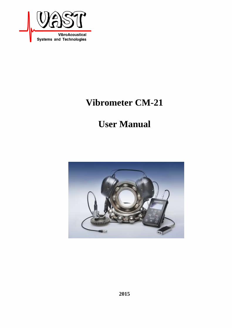
Vibrometer CM-21
User Manual
2015

Vibrometer CM-21 User manual
2

Vibrometer CM-21 User manual
3
Vibrometer CM-21 is a portable battery powered device used for condition monitoring purposes.
It allows measurement of a number of parameters like vibration, temperature, rotation speed, etc.
Contents
1 Uses ......................................................................................................................................... 5 2 Vibrometer set ......................................................................................................................... 5 3 Specifications .......................................................................................................................... 6 4 Using the CM-21 ..................................................................................................................... 7
4.1 User interface and operation ............................................................................................. 8
4.2 Charging the CM-21 ......................................................................................................... 9 4.3 Switching the CM-21 on. ................................................................................................ 10 4.4 Basic Operation of the CM-21 ........................................................................................ 10
4.4.1 Measurements .......................................................................................................... 10
4.4.2 Saving measurement results .................................................................................... 11 4.4.3 View saved measurement results ............................................................................. 12
4.4.4 Navigator for measurements .................................................................................... 12
4.5 Setting up the CM-21 ...................................................................................................... 13
4.5.1 Setting the accelerometer sensitivity ....................................................................... 13 4.5.2 Setting the bandpass filter........................................................................................ 14
4.5.3 Setting the magnitude value .................................................................................... 15 4.5.4 Alarm levels setup. .................................................................................................. 16 4.5.5 Date-time set up. ...................................................................................................... 17
4.5.6 Auto switch off setting. ........................................................................................... 17 4.5.7 User interface language setting................................................................................ 17
5 Measurements ........................................................................................................................ 18 5.1.1 Route measurements. ............................................................................................... 19 5.1.2 Rotation speed measurements. ................................................................................ 20
6 Audio monitoring .................................................................................................................. 20

Vibrometer CM-21 User manual
4

Vibrometer CM-21 User manual
5
1 Uses Measurements of low frequency vibration selected by band-pass filters according to
ISO 10816 and additional filters. Vibration is measured in acceleration, velocity and
displacement units
Measurement of high frequency vibration components for bearing diagnostics
Condition monitoring and alarming using alarms levels set up by the operator.
Rotation speed measurements using photo tacho probe
Temperature measurements with integrated pyrometer
Audio monitoring of the vibration signals from the vibration sensor with earphones
The functions of the Vibrometer CM-21 may be extended with further firmware updates.
2 Vibrometer set
The Vibrometer is supplied in the following set:
№ Description Quantity
1 Vibrometer CM-21 (main unit) 1
2 Accelerometer IEPE type 608 1
3 Protective case 1
4 Magnet for accelerometer DM2 1
5 Probe for accelerometer 1
6 Mains adapter (Charger) CA-CM-21 1
7 User manual 1
8 System report 1
9 Tachoprobe FD-2 1 1
11 Cable for Tachoprobe KMM-21-1 1 1
12 Connector to earphones 3.5mm 1 1
13 USB cable USB-CM-21 1 1
1) Supplied in the advanced kit configuration

Vibrometer CM-21 User manual
6
3 Specifications
Vibration measurement range:
acceleration, m/s2 0,1 - 1000
velocity, mm/s 0,1 - 1000
displacement, um 1 - 10000
Vibration frequency range, Hz 2- 2000
Frequency bands for vibration measurements according to ISO 10816, Hz
2 - 1000,
10 - 1000,
10 - 2000
High frequency bands, kHz
6.4-25
10-25
15-25
High frequency acceleration measurements
RMS
Peak
Peak-factor
Bandpass filters specifications according to ISO 2954-97
Relative error with vibration measurements in amplitude range, % +\- 5
Relative error with vibration measurements in frequency range, % +\- 7
Main relative error with vibration measurements, % +\-10
Rotation speed measurements
Rotation speed measurement range, Hz (RPM) 2 - 650 (120 - 39000)
Relative error in rotation speed measurements, % ± 1
Temperature measurements
Temperature indication distance, m 0.1 – 1.0
Temperature range, C Minus 40 – plus 350
Temperature resolution, C 0.1
Other
Time working from batteries, not less, hours 8
Service life, not less, hours 10000
Weight, kg 0,315
Size, mm 86×138×26
Protection IP65
Environmental conditions for operation:
Temperature, C From -20 up to +50
Relative humidity, % Up to 90

Vibrometer CM-21 User manual
7
4 Using the CM-21
Connectors
The CM-21 has the following connectors on the top panel:
Tacho tºC
↓ ↓ ↓ ↓
Here:
Accelerometer input. Connect the accelerometer for vibration measurements
Connector for audio monitoring of the vibration signal – connect earphones using the
earphone 3.5mm adapter from the advanced kit or special earphones.
This connector is also user for communication with host computer using USB cable from
the advanced kit. This connector is also used for charging the CM-21 with mains supply
(charger) or host computer USB port
Tacho Tachoprobe connector. Connect FD-2 tachoprobe for rotation speed measurements
tºC Integrated temperature sensor. Point with this sensor to the area for temperature
monitoring

Vibrometer CM-21 User manual
8
4.1 User interface and operation
All the controls of the CM-21 are located on the front panel
along with the display.
Control button Function Notes
On\Off button Press and hold button for on-
off operation. Once the CM-
21 is switched on is starts the
measurement in the last setup.
Calls the main menu of the CM-21allowing
choice of rpm or vibration measurements,
review of the saved measurements and
setting up the parameters of the CM-21
Cursor key in menu ad display navigation.
Also used to increment the
value in the accelerometer
sensitivity setup before
decimal point.
Cursor key in menu ad display navigation. Also used to decrement the
value in the accelerometer
sensitivity setup before
decimal point.

Vibrometer CM-21 User manual
9
(right)
Function button. Mostly Enter
(left)
Function button. Mostly cancel This button is also used to
reset the instrument in rear
case it may hang up
Recording or saving the measured vibration When saving you can save
machine and point number.
Measurements are saved in
numbered memory cells.
Audio volume decrease
Also used as left cursor key
Also used to increment the
value in the accelerometer
sensitivity setup after decimal
point.
Audio volume increase
Also used as right cursor key
Also used to decrement the
value in the accelerometer
sensitivity setup after decimal
point.
4.2 Charging the CM-21
The CM-21 operated from internal Li-Ion rechargeable battery 1700 mAh. For charging the
battery you can use the dedicated charger or the USB port of the computer. Charging time from
the dedicated charger is two times less that from the computer.
To charge the battery - connect the charger to the computer connector of the CM-21 and plug the
charger to the mains supply. The CM-21 will switch on automatically and in the top left corner
of the display you will see battery and +\- signs indicating charging, see figure below
It may take up to 4 hours to charge the empty battery from the charger or up to 8 hours from the
computer USB port.
It is recommended to charge the battery at the temperature between 0 and 25 C.
Vibrometer CM-21 User manual
10
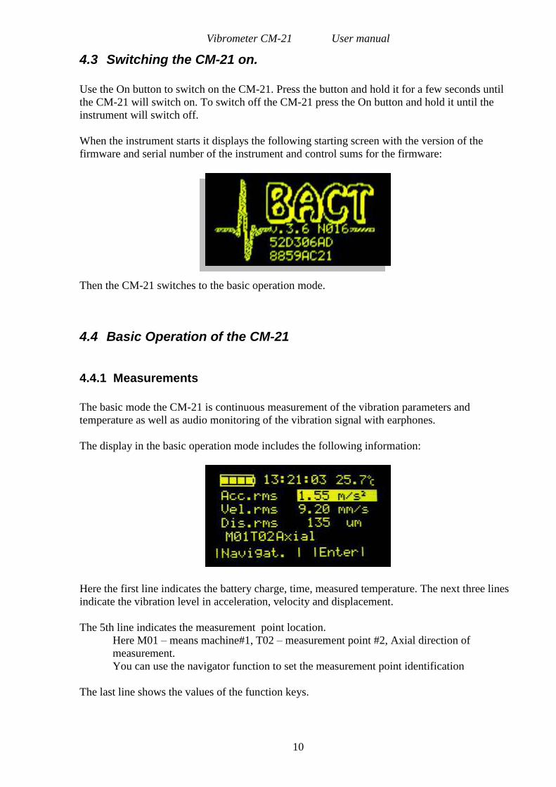
4.3 Switching the CM-21 on.
Use the On button to switch on the CM-21. Press the button and hold it for a few seconds until
the CM-21 will switch on. To switch off the CM-21 press the On button and hold it until the
instrument will switch off.
When the instrument starts it displays the following starting screen with the version of the
firmware and serial number of the instrument and control sums for the firmware:
Then the CM-21 switches to the basic operation mode.
4.4 Basic Operation of the CM-21
4.4.1 Measurements
The basic mode the CM-21 is continuous measurement of the vibration parameters and
temperature as well as audio monitoring of the vibration signal with earphones.
The display in the basic operation mode includes the following information:
Here the first line indicates the battery charge, time, measured temperature. The next three lines
indicate the vibration level in acceleration, velocity and displacement.
The 5th line indicates the measurement point location.
Here M01 – means machine#1, T02 – measurement point #2, Axial direction of
measurement.
You can use the navigator function to set the measurement point identification
The last line shows the values of the function keys.

Vibrometer CM-21 User manual
11
In the basic mode you can choose only one vibration parameter for display using the Up and
Down cursor keys and press the Enter button (right function key). The display will change to the
following:
To leave this mode use the Cancel button.
4.4.2 Saving measurement results
To save measurement result use the Rec button on the CM-21. The instrument will display the
following screen
Here the first line contains date, time and temperature, next three lines measurement results to be
saved. If some alarm level is exceeded the signes will present warning left from the magnitudes –
arrow down – low level alarm, “!” – alert, and bold “!” – danger.
The next line displays the memory cell or measurement point Id where the results will be saved.
You can change:
Machine number with Up and Down cursor keys
Point number with “Volume +” and “Volume –“ keys
Direction of measurements with the Menu and Rec keys.
To save the results in the selected measurement point Id use the Yes function key, to cancel
saving use No function key.
If you save the results the CM-21 will return to the basic measurement mode.
Note – the measurement results in the basic mode cannot be unloaded to the computer – they
can be reviewed on the screen of the CM-21 only. To be able to unload measurement results
for trending use the route map measurements – data collector mode.
Vibrometer CM-21 User manual
12
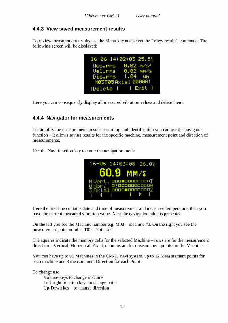
4.4.3 View saved measurement results
To review measurement results use the Menu key and select the “View results” command. The
following screen will be displayed:
Here you can consequently display all measured vibration values and delete them.
4.4.4 Navigator for measurements
To simplify the measurements results recording and identification you can use the navigator
function – it allows saving results for the specific machine, measurement point and direction of
measurements,
Use the Navi function key to enter the navigation mode.
Here the first line contains date and time of measurement and measured temperature, then you
have the current measured vibration value. Next the navigation table is presented.
On the left you see the Machine number e.g. M03 – machine #3. On the right you see the
measurement point number T02 – Point #2
The squares indicate the memory cells for the selected Machine – rows are for the measurement
direction – Vertical, Horizontal, Axial, columns are for measurement points for the Machine.
You can have up to 99 Machines in the CM-21 navi system, up to 12 Measurement points for
each machine and 3 measurement Direction for each Point .
To change use
Volume keys to change machine
Left-right function keys to change point
Up-Down kes – to change direction

Vibrometer CM-21 User manual
13
Empty square indicates empty memory cell, solid square indicates saved results in the memory,
“!” indicates the current cell to where the results will be saved by the Rec button.
When you select the cell with measured results the saved value is displayed on the screen.
To leave the Navi mode use the Menu button and then Cancel function key.
4.5 Setting up the CM-21
Before taking measurements the CM-21 can be set up to work according to your tasks. You can
set the following parameters:
Sensitivity of the accelerometer
Bandpass filter used for vibration measurements
Magnitude values detector (rms, peak, peak-peak)
Alarm levels
Date-time
Auto switch off
Language for the interface
To enter the setup functions use the Menu button on the CM-21 in the basic operation mode,
select by the Up and Down cursor keys the Setup menu and press Enter function key.
4.5.1 Setting the accelerometer sensitivity
The instrument comes with the sensor and sensitivity is already set up, but if you replace the
accelerometer or recalibrate it you may need to adjust the sensitivity coefficient. To do this you
need to:
1. Use the Menu button on the CM-21 in the basic operation mode, select by the Up and
Down cursor keys the Setup menu and press Enter function key
2. In the Setup menu select the Sensitivity function and press Enter key
3. Enter the password for your instrument that you can find in the System report supplied
with the instrument. It is done so that unauthorized personnel will not occasionally
change the sensitivity of the measurement system causing wrong measurements results.
To enter the password use Up and Down cursor keys to select a number at the position
and Volume+, Volume- keys to advance in position. If you do not know the password
you can view the sensitivity, but can not change it. To view the sensitivity press the Enter
(right function key).

Vibrometer CM-21 User manual
14
4. The following Screen will be displayed
Use the cursor and volume keys to adjust the value and press Enter to save sensitivity or
Cancel to exit without saving
4.5.2 Setting the bandpass filter
You can conduct vibration measurements with different bandpass filters according to the task.
The basic vibration standard requires measurements of vibration in the range of 10-1000Hz for
the machines rotating above 600rpm and 2-1000Hz for the slow rotating machines – operating
under 600rpm, also there is a possibility to measure high frequency vibration for bearing analysis
and friction forces monitoring. Note that in High frequency domain only the acceleration can be
measured.
To set up the appropriate filter:
1. Use the Menu button on the CM-21 in the basic operation mode, select by the Up and
Down cursor keys the Setup menu and press Enter function key
2. In the Setup menu select the Bandpass filter function and press Enter key
3. The following screen will be displayed
Here you can use Up ad Down keys to select low or high frequency filter and make choice by
Enter button.
There are two special measurement setups – one for measurements of High and Low
frequency simultaneously LF + HF and another for measurements acceleration in 3 bands –
low, medium and high frequency:

Vibrometer CM-21 User manual
15
When you choose LF + HF you will need to set both High- and Low- frequency bands
simultaneously.
This mode is recommended for general condition monitoring and bearing condition monitoring.
The high frequency vibration starts to increase with bearing defects development while low
frequency vibration increases with general machine degradation.
4.5.3 Setting the magnitude value
You can choose between RMS (root mean square), peak and peak-peak values to be displayed
for the vibration reading. The ISO standards require mostly RMS readings nowadays, though
some regulations may require different values representation.
To set up the appropriate readings:
1. Use the Menu button on the CM-21 in the basic operation mode, by Up and Down cursor
keys chose the Setup menu and press Enter function key
2. In the Setup menu select the Magnitude value and press Enter key
3. The following Screen will be displayed
Here you can use Up and Down cursor keys to select the magnitude and Volume+, Volume- keys
to make a choice of the magnitude representation.
Accuracy means how many decimal digits will be displayed during measurements, The choice is
between 2 and 3 digits. The CM-21 allows two decimal digits accuracy, but for the calibration
purposes 3 digits can be measured.
Use enter function key to confirm the choice.
Vibrometer CM-21 User manual
16
4.5.4 Alarm levels setup.
You can set up alarms to all the measurements done with the CM-21 i.e.
Acceleration low frequency
Acceleration high frequency
Acceleration peak factor (Peak value divided by RMS value)
Velocity
Displacement
Rotation Speed
Temperature
Choice of the alarm levels can be done with the ISO standards for your equipment, other
regulations, or the general knowledge and experience. Only one set of alarm levels can be set for
the CM-21. Each of the measurements can have tree thresholds:
Normal
Alarm
Danger
When the measured value exceeds the threshold the alarm will be displayed on the screen
To set up the appropriate alarms:
1. Use the Menu button on the CM-21 in the basic operation mode, select by the Up and
Down cursor keys the Setup menu and press Enter function key
2. In the Setup menu select the Alarm levels and press Enter key
3. The list of measurements and alarms will be displayed. Use the cursor Up and Down
keys to select the measurement and Volume+, Volume- keys to set alarm on on/off for
this measurement
4. Once you set the alarm ON use the Enter key to set up levels for alarms
5. Use the cursor keys to select between Normal, alert and danger alarms and press Enter to
set the levels
6. The following Screen will be displayed
Here you can use Up, Down cursor keys and Volume+, Volume- keys to set the alarm
level. Use the Enter function key to confirm the choice.

Vibrometer CM-21 User manual
17
4.5.5 Date-time set up.
For correct date-time stamp for saved measurements we recommend to set the entire clock of the
CM-21.
To set up date and time:
1. Use the Menu button on the CM-21 in the basic operation mode, select by the Up and
Down cursor keys the Setup menu and press Enter function key
2. In the Setup menu select the Date/time setup and press Enter key
3. Use Up, Down cursor keys and Volume+, Volume- keys to set the date and time Use the
Enter (right) function key to confirm the settings
4.5.6 Auto switch off setting.
You can set the CM-21 to switch off automatically if no buttons are pressed for a certain time
(about 20 minutes). It may save battery from the occasional discharge.
To set up auto switch off:
1. Use the Menu button on the CM-21 in the basic operation mode, select by the Up and Down
cursor keys the Setup menu and press Enter function key
2. In the Setup menu select the Auto switch and press Enter key
3. Use Volume+, Volume- keys to set the function. Use the Enter function key to confirm the
settings
4.5.7 User interface language setting.
You can set the CM-21 to work in several Languages.
To select the language:
1. Use the Menu button on the CM-21 in the basic operation mode, select by the Up and
Down cursor keys the Setup menu and press Enter function key
2. In the setup menu use up\down keys to select the Language menu and press ender
function key
3. Select the desired language and press Enter to confirm changes
4. Switch off the instrument to save this global setting an switch it on back.

Vibrometer CM-21 User manual
18
If is some case the instrument will switch to the language you do not understand, for example
Russian language here is the menus you have to select to get to Language settings:
The main menu in Russian with the setup selection:
The setup menu with the selected language menu in Russian:
When you get to the Language menu, the languages will change with menu items selection.
5 Measurements
The CM-21 has three measurement modes^
- Basic measurements
- Route measurements
- RPM measurements
The CM-21 once in the basic operation mode makes continuous measurements of set up
vibration parameters and temperature. Note that for low frequency vibration measurements it
will measure acceleration, velocity and displacement values for the selected band. In the high
frequency domain it will measure only acceleration, but in rms, peak and peak factor values. In
bearing condition monitoring when initial defects occur first will grow the peak factor value
when the defect becomes severe the peak factor value may decrease and RMS value starts to
grow in high frequency domain.
Vibration is measured with the external accelerometer that should be connected to the input
connector. The temperature is measured with the integrated pyrometer. To make temperature
measurements point with the pyrometer window to the object. The measurement distance should
be within the range on 0.1-1 meters. The shorter the distance, the more precise are the
measurements.
The basic measurements can be saved to CM-21, but currently can not be unloaded to computer.
The basic measurements are described in Chapter 4.4 above

Vibrometer CM-21 User manual
19
5.1.1 Route measurements.
Route measurements are designed for the periodical condition monitoring of the equipment. The
measurements are done according to the route map created in the VibroLevel or other compatible
software. The measurement setup and alarms are stored in the rout map for each point
individually. The measurement results are saved for each point and can be unloaded to computer
for storage and trending.
Each point is identified by corresponding Station, Machine, Measurement point and direction of
measurement. The route can contain machines and points only from one station.
Once the routes are loaded to the CM-21 you can go to the main Menu and use the Choose Route
command to select route for measurements:
Here in the first line you the Station name and the route name. The second line shows the
number of measurement points in the route
You can choose route by Up\Down buttons and confirm choice by the Enter key.
The route measurement display contains the following information:
Here you see
- What is measured (velocity peak value),
- Low level alarm
- Measured value
- Machine Id from the route
- Measurement point Id from the route and measurement direction set in the route
- Date\time of measurement if it was measured already and saved.
The CM-21 makes continuous measurements and once you see the result you can save
measurements with Rec button,
When the measurement is saved CM-21 advances in the route to the next measurement point,
You can scroll measurement points in the route with Up\Down keys
Vibrometer CM-21 User manual
20
You can overwrite previous measurements with the new ones just saving the new one on top of
the previous data. Previous data will be lost in this case, Only one measurement result can be
stored for the point.
Once the Danger or Alert alarm level will be exceeded the CM-21 will present alarm with color
and beep sound:
To leave he route you go to Menu, Choose route and use the back function key. The CM-2 will
return to the basic mode.
5.1.2 Rotation speed measurements.
Rotation speed measurements are done with the external FD-2 tachoprobe. Connect it to the CM-
21, Use the Menu button and select the Rotation speed measurement in the menu.
Use the Up/Down keys to change measurement units from Hz to RPM
The tachoprobe requires some blister mark to be attached to the shaft. In most cases you can use
chock mark or it may work without the mark as the sensor has auto gain and in many cases can
find some uneven mark on the shaft itself. The working distance to the shaft is 1-20 cm. When
the probe senses the mark it blinks with led indicator.
6 Audio monitoring
The CM-21 provides output to the earphones for audio monitoring of the vibration signal. To
listen to the vibration signal simply connect earphones to the audio connector. The volume of the
signal can be adjusted using +\- volume buttons
Copyright © 2022 FDOKUMEN