
Tables of molecular vibrational frequencies, consolidated ...
Upload
independentCategory
view
2download
0
International Journal of Mechanical Sciences 59 (2012) 44–54
Contents lists available at SciVerse ScienceDirect
International Journal of Mechanical Sciences
0020-74
http://d
n Fax:
E-m
journal homepage: www.elsevier.com/locate/ijmecsci
Vibrational response of thin tubes to sequential moving pressures
Majid Mirzaei n
Department of Mechanical Engineering, Tarbiat Modares University, Tehran, Iran
a r t i c l e i n f o
Article history:
Received 3 August 2011
Received in revised form
12 February 2012
Accepted 7 March 2012Available online 24 March 2012
Keywords:
Pulse detonation engine
Stress analysis
Noise
Vibration
Finite element analysis
03/$ - see front matter & 2012 Elsevier Ltd. A
x.doi.org/10.1016/j.ijmecsci.2012.03.002
þ98 21 88005040.
ail addresses: [email protected]; majid
a b s t r a c t
This paper presents a set of analytical solutions for the vibrational behavior of thin tubes under
sequences of internal moving pressures. Such analyses are applicable to a number of theoretical and
practical problems, like transient dynamic response of arteries due to pulsatory blood flow, transient
deformations of gas pipelines due to pressure fluctuations, or the vibrational response of pulse
detonation engines (PDE). However, the presented solutions are tailored for successive applications
of specific loading profiles that represent gaseous detonations. The solutions are compared with the
available experimental data and complementary finite element simulations. Representative analyses
are carried out for an experimental detonation tube under loading spectra traveling with different time
delays. It is shown that the resulting vibrational spectra can be highly affected by the frequency of the
sequential loadings and high dynamic amplification factors can exist even at non-critical speeds. It is
also shown that application of sequential moving pressures with proper loading frequencies can
substantially reduce the structural vibration.
& 2012 Elsevier Ltd. All rights reserved.
1. Introduction
Formulation of the vibrational behavior of thin tubes undersequential moving pressures constitutes elastodynamic problemswith several applications, like transient dynamic response ofarteries due to pulsatory blood flow [1], transient deformationsof gas pipelines due to pressure fluctuations, cyclic cracking ofexploded pressure vessels [2], or the vibrational response of pulsedetonation engines (PDE) [3]. The latter is currently regarded as apromising candidate for providing very efficient propulsion sys-tems for both subsonic and supersonic aviation [4–6] (see Fig. 1).One of the main challenges towards realization of PDEs is thestress analysis of detonation tubes. This is a complicated taskbecause every single detonation results in a spectrum of transientdynamic stresses in the tube wall. The calculation of critical speeds
is also a major concern in the design procedure of cylinders thatare subjected to internal moving pressures. It is known thatdynamic strains can be in resonance if the internal pressuremoves at critical speeds. Moreover, since the PDE generates quasisteady thrust by high cycling of gaseous detonations, the inter-actions between the stress waves caused by successive detona-tions must also be considered in the stress analysis process.Although there have been several studies on the stress analysis
ll rights reserved.
of cylindrical tubes under a single detonation [3,7–16], suchanalysis for repetitive detonation loadings has not been reported.
In this paper a modified form of the transient analytic modelreported in Refs. [15,16] has been developed to cover the effectsof sequential internal gaseous detonations. The solutions arecompared with the available experimental data and complemen-tary finite element simulations. In continuation, the influence ofthe loading frequency on the vibrational behavior of detonationtubes is investigated.
2. Analytic solutions
The pressure history for gaseous detonation can be repre-sented by an exponential approximation to the Taylor–Zeldovichmodel for variation of pressure at a fixed point in space [12]
pðtÞ ¼p1, 0ototcj
ðp2�p3Þexpð�ðt�tcjÞ=TÞþp3, tcjrt:
(ð1Þ
In the above expression, p1 is the initial pressure of the gasmixture, p2 is the peak pressure, p3 is the final pressure, t is thetime variable, T is the exponential decay factor, and tcj¼x/Vcj
(Vcj¼Chapman–Jouguet velocity) is the time required for thedetonation front to reach the location x. Fig. 2 schematicallydepicts the variation of internal pressure with time for a singledetonation and also sequential detonations. The passage of eachhigh-speed moving pressure results in a spectrum of transientdynamic stresses in the tube wall. As each detonation loading
Nomenclature
E Young’s modulus, N/m2
G shear modulus, N/m2
H step functionL tube length, mR tube mean radius, mT exponential decay factor, sV load speed, m/sVcj Chapman–Jouguet speed, m/sVd dilatational wave speed, m/sVs shear wave speed, m/sh tube thickness, mm detonation indexn mode indexp1 pre-detonation pressure, Pap2 maximum-detonation pressure, Pa
p3 post-shock pressure, PaPext external pressure, Papcj Chapman–Jouguet pressure, Pat time variable, s~t general time variable, sw total radial deflection, mwb radial deflection, bending, mws radial deflection, shear, mx axial coordinate, mb dimensionless tube thickness parameterk shear correction factorn Poisson’s ratior density, kg/m3
Lj dimensionless excitation parameters (j¼1,2,3)c rotationF dynamic amplification factor
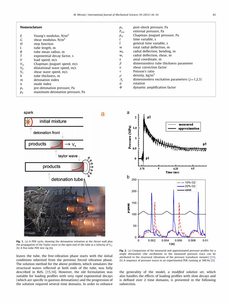
Fig. 1. (a) A PDE cycle, showing the detonation initiation at the thrust wall plus
the propagation of the Taylor wave to the open end of the tube at a velocity of Vcj.
(b) A five-tube PDE test rig [6].Fig. 2. (a) Comparison of the measured and approximated pressure profiles for a
single detonation (the oscillations in the measured pressure trace can be
attributed to the structural vibrations of the pressure transducer mounts) [11].
(b) A sequence of pressure traces in an experimental PDE running at 300 Hz [5].
M. Mirzaei / International Journal of Mechanical Sciences 59 (2012) 44–54 45
leaves the tube, the free-vibration phase starts with the initialconditions inherited from the previous forced vibration phase.The solution method for the above problem, which simulates thestructural waves reflected at both ends of the tube, was fullydescribed in Refs. [15,16]. However, the old formulation wassuitable for loading profiles with very rapid exponential decays(which are specific to gaseous detonations) and the progression ofthe solution required several time domains. In order to enhance
the generality of the model, a modified solution set, whichalso handles the effects of loading profiles with slow decays andis defined over 2 time domains, is presented in the followingsubsection.
M. Mirzaei / International Journal of Mechanical Sciences 59 (2012) 44–5446
2.1. New transient dynamic solution for a single detonation
In general, the radial displacement of the tube consists of twoparts
wðx,tÞ ¼wbðx,tÞþwsðx,tÞ: ð2Þ
in which wb is due to bending and ws is due to transverse shear.The boundary and initial value problems that governs the radialdisplacements due to bending and shear, along with the details ofthe solution procedure, are reported in [15,16] and summarizedin Appendix A. The final solutions for these two displacementcomponents can be written in closed form as
11wb ðx,t1Þ ¼X2nn
n ¼ 1
("11Tnsþ
1Tndþ11An sinð1on t1Þþ
11Bn cosð1on t1Þ
# ffiffiffi2
L
rsin
npL
x� �)
11ws ðx,t1Þ ¼
X2nn
n ¼ 1
("11Tnsþ
1Tndþ11An sinð1on t1Þþ
11Bn cosð1on t1Þ
#
�npL
� �2ffiffiffi2
L
rsin
npL
x� �)
�h2
12
!V2
d�1V
2
V2s
!
0ot1oL=1V : ð3Þ
The terms on the right hand side of the above expressions arerather lengthy, so they are defined in the Appendix A. It should benoted that the left superscript is the detonation index, e.g.,1 represents a single detonation. Moreover, the solution for eachdetonation comprises of two time domains which are labeledusing the left subscript. The solution for the second time domain is
12wb ðx,t2Þ ¼
X2nn
n ¼ 1
(12Tnsþ
12An sinð1ont2Þþ
12Bn cosð1ont2Þ
h i
�
ffiffiffi2
L
rsin
npL
x� �)
12ws ðx,t2Þ ¼
X2nn
n ¼ 1
(12Tnsþ
12An sinð1ont2Þþ
12Bn cosð1ont2Þ
h i
�npL
� �2ffiffiffi2
L
rsin
npL
x� �)
�h2
12
!V2
d�1V
2
V2s
!
L=1V ot2: ð4Þ
It should be mentioned that in the previous derivations theprogression of the solution in time required a sequence of finitetime intervals [15,16]. A main advantage of the new solution is
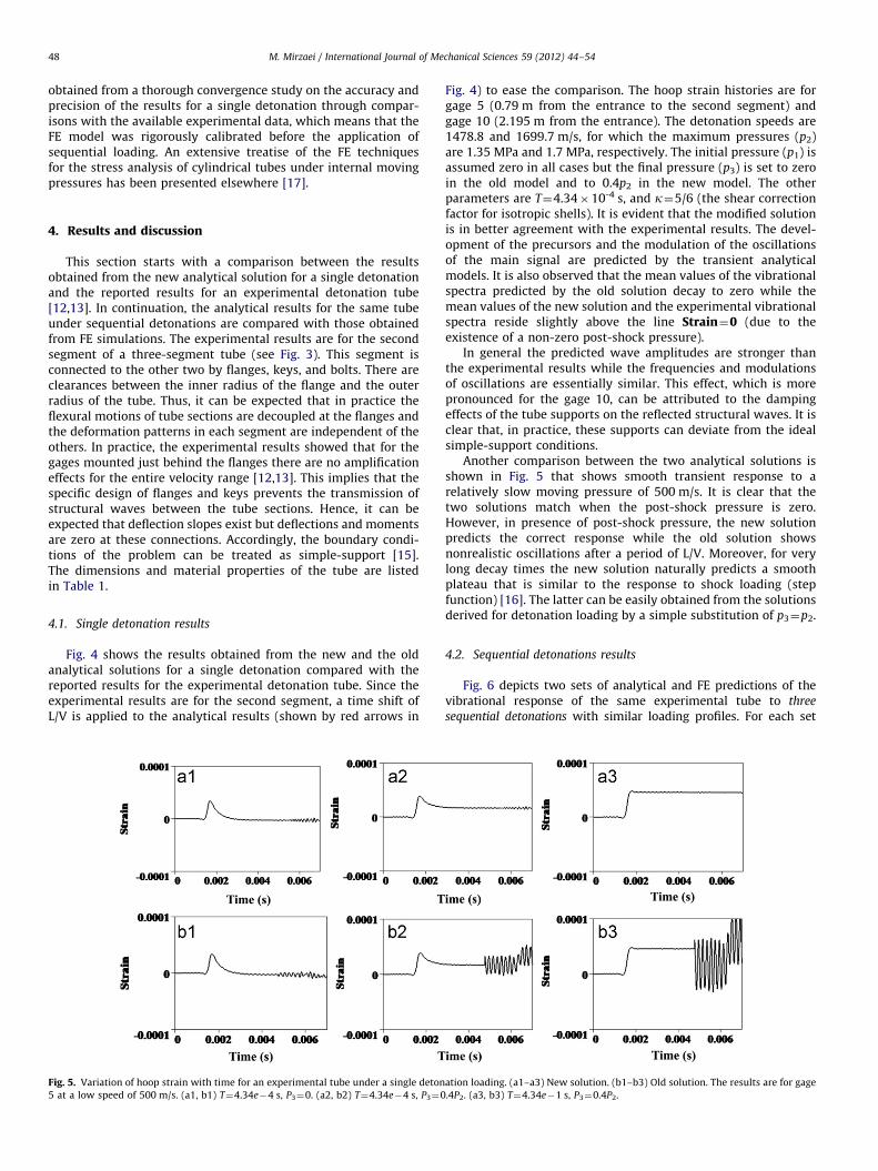
Fig. 3. Schematic of the three-segment experimental deto
that it comprises of only two time domains, i.e., 0ot1oL=1V andL=1V ot2. Also note that n* is the mode number that correspondsto the first critical speed, as fully described in [16] and summarizedin the Appendix B. The accurate results can only be obtained if thenumber of terms in the above series expansions exceeds n*, and itcan be shown that the summation of 2n* terms ensures excellentconvergence [16]. In practice, the contribution of ws to the mainsignals of flexural waves is not significant but it affects the highfrequency precursor signals. Moreover, for accurate capturing ofhigh-frequency transverse shear strains, particularly near thesecond critical speed, the number of the related series termsshould exceed the mode number that corresponds to the second
critical speed [16] (see Appendix B).
2.2. Transient dynamic solutions for sequential detonations
The solution procedure for a single detonation can be extendedfor a typical PDE loading spectrum by solving the initial andboundary value problem for each detonation phase based on datainherited from the previous phase. The presented formulation,that handles different specifications (speed, pressure, etc.) for eachsingle detonation plus arbitrary time delays between successivedetonations, is
ml w ¼ m
l wbþml ws l¼ 1,2 m¼ 2,3. . .
m1 wb ¼
X2nn
n ¼ 1
(m1 Tnsþ
mTndþm1 An sinðmont2m�1Þ
�
þm1 Bn cosðmont2m�1Þ
� ffiffiffi2
L
rsin
npL
x� �)
m1 ws ¼
X2nn
n ¼ 1
(m1 Tnsþ
mTndþm1 An sinðmont2m�1Þ
�
þm1 Bn cosðmont2m�1Þ
� npL
� �2ffiffiffi2
L
rsin
npL
x� �)
�h2
12
!V2
d�mV2
V2s
!
m2 wb ¼
X2nn
n ¼ 1
(m2 Tnsþ
m2 An sinðmont2mÞþ
m2 Bn cosðmont2mÞ
� �
�
ffiffiffi2
L
rsin
npL
x� �)
m2 ws ¼
X2nn
n ¼ 1
(m2 Tnsþ
m2 An sinðmont2mÞ
�
þm2 Bn cosðmont2mÞ
� npL
� �2ffiffiffi2
L
rsin
npL
x� �)
�h2
12
!V2
d�mV2
V2s
!
nation tube and the position of strain gages [12,13].

M. Mirzaei / International Journal of Mechanical Sciences 59 (2012) 44–54 47
0ot2m�1oL=mV , 0ot2m: ð5Þ
In the above expressions m represents the detonation index.Other terms are defined in the Appendix A.
In order to combine the solutions of various time domains wedefine ~t as the general time parameter for the whole problemsuch that
t1 ¼ ~t , t2 ¼ ~t�L=1V , t3 ¼ ~t�D1, t4 ¼ ~t�D1�L=2V ,
t5 ¼ ~t�D1�D2, t6 ¼ ~t�D1�D2�L=3V � � �
t2m�1 ¼ ~t�D1 � � � �Dm�1, t2m ¼ ~t�D1 � � � �Dm�1�L=mV : ð6Þ
In the above Dm�1 is the delay time before the detonation numberm. Thus, the total response for m sequential detonations can bewritten as
Table 1Material and geometrical properties of the experimental tube [12,13].
r (kg/m3) E (N/m2) n Rout (m) Rin (m) L (m)
8000 193�109 0.23 0.1651 0.1397 2.38
Fig. 4. Variation of hoop strain with time for an experimental tube under a single deton
Old solution [15,16]. The results marked by (1) are for gage 5, detonation velocity of 16
1478.7 and 1699.7 m/s, respectively.
~wðx, ~tÞ ¼ 11w½1�Hð~t�L=1V Þ�þ1
2w½1�Hð~t�D1Þ�Hð~t�L=1V Þ
þ21w½1�Hð~t�D1�L=2V Þ�Hð~t�D1Þþ
22w½1�Hð~t�D1�D2Þ�
Hð~t�D1�L=2V Þþ � � � þm1 w½1�Hð~t�D1 � � � �Dm�1�L=mV Þ�
Hð~t�D1 � � � �Dm�1Þþm2 wHð~t�D1 � � � �Dm�1�L=mV Þ: ð7Þ
It is clear that the above solution admits different time delaysbetween successive detonations and accounts for combinations ofvarious detonation cycles with different specifications (speed,pressure, etc.).
3. Finite element simulations
The presented analytic solution for a single detonation iscompared with the available experimental results in the followingsection. However, no experimental result has been reported in theliterature for sequential detonations. Thus, in order to verify theproposed analytical solution a series of complementary finiteelement (FE) simulations were carried out using the Abaqus/CAEcommercial package. The FE model was built using 10,000axisymetric elements (with 1000 and 10 elements in the long-itudinal and radial directions, respectively). These numbers were
ation loading. (a1–a3) New solution. (b1–b3) Experimental results [12,13]. (c1–c3)
99.7 m/s, and those marked by (2) and (3) are for gage 10, detonation velocities of
M. Mirzaei / International Journal of Mechanical Sciences 59 (2012) 44–5448
obtained from a thorough convergence study on the accuracy andprecision of the results for a single detonation through compar-isons with the available experimental data, which means that theFE model was rigorously calibrated before the application ofsequential loading. An extensive treatise of the FE techniquesfor the stress analysis of cylindrical tubes under internal movingpressures has been presented elsewhere [17].
4. Results and discussion
This section starts with a comparison between the resultsobtained from the new analytical solution for a single detonationand the reported results for an experimental detonation tube[12,13]. In continuation, the analytical results for the same tubeunder sequential detonations are compared with those obtainedfrom FE simulations. The experimental results are for the secondsegment of a three-segment tube (see Fig. 3). This segment isconnected to the other two by flanges, keys, and bolts. There areclearances between the inner radius of the flange and the outerradius of the tube. Thus, it can be expected that in practice theflexural motions of tube sections are decoupled at the flanges andthe deformation patterns in each segment are independent of theothers. In practice, the experimental results showed that for thegages mounted just behind the flanges there are no amplificationeffects for the entire velocity range [12,13]. This implies that thespecific design of flanges and keys prevents the transmission ofstructural waves between the tube sections. Hence, it can beexpected that deflection slopes exist but deflections and momentsare zero at these connections. Accordingly, the boundary condi-tions of the problem can be treated as simple-support [15].The dimensions and material properties of the tube are listedin Table 1.
4.1. Single detonation results
Fig. 4 shows the results obtained from the new and the oldanalytical solutions for a single detonation compared with thereported results for the experimental detonation tube. Since theexperimental results are for the second segment, a time shift ofL/V is applied to the analytical results (shown by red arrows in
Fig. 5. Variation of hoop strain with time for an experimental tube under a single deton
5 at a low speed of 500 m/s. (a1, b1) T¼4.34e�4 s, P3¼0. (a2, b2) T¼4.34e�4 s, P3¼0
Fig. 4) to ease the comparison. The hoop strain histories are forgage 5 (0.79 m from the entrance to the second segment) andgage 10 (2.195 m from the entrance). The detonation speeds are1478.8 and 1699.7 m/s, for which the maximum pressures (p2)are 1.35 MPa and 1.7 MPa, respectively. The initial pressure (p1) isassumed zero in all cases but the final pressure (p3) is set to zeroin the old model and to 0.4p2 in the new model. The otherparameters are T¼4.34�10-4 s, and k¼5/6 (the shear correctionfactor for isotropic shells). It is evident that the modified solutionis in better agreement with the experimental results. The devel-opment of the precursors and the modulation of the oscillationsof the main signal are predicted by the transient analyticalmodels. It is also observed that the mean values of the vibrationalspectra predicted by the old solution decay to zero while themean values of the new solution and the experimental vibrationalspectra reside slightly above the line Strain¼0 (due to theexistence of a non-zero post-shock pressure).
In general the predicted wave amplitudes are stronger thanthe experimental results while the frequencies and modulationsof oscillations are essentially similar. This effect, which is morepronounced for the gage 10, can be attributed to the dampingeffects of the tube supports on the reflected structural waves. It isclear that, in practice, these supports can deviate from the idealsimple-support conditions.
Another comparison between the two analytical solutions isshown in Fig. 5 that shows smooth transient response to arelatively slow moving pressure of 500 m/s. It is clear that thetwo solutions match when the post-shock pressure is zero.However, in presence of post-shock pressure, the new solutionpredicts the correct response while the old solution showsnonrealistic oscillations after a period of L/V. Moreover, for verylong decay times the new solution naturally predicts a smoothplateau that is similar to the response to shock loading (stepfunction) [16]. The latter can be easily obtained from the solutionsderived for detonation loading by a simple substitution of p3¼p2.
4.2. Sequential detonations results
Fig. 6 depicts two sets of analytical and FE predictions of thevibrational response of the same experimental tube to three
sequential detonations with similar loading profiles. For each set
ation loading. (a1–a3) New solution. (b1–b3) Old solution. The results are for gage
.4P2. (a3, b3) T¼4.34e�1 s, P3¼0.4P2.

Fig. 6. Analytical and FE predictions of the vibrational response of an experimental tube to three sequential detonations with similar loading profiles (p2¼1.7 MPa,
p1¼p3¼0, V¼1699.7 m/s, and T¼4.34�10-4 s) and equal time intervals: (a) and (b) D1¼D2¼10.135 ms, (c) and (d) D1¼D2¼8.074 ms.
M. Mirzaei / International Journal of Mechanical Sciences 59 (2012) 44–54 49
the time delay between successive detonations is the same andequal to 10.135 and 8.074 ms respectively. It is clear that there isan excellent match between the analytical and FE solutions. Theinteresting point is that the frequency of loading significantlyaffects both the amplitude and modulation of the response, causingsequential strain amplification and attenuation in the first andsecond sets respectively. Moreover one of the major advantages ofthe analytical solution is that it can provide continuous data inspace and time, so the overall vibrational behavior of the tube inthese two cases can also be compared using 3D plots as depicted inFig. 7. On the other hand a key design parameter for tubes underdynamic loading is the dynamic amplification factor (F) which isdefined as the ratio between the maximum dynamic strain and theequivalent static strain. The amplification factor is a function of
velocity and has its maximum at critical speeds [16]. The max-imum measured value of F for the above experimental tube (usingelectrical strain gages) is 3.9 [13]. This value was accuratelypredicted by the transient analytic model [15,16]. However, theoccurrence of dynamic amplification factors as high as 7 wasshown near the end of the same tube using similar 3D plots [16].The plots of Fig. 7 clearly show the dominance of relatively high-amplitude and low-amplitude oscillations over the entire length ofthe tube caused by two different loading frequencies.
Finally, Fig. 8 depicts a similar comparison, but for differenttime delays between successive detonations. This is a clearexample that shows how proper or improper selections of thedetonation time delays can lead to amplification or attenuation ofthe structural vibration in a PDE. In fact, one of the most
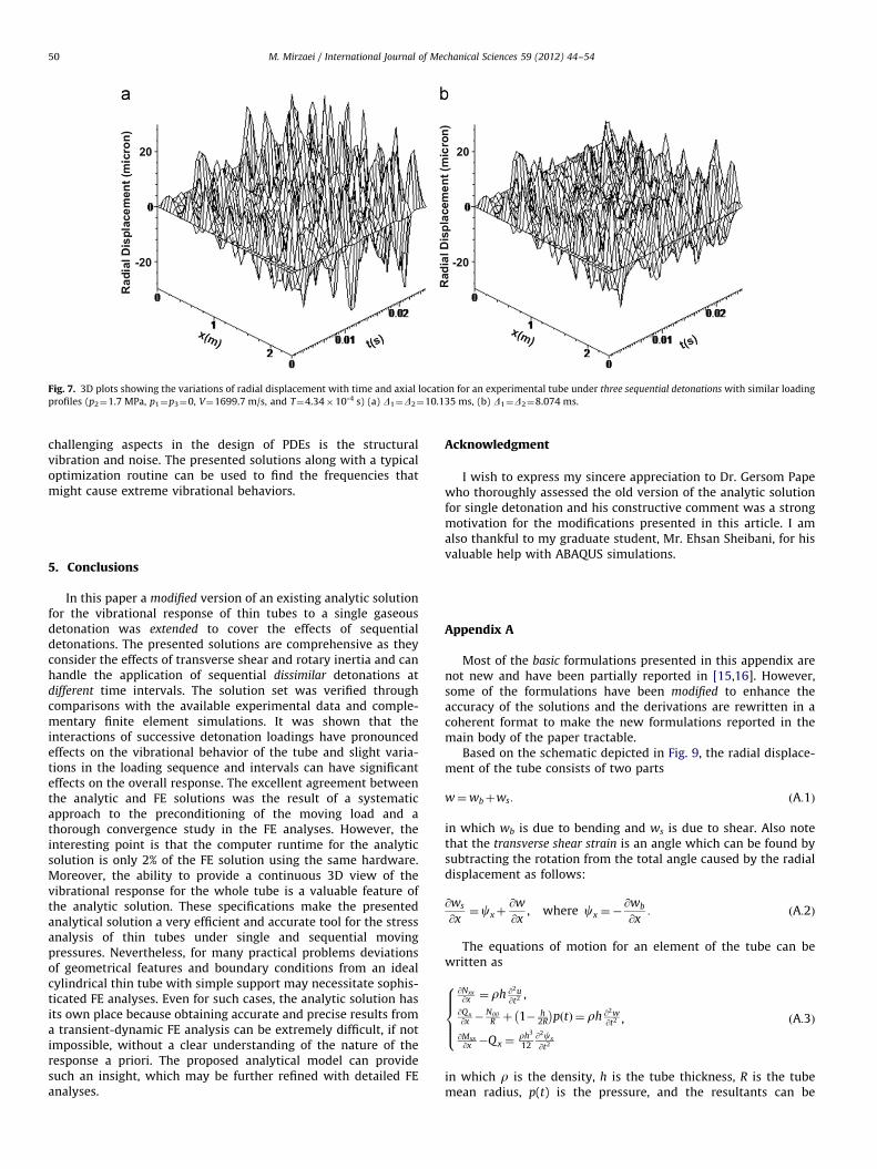
Fig. 7. 3D plots showing the variations of radial displacement with time and axial location for an experimental tube under three sequential detonations with similar loading
profiles (p2¼1.7 MPa, p1¼p3¼0, V¼1699.7 m/s, and T¼4.34�10-4 s) (a) D1¼D2¼10.135 ms, (b) D1¼D2¼8.074 ms.
M. Mirzaei / International Journal of Mechanical Sciences 59 (2012) 44–5450
challenging aspects in the design of PDEs is the structuralvibration and noise. The presented solutions along with a typicaloptimization routine can be used to find the frequencies thatmight cause extreme vibrational behaviors.
5. Conclusions
In this paper a modified version of an existing analytic solutionfor the vibrational response of thin tubes to a single gaseousdetonation was extended to cover the effects of sequentialdetonations. The presented solutions are comprehensive as theyconsider the effects of transverse shear and rotary inertia and canhandle the application of sequential dissimilar detonations atdifferent time intervals. The solution set was verified throughcomparisons with the available experimental data and comple-mentary finite element simulations. It was shown that theinteractions of successive detonation loadings have pronouncedeffects on the vibrational behavior of the tube and slight varia-tions in the loading sequence and intervals can have significanteffects on the overall response. The excellent agreement betweenthe analytic and FE solutions was the result of a systematicapproach to the preconditioning of the moving load and athorough convergence study in the FE analyses. However, theinteresting point is that the computer runtime for the analyticsolution is only 2% of the FE solution using the same hardware.Moreover, the ability to provide a continuous 3D view of thevibrational response for the whole tube is a valuable feature ofthe analytic solution. These specifications make the presentedanalytical solution a very efficient and accurate tool for the stressanalysis of thin tubes under single and sequential movingpressures. Nevertheless, for many practical problems deviationsof geometrical features and boundary conditions from an idealcylindrical thin tube with simple support may necessitate sophis-ticated FE analyses. Even for such cases, the analytic solution hasits own place because obtaining accurate and precise results froma transient-dynamic FE analysis can be extremely difficult, if notimpossible, without a clear understanding of the nature of theresponse a priori. The proposed analytical model can providesuch an insight, which may be further refined with detailed FEanalyses.
Acknowledgment
I wish to express my sincere appreciation to Dr. Gersom Papewho thoroughly assessed the old version of the analytic solutionfor single detonation and his constructive comment was a strongmotivation for the modifications presented in this article. I amalso thankful to my graduate student, Mr. Ehsan Sheibani, for hisvaluable help with ABAQUS simulations.
Appendix A
Most of the basic formulations presented in this appendix arenot new and have been partially reported in [15,16]. However,some of the formulations have been modified to enhance theaccuracy of the solutions and the derivations are rewritten in acoherent format to make the new formulations reported in themain body of the paper tractable.
Based on the schematic depicted in Fig. 9, the radial displace-ment of the tube consists of two parts
w¼wbþws: ðA:1Þ
in which wb is due to bending and ws is due to shear. Also notethat the transverse shear strain is an angle which can be found bysubtracting the rotation from the total angle caused by the radialdisplacement as follows:
@ws
@x¼cxþ
@w
@x, where cx ¼�
@wb
@x: ðA:2Þ
The equations of motion for an element of the tube can bewritten as
@Nxx
@x ¼ rh @2u@t2 ,
@Qx
@x �Nyy
R þ 1� h2R
� �pðtÞ ¼ rh @2w
@t2
@Mxx@x �Qx ¼
rh3
12@2cx
@t2
,
8>>><>>>:
ðA:3Þ
in which r is the density, h is the tube thickness, R is the tubemean radius, p(t) is the pressure, and the resultants can be
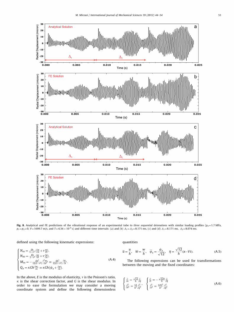
Fig. 8. Analytical and FE predictions of the vibrational response of an experimental tube to three sequential detonations with similar loading profiles (p2¼1.7 MPa,
p1¼p3¼0, V¼1699.7 m/s, and T¼4.34�10-4 s) and different time intervals: (a) and (b) D1¼D2¼8.171 ms, (c) and (d) D1¼8.171 ms, D2¼8.074 ms.
M. Mirzaei / International Journal of Mechanical Sciences 59 (2012) 44–54 51
defined using the following kinematic expressions:
Nxx ¼Eh
1�n2@u@x þn
wR
� �:
Nyy ¼Eh
1�n2wR þn
@u@x
� �:
Mxx ¼�Eh3
12ð1�n2Þ
@2wb
@x2 �Eh3
12ð1�n2Þ
@cx
@x :
Qx ¼ kGh @ws
@x � kGh cxþ@w@x
� �:
8>>>>>><>>>>>>:
ðA:4Þ
In the above, E is the modulus of elasticity, n is the Poisson’s ratio,k is the shear correction factor, and G is the shear modulus. Inorder to ease the formulation we may consider a movingcoordinate system and define the following dimensionless
quantities
u¼u
h, w¼
w
h, cx ¼
cxffiffiffiffiffiffi12p , Z¼
ffiffiffiffiffiffi12p
hðx�VtÞ: ðA:5Þ
The following expressions can be used for transformationsbetween the moving and the fixed coordinates:
@@x ¼
ffiffiffiffi12p
h@@Z
@2
@x2 ¼12h2
@2
@Z2
,
@@t ¼�
ffiffiffiffi12p
Vh
@@Z
@2
@t2 ¼12V2
h2@2
@Z2
8><>:
8><>: ðA:6Þ
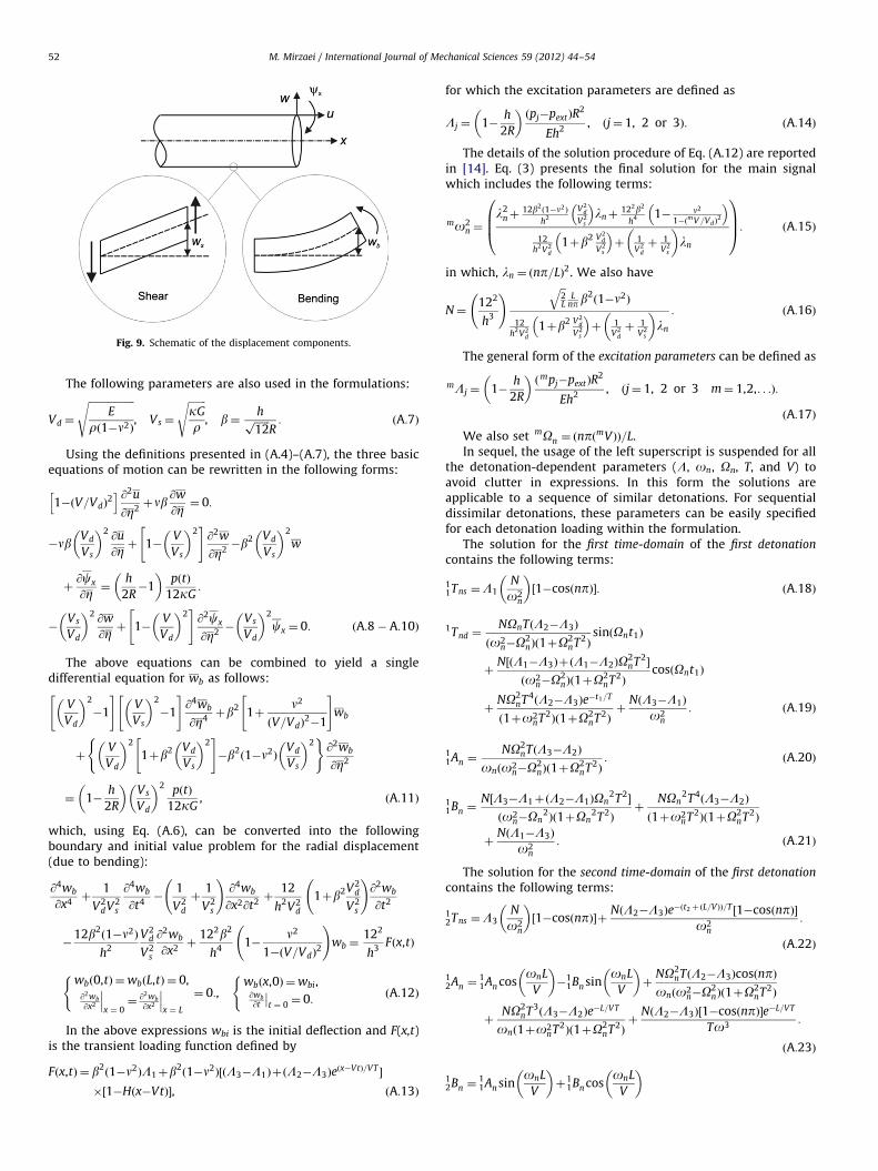
Fig. 9. Schematic of the displacement components.
M. Mirzaei / International Journal of Mechanical Sciences 59 (2012) 44–5452
The following parameters are also used in the formulations:
Vd ¼
ffiffiffiffiffiffiffiffiffiffiffiffiffiffiffiffiffiffiE
rð1�n2Þ
s, Vs ¼
ffiffiffiffiffiffiffikG
r
s, b¼
hffiffiffiffiffiffi12p
R: ðA:7Þ
Using the definitions presented in (A.4)–(A.7), the three basicequations of motion can be rewritten in the following forms:
1�ðV=VdÞ2
h i @2u
@Z2þnb @w
@Z ¼ 0:
�nb Vd
Vs
2 @u
@Z þ 1�V
Vs
2" #
@2w
@Z2�b2 Vd
Vs
2
w
þ@cx
@Z¼
h
2R�1
pðtÞ
12kG:
�Vs
Vd
2 @w
@Z þ 1�V
Vd
2" #
@2cx
@Z2�
Vs
Vd
2
cx ¼ 0: ðA:8� A:10Þ
The above equations can be combined to yield a singledifferential equation for wb as follows:
V
Vd
2
�1
" #V
Vs
2
�1
" #@4wb
@Z4þb2 1þ
n2
ðV=VdÞ2�1
" #wb
þV
Vd
2
1þb2 Vd
Vs
2" #
�b2ð1�n2Þ
Vd
Vs
2( )
@2wb
@Z2
¼ 1�h
2R
Vs
Vd
2 pðtÞ
12kG, ðA:11Þ
which, using Eq. (A.6), can be converted into the followingboundary and initial value problem for the radial displacement(due to bending):
@4wb
@x4þ
1
V2dV2
s
@4wb
@t4�
1
V2d
þ1
V2s
!@4wb
@x2@t2þ
12
h2V2d
1þb2V2d
V2s
!@2wb
@t2
�12b2
ð1�n2Þ
h2
V2d
V2s
@2wb
@x2þ
122b2
h41�
n2
1�ðV=VdÞ2
!wb ¼
122
h3Fðx,tÞ
wbð0,tÞ ¼wbðL,tÞ ¼ 0,@2wb
@x2
���x ¼ 0¼
@2wb
@x2
���x ¼ L
¼ 0:,wbðx,0Þ ¼wbi,@wb
@t
��t ¼ 0¼ 0:
((ðA:12Þ
In the above expressions wbi is the initial deflection and F(x,t)is the transient loading function defined by
Fðx,tÞ ¼ b2ð1�n2ÞL1þb
2ð1�n2Þ½ðL3�L1ÞþðL2�L3Þe
ðx�VtÞ=VT �
�½1�Hðx�VtÞ�, ðA:13Þ
for which the excitation parameters are defined as
Lj ¼ 1�h
2R
ðpj�pextÞR
2
Eh2, ðj¼ 1, 2 or 3Þ: ðA:14Þ
The details of the solution procedure of Eq. (A.12) are reportedin [14]. Eq. (3) presents the final solution for the main signalwhich includes the following terms:
mo2n ¼
l2nþ
12b2ð1�n2Þ
h2
V2d
V2s
� �lnþ
122b2
h4 1� n2
1�ðmV =VdÞ2
� �12
h2V2d
1þb2 V2d
V2s
� �þ 1
V2d
þ 1V2
s
ln
0BB@
1CCA: ðA:15Þ
in which, ln ¼ ðnp=LÞ2. We also have
N¼122
h3
! ffiffi2L
qL
np b2ð1�n2Þ
12h2V2
d
1þb2 V2d
V2s
� �þ 1
V2d
þ 1V2
s
ln
: ðA:16Þ
The general form of the excitation parameters can be defined as
mLj ¼ 1�h
2R
ðmpj�pextÞR
2
Eh2, ðj¼ 1, 2 or 3 m¼ 1,2,. . .Þ:
ðA:17Þ
We also set mOn ¼ ðnpðmVÞÞ=L.
In sequel, the usage of the left superscript is suspended for allthe detonation-dependent parameters (L, on, On, T, and V) toavoid clutter in expressions. In this form the solutions areapplicable to a sequence of similar detonations. For sequentialdissimilar detonations, these parameters can be easily specifiedfor each detonation loading within the formulation.
The solution for the first time-domain of the first detonation
contains the following terms:
11Tns ¼L1
N
o2n
1�cosðnpÞ½ �: ðA:18Þ
1Tnd ¼NOnTðL2�L3Þ
ðo2n�O
2nÞð1þO
2nT2ÞsinðOnt1Þ
þN½ðL1�L3ÞþðL1�L2ÞO
2nT2�
ðo2n�O
2nÞð1þO
2nT2Þ
cosðOnt1Þ
þNO2
nT4ðL2�L3Þe
�t1=T
ð1þo2nT2Þð1þO2
nT2Þþ
NðL3�L1Þ
o2n
: ðA:19Þ
11An ¼
NO2nTðL3�L2Þ
onðo2n�O
2nÞð1þO
2nT2Þ: ðA:20Þ
11Bn ¼
N½L3�L1þðL2�L1ÞOn2T2�
ðo2n�On
2Þð1þOn
2T2Þþ
NOn2T4ðL3�L2Þ
ð1þo2nT2Þð1þO2
nT2Þ
þNðL1�L3Þ
o2n
: ðA:21Þ
The solution for the second time-domain of the first detonation
contains the following terms:
12Tns ¼L3
N
o2n
1�cosðnpÞ½ �þ
NðL2�L3Þe�ðt2þðL=VÞÞ=T ½1�cosðnpÞ�
o2n
:
ðA:22Þ
12An ¼
11An cos
onL
V
�
11Bn sin
onL
V
þ
NO2nTðL2�L3Þcos npð Þ
onðo2n�O
2nÞð1þO
2nT2Þ
þNO2
nT3ðL3�L2Þe
�L=VT
onð1þo2nT2Þð1þO2
nT2Þþ
NðL2�L3Þ½1�cosðnpÞ�e�L=VT
To3:
ðA:23Þ
12Bn ¼
11An sin
onL
V
þ
11Bn cos
onL
V

M. Mirzaei / International Journal of Mechanical Sciences 59 (2012) 44–54 53
þN½L1�L3þO
2nT2ðL1�L2Þ�cosðnpÞ
ðo2n�O
2nÞð1þO
2nT2Þ
þNOn
2T4ðL2�L3Þe
�L=VT
ð1þo2nT2Þð1þO2
nT2Þ
þN L1�L3þðL3�L2Þe
�L=VT� �
½1�cosðnpÞ�o2
n
þNðL3�L1Þ
o2n
:
ðA:24Þ
The solution for the subsequent detonations contains thefollowing terms for the first time-domain:
m1 Tns ¼L1
N
o2n
1�cosðnpÞ½ �: ðA:25Þ
mTnd ¼NOnTðL2�L3Þ
ðo2n�O
2nÞð1þO
2nT2ÞsinðOnt2m�1Þ
þN½ðL1�L3ÞþðL1�L2ÞO
2nT2�
ðo2n�O
2nÞð1þO
2nT2Þ
cosðOnt2m�1Þ
þNO2
nT4ðL2�L3Þe
�ðt2m�1Þ=T
ð1þo2nT2Þð1þO2
nT2Þþ
NðL3�L1Þ
o2n
: ðA:26Þ
m1 An ¼
m�12Ancos on Dm�1�
L
V
� �
m�12Bnsin on Dm�1�
L
V
�
þNO2
nT3ðL2�L3Þ
onð1þo2nT2Þð1þO2
nT2Þþ
NO2nTðL3�L2Þ
onðo2n�O
2nÞð1þO
2nT2Þ
þNðL3�L2Þ½1�cosðnpÞ�e�ðDm�1Þ=T
To3: ðA:27Þ
m1 Bn ¼
m�12Ansin on Dm�1�
L
V
� þ
m�12Bncos on Dm�1�
L
V
�
þNOn
2T4ðL3�L2Þ
ð1þon2T2Þð1þOn
2T2Þ
þN½L3�L1þðL2�L3Þe
�ðDm�1Þ=T �½1�cosðnpÞ�o2
n
þNðL1�L3Þ
o2n
þN L3�L1þO
2nT2ðL2�L1Þ
h iðo2
n�O2nÞð1þO
2nT2Þ
: ðA:28Þ
Fig. 10. An implicit plot of Eq. (B.2) showing the first and second critical speeds
for the experimental detonation tube. The mode numbers are shown using
logarithmic scale for clarity.
Finally, the second time-domain of the solution for the subse-
quent detonations contains the following terms:
m2 Tns ¼L3
N
o2n
1�cosðnpÞ½ �þ
NðL2�L3Þe�ðt2mþL=VÞ=T ½1�cosðnpÞ�
o2n
:
ðA:29Þ
m2 An ¼
m1 An cos
onL
V
�
m1 Bn sin
onL
V
þ
NO2nTðL2�L3ÞcosðnpÞ
onðo2n�O
2nÞð1þO
2nT2Þ
þNO2
nT3ðL3�L2Þe
�L=VT
onð1þo2nT2Þð1þO2
nT2Þþ
NðL2�L3Þ½1�cosðnpÞ�e�L=VT
To3:
ðA:30Þ
m2 Bn ¼
m1 An sin
onL
V
þ
m1 Bn cos
onL
V
þN½L1�L3þO
2nT2ðL1�L2Þ�cosðnpÞ
ðo2n�O
2nÞð1þO
2nT2Þ
þNO2
nT4ðL2�L3Þe
�L=VT
ð1þo2nT2Þð1þO2
nT2Þ
þN½L1�L3þðL3�L2Þe
�L=VT �½1�cosðnpÞ�o2
n
þNðL3�L1Þ
o2n
:
ðA:31Þ
Appendix B
The normalized elastic response is usually expressed in termsof the dynamic amplification factor, which is defined as the ratiobetween the maximum dynamic strain and the equivalent staticstrain
F¼edynamicðmaxÞ
estatic: ðB:1Þ
The amplification factor is a function of velocity and has itsmaximum at critical speeds. For the presented analytic solutions,these conditions can be found by setting the common denomi-nator of the first and the second term in Eq. (A.19) equal to zero,which gives
V ¼onL
np : ðB:2Þ
An implicit plot of the above equation contains two extremevalues corresponding to the first (flexural) and the second (shear)critical speeds, which we call them Vf c and Vs c , respectively [15](see Fig. 10). In order to compute the critical speeds, we cansubstitute the particular value of n that corresponds to theminimum speed (n*
¼25) into Eq. (B.2) and solve it for V. Theequation has two real roots which give the first and the third
critical speeds. The second critical speed (Vs c) can be founddirectly by calculating the limit of Eq. (B.2) as n-N, which is
Vsc ¼VsVdffiffiffiffiffiffiffiffiffiffiffiffiffiffiffiffiV2
s þV2d
q �2k
2þkð1�nÞ
1=2ffiffiffiffiG
r
s: ðB:3Þ
For those cases that k¼1, the above expression simplifies to
Vsc ¼2
3�n
1=2ffiffiffiffiG
r
s: ðB:4Þ
References
[1] Humphrey JD, Na S. Elastodynamics and arterial wall stress. Ann Biomed Eng2002;30:09–23.

M. Mirzaei / International Journal of Mechanical Sciences 59 (2012) 44–5454
[2] Mirzaei M. Failure analysis of an exploded gas cylinder. Eng Failure Anal2008;15/7:820–34.
[3] Zhou J, Deng Z, Liu T, Hou X. Elastic structural response of prismatic metal
sandwich tubes to internal moving pressure loading. Int J Solids Struct2009;46(11–12):2354–71.
[4] Roy GD, Frolov SM, Borisov AA, Netzer DW. Pulse detonation propulsion:challenges, current status, and future perspective. Prog Energy Combust Sci
2004;30:545–672.[5] Cutler AD. Parametric study of high frequency pulse detonation tubes. In:
presented at 44th AIAA/ASME/SAE/ASEE joint propulsion conference and
exhibit. Hartford, CT, US; 2008.[6] Kandebo SW. Taking the Pulse. Aviation Week & Space Technology
2004;160(10):32.[7] Tang S. Dynamic response of a tube under moving pressure. In: Proceedings
of the American society of civil engineers, engineering mechanics division.vol. 5; 1965. p. 97–122.
[8] Reismann H. Response of a pre-stressed cylindrical shell to moving pressureload. In: Ostrach S, Scanlon RH, editors. Proceedings of the eighth midwestmechanics conference: Pergamon Press: Oxford; 1965. p. 349–363.
[9] Simkins TE. Amplification of flexural waves in gun tubes. J Sound Vib 1994;172:145–54.
[10] Sperber A, Schildber HP, Schlehlein S. Dynamic load on a pipe caused byacetylene detonations-experiments and theoretical approaches. J Shock Vib1999;6:29–43.
[11] Chao TW. Gaseous detonation-driven fracture of tubes. PhD thesis. Pasadena,California: California Institute of Technology; 2004.
[12] Beltman WM, Shepherd JE. The structural response of tubes to detonationand shock loading, parts I and II, technical report FM98-3. California Instituteof Technology, Pasadena, CA; 1998.
[13] Beltman WM, Shepherd JE. Linear elastic response of tubes to internaldetonation loading. J Sound Vib 2002;252(4):617–55.
[14] Mirzaei M, Mazaheri K, Biglari H. Analytical modeling of the elastic responseof tubes to internal detonation loading. Int J Pressure Vessels Piping2005;82(12):883–95.
[15] Mirzaei M, Salavatian M, Biglari H. Analytical and numerical modeling of thetransient elasto-dynamic response of a cylindrical tube to internal detonationloading. Int J Pressure Vessels Piping 2006;83/7:531–9.
[16] Mirzaei M. On amplification of stress waves in cylindrical tubes underinternal dynamic pressures. Int J Mech Sci 2008;50(8):1292–303.
[17] Mirzaei M. Finite element analysis of deformation and fracture of cylindricaltubes under internal moving pressures. Finite Element Analysis, DavidMoratal, editor. ISBN:978-953-307-123-7, INTech, Chapter 21. Availablefrom: /http://www.intechopen.comS; 2010.
Copyright © 2022 FDOKUMEN