VIA ELECTRONIC SUBMISSION September 17, 2020 ...
182
Trans Mountain Expansion Project Email: [email protected] | Phone: 1.866.514.6400 | Website: www.transmountain.com | @TransMtn Suite 2700, 300 5 th Avenue SW, Calgary, AB T2P 5J2 VIA ELECTRONIC SUBMISSION September 17, 2020 Canada Energy Regulator Suite 210, 517 Tenth Avenue S.W. Calgary, Alberta T2R 0A8 To: Mr. Jean-Denis Charlebois, Secretary of the Commission Dear Mr. Charlebois: Re: Trans Mountain Pipeline ULC (“Trans Mountain”) Trans Mountain Expansion Project (“Project”) Order AO-002-XO-T260-009-2016 (Pump2) Condition 30 b), c) and d) – Power system protection for pump stations and terminals Kamloops Pump Station (Phase 18) File: OF-Fac-Oil-T260-2013-03 61 On May 19, 2017, the National Energy Board (Board) granted timing relief for compliance filings for Conditions 30 b), c) and d), which changed the submission deadline from “six months prior to construction of each pump station and terminal” to “12 months prior to commencing dry commissioning of each pump station and terminal” [A83745]. In granting this relief, the Board directed Trans Mountain to provide a complete timeline for each terminal and pump station, of the the detailed design phase, the construction phase and the dry commissioning phase, as well as an estimated date that Trans Mountain intended to apply for Leave to Open for these facilities. On July 14, 2017, Trans Mountain submitted a response to the Board’s request [A84967] to provide a detailed timeline for the relevant facilities. On May 23, 2018, Trans Mountain wrote to the Board (now Canada Energy Regulator [CER]), indicating that it would be unable to meet the timelines that it had previously provided, due to a suspension in Project activities [A92067]. As a result of the uncertainty with respect to the overall Project schedule, Trans Mountain stated that it would keep the CER apprised through its monthly Condition 62 (Construction Schedule) filings of the status of developments at both pump stations and terminals and would provide the requested electrical system design information 12 months in advance of commencing dry commissioning activities.
-
Upload
khangminh22 -
Category
Documents
-
view
0 -
download
0
Transcript of VIA ELECTRONIC SUBMISSION September 17, 2020 ...

Trans Mountain Expansion Project
Email: [email protected] | Phone: 1.866.514.6400 | Website: www.transmountain.com | @TransMtn
Suite 2700, 300 5th Avenue SW, Calgary, AB T2P 5J2
VIA ELECTRONIC SUBMISSION
September 17, 2020
Canada Energy Regulator Suite 210, 517 Tenth Avenue S.W. Calgary, Alberta T2R 0A8
To: Mr. Jean-Denis Charlebois, Secretary of the Commission
Dear Mr. Charlebois:
Re: Trans Mountain Pipeline ULC (“Trans Mountain”) Trans Mountain Expansion Project (“Project”) Order AO-002-XO-T260-009-2016 (Pump2) Condition 30 b), c) and d) – Power system protection for pump stations and terminals Kamloops Pump Station (Phase 18)
File: OF-Fac-Oil-T260-2013-03 61
On May 19, 2017, the National Energy Board (Board) granted timing relief for compliance filings
for Conditions 30 b), c) and d), which changed the submission deadline from “six months prior to
construction of each pump station and terminal” to “12 months prior to commencing dry
commissioning of each pump station and terminal” [A83745]. In granting this relief, the Board
directed Trans Mountain to provide a complete timeline for each terminal and pump station, of the
the detailed design phase, the construction phase and the dry commissioning phase, as well as
an estimated date that Trans Mountain intended to apply for Leave to Open for these facilities.
On July 14, 2017, Trans Mountain submitted a response to the Board’s request [A84967] to provide
a detailed timeline for the relevant facilities. On May 23, 2018, Trans Mountain wrote to the Board
(now Canada Energy Regulator [CER]), indicating that it would be unable to meet the timelines
that it had previously provided, due to a suspension in Project activities [A92067]. As a result of
the uncertainty with respect to the overall Project schedule, Trans Mountain stated that it would
keep the CER apprised through its monthly Condition 62 (Construction Schedule) filings of the
status of developments at both pump stations and terminals and would provide the requested
electrical system design information 12 months in advance of commencing dry commissioning
activities.

Page 2
With the ongoing development of the Project, Trans Mountain has progressed the electrical system
design information as outlined in Condition 30. In meeting the requirements of this Condition,
Trans Mountain will be making separate submissions for each of the terminals (Westridge Marine
Terminal, Burnaby Terminal, Sumas Terminal and Edmonton Terminal) and for each pump station.
These may be submitted individually or in batches, depending on the timing of their completion.
This regulatory filing is for the Kamloops Pump Station (Phase 18). Provided below is a condition
concordance table, which highlights where the relevant information relating to sub-parts of the
Condition can be found.
CER Condition Report References
30 a) i) Section 5
30 a) ii) Appendices 2 and 6
30 a) iii) and 30 a) iv) Appendix 7
30 a) v) Section 5
30 b) i) and 30 b) ii) Section 5
30 c) i) and 30 c) ii) Section 4
30 d) Appendix 11.1
Should you have any questions or wish to discuss this matter further, please contact the
undersigned at [email protected] or (403) 514-6400.
Yours truly,
Original signed by
Scott Stoness
Vice President, Regulatory and Compliance
Trans Mountain Canada Inc.
Encl.
Kamloops - Power System Study with Short Circuit Analysis, Arc Flash, and Protection
Coordination Study; TMEP Document # 01-13283-PA-BL02-TTF-RPT-0001 R0

TRANS MOUNTAIN EXPANSION PROJECT
Kamloops- Power System Study with Short Circuit Analysis, Arc Flash, and Protection Coordination Study
TMEP Document # 01-13283-PA-KS02-TTF-RPT-0001 R0
REVISION INDEX
RevNo.
Prepared by TMEP Date
Reviewed by TMEP /
DateApproved by TMEP / Date Pages Revised Issued Type
0 B. Bilkhu2021-09-16
G. Lohchav2021-09-16
A, Reza-Moeini2021-09-16 ALL Issued for Use
,2021-09-16

TRANS MOUNTAIN EXPANSION PROJECT
01-13283-PA-KS02-TTF-RPT-0001 Revision 0 2021-09-16 Page 2 of 60
Kamloops- Power System Study with Short Circuit Analysis, Arc Flash, and Protection Coordination Study
TABLE OF CONTENTS1.0 Introduction.............................................................................................................................................................. 42.0 Executive Summary ............................................................................................................................................... 52.1 Short Circuit Study........................................................................................................................................................ 52.2 Protective Device Coordination..................................................................................................................................... 52.3 Arc Flash Summary....................................................................................................................................................... 5
3.0 Data Input and Assumptions .............................................................................................................................. 74.0 Short Circuit Study ................................................................................................................................................. 85.0 Protective Device Coordination ....................................................................................................................... 115.1 Time Current Curves ................................................................................................................................................... 11
TCC #1, 4.16kV 2VFD-3301 Phase Overcurrent Protection......................................................................11 TCC #2, 4.16kV Maintenance Switch ON Overcurrent Protection............................................................11 TCC #3, 4.16kV 2MPM-01 Motor Phase Overcurrent Protection .............................................................11 TCC #4, 600V 2MCC-3201 Phase Overcurrent Protection ........................................................................11 TCC #5, 600V Generator Phase Overcurrent Protection ...........................................................................12 TCC #6, 4.16kV Ground Fault Protection ..................................................................................................12
5.2 Canada Energy Regulator (CER) Condition Requirement .......................................................................................... 126.0 Arc Flash Analysis ................................................................................................................................................. 136.1 Simulation Software .................................................................................................................................................... 146.2 Operating Scenarios..................................................................................................................................................... 17
Utility Fault Contribution, Motors ON .......................................................................................................17 Utility Fault Contribution, Motors OFF .....................................................................................................17 Utility Fault Contribution, Motors ON, Maintenance Mode On................................................................17 Generator On ...............................................................................................................................................17
6.3 Arc Flash Results......................................................................................................................................................... 187.0 Recommendations................................................................................................................................................ 208.0 Appendix 1 – SKM Arc Flash Results.............................................................................................................. 218.1 Arc Flash- Worst Case Scenario- Utility Normal Operation (Scenarios 0-1).............................................................. 218.2 Arc Flash- Maintenance Switch Operation (Scenario 2) ............................................................................................. 228.3 Arc Flash- Generator Scenario (Scenario 3)................................................................................................................ 23
9.0 Appendix 2 – TCC Curves and Single Line Diagrams ............................................................................... 249.1 TCC #1 - 4.16kV 2VFD-3301 Phase Overcurrent Protection ..................................................................................... 249.2 SLD #1 – 4.16kV 2VFD-3301 Phase Overcurrent Protection..................................................................................... 259.3 TCC #2 – 4.16kV Maintenance Switch ON Overcurrent Protection........................................................................... 269.4 SLD #2 – 4.16kV Maintenance Switch ON Overcurrent Protection........................................................................... 279.5 TCC #3 – 4.16kV 2MPM-01 Motor Phase Overcurrent Protection ............................................................................ 289.6 SLD #3 – 4.16kV 2MPM-01 Motor Phase Overcurrent Protection ............................................................................ 299.7 TCC #4 – 600V 2MCC-3201 Phase Overcurrent Protection....................................................................................... 309.8 SLD #4 – 600V 2MCC-3201 Phase Overcurrent Protection....................................................................................... 319.9 TCC #5 – Generator Phase Overcurrent Protection..................................................................................................... 329.10 SLD #5 – Generator Phase Overcurrent Protection..................................................................................................... 339.11 TCC #6 – 4.16kV Ground Fault Protection................................................................................................................. 349.12 SLD #6 – 4.16kV Ground Fault Protection ................................................................................................................. 35
10.0 Appendix 3 SKM Single Line Diagram- Input Data................................................................................... 3611.0 Appendix 4 – Input Data .................................................................................................................................... 3711.1 Single Line Diagrams .................................................................................................................................................. 3711.2 Vacuum Contactor Data .............................................................................................................................................. 38

TRANS MOUNTAIN EXPANSION PROJECT
01-13283-PA-KS02-TTF-RPT-0001 Revision 0 2021-09-16 Page 3 of 60
Kamloops- Power System Study with Short Circuit Analysis, Arc Flash, and Protection Coordination Study
11.3 Motor Data .................................................................................................................................................................. 39 11.4 Station Service Transformer (SST) Test Data ............................................................................................................. 40 11.5 Generator Data ............................................................................................................................................................ 42
12.0 Appendix 5 – Arc Flash Labels.......................................................................................................................... 44 13.0 Appendix 6 – Protective Device Settings ..................................................................................................... 58 14.0 Appendix 7 – Engineering Specifications..................................................................................................... 59 15.0 Appendix 8 – Substation Study ....................................................................................................................... 60
Cautions and Disclaimers:
The results contained in this report are based on information and calculations from the IEEE Standard 1584-2018: “IEEE Guide for Performing Arc Flash Hazard Calculations.” The incident energy levels may change significantly if the fault clearing times change due to a protective device setting change or if the protective device fails to operate due to a lack of maintenance. The calculated result may also change due to major changes in the electrical system and/or a change in the utility fault level. It is therefore important to periodically re-evaluate the incident energy level and arc flash boundary calculations.

TRANS MOUNTAIN EXPANSION PROJECT
01-13283-PA-KS02-TTF-RPT-0001 Revision 0 2021-09-16 Page 4 of 60
Kamloops- Power System Study with Short Circuit Analysis, Arc Flash, and Protection Coordination Study
1.0 Introduction
The purpose of this study is to perform
short circuit study for Line 2 electrical systemprotective device coordination of the Line 2 4.16kV, and 600V protective devices, incident energy calculation for Line 2 4.16kV, 600V, and 208V equipment
at the Trans Mountain Kamloops Pump Station facility. The electrical system model was createdusing SKM – Power Tools for Windows Software (9.0.1.4 version), and is based on the provided single line diagrams, data supplied by manufacturers and the libraries within the SKM software.Where electrical equipment data was not available, typical data sheets from vendors and SKMlibrary data were utilized.
The power system studies for substation including 4160V switchgear is completed by Power Interconnection Infrastructure Contractor (PIIC) attached in Appendix 8.
The Trans Mountain Kamloops Pump Station is fed from a 15/125 MVA, 138kV/4.16kVtransformer. The 4.16kV Medium Voltage (MV) switchgear SESB-SWG1 feeds four Line 2 4.16kV VFDs (2VFD-3301/3302/3303/3304), and Line 2 4.16kV/600V Station Service Transformer (SST). The Line 2 SST supplies power to the 600V MCC (2MCC-3201). The 2MCC-3201 is also fed from an emergency generator in case the utility is out of service.
Please refer to the SKM single line diagram in Section 10.0 Appendix 3.

TRANS MOUNTAIN EXPANSION PROJECT
01-13283-PA-KS02-TTF-RPT-0001 Revision 0 2021-09-16 Page 5 of 60
Kamloops- Power System Study with Short Circuit Analysis, Arc Flash, and Protection Coordination Study
2.0 Executive Summary
2.1 Short Circuit Study The Short Circuit Study is a summary of calculating the maximum current that flows in the electrical system under bolted three-phase and single-phase fault conditions. The main system components were included within the model to determine the actual system impedances.
Section 4.0 of this report details short circuit fault current for different types of faults.
2.2 Protective Device CoordinationThe protective device coordination study determines the protective device settings to ensure proper equipment protection and maximum selectivity in the event of a fault or a thermal overload condition.
The following is a brief summary of the protective device coordination. Section 5.0 of this reportdiscusses protective device coordination in detail.
The 4.16kV protection devices for the newly installed 5000HP motors coordinate with the respective upstream devices and protect the motors from thermal damage due to electrical and mechanical faults.
For the 600V protection devices, due to the non-adjustable settings of the MCC main breaker, itmiscoordinates with the downstream breakers in high fault region.
2.3 Arc Flash SummaryThe worst-case incident energy at the VFD input was calculated as 12.8cal/cm2 during maximum utility contribution and all motors ON scenario.
A maintenance mode has been enabled at the 4.16kV switchgear to reduce the incident energy below 8cal/cm2 during maintenance operation. When maintenance mode is utilized, the calculated incident energy at the 2VFD-3301/3302/3303/3304 has been significantly reduced to 3.0cal/cm2.
The worst-case incident energy for the 600V MCC transfer switch 2TRS-3201 was calculated as 7.4cal/cm2.The worst-case incident energy at the LV MCC (2MCC-3201) were calculated to be 4.1cal/cm2. The incident energy at the line side of Generator main breaker was calculated as3.5cal/cm2 based on a maximum arcing duration of 2 seconds.
The comparison of the incident energy calculated for different operating scenarios can be found in section 6.3 of this report.

TRANS MOUNTAIN EXPANSION PROJECT
01-13283-PA-KS02-TTF-RPT-0001 Revision 0 2021-09-16 Page 6 of 60
Kamloops- Power System Study with Short Circuit Analysis, Arc Flash, and Protection Coordination Study
Refer to section 8.0 Appendix 1 of this report for the worst-case arc flash results during utilitymaximum, minimum & normal, maintenance mode, and generator operation scenarios.

TRANS MOUNTAIN EXPANSION PROJECT
01-13283-PA-KS02-TTF-RPT-0001 Revision 0 2021-09-16 Page 7 of 60
Kamloops- Power System Study with Short Circuit Analysis, Arc Flash, and Protection Coordination Study
3.0 Data Input and AssumptionsThe data below was based on the IEEE-1584(2018) standard and typical data from the SKM librarybecause actual data was not available.
The electrode configuration for medium voltage buses is modeled as HCB (Horizontal electrodes in a metal “box” enclosure). The typical medium voltage enclosure dimensions are used.The LV MCC does not have any rackable/removeable equipment, so VCBB (Vertical electrodes terminated in an insulating “barrier,” inside a metal “box” enclosure) electrodeconfiguration is used for LV MCC. The box height is used as 6 inches for worst case scenario. The impedance data for the cables used in the model was taken from the SKM library.

TRANS MOUNTAIN EXPANSION PROJECT
01-13283-PA-KS02-TTF-RPT-0001 Revision 0 2021-09-16 Page 8 of 60
Kamloops- Power System Study with Short Circuit Analysis, Arc Flash, and Protection Coordination Study
4.0 Short Circuit Study A short circuit study was performed to determine the maximum short circuit current that would be present during an electrical system disturbance. The main system components were included within the model to determine the actual system impedance. The worst-case short circuit current was observed under the following conditions:
Maximum utility fault contributionThe pre-fault voltage was set at 1.05 per unit.All MV motors were considered as in service and operating at full load.The largest Low Voltage (LV) re-injection pump motor was considered running and all other MOV motors are considered as out of service.
Based on the table 1 & 2, all equipment short circuit ratings are higher than the maximum available fault current to meet the CER condition 30 (C) (1) & (2) conditions
Table 1 Short Circuit Fault Currents- Utility operation
LLL Fault LL Fault LLG Fault SLG Fault Maximum Fault
2ATS_Utility 600 42000 13513 11703 13444 12860 120852DPL-3301 600 10000 8951 7752 8770 6967 19822DPL-3302 600 10000 8417 7289 8198 6421 19312DPL-3303 600 10000 7289 6313 7010 5346 18802DPL-3304 600 10000 6732 5830 6434 4849 18292HCP-3201 208 10000 3623 3137 3724 3670 33512LPL-3201 208 10000 2219 1922 2261 2207 21272MCC-3201 4160 48600 13513 11703 13444 12860 20982VFD-3301 4160 50000 22757 19708 19712 15 162VFD-3302 4160 50000 22577 19552 19556 15 162VFD-3303 4160 50000 22399 19398 19401 15 162VFD-3304 4160 50000 22222 19245 19249 15 16
Equipment NameBus Nominal Voltage (V) Scenario 0 - Utility Max Fault
Initial symmetrical RMS short circuit current (Amps)Bus Symmetrical
RMS Current (Amps)

TRANS MOUNTAIN EXPANSION PROJECT
01-13283-PA-KS02-TTF-RPT-0001 Revision 0 2021-09-16 Page 9 of 60
Kamloops- Power System Study with Short Circuit Analysis, Arc Flash, and Protection Coordination Study
Table 2 Short Circuit Fault Currents- Generator operation
A comprehensive short circuit evaluation method was used to perform this short circuit analysis. The SKM software offers multiple options to perform a short circuit analysis. Figure no.1 shows the options used in this study for maximum utility fault contribution scenario.
Figure 1 Comprehensive Short Circuit Study Options
Figure no.2 shows the options used in this study for minimum utility fault contribution scenario.
LLL Fault LL Fault LLG Fault SLG Fault Maximum Fault2ATS_GEN 600 42000 3269 2831 2972 1927 32692DPL-3301 600 10000 2993 2592 2725 1786 29932DPL-3302 600 10000 2948 2553 2685 1763 29482DPL-3303 600 10000 2840 2459 2587 1705 28402DPL-3304 600 10000 2776 2404 2529 1670 27762HCP-3201 208 10000 2912 2522 3180 3796 37962LPL-3201 208 10000 1964 1701 2083 2064 20832MCC-3201 600 42000 3269 2831 2972 1927 3269
Equipment Name Bus Nominal Voltage (V)
Initial symmetrical RMS short circuit current (Amps)Scenario 3 - Generator Scenario
Bus Symmetrical
RMS Current

TRANS MOUNTAIN EXPANSION PROJECT
01-13283-PA-KS02-TTF-RPT-0001 Revision 0 2021-09-16 Page 10 of 60
Kamloops- Power System Study with Short Circuit Analysis, Arc Flash, and Protection Coordination Study
Figure 2 Comprehensive Short Circuit Study Options

TRANS MOUNTAIN EXPANSION PROJECT
01-13283-PA-KS02-TTF-RPT-0001 Revision 0 2021-09-16 Page 11 of 60
Kamloops- Power System Study with Short Circuit Analysis, Arc Flash, and Protection Coordination Study
5.0 Protective Device Coordination
5.1 Time Current CurvesTime-Current Characteristic (TCC) Curves were created to evaluate and selectively coordinate theprotective devices for the facility. These curves along with the related SKM Single Line Diagrams are located in section 9.0 Appendix 2. These TCC curves show the tripping characteristics of protective devices (both phase and ground fault) in the system. The TCC curves are:
TCC #1, 4.16kV 2VFD-3301 Phase Overcurrent Protection
Refer to the TCC curve in section 9.1. The TCC curve for the 4.16kV VFD phase overcurrent protection shows the coordination of the main switchgear VCB protection relay MFR5, and VFD feeder protection fuse FU-2VFD-3301.
The pickup of the main switchgear protection relay MFR5 was set at 780A based on the cable 2BRK3501-2VFD-3301_P1-2 ampacity 782A (Table 2 of CEC2018). One definite time curve was selected with time delay to coordinate with the VFD/motor protection fuses. The pickup of definite curve slightly miscoordinates with the fuse. This is to ensure that pickup is less than the minimum fault current at all the stations.
TCC #2, 4.16kV Maintenance Switch ON Overcurrent Protection
Refer to the TCC curve in section 9.3. A maintenance mode has been enabled to reduce the incident energy below 8 cal/cm2 during maintenance operation. When maintenance mode is selected, a definite time curve will be enabled without time delay to clear the fault instantaneously.
TCC #3, 4.16kV 2MPM-01 Motor Phase Overcurrent Protection
Refer to the TCC curve in section 9.5. The TCC curve for the 4.16kV motor phase overcurrent protection shows the coordination of the motor feeder protection relay 2MPR-MPM-01, and the motor damage curve.
The pickup of the motor protection relay 2MPR-MPM-01 was set at 115% of the motor FLA(620A) based on the motor service factor of 1.15. Refer to section 11.3 for the motor nameplate information. The curve was chosen to selectively coordinate with the motor damage curve.
TCC #4, 600V 2MCC-3201 Phase Overcurrent Protection
Refer to the TCC curve in section 9.7. The TCC curve for the 4.16kV motor phase overcurrent protection shows the coordination of the Station Service Transformer (SST) protection relay (MFR9), transformer damage curve, and downstream LV MCC main breaker BKR-2MCC-3201.
The pickup of the transformer protection relay is set at 105 Amps based on the cable 2BRK3505-2TXR3201-P ampacity 154A (Table 2 and Table 5 of CEC2018) and transformer FLA (104A).

TRANS MOUNTAIN EXPANSION PROJECT
01-13283-PA-KS02-TTF-RPT-0001 Revision 0 2021-09-16 Page 12 of 60
Kamloops- Power System Study with Short Circuit Analysis, Arc Flash, and Protection Coordination Study
Two definite time curves were selected with time delay to coordinate with the downstream breaker and transformer inrush current.
The pickup of the BKR-2MCC-3201 was set at 736A base on the transformer FLA 721A. The pickup of the breaker is lower than the 4.16kV feeder cable, 600V feeder cable and 600V MCC ampacity. Due to non-adjustable settings of the main breaker, it miscoordinates with the downstream breakers in instantaneous region.
TCC #5, 600V Generator Phase Overcurrent Protection
Refer to the TCC curve in section 9.9. The TCC curve for the 600V Generator phase overcurrent protection shows the coordination of the Generator decrement curve, Generator main breaker BKR-2GEN-3201, and the BKR-2MC-3201. Due to thermal magnetic nature of the generator breaker, it cannot be properly coordinated with the downstream breaker.
TCC #6, 4.16kV Ground Fault Protection
Refer to the TCC curve in section 9.11. The TCC curve for the 4.16kV Switchgear ground fault protection shows the coordination of ground fault protection element of the switchgear breaker relays MFR4, MFR5, MFR6, MFR7, MFR8 & MFR9. The transformer single line to ground (SLG) fault current is limited to 15A by means of a neutral ground resistor (NGR). The SLG fault at main switchgear (MFR5, MFR6, MFR7. MFR8 and MFR9) is set at 7.5A with a time delay of 0.2sec.
To meet the CER condition 30 (b) 1), the MFR 4 relay ground pickup is set to 100 Amps with no intentional delay to clear the fault instantaneously in case NGR fails.
5.2 Canada Energy Regulator (CER) Condition RequirementThe CER conditions 30 (b) II) requires that motor does not contribute to a fault during a fault on the other motor feeder. The induction motors contribute only for few cycles. Depending on the amount of fault current, the motor fuse or upstream overcurrent relay will clear the fault in 330msec or less which will block the contribution from other motors. All the pump stations in British Columbia and at Kamloops Pump stations have dedicated frequency drives (VFD). The VFD also block the contribution from a motor during a fault on the other motor fed from the same bus.

TRANS MOUNTAIN EXPANSION PROJECT
01-13283-PA-KS02-TTF-RPT-0001 Revision 0 2021-09-16 Page 13 of 60
Kamloops- Power System Study with Short Circuit Analysis, Arc Flash, and Protection Coordination Study
6.0 Arc Flash AnalysisAn arc fault is initiated by current passing between two conducting metals through ionized gas or vapor caused by a flashover or by a breakdown of insulating material. The resulting arc flash produces intense heat (up to 35,000 degrees Fahrenheit), a sound blast and pressure waves.
The amount of arc flash energy released is a function of the arcing current, the duration of the arc and the working distance. The protective device may take a longer time to clear the fault when an arcing current is low. So, in the case of a lower fault current, the incident energy may increase significantly. It is very important that multiple operating scenarios are simulated to calculate the incident energy.
The SKM software uses the IEEE 1584-2018 empirical formulas to calculate incident energy. The IEEE 1584-2018 empirical formulas are applicable for systems with the following parameters:
Voltages in the range of 208-15000 volts – three phaseFrequencies of 50Hz or 60HzBolted fault current in the range
o 208 to 600V: 500-106,000 ampso 601-15000V: 200 – 65,000 amps
Equipment enclosures of commonly available sizesGaps between conductors
o 208 to 600V: 6.35-76.2 mmo 601-15000V: 19.05 – 254 mm
Faults involving three phases
The protective device may take a very long time to clear the fault when arcing current is very low or the settings cannot be reduced. IEEE-1584 mentions that a person exposed to an arc flash will move away quickly if it is possible and two seconds is a reasonable maximum calculation time for someone to move away. In this study, the maximum fault clearing time is limited to 2 seconds to calculate incident energy. However, please note that the generator sustained fault current duration is 10 seconds. In the event of an electrical fault, where clear egress is not available to evacuate within 2 seconds, the actual incident energy could be higher.
The working distance used in this study is as per IEEE standard 1584-2018, outlined in the table below:

TRANS MOUNTAIN EXPANSION PROJECT
01-13283-PA-KS02-TTF-RPT-0001 Revision 0 2021-09-16 Page 14 of 60
Kamloops- Power System Study with Short Circuit Analysis, Arc Flash, and Protection Coordination Study
Table 3 Working Distance
Classes of equipment Typical working distance (mm)
Typical working distance (inches)
15 kV switchgear 914.4 365 kV switchgear/MCC 914.4 36Low-voltage switchgear <750V 609.6 24Low-voltage MCCs & Panel boards 457.2 18Cable 457.2 18
An arc flash hazard assessment should be completed at any location where workers may be exposed to the risk of an arc flash. All panels with breakers or fuses should be included in the study if there is the potential for an injury. According to IEEE Std. 1584-2018, the arc may exist at 240V or less voltage equipment if available fault current is 2000A or higher.
6.1 Simulation SoftwareSKM Version 9.0.1.4 has been used to complete this study. The software uses formulas and equations from IEEE Standard “IEEE 1584-2018, Guide for Performing Arc-Flash Hazard Calculations”. The standard provides empirically derived equations which are valid for voltages ranging from 208 V to 15 kV, and for different equipment configurations. The software has multiple options to calculate the incident energy. The following Figures 3 to 6 show the SKM suggested study options used to calculate the incident energy in this study:
Figure 3 Arc Flash Study Options

TRANS MOUNTAIN EXPANSION PROJECT
01-13283-PA-KS02-TTF-RPT-0001 Revision 0 2021-09-16 Page 15 of 60
Kamloops- Power System Study with Short Circuit Analysis, Arc Flash, and Protection Coordination Study
Figure 4 Arc Flash Study Options- Normal Utility Operation
Figure 5 Arc Flash Study Options- Generator Operation

TRANS MOUNTAIN EXPANSION PROJECT
01-13283-PA-KS02-TTF-RPT-0001 Revision 0 2021-09-16 Page 16 of 60
Kamloops- Power System Study with Short Circuit Analysis, Arc Flash, and Protection Coordination Study
Figure 6 Arc Flash Study Options

TRANS MOUNTAIN EXPANSION PROJECT
01-13283-PA-KS02-TTF-RPT-0001 Revision 0 2021-09-16 Page 17 of 60
Kamloops- Power System Study with Short Circuit Analysis, Arc Flash, and Protection Coordination Study
6.2 Operating Scenarios
The following different operating scenarios were used to calculate the maximum incident energyon each bus.
Utility Fault Contribution, Motors ON
This scenario used the fault contribution from utility to calculate the arc flash hazard. All motors were running. Per unit voltage was set to 1.05 per unit.
Utility Fault Contribution, Motors OFF
This scenario used the fault contribution from utility to calculate the arc flash hazard. All motors were out of service. Per unit voltage was set to 1.0 per unit.
Utility Fault Contribution, Motors ON, Maintenance Mode OnThis scenario used the fault contribution from utility to calculate the arc flash hazard. All motors were running. Per unit voltage was set to 1.05 per unit. The maintenance mode available on VFD feeder relay was activated.
Generator On
This scenario used the emergency generator feeding the LV MCC in the event of an outage. All motors were out of service. Per unit voltage was set to 1.0 per unit.

TRANS MOUNTAIN EXPANSION PROJECT
01-13283-PA-KS02-TTF-RPT-0001 Revision 0 2021-09-16 Page 18 of 60
Kamloops- Power System Study with Short Circuit Analysis, Arc Flash, and Protection Coordination Study
6.3 Arc Flash Results
The worst-case incident energy at the VFD input was calculated as 12.8cal/cm2 during maximum utility contribution and all motors ON scenario.
A maintenance mode has been enabled at the 4.16kV switchgear to reduce the incident energy below 8cal/cm2 during maintenance operation. When maintenance mode is utilized, the calculated incident energy at the 2VFD-3301/3302/3303/3304 has been significantly reduced to 3.0cal/cm2.
The worst-case incident energy for the 600V MCC transfer switch 2TRS-3201 was calculated as 7.4cal/cm2.The worst-case incident energy at the LV MCC (2MCC 3201) were calculated to be 4.1cal/cm2. The incident energy at the line side of Generator main breaker was calculated as 3.5cal/cm2 based on a maximum arcing duration of 2 seconds.The below Tables are the summary of maximum incident energy calculated under different operating scenarios described in section 6.2.
Table 4 Worst Case Incident Energy- Utility Normal Operation
Scenario-0 Scenario-1Maximum Utility Fault, Motors On
Minimum Utility Fault, Motors On
2ATS_Utility 600 7.40 6.90 7.40 Category 22DPL-3301 600 0.20 0.20 0.20 Category 12DPL-3302 600 0.20 0.20 0.20 Category 12DPL-3303 600 0.20 0.20 0.20 Category 12DPL-3304 600 0.20 0.20 0.20 Category 12HCP-3201 208 6.40 6.40 6.40 Category 22LPL-3201 208 3.70 3.70 3.70 Category 12MCC-3201 600 4.10 3.90 4.10 Category 22VFD-3301 4160 12.80 12.70 12.80 Category 32VFD-3302 4160 12.70 12.60 12.70 Category 32VFD-3303 4160 12.60 12.50 12.60 Category 32VFD-3304 4160 12.50 12.40 12.50 Category 3
Bus Nominal Voltage (V)
Equipment NameMaximum Incident Energy (cal/cm2)
PPE Category

TRANS MOUNTAIN EXPANSION PROJECT
01-13283-PA-KS02-TTF-RPT-0001 Revision 0 2021-09-16 Page 19 of 60
Kamloops- Power System Study with Short Circuit Analysis, Arc Flash, and Protection Coordination Study
Table 5 Worst Case Incident Energy- Utility Maintenance Switch Operation
Table 6 Incident Energy- Emergency Generator Operation
Note: The yellow highlighted cells show the maximum incident energy of each bus in all scenarios.
Scenario-2Maximum Utility
Fault, Motors On, Maint On
2ATS_Utility 600 7.40 Category 22DPL-3301 600 0.20 Category 12DPL-3302 600 0.20 Category 12DPL-3303 600 0.20 Category 12DPL-3304 600 0.20 Category 12HCP-3201 208 6.40 Category 22LPL-3201 208 3.70 Category 12MCC-3201 600 4.10 Category 22VFD-3301 4160 3.10 Category 12VFD-3302 4160 3.10 Category 12VFD-3303 4160 3.00 Category 12VFD-3304 4160 3.00 Category 1
Equipment NameBus Nominal Voltage (V) PPE Category
Scenario-3
Generator On2ATS_GEN 600 4.0 Category 22DPL-3301 600 0.1 Category 12DPL-3302 600 0.1 Category 12DPL-3303 600 0.1 Category 12DPL-3304 600 0.1 Category 12GEN-3201 600 3.5 Category 12HCP-3201 208 3.0 Category 12LPL-3201 208 2.2 Category 12MCC-3201 600 3.8 Category 1
Equipment NameBus Nominal Voltage (V)
PPE Category

TRANS MOUNTAIN EXPANSION PROJECT
01-13283-PA-KS02-TTF-RPT-0001 Revision 0 2021-09-16 Page 20 of 60
Kamloops- Power System Study with Short Circuit Analysis, Arc Flash, and Protection Coordination Study
7.0 Recommendations
a) Ensure “As Left” protection setting sheets are forwarded to Trans Mountain Engineering forconfirmation.

TRANS MOUNTAIN EXPANSION PROJECT
01-13283-PA-KS02-TTF-RPT-0001 Revision 0 2021-09-16 Page 21 of 60
Kamloops- Power System Study with Short Circuit Analysis, Arc Flash, and Protection Coordination Study
8.0 Appendix 1 – SKM Arc Flash Results
8.1 Arc Flash- Worst Case Scenario- Utility Normal Operation (Scenarios 0-1)Bus Name Protective Bus Bus Bus Prot Dev Prot Dev Trip/ Breaker Ground Equip Electrode Config Box Box Box Gap Arc Flash Working Incident PPE Level / Notes (*N)
Device kV Bolted Arcing Bolted Arcing Delay Opening Type Height Width Depth (mm) Boundary Distance EnergyName Fault Fault Fault Fault Time Time/Tol (mm) (mm) (mm) (m) (m) (cal/cm2)
(kA) (kA) (kA) (kA) (sec.) (sec.)2ATS_Utility MFR9 (Phase) 0.60 13.51 11.72 11.40 9.89 0.2 0.0500 PNL VCBB 356 305 254 25 1.25 0.46 7.39 Level 2 (*S0)2DPL-3301 BKR-2DPL-3301 0.60 8.95 7.39 8.95 7.39 0.015 0.0000 PNL VCB 356 305 254 25 0.17 0.46 0.25 Level 1 (*S0)2DPL-3302 BKR-2DPL-3302 0.60 8.42 6.94 8.42 6.94 0.015 0.0000 PNL VCB 356 305 254 25 0.17 0.46 0.23 Level 1 (*S0)2DPL-3303 BKR-2DPL-3303 0.60 7.29 5.98 7.29 5.98 0.015 0.0000 PNL VCB 356 305 254 25 0.15 0.46 0.20 Level 1 (*S0)2DPL-3304 BKR-2DPL-3304 0.60 6.73 5.51 6.73 5.51 0.015 0.0000 PNL VCB 356 305 254 25 0.14 0.46 0.18 Level 1 (*S0)2HCP-3201 BKR-2HCP-3201 0.208 3.62 1.51 3.62 1.51 2 0.0000 PNL VCB 356 305 254 25 1.31 0.46 6.44 Level 2 (*N9) (*S0)2LPL-3201 BKR-2LPL-3201 0.208 2.22 0.89 2.22 0.89 2 0.0000 PNL VCB 356 305 254 25 0.93 0.46 3.70 Level 1 (*N9) (*S0)2MCC-3201 BKR-2MCC-3201 0.60 13.51 11.72 11.40 9.89 0.14 0.0000 PNL VCBB 356 305 254 25 0.90 0.46 4.07 Level 2 (*S0)2VFD-3301 MFR5 (Phase) 4.16 22.76 19.93 22.76 19.93 0.2 0.0500 SWG HCB 1143 762 762 104 3.64 0.92 12.8 Level 3 (*S0)2VFD-3302 MFR6 (Phase) 4.16 22.58 19.78 22.58 19.78 0.2 0.0500 SWG HCB 1143 762 762 104 3.62 0.92 12.7 Level 3 (*S0)2VFD-3303 MFR7 (Phase) 4.16 22.40 19.62 22.40 19.62 0.2 0.0500 SWG HCB 1143 762 762 104 3.60 0.92 12.6 Level 3 (*S0)2VFD-3304 MFR8 (Phase) 4.16 22.22 19.47 22.22 19.47 0.2 0.0500 SWG HCB 1143 762 762 104 3.59 0.92 12.5 Level 3 (*S0)
#Level 1 = 5 (*N9) - Max Arcing Duration Reached
#Level 2 = 3#Level 3 = 4
IEEE 1584 2018 Bus Report - Comprehensive Fault (80% Cleared Fault Threshold, mis-coordination checkedWorst Case: (*S0) - Base Project(*S1) - S1: Motors OFF

TRANS MOUNTAIN EXPANSION PROJECT
01-13283-PA-KS02-TTF-RPT-0001 Revision 0 2021-09-16 Page 22 of 60
Kamloops- Power System Study with Short Circuit Analysis, Arc Flash, and Protection Coordination Study
8.2 Arc Flash- Maintenance Switch Operation (Scenario 2)Bus Name Protective Bus Bus Bus Prot Dev Prot Dev Trip/ Breaker Ground Equip Electrode Config Box Box Box Gap Arc Flash Working Incident PPE Level / Notes (*N)
Device kV Bolted Arcing Bolted Arcing Delay Opening Type Height Width Depth (mm) Boundary Distance EnergyName Fault Fault Fault Fault Time Time/Tol (mm) (mm) (mm) (m) (m) (cal/cm2)
(kA) (kA) (kA) (kA) (sec.) (sec.)2ATS_Utility MFR9 (Phase) 0.60 13.51 11.72 11.40 9.89 0.2 0.0500 PNL VCBB 356 305 254 25 1.25 0.46 7.39 Level 2 2DPL-3301 BKR-2DPL-3301 0.60 8.95 7.39 8.95 7.39 0.015 0.0000 PNL VCB 356 305 254 25 0.17 0.46 0.25 Level 1 2DPL-3302 BKR-2DPL-3302 0.60 8.42 6.94 8.42 6.94 0.015 0.0000 PNL VCB 356 305 254 25 0.17 0.46 0.23 Level 1 2DPL-3303 BKR-2DPL-3303 0.60 7.29 5.98 7.29 5.98 0.015 0.0000 PNL VCB 356 305 254 25 0.15 0.46 0.20 Level 1 2DPL-3304 BKR-2DPL-3304 0.60 6.73 5.51 6.73 5.51 0.015 0.0000 PNL VCB 356 305 254 25 0.14 0.46 0.18 Level 1 2HCP-3201 BKR-2HCP-3201 0.208 3.62 1.51 3.62 1.51 2 0.0000 PNL VCB 356 305 254 25 1.31 0.46 6.44 Level 2 (*N9) 2LPL-3201 BKR-2LPL-3201 0.208 2.22 0.89 2.22 0.89 2 0.0000 PNL VCB 356 305 254 25 0.93 0.46 3.70 Level 1 (*N9) 2MCC-3201 BKR-2MCC-3201 0.60 13.51 11.72 11.40 9.89 0.14 0.0000 PNL VCBB 356 305 254 25 0.90 0.46 4.07 Level 2 2VFD-3301 MFR5 (AFMS) 4.16 22.76 19.93 22.76 19.93 0.01 0.0500 SWG HCB 1143 762 762 104 1.59 0.92 3.09 Level 1 2VFD-3302 MFR6 (AFMS) 4.16 22.58 19.78 22.58 19.78 0.01 0.0500 SWG HCB 1143 762 762 104 1.58 0.92 3.06 Level 1 2VFD-3303 MFR7 (AFMS) 4.16 22.40 19.62 22.40 19.62 0.01 0.0500 SWG HCB 1143 762 762 104 1.58 0.92 3.03 Level 1 2VFD-3304 MFR8 (AFMS) 4.16 22.22 19.47 22.22 19.47 0.01 0.0500 SWG HCB 1143 762 762 104 1.57 0.92 3.01 Level 1
#Level 1 = 9 (*N9) - Max Arcing Duration Reached
#Level 2 = 3
IEEE 1584 2018 Bus Report - Comprehensive Fault (80% Cleared Fault Threshold, include Ind. Motors for 5.0 Cycles, mis-coordination checked

TRANS MOUNTAIN EXPANSION PROJECT
01-13283-PA-KS02-TTF-RPT-0001 Revision 0 2021-09-16 Page 23 of 60
Kamloops- Power System Study with Short Circuit Analysis, Arc Flash, and Protection Coordination Study
8.3 Arc Flash- Generator Scenario (Scenario 3)Bus Name Protective Bus Bus Bus Prot Dev Prot Dev Trip/ Breaker Ground Equip Electrode Config Box Box Box Gap Arc Flash Working Incident PPE Level / Notes (*N)
Device kV Bolted Arcing Bolted Arcing Delay Opening Type Height Width Depth (mm) Boundary Distance EnergyName Fault Fault Fault Fault Time Time/Tol (mm) (mm) (mm) (m) (m) (cal/cm2)
(kA) (kA) (kA) (kA) (sec.) (sec.)2ATS_GEN BKR-2GEN-3201 0.60 3.27 2.74 1.07 0.89 2 0.0000 PNL VCBB 356 305 254 25 0.89 0.46 4.00 Level 2 (*N9) 2DPL-3301 BKR-2DPL-3301 0.60 2.99 2.37 2.99 2.37 0.015 0.0000 PNL VCB 356 305 254 25 0.09 0.46 0.07 Level 1 2DPL-3302 BKR-2DPL-3302 0.60 2.95 2.33 2.95 2.33 0.015 0.0000 PNL VCB 356 305 254 25 0.08 0.46 0.07 Level 1 2DPL-3303 BKR-2DPL-3303 0.60 2.84 2.25 2.84 2.25 0.015 0.0000 PNL VCB 356 305 254 25 0.08 0.46 0.07 Level 1 2DPL-3304 BKR-2DPL-3304 0.60 2.78 2.19 2.78 2.19 0.015 0.0000 PNL VCB 356 305 254 25 0.08 0.46 0.07 Level 1 2GEN-3201 MaxTripTime @2.0s 0.60 3.24 2.57 1.07 0.81 2 0.0000 PNL VCB 356 305 254 25 0.89 0.46 3.47 Level 1 (*N2) (*N9) 2HCP-3201 BKR-2HCP-3201 0.208 2.91 1.19 2.91 1.19 2 0.0000 PNL VCB 356 305 254 25 0.82 0.46 3.03 Level 1 (*N9) 2LPL-3201 BKR-2LPL-3201 0.208 1.96 0.78 1.96 0.78 2 0.0000 PNL VCB 356 305 254 25 0.68 0.46 2.24 Level 1 (*N9) 2MCC-3201 BKR-2INP-1001 0.60 3.27 2.74 1.53 1.28 0.015 0.0000 PNL VCBB 356 305 254 25 0.87 0.46 3.78 Level 1 (*N5) (*N9)
#Level 1 = 8 (*N2) < 80% Cleared Fault Threshold
#Level 2 = 1 (*N5) - Miscoordinated, Upstream Device Tripped(*N9) - Max Arcing Duration Reached
IEEE 1584 2018 Bus Report - Comprehensive Fault (80% Cleared Fault Threshold, include Ind. Motors for 5.0 Cycles, mis-coordination checked

TRANS MOUNTAIN EXPANSION PROJECT
01-13283-PA-KS02-TTF-RPT-0001 Revision 0 2021-09-16 Page 24 of 60
Kamloops- Power System Study with Short Circuit Analysis, Arc Flash, and Protection Coordination Study
9.0 Appendix 2 – TCC Curves and Single Line Diagrams
9.1 TCC #1 - 4.16kV 2VFD-3301 Phase Overcurrent Protection
780 A
0.5 1 10 100 1K 10K0.01
0.10
1
10
100
1000
10000
CURRENT IN AMPERES
1. 4.16kV 2VFD-3301.tcc Ref. Voltage: 4160V Current in Amps x 10
TIME IN
SECO
ND
S
GE MULTILIN 850GE-850 CT 1000 / 5 ASettings Phase 51P 0.78 (780A) ANSI, Ext. Inverse 1; 24 (S;M) 50P 10 (10000A) 50P Delay 0.2 sec
MFR5
GOULD SHAWMUT A055B, 5.5kV Bolt-In A055B, 900E Trip 900.0 ASettings Phase 900 Amps
FU-2VFD-3301
GE MULTILIN 850GE-850 CT 1000 / 5 ASettings Phase 51P 0.78 (780A) ANSI, Ext. Inverse 1; 24 (S;M) 50P 10 (10000A) 50P Delay 0.2 sec
MFR5
GOULD SHAWMUT A055B, 5.5kV Bolt-In A055B, 900E Trip 900.0 ASettings Phase 900 Amps
FU-2VFD-3301

TRANS MOUNTAIN EXPANSION PROJECT
01-13283-PA-KS02-TTF-RPT-0001 Revision 0 2021-09-16 Page 25 of 60
Kamloops- Power System Study with Short Circuit Analysis, Arc Flash, and Protection Coordination Study
9.2 SLD #1 – 4.16kV 2VFD-3301 Phase Overcurrent Protection
2MPR-MPM-01
2VFD-3301InitSymRMS 3P 23972 AInitSymRMS LL 20761 A
2VFD3301-2MPM01-PInitSymRMS 3P 4388 AInitSymRMS 3P 875 AInitSymRMS LL 3800 AInitSymRMS LL 758 A
2MPM-01
DS-2VFD-3301
FU-2VFD-3301
2VFD-3301.
2MPR-MPM-02
2VFD-3302InitSymRMS 3P 23781 AInitSymRMS LL 20595 A
2VFD3302-2MPM02-PInitSymRMS 3P 4386 AInitSymRMS 3P 875 AInitSymRMS LL 3798 AInitSymRMS LL 757 A
2MPM-02
DS-2VFD-3302
FU-2VFD-3302
2VFD-3302.
2BRK3502-2VFD3302-PInitSymRMS 3P 23781 AInitSymRMS LL 20595 A
2BRK3501-2VFD3301-PInitSymRMS 3P 23972 AInitSymRMS LL 20761 A
MFR6-G
2BKR-3502
MFR6
SW G1InitSymRMS 3P 25025InitSymRMS LL 2167
MFR5-G
2BKR-3501
MFR5 MFR7MFR8
MFR4
2BKR-3503
MFR7-G
2BRK3503-2VFD3303-PInitSymRMS 3P 23593 AInitSymRMS LL 20432 A
2VFD-3303InitSymRMS 3P 23593 AInitSymRMS LL 20432 A
2BKR-3504
MFR8-G
2BRK3504-2VFD3304-PInitSymRMS 3P 23406 AInitSymRMS LL 20270 A
2VFD-3304InitSymRMS 3P 23406 AInitSymRMS LL 20270 A
TXR1-SWG1-PCInitSymRMS 3P 358 AInitSymRMS 3P 24672 AInitSymRMS LL 310 AInitSymRMS LL 21367 A
SW T2
MFR1-LV
MFR3
S
P TXR1Nominal kVA 15000 kVAFullLoad kVA 25000 kVAPri RatedVoltage 138000 VPri FLA 104.6 ASec RatedVoltage 4160 VSec FLA 3469.7 AZ% 8.0000 %
BRK1
MFR1-HV
SW T1
BCH-SVA-DUG-1L204-19/1SC 3P 7418 AmpsSC SLG 5628 AmpsRPos PU 0.011100 puXPos PU 0.055300 puRZero PU 0.016600 puXZero PU 0.109000 pu
DS-2VFD-3303
FU-2VFD-3303
2VFD-3303.
DS-2VFD-3304
FU-2VFD-3304
2VFD-3304.
2MPR-MPM-03
2VFD3303-2MPM03-PInitSymRMS 3P 4383 AInitSymRMS 3P 874 AInitSymRMS LL 3796 AInitSymRMS LL 757 A
2MPR-MPM-04
2VFD3304-2MPM04-PInitSymRMS 3P 4383 AInitSymRMS 3P 874 AInitSymRMS LL 3796 AInitSymRMS LL 757 A
2MPM-032MPM-04

TRANS MOUNTAIN EXPANSION PROJECT
01-13283-PA-KS02-TTF-RPT-0001 Revision 0 2021-09-16 Page 26 of 60
Kamloops- Power System Study with Short Circuit Analysis, Arc Flash, and Protection Coordination Study
9.3 TCC #2 – 4.16kV Maintenance Switch ON Overcurrent Protection
780 A
0.5 1 10 100 1K 10K0.01
0.10
1
10
100
1000
10000
CURRENT IN AMPERES
2. 4.16kV Maint Switch ON.tcc Ref. Voltage: 4160V Current in Amps x 10 2. 4
TIME IN
SECO
ND
S
MFR5GE MULTILIN 850GE-850 CT 1000 / 5 ASettings AFMS 51P 0.78 (780A) ANSI, Ext. Inverse 1; 24 (S;M) 50P 10 (10000A) 50P Delay 0.01 sec
GOULD SHAWMUT A055B, 5.5kV Bolt-In A055B, 900E Trip 900.0 ASettings Phase 900 Amps
FU-2VFD-3301
MFR5GE MULTILIN 850GE-850 CT 1000 / 5 ASettings AFMS 51P 0.78 (780A) ANSI, Ext. Inverse 1; 24 (S;M) 50P 10 (10000A) 50P Delay 0.01 sec
GOULD SHAWMUT A055B, 5.5kV Bolt-In A055B, 900E Trip 900.0 ASettings Phase 900 Amps
FU-2VFD-3301

TRANS MOUNTAIN EXPANSION PROJECT
01-13283-PA-KS02-TTF-RPT-0001 Revision 0 2021-09-16 Page 27 of 60
Kamloops- Power System Study with Short Circuit Analysis, Arc Flash, and Protection Coordination Study
9.4 SLD #2 – 4.16kV Maintenance Switch ON Overcurrent Protection
2MPR-MPM-01
2VFD-3301InitSymRMS 3P 23972 AInitSymRMS LL 20761 A
2VFD3301-2MPM01-PInitSymRMS 3P 4388 AInitSymRMS 3P 875 AInitSymRMS LL 3800 AInitSymRMS LL 758 A
2MPM-01
DS-2VFD-3301
FU-2VFD-3301
2VFD-3301.
2MPR-MPM-02
2VFD-3302InitSymRMS 3P 23781 AInitSymRMS LL 20595 A
2VFD3302-2MPM02-PInitSymRMS 3P 4386 AInitSymRMS 3P 875 AInitSymRMS LL 3798 AInitSymRMS LL 757 A
2MPM-02
DS-2VFD-3302
FU-2VFD-3302
2VFD-3302.
2BRK3502-2VFD3302-PInitSymRMS 3P 23781 AInitSymRMS LL 20595 A
2BRK3501-2VFD3301-PInitSymRMS 3P 23972 AInitSymRMS LL 20761 A
MFR6-G
2BKR-3502
MFR6
SW G1InitSymRMS 3P 25025InitSymRMS LL 2167
MFR5-G
2BKR-3501
MFR5 MFR7MFR8
MFR4
2BKR-3503
MFR7-G
2BRK3503-2VFD3303-PInitSymRMS 3P 23593 AInitSymRMS LL 20432 A
2VFD-3303InitSymRMS 3P 23593 AInitSymRMS LL 20432 A
2BKR-3504
MFR8-G
2BRK3504-2VFD3304-PInitSymRMS 3P 23406 AInitSymRMS LL 20270 A
2VFD-3304InitSymRMS 3P 23406 AInitSymRMS LL 20270 A
TXR1-SWG1-PCInitSymRMS 3P 358 AInitSymRMS 3P 24672 AInitSymRMS LL 310 AInitSymRMS LL 21367 A
SW T2
MFR1-LV
MFR3
S
P TXR1Nominal kVA 15000 kVAFullLoad kVA 25000 kVAPri RatedVoltage 138000 VPri FLA 104.6 ASec RatedVoltage 4160 VSec FLA 3469.7 AZ% 8.0000 %
BRK1
MFR1-HV
SW T1
BCH-SVA-DUG-1L204-19/1SC 3P 7418 AmpsSC SLG 5628 AmpsRPos PU 0.011100 puXPos PU 0.055300 puRZero PU 0.016600 puXZero PU 0.109000 pu
DS-2VFD-3303
FU-2VFD-3303
2VFD-3303.
DS-2VFD-3304
FU-2VFD-3304
2VFD-3304.
2MPR-MPM-03
2VFD3303-2MPM03-PInitSymRMS 3P 4383 AInitSymRMS 3P 874 AInitSymRMS LL 3796 AInitSymRMS LL 757 A
2MPR-MPM-04
2VFD3304-2MPM04-PInitSymRMS 3P 4383 AInitSymRMS 3P 874 AInitSymRMS LL 3796 AInitSymRMS LL 757 A
2MPM-032MPM-04

TRANS MOUNTAIN EXPANSION PROJECT
01-13283-PA-KS02-TTF-RPT-0001 Revision 0 2021-09-16 Page 28 of 60
Kamloops- Power System Study with Short Circuit Analysis, Arc Flash, and Protection Coordination Study
9.5 TCC #3 – 4.16kV 2MPM-01 Motor Phase Overcurrent Protection
0.5 1 10 100 1K 10K0.01
0.10
1
10
100
1000
10000
CURRENT IN AMPERES
3. 4.16kV 2MPM-01.tcc Ref. Voltage: 4160V Current in Amps x 10
TIME IN
SECO
ND
S
HP 5000.0 hpFLA 620.024 A
2MPM-01
GE MULTILIN 869GE-869 CT 1000 / 5 ASettings Phase O/L Factor 1.15 (713A) Motor Curves 4
2MPR-MPM-01
HP 5000.0 hpFLA 620.024 A
2MPM-01
GE MULTILIN 869GE-869 CT 1000 / 5 ASettings Phase O/L Factor 1.15 (713A) Motor Curves 4
2MPR-MPM-01

TRANS MOUNTAIN EXPANSION PROJECT
01-13283-PA-KS02-TTF-RPT-0001 Revision 0 2021-09-16 Page 29 of 60
Kamloops- Power System Study with Short Circuit Analysis, Arc Flash, and Protection Coordination Study
9.6 SLD #3 – 4.16kV 2MPM-01 Motor Phase Overcurrent Protection
2MPR-MPM-01
2VFD-3301InitSymRMS 3P 23972 AInitSymRMS LL 20761 A
2VFD3301-2MPM01-PInitSymRMS 3P 4388 AInitSymRMS 3P 875 AInitSymRMS LL 3800 AInitSymRMS LL 758 A
2MPM-01
DS-2VFD-3301
FU-2VFD-3301
2VFD-3301.
2MPR-MPM-02
2VFD-3302InitSymRMS 3P 23781 AInitSymRMS LL 20595 A
2VFD3302-2MPM02-PInitSymRMS 3P 4386 AInitSymRMS 3P 875 AInitSymRMS LL 3798 AInitSymRMS LL 757 A
2MPM-02
DS-2VFD-3302
FU-2VFD-3302
2VFD-3302.
2BRK3502-2VFD3302-PInitSymRMS 3P 23781 AInitSymRMS LL 20595 A
2BRK3501-2VFD3301-PInitSymRMS 3P 23972 AInitSymRMS LL 20761 A
MFR6-G
2BKR-3502
MFR6
SW G1InitSymRMS 3P 25025InitSymRMS LL 2167
MFR5-G
2BKR-3501
MFR5 MFR7MFR8
MFR4
2BKR-3503
MFR7-G
2BRK3503-2VFD3303-PInitSymRMS 3P 23593 AInitSymRMS LL 20432 A
2VFD-3303InitSymRMS 3P 23593 AInitSymRMS LL 20432 A
2BKR-3504
MFR8-G
2BRK3504-2VFD3304-PInitSymRMS 3P 23406 AInitSymRMS LL 20270 A
2VFD-3304InitSymRMS 3P 23406 AInitSymRMS LL 20270 A
TXR1-SWG1-PCInitSymRMS 3P 358 AInitSymRMS 3P 24672 AInitSymRMS LL 310 AInitSymRMS LL 21367 A
SW T2
MFR1-LV
MFR3
S
P TXR1Nominal kVA 15000 kVAFullLoad kVA 25000 kVAPri RatedVoltage 138000 VPri FLA 104.6 ASec RatedVoltage 4160 VSec FLA 3469.7 AZ% 8.0000 %
BRK1
MFR1-HV
SW T1
BCH-SVA-DUG-1L204-19/1SC 3P 7418 AmpsSC SLG 5628 AmpsRPos PU 0.011100 puXPos PU 0.055300 puRZero PU 0.016600 puXZero PU 0.109000 pu
DS-2VFD-3303
FU-2VFD-3303
2VFD-3303.
DS-2VFD-3304
FU-2VFD-3304
2VFD-3304.
2MPR-MPM-03
2VFD3303-2MPM03-PInitSymRMS 3P 4383 AInitSymRMS 3P 874 AInitSymRMS LL 3796 AInitSymRMS LL 757 A
2MPR-MPM-04
2VFD3304-2MPM04-PInitSymRMS 3P 4383 AInitSymRMS 3P 874 AInitSymRMS LL 3796 AInitSymRMS LL 757 A
2MPM-032MPM-04

TRANS MOUNTAIN EXPANSION PROJECT
01-13283-PA-KS02-TTF-RPT-0001 Revision 0 2021-09-16 Page 30 of 60
Kamloops- Power System Study with Short Circuit Analysis, Arc Flash, and Protection Coordination Study
9.7 TCC #4 – 600V 2MCC-3201 Phase Overcurrent Protection
TX Inrush
104 A105 A
0.5 1 10 100 1K 10K0.01
0.10
1
10
100
1000
10000
CURRENT IN AMPERES
4.600V 2MCC-3201.tcc Ref. Voltage: 4160V Current in Amps x 1
TIME IN
SECO
ND
S
Pri RatedVoltage 4160 VPri FLA 104.1 ASec RatedVoltage 600 VSec FLA 721.7 A
2TXR-3201
ALLEN-BRADLEY 140G, J-Frame 140G-J6 Trip 90.0 APlug 90.0 ASettings Phase Thermal Curve (Hot) 1 (90A) INST 5 (450A)
BKR-2HCP-3201
GE MULTILIN 850GE-850 CT 100 / 5 ASettings Phase 51P 1.05 (105A) ANSI, Norm. Inverse 1; 4 (S;M) 50P 2 (200A) 50P Delay 0.2 sec 50P 20 (2000A)
MFR9
ALLEN-BRADLEY 140G- N Frame E12-N0 Trip 1200.0 APlug 800.0 ASettings Phase LTPU 0.92 (736A) LTD 3 STPU 1.8 (1440A) STD 0.1 (I^s T Off) INST 12 (9600A) INST OR Fixed (18000A)
BKR-2MCC-3201

TRANS MOUNTAIN EXPANSION PROJECT
01-13283-PA-KS02-TTF-RPT-0001 Revision 0 2021-09-16 Page 31 of 60
Kamloops- Power System Study with Short Circuit Analysis, Arc Flash, and Protection Coordination Study
9.8 SLD #4 – 600V 2MCC-3201 Phase Overcurrent Protection
S
P
2TXR-3201Nominal kVA 750 kVAFullLoad kVA 750 kVAPri RatedVoltage 4160 VPri FLA 104.1 ASec RatedVoltage 600 VSec FLA 721.7 AZ% 5.6800 %
2TXR3201-2TRS3201-PInitSymRMS 3P 3053 AInitSymRMS 3P 11973 AInitSymRMS LL 2644 AInitSymRMS LL 10369 AInitSymRMS SLG 1940 AInitSymRMS SLG 12102 AInitSymRMS LLG 2690 AInitSymRMS LLG 12274 A
E N
2TRS-3201
2ATS_UtilityInitSymRMS 3P 15045 AInitSymRMS LL 13029 AInitSymRMS LLG 14844 AInitSymRMS SLG 14009 A
BKR-2MCC-3201
BKR-2INP-2001
2MCC3201-2INP3201-PInitSymRMS 3P 256 AInitSymRMS 3P 3354 AInitSymRMS LL 222 AInitSymRMS LL 2904 AInitSymRMS SLG 159 AInitSymRMS SLG 2164 AInitSymRMS LLG 226 AInitSymRMS LLG 3089 A
2INP-20012MCC-3201-MTR-LUMP
2MCC-3201-LUMP
2BRK3505-2TXR3201-PInitSymRMS 3P 358 AInitSymRMS 3P 21621 AInitSymRMS LL 310 AInitSymRMS LL 18724 AInitSymRMS SLG 16 AInitSymRMS LLG 310 AInitSymRMS LLG 18728 A
BKR-2DPL-3301
2MCC3201-2DPL3301-PInitSymRMS 3P 11057 AInitSymRMS LL 9576 AInitSymRMS SLG 8836 AInitSymRMS LLG 10882 A
2DPL-3301InitSymRMS 3P 11057 AInitSymRMS LL 9576 AInitSymRMS LLG 10882 AInitSymRMS SLG 8836 A
2HCP-3201InitSymRMS 3P 3824 AInitSymRMS LL 3312 AInitSymRMS LLG 3926 AInitSymRMS SLG 3868 A
2HTT3201-2HCP3201-PInitSymRMS 3P 3824 AInitSymRMS LL 3312 AInitSymRMS SLG 3868 AInitSymRMS LLG 3926 A
S
P
2HTT-3201Nominal kVA 75 kVAFullLoad kVA 75 kVAPri RatedVoltage 600 VPri FLA 72.2 ASec RatedVoltage 208 VSec FLA 208.2 AZ% 5.0000 %
BKR-2HCP-3201
2MCC3201-2HTT3201-PInitSymRMS 3P 13641 AInitSymRMS LL 11814 AInitSymRMS SLG 11867 AInitSymRMS LLG 13767 A
2LPL-3201InitSymRMS 3P 2337 AInitSymRMS LL 2024 AInitSymRMS LLG 2380 AInitSymRMS SLG 2322 A
2TXR3202--2LPL3201-PInitSymRMS 3P 2337 AInitSymRMS LL 2024 AInitSymRMS SLG 2322 AInitSymRMS LLG 2380 A
S
P
2TXR-3202Nominal kVA 45 kVAFullLoad kVA 45 kVAPri RatedVoltage 600 VPri FLA 43.3 ASec RatedVoltage 208 VSec FLA 124.9 AZ% 5.0000 %
BKR-2LPL-3201
2MCC3201-2TXR3202-PInitSymRMS 3P 12269 AInitSymRMS LL 10626 AInitSymRMS SLG 10429 AInitSymRMS LLG 12196 A
BKR-2DPL-3302
2MCC3201-2DPL3302-PInitSymRMS 3P 9738 AInitSymRMS LL 8434 AInitSymRMS SLG 7442 AInitSymRMS LLG 9472 A
2DPL-3302InitSymRMS 3P 9738 AInitSymRMS LL 8434 AInitSymRMS LLG 9472 AInitSymRMS SLG 7442 A
2MCC-3201
InitSymRMS 3P 15045 AInitSymRMS LL 13029 AInitSymRMS LLG 14844InitSymRMS SLG 14009
BKR-2INP-1001
2INP1001-SS
2INP1001SS-2INP1001-PInitSymRMS 3P 1533 AInitSymRMS 3P 8088 AInitSymRMS LL 1327 AInitSymRMS LL 7004 AInitSymRMS SLG 951 AInitSymRMS SLG 5561 AInitSymRMS LLG 1356 AInitSymRMS LLG 7967 A
2INP-1001
MFR9-G
2BKR-3505
MFR9
SW G1InitSymRMS 3P 25025 AInitSymRMS LL 21672 AInitSymRMS LLG 21676 AInitSymRMS SLG 16 A

TRANS MOUNTAIN EXPANSION PROJECT
01-13283-PA-KS02-TTF-RPT-0001 Revision 0 2021-09-16 Page 32 of 60
Kamloops- Power System Study with Short Circuit Analysis, Arc Flash, and Protection Coordination Study
9.9 TCC #5 – Generator Phase Overcurrent Protection
0.5 1 10 100 1K 10K0.01
0.10
1
10
100
1000
10000
CURRENT IN AMPERES
5. 600V 2GEN3201.tcc Ref. Voltage: 600V Current in Amps x 10
TIME IN
SECO
ND
S
ALLEN-BRADLEY 140G- N Frame E12-N0 Trip 1200.0 APlug 800.0 ASettings Phase LTPU 0.92 (736A) LTD 3 STPU 1.8 (1440A) STD 0.1 (I^s T Off) INST 12 (9600A) INST OR Fixed (18000A)
BKR-2MCC-3201
CUTLER-HAMMER FDC FDC Trip 150.0 APlug 150.0 ASettings Phase Fixed
BKR-2GEN-3201
ALLEN-BRADLEY 140G- N Frame E12-N0 Trip 1200.0 APlug 800.0 ASettings Phase LTPU 0.92 (736A) LTD 3 STPU 1.8 (1440A) STD 0.1 (I^s T Off) INST 12 (9600A) INST OR Fixed (18000A)
BKR-2MCC-3201
CUTLER-HAMMER FDC FDC Trip 150.0 APlug 150.0 ASettings Phase Fixed
BKR-2GEN-3201

TRANS MOUNTAIN EXPANSION PROJECT
01-13283-PA-KS02-TTF-RPT-0001 Revision 0 2021-09-16 Page 33 of 60
Kamloops- Power System Study with Short Circuit Analysis, Arc Flash, and Protection Coordination Study
9.10 SLD #5 – Generator Phase Overcurrent Protection
E N
2TRS-3201
BKR-2MCC-3201
2GEN-3201.
2GEN3201-2TRS3201-PInitSymRMS 3P 3020 AInitSymRMS 3P 1065 AInitSymRMS LL 2615 AInitSymRMS LL 923 AInitSymRMS SLG 1042 AInitSymRMS SLG 1059 AInitSymRMS LLG 2644 AInitSymRMS LLG 1071 A
2ATS_GENInitSymRMS 3P 4125 AInitSymRMS LL 3572 AInitSymRMS LLG 3707 AInitSymRMS SLG 2098 A
BKR-2INP-2001
2MCC3201-2INP3201-PInitSymRMS 3P 256 AInitSymRMS 3P 2314 AInitSymRMS LL 222 AInitSymRMS LL 2004 AInitSymRMS SLG 87 AInitSymRMS SLG 1320 AInitSymRMS LLG 224 AInitSymRMS LLG 2116 A
2INP-20012MCC-3201-MTR-LUMP2MCC-3201-LUMP
BKR-2GEN-3201
2GEN-3201InitSymRMS 3P 4067 AInitSymRMS LL 3522 AInitSymRMS LLG 3688 AInitSymRMS SLG 2109 A
BKR-2DPL-3301
2MCC3201-2DPL3301-PInitSymRMS 3P 3815 AInitSymRMS LL 3304 AInitSymRMS SLG 1982 AInitSymRMS LLG 3447 A
2DPL-3301InitSymRMS 3P 3815 AInitSymRMS LL 3304 AInitSymRMS LLG 3447 AInitSymRMS SLG 1982 A
2HCP-3201InitSymRMS 3P 3109 AInitSymRMS LL 2692 AInitSymRMS LLG 3345 AInitSymRMS SLG 3351 A
2HTT3201-2HCP3201-PInitSymRMS 3P 3109 AInitSymRMS LL 2692 AInitSymRMS SLG 3351 AInitSymRMS LLG 3345 A
S
P
2HTT-3201Nominal kVA 75 kVAFullLoad kVA 75 kVAPri RatedVoltage 600 VPri FLA 72.2 ASec RatedVoltage 208 VSec FLA 208.2 AZ% 5.0000 %
BKR-2HCP-3201
2MCC3201-2HTT3201-PInitSymRMS 3P 4027 AInitSymRMS LL 3488 AInitSymRMS SLG 2061 AInitSymRMS LLG 3622 A
2LPL-3201InitSymRMS 3P 2051 AInitSymRMS LL 1776 AInitSymRMS LLG 2153 AInitSymRMS SLG 2127 A
2TXR3202--2LPL3201-PInitSymRMS 3P 2051 AInitSymRMS LL 1776 AInitSymRMS SLG 2127 AInitSymRMS LLG 2153 A
S
P
2TXR-3202Nominal kVA 45 kVAFullLoad kVA 45 kVAPri RatedVoltage 600 VPri FLA 43.3 ASec RatedVoltage 208 VSec FLA 124.9 AZ% 5.0000 %
BKR-2LPL-3201
2MCC3201-2TXR3202-PInitSymRMS 3P 3950 AInitSymRMS LL 3421 AInitSymRMS SLG 2043 AInitSymRMS LLG 3578 A
BKR-2DPL-3302
2MCC3201-2DPL3302-PInitSymRMS 3P 3684 AInitSymRMS LL 3190 AInitSymRMS SLG 1931 AInitSymRMS LLG 3335 A
2DPL-3302InitSymRMS 3P 3684 AInitSymRMS LL 3190 AInitSymRMS LLG 3335 AInitSymRMS SLG 1931 A
2MCC-3201
InitSymRMS 3P 4125 AInitSymRMS LL 3572 AInitSymRMS LLG 3707 AInitSymRMS SLG 2098 ABKR-2INP-1001
2INP1001-SS
2INP1001SS-2INP1001-PInitSymRMS 3P 1533 AInitSymRMS 3P 2332 AInitSymRMS LL 1327 AInitSymRMS LL 2020 AInitSymRMS SLG 520 AInitSymRMS SLG 1372 AInitSymRMS LLG 1338 AInitSymRMS LLG 2100 A
2INP-1001

TRANS MOUNTAIN EXPANSION PROJECT
01-13283-PA-KS02-TTF-RPT-0001 Revision 0 2021-09-16 Page 34 of 60
Kamloops- Power System Study with Short Circuit Analysis, Arc Flash, and Protection Coordination Study
9.11 TCC #6 – 4.16kV Ground Fault Protection
9 A
0.5 1 10 100 1K 10K0.01
0.10
1
10
100
1000
10000
CURRENT IN AMPERES
6. 4.16kV Ground.tcc Ref. Voltage: 4160V Current in Amps x 0.1
TIME IN
SECO
ND
S
MFR9-G
MFR8-G
MFR7-G
MFR6-G
GE MULTILIN 850GE-850 CT 50 / 5 ASettings Ground 50G 0.15 (7.5A) 50G Delay 0.2 sec
MFR5-G
GE MULTILIN 350350CT 100 / 5 ASettings G 50SG IOC Pickup 0.09 (9A) 50SG IOC Delay 0.5 sec 50SG IOC Pickup 1 (100A)
MFR4
MFR9-G
MFR8-G
MFR7-G
MFR6-G
GE MULTILIN 850GE-850 CT 50 / 5 ASettings Ground 50G 0.15 (7.5A) 50G Delay 0.2 sec
MFR5-G
GE MULTILIN 350350CT 100 / 5 ASettings G 50SG IOC Pickup 0.09 (9A) 50SG IOC Delay 0.5 sec 50SG IOC Pickup 1 (100A)
MFR4

TRANS MOUNTAIN EXPANSION PROJECT
01-13283-PA-KS02-TTF-RPT-0001 Revision 0 2021-09-16 Page 35 of 60
Kamloops- Power System Study with Short Circuit Analysis, Arc Flash, and Protection Coordination Study
9.12 SLD #6 – 4.16kV Ground Fault Protection
2MPR-MPM-01
2VFD-3301InitSymRMS LLG 20764 AInitSymRMS SLG 16 A
2VFD3301-2MPM01-PInitSymRMS SLG 9 AInitSymRMS SLG 7 AInitSymRMS LLG 3801 AInitSymRMS LLG 761 A
2MPM-01
DS-2VFD-3301
FU-2VFD-3301
2VFD-3301.
2MPR-MPM-02
2VFD-3302InitSymRMS LLG 20599 AInitSymRMS SLG 16 A
2VFD3302-2MPM02-PInitSymRMS SLG 9 AInitSymRMS SLG 7 AInitSymRMS LLG 3799 AInitSymRMS LLG 760 A
2MPM-02
DS-2VFD-3302
FU-2VFD-3302
2VFD-3302.
2BRK3502-2VFD3302-PInitSymRMS SLG 16 AInitSymRMS LLG 20599 A
2BRK3501-2VFD3301-PInitSymRMS SLG 16 AInitSymRMS LLG 20764 A
MFR6-G
2BKR-3502
MFR6
SW G1InitSymRMS LLG 2167InitSymRMS SLG 16 A
MFR5-G
2BKR-3501
MFR5 MFR7MFR8 MFR9
MFR4
2BKR-3503
MFR7-G
2BRK3503-2VFD3303-PInitSymRMS SLG 16 AInitSymRMS LLG 20436 A
2VFD-3303InitSymRMS LLG 20436 AInitSymRMS SLG 16 A
2BKR-3504
MFR8-G
2BRK3504-2VFD3304-PInitSymRMS SLG 16 AInitSymRMS LLG 20274 A
2VFD-3304InitSymRMS LLG 20274 AInitSymRMS SLG 16 A
2BKR-3505
MFR9-G
2BRK3505-2TXR3201-PInitSymRMS SLG 16 AInitSymRMS LLG 310 AInitSymRMS LLG 18728 A
TXR1-SWG1-PCInitSymRMS SLG 16 AInitSymRMS LLG 310 AInitSymRMS LLG 21371 A
SW T2
MFR1-LV
MFR3
S
P TXR1Nominal kVA 15000 kVAFullLoad kVA 25000 kVAPri RatedVoltage 138000 VPri FLA 104.6 ASec RatedVoltage 4160 VSec FLA 3469.7 AZ% 8.0000 %
BRK1
MFR1-HV
SW T1
BCH-SVA-DUG-1L204-19/1SC 3P 7418 AmpsSC SLG 5628 AmpsRPos PU 0.011100 puXPos PU 0.055300 puRZero PU 0.016600 puXZero PU 0.109000 pu
DS-2VFD-3303
FU-2VFD-3303
2VFD-3303.
DS-2VFD-3304
FU-2VFD-3304
2VFD-3304.
2MPR-MPM-03
2VFD3303-2MPM03-PInitSymRMS SLG 9 AInitSymRMS SLG 7 AInitSymRMS LLG 3797 AInitSymRMS LLG 760 A
2MPR-MPM-04
2VFD3304-2MPM04-PInitSymRMS SLG 9 AInitSymRMS SLG 7 AInitSymRMS LLG 3797 AInitSymRMS LLG 760 A
2MPM-032MPM-04

TRANS MOUNTAIN EXPANSION PROJECT
01-13283-PA-KS02-TTF-RPT-0001 Revision 0 2021-09-16 Page 36 of 60
Kamloops- Power System Study with Short Circuit Analysis, Arc Flash, and Protection Coordination Study
10.0 Appendix 3 SKM Single Line Diagram- Input Data
2MPR-MPM-01
BKR-2DPL-3301
2MCC3201-2DPL3301-P(1) Size 2/0 AWGCopper (3/C+G)TECK90, 35.0 Meters
2DPL-3301600.0 V
2HCP-3201208.0 V
2HTT3201-2HCP3201-P(2) Size 4/0 AWGCopper (4/C+G)TECK90, 10.0 Meters
S
P
2HTT-3201Size 75 kVAPri RatedVoltage 600 VSec RatedVoltage 208 VPri Delt aSec Wye-Ground%Z 5.0000 %
BKR-2HCP-3201
2MCC3201-2HTT3201-P(1) Size 1/0 AWGCopper (3/C+G)TECK90, 10.0 Meters
2LPL-3201208.0 V
2TXR3202--2LPL3201-P(1) Size 2/0 AWGCopper (4/C+G)TECK90, 10.0 Meters
S
P
2TXR-3202Size 45 kVAPri RatedVoltage 600 VSec RatedVoltage 208 VPri Delt aSec Wye-Ground%Z 5.0000 %
BKR-2LPL-3201
2MCC3201-2TXR3202-P(1) Size 4 AWGCopper (3/C+G)TECK90, 10.0 Meters
2VFD-33014160.0 V
2VFD3301-2MPM01-P(2) Size 500 kcmilCopper 1-(3/C)133%, 25.0 Meters
2MPM-015000 hpLoad Factor 1.00X"d 0.15 pu
DS-2VFD-3301
FU-2VFD-3301
2VFD-3301.
S
P
2TXR-3201Size 750 kVAPri RatedVoltage 4160 VSec RatedVoltage 600 VPri Delt aSec Wye-Ground%Z 5.6800 %
2TXR3201-2TRS3201-P(2) Size 350 kcmilCopper (3/C+G)TECK90, 10.0 Meters
E N
2TRS-3201
2ATS_Utility600.0 V
BKR-2MCC-3201 2MCC-3201
600.0 V
2GEN-3201.117 kVAX"d 0.1 pu
2GEN3201-2TRS3201-P(1) Size 2/0 AWGCopper (3/C+G)TECK90, 10.0 Meters
2ATS_GEN600.0 V
BKR-2INP-2001
2MCC3201-2INP3201-P(1) Size 2 AWGCopper (3/C+G)TECK90, 140.0 Meters
2INP-200140 hpLoad Factor 1.00X"d 0.15 pu
2MCC-3201-MTR-LUMP65 hpLoad Factor 1.00X"d 0.15 pu
2MCC-3201-LUMP130 kVA
BKR-2GEN-3201
2GEN-3201600.0 V2MPR-MPM-02
2VFD-33024160.0 V
2VFD3302-2MPM02-P(2) Size 500 kcmilCopper 1-(3/C)133%, 30.0 Meters
2MPM-025000 hpLoad Factor 1.00X"d 0.15 pu
DS-2VFD-3302
FU-2VFD-3302
2VFD-3302.
2BRK3505-2TXR3201-P(1) Size 1/0 AWGCopper 1-(3/C)133%, 70.0 Meters
2BRK3502-2VFD3302-P(2) Size 500 kcmilCopper 1-(3/C)133%, 95.0 Meters
2BRK3501-2VFD3301-P(2) Size 500 kcmilCopper 1-(3/C)133%, 80.0 Meters
BKR-2DPL-3302
2MCC3201-2DPL3302-P(1) Size 2/0 AWGCopper (3/C+G)TECK90, 50.0 Meters
2DPL-3302600.0 V
BKR-2INP-1001
2INP1001SS-2INP1001-P(1) Size 350 kcmilCopper (3/C+G)TECK90, 115.0 Meters
2INP-1001250 hpLoad Factor 1.00X"d 0.15 pu
2INP1001-SS
MFR4
MFR9-G
MFR9
2BKR-3505
MFR3
MFR8-G
MFR8
2BKR-3504
MFR7-G
MFR7
2BKR-3503
MFR6-G
MFR6
2BKR-3502
SW T2
MFR5-G
MFR5
2BKR-3501
MFR1-LV
MFR1-HV
SW T1
SW G1
4160.0 V
BRK1
TXR1-SWG1-PC(6) Size 750 kcmilCopper 3/CMV, 15.0 Meters
S
P TXR1Size 15000 kVAPri RatedVoltage 138000 VSec RatedVoltage 4160 VPri Delt aSec Wye-Ground%Z 8.0000 %
BCH-SVA-DUG-1L204-19/1Isc 3P 7417.5 AmpsIsc SLG 5628.3 Amps
2MPR-MPM-03
2VFD-33034160.0 V
2VFD3303-2MPM03-P(2) Size 500 kcmilCopper 1-(3/C)133%, 35.0 Meters
2MPM-035000 hpLoad Factor 1.00X"d 0.15 pu
DS-2VFD-3303
FU-2VFD-3303
2VFD-3303.
2BRK3503-2VFD3303-P(2) Size 500 kcmilCopper 1-(3/C)133%, 110.0 Meters
2MPR-MPM-04
2VFD-33044160.0 V
2VFD3304-2MPM04-P(2) Size 500 kcmilCopper 1-(3/C)133%, 35.0 Meters
2MPM-045000 hpLoad Factor 1.00X"d 0.15 pu
DS-2VFD-3304
FU-2VFD-3304
2VFD-3304.
2BRK3504-2VFD3304-P(2) Size 500 kcmilCopper 1-(3/C)133%, 125.0 Meters
BKR-2DPL-3303
2MCC3201-2DPL3303-P(1) Size 2/0 AWGCopper (3/C+G)TECK90, 65.0 Meters
2DPL-3303600.0 V
BKR-2DPL-3304
2MCC3201-2DPL3304-P(1) Size 2/0 AWGCopper (3/C+G)TECK90, 80.0 Meters
2DPL-3304600.0 V

TRANS MOUNTAIN EXPANSION PROJECT
01-13283-PA-KS02-TTF-RPT-0001 Revision 0 2021-09-16 Page 37 of 60
Kamloops- Power System Study with Short Circuit Analysis, Arc Flash, and Protection Coordination Study
11.0 Appendix 4 – Input Data
11.1 Single Line Diagrams(Refer to attached single line diagrams used for this study)


TRANS MOUNTAIN EXPANSION PROJECT
01-13283-PA-KS02-TTF-RPT-0001 Revision 0 2021-09-16 Page 38 of 60
Kamloops- Power System Study with Short Circuit Analysis, Arc Flash, and Protection Coordination Study
11.2 Vacuum Contactor Data

TRANS MOUNTAIN EXPANSION PROJECT
01-13283-PA-KS02-TTF-RPT-0001 Revision 0 2021-09-16 Page 39 of 60
Kamloops- Power System Study with Short Circuit Analysis, Arc Flash, and Protection Coordination Study
11.3 Motor Data

TRANS MOUNTAIN EXPANSION PROJECT
01-13283-PA-KS02-TTF-RPT-0001 Revision 0 2021-09-16 Page 40 of 60
Kamloops- Power System Study with Short Circuit Analysis, Arc Flash, and Protection Coordination Study
11.4 Station Service Transformer (SST) Test Data

TRANS MOUNTAIN EXPANSION PROJECT
01-13283-PA-KS02-TTF-RPT-0001 Revision 0 2021-09-16 Page 41 of 60
Kamloops- Power System Study with Short Circuit Analysis, Arc Flash, and Protection Coordination Study

TRANS MOUNTAIN EXPANSION PROJECT
01-13283-PA-KS02-TTF-RPT-0001 Revision 0 2021-09-16 Page 42 of 60
Kamloops- Power System Study with Short Circuit Analysis, Arc Flash, and Protection Coordination Study
11.5 Generator Data

TRANS MOUNTAIN EXPANSION PROJECT
01-13283-PA-KS02-TTF-RPT-0001 Revision 0 2021-09-16 Page 43 of 60
Kamloops- Power System Study with Short Circuit Analysis, Arc Flash, and Protection Coordination Study

TRANS MOUNTAIN EXPANSION PROJECT
01-13283-PA-KS02-TTF-RPT-0001 Revision 0 2021-09-16 Page 44 of 60
Kamloops- Power System Study with Short Circuit Analysis, Arc Flash, and Protection Coordination Study
12.0 Appendix 5 – Arc Flash Labels
WARNING Arc-Flash and Shock Hazard
1 , 20 In Service Maintenance
Incident Energy Flash Hazard
0.25(cal/cm2) N/A
Arc Flash Hazard/Risk Category
1 N/A
Unqualified PersonnelFlash Protection Boundary
0.17 m(0.56 ft.) N/A
Qualified Personnel Only Limited Approach Boundary
1.0 m(3.5 ft.)
Restricted Approach Boundary
0.3 m(1.0 ft.)
Shock Hazard 600 VACEquipment: Isolation Point:
2DPL-3301 BKR-2DPL-3301
Kamloops
Trans Mountain
!

TRANS MOUNTAIN EXPANSION PROJECT
01-13283-PA-KS02-TTF-RPT-0001 Revision 0 2021-09-16 Page 45 of 60
Kamloops- Power System Study with Short Circuit Analysis, Arc Flash, and Protection Coordination Study
WARNING Arc-Flash and Shock Hazard
In Service Maintenance
Incident Energy Flash Hazard
0.23(cal/cm2) N/A
Arc Flash Hazard/Risk Category
1 N/A
Unqualified PersonnelFlash Protection Boundary
0.17 m(0.56 ft.) N/A
Qualified Personnel Only Limited Approach Boundary
1.0 m(3.5 ft.)
Restricted Approach Boundary
0.3 m(1.0 ft.)
Shock Hazard 600 VACEquipment: Isolation Point:
2DPL-3302 BKR-2DPL-3302
Kamloops
Trans Mountain
!

TRANS MOUNTAIN EXPANSION PROJECT
01-13283-PA-KS02-TTF-RPT-0001 Revision 0 2021-09-16 Page 46 of 60
Kamloops- Power System Study with Short Circuit Analysis, Arc Flash, and Protection Coordination Study
WARNING Arc-Flash and Shock Hazard
In Service Maintenance
Incident Energy Flash Hazard
0.20(cal/cm2) N/A
Arc Flash Hazard/Risk Category
1 N/A
Unqualified PersonnelFlash Protection Boundary
0.15 m(0.5 ft.) N/A
Qualified Personnel Only Limited Approach Boundary
1.0 m(3.5 ft.)
Restricted Approach Boundary
0.3 m(1.0 ft.)
Shock Hazard 600 VACEquipment: Isolation Point:
2DPL-3303 BKR-2DPL-3303
Kamloops
Trans Mountain
!

TRANS MOUNTAIN EXPANSION PROJECT
01-13283-PA-KS02-TTF-RPT-0001 Revision 0 2021-09-16 Page 47 of 60
Kamloops- Power System Study with Short Circuit Analysis, Arc Flash, and Protection Coordination Study
WARNING Arc-Flash and Shock Hazard
In Service Maintenance
Incident Energy Flash Hazard
0.18(cal/cm2) N/A
Arc Flash Hazard/Risk Category
1 N/A
Unqualified PersonnelFlash Protection Boundary
0.14 m(0.5 ft.) N/A
Qualified Personnel Only Limited Approach Boundary
1.0 m(3.5 ft.)
Restricted Approach Boundary
0.3 m(1.0 ft.)
Shock Hazard 600 VACEquipment: Isolation Point:
2DPL-3304 BKR-2DPL-3304
Kamloops
Trans Mountain
!

TRANS MOUNTAIN EXPANSION PROJECT
01-13283-PA-KS02-TTF-RPT-0001 Revision 0 2021-09-16 Page 48 of 60
Kamloops- Power System Study with Short Circuit Analysis, Arc Flash, and Protection Coordination Study
WARNING Arc-Flash and Shock Hazard
In Service Maintenance
Incident Energy Flash Hazard
6.44(cal/cm2) N/A
Arc Flash Hazard/Risk Category
2 N/A
Unqualified PersonnelFlash Protection Boundary
1.31 m(4.3 ft.) N/A
Qualified Personnel Only Limited Approach Boundary
1.0 m(3.5 ft.)
Restricted Approach Boundary
0.3 m(1.0 ft.)
Shock Hazard 208 VACEquipment: Isolation Point:
2HCP-3201 BKR-2HCP-3201
Kamloops
Trans Mountain
!

TRANS MOUNTAIN EXPANSION PROJECT
01-13283-PA-KS02-TTF-RPT-0001 Revision 0 2021-09-16 Page 49 of 60
Kamloops- Power System Study with Short Circuit Analysis, Arc Flash, and Protection Coordination Study
WARNING Arc-Flash and Shock Hazard
In Service Maintenance
Incident Energy Flash Hazard
3.7(cal/cm2) N/A
Arc Flash Hazard/Risk Category
1 N/A
Unqualified PersonnelFlash Protection Boundary
0.93 m(3.05 ft.) N/A
Qualified Personnel Only Limited Approach Boundary
1.0 m(3.5 ft.)
Restricted Approach Boundary
0.3 m(1.0 ft.)
Shock Hazard 208 VACEquipment: Isolation Point:
2LPL-3201 BKR-2LPL-3201
Kamloops
Trans Mountain
!

TRANS MOUNTAIN EXPANSION PROJECT
01-13283-PA-KS02-TTF-RPT-0001 Revision 0 2021-09-16 Page 50 of 60
Kamloops- Power System Study with Short Circuit Analysis, Arc Flash, and Protection Coordination Study
WARNING Arc-Flash and Shock Hazard
In Service Maintenance
Incident Energy Flash Hazard
4.1(cal/cm2) N/A
Arc Flash Hazard/Risk Category
2 N/A
Unqualified PersonnelFlash Protection Boundary
0.9 m(3 ft.) N/A
Qualified Personnel Only Limited Approach Boundary
1.0 m(3.5 ft.)
Restricted Approach Boundary
0.3 m(1.0 ft.)
Shock Hazard 600 VACEquipment: Isolation Point:2MCC-3201 BKR-2MCC-3201
Kamloops
Trans Mountain
!

TRANS MOUNTAIN EXPANSION PROJECT
01-13283-PA-KS02-TTF-RPT-0001 Revision 0 2021-09-16 Page 51 of 60
Kamloops- Power System Study with Short Circuit Analysis, Arc Flash, and Protection Coordination Study
WARNING Arc-Flash and Shock Hazard
In Service Maintenance
Incident Energy Flash Hazard
12.8(cal/cm2)
3.09(cal/cm2)
Arc Flash Hazard/Risk Category
3 1
Unqualified PersonnelFlash Protection Boundary
3.64 m(12ft.)
1.59 m(5.2 ft.)
Qualified Personnel Only Limited Approach Boundary
3.0 m(10 ft.)
Restricted Approach Boundary
0.7 m(2.2 ft.)
Shock Hazard 4160 VACEquipment: Isolation Point:
2VFD-3301 2BRK-3501
Kamloops
Trans Mountain
!

TRANS MOUNTAIN EXPANSION PROJECT
01-13283-PA-KS02-TTF-RPT-0001 Revision 0 2021-09-16 Page 52 of 60
Kamloops- Power System Study with Short Circuit Analysis, Arc Flash, and Protection Coordination Study
WARNING Arc-Flash and Shock Hazard
In Service Maintenance
Incident Energy Flash Hazard
12.7(cal/cm2)
3.06(cal/cm2)
Arc Flash Hazard/Risk Category
3 1
Unqualified PersonnelFlash Protection Boundary
3.62 m(11.9ft.)
1.58 m(5.2 ft.)
Qualified Personnel Only Limited Approach Boundary
3.0 m(10 ft.)
Restricted Approach Boundary
0.7 m(2.2 ft.)
Shock Hazard 4160 VACEquipment: Isolation Point:
2VFD-3302 2BRK-3502
Kamloops
Trans Mountain
!

TRANS MOUNTAIN EXPANSION PROJECT
01-13283-PA-KS02-TTF-RPT-0001 Revision 0 2021-09-16 Page 53 of 60
Kamloops- Power System Study with Short Circuit Analysis, Arc Flash, and Protection Coordination Study
WARNING Arc-Flash and Shock Hazard
In Service Maintenance
Incident Energy Flash Hazard
12.6(cal/cm2)
3.03(cal/cm2)
Arc Flash Hazard/Risk Category
3 1
Unqualified PersonnelFlash Protection Boundary
3.60 m(11.8ft.)
1.58 m(5.2 ft.)
Qualified Personnel Only Limited Approach Boundary
3.0 m(10 ft.)
Restricted Approach Boundary
0.7 m(2.2 ft.)
Shock Hazard 4160 VACEquipment: Isolation Point:
2VFD-3303 2BRK-3503
Kamloops
Trans Mountain
!

TRANS MOUNTAIN EXPANSION PROJECT
01-13283-PA-KS02-TTF-RPT-0001 Revision 0 2021-09-16 Page 54 of 60
Kamloops- Power System Study with Short Circuit Analysis, Arc Flash, and Protection Coordination Study
WARNING Arc-Flash and Shock Hazard
In Service Maintenance
Incident Energy Flash Hazard
12.5(cal/cm2)
3.01(cal/cm2)
Arc Flash Hazard/Risk Category
3 1
Unqualified PersonnelFlash Protection Boundary
3.59 m(11.8ft.)
1.57 m(5.15 ft.)
Qualified Personnel Only Limited Approach Boundary
3.0 m(10 ft.)
Restricted Approach Boundary
0.7 m(2.2 ft.)
Shock Hazard 4160 VACEquipment: Isolation Point:
2VFD-3304 2BRK-3504
Kamloops
Trans Mountain
!

TRANS MOUNTAIN EXPANSION PROJECT
01-13283-PA-KS02-TTF-RPT-0001 Revision 0 2021-09-16 Page 55 of 60
Kamloops- Power System Study with Short Circuit Analysis, Arc Flash, and Protection Coordination Study
WARNING Arc-Flash and Shock Hazard
In Service Maintenance
Incident Energy Flash Hazard
7.39(cal/cm2) N/A
Arc Flash Hazard/Risk Category
2 N/A
Unqualified PersonnelFlash Protection Boundary
1.25 m(4.1 ft.) N/A
Qualified Personnel Only Limited Approach Boundary
1.0 m(3.5 ft.)
Restricted Approach Boundary
0.3 m(1.0 ft.)
Shock Hazard 600 VACEquipment: Isolation Point:ATS_UTILITY 2BRK-3505
Kamloops
Trans Mountain
!

TRANS MOUNTAIN EXPANSION PROJECT
01-13283-PA-KS02-TTF-RPT-0001 Revision 0 2021-09-16 Page 56 of 60
Kamloops- Power System Study with Short Circuit Analysis, Arc Flash, and Protection Coordination Study
WARNING Arc-Flash and Shock Hazard
In Service Maintenance
Incident Energy Flash Hazard
3.47(cal/cm2) N/A
Arc Flash Hazard/Risk Category
1 N/A
Unqualified PersonnelFlash Protection Boundary
0.89 m(2.92 ft.) N/A
Qualified Personnel Only Limited Approach Boundary
1.0 m(3.5 ft.)
Restricted Approach Boundary
0.3 m(1.0 ft.)
Shock Hazard 600 VACEquipment: Isolation Point:
2GEN-3201 2 Seconds
Kamloops
Trans Mountain
!

TRANS MOUNTAIN EXPANSION PROJECT
01-13283-PA-KS02-TTF-RPT-0001 Revision 0 2021-09-16 Page 57 of 60
Kamloops- Power System Study with Short Circuit Analysis, Arc Flash, and Protection Coordination Study
WARNING Arc-Flash and Shock Hazard
In Service Maintenance
Incident Energy Flash Hazard
4.0(cal/cm2) N/A
Arc Flash Hazard/Risk Category
2 N/A
Unqualified PersonnelFlash Protection Boundary
0.89 m(2.92 ft.) N/A
Qualified Personnel Only Limited Approach Boundary
1.0 m(3.5 ft.)
Restricted Approach Boundary
0.3 m(1.0 ft.)
Shock Hazard 600 VACEquipment: Isolation Point:
ATS_GEN BKR-2GEN-3201
Kamloops
Trans Mountain
!

TRANS MOUNTAIN EXPANSION PROJECT
01-13283-PA-KS02-TTF-RPT-0001 Revision 0 2021-09-16 Page 58 of 60
Kamloops- Power System Study with Short Circuit Analysis, Arc Flash, and Protection Coordination Study
13.0 Appendix 6 – Protective Device Settings


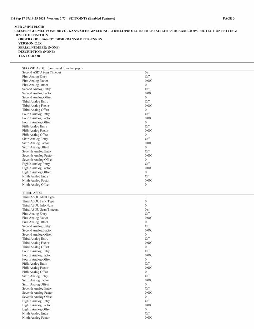


TRANS MOUNTAIN EXPANSION PROJECT
01-13283-PA-KS02-TTF-RPT-0001 Revision 0 2021-09-16 Page 59 of 60
Kamloops- Power System Study with Short Circuit Analysis, Arc Flash, and Protection Coordination Study
14.0 Appendix 7 – Engineering Specifications


TRANS MOUNTAIN EXPANSION PROJECT
01-13283-PA-KS02-TTF-RPT-0001 Revision 0 2021-09-16 Page 60 of 60
Kamloops- Power System Study with Short Circuit Analysis, Arc Flash, and Protection Coordination Study
15.0 Appendix 8 – Substation Study

Trans Mountain Expansion Project Early Works Agreement
Kamloops Substation Switchyard
Electrical System Study
Contractor Revision Date: 2020-06-19
Contractor Revision No.: 0
Page 1 of 56
Rev No.
Prepared by/ Date
Reviewed by/ Date
Approved by/ Date
Reviewed by TMEP
Pages Revised
Issued Type
0 J. Kasturi
2020-06-19 W. Han
2020-06-19 T. DeFreitas 2020-06-19
Issued for Construction
Trans Mountain Expansion Project
Early Works Agreement
Kamloops Substaion Switchyard Electrical System Study
Issued for Construction
(WD#3)
TMEP Document # 01-13283-PD-KS00-EL-STY-0002 R0

Trans Mountain Expansion Project Early Works Agreement
Kamloops Substation Switchyard
Electrical System Study
Contractor Revision Date: 2020-06-19
Contractor Revision No.: 0
Page 2 of 56
Table of Contents
1 SCOPE 3
2 DESIGN CRITERIA 3
3 DESIGN BASIS 3
4 SCENARIOS 5
5 RESULTS 5
6 CONCLUSION 10

Trans Mountain Expansion Project Early Works Agreement
Kamloops Substation Switchyard
Electrical System Study
Contractor Revision Date: 2020-06-19
Contractor Revision No.: 0
Page 3 of 56
1 SCOPE
This document covers the power system study of the Kamloops Substation Switchyard. The objective is to determine the short circuit and arc-flash incident energy levels at the medium voltage switchyard being designed for Trans Mountain Corporation’s (TMC) Pipeline Expansion Project in Kamloops, British Columbia, Canada.
2 DESIGN CRITERIA
2.1 Short Circuit
The equipment shall be rated for short circuit currents during fault conditions.
2.2 Arc-Flash
The incident energy levels of the equipment during faults shall be below 8 Cal/cm2 (Category 2) per Trans Mountain Corporation’s requirements for indoor switchgear equipment.
2.3 Protection Coordination
The protective device coordination shall be selective with 0.2 s Coordination Time Interval (CTI) between protective devices.
3 DESIGN BASIS
3.1 Electrical System
The station consists of a new switchyard substation 138 kV-4.16 kV, 15/20/25 MVA substation with one (1) incoming line and five (5) 4.16 kV substation electrical service building (SESB) switchgear feeders. The downstream equipment after the SESB-SWG1 feeder relays were not in scope. However, the system model downstream of the feeders was modeled as lumped demand load from the load list provided by TMC. The downstream equipment shown in the model was only used to create worst case maximum fault current contributions from motors during fault conditions. Although the motors are controlled using VFDs, to achieve the worst case fault current contributions from motors during fault conditions, the VFDs were not modeled. Also, these downstream loads were modeled to accomplish selective coordination.

Trans Mountain Expansion Project Early Works Agreement
Kamloops Substation Switchyard
Electrical System Study
Contractor Revision Date: 2020-06-19
Contractor Revision No.: 0
Page 4 of 56
3.2 Software Model
The SKM Power Tools version 8.0.3.7 has been used for modeling the electrical system. The system has been modeled based on the single line drawing, provided in appendix, with the following parameters.
3.2.1 Utility
Station is fed from BC Hydro owned line between Savona (SVA) to Douglas (DUG) substations via a tap off the transmission line designated 1L204 at structure 19/1. Fault current information at the point of interconnection provided by BC Hydro was used when performing the study. Thevenin impedance values were considered accurate within ±10%.
Fault Impedance (100 MVA, 138 kV base) Z1 = 0.0111 + j 0.0553 p.u. Z0 = 0.0166 + j 0.1090 p.u.
3.2.2 Transformer
Transformers are modeled based on the design ratings shown on the single line drawing and any information available from the manufacturer. Typical values of X/R ratios were used when manufacturer data is not available. Typical impedance tolerance of -7.5% was used during short circuit analysis as this will increase available short circuit current through the transformer and +7.5% was used during load flow and motor starting as this will cause a larger voltage drop and provide the worst case scenario.
The transformer is modeled with the parameters below: TXR1 Apparent Power (MVA) 15/20/25 Primary Voltage (kV) 138 Secondary Voltage (kV) 4.16 Impedance (%) 8.000 Connection D-YG (NGR: 15 A, 10 sec) X/R Ratio 19.811

Trans Mountain Expansion Project Early Works Agreement
Kamloops Substation Switchyard
Electrical System Study
Contractor Revision Date: 2020-06-19
Contractor Revision No.: 0
Page 5 of 56
3.2.3 Cables
Typical cable impedances from SKM library were modeled based on TECK cables.
3.2.4 Loads
Loads were modeled per the equipment load list provided by Trans Mountain Corporation (TMC). It shall be noted that the loads, not in PIIC scope, were modeled as lumped load. See appendix for load list provided by TMC.
4 SCENARIOS
4.1 Nominal Fault Current Operation
4.1.1 Nominal Operation
Pre fault voltage – 1.00 p.u. All feeders in service. No arc-flash instantaneous protection considered.
4.1.2 Nominal Operation with Arc-flash Protection
Pre fault voltage – 1.00 p.u. All feeders in service. Arc-flash instantaneous protection considered.
4.1.3 Nominal Operation with Arc-flash Protection & Maintenance Mode
Pre fault voltage – 1.00 p.u. All feeders in service. Arc-flash instantaneous protection considered. Maintenance mode settings considered.
5 RESULTS
The results of the power system studies for different operating conditions are listed below.

Trans Mountain Expansion Project Early Works Agreement
Kamloops Substation Switchyard
Electrical System Study
Contractor Revision Date: 2020-06-19
Contractor Revision No.: 0
Page 6 of 56
5.1 Short Circuit
The equipment was rated for short circuit currents during fault conditions. See appendix for short-circuit analysis reports from SKM.
Short Circuit
Equipment (Scenario)
Rating (kA) Rating (%)
Device Momentary* Calculated
Interrupt Calculated Momentary
Interrupt Momentary
SESB-SWG1 (4.1) 63.000 100.800 34.314 63.445 54.467 62.941 *Momentary Rating is 1.6 times Device Interrupt Rating
5.2 Arc-Flash
The incident energy levels of the equipment during faults were below 8 Cal/cm2 (Category 2) per Trans Mountain Corporation’s requirements while maintaining the selectivity between devices. See appendix for arc-flash analysis reports from SKM.
Incident Energy Table Category Incident Energy (Cal/cm2)
0 0.0 – 1.2 1 1.2 – 4.0 2 4.0 – 8.0 3 8.0 – 25.0 4 25.0 – 40.0
Dangerous >40.0

Trans Mountain Expansion Project Early Works Agreement
Kamloops Substation Switchyard
Electrical System Study
Contractor Revision Date: 2020-06-19
Contractor Revision No.: 0
Page 7 of 56
Arc-Flash
Equipment
Bus Fault Current (kA) Incident Energy (Cal/cm2)
Bolted Arcing No Arc-Flash Instantaneous
Protection
Arc-Flash Instantaneous
Protection
Arc-Flash Instantaneous Protection & Maintenance
Mode 4.1 SWG1 39.65 33.82 35.10 7.30 7.30 MFR4 39.65 33.82 35.10 35.10 5.50 MFR5 39.65 33.82 16.50 32.40 5.50 MFR6 39.65 33.82 16.50 32.40 5.50 MFR7 39.65 33.82 16.50 32.40 5.50 MFR8 39.65 33.82 16.50 32.40 5.50 MFR9 39.65 33.82 6.10 6.10 6.10
Appendix C.1.1 shows arc-flash analysis for scenario. The arc-flash incident energy levels were higher than category 2 due to the fact that the settings were set high to provide selective coordination, and the trip times are longer.
Appendix C.1.2 shows arc-flash analysis for scenario. When arc-flash sensor enabled relays were used the incident energy levels for the protective device equipment were reduced but not below the required Category 2 energy levels. However, considering the line side and load side incident energy levels for worst case conditions, the energy levels were above category 2 limits.
Appendix C.1.3 shows arc-flash analysis for scenario. In this scenario, maintenance mode switch was used to enable a different group settings in the relays to activate instantaneous settings to limit incident energy levels, thereby providing safety for personnel with a compromise in selective coordination.
5.3 Protection Coordination
The protective device coordination settings for the equipment were set to be selective with 0.2 s Coordination Time Interval (CTI). Coordination between the downstream devices and the feeder relays that was not selective were not in PIIC scope. See appendix for time current curves.

Trans Mountain Expansion Project Early Works Agreement
Kamloops Substation Switchyard
Electrical System Study
Contractor Revision Date: 2020-06-19
Contractor Revision No.: 0
Page 8 of 56
5.3.1 TCC #01 – 1T1 HV PHASE PROTECTION
This time current curve shows the coordination between relay MFR1-HV, transformer protection relay, and transformer TXR1 damage curve. The curve shows the protection for transformer.
5.3.2 TCC #02 – SWG1 PHASE PROTECTION
This time current curve shows the coordination between transformer relay MFR1-LV and switchgear main MFR4.
5.3.3 TCC #03 – 2VFD-3301 PROTECTION
This time current curve shows the coordination between MFR1 and MFR3, relay that feeds 2VFD-3301. The curve shows selective coordination has been achieved with 0.2 sec CTI. Although the curve shows non selective coordination between the fuse and relays in the long time region, it shall be noted that the fuse provides instantaneous protection for the downstream VFD and the relay provides protection in the long time region and thermal or overload protection. This settings also apply for 2VFD-3202, 2VFD-3203, and 2VFD-3204.
5.3.4 TCC #04 – 2TXR-3201 PROTECTION
This time current curve shows the coordination between MFR1 and MFR5 relay that feeds 2TXR-3201 transformer. The curve shows selective coordination has been achieved with 0.2 sec CTI.
5.3.5 TCC #05 – 1T1 HV RES GROUND PROTECTION
This time current curve shows the ground fault current coordination between MFR-HV for TXR1.
5.3.6 TCC #06 – SWG1 GROUND PROTECTION
This time current curve shows the ground fault current coordination between TXR1 neutral relay, MFR4, and the feeder ground relays of SWG1.
The table below lists the protective device settings for the relays. The settings for maintenance mode are also included in the table.

Trans Mountain Expansion Project Early Works Agreement
Kamloops Substation Switchyard
Electrical System Study
Contractor Revision Date: 2020-06-19
Contractor Revision No.: 0
Page 9 of 56
Relay Settings
SETTINGS
SERVING TAG PHASE/ GROUND
RELAY CT RATIO
TAP CURVE-TIME DIAL INST INST
DELAY
BRK1/TXR1 MFR1-HV 50/51 P GE-845 200/5 0.65 AVI-6.00 9.00 0.01 s *AFMS 0.65 AVI-6.00 9.00 0.01 s 50/51 N 200/5 0.40 AVI-6.00 4.50 0.05 s MFR1-LV 50/51 P GE-845 4000/5 1.00 AEI-3.00 2.70 0.55 s *AFMS 1.00 AEI-3.00 2.70 0.01 s
NGR MFR3 50G SE-330 200/5 --- --- 6% 0.70 s
SWG1 MFR4 50/51 P GE-350 4000/5 1.00 AEI-3.00 2.70 0.55 s *AFMS 1.00 AEI-3.00 2.70 0.01 s 50/51 G1 50/5 --- --- 0.09 0.5 s 50/51 G2 --- --- 1.00 0.00 s
2VFD-3301 MFR5 50/51 P GE-850 1000/5 0.78 AEI-24.00 10.00 0.20 s *AFMS 0.78 AEI-24.00 10.00 0.01 s 50/51 G 50/5 --- --- 0.15 0.30 s
2VFD-3302 MFR6 50/51 P GE-850 1000/5 0.78 AEI-24.00 10.00 0.2 s *AFMS 0.78 AEI-24.00 10.00 0.01 s 50/51 G 50/5 --- --- 0.15 0.30 s
2VFD-3303 MFR7 50/51 P GE-850 1000/5 0.78 AEI-24.00 10.00 0.20 s *AFMS 0.78 AEI-24.00 10.00 0.01 s 50/51 G 50/5 --- --- 0.15 0.30 s
2VFD-3304 MFR8 50/51 P GE-850 1000/5 0.78 AEI-24.00 10.00 0.20 s *AFMS 0.78 AEI-24.00 10.00 0.01 s 50/51 G 50/5 --- --- 0.15 0.30 s
2TXR-3201 MFR9 50/51 P1 GE-850 100/5 1.05 ANI-4.00 2.00 0.20 s 50/51 P2 --- --- 20.00 0.00 s *AFMS 1.05 ANI-4.00 2.00 0.20 s

Trans Mountain Expansion Project Early Works Agreement
Kamloops Substation Switchyard
Electrical System Study
Contractor Revision Date: 2020-06-19
Contractor Revision No.: 0
Page 10 of 56
Relay Settings
SETTINGS
SERVING TAG PHASE/ GROUND
RELAY CT RATIO
TAP CURVE-TIME DIAL INST INST
DELAY
--- --- 20.00 0.00 s 50/51 G 50/5 --- --- 0.15 0.30 s
*AFMS – Arc Flash Maintenance Switch Settings
6 CONCLUSION
The study must be performed again for any changes in the fault current information available from the utility, any deviations from the transformer tap settings or any other load change conditions to confirm proper performance of the system. It shall be noted that the system model under study did not include downstream equipment from the 4.16 kV feeders of SESB-SWG1 switchgear.
1. The short circuit analysis confirmed that fault current levels were below the proposed 63 KAIC for the 4.16 kV SESB switchgear (SWG1) equipment ratings.
2. The incident energy levels of the equipment during faults were below 8 Cal/cm2 (Category 2) per Trans Mountain Corporation’s requirements while maintaining the selectivity between devices when maintenance mode settings were enabled.
The incident energy levels were above category 2 on the line side of incomer section of the switchgear. The incident energy levels are below category 2 for bus and load side of the switchgear. These energy levels were reduced to category 2 or below using maintenance mode settings.
It shall be noted that the arc-flash category for the incomer cell of the switchgear was “Category 4.” This was based on the line side incident energy levels. The bus or load side of this incomer cell was at or below Category 2 incident energy level. When line side incident energy level tag was considered, the category was Category 4. However, the relay in the incomer section has arc-flash light sensor enabled, along with instantaneous element enabled. For an arc-flash incident energy build up on the line side of the switchgear, the relay is capable of detecting the fault current and tripping the entire bus feeders and isolating the switchgear from catastrophic failures and provide safety of personnel working on the switchgear. It is always advised to use maintenance mode settings.
3. The protective device coordination settings for the equipment were set to be selective with 0.2 s Coordination Time Interval (CTI). It is advised to analyze the coordination of the downstream equipment with the SWG1 feeders.


j


In Se
rvice
(c
al/c
m2 )
Mai
nten
ance
(c
al/c
m2 )
In
serv
iceM
aint
enan
ceIn
se
rvice
Mai
nten
ance
June
19,
20
2035
.17.
34
265
726
330
070
SWG1
SWT2
4160
Kam
loop
s Te
rmin
alKW
PE
Equi
pmen
tIso
latio
n Po
int
Shoc
k Ha
zard
(V
AC)
Stat
ion
Engi
neer
ing
Cons
ulta
nt
Rest
ricte
d Ap
proa
ch
Boun
dary
(c
m)
Date
Incid
ent E
nerg
y Fl
ash
Haza
rdAr
c Fla
sh H
azar
d/Ri
sk
Cate
gory
Flas
h Pr
otec
tion
Boun
dary
(cm
)Lim
ited
Appr
oach
Bo
unda
ry
(cm
)


-----------------------------------------------------------------------------------------
Device Name: MFR1-HV TCC Name: TCC #01 - TXR1 HV PHASE PROTECTION.tcc
Bus Name: TXR1-HV Bus Voltage: 138000.0V
Function Name: Phase Manufacturer: GE MULTILIN
Description: 50/51P Type: 845
AIC Rating: N/A Fault Duty: 7716.1A
Current Rating: 200A / 5A Tcc Current Multiplier: 1
Tcc Time Multiplier: 1 Tcc Time Adder: 0
Setting: 1) 51P 0.65 (130A) Test Points: @2.0X, 7.951s
2) ANSI Very Inverse 1; 6 @5.0X, 1.559s
3) 50P-1 9 (1800A) @10.0X, 0.874s
4) 50P-1 Delay 0.01 (seconds)
-----------------------------------------------------------------------------------------
Device Name: TXR1 TCC Name: TCC #01 - TXR1 HV PHASE PROTECTION.tcc
Bus Name: TXR1-HV Bus Voltage: 138000.0V / 4160V
Tcc Current Multiplier: 1
Tcc Time Multiplier: 1 Tcc Time Adder: 0
Description: 2-Winding Transformer Damage Curve Rated Volts: 138000 LL/4160 LL
Nominal kVA: 15000.0kVA Pri Connection: Delta
Full Load kVA: 25000.0kVA Sec Connection: Wye-Ground
Impedance (%Z): 8.0000 Inrush Factor: 12.0x

-----------------------------------------------------------------------------------------
Device Name: MFR1-HV TCC Name: TCC #02 - SWG1 PHASE PROTECTION.tcc
Bus Name: TXR1-HV Bus Voltage: 138000.0V
Function Name: Phase Manufacturer: GE MULTILIN
Description: 50/51P Type: 845
AIC Rating: N/A Fault Duty: 7716.1A
Current Rating: 200A / 5A Tcc Current Multiplier: 1
Tcc Time Multiplier: 1 Tcc Time Adder: 0
Setting: 1) 51P 0.65 (130A) Test Points: @2.0X, 7.951s
2) ANSI Very Inverse 1; 6 @5.0X, 1.559s
3) 50P-1 9 (1800A) @10.0X, 0.874s
4) 50P-1 Delay 0.01 (seconds)
-----------------------------------------------------------------------------------------
Device Name: TXR1 TCC Name: TCC #02 - SWG1 PHASE PROTECTION.tcc
Bus Name: TXR1-HV Bus Voltage: 138000.0V / 4160V
Tcc Current Multiplier: 1
Tcc Time Multiplier: 1 Tcc Time Adder: 0
Description: 2-Winding Transformer Damage Curve Rated Volts: 138000 LL/4160 LL
Nominal kVA: 15000.0kVA Pri Connection: Delta
Full Load kVA: 25000.0kVA Sec Connection: Wye-Ground
Impedance (%Z): 8.0000 Inrush Factor: 12.0x
-----------------------------------------------------------------------------------------
Device Name: MFR1-LV TCC Name: TCC #02 - SWG1 PHASE PROTECTION.tcc
Bus Name: TXR1-LV Bus Voltage: 4160.0V
Function Name: Phase Manufacturer: GE MULTILIN
Description: 50/51P Type: 845
AIC Rating: N/A Fault Duty: 39682.4A
Current Rating: 4000A / 5A Tcc Current Multiplier: 1
Tcc Time Multiplier: 1 Tcc Time Adder: 0
Setting: 1) 51P 1 (4000A) Test Points: @2.0X, 5.233s
2) ANSI Ext Inverse 1; 3 @5.0X, 0.742s
3) 50P-1 2.7 (10800A) @10.0X, 0.295s
4) 50P-1 Delay 0.55 (seconds)
-----------------------------------------------------------------------------------------
Device Name: MFR4 TCC Name: TCC #02 - SWG1 PHASE PROTECTION.tcc
Bus Name: SWG1 Bus Voltage: 4160.0V
Function Name: Phase Manufacturer: GE MULTILIN
Description: 50P/51P, ANSI Type: 350
AIC Rating: N/A Fault Duty: 39653.2A
Current Rating: 4000A / 5A Tcc Current Multiplier: 1
Tcc Time Multiplier: 1 Tcc Time Adder: 0
Setting: 1) 51P TOC Pickup 1 (4000A) Test Points: @2.0X, 5.233s
2) ANSI Extr Inv 1; 3 @5.0X, 0.742s
3) 50P IOC Pickup 2.7 (10800A) @10.0X, 0.295s
4) 50P IOC Delay 0.55 (seconds)

-----------------------------------------------------------------------------------------
Device Name: MFR4 TCC Name: TCC #03 - 2VFD-3301 PROTECTION.tcc
Bus Name: SWG1 Bus Voltage: 4160.0V
Function Name: Phase Manufacturer: GE MULTILIN
Description: 50P/51P, ANSI Type: 350
AIC Rating: N/A Fault Duty: 39653.2A
Current Rating: 4000A / 5A Tcc Current Multiplier: 1
Tcc Time Multiplier: 1 Tcc Time Adder: 0
Setting: 1) 51P TOC Pickup 1 (4000A) Test Points: @2.0X, 5.233s
2) ANSI Extr Inv 1; 3 @5.0X, 0.742s
3) 50P IOC Pickup 2.7 (10800A) @10.0X, 0.295s
4) 50P IOC Delay 0.55 (seconds)
-----------------------------------------------------------------------------------------
Device Name: MFR5 TCC Name: TCC #03 - 2VFD-3301 PROTECTION.tcc
Bus Name: SWG1 Bus Voltage: 4160.0V
Function Name: Phase Manufacturer: GE MULTILIN
Description: 50/51P Type: 850
AIC Rating: N/A Fault Duty: 39653.2A
Current Rating: 1000A / 5A Tcc Current Multiplier: 1
Tcc Time Multiplier: 1 Tcc Time Adder: 0
Setting: 1) 51P 0.78 (780A) Test Points: @2.0X, 41.864s
2) ANSI, Ext. Inverse 1; 24 @5.0X, 5.938s
3) 50P 10 (10000A) @10.0X, 2.358s
4) 50P Delay 0.2 (seconds)
-----------------------------------------------------------------------------------------
Device Name: 2BRK3501-2VFD3301-PC TCC Name: TCC #03 - 2VFD-3301 PROTECTION.tcc
Bus Name: SWG1 Bus Voltage: 4160.0V
Tcc Current Multiplier: 1
Tcc Time Multiplier: 1 Tcc Time Adder: 0
Description: Cable Damage Curve Qty/Ph: 2
Size: 500
Material: Copper Cont. Temp: 90 deg C.
Total Ampacity: 711.0 Damage Temp: 250 deg C.
-----------------------------------------------------------------------------------------
Device Name: FUS-2VFD3301 TCC Name: TCC #03 - 2VFD-3301 PROTECTION.tcc
Bus Name: 2VFD3301-P Bus Voltage: 4160.0V
Function Name: Phase Manufacturer: GOULD SHAWMUT
Description: 750E-900E Type: A055B, 5.5kV Bolt-In
AIC Rating: 63kA Fault Duty: 37457.4A
Cartridge: A055B, 900E 5500V 900A Tcc Current Multiplier: 1
Tcc Time Multiplier: 1 Tcc Time Adder: 0
Size: 900A

-----------------------------------------------------------------------------------------
Device Name: MFR4 TCC Name: TCC #04 - 2TXR-3201 PROTECTION.tcc
Bus Name: SWG1 Bus Voltage: 4160.0V
Function Name: Phase Manufacturer: GE MULTILIN
Description: 50P/51P, ANSI Type: 350
AIC Rating: N/A Fault Duty: 39653.2A
Current Rating: 4000A / 5A Tcc Current Multiplier: 1
Tcc Time Multiplier: 1 Tcc Time Adder: 0
Setting: 1) 51P TOC Pickup 1 (4000A) Test Points: @2.0X, 5.233s
2) ANSI Extr Inv 1; 3 @5.0X, 0.742s
3) 50P IOC Pickup 2.7 (10800A) @10.0X, 0.295s
4) 50P IOC Delay 0.55 (seconds)
-----------------------------------------------------------------------------------------
Device Name: MFR9 TCC Name: TCC #04 - 2TXR-3201 PROTECTION.tcc
Bus Name: SWG1 Bus Voltage: 4160.0V
Function Name: Phase Manufacturer: GE MULTILIN
Description: 50/51P Type: 850
AIC Rating: N/A Fault Duty: 39653.2A
Current Rating: 100A / 5A Tcc Current Multiplier: 1
Tcc Time Multiplier: 1 Tcc Time Adder: 0
Setting: 1) 51P 1.05 (105A) Test Points: @2.0X, 7.062s
2) ANSI, Norm. Inverse 1; 4 @5.0X, 1.627s
3) 50P 2 (200A) @10.0X, 0.904s
4) 50P Delay 0.2 (seconds)
5) 50P 20 (2000A)
-----------------------------------------------------------------------------------------
Device Name: 2BRK3505-2TXR3201-PC TCC Name: TCC #04 - 2TXR-3201 PROTECTION.tcc
Bus Name: SWG1 Bus Voltage: 4160.0V
Tcc Current Multiplier: 1
Tcc Time Multiplier: 1 Tcc Time Adder: 0
Description: Cable Damage Curve Qty/Ph: 1
Size: 2
Material: Copper Cont. Temp: 90 deg C.
Total Ampacity: 108.0 Damage Temp: 250 deg C.
-----------------------------------------------------------------------------------------
Device Name: 2TXR-3201 TCC Name: TCC #04 - 2TXR-3201 PROTECTION.tcc
Bus Name: 2TXR-3201-P Bus Voltage: 4160.0V / 600V
Tcc Current Multiplier: 1
Tcc Time Multiplier: 1 Tcc Time Adder: 0
Description: 2-Winding Transformer Damage Curve Rated Volts: 4160 LL/600 LL
Nominal kVA: 300.0kVA Pri Connection: Delta
Full Load kVA: 300.0kVA Sec Connection: Wye-Ground
Impedance (%Z): 5.7500 Inrush Factor: 12.0x

-----------------------------------------------------------------------------------------
Device Name: MFR1-HV TCC Name: TCC #05 - TXR1 HV RES GROUND PROTECTION.tcc
Bus Name: TXR1-HV Bus Voltage: 138000.0V
Function Name: Neutral Manufacturer: GE MULTILIN
Description: 50/51N Type: 845
AIC Rating: N/A Fault Duty: 5740.3A
Current Rating: 200A / 5A Tcc Current Multiplier: 1
Tcc Time Multiplier: 1 Tcc Time Adder: 0
Setting: 1) 51N 0.4 (80A) Test Points: @2.0X, 7.951s
2) ANSI Very Inverse 1; 6 @5.0X, 1.559s
3) 51N-1 4.5 (900A) @10.0X, 0.874s
4) 51N-1 Delay 0.01 (seconds)
-----------------------------------------------------------------------------------------
Device Name: TXR1 TCC Name: TCC #05 - TXR1 HV RES GROUND PROTECTION.tcc
Bus Name: TXR1-HV Bus Voltage: 138000.0V / 4160V
Tcc Current Multiplier: 1
Tcc Time Multiplier: 1 Tcc Time Adder: 0
Description: 2-Winding Transformer Damage Curve Rated Volts: 138000 LL/4160 LL
Nominal kVA: 15000.0kVA Pri Connection: Delta
Full Load kVA: 25000.0kVA Sec Connection: Wye-Ground
Impedance (%Z): 8.0000 Inrush Factor: 12.0x

-----------------------------------------------------------------------------------------
Device Name: MFR3 TCC Name: TCC #06 - SWG1 GROUND PROTECTION.tcc
Bus Name: TXR1-LV Bus Voltage: 4160.0V
Function Name: Ground Manufacturer: STARTCO
Description: 50/ 51G/ 51N Type: SE-330
AIC Rating: N/A Fault Duty: 34369.7A
Current Rating: 200A / 5A Tcc Current Multiplier: 1
Tcc Time Multiplier: 1 Tcc Time Adder: 0
Setting: 1) GF Trip Level 6 % (12A) Test Points: @2.0X, 1.000s
2) GF Trip Time 1 (seconds) @5.0X, 1.000s
@10.0X, 1.000s
-----------------------------------------------------------------------------------------
Device Name: MFR4 TCC Name: TCC #06 - SWG1 GROUND PROTECTION.tcc
Bus Name: SWG1 Bus Voltage: 4160.0V
Function Name: G Manufacturer: GE MULTILIN
Description: 50SG/51SG, ANSI Type: 350
AIC Rating: N/A Fault Duty: 34344.4A
Current Rating: 100A / 5A Tcc Current Multiplier: 1
Tcc Time Multiplier: 1 Tcc Time Adder: 0
Setting: 1) 50SG IOC Pickup 0.09 (9A) Test Points: @2.0X, 0.500s
2) 50SG IOC Delay 0.5 (seconds) @5.0X, 0.500s
3) 50SG IOC Pickup 1 (100A) @10.0X, 0.501s
-----------------------------------------------------------------------------------------
Device Name: MFR5-G TCC Name: TCC #06 - SWG1 GROUND PROTECTION.tcc
Bus Name: SWG1 Bus Voltage: 4160.0V
Function Name: Ground Manufacturer: GE MULTILIN
Description: 50/51G Type: 850
AIC Rating: N/A Fault Duty: 34344.4A
Current Rating: 50A / 5A Tcc Current Multiplier: 1
Tcc Time Multiplier: 1 Tcc Time Adder: 0
Setting: 1) 50G 0.15 (7.5A) Test Points: @2.0X, 0.200s
2) 50G Delay 0.2 (seconds) @5.0X, 0.200s
@10.0X, 0.200s
-----------------------------------------------------------------------------------------
Device Name: MFR6-G TCC Name: TCC #06 - SWG1 GROUND PROTECTION.tcc
Bus Name: SWG1 Bus Voltage: 4160.0V
Function Name: Ground Manufacturer: GE MULTILIN
Description: 50/51G Type: 850
AIC Rating: N/A Fault Duty: 34344.4A
Current Rating: 50A / 5A Tcc Current Multiplier: 1
Tcc Time Multiplier: 1 Tcc Time Adder: 0
Setting: 1) 50G 0.15 (7.5A) Test Points: @2.0X, 0.200s
2) 50G Delay 0.2 (seconds) @5.0X, 0.200s
@10.0X, 0.200s
-----------------------------------------------------------------------------------------
Device Name: MFR7-G TCC Name: TCC #06 - SWG1 GROUND PROTECTION.tcc
Bus Name: SWG1 Bus Voltage: 4160.0V
Function Name: Ground Manufacturer: GE MULTILIN
Description: 50/51G Type: 850
AIC Rating: N/A Fault Duty: 34344.4A
Current Rating: 50A / 5A Tcc Current Multiplier: 1
Tcc Time Multiplier: 1 Tcc Time Adder: 0
Setting: 1) 50G 0.15 (7.5A) Test Points: @2.0X, 0.200s
2) 50G Delay 0.2 (seconds) @5.0X, 0.200s
@10.0X, 0.200s
-----------------------------------------------------------------------------------------
Device Name: MFR8-G TCC Name: TCC #06 - SWG1 GROUND PROTECTION.tcc
Bus Name: SWG1 Bus Voltage: 4160.0V
Function Name: Ground Manufacturer: GE MULTILIN
Description: 50/51G Type: 850
AIC Rating: N/A Fault Duty: 34344.4A
Current Rating: 50A / 5A Tcc Current Multiplier: 1
Tcc Time Multiplier: 1 Tcc Time Adder: 0
Setting: 1) 50G 0.15 (7.5A) Test Points: @2.0X, 0.200s
2) 50G Delay 0.2 (seconds) @5.0X, 0.200s
@10.0X, 0.200s
-----------------------------------------------------------------------------------------
Device Name: MFR9-G TCC Name: TCC #06 - SWG1 GROUND PROTECTION.tcc
Bus Name: SWG1 Bus Voltage: 4160.0V
Function Name: Ground Manufacturer: GE MULTILIN
Description: 50/51G Type: 850
AIC Rating: N/A Fault Duty: 34344.4A
Current Rating: 50A / 5A Tcc Current Multiplier: 1
Tcc Time Multiplier: 1 Tcc Time Adder: 0
Setting: 1) 50G 0.15 (7.5A) Test Points: @2.0X, 0.200s
2) 50G Delay 0.2 (seconds) @5.0X, 0.200s
@10.0X, 0.200s

-----------------------------------------------------------------------------------------
Device Name: MFR1-HV TCC Name: TCC #01 - TXR1 HV PHASE PROTECTION.tcc
Bus Name: TXR1-HV Bus Voltage: 138000.0V
Function Name: AFMS Manufacturer: GE MULTILIN
Description: 50/51P Type: 845
AIC Rating: N/A Fault Duty: 7716.1A
Current Rating: 200A / 5A Tcc Current Multiplier: 1
Tcc Time Multiplier: 1 Tcc Time Adder: 0
Setting: 1) 51P 0.65 (130A) Test Points: @2.0X, 7.951s
2) ANSI Very Inverse 1; 6 @5.0X, 1.559s
3) 50P-1 9 (1800A) @10.0X, 0.874s
4) 50P-1 Delay 0.01 (seconds)
-----------------------------------------------------------------------------------------
Device Name: TXR1 TCC Name: TCC #01 - TXR1 HV PHASE PROTECTION.tcc
Bus Name: TXR1-HV Bus Voltage: 138000.0V / 4160V
Tcc Current Multiplier: 1
Tcc Time Multiplier: 1 Tcc Time Adder: 0
Description: 2-Winding Transformer Damage Curve Rated Volts: 138000 LL/4160 LL
Nominal kVA: 15000.0kVA Pri Connection: Delta
Full Load kVA: 25000.0kVA Sec Connection: Wye-Ground
Impedance (%Z): 8.0000 Inrush Factor: 12.0x

-----------------------------------------------------------------------------------------
Device Name: MFR1-HV TCC Name: TCC #02 - SWG1 PHASE PROTECTION.tcc
Bus Name: TXR1-HV Bus Voltage: 138000.0V
Function Name: AFMS Manufacturer: GE MULTILIN
Description: 50/51P Type: 845
AIC Rating: N/A Fault Duty: 7716.1A
Current Rating: 200A / 5A Tcc Current Multiplier: 1
Tcc Time Multiplier: 1 Tcc Time Adder: 0
Setting: 1) 51P 0.65 (130A) Test Points: @2.0X, 7.951s
2) ANSI Very Inverse 1; 6 @5.0X, 1.559s
3) 50P-1 9 (1800A) @10.0X, 0.874s
4) 50P-1 Delay 0.01 (seconds)
-----------------------------------------------------------------------------------------
Device Name: TXR1 TCC Name: TCC #02 - SWG1 PHASE PROTECTION.tcc
Bus Name: TXR1-HV Bus Voltage: 138000.0V / 4160V
Tcc Current Multiplier: 1
Tcc Time Multiplier: 1 Tcc Time Adder: 0
Description: 2-Winding Transformer Damage Curve Rated Volts: 138000 LL/4160 LL
Nominal kVA: 15000.0kVA Pri Connection: Delta
Full Load kVA: 25000.0kVA Sec Connection: Wye-Ground
Impedance (%Z): 8.0000 Inrush Factor: 12.0x
-----------------------------------------------------------------------------------------
Device Name: MFR1-LV TCC Name: TCC #02 - SWG1 PHASE PROTECTION.tcc
Bus Name: TXR1-LV Bus Voltage: 4160.0V
Function Name: AFMS Manufacturer: GE MULTILIN
Description: 50/51P Type: 845
AIC Rating: N/A Fault Duty: 39682.4A
Current Rating: 4000A / 5A Tcc Current Multiplier: 1
Tcc Time Multiplier: 1 Tcc Time Adder: 0
Setting: 1) 51P 1 (4000A) Test Points: @2.0X, 5.233s
2) ANSI Ext Inverse 1; 3 @5.0X, 0.742s
3) 50P-1 2.7 (10800A) @10.0X, 0.295s
4) 50P-1 Delay 0.01 (seconds)
-----------------------------------------------------------------------------------------
Device Name: MFR4 TCC Name: TCC #02 - SWG1 PHASE PROTECTION.tcc
Bus Name: SWG1 Bus Voltage: 4160.0V
Function Name: AFMS Manufacturer: GE MULTILIN
Description: 50P/51P, ANSI Type: 350
AIC Rating: N/A Fault Duty: 39653.2A
Current Rating: 4000A / 5A Tcc Current Multiplier: 1
Tcc Time Multiplier: 1 Tcc Time Adder: 0
Setting: 1) 51P TOC Pickup 1 (4000A) Test Points: @2.0X, 5.233s
2) ANSI Extr Inv 1; 3 @5.0X, 0.742s
3) 50P IOC Pickup 2.7 (10800A) @10.0X, 0.295s
4) 50P IOC Delay 0.01 (seconds)

-----------------------------------------------------------------------------------------
Device Name: MFR4 TCC Name: TCC #03 - 2VFD-3301 PROTECTION.tcc
Bus Name: SWG1 Bus Voltage: 4160.0V
Function Name: AFMS Manufacturer: GE MULTILIN
Description: 50P/51P, ANSI Type: 350
AIC Rating: N/A Fault Duty: 39653.2A
Current Rating: 4000A / 5A Tcc Current Multiplier: 1
Tcc Time Multiplier: 1 Tcc Time Adder: 0
Setting: 1) 51P TOC Pickup 1 (4000A) Test Points: @2.0X, 5.233s
2) ANSI Extr Inv 1; 3 @5.0X, 0.742s
3) 50P IOC Pickup 2.7 (10800A) @10.0X, 0.295s
4) 50P IOC Delay 0.01 (seconds)
-----------------------------------------------------------------------------------------
Device Name: MFR5 TCC Name: TCC #03 - 2VFD-3301 PROTECTION.tcc
Bus Name: SWG1 Bus Voltage: 4160.0V
Function Name: AFMS Manufacturer: GE MULTILIN
Description: 50/51P Type: 850
AIC Rating: N/A Fault Duty: 39653.2A
Current Rating: 1000A / 5A Tcc Current Multiplier: 1
Tcc Time Multiplier: 1 Tcc Time Adder: 0
Setting: 1) 51P 0.78 (780A) Test Points: @2.0X, 41.864s
2) ANSI, Ext. Inverse 1; 24 @5.0X, 5.938s
3) 50P 10 (10000A) @10.0X, 2.358s
4) 50P Delay 0.01 (seconds)
-----------------------------------------------------------------------------------------
Device Name: 2BRK3501-2VFD3301-PC TCC Name: TCC #03 - 2VFD-3301 PROTECTION.tcc
Bus Name: SWG1 Bus Voltage: 4160.0V
Tcc Current Multiplier: 1
Tcc Time Multiplier: 1 Tcc Time Adder: 0
Description: Cable Damage Curve Qty/Ph: 2
Size: 500
Material: Copper Cont. Temp: 90 deg C.
Total Ampacity: 711.0 Damage Temp: 250 deg C.
-----------------------------------------------------------------------------------------
Device Name: FUS-2VFD3301 TCC Name: TCC #03 - 2VFD-3301 PROTECTION.tcc
Bus Name: 2VFD3301-P Bus Voltage: 4160.0V
Function Name: Phase Manufacturer: GOULD SHAWMUT
Description: 750E-900E Type: A055B, 5.5kV Bolt-In
AIC Rating: 63kA Fault Duty: 37457.4A
Cartridge: A055B, 900E 5500V 900A Tcc Current Multiplier: 1
Tcc Time Multiplier: 1 Tcc Time Adder: 0
Size: 900A

-----------------------------------------------------------------------------------------
Device Name: MFR4 TCC Name: TCC #04 - 2TXR-3201 PROTECTION.tcc
Bus Name: SWG1 Bus Voltage: 4160.0V
Function Name: AFMS Manufacturer: GE MULTILIN
Description: 50P/51P, ANSI Type: 350
AIC Rating: N/A Fault Duty: 39653.2A
Current Rating: 4000A / 5A Tcc Current Multiplier: 1
Tcc Time Multiplier: 1 Tcc Time Adder: 0
Setting: 1) 51P TOC Pickup 1 (4000A) Test Points: @2.0X, 5.233s
2) ANSI Extr Inv 1; 3 @5.0X, 0.742s
3) 50P IOC Pickup 2.7 (10800A) @10.0X, 0.295s
4) 50P IOC Delay 0.01 (seconds)
-----------------------------------------------------------------------------------------
Device Name: MFR9 TCC Name: TCC #04 - 2TXR-3201 PROTECTION.tcc
Bus Name: SWG1 Bus Voltage: 4160.0V
Function Name: AFMS Manufacturer: GE MULTILIN
Description: 50/51P Type: 850
AIC Rating: N/A Fault Duty: 39653.2A
Current Rating: 100A / 5A Tcc Current Multiplier: 1
Tcc Time Multiplier: 1 Tcc Time Adder: 0
Setting: 1) 51P 1.05 (105A) Test Points: @2.0X, 7.062s
2) ANSI, Norm. Inverse 1; 4 @5.0X, 1.627s
3) 50P 2 (200A) @10.0X, 0.904s
4) 50P Delay 0.2 (seconds)
5) 50P 20 (2000A)
-----------------------------------------------------------------------------------------
Device Name: 2BRK3505-2TXR3201-PC TCC Name: TCC #04 - 2TXR-3201 PROTECTION.tcc
Bus Name: SWG1 Bus Voltage: 4160.0V
Tcc Current Multiplier: 1
Tcc Time Multiplier: 1 Tcc Time Adder: 0
Description: Cable Damage Curve Qty/Ph: 1
Size: 2
Material: Copper Cont. Temp: 90 deg C.
Total Ampacity: 108.0 Damage Temp: 250 deg C.
-----------------------------------------------------------------------------------------
Device Name: 2TXR-3201 TCC Name: TCC #04 - 2TXR-3201 PROTECTION.tcc
Bus Name: 2TXR-3201-P Bus Voltage: 4160.0V / 600V
Tcc Current Multiplier: 1
Tcc Time Multiplier: 1 Tcc Time Adder: 0
Description: 2-Winding Transformer Damage Curve Rated Volts: 4160 LL/600 LL
Nominal kVA: 300.0kVA Pri Connection: Delta
Full Load kVA: 300.0kVA Sec Connection: Wye-Ground
Impedance (%Z): 5.7500 Inrush Factor: 12.0x

-----------------------------------------------------------------------------------------
Device Name: MFR1-HV TCC Name: TCC #05 - TXR1 HV RES GROUND PROTECTION.tcc
Bus Name: TXR1-HV Bus Voltage: 138000.0V
Function Name: Neutral Manufacturer: GE MULTILIN
Description: 50/51N Type: 845
AIC Rating: N/A Fault Duty: 5740.3A
Current Rating: 200A / 5A Tcc Current Multiplier: 1
Tcc Time Multiplier: 1 Tcc Time Adder: 0
Setting: 1) 51N 0.4 (80A) Test Points: @2.0X, 7.951s
2) ANSI Very Inverse 1; 6 @5.0X, 1.559s
3) 51N-1 4.5 (900A) @10.0X, 0.874s
4) 51N-1 Delay 0.01 (seconds)
-----------------------------------------------------------------------------------------
Device Name: TXR1 TCC Name: TCC #05 - TXR1 HV RES GROUND PROTECTION.tcc
Bus Name: TXR1-HV Bus Voltage: 138000.0V / 4160V
Tcc Current Multiplier: 1
Tcc Time Multiplier: 1 Tcc Time Adder: 0
Description: 2-Winding Transformer Damage Curve Rated Volts: 138000 LL/4160 LL
Nominal kVA: 15000.0kVA Pri Connection: Delta
Full Load kVA: 25000.0kVA Sec Connection: Wye-Ground
Impedance (%Z): 8.0000 Inrush Factor: 12.0x

-----------------------------------------------------------------------------------------
Device Name: MFR3 TCC Name: TCC #06 - SWG1 GROUND PROTECTION.tcc
Bus Name: TXR1-LV Bus Voltage: 4160.0V
Function Name: Ground Manufacturer: STARTCO
Description: 50/ 51G/ 51N Type: SE-330
AIC Rating: N/A Fault Duty: 34369.7A
Current Rating: 200A / 5A Tcc Current Multiplier: 1
Tcc Time Multiplier: 1 Tcc Time Adder: 0
Setting: 1) GF Trip Level 6 % (12A) Test Points: @2.0X, 1.000s
2) GF Trip Time 1 (seconds) @5.0X, 1.000s
@10.0X, 1.000s
-----------------------------------------------------------------------------------------
Device Name: MFR4 TCC Name: TCC #06 - SWG1 GROUND PROTECTION.tcc
Bus Name: SWG1 Bus Voltage: 4160.0V
Function Name: G Manufacturer: GE MULTILIN
Description: 50SG/51SG, ANSI Type: 350
AIC Rating: N/A Fault Duty: 34344.4A
Current Rating: 100A / 5A Tcc Current Multiplier: 1
Tcc Time Multiplier: 1 Tcc Time Adder: 0
Setting: 1) 50SG IOC Pickup 0.09 (9A) Test Points: @2.0X, 0.500s
2) 50SG IOC Delay 0.5 (seconds) @5.0X, 0.500s
3) 50SG IOC Pickup 1 (100A) @10.0X, 0.501s
-----------------------------------------------------------------------------------------
Device Name: MFR5-G TCC Name: TCC #06 - SWG1 GROUND PROTECTION.tcc
Bus Name: SWG1 Bus Voltage: 4160.0V
Function Name: Ground Manufacturer: GE MULTILIN
Description: 50/51G Type: 850
AIC Rating: N/A Fault Duty: 34344.4A
Current Rating: 50A / 5A Tcc Current Multiplier: 1
Tcc Time Multiplier: 1 Tcc Time Adder: 0
Setting: 1) 50G 0.15 (7.5A) Test Points: @2.0X, 0.200s
2) 50G Delay 0.2 (seconds) @5.0X, 0.200s
@10.0X, 0.200s
-----------------------------------------------------------------------------------------
Device Name: MFR6-G TCC Name: TCC #06 - SWG1 GROUND PROTECTION.tcc
Bus Name: SWG1 Bus Voltage: 4160.0V
Function Name: Ground Manufacturer: GE MULTILIN
Description: 50/51G Type: 850
AIC Rating: N/A Fault Duty: 34344.4A
Current Rating: 50A / 5A Tcc Current Multiplier: 1
Tcc Time Multiplier: 1 Tcc Time Adder: 0
Setting: 1) 50G 0.15 (7.5A) Test Points: @2.0X, 0.200s
2) 50G Delay 0.2 (seconds) @5.0X, 0.200s
@10.0X, 0.200s
-----------------------------------------------------------------------------------------
Device Name: MFR7-G TCC Name: TCC #06 - SWG1 GROUND PROTECTION.tcc
Bus Name: SWG1 Bus Voltage: 4160.0V
Function Name: Ground Manufacturer: GE MULTILIN
Description: 50/51G Type: 850
AIC Rating: N/A Fault Duty: 34344.4A
Current Rating: 50A / 5A Tcc Current Multiplier: 1
Tcc Time Multiplier: 1 Tcc Time Adder: 0
Setting: 1) 50G 0.15 (7.5A) Test Points: @2.0X, 0.200s
2) 50G Delay 0.2 (seconds) @5.0X, 0.200s
@10.0X, 0.200s
-----------------------------------------------------------------------------------------
Device Name: MFR8-G TCC Name: TCC #06 - SWG1 GROUND PROTECTION.tcc
Bus Name: SWG1 Bus Voltage: 4160.0V
Function Name: Ground Manufacturer: GE MULTILIN
Description: 50/51G Type: 850
AIC Rating: N/A Fault Duty: 34344.4A
Current Rating: 50A / 5A Tcc Current Multiplier: 1
Tcc Time Multiplier: 1 Tcc Time Adder: 0
Setting: 1) 50G 0.15 (7.5A) Test Points: @2.0X, 0.200s
2) 50G Delay 0.2 (seconds) @5.0X, 0.200s
@10.0X, 0.200s
-----------------------------------------------------------------------------------------
Device Name: MFR9-G TCC Name: TCC #06 - SWG1 GROUND PROTECTION.tcc
Bus Name: SWG1 Bus Voltage: 4160.0V
Function Name: Ground Manufacturer: GE MULTILIN
Description: 50/51G Type: 850
AIC Rating: N/A Fault Duty: 34344.4A
Current Rating: 50A / 5A Tcc Current Multiplier: 1
Tcc Time Multiplier: 1 Tcc Time Adder: 0
Setting: 1) 50G 0.15 (7.5A) Test Points: @2.0X, 0.200s
2) 50G Delay 0.2 (seconds) @5.0X, 0.200s
@10.0X, 0.200s


![[biodiv] Submission Acknowledgement - UNIB Scholar ...](https://static.fdokumen.com/doc/165x107/63240a99117b4414ec0c9818/biodiv-submission-acknowledgement-unib-scholar-.jpg)