VF-AS1 - Sunnice
329
E6581442 Instruction Manual The new high-performance inverter TOSVERT TM VF-AS1 200V class 0.4 75kW 400V class 0.75 500kW 1 Read first II II Introduction I Safety precautions Contents 2 Connection equipment 3 Operations 4 Searching and setting parameters 5 Basic parameters 6 Extended parameters 7 Operation with external signal 8 Monitoring the operation status 9 Measures to satisfy the standards 10 10 Selection of peripheral devices 11 11 Table of parameters 12 12 Specifications 13 13 Before making a service call 14 14 Inspection and maintenance 15 15 Warranty 16 16 Disposal of the inverter NOTICE 1.Make sure that this instruction manual is delivered to the end user of the inverter unit. 2.Read this manual before installing or operating the inverter unit, and store it in a safe place for reference.
-
Upload
khangminh22 -
Category
Documents
-
view
0 -
download
0
Transcript of VF-AS1 - Sunnice

E6581442
Instruction Manual
The new
high-performance inverter
TOSVERTTM
VF-AS1
200V class 0.4 75kW400V class 0.75 500kW
1Read first
IIIIIntroduction
ISafety precautions
Contents
2Connection equipment
3Operations
4 Searching and setting parameters
5Basic parameters
6Extended parameters
7Operation with external signal
8Monitoring the operation status
9Measures tosatisfy thestandards
1010Selection ofperipheraldevices
1111Table of parameters
1212Specifications
1313Before making a service call
1414Inspection and maintenance
1515Warranty
1616Disposal of the inverter
NOTICE
1.Make sure that this instruction manual is delivered to the end user of
the inverter unit.
2.Read this manual before installing or operating the inverter unit, and
store it in a safe place for reference.
TO
SV
ER
T V
F-A
S1
Instruction Manual
The new
high-performance inverter
TOSHIBAINDUSTRIAL AND POWE RSYSTEMS & SE RVICES COMPANY
OVERSEAS SALES & MARKETING DEPT.ELECTRICAL APPARATUS & MEASUREMENT DIV.
1-1, Shibaura 1-chome, Minato-Ku, Tokyo 105-8001, JapanTEL: +81-(0)3-3457-4911FAX: +81-(0)3-5444-9268
TOSHIBA I NTERNATIONAL CORPORATION13131 West Little York RD., Houston, TX 77041, U.S.ATEL: +1-713-466-0277FAX: +1-713-896-5226
TOSHIBA ASIA P ACIFIC PTE., LT D152 Beach Rd., #16-00 Gateway East,Singapore 189721TEL: +65-6297-0900FAX: +65-6297-5510
TOSHIBA CHINA CO., LT D23rd Floor, HSBC Tower, 101 Yin ChengEast Road, Pudong New Area, Shanghai200120, The People's Republic of ChinaTEL: +86-(0)21-6841-5666FAX: +86-(0)21-6841-1161
TOSHIBA I NTERNATIONAL CORPORATION PTY., L TD2 Morton Street Parramatta, NSW2150, AustraliaTEL: +61-(0)2-9768-6600 FAX: +61-(0)2-9890-7542
TOSHIBA I NFORMATION, I NDUSTRIAL AND POWE R SYSTEMS T AIWAN CORP.6F, No66, Sec1 Shin Sheng N.RD, Taipei, TaiwanTEL: +886-(0)2-2581-3639 FAX: +886-(0)2-2581-3631
For further information, please contact your nearest Toshiba Liaison Representative or International Operations - Producer Goods. The data given in this manual are subject to change without notice.2006-08

E6581591
2/2
Precautions of using 4-20mA input signal
VFAS1/PS1 have adopted the semiconductor switch as the change function of 4-20mA current input
and the voltage input of 0-10V.
When the power supply is turned off, 4-20mA input circuit will be in open state, then it will be in high
impedance condition.
Therefore if the 4-20mA current generator has a wire breakage detection, it will make the wire breakage
error.
When the power supply is turned on, the semiconductor switch will change in close state.
If the response of the 4-20mA current generator is not fast (0.2s or less), VFAS1/PS1 will detect over
voltage and occur trip E-10, analog input terminal over-voltage .
Caution
Mandatory
If you use 4-20mA current input for frequency setting, please perform the following countermeasure.
(1) When the power supply turns on/off, please turn on/off also 4-20mA current signal.
(2) Please keep a control power to VFAS1/PS1 connecting the control power supply
backup option, CPS002Z, or external power supply of 24Vdc-1.05A.
Connect the control power supply device between control terminal +SU and CC.
(3)Between VI/II and CCA of control terminals, connect the resistor of 1/2W-500ohm or
470ohms, and use VI/II terminal not as 4-20mA input but as 0-10V input.
Therefore, please set the following parameter.
F108(analog VI/II voltage/current switching) =0 (voltage input:default setting)
F201(VI/II input point 1 setting) =20% (in case of 500 ohm)
19% (in case of 470 ohm)
F203(VI/II input point 2 setting) =98% (in case of 500 ohm)
93% (in case of 470 ohm)
E6581578
Additional sheet
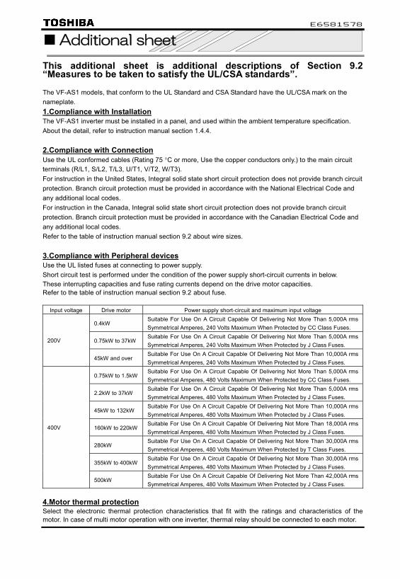
This additional sheet is additional descriptions of Section 9.2 “Measures to be taken to satisfy the UL/CSA standards”. The VF-AS1 models, that conform to the UL Standard and CSA Standard have the UL/CSA mark on the nameplate. 1.Compliance with Installation The VF-AS1 inverter must be installed in a panel, and used within the ambient temperature specification. About the detail, refer to instruction manual section 1.4.4. 2.Compliance with Connection Use the UL conformed cables (Rating 75 °C or more, Use the copper conductors only.) to the main circuit terminals (R/L1, S/L2, T/L3, U/T1, V/T2, W/T3). For instruction in the United States, Integral solid state short circuit protection does not provide branch circuit protection. Branch circuit protection must be provided in accordance with the National Electrical Code and any additional local codes. For instruction in the Canada, Integral solid state short circuit protection does not provide branch circuit protection. Branch circuit protection must be provided in accordance with the Canadian Electrical Code and any additional local codes. Refer to the table of instruction manual section 9.2 about wire sizes.
3.Compliance with Peripheral devices Use the UL listed fuses at connecting to power supply. Short circuit test is performed under the condition of the power supply short-circuit currents in below. These interrupting capacities and fuse rating currents depend on the drive motor capacities. Refer to the table of instruction manual section 9.2 about fuse.
Input voltage Drive motor Power supply short-circuit and maximum input voltage
0.4kW Suitable For Use On A Circuit Capable Of Delivering Not More Than 5,000A rms Symmetrical Amperes, 240 Volts Maximum When Protected by CC Class Fuses.
0.75kW to 37kW Suitable For Use On A Circuit Capable Of Delivering Not More Than 5,000A rms Symmetrical Amperes, 240 Volts Maximum When Protected by J Class Fuses.
200V
45kW and over Suitable For Use On A Circuit Capable Of Delivering Not More Than 10,000A rms Symmetrical Amperes, 240 Volts Maximum When Protected by J Class Fuses.
0.75kW to 1.5kW Suitable For Use On A Circuit Capable Of Delivering Not More Than 5,000A rms Symmetrical Amperes, 480 Volts Maximum When Protected by CC Class Fuses.
2.2kW to 37kW Suitable For Use On A Circuit Capable Of Delivering Not More Than 5,000A rms Symmetrical Amperes, 480 Volts Maximum When Protected by J Class Fuses.
45kW to 132kW Suitable For Use On A Circuit Capable Of Delivering Not More Than 10,000A rms Symmetrical Amperes, 480 Volts Maximum When Protected by J Class Fuses.
160kW to 220kW Suitable For Use On A Circuit Capable Of Delivering Not More Than 18,000A rms Symmetrical Amperes, 480 Volts Maximum When Protected by J Class Fuses.
280kW Suitable For Use On A Circuit Capable Of Delivering Not More Than 30,000A rms Symmetrical Amperes, 480 Volts Maximum When Protected by T Class Fuses.
355kW to 400kW Suitable For Use On A Circuit Capable Of Delivering Not More Than 30,000A rms Symmetrical Amperes, 480 Volts Maximum When Protected by J Class Fuses.
400V
500kW Suitable For Use On A Circuit Capable Of Delivering Not More Than 42,000A rms Symmetrical Amperes, 480 Volts Maximum When Protected by J Class Fuses.
4.Motor thermal protection Select the electronic thermal protection characteristics that fit with the ratings and characteristics of the motor. In case of multi motor operation with one inverter, thermal relay should be connected to each motor.

E6581521③
1
Information on software version up Following information is changed specification points by software version up (Ver. 136,142,150). The software version can be checked by the "CPU1 version" of status monitor. Please refer to "8.2 Monitoring the status". The software version would be changed without preliminary announcement.
Item Changed contents Page New auto-tuning function (200V-55kW or more, 400V-90kW or more)
The new function is for 200V-55kW or more and 400V-90kW or more. By the auto-tuning execution of =2 and 4, all parameter of motor constant 1-4 () can be set. However, it might take about three minutes for the auto tuning. It is not error that the tuning time is long. Do not touch a motor, wiring equipment and so on during the tuning because the motor doesn't rotate but the electrical power is applied. Do not approach near the motor and the machine because the motor rotates after the tuning.
6.22
Added the monitor for options in parameter ,
,:FM/AM terminal meter selection Adjustment range:0~64 → 0~76 65~73:Function none 74:MON1 75:MON2 76:RP
5.16
Added parameter :Output voltage waveform selection Adjustment range 0:PWM carrier frequency control 1
1:PWM carrier frequency control 2 It is setting it as =1,Inverter loss can be reduced a little with following condition by =1. It has the effect of raising some amount of the overload for inverter(when inverter overload detection being estimation of temperature system (=1)). 1) when using it with the career frequency raised (4kHz or more) 2) The driving frequency is 30% or more of the base frequency However, the magnetic noise from a motor is changed a little. Please confirm the noise whether there is any problem. This parameter works at 200V-55kW or more and 400V-90kW or more.
-
Added the setting for using sinusoidal filter (option) in parameter
:Carrier frequency control mode selection Adjustment range:0~3 → 0~5 4:Not decrease carrier frequency automatically, with sinusoidal filter 5:Decrease carrier frequency automatically, with sinusoidal filter If =4 or 5 is set, it automatically becomes V/f control (=0) mode. Moreover, the lower-limit of the career frequency becomes 4kHz. This parameter works at 200V-55kW or more and 400V-90kW or more.
5.17
Added parameter
:Creeping time1 Adjustment range:0.00~2.50sec. This function is for the brake control of hoist. It is possible to adjust the time of closed brake from reaching the creep frequency (). It is able to be minimize swing of burden because it is possible to close a brake when the rotation of motor fully reach the creep frequency.
-
Added the setting for dancer control in parameter
:PID control switching Adjustment range:0~3 → 0~4 4:Dancer control The dancer control function for control of line speed by the speed reference and the positioning feedback signal of dancer roll was added.
*1
Output frequency
[Hz]
Torque
Braking signal
RUN command
time[s]
Torque Control Speed control
Braking request Brake release request
Issue of Torque command
Creeping frequency
Starting frequency
Braking operation

E6581521③
2
Item Changed contents Page Added parameter :PID output dead band
Adjustment range:0~100% The parameter for dead band adjustment of the PID output was added for dancer control.
*1
The description of the adjustable range and the Minimum setting unit were corrected for parameter
:Motor constant 3 (leak inductance) Adjustment range:0~200% → 0~200(×0.1%) Minimum setting unit(Panel/Communication):0.1/0.1 → 1/1
6.22
Added parameter :Torque reference filter Adjustment range:0~1000ms The filter for the input command of the torque control was added.
*2
Added parameter :Torque reference polarity selection Adjustment range 0:When reversing, reverse the polarity 1:When reversing, doesn’t reverse the polarity The polarity of the torque signal passed from the master to the slave was added for the tune driving such as master (speed control) and slave (torque control) driving, and to make both the foword and reverse are made the same polarity.
*2
Added parameter :Motor oscillation control Adjustment range 0:Disabled 1:Enabled (Low gain) 2:Enabled (Middle gain) 3:Enabled (High gain) When a motor is in unstable with light load, this parameter can change the motor gain to make motor condition stable. First set f467=1 and check the motor condition. Please set 2 to 3 in case motor needs more stable condition. This parameter is effective at only V/f control mode( =0,1,5).
―
Added parameter :Stall prevention control switching Adjustment range 0:Stall prevention control 1 1: Stall prevention control 2 The operation of the stall prevention control can be switched. Set =1 when the overvoltage trip etc. are displayed when acceleration and the deceleration are switched. This parameter is effective at only V/f control mode( =0,1,5).
―
Added parameter :Overvoltage limit constant Adjustment range 0: Automatic, 1~1000ms The filter time constant of the overvoltage limitation can be adjusted. This parameter is effective at only V/f control mode( =0,1,5).
―
Added parameter :Max output voltage modulation rate Adjustment range 0:Standard 1:Disable 2:Enabled(Low gain) 3: Enabled(High gain) In the case that Inverter output voltage drops and output current exceeds motor rating current at the frequency higher than base frequency. Change this parameter setting and check whether the output current is reduced.
―
Added parameter ~
This function is for Etherenet communication option. (planning) *3
Enable range in parameter
: Abnormal speed detection time V/f:(=0,1,5):Disable → Enable Speed control :(=2,3,4) :Disable → Enable PM control :(=6) :Disable → Enable
The function was added for sensorless control.
6.33.13
Minimumsetting unit,Default setting and enable range in parameter ,
:Overspeed detection frequency upper band :Overspeed detection frequency lower bandMinimum setting unit(Panel / Communication):0.1/0.01 → 0.01/0.01 Default setting:0.0 → 0 V/f(=0,1,5) :Disable → Enable Speed control(=2,3,4) :Disable → Enable PM control(=6) :Disable → Enable The function was added for sensorless control.
6.33.13
Added the monitor for options in parameter ,
,: MON1/MON2 terminal meter selection. Adjustment range:0~64 → 0~76 65~73:Function none 74:MON1 75:MON2 76:RP
*9
The adjustment range of parameter
:FM output filter Adjustment range:0~4 → 0~8 5:Filter approx.120ms 6:Filter approx.250ms 7:Filter approx.500ms 8:Filter approx.1s The adjustment range of FM output filter was added.
5.16

E6581521③
3
Item Changed contents Page Added the conversion parameter of
=1 The following parameters were added to the conversion object. (Frequency on the operation panel). , , , , , , , , , , , , , , . Almost parameters used by the PID control were added.
6.36.2
~:Status monitor Display selection Adjustment range:0~69 → 0~80
Added the new monitor in parameter ~
70:Rated voltage 71:Rotational speed 72:Communication option Reception counter 73:Communication option Abnormal counter 74:MON1 75:MON2
76:RP 77:COUNT1 78:COUNT2 79:PID result frequency 80:Synchronous speed Frequency command
8.3
Added parameter ~ This function is for Etherenet communication option. (planning) *3
Added parameter :Communication1 time-out condition selection Adjustment range 0:Disconnection detection 1:When communication mode enable 2:1+Driving operation
*4
Added parameter ~
This function is for Modbus plus communication option. (planning) *5
Added parameter ~
This function is for Etherenet communication option. (planning) *3
Added parameter ,
,:Communication option setting 8,9 Adjustment range:0000~FFFF *6
Added parameter ,
,:Communication option setting 16,17 Adjustment range:0000~FFFF *6
Added parameter :Communication2 time-out condition selection Adjustment range 0:Disconnection detection 1:When communication mode enable 2:1+Driving operation
*6
:Motor pairs of poles for communication Adjustment range
Added parameter
1:2 Poles 2:4 Poles 3:6 Poles 4:8 Poles
5:10 Poles 6:12 Poles 7:14 Poles 8:16 Poles
*7
The adjustment range of parameter ,
,:Block write data 1,2 Adjustment range:0~5 → 0~6 6:Rotational speed instruction
6.39.1
The adjustment range of parameter ~
~:Block read data 1~5 Adjustment range:0~19 → 0~20 20:Rotational speed
6.39.1
The adjustment range of parameter
:Input function command 12Adjustment range:0~20 → 0~22 21:CLR 22:CLRN
*8
The adjustment range of parameter
:Analog input function target 1 Adjustment range:0~5 → 0~6 6:Inner memory 1
*8
The adjustment range of parameter
:Analog input function target 2 Adjustment range:0~5 → 0~6 6:Inner memory 2
*8
The output frequency is added to the status monitor.
Display information on the output frequency [FE00] was added ahead of input terminal information #1 on the state monitor. This monitor keeps displaying the frequency at trip during the state of trip.
8.1
*1:⇒For details, refer to Instruction Manual (E6581329) specified in Section 6.42. *2:⇒For details, refer to Instruction Manual (E6581331) specified in Section 6.42. *3:⇒This function is for Etherenet communication option(planning). *4:⇒For details, refer to Instruction Manual (E6581315) specified in Section 6.42. *5:⇒This function is for Modbus plus communication option(planning). *6:⇒For details, refer to Instruction Manual (E6581281,E6581343) specified in Section 6.42. *7:⇒For details, refer to Instruction Manual (E6581281,E6581343,E6581476) specified in Section 6.42. *8:⇒For details, refer to Instruction Manual (E6581335) specified in Section 6.42. *9:⇒For details, refer to Instruction Manual (E6581341) specified in Section 6.42.

E6581521③
4
Monitor FM/AM/pulse output function selection Sensorless vector/vector with sensor (:Effective, -:Ineffective) FM/AM/Pulse
output Monitor output
Option No. Communi cation No. Option No. Communi
cation No.
Function Unit of
communication
Tripretention Speed control
TorqueControl
PM Control V/f Reference
70 FE71 Rated voltage 0.1 × / /
71 FE90 Rotational speed 1 × / /
72 FA15Communicationoption Reception counter 1 × / /
65~73 Function none
73 FA16Communicationoption Abnormal counter 1 × / /
74 FE43 74 FE43 MON1 0.01% × / /
75 FE44 75 FE44 MON2 0.01% × / /
76 FE56 76 FE56 RP 0.01% × / /
- - 77 FD85 COUNT1 1 × / /
- - 78 FD86 COUNT2 1 × / /
- - 79 FD52 PID result frequency 0.1/0.01 × / -
- - 80 FE84Synchronous speed Frequency command
0.1/0.01 / -
5.16 8.3
Input terminal function setting Sensorless vector/vector with sensor (:Effective, -:Ineffective) Positive
logic Negative
logic Function
Speed control
Torque Control
PM Control
V/f = = Reference
94 95 Dancer Correction OFF
/ - - 7.2.1
Output terminal function setting Sensorless vector/vector with sensor (:Effective, -:Ineffective) Positive
logic
Negative logic
Function Speed control
Torque Control
PM Control
V/f Reference
164 165 Motor oscillation contro1 (VFA7 Compatibility)
/ -/- 7.2.2
Trip information Updated trip information on VF-AS1 Instruction Manual E6581442 / E6581301③.
The information addition of Trip
Possible causes:・The output side of an inverter was opened by magnetic contact etc. during operation. Remedies:・Set output phase failure detection mode selection to 5(Output side disconnection detection exist).
Open the output side to the capacity of 200V-55kW or more and 400V-90kW or more after assuming the motor to be a free run by using the terminal ST.
M-3
Specification of trip
Possible causes:・Encoder error (inverter error) Remedies:・Check connection of encoder.
・Connect encoder correctly. ↓ Possible causes:・Speed error(Inverter error ,Encoder error)
・Over speed by overvoltage limit operation Remedies:・Check the setting of f622~f624
・Check connection of encoder. ・In the case of overvoltage limit operation, install a dynamic
braking resistor.
M-4
Specification of trip
Possible causes: ・An internal control error occurs. Remedies:・Make a service call. ↓ Possible causes: ・Output voltage / Output frequency ratio is too high
compared to motor rating. ・It was run in vector control mode (=,,, or )
without setting parameters (Auto-tuning) concerning the motor.
・Motor was in over-excitation state during deceleration. ・Motor constant 1 (Torque boost) f410 is too large. ・Motor was started under the brake closed.
Remedies:・Set Base frequency voltage 1 vlv and Base frequency vl in accordance with motor rating.
・When operating a motor in V/f control mode selection =,,, or , follow section 6.22, and then set the parameters (Auto-tuning) concerning the motor.
・If the inverter is tripped during deceleration because of V/f control error (e-20) when f305 (Over voltage limit operation) is set to 2 or 3, decrease the value for f319 (Regenerative over-excitation upper limit).
・If the inverter is tripped during low frequency, decrease the value for f410.
・If the inverter is tripped during braking, make the brake release timing early.
M-4

E6
58
15
21
③
5
Sensorless vector/vector with sensor (:Effective, -:Ineffective)Vector control
Title Communi
cation No.
Function Adjustment range Minimum
setting unit (Panel/Communi
cation)
Default setting
Write during running Speed
control Torque control
PM control V/f Reference Remarks
0005 FM terminal meter selection 0~76 1/1 0 Enabled / / 5.16 Change
0670 AM terminal meter selection 0~76 1/1 2 Enabled / / 5.16 Change
0313 Output voltage waveform selection *3
0:PWM carrier frequency control 1 1:PWM carrier frequency control 2 1/1 0 Disabled / / - Add
0316 Carrier frequency control mode selection
0:Not decrease carrier frequency automatically 1:Decrease carrier frequency automatically 2:Not decrease carrier frequency automatically, 400V class supported 3:Decrease carrier frequency automatically, 400V class supported 4:Not decrease carrier frequency automatically, with sinusoidal filter *3 5:Decrease carrier frequency automatically, with sinusoidal filter *3
1/1 1 Disabled / / 5.17 Change
0340 Creeping time1 0.00~2.50sec. 0.01/0.01 0 Enabled / ― ― ― - Add
0359 PID control switching
0:No PID control 1:Process type PID control (temp./pressure, etc.) operation 2:Speed type PID control (potentiometer, etc.) operation 3:Stop retaining P control 4:Dancer control
1/1 0 Disabled / ― *1,*2 Change
0379 PID output dead band 0~100% 1/1 0 Enabled / ― *2 Add
0412 Motor constant 3 (leak inductance) 0~200(×0.1%) 1/1 *4 Disabled / / ― ― 6.22 Change
0421 Torque reference filter 0~1000ms 1/1 0 Enabled ― / ― ― *5 Add
0455 Torque reference polarity selection
0:It is interchangeable so far.(When reversing,reverses the polarity.)1:The polarity doesn't reverse when reversing.
1/1 0 Disabled / / ― *5 Add
0467 Motor oscillation control
0:Disabled 1:Enabled(Low gain) 2:Enabled(Middle gain) 3:Enabled(High gain)
1/1 0 Disabled ―/― ―/― ― - Add
0468 Stall prevention control switching
0: Stall prevention control 1 1: Stall prevention control 2 1/1 0 Disabled ―/― ―/― ― - Add
0469 Overvoltage limit constant 0: Automatic, 1~1000ms 1/1 0 Disabled ―/― ―/― ― - Add
0495 Max output voltage modulation rate
0:Standard 1:Disabled 2:Enabled(Low gain) 3:Enabled(High gain)
1/1 0 Disabled / / - Add
0576 IP address setting method 0~2 1/1 0 Enabled / / *6 Add
0577 IP card Data1 0~255 1/1 0 Enabled / / *6 Add*1:⇒For details, refer to Instruction Manual (E6581319) specified in Section 6.42. *2:⇒For details, refer to Instruction Manual (E6581329) specified in Section 6.42. *3:⇒VFAS1-2550P or more and VFAS1-4900PC or more. *4:⇒Default values vary depending on the capacity. ⇒ See the table of K-50. *5:⇒For details, refer to Instruction Manual (E6581331) specified in Section 6.42. *6:⇒This function is for Etherenet communication option. (planning)

E6
58
15
21
③
6
Sensorless vector/vector with sensor (:Effective, -:Ineffective)Vector control
Title Communi
cation No.
Function Adjustment range Minimum
setting unit (Panel/Communi
cation)
Default setting
Write during running Speed
control Torque control
PM control V/f Reference Remarks
0588 Data2 0~255 1/1 0 Enabled / / *1 Add 0589 Data3 0~255 1/1 0 Enabled / / *1 Add 0580
IP card Data4 0~255 1/1 0 Enabled / / *1 Add
0581 Data1 0~255 1/1 0 Enabled / / *1 Add 0582 Data2 0~255 1/1 0 Enabled / / *1 Add 0583 Data3 0~255 1/1 0 Enabled / / *1 Add 0584
Subnet mask
Data4 0~255 1/1 0 Enabled / / *1 Add 0585 Data1 0~255 1/1 0 Enabled / / *1 Add 0586 Data2 0~255 1/1 0 Enabled / / *1 Add 0587 Data3 0~255 1/1 0 Enabled / / *1 Add 0588
IP gate1
Data4 0~255 1/1 0 Enabled / / *1 Add 0589 Data1 0~255 1/1 0 Enabled / / *1 Add 0590 Data2 0~255 1/1 0 Enabled / / *1 Add 0591 Data3 0~255 1/1 0 Enabled / / *1 Add 0592
IP master
Data4 0~255 1/1 0 Enabled / / *1 Add 0593 IO scan permission 0~1 1/1 0 Enabled / / *1 Add 0594 Communication time-out(Modbus) 0.0~60.0sec. 0.1/0.1 0 Enabled / / *1 Add
0622 Abnormal speed detection time 0.01~100.0sec. 0.01/0.01 0.01 Enabled / / 6.33.13 Change
0623 Overspeed detection frequency upper band 0.00:Disableed, 0.01~30.00Hz 0.01/0.01 0.00 Enabled / / 6.33.13 Change
0624 Overspeed detection frequency lower band 0.00:Disableed, 0.01~30.00Hz 0.01/0.01 0.00 Enabled / / 6.33.13 Change
0672 MON1 terminal meter selection 0~76 1/1 4 Enabled / / *2 Change
0674 MON2 terminal meter selection 0~76 1/1 5 Enabled / / *2 Change
0684 FM output filter
0:No filter 1:Filter approX10ms 2:Filter approX15ms 3:Filter approX30ms 4:Filter approX60ms
5:Filter approX120ms 6:Filter approX250ms 7:Filter approX500ms 8:Filter approX1s
1/1 0 Enabled / / 5.16 Change
~
0710 ~
0718 Status monitor display selection 0~80 1/1 *4 Enabled / / 8.3 Change
0784 Data1 0~255 1/1 0 -*3 / / *1 Add
0785 MAC address Data2 0~255 1/1 0 -*3 / / *1 Add
*1:⇒This function is for Etherenet communication option.(planning) *2:⇒For details, refer to Instruction Manual (E6581341) specified in Section 6.42. *3:⇒ Read only *4:⇒For details,refer to K-26

E6
58
15
21
③
7
Sensorless vector/vector with sensor (:Effective, -:Ineffective)Vector control
Title Communi
cation No.
Function Adjustment range Minimum
setting unit (Panel/Communi
cation)
Default setting
Write during running Speed
control Torque control
PM control V/f Reference Remarks
0786 Data3 0~255 1/1 0 -*3 / / *1 Add 0787 Data4 0~255 1/1 0 -*4 / / *1 Add 0788 Data5 0~255 1/1 0 -*4 / / *1 Add 0789
MAC address
Data6 0~255 1/1 0 -*4 / / *1 Add 0792 Data1 0000~FFFF 1/1 0 -*4 / / *1 Add 0793 Data2 0000~ FFFF 1/1 0 -*4 / / *1 Add 0794 Data3 0000~ FFFF 1/1 0 -*4 / / *1 Add 0795 Data4 0000~ FFFF 1/1 0 -*4 / / *1 Add 0796 Data5 0000~ FFFF 1/1 0 -*4 / / *1 Add 0797 Data6 0000~ FFFF 1/1 0 -*4 / / *1 Add 0798 Data7 0000~ FFFF 1/1 0 -*4 / / *1 Add 0799
Device name
Data8 0000~ FFFF 1/1 0 -*4 / / *1 Add
0808 Communication1 time-out condition selection
0:Disconnection detection 1:When communication mode enable 2:1+Driving operation
1/1 0 Enabled / / *2 Add
0815 Address monitor (Modbus puls) 1~64 1/1 1 -*4 / / *3 Add
0816 Command selection (Modbus puls)
0:Prohibition,1:Prohibition 1/1 0 Enabled / / *3 Add
0817 Number of command (Modbus puls) 0~8 1/1 0 Enabled / / *3 Add
0818 Number of monitors (Modbus puls) 0~8 1/1 0 Enabled / / *3 Add
0819 Command station (Modbus puls) 0~64 1/1 0 Enabled / / *3 Add
0821 Baud rate (Ethernet)
0:Automatic detection 1:10Mbps Full 2:10Mbps Half 3:100Mbps Full 4:100Mbps Half
1/1 0 Enabled / / *1 Add
0822 Baud rate monitor right port (Ethernet)
0:Automatic detection 1:10Mbps Full 2:10Mbps Half 3:100Mbps Full 4:100Mbps Half
1/1 - - / / *1 Add
0823 Baud rate monitor left port (Ethernet)
0:Automatic detection 1:10 Mbps Full 2:10Mbps Half 3:100Mbps Full 4:100Mbps Half
1/1 - - / / *1 Add
*1:⇒This function is for Etherenet communication option.(planning). *2:⇒For details, refer to Instruction Manual (E6581315) specified in Section 6.42. *3:⇒This function is for Modbus plus communication option(planning). *4:⇒Read only

E6
58
15
21
③
8
Sensorless vector/vector with sensor (:Effective, -:Ineffective)Vector control
Title Communi
cation No.
Function Adjustment range Minimum
setting unit (Panel/Communi
cation)
Default setting
Write during running Speed
control Torque control
PM control V/f Reference Remarks
0824 (Reservation)
0:- 1:- 2:- 3:-
1/1 0 Enabled / / *1 Add
0837 Communication option setting 8 0000~FFFF 1/1 0 Enabled / / *2 Add
0838 Communication option setting 9 0000~FFFF 1/1 0 Enabled / / *2 Add
0847 Communication option setting 15 0000~FFFF 1/1 0 Enabled / / *2 Add
0848 Communication option setting 16 0000~FFFF 1/1 0 Enabled / / *2 Add
0849 Communication2 time-out condition selection
0:Disconnection detection 1:When communication mode enable 2:1+Driving operation
1/1 0 Enabled / / *2 Add
0856 Motor pairs of poles for communication
1:2Poles 2:4 Poles 3:6 Poles 4:8 Poles 5:10 Poles 6:12 Poles 7:14 Poles 8:16 Poles
1/1 2 Enabled / / *3 Add
0870 Block write data 1 0871 Block write data 2
0~6 6:Rotational speed instruction 1/1 0 Enabled / / 6.39.1 Change
~
0875 ~
0879
Block read data 1~5
0~20 20:Rotational speed 1/1 0 Enabled / / 6.39.1 Change
0901 Input function command 12
0~20 21:CLR 22:CLRN
1/1 0 Enabled / / *4 Change
0959 Analog input function target 1 0~6 6:Internal memory1 1/1 0 Enabled / / *4 Change
0962 Analog input function target 2 0~6 6:Internal memory2 1/1 0 Enabled / / *4 Change
*1:⇒This function is for Etherenet communication option.(planning) *2:⇒For details, refer to Instruction Manual (E6581281,E6581343) specified in Section 6.42. *3:⇒For details, refer to Instruction Manual (E6581281,E6581343,E6581476) specified in Section 6.42. *4:⇒For details, refer to Instruction Manual (E6581335) specified in Section 6.42.

E6581442
1
II. Safety precautionsThe items described in these instructions and on the inverter itself are very important so that you can use the invertersafely prevent injury to yourself and other people around you as well as prevent damage to property in the area.Thoroughly familiarize yourself with the symbols and indications shown below and then continue to read the manual.Make sure that you observe all cautions given.
Explanation of markingsMarking Meaning of marking
Danger Indicates that errors in operation may lead to death or serious injury.
Caution Indicates that errors in operation may lead to injury (*1) to people or that theseerrors may cause damage to physical property. (*2)
(*1) Such things as injury, burns or shock that will not require hospitalization or long periods of outpatient treatment.(*2) Physical property damage refers to wide-ranging damage to assets and materials.
Meanings of symbolsMarking Meaning of marking
Indicates prohibition (Don't do it).What is prohibited will be described in or near the symbol in either text or pictureform.Indicates something mandatory (must be done).What is mandatory will be described in or near the symbol in either text or pictureform.Indicates danger.What is dangerous will be described in or near the symbol in either text or pictureform.Indicates caution.What the caution should be applied to will be described in or near the symbol ineither text or picture form.
Limits in purposeThis inverter is used for controlling speeds of three-phase induction motors in general industrial use.
Safety precautionsThe inverter cannot be used in any device that would present danger to the human
body or which a malfunction or error in operation would present a direct threat tohuman life (nuclear power control device, aviation and space flight control device,traffic device, life support or operation system, safety device, etc.). If the inverter isto be used for any special purpose, first get in touch with the supplier.
When using inverters for critical equipment, even though the inverters aremanufactured under strict quality control always fit your equipment with safetydevices to prevent serious accident or loss should the inverter fail (such as failureto issue an inverter trouble signal)
Do not use the inverter for loads other than those of properly applied three-phaseinduction motors in general industrial use.(Use in other than properly applied three-phase induction motors may cause anaccident.)When the inverter is used to control the operation of a permanent magnet motor, acombination test must be conducted in advance. For details on the test, contactyour supplier.

E6581442
2
I General Operation
Danger Reference
Disassemblyprohibited
• Never disassemble, modify or repair. This can result in electric shock, fire and injury. Forrepairs, call your sales agency.
2.
Prohibited
• Never remove the front cover when power is on or open door if enclosed in a cabinet.The unit contains many high voltage parts and contact with them will result in electric shock.
• Don't stick your fingers into openings such as cable wiring hole and cooling fan covers. Thiscan result in electric shock or other injury.
• Don't place or insert any kind of object into the inverter (electrical wire cuttings, rods, wires).This can result in electric shock or fire.
• Do not allow water or any other fluid to come in contact with the inverter. This can result inelectric shock or fire.
2.
2.
2.
2.
Mandatory
• Turn power on only after attaching the front cover or closing door if enclosed in a cabinet.If power is turned on without the front cover attached or closing door if enclosed in a cabinet,this can result in electric shock or other injury.
• If the inverter begins to emit smoke or an unusual odor, or unusual sounds, immediately turnpower off. If the equipment is continued to operate in such a state, the result may be fire. Callyour local sales agency for repairs.
• Always turn power off if the inverter is not used for long periods of time since there is apossibility of malfunction caused by leaks, dust and other material.The leakage current caused by the contamination may result in fire.
2.3.
3.
3.
Caution Reference
Prohibitedcontact
• Do not touch any radiating fins or radiating resistors.They can become very hot, and you may get burned if you touch them.
3.

E6581442
3
I Transportation & installation
Danger Reference
Prohibited
• Do not install or operate the inverter if it is damaged or any component is missing. This canresult in electric shock or fire. Please consult your local sales agency for repairs.
• Do not place any inflammable objects nearby. If a flame is emitted due to malfunction, it mayresult in a fire.
• Do not install in any location where the inverter could come into contact with water or otherfluids. This can result in electric shock or fire.
2.
1.4.4
2.
Mandatory
• Must be used in the environmental conditions prescribed in the instruction manual. Useunder any other conditions may result in malfunction.
• Must be installed in non-inflammables such as metals.The rear panel gets very hot. If installation is in an inflammable object, this can result in fire.
• Do not operate with the front panel cover removed. Doing so could result in electric shock.• An emergency stop device must be installed that fits with system specifications (e.g. shut off
input power then engage mechanical brake).Operation cannot be stopped immediately by the inverter alone, thus risking an accident orinjury.
• All options used must be those specified by Toshiba.The use of any other option may result in an accident.
1.4.4
1.4.4
1.4.410.
1.4.4
1.4.4
Caution Reference
Prohibited
• When operating, do not hold by the front panel covers.The covers may come off and the unit will drop out resulting in injury.
• Do not install in any area where the unit would be subject to large amounts of vibration.That could result in the unit falling, resulting in injury.
2.
1.4.4
Mandatory
• Models (20kg or more in weight) designed for 200V-18.5kW or larger and 400V-22kW orlarger should be carried by 2 people more, or it could fall and cause an injury.
• Handle large capacity models using a crane.Lifting heavy inverters can cause injury to persons.Taking care of safety for users, handle carefully in order not to damage the inverter.Carefully lift up the inverter, hanging wires on the hanging bolts or holes on the top orbottom of the inverter.
Note 1: Always keep the two sling ropes in balance when lifting the inverter, and take care thatunexpected force does not apply to the inverter during lifting.
Note 2: Always protect the inverter with a cover when transporting it.Note 3: Do not put your hand in the wiring port or do not hold it when transporting the inverter.• The main unit must be installed on a base that can bear the unit's weight.
If the unit is installed on a base that cannot withstand that weight, the unit may fall resultingin injury.
• Install a mechanical brake whenever the motor requires a brake (device which retains themotor shaft).Failure to do so could lead to injury to persons because the inverter itself has no function ofmechanically retaining the brake shaft.
2.
1.4.4
1.4.4

E6581442
4
I Wiring
Danger Reference
Prohibited
• Do not connect input power to the output (motor side) terminals (U/T1,V/T2,W/T3).That will destroy the inverter and may result in fire.
• Do not connect resistors to the DC terminals (between PA/+ and PC/-, or between PO andPC/-).That may cause a fire.Connect resistors as directed by the instructions for “Installing separate braking resistors.”
• Within 15 minutes after turning off input power, do not touch wires of devices (MCCB)connected to the input side of the inverter.That could result in electric shock.
2.2
2.25.19
2.2
Mandatory
• Electrical construction work must be done by a qualified expert.Connection of input power by someone who does not have that expert knowledge mayresult in fire or electric shock.
• Connect output terminals (motor side) correctly.If the phase sequence is incorrect, the motor will operate in reverse and that may result ininjury.
• Wiring must be done after installation.If wiring is done prior to installation that may result in injury or electric shock.
• The following steps must be performed before wiring.(1) Turn off all input power to the inverter.(2) Wait at least 15 minutes and check to make sure that the charge lamp is no longer lit.(3) Use a tester that can measure DC voltage 800VDC or more, and check to make sure
that the voltage to the DC main circuits (between PA/+ and PC/-) is 45V or less. If these steps are not properly performed, the wiring will cause electric shock.• Tighten the screws on the terminal board to specified torque.
If the screws are not tightened to the specified torque, it may lead to fire.• Check to make sure that the input power voltage is +10%, -15% of the rated power voltage
written on the rating label (±10% when the load is 100% in continuous operation).If the input power voltage is not +10%, -15% of the rated power voltage (±10% when theload is 100% in continuous operation) this may result in fire.
2.
2.
2.
2.
2.
1.4.4
• Ground must be connected securely.If the ground is not securely connected, it could lead to electric shock or fire when amalfunction or current leak occurs.
2.2.210.
Caution Reference
Prohibited
• Do not attach equipment (such as noise filters or surge absorbers) that have built-incapacitors to the output (motor side) terminals.That could result in a fire.
2.1
Caution Charged capacitors can present a shock hazard even after source power isremoved
Drives with EMC filters will retain a charge on the input terminals for up to 15 min. after the power has been removed.To avoid electrical shock, don’t touch the connector terminals and uninsulated source cables at either the maincircuit disconnect or the drive until the capacitive charge has dissipated.
Be Grounded

E6581442
5
I Operations
Danger Reference
Prohibited
• Do not touch inverter terminals when electrical power is applied to the inverter even if themotor is stopped.Touching the inverter terminals while power is connected to it may result in electric shock.
• Do not touch switches when thands are wet and do not try to clean the inverter with a dampcloth.Such practices may result in electric shock.
• Do not go near the motor in alarm-stop status when the retry function is selected.The motor may suddenly restart and that could result in injury.Take measures for safety, e.g. attaching a cover to the motor, against accidents when themotor unexpectedly restarts.
• The inverter is tuned automatically (auto-tuning = , ) when the inverter is startedfor the first time after setup.During auto-tuning, which takes several seconds, the motor is energized, although it isstanding still. Noise may be produced by the motor during auto-tuning, which, however,does not indicate that something is wrong with the inverter or the motor.
• Do not set the stall prevention level ( ) extremely low.If the stall prevention level parameter ( ) is set at or below the no-load current of themotor, the stall preventive function will always be active and increase the frequency when itjudges that regenerative braking is taking place.Do not set the stall prevention level parameter ( ) below 30% under normal useconditions.
3.
3.
3.
6.22
6.33.1
Mandatory
• Do not turn on the power before attaching the front cover.When storing inside the cabinet and using with the front cover removed, always close thecabinet doors first and then turn power on. If the power is turned on with the front cover orthe cabinet doors open, it may result in electric shock.
• Make sure that operation signals are off before resetting the inverter after malfunction.If the inverter is reset before turning off the operating signal, the motor may restart suddenlycausing injury.
• Provide cranes and hoists with sufficient circuit protection such as mechanical braking.Without sufficient circuit protection, the resulting insufficient motor torque during tuningcould create a risk of machine stalling/falling.
3.10.
3.
6.22
Caution Reference
Mandatory
• Observe all permissible operating ranges of motors and mechanical equipment. (Refer tothe motor's instruction manual)Not observing these ranges may result in injury.
3.
When sequence for restart after a momentary failure is selected Caution Reference
Mandatory
• Stand clear of motors and mechanical equipment.If the motor stops due to a momentary power failure, the equipment will start suddenly whenpower is restored.This could result in unexpected injury.
• Attach cautions about sudden restart after a momentary power failure on inverters, motorsand equipment for prevention of accidents in advance.
5.18.1
When retry function is selected Caution Reference
Mandatory
• Stand clear of motors and equipment.If the motor and equipment stop when the alarm is given, selection of the retry function willrestart them suddenly after the specified time has elapsed and alarm condition hasdisappeared. This could result in unexpected injury.
• To prevent accidents, stick caution notices that the inverter has a retry function to theinverter, the motor and the machine.
6.14.1

E6581442
6
I Maintenance and inspection Danger Reference
Prohibited
• Never replace any part by yourself.This could be a cause of electric shock, fire and bodily injury. To replace parts, call the localsales agency.
14.2
Mandatory
• The equipment must be inspected every day.If the equipment is not inspected and maintained, errors and malfunctions may not bediscovered which could lead to accidents.
• Before inspection, perform the following steps.(1) Turn off all input power to the inverter.(2) Wait at least 15 minutes and check to make sure that the charge lamp is no longer lit.(3) Use a tester that can measure DC voltage 800VDC or more, and check to make sure
that the voltage to the DC main circuits (between PA/+ and PC/-) is 45V or less.If inspection is performed without performing these steps first, it could lead to electric shock.
14.
14.14.2
Disposal Caution Reference
Mandatory
• If you throw away the inverter, have it done by a specialist in industry waste disposal*.If you throw away the inverter by yourself, this can result in explosion of capacitor orproduce noxious gases, resulting in injury.
(*) Persons who specialize in the processing of waste and known as “industrial waste productcollectors and transporters” or “industrial waste disposal persons.” If the collection, transportand disposal of industrial waste is done by someone who is not licensed for that job, it is apunishable violation of the law. (Laws in regard to cleaning and processing of wastematerials)
16.
Attach caution labelsShown here are examples of caution labels to prevent, in advance, accidents in relation to inverters, motors and otherequipment.If the inverter has been programmed for auto-restart function after momentary power failure or retry function, placecaution labels in a place where they can be easily seen and read.
If the inverter has been programmed for restartsequence of momentary power failure, placecaution labels in a place where they can be easilyseen and read.(Example of caution label)
If the retry function has been selected, placecaution labels in a location where they can beeasily seen and read.(Example of caution label)
Caution(Functions programmed for restart)
Caution(Functions programmed for retry)
Do not go near motors and equipment.Motors and equipment that have stoppedtemporarily after momentary power failure willrestart suddenly after recovery.
Do not go near motors and equipment.Motors and equipment that have stoppedtemporarily after an alarm will restartsuddenly after the specified time has elapsedand alarm condition has disappeared.

E6581442
7
II
II. IntroductionThank you for your purchase of the Toshiba “TOSVERT VF-AS1” industrial inverter.
This instruction manual is intended for inverters with CPU version 130 or later.The CPU version will be frequently upgraded.

E6581442
i
- Contents -
I. Safety precautions・・・・・・・・・・・・・・・・・・・・・・・・・・・・・・・・・・・・・・・・・・・・・・・・・・・・・・・・・・・・・・・・・・・・・・・・・・・・・・・・・・・・ 1I I. Introduction ・・・・・・・・・・・・・・・・・・・・・・・・・・・・・・・・・・・・・・・・・・・・・・・・・・・・・・・・・・・・・・・・・・・・・・・・・・・・・・・・・・・・・・・・・ 7
1. Read first ・・・・・・・・・・・・・・・・・・・・・・・・・・・・・・・・・・・・・・・・・・・・・・・・・・・・・・・・・・・・・・・・・・・・・・・・・・・・・・・・・・・・・・・ A-11.1 Check the product・・・・・・・・・・・・・・・・・・・・・・・・・・・・・・・・・・・・・・・・・・・・・・・・・・・・・・・・・・・・・・・・・・・・・・・・・・・・ A-11.2 Contents of the product code ・・・・・・・・・・・・・・・・・・・・・・・・・・・・・・・・・・・・・・・・・・・・・・・・・・・・・・・・・・・・・・・・・・ A-11.3 Structure of the main body・・・・・・・・・・・・・・・・・・・・・・・・・・・・・・・・・・・・・・・・・・・・・・・・・・・・・・・・・・・・・・・・・・・・・ A-2
1.3.1 Names and functions ・・・・・・・・・・・・・・・・・・・・・・・・・・・・・・・・・・・・・・・・・・・・・・・・・・・・・・・・・・・・・・・・・・・・・ A-21.3.2 Detaching the cover ・・・・・・・・・・・・・・・・・・・・・・・・・・・・・・・・・・・・・・・・・・・・・・・・・・・・・・・・・・・・・・・・・・・・・・ A-91.3.3 Grounding capacitor switching method ・・・・・・・・・・・・・・・・・・・・・・・・・・・・・・・・・・・・・・・・・・・・・・・・・・・・・・ A-121.3.4 Installing the DC reactor・・・・・・・・・・・・・・・・・・・・・・・・・・・・・・・・・・・・・・・・・・・・・・・・・・・・・・・・・・・・・・・・・・・ A-15
1.4 Notes on the application ・・・・・・・・・・・・・・・・・・・・・・・・・・・・・・・・・・・・・・・・・・・・・・・・・・・・・・・・・・・・・・・・・・・・・・ A-161.4.1 Motors・・・・・・・・・・・・・・・・・・・・・・・・・・・・・・・・・・・・・・・・・・・・・・・・・・・・・・・・・・・・・・・・・・・・・・・・・・・・・・・・・・ A-161.4.2 Inverters ・・・・・・・・・・・・・・・・・・・・・・・・・・・・・・・・・・・・・・・・・・・・・・・・・・・・・・・・・・・・・・・・・・・・・・・・・・・・・・・・ A-181.4.3 What to do about the leak current ・・・・・・・・・・・・・・・・・・・・・・・・・・・・・・・・・・・・・・・・・・・・・・・・・・・・・・・・・・ A-191.4.4 Installation ・・・・・・・・・・・・・・・・・・・・・・・・・・・・・・・・・・・・・・・・・・・・・・・・・・・・・・・・・・・・・・・・・・・・・・・・・・・・・・ A-21
2. Connection equipment ・・・・・・・・・・・・・・・・・・・・・・・・・・・・・・・・・・・・・・・・・・・・・・・・・・・・・・・・・・・・・・・・・・・・・・・・・・・・ B-12.1 Cautions on wiring・・・・・・・・・・・・・・・・・・・・・・・・・・・・・・・・・・・・・・・・・・・・・・・・・・・・・・・・・・・・・・・・・・・・・・・・・・・・ B-12.2 Standard connections・・・・・・・・・・・・・・・・・・・・・・・・・・・・・・・・・・・・・・・・・・・・・・・・・・・・・・・・・・・・・・・・・・・・・・・・・ B-32.3 Description of terminals ・・・・・・・・・・・・・・・・・・・・・・・・・・・・・・・・・・・・・・・・・・・・・・・・・・・・・・・・・・・・・・・・・・・・・・・ B-10
2.3.1 Main circuit terminals ・・・・・・・・・・・・・・・・・・・・・・・・・・・・・・・・・・・・・・・・・・・・・・・・・・・・・・・・・・・・・・・・・・・・・ B-102.3.2 Control circuit terminal block・・・・・・・・・・・・・・・・・・・・・・・・・・・・・・・・・・・・・・・・・・・・・・・・・・・・・・・・・・・・・・・ B-112.3.3 Serial RS485 communication connector・・・・・・・・・・・・・・・・・・・・・・・・・・・・・・・・・・・・・・・・・・・・・・・・・・・・・ B-16
3. Operations ・・・・・・・・・・・・・・・・・・・・・・・・・・・・・・・・・・・・・・・・・・・・・・・・・・・・・・・・・・・・・・・・・・・・・・・・・・・・・・・・・・・・・・ C-13.1 Setting/monitor modes ・・・・・・・・・・・・・・・・・・・・・・・・・・・・・・・・・・・・・・・・・・・・・・・・・・・・・・・・・・・・・・・・・・・・・・・・ C-23.2 Simplified operation of the VF-AS1 ・・・・・・・・・・・・・・・・・・・・・・・・・・・・・・・・・・・・・・・・・・・・・・・・・・・・・・・・・・・・・ C-3
3.2.1 Terminal board operation・・・・・・・・・・・・・・・・・・・・・・・・・・・・・・・・・・・・・・・・・・・・・・・・・・・・・・・・・・・・・・・・・・ C-33.2.2 Panel operation ・・・・・・・・・・・・・・・・・・・・・・・・・・・・・・・・・・・・・・・・・・・・・・・・・・・・・・・・・・・・・・・・・・・・・・・・・・ C-7
4. Searching and setting parameters ・・・・・・・・・・・・・・・・・・・・・・・・・・・・・・・・・・・・・・・・・・・・・・・・・・・・・・・・・・・・・・・・・・ D-14.1 How to set parameters ・・・・・・・・・・・・・・・・・・・・・・・・・・・・・・・・・・・・・・・・・・・・・・・・・・・・・・・・・・・・・・・・・・・・・・・・ D-2
4.1.1 Setting parameters in the selected quick mode・・・・・・・・・・・・・・・・・・・・・・・・・・・・・・・・・・・・・・・・・・・・・・・ D-24.1.2 Setting parameters in the standard setting mode ・・・・・・・・・・・・・・・・・・・・・・・・・・・・・・・・・・・・・・・・・・・・・ D-3
4.2 Functions useful in searching for a parameter or changing a parameter setting ・・・・・・・・・・・・・・・・・・・・・・・ D-4
5. Basic parameters ・・・・・・・・・・・・・・・・・・・・・・・・・・・・・・・・・・・・・・・・・・・・・・・・・・・・・・・・・・・・・・・・・・・・・・・・・・・・・・・・ E-15.1 History function ・・・・・・・・・・・・・・・・・・・・・・・・・・・・・・・・・・・・・・・・・・・・・・・・・・・・・・・・・・・・・・・・・・・・・・・・・・・・・・ E-15.2 Setting acceleration/deceleration time・・・・・・・・・・・・・・・・・・・・・・・・・・・・・・・・・・・・・・・・・・・・・・・・・・・・・・・・・・・ E-2
5.2.1 Automatic acceleration/deceleration ・・・・・・・・・・・・・・・・・・・・・・・・・・・・・・・・・・・・・・・・・・・・・・・・・・・・・・・・ E-25.2.2 Manually setting acceleration/deceleration time ・・・・・・・・・・・・・・・・・・・・・・・・・・・・・・・・・・・・・・・・・・・・・・ E-3
5.3 Increasing starting torque ・・・・・・・・・・・・・・・・・・・・・・・・・・・・・・・・・・・・・・・・・・・・・・・・・・・・・・・・・・・・・・・・・・・・・ E-35.4 Setting parameters by operating method ・・・・・・・・・・・・・・・・・・・・・・・・・・・・・・・・・・・・・・・・・・・・・・・・・・・・・・・・ E-55.5 Selection of operation mode ・・・・・・・・・・・・・・・・・・・・・・・・・・・・・・・・・・・・・・・・・・・・・・・・・・・・・・・・・・・・・・・・・・・ E-65.6 Selecting control mode・・・・・・・・・・・・・・・・・・・・・・・・・・・・・・・・・・・・・・・・・・・・・・・・・・・・・・・・・・・・・・・・・・・・・・・・ E-115.7 Manual torque boost–increasing torque boost at low speeds ・・・・・・・・・・・・・・・・・・・・・・・・・・・・・・・・・・・・・・・ E-165.8 Base frequency ・・・・・・・・・・・・・・・・・・・・・・・・・・・・・・・・・・・・・・・・・・・・・・・・・・・・・・・・・・・・・・・・・・・・・・・・・・・・・・ E-165.9 Maximum frequency ・・・・・・・・・・・・・・・・・・・・・・・・・・・・・・・・・・・・・・・・・・・・・・・・・・・・・・・・・・・・・・・・・・・・・・・・・・ E-175.10 Upper limit and lower limit frequencies ・・・・・・・・・・・・・・・・・・・・・・・・・・・・・・・・・・・・・・・・・・・・・・・・・・・・・・・・・・ E-175.11 Setting frequency command characteristics・・・・・・・・・・・・・・・・・・・・・・・・・・・・・・・・・・・・・・・・・・・・・・・・・・・・・・ E-185.12 Preset speed operation (speeds in 15 steps))・・・・・・・・・・・・・・・・・・・・・・・・・・・・・・・・・・・・・・・・・・・・・・・・・・・ E-185.13 Selecting forward and reverse runs (operation panel only) ・・・・・・・・・・・・・・・・・・・・・・・・・・・・・・・・・・・・・・・・・ E-215.14 Setting the electronic thermal ・・・・・・・・・・・・・・・・・・・・・・・・・・・・・・・・・・・・・・・・・・・・・・・・・・・・・・・・・・・・・・・・・・ E-225.15 Changing the display unit % to A (ampere)/V (volt)・・・・・・・・・・・・・・・・・・・・・・・・・・・・・・・・・・・・・・・・・・・・・・・・ E-265.16 Meter setting and adjustment ・・・・・・・・・・・・・・・・・・・・・・・・・・・・・・・・・・・・・・・・・・・・・・・・・・・・・・・・・・・・・・・・・・ E-27

E6581442
ii
5.17 PWM carrier frequency ・・・・・・・・・・・・・・・・・・・・・・・・・・・・・・・・・・・・・・・・・・・・・・・・・・・・・・・・・・・・・・・・・・・・・・・ E-315.18 Trip-less intensification ・・・・・・・・・・・・・・・・・・・・・・・・・・・・・・・・・・・・・・・・・・・・・・・・・・・・・・・・・・・・・・・・・・・・・・・ E-32
5.18.1 Auto-restart (Restart during coasting) ・・・・・・・・・・・・・・・・・・・・・・・・・・・・・・・・・・・・・・・・・・・・・・・・・・・・・・・ E-325.18.2 Regenerative power ride-through control/Deceleration stop during power failure/
Synchronized acceleration/deceleration・・・・・・・・・・・・・・・・・・・・・・・・・・・・・・・・・・・・・・・・・・・・・・・・・・・・・・・・・ E-345.19 Dynamic (regenerative) braking - For abrupt motor stop ・・・・・・・・・・・・・・・・・・・・・・・・・・・・・・・・・・・・・・・・・・・ E-365.20 Standard default setting・・・・・・・・・・・・・・・・・・・・・・・・・・・・・・・・・・・・・・・・・・・・・・・・・・・・・・・・・・・・・・・・・・・・・・・ E-425.21 Searching for all reset parameters and changing their settings ・・・・・・・・・・・・・・・・・・・・・・・・・・・・・・・・・・・・・ E-445.22 EASY key function ・・・・・・・・・・・・・・・・・・・・・・・・・・・・・・・・・・・・・・・・・・・・・・・・・・・・・・・・・・・・・・・・・・・・・・・・・・・ E-45
6. Extended parameters・・・・・・・・・・・・・・・・・・・・・・・・・・・・・・・・・・・・・・・・・・・・・・・・・・・・・・・・・・・・・・・・・・・・・・・・・・・・・ F-16.1 Input/output parameters・・・・・・・・・・・・・・・・・・・・・・・・・・・・・・・・・・・・・・・・・・・・・・・・・・・・・・・・・・・・・・・・・・・・・・・ F-1
6.1.1 Low-speed signal ・・・・・・・・・・・・・・・・・・・・・・・・・・・・・・・・・・・・・・・・・・・・・・・・・・・・・・・・・・・・・・・・・・・・・・・・ F-16.1.2 Putting out signals of arbitrary frequencies ・・・・・・・・・・・・・・・・・・・・・・・・・・・・・・・・・・・・・・・・・・・・・・・・・・ F-2
6.2 Input signal selection ・・・・・・・・・・・・・・・・・・・・・・・・・・・・・・・・・・・・・・・・・・・・・・・・・・・・・・・・・・・・・・・・・・・・・・・・・ F-36.2.1 Priority when forward/reverse run commands are entered simultaneously ・・・・・・・・・・・・・・・・・・・・・・・ F-36.2.2 Assigning priority to the terminal board in the operation panel and operation mode ・・・・・・・・・・・・・・・ F-46.2.3 Analog input signal switching ・・・・・・・・・・・・・・・・・・・・・・・・・・・・・・・・・・・・・・・・・・・・・・・・・・・・・・・・・・・・・・ F-5
6.3 Terminal function selection ・・・・・・・・・・・・・・・・・・・・・・・・・・・・・・・・・・・・・・・・・・・・・・・・・・・・・・・・・・・・・・・・・・・・ F-66.3.1 Keeping an input terminal function always active (ON) ・・・・・・・・・・・・・・・・・・・・・・・・・・・・・・・・・・・・・・・・ F-66.3.2 Modifying input terminal functions ・・・・・・・・・・・・・・・・・・・・・・・・・・・・・・・・・・・・・・・・・・・・・・・・・・・・・・・・・・ F-66.3.3 Using the servo lock function ・・・・・・・・・・・・・・・・・・・・・・・・・・・・・・・・・・・・・・・・・・・・・・・・・・・・・・・・・・・・・・ F-86.3.4 Modifying output terminal functions・・・・・・・・・・・・・・・・・・・・・・・・・・・・・・・・・・・・・・・・・・・・・・・・・・・・・・・・・ F-86.3.5 Response time of input/output terminals ・・・・・・・・・・・・・・・・・・・・・・・・・・・・・・・・・・・・・・・・・・・・・・・・・・・・ F-9
6.4 Basic parameters 2・・・・・・・・・・・・・・・・・・・・・・・・・・・・・・・・・・・・・・・・・・・・・・・・・・・・・・・・・・・・・・・・・・・・・・・・・・・ F-96.4.1 Switching among V/f characteristics 1, 2, 3 and 4 from input terminal ・・・・・・・・・・・・・・・・・・・・・・・・・・・ F-9
6.5 V/f 5-point setting ・・・・・・・・・・・・・・・・・・・・・・・・・・・・・・・・・・・・・・・・・・・・・・・・・・・・・・・・・・・・・・・・・・・・・・・・・・・・ F-116.6 Speed command switching ・・・・・・・・・・・・・・・・・・・・・・・・・・・・・・・・・・・・・・・・・・・・・・・・・・・・・・・・・・・・・・・・・・・・ F-11
6.6.1 Using two types of frequency (speed) commands ・・・・・・・・・・・・・・・・・・・・・・・・・・・・・・・・・・・・・・・・・・・・ F-116.7 Operation frequency・・・・・・・・・・・・・・・・・・・・・・・・・・・・・・・・・・・・・・・・・・・・・・・・・・・・・・・・・・・・・・・・・・・・・・・・・・ F-13
6.7.1 Start frequency/Stop frequency ・・・・・・・・・・・・・・・・・・・・・・・・・・・・・・・・・・・・・・・・・・・・・・・・・・・・・・・・・・・・ F-136.7.2 Run/Stop control with frequency setting signals ・・・・・・・・・・・・・・・・・・・・・・・・・・・・・・・・・・・・・・・・・・・・・・ F-136.7.3 Frequency setting signal 0Hz dead zone handling function ・・・・・・・・・・・・・・・・・・・・・・・・・・・・・・・・・・・・ F-14
6.8 DC braking・・・・・・・・・・・・・・・・・・・・・・・・・・・・・・・・・・・・・・・・・・・・・・・・・・・・・・・・・・・・・・・・・・・・・・・・・・・・・・・・・・ F-146.8.1 DC braking・・・・・・・・・・・・・・・・・・・・・・・・・・・・・・・・・・・・・・・・・・・・・・・・・・・・・・・・・・・・・・・・・・・・・・・・・・・・・・ F-146.8.2 Motor shaft fixing control ・・・・・・・・・・・・・・・・・・・・・・・・・・・・・・・・・・・・・・・・・・・・・・・・・・・・・・・・・・・・・・・・・・ F-166.8.3 Function of issuing a 0Hz command during a halt ・・・・・・・・・・・・・・・・・・・・・・・・・・・・・・・・・・・・・・・・・・・・ F-17
6.9 Auto-stop in case of lower-limit frequency continuous operation ・・・・・・・・・・・・・・・・・・・・・・・・・・・・・・・・・・・・ F-186.10 Jog run mode・・・・・・・・・・・・・・・・・・・・・・・・・・・・・・・・・・・・・・・・・・・・・・・・・・・・・・・・・・・・・・・・・・・・・・・・・・・・・・・・ F-196.11 Setting frequency via external contact input (Up/Down frequency setting)・・・・・・・・・・・・・・・・・・・・・・・・・・・・ F-206.12 Jump frequency - jumping resonant frequencies ・・・・・・・・・・・・・・・・・・・・・・・・・・・・・・・・・・・・・・・・・・・・・・・・・ F-226.13 Preset speed operation frequencies ・・・・・・・・・・・・・・・・・・・・・・・・・・・・・・・・・・・・・・・・・・・・・・・・・・・・・・・・・・・・ F-23
6.13.1 Preset speed operation frequency 8 to 15 ・・・・・・・・・・・・・・・・・・・・・・・・・・・・・・・・・・・・・・・・・・・・・・・・・・・ F-236.13.2 Forced oeration control ・・・・・・・・・・・・・・・・・・・・・・・・・・・・・・・・・・・・・・・・・・・・・・・・・・・・・・・・・・・・・・・・・・・ F-23
6.14 Trip-less intensification ・・・・・・・・・・・・・・・・・・・・・・・・・・・・・・・・・・・・・・・・・・・・・・・・・・・・・・・・・・・・・・・・・・・・・・・ F-246.14.1 Retry function ・・・・・・・・・・・・・・・・・・・・・・・・・・・・・・・・・・・・・・・・・・・・・・・・・・・・・・・・・・・・・・・・・・・・・・・・・・・ F-246.14.2 Avoiding overvoltage tripping ・・・・・・・・・・・・・・・・・・・・・・・・・・・・・・・・・・・・・・・・・・・・・・・・・・・・・・・・・・・・・・ F-256.14.3 Output voltage adjustment/Supply voltage correction ・・・・・・・・・・・・・・・・・・・・・・・・・・・・・・・・・・・・・・・・・ F-256.14.4 Reverse run prohibition ・・・・・・・・・・・・・・・・・・・・・・・・・・・・・・・・・・・・・・・・・・・・・・・・・・・・・・・・・・・・・・・・・・・ F-27
6.15 Drooping control ・・・・・・・・・・・・・・・・・・・・・・・・・・・・・・・・・・・・・・・・・・・・・・・・・・・・・・・・・・・・・・・・・・・・・・・・・・・・・ F-276.16 Light-load high-speed operation function ・・・・・・・・・・・・・・・・・・・・・・・・・・・・・・・・・・・・・・・・・・・・・・・・・・・・・・・・ F-286.17 Braking function ・・・・・・・・・・・・・・・・・・・・・・・・・・・・・・・・・・・・・・・・・・・・・・・・・・・・・・・・・・・・・・・・・・・・・・・・・・・・・ F-296.18 Acceleration/deceleration suspend function・・・・・・・・・・・・・・・・・・・・・・・・・・・・・・・・・・・・・・・・・・・・・・・・・・・・・・ F-316.19 Commercial power/inverter switching ・・・・・・・・・・・・・・・・・・・・・・・・・・・・・・・・・・・・・・・・・・・・・・・・・・・・・・・・・・・ F-326.20 PID control ・・・・・・・・・・・・・・・・・・・・・・・・・・・・・・・・・・・・・・・・・・・・・・・・・・・・・・・・・・・・・・・・・・・・・・・・・・・・・・・・・・ F-336.21 Stop position control function ・・・・・・・・・・・・・・・・・・・・・・・・・・・・・・・・・・・・・・・・・・・・・・・・・・・・・・・・・・・・・・・・・・ F-346.22 Setting motor constants・・・・・・・・・・・・・・・・・・・・・・・・・・・・・・・・・・・・・・・・・・・・・・・・・・・・・・・・・・・・・・・・・・・・・・・ F-346.23 Increasing the motor output torque further in low speed range ・・・・・・・・・・・・・・・・・・・・・・・・・・・・・・・・・・・・・ F-38

E6581442
iii
6.24 Torque control ・・・・・・・・・・・・・・・・・・・・・・・・・・・・・・・・・・・・・・・・・・・・・・・・・・・・・・・・・・・・・・・・・・・・・・・・・・・・・・・ F-396.24.1 Torque command ・・・・・・・・・・・・・・・・・・・・・・・・・・・・・・・・・・・・・・・・・・・・・・・・・・・・・・・・・・・・・・・・・・・・・・・・ F-396.24.2 Speed limits in torque control mode・・・・・・・・・・・・・・・・・・・・・・・・・・・・・・・・・・・・・・・・・・・・・・・・・・・・・・・・・ F-396.24.3 Torque bias and load sharing gain ・・・・・・・・・・・・・・・・・・・・・・・・・・・・・・・・・・・・・・・・・・・・・・・・・・・・・・・・・・ F-39
6.25 Torque limit・・・・・・・・・・・・・・・・・・・・・・・・・・・・・・・・・・・・・・・・・・・・・・・・・・・・・・・・・・・・・・・・・・・・・・・・・・・・・・・・・・ F-416.25.1 Torque limit switching ・・・・・・・・・・・・・・・・・・・・・・・・・・・・・・・・・・・・・・・・・・・・・・・・・・・・・・・・・・・・・・・・・・・・・ F-416.25.2 Torque limit mode selection at acceleration/deceleration・・・・・・・・・・・・・・・・・・・・・・・・・・・・・・・・・・・・・・・ F-43
6.26 Stall prevention function・・・・・・・・・・・・・・・・・・・・・・・・・・・・・・・・・・・・・・・・・・・・・・・・・・・・・・・・・・・・・・・・・・・・・・・ F-456.26.1 Power running stall continuous trip detection time ・・・・・・・・・・・・・・・・・・・・・・・・・・・・・・・・・・・・・・・・・・・・ F-456.26.2 Regenerative braking stall prevention mode selection ・・・・・・・・・・・・・・・・・・・・・・・・・・・・・・・・・・・・・・・・・ F-45
6.27 Current and speed control gain ・・・・・・・・・・・・・・・・・・・・・・・・・・・・・・・・・・・・・・・・・・・・・・・・・・・・・・・・・・・・・・・・ F-456.28 Fine adjustment of frequency setting signal ・・・・・・・・・・・・・・・・・・・・・・・・・・・・・・・・・・・・・・・・・・・・・・・・・・・・・・ F-466.29 Operating a synchronous motor ・・・・・・・・・・・・・・・・・・・・・・・・・・・・・・・・・・・・・・・・・・・・・・・・・・・・・・・・・・・・・・・・ F-466.30 Acceleration/deceleration 2 ・・・・・・・・・・・・・・・・・・・・・・・・・・・・・・・・・・・・・・・・・・・・・・・・・・・・・・・・・・・・・・・・・・・・ F-47
6.30.1 Setting acceleration/deceleration patterns and switching acceleration/decelerationpatterns 1, 2, 3 and 4 ・・・・・・・・・・・・・・・・・・・・・・・・・・・・・・・・・・・・・・・・・・・・・・・・・・・・・・・・・・・・・・・・・・・・・ F-47
6.31 Pattern operation・・・・・・・・・・・・・・・・・・・・・・・・・・・・・・・・・・・・・・・・・・・・・・・・・・・・・・・・・・・・・・・・・・・・・・・・・・・・・ F-506.32 Preset speed mode・・・・・・・・・・・・・・・・・・・・・・・・・・・・・・・・・・・・・・・・・・・・・・・・・・・・・・・・・・・・・・・・・・・・・・・・・・・ F-526.33 Protection functions ・・・・・・・・・・・・・・・・・・・・・・・・・・・・・・・・・・・・・・・・・・・・・・・・・・・・・・・・・・・・・・・・・・・・・・・・・・ F-53
6.33.1 Setting of stall prevention level ・・・・・・・・・・・・・・・・・・・・・・・・・・・・・・・・・・・・・・・・・・・・・・・・・・・・・・・・・・・・・ F-536.33.2 Inverter trip record retention ・・・・・・・・・・・・・・・・・・・・・・・・・・・・・・・・・・・・・・・・・・・・・・・・・・・・・・・・・・・・・・・ F-536.33.3 Emergency stop ・・・・・・・・・・・・・・・・・・・・・・・・・・・・・・・・・・・・・・・・・・・・・・・・・・・・・・・・・・・・・・・・・・・・・・・・・ F-546.33.4 Output phase failure detection ・・・・・・・・・・・・・・・・・・・・・・・・・・・・・・・・・・・・・・・・・・・・・・・・・・・・・・・・・・・・・ F-556.33.5 OL reduction starting frequency ・・・・・・・・・・・・・・・・・・・・・・・・・・・・・・・・・・・・・・・・・・・・・・・・・・・・・・・・・・・・ F-556.33.6 Motor 150%-overload time limit ・・・・・・・・・・・・・・・・・・・・・・・・・・・・・・・・・・・・・・・・・・・・・・・・・・・・・・・・・・・・ F-556.33.7 Input phase failure detections・・・・・・・・・・・・・・・・・・・・・・・・・・・・・・・・・・・・・・・・・・・・・・・・・・・・・・・・・・・・・・ F-556.33.8 Control mode for low current・・・・・・・・・・・・・・・・・・・・・・・・・・・・・・・・・・・・・・・・・・・・・・・・・・・・・・・・・・・・・・・ F-566.33.9 Detection of output short circuit ・・・・・・・・・・・・・・・・・・・・・・・・・・・・・・・・・・・・・・・・・・・・・・・・・・・・・・・・・・・・ F-576.33.10 Overtorque trip・・・・・・・・・・・・・・・・・・・・・・・・・・・・・・・・・・・・・・・・・・・・・・・・・・・・・・・・・・・・・・・・・・・・・・・・・・・ F-576.33.11 Cooling fan control selection・・・・・・・・・・・・・・・・・・・・・・・・・・・・・・・・・・・・・・・・・・・・・・・・・・・・・・・・・・・・・・・ F-586.33.12 Cumulative operation time alarm setting・・・・・・・・・・・・・・・・・・・・・・・・・・・・・・・・・・・・・・・・・・・・・・・・・・・・・ F-586.33.13 Abnormal speed detection・・・・・・・・・・・・・・・・・・・・・・・・・・・・・・・・・・・・・・・・・・・・・・・・・・・・・・・・・・・・・・・・・ F-596.33.14 Overvoltage limit operation ・・・・・・・・・・・・・・・・・・・・・・・・・・・・・・・・・・・・・・・・・・・・・・・・・・・・・・・・・・・・・・・・ F-596.33.15 Undervoltage trip・・・・・・・・・・・・・・・・・・・・・・・・・・・・・・・・・・・・・・・・・・・・・・・・・・・・・・・・・・・・・・・・・・・・・・・・・ F-596.33.16 Regenerative power ride-through control level ・・・・・・・・・・・・・・・・・・・・・・・・・・・・・・・・・・・・・・・・・・・・・・・・・・・ F-606.33.17 Braking answer waiting time ・・・・・・・・・・・・・・・・・・・・・・・・・・・・・・・・・・・・・・・・・・・・・・・・・・・・・・・・・・・・・・・ F-606.33.18 VI/II analog input wire breakage detection level ・・・・・・・・・・・・・・・・・・・・・・・・・・・・・・・・・・・・・・・・・・・・・・ F-606.33.19 Guide to time of replacement ・・・・・・・・・・・・・・・・・・・・・・・・・・・・・・・・・・・・・・・・・・・・・・・・・・・・・・・・・・・・・・ F-616.33.20 Rush current suppression relay activation time ・・・・・・・・・・・・・・・・・・・・・・・・・・・・・・・・・・・・・・・・・・・・・・・ F-616.33.21 Motor thermal protection ・・・・・・・・・・・・・・・・・・・・・・・・・・・・・・・・・・・・・・・・・・・・・・・・・・・・・・・・・・・・・・・・・・ F-616.33.22 Braking resistance overload curve ・・・・・・・・・・・・・・・・・・・・・・・・・・・・・・・・・・・・・・・・・・・・・・・・・・・・・・・・・・ F-616.33.23 Selection of a restart condition for the motor stopped with a mechanical brake ・・・・・・・・・・・・・・・・・・・ F-626.33.24 Protection against a failure of the control power backup device (optional CPS002Z)・・・・・・・・・・・・・・・ F-62
6.34 Override ・・・・・・・・・・・・・・・・・・・・・・・・・・・・・・・・・・・・・・・・・・・・・・・・・・・・・・・・・・・・・・・・・・・・・・・・・・・・・・・・・・・・ F-646.35 Adjustment parameters ・・・・・・・・・・・・・・・・・・・・・・・・・・・・・・・・・・・・・・・・・・・・・・・・・・・・・・・・・・・・・・・・・・・・・・・ F-66
6.35.1 Pulse train output for meters・・・・・・・・・・・・・・・・・・・・・・・・・・・・・・・・・・・・・・・・・・・・・・・・・・・・・・・・・・・・・・・ F-666.35.2 Setting of optional meter outputs ・・・・・・・・・・・・・・・・・・・・・・・・・・・・・・・・・・・・・・・・・・・・・・・・・・・・・・・・・・・ F-676.35.3 Calibration of analog outputs ・・・・・・・・・・・・・・・・・・・・・・・・・・・・・・・・・・・・・・・・・・・・・・・・・・・・・・・・・・・・・・ F-67
6.36 Operation panel parameter ・・・・・・・・・・・・・・・・・・・・・・・・・・・・・・・・・・・・・・・・・・・・・・・・・・・・・・・・・・・・・・・・・・・・ F-686.36.1 Prohibition of key operations and parameter settings・・・・・・・・・・・・・・・・・・・・・・・・・・・・・・・・・・・・・・・・・・ F-686.36.2 Displaying the rotational speed of the motor or the line speed ・・・・・・・・・・・・・・・・・・・・・・・・・・・・・・・・・・ F-696.36.3 Changing the steps in which the value displayed changes ・・・・・・・・・・・・・・・・・・・・・・・・・・・・・・・・・・・・・ F-706.36.4 Changing the standard monitor display・・・・・・・・・・・・・・・・・・・・・・・・・・・・・・・・・・・・・・・・・・・・・・・・・・・・・・ F-716.36.5 Canceling the operation command ・・・・・・・・・・・・・・・・・・・・・・・・・・・・・・・・・・・・・・・・・・・・・・・・・・・・・・・・・ F-716.36.6 Selection of operation panel stop pattern ・・・・・・・・・・・・・・・・・・・・・・・・・・・・・・・・・・・・・・・・・・・・・・・・・・・・ F-716.36.7 Setting of a torque command in panel operation mode ・・・・・・・・・・・・・・・・・・・・・・・・・・・・・・・・・・・・・・・・ F-716.36.8 Torque-related parameters for panel operation ・・・・・・・・・・・・・・・・・・・・・・・・・・・・・・・・・・・・・・・・・・・・・・・ F-72
6.37 Tracing functions・・・・・・・・・・・・・・・・・・・・・・・・・・・・・・・・・・・・・・・・・・・・・・・・・・・・・・・・・・・・・・・・・・・・・・・・・・・・・ F-72
E6581442
iv
6.38 Integral output power ・・・・・・・・・・・・・・・・・・・・・・・・・・・・・・・・・・・・・・・・・・・・・・・・・・・・・・・・・・・・・・・・・・・・・・・・・ F-756.39 Communication function ・・・・・・・・・・・・・・・・・・・・・・・・・・・・・・・・・・・・・・・・・・・・・・・・・・・・・・・・・・・・・・・・・・・・・・ F-76
6.39.1 2-wire RS485/4-wire RS485 ・・・・・・・・・・・・・・・・・・・・・・・・・・・・・・・・・・・・・・・・・・・・・・・・・・・・・・・・・・・・・・・ F-766.39.2 Open network option ・・・・・・・・・・・・・・・・・・・・・・・・・・・・・・・・・・・・・・・・・・・・・・・・・・・・・・・・・・・・・・・・・・・・・ F-82
6.40 My function・・・・・・・・・・・・・・・・・・・・・・・・・・・・・・・・・・・・・・・・・・・・・・・・・・・・・・・・・・・・・・・・・・・・・・・・・・・・・・・・・・ F-826.41 Traverse function ・・・・・・・・・・・・・・・・・・・・・・・・・・・・・・・・・・・・・・・・・・・・・・・・・・・・・・・・・・・・・・・・・・・・・・・・・・・・ F-836.42 Instruction manuals for optionally available devices and special functions ・・・・・・・・・・・・・・・・・・・・・・・・・・・ F-83
7. Operation with external signal ・・・・・・・・・・・・・・・・・・・・・・・・・・・・・・・・・・・・・・・・・・・・・・・・・・・・・・・・・・・・・・・・・・・・・ G-17.1 External operation・・・・・・・・・・・・・・・・・・・・・・・・・・・・・・・・・・・・・・・・・・・・・・・・・・・・・・・・・・・・・・・・・・・・・・・・・・・・ G-17.2 Applied operation with input and output signals (operation by terminal board) ・・・・・・・・・・・・・・・・・・・・・・・・ G-2
7.2.1 Functions of input terminals (in case of sink logic) ・・・・・・・・・・・・・・・・・・・・・・・・・・・・・・・・・・・・・・・・・・・・ G-27.2.2 Functions of output terminals (incase of sink logic) ・・・・・・・・・・・・・・・・・・・・・・・・・・・・・・・・・・・・・・・・・・・ G-57.2.3 Setup of input terminal operation time ・・・・・・・・・・・・・・・・・・・・・・・・・・・・・・・・・・・・・・・・・・・・・・・・・・・・・・ G-97.2.4 Analog input filter ・・・・・・・・・・・・・・・・・・・・・・・・・・・・・・・・・・・・・・・・・・・・・・・・・・・・・・・・・・・・・・・・・・・・・・・・ G-9
7.3 Setup of external speed command (analog signal)・・・・・・・・・・・・・・・・・・・・・・・・・・・・・・・・・・・・・・・・・・・・・・・・ G-107.3.1 Setup by analog input signals (RR/S4 terminal) ・・・・・・・・・・・・・・・・・・・・・・・・・・・・・・・・・・・・・・・・・・・・・・ G-117.3.2 Setup by analog input signals (VI/II terminal) ・・・・・・・・・・・・・・・・・・・・・・・・・・・・・・・・・・・・・・・・・・・・・・・・ G-127.3.3 Setup by analog input signals (RX terminal) ・・・・・・・・・・・・・・・・・・・・・・・・・・・・・・・・・・・・・・・・・・・・・・・・・ G-13
8. Monitoring the operation status ・・・・・・・・・・・・・・・・・・・・・・・・・・・・・・・・・・・・・・・・・・・・・・・・・・・・・・・・・・・・・・・・・・・・ H-18.1 Screen composition in the status monitor mode ・・・・・・・・・・・・・・・・・・・・・・・・・・・・・・・・・・・・・・・・・・・・・・・・・・ H-18.2 Monitoring the status ・・・・・・・・・・・・・・・・・・・・・・・・・・・・・・・・・・・・・・・・・・・・・・・・・・・・・・・・・・・・・・・・・・・・・・・・・ H-2
8.2.1 Status monitor under normal conditions ・・・・・・・・・・・・・・・・・・・・・・・・・・・・・・・・・・・・・・・・・・・・・・・・・・・・・ H-28.2.2 Display of detailed information on a past trip ・・・・・・・・・・・・・・・・・・・・・・・・・・・・・・・・・・・・・・・・・・・・・・・・・ H-5
8.3 Changing status monitor function・・・・・・・・・・・・・・・・・・・・・・・・・・・・・・・・・・・・・・・・・・・・・・・・・・・・・・・・・・・・・・・ H-68.4 Display of trip information ・・・・・・・・・・・・・・・・・・・・・・・・・・・・・・・・・・・・・・・・・・・・・・・・・・・・・・・・・・・・・・・・・・・・・ H-8
8.4.1 Trip code display・・・・・・・・・・・・・・・・・・・・・・・・・・・・・・・・・・・・・・・・・・・・・・・・・・・・・・・・・・・・・・・・・・・・・・・・・ H-88.4.2 Monitor display at tripping ・・・・・・・・・・・・・・・・・・・・・・・・・・・・・・・・・・・・・・・・・・・・・・・・・・・・・・・・・・・・・・・・・ H-10
8.5 Display of alarm, pre-alarm, etc. ・・・・・・・・・・・・・・・・・・・・・・・・・・・・・・・・・・・・・・・・・・・・・・・・・・・・・・・・・・・・・・・ H-12
9. Measures to satisfy the standards ・・・・・・・・・・・・・・・・・・・・・・・・・・・・・・・・・・・・・・・・・・・・・・・・・・・・・・・・・・・・・・・・・・ I-19.1 How to cope with the CE standard・・・・・・・・・・・・・・・・・・・・・・・・・・・・・・・・・・・・・・・・・・・・・・・・・・・・・・・・・・・・・・ I-1
9.1.1 EMC directive ・・・・・・・・・・・・・・・・・・・・・・・・・・・・・・・・・・・・・・・・・・・・・・・・・・・・・・・・・・・・・・・・・・・・・・・・・・・ I-19.1.2 Measures to satisfy the EMC directive ・・・・・・・・・・・・・・・・・・・・・・・・・・・・・・・・・・・・・・・・・・・・・・・・・・・・・・ I-29.1.3 Low-voltage directive ・・・・・・・・・・・・・・・・・・・・・・・・・・・・・・・・・・・・・・・・・・・・・・・・・・・・・・・・・・・・・・・・・・・・・ I-79.1.4 Measures to be taken to satisfy the low-voltage directive ・・・・・・・・・・・・・・・・・・・・・・・・・・・・・・・・・・・・・・ I-7
9.2 Measures to be taken to satisfy the UL/CSA standards・・・・・・・・・・・・・・・・・・・・・・・・・・・・・・・・・・・・・・・・・・・・ I-89.2.1 Caution in installing the inverter ・・・・・・・・・・・・・・・・・・・・・・・・・・・・・・・・・・・・・・・・・・・・・・・・・・・・・・・・・・・・ I-89.2.2 Caution in wiring and rated current ・・・・・・・・・・・・・・・・・・・・・・・・・・・・・・・・・・・・・・・・・・・・・・・・・・・・・・・・・ I-89.2.3 Caution as to peripheral devices ・・・・・・・・・・・・・・・・・・・・・・・・・・・・・・・・・・・・・・・・・・・・・・・・・・・・・・・・・・・ I-89.2.4 Caution as to the protection of motors from overload・・・・・・・・・・・・・・・・・・・・・・・・・・・・・・・・・・・・・・・・・・ I-9
9.3 Compliance with safety standards ・・・・・・・・・・・・・・・・・・・・・・・・・・・・・・・・・・・・・・・・・・・・・・・・・・・・・・・・・・・・・・ I-10
10. Selection of peripheral devices・・・・・・・・・・・・・・・・・・・・・・・・・・・・・・・・・・・・・・・・・・・・・・・・・・・・・・・・・・・・・・・・・・・・・ J-110.1 Selection of wiring materials and devices・・・・・・・・・・・・・・・・・・・・・・・・・・・・・・・・・・・・・・・・・・・・・・・・・・・・・・・・ J-110.2 Installation of a magnetic contactor ・・・・・・・・・・・・・・・・・・・・・・・・・・・・・・・・・・・・・・・・・・・・・・・・・・・・・・・・・・・・・ J-310.3 Installation of an overload relay ・・・・・・・・・・・・・・・・・・・・・・・・・・・・・・・・・・・・・・・・・・・・・・・・・・・・・・・・・・・・・・・・ J-310.4 Application and functions of options ・・・・・・・・・・・・・・・・・・・・・・・・・・・・・・・・・・・・・・・・・・・・・・・・・・・・・・・・・・・・ J-410.5 Optional internal devices ・・・・・・・・・・・・・・・・・・・・・・・・・・・・・・・・・・・・・・・・・・・・・・・・・・・・・・・・・・・・・・・・・・・・・・ J-810.6 Connection of a DC power supply and other electric units ・・・・・・・・・・・・・・・・・・・・・・・・・・・・・・・・・・・・・・・・・ J-11
10.6.1 Connection of a single-phase 200V power supply ・・・・・・・・・・・・・・・・・・・・・・・・・・・・・・・・・・・・・・・・・・・・ J-1110.6.2 When using the inverter along with a DC power supply・・・・・・・・・・・・・・・・・・・・・・・・・・・・・・・・・・・・・・・・ J-11
11. Table of parameters ・・・・・・・・・・・・・・・・・・・・・・・・・・・・・・・・・・・・・・・・・・・・・・・・・・・・・・・・・・・・・・・・・・・・・・・・・・・・・・ K-1
12. Specifications・・・・・・・・・・・・・・・・・・・・・・・・・・・・・・・・・・・・・・・・・・・・・・・・・・・・・・・・・・・・・・・・・・・・・・・・・・・・・・・・・・・・ L-112.1 Models and their standard specifications ・・・・・・・・・・・・・・・・・・・・・・・・・・・・・・・・・・・・・・・・・・・・・・・・・・・・・・・・ L-1

E6581442
v
12.2 Outside dimensions and mass ・・・・・・・・・・・・・・・・・・・・・・・・・・・・・・・・・・・・・・・・・・・・・・・・・・・・・・・・・・・・・・・・・ L-5
13. Before making a service call- Trip information and remedies ・・・・・・・・・・・・・・・・・・・・・・・・・・・・・・・・・・・・・・・・・・・ M-113.1 Trip causes/warnings and remedies ・・・・・・・・・・・・・・・・・・・・・・・・・・・・・・・・・・・・・・・・・・・・・・・・・・・・・・・・・・・・ M-113.2 Method of resetting causes of trip ・・・・・・・・・・・・・・・・・・・・・・・・・・・・・・・・・・・・・・・・・・・・・・・・・・・・・・・・・・・・・・ M-713.3 If the motor does not run while no trip message is displayed.・・・・・・・・・・・・・・・・・・・・・・・・・・・・・・・・・・・・・・・ M-813.4 How to check other troubles ・・・・・・・・・・・・・・・・・・・・・・・・・・・・・・・・・・・・・・・・・・・・・・・・・・・・・・・・・・・・・・・・・・・ M-9
14. Inspection and maintenance ・・・・・・・・・・・・・・・・・・・・・・・・・・・・・・・・・・・・・・・・・・・・・・・・・・・・・・・・・・・・・・・・・・・・・・・ N-114.1 Regular inspection ・・・・・・・・・・・・・・・・・・・・・・・・・・・・・・・・・・・・・・・・・・・・・・・・・・・・・・・・・・・・・・・・・・・・・・・・・・・ N-114.2 Periodical inspection・・・・・・・・・・・・・・・・・・・・・・・・・・・・・・・・・・・・・・・・・・・・・・・・・・・・・・・・・・・・・・・・・・・・・・・・・・ N-214.3 Making a call for servicing ・・・・・・・・・・・・・・・・・・・・・・・・・・・・・・・・・・・・・・・・・・・・・・・・・・・・・・・・・・・・・・・・・・・・・ N-414.4 Keeping the inverter in storage・・・・・・・・・・・・・・・・・・・・・・・・・・・・・・・・・・・・・・・・・・・・・・・・・・・・・・・・・・・・・・・・・ N-4
15. Warranty ・・・・・・・・・・・・・・・・・・・・・・・・・・・・・・・・・・・・・・・・・・・・・・・・・・・・・・・・・・・・・・・・・・・・・・・・・・・・・・・・・・・・・・・・ O-1
16. Disposal of the inverter・・・・・・・・・・・・・・・・・・・・・・・・・・・・・・・・・・・・・・・・・・・・・・・・・・・・・・・・・・・・・・・・・・・・・・・・・・・・ P-1

E6581442
A-1
1
1. Read first
1.1 Check the product
Before using the product you have purchased, check to make sure that it is exactly what you ordered.
Caution
Mandatory
Use an inverter that conforms to the specifications of the power supply and three-phase inductionmotor being used. If the inverter being used does not conform to those specifications, not only will thethree-phase induction motor not rotate correctly, but it may cause serious accidents throughoverheating and fire.
Type indicationlabel
Series namePower supplyMotor capacity
Inverter TypeApplicable motorInvert rated output capacityPower supplyRelated input currentRelated output currentSerial No.
Type indication Inverter main unit
Carton box
Name plate
Warning label
VF-AS1 3PH-200/240V 3.7kW/5HP
Type indication
Name plate
Warning label
Instruction manual
This manualRisk of injury, electric shock or fire.・ Read the Instruction Manual.・ Do not open the cover while power is applied or
for 15 minutes after power has been removed.・ Ensure proper earth connection.
DANGER
1. 2 Contents of the product code
Explanation of the type and form written on the label.Type Form
V F A S 1 - 2 0 3 7 P L Y - W N 1 - A 2 2
Model name
TOSVERTVF-AS1 series
Operation panel
P: Provided
Additional functions II
Y: Others(non-standard)
Applicable motor capacity
004:0.4kW007:0.75kW015:1.5kW022:2.2kW037:3.7/4.0kW055:5.5kW075:7.5kW110:11kW150:15kW185:18.5kW220:22kW300:30kW370:37kW
450:45kW550:55kW750:75kW900:90kW110K:110kW132K:132kW160K:160kW200K:200kW220K:220kW280K:280kW355K:355kW400K:400kW500K:500kW
Voltage class
2: 200V~240V4: 380V~480V
Specialspecification code
A : Specialspecification code( is a number)
Additional functions I
L: Built-in EMC filter +
basic filterM: Built-in basic filterC: Built-in EMC filter
Special specification code
Default interfacelogic (*1)
WN1: NegativeWP1: PositiveHN (*2): US Negative
*1): This code represents the factory default logic setting. You can switch from one input/output logic to the other usingslide switch SW1. ⇒ For more details, refer to Section 2.3.2.
*2): WN1 and WP1 only above 280kW.Warning : Always shut power off first then check the ratings label of inverter held in a cabinet.

E6581442
A-2
1
1. 3 Structure of the main body
1.3.1 Names and functions1) Outside view
Be sure to close thecover before starting theoperation to preventpersons from touchingthe terminal in error.
Control circuitterminal cover
Be sure to attach thecover before starting theoperation to preventpersons from touchingthe terminal in error.
Main circuit terminalcover
Operation panel
Inverter type andproduction No. are on theback side of the controlcircuit terminal cover.
[Front panel]
Cooling fan
Wiring port
Protective cover on the top [Note]
Ventilation slit
Name plate
[Bottom view] [Side view]
Note: Remove this cover when installing the inverter side by side with other inverters where the ambient temperature will riseabove 40°C. ⇒ For more details, refer to Section 1.4.4.

E6581442
A-3
1
Operation panel
RUN key lamp
Lights when the RUNkey is enabled.
RUN key
Pressing this key whilethe RUN key lamp is litstarts the operation.
Pressing this key while theRUN key lamp is litcauses the motor to makea deceleration stop. Pressthe key twice to reset theinverter after a trip.
STOP key
Up/Down key lamp
With these keys, youcan set the operationfrequency while theUp/Down key lamp islit. [Note 2]
2-wire RS485 connector. Thisconnector is used to connect anoptional device, such as anextended control panel.
Up key
Down key
RUN lamp
Lights when an ONcommand is issued but nofrequency signal is sentout. It blinks whenoperation is started.
MODE key
Displays the operationfrequency, aparameter, the causeof a failure, and so on.
MON lamp
Lights when the inverteris in monitor mode.Blinks when the inverteris placed in trip recorddisplay mode.
PRG lamp
Lights when theinverter is in parametersetting mode.
ENTER key
EASY key lamp
Lights when the EASYkey is enabled.
EASY key [Note 1]
Press this key to controlthe function assignedwith a parameter.
% lamp
Lights when the unitis %.
Hz lamp
Lights when the unit isHz.
Serial RS485 connector/cover
Note 1: ⇒ For details EASY Key functions, refer to Section 5.22.
Note 2: When parameter is set to , the operation frequency cannot be set even if this lamp is lit.

E6581442
A-4
1
2) Main circuit terminal
M4 screw
Shorting-bar
Grounding capacitorswitching switch
Grounding terminal(M5 screw)
Screw hole for EMC plate
M4 screw
Shorting-bar
Grounding capacitorswitching switch
Grounding terminal(M5 screw)
Screw hole for EMC plate
M5 screwShorting-barGrounding capacitorswitching switch
Grounding terminal(M5 screw)
Screw hole for EMC plate
VFAS1-2004PL~2015PLVFAS1-4007PL~4022PL
VFAS1-2022PL, 2037PLVFAS1-4037 PL
VFAS1-2055PLVFAS1-4055PL, 4075PL

E6581442
A-5
1
M5 screwShorting-bar
Grounding capacitorswitching switch
Grounding terminal(M5 screw)
Screw hole for EMC plate
M6 screwShorting-bar
Grounding capacitorswitching switch
Grounding terminal(M5 screw)
Screw hole for EMC plate
M8 screw Shorting-barGrounding capacitor switching switch
Grounding terminal(M5 screw)
Screw hole for EMC plate
Grounding capacitor switching switch(400V model)
Grounding terminal(M8 screw)
Use crimped ringlugs of appropriatesize on input andoutput cables. Attachto the top side of theterminal block only.Do not place wiresin the hole of theterminal block.
A: -WN1 and –WP1 products. B: -HN products only.
Insert the cables(stripped theappropriate length)directly into the holes inthe front of the powerterminal block. Tightento recommendedtorque using thesocket head capscrew provided in theterminal block.
VFAS1-2075PLVFAS1-4110PL
VFAS1-2110PM, 2150PMVFAS1-4150PL, 4185PL
VFAS1-2185PM, 2220PMVFAS1-4220PL

E6581442
A-6
1
M8 screwShorting-bar
Grounding capacitor switching switch
Grounding terminal(M5 screw)
Screw hole for EMC plate
Grounding terminal(M8 screw)
Use crimped ringlugs of appropriatesize on input andoutput cables. Attachto the top side of theterminal block only.Do not place wiresin the hole of theterminal block.
A: -WN1 and –WP1 products. B: -HN products only.
Insert the cables(stripped theappropriate length)directly into the holes inthe front of the powerterminal block. Tightento recommendedtorque using thesocket head capscrew provided in theterminal block.
M12 screw Shorting-barGrounding capacitor switching switch
Grounding terminal(M8 screw)
Screw hole for EMC plate
Grounding terminal(M12 screw)
Use crimped ringlugs of appropriatesize on input andoutput cables. Attachto the top side of theterminal block only.Do not place wiresin the hole of theterminal block.
A: -WN1 and –WP1 products. B: -HN products only.
Insert the cables(stripped theappropriate length)directly into the holes inthe front of the powerterminal block. Tightento recommendedtorque using thesocket head capscrew provided in theterminal block.
Grounding terminal(M10 screw)
M12 screw
Grounding capacitorswitching bar
M10 screw
M8 screw
VFAS1-4300PL, 4370PL
VFAS1-2550PVFAS1-4900PC
VFAS1-2300PM~2450PMVFAS1-4450PL~4750PL

E6581442
A-7
1
Grounding terminal(M10 screw)
M12 screw
Grounding capacitorswitching bar
M10 screw
M8 screw
M4 screw
Grounding terminal(M10 screw)
M12 screwGroundingcapacitorswitching screw
M10 screw
M10 screw
M4 screw
Grounding terminal(M12 screw)
M12 screwM12 screw
M10 screw
M4 screw
Groundingcapacitorswitching screw
VFAS1-4160KPC
VFAS1-2750PVFAS1-4110KPC
VFAS1-4132KPC

E6581442
A-8
1
Grounding terminal(M12 screw)
M12 screwGroundingcapacitorswitching screw
M12 screw
M4 screw
Grounding terminal(M12 screw)
M12 screwGroundingcapacitorswitching screw
M12 screwM4 screw
Grounding terminal(M12 screw)
M12 screwGroundingcapacitorswitching screw
M12 screwM4 screw
VFAS1-4200KPC~4280KPC
VFAS1-4500KPC
VFAS1-4355KPC, 4400KPC

E6581442
A-9
1
3) Control circuit terminal blockThe control circuit terminal block is common to all equipment.
PWR-P24/PLC Shorting bar
Control circuit terminal block screw size: M3
Serial 4-wire RS485connector
⇒ For details on all terminal functions, refer to Section 2.3.2.
1.3.2 Detaching the cover
Main circuit terminal coverTo wire the main circuit terminal for models 200V-15kW or smaller and 400V-18.5kW or smaller, remove the maincircuit terminal cover in line with the steps given below.(A) (B)
(1)
(2)
90°
Main circuit terminal
Open the main circuit terminal cover.* To open the cover, lift it with your finger
placed at the part on the right side of thecover.
Remove the main circuit terminal cover.* Turn the screw securing the cover
counterclockwise by 90° to release thelock (do not turn the screw by more than90°. Or the screw might be broken.), andthen hold the cover by both ends and pullthe cover up, slightly bending it inward.

E6581442
A-10
1
For 200V/0.4kW to 200V/15kW models and 400V/0.75kW to 400V/18.5kW models, cut off the tabs (part A in the figurebelow) on the main circuit terminal cover if necessary for connecting the cables from the power supply.
200V-0.4kW~3.7/4.0kW400V-0.75kW~3.7/4.0kW
200V-5.5kW~15kW400V-5.5kW~18.5kW
A A
Front coverTo wire the main circuit terminal for models 200V-18.5kW or more and 400V-22kW or more, remove the front cover.
Main circuit terminal
Remove the screw
Control circuit terminal coverTo wire the control circuit terminal, open the control circuit terminal cover in line with the steps given below.(A) (B)
(2)
(3)
Control circuit terminal
(1)
Open the control circuit terminal cover.* To open the cover, lift it with your finger
placed at the part on the right side of thecover.
Remove the terminal, if necessary.* To do so, open the main circuit terminal
cover, loosen the screws that fix theterminal, using a (-) screwdriver or torx(T20H) screwdriver, placed your finger onpart and pull out the terminal.

E6581442
A-11
1
Charge lampThis lamp is lit when a high voltage remains in the inverter. When removing the main circuit terminal cover or opening thefront cover, be sure to check that this lamp is off and follow the instructions about wiring on page 4.The mounting position of the charge lamp varies from model to model.
VFAS1-2004PL~2150PMVFAS1-4007PL~4185PL
VFAS1-2185PM~2450PMVFAS1-4220PL~4750PL
VFAS1-2550P, 2750PVFAS1-4900PC~4500KPC
This lamp is placed behind the main circuitterminal cover.
Charge lamp
Charge lamp
Charge lamp

E6581442
A-12
1
1.3.3 Grounding capacitor switching methodThe inverter is grounded through a capacitor. The leakage current from the inverter can be reduced using the selectorswitch, switching bar or switching screw (depending on the model) on the main circuit terminal board. This switchingdevice is used to detach the capacitor from the grounding circuit or to reduce its capacitance.Some models have capacitors that can be detached completely, while others have capacitors whose capacitances canbe reduced.Note 1: Please note that, without the capacitor, the inverter does not comply with the EMC directive.Note 2: When attaching or detaching the capacitor, be sure to turn off power.
200V/45kW - 400V/75kW models and smaller: Grounding capacitor switching switch
Danger
Prohibited
If you are using an inverter with a capacity of 400V-3.7/4.0kW or less or with a capacitybetween 400V-5.5kW and 400V-18.5kW, if the cables connecting the inverter to the motor is100 m or more in length, and if the grounding capacitor is detached from the inverter, besure to set the carrier frequency ( ) at 4kHz or less. If the carrier frequency is set above4kHz, internal parts of the inverter may overheat and become damaged.
*1: There are two places according to themodel.⇒ For details, refer to Section 1.3.1.
*2: For 400V-3.7/4.0kW model and smaller, the switch is fixedwith a label saying “CF/SFr 4kHz.” If such a label is affixedto your inverter, you should set the carrier frequency ( ) at4kHz or less according to the instructions when switching.
*1
*2
*2
200V 11kW, 15kW, 30kW~45kW400V 22kW~75kW
200V 0.4kW~7.5kW, 18.5kW, 22kW400V 0.75kW~18.5kW
Note: If you are using a 400V-3.7/4.0kW model or less or a modelwith a capacity between 400V-5.5kW and 400V-18.5kW with itconnected to a motor through cables 100m or more in length,you should set the carrier frequency ( ) at 4kHz or less whenpulling up the switch. Be sure to read the above precaution.
To connect and ground the capacitor,push in the button.(Factory default position)
Pull up this part to detach the capacitorto prevent it from being grounded.
Small
To change the capacitance from Smallto Large, push in the button.(Factory default position)
To change the capacitance from Largeto Small, pull up the button.
Large
SmallLarge

E6581442
A-13
1
200V/55kW models and larger 400V/90kW, 110kW models: Grounding capacitor switching bar
To change the capacitance fromSmall to Large, secure the upperend of the grounding capacitorswitching bar to the inverterchassis, with a screw.
To change the capacitance fromLarge to Small, remove the screwthat fixes the upper end of thegrounding capacitor switching barand turn the switching bar, asshown in the figure on the left.(Factory default position)
Large
Small
Large
Small
Danger
Prohibited
In case of one phase grounding system (A three-phase supply power is connected in delta),do not change the connection of grounding capacitor before factory setting. If connectionchanged (this means the capacitance is increased), the capacitor may become damaged.
Note: If a neutral grounding system is used, changing the connection of the grounding capacitor as shown in thefigure at the top (changing the capacitance from Small to Large) makes the inverter compliant with the EMCdirective.
400V/132kW models and larger: Grounding capacitor switching screw
«132kW, 160kW, 355kW~500kW»
To change the capacitance fromSmall to Large, fix to part A shownin the figure on the left with thegrounding capacitor switchingscrew.
To change the capacitance fromLarge to Small, fix to part B shownin the figure on the left with thegrounding capacitor switchingscrew.(Factory default position)
A
B
A
B
Large
Small
Large
Small
*1: For 355kW to 500kW models, thereare two places.⇒ For details, refer to Section 1.3.1.
*1
Danger
Prohibited
In case of one phase grounding system (A three-phase supply power is connected in delta),do not change the connection of grounding capacitor before factory setting. If connectionchanged (this means the capacitance is increased), the capacitor may become damaged.
Note: If a neutral grounding system is used, changing the connection of the grounding capacitor as shown in thefigure at the top (changing the capacitance from Small to Large) makes the inverter compliant with the EMCdirective.

E6581442
A-14
1
«200kW~280kW»
To change the capacitance fromSmall to Large, fix to part A shownin the figure on the left with thegrounding capacitor switchingscrew.
To change the capacitance fromLarge to Small, fix to part B shownin the figure on the left with thegrounding capacitor switchingscrew.(Factory default position)
A B
Large Small
Large Small
Danger
Prohibited
In case of one phase grounding system (A three-phase supply power is connected in delta),do not change the connection of grounding capacitor before factory setting. If connectionchanged (this means the capacitance is increased), the capacitor may become damaged.
Note: If a neutral grounding system is used, changing the connection of the grounding capacitor as shown in thefigure at the top (changing the capacitance from Small to Large) makes the inverter compliant with the EMCdirective.

E6581442
A-15
1
1.3.4 Installing the DC reactor
How to install (Example: VFAS1-4160KPC)
(1) (2)
Reactor unit
Reactor case
Front cover
(3) (4)
Cover
Front panel
Top panel
接続語
Remove the front cover. Mount the reactor case on an inner wall ofthe cabinet and secure the reactor unit tothe case with screws.
Connect the reactor unit to the POand PA/+ terminals on the main-circuit terminal board. Thenconnect the supplied earth wire.⇒ See the figures on the next
page.Fix the front cover after connecting.
Secure the cover, front panel and top panelto the reactor case with screws.

E6581442
A-16
1
Example of wiring of each model
«VFAS1-2550P, 2750P, 4900PC~4132KPC» «VFAS1-4160KPC~4280KPC»
«VFAS1-4355KPC~4500KPC»
PA/+
PO PA/+
Earth wire
Earth wire
PO.2PO.1
PO PA/+
Earth wire
1.4 Notes on the application
1.4.1 MotorsKeep the following in mind when using the VF-AS1 to drive a motor.
Caution
Mandatory
Use an inverter that conforms to the specifications of power supply and three-phase induction motorbeing used. If the inverter being used does not conform to those specifications, not only will thethree-phase induction motor not rotate correctly, but it may cause serious accidents throughoverheating and fire.
Comparisons with commercial power operationThe VF-AS1 Inverter employs the sinusoidal PWM system to supply the motor. This is why compared to operationwith a commercial power there will be a slight increase in motor temperature, noise and vibration. The main supplyvoltage and current will also be distorted due to harmonic distortion while increase the line current.
Operation in the low-speed areaWhen running continuously at low speed in conjunction with a general purpose motor, there may be a decline in thatmotor's cooling effect. If this happens, operate with the output decreased from rated load.To carry out low-speed operation continuously at the rated torque, we recommend to use a inverter rated motor or aforced cooled motor designed for use with an inverter. When operating in conjunction with a inverter rated motor,you must change the inverter's motor overload protection level to VF motor use ( ).
Adjusting the overload protection levelThe VF-AS1 Inverter protects against overloads with its electronic thermal overload detection circuits. The electronicthermal's reference current of the inverter must be adjusted in line with the rated current of the motor being used incombination.

E6581442
A-17
1
High-speed operation at and above 50Hz/60Hz (rated frequency)Operating at frequencies greater than 50Hz/60Hz will increase noise and vibration. There is also a possibility thatsuch operation will exceed the motor's mechanical strength under these conditions and the bearing limits. Youshould verify with the motor's manufacturer operating.
Method of lubricating load mechanismsOperating an oil-lubricated reduction gear and gear motor in the low-speed areas will worsen the lubricating effect.Check with the manufacturer to find out about operable speed range.
Low loads and low inertia loadsThe motor may demonstrate instability such as abnormal vibrations or overcurrent trips at light loads of 50% orunder of the rated load, or when the load's moment of inertia is extremely small. If that happens reduce the carrierfrequency.
Occurrence of instabilityUnstable phenomena may occur under the load and motor combinations shown below.• Combined with a motor that exceeds applicable motor ratings recommended for the inverter• Combined with special motorsTo deal with the above lower the settings of inverter carrier frequency. (When performing vector control, set thecarrier frequency at 2kHz or more. If the carrier frequency is set below 2kHz, it will be automatically corrected to2kHz by the inverter.)• Combined with couplings between load devices and motors with high backlashIn this case, set the S-pattern acceleration/deceleration function and adjust the response time inertial momentsetting during vector control or switch to V/f control ( = ).• Combined with loads that have sharp fluctuations in rotation such as piston movementsIn this case, adjust the response time inertial moment setting during vector control or switch to V/f control ( = ).If it is operated in vector control mode (For torque control mode), only a motor whose capacity is same as inverterstandard or 1 ranking lower should applied.
Braking a motor when power supply is lostA motor with its power cut off goes into freewheel, and does not stop immediately. To stop the motor quickly as soonas the power is cut off install an auxiliary brake. There are different kinds of brake devices, both electrical andmechanical. Select the brake that is best for the system.
Loads that generate negative torqueWhen combined with loads that generate negative torque the protection for overvoltage and overcurrent on theinverter will go into operation and may cause a trip. For this kind of situation, you must install a dynamic brakingresistor, etc. that complies with the load conditions.
Motor with brakeIf a brake motor is used with the braking circuit connected to the output terminals of the inverter, the brake cannot bereleased because of a voltage drop at startup. Therefore, when using the inverter along with a brake motor, connectthe braking circuit to the power supply side of the inverter, as shown in the figure below. In most cases, the use of abrake motor causes an increase in noise at low-speed.
B
IM
LOW
OUT1 P24Three-phasepowersupply
MC2
MC3
MC2
MC1
MC2 B
IM
MC3
MC1
MC3
FLB FLC PWR P24Three-phasepowersupply
LOW
(Non-exciting brake)(Non-exciting brake)
MC1
MC2
Circuit configuration 1 Circuit configuration 2

E6581442
A-18
1
In circuit configuration 1, the brake is turned on and off through MC2 and MC3. If the circuit is configured in someother way, the overcurrent trip may be activated because of the locked rotor current when the brake goes intooperation.Circuit configuration 2 uses low-speed signal OUT1 to turn on and off the brake. Turning the brake on and off with alow-speed detection (OUT1 function) may be better in such applications as elevators. Please confer with yoursupplier before designing the system.
Measures to protect motors against surge voltagesIn a system in which a 400V-class inverter is used to control the operation of a motor, very high surge voltages maybe produced. When applied to the motor coils repeatedly for a long time this can cause deterioration of theirinsulation, depending on the wire length, wire routing and types of wires used. Here are some examples ofmeasures against surge voltages.
(1) Lower the inverter’s carrier frequency.(2) Set the parameter (Carrier frequency control mode selection) to or .(3) Use motors with a high dielectric strength.(4) Insert an reactor or a surge voltage suppression filter between the inverter and the motor.
1.4.2 InvertersProtecting inverters from overcurrent
The inverter has an overcurrent protection function. The programmed current level is set to the inverter's maximumapplicable motor. If the motor used has a small capacity, the stall prevention level, overcurrent level and the motorelectronic thermal protection must be readjusted. If adjustment is necessary, refer to Section 5.14, and makeadjustments as directed.
Inverter capacityDo not operate a large capacity motor with a small capacity (kVA) inverter even with light loads. Current ripple willraise the output peak current making it easier to set off the overcurrent trip.
Power factor correction capacitorPower factor correction capacitors cannot be installed on the output side of the inverter. When a motor is run thathas a power factor correction capacitor attached to it, remove the capacitors. This can cause inverter malfunctiontrips and capacitor destruction.
Remove the power factorcorrection capacitor and surgeabsorber
Power factor correction
it
U
V
W
InverterIM
Operating at other than rated voltageConnections to voltages other than the rated voltage described in the rating label cannot be made. If a connectionmust be made to a power supply other than one with rated voltage, use a transformer to raise or lower the voltage tothe rated voltage.
Circuit interrupting when two or more inverters are used on the same power line.
MCCB1
MCCBn
MCCB3
MCCB2INV1
INV2
INVn
(Circuit interrupting fuse)
Breaking of selected inverter

E6581442
A-19
1
There is no fuse in the inverter's main circuit. Thus, as the diagram above shows, when more than one inverter is usedon the same power line, you must select interrupting characteristics so that only the MCCB2 will trip and the MCCB1will not trip when a short occurs in the inverter (INV1). When you cannot select the proper characteristics install acircuit interrupting fuse between the MCCB2 and the INV1.
If power supply distortion is not negligibleIf the power supply distortion is not negligible because the inverter shares a power distribution line with othersystems causing distorted waveforms, such as systems with thyristers or large-capacity inverters, install an inputreactor to improve the input power factor, to reduce higher harmonics, or to suppress external surges.
DisposalIf an inverter is no longer usable, dispose of it as industrial waste.
1.4.3 What to do about the leak current
CautionCurrent may leak through the inverter's input/output wires because of insufficient electrostatic capacity on the motor with badeffects on peripheral equipment. The leakage current's value is affected by the carrier frequency and the length of the input/outputwires. Test and adopt the following remedies against leakage current.
(1) Effects of leakage current across groundLeakage current may flow not just through the inverter system but also through ground wires to other systems.Leakage current will cause earth leakage current breakers, leakage current relays, ground relays, fire alarms andsensors to operate improperly, and it will cause superimposed noise on the CRT screen or display of incorrect currentvalues during current detection with the CRT.
Leakage current path across ground
Power supply
inverter
inverter
Remedies:
1. Reduce PWM carrier frequency.The setting of PWM carrier frequency is done with the parameter .
2. If there is no radio-frequency interference or similar problem, detach the built-in noise filter capacitor.⇒ Refer to Section 1.3.3. (For inverters of certain capacities, the PWM carrier frequency ( ) must be set at4 kHz or below.)
3. Use high frequency remedial products for earth leakage breakers.If you use equipment like this, there is no need to reduce the PWM carrier frequency.
4. If the sensors and CRT are affected, it can be remedied by reducing the PWM carrier frequency described in1 above, but if this cannot be remedied because of the increase in the motor's electric magnetic noise, pleaseconsult with your supplier.
* Cautions for applying models with a built-in noise filter.For the models with a built-in noise filter, the leakage current value at power supply of ∆ (delta) connecting wire(single-phase earth) can be larger than normal inverter, so be careful.<Standard leakage current value (single-phase earth)>VFAS1-2004PL~2150PM: Approx. 15mAVFAS1-2185PM~2450PM: Approx. 1mA

E6581442
A-20
1
(2) Affects of leakage current across supply lines
Power supply inverter
Thermal relay
Leakage current path across wires
(1) Thermal relaysThe high frequency component of current leaking into electrostatic capacity between inverter output wires willincrease the effective current values and make externally connected thermal relays operate improperly. If themotor cables are more than 50m long, external thermal relay may operate improperly with models having motorsof low rated current, especially the 400V class low capacity (3.7/4.0kW or less) models, because the leakagecurrent will be high in proportion to the motor rating.
Remedies:
1. Use the electronic thermal overload built into the inverter.The setting of the electronic thermal overload is done using parameter or .
2. Reduce the inverter's PWM carrier frequency. However, that will increase the motor's acoustic noise.The setting of PWM carrier frequency is done with the parameter .
3. This can be improved by installing 0.1µ~0.5µF-1000Vdc film capacitor to the input/output terminals of eachphase in the thermal overload relay.
Thermal overload relays
(2) CT and ammeterIf a CT and ammeter are connected externally to measure inverter output current, the leakage current's highfrequency component may destroy the ammeter or CT. If the motor cables are more than 50m long, it will be easyfor the high frequency component to pass through the externally connected CT and be superimposed on andburn the ammeter with models having motors of low rated current, especially the 400V class low capacity(3.7/4.0kW or less) models, because the leakage current will increase in proportion to the motor's rated current.
Remedies:
1. Use a meter output terminal in the inverter control circuit.The output current can be output on the meter output terminal (AM, FM). If the meter is connected, use anammeter of 1mAdc full scale or a voltmeter of 7.5Vdc-1mA full scale. Inverter output terminal (FM) can be changed to 0-20mAdc (4-20mAdc) with .
2. Use the monitor functions built into the inverter.Use the monitor functions on the panel built into the inverter to check current values.
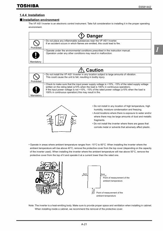
E6581442
A-21
1
1.4.4 Installation Installation environment
The VF-AS1 Inverter is an electronic control instrument. Take full consideration to installing it in the proper operatingenvironment.
Danger
Prohibited
• Do not place any inflammable substances near the VF-AS1 Inverter.If an accident occurs in which flames are emitted, this could lead to fire.
Mandatory
• Operate under the environmental conditions prescribed in the instruction manual.Operation under any other conditions may result in malfunction.
Caution
Prohibited
• Do not install the VF-AS1 Inverter in any location subject to large amounts of vibration.This could cause the unit to fall, resulting in bodily injury.
Mandatory
• Check to make sure that the input power supply voltage is +10%, -15% of the rated supply voltagewritten on the rating label (±10% when the load is 100% in continuous operation).If the input power voltage is not +10%, -15% of the rated power voltage (±10% when the load is100% in continuous operation) this may result in fire.
• Do not install in any location of high temperature, highhumidity, moisture condensation and freezing.
• Avoid locations where there is exposure to water and/orwhere there may be large amounts of dust and metallicfragments.
• Do not install the inverter where there are gases thatcorrode metal or solvents that adversely affect plastic.
• Operate in areas where ambient temperature ranges from -10°C to 60°C. When installing the inverter where theambient temperature will rise above 40°C, remove the protective cover from the top cover (depending on the capacityof the inverter used). When installing the inverter where the ambient temperature will rise above 50°C, remove theprotective cover from the top of it and operate it at a current lower than the rated one.
Measuring position
Point of measurement of theambient temperature
Point of measurement of theambient temperature
5cm 5cm
10cm
Note: The inverter is a heat-emitting body. Make sure to provide proper space and ventilation when installing in cabinet.When installing inside a cabinet, we recommend the removal of the protective cover.

E6581442
A-22
1
• Do not install in any location that is subject to large amounts of vibration.
Note: If the VF-AS1 Inverter is installed in a location thatis subject to vibration, anti-vibration measures arerequired.Please consult with your supplier about thesemeasures.
• If the VF-AS1 Inverter is installed near any of the equipment listed below, provide measures to insure against errorsin operation.
Solenoids: Attach surge suppressor on coil.Brakes: Attach surge suppressor on coil.Magnetic contactors: Attach surge suppressor on coil.Fluorescent lamps: Attach surge suppressor on coil.Resistors: Place far away from VF-AS1 Inverter.
• Do not touch the heat sink, because it becomes hot during operation.
How to install
Danger
Prohibited
• Do not operate the inverter if it is damaged or any component is missing.This can result in electric shock or fire. Call your local sales agency for repairs.
Mandatory
• Must be installed in non-inflammables such as metals.The rear panel gets very hot. If installation is in an inflammable object, this can result in fire.
• Do not operate with the front panel cover removed.This can result in electric shock.
• An emergency stop device must be installed that fits with system specifications. (e.g. shut off inputpower then engage mechanical brake)Operation cannot be stopped immediately by the inverter alone, thus risking an accident or injury.
• All options used must be those specified by Toshiba.The use of any other option may result in an accident.
Caution
Mandatory
• The main unit must be installed on a base that can bear the unit's weight.If the unit is installed on a base that cannot withstand that weight, the unit may fall resulting in injury.
• If braking is necessary (to hold motor shaft), install a mechanical brake.The brake on the inverter will not function as a mechanical hold, and if used for that purpose, injurymay result.
Resistor

E6581442
A-23
1
Install the inverter in a well-ventilated indoor place and mount it on a flat metal plate in portrait orientation.If you are installing more than one inverter, the separation between inverters should be at least 5cm, and they should bearranged in horizontal rows.If the inverters are horizontally arranged with no space between them (side-by-side installation), remove of theprotective cover on top of the inverter. It is necessary to decrease the current if the inverter is operated at over 50°C.
(a): Standard installation (b): Side-by-side installation
H1 or more
H2 or more5cm or more5cm or more
H3 or more
H3 or more
*1 200V 0.4kW~15kW, 400V 0.75kW~18.5kW*2 200V 18.5kW~45kW, 400V 22kW~75kW
*1
*2
H1(cm) H2(cm) H3(cm)200V 75kW or smaller400V 110kW or smaller 10 10 10
400V 132, 160kW 15 15 25400V 200~280kW 20 15 25400V 355, 400kW 30 25 25400V 500kW 40 25 25
The space shown in the diagram is the minimum allowable clearance. Make the space on top and bottom as large aspossible to allow for air passage. For models designed for 200V-75kW and 400V-110kW motors or larger, leave aspace of 30cm or more above and below the inverter.
Note: Do not install in any location where there is high humidity or high temperatures and where there are largeamounts of dust and metallic fragments. If you are going to install the equipment in any area that presents apotential problem, please consult with your supplier before doing so.
Current reduction curveDepending on the way in which the inverter is installed, the ambient temperature and the carrier frequency setting,you may need to reduce the inverter’s continuous output current.Reduction rates vary depending on the capacity. The capacities shown in these diagrams are capacities with thehighest reduction rates. For the capacity of your inverter, see section 12, “Specifications.” The table in 12.1 listscurrent ratings at a carrier frequency of 12kHz.The VFAS1 has the function of adjusting the inverter’s overload resistance automatically according to the ambienttemperature, as shown in the figure below. This function enhances the inverter’s overload resistance when theambient temperature is low. To use this function, set the parameter to .The output current of 100% on the axis of ordinate corresponds to the output current at a carrier frequency of 4kHz(for 200V-45kW or less models, and 400V-75kW or less models) or 2.5kHz (for 200V-55kW or more models, and400V-90kW or more models).If is set to (default setting), protection will be provided by reducing the output current (approximate linearreduction) in 12, “Specifications,” by adjusting the PWM carrier frequency or at the occurrence of the event shown inthe diagram below, which occurs first.
200V 0.4~15kW400V 0.75~18.5kW
(See lines shown in - - - for 2.2kW)
4kHz 8kHz 12kHz 16kHz
Carrier frequency ( )
100%
90%
80%
70%
60%
50%
Output current
40°C: (a)50°C: When the upper protection cover is removed under
condition (a)(b)
50°C: (a)
60°C: (a)When the upper protection cover is removed undercondition (a)(b)
Ambient temperature: Permanently-installed inverters

E6581442
A-24
1 2.5kHz 4kHz 8kHz 12kHz 16kHz
Carrier frequency ( )
200V 18.5~45kW (See lines shown in - - - for 22kW)400V 22~75kW
100%
90%
80%
70%
60%
50%
Output current
40°C: (a)When the upper protection cover is removed undercondition (a)(b)
50°C: (a)When the upper protection cover is removed undercondition (a)(b)
60°C: (a)When the upper protection cover is removed undercondition (a)(b)
Ambient temperature: Permanently-installed inverters
400V 90~110kW
2.5kHz 3kHz 4kHz 5kHz 6kHz 7kHz 8kHz
Carrier frequency ( )
100%
90%
80%
70%
60%
50%
40%output current
50°C: (a)(b)
= (Default setting)
60°C: (a)(b)
400V 132kW or more
2.5kHz 3kHz 4kHz 5kHz 6kHz 7kHz 8kHz
Carrier frequency ( )
100%
90%
80%
70%
60%
50%
40%
output current
Ambient temperature: Permanently-installed inverters
50°C: (a)(b)
= (Default setting)
60°C: (a)(b)
40°C: (a)(b)
200V 55kW or more
2.5kHz 3kHz 4kHz 5kHz 6kHz 7kHz 8kHz
Carrier frequency ( )
100%
90%
80%
70%
60%
50%
40%
output current
Ambient temperature: Permanently-installed inverters
40°C: (a)(b)
50°C: (a)(b)
= (Default setting)60°C: (a)
(b)
Ambient temperature: Permanently-installed inverters
40°C: (a)(b)
The rated current indicated on the nameplate of a 15kW inverter or smaller is the current that flows at 4kHz. If thecarrier frequency is set at 12kHz by default, therefore, the rated current needs to be decreased.⇒ For more details, refer to Section 12.When = (Default setting), however, the carrier frequency decreases automatically with increase in currentto secure the rated current for frequencies below 4kHz.Random control is exercised when the motor is operated in a low-frequency range where it produces annoyingmagnetic noise. If the carrier frequency control mode selection parameter ( ) is set to or , the output voltage may drop.The carrier frequency ( ) should be set below 4kHz.

E6581442
A-25
1
Calorific values of the inverter and the required ventilationThe energy loss when the inverter converts power from AC to DC and then back to AC is about 5%. In order tosuppress the rise in temperature inside the cabinet when this loss becomes heat loss, the interior of the cabinet mustbe ventilated and cooled.
The amount of forced air-cooling ventilation required and the necessary heat exchange surface area when operating ina sealed cabinet according to motor capacity are as follows.
Voltageclass
Applicable Motor(kW)
Calorific values(W)
Amount of forced air coolingventilation required
(m3/min)
Heat exchange surface arearequired for sealed storage
cabinet(m2)
0.4 50 0.29 1.00.75 70 0.40 1.41.5 113 0.65 2.32.2 135 0.78 2.7
3.7/4.0 191 1.1 3.85.5 307 1.8 6.27.5 408 2.4 8.211 593 3.4 11.915 692 4.0 13.9
18.5 800 4.6 16.022 865 5.0 17.330 1140 6.6 22.837 1340 7.7 26.845 1570 9.0 31.455 1720 9.9 34.4
200V
75 2210 12.7 44.20.75 57 0.33 1.21.5 82 0.47 1.72.2 112 0.64 2.3
3.7/4.0 136 0.78 2.85.5 262 1.5 5.37.5 328 1.9 6.611 448 2.6 9.015 577 3.3 11.6
18.5 682 3.9 13.722 720 4.2 14.430 980 5.6 19.637 1180 6.8 23.645 1360 7.8 27.255 1560 9.0 31.275 2330 13.4 46.690 2410 13.8 48.2110 2730 15.6 54.6132 3200 18.3 64.0160 3820 21.9 76.4200 4930 28.2 98.6220 5405 30.9 108.1280 6830 39.1 136.6355 7960 45.5 159.2400 9300 53.2 186.0
400V
500 11400 65.2 228.0Note1: The heat loss for the optional external devices (input reactor, DC reactor, radio noise reduction filters, etc.) is
not included in the calorific values in the table. With the exception of inverters indented for motors withcapacities of 355kW and more, in which case the calorific value of the DC reactor is included.
Note2: Each calorific value in the table refers to the quantity of heat that an inverter produces when it is operatedcontinuously at the factory default (carrier frequency) under a load factor of 100%.

E6581442
A-26
1
Panel designing taking into consideration the effects of noiseThe inverter generates high frequency noise. When designing the control panel setup, consideration must be given tothat noise. Examples of measures are given below.• Wire so that the main circuit wires and the control circuit wires are separated. Do not place them in the same conduit,
do not run them parallel, and do not bundle them.• Provide shielding and twisted wire for control circuit wiring.• Separate the input (power) and output (motor) wires of the main circuit. Do not place them in the same conduit, do
not run them parallel, and do not bundle them.• Ground the inverter ground terminals ( ).• Install surge suppressor on any magnetic contactor and relay coils used around the inverter.• Install noise filters if necessary.
Installing more than one unit in a cabinetIf you are installing two or more inverters in one cabinet, pay attention to the following.
• Inverters may be installed side by side with each other with no space left between them.• When installing inverters side by side, remove the protective cover on the top surface of each inverter.
The output current may need to be reduced, depending on the ambient temperature and the carrier frequency, so see“How to install” in this section.
• Ensure a space of at least 20cm on the top and bottom of the inverters.• Install an air deflecting plate so that the heat rising up from the inverter on the bottom does not affect the inverter on
the top.
Ventilation fan
Inverter
Air deflecting plate
Inverter

E6581442
B-1
2
2. Connection equipment
Danger
Disassemblyprohibited
• Never disassemble, modify or repair.This can result in electric shock, fire and injury. For repairs, call your sales agency.
Prohibited
• Don't stick your fingers into openings such as cable wiring hole and cooling fan covers.This can result in electric shock or other injury.
• Don't place or insert any kind of object into the inverter (electrical wire cuttings, rods, wires). Thiscan result in electric shock or fire.
• Do not allow water or any other fluid to come in contact with the inverter.That may result in electric shock or fire.
Caution
Prohibited
• Do not transport the inverter with its front door detached.The covers may come off and the unit will drop out resulting in injury.
Mandatory
• Models (20kg or more in weight) designed for 200V-18.5kW or larger and 400V-22kW or largershould be carried by at least two persons.Carrying it alone could cause injury.
2.1 Cautions on wiring
Danger
Prohibited
• Never remove the front cover when power is on or open door if enclosed in a cabinet.The unit contains many high voltage parts and contact with them will result in electric shock.
Mandatory
• Turn power on only after attaching the front cover or closing door if enclosed in a cabinet.If power is turned on without the front cover attached or closing door if enclosed in a cabinet. Thiscan result in electric shock or other injury.
• Electrical construction work must be done by a qualified expert.Connection of input power by someone who does not have that expert knowledge may result in fireor electric shock.
• Connect output terminals (motor side) correctly.If the phase sequence is incorrect, the motor will operate in reverse and that may result in injury.
• Wiring must be done after installation.If wiring is done prior to installation that may result in injury or electric shock.
• The following steps must be performed before wiring.(1) Shut off all input power.(2) Wait at least 15 minutes and check to make sure that the charge lamp is no longer lit.(3) Use a tester that can measure DC voltage (800 VDC or more), and check to make sure that the
voltage to the DC main circuits (between PA/+ and PC/-) is 45 V or less.If these steps are not properly performed, the wiring will cause electric shock.• Tighten the screws on the terminal board to specified torque.
If the screws are not tightened to the specified torque, it may lead to fire.
Be Grounded
• Ground must be connected securely.If the ground is not securely connected, it could lead to electric shock or fire when a malfunction orcurrent leak occurs.

E6581442
B-2
2
Caution
Prohibited
• Do not attach devices with built-in capacitors (such as noise filters or surge absorber) to the output(motor side) terminal.This could cause a fire.
Preventing radio noiseTo prevent electrical interference such as radio noise, separately bundle wires to the main circuit's power terminals(R/L1, S/L2, T/L3) and wires to the motor terminals (U/T1, V/T2, W/T3).
Control and main power supplyThe control power supply and the main circuit power supply for the VF-AS1 are the same. If a malfunction or tripcauses the main circuit to be shut off, control power will also be shut off.If you want to keep the control circuit alive when the main circuit shuts off due to trouble or tripping, you use an optionalcontrol power supply backup unit (CPS002Z).
Wiring• Because the space between the main circuit terminals is small use sleeved pressure terminals for the connections.
(stripped wires may be connected directly for 200V/18.5kW to 200V/45kW models and 400V/22kW to 400V/75kWmodels). Connect the terminals so that adjacent terminals do not touch each other.
• For ground terminal G/E use wires of the size that is equivalent to or larger than those given in table below andalways ground the inverter.Use as large and short a ground wire as possible and wire it as close as possible to the inverter.
Voltage class Applicable Motor Grounding wire size(AWG) [Note]
Grounding wire size(mm2) [Note]
0.4~4.0kW 12 3.55.5 kW 10 5.57.5 kW 8 811~15 kW 6 1418.5~30 kW 4 2237, 45 kW 2 3850 kW 2 70
200V
75kW 2 950.75~7.5 kW 12 3.511 kW 10 5.515~22 kW 8 830 kW 6 1437~55 kW 4 2275 kW 2 3890kW 2 70110kW 2 95132 kW 1/0 95160 kW 1/0 120200 kW 1/0 150220 kW 2/0 150280 kW 3/0 120×2355 kW 4/0 120×2400 kW 4/0 150×2
400V
500 kW 250MCM 150×2Note1: The recommended cable size is that of the cable (e.g. 600V class, HIV cable) with continuous maximum
permissible temperature of 75°C. Ambient temperature is 50°C or less and the wiring distance is 30m or less.
• Refer to the table in Section 10.1 for wire sizes.• The length of the main circuit wire in Section 10.1 should be no longer than 30m. If the wire is longer than 30m, the
wire size (diameter) must be increased.• Tighten the screws on the terminal board to specified torque.
Recommended tightening torque for screws onthe terminal board
N·m Ib·insM3 0.6 5.3M4 1.4 12.4M5 3.0 26.6M6 5.4 47.8M8 12.0 106
M10 24.0 212M12 41.0 360

E6581442
B-3
2
2.2 Standard connections
Danger
Prohibited
• Do not connect input power to the output (motor side) terminals (U/T1, V/T2, W/T3).Connecting input power to the output could destroy the inverter or cause a fire.
• Do not connect a regenerative braking resistor to any DC terminal (between PA/+ and PC/-, orbetween PO and PC/-).If a braking resistor is connected by mistake, it may overheat extremely and cause a fire.Connect resistors as directed in the instructions for Section 5.19.
• Within 15 minutes after turning off input power, do not touch wires of devices (MCCB) connected tothe input side of the inverter.That could result in electric shock.
Be Grounded
• Ground must be connected securely.If the ground is not securely connected, it could lead to electric shock or fire when a malfunction orcurrent leak occurs.

E6581442
B-4
2
[Standard connection diagram – sink logic]The figure below shows an example of typical wiring in the main circuit 200V 0.4-45kW/400V 0.75-75kW inverter.
*1: The inverter is shipped with the terminals PO and PA/+ shorted with a bar (200V-45kW or smaller, 400V-75kW or smaller).Remove this shorting bar when installing a DC reactor (DCL).
*2: The DC reactor is built in for models 200V-11kW~45kW and 400V-18.5kW~75kW.*3: The noise filter is built in for models 200V-45kW or smaller and all of 400V.*4: External braking resistor (option). Dynamic braking drive circuit built-in (GTR7) as standard for models 160kW or smaller.*5: To supply a DC power, connect the cables to the PA/+ and PC/- terminals.*6: If you want to use a DC power supply to operate the inverter (200V: 18.5kW or more, 400V: 22kW or more), be sure to
contact your supplier customer support center, because an inrush current limiting circuit is required in such a case.*7: ⇒ Refer to Section 2.3.2 for chip switch functions.*8: The functions assigned to terminals OUT1, VI/II and RR/S4 can be switched by changing parameter settings.
⇒ For details refer to Section 2.3.2.*9: To supply control power from an external power supply for backing up the control power supplied from the inverter, an
optional control power backup device (CPS002Z) is required. In such a case, the backup device is used at the same time withthe internal power supply of the inverter.The optional control power backup unit can be used with both 200V and 400V models.To back up control power, set the parameter (Control power supply backup option failure monitoring) properly.⇒ For more information, refer to 6.33.24.
*10: For PWR connection conforming to safety standards, refer to Section 9.3.

E6581442
B-5
2
[Standard connection diagram - sink logic]The figure below shows an example of typical wiring in the main circuit 200V 55, 75kW/400V 90-280kW inverter.
*1: Be sure to connect the DC reactor.*2: To supply a DC power, connect the cables to the PA/+ and PC/- terminals.*3: If you want to use a DC power supply to operate the inverter, be sure to contact your supplier customer support center,
because an inrush current limiting circuit is required in such a case.*4: The noise filter is built in for models all of 400V.*5: For models 200V-75kW and 400V-110kW or larger, three-phase power input is necessary to drive the fan if you want to use
a DC power supply.*6: Every 200V model of any capacity and every 400V model with a capacity of 160kW or less come with dynamic braking unit
drive circuits (GTR7) built into them as standard equipment, so if your inverter is among these models, connect an externalbraking resistor (optional) alone.
*7: If you are using a 400V/200kW model or larger, use a braking unit (optional) and an external braking resistor (optional) incombination.
*8: ⇒ Refer to Section 2.3.2 for switch functions.*9: The functions assigned to terminals OUT1, VI/II and RR/S4 can be switched by changing parameter settings.
⇒ For details refer to Section 2.3.2.*10: To supply control power from an external power supply for backing up the control power supplied from the inverter, an
optional control power backup device (CPS002Z) is required. In such a case, the backup device is used at the same timewith the internal power supply of the inverter.The optional control power backup unit can be used with both 200V and 400V models.To back up control power, set the parameter (Control power supply backup option failure monitoring) properly.⇒ For more information, refer to 6.33.24.
*11: For PWR connection conforming to safety standards, refer to Section 9.3.

E6581442
B-6
2
[Standard connection diagram - sink logic]The figure below shows an example of typical wiring in the main circuit 400V 355-500kW inverter.
*1: Be sure to connect the DC reactor.*2: To supply a DC power, connect the cables to the PA/+ and PC/- terminals.*3: If you want to use a DC power supply to operate the inverter, be sure to contact your supplier customer support center,
because an inrush current limiting circuit is required in such a case.*4: Three-phase power input is necessary to drive the fan if you want to use a DC power supply.*5: Use a braking unit (optional) and an external braking resistor (optional) in combination.*6: ⇒ Refer to Section 2.3.2 for switch functions.*7: The functions assigned to terminals OUT1, VI/II and RR/S4 can be switched by changing parameter settings.
⇒ For details refer to Section 2.3.2.*8: To supply control power from an external power supply for backing up the control power supplied from the inverter, an
optional control power backup device (CPS002Z) is required. In such a case, the backup device is used at the same timewith the internal power supply of the inverter.To back up control power, set the parameter (Control power supply backup option failure monitoring) properly.⇒ For more information, refer to 6.33.24.
*9: For PWR connection conforming to safety standards, refer to Section 9.3.

E6581442
B-7
2
[Standard connection diagram - source logic]The figure below shows an example of typical wiring in the main circuit 200V 0.4-45kW/400V 0.75-75kW inverter.
*1: The inverter is shipped with the terminals PO and PA/+ shorted with a bar (200V-45kW or smaller, 400V-75kW or smaller).Remove this shorting bar when installing a DC reactor (DCL).
*2: The DC reactor is built in for models 200V-11kW~45kW and 400V-18.5kW~75kW.*3: The noise filter is built in for models 200V-45kW or smaller and all of 400V.*4: External braking resistor (option). Dynamic braking drive circuit built-in (GTR7) as standard for models 160kW or smaller.*5: To supply a DC power, connect the cables to the PA/+ and PC/- terminals.*6: If you want to use a DC power supply to operate the inverter (200V: 18.5kW or more, 400V: 22kW or more), be sure to
contact your supplier customer support center, because an inrush current limiting circuit is required in such a case.*7: ⇒ Refer to Section 2.3.2 for chip switch functions.*8: The functions assigned to terminals OUT1, VI/II and RR/S4 can be switched by changing parameter settings.
⇒ For details refer to Section 2.3.2.*9: To supply control power from an external power supply for backing up the control power supplied from the inverter, an
optional control power backup device (CPS002Z) is required. In such a case, the backup device is used at the same timewith the internal power supply of the inverter.The optional control power backup unit can be used with both 200V and 400V models.To back up control power, set the parameter (Control power supply backup option failure monitoring) properly.⇒ For more information, refer to 6.33.24.
*10: For PWR connection conforming to safety standards, refer to Section 9.3.

E6581442
B-8
2
[Standard connection diagram - source logic]The figure below shows an example of typical wiring in the main circuit 200V 55, 75kW/400V 90-280kW inverter.
*1: Be sure to connect the DC reactor.*2: To supply a DC power, connect the cables to the PA/+ and PC/- terminals.*3: If you want to use a DC power supply to operate the inverter, be sure to contact your supplier customer support center,
because an inrush current limiting circuit is required in such a case.*4: The noise filter is built in for models all of 400V.*5: For models 200V-75kW and 400V-110kW or larger, three-phase power input is necessary to drive the fan if you want to use
a DC power supply.*6: Every 200V model of any capacity and every 400V model with a capacity of 160kW or less come with dynamic braking unit
drive circuits (GTR7) built into them as standard equipment, so if your inverter is among these models, connect an externalbraking resistor (optional) alone.
*7: If you are using a 400V/200kW model or larger, use a braking unit (optional) and an external braking resistor (optional) incombination.
*8: ⇒ Refer to Section 2.3.2 for switch functions.*9: The functions assigned to terminals OUT1, VI/II and RR/S4 can be switched by changing parameter settings.
⇒ For details refer to Section 2.3.2.*10: To supply control power from an external power supply for backing up the control power supplied from the inverter, an
optional control power backup device (CPS002Z) is required. In such a case, the backup device is used at the same timewith the internal power supply of the inverter.The optional control power backup unit can be used with both 200V and 400V models.To back up control power, set the parameter (Control power supply backup option failure monitoring) properly.⇒ For more information, refer to 6.33.24.
*11: For PWR connection conforming to safety standards, refer to Section 9.3.

E6581442
B-9
2
[Standard connection diagram - source logic]The figure below shows an example of typical wiring in the main circuit 400V 355-500kW inverter.
*1: Be sure to connect the DC reactor.*2: To supply a DC power, connect the cables to the PA/+ and PC/- terminals.*3: If you want to use a DC power supply to operate the inverter, be sure to contact your supplier customer support center,
because an inrush current limiting circuit is required in such a case.*4: Three-phase power input is necessary to drive the fan if you want to use a DC power supply.*5: Use a braking unit (optional) and an external braking resistor (optional) in combination.*6: ⇒ Refer to Section 2.3.2 for switch functions.*7: The functions assigned to terminals OUT1, VI/II and RR/S4 can be switched by changing parameter settings.
⇒ For details refer to Section 2.3.2.*8: To supply control power from an external power supply for backing up the control power supplied from the inverter, an
optional control power backup device (CPS002Z) is required. In such a case, the backup device is used at the same timewith the internal power supply of the inverter.To back up control power, set the parameter (Control power supply backup option failure monitoring) properly.⇒ For more information, refer to 6.33.24.
*9: For PWR connection conforming to safety standards, refer to Section 9.3.

E6581442
B-10
2
2.3 Description of terminals
2.3.1 Main circuit terminalsThis diagram shows an example of wiring of the main circuit. Use options if necessary.
Power supply and motor connections
Power supply
S/L2 T/L3 MotorNo-fusebreaker
Connect the powercables to RL1, S/L2,and T/L3.
Connect the motorcables to U/T1, V/T2and W/T3.
VF-AS1
E
U/T1 V/T2 W/T3R/L1
Connection with peripheral equipment
Motor
Zero-phasereactor
Powersupply
Inverter
Braking resistor [Note]
Surgesuppressing filter
DC reactor
Simplifiedradio noisefilter
High-attenuationradio noisereduction filter
Input ACreactor
Magneticcontactor
No-fusebreaker
R/L1
S/L2
T/L3
PA/+ P0 PA PB
V/T2
U/T1
W/T3
IM
Note: Connect a braking unit betweenthe terminals PA/+ and PC/-, ifnecessary.
Main circuitTerminal symbol Terminal function
Grounding terminal for inverter casing
R/L1, S/L2, T/L3(R/L1.1, S/L2.1, T/L3.1,R/L1.2, S/L2.2, T/L3.2)*1
Power input terminal200V class: 400V class:0.4~75kW Three-phase 200~240V-50/60Hz 0.75~90kW Three-phase 380~480V-50/60Hz
110~500kW Three-phase 380~440V-50HzThree-phase 380~480V-60Hz
U/T1, V/T2, W/T3 Connect to a (3-phase induction) motor.
PA/+, PB(PA, PB) *2
Connect a braking resistor.Change the parameters , and if necessary.200kW models and larger are not equipped with terminal PB.
PC/-This is a negative potential terminal in the internal DC main circuit. DC power supply can be inputacross the PA/+ terminals (positive potential). (For 200V-18.5kW or more models, and 400V-22kWor more models, an optional circuit is needed to suppress a rush current.)
PO, PA/+Terminals for connecting a DC reactor (DCL: optional external device). Shorted by a short bar whenshipped from the factory (200V: 45kW or smaller, 400V: 75kW or smaller). Before installing DCL,remove the short bar.
RO, SO, TO
200V class: 75kW 400V class:110kW~500kWInverter’s cooling fan power input terminals. When using a DC power supply, connect three-phasepower cables. When using DC power for the main circuit, be sure to connect a three-phase powersupply to these terminals.
*1: Value in ( ) 400V-355~500kW.*2: Value in ( ) 200V-55kW or larger, 400V-90~160kW.

E6581442
B-11
2
2.3.2 Control circuit terminal blockThe control circuit terminal block is common to all equipment.
PWR-P24/PLC Shorting bar (VFAS1- * * * * * -WN1 or -WP1)Color of a label is yellow.
⇒ How to set input terminal function, refer to section 7.
Note:Control circuit terminal block is different between the previous version of CPU(Up to Ver.124) and the presentversion of CPU(above Ver.130).If it was changed into different type, Inverter doesn't work correctly.When you change a control circuit terminal block, please be careful whether the type of terminal is the same.Previous version: There is "ST" terminal instead of "PWR" terminal and color of a terminal label is white.Present version: There is "PWR" terminal instead of "ST" terminal and color of a terminal label is yellow.
Terminalsymbol
Input/output
Function (Sink logic)VFAS1-****-WN1, HN
Function (Source logic)VFAS1-****-WP1 Electrical specifications
F Input
Shorting across F-CC causes forwardrotation; open causes decelerationstop. (Across PWR-P24/PLC is shortstate.)
Shorting across F-P24/PLC causesforward rotation; open causesdeceleration stop.
R Input
Shorting across R-CC causes reverserotation; open causes decelerationstop. (Across PWR-P24/PLC is shortstate.)
Shorting across R-P24/PLC causesreverse rotation; open causesdeceleration stop.
RES Input
Shorting and then opening RES-CCcancels the status held by an inverterprotective function. When the inverteris operating normally, shorting and thenopening RES-CC produces no effect.
Shorting and then opening RES-P24/PLC cancels the status held by aninverter protective function. When theinverter is operating normally, shortingand then opening RES-P24/PLCproduces no effect.
S1 Input Shorting across S1-CC causes presetspeed operation.
Shorting across S1-P24/PLC causespreset speed operation.
S2 Input Shorting across S2-CC causes presetspeed operation.
Shorting across S2-P24/PLC causespreset speed operation.
S3 Input Shorting across S3-CC causes presetspeed operation.
Shorting across S3-P24/PLC causespreset speed operation.
RR/S4 Input
Multifunction program
mable contact input
SW3: When SW3 is in the S4 position,S4 and CC are shorted and presetspeed operation is selected.
SW3: When SW3 is in the S4 position,S4 and P24/PLC are shorted and presetspeed operation is selected.
Voltage free contactinput24Vdc-5mA or less
*Sink/source selectablewith SW1
Sink inputON:Less than DC10VOFF:DC16V or more
Source inputON:DC11V or moreOFF:Less than DC5V
Note:Even when anexternal power supplyis used (in sink logicmode, i.e., when SINK(PLC) is selected),connect the referencepotential-side (0Vside) cable from thepower supply to theCC terminal.
SW1=SINK (INT): Sink logic (When theinternal 24V power supply is used)
2.2kΩ
P24/PLC
CC
2.2kΩ
P24SINK SOURCE
SW1
SW1=SINK (PLC): Sink logic (When anexternal 24V power supply is used)
SW1=SOURCE (INT/PLC):Source logic (When the internal 24Vpower supply or an external 24V powersupply is used)If SW1 is set to 1 If SW1 is set to 2
If SW1 is set to 3
2.2kΩ
CC
2.2kΩ
P24SINK SOURCE
SW1
CC
SOURCE
2.2kΩ
P24/PLC
2.2kΩ
P24
SINKSW1
P24/PLC
Lan current signal.Choose low currentcontacts to avoidpoor attaching.

E6581442
B-12
2
Terminalsymbol
Input/output Function (Sink Source logic) Electrical
specifications Inverter internal circuits
PWR*2 Input
If P24/PLC and PWR are short-circuited, themotor is put into a standby state. And if thecircuit between them is opened, the motorcoasts and stops. These terminals can be usedfor interlock.This terminal is not a multifunctionprogrammable input terminal. It is a terminalwith the power removal function that complieswith SIL II of the safety standard IEC61508 andthe requirements for category 3 of EN954-1.
Regardless of thesetting of SW1ON: DC17V or moreOFF: Less than DC2V
(OFF: Coast stop)
Output24Vdc power output (when SW1 is in anyposition other than PLC)24V internal output terminal
24Vdc-200mA -P24/PLC
InputIf SW1 is turned to the PLC position, thisterminal can be used as a common terminalwhen an external power supply is used.
- -
CC *1Commonto input/output
Digital signal equipotential (0V) terminal for thecontrol circuit and equipotential (0V) terminalfor an optional control power supply backup.
- -
PP Output Analog input setting power output10Vdc
(Permissible loadcurrent:10mAdc)
RR/S4 Input
SW3: Multifunction programmable analog inputterminal when SW3 is in the RR position.Standard default setting:0~10Vdc input and0~60Hz frequency.
10Vdc(Internal impedance:30 kΩ)
VI/I I Input
Multifunction programmable analog input.Standard default setting: 0~10Vdc input and0~60Hz frequency.This terminal can also be used as a 4-20mAdc(0-20mAdc) input terminal, if the parameter
set to .
10Vdc(Internal impedance:30 kΩ)
4~20mA(Internal impedance:242Ω)
RX InputMultifunction programmable analog input.Standard default setting:0~±10Vdc input and0~±60Hz frequency.
10Vdc(Internal impedance:22 kΩ)
FM Output
Multifunction programmable analog output.Standard default setting: output frequencyUse this terminal to connect a 1mAdc full-scaleammeter. This terminal can also be used as a 0-10V ( = ) or 0-20mA terminal( = ), if the SW2 switch is set to 0-10V/0-20mA side.
1mA full-scale DCammeter (Allowable loadresistance 7.5kΩ or less)or 7.5Vdc-1mA full-scale
DC voltmeter0-10V full-scale DCvoltmeter (Allowable
load resistance 500Ω ormore)/0-20mA (4-20mA)Full-scale DC ammeter
voltmeter (Allowableload resistance 500Ω or
less)
AM Output
Multifunction programmable analog output.Standard default setting: output currentUse this terminal to connect a 1mAdc full-scaleammeter or 7.5Vdc (10Vdc)-1mA full-scalevoltmeter.
1mA full-scale DCammeter ammeter
(Allowable loadresistance 7.5kΩ or less)or 7.5Vdc-1mA full-scale
DC voltmeter
OUT1
Multifunction programmable open collectoroutput. The default setting is to output a signalwhen output low speed threshold has beenreached. Depending on the SW4 setting,pulses are output with frequencies of 1.00kHzto 43.20kHz. Standard default setting:3.84kHz
OUT2
Multifunction programmable open collectoroutput. By default, it is set to output a signalindicating the completion of acceleration ordeceleration.
NO
Output
Digital output signal equipotential (0V) terminalfor the control circuit. It is isolated from the CCterminal.
Open collector output24Vdc-50mA
*Sink logic/sourcelogic switchable
P15
15k
7k
P5
15k
15k
242
S4P5
RRSW3
12.7k2.2k
15k
20
P24
OUT1
OUT2
SW4 PULS
LO
20
NO
15VConstantvoltagecircuit
P5
27k
10k
PWR
P24/PLC
SW2 +
-+
-
4.7k
120
70
0-1mA
0-10V0-20mA
4.7k+
-

E6581442
B-13
2
Terminalsymbol
Input/output Function (Sink Source logic) Electrical
specifications Inverter internal circuits
CCA*1
Commonto input/output
Analog input/output signal equipotential (0V)terminal for the control circuit. - -
+SU InputDC power input terminal for operating thecontrol circuit. Connect a control power backupdevice (optional) between +SU and CC.
Voltage:24Vdc±10%Use a power supply
with a current rating of1.05A or more.
FLAFLBFLC
Output
Relay contact output. Contact ratingUsed to detect the activation of the inverter'sprotective function. Contact across FLA-FLC isclosed and FLB-FLC is opened duringprotection function operation.
250Vac-2A30Vdc-1A
:at resistance load250Vac-1A:cosφ=0.4
*1: Although the CC terminal and the CCA terminal are not insulated, they should be used separately, one for the logic circuit andthe other for the analog circuit
*2: The PWR terminal is not the same as the ST (standby signal input) terminal provided for conventional models. To use the STfunction, assign it to a multifunction terminal (F, R, RES or S1 to S4) that is not currently in use.Example: When assigning the ST function to the S3 terminal,
Set to (to cancel its factory default setting: = ST always active), andSet to (to assign the ST function to the S3 terminal).These settings put the motor into a standby state if S3 and CC are short-circuited, or coast and stop the motor if thecircuit between S3 and CC is opened.
⇒ For PWR connection conforming to safety standards, refer to Section 9.3.
SW SW settingsDefault setting
(Settings markedwith )
Function
(-WN1, HN)
Setting for using the inverter’s internal power supply in sink logicmode
Setting for using the inverter’s external power supply in sink logicmodeSW1
(-WP1)
Setting for operating the inverter in source logic mode
Setting for using the analog output terminal FM to output currentof 0-1mA
SW2 Setting for using the analog output terminal FM to output currentof 0-10V or 0-20mA (4-20mA)0-10V ( = ) or 0-20mA ( = ) can be selected bychanging parameter settings.
Setting for using the input terminal RR/S4 as an analog inputterminal (0-10Vdc)
SW3Setting for using the input terminal RR/S4 as a contact inputterminal
Setting for using the output terminal OUT1 as a logic outputterminalWhen turning the switch to this position, always set the parameter
to (logic output).SW4
Setting for using the output terminal OUT1 as a pulse outputterminalWhen turning the switch to this position, always set the parameter
to (pulse output).
P24
FL
FLA
FLB
FLC
P241+SU
CC
SOURCE SINK
PLCINT/PLC INT
SOURCE SINK
PLCINT/PLC INT
SOURCE SINK
PLCINT/PLC INT
0-10V0-20mA 0-1mA
FM
0-10V0-20mA 0-1mA
FM
S4RR/S4
RR
S4RR/S4
RR
PULS LOOUT1
PULS LoOUT1

E6581442
B-14
2
Sink logic/source logic (When inverter's internal power supply is used)Current flowing out turns control input terminals on. These are called sink logic terminals.The method generally used in Europe is source logic in which current flowing into the input terminal turns it on.Sink logic terminals and source logic terminals are sometimes referred to as negative logic terminals and positive logicterminals, respectively.Each logic is supplied with power from either the inverter's internal power supply or an external power supply, and itsconnections vary depending on the power supply used. Note that the PWR terminal is designed for safety purposes towork always in source logic mode, regardless of the setting of SW1.
<Examples of connections when the inverter's internal power supply is used>
Source logicSink logic
CC
OUT1
P24/PLC
F
Common
Common
Output
Input
Input24VDC
Output
F
CCCommon
Output
Input24VDC
Output
NO
24VDC
CC
NO
OUT1
P24/PLC
24VDC
Input
Common
InverterProgrammablecontroller
InverterProgrammablecontroller
P24/PLC
F
R
CC
PWR
OUT1
OUT2
NO
CC
RY
RY
Inverter
P24/PLC
F
R
PWR
CC
OUT1
OUT2
NO
RY
RY
Inverter
SW1INT
SW1INT/PLC
SINK SOURCE
P24/PLC

E6581442
B-15
2
Sink logic/source logic (When an external power supply is used)The P24/PLC terminal is used to connect to an external power supply or to insulate a terminal from other input oroutput terminals. Use the slide switch SW1 to switch between sink logic and source logic configurations. Note that thePWR terminal is designed for safety purposes to work always in source logic mode, regardless of the setting of SW1.<Examples of connections when an external power supply is used>
Source logicSink logic
CC
F
Common
Output
Input24VDC
Output
FOutput
Input24VDC
Output
OUT1
NO
24VDC
Input
Common
InverterProgrammablecontroller
InverterProgrammablecontroller
P24/PLCCommon
24VDC
NOCommon
OUT1Input
SW1 SW1
P24/PLC
F
R
PWR
CC
OUT1
OUT2
Note: Be sure to connect the 0V terminal on the external power supply to the CCterminal on the inverter.
*When OUT1 is used as a pulse output terminal (when SW4 is in the PULS position), the circuitshown below is always formed regardless of the logic selected (sink or source) and the powersupply used (internal or external power supply).
RY
RY
External 24Vpower supply
+24V0V
F
R
PWR
CC
OUT1
OUT2
NO
RY
RY
External 24Vpower supply
+24V0V
CC
P24
SW4 PULS
NO
OUT1CC
PLC INT/PLC
SINK SOURCE

E6581442
B-16
2
2.3.3 Serial RS485 communication connectorThe VF-AS1 is equipped with two connectors: a two-wire RS485 connector (on the operation panel) and a four-wireRS485 connector. The two wire RS485 connector is used to connect an external option (such as remote keypad orcomputer) to the inverter. To connect to a network, use the four-wire RS485 connector, following the instructionsbelow.
2-wire RS485 4-wire RS485Signalname
Pinnumber Description
Signalname
Pinnumber Description
DA 4 Same phase data RXA 4 Same phase reception data (positive line)DB 5 Anti-phase data RXB 5 Anti-phase reception data (positive line)SG 8 Ground line of signal data TXA 3 Same phase transmitting data (positive line)
This table shows signal line of inverter side. TXB 6 Anti-phase transmitting data (positive line)* Never use pin-1, 2, 3, 6 and 7. SG 2, 8 Ground line of signal data
This table shows signal line of inverter side.(Example: RXA signal is received by inverter.)* Never use pin-1 (P24) and pin-7 (P11).
Connecting diagram for 4-wire RS485 communication
Terminatingresistance100Ω -1/4W
AS1 (slave)Upper computer orVF-AS1 (master)
RXA
RXB
TXA
TXB
SG
RXA
RXB
TXA
TXB
SG
RXA
RXB
TXA
TXB
SG
RXA
RXB
TXA
TXB
SG
cross each other straight straight
AS1 (slave) AS1 (slave)
Note* Separate the communication line and the main circuit wiring by 20cm or more.* Never use pin-1 (P24) and pin-7 (P11).* Connect RXA and RXB, between TXA and TXB using twisted pair cable.* Connect terminating resistances at both ends of a transmission line.* When using 2-wire type, short RXB to TXB and RXA to TXA.
When connecting a communications device via the two-wire connector, carefully read the precautions for use in theoperating manual for the communications device.
* When connecting the VF-AS1 to other inverters, you do not need to connect the master receive lines (pins 4 and 5)or the slave send lines (pins 3 and 6).
2-wire RS485 communication
4-wire RS485 communication
Pin-1 Pin-8

E6581442
C-1
3
3. OperationsThis section explains the basics of operation of the inverter.
Check the following again before starting operation.1) Are all wires and cables connected correctly?2) Does the supply voltage agree with the rated input voltage?
Danger
Prohibited
• Do not touch inverter terminals when electrical power is applied to the inverter even if the motor isstopped.Touching the inverter terminals while power is connected to it may result in electric shock.
• Do not touch switches when the hands are wet and do not try to clean the inverter with a dampcloth.Such practices may result in electric shock.
• Do not go near the motor in alarm-stop status when the retry function is selected.The motor may suddenly restart and that could result in injury.Take measures for safety, e.g. attaching a cover to the motor, against accidents when the motorunexpectedly restarts.
Mandatory
• Turn power on only after attaching the front cover or closing door if enclosed in a cabinet.If power is turned on without the front cover attached or closing door may result in electric shock orother injury.
• If the inverter begins to emit smoke or an unusual odor, or unusual sounds, immediately turnpower off.If the equipment is continued in operation in such a state, the result may be fire. Call your localsales agency for repairs.
• Always turn power off if the inverter is not used for long periods of time.• Do not turn on the power before attaching the front cover.
When enclosed inside a cabinet and using with the front cover removed, always close the cabinetdoors first and then turn power on. If the power is turned on with the front cover or with the cabinetdoors open, it may result in electric shock.
• Make sure that operation signals are off before resetting the inverter after malfunction.If the inverter is reset before turning off the operating signal, the motor may restart suddenlycausing injury.
Warning
Prohibitedcontact
• Do not touch heat radiating fins or discharge resistors.These devices are hot, and you'll get burned if you touch them.
Prohibited
• Observe all permissible operating ranges of motors and mechanical equipment. (Refer to themotor's instruction manual.)Not observing these ranges may result in injury.

E6581442
C-2
3
3.1 Setting/monitor modes
The VF-AS1 has the following three setting/monitor modes.
Standard monitor mode The standard inverter mode. This mode is enabledwhen inverter power goes on.
Setting monitor mode The mode for setting inverter parameters.⇒ How to set parameters, refer to Section 4. 1.
This mode is divided into two modes according to the parameter readout modeselected.
Quick mode :Eight frequently used basic parameters are justdisplayed.The maximum 32 parameters that you select byyourselves are displayed.
Standard setting mode :Both basic and extended all parameters are displayed.
Status monitor mode The mode for monitoring all inverter status.Allows monitoring of set frequencies, output current/voltage and terminal
information.
⇒ Refer to Section 8.
Pressing the key MODE will move the inverter through each of the modes.
Status monitor mode
Standard monitor mode(when the power is turned on)
Setting monitor mode
This mode is for monitoring the output frequency and setting the frequency reference value. If alsodisplays information about status alarms during running and trips.
• Setting frequency reference values ⇒ Refer to Section 3.2.2.• Status alarm
If there is an error in the inverter, the alarm signal and the frequency will flash alternately inthe LED display.
: When a current flows at or higher than the overcurrent stall prevention level.: When a voltage is generated at or higher than the over voltage stall prevention level.: When the cumulative amount of overload reaches 50% or more of the overload trip
value.: When temperature inside the inverter rises above overheating protection alarm level
(about 95°C)
How to search and setparameters⇒ Refer to Section 4.1.
Monitoring ofoperation status⇒ Refer to
Section 8.1.

E6581442
C-3
3
3.2 Simplified operation of the VF-AS1
On of three operation modes can be selected: terminal board operation, operation panel and combination of both.⇒ For other operation modes, refer to Section 5.5.
Terminal board mode :Operation by means of external signals
Operation panel mode :Operation by pressing keys on the operation panel
Operation panel + terminal board mode :Frequency, start/stop signals can be
sent individually from the operating panel and terminal board.
3.2.1 Terminal board operationIn this mode, the motor is started or stopped according to the ON/OFF signal to input terminals (such as the S3terminal and the F terminal). Also, the frequency is set according to the potentiometer/voltage/current signals to analoginput terminals (such as the RR/S4 terminal, VI/II terminal and RX terminal).⇒ For more details, refer to Section 7.
Example of standard connection
Motor
IM
CCA RX VI/II RR/S4 PP
F
R
P24/PLC
R/L1 U/T1
External potentiometer (or voltage signal RR/S4-CCA:0 to 10V)
Voltage signal:-10~+10Vdc
Voltage signal:0~10Vdcor current signal:4(0)~20mAdc
ON:Forward run, OFF:Deceleration stop
Stand-by:ON:Stand-by, OFF:Coast stop(Set the parameters to and to toassign the standby signalinput function to the S3terminal.)
CC
ON:Reverse run, OFF:Deceleration stop
V/T2
W/T3
S/L2
T/L3
Powersupply
MCCB
Inverter
PWR
S3
Run/Deceleration stop Selecting a command mode for basic parameters = (standard default setting) and are connected: Forward run
and are disconnected: Deceleration stop
(When terminals and are electrically connected)
F CC
F CC
P24/PLCPWR
Frequency
ONOFF
ONOFF
F-CC
Deceleration
S3-CC
For coast stopOpen the connection between S3 and CCwhen stopping the motor in the statedescribed at left. The monitor on the inverterat this time will display .
Motorspeed
ONOFF
ONOFF
F-CC
S3-CC
Coast stop

E6581442
C-4
3
Frequency setting1) Setting the frequency using potentiometer
[Parameter setting]
Set the “basic parameter frequency setting mode selection 1” parameter to . (There is no need to set this parameter before the first use after purchase.)
2) Setting the frequency using input voltage (0~10V)
[Parameter setting]
Set the “basic parameter frequency setting mode selection 1” parameter to .(There is no need to set this parameter before the first use after purchase.)
3) Setting the frequency using current input (4(0)~20mA)
[Parameter setting]
+
-
RR/S4
CCA Frequency
00Vdc 10Vdc
Voltage signalVoltage signal (0~10V) for setting the operation frequency⇒ Refer to Section 7.3 for details of adjustment.
60Hz:Voltage signal 0-10Vdc
VI/II
CCA Frequency
04mAdc 20mAdc
Current signalCurrent signal (4(0)~20mA) for setting the operation frequency⇒ Refer to Section 7.3 for details of adjustment.
60Hz:Current signal 4(0)-20mAdc
+
-
Set the “extended parameter analog input VI/II voltage/current switching”parameter to .In addition, set the “basic parameter frequency setting mode selection 1” parameter
to .To bring the operation frequency to 0Hz at an input current of 4mA, set the “VI/VII inputpoint setting 1” parameter to .
PP
CCA
:Frequency settingsWith potentiometer
MIN
MAX
Frequency
60Hz
0MIN MAX
RR/S4
PotentiometerThe operation frequency by potentiometer (1~10kΩ- 1/4W ) for setting⇒ Refer to Section 7.3 for details of adjustment.

E6581442
C-5
3
4) Setting the frequency using input voltage (0~10Vdc)
[Parameter setting]
5) Setting the frequency using input voltage (0~±10Vdc)The direction can be changed by switching between positive and negative signals.
[Parameter setting]
Set the “basic parameter frequency setting mode selection 1” parameter to .
Note: Set reference frequency priority selection to ( / terminal switching, default setting).Changing the settings of two speed command parameters at a time, refer to Section 6.6.
[Example of setting: To set the frequency by applying a current of 4(0)-20mAdc via the VI/II terminal.]
Key operated LED display Operation
Displays the operation frequency. (Perform during operation stopped.)(When standard monitor display selection = [Outputfrequency])
Displays the first basic parameter “History function ( ).”
Press either the or key to select “ .”
Press the ENTER key to display the parameter setting (Defaultsetting: ).
Press the key to change the parameter to .
⇔Press the ENTER key to save the changed parameter. and theparameter are displayed alternately.
MODE
Frequency
00Vdc 10Vdc
60Hz
Set the “extended parameter analog input VI/II voltage/current switching”parameter to .In addition, set the “basic parameter frequency setting mode selection 1” parameter
to (default setting).
+
-
RX
CCA-10Vdc
+10Vdc
Forward run
Reverse run
60Hz
60Hz
+
-
ENT
ENT
VI/II
CCA
Voltage signalVoltage signal (0~10V) for setting the operation frequency⇒ Refer to Section 7.3 for details of adjustment.
:Voltage signal 0-10Vdc
Voltage signalVoltage signal (0~±10V) for setting the operation frequency⇒ Refer to Section 7.3 for details of adjustment.
:Voltage signal 0-±10Vdc

E6581442
C-6
3
Key operated LED display Operation
Press either the key or the key to change to the parametergroup .
Press the ENTER key to display the first extended parameter .
Press the key to change to .
Pressing the ENTER key allows the reading of parameter setting.(Default setting: )
Press the key to change the parameter to .
⇔Press the ENTER key to save the changed parameter. and theparameter are displayed alternately.
ENT
ENT
ENT
ENT
ENT
ENT

E6581442
C-7
3
3.2.2 Panel operationThis section describes how to start/stop the motor, and set the operation frequency with the operating panel.
For coast stopChange the setting of theparameter .
The operation frequency canbe changed anytime evenduring operation.
Motorspeed
Coast stop
Motor
IM
F
PWR
R
R/L1 U/T1
P24/PLC
Shorted by ashorting barwhenshipped fromthe factory.
Example of basic connection
S/L2
T/L3V/T2
W/T3
Powersupply
MCCB
:Set frequency
:Motor starts
:Stop the motor(deceleration stop)
RUN
STOP
CCA RX VI/II RR/S4 PP
Inverter
Changing parameter settingsFor control panel operation, parameter settings need to be changed in advance.If you use parameter that makes it possible to select an operation mode in one operation, you can completethis operation by just making settings once.Here are the steps to be followed to change the setting to (frequency setting and operation by means of thecontrol panel).
[Setting procedure]Key operated LED display Operation
Displays the operation frequency (operation stopped). (Whenstandard monitor display selection = [Output frequency])
Press the EASY key.
(automatic function setting) at the head of the basic parametersavailable in quick mode is displayed.
Press the ENTER key to display the parameter setting (Defaultsetting: ).
Press the key to change the parameter to (Frequency settingand operation on operation panel).
⇔Press the ENTER key to save the changed parameter. and theparameter are displayed alternately.
*Pressing the MODE key returns the display to standard monitor mode (displaying operation frequency).
MODE
ENT
ENT
EASY

E6581442
C-8
3
Example of operation panel controlKey operated LED display Operation
The running frequency is displayed. (When standard monitor displayselection = [Output frequency])
Set the operation frequency.
⇔Press the ENTER key to save the operation frequency. and thefrequency are displayed alternately.
⇒ Pressing the RUN key causes the motor to accelerate to the setfrequency in the specified acceleration time.
=Pressing the key or the key will change the operation frequencyeven during operation.
⇒ Pressing the STOP key reduces the frequency and causes the motor todecelerate to a stop.
Selecting a stop mode with the operation panel
In addition to deceleration stop by pressing STOP key (in the specified deceleration time), the operating panel has
the following two stop modes.
Stop mode Action Operation, setting, etc.
Coast stop In this mode, powersupply from theinverter to the motoris shut offinstantaneously,which causes themotor to coast stop.
This stop mode is enabled only in modes where the operation panelcan be used for operation.To enable the coast stop mode, set the parameter = .⇒ For more details, refer to Section 6.36.6.*Default setting: = (Deceleration stop)
Emergency stop(from theoperation panel inmodes other thanthe paneloperation mode)
A stop mode can beselected from among:• Coast stop• Deceleration stop• Emergency DCbraking
• Deceleration stopNote: Default
setting: =(Coast stop)
In modes other than the operation panel operation mode, you canstop the motor (emergency stop) by entering a command from theoperation panel. (To quickly stop the motor in the operation paneloperation mode, set the parameter to this mode.)Pressing the STOP key on the panel twice enables emergencystop.(1) Press the STOP key.
“ ” starts blinking.(2) Press the STOP key again.
(Emergency stop)= to , the motor makes an emergencystop (or trips) according to the setting. “ ” will be displayed and afailure detection signal generated (FL activated). Select the outputterminal function ( ) to deactivate FL.To clear “ ,” press any key other than the STOP key while“ ” is being displayed.⇒ For more details, refer to Section 6.33.3.*Default setting: = (Coast stop)
- Warning -The emergency stop function is designed to forcefully stop themotor by pressing the Stop key on the operation panel inmodes other than the operation panel control mode.The emergency stop function cannot be disabled by anysetting. Every emergency stop is memorized as a trip in thetrip history record.
ENT
RUN
STOP

E6581442
D-1
4
4. Searching and setting parametersThere are two types of setting mode quick mode and standard setting mode.
Quick mode : EASY key: ONEight frequently used basic parameters are just displayed(Factory default position).Quick mode (EASY)
Title FunctionAutomatic function settingV/f control mode selection
Maximum frequencyAcceleration time 1Deceleration time 1
Motor electronic thermal protection level 1FM terminal meter adjustment
Registered parameter display selection
Parameters you selected can be displayed by changingthe parameter. (Up to 32 parameters)
Standard setting mode : EASY key: OFFBoth basic and extended all parameters are displayed.
Basic parameters : This parameter is a basic parameter for theoperation of the inverter.⇒ For details of basic parameters, refer to Section 5.
⇒ For parameter settings, refer to Section 11.
Extended parameters :The parameters for detailed and specialsetting.⇒ For details of extended parameters, refer to Section 6.⇒ For parameter settings, refer to Section 11.
For reasons of safety, the following parameters have been set up so that they cannot be reprogrammed while theinverter is running.
[Basic parameters] (Automatic acceleration/deceleration) (Automatic torque boost) (Automatic function setting)
(Command mode selection) (Frequency setting mode selection 1)
(V/f control mode selection)(Base frequency 1)(Base frequency voltage 1)
(Maximum frequency)(Auto-restart control selection)(Regenerative power ride-through control)(Dynamic braking selection)(Dynamic braking resistance)(Allowable continuous braking resistance)
(Factory default setting)
⇒ To write-protect extended parameters during operation, refer to Section 11.

E6581442
D-2
4
4.1 How to set parameters
This section explains how to set parameters, while showing how parameters are organized in each setting monitormode.
4.1.1 Setting parameters in the selected quick mode
To place the inverter in this mode, press the EASY key (the LED lights up), and then press the MODE key.
Note that extended parameters are not displayed in the quick mode.
How to set basic parameters
(1) Selects parameter to be changed. (Press the or key.)
(2) Reads the programmed parameter setting. (Press the key.)
(3) Change the parameter value. (Press the or key.)
(4) Press this key to save the change. (Press the key.)
Adjustment range and display of parameters: An attempt has been made to assign a value that is higher than the programmable range. Or, as a result of
changing other parameters, the programmed value of the parameter that is now selected exceeds the upperlimit.
: An attempt has been made to assign a value that is lower than the programmable range. Or, as a result ofchanging other parameters, the programmed value of the parameter that is now selected exceeds the lowerlimit.
If the above alarm is flashing on and off, no setting can be done of values that are equal to or greater than or equalto or lower than .
ENT
ENT
Standard monitor mode
* Parameter title and the settingvalue are displayed alternately.
*
Select keyUsed to selectitem
Mode keyUsed to select modeand operation level
8 kinds of standard parameter are displayed
Basic param
eter setting
Enter keyUsed to set valuesand return toprevious menu
Quick mode (EASY)Title Function
Automatic function settingV/f control mode selection
Maximum frequencyAcceleration time 1Deceleration time 1
Motor electronic thermal protection level 1FM terminal meter adjustment
Registered parameter display selection

E6581442
D-3
4
4.1.2 Setting parameters in the standard setting mode
Press the MODE key to place the inverter in this mode.
How to set basic parameters
(1) Selects parameter to be changed.
(Press the or key.)
(2) Reads the programmed parameter setting.
(Press the key.)
(3) Change the parameter value.
(Press the or key.)
(4) Press this key to save the change. (Press the key.)
How to set extended parametersEach extended parameter is composed of an “ ” and three figures that follow the f, so first select and read out theheading of the parameter you want “ ” ~ “ .” (“ ”:Parameter bearing a number between 100 and199, “ ”:Parameter bearing a number between 900 and 999)
(1) Select the title of the parameter you want to change. (Press the or key.)
(2) Press the Enter key to activate the selected parameter. (Press the key.)
(3) Selects parameter to be changed. (Press the or key.)
(4) Reads the programmed parameter setting. (Press the key.)
(5) Change the parameter value. (Press the or key.)
(6) Press this key to save the change. (Press the key.)
ENT
ENT
ENT
ENT
ENT
.
Standard monitor mode
* Parameter title and thesetting value are displayedalternately.
*
*
Select keyUsed to selectitem
Mode keyUsed to select modeand operation level
50 kinds of standard parameter are displayed
Basic param
eter setting
Extended param
eter
Enter keyUsed to set valuesand return toprevious menu

E6581442
D-4
4
4.2 Functions useful in searching for a parameter or changing a parameter setting
This section explains functions useful in searching for a parameter or changing a parameter setting. To use thesefunctions, a parameter needs to be selected or set in advance.
Changed parameter search function
Automatically searches for only those parameters that are programmed with valuesdifferent from the standard default setting. To use this function, select the parameter.⇒ For more details, refer to Section 5.21.
Parameter change history function
Automatically searches for the last five parameters that have been set to values differentfrom their standard default values. To use this function, select the parameter.⇒ For more details, refer to Section 5.1.
Function of resetting all parameters to their default settings
Use the parameter to reset all parameters back to their default settings.⇒ For more details, refer to Section 5.20.
Adjustment range and display of parameters: An attempt has been made to assign a value that is higher than the programmable range. Or, as a result of
changing other parameters, the programmed value of the parameter that is now selected exceeds the upperlimit.
: An attempt has been made to assign a value that is lower than the programmable range. Or, as a result ofchanging other parameters, the programmed value of the parameter that is now selected exceeds the lowerlimit.
If the above alarm is flashing on and off, no setting can be done of values that are equal to or greater than or equalto or lower than .

E6581442
E-1
5
5. Basic parametersThis parameter is a basic parameter for the operation of the inverter.⇒ Refer to Section 11, Table of parameters.
5.1 History function
: History function
Note 1: If no history information is stored, this parameter is skipped and the next parameter .Note 2: and are added respectively to the first and last parameters in a history of changes.
[Setting methods]Key operated LED display Operation
Displays the operation frequency (operation stopped).(When standard monitor display selection =[Output frequency])The first basic parameter “History function ( )” isdisplayed.
The parameter that was set or changed last is displayed.
Press the ENTER key to display the set value.
Press the key and key to change set value.
⇔Press the ENTER key to save the changed value. Theparameter name and the programmed value will flash onand off alternately.
( ) ****Use the same steps as those given above to displayparameters that you want to search for or change settingwith the key and key.
( ) ( ): First historic record: Last historic record
Parameter display↓
↓
↓
Press the MODE key to return to the parameter settingmode .After that you can press the MODE key to return to thestatus monitor mode or the standard monitor mode (displayof operation frequency).
• FunctionAutomatically searches for 5 latest parameters that are programmed with values different fromthe standard default setting and displays them in the . Parameter setting can also bechanged within this group .This function comes in very handy when you adjust the inverter repeatedly using the sameparameter.
MODE
ENT
ENT
ENT
MODE
MODE
MODE

E6581442
E-2
5
5.2 Setting acceleration/deceleration time
: Automatic acceleration/deceleration : Acceleration time 1 : Deceleration time 1
5.2.1 Automatic acceleration/decelerationThis automatically adjusts acceleration and deceleration time in line with load size. =* Adjusts the acceleration/deceleration time automatically within the range of 1/8 to 8 times as long as the time
set with the or , depending on the current rating of the inverter. =* Automatically adjusts speed during acceleration only. During deceleration, speed is not adjusted
automatically but reduced at the rate set with .
DecelerationAcceleration
When load is small
Time [s]0
DecelerationAcceleration
When load is largeOutputfrequency [Hz]
Outputfrequency [Hz]
Time [s]0
Acceleration/deceleration time → decrease Acceleration/deceleration time → increase
Set (automatic acceleration/deceleration) to or .
[Parameter setting]Title Function Adjustment range Default setting
Automatic acceleration/deceleration
:Disabled (Manual setting):Automatic setting:Automatic setting (duringacceleration only)
When automatically setting acceleration/deceleration time, always change the acceleration/deceleration time so thatit conforms with the load.The acceleration/deceleration time changes constantly with load fluctuations.For inverters that requires a fixed acceleration/deceleration time, use the manual settings ( , ).When using a braking resistor or braking unit, do not set the = . Or the regenerative braking resistor may beoverloaded.Use this parameter after actually connecting the motor.Setting acceleration/deceleration time ( , ) in conformance with mean load allows optimum setting thatconforms to further changes in load.When the inverter is used with a load that fluctuates considerably, it may fail to adjust the acceleration ordeceleration time in time, and therefore may be tripped.
• Function1) For acceleration time 1 programs the time that it takes for the inverter output frequency to go from
0Hz to maximum frequency .2) For deceleration time 1 programs the time that it takes for the inverter output frequency to got from
maximum frequency to 0Hz.

E6581442
E-3
5
5.2.2 Manually setting acceleration/deceleration timeSet acceleration time from 0 (Hz) operation frequency to maximum frequency and deceleration time as the timewhen operation frequency goes from maximum frequency to 0 (Hz).
Output frequency [Hz]
Time [s]0
= (Manual setting)
[Parameter setting]Title Function Adjustment range Default setting
Acceleration time 1 [Note]~ sec.According to model
⇒ Refer to page K-46.
Deceleration time 1 [Note]~ sec.According to model
⇒ Refer to page K-46.
Note:The minimum setting of acceleration and deceleration times have been set respectively at 0.1 sec. by default, butthey can be changed within a range of 0.01 sec. (setting range:0.01~600.0 sec.) by changing the setting of theparameter (default setting).⇒ For details, refer to Section 5.20.
If the programmed value is shorter than the optimum acceleration/deceleration time determined by load conditions,overcurrent stall or overvoltage stall function may make the acceleration/deceleration time longer than theprogrammed time. If an even shorter acceleration/deceleration time is programmed, there may be an overcurrenttrip or overvoltage trip for inverter protection.⇒ For details, refer to Section 13.1.
5.3 Increasing starting torque
: Automatic torque boost
[Parameter setting]Title Function Adjustment range Default setting
Automatic torque boost: Disabled (Always is displayed.): Automatic torque boost+auto-tuning 1: Sensorless vector control 1+auto-tuning 1
Note: Parameter displays on the right always return to after resetting. The previous setting is displayed on theleft.
Ex.
• FunctionSimultaneously switches inverter output V/f control and programs motor constants automatically(auto-tuning function 1) to improve torque generated by the motor. This parameter integrates thesetting of special V/f control selection such as automatic torque boost or vector control.
Constant torque characteristics (default setting) Automatic torque boost+auto-tuning 1 Sensorless vector control 1+auto-tuning 1
Note: Square reduction torque control, sensor vector control (optional), etc. can be selected using the V/fcontrol mode selection parameter .⇒ For details, refer to Section 5.6.
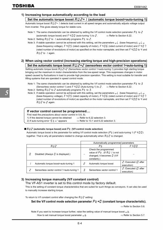
E6581442
E-4
5
1) Increasing torque automatically according to the load Set the automatic torque boost = (automatic torque boost+auto-tuning 1)Automatic torque boost = detects load current in all speed ranges and automatically adjusts voltage outputfrom inverter. This gives steady torque for stable runs.
Note 1: The same characteristic can be obtained by setting the V/f control mode selection parameter to (automatic torque boost) and (auto-tuning 1) to . ⇒ Refer to Section 6.22.
Note 2: Setting to automatically programs to .Note 3: If stable operation cannot be achieved with this setting, set the parameters (base frequency),
(base-frequency voltage), (rated capacity of motor), (rated current of motor) and (rated number of revolutions of motor) as specified on the motor nameplate, and then set to and
to again.
2) When using vector control (increasing starting torque and high-precision operations) Set the automatic torque boost = (sensorless vector control 1+auto-tuning 1)Setting automatic torque boost = (Sensorless vector control 1+auto-tuning 1) provides high starting torquebringing out the maximum in motor characteristics from the low-speed range. This suppresses changes in motorspeed caused by fluctuations in load to provide high precision operation. This setting is most suitable for transfer andlifting systems that are operated in speed control mode.
Note 1: The same characteristic can be obtained by setting the V/f control mode selection parameter to (Sensorless vector control 1) and (Auto-tuning 1) to . ⇒ Refer to Section 6.22.
Note 2: Setting to automatically programs to .Note 3: If stable operation cannot be achieved with this setting, set the parameters (base frequency),
(base-frequency voltage), (rated capacity of motor), (rated current of motor) and (rated number of revolutions of motor) as specified on the motor nameplate, and then set to and
to again.
(automatic torque boost) and (V/f control mode selection)Automatic torque boost is the parameter for setting V/f control mode selection ( ) and auto-tuning 1 ( )together. That is why all parameters related to change automatically when is changed.
Automatically programmed parameters
Disabled (Always is displayed.) –
Check the programmedvalue of . (If is notchanged, it becomes (V/fconstant).)
–
Automatic torque boost+auto-tuning 1 Automatic torque boost: Executed ( after
execution)
Sensorless vector control 1+auto-tuning 1 Sensorless vector control 1: Executed ( after
execution)
3) Increasing torque manually (V/f constant control)The VF-AS1 inverter is set to this control mode by factory default.This is the setting of constant torque characteristics that are suited for such things as conveyors. It can also be usedto manually increase starting torque.
To return to V/f constant control after changing the setting:
Set the V/f control mode selection parameter = (constant torque characteristic).⇒ Refer to Section 5.6.
Note:If you want to increase torque further, raise the setting value of manual torque boost .How to set manual torque boost parameter ⇒ Refer to Section 5.7.
If vector control cannot be programmed....First read the precautions about vector control in 5.6, 9).1) If the desired torque cannot be obtained ⇒ Refer to 6.22 selection 3.2) If auto-tuning error “ ” appears ⇒ Refer to 13.1 and 6.22 selection 3.

E6581442
E-5
5
5.4 Setting parameters by operating method
: Automatic function setting
[Parameter setting]Title Function Adjustment range Default setting
Automatic functionsetting
:Disabled:Frequency setting by means of voltage:Frequency setting by means of current:Voltage/current switching from external terminal:Frequency setting on operation panel and operation by means of terminal:Frequency setting and operation on operation panel
Automatically programmed functions and parameter set valuesDefaultsetting
:Disabled
:Frequency settingby means ofvoltage
:Frequency settingby means ofcurrent
:Voltage/currentswitching fromexternal terminal
:Frequency settingon operation paneland operation bymeans of terminal
:Frequency settingand operation onoperation panel
:Terminalboard – – – – :Terminal board :Operation panel
:RR/S4 – :RR/S4 :VI/II :RR/S4 :Operationpanel
:Operationpanel
:Voltageinput – – :Current input :Current input – –
(S3):Preset
speedcommand 3
– – – :Frequencypriority switching – –
: /
terminalswitching
–: /
terminalswitching
: /terminal
switching
: /terminal
switching
: /terminal
switching
: /terminal
switching % – – % % – –:VI/II – :RR/S4 :VI/II :VI/II :Operation
panel:Operation
panel⇒ Refer to Section 11 for input terminal functions.
No change is made to the parameter setting.
Operation is performed by applying a voltage for setting the RR/S4 terminal 1 frequency.When sink logic is selected:PWR-P24/PLC ON: Standby (ON (short-circuited) by default)F-CC ON: Forward runR-CC ON: Reverse run
This setting is used to set the frequency by applying a current of 4-20mA to the VI/II terminal.PWR-P24/PLC ON: Standby (ON (short-circuited) by default)F-CC ON: Forward runR-CC ON: Reverse run
Switching between remote and local (different frequency commands) can be performed by turning on or off the S3 terminal. Inthat case, apply a voltage via the RR/S4 terminal and a current via the VI/II terminal.S3-CC OFF: The frequency is set according to the voltage applied to the RR/S4 terminal.S3-CC ON: The frequency is set according to the current applied to the VI/II terminal.
In sink logic mode: PWR-P24/PLC ON: Standby (ON (short-circuited) by default), F-CC ON: Forward run, R-CC ON: Reverserun.
• FunctionAutomatically programs all parameters (parameters described below) related to the functions byselecting the inverter's operating method.The major functions can be programmed simply.
Disabled ( = )
Frequency setting by means of voltage: ( = )
Frequency setting by means of current ( = )
Voltage/current switching by means of an external terminal ( = )

E6581442
E-6
5
This setting is used to set the frequency using the operation panel and to perform operation control using the terminal board.
Use the and keys to set the frequency.
In sink logic mode: PWR-P24/PLC ON: Standby (ON (short-circuited) by default),F-CC ON: Forward run, R-CC ON: Reverse run.
This setting is used to set the frequency and to perform operation control, using the operation panel.
Use the and keys to set the frequency.
Use the and keys to perform operation control.
5.5 Selection of operation mode
: Command mode selection : Frequency setting mode selection 1
<Command mode selection>[Parameter setting]
Title Function Adjustment range Default setting
Command modeselection
:Terminal input enabled:Operation panel input enabled (including LED/LCD optioninput)
:2-wire RS485 communication input:4-wire RS485 communication input:Communication option input
[Programmed value]
: Terminal board operation ON and OFF of an external signal Runs and stops operation.
: Operation panel operation Press the and keys on the operation panel to Run and
stop a run. (including LED/LCD option input)
: 2-wire RS485 communication operation Run and stop commands are entered from the2-wire RS485 communications device.(Communication No.: FA00)
: 4-wire RS485 communication operation Run and stop commands are entered from the 4-wireRS485 communications device.(Communication No.: FA04)
: Communication option input enabled Signals from an optional communication device are usedto start and stop operation.⇒ For details, refer to Instruction Manual (E6581281,
E6581343, E6581288) specified in Section 6.42.
* There are two types of function: the function that conforms to commands selected by , and thefunction that conforms only to commands from the terminal board.⇒ Refer to the table of input terminal function selection in Section 7.2.
* When priority is given to commands from a linked computer or terminal board, they have priority over thesetting of .
• FunctionThese parameters are to program which command to the inverter (from operation panel, terminal board, remoteinput device or options) will be given priority in running/stopping the operation and in frequency setting (speed).
RUN STOP
Frequency setting and operation with operation panel ( = )
RUN STOP
Frequency setting with operation panel and operation with terminal board ( = )

E6581442
E-7
5
<Frequency setting mode selection>[Parameter setting]
Title Function Adjustment range Default setting
Frequency setting modeselection 1
:VI/II (voltage/current input):RR/S4 (potentiometer/voltage input):RX (voltage input):Operation panel input enabled (includingLED/LCD option input)
:2-wire RS485 communication input:4-wire RS485 communication input:Communication option input:Optional AI1 (differential current input):Optional AI2 (voltage/current input)
:Up/Down frequency:Optional RP pulse input:Optional high-speed pulse input: - [Note 1]
[Programmed value]
: VI/II input Speed setting commands are entered by external signals (0~10Vdc or4(0)~20mAdc).
: RR/S4 input Speed setting commands are entered by external signals (RR/S4terminal:0~10Vdc).
: RX input Speed setting commands are entered by external signals (RX terminal:0~±10Vdc(±5Vdc)).
: Operation panel input Press the and keys on the operation panel to set thefrequency.(including LED/LCD option input)
: 2-wire RS485 communication operation Speed commands are entered from the 2-wireRS485 communications device.(Communication No.:FA01)
: 4-wire RS485 communication operation Speed commands are entered from the 4-wire RS485communications device.(Communication No.:FA05)
: Communication option input enabled Speed commands are entered from an optionalcommunication device.⇒ For details, refer to Instruction Manual (E6581281,
E6581343, E6581288) specified in Section 6.42.
: AI1 input Speed setting commands are entered by external signals (AI1 terminal (option):0~±10Vdc (±5Vdc)).
: AI2 input Speed setting commands are entered by external signals (AI2 terminal: 0~10Vdcor 4(0)~20mAdc) (optional).
: Up/Down frequency Speed commands are entered by means of Up/Down frequency signalsfrom the terminal board. ⇒ Refer to Section 7.2.
: RP pulse input Speed commands are entered by means of RP pulses (optional).
: High-speed pulse input Speed commands are entered by means of high-speed pulses(optional).
Note 1: For options (unsupported)

E6581442
E-8
5
The functions assigned to the following control input terminals (contact input: ⇒ Refer to Section 7.2) are alwaysactivated regardless of the settings of the command mode selection and frequency setting mode selection 1
.• Reset terminal (default setting: RES, valid only for tripping)• Power removal terminal (assigned to PWR by default)• Emergency stop terminal
To make changes in the command mode selection and the frequency setting mode selection 1 firststop the inverter temporarily.No change can be made to them if the inverter is in operation.
Preset speed operation: Set this parameter at (terminal board).: Any setting is valid.
1) Setting the run, stop and operation frequencies with the operation panel
Title Function Example of setting
Command mode selection (Operation
panel input)Frequency setting modeselection 1
(Operationpanel input)
Run/stop :Press the and keys
on the operation panelTo switch between forward run and reverse run,use the forward/reverse run selection .
Speed command :Press the andkeys on the operationpanel to set the frequency.
Motor
IM
CCA
F
R
PWR
R/L1
P24/PLC
Shorted by a shorting bar whenshipped from the factory.
Powersupply S/L2
T/L3
U/T1V/T2W/T3
RX VI/II RR/S4 PP
To save the frequency, pressthe ENTER key. Then, and the set frequency aredisplayed alternately for awhile.
Inverter
RUN STOP

E6581442
E-9
5
2) Setting the run and stop frequencies (forward run, reverse run and coaststop) by means of external signals and setting the operation frequencywith the operation panel
Title Function Example of settingCommand mode selection (Terminal
input)Frequency setting modeselection 1
(Operationpanel input)
Run/stop : ON/OFF of terminals F-CC/R-CC(Standby: connection of terminalsS3 and CC)
Speed command : Set the frequency, using
the keys on
the operation panel.
Powersupply
Motor
IMR/L1S/L2T/L3
U/T1V/T2
W/T3
ON:Forward run,OFF:Deceleration stopON:Reverse run,OFF:Deceleration stop
The inverter is factory-configured so that, if F andR are turned on at thesame time, the inverter willstop operation. Ifnecessary, the direction ofrotation can be reversedby changing parametersettings.⇒ Refer to Section 6.2.1.
To save the frequency,press the ENTER key.Then, and the setfrequency aredisplayed alternatelyfor a while.
CCA RX VI/II RR/S4 PP
Inverter
F
R
CC
ON:Standby,OFF:Coast stop(Set the parameters
to and to to assign the standbysignal input function to theS3 terminal.)
S3
PWR
P24/PLC
3) Setting the run and stop frequencies (forward run, reverse run anddeceleration stop) with the operation panel and setting the operationfrequency by means of external signals
Title Function Example of settingCommand modeselection (Operation panel input)
Frequency settingmode selection 1
(VI/II (voltage/currentinput) )(RR/S4 (potentiometer/voltage input) )(RX (voltage input) )
Run/stop : Press the and keys on
the operation panelTo switch between forward run and reverse run,use the forward/reverse run selection .
Speed command : External signal input(1) VI/II terminal: 0~+10Vdc
(0~+5Vdc) or4(0)~20mAdc
(2) RR/S4 terminal: Potentiometer0~+10Vdc (0~+5Vdc)
(3) RX terminal: 0~±10Vdc (0~±5Vdc)
Motor
IM
F
R
PWR
R/L1
P24/PLC
Shorted by a shorting bar whenshipped from the factory.
Powersupply S/L2
T/L3
U/T1V/T2W/T3
(1) 0~+10Vdc(0~+5Vdc)or 4(0)-20mA
(3) 0~±10Vdc(0~±5Vdc)
(2) External potentiometer
-
-+
+
* Other speed setting : 2-wire RS485 input : 4-wire RS485 input enabled : Communication option input
enabled * : Optional AI1 (differential current
input) * : Optional AI2 (voltage/current
input) *: Up/Down frequency: RP pulse input *: High-speed pulse input *: -
* Commands marked with * areoptional. Refer to Instruction Manualof options described in Section 10.
CCA RX VI/II RR/S4 PP
Inverter
RUN STOP

E6581442
E-10
5
4) Setting the run, stop and operation frequencies (forward run, reverse runand coast stop) by means of external signals (default setting)
Title Function Example of settingCommand modeselection :(Terminal input)
Frequency settingmode selection 1
(VI/II (voltage/current input) )(RR/S4(potentiometer/voltageinput) )(RX (voltage input) )
Run/stop :ON/OFF of terminals F-CC/R-CC Speed command :External signal input(1) VI/II terminal: 0~+10Vdc
(0~+5Vdc) or4(0)~20mAdc
(2) RR/S4 terminal: Potentiometer0~+10Vdc (0~+5Vdc)
(3) RX terminal: 0~±10Vdc (0~±5Vdc)
Motor
IMR/L1Power
supply S/L2T/L3
U/T1V/T2
W/T3
(1) 0~+10Vdc(0~+5Vdc)or 4(0)~20mAdc
(3) 0~±10Vdc(0~±5Vdc)
(2) External potentiometer
-
-+
+
* Other speed setting : 2-wire RS485 input : 4-wire RS485 input enabled : Communication option input enabled * : Optional AI1 (Differential current
input) * : Optional AI2 (voltage/current input) *
: Up/Down frequency: RP pulse input *: High-speed pulse input *: -
* Commands marked with * areoptional. Refer to Instruction Manualof options described in Section 10.
CCA RX VI/II RR/S4 PP
Inverter
The inverter is factory-configured so that, if F andR are turned on at thesame time, the inverter willstop operation. Ifnecessary, the direction ofrotation can be reversedby changing parametersettings.⇒ Refer to Section 6.2.1.
ON:Reverse run,OFF:Deceleration stop
F
R
CC
ON:Standby,OFF:Coast stop(Set the parameters to and to toassign the standby signalinput function to the S3terminal.)
S3
ON:Forward run,OFF:Deceleration stop
PWR
P24/PLC

E6581442
E-11
5
5.6 Selecting control mode
: V/f control mode selection
[Parameter setting]Title Function Adjustment range Default setting
V/f control mode selection
: Constant torque characteristics: Voltage decrease curve: Automatic torque boost: Sensorless vector control 1: Sensorless vector control 2: V/f 5-point setting: PM control: PG feedback control: PG feedback vector control
Caution
Mandatory
• When operating the inverter with set to , , , or , be sure to set the motor constantparameter correctly. Failure to do this may cause the inverter not to control the motor properly,and thus cause the motor not to deliver the desired performance. For more information, see theexplanation of each setting in the following sections.
1) Constant torque characteristics (Normal way of use) Setting of V/f control mode selection = (Constant torque characteristics)This is applied to loads with equipment like conveyors and cranes that require the same torque at low speeds as atrated speeds.
Base frequency voltage 1
Output frequency [Hz]
Base frequency 0
Output voltage
[V]/[%]
* To increase the torque further, increase the setting value of the manual torque boost parameter .⇒ For more details, refer to Section 5.7.
• FunctionWith “VF-AS1,” the V/f controls shown below can be selected.0: Constant torque characteristics1: Voltage decrease curve2: Automatic torque boost (*1)3: Sensorless vector control 1 (*1)4: Sensorless vector control 25: V/f 5-point setting6: PM control (*2)7: PG feedback control (*3)8: PG feedback vector control (*3)
(*1) “Automatic control” parameter automatically sets this parameter and auto-tuning 1 at a time.(*2) Use a dedicated motor with permanent magnets.(*3) A PG feedback device (optional) is needed for this control.

E6581442
E-12
5
2) Decreasing output voltage Setting of V/f control mode selection = (Voltage decrease curveThis is appropriate for load characteristics of such things as fans, pumps and blowers in which the torque in relationto load rotation speed is proportional to its square.
Base frequency voltage 1
Output voltage
[V]/[%]
Base frequency 0 Output frequency [Hz]
3) Increasing starting torque Setting of V/f control mode selection = (Automatic torque boost)Detects load current in all speed ranges and automatically adjusts voltage output (torque boost) from inverter.This gives steady torque for stable runs.
Base frequency voltage 1
Output voltage
[V]/[%]Output frequency [Hz]
Base frequency 0
:The torqueboost rate isadjustedautomatically.
Note:This control system can oscillate and destabilize runs depending on the load. If that should happen, set V/fcontrol mode selection to (Constant torque characteristics) and increase torque manually.
Motor constant must be set.The motor constant can be set in any of the following two ways:1) Automatic setting
Enter the following information that is indicated on the motor nameplate, and then execute the auto-tuning 1command (Set to , and then reset to .).<Information indicated on motor nameplate>
(Base frequency), (Base frequency voltage), (Motor rated capacity), (Motor ratedcurrent), (Motor rated rotational speed)⇒ Refer to 6.22 selection 2.
2) Manual settingSet each motor constant manually.⇒ Refer to 6.22 selection 3.

E6581442
E-13
5
4) Vector control–increasing starting torque and achieving high-precisionoperation. Setting of V/f control mode selection = , (Sensorless vector control 1, 2)Using sensorless vector control with a Toshiba standard motor will provide the highest torque at the lowest speedranges. The effects obtained through the use of sensorless vector control are described below.
(1) Provides large starting torque.(2) Effective when stable operation is required to move smoothly up from the lowest speeds.(3) Effective in elimination of load fluctuations caused by motor slippage.(4) Effective in producing high motor torque at low speed.
Set to (sensorless vector control 1) to operate multiple motors of the same type in parallel or to operate amotor with a two or more notches lower rating.To perform torque control, set to (sensorless vector control 2), which is designed to perform operation controlwith higher accuracy. In that case, however, the inverter should be used only for operating a single motor with anequal or one notch lower rating.
Motor constant must be set.The motor constant can be set in any of the following two ways:1) Automatic setting
Enter the following information that is indicated on the motor nameplate, and then execute the auto-tuning 1command (Set to , and then reset to .).<Information indicated on motor nameplate>
(Base frequency), (Base frequency voltage), (Motor rated capacity), (Motor ratedcurrent), (Motor rated rotational speed)⇒ Refer to 6.22 selection 2.
2) Manual settingSet each motor constant manually.⇒ Refer to 6.22 selection 3.
5) Setting of V/f characteristic arbitrarily Setting of V/f control mode selection = (V/f 5-point setting)In this mode, the base frequency and the base frequency voltage for the V/f control need to be set to operate themotor while switching a maximum of 5 different V/f characteristics.
[Parameter setting]Title Function Adjustment range Default setting
V/f 5-point setting VF1 frequency ~ HzV/f 5-point setting VF1 voltage ~ % *V/f 5-point setting VF2 frequency ~ HzV/f 5-point setting VF2 voltage ~ % *V/f 5-point setting VF3 frequency ~ HzV/f 5-point setting VF3 voltage ~ % *V/f 5-point setting VF4 frequency ~ HzV/f 5-point setting VF4 voltage ~ % *V/f 5-point setting VF5 frequency ~ HzV/f 5-point setting VF5 voltage ~ % *
*100% adjustment value (200V class: 200V, 400V class: 400V)

E6581442
E-14
5
Base frequencyvoltage 1
Output voltage
[V]/[%]
Output frequency [Hz]
Base frequency 1
0
VF1VF2
VF3VF4
VF5
V/f 5-point setting
Note 1: Restrict the amount of torque to boost ( ) to 3% or so. Boosting the torque too much may impair thelinearity between points.
Note 2: If the V/f 5-point is set within the diagonally shaded area in the figure below, the V/f 5-point is placedautomatically on the boundary line (heavy line in the figure).
: Area in which theV/f 5-point cannotbe set
Voltage
Frequency0
× 0.4413
100%
6) Operating a permanent magnet motor Setting of V/f control mode selection = (PM control)Permanent magnet motors (PM motors) that are light, small in size and highly efficient, as compared to inductionmotors, can be operated in sensorless operation mode. Note that this feature can be used only for specific motors.For more information, contact your supplier.
7) Operating the motor at periodic speeds by means of a motor speedsensor Setting for V/f control mode selection = (PG feedback contro)Set to to operate the motor at periodic speeds.A PG feedback device (optional) is needed. In addition, a motor with a speed sensor (encoder) should be used.Use this setting when operating a motor two or more ranks lower in capacity than the inverter at periodic speeds.Note that the accuracy obtained by = is lower than that obtained by setting to . Also, should be set to
to perform torque control. cannot be set to in such a case.Output torque decreases considerably in regenerative low speed operation (motor slip frequency or less). Set to
if regenerative low speed torque is necessary.
Motor constant must be set.The motor constant can be set in any of the following two ways:1) Automatic setting
Enter the following information that is indicated on the motor nameplate, and then execute the auto-tuning 1command (Set to , and then reset to .).<Information indicated on motor nameplate>
(Base frequency), (Base frequency voltage), (Motor rated capacity), (Motor ratedcurrent), (Motor rated rotational speed) ⇒ Refer to 6.22 selection 2.
2) Manual settingSet each motor constant manually. ⇒ Refer to 6.22 selection 3.

E6581442
E-15
5
8) Performing speed control/torque control with high accuracy using themotor speed sensor Setting for V/f control mode selection = (PG feedback vector control)The torque produced by the motor is controlled by means of specified torque command signals. The rotational speedof the motor depends on the relation between the load torque and the torque produced by the motor.A PG feedback device (optional) is needed. In addition, a motor with a speed sensor (encoder) should be used.Set to (PG feedback vector control) to perform speed/torque control with high accuracy.
Motor constant must be set.The motor constant can be set in any of the following two ways:1) Automatic setting
Enter the following information that is indicated on the motor nameplate, and then execute the auto-tuning 1command (Set to , and then reset to .).<Information indicated on motor nameplate>
(Base frequency), (Base frequency voltage), (Motor rated capacity), (Motor ratedcurrent), (Motor rated rotational speed)⇒ Refer to 6.22 selection 2.
2) Manual settingSet each motor constant manually.⇒ Refer to 6.22 selection 3.
9) Precautions on vector control1) When operating a motor in automatic torque boost mode or vector control mode ( = , , , or ), enter
each motor constant indicated on the nameplate ( (base frequency), (base-frequency voltage), (rated capacity of motor), (rated current of motor) and (rated number of revolutions of motor) ),read the precautions on auto-tuning 1 on section 6.22 (1), and then set to (auto-tuning). If the cablelength is in excess of 30m, be sure to perform the auto-tuning ( = ) mentioned above, even when using astandard motor recommended by Toshiba.
2) The sensorless vector control exerts its characteristics effectively in frequency areas below the base frequency( ). The same characteristics will not be obtained in areas above the base frequency.
3) When setting to or , use the inverter along with a general-purpose motor with an equal or one notch lowerrating.
4) Use a motor that has 2 to 16P.5) Always operate the motor in single operation (one inverter to one motor). (Except for; = ) Sensorless vector
control cannot be used when one inverter is operated with more than one motor.6) The torque produced by the motor decreases more or less around the rated frequency because of a voltage drop
cause motor-generated torque in the vicinity of rated frequency to be somewhat lower.7) Connecting a reactor or surge voltage suppression filter between the inverter and the motor may reduce motor-
generated torque. Setting auto-tuning 1 may also cause a trip ( , ~ )rendering sensorless vectorcontrol unusable. In the event of a trip, perform auto-tuning with the inverter connected directly to the motor, orenter the motor constant calculated from the motor test results.
8) Connect speed sensor for vector control with sensor to the motor. Connecting via gear, etc. causes motor'soscillating or inverter's trip by lack of rigidity.

E6581442
E-16
5
5.7 Manual torque boost–increasing torque boost at low speeds
: Manual torque boost 1
Output voltage
Base frequency voltage 1
[V]/[%]Output frequency [Hz]
Base frequency 0
[Parameter setting]Title Function Adjustment range Default setting
Manual torque boost 1 ~ % According to model ⇒ Refer to page K-46.This parameter is valid when = (Constant torque characteristics), (square reduction torque), (V/f 5-point setting).
Note: The optimum value is programmed for each inverter capacity. Be careful not to increase the torque boost ratetoo much because it could cause an overcurrent trip at startup. If you are going to change the set values, keepthem within ±2% of the standard default values.
5.8 Base frequency
: Base frequency 1 : Base frequency voltage 1
Note:This is an important parameter that determines the constant torque control area.
Output voltage
Base frequency voltage 1
[V] Output frequency [Hz]0Base frequency
[Parameter setting]Title Function Adjustment range Default setting
Basefrequency 1 ~ Hz Inverter with a model number ending with -WN1, HN:
-WP1:
Basefrequencyvoltage 1
200V class: ~ V400V class: ~ V
200V models: 400V models:
Inverter with a model number ending with -WN1, HN:-WP1:
Note: The output frequency is limited to a frequency 10.5 times as high as the base frequency ( ). Even if themaximum frequency ( ) or the upper limit frequency ( ) is set above this frequency, this limitation isimposed on the output frequency.
• FunctionIf torque is inadequate at low speeds, increase torque by raising the torque boost rate with this parameter.
• FunctionSets the base frequency and the base frequency voltage in conformance with load specifications or the motor'srated frequency.

E6581442
E-17
5
5.9 Maximum frequency
: Maximum frequency
Output frequency [Hz]
In case of =80Hz
In case of =60Hz
80Hz
60Hz
0 100% Frequency setting signal [%]
• This function determines themaximum value in line with theratings of the motor and load.
• Maximum frequency cannot beadjusted during operation. Toadjust, first stop the inverter.
If is increased, adjust the upper limit frequency as necessary.
[Parameter setting]Title Function Adjustment range Default setting
Maximum frequency ~ HzNote: The output frequency is limited to a frequency 10.5 times as high as the base frequency ( ). Even if the
maximum frequency ( ) or the upper limit frequency ( ) is set above this frequency, this limitation isimposed on the output frequency.
5.10 Upper limit and lower limit frequencies
: Upper limit frequency : Lower limit frequency
Lower limitfrequency
0 100%
Output frequency [Hz] Upper limitfrequency
0 100%
Output frequency [Hz]
Frequencysetting signal
Frequencysetting signal
Frequencies that go higherthan will not be output.
The output frequency cannotbe set at less than .
[Parameter setting]Title Function Adjustment range Default setting
Upper limit frequency ~ HzInverter with a model number ending with
-WN1, HN: -WP1:
Lower limit frequency ~ Hz
• Function1) Programs the range of frequencies output by the inverter (maximum output values).2) This frequency is used as the reference for acceleration/deceleration time.
• FunctionPrograms the lower limit frequency that determines the lower limit of the output frequency and the upper limitfrequency that determines the upper limit of that frequency.

E6581442
E-18
5
5.11 Setting frequency command characteristics
~ , : VI/II point setting~ , : RR/S4 point setting~ : RX point setting~ :~ :~ :~ : Point 1, 2 setting/ frequency
⇒ For details, refer to Section 7.3.
5.12 Preset speed operation (speeds in 15 steps)
~ : Preset speed operation frequencies 1~7~ : Preset speed operation frequencies 8~15~ : Preset speed operation frequencies 1~15 operation mode
[Setting methods]1)Run/stop
Run and stop control is experienced by the operation panel (Default setting).
Title Function Adjustment range Example of setting
Command modeselection
: Terminal input enabled: Operation panel input enabled (includingLED/LCD option input)
: 2-wire RS485 communication input: 4-wire RS485 communication input: Communication option input
Note 1: If speed commands (analog signal or digital input) are switched in line with preset speed operations, select theterminal board using the frequency setting mode selection 1 .⇒ Refer to 3) or Section 5.5.
2)Preset speed frequency settingSet the speed (frequency) of the number of steps necessary.
Setting from speed 1 to speed 7Title Function Adjustment range Default setting
~Preset speed operationfrequencies 1~7 ~
Setting from speed 8 to speed 15Title Function Adjustment range Default setting
~Preset speed operationfrequencies 8~15
~
It sets up, when using the optional circuit board.
• FunctionA maximum of 15 speed steps can be selected just by switching an external contact signal. Preset speedfrequencies can be programmed anywhere from the lower limit frequency to the upper limit frequency .
• FunctionThese parameters adjust the output frequency according to the externally applied analog signal (0~10Vdcvoltage, 4(0)~20mAdc current) and the entered command for setting an external contact frequency.

E6581442
E-19
5
Example of preset speed contact input signal: ON –: OFF (Speed commands other than preset speed commands are valid when all are OFF)
Preset speedTerminal
1 2 3 4 5 6 7 8 9 10 11 12 13 14 15S1-CC – – – – – – –S2-CC – – – – – – –S3-CC – – – – – – –RR/S4-CC – – – – – – –
Terminal functions are as follows. (Default setting)Terminal S1 ・・・・・・・・・ Input terminal function selection 5 (S1) = (S1)Terminal S2 ・・・・・・・・・ Input terminal function selection 6 (S2) = (S2)Terminal S3 ・・・・・・・・・ Input terminal function selection 7 (S3) = (S3)Terminal RR/S4 ・・・・ Input terminal function selection 8 (S4) = (S4)
The RR/S4 terminal is set by default as an analog voltage input terminal. To use it as an input terminal for presetspeed operation, turn the SW3 switch to the S4 position.
[An example of the connection of terminals]
F (Forward run)
CC
RR/S4
S2
S3
S1
R (Reverse run)
Forward
Reverse
Preset speed command 1
Preset speed command 2
Preset speed command 3
Preset speed command 4
SW3
S4 RR
3)Using other speed commands with preset speed commandWhen no preset speed command is issued, the inverter accepts an input command from the operation panel oranother analog input device.
Other speed commandsFrequency setting signals from the operation
panelAnalog signal input command(VI/II, RR/S4, RX, AI1 and AI2)
Preset speedcommand
Entered Not entered Entered Not entered
EnteredPreset speed
command validPreset speed
command validPreset speed
command validPreset speed
command valid
Not paintedOperation panelcommand valid – Analog signal valid –
The preset speed command is always given priority when other speed commands are input at the same time.To use the RR/S4 terminal as an analog input terminal, turn the SW4 switch to the RR position. Note that thismakes it impossible to use the function assigned to S4.
CC
S2S3RR/S4
S1

E6581442
E-20
5
Below is an example of 7-step speed operation.
F-CC
S1-CC
S2-CC
S3-CC
ONOFF
ONOFF
ONOFF
ONOFF
Outputfrequency [Hz]
Time[s]0
Example of 7-step speed operation
4)Setting the operation modeAn operation mode can be selected for each preset speed.
Operation mode settingTitle Function Adjustment range Example of setting
Preset speed operation modeselection
: Preset speed operation with nomode
: Preset speed operation withmode
: Preset speed operation with no mode ・・・・・ Only frequency commands are governed by the presetspeed command (1 to 15) entered.
: Preset speed operation with mode ・・・・・・・・ The direction of rotation, the V/f control mode, theacceleration and deceleration times and the torque limitcan be set individually for each preset speed command.
If you selected “enabled” ( = ), the motor runs operation mode setting directions as below withoutfollowing terminal F, R.
Operation mode settingTitle Function Adjustment range Example of setting
~Preset speedoperation frequency1~15 operation mode
: Forward run+ : Reverse run+ : Acceleration/deceleration switching
signal 1+ : Acceleration/deceleration switching
signal 2+ : V/f switching signal 1+ : V/f switching signal 2+ : Torque limit switching signal 1+ : Torque limit switching signal 2
For the settings marked with +, more than one function can be selected at the same time by entering the sum ofthe numbers of the desired functions.Ex.) (+ ) + (+ ) = By entering “ ”, you can activate the reverse run function and the acceleration/deceleration switching signal 1function at the same time.

E6581442
E-21
5
5.13 Selecting forward and reverse runs (operation panel only)
: Forward/reverse run selection
[Parameter setting]Title Function Adjustment range Default setting
Forward/reverse run selection
: Forward run: Reverse run: Forward run (F/R switching possible): Reverse run (F/R switching possible)
Check the direction of rotation on the status monitor.: Forward run : Reverse run
⇒ For monitoring, refer to Section 8.1.
When the F and R terminals are used for switching between forward run and stop from the terminal board, the forward/reverse run selection parameter is rendered invalid.
Short across the F-CC terminals: forward runShort across the R-CC terminals: reverse run
If F and CC, as well as R and CC are connected at the same time: Stop (Default setting)Use the parameter to select between reverse run and stop in this case.⇒ For more details, refer to Section 6.2.1.
This function is valid only when is set at (Operation panel input enabled).
To switch between forward run and reverse run from the control panel with parameter set to or , perform
these steps: to switch to forward run, press the key while holding the key down, or to switch to reverse
run, press the key while holding key down.
• FunctionProgram the direction of rotation of the motor when the running and stopping are made using the RUN key andSTOP key on the operation panel.Valid when (command mode selection) = (operation panel input).
ENT
ENT

E6581442
E-22
5
5.14 Setting the electronic thermal
: Motor electronic thermal protection level 1 : Electronic thermal protection characteristic selection : OL reduction starting frequency : Motor 150%-overload time limit : Temperature detection
[Parameter setting]Title Function Adjustment range Default setting
Motor electronicthermalprotection level 1
~ %
Defaultsetting Motor type
Overloadprotection Overload stall
(protect) × (not stall) (protect) (stall)
× (not protect) × (not stall)Standard
Motor× (not protect) (stall)
(protect) × (not stall) (protect) (stall)
× (not protect) × (not stall)
Electronicthermalprotectioncharacteristicselection VF
Motor(specialmotor) × (not protect) (stall)
1) Setting the motor electronic thermal protection level 1 and electronic thermal protectioncharacteristics selection
The electronic thermal protection characteristics selection is used to enable or disable the motor overload tripfunction ( ) and the overload stall function.The motor overload trip function ( ) needs to be selected with the parameter , while the inverter overloadtrip function ( ) is always activated.
[Using standard motors (other than motors intended for use with inverters)]When a motor is used in the lower frequency range than the rated frequency, that will decrease the cooling effectsfor the motor. This speeds up the start of overload detection operations when a standard motor is used in order toprevent overheating. Setting of electronic thermal protection characteristics selection
Default setting Overload protection Overload stall (protect) × (not stall) (protect) (stall)
× (not protect) × (not stall)× (not protect) (stall)
• FunctionThis parameter allows selection of the appropriate electronic thermal protection characteristics according to theparticular rating and characteristics of the motor.
Explanation of terms:Overload stall (Soft stall)
The function of automatically lowering the output frequency before the motor overload trip function is activated when the inverter detects that an excessive load is applied to the motor. (Lowers
maximum about 48Hz when basic frequency is 60Hz.) This function enables the inverter to output afrequency commensurate with the load current so that the motor can keep running without tripping.This function is useful for such loads as fans, pump, and blowers, which have the square reductiontorque characteristic that the current passed decreases as the rotating speed falls.
Note:Do not use this overload stall function for loads with a constant torque characteristic (e.g., a beltconveyer to which a constant load current is always passed regardless of their speed).

E6581442
E-23
5
Setting of motor electronic thermal protection level 1 If the capacity of the motor is smaller than the capacity of the inverter, or the rated current of the motor is smallerthan the rated current of the inverter, adjust the electronic thermal protection level 1 so that it fits the motor'srated current.
×0.6
×1.0
Output frequency [Hz]
Output current reduction factor [%]/[A]
0 30Hz
Note:The motor overload starting level is fixed at 30Hz. If necessary, set to , , or . (See the following section.) Even if the inverter is used with a Toshiba
standard motor, the load may need to be reduced at frequencies of 30Hz and morein some cases. In such cases, set to , , or and set the reductionstarting frequency ( ) according to the motor.
[Example of setting: When the VFAS1-2007PL is running with a 0.4kW motor having 2A rated current]Key operated LED display Operation
Displays the operation frequency. (Perform during operation stopped.)(When standard monitor display selection = [Output frequency])
The first basic parameter “History function ( )” is displayed.
Press either the key or the key to change the parameter to .
Press the ENTER key to display the parameter setting (Default setting:%).
Press the key to change the parameter to (= motor rated current/inverter output rated current x 100
= 2.0/5.0 × 100)
⇔Press the ENTER key to save the changed parameter. and theparameter are displayed alternately.
[Using a VF motor (motor for use with inverter)] Setting of electronic thermal protection characteristics selection
Default setting Overload protection Overload stall (protect) × (not stall) (protect) (stall)
× (not protect) × (not stall)× (not protect) (stall)
A VF motor (a motor for use with an inverter) can be used in lower frequency ranges than the standard motor, but ifthat frequency is extremely low, the effects of cooling on the motor will deteriorate.In such a case, set the OL reduction start frequency parameter according to the characteristics of the motor.(Refer to the figure below.)
As a guide, it is advisable to set this parameter around the default value (VF motor 6Hz).
[Parameter setting]Title Function Adjustment range Default setting
OL reduction starting frequency ~ HzNote: is enabled when = ~ .
MODE
ENT
ENT

E6581442
E-24
5
Setting of motor electronic thermal protection level 1 If the capacity of the motor is smaller than the capacity of the inverter, or the rated current of the motor is smallerthan the rated current of the inverter, adjust the electronic thermal protection level 1 so that it fits the motor'srated current.* If the indications are in percentages[%], then 100% equals the inverter's rated output current [A].
×0.6
×1.0
= Hz Output frequency [Hz]
Output current reduction factor [%]/[A]
0
Setting the motor overload starting level
2) Motor 150%-overload time limit
The motor 150%-overload time limit parameter is used to set the time elapsed before the motor trips undera load of 150% (overload trip ) within a range of 10 to 2400 sec.
[Example setting]Monitored output
current [%]Motor overload time [s] (Outline data)
= == =
0.01Hz 0.01Hz
68 34 – 7200 – 360070 35 – 3600 – 180080 40 – 1000 – 50090 45 – 600 – 300100 50 – 420 – 210112 56 12000 310 6000 155120 60 2400 270 1200 135130 65 1200 230 600 115140 70 800 190 400 95150 75 600 170 300 85200 100 270 110 135 55
Monitored output current [%]
time [s]
Motor 150%-overload time limit
Motor overload
0
×0.6×1.1
×1.5
Operation frequencyno less than
Operation frequency0.01Hz *1
*1 Except for the cases of = , [Hz]
Motor overload protection characteristics
[Parameter setting]Title Function Adjustment range Default setting
Motor 150%-overload time limit ~ sec.

E6581442
E-25
5
3) Inverter overload characteristicsSet to protect the inverter unit. Cannot be turned off by parameter setting.The inverter has two overload detecting functions, which can be switched from one to another using parameter
(temperature detection).[Parameter setting]
Title Function Adjustment range Default setting
Temperature detection:Standard (150%-60 sec.): Estimation of temperature
If the inverter overload trip function ( ) is activated frequently, this can be improved by adjusting the stalloperation level downward or increasing the acceleration time or deceleration time .
= (Standard)Protection is given uniformly regardless of ambient temperature, as shown by the 150%-60 sec overload curve inthe figure below.
60
100%: Inverter rated output current
time [s]
Inverter overload
Monitored output current [%]0
110% 150%
Current[%]
Inverter overload time [s](Outline data)
111 2400120 240130 120140 80150 60165 2200 0.1
Inverter overload protection characteristics = (Estimation of temperature)
This parameter adjusts automatically overload protection, predicting the inverter internal temperature rise.(diagonally shaded area in the figure below)
60
100%: Inverter rated output current
time [s]
Monitored output current [%]0
110% 150%
Inverter overload protection characteristics
Note 1: If the load applied to the inverter exceeds 150% of its rated load or the operation frequency is less than0.1Hz, the inverter may trip ( or ~ ) in a shorter time.
Note 2: The inverter is factory-set so that, if the inverter becomes overloaded, it will automatically reduce thecarrier frequency to avoid an overload trip ( or ~ ). A reduction in carrier frequencycauses an increase in noise from the motor, but this does not affect the performance of the inverter.If you do not want the inverter to reduce the carrier frequency automatically, set the parameter
= .

E6581442
E-26
5
5.15 Changing the display unit % to A (ampere)/V (volt)
: Current/voltage unit selection
Example of settingDuring the operation of the VFAS1-2037PL (rated current 16.6A) at the rated load (100% load), units are displayedas follows:
1)Display in percentage terms 2)Display in amperes/volts
Output current:16.6A
DC voltage:200V
(Converted intoAC voltage)
DC voltage:100%
Output current:100%
[Parameter setting]Title Function Adjustment range Default setting
Current/voltage unit selection: %
: % → A (ampere)/V (volt)
• FunctionThese parameters are used to change the unit of monitor display.
% ⇔A (ampere)/V (volt)Current 100% = Inverter’s rated current200V-class voltage 100% = 200Vac400V-class voltage 100% = 400Vac
* The converts the following parameter settings:• A display Current monitor display
Setting of electronic thermal protection level 1/2/3/4 , , , ,
DC braking currentStall prevention level
• V display Voltage monitor displayV/f 5-point setting , , , ,
Note: Base frequency voltage 1~4 ( , , , ) is always displayed in the unit of V.

E6581442
E-27
5
5.16 Meter setting and adjustment
: FM terminal meter selection : FM terminal meter adjustment : Constant at the time of filtering : FM voltage/current output
switching : Inclination characteristic of FM
output : FM bias adjustment
: FM output filter : AM terminal meter
selection : AM terminal meter
adjustment : Inclination characteristic
of AM output : AM bias adjustment
Note 1: The signal output from the FM and AM terminal is an analog voltage signal or an analog current signal.(positive (+) side output. For signed data, an absolute value is output. To output data with positive andnegative sings, you need to use two extended terminal boards (optional).)
Note 2: To the FM terminal, connect either a full-scale 0~1mAdc ammeter or a full-scale 0~7.5Vdc (or 10Vdc)voltmeter, if necessary. The FM terminal can also be used as a 0(4)~20mAdc output terminal.To the AM terminal, connect either a full-scale 0~1mAdc ammeter or a full-scale 0~7.5Vdc (or 10Vdc)voltmeter, if necessary.
Connect meters as shown below.
<Connection to terminal FM>
FM
CC
VF-AS1
The reading of the frequency meter fluctuates during calibration.
Meter: Frequency meter(default setting)
+
-
A frequency meter QS60T is optionally available.
Output modes of the FM terminal
0-10V0-20mA 0-1mA
FM
When used with a 0~1mAdc ammeter(Default setting)
SW2
When the optional frequency meter QS60T isconnected, this mode is selected.
0-10V0-20mA 0-1mA
FM
When used with a DC0~10V voltmeter
SW2=
0-10V0-20mA 0-1mA
FM
When used with a 0(4)~20mAdc
SW2=
<Connection to terminal AM >
AM
CC
VF-AS1
The reading of the ammeter fluctuates during calibration.
Meter: Ammeter(default setting)
+
-
It is recommendable to use an ammeter with a current rating 1.5 or more times as high as the output currentrating of the inverter.
• FunctionInverter’s operation data is sent to the FM terminal (AM terminal) as analog voltage signals or analog currentsignals. To display inverter’s operation data, connect a meter to this terminal. The “FM terminal-connected meteradjustment ” (AM terminal-connected meter adjustment ) parameter is used to calibrate the meter.

E6581442
E-28
5
[Terminal FM-related parameters]
Title Function Adjustment range Adjustmentlevel Default setting
FM terminal meterselection
: Output frequency: Frequency command value: Output current: Input voltage (DC detection): Output voltage: Compensated frequency *2: Speed feedback (real-time value): Speed feedback (1 second filter): Torque: Torque command: Torque current: Exiting current: PID feedback value: Motor overload factor (OL2 data): Inverter overload factor (OL1 data): Regenerative braking resistance overload factor (OLr data): Regenerative braking resistor load factor (% ED): Input power: Output power: Optional AI2 input: RR/S4 input: VI/II input: RX input: Optional AI1 input: FM output (Do not select this option.): AM output: Fixed output 1: Communication data output: Fixed output 2: Fixed output 3: Cumulative input power: Cumulative output power: Gain display: My function monitor 1: My function monitor 2: My function monitor 3: My function monitor 4: Signed output frequency: Signed frequency command value: Signed compensated frequency: Signed speed feedback (real-time value): Signed speed feedback (1 second filter): Signed torque: Signed torque command: Signed torque current: Signed PID feedback value: Signed RX input: Signed optional AI1 input: Signed fixed output 1: Signed fixed output 2: Signed fixed output 3
(a)(a)(b)(c)(c)(a)(a)(a)(d)(d)(b)(b)(a)(a)(a)(a)(a)(b)(b)(a)(a)(a)(a)(a)(a)(a)––––
(a)(a)–*1*1*1*1(a)(a)(a)(a)(a)(d)(d)(b)(a)(a)(a)–––
FM terminal meteradjustment – *3
Constant at the timeof filtering *4 msec, msec~ msec
FM voltage/currentoutput switching :Voltage output (0~10V), :Current output (0~20mA)
FM output gradientcharacteristic
:Negative gradient (downward-sloping),:Positive gradient (upward-sloping)
FM bias adjustment – ~ %
FM output filter
:No filter:Filter approx. 10ms:Filter approx. 15ms:Filter approx. 30ms:Filter approx. 60ms
*1: Monitor adjustment level selected.*2: “Compensated frequency” refers to the frequency actually sent from an inverter to the motor connected.*3: Default setting value is adjusted for connection of frequency meters "QS60T".
(Between FM and CCA: Approx. 3.6V)*4: The output current, input voltage, output voltage, compensated frequency, speed feedback (real-time value) torque, torque
current and exciting current output (FM/AM/pulse and monitor output) can be filtered.

E6581442
E-29
5
[Terminal AM-related parameters]Title Function Adjustment range Default setting
AM terminal meter selection Same as ( :AM output disabled)AM terminal meter adjustment – *1AM output gradientcharacteristic
:Negative gradient (downward-sloping),:Positive gradient (upward-sloping)
AM bias adjustment – ~ %*1: Default setting value is adjusted for connection of frequency meters "QS60T".
(Between AM and CCA: Approx. 3.6V) Resolution
Both the terminals FM and AM have a maximum resolution of 1/1024.
[Example of the calibration of the frequency meter connected to the terminal FM]* Use the meter's adjustment screw to pre-adjust zero-point.
Key operated LED display Operation
– Displays the operation frequency.(When standard monitor display selection = [Output frequency])
The first basic parameter “History function ( )” is displayed.
Press either the or key to select “ .”
Press the ENTER key to display the operation frequency.
Press either the key or the key to adjust the meter.The meter reading will change at this time but be careful because there willbe no change in the inverter's digital LED (monitor) indication.
By setup, before the needle of meter beings to sway, it will take time.
⇔The adjustment is complete. and the frequency are displayedalternately.
The display returns to its original indications.(When standard monitor display selection = [Output frequency])
Meter adjustment 1 when the inverter is at rest (adjustment by setting ( ) to : Fixed output 1,: Fixed output 2, : Fixed output 3)
If it is difficult to calibrate a meter because of large fluctuations of its reading, you may put the inverter out ofoperation to make its calibration easier.It is possible to adjust the meter for the data item selected with the parameter or . Adjustmentlevels (a) through (d) shown in the table on the previous page change according to the settings of fixed outputs 1through 3, as shown in the table below. Use this table as a reference when calibrating the meter(s).Values adjusted with fixed outputs are put out from the FM (AM) terminal when values in the table are used foroperation. For examples of adjustments, see the next page.Fixed output 1 comes in handy for adjusting items at adjustment level (a) or (c).Fixed output 2 comes in handy for adjusting items at adjustment level (b).Fixed output 3 comes in handy for adjusting items at adjustment level (d).
For meter connection, the VF-AS1 inverter has two output terminals; FM and AM, which can be usedsimultaneously.
With the default settings, FM terminal outputs about 4.7V (external impedance is ) or about 1mA (externalimpedance is 0Ω), when running frequency is 80Hz. AM terminal outputs about 4.7V or about 1mA, when theoutput current reading on the operation panel is 185%.
MODE
ENT
ENT
MODE
[Hint]It's easier to make theadjustment if you push andhold for several seconds.

E6581442
E-30
5
Meter adjustment
Adjustment levelFixed output 1
( )=Fixed output 2
( )=Fixed output 3
( )=(a) 54% 40%(b) 185% 100% 74%(c) 150% 81% 60%(d) 250% 135% 100%
Note: The 100% value of input/output power is the product of 3 ×200V (400V) × inverter’s rated current.
[Example: Procedure of calibrating the meter connected to the terminal AM to which “output current” is assigned.]Key operated LED display Operation
– Displays the operation frequency. (Perform during operation stopped.)(When standard monitor display selection = [Output frequency])
The first basic parameter “History function ( )” is displayed.
Press either the or key to select “ . ”
Pressing the ENTER key allows the reading of parameter setting.
Set the parameter at (fixed output for meter calibration 2) by pressingthe key.
⇔ Press the ENTER key to save the change. Then, and the set valueare displayed alternately.
Select the AM terminal meter adjustment by pressing the key.
Press the ENTER key to switch to the data display mode.
Press either the key or the key to adjust the meter.Adjust the pointer to the graduation to which you want it to point when theinverter passes a current 100% larger than its rated output current.(The meter reading will change at this time but be careful because therewill be no change in the inverter's indication).
By setup, before the needle of meter beings to sway, it will take time.
⇔Press the ENTER key to save the change. Then and the set value aredisplayed alternately.
Select the “AM terminal meter adjustment ” by pressing the key.
Pressing the ENTER key allows the reading of parameter setting.
Return the parameter setting to (output current display).
⇔Press the ENTER key to save the change. Then, and the set valueare displayed alternately.Press the MODE key three times to return to the running frequency displaymode. (When standard monitor display selection = [Outputfrequency])
MODE
ENT
ENT
ENT
ENT
ENT
ENT
MODE
[Hint]It's easier to make theadjustment if you push andhold for several seconds.

E6581442
E-31
5
Gradient bias adjustment of analog monitor outputHere is an example of the adjustment of output from 0-20mA → 20-0mA, 4-20mA using the FM terminal.
= , = = , =
20
0 100%0
(mA)20
0 100%0
(mA)
4
= , = = , =
large
(mA)20
00
100%
small
(mA)20
00
100%
4
The analog output inclination can be adjusted using the parameter .
5.17 PWM carrier frequency
: PWM carrier frequency : Random mode : Carrier frequency control mode selection
[Parameter setting]Title Function Adjustment range Default setting
PWM carrier frequency ~ kHz ( ~ kHz) [Note 1]According to model
⇒ Refer to page K-46.Random mode :Disabled, : Enabled
Carrier frequencycontrol mode selection
:Not decrease carrier frequency automatically:Decrease carrier frequency automatically:Not decrease carrier frequency automatically,400V class supported:Decrease carrier frequency automatically,400V class supported
Note 1: For 200V-55/75kW models and 400V-90kW to 400V-280kW models, the carrier frequency is between 2.5and 8.0kHz inclusive.
Note 2: If is set at 2.0kHz or above, it cannot be decreased below 2.0kHz during operation. Changes made todecrease below 2.0kHz take effect when operation is restarted after it is stopped.
Note 3: If is 1.9kHz or less, you cannot change the setting at 2.0kHz or more. Changes made to increase to2.0kHz or above take effect immediately.
Note 4: If (V/f control mode selection) is set to , , , , or , the inverter sets a lower limit of 2.0kHz for .
• Function1) The sound tone of acoustic noise can be changed by adjusting the PWM carrier frequency. This parameter is
also effective in preventing the motor from resonating with its load machine or its fan cover.2) In addition, this parameter reduces the electromagnetic noise generated by the inverter. Reduce the carrier
frequency to reduce electromagnetic noise. Note: Although the electromagnetic noise level is reduced, themagnetic noise of the motor is increased.
3) The random mode reduces motor magnetic noise by changing the pattern of the reduced carrier frequency.4) To set the parameter to or has the effect of suppressing voltage serge to the motor. Reduce the
carrier frequency to less than 4kHz if the wiring between the inverter and motor is long (20 to 100m as aguide).

E6581442
E-32
5
Note 5: If you change the carrier frequency, you may need to reduce the inverter’s continuous output current.⇒ Refer to Section 1.4.4, “Current reduction curve.”
Note 6: If the motor becomes overloaded when is set to or (carrier frequency not decreasedautomatically), an overload trip occurs.
Note 7: For the setting = or to take effect, power needs to be turned off and then turned back on. Andthis parameter is invalidated for the ratings of 90 kW and over.
Note 8: When setting to or , be sure to set at 4.0kHz or less.Note 9: When setting the carrier frequency ( ) between and . kHz, you are recommended to set
below 130%.
5.18 Trip-less intensification
5.18.1 Auto-restart (Restart during coasting) : Auto-restart control selection
Warning
Mandatory
• Do not go near motors and equipment.Motors and equipment that have stopped temporarily after momentary power failure will restartsuddenly after recovery. This could result in unexpected injury.
• Attach warnings about sudden restart after a momentary power failure on inverters, motors andequipment for prevention of accidents in advance.
• FunctionAuto-restart detect the rotating speed and direction of rotation of the motor during coasting or momentarypower failure, to ensure that the motor restarts smoothly (Motor speed search function). This parameter alsoallows commercial power operation to be switched to inverter operation without stopping the motor.During operation, “ ” is displayed.
1) Auto-restart after momentary power failure (Auto-restart function)
Input voltage
Motor speed
F-CCONOFF
= : This function operates after power has been restored following detection of an undervoltage by the maincircuits and control power.
Title Function Adjustment range Default setting Example of setting
Auto-restart controlselection
:Disabled:At auto-restart after momentary stop: When turning ST operation standby
signal on or off [Note 1]: + :At start-up
or
Note 1: ST standby signal can be turned on and off by turning on and off the terminal to which it is assigned.Example: When ST standby signal is assigned to the S3 terminal, setting to , to (cancels the “ST
standby signal always ON” setting. By default, this parameter is set to : always ON.) and to (assigns ST standby signal to the S3 terminal) makes it possible to momentarily stop and restart the motorby just turning the S3 terminal off and then back on.
* If the motor is restarted in retry mode, this function will operate, regardless of the setting of this parameter.* The function ( = , , , ) is activated when the reset of trip or the power is turned on.* The function ( = , ) is activated when an undervoltage is detected in the main circuit.

E6581442
E-33
5
2) Restarting motor during coasting (Motor speed search function)
Motor speed
F-CCONOFF
ONOFF
S3 (ST operation standbysignal) -CC
= : This function operates after the S3-CC terminal connection has been opened first and then connectedagain.
Title Function Adjustment range Default setting Example of setting
Auto-restart controlselection
:Disabled:At auto-restart after momentary stop:When turning ST on or off: + :At start-up
or
* To restart the inverter in operation panel operation mode, press RUN key after a power failure.* When (Number of PG input phases) = (single phase) in PG feedback vector control mode ( = , ), the
inverter may trip ( : speed error) if the direction of rotation of the motor does not agree with.
Operation and application of the auto-restart function• By using retry function together, auto restart function can be actuated at the time of tripping. Application to a crane or hoistThe crane or hoist may have its load moved downward during the above waiting time from input of the operation startingcommand to the restart of the motor. To apply the inverter to such machines, therefore, set the auto-restart control modeselection parameter to “ ” (Disabled). And avoid using the retry function.• At restart, it takes several seconds. for the inverter to check to see the number of revolutions of the motor. For this reason,
the start-up takes more time than usual.• When the auto restart function is selected, this function is actuated also at time of activation of motor and at the first
operation after the reset of tripping. The operation will restart after the waiting time passes.• Use this function when operating a system with one motor connected to one inverter. This function may not operate
properly in a system configuration with multiple motors connected to one inverter.

E6581442
E-34
5
5.18.2 Regenerative power ride-through control/Deceleration stop during power failure/Synchronized acceleration/deceleration : Regenerative power ride-through control : Non-stop control time/Deceleration time during power failure : Synchronized deceleration time : Synchronized acceleration time : Regenerative power ride-through control level
[Parameter setting]Title Function Adjustment range Default setting
Regenerative power ride-throughcontrol selection
:Disabled:Power ride-through: Deceleration stop during power failure::Synchronized deceleration/acceleration(synchronized acceleration/deceleration signal):Synchronized deceleration/acceleration(synchronized acceleration/decelerationsignal+power failure)
Non-stop control time/Decelerationtime during power failure ~ sec.Synchronized deceleration time ~ sec.Synchronized acceleration time ~ sec.Regenerative power ride-through control level ~ %
Note 1: The power ride-through control time when = depends on the setting of , and the decelerationtime when = depends on the setting of .Also, the deceleration time and the acceleration time when = or depend on the setting of and that of , respectively.
Note 2: Even if these functions are used, a motor may coast according to load conditions.In this case, use the auto-restart function along with this parameter function.
Note 3: These functions do not operate at the time of torque control or position control.Note 4: Jog run function doesn't operate at synchronized acceleration/deceleration.Note 5: Although the setting of can be written when is set to (non-stop control), it cannot be written
when is set to (momentary power failure slowdown stop).Note 6: For the parameter 100% corresponds to 200V (200V class) or 400V (400V class).
An example of setting when =[When power is interrupted]
Motor speed
Several hundreds of millisecondsto several tens of seconds.
Input voltage
Coasting time
Note: If power is interruptedduring deceleration stop,power ride-through controlwill not be performed.
[If momentary power failure occurs]
Motor speed
Input voltage
Non-stop control Normal acceleration
• Function1) Regenerative power ride-through control: When momentary power failure occurs during operation, this
function makes operation continue using the regenerationenergy from a motor.
2) Deceleration stop during power failure: When momentary power failure occurs during operation, thisfunction stops the motor quickly compulsorily. A forcible stop iscarried out in (Deceleration time) using the regenerationenergy from the motor.(Deceleration time varies with control.)After the forced stop, the inverter remains static until you put offthe operation command momentarily.
3) Synchronized acceleration/deceleration: When the inverter is used with textile machines, this functionstops more than one textile machine simultaneously in the eventof a momentary power failure and it prevents the breakage ofyarns around bobbins at the recovery from the power failure.
The time for which the operation of the motorcan be continued depends on the machineinertia and load conditions. Before using thisfunction, therefore, perform verification tests.
Use with the retry function allows the motor tobe restarted automatically without beingbrought to an abnormal stop.

E6581442
E-35
5
An example of setting when =
Motor speed
Time
Input voltage
Deceleration stop
• Even after the recovery from an input power failure, the motor continues slowing down to a stop. If the voltage in theinverter main circuit falls below a certain level, however, control will be stopped and the motor will coast.
• The deceleration time varies according to the setting of . In this case, the deceleration time refers to the timeelapsed before a motor running at (maximum frequency) comes to a full stop.
An example of setting when = (when the function of receiving synchronized acceleration/decelerationsignals is assigned to the input terminal S1)
(Input terminal function selection 5 (S1)) = (Synchronized acceleration/deceleration signal)
Motor speed
Time
Synchronizedacceleration/deceleration signal(S1 terminal) Inverter 1
Inverter 2
ON
• If the parameters , are set for same acceleration and deceleration time and if synchronizedacceleration/deceleration signals set using the input terminal functions ( , ) are used, multiple motors can bestopped at about the same time or speed commands can be issued to them at about the same time.
• If a synchronized acceleration/deceleration signal is impressed, the synchronized deceleration function decreasesthe output frequency to 0Hz to decelerate the motor linearly within the time specified with . (The S-patternoperation function or the braking sequence cannot be used along with this function.)When the motor comes to a full stop, the message “STOP” appears on the display panel.
• If the synchronized acceleration/deceleration signal is canceled during synchronized deceleration, the synchronizedacceleration function increases the output frequency to the frequency at the start of synchronized deceleration or tothe command frequency, whichever is lower, to accelerate the motor linearly within the time specified with .(The S-pattern operation function, the braking sequence or the auto-tuning function cannot be used along with thisfunction.)When acceleration is started, the message “STOP” on the display panel disappears.
• If a forward/reverse switching command or a stop command is issued during synchronized acceleration ordeceleration, synchronized acceleration or deceleration will be canceled.
An example of setting when =Synchronized deceleration if a synchronized acceleration/deceleration signal is impressed or if a power failureoccurs, or synchronized acceleration if the synchronized acceleration/deceleration signal is canceled.
Motor speed
Time
Synchronizedacceleration/deceleration signal(S1 terminal) Inverter 1
Inverter 2
ON
Input voltage

E6581442
E-36
5
5.19 Dynamic (regenerative) braking - For abrupt motor stop
: Dynamic braking selection : Dynamic braking resistance : Allowable continuous braking resistance : Braking resistance overload time
[Parameter setting]Title Function Adjustment range Default setting
Dynamic braking selection
:Disabled:Enabled (bracking resistance overloaddetect):Enabled (bracking resistance overload notdetect)
Dynamic braking resistance ~ ΩAccording to model
⇒ Refer to page K-46.Allowable continuous brakingresistance ~ kW
According to model⇒ Refer to page K-46.
Braking resistance overloadtime ~ sec.
* Protection levels defined by (Refer to Section 6.14.2).Note 1: The time set using is the time for which the resistor sustains an overload. (Enter the time elapsed
before the inverter trips if a load 10 times as large as the allowable continuous braking resistance specifiedusing is applied.) There is no need to change resistance settings recommended by Toshiba (exceptDGP resistance setting).
Note 2: If the parameter is set to or (regenerative braking selected), the inverter will be set automatically soas to deal with the regenerative energy from the motor by means of a resistor, without taking any action to limitovercurrent. (The same function as = )
Note 3: For inverters with ratings of 400V-200kW or more, set to , because separate dynamic braking units arenot included as standard equipment.
• FunctionDynamic braking is used in the following cases:1) Need to stop the motor quickly.2) The inverter trips because of an overvoltage (OP) during deceleration.3) Fluctuation of load condition causes a regenerative power even at a constant speed such as press machine.

E6581442
E-37
5
All 200V VF-AS1 and 400V VF-AS1 with ratings of up to 160kW have built-in dynamic braking resistors as standardequipment. If the rating of your inverter falls within this range, connect the resistor, as shown in Figure a) below orFigure b) on the next page. If your inverter has a power rating of 200kW or more, connect a resistor, as shown inFigure c).
Connecting an external braking resistor (optional)a) External braking resistor (with a thermal fuse) (optional)
IM
MotorR/L1S/L2
T/L3
U/T1Three-phasemain circuitPower supply
PA/+ PBMCCB
An external braking resistor(optional)
Inverter
V/T2
W/T3
[Parameter setting]Title Function Adjustment range Example of setting
Dynamic braking selection
:Disabled:Enabled (braking resistanceoverload detect):Enabled (braking resistanceoverload not detect)
Do not connect an external resistor with a resistance (combined resistance) smaller than the minimum admissibleresistance.For overload protection, be sure to set the parameters and properly.
[Parameter setting]Title Function Adjustment range Example of setting
Dynamic braking resistance ~ Ω Any valueAllowable continuous brakingresistance
~ kW Any value
Braking resistance overloadtime
~ sec.
Set the parameter to for type PBR*- or to
any value for othertypes.

E6581442
E-38
5
b) When a using braking resistor without thermal fuse
Fuse
IM
Motor
TC
MC
R/L1S/L2
T/L3
PA/+
FLB
PB
F
FLC
FLA
R
CC
An external braking resistor (optional)PBR
[Note 1]
MCMCCB
Three-phasemain circuitpower supply
Power supply
TH - Ry
Surge killer
Forward run/stop
Reverse run/stop
* If no power supply is providedfor the control circuit
Inverter
Depressiontransformer2:1[Note 2]
U/T1V/T2
W/T3
Note 1: Connection when using an MCCB with a top coil instead of an MC.Note 2: A depression transformer is required for 400V models but not for 200V models.
[Parameter setting]Title Function Adjustment range Example of setting
Dynamic braking selection
:Disabled:Enabled (braking resistanceoverload detect):Enabled (braking resistanceoverload not detect)
Dynamic braking resistance ~ Ω Any valueAllowable continuous brakingresistance
~ kW Any value
(When the thermal braking resistor option is not used, be sure to set the parameters and properlyfor overload protection.)
* As a last resort to prevent fire, be sure to connect a thermal relay (THR). Although the inverter has a means ofpreventing overload and overcurrent to protect the braking resistor, the thermal relay is activated in case theprotection function fails to work. Select and connect a thermal relay (THR) appropriate to the capacity (wattage)of the braking resistor.
- Warning -In the above circuit, the MC in the main circuit is turned off if an inverter's protective function is activated, andconsequently no trip message is displayed. The inverter recovers from a trip if it is turned off. So, check the triphistory record after turning off the inverter and then on again. ⇒ Refer to Section 8.2.1.To prevent a trip condition from being cleared by turning off the power and then on again, change the setting of theinverter trip retention selection parameter . ⇒ Refer to Section 6.33.2.

E6581442
E-39
5
c) Capacities of 400V-200kW or more
Fuse
IM
Motor
TC
MC
R/L1S/L2T/L3
PA/+
FLB
PC/-
F
FLC
FLA
R
CC
An external braking resistor (optional)PBR
[Note 1]
MCMCCB
Three-phasemain circuitpower supply
Power supply
Surge killer
Forward run/stopReverse run/stop
* If no power supply is providedfor the control circuit
Inverter
Depressiontransformer2:1
TH - Ry
PA PB Dynamic braking unit (optional)PB7
U/T1V/T2
W/T3
Note 1: Connection when using an MCCB with a top coil instead of an MC.
[Parameter setting]Title Function Adjustment range Example of setting
Dynamic braking selection
:Disabled:Enabled (braking resistanceoverload detect):Enabled (braking resistance
overload not detect)
* As a last resort to prevent fire, be sure to connect a thermal relay (THR). Although the inverter has a means ofpreventing overload and overcurrent to protect the braking resistor, the thermal relay is activated in case theprotection function fails to work. Select and connect a thermal relay (THR) appropriate to the capacity (wattage)of the braking resistor.
- Warning -In the above circuit, the MC in the main circuit is turned off if an inverter's protective function is activated, andconsequently no trip message is displayed. The inverter recovers from a trip if it is turned off. So, check the triphistory record after turning off the inverter and then on again. ⇒ Refer to Section 8.2.1.To prevent a trip condition from being cleared by turning off the power and then on again, change the setting of theinverter trip retention selection parameter . ⇒ Refer to Section 6.33.2.

E6581442
E-40
5
Selection of braking resistor option and braking unitStandard braking resistors are listed in the table below.The usage rate is 3%. (Except for type DGP***)
Braking resistor
Inverter type Model number[Note 2]
RatingContinuous regenerative
braking allowable capacity[Note 1]
VFAS1-2004PL,2007PL
PBR-2007 120W -200Ω 48W
VFAS1-2015PL,2022PL
PBR-2022 120W -75Ω 48W
VFAS1-2037PL PBR-2037 120W - 40Ω 48WVFAS1-2055PL PBR3-2055 240W - 20Ω 96WVFAS1-2075PL PBR3-2075 440W -15Ω 130WVFAS1-2110PM PBR3-2110 660W -10Ω 200WVFAS1-2150PM,
2185PMPBR3-2150 880W -7.5Ω 270W
VFAS1-2220PM PBR3-2220 1760W -3.3Ω 610WVFAS1-2300PM PBR3-2220 1760W - 3.3Ω 610WVFAS1-2370PM
~2550PPBR-222W002 2200W - 2Ω 1000W
VFAS1-2750P DGP600W-B1 3.4kW - 1.7Ω 3400WVFAS1-4007PL
~4022PLPBR-2007 120W - 200Ω 48W
VFAS1-4037PL PBR-4037 120W -160Ω 48WVFAS1-4055PL PBR3-4055 240W - 80Ω 96WVFAS1-4075PL PBR3-4075 440W -60Ω 130WVFAS1-4110PL PBR3-4110 660W - 40Ω 190WVFAS1-4150PL,
4185PLPBR3-4150 880W -30Ω 270W
VFAS1-4220PL PBR3-4220 1760W - 15Ω 540WVFAS1-4300PL PBR3-4220 1760W- 15Ω 540WVFAS1-4370PL
~4750PLPBR-417W008 1760W -8Ω 1000W
VFAS1-4900PC~4160KPC
DGP600W-B2 7.4kW - 3.7Ω 7400W
VFAS1-4200KPC,4220KPC
[Note 3]PB7-4200K
+DGP600W-B3
8.7kW -1.9Ω 8700W
VFAS1-4280KPC [Note 3]PB7-4200K
+DGP600W-B4
14kW - 1.4Ω 14000W
VFAS1-4355KPC,4400KPC
[Note 3]
PB7-4400K+
DGP600W-B3×2 (parallel)
17.4kW –0.95Ω 17400W
VFAS1-4500KPC [Note 3]
PB7-4400K+
DGP600W-B4×2 (parallel)
28kW –0.7Ω 28000W
Note 1: Continuous regenerative braking allowable capacities vary according to the rated capacity and resistance ofthe resistor for reasons of endurance.
Note 2: PBR- , PBR3- and DGP600W-B : Braking resistor (Connected to PA/+, PB terminal)Note 3: PB7-4 : Braking unit (Connected to PA/+, PC/- terminal)
Combined braking resistor (Connected to PA/+, PB terminal of PB7-4 )
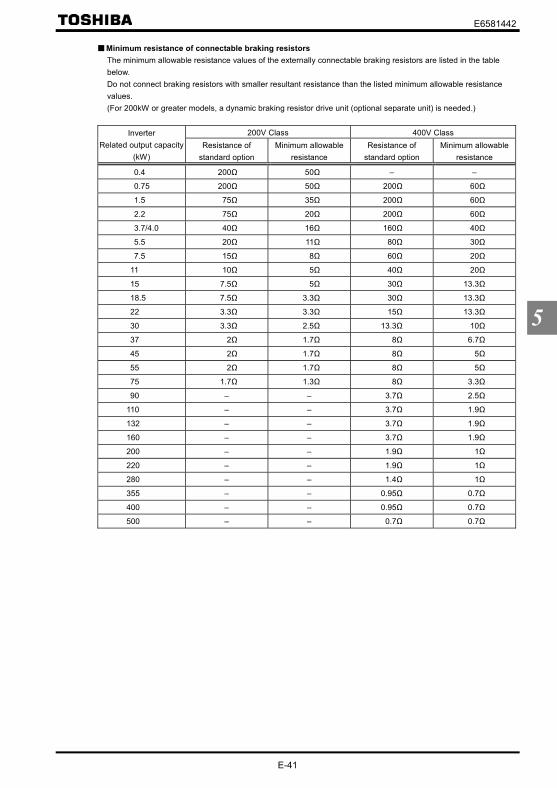
E6581442
E-41
5
Minimum resistance of connectable braking resistorsThe minimum allowable resistance values of the externally connectable braking resistors are listed in the tablebelow.Do not connect braking resistors with smaller resultant resistance than the listed minimum allowable resistancevalues.(For 200kW or greater models, a dynamic braking resistor drive unit (optional separate unit) is needed.)
200V Class 400V ClassInverterRelated output capacity
(kW)Resistance of
standard optionMinimum allowable
resistanceResistance of
standard optionMinimum allowable
resistance
0.4 200Ω 50Ω – –
0.75 200Ω 50Ω 200Ω 60Ω
1.5 75Ω 35Ω 200Ω 60Ω
2.2 75Ω 20Ω 200Ω 60Ω
3.7/4.0 40Ω 16Ω 160Ω 40Ω
5.5 20Ω 11Ω 80Ω 30Ω
7.5 15Ω 8Ω 60Ω 20Ω
11 10Ω 5Ω 40Ω 20Ω
15 7.5Ω 5Ω 30Ω 13.3Ω
18.5 7.5Ω 3.3Ω 30Ω 13.3Ω
22 3.3Ω 3.3Ω 15Ω 13.3Ω
30 3.3Ω 2.5Ω 13.3Ω 10Ω
37 2Ω 1.7Ω 8Ω 6.7Ω
45 2Ω 1.7Ω 8Ω 5Ω
55 2Ω 1.7Ω 8Ω 5Ω
75 1.7Ω 1.3Ω 8Ω 3.3Ω
90 – – 3.7Ω 2.5Ω
110 – – 3.7Ω 1.9Ω
132 – – 3.7Ω 1.9Ω
160 – – 3.7Ω 1.9Ω
200 – – 1.9Ω 1Ω
220 – – 1.9Ω 1Ω
280 – – 1.4Ω 1Ω
355 – – 0.95Ω 0.7Ω
400 – – 0.95Ω 0.7Ω
500 – – 0.7Ω 0.7Ω

E6581442
E-42
5
5.20 Standard default setting
: Factory default setting
Title Function Adjustment range Default setting
Factory defaultsetting
: –:50Hz default setting:60Hz default setting:Factory default setting:Trip clear:Cumulative operation time cleared:Initialization of type information:Save user-defined parameters:Reset of user-defined parameters:Cumulative fan operation time record clear
:Acceleration/deceleration time setting 0.01 sec.~600.0 sec.[Note 4]:Acceleration/deceleration time setting 0.1 sec.~6000 sec.
Note 1: This parameter is used to change the settings of other parameters. Therefore, is always displayed.Note 2: cannot be set during the inverter operating. Always stop the inverter first and then program.Note 3: When parameter is invoked, the value set previously is displayed on the left side of the parameter.Note 4: If is set to , the optional communication devices DEV002Z, PDP002Z and CCL001Z cannot be used
with the inverter. (The personal computer communications software PCM001Z cannot be used, either.)Furthermore, the copy function of the LED extended panel option (RKP002Z) does not work normally, so useonly the parameter setting function and the monitoring function.
Note 5: If the power is turned off while the parameter is being set, an error ( ) will occur when the poweris turned back on. If the error occurs, set again.
[Programmed value]
50Hz default setting ( = )Setting at causes all the following parameters to be set for operation using a base frequency of 50Hz.(This does not change the settings of any other parameters.)
• Maximum frequency : 50Hz • VI/II input point 2 frequency : 50Hz• Base frequency 1 : 50Hz • RR/S4 input point 2 frequency : 50Hz• Base frequency 2 : 50Hz • RX input point 2 frequency : 50Hz• Base frequency 3 : 50Hz • AI1 input point 2 frequency : 50Hz• Base frequency 4 : 50Hz • AI2 input point 2 frequency : 50Hz• Upper limit frequency : 50Hz • RP/high-speed pulse input point 2 frequency : 50Hz• Forward speed limit input level : 50Hz • PID deviation upper limit : 50Hz• Reverse speed limit input level : 50Hz • PID deviation lower limit : 50Hz• Commercial power/inverter switching frequency : 50Hz • Process upper limit : 50Hz• Point 2 frequency : 50Hz • PID output upper limit : 50Hz• Automatic light-load high-speed operation frequency : 50Hz • Motor rated rotational speed :1400~1480min-1 (According to model)
60Hz default setting ( = )Setting at causes all the following parameters to be set for operation using a base frequency of 60Hz.(This does not change the settings of any other parameters.)
• Maximum frequency : 60Hz • VI/II input point 2 frequency : 60Hz• Base frequency 1 : 60Hz • RR/S4 input point 2 frequency : 60Hz• Base frequency 2 : 60Hz • RX input point 2 frequency : 60Hz• Base frequency 3 : 60Hz • AI1 input point 2 frequency : 60Hz• Base frequency 4 : 60Hz • AI2 input point 2 frequency : 60Hz• Upper limit frequency : 60Hz • RP/high-speed pulse input point 2 frequency : 60Hz• Forward speed limit input level : 60Hz • PID deviation upper limit : 60Hz• Reverse speed limit input level : 60Hz • PID deviation lower limit : 60Hz• Commercial power/inverter switching frequency : 60Hz • Process upper limit : 60Hz• Point 2 frequency : 60Hz • PID output upper limit : 60Hz• Automatic light-load high-speed operation frequency : 60Hz • Motor rated rotational speed :1680~1775min-1 (According to model)
• FunctionThis parameter is to set two or more parameters at a time for different commands. Using this parameter, allparameters can be also return to their respective default settings by one operation, and save or set specificparameters individually.

E6581442
E-43
5
Default setting ( = )Setting parameter to resets all parameters except the following to their default settings.
When this parameter is set to 3, is displayed for a while, then switches back to the original display ( or ). Note that this setting also clears all trip history records. Trip history data will be cleared at this time.
Following parameters are designed considering maintenance that they cannot be reset to the factory default settingeven if you set the parameter at . Following parameters are not displayed on the user parameter group
even if their settings are different from their default settings. So please be careful.
Title Function Title FunctionHistory function Optional AI2 input biasFM terminal meter selection Optional AI2 input gainFM terminal meter adjustment Logic output/pulse train output selection (OUT1)AM terminal meter selection MON1 terminal meter selectionAM terminal meter adjustment MON1 terminal meter adjustmentAnalog VI/VII voltage/current switching MON2 terminal meter selectionAnalog AI2 (optional circuit board)voltage/current switching MON2 terminal meter adjustment
VI/II input bias FM voltage/current output switchingVI/II input gain MON1 voltage/current output switchingRR/S4 input bias MON2 voltage/current output switchingRR/S4 input gainRX input bias
~Quick registration parameter 1~32
RX input gain Free notesOptional AI1 input bias Network option reset settingOptional AI1 input gain
Trip clear ( = )Setting to initializes the past four sets of recorded trip history data.* (The parameter does not change.)
Cumulative operation time clear ( = )Setting to resets the cumulative operation time monitor to the initial value (0 [zero] time).
Initialization of type information ( = )When a trip occurs because of a type error ( is displayed), you can clear the trip by setting to . Thisfunction is used to reformat a control circuit board to adapt it to an inverter, for example, when a circuit board isremoved from an inverter to use another inverter for maintenance or for other reasons. This setting clears all typedata stored in the inverter.
Save user-defined parameters ( = )Setting to causes all the current parameter settings to be stored individually.
Reset of user-defined parameters ( = )Setting to returns all parameters to the settings saved by setting the parameter = .* The above settings and allows you to have your own default parameter settings.
Cumulative fan operation time clear ( = )Setting to resets the cumulative fan operation time to the initial value (0 [zero] time). Set this parameterwhen replacing the cooling fan, and so on.
Acceleration/deceleration time setting: 0.01 to 600.0 sec. ( = )When is set to , the acceleration/deceleration time can be set within a range of 0.01 to 600.0 sec.
Acceleration/deceleration time setting: 0.1 to 6000 sec. ( = )When is set to , the acceleration/deceleration time can be set within a range of 0.1 to 6000 sec.

E6581442
E-44
5
5.21 Searching for all reset parameters and changing their settings
: Automatic edit function
Note 1: If you reset a parameter to its factory default, the parameter will no longer appear in .
Note 2: It may take several seconds to display changed parameters because all data stored in the user parameter
group is checked against the factory default settings. To cancel the parameter group search in process,
press the key.
Note 3: Parameters which cannot be reset to the default setting after setting to are not displayed.
⇒ Refer to Section 5.20 for details.
How to search and reprogram parametersThe operations of search and resetting of parameters are as follows.
Key operated LED display Operation
Displays the operation frequency (operation stopped).(When standard monitor display selection = [Outputfrequency])
The first basic parameter “History function ( )” is displayed.
Press or key to select .
Press the ENTER key to enable the user parameter automatic editfunction.
or
Searches for parameters that are different in value from the standarddefault setting and displays those parameters. Press the ENTER keyor the key to change the parameter displayed. ( Press the keyto search for parameters in reverse direction.)
Press the ENTER key to display the set value.
Press the key and key to change set value.
⇔Press the ENTER key to save the changed value. The parametername and the programmed value will flash on and off alternately.
( )( )
Use the same steps as those given above to display parameters thatyou want to search for or change setting with the key and key.
( ) When appears again, the search is ended.
Parameter display↓
↓
A search can be canceled by pressing the MODE key. Press the keyonce while the search is underway to return to the display ofparameter setting mode.After that you can press the MODE key to return to the status monitormode or the standard monitor mode (display of operation frequency).
MODE
• FunctionAutomatically searches for only those parameters that are programmed with values different from thestandard default setting and displays them in the user parameter group . Parameter setting can also bechanged within this group.
MODE
ENT
ENT
ENT
ENT
MODE
MODE
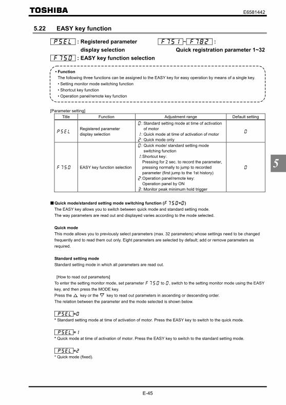
E6581442
E-45
5
5.22 EASY key function
: Registered parameterdisplay selection
: EASY key function selection
~ :Quick registration parameter 1~32
[Parameter setting]Title Function Adjustment range Default setting
Registered parameterdisplay selection
: Standard setting mode at time of activationof motor
: Quick mode at time of activation of motor: Quick mode only
EASY key function selection
: Quick mode/ standard setting modeswitching function
:Shortcut key:Pressing for 2 sec. to record the parameter,pressing normally to jump to recordedparameter (first jump to the 1st history):Operation panel/remote key:Operation panel by ON: Monitor peak minimum hold trigger
Quick mode/standard setting mode switching function ( = )The EASY key allows you to switch between quick mode and standard setting mode.The way parameters are read out and displayed varies according to the mode selected.
Quick modeThis mode allows you to previously select parameters (max. 32 parameters) whose settings need to be changedfrequently and to read them out only. Eight parameters are selected by default; add or remove parameters asrequired.
Standard setting modeStandard setting mode in which all parameters are read out.
[How to read out parameters]To enter the setting monitor mode, set parameter to , switch to the setting monitor mode using the EASYkey, and then press the MODE key.Press the key or the key to read out parameters in ascending or descending order.The relation between the parameter and the mode selected is shown below.
=* Standard setting mode at time of activation of motor. Press the EASY key to switch to the quick mode.
=* Quick mode at time of activation of motor. Press the EASY key to switch to the standard setting mode.
=* Quick mode (fixed).
• FunctionThe following three functions can be assigned to the EASY key for easy operation by means of a single key.• Setting monitor mode switching function• Shortcut key function• Operation panel/remote key function

E6581442
E-46
5
[How to select parameters]Select the desired parameters as parameters 1 to 32 ( ~ ). Note that parameters should be specifiedby communication number. For communication numbers, refer to Table of parameters.In the quick mode, only parameters registered as parameters 1 to 32 are displayed in order of registration.By default, parameters are set as shown in the table below.
[Parameter setting]Title Function Adjustment range Default setting
Quick registration parameter 1 ~ ( )Quick registration parameter 2 ~ ( )Quick registration parameter 3 ~ ( )Quick registration parameter 4 ~ ( )Quick registration parameter 5 ~ ( )Quick registration parameter 6 ~ ( )Quick registration parameter 7 ~ ( )
~Quick registration parameter 8~Quick registration parameter 31
~
Quick registration parameter 32 ~ ( )
Note: If any number other than communication numbers is specified, it isregarded as (no function assigned).
Continuous : Disabled
Shortcut key function ( = )This function allows you to register, in a shortcut list, parameters whose settings need to be changed frequently sothat you can read them out easily in a single operation.The shortcut is usable in the frequency monitor mode only.
[Operation]Set the parameter to , read out the setting of the parameter you want to register, and press and hold downthe EASY key for 2 sec. or more. The registration of the parameter in a shortcut list has been completed.To read out the parameter, just press the EASY key.
Operation panel/remote key function ( = )This function allows you to easily switch control devices (operation panel and terminal board) used to start and stopoperation and to set the frequency.To switch between control device, set the parameter to , and then select the desired control device, usingthe EASY key.
[When using the terminal board]If = , no switching operation is required.
[When using the operation panel]Turn on the EASY key.
Peak hold function ( = )This function allows you to set peak hold and minimum hold triggers for parameters , , ,
and , using the EASY key. The measurement of the minimum and maximum values set for ,, , and starts the instant when you press the EASY key after setting parameter to .
The peak hold and minimum hold values are displayed in absolute values.

E6581442
F-1
6
6. Extended parametersExtended parameters are provided for sophisticated operation, fine adjustment and other special purposes.⇒ Refer to Section 11, Table of parameters.
6.1 Input/output parameters
6.1.1 Low-speed signal : Low-speed signal output frequency
[Parameter setting]Title Function Adjustment range Default setting
Low-speed signal output frequency ~ Hz
Output frequency [Hz]
Time [s]Low-speed signal outputP24-OUT1 terminals (Default setting)P24-OUT2 terminalsFLA-FLB-FLC terminals
ONOFF
Low-speed signal output: Inverted ONOFF
0
Set frequency
[Connection diagram (Sink logic)]
P24
OUT1 (or OUT2)
NO
CC
Ry
• FunctionWhen the output frequency exceeds the setting of an ON signal will be generated. This signal can beused as an electromagnetic brake excitation/release signal.
Through the open collector terminal OUT1 or OUT2 (24Vdc-50mA [max.]).
• Output terminal settingThe low-speed signal (ON signal) output function has been assigned to the terminal OUT1 by default. Thissetting must be changed to invert the polarity of the signal.[Parameter setting]
Title Function Adjustment range Example of settingOutput terminal function selection1(OUT1) ~
(ON signal) or(OFF signal)
Note:To put out signals to OUT2, select the parameter .

E6581442
F-2
6
6.1.2 Putting out signals of arbitrary frequencies : Speed reach setting frequency : Speed reach detection band
• FunctionWhen the output frequency becomes equal to the frequency set by ± , an ON or OFF isgenerated.
[Parameter setting of frequency and detection band]Title Function Adjustment range Default setting
Speed reach setting frequency ~ HzSpeed reach detection band ~ Hz
[Parameter setting of output terminal selection]Title Function Adjustment range Example of setting
Output terminal function selection 2(OUT2) ~
(RCH (specified speed ON signal) )or
(RCH (specified speed OFF signal) )Note:To put out signals to OUT1, select the parameter .
1) If the detection band value + the set frequency is less than the designatedfrequency
Output frequency [Hz]
Speed reach setting frequency : Inverse
Time [s]
–
ONOFF
+
ONOFF
0
( )
Speed reach setting frequencyP24-OUT1 terminalsP24-OUT2 terminals (Default setting)FLA-FLB-FLC terminals
2) If the detection band value + the set frequency is more than the designatedfrequency
Output frequency [Hz]
Time [s]
–
ONOFF
+
Speed reach setting frequency : Inverse ONOFF
0
( )
Speed reach setting frequencyP24-OUT1 terminalsP24-OUT2 terminals (Default setting)FLA-FLB-FLC terminals

E6581442
F-3
6
6.2 Input signal selection
6.2.1 Priority when forward/reverse run commands are entered simultaneously : Priority when forward/reverse run commands are entered
simultaneously
• FunctionThis parameter allows you to select the direction in which the motor runs when a forward run (F) commandand a reverse run (R) command are entered simultaneously.
1)Reverse run2)Deceleration stop
[Parameter setting]Title Function Adjustment range Default setting
Priority when forward/reverse runcommands are enteredsimultaneously
:Reverse run, :Stop
Output frequency [Hz]
Forward run
Reverse run
Forward run signal
Reverse run signal
ONOFFONOFF
If a F command and a R command are entered simultaneously,the motor will run in the reverse direction.
0
Set frequency
Set frequency
Time [s]
[ = (Reverse run)]
Forward run signal
Reverse run signal
Output frequency [Hz]
Set frequency Forward run
Reverse run
ONOFFONOFF
If a F command and a R command are entered simultaneouslythe motor will slow down to a stop.
Time [s] 0
[ = (Stop)]

E6581442
F-4
6
• FunctionThis parameter is used to give priority to certain external commands entered from the terminal board inoperation panel and operation mode.For example, when jogging the motor by giving signals externally.
6.2.2 Assigning priority to the terminal board in the operation panel and operation mode : Input terminal priority selection
[Parameter setting]Title Function Adjustment range Default setting
Input terminal priority selection :Disabled, :Enabled
[ : Deselect (terminal board has no priority)]Priority is always given to commands (operation commands) entered from the operation panel. To give priority tocommands from the terminal board, it is necessary to switch from control panel operation to terminal boardoperation by sending signals through the terminal board.
Command from the operation panel( = )
Command from the terminal board
Valid command
The mode switching terminalsare used to switch to terminalboard operation mode.⇒ Refer to Section 7.2.
[ : Select (terminal board has priority)]Priority is given to commands entered from the terminal board even in operation panel operation mode.
Command from the operation panel( = )
Command from the terminal board
Internal commandA
B
A: No command from the terminal board.B: Command from the terminal board.
Priority command from terminal board (Operation command)Jog run : input terminal selection /DC braking : input terminal selection /
An example of switching to jog run in operation panel operation mode.
[In case that terminals S3 and CC are assigned to jog run]Assign control terminal S3 ([ : preset speed 3] in default setting) as the jog run setting terminal.
Title Function Adjustment range Example of settingInput terminal functionselection 7 (S3) ~ (Jog run settin g terminal)

E6581442
F-5
6
• FunctionThese parameters are used to switch signals to be sent to the analog input terminals VI/II and AI2 (optional).
S3-CC(Jog run)
Output frequency [Hz]
Forward run
Forward run
0
Set frequency
Panel key RUN STOP RUN STOP RUN STOP
6.2.3 Analog input signal switching : Analog input VI/VII voltage/current switching : Analog input AI2 (optional circuit board) voltage/current switching
[Parameter setting]Title Function Adjustment range Example of setting
Analog VI/VII voltage/current switching: Voltage input: Current input
Analog input AI2 (optional circuit board)voltage/current switching
: Voltage input: Current input
When using the analog input terminal VI/IIas a voltage input terminal (VI)
=
When using the analog input terminal VI/IIas a voltage input terminal (II)
=
CCA VI/II
0~10V input
CCA VI/II
0~20mA(4~20mA) input
CCA: Analog common
⇒ For an explanation of input gain and bias adjustments, refer to Section 6.28.

E6581442
F-6
6
6.3 Terminal function selection
6.3.1 Keeping an input terminal function always active (ON) , , : Always ON function selection 1~3
• FunctionThis parameter specifies an input terminal function that is always kept active (ON). (Only one functionselectable)
[Parameter setting]Title Function Adjustment range Default setting
Always ON function selection 1 ~Always ON function selection 2 ~Always ON function selection 3 ~
* The selected function is always kept active regardless of the type of logic (positive or negative) in the table offunction settings in 7.2.1.
6.3.2 Modifying input terminal functions : Input terminal function selection 1 (F) : Input terminal function selection 2 (R) : Input terminal function selection 4 (RES) : Input terminal function selection 5 (S1) : Input terminal function selection 6 (S2)
: Input terminal function selection 7 (S3) : Input terminal function selection 8 (RR/S4)~ :
Input terminal function selection 9~16~ :
Input terminal function selection 17~20⇒ For details, refer to Section 7.2.1.
• FunctionUse the above parameters to send signals from an external programmable controller to various control inputterminals to operate and/or set the inverter.The desired contact input terminal functions can be selected from 120 types ( - ). This gives systemdesign flexibility.Using the SW3 switch, the function of the RR/S4 terminal can be selected between analog input and contactinput. By default, the RR/S4 terminal is set as an analog input terminal (voltage input terminal). To use it as acontact input terminal, therefore, you need to turn the SW3 switch to the S4 position.
Setting of contact input terminal functionTerminalsymbol Title Function Adjustment range
Defaultsetting
– Always ON function selection 1 (ST)– , Always ON function selection 2, 3F Input terminal function selection 1 (F) (F)R Input terminal function selection 2 (R) (R)
RES Input terminal function selection 4 (RES) (RES)S1 Input terminal function selection 5 (S1) (S1)S2 Input terminal function selection 6 (S2) (S2)S3 Input terminal function selection 7 (S3)
~(⇒ Refer toSection 11.)
(S3)The terminal below is operative only when SW3 is in the S4 position. – –RR/S4 Input terminal function selection 7 (S4) ~ [Note 2] (S4)
Note 1: The function that has been selected using , and (always ON function selection 1~3parameter) are always activated.
Note 2: When using the RR/R4 terminal as a contact input terminal (sink logic), always turn the SW3 slide switch tothe S4 position.

E6581442
F-7
6
Connection method1) a-contact input
CC
Inputterminal This function is activated when the input terminal and CC
(common) are short-circuited. Use this function tospecify forward/reverse run or a preset speed operation.
Inverter a-contact switch Sink setting
2) Connection with transistor output
Operation can be controlled by connecting the input and CC(common) terminals to the output (no-contacts switch) of theprogrammable controller. Use this function to specifyforward/reverse run or a preset speed operation. Use atransistor that operates at 24Vdc/5mA.
CC
Inputterminal
Inverter Programmable controller
* Interface between programmable controller and inverter
Note: When using a programmable controller with open collector outputs for control, connect it to the P24/PLCterminal, as shown in the figure below, to prevent the inverter from malfunctioning because of currentflowing in.Also, be sure to turn the SW1 slide switch to the PLC position.
Programmable controller
PLC
+24Vpowersupply
PLC
SW1+24V
F~S4
CC
P24/PLC
Inverter
3) Sink logic/source logic inputSink logic/source logic (input/output terminal logic) switching is possible.⇒ For details, refer to Section 2.3.2.

E6581442
F-8
6
6.3.3 Using the servo lock function : Input terminal function selection 4 (RES) : Starting frequency setting
[Parameter setting]Title Function Adjustment range Example of setting
Input terminal function selection 4 (RES) ~Starting frequency setting ~ Hz
Note 1: This function is enabled only when parameter is set to (PG feedback vector control).Note 2: To activate servo lock, parameter (starting frequency setting) needs to be set to [Hz].Note 3: These parameters are not intended for position control, and if a load larger than the holding power of the
motor is applied, the motor rotates. Keep this in mind.
If parameter (for selecting a function for the RES terminal) is set to , a servo lock signal is added to theRES signal. In that case, turning on the signal to the RES terminal activates the servo lock function. Note that evenwhen the servo lock function is activated, or the operations can be performed normally by inputting an F or R signal.
Output frequency [Hz]
Servo lock signal+RES signal
F signal
0 Time [s] Coasting
R signal
Servo lock status
Even if the motor is started with servo lock activated, a starting torque of 150% or more can be produced.In such a case, however, the thermal protection level is lowered just as is the case with low-speed operation.Therefore, the following parameters• (Thermal protection characteristic selection)• (Motor electronic-thermal protection level 1), , , • (OL reduction starting frequency)• (Motor 150%-overload time limit)need to be adjusted according to the motor.
6.3.4 Modifying output terminal functions : Output terminal function selection 1 (OUT1) : Output terminal function selection 2 (OUT2) : Output terminal function selection 3 (FL)~ : Output terminal function selection 4~9~ : Output terminal function selection 10, 11
⇒ For details, refer to Section 7.2.2.
• FunctionAs with the operation of a server motor, these parameters allow you to operate the motor at 0Hz by simplyissuing an operation signal. These parameters are used to hold the motor at a standstill.

E6581442
F-9
6
6.3.5 Response time of input/output terminals : Input terminal 1 response time selection : Input terminal 2 response time selection : Input terminal 4 response time selection : Input terminal 5~12 response time selection : Input terminal 13~20 response time selection
⇒ For details, refer to Section 7.2.3.The output terminal and the response time can be set with “My function.”⇒ For details, refer to Section 6.39.
6.4 Basic parameters 2
6.4.1 Switching among V/f characteristics 1, 2, 3 and 4 from input terminal : Base frequency 2 : Base frequency voltage 2 : Manual torque boost 2 : Thermal protection level 2 : Base frequency 3 : Base frequency voltage 3
: Manual torque boost 3 : Thermal protection level 3 : Base frequency 4 : Base frequency voltage 4 : Manual torque boost 4 : Thermal protection level 4
• FunctionUse the above parameters to switch the operation of 4 motors with a single inverter and to select motor V/fcharacteristics (1 to 4) according to the particular needs or operation mode.[Switching methods]
Terminals are used for this switching.Note:The setting of parameter (V/f control mode selection) is valid only when V/f1 is selected. If
V/f2,V/f3 or V/f4 is selected, V/f control is performed in constant torque mode. Do not switch motorswhen the parameter (V/f control mode selection) is set at , . For parameters selected whenchanging V/f characteristics (1 to 4), refer to table on the next page.
Note: Refer to Section 5. 8 (Base frequency 1) for , and ,Section 5. 8 (Base frequency voltage 1) for , and ,Section 5.7 (Manual torque boost) for , and ,and Section 5.14 (Motor electronic thermal protection level 1) for , and ,respectively.

E6581442
F-10
6
Setting of switching terminalsThe V/f1, V/f2, V/f3 and V/f4 switching function is not yet assigned to any terminal. Therefore, it is necessary toassign them to unused terminals.
Ex.) Assigning the V/f switching 1 function to S1 and the V/f switching 2 function to S2.Title Function Adjustment range Example of setting
Input terminal function selection 5 (S1) ~ (V/f switching 1)Input terminal function selection 6 (S2) ~ (V/f switching 2)
S1: V/f switching 1
S2: V/f switching 2
CC
M
S1-CC S2-CC V/f Parameters selected
OFF OFF 1
Base frequency 1 : Base frequency voltage 1 : Manual torque boost 1 : Thermal protection 1 :
ON OFF 2
Base frequency 2 : Base frequency voltage 2 : Manual torque boost 2 : Thermal protection 2 :
OFF ON 3
Base frequency 3 : Base frequency voltage 3 : Manual torque boost 3 : Thermal protection 3 :
ON ON 4
Base frequency 4 : Base frequency voltage 4 : Manual torque boost 4 : Thermal protection 4 :
Select V/f1 when using the vector control and the V/f-5 point setting.Selecting V/f2,.V/f3, or V/f4 disables vector control but enables the V/f constant control. By using “My function,” torque limits and acceleration/deceleration modes can be switched along with V/fswitching.
Note:With the operation panel or communication, the panel acceleration/deceleration selection ( ) can be set.* This function is active only in operation panel operation mode.

E6581442
F-11
6
6.5 V/f 5-point setting
: V/f 5-point setting VF1 frequency : V/f 5-point setting VF1 voltage : V/f 5-point setting VF2 frequency : V/f 5-point setting VF2 voltage : V/f 5-point setting VF3 frequency : V/f 5-point setting VF3 voltage
: V/f 5-point setting VF4 frequency : V/f 5-point setting VF4 voltage : V/f 5-point setting VF5 frequency : V/f 5-point setting VF5 voltage
⇒ For details, refer to Section 5.6,5).
6.6 Speed command switching
6.6.1 Using two types of frequency (speed) commands : Frequency setting mode selection 1 : Frequency priority selection : Frequency setting mode selection 2 : Speed command priority switching frequency
• FunctionThese parameters switch two types of frequencies• Automatic switching by parameter setting• Automatic switching by means of switching frequencies• Switching with input terminal
1) Switching with input terminal board ( = )Reference can be switched if the frequency priority switching function is assigned to a terminal.
Command selectedwith
Command selectedwith
Operation frequency
command
A
B
A : Selects the command set with parameter . – Operation frequency command switching terminal OFFB : Selects the command set with parameter . – Operation frequency command switching terminal ON
Ex.) When the frequency priority switching function is assigned to terminal S3.Title Function Adjustment range Example of setting
Input terminal function selection 7 (S3) ~(Operation frequency command
switching)
Speed command
OFFCommand selected with
ONCommand selected with
S3
CC

E6581442
F-12
6
2) Automatic switching by means of switching frequencies ( = )
A
B
Command selectedwith
Command selectedwith
Operation frequency
command
A: If the frequency set with is higher than that set with ・・・・・・・・・・・・・・ Priority is given to thecommand set with .
B: If the frequency set with is equal to or lower than that set with ・・・・・ Priority is given to thecommand set with .
Priority is given tothe command setwith .
Priority is given tothe command setwith .
Frequency setting signal
[ Parameter setting]Title Function Adjustment range Default setting
Frequency setting mode selection 1
:VI/II (voltage/current input):RR/S4 (potentiometer/voltage input):RX (voltage input):Operation panel input enabled(including LED/LCD option input):2-wire RS485 communication input:4-wire RS485 communication input:Communications option input:Optional AI1 (differential current input):Optional AI2 (voltage/current input)
:Up/Down frequency:Optional RP pulse input:Optional high-speed pulse input:Optional binary/BCD input
Frequency priority selection
: / terminal switching(input terminal function selection ,
): / frequency switching(switching with )
Frequency setting mode selection 2 Same as ( ~ )Speed command priority switchingfrequency
~ Hz

E6581442
F-13
6
6.7 Operation frequency
6.7.1 Start frequency/Stop frequency : Start frequency setting : Stop frequency setting
• FunctionThe frequency set with the parameter is put out as soon as operation is started.Use the parameter when a delay in response of starting torque according to theacceleration/deceleration time is probably affecting operation. Setting the starting frequency to a value from0.5 to 2.0Hz (max. 5Hz) is recommended. The occurrence of an overcurrent can be suppressed by settingthis frequency below the rated slippage of the motor. If 0 speed torque is needed ( = , ), set ,
at 0.0Hz.• At start up : frequency set with is put out immediately.• At stop : The output frequency drops to 0Hz immediately by the frequency set with .
[Parameter setting]Title Function Adjustment range Default setting
Starting frequency setting ~ HzStop frequency setting ~ Hz
Start frequency setting
Stop frequency setting
Output frequency [Hz]
Time [s]0
Note: Set these parameters so that the start frequency is higher than the stop frequency .If the -set frequency is lower than the -set frequency, the reference frequency must behigher than the -set frequency to start the motor.If both and are set to Hz, the motor will start even if the frequency set is 0.0Hz.
6.7.2 Run/Stop control with frequency setting signals : Operation start frequency : Operation start frequency hysteresis
• FunctionThe Run/Stop of operation can be controlled simply with frequency setting signals.
[Parameter setting]Title Function Adjustment range Default setting
Operation starting frequency ~Operation starting frequency hysteresis ~ Hz

E6581442
F-14
6
0
+
–
The inverter begins accelerating afterthe frequency command value hasreached point B.Deceleration stop begins when thefrequency command value decreasesbelow point A.
Output frequency [Hz]
A B 100% Operation frequency command value
6.7.3. Frequency setting signal 0Hz dead zone handling function : Frequency command dead band
• FunctionIf the frequency is set to 0Hz by means of an analog signal so that the motor shaft can be locked by sensorvector control ( = , ) the frequency may not always be 0Hz because of drift or offset.In such a case, this parameter allows you to correctly set the operation frequency command to 0Hz. If theoperation frequency command is below the frequency setting signal 0Hz insensitive frequency set with
, parameter will adjust the operation frequency command to 0Hz.
[Parameter setting]Title Function Adjustment range Default setting
Frequency command dead band ~ Hz
Operation frequencycommand valueOutput after handlingof the dead zone
0HzOperation frequencycommand value
Note 1: This function is invalid to presetthe speed operation frequencycommand.
Note 2: It is effective as frequencyinstruction is to the frequencyreference chosen by ,
, communication,etc.Note 3: The addition and multiplication of
the override function is carried outto the frequency in which thisfunction operated.
6.8 DC braking
6.8.1 DC braking : DC braking start frequency : DC braking current
: DC braking time : Forward/reverse DC braking
priority control
• FunctionA large braking torque can be obtained by applying a direct current to the motor. These parameters set thedirect current applied to the motor, the application time and the start frequency.
[Parameter setting]Title Function Adjustment range Default setting
DC braking start frequency ~ HzDC braking current ~ %DC braking time ~ sec.Forward/reverse DC braking priority control :Disabled, :Enabled

E6581442
F-15
6
ONOFF
Time [s]
DC braking start frequency
DC braking current
DC braking time
Output frequency [Hz]
DC braking
Operation signal (F-CC)
Output current [A]
0
0
Set frequency
Note:During DC braking, the DC brakingcurrent may be adjustedautomatically to prevent the overloadprotection function from beingactivated and causing the inverter totrip.The DC braking current may beadjusted automatically to preventtripping.When the inverter is used with astandard motor, setting thepercentage of DC braking ( )above 60% may activate the thermalprotection function to prevent themotor from being overloaded,depending on the setting of (DC braking time).
LED display displayed
<DC braking start conditions>The forward/reverse DC braking priority control function recognizes certain conditions such as stopcommands from the inverter, and is activated when the output frequency goes down below the DC braking startfrequency set with . In this case, the conditions under which DC braking starts include not only the issue of astart or stop command from the operation panel or an external input device, but also a fall in the reference frequencybelow the value set with (stop frequency setting) or a fall in the output frequency below the operation stopfrequency setting .
[DC braking under normal conditions] (Forward/reverse run DC braking priority control = [Disabled])
ON
OFF
Time [s]
: DC braking
Output frequency [Hz]
Operation signal (F-CC)
Reference frequency
0
0
Set frequency
~~~~~~ ~~
~~ ~~
(1) (2) (3)(2)
(1) If and > reference frequency : DC braking(2) If > reference frequency > : Operation at the command frequency
If and > reference frequency : DC braking(3) If an operation command is entered during DC braking : DC braking is discontinued to restart the operation.

E6581442
F-16
6
[Priority to DC braking during forward/reverse operation] (Forward/reverse run DC braking priority control= [Enabled])
Time [s]
Output frequency [Hz]
Forward run signal (F-CC)
ONOFF
Reference frequency
0
0
Set frequency
~~~~
~~~~
: DC braking
(4) (5) (6)
Reverse run signal (R-CC)
ONOFF
= =
(7)
(4) During normal forward/reverse run ( = ) : Not recognized as a stop command, so that the DCbraking is not active.
(5) If a reverse run (or forward) command is entered during forward run (or reverse) ( = ) :DC braking when the frequency set with decreases below the reference frequency duringdeceleration.
(6) If an operation command is entered during DC braking : RUN command has a priority.(7) If an operation command is changed from ON to OFF during DC braking, DC braking is discontinued to stop the
operation.
6.8.2 Motor shaft fixing control : Motor shaft fixing control
• FunctionThis function is used to prevent the motor from running unexpectedly after the motor is stopped becauseit’s shaft is not restrained or to preheat the motor.
[Parameter setting]Title Function Adjustment range Default setting
Motor shaft fixing control :Disabled, :Enabled
If the motor shaft fixing control parameter is set at , DC braking continue at half a braking rate of that set with to retain the motor after it has come to a full stop by DC braking. To discontinue motor shaft axis fixing control,
cancel the assignment of the input terminal function “ST standby command (6)” to an input terminal. Note, however,that this function doesn't operate after a DC braking command is entered by control input terminal signal.
When assigning the ST function to the S3 terminal.Title Function Adjustment range Default setting
Always ON function selection 1 ~Input terminal function selection 7 (S3) ~

E6581442
F-17
6
Time [s]
DC braking start frequency
Output frequency [Hz]LED display
Operation signal (F-CC)ONOFF
Output current [A]0
0
Set frequency
Operation standby signal (S3-CC) ONOFF
2
is displayed.
is displayed.
Note 1: If the motor shaft fixing control parameter is set at (enabled) when the output frequency is belowthe DC braking start frequency and terminals S3-CC are closed (ON), the DC braking function isactivated and the motor shaft fixing control continues regardless of the setting of the DC braking timeparameter .
Note 2: If a power failure occurs during motor shaft fixing control and the motor starts to a coast, motor shaft fixingcontrol will be canceled. Also, if the inverter trips during motor shaft fixing control and is restored to workingorder by the retry function, motor shaft fixing control will be canceled.
6.8.3 Function of issuing a 0Hz command during a halt : 0Hz command output selection
• FunctionThis function controls the motor in the zero-speed state at the time of stop. If this function is set up, the0Hz command will be put out instead of DC braking at the time of a stop,and a motor will be controlled inthe setting time stop state. The monitor display serves as during this control operation. This functionoperates only at the time of vector control with a sensor ( = , ).Refer to DC braking (Section 6.8.1) for conditions of operation. The position of DC braking is served as anoperation which sets the operation frequency command to 0Hz.
[Parameter setting]Title Function Adjustment range Default setting
0Hz command output selection: Standard (DC braking): 0Hz command
DC braking starting frequency ~ HzDC braking time ~ sec.
Note 1: This function doesn't operate when = .Note 2: If this function is set up, motor shaft fixing control cannot be used.Note 3: This function doesn't operate at the time of a torque control.Note 4: This function doesn't operate except = , of the vector control mode with a sensor. In order to use this
function, the option board for PG feedback is required. Other than the vector control with a sensor = , ,the usual DC braking operates.
Note 5: Since the reference frequency that will suspend the motor abruptly from the state of high rotation if ( )is set up highly, please be careful. A trip may occur according to load conditions.
Note 6: This parameter has a function similar to the DC braking function, which is activated by a command from theterminal board or an external control device (input terminal function or , or command from externalcontrol device). To the DC braking function which will be activated if (jog run stop pattern) is set to (DC braking), and to the DC braking function which will be activated if (emergency stop pattern) is setto (DC braking), but it issues 0Hz commands instead of DC braking commands.

E6581442
F-18
6
6.9 Auto-stop in case of lower-limit frequency continuous operation
: Time limit for lower-limit frequency operation
• FunctionIf operation is carried out continuously at a frequency below the lower-limit frequency ( ) for the periodtime set , theinverter will automatically slow down the motor to a stop.“ ” is always displayed on the operation panel. (Blinking alternately)The auto-stop function will be disabled when the frequency command value reaches over the lower limitfrequency ( )+0.2Hz or the operation command is turned to off.
[Parameter setting]Title Function Adjustment range Default setting
Auto-stop in case of lower-limit frequencycontinuous operation
:None ~ sec.
Output frequency [Hz]
Time [s]
Operation signal (F-CC)ON
OFF
+0.2Hz
Note:This function is enabled even at the start of operation and during switching between forward and reverse run.

E6581442
F-19
6
6.10 Jog run mode
: Jog run frequency : Jog run stop pattern : Operation panel jog run mode
• FunctionUse the jog run parameters to operate the motor in jog mode. Input of a jog run signal generates a jog runfrequency output at once, irrespective of the designated acceleration time.Also, you can choose an operation panel start/stop mode between the ordinary start/stop mode and the jogrun start/stop mode.
The jog run function needs to be assigned to an input terminal.When assigning it to the S3 terminal, set to .The motor can be operated in jog run mode while the jog run setting terminals are connected (S3-CC: ON).
[Parameter setting]Title Function Adjustment range Default setting
Jog run frequency ~ Hz
Jog run stop pattern:Deceleration stop, : Coast stop,:DC braking stop
Operation panel jog run mode:Disabled,:Operation panel jog run mode enabled
<Examples of jog run>
S3-CC (JOG) ON + F-CC ON: Forward jog run
S3-CC (JOG) ON + R-CC ON: Reverse jog run
( Normal operation frequency signal input + F-CC ON: Forward run, Normal operation frequency signal input + R-CC ON: Reverse run )
F-CC
R-CC
S3-CC
Input of operationfrequency setting signal
Output frequency [Hz]
Forwardrun Reverse
run
Forwardrun
Forward run
0
Set frequency
Time [s]
• The jog run setting terminal (S3-CC) is enabled when the operation frequency is below the jog run frequency.This connection does not function at an operation frequency exceeding the jog run frequency.
• The motor can be operated in jog mode while the jog run setting terminals are connected (S3-CC: ON).• Jog run has priority, even when a new operation command is given during operation.• Even during panel operation ( = ), the inverter can be switched forcibly to jog run mode by turning on or
off the input terminal if parameter (input terminal priority selection) is set to and the jog run settingfunction ( , ) is assigned to the input terminal.
• Even for = or , an emergency DC braking becomes enabled when setting = .• If a forward run command and a reverse run command are entered simultaneously while (priority selection
(both F-CC and R-CC are ON)) is set to (reverse run), operation modes are switched as follows: forward jog run→ deceleration stop (jog frequency → 0Hz) → reverse jog run. Keep this in mind.
• The jog frequency is not restricted by the upper limit frequency ( ).

E6581442
F-20
6
[Setting of jog run setting terminal (S3-CC)]Assign control terminal S3 ([ : preset speed 3] in default setting) as the jog run setting terminal.
Title Function Adjustment range Example of settingInput terminal function selection 7 (S3) ~ (Jog run setting terminal)
Note:During the jog run mode, there is LOW (low speed detection signal) output but no RCH (designated frequencyreach signal) output, and PID control does not work.
•When the inverter is in panel jog mode, pressing the key displays , while pressing the key displays .
•When is displayed, the inverter will be placed in forward jog run mode as long as the key is held down.
•When is displayed, the inverter will be placed in reverse jog run mode as long as the key is held down.
•During jog run, the direction of rotation can be changed using the and keys. Press the key to run
the motor in the forward direction, or press the key to run it in the reverse direction.
•If you press and hold down the key for 20 seconds or more, the key failure alarm “ ” will be displayed.
The figure below shows the relationship between the operation panel jog run mode and each of the other modes.
Pressing the key, which will move the inverter through each of the modes.
Status monitor mode
Status monitor mode Status monitor mode
MODEMODE
Operation paneljog run mode
MODE MODE
Note1: When the inverter is in operation (RUN key lamp is lit) or when an operation command is issued (RUN key lampis lit), the inverter cannot be switched to operation panel jog run mode.
Note 2: When parameter (input terminal priority selection) is set to , the inverter does not display anymessage saying that it is in panel jog run mode.
6.11 Setting frequency via external contact input (Up/Down frequency setting)
: Input from external contacts - Up response time : Input from external contacts - Up frequency step : Input from external contacts - Down response time : Input from external contacts - Down frequency step : Initial Up/Down frequency : Initial Up/Down frequency rewriting
• FunctionThese parameters are used to set the output frequency by means of a contact signal from the externalcontrol device.
[Parameter setting]Title Function Adjustment range Default setting
Input from external contacts - Up response time ~ sInput from external contacts - Up frequency step ~ HzInput from external contacts - Down response time ~ sInput from external contacts - Down frequency step ~ HzInitial Up/Down frequency ~ Hz
Initial Up/Down frequency rewriting:Not changed:Setting of changedwhen power is turned off.
These functions are operative when parameter (frequency setting mode selection 1) is set to orparameter (frequency setting mode selection 2) is set to .
RUN
RUN
RUN
MODE

E6581442
F-21
6
Adjustment with continuous signals (Parameter setting example 1)Set parameters as follows to adjust the output frequency up or down in proportion to the frequency adjustment signalinput time:
Panel frequency incremental gradient = / setting timePanel frequency decremental gradient = / setting time
Set parameters as follows to adjust the output frequency up or down almost in synchronization with the adjustment bythe panel frequency command:
= = ( (or ) / ) ( / setting time)( (or ) / ) ( / setting time)
«Sample sequence diagram 1: Adjustment with continuous signals»
The dotted line represents the actual output frequency.Frequency 0 Hz
Lower limit frequency
Upper limit frequency
Decrementing (DOWN) signal
Incrementing (UP)
RUN command
Set frequency clearing signal
Command frequency [Hz]Gradient /
Gradient /
Adjustment with pulse signals (Parameter-setting example 2)Set parameters as follows to adjust the frequency in steps of one pulse:
, Pulse ON time, = Frequency obtained with each pulse
* The inverter does not respond to any pulses with an ON time shorter than set with or . 12msor more of clearing signal is allowed.
«Sample sequence diagram 2: Adjustment with pulse signals»
Operation command (such as F)
Incrementing (UP) signal
Decrementing (DOWN) signal
Clear signalUpper limit frequency
0Hz
Command frequency [Hz](The dotted line representsthe actual output frequency.)

E6581442
F-22
6
If two signals are input simultaneously• If a clear single and an up or down signal are input simultaneously, priority will be given to the clear signal.• If up and down signals are input simultaneously, the frequency will be increased or reduced by the difference between
the settings of and . For example, if the setting is larger, the frequency will be increased by thevalue obtained by subtracting the setting of from that of .
Setting of the initial Up/Down frequencyTo adjust the frequency start at a specified frequency other than 0.0 Hz (default initial frequency) after turning on theinverter, specify the desired frequency using (initial Up/Down frequency).
Change of the initial Up/Down frequencyTo make the inverter automatically save the frequency immediately before it is turned off and start operation at thatfrequency next time power is turned on, set (change of initial Up/Down frequency) to (which changes thesetting of when power is turned off).Keep in mind that the setting of is changed each time power is turned off.
Frequency adjustment rangeThe frequency can be set from 0.0 Hz to (Maximum frequency). The lower limit frequency will be set as soon as theset frequency clearing function (function number , ) is entered from the input terminal.
Minimum unit of frequency adjustmentIf (Frequency free unit magnification) is set to , the output frequency can be adjusted in steps of 0.01Hz.
6.12 Jump frequency - jumping resonant frequencies
: Jump frequency 1 : Jumping width 1 : Jump frequency 2 : Jumping width 2 : Jump frequency 3 : Jumping width 3
• FunctionResonance due to the natural frequency of the mechanical system can be avoided by jumping the resonantfrequency during operation. During jumping, hysteresis characteristics with respect to the jump frequencyare given to the motor.
Jumping width 3 ( )
Jumping width 2 ( )
Jumping width 1 ( )Jump frequency 1 ( )
Jump frequency 3 ( )
Jump frequency 2 ( )
Frequency setting signal0
Output frequency [Hz]

E6581442
F-23
6
[Parameter setting]Title Function Adjustment range Default setting
Jump frequency 1 ~ HzJumping width 1 ~ HzJump frequency 2 ~ HzJumping width 2 ~ HzJump frequency 3 ~ HzJumping width 3 ~ Hz
If the upper limit frequency ( ) is within jump frequency range,it is limited to the lowest frequency in the jump frequency range.
If the lower limit frequency ( ) is within jump frequency range,it is limited to the highest frequency in the jump frequency range.
Do not overlap upper limit frequency ( ) and lower limit frequency ( )within jump frequency range.If they are overlapped, it is operated lowest jump frequency.
Do not overlap two or more jump frequency ranges, orit cannot be operated within normal range.
During acceleration or deceleration,the jumping function is disabled for the operation frequency.
6.13 Preset speed operation frequencies
6.13.1 Preset speed operation frequency 8 to 15~ : Preset speed operation frequencies 8 to 15
⇒ For details, refer to Section 5.12.
6.13.2 Forced operation control : Preset speed operation frequency 15 (Forced operation frequency)
• FunctionForced operation control is used when operating the motor at the specified frequency in case of anemergency. If forced operation control is assigned to the terminal board selection parameter and a forcedoperation control signal is given, the motor will be operated at the frequency specified with (presetspeed operation frequency 15). (When the input terminal board selection parameter is set to or .)
Jumping width 2
Jumping width 1

E6581442
F-24
6
6.14 Trip-less intensification
6.14.1 Retry function : Retry selection (selecting the no. of times)
Warning
Mandatory
• Stand clear of motors and equipment.The motor and equipment stop when the alarm is given, selection of the retry function will restart themsuddenly after the specified time has elapsed. This could result in unexpected injury.
• Take measures for safety, e.g. attach a cover to the motor, to prevent accidents if the motor suddenlyrestarts.
• FunctionThis parameter resets the inverter automatically when the inverter gives a trip. During the retry mode, themotor speed search function operated automatically as required and thus allows smooth motor restarting.
[Parameter setting]Title Function Adjustment range Default setting
Retry selection (selecting the no. of times) : Deselect, ~ times
The likely causes of tripping and the corresponding retry processes are listed below.Cause of tripping Retry process Canceling conditions
Momentary power failureOvercurrentOvervoltageOverload
Up to 10 times in succession1st retry : About 1 sec after tripping2nd retry : About 2 sec after tripping3rd retry : About 3 sec after tripping
...10th retry : About 10 sec. after tripping
The retry function will be canceled at onceif tripping is caused by an unusual eventother than momentary power failure,overcurrent, overvoltage or overload.This function will also be canceled if a retryis not successful within the specifiednumber of times.
Trips covered by the retry function• , , : Overcurrent• , , : Overcurrent in DC section or
overheating of devices• , , : Overvoltage
• : Inverter overload• : Motor overload• : Braking resistor
overload
• : Overheat• : PM motor step-out
The retry function is disabled in the following unusual events:• , , : Arm overcurrent at start-up• : Input phase failure• : Output phase failure• : Loaded side overcurrent at start time• : External thermal error• : Low current• : Voltage drop in main circuit• : Overtorque• , : Ground fault• : Emergency stop
• , , : EEPROM error• : Main RAM error• : Main ROM error• : CPU trip• : Interruption of operation command from
external control device• : Gate array fault• : Output current detector error• : Optional unit error• ~• Others (Other than trips covered by the retry function)
Protective operation detection relay signals (FLA, FLB, FLC terminal signals) are not sent during use of the retryfunction. (factory default setting)A virtual cooling time is provided for overload tripping ( , , ).⇒ See Section 13.2 for the virtual cooling time.In this case, the retry function operates after the virtual cooling time and retry time.In the event of overvoltage tripping ( ~ ), re-tripping may result unless the DC voltage decreases below apredetermined level.In the event of overheating-caused tripping ( ), re-tripping may result unless the internal temperature decreasesbelow a predetermined level, since the internal temperature detection function of the inverter works.

E6581442
F-25
6
Even when trip retention selection parameter ( ) is set to , the retry function is enabled by setting.During retry the blinking display will alternate between and the monitor display specified by parametermonitor display selection parameter .The number of retries will be cleared if the inverter is not tripped for the specified period of time after a successful retry.“A successful retry” means that the inverter output frequency reaches the command frequency without causing theinverter to re-trip.At the occurrence of a trip, the rotational speed of the motor is measured and, after the motor is restarted, it’s speedis regulated to the speed measured.
6.14.2 Avoiding overvoltage tripping : Overvoltage limit operation : Regenerative over-excitation upper limit
: Overvoltage limitoperation level
• FunctionThese parameters are used to automatically control the output frequency and prevent the motor fromtripping because of overvoltage due to a rise in the voltage in the DC section during deceleration orconstant speed operation. Note that the deceleration time may be prolonged when the overvoltage limitingfunction is activated.
Overvoltage limit operation level
DCvoltage
Outputfrequency
: Overvoltage stall protection
[Parameter setting]Title Function Adjustment range Default setting
Overvoltage limit operation
:Enabled:Disabled:Enabled (quick deceleration):Enabled (dynamic quick deceleration)
Regenerative over-excitation upper limit ~ % [Note]Overvoltage limit operation level ~ % [Note]
Note: 100% corresponds to an input voltage of 200V for 200V models or to in an input voltage of 400V for 400Vmodels.
If is set to (quick deceleration), the inverter will increase the voltage to the motor (over-excitationcontrol) to increase the amount of energy consumed by the motor when the voltage reaches the overvoltageprotection level, and therefore the motor can be decelerated more quickly than normal deceleration.If is set to (dynamic quick deceleration), the inverter will increase the voltage to the motor (over-excitation control) to increase the amount of energy consumed by the motor as soon as the motor begins to slowdown, and therefore the motor can be decelerated still more quickly than quick deceleration.The parameter is used to adjust the maximum energy that the motor consumes during deceleration, and ifthe inverter is tripped during deceleration because of an overvoltage, specify a larger value.Parameter serves also as a parameter for setting the regenerative braking level (see section 5.19.).
6.14.3 Output voltage adjustment/Supply voltage correction : Base frequency voltage 1 (output voltage adjustment) : Base frequency voltage selection (supply voltage correction)
• Function Base frequency voltage 1 (output voltage adjustment)This parameter is used to set the voltage for the base frequency 1 . It can also be used to prevent thebase frequency over from being put out even if the voltage is higher than the voltage set is applied.(This parameter is operative when is or . ) Base frequency voltage selection (correction of supply voltage)The parameter maintains a constant V/f ratio, even when the input voltage decreases. The torqueduring low-speed operation is prevented from decreasing.
Supply voltage correction ・・・・・ Maintains a constant V/f ratio, even when the input voltage fluctuates.Output voltage adjustment ・・・・ Limits the voltage at frequencies exceeding the base frequency. Note that no limit
is imposed on the output voltage if the supply voltage is not compensated.

E6581442
F-26
6
[Parameter setting]Title Function Adjustment range Default setting
Base frequency voltage 1(output voltageadjustment)
V class: ~ VV class: ~ V
200V models:
400V models:
Base frequency voltageselection(correction of supplyvoltage)
:Without voltage compensation (limitless output voltage): With voltage compensation (limitless output voltage): Without voltage compensation (limited output voltage): With voltage compensation (limited output voltage)
If is set to or , the output voltage will change in proportion to the input voltage.Even if the base frequency voltage ( ) is set above the input voltage, the output voltage will not exceed theinput voltage.The rate of voltage to frequency can be adjusted according to the rated motor capacity. For example, setting
to prevents the output voltage from increasing, even if the input voltage changes when the operationfrequency exceeds the base frequency.When the V/f control mode selection parameter ( ) is set to any number between ~ or ~ , the supplyvoltage is corrected regardless of the setting of .
[ = : Supply voltage uncorrected, output voltageunlimited]
[ = : Supply voltage corrected, output voltageunlimited]
Inputvoltage
High
Low
Output frequency
Output
voltage
[V]
0
Input voltage
Inputvoltage
High
Low
Output voltage
[V]
Output frequency 0
* The above applies when V/f control mode selectionparameter is set to , or .
Rated voltage>1 the output voltage can be
prevented from exceedingthe input voltage.
* Note that a voltage higher than is applied atoutput frequencies over the base frequency , evenif is set below the input voltage.
[ = : Supply voltage uncorrected, output voltagelimited]
[ = : Supply voltage corrected, output voltagelimited]
Inputvoltage
High
Low
Output frequency
Output
voltage
[V]
0
Input voltage
Inputvoltage
HighLow
Output voltage
[V]
Output frequency 0
* The above applies when V/f control mode selectionparameter is set to , or .
Rated voltage>1 the output voltage can be
prevented from exceedingthe input voltage.
Note: Rated voltage is fixed for 200V class at 200V and 400V class at 400V.

E6581442
F-27
6
6.14.4 Reverse run prohibition : Reverse run prohibition selection
• FunctionThis function prevents the motor from running in the forward or reverse direction when it receives the wrongoperation signal.
[Parameter setting]Title Function Adjustment range Default setting
Reverse-run prohibition selection :Permit all, :Prohibit reverse run:Prohibit forward run
Warning!!• If an operation command is entered to rotate the motor in the direction prohibited for the preset speed
operation with the mode or forced jog operation, this parameter will cancel the command regardless ofoperation mode.
• If the motor constant is not set properly while vector control mode or automatic torque boost mode isselected, the motor may turn in the reverse direction. The number of revolutions that correspond to the slipfrequency, in these modes, therefore, the stop frequency ( ) should be set at the same level as theslip frequency. In sensor vector control mode ( = , ), depending on the setting of , the motorrestarted may rotate in the direction opposite to the prohibited direction regardless of the setting of thisparameter.
6.15 Drooping control
: Drooping gain : Speed at drooping gain 0% : Speed at drooping gain : Drooping insensitive torque : Drooping output filter
• FunctionWhen multiple inverters and motors are used to operate a system, the load can distribute to them using thisfunction. These parameters allow you to adjust the frequency range, and also insensitive torque and gain.
Frequency
Drooping gain
Drooping insensitive torque
Internal torquecommand
Drooping gain
–
–
–
Drooping insensitive frequency
Gain2Gain1
[Parameter setting]Title Function Adjustment range Default setting
Drooping gain [Note] ~ %Speed at drooping gain 0% ~ HzSpeed at drooping gain ~ HzDrooping insensitive torque ~ %Drooping output filter ~ rad/s
Note: Drooping gain can be changed within a range of 0.1 to 100.0% during operation. When changing the setting to0.0 (no drooping) or 0.0, stop operation.
• Drooping control can be performed only when is set to , , or .• When torque over the insensitive torque is applied, the frequency is decreased (during power running) or
increased (during regenerative braking).• The drooping function is operative at frequencies over the frequency set with .• In the frequency range between the frequencies set with and , the degree of drooping changes
according to the magnitude of frequency.

E6581442
F-28
6
• The error in drooping insensitive torque increases in the frequency range above the base frequency, and it istherefore recommended that these functions be used at frequencies below the base frequency.
• During drooping control, the output frequency is not restricted by the maximum frequency ( ).
The change in frequency at the time of drooping can be calculated, as described below:
a) Gain by internal torque reference (Gain1)If internal torque reference (%) ≧ 0Gain1 = (internal torque reference - dead band ) / 100
Gain1 needs to be set at 0 or a positive number.If internal torque reference (%) < 0Gain1 = (internal torque reference + dead band ) / 100
Gain1 needs to be set at 0 or a negative number.
b) Gain by frequency after acceleration (Gain2)If < | Frequency after acceleration | Frequency 1 set with
Gain2 = 0| Frequency after acceleration | > Frequency 2 set with
Gain2 = Drooping gain / 100
If frequency 1 < | Frequency after acceleration | Frequency 2
If ≧ | Frequency after acceleration | Frequency 1 set with
Gain2 = 0If | Frequency after acceleration | > Frequency 1
Gain2 = Drooping gain / 100
c) Drooping speedDrooping speed = base frequency Note × Gain1 × Gain2Note:If the base frequency exceeds 100 Hz, count it as 100 Hz.
6.16 Light-load high-speed operation function
: Light-load high-speed operationselection
: Light-load high-speed learningfunction
: Automatic light-load high-speedoperation frequency
: Light-load high-speed operationswitching lower limit frequency
: Light-load high-speed operationload waiting time
: Light-load high-speed operationload detection time
: Light-load high-speed operationheavy load detection time
: Switching load torque duringpower running
: Heavy-load torque during powerrunning
: Heavy-load torque duringconstant-speed power running
: Switching load torque duringregenerative braking
⇒ For details, refer to Instruction Manual (E6581327) specified in Section 6.42.
Gain2 = ×(| Frequency after acceleration | – Frequency 1 )
(Frequency 2 – Frequency 1 )
Drooping gain
100

E6581442
F-29
6
6. 17 Braking function
: Braking mode selection : Load portion torque input
selection : Hoisting torque bias input : Lowering torque bias multiplier
: Brake release time : Creeping frequency : Creeping time : Braking time learning function
• FunctionThese parameters can be used as brake sequences for lifts and similar equipment.To ensure smooth operation, the motor produces enough torque before the brake is released.
Title Function Adjustment range Default setting
Braking mode selection
:Disabled:Forward winding up:Reverse winding up:Horizontal operation
Load portion torque input selection
:Disabled:VI/II (voltage/current input):RR/S4 (potentiometer/voltage input):RX (voltage input): enabled:2-wire RS485 input enabled:4-wire RS485 input enabled:Communications option input enabled:Optional AI1 (differential current input)
Hoisting torque bias input (validonly when = ) - ~ %
Lowering torque bias multiplier ~ %Brake release time ~ sec.Creeping frequency ~ HzCreeping time ~ sec.
Braking time learning function:Disabled:Brake signal learning (0 after adjustment)
Starting procedureAt the run command, the inverter makes the motor produce the torque specified with parameter . As soon asa torque output command is issued, a brake release request signal is put out through the brake output terminal.Upon expiration of the brake release time set with , the motor starts to accelerate.

E6581442
F-30
6
Stopping procedureAt the stop command, the operation frequency is decreased to the creep frequency set with parameter andthe creep frequency is maintained for the creep time set with . While the creep frequency is maintained, thebrake release signal is put out through the braking signal output terminal to apply the brake.
Output frequency[Hz]
Torque
Braking signal
RUN command
Time [s]
Torque control Speed control
Braking request
Brake release request
Issue of torque command
Creepinjg frequency
Starting frequency
Braking operation
Ex.) When using the OUT1 terminal as the brake signal output terminalTitle Function Adjustment range Example of setting
Output terminal function selection 1 (OUT1) ~
Learning functionUsing this function, rough settings can be made automatically and also parameters , and can be set automatically.After the learning function is set, will be set automatically to and to . If necessary, fineadjust the parameter setting manually.
[Learning operation]Set parameter to and enter an operation command to start learning. (The frequency and “ ” aredisplayed alternately.)Parameter (torque) is set, the brake release timing is calculated, and parameter (release time) isset based on the calculation result. is set automatically according to the motor constant calculated. At thestop of operation, (creep time) are set.Note1: Learning should be performed under light-load conditions.Note2: For the braking functions, the pre-excitation time is automatically determined by the inverter from motor-
related constants.When the VFAS1-2037PL is used in combination with a Toshiba 4P-3.7kW-60Hz-200V standard motor, thepreliminary excitation time is approximately 0.1 to 0.2 seconds.Depending on the motor used, the preliminary excitation time may be prolonged.
Note3: When using braking functions, set parameter (automatic torque boost) to (voltage vector control +auto-tuning 1) or set motor-related parameters to .
Note 4: If a counterweight is provided, a learning error may occur. If so, make an adjustment manually.Note 5: Brake learning ( = ) should be carried out for normal rotation if is set to (forward winding),
or for reverse rotation if is set to (reverse winding).

E6581442
F-31
6
6.18 Acceleration/deceleration suspend function
: Acceleration/decelerationsuspend function
: Acceleration suspend frequency : Acceleration suspend time
: Deceleration suspend frequency : Deceleration suspend time
• FunctionUsing these parameters, acceleration or deceleration can be suspended to let the motor run at a constantspeed. There are two ways to suspend acceleration or deceleration: suspending it automatically by settingthe suspend frequency and time using parameters, and suspending it by means of a signal from anexternal control device.These parameters are useful in starting and stopping transfer equipment, textile machines (winders), andso on.
[Parameter setting]Title Function Adjustment range Setting value
Acceleration/deceleration suspend function:Disabled:Parameter setting:Terminal input
Acceleration suspend frequency ~ HzAcceleration suspend time ~ sec.Deceleration suspend frequency ~ HzDeceleration suspend time ~ sec.
Note1: The acceleration suspend frequency ( ) should not be set below the starting frequency ( ).Note2: The deceleration suspend frequency ( ) should not be set below the stop frequency ( ).Note3: If the output frequency is lowered by a stall prevention function, the acceleration suspend function may be
activated.
1) To suspend acceleration or deceleration automaticallySet the desired frequency with or and the desired time with or , and then set
to .When the frequency set is reached, the motor stops accelerating or decelerating to rotate at a constant speed.
Output frequency [Hz]
Time [s]
2) To suspend acceleration or deceleration by means of a signal from an external control deviceSet for the desired external signal input terminal. As long as ON signals are inputted, the motor continues torotate at a constant speed.
Output frequency [Hz]
Time [s]Terminal board input
Ex.) When using the RR/S4 terminal as the acceleration/deceleration suspend terminalTitle Function Adjustment range Example of setting
Input terminal function selection 8 (RR/S4) ~

E6581442
F-32
6
If the stall control function is activated during constant-speed rotationThe frequency drops momentarily as a result of stall control, but the time for which the frequency drops is included inthe suspend time.
Output frequency [Hz]
Time [s] Stall
t1 ts t2
(Momentary acceleration (deceleration) suspend time) = (t1 + t2 + ts)
Stall controlRefers to the inverter’s function of automatically changing the operation frequency when it detects anovercurrent, overload or overvoltage. Using the following parameters, you can specify the way, the stallcontrol is performed for each kind of stall.Overcurrent stall : (Stall prevention level 1)Overload stall : (Electronic thermal protection characteristic selection)Overvoltage stall : (Overvoltage limit operation)
Note: Setting the frequency command at the same frequency as the acceleration suspend frequency ( )disables the acceleration suspend function.Similarly, setting the frequency command at the same frequency as the deceleration suspend frequency( ) disables the deceleration suspend function.
6.19 Commercial power/inverter switching
: Commercial power/inverter switching output selection : Commercial power/inverter switching frequency : Inverter-side switching waiting time : Commercial power-side switching waiting time : Commercial power switching frequency holding time
• FunctionThese parameters are used to specify whether to send a switching signal to an external sequencer (such asan MC) in the event that the inverter trips. The use of an input signal makes it possible to switch betweeninverter operation and commercial power operation without stopping the motor.
⇒ For details, see Instruction Manual (E6581364) specified in Section 6.42.[Parameter setting]
Title Function Adjustment range Default setting
Commercial power/inverterswitching output selection
:Disabled:Automatic switching in the event of a trip:Commercial power switching frequency setting:Commercial power switching frequency setting +automatic switching in the event of a trip [Note1]
Commercial power/inverterswitching frequency ~ Hz
Inverter with amodel number
ending with-WN1, HN:
-WP1:
Inverter-side switchingwaiting time ~ sec.
According tomodel
⇒ Refer to pageK-46.
Commercial power-sideswitching waiting time ~ sec.
Commercial power switchingfrequency holding time ~ sec.
Note1: For trips whose causes are displayed with , , or , switching is not done automatically.Note2: Braking function doesn't operate.

E6581442
F-33
6
[Timing chart (example)]
Set frequency
Commercial power/inverter switching frequency
MC output for inverter operationCommercial power/inverter switching output 1
(P24-OUT1)
MC output for commercial power operationCommercial power/inverter switching output 2
(P24-OUT2)
Commercial power switching signal (S3-CC)
ON
Commercial power-side switchingwaiting time
Inverter-side switching waitingtime
Detection time
Commercial power switching frequencyholding time
ON
ON
ON
Commercial power switching signal S3-CC ON : Commercial power operationCommercial power switching signal S3-CC OFF : Inverter operation
Title Function Adjustment range Example of settingCommercial power/inverter switching output selection ~ or Commercial power/inverter switching frequency ~ Hz Power supply frequency etc.
Inverter-side switching waiting time ~ sec.According to model
⇒ Refer to page K-46.Commercial power-side switching waiting time ~ sec.Commercial power switching frequency holding time ~ sec.
Input terminal function selection 7 (S3) ~(Commercial power switching)
Output terminal function selection 1 (OUT1) ~ (Commercial power/inverterswitching output 1)
Output terminal function selection 2 (OUT2) ~ (Commercial power/inverterswitching output 2)
- Warning -• When switching to commercial power, make sure that the direction in which the motor rotates when operated
on commercial power agrees with the forward direction when operated via the inverter.• Do not select any option ( = ) of (reverse rotation prohibition selection) that prohibits forward
rotation. Or it becomes impossible to switch to commercial power, because the motor cannot rotate in theforward direction.
6.20 PID control
: PID control switching : PID control feedback control signal selection : Delay filter : Proportional (P) gain : Integral (I) gain : PID deviation upper limit : PID deviation lower limit : Differential (D) gain
: Process upper limit : Process lower limit : PID control waiting time : PID output upper limit : PID output lower limit : Process increasing rate
(speed type PID control) : Process decreasing rate
(speed type PID control)⇒ For details, see Instruction Manual (E6581329) specified in Section 6.42.

E6581442
F-34
6
6.21 Stop position control function
: V/f control mode selection : PID control switching : PID control feedback control
signal selection : Proportional (P) gain
: Number of PG input pulses : Selection of number of PG
input phases : Simple positioning
completion range
⇒ For details, see Instruction Manual (E6581319) specified in Section 6.41.
6.22 Setting motor constants
: Auto-tuning 1 : Slip frequency gain : Cooled : Motor rated capacity (motor nameplate) : Motor rated current (motor nameplate)
: Motor rated rotational speed (motor nameplate) : Motor constant 1 (torque boost) : Motor constant 2 (no-load current) : Motor constant 3 (leak inductance) : Motor constant 4 (rated slip)
Warning
Mandatory
When selecting automatic torque boost and vector control (i.e., when setting the parameter to , ,, or . By default, is set to (v/f constant control)), be sure to set every parameter concerned
in accordance with the flowchart on the next page. Failure to do this may cause the inverter not to controlthe motor properly, and therefore cause the motor not to deliver the desired performance.

E6581442
F-35
6Set at *2(After execution, the setting returnsto .)
is displayed.
The base frequency or the ratedrotational speed of the motor isnot set correctly. Check theirsettings.
Enter the correct value for or , and then set to again.
Set the following parameters, as specified on the motor nameplate.Nameplateinformation Title Setting range
Base frequency ~ HzBase frequencyvoltage
~ (200V)~ (400V)
Rated capacityof motor ~ kW
Motor ratedcurrent ~ A
Motor ratedspeed
~min-1
The following parameters havebeen calculated and set.
Motor constant 1 Motor constant 2 Motor constant 3 Motor constant 4
End
NO
YES
NO
YES
and have beentuned to the motor connected.
Parameters and use the value calculated
automatically by the inverter.
End
or is displayed.
End
YES
NO
Is the motor Toshiba standardfour-pole motor with the samecapacity rating as the inverter?Is the motor cable 30m or less
in length? *1
Operation in automatic torqueboost mode or vector controlmode( = , , , , )
Check the precautions to be taken when setting the auto tuning parameter to 1, and if no problem is found, then set
to and start operation.
Is the motor actuallyconnected and in a
standby state?
YES
NO
Make necessary settings, asspecified in (1) Setting auto-tuning.
End
*3
*2: No problem even if the motor is not connected.*3: It does not matter whether the motor is under load or
no-load conditions.
*1:Motor used
Type No. of motor poles CapacityTuning required or not
(Yes in flowchart: Tuning required, No: Tuning not required)Same as the inverter capacity * Not required (tuned to factory defaults)
4P Different from the inverter capacitySame as the inverter capacity
Toshibastandardmotor Other than 4P Different from the inverter capacityOthers
Required
* When using a long cable (guide: 30m or over), be sure to make auto-tuning 1 ( = ).

E6581442
F-36
6
(1) Setting auto-tuningThis auto tuning function allows you to set the motor constant easily, which needs to be set when operating in autotorque boost mode or vector control mode ( = , , , or ).There are two parameters ( and described below) for auto tuning. For the steps to be followed whensetting these parameters, see the flowchart on the previous page. This section provides an explanation of and .[Parameter setting]
Title Function Adjustment range Default setting
Auto-tuning 1
:No auto-tuning:Initialize motor constant ( after execution):Continue operation continued after auto-tuning( after execution):Auto-tuning by input terminal signal:Motor constant auto calculation ( after execution)
= : Resets (motor constant 1), (motor constant 2), (motor constant 3) and (motor constant 4) to their factory default settings (constant of a Toshiba standard four-pole
motor with the same capacity as the inverter).= : Makes the inverter tune the motor constant, considering how the motor is connected, when it is started
for the first time after this setting is made. Connect the motor to the inverter in advance when selectingthis setting.
= : Makes the inverter only tune the motor constant, unlike = . Connect the motor to the inverterin advance when selecting this setting.(Use this setting if the machine cannot be started as-is after tuning for some reason on the part of themachine.)
= : If you select this setting after entering the information indicated on the motor nameplate ( (basefrequency), (base frequency voltage), (rated current of motor), (rated speed ofrotation of motor)), the inverter will calculate the motor constant and set the parameters through automatically.There is no need to connect the motor when making this setting.
[Parameter setting]Title Function Adjustment range Default setting
Cooled:Disabled:Self-cooled motor:Forced-air-cooled motor
Cooled refers to the function of adjusting the motor constant automatically, while estimating the increase in themotor temperature.If your inverter is equipped with a self-cooling fan (fan connected directly to the motor shaft), set to . Whenusing a motor with a cooling fan (forced air-cooling type), set to .• Perform Cooled along with auto-tuning 1.• Perform auto-tuning when the motor is cold (temperature equal to the ambient temperature).
Precautions on auto-tuning 1(1) The inverter is tuned automatically (auto-tuning 1 = ) when the inverter is started for the first
time after setup. During auto-tuning 1, which takes several seconds, the motor is energized, althoughit is standing still. Noise may be produced by the motor during auto-tuning 1, which, however, does notindicate that something is wrong with the inverter or the motor.
(2) Conduct auto-tuning 1 ( = ) only after the motor has been connected and operationcompletely stopped.If auto-tuning is conducted immediately after operation stops, the presence of a residual voltage mayresult in abnormal tuning.
(3) Usually, auto-tuning terminates in some seconds. If an error occurs, however, the inverter trips(display ) and no motor constant is set. For these motors, perform manual tuning using (2)described below.
(4) It may not be possible to tune automatically special motors such as high-speed motor or high-slipmotor. For these motors, perform manual tuning using (2) described below.
(5) Provide cranes and hoists with sufficient circuit protection such as mechanical braking. Withoutsufficient circuit protection, the result of insufficient motor torque during tuning could create the risk ofthe machine stalling/failing.
(6) If auto-tuning is impossible or an auto-tuning error ( ) is displayed, perform manual tuning with (2)described below.
Precautions on vector control ⇒ Refer to Section 5.6,9).

E6581442
F-37
6
Examples of setting the motor constantsa) Combination with a Toshiba standard motor (4P motor with the same capacity as the
inverter)Inverter : VFAS1-2037PLMotor : 3.7kW-4P-60Hz
1) Set the V/f control mode selection at (Sensorless vector control).2) Set the auto-tuning 1 ( ) at . (When the cable length is 30m or over.)
b) Combination with a standard motor other than the above Toshiba motorInverter : VFAS1-2037PLMotor : 2.2kW-2P-50Hz
1) Set the V/f control mode selection at (Sensorless vector control).2) Set , , , and , as specified on the motor nameplate.3) Set the auto-tuning 1( ) at .4) Set the auto-tuning 1 ( ) at .
(2) Setting sensorless vector control and manual independentlySetting motor constantsPerform all operations in the flowchart on the previous page. If the motor specifications are unknown, enter only themotor capacity ( ) and set parameter to . After that, run the motor and set other parameters withthe following explanation about parameter adjustments as a guide.
This section describes how to set motor constants. Select the items to be improved and change the related motorconstants.
(1) Slip frequency gain This parameter is to adjust the slippage of the motor.Setting this parameter at a larger number can reduce the slippage of the motor. However, setting it at anexcessively large number may result in hunting, etc., and thus cause an unstable operation.
(2) Motor constant 1 (Torque boost) (Motor test reports may be useful.)This parameter is to adjust the primary resistance of the motor. Setting this parameter at a larger value can preventthe drop of the motor torque in low speed ranges due to a voltage drop. However, setting it at an excessively largenumber may result in large current in low speed range and appearance of an overload trip, etc.
(3) Motor constant 2 (No-load current) (Motor test reports may be useful.)This parameter is to adjust the exciting inductance of the motor. The larger the set value, the more exciting currentcan be increased. Note that specifying a too large value for the motor constant may cause hunting.
(4) Motor constant 3 (Leak inductance) (Motor test reports may be useful.)This parameter is to adjust the leakage inductance of the motor. The larger the set value, the larger torque themotor can produce in high-speed ranges.
(5) Motor constant 4 (Rated slip)This parameter is to adjust the secondary resistance of the motor. The amount of compensation for slip increaseswith increase in this value.
(6) (Speed loop proportional gain)This parameter is to adjust the gain responsive to speed. Specifying a large gain increases the speed of response,but specifying an excessively large gain may result in the occurrence of hunting. If operation is unstable andhunting occurs, operation can be stabilized in most cases by reducing the gain.
(7) (Moment of inertia of load)This parameter is used to adjust the excess response speed. Specifying a large value reduces the amount ofovershoot at the completion of acceleration. So, specify a value appropriate to the actual moment of inertia of theload.

E6581442
F-38
6
6.23 Increasing the motor output torque further in low speed range
: Exciting strengthening coefficient : Stall prevention factor
The output torque of the motor can adjusted using the parameters described in 6.22 in most cases, but if a fineradjustment is required, use these parameters.
[Parameter setting]Title Function Adjustment range Default setting
Exciting strengthening coefficient ~ %Stall prevention factor ~
If the torque needs to be increased in low speed range (10Hz or less as a guide)Perform auto-tuning according to the instructions in 6.22, and if the torque needs to be increased further in lowspeed range, first increase the slip frequency gain ( ) to a degree (80% or so as a guide) that hunting of themotor does not occur. Then, increase motor constant 1 ( ) by 1.1 times the current value as a guide. If thetorque needs to be increased even further, increase the exciting current factor ( ) to a maximum of 130%.
is a parameter that increases the magnetic flux of the motor at low speeds, so specifying a higher value for increases the no-load current. If the no-load current exceeds the rated current, do not adjust this parameter.
If the motor stalls when operated at frequencies above the base frequencyAdjust (stall prevention factor).If a heavy load is applied momentarily (transiently), the motor may stall before the load current reaches the stallprevention level ( ). In such a case, a motor stall may be avoided by reducing the value of gradually.

E6581442
F-39
6
6.24 Torque control⇒ For details, refer to Instruction Manual (E6581331) specified in Section 6.42.
6.24.1 Torque command : V/f control mode selection : Torque command selection : VI/II input point 1 setting : VI/II input point 2 setting : RR/S4 input point 1 setting : RR/S4 input point 2 setting : RX input point 1 setting : RX input point 2 setting : AI2 input point 1 setting : AI2 input point 2 setting
: VI/II input point 1 rate : VI/II input point 2 rate : RR/S4 input point 1 rate : RR/S4 input point 2 rate : RX input point 1 rate : RX input point 2 rate
: Prohibition of rotation in any direction other than the specified one (F or R) : Opelation panel torque command
⇒ For details, refer to Instruction Manual (E6581331) specified in Section 6.42.
6.24.2 Speed limits in torque control mode : Forward speed limit input selection : Forward speed limit input level : Reverse speed limit input selection : Reverse speed limit input level
: Speed limit (torque=0) center valuereference selection
: Speed limit (torque=0) center value : Speed limit (torque=0) band
⇒ For details, refer to Instruction Manual (E6581331) specified in Section 6.42.
6.24.3 Torque bias and load sharing gain : Load portion torque input selection : Tension torque bias input selection : Load sharing gain input selection
1) Selection of torque bias input
Torque bias
Torque control+
+
+Speed control
[Parameter setting]Title Function Adjustment range Default setting
Load portion torque inputselection
:Disabled:VI/II (voltage/current input):RR/S4 (potentiometer/voltage input):RX (voltage input): enabled:2-wire RS485 input enabled:4-wire RS485 input enabled:Communication option input enabled:Optional AI1 (Differential current input)
Hoisting torque bias input(valid only when = ) ~ %

E6581442
F-40
6
For a crane/hoist, an elevator application, as liftedup and down at controlled speeds, the direction ofrotation is frequently reversed. In such cases, theload can be started smoothly, by adding loadtorque into the torque reference equivalent to theadditional torque, when starting acceleration afterreleasing the brake.
[Selection of external signals]
2) Selection of tension torque bias input and load sharing gain input
Torque reference Torque command+
Tension torque bias
Load sharing gain
× ++
[Parameter setting]Title Function Adjustment range Default setting
Tension torque bias inputselection
:Disabled:VI/II (voltage/current input):RR/S4 (potentiometer/voltage input):RX (voltage input):Operation panel input enabled (includingLED/LCD option input):2-wire RS485 input enabled:4-wire RS485 input enabled:Communication option input enabled:Optional AI1 (Differential current input)
Control panel tension torque bias ~ %
Load sharing gain selection
:Disabled:VI/II (voltage/current input):RR/S4 (potentiometer/voltage input):RX (voltage input):Operation panel input enabled (includingLED/LCD option input):2-wire RS485 input enabled:4-wire RS485 input enabled:Communication option input enabled:Optional AI1 (Differential current input)
Control panel load sharing gain ~ %
[Selection of external signals]
,
RR/S4-CCA – 0~10V (0~250%)
RX-CCA – 0~±10V (-250~250%)
VI/II-CCA – 0~10V (0~250%)
VI/II-CCA – 4(0)20m (0~250%)
Voltage signals
Current signals
RR/S4-CCA – 0~10V (0~250%)
RX-CCA – 0~±10V (-250~250%)
VI/II-CCA – 0~10V (0~250%)
VI/II-CCA – 4(0)~20mA (0~250%)
Voltage signals
Current signals
Additional torque(fixed direction)
Reverse run
Forward run
Tension torque biasas additional torque

E6581442
F-41
6
6.25 Torque limit
6.25.1 Torque limit switching : Power running torque limit 1
selection : Power running torque limit 1
level : Regenerative braking torque
limit 1 selection : Regenerative braking torque
limit 1 level : Power running torque limit 2
level : Regenerative braking torque
limit 2 level
: Power running torque limit 3level
: Regenerative braking torquelimit 3 level
: Power running torque limit 4level
: Regenerative braking torquelimit 4 level
: Constant output zone torquelimit selection
•FunctionThis function is to decrease or increase the output frequency according to the loading condition when themotor torque reaches the limit level. Setting a torque limit parameter at 250% means “Invalid.”With this function, you can also select from between limiting the constant output or limiting the constanttorque in the constant output zone.
Setting methods(1) When setting limits to torque, use internal parameters (Torque limits can also be set with an external control
device.)
+250% torque
-250% torque
Powerrunning
Regenerative Forward run
Regenerative
Powerrunning
Positive torque
Negative torque
Reverse run
: =: =
With the parameter , you can select the item that is limited in the constant output zone (somewhat weakmagnetic field) from between constant output ( = : default setting) and constant torque ( = ).When you select the constant torque limit option, you should preferably select the output voltage limit option( = ) with the parameter (base frequency voltage selection).
Torque limits can be set with the parameters and .[Setting of power running torque]
(Power running torque limit 1 selection) : Set at ( ) (Power running torque limit 1) : Set a desirable torque limit level.
[Setting of regenerative torque] (Regenerative braking torque limit 1 selection) : Set at ( ) (Regenerative braking torque limit 1) : Set a desirable torque limit level.

E6581442
F-42
6
[Parameter setting]Title Function Adjustment range Default setting
Power running torque limit 1 selection
:VI/II (voltage/current input):RR/S4 (potentiometer/voltageinput)
:RX (voltage input):
Power running torque limit 1 level ~ % %:Disabled %
Regenerative braking torque limit 1selection
:VI/II (voltage/current input):RR/S4 (potentiometer/voltageinput)
:RX (voltage input):
Regenerative braking torque limit 1 level ~ % %:Disabled %Constant output zone torque limitselection
:Constant output limit:Constant torque limit
Using parameters, four different torque limits can be set for each operating status: power running andregenerative braking. Refer to Section 7.2.1 for the setting for switching from the terminal board.
Power running torque limit 1 – Regenerative braking torque limit 1 – Power running torque limit 2 – Regenerative braking torque limit 2 – Power running torque limit 3 – Regenerative braking torque limit 3 – Power running torque limit 4 – Regenerative braking torque limit 4 –
Note:If the value set with (stall prevention level) is smaller than the torque limit, then the value set with acts as the torque limit.
(2) When setting limits to torque, using external signals
+250% torque
-250% torque
Powerrunning
Regenerative Forward run
Regenerative
Powerrunning
Reverse run
Positive torque
Negative torque
The torque limits can be changed arbitrarily by means of external signals.
[Selection of external signals],
RR/S4 -CCA – 0~10V
RX-CCA – 0~±10V
VI/II-CCA – 0~10V
VI/II-CCA – 4(0)~20mA
Voltage signals
Current signals

E6581442
F-43
6
04mA 20mA
0V
-100%
+10V
-10V 0%
100%
+100% 100%
Torque producedby motor
Torque producedby motor
Torque producedby motor
00V 10V
RX-CCA
II-CCA
RR/S4 -CCA, VI-CCA
[Parameter setting]Title Function Adjustment range Default setting
Power running torque limit 1 selection
:VI/II (voltage/current input):RR/S4 (potentiometer/voltageinput)
:RX (voltage input):
Regenerative braking torque limit 1selection
:VI/II (voltage/current input):RR/S4 (potentiometer/voltageinput)
:RX (voltage input):
In torque control mode, the values set with these parameters limit torque command values. Torque limits may not beset properly when the V/f constant mode, square reduction mode, or automatic torque boost mode is selected.
6.25.2 Torque limit mode selection at acceleration/deceleration : Acceleration/deceleration operation after torque limit
•FunctionUsing this function in combination with the mechanical brake of the lifting gear (such as a crane or hoist)makes it possible to minimize the delay before the brake starts working, and thus prevents the load fromfalling because of a decrease in torque.Moreover, it improves the motor’s response during inching operation and keeps the load from sliding down.
[Parameter setting]Title Function Adjustment range Default setting
Acceleration/deceleration operation aftertorque limit
: In sync withacceleration/deceleration
: In sync with min. time
(1) = (In sync with acceleration/deceleration)The increase in operation frequency is inhibited by the activation of the torque limit function. In this control mode,therefore, the actual speed is always kept in sync with the operation frequency. The operation frequency restarts toincrease when torque decreases as a result of the release of the mechanical brake, so the time required for thespecified speed to be reached is the sum of the delay in operation of the mechanical brake and the accelerationtime.

E6581442
F-44
6
Frequency [Hz]
Time [s]
Torque [N·m]
Time [s]
Torque limit level
Actual speed
If the torque limit functionis not activated
Operation frequency
Time [s]
Mechanical brakeON OFF
(released)
(2) = (In sync with min. time)The operation frequency keeps increasing, even if the torque limit function is activated.In this control mode, the actual speed is kept in sync with the operation frequency, while torque is held at a limitlevel when it decreases as a result of the release of the mechanical brake. The use of this function prevents theload from failing and improves the motor’s response during inching operation.
Frequency [Hz]
Torque [N·m]
Torque limit level
Mechanical brakeTime [s]
Actual speed(Acceleration rates vary dependingon the torque limit level.)
Operation frequency
Time [s]
Time [s]
ON OFF(released)
Torque is held at a limit level evenafter the mechanical brake is released.

E6581442
F-45
6
6.26 Stall prevention function
6.26.1 Power running stall continuous trip detection time : Power running stall continuous trip detection time
• FunctionA function for preventing lifting gear from failing accidentally. If the stall prevention function is activated insuccession, the inverter judges that the motor has stalled and trips.
[Parameter setting]Title Function Adjustment range Default setting
Power running stall continuous trip detection time ~ sec.
Time [s]
Output frequency [Hz]
Time [s]
Output current [%]
less than
“ ” trip
6.26.2 Regenerative braking stall prevention mode selection : Regenerative braking stall prevention mode selection
• FunctionA function for preventing lifting gear from stopping in the wrong position. Only the function of preventing astall by maintaining the current and voltage constant during regenerative braking (deceleration stop) isdeactivated.
[Parameter setting]Title Function Adjustment range Default setting
Regenerative braking stall preventionmode selection
:Stall during regenerative braking:Not stall during regenerative braking
6.27 Current and speed control gain
~ : Current and speed control gain⇒ For details, refer to Instruction Manual (E6581333) specified in Section 6.42.

E6581442
F-46
6
6.28 Fine adjustment of frequency setting signal
: VI/II input bias : VI/II input gain : RR/S4 input bias : RR/S4 input gain : RX input bias
: RX input gain : Optional AI1 input bias : Optional AI1 input gain : Optional AI2 input bias : Optional AI2 input gain
• Function
These parameters are used to fine adjust the relation between the frequency setting signal input throughthe analog input terminal and the output frequency.Use these parameters to make fine adjustments after making rough adjustments using the parameters
~ .
The figure below shows the characteristic of the frequency setting signal input through the analog input terminal andthat of the output frequency.
Output frequency [Hz]
Maximum frequency
, ,
0
, , ,
Factory default setting
Large
Small
Small
Large
0% 100%
0V 10Vdc4mA 20mAdcFrequency setting signal (Analog input terminal)
Bias adjustment of analog input terminals ( , , , , )To give leeway, the inverter is factory-adjusted by default so that it will not produce an output until a certain amountof voltage is applied to the analog input terminals.To reduce leeway, decrease the bias of the analog terminal in use.Note that specifying a too large value may cause an output frequency to be output, even though the operationfrequency is 0 (zero) Hz.
Gain adjustment of analog input terminals ( , , , , )The inverter is factory-adjusted by default so that the operation frequency can reach the maximum frequency, eventhough the voltage and current to the analog input terminals are below the maximum levels.To make an adjustment so that the frequency reaches its peak value at the maximum voltage and current, decreasethe gain of the analog terminal in use.Note that specifying a too small value may cause the operation frequency not to reach the maximum frequency, eventhough the maximum voltage and current are applied.
6.29 Operating a synchronous motor
, : PM motor constant 1, : Step-out detection current level/ detection time
This parameter is used only when the inverter is used with a synchronous motor. If you intend to use your inverter witha synchronous motor, contact us at the your supplier.

E6581442
F-47
6
6.30 Acceleration/deceleration 2
6.30.1 Setting acceleration/deceleration patterns and switchingacceleration/deceleration patterns 1, 2, 3 and 4
: Acceleration time 2 : Deceleration time 2 : Acceleration/deceleration 1 pattern : Acceleration/deceleration 2 pattern : Panel acceleration/deceleration selection : Acceleration/deceleration switching frequency 1 : Acceleration S-pattern lower limit adjustment : Acceleration S-pattern upper limit adjustment : Deceleration S-pattern lower limit adjustment
: Deceleration S-pattern upper limit adjustment : Acceleration time 3 : Deceleration time 3 : Acceleration/deceleration 3 pattern : Acceleration/deceleration switching frequency 2 : Acceleration time 4 : Deceleration time 4 : Acceleration/deceleration 4 pattern : Acceleration/deceleration switching frequency 3
• FunctionFour acceleration times and four deceleration times can be specified individually. The selection/switchingmode can be selected from the following 3 options:
1) Selection by means of parameters2) Switching by means of frequencies3) Switching by means of terminals
[Parameter setting]Title Function Adjustment range Default setting
Acceleration time 2 [Note]~ sec. According to modelDeceleration time 2 [Note]~ sec. According to model
Panel acceleration/decelerationselection
:Acceleration/deceleration 1: Acceleration/deceleration 2: Acceleration/deceleration 3: Acceleration/deceleration 4
Acceleration time 3 [Note]~ sec. According to modelDeceleration time 3 [Note]~ sec. According to modelAcceleration time 4 [Note]~ sec. According to modelDeceleration time 4 [Note]~ sec. According to model
Note:The minimum setting of acceleration and deceleration times have been set respectively at 0.1 sec. by default,but they can be changed within a range of 0.01 sec. (setting range:0.01~600.0 sec.) by changing the setting ofthe parameter (default setting).⇒ For details, refer to Section 5.20.
1) Selection using parameters
Time [s]
Output frequency [Hz]
0
Time [s]
Time [s]
Time [s]
=
=
=
=
Acceleration/deceleration time 1 is initially set as the default. Acceleration/deceleration time 2, 3 and 4can beselected by changing the setting of the .Enabled if = (operation panel input enabled).

E6581442
F-48
6
2) Switching by frequencies - Automatically switching acc/dec times at certain frequenciesTitle Function Adjustment range Default setting
Acceleration/deceleration switching frequency 1 ~ HzAcceleration/deceleration switching frequency 2 ~ HzAcceleration/deceleration switching frequency 3 ~ Hz
Note:Regardless of the sequence of input of frequencies, acc/dec times are switched from 1 to 2 at the lowestfrequency, from 2 to 3 at the middle frequency and from 3 to 4 at the highest frequency. (For example, if thefrequency set with is higher than that set with , the acc/dec time 1 is selected in the frequencyrange below the -set frequency, while the acc/dec time 2 is selected in the frequency range of the
-set frequency to the -set frequency.)
(5) Deceleration at the gradient corresponding todeceleration time
(6) Deceleration at the gradient corresponding todeceleration time
(7) Deceleration at the gradient corresponding todeceleration time
(8) Deceleration at the gradient corresponding todeceleration time
Output frequency [Hz]
(4)(1) (2) (3) (5) (6) (7) (8)
Time [s]0
Set frequency
(1) Acceleration at the gradient corresponding toacceleration time
(2) Acceleration at the gradient corresponding toacceleration time
(3) Acceleration at the gradient corresponding toacceleration time
(4) Acceleration at the gradient corresponding toacceleration time
3) Switching using external terminals - Switching the acceleration/deceleration time via external terminals
(5) Deceleration at the gradient correspondingto deceleration time
(6) Deceleration at the gradient correspondingto deceleration time
(7) Deceleration at the gradient correspondingto deceleration time
(8) Deceleration at the gradient correspondingto deceleration time
Output frequency [Hz]
(4)(1) (2) (3) (5) (6) (7) (8)
Acceleration/decelerationswitching signal 1
Acceleration/decelerationswitching signal 2
Time [s]0
(1) Acceleration at the gradient correspondingto acceleration time
(2) Acceleration at the gradient correspondingto acceleration time
(3) Acceleration at the gradient correspondingto acceleration time
(4) Acceleration at the gradient correspondingto acceleration time

E6581442
F-49
6
Setting parametersa) Operating method: Terminal input
Set the command mode selection to .
b) Use the S2 and S3 terminals for switching. (Instead, other terminals may be used.)
S2: Acceleration/deceleration switching signal 1S3: Acceleration/deceleration switching signal 2
Title Function Adjustment range Example of setting
Input terminal function selection 6 (S2) ~ (Acceleration/decelerationswitching signal 1)
Input terminal function selection 7 (S3) ~ (Acceleration/decelerationswitching signal 2)
Acceleration/deceleration patternAcceleration/deceleration patterns can be selected individually, using the acceleration/deceleration 1, 2, 3 and 4parameters.
1) Straight acceleration/deceleration2) S-pattern acceleration/deceleration 13) S-pattern acceleration/deceleration 2Title Function Adjustment range Default setting
Acceleration/deceleration 1 pattern :Straight, :S-pattern 1, :S-pattern 2Acceleration/deceleration 2 pattern :Straight, :S-pattern 1, :S-pattern 2Acceleration S-pattern lower limitadjustment ~ %
Acceleration S-pattern upper limitadjustment ~ %
Deceleration S-pattern lower limitadjustment ~ %
Deceleration S-pattern upper limitadjustment ~ %
Acceleration/deceleration 3 pattern :Straight, :S-pattern 1, :S-pattern 2Acceleration/deceleration 4 pattern :Straight, :S-pattern 1, :S-pattern 2
1) Straight acceleration/decelerationA general acceleration/deceleration pattern.This pattern can usually be used.
Output frequency [Hz]
Maximum frequency
Time [s]0
2) S-pattern acceleration/deceleration 1Select this pattern to accelerate/decelerate the motor rapidly to a high-speed region with an output frequency of60Hz or more or to minimize the shocks applied during acceleration/deceleration. This pattern is suitable forconveyer machines.
Actual acceleration time
× % × %
Time [s]
Output frequency [Hz]
0
Maximum frequency
Set frequency
Actual deceleration time
Maximum frequency
Set frequency
× % × %
Time [s]
Output frequency [Hz]
0
Both the S-pattern lower-limit setting ( , ) and the S-pattern upper limit setting ( , )affect all acceleration/deceleration pattern settings.

E6581442
F-50
6
3) S-pattern acceleration/deceleration 2Select this pattern to obtain slow acceleration in a demagnetizing region with a small motor acceleration torque. Thispattern is suitable for high-speed spindle operation.
Set frequency
Actual acceleration time
Output frequency [Hz]
Time [s]0
Base frequency
Set frequency
Actual deceleration time
Output frequency [Hz]
Time [s]0
Base frequency
Maximum frequency
Maximum frequency
6.31 Pattern operation
: Pattern operation selection : Pattern operation mode, : Number of repetitions of pattern group 1, 2~ : Pattern group 1 selection 1~8~ : Pattern group 2 selection 1~8~ : Speed 1~15 operation time
• FunctionThese parameters allow you to combine a maximum of 30 operation frequencies, operation time andacceleration/deceleration time (15 combinations of parameters x 2 patterns) for automatic pattern operationby means of the terminal board.
[Parameter setting]Title Function Adjustment range Default setting
Pattern operation selection:Disabled,:Enabled (setting in seconds):Enabled (setting in minutes)
Pattern operation mode
:Pattern operation reset whensystem stops operation:Pattern operation continuedeven after system stopsoperation
Number of repetitions of pattern group 1 ~ , :Successive~ Pattern group 1 selection 1~8 :Skip, ~
Number of repetitions of pattern group 2 ~ , :Successive~ Pattern group 2 selection 1~8 :Skip, ~
~ Speed 1~15 operation time
~ (The unit dependson the setting of .)
:Infinite (depends on thestop trigger entered)
* Forward/reverse, acc/dec time 1, 2, V/f 1, 2 can be set with ~ (Preset speed operation frequency1~15 operation modes). ⇒ For details, refer to Section 5.12.
Note:When the function of auto-restart is active, the time spent for speed search is added to the operation time setfor pattern operation. Consequently, the effective operation time sometimes becomes shorter than the settledoperation time.

E6581442
F-51
6
<Basic operating>Step Setting Parameter
1 Set the pattern operation selectionparameter at “Enabled.”
= (Disabled) (Pattern operation enabled, setting in seconds) (Pattern operation enabled, setting in minutes)
2 Set all necessary operation frequencies.In addition, set frequencies for presetspeed operation.
~ (Preset speed operation frequencies 1~7)~ (Preset speed operation frequencies 8~15)
(Preset speed operation mode selection)~ (Preset speed operation frequency 1~15
operation mode)3 Set the required operation time at each of
the set operation frequencies. Using, select the unit of time to be set
(second or minute).
~ (Operating time at each speed)
4 Set the sequence of each speed.This sequence following three methods.(1) Select a run/stop operation from the
pattern operation mode.
(2) Select a pattern group, and then set thesequence of each speed.
(3) According to the required parametergroup, select pattern operationselection 1 or 2 from input terminalfunction selection to .Selecting pattern operationcontinuation signals makes it possibleto select a start/stop method.
→ = (Patterned operation canceled during stop)* Pattern operation is reset by stop/switching
operation before operating restarts.= (Patterned operation continued during stop)
* Pattern operation is started by stop/switchingoperation. The system stops temporarily oncompletion of every routine, then proceeds to thenext routine.
→ (Number of repetitions of pattern group 1)~ (Pattern group 1 selection 1~8)
(Number of repetitions of pattern group 2)~ (Pattern group 2 selection 1~8)
→ ~ = , (Pattern operation selection 1)= , (Pattern operation selection 2)= , (Pattern operation continuation
signal)= , (Pattern operation trigger
signal)
5 Monitor displayed during pattern operationSpecify the pattern operation monitor item ( to ) that you want to display as a status monitor item( to ). This setting makes the inverter display the pattern operating status.
Condition Marking Specification
Pattern and pattern group(A) (B)
(A): Number of the pattern group(B): Number of the pattern
Pattern group – remainingnumber of repetitions
Indicates that pattern operation has beenperformed 123 times.
Operation preset speed Frequency reference with preset speed 1 data.
Remaining time of the currentpattern operation
Current pattern is finished in 1234 sec.Operation time is set for infinity or the system iswaiting for the next step command.

E6581442
F-52
6
Pattern operation switching output (output terminal function: , )If the pattern operation switching output function is selected (activated), a signal is put out on completion of all thepredetermined patterns of operation. When there is no operation command left to be entered or the patternoperation selection signal changes, the output terminals are turned off.
Terminalsymbol Title Function
Adjustmentrange Example of setting
OUT1Output terminalfunction selection 1 ~
(Pattern operation finished – ON signal)or
(Pattern operation finished – OFF signal)Note:To put out signals to the terminal OUT2, select the parameter .
Note: •Pattern operation groups should be selected by terminal input.• If no signal is put out from any pattern operation signal (all terminals are turned off), or after the pattern
operation is completed, the system returns to the normal operation mode.•When two or more pattern group numbers are entered simultaneously, the pattern group operations are
performed in ascending order and automatically switched to one another. In this case, it may take about0.06 seconds to search for each pattern.
•Do not turn on the operation signal in 10 ms after turning on pattern operation selections 1 and 2 when themachine is at rest. Or the normal operation frequency may be output.
(1)
Pattern operation input 1 (S1-CC)
Pattern operation input 2 (S2-CC)
ON
ON
(1) : Pattern group 1 in operation (2) : Pattern group 2 in operation
<Parameter setting>= (Pattern operation selection 1)= (Pattern operation selection 2)
Pattern run operation
(2)
6.32 Preset speed mode
~ : Preset speed operation modes
⇒ For more details, refer to Section 5.12.

E6581442
F-53
6
6.33 Protection functions
6.33.1 Setting of stall prevention level : Stall prevention level
Warning
Prohibited
• Do not set the stall prevention level ( ) extremely low.If the stall prevention level parameter ( ) is set at or below the no-load current of the motor, the stallpreventive function will be always active and increase the frequency when it judges that regenerativebraking is taking place.Do not set the stall prevention level parameter ( ) below 30% under normal use conditions.
• FunctionThis parameter reduces the output frequency by activating a current stall prevention function against acurrent exceeding the -specified level.
[Parameter setting]Title Function Adjustment range Default setting
Stall prevention level ~ %, :Deactivated
[Display during the alarm ]During an alarm status, (that is, when there is a current flow in excess of the stall prevention level), the outputfrequency changes. At the same time, to the left of this value, “ ” is displayed flashing on and off.
Example of display
6.33.2 Inverter trip record retention : Inverter trip record retention selection
• FunctionIf the inverter trips, this parameter will retain the corresponding trip information. Trip information that hasthus been stored into memory can be displayed, even after power has been reset.
[Parameter setting]Title Function Adjustment range Default setting
Inverter trip record retention selection:Clear when power is turned off.:Retain even after power is turned off.
Up to four sets of latest trip records displayed in status monitor mode can be stored into memory.Data (current, voltage, etc.) displayed in status monitor mode when the inverter is tripped is cleared when power isturned off.
Flow of operation when =
Power supply reset
Operation panel(terminal) reset
Inverter trip
Retention of failurerecords is also canceled.
Ready for normaloperation
Turn on power againFault displayFL not active
Trip againFault displayFL active
If the cause of tripping or that ofanother failure is not yet removed.

E6581442
F-54
6
6.33.3 Emergency stop : Emergency stop : Emergency DC braking control time
• FunctionEmergency stop mode can be selected. At emergency stop, a trip message (“ ”) is displayed. FL relay canbe deactivated using the output function selection.
1) Emergency stop by terminal operationEmergency stop can be performed with the a or b-contact. Assign the emergency stop function to a terminal asdescribed below, and select a stop mode.
a-contact
CC
Input terminalb-contact
CC
Input terminal
2) Emergency stop
= : The motor is brought to a stop within the time specified with = : DC braking is performed at the current specified with (DC braking current) for the time
specified with (emergency DC braking control time).
= : The motor is brought to a stop within the time specified with (deceleration time 4).Use this setting to bring the motor to a stop within time different from the normaldeceleration time specified with .
3) Selecting the operation of the FL relayUsing the output terminal selection parameter, you can specify whether or not to operate the FL relay.
(output terminal selection 3) = (default): Operates the FL relay in the event of an emergency stop. (output terminal selection 3) = : Does not operate the FL relay in the event of an emergency stop.
[Parameter setting]Title Function Adjustment range Default setting
Emergency stop
:Coast stop:Deceleration stop:Emergency DC braking:Deceleration stop (deceleration 4)
Emergency DC braking control time ~ sec.DC braking current ~ %
(Example of terminal assignment): Assigning the emergency stop function to the S3 terminal.Title Function Adjustment range Example of setting
Input terminal function selection 7(S3) ~ (Emergency stop)Note 1: Emergency stopping via the specified terminal is possible, even during operation panel operation.Note 2: If = (Emergency DC braking) and DC braking is not required for normal stopping, set the DC
braking time to [s].
4) Emergency stopping from the operation panel is possiblePressing the STOP key on the operation panel twice enables emergency stop.
(1) Press the STOP key ———— “ ” will blink.(2) Press the STOP key again — If (Emergency stop) = ~ , the motor makes an emergency stop (or
trips) according to the setting.If “ ” is displayed an error detection signal (FL) is issued (FL is activated).

E6581442
F-55
6
6.33.4 Output phase failure detection : Output phase failure detection mode selection
• FunctionThis parameter detects inverter output phase failure. If the inverter detects an open phase failure, thetripping function and the FL relay will be activated. At the same time, the trip information will alsobe displayed.Set = to open the motor-inverter connection by switching commercial power operation to inverteroperation.
= : No tripping= : With the power on, the phase failure detection is enabled only at the start of the first operation. The
inverter will trip if the inverter detects an open phase failure.= : The inverter checks for output phase failures each time it starts operation. The inverter will trip if the
inverter detects an open phase failure.= : The inverter checks for output phase failures during operation. The inverter will trip if the inverter
detects an open phase failure.= : The inverter checks for output phase failures at the start of and during operation. The inverter will trip if
the inverter detects an open phase failure.= : If the inverter detects an open phase failure in every phase, it does not trip but restarts operation when
every phase is reconnected.The inverter does not check for output phase failures when restarting after a momentary power failure.
Note:A check for output phase failures is made during auto-tuning 1 ( = , ), regardless of the setting of thisparameter .
[Parameter setting]Title Function Adjustment range Default setting
Output phase failuredetection modeselection
:Deselect:At starting (only one time after power is turned on):At starting (each time power is turned on):During operation:At starting + during operation:Output cut-off detection enabled
6.33.5 OL reduction starting frequency : OL reduction starting frequency
⇒ For more details, refer to Section 5.14.
6.33.6 Motor 150%-overload time limit : Motor 150%-overload time limit
⇒ For more details, refer to Section 5.14.
6.33.7 Input phase failure detections : Input phase failure detection mode selection
• FunctionThis parameter detects inverter input phase failure. At the occurrence of a phase failure, the protection message is displayed.
= : No tripping (Failure signal FL deactivated).= : This parameter detects inverter input phase failure. If the inverter detects an open phase failure, it trips.
[Parameter setting]Title Function Adjustment range Default setting
Input phase failure detection mode selection :Disabled, :Enabled
Note 1: Setting to (input phase failure detection: disabled) may result in a breakage of the capacitor in theinverter main circuit if operation is continued under a heavy load in spite of the occurrence of an input phasefailure.
Note 2: When using a single-phase direct current to operate the inverter, disable this function ( = )

E6581442
F-56
6
6.33.8 Control mode for low current : Low current detection hysteresis width : Low current trip selection : Low current detection current : Low current detection time
• FunctionIf the current is lower than level and passes for a time longer than , the inverter trips.Trip information is displayed as “ .”
= : No tripping (Failure signal FL deactivated).A low current alarm can be put out by setting the output terminal function selection parameter.
= : The inverter will trip (the failure signal FL will be activated) if a current below the current set with flows for the period of time specified with .
Title Function Adjustment range Default settingLow current detection hysteresis width ~ %
Low current trip selection: No trip:Trip
Low current detection current ~ %Low current detection time ~ sec.
<Example of operation>Output terminal function: 26 (UC) Low current detection
= (No trip)
Ex.) When outputting low current detection signals through output terminal OUT1Title Function Adjustment range Example of setting
Output terminal function selection 1(OUT1) ~Note:To put out signals to the terminal OUT2, select the parameter .
Time [sec]
+
Output current [%]
Low currentsignal output
ONOFF OFF
less than
When = (tripping), the inverter will trip if low current lasts for the period of time set with .After tripping, the low current signal remains ON.

E6581442
F-57
6
6.33.9 Detection of output short circuit : Selection of short circuit detection at starting
• FunctionDetects a short-circuit on the output side of the inverter.
Title Function Adjustment range Default setting
Selection of short circuitdetection at starting
:Each time (standard pulse):Only one time after power is turned on:Each time (short pulse):Only one time after power is turn on (short pulse):Each time (Extremely shot-time pulse):Only one time after power is turn on (Extremely shot-time pulse)
・・・・・・・・・ , , : Standard —— detecting at starting, , : A check is made once at the first start of operation after the power is turned on or the
inverter is reset.Note: If the input voltage is rather high (480V as a guide) or the inverter is used to operate a high-speed motor, set
to or . Any other setting may cause the motor to malfunction, because a high-speed motor has avery low impedance. If the inverter malfunctions for reasons of impedance even though is set to or ,then set to or .
6.33.10 Overtorque trip : Overtorque trip selection : Overtorque detection level during power running : Overtorque detection level during regenerative braking : Overtorque detection time : Overtorque detection hysteresis
• FunctionTrips the inverter or issues an alarm if the total time for which torque is above the level set with
/ reaches the time set with . Trip information is displayed as “ .”
= (No trip) ・・・・・・・・ No tripping (FL is not active).
= (Tripping) ・・・・・・・ The inverter will trip (the failure signal FL will be activated) if a torque larger than (during power running) or (during regeneration) passes for a time
longer than the time set with .Title Function Adjustment range Default setting
Overtorque trip selection :No trip, :TripOvertorque detection level during power running ~ %Overtorque detection level during regenerative braking ~ %Overtorque detection time ~ sec.Overtorque detection hysteresis ~ %
Note:Using the output terminal function selection parameter, the inverter can be set so that it outputs overtorquedetection signals regardless of the setting of . ⇒ Refer to Section 7.2.2.
<Example of operation>Output terminal function: 28 Overtorque detection
= (No trip)
Ex.) When outputting overtorque detection signals through output terminal OUT1Title Function Adjustment range Example of setting
Output terminal function selection 1(OUT1) ~Note:To put out signals to the terminal OUT2, select the parameter .

E6581442
F-58
6
Time [sec]
-
Torque [%]
Overtorquesignal output
ONOFF OFF
less than
When = (tripping), the inverter will trip if overtorque lasts for the period of time set with . Insuch a case, the overtorque signal remains ON.
6.33.11 Cooling fan control selection : Cooling fan control selection
• FunctionWith this parameter, you can set the condition of cooling fan so that it operates only when the inverterrequires cooling, and thus it can be used for a longer period.
= : Automatic control of cooling fan, enabled. Operates only when the inverter is in operation.= : Automatic control of cooling fan, disabled. The cooling fan always operates when the inverter is
energized.
The cooling fan automatically operates whenever the ambient temperature is high, even when the inverter is out ofoperation.
Title Function Adjustment range Default settingCooling fan control selection :Auto, :Always ON
Note: For the setting of to take effect, the inverter needs to be turned off and turned back on after the setting.
6.33.12 Cumulative operation time alarm setting : Cumulative operation time alarm setting
• FunctionThis parameter is to make a setting so that the inverter puts out a signal when its cumulative operation timehas reached the time set with .
* Indication of represents 10 hours. Ex.: If is displayed, the cumulative operation time is 3855 hours.
Title Function Adjustment range Default settingCumulative operation time alarm setting ~
Setting of output signalEx.) When assigning the cumulative operation alarm signal output function to the OUT2 terminal
Title Function Adjustment range Example of settingOutput terminal function selection 2 (OUT2) ~ (Negative logic )

E6581442
F-59
6
6.33.13 Abnormal speed detection : Abnormal speed detection time : Overspeed detection frequency upper band : Overspeed detection frequency lower band
• FunctionThese parameters allow you to set the inverter so that, when it is in sensor speed control mode ( = ,
), it always monitors the rotational speed of the motor, even when the motor is at rest, and if the speedremains out of the specified limits for the specified length of time, it outputs an error signal.
Title Function Adjustment range Default settingAbnormal speed detection time ~ sec.Overspeed detection frequency upper band : Disabled, ~ HzOverspeed detection frequency lower band : Disabled, ~ Hz
Output frequency [Hz]
Time [s]0
Output frequency
trip
Note 1: This function doesn't operate at the time of a torque control.Note 2: It is advisable to set the parameter (Acceleration/deceleration operation after torque limit) to when
this function is set.
6.33.14 Overvoltage limit operation : Overvoltage limit operation level
⇒ For more details, refer to Section 6.14.2.
6.33.15 Undervoltage trip : Undervoltage detection level : Undervoltage trip selection : Undervoltage (trip alarm) detection time
• FunctionThis parameter is used for selecting the control mode when an undervoltage is detected. (Invalid, while theinverter stops.) When selecting “tripping enabled,” you can also specify the time elapsed before the invertertrips.
= : (Disabled) ・・・・・・・・・ Inverter stops,but does not trip. (FL is not active.)= : (Enabled) ・・・・・・・・・ The inverter trips if an undervoltage passes for the time set with or
over. (FL is activated.)
Title Function Adjustment range Default settingUndervoltage detection level ~ %, %: (auto mode)Undervoltage trip selection : Disabled, : EnabledUndervoltage (trip alarm) detection time ~ sec.
Note: For , 100% corresponds to a voltage of 200V (for 200V class) or 400V (for 400V class)

E6581442
F-60
6
6.33.16 Regenerative power ride-through control level : Regenerative power ride-through control level
• FunctionThis parameter is used to set the operation level of the regenerative power ride-through control and thedeceleration stop. (Refer to Section 5.18.2.)
Title Function Adjustment range Default settingRegenerative power ride-through control level ~ %
Note1: Set this parameter at a value of +5% or more. Or the braking time of regenerative power ride-thoughcontrol could be extremely shorter. This setting is not necessary if is set to (auto mode).
Note2: When power on or reset operation, the power supply voltage is detected. If the setting value of parameter is too low, the setting value is automatically adjusted to stabilize the performance.
Note3: For , 100% corresponds to a voltage of 200V (for 200V class) or 400V (for 400V class)
6.33.17 Braking answer waiting time : Braking answer waiting time
• FunctionThis parameter is used to set the waiting time for answer from system (Input terminal function setting:System supporting sequence (BA: Braking answer , )). After start of operation, if no answer isreceived in set time ( ), the inverter trips ( ).
Title Function Adjustment range Default setting
Braking answer waiting time:Disabled~ sec.
6.33.18 VI/II analog input wire breakage detection level : VI/II analog input wire breakage detection level
• FunctionThe inverter will trip if the VI/II value remains below the specified value for 0.3 seconds or moreThemessage “ ” is displayed.
= : Disabled ・・・・・・ The detection function is disabled.= ~ ・・・・・・・・ The inverter will trip if the VI/II value remains below the specified value for 0.3
seconds or more.
Title Function Adjustment range Default setting
VI/II analog input wire breakage detection level:None~ %

E6581442
F-61
6
6.33.19 Guide to time of replacement : Annual average ambient temperature
• FunctionYou can set the inverter so that it will calculate the remaining useful life of the cooling fan, main circuitcapacitor and on-board capacitor from the ON time of the inverter, the operating time of the motor, theoutput current (load factor) and the setting of and that it will display and send out an alarm throughoutput terminals when each component is approaching the end of its useful life.
Title Function Adjustment range Default setting
Annual average ambient temperature
: -10~+10°C: +11~+20°C: +21~+30°C: +31~+40°C: +41~+50°C: +51~+60°C
Note 1: Using , enter the annual average temperature around the inverter. Be careful not to enter the annualhighest temperature.
Note 2: Set at the time of installation of the inverter, and do not change its setting after the start of use.Changing the setting may cause a part replacement alarm calculation error.
6.33.20 Rush current suppression relay activation time : Rush current suppression relay activation time
• FunctionThis parameter is used to control the rush current suppressing resistor shorting relay when a direct currentis passed or multiple inverters are used with their DC sections connected to each other.
Title Function Adjustment range Default settingRush current suppression relayactivation time ~ sec.
The rush current suppressing relay is activated on the expiration of the time limit set with parameter after thevoltage in the DC section of the inverter has reached the specified level.
DC voltage
ONRush currentsuppression relay
6.33.21 Motor thermal protection~ : PTC thermal selection
⇒ For details, refer to Instruction Manual (E6581339) specified in Section 6.42.
6.33.22 Braking resistance overload curve : Braking resistance overload time
⇒ Refer to 5.19 for details.

E6581442
F-62
6
6.33.23 Selection of a restart condition for the motor stopped with a mechanical brake : Brake-equipped motor restart condition selection
• FunctionWith this function, the motor can be restarted immediately after a stop if it is operated at a frequency of morethan 10Hz (20Hz or less) and stopped with a mechanical brake.Use this function only when a mechanical brake is used to stop the motor. Using this function for a motorwithout a mechanical brake, the inverter may be tripped or fail.
Title Function Adjustment range Default settingBrake-equippedmotor restartcondition selection
: Default (no waiting time for frequencies of 10Hz and less): Conditional (no waiting time for frequencies of 20Hz and
less)
The timing chart in the figure below shows how the motor is operated and stopped with a mechanical brake.By default, restart waiting time is set to prevent the inverter from being tripped because of the immediate restart of themotor which started coasting at a frequency of more than 10Hz and stopped (when the ST function is assigned to theS3 terminal, S3 signal is cut off).This waiting time, however, is not necessary if a mechanical brake is used to stop the motor more reliably. When usinga mechanical brake to stop the motor, set this parameter to to allow the motor to restart immediately after astop if it started coasting at a frequency of 20Hz or less and stopped.<Ex.:When parameter is set to .>
Starting signal(S3 and F)
Mechanical brake
Output frequency [Hz]
0
20Hz
Time [s]
[Note1]10Hz
Starting waiting time Starting waiting time
When assigning the ST function to the S3 terminal,Set to (to cancel its factory default setting: = ST always active), andSet to (to assign the ST function to the S3 terminal).
Note 1: By default, the restart waiting time shown in the figure is set, and the restart of the motor is delayed by the timeindicated by the dashed line.
Note 2: If the motor started coasting at a frequency of more than 20Hz, it will restart after the expiration of the waiting time.
6.33.24 Protection against a failure of the control power backup device (optional CPS002Z) : Control power supply backup option failure monitoring
• FunctionIf the control power backup device (optional CPS002Z) fails to supply power for some reason or other, theinverter will put out an alarm signal or a trip signal, depending on the setting of this parameter.Leaving this parameter disabled may cause the main power supply to be turned on and off endlessly ifsomething unusual occurs, depending on your sequence etc., so you should set this parameter properlywhen using the optional power backup device.
Title Function Adjustment range Default setting
Control power supply backupoption failure monitoring
: Control power supply not backed up: Control power supply backed up(alarm in the event of a failure): Control power supply backed up(tripping in the event of a failure)

E6581442
F-63
6
= : If control power is not backed up with an external backup device:Select this setting if an external backup device is not connected to the inverter’s control terminals +SU and CC.
= : If control power is backed up with an external backup device (alarm signal output):Be sure to select this setting if an external backup device is connected to the inverter’s control terminals +SU andCC, and if the main power supply is turned on and off endlessly for reasons of sequence, as shown below, in theevent the external power backup device fails.
R/L1
S/L2
T/L3
+SU
CCFLA
FLB
FLC
MCRUN
Control power supply backupoption (CPS002Z)
3 φ
MC
RUN
<Example of a situation in which the main power supply is turned on and off endlessly>In the example of connection shown above, if the control power backup device (optional) fails and becomes incapableof supplying control power, control power is supplied from the inverter’s main circuit and operation is continued withoutinterruption. If the inverter is tripped under these circumstances because of a ground fault or overcurrent (and if
is set to ):
(1) The FL relay is triggered and the main power supply is shut off by the MC.↓
(2) As a result of shutoff by the MC, the voltage in the inverter’s main circuit and control circuit drop.↓
(3) As a result of a drop in control voltage, the FL relay recovers from a trip.↓
(4) The release of the FL relay turns the MC back on.↓
(5) Operation is restarted and if the problem causing the inverter to be tripped is not eliminated, the inverter is trippedagain, the situation in (1) arises again, and thus the above cycle of operation is repeated endlessly.
If is set to , however, the inverter will cut off the power supply, let the motor coast, and raise a alarmin the event something unusual (voltage drop) occurs with the power supplied through the +SU and CC terminals.Once the alarm has been raised, the inverter is not reset even if the control voltage returns to its normal level.To reset the inverter, turn off the main circuit power supply.This is the way in which this setting (power reset) prevents the power from being turned on and off endlessly by themechanism described above.
= : If control power is backed up with an external backup device (trip signal output):This setting trips the inverter in the event something unusual (voltage drop) occurs with the external control powerbackup device. Trip code is displayed.In the event of this trip, unlike ordinary trips, the inverter is held tripped regardless of the setting of (invertertrip retention selection). By holding the inverter tripped, this setting prevents the power from being turned on and offendlessly.This setting is effective only when the inverter is used in a standard connection shown in Chapter 2.
Note: Even if is set to while control power is backed up, the inverter will cut off the power supply and issue a alarm in the event the backup device fails during operation.
If the backup device is already faulty when it is turned on, it will not be recognized to be faulty even if this settingis selected.

E6581442
F-64
6
6.34 Override
: Override addition input selection : Override multiplication input selection
• FunctionThese parameters are used to adjust reference frequencies by means of external input.
Title Function Adjustment range Default setting
Override addition input selection[Hz]
:Disabled:VI/II (voltage/current input):RR/S4 (potentiometer/voltage input):RX (voltage input):Operation panel input enabled (includingLED/LCD option input):2-wire RS485 input enabled:4-wire RS485 input enabled:Communication option input enabled:Optionl AI1 (differential current input):Optionl AI2 (voltage/current input)
:Up/Down frequency:Optionl RP pulse input:Optionl high-speed pulse input:Optionl binary/BCD input
Override multiplication inputselection[%]
:Disabled:VI/II (voltage/current input):RR/S4 (potentiometer/voltage input):RX (voltage input)::Optionl AI1
The override functions calculate output frequency by the following expression:
Frequency command value × (1+ )+Value [Hz] selected with
1) Additive overrideIn th1is mode, an externally input override frequency is added to operation frequency command.[Ex.1: RR/S4 (Reference frequency), VI/II (Override input)] [Ex.2:RX (Reference frequency), VI/II (Override input)]
Output frequency Over-ridden frequency
Override(VI/II input)
010V
Over-ridden frequency
Override(VI/II input)
010V
RR/S4 input(Referencefrequency)( )
RX input(Referencefrequency)( )
Output frequency
Reverse run
Forward run
Value [%] selected with 100

E6581442
F-65
6
Ex.1:= (VI/II input), = (disabled)
Output frequency = Reference frequency + Override (VI/II input [Hz])
Ex.2:= (VI/II input), = (disabled)
Output frequency = Reference frequency + Override (VI/II input [Hz])
2) Multiplicative overrideIn this mode, each output frequency is multiplied by an externally override frequency.[Ex.1: RR/S4 (Reference frequency), VI/II (Override input)] [Ex.2: RX (Reference frequency), VI/II (Override input)]
Outputfrequency
0 10V
Over-ridden frequency
Outputfrequency
0 10V
Over-ridden frequency
RR/S4 input(Referencefrequency)( )
RX input(Referencefrequency)( )
Reverse run
Forward run
Ex.1:= (Disabled), = (VI/II input), = (RR/S4 input), = , =
RR/S4 input, ( = , = , = , = )VI/II input ( = , = , = , = )⇒ Setting of RR/S4 input: Refer to Section 7.3.1, Setting of VI/II input: Refer to Section 7.3.2.
Output frequency = Reference frequency × 1 + Override (VI/II input [%]/100)
Ex.2:= (Disabled), = (VI/II input), = (RX input), = , =
RX input ( = , = , = , = )VI/II input ( = , = , = , = )⇒ Setting of RX input: Refer to Section 7.3.3, Setting of VI/II input: Refer to Section 7.3.2.
Output frequency = Reference frequency × 1 + Override (VI/II input [%]/100)
Ex.3:Title Function Adjustment range Default setting
Operation panel override multiplication gain ~ %
Output frequency = Reference frequency × 1 + Override ( setting value [%]/100

E6581442
F-66
6
6.35 Adjustment parameters
6.35.1 Pulse train output for meters : Logic output/pulse output selection (OUT1) : Pulse output function selection : Selection of number of pulses
•FunctionPulse trains can be sent out through the OUT1-NO output terminals.To do so, it is necessary to select a pulse output mode and specify the number of pulses.
Set the SW4 to pulse output (PULS).Ex.) When operations frequencies (0 to 60Hz) are put out by means of 0 to 10kHz
= , = , = , =The pulse will change between 0 and 10kHz according to the operations frequencies between 0 and 60Hz.
⇒ See the circuit diagram shown at the bottom of page B-15.
Title Function Adjustment range Default settingLogic output/pulse output selection(OUT1)
:Logic output:Pulse output
Pulse output function selection
:Output frequency:Frequency command value:Output current:Input voltage (DC detection):Output voltage:Compensated frequency:Speed feedback (realtime value):Speed feedback (1-second filter):Torque:Torque command
:Torque current:Exiting current:PID feedback value:Motor overload factor (OL2 data):Inverter overload factor (OL1 data):Regenerative braking resistanceoverload factor (OLr data):Regenerative braking resistor loadfactor (% ED):Input power:Output power:Optional AI2 input:RR/S4 input:VI/II input:RX input:Optional AI1 input:FM output:AM output:Fixed output 1:Communication data output:Fixed output 2:Fixed output 3:Cumulative input power:Cumulative output power:My function monitor 1:My function monitor 2:My function monitor 3:My function monitor 4
Selection of number of pulses . ~ . kHzNote: The pulse length is fixed. Therefore, the duty is variable.

E6581442
F-67
6
6.35.2 Setting of optional meter outputs~ , ~ : Meter output settings
⇒ For details, refer to Instruction Manual (E6581341) specified in Section 6.42.
6.35.3 Calibration of analog outputs : FM voltage/current output switching, : FM output gradient characteristic and bias adjustment, : AM output gradient characteristic and bias adjustment
•FunctionOutput signals from FM/AM terminals are analog voltage signals. Their standard setting range is from 0 to10Vdc.The output current from terminal FM can be changed to 0 to 20mAdc (or 4 to 20mAdc) by changing the settingsof terminal SW2 and a parameter.
[Parameter setting]Title Function Adjustment range Default setting
FM voltage/current outputswitching
: Voltage 0~10V output: Current 0~20mA output
FM output gradientcharacteristic
: Negative gradient(descending)
: Positive gradient (ascending)FM bias adjustment - ~ . %
AM output gradientcharacteristic
: Negative gradient(descending)
: Positive gradient (ascending)AM bias adjustment - ~ . %
Note: To switch to 0-20mAdc (4-20mAdc), set to .
FM terminals setting example
SW2=OFF , = = (%) SW2=OFF , = = (%)
20
00Internal calculated value
100% 0Internal calculated value
100%
4
Output current
(mA)20
Output current
(mA)
SW2=OFF = = = (%) SW2=OFF = = = (%)
20
00Internal calculated value
100% 0 100%
: Large gain :Small gain
4
Output current
(mA)20
Output current
(mA)
Internal calculated value
The analog output inclination can be adjusted using the parameter For code data 50 to 64, negative inclination is invalid.

E6581442
F-68
6
6.36 Operation panel parameter
6.36.1 Prohibition of key operations and parameter settings : Parameter write protect selection : Operation panel frequency setting prohibition selection : Operation panel emergency stop operation prohibition selection : Operation panel reset operation prohibition selection : Prohibition of change of / during operation : All key operation prohibition
•FunctionThese parameters allow you to prohibit the operation of the RUN and STOP keys on the operation paneland the change of parameters. Using these parameters, you can also prohibit various key operations.
[Parameter setting]Title Function Adjustment range Default setting
Parameter write protect selection :Permit, :ProhibitOperation panel frequency setting prohibition selection :Permit, :ProhibitOperation panel emergency stop operation prohibitionselection :Permit, :Prohibit
Operation panel reset operation prohibition selection :Permit, :ProhibitProhibition of change of / during operation :Permit, :ProhibitAll key operation prohibition :Permit, :Prohibit
Note: For the setting of to take effect, the inverter needs to be turned off and turned back on after thesetting.
Resetting method1) Canceling the prohibition setting
The setting of only parameter can be changed at any time, even if it is set to .
2) Canceling the prohibition setting
When this parameter is set to 1 (key operation prohibited), press and hold down the key for 5 seconds or
more. The message appears and this setting is canceled temporarily to enable key operation.
To cancel this setting permanently, change the setting of directly.
ENT

E6581442
F-69
6
6.36.2 Displaying the rotational speed of the motor or the line speed : Frequency free unit display magnification : Frequency free unit conversion selection : Free unit display gradient characteristic : Free unit display bias
•FunctionThe frequency or any other item displayed on the monitor can be converted freely into the rotational speedof the motor, the operating speed of the load, and so on. Using these parameters, the units of the amountsof processing and feedback in PID control can also be changed.
The value obtained by multiplying the displayed frequency by the set value will be displayed as follows: Value displayed = Monitor-displayed or parameter-set frequency × 1) Displaying the motor speed
To switch the display mode from 60Hz (default setting) to 1800 min-1 (the rotating speed of the 4P motor)
=× . =
= .
Hz
2) Displaying the speed of the loading unitTo switch the display mode from 60Hz (default setting) to 6 m/min-1 (the speed of the conveyer)
= . = .× . = .
Hz
Note:This parameter displays the inverter output frequency as the value obtained by multiplying it by a positivenumber. Even when the actual speed of the motor changes according to the particular changes in load, theoutput frequency will always be displayed.
Title Function Adjustment range Default settingFrequency free unit displaymagnification
. :OFF
. ~ ..
Frequency free unit conversionselection
:All frequencies display free unit conversion:PID frequencies free unit conversion
Free unit display gradientcharacteristic
:Negative gradient (descending):Positive gradient (ascending)
Free unit display bias . ~ Hz .
* The converts the following parameter settings: In case of =•Free unit Frequency monitor display
Frequency-Related parameters , , , , , ~ ,, , , , , ,, , , , , ,, , , , , , , , , , , ,~ , ~ , , ,, , , , , ,, , , , , ,, , , , , , , , , ~
In case of =•Free unit PID control -Related parameters , , ,

E6581442
F-70
6
An example of setting: When is , and is
800
0
1000
0
Panel indication800
0
Panel indication Panel indication
= , = = , =
= , =
0 80(Hz) 0 80(Hz)Output frequency Output frequency
Output frequency 80 (Hz)
200
0
6.36.3 Changing the steps in which the value displayed changes : Changing step selection 1 (pressing a panel key once) : Change step selection 2 (panel display)
•FunctionThese parameters are used to specify steps in which the command value or standard monitor outputfrequency displayed on the panel changes each time you press the up or down key to set a frequency onthe operation panel.
Note: The settings of these parameters have no effect when the free unit selection ( ) is enabled.
When is not , and is (disabled).Under normal conditions, the panel frequency command value increases in steps of 0.1Hz each time you press the
key. If is not 0.00, the frequency command value will increase by the value with each time you
press the key. Similarly, it will decrease by the value set with each time you press the key.
In this case, the output frequency displayed in standard monitor mode changes in steps of 0.1Hz, as usual.
When is not , and is not .The value displayed on the panel also can be changed in steps.
Output frequency displayed in standard monitor = Internally output frequency ×
Title Function Adjustment range Default settingChanging step selection 1(pressing a panel key once)
. :Disabled
. ~ Hz.
Changing step selection 2(panel display)
:Disabled~
Example of setting 1Set = [Hz]:Each time you press the key, Each time the frequency setting changes in steps of 10.0Hz: 0.0 → 10.0 →20.0 → ... → 60.0 [Hz]. This function comes in very handy when operating the load at limited frequencies thatchange in steps of 1 Hz, 5Hz, 10Hz, and so on.
Example of setting 2Set = [Hz], = :
Each time you press the key, the frequency setting changes in steps of 1 Hz: 0 → 1 → 2 → ... → 60 [Hz]and also the value displayed on the operation panel changes in steps of 1. Use these settings to hide decimalfractions. And also the value displayed on the operation panel changes in steps of 1. Use these settings to hidedecimal fractions.

E6581442
F-71
6
6.36.4 Changing the standard monitor display : Standard monitor display selection~ : Status monitor 1~8 display selection
These parameters are used to select the item to be displayed when the power turned on and also to change itemsdisplayed in status monitor mode.⇒ For details, refer to Section 8.3.
6.36.5 Canceling the operation command : Operation command clear selection when standby terminal (ST) is OFF
•FunctionWhen the standby (ST) terminal is turned off during panel operation, the inverter will restart operation if theST terminal is turned back on. Using this parameter, you can also set the inverter so that, even if the ST isturned back on, it will not restart operation until you press the RUN key.
Title Function Adjustment range Default settingOperation command clear selectionwhen standby terminal (ST) is OFF
:Clear operation command:Retain operation command
6.36.6 Selection of operation panel stop pattern : Operation panel stop pattern selection
•Function
This parameter are used to select a mode in which the motor started by pressing the RUN key on the
operation panel is stopped when the STOP key is pressed.
1) Deceleration stopThe motor stops in the deceleration time set with the parameter (or , ).
2) Coast stopThe output of the inverter is cut off. The motor comes to a stop after coasting for a while by inertia. Depending onthe load, the motor may keep running for a good long time.
[Parameter setting]Title Function Adjustment range Default setting
Operation panel stop pattern selection:Deceleration stop:Coast stop
6.36.7 Setting of a torque command in panel operation mode : Operation panel torque command (reference value in %)
•FunctionThis parameter allows you to set a torque command value when torque is controlled with the operationpanel.Note:This parameter is operative only when , , and are set to . The value
set with this parameter is used as the command value (%) for each function.
Operation panel operation: Torque command selection is set at (Panel input).
[Parameter setting]Title Function Adjustment range Default setting
Operation panel torque command - ~ %⇒ For details, refer to Instruction Manual (E6581331) specified in Section 6.42.

E6581442
F-72
6
6.36.8 Torque-related parameters for panel operation : Operation panel tension torque bias : Operation panel load sharing gain
These parameters are used to specify the torque bias and how to share the load.⇒ For details, refer to Instruction Manual (E6581331) specified in Section 6.42.
6.37 Tracing functions
: Trace selection : Trace cycle
: Trace data 1 : Trace data 2 : Trace data 3 : Trace data 4
•FunctionThese parameters are used to memorize and read out the data collected at the time of tripping or triggering.Up to 4 kinds of data can be selected from 64 kinds of data, and the data collected at 100 consecutivepoints can be stored in memory as trace data.Here is the time at which trace data is acquired.•Tripping: Data collected before the occurrence•Triggering:Data collected after triggering
Note: To read data on a PC.
Title Function Adjustment range Default setting
Trace selection:Deselect:At tripping:At triggering
Trace cycle
:4ms:20ms:100ms:1s:10s
Trace data 1 ~Trace data 2 ~Trace data 3 ~Trace data 4 ~

E6581442
F-73
6
1) To acquire trace data at the occurrence of tripping: =(Examples of current date output)
:Trace data
Trace data 1
Trip
Failure FL signal
Monitor value of output current
2) To acquire trace data at the time of triggering: =
Trace data 1
Trigger input
Ex.) When using the RR/S4 terminal as the tracing back trigger signal terminalTitle Function Adjustment range Example of setting
Input terminal function selection 8 (RR/S4) ~
Note 1: If the inverter trips when no trigger signal is given, trace data is overwritten with tripping data.Note 2: Trace data is overwritten each time a trigger signal is given.Note 3: Do not disconnect the control power supply or the main circuit power supply to hold a trace data after 15
seconds of tripping.

E6581442
F-74
6
[Setup values of ~ ]
Default settingCommunication
No.Trace (monitor) function
Communicationunit at tracing
FD00 Output frequency 0.01HzFD02 Frequency command value 0.01HzFD03 Output current 0.01%FD04 Input voltage (DC detection) 0.01%FD05 Output voltage 0.01%FD15 Compensated frequency 0.01HzFD16 Speed feedback (real-time value) 0.01HzFD17 Speed feedback (1-second filter) 0.01HzFD18 Torque 0.01%FD19 Torque command 0.01%FD20 Torque current 0.01%FD21 Exciting current 0.01%FD22 PID feedback value 0.01%FD23 Motor overload factor (OL2 data) 0.01%FD24 Inverter overload factor (OL1 data) 0.01%FD25 Regenerative braking resistance overload factor (OLr data) 0.01%FD28 Regenerative braking resistor load factor (% ED) 0.01%FD29 Input power 0.01kWFD30 Output power 0.01kWFE39 Optional AI2 input 0.01%FE35 RR/S4 input 0.01%FE36 VI/II input 0.01%FE37 RX input 0.01%FE38 Optional AI1 input 0.01%FE40 FM output 0.01%FE41 AM output 0.01%FE76 Integral input power 0.01kWhrFE77 Integral output power 0.01kWhrFE60 My function monitor 1 1cFE61 My function monitor 2 1cFE62 My function monitor 3 1cFE63 My function monitor 4 1c
Acquisition of trace dataTrace data is acquired through a communication device.The VF-AS1 supports the protocols listed below.
•RS485 (Standard protocol)

E6581442
F-75
6
Trace data communication number
CommunicationNo.
FunctionMinimum setting
/readout unitSetting/readout range Default setting
E000 Trace data 1~4 pointer / ~E100 Data 1 of trace data 1 / ~
Data 2~99 of trace data 1 / ~E199 Data 100 of trace data 1 / ~E200 Data 1 of trace data 2 / ~
Data 2~99 of trace data 2 / ~E299 Data 100 of trace data 2 / ~E300 Data 1 of trace data 3 / ~
Data 2~99 of trace data 3 / ~E399 Data 100 of trace data 3 / ~E400 Data 1 of trace data 4 / ~
Data 2~99 of trace data 4 / ~E499 Data 100 of trace data 4 / ~
Ex.) When operation frequency data is acquired through a communication deviceData acquired ( ) h=8000 ⇒ 8000×0.01Hz=80.0Hz
Relationship between pointer and dataThe table below shows the relationship between pointer (E000 set value) and trace data (1 to 4).
Pointer (E000 set value) ~
Trace data 1(E100~E199) E100 E101 E102 ~ E198 E199Trace data 2(E200~E299) E200 E201 E202 ~ E298 E299Trace data 3(E300~E399) E300 E301 E302 ~ E398 E399Trace data 4(E400~E499) E400 E401 E402 ~ E498 E499
<Example of setting> If E000 is set to :(Earliest data) (Latest data)
Trace data 1 E102 ~ E199, E100, E101Trace data 2 E202 ~ E299, E200, E201Trace data 3 E302 ~ E399, E300, E301Trace data 4 E402 ~ E499, E400, E401
Note 1: Use the parameters through to specify the types of trace data (1 to 4).Note 2: Communication numbers E000 is automatically incremented by the inverter when data is traced
continuously.* In ordinary cases, these parameters do not need to be rewritten.
6.38 Integral output power
: Integral output power retention selection : Integral output power display unit selection
•FunctionAt the main power off ,it is selectable whether retention of integral output power values or not.And also, the display unit is selectable.
Title Function Adjustment range Default setting
Integral output power retention selection: Disabled: Enabled
Integral output power display unit selection
: 1 = 1 kWh: 0.1 = 1 kWh: 0.01 = 1 kWh: 0.001 = 1 kWh: 0.0001 = 1 kWh
Accoding tomodel
⇒ Refer topage K-46.

E6581442
F-76
6
6.39 Communication function
6.39.1 2-wire RS485/4-wire RS485 : Communication speed (2-wire RS485) : Parity (common to 2-wire RS485 and 4-wire RS485) : Inverter number (common) : Communications time-out time (common to 2-wire RS485 and 4-wire RS485) : Communications time-out action (common to 2-wire RS485 and 4-wire RS485) : Send waiting time (2-wire RS485) : Master/slave setting for Inverter-to-inverter communications (common
to 2-wire RS485) : Protocol selection (2-wire RS485) : Frequency point selection : Point 1 setting : Point 1 frequency : Point 2 setting : Point 2 frequency : Communication speed (4-wire RS485) : Send waiting time (4-wire RS485) : Inverter-to-inverter communication setting (4-wire RS485) : Protocol selection (4-wire RS485), : Block write data 1, 2~ : Block read data 1~5 : Free notes
⇒ For details, see Instruction Manual (E6581315) specified in Section 6.42.
•FunctionThese parameters allow you to connect the inverter to a higher-level system (host) and to set up a networkfor data communications between inverters. They make it possible for the inverter to be linked to acomputer and to carry out data communications with other inverters.<Computer link function>
This function allows the inverter to carry out data communications with a higher-level system (host).(1) Monitoring inverter status (such as the output frequency, current, and voltage)(2) Sending RUN, STOP and other control commands to the inverter(3) Reading, editing and writing inverter parameter settings
<Inverter-to-inverter communication function>This function allows you to set up a network that makes it possible to carry out proportional operation ofmultiple inverters (without using a computer).
Timer function .................................................... Designed to detect broken communications cables. If nodata is sent to the inverter within the specified time, thisfunction trips the inverter (“ ” is displayed on thedisplay panel) or gives an alarm (“ ” is displayed).
Broadcast function ......................................... Refers to the function of issuing a command (data writing)to multiple inverters in one session.
Inverter-to-inverter communication function .. Refers to the function that enables the master inverter tosend the data selected with a parameter to all slaveinverters on the same network. This function allows you toset up a network that makes it possible to carry outsynchronized operation or proportional operation (setting ofpoint frequencies) in an abbreviated manner.

E6581442
F-77
6
1) 2-wire RS485The 2-wire RS485 device on the operation panel and the 4-wire RS485 device on the control circuit terminal blockare intended for data communications between inverters. To use an optional part for the RS485 device, it shouldbe connected to the communication connector (RJ45) on the operation panel. Through the 2-wire RS485 deviceand a USB device (optional), the inverter can be linked to a computer.
Here are the parts optionally available for the 2-wire RS485 device.•Optional USB-to-Serial conversion unit (Model: USB001Z)
Inverter-to-RS485/USB device interconnect cable (Model: CAB0011 (1m), CAB0013 (3m), CAB0015 (5m))RS485/USB device-to-computer interconnect cable. Use a commercially available USB1.1 or 2.0 cable. (Type: A-B, Cablelength: 0.25~1.5m)
•Optional LED Remote Keypad (Model: RKP002Z)Communication cable (Model:CAB0011 (1m), CAB0013 (3m), CAB0015 (5m))
•Optional LCD Remote Keypad (Model: RKP004Z)LCD special cable (Model:CAB0071 (1m), CAB0073 (3m), CAB0075 (5m), CAB00710 (10m))
Note: Do not connect the cable (CAB0011, 0013 or 0015) from the communication device to the optional LCDRemote Keypad. Or the inverter or the optinol LCD Remote Keypad could be damaged.
Setting for issuing run/stop commands from an external control deviceTitle Function Adjustment range Default setting Example of setting
Command mode selection ~(Terminal input enabled) (2-wire RS485)
Note:When parameter (setting for communications between inverters) is used, the setting =cannot be used for slave inverters.
Setting for issuing speed commands from an external control deviceTitle Function Adjustment range Default setting Example of setting
Frequency setting modeselection 1 ~ (RR/S4 input) (2-wire RS485)
Communication parameters (2-wire RS485)These parameters allow you to change the communication speed, parity check setting, inverter number,communication error trip timer setting, etc. from the operation panel or an external control device.
Title Function Adjustment range Default settingCommunication speed (2-wire RS485) :9600 bps, :19200 bps, :38400 bpsParity(common to 2-wire RS485 and 4-wire RS485)
:Non parity, :Even parity:Odd parity
Inverter number (common) ~Communications time-out time(common to 2-wire RS485 and 4-wire RS485)
:OFF~ sec.
Setting 2-wireRS485
4-wireRS485
No action No actionAlarm No actionTrip No action
No action AlarmAlarm AlarmTrip Alarm
No action TripAlarm Trip
Communications time-out action *(common to 2-wire RS485 and 4-wire RS485)
Trip TripSend waiting time(2-wire RS485)
:Normal communications~ sec.
Master/slave setting for Inverter-to-invertercommunications(common to 2-wire RS485)
:Slave (issues a 0Hz command ifsomething goes wrong with themaster):Slave (continues operation ifsomething goes wrong with themaster):Slave (trips for emergency stop ifsomething goes wrong with themaster):Master (sends a frequencycommand):Master (sends an output frequency):Master (sends a torque command):Master (sends an output torquecommand)
Protocol selection (2-wire RS485) :TOSHIBA, :MODBUS

E6581442
F-78
6
Title Function Adjustment range Default setting
Frequency point selection
:Disabled:2-wire RS485:4-wire RS485:Communication add option
Point 1 setting ~ %Point 1 frequency ~ HzPoint 2 setting ~ %
Point 2 frequency ~ Hz
Inverter with a modelnumber ending with-WN1, HN: -WP1:
Block write data 1
:Disabled:Command information 1:Command information 2:Frequency command:Terminal board output data:Communication analog output
Block write data 2 Ditto
Block read data 1
:Deselect:Status information:Output frequency:Output current:Output voltage:Alarm information:PID feedback value:Input terminal board monitor:Output terminal board monitor:VI/II terminal board monitor
:RR/S4 terminal board monitor:RX terminal board monitor:Input voltage (DC detection):Speed feedback frequency:Torque:MY monitor 1:MY monitor 2:MY monitor 3:MY monitor 4:Free notes
Block read data 2 DittoBlock read data 3 DittoBlock read data 4 DittoBlock read data 5 DittoFree notes ~
* : No action ... No action is taken even if a timeout occurs.Alarm ......... An alarm goes off if a timeout occurs.
The message “ ” blinks at the left end of the operation panel.Trip ............ The inverter trips when a communication time-over occurs.
The message “ ” blinks on the operation panel.Note:Changes to the parameters , and do not take effect until the power is turned off and
then on again.

E6581442
F-79
6
2) 4-wire RS485The 4-wire RS485 device included as standard equipment, allows you to connect the inverter to a higher-levelsystem (host) and to set up a network for data communications between inverters. It makes it possible for theinverter to be linked to a computer and to carry out data communications with other inverters.The connector (RJ45) for the 4-wire RS485 device on the control circuit terminal block is used to connect to otherinverters.
Transmission specificationsItem Specifications
Interface Compliant with RS485Transmission pathspecification
Half-duplex type [Buss type (terminator resistor required at each end of system)]
Wiring type Compatible with both 4-wire and 2-wire typesTransmission distance Up to 500m (overall length of the cable)Number of connectableunits
Up to 32 units (including the host computer)Number of inverters that can be connected in a system: Up to 32 units
Synchronization scheme Asynchronous
Transmission rateDefault: 19200 baud (parameter setting)Selectable from 9600/19200/38400 baud
Character transmissionASCII mode : JIS X 0201 8-bit (ASCII)Binary code : Binary, 8-bit (fixed)
Stop bit length Inverter receiving: 1 bit, Inverter sending: 2 bitsError detection Parity: Even, Odd, or None selectable by parameter setting; check sum methodError correction Not providedResponse monitoring Not providedCharacter transmissionformat
Reception: 11 bit, Sending: 12 bit (with parity)
Transmission waiting timesetting
Possible
Others
Inverter’s action at the occurrence of a communication timeout selectable fromtripping/raising an alarm/doing nothing→When alarm is selected, “ ” blinks at the left end of the operation panel
When tripping is selected, “ ” is displayed on the operation panel
Example of the connection of inverters linked to a computer<Independent communication>
Perform computer-inverter connection as follows to send operation frequency commands from the host computerto inverter No. 3:
Host computer
INV
No.29
INV
No.30
~~
: Wiring: Data (host → INV): Response data(INV → host)
Givenaway
Givenaway
Givenaway
Givenaway
Givenaway
INV
No.03
INV
No.02
INV
No.01
INV
No.00
“Given away” : Only the inverter with the selected inverter number conducts data processing. All other inverters,even if they have received the data, give it away and stand by to receive the next data.
: Use the terminal board to branch the cable.(1) Data is sent from the host computer.(2) Data from the computer is received at each inverter and the inverter numbers are checked.(3) The command is decoded and processed only by the inverter with the selected inverter number.(4) The selected inverter responds by sending the processing results, together with its own inverter number, to the
host computer.(5) As a result, only the selected inverter starts operating in accordance with the operation frequency command by
communicating independently.

E6581442
F-80
6
<Broadcast>When an operation frequency command is broadcasted from the host computer to inverters
INV
No.29
INV
No.30
~~
: Wiring: Data (host → INV)
INV
No.03
INV
No.02
INV
No.00
INV
No.01
Host computer
: Use the terminal board to branch the cable.(1) Data is sent from the host computer.(2) Data from the computer is received at each inverter and the inverter numbers are checked.(3) Data with an asterisk (*) in the inverter number position is taken as broadcast data and the command is
deciphered and executed.(4) To avoid collisions between data, only the inverter with the asterisk (*) replaced with a zero (0) returns data to
the host computer.(5) As a result, all inverters connected are operated at the operation frequency specified by the command
broadcasted.Note: If an inverter number is assigned to each group of inverters, data can be broadcasted on a group-by-group
basis.(This function is usable only in ASCII mode. For binary mode, see Instruction Manual (E6581315)specified in Section 6.42.)Ex.) When the inverter number *1 is specified, data is broadcasted to inverters Nos. 01, 11, 21, 31, ... 91.
At that time, data is returned by the inverter bearing number 01.
Inverter-to-inverter communicationWhen all slave inverters are connected they operat at the same frequency as the master inverter (no setting of pointfrequencies in this case)
Master inverter
INV
No.29
INV
No.30
~~
: Wiring: Data (Master → Slave)
INV
No.03
INV
No.02
INV
No.01
INV
No.00
: Use the terminal board to branch the cable.(1) The master inverter transmits frequency command data to its slave inverters.(2) The slave inverter calculate a frequency reference from the data received and save the frequency calculated.(3) As a result, all slave inverters operate at the same frequency as the master inverter.Note:The master inverter always sends frequency command data to its slave inverters.
The slave inverters are always on standby so that they can receive an frequency command from the masterinverter at anytime.
Setting for issuing run/stop commands from an external control deviceTitle Function Adjustment range Default setting Example of setting
Command mode selection ~ (Terminal input enabled) (4-wire RS485)Note:When parameter (setting for communications between inverters) is used, the setting =
cannot be used for slave inverters.
Setting for issuing speed commands from an external control deviceTitle Function Adjustment range Default setting Example of setting
Frequency setting modeselection 1 ~ (RR/S4 input) (4-wire RS485)

E6581442
F-81
6
Communication parameters (4-wire RS485)These parameters allow you to change the communication speed, parity, inverter number, communication error triptimer setting, etc. from the operation panel or an external control device.
Title Function Adjustment range Default setting
Parity(common to 2-wire RS485 and 4-wire RS485)
:Non parity:Even parity:Odd parity
Inverter number (common) ~Communications time-out time(common to 2-wire RS485 and 4-wire RS485)
:OFF~ sec.
Setting2-wireRS485
4-wireRS485
No action No actionAlarm No actionTrip No action
No action AlarmAlarm AlarmTrip Alarm
No action TripAlarm Trip
Communications time-out action *(common to 2-wire RS485 and 4-wire RS485)
Trip Trip
Frequency point selection
:Disabled:2-wire RS485:4-wire RS485:Communication add option
Point 1 setting ~ %Point 1 frequency ~ HzPoint 2 setting ~ %
Point 2 frequency ~ Hz
Inverter with amodel number
ending with-WN1, HN:
-WP1:
Communication speed (4-wire RS485):9600 bps, :19200 bps,:38400 bps
Send waiting time (4-wire RS485) :Default, ~ sec.
Inverter-to-inverter communication setting(4-wire RS485)
:Slave (issues a 0Hz command ifsomething goes wrong with themaster):Slave (continues operation ifsomething goes wrong with themaster):Slave (trips for emergency stop ifsomething goes wrong with themaster):Master (sends a frequencycommand):Master (sends an output frequency):Master (sends a torque command):Master (sends an output torquecommand)
Protocol selection (4-wire RS485):TOSHIBA:MODBUS
Block write data 1
:Disabled:Command information 1:Command information 2:Frequency command:Terminal board output data:Communication analog output
Block write data 2 Ditto

E6581442
F-82
6
Title Function Adjustment range Default setting
Block read data 1
:Deselect:Status information:Output frequency:Output current:Output voltage:Alarm information:PID feedback value:Input terminal board monitor:Output terminal board monitor:VI/II terminal board monitor
:RR/S4 terminal board monitor:RX terminal board monitor:Input voltage (DC detection):Speed feedback frequency:Torque:MY monitor 1:MY monitor 2:MY monitor 3:MY monitor 4:Free notes
Block read data 2 DittoBlock read data 3 DittoBlock read data 4 DittoBlock read data 5 DittoFree notes ~
* : No action ... No action is taken even if a timeout occurs.Alarm ......... An alarm goes off if a timeout occurs.
The message “ ” blinks at the left end of the operation panel.Trip ............ The inverter trips when a communication time-over occurs.
The message “ ” blinks on the operation panel.Note:Changes to the parameters , and do not take effect until the power is turned off and
then on again.
6.39.2 Open network option~ : Communication option settings 1 to 7~ : Communication option settings 8 to 13
: Disconnection detection extended time: Inverter operation at disconnection: Preset speed operation selection
, : Selection of monitoring⇒ For details, refer to Instruction Manual (E6581281, E6581343) specified in Section 6.42.
6.40 My function
: Input function target 11~ : My function selection⇒ For details, refer to Instruction Manual (E6581335) specified in Section 6.42.

E6581442
F-83
6
6.41 Traverse function
: Traverse selection : Traverse acceleration time : Traverse deceleration time
: Traverse step : Traverse jump step
⇒ For details, refer to Instruction Manual (E6581337) specified in Section 6.42.
6.42 Instruction manuals for optionally available devices and special functionsFor details, refer to the instruction manual for each optional device or function.
No. DescriptionModel
numberInstructionManual No.
Remarks
1 Light-load high-speed operation function – E65813272 PID control operation function – E65813293 Torque control operation function – E6581331
4Current and speed control gain adjustmentmethod
– E6581333
5 My function – E65813356 Traverse function – E65813377 Switching between commercial power and inverter – E65813648 AS1 serial communication function – E6581315
9Combination of the VFAS1 and a DC powersupply
– E6581432
10 Expansion I/O card 1 option ETB003Z E6581339Attached to expansion I/O card 1option
11 Expansion I/O card 2 option ETB004Z E6581341Attached to expansion I/O card 2option
12 PG feedback optionVEC004Z~VEC007Z
E6581319 Attached to PG feedback option
13 DeviceNet option DEV002Z E6581295 Attached to DeviceNet option14 DeviceNet option function DEV002Z E6581281 Detailed instruction manual
15 PROFIBUS-DP option PDP002Z E6581279Attached to PROFIBUS –DPoption
16 PROFIBUS-DP option function PDP002Z E6581343 Detailed instruction manual17 CC-Link option CCL001Z E6581286 Attached to CC-Link option18 CC-Link option function CCL001Z E6581288 Detailed instruction manual19 LCD Remote Keypad RKP004Z E6581323 Attached to LCD Remote Keypad20 LED Remote Keypad RKP002Z E6581277 Attached to LED Remote Keypad
21 Control power supply backup option CPS002Z E6581289Attached to control power supplybackup option
22 USB-to-Serial conversion unit USB001Z E6581282Attached to USB-to-Serialconversion unit
23 USB-to-Serial conversion unit USB001Z E6581299Attached in the strage device ofUSB-to-Serial conversion unit
24 Optional braking unit PB7PB7-4200KPB7-4400K
E6581436 For 200kW or more units
25 Fin outside mounting kit (optional) FOT***ZE6581399E6581400E6581365
200V-15kW, 400V-18.5kW200V-18.5~45kW, 400V-22~75kW200V-55kW~, 400V-90kW~

E6581442
G-1
7
7. Operation with external signal
7.1 External operation
The inverter can be freely controlled externally.Parameters must be differently set depending on the operation method. Make sure of the operation method beforesetting parameters, and set parameters properly to the operation mode according to the procedure mentioned below.
[Steps in setting parameters]
Check of external signal conditions
In case of control panel operation command input= (Operation panel input
enabled)
In case of run/stop with external input= (VI/II (voltage/current input))
(RR/S4 (potentiometer/voltage input)) (RX (voltage input)) (2-wire RS485 input enabled) (4-wire RS485 input enabled) (Communication option input enabled)
(Optional AI1 (Differential currentinput)) (Optional AI2 (voltage/current input)) (UP/DOWN frequency) (RP pulse input) (High speed pulse input) (Binary/BCD input)
Operation signal:operation panelSpeed command:operation panel
Refer to Section 5.5Example 1.
Operation signal:terminal boardSpeed command:operation panel
Operation signal:operation panelSpeed command:terminal board
Operation signal:terminal boardSpeed command:terminal board
In case of run/stop with external input= (Terminal input enabled) *
(2-wire RS485 input enabled)(4-wire RS485 input enabled)(Communication option input enabled)
*Sink logic and source logic (logic of input/outputterminal) are switchable to each other.For details, refer to Section 2.3.2.
In case of control panel operation command input
= (Operation panel inputenabled)
Refer to Section 5.5Example 2.
Refer to Section 5.5Example 3.
Refer to Section 5.5Example 4.

E6581442
G-2
7
7.2 Applied operation with input and output signals (operation by terminal board)
7.2.1 Functions of input terminals (in case of sink logic)Use the above parameters to send signals from an external programmable controller to various control input terminalsto operate and/or set the inverter.The desired contact input terminal functions can be selected from 120 types. This gives system design flexibility.
[Control terminal board]
Setting of contact input terminal functionTerminalsymbol
Title FunctionAdjustmen
t rangeDefault setting
- Always ON function selection 1 (Standby)
- , Always ON function selection 2, 3 (No function is
assigned)F Input terminal function selection 1 (F) (Forward run)R Input terminal function selection 2 (R) (Reverse run)
RES Input terminal function selection 4 (RES) (Reset)S1 Input terminal function selection 5 (S1) (Preset speed 1)S2 Input terminal function selection 6 (S2) (Preset speed 2)S3 Input terminal function selection 7 (S3) (Preset speed 3)
RR/S4 Input terminal function selection 8 (RR/S4) (Preset speed 4)LI1~LI8 ~ Input terminal function selection 9~16
B12~B15 ~ Input terminal function selection 17~20
~
⇒ Referto Section
7.2.1.
Note: When , and (Always ON function selection 1~3) are selected, selected function isgenerally activated regardless of positive or negative logic.
Note: ~ is for use of expansion terminal board option unit.Note: ~ is for use of 16 bit binary board option unit.
Connection method1) In case of positive logic (a-contact) input
Inverter A-contact switch
CC
Input terminalThis function is activated when the inputterminal and CC (common) are short-circuited.Use this function to specify forward/reverserun or a preset speed operation.
2) In case of negative logic (b-contact) input
B-contact switch
CC
Input terminalThis function is activated when the inputterminal and CC (common) are open-circuit.Use this function to specify operation standbysignal or reset signal.
Inverter

E6581442
G-3
7
3) Connection with transistor output
The inverter can be controlled by connectingthe input terminal with output (contactlessswitch) of a programmable controller. Use thisfunction to specify forward/reverse run or apreset speed operation. Use a transistor thatoperates on 24Vdc, 5mA power.
CC
Input terminal
Inverter Programmable controller
* Interface between programmable controller and inverterWhen using an open-collector output type programmable control device to control the operation of a motor, connectcables, as shown in the schematic diagram for sink/source logic (when an external power supply is used) on pageB-15. When using the internal power supply of the inverter, connect cables, as shown in the schematic diagram onpage B-14. If the programmable control device is turned off with the inverter left on, an incorrect signal will flow intothe inverter, as shown in the figure below, because there is a potential difference between the control power supplies.Be sure to provide an interlock so that the programmable controller cannot be turned off when the inverter is on.
External +24Vpower supplyP24
COM
Fuse
Fuse blowoutdetector circuit Inverter internal
+24V powersupply
+24VProgrammable controller Inverter
Input terminal(F, R….)
Example of use- three-wire operationThe three-wire operation function allows you to make the inverter self-hold its operation, without setting up asequential circuit, so that the inverter can be operated by means of external signals (reset contact signals).
F
CC
S3
Revers run
HD
Forward run (F): If you press the Forward (F) button, themotor rotates in the forward direction at thefrequency specified with a command.
Revers run (R): If you press the Reverse (R) button, themotor rotates in the reverse direction at thefrequency specified with a command.
HD (S3): If you press the HD (S3) button, the motordecelerates and comes to a stop.
R
Forward run
[Parameter setting]
Terminalsymbol
Title Function Adjustment range Example of setting
S3 Input terminal functionselection 7(S3) ~ ( HD operation retention)

E6581442
G-4
7
Table of setting of contact input terminal functionParameter setting Parameter setting
Positivelogic
Negativelogic
Function Positivelogic
Negativelogic
Function
No function is assigned Servo lock signal F: Forward run command Simple positioning (positioning loop) R: Reverse run command Integrating wattmeter display clear ST: Standby Trace back trigger signal
RES: Reset Light-load high-speed operationprohibitive signal
S1: Preset speed 1 No function assigned S2: Preset speed 2 No function assigned S3: Preset speed 3 No function assigned S4: Preset speed 4 Binary data write Jog run Up/down frequency (up) *1 Emergency stop Up/down frequency (down) *1 DC braking Up/down frequency (clear) Acceleration/deceleration switching 1 No function assigned Acceleration/deceleration switching 2 No function assigned V/f switching signal 1 Forward/reverse selection V/f switching signal 2 Run/stop command *3 Torque limit switching signal 1 Commercial power/INV switching Torque limit switching signal 2 Frequency reference priority switching PID control OFF selection VI/II terminal priority Pattern operation group 1 Command terminal board priority Pattern operation selection 2 Permission of parameter editing Pattern operation continuation signal Speed/Torque switching Pattern operation trigger signal No function assigned External thermal error No function assigned Communication priority cancel No function assigned HD operation retention No function assigned PID differentiation/integration clear Rapidest deceleration command PID forward/reverse switching Preliminary excitation *4 Forced continuous operation Braking request Specified speed operation No function assigned
Acceleration/deceleration suspendsignal
Brake answer back input
Power failure synchronized signal No function assigned My function RUN signal Traverse permission signal Auto-tuning signal Speed gain switching
*1: Valid when (Frequency setting mode selection 1) is set at (Up/down frequency).The frequency setting range is between = ~ (Upper limit frequency). The acceleration/deceleration timewith respect to the frequency setting remains / , unless switching between acceleration anddeceleration is performed.
*2: To switch acceleration/deceleration pattern, V/f pattern, torque limit 1~4, give the following signals to switchingfunctions.
*3: If , (F: Forward run command) or , (R: Reverse run command) is assigned at the same time, thisfunction has a priority.
*4: After the motor slows down and comes to a full stop at a pre-excitation command, the motor is set freemomentarily to bring it into a pre-excitation state.This function should not be used when is set to or . Or the inverter might malfunction.
Switching signal 1 Switching signal 2Acceleration/deceleration, V/f, torque limit 1 OFF OFFAcceleration/deceleration, V/f, torque limit 2 ON OFFAcceleration/deceleration, V/f, torque limit 3 OFF ONAcceleration/deceleration, V/f, torque limit 4 ON ON

E6581442
G-5
7
Sink logic/source logicSwitching between sink logic and source logic (input/output terminal logic) is possible.⇒ For details, refer to the Section 2.3.2.
7.2.2 Functions of output terminals (incase of sink logic)Use the above parameters to send various signals from the inverter to external equipment.By setting parameters for the OUT1, OUT2 and FL (FLA, FLB and FLC) terminals on the terminal board, you can use0~255 functions and functions obtained by combining them.
[Control terminal board]
How to use
Function of OUT1··········To be set by parameter
Function of OUT2··········To be set by parameter
Functions of FLA, FLB, and FLC··········To be set by parameter
Setting of output terminal functionTerminalsymbol
Title Function Adjustment range Default setting
OUT1Output terminal functionselection 1
~(Low-speed signal)
OUT2Output terminal functionselection 2 ~ (Acceleration/decele
ration completion)
FLOutput terminal selection 3
~(Failure FL)
OUT3~OUT6R1~R2
~ Output terminal functionselection 4~9
~
R3, R4 , Output terminal functionselection 10~11
~
Note: ~ is for use of expansion terminal board 1 option unit.Note: ~ is for use of expansion terminal board 2 option unit.Note: , is for use of 16 bit binary board option unit.
FLA
FLB
P24
OUT1
FLC
OUT2
Ry
Ry
NO
CC

E6581442
G-6
7
Output terminal function (open collector, relay outputs) setting and detection levelsFor the open connector output terminals (OUT1, OUT2) and the relay output terminals (FLA, FLB and FLC),functions can be selected from 0 to 255 functions. The selectable functions and detection levels are listed in thetable below.Up to 7 output terminals can be used if add-on options are used in combination with the inverter, while up to 3 outputterminals can be used if no add-on option is used.
Table of output terminal functions and detection levelsParameter setting
Positivelogic
Negativelogic
Function Operation output specifications (in case of positive logic)
Lower limit frequency(LL)
ON:The running frequency is equal to or higher than the settingof (Lower limit frequency)OFF:The running frequency is lower than the setting of .
Upper limit frequency(UL)
ON:The running frequency is equal to or higher than the settingof (Upper limit frequency)OFF:The running frequency is lower than the setting of .
Low-speed signalON:The running frequency is equal to or higher than the settingof (low-speed signal output frequency)OFF:The running frequency is lower than the setting of .
Acceleration/deceleration completion
ON:The difference between the frequency command and therunning frequency is within the setting of .OFF:In acceleration or deceleration.
Speed reach signalON:The running frequency is in the range of ± .OFF:The running frequency is out of the range of ±
.Failure FL(All trips)
ON:Inverter is tripped.OFF:Inverter trip is canceled.
Failure FL(Except EF, OCL)
ON:Inverter is tripped (except and )OFF:Inverter trip is canceled. (reset)
Overcurrent (OC) pre-alarm
ON:Inverter output current is over the (Stall preventionlevel) set value.OFF:Inverter output current is under the .
Inverter overload(OL1) pre-alarm
ON:A certain rate of inverter overload ( ) detection time isover.OFF:The detection time is within a certain limit.
Motor overload (OL2)pre-alarm
ON:A certain rate of inverter overload ( ) detection time isover.OFF:The detection time is within a certain limit.
Overheat pre-alarm
ON:The temperature of the cooling fin is 95°C or higher insidethe inverter.OFF:The temperature drops to 90°C or lower after overheat pre-alarm was on.
Overvoltage pre-alarmOvervoltage control operation or PB operation in progress. ON:PB operation level + 3%(200V class: Approx. 370Vdc, 400V class :Approx. 740Vdc)
Undervoltage in maincircuit (MOFF)detection
ON:The main circuit voltage is lower than the main circuitundervoltage detection ( ) level.(200V class: Approx. 170Vdc, 400V class: Approx. 340Vdc)
Low current detection ON: The state that inverter output current is set value orlarger continued more than set value.
<Technical terms>
• Alarm ·······Alarm output beyond a certain setting value.• Pre-alarm ·······Alarm output of the state where the inverter may carry out a trip by continuation.• Serious failure ·······Output signal in a serious failure of the protection function of the inverter.
(Arm overcurrent ( , , ), Load side overcurrent ( ), Short-circuiting( , ), Phase failure ( , ), Abnormal output current detection( ))
• Light failure ·······Output signal in a slight failure of the protection function of the inverter.(Overload ( , ), overvoltage ( , , ), overcurrent duringacceleration/deceleration/fixed speed operation ( , , , , , ))
• Emergency stop ·······Output signal when the inverter comes into emergency stop.Stopping manner is set with (emergency stop).

E6581442
G-7
7
Parameter settingPositive
logicNegative
logicFunction Operation output specifications (in case of positive logic)
Over-torque detection ON:The state that torque component is , setvalue or larger continued more than set value.
Braking resistoroverload pre-alarm
ON:A certain rate of braking resister overload trip ( )detection time is over.OFF:The detection time is within a certain limit.
In emergency stop ON:In emergency stop operation ( is indicated).OFF:The detection time is within a certain limit.
In retry ON:In retry operation ( is indicated).OFF:No retry operation is performed.
Pattern operationswitching output
ON:In normal operation or pattern operation has finished.OFF:In pattern operation.
PID deviation limit ON:PID deviation is in or set value.
Run/Stop ON:Running frequency is output or DC injection breaking ( ) isperformed.
Serious failure (OCA,OCL, EF, phase failure,etc.)
ON:Serious failure ( , , , phase failure, abnormaloutput, short-circuit) is detected.OFF:Inverter has recovered from serious failure. (Serious failurehas been reset)
Light failure (OL, OC1,2, 3, OP)
ON:Light failure ( , , , , ) is detected.OFF:Inverter has recovered from light failure. (Light failure hasbeen reset)
Commercialpower/inverterswitching output 1
Refer to Section 6.19.
Commercialpower/inverterswitching output 2
Refer to Section 6.19.
Cooling fan ON/OFF ON:Cooling fan is in operation.OFF:Cooling fan is off operation.
In jogging operation(In jog run)
ON:In jog runOFF:In normal operation
Operationpanel/terminal boardoperation switching
ON:In operation by terminal board.OFF:In operation by operation panel.
Cumulative operationtime alarm
ON:Cumulative operation time is beyond the set value.OFF:Cumulative operation time is less than the setvalue.
PROFIBUS/DeviceNet/CC-Link communication error
ON:Communication error occurred.OFF:Communication error is canceled (reset).
Forward/reverseswitching
OFF:In forward operation.ON:In reverse operation.(The last status is held while operation is suspended.)
Ready for operation 1ON:In operable status or operation can be started with frequencycommand input as an operation switching answer-back.OFF:In inoperable status.
Ready for operation 2ON:In operable status or operation can be started with ST andRUN signals and frequency command input.OFF:In inoperable status.
Brake release (BR) Output the braking signal according to the brake sequence.
In (pre-)alarm status
ON:More than one of alarm, pre-alarm, undervoltage, low currentover-torque, poor control power supply, PID deviation limit,abnormal frequency setting or torque limit have occurred ordetected.OFF:All the alarms above are canceled.
Forward speed limit(torque control)
ON:Forward operation speed is set value or over.OFF:Forward operation speed is less than set value.
Reverse speed limit(torque control)
ON:Reverse operation speed is set value or over.OFF:Reverse operation speed is less than set value.
Inverter healthy output ON and OFF are alternately output at intervals of 1 second.RS485communication error
ON:Communication error occurred.OFF:Communication error is canceled (reset).
Error code output 1Error code output 2Error code output 3Error code output 4Error code output 5Error code output 6
Output the error code in 6-bit.

E6581442
G-8
7
Parameter settingPositive
logicNegative
logicFunction Operation output specifications (in case of positive logic)
Specified data output1Specified data output2Specified data output3Specified data output4Specified data output5Specified data output6Specified data output7
Output of the designated data in 7-bit.
Light load output ON:Load is equal to ~ set values or less.Heavy load output ON:Load is larger than ~ set value.Positive torque limit ON:Positive torque is over the positive torque limit level.Negative torque limit ON:Negative torque is over the positive torque limit level.Output for external rushsuppression relay ON:External rush suppression relay is actuated.
Completion of stoppositioning ON:Stop positioning has been completed.
L-STOP ON:Operation at the lower limit frequency is performedcontinuously.
Power failuresynchronized operation ON:Power failure synchronized operation is performed.
Traverse in progress ON:Traverse operation is performed.Traverse deceleration inprogress ON:Traverse deceleration operation is performed.
Part replacement alarm Alarm:The time of replacement of parts is approaching.Over-torque pre-alarm ON:Over-torque is detected.Frequency command 1/2 selection ON:Frequency command selection 2 is selected.
Failure FL (Exceptemergency stop) ON:A trip other than emergency stop has occurred.
My function output 1 ON:My function output 1 is ON.My function output 2 ON:My function output 2 is ON.My function output 3 ON:My function output 3 is ON.My function output 4 ON:My function output 4 is ON.My function output 5 ON:My function output 5 is ON.My function output 6 ON:My function output 6 is ON.My function output 7 ON:My function output 7 is ON.My function output 8 ON:My function output 8 is ON.My function output 9 ON:My function output 9 is ON.My function output 10 ON:My function output 10 is ON.My function output 11 ON:My function output 11 is ON.My function output 12 ON:My function output 12 is ON.My function output 13 ON:My function output 13 is ON.My function output 14 ON:My function output 14 is ON.My function output 15 ON:My function output 15 is ON.My function output 16 ON:My function output 16 is ON.Always OFF (for terminalsignal tests) Output signal always OFF
Note 1: “ON” in positive logic : Open collector output transistor or relay is turned on.“OFF” in positive logic : Open collector output transistor or relay is turned off.“ON” in negative logic : Open collector output transistor or relay is turned off.“OFF” in negative logic : Open collector output transistor or relay is turned on.
Note 2: Alarm output check conditions are as follows.(1) Undervoltage detected :To be checked during operation.(2) Low current detected : To be checked during operation command.(3) Overtorque detected : To be checked always.
Sink logic/source logicSink logic and source logic (logic of input/output terminal) can be switched to each other.⇒ For details, refer to Section 2.3.2.

E6581442
G-9
7
7.2.3 Setup of input terminal operation time
Setup of response timeTitle Function Adjustment range Default setting
Input terminal 1 response time selection (F) ~ msInput terminal 2 response time selection (R) ~ msInput terminal 4 response time selection(RES)
~ ms
Input terminal 5~12 response time selection ~ msInput terminal 13~20 response timeselection
~ ms
: Setting when vector option unit or expansion terminal board option is used.
Note: Response time refers to the time elapsing before the inverter receives a signal from a terminal. In reality, anextra several milliseconds is required for the inverter to produce an output.
7.2.4 Analog input filter
Response time settingTitle Function Adjustment range Default setting
Analog input filter
:No filter:Filter approx. 10ms:Filter approx. 15ms:Filter approx. 30ms:Filter approx. 60ms
•FunctionThe input/output terminal operation time setup function is used to extend response time if there is somethingmalfunctioning because of noise or chattering of input relay.
•FunctionThis function is effective to remove noise from the frequency setting circuit. If operation is unstable because ofnoise, increase the time constant of the analog input filter.

E6581442
G-10
7
7.3 Setup of external speed command (analog signal)
Function of analog input terminals can be selected from four functions (external potentiometer, 0 to 10Vdc, 4 (0) to20mAdc, -10 to +10Vdc). The selective function of analog input terminals gives system design flexibility.⇒ Refer to Section 6.28 for fine adjustment of analog setting signal and output frequency.
[Control terminal board]
Setting of analog input terminal functionsTerminalsymbol
Title Function Adjustment rangeDefaultsetting
- Frequency priority selection
: / terminalswitching (input terminalfunction selection ,
): /
frequency switching(switch by )
VI/II input point 1 setting ~ %VI/II input point 1 frequency ~ HzVI/II input point 2 setting ~ %
VI/II
VI/II input point 2 frequency ~ Hz *1- Frequency setting mode selection 2 Same as ( ~ )- Speed command priority switching frequency ~
All Analog input filter (No filter)~ (Max. filter)RR/S4 input point 1 setting ~ %RR/S4 input point 1 frequency ~ HzRR/S4 input point 2 setting ~ %
RR/S4
RR/S4 input point 2 frequency ~ Hz *1RX input point 1 setting - ~ %RX input point 1 frequency ~ HzRX input point 2 setting - ~ %
RX
RX input point 2 frequency ~ Hz *1
~AI1, AI2 input point setting
For details, see Instruction Manual(E6581341) specified in Section 6.41.
Option
~RP/high speed pulse input point setting
For details, see Instruction Manual(E6581319) specified in Section 6.41.
*1: Inverter with a model number ending with -WN1, HN: 60.0 -WP1: 50.0Note 1: Input terminals of AI1 and AI2 are at expansion TB option unit.Note 2: Input terminals of RP/high speed pulse is at PG feedback device option unit.

E6581442
G-11
7
7.3.1 Setup by analog input signals (RR/S4 terminal)If a potentiometer (1~10kΩ-1/4W) for setting up frequency is connected with the RR/S4 terminal, the inverter can berun and stopped with external commands.For bringing this function into practice, connect a potentiometer to the terminals of PP, RR/S4 and CC so as to dividethe reference voltage (10Vdc) at the terminal PP and to input 0 to 10Vdc of divided voltage between the RR/S4 and CCterminals.If analog voltage signal of 0 to 10Vdc is input between the terminals of RR/S4 and CC, frequency can be set up withoutconnection of a potentiometer.
Title Function Adjustment range Default setting Example of setting
Command mode selection ~ (Terminal) (Terminal)Frequency setting mode selection 1 ~ (RR/S4) (RR/S4)FM terminal meter selection ~FM terminal meter adjustment - - -Frequency priority selection ,
Analog input filter (No filter)~ (Max.
filter)RR/S4 input point 1 setting ~ %RR/S4 input point 1 frequency ~ HzRR/S4 input point 2 setting ~ %RR/S4 input point 2 frequency ~ Hz *1 *1
*1: Inverter with a model number ending with -WN1, HN: 60.0 -WP1: 50.0
Motor
IMR/L1 U/T1
MCCB
Powersupply S/L2
T/L3V/T2W/T3
CCA RX
RES
S1
S2
CC
S3
F
R
FM
AM
FLA
FLB
FLC
P24/PLC
PWR
OUT1
VI/II PP
VF-AS1
CHARGE
Run/stop setupTo control switching between forward run(F) and reverse run (R), and stop byexternal commands. Setup of frequency setting signal andrunning frequency characteristic
To set up frequency setting signal to beinput to the potentiometer (RR/S4terminal) and characteristic of runningfrequency.Frequency characteristic is set up at thetwo points of RR/S4 reference point 1( )/frequency ( ), RR/S4reference point 2 ( )/frequency( ). Connection and calibration offrequency meterConnect a 1mAdc full-scale DC currentmeter, 7.5Vdc full-scale DC voltmeter orrectifier type AC voltmeter. Forcalibration of the meter, refer to theSection 5.16.
Forward run
Reverse run
1~10kΩ-1/4W
Hz
%
Point 2Point 1
Frequency setting
0% 100% (0V ~ 10V)
Operationfrequency
FrequencymeterNO
CC
RR/S4
OUT2

E6581442
G-12
7
7.3.2 Setup by analog input signals (VI/II terminal)Connect current signal (4 (0) to 20mAdc) or voltage signal (0 to 10Vdc) to the terminal II so that the inverter can be runand stopped with external commands.
Example of settingTitle Function
Adjustmentrange
Default setting4 (0)~20mAdc 0~10Vdc
Command mode selection ~ (Terminal) (Terminal) (Terminal)Frequency setting mode selection 1 ~ (RR/S4) (VI/II) (VI/II)FM terminal meter selection ~FM terminal meter adjustment - - - -
Analog VI/II voltage/current switching: Voltage input: Current input
Frequency priority selection , VI/II input point 1 setting ~ %VI/II input point 1 frequency ~ HzVI/II input point 2 setting ~ %VI/II input point 2 frequency ~ Hz *1 *1 *1
Analog input filter (No filter)~
(Max. filter)
*1: Inverter with a model number ending with -WN1, HN: 60.0 -WP1: 50.0
Run/stop setupTo control switching between forward run(F) and reverse run (R), run and stop byexternal commands. Setup of frequency setting signal andrunning frequency characteristicTo set up frequency setting signal to beinput to the external signal (VI/II terminal)and characteristic of running frequency.Frequency characteristic is set up at thetwo points of VI/II reference point 1( )/frequency ( ), VI/IIreference point 2 ( )/frequency( ). Connection and calibration offrequency meterConnect a 1mAdc full-scale DC currentmeter, 7.5Vdc full-scale DC voltmeter orrectifier type AC voltmeter. For calibrationof the meter, refer to the Section 5.16.
Hz
%
Point 2Point 1
Frequency setting signal
0% 20% 100% (0 ~ 4 ~ 20mA) current input (0 ~ 10V) voltage input
Operationfrequency
*4(0)~20mAdcor 0~10Vdc
+
-
To apply a current through the VI/II terminal, thesetting of needs to be changed.
MotorR/L1 U/T1
MCCB
Powersupply S/L2
T/L3V/T2W/T3
CCA RX
RES
S1
S2
CC
S3
F
R
FM
AM
FLA
FLB
FLC
P24/PLC
PWR
OUT1
VI/II PP
VF-AS1
CHARGE
Forward run
Reverse run
FrequencymeterNO
CC
RR/S4
IM
OUT2

E6581442
G-13
7
7.3.3 Setup by analog input signals (RX terminal)Connect voltage signal (0 to ±10Vdc) to the terminal RX so that the inverter can be run and stopped with externalcommands.
Title Function Adjustment range Default setting Example of setting
Command mode selection ~ (Terminal) (Terminal)Frequency setting modeselection 1
~ (RR/S4) (RX)
FM terminal meter selection ~FM terminal meter adjustment - - -Frequency priority selection , Analog input filter (No filter)~ (Max. filter)RX input point 1 setting - ~ %RX input point 1 frequency ~ HzRX input point 2 setting - ~ %RX input point 2 frequency ~ Hz *1 *1
*1: Inverter with a model number ending with -WN1, HN: 60.0 -WP1: 50.0
Run/stop setupRun/stop operation by means of externalcommands. Setup of frequency setting signal andrunning frequency characteristicTo set up frequency setting signal to beinput to the external signal (RX terminal)and characteristic of running frequency.Frequency characteristic is set up at thetwo points of RX reference point 1( )/frequency ( ), RXreference point 2 ( )/frequency( ). Connection and calibration offrequency meterConnect a 1mAdc full-scale DC currentmeter, 7.5Vdc full-scale DC voltmeter orrectifier type AC voltmeter.For calibration of the meter, refer to theSection 5.16.
Run/Stop
-10~+10Vdc
%
Point 2
Point 1
Frequency setting signal
-100% 0% 100% (-10V ~ 0V ~ +10V)
Operation frequency Hz
↑Forwardrun
Reverserun↓
*: Regardless of open/closed circuit between R and CC terminals, run and stop operation iscontrollable.Switching between forward run and reverse run is controllable by the terminals F/R and RXif reverse run prohibition selection is properly set up.⇒ For details, refer to Section 6.14.4.
MotorR/L1 U/T1
MCCB
Powersupply S/L2
T/L3V/T2W/T3
CCA RX
RES
S1
S2
CC
S3
F
R
FM
AM
FLA
FLB
FLC
P24/PLC
PWR
OUT1
VI/II PP
VF-AS1
CHARGE
Frequencymeter
NO
CC
RR/S4
IM
OUT2

E6581442
H-1
8
8. Monitoring the operation status
8.1 Screen composition in the status monitor mode
The status monitor mode is used to monitor the operation status of the inverter.⇒ For modes available and instructions about how to switch them, refer to section 3.1.Here is the screen composition in the status monitor mode.
*
Enter keyUsed to set values andreturn to previous menu
Select keyUsed to selectitem
Mode keyUsed to select modeand operation level
Status monitor mode
*
*
*
Standard monitor mode(when the power is turned on)
Setting monitor mode
22 kinds of parameter are displayed
At normal operation – O
peration status is displayed => Refer to Section 8.2.1
When tripped – A trip is displayed => R
efer to Section 8.4.2
Details of past trip history (4 kinds)
10 kinds of trip are displayed => Refer to Section 8.2.2
10 kinds of trip are displayed
* A trip and trip No. are displayedalternately.

E6581442
H-2
8
8.2 Monitoring the status
8.2.1 Status monitor under normal conditionsIn this mode, you can monitor the operation status of the inverter.
To monitor the inverter when it is normally running, press the key twice and the current status is indicatedon the LED display.
Setting procedure (EX.: operation at 60 Hz)Commun
icationNo.
Item displayed Keyoperated
LEDdisplay Description
-Standard monitormode
The operation frequency is displayed (during operation).(When standard monitor display selection is setto [Output frequency])
FE01Setting monitormode
The first basic parameter “History function ( )” isdisplayed.
FE01Status monitor mode(Rotating direction)
The rotating direction is displayed. ( :Forward run,:Reverse run)
-Frequencycommand value
The operation frequency command value is displayed.(When = , Frequency command)
- Output currentThe inverter output current (load current) is displayed.(When = , Output current)
-Input voltage (DCdetection)
The Inverter DC voltage (default setting: unit %) isdisplayed.(When = , Input voltage) [Note 3]
- Output voltageThe inverter output voltage (default setting: unit %) isdisplayed.(When = , output voltage)
- TorqueThe torque is displayed.(When = torque)
-
Regenerativebraking resistanceoverload factor(PBrOL data)
The regenerative braking resistance overload factor isdisplayed.(When = , regenerative braking resistanceoverload factor)
-Inverter overloadfactor(OL1 data)
The inverter overload factor is displayed.(When = , inverter overload factor)
-Motor overloadfactor
The motor overload factor (default setting: unit %) isdisplayed.(When = , Motor overload factor)
Input terminalinformation 1
The ON/OFF status of each of the control signal inputterminals (F, R, RES, S1, S2, S3, RR/S4) is displayed inbits.
Input terminalinformation 2
The ON/OFF status of each of the optional control signalinput terminals (LI1, LI2, LI3, LI4) is displayed in bits.
FE06
Input terminalinformation 3
The ON/OFF status of each of the optional control signalinput terminals (LI5, LI6, LI7, LI8) is displayed in bits.
Output terminalinformation 1
The ON/OFF status of each of the control signal outputterminals (OUT1, OUT2, FL) is displayed in bits.
FE07Output terminalinformation 2
The ON/OFF status of each of the optional control signaloutput terminals (OUT3, OUT4, R1, OUT5, OUT6, R2,R3, R4) is displayed in bits.
FE08 CPU1 version The version of the CPU1 is displayed.
FE73 CPU2 version The version of the CPU2 is displayed.
(Continued overleaf)
*1
MODE
*2
*3
*4
MODE
*5
*7
*8
*9
*6
MODE
[Note 4]

E6581442
H-3
8
(Continued)Commun
icationNo.
Item displayed Keyoperated
LEDdisplay Description
FE10 Past trip 1 ⇔ Past trip 1 (displayed alternately at 0.5-sec. intervals)
FE11 Past trip 2 ⇔ Past trip 2 (displayed alternately at 0.5-sec. intervals)
FE12 Past trip 3 ⇔ Past trip 3 (displayed alternately at 0.5-sec. intervals)
FE13 Past trip 4 ⇔ Past trip 4 (displayed alternately at 0.5-sec. intervals)
FE79Part replacementalarm information
The ON/OFF status of each of the cooling fan, circuitboard capacitor, main circuit capacitor or partreplacement alarm of cumulative operation time isdisplayed in bits.ON:OFF:
FE14Cumulativeoperation time
The cumulative operation time is displayed.(Indication of 0.1 represents 10 hours.)
Default displaymode
[Note 1]The operation frequency is displayed (during operation).
Note 1: Press the keys to change items displayed in the status monitor mode.
Note 2: Contents of status indications of *1, *2, *3, *4, *5, *6, *7, *8, and *9 can be selected from 44 kinds ofinformation.Contents of status indications that are set up at (standard monitor display selection) and
~ (status monitor 1 to 8 display selection) are displayed.Unit of current and voltage indications can be changed from % to A (ampere)/V (volt) and vice versarespectively. ⇒ Refer to Section 5.15.
Note 3: Indicated input voltage is DC voltage just after input voltage is rectified multiplied by 1 2 .Note 4: The number of bars displayed varies depending on the setting of (logic output/pulse train output
selection.)The bar representing the OUT1 terminal is displayed only when logic output function is assigned to it.If = : The bar representing OUT1 is displayed.If = : The bar representing OUT1 is not displayed.
Note 5: Past rip records are displayed in the following sequence: 1 (latest trip record) ⇔2⇔3⇔4 (oldest trip record).If there is no trip record, is displayed.
Details on past trip record 1, 2, 3 or 4 can be displayed by pressing the ENT key when past trip 1, 2, 3 or 4
is displayed. ⇒ For more details, refer to Section 8.2.2.Note 6: The part replacement alarm is displayed based on the value calculated from the annual average ambient
temperature, operation time and load current specified using .Use this alarm as a guide only, since it is based on a rough estimation.
Note 7: The cumulative operation time increments only when the machine is in operation.
MODE
Cooling fanCumulativeoperation time Control circuit board
capacitor
Main circuit capacitor
[Note 6]
[Note 5]
[Note 7]
[Note 5]
[Note 5]
[Note 5]

E6581442
H-4
8
Input terminal information
Input terminal 1 (F) : : 0
Input terminal 2 (R) : : 1 When there is signal input
- : - : -
Input terminal 4 (RES) : : 3 When there is no signal input
Input terminal 5 (S1) : : 4 (blank in the upper half)
Input terminal 6 (S2) : : 5
Input terminal 7 (S3) : : 6
Input terminal 8 (RR/S4) : : 7
Data bit of communication No. FE06
Input terminal 9 (LI1) : : 8 When there is signal input
Input terminal 10 (LI2) : : 9
Input terminal 11 (LI3) : : 10 When there is no signal input
Input terminal 12 (LI4) : : 11 (blank in the upper half)
Input terminal 13 (LI5) : : 12 When there is signal input
Input terminal 14 (LI6) : : 13
Input terminal 15 (LI7) : : 14 When there is no signal input
Input terminal 16 (LI8) : : 15 (blank in the upper half)
Input terminal 9 to 16 : Expansion terminal board option unit
Add-on option
Note: When is set at a number of to expansion terminal board option input terminal information ( , )indicate information of lower 8 bit terminal (B0~B7).
Output terminal information
Output terminal 1 (OUT1) : : 1 When there is signal output
Output terminal 2 (OUT2) : : 2
Output terminal 3 (FL) : : 3 When there is no signal output
(blank in the upper half)
Data bit of communication No. FE07
Output terminal 4 (OUT3) : : 4
Output terminal 5 (OUT4) : : 5
Output terminal 6 (R1) : : 6 When there is signal output
Output terminal 7 (OUT5) : : 7
Output terminal 8 (OUT6) : : 8 When there is no signal output
Output terminal 9 (R2) : : 9 (blank in the upper half)
Output terminal 10 (R3) : : 10
Output terminal 11 (R4) : : 11
Output terminal 4, 5, 6 (OUT3, OUT4, R1) :Expansion terminal board
option unit 1
Output terminal 7, 8, 9 (OUT5, OUT6, R2) :Expansion terminal board
option unit 2
Output terminal 10, 11 (R3, R4) :16-bit BIN/BCD option
Add-on option
Cumulative operation timeFor indication of cumulative operation hours, running hours are counted up when the output frequency monitorreads a frequency other than 0.0Hz. 10 hours is indicated as 0.1 (unit of Indication).

E6581442
H-5
8
8.2.2 Display of detailed information on a past tripDetails on a past trip (of trips 1 to 4) can be displayed, as shown in the table below, by pressing the key when thetrip record is selected in the status monitor mode.Unlike the " Monitor display at tripping " in 8.4.2, details on a past trip can be displayed, even after the inverter is turned offor reset.
Item displayed Keyoperated LED display Description
Past trip 1 ⇔ Past trip 1 (displayed alternately.)
Continuous tripsThe number of time the same trip occurred in succession is displayed.( , , , Unit: times)
Output frequency The operation frequency when the trip occurred is displayed.
Status monitor mode(Rotating direction)
The direction of rotation is displayed. ( :Forward run, :Reverse run)
Frequency commandvalue
The operation frequency command value is displayed.(When = , Frequency command)
Output currentThe inverter output current (load current) is displayed.(When = , Output current)
Input voltage (DCdetection)
The inverter DC voltage is displayed. (Default setting unit: %)(When = , Input voltage) [Note 3]
Output voltageThe inverter output voltage is displayed. (Default setting unit: %)(When = , output voltage)
Input terminalinformation
The ON/OFF status of each of the control signal input terminals (F, R,RES, S1, S2, S3, RR/S4) is displayed in bits.
Output terminalinformation
The ON/OFF status of each of the control signal output terminals(OUT1, OUT2, FL) is displayed in bits.
Cumulative operationtime
The cumulative operation time when the trip occurred is displayed.(0.01=1 hour, 1.00=100 hours)
Past trip 1 ⇔ Press this key to return to past trip 1.
Note 1: Press the or key to change items displayed in the status monitor mode.
Note 2: You can switch between % and A (ampere)/V (volt), using the parameter (current/voltage unit selection).Note 3: The input voltage displayed is 1/ 2 times as large as the rectified DC input voltage.Note 4: The number of bars displayed varies depending on the setting of (logic output/pulse train output
selection). The bar representing the OUT1 terminal is displayed only when logic output function is assigned to it.If = :The bar representing OUT1 is displayed.If = :The bar representing OUT1 is not displayed.
Note 5: If there is no trip record, is displayed.
Note 6: The cumulative operation time increments only when the machine is in operation.
ENT
ENT
[Note 5]
[Note 1]
MODE
[Note 6]
[Note 4]
[Note 2]
[Note 2][Note 3]
[Note 2]

E6581442
H-6
8
8.3 Changing status monitor function
Changing the display format while power is onThe item displayed in the standard monitor mode (*1 on the left side of table on page H-2), for example, operationfrequency which is displayed by default in this way: “= ” when power is on or “ ” when power is off, can bechanged to any item shown on page H-7. This new format, however, will not display an assigned prefix such as or
.・Standard monitor mode ⇒ Standard monitor display selection ( )
Title Function Adjustment range Default setting
Standard monitor holdfunction
:Real time:Peak hold:Minimum hold
Standard monitordisplay selection
~⇒ Refer to page H-7.
Specify how to output the monitored values that are assigned to status monitors 1 through 8.
If is set to , the monitored values selected with (standard monitor display selection parameter) aredisplayed one after another.
For peak hold values and minimum hold values, the minimum values in each operation mode are displayed. When the
motor is at a standstill, the values monitored last are held as they were until the motor is started the next time.The maximum and minimum values monitored after power is turned on or after the reset with the EASY key are alwaysdisplayed no matter whether the motor is in operation or at a standstill.
Changing contents of status monitor indicationRegarding contents of status monitor indications appearing in the left column of the table on page H-2, those markedwith *2 to *9 can be changed for others. Select a desirable monitor function from among optional monitor functionsappearing on page H-7.
*2 Frequency command ⇒ Changeable by status monitor 1 display selection ( ).*3 Output current ⇒ Changeable by status monitor 2 display selection ( ).*4 Input voltage ⇒ Changeable by status monitor 3 display selection ( ).*5 Output voltage ⇒ Changeable by status monitor 4 display selection ( ).*6 Torque ⇒ Changeable by status monitor 5 display selection ( ).*7 Regenerative braking resistance overload factor ⇒ Changeable by status monitor 6 display selection ( ).*8 Inverter overload factor ⇒ Changeable by status monitor 7 display selection ( ).*9 Motor overload factor ⇒ Changeable by status monitor 8 display selection ( ).
Title Function Adjustment range Default setting
Status monitor 1 display selection ~ ⇒ Refer to page H-7.Status monitor 2 display selection DittoStatus monitor 3 display selection DittoStatus monitor 4 display selection DittoStatus monitor 5 display selection DittoStatus monitor 6 display selection DittoStatus monitor 7 display selection DittoStatus monitor 8 display selection Ditto
*If to are set at “ ” (Output frequency) the operation frequency is not held in trip status.

E6581442
H-7
8
[Setup values of monitor indication parameters ( ~ )]Communication
No.Defaultsetting Item displayed Marking Unit (Panel) Unit
(Communication)FD00 Output frequency Depends on 0.01HzFE02 Frequency command value Depends on 0.01HzFE03 Output current 1% or 0.01%FE04 Input voltage (DC detection) 1% or 0.01%FE05 Output voltage 1% or 0.01%FE15 Compensated frequency Depends on 0.01HzFE16 Speed feedback (real-time value) Depends on 0.01HzFE17 Speed feedback (1-second filter) Depends on 0.01HzFE18 Torque 1% 0.01%FE19 Torque command 1% 0.01%FE20 Torque current 1% 0.01%FE21 Exciting current 1% 0.01%FE22 PID feedback value Depends on 0.01HzFE23 Motor overload factor (OL2 data) 1% 0.01%FE24 Inverter overload factor (OL1 data) 1% 0.01%
FE25 Regenerative braking resistanceoverload factor (OLr data) 1% 1%
FE28 Regenerative braking resistance loadfactor (% ED) 1% 1%
FE29 Input power 0.1kW 0.01kWFE30 Output power 0.1kW 0.01kWFE39 Optional AI2 input 1% *2FE35 RR/S4 input 1% *1FE36 VI/II input 1% *1FE37 RX input 1% *1FE38 Optional AI1 input 1% *2FE40 FM output 1 1FE41 AM output 1 1
(FA65) Communication data output [Note 4] [Note 4] [Note 4]FE66 Attached to expansion I/O card 1 CPU version - -FE67 Attached to expansion I/O card 2 CPU version - -FE76 Integral input power 0.01(1kWhr) 0.01kWhrFE77 Integral output power 0.01(1kWhr) 0.01kWhrFE00 Signed output frequency Depends on 0.01HzFE02 Signed frequency command value Depends on 0.01HzFE15 Signed compensated frequency Depends on 0.01HzFE16 Signed speed feedback (real-time value) Depends on 0.01HzFE17 Signed speed feedback (1-second filter) Depends on 0.01HzFE18 Signed torque 1% 0.01%FE19 Signed torque command 1% 0.01%FE20 Signed torque current 1% 0.01%FE22 Signed PID feedback value Depends on 0.01HzFE37 Signed RX input 1% *1FE38 Signed optional AI2 input 1% *2FD50 Light-load high-speed load torque monitor 1 1% 0.01%FD51 Light-load high-speed load torque monitor 2 1% 0.01%FE31 Pattern operation group number 0.1 0.1
FE32 Remaining no. of cycles for whichpattern operation is continued 1 1
FE33 Pattern operation preset speed numbers 1 1
FE34 Remaining time for which patternoperation is continued 0.1 0.1
Note 1: *1: Analog value entered: Analog value entered x value monitored/2047*2: Analog value entered: Analog value entered x value monitored/1023
Note 2: If any value other than the values in the above table is specified, the number “ ” is displayed.Note 3: If a negative value is specified, the negative sign “-” is displayed. The negative sign “-” is affixed only to values
displayed on the monitor. Keep in mind that no sign is affixed to any values read through a communicationsdevice.
Note 4: Data set with FA65-FA79 is displayed.⇒ For details, refer to Instruction Manual (E6581315) specified in Section 6.42.
[Note 3][Note 3][Note 3]
[Note 3][Note 3]
[Note 3][Note 3][Note 3][Note 3][Note 3][Note 3]

E6581442
H-8
8
8.4 Display of trip information
8.4.1 Trip code displayIf the inverter trips, an error code is displayed to suggest the cause. In the status monitor mode, the status when theinverter trip is held. Display of trip information
Error code Description Communication/Error codeCommunication No.:FC90
Overcurrent during acceleration 1Overcurrent during deceleration 2Overcurrent during fixed speed operation 3Overcurrent flowing in element during acceleration(Overheat)
37
Overcurrent flowing in element during deceleration(Overheat)
38
Overcurrent flowing in element during fixed speed(Overheat)
39
U-phase arm overcurrent 5V-phase arm overcurrent 6W-phase arm overcurrent 7Overcurrent (Loaded side overcurrent at start time) 4Dynamic braking element overcurrent (200V-55kW orlarger, 400V-90kW or larger)
36
Overheating 16Thermal trip stop command from external device 46Inverter overload 13Motor overload 14Dynamic braking resistor overload 15Overvoltage during acceleration 10Overvoltage during deceleration 11Overvoltage during fixed speed operation 12Overtorque 32Low current operation 29Undervoltage (main circuit power supply) 30Emergency stop 17E E P ROM fault (writing error) 18Initial read error (parameter initialization) 19Initial read error (parameter initialization) 20
33Ground fault
34Output phase failure 9Input phase failure 8Inverter RAM fault 21Inverter ROM fault 22CPU fault 23Communication error interruption 24Gate array fault 25Output current detector error 26Communication error ( set to .) 27Tuning error except Etn1~3 40
tuning error 84 tuning error 85
, , ~ setting error 86Inverter type error 41Analog input terminal overvoltage 42Abnormal brake sequence 43Disconnection of encoder 44
(Continued overleaf)

E6581442
H-9
8
(Continued)
Error code Description Communication/Error codeCommunication No.:FC90
Speed error (Over speed) 45Analog input disconnection 50Abnormal CPU2 communication 51V/f control error 52CPU1 fault 53Abnormal logic input voltage 54Add-on option 1 error 55Add-on option 2 error 56Stop position retaining error 57CPU2 fault 58Control power backup undervoltage 61Step-out (for PM motors only) 47
(*) No error 0Note: Past trip records (trip records retained or trips that occurred in the past) can be called up.
⇒ See Section 8.2.1(*) This is not a trip code. This code is displayed to show the absence of error when the past trip monitor modeis selected.

E6581442
H-10
8
8.4.2 Monitor display at trippingAt the occurrence of a trip, the same information as that displayed in the mode described in 8.2.1, “Status monitorunder normal conditions,” can be displayed, as shown in the table below, if the inverter is not turned off or reset.To display trip information after turning off or resetting the inverter, follow the steps described in 8.2.2, “Display ofdetailed information a past trip.” Example of call-up of trip informationCommun
icationNo.
Item displayed Keyoperated
LEDdisplay Description
FC90 Trip informationStatus monitor mode (The code blinks if a trip occurs.)The motor coasts and comes to a stop (coast stop).
- Setting monitor modeThe first basic parameter “History function ( )” isdisplayed.
FE00 Output frequencyThe operation frequency when the trip occurred isdisplayed.
FE01 Direction of rotationThe direction of rotation when the trip occurred isdisplayed.( :Forward run, :Reverse run)
-Frequency commandvalue
The operation command value when the trip occurredis displayed.
- Output currentThe inverter output current at tripping (load current) isdisplayed.
-Input voltage (DCdetection)
The inverter DC voltage at the occurrence of a trip isdisplayed.
- Output voltageThe inverter output voltage at the occurrence of a tripis displayed.
- Torque The torque when the trip occurred is displayed.
-Regenerative brakingresistance overloadfactor (PbrOL data)
The regenerative braking resistance overload factor attripping is displayed.
-Inverter overloadfactor (OL1 data)
The inverter overload factor at tripping is displayed.
-Motor overload factor(OL2 data)
The motor overload factor at tripping is displayed.
Input terminalinformation 1
The ON/OFF status of each of the control inputterminals at tripping (F, R, RES, S1, S2, S3, RR/S4) isdisplayed in bits.
Input terminalinformation 2
The ON/OFF status of each of the optional controlinput terminals at tripping (LI1, LI2, LI3, LI4) isdisplayed in bits.
FE06
Input terminalinformation 3
The ON/OFF status of each of the optional controlinput terminals at tripping (LI5, LI6, LI7, LI8) isdisplayed in bits.
Output terminalinformation 1
The ON/OFF status of each of the control outputterminals at tripping (OUT1, OUT2 and FL) isdisplayed in bits.
FE07Output terminalinformation 2
The ON/OFF status of each of the optional controloutput terminals (OUT3, OUT4, R1, OUT5, OUT6, R2,R3, R4) is displayed in bits.
FE08 CPU1 version The version of the CPU1 is displayed.
FE73 CPU2 version The version of the CPU2 is displayed.
(Continued overleaf)
*1
MODE
MODE
[Note 4] *2
*5
*6
*7
[Note 6]
[Note 4][Note 5] *3
[Note 3]
[Note 4] *4
*8

E6581442
H-11
8
(Continued)Commun
icationNo.
Item displayed Keyoperated
LEDdisplay Description
FE10 Past trip 1 ⇔ Past trip 1 (displayed alternately at 0.5-sec. intervals)
FE11 Past trip 2 ⇔ Past trip 2 (displayed alternately at 0.5-sec. intervals)
FE12 Past trip 3 ⇔ Past trip 3 (displayed alternately at 0.5-sec. intervals)
FE13 Past trip 4 ⇔ Past trip 4 (displayed alternately at 0.5-sec. intervals)
FE79Part replacementalarm information
The ON/OFF status of each of the cooling fan, circuitboard capacitor, main circuit capacitor or partreplacement alarm of cumulative operation time isdisplayed in bits.
ON: OFF:
FE14Cumulative operationtime
The cumulative operation time is displayed.(Indication of 0.1 represents 10 hours.)
- Default display mode
×2
Status monitor mode (The code blinks if a trip occurs.)Reverts to the first trip indication.
Note 1: If trouble occurs while the CPU is being initialized after the inverter is turned on or reset, the trip recordretaining function does not record it but displays a status monitor item.
Note 2: Contents of status indications of *1, *2, *3, *4, *5, *6, *7, and *8 can be selected from 44 kinds of information.Contents of status indications that are set up at ~ (status monitor 1 to 8 display mode) aredisplayed.
Note 3: Items displayed when a trip occurs can be changed by pressing or key.
Note 4: You can switch between % and A (ampere)/V (volt), using the parameter (current/voltage unitselection).
Note 5: The input voltage displayed is 1/ 2 times as large as the rectified DC input voltage.Note 6: The number of bars displayed varies depending on the setting of (logic output/pulse train output
selection). The bar representing the OUT-NO terminal is displayed only when logic output function is assignedto it.If = :The bar representing OUT-NO is displayed.If = :The bar representing OUT-NO is not displayed.
Note 7: Past rip records are displayed in the following sequence: 1 (latest trip record) ⇔2⇔3⇔4 (oldest trip record).If there is no trip record, is displayed.
Details on past trip record 1, 2, 3 or 4 can be displayed by pressing the key when past trip 1, 2, 3 or 4 is
displayed. ⇒ For more details, refer to Section 8.2.2.Note 8: The time elapsed before an end of part replacement alarm is issued is calculated from the average yearly
ambient temperature, operation time and load current entered using , and it is no more than anestimation, and therefore it should be used for reference purposes only.
Note 9: The cumulative operation time increments only when the machine is in operation.Note 10: At the occurrence of a trip, maximum values are not always recorded and displayed for reasons of detecting
time.
ENT
[Note 7]
[Note 7]
[Note 7]
Cooling fanCumulativeoperation time Control circuit board
capacitorMain circuit capacitor
MODE
[Note 9]
[Note 7]
[Note 8]

E6581442
H-12
8
8.5 Display of alarm, pre-alarm, etc.
When the inverter alarm, pre-alarm, etc. occurred, the contents are displayed. (Some are not displayed.)Listed below ones can be monitored via communication (FC91). Refer to 13.1 for the other alarms.
Bit Description Panel indication
0 Overcurrent pre-alarm1 Inverter overload pre-alarm2 Motor overload pre-alarm3 Overheat pre-alarm4 Overvoltage pre-alarm achieving PBR operation level5 Main circuit undervoltage detected6 (Reservation area) -7 Low current alarm -8 Overtorque detection -9 Braking resistor overload pre-alarm -
10 Cumulative operation time alarm -11 PROFIBUS/DeviceNet/CC-Link communication error12 RS485 communication error13 (Reservation area) -14 Forced deceleration stop because of a momentary power failure15 Pre-alarm stop because of prolonged lower-limit frequency operation
Note: For each bit, “0” indicates normal condition and “1” indicates appearance of alarm, etc.

E6581442
I-1
9
9. Measures to satisfy the standards
9.1 How to cope with the CE standard
In Europe, the EMC directive and the low-voltage directive, which took effect in 1996 and 1997, respectively, make itobligatory to put the CE mark on every applicable product to prove that it complies with the directives. Inverters do notwork alone but are designed to be installed in a control panel and always used in combination with other machines orsystems which control them, so they themselves are not considered to be subject to the EMC directive. However, theCE mark must be put on all inverters because they are subject to the low-voltage directive.
The CE mark must be put on all machines and systems with built-in inverters because such machines and systems aresubject to the above directives. It is the responsibility of the manufacturers of such final products to put the CE mark oneach one. If they are “final” products, they might also be subject to machine-related directives. It is the responsibility ofthe manufacturers of such final products to put the CE mark on each one. In order to make machines and systems withbuilt-in inverters compliant with the EMC directive and the low-voltage directive, this section explains how to installinverters and what measures should be taken to satisfy the EMC directive.
We have tested representative models with them installed as described later in this manual to check for conformitywith the EMC directive. However, we cannot check all inverters for conformity because whether or not they conform tothe EMC direction depends on how they are installed and connected. Applicable EMC standards vary depending onthe composition of the control panel in which the inverter is installed, the relationship with other electrical devicesinstalled in the control panel, wiring conditions, equipment layout, and so on, so you should check whether yourmachine or system complies with EMC standards as a whole. Therefore, please verify for yourself whether yourmachine or system conforms to the EMC directive.
9.1.1 EMC directive Inverters themselves are not subject to approval for CE marking.The CE mark must be put on every final product that includes an inverter(s) and a motor(s). The VF-AS1 series ofinverters complies with the EMC directive if an EMC filter recommended by Toshiba is connected to it and wiring iscarried out correctly.
EMC directive89/336/EEC
The EMC standards are broadly divided into two categories; immunity- and emission-related standards, each of whichis further categorized according to the operating environment of each individual machine. Since inverters are intendedfor use with industrial systems under industrial environments, they fall within the EMC categories listed in Table 1below. The tests required for machines and systems as final products are almost the same as those required forinverters.
Table 1 (EMC standards)Category Subcategory Product standards Test standard
RadiatedEmission
ConductedEN55011
Electrostatic discharge IEC61000-4-2Radiated, radio-frequency,electromagnetic field
IEC61000-4-3
Electrical fast transient burst IEC61000-4-4Surge IEC61000-4-5Conducted disturbances, induced byradio-frequency field
IEC61000-4-6
Immunity
Voltage dips, short interruptions andvoltage variations
IEC61800-3
IEC61000-4-11

E6581442
I-2
9
9.1.2 Measures to satisfy the EMC directiveConcrete measures for EMC directive of CE markings are shown below.
Models with a built-in EMC filter(1) 200V class: VFAS1-2004PL~2075PL
400V class: VFAS1-4007PL~4500KPCThe above mentioned models install EMC noise filter inside. So the conducted and radiated noise can be reduced,optional EMC noise filters are not needed.(If a further noise reduction is required, insert an additional filter described in I-4 on the input side of the inverter.)
Table 2 EMC directive complianceRequirements
Inverter type EMC plate typePWM carrier
frequency(kHz)
Length ofmotor
connectingcable(m)
Conducted noiseIEC61800-3 category C2(EN55011 classA Group1)
Conducted noiseIEC61800-3 category C3(EN55011 classA Group2)
4 10VFAS1-2004PL~VFAS1-2015PL
EMP101Z16 54 10
VFAS1-2022PL16 5
With a built-in filter -
4 10VFAS1-2037PL
EMP102Z
16 54 10VFAS1-2055PL,
VFAS1-2075PLEMP103Z
16 5
- With a built-in filter
4 10VFAS1-4007PL~VFAS1-4022PL
EMP101Z16 54 10
VFAS1-4037PL EMP102Z16 5
With a built-in filter -
4 10VFAS1-4055PL~VFAS1-4110PL
EMP103Z16 54 10
VFAS1-4150PL16 52.5 25
VFAS1-4185PLEMP104Z
16 252.5 50
VFAS1-4220PL EMP105Z16 252.5 50VFAS1-4300PL,
VFAS1-4370PLEMP106Z
16 252.5 50VFAS1-4450PL~
VFAS1-4750PLEMP108Z
16 25VFAS1-4900PC - 2.5 50VFAS1-4110KPC - 2.5 50VFAS1-4132KPC - 2.5 50VFAS1-4160KPC - 2.5 50VFAS1-4200KPC - 2.5 50VFAS1-4220KPC - 2.5 50VFAS1-4280KPC - 2.5 50VFAS1-4355KPC,VFAS1-4400KPC,
- 2.5 50
VFAS1-4500KPC, - 2.5 50
- With a built-in filter
( ): An optional regenerative braking unit PB7 is used.

E6581442
I-3
9
(2) Use shielded power cables and control signal cables for the input and output lines of the inverter. Route the cablesand wires so as to minimize their lengths. Keep a distance between the power cable and the control cable andbetween the input and output wires of the power cable. Do not route them in parallel or bind them together, insteadcross at right angle.
(3) Install the inverter in an enclosed steel cabinet, it is more effective in limiting the radiation. Using wires as thick andshort as possible, earth the control panel securely with a distance kept between the earth cable and the powercable.
(4) To limit the radiation noise from cables, earth each shielded cable to the EMC plate. It is effective to earth shieldedcables in the vicinity of the inverter and filter (within a radius of 10cm from each of them). Inserting a ferrite core in ashielded cable is even more effective in limiting the radiation noise.
(5) To further limit the radiation noise, insert a zero-phase reactor in the inverter output line and insert ferrite cores inthe earth cables of the EMC and cabinet.
[Ex. Countermeasure - inverter wiring]
Peel off the outer sheath of thecable and fix the shielded part with ametal saddle.
Strip and earth the shielded cable,following the example shown inFig.
Control wiring (Shielded cabless)Relay contact output FLA, FLB, FLC
Control wiring (Shielded cabless)Analog input VI/II, RR/S4, PP, CCAAnalog output FM, AM, CCA
PG feedback signal line (Shielded cabless)
Power supply wiring (Shielded cabless)R/L1, S/L2, T/L3 Motor wiring (Shielded cabless)
U/T1, V/T2, W/T3
Braking resistor wiring (Shielded cabless)PA/+, PB
EMC plate (Refer to Table 2.)
4-wire RS485 communication line (Shielded cab
Control wiring (Shielded cabless)Logic input/output +SU, F, R, S1~S3, RES,
PWR, NO, P24/PLC, OUT1,OUT2, CC
Fig. 1

E6581442
I-4
9
When an external EMC filter is added(1) Additional external EMC filters have the further effect of suppressing conduction and radiation noises. Use the
recommended EMC noise filter specified in Table 3. This combination of inverter and filter was used whenexamining the inverter for compliance with the EMC directive.Table 3 lists noise filters recommended for the inverters.
Table 3 Combinations of inverter and EMC filterRequirements
Inverter typePWM carrier
frequency(kHz)
Length of motorconnecting cable
(m)
Conducted noiseIEC61800-3 category C2(EN55011 classA Group1)
Applicable filters
Conducted noiseIEC61800-3 category C1
(EN55011 classB Group1)Applicable filters
50 EMF3-4012A EMF3-4012A3~4 100 EMF3-4012A -20 EMF3-4012A EMF3-4012A
VFAS1-2004PL~VFAS1-2015PL
4.1~16 50 EMF3-4012A -50 EMF3-4026B EMF3-4026B3~4 100 EMF3-4026B -20 EMF3-4026B EMF3-4026B
VFAS1-2022PL,VFAS1-2037PL
4.1~16 50 EMF3-4026B -50 EMF3-4035C EMF3-4035C3~4 100 EMF3-4035C -20 EMF3-4035C EMF3-4035CVFAS1-2055PL
4.1~16 50 EMF3-4035C -50 EMF3-4046D EMF3-4046D3~4 100 EMF3-4046D -20 EMF3-4046D EMF3-4046DVFAS1-2075PL
4.1~16 50 EMF3-4046D -50 EMF3-4072E EMF3-4072E3.5~4 100 EMF3-4072E -25 EMF3-4072E EMF3-4072E
VFAS1-2110PM,VFAS1-2150PM
4.1~12 50 EMF3-4072E -50 EMF3-4090F EMF3-4090F2~2.5 100 EMF3-4090F -25 EMF3-4090F EMF3-4090F
VFAS1-2185PM,VFAS1-2220PM
2.6~12 50 EMF3-4090F -50 EMF3-4180H EMF3-4180H2~2.5 100 EMF3-4180H -25 EMF3-4180H EMF3-4180H
VFAS1-2300PM~VFAS1-2450PM
2.6~12 50 EMF3-4180H -50 EMF3-4300I EMF3-4300I2~4 100 EMF3-4300I -25 EMF3-4300I EMF3-4300I
VFAS1-2550P,VFAS1-2750P
4.1~8 50 EMF3-4300I -50 EMF3-4012A EMF3-4012A3~4 100 EMF3-4012A -20 EMF3-4012A EMF3-4012A
VFAS1-4007PL~VFAS1-4022PL
4.1~16 50 EMF3-4012A -50 EMF3-4026B EMF3-4026B3~4 100 EMF3-4026B -20 EMF3-4026B EMF3-4026BVFAS1-4037PL
4.1~16 50 EMF3-4026B -50 EMF3-4035C EMF3-4035C3~4 100 EMF3-4035C -20 EMF3-4035C EMF3-4035C
VFAS1-4055PL,VFAS1-4075PL
4.1~16 50 EMF3-4035C -50 EMF3-4046D EMF3-4046D3~4 100 EMF3-4046D -20 EMF3-4046D EMF3-4046DVFAS1-4110PL
4.1~16 50 EMF3-4046D -100 EMF3-4072E EMF3-4072E3.5~4 300 EMF3-4072E -100 EMF3-4072E EMF3-4072E
VFAS1-4150PL,VFAS1-4185PL
4.1~12 200 EMF3-4072E -(Continued overleaf)

E6581442
I-5
9
(Continued)Requirements
Inverter typePWM carrier
frequency(kHz)
Length of motorconnecting cable
(m)
Conducted noiseIEC61800-3 category C2(EN55011 classA Group1)
Applicable filters
Conducted noiseIEC61800-3 category C1
(EN55011 classB Group1)Applicable filters
100 EMF3-4090F EMF3-4090F3.5~4 300 EMF3-4090F -100 EMF3-4090F EMF3-4090FVFAS1-4220PL
4.1~12 200 EMF3-4090F -100 EMF3-4092G EMF3-4092G3.5~4 300 EMF3-4092G -100 EMF3-4092G EMF3-4092GVFAS1-4300PL
4.1~12 200 EMF3-4092G -100 EMF3-4092G EMF3-4092G2~2.5 300 EMF3-4092G -100 EMF3-4092G EMF3-4092GVFAS1-4370PL
2.6~12 200 EMF3-4092G -100 EMF3-4180H EMF3-4180H2~2.5 300 EMF3-4180H -100 EMF3-4180H EMF3-4180H
VFAS1-4450PL~VFAS1-4750PL
2.6~12 200 EMF3-4180H -50 EMF3-4300I EMF3-4300I2~4 300 EMF3-4300I -25 EMF3-4300I EMF3-4300I
VFAS1-4900PC~VFAS1-4132KPC
4.1~8 150 EMF3-4300I -50 EMF3-4600J EMF3-4600J2~4 300 EMF3-4600J -25 EMF3-4600J EMF3-4600J
VFAS1-4160KPC~VFAS1-4280KPC
4.1~8 150 EMF3-4600J -50 EMF3-4600J × 2 EMF3-4600J × 22~4 300 EMF3-4600J × 2 -25 EMF3-4600J × 2 EMF3-4600J × 2
VFAS1-4355KPC~VFAS1-4500KPC
4.1~8 150 EMF3-4600J × 2 -
(2) Use shielded cables for the power and control cables, including filter input cables and inverter output cables. Routethe cables and wires so as to minimize their lengths. Keep a distance between the power cable and the controlcable and between the input and output wires of the power cable. Do not route them in parallel or bind themtogether, instead cross at right angle.
(3) Install the filter and the inverter in an enclosed steel cabinet, it is more effective in limiting the radiation. Earth thecabinet body securely with the thickest and shortest possible electric wire installed away from the power cables.
(4) Route the EMC filter input and output wires apart from each other.
(5) To limit the radiation noise from cables, earth each shielded cable to the EMC plate. It is effective to earth shieldedcables in the vicinity of the inverter and filter (within a radius of 10cm from each of them). Inserting a ferrite core in ashielded cable is even more effective in limiting the radiation noise.
(6) To further limit the radiation noise, insert a zero-phase reactor in the inverter output line and insert ferrite cores inthe earth cables of the EMC plate and cabinet.
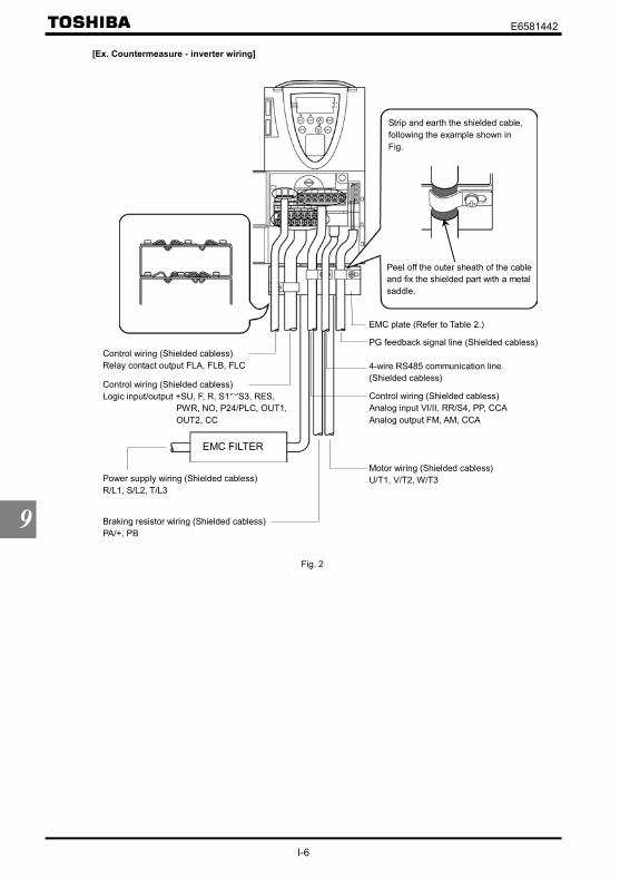
E6581442
I-6
9
[Ex. Countermeasure - inverter wiring]
EMC FILTER
Peel off the outer sheath of the cableand fix the shielded part with a metalsaddle.
Strip and earth the shielded cable,following the example shown inFig.
Control wiring (Shielded cabless)Relay contact output FLA, FLB, FLC
Control wiring (Shielded cabless)Analog input VI/II, RR/S4, PP, CCAAnalog output FM, AM, CCA
PG feedback signal line (Shielded cabless)
Power supply wiring (Shielded cabless)R/L1, S/L2, T/L3
Motor wiring (Shielded cabless)U/T1, V/T2, W/T3
Braking resistor wiring (Shielded cabless)PA/+, PB
EMC plate (Refer to Table 2.)
4-wire RS485 communication line(Shielded cabless)
Control wiring (Shielded cabless)Logic input/output +SU, F, R, S1~S3, RES,
PWR, NO, P24/PLC, OUT1,OUT2, CC
Fig. 2

E6581442
I-7
9
[Operation with external signals]When using signals from an external control device to operate the inverter, take the measures shown in Figure 3.
Ex.) When using the potentiometer and forward run/reverse run terminals
Ferrite core 1
Shielded cable or [Note 1]
Fig. 3
[Accessories for countermeasure] Recommended shield cable : Showa electric Wire & Cable Co., LTD
Type : CV-SRating : 600V or lessCross-sectional area : 2~1000mm2
If it is difficult to procure shielded cables, protect cables with conduit tubes. [Note 1] Recommended shield : SUMITOMO 3M Limited, Electromagnetic wave guard shielding sleeve
Type : DS-5, 7, 10, 14 EMC filter Type : EMF3 series Recommended ferrite core 1 : TDK Corporation
Type : ZCAT3035-1330Use the following, as required.
Recommended ferrite core : NEC TOKIN CorporationType : ESD-R-47D-1
Zero-phase reactor : Soshin Electric Co., Ltd.Type : RC5078 or RC9129
High-attenuation radio noise reduction filter : Soshin Electric Co., Ltd.Type : NF series
9.1.3 Low-voltage directiveThe low-voltage directive provides for the safety of machines and systems. All Toshiba inverters are CE-marked inaccordance with the standard IEC61800-5-1 specified by the low-voltage directive, and can therefore be installed inmachines or systems and imported without a problem to European countries.
Applicable standard: IEC61800-5-1Adjustable speed electrical power drive system
Pollution level: 2 (5.2.15.2)Overvoltage category: 3 200V class, 3.0mm (5.2.16.1)
400V class, 5.5mm (5.2.16.1)
9.1.4 Measures to be taken to satisfy the low-voltage directiveWhen incorporating the inverter into a machine or system, it is necessary to take the following measures so that theinverter satisfies the low-voltage directive.
(1) Install the inverter in a cabinet and ground the inverter enclosure. When doing maintenance, be extremely carefulnot to put your fingers into the inverter through a wiring hole and touch a charged part, which may occur dependingon the model and capacity of the inverter used.
(2) Do not connect two or more wires to the main circuit earth terminal of the inverter. If necessary, install an additionalearth terminal on the EMC plate on which the inverter is installed and connect another cable to it. (Refer to Fig. 4.)See the table of section 10.1.

E6581442
I-8
9
(3) Install a non-fuse circuit breaker on the input side of the inverter.
EMC plate
InverterGroundingterminal
Install an earth terminal.
Fig. 4
9.2 Measures to be taken to satisfy the UL/CSA standards
All VF-AS1 series inverters are certified by UL and CSA, and have nameplates with UL and CSA markings.
9.2.1 Caution in installing the inverterA UL certificate was granted on the assumption that the inverter would be installed in a cabinet. Therefore, install theinverter in a cabinet and if necessary, take measures to maintain the ambient temperature (temperature in the cabinet)within the specified temperature range.For models designed for 15kW motors or smaller, if the cover on the top of the inverter is removed, the ambienttemperature can rise to 50°C in some cases, although the maximum allowable ambient temperature is 40°C.Incidentally, models (with no cover on the top) designed for 18.5 kW motors or larger can be used at ambienttemperatures of up to 50°C.
9.2.2 Caution in wiring and rated currentFor electric wires to be connected to the inverter’s input terminals (R/L1, S/L2, T/L3), output terminals (U/T1, V/T2,W/T3) or other main circuit terminals, use UL-certified electric wires (copper wires with conductors for which themaximum allowable temperature is 75°C or over) and round solderless terminals and tighten the terminal screws(stripped wires may be connected directly for 200V/18.5kW to 200V/45kW models and 400V/22kW to 400V/75kWmodels) to the specified torque when connecting the wires to the terminal board. To crimp a round solderless terminalonto a wire, use a crimping tool recommended by the terminal manufacturer.⇒ For recommended electric wire sizes, see Tables 5.UL-certified rated output current is not the same as inverter unit rated current. Refer to Table 5.
9.2.3 Caution as to peripheral devicesWhen installing a no-fuse circuit breaker or a fuse box on the primary side of the inverter, use UL-certified one.The UL certification test on this inverter was conducted under the power supply short-circuit current* conditions shownin Table 4 (*: current that flows in the event of a short-circuit in the power supply). Note that power supply short-circuitcurrents vary depending on the capacity of the motor used.
Table 4 Power supply short-circuit current and maximum input voltageMax. input voltage (V)Applicable motor
(kW)Power supply short-circuit current
(A) 200V class 400V class0.4~37 5,00045~132 10,000
160~280 18,000355, 400 30,000
500 42,000
240 480

E6581442
I-9
9
Table 5 AIC, Fuse and Wire sizes
Voltageclass
Applicablemotor [kW]
Inverter modelUL
output current(A) *2, *3
AIC (A)(Interrupting
capacity)
Fuse classand current
(A)
Input wire sizes ofpower circuit
*4
Output wire sizes ofpower circuit
*4
Earth*4
0.4 VFAS1-2004PL 2.5 ( = ) AIC 5000A CC 7Amax. AWG 14 AWG 14 AWG 140.75 VFAS1-2007PL 4.8 ( = ) AIC 5000A J 15Amax. AWG 14 AWG 14 AWG 141.5 VFAS1-2015PL 7.8 ( = ) AIC 5000A J 25Amax. AWG 14 AWG 14 AWG 142.2 VFAS1-2022PL 11.0 ( = ) AIC 5000A J 25A max. AWG 12 AWG 12 AWG 143.7/4.0 VFAS1-2037PL 17.5 ( = ) AIC 5000A J 45Amax. AWG 10 AWG 10 AWG 125.5 VFAS1-2055PL 25.3 ( = ) AIC 5000A J 60Amax. AWG 8 AWG 8 AWG 107.5 VFAS1-2075PL 32.2 ( = ) AIC 5000A J 70Amax. AWG 8 AWG 8 AWG 1011 VFAS1-2110PM 48.3 ( = ) AIC 5000A J 90Amax. AWG 4 AWG 4 AWG 1015 VFAS1-2150PM 62.1 ( = ) AIC 5000A J 110Amax. AWG 4 AWG 4 AWG 1018.5 VFAS1-2185PM 74.8 ( = . ) AIC 5000A J 125Amax. AWG 3 AWG 3 AWG 822 VFAS1-2220PM 88 ( = . ) AIC 5000A J 150Amax. AWG 2 AWG 2 AWG 830 VFAS1-2300PM 114 ( = . ) AIC 5000A J 200Amax. AWG 2/0 AWG 2/0 AWG 637 VFAS1-2370PM 143 ( = . ) AIC 5000A J 225Amax. AWG 3/0 AWG 3/0 AWG 645 VFAS1-2450PM 169 ( = . ) AIC 10000A J 300Amax. AWG 4/0 AWG 4/0 AWG 655 VFAS1-2550P 221 ( = . ) AIC 10000A J 350Amax. AWG 3/0 × 2 AWG 3/0 × 2 AWG 2
200Vclass
75 VFAS1-2750P 285 ( = . ) AIC 10000A J 450Amax. AWG 4/0 × 2 250MCM × 2 AWG 20.75 VFAS1-4007PL 2.1 ( = ) AIC 5000A CC 6Amax. AWG 14 AWG 14 AWG 141.5 VFAS1-4015PL 3.4 ( = ) AIC 5000A CC 12Amax. AWG 14 AWG 14 AWG 142.2 VFAS1-4022PL 4.8 ( = ) AIC 5000A J 15Amax. AWG 14 AWG 14 AWG 143.7/4.0 VFAS1-4037PL 7.6 ( = ) AIC 5000A J 25Amax. AWG 12 AWG 12 AWG 145.5 VFAS1-4055PL 11.0 ( = ) AIC 5000A J 40Amax. AWG 10 AWG 10 AWG 127.5 VFAS1-4075PL 14. 0 ( = ) AIC 5000A J 40Amax. AWG 10 AWG 10 AWG 1211 VFAS1-4110PL 21.0 ( = ) AIC 5000A J 60Amax. AWG 8 AWG 8 AWG 1015 VFAS1-4150PL 27.0 ( = ) AIC 5000A J 70Amax. AWG 6 AWG 6 AWG 1018.5 VFAS1-4185PL 34.0 ( = ) AIC 5000A J 70Amax. AWG 6 AWG 6 AWG 1022 VFAS1-4220PL 40.0 ( = ) AIC 5000A J 80Amax. AWG 6 AWG 6 AWG 1030 VFAS1-4300PL 52.0 ( = ) AIC 5000A J 90Amax. AWG 4 AWG 4 AWG 1037 VFAS1-4370PL 65.0 ( = . ) AIC 5000A J 110Amax. AWG 3 AWG 3 AWG 845 VFAS1-4450PL 77.0 ( = . ) AIC 10000A J 150Amax. AWG 1 AWG 1 AWG 855 VFAS1-4550PL 96.0 ( = . ) AIC 10000A J 175Amax. AWG 1/0 AWG 1/0 AWG 675 VFAS1-4750PL 124.0 ( = . ) AIC 10000A J 225Amax. AWG 3/0 AWG 3/0 AWG 6
90 VFAS1-4900PC 179.0 ( = . ) AIC 10000A J 300Amax.AWG 1/0 × 2
250 MCM × 2 *1AWG 1/0 × 2
250 MCM × 2 *1AWG 2
250 MCM *1
110 VFAS1-4110KPC 215.0 ( = . ) AIC 10000A J 350Amax.AWG 3/0 × 2
250 MCM × 2 *1AWG 3/0 × 2
250 MCM × 2 *1AWG 2
250 MCM *1
132 VFAS1-4132KPC 259.0 ( = . ) AIC 10000A J 350Amax.AWG 4/0 × 2
250 MCM × 2 *1AWG 4/0 × 2
250 MCM × 2 *1AWG 1
250 MCM *1
160 VFAS1-4160KPC 314.0 ( = . ) AIC 18000A J 400A max.300 MCM × 2
350 MCM × 2 *1300 MCM × 2
350 MCM × 2 *1AWG 1
250 MCM *1
200 VFAS1-4200KPC 387.0 ( = . ) AIC 18000A J 500Amax.AWG 4/0 × 3
350 MCM × 3 *1AWG 4/0 × 3
350 MCM × 3 *1AWG 1/0
250 MCM × 2 *1
220 VFAS1-4220KPC 427.0 ( = . ) AIC 18000A J 500Amax.250 MCM × 3
350 MCM × 3 *1250 MCM × 3
350 MCM × 3 *1AWG 2/0
250 MCM × 2 *1
280 VFAS1-4280KPC 550.0 ( = . ) AIC 18000A J 700Amax.350 MCM × 3
350 MCM × 3 *1350 MCM × 3
350 MCM × 3 *1AWG 3/0
250 MCM × 2 *1
355 VFAS1-4355KPC 671.0 ( = . ) AIC 30000A J 450A × 2 max.400 MCM × 2 × 2500 MCM × 2 × 2 *1
400 MCM × 4500 MCM × 4 *1
AWG 4/0500 MCM *1
400 VFAS1-4400KPC 759.0 ( = . ) AIC 30000A J 500A × 2 max.500 MCM × 2 × 2500 MCM × 2 × 2 *1
500 MCM × 4500 MCM × 4 *1
AWG 4/0500 MCM *1
400Vclass
500 VFAS1-4500KPC 941.0 ( = . ) AIC 42000AJ 600/630A
× 2 max.400 MCM × 3 × 2500 MCM × 3 × 2 * 1
400 MCM × 5500 MCM × 5 *1
250 MCM500 MCM *1
*1: This part shows the wiring size with using the Lug terminal.The Lug terminals are an option.
*2: UL output current is different from unit rating output current.*3: The value of the UL rated output current is applicable when the carrier frequency ( ) is less than the value
shown in the table.*4: The cables used must be 75°C copper cables within 40°C ambient temperature.
9.2.4 Caution as to the protection of motors from overloadWhen using the inverter’s thermal protection function to protect the motor from overload, read the instruction manualincluded with the inverter carefully and set parameters according to the specifications of the motor used.When using the inverter to control the operation of multiple motors, install an overload relay for each individual motor.

E6581442
I-10
9
9.3 Compliance with safety standardsThe VFAS1 inverter has the “power removal” safety function that complies with safety standards.To ensure safety performance, however, the mechanical system with which the VFAS1 inverter is used has to adhereto such standards as a whole.To be more specific, in order for the system to satisfy the following safety standards, it needs to be configured, asshown on the next page, with the power removal terminal of the VFAS1 inverter (PWR terminal on the control terminalboard) so that it will coast or decelerate to a stop in the event of a failure.To ensure that the motor coasts or decelerates to a stop if un unusual event occurs, the power removal circuit isdesigned with redundancy and it has a diagnosis circuit that determines whether the unusual event is at a permissiblelevel or not, in addition to a hardware circuit and software that cut off the operation signal if the unusual event is judgedimpermissible. This safety function is certified by the certification organization “INERIS.”
The VFAS1 inverter meets the IEC/EN61508 SIL2 requirements.(The term “SIL” is an acronym for “Safety Integrity Level,” which is a safety performance scale.)
The VFAS1 inverter falls under Category 3 of the safety standard EN954-1 for mechanical systems. The VFAS1 inverter supports the two stopping methods defined in IEC/EN61800-5-2.
One is “STO,” which refers to “coast and stop,” and the other is “ST1,” which refers to “deceleration stop.”
EN61508 is an international standard that defines safety performance required for systems provided with electric andelectronic programmable devices, and SIL2 applies to systems that are configured with dangerous failure rates of aslow as 10-6 to 10-7, as shown in the table below. For the relationship between SIL and inverter configuration, see thefollowing pages.
<<Target for EIC/EN61508 safety performance scale>>SIL Heavy-duty operation mode or continuous operation mode (Hourly dangerous failure rate)4 10-9 ~ 10-8
3 10-8 ~ 10-7
2 10-7 ~ 10-6
1 10-6 ~ 10-5
The European standard EN954-1, a basic safety standard for mechanical system, categorizes machines by degree ofdanger.Placed in Category 3 are machines that are designed with redundancy so that a single failure will not cause adegradation in their safety performance.For the relationship between each category and the safety function, see the table below.
<<Categories relating to safety according to EN 954-1>>Categories Basic safety principle Control system requirements Behaviour in the event of a fault
B Selection of components thatconform to relevantstandards.
Control in accordance with goodengineering practice.
Possible loss of safety function.
1 Selection of components andbasic safety principles.
Use of tried and tested componentsand proven safety principles.
Possible loss of safety function,but with less probability of thisthan with B
2 Selection of components andbasic safety principles.
Cyclic testing. The test intervalsmust be suited to the machine andits applications.
Fault detected at each test.
3 Structure of the safety circuits. A single fault must not cause loss ofthe safety function.This single fault must be detected ifreasonably practicable.
Safety function ensured, except inthe event of an accumulation offaults.
4 Structure of the safety circuits. A single fault must not cause loss ofthe safety function.This fault must be detected at orbefore the next demand on thesafety function.An accumulation of faults must notcause loss of the safety function.
Safety function always ensured.
The three stopping methods described on the following pages were selected in accordance with IEC60204-1.Stopping method 1 (Stop category 0): Stops the mechanical system by cutting off the power supply immediately.Stopping method 2 (Stop category 1): First controls the mechanical system to stop it, and then cuts off the power supply.Stopping method 3 (Stop category 2): First cut off the power supply, and then controls the mechanical system to stop it.
Caution
Mandatory
For preventive maintenance, check at least once a year whether the power removal safety functionoperates normally.

E6581442
I-11
9
Safety category1: EN954-1 category1, IEC/EN61508, SIL1Stop category1: IEC/EN60204-1
Coast stop under the control of the MC in the main circuit
(1) An example of connection for operation in sink mode (common: CC)• In this connection, the PWR terminal is not used. This connection falls under Stop Category 0 defined in
IEC/EN60204-1.
Symbols DescriptionB1 VF-AS1 inverterMCCB1 Circuit breakerMC1 Magnetic condactorMCCB2 Circuit breaker for control transformerT1 Control transformer 400/200V (For 400V class only)CP Circuit protectorPB1 Push button switch (Run)PB2 Push button switch (Stop/emergency stop)Rs Control relay
*1: Some inverters* are shipped with the PO and PA/+ terminals short-circuited with a shorting bar. (* 200V/45kWclass and lower and 400V/75kW class and lower)
*2: To back up the inverter’s internal power supply that supplies control power, an external control power backupdevice (CPS002Z - optional) is required. The optional control power backup device can be used with both 200Vand 400V classes.
*3: By default, the FL relay is set as a failure FL output relay.

E6581442
I-12
9
Safety category1: EN954-1 category1, IEC/EN61508, SIL1Stop category0: IEC/EN60204-1
Coast stop under the control of the MC in the main circuit
(2) An example of connection for operation in source mode (common: P24)• In this connection, the PWR terminal is not used. This connection falls under Stop Category 0 defined in
IEC/EN60204-1.
Symbols DescriptionB1 VF-AS1 inverterMCCB1 Circuit breakerMC1 Magnetic condactorMCCB2 Circuit breaker for control transformerT1 Control transformer 400/200V (For 400V class only)CP Circuit protectorPB1 Push button switch (Run)PB2 Push button switch (Stop/emergency stop)Rs Control relay
*1: Some inverters* are shipped with the PO and PA/+ terminals short-circuited with a shorting bar. (* 200V/45kWclass and lower and 400V/75kW class and lower)
*2: To back up the inverter’s internal power supply that supplies control power, an external control power backupdevice (CPS002Z - optional) is required. The optional control power backup device can be used with both 200Vand 400V classes.
*3: By default, the FL relay is set as a failure FL output relay.

E6581442
I-13
9
Safety category3: EN954-1 category3, IEC/EN61508, SIL2Stop category0: IEC/EN60204-1
Coast stop under the control of PWR
(1) An example of connection for operation in sink mode (common: CC)• In this connection, the PWR terminal is used to connect a safety device. The emergency stop circuit is
supervised by the external safety relay. This safety relay can be shared among several inverters.• If the PWR terminal is turned off, the motor will coast and stop. This operation falls under Stop Category 0
defined in IEC/EN60204-1.• The motor is prevented from restarting automatically before the PWR terminal is turned back on.• When using the inverter to control the operation of a mechanical brake (for example, when using with a hoist or
crane), connect the cable from the output terminal of the safety relay to the brake control circuit.
Symbols DescriptionB1 VF-AS1 inverterMCCB1 Circuit breakerB2 Safety relay: XPS-AC (manufactured by Schneider Electric)F1 FusePb1 Push button switch 2b contact (for emergency stop)Pb2 Push button switch (for reset and start)
*1: Some inverters* are shipped with the PO and PA/+ terminals short-circuited with a shorting bar. (* 200V/45kWclass and lower and 400V/75kW class and lower)
*2: Supply voltage: AC/DC24V, AC48V, AC115V, AC230V*3: If an emergency stop command is issued, the PWR terminal will be turned off to coast and stop the motor.*4: Pb2 is used to reset/start the inverter after the power is turned on or in the event of an emergency stop.
ESC is used to set reset/start conditions for the external device.*5: To connect a safety relay to the PWR terminal, use a coaxial cable RG174/U (MIL-C17) or KX3B (NFC93-550)
2.54 mm or more in outside diameter and 2 m or less in length. When using a shielded cable, ground it.

E6581442
I-14
9
Safety category3: EN954-1 category3, IEC/EN61508, SIL2Stop category0: IEC/EN60204-1
Coast stop under the control of PWR
(2) An example of connection for operation in source mode (common: P24)• In this connection, the PWR terminal is used to connect a safety device. The emergency stop circuit is
supervised by the external safety relay. This safety relay can be shared among several inverters.• If the PWR terminal is turned off, the motor will coast and stop. This operation falls under Stop Category 0
defined in IEC/EN60204-1.• The motor is prevented from restarting automatically before the PWR terminal is turned back on.• When using the inverter to control the operation of a mechanical brake (for example, when using with a hoist or
crane), connect the cable from the output terminal of the safety relay to the brake control circuit.
Symbols DescriptionB1 VF-AS1 inverterMCCB1 Circuit breakerB2 Safety relay: XPS-AC (manufactured by Schneider Electric)F1 FusePb1 Push button switch 2b contact (for emergency stop)Pb2 Push button switch (for reset and start)
*1: Some inverters* are shipped with the PO and PA/+ terminals short-circuited with a shorting bar. (* 200V/45kWclass and lower and 400V/75kW class and lower)
*2: Supply voltage: AC/DC24V, AC48V, AC115V, AC230V*3: If an emergency stop command is issued, the PWR terminal will be turned off to coast and stop the motor.*4: Pb2 is used to reset/start the inverter after the power is turned on or in the event of an emergency stop.
ESC is used to set reset/start conditions for the external device.*5: To connect a safety relay to the PWR terminal, use a coaxial cable RG174/U (MIL-C17) or KX3B (NFC93-550)
2.54 mm or more in outside diameter and 2 m or less in length. When using a shielded cable, ground it.

E6581442
I-15
9
Safety category3: EN954-1 category3, IEC/EN61508, SIL2Stop category1: IEC/EN60204-1
Deceleration stop under the control of PWR
(1) An example of connection for operation in sink mode (common: CC)• In this connection, the PWR terminal is used to connect a safety device. The emergency stop circuit is
supervised by the external safety relay. This safety relay can be shared among several inverters.• In the event of an emergency stop, the external safety relay issues a deceleration command to the inverter.
At this command, the motor slows down and stops. Then, the safety relay turns off the PWR terminal onexpiration of the time limit (max. 30 sec) set for the relay. This operation falls under Stop Category 1 defined inIEC/EN60204-1.
• For this connection, the function of issuing the forward run command (2) needs to be assigned to the F terminal,and the function of issuing the reverse run command (4) to the R terminal.
Symbols DescriptionB1 VF-AS1 inverterMCCB1 Circuit breakerB2 Safety relay: XPS-ATE (manufactured by Schneider Electric)F1 FusePb1 Push button switch 2b contact (for emergency stop)Pb2 Push button switch (for reset and start)
*1: Some inverters* are shipped with the PO and PA/+ terminals short-circuited with a shorting bar. (* 200V/45kWclass and lower and 400V/75kW class and lower)
*2: Supply voltage: AC/DC24V, AC48V, AC115V, AC230V*3: If an emergency stop command is issued, the PWR terminal will be turned off to coast and stop the motor.*4: Pb2 is used to reset/start the inverter after the power is turned on or in the event of an emergency stop.
ESC is used to set reset/start conditions for the external device.*5: If a deceleration time of more than 30 seconds is required, use a safety relay XPS-AV, which allows you to set the
deceleration time at a maximum of 300 seconds.*6: To connect a safety relay to the PWR terminal, use a coaxial cable RG174/U (MIL-C17) or KX3B (NFC93-550)
2.54 mm or more in outside diameter and 2 m or less in length. When using a shielded cable, ground it.

E6581442
I-16
9
Safety category3: EN954-1 category3, IEC/EN61508, SIL2Stop category1: IEC/EN60204-1
Deceleration stop under the control of PWR
(2) An example of connection for operation in source mode (common: P24)• In this connection, the PWR terminal is used to connect a safety device. The emergency stop circuit is
supervised by the external safety relay. This safety relay can be shared among several inverters.• In the event of an emergency stop, the external safety relay issues a deceleration command to the inverter.
At this command, the motor slows down and stops. Then, the safety relay turns off the PWR terminal onexpiration of the time limit (max. 30 sec) set for the relay. This operation falls under Stop Category 1 defined inIEC/EN60204-1.
• For this connection, the function of issuing the forward run command (2) needs to be assigned to the F terminal,and the function of issuing the reverse run command (4) to the R terminal.
Symbols DescriptionB1 VF-AS1 inverterMCCB1 Circuit breakerB2 Safety relay: XPS-ATE (manufactured by Schneider Electric)F1 FusePb1 Push button switch 2b contact (for emergency stop)Pb2 Push button switch (for reset and start)
*1: Some inverters* are shipped with the PO and PA/+ terminals short-circuited with a shorting bar. (* 200V/45kWclass and lower and 400V/75kW class and lower)
*2: Supply voltage: AC/DC24V, AC48V, AC115V, AC230V*3: If an emergency stop command is issued, the PWR terminal will be turned off to coast and stop the motor.*4: Pb2 is used to reset/start the inverter after the power is turned on or in the event of an emergency stop.
ESC is used to set reset/start conditions for the external device.*5: If a deceleration time of more than 30 seconds is required, use a safety relay XPS-AV, which allows you to set the
deceleration time at a maximum of 300 seconds.*6: To connect a safety relay to the PWR terminal, use a coaxial cable RG174/U (MIL-C17) or KX3B (NFC93-550)
2.54 mm or more in outside diameter and 2 m or less in length. When using a shielded cable, ground it.

E6581442
J-1
10
10. Selection of peripheral devices
Danger
Mandatory
• When using the inverter without the front cover, be sure to place the inverter unit inside a cabinet. Ifthey are used outside the cabinet, it may cause electric shock.
Be Grounded
• Be sure to ground every unit. If not, it may cause electric shock or fire on the occasion of failure,short-circuit or electric leak.
10.1 Selection of wiring materials and devices
Wire sizeMain circuit
Input terminal (R, S, T)
Output terminal(U, V, W)
DC terminalBraking resistor/
Braking unit(optional) (*4)
Earth cableVoltageclass
Applicablemotor [kW]
Inverter model
AWG mm2 AWG mm2 AWG mm2 AWG mm2 AWG mm2
0.4 VFAS1-2004PL 14 1.5 14 1.5 14 1.5 14 1.5 14 2.50.75 VFAS1-2007PL 14 1.5 14 1.5 14 1.5 14 1.5 14 2.51.5 VFAS1-2015PL 14 1.5 14 1.5 12 1.5 14 1.5 14 2.52.2 VFAS1-2022PL 12 1.5 12 1.5 10 2.5 14 1.5 14 2.53.7/4.0 VFAS1-2037PL 10 4 10 4 8 6 14 1.5 12 45.5 VFAS1-2055PL 8 6 8 6 6 10 14 1.5 10 67.5 VFAS1-2075PL 8 10 8 10 4 16 12 2.5 10 1011 VFAS1-2110PM 4 16 4 16 3 16 10 4 10 1615 VFAS1-2150PM 4 25 4 25 1 25 8 6 10 1618.5 VFAS1-2185PM 3 25 3 25 1/0 35 8 10 8 1622 VFAS1-2220PM 2 25 2 25 2/0 35 6 16 8 1630 VFAS1-2300PM 2/0 50 2/0 50 4/0 70 4 25 6 2537 VFAS1-2370PM 3/0 70 3/0 70 250MCM 95 3 35 6 3545 VFAS1-2450PM 4/0 70 4/0 70 300MCM 95 2 50 6 3555 VFAS1-2550P 3/0×2 70×2 3/0×2 120 4/0×2 95×2 1/0 50 2 70
200Vclass
75 VFAS1-2750P 4/0×2 95×2 250MCM×2 70×2 300MCM×2 120×2 1/0 35×2 2 950.75 VFAS1-4007PL 14 1.5 14 1.5 14 1.5 14 1.5 14 2.51.5 VFAS1-4015PL 14 1.5 14 1.5 14 1.5 14 1.5 14 2.52.2 VFAS1-4022PL 14 1.5 14 1.5 14 1.5 14 1.5 14 2.53.7/4.0 VFAS1-4037PL 12 1.5 12 1.5 10 2.5 14 1.5 14 2.55.5 VFAS1-4055PL 10 2.5 10 2.5 8 4 14 1.5 12 2.57.5 VFAS1-4075PL 10 4 10 4 8 6 14 1.5 12 411 VFAS1-4110PL 8 6 8 6 6 10 14 1.5 10 615 VFAS1-4150PL 6 10 6 10 4 16 12 2.5 10 1018.5 VFAS1-4185PL 6 10 6 10 4 16 10 2.5 10 1022 VFAS1-4220PL 6 10 6 10 4 16 10 4 10 1030 VFAS1-4300PL 4 16 4 16 2 25 8 6 10 1637 VFAS1-4370PL 3 25 3 25 1 35 8 10 8 1645 VFAS1-4450PL 1 35 1 35 2/0 50 6 16 8 1655 VFAS1-4550PL 1/0 50 1/0 50 3/0 70 6 16 6 2575 VFAS1-4750PL 3/0 70 3/0 70 250MCM 95 3 35 6 3590 VFAS1-4900PC 1/0×2 70×2 1/0×2 95 1/0×2 95×2 1/0 35 2 70110 VFAS1-4110KPC 3/0×2 95×2 3/0×2 120 2/0×2 120×2 1/0 50 2 95132 VFAS1-4132KPC 4/0×2 95×2 4/0×2 150 4/0×2 120×2 4/0 70 1/0 95160 VFAS1-4160KPC 300MCM×2 120×2 300MCM×2 95×2 350MCM×2 150×2 4/0 95 1/0 120200 VFAS1-4200KPC 4/0×3 150×2 4/0×3 120×2 3/0×3 150×3 300MCM 150 1/0 150220 VFAS1-4220KPC 300MCM×3 150×3 250MCM×3 120×2 4/0×3 150×3 300MCM 150 2/0 150280 VFAS1-4280KPC 350MCM×3 150×3 350MCM×3 185×2 300MCM×3 150×4 300MCM 150 3/0 120×2
355 VFAS1-4355KPC 400MCM×2×2 (*6)
120×2×2(*6) 400MCM×4 150×3 500MCM×3 185×4 350MCM×2 185×2 4/0 120×2
400 VFAS1-4400KPC 500MCM×2×2 (*6)
150×2×2(*6) 500MCM×4 185×3 500MCM×4 185×4
(*5) 350MCM×2 185×2 4/0 150×2
400Vclass
500 VFAS1-4500KPC 400MCM×3×2 (*6)
150×3×2(*6) 400MCM×5 185×4 500MCM×4 180×4
(*5) 350MCM×2 185×2 250MCM 150×2(*1): The recommended cable size is that of the cable (e.g. 600V class, HIV cable) with continuous maximum permissible temperature of 75°C. Ambient
temperature is 40°C or less and the wiring distance is 30m or less.(*2): For the control circuit, use shielded wires whose size (cross-section) is 0.75 mm2 or more.(*3): For the earth cable, use wires larger than the specified ones in size (cross-section).(*4): Recommended wire size for an optional braking resistor. Refer to 5.19 for use of external braking resistor.(*5): The recommended cable is 600V class HIV cable with permissible temperature of 90°C.(*6): The number refers to a cable composition. For example, in the case of “120×2×2”: 120×2×2 Number of cables connected in parallel on the terminal board
Number of cables connected to each terminal boardWire size 120mm2

E6581442
J-2
10
Selection of wiring equipmentNo-fuse breaker
(MCCB)Magnetic contactor
(MC)Input current[A]
WithoutReactor
WithReactor
WithoutReactor
WithReactor
Voltageclass
Applicablemotor [kW] Inverter model
WithoutReactor
WithReactor
Rated current[A]
Rated current[A]
Operationlcurrent [A]
AC-1
Operationlcurrent [A]
AC-10.4 VFAS1-2004PL 3.5 2.1 5 5 25 25
0.75 VFAS1-2007PL 6.1 3.2 10 5 25 25
1.5 VFAS1-2015PL 11.5 6.4 15 10 25 25
2.2 VFAS1-2022PL 15 9.3 20 15 25 25
3.7/4.0 VFAS1-2037PL 26.0 15.5 30 30 32 25
5.5 VFAS1-2055PL 35 22. 5 50 40 40 25
7.5 VFAS1-2075PL 45 34.5 60 40 50 40
11 VFAS1-2110PM - 53.5 - 75 - 80
15 VFAS1-2150PM - 72 - 100 - 80
18.5 VFAS1-2185PM - 77 - 100 - 80
22 VFAS1-2220PM - 88 - 125 - 125
30 VFAS1-2300PM - 125 - 150 - 125
37 VFAS1-2370PM - 140 - 175 - 250
45 VFAS1-2450PM - 165 - 200 - 250
55 VFAS1-2550P - 200 - 250 - 275
200Vclass
75 VFAS1-2750P - 270 - 350 - 350
0.75 VFAS1-4007PL 3.7 2.1 5 4 25 25
1.5 VFAS1-4015PL 5.8 3.8 10 6.3 25 25
2.2 VFAS1-4022PL 8.2 5.7 14 10 25 25
3.7/4.0 VFAS1-4037PL 14.0 8.7 18 14 25 25
5.5 VFAS1-4055PL 20.5 12.7 32 25 25 25
7.5 VFAS1-4075PL 27 16.3 32 25 32 25
11 VFAS1-4110PL 36.5 21.5 50 30 40 32
15 VFAS1-4150PL 48 33.5 60 40 50 40
18.5 VFAS1-4185PL - 45.5 - 60 - 50
22 VFAS1-4220PL - 50 - 60 - 50
30 VFAS1-4300PL - 66 - 100 - 80
37 VFAS1-4370PL - 84 - 100 - 125
45 VFAS1-4450PL - 105 - 125 - 125
55 VFAS1-4550PL - 120 - 150 - 125
75 VFAS1-4750PL - 165 - 200 - 250
90 VFAS1-4900PC - 170 - 200 - 250
110 VFAS1-4110KPC - 200 - 250 - 275
132 VFAS1-4132KPC - 240 - 300 - 315
160 VFAS1-4160KPC - 290 - 350 - 350
200 VFAS1-4200KPC - 360 - 500 - 500
220 VFAS1-4220KPC - 395 - 500 - 500
280 VFAS1-4280KPC - 495 - 700 - 700355 VFAS1-4355KPC - 637 - 1000 - 1000400 VFAS1-4400KPC - 709 - 1000 - 1000
400Vclass
500 VFAS1-4500KPC - 876 - 1200 - 1600
(*1): Selections for use of the Toshiba 4-pole standard motor with power supply voltage of 200V/400V-50Hz.(*2): Choose the MCCB according to the power supply capacity.
For comply with UL and CSA standard, use the fuse certified by UL and CSA.(*3): When using on the motor side during commercial-power supply operation, choose the MC with class AC-3 rated current for
the motor rated current.(*4): Attach surge killers to the magnetic contactor and exciting coil of the relay.(*5): In the case the magnetic contactor (MC) with 2a-type auxiliary contacts is used for the control circuit, raise the reliability of
the contact by using 2a-type contacts in parallel connection.(*6): For 200V/55kW model and larger and 400V/90kW model and larger, be sure to install a DC reactor.

E6581442
J-3
10
10.2 Installation of a magnetic contactor
If using the inverter without installing a magnetic contactor (MC) in the primary circuit, use an MCCB (with a powercutoff device) to open the primary circuit when the inverter protective circuit is activated.If using a braking resistor or braking resistor unit, install a magnetic contactor (MC) or no-fuse breaker with a powercutoff device to the power supply of the inverter, so that the power circuit opens when the failure detection relay (FL) inthe inverter or the external overload relay is activated.
Magnetic contactor in the primary circuitTo detach the inverter from the power supply in any of the following cases, insert a magnetic contactor (primary-sidemagnetic contactor) between the inverter and the power supply.(1) If the motor overload relay is tripped(2) If the protective detector (FL) built into the inverter is activated(3) In the event of a power failure (for prevention of auto-restart)(4) If the resistor protective relay is tripped when a braking resistor or braking resistor unit is usedWhen using the inverter with no magnetic contactor (MC) on the primary side, install a no-fuse breaker with a voltagetripping coil instead of an MC and adjust the no-fuse breaker so that it will be tripped if the protective relay referred toabove is activated. To detect a power failure, use an undervoltage relay or the like.
Motor
IM
PWR
F
CC
R/L1 U/T1
Operation preparation
ReverseR
Forward
V/T2W/T3
S/L2T/L3
Power supply
MCCB MC
Example of connection of a magnetic contactor in the primary circuitNote on wiring• When frequently switching between start and stop, do not use the magnetic contactor on the primary side as an
on-off switch for the inverter.Instead, stop and start the inverter by using terminals F and CC (forward run) or R and CC (reverse run).
• Be sure to attach a surge killer to the exciting coil of the magnetic contactor (MC).
Magnetic contactor in the secondary circuitA magnetic contactor may be installed on the secondary side to switch controlled motors or supply commercial powerto the load when the inverter is out of operation.
Note on wiring• Be sure to interlock the magnetic contactor on the secondary side with the power supply to prevent commercial
power from being applied to the inverter output terminals.• When installing a magnetic contactor (MC) between the inverter and the motor, avoid turning the magnetic
contactor on or off during operation. Turning the magnetic contactor on or off during operation causes a current torush into the inverter which could lead to malfunction.
10.3 Installation of an overload relay
1) The VF-AS1 inverter has an electronic-thermal overload protective function.In the following cases, however, an overload relay suitable for the adjustment of the motor electronic thermalprotection level ( ) or appropriate to the motor used should be installed between the inverter and the motor.• When using a motor with a current rating different to that of the corresponding Toshiba general-purpose motor• When operating a single motor with an output smaller than that of the applicable standard motor.When operating multiple motors at a time, be sure to install an overload relay for each individual motor.
2) When using the VF-AS1 inverter to operate a constant-torque motor, such as the Toshiba VF motor, adjust theprotection characteristic of the electronic thermal protection unit ( ) to the VF motor use.
3) It is recommended to use a motor with a thermal relay embedded in the motor coil to give sufficient protection tothe motor, especially when it runs in a low-speed range.

E6581442
J-4
10
10.4 Application and functions of optionsSeparate type options shown below are prepared for the inverter VF-AS1
No-fusebreaker(MCCB)
N.F
motor
IM
Magneticcontactor(MC)
Power supply
(1) Input AC reactor(ACL)
(3) High attention radionoise filter
(4) Zero-phase reactorferrite core type radionoise filter
(5) EMC filter for CEcompliance
(2) DC reactor(DCL)
(6) Braking resistor
(4) Zero-phasereactor ferritecore type radionoise filter
VF-AS1 N.F
(8) Motor end surgevoltage suppressionfilter (for 400Vmodels only)
(9) Control power supplybackup option
(7) Motor noisereduction filter
(6) Braking resistor/Braking unit
(200kW models and larger)
Sorts of separate-type options
No. Option name Function, purpose.
(1)
Input AC reactor(ACL)
(2)
DC reactor(DCL)
To be used for improvement of input power-factor of the inverter power source, for reducinghigher harmonic or suppressing external surge. The input reactor can be installed when thepower capacity is 500 kVA or more and it is 10 times or more as high as the inverter capacityor there are some source distorted wave generation such as a thyristor, etc. and a highcapacity inverter connected with the same distribution system.
The DC reactor is superior to the input AC reactor in power-factor improvement. For theinverter system that is required to be high reliable, it is recommended to use the input ACreactor that effectually suppresses external surge together with the DC reactor.200V/11 to 45kW models and 400V/18.5 to 75kW models come with a built-in DC rector asstandard equipment.* If you are using a 200V/55kW model or larger or a 400V/90kW model or larger, be sure to
connect a DC reactor. (No DC reactor is required when the inverter is powered from a DCpower supply.)
(3)
High attenuationradio noise filter (LCfilter) NF type,(manufactured bySoshin Electric Co.,Ltd.)
• Effectual to prevent audio equipment used near the inverter from radio interference.• Install this filter in the inverter’s input side.• Excellent attenuation characteristic for wide frequency band from AM radio band nearly to
10 MHz.• To be used when electric appliances that are easily affected by noise are installed in the
periphery of the inverter
(4)
Rad
io n
oise
redu
ctio
n fil
ter
Zero-phase reactor(Inductive filter)(Ferrite core type)
• Effectual to prevent audio equipment used near the inverter from radio interference.• Effectual to reduce noise in the input and output sides of the inverter.• Excellent attenuation characteristic for several decibels in wide frequency band from AM
radio band nearly to 10 MHz.
(5)
EMC filter for CEcompliance(EMF3-*****)
If EMC filter is installed in proper connection, the inverter has consistency with EMCcommands. 200V/0.4kW to 200V/7.5kW models and 400V/0.75 to 400V/500kW models comestandard with built-in noise filters. The effectiveness of the built-in filter can, however, beincreased by adding an EMC filter.
EffectHarmonic suppressionType of
reactor Power-factor improvement 200V, 3.7/4.0kW
or lessOther
combination
External surge suppression
Input AC reactor Effective Effective Effective Effective
DC reactor Very effective Effective Very effective Not effective

E6581442
J-5
10
No. Option name Function, purpose.
(6)
Braking resistor To be used to shorten deceleration time for the reason of frequently operated quickdeceleration and suspension or high inertia load. This increases consumption of regenerativeenergy in dynamic braking.• Braking resistor: (resistor + protective thermal relay) are built in.• Braking unit (200kW or larger): dynamic brake drive circuit is built in. A resistor needs to be prepared separately.
(7)Motor noise reductionfilter (for large capacitymodel only)
Can be used to suppress the magnetic noise from motor.The magnetic noise will be approx. a few dB to 10dB(A) lower than the noise during operationwithout reactor. (However, note that some magnetic noise occurs from the reactor.)
(8)
Motor end surge voltagesuppression filter(for 400 V models only)
In a system in which 400 V class general motor is driven by a voltage PWM type inverterusing a high-speed switching device (IGBT, etc.), surge voltage depending on cable constantmay cause deterioration in insulation of motor winding. Take measures against surge voltagesuch as use of insulation-reinforced motor, installation of AC reactor, surge voltagesuppression filter, sine wave filter and so on in the inverter’s output side.Note) Set the carrier frequency to 4.0~8.0kHz or larger when sine wave filter is used.
(9)
Control power supplybackup option
The VF-AS1 supplies control power from the main circuit power supply in it. The optionalbackup unit is designed to supply control power in the event the main circuit power supplyshuts down.The optional backup unit can be used with both 200V and 400V models.
(10)
LED Remote Keypadoption(with parameter copyfunction)
Extention operation panel unit with parameter copy function. Includes LED display,RUN/STOP key, UP/DOWN key, MODE key, ENT key, EASY key, and COPY MODE key.(When using this unit, set as follows: (common serial transmission waiting time) =
(default setting). Use communication cable No. 13 to connect to the inverter.Panel type: RKP002ZCable type: CAB0011, CAB0011 (1m), CAB0013 (3m), CAB0015 (5m)
(11)
LCD Remote Keypadoption
This LCD operation panel unit can be installed to the inverter unit. Includes LCD display, RUNkey, STOP/RESET key, job dial, ESC key, FWD/REV key and F1 to F4 key.Special cable is needed to connect the inverter and LCD panel.Panel type: RKP004ZLCD cable type: CAB0071 (1m), CAB0073 (3m), CAB0075 (5m) , CAB00710 (10m)
(12)
RS485/USBcommunicationconverter unit(for communication withmultiple inverters)
More than one inverter can be controlled with a personal computer and so on if this unit isused for connection between inverters and personal computer.• Computer link: Since this unit makes it possible to connect inverters with higher-class
computer, FA computer, etc., a data communication network can beconstructed among multiple inverters.
• Communication among inverters: For the purpose of proportional operation of multipleinverters, a frequency data communication network canbe constructed among multiple inverters.
Unit type: USB001Z
(13)Communication cable For RS485/USB communication (between inverter and RS485/USB communication
conversion unit)Cable type: CAB0011 (1m), CAB0013 (3m), CAB0015 (5m)
(14)Remote control panel A frequency meter, frequency setup device, RUN/STOP (forward, reverse) switch are built in
this operation panel. (Model: CBVR-7B1)

E6581442
J-6
10
Selection table of separate-type options (1/2)Input filter
Voltageclass
Applicablemotor[kW]
Invertermodel EMC filter
(*1)
Highattenuationradio noise
filter
Zero-phasecore
Capacitivefilter
DC reactor (DCL)
Dynamic brake drive
circuit(GTR7)
(*2)
Control power supply backup
0.4 VFAS1-2004PL Built-in Built-in Built-in Built-in Option Built-in Option0.75 VFAS1-2007PL Built-in Built-in Built-in Built-in Option Built-in Option1.5 VFAS1-2015PL Built-in Built-in Built-in Built-in Option Built-in Option2.2 VFAS1-2022PL Built-in Built-in Built-in Built-in Option Built-in Option3.7/4.0 VFAS1-2037PL Built-in Built-in Built-in Built-in Option Built-in Option5.5 VFAS1-2055PL Built-in Built-in Built-in Built-in Option Built-in Option7.5 VFAS1-2075PL Built-in Built-in Built-in Built-in Option Built-in Option11 VFAS1-2110PM Option Option Built-in Built-in Built-in Built-in Option15 VFAS1-2150PM Option Option Built-in Built-in Built-in Built-in Option18.5 VFAS1-2185PM Option Option Built-in Built-in Built-in Built-in Option22 VFAS1-2220PM Option Option Built-in Built-in Built-in Built-in Option30 VFAS1-2300PM Option Option Built-in Built-in Built-in Built-in Option37 VFAS1-2370PM Option Option Built-in Built-in Built-in Built-in Option45 VFAS1-2450PM Option Option Built-in Built-in Built-in Built-in Option
55 VFAS1-2550P Option Option Option Built-in Attached asstandard Built-in Option
200Vclass
75 VFAS1-2750P Option Option Option Built-in Attached asstandard Built-in Option
0.75 VFAS1-4007PL Built-in Built-in Built-in Built-in Option Built-in Option1.5 VFAS1-4015PL Built-in Built-in Built-in Built-in Option Built-in Option2.2 VFAS1-4022PL Built-in Built-in Built-in Built-in Option Built-in Option3.7/4.0 VFAS1-4037PL Built-in Built-in Built-in Built-in Option Built-in Option5.5 VFAS1-4055PL Built-in Built-in Built-in Built-in Option Built-in Option7.5 VFAS1-4075PL Built-in Built-in Built-in Built-in Option Built-in Option11 VFAS1-4110PL Built-in Built-in Built-in Built-in Option Built-in Option15 VFAS1-4150PL Built-in Built-in Built-in Built-in Option Built-in Option18.5 VFAS1-4185PL Built-in Built-in Built-in Built-in Built-in Built-in Option22 VFAS1-4220PL Built-in Built-in Built-in Built-in Built-in Built-in Option30 VFAS1-4300PL Built-in Built-in Built-in Built-in Built-in Built-in Option37 VFAS1-4370PL Built-in Built-in Built-in Built-in Built-in Built-in Option45 VFAS1-4450PL Built-in Built-in Built-in Built-in Built-in Built-in Option55 VFAS1-4550PL Built-in Built-in Built-in Built-in Built-in Built-in Option75 VFAS1-4750PL Built-in Built-in Built-in Built-in Built-in Built-in Option
90 VFAS1-4900PC Built-in Option Option Built-in Attached asstandard Built-in Option
110 VFAS1-4110KPC Built-in Option Option Built-in Attached asstandard Built-in Option
132 VFAS1-4132KPC Built-in Option Option Built-in Attached asstandard Built-in Option
160 VFAS1-4160KPC Built-in Option Option Built-in Attached asstandard Built-in Option
200 VFAS1-4200KPC Built-in Option Option Built-in Attached asstandard Option Option
220 VFAS1-4220KPC Built-in Option Option Built-in Attached asstandard Option Option
280 VFAS1-4280KPC Built-in Option Option Built-in Attached asstandard Option Option
355 VFAS1-4355KPC Built-in Option Option Built-in Attached asstandard Option Option
400 VFAS1-4400KPC Built-in Option Option Built-in Attached asstandard Option Option
400Vclass
500 VFAS1-4500KPC Built-in Option Option Built-in Attached asstandard Option Option
(*1): For the types and effects of EMC filters, refer to section 9.1.(*2): An optional braking resistor is required for every model of any capacity (see Selection table of separate-type options (2/2)).

E6581442
J-7
10
Selection table of separate-type options (2/2)Radio noise reduction filter
Voltageclass
Appli-cablemotor[kW]
Invertermodel
Input ACreactor(ACL)
DC reactor(DCL)(*7)
Highattenuation
type
Coretype(*1)
Braking resistor(*2)
Motor endsurge voltagesuppression
filter (*5)
Motornoise
reductionfilter
Controlpowersupplybackup
0.4 VFAS1-2004PL0.75 VFAS1-2007PL PFL-2005S DCL-2007 PBR-2007
1.5 VFAS1-2015PL2.2 VFAS1-2022PL PFL-2011S DCL-2022 PBR-2002
3.7/4.0 VFAS1-2037PL PFL-2018S DCL-2037 PBR-20375.5 VFAS1-2055PL PFL-2025S DCL-2055 PBR3-20557.5 VFAS1-2075PL DCL-2110
Built-in
PBR3-207511 VFAS1-2110PM PFL-2050S NF3050A-MJ PBR3-211015 VFAS1-2150PM
–
18.5 VFAS1-2185PM NF3080A-MJ PBR3-2150
22 VFAS1-2220PMPFL-2100S
NF3100A-MJ30 VFAS1-2300PM PBR3-2220
37 VFAS1-2370PM PFL-2150S NF3150A-MJ(*8)
45 VFAS1-2450PM PFL-2200S
Built-in
NF3200A-MJ (*9)55 VFAS1-2550P PFL-2300S NF3250A-MJ
PBR-222W002NRL-2220
200Vclass
75 VFAS1-2750P PFL-2400S
These inverterscome standard
with a DC reactor.NF3200A-MJ×2 (parallel)
RC9129
DGP600W-B1[DGP600W-C1]
–
NRL-2300
0.75 VFAS1-4007PL1.5 VFAS1-4015PL
DCL-2007(*6) MSF-4015Z
2.2 VFAS1-4022PLPBR-2007
3.7/4.0 VFAS1-4037PL
PFL-4012SDCL-2022
(*6) PBR-4037 MSF-4037Z
5.5 VFAS1-4055PL PBR3-40557.5 VFAS1-4075PL PBR3-4075 MSF-4075Z
11 VFAS1-4110PLPFL-4025S DCL-4110
PBR3-411015 VFAS1-4150PL DCL-4220 MSF-4150Z
18.5 VFAS1-4185PL PBR3-4150
–
22 VFAS1-4220PLPFL-4050S MSF-4220Z
30 VFAS1-4300PL PBR3-4220
37 VFAS1-4370PL MSF-4370Z
45 VFAS1-4450PLPFL-4100S
55 VFAS1-4550PL MSF-4550Z
(*8)
75 VFAS1-4750PL PFL-4150S
Built-in
Built-in
PBR-417W008
MSF-4750Z90 VFAS1-4900PC NF3200C-MJ MSL-4215T110 VFAS1-4110KPC PFL-4300S NF3250C-MJ
NRL-4230
MSL-4314T132 VFAS1-4132KPC NRL-4300
160 VFAS1-4160KPCPFL-4400S
RC9129
DGP600W-B2[DGP600W-C2]
NRL-4350
200 VFAS1-4200KPC
NF3200C-MJ×2 (parallel)
220 VFAS1-4220KPCPFL-4600S
NF3250C-MJ×2 (parallel)
PB7-4200K(*3)DGP600W-B3
[DGP600W-C3]
MSL-4481TNRL-4460
280 VFAS1-4280KPC PFL-4800S NF3250C-MJ×3(parallel)
PB7-4200K(*3)DGP600W-B4
[DGP600W-C4]NRL-4550
355 VFAS1-4355KPC
MSL-4759T
400 VFAS1-4400KPC
PFL-4450S×2(parallel)
PB7-4400K(*3)DGP600W-B3
×2(parallel)[DGP600W-C3
×2(parallel)]
400Vclass
500 VFAS1-4500KPC PFL-4613S×2(parallel)
Attached asstandard
EMF3-4600J×2 (parallel)
FT-1KMF200160PB
PB7-4400K(*3)DGP600W-B4
×2(parallel)[DGP600W-C4
×2(parallel)]
MSL-41188T
–
CPS002Z
(*1): This filter needs to be wound 4 turns or more around with the input side power line. This filter can be used for the output side in the same manner. Forthe wire whose size is 22 mm2 or more, install at least 4 filters in series. Round type (Model: RC5078) is also available.
(*2): Model in square brackets is fitted with top cover.(*3): To use a 400V/200kW inverter or larger in combination with an external braking resistor (DGP600 series), a braking unit (PB7) with a built-in braking
resistor drive circuit is also needed.(*4): The options are selected based on the premise that 600V HIV insulated wires (continuous allowable temperature: 75°C) are used.(*5): Each MSF-****Z model is composed of a reactor, a resistor and a capacitor, and as a guide, use a cable 300m or less in length to connect the inverter
to the motor.Each MSL-****T model is an output-dedicated surge suppression reactor, and as a guide, use a cable 100m or less in length (or 50m or less for ashielded cable) to connect the inverter to the motor, although allowable cable lengths vary according to the input voltage.)
(*6): These reactors are usable for each of 200V class and 400V class.(*7): Be sure to connect DC reactor to 200V-55kW or more or 400V-90kW or more inverter. (Not necessary for DC power input.)
When a 200V-55kW or more inverter or 400V-90 to 280kW inverter is replaced with new one, the reactor (model: DCL-****) used with the currentinverter can be used as-is with the new inverter. In such cases, therefore, you do not need to purchase any reactors in this table.
(*8): To reduce the motor noise, use an inverter with a capacity larger than the motor by one level and set the carrier frequency parameter (CF) at 8kHz orso.
(*9): To reduce the motor noise, use an inverter with a capacity larger than the motor by two levels and set the carrier frequency parameter (CF) at 8kHz orso.

E6581442
J-8
10
10.5 Optional internal devicesHere are the internal devices optionally available. There are two types of optional devices: Add-on type and Plug-intype.
Table of optional devices
Option name Function, purpose ModelType ofinstallation
(1) Expansion I/O card1 option(Logic input/output + PTC input)
ETB003Z Add-on
Exp
ansi
onte
rmin
alfu
nctio
n
(2) Expansion I/O card2 option(Function of the above optional card 1+ Analogue input/output + Pulse input)
Used to extend input and outputterminals.
ETB004Z Add-on
(3) CC-Link communication optionUsed to connect to a CC-Linknetwork for control.
CCL001Z Add-on
(4) DeviceNet communication optionUsed to connect to a DeviceNetnetwork for control.
DEV002Z Add-on
Com
mun
icat
ion
func
tion
(5) PROFIBUS-DP communication optionUsed to connect to a PROFIBUS-DP network for control.
PDP002Z Add-on
(6) PG feedback option(Push-pull 12V)
VEC004Z Plug-in
(7) PG feedback option(Push-pull 15V)
VEC005Z Plug-in
Oth
er fu
nctio
n
(8) PG feedback option(RS422-5V)
Used to issue motor pulse train ratecommands or used for sensorvector control.
VEC007Z Plug-in
Functions of Add-on type options(1) Expansion I/O card1 option (Logic input/output + PTC input)
Function Description
Multifunction programmable contactinput (4 points)
No-voltage contact input (24Vdc-5mA or less)Sink logic input (at a common voltage of 24V) Source logic input ON: Less than 10Vdc ON: 11Vdc or more OFF: 16Vdc or more OFF: Less than 5Vdc
Multifunction programmable opencollector output (2 points)
Driving current: Max. 50mA when an external power source is usedMax. 20mA when the internal power source is used
Driving voltage: 12V (min) to 30V (max)Multifunction programmable relaycontact output
1C contact configuration250Vac-2A (cosφ=1), 250Vac-1A (cosφ=0.4), 30Vdc-1A
External thermal trip input Resistance between TH+ and TH-Error: Approx. 70Ω or less or approx. 3kΩ or moreRecovery from error: Approx. 1.6kΩ
24V power output 24Vdc - 60mA max-10V power output -10Vdc -10mAContact input common terminal Common terminals for contact input

E6581442
J-9
10
(2) Expansion I/O card2 option (Function of optional card 1 + Analogue input/output + Pulse input)Function Description
Multifunction programmable contactinput (4 points)
No-voltage contact input (24Vdc-5mA or less)Sink logic input (at a common voltage of 24V) Source logic input ON: Less than 10Vdc ON: 11Vdc or more OFF: 16Vdc or more OFF: Less than 5Vdc
Multifunction programmable opencollector output (2 points)
Driving current: Max. 50mA when an external power source is usedMax. 20mA when the internal power source is used
Driving voltage: 12V (min) to 30V (max)Multifunction programmable relaycontact output
1C contact configuration250Vac-2A (cosφ=1), 250Vac-1A (cosφ=0.4), 30Vdc-1A
Differential current input Current input: 20mA or lessVoltage input: Differential voltages 5V or less, -10V or more, +10V or less
Analog input Current input: 20mA or lessVoltage input: 0V to 10V
Monitor output Voltage output: -10V to 10V, 0V to 10VCurrent output: 0mA to 20mA
Pulse train input Input pulse specifications Voltage: Max. 5V Current: Max. 15mA Frequency: Max. 30kHz Duty: 50±10%
External thermal trip input Resistance between TH+ and TH-Error: Approx. 70Ω or less or approx. 3kΩ or moreRecovery from error: Approx. 1.6kΩ
24V power output 24Vdc - 60mA max-10V power output -10Vdc -10mAContact input common terminal Common terminals for contact input
Functions of Plug-in type optionsPG feedback option (6) (7) PG feedback option (8)
Model VEC004Z, VEC005Z VEC007ZSensor vectorcontroloperation
Speed control operation: Zero-speed - 150% torqueSpeed control range: 1:1000 (1000ppr PG)Torque control operation: Torque control accuracy ±10%Torque control range: -100% to +100%
PG method Complementary method, open collector method Line drive methodPG cable length Max. 100m (complementary method) Max. 30mPG supplypower
VEC004Z: 12V-160mAVEC005Z: 15V-150mA
5V-160mA
Maximum pulseinput frequency
300kHz or less* If a two-phase open collector is used, a study needs to be made to determine the derating factor. For
details, refer to the operating manual for the optional device.Pulse duty: 50±10%
Pulse inputvoltage
12Vdc~24Vdc Line driver (LTC485 or equivalent)
Recommendedencoder
Manufacturer: Sumtak CorporationModel: IRS360 seriesSupply voltage: 10.8 to 26.4VOutput method: Complementary output
Manufacturer: Sumtak CorporationModel: IRS320 seriesSupply voltage: 5VOutput method: Line driver method
Wiring ofencoder
Cable type: Twisted-pair shielded cableConductor resistance: Conductor resistance (Ω/m) x cable length (m) x 2 x current consumption (A) < VD
(V)VD (V): 1.0V (VEC004Z, VEC005Z, 0.3V (VEC007Z)Applicable cable: 0.2 to 0.75mm2
* When a power cable 0.2 mm2 in cross sectional area is used, the encoder cable length should be:Max. 30m (VEC004Z, VEC005Z orMax. 10m (VEC007Z)
Recommended cable: Kuramo Electric KVC-36SB, Furukawa Electric ROVV-SB

E6581442
J-10
10
How to install
Add-on type devices and insertion type devices are installed in different ways. Install them correctly, as shown in thefigures below.
Add-on type
Plug-in type
Up to two Add-on type devices and one Plug-in typedevice can be installed at the same time. Note,however, that two identical optional devices and twoidentical optional communication devices cannot beconnected and used.
Depending on the capacity, the installation of an Add-on type device may increase the depth of the inverter.
200V 0.4~45kW400V 0.75~37kW
400V 45~75kW
200V 55, 75kW400V 90~500kW
Note: The inverters of these capacitiescome equipped with an Add-ontype option case as standard.When installing an optionalAdd-on type device, remove thecase.
Standard type+
one Add-on
Standard type Standard type+
two Add-on

E6581442
J-11
10
10.6 Connection of a DC power supply and other electric units
Besides a three-phase commercial power supply, a single-phase 200V power supply (5.5kW or less) and a DC powersupply can be connected to the VFAS1 inverter.When connecting each of these units, keep in mind the points described in the following sections.
10.6.1 Connection of a single-phase 200V power supplyThe table below shows which model to select when operating a three-phase induction motor, using a single-phase200V power supply (200-240V, 50/60Hz).
Input power Applicable motor (kW) Inverter type
0.4 VFAS1-2007PL0.75 VFAS1-2015PL1.5 VFAS1-2022PL2.2 VFAS1-2037PL3.7 VFAS1-2055PL
Single phase200~240V50/60Hz
5.5 VFAS1-2075PLNote: Set the parameter to (input phase failure detection mode selection: disabled).
10.6.2 When using the inverter along with a DC power supplyKeep the following in mind when connecting a DC power supply to the VFAS1 (PA/+ and PC/- terminals).
Note 1: An optional initial charger (MCR-2550) is needed for middle- and large-capacity models.Note 2: An inverter cooling fan is needed for large-capacity models.Note 3: A DC reactor does not need to be connected to the inverter.
⇒ For details about use in combination with a DC power supply, refer to the instruction manual (E6581432) specifiedin section 6.42.
Voltage class Inverter model Initial charger (optional)Change to connection ofcooling fan power supply
DC reactor
VFAS1-2004PL~VFAS1-2150PM
No required No required No required
VFAS1-2185PM~VFAS1-2550P
MCR-2550×1 No required No required200V class
VFAS1-2750P MCR-2550×2 (parallel) Required No requiredVFAS1-4007PL~VFAS1-4185PL
No required No required No required
VFAS1-4220PL~VFAS1-4900PC
MCR-2550×1 No required No required
VFAS1-4110KPC MCR-2550×1 Required No requiredVFAS1-4132KPC~VFAS1-4220KPC
MCR-2550×2 (parallel) Required No required
VFAS1-4280KPC MCR-2550×3 (parallel)) Required No requiredVFAS1-4355KPC,VFAS1-4400KPC
MCR-2550×4 (parallel) Required No required
400V class
VFAS1-4500KPC MCR-2550×5 (parallel) Required No requiredNote: Set the parameter to (input phase failure detection mode selection: disabled).

K-1
E6581442
11
11.
Tab
le o
f p
ara
mete
rs1.
Bas
ic p
aram
eter
[1/4
]S
enso
rless
vec
tor/v
ecto
r with
sen
sor (:
Effe
ctiv
e, -:
Inef
fect
ive)
Vect
or c
ontro
lTi
tleC
omm
uni
catio
nN
o.Fu
nctio
nA
djus
tmen
t ran
geMi
nimum
settin
g un
it(Pa
nel/C
ommu
nica
tion)
Def
ault
setti
n gW
rite
durin
gru
nning
Spee
dco
ntro
lTo
rque
cont
rol
PM
cont
rol
V/f
Ref
eren
ce
-H
isto
ry fu
nctio
n1/
1-
-/
/
5. 1
0000
Aut
omat
icac
cele
ratio
n/de
cele
ratio
n0:
Dis
able
d1:
Aut
omat
ic s
ettin
g2:
Aut
omat
ic s
ettin
g (d
urin
g ac
cele
ratio
n on
ly)
1/1
0D
isab
led
/
-
5.
2
0001
Aut
omat
ic to
rque
boo
st0:
Dis
able
d1:
Aut
omat
ic to
rque
boo
st +
aut
o-tu
ning
12:
Sen
sorle
ss v
ecto
r con
trol 1
+ au
to-tu
ning
11/
10
Dis
able
d/
-
5.
3
0040
Aut
omat
ic fu
nctio
nse
tting
0:D
isab
led
1:Fr
eque
ncy
setti
ng b
y m
eans
of v
olta
ge2:
Freq
uenc
y se
tting
by
mea
ns o
f cur
rent
3:Vo
ltage
/cur
rent
sw
itchi
ng fr
om e
xter
nal t
erm
inal
4: F
requ
ency
set
ting
on o
pera
tion
pane
l and
ope
ratio
n by
mea
ns o
f ter
min
als
5: F
requ
ency
set
ting
and
oper
atio
n on
ope
ratio
n pa
nel
1/1
0D
isab
led
/
/
5. 4
0003
Com
man
d m
ode
sele
ctio
n
0:Te
rmin
al in
put e
nabl
ed1:
Ope
ratio
n pa
nel i
nput
ena
bled
(inc
ludi
ng L
ED
/LC
Dop
tion
inpu
t)2:
2-w
ire R
S48
5 co
mm
unic
atio
n in
put
3:4-
wire
RS
485
com
mun
icat
ion
inpu
t4:
Com
mun
icat
ion
optio
n in
put
1/1
0D
isab
led
/
/
5. 5
0004
Freq
uenc
y se
tting
mod
ese
lect
ion
1
1:V
I/II (
volta
ge/c
urre
nt in
put)
2:R
R/S
4 (p
oten
tiom
eter
/vol
tage
inpu
t)3:
RX
(vol
tage
inpu
t)4:
Ope
ratio
n pa
nel i
nput
ena
bled
(inc
ludi
ng L
ED
/LC
Dop
tion
inpu
t)5:
2-w
ire R
S48
5 co
mm
unic
atio
n in
put
6:4-
wire
RS
485
com
mun
icat
ion
inpu
t7:
Com
mun
icat
ion
optio
n in
put
8:O
ptio
nal A
I1 (d
iffer
entia
l cur
rent
inpu
t)9:
Opt
iona
l AI2
(vol
tage
/cur
rent
inpu
t)10
:UP
/DO
WN
freq
uenc
y11
:Opt
iona
l RP
puls
e in
put
12:O
ptio
nal h
igh-
spee
d pu
lse
inpu
t13
:Opt
iona
l bin
ary/
BC
D in
put *
1
1/1
2D
isab
led
/
-
5.
5
*1: U
nsup
porte
d op
tion

E6581442
11
K-2
1. B
asic
par
amet
er [2
/4]
Sen
sorle
ss v
ecto
r/vec
tor w
ith s
enso
r (:
Effe
ctiv
e, -:
Inef
fect
ive)
Vect
or c
ontro
lTi
tleC
omm
uni
catio
nN
o.Fu
nctio
nA
djus
tmen
t ran
geMi
nimum
settin
g un
it(Pa
nel/C
ommu
nica
tion)
Def
ault
setti
n gW
rite
durin
gru
nning
Spee
dco
ntro
lTo
rque
cont
rol
PM
cont
rol
V/f
Ref
eren
ce
0015
V/f
cont
rol m
ode
sele
ctio
n
0:C
onst
ant t
orqu
e ch
arac
teris
tics
1:Vo
ltage
dec
reas
e cu
rve
2:A
utom
atic
torq
ue b
oost
3:S
enso
rless
vec
tor c
ontro
l 1 (s
peed
)4:
Sen
sorle
ss v
ecto
r con
trol 2
(spe
ed/to
rque
)5:
V/f
5-po
int s
ettin
g6:
PM
con
trol
7:P
G fe
edba
ck c
ontro
l8:
PG
feed
back
vec
tor c
ontro
l
1/1
0D
isab
led
-/- -/- /-
/-
/-
-/- -/- -/ -/
-/- -/- -/- -/- /-
-/- -/- -/- -/
- - - - - - - -
- - - - - -
5. 6
0016
Man
ual t
orqu
e bo
ost 1
0.0~
30.0
%0.
1/0.
1*1
Ena
bled
--
5. 7
0014
Bas
e fre
quen
cy 1
25.0
~500
.0H
z0.
1/0.
01*3
Dis
able
d/
/
5. 8
0409
Bas
e fre
quen
cy v
olta
ge 1
200V
cla
ss:5
0~33
0V40
0V c
lass
:50~
660V
1/0.
1*1
Dis
able
d/
/
5. 8
0011
Max
imum
freq
uenc
y30
.0~5
00.0
Hz
0.1/
0.01
80.0
Dis
able
d/
/
5. 9
0012
Upp
er li
mit
frequ
ency
0.0~
Hz
0.1/
0.01
*3E
nabl
ed/
-
5.
10
0013
Low
er li
mit
frequ
ency
0.0~
Hz
0.1/
0.01
0.0
Ena
bled
/
-
5.
10
0009
Acc
eler
atio
n tim
e 1
0.1~
6000
sec
.0.
1/0.
1 *2
*1E
nabl
ed/
-
5.
200
10D
ecel
erat
ion
time
10.
1~60
00 s
ec.
0.1/
0.1
*2*1
Ena
bled
/
-
5.
2
0213
RR
/S4
inpu
t poi
nt 2
frequ
ency
0.0~
Hz
0.1/
0.01
*3E
nabl
ed/
-
5.
11
0204
VI/II
inpu
t poi
nt 2
freq
uenc
y0.
0~ H
z0.
1/0.
01*3
Ena
bled
/
-
5.
11
0018
Pre
set s
peed
ope
ratio
nfre
quen
cy 1
~ H
z0.
1/0.
010.
0E
nabl
ed/
-
5.
12
0019
Pre
set s
peed
ope
ratio
nfre
quen
cy 2
~ H
z0.
1/0.
010.
0E
nabl
ed/
-
5.
12
0020
Pre
set s
peed
ope
ratio
nfre
quen
cy 3
~ H
z0.
1/0.
010.
0E
nabl
ed/
-
5.
12
0021
Pre
set s
peed
ope
ratio
nfre
quen
cy 4
~ H
z0.
1/0.
010.
0E
nabl
ed/
-
5.
12
0022
Pre
set s
peed
ope
ratio
nfre
quen
cy 5
~ H
z0.
1/0.
010.
0E
nabl
ed/
-
5.
12
0023
Pre
set s
peed
ope
ratio
nfre
quen
cy 6
~ H
z0.
1/0.
010.
0E
nabl
ed/
-
5.
12
0024
Pre
set s
peed
ope
ratio
nfre
quen
cy 7
~ H
z0.
1/0.
010.
0E
nabl
ed/
-
5.
12
0008
Forw
ard
run/
reve
rse
run
sele
ctio
n (o
pera
tion
pane
lop
erat
ion)
0:Fo
rwar
d ru
n1:
Rev
erse
run
2:Fo
rwar
d ru
n (F
orw
ard/
reve
rse
switc
habl
e on
ope
ratio
npa
nel)
3:R
ever
se ru
n (F
orw
ard/
reve
rse
switc
habl
e on
ope
ratio
npa
nel)
1/1
0E
nabl
ed/
/
5. 1
3
*1: D
efau
lt va
lues
var
y de
pend
ing
on th
e ca
paci
ty. ⇒
See
the
tabl
e of
K-4
6.*2
: Cha
ngin
g th
e pa
ram
eter
e
nabl
es to
set
to 0
.01
sec.
(adj
ustm
ent r
ange
: 0.0
1~60
0.0
sec.
).*3
: Inv
erte
r with
a m
odel
num
ber e
ndin
g w
ith
-WN
1, H
N: 6
0.0
-W
P1:
50.
0

K-3
E6581442
11
1. B
asic
par
amet
er [3
/4]
Sen
sorle
ss v
ecto
r/vec
tor w
ith s
enso
r (:
Effe
ctiv
e, -:
Inef
fect
ive)
Vect
or c
ontro
lTi
tleC
omm
uni
catio
nN
o.Fu
nctio
nA
djus
tmen
t ran
geMi
nimum
settin
g un
it(Pa
nel/C
ommu
nica
tion)
Def
ault
setti
ngW
rite
durin
gru
nning
Spee
dco
ntro
lTo
rque
cont
rol
PM
cont
rol
V/f
Ref
eren
ce
0600
Mot
or e
lect
roni
c th
erm
alpr
otec
tion
leve
l 110
~100
%1/
110
0E
nabl
ed/
/
5. 1
4
Set
ting
Mot
or ty
peO
verlo
adpr
otec
tion
OL
stal
l
0
(pro
tect
)×
(not
sta
ll)1
(p
rote
ct)
(s
tall)
2×
(not
pro
tect
)×
(not
sta
ll)3
Stan
dard
Mot
or×
(not
pro
tect
)
(sta
ll)4
(p
rote
ct)
× (n
ot s
tall)
5
(pro
tect
)
(sta
ll)6
× (n
ot p
rote
ct)
× (n
ot s
tall)
0017
Ele
ctro
nic
ther
mal
prot
ectio
n ch
arac
teris
ticse
lect
ion
7
VF
Mot
or
× (n
ot p
rote
ct)
(s
tall)
1/1
0E
nabl
ed/
5. 1
4
5.
14
0701
Cur
rent
/vol
tage
uni
tse
lect
ion
0:%
, 1:A
(am
pere
)/V (v
olt)
1/1
0E
nabl
ed/
/
5. 1
5
0005
FM te
rmin
al m
eter
sele
ctio
n0~
64 *
11/
10
Ena
bled
/
/
5. 1
6
0006
FM te
rmin
al m
eter
adju
stm
ent
-1/
1*4
Ena
bled
/
/
5. 1
6
0670
AM
term
inal
met
erse
lect
ion
0~64
*1
1/1
2E
nabl
ed/
/
5. 1
6
0671
AM
term
inal
met
erad
just
men
t-
1/1
*4E
nabl
ed/
/
5. 1
6
0300
PWM
car
rier f
requ
ency
1.0~
16.0
kHz
(2.5
~8.0
kHz)
*2
0.1/
0.1
*3E
nabl
ed/
/
5. 1
7
0301
Aut
o-re
star
t con
trol
sele
ctio
n
0:D
isab
led
1:A
t aut
o-re
star
t afte
r mom
enta
ry s
top
2:W
hen
turn
ing
ST
on o
r off
3:1+
24:
At s
tart-
up
1/1
0D
isab
led
/
/
5. 1
8.1
0302
Reg
ener
ativ
e po
wer
ride
-th
roug
h co
ntro
l
0:D
isab
led
1:P
ower
ride
-thro
ugh
2:D
ecel
erat
ion
stop
dur
ing
pow
er fa
ilure
3:S
ynch
roni
zed
dece
lera
tion/
acce
lera
tion
(syn
chro
nize
dac
cele
ratio
n/de
cele
ratio
n si
gnal
)4:
Syn
chro
nize
d de
cele
ratio
n/ac
cele
ratio
n (s
ynch
roni
zed
acce
lera
tion/
dece
lera
tion
sign
al+p
ower
failu
re)
1/1
0D
isab
led
/
-/-
5. 1
8. 2
0304
Dyn
amic
bra
king
sele
ctio
n0:
Dis
able
d1:
Ena
bled
(bra
king
resi
stan
ce o
verlo
ad d
etec
t)2:
Ena
bled
(bra
king
resi
stan
ce o
verlo
ad n
ot d
etec
t)1/
10
Dis
able
d/
/
5. 1
9
0308
Dyna
mic
brak
ing
resi
stan
ce0.
5~10
00Ω
0.1/
0.1
*3D
isab
led
/
/
5. 1
9
0309
Allo
wab
le c
ontin
uous
brak
ing
resi
stan
ce0.
01~6
00.0
kW0.
01/0
.01
*3D
isab
led
/
/
5. 1
9
*1: ⇒
For
the
adju
stm
ent r
ange
, see
the
tabl
e on
pag
e K
-39.
*2: F
or 2
00V-
55/7
5kW
mod
els
and
400V
-90k
W to
400
V-28
0kW
mod
els,
the
carr
ier f
requ
ency
is b
etw
een
2.5
and
8.0k
Hz
incl
usiv
e.*3
: Def
ault
valu
es v
ary
depe
ndin
g on
the
capa
city
. ⇒ S
ee th
e ta
ble
of K
-46.
*4: D
efau
lt se
tting
val
ue is
adj
uste
d fo
r con
nect
ion
of fr
eque
ncy
met
ers
"QS
60T"
. (B
etw
een
FM a
nd C
CA
: App
rox.
3.6
V) (
Bet
wee
n A
M a
nd C
CA
: App
rox.
3.6
V)

E6581442
11
K-4
1. B
asic
par
amet
er [4
/4]
Sen
sorle
ss v
ecto
r/vec
tor w
ith s
enso
r (:
Effe
ctiv
e, -:
Inef
fect
ive)
Vect
or c
ontro
lTi
tleC
omm
uni
catio
nN
o.Fu
nctio
nA
djus
tmen
t ran
geMi
nimum
settin
g un
it(Pa
nel/C
ommu
nica
tion)
Def
ault
setti
n gW
rite
durin
gru
nning
Spee
dco
ntro
lTo
rque
cont
rol
PM
cont
rol
V/f
Ref
eren
ce
0007
Fact
ory
defa
ult s
ettin
g
0: -
1:50
Hz
defa
ult s
ettin
g2:
60 H
z de
faul
t set
ting
3:Fa
ctor
y de
faul
t set
ting
4:Tr
ip c
lear
5:C
umul
ativ
e op
erat
ion
time
clea
red
6:In
itial
izat
ion
of ty
pe in
form
atio
n7:
Sav
e us
er-d
efin
ed p
aram
eter
s8:
Res
et o
f use
r-de
fined
par
amet
ers
9:C
umul
ativ
e fa
n op
erat
ion
time
reco
rd c
lear
10:A
ccel
erat
ion/
dece
lera
tion
time
setti
n g 0
.01
sec.
~600
.0se
c.11
:Acc
eler
atio
n/de
cele
ratio
n tim
e se
tting
0.1
sec.
~600
0sec
.
1/1
0D
isab
led
/
/
5. 2
0
0050
Reg
iste
red
para
met
erdi
spla
y se
lect
ion
0:St
anda
rd s
ettin
g m
ode
at ti
me
of a
ctiv
atio
n of
mot
or1:
Qui
ck m
ode
at ti
me
of a
ctiv
atio
n of
mot
or2:
Qui
ck m
ode
only
1/1
0E
nabl
ed/
/
5. 2
2
~-
Ext
ende
d pa
ram
eter
sS
et d
etai
led
para
met
ers
show
n in
the
follo
win
g pa
ges.
--
-/
/
-
-A
utom
atic
edi
t fun
ctio
n-
--
/
/
4. 2

K-5
E6581442
11
2. E
xten
ded
para
met
ers
[1] F
requ
ency
sig
nal
Sen
sorle
ss v
ecto
r/vec
tor w
ith s
enso
r (:
Effe
ctiv
e, -:
Inef
fect
ive)
Vect
or c
ontro
lTi
tleC
omm
uni
catio
nN
o.Fu
nctio
nA
djus
tmen
t ran
geMi
nimum
settin
g un
it(Pa
nel/C
ommu
nica
tion)
Def
ault
setti
ngW
rite
durin
gru
nning
Spee
dco
ntro
lTo
rque
cont
rol
PM
cont
rol
V/f
Ref
eren
ce
0100
Low
-spe
ed s
igna
l out
put
frequ
ency
0.0~
Hz
0.1/
0.01
0.0
Ena
bled
/
/
6. 1
. 1
0101
Spee
d re
ach
setti
ngfre
quen
cy0.
0~ H
z0.
1/0.
010.
0E
nabl
ed/
/
6. 1
. 2
0102
Spee
d re
ach
dete
ctio
nba
nd0.
0~ H
z0.
1/0.
012.
5E
nabl
ed/
/
6. 1
. 2
[2] I
nput
sig
nal s
elec
tion
Sen
sorle
ss v
ecto
r/vec
tor w
ith s
enso
r (:
Effe
ctiv
e, -:
Inef
fect
ive)
Vect
or c
ontro
lTi
tleC
omm
uni
catio
nN
o.Fu
nctio
nA
djus
tmen
t ran
geMi
nimum
settin
g un
it(Pa
nel/C
ommu
nica
tion)
Defa
ultse
tting
Writ
e du
ring
runn
ingSp
eed
cont
rol
Torq
ueco
ntro
l
PM
cont
rol
V/f
Ref
eren
ce
0105
Prio
rity
whe
nfo
rwar
d/re
vers
e ru
nco
mm
ands
are
ent
ered
sim
ulta
neou
sly
0:R
ever
se ru
n1:
Stop
1/1
1D
isab
led
/
/
6. 2
. 1
0106
Inpu
t ter
min
al p
riorit
yse
lect
ion
0:D
isab
led
1:E
nabl
ed1/
10
Dis
able
d/
/
6. 2
. 2
0107
Uns
uppo
rted
0: -
1: -
2: -
3: -
4: -
5: -
6: -
7: -
8: -
1/1
0D
isab
led
/
/
*1
0108
Ana
log
VI/V
IIvo
ltage
/cur
rent
sw
itchi
ng0:
Volta
ge in
put
1:C
urre
nt in
put
1/1
0D
isab
led
/
/
6. 2
. 3
0109
Ana
log
AI2
(opt
iona
lci
rcui
t boa
rd)
volta
ge/c
urre
nt s
witc
hing
0:Vo
ltage
inpu
t1:
Cur
rent
inpu
t1/
10
Dis
able
d/
/
6. 2
. 3
*1: U
nsup
porte
d op
tion

E6581442
11
K-6
[3] T
erm
inal
func
tion
sele
ctio
nS
enso
rless
vec
tor/v
ecto
r with
sen
sor (:
Effe
ctiv
e, -:
Inef
fect
ive)
Vect
or c
ontro
lTi
tleC
omm
uni
catio
nN
o.Fu
nctio
nA
djus
tmen
t ran
geMi
nimum
settin
g un
it(Pa
nel/C
ommu
nica
tion)
Def
ault
setti
n gW
rite
durin
gru
nning
Spee
dco
ntro
lTo
rque
cont
rol
PM
cont
rol
V/f
Ref
eren
ce
0110
Alw
ays
ON
func
tion
sele
ctio
n1
0~13
5 *1
1/1
6D
isab
led
/
/
6. 3
. 1
0111
Inpu
t ter
min
al fu
nctio
n se
lect
ion
1(F
)0~
135
*11/
12
Dis
able
d/
/
7. 2
. 1
0112
Inpu
t ter
min
al fu
nctio
n se
lect
ion
2(R
)0~
135
*11/
14
Dis
able
d/
/
7. 2
. 1
0113
*3-
--
--
--
--
0114
Inpu
t ter
min
al fu
nctio
n se
lect
ion
4 (R
ES
)0~
135
*11/
18
Dis
able
d/
/
7. 2
. 1
0115
Inpu
t ter
min
al fu
nctio
n se
lect
ion
5 (S
1)0~
135
*11/
110
Dis
able
d/
/
7. 2
. 1
0116
Inpu
t ter
min
al fu
nctio
n se
lect
ion
6 (S
2)0~
135
*11/
112
Dis
able
d/
/
7. 2
. 1
0117
Inpu
t ter
min
al fu
nctio
n se
lect
ion
7 (S
3)0~
135
*11/
114
Dis
able
d/
/
7. 2
. 1
0118
Inpu
t ter
min
al fu
nctio
n se
lect
ion
8 (R
R/S
4)0~
135
*11/
172
Dis
able
d/
/
7. 2
. 1
0119
Inpu
t ter
min
al fu
nctio
n se
lect
ion
9 (L
I1)
0~13
5 *1
1/1
0D
isab
led
/
/
7. 2
. 1
0120
Inpu
t ter
min
al fu
nctio
n se
lect
ion
10 (L
I2)
0~13
5 *1
1/1
0D
isab
led
/
/
7. 2
. 1
0121
Inpu
t ter
min
al s
elec
tion
11(L
I3)
0~13
5 *1
1/1
0D
isab
led
/
/
7. 2
. 1
0122
Inpu
t ter
min
al s
elec
tion
12(L
I4)
0~13
5 *1
1/1
0D
isab
led
/
/
7. 2
. 1
0123
Inpu
t ter
min
al s
elec
tion
13(L
I5)
0~13
5 *1
1/1
0D
isab
led
/
/
7. 2
. 1
0124
Inpu
t ter
min
al s
elec
tion
14(L
I6)
0~13
5 *1
1/1
0D
isab
led
/
/
7. 2
. 1
0125
Inpu
t ter
min
al s
elec
tion
15(L
I7)
0~13
5 *1
1/1
0D
isab
led
/
/
7. 2
. 1
0126
Inpu
t ter
min
al s
elec
tion
16(L
I8)
0~13
5 *1
1/1
0D
isab
led
/
/
7. 2
. 1
0127
Alw
ays
ON
func
tion
sele
ctio
n2
0~13
5 *1
1/1
0D
isab
led
/
/
6. 3
. 1
0128
Alw
ays
ON
func
tion
sele
ctio
n3
0~13
5 *1
1/1
0D
isab
led
/
/
6. 3
. 1
0130
Out
put t
erm
inal
func
tion
sele
ctio
n 1
(OU
T1)
0~25
5 *2
1/1
4D
isab
led
/
/
7. 2
. 2
0131
Out
put t
erm
inal
func
tion
sele
ctio
n 2
(OU
T2)
0~25
5 *2
1/1
6D
isab
led
/
/
7. 2
. 2
0132
Out
put t
erm
inal
func
tion
sele
ctio
n 3
(FL)
0~25
5 *2
1/1
10D
isab
led
/
/
7. 2
. 2
0133
Out
put t
erm
inal
func
tion
sele
ctio
n 4
(OU
T3)
0~25
5 *2
1/1
254
Dis
able
d/
/
7. 2
. 2
0134
Out
put t
erm
inal
func
tion
sele
ctio
n 5
(OU
T4)
0~25
5 *2
1/1
254
Dis
able
d/
/
7. 2
. 2
0135
Out
put t
erm
inal
func
tion
sele
ctio
n 6
(R1)
0~25
5 *2
1/1
254
Dis
able
d/
/
7. 2
. 2
0136
Out
put t
erm
inal
func
tion
sele
ctio
n 7
(OU
T5)
0~25
5 *2
1/1
254
Dis
able
d/
/
7. 2
. 2
0137
Out
put t
erm
inal
func
tion
sele
ctio
n 8
(OU
T6)
0~25
5 *2
1/1
254
Dis
able
d/
/
7. 2
. 2
0138
Out
put t
erm
inal
func
tion
sele
ctio
n 9
(R2)
0~25
5 *2
1/1
254
Dis
able
d/
/
7. 2
. 2
*1: ⇒
For
the
adju
stm
ent r
ange
, see
the
tabl
e on
pag
e K
-41.
*2
: ⇒ F
or th
e ad
just
men
t ran
ge, s
ee th
e ta
ble
on p
age
K-4
3.
*3:
has
no fu
nctio
n.

K-7
E6581442
11
[4] T
erm
inal
resp
onse
tim
e se
tup
Sen
sorle
ss v
ecto
r/vec
tor w
ith s
enso
r (:
Effe
ctiv
e, -:
Inef
fect
ive)
Vect
or c
ontro
lTi
tleC
omm
uni
catio
nN
o.Fu
nctio
nA
djus
tmen
t ran
geMi
nimum
settin
g un
it(Pa
nel/C
ommu
nica
tion)
Def
ault
setti
ngW
rite
durin
gru
nning
Spee
dco
ntro
lTo
rque
cont
rol
PM
cont
rol
V/f
Ref
eren
ce
0140
Inpu
t ter
min
al 1
resp
onse
tim
ese
lect
ion
(F)
2~20
0ms
1/1
8D
isab
led
/
/
7. 2
. 3
0141
Inpu
t ter
min
al 2
resp
onse
tim
ese
lect
ion
(R)
2~20
0ms
1/1
8D
isab
led
/
/
7. 2
. 3
0142
*6-
--
--
--
--
0143
Inpu
t ter
min
al 4
resp
onse
tim
ese
lect
ion
(RE
S)
2~20
0ms
1/1
8D
isab
led
/
/
7. 2
. 3
0144
Inpu
t ter
min
al 5
~12
resp
onse
time
sele
ctio
n2~
200m
s1/
18
Dis
able
d/
/
7. 2
. 3
0145
Inpu
t ter
min
al 1
3~20
resp
onse
time
sele
ctio
n5~
200m
s1/
18
Dis
able
d/
/
7. 2
. 3
0164
Inpu
t ter
min
al s
elec
tion
17(B
12)
0~13
5 *1
1/1
0D
isab
led
/
/
7. 2
. 1
0165
Inpu
t ter
min
al s
elec
tion
18(B
13)
0~13
5 *1
1/1
0D
isab
led
/
/
7. 2
. 1
0166
Inpu
t ter
min
al s
elec
tion
19(B
14)
0~13
5 *1
1/1
0D
isab
led
/
/
7. 2
. 1
0167
Inpu
t ter
min
al s
elec
tion
20(B
15)
0~13
5 *1
1/1
0D
isab
led
/
/
7. 2
. 1
0168
Out
put t
erm
inal
func
tion
sele
ctio
n 10
(R3)
*5
0~25
5 *2
1/1
254
Dis
able
d/
/
7. 2
. 2
0169
Out
put t
erm
inal
func
tion
sele
ctio
n 11
(R4)
*5
0~25
5 *2
1/1
254
Dis
able
d/
/
7. 2
. 2
0170
Bas
e fre
quen
cy 2
25.0
~ H
z0.
1/0.
01*4
Dis
able
d-
--
6.
4. 1
0171
Bas
e fre
quen
cy v
olta
ge 2
50~3
30V
/660
V1/
0.1
*3D
isab
led
--
-
6. 4
. 101
72M
anua
l tor
que
boos
t 20.
0~30
.0%
0.1/
0.1
*3E
nabl
ed-
--
6.
4. 1
0173
Ther
mal
pro
tect
ion
leve
l 210
~100
%1/
110
0E
nabl
ed-
--
6.
4. 1
0174
Bas
e fre
quen
cy 3
25.0
~ H
z0.
1/0.
01*4
Dis
able
d-
--
6.
4. 1
0175
Bas
e fre
quen
cy v
olta
ge 3
50~3
30V
/660
V1/
0.1
*3D
isab
led
--
-
6. 4
. 101
76M
anua
l tor
que
boos
t 30.
0~30
.0%
0.1/
0.1
*3E
nabl
ed-
--
6.
4. 1
0177
Ther
mal
pro
tect
ion
leve
l 310
~100
%1/
110
0E
nabl
ed-
--
6.
4. 1
0178
Bas
e fre
quen
cy 4
25.0
~ H
z0.
1/0.
01*4
Dis
able
d-
--
6.
4. 1
0179
Bas
e fre
quen
cy v
olta
ge 4
50~3
30V
/660
V1/
0.1
*3D
isab
led
--
-
6. 4
. 101
80M
anua
l tor
que
boos
t 40.
0~30
.0%
0.1/
0.1
*3E
nabl
ed-
--
6.
4. 1
0181
Ther
mal
pro
tect
ion
leve
l 410
~100
%1/
110
0E
nabl
ed-
--
6.
4. 1
*1: ⇒
For
the
adju
stm
ent r
ange
, see
the
tabl
e on
pag
e K
-41.
*2: ⇒
For
the
adju
stm
ent r
ange
, see
the
tabl
e on
pag
e K
-43.
*3: D
efau
lt va
lues
var
y de
pend
ing
on th
e ca
paci
ty. ⇒
See
the
tabl
e of
K-4
6.*4
: Inv
erte
r with
a m
odel
num
ber e
ndin
g w
ith
-WN
1, H
N: 6
0.0
-W
P1:
50.
0*5
: Uns
uppo
rted
optio
n*6
: h
as n
o fu
nctio
n.

E6581442
11
K-8
[5] V
/f 5-
poin
t set
ting
Sen
sorle
ss v
ecto
r/vec
tor w
ith s
enso
r (:
Effe
ctiv
e, -:
Inef
fect
ive)
Vect
or c
ontro
lTi
tleC
omm
uni
catio
nN
o.Fu
nctio
nA
djus
tmen
t ran
geMi
nimum
settin
g un
it(Pa
nel/C
ommu
nica
tion)
Def
ault
setti
n gW
rite
durin
gru
nning
Spee
dco
ntro
lTo
rque
cont
rol
PM
cont
rol
V/f
Ref
eren
ce
0190
V/f
5-po
int s
ettin
g V
F1fre
quen
cy0.
0~ H
z0.
1/0.
010.
0D
isab
led
--
-
5. 6
0191
V/f
5-po
int s
ettin
g V
F1 v
olta
ge0.
0~10
0.0%
0.1/
0.01
0.0
Dis
able
d-
--
5.
6
0192
V/f
5-po
int s
ettin
g V
F2fre
quen
cy0.
0~ H
z0.
1/0.
010.
0D
isab
led
--
-
5. 6
0193
V/f
5-po
int s
ettin
g V
F2 v
olta
ge0.
0~10
0.0%
0.1/
0.01
0.0
Dis
able
d-
--
5.
6
0194
V/f
5-po
int s
ettin
g V
F3fre
quen
cy0.
0~ H
z0.
1/0.
010.
0D
isab
led
--
-
5. 6
0195
V/f
5-po
int s
ettin
g V
F3 v
olta
ge0.
0~10
0.0%
0.1/
0.01
0.0
Dis
able
d-
--
5.
6
0196
V/f
5-po
int s
ettin
g V
F4fre
quen
cy0.
0~ H
z0.
1/0.
010.
0D
isab
led
--
-
5. 6
0197
V/f
5-po
int s
ettin
g V
F4 v
olta
ge0.
0~10
0.0%
0.1/
0.01
0.0
Dis
able
d-
--
5.
6
0198
V/f
5-po
int s
ettin
g V
F5fre
quen
cy0.
0~ H
z0.
1/0.
010.
0D
isab
led
--
-
5. 6
0199
V/f
5-po
int s
ettin
g V
F5 v
olta
ge0.
0~10
0.0%
0.1/
0.01
0.0
Dis
able
d-
--
5.
6
[6] S
peed
/torq
ue re
fere
nce
gain
/bia
s se
tup
[1/2
]S
enso
rless
vec
tor/v
ecto
r with
sen
sor (:
Effe
ctiv
e, -:
Inef
fect
ive)
Vect
or c
ontro
lTi
tleC
omm
uni
catio
nN
o.Fu
nctio
nA
djus
tmen
t ran
geMi
nimum
settin
g un
it(Pa
nel/C
ommu
nica
tion)
Def
ault
setti
ngW
rite
durin
gru
nning
Spee
dco
ntro
lTo
rque
cont
rol
PM
cont
rol
V/f
Ref
eren
ce
0200
Freq
uenc
y pr
iorit
y se
lect
ion
0:/
term
inal
sw
itchi
ng (i
nput
term
inal
func
tion
sele
ctio
n 10
4, 1
05)
1:/
freq
uenc
y sw
itchi
ng (s
witc
hing
with
)
1/1
0E
nabl
ed/
-
6.
6. 1
0201
VI/I
I inp
ut p
oint
1 s
ettin
g0~
100%
1/1
0E
nabl
ed/
/
7. 3
. 202
02V
I/II i
nput
poi
nt 1
freq
uenc
y0.
0~ H
z0.
1/0.
010.
0E
nabl
ed/
-
7.
3. 2
0203
VI/I
I inp
ut p
oint
2 s
ettin
g0~
100%
1/1
100
Ena
bled
/
/
7. 3
. 202
04VI
/II in
put p
oint
2 fr
eque
ncy
0.0~
Hz
0.1/
0.01
*1E
nabl
ed/
-
5.
11
0205
VI/I
I inp
ut p
oint
1 ra
te0~
250%
(for
torq
ue c
ontro
l etc
.)1/
0.01
0E
nabl
ed/
/
--
*202
06V
I/II i
nput
poi
nt 2
rate
0~25
0% (f
or to
rque
con
trol e
tc.)
1/0.
0110
0E
nabl
ed/
/
--
*2
0207
Freq
uenc
y se
tting
mod
ese
lect
ion
2S
ame
as
(1~1
3)1/
11
Dis
able
d/
-
6.
6. 1
0208
Spee
d co
mm
and
prio
rity
switc
hing
freq
uenc
y0.
1~ H
z0.
1/0.
010.
1E
nabl
ed/
-
6.
6. 1
0209
Ana
log
inpu
t filt
er
0:N
o fil
ter
1:Fi
lter a
ppro
x. 1
0ms
2:Fi
lter a
ppro
x. 1
5ms
3:Fi
lter a
ppro
x. 3
0ms
4:Fi
lter a
ppro
x. 6
0ms
1/1
0E
nabl
ed/
/
7. 2
. 4
0210
RR
/S4
inpu
t poi
nt 1
set
ting
0~10
0%1/
10
Ena
bled
/
/
7. 3
. 102
11R
R/S
4 in
put p
oint
1 fr
eque
ncy
0.0~
Hz
0.1/
0.01
0.0
Ena
bled
/
-
7.
3. 1
This
par
amet
er m
oves
to a
fund
amen
tal p
aram
eter
.*1
: Inv
erte
r with
a m
odel
num
ber e
ndin
g w
ith
-WN
1, H
N: 6
0.0
-W
P1:
50.
0*2
: ⇒ F
or d
etai
ls, r
efer
to In
stru
ctio
n M
anua
l (E
6581
331)
spe
cifie
d in
Sec
tion
6.42
.

K-9
E6581442
11
[6] S
peed
/torq
ue re
fere
nce
gain
/bia
s se
tup
[2/2
]S
enso
rless
vec
tor/v
ecto
r with
sen
sor (:
Effe
ctiv
e, -:
Inef
fect
ive)
Vect
or c
ontro
lTi
tleC
omm
uni
catio
nN
o.Fu
nctio
nA
djus
tmen
t ran
geMi
nimum
settin
g un
it(Pa
nel/C
ommu
nica
tion)
Def
ault
setti
ngW
rite
durin
gru
nning
Spee
dco
ntro
lTo
rque
cont
rol
PM
cont
rol
V/f
Ref
eren
ce
0212
RR
/S4
inpu
t poi
nt 2
set
ting
0~10
0%1/
110
0E
nabl
ed/
/
7. 3
. 102
13R
R/S
4 in
put p
oint
2 fr
eque
ncy
0.0~
Hz
0.1/
0.01
*4E
nabl
ed/
-
5.
11
0214
RR
/S4
inpu
t poi
nt 1
rate
0~25
0% (f
or to
rque
con
trol e
tc.)
1/0.
010
Ena
bled
/
/
--
*102
15R
R/S
4 in
put p
oint
2 ra
te0~
250%
(for
torq
ue c
ontro
l etc
.)1/
0.01
100
Ena
bled
/
/
--
*102
16R
X in
put p
oint
1 s
ettin
g-1
00~1
00%
1/1
0E
nabl
ed/
/
7. 3
. 302
17R
X in
put p
oint
1 fr
eque
ncy
0.0~
Hz
0.1/
0.01
0.0
Ena
bled
/
-
7.
3. 3
0218
RX
inpu
t poi
nt 2
set
ting
-100
~100
%1/
110
0E
nabl
ed/
/
7. 3
. 302
19R
X in
put p
oint
2 fr
eque
ncy
0.0~
Hz
0.1/
0.01
*4E
nabl
ed/
-
7.
3. 3
0220
RX
inpu
t poi
nt 1
rate
-250
~250
% (f
or to
rque
con
trol e
tc.)
1/0.
010
Ena
bled
/
/
--
*102
21R
X in
put p
oint
2 ra
te-2
50~2
50%
(for
torq
ue c
ontro
l etc
.)1/
0.01
100
Ena
bled
/
/
--
*102
22A
I1 in
put p
oint
1 s
ettin
g-1
00~1
00%
1/1
0E
nabl
ed/
/
*202
23A
I1 in
put p
oint
1 fr
eque
ncy
0.0~
Hz
0.1/
0.01
0.0
Ena
bled
/
-
*2
0224
AI1
inpu
t poi
nt 2
set
ting
-100
-100
%1/
110
0E
nabl
ed/
/
*202
25A
I1 in
put p
oint
2 fr
eque
ncy
0.0~
Hz
0.1/
0.01
*4E
nabl
ed/
-
*2
0226
AI1
inpu
t poi
nt 1
rate
-250
~250
% (f
or to
rque
con
trol e
tc.)
1/0.
010
Ena
bled
/
/
--
*202
27A
I1 in
put p
oint
2 ra
te-2
50~2
50%
(for
torq
ue c
ontro
l etc
.)1/
0.01
100
Ena
bled
/
/
--
*202
28A
I2 in
put p
oint
1 s
ettin
g0~
100%
1/1
0E
nabl
ed/
/
*202
29A
I2 in
put p
oint
1 fr
eque
ncy
0.0~
Hz
0.1/
0.01
0.0
Ena
bled
/
-
*2
0230
AI2
inpu
t poi
nt 2
set
ting
0~10
0%1/
110
0E
nabl
ed/
/
*202
31A
I2 in
put p
oint
2 fr
eque
ncy
0.0~
Hz
0.1/
0.01
*4E
nabl
ed/
-
*2
0234
RP
/hig
h sp
eed
puls
e in
put p
oint
1 se
tting
0~10
0%1/
10
Ena
bled
/
-
*3
0235
RP
/hig
h sp
eed
puls
e in
put p
oint
1 fre
quen
cy0.
0~ H
z0.
1/0.
010.
0E
nabl
ed/
-
*3
0236
RP
/hig
h sp
eed
puls
e in
put p
oint
2 se
tting
0~10
0%1/
110
0E
nabl
ed/
-
*3
0237
RP
/hig
h sp
eed
puls
e in
put p
oint
2 fre
quen
cy0.
0~ H
z0.
1/0.
01*4
Ena
bled
/
-
*3
This
par
amet
er m
oves
to a
fund
amen
tal p
aram
eter
.*1
: ⇒ F
or d
etai
ls, r
efer
to In
stru
ctio
n M
anua
l (E
6581
331)
spe
cifie
d in
Sec
tion
6.42
.*2
: ⇒ F
or d
etai
ls, r
efer
to In
stru
ctio
n M
anua
l (E
6581
341)
spe
cifie
d in
Sec
tion
6.42
.*3
: ⇒ F
or d
etai
ls, r
efer
to In
stru
ctio
n M
anua
l (E
6581
319)
spe
cifie
d in
Sec
tion
6.42
.*4
: Inv
erte
r with
a m
odel
num
ber e
ndin
g w
ith
-WN
1, H
N: 6
0.0
-W
P1:
50.
0

E6581442
11
K-10
[7]
Ope
ratio
n fre
quen
cyS
enso
rless
vec
tor/v
ecto
r with
sen
sor (:
Effe
ctiv
e, -:
Inef
fect
ive)
Vect
or c
ontro
lTi
tleC
omm
uni
catio
nN
o.Fu
nctio
nA
djus
tmen
t ran
geMi
nimum
settin
g un
it(Pa
nel/C
ommu
nica
tion)
Def
ault
setti
n gW
rite
durin
gru
nning
Spee
dco
ntro
lTo
rque
cont
rol
PM
cont
rol
V/f
Ref
eren
ce
0240
Star
ting
frequ
ency
set
ting
0.0~
10.0
Hz
0.1/
0.01
0.1
Ena
bled
/
-
6.
7. 1
0241
Ope
ratio
n st
art f
requ
ency
0.0~
Hz
0.1/
0.01
0.0
Ena
bled
/
-
6.
7. 2
0242
Ope
ratio
n st
art f
requ
ency
hyst
eres
is0.
0~30
.0H
z0.
1/0.
010.
0E
nabl
ed/
-
6.
7. 2
0243
Stop
freq
uenc
y se
tting
0.0~
30.0
Hz
0.1/
0.01
0.0
Ena
bled
/
-
6.
7. 1
0244
Freq
uenc
y co
mm
and
dead
band
0.0~
5.0H
z0.
1/0.
010.
0E
nabl
ed/
-
6.
7. 3
[8] D
C b
raki
ngS
enso
rless
vec
tor/v
ecto
r with
sen
sor (:
Effe
ctiv
e, -:
Inef
fect
ive)
Vect
or c
ontro
lTi
tleC
omm
uni
catio
nN
o.Fu
nctio
nA
djus
tmen
t ran
geMi
nimum
settin
g un
it(Pa
nel/C
ommu
nica
tion)
Def
ault
setti
ngW
rite
durin
gru
nning
Spee
dco
ntro
lTo
rque
cont
rol
PM
cont
rol
V/f
Ref
eren
ce
0250
DC
bra
king
sta
rt fre
quen
cy0.
0~12
0.0H
z0.
1/0.
010.
0E
nabl
ed/
-
6.
8. 1
0251
DC
bra
king
cur
rent
0~10
0%1/
150
Ena
bled
/
-
6.
8. 1
0252
DC
bra
king
tim
e0.
0~20
.0 s
ec.
0.1/
0.1
1.0
Ena
bled
/
-
6.
8. 1
0253
Forw
ard/
reve
rse
DC
bra
king
prio
rity
cont
rol
0:D
isab
led,
1:E
nabl
ed1/
10
Ena
bled
/
-
6.
8. 1
0254
Mot
or s
haft
fixin
g co
ntro
l0:
Dis
able
d, 1
:Ena
bled
1/1
0E
nabl
ed/
-
6.
8. 2
0255
0Hz
com
man
d ou
tput
sel
ectio
n0:
Def
ault
(DC
bra
king
)1:
0Hz
com
man
d1/
10
Ena
bled
-/-
6. 8
. 3
0256
Tim
e lim
it fo
r low
er-li
mit
frequ
ency
ope
ratio
n0.
0:D
isab
led
0.1~
600.
0 se
c.0.
1/0.
10.
0E
nabl
ed/
/
6. 9
[9] J
oggi
ng o
pera
tion
Sen
sorle
ss v
ecto
r/vec
tor w
ith s
enso
r (:
Effe
ctiv
e, -:
Inef
fect
ive)
Vect
or c
ontro
lTi
tleC
omm
uni
catio
nN
o.Fu
nctio
nA
djus
tmen
t ran
geMi
nimum
settin
g un
it(Pa
nel/C
ommu
nica
tion)
Def
ault
setti
ngW
rite
durin
gru
nning
Spee
dco
ntro
lTo
rque
cont
rol
PM
cont
rol
V/f
Ref
eren
ce
0260
Jog
run
frequ
ency
~20.
0Hz
0.1/
0.01
5.0
Ena
bled
/
-
6.
10
0261
Jog
run
stop
pat
tern
0:D
ecel
erat
ion
stop
1:C
oast
sto
p2:
DC
bra
king
sto
p1/
10
Dis
able
d/
-
6.
10
0262
Ope
ratio
n pa
nel j
og ru
n m
ode
0:D
isab
led
1:O
pera
tion
pane
l jog
run
mod
e en
able
d1/
10
Ena
bled
/
-
6.
10
0264
Inpu
t fro
m e
xter
nal c
onta
cts
-U
P re
spon
se ti
me
0.0~
10.0
sec
.0.
1/0.
10.
1E
nabl
ed/
-
6.
11
0265
Inpu
t fro
m e
xter
nal c
onta
cts
-U
P fre
quen
cy s
tep
0.0~
Hz
0.1/
0.01
0.1
Ena
bled
/
-
6.
11
0266
Inpu
t fro
m e
xter
nal c
onta
cts
-D
OW
N re
spon
se ti
me
0.0~
10.0
sec
.0.
1/0.
10.
1E
nabl
ed/
-
6.
11
0267
Inpu
t fro
m e
xter
nal c
onta
cts
-D
OW
N fr
eque
ncy
step
0.0~
Hz
0.1/
0.01
0.1
Ena
bled
/
-
6.
11
0268
Initi
al U
P/D
OW
N fr
eque
ncy
~ H
z0.
1/0.
010.
0E
nabl
ed/
-
6.
11
0269
Initi
al u
p/do
wn
frequ
ency
rew
ritin
g0:
Not
cha
nged
1:S
ettin
g of
c
hang
ed w
hen
pow
er is
turn
ed o
ff1/
11
Ena
bled
/
-
6.
11

K-11
E6581442
11
[10]
Jum
p fre
quen
cyS
enso
rless
vec
tor/v
ecto
r with
sen
sor (:
Effe
ctiv
e, -:
Inef
fect
ive)
Vect
or c
ontro
lTi
tleC
omm
uni
catio
nN
o.Fu
nctio
nA
djus
tmen
t ran
geMi
nimum
settin
g un
it(Pa
nel/C
ommu
nica
tion)
Def
ault
setti
ngW
rite
durin
gru
nning
Spee
dco
ntro
lTo
rque
cont
rol
PM
cont
rol
V/f
Ref
eren
ce
0270
Jum
p fre
quen
cy 1
0.0~
Hz
0.1/
0.01
0.0
Ena
bled
/
-
6.
12
0271
Jum
ping
wid
th 1
0.0~
30.0
Hz
0.1/
0.01
0.0
Ena
bled
/
-
6.
12
0272
Jum
p fre
quen
cy 2
0.0~
Hz
0.1/
0.01
0.0
Ena
bled
/
-
6.
12
0273
Jum
ping
wid
th 2
0.0~
30.0
Hz
0.1/
0.01
0.0
Ena
bled
/
-
6.
12
0274
Jum
p fre
quen
cy 3
0.0~
Hz
0.1/
0.01
0.0
Ena
bled
/
-
6.
12
0275
Jum
ping
wid
th 3
0.0~
30.0
Hz
0.1/
0.01
0.0
Ena
bled
/
-
6.
12
[11]
Pre
set s
peed
ope
ratio
n fre
quen
cy (8
~15)
Sen
sorle
ss v
ecto
r/vec
tor w
ith s
enso
r (:
Effe
ctiv
e, -:
Inef
fect
ive)
Vect
or c
ontro
lTi
tleC
omm
uni
catio
nN
o.Fu
nctio
nA
djus
tmen
t ran
geMi
nimum
settin
g un
it(Pa
nel/C
ommu
nica
tion)
Def
ault
setti
ngW
rite
durin
gru
nning
Spee
dco
ntro
lTo
rque
cont
rol
PM
cont
rol
V/f
Ref
eren
ce
0287
Pre
set s
peed
ope
ratio
nfre
quen
cy 8
~ H
z0.
1/0.
010.
0E
nabl
ed/
-
5.
12
0288
Pre
set s
peed
ope
ratio
nfre
quen
cy 9
~ H
z0.
1/0.
010.
0E
nabl
ed/
-
5.
12
0289
Pre
set s
peed
ope
ratio
nfre
quen
cy 1
0~
Hz
0.1/
0.01
0.0
Ena
bled
/
-
5.
12
0290
Pre
set s
peed
ope
ratio
nfre
quen
cy 1
1~
Hz
0.1/
0.01
0.0
Ena
bled
/
-
5.
12
0291
Pre
set s
peed
ope
ratio
nfre
quen
cy 1
2~
Hz
0.1/
0.01
0.0
Ena
bled
/
-
5.
12
0292
Pre
set s
peed
ope
ratio
nfre
quen
cy 1
3~
Hz
0.1/
0.01
0.0
Ena
bled
/
-
5.
12
0293
Pre
set s
peed
ope
ratio
nfre
quen
cy 1
4~
Hz
0.1/
0.01
0.0
Ena
bled
/
-
5.
12
0294
Pre
set s
peed
ope
ratio
nfre
quen
cy 1
5 (
Forc
ed o
pera
tion
frequ
ency
)~
Hz
0.1/
0.01
0.0
Ena
bled
/
-
5.
12
[12]
Trip
less
inte
nsifi
catio
n se
tup
[1/2
]S
enso
rless
vec
tor/v
ecto
r with
sen
sor (:
Effe
ctiv
e, -:
Inef
fect
ive)
Vect
or c
ontro
lTi
tleC
omm
uni
catio
nN
o.Fu
nctio
nA
djus
tmen
t ran
geMi
nimum
settin
g un
it(Pa
nel/C
ommu
nica
tion)
Def
ault
setti
ngW
rite
durin
gru
nning
Spee
dco
ntro
lTo
rque
cont
rol
PM
cont
rol
V/f
Ref
eren
ce
0300
PWM
car
rier f
requ
ency
1.0~
16.0
kHz
(2.5
~8.0
kHz)
*1
0.1/
0.1
*2E
nabl
ed/
/
5. 1
7
0301
Aut
o-re
star
t con
trol s
elec
tion
0:D
isab
led,
1:A
t aut
o-re
star
t2:
Whe
n tu
rnin
g S
T op
erat
ion
stan
dby
sign
al o
n or
off,
3:1+
2, 4
:Sta
rting
1/1
0D
isab
led
/
/
5. 1
8.1
0302
Reg
ener
ativ
e po
wer
ride
-th
roug
h co
ntro
l
0:D
isab
led,
1:P
ower
ride
-thro
ugh
2:D
ecel
erat
ion
stop
dur
ing
pow
er fa
ilure
3:S
ynch
roni
zed
dece
lera
tion/
acce
lera
tion
(syn
chro
nize
d ac
cele
ratio
n/de
cele
ratio
n si
gnal
)4:
Syn
chro
nize
d de
cele
ratio
n/ac
cele
ratio
n(s
ynch
roniz
ed a
ccele
ratio
n/de
celer
ation
sign
al+po
wer f
ailur
e)
1/1
0D
isab
led
/
-/-
5. 1
8. 2
0303
Ret
ry s
elec
tion
0:D
esel
ect,
1-10
tim
es1/
10
Ena
bled
/
/
6. 1
4. 1
This
par
amet
er m
oves
to a
fund
amen
tal p
aram
eter
.
*1: F
or 2
00V-
55/7
5kW
mod
els
and
400V
-90k
W to
400
V-28
0kW
mod
els,
the
carr
ier f
requ
ency
is b
etw
een
2.5
and
8.0k
Hz
incl
usiv
e.*2
: Def
ault
valu
es v
ary
depe
ndin
g on
the
capa
city
. ⇒ S
ee th
e ta
ble
of K
-46.

E6581442
11
K-12
[12]
Trip
less
inte
nsifi
catio
n se
tup
[2/2
]S
enso
rless
vec
tor/v
ecto
r with
sen
sor (:
Effe
ctiv
e, -:
Inef
fect
ive)
Vect
or c
ontro
lTi
tleC
omm
uni
catio
nN
o.Fu
nctio
nA
djus
tmen
t ran
geMi
nimum
settin
g un
it(Pa
nel/C
ommu
nica
tion)
Def
ault
setti
n gW
rite
durin
gru
nning
Spee
dco
ntro
lTo
rque
cont
rol
PM
cont
rol
V/f
Ref
eren
ce
0304
Dyn
amic
bra
king
sel
ectio
n0:
Dis
able
d1:
Ena
bled
(bra
king
resi
stan
ce o
verlo
ad d
etec
t)2:
Ena
bled
(bra
king
resi
stan
ce o
verlo
ad n
ot d
etec
t)1/
10
Dis
able
d/
/
5. 1
9
0305
Ove
rvol
tage
lim
it op
erat
ion
0:E
nabl
ed1:
Dis
able
d2:
Ena
bled
(qui
ck d
ecel
erat
ion)
3:E
nabl
ed (d
ynam
ic q
uick
dec
eler
atio
n)1/
12
Dis
able
d/
/
6. 1
4. 2
0307
Bas
e fre
quen
cy v
olta
gese
lect
ion
(cor
rect
ion
of s
uppl
y vo
ltage
)
0:W
ithou
t vol
tage
com
pens
atio
n (li
mitle
ss o
utpu
t vol
tage
)1:
With
vol
tage
com
pens
atio
n (li
mitle
ss o
utpu
t vol
tage
)2:
With
out v
olta
ge c
ompe
nsat
ion
(lim
ited
outp
ut v
olta
ge)
3:W
ith v
olta
ge c
ompe
nsat
ion
(lim
ited
outp
ut v
olta
ge)
1/1
0D
isab
led
Para
met
er is
chan
geab
le, b
ut fix
ed to
"with
volta
ge co
mpen
satio
n" in
tern
ally.
Whe
n is
set t
o 0
or 1
, fixe
d at
1 int
erna
lly.
Whe
n is
set t
o 2
or 3
, fixe
d at
3 int
erna
lly.
6.
14.
3
0308
Dyn
amic
bra
king
resi
stan
ce0.
5~10
00Ω
0.1/
0.1
*1D
isab
led
/
/
5. 1
903
09Al
lowab
le co
ntinu
ous b
rakin
g re
sistan
ce0.
01~6
00.0
kW0.
01/0
.01
*1D
isab
led
/
/
5. 1
9
0310
Non
-sto
p co
ntro
l tim
e/de
cele
ratio
ntim
e du
ring
pow
er fa
ilure
0.1~
320.
0 se
c.0.
1/0.
12.
0En
abled
*3/
Disa
bled
/
-/-
5. 1
8. 2
0311
Rev
erse
-run
pro
hibi
tion
sele
ctio
n0:
Per
mit
all,
1:P
rohi
bit r
ever
se ru
n2:
Pro
hibi
t for
war
d ru
n1/
10
Dis
able
d/
/
6. 1
4. 4
0312
Ran
dom
mod
e0:
Dis
able
d, 1
:Ena
bled
1/1
0D
isab
led
/
/
5. 1
7
0316
Car
rier f
requ
ency
con
trol m
ode
sele
ctio
n
0:N
ot d
ecre
ase
carr
ier f
requ
ency
aut
omat
ical
ly1:
Dec
reas
e ca
rrie
r fre
quen
cy a
utom
atic
ally
2:N
ot d
ecre
ase
carr
ier f
requ
ency
aut
omat
ical
ly,40
0V c
lass
sup
porte
d3:
Dec
reas
e ca
rrie
r fre
quen
cy a
utom
atic
ally,
400
Vcl
ass
supp
orte
d
1/1
1D
isab
led
/
/
5. 1
7
0317
Syn
chro
nize
d de
cele
ratio
n tim
e(ti
me
elap
sed
betw
een
star
t of
dece
lera
tion
to s
top)
0.1~
6000
sec
.0.
1/0.
1 *2
2.0
Ena
bled
/
-/-
5. 1
8. 2
0318
Syn
chro
nize
d ac
cele
ratio
n tim
e(ti
me
elap
sed
betw
een
star
t of
acce
lera
tion
to a
chie
vem
ent o
fsp
ecifi
ed s
peed
)0.
1~60
00 s
ec.
0.1/
0.1
*22.
0E
nabl
ed/
-/-
5. 1
8. 2
0319
Reg
ener
ativ
e ov
er-e
xcita
tion
uppe
r lim
it10
0~16
0%1/
114
0D
isab
led
/
/
-
6. 1
4. 2
This
par
amet
er m
oves
to a
fund
amen
tal p
aram
eter
. *
1: D
efau
lt va
lues
var
y de
pend
ing
on th
e ca
paci
ty. ⇒
See
the
tabl
e of
K-4
6.*2
: Cha
ngin
g th
e pa
ram
eter
e
nabl
es to
set
to 0
.01
sec.
(adj
ustm
ent r
ange
: 0.0
1~60
0.0
sec.
).*3
: Alth
ough
the
setti
ng c
an b
e w
ritte
n in
to m
emor
y if
is s
et to
(p
ower
ride
-thro
ugh
cont
rol),
it c
anno
t be
writ
ten
if is
set
to
(dec
eler
atio
n st
op d
urin
g a
pow
er fa
ilure
).[1
3] D
roop
ing
cont
rol
Sen
sorle
ss v
ecto
r/vec
tor w
ith s
enso
r (:
Effe
ctiv
e, -:
Inef
fect
ive)
Vect
or c
ontro
lTi
tleC
omm
uni
catio
nN
o.Fu
nctio
nA
djus
tmen
t ran
geMi
nimum
settin
g un
it(Pa
nel/C
ommu
nica
tion)
Def
ault
setti
ngW
rite
durin
gru
nning
Spee
dco
ntro
lTo
rque
cont
rol
PM
cont
rol
V/f
Ref
eren
ce
0320
Dro
opin
g ga
in0.
0~10
0.0%
(Ena
bled
if
=3, 4
, 7 o
r 8)
0.1/
0.1
0.0
Enab
led*1
/
--
-6.
15
0321
Spee
d at
dro
opin
g ga
in 0
%0.
0~32
0.0H
z (E
nabl
ed if
=3
, 4, 7
or 8
)0.
1/0.
010.
0E
nabl
ed/
--
-6.
15
0322
Spee
d at
dro
opin
g ga
in
0.0~
320.
0Hz
(Ena
bled
if
=3, 4
, 7 o
r 8)
0.1/
0.01
0.0
Ena
bled
/
--
-6.
15
0323
Dro
opin
g in
sens
itive
torq
ue0~
100%
(Ena
bled
if
=3, 4
, 7 o
r 8)
1/1
10E
nabl
ed/
--
-6.
15
*1: D
roop
ing
gain
can
be
chan
ged
with
in a
rang
e of
0.1
to 1
00.0
% d
urin
g op
erat
ion.
Whe
n ch
angi
ng th
e se
tting
to 0
.0 (n
o dr
oopi
ng) o
r 0.0
, sto
p op
erat
ion.

K-13
E6581442
11
[14]
Fun
ctio
ns fo
r lift
[1/2
]S
enso
rless
vec
tor/v
ecto
r with
sen
sor (:
Effe
ctiv
e, -:
Inef
fect
ive)
Vect
or c
ontro
lTi
tleC
omm
uni
catio
nN
o.Fu
nctio
nA
djus
tmen
t ran
geMi
nimum
settin
g un
it(Pa
nel/C
ommu
nica
tion)
Def
ault
setti
ngW
rite
durin
gru
nning
Spee
dco
ntro
lTo
rque
cont
rol
PM
cont
rol
V/f
Ref
eren
ce
0324
Dro
opin
g ou
tput
filte
r0.
1~20
0.0
rad/
s (E
nabl
ed if
=3
, 4, 7
or 8
)0.
1/0.
110
0.0
Ena
bled
/
--
-6.
15
0328
Ligh
t-loa
d hi
gh-s
peed
ope
ratio
nse
lect
ion
0:D
isab
led
1:H
igh-
spee
d op
erat
ion
spee
d se
t aut
omat
ical
ly(P
ower
runn
ing
at F
com
man
d: In
crea
se)
2:H
igh-
spee
d op
erat
ion
spee
d se
t aut
omat
ical
ly(P
ower
runn
ing
at R
com
man
d: In
crea
se)
3:H
igh-
spee
d op
erat
ion
spee
d se
t with
(P
ower
runn
ing
at F
com
man
d: In
crea
se)
4:H
igh-
spee
d op
erat
ion
spee
d se
t with
(P
ower
runn
ing
at R
com
man
d: In
crea
se)
1/1
0D
isab
led
/
-
*1
0329
Light
-load
high
-spe
ed le
arnin
gfu
nctio
n0:
No
lear
ning
, 1:F
orw
ard
run
lear
ning
2:R
ever
se ru
n le
arni
ng1/
10
Dis
able
d/
--
-*1
0330
Aut
omat
ic li
ght-l
oad
high
-spe
edop
erat
ion
frequ
ency
30.0
~ H
z0.
1/0.
01*2
Ena
bled
/
-
*1
0331
Ligh
t-loa
d hi
gh-s
peed
ope
ratio
nsw
itchi
n g lo
wer
lim
it fre
quen
cy5.
0~ H
z0.
1/0.
0140
.0E
nabl
ed/
-
*1
0332
Ligh
t-loa
d hi
gh-s
peed
ope
ratio
nlo
ad w
aitin
g tim
e0.
0~10
.0 s
ec.
0.1/
0.1
0.5
Ena
bled
/
-
*1
0333
Ligh
t-loa
d hi
gh-s
peed
ope
ratio
nlo
ad d
etec
tion
time
0.0~
10.0
sec
.0.
1/0.
11.
0E
nabl
ed/
-
*1
0334
Ligh
t-loa
d hi
gh-s
peed
ope
ratio
nhe
avy
load
det
ectio
n tim
e0.
0~10
.0 s
ec.
0.1/
0.1
0.5
Ena
bled
/
-
*1
0335
Sw
itchi
ng lo
ad to
rque
dur
ing
pow
er ru
nnin
g-2
50~2
50%
1/0.
0150
Ena
bled
/
-
*1
0336
Heav
y-loa
d to
rque
dur
ing p
ower
runn
ing-2
50~2
50%
1/0.
0110
0E
nabl
ed/
-
*1
0337
Hea
vy-lo
ad to
rque
dur
ing
cons
tant
pow
er ru
nnin
g-2
50~2
50%
1/0.
0150
Ena
bled
/
-
*1
0338
Sw
itchi
ng lo
ad to
rque
dur
ing
rege
nera
tive
brak
ing
-250
~250
%1/
0.01
50E
nabl
ed/
-
*1
0341
Bra
king
mod
e se
lect
ion
0:D
isab
led,
1:F
orw
ard
win
ding
up
2:R
ever
se w
indi
ng u
p, 3
:Hor
izon
tal o
pera
tion
1/1
0D
isab
led
/
--
-6.
17
0342
Load
por
tion
torq
ue in
put s
elec
tion
0:D
isab
led,
1:V
I/II (
volta
ge/c
urre
nt in
put)
2:R
R/S
4 (p
oten
tiom
eter
/vol
tage
inpu
t)3:
RX
(vol
tage
inpu
t)4:
enab
led
5:2-
wire
RS
485
com
mun
icat
ion
inpu
t6:
4-w
ire R
S48
5 co
mm
unic
atio
n in
put
7:C
omm
unic
atio
ns o
ptio
n in
put e
nabl
ed8:
Opt
iona
l AI1
(diff
eren
tial c
urre
nt in
put)
1/1
4E
nabl
ed/
--
-6.
17
0343
Hoi
stin
g to
rque
bia
s in
put (
valid
only
whe
n =
)-2
50~2
50%
1/0.
0110
0E
nabl
ed/
--
-6.
17
0344
Low
erin
g to
rque
bia
s m
ultip
lier
0~10
0%1/
0.01
100
Ena
bled
/
--
-6.
17
0345
Bra
ke re
leas
e tim
e0.
00~2
.50
sec.
0.01
/0.0
10.
05E
nabl
ed/
--
-6.
17
0346
Cre
epin
g fre
quen
cy~2
0.0
Hz
0.1/
0.01
3.0
Dis
able
d/
--
-6.
17
0347
Cre
epin
g tim
e0.
00~2
.50
sec.
0.01
/0.0
10.
10E
nabl
ed/
--
-6.
17
0348
Bra
king
tim
e le
arni
ngfu
nctio
n0:
Dis
able
d1:
Bra
ke s
igna
l lea
rnin
g (0
afte
r adj
ustm
ent)
1/1
0E
nabl
ed/
--
-6.
17
*1: ⇒
For
det
ails
, ref
er to
Inst
ruct
ion
Man
ual (
E65
8132
7) s
peci
fied
in S
ectio
n 6.
42.
*2:
Inve
rter w
ith a
mod
el n
umbe
r end
ing
with
-W
N1,
HN
: 60.
0 -
WP
1: 5
0.0

E6581442
11
K-14
[14]
Fun
ctio
ns fo
r lift
[2/2
]S
enso
rless
vec
tor/v
ecto
r with
sen
sor (:
Effe
ctiv
e, -:
Inef
fect
ive)
Vect
or c
ontro
lTi
tleC
omm
uni
catio
nN
o.Fu
nctio
nA
djus
tmen
t ran
geMi
nimum
settin
g un
it(Pa
nel/C
ommu
nica
tion)
Def
ault
setti
n gW
rite
durin
gru
nning
Spee
dco
ntro
lTo
rque
cont
rol
PM
cont
rol
V/f
Ref
eren
ce
0349
Acc
eler
atio
n/de
cele
ratio
nsu
spen
d fu
nctio
n0:
Dis
able
d, 1
:Par
amet
er s
ettin
g, 2
:Ter
min
al in
put
1/1
0D
isab
led
/
-
6.
18
0350
Acc
eler
atio
n su
spen
d fre
quen
cy0.
0~ H
z0.
1/0.
010.
0E
nabl
ed/
-
6.
18
0351
Acc
eler
atio
n su
spen
d tim
e0.
0~10
.0 s
ec.
0.1/
0.1
0.0
Ena
bled
/
-
6.
18
0352
Dec
eler
atio
n su
spen
d fre
quen
cy0.
0~ H
z0.
1/0.
010.
0E
nabl
ed/
-
6.
18
0353
Dec
eler
atio
n su
spen
d tim
e0.
0~10
.0 s
ec.
0.1/
0.1
0.0
Ena
bled
/
-
6.
18
[15]
Com
mer
cial
/inve
rter s
witc
hing
func
tion
Sen
sorle
ss v
ecto
r/vec
tor w
ith s
enso
r (:
Effe
ctiv
e, -:
Inef
fect
ive)
Vect
or c
ontro
lTi
tleC
omm
uni
catio
nN
o.Fu
nctio
nA
djus
tmen
t ran
geMi
nimum
settin
g un
it(Pa
nel/C
ommu
nica
tion)
Defa
ultse
tting
Writ
e du
ring
runn
ingSp
eed
cont
rol
Torq
ueco
ntro
l
PM
cont
rol
V/f
Ref
eren
ce
0354
Com
mer
cial
pow
er/in
verte
rsw
itchi
ng o
utpu
t sel
ectio
n
0:D
isab
led
1:A
utom
atic
sw
itchi
ng in
the
even
t of a
trip
2:C
omm
erci
al p
ower
sw
itchi
n g fr
eque
ncy
setti
ng3:
Com
mer
cial
pow
er s
witc
hing
freq
uenc
y se
tting
+au
tom
atic
sw
itchi
ng in
the
even
t of a
trip
1/1
0D
isab
led
/
/
6. 1
9
0355
Com
mer
cial
pow
er/in
verte
rsw
itchi
ng fr
eque
ncy
0~ H
z0.
1/0.
01*2
Ena
bled
/
/
6. 1
9
0356
Inve
rter-
side
sw
itchi
ng w
aitin
gtim
e0.
10~1
0.00
sec
.0.
01/0
.01
*1E
nabl
ed/
/
6. 1
9
0357
Com
mer
cial
pow
er-s
ide
switc
hing
wai
ting
time
0.40
~10.
00 s
ec.
0.01
/0.0
10.
62E
nabl
ed/
/
6. 1
9
0358
Com
mer
cial
pow
er s
witc
hing
frequ
ency
hol
ding
tim
e0.
10~1
0.00
sec
.0.
01/0
.01
2.00
Ena
bled
/
/
6. 1
9
*1: D
efau
lt va
lues
var
y de
pend
ing
on th
e ca
paci
ty. ⇒
See
the
tabl
e of
K-4
6.
*2: I
nver
ter w
ith a
mod
el n
umbe
r end
ing
with
-W
N1,
HN
: 60.
0 -
WP
1: 5
0.0
[16]
PID
con
trol [
1/2]
Sen
sorle
ss v
ecto
r/vec
tor w
ith s
enso
r (:
Effe
ctiv
e, -:
Inef
fect
ive)
Vect
or c
ontro
lTi
tleC
omm
uni
catio
nN
o.Fu
nctio
nA
djus
tmen
t ran
geMi
nimum
settin
g un
it(Pa
nel/C
ommu
nica
tion)
Def
ault
setti
ngW
rite
durin
gru
nning
Spee
dco
ntro
lTo
rque
cont
rol
PM
cont
rol
V/f
Ref
eren
ce
0359
PID
con
trol s
witc
hing
0:N
o P
ID c
ontro
l1:
Pro
cess
type
PID
con
trol (
tem
p./p
ress
ure,
etc
.)op
erat
ion
2:Sp
eed
type
PID
con
trol (
pote
ntio
met
er, e
tc.)
oper
atio
n3:
Stop
reta
inin
g P
cont
rol
1/1
0D
isab
led
/
-
*1
, *2
0360
PID
con
trol f
eedb
ack
cont
rol
sign
al s
elec
tion
0:D
evia
tion
inpu
t (no
feed
back
inpu
t)1:
VI/I
I (vo
ltage
/cur
rent
inpu
t)2:
RR
/S4
(pot
entio
met
er/v
olta
ge in
put)
3:R
X (v
olta
ge in
put)
4:O
ptio
nal A
I1 (d
iffer
entia
l cur
rent
inpu
t)5:
Opt
iona
l AI2
(vol
tage
/cur
rent
inpu
t)6:
PG
feed
back
opt
ion
1/1
0D
isab
led
/
-
*1
, *2
0361
Del
ay fi
lter
0.0~
25.0
1/1
0.1
Ena
bled
/
-
*2
0362
Pro
porti
onal
(P) g
ain
0.01
~100
.00.
01/0
.01
0.10
Ena
bled
/
-
*1
, *2
*1: ⇒
For
det
ails
, ref
er to
Inst
ruct
ion
Man
ual (
E65
8131
9) s
peci
fied
in S
ectio
n 6.
42.
*2:
⇒ F
or d
etai
ls, r
efer
to In
stru
ctio
n M
anua
l (E
6581
329)
spe
cifie
d in
Sec
tion
6.42
.

K-15
E6581442
11
[16]
PID
con
trol [
2/2]
Sen
sorle
ss v
ecto
r/vec
tor w
ith s
enso
r (:
Effe
ctiv
e, -:
Inef
fect
ive)
Vect
or c
ontro
lTi
tleC
omm
uni
catio
nN
o.Fu
nctio
nA
djus
tmen
t ran
geMi
nimum
settin
g un
it(Pa
nel/C
ommu
nica
tion)
Def
ault
setti
ngW
rite
durin
gru
nning
Spee
dco
ntro
lTo
rque
cont
rol
PM
cont
rol
V/f
Ref
eren
ce
0363
Inte
gral
(I) g
ain
0.01
~100
.00.
01/0
.01
0.10
Ena
bled
/
-
*1
0364
PID
dev
iatio
n up
per l
imit
~ H
z0.
1/0.
01*2
Ena
bled
/
-
*1
0365
PID
dev
iatio
n lo
wer
lim
it~
Hz
0.1/
0.01
*2E
nabl
ed/
-
*1
0366
Diff
eren
tial (
D) g
ain
0.00
~2.5
50.
01/0
.01
0.00
Ena
bled
/
-
*1
0367
Pro
cess
upp
er li
mit
~ H
z0.
1/0.
01*2
Ena
bled
/
-
*1
0368
Pro
cess
low
er li
mit
~ H
z0.
1/0.
01E
nabl
ed/
-
*1
0369
PID
con
trol w
aitin
g tim
e0~
2400
sec
.1/
10
Ena
bled
/
-
*1
0370
PID
out
put u
pper
lim
it~
Hz
0.1/
0.01
*2E
nabl
ed/
-
*1
0371
PID
out
put l
ower
lim
it~
Hz
0.1/
0.01
Ena
bled
/
-
*1
0372
Proc
ess
incr
easin
g ra
te (s
peed
type
PID
con
trol)
0.1~
600.
00.
1/0.
110
.0E
nabl
ed/
-
*1
0373
Proc
ess
decr
easin
g ra
te (s
peed
type
PID
con
trol)
0.1~
600.
00.
1/0.
110
.0E
nabl
ed/
-
*1
*1: ⇒
For
det
ails
, ref
er to
Inst
ruct
ion
Man
ual (
E65
8132
9) s
peci
fied
in S
ectio
n 6.
42.
*2:
Inve
rter w
ith a
mod
el n
umbe
r end
ing
with
-W
N1,
HN
: 60.
0 -
WP
1: 5
0.0
[17]
Spe
ed fe
edba
ck/p
ositi
onin
g co
ntro
lS
enso
rless
vec
tor/v
ecto
r with
sen
sor (:
Effe
ctiv
e, -:
Inef
fect
ive)
Vect
or c
ontro
lTi
tleC
omm
uni
catio
nN
o.Fu
nctio
nA
djus
tmen
t ran
geMi
nimum
settin
g un
it(Pa
nel/C
ommu
nica
tion)
Def
ault
setti
ngW
rite
durin
gru
nning
Spee
dco
ntro
lTo
rque
cont
rol
PM
cont
rol
V/f
Ref
eren
ce
0375
Num
ber o
f PG
inpu
t pul
ses
12~9
999
1/1
500
Dis
able
d-/
-/
--
*1
0376
Sel
ectio
n of
num
ber o
f PG
inpu
tph
ases
1:S
ingl
e-ph
ase
inpu
t2:
Two-
phas
e in
put
3:Tw
o-ph
ase
inpu
t (In
vers
ion
of p
olar
ity)
1/1
2D
isab
led
-/
-/
--
*1
0377
PG
dis
conn
ectio
n de
tect
ion
0:D
isab
led
1:E
nabl
ed (w
ith fi
lter)
2:E
nabl
ed(D
etec
tion
of m
omen
tary
pow
er fa
ilure
)1/
10
Dis
able
d-/
-/
--
*1
0378
Num
ber o
f RP
term
inal
inpu
tpu
lses
12~9
999
1/1
500
Dis
able
d/
/
*2
0381
Sim
ple
posi
tioni
ng c
ompl
etio
nra
nge
1~40
001/
110
0E
nabl
ed-/
--
-*1
*1: ⇒
For
det
ails
, ref
er to
Inst
ruct
ion
Man
ual (
E65
8131
9) s
peci
fied
in S
ectio
n 6.
42.
*2: ⇒
For
det
ails
, ref
er to
Inst
ruct
ion
Man
ual (
E65
8134
1) s
peci
fied
in S
ectio
n 6.
42.
[18]
Mot
or c
onst
ant [
1/2]
Sen
sorle
ss v
ecto
r/vec
tor w
ith s
enso
r (:
Effe
ctiv
e, -:
Inef
fect
ive)
Vect
or c
ontro
lTi
tleC
omm
uni
catio
nN
o.Fu
nctio
nA
djus
tmen
t ran
geMi
nimum
settin
g un
it(Pa
nel/C
ommu
nica
tion)
Def
ault
setti
ngW
rite
durin
gru
nning
Spee
dco
ntro
lTo
rque
cont
rol
PM
cont
rol
V/f Co
nstan
tR
efer
ence
0400
Aut
o-tu
ning
1
0:N
o au
to-tu
ning
1:In
itial
ize
mot
or c
onst
ant (
0 af
ter e
xecu
tion)
2:C
ontin
ue o
pera
tion
cont
inue
d af
ter a
uto-
tuni
ng (0
afte
r exe
cutio
n)3:
Aut
o-tu
ning
by
inpu
t ter
min
al s
igna
l4:
Mot
or c
onst
ant a
uto
calc
ulat
ion
(0 a
fter
exec
utio
n)
1/1
0D
isab
led
/
/
--
6. 2
2

E6581442
11
K-16
[18]
Mot
or c
onst
ant [
2/2]
Sen
sorle
ss v
ecto
r/vec
tor w
ith s
enso
r (:
Effe
ctiv
e, -:
Inef
fect
ive)
Vect
or c
ontro
lTi
tleC
omm
uni
catio
nN
o.Fu
nctio
nA
djus
tmen
t ran
geMi
nimum
settin
g un
it(Pa
nel/C
ommu
nica
tion)
Def
ault
setti
n gW
rite
durin
gru
nning
Spee
dco
ntro
lTo
rque
cont
rol
PM
cont
rol
V/f Co
nstan
tR
efer
ence
0401
Slip
freq
uenc
y ga
in0~
150%
1/1
70E
nabl
ed/
--
--
6. 2
2
0402
Coo
led
0:D
isab
led
1:S
elf-c
oole
d m
otor
2:Fo
rced
air-
cool
ed m
otor
1/1
0D
isab
led
/
/
--
6. 2
2
0405
Mot
or ra
ted
capa
city
(mot
orna
me
plat
e)0.
10~5
00.0
kW0.
01/0
.01
*1D
isab
led
/
/
--
6. 2
2
0406
Mot
or ra
ted
curre
nt (m
otor
nam
epl
ate)
0.1~
2000
A0.
1/0.
1*1
Dis
able
d/
/
--
6. 2
2
0407
Mot
or ra
ted
rota
tiona
l spe
ed(m
otor
nam
e pl
ate)
100~
6000
0min
-1 *
21/
1*1
Dis
able
d/
/
--
6. 2
2
0410
Mot
or c
onst
ant 1
(tor
que
boos
t)0.
0~30
.0%
0.1/
0.1
*1E
nabl
ed/
/
--
6. 2
2
0411
Mot
or c
onst
ant 2
(no
load
curr
ent)
10~9
0%1/
1*1
Dis
able
d/
/
--
6. 2
2
0412
Mot
or c
onst
ant 3
(lea
kin
duct
ance
)0~
200%
0.1/
0.1
*1D
isab
led
/
/
--
6. 2
2
0413
Mot
or c
onst
ant 4
(rat
ed s
lip)
0.1~
25.0
%0.
1/0.
1*1
Dis
able
d/
/
--
6. 2
2
0415
Exc
iting
stre
ngth
enin
gco
effic
ient
100~
130%
1/1
100
Dis
able
d/
/
--
6. 2
3
0416
Stal
l pre
vent
ion
fact
or10
~250
1/1
100
Dis
able
d/
/
--
6. 2
3*1
: Def
ault
valu
es v
ary
depe
ndin
g on
the
capa
city
. ⇒ S
ee th
e ta
ble
of K
-46.
*2: I
f the
spe
ed o
f rot
atio
n is
set
at 1
0,00
0min
-1 o
r mor
e, th
e er
ror m
essa
ges
and
(i
f the
spe
ed o
f rot
atio
n is
set
at 1
0,00
0min
-1) a
re d
ispl
ayed
alte
rnat
ely.
[19]
Tor
que
cont
rol [
1/2]
Sen
sorle
ss v
ecto
r/vec
tor w
ith s
enso
r (:
Effe
ctiv
e, -:
Inef
fect
ive)
Vect
or c
ontro
lTi
tleC
omm
uni
catio
nN
o.Fu
nctio
nA
djus
tmen
t ran
geMi
nimum
settin
g un
it(Pa
nel/C
ommu
nica
tion)
Def
ault
setti
ngW
rite
durin
gru
nning
Spee
dco
ntro
lTo
rque
cont
rol
PM
cont
rol
V/f Co
nstan
tR
efer
ence
0420
Torq
ue c
omm
and
sele
ctio
n
1:V
I/II (
volta
ge/c
urre
nt in
put)
2:R
R/S
4 (p
oten
tiom
eter
/vol
tage
inpu
t)3:
RX
(vol
tage
inpu
t)4:
Ope
ratio
n pa
nel i
nput
ena
bled
(inc
ludi
ngLE
D/L
CD
opt
ion
inpu
t)5:
2-w
ire R
S48
5 co
mm
unic
atio
n in
put
6:4-
wire
RS
485
com
mun
icat
ion
inpu
t7:
Com
mun
icat
ions
opt
ion
inpu
t ena
bled
8:O
ptio
nal A
I1 (d
iffer
entia
l cur
rent
inpu
t)
1/1
3E
nabl
ed-
/
--
*1
0423
Tens
ion
torq
ue b
ias
inpu
tse
lect
ion
(torq
ue c
ontro
l)0:
Dis
able
d, 1
~8 (s
ame
as
)1/
10
Ena
bled
-/
--
6. 2
4. 3
0424
Load
sha
ring
gain
inpu
tse
lect
ion
0:D
isab
led,
1~8
(sam
e as
)
1/1
0E
nabl
ed-
/
--
6. 2
4. 3
*1: ⇒
For
det
ails
, ref
er to
Inst
ruct
ion
Man
ual (
E65
8133
1) s
peci
fied
in S
ectio
n 6.
42.

K-17
E6581442
11
[19]
Tor
que
cont
rol [
2/2]
Sen
sorle
ss v
ecto
r/vec
tor w
ith s
enso
r (:
Effe
ctiv
e, -:
Inef
fect
ive)
Vect
or c
ontro
lTi
tleC
omm
uni
catio
nN
o.Fu
nctio
nA
djus
tmen
t ran
geMi
nimum
settin
g un
it(Pa
nel/C
ommu
nica
tion)
Def
ault
setti
ngW
rite
durin
gru
nning
Spee
dco
ntro
lTo
rque
cont
rol
PM
cont
rol
V/f Co
nstan
tR
efer
ence
0425
Forw
ard
spee
d lim
it in
put
sele
ctio
n
0:D
isab
led
1:V
I/II (
volta
ge/c
urre
nt in
put)
2:R
R/S
4 (p
oten
tiom
eter
/vol
tage
inpu
t)3:
RX
(vol
tage
inpu
t)4:
ena
bled
1/1
0E
nabl
ed-
/
--
*1
0426
Forw
ard
spee
d lim
it in
put l
evel
0.0~
Hz
0.1/
0.01
*2E
nabl
ed-
/
--
*1
0427
Rev
erse
spe
ed li
mit
inpu
tse
lect
ion
0:D
isab
led
1:V
I/II (
volta
ge/c
urre
nt in
put)
2:R
R/S
4 (p
oten
tiom
eter
/vol
tage
inpu
t)3:
RX
(vol
tage
inpu
t)4:
ena
bled
1/1
0E
nabl
ed-
/
--
*1
0428
Rev
erse
spe
ed li
mit
inpu
t lev
el0.
0~ H
z0.
1/0.
01*2
Ena
bled
-/
--
*1
0430
Spee
d lim
it (to
rque
= 0
) cen
ter
valu
e re
fere
nce
sele
ctio
n
0:D
isab
led
1:V
I/II (
volta
ge/c
urre
nt in
put)
2:R
R/S
4 (p
oten
tiom
eter
/vol
tage
inpu
t)3:
RX
(vol
tage
inpu
t)4:
ena
bled
1/1
0E
nabl
ed-
/
--
*1
0431
Spee
d lim
it (to
rque
= 0
) cen
ter
valu
e0.
0~ H
z0.
1/0.
010.
0E
nabl
ed-
/
--
*1
0432
Spee
d lim
it (to
rque
= 0
) ban
d0.
0~ H
z0.
1/0.
010.
0E
nabl
ed-
/
--
*1
0435
Pro
hibi
tion
of ro
tatio
n in
any
dire
ctio
n ot
her t
han
the
spec
ified
one
(F o
r R)
0:D
isab
led
1:E
nabl
ed1/
10
Ena
bled
-/
--
*1
*1: ⇒
For
det
ails
, ref
er to
Inst
ruct
ion
Man
ual (
E65
8133
1) s
peci
fied
in S
ectio
n 6.
42.
*2:
Inve
rter w
ith a
mod
el n
umbe
r end
ing
with
-W
N1,
HN
: 60.
0 -
WP
1: 5
0.0
[20]
Tor
que
limit
[1/2
]S
enso
rless
vec
tor/v
ecto
r with
sen
sor (:
Effe
ctiv
e, -:
Inef
fect
ive)
Vect
or c
ontro
lTi
tleC
omm
uni
catio
nN
o.Fu
nctio
nA
djus
tmen
t ran
geMi
nimum
settin
g un
it(Pa
nel/C
ommu
nica
tion)
Def
ault
setti
ngW
rite
durin
gru
nning
Spee
dco
ntro
lTo
rque
cont
rol
PM
cont
rol
V/f Co
nstan
tR
efer
ence
0440
Pow
er ru
nnin
g to
rque
lim
it 1
sele
ctio
n
1:V
I/II (
volta
ge/c
urre
nt in
put)
2:R
R/S
4 (p
oten
tiom
eter
/vol
tage
inpu
t)3:
RX
(vol
tage
inpu
t)4:
1/1
4E
nabl
ed/
/
-
6. 2
5. 1
0441
Pow
er ru
nnin
g to
rque
lim
it 1
leve
l0.
0~24
9.9%
, 250
.0:D
isab
led
0.1/
0.01
250.
0E
nabl
ed/
/
-
6. 2
5. 1
0442
Reg
ener
ativ
e br
akin
g to
rque
limit
1 se
lect
ion
1:V
I/II (
volta
ge/c
urre
nt in
put)
2:R
R/S
4 (p
oten
tiom
eter
/vol
tage
inpu
t)3:
RX
(vol
tage
inpu
t)4:
1/1
4E
nabl
ed/
/
-
6. 2
5. 1

E6581442
11
K-18
[20]
Tor
que
limit
[2/2
]S
enso
rless
vec
tor/v
ecto
r with
sen
sor (:
Effe
ctiv
e, -:
Inef
fect
ive)
Vect
or c
ontro
lTi
tleC
omm
uni
catio
nN
o.Fu
nctio
nA
djus
tmen
t ran
geMi
nimum
settin
g un
it(Pa
nel/C
ommu
nica
tion)
Def
ault
setti
n gW
rite
durin
gru
nning
Spee
dco
ntro
lTo
rque
cont
rol
PM
cont
rol
V/f Co
nstan
tR
efer
ence
0443
Reg
ener
ativ
e br
akin
g to
rque
limit
1 le
vel
0.0~
249.
9%, 2
50.0
:Dis
able
d0.
1/0.
0125
0.0
Ena
bled
/
/
-
6. 2
5. 1
0444
Pow
er ru
nnin
g to
rque
lim
it 2
leve
l0.
0~24
9.9%
, 250
.0:D
isab
led
0.1/
0.01
250.
0E
nabl
ed/
/
-
6. 2
5. 1
0445
Reg
ener
ativ
e br
akin
g to
rque
limit
2 le
vel
0.0~
249.
9%, 2
50.0
:Dis
able
d0.
1/0.
0125
0.0
Ena
bled
/
/
-
6. 2
5. 1
0446
Pow
er ru
nnin
g to
rque
lim
it 3
leve
l0.
0~24
9.9%
, 250
.0:D
isab
led
0.1/
0.01
250.
0E
nabl
ed/
/
-
6. 2
5. 1
0447
Reg
ener
ativ
e br
akin
g to
rque
limit
3 le
vel
0.0~
249.
9%, 2
50.0
:Dis
able
d0.
1/0.
0125
0.0
Ena
bled
/
/
-
6. 2
5. 1
0448
Pow
er ru
nnin
g to
rque
lim
it 4
leve
l0.
0~24
9.9%
, 250
.0:D
isab
led
0.1/
0.01
250.
0E
nabl
ed/
/
-
6. 2
5. 1
0449
Reg
ener
ativ
e br
akin
g to
rque
limit
4 le
vel
0.0~
249.
9%, 2
50.0
:Dis
able
d0.
1/0.
0125
0.0
Ena
bled
/
/
-
6. 2
5. 1
0451
Acc
eler
atio
n/de
cele
ratio
nop
erat
ion
afte
r tor
que
limit
0:In
syn
c w
ith a
ccel
erat
ion/
dece
lera
tion
1:In
syn
c w
ith m
in. t
ime
1/1
0D
isab
led
/
-
-6.
25.
2
0452
Pow
er ru
nnin
g st
all c
ontin
uous
trip
dete
ctio
n tim
e0.
0~1.
0 se
c.0.
1/0.
10.
0E
nabl
ed/
-
6.
26.
1
0453
Reg
ener
ativ
e br
akin
g st
all
prev
entio
n m
ode
sele
ctio
n0:
Stal
l dur
ing
rege
nera
tive
brak
ing
1:N
ot s
tall
durin
g re
gene
rativ
e br
akin
g1/
10
Ena
bled
/
-
6.
26.
2
0454
Con
stan
t out
put z
one
torq
uelim
it se
lect
ion
0:C
onst
ant o
utpu
t lim
it1:
Con
stan
t tor
que
limit
1/1
0D
isab
led
/
/
-
6. 2
5. 1
[21]
Adj
ustm
ent p
aram
eter
s [1
/2]
Sen
sorle
ss v
ecto
r/vec
tor w
ith s
enso
r (:
Effe
ctiv
e, -:
Inef
fect
ive)
Vect
or c
ontro
lTi
tleC
omm
uni
catio
nN
o.Fu
nctio
nA
djus
tmen
t ran
geMi
nimum
settin
g un
it(Pa
nel/C
ommu
nica
tion)
Def
ault
setti
ngW
rite
durin
gru
nning
Spee
dco
ntro
lTo
rque
cont
rol
PM
cont
rol
V/f Co
nstan
tR
efer
ence
0458
Cur
rent
con
trol p
ropo
rtion
al g
ain
0~10
01/
10
Dis
able
d/
/
--
*104
60Sp
eed
loop
pro
porti
onal
gai
n1~
9999
1/1
12E
nabl
ed/
--
-*1
0461
Spee
d lo
op s
tabi
lizat
ion
coef
ficie
nt1~
9999
1/1
100
Ena
bled
/
--
-*1
0462
Mom
ent o
f ine
rtia
of lo
ad 1
0~10
01/
135
Ena
bled
/
-
-*1
0463
Seco
nd s
peed
loop
pro
porti
onal
gai
n1~
9999
1/1
12E
nabl
ed/
--
-*1
0464
Sec
ond
spee
d lo
op s
tabi
lizat
ion
coef
ficie
nt1~
9999
1/1
100
Ena
bled
/
-
-*1
0465
Mom
ent o
f ine
rtia
of lo
ad 2
0~10
01/
135
Ena
bled
/
-
-*1
0466
Spee
d P
I sw
itchi
ng fr
eque
ncy
0.0~
Hz
1/1
0.0
Ena
bled
/
--
-*1
0470
VI/I
I inp
ut b
ias
0~25
51/
1*2
Ena
bled
/
/
6. 2
804
71V
I/II i
nput
gai
n0~
255
1/1
*2E
nabl
ed/
/
6. 2
804
72R
R/S
4 in
put b
ias
0~25
51/
1*2
Ena
bled
/
/
6. 2
804
73R
R/S
4 in
put g
ain
0~25
51/
1*2
Ena
bled
/
/
6. 2
804
74R
X in
put b
ias
0~25
51/
1*2
Ena
bled
/
/
6. 2
8*1
: ⇒ F
or d
etai
ls, r
efer
to In
stru
ctio
n M
anua
l (E
6581
333)
spe
cifie
d in
Sec
tion
6.42
.*2
: ⇒ S
ettin
gs v
ary
from
uni
t to
unit.
Eve
n if
is s
et to
, n
o ch
ange
is m
ade
to th
ese
valu
es.

K-19
E6581442
11
[21]
Adj
ustm
ent p
aram
eter
s [2
/2]
Sen
sorle
ss v
ecto
r/vec
tor w
ith s
enso
r (:
Effe
ctiv
e, -:
Inef
fect
ive)
Vect
or c
ontro
lTi
tleC
omm
uni
catio
nN
o.Fu
nctio
nA
djus
tmen
t ran
geMi
nimum
settin
g un
it(Pa
nel/C
ommu
nica
tion)
Def
ault
setti
ngW
rite
durin
gru
nning
Spee
dco
ntro
lTo
rque
cont
rol
PM
cont
rol
V/f Co
nstan
tR
efer
ence
0475
RX
inpu
t gai
n0~
255
1/1
*1E
nabl
ed/
/
6. 2
804
76O
ptio
nal A
I1 in
put b
ias
0~25
51/
1*1
Ena
bled
/
/
6. 2
804
77O
ptio
nal A
I1 in
put g
ain
0~25
51/
1*1
Ena
bled
/
/
6. 2
804
78O
ptio
nal A
I2 in
put b
ias
0~25
51/
1*1
Ena
bled
/
/
6. 2
804
79O
ptio
nal A
I2 in
put g
ain
0~25
51/
1*1
Ena
bled
/
/
6. 2
8
0498
PM
mot
or c
onst
ant 1
(d a
xis
indu
ctan
ce)
0~10
0%0.
1/0.
110
.0D
isab
led
--
-
6. 2
9
0499
PM
mot
or c
onst
ant 2
(q a
xis
indu
ctan
ce)
0~10
0%0.
1/0.
110
.0D
isab
led
--
-
6. 2
9
*1: ⇒
Set
tings
var
y fro
m u
nit t
o un
it. E
ven
if is
set
to
, no
chan
ge is
mad
e to
thes
e va
lues
.
[22]
Acc
eler
atio
n/de
cele
ratio
n 2
[1/2
]S
enso
rless
vec
tor/v
ecto
r with
sen
sor (:
Effe
ctiv
e, -:
Inef
fect
ive)
Vect
or c
ontro
lTi
tleC
omm
uni
catio
nN
o.Fu
nctio
nA
djus
tmen
t ran
geMi
nimum
settin
g un
it(Pa
nel/C
ommu
nica
tion)
Def
ault
setti
ngW
rite
durin
gru
nning
Spee
dco
ntro
lTo
rque
cont
rol
PM
cont
rol
V/f Co
nstan
tR
efer
ence
0500
Acc
eler
atio
n tim
e 2
0.1~
6000
sec
.0.
1/0.
1 *2
*1E
nabl
ed/
-
6.
30.
105
01D
ecel
erat
ion
time
20.
1~60
00 s
ec.
0.1/
0.1
*2*1
Ena
bled
/
-
6.
30.
1
0502
Acc
eler
atio
n/de
cele
ratio
n 1
patte
rn0:
Stra
ight
, 1:S
-pat
tern
1, 2
:S-p
atte
rn 2
1/1
0E
nabl
ed/
-
6.
30.
1
0503
Acc
eler
atio
n/de
cele
ratio
n 2
patte
rn0:
Stra
ight
, 1:S
-pat
tern
1, 2
:S-p
atte
rn 2
1/1
0E
nabl
ed/
-
6.
30.
1
0504
Pan
el a
ccel
erat
ion/
dece
lera
tion
sele
ctio
n
1:A
ccel
erat
ion/
dece
lera
tion
12:
Acc
eler
atio
n/de
cele
ratio
n 2
3:A
ccel
erat
ion/
dece
lera
tion
34:
Acc
eler
atio
n/de
cele
ratio
n 4
1/1
1E
nabl
ed/
-
6.
30.
1
0505
Acc
eler
atio
n/de
cele
ratio
nsw
itchi
ng fr
eque
ncy
10.
0~ H
z0.
1/0
.01
0.0
Ena
bled
/
-
6.
30.
1
0506
Acc
eler
atio
n S
-pat
tern
low
erlim
it ad
just
men
t0~
50%
1/1
10E
nabl
ed/
-
6.
30.
1
0507
Acc
eler
atio
n S
-pat
tern
upp
erlim
it ad
just
men
t0~
50%
1/1
10E
nabl
ed/
-
6.
30.
1
0508
Dec
eler
atio
n S
-pat
tern
low
erlim
it ad
just
men
t0~
50%
1/1
10E
nabl
ed/
-
6.
30.
1
0509
Dec
eler
atio
n S
-pat
tern
upp
erlim
it ad
just
men
t0~
50%
1/1
10E
nabl
ed/
-
6.
30.
1
0510
Acc
eler
atio
n tim
e 3
0.1~
6000
sec
.0.
1/0.
1 *2
*1E
nabl
ed/
-
6.
30.
105
11D
ecel
erat
ion
time
30.
1~60
00 s
ec.
0.1/
0.1
*2*1
Ena
bled
/
-
6.
30.
1
0512
Acc
eler
atio
n/ d
ecel
erat
ion
3pa
ttern
0:St
raig
ht, 1
:S-p
atte
rn 1
, 2:S
-pat
tern
21/
10
Ena
bled
/
-
6.
30.
1
0513
Acc
eler
atio
n/de
cele
ratio
nsw
itchi
ng fr
eque
ncy
20.
0~ H
z0.
1/0.
010.
0E
nabl
ed/
-
6.
30.
1
*1: D
efau
lt va
lues
var
y de
pend
ing
on th
e ca
paci
ty. ⇒
See
the
tabl
e of
K-4
6.*2
: Cha
ngin
g th
e pa
ram
eter
e
nabl
es to
set
to 0
.01
sec.
(adj
ustm
ent r
ange
: 0.0
1~60
0.0
sec.
).

E6581442
11
K-20
[22]
Acc
eler
atio
n/de
cele
ratio
n 2
[2/2
]S
enso
rless
vec
tor/v
ecto
r with
sen
sor (:
Effe
ctiv
e, -:
Inef
fect
ive)
Vect
or c
ontro
lTi
tleC
omm
uni
catio
nN
o.Fu
nctio
nA
djus
tmen
t ran
geMi
nimum
settin
g un
it(Pa
nel/C
ommu
nica
tion)
Def
ault
setti
n gW
rite
durin
gru
nning
Spee
dco
ntro
lTo
rque
cont
rol
PM
cont
rol
V/f Co
nstan
tR
efer
ence
0514
Acc
eler
atio
n tim
e 4
0.1~
6000
sec
.0.
1/0.
1 *2
*1E
nabl
ed/
-
6.
30.
105
15D
ecel
erat
ion
time
40.
1~60
00 s
ec.
0.1/
0.1
*2*1
Ena
bled
/
-
6.
30.
1
0516
Acc
eler
atio
n/ d
ecel
erat
ion
4pa
ttern
0:St
raig
ht, 1
:S-p
atte
rn 1
, 2:S
-pat
tern
21/
10
Ena
bled
/
-
6.
30.
1
0517
Acc
eler
atio
n/de
cele
ratio
nsw
itchi
ng fr
eque
ncy
30.
0~ H
z0.
1/0.
010.
0E
nabl
ed/
-
6.
30.
1
*1: D
efau
lt va
lues
var
y de
pend
ing
on th
e ca
paci
ty. ⇒
See
the
tabl
e of
K-4
6.*2
: Cha
ngin
g th
e pa
ram
eter
e
nabl
es to
set
to 0
.01
sec.
(adj
ustm
ent r
ange
: 0.0
1~60
0.0
sec.
).
[23]
Pat
tern
ope
ratio
n [1
/3]
Sen
sorle
ss v
ecto
r/vec
tor w
ith s
enso
r (:
Effe
ctiv
e, -:
Inef
fect
ive)
Vect
or c
ontro
lTi
tleC
omm
uni
catio
nN
o.Fu
nctio
nA
djus
tmen
t ran
geMi
nimum
settin
g un
it(Pa
nel/C
ommu
nica
tion)
Def
ault
setti
ngW
rite
durin
gru
nning
Spee
dco
ntro
lTo
rque
cont
rol
PM
cont
rol
V/f Co
nstan
tR
efer
ence
0520
Pat
tern
ope
ratio
n se
lect
ion
0:D
isab
led
1:E
nabl
ed (s
ettin
g in
uni
ts o
f sec
onds
)2:
Ena
bled
(set
ting
in u
nits
of m
inut
es)
1/1
0D
isab
led
/
-
6.
31
0521
Pat
tern
ope
ratio
n m
ode
0:P
atte
rn o
pera
tion
rese
t whe
n sy
stem
sto
psop
erat
ion
1:P
atte
rn o
pera
tion
cont
inue
d ev
en a
fter s
yste
mst
ops
oper
atio
n1/
10
Dis
able
d/
-
6.
31
0522
Num
ber o
f rep
etitio
ns o
f pat
tern
grou
p 1
1~25
4, 2
55:S
ucce
ssiv
e1/
11
Dis
able
d/
-
6.
31
0523
Pat
tern
gro
up 1
sel
ectio
n 1
0:S
kip,
1~1
51/
10
Dis
able
d/
-
6.
31
0524
Pat
tern
gro
up 1
sel
ectio
n 2
0:S
kip,
1~1
51/
10
Dis
able
d/
-
6.
31
0525
Pat
tern
gro
up 1
sel
ectio
n 3
0:S
kip,
1~1
51/
10
Dis
able
d/
-
6.
31
0526
Pat
tern
gro
up 1
sel
ectio
n 4
0:S
kip,
1~1
51/
10
Dis
able
d/
-
6.
31
0527
Pat
tern
gro
up 1
sel
ectio
n 5
0:S
kip,
1~1
51/
10
Dis
able
d/
-
6.
31
0528
Pat
tern
gro
up 1
sel
ectio
n 6
0:S
kip,
1~1
51/
10
Dis
able
d/
-
6.
31
0529
Pat
tern
gro
up 1
sel
ectio
n 7
0:S
kip,
1~1
51/
10
Dis
able
d/
-
6.
31
0530
Pat
tern
gro
up 1
sel
ectio
n 8
0:S
kip,
1~1
51/
10
Dis
able
d/
-
6.
31
0531
Num
ber o
f rep
etitio
ns o
f pat
tern
grou
p 2
1~25
4, 2
55:S
ucce
ssiv
e1/
11
Dis
able
d/
-
6.
31
0532
Pat
tern
gro
up 2
sel
ectio
n 1
0:S
kip,
1~1
51/
10
Dis
able
d/
-
6.
31
0533
Pat
tern
gro
up 2
sel
ectio
n 2
0:S
kip,
1~1
51/
10
Dis
able
d/
-
6.
31
0534
Pat
tern
gro
up 2
sel
ectio
n 3
0:S
kip,
1~1
51/
10
Dis
able
d/
-
6.
31
0535
Pat
tern
gro
up 2
sel
ectio
n 4
0:S
kip,
1~1
51/
10
Dis
able
d/
-
6.
31
0536
Pat
tern
gro
up 2
sel
ectio
n 5
0:S
kip,
1~1
51/
10
Dis
able
d/
-
6.
31
0537
Pat
tern
gro
up 2
sel
ectio
n 6
0:S
kip,
1~1
51/
10
Dis
able
d/
-
6.
31
0538
Pat
tern
gro
up 2
sel
ectio
n 7
0:S
kip,
1~1
51/
10
Dis
able
d/
-
6.
31
0539
Pat
tern
gro
up 2
sel
ectio
n 8
0:S
kip,
1~1
51/
10
Dis
able
d/
-
6.
31

K-21
E6581442
11
[23]
Pat
tern
ope
ratio
n [2
/3]
Sen
sorle
ss v
ecto
r/vec
tor w
ith s
enso
r (:
Effe
ctiv
e, -:
Inef
fect
ive)
Vect
or c
ontro
lTi
tleC
omm
uni
catio
nN
o.Fu
nctio
nA
djus
tmen
t ran
geMi
nimum
settin
g un
it(Pa
nel/C
ommu
nica
tion)
Def
ault
setti
ngW
rite
durin
gru
nning
Spee
dco
ntro
lTo
rque
cont
rol
PM
cont
rol
V/f Co
nstan
tR
efer
ence
0540
Spee
d 1
oper
atio
n tim
e0.
1~60
00 (T
he u
nit d
epen
ds o
n th
e se
tting
of
.)60
00:In
finite
(dep
ends
on
the
stop
trig
ger e
nter
ed)
0.1/
0.1
5.0
Ena
bled
/
-
6.
31
0541
Spee
d 2
oper
atio
n tim
eD
itto
0.1/
0.1
5.0
Ena
bled
/
-
6.
31
0542
Spee
d 3
oper
atio
n tim
eD
itto
0.1/
0.1
5.0
Ena
bled
/
-
6.
31
0543
Spee
d 4
oper
atio
n tim
eD
itto
0.1/
0.1
5.0
Ena
bled
/
-
6.
31
0544
Spee
d 5
oper
atio
n tim
eD
itto
0.1/
0.1
5.0
Ena
bled
/
-
6.
31
0545
Spee
d 6
oper
atio
n tim
eD
itto
0.1/
0.1
5.0
Ena
bled
/
-
6.
31
0546
Spee
d 7
oper
atio
n tim
eD
itto
0.1/
0.1
5.0
Ena
bled
/
-
6.
31
0547
Spee
d 8
oper
atio
n tim
eD
itto
0.1/
0.1
5.0
Ena
bled
/
-
6.
31
0548
Spee
d 9
oper
atio
n tim
eD
itto
0.1/
0.1
5.0
Ena
bled
/
-
6.
31
0549
Spee
d 10
ope
ratio
n tim
eD
itto
0.1/
0.1
5.0
Ena
bled
/
-
6.
31
0550
Spee
d 11
ope
ratio
n tim
eD
itto
0.1/
0.1
5.0
Ena
bled
/
-
6.
31
0551
Spee
d 12
ope
ratio
n tim
eD
itto
0.1/
0.1
5.0
Ena
bled
/
-
6.
31
0552
Spee
d 13
ope
ratio
n tim
eD
itto
0.1/
0.1
5.0
Ena
bled
/
-
6.
31
0553
Spee
d 14
ope
ratio
n tim
eD
itto
0.1/
0.1
5.0
Ena
bled
/
-
6.
31
0554
Spee
d 15
ope
ratio
n tim
eD
itto
0.1/
0.1
5.0
Ena
bled
/
-
6.
31
0560
Pre
set s
peed
ope
ratio
n m
ode
sele
ctio
n0:
Pre
set s
peed
ope
ratio
n w
ith n
o m
ode
1:P
rese
t spe
ed o
pera
tion
with
mod
e1/
10
Dis
able
d/
-
5.
12
0561
Pre
set s
peed
ope
ratio
nfre
quen
cy 1
ope
ratio
n m
ode
0:Fo
rwar
d ru
n+1
:Rev
erse
run
+2:A
ccel
erat
ion/
dece
lera
tion
switc
hing
sig
nal 1
+4:A
ccel
erat
ion/
dece
lera
tion
switc
hing
sig
nal 2
+8:V
/f sw
itchi
ng s
igna
l 1+1
6:V
/f sw
itchi
ng s
igna
l 2+3
2:To
rque
lim
it sw
itchi
ng s
igna
l 1+6
4:To
rque
lim
it sw
itchi
ng s
igna
l 2
1/1
0D
isab
led
/
-
5.
12
0562
Pre
set s
peed
ope
ratio
nfre
quen
cy 2
ope
ratio
n m
ode
Ditt
o1/
10
Dis
able
d/
-
5.
12
0563
Pre
set s
peed
ope
ratio
nfre
quen
cy 3
ope
ratio
n m
ode
Ditt
o1/
10
Dis
able
d/
-
5.
12
0564
Pre
set s
peed
ope
ratio
nfre
quen
cy 4
ope
ratio
n m
ode
Ditt
o1/
10
Dis
able
d/
-
5.
12
0565
Pre
set s
peed
ope
ratio
nfre
quen
cy 5
ope
ratio
n m
ode
Ditt
o1/
10
Dis
able
d/
-
5.
12
0566
Pre
set s
peed
ope
ratio
nfre
quen
cy 6
ope
ratio
n m
ode
Ditt
o1/
10
Dis
able
d/
-
5.
12
0567
Pre
set s
peed
ope
ratio
nfre
quen
cy 7
ope
ratio
n m
ode
Ditt
o1/
10
Dis
able
d/
-
5.
12
0568
Pre
set s
peed
ope
ratio
nfre
quen
cy 8
ope
ratio
n m
ode
Ditt
o1/
10
Dis
able
d/
-
5.
12
0569
Pre
set s
peed
ope
ratio
nfre
quen
cy 9
ope
ratio
n m
ode
Ditt
o1/
10
Dis
able
d/
-
5.
12

E6581442
11
K-22
[23]
Pat
tern
ope
ratio
n [3
/3]
Sen
sorle
ss v
ecto
r/vec
tor w
ith s
enso
r (:
Effe
ctiv
e, -:
Inef
fect
ive)
Vect
or c
ontro
lTi
tleC
omm
uni
catio
nN
o.Fu
nctio
nA
djus
tmen
t ran
geMi
nimum
settin
g un
it(Pa
nel/C
ommu
nica
tion)
Def
ault
setti
n gW
rite
durin
gru
nning
Spee
dco
ntro
lTo
rque
cont
rol
PM
cont
rol
V/f Co
nstan
tR
efer
ence
0570
Pres
et s
peed
ope
ratio
n fre
quen
cy10
ope
ratio
n m
ode
Ditt
o1/
10
Dis
able
d/
-
5.
12
0571
Pres
et s
peed
ope
ratio
n fre
quen
cy11
ope
ratio
n m
ode
Ditt
o1/
10
Dis
able
d/
-
5.
12
0572
Pres
et s
peed
ope
ratio
n fre
quen
cy12
ope
ratio
n m
ode
Ditt
o1/
10
Dis
able
d/
-
5.
12
0573
Pres
et s
peed
ope
ratio
n fre
quen
cy13
ope
ratio
n m
ode
Ditt
o1/
10
Dis
able
d/
-
5.
12
0574
Pres
et s
peed
ope
ratio
n fre
quen
cy14
ope
ratio
n m
ode
Ditt
o1/
10
Dis
able
d/
-
5.
12
0575
Pres
et s
peed
ope
ratio
n fre
quen
cy15
ope
ratio
n m
ode
Ditt
o1/
10
Dis
able
d/
-
5.
12
[24]
Pro
tect
ion
func
tions
[1/3
]S
enso
rless
vec
tor/v
ecto
r with
sen
sor (:
Effe
ctiv
e, -:
Inef
fect
ive)
Vect
or c
ontro
lTi
tleC
omm
uni
catio
nN
o.Fu
nctio
nA
djus
tmen
t ran
geMi
nimum
settin
g un
it(Pa
nel/C
ommu
nica
tion)
Def
ault
setti
ngW
rite
durin
gru
nning
Spee
dco
ntro
lTo
rque
cont
rol
PM
cont
rol
V/f Co
nstan
tR
efer
ence
0601
Stal
l pre
vent
ion
leve
l0~
164%
, 165
:Dea
ctiv
ated
1/1
150
Ena
bled
/
-
6.
33.
1
0602
Inve
rter t
rip re
cord
rete
ntio
nse
lect
ion
0:C
lear
whe
n po
wer
is tu
rned
off
1:R
etai
n ev
en a
fter p
ower
is tu
rned
off
1/1
0E
nabl
ed/
/
6. 3
3. 2
0603
Em
erge
ncy
stop
0:C
oast
sto
p1:
Dec
eler
atio
n st
op2:
Em
erge
ncy
DC
bra
king
3:D
ecel
erat
ion
stop
(dec
eler
atio
n 4)
1/1
0D
isab
led
/
/
6. 3
3. 3
0604
Em
erge
ncy
DC
bra
king
con
trol
time
0.0~
20.0
sec
.0.
1/0.
11.
0E
nabl
ed/
/
6. 3
3. 3
0605
Out
put p
hase
failu
re d
etec
tion
mod
e se
lect
ion
0:D
esel
ect
1:A
t sta
rting
(onl
y on
e tim
e af
ter p
ower
is tu
rned
on)
2:A
t sta
rting
(eac
h tim
e po
wer
is tu
rned
on)
3:D
urin
g op
erat
ion
4:A
t sta
rting
+ d
urin
g op
erat
ion
5:O
utpu
t cut
-off
dete
ctio
n en
able
d
1/1
0D
isab
led
/
/
6. 3
3. 4
0606
OL
redu
ctio
n st
artin
g fre
quen
cy0.
0~60
.0H
z0.
1/0.
016.
0E
nabl
ed/
/
5. 1
406
07M
otor
150
%-o
verlo
ad ti
me
limit
10~2
400
sec.
1/1
300
Ena
bled
/
/
5. 1
4
0608
Inpu
t pha
se fa
ilure
det
ectio
nm
ode
sele
ctio
n0:
Dis
able
d1:
Ena
bled
1/1
1D
isab
led
/
/
6. 3
3. 7
0609
Low
cur
rent
det
ectio
n hy
ster
esis
wid
th1~
20%
1/1
10E
nabl
ed/
/
6. 3
3. 8
0610
Low
cur
rent
trip
sel
ectio
n0:
No
trip
1:Tr
ip1/
10
Ena
bled
/
/
6. 3
3. 8
0611
Low
cur
rent
det
ectio
n cu
rren
t0~
100%
1/1
0E
nabl
ed/
/
6. 3
3. 8
0612
Low
cur
rent
det
ectio
n tim
e0~
255
sec.
1/1
0E
nabl
ed/
/
6. 3
3. 8

K-23
E6581442
11
[24]
Pro
tect
ion
func
tions
[2/3
]S
enso
rless
vec
tor/v
ecto
r with
sen
sor (:
Effe
ctiv
e, -:
Inef
fect
ive)
Vect
or c
ontro
lTi
tleC
omm
uni
catio
nN
o.Fu
nctio
nA
djus
tmen
t ran
geMi
nimum
settin
g un
it(Pa
nel/C
ommu
nica
tion)
Def
ault
setti
ngW
rite
durin
gru
nning
Spee
dco
ntro
lTo
rque
cont
rol
PM
cont
rol
V/f Co
nstan
tR
efer
ence
0613
Sel
ectio
n of
sho
rt ci
rcui
tde
tect
ion
at s
tarti
ng
0:E
ach
time
(sta
ndar
d pu
lse)
1:O
nly
one
time
afte
r pow
er is
turn
ed o
n2:
Eac
h tim
e (s
hort
puls
e)3.
Onl
y on
e tim
e af
ter p
ower
is tu
rn o
n (s
hort
puls
e)4:
Eac
h tim
e (E
xtre
mel
y sh
ot-ti
me
puls
e)5.
Onl
y on
e tim
e af
ter p
ower
is tu
rn o
n (E
xtre
mel
ysh
ot-ti
me
puls
e)
1/1
0D
isab
led
/
/
6. 3
3. 9
0615
Ove
rtorq
ue tr
ip s
elec
tion
0:N
o tri
p1:
Trip
1/1
0E
nabl
ed/
/
6. 3
3. 1
0
0616
Ove
rtorq
ue d
etec
tion
leve
ldu
ring
pow
er ru
nnin
g0~
250%
1/0.
0115
0E
nabl
ed/
/
6. 3
3. 1
0
0617
Ove
rtorq
ue d
etec
tion
leve
ldu
ring
rege
nera
tive
brak
ing
0~25
0%1/
0.01
150
Ena
bled
/
/
6. 3
3. 1
0
0618
Ove
rtorq
ue d
etec
tion
time
0.00
~10.
00 s
ec.
0.01
/0.0
10.
50E
nabl
ed/
/
6. 3
3. 1
006
19O
verto
rque
det
ectio
n hy
ster
esis
0~10
0%1/
0.01
10E
nabl
ed/
/
6. 3
3. 1
0
0620
Coo
ling
fan
cont
rol s
elec
tion
0:A
uto
1:A
lway
s O
N1/
10
Ena
bled
/
/
6. 3
3. 1
1
0621
Cum
ulat
ive
oper
atio
n tim
e al
arm
setti
ng0.
1~99
9.9
(x10
0h)
0.1/
0.1
610.
0E
nabl
ed/
/
6. 3
3. 1
2
0622
Abn
orm
al s
peed
det
ectio
n tim
e0.
01~1
00.0
sec
.0.
01/0
.01
0.01
Ena
bled
-/
/
--
6. 3
3. 1
3
0623
Ove
rspe
ed d
etec
tion
frequ
ency
uppe
r ban
d0.
0:D
isab
led,
0.1
~30.
0Hz
0.1/
0.01
0.0
Ena
bled
-//
--
6. 3
3. 1
3
0624
Ove
rspe
ed d
etec
tion
frequ
ency
low
er b
and
0.0:
Dis
able
d, 0
.1~3
0.0H
z0.
1/0.
010.
0E
nabl
ed-/
/
--
6. 3
3. 1
3
0625
Und
ervo
ltage
det
ectio
n le
vel
50~7
9%, 8
0: (a
uto
mod
e)1/
180
Dis
able
d/
/
6. 3
3. 1
506
26O
verv
olta
ge li
mit
oper
atio
n le
vel
100~
150%
1/1
134
Dis
able
d/
-
6.
14.
2
0627
Und
ervo
ltage
trip
sel
ectio
n0:
Dis
able
d1:
Ena
bled
1/1
0D
isab
led
/
/
6. 3
3. 1
5
0628
Und
ervo
ltage
(trip
ala
rm)
dete
ctio
n tim
e0.
01~1
0.00
sec
.0.
01/0
.01
0.03
Dis
able
d/
/
6. 3
3. 1
5
0629
Rege
nera
tive
powe
r rid
e-th
roug
hco
ntro
l lev
el55
~100
%1/
175
Dis
able
d/
/
6. 3
3. 1
6
0630
Bra
king
ans
wer
wai
ting
time
0.0:
Dis
able
d, 0
.1~1
0.0
sec.
0.1/
0.1
0.0
Ena
bled
/
--
-6.
33.
17
0631
Tem
pera
ture
det
ectio
n0:
Stan
dard
(150
%-6
0 se
c.)
1:E
stim
atio
n of
tem
pera
ture
1/1
0D
isab
led
--
--
5. 1
4
0633
VI/I
I ana
log
inpu
t wire
bre
akag
ede
tect
ion
leve
l0:
Non
e1~
100%
1/1
0E
nabl
ed/
/
6. 3
3. 1
8
0634
Ann
ual a
vera
ge a
mbi
ent
tem
pera
ture
(cal
cula
tion
for p
art
repl
acem
ent a
larm
s)
1:-1
0~+1
0°C
2:+1
1~+2
0°C
3:+2
1~+3
0°C
4:+3
1~+4
0°C
5:+4
1~+5
0°C
6:+5
1~+6
0°C
1/1
3E
nabl
ed/
/
6. 3
3. 1
9
0635
Rus
h cu
rren
t sup
pres
sion
rela
yac
tivat
ion
time
0.0~
2.5
sec.
0.1/
0.1
0.0
Dis
able
d/
/
6. 3
3. 2
0

E6581442
11
K-24
[24]
Pro
tect
ion
func
tions
[3/3
]S
enso
rless
vec
tor/v
ecto
r with
sen
sor (:
Effe
ctiv
e, -:
Inef
fect
ive)
Vect
or c
ontro
lTi
tleC
omm
uni
catio
nN
o.Fu
nctio
nA
djus
tmen
t ran
geMi
nimum
settin
g un
it(Pa
nel/C
ommu
nica
tion)
Def
ault
setti
n gW
rite
durin
gru
nning
Spee
dco
ntro
lTo
rque
cont
rol
PM
cont
rol
V/f Co
nstan
tR
efer
ence
0637
PTC
1 th
erm
al s
elec
tion
0:D
esel
ect
1:S
elec
t1/
10
Dis
able
d/
/
*1
0638
PTC
2 th
erm
al s
elec
tion
0:D
esel
ect
1:S
elec
t1/
10
Dis
able
d/
/
*1
0639
Bra
king
resi
stan
ce o
verlo
ad ti
me
(10
times
of r
ated
torq
ue)
0.1~
600.
0 se
c.0.
1/0.
15.
0D
isab
led
/
/
5. 1
9
0640
Step
-out
det
ectio
n cu
rrent
leve
l(fo
r PM
mot
ors)
10~1
501/
110
0D
isab
led
--
-
6. 2
9
0641
Step
-out
det
ectio
n tim
e (fo
r PM
mot
ors)
0.0:
Not
det
ect
0.1~
25.0
0.1/
0.1
0.0
Dis
able
d-
-
-6.
29
0643
Bra
ke-e
quip
ped
mot
or re
star
tco
nditi
on s
elec
tion
0:D
efau
lt (n
o w
aitin
g tim
e fo
r fre
quen
cies
of 1
0Hz
and
less
)1:
Con
ditio
nal (
no w
aitin
g tim
e fo
r fre
quen
cies
of
20H
z an
d le
ss)
1/1
0D
isab
led
/
/
6. 3
3. 2
3
0647
Con
trol p
ower
sup
ply
back
upop
tion
failu
re m
onito
ring
0:C
ontro
l pow
er s
uppl
y no
t bac
ked
up1:
Con
trol p
ower
sup
ply
back
ed u
p (a
larm
in th
eev
ent o
f a fa
ilure
)2:
Con
trol p
ower
sup
ply
back
ed u
p (tr
ippi
ng in
the
even
t of a
failu
re)
1/1
0D
isab
led
/
/
6. 3
3. 2
4
*1: ⇒
For
det
ails
, ref
er to
Inst
ruct
ion
Man
ual (
E65
8133
9) s
peci
fied
in S
ectio
n 6.
42.
[25]
Ove
rrid
eS
enso
rless
vec
tor/v
ecto
r with
sen
sor (:
Effe
ctiv
e, -:
Inef
fect
ive)
Vect
or c
ontro
lTi
tleC
omm
uni
catio
nN
o.Fu
nctio
nA
djus
tmen
t ran
geMi
nimum
settin
g un
it(Pa
nel/C
ommu
nica
tion)
Def
ault
setti
ngW
rite
durin
gru
nning
Spee
dco
ntro
lTo
rque
cont
rol
PM
cont
rol
V/f Co
nstan
tR
efer
ence
0660
Ove
rrid
e ad
ditio
n in
put s
elec
tion
0:D
isab
led
1:V
I/II (
volta
ge/c
urre
nt in
put)
2:R
R/S
4 (p
oten
tiom
eter
/vol
tage
inpu
t)3:
RX
(vol
tage
inpu
t)4:
Ope
ratio
n pa
nel i
nput
ena
bled
(inc
ludi
ngLE
D/L
CD
opt
ion
inpu
t)5:
2-w
ire R
S48
5 in
put e
nabl
ed6:
4-w
ire R
S48
5 in
put e
nabl
ed7:
Com
mun
icat
ions
opt
ion
inpu
t ena
bled
8:O
ptio
nal A
I1 (d
iffer
entia
l cur
rent
inpu
t)9:
Opt
iona
l AI2
(vol
tage
/cur
rent
inpu
t)10
:UP
/DO
WN
freq
uenc
y11
:Opt
iona
l RP
puls
e in
put
12:O
ptio
nal h
igh-
spee
d pu
lse
inpu
t13
:Opt
iona
l bin
ary/
BC
D in
put
1/1
0E
nabl
ed/
-
6.
34
0661
Ove
rrid
e m
ultip
licat
ion
inpu
tse
lect
ion
0:D
isab
led,
1:V
I/II,
2:R
R/S
4, 3
:RX
, 4:
,5:
Opt
iona
l AI1
1/1
0E
nabl
ed/
-
6.
34
0669
Logi
c ou
tput
/pul
se o
utpu
tse
lect
ion
(OU
T1)
0:Lo
gic
outp
ut1:
Pul
se o
utpu
t1/
10
Dis
able
d/
/
6. 3
5. 1
0670
AM
term
inal
met
er s
elec
tion
0~64
*1
1/1
2E
nabl
ed/
/
5. 1
6Th
is p
aram
eter
mov
es to
a fu
ndam
enta
l par
amet
er.
*1: ⇒
For
the
adju
stm
ent r
ange
, see
the
tabl
e on
pag
e K
-39.

K-25
E6581442
11
[26]
Met
er o
utpu
t S
enso
rless
vec
tor/v
ecto
r with
sen
sor (:
Effe
ctiv
e, -:
Inef
fect
ive)
Vect
or c
ontro
lTi
tleC
omm
uni
catio
nN
o.Fu
nctio
nA
djus
tmen
t ran
geMi
nimum
settin
g un
it(Pa
nel/C
ommu
nica
tion)
Def
ault
setti
ngW
rite
durin
gru
nning
Spee
dco
ntro
lTo
rque
cont
rol
PM
cont
rol
V/f Co
nstan
tR
efer
ence
0671
AM
term
inal
met
er a
djus
tmen
t-
1/1
-E
nabl
ed/
/
5. 1
606
72M
ON
1 te
rmin
al m
eter
sel
ectio
n0~
64 *
11/
14
Ena
bled
/
/
*2
0673
MO
N1
term
inal
met
erad
just
men
t-
1/1
-E
nabl
ed/
/
*2
0674
MO
N2
term
inal
met
er s
elec
tion
0~64
*1
1/1
5E
nabl
ed/
/
*2
0675
MO
N2
term
inal
met
erad
just
men
t-
1/1
-E
nabl
ed/
/
*2
0676
Pul
se o
utpu
t fun
ctio
n se
lect
ion
0~49
*1
1/1
0E
nabl
ed/
/
6. 3
5. 1
0677
Sel
ectio
n of
num
ber o
f pul
ses
1.00
~43.
20kH
z0.
01/0
.01
3.84
Ena
bled
/
/
6. 3
5. 1
0678
Con
stan
t at t
he ti
me
of fi
lterin
g4m
sec,
8m
sec~
100m
sec
1/1
64E
nabl
ed/
/
5. 1
6
0681
FM v
olta
ge/c
urre
nt o
utpu
tsw
itchi
ng0:
Volta
ge 0
~10V
out
put
1:C
urre
nt 0
~20m
A ou
tput
1/1
0D
isab
led
/
/
6. 3
5. 3
0682
FM o
utpu
t gra
dien
tch
arac
teris
tic0:
Neg
ativ
e gr
adie
nt (d
esce
ndin
g)1:
Pos
itive
gra
dien
t (as
cend
ing)
1/1
1E
nabl
ed/
/
6. 3
5. 3
0683
FM b
ias
adju
stm
ent
-10.
0~10
0.0%
0.1/
0.1
0.0
Ena
bled
/
/
6. 3
5. 3
0684
FM o
utpu
t filt
er
0:N
o fil
ter
1:Fi
lter a
ppro
x. 1
0ms
2:Fi
lter a
ppro
x. 1
5ms
3:Fi
lter a
ppro
x. 3
0ms
4:Fi
lter a
ppro
x. 6
0ms
1/1
0E
nabl
ed/
/
5. 1
6
0685
AM
out
put g
radi
ent
char
acte
ristic
0:N
egat
ive
incl
inat
ion
(dow
nwar
d sl
ope)
1:P
ositi
ve in
clin
atio
n (u
pwar
d sl
ope)
1/1
1E
nabl
ed/
/
6. 3
5. 3
0686
AM
bia
s ad
just
men
t-1
0.0~
100.
0%0.
1/0.
10.
0E
nabl
ed/
/
6. 3
5. 3
0688
MO
N1
volta
ge/c
urre
nt o
utpu
tsw
itchi
ng0:
Volta
ge -1
0~10
V o
utpu
t1:
Volta
ge 0
~10V
out
put
2:C
urre
nt 0
~20m
A ou
tput
1/1
1D
isab
led
/
/
*2
0689
MO
N1
outp
ut g
radi
ent
char
acte
ristic
0:N
egat
ive
incl
inat
ion
(dow
nwar
d sl
ope)
1:P
ositi
ve in
clin
atio
n (u
pwar
d sl
ope)
1/1
1E
nabl
ed/
/
*2
0690
MO
N1
bias
adj
ustm
ent
-10.
0~10
0.0%
0.1/
0.1
0.0
Ena
bled
/
/
*2
0691
MO
N2
volta
ge/c
urre
nt o
utpu
tsw
itchi
ng0:
Volta
ge -1
0~10
V o
utpu
t1:
Volta
ge 0
~10V
out
put
2:C
urre
nt 0
~20m
A ou
tput
1/1
1D
isab
led
/
/
*2
0692
MO
N2
outp
ut g
radi
ent
char
acte
ristic
0:N
egat
ive
incl
inat
ion
(dow
nwar
d sl
ope)
1:P
ositi
ve in
clin
atio
n (u
pwar
d sl
ope)
1/1
1E
nabl
ed/
/
*2
0693
MO
N2
bias
adj
ustm
ent
-10.
0~10
0.0%
0.1/
0.1
0.0
Ena
bled
/
/
*2Th
is p
aram
eter
mov
es to
a fu
ndam
enta
l par
amet
er.
*1: ⇒
For
the
adju
stm
ent r
ange
, see
the
tabl
e on
pag
e K
-39.
*2: ⇒
For
det
ails
, ref
er to
Inst
ruct
ion
Man
ual (
E65
8134
1) s
peci
fied
in S
ectio
n 6.
42.

E6581442
11
K-26
[27]
Ope
ratio
n pa
nel p
aram
eter
s [1
/3]
Sen
sorle
ss v
ecto
r/vec
tor w
ith s
enso
r (:
Effe
ctiv
e, -:
Inef
fect
ive)
Vect
or c
ontro
lTi
tleC
omm
uni
catio
nN
o.Fu
nctio
nA
djus
tmen
t ran
geMi
nimum
settin
g un
it(Pa
nel/C
ommu
nica
tion)
Def
ault
setti
n gW
rite
durin
gru
nning
Spee
dco
ntro
lTo
rque
cont
rol
PM
cont
rol
V/f Co
nstan
tR
efer
ence
0700
Par
amet
er w
rite
prot
ect
sele
ctio
n0:
Per
mit
1:P
rohi
bit
1/1
0E
nabl
ed/
/
6. 3
6. 1
0701
Cur
rent
/vol
tage
uni
t sel
ectio
n0:
%, 1
:A (a
mpe
re)/V
(vol
t)1/
10
Ena
bled
/
/
5. 1
5
0702
Freq
uenc
y fre
e un
it di
spla
ym
agni
ficat
ion
0.00
:OFF
, 0.0
1~20
0.0
0.01
/0.0
10.
00E
nabl
ed/
/
6. 3
6. 2
0703
Freq
uenc
y fre
e un
it co
nver
sion
sele
ctio
n0:
All
frequ
enci
es d
ispl
ay fr
ee u
nit c
onve
rsio
n1:
PID
freq
uenc
ies
free
unit
conv
ersi
on1/
10
Ena
bled
/
/
6. 3
6. 2
0705
Free
uni
t dis
play
gra
dien
tch
arac
teris
tic0:
Neg
ativ
e in
clin
atio
n (d
ownw
ard
slop
e)1:
Pos
itive
incl
inat
ion
(upw
ard
slop
e)1/
11
Ena
bled
/
/
6. 3
6. 2
0706
Free
uni
t dis
play
bia
s0.
00~
Hz
0.01
/0.0
10.
00E
nabl
ed/
/
6. 3
6. 2
0707
Cha
ngin
g st
ep s
elec
tion
10.
00:D
isab
led,
0.0
1~ H
z0.
01/0
.01
0.00
Ena
bled
/
/
6. 3
6. 3
0708
Cha
ngin
g st
ep s
elec
tion
20:
Dis
able
d, 1
~255
1/1
0E
nabl
ed/
/
6. 3
6. 3
0709
Sta
ndar
d m
onito
r hol
d fu
nctio
n0:
Rea
l tim
e, 1
:Pea
k ho
ld, 2
:Min
imum
hol
d1/
10
Ena
bled
/
/
8. 3
0710
Stan
dard
mon
itor d
ispl
ayse
lect
ion
0~70
*1
1/1
0E
nabl
ed/
/
8. 3
0711
Stat
us m
onito
r 1 d
ispl
ayse
lect
ion
Ditt
o1/
11
Ena
bled
/
/
8. 3
0712
Stat
us m
onito
r 2 d
ispl
ayse
lect
ion
Ditt
o1/
12
Ena
bled
/
/
8. 3
0713
Stat
us m
onito
r 3 d
ispl
ayse
lect
ion
Ditt
o1/
13
Ena
bled
/
/
8. 3
0714
Stat
us m
onito
r 4 d
ispl
ayse
lect
ion
Ditt
o1/
14
Ena
bled
/
/
8. 3
0715
Stat
us m
onito
r 5 d
ispl
ayse
lect
ion
Ditt
o1/
18
Ena
bled
/
/
8. 3
0716
Stat
us m
onito
r 6 d
ispl
ayse
lect
ion
Ditt
o1/
116
Ena
bled
/
/
8. 3
0717
Stat
us m
onito
r 7 d
ispl
ayse
lect
ion
Ditt
o1/
115
Ena
bled
/
/
8. 3
0718
Stat
us m
onito
r 8 d
ispl
ayse
lect
ion
Ditt
o1/
114
Ena
bled
/
/
8. 3
0719
Ope
ratio
n co
mm
and
clea
rse
lect
ion
whe
n st
andb
y te
rmin
al(S
T) is
OFF
0:C
lear
ope
ratio
n co
mm
and
1:R
etai
n op
erat
ion
com
man
d1/
11
Ena
bled
/
/
6. 3
6. 5
0721
Ope
ratio
n pa
nel s
top
patte
rnse
lect
ion
0:D
ecel
erat
ion
stop
1:C
oast
sto
p1/
10
Ena
bled
/
/
6. 3
6. 6
0725
Ope
ratio
n pa
nel t
orqu
eco
mm
and
-250
~250
%1/
0.01
0E
nabl
ed-
/
--
6. 3
6. 7
0727
Ope
ratio
n pa
nel t
ensi
on to
rque
bias
-250
~250
%1/
0.01
0E
nabl
ed-
/
--
6. 3
6. 8
0728
Ope
ratio
n pa
nel l
oad
shar
ing
gain
0~25
0%1/
0.01
100
Ena
bled
-/
--
6. 3
6. 8
0729
Ope
ratio
n pa
nel o
verr
ide
mul
tiplic
atio
n ga
in-1
00~1
00%
1/0.
010
Ena
bled
/
-
6.
34
0730
Ope
ratio
n pa
nel f
requ
ency
setti
ng p
rohi
bitio
n se
lect
ion
0:P
erm
it1:
Pro
hibi
t1/
10
Ena
bled
/
/
6. 3
6. 1
This
par
amet
er m
oves
to a
fund
amen
tal p
aram
eter
. *
1: ⇒
For
the
adju
stm
ent r
ange
, see
the
tabl
e on
pag
e K
-39.

K-27
E6581442
11
[27]
Ope
ratio
n pa
nel p
aram
eter
s [2
/3]
Sen
sorle
ss v
ecto
r/vec
tor w
ith s
enso
r (:
Effe
ctiv
e, -:
Inef
fect
ive)
Vect
or c
ontro
lTi
tleC
omm
uni
catio
nN
o.Fu
nctio
nA
djus
tmen
t ran
geMi
nimum
settin
g un
it(Pa
nel/C
ommu
nica
tion)
Def
ault
setti
ngW
rite
durin
gru
nning
Spee
dco
ntro
lTo
rque
cont
rol
PM
cont
rol
V/f Co
nstan
tR
efer
ence
0734
Ope
ratio
n pa
nel e
mer
genc
y st
opop
erat
ion
proh
ibiti
on s
elec
tion
0:P
erm
it1:
Pro
hibi
t1/
10
Ena
bled
/
/
6. 3
6. 1
0735
Ope
ratio
n pa
nel r
eset
ope
ratio
npr
ohib
ition
sel
ectio
n0:
Per
mit
1:P
rohi
bit
1/1
0E
nabl
ed/
/
6. 3
6. 1
0736
Pro
hibi
tion
of c
hang
e of
/ d
urin
gop
erat
ion
0:P
erm
it1:
Pro
hibi
t1/
11
Ena
bled
/
/
6. 3
6. 1
0737
All
key
oper
atio
n pr
ohib
ition
0:P
erm
it1:
Pro
hibi
t1/
10
Ena
bled
/
/
6. 3
6. 1
0740
Trac
e se
lect
ion
0:D
esel
ect,
1:A
t trip
ping
, 2:A
t trig
gerin
g1/
11
Ena
bled
/
/
6. 3
707
41Tr
ace
cycl
e0:
4ms,
1:2
0ms,
2:1
00m
s, 3
:1s,
4:1
0s1/
12
Ena
bled
/
/
6. 3
707
42Tr
ace
data
10~
491/
10
Ena
bled
/
/
6. 3
707
43Tr
ace
data
20~
491/
11
Ena
bled
/
/
6. 3
707
44Tr
ace
data
30~
491/
12
Ena
bled
/
/
6. 3
707
45Tr
ace
data
40~
491/
13
Ena
bled
/
/
6. 3
7
0748
Inte
gral
out
put p
ower
rete
ntio
nse
lect
ion
0:D
isab
led
1:E
nabl
ed1/
11
Ena
bled
/
/
6. 3
8
0749
Inte
gral
out
put p
ower
dis
play
unit
sele
ctio
n
0:1=
1kW
h1:
0.1
=1kW
h2:
0.0
1=1k
Wh
3: 0
.001
=1kW
h4:
0.0
001=
1kW
h
1/1
*2E
nabl
ed/
/
6. 3
8
0750
EA
SY
key
func
tion
sele
ctio
n
0:Q
uick
mod
e/st
anda
rd s
ettin
g m
ode
switc
hing
func
tion
1:Sh
ortcu
t key
:Pre
ssin
g fo
r 2 s
ec. t
o re
cord
the
para
met
er, p
ress
ing
norm
ally
to ju
mp
to re
cord
ed p
aram
eter
(firs
t jum
p to
the
1st h
isto
ry)
2:O
pera
tion
pane
l/rem
ote
key:
Ope
ratio
n pa
nel b
yO
N3:
Mon
itor p
eak
min
imum
hol
d tri
gger
1/1
0D
isab
led
/
/
5. 2
2
0751
Qui
ck re
gist
ratio
n pa
ram
eter
10~
999
*11/
140
(AU
4)E
nabl
ed/
/
5. 2
2
0752
Qui
ck re
gist
ratio
n pa
ram
eter
20~
999
*11/
115 (p
t)E
nabl
ed/
/
5. 2
2
0753
Qui
ck re
gist
ratio
n pa
ram
eter
30~
999
*11/
111 (FH
)E
nabl
ed/
/
5. 2
2
0754
Qui
ck re
gist
ratio
n pa
ram
eter
40~
999
*11/
19
(AC
C)
Ena
bled
/
/
5. 2
2
0755
Qui
ck re
gist
ratio
n pa
ram
eter
50~
999
*11/
110
(dE
C)
Ena
bled
/
/
5. 2
2
0756
Qui
ck re
gist
ratio
n pa
ram
eter
60~
999
*11/
160
0(tH
r)E
nabl
ed/
/
5. 2
2
*1: T
he c
omm
unic
atio
n nu
mbe
r of
the
para
met
er is
use
d fo
r th
is s
ettin
g.

E6581442
11
K-28
[27]
Ope
ratio
n pa
nel p
aram
eter
s [3
/3]
Sen
sorle
ss v
ecto
r/vec
tor w
ith s
enso
r (:
Effe
ctiv
e, -:
Inef
fect
ive)
Vect
or c
ontro
lTi
tleC
omm
uni
catio
nN
o.Fu
nctio
nA
djus
tmen
t ran
geMi
nimum
settin
g un
it(Pa
nel/C
ommu
nica
tion)
Def
ault
setti
n gW
rite
durin
gru
nning
Spee
dco
ntro
lTo
rque
cont
rol
PM
cont
rol
V/f Co
nstan
tR
efer
ence
0757
Qui
ck re
gist
ratio
n pa
ram
eter
70~
999
*11/
16
(FM
)E
nabl
ed/
/
5. 2
2
0758
Qui
ck re
gist
ratio
n pa
ram
eter
80~
999
*11/
199
9E
nabl
ed/
/
5. 2
207
59Q
uick
regi
stra
tion
para
met
er 9
0~99
9 *1
1/1
999
Ena
bled
/
/
5. 2
207
60Q
uick
regi
stra
tion
para
met
er 1
00~
999
*11/
199
9E
nabl
ed/
/
5. 2
207
61Q
uick
regi
stra
tion
para
met
er 1
10~
999
*11/
199
9E
nabl
ed/
/
5. 2
207
62Q
uick
regi
stra
tion
para
met
er 1
20~
999
*11/
199
9E
nabl
ed/
/
5. 2
207
63Q
uick
regi
stra
tion
para
met
er 1
30~
999
*11/
199
9E
nabl
ed/
/
5. 2
207
64Q
uick
regi
stra
tion
para
met
er 1
40~
999
*11/
199
9E
nabl
ed/
/
5. 2
207
65Q
uick
regi
stra
tion
para
met
er 1
50~
999
*11/
199
9E
nabl
ed/
/
5. 2
207
66Q
uick
regi
stra
tion
para
met
er 1
60~
999
*11/
199
9E
nabl
ed/
/
5. 2
207
67Q
uick
regi
stra
tion
para
met
er 1
70~
999
*11/
199
9E
nabl
ed/
/
5. 2
207
68Q
uick
regi
stra
tion
para
met
er 1
80~
999
*11/
199
9E
nabl
ed/
/
5. 2
207
69Q
uick
regi
stra
tion
para
met
er 1
90~
999
*11/
199
9E
nabl
ed/
/
5. 2
207
70Q
uick
regi
stra
tion
para
met
er 2
00~
999
*11/
199
9E
nabl
ed/
/
5. 2
207
71Q
uick
regi
stra
tion
para
met
er 2
10~
999
*11/
199
9E
nabl
ed/
/
5. 2
207
72Q
uick
regi
stra
tion
para
met
er 2
20~
999
*11/
199
9E
nabl
ed/
/
5. 2
207
73Q
uick
regi
stra
tion
para
met
er 2
30~
999
*11/
199
9E
nabl
ed/
/
5. 2
207
74Q
uick
regi
stra
tion
para
met
er 2
40~
999
*11/
199
9E
nabl
ed/
/
5. 2
207
75Q
uick
regi
stra
tion
para
met
er 2
50~
999
*11/
199
9E
nabl
ed/
/
5. 2
207
76Q
uick
regi
stra
tion
para
met
er 2
60~
999
*11/
199
9E
nabl
ed/
/
5. 2
207
77Q
uick
regi
stra
tion
para
met
er 2
70~
999
*11/
199
9E
nabl
ed/
/
5. 2
207
78Q
uick
regi
stra
tion
para
met
er 2
80~
999
*11/
199
9E
nabl
ed/
/
5. 2
207
79Q
uick
regi
stra
tion
para
met
er 2
90~
999
*11/
199
9E
nabl
ed/
/
5. 2
207
80Q
uick
regi
stra
tion
para
met
er 3
00~
999
*11/
199
9E
nabl
ed/
/
5. 2
207
81Q
uick
regi
stra
tion
para
met
er 3
10~
999
*11/
199
9E
nabl
ed/
/
5. 2
2
0782
Qui
ck re
gist
ratio
n pa
ram
eter
32
0~99
9 *1
1/1
50(P
SE
L)E
nabl
ed/
/
5. 2
2
*1: T
he c
omm
unic
atio
n nu
mbe
r of
the
para
met
er is
use
d fo
r th
is s
ettin
g.

K-29
E6581442
11
[28]
Com
mun
icat
ion
func
tion
[1/4
]S
enso
rless
vec
tor/v
ecto
r with
sen
sor (:
Effe
ctiv
e, -:
Inef
fect
ive)
Vect
or c
ontro
lTi
tleC
omm
uni
catio
nN
o.Fu
nctio
nA
djus
tmen
t ran
geMi
nimum
settin
g un
it(Pa
nel/C
ommu
nica
tion)
Def
ault
setti
ngW
rite
durin
gru
nning
Spee
dco
ntro
lTo
rque
cont
rol
PM
cont
rol
V/f Co
nstan
tR
efer
ence
0800
Com
mun
icat
ion
spee
d (2
-wire
RS
485)
0:96
00 b
ps1:
1920
0 bp
s2:
3840
0 bp
s1/
11
Ena
bled
/
/
6. 3
9. 1
0801
Par
ity (c
omm
on to
2-w
ire R
S48
5an
d 4-
wire
RS
485)
0:N
on p
arity
1:E
ven
parit
y,2:
Odd
par
ity1/
11
Ena
bled
/
/
6. 3
9. 1
0802
Inve
rter n
umbe
r (co
mm
on)
0~24
71/
10
Ena
bled
/
/
6. 3
9. 1
0803
Com
mun
icat
ions
tim
e-ou
t tim
e(c
omm
on to
2-w
ire R
S48
5 an
d4-
wire
RS
485)
0:O
FF, 1
~100
sec
.1/
10
Ena
bled
/
/
6. 3
9. 1
0804
Com
mun
icat
ions
tim
e-ou
t act
ion
(com
mon
to 2
-wire
RS
485
and
4-w
ire R
S48
5)0~
81/
18
Ena
bled
/
/
6. 3
9. 1
0805
Sen
d w
aitin
g tim
e (2
-wire
RS
485)
0.00
:Def
ault,
0.0
1~2.
00 s
ec.
0.01
/0.0
10.
00E
nabl
ed/
/
6. 3
9. 1
0806
Mas
ter/s
lave
set
ting
for i
nver
ter-
to-in
verte
r com
mun
icat
ions
(2-
wire
RS
485)
0:S
lave
(iss
ues
a 0H
z co
mm
and
if so
met
hing
goes
wro
ng w
ith th
e m
aste
r)1:
Sla
ve (c
ontin
ues
oper
atio
n if
som
ethi
ng g
oes
wro
ng w
ith th
e m
aste
r)2:
Sla
ve (t
rips
for e
mer
genc
y st
op if
som
ethi
nggo
es w
rong
with
the
mas
ter)
3:M
aste
r (se
nds
a fre
quen
cy c
omm
and)
4:M
aste
r (se
nds
an o
utpu
t fre
quen
cy)
5.M
aste
r (se
nds
a to
rque
com
man
d)6.
Mas
ter (
send
s an
out
put t
orqu
e co
mm
and)
1/1
0E
nabl
ed/
/
6. 3
9. 1
0807
Pro
toco
l sel
ectio
n (2
-wire
RS
485)
0:TO
SH
IBA
1:M
OD
BU
S1/
10
Ena
bled
/
/
6. 3
9. 1
0810
Freq
uenc
y po
int s
elec
tion
0:D
isab
led
1:2-
wire
RS
485
2:4-
wire
RS
485
3:C
omm
unic
atio
n ad
d op
tion
1/1
0E
nabl
ed/
-
6.
39.
1
0811
Poi
nt 1
set
ting
0-10
0%1/
10
Enab
led*2
/
-
6.
39.
108
12P
oint
1 fr
eque
ncy
0.0~
Hz
0.1/
0.01
0.0
Enab
led*2
/
-
6.
39.
108
13P
oint
2 s
ettin
g0~
100%
1/1
100
Enab
led*2
/
-
6.
39.
108
14P
oint
2 fr
eque
ncy
0.0~
Hz
0.1/
0.01
*1En
abled
*2/
-
6.
39.
1
0820
Com
mun
icat
ion
spee
d (4
-wire
RS
485)
0:96
00 b
ps1:
1920
0 bp
s2:
3840
0 bp
s1/
11
Ena
bled
/
/
6. 3
9. 1
0825
Sen
d w
aitin
g tim
e (4
-wire
RS
485)
0.00
:Def
ault,
0.0
1~2.
00 s
ec.
0.01
/0.0
10.
00E
nabl
ed/
/
6. 3
9. 1
*1: I
nver
ter w
ith a
mod
el n
umbe
r end
ing
with
-W
N1,
HN
: 60.
0 -
WP
1: 5
0.0
*2: E
ffect
ive
whe
n a
com
man
d va
lue
is s
ent b
y co
mm
unic
atio
n.

E6581442
11
K-30
[28]
Com
mun
icat
ion
func
tion
[2/4
]S
enso
rless
vec
tor/v
ecto
r with
sen
sor (:
Effe
ctiv
e, -:
Inef
fect
ive)
Vect
or c
ontro
lTi
tleC
omm
uni
catio
nN
o.Fu
nctio
nA
djus
tmen
t ran
geMi
nimum
settin
g un
it(Pa
nel/C
ommu
nica
tion)
Def
ault
setti
n gW
rite
durin
gru
nning
Spee
dco
ntro
lTo
rque
cont
rol
PM
cont
rol
V/f Co
nstan
tR
efer
ence
0826
Inve
rter-
to-in
verte
rco
mm
unic
atio
n se
tting
(4-w
ireR
S48
5)
0:S
lave
(iss
ues
a 0H
z co
mm
and
if so
met
hing
goe
sw
rong
with
the
mas
ter)
1:S
lave
(con
tinue
s op
erat
ion
if so
met
hing
goe
sw
rong
with
the
mas
ter)
2:S
lave
(trip
s fo
r em
erge
ncy
stop
if s
omet
hing
goes
wro
ng w
ith th
e m
aste
r)3:
Mas
ter (
send
s a
frequ
ency
com
man
d)4:
Mas
ter (
send
s an
out
put f
requ
ency
)5:
Mas
ter (
send
s a
torq
ue c
omm
and)
6:M
aste
r (se
nds
an o
utpu
t tor
que
com
man
d)
1/1
0E
nabl
ed/
/
6. 3
9. 1
0829
Pro
toco
l sel
ectio
n (4
-wire
RS
485)
0:TO
SH
IBA
1:M
OD
BU
S1/
10
Ena
bled
/
/
6. 3
9. 1
0830
Com
mun
icat
ion
optio
n(D
evic
eNet
/PR
OFI
BUS)
set
ting
10~
71/
10
Ena
bled
/
/
*1
0831
Com
mun
icat
ion
optio
n(D
evic
eNet
/PR
OFI
BUS)
set
ting
200
00~
1/1
0000
Ena
bled
/
/
*1
0832
Com
mun
icat
ion
optio
n(D
evic
eNet
/PR
OFI
BUS)
set
ting
300
00~
1/1
0000
Ena
bled
/
/
*1
0833
Com
mun
icat
ion
optio
n(D
evic
eNet
/PR
OFI
BUS)
set
ting
400
00~
1/1
0000
Ena
bled
/
/
*1
0834
Com
mun
icat
ion
optio
n(D
evic
eNet
/PR
OFI
BUS)
set
ting
500
00~
1/1
0000
Ena
bled
/
/
*1
0835
Com
mun
icat
ion
optio
n(D
evic
eNet
/PR
OFI
BUS)
set
ting
600
00~
1/1
0000
Ena
bled
/
/
*1
0836
Com
mun
icat
ion
optio
n(D
evic
eNet
/PR
OFI
BUS)
set
ting
700
00~
1/1
0000
Ena
bled
/
/
*1
0841
Com
mun
icat
ion
optio
n(D
evic
eNet
/PR
OFI
BUS)
set
ting
800
00~
1/1
0000
Ena
bled
/
/
*1
0842
Com
mun
icat
ion
optio
n(D
evic
eNet
/PR
OFI
BUS)
set
ting
900
00~
1/1
0000
Ena
bled
/
/
*1
0843
Com
mun
icat
ion
optio
n (D
evice
Net
/PR
OFI
BUS)
set
ting
1000
00~
1/1
0000
Ena
bled
/
/
*1
0844
Com
mun
icat
ion
optio
n (D
evice
Net
/PR
OFI
BUS)
set
ting
1100
00~
1/1
0000
Ena
bled
/
/
*1
*1: ⇒
For
det
ails
, ref
er to
Inst
ruct
ion
Man
ual (
E65
8128
1, E
6581
343)
spe
cifie
d in
Sec
tion
6.42
.

K-31
E6581442
11
[28]
Com
mun
icat
ion
func
tion
[3/4
]S
enso
rless
vec
tor/v
ecto
r with
sen
sor (:
Effe
ctiv
e, -:
Inef
fect
ive)
Vect
or c
ontro
lTi
tleC
omm
uni
catio
nN
o.Fu
nctio
nA
djus
tmen
t ran
geMi
nimum
settin
g un
it(Pa
nel/C
ommu
nica
tion)
Def
ault
setti
ngW
rite
durin
gru
nning
Spee
dco
ntro
lTo
rque
cont
rol
PM
cont
rol
V/f Co
nstan
tR
efer
ence
0845
Com
mun
icat
ion
optio
n (D
evice
Net
/PR
OFI
BUS)
set
ting
1200
00~
1/1
0000
Ena
bled
/
/
*1
0846
Com
mun
icat
ion
optio
n (D
evice
Net
/PR
OFI
BUS)
set
ting
1300
00~
1/1
0000
Ena
bled
/
/
*1
0850
Dis
conn
ectio
n de
tect
ion
exte
nded
tim
e0.
0~10
0.0
sec.
0.1/
0.1
0.0
Ena
bled
/
/
*1
0851
Inve
rter o
pera
tion
atdi
scon
nect
ion
0:In
verte
r sto
p, c
omm
unic
atio
n co
mm
and,
frequ
ency
mod
e op
en (b
y ,
)1:
Non
e (c
ontin
ued
oper
atio
n)2:
Dec
eler
atio
n st
op3:
Coa
st s
top
4:N
etw
ork
erro
r ( tr
ip)
5:P
rese
t spe
ed o
pera
tion
(by
set
ting)
1/1
0E
nabl
ed/
/
*1
0852
Pre
set s
peed
ope
ratio
nse
lect
ion
0:N
one
1~15
:Pre
set s
peed
ope
ratio
n (b
y pa
ram
eter
setti
ng)
1/1
0E
nabl
ed/
/
*1
0853
Com
mun
icat
ion
optio
n st
atio
nad
dres
s m
onito
r0~
255
1/1
0E
nabl
ed/
/
*2
0854
Com
mun
icat
ion
optio
n sp
eed
switc
h m
onito
rD
evic
eNet
/CC
-Lin
k0~
255
1/1
0E
nabl
ed/
/
*2
0870
Blo
ck w
rite
data
1
0:D
isab
led
1:C
omm
and
info
rmat
ion
12:
Com
man
d in
form
atio
n 2
3:Fr
eque
ncy
com
man
d4:
Term
inal
boa
rd o
utpu
t dat
a5:
Com
mun
icat
ion
anal
og d
ata
1/1
0E
nabl
ed/
/
6. 3
9. 1
0871
Blo
ck w
rite
data
2D
itto
1/1
0E
nabl
ed/
/
6. 3
9. 1
*1: ⇒
For
det
ails
, ref
er to
Inst
ruct
ion
Man
ual (
E65
8128
1, E
6581
343)
spe
cifie
d in
Sec
tion
6.42
.*2
: ⇒ F
or d
etai
ls, r
efer
to In
stru
ctio
n M
anua
l (E
6581
281,
E65
8134
3, E
6581
288)
spe
cifie
d in
Sec
tion
6.42
.

E6581442
11
K-32
[28]
Com
mun
icat
ion
func
tion
[4/4
]S
enso
rless
vec
tor/v
ecto
r with
sen
sor (:
Effe
ctiv
e, -:
Inef
fect
ive)
Vect
or c
ontro
lTi
tleC
omm
uni
catio
nN
o.Fu
nctio
nA
djus
tmen
t ran
geMi
nimum
settin
g un
it(Pa
nel/C
ommu
nica
tion)
Def
ault
setti
n gW
rite
durin
gru
nning
Spee
dco
ntro
lTo
rque
cont
rol
PM
cont
rol
V/f Co
nstan
tR
efer
ence
0875
Blo
ck re
ad d
ata
1
0:D
esel
ect
1:St
atus
info
rmat
ion
2:O
utpu
t fre
quen
cy3:
Out
put c
urre
nt4:
Out
put v
olta
ge5:
Ala
rm in
form
atio
n6:
PID
feed
back
val
ue7:
Inpu
t ter
min
al b
oard
mon
itor
8:O
utpu
t ter
min
al b
oard
mon
itor
9:V
I/II t
erm
inal
boa
rd m
onito
r10
:RR
/S4
term
inal
boa
rd m
onito
r11
:RX
term
inal
boa
rd m
onito
r12
:Inpu
t vol
tage
(DC
det
ectio
n)13
:Spe
ed fe
edba
ck fr
eque
ncy
14:T
orqu
e15
:MY
mon
itor 1
16:M
Y m
onito
r 217
:MY
mon
itor 3
18:M
Y m
onito
r 419
:Fre
e no
tes
1/1
0E
nabl
ed/
/
6. 3
9. 1
0876
Blo
ck re
ad d
ata
2D
itto
1/1
0E
nabl
ed/
/
6. 3
9. 1
0877
Blo
ck re
ad d
ata
3D
itto
1/1
0E
nabl
ed/
/
6. 3
9. 1
0878
Blo
ck re
ad d
ata
4D
itto
1/1
0E
nabl
ed/
/
6. 3
9. 1
0879
Blo
ck re
ad d
ata
5D
itto
1/1
0E
nabl
ed/
/
6. 3
9. 1
0880
Free
not
es0~
1/1
0E
nabl
ed/
/
6. 3
9. 1
0899
Net
wor
k op
tion
rese
t set
ting
0:N
one
1:R
eset
opt
ion
circ
uit b
oard
and
inve
rter
1/1
0D
isab
led
/
/
*1
*1: ⇒
For
det
ails
, ref
er to
Inst
ruct
ion
Man
ual (
E65
8128
1) s
peci
fied
in S
ectio
n 6.
42.

K-33
E6581442
11
[29]
My
func
tion
[1/5
]S
enso
rless
vec
tor/v
ecto
r with
sen
sor (:
Effe
ctiv
e, -:
Inef
fect
ive)
Vect
or c
ontro
lTi
tleC
omm
uni
catio
nN
o.Fu
nctio
nA
djus
tmen
t ran
geMi
nimum
settin
g un
it(Pa
nel/C
ommu
nica
tion)
Def
ault
setti
ngW
rite
durin
gru
nning
Spee
dco
ntro
lTo
rque
cont
rol
PM
cont
rol
V/f Co
nstan
tR
efer
ence
0900
Inpu
t fun
ctio
n ta
rget
11
Inpu
t ter
min
al fu
nctio
n nu
mbe
r0:
Des
elec
t1:
F te
rmin
al2:
R te
rmin
al3:
-4:
RE
S te
rmin
al5:
S1
term
inal
6:S
2 te
rmin
al7:
S3
term
inal
8:R
R/S
4 te
rmin
al9:
LI1
term
inal
10:L
I2 te
rmin
al11
:LI3
term
inal
12:L
I4 te
rmin
al13
:LI5
term
inal
14:L
I6 te
rmin
al15
:LI7
term
inal
16:L
I8 te
rmin
al17
:B12
term
inal
18:B
13 te
rmin
al19
:B14
term
inal
20:B
15 te
rmin
al21
:Virt
ual i
nput
term
inal
122
:Virt
ual i
nput
term
inal
223
:Virt
ual i
nput
term
inal
324
:Virt
ual i
nput
term
inal
425
~32:
Inte
rnal
term
inal
1~8
918~
934:
MY
func
tion
num
ber
1000
~125
5:O
utpu
t sel
ectio
n nu
mbe
r20
00~2
099:
FD00
~FD
9930
00~3
099:
FE00
~FE
99
1/1
0D
isab
led
/
/
*1
*1: ⇒
For
det
ails
, ref
er to
Inst
ruct
ion
Man
ual (
E65
8133
5) s
peci
fied
in S
ectio
n 6.
42.

E6581442
11
K-34
[29]
My
func
tion
[2/5
]S
enso
rless
vec
tor/v
ecto
r with
sen
sor (:
Effe
ctiv
e, -:
Inef
fect
ive)
Vect
or c
ontro
lTi
tleC
omm
uni
catio
nN
o.Fu
nctio
nA
djus
tmen
t ran
geMi
nimum
settin
g un
it(Pa
nel/C
ommu
nica
tion)
Def
ault
setti
ngW
rite
durin
gru
nning
Spee
dco
ntro
lTo
rque
cont
rol
PM
cont
rol
V/f Co
nstan
tR
efer
ence
0901
Inpu
t fun
ctio
n co
mm
and
12
0:N
OP
(not
ope
ratio
n)1:
ST
(mov
e)2:
STN
3:A
ND
(log
ical
pro
duct
)4:
AN
DN
5:O
R (l
ogic
al s
um)
6:O
RN
7:E
Q (e
qual
)8:
NE
(not
equ
al)
9:G
T (g
reat
er th
an)
10:G
E (g
reat
er o
r equ
al)
11:L
T (le
ss th
an)
12:L
E (l
ess
or e
qual
)13
:AS
UB
(abs
olut
e)14
:ON
(on
dela
y tim
er)
15:O
FF (o
ff de
lay
timer
)16
:CO
UN
T 1
(cou
nter
1)
17:C
OU
NTR
2 (c
ount
er 2
)18
:HO
LD (h
old)
19:S
ET
(set
)20
:RE
SE
T (r
eset
)
1/1
0D
isab
led
/
/
*1
0902
Inpu
t fun
ctio
n ta
rget
12
Sam
e as
1/
10
Dis
able
d/
/
*109
03In
put f
unct
ion
com
man
d 13
Sam
e as
1/
10
Dis
able
d/
/
*109
04In
put f
unct
ion
targ
et 1
3S
ame
as
1/1
0D
isab
led
/
/
*1
0905
Out
put f
unct
ion
assi
gned
obj
ect
1S
ame
as
1/1
0D
isab
led
/
/
*1
0906
Inpu
t fun
ctio
n ta
rget
21
Sam
e as
1/
10
Dis
able
d/
/
*109
07In
put f
unct
ion
com
man
d 22
Sam
e as
1/
10
Dis
able
d/
/
*109
08In
put f
unct
ion
targ
et 2
2S
ame
as
1/1
0D
isab
led
/
/
*1
0909
Inpu
t fun
ctio
n co
mm
and
23S
ame
as
1/1
0D
isab
led
/
/
*1
0910
Inpu
t fun
ctio
n ta
rget
23
Sam
e as
1/
10
Dis
able
d/
/
*1
0911
Out
put f
unct
ion
assi
gned
obj
ect
2S
ame
as
1/1
0D
isab
led
/
/
*1
0912
Inpu
t fun
ctio
n ta
rget
31
Sam
e as
1/
10
Dis
able
d/
/
*109
13In
put f
unct
ion
com
man
d 32
Sam
e as
1/
10
Dis
able
d/
/
*109
14In
put f
unct
ion
targ
et 3
2S
ame
as
1/1
0D
isab
led
/
/
*1*1
: ⇒ F
or d
etai
ls, r
efer
to In
stru
ctio
n M
anua
l (E
6581
335)
spe
cifie
d in
Sec
tion
6.42
.

K-35
E6581442
11
[29]
My
func
tion
[3/5
]S
enso
rless
vec
tor/v
ecto
r with
sen
sor (:
Effe
ctiv
e, -:
Inef
fect
ive)
Vect
or c
ontro
lTi
tleC
omm
uni
catio
nN
o.Fu
nctio
nA
djus
tmen
t ran
geMi
nimum
settin
g un
it(Pa
nel/C
ommu
nica
tion)
Def
ault
setti
n gW
rite
durin
gru
nning
Spee
dco
ntro
lTo
rque
cont
rol
PM
cont
rol
V/f Co
nstan
tR
efer
ence
0915
Inpu
t fun
ctio
n co
mm
and
33S
ame
as
1/1
0D
isab
led
/
/
*109
16In
put f
unct
ion
targ
et 3
3S
ame
as
1/1
0D
isab
led
/
/
*1
0917
Out
put f
unct
ion
assi
gned
obj
ect
3S
ame
as
1/1
0D
isab
led
/
/
*1
0918
My
outp
ut p
erce
nt d
ata
10.
00~2
00.0
%0.
01/0
.01
0.00
Ena
bled
/
/
*109
19M
y ou
tput
per
cent
dat
a 2
0.00
~200
.0%
0.01
/0.0
10.
00E
nabl
ed/
/
*109
20M
y ou
tput
per
cent
dat
a 3
0.00
~200
.0%
0.01
/0.0
10.
00E
nabl
ed/
/
*109
21M
y ou
tput
per
cent
dat
a 4
0.00
~200
.0%
0.01
/0.0
10.
00E
nabl
ed/
/
*109
22M
y ou
tput
per
cent
dat
a 5
0.00
~200
.0%
0.01
/0.0
10.
00E
nabl
ed/
/
*109
23M
y ou
tput
freq
uenc
y da
ta 1
0.0~
500.
0Hz
0.1/
0.1
0.0
Ena
bled
/
/
*109
24M
y ou
tput
freq
uenc
y da
ta 2
0.0~
500.
0Hz
0.1/
0.1
0.0
Ena
bled
/
/
*109
25M
y ou
tput
freq
uenc
y da
ta 3
0.0~
500.
0Hz
0.1/
0.1
0.0
Ena
bled
/
/
*109
26M
y ou
tput
freq
uenc
y da
ta 4
0.0~
500.
0Hz
0.1/
0.1
0.0
Ena
bled
/
/
*109
27M
y ou
tput
freq
uenc
y da
ta 5
0.0~
500.
0Hz
0.1/
0.1
0.0
Ena
bled
/
/
*109
28M
y ou
tput
tim
e da
ta 1
0.01
~600
.0se
c0.
01/0
.01
0.01
Ena
bled
/
/
*109
29M
y ou
tput
tim
e da
ta 2
0.01
~600
.0se
c0.
01/0
.01
0.01
Ena
bled
/
/
*109
30M
y ou
tput
tim
e da
ta 3
0.01
~600
.0se
c0.
01/0
.01
0.01
Ena
bled
/
/
*109
31M
y ou
tput
tim
e da
ta 4
0.01
~600
.0se
c0.
01/0
.01
0.01
Ena
bled
/
/
*109
32M
y ou
tput
tim
e da
ta 5
0.01
~600
.0se
c0.
01/0
.01
0.01
Ena
bled
/
/
*109
33N
o. o
f tim
es o
f My
outp
ut d
ata
10~
9999
tim
es1/
10
Ena
bled
/
/
*109
34N
o. o
f tim
es o
f My
outp
ut d
ata
20~
9999
tim
es1/
10
Ena
bled
/
/
*109
35In
put f
unct
ion
targ
et 4
1S
ame
as
1/1
0E
nabl
ed/
/
*109
36In
put f
unct
ion
com
man
d 42
Sam
e as
1/
10
Ena
bled
/
/
*109
37In
put f
unct
ion
targ
et 4
2S
ame
as
1/1
0E
nabl
ed/
/
*109
38In
put f
unct
ion
com
man
d 43
Sam
e as
1/
10
Ena
bled
/
/
*109
39In
put f
unct
ion
targ
et 4
3S
ame
as
1/1
0E
nabl
ed/
/
*1
0940
Out
put f
unct
ion
assi
gned
obj
ect
4S
ame
as
1/1
0E
nabl
ed/
/
*1
0941
Inpu
t fun
ctio
n ta
rget
51
Sam
e as
1/
10
Ena
bled
/
/
*109
42In
put f
unct
ion
com
man
d 52
Sam
e as
1/
10
Ena
bled
/
/
*109
43In
put f
unct
ion
targ
et 5
2S
ame
as
1/1
0E
nabl
ed/
/
*109
44In
put f
unct
ion
com
man
d 53
Sam
e as
1/
10
Ena
bled
/
/
*109
45In
put f
unct
ion
targ
et 5
3S
ame
as
1/1
0E
nabl
ed/
/
*1
0946
Out
put f
unct
ion
assi
gned
obj
ect
5S
ame
as
1/1
0E
nabl
ed/
/
*1
0947
Out
put f
unct
ion
targ
et 6
1S
ame
as
1/1
0E
nabl
ed/
/
*1*1
: ⇒ F
or d
etai
ls re
fer t
o th
e In
stru
ctio
n M
anua
l (E
6581
335)
for t
his
para
met
er.

E6581442
11
K-36
[29]
My
func
tion
[4/5
]S
enso
rless
vec
tor/v
ecto
r with
sen
sor (:
Effe
ctiv
e, -:
Inef
fect
ive)
Vect
or c
ontro
lTi
tleC
omm
uni
catio
nN
o.Fu
nctio
nA
djus
tmen
t ran
geMi
nimum
settin
g un
it(Pa
nel/C
ommu
nica
tion)
Def
ault
setti
ngW
rite
durin
gru
nning
Spee
dco
ntro
lTo
rque
cont
rol
PM
cont
rol
V/f Co
nstan
tR
efer
ence
0948
Inpu
t fun
ctio
n co
mm
and
62S
ame
as
1/1
0E
nabl
ed/
/
*109
49In
put f
unct
ion
targ
et 6
2S
ame
as
1/1
0E
nabl
ed/
/
*109
50In
put f
unct
ion
com
man
d 63
Sam
e as
1/
10
Ena
bled
/
/
*109
51In
put f
unct
ion
targ
et 6
3S
ame
as
1/1
0E
nabl
ed/
/
*1
0952
Out
put f
unct
ion
assi
gned
obj
ect
6S
ame
as
1/1
0E
nabl
ed/
/
*1
0953
Inpu
t fun
ctio
n ta
rget
71
Sam
e as
1/
10
Ena
bled
/
/
*109
54In
put f
unct
ion
com
man
d 72
Sam
e as
1/
10
Ena
bled
/
/
*109
55In
put f
unct
ion
targ
et 7
2S
ame
as
1/1
0E
nabl
ed/
/
*109
56In
put f
unct
ion
com
man
d 73
Sam
e as
1/
10
Ena
bled
/
/
*109
57In
put f
unct
ion
targ
et 7
3S
ame
as
1/1
0E
nabl
ed/
/
*1
0958
Out
put f
unct
ion
assi
gned
obj
ect
7S
ame
as
1/1
0E
nabl
ed/
/
*1
0959
Ana
log
inpu
t fun
ctio
n ta
rget
11
0:D
isab
led
1:V
I/II
2:R
R/S
43:
RX
4:O
ptio
nal A
I1+,
Opt
iona
l AI1
-5:
Opt
iona
l AI2
1/1
0E
nabl
ed/
/
*1
0961
Ana
log
func
tion
assi
gned
obj
ect
11
0:D
isab
led
1: A
ccel
erat
ion
2: U
pper
lim
it fre
quen
cy (
)3:
Acc
eler
atio
n m
ultip
licat
ion
fact
or4:
Dec
eler
atio
n m
ultip
licat
ion
fact
or5:
Man
ual t
orqu
e bo
ost (
)6:
OC
sta
ll (
)7:
Ther
mal
pro
tect
ion
()
8:Sp
eed
loop
P g
ain
()
9:D
roop
ing
gain
()
10:P
ID P
gai
n (
)
1/1
0D
isab
led
/
/
*1
*1: ⇒
For
det
ails
, ref
er to
Inst
ruct
ion
Man
ual (
E65
8133
5) s
peci
fied
in S
ectio
n 6.
42.
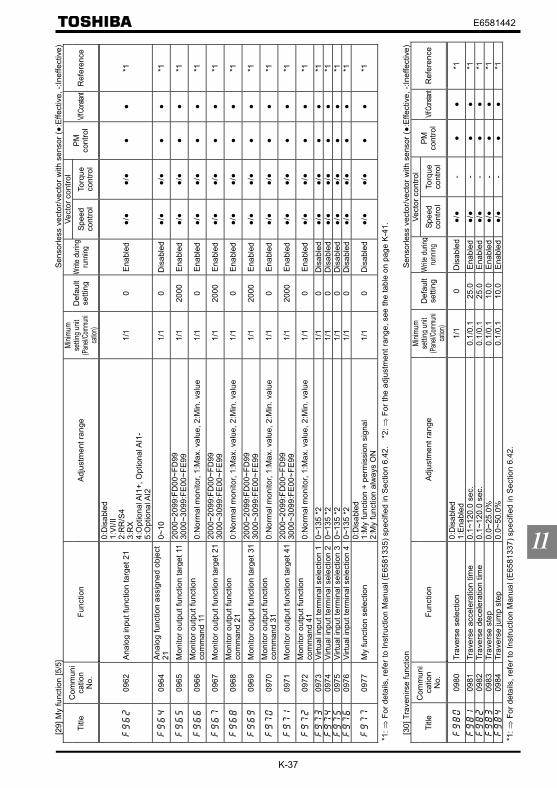
K-37
E6581442
11
[29]
My
func
tion
[5/5
]S
enso
rless
vec
tor/v
ecto
r with
sen
sor (:
Effe
ctiv
e, -:
Inef
fect
ive)
Vect
or c
ontro
lTi
tleC
omm
uni
catio
nN
o.Fu
nctio
nA
djus
tmen
t ran
geMi
nimum
settin
g un
it(Pa
nel/C
ommu
nica
tion)
Def
ault
setti
ngW
rite
durin
gru
nning
Spee
dco
ntro
lTo
rque
cont
rol
PM
cont
rol
V/f Co
nstan
tR
efer
ence
0962
Ana
log
inpu
t fun
ctio
n ta
rget
21
0:D
isab
led
1:V
I/II
2:R
R/S
43:
RX
4:O
ptio
nal A
I1+,
Opt
iona
l AI1
-5:
Opt
iona
l AI2
1/1
0E
nabl
ed/
/
*1
0964
Ana
log
func
tion
assi
gned
obj
ect
210~
101/
10
Dis
able
d/
/
*1
0965
Mon
itor o
utpu
tfun
ctio
n ta
rget
11
2000
~209
9:FD
00~F
D99
3000
~309
9:FE
00~F
E99
1/1
2000
Ena
bled
/
/
*1
0966
Mon
itor o
utpu
t fun
ctio
nco
mm
and
110:
Nor
mal
mon
itor,
1:M
ax. v
alue
, 2:M
in. v
alue
1/1
0E
nabl
ed/
/
*1
0967
Mon
itor o
utpu
tfun
ctio
n ta
rget
21
2000
~209
9:FD
00~F
D99
3000
~309
9:FE
00~F
E99
1/1
2000
Ena
bled
/
/
*1
0968
Mon
itor o
utpu
t fun
ctio
nco
mm
and
210:
Nor
mal
mon
itor,
1:M
ax. v
alue
, 2:M
in. v
alue
1/1
0E
nabl
ed/
/
*1
0969
Mon
itor o
utpu
tfun
ctio
n ta
rget
31
2000
~209
9:FD
00~F
D99
3000
~309
9:FE
00~F
E99
1/1
2000
Ena
bled
/
/
*1
0970
Mon
itor o
utpu
t fun
ctio
nco
mm
and
310:
Nor
mal
mon
itor,
1:M
ax. v
alue
, 2:M
in. v
alue
1/1
0E
nabl
ed/
/
*1
0971
Mon
itor o
utpu
tfun
ctio
n ta
rget
41
2000
~209
9:FD
00~F
D99
3000
~309
9:FE
00~F
E99
1/1
2000
Ena
bled
/
/
*1
0972
Mon
itor o
utpu
t fun
ctio
nco
mm
and
410:
Nor
mal
mon
itor,
1:M
ax. v
alue
, 2:M
in. v
alue
1/1
0E
nabl
ed/
/
*1
0973
Virtu
al in
put t
erm
inal
sel
ectio
n 1
0~13
5 *2
1/1
0D
isab
led
/
/
*109
74Vi
rtual
inpu
t ter
min
al s
elec
tion
20~
135
*21/
10
Dis
able
d/
/
*109
75Vi
rtual
inpu
t ter
min
al s
elec
tion
30~
135
*21/
10
Dis
able
d/
/
*109
76Vi
rtual
inpu
t ter
min
al s
elec
tion
40~
135
*21/
10
Dis
able
d/
/
*1
0977
My
func
tion
sele
ctio
n0:
Dis
able
d1:
My
func
tion
+ pe
rmis
sion
sig
nal
2:M
y fu
nctio
n al
way
s O
N1/
10
Dis
able
d/
/
*1
*1: ⇒
For
det
ails
, ref
er to
Inst
ruct
ion
Man
ual (
E65
8133
5) s
peci
fied
in S
ectio
n 6.
42.
*2:
⇒ F
or th
e ad
just
men
t ran
ge, s
ee th
e ta
ble
on p
age
K-4
1.
[30]
Tra
veni
rse
func
tion
Sen
sorle
ss v
ecto
r/vec
tor w
ith s
enso
r (:
Effe
ctiv
e, -:
Inef
fect
ive)
Vect
or c
ontro
lTi
tleC
omm
uni
catio
nN
o.Fu
nctio
nA
djus
tmen
t ran
geMi
nimum
settin
g un
it(Pa
nel/C
ommu
nica
tion)
Def
ault
setti
ngW
rite
durin
gru
nning
Spee
dco
ntro
lTo
rque
cont
rol
PM
cont
rol
V/f Co
nstan
tR
efer
ence
0980
Trav
erse
sel
ectio
n0:
Dis
able
d1:
Ena
bled
1/1
0D
isab
led
/
-
*1
0981
Trav
erse
acc
eler
atio
n tim
e0.
1~12
0.0
sec.
0.1/
0.1
25.0
Ena
bled
/
-
*1
0982
Trav
erse
dec
eler
atio
n tim
e0.
1~12
0.0
sec.
0.1/
0.1
25.0
Ena
bled
/
-
*1
0983
Trav
erse
ste
p0.
0~25
.0%
0.1/
0.1
10.0
Ena
bled
/
-
*1
0984
Trav
erse
jum
p st
ep0.
0~50
.0%
0.1/
0.1
10.0
Ena
bled
/
-
*1
*1: ⇒
For
det
ails
, ref
er to
Inst
ruct
ion
Man
ual (
E65
8133
7) s
peci
fied
in S
ectio
n 6.
42.

K-38
E6581442
11
[Con
tent
s of
mon
itor d
ispl
ays]
Sen
sorle
ss v
ecto
r/vec
tor w
ith s
enso
r (:
val
id, -
: inv
alid
)
Com
mun
ica
tion
No.
Func
tion
Uni
t(C
omm
unic
atio
n)M
onito
r out
put
sele
ctio
nTr
ipre
tent
ion
Met
erou
tput
sele
ctio
nSp
eed
cont
rol
Torq
ueco
ntro
lP
M c
ontro
lV
/fR
efer
ence
-St
anda
rd m
onito
r-
* 1
FE00
Trip
freq
uenc
y m
onito
r0.
01H
zwh
en tr
ipped
when
tripp
ed-
/
/
Con
tent
s of
sta
tus
mon
itor d
ispl
ay
FE31
Pat
tern
ope
ratio
n gr
oup
sele
ctio
n-
at a
pat
tern
oper
atio
n
-/
-
FE32
Num
ber o
f tim
es to
repe
at c
urre
ntpa
ttern
1at
a p
atte
rnop
erat
ion
-
/
-
FE33
Pat
tern
ope
ratio
n - n
umbe
r of p
rese
tsp
eeds
1at
a p
atte
rnop
erat
ion
-
/
-
FE34
Rem
aini
ng ti
me
of c
urre
nt p
atte
rnop
erat
ion
1at
a p
atte
rnop
erat
ion
-
/
-
FE01
Stat
us (r
otat
ion
dire
ctio
n)-
Fixe
d
-/
/
-St
atus
mon
itor 1
-*
1-
Stat
us m
onito
r 2-
* 1
-St
atus
mon
itor 3
-*
1-
Stat
us m
onito
r 4-
* 1
-St
atus
mon
itor 5
-*
1-
Stat
us m
onito
r 6-
* 1
-St
atus
mon
itor 7
-*
1-
Stat
us m
onito
r 8-
* 1
FE06
Inpu
t ter
min
al in
form
atio
n-
Fixe
d
-/
/
-In
put t
erm
inal
info
rmat
ion
(opt
iona
l)-
Fixe
d
-/
/
-In
put t
erm
inal
info
rmat
ion
(opt
iona
l)-
Fixe
d
-/
/
FE07
Out
put t
erm
inal
info
rmat
ion
-Fi
xed
-
/
/
-O
utpu
t ter
min
al in
form
atio
n (o
ptio
nal)
-Fi
xed
-
/
/
FE08
CP
U1
vers
ion
1Fi
xed
×-
/
/
FE73
CP
U2
vers
ion
-Fi
xed
×-
/
/
FE10
Pas
t trip
1-
Fixe
d×
-/
/
FE11
Pas
t trip
2-
Fixe
d×
-/
/
FE12
Pas
t trip
3-
Fixe
d×
-/
/
FE13
Pas
t trip
4-
Fixe
d×
-/
/
FE79
Par
t rep
lace
men
t ala
rm in
form
atio
n-
Fixe
d×
-/
/
FE14
Cum
ulat
ive
oper
atio
n tim
e1h
Fixe
d×
-/
/
8.2.
1
*1: S
tatu
s in
a tr
ip m
ay n
ot b
e he
ld d
epen
ding
on
sele
cted
func
tion.
Ref
er to
nex
t pag
e; ⇒
[Mon
itor F
M/A
M/p
ulse
out
put f
unct
ion
sele
ctio
n].

K-39
E6581442
11
[Mon
itor F
M/A
M/p
ulse
out
put f
unct
ion
sele
ctio
n (1
/2)]
Sen
sorle
ss v
ecto
r/vec
tor w
ith s
enso
r : v
alid
, -: i
nval
id)
FM/A
M/p
ulse
out
put
Mon
itor
outp
ut
Optio
n No
.Co
mm
unica
tion
No.
Optio
n No
.Co
mm
unica
tion
No.
Func
tion
Uni
t(C
omm
unic
atio
n)Tr
ip re
tent
ion
Spee
dco
ntro
lTo
rque
cont
rol
PM
con
trol
V/f
Ref
eren
ce
0FD
000
FE00
Out
put f
requ
ency
0.01
Hz
/
/
1FD
021
FE02
Freq
uenc
y co
mm
and
valu
e0.
01H
z
/
-
2
FD03
2FE
03O
utpu
t cur
rent
0.01
%
/
/
3FD
043
FE04
Inpu
t vol
tage
(DC
det
ectio
n)0.
01%
/
/
4FD
054
FE05
Out
put v
olta
ge0.
01%
/
/
5FD
155
FE15
Com
pens
ated
freq
uenc
y0.
01H
z
/
/
6FD
166
FE16
Spee
d fe
edba
ck (r
eal-t
ime
valu
e) *
10.
01H
z
-/-/
--
7FD
177
FE17
Spee
d fe
edba
ck (1
-sec
ond
filte
r) *1
0.01
Hz
-/
-/-
-8
FD18
8FE
18To
rque
0.01
%
/
/
*
29
FD19
9FE
19To
rque
com
man
d0.
01%
-
/
--
11FD
2011
FE20
Torq
ue c
urre
nt0.
01%
/
/
-*
212
FD21
12FE
21E
xciti
ng c
urre
nt0.
01%
/
/
-*
213
FD22
13FE
22P
ID fe
edba
ck v
alue
0.01
Hz
/
-
14
FD23
14FE
23M
otor
ove
rload
fact
or (O
L2 d
ata)
0.01
%
/
/
15FD
2415
FE24
Inve
rter o
verlo
ad fa
ctor
(OL1
dat
a)0.
01%
/
/
16FD
2516
FE25
Reg
ener
ativ
e br
akin
g re
sist
ance
over
load
fact
or (O
Lr d
ata)
1%
/
/
17FD
2817
FE28
Rege
nera
tive
brak
ing re
sisto
r loa
d fa
ctor (
% E
D)1%
/
/
18FD
2918
FE29
Inpu
t pow
er0.
01kW
/
/
19FD
3019
FE30
Out
put p
ower
0.01
kW
/
/
23FE
3923
FE39
Opt
iona
l AI2
inpu
t*4
×/
/
24FE
3524
FE35
RR
/S4
inpu
t*3
×/
/
25FE
3625
FE36
VI/I
I inp
ut*3
×/
/
26FE
3726
FE37
RX
inpu
t*3
×/
/
27FE
3827
FE38
Opt
iona
l AI1
inpu
t*4
×/
/
28FE
4028
FE40
FM o
utpu
t1
×/
/
29FE
4129
FE41
AM
out
put
1×
/
/
30FE
51-
-Fi
xed
outp
ut 1
0.01
%×
/
/
31FA
51 *
5-
-C
omm
unic
atio
n da
ta o
utpu
t1
×/
/
32FE
50-
-Fi
xed
outp
ut 2
0.01
%×
/
/
33FE
52-
-Fi
xed
outp
ut 3
0.01
%×
/
/
--
31FA
65C
omm
unic
atio
n da
ta o
utpu
t0.
01%
×/
/
--
32FE
66A
ttach
ed to
exp
ansi
on I/
O c
ard
1 C
PU
vers
ion
-×
/
/
5.16 8.3
*1: E
stim
ated
spe
ed is
out
put i
f the
re is
no
PG
feed
back
. If u
sed
as p
ulse
inpu
t com
man
d w
ith P
G fe
edba
ck o
ptio
n, fr
eque
ncy
is d
ispl
ayed
as
in th
e P
G fe
edba
ck.
*2: R
efer
ence
dat
a
*3: A
nalo
g va
lue
ente
red:
Ana
log
valu
e en
tere
d ×
valu
e m
onito
red/
2047
*
4:A
nalo
g va
lue
ente
red:
Ana
log
valu
e en
tere
d ×
valu
e m
onito
red/
1023
*5: C
omm
unic
atio
n no
. FA
51 is
use
d fo
r FM
, FA
52 fo
r AM
, FA
53 fo
r MO
N1
and
FA54
for M
ON
2 an
d pu
lse
outp
ut, r
espe
ctiv
ely.
⇒ F
or d
etai
ls, r
efer
to S
ectio
n 5.
16; [
Term
inal
FM
-rela
ted
para
met
ers]
.
⇒
For
mon
itor i
ndic
atio
ns, r
efer
to S
ectio
n 8.
3; [S
et u
p va
lues
of m
onito
r ind
icat
ion
para
met
ers]
.

K-40
E6581442
11
[Mon
itor F
M/A
M/p
ulse
out
put f
unct
ion
sele
ctio
n (2
/2)]
Sen
sorle
ss v
ecto
r/vec
tor w
ith s
enso
r (:
val
id, -
: inv
alid
)FM
/AM
/pul
se o
utpu
tM
onito
r ou
tput
Optio
n No
.Co
mm
unica
tion
No.
Optio
n No
.Co
mm
unica
tion
No.
Func
tion
Uni
t(C
omm
unic
atio
n)Tr
ip re
tent
ion
Spee
d co
ntro
lTo
rque
cont
rol
PM co
ntro
lV/
fRe
fere
nce
--
33FE
67A
ttach
ed to
exp
ansi
on I/
O c
ard
2 C
PU
vers
ion
-×
/
/
34FE
7634
FE76
Inte
gral
inpu
t pow
er0.
01kW
×/
/
35FE
7735
FE77
Inte
gral
out
put p
ower
0.01
kW×
/
/
4500
06 *
306
71 *
4-
-G
ain
disp
lay
1-
/
/
46FE
60-
-M
y fu
nctio
n m
onito
r 1 (O
utpu
t of
unsi
gned
val
ue)
1×
/
/
47FE
61-
-M
y fu
nctio
n m
onito
r 2 (O
utpu
t of
unsi
gned
val
ue)
1×
/
/
48FE
62-
-M
y fu
nctio
n m
onito
r 3 (O
utpu
t of s
igne
dva
lue)
*2
1×
/
/
49FE
63-
-M
y fu
nctio
n m
onito
r 4 (O
utpu
t of s
igne
dva
lue)
*2
1×
/
/
50FD
0050
FE00
Sig
ned
outp
ut fr
eque
ncy
-
/
/
51FD
0251
FE02
Sig
ned
frequ
ency
com
man
d va
lue
-
/
-
52
FD15
52FE
15S
igne
d co
mpe
nsat
ed fr
eque
ncy
-
/
/
53FD
1653
FE16
Sig
ned
spee
d fe
edba
ck (r
eal-t
ime
valu
e)-
-/
-/-
-54
FD17
54FE
17S
igne
d sp
eed
feed
back
(1-s
econ
d fil
ter)
-
-/-/
--
55FD
1855
FE18
Sig
ned
torq
ue-
/
/
*
156
FD19
56FE
19S
igne
d to
rque
com
man
d-
-
/
--
58FD
2058
FE20
Sig
ned
torq
ue c
urre
nt-
/
/
-
*159
FD22
59FE
22S
igne
d P
ID fe
edba
ck v
alue
-
/
-
60
FE37
60FE
37S
igne
d R
X in
put
-×
/
/
61FE
3861
FE38
Sig
ned
optio
nal A
I1 in
put
-×
/
/
62FE
51-
-S
igne
d fix
ed o
utpu
t 1-
×/
/
63FE
50-
-S
igne
d fix
ed o
utpu
t 2-
×/
/
64FE
52-
-S
igne
d fix
ed o
utpu
t 3-
×/
/
--
64FD
50Li
ght-l
oad
high
-spe
ed lo
ad to
rque
mon
itor 1
0.01
%×
/
/
--
65FD
51Li
ght-l
oad
high
-spe
ed lo
ad to
rque
mon
itor 2
0.01
%×
/
/
--
66FE
31P
atte
rn o
pera
tion
grou
p nu
mbe
r0.
1×
/
-
--
67FE
32R
emai
ning
no.
of c
ycle
s fo
r whi
ch p
atte
rnop
erat
ion
is c
ontin
ued
1×
/
-
--
68FE
33P
atte
rn o
pera
tion
pres
et s
peed
num
bers
1×
/
-
--
69FE
34R
emai
ning
tim
e fo
r whi
ch p
atte
rnop
erat
ion
is c
ontin
ued
0.1
×/
-
5.16 8.3
*1: R
efer
ence
dat
a
*2: A
n ab
solu
te v
alue
is o
utpu
t for
pul
se tr
ain
outp
ut o
f 48
and
49.
*3
: Com
mun
icat
ion
no. f
or F
M o
utpu
t
*4: C
omm
unic
atio
n no
. for
AM
out
put
⇒ F
or d
etai
ls, r
efer
to S
ectio
n 5.
16; [
Term
inal
FM
-rela
ted
para
met
ers]
.⇒
For
mon
itor i
ndic
atio
ns, r
efer
to S
ectio
n 8.
3; [S
et u
p va
lues
of m
onito
r ind
icat
ion
para
met
ers]
.

K-41
E6581442
11
[Inpu
t ter
min
al fu
nctio
n se
tting
(1/2
)]S
enso
rless
vec
tor/v
ecto
r with
sen
sor (:
val
id, -
: inv
alid
)P
ositi
velo
gic
Neg
ativ
elo
gic
Func
tion
Spee
dco
ntro
lTo
rque
cont
rol
PM
con
trol
V/f
==
Ref
eren
ce
01
No
func
tion
is a
ssig
ned
/
/
--
23
F: F
orw
ard
run
com
man
d/
/
-
45
R: R
ever
se ru
n co
mm
and
/
/
-
67
ST:
Sta
ndby
/
/
*1-
89
RE
S: R
eset
/
/
*2-
1011
S1:
Pre
set s
peed
1/
-
-12
13S
2: P
rese
t spe
ed 2
/
-
-14
15S
3: P
rese
t spe
ed 3
/
-
-16
17S
4: P
rese
t spe
ed 4
/
-
-18
19Jo
g ru
n/
-
20
21E
mer
genc
y st
op/
/
*2-
2223
DC
bra
king
/
-
24
25A
ccel
erat
ion/
dece
lera
tion
switc
hing
1/
-
-26
27A
ccel
erat
ion/
dece
lera
tion
switc
hing
2/
-
-28
29V
/f sw
itchi
ng s
igna
l 1/
-
-30
31V
/f sw
itchi
ng s
igna
l 2/
-
-32
33To
rque
lim
it sw
itchi
ng s
igna
l 1/
/
-
3435
Torq
ue li
mit
switc
hing
sig
nal 2
/
/
-
3637
PID
con
trol O
FF s
elec
tion
/
-
-38
39P
atte
rn o
pera
tion
sele
ctio
n 1
/
-
-40
41P
atte
rn o
pera
tion
sele
ctio
n 2
/
-
-42
43P
atte
rn o
pera
tion
cont
inua
tion
sign
al/
-
-44
45P
atte
rn o
pera
tion
trigg
er s
igna
l/
-
-46
47E
xter
nal t
herm
al e
rror
/
-
-48
49C
omm
unic
atio
n pr
iorit
y ca
ncel
/
-
-
5051
Hol
ding
of H
D o
pera
tion
(sto
p of
thre
e-w
ireop
erat
ion)
/
-
-
5253
PID
diff
eren
tiatio
n/in
tegr
atio
n re
set
/
-
-54
55P
ID fo
rwar
d/re
vers
e sw
itchi
ng/
-
-56
57Fo
rced
con
tinuo
us o
pera
tion
/
-
-58
59Sp
ecifi
ed s
peed
ope
ratio
n/
-
-60
61A
ccel
erat
ion/
dece
lera
tion
susp
end
sign
al/
-
-62
63P
ower
failu
re s
ynch
roni
zed
sign
al/
-
-64
65M
y fu
nctio
n R
UN
sig
nal
/
/
-
6667
Aut
o-tu
ning
sig
nal
/
-
-68
69Sp
eed
gain
sw
itchi
ng/
-
-
7.2.
1
*1: V
alid
any
tim
e*2
: Ind
epen
dent
of
, and
all
com
man
d ar
e va
lid.

K-42
E6581442
11
[Inpu
t ter
min
al fu
nctio
n se
tting
(2/2
)]S
enso
rless
vec
tor/v
ecto
r with
sen
sor (:
val
id, -
: inv
alid
)P
ositi
velo
gic
Neg
ativ
elo
gic
Func
tion
Spee
dco
ntro
lTo
rque
cont
rol
PM
con
trol
V/f
==
Ref
eren
ce
7071
Ser
vo lo
ck s
igna
l/
-
-72
73S
impl
e po
sitio
ning
(pos
ition
ing
loop
)/
-
-74
75In
tegr
atin
g w
attm
eter
dis
play
cle
ar/
-
-76
77Tr
ace
back
trig
ger s
igna
l/
-
-78
79Li
ght-l
oad
high
-spe
ed o
pera
tion
proh
ibiti
ve s
igna
l/
-
-86
87B
inar
y da
ta w
rite
/
/
-
8889
Up/
Dow
n fre
quen
cy (u
p)*1
/
-
-90
91U
p/D
own
frequ
ency
(dow
n)*1
/
-
-92
93U
p/D
own
frequ
ency
(cle
ar)
/
-
-98
99Fo
rwar
d/re
vers
e se
lect
ion
/
/
-
100
101
Run
/Sto
p co
mm
and
/
/
-
102
103
Com
mer
cial
pow
er/IN
V s
witc
hing
/
-
-10
410
5Fr
eque
ncy
refe
renc
e pr
iorit
y sw
itchi
ng/
-
-10
610
7V
I/II t
erm
inal
prio
rity
/
-
-10
810
9C
omm
and
term
inal
boa
rd p
riorit
y/
/
-
110
111
Par
amet
er e
ditin
g en
ablin
g/
/
-
112
113
Spee
d/To
rque
sw
itchi
ng/
/
--
*2-
122
123
Rap
ides
t dec
eler
atio
n co
mm
and
/
-
-12
412
5P
relim
inar
y ex
cita
tion
/
/
-
126
127
Bra
king
requ
est
/
-
-13
013
1B
rake
ans
wer
bac
k in
put
/
-
-13
413
5Tr
aver
se p
erm
issi
on s
igna
l/
-
-
7.2.
1
*1: T
he d
ecel
erat
ion/
dece
lera
tion
time
depe
nds
on th
e /
set
ting,
unl
ess
switc
hing
bet
wee
n ac
cele
ratio
n an
d de
cele
ratio
n is
per
form
ed.
*2: D
epen
dent
on
.

K-43
E6581442
11
[Out
put t
erm
inal
func
tion
setti
ng (1
/3)]
Sen
sorle
ss v
ecto
r/vec
tor w
ith s
enso
r (:
val
id, -
: inv
alid
)P
ositi
velo
gic
Neg
ativ
elo
gic
Func
tion
Spee
d co
ntro
lTo
rque
con
trol
PM
con
trol
V/f
Ref
eren
ce
01
LL/
/
23
UL
/
/
45
LOW
/
/
67
Acc
eler
atio
n/de
cele
ratio
n co
mpl
etio
n/
-
8
9Sp
ecifi
ed s
peed
arr
ival
/
/
1011
Failu
re F
L (a
ll tri
p)/
/
1213
Failu
re F
L (e
xcep
t for
EF,
OC
L, E
PH
O a
nd O
L2)
/
/
1415
Ove
rcur
rent
pre
-ala
rm/
/
1617
Inve
rter o
verlo
ad p
re-a
larm
/
/
1819
Mot
or o
verlo
ad p
re-a
larm
/
/
2021
Ove
rhea
t pre
-ala
rm/
/
2223
Ove
rvol
tage
pre
-ala
rm/
/
2425
Mai
n ci
rcui
t und
ervo
ltage
ala
rm/
/
2627
Low
cur
rent
ala
rm/
/
2829
Ove
rtorq
ue a
larm
/
/
3031
Bra
king
resi
stor
ove
rload
pre
-ala
rm/
/
3233
In e
mer
genc
y st
op/
/
3435
In c
ours
e of
retry
/
/
3637
Pat
tern
ope
ratio
n sw
itchi
ng o
utpu
t/
-
38
39P
ID d
evia
tion
limit
/
-
40
41R
un/S
top
/
/
4243
Ser
ious
failu
re (O
CA
, OC
L, E
F, p
hase
failu
re, e
tc.)
/
/
4445
Ligh
t fai
lure
(OL,
OC
1, 2
, 3, O
P)
/
/
4647
Com
mer
cial
/INV
sw
itchi
ng o
utpu
t 1 (f
or in
verte
rop
erat
ion
outp
ut)
/
-
4849
Com
mer
cial
/INV
sw
itchi
ng o
utpu
t 2 (f
or c
omm
erci
alop
erat
ion
outp
ut)
/
-
5051
Coo
ling
fan
ON
/OFF
/
/
5253
In J
og ru
n/
-
54
55P
anel
ope
ratio
n/te
rmin
al b
oard
ope
ratio
n sw
itchi
ng/
/
5657
Cum
ulat
ive
oper
atio
n tim
e al
arm
/
/
5859
PRO
FIBU
S/D
evic
eNet
/CC
-Lin
k co
mm
unic
atio
n er
ror
/
/
6061
Forw
ard/
reve
rse
run
/
/
6263
Rea
dy fo
r ope
ratio
n 1
/
/
6465
Rea
dy fo
r ope
ratio
n 2
/
/
6869
Bra
king
rele
ase
sign
al/
-
70
71In
(pre
-)al
arm
sta
tus
/
/
7273
Forw
ard
spee
d lim
it (to
rque
con
trol)
-/
--
7475
Rev
erse
spe
ed li
mit
(torq
ue c
ontro
l)-
/
--
7.2.
2

K-44
E6581442
11
[Out
put t
erm
inal
func
tion
setti
ng (2
/3)]
Sen
sorle
ss v
ecto
r/vec
tor w
ith s
enso
r (:
val
id, -
: inv
alid
)P
ositi
velo
gic
Neg
ativ
elo
gic
Func
tion
Spee
d co
ntro
lTo
rque
con
trol
PM
con
trol
V/f
Ref
eren
ce
7677
Inve
rter h
ealth
y ou
tput
/
/
7879
RS
485
com
mun
icat
ion
erro
r/
/
8081
Err
or c
ode
outp
ut 1
(6-b
it ou
tput
)/
/
8283
Err
or c
ode
outp
ut 2
(6-b
it ou
tput
)/
/
8485
Err
or c
ode
outp
ut 3
(6-b
it ou
tput
)/
/
8687
Err
or c
ode
outp
ut 4
(6-b
it ou
tput
)/
/
8889
Err
or c
ode
outp
ut 5
(6-b
it ou
tput
)/
/
9091
Err
or c
ode
outp
ut 6
(6-b
it ou
tput
)/
/
9293
Des
igna
ted
data
out
put 1
(7-b
it ou
tput
)/
/
9495
Des
igna
ted
data
out
put 2
(7-b
it ou
tput
)/
/
9697
Des
igna
ted
data
out
put 3
(7-b
it ou
tput
)/
/
9899
Des
igna
ted
data
out
put 4
(7-b
it ou
tput
)/
/
100
101
Des
igna
ted
data
out
put 5
(7-b
it ou
tput
)/
/
102
103
Des
igna
ted
data
out
put 6
(7-b
it ou
tput
)/
/
104
105
Des
igna
ted
data
out
put 7
(7-b
it ou
tput
)/
/
106
107
Ligh
t loa
d si
gnal
/
-/-
10
810
9H
eavy
load
sig
nal
/
-/-
11
011
1P
ositi
ve to
rque
lim
it/
/
112
113
Neg
ativ
e to
rque
lim
it/
/
114
115
Out
put f
or e
xter
nal r
ush
supp
ress
ion
rela
y/
/
118
119
Com
plet
ion
of s
top
posi
tioni
ng (f
or s
impl
e po
sitio
ning
)-/-
-/--
-12
012
1L-
STO
P/
/
122
123
Pow
er fa
ilure
syn
chro
nize
d op
erat
ion
/
/
124
125
Trav
erse
mot
ion
/
/
126
127
Trav
erse
dec
eler
atio
n in
pro
gres
s/
/
128
129
Part
repl
acem
ent a
larm
/
/
130
131
Ove
rtorq
ue p
re-a
larm
/
/
132
133
Ope
ratio
n fre
quen
cy c
omm
and
1/2
sele
ctio
n/
/
134
135
Failu
re F
L (e
xcep
t em
erge
ncy
stop
)/
/
222
223
My
func
tion
outp
ut 1
/
/
224
225
My
func
tion
outp
ut 2
/
/
226
227
My
func
tion
outp
ut 3
/
/
228
229
My
func
tion
outp
ut 4
/
/
230
231
My
func
tion
outp
ut 5
/
/
232
233
My
func
tion
outp
ut 6
/
/
234
235
My
func
tion
outp
ut 7
/
/
236
237
My
func
tion
outp
ut 8
/
/
238
239
My
func
tion
outp
ut 9
/
/
7.2.
2

K-45
E6581442
11
[Out
put t
erm
inal
func
tion
setti
ng 3
/3]
Sen
sorle
ss v
ecto
r/vec
tor w
ith s
enso
r (:
val
id, -
: inv
alid
)P
ositi
velo
gic
Neg
ativ
elo
gic
Func
tion
Spee
d co
ntro
lTo
rque
con
trol
PM
con
trol
V/f
Ref
eren
ce
240
241
My
func
tion
outp
ut 1
0/
/
242
243
My
func
tion
outp
ut 1
1/
/
244
245
My
func
tion
outp
ut 1
2/
/
246
247
My
func
tion
outp
ut 1
3/
/
248
249
My
func
tion
outp
ut 1
4/
/
250
251
My
func
tion
outp
ut 1
5/
/
252
253
My
func
tion
outp
ut 1
6/
/
254
255
Alw
ays
OFF
(for
term
inal
sig
nal t
ests
)/
/
7.2.
2

K-46
E6581442
11
Stan
dard
def
ault
setti
ngs
clas
sifie
d by
inve
rter m
odel
(cap
acity
)
Inve
rter t
ype
Torq
uebo
ost
Bas
efr
eque
ncy
volta
geAc
c/de
ctim
e / / / /
PW
MCa
rrier
frequ
ency
Dyn
amic
brak
ing
resi
stan
ce
Allo
wab
leco
ntin
uous
brak
ing
resi
stan
ce
Inve
rter s
ide
switc
hing
wai
ting
time
Mot
or ra
ted
capa
city
Mot
or ra
ted
curre
ntM
otor
rate
dro
tatio
nal s
peed
*1
Mot
orco
nsta
nt 1
(torq
uebo
ost )
Mot
orco
nsta
nt 2
(no
load
curre
nt)
Mot
orco
nsta
nt 3
(leak
indu
ctanc
e )
Mot
orco
nsta
nt 4
(rate
d sli
p)
Disp
lay
unit
sele
ctio
n fo
rin
tegr
alou
t put
pow
er
VFA
S1-
2004
PLV
FAS
1-20
07PL
VFA
S1-
2015
PLV
FAS
1-20
22PL
VFA
S1-
2037
PLV
FAS
1-20
55PL
VFA
S1-
2075
PLV
FAS
1-21
10P
MV
FAS
1-21
50P
MV
FAS
1-21
85P
MV
FAS
1-22
20P
MV
FAS
1-23
00P
MV
FAS
1-23
70P
MV
FAS
1-24
50P
MV
FAS
1-25
50P
VFA
S1-
2750
PV
FAS
1-40
07PL
*2V
FAS
1-40
15PL
*2V
FAS
1-40
22PL
*2V
FAS
1-40
37PL
*2V
FAS
1-40
55PL
*2V
FAS
1-40
75PL
*2V
FAS
1-41
10P
L*2
VFA
S1-
4150
PL*2
VFA
S1-
4185
PL*2
VFA
S1-
4220
PL*2
VFA
S1-
4300
PL*2
VFA
S1-
4370
PL*2
VFA
S1-
4450
PL*2
VFA
S1-
4550
PL*2
VFA
S1-
4750
PL*2
VFA
S1-
4900
PC*2
VFA
S1-
4110
KP
C*2
VFA
S1-
4132
KPC
*2V
FAS
1-41
60K
PC*2
VFA
S1-
4200
KPC
*2V
FAS
1-42
20K
PC*2
VFA
S1-
4280
KPC
*2V
FAS
1-43
55K
PC*2
VFA
S1-
4400
KPC
*2V
FAS
1-45
00K
PC*2
*1: F
acto
ry d
efau
lt se
tting
s w
hen
the
base
freq
uenc
y (
) is
set a
t 60H
z (5
0Hz)
*2: I
nver
ter w
ith a
mod
el n
umbe
r end
ing
with
-W
N1,
HN
:
-WP
1:

E6581442
L-1
12
12. Specifications
12.1 Models and their standard specifications
1) Standard specifications (small/medium capacity types)Item Specification
Voltage class 200V classApplicable motor (kW) 0.4 0.75 1.5 2.2 3.7/4.0 5.5 7.5 11 15 18.5 22 30 37 45Applicable motor (HP) 0.5 1 2 3 5 7.5 10 15 20 25 30 40 50 60
Type VFAS1-Form 2004PL 2007PL 2015PL 2022PL 2037PL 2055PL 2075PL 2110PM 2150PM 2185PM 2220PM 2300PM 2370PM 2450PMOutput capacity (kVA)[Note 1] 1.1 1.8 3.0 4.2 6.7 10 13 21 25 29 34 46 55 67
Output current(A) [Note 2]
3.0(3.0)
4.8(4.5)
8.0(8.0)
11(10.5)
17.5(16.6)
27.5(25.0)
33(33)
54(49)
66(64)
75(66)
88(75)
120(88)
144(120)
176(140)
Output voltage Three-phase 200V~240V (The maximum output voltage is equal to the input supply voltage.)
Rating
Overloadcurrent rating 150%-1 minute, 165%-2 sec.
Dynamicbraking circuit Built-in dynamic braking drive circuit
Electricalbraking Dynamic braking
resistorAn external braking resistor (optional)
⇒ Rating: Refer to 5.19.
Voltage-frequency Three-phase 200~240V-50/60Hz [Note 3]Pow
ersupply Allowable
fluctuation Voltage + 10% - 15% [Note 4] Frequency ±5%
Protective method IP20 Enclosed type (JEM1030) IP00 Open type (JEM1030) [Note 5]Cooling method Forced air-cooledCooling fan noise (dBA) 43 43 43 55 55 56 58 60 60 60 60 64 64 64Color RAL7016EMC filter Built-in Basic filter (Not complies with the European EMC Directive)DC reactor External DC reactor (option) Built-in
Item SpecificationVoltage class 400V classApplicable motor (kW) 0.75 1.5 2.2 3.7/4.0 5.5 7.5 11 15 18.5 22 30 37 45 55 75Applicable motor (HP) 1 2 3 5 7.5 10 15 20 25 30 40 50 60 75 100
Type VFAS1-Form 4007PL 4015PL 4022PL 4037PL 4055PL 4075PL 4110PL 4150PL 4185PL 4220PL 4300PL 4370PL 4450PL 4550PL 4750PLOutput capacity (kVA)[Note 1] 1.8 3.1 4.4 8.0 11 13 21 25 31 37 50 60 72 88 122
Output current(A) [Note 2]
2.3(2.3)
4.1(4.0)
5.8(4.6)
10.5 (8.6)
14.3(13)
17.6(17)
27.7(25)
33(32)
41(37)
48(38)
66(53)
79(60)
94(75)
116(93)
160(120)
Output voltage Three-phase 380V~480V (The maximum output voltage is equal to the input supply voltage.)
Rating
Overloadcurrent rating 150%-1 minute, 165%-2 sec.
Dynamicbraking circuit Built-in dynamic braking drive circuit
Electricalbraking Dynamic braking
resistorAn external braking resistor (optional)
⇒ Rating: Refer to 5.19.Voltage-frequency Three-phase 380~480V-50/60Hz [Note 3]P
ower
supply Allowablefluctuation Voltage + 10% - 15% [Note 4] Frequency ±5%
Protective method IP20 Enclosed type (JEM1030) IP00 Open type (JEM1030) [Note 5]Cooling method Forced air-cooledCooling fan noise (dBA) 43 43 43 55 56 56 58 60 60 60 64 64 64 64 64Color RAL7016EMC filter Built-inDC reactor External DC reactor (option) Built-in
Note 1: Capacity is calculated at 220V for the 200V models and at 440V for the 400V models.Note 2: Rated output current when the PWM carrier frequency (parameter ) is 4kHz or less.
The values between parentheses refer to rated output currents when set to 12kHz.⇒ Refer to 1.4.4 ”Current reduction curve” for details.
Note 3: If you are using a 200V-15kW or 400V-2.2kW inverter and the ambient temperature is 40°C or more, decreasethe PWM carrier frequency to 8kHz. Setting to enables you to protect the overload caused byambient temperature described in page A-23.An external power supply backup available (optional) (Type: CPS002Z)
Note 4: ±10% when the inverter is used continuously (load of 100%).Note 5: Inverters, 18.5kW or greater, do not have wiring port covers. They have large openings, but there is no space
to bend the external cables inside the unit. If they are fitted external to the cabinet, please use an optionalwiring port cover.
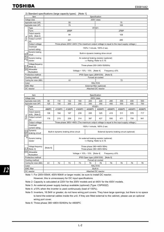
E6581442
L-2
12
2) Standard specifications (large capacity types) [Note 1]Item Specification
Voltage class 200V classApplicable motor (kW) 55 75Applicable motor (HP) 75 100
Type VFAS1-Form 2550P 2750POutput capacity(kVA) [Note 2] 84 109
Output current(A) 221 285
Output voltage Three-phase 200V~240V (The maximum output voltage is equal to the input supply voltage.)
Rating
Overloadcurrent rating 150%-1 minute, 165%-2 sec.
Dynamic brakingcircuit Built-in dynamic braking drive circuit
Electricalbraking Dynamic braking
resistorAn external braking resistor (optional)
⇒ Rating: Refer to 5.19.
Voltage-frequency[Note 3] Three-phase 200~240V-50/60HzP
ower
supply Allowablefluctuation Voltage + 10% - 15% [Note 4] Frequency ±5%
Protective method IP00 Open type (JEM1030) [Note 5]Cooling method Forced air-cooledCooling fan noise (dBA) 61 72Color RAL7016EMC filter External filter (optional)DC reactor Attached DC reactor
Item SpecificationVoltage class 400V classApplicable motor (kW) 90 110 132 160 200 220 280 355 400 500Applicable motor (HP) 125 150 200 250 300 350 450 550 600 700
Type VFAS1-Form 4900PC 4110KPC 4132KPC 4160KPC 4200KPC 4220KPC 4280KPC 4355KPC 4400KPC 4500KPCOutput capacity(kVA) [Note 2] 136 164 197 239 295 325 419 511 578 717
Output current(A) 179 215 259 314 387 427 550 671 759 941
Output voltage Three-phase 380V~480V (The maximum output voltage is equal to the input supply voltage.)
Rating
Overloadcurrent rating 150%-1 minute, 165%-2 sec.
Dynamicbraking circuit Built-in dynamic braking drive circuit External dynamic braking circuit (optional)
Electrical
brakingDynamic brakingresistor
An external braking resistor (optional)⇒ Rating: Refer to 5.19.
Voltage-frequency[Note 3] [Note 6] Three-phase 380~440V-50Hz
Three-phase 380~480V-60Hz
Pow
ersupply Allowable
fluctuation Voltage + 10% - 15% [Note 4] Frequency ±5%
Protective method IP00 Open type (JEM1030) [Note 5]Cooling method Forced air-cooledCooling fan noise (dBA) 61 72 73 73 76 76 76 76 76 78Color RAL7016EMC filter Built-inDC reactor Attached DC reactor
Note 1: For 200V-55kW, 400V-90kW or larger model, be sure to install DC reactor.However, this is unnecessary for DC input specifications.
Note 2: Capacity is calculated at 220V for the 200V models and at 440V for the 400V models.Note 3: An external power supply backup available (optional) (Type: CSP002Z)Note 4: ±10% when the inverter is used continuously (load of 100%).Note 5: Inverters, 18.5kW or greater, do not have wiring port covers. They have large openings, but there is no space
to bend the external cables inside the unit. If they are fitted external to the cabinet, please use an optionalwiring port cover.
Note 6: Three-phase 380~480V-50/60Hz for 4900PC

E6581442
L-3
12
3) Common specificationItem Specification
Control system Sinusoidal PWM controlOutput voltage adjustment Main circuit voltage feedback control. (Switchable between automatic adjustment/fix/control off)
Output frequency range Setting between 0.01 to 500Hz. Default max. frequency is set to 0.01 to 60Hz.Maximum frequency adjustment (30 to 500Hz)
Minimum setting steps offrequency
0.01Hz: operation panel input (60Hz base),0.02Hz: analog input (60Hz base, 11 bit/0 to 10Vdc)
Frequency accuracy Analog input: ±0.2% of the maximum output frequency (at 25±10°C)Digital input: ±0.01%±0.022Hz of the output frequency
Voltage/frequencycharacteristics
V/f constant, square reduction torque control, automatic torque boost, vector calculation control, basefrequency adjustment 1, 2, 3, and 4 (25 to 500Hz), V/f 5-point arbitrary setting, torque boost adjustment (0to 30%), start frequency adjustment (0 to 10Hz), stop frequency adjustment (0 to 30Hz)
Frequency setting signal
3kΩ potentiometer (possible to connect to 1 to 10kΩ-rated potentiometer)0 to 10Vdc (input impedance Zin: 30kΩ)0 to ±10Vdc (Zin: 22kΩ)4 to 20mAdc (Zin:242Ω)
Terminal board basefrequency
The characteristic can be set arbitrarily by two-point setting. Compliant with 6 types of input; analog input(RR, VI/II, RX, RX2), pulse input and binary/BCD input (*RX2, binary/BCD input: optional)
Frequency jump 3 places. Setting of jump frequency and width.Upper and lower limitfrequencies
Upper limit frequency: 0 to max. frequency, lower limit frequency: 0 to upper limit frequency
PWM carrier frequency 200V-45kW or less, adjustable between 1.0 to 16kHz for 400V-75kW or less200V-55kW or less, adjustable between 2.5 to 8kHz for 400V-90kW or more
PID control Adjustment of proportional gain, integral time, differential time and delay filter
Control specification
Torque control Voltage command input specification: DC 0 to ±10VAcceleration/decelerationtime
0.01 to 6000 sec. Selectable from among acceleration/deceleration. times 1, 2, 3 and 4. Automaticacceleration/deceleration function. S-pattern acceleration/deceleration 1 and 2 pattern adjustable.
DC braking Adjustment of braking start frequency (0 to 120Hz), braking (0 to 100%) and braking time (0 to 20 sec.).With emergency stop braking function and motor shaft fix control function.
Forward run/reverse run[Note 1]
With F-CC closed to forward run, with R-CC closed to reverse run, with both closed to reverse run. WithPWR-CC opened to coast stop. Emergency stop by panel operation or terminal board.
Jog run[Note 1]
Jog mode, if selected, allows jog operation from the operation panelJog run operation by terminal board is possible by setting the parameters.
Preset speed operation[Note 1]
By changing the combination of open/close between S1, S2, S3, RR/S4-CC, set frequency + 15-speedoperation.Selectable between acceleration/deceleration time, torque limit and V/f by set frequency.
Retry Capable of restarting after a check of the main circuit elements in case the protective function is activated.Max. 10 times selectable arbitrarily. Waiting time adjustment (0 to 10 sec.)
Soft stall Automatic load reduction control at overloading. (Default: OFF)Cooling fan ON/OFF The cooling fan will be stopped automatically to assure long life when unnecessary.Operation panel keyoperation ON/OFF control
Key prohibition selectable between STOP key only, MODE key only, etc. All key operations can beprohibited.
Regenerative power ride-through control
Possible to keep the motor running using its regenerative energy in case of a momentary power failure.(Default: OFF)
Auto-restart operation Possible to restart the motor in coasting in accordance with its speed and direction. (Default: OFF)Simplified patternoperation
Possible to select each 8 patterns in 2 groups from 15-speed operation frequency. Max. 16 types ofoperation possible. Terminal board operation/repeat operation possible.
Commercial inverterswitching
Possible to switch operation by commercial power source or inverter
Light-load high-speedoperation
Increases the operating efficiency of the machine by increasing the rotational speed of the motor when it isoperated under light load.
Drooping function When two or more inverters are used to operate a single load, this function prevents load fromconcentrating on one inverter due to unbalance.
Operation specifications
Override function External input signal adjustment is possible to the operation frequency command value.
Protective function
Stall prevention, current limit, overcurrent, overvoltage, short circuit on the load side, ground fault on theload side [Note 6], undervoltage, momentary power failure (15ms or more), non-stop control at momentarypower failure, overload protection, arm overload at starting, overcurrent on the load side at starting,overcurrent and overload at dynamic braking resistance, fin overheat, emergency stop
Electronic thermalcharacteristic
Switchable between standard motor/constant torque VF motor, adjustment of overload protection and stallprevention level.
Protective function
Reset Reset by 1a contact closed (or 1b contact opened), or by operation panel. Or power source OFF/ON. Thisfunction is also used to save and clear trip records.
(Continued overleaf)

E6581442
L-4
12
(Continued)Item Specification
Alarms Stall prevention during operation, overload limit, overload, undervoltage on power source side, DC circuitundervoltage, setting error, in retry, upper limit, lower limit.
Causes offailures
Overcurrent, overvoltage, fin overheat, short circuit on the load side, ground fault on the load side, inverteroverload, arm overcurrent at starting, overcurrent on the load side at starting, EEPROM error, RAM error,ROM error, transmission error, (dynamic braking resistor overcurrent/overload), (emergency stop),(undervoltage), (low current), (overtorque), (motor overload), (output phase failure)The items in the parentheses are selectable.
Monitoringfunction
Operation frequency, operation frequency command, forward run/reverse run, output current, DC voltage,output voltage, compensated frequency, terminal board input/output information, CPU version, controlEEPROM version, past trip history, cumulative operation time, speed feedback, torque, torque command,torque current, exiting current, PID feedback value, motor overload factor, inverter overload factor, PBRoverload factor, PBR load factor, input power, output power, peak output current, peak DC voltage, Motorcounter pseudo PG, position pulse, RR input, VI/II input, RX input, RX2 input, FM output, AM output,meter adjustment fix output, flash memory version, main circuit EEPROM version, types of connectionoption, previous default setting, previous automatic control (AU2)
Free unit display Display of optional units other than output frequency (motor speed, line speed, etc), current ampere/%switch, voltage volt/% switch
Automatic editfunction
Searches automatically parameters that are different from the standard default setting parameters. Easyto find changed parameters.
4-digitand 7-segmentLED
User defaultsetting
User parameter settings can be saved as default settings. Allows to reset the parameters to the user-defined parameter settings.
Display function
LED Charge display Displays main circuit capacitor charging.
Input/output terminal inputfunction
Possible to select positive logic or negative logic with programmable input/output terminal function menu.[Note 1] [Note 2](Default setting: positive logic)
Sink/source switching Possible to switch between minus common (CC) and plus common (P24) for control terminal.(Default setting: minus common (CC))
Failure detection signal 1c contact output (250Vac-2A-cosФ=1, 250Vac-1A-cosФ=0.4, 30Vdc-1A)Low speed/speed reachsignal output[Note 2]
Open collector output (24Vdc, max. 50mA, output impedance: 33Ω)
Upper/lower limitfrequency signal output[Note 2]
Open collector output (24Vdc, max. 50mA, output impedance: 33Ω)
Output for frequencymeter/Output for ammeter[Note 3]
Analog output. 1mAdc full-scale DC ammeter or 7.5Vdc-1mA voltmeter
output signal
Pulse train frequencyoutput
Open collector output (24Vdc, max. 50mA)
Communication function RS-485 standard 2-channel equipped (connector: modular 8P)CC-Link, DeviceNet and PROFIBUS-DP are optional.
Use environments Indoor use. Altitude: 3000m or less (current reduction necessary if 1000m or more.) Place not exposed todirect sunlight and free of corrosive and explosive gases.
Ambient temperature -10 to +60°C (Remove the upper cover if 40°C or more, max. 60°C) [Note 4]Storage temperature -25 to +70°CRelative humidity 20 to 93% (free from condensation)
Environm
ents
Vibration 5.9m/s20.6G or less (10 to 55Hz) (Compliant with JIS C60068-2-6)
Note 1: 16 contact input terminals (of which 8 are options) are programmable contact input terminals, and they make itpossible to arbitrarily select from 136 types of signals.
Note 2: Programmable ON/OFF output terminals make it possible to arbitrarily select from 150 types of signals.Note 3: Programmable analog output terminals make it possible to arbitrarily select from 55 types of signals.Note 4: When using inverters where the ambient temperature will rise above 50°C, remove the upper cover and
operate each inverter at a current lower than the rated one.Note 5: Inverters, 18.5kW or greater, do not have wiring port covers. They have large openings, but there is no space
to bend the external cables inside the unit. If they are fitted external to the cabinet, please use an optionalwiring port cover.
Note 6: This function protects inverters from overcurrent due to output circuit ground fault.

E6581442
L-5
12
12.2 Outside dimensions and mass
Outside dimensions and massDimensions (mm)Voltage
class
Applicablemotor(kW)
Applicablemotor(HP)
Inverter typeW H D W1 H1 W2 H2 H3 H4
DrawingApprox.weight
(kg)0.4 0.5 VFAS1-2004PL0.75 1 VFAS1-2007PL1.5 2 VFAS1-2015PL
130 230 152 114 220 - - - - A 3
2.2 3 VFAS1-2022PL3.7/4.0 5 VFAS1-2037PL
155 260 164 138 249 - - - - B 4
5.5 7.5 VFAS1-2055PL 175 295 164 158 283 - - - - C 5.57.5 10 VFAS1-2075PL 210 295 191 190 283 - - - - D 7.511 15 VFAS1-2110PM15 20 VFAS1-2150PM
230 400 191 210 386 - - - - E 14
18.5 25 VFAS1-2185PM22 30 VFAS1-2220PM
240 420 212 206 403 - - - - F 21
30 40 VFAS1-2300PM37 50 VFAS1-2370PM45 60 VFAS1-2450PM
320 550 242 280 525 - - - - H 41
55 75 VFAS1-2550P 310680
(920) 370 250 650 320 75 150 30 J59
(87)
200V
75 100 VFAS1-2750P 350782
(1022) 370 298 758 360 72 150 30 K72
(103)0.75 1 VFAS1-4007PL1.5 2 VFAS1-4015PL2.2 3 VFAS1-4022PL
130 230 152 114 220 - - - - A 3
3.7/4.0 5 VFAS1-4037PL 155 260 164 138 249 - - - - B 45.5 7.5 VFAS1-4055PL7.5 10 VFAS1-4075PL
175 295 164 158 283 - - - - C 5.5
11 15 VFAS1-4110PL 210 295 191 190 283 - - - - D 815 20 VFAS1-4150PL 1318.5 25 VFAS1-4185PL
230 400 191 210 386 - - - - E16
22 30 VFAS1-4220PL 240 420 212 206 403 - - - - F 2130 40 VFAS1-4300PL37 50 VFAS1-4370PL
240 550 242 206 529 - - - - G 29
45 60 VFAS1-4450PL55 75 VFAS1-4550PL75 100 VFAS1-4750PL
320 630 290 280 605 - - - - I 48
90 125 VFAS1-4900PC 310680
(920)370 250 650 320 75 150 30 J
59(89)
110 150 VFAS1-4110KPC 350782
(1022) 370 298 758 360 72 150 30 K74
(108)
132 200 VFAS1-4132KPC 330950
(1190) 370 285 920 340 75 150 30 L82
(118)
160 250 VFAS1-4160KPC 430950
(1190)370 350 920 440 75 150 30 M
104(161)
200 300 VFAS1-4200KPC134
(194)220 350 VFAS1-4220KPC280 450 VFAS1-4280KPC
585950
(1190) 370 540 920 598 75 150 30 N136
(204)355 550 VFAS1-4355KPC400 600 VFAS1-4400KPC
8801150(1390)
370 418 1120 890 75 150 30 O225
(330)
400V
500 700 VFAS1-4500KPC 11081150(1390) 370 533 1120 1120 75 150 30 P
330(462)
Note: Value in ( ) includes attached DC reactor.

E6581442
L-6
12
Outline drawing
(Insta
llatio
n dim
ensio
n)(Installation dimension)
(Insta
llatio
n dim
ensio
n)
(Installation dimension)
Fig. A Fig. B
(Insta
llatio
n dim
ensio
n)
(Installation dimension)(In
stalla
tion
dimen
sion)
(Installation dimension)
Fig. C Fig.D
(Insta
llatio
n dim
ensio
n)
(Installation dimension)
(Insta
llatio
n dim
ensio
n)
(Installation dimension)
Fig. E Fig. F

E6581442
L-7
12
(Installation dimension)
(Insta
llatio
n dim
ensio
n)
(Installation dimension)(In
stalla
tion
dimen
sion)
Fig. G Fig. H
(Insta
llatio
n dim
ensio
n)
(Installation dimension)
(Insta
llatio
n dim
ensio
n)
(Installation dimension)
DC re
acto
r (DC
L1 ty
pe)
Fig. I Fig. J

E6581442
L-8
12
(Insta
llatio
n dim
ensio
n)
(Installation dimension)
(Insta
llatio
n dim
ensio
n)
(Installation dimension)
DC re
acto
r (DC
L1 ty
pe)
DC re
acto
r (DC
L1 ty
pe)
Fig. K Fig. L
Bra
king
uni
t (op
tiona
l)
(Installation dimension)
(Insta
llatio
n dim
ensio
n)
(Installation dimension)
(Insta
llatio
n dim
ensio
n)
DC re
acto
r (DC
L1 ty
pe)
DC re
acto
r (DC
L1 ty
pe)
Fig. M Fig. N

E6581442
L-9
12
(Inst
alla
tion
dim
ensi
on)
Braking unit (optional)
DC
reac
tor (
DC
L1 ty
pe)
(Installation dimension) (Installation dimension)
Cup
per c
onne
ctin
g ba
r
Fig. O
(Inst
alla
tion
dim
ensi
on)
Braking unit (optional)
DC
reac
tor (
DC
L1 ty
pe)
(Installation dimension) (Installation dimension)
Cup
per c
onne
ctin
g ba
r
Fig. P

E6581442
M-1
13
13. Before making a service call - Trip information and remedies
13.1 Trip causes/warnings and remedies
When a problem arises, diagnose it in accordance with the following table.If it is found that replacement of parts is required or the problem cannot be solved by any remedy described in the table,contact your supplier.[Trip information]
Errorcode Description Possible causes Remedies
*Overcurrentduringacceleration
•The acceleration time is too short.•The V/f setting is improper.•A restart signal is input to therotating motor after a momentarystop, etc.
•A special motor (e.g. motor with asmall impedance) is used.
•Manual torque boost value ( ) is large.
•Increase the acceleration time .•Check the V/f parameter setting.•Use (Auto-restart) and (Regenerativepower ride-though control).
•Increase the carrier frequency .•Decrease setting value.•Decrease (stall prevention level) to 130 asa guide.
•Increase (carrier frequency) setting value if itis set at lower value (2kHz or less).
*Overcurrentduringdeceleration
•The deceleration time is tooshort. (in deceleration)
•Increase the deceleration time .
*Overcurrentduring fixedspeed
•The load fluctuates abruptly.•The load is in an abnormalcondition.
•Reduce the load fluctuation.•Check the load (operated machine).
[Note] , , originate from
causes other than thosementioned above.
•A main circuit elements is defective.•Overheat protection is activated.
•Make a service call.•Check operation of cooling fan.•Check cooling fan control mode parameter
.
* U-phase armshort-circuit
•A main circuit elements is defective(U-phase).
•Make a service call.
* V-phase armshort-circuit
•A main circuit elements is defective(V-phase).
•Make a service call.
* W-phase armshort-circuit
•A main circuit elements is defective(W-phase).
•Make a service call.
Loaded sideovercurrent atstart time
•The insulation of the output maincircuit or motor is defective.
•The motor has too smallimpedance.
•The drive circuit board in theinverter was damaged.
•Check the cables and wires for defectiveinsulation.
•Selection of short circuit detection at startingparameter .
•If this error message appears when a motor is notconnected to the inverter, the inverter itself may befaulty, so make a service call.
Dynamic brakingelementovercurrent(200V-55kW orlarger, 400V-90kW or larger)
•PB-PC/+ circuit is shorted.•A resistor with resistance smallerthan the minimum allowableresistance is connected.
•Parameter was set to or without connecting regenerativebrake or with wire disconnected(with dynamic braking).
•Check the impedance wiring for the resistor, etc.•Make a service call.•Check if regenerative brake is connected.•If regenerative brake is not necessary, setparameter to .
Overheating
•The cooling fan does not rotate.•The ambient temperature is toohigh.
•The vent is blocked up.•A heat generating device isinstalled close to the inverter.
•The thermistor in the unit isdisconnected.
•Restart the operation by resetting the inverter afterit has cooled down enough.
•The fan requires replacement if it does not rotateduring operation.
•Secure sufficient space around the inverter.•Do not place any heat generating device near theinverter.
•Make a service call.
Thermal tripstop commandfrom externaldevice
•An input signal is impressed atcontrol input terminal PTG foroptional add-on cards.
•A thermal trip command (inputterminal function: or ) isissued by an external controldevice.
•The motor is overheated, so check whether thecurrent flowing into the motor exceeds the ratedcurrent.
* In the event one of the error codes to and to appears, in which case a main circuitcomponent has most probably failed, the only way to reset the inverter is to turn power off and back on.(Continued overleaf)

E6581442
M-2
13
(Continued)Errorcode Description Possible causes Remedies
Inverteroverload
•Rapid acceleration is operated.•The DC braking amount is toolarge.
•The V/f setting is improper.•A restart signal is input to therotating motor after a momentarystop, etc.
•The load is too large.
•Increase the acceleration time .•Reduce the DC braking amount and theDC braking time .
•Check the V/f parameter setting.•Use (Auto-restart) and (Regenerativepower ride-though control).
•Use an inverter with a larger rating.
Motor overload
•The V/f parameter is improperly set.•The motor is locked up.•Low-speed operation is performedcontinuously.
•An excessive load is applied to themotor during operation.
•Check the V/f parameter setting.•Check the load (operated machine).•Check the setting and adjust according to the sustainable overload in the motorlow-speed range.
•Reduce the DC braking amount and theDC braking time .
Dynamicbraking resistoroverload
•Rapid deceleration is operated.•Dynamic braking is too large.
•Increase the deceleration time .•Increase the capacity of dynamic braking resistor(wattage) and adjust PBR capacity parameter
.
Overvoltageduringacceleration
•The input voltage fluctuates abnormally.(1)The power supply has a capacity
of 500kVA or more.(2)A power factor improvement
capacitor is opened and closed.(3)A system using a thyrister is
connected to the same powerdistribution line.
•A restart signal is input to therotating motor after a momentarystop, etc.
•Insert a suitable input reactor.
•Use (Auto-restart) and (Regenerativepower ride-though control).
Overvoltageduringdeceleration
•The deceleration time is tooshort (regenerative energy is toolarge).
•The dynamic braking resistor has aconsiderably large resistance.
• (Dynamic braking resistor) is OFF.Overvoltage limit operation is OFF.
•The input voltage fluctuates abnormally.(1)The power supply has a capacity
of 500kVA or more.(2)A power factor improvement
capacitor is opened and closed.(3)A system using a thyrister is
connected to the same powerdistribution line.
•Increase the deceleration time .
•Install a dynamic braking resistor.•Decrease dynamic braking resistance. (Also resetthe .)
•Set dynamic braking mode parameter properly.
•Set overvoltage limit operation properly.•Insert a suitable input reactor.
Overvoltageduring fixedspeed operation
•The input voltage fluctuatesabnormally.
(1)The power supply has a capacityof 500kVA or more.
(2)A power factor improvementcapacitor is opened and closed.
(3)A system using a thyrister isconnected to the same powerdistribution line.
•The motor is in a regenerativestate because the load causes themotor to run at a frequency higherthan the inverter output frequency.
•Insert a suitable input reactor.
•Install a dynamic braking resistor.
* Overtorque
•Overtorque reaches to a detectionlevel during operation.
•Stall prevention operation wasperformed continuously for alength of time longer than that setwith .
•Check system error.
•Check whether the motor is overloaded or thebrake is engaged.
* Low currentoperation
•The output current decreased to alow-current detection level duringoperation.
•Check the suitable detection level for the system( ).
•Make a service call if the setting is correct.
* Undervoltage(main circuit)
•The input voltage (in the maincircuit) is too low.
•Momentary power failure occursbecause undervoltage continueslonger than undervoltage detectiontime .
•Check the input voltage.•To cope with a momentary stop due toundervoltage, enable (Regenerative powerride-through control), (auto-restart control),and (Undervoltage detection time).
*Presence or absence of parameter trip can be selected.(Continued overleaf)

E6581442
M-3
13
(Continued)Errorcode Description Possible causes Remedies
Emergency stop
•Inverter is stopped by paneloperation during automatic orremote operation.
•A stop command (input terminalfunction: or ) is issued byan external control device.
•Reset the inverter.
EEPROM error •A data writing error occurs. •Turn off the inverter, then turn it again. If it does notrecover from the error, make a service call.
Initial read error•Some internal data is corrupted.•Power was turned off while was being set.
•Make a service call.•Set again. If the inverter does not recoverfrom the error, make a service call.
Initial read error •Some internal data is corrupted. •Make a service call.
Ground fault •A current leaked from an outputcable or the motor to ground.
•Check the cable and the motor for ground faults.
* Output phasefailure
•A phase failure occurred in theoutput line of the main circuit.
•Check the main circuit output line, motor, etc. forphase failure.
•Select output phase failure detection parameter . * Input phase
failure•A phase failure occurred in theinput line of the main circuit.
•Check the main circuit input line for phase failure.
Main unit RAMfault
•The control RAM is defective. •Make a service call.
Main unit ROMfault
•The control ROM is defective. •Make a service call.
CPU fault •The control CPU is defective. •Make a service call.
Communicationtime-out error
• A normal communication was notpossible for the time or longer setby .
•Check the remote control device, cables, etc.
Gate array fault •Main gate array is defective. •Make a service call.Output currentdetector error
•The main output current detector isdefective.
•Make a service call.
Optional unitfault
•An optional device has failed.(such as a communication device[add-on option])
•Check the connection of optional board(s).•Refer to instructions of options concerned specifiedin Section 6.42.
Tuning error
•The capacity of the motorconnected is 2 notches or moresmaller than the inverter capacity.
•The motor connected is not athree-phase inductive motor.
•Tuning is performed while themotor is running.
•Make sure that a motor is connected.•Make sure that the motor is at standstill.•Perform auto-tuning 1 again and if the errorpersists, perform tuning manually.
tuningerror
•Tuning required to boost torque asspecified with cannot beperformed.
•The capacity of the motorconnected is 2 notches or moresmaller than the inverter capacity.
•The motor connected is not athree-phase inductive motor.
•Tuning is performed while no motoris connected.
•The cables connecting the inverterto the motor are too long; they aremore than 30m in length.
•Tuning is performed while themotor is running.
•Make sure that a motor is connected.•Make sure that the motor is at standstill.•Perform auto-tuning 1 again and if the errorpersists, perform tuning manually.
tuningerror
•Tuning required to leak inductanceas specified with cannotbe performed.
•Tuning required to boost torque asspecified with cannot beperformed.
•The capacity of the motorconnected is 2 notches or moresmaller than the inverter capacity.
•The motor connected is not athree-phase inductive motor.
•Tuning is performed while no motoris connected.
•The cables connecting the inverterto the motor are too long; they aremore than 30m in length.
•Tuning is performed while themotor is running.
•Make sure that a motor is connected.•Make sure that the motor is at standstill.•Perform auto-tuning 1 again and if the errorpersists, perform tuning manually.
*Presence or absence of parameter trip can be selected.(Continued overleaf)

E6581442
M-4
13
(Continued)Errorcode Description Possible causes Remedies
Motor constantsetting error
Some items indicated on the motornameplate are not entered correctly.•Base frequency •Base frequency voltage 1 •Motor rated capacity •Motor rated current •Motor rated speed
•Make sure that all items on the motor nameplateare entered correctly.
Inverter typeerror
•Is circuit board (or maincircuit/drive circuit board)replaced?
•When board has been replaced, input for .
Analog inputterminalovervoltage
•Overrated voltage is applied toanalog input.
•Apply voltage within the rated voltage.
Sequence error
•The signal from system is notinputted into input terminals.
•The input terminal function ( ,) is not set up.
•A value other than 0.0 is specifiedfor , although the brakeanswer function is not used.
•Please check if the sequence is normal or not.•Please set or as the input terminal touse.
•Please set up 0.0, when you do not use system-supporting sequence.
Encoder error
•Disconnection of encoder circuit.•The encoder is not connectedcorrectly.
•Check connection of encoder.Connect encoder correctly.
•Check whether the setting of matches thephase-A and phase-B connections of the encoder.
Speed error(Over speed)
•Encoder error (inverter error) •Check connection of encoder.Connect encoder correctly.
Key failurealarm
•The same key is input continuouslymore than 20 seconds.
•Check the operation panel.
Terminal inputerror
•Braking down of a wire for VI/IIinput signal.
•Terminal circuit board comes offand falls
•P24 overcurrent
•Check VI/II input signal.
•Install the control terminal board to the inverter.
•Check P24 terminal short circuit to CC or CCA.AbnormalCPU2communication
•An error arises during CPU2communication.
•Make a service call.
V/f control error •An internal control error occurs. •Make a service call.
CPU1 fault •A software error occurs in thecontrol CPU.
•Make a service call.
Abnormal logicinput voltage
•An abnormal voltage is applied tothe control logic input terminal.
•Check the signal given to the logic connected withthe input terminal.
Option 1 error •Expansion I/O card 1 is defective. •Make a service call.Option 2 error •Expansion I/O card 2 is defective. •Make a service call.
Stop positionretaining error
•A deviation error occurs during stopposition retaining control.
•The stop position adjustment rangespecified with is toonarrow.
•Creeping speed is too fast.
•Check connection of encoder.•Adjust the proportional P gain .•Increase .
•Lower the creeping speed.
CPU2 fault•Motor control CPU is defective.•The drive circuit board in theinverter was damaged.
•Make a service call.
Control powerbackupundervoltageerror
•The control voltage between +SUand CC terminals is too low.
•Control power is not suppliedthrough +SU and CC terminals.
•The parameter is not setcorrectly.
•Check whether the voltage between +SU and CCterminals is DC20V or more.
•Set to 0 if a control power backup deviceis not connected to +SU and CC terminals.To reset the inverter that has been tripped becauseof this error, turn it off and then back on.
Step-out (forPM motorsonly)
•The motor shaft is locked.•One output phase is open.•An impact load is applied.
•Unlock the motor shaft.•Check the interconnect cables between theinverter and the motor.
Power removalerror
•Error of power removal signal •Make a service call.
Note: Please contact us if you find any trips other than the above.

E6581442
M-5
13
[Alarm] The following are messages only. No trip is developed.Errorcode Problem Possible causes Remedies
ST signal OFF•ST terminal (terminal to which theST function is assigned) is in open-circuit.
•Close ST (terminal to which the ST function isassigned)-CC circuit.
PWR signalOFF
•PWR terminal is in open-circuit. •Close PWR-CC circuit.
Control powerbackupundervoltage
•The control voltage between +SUand CC terminals is too low.
•Control power is not suppliedthrough +SU and CC terminals.
•The parameter is not setcorrectly.
•Check whether the voltage between +SU and CCterminals is DC20V or more.
•Set to if a control power backup deviceis not connected to +SU and CC terminals.In the event of a error, the inverter will notbe reset automatically even if the control voltagebetween +SU and CC terminals returns to itsnormal level. To reset the inverter, turn it off andthen back it on.
Undervoltage inmain circuit
•The supply voltage between R, Sand T is under voltage.
•Trouble of rush current restraintcircuit or DC circuit fuse.
•Measure the main circuit supply voltage.If the voltage is at a normal level, the inverterrequires repairing.
•Make a service call.
Retry
•The inverter is in the process ofretry.
•A momentary stop occurred.
•The inverter is normal if it restarts after severaltens of seconds. The inverter restartsautomatically. Be careful of the machine because itmay suddenly restart.
Point settingalarm
•The frequency setting signals atpoints 1 and 2 are set too close toeach other.
•Set the frequency setting signals at points 1 and 2apart from each other.
Clear enablingindication
•This message is displayed whenpressing the STOP key while anerror code is displayed.
•Input terminal RES signal is ONduring trip display.
•Press the STOP key again to clear the trip.
•Turn off the input terminal RES signal.
Emergency stopenablingindication
•The operation panel is used to stopthe operation in automatic controlor remote control mode.
•Press the STOP key for an emergency stop. Tocancel the emergency stop, press any other key.
/
Setting erroralarmAn error codeand data aredisplayedalternately twiceeach.
•An error is found in a setting whendata is reading or writing.
•Check whether the setting is made correctly.
DC braking •DC braking in process •The message goes off in several tens of seconds ifno problem occurs. [Note]
Shaft fixing incontrol
•Motor shaft fixing control is inprocess.
•If the message disappears by stop command (ST(terminal to which the ST function is assigned)-CCopen), it is normal.
Panel indicationoverflow
•The digit number of the itemdisplayed, e.g., frequency, is inexcess of the specified digitnumber.
(Number of overflowing digits isindicated.)
•For indication of frequency, set multiplying rate( ) lower. (Parameter setting that results inoverflow is of course valid.)
Parameters inthe process ofinitialization
•Parameters are being initialized todefault values.
•Normal if the message disappears after a while(several seconds to several tens of seconds).
In auto-tuning 1 •Auto-tuning 1 in process. •Normal if it the message disappears after a fewseconds.
Auto-stopbecause ofcontinuousoperation at thelower-limitfrequency
•The automatic stop function of is being performed.
•This function is deactivated when the commandfrequency becomes 0.2Hz or more higher than thelower-limit frequency (LL) or when a command forstopping operation is entered.
Momentarypower failureslowdown stopprohibitionfunctionactivated.
•The deceleration stop function of (regenerative power ride-
through control) is activated.
•To restart operation, reset the inverter or input anoperation signal again.
(Continued overleaf)

E6581442
M-6
13
(Continued)Errorcode Problem Possible causes Remedies
/ Display offirst/last dataitems
•First and last data in the group.
•To exit from the group, press the MODE key.
During learning•Learning for brake sequenceoperation or light-load high-speedoperation is currently in progress.
•To cancel learning, suspend it and set learningparameters to .
Brake sequencelearning error
•Braking operation is not performednormally.
•The load is too heavy.•There are some operation errors.
•Brake signal output ( , ) is not assigned tothe control output terminal.
•The brake function mode selection parameter( ) is not set.
• Learning is performed while the load is liftedLight-load high-speed learningoperation error
•There are some errors in theoperation for learning for light-loadhigh-speed operation.
•Check whether the learning operation for light-loadhigh-speed operation is performed correctly.⇒ Refer to 6.16.
Light-load high-speed learningoverload error
•Learning operation for light-loadhigh-speed operation is performedwhile the load is lifted.
•Motor constants ( , , to ) are not
entered correctly.
•Check the load.•Check the motor constant setting.
Key operationpermittedtemporarily
•This message appears if theENTER key is pressed and helddown for 5 seconds or more whenkey operation is prohibited by
.
•When this message is displayed, all the keys areoperational. To prohibit key operation again, turnoff the inverter and then turn it back on.
Note: In the case of DC injection breaking ON/OFF function is selected for an input terminal; if “ ” disappears as aresult of open-circuit between the terminal and CC, it is normal.
[Pre-alarm display]Errorcode Description Possible causes Remedies
Overcurrent pre-alarm Same as (Overcurrent) Same as (Overcurrent)Overvoltage pre-alarmAchieving PBR operationlevel
Same as (Overvoltage) blink while PBR is operating is not an
error.
Same as (Overvoltage) blink while PBR is operating is not an
error.Overload pre-alarm Same as and (Overload) Same as and (Overload)Overheat pre-alarm Same as (Overheat) Same as (Overheat)Communication error •Various transmission errors occur
when computer is linked up withinverter system.
•Various transmission errors occur ininverter to inverter communication(slave side). Time-out or trip in masterside.
•For measures to correct various kindsof data transmission errors, refer tothe instruction manual for thecommunications device used specifiedin Section 6.42.
•Check the master inverter.
If two or more problems arise simultaneously, one of the following alarms appears and blinks., , , , ……,
The blinking alarms , , , , are displayed in this order from left to right.

E6581442
M-7
13
13.2 Method of resetting causes of trip
Do not reset the inverter when tripped because of a failure or error before eliminating the cause. Resetting the trippedinverter before eliminating the problem causes it to trip again.
For recovering inverter from trip status,
(1) By turning off the power (Keep the inverter off until the LED turns off.)⇒ Refer to Section 6.33.2 (inverter trip retention selection ) for details.
(2) By means of an external signal (shorting RES and CC on control terminal board → release)(3) By operation panel operation(4) By means of a communication
⇒ For details, refer to the instruction manual for the communications device usedspecified in section 6.41.
reset it in one of the following ways.
To reset the inverter by operation panel operation, follow these steps.1. Check whether the LED on the control panel indicates that tripping has occurred. If the occurrence of tripping is
not indicated, press the MODE key to display it.2. Press the STOP key and make sure that is displayed.3. Pressing the STOP key again will reset the inverter if the cause of the trip has already been eliminated.
When any overload function [ : Inverter overload, : Motor overload, : Dynamic braking resistoroverload] is active, the inverter cannot be reset by inputting a reset signal from an external device or by operationpanel operation before the virtual cooling time has passed.
Standard virtual cooling time … In case of : for about 30 seconds after tripIn case of : for about 120 seconds after tripIn case of : for about 20 seconds after trip
Note: or can be reset during virtual cooling time if the CPU1 version is Ver.106 or successor. However,note that the inverter is in a state easy to trip during virtual cooling time.
If the inverter trips because of overheat ( ), reset it after a considerably long time enough for cooling it downcompletely, because overheat is detected based on its internal temperature.
- Caution -For quickly recovering inverter from trip status, turn it off once and reset it. However, this measure is takenfrequently, it may cause damage to the motor and other component units.

E6581442
M-8
13
13.3 If the motor does not run while no trip message is displayed...
If the motor does not run while no trip message is displayed, follow these steps to track down the cause.
The motor does not run.
Is the 7-segment LEDextinguished?
Check the power supplyand the MCCB.
Is power beingsupplied normally?
Supply the powernormally.
Make a service call.
Is blinking? Main circuit power is undervoltage. Check the input voltage. If a DCreactor (DCL) is connected, check also its wiring.⇒ For monitoring input voltage, refer to Section 8.2.1.
Is displayed? • Check whether a control terminal circuit board is connected to the inverter.• When sink logic is enabled (SW1: SINK), no connection is established
between ST and CC. Close the circuit between CC and the terminal towhich the ST (standby) function on the control circuit terminal isassigned. ⇒ Refer to section 7.2.1.
• When source logic is enabled (SW1: SOURCE), no connection is establishedbetween ST and P24. Establish a connection between P24 and the terminalon the control terminal board to which the ST (standby) function is assigned.
Is any failure messagedisplayed?⇒ Refer to Section 13.1.
Track down and eliminate the cause of the failure and then reset theinverter.⇒ For resetting, refer to Section 13.2.
Are and afailure messagedisplayed alternately?
The inverter is in the process of retrying. The retry function can be disabledby normal or emergency stop operation, or by turning off the inverter.
RUN key lamp lighted?
• Check to see that the frequency setting signal is not set at zero.• Check the settings of the frequency setting signal parameters ,
, and . ⇒ Refer to Section 5.5.• Check the frequency setting signal points 1 and 2 settings.⇒ Refer to Section 7.3.
• Check that the start-up frequency is not higher than the operationfrequency. ⇒ Refer to Section 6.7.
• Check that the frequency setting (preset-speed operation frequency,etc.) is not set at zero.
• Check that the motor is not under a too large load or not locked up.→Reduce the load if necessary.
Determine the cause, using the parameter display function and the status monitoring function.⇒ Refer to Section 11 for the parameter display function or Section 8 for the status motoring
function.
• When operation panel operation is selected ... Press the RUN key to startthe operation.
• Check whether the operation panel operation frequency is set properly.⇒ Refer to Section 3.2.2.
• If another operation mode is selected ... Change the setting of thecommand mode selection parameter . ⇒ Refer to Section 5.5.
YES :NO :
• If the control panel operation mode is selected ... Change the settingof the command mode selection parameter to .⇒ Refer to Section 5.5.
• In other operation mode ... Check whether the external operationcommand is entered. Setup status of input terminals can be checkedby the monitor. ⇒ Refer to Section 8.1.
• Check setup contents of parameter (selection of operation towhich priority is given when forward/reverse run commands are inputsimultaneously). ⇒ Refer to Section 6.2.1.
Is displayed?

E6581442
M-9
13
13.4 How to check other troubles
The following table provides a listing of other troubles, their possible causes and remedies.
Troubles Causes and remedies
The motor runs in the wrongdirection.
•Invert the phases of the output terminals U, V and W.•Invert the forward/reverse run signal terminals of the external input device.⇒ Refer to Section 7.2, Assignment of functions to control terminals.
The motor runs but itsspeed does not changenormally.
•The load is too heavy.•Reduce the load.•Soft stall function is activated.Switch off soft stall function. ⇒ Refer to Section 5.14.
•The maximum frequency and the upper limit frequency are set too low.Increase the maximum frequency and the upper limit frequency .
•The frequency setting signal is too low.Check the signal set value, circuit, cables, etc.
•Check the setting characteristics (point 1 and point 2 settings) of the frequency settingsignal parameters. ⇒ Refer to Section 7.3.
•The base frequency voltage 1 is too low.•If the motor runs at a low speed, check to see that the stall prevention function isactivated because the torque boost amount is too large.Adjust the torque boost amount ( ) and the acceleration time ( ).⇒ Refer to Section 5.7 and 5.2.
The motor does notaccelerate or deceleratesmoothly.
•The acceleration time ( ) or the deceleration time ( ) is set too short.Increase the acceleration time ( ) or the deceleration time ( ).
A too large current flowsinto the motor.
•The load is too heavy.Reduce the load.
•If the motor runs at a low speed, check whether the torque boost amount is too large.⇒ Refer to Section 5.7.
The motor runs at a higheror lower speed than thespecified one.
•The motor has improper voltage rating.Use a motor with a proper voltage rating.
•The motor terminal voltage is too low.Check the setting of the base frequency voltage parameter ( ).⇒ Refer to Section 5.8.Change the cable for thicker one.
•The reduction gear ratio, etc., is not set properly.Adjust the reduction gear ratio, etc.
•The output frequency is not set correctly.Check the output frequency range.
•Adjust the base frequency. ⇒ Refer to Section 5.8.The motor speed variesduring operation.
•The load is too heavy or too light.Reduce the load fluctuation.
•The inverter or motor used does not have a rating large enough to drive the load.Use an inverter or motor with a rating large enough.
•Check whether the frequency setting signal changes.•If the V/f control selection parameter is set at or larger ( and are removed.),check the vector control setting, operation conditions, etc. ⇒ Refer to Section 5.6.
Some or all of seven keyson operation panel don'twork.Access to parameter resultsin failure.Parameter settings cannotbe changed.Monitor (Display) isuncontrollable.
•Change panel operation prohibition parameter ~ .
* Parameter is occasionally set for key operation prohibition mode. Cancel keyoperation prohibition mode according to the following procedure.To cancel the setting, press and hold down the ENTER key for 5 seconds ormore.
(1)If parameter write protect selection parameter is set at (prohibited),change the setting to (allowed).
(2)If there is an input terminal that is set for (or ) (parameter editingenabling ) by input terminal function parameter, turn on the terminal.
How to cope with parameter setting-related problemsIf you forget parameterswhich have been reset
•You can search for all reset parameters and change their settings.⇒ Refer to Section 5.21 for details.
If you want to return allreset parameters to theirrespective default settings
•You can return all parameters which have been reset to their default settings.⇒ Refer to Section 5.20 for details.

E6581442
N-1
14
14. Inspection and maintenanceDanger
Mandatory
• The equipment must be inspected every day.If the equipment is not inspected and maintained, errors and malfunctions may not be discovered which couldlead to accidents.
• Before inspection, perform the following steps.(1) Shut off all input power to the inverter.(2) Wait at least 15 minutes and check to make sure that the charge lamp is no longer lit.(3) Use a tester that can measure DC voltages (800V DC or more), and check that the voltage to the DC
main circuits (between PA/+ and PC/-) does not exceed 45V.Performing an inspection without carrying out these steps first could lead to electric shock.
Be sure to inspect the inverter regularly and periodically to prevent it from breaking down because of the environmentof use, such as temperature, humidity, dust and vibration, or deterioration of its components with aging.
14.1 Regular inspection
Electronic parts are easily affected by heat. Install the Inverter in a cool, well-ventilated, dust-free area for achievingthe original performance for a prolonged amount of time in demonstrate its original performance for a long time.The purpose of regular inspections is to maintain the correct environment of use and to find any sign of failure ormalfunction by comparing current operation data with past operation records.
Inspection procedureSubject ofinspection Inspection item Inspection
cycle Inspection method Criteria for judgment
1.Indoorenvironmentunit
1) Dust and gas
2) Drooping of waterand other liquid
3) Ambienttemperature
Occasionally
Occasionally
Occasionally
1) Visual check, checkby means of athermometer, smellcheck
2) Visual check3) Check by means of
a thermometer
1) Improve bad points.2) Check for any trace of water
condensation.3) Max. temperature:60°C
2.Componentparts andunits
1) Vibration and noise Occasionally Tactile check of thecabinet
Is something unusual is found,open the door and check thetransformer, reactors,contactors, relays, cooling fan,etc., inside. If necessary, stopthe operation.
3.Operationdata(output side)
1) Load current
2) Voltage (*)
Occasionally
Occasionally
Moving-iron type ACammeterRectifier type ACvoltmeter
To be within the rated voltageand current according to unitambient temperature.No significant difference fromdata collected in a normalstate.
*: The voltage measured may slightly vary from voltmeter to voltmeter. When measuring the voltage, always takereadings from the same circuit tester or voltmeter.
Check points1. Something unusual in the installation environment2. Something unusual in the cooling system3. Unusual vibration or noise4. Overheating or discoloration5. Unusual odor6. Unusual motor vibration, noise or overheating7. Adhesion or accumulation of foreign substances (conductive substances)
Cautions about cleaningTo clean the inverter, wipe dirt off only its surface with a soft cloth but do not try to remove dirt or stains from any otherpart. If stubborn stains persist, remove them by wiping gently with a cloth dampened with neutral detergent or ethanol.Never use any of the chemicals in the table below; the use of any of them may damage or peel the coating away frommolded parts (such as plastic covers and units) of the inverter.
Acetone Ethylene chloride TetrachloroethaneBenzen Ethyl acetate TrichloroethyleneChloroform Glycerin Xylene

E6581442
N-2
14
14.2 Periodical inspection
Make a periodical inspection at intervals of 3 or 6 months depending on the operating conditions.
Danger
Mandatory
• Before inspection, perform the following steps.(1) Shut off all input power to the inverter.(2) Wait at least 15 minutes and check to make sure that the charge lamp is no longer lit.(3) Use a tester that can measure DC voltages (800VDC or more), and check that the voltage to the DC
main circuits (between PA/+ and PC/-) does not exceed 45V.Performing an inspection without carrying out these steps first could lead to electric shock.
Prohibited
• Never replace any part.This could be a cause of electric shock, fire and bodily injury. To replace parts, call the local sales agency.
Check items1. Check to see if all screwed terminals are tightened firmly. If any screw is found loose, tighten it again with a
screwdriver.2. Check to see if all caulked terminals are fixed properly. Check them visually to see that there is no trace of
overheating around any of them.3. Check all cables and wires for damage. Check them visually.4. Clean up dust and soil. With a vacuum cleaner, remove dirt and dust. When cleaning, clean the vents and the
printed circuit boards. Always keep them clean to prevent a damage due to dirt or dust.5. If no power is supplied to the inverter for a long time, the performance of its large-capacity electrolytic capacitor
declines. When leaving the inverter unused for a long time, supply it with electricity once every two years, for 5 hoursor more each, to check the operation of the inverter. Supply electricity for at least 5 hours with the motordisconnected. It is advisable not to supply the commercial power directly to the inverter but to gradually increase thepower supply voltage with a transformer.
6. If insulation test is needed, conduct it for the main circuit terminal board using a 500V insulation resistance testeronly. Never conduct an insulation test on control terminals other than terminals on the printed circuit board or oncontrol terminals. When testing the motor for insulation performance, separate it from the inverter in advance bydisconnecting the cables from the inverter output terminals U, V and W. When conducting an insulation test onperipheral circuits other than the motor circuit, disconnect all cables from the inverter so that no voltage is applied tothe inverter during the test.
Note: Before an insulation test, always disconnect all cables from the main circuit terminal board and test theinverter separately from other equipment.
500V insulationresistancetester
E R/L1 S/L2 T/L3 U/T1 V/T2 W/T3 PA/+ PO PB PC/- RO SO TO
7. Never test the inverter for pressure. A pressure test may cause damage to its components.8. Voltage and temperature check
Recommended voltmeterInput side ... Moving-iron type voltmeter ( )
Output side ... Rectifier type voltmeter ( )It will be very helpful for detecting a defect if you always measure and record the ambient temperature before, duringand after the operation.

E6581442
N-3
14
Replacement of expendable partsThe inverter is composed of a large number of electronic parts including semiconductor devices. The following partsdeteriorate with the passage of time because of their composition or physical properties. The use of aged ordeteriorated parts leads to degradation in the performance or a breakdown of the inverter. To avoid such trouble, theinverter should be checked periodically.
Note: Generally, the life of a part depends on the ambient temperature and the conditions of use. The life spanslisted below are applicable to parts when used under normal environmental conditions.
1) Cooling fanThe fan, which cools down heat-generating parts, has a service life of about 30,000 hours (about 7 years) (averageambient temperature: 40°C, operation time: 12 hours per day). The fan also needs to be replaced if it makes a noiseor vibrates abnormally.Remove the portion A and then portion B in the following figure to remove the cooling fan.
(A) (B)(1) (2)
2) Smoothing capacitorThe smoothing aluminum electrolytic capacitor in the main circuit DC section degrades in performance because ofripple currents, etc. The smoothing aluminum electrolytic capacitor in the main circuit DC section degrades inperformance because of ripple currents, etc. It becomes necessary to replace the capacitor after it is used for about5 years under normal conditions (average ambient temperature: 40°C, load factor: not more than 80%, operationtime: 12 hours per day). For the inverter that applicable motor output is 15kW (200V)-18.5kW (400V) or less, replacethe capacitor together with the printed circuit board.<Criteria for appearance check>
• Absence of liquid leak• Safety valve in the depressed position• Measurement of electrostatic capacitance and insulation resistance
Note: When it becomes necessary to replace expendable parts, contact your supplier. For safety's sake, neverreplace any part on your own.
By checking the cumulative operating time and the part replacement alarm information, you can get a rough idea ofwhen each part should be replaced. For the replacement of parts, contact the service network or your supplier.(Operation hours can be known by alarm output, if it is set. For more details, refer to Section 6.33.12.)
Standard replacement cycles of principal partsThe table below provides a listing of the replacement cycles of parts when used under normal conditions (averageambient temperature: 40°C, load factor: not more than 80%, operation time: 12 hours per day). The replacement cycleof each part does not mean its service life but the number of years over which its failure rate does not increasesignificantly.
Part name Standard replacement cycle Replacement mode and others
(200V/55kW models and400V/90kW models or smaller) 5 years Replacement with a new one
5 years (Inside air cooling fan)Cooling fan(200V/75kW models and400V/110kW models or larger) 10 years (Outside air cooling fan)
Replacement with a new one
Smoothing capacitor 5 years Replace with a new one(depending on the check results)
Circuit breaker and relays - Whether to replace or not dependson the check results
Aluminum capacitor on printed circuit board 5 years Replace with a new circuit board(depending on the check results)
Note: The life of a part greatly varies depending on the environment of use. Do not install in any location where there are largeamounts of dust, metallic fragments and oil mist.

E6581442
N-4
14
14.3 Making a call for servicing
For the Toshiba service network, refer to the back cover of this instruction manual. If defective conditions areencountered, please contact the Toshiba service section in charge via your Toshiba dealer.When making a call for servicing, please inform us of the contents of the rating label on the right panel of the inverter,the presence or absence of optional devices, etc., in addition to the details of the failure.
14.4 Keeping the inverter in storage
Take the following precautions when keeping the inverter in storage temporarily or for a long period of time.
1. Store the inverter in a well-ventilated place away from heat, damp, dust and metal powder.(storage temperature:-25~+70°C)
2. If no power is supplied to the inverter for a long time, the performance of its large-capacity electrolytic capacitordeclines.When leaving the inverter unused for a long time, supply it with electricity once every two years, for 5 hours or moreeach, to recover the performance of the large-capacity electrolytic capacitor. And also check the function of theinverter. It is advisable not to supply the commercial power directly to the inverter but to gradually increase thepower supply voltage with a transformer, etc.

E6581442
O-1
15
15. WarrantyAny part of the inverter that proves defective will be repaired and adjusted free of charge under the followingconditions:
1. This warranty applies only to the inverter main unit.2. Any part of the inverter which fails or is damaged under normal use within twelve months from the date of delivery
shall be repaired free of charge.3. For the following kinds of failure or damage, the repair cost shall be borne by the customer even within the warranty
period.• Failure or damage caused by improper or incorrect use or handling, or unauthorized repair or modification of the
inverter• Failure or damage caused by the inverter falling or an accident during transportation after the purchase• Failure or damage caused by fire, salty water or wind, corrosive gas, earthquake, storm or flood, lightning,
abnormal voltage supply, or other natural disasters• Failure or damage caused by the use of the inverter for any purpose or application other than the intended one
4. All expenses incurred by Toshiba for on-site services shall be charged to the customer, unless a service contract issigned beforehand between the customer and Toshiba, in which case the service contract has priority over thiswarranty.

E6581442
P-1
16
16. Disposal of the inverter
Warning
Mandatory
• For safety's sake, do not dispose of the disused inverter yourself but ask an industrial wastedisposal agent (*).If the collection, transport and disposal of industrial waste is done by someone who is notlicensed for that job, it is a punishable violation of the law. (Laws in regard to cleaning andprocessing of waste materials)
(*) Persons who specialize in the processing of waste and known as “industrial waste productcollectors and transporters” or “industrial waste disposal persons.”
When disposing a used inverter, pay heed to the following points.
Blasting during incineration : There is a danger that electrolytic condensers used in the inverter may burst if it isburnt in an incinerator, because electrolyte inside the condenser expands with heat.Be careful of blasting of electrolytic condensers.
Plastics : Plastics used as covers of the inverter and so on generate poisonous gas when the inverter burnt. Whenburning the inverter, be careful of such poisonous gas.
Disposing manner : Be sure to dispose the inverter properly as an industrial waste.

E6581442
Instruction Manual
The new
high-performance inverter
TOSVERTTM
VF-AS1
200V class 0.4 75kW400V class 0.75 500kW
1Read first
IIIIIntroduction
ISafety precautions
Contents
2Connection equipment
3Operations
4 Searching and setting parameters
5Basic parameters
6Extended parameters
7Operation with external signal
8Monitoring the operation status
9Measures tosatisfy thestandards
1010Selection ofperipheraldevices
1111Table of parameters
1212Specifications
1313Before making a service call
1414Inspection and maintenance
1515Warranty
1616Disposal of the inverter
NOTICE
1.Make sure that this instruction manual is delivered to the end user of
the inverter unit.
2.Read this manual before installing or operating the inverter unit, and
store it in a safe place for reference.
TO
SV
ER
T V
F-A
S1
Instruction Manual
The new
high-performance inverter
TOSHIBAINDUSTRIAL AND POWE RSYSTEMS & SE RVICES COMPANY
OVERSEAS SALES & MARKETING DEPT.ELECTRICAL APPARATUS & MEASUREMENT DIV.
1-1, Shibaura 1-chome, Minato-Ku, Tokyo 105-8001, JapanTEL: +81-(0)3-3457-4911FAX: +81-(0)3-5444-9268
TOSHIBA I NTERNATIONAL CORPORATION13131 West Little York RD., Houston, TX 77041, U.S.ATEL: +1-713-466-0277FAX: +1-713-896-5226
TOSHIBA ASIA P ACIFIC PTE., LT D152 Beach Rd., #16-00 Gateway East,Singapore 189721TEL: +65-6297-0900FAX: +65-6297-5510
TOSHIBA CHINA CO., LT D23rd Floor, HSBC Tower, 101 Yin ChengEast Road, Pudong New Area, Shanghai200120, The People's Republic of ChinaTEL: +86-(0)21-6841-5666FAX: +86-(0)21-6841-1161
TOSHIBA I NTERNATIONAL CORPORATION PTY., L TD2 Morton Street Parramatta, NSW2150, AustraliaTEL: +61-(0)2-9768-6600 FAX: +61-(0)2-9890-7542
TOSHIBA I NFORMATION, I NDUSTRIAL AND POWE R SYSTEMS T AIWAN CORP.6F, No66, Sec1 Shin Sheng N.RD, Taipei, TaiwanTEL: +886-(0)2-2581-3639 FAX: +886-(0)2-2581-3631
For further information, please contact your nearest Toshiba Liaison Representative or International Operations - Producer Goods. The data given in this manual are subject to change without notice.2006-08


![vk;dj vihyh; vf/kdj.k] t;iqj U;k;ihB] t;iqj lquokbZ dh rkjh[k ... - | Taxsutra](https://static.fdokumen.com/doc/165x107/63349d98b9085e0bf5091b4c/vkdj-vihyh-vfkdjk-tiqj-ukihb-tiqj-lquokbz-dh-rkjhk-taxsutra.jpg)


![dk;kZy; ftyk f'k{kk vf/kdkjh] ftyk tcyiqj - Education Portal 2.0](https://static.fdokumen.com/doc/165x107/631ebde95ff22fc74506d6d8/dkkzy-ftyk-fkkk-vfkdkjh-ftyk-tcyiqj-education-portal-20.jpg)

![vf[kyHkkjrh; vk;qfoZKkuLakLFkku] jk;iqj ¼NRrhlx](https://static.fdokumen.com/doc/165x107/6318513f3394f2252e02a810/vfkyhkkjrh-vkqfozkkulaklfkku-jkiqj-nrrhlx.jpg)
![vf[ky Hkkjrh; vk;qfoZKku laLFkku] iVuk Corrigendum - AIIMS ...](https://static.fdokumen.com/doc/165x107/631a41301e5d335f8d0b7fb5/vfky-hkkjrh-vkqfozkku-lalfkku-ivuk-corrigendum-aiims-.jpg)


![gfj}kj vuUr dqEHk fuf/k vf/kfu;e] 2003 - India Code](https://static.fdokumen.com/doc/165x107/63183bd571e3f2062907133f/gfjkj-vuur-dqehk-fufk-vfkfue-2003-india-code.jpg)