VESDA Open HLI Protocol Summary VHX-0300 Peer-to-Peer
60
10554_05_Open HLI Peer-to-Peer Protocol.doc Vision Systems - VESDA ™ VESDA Open HLI Protocol Summary VHX-0300 Peer-to-Peer This work is unpublished and contains valuable confidential and proprietary information. Disclosure, use or reproduction outside of Vision Systems Limited is prohibited except as authorised in writing. Vision Systems reserves the right to alter this document at any time without notice as part of ongoing product development. The details contained herein are believed correct at the time of writing. Vision Systems does not warrant the details within this document in any way except where expressly stated in the product warranty. This document may not be copied wholly or in part without the express permission of Vision Systems. REVISION HISTORY Rev Project Date Description 00 1 Apr 2004 Initial Release Derived from 03192_11 which is now obsolete. Master/Slave and Peer- to-Peer have been separated into 2 documents. M/S=10553_xx, P/P=10554_xx 01 13 Apr 2004 Added detail information on the use of the airflow monitoring commands 02 V0075MJ0 16 Sep 2005 Added Fault codes from 78 to 89 (Tafazal Chaudhry) 03 V0075MJ0 4 Nov 2005 Add supplemental information and notes on behavioural changes Multiple corrections in notes to open commands. 04 V0075MJ0 15 Dec 2005 Reformatting and additional descriptive information based on feedback from Gerry and Cao-Wei. (John Low-Shang and Tafazal Chaudhry) 05 V0075MJ0 21 Dec 2005 Minor corrections on page 31 and 33 as per TI TINY00037831. (Tafazal Chaudhry) Author Vision S y stems
-
Upload
khangminh22 -
Category
Documents
-
view
0 -
download
0
Transcript of VESDA Open HLI Protocol Summary VHX-0300 Peer-to-Peer

10554_05_Open HLI Peer-to-Peer Protocol.doc
Vision Systems - VESDA™
VESDA Open HLI Protocol Summary
VHX-0300 Peer-to-Peer This work is unpublished and contains valuable confidential and proprietary information. Disclosure, use or reproduction outside of Vision Systems Limited is prohibited except as authorised in writing. Vision Systems reserves the right to alter this document at any time without notice as part of ongoing product development. The details contained herein are believed correct at the time of writing. Vision Systems does not warrant the details within this document in any way except where expressly stated in the product warranty. This document may not be copied wholly or in part without the express permission of Vision Systems.
REVISION HISTORY
Rev Project Date Description 00 1 Apr 2004 Initial Release
Derived from 03192_11 which is now obsolete. Master/Slave and Peer-to-Peer have been separated into 2 documents. M/S=10553_xx, P/P=10554_xx
01 13 Apr 2004 Added detail information on the use of the airflow monitoring commands 02 V0075MJ0 16 Sep 2005 Added Fault codes from 78 to 89 (Tafazal Chaudhry) 03 V0075MJ0 4 Nov 2005 Add supplemental information and notes on behavioural changes
Multiple corrections in notes to open commands. 04 V0075MJ0 15 Dec 2005 Reformatting and additional descriptive information based on feedback
from Gerry and Cao-Wei. (John Low-Shang and Tafazal Chaudhry) 05 V0075MJ0 21 Dec 2005 Minor corrections on page 31 and 33 as per TI TINY00037831. (Tafazal
Chaudhry)
Author
Vision Systems

Vision Systems
VESDA Open HLI Protocol Summary
10554_05_Open HLI Peer-to-Peer Protocol.doc Vision Systems Limited Proprietary & Confidential Page 2
TABLE OF CONTENTS
Glossary ..............................................................................................................................................................................4 Conventions.........................................................................................................................................................................4 1. The Open HLI Protocol .............................................................................................................................5
1.1. Introduction..........................................................................................................................................................5 1.1.1. Product Family ................................................................................................................................................5
1.2. Protocol Modes....................................................................................................................................................6 1.2.1. Introduction .....................................................................................................................................................6 1.2.2. Defaults (Factory-set)......................................................................................................................................6 1.2.3. Peer-to-Peer (Unsolicited)...............................................................................................................................6 1.2.4. Master/Slave mode .........................................................................................................................................7
1.3. Message Format..................................................................................................................................................8 1.3.1. Transmission parameters................................................................................................................................8 1.3.2. Message Frame Format..................................................................................................................................8
1.3.2.1. Predefined characters:..............................................................................................................................8 1.3.2.2. Zone ID.....................................................................................................................................................8 1.3.2.3. Sector ID...................................................................................................................................................9
1.3.2.3.1. Sector Addressing Techniques...........................................................................................................9 1.3.2.4. Data Length ............................................................................................................................................10 1.3.2.5. CRC Error Correction .............................................................................................................................10 1.3.2.6. DLE Byte Stuffing: ..................................................................................................................................10 1.3.2.7. ACK & NAK Messages ...........................................................................................................................11
1.4. Open HLI Start-up Delay ...................................................................................................................................12 1.5. Open HLI Message Processing Limit.................................................................................................................12 1.6. Time between unsolicited messages .................................................................................................................12 1.7. Efficient Zone Status updates............................................................................................................................12 1.8. Alarm and Fault latching and relays...................................................................................................................13 1.9. LaserPLUS Fire 2 and Fire confirmation............................................................................................................13 1.10. Required Equipment ......................................................................................................................................13 1.11. Primary Reporting..........................................................................................................................................14 1.12. Host/Open HLI polling rate limitation .............................................................................................................14
2. Command ID Summary...........................................................................................................................15 3. Command Messages ..............................................................................................................................16
3.1. Set HLI Operation Mode (1)...............................................................................................................................16 3.2. Get HLI Operation Mode (2) ..............................................................................................................................19 3.3. HLI Response (Success / Fault) (3)...................................................................................................................20 3.4. Zone Update Request (4) ..................................................................................................................................21 3.5. Current Zone Status (5) .....................................................................................................................................23 3.6. Remote Input (6)................................................................................................................................................25 3.7. HLI Refresh (7) ..................................................................................................................................................27 3.8. Create Display (8)..............................................................................................................................................28 3.9. Display Information (HLI Response) (9).............................................................................................................29 3.10. Update Display Status (10) ............................................................................................................................31 3.11. Current Display Status (11)............................................................................................................................33 3.12. Get Fault Status (12) .....................................................................................................................................36 3.13. Current Fault Status (13) ...............................................................................................................................37 3.14. Get Fault String (14) ......................................................................................................................................38 3.15. Current Fault String (15) ................................................................................................................................39 3.16. Update Airflow Status (16) .............................................................................................................................40
3.16.1. Important note on Airflow monitoring...........................................................................................................40 3.17. Current Airflow Status (17).............................................................................................................................41
3.17.1. Important note on Airflow Percentage Monitoring .......................................................................................44 3.17.2. Recommendations on monitoring Airflow....................................................................................................44
3.18. HLI Enquiry (20).............................................................................................................................................45 3.19. HLI SignON (21) ............................................................................................................................................46 3.20. Get Detector Type (22) ..................................................................................................................................47 3.21. Current Detector Type (23) ............................................................................................................................48
Appendix 1: Protocol Summary .........................................................................................................................................49 Message Format ....................................................................................................................................................49 Command ID Summary..........................................................................................................................................50
Appendix 2: Fault ID Codes...............................................................................................................................................51 Appendix 3: VESDA CRC Algorithm..................................................................................................................................53
Vision Systems
VESDA Open HLI Protocol Summary
10554_05_Open HLI Peer-to-Peer Protocol.doc Vision Systems Limited Proprietary & Confidential Page 3
Notation..................................................................................................................................................................53 Glossary of Terms ..................................................................................................................................................53 References.............................................................................................................................................................53 Algorithm ................................................................................................................................................................53
Appendix 4: Technical Tips when using HLI in Peer-to-Peer operation mode ...................................................................54 Appendix 5: Software Implementations .............................................................................................................................55
CRC Implementation In C ......................................................................................................................................55 Notes for Non C/C++ Readers: ..............................................................................................................................55 Alternative CRC Implementation In C.....................................................................................................................56 Extracting the CRC Bytes.......................................................................................................................................57
Appendix 6: Notes on Open HLI behaviours......................................................................................................................58 Summary of communicating with the VHX-0300 HLI..............................................................................................58 Command 7 behaviour ...........................................................................................................................................58 OpenHLI behaviour with LaserSCANNER..............................................................................................................59 Behaviour when Moving Zones ..............................................................................................................................60
VESDA® is a registered trademark of Vision Systems.

Vision Systems
VESDA Open HLI Protocol Summary
10554_05_Open HLI Peer-to-Peer Protocol.doc Vision Systems Limited Proprietary & Confidential Page 4
Glossary ACK Acknowledgment of a valid message Alarm Presence of smoke detected in the sampling environment Detector VESDA Fire Detector (eg. LaserCOMPACT, LaserPLUS, LaserSCANNER) Fault Inoperative, damaged or misconfigured device is resulting in the unit not operating
in its intended mode.
HLI VESDA High Level Interface device Host A module communicating on a shared link (eg. a computer connected to the HLI) LaserCOMPACT Detector derived from LaserPLUS technology for application at smaller sites than those
at which LaserPLUS is targeted (up to 800m2 as opposed to 2,000m2). This is primarily achieved through use of a smaller aspirator and a single pipe, rather than four. (VLC)
LaserFOCUS A family range of detectors targeting smaller areas from 250m2 to 500m2. This range of
detectors shall be recognised as a VLP one pipe product by third party applications. (VLF)
LaserPLUS Laser based smoke detection equipment developed by Vision
Systems. (VLP). LaserSCANNER A version of the LaserPLUS which can address the 4 pipes individually. (VLS)
LLI Low level Interface - traditional interface using analogue outputs
Master Nominated controller on a communication link NAK Negative acknowledgment indicating that a received message is invalid OEM Original Equipment Manufacturer Slave Nominated servant on a communication link VESDA Trademark of Vision Systems Ltd VESDAnet Network used to connect LaserPLUS products (including LaserCOMPACT) and
maintain communication
Conventions h Hexadecimal number. (eg. 10h equals 16 in decimal) 0/1 Host HLI Host can turn this command bit to either ON or OFF HLI Host HLI will respond with this status bit in either ON or OFF state Note: All values are in Decimal format unless otherwise noted.
Vision Systems
VESDA Open HLI Protocol Summary
10554_05_Open HLI Peer-to-Peer Protocol.doc Vision Systems Limited Proprietary & Confidential Page 5
1. The Open HLI Protocol
1.1. Introduction The Open HLI interface provides remote access to the functionality and operation of a VESDA Detector unit or VESDAnet network. Due to the wide range of operating requirements the Open Protocol has attempted to meet the needs of each environment. The Open HLI is available in two models. The VHX-0310 operates in a Master/Slave mode and the VHX-0300 is a Peer-to-Peer device offering the option of unsolicited messages. NOTE: The choice of HLI operating mode between the two models is no longer configurable by Host. This is to provide optimum performance of the two operating modes. Please ensure that you have the correct manual for the chosen HLI. This document applies to the VHX-0300
1.1.1. Product Family The Open Protocol is supported by the following HLI products:
Cat No. Description VHX-0300 Open HLI – Peer-to-Peer only VHX-0310 Open HLI – Master / Slave only VHX-3000-F Open HLI (OEM)
NOTE: The VHX-0300 & VHX-0310 are no longer switchable between Peer-to-Peer or Master/Slave mode but are optimised for better performance as a pure Peer-to-Peer or Master/Slave device. IMPORTANT: See Section 1.11 for an important warning about using the Open HLI products for a primary reporting path. NOTE: The VESDA LaserFOCUS product family shall be recognised and identified by the monitoring application as a single pipe VLP detector. It has the same level and number of alarms as a VLP detector.

Vision Systems
VESDA Open HLI Protocol Summary
10554_05_Open HLI Peer-to-Peer Protocol.doc Vision Systems Limited Proprietary & Confidential Page 6
1.2. Protocol Modes 1.2.1. Introduction The Open HLI is available in two models. The VHX-0300 operates in a Master/Slave mode and the VHX-0310 is a Peer-to-Peer device offering the option of unsolicited messages. Prior to April 2002, it was possible to switch the VHX-0300 from Peer-to-Peer mode to master/slave mode. As of April 2002, the two modes of operation were split into two different products. The two separate products are optimised for their mode of operation.
1.2.2. Defaults (Factory-set) The VHX-0300 unit is factory-set to default to having only Current Zone Status (Command ID #5) enabled for unsolicited message transmission on a regular basis for each zone. The Current Airflow Status, Current Fault Status and Current Display Status messages are not transmitted unsolicited.
1.2.3. Peer-to-Peer (Unsolicited) This version of the HLI uses a Peer-to-Peer relationship. Both the HOST and the HLI have the same authority. Both can initiate communication. Data is passed, unsolicited, between the HOST and HLI. Both the HOST and HLI are responsible for supervising the communications link between them. If the link should fail, the HLI can report this failure via the standard VESDAnet fault reporting mechanism. Example:
HOST HLI Request A HOST HLI ACK HOST HLI Reply A HOST HLI ACK
HOST HLI Reply B unsolicited HOST HLI ACK
Operating in this mode requires the use of the ACK and NAK characters to verify that a message has been read by the destination. In the event of the message being corrupted or lost the sender will resend the message. In Peer-to-Peer mode the host can transmit multiple requests and receive a reply for each request. Each request and reply is either acknowledged or failed with a either single ACK character or NAK character respectively. The order of replies is asynchronous.
If a packet is found to be corrupted a NAK character is sent. Example: HOST HLI Request A Corrupt Packet - invalid CRC HOST HLI NAK for A HOST HLI Request A HOST HLI ACK for A The host can have up to 10 outstanding requests. If additional requests are received the HLI will respond with a NAK character. This is a simple form of flow control.

Vision Systems
VESDA Open HLI Protocol Summary
10554_05_Open HLI Peer-to-Peer Protocol.doc Vision Systems Limited Proprietary & Confidential Page 7
NOTE: As this operating mode is a Peer-to-Peer relationship, the Host need not poll the HLI. Data is passed, unsolicited between the Host and HLI. It is recommended that the Host program is able to identify the message format from the HLI. Upon power up the Peer-to-Peer Open HLI (VHX-0300), the Host must send Cmd 1 to switch on the parameters embedded in the application software. The Host then waits for unsolicited Cmd 5.
1.2.4. Master/Slave mode The Master/Slave mode is discussed in a separate document (10553_xx).

Vision Systems
VESDA Open HLI Protocol Summary
10554_05_Open HLI Peer-to-Peer Protocol.doc Vision Systems Limited Proprietary & Confidential Page 8
1.3. Message Format 1.3.1. Transmission parameters The following transmission parameters are fixed for the Open HLI.
Baud Rate: 19200 baud Parity: None Characters: 8 bits Stop Bits: 1 stop bit
The HLI uses a Texas Instruments TL16C452 DUART that transmits the Least Significant Bit first. The format of data transmitted is big-endian i.e. Most Significant Byte first.
1.3.2. Message Frame Format The following is the message frame format for Open HLI Protocol. Byte
Order DLE STX Command
ID Network
ID Zone
ID Sector
ID Data
Length Data DLE ETX CRC
No. Bytes
1 1 1 1 1 1 1 [0-128] 1 1 2
Byte Value
10h 2 --- --- --- --- --- --- 10h 3 ---
The message is transmitted from left to right. “h” indicates hex-digit. eg. “10h” is equivalent to 16 in decimal value. See table below for the Predefined characters used.
1.3.2.1. Predefined characters:
Character Hex DecimalSTX 2 2 ETX 3 3 DLE 10 16
ACK 6 6 NAK 15 21
1.3.2.2. Zone ID The Zone ID refers to the VESDA Detector Zone. A special FFh (or 255 decimal) Zone ID is used when addressing the Open HLI itself, eg. when using Command ID #1 (Set Operation Mode) to configure the Open HLI.
Vision Systems
VESDA Open HLI Protocol Summary
10554_05_Open HLI Peer-to-Peer Protocol.doc Vision Systems Limited Proprietary & Confidential Page 9
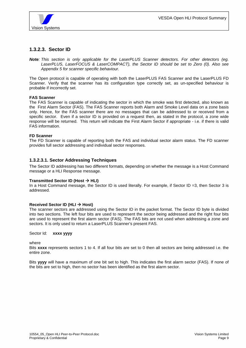
1.3.2.3. Sector ID Note: This section is only applicable for the LaserPLUS Scanner detectors. For other detectors (eg.
LaserPLUS, LaserFOCUS & LaserCOMPACT), the Sector ID should be set to Zero (0). Also see Appendix 5 for scanner specific behaviour.
The Open protocol is capable of operating with both the LaserPLUS FAS Scanner and the LaserPLUS FD Scanner. Verify that the scanner has its configuration type correctly set, as un-specified behaviour is probable if incorrectly set. FAS Scanner The FAS Scanner is capable of indicating the sector in which the smoke was first detected, also known as the First Alarm Sector (FAS). The FAS Scanner reports both Alarm and Smoke Level data on a zone basis only. Hence, for the FAS scanner there are no messages that can be addressed to or received from a specific sector. Even if a sector ID is provided on a request then, as stated in the protocol, a zone wide response will be returned. This return will indicate the First Alarm Sector if appropriate - i.e. if there is valid FAS information. FD Scanner The FD Scanner is capable of reporting both the FAS and individual sector alarm status. The FD scanner provides full sector addressing and individual sector responses.
1.3.2.3.1. Sector Addressing Techniques The Sector ID addressing has two different formats, depending on whether the message is a Host Command message or a HLI Response message. Transmitted Sector ID (Host HLI) In a Host Command message, the Sector ID is used literally. For example, if Sector ID =3, then Sector 3 is addressed. Received Sector ID (HLI Host) The scanner sectors are addressed using the Sector ID in the packet format. The Sector ID byte is divided into two sections. The left four bits are used to represent the sector being addressed and the right four bits are used to represent the first alarm sector (FAS). The FAS bits are not used when addressing a zone and sectors. It is only used to return a LaserPLUS Scanner’s present FAS. Sector Id: xxxx yyyy where Bits xxxx represents sectors 1 to 4. If all four bits are set to 0 then all sectors are being addressed i.e. the entire zone. Bits yyyy will have a maximum of one bit set to high. This indicates the first alarm sector (FAS). If none of the bits are set to high, then no sector has been identified as the first alarm sector.

Vision Systems
VESDA Open HLI Protocol Summary
10554_05_Open HLI Peer-to-Peer Protocol.doc Vision Systems Limited Proprietary & Confidential Page 10
For example, the following Sector Ids may be received from the Open HLI:
Received Sector ID (“x” denotes digit)
Denotes “Response from”
0 Zone – wide (or non-sector specific mode)
8x (hex) or 1000xxxx (binary) Sector #1 4x (hex) or 0100xxxx (binary) Sector #2 2x (hex) or 0010xxxx (binary) Sector #3 1x (hex) or 0001xxxx (binary) Sector #4
Using this technique an individual sector can be addressed or the entire zone can be addressed. Sector ID - Summary The following table summarises the usage of Sector Ids in both Host command messages & Response messages from the HLI.
Sector ID
(Host HLI) Sector ID
(HLI Host)* Denotes
1 80h Sector 1 2 40h Sector 2 3 20h Sector 3 4 10h Sector 4
* When a First Alarm Sector (FAS) has been identified, the right digit of the received Sector ID will be non-zero to reflect the
identified FAS.
1.3.2.4. Data Length The message length is variable, depending on the number of Data Bytes to be sent. If there is no Data Bytes to be transmitted, then set the Data Length to zero (0) and omit the Data Length field from the message. However, the Data Length byte (with zero value) must still be included in the transmitted message. This is commonly found in many Host command messages which do not contain any data bytes.
1.3.2.5. CRC Error Correction The CRC used is CRC-16 (CCiTT). The first CRC byte is the Most Significant Byte obtained from a CRC calculation, which is performed in 16 bits (2 bytes) The CRC includes everything from the first DLE to the ETX. Any Byte-stuffing character is not included in the CRC calculation. See Appendix 5: Software Implementations, for a comprehensive treatment of CRC as used in the VESDA communications.
1.3.2.6. DLE Byte Stuffing: The Open HLI protocol uses DLE characters to signal the start & end a message transmission. Hence any Data characters that correspond to the value of DLE (10 hex or 16 decimal) must be padded with another DLE byte to prevent the receiving device from being confused.

Vision Systems
VESDA Open HLI Protocol Summary
10554_05_Open HLI Peer-to-Peer Protocol.doc Vision Systems Limited Proprietary & Confidential Page 11
For example, a DLE character is normally followed by either a STX or an ETX character. If a DLE character is found in the data stream then an additional DLE character is inserted to represent that data byte. i.e. Each data byte of 10 hex in the data stream is represented by two DLE characters in the final transmission message. The receiving device must also strip away the any DLE byte-stuffing characters before interpreting the data. Byte stuffing is only applied between the DLE STX and the DLE ETX portions of the message. Note: The Open HLI Protocol does not include the DLE Byte stuffing characters in the CRC
calculations.
1.3.2.7. ACK & NAK Messages In Unsolicited (Peer-to-Peer) mode, the Open HLI will reply to any command messages sent from the Host with a single ACK (06h) or NAK (15h) character. Similarly the third party software must respond to messages from the Open HLI with ACKs or NAKs. If the HLI does not receive a ACK or NAK, it will retry sending the message three times before discarding it. However, if there are lots of messages coming from VESDAnet side (for example, because of large number of detectors) the HLI buffers will start filling up because the HLI will not be able to get rid of the messages as quickly as they are arriving in the HLI. At this point if the third party software starts communicating with the HLI, it will be observed that HLI starts sending the accumulated messages. In such a situation the HLI will respond to the third party commands only after it has finished sending out old messages. Note that HLI can keep 128 message buffers in the HLI, which means that HLI can keep a back log of 128 messages only. It is recommended to clear the buffers of the HLI (refresh the HLI) by sending command 7, if the 3rd party software is ran/connected after the HLI has been running for a while. This action will clear the back log of messages.

Vision Systems
VESDA Open HLI Protocol Summary
10554_05_Open HLI Peer-to-Peer Protocol.doc Vision Systems Limited Proprietary & Confidential Page 12
1.4. Open HLI Start-up Delay Important: When the HLI is powered ON the user must wait approximately 10 to 30 seconds before
sending any commands to the HLI.
During this time, the HLI starts up its application code and also requests the zone status information from each zone. Depending on the size of the network this process may take 10 to 30 seconds. Any command sent by a Host during the startup period will be ignored. For example, the Host should wait for the Start-up period to expire before attempting to re-configure the Open HLI using Set Operation Mode message (Command ID #1).
1.5. Open HLI Message Processing Limit The Open HLI is designed to handle a maximum of 128 outstanding poll messages at any given time. It is possible to overloading the Open HLI by polling too quickly. Adhere to “Host/Open HLI polling rate limitation” given in section 1.12 to keep the number of outstanding HLI replies below the maximum limit of 128 messages.
1.6. Time between unsolicited messages The time interval between unsolicited messages varies between messages and VESDA installations. The Current Fault Status messages will only occur as a result of a fault, rather than on a regular basis. The other three messages (Current Zone Status, Current Display Status, Current Airflow Status) will occur on a regular basis. The Current Airflow Status occurs every 30 seconds. This is the airflow reporting period. Both the Current Display Status and Current Zone Status messages occur on a 45 second interval. Each zone is capable of transmitting an unsolicited message. The Current Zone Status and Current Airflow Status are configured to operate in an unsolicited mode on a network basis. Individual zones cannot be configured to transmit unsolicited messages. On the other hand, the Current Display Status message can be configured to unsolicited operation on a zone basis. The Current Zone Status and Current Display Status are not used simultaneously. If a zone is configured to use Current Display Status then no Current Zone Status is transmitted.
1.7. Efficient Zone Status updates In a typical LaserPLUS installation that is correctly commissioned, the presence of faults and alarms is relatively rare. Correspondingly the status of each zone is not likely to change very frequently. This results in the transmission of status information which is not likely to have changed. In the case of a large network this may lead to excessive data transmissions as each zone is reporting largely redundant status information. To reduce the traffic to the absolute minimum, the unsolicited message set can be configured to enable only the Current Zone Status messages. Any unsolicited message sent by the HLI should be acknowledged by the Host with an ACK character (if the CRC is correct). This will prevent unnecessary transmission retries from the HLI.

Vision Systems
VESDA Open HLI Protocol Summary
10554_05_Open HLI Peer-to-Peer Protocol.doc Vision Systems Limited Proprietary & Confidential Page 13
1.8. Alarm and Fault latching and relays The HLI uses the present Alarm and Fault latch state when determining if a status change has occurred. Note that the latching state may not reflect the relay configuration. If configurable relays are being used then the Alarm and Fault latching state may not reflect an individual device’s relay configuration. In addition the Alarm and Fault status reflects that in use by the detector. Please refer to the LaserPLUS operating manual for further details. Note: The LaserCOMPACT does not have configurable relays.
1.9. LaserPLUS Fire 2 and Fire confirmation The Fire2 level is used as a ‘Double Knock’ trigger. In the two messages that report the alarm levels the bits for Alert, Action, Fire 1 and Fire 2 are all set in the event of the Fire 2 state being reached. The messages involved are Current Zone Status 5 Display Info 9 Note: The LaserCOMPACT has only two alarm levels: “Pre-Alarm” and “Fire”. If the “Alert” alarm level is configured, then a third alarm level is available (for US-models only).
1.10. Required Equipment To connect to an Open interface the following is required:
- a Open Protocol HLI unit - a correctly assembled RS232 cable
The Open HLI connection is via a standard RS232 connection i.e. full duplex. The HLI uses a DB9, female connector. A direct connect cable is used to connect between host and HLI. Presently the pin arrangement is TX pin 2 RX pin 3 Ground pin 5 RTS pin 8 CTS pin 7 Both the OEM host and HLI can communicate simultaneously.
Vision Systems
VESDA Open HLI Protocol Summary
10554_05_Open HLI Peer-to-Peer Protocol.doc Vision Systems Limited Proprietary & Confidential Page 14
1.11. Primary Reporting The Open HLI products are NOT intended for use as the primary reporting path. See the following important warning.
IMPORTANT WARNING: In the case when the OPEN HLI products are use for primary reporting, some form of redundant system (for example, using a second OPEN HLI) is highly recommended. This recommendation is to avoid a potential single point failure as the OPEN HLI is providing the only interface to the HOST system.
1.12. Host/Open HLI polling rate limitation It is not recommended that the Peer-to-Peer HLI is polled regularly by the Host. If the Host requires to poll the Peer-to-Peer HLI, it is recommended that a message rate of not more than 1 message every 2 seconds is used. NOTE: Polling is not REQUIRED when using a Peer-to-Peer HLI.

Vision Systems
VESDA Open HLI Protocol Summary
10554_05_Open HLI Peer-to-Peer Protocol.doc Vision Systems Limited Proprietary & Confidential Page 15
2. Command ID Summary
Command Name Cmd ID
From To Description
Set Operation 1 HOST HLI HLI HOST
Set the operating message set. This is recorded in volatile memory.
Get Operation 2 HLI HOST Get the operating message set. Response 3 HOST HLI
HLI HOST Universal indicator of success/failure.
Zone Update 4 HOST HLI Request for an update of a Zone’s
status Current Zone Status 5 HLI HOST A Zone’s present status. Remote Operation 6 HOST HLI Allows a zone to be Reset, Isolated or
Silenced HLI Refresh 7 HOST HLI Clear the data stored locally on the
High Level Interface Create Display 8 HOST HLI Request the information required to
create a virtual Display Display Info 9 HLI HOST The information required to create a
virtual display. Update Display status 10 HOST HLI Request for data required to update a
virtual Display. Current Display Status 11 HLI HOST A Display’s status. Update Fault Status 12 HOST HLI Update the fault status of a zone. Current Fault Status 13 HLI HOST The current fault status of a zone. Get Fault String 14 HOST HLI Get the fault string used by VESDA by
providing the fault number. Fault String 15 HLI HOST The fault string associated with a fault
number. Update Airflow Status 16 HOST HLI Update a zone’s airflow status Current Airflow Status 17 HLI HOST A zone’s airflow status. HLI Enquiry 20 HOST HLI Request HLI information HLI SignOn 21 HLI HOST HLI data eg Version number Get Device Type 22 HOST HLI Get a device type Current Device Type 23 HLI HOST Current device type Network Alarm Status Update Request
64 HOST HLI Not applicable to Peer-to-Peer HLI. If Command 64 is inadvertently sent to a Peer-to-Peer HLI, code “CB” will be received by Host in a Cmd 3 response to indicate “INVALID” command
The HLI can be configured to send these messages as unsolicited messages to the HOST.

Vision Systems
VESDA Open HLI Protocol Summary
10554_05_Open HLI Peer-to-Peer Protocol.doc Vision Systems Limited Proprietary & Confidential Page 16
3. Command Messages
3.1. Set HLI Operation Mode (1) This command (ID 1) is no longer applicable for switching between modes of operation. Command ID 1 is used after first power up of the Peer-to-Peer HLI by Host to initialise relevant parameters in the Peer-to-Peer application software.
Command ID : 1 (01h) Description: Sets the Operation Mode of the Open HLI unit. Message Flow: HOST HLI Message Type: Poll Command Data Length: 1 byte Data Format: Operation Type u 0 v w x y 0 0 1 byte where
u = Communication mode between Host and HLI 1 = Master / Slave mode (not applicable) 0 = Unsolicited mode Unsolicited Mode:
Bit No. 7 6 5 4 3 2 1 0 Bit Name u 0 v w x y 0 0
Value 0 0 0/1 0/1 0/1 0/1 0 0 In Unsolicited mode, full broadcasting and multiple requests are allowed. Some messages can be sent unsolicited by the HLI to the Host. The Host can still poll the HLI for data. The HLI will send a single ACK or NAK character to acknowledge every command message received from the Host. In Unsolicited mode, four different unsolicited messages can be sent unsolicited by HLI:
Bit Description Corresponding Command ID
Dec Hex v Current Zone Status 5 05h w Current Display Status 11 0Bh x Current Fault Status 13 0Dh y Current Airflow Status 17 11h
1 indicates set to unsolicited 0 indicates set to poll only
Vision Systems
VESDA Open HLI Protocol Summary
10554_05_Open HLI Peer-to-Peer Protocol.doc Vision Systems Limited Proprietary & Confidential Page 17
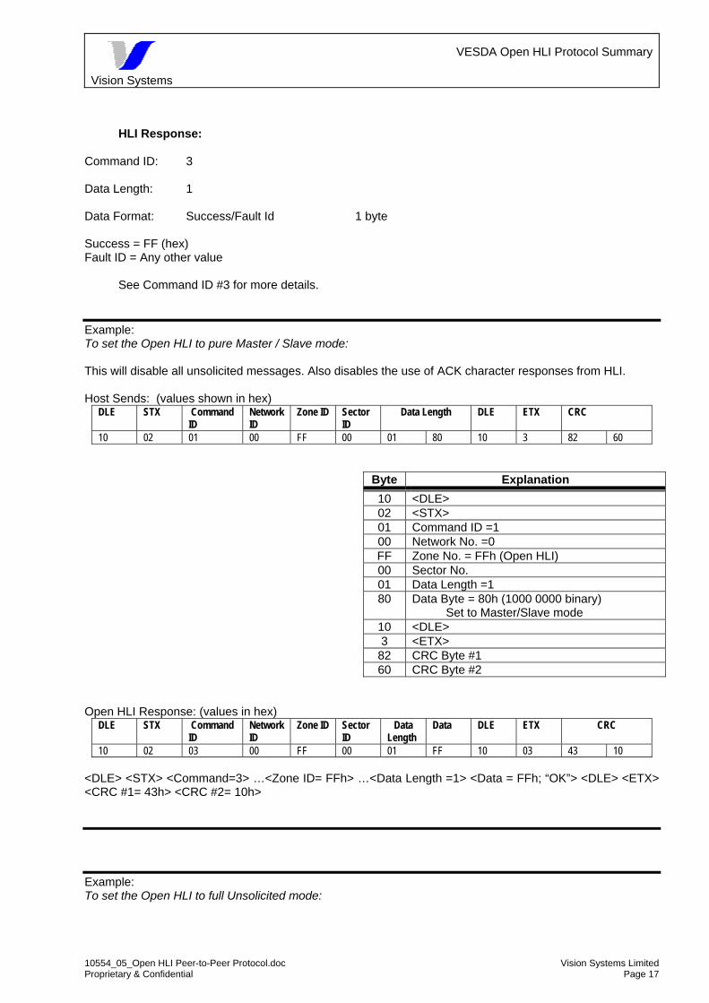
HLI Response:
Command ID: 3 Data Length: 1 Data Format: Success/Fault Id 1 byte Success = FF (hex) Fault ID = Any other value
See Command ID #3 for more details.
Example: To set the Open HLI to pure Master / Slave mode: This will disable all unsolicited messages. Also disables the use of ACK character responses from HLI. Host Sends: (values shown in hex)
DLE STX Command ID
Network ID
Zone ID Sector ID
Data Length DLE ETX CRC
10 02 01 00 FF 00 01 80 10 3 82 60
Byte Explanation 10 <DLE> 02 <STX> 01 Command ID =1 00 Network No. =0 FF Zone No. = FFh (Open HLI) 00 Sector No. 01 Data Length =1 80 Data Byte = 80h (1000 0000 binary)
Set to Master/Slave mode 10 <DLE> 3 <ETX>
82 CRC Byte #1 60 CRC Byte #2
Open HLI Response: (values in hex)
DLE STX Command ID
Network ID
Zone ID Sector ID
Data Length
Data DLE ETX CRC
10 02 03 00 FF 00 01 FF 10 03 43 10 <DLE> <STX> <Command=3> …<Zone ID= FFh> …<Data Length =1> <Data = FFh; “OK”> <DLE> <ETX> <CRC #1= 43h> <CRC #2= 10h> Example: To set the Open HLI to full Unsolicited mode:

Vision Systems
VESDA Open HLI Protocol Summary
10554_05_Open HLI Peer-to-Peer Protocol.doc Vision Systems Limited Proprietary & Confidential Page 18
This will enable all unsolicited messages. Also enables the use of ACK character responses from HLI. Host Sends: (values shown in hex) DLE STX Command
ID Network ID
Zone ID
Sector ID
Data Length
Data DLE ETX CRC
10 02 01 00 FF 00 01 3E 10 3 18 39
Byte Explanation 10 <DLE> 02 <STX> 01 Command ID =1 00 Network No. =0 FF Zone No. = FF (Open HLI) 00 Sector No. 01 Data Length =1 3E Data Byte = 3Eh (0011 1110 binary)
Set to Unsolicited mode & Enable all unsolicited message types
10 <DLE> 3 <ETX>
18 CRC Byte #1 39 CRC Byte #2
Open HLI Response: (values in hex) DLE STX Command
ID Network ID
Zone ID Sector ID
Data Length
Data DLE ETX CRC
10 02 03 00 FF 00 01 FF 10 03 43 10 <DLE> <STX> <Command=3> …<Zone ID= FFh> …<Data Length =1> <Data = FFh; “OK”> <DLE> <ETX> <CRC #1= 43h> <CRC #2= 10h> Note: The VHX-0310 is not affected by this command, as it is Master/Slave only product.
Important: The Open HLI (VHX-0300) uses the following configuration for its default Operation Type: 0x0010000 The Operation Mode is retained in volatile memory. In the event of a power cycle, the HLI unit resets to the factory-default configuration.
Tip: It is preferable for the Open HLI to receive this message as its first command after a power cycle. (for VHX-0300 only)
Warning: The HLI normally takes up to 30 seconds after a power reset before it is ready to respond any command messages from the Host.
Note: This message also serves as a HLI-to-Host response when the HLI receives a Command #2 from the Host. The reported data bits would reflect the current operation mode.
The VHX-0310 would always respond to a Command #2 poll with a Command #1 message containing a data value of 80 hex, signifying Master / Slave mode.

Vision Systems
VESDA Open HLI Protocol Summary
10554_05_Open HLI Peer-to-Peer Protocol.doc Vision Systems Limited Proprietary & Confidential Page 19
3.2. Get HLI Operation Mode (2) Command ID : 2 (02h) Description: Host requests for current HLI Operations Mode. Message Flow: HOST HLI Message Type: Poll Command Data Length: 0 Data Format: --- Note: The VHX-0310 would always respond to this command with a Command #1 message
containing a data value of 80 hex, signifying Master / Slave mode. Example: To request for the current HLI Operation Mode. This applies only to the HLI that is directly connected to the Host Host Sends: (values shown in hex) DLE STX Command
ID Network ID
Zone ID Sector ID
Data Length
Data DLE ETX CRC
10 02 02 00 FF 00 00 10 03 91 10
Byte Explanation 10 <DLE> 02 <STX> 02 Command ID =2 00 Network No. =0 FF Zone No. = FF (Connected HLI) 00 Sector No. 00 Data Length =0 (Hence omit Data Byte field) 10 <DLE> 3 <ETX>
91 CRC Byte #1 10 CRC Byte #2
A Sample Open HLI Response: (values in hex) DLE STX Command
ID Network ID
Zone ID Sector ID
Data Length
Data DLE ETX CRC
10 02 01 00 FF 00 01 20 10 03 8D B7 <DLE> <STX> <Command=1> …<Zone ID= FFh> …<Data Length =1> <Data Byte= 20h; Unsolicited Mode, Enabled Current Zone Status Unsolicited messages> <DLE> <ETX> <CRC #1= 8Dh> <CRC #2= B7h> See Command ID #1 for more information on Bit values.
Vision Systems
VESDA Open HLI Protocol Summary
10554_05_Open HLI Peer-to-Peer Protocol.doc Vision Systems Limited Proprietary & Confidential Page 20
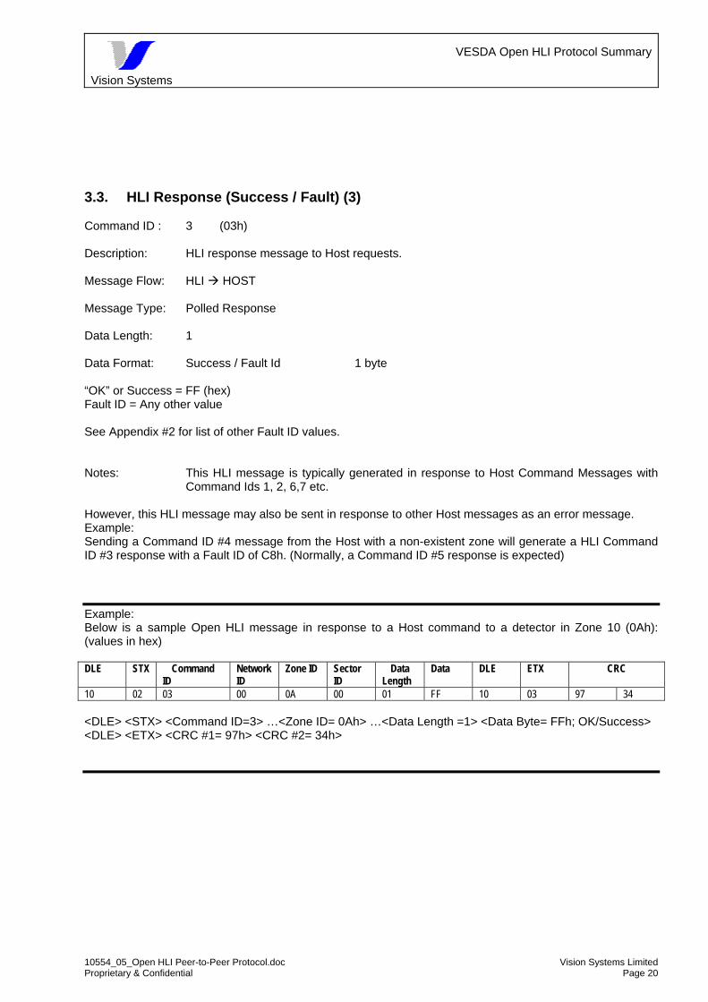
3.3. HLI Response (Success / Fault) (3) Command ID : 3 (03h) Description: HLI response message to Host requests. Message Flow: HLI HOST Message Type: Polled Response Data Length: 1 Data Format: Success / Fault Id 1 byte “OK” or Success = FF (hex) Fault ID = Any other value See Appendix #2 for list of other Fault ID values. Notes: This HLI message is typically generated in response to Host Command Messages with
Command Ids 1, 2, 6,7 etc. However, this HLI message may also be sent in response to other Host messages as an error message. Example: Sending a Command ID #4 message from the Host with a non-existent zone will generate a HLI Command ID #3 response with a Fault ID of C8h. (Normally, a Command ID #5 response is expected) Example: Below is a sample Open HLI message in response to a Host command to a detector in Zone 10 (0Ah): (values in hex) DLE STX Command
ID Network ID
Zone ID Sector ID
Data Length
Data DLE ETX CRC
10 02 03 00 0A 00 01 FF 10 03 97 34 <DLE> <STX> <Command ID=3> …<Zone ID= 0Ah> …<Data Length =1> <Data Byte= FFh; OK/Success> <DLE> <ETX> <CRC #1= 97h> <CRC #2= 34h>

Vision Systems
VESDA Open HLI Protocol Summary
10554_05_Open HLI Peer-to-Peer Protocol.doc Vision Systems Limited Proprietary & Confidential Page 21
3.4. Zone Update Request (4) Command ID : 4 (04h) Description: Host requests for current Zone update. Message Flow: HOST HLI Message Type: Poll Command Data Length: 0 Data Format: --- HLI Response: See Command ID #5 for more details.
Note: Laser Scanners have four sectors.
Use Command ID #10 can be used to obtain Alarm status & Smoke Levels for individual sectors. Example: Request for Current Zone Update from Zone 3. Note: In this example, Zone 3 can be a LaserPLUS or a LaserCOMPACT. Host Sends: (values shown in hex) DLE STX Command
ID Network ID
Zone ID Sector ID Data Length
DLE ETX CRC
10 02 04 00 03 00 00 10 3 21 4B
Byte Explanation 10 <DLE> 02 <STX> 04 Command ID = 4 00 Network No. =0 03 Zone No. = 03 00 Sector No. 00 Data Length =0 (Hence no data byte field) 10 <DLE> 3 <ETX>
21 CRC Byte #1 4B CRC Byte #2
Open HLI Response: (values in hex)
DLE STX Command ID
Network ID
Zone ID
Sector ID
Data Length
Data DLE ETX CRC
10 02 05 00 03 00 02 06 41 10 03 55 CF <DLE> <STX> <Command=5> …<Zone ID= 03h> …<Data Length =2> <Data Bytes #1 & #2= 06h & 41h; “Urgent Zone Alert”> <DLE> <ETX> <CRC #1= 55h> <CRC #2= CFh> Interpretation: Zone 3 is in Urgent Zone Alert. This was simulated by causing an Air Flow fault in Zone 3.
See Command ID #5 for more details.

Vision Systems
VESDA Open HLI Protocol Summary
10554_05_Open HLI Peer-to-Peer Protocol.doc Vision Systems Limited Proprietary & Confidential Page 22

Vision Systems
VESDA Open HLI Protocol Summary
10554_05_Open HLI Peer-to-Peer Protocol.doc Vision Systems Limited Proprietary & Confidential Page 23
3.5. Current Zone Status (5) Command ID : 5 (05h) Description: HLI reports current Zone Status. Message Flow: HLI HOST Message Type: Polled Response (to Command ID #4) or Unsolicited Message Data Length: 2 bytes (16 bits) Data Format: Alarm 4 bits Fault 7 bits Isolated 1 bit Normalising 1 bit Auto-Learning 1 bit Scanning 1 bit Other Zone Info 1 bit First Data Byte:
Bit No. 7 6 5 4 3 2 1 0 Bit Name Alert Action Fire 1 Fire 2 System Zone Urgent Power
Value 0/1 0/1 0/1 0/1 0/1 0/1 0/1 0/1 Alarms Faults
Second Data Byte:
Bit No. 7 6 5 4 3 2 1 0 Bit Name Network Air
Flow Filter Isolated Normali
sing Auto
Learning Scanning Other
Zone Info
Value 0/1 0/1 0/1 0/1 0/1 0/1 0/1 0/1 Faults Status
1 = True Status (eg. In Alarm or Fault Condition) 0 = False
Note: The LaserCOMPACT has only two alarm levels: Pre-Alarm and Fire. (For US markets, an additional “Alert” level is configurable)
LaserPLUS Alarm Levels LaserCOMPACT Alarm Levels Fire 2 (Not Applicable) Fire 1 Fire Action Pre-Alarm Alert Alert
(If configured, for US models only) Table. Corresponding Detector Alarm Levels

Vision Systems
VESDA Open HLI Protocol Summary
10554_05_Open HLI Peer-to-Peer Protocol.doc Vision Systems Limited Proprietary & Confidential Page 24
Important: Laser Scanners can have up to four sectors. Command ID #5 will only return the Zone-wide information in response to Command ID #4. The Alarm bits reflect the highest sector alarm.
Use Command ID #10 to obtain Sector Alarm status & Sector Smoke Levels.
Important: The “Scanning bit” is active as long as scanning continues. Important: The “Other Zone Info bit” applies only LaserSCANNER. Example: Sample Unsolicited Message from Zone 10 (0Ah): DLE STX Command
ID Network ID
Zone ID
Sector ID
Data Length
Data DLE ETX CRC
10 02 05 00 0A 00 02 08 80 10 03 EA F2 (values in hex) <DLE> <STX> <Command=5> …<Zone ID= 0Ah> …<Data Length =2> <Data Bytes #1 & #2= 08h & 80h; “System Fault & Network Fault”> <DLE> <ETX> <CRC #1= EAh> <CRC #2= F2h> Interpretation: Zone 10 (0Ah) is reporting a System Fault & a Network Fault. This was caused by plugging a new Programmer into a VESDAnet socket.
NOTE: In the case of unsolicited messages (ie not requested by a cmd 4 from the host), the sector number will contain the values as per 1.3.2.3.1. Thus sectors 1 through 4 appear as 80h, 40h, 20h and 10h respectively. In addition the sector number may also contain in the right hand digit a non-zero value to indicate the identified FAS. These may appear as 88h indicating sector 1 data and sector 1 as First alarm sector, or 48h indicating sector 2 with FAS in sector 1. NOTE: See appendix 6 for VLS specific behaviours. In particular, the zone information may be different from the sector information. Zone information for VLS may not be valid until a reset has occurred.

Vision Systems
VESDA Open HLI Protocol Summary
10554_05_Open HLI Peer-to-Peer Protocol.doc Vision Systems Limited Proprietary & Confidential Page 25
3.6. Remote Input (6) Command ID : 6 (06h) Description: HOST controls Detector remotely. Message Flow: HOST HLI Message Type: Poll Command Data Length: 1 byte Data Format: Data Byte:
Bit No. 7 6 5 4 3 2 1 0 Bit Name 0 Reset y t z w u v
Value 0 0/1 0/1 0/1 0/1 0/1 0/1 0/1
where x Reset (all zones allowed) y Isolate (all zones allowed) t De-isolate (all zones allowed)
z Silence (all zones allowed) w Start Test (Detector Test - all zones allowed) u Start Scanning (for LaserSCANNER only, 1 zone) v Stop Test (Detector Test – all zones allowed)
1 = Execute Command 0 = No command
Note: Setting a bit to ‘1’ (True) will initiate the appropriate command actions.
The following command bits work in pairs
Isolate / De-isolate: Set Bit 5 (“y”-bit) to Isolate a zone or all zones. Set Bit 4 (“t”-bit) to De-isolate a zone or all zones. Detector Test Set Bit 2 (“w”-bit) to Start the Detector Test for a zone or all zones. The Host must then set Bit 0 (“v”-bit) to Stop the Test. For Network Isolate / De-isolate broadcasts to all Zones use the Broadcast ID / Zone ID = FFh For Network Reset broadcasted to all Zones use the Broadcast ID / Zone ID = FFh. Warning: Network reset will CLEAR all current alarm status.
Warning The Detector Test will cause a “Fire” (& Alert & Action) alarm condition on the Detector under test.
HLI Response: Command ID: 3

Vision Systems
VESDA Open HLI Protocol Summary
10554_05_Open HLI Peer-to-Peer Protocol.doc Vision Systems Limited Proprietary & Confidential Page 26
Data Length: 1 Data Format: Success/Fault ID 1 byte Success = FF (hex) Fault ID = Any other value See Command ID #3 and Appendix 2 (Fault Ids) for more details. Example: RESET command to a Detector in Zone 10 (0Ah) Host Command String: (values shown in hex)
DLE STX Command ID
Network ID
Zone ID Sector ID
Data Length
Data DLE ETX CRC
10 02 06 00 0A 00 01 40 10 03 C0 D0 Explanation: Data Byte #1 = 40h (Reset command) HLI Response:
DLE STX Command ID
Network ID
Zone ID Sector ID
Data Length
Data DLE ETX CRC
10 02 03 00 0A 00 01 FF 10 03 97 34 Explanation: Data Byte #1 = FFh (OK / Success)

Vision Systems
VESDA Open HLI Protocol Summary
10554_05_Open HLI Peer-to-Peer Protocol.doc Vision Systems Limited Proprietary & Confidential Page 27
3.7. HLI Refresh (7) Command ID : 7 (07h) Description: HOST commands HLI to refresh. This will clear all data stored Iocally in the HLI. Message Flow: HOST HLI Message Type: Poll Command Data Length: 0 Data Format: --- HLI Response: Command ID: 3 Data Length: 1 Data Format:: Success/Fault ID Success = FF (hex) Fault ID = Any other value Example: HLI Refresh command Host Command String: (values shown in hex)
DLE STX Command ID
Network ID
Zone ID Sector ID Data Length
DLE ETX CRC
10 02 07 00 FF 00 00 10 03 61 B3 Explanation: Zone ID = FFh (Open HLI) HLI Response:
DLE STX Command ID
Network ID
Zone ID Sector ID
Data Length
Data DLE ETX CRC
10 02 03 00 FF 00 01 FF 10 03 43 10 Explanation: Data Byte #1 = FFh (OK / Success) NOTES: After sending a cmd 7 to the Open HLI, all data is cleared from the device list in the HLI. An immediate request on any zone will result in a invalid zone (hex C8) response. See Appendix 6: Notes on Open HLI behaviours for cmd 7 behaviour details.

Vision Systems
VESDA Open HLI Protocol Summary
10554_05_Open HLI Peer-to-Peer Protocol.doc Vision Systems Limited Proprietary & Confidential Page 28
3.8. Create Display (8) Command ID : 8 (08h) Description: HOST requests for information to create a zone mimic display. Message Flow: HOST HLI Message Type: Poll Command Data Length: 0 Data Format: ---- HLI Response: Command ID: 9 Data Length: 31 bytes See Command ID #9 for details Example: Request for Zone Display information (from Zone 3) Host Command String: (values shown in hex)
DLE STX Command ID
Network ID
Zone ID Sector ID Data Length
DLE ETX CRC
10 02 08 00 03 00 00 10 03 90 D1 HLI Response: DLE STX Command
ID Network
ID Zone
ID Sector
ID Data
Length Data DLE
ETX CRC
10 02 09 00 03 00 1F ….(31 data bytes)… 10 03 CRC1 CRC2 Explanation: Data Length = 31 bytes (1Fh = 31d) Note: The 31st byte of the data is not currently used.

Vision Systems
VESDA Open HLI Protocol Summary
10554_05_Open HLI Peer-to-Peer Protocol.doc Vision Systems Limited Proprietary & Confidential Page 29
3.9. Display Information (HLI Response) (9) Command ID : 9 (09h) Description: HLI sends Zone Display Information to Host. This includes alarm levels and Location Name. Message Flow: HLI HOST Message Type: Polled Response (to Command ID #8) Data Length: 31 bytes Data Format:
Byte No. Description Comment 1 – 2 Alert Alert Alarm Level = (Byte 1 & 2) / 1000 3 – 4 Action Action Alarm Level = (Byte 3 & 4) / 1000 5 – 6 Fire1 Fire1 Alarm Level = (Byte 5 & 6) / 1000 7 – 8 Fire2 Fire2 Alarm Level = (Byte 7 & 8) / 1000
9 – 30 Location Name
ASCII format
31 Not used Note: Each reported alarm level is multiplied by 1000. Eg 0.050 is returned as 50. The LaserCOMPACT has only two alarm levels: Pre-Alarm and Fire. (For US markets, an additional “Alert” level is configurable)
LaserPLUS
Alarm Levels LaserCOMPACT Alarm Levels
Fire 2 (Not Applicable) Fire 1 Fire Action Pre-Alarm Alert Alert
(if configured, for US models only) Table. Corresponding Detector Alarm Levels
Example: Request for Zone Display information (from Zone 10 or 0Ah) Host Command String: (values shown in hex)
DLE STX Command ID
Network ID
Zone ID Sector ID Data Length
DLE ETX CRC
10 02 08 00 0A 00 00 10 03 90 D1 HLI Response: DLE STX Command
ID Network ID
Zone ID
Sector ID
Data Length
Data DLE ETX CRC
10 02 09 00 0A 00 1F ….(31 data bytes)… 10 03 CRC1 CRC2

Vision Systems
VESDA Open HLI Protocol Summary
10554_05_Open HLI Peer-to-Peer Protocol.doc Vision Systems Limited Proprietary & Confidential Page 30
Explanation: Data Length = 31 bytes (1Fh = 31d) If Data Byte #1 = 0 & Data Byte #2 = 50h, then Alert Alarm Level = 0.080 (where 50h = 80). If Data Bytes #9 to #30 are, for example:
…. 47 61 74 65 68 6F 75 73 65 20 …. This corresponds to “Gatehouse….” In ASCII. Note: The 31st byte of the data is not currently used.

Vision Systems
VESDA Open HLI Protocol Summary
10554_05_Open HLI Peer-to-Peer Protocol.doc Vision Systems Limited Proprietary & Confidential Page 31
3.10. Update Display Status (10) Command ID : 10 (0Ah) Description: HOST requests for update on display status. Message Flow: HOST HLI Message Type: Poll Command Data Length: 1 Byte Data Format: 0 to 4 0 = Sector 0 Status 1 = Sector 1 Status 2 = Sector 2 Status 3 = Sector 3 Status 4 = Sector 4 Status HLI Response: Command ID: 11 Data Length: 6 bytes See Command ID #11 for details. Example 1: Request for Display Status Update from Zone 10 or 10h, sector 0 Host Command String: (values shown in hex)
DLE STX Command ID
Network ID Zone ID Sector ID Data Length
DLE ETX CRC
10 02 0A 00 0A 00 00 10 03 F6 0E HLI Response: DLE STX Command
ID Network
ID Zone
ID Sector
ID Data
Length Data DLE ETX CRC
10 02 0B 00 0A 00 06 00 00 01 00 00 00 10 03 6C 19
Explanation: Data Length = 6 bytes Data Byte #1 = 0 & Data Byte #2 = 0, i.e. Smoke Level = 0.000 %/m. Data Bytes #3 = 1, hence Detector Status = “OK”.
Example 2: In the event of Fire, Request for Display Status Update from Zone 3, sector 2 Host Command String: (values shown in hex)

Vision Systems
VESDA Open HLI Protocol Summary
10554_05_Open HLI Peer-to-Peer Protocol.doc Vision Systems Limited Proprietary & Confidential Page 32
DLE STX Command
ID Network
ID Zone ID Sector ID Data
Length DLE ETX CRC
10 02 0A 00 03 02 00 10 03 9E 1C HLI Response: DLE STX Command
ID Network ID
Zone ID Sector ID Data Length
Data DLE ETX CRC
10 02 0B 00 03 48 06 00 F3 E2 66 00 00 10 03 96 0A Explanation: Sector ID = 48 i.e.
• 4 represents sector 2 i.e. reading sector 2 • 8 represents sector 1 i.e. First Alarm Sector (FAS) is sector 1
Data Length = 6 bytes Data Byte #1 = 0 & Data Byte #2 = F3, i.e. Smoke Level = 0.243 %/m. Data Byte #3 = E2, i.e. Alarm = Fire1, Isolated, Not OK Data Byte #4 = 66, i.e. Faults = Zone, Urgent, Airflow, Filter

Vision Systems
VESDA Open HLI Protocol Summary
10554_05_Open HLI Peer-to-Peer Protocol.doc Vision Systems Limited Proprietary & Confidential Page 33
3.11. Current Display Status (11) Command ID : 11 (0Bh) Description: HLI reports the Current Display Status to the Host. Message Flow: HLI HOST Message Type: Polled Response (to Command ID #10) or Unsolicited Message Data Length: 6 bytes Data Format:
Byte No. Description Comment 1 – 2 Smoke Level Smoke Level = (Byte 1 & 2) / 1000
e.g. 0.050 is reported as 50. 3 Alarm LEDs
Status See below.
4 Fault LEDs Status
See below.
5 Alarm Flash Status
Future Implementation
6 Fault Flash Status
Future Implementation
Byte 3 (Alarm LEDs Status):
Bit No. 7 6 5 4 3 2 1 0 Bit Name Alert Action Fire 1 Fire 2 Major
Fault Minor Fault
Isolated OK
Value 0/1 0/1 0/1 0/1 0/1 0/1 0/1 0/1 Note: The OK bit is not strictly an alarm bit. It actually signifies NO Faults present. Byte 4 (Fault LEDs Status):
Bit No. 7 6 5 4 3 2 1 0 Bit Name System Zone Urgent Power Network Airflow Filter Other
Value 0/1 0/1 0/1 0/1 0/1 0/1 0/1 0/1 1 indicates TRUE (Alarm or Fault Condition) 0 indicates FALSE
Note: Note: The LaserCOMPACT has only two alarm levels: Pre-Alarm and Fire. (For US markets, an additional “Alert” level is configurable)
LaserPLUS Alarm Levels LaserCOMPACT Alarm Levels
Fire 2 (Not Applicable) Fire 1 Fire Action Pre-Alarm Alert Alert
(if configured, for US models only) Table. Corresponding Detector Alarm Levels

Vision Systems
VESDA Open HLI Protocol Summary
10554_05_Open HLI Peer-to-Peer Protocol.doc Vision Systems Limited Proprietary & Confidential Page 34
Note for LaserSCANNER: Sector-Specific Information LaserSCANNER FD detectors support Sector-specific information. Using a non-zero Sector ID (from 1 to 4) will return the Sector Smoke Level, Sector Alarm level for the specified sector. Using a Sector ID of zero (0) will return the average Zone Smoke Level, the FAS & the highest alarm bits in that zone. The smoke level corresponds to the average smoke level when all pipes are open. i.e. this value is not the smoke level for a particular sector. Alarm LED Status Bits The Alarm LED Status is latched in the Open HLI. The Host is expected to refresh the HLI to get the current alarm status. The Alarm LED Status bits are best viewed as alarm event trigger bits. The HLI will set the bits when it first detects an alarm condition. Important: When the LaserSCANNER stops scanning (and all pipes are open), the Alarm LED
status bits will keep latching unless refreshed. See command 7 for refreshing methods. The LaserSCANNER will stop scanning when either all alarm conditions have ceased and smoke levels have returned to normal OR in the exceptionally rare real-life situation when the smoke levels have remained constant over a period of time.
Important: See appendix 6 for VLS specific behaviours. In particular, the zone information may be different from the sector information. Zone information for VLS may not be valid until a reset has occurred.
Important: The status information for sectors 1 through sector 4 is NOT valid if there is NO FIRE
ALARMs. The information for the sectors only gets updated when the scanner starts scanning. To get LED status when the detector is not in fire, send command 10 with sector number set to zero.
Example: Request for Display Status Update (from Zone 10 or 0Ah) Host Command String: (values shown in hex)
DLE STX Command ID
Network ID
Zone ID Sector ID Data Length
DLE ETX CRC
10 02 0A 00 0A 00 00 10 03 F6 0E HLI Response: DLE STX Command
ID Network ID Zone ID Sector ID Data
Length Data DLE ETX CRC
10 02 0B 00 0A 00 06 00 00 01 00 00 00 10 03 6C 19
Explanation: Data Length = 6 bytes Data Byte #1 = 0 & Data Byte #2 = 0, i.e. Smoke Level = 0.000 %/m. Data Bytes #3 = 1, hence Detector Status = “OK”.

Vision Systems
VESDA Open HLI Protocol Summary
10554_05_Open HLI Peer-to-Peer Protocol.doc Vision Systems Limited Proprietary & Confidential Page 35

Vision Systems
VESDA Open HLI Protocol Summary
10554_05_Open HLI Peer-to-Peer Protocol.doc Vision Systems Limited Proprietary & Confidential Page 36
3.12. Get Fault Status (12) Command ID : 12 (0Ch) Description: HOST requests for current zone fault status. Message Flow: HOST HLI Message Type: Poll Command Data Length: 0 Data Format: ---- HLI Response: Command ID: 13 Data Length: Variable See Command ID #13 for details. Example: Request for Current Zone Fault Status (from Zone 10 or 0Ah) Host Command String: (values shown in hex)
DLE STX Command ID
Network ID
Zone ID Sector ID Data Length
DLE ETX CRC
10 02 0C 00 0A 00 00 10 03 AE C3 HLI Response: DLE STX Command
ID Network
ID Zone ID Sector
ID Data
Length Data DLE ETX CRC
10 02 0D 00 0A 00 02 01 27 10 03 EF 89
Explanation: Data Length = 2 bytes Data Byte #1 = 01 i.e. “Number of Faults =1” Data Byte #2 = 27h (or 39 decimal), i.e. “Zone 10 has “Urgent High Air Flow – Pipe 4” fault

Vision Systems
VESDA Open HLI Protocol Summary
10554_05_Open HLI Peer-to-Peer Protocol.doc Vision Systems Limited Proprietary & Confidential Page 37
3.13. Current Fault Status (13) Command ID : 13 (0Dh) Description: HLI reports the Current Fault Status to the Host. Message Flow: HLI HOST Message Type: Polled Response (to Command ID #12) or Unsolicited Message Data Length: Variable (up to 22 bytes) Data Format:
Data Byte No.
Description Comment
1 No. of Faults Indicates No. of Faults in Fault List. 2 - 22 Fault List Fault List (variable length).
Each Fault is 1 byte Note: See Appendix 2 for list of Faults & their corresponding IDs.
Example: Request for Current Zone Fault Status (from Zone 10 or 0Ah) Host Command String: (values shown in hex)
DLE STX
Command ID
Network ID
Zone ID Sector ID Data Length
DLE ETX CRC
10 02 0C 00 0A 00 00 10 03 AE C3 HLI Response:
DLE STX Command ID
Network ID
Zone ID
Sector ID
Data Length
Data DLE ETX
CRC
10 02 0D 00 0A 00 02 01 27 10 03 EF 89 Explanation: Data Length = 2 bytes Data Byte #1 = 01 i.e. “Number of Faults =1” Data Byte #2 = 27h (or 39 decimal), i.e. “Zone 10 has “Urgent High Air Flow – Pipe 4” fault

Vision Systems
VESDA Open HLI Protocol Summary
10554_05_Open HLI Peer-to-Peer Protocol.doc Vision Systems Limited Proprietary & Confidential Page 38
3.14. Get Fault String (14) Command ID : 14 (0Eh) Description: HOST requests for fault string used by VESDA by providing the Fault ID number. Message Flow: HOST HLI Message Type: Poll Command Data Length: 1 Data Format: Fault ID (1 byte) HLI Response: Command ID: 15 See Command ID #15 for details. Example: Request for VESDA Fault String for Fault ID of 23 (= 17h) Host Command String: (values shown in hex)
DLE STX Command ID
Network ID
Zone ID Sector ID
Data Length
Data DLE ETX CRC
10 02 0E 00 FF 00 01 17 10 03 36 AE HLI Response: DLE STX Command
ID Network ID Zone ID Sector ID Data
Length Data DLE ETX CRC
10 02 0F 00 FF 00 16 17 4C 61 73 65 72 10 03 F1 97
Explanation: Data Length = 16h bytes (or 22 in decimal) Data Byte #1 = 17h (HLI echoes the given Fault ID) Data Byte #2 to #6 = 4Ch, …., 72h spells “Laser” etc.

Vision Systems
VESDA Open HLI Protocol Summary
10554_05_Open HLI Peer-to-Peer Protocol.doc Vision Systems Limited Proprietary & Confidential Page 39
3.15. Current Fault String (15) Command ID : 15 (0Fh) Description: HLI returns the Fault String associated with the Fault Number that was provided by the
Host. Message Flow: HLI HOST Message Type: Polled Response (to Command ID #15) Data Length: 36 bytes Data Format:
Data Byte No.
Description Comment
1 Fault Number Fault ID number as sent by HOST 2 – 36 Fault String Fault String associated with Fault No.
Note: See Appendix 2 for list of Faults & their corresponding IDs.
Example: Request for VESDA Fault String for Fault ID of 23 (= 17h) Host Command String: (values shown in hex)
DLE STX Command ID
Network ID
Zone ID Sector ID
Data Length
Data DLE ETX CRC
10 02 0E 00 FF 00 01 17 10 03 36 AE HLI Response: DLE STX Command
ID Network ID Zone ID Sector ID Data
Length Data DLE ETX CRC
10 02 0F 00 FF 00 16 17 4C 61 73 65 72 10 03 F1 97
Explanation: Data Length = 16h bytes (or 22 in decimal) Data Byte #1 = 17h (HLI echoes the given Fault ID) Data Byte #2 to #6 = 4Ch, …., 72h spells “Laser” etc.

Vision Systems
VESDA Open HLI Protocol Summary
10554_05_Open HLI Peer-to-Peer Protocol.doc Vision Systems Limited Proprietary & Confidential Page 40
3.16. Update Airflow Status (16) Command ID : 16 (10h) Description: HOST requests for update on Zone Airflow status. Message Flow: HOST HLI Message Type: Poll Command Data Length: 0 Data Format: ---- HLI Response: Command ID: 17 Data Length: 5 bytes See Command ID #17 for details.
Note: Pipes #2 to #4 are not relevant for LaserCOMPACT Detectors, which have only one pipe. Example: Request for Zone Airflow Status from Zone 3 Host Command String: (values shown in hex)
DLE STX Command ID
Network ID
Zone ID Sector ID
Data Length
Data DLE ETX CRC
10 02 10 10 00 03 00 00 10 03 FB F4 Note: An extra byte of 10h has been added to distinguish the Command ID byte (10h) from the <DLE> character. See section on Byte-Stuffing for details. HLI Response: DLE STX Command
ID Network ID Zone ID Sector ID Data
Length Data DLE ETX CRC
10 02 11 00 03 00 05 08 64 00 00 00 10 03 40 F3
Explanation: Data Length = 5 bytes Data Byte #1 = 08h (i.e. only Pipe 1 is in use) Data Byte #2 = 64h (or 100 in decimal) (i.e. Airflow = 100%).
3.16.1. Important note on Airflow monitoring

Vision Systems
VESDA Open HLI Protocol Summary
10554_05_Open HLI Peer-to-Peer Protocol.doc Vision Systems Limited Proprietary & Confidential Page 41
See important note, on the use of command ID 16 and resultant ID 17 response, in the notes after the command ID 17 section.
3.17. Current Airflow Status (17) Command ID : 17 (11h) Description: HLI reports the Zone Airflow Status to the Host. Message Flow: HLI HOST Message Type: Polled Response (to Command ID #16) or Unsolicited Message (only sent when in fault) Data Length: 5 bytes Data Format:
Data Byte No.
Description Comment
1 Pipes in Use Indicates which pipes are in use. See below for details.
2 Pipe 1 Airflow Pipe 1 Airflow reading (%) 3 Pipe 2 Airflow Pipe 2 Airflow reading (%) 4 Pipe 3 Airflow Pipe 3 Airflow reading (%) 5 Pipe 4 Airflow Pipe 4 Airflow reading (%)
Each pipe airflow is expressed as a percentage of normalised operating air flow. Eg. 100% is the Normalised Operating Air Flow. Data Byte 1:
Bit No. 7 6 5 4 3 2 1 0 Bit Name 0 0 0 0 Pipe 1 Pipe 2 Pipe 3 Pipe 4
Value 0 0 0 0 0/1 0/1 0/1 0/1
where 1 = Pipe Open (In Use) 0 = Pipe Closed (Not in use)
Note: Pipes #2 to #4 are not relevant for LaserCOMPACT Detectors, which have only one pipe. Example: Request for Zone Airflow Status from a LaserCOMPACT in Zone 3 Host Command String: (values shown in hex)
DLE STX Command ID
Network ID
Zone ID Sector ID
Data Length
Data DLE ETX CRC
10 02 10 10 00 03 00 00 10 03 FB F4

Vision Systems
VESDA Open HLI Protocol Summary
10554_05_Open HLI Peer-to-Peer Protocol.doc Vision Systems Limited Proprietary & Confidential Page 42
Note: An extra byte of 10h has been added to distinguish the Command ID byte (10h) from the <DLE> character. See section on Byte-Stuffing for details. HLI Response: DLE STX Command
ID Network ID Zone ID Sector ID Data
Length Data DLE ETX CRC
10 02 11 00 03 00 05 08 64 00 00 00 10 03 40 F3
Explanation: Data Length = 5 bytes Data Byte #1 = 08h (i.e. only Pipe 1 is in use) Data Byte #2 = 64h (or 100 in decimal) (i.e. Airflow = 100%). Example: Request for Zone Airflow Status from a LaserSCANNER in Zone 10 (0Ah) Host Command String: (values shown in hex)
DLE STX Command ID
Network ID
Zone ID Sector ID
Data Length
Data DLE ETX CRC
10 02 10 10 00 0A 00 00 10 03 AA 90 Note: An extra byte of 10h has been added to distinguish the Command ID byte (10h) from the <DLE> character. See section on Byte-Stuffing for details. HLI Response: DLE STX Command
ID Network ID Zone ID Sector ID Data
Length Data DLE ETX CRC
10 02 11 00 0A 00 05 0F 61 5E 60 5E 10 03 C8 A4
Explanation: Data Length = 5 bytes Data Byte #1 = 0Fh (i.e. All four pipes are in use) Data Byte #2 = 61h (or 97 in decimal,)
(i.e. Pipe #1 Airflow = 97%). Data Byte #3 = 5Eh (or 94 in decimal,)
(i.e. Pipe #2 Airflow = 94%). Data Byte #4 = 60h (or 96 in decimal,)
(i.e. Pipe #3 Airflow = 96%). Data Byte #5 = 5Eh (or 94 in decimal,)
(i.e. Pipe #4 Airflow = 94%).

Vision Systems
VESDA Open HLI Protocol Summary
10554_05_Open HLI Peer-to-Peer Protocol.doc Vision Systems Limited Proprietary & Confidential Page 43

Vision Systems
VESDA Open HLI Protocol Summary
10554_05_Open HLI Peer-to-Peer Protocol.doc Vision Systems Limited Proprietary & Confidential Page 44
3.17.1. Important note on Airflow Percentage Monitoring VESDAnet has not been designed for the continuous monitoring of airflow percentage. The airflow status is monitored against the threshold levels and the flow percentage set during the Normalisation process. Fault messages are created when the flow changes outside the Upper and Lower limits. The flow percentage data, per pipe, is available and updated regularly when monitoring with a VESDA configuration tool such as VConfig Pro (VSW-005) or a hand held programmer (VHH-1000). A power on or sign-on event by a VESDAnet device such as a detector will transmit the flow percentage rate with other alarm, fault and smoke reading information.
• The VHX-0300 HLI would send this data immediately to the monitoring software. • The VHX-0310 HLI would only transmit this data when requested via a Command ID 16 request
from the monitoring software. • No other normal event will refresh the flow percentage to any type of open protocol HLI and on-to
the monitoring software.
3.17.2. Recommendations on monitoring Airflow
1. Third party software monitoring tools should not attempt to view the actual VESDA detector flow rate data.
2. Command ID 16 from the monitoring software, is a request for the current airflow percentage. 3. The reply to the monitoring software, via a command ID 17, will be the last known airflow stored in
the HLI cache memory. • This data is not the actual current rate, but the last recorded flow rate. • This rate could have been recorded at the last power on event or the last time a network log-
in was provided by a VESDA configuration tool such as Vconfig Pro or a hand hel programmer. • Therefore, its accuracy to actual flow rates at a given moment may be inaccurate.
4. Do not expect command ID 7 to update the monitoring software for all the VESDA network
information. • Command ID 7 is to refresh the HLI buffer. • All previous information will be removed and replaced with smoke readings, fault and alarm
status information. • Previous sign-on messages that would have included flow percentages will be deleted.

Vision Systems
VESDA Open HLI Protocol Summary
10554_05_Open HLI Peer-to-Peer Protocol.doc Vision Systems Limited Proprietary & Confidential Page 45
3.18. HLI Enquiry (20) Command ID : 20 (14h) Description: HOST requests for HLI Information. Message Flow: HOST HLI Message Type: Poll Command Data Length: 0 Data Format: --- HLI Response: Command ID: 21 See Command ID #21 for details. Example: Request for HLI Information Host Command String: (values shown in hex)
DLE STX Command ID
Network ID
Zone ID Sector ID Data Length
DLE ETX CRC
10 02 14 00 FF 00 00 10 03 7C 14 Zone ID = FFh (Direct command to Open HLI) Sample HLI Response: DLE STX Command
ID Network ID Zone ID Sector ID Data
Length Data DLE ETX CRC
10 02 15 00 FF 00 03 02 00 03 10 03 50 A1
Explanation: Data Length = 3 bytes Data Byte #1 to #3 = 02, 00, 03 (i.e. Open HLI Software Version Number 2.0.3)

Vision Systems
VESDA Open HLI Protocol Summary
10554_05_Open HLI Peer-to-Peer Protocol.doc Vision Systems Limited Proprietary & Confidential Page 46
3.19. HLI SignON (21) Command ID : 21 (15h) Description: HLI reports the its Software Version Number to HOST. Message Flow: HLI HOST Message Type: Polled Response (to Command ID #20) or Unsolicited Message Data Length: 3 bytes Data Format:
Data Byte No.
Description Comment
1 – 3 Version No. Open HLI Version No.
Example: Request for HLI Information Host Command String: (values shown in hex)
DLE STX Command ID
Network ID
Zone ID Sector ID Data Length
DLE ETX CRC
10 02 14 00 FF 00 00 10 03 7C 14
Zone ID = FFh (Direct command to Open HLI) Sample HLI Response: DLE STX Command
ID Network ID Zone ID Sector ID Data
Length Data DLE ETX CRC
10 02 15 00 FF 00 03 02 00 03 10 03 50 A1
Explanation: Data Length = 3 bytes Data Byte #1 to #3 = 02, 00, 03 (i.e. Open HLI Software Version Number 2.0.3)

Vision Systems
VESDA Open HLI Protocol Summary
10554_05_Open HLI Peer-to-Peer Protocol.doc Vision Systems Limited Proprietary & Confidential Page 47
3.20. Get Detector Type (22) Command ID : 22 (16h) Description: HOST requests for current Detector Type. Message Flow: HOST HLI Message Type: Poll Command Data Length: 0 Data Format: --- HLI Response: Command ID: 23 (17h) Data Length: 1 byte Returns: Current Detector Type See Command ID #23 for details.
Note: If a non-existent zone is polled, the HLI will respond with a Command ID #3 message with a fault code. See Command ID #3 for details.
Example: Request for Current Detector Type from Zone 10 (0Ah) Host Command String: (values shown in hex)
DLE STX Command ID
Network ID
Zone ID Sector ID Data Length
DLE ETX CRC
10 02 16 00 0A 00 00 10 03 F2 5D Sample HLI Response:
DLE STX Command ID
Network ID
Zone ID Sector ID
Data Length
Data DLE ETX CRC
10 02 17 00 0A 00 01 03 10 03 42 FF Explanation: Data Length = 1 byte Data Byte = 03 (i.e. There is a LaserPLUS FD Scanner in this Zone)

Vision Systems
VESDA Open HLI Protocol Summary
10554_05_Open HLI Peer-to-Peer Protocol.doc Vision Systems Limited Proprietary & Confidential Page 48
3.21. Current Detector Type (23) Command ID : 23 (17h) Description: HLI reports the current Detector type to HOST. Message Flow: HLI HOST Message Type: Polled Response (to Command ID #22) Data Length: 1 byte Data Format: Data Byte 1:
Byte Value Device Type 1 LaserPLUS & LaserFOCUS 2 LaserPLUS FAS Scanner 3 LaserPLUS FD Scanner 4 LaserCOMPACT
Note: If a non-existent zone is polled, the HLI will respond with a Command ID #3 message
with a fault code. See Command ID #3 for details.
Example: Request for Current Detector Type from Zone 10 (0Ah) Host Command String: (values shown in hex)
DLE STX Command ID
Network ID
Zone ID Sector ID Data Length
DLE ETX CRC
10 02 16 00 0A 00 00 10 03 F2 5D Sample HLI Response: DLE STX Command
ID Network ID Zone ID Sector ID Data
Length Data DLE ETX CRC
10 02 17 00 0A 00 01 03 10 03 42 FF
Explanation: Data Length = 1 byte Data Byte = 03 (i.e. There is a LaserPLUS FD Scanner in this Zone)

Vision Systems
VESDA Open HLI Protocol Summary
10554_05_Open HLI Peer-to-Peer Protocol.doc Vision Systems Limited Proprietary & Confidential Page 49
Appendix 1: Protocol Summary
Message Format Byte
Order DLE STX Command
ID Network
ID Zone
ID Sector
ID Data
Length Data DLE ETX CRC
No. Bytes
1 1 1 1 1 1 1 [0-128] 1 1 2
Zero Data Length If the Data Length is zero (0), then the Data Length field is omitted from the message. But the Data Length byte must still be included. CRC Error Correction The CRC used is CRC-16 (CCiTT). The first CRC byte is the Most Significant Byte obtained from a CRC calculation, which is performed in 16 bits (2 bytes) The CRC includes everything from the first DLE to the ETX. Any Byte-stuffing character is not included in the CRC calculation. See Appendix 3 for a comprehensive treatment of CRC as used in the VESDA communications. DLE Byte Stuffing: A DLE character is normally followed by either an STX, ETX or another DLE. If a DLE character is found in the data stream then an additional DLE character is inserted. The byte stuffing is only applied between the DLE STX and the DLE ETX. Transmission parameters:
Baud Rate: 19200 baud Parity: None Characters: 8 bits Stop Bits: 1 stop bit.
Predefined characters: STX 02Hex ETX 03Hex ACK 06Hex NAK 15Hex DLE 10Hex ACK & NAK Messages In Unsolicited (Peer-to-Peer) mode, the Open HLI will reply to any command messages sent from the Host with a single ACK (06h) or NAK (15h) character. ACK characters are not used in the Master/Slave mode. The HLI uses a Texas Instruments TL16c452 DUART that transmits the Least Significant Bit first. The format of data transmitted is big-endian ie Most Significant Byte first.

Vision Systems
VESDA Open HLI Protocol Summary
10554_05_Open HLI Peer-to-Peer Protocol.doc Vision Systems Limited Proprietary & Confidential Page 50
Command ID Summary
Command Name Cmd ID
From To Description
Set Operation 1 HOST HLI HLI HOST
Set the operating message set. This is recorded in volatile memory
Get Operation 2 HLI HOST Get the operating message set. Response 3 HOST HLI
HLI HOST Universal indicator of success/failure.
Zone Update 4 HOST HLI Request for an update of a Zone’s
status Current Zone Status 5 HLI HOST A Zone’s present status. Remote Operation 6 HOST HLI Allows a zone to be Reset, Isolated or
Silenced HLI Refresh 7 HOST HLI Clear the data stored locally on the
High Level Interface Create Display 8 HOST HLI Request the information required to
create a virtual Display Display Info 9 HLI HOST The information required to create a
virtual display. Update Display status 10 HOST HLI Request for data required to update a
virtual Display. Current Display Status 11 HLI HOST A Display’s status. Update Fault Status 12 HOST HLI Update the fault status of a zone. Current Fault Status 13 HLI HOST The current fault status of a zone. Get Fault String 14 HOST HLI Get the fault string used by VESDA by
providing the fault number. Fault String 15 HLI HOST The fault string associated with a fault
number. Update Airflow Status 16 HOST HLI Update a zone’s airflow status Current Airflow Status 17 HLI HOST A zone’s airflow status. HLI Enquiry 20 HOST HLI Request HLI information HLI SignOn 21 HLI HOST HLI data eg Version number Get Device Type 22 HOST HLI Get a device type Current Device Type 23 HLI HOST Current device type Network Alarm Status Update Request
64 HOST HLI Not applicable to Peer-to-Peer HLI. If Command 64 is inadvertently sent to a Peer-to-Peer HLI, code “CB” will be received by Host in a Cmd 3 response to indicate “INVALID” command
The HLI can be configured to send these messages as unsolicited messages to the HOST.

Vision Systems
VESDA Open HLI Protocol Summary
10554_05_Open HLI Peer-to-Peer Protocol.doc Vision Systems Limited Proprietary & Confidential Page 51
Appendix 2: Fault ID Codes Fault ID (decimal)
Fault ID (hex)
Fault Description
0 0 Aspirator failed 1 1 Power supply battery failed 2 2 Comms fault on Port A 3 3 Detector PIC failure 4 4 Filter removed 5 5 Reference Detector lost 6 6 Power supply DC output failure 7 7 Software fault found 8 8 Aspirator speed control failure 9 9 Comms fault on Port B 10 A LED card on display not found 11 B Filter approaching capacity 12 C Zone set-up = factory defaults 13 D More than one Detector in zone 14 E Flow sensors = factory defaults 15 F AC mains failure 16 10 Relays not found 17 11 No comms from Detector 18 12 Too many Displays in zone 19 13 Flow sensor failure pipe 4 20 14 Flow sensor failure pipe 3 21 15 Flow sensor failure pipe 2 22 16 Flow sensor failure pipe 1 23 17 Laser signal too low 24 18 Cannot find Display/Relay 25 19 Comms on Port A while open-ended 26 1A Comms on Port B while open-ended 27 1B AutoLearn aborted 28 1C Scanner option misconfigured 29 1D Manufacturer setup corrupted 30 1E Relay config = factory defaults 31 1F Relay state = factory defaults 32 20 Detector clocks not synchronised 33 21 User list = factory defaults 34 22 Detector setup=factory defaults 35 23 Prgmr setup = factory defaults 36 24 Event log corrupt 37 25 Detector cal = factory defaults 38 26 Detector EEPROM failure 39 27 Urgent high airflow pipe 4 40 28 Minor high airflow pipe 4 41 29 Minor low airflow pipe 4 42 2A Urgent low airflow pipe 4 43 2B Urgent high airflow pipe 3 44 2C Minor high airflow pipe 3 45 2D Minor low airflow pipe 3 46 2E Urgent low airflow pipe 3 47 2F Urgent high airflow pipe 2 48 30 Minor high airflow pipe 2 49 31 Minor low airflow pipe 2 50 32 Urgent low airflow pipe 2 51 33 Urgent high airflow pipe 1 52 34 Minor high airflow pipe 1

Vision Systems
VESDA Open HLI Protocol Summary
10554_05_Open HLI Peer-to-Peer Protocol.doc Vision Systems Limited Proprietary & Confidential Page 52
53 35 Minor low airflow pipe 1 54 36 Urgent low airflow pipe 1 55 37 Power Supply ID No. duplicated 56 38 Clock failed 57 39 Display setup = factory defaults 58 3A Too many auto scans in one week 59 3B Fault test 60 3C Battery Charger failure 61 3D Power Supply fuse failure 62 3E Power Supply PIC failure 63 3F No comms from Power Supply 64 40 Power Supply output relay failed 65 41 Incompatible SW version detected 66 42 Status report period too short 67 43 Network delay too short 68 44 HLI setup = factory defaults 69 45 Ref. Detector has reference 70 46 LC Module reference misconfigured 71 47 Too many LC modules in Zone 72 48 LC Module setup = factory defaults 73 49 Filter clogged 74 4A Flow too high for Detector 75 4B Normalisation Failed 76 4C Filter Replaced (not ACKed) 77 4D Normalizing 78 4E Too Many Zones detected by HLI 79 4F Both numbers failed during a modem dial-
out 80 50 Default flow zero-point 81 51 Default variant config 82 52 Urgent Fault Valve Closed - Pipe 1 83 53 Minor Fault Valve Open - Pipe 1 84 54 Urgent Fault Valve Closed - Pipe 2 85 55 Minor Fault Valve Open - Pipe 2 86 56 Urgent Fault Valve Closed - Pipe 3 87 57 Minor Fault Valve Open - Pipe 3 88 58 Urgent Fault Valve Closed - Pipe 4 89 59 Minor Fault Valve Open - Pipe 4
Note: A value of “FF” (hex) in the Fault ID field indicates “Success“.
A value of “C8” (hex) indicates “Invalid Zone”. A value of “C9” (hex) indicates “Invalid Fault ID”. A value of “CB” (hex) indicates “Invalid Command”.

Vision Systems
VESDA Open HLI Protocol Summary
10554_05_Open HLI Peer-to-Peer Protocol.doc Vision Systems Limited Proprietary & Confidential Page 53
Appendix 3: VESDA CRC Algorithm
Notation In this document, unless otherwise noted, all numbers are in decimal format. In this document, “Bit 0” is the least-significant bit of a byte. “Bit 7” is the most-significant bit of a byte.
Most-significant
bit
Least-significant bit
Bit: 7 6 5 4 3 2 1 0 Bit numbering is similar for multiple-byte values. Bit 15 is the most-significant byte of a two-byte value.
Glossary of Terms CRC “Cyclic Redundancy Check” LSB “Least-Significant Byte” MSB “Most-Significant Byte” PIC Microchip family of microcontrollers UART “Universal Asynchronous Receiver/Transmitter”
References [1] "A Painless Guide To CRC Error Detection Algorithms" version 3, by Ross Williams, 19 August 1993.
Available at: ftp://ftp.rocksoft.com/papers/crc_v3.txt
Algorithm The CRC is a 16-bit CRC, having the following attributes: • The generating polynomial is the CCITT polynomial x16 + x12 + x5 + 1. • The CRC register is initialised to zero. • Each input byte is bit-reflected (so bit 7 becomes bit 0, bit 6 becomes bit 1, etc -- also known as little-
endian bit order). • The final CRC value is bit-reflected (so bit 15 becomes bit 0, bit 14 becomes bit 1, etc).
See reference [1] for a description of CRC concepts and algorithms. With reference to [1], the VESDA CRC algorithm can be specified as follows: Name : "CRC-16 VESDA" Width : 16 Poly : 1021 Init : 0000 RefIn : True RefOut : True XorOut : 0000 Check : 2189

Vision Systems
VESDA Open HLI Protocol Summary
10554_05_Open HLI Peer-to-Peer Protocol.doc Vision Systems Limited Proprietary & Confidential Page 54
Appendix 4: Technical Tips when using HLI in Peer-to-Peer operation mode
• It is not recommended that the Peer-to-Peer HLI is polled by the Host. If the Host requires to poll the Peer-to-Peer HLI, it is recommended that message rate as given in 1.12 Host/Open HLI polling rate limitation.
• It is recommended that at first power up, the Host send a Command ID 1 to the Peer-to-Peer HLI to initialise relevant parameters in the application code. The Host then waits for unsolicited Command ID 5.
• The Host is recommended to send Command ID 10 to obtain detail zone information if necessary. The HLI responses with Command ID 11 as described in this document.

Vision Systems
VESDA Open HLI Protocol Summary
10554_05_Open HLI Peer-to-Peer Protocol.doc Vision Systems Limited Proprietary & Confidential Page 55
Appendix 5: Software Implementations
CRC Implementation In C The following C source code provides an implementation of the VESDA CRC algorithm. typedef unsigned short uint16; /* unsigned 16-bit integer */ typedef unsigned char uint8; /* unsigned 8-bit integer */ /*----------------------------------------------------------------------- CalculateCRC 'ptr' points to the start of the block of data for which the CRC is to be calculated. 'length' specifies the data block size in bytes -----------------------------------------------------------------------*/ uint16 CalculateCRC(const uint8 * ptr, const uint8 length) { uint16 crc = 0; uint16 q; uint8 i; for ( i = 0; i < length; i++) { q = (crc ^ ptr[i]) & 15; crc = (crc >> 4) ^ (q * 4225); q = (crc ^ (ptr[i] >> 4)) & 15; crc = (crc >> 4) ^ (q * 4225); } return crc; }
Notes for Non C/C++ Readers: The “^” operator in C/C++ denotes Bitwise Exclusive-OR (XOR) The “&” operator in C/C++ denotes Bitwise And (AND) The “>>” symbol in C/C++ denotes Bitwise Shift Right. For example “CRC >> 4” means Bitwise right shift the value of CRC by 4 bits. Zeroes are placed into the four left-most bits of CRC. This is equivalent to an integer division of CRC by 16 and storing the value back to CRC.

Vision Systems
VESDA Open HLI Protocol Summary
10554_05_Open HLI Peer-to-Peer Protocol.doc Vision Systems Limited Proprietary & Confidential Page 56
Alternative CRC Implementation In C The following C source code provides an alternative implementation. The implementation is very similar to the previous implementation, except that multiplications are replaced by a look-up into a 16-entry table of pre-calculated multiply results. This implementation may be more suited to a processor without a multiplication instruction, such as a PIC microcontroller. typedef unsigned short uint16; /* unsigned 16-bit integer */ typedef unsigned char uint8; /* unsigned 8-bit integer */ uint16 CRCLookupTable[16] = /* 16-entry look-up table (32 bytes) */ { 4225*0, 4225*1, 4225*2, 4225*3, 4225*4, 4225*5, 4225*6, 4225*7, 4225*8, 4225*9, 4225*10, 4225*11, 4225*12, 4225*13, 4225*14, 4225*15 }; /*----------------------------------------------------------------------- CalcTableCRC 'ptr' points to the start of the block of data for which the CRC is to be calculated. 'length' specifies the data block size in bytes -----------------------------------------------------------------------*/ uint16 CalcTableCRC(const uint8 * ptr, uint8 length) { uint16 crc = 0; uint16 q; uint8 i; for ( i = 0; i < length; i++) { q = (crc ^ ptr[i]) & 15; crc = (crc >> 4) ^ (CRCLookupTable[q]); q = (crc ^ (ptr[i] >> 4)) & 15; crc = (crc >> 4) ^ (CRCLookupTable[q]); } return crc; }
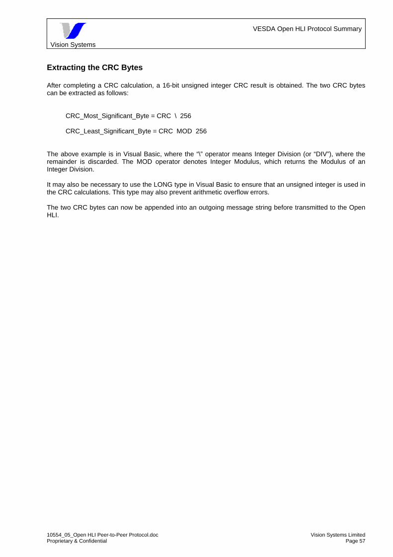
Vision Systems
VESDA Open HLI Protocol Summary
10554_05_Open HLI Peer-to-Peer Protocol.doc Vision Systems Limited Proprietary & Confidential Page 57
Extracting the CRC Bytes After completing a CRC calculation, a 16-bit unsigned integer CRC result is obtained. The two CRC bytes can be extracted as follows:
CRC_Most_Significant_Byte = CRC \ 256
CRC_Least_Significant_Byte = CRC MOD 256 The above example is in Visual Basic, where the “\” operator means Integer Division (or “DIV”), where the remainder is discarded. The MOD operator denotes Integer Modulus, which returns the Modulus of an Integer Division. It may also be necessary to use the LONG type in Visual Basic to ensure that an unsigned integer is used in the CRC calculations. This type may also prevent arithmetic overflow errors. The two CRC bytes can now be appended into an outgoing message string before transmitted to the Open HLI.

Vision Systems
VESDA Open HLI Protocol Summary
10554_05_Open HLI Peer-to-Peer Protocol.doc Vision Systems Limited Proprietary & Confidential Page 58
Appendix 6: Notes on Open HLI behaviours
Summary of communicating with the VHX-0300 HLI.
Command 7 behaviour A cmd 7 clears the entire HLI buffer. Any command sent immediately after this will respond with C8 indicating a “invalid zone”. In detail, what actually happens with a cmd 7 in broadcast mode, is that having cleared the HLI buffer we need to wait until each zone has sent its periodic status message which the HLI picks up and re-populates the buffer. The order in which these updates appear is indeterminate i.e. they will appear in any order and thus re-populate the HLI buffer in any order. See next section for an exception in the case of VLS devices. Two alternatives are available at this point.
• Wait for a period (approximately 3 seconds per device on network) before sending commands to the HLI.
• Repeat the required command for each zone, until the C8 goes away and valid data is returned. The term “comms lost” should not be used in this context, as we still have communications, but there is no valid data to receive. In any event the HLI will begin to send updated data to the host as soon as it gets them from devices. The exception being with scanners (see next section). ============================================================ Example sequence ============================================================ Send: 10 02 07 00 FF 00 00 10 03 61 B3 This clears the whole HLI buffer. The zone number should be 00 or FF.
Cmd 7 is clearing all the data from the HLI buffer. Recv: 10 02 03 00 02 00 01 FF 10 03 B6 6C
Response to cmd 7 OK Send: 10 02 08 00 02 00 00 10 03 9B 95
Send cmd 8 for zone 2 Recv: 10 02 03 00 02 00 01 C8 10 03 BC C7 C8 in response says that zone 2 is invalid. This is because the zone 2 data has not yet been updated since we cleared it Send: 10 02 08 00 02 00 00 10 03 9B 95
Sending another cmd 8 too quickly Recv: 10 02 03 00 02 00 01 C8 10 03 BC C7
This C8 will be received until the HLI buffer data for this zone becomes valid again.
This in NOT a comms failure. The HLI is correctly reporting a non-existant zone, as the buffer has not yet received any info on this zone. If the Host PC periodically sends the cmd 8, it will eventually get a cmd 9 response.

Vision Systems
VESDA Open HLI Protocol Summary
10554_05_Open HLI Peer-to-Peer Protocol.doc Vision Systems Limited Proprietary & Confidential Page 59
OpenHLI behaviour with LaserSCANNER An exception to the above description is the behaviour of the HLI when there is a scanner device (VLS) on the network being monitored. VLS (scanner) Message Sequences The open HLI gets its data from Head Status messages from devices on the VESDAnet. However, once a scanner detects smoke and enters scan mode, head status messages from that scanner cease to arrive. Instead the scanner sends a ScanFirst message followed by ScanData messages (once for each pipe configured). This will continue until the scanner leaves scan mode. It only does this when the smoke level goes below the threshold previously set. Then regular Head status messages will occur from the scanner. If the smoke level does not change, scanning will also stop and no updated messages will be received. Note that the scanning bit remains ‘set’ while alarms are active in the detector. Scanning bit is reset to ‘0’ when the HLI is refreshed with command 7. Scanning bit only sets when the scanning a fresh. Clearing VLS Status in HLI Once the fault/alarm condition has been cleared, resetting the scanner will get the new state updated. A cmd 7 will also get the new state correctly, but will take longer as the cmd 7 has cleared all the device entries in the HLI. The reset may be accomplished by either the device reset button or from the third party monitoring software. Status Latching It is noted in this document that the open HLI does NOT latch alarms for the scanner. However, the faults are latched. Resetting the scanner will clear the faults. It is recommended that the 3rd party software/infrastructure should latch the Alarms if required. First Alarm Sector Latching & Clearing The First Alarm Sector (FAS) value is also latched like the fault bits. It is recommended that when the smoke has decreased below Alert alarm level, the scanner detector is reset so that FAS value is updated along with the faults. Refreshing the HLI after it has started scanning will clear the first alarm sector. The FAS value will remain cleared unless the scanning restarts. The scanning starts only when the smoke rises from below the alarm threshold and raises above any of the thresholds or when the scanner detector is reset while it is in fire alarm condition. It is recommended that after a refresh, the scanner is reset using command 6, to get the FAS again. Updated Data Delay Note that it requires some time for the refreshed data from a device on the network to be available. This is at least 3 seconds per device, and the order of refreshing is indeterminate. Retrieving Sector Information Five sectors are defined in the HLI for the Scanner. Sectors 1, 2, 3 and 4 correspond to “only pipe 1 open”, “only pipe 2 open”, “only pipe 3 open” and “only pipe 4 open” respectively. Sector 0 corresponds to all pipes open, so it is the overall status of the scanner. Command 10 is used to fetch sector information by specifying the sector number. However, the sector 1, 2, 3 and 4 information is not valid if scanner is not scanning. Sector 1 through 4 are only updated when the scanner is scanning because of significant changes in smoke. DO NOT fetch sector 1, 2, 3 and 4 information if scanner is not scanning because the status information is not valid.

Vision Systems
VESDA Open HLI Protocol Summary
10554_05_Open HLI Peer-to-Peer Protocol.doc Vision Systems Limited Proprietary & Confidential Page 60
Behaviour when Moving Zones When an existing zone in a VESDAnet network is re-numbered, it is essential that a cmd 7 is sent to the HLI. This will clear the entire HLI buffer which will then acquire the new zone number. Failure to do this will cause the old zone number to be retained in the HLI buffer.