Very-Near-Field Solutions for Antenna Measurement Problems
68
Very-Near-Field Solutions for Antenna Measurement Problems
-
Upload
khangminh22 -
Category
Documents
-
view
3 -
download
0
Transcript of Very-Near-Field Solutions for Antenna Measurement Problems

Very-Near-Field Solutions
for
Antenna Measurement Problems

Chamber on your Desktop
EMxpert
– EMC diagnostic tool to rapidly diagnose and solve EMC/EMS/EMI problems with real-time PCB emission analysis
RFxpert
– APM tool enabling to quickly evaluate performance and optimize designs with real-time antenna performance characterization

Fundamentals
High-density planar antenna array
High-speed electronic switching
Very-near-field measurements
Far-field calculation
“Real-time” real-fast
No chamber

Introduction to Near-Field Theory

Existing Solutions
Anechoic Chamber
– Slow testing
– High CAPEX and OPEX
– Real-estate
– Qualified personnel
Reverberation Chamber
– Fast testing
– No pattern
– Qualified personnel

What is Near-Field?
Anything not in the far-field
Far-field is where the pattern is not changing with thedistance
Common definitions
Usually stay out of the reactive region

Functionality
300 MHz to 6.0 GHz
Far-field patterns and bisections
– EIRP / TRP / TIS Proxy
– Circular and linear polarization
Very-near-field insights
– Amplitude
– Phase
– Polarity
Gain and efficiency
DLL programming

RF Test Solution
Typically looking for far-field parameters
– Gain, efficiency, pattern are basic measures
– More complex applications such as Envelope Correlation, Axial Ratio and Beam Forming
Debugging via near-field

Far-Field Measurements
Far-field site far and demanding a large area
Open-air-test-site (OATS) avoids reflections– Almost impossible in an urban environment
Anechoic Chambers

Near-Field to Far-Field Transformation
Near-field measurement
– Smaller footprint
– Can be as accurate as far-field
Near to Far projections
– Plane Wave/Modal Expansion
– Magnetic currents
– Genetic algorithms and more

Planar Near-Field Theory
The radiation of the antenna can be described in terms of angular spectrum of waves
Based on Huygen’s principle
Fourier transform from near-field space to propagation vectors in far-field
Image: www.schoolphysics.co.uk

Planar Near-Field Theory
An antenna can propagate in all directions
The phases and amplitudes in each directions will vary
In the near field all elements are interdependent

Planar Near-Field Theory
Sample near field elements along a planar surface
Measure amplitude and phase in each point
Combination of phase fronts

Planar Near-Field Theory
Use sampled points to reconstruct new phase fronts
No difference between this and the original phase front that was sampled

Planar Near-Field Theory
Separate the various phase fronts or plane waves based on their weightings
This set of plane waves in all directions is the plane wave spectrum

The term k may be called the wave number vector and the terms in the integration represent a uniform plane wave propagating in the k direction
yx
j
yx dkdkekkzyxrk
AE
),(2
1),,(
yx
j
yx dkdkekkzyxrk
AkH
),(2
1),,(
Based on Maxwell’s equations and a source-less boundary condition we can construct the following equations
rkA
j
yx ekk ),(
Planar Near-Field Theory

And can be determined by ,
Planar Near-Field Theory
dydxezyxEekkA
ykxkj
txzkj
yxxyxtz)(
),,(2
1),(
dydxezyxEekkA
ykxkj
tyzkj
yxyyxtz)(
),,(2
1),(
),( yx kkA

Planar Near-Field Benefits
Simple Fourier transform
Easy to calculate quickly
Easy to sample data
),(),,( yxz
rjk
kkkr
jezyx AE

A Very-Near-Field Implementation

Very-Near-Field Challenges
Coupling unavoidable so make it predictable
Static array has constant effect for each sample

Very-Near-Field Implementation
Array of probes
Addressable array of probes makes very-near-field sampling very fast and repeatable
Small loops not sensitive but very broadband, with good isolation and polarization specifications
Reference channel for phase measurement of active devices

Very-Near-Field Implementation

Results with Ideal Data
Still have limitations of finite planar scans
Hemispherical results
Limited angular coverage
E-theta always reduces to zero at horizon

Aggregate Node
Combined scan results for full spherical far-field view
User defined elevation for asymmetrical devices

Very-Near-Field Benefits
Visualizing interference in the near-field
– Resonance and mutual coupling

Very-Near-Field Benefits
Antenna position
Loading and field perturbation

Very-Near-Field Benefits
Effects of Surrounding Material

Aggregated Very-Near-Field
Multiple planar measurements combined together to provide larger effective scan area
Multiple planar scans do not need to be co-planar
– Can used to created 3D scan surfaces or even enclosed surfaces

Aggregated Very-Near-Field

RFX and RFX2

RFxpert
Fast measurements
– Continuous “real-time”
– Single scan < 1 second
Compact tabletop instrument
Cost effective solution
Easy-to-use by any engineer

High Accuracy
Repeatability
– +/- 0.2 dB from one measurement to the next
– +/- 0.5 dB within the white test zone
Relative accuracy
– +/- 0.5 dB comparative measurements

Absolute Accuracy Out-of-the-Box
Aligned to the Atlanta CTIA Satimo chamber
Re-align your RFxpert to your chamber– Portfolio of devices
– 2σ = +/- 1.1 dB at 700 MHz (better at higher frequency)

Absolute Accuracy Out-of-the-Box
Aligned to the Atlanta CTIA Satimo chamber
Re-align your RFxpert to your chamber– One device
– 2σ = +/-0.54 dB at 700 MHz

Technical Specifications

Configuration
USB USB
RFxpert
EMSCAN Application
VNA or BSE
Power Sensor
USB
RF
GPIB USB

Frequency Scan
Gain, efficiency, EIRP and TRP of a device at a discrete frequency and across a range of frequencies through remote control of a VNA

Circular Polarization
LHCP / RHCP / AR over a range of ±30° from the center line

Aggregate Node
Combined frequency scanning results for full spherical far-field view
User defined elevation for asymmetrical devices

Very-Near-Field
Insights into design issues

Comparison with Simulation

Simulation
Agilent EDA simulation
Toyo corporation (EMSCAN Representative)
Tokyo, Japan
June 19, 2012

3cm上方磁界強度 遠方界位相重みづけ
4 ブランチアンテナ

3D Farfield
3GHz 4GHz 5GHz 6GHz

Mode3:左右で逆相
Mode2:上下で逆相
Mode4:斜め同士が同相
Mode1:4つとも同位相
mag(Hx) mag(Hy)Farfield(dBi)
EMPro RFexpertEMPro RFexpert EMPro RFexpert

Comparison with Chamber Results

Note: Low band offset applied by customer
Mobile Phone Efficiency

Note: Low band offset applied by customer
Mobile Phone Efficiency

Note: Low band offset applied by customer
Mobile Phone Efficiency

CTIA
RFxpert
Patterns of Various Mobile Phones

Passive Antenna Results
47 antennas measured in CTIA MVG Satimo chamber
– 20 PIFAs, 10 Patch designed by EMSCAN
– 17 acquired antennas are a mix of different sorts

PRAD Offset Table
Re-alignment process

Test Applications
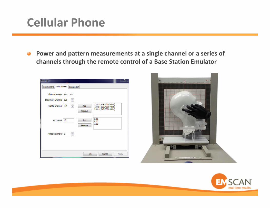
Cellular Phone
Power and pattern measurements at a single channel or a series of channels through the remote control of a Base Station Emulator

IoT
Fast pre-certification

Cellular Base Station Antenna

Testing of Large or Long Antennas

Phase Center

Wi-Fi
Any customized pulse up to 60-second timeout

Phased Array Antenna
Phase balancing
Picture from www.mathworks.com/

GPS Antenna
Circular Polarization

MIMO
Very-near-field for antenna diversity and mutual coupling
Far-field for real-time tuning
Correlation
– Envelope and pattern correlation
• Hemispherical RFX
• Spherical RFX2

Smart Meters
Connectivity with– GSM, Mobile
– WLAN / WiFi
– ZigBee
– M-Bus
– Custom
– Others …
Measurement of antennas
Measuring active device with long timeout

Conclusion

Very-Near-Field Benefits
Ability to see surface currents
Very fast scanning
Repeatable
No chamber
Low maintenance
Easy to use

RFxpert Advantages
Interaction effects in real-time
Very-near-field measurements
Fast and repeatable
Low CAPEX

Some Customers