Verification and Validation in Computational Fluid Dynamics: the FLOWNET Database Experience
9
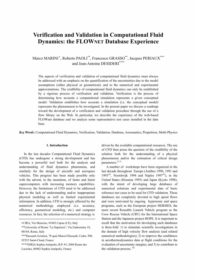
Verification and Validation in Computational Fluid Dynamics: the FLOWNET Database Experience Marco MARINI ∗ , Roberto PAOLI ** , Francesco GRASSO ** , Jacques PERIAUX *** and Jean-Antoine DESIDERI **** The aspects of verification and validation of computational fluid dynamics must always be addressed with an emphasis on the quantification of the uncertainties due to the model assumptions (either physical or geometrical), and to the numerical and experimental approximations. The credibility of computational fluid dynamics can only be established by a rigorous process of verification and validation. Verification is the process of determining how accurate a computational simulation represents a given conceptual model. Validation establishes how accurate a simulation (i.e. the conceptual model) represents the phenomenon to be investigated. In the present paper we discuss a roadmap toward the development of a verification and validation procedure through the use of a flow library on the Web. In particular, we describe the experience of the web-based FLOWnet database and we analyze some representative test cases installed in the data base. Key Words: Computational Fluid Dynamics, Verification, Validation, Database, Aeronautics, Propulsion, Multi-Physics 1. Introduction In the last decades Computational Fluid Dynamics (CFD) has undergone a strong development and has become a powerful tool both for the analysis and understanding of fluid dynamics phenomena, and similarly for the design of aircrafts and aerospace vehicles. This progress has been made possible only with the advent, in the meantime, of faster and faster supercomputers with increasing memory capabilities. However, the limitations of CFD need to be addressed due to the lack of understanding and/or inappropriate physical modeling as well as limited experimental information. In addition, CFD is strongly affected by the numerical methodology employed (i.e. accuracy, efficiency, geometrical modeling, etc.) and computer resources. In fact, the selection of a numerical strategy is ∗CIRA, Via Maiorise, 81043 Capua (CE), Italy **University of Rome “La Sapienza”, Via Eudossiana 18, 00184, Rome, Italy ***Dassault Aviation, 78 quai Marcel Dassault, Cedex 300, 92552 Saint-Cloud, France ****INRIA Sophia-Antipolis, B.P. 93, 2004 Route des Lucioles, 06902 Sophia-Antipolis, France driven by the available computational resources. The use of CFD then poses the question of the credibility of the solution both for the understanding of a physical phenomenon and/or the estimation of critical design parameters. (1-3) A number of workshops have been organized in the last decade throughout Europe (Antibes 1990, 1991 and 1993 (4) , Noordwijk 1994 and Naples 1997 (5) ), in the United States (Houston 1995) and Japan (Kyoto 1998), with the intent of developing large databases of numerical solutions and experimental data of basic reference test cases to be used for CFD validation. These databases are completely devoted to high speed flows and were motivated by ongoing hypersonic and space programs, such as the European project HERMES, the more recent Reusable Launch Vehicle program as the Crew Rescue Vehicle (CRV) for the International Space Station and the Japanese project HOPE. It is important to recall that the motivation for developing such databases is three-fold: 1) to stimulate scientific investigations in the domain of high velocity flow analysis (and related numerical methodologies); 2) to improve the confidence in aerothermodynamics data at flight conditions for the evaluation of uncertainty margins; and 3) to contribute to the validation process. (6)
-
Upload
independent -
Category
Documents
-
view
6 -
download
0
Transcript of Verification and Validation in Computational Fluid Dynamics: the FLOWNET Database Experience
Verification and Validation in Computational Fluid
Dynamics: the FLOWNET Database Experience
Marco MARINI ∗, Roberto PAOLI**, Francesco GRASSO**, Jacques PERIAUX***
and Jean-Antoine DESIDERI****
The aspects of verification and validation of computational fluid dynamics must always be addressed with an emphasis on the quantification of the uncertainties due to the model assumptions (either physical or geometrical), and to the numerical and experimental approximations. The credibility of computational fluid dynamics can only be established by a rigorous process of verification and validation. Verification is the process of determining how accurate a computational simulation represents a given conceptual model. Validation establishes how accurate a simulation (i.e. the conceptual model) represents the phenomenon to be investigated. In the present paper we discuss a roadmap toward the development of a verification and validation procedure through the use of a flow library on the Web. In particular, we describe the experience of the web-based FLOWnet database and we analyze some representative test cases installed in the data base.
Key Words: Computational Fluid Dynamics, Verification, Validation, Database, Aeronautics, Propulsion, Multi-Physics
1. Introduction
In the last decades Computational Fluid Dynamics (CFD) has undergone a strong development and has become a powerful tool both for the analysis and understanding of fluid dynamics phenomena, and similarly for the design of aircrafts and aerospace vehicles. This progress has been made possible only with the advent, in the meantime, of faster and faster supercomputers with increasing memory capabilities. However, the limitations of CFD need to be addressed due to the lack of understanding and/or inappropriate physical modeling as well as limited experimental information. In addition, CFD is strongly affected by the numerical methodology employed (i.e. accuracy, efficiency, geometrical modeling, etc.) and computer resources. In fact, the selection of a numerical strategy is
∗CIRA, Via Maiorise, 81043 Capua (CE), Italy **University of Rome “La Sapienza”, Via Eudossiana 18, 00184, Rome, Italy ***Dassault Aviation, 78 quai Marcel Dassault, Cedex 300, 92552 Saint-Cloud, France ****INRIA Sophia-Antipolis, B.P. 93, 2004 Route des Lucioles, 06902 Sophia-Antipolis, France
driven by the available computational resources. The use of CFD then poses the question of the credibility of the solution both for the understanding of a physical phenomenon and/or the estimation of critical design parameters.(1-3)
A number of workshops have been organized in the last decade throughout Europe (Antibes 1990, 1991 and 1993(4), Noordwijk 1994 and Naples 1997(5)), in the United States (Houston 1995) and Japan (Kyoto 1998), with the intent of developing large databases of numerical solutions and experimental data of basic reference test cases to be used for CFD validation. These databases are completely devoted to high speed flows and were motivated by ongoing hypersonic and space programs, such as the European project HERMES, the more recent Reusable Launch Vehicle program as the Crew Rescue Vehicle (CRV) for the International Space Station and the Japanese project HOPE. It is important to recall that the motivation for developing such databases is three-fold: 1) to stimulate scientific investigations in the domain of high velocity flow analysis (and related numerical methodologies); 2) to improve the confidence in aerothermodynamics data at flight conditions for the evaluation of uncertainty margins; and 3) to contribute to the validation process. (6)
One of the most challenging problems of modern aerospace engineering is undoubtedly the prediction of complex flows at different regimes around complicated shapes due to multi-disciplinary aspects,. This demands for a continuous (ongoing) activity toward the development of accurate and robust CFD codes. In order to provide the scientific and industrial communities with a validation strategy for flow modeling, and both computational and experimental methodologies ranging from subsonic, transonic to supersonic and hypersonic regimes, the European Community Commission has supported the set-up of the Thematic Network FLOWnet (Flow Library On the Web network).
The ultimate goal of the network is to stimulate collaboration between industrial and research partners in order to evaluate continuously the quality of the simulations and the performance of CFD software, the scope being to improve complex design in aeronautical and aerospace industry. Six kernel members (INRIA, Dassault Aviation, EADS, CIRA, DLR and University of Rome “La Sapienza”) share the project responsibilities that include: i) coordination and management of the (industrial and academic) node-partners; ii) creation of the database and selection of basic reference test cases; iii) evaluation and integration of available experiments and computational results; iv) organization of database workshops, short courses, seminars and trainings; and v) data quality assessment. The twenty-six node-partners of the network belong to industries, research institutions, and universities, and share the knowledge in flow modeling, flow simulations, and experiments. In particular, they provide experimental and/or computational data for a better understanding of flows in several scientific areas such as aerospace, propulsion and turbo-machinery, wind energy, multi-physics, multi-optimization and unsteady flows.
A valuable aspect of the FLOWnet network is the massive use of the World Wide Web to build a database that can be continuously accessed and enriched by FLOWnet contributors, thus enhancing the exchange of knowledge and experiences among the partners, as well as contributing to stimulate synergy.(7) In addition, FLOWnet provides a continuously updated platform for pre-industrial code verification and validation, that are of extreme importance to improve the reliability of scientific computing in industry.(7)
In the next sections the issues related to CFD verification and validation are discussed, and the content of the FLOWnet database is described. A brief synthesis of results of some interesting test cases installed in the database is given together with lessons learned.
2. CFD Verification and Validation
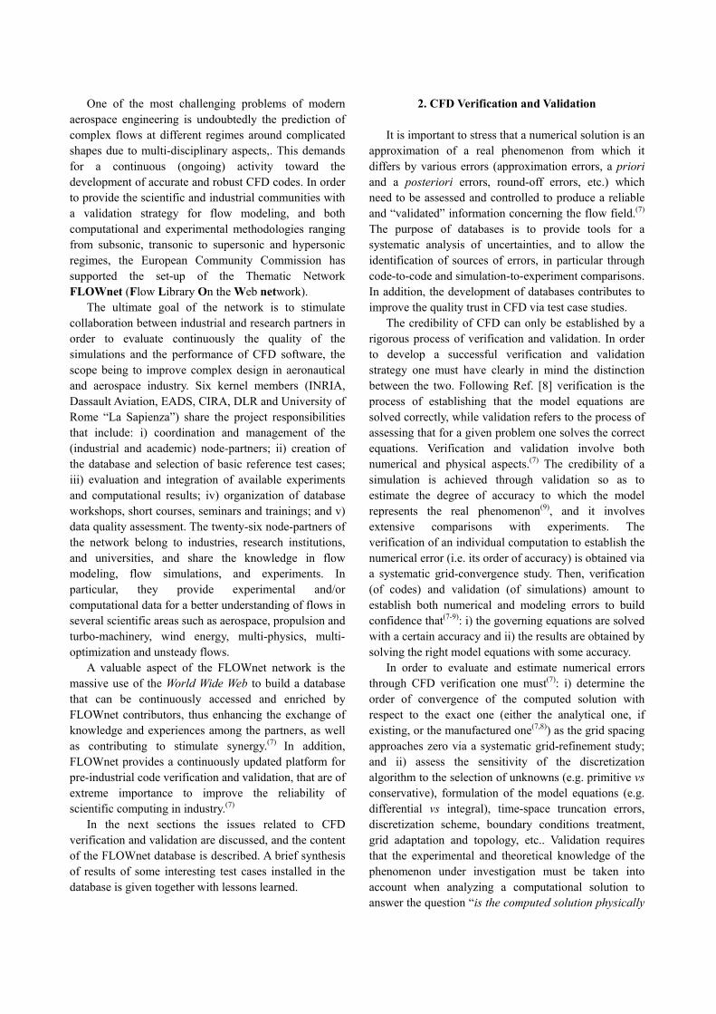
It is important to stress that a numerical solution is an approximation of a real phenomenon from which it differs by various errors (approximation errors, a priori and a posteriori errors, round-off errors, etc.) which need to be assessed and controlled to produce a reliable and “validated” information concerning the flow field.(7)
The purpose of databases is to provide tools for a systematic analysis of uncertainties, and to allow the identification of sources of errors, in particular through code-to-code and simulation-to-experiment comparisons. In addition, the development of databases contributes to improve the quality trust in CFD via test case studies.
The credibility of CFD can only be established by a rigorous process of verification and validation. In order to develop a successful verification and validation strategy one must have clearly in mind the distinction between the two. Following Ref. [8] verification is the process of establishing that the model equations are solved correctly, while validation refers to the process of assessing that for a given problem one solves the correct equations. Verification and validation involve both numerical and physical aspects.(7) The credibility of a simulation is achieved through validation so as to estimate the degree of accuracy to which the model represents the real phenomenon(9), and it involves extensive comparisons with experiments. The verification of an individual computation to establish the numerical error (i.e. its order of accuracy) is obtained via a systematic grid-convergence study. Then, verification (of codes) and validation (of simulations) amount to establish both numerical and modeling errors to build confidence that(7-9): i) the governing equations are solved with a certain accuracy and ii) the results are obtained by solving the right model equations with some accuracy.
In order to evaluate and estimate numerical errors through CFD verification one must(7): i) determine the order of convergence of the computed solution with respect to the exact one (either the analytical one, if existing, or the manufactured one(7,8)) as the grid spacing approaches zero via a systematic grid-refinement study; and ii) assess the sensitivity of the discretization algorithm to the selection of unknowns (e.g. primitive vs conservative), formulation of the model equations (e.g. differential vs integral), time-space truncation errors, discretization scheme, boundary conditions treatment, grid adaptation and topology, etc.. Validation requires that the experimental and theoretical knowledge of the phenomenon under investigation must be taken into account when analyzing a computational solution to answer the question “is the computed solution physically
correct ?”. Following Ref. [7] CFD validation implies the three following steps: i) definition of the appropriate physical model; ii) evaluation of the level of reliability of both experimental and numerical methods; and iii) quantification of the sources of uncertainties. CFD validation involves comparison of numerical solutions with experiments; however, it also requires a systematic accuracy assessment of the experimental data, the errors amounting to: calibration, data acquisition, data reduction, measurement technique and geometry definition. To assess the modeling errors one must usually identify(7): i) the controlling physical phenomena and the model uncertainties; ii) the uncertainties in the initial and boundary conditions both from the physical and numerical point of view; iii) the critical conditions in the solution behavior (e.g. laminar-to-turbulence transition, turbulence, separation, unsteadiness, real gas effects, gas/surface interaction, phase changes); etc.. Moreover, validation must be thought as an on going activity that is beneficial to both computational and experimental methods(7) thus implying a strong synergism between computational fluid dynamics (CFD) and experimental fluid dynamics (EFD). A possible roadmap to build a validation strategy may rely on the following phases:
A. Phase 1
A.1 Consider simple flow features; A.2 Identify test cases for which analytic and/or manufactured solutions (or even direct numerical simulations) are available; A.3 Assess accuracy, convergence and capability.
B. Phase 2 B.1 Consider simple/moderate flow physics; B.2 Establish grid requirements; B.3 Assess model assumptions through comparison with benchmark experiments.
C. Phase 3 C.1 Assess accuracy by comparison with high quality experiments; C.2 Evaluate model limitations and determine grid requirements.
D. Phase 4 D.1 Consider complete flow physics; D.2 Carry out parametric analysis with through comparison with test data.
It is important to stress that in principle a verification
and validation procedure for CFD may require simulations of a very large number of reference test cases. However, such a methodological approach is not always feasible if one wants to explore all possible
combinations of physical phenomena. Therefore, one may focus on basic reference test cases and the use of a database such as FLOWnet is essential for verification and validation.
3. The Web-based FLOWnet Database, Structure and Content
The development of the FLOWnet database is the
result of collaborative efforts between INRIA, CIRA and University of Rome “La Sapienza” who share the responsibilities for the implementation and analysis of the data content. The latter is the result of the contributions to two workshops that have been organized, respectively, by the University of Rome “La Sapienza” in Rome (Italy) on March 15-17, 2000 and by DLR in Göttingen (Germany) on February 5-7, 2001. The organization of the workshops has brought together partners from academics, research institutions and industries thus promoting the synergy and the exchange of knowledge through: 1) the analyses of each contribution; 2) comparisons with experiments; and 3) syntheses of the contributed results for data quality assessment, and evaluations of the physical models and numerical methodologies.
The data submitted for the workshops have been installed in the database at INRIA Sophia-Antipolis, which is accessible at the URL address http://www-sop.inria.fr/sinus/flownet/index.php3. For the database implementation a three-level procedure has been devised, whereby: 1) INRIA has the responsibility of data verification for electronic compatibility (format and rules); 2) CIRA verifies the compatibility of the data with respect to test case specifications; and 3) the University of Rome verifies the physical aspects of the simulations. All test cases are supported by well documented experiments, and they have been selected so as to cover a wide range of flow physics within six scientific areas. Table 1 lists all the selected test cases, together with the test case responsible (belonging either to industries, research institutions or academics) and number of contributions.
Table 1 FLOWnet Database Case Studies
Area Test Case Responsible Res.A.1 2D subsonic airfoil EADS 2 A.1 NLR7301 airfoil with flap SAAB 3 A.1 M2155 transonic wing EADS 5 A.1 skewed bump ONERA 1 A.2 over-expanded nozzle LEA 3 A.2 supersonic high-lift ELAC RWTH 1
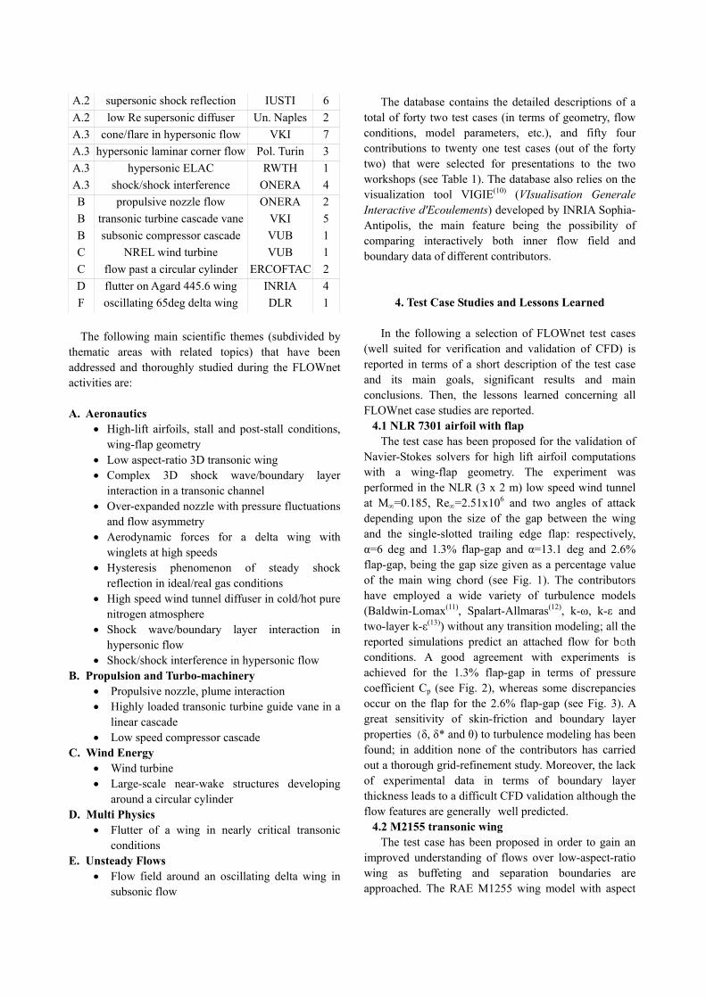
A.2 supersonic shock reflection IUSTI 6 A.2 low Re supersonic diffuser Un. Naples 2 A.3 cone/flare in hypersonic flow VKI 7 A.3 hypersonic laminar corner flow Pol. Turin 3 A.3 hypersonic ELAC RWTH 1 A.3 shock/shock interference ONERA 4 B propulsive nozzle flow ONERA 2 B transonic turbine cascade vane VKI 5 B subsonic compressor cascade VUB 1 C NREL wind turbine VUB 1 C flow past a circular cylinder ERCOFTAC 2 D flutter on Agard 445.6 wing INRIA 4 F oscillating 65deg delta wing DLR 1 The following main scientific themes (subdivided by
thematic areas with related topics) that have been addressed and thoroughly studied during the FLOWnet activities are:
A. Aeronautics
• High-lift airfoils, stall and post-stall conditions, wing-flap geometry
• Low aspect-ratio 3D transonic wing • Complex 3D shock wave/boundary layer
interaction in a transonic channel • Over-expanded nozzle with pressure fluctuations
and flow asymmetry • Aerodynamic forces for a delta wing with
winglets at high speeds • Hysteresis phenomenon of steady shock
reflection in ideal/real gas conditions • High speed wind tunnel diffuser in cold/hot pure
nitrogen atmosphere • Shock wave/boundary layer interaction in
hypersonic flow • Shock/shock interference in hypersonic flow
B. Propulsion and Turbo-machinery • Propulsive nozzle, plume interaction • Highly loaded transonic turbine guide vane in a
linear cascade • Low speed compressor cascade
C. Wind Energy • Wind turbine • Large-scale near-wake structures developing
around a circular cylinder D. Multi Physics
• Flutter of a wing in nearly critical transonic conditions
E. Unsteady Flows • Flow field around an oscillating delta wing in
subsonic flow
The database contains the detailed descriptions of a total of forty two test cases (in terms of geometry, flow conditions, model parameters, etc.), and fifty four contributions to twenty one test cases (out of the forty two) that were selected for presentations to the two workshops (see Table 1). The database also relies on the visualization tool VIGIE(10) (VIsualisation Generale Interactive d'Ecoulements) developed by INRIA Sophia-Antipolis, the main feature being the possibility of comparing interactively both inner flow field and boundary data of different contributors.
4. Test Case Studies and Lessons Learned In the following a selection of FLOWnet test cases
(well suited for verification and validation of CFD) is reported in terms of a short description of the test case and its main goals, significant results and main conclusions. Then, the lessons learned concerning all FLOWnet case studies are reported.
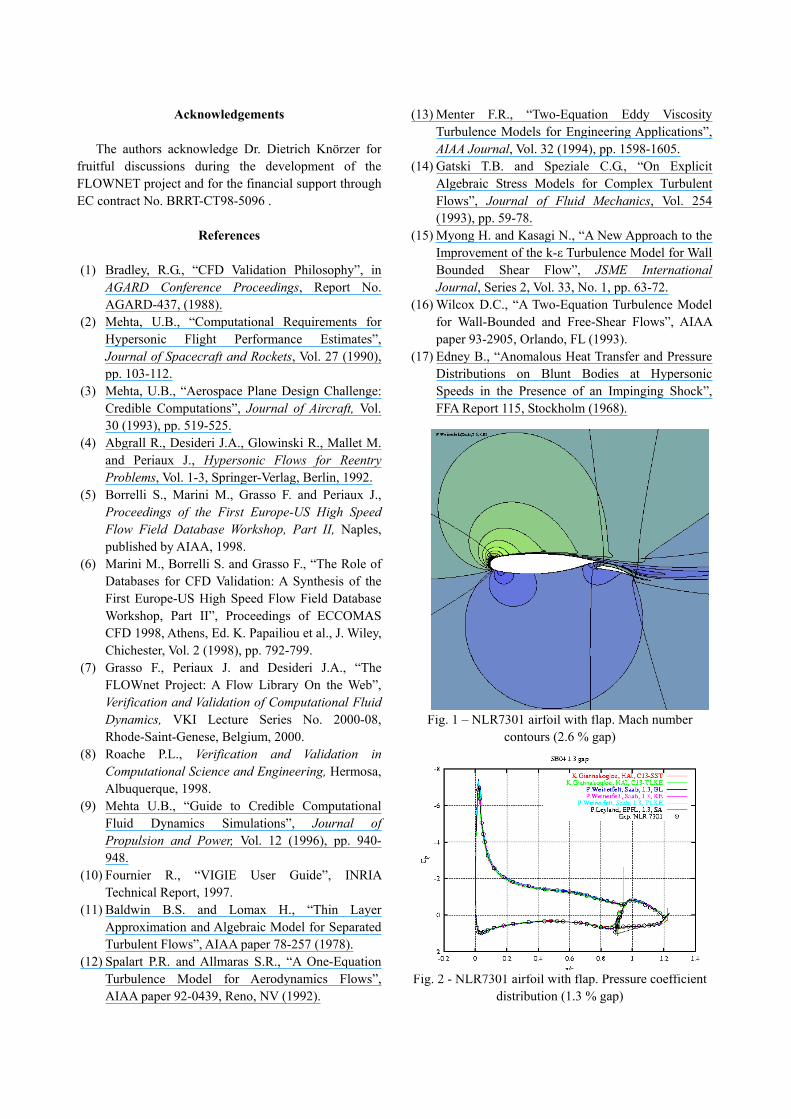
4.1 NLR 7301 airfoil with flap The test case has been proposed for the validation of
Navier-Stokes solvers for high lift airfoil computations with a wing-flap geometry. The experiment was performed in the NLR (3 x 2 m) low speed wind tunnel at M∞=0.185, Re∞=2.51x10⁶ and two angles of attack depending upon the size of the gap between the wing and the single-slotted trailing edge flap: respectively, α=6 deg and 1.3% flap-gap and α=13.1 deg and 2.6% flap-gap, being the gap size given as a percentage value of the main wing chord (see Fig. 1). The contributors have employed a wide variety of turbulence models (Baldwin-Lomax(11), Spalart-Allmaras(12), k-ω, k-ε and two-layer k-ε(13)) without any transition modeling; all the reported simulations predict an attached flow for both conditions. A good agreement with experiments is achieved for the 1.3% flap-gap in terms of pressure coefficient Cp (see Fig. 2), whereas some discrepancies occur on the flap for the 2.6% flap-gap (see Fig. 3). A great sensitivity of skin-friction and boundary layer properties (δ, δ* and θ) to turbulence modeling has been found; in addition none of the contributors has carried out a thorough grid-refinement study. Moreover, the lack of experimental data in terms of boundary layer thickness leads to a difficult CFD validation although the flow features are generally well predicted.
4.2 M2155 transonic wing The test case has been proposed in order to gain an
improved understanding of flows over low-aspect-ratio wing as buffeting and separation boundaries are approached. The RAE M1255 wing model with aspect
ratio 3.27 has been considered to study complex transonic flows by the Reynolds Averaged Navier Stokes equations under severe adverse pressure gradient conditions that produce both trailing edge and shock-induced boundary layer separations. Two sub-cases have been considered: Case 2 (M∞=0.806 and α=2.5 deg) and Case 4 (M∞=0.854 and α=1.5 deg), both with Re∞ =4.1x10⁶ and transition fixed at 5% of the local chord. For Case 2 a λ-shock structure takes place on the upper surface, with the shock intersection at about 50% of span, and a single local shock on the outer 50% causing local separation (see Figs. 4 and 5). There is no trailing edge separation. For Case 4 also a λ-shock structure appears on the upper surface, and trailing edge separation between 30% and 50% of the span. The lower surface boundary layer is extremely skewed in the region of the outboard shock. The different turbulence models which have been used by the various contributors (Menter SST(13) (Shear Stress Model), EARSM(14) (Explicit Algebraic Reynolds Stress Model), Spalart-Allmaras(12), Myong-Kasagi(15) k-ε and Wilcox(16) k-ω) yield similar pressure coefficient (Cp) distributions for both cases. The pressure coefficient distributions for Case 2 along span-wise direction (at different sections y/b=const) agree rather well with the experiments (see Fig. 6). Nevertheless, all computations predict the shock location slightly downstream of the measurements. The skin-friction lines (Figs. 4 and 5) indicate that the flow separates in a region between 50% and 80% of the span, the separation line appearing closer to the leading edge of the wing at its extremity. Differences in the size of the separation region are predicted depending on turbulence modeling. The lift coefficient for the whole wing is rather well reproduced, while computations overestimate the drag coefficient. Concerning Case 4, the flow features are well predicted and the pressure coefficient distributions along span-wise direction are well reproduced (however, the results are not reported for space limitations). A comparative analysis of the contributed results indicates that the scatter on the shock location is reduced and similarly the accuracy of the predicted results is increased when using a nonlinear k-ε model.
4.3 Supersonic shock reflection The test case has been proposed to evaluate Euler
and Navier-Stokes solvers for the analysis of hysteresis phenomena occurring in high speed steady shock reflections. Two sub-cases were selected: M∞=4.96 and “cold” conditions, and M∞=7 and “hot” conditions. The “cold” experiments were conducted in the wind tunnel facility at ITAM, Russia, and different wedge angles (from 21 to 40 deg) were used to cause the hysteresis.
The simulations do confirm the occurrence of the hysteresis phenomenon between regular (RR) and Mach (MR) reflections inside the dual solution region (see Fig. 7). The Mach stem height is well predicted for moderate wedge angles while it is over-estimated (with respect to experiments) in the proximity of the Mach-to-Regular reflection transition angle (see Fig. 8), this being due to a strong dependency upon the grid when calculating a Mach stem with vanishing height. Less sensitivity to grid resolution is observed for the Regular-to-Mach reflection transition. Possible three-dimensional effects can affect the Mach stem height for higher wedge angles. The viscous simulation yields a slight displacement of Mach stem location due to the wedge displacement thickness effects, and a better agreement with experiments. The simulations conducted at higher Mach number (“hot” conditions) well reproduce the hysteresis behavior between RR and MR and confirm the reduction of the Mach stem height due to thermo-chemical non-equilibrium phenomena. Moreover, a strong oxygen dissociation and a fast nitrogen relaxation are observed just after the normal shock in the MR configuration.
4.4 Shock/shock interference The problem has been selected in order to evaluate
CFD codes for the analysis of complex shock/shock interactions occurring when a shock wave (generated by a wedge) impinges on the bow shock around a circular cylinder. The experimental conditions are those of the experiment performed at the ONERA-R5Ch hypersonic wind tunnel facility (M∞=9.95 and Re∞,D=1240); all simulations correspond to ideal gas and fully laminar flow assumptions. Following Edney's classification(17), the type-IV shock/shock interference is produced (see Fig. 9). The results show the steadiness of the flow field and the great sensitivity of the interaction pattern to incident shock wave angle and its strength; in addition, all computations slightly over-estimate the stand-off distance. A “weakly” coupled shock generator/cylinder simulation yields a better prediction of the jet bow shock impingement angular position, but it over-estimates pressure and heat flux peak values (see Figs. 10 and 11). No effects of slip-flow assumption on surface properties have been predicted. Two open questions remain: 1) with regard to the experiments, the measurements have been taken with too large taps and thermocouples; 2) with regard to the computations, the simulations should be carried out considering both the shock generator and the cylinder, so as to take into account the interaction of the bow shock with the incident shock and the expansion fan generated at shoulder of the shock generator. The use of multi-block
unstructured grids to handle complex geometries should be considered.
4.5 Lessons Learned The test case syntheses of the FLOWnet database
contributions lead to the conclusion that further studies are needed in the following critical areas:
• grid sensitivity analysis; • turbulence and transition modeling (e.g. for high-
lift airfoils and three-dimensional transonic wings); • initial and boundary conditions for turbulent
quantities in fully turbulent flows; • influence of laminar-to-turbulence transition and
turbulence intensity for heat transfer prediction in turbo-machinery;
• turbulence and vortex break-down modeling for a delta wing oscillating in pitch at very high angles of attack;
• flow unsteadiness (e.g. over-expanded nozzles with flow separation and shock/shock interference);
• flow condensation effects due to very low free stream temperature;
• flow conditions for which the slip-flow assumption is important;
• geometry modeling (e.g. shock generator and cylinder for shock/shock interference);
• jet plume interaction with outer flow; • effect of inlet flow angle and tip clearance on blade
flows in low-speed compressors; • influence of Reynolds number on unsteady near-
wake flow structures around a cylinder; • effect of flow modeling (inviscid/viscous and
linear/non-linear) in flutter prediction; • uncertainty estimation in experimental
measurements; • experimental measurements of separated and
vortex-dominated flows; • influence of model support in experimental tests,
and its reproduction in numerical simulations. The analysis of these critical issues lead us to
conclude that: i) simple representative experiments may be of little use when physical models are lacking; ii) theoreticians should closely interact with experimentalists to minimize the sources of uncertainties when defining test cases for CFD verification and validation, i.e. the synergism between CFD and EFD is highly recommended; iii) a detailed analysis of the sensitivity of the computed solution to the physical and numerical modeling should be always carried out; and iv) the grid independence of computed results must always be established.
5. Conclusions
In the present paper we have discussed the problem
of verification and validation of computational fluid dynamics through the development (and the use) of the web-based FLOWnet database. Verification is the process of determining how accurate a computational simulation represents a given conceptual model. Validation establishes how accurate a simulation (i.e. the conceptual model) represents the phenomenon to be investigated. The aspects of verification and validation must always be addressed with an emphasis on the quantification of the uncertainties due to the model assumptions (either physical or geometrical), and to the numerical and experimental approximations. In the present paper we discuss a roadmap toward the development of a verification and validation procedure through the use of a flow library on the Web. In particular, we show that validation is an ongoing activity that implies a synergism between theoretical, computational and experimental fluid dynamics. The use of a database such as FLOWnet is of great help for promoting such a synergism, thus favouring the exchange of knowledge by bringing together experts in different disciplines. This is achieved through the organization of workshops, open day case studies, and through a continuous evaluation of both numerical and experimental data in order to improve the credibility and quality trust in CFD for industrial applications.
Multi-disciplinary integrated design involves the
coupling of disciplines such as fluid/structure interactions, aero-acoustics, vibro-acoustics and hydro-acoustics, electromagnetism/structure interactions, etc.. Such coupling is generally nonlinear and single disciplinary validation does not guarantee multi-disciplinary validation. The roadmap to a multi-physics validation involves the assessment of multi-modeling errors by identifying: i) the controlling phenomena at the interfaces; ii) the appropriate interface treatment (both from the physical and numerical point of view) and the model uncertainties; and iii) the critical conditions in the solution behavior (e.g. laminar-to-turbulence transition, flutter, peak acoustic load, etc.). Multi-physics validation also requires a systematic evaluation of the experimental data and a strong synergy among applied mathematicians, computer scientists, engineers, theoreticians and experimentalists, and it will undoubtedly play a key role in future advanced integrated design and manufacturing.
Acknowledgements
The authors acknowledge Dr. Dietrich Knörzer for fruitful discussions during the development of the FLOWNET project and for the financial support through EC contract No. BRRT-CT98-5096 .
References
(1) Bradley, R.G., “CFD Validation Philosophy”, in
AGARD Conference Proceedings, Report No. AGARD-437, (1988).
(2) Mehta, U.B., “Computational Requirements for Hypersonic Flight Performance Estimates”, Journal of Spacecraft and Rockets, Vol. 27 (1990), pp. 103-112.
(3) Mehta, U.B., “Aerospace Plane Design Challenge: Credible Computations”, Journal of Aircraft, Vol. 30 (1993), pp. 519-525.
(4) Abgrall R., Desideri J.A., Glowinski R., Mallet M. and Periaux J., Hypersonic Flows for Reentry Problems, Vol. 1-3, Springer-Verlag, Berlin, 1992.
(5) Borrelli S., Marini M., Grasso F. and Periaux J., Proceedings of the First Europe-US High Speed Flow Field Database Workshop, Part II, Naples, published by AIAA, 1998.
(6) Marini M., Borrelli S. and Grasso F., “The Role of Databases for CFD Validation: A Synthesis of the First Europe-US High Speed Flow Field Database Workshop, Part II”, Proceedings of ECCOMAS CFD 1998, Athens, Ed. K. Papailiou et al., J. Wiley, Chichester, Vol. 2 (1998), pp. 792-799.
(7) Grasso F., Periaux J. and Desideri J.A., “The FLOWnet Project: A Flow Library On the Web”, Verification and Validation of Computational Fluid Dynamics, VKI Lecture Series No. 2000-08, Rhode-Saint-Genese, Belgium, 2000.
(8) Roache P.L., Verification and Validation in Computational Science and Engineering, Hermosa, Albuquerque, 1998.
(9) Mehta U.B., “Guide to Credible Computational Fluid Dynamics Simulations”, Journal of Propulsion and Power, Vol. 12 (1996), pp. 940-948.
(10) Fournier R., “VIGIE User Guide”, INRIA Technical Report, 1997.
(11) Baldwin B.S. and Lomax H., “Thin Layer Approximation and Algebraic Model for Separated Turbulent Flows”, AIAA paper 78-257 (1978).
(12) Spalart P.R. and Allmaras S.R., “A One-Equation Turbulence Model for Aerodynamics Flows”, AIAA paper 92-0439, Reno, NV (1992).
(13) Menter F.R., “Two-Equation Eddy Viscosity Turbulence Models for Engineering Applications”, AIAA Journal, Vol. 32 (1994), pp. 1598-1605.
(14) Gatski T.B. and Speziale C.G., “On Explicit Algebraic Stress Models for Complex Turbulent Flows”, Journal of Fluid Mechanics, Vol. 254 (1993), pp. 59-78.
(15) Myong H. and Kasagi N., “A New Approach to the Improvement of the k-ε Turbulence Model for Wall Bounded Shear Flow”, JSME International Journal, Series 2, Vol. 33, No. 1, pp. 63-72.
(16) Wilcox D.C., “A Two-Equation Turbulence Model for Wall-Bounded and Free-Shear Flows”, AIAA paper 93-2905, Orlando, FL (1993).
(17) Edney B., “Anomalous Heat Transfer and Pressure Distributions on Blunt Bodies at Hypersonic Speeds in the Presence of an Impinging Shock”, FFA Report 115, Stockholm (1968).
Fig. 1 – NLR7301 airfoil with flap. Mach number contours (2.6 % gap)
Fig. 2 - NLR7301 airfoil with flap. Pressure coefficient distribution (1.3 % gap)
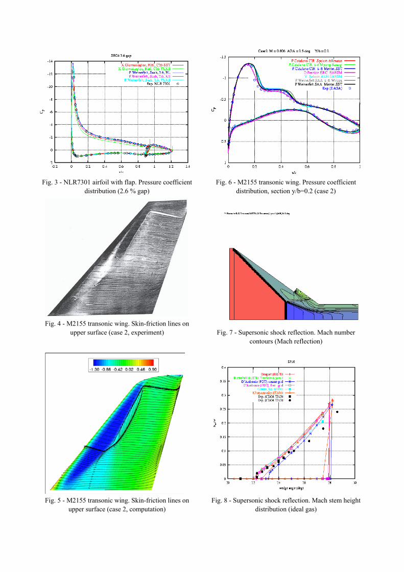
Fig. 3 - NLR7301 airfoil with flap. Pressure coefficient distribution (2.6 % gap)
Fig. 4 - M2155 transonic wing. Skin-friction lines on upper surface (case 2, experiment)
Fig. 5 - M2155 transonic wing. Skin-friction lines on upper surface (case 2, computation)
Fig. 6 - M2155 transonic wing. Pressure coefficient distribution, section y/b=0.2 (case 2)
Fig. 7 - Supersonic shock reflection. Mach number contours (Mach reflection)
Fig. 8 - Supersonic shock reflection. Mach stem height distribution (ideal gas)
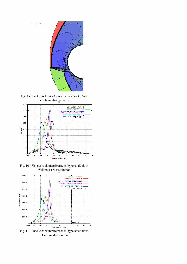
Fig. 9 - Shock/shock interference in hypersonic flow. Mach number contours
Fig. 10 - Shock/shock interference in hypersonic flow. Wall pressure distribution
Fig. 11 - Shock/shock interference in hypersonic flow. Heat flux distribution