Ver. 4.10i
325
ISO 9001 CERTIFIED Ver. 4.10i www.vmeca.com
-
Upload
khangminh22 -
Category
Documents
-
view
1 -
download
0
Transcript of Ver. 4.10i

GERMANY / ASIA /
VTEC / KPS Co.,Ltd.RM206.Saehan Venture World B/D113-15, Shiheung-dong, Geumcheon-gu,Seoul, KoreaTel: +82-2-2617-5008 (Rep.) Fax: +82-2-2617-5009http://www.vmeca.come-mail: [email protected]
VTEC / KPS Co.,Ltd.RM206.Saehan Venture World B/D113-15, Shiheung-dong, Geumcheon-gu,Seoul, KoreaTel: +82-2-2617-5008 (Rep.) Fax: +82-2-2617-5009http://www.vmeca.come-mail: [email protected]
•Argentina •Australia •Austria •Belgium
•Canada •China •Colombia •Denmark
•France •India •Indonesia •Iran
•Israel •Italy •Lebanon •Malaysia
•Mexico •Netherlands •New Zealand•Norway
•Philippine •Poland •Spain •Sweden
•Switzerland •Singapore •Taiwan •Thailand
•Turkey •UK •Japan
USA /
VtecUSA, Inc.1305 N. San Gabriel Bl., #203,South San Gabriel, CA 91770Tel: +1-213-258-7114(Rep.)Fax: +1-626-569-9978http://www.vtecusa.come-mail: [email protected]
Distributor
(1001342 i)
www.vmeca.com
V’tec Vakuum Technologie GmbHAuf dem Bruhl 6D-72658 Bempflingen, GermanyTel. +49(0)7123/932834Fax. +49(0)7123/932865http://www.vmeca.come-mail : [email protected]
ISO 9001 CERTIFIEDVer. 4.10i
Ver. 4
.10i www.vmeca.com

ISO 9001 CERTIFIED
Vacuum Flow & Quick Response
(Improving Productivity)
Multi-stage Vacuum Cartridge
(High Quality Vacuum Technology)
Check Valves
(Safety & Speed of Evacuation.)
Minimum Compressed Air
(Energy Saving)
•The “V” in our logo comes from Vacuum technology and “MECA” comes from the Mechanical
technology.
•By using the vacuum cartridge icon and blue VTEC color, it clearly reminds that “VMECA”
is the same brand as VTEC.
•The VMECA reflects vacuum and mechanical technologies that combines well and supplies
complement system to the customers.

VA
CU
UM
T
EC
HN
OL
OG
Y
CONTENTS
VA
CU
UM
T
EC
HN
OL
OG
YS
UC
TIO
N
CU
PS
VA
CU
UM
S
PE
ED
ER
VA
CU
UM
P
UM
PS
V-G
RIP
SY
ST
EM
AC
CE
SS
OR
IES
VACUUM TECHNOLOGY
Page 4
SUCTION CUPS
Page 10
VACUUM SPEEDER
Page 75
VACUUM PUMPS
Page 103
V-GRIP SYSTEM
Page 310
ACCESSORIES
Page 317

VACUUM TECHNOLOGY
Specifications subject to change without notice.4 www.vmeca.com
Vacuum is created with an air-jet system when compressed air (3-6bar) passes at high speed
through the pump nozzles.
VMECA Vacuum Cartridge is a new and innovative multistage vacuum pump.
- It is extremely compact in size and very light weight.
- It is “engineering and design friendly” making it easy to create a vacuum pump
and system for a specific application or machine.
The VMECA Vacuum Cartridge provides a high vacuum flow rate (3x higher) and an extremely
quick response time (about 1.5x greater) compared to typical and conventional ejectors.
The VMECA Vacuum Cartridge operates using compressed air at a pressure of 1.7 ~ 6bar and
maintains vacuum despite fluctuations and drops in air pressure.
The VMECA Vacuum Cartridge design allows the pump to be located near or at the point of use
reducing system volume, increasing speed and reducing cycle time.
Reduced system volume means fewer connections, fewer potential leaks, and less air to evacuate
allowing for an incrementally smaller pump using less compressed air.
1
2
PRINCIPLE
②
②

Be sure to before handling.
Safe designs should be developed, which accounts for the
possibility of accidents resulting from a drop in vacuum
pressure due to power failure or trouble with the air supply,
etc.
If vacuum pressure drops and there is a loss of vacuum pad
adsorption force, work pieces being carried may fall, causing
human injury or damage to machinery, Safety measures should
be implemented such as the installation of drop prevention guides.
Select vacuum pumps which have a suitable suction flow rate.
<When there is a vacuum leak from the work piece or the piping>
If the vacuum pump suction flow rate is too low, this will cause
poor adsorption.
<When piping is long or large diameter>
The adsorption response time will increase due to the increased
volume of the piping. Select vacuum pumps with a suitable suc-
tion flow rate by referring to their technical data.
If the suction flow rate is too high, setting of vacuum switch-
es will become difficult.In the case of adsorbing a small work piece of only a few millime-
ters, if an vacuum pump is selected which has a high suction flow
rate, the pressure difference when adsorbing and releasing the
work piece is small, and sometimes setting of the vacuum switch
becomes difficult. Therefore, an appropriate vacuum pump should
be selected.
When two or more pads are piped to one vacuum pump, if one
pad releases its work piece, the other pads will also release.
Use piping with an adequate effective sectional area.
When one pad is removed from its work piece, there is a drop in
vacuum pressure which causes the other pads to release their
work pieces also.
Select piping for the vacuum side which has an adequate effective
sectional area, so that the vacuum pump’s maximum suction flow rate
can be accomodated by the piping. Also, make sure that there are no
unnecessa restrictions or leaks, etc. along the course of the piping.
The piping on the air supply side must be designed so that it corre-
sponds to each vacuum pump’s air consumption. The effective
sectional area of tubing, fittings and valves, etc., should be sufficiently
large, and the pressure drop reaching the vacuum pump should be
kept to a minimum. Furthermore, design of the air supply should be
performed while taking into consideration the vacuum pump maxi-
mum air consumption and the air consumption of other pneumatic
circuits.
The performance of vacuum pumps will deteriorate due to clogging
in filters. Large flow filters should be used, especially in dusty loca-
tions.
If the exhaust port is obstructed when mounted, a vacuum will not
be generated.
Use piping with a large effective sectional area on the
exhaust side of the vacuum pump.
If the exhaust piping is restrictive, there will be a decline in the
vacuum pump’s performance.
Make sure that there are no crushed areas in the piping due
to damage or bending.
Vacuum Equipment / Common Precautions
Warning
Follow vacuum specifications for vacuum switching valves
and vacuum breakers.
If valves are installed in vacuum piping which do not follow vacu-
um specifications, vacuum leakage will occur, Be certain to use
vacuum specification valves.
Selection & Design Mounting
Piping
Operating Environment
Maintenance
For information on related items, such as directional control
equipment and drive equipment, refer to the caution sections
in each respective catalog.
Caution
Do not obstruct the exhaust port of the Vacuum pump.
Warning
Piping which is direct and of the shortest possible length should
be used for both the vacuum and supply sides, and dis organized
piping should be avoided. Unnecessary length increases the pip-
ing volume, and thus increases the response time.
Avoid disorganized piping.
Clean suction filters on a regula basis.
(Refer to specifications).
Caution
Do not operate in atmospheres of corrosive gases, chemicals,
sea water, water or steam.
Do not operate in explosive areas.
Do not operate in locations where vibration or impact occurs.
Confirm the specifications for each series.
In locations which receive direct sunlight, provide a protective
cover, etc.
In locations near heat sources, protect against radiated heat.
In locations where there is contact with spatter from water, oil
or solder, etc., implement suitable protective measures.
In cases where the vacuum unit is surrounded by other equip
ment, etc., or the unit is energized for an extended time,
implement measures to exhaust excess heat, so that tempera-
tures remain within the range of the vacuum unit’s
specifications.
Warning
Warning

VACUUM TECHNOLOGY
Specifications subject to change without notice.6 www.vmeca.com
Pressure and vacuum comparison tables
kPa
bar kg/cm2 Torr psi (lbf/in2) kPa inHgPa (N / m2)
1. Pressure conversion table
mbar Torr -inHg% vacuum -mmHg
kPa bar psi (lbf/ in2) at (kg/cm2)
1013
913
813
713
613
513
413
313
213
113
0
101.3
91.3
81.3
71.3
61.3
51.3
41.3
31.3
21.3
11.3
0
0
10
20
30
40
50
60
70
80
90
101.3
0
9.9
19.7
29.6
39.5
49.3
59.2
69.1
79
89
100
760
685
610
535
460
385
310
235
160
85
0
0
75
150
225
300
375
450
525
600
675
760
0
3
6
9
12
15
18
21
24
27
30
Values at sea level
Absolute vacuum
2. Vacuum comparison table (pressure below atmospheric)
3. Pressure comparison table (pressure above atmospheric)
1013
1000
900
800
700
600
500
400
300
200
100
0
10.13
10
9
8
7
6
5
4
3
2
1
0
10.3
10.2
9.2
8.2
7.1
6.1
5.1
4.1
3.1
2
1
0
146.9
145
130.5
116
101.5
87
72.5
58
43.5
29
14.5
0
1
1000
100000
98066.5
133.322
6894.76
1 Pa
1 kpa
1 bar
1 kg/cm2
1 torr
1 Psi
0.00001
0.01
1
0.980665
1.33322X10⁻³
68.9476X10⁻³
10.1972X10⁻⁶
10.1972X10⁻³
1.01972
1
1.35951X10⁻³
70.3069X10⁻³
7.50062X10⁻³
7.50062
750.062
735.559
1
51.7149
0.145038X10⁻³
0.145038
14.5038
14.2233
19.3368X10⁻³
1
0.001
1
100
98.0665
0.133322
6.89476
0.3X10⁻³
0.3
30
29.42
0.04
2.07
1Torr = 1mmHg(0 ②) 1mm column of water = 9.81 Pa
-kPa

l /s m3/min m3/h scfm l / min
1
0.28X10⁻³
16.67X10⁻⁶
1X10⁻³
0.472X10⁻³
1
2
3
4
5
6
7
8
9
10
11
12
13
14
15
16
17
18
19
20
25
30
35
40
45
50
1m3/s
1m3/h
1 l/min
1 l/s
1ft3/min
0.06
0.12
0.18
0.24
0.30
0.36
0.42
0.48
0.54
0.60
0.66
0.72
0.78
0.84
0.90
0.96
1.02
1.08
1.14
1.20
1.50
1.80
2.10
2.40
2.70
3.00
3.60
7.20
10.80
14.40
18.00
21.60
25.20
28.80
32.40
36.00
39.60
43.20
46.80
50.40
54.00
57.60
61.20
64.80
68.40
72.00
90.00
108.00
126.00
144.00
162.00
180.00
2.12
4.24
6.36
8.47
10.59
12.71
14.83
16.95
19.07
21.19
23.30
25.42
27.54
29.66
31.78
33.90
36.02
38.13
40.25
42.37
52.97
63.56
74.15
84.74
95.34
105.93
60
120
180
240
300
360
420
480
540
600
660
720
780
840
900
960
1020
1080
1140
1200
1500
1800
2100
2400
2700
3000
3600
1
0.06
3.6
1.6992
60000
16.6667
1
60
28.32
1000
0.2778
0.0167
1
0.4720
2118.9
0.5885
0.035
2.1189
1
m3/h l /min l /s ft3 / min (scfm)m3/s
Flow rate comparison table
Flow : Volume per unit of time
Quantity designations : Q,q(Q)=V/t(volume/time)
SI-unit : cubic metres per second (m3/s)
Common multiple units : liter/min, liter/s, liter/h
4. Flow rate comparison tables
VACUUM TECHNOLOGY
7Specifications subject to change without notice. www.vmeca.com
VA
CU
UM
T
EC
HN
OL
OG
Y
VACUUM TECHNOLOGY
Specifications subject to change without notice.8 www.vmeca.com
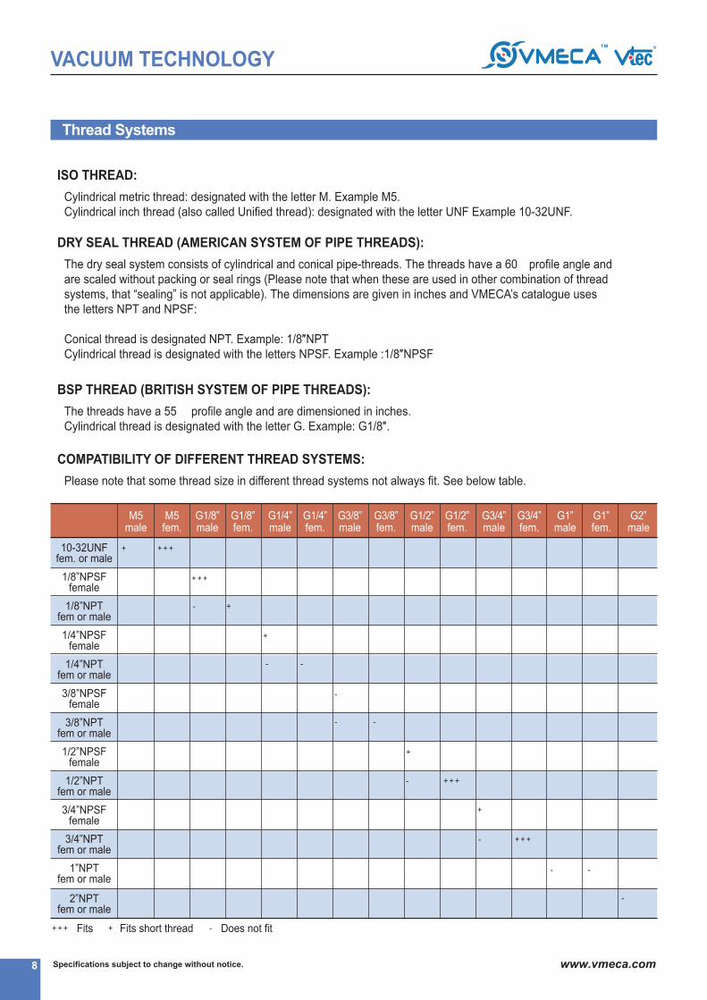
Thread Systems
Cylindrical metric thread: designated with the letter M. Example M5.
Cylindrical inch thread (also called Unified thread): designated with the letter UNF Example 10-32UNF.
ISO THREAD:
The dry seal system consists of cylindrical and conical pipe-threads. The threads have a 60② profile angle and
are scaled without packing or seal rings (Please note that when these are used in other combination of thread
systems, that “sealing” is not applicable). The dimensions are given in inches and VMECA’s catalogue uses
the letters NPT and NPSF:
Conical thread is designated NPT. Example: 1/8″NPT
Cylindrical thread is designated with the letters NPSF. Example :1/8″NPSF
DRY SEAL THREAD (AMERICAN SYSTEM OF PIPE THREADS):
The threads have a 55② profile angle and are dimensioned in inches.
Cylindrical thread is designated with the letter G. Example: G1/8″.
BSP THREAD (BRITISH SYSTEM OF PIPE THREADS):
Please note that some thread size in different thread systems not always fit. See below table.
COMPATIBILITY OF DIFFERENT THREAD SYSTEMS:
M5male
+ + + +
M5fem.
G1/8”male
G1/8”fem.
G1/4”male
G1/4”fem.
G3/8”male
G3/8”fem.
G1/2”male
G1/2”fem.
G3/4”male
G3/4”fem.
G1”male
G1”fem.
G2”male
10-32UNFfem. or male
1/8”NPSFfemale
1/8”NPTfem or male
1/4”NPSFfemale
1/4”NPTfem or male
3/8”NPSFfemale
3/8”NPTfem or male
1/2”NPSFfemale
1/2”NPTfem or male
3/4”NPSFfemale
3/4”NPTfem or male
1”NPTfem or male
2”NPTfem or male
+ + +
- +
+
- -
-
- -
+
- + + +
-
- -
- + + +
+
+ + + Fits + Fits short thread - Does not fit

VACUUM TECHNOLOGY
9Specifications subject to change without notice. www.vmeca.com
VA
CU
UM
T
EC
HN
OL
OG
Y
Applications for vtec vacuum equipment
Handling Box for Robotic palletizing②
Robot industry②
Pick & place for food industry②
②
Plastic bag opening②
Thin film feeding②
Packaging machine②
Panel lifting for Automotive industry
SUCTION
CUPS
SUCTION
CUPS
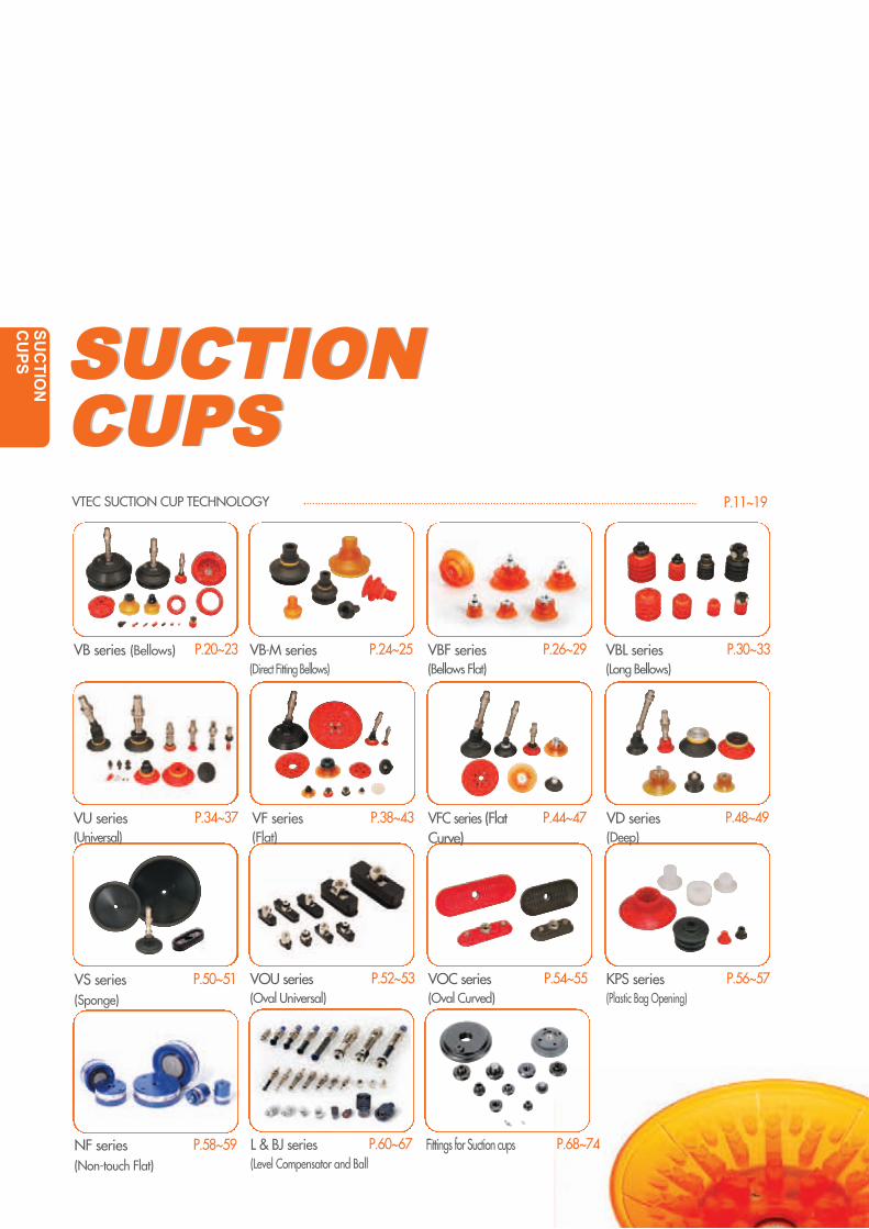
L & BJ series(Level Compensator and Ball
P.52~53
P.60~67 P.68~74Fittings for Suction cups
VOU series(Oval Universal)
VOC series(Oval Curved)
P.56~57KPS series(Plastic Bag Opening)
VTEC SUCTION CUP TECHNOLOGY P.11~19
VB series (Bellows) P.20~23 VB-M series(Direct Fitting Bellows)
P.24~25 VBF series(Bellows Flat)
VBL series(Long Bellows)
VU series(Universal)
P.26~29 P.30~33
P.34~37 P.38~43 P.44~47 P.48~49VF series(Flat)
VFC series (FlatCurve)
VD series(Deep)
P.50~51VS series(Sponge)
P.58~59NF series(Non-touch Flat)
SU
CT
ION
C
UP
S
P.54~55

11
SUCTION CUPS
Specifications subject to change without notice. www.vmeca.com
SU
CT
ION
C
UP
S
1. Advantages of suction cup
Materials’ handling with suction cup is very simple low cost and reliable.
It is therefore a solution worth using before considering more complicated handling techniques.
Suction cups can lift, and hold objects from a few grams up to several kg.
2. The principle of suction cup
Why does a suction cup suck onto the surface it’s placed on? It’s quite simple and is all to do with
atmospheric pressure. Atmospheric pressure can generally be defined as the weight of the air above
us on earth. When a lower pressure is created (vacuum) than atmospheric pressure (1 bar), forces
are produced; these forces are required to enable suction cups to work. As a vacuum is drawn
through the cup, the atmospheric pressure outside the cup is greater than that inside the cup, thus
creating a holding force between the cup and the surface, the larger the cup and deeper the vacuum
then the greater the holding force.
▶Advantages
Easy installation
Low service requirement
Low price
Does not damage the goods
Fast attachment and detachment
Connection Vacuum Pump
How a suction cup works. Weights that can be lifted with suction cups.
Atmospheric pressureforcing cup onto surface
Ø400
Vacuum Pad
(VS400)
V-TEC Multistage
Ejector Pump
(-70 kPa)

Specifications subject to change without notice.12 www.vmeca.com
SUCTION CUPS
3. How to select the suction cup
4. Calculating achievable perpendicular / parallel lifting force (-60kPa=-450 mmHg)
D : Suction cup dia. (mm)
m : Mass to lift (kg)
u : Vacuum level (-kPa)
n : Safety factor (2 or 3)
s : Quantity of cup
W : Lifting force (N)
P : Vacuum level (-kPa)
S : Size of suction cup (cm2)
n : Safety factor Perpendicular : insert 2 or 3
Parallel : 3 insert or 4
Perpendicular Parallel
D =113XU x s
m x n
W= PxSx0.1 xn
1

0~0.295
0~0.71
0~2.5
0~3.26
0~5
0~8.67
0~20.4
0~25.51
0~61.22
0~0.295
0~0.86
0~2.5
0~5.1
0~5.81
0~15.3
0~20.4
0~45.9
0~86.7
0~438.7
0~0.098
0~0.23
0~0.83
0~1.08
0~1.66
0~2.89
0~6.8
0~8.5
0~20.4
0~0.008
0~0.44
0~0.81
0~1
0~2.24
0~3.77
0~11.22
0~23.97
0~137.64
0~0.002
0~0.14
0~0.27
0~0.33
0~0.74
0~1.25
0~3.74
0~7.99
0~45.88
Ø2-8
Ø10-15
0~0.005
0~0.17
0~0.31
0~0.81
0~1.12
0~2.19
0~8.16
0~17.5
0~35.0
0~96.9
0~0.145
0~0.43
0~1.25
0~2.55
0~2.9
0~7.65
0~10.2
0~22.9
0~43.3
0~219.3
0~0.01
0~0.34
0~0.63
0~1.63
0~2.24
0~4.38
0~16.32
0~35
0~70
0~193.8
Ø20-25
Ø30-35
Ø40
Ø50-60
Ø75-80
Ø100-115
Ø150
Ø200-300
13
SUCTION CUPS
Specifications subject to change without notice. www.vmeca.com
SU
CT
ION
C
UP
S
Cup Size (mm) Safety factor force (kg) force (kg) Safety factor force (kg) force (kg)
min max min max min max min max
-60kPa Lifting force(kg) Perpendicular -60kPa Lifting force(kg) Parallel
5. Recommended vacuum level to use (-60kPa)
There are several reasons why –60 kPa is the optimum vacuum level to use with suction cups. The energy
required creating –60 kPa is low in comparison to that required generating –90 kPa. The additional lifting force that
can be achieved between these two levels is not that high, considering that it takes approx ten times as much
energy to create the –90 kPa level. If a vacuum circuit is designed to run at –90 kPa then clearly there is very little
capacity left in the pump performance, thus no margin for error. Lastly suction cups running at –90 kPa adhere to
the surface with far more contact force, hence stressing the cup much more, which will result in premature wear of
the cup itself.
Object
Suction cup size : Ø20 Suction cup size : Ø50
2kg
2 kg 2 kg
Vacuum level
-90kPa
-60kPa
-20kPa
Cup size
Ø20
Ø30
Ø50
U = -20kPaU = -90kPa
For example
Lifting force comparison table for cup size

1. Choose the model depending on the shape of object to lift.2. Choose the size of the cup based on the weight of the
object to lift.3. Choose lie material of the cup based on the working
environment and surface texture.4. Select the fitting size to suit the application.5. Select the accessory depending on the application
i.e.. level compensator or ball joint.
Specifications subject to change without notice.14www.vmeca.com
SUCTION CUPS
6. Applications for suction cups
VB (Bellows)
The bellows cup is very good at compensating for a degree of
difference in level and curvature of the work piece
Similar advantages to that of the normal bellows cups but can
cope with an increased degree of height compensation and is
particularly good for handling fragile objects
Good lifting forces can be achieved with this cup, is best suited
to flat stable surfaces, but can cope with a small degree of cur-
vature.
Again good lifting forces can be achieved with this pad; opti-
mum-lifting forces can be achieved with this cup in the
horizontal plane, but is also good in the vertical plane.
This pad is specifically designed to cope with both flat and
curved surfaces, which means that multiple objects can be
handled with the same vacuum pad
Features and strengths
This is best suited to curved or irregular surfaces
Also, it is deep and grip around corners and edges.
This pad is best suitable for gandling long objects With flat orcurved surgaces.Specially, paralle to the surgace of the object it has a thick anddurable lip.
Used for handling rough and uneven surfaces and when used
with ball joint option and level spring option can accommodate
very unlevel and uneven surfaces.
Developed to be used for opening plastic bags this pad gives
good adhesive to thin plastic and film type materials.
VBL(Long Bellows)
VS (Sponge)
KPS (Plastic Bag Opening)
VU (Universal)
VF (Flat)
VFC (Flat Curve)
VD (Deep flat)
VOC (Oval Curved)
Vtec suction cups are available in a wide range of shapes, sizes,materials and configurations. The standard cups range from 2mmto 400mm in diameter, with lifting forces of up to 1300kg at - 90kPa.Many types of object and materials can be lifted, flat, curved,smooth, coarse, dense and porous. All the cups are manufactured to very high standards, and cups canbe ordered separately or complete with fitting.
VBF(Bellows & Flat)
Best suitable for handling long objects
With flat and curved surfacesVOU(Oval Universal)
Non-contact handling item. Safe gripping with mark free.
No moving parts.
NF(Non-touch Flat)
Sheet VeneerPlastic SheetsThin Film SheetsCardboard Boxes and Electronic components
Sheet Veneer▶Plastic SheetsCardboard boxes CardboardPackaging MaterialsThin Film Sheets
▶Vaneer sheets ▶Sheet metal▶Automotive body panels and door▶Plastic sheets▶plywood ▶Glass
Fragile Objects ▶EggsGeneral Foodstuffs ▶BreadGlass
Small ComponentsSemiconductor ChipsPackaging MaterialsSheet Metal
Sheet MetalVeneer SheetsPlastic Sheet MaterialElectronic Components
Automotive WindscreensShaped Sheet Metal PanelsSheet Metal
Plastic sheetsSheet veneerSheet metalShaped sheet metal panels
Semiconductor chipsElectronic componentsSmall ampul
Long objects with flatCurved surfacesShaped sheet metal panels
Handling thin Film with adjustable supportRough Wood Paving SlabsMasonry Bricks
Thin film sheet and plastic bags, Plastic Bag Opening, paper Bag HandlingThin Film Materials
Circuit boards, CDs and DVDs, Metal, Wood,Packaging, Plastic, Thin products, Film,Paper, Mirrors, Paper-board..
Same general advantages to that of the normal bellows cupsbut can be fitted directly onto a piece of pipe, thus makinginstallation very simple and reducing pad costs to a minimum,very suitable for integration to packaging machines.
Good lifting force can be achieved with this cup in the vertical
plane. Prevent transformation when lifting metal thin plate.
VB-M (Direct Fitting Bellows)
Type
How to select a suction cup
Description SomeApplications
20 ~ 23
24
26 ~ 29
30 ~ 33
34 ~ 37
38 ~ 43
44 ~ 47
48 ~ 49
52 ~ 53
54 ~ 55
50 ~ 51
56 ~ 57
58 ~ 59
15
SUCTION CUPS
Specifications subject to change without notice. www.vmeca.com
SU
CT
ION
C
UP
S
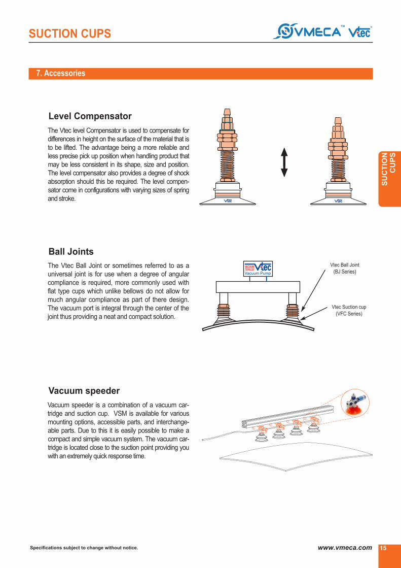
7. Accessories
The Vtec level Compensator is used to compensate for
differences in height on the surface of the material that is
to be lifted. The advantage being a more reliable and
less precise pick up position when handling product that
may be less consistent in its shape, size and position.
The level compensator also provides a degree of shock
absorption should this be required. The level compen-
sator come in configurations with varying sizes of spring
and stroke.
Vtec Ball Joint
(BJ Series)
Vtec Suction cup
(VFC Series)
The Vtec Ball Joint or sometimes referred to as a
universal joint is for use when a degree of angular
compliance is required, more commonly used with
flat type cups which unlike bellows do not allow for
much angular compliance as part of there design.
The vacuum port is integral through the center of the
joint thus providing a neat and compact solution.
Vacuum speeder is a combination of a vacuum car-
tridge and suction cup. VSM is available for various
mounting options, accessible parts, and interchange-
able parts. Due to this it is easily possible to make a
compact and simple vacuum system. The vacuum car-
tridge is located close to the suction point providing you
with an extremely quick response time.
Level Compensator
Ball Joints
Vacuum speeder

Specifications subject to change without notice.16 www.vmeca.com
SUCTION CUPS
Vacuum
Release
8. Material and characteristic of suction cup
Oil ResistanceTemperatureMaterial Weather & ozone Durability
7. Accessories
Ordered as an integral part of the suction cup, the
valve is useful on applications where multiple
cups are used and not all cups come into contact
with surface to lifted. The valve has a small vacu-
um port so as not to degradate the vacuum
supply if the cup is uncovered whilst still providing
enough flow to achieve the required vacuum.
When the cup comes in contact with the surface
only the volume inside the cup has to be evacuat-
ed. When release of the product is required, this
can still be done quickly, because as air if forced
back through the cup the plate valve opens up
and allows full flow through. This valve is only
suitable for use with smooth surface non-porous
materials.
Vacuum Efficiency valve (EV)
When the suction cup is not in contact with the
object, the valve closes the opening in the fitting.
No air can flow through the suction cup and the
pump does not need to compensate for leakage.
The system is not disturbed and vacuum is main-
tained up to the fitting.
The valve first opens when the suction cup makes
contact with the object.
The air can then flow through the fitting and vacu-
um is created in the cup.
Button Valve : BV
N - NBR
S - Silicon, WS-White Silicon
HS - High Temp. Silicon
C.S - Conductive (special material)
U - Urethane
A - Mark free
PU- Poly Urethane
E - EPDM
Excellence
Good
Good
Excellence
Excellence
Excellence
Excellence
Very good
Excellence
unsuitable
unsuitable
Excellence
Excellence
Excellence
Excellence
unsuitable
Very good
Excellence
Excellence
Very good
Excellence
Very good
Excellence
Excellence
-20▶ to + 110▶
-70▶ to + 200▶
-70▶ to + 280▶
-45▶ to + 90▶
E▶ to + 100▶
-10▶ to + 100▶
-0▶ to + 60▶
E▶ to + 150▶

17
SUCTION CUPS
Specifications subject to change without notice. www.vmeca.com
SU
CT
ION
C
UP
S
▶▶▶
9. How to select suction cup
Suction cup
▶▶▶
▶▶▶
▶▶▶
▶▶▶
▶▶▶
▶▶▶
▶▶▶
▶▶▶ ▶▶▶ ▶▶▶ ▶▶▶
▶▶
▶▶▶
▶▶▶
▶▶▶
Shape
Slightly
surface
Concave
surfaceFlat
Smooth
surface
Uneven
surface
Varying
surface
levels
Thin
flexible
materials
Good
stabilityMark free Safety
Parallel
lift
Without
fitting
Opening
plastic
bag
Requirements
▶▶▶
▶▶▶
▶▶▶
▶▶▶
▶▶▶ ▶▶▶
▶▶▶
▶▶▶
▶▶▶
▶▶▶
▶▶▶
▶▶▶
▶▶▶ ▶▶▶
▶▶▶
▶▶▶
▶▶▶ ▶▶▶
▶▶▶
▶▶▶
▶▶▶
▶▶▶
▶▶▶ ▶
▶
▶▶▶
▶▶
▶▶▶
▶▶▶
▶▶▶
▶▶▶
▶▶▶
▶▶▶
▶▶▶
▶▶▶ ▶▶
▶▶▶
▶▶▶
▶▶
▶▶▶
▶▶▶
▶▶
▶▶▶
▶▶
▶▶▶ ▶
▶▶▶
▶▶▶
▶
▶
▶
▶
▶
▶▶▶ ▶▶ ▶▶▶ ▶▶▶▶▶▶ ▶
▶▶▶
▶▶▶
▶▶▶
▶▶▶
▶▶▶
▶▶▶
▶▶
▶▶
▶▶▶ ▶▶▶ ▶▶▶ ▶▶▶▶▶▶ ▶▶▶ ▶▶▶ ▶▶▶▶▶▶ ▶
▶▶
▶
VB
VB-M
VBF
VBL
VU
VF
VFC
VD
VOU
VOC
VS
KPS
NF
Slightly curved surface
VB model
Without fitting
VB-M model
Sheet metal
VBF model
Concave surface
VU model
Uneven surface
VS model
Thin surface,
adjustable support
VS model
Opening plastic bag
KPS model
Non-contact handling item
NF Series
Transfering to parallel
VF, VFC model
Long flat
VOC model
Long convex or flat
VOU model
Convex surface
VD model
▶▶▶ Excellent ▶▶ Verygood ▶ good

Specifications subject to change without notice.18 www.vmeca.com
SUCTION CUPS
10. Suction cup specifications
ModelDesignE
Liftingforce(kg) Perpendicular Liftingforce(kg) Parallel
-20 kPa -60 kPa -90 kPa -20 kPa -60 kPa -90 kPa
Volume(cm3)
Diameter(mm)
Material
N (W)S CS U (W)PU
VB 5VB 6XVB 8VB 10VB 12 VB 15 VB 17VB 20VB 30 VB 40VB 50VB 75 VB 110 VB 150VB 20MVB 30MVB 50M VBF 25VBF 30VBF 40VBF 50VBF 60VBF 80VBF 100VBL 15VBL 20VBL 30VBL 35MVBL 40VBL 40BVBL 50VOBL 35X90VU 1.5XVU 2VU 2XVU 3VU 3kVU 4VU 4XVU 6VU 8VU 10VU 15VU 20VU 25VU 30VU 40VU 50VU 80VF 15VF 20VF 25VF 30VF 40VF 50
VF 50X2
5.67
8.81112
15.518.52234435378115155223453253242
51.5648410315.5203035404250
30X901.92.62.63.83.55
4.67911
16.5222732425378
16.52227324253
53
0.10.10.20.50.591.11.52.71015321103106502.710322.66
7.21122
59.5103.51.95
4132127265543
0.00150.00250.0030.010.0180.030.030.050.10.20.51
1.52
5.51232
0.371
1.12
4.810
10
●
●
●
●
●
●
●
●
●
●
●
●
●
●
●
●
●
●
●
●
●
●
●
●
●
●
●
●
●
●
●
●
●
●
●
●
●
●
●
●
●
●
●
●
●
●
●
●
●
●
●
●
●
●
●
●
●
●
●
●
●
●
●
●
●
●
●
●
●
●
●
●
●
●
●
●
●
●
●
●
●
●
●
●
●
●
●
●
●
●
●
●
●
●
●
●
●
●
●
●
●
●
●
●
●
●
●
●
●
●
●
●
●
●
●
●
●
●
●
●
●
●
●
●
●
●
●
●
●
●
●
●
●
●
●
●
●
●
●
●
●
●
●
●
●
●
●
●
●
●
●
●
●
●
●
●
●
●
●
●
●
●
●
●
●
●
●
●
●
●
●
●
●
●
●
●
●
●
●
●
●
●
●
●
●
●
●
●
●
●
●
●
●
●
●
●
●
●
●
●
0.030.050.080.150.20.290.40.61.222.243.367.6513.97
300.71.53.21.11.772.54.188.9411.9214.90.290.030.060.080.111.030.172.5
0.00080.0030.0030.0090.0140.020.020.050.10.150.350.60.911.222.043.577.770.350.610.911.222.043.67
3.67
0.080.110.160.340.410.60.81.02.243.976.6317.04
35701.22.67.93.26.269.6613.216.2621.6827.10.60.060.160.190.222.10.433.2
0.0030.010.010.040.060.090.090.170.290.440.851.221.982.553.977.4419.80.861.471.982.554.087.55
7.55
0.10.140.250.50.620.91.01.422.75
58.3623.0647.0490.11.63.910.53.89.4812.816.2818.5424.7230.9
0.0040.00150.00150.060.090.130.130.250.390.701.121.632.53.065.09.3825.211.121.932.553.165.109.79
9.79
0.610.861.182.096.849.1211.4
0.020.020.030.10.150.350.60.70.791.422.044.530.350.510.811.121.532.44
2.44
1.373.096.59.6
12.8417.1221.4
0.080.080.150.290.440.550.890.951.002.243.7712.70.660.810.911.632.554.08
4.08
1.897.7511.314.716.9222.5628.2
0.100.100.200.340.500.601.001.051.122.84.4816.940.760.861.022.043.065.10
5.1▶ Lifting force : Not considered safety factor.
20 ~ 23
26 ~ 29
30 ~ 33
34 ~ 37
38 ~ 43
24

19
SUCTION CUPS
Specifications subject to change without notice. www.vmeca.com
SU
CT
ION
C
UP
S
10. Suction cup specifications
ModelE
Liftingforce(kg) Perpendicular Liftingforce(kg) Parallel
-20 kPa -60 kPa -90 kPa -20 kPa -60 kPa -90 kPa
Volume(cm3)
Diameter(mm)
Material
N (W)S CS U (W)PU●
●
●
●
●
●
●
●
●
●
●
●
●
●
●
●
●
●
●
●
●
●
●
●
●
●
●
●
●
●
●
●
●
●
●
●
●
●
●
●
●
●
●
●
●
●
●
●
●
●
●
●
●
●
●
●
●
●
●
●
●
●
●
●
●
●
●
●
●
●
●
●
●
●
●
●
●
●
●
●
●
●
●
●
●
●
●
●
●
●
●
●
●
●
●
●
●
●
●
●
●
●
●
●
●
●
●
●
●
●
●
●
●
●
●
●
●
●
●
●
●
●
●
●
●
●
●
●
●
●
●
●
●
●
●
●
●
●
●
●
●
●
●
●
●
●
●
●
●
●
●
●
●
●
●
●
●
●
●
●
●
●
●
●
●
●
●
●
●
●
●
●
●
●
●
●
●
●
●
●
●
●
●
●
●
●
●
●
●
●
Design
VF75
VF 90
VF 110
VF 150
VF 200
VF 300
VFC 50
VFC 60
VFC 60X
VFC 75
VFC 75X1
VFC 75X2
VFC 90
VFC 100VD 30
VD 40
VD 50
VD 60
VD 70
VD 85
VD 85X
VD 90F
VS 30X80
VS 35
VS 60
VS 100
VS 150
VS 200
VS 300
VS 400
VOU4x10
VOU4x20
VOU6x10
VOU6x20
VOU8x20
VOU8x30
VOU10x30
VOU15x45
VOU20x60
VOC 11 x 23
VOC 35 x 90
VOC 35 x 110
VOC 60 x 140
VOC 60 x 180
KPS-1
KPS-2
KPS-3
KPS-4
KPS-5
KPS-5-15
KPS-6
KPS-7
KPS-8
KPS-9
VU-30-X
77
92
112
152
200
304
50
60
60
75
75
75
90
100
30
40
50
61
72
85
85
89.5
30X80
35
60
100
150
200
300
400
4X10
4X20
6X10
6X20
8X20
8X30
10X30
15X45
20X60
11X23
35X90
35X110
60X140
60X180
34
28
13
16
28
15
30
68
22.5
40.5
30
20
50
70
160
460
820
10
20
20
30
30
30
60
80
4.5
75
13.5
22
38
60
60
56
43
6
20
55
125
543
1285
2285
0.064
0.094
0.081
0.137
0.17
0.25
0.394
1.584
3.532
2.0
20
25
52
67
14.5
2.0
0.5
1.0
2.0
1.1
2.0
20
1.4
8
1.8
8.16
10.2
14.28
30.61
76.53
163
2.85
4.55
4.55
7.65
7.65
7.65
9.8
12.75
1.22
2.04
3.57
5.50
7.15
10
10
9.25
2.7
2.04
6.12
18.36
38
76.53
163.26
326
0.61
5
6.25
13.4
19.1
1.22
0.7
0.35
0.6
0.7
0.4
0.8
5.5
0.5
1.55
0.65
20.40
27.84
42.85
86.73
193.87
438
6.94
11.57
11.57
19.38
19.38
19.38
24.82
35.71
2.55
3.97
7.44
14
18.8
28
28
24.36
9.1
5.10
15.3
45.9
97
193.87
438.77
876
1.3
13.4
16.7
38
54.2
2.24
1.53
0.85
1.22
1.53
1.11
1.7
14
1.15
2.8
1.48
27.55
57.14
57.14
112.54
275.51
653
10.2
15.3
15.3
25.51
25.51
25.51
32.65
46.93
3.06
5.0
9.38
18.5
24.9
39
39
32.17
14
7.14
22.44
67.34
138
275.51
653.06
1300
0.205
0.347
0.256
0.603
0.818
1.053
1.554
3.271
6.352
1.6
17.4
21.7
53
75.7
2.75
1.83
1.12
1.63
1.83
1.23
2.05
18.5
1.25
5.1
17.8
6.12
14.28
14.28
25.51
38.3
135
2.61
3.05
3.05
6.19
6.19
6.19
9.52
12.24
0.73
1.22
2.14
3.3
4.2
6.0
6.0
7.97
0.6
4
5
10.72
15.28
14.26
30.61
30.61
81.63
137.5
476
8.2
10.7
10.7
20.9
20.9
20.9
27.89
28.57
1.83
3.00
5.62
11.1
16.2
23.4
23.4
18.15
1.5
13.92
17.36
42.4
60.56
11.22
25.51
25.51
61.22
96.9
307
6.34
7.92
7.92
15.46
15.46
15.46
21.59
23.97
1.53
2.38
4.46
8.4
11.6
16.8
16.8
14.42
1.2
10.72
13.36
30.4
43.36
38 ~ 43
44 ~ 47
48 ~ 49
50 ~ 51
52 ~ 53
54 ~ 55
56 ~ 57
▶ Lifting force : Not considered safety factor.

Specifications subject to change without notice.20 www.vmeca.com
SUCTION CUPS
VBSeries(Bellows)
•Sheet Veneer
•Plastic Sheets
•Paper Box handling
•Thin Film Sheets
•Cardboard Boxes and Electronic Components
Features and Strengths
Suitable for Handling
Order No.
▶ See pages 21, 60~67.
▶ ValvesEfficiencyvalve: EV
●
▶ Thread size
●
▶ Filter
no mark
F●
- Standard
- With filter (PE)
VB30, VB40, VB50, VB75,
VB110
▶ Material
●
*OnlyforVB15, VB20, VB30, VB40, VB50, VB75
Remark : VB30~150 fittings are including mesh filter.
* Only for silicon material
(A) : AL-Material (Only VB75, VB75B)
VB5
VB6X
VB8
VB10
VB12
VB15
VB17
VB20
VB30
VB40
VB50
VB75
VB75B
VB110
VB110B
VB150
▶ Diameter
●
N
S
WS
HS
CS
U
A
PU
WPU
▶
18F
▶
PU
▶
F EV- - -
▶
VB30
▶
L1820T BJ 18
▶ ▶
- NBR
- Silicon
- White Silicon
- High Temp. Silicon
- Conductive (Special mat’l)
- Urethane
- Mark Free
- Poly Urethane*
- PolyUrethane*(Minimalmark)
- Ø5
- Ø6
- Ø8
- Ø10
- Ø12
- Ø15
- Ø17
- Ø20
- Ø30
- Ø40
- Ø50
- Ø75
- Ø75
- Ø110
- Ø110
- Ø150
no mark
EV
- standard
- Vacuum efficiency valve (Seepage: 16)
(VB17, VB2O, VB3O, VB4O, VB5O)
Particularly good for use on curved surfaces and for separating
thin sheets of materials in stacks.
The bellows cup is very good at compensating for a degree of dif-
ference in level and curvature of the work piece, more angular and
level compensation can be achieved by using other Vtec cup
accessories.
- M5 male (VB5, VB8, VB10, VB12, VB15)
- G1/8″ male (VB3O, VB4O)
- G1/4″ male (VB3O, VB4O, VB5O)
- G3/8″ male (VB5O)
- M5 female and G1/8" male (VB17, VB2O)
- M5 female and G1/8" male (VB2O)
- G1/8″ female (VB17,VB20,VB3O,VB4O,VB5O,VB75,VB75B)
- G1/8″ female (VB30, VB40)
- G1/4″ female (VB75, VB75B)
- G3/8″ female (VB75, VB75B)
- G1/2″ female (VB75, VB75B, VB110, VB110B, VB15O)
- M5X5 female (VB17, VB2O)
- G1/8″ X 5 female (VB3O, VB4O, VB5O)
M5M
18M
14M
38M
M518MF
M518MFB*
18F(A)
18FB*
14F(A)
38F(A)
12F(A)
M5X5F
18X5F

21
SUCTION CUPS
Specifications subject to change without notice. www.vmeca.com
SU
CT
ION
C
UP
S
Accessories order No.
Recommended (max.) lifting forces
ModelVolume
(cm3)
LiftingForce(kg) - Parallel
-20 kPa -60 kPa -90 kPa
*Not available with Ball Joint (BJ)..
BJ12
▶ Levelcompensator
Model Stroke(mm)▶ Balljointmodel
L506TX, L506TS, L506TM, L506TU
L510LTX, L510LTS, L510LTM, L510LTU
L507T, L507TN
L515T
L510, L510T
L520, L520T, L520TF
L1805F
L525TXN,L525TSN, L525TMN, L525TUN
L1805M, L1805F
L1810T, L1810TS, L1810TSE
L1815T, L1815
L1820T, L1820TS
L1820TN*
L1830, L1830T, L1830TS
L1850, L1850T
L1230, L1230T
L1250, L1250T
6
10
7
15
10
20
5
25
5
10
15
20
20
30
50
30
50
● ●
VB5
VB6X
VB8
VB10
VB12
VB15
VB17
VB20
VB30
VB40
VB50
VB75(B)
VB110(B)
VB150
0.05
0.09
0.15
0.48
0.59
1.1
1.5
2.7
10
15
32
110
310
650
0.03
0.05
0.08
0.15
0.2
0.29
0.4
0.6
1.22
2.24
3.36
7.65
13.97
30
0.08
0.11
0.16
0.34
0.41
0.6
0.8
1
2.24
3.97
6.63
17.04
35
70
0.10
0.14
0.25
0.5
0.62
0.9
1
1.42
2.75
5
8.36
23.06
47.04
90.1
L1820T BJ 18
▶ ▶
BJ18

Specifications subject to change without notice.22 www.vmeca.com
SUCTION CUPS
Dimensional information
▶ VB5 VB8 VB10 VB12 VB15
▶ VB17
▶ VB20 VB30 VB40 VB50
▶ VB75 VB110 VB150
▶ VB6X
Model A A B
6.2
9.6
12
14
17.5
9.2
11.9
16
16.5
19.5
5.8
8.8
11
12
15.5
VB5
VB8
VB10
VB12
VB15
Model A A B
24
36
46
58
19
26
28
35
22
34
43
53
VB20
VB30
VB40
VB50
Model A A B
83
124
166
37
54
71
HOLE
4-Ø6.5 P.C.D Ø35
8-Ø6 P.C.D Ø55
8-Ø6 P.C.D Ø70.5
78
115
155
VB75(B)
VB110(B)
VB150
Model A A
VB6X
Model A A B
16.6 15.618.5VB17
′
′
′
′
′
[mm]
[mm]
[mm]
[mm]
[mm]
7
B
9 13.5

23
SUCTION CUPS
Specifications subject to change without notice. www.vmeca.com
SU
CT
ION
C
UP
S
Dimensional information
▶ Malethread
▶ Femalethread
Model ØA ØA′ B C D E
Model
▶ Malethread
ØA ØA′ D EC GF I
Model
VB17-18F
VB20-18F
VB30-18F
ØA ØA′ DC G I
Model
▶ Femalethreadx5
VB20-M5X5F
VB30-18X5F
VB40-18X5F
VB50-18X5F
ØA ØA′ DC G H J
VB17-M5X5F
Model
▶ Femalethread
VB75(B)-18F
VB75(B)-38F
VB75(B)-12F
VB110(B)-12F
VB150-12F
ØA ØA′ DC G
K
78
78
78
78
115
155
83
83
83
83
124
166
18
18
18
18
15
14
50
50
50
50
63
78
G1/8″
G1/4″
G3/8″
G1/2″
G1/2″
G1/2″
VB75(B)-14F
VB30-18FB*
VB40-18F
VB40-18FB*
VB50-18F
VB5-M5M
VB8-M5M
VB10-M5M
VB12-M5M
VB15-M5M
3.5
3.5
4
4
4
VB17-M518MF
VB20-M518MF
VB20-M518MFB*
VB30-18M
VB30-14M
VB40-18M
VB40-14M
VB50-14M
VB50-38M
*Only for silicon material
*Only for silicon material
M518MFB
18FB
[mm]
[mm]
[mm]
[mm]
[mm]
18.5 16.6
24
36
46
58
9
9
18
18
18
24.6
28
44
46
53
M5X5 5
5
10
10
10
15
15
22
22
28
22
22
30
30
36
M5X5
G1/8″X5
G1/8″X5
G1/8″X5
22
34
43
53
8
8
8
23.6
27
34
G1/8″
G1/8″
G1/8″
SW15
SW15
SW17
16.6
24
36
18.5
22
34
935 G1/8″ SW213634
836 G1/8″ SW174643
937 G1/8″ SW214643
944 G1/8″ SW245853
18.5 1.5
1.5
5
6
5
6
6
6
6
7
9
7
9
10
17.1
20.5
31
32
33
34
41
G1/8″
G1/8″
G1/8″
G1/4″
G1/8″
G1/4″
G3/8″
SW12
SW12
SW17
SW17
SW17
SW17
SW24
22
34
34
43
43
53
6 941 G1/4″ SW2453
16.6
24
3 722 G1/8″ SW1622 24
36
36
46
46
58
58
M5
M5
M5
-
-
-
-
-
-
21
5.6
8.8
11
6.2
9.6
9.2
11.9
1612
21.512 16.514
13.2 4
4
5
5
5
15.9
15.5 19.517.5 24.5

Specifications subject to change without notice.24 www.vmeca.com
SUCTION CUPS
Order No.
Recommended (max.) lifting forces
Model
VB20M
VB30M
VB50M
2.7
10
32
0.7
1.5
3.2
1.2
2.6
7.9
1.6
3.9
10.5
▶ ▶▶
VB30M N F
VB-MSeries(DirectFittingBellows)
Same general advantages to that of the normal bellows cups
but can be fitted directly onto a piece of pipe, thus making
installation very simple and reducing cup costs to a minimum,
very suitable for integration to packaging machines.
•Cardboard
•Packaging Materials
•Thin Film Sheets
•Sheet Veneer
•Plastic Sheets
Features and Strengths
Suitable for Handling
▶ Filter▶ Diameter
VB20M
VB30M
VB50M
- Ø20
- Ø30
- Ø50
no mark
F●
- Standard
- With filter(PE)
(VB30M, VB50M)
▶ Material
●
●
-20 kPa -60 kPa -90 kPa
Volume
(cm3)
LiftingForce(kg)
-Perpendicular
N
S
HS
WS
CS
U
A
PU
WPU
- NBR (VB20M, VB30M, VB50M)
- Silicon (VB20M, VB30M, VB50M)
- High Temp. Silicon (VB20M, VB30M, VB50M)
- White Silicon (VB20M, VB30M, VB50M)
- Conductive(Specialmat’l) (VB20M, VB30M, VB50M)
- Urethane (VB20M, VB30M,VB50M)
- Mark Free (VB20M, VB30M, VB50M)
- PolyUrethane(VB20M, VB30M, VB50M)
- Poly Urethane (Minimal mark)(VB20M, VB30M, VB50M)
25
SUCTION CUPS
Specifications subject to change without notice. www.vmeca.com
SU
CT
ION
C
UP
S
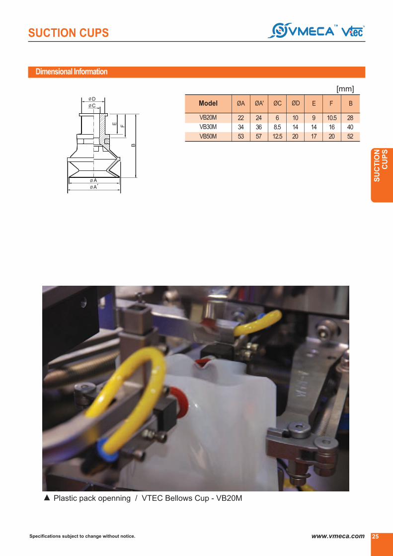
Dimensional Information
Model
VB20M
VB30M
VB50M
22
34
53
24
36
57
6
8.5
12.5
10
14
20
9
14
17
10.5
16
20
28
40
52
ØA ØA′ ØC ØD E F B
[mm]
Plastic pack openning / VTEC Bellows Cup - VB20M▲

Specifications subject to change without notice.26 www.vmeca.com
SUCTION CUPS
VBFSeries(Bellows& Flat)
•Enhancing the adhesion to the surface
•Good lifting force can be achieved with this cup
in the vertical plane
•Prevent transformation when lifting metal thin plate
•Veneer sheets •Sheet metal
•Automotive panels and door
•Plywood •Glass
Features and Strengths
Suitable for Handling
Order No.
▶ See pages 27, 60~67.
▶
12F
▶
PU
▶
F - - - -
▶
VBF100
▶
L 1230 BJ12
▶ ▶
▶ Diameter
VBF25
VBF30
VBF40
VBF50
VBF60
VBF80
VBF100
- Ø25
- Ø32
- Ø42
- Ø51
- Ø64
- Ø84
- Ø103●
▶ Material
PU
WPU
- Poly Urethane
- WhitePolyurethane
●
▶ Filter
No Mark
F
- Standard
- With Filter(PE)●
▶ Thread Size
18F
14F
38F
12F
14M
M10M
●
▶ Quick Mount Adaptor
No Mark - Standard
QA - QuickMountAdaptor**
**Only for G3/8▶ female
and level compensator is not available
* Available only VBF 60, 80, 100
●
- G1/8▶ female (VBF 25,30,40,50,60,80,100)
- G1/4▶ female (VBF 25,30,40,50,60,80,100)
- G3/8▶female (VBF 25,30,40,50,60,80,100)
- G1/2▶ female (VBF 60,80,100)
- G1/4▶ male (VBF 25,30,40,50,60,80,100)
- M10xP1.5 male (VBF 25,30,40,50,60,80)
Stroke(mm)
5
15
20
30
50
20
30
50
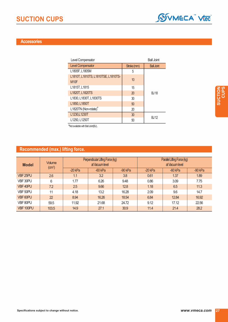
Accessories
Recommended (max.) lifting force.
Model
VBF25PU
VBF30PU
VBF40PU
VBF50PU
VBF60PU
VBF80PU
VBF100PU
-20 kPa -60 kPa -90 kPa
Volume
(cm3)
2.6
6
7.2
11
22
59.5
103.5
1.1
1.77
2.5
4.18
8.94
11.92
14.9
3.2
6.26
9.66
13.2
16.26
21.68
27.1
3.8
9.48
12.8
16.28
18.54
24.72
30.9
PerpendicularLiftingForce(kg)
atVacuumlevel
-20 kPa -60 kPa -90 kPa
0.61
0.86
1.18
2.09
6.84
9.12
11.4
1.37
3.09
6.5
9.6
12.84
17.12
21.4
1.89
7.75
11.3
14.7
16.92
22.56
28.2
ParallelLiftingForce(kg)
atVacuumlevel
▶ Level Compensator ▶ Ball Joint
Level Compensator
L1805F, L1805M
L1810T, L1810TS, L1810TSE, L1810TS-
M10F
L1815T, L1815
L1820T, L1820TS
L1830, L1830T, L1830TS
L1850, L1850T
L1820TN (Non-rotate)*
L1230,L1230T
L1250, L1250T
10
BallJoint
BJ18
BJ12
27
SUCTION CUPS
Specifications subject to change without notice. www.vmeca.com
SU
CT
ION
C
UP
S
*Not available with Ball Joint(BJ)..

Specifications subject to change without notice.28 www.vmeca.com
SUCTION CUPS
Dimensional information
▲ VBF 25PU, VBF 30PU, VBF 40PU, VBF 50PU
▲ VBF 60 PU, VBF 80PU, VBF 100PU

29
SUCTION CUPS
Specifications subject to change without notice. www.vmeca.com
SU
CT
ION
C
UP
S
Dimensional information
Model D2D1SSWH2H1GA1
G1/8″female
G1/4″female
G3/8″female
G1/4″male
M10xP1.5 male
G1/8″female
G1/4″female
G3/8″female
G1/4″male
M10xP1.5 male
G1/8″female
G1/4″female
G3/8″female
G1/4″male
M10xP1.5 male
G1/8″female
G1/4″female
G3/8″female
G1/4″male
M10xP1.5 male
G1/8″female
G1/4″female
G3/8″female
G1/2″female
G1/4″male
M10xP1.5 male
G1/8″female
G1/4″female
G3/8″female
G1/2″female
G1/4″male
M10xP1.5 male
G1/8″ female
G1/4″ female
G3/8″ female
G1/2″ female
G1/4″male
32
25.5
42
51.5
64
84
103
7
6.1
9
11.5
15
22.5
20.5
32
26.5
32
40
50
68
83
[ Measure unit : mm]
VBF25PU- 18F
VBF25PU- 14F
VBF25PU- 38F
VBF25PU- 14M
VBF25PU- M10M
VBF30PU- 18F
VBF30PU- 14F
VBF30PU- 38F
VBF30PU- 14M
VBF30PU- M10M
VBF40PU- 18F
VBF40PU- 14F
VBF40PU- 38F
VBF40PU- 14M
VBF40PU- M10M
VBF50PU- 18F
VBF50PU- 14F
VBF50PU- 38F
VBF50PU- 14M
VBF50PU- M10M
VBF60PU- 18F
VBF60PU- 14F
VBF60PU- 38F
VBF60PU- 12F
VBF60PU- 14M
VBF60PU- M10M
VBF80PU- 18F
VBF80PU- 14F
VBF80PU- 38F
VBF80PU- 12F
VBF80PU- 14M
VBF80PU- M10M
VBF100PU- 18F
VBF100PU- 14F
VBF100PU- 38F
VBF100PU- 12F
VBF100PU- 14M
25
25
41
25
25
28
28
44
28
28
29
29
45
29
29
37
37
37
37
37
41.5
41.5
41.5
41.5
41.5
41.5
49.5
49.5
49.5
49.5
49.5
49.5
55
55
55
55
55
-
-
-
10
12
-
-
-
10
12
-
-
-
10
12
-
-
-
10
12
-
-
-
-
10
12
-
-
-
-
10
12
-
-
-
-
10
17
17
17
17
17
17
17
17
17
17
17
17
17
17
17
22
22
22
22
22
21
21
21
26
21
21
21
21
21
26
21
21
22
22
22
24
22
19.5
19.5
19.5
19.5
19.5
19.8
19.8
-
19.8
19.8
19.8
19.8
-
19.8
19.8
24.8
24.8
24.8
24.8
24.8
24
24
24
29
24
24
24
24
24
29
24
24
24
24
24
27
24
Specifications subject to change without notice.30 www.vmeca.com
SUCTION CUPS
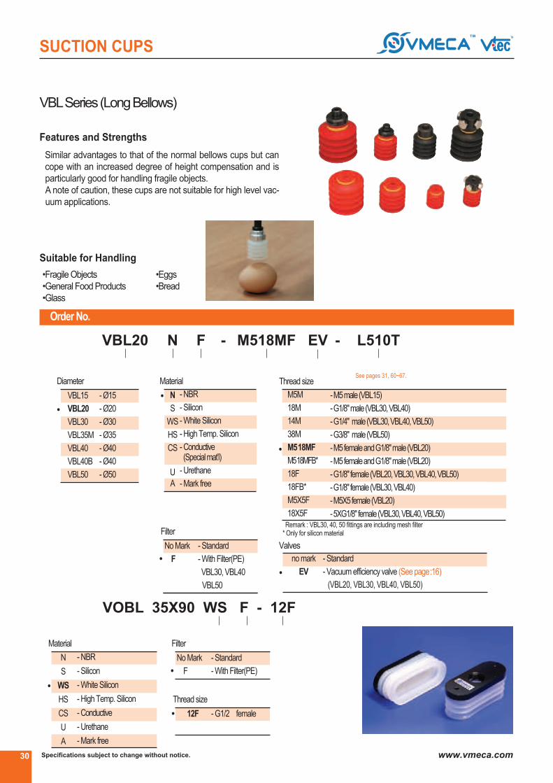
Order No.
M518MF
▶
N
▶
EV -
▶
VBL20
▶
F -
▶
L510T
▶
VBLSeries(LongBellows)
Similar advantages to that of the normal bellows cups but can
cope with an increased degree of height compensation and is
particularly good for handling fragile objects.
A note of caution, these cups are not suitable for high level vac-
uum applications.
•Fragile Objects
•General Food Products
•Glass
•Eggs
•Bread
Features and Strengths
Suitable for Handling
▶ See pages 31, 60~67.▶ Thread size▶ Diameter
VBL15
VBL20
VBL30
VBL35M
VBL40
VBL40B
VBL50
- Ø15
- Ø20
- Ø30
- Ø35
- Ø40
- Ø40
- Ø50
▶ Material
●
●
M5M
18M
14M
38M
M518MF
M518MFB*
18F
18FB*
M5X5F
18X5F
- M5 male(VBL15)
- G1/8" male(VBL30, VBL40)
- G1/4" male(VBL30, VBL40, VBL50)
- G3/8" male(VBL50)
- M5 femaleandG1/8" male(VBL20)
- M5 femaleandG1/8" male(VBL20)
- G1/8" female(VBL20, VBL30, VBL40, VBL50)
- G1/8" female(VBL30, VBL40)
- M5X5 female(VBL20)
- 5XG1/8" female(VBL30, VBL40, VBL50)
●
N
S
WS
HS
CS
U
A
- NBR
- Silicon
- White Silicon
- High Temp. Silicon
- Conductive(Specialmat’l)
- Urethane
- Mark free
▶ Filter
No Mark
F
- Standard
- With Filter(PE)
VBL30, VBL40
VBL50
●
Remark : VBL30, 40, 50 fittings are including mesh filter* Only for silicon material
▶ Valves
no mark
EV●
- Standard
- Vacuum efficiency valve (See page: 16)
(VBL20, VBL30, VBL40, VBL50)
▶ Material
●
N
S
WS
HS
CS
U
A
- NBR
- Silicon
- White Silicon
- High Temp. Silicon
- Conductive
- Urethane
- Mark free
▶▶
VOBL 35X90 WS F - 12F
▶
▶ Filter
No Mark
F
- Standard
- With Filter(PE)●
▶ Thread size
12F - G1/2▶ female●

31
SUCTION CUPS
Specifications subject to change without notice. www.vmeca.com
SU
CT
ION
C
UP
S
Accessories order No.
Recommended (max.) lifting forces
Model-20 kPa -60 kPa
Volume
(cm3)
0.6
0.06
0.16
0.19
0.22
2.1
0.43
3.2*
LiftingForce(kg) - Perpendicular
▶Levelcompensator
Model Stroke
10
10
20
20
5
5
10
10
15
20
20
30
30
50
50
L510T
▶
●
L510
L510T
L520
L520T, L520TF
L1805F
L1805M
L1810T
L1810TS, L1810TSE
L1815T, L1815
L1820T, L1820TS
L1820TN
L1830
L1830T, L1830TS
L1850
L1850T
* Lifting force with PE filter
VBL15
VBL20
VBL30
VBL35M
VBL40
VBL40B
VBL50
VOBL35X90
1.95
4
13
21
27
26
55
43
0.29
0.03
0.06
0.08
0.11
1.03
0.17
2.5*

Specifications subject to change without notice.32 www.vmeca.com
SUCTION CUPS
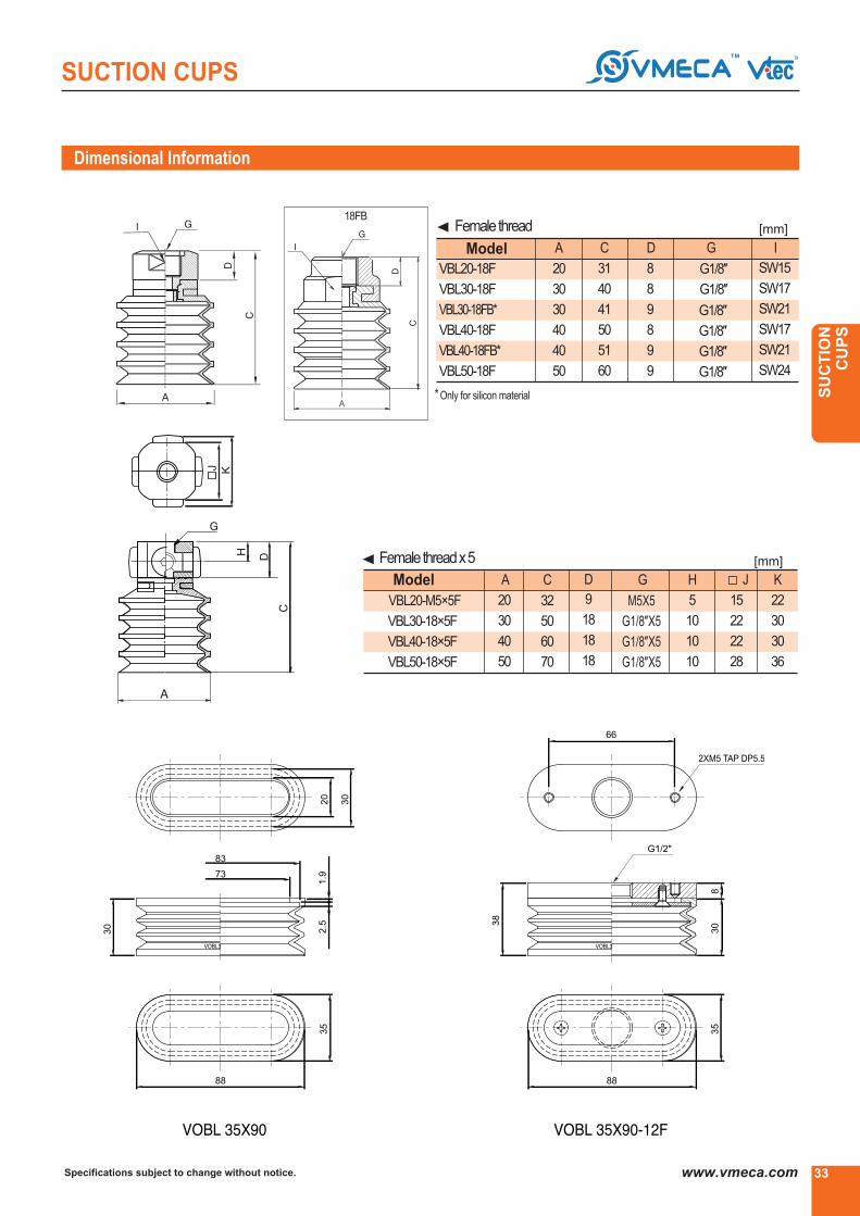
Dimensional Information
▶ VBL20, VBL30, VBL40, VBL50
Model A B
23
32
42
52
20
30
40
50
VBL20
VBL30
VBL40
VBL50
▶ Malethread
Model
VBL20-M518MF
VBL30-18M
VBL30-14M
VBL40-18M
VBL40-14M
VBL50-14M
A D EC G I
SW12.2
SW16
SW17
SW17
SW17
SW17
SW24
SW24
20
20
30
30
40
40
50
50
1.5
3
5
6
5
6
6
6
6
7
7
9
7
9
9
10
24.5
26
37
38
47
48
58
58
G1/8″
G1/8″
G1/8″
G1/4″
G1/8″
G1/4″
G1/4″
G3/8″
VBL20-M518MFB*
VBL50-38M
F
M5
M5
-
-
-
-
-
-
M518MFB
* Only for silicon material
[mm]
[mm]
VBL15 VBL15M5M VBL35M VBL40B
33
SUCTION CUPS
Specifications subject to change without notice. www.vmeca.com
SU
CT
ION
C
UP
S
Dimensional Information
Model
▲ Femalethread
A
20
30
30
40
40
50
8
8
9
8
9
9
31
40
41
50
51
60
SW15
SW17
SW21
SW17
SW21
SW24
DC
G1/8″
G1/8″
G1/8″
G I
VBL20-18F
VBL30-18F
VBL30-18FB*
G1/8″VBL40-18F
G1/8″VBL40-18FB*
G1/8″VBL50-18F
Model
Femalethreadx5
A
20
30
40
50
M5X5
G1/8″X5
G1/8″X5
G1/8″X5
D
9
18
18
18
C
32
50
60
70
G H
5
10
10
10
15
22
22
28
VBL20-M5×5F
VBL30-18×5F
VBL40-18×5F
VBL50-18×5F
J
* Only for silicon material
[mm]
[mm]
K
22
30
30
36
▲
18FB

Specifications subject to change without notice.34 www.vmeca.com
SUCTION CUPS
Order No.
▶ See pages 35, 60~67.
VUSeries(Universal)
Good lifting forces can be achieved with this cup, is best suit-
ed to flat stable surfaces, but can cope with a small degree of
curvature.
Very small cup are available down to just 1.5mm diameter.
•Small components
•Semiconductor Chips
•Packaging Materials
•Sheet Metal
•Printing Industry
•Paper Box
Features and Strengths
Suitable for Handling
VU1.5X
VU2
VU2X
VU3
VU3K
VU4
VU4X
VU6
VU8
VU10
VU15
VU20
VU25
VU30
VU40
VU50
VU80
- Ø1.5
- Ø2
- Ø2
- Ø3
- Ø3.5
- Ø4
- Ø4
- Ø6
- Ø8
- Ø10
- Ø15
- Ø20
- Ø25
- Ø30
- Ø40
- Ø50
- Ø80no mark
EV
- standard
- Vacuum efficiency valve (See page: 16)
(VU20, VU25, VU30, VU40, VU50)
●
●
●
●
▶ Valves
▶ Diameter ▶ Material ▶ Thread size
- M2.5 male (VU2,VU3)
- M5 male (VU2, VU3, VU4, VU6, VU8, VU10, VU15)
- G1/8" male (VU40)
- G1/4" male (VU40, VU50)
- G3/8" male (VU50)
- M5 femaleandG1/8" male(VU20, VU25, VU30)
- M5 femaleandG1/8" male(VU20, VU25, VU30)
- G1/8" female (VU30, VU40, VU50, VU80)
- G1/8" female (VU40)
- M5X5 female (VU20, VU25, VU30)
- G1/8"X5 female (VU40, VU50)
- Ø8 HOLE (VU80)
Remaark : VU40, 50 fittings are including mesh filter.
* Only for silicon material
N
S
WS
HS
CS
U
A
- NBR
- Silicon
- White Silicon
- High Temp.Silicon
- Conductive(Specialmat’l)
- Urethane
- Mark free
M2.5M
M5M
18M
14M
38M
M518MF
M518MFX*
18F
18FX*
M5X5F
18X5F
8
▶
EV
▶
N
▶
18F - -
▶
VU40 L1820T BJ 18
▶ ▶
35
SUCTION CUPS
Specifications subject to change without notice. www.vmeca.com
SU
CT
ION
C
UP
S
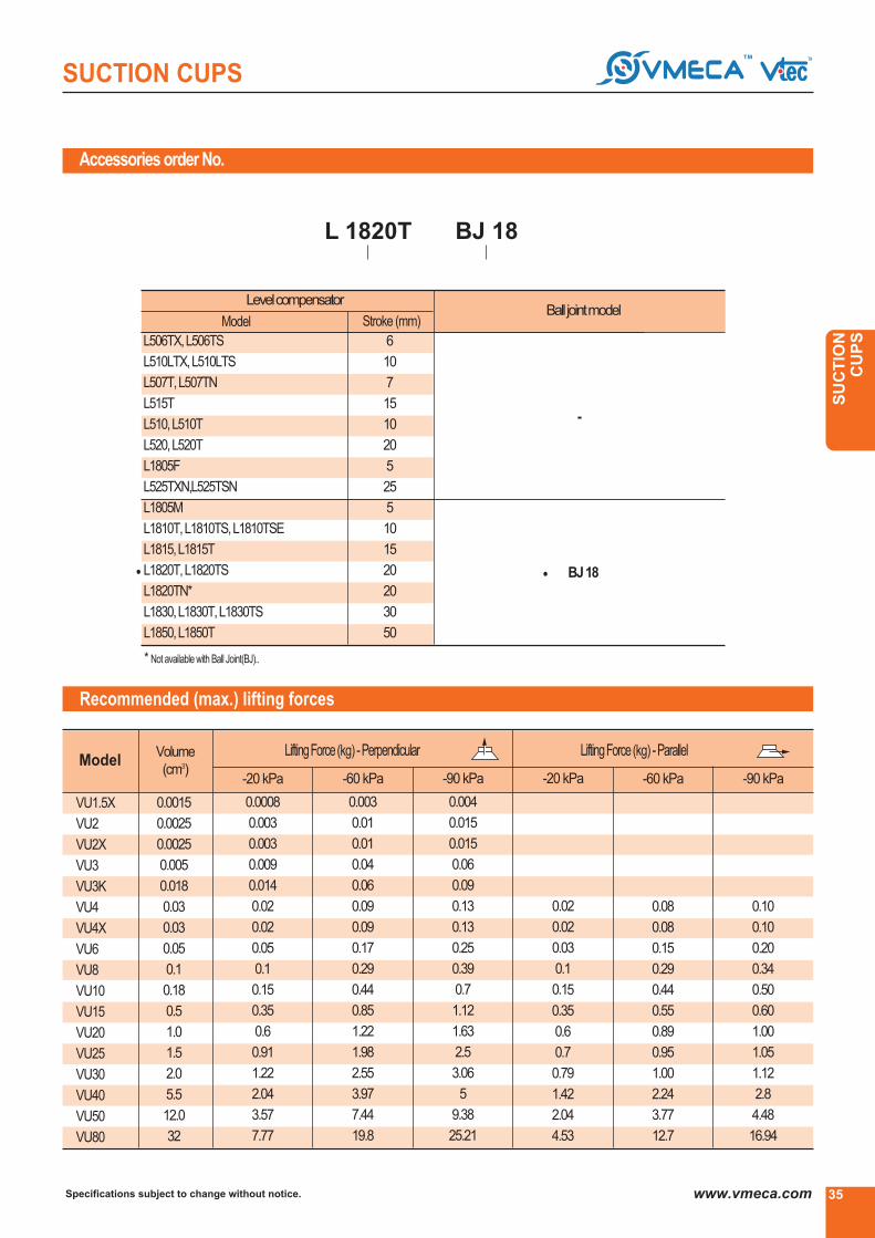
Accessories order No.
Recommended (max.) lifting forces
L 1820T BJ 18
⑥ ⑥
▶Levelcompensator
Model Stroke (mm)▶Balljointmodel
L506TX, L506TS
L510LTX, L510LTS
L507T, L507TN
L515T
L510, L510T
L520, L520T
L1805F
L525TXN,L525TSN
L1805M
L1810T, L1810TS, L1810TSE
L1815, L1815T
L1820T, L1820TS
L1820TN*
L1830, L1830T, L1830TS
L1850, L1850T
BJ18
-
6
10
7
15
10
20
5
25
5
10
15
20
20
30
50
● ●
* Not available with Ball Joint(BJ)..
Model
VU1.5X
VU2
VU2X
VU3
VU3K
VU4
VU4X
VU6
VU8
VU10
VU15
VU20
VU25
VU30
VU40
VU50
VU80
-20 kPa
Volume
(cm3)
0.0015
0.0025
0.0025
0.005
0.018
0.03
0.03
0.05
0.1
0.18
0.5
1.0
1.5
2.0
5.5
12.0
32
0.0008
0.003
0.003
0.009
0.014
0.02
0.02
0.05
0.1
0.15
0.35
0.6
0.91
1.22
2.04
3.57
7.77
-60 kPa
0.003
0.01
0.01
0.04
0.06
0.09
0.09
0.17
0.29
0.44
0.85
1.22
1.98
2.55
3.97
7.44
19.8
-90 kPa
0.004
0.015
0.015
0.06
0.09
0.13
0.13
0.25
0.39
0.7
1.12
1.63
2.5
3.06
5
9.38
25.21
-20 kPa
0.02
0.02
0.03
0.1
0.15
0.35
0.6
0.7
0.79
1.42
2.04
4.53
-60 kPa
0.08
0.08
0.15
0.29
0.44
0.55
0.89
0.95
1.00
2.24
3.77
12.7
-90 kPa
0.10
0.10
0.20
0.34
0.50
0.60
1.00
1.05
1.12
2.8
4.48
16.94
LiftingForce(kg) - Perpendicular LiftingForce(kg) - Parallel
Specifications subject to change without notice.36 www.vmeca.com
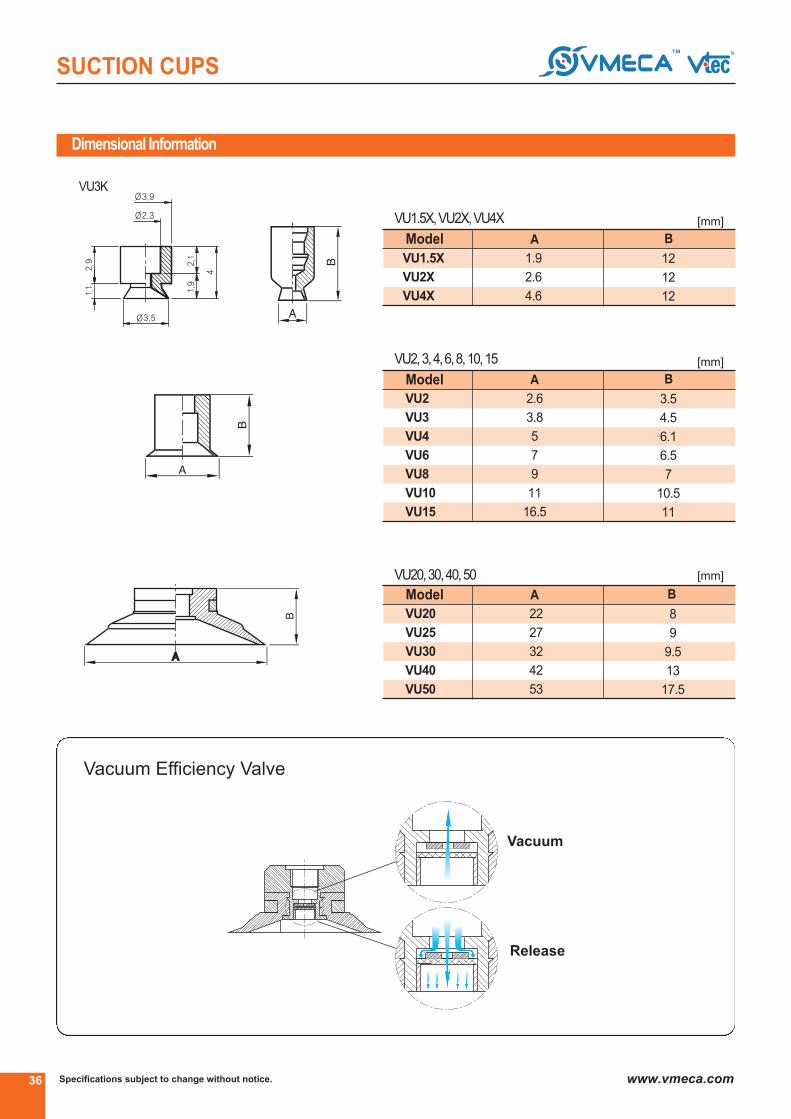
SUCTION CUPS
Dimensional Information
Vacuum Efficiency Valve
▶▶▶▶ Button valve : BV
Vacuum
Release
Model B
12
12
12
1.9
2.6
4.6
VU1.5X
VU2X
VU4X
A
Model A B
3.5
4.5
6.1
6.5
7
10.5
11
2.6
3.8
5
7
9
11
16.5
VU2
VU3
VU4
VU6
VU8
VU10
VU15
Model A B
22
27
32
42
53
VU20
VU25
VU30
VU40
VU50
▶ VU1.5X, VU2X, VU4X
▶ VU2, 3, 4, 6, 8, 10, 15
▶ VU20, 30, 40, 50
8
9
9.5
13
17.5
VU3K
[mm]
[mm]
[mm]

37
SUCTION CUPS
Specifications subject to change without notice. www.vmeca.com
SU
CT
ION
C
UP
S
Dimensional Information
▶ Malethread
A D FC G IEModel
* For silicone material
ModelVU2-M2.5MorM5M
VU3-M2.5MorM5M
VU4-M5M
VU6-M5M
VU8-M5M
VU10-M5M
VU15-M5M
A B C
Model
▶ Femalethread
A DC G
VU20-18F
VU25-18F
D E F
I
VU30-18F
VU40-18F
VU40-18FX*
VU50-18F
VU80-18F
VU80-8
Model
▶ FemalethreadX5
A KD EC G
VU25-M5X5F
VU30-M5X5F
VU40-18X5F
VU50-18X5F
J
VU20-M5X5F
* For silicone material
M518MFX
18FX
VU80
▶ Malethread
[mm]
[mm]
[mm]
[mm]
3.8
2.6 3.5 2.5/4.6
2.5/4.6
4
4
4
5
5
3/4.2
3/4.2
3.5
3.5
3.5
3.5
3.5
5
7
9
11
16.5
4.5
6.1
6.5
7
10.5
11.5
M2.5orM5
M2.5orM5
M5
M5
M5
M5
M5
6/8.1
16
7/9.1
10.1
10.5
11
15.5
VU20-M518MF
VU30-M518MF
G1/8″
G1/8″
SW12
SW12
22
32
1.5
1.5
M5
M5
9.5
11
VU40-18M G1/8″ SW1742 5 -
6
VU20-M518MFX* G1/8″ SW1622 3 M511 7
6
VU30-M518MFX* G1/8″ SW1632 3 M512.5 7
718
VU40-14M G1/4″ SW1742 6 -919
VU50-14M G1/4″ SW2453 6 -923.5
VU50-38M G3/8″ SW2453 6 -1023.5
VU25-M518MF G1/8″ SW1227 1.5 M5610.5
VU25-M518MFX* G1/8″ SW1627 3 M5712
G1/8″
G1/8″
22
27
8
8
16
17
SW15
SW15
G1/8″32 817.5 SW15
G1/8″42 821 SW17
G1/8″42 922 SW21
G1/8″53 926.5 SW24
G1/8″78 -21.5 SW19
Ø878 -21.5 SW19
M5X5
M5X5
22
22
22
30
36
15
15
15
22
28
M5X5
G1/8″X5
G1/8″X5
9
9
9
18
18
5
5
5
10
10
17
18
18.5
31
35.5
22
27
32
42
53

Specifications subject to change without notice.38 www.vmeca.com
SUCTION CUPS
Order No.
▶ See pages 39, 60~67.
VFSeries(Flat)
Good lifting forces can be achieved with this cup in the horizon-
tal plane, but is also good in the vertical plane.
The feet inside the cup provide a good register as well as
enhancing the adhesion to the surface.
•Sheet metal
•Plastic
•Veneer Sheets
•Electronic components
Features and Strengths
Suitable for Handling
▶
18F
▶
PU
▶
BV- -
▶
VF40
▶
L 1820T BJ 18
▶
▶ Diameter
VF15
VF20
VF25
VF30
VF40
VF50
VF50X2
VF75
VF90
VF110
VF150
VF200
VF300
- Ø15
- Ø20
- Ø25
- Ø30
- Ø40
- Ø50
- Ø50
- Ø75
- Ø90*
- Ø110
- Ø150
- Ø200
- Ø300
●
▶ Material
N
S
WS
HS
CS
U
A
PU
WPU
●
▶Only PU Material
no mark -
EV -
BV -
Standard
Vacuum Efficiency Valve (See page : 16)
(VF20, VF25, VF30, VF40, VF50)
Button Valve (Seepage: 16)
(VF20, VF25, VF30, VF40, VF50, VF75, VF90, VF110, VF150)
●
▶ Valves
●
▶ Thread size
M5M
18M
14M
38M
M16M
M518MF
M518MFX*
18F(A)
18FX*
14F(A)
38F(A)
12F(A)
M5X5F
18X5F
34F
Remark : VF40~200 fittings are including mesh filter.
* Only for silicon material (A) : AL-Material (Only VF75, VF90)
- NBR
- Silicon
- White Silicon
- High Temp.
Silicon
- Conductive(Special mat’l)
- Urethane
- Mark free
- PolyUrethane*
- Poly Urethane*(Minimal mark)
- M5 male(VF15)
- G1/8" male(VF40)
- G1/4" male(VF40, VF50)
- G3/8" male(VF50)
- M16XP1.0 male(VF50X2)
- M5 femaleandG1/8" male(VF20, VF25, VF30)
- M5 femaleandG1/8" male(VF20, VF25, VF30)
- G1/8" female(VF20, VF25, VF30, VF40, VF50, VF75, VF90)
- G1/8" female(VF40)
- G1/4" female(VF75, VF90)
- G3/8" female(VF75, VF90)
- G1/2" female(VF75, VF90, VF110, VF150, VF200)
- M5X5 female(VF20, VF25, VF30)
- G1/8"X5 female(VF40, VF50)
- G3/4" female(VF300)
*OnlyforVF30, VF40, VF50,
▶OnlyforVF75, VF90

39
SUCTION CUPS
Specifications subject to change without notice. www.vmeca.com
SU
CT
ION
C
UP
S
Accessories order No.
Recommended (max.) lifting forces
Model
VF15
VF20
VF25
VF30
VF40
VF50
VF50x2
VF75
VF90
VF110
VF150
VF200
VF300
-20 kPa
Volume
(cm3)
0.037
1.0
1.1
2.0
4.8
10
10
20
50
70
160
460
820
0.35
0.61
0.91
1.22
2.04
3.67
3.67
8.16
10.2
14.28
30.61
76.53
163
-60 kPa
0.86
1.47
1.98
2.55
4.08
7.55
7.55
20.40
27.83
42.58
86.73
193.87
438
-90 kPa
1.12
1.93
2.55
3.16
5.10
9.79
9.79
27.55
37.41
57.14
112.24
275.51
653
-20 kPa
0.35
0.51
0.81
1.12
1.53
2.44
2.44
6.12
8.84
14.28
25.51
38.3
135
-60 kPa
0.66
0.81
0.91
1.63
2.55
4.08
4.08
11.22
15.98
25.51
61.22
96.9
307
-90 kPa
0.76
0.86
1.02
2.04
3.06
5.10
5.10
14.28
19.72
30.61
81.63
137.5
476
LiftingForce(kg) - Perpendicular LiftingForce(kg) - Parallel
L 1820T BJ 18
⑥ ⑥
▶Levelcompensator
Model Stroke (mm)▶Balljointmodel
L506TX, L506TS
L510LTX, L510LTS
L507T, L507TN
L515T
L510, L510T
L520, L520T, L520TF
L1805F
L525TSN
L1805M
L1810T, L1810TS, L1810TSE
L1815, L1815T
L1820T, L1820TS
L1820TN*
L1830, L1830T, L1830TS
L1850, L1850T
L1230, L1230T
L1250, L1250T
BJ18
BJ12
-
6
10
7
15
10
20
5
25
5
10
15
20
20
30
50
30
50
● ●
Remark : When apply level compensator into VF300, Use 1/2” level compensator 2pcs or 4pcs
*Not available with ball joint(BJ)..

Specifications subject to change without notice.40 www.vmeca.com
SUCTION CUPS
Dimensional Information including
▶ Male/ Femalethread
Model A Y B DC
VF50x2 53 7.5 17.5 43.5 20
Model
▶ VF15
VF15
A
16.5
B
11
Model
▶ VF75, 90, 110, 150, 200
VF75
VF90
VF110
VF150
VF200
A
77
92
112
152
200
B
13
12.5
20
26
41
HOLE
4-Ø6.5 P.C.D Ø35
4-Ø6.5 P.C.D Ø35
8-Ø6 P.C.D Ø55
8-Ø6 P.C.D Ø70.5
-
Model
▶ VF20, 25, 30, 40, 50
VF20
VF25
VF30
VF40
VF50
A
22
27
32
42
53
B
8
9
10
13
17.5
Model
▶ Malethread
VF15-M5-M
A
16.5
B
11
C D E
16 5 3.5
[mm]
[mm]
[mm]
[mm]
[mm]

41
SUCTION CUPS
Specifications subject to change without notice. www.vmeca.com
SU
CT
ION
C
UP
S
Dimensional Information
▶ Femalethread
Model A KD EC G
VF20-M5X5F
VF25-M5X5F
M5x5
M5x5
M5x5
G1/8″X5
G1/8″X5
22
22
22
30
36
15
15
15
22
28
22
27
32
42
53
9
9
9
18
18
5
5
5
10
10
17
18
19
31
35.5
VF30-M5X5F
VF40-18X5F
VF50-18X5F
J
Model
▶ Femalethread
VF20-18F
VF25-18F
A DC G I
22
27
32
42
42
53
8
8
8
8
9
9
16
17
18
21
22
26.5
G1/8″
G1/8″
G1/8″
G1/8″
G1/8″
G1/8″
SW15
SW15
SW15
SW17
SW21
SW21
VF30-18F
VF40-18F
VF40-18FX*
VF50-18F
* For silicone material
Model
▶ Male/Femalethread
VF40-18M
VF20-M518MF
VF25-M518MF
VF30-M518MF
VF40-14M
VF50-14M
A D E FC G I
VF20-M518MFX*
VF25-M518MFX*
VF30-M518MFX*
VF50-38M
*For silicone material
M518MFX
18FX
[mm]
[mm]
[mm]
22
22
27
27
32
32
42
42
53
53
9.5
11
10.5
12
11.5
13
18
19
22.5
23.5
1.5
3
1.5
3
1.5
3
5
6
6
6
6
7
6
7
6
7
7
9
10
10
M5
M5
M5
M5
M5
M5
-
-
-
-
G1/8”
G1/8”
G1/8”
G1/8”
G1/8”
G1/8”
G1/8”
G1/4”
G1/4”
G3/8”
SW12
SW16
SW12
SW16
SW12
SW16
SW17
SW17
SW24
SW24
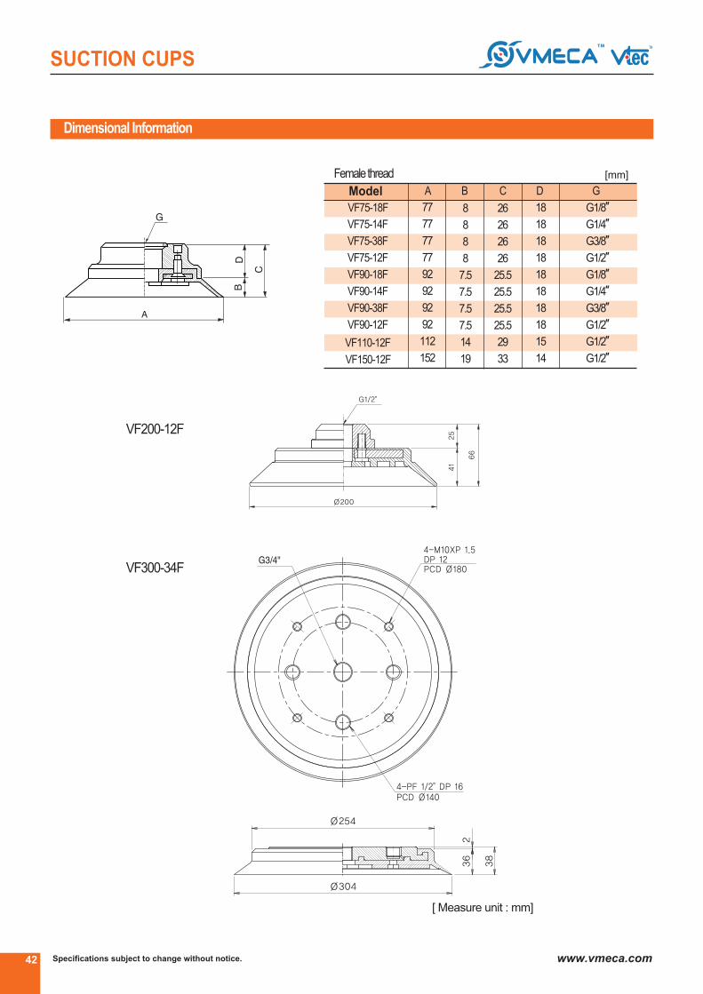
Specifications subject to change without notice.42 www.vmeca.com
SUCTION CUPS
VF200-12F
Dimensional Information
VF300-34F
Model
▶ Femalethread
VF75-18F
VF75-14F
VF75-38F
VF75-12F
VF90-18F
VF90-14F
VF90-38F
VF90-12F
VF110-12F
VF150-12F
A B C D G
G1/8″
G1/4″
G3/8″
G1/2″
G1/8″
G1/4″
G3/8″
G1/2″
G1/2″
G1/2″
77
77
77
77
92
92
92
92
112
152
8
8
8
8
7.5
7.5
7.5
7.5
14
19
26
26
26
26
25.5
25.5
25.5
25.5
29
33
18
18
18
18
18
18
18
18
15
14
[mm]
[ Measure unit : mm]

43
SUCTION CUPS
Specifications subject to change without notice. www.vmeca.com
SU
CT
ION
C
UP
S
Dimensional Information including button valve
VF30-BV
VF110-BV
VF150-BV
VF40-BV VF50-BV
VF75-BV
[ Measure unit : mm]
[ Measure unit : mm]

Specifications subject to change without notice.44 www.vmeca.com
SUCTION CUPS
Order No.
VFC50
VFC60
VFC60X1
VFC75
VFC75X1
VFC75X2
VFC90
VFC100
- Ø50
- Ø60
- Ø60
- Ø75
- Ø75
- Ø75
- Ø90*
- Ø100
M10M
M16M
1838MF
18F(A)
14F(A)
38F(A)
12F(A)
- M10XP1.5 male (VFC60X1,VFC75X1)
- M16XP1.0 male (VFC75X2)
- G1/8″ female and G3/8″male (VFC50, VFC60, VFC75)
- G1/8″ female (VFC90, VFC100)
- G1/4″ (VFC90, VFC100)
- G3/8″ female (VFC90, VFC100)
- G1/2" female (VFC90, VFC100)
▶ See pages 45, 60~67.
▶
1838MF
▶
PU - -
▶
VFC50 L1820T BJ 18
▶ ▶
●
●
*Only for PU Material
VFCSeries(FlatCurve)
This cup is specifically designed to cope with both flat
and curved surfaces, which means that multiple objects
can be handled with the same suction cup.
•Automotive Windscreens, Roof and Door.
•Sheet Metal
•Shaped Sheet Metal Panels
•TV Cathode ray Tube
Features and Strengths
Suitable for Handling
▶ Diameter
- NBR
- Silicon
- White Silicon
- High Temp.Silicon
- Conductive(Special mat’l)
- Urethane
- Mark free
- PolyUrethane*
- Poly Urethane*(Minimal mark)
●
*Only for VFC50, VFC60VFC75, VFC90, VFC100
▶ Material ▶ Thread size
N
S
WS
HS
CS
U
A
PU
WPU
Remark : VFC90, 100 fittings are including mesh filter.(A) : AL-Material

45
SUCTION CUPS
Specifications subject to change without notice. www.vmeca.com
SU
CT
ION
C
UP
S
Accessories order No.
Recommended (max.) lifting forces
L 1820T BJ 18
▶ ▶
▶ Levelcompensator
Model Stroke▶ Balljointmodel
L1805M
L1810T
L1810TS, L1810TSE
L1815T, L1815
L1820T, L1820TS
L1820TN*
L1830
L1830T, L1830TS
L1850
L1850T
L1230
L1230T
L1250
L1250T
BJ18
BJ12
5
10
10
15
20
20
30
30
50
50
30
30
50
50
●
●
* Not available with ball joint(BJ)
Model
VFC50
VFC60
VFC60X1
VFC75
VFC75X1
VFC75X2
VFC90
VFC100
-20 kPa
Volume
(cm3)
10
20
20
30
30
30
60
80
2.85
4.55
4.55
7.65
7.65
7.65
9.8
12.75
-60kPa
6.94
11.57
11.57
19.38
19.38
19.38
24.82
35.71
-90kPa
10.2
15.3
15.3
25.51
25.51
25.51
32.65
46.93
-20 kPa
2.61
3.05
3.05
6.19
6.19
6.19
9.52
12.24
-60kPa
6.34
7.92
7.92
15.46
15.46
15.46
21.59
23.97
-90kPa
8.2
10.7
10.7
20.9
20.9
20.9
27.89
28.57
LiftingForce(kg) - Perpendicular LiftingForce(kg) - Parallel

Specifications subject to change without notice.46 www.vmeca.com
SUCTION CUPS
Dimensional Information
[ Measure unit : mm]
VFC50-1838MF
VFC60-1838MF
VFC75-1838MF
VFC75 X 2
VFC75 X 1
VFC60 X 1

47
SUCTION CUPS
Specifications subject to change without notice. www.vmeca.com
SU
CT
ION
C
UP
S
Dimensional Information
VFC90
VFC100
[ Measure unit : mm]

Specifications subject to change without notice.48 www.vmeca.com
SUCTION CUPS
Order No.
Accessories order No.
▶
18F
▶
PU - -
▶
VD50 L 1820T BJ 18
▶ ▶▶ See pages 60~67.
VDSeries(Deep)
This cup is best suited to curved or irregular surfaces.
Also, it is deep and grip around corners and edges.
•Automotive Roof and Door.
•Sheet metal
•Plastic sheets
•Sheet veneer
•Shaped sheet metal panels
Features and Strengths
Suitable for Handling
VD30
VD40
VD50
VD60
VD70
VD85
VD85X
VD90F
- NBR
- Silicon
- White Silicon
- High Temp.Silicon
- Conductive(Special mat’l)
- Urethane
- Mark free
- PolyUrethane*
- Poly Urethane*(Minimal mark)
- Ø30
- Ø40
- Ø50
- Ø60
- Ø70*
- Ø85
- Ø85
- Ø90*
- M8XP1.25 male(VD30, VD40, VD50, VD60, VD70, VD85)
- M10XP1.5 male(VD30, VD40, VD50, VD60, VD70, VD85)
- G1/8" female(VD30, VD40, VD50, VD60, VD70, VD85, VD90F)
- G1/4" female(VD90F)
- G3/8" female(VD90F)
- G1/2" female(VD85, VD90F)
- Ø19 Hole(VD90F)
● ●
*Only for VD30,VD40,VD50, VD60, VD70, VD90F
▶Only for PU material
▶ Thread size▶ Diameter ▶ Material
M8M
M10M
18F
14F
38F
12F
H19
N
S
WS
HS
CS
U
A
PU
WPU
L 1820T BJ 18
▶
▶ Levelcompensator
Model Stroke (mm)▶ Balljointmodel
L1805M
L1810T, L1810TS, L1810TSE
L1815T, L1815
L1820T, L1820TS
L1820TN*
L1830, L1830T, L1830TS
L1850, L1850T
L1230, L1230T
L1250, L1250T
BJ18
BJ12
5
10
15
20
20
30
50
30
50
● ●
* Not available with ball joint(BJ)
▶
●

49
SUCTION CUPS
Specifications subject to change without notice. www.vmeca.com
SU
CT
ION
C
UP
S
Model-20 kPa -60 kPa -90 kPa
Volume
(cm3)
Recommended (max.) lifting forces
VD30
VD40
VD50
VD60
VD70
VD85
VD85X
VD90F
1.53
2.38
4.46
8.4
11.6
16.8
16.8
14.42
0.73
1.22
2.14
3.3
4.2
6.0
6.0
7.97
1.83
3.00
5.62
11.1
16.2
23.4
23.4
18.15
4.5
7
13.5
22
38
60
68
56
-20 kPa -60 kPa -90 kPa
2.55
3.97
7.44
14
18.8
28
28
24.36
1.22
2.04
3.57
5.50
7.15
10
10
9.25
3.06
5.0
9.38
18.5
24.9
39
39
32.17
Lifting Force (kg)- Perpendicular
Lifting Force (kg)- Parallel
Dimensional information
Model B F
30
40
50
61
72
25
25
25
30
30
G1/8″
G1/8″
G1/8″
G1/8″
G1/8″
VD30
VD40
VD50
VD60
VD70
Model A B F
85
88
28.5
37
G1/8″,G1/2″
G1/8″
VD85
VD85X
▶ Femalethread
▶ Femalethread
A
Model A
30
40
50
61
72
85
B
25
25
25
30
30
28.5
C
35
35
35
41.5
41.5
38.5
D G
10
10
10
10
10
10
M8xP1.25 or M10xP1.5
M8xP1.25 or M10xP1.5
M8xP1.25 or M10xP1.5
M8xP1.25 or M10xP1.5
M8xP1.25 or M10xP1.5
M8xP1.25 or M10xP1.5
VD30
VD40
VD50
VD60
VD70
VD85
▶ Malethread
VD85
▶ VD85X
▶
VD90F- 18F, 14F, 38F, 12F VD90F- H19
▶
▶
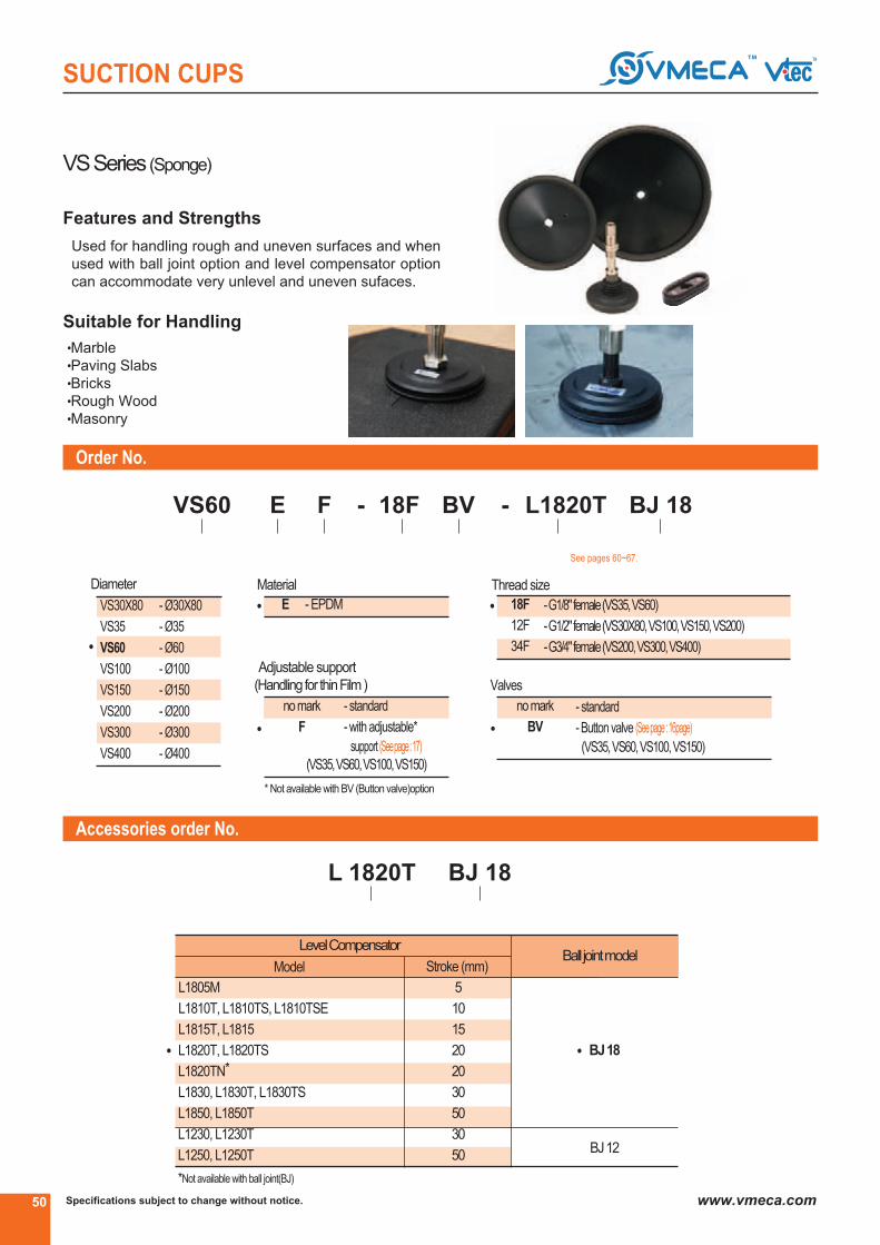
Specifications subject to change without notice.50 www.vmeca.com
SUCTION CUPS
Order No.
Accessories order No.
▶
18F BV
▶
E - -
▶
VS60
▶
F L1820T BJ 18
▶ ▶ ▶
L 1820T BJ 18
▶ ▶
▶ See pages 60~67.
▶ LevelCompensator
Model Stroke (mm)▶ Balljointmodel
BJ18
BJ12
● ●
VSSeries(Sponge)
Used for handling rough and uneven surfaces and when
used with ball joint option and level compensator option
can accommodate very unlevel and uneven sufaces.
•Marble
•Paving Slabs
•Bricks
•Rough Wood
•Masonry
Features and Strengths
Suitable for Handling
VS30X80
VS35
VS60
VS100
VS150
VS200
VS300
VS400
- Ø30X80
- Ø35
- Ø60
- Ø100
- Ø150
- Ø200
- Ø300
- Ø400
●
▶ Diameter
E - EPDM●
nomark
F
- standard
- with adjustable*
support (Seepage: 17)
▶ Adjustable support
(Handling for thinFilm)
●
▶ Material
* Not available with BV (Button valve)option
18F
12F
34F
- G1/8" female(VS35, VS60)
- G1/2" female(VS30X80, VS100, VS150, VS200)
- G3/4" female(VS200, VS300, VS400)
●
nomark
BV
- standard
- Button valve (Seepage: 16page)
(VS35, VS60, VS100, VS150)
●
▶ Valves
▶ Thread size
*Not available with ball joint(BJ)
L1805M
L1810T, L1810TS, L1810TSE
L1815T, L1815
L1820T, L1820TS
L1820TN*
L1830, L1830T, L1830TS
L1850, L1850T
L1230, L1230T
L1250, L1250T
5
10
15
20
20
30
50
30
50
(VS35, VS60, VS100, VS150)

51
SUCTION CUPS
Specifications subject to change without notice. www.vmeca.com
SU
CT
ION
C
UP
S
Recommended (max.) lifting forces
Model A B C
VS200
VS300
VS400
34
34
34
G1/2″, G3/4″
G3/4″
G3/4″
215
315
415
Dimensional Information
Model
VS30X80
VS35
VS60
VS100
VS150
VS200
VS300
VS400
-20 kPa -60 kPa
Volume
(cm3)
43
6
20
55
125
543
1285
2285
2.7
2.04
6.12
18.36
38
76.53
163.26
326
9.1
5.1
15.3
45.9
97
193.87
438.77
876
-90 kPa
14
7.14
22.44
67.34
138
275.51
653.06
1300
LiftingForce(kg) - Perpendicular
[mm]
VS35-BV VS60-BV VS100-BV, VS150-BV
VS 30X80
Model A B C
VS35
VS60
VS100
VS150
42.5
67.5
107.5
157.5
15.5
15.5
19.5
19.5
G1/8″
G1/8″
G1/2″
G1/2″
[mm]
[ Measure unit : mm]
Button valve dimensional Information
■ Female thread
VS35, 60, 100, 150 VS200, 300, 400

Specifications subject to change without notice.52 www.vmeca.com
SUCTION CUPS
Order No.
③
N
③
15X45 - -
③
VOU F 18F L 1820TN
③ ③ ③ See pages 60~67.
VOU-Series
Features and Strengths
VOU 4 X 10
VOU 4 X 20
VOU 6 X 10
VOU 6 X 20
VOU 8 X 20
VOU 8 X 30
VOU 10 X 30
VOU 15 X 45
VOU 20 X 60
- NBR
- Silicon
- White Silicon
- High Temp.
Silicon
- M5X0.8 Male VOU4X10, 4X20, 6X10, 6X20
- M5X0.8 Female 8X20, 8X30, 10X30
- G1/8" Male VOU15X45, 20X60
- G1/8" Female
●
●
●
*Only for VOU 15x45
VOU 20X60
③ Fitting thread③ Suction cup Ø(mm) ③ Material
N
S
WS
HS
No Mark - Standard
F* - With meshfilter
- VOU 4X10, 4X20, 6X10, 6X20,
8X20, 8X30, 10X30
- VOU 15x45, 20x60
●
●
③ Level Compensator (Accessory)③ Filter
L507TN
L1820TN
M5M
M5F
18M
18F
•Best suitable for handling long objects with flat
and curved surfaces
•Good lifting forces can be achieved with small size
•Conductive silicon is excellent for handling PCB board
or Electronic componets
•Easily mountable without detaching a fitting from the machine
(save the maintenance time)
•Semiconductor Chips (PCB board)
•Electronic components
•Small glass cases (e.g. ampule)
•Pipe
Suitable for Handling

53
SUCTION CUPS
Specifications subject to change without notice. www.vmeca.com
SU
CT
ION
C
UP
S
Min.curvatureradius
R(mm)Model
LiftingForce(kg)
-PerpendicularInternalvolume
(cm3)
Weight
③ (kg)
Recommended (max.) lifting forces
Model
4
VOU 4 x 10..M5M
VOU 4 x 10..M5F
VOU 4 x 20..M5M
VOU 4 x 20..M5F
VOU 6 x 10..M5M
VOU 6 x 10..M5F
VOU 6 x 20..M5M
VOU 6 x 20..M5F
VOU 8 x 20..M5M
VOU 8 x 20..M5F
VOU 8 x 30..M5M
VOU 8 x 30..M5F
VOU 10 x 30..M5M
VOU 10 x 30..M5F
VOU 15 x 45..18M
VOU 15 x 45..18F
VOU 20 x 60..18M
VOU 20 x 60..18F
Dimensional information
0.205
0.347
0.256
0.603
0.818
1.053
1.554
3.271
6.352
0.064
0.094
0.081
0.137
0.17
0.25
0.394
1.584
3.532
3.5
3.5
4.5
4.5
6.5
6.5
8
11
17
0.00031
0.00036
0.00031
0.00037
0.00037
0.00043
0.00047
0.022
0.031
VOU4X10 -...
VOU4X20 -...
VOU6X10 -...
VOU6X20 -...
VOU8X20 -...
VOU8X30 -...
VOU10X30-...
VOU15X45 -...
VOU20X60 -...
③
③
A1 A2 H1
M5 x 0.8
M5 x 0.8
4
M5 x 0.8
M5 x 0.8
6
M5 x 0.8
M5 x 0.8
6
M5 x 0.8
M5 x 0.8
8
M5 x 0.8
M5 x 0.8
8
M5 x 0.8
M5 x 0.8
10
M5 x 0.8
M5 x 0.8
15
G1/8”
G1/8”
20
10
20
10
20
20
30
30
45
60
7
7
7
7
7
7
8.2
15.5
17.5
11.5
-
11.5
-
11.5
-
11.5
-
11.5
-
11.5
-
12.7
-
23
-
25
-
4
-
4
-
4
-
4
-
4
-
4
-
4
-
7
-
7
-
-
15
-
15
-
15
-
15
-
15
-
15
-
16.2
-
25.5
-
27.5
G1/8”
G1/8”
H2 H3 H4 M

Specifications subject to change without notice.54 www.vmeca.com
SUCTION CUPS
Order No.
③
N
③
VOC 35x90
③
38F-
●
●
VOCSeries(OvalCurved)
This cup is best suitable for handling long objects with
flat or curved surfaces.
Specially, parallel to the surface of the object It has a
thick and durable lip.
•Long Objects with Flat
•Curved Surfaces
•Shaped Sheet Metal Panels
•Automotive Bumper
Features and Strengths
Suitable for Handling
③ Suction cupØ(mm) ③ Material
●
③ Thread size
Recommended (max.) lifting forces
Model
VOC11 X23
VOC35 X90
VOC35 X110
VOC60 X140
VOC60 X180
-20 kPa
Volume
(cm3)
2.0
20
25
52
67
0.61
5
6.25
13.4
19.1
-60 kPa
1.3
13.4
16.7
38.0
54.2
-90 kPa
1.6
17.4
21.7
53.0
75.7
-20 kPa
0.6
4
5
10.72
15.28
-60 kPa
1.2
10.72
13.36
30.4
43.36
-90 kPa
1.5
13.92
17.36
42.4
60.56
LiftingForce(kg) - Perpendicular LiftingForce(kg) - Parallel
N
S
WS
HS
CS
U
A
- NBR
- Silicon
- White Silicon
- High Temp.Silicon
- Conductive(Specil mat’l)
- Urethane
- Mark free
VOC11x23
VOC35x90
VOC35x110
VOC60x140
VOC60x180
- Ø11x23
- Ø35x90
- Ø35x110
- Ø60x140
- Ø60x180
38F - G3/8③ female
(VOC35X90,35X110
VOC60X140, 60X180
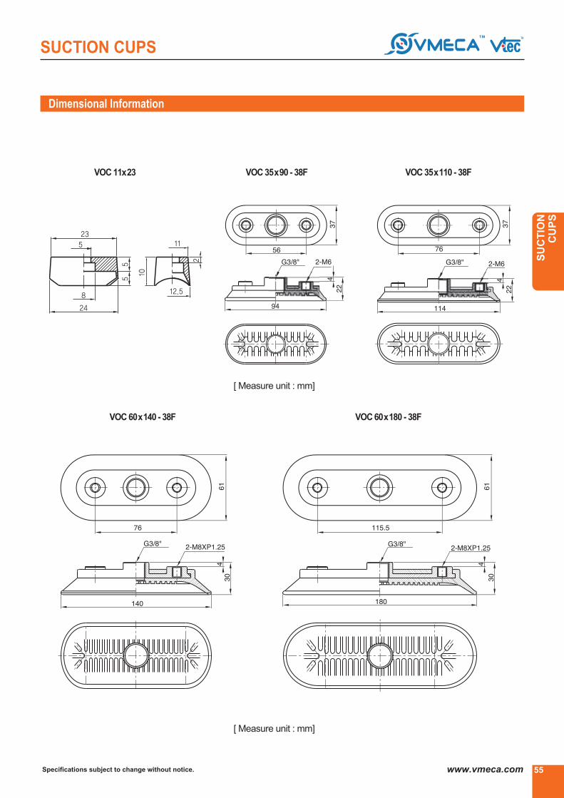
55
SUCTION CUPS
Specifications subject to change without notice. www.vmeca.com
SU
CT
ION
C
UP
S
Dimensional Information
VOC 35x90 - 38FVOC 11x23 VOC 35x110 - 38F
VOC 60x140 - 38F VOC 60x180 - 38F
[ Measure unit : mm]
[ Measure unit : mm]

Specifications subject to change without notice.56 www.vmeca.com
SUCTION CUPS
Recommended (max.) lifting forces
ModelVolume
(cm3)
14.5
2.0
0.5
1.0
2.0
1.1
2.0
20
1.4
8
1.8
1.22
0.7
0.35
0.6
0.7
0.4
0.8
5.5
0.5
1.55
0.65
2.24
1.53
0.85
1.22
1.53
1.11
1.7
14
1.15
2.8
1.48
2.75
1.83
1.12
1.63
1.83
1.23
2.05
18.5
1.25
5.1
1.78
-20 kPa -60 kPa -90 kPa
LiftingForce(kg) - Perpendicular
KPSSeries(PlasticBagOpening)
Developed to be used for opening plastic bags this cup
gives good adhesion to thin plastic and film type materi-
als.
•Plastic Bag Opening
•Thin Film Materials
•Paper Bag Handling
Features and Strengths
Suitable for Handling
Order No.
③
U
③
KPS-1
●
●
③ Suction cup Ø ③ Material
KPS-1
KPS-2
KPS-3
KPS-4
KPS-5
KPS-5-15
KPS-6
KPS-7
KPS-8
KPS-9
VU-30-X
KPS-1*
KPS-2
KPS-3
KPS-4
KPS-5*
KPS-5-15*
KPS-6
KPS-7
KPS-8
KPS-9*
VU-30-X
N
S
WS
HS
CS
U
- NBR
- Silicon
- White Silicon
- High Temp. Silicon
- Conductive (Special mat’l)
- Urethane
- Ø34
- Ø28
- Ø13
- Ø16
- Ø28
- Ø15
- Ø30
- Ø68
- Ø25
- Ø40
- Ø30
* G1/8③ Femalefittingavailable
Remark : KPS-8 available only ‘S’,
‘WS’, ‘HS’

57
SUCTION CUPS
Specifications subject to change without notice. www.vmeca.com
SU
CT
ION
C
UP
S
Dimensional Information
KPS-1 KPS-2 KPS-3 KPS-4
[ Measure unit : mm]
KPS-5 KPS-5-15 KPS-6
KPS-8KPS-7 KPS-9
VU-30-X

Specifications subject to change without notice.58 www.vmeca.com
SUCTION CUPS
Technical Data
ModelWeight
(g)
Operating
pressure
(bar) 4 bar 5 bar 6 bar 4 bar 5 bar 6 bar
Holdingforce, (kg)atdifferentpressure
Airconsumption(Nl/m)
NFSeries(Non-touchFlat)
Circuit boards, Solar cell, CDs and DVDs, Uneven sheet
Wood, Packaging, Plastic, Thin products, Film, Paper,
Mirrors, Paper-board..
•Non-contact handling item
•Integrated Multi-suction system
•Low air consumption
•Large vacuum flow and powerful suction force
•Safe gripping with mark free
•No moving parts
•Excellent gripping with metal sheets with holes.
Application
Main advantages
NF 20 06
NF 20 12
NF 40 06
NF 40 12
NF 60 06
NF 60 12
75
138
53
120
105
160
82
166
68
128
123
190
0.2
0.2
0.29
0.49
0.59
0.99
0.22
0.22
0.39
0.59
0.79
1.25
0.22
0.22
0.49
0.68
0.89
1.49
AI: 21
Peek: 11.5
AI: 55
Peek: 30
AI: 130
Peek: 70
4 ~ 6
4 ~ 6
4 ~ 6
Order No.
NF 20
NF 40
NF 60
- Ø20
- Ø40
- Ø60
③
A
③
40 06 -
③
NF 18F
③
③ Vacuum pad Ø
- standard
- an extra vacuum flow
③ Vacuum flows
06
12
- M5XPO.8 female (NF20..)
- G1/8③ female (NF40.., NF60..)
③ Thread size
M5F
18F●
●
●
90
198
82
135
126
223
**PEEK
•Excellentelectrical insulatingproperties
•HighabrasionResistance
•GoodLubricity
•ConsecutivelyOperatingTemp. : 250③
•FoodQuality
A
P
③ Material
● - Aluminum
- PEEK**

59
SUCTION CUPS
Specifications subject to change without notice. www.vmeca.com
SU
CT
ION
C
UP
S
③ NF 20 06.. / NF 20 12..
③ NF 60 06.. / NF 60 12..
③ NF 40 06.. / NF 40 12..
The principle of VMECA NF PAD
Applications
Dimensional information
[ Measure unit : mm[in]

Specifications subject to change without notice.60 www.vmeca.com
5-Series
LEVEL COMPENSATOR
Dimensional Information
Model Thread Size Stroke (mm) Weight (g)
LevelCompensator
The Vtec level compensator is used to compensate for differ-
ences in height on the surface of the material that is to be
lifted. The advantages being a more reliable and less precise
pick up position when handling product that may be less con-
sistent in it shape, size and position. The level compensator
also provides a degree of shock absorption should this be
required. The level compensator come in configurations with
varying sizes of spring and stroke.
Features and Strengths
L510T M5-male
L520T M5-male
L510 M5-male
L520 M5-male
L506TX VB6X,VU1.5X,VU2X,VU4X
L506TS VU10,VU15,VF15,VB10,VB12,VB15
L506TU VU4,VU6,VU8,VB5,VB8
L506TM VU2,VU3
L510LTX VB6X,VU1.5X,VU2X,VU4X
L510LTS VU10,VU15,VF15,VB10,VB12,VB15
L510LTU VU4,VU6,VU8,VB5,VB8
L510LTM VU2,VU3
L507T M5-female
L515T M5-female
L520TF M5-female
10
20
10
20
6
6
6
6
10
10
10
10
7
15
20
30
33
33
36
12
12
11
11
19.5
19.8
19.2
19
17
20
20
L510T L520T L510 L520
[ Measure unit : mm]

61Specifications subject to change without notice. www.vmeca.com
SU
CT
ION
C
UP
S
LEVEL COMPENSATOR
L506TX L506TS L506TU L506TM
L510LTX L510LTS L510LTU L510LTM
L507T L515T L520TF
Dimensional Information
[ Measure unit : mm]

Specifications subject to change without notice.62 www.vmeca.com
LEVEL COMPENSATOR
Model Thread Size Stroke (mm) Weight (g)
L 1810TS L 1810TSE L 1815T L 1815
L 1805F L 1805M L 1810T L 1810TS - M10F
Dimensional Information
18-Series
L1805F G1/8③ - female 5 24
L1805M G1/8③ - male 5 28
L1810T G1/8③ - male 10 44
L1810TS-M10F M10 - female 10 67
L1810TS G1/8③ - male 10 73
L1810TSE G1/8③ - male 10 93
L1815 G1/8③ - male 15 86
L1815T G1/8③ - male 15 36
L1820T G1/8③ - male 20 56
L1820TS G1/8③ - male 20 83
L1830 G1/8③ - male 30 54
L1830T G1/8③ - male 30 60
L1830TS G1/8③ - male 30 130
L1850 G1/8③ - male 50 105
L1850T G1/8③ - male 50 66
[ Measure unit : mm]
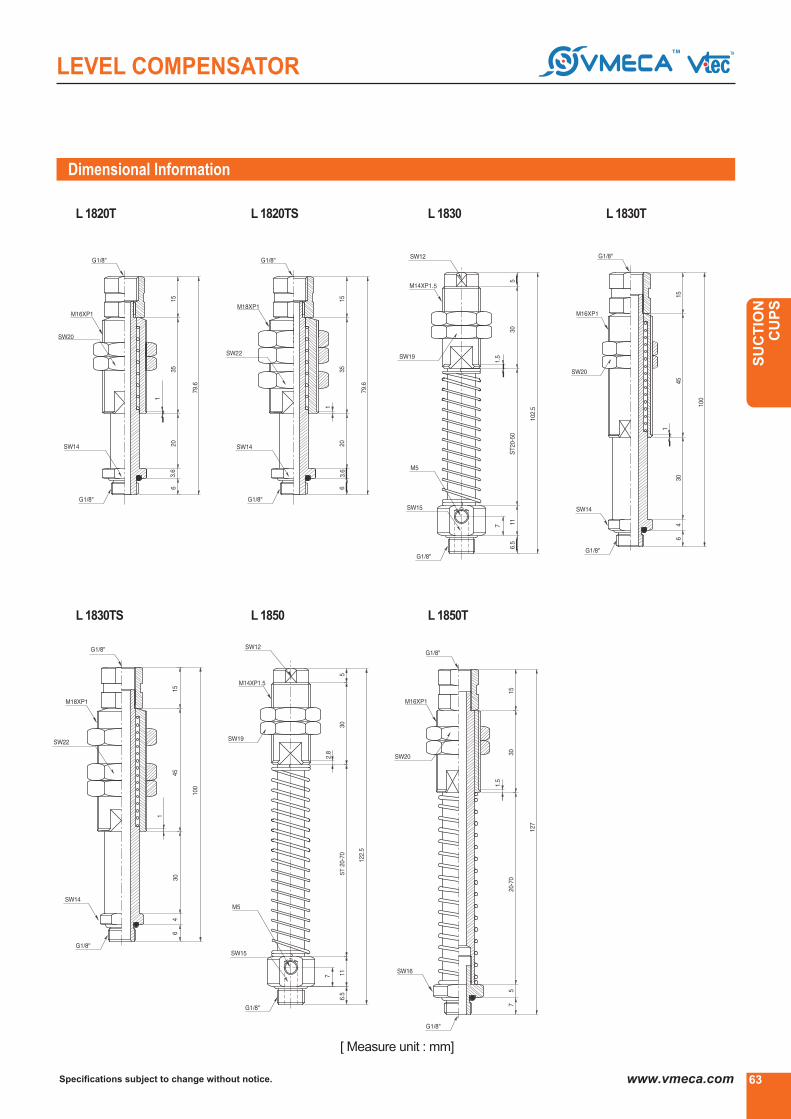
63Specifications subject to change without notice. www.vmeca.com
SU
CT
ION
C
UP
S
LEVEL COMPENSATOR
L 1820T L 1820TS L 1830 L 1830T
L 1830TS L 1850 L 1850T
Dimensional Information
[ Measure unit : mm]

Specifications subject to change without notice.64 www.vmeca.com
LEVEL COMPENSATOR
Model Thread Size Stroke (mm) Weight (g)
L1230 G 1/2③ 30 289
L1250 G 1/2③ 50 350
L1230T G 1/2③ 30 241
L1250T G 1/2③ 50 156
L 1230 L 1250 L 1230T
L 1250T
Dimensional Information
12-Series
[ Measure unit : mm]

65Specifications subject to change without notice. www.vmeca.com
SU
CT
ION
C
UP
S
LEVEL COMPENSATOR
Dimensional Information
L 525TXN L 525TSN L 525TUN L 525TMN
Model Thread Size Stroke (mm) Weight (g)
L525TXN VB6X,VU1.5X,VU2X,VU4X 25 20.7
L525TSN VU10,VU15,VF15,VB10,VB12,VB15 25 20.6
L525TUN VU4,VU6,VU8,VB5,VB8 25 20.3
L525TMN VU2,VU3 25 20.1
L507TN M5-female 7 18
L1820TN G1/8③-male 20 54
L1850TN G1/8③-male 50 140
NonRotaingLevelCompensator
L 507TN L 1820TN L 1850TN
[ Measure unit : mm]

BJ 18 BJ 12
Specifications subject to change without notice.66 www.vmeca.com
BALL JOINTS
BJ 18
BJ 12
G1/8″
G1/2″
25
50
Model ThreadSize Angle Max. Load(kg) Weight (g)
±12③±
12③
19
112
Dimensional Information
BallJoints
The Vtec Ball Joint or sometimes referred to as a universal joint
is for use when a degree of angular compliance is required,
more commonly used with flat type cups which unlike bellows
do not allow for much angular compliance as part of their
design.
The vacuum port is integral through the centre of the joint thus
providing a neat and compact solution.
Features and Strengths
[ Measure unit : mm]
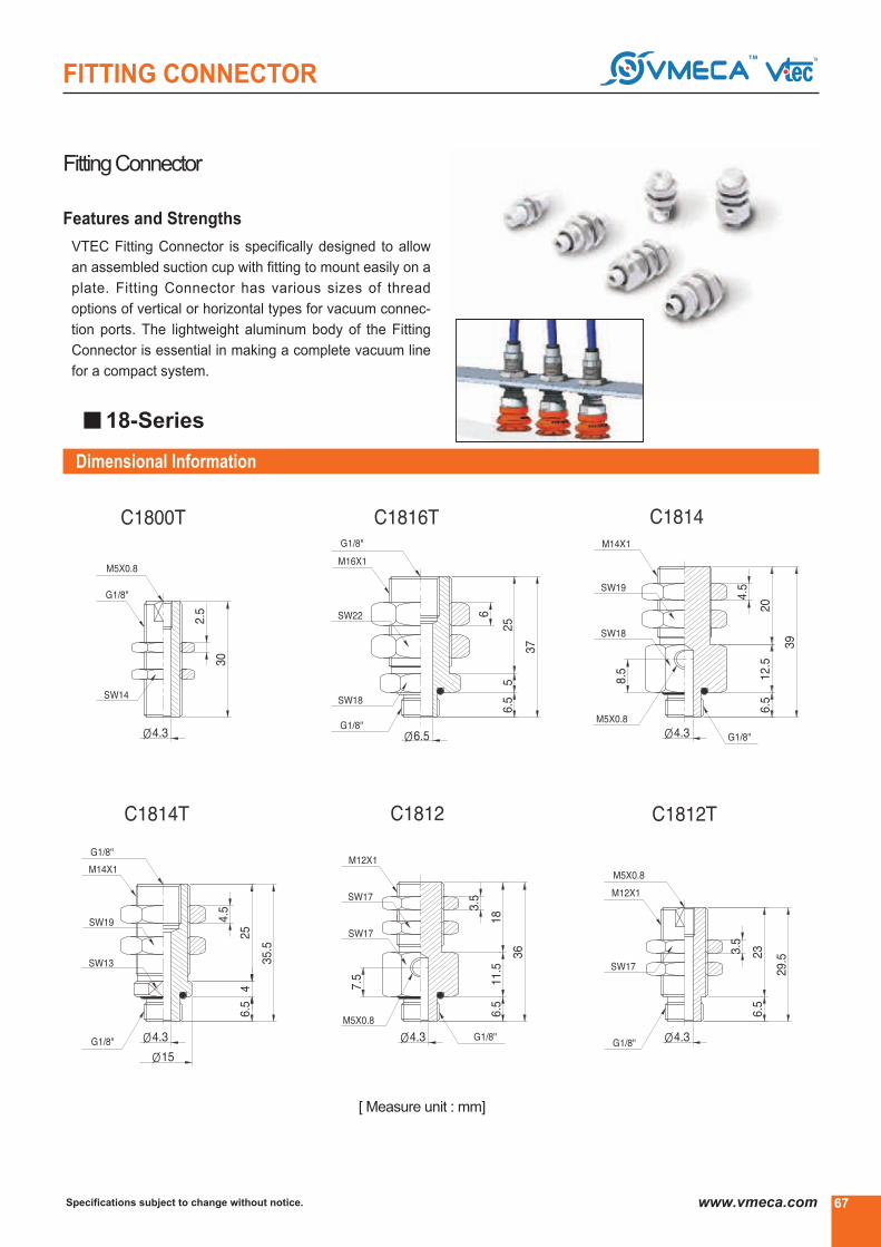
Specifications subject to change without notice. www.vmeca.com
FITTING CONNECTOR
FittingConnector
VTEC Fitting Connector is specifically designed to allow
an assembled suction cup with fitting to mount easily on a
plate. Fitting Connector has various sizes of thread
options of vertical or horizontal types for vacuum connec-
tion ports. The lightweight aluminum body of the Fitting
Connector is essential in making a complete vacuum line
for a compact system.
Features and Strengths
67
Dimensional Information
18-Series
[ Measure unit : mm]

Specifications subject to change without notice.68 www.vmeca.com
FITTING
Fittings(Option)
M5/18-MFO

VACUUM
SPEEDER
VACUUM
SPEEDER
VA
CU
UM
S
PE
ED
ER
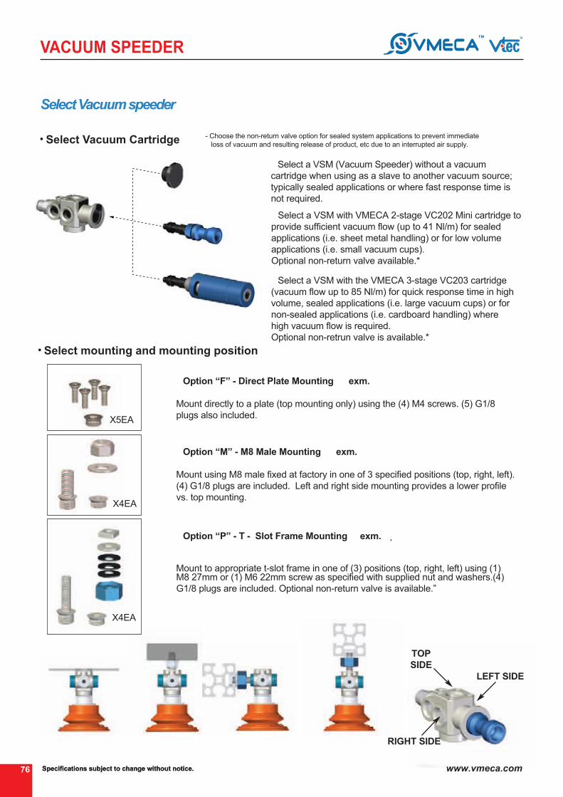
④
Specifications subject to change without notice.76 www.vmeca.com
VACUUM SPEEDER
④
Select Vacuum speeder
Select a VSM (Vacuum Speeder) without a vacuum
cartridge when using as a slave to another vacuum source;
typically sealed applications or where fast response time is
not required.
④
④ Option “F” - Direct Plate Mounting exm. ④
Mount directly to a plate (top mounting only) using the (4) M4 screws. (5) G1/8
plugs also included.
Select a VSM with VMECA 2-stage VC202 Mini cartridge to
provide sufficient vacuum flow (up to 41 Nl/m) for sealed
applications (i.e. sheet metal handling) or for low volume
applications (i.e. small vacuum cups).
Optional non-return valve available.*
Select Vacuum Cartridge
④ Option “M” - M8 Male Mounting exm. ④
Mount using M8 male fixed at factory in one of 3 specified positions (top, right, left).
(4) G1/8 plugs are included. Left and right side mounting provides a lower profile
vs. top mounting.
④ Option “P” - T - Slot Frame Mounting exm. ④, ④
Mount to appropriate t-slot frame in one of (3) positions (top, right, left) using (1)M8 27mm or (1) M6 22mm screw as specified with supplied nut and washers.(4)
G1/8 plugs are included. Optional non-return valve is available.”
Select mounting and mounting position
X5EA
X4EA
④ ④ ④ ④
TOP
SIDE
LEFT SIDE
RIGHT SIDE
Specifications subject to change without notice.
- Choose the non-return valve option for sealed system applications to prevent immediate
loss of vacuum and resulting release of product, etc due to an interrupted air supply.
X4EA
Select a VSM with the VMECA 3-stage VC203 cartridge
(vacuum flow up to 85 Nl/m) for quick response time in high
volume, sealed applications (i.e. large vacuum cups) or for
non-sealed applications (i.e. cardboard handling) where
high vacuum flow is required.
Optional non-retrun valve is available.*

77
VACUUM SPEEDER
Specifications subject to change without notice. www.vmeca.com
VA
CU
UM
S
PE
ED
ER
Guide pin
Slave units
VSM Example
Compressed air Vacuum
④ Use a VSM (Vacuum Speeder) as a slave unit with vacuum supplied by
another VSM in sealed applications or in applications where quick response time
is not required.
④ To prevent the Vacuum Speeder from rotating when mounted in the top
position use a guide pin inserted into the M5 port on the top of the VSM and
extended into the t-frame slot.
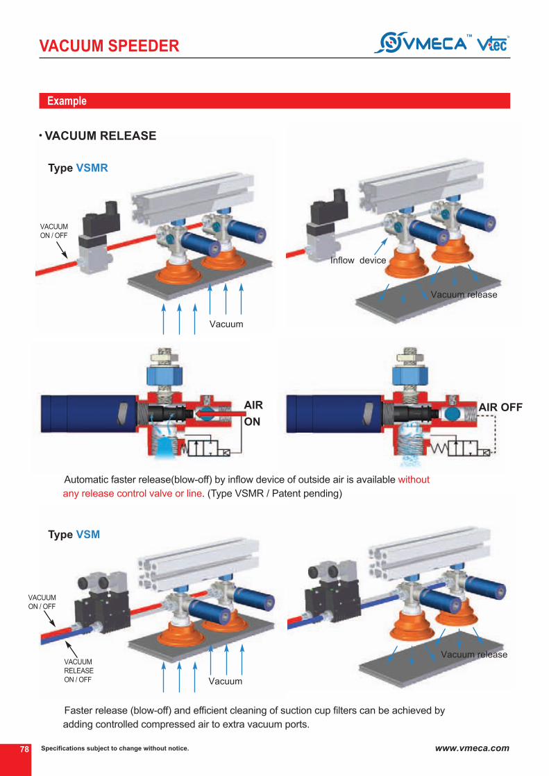
Specifications subject to change without notice.78 www.vmeca.com
VACUUM SPEEDER
Vacuum
VACUUM RELEASE
Example
VACUUM
ON / OFF
Vacuum release
Inflow device
Vacuum release
Type VSMR ▶
④
④
Automatic faster release(blow-off) by inflow device of outside air is available without
any release control valve or line. (Type VSMR / Patent pending)
Faster release (blow-off) and efficient cleaning of suction cup filters can be achieved by
adding controlled compressed air to extra vacuum ports.
Type VSM ▶
Vacuum
AIR
ON
AIR OFF
VACUUM
ON / OFF
VACUUM
RELEASE
ON / OFF

79
VACUUM SPEEDER
Specifications subject to change without notice. www.vmeca.com
VA
CU
UM
S
PE
ED
ER
- Vacuum cartridge VC202 incl. holding plug
Max. vacuum level
Max. flow rate
Supply air pressure
Air consumption
Supply air type
Working temperature
Noise level
Series VSMR..
Main advantages
Vacuum cartridge
Mount and mounting position
1
2
Efficient individual and independent point-of-use vacuum.
Extremely quick response.
Multiple connection ports available
Quick release system without release control valve.
Maintains vacuum despite fluctuations and drops in air pressure.
VMECA TWOFOLD SILENCER assures low noise levels.
(about 30% lower than conventional silencer)
F
MT8
ML8
MR8
PT8
PL8
PR8
PT6
PL6
PR6
- 4x screw M4 top, 5x plug G1/8″(direct mount)
- M8 16mm screw top, 4x plug G1/8″ incl. mounting kit
- M8 16mm screw left, 4x plug G1/8″ incl. mounting kit
- M8 16mm screw right, 4x plug G1/8″ incl. mounting kit
- M8 27mm screw top, 4x plug G1/8″ incl. profile kit with jam nut
- M8 27mm screw left, 4x plug G1/8″ incl. profile kit with jam nut
- M8 27mm screw right, 4x plug G1/8″ incl. profile kit with jam nut
- M6 22mm screw top, 4x plug G1/8″ incl. profile kit with jam nut
- M6 22mm screw left, 4x plug G1/8″ incl. profile kit with jam nut
- M6 22mm screw right, 4x plug G1/8″ incl. profile kit with jam nut
203 - Vacuum cartridge VC203
incl. twofold silencer
202
VSMR 203 - PT8..VBF80 PU - 38M
1 2
Order No.
See pages 83~97
PT
: -90kPa (-26.57 inHg)
: 85.8 Nl/min (3.03 scfm)
: 3~6 bar, max 7 bar(43.5~87psi, max 101.5psi)
: 20~32 Nl/min (0.7~1.13 scfm)
: Dry compressed air
: -20④ ~ +80④
: 55~65 ④]
④

Specifications subject to change without notice.80 www.vmeca.com
VACUUM SPEEDER
Max. vacuum level
Max. flow rate
Supply air pressure
Air consumption
Supply air type
Working temperature
Noise level
Series VSM..
VSM 203 - PT8..VBF80 PU - 38M
1 2
Vacuum cartridge
Mount and mounting position
203
203 N
202
202 N
020
- Vacuum cartridge VC203incl. twofold silencer
- Vacuum cartridge VC203 with non-return valveincl. twofold silencer
- Vacuum cartridge VC202incl. holding plug
- Vacuum cartridge VC202 with non-return valveincl. holding plug
- No vacuum cartridge (slave unit)
1
2
: -90kPa (-26.57 inHg)
: 85.8 Nl/min (3.03 scfm)
: 3~6 bar, max 7 bar(43.5~87psi, max 101.5psi)
: 20~32 Nl/min (0.7~1.13 scfm)
: Dry compressed air
: -20④ ~ +80④
: 55~65 ④]
Order No.
F
MT8
ML8
MR8
PT8
PL8
PR8
PT6
PL6
PR6
- 4x screw M4 top, 5x plug G1/8″(direct mount)
- M8 16mm screw top, 4x plug G1/8″ incl. mounting kit
- M8 16mm screw left, 4x plug G1/8″ incl. mounting kit
- M8 16mm screw right, 4x plug G1/8″ incl. mounting kit
- M8 27mm screw top, 4x plug G1/8″ incl. profile kit with jam nut
- M8 27mm screw left, 4x plug G1/8″ incl. profile kit with jam nut
- M8 27mm screw right, 4x plug G1/8″ incl. profile kit with jam nut
- M6 22mm screw top, 4x plug G1/8″ incl. profile kit with jam nut
- M6 22mm screw left, 4x plug G1/8″ incl. profile kit with jam nut
- M6 22mm screw right, 4x plug G1/8″ incl. profile kit with jam nut
Efficient individual and independent point-of-use vacuum.
Extremely quick response.
Multiple connection ports available
Maintains vacuum despite fluctuations and drops in air pressure.
VMECA TWOFOLD SILENCER assures low noise levels.
(about 30% lower than conventional silencer)
Main advantages
PT
See pages 83~97④

VSMR202.
VSM202..0.314 26 90
VSMR203..
VSM203..0.314 26 90
81
VACUUM SPEEDER
Specifications subject to change without notice. www.vmeca.com
VA
CU
UM
S
PE
ED
ER
Technical Data
Model
Feed
pressure
(MPa)
Air
consumption
(Nl/m)
Time, s/l, evacuate a volume
to different vacuum levelMax.
Vacuum level
(-kPa)
Suction cup
-20 kPa
VB 30..VB40..VB50..VB75 (B)..VBF 30..VBF 40..VBF 50..VBF 60..VBF 80..VBF 100.VBL 30..VBL 40..VBL 50..VF 30..VF 40..VF 50..VF 75..VF 90..VF 110..VFC 50..VFC 60..VFC 75..VFC 90..VFC 100..VOU 15X45..VOU 20X60..VOC 35X90..VOC 35X110..VOC 60X140..VOC 60X180..VB 30..VB 40.. VB 50..VB 75 (B)..VBF 30..VBF 40..VBF 50..VBF 60..VBF 80..VBF 100..VBL 30..VBL 40..VBL 50..VF 30..VF 40..VF 50..VF 75..VF 90..VF 110..VFC 50..VFC 60..VFC 75..VFC 90..VFC 100..VOU 15X45..VOU 20X60..VOC 35X90..VOC 35X110..VOC 60X140..VOC 60X180..
0.050.060.070.150.050.050.060.080.140.170.050.080.1
0.040.040.050.060.070.110.050.060.080.110.130.040.050.060.070.130.160.060.070.080.170.050.050.060.080.160.2
0.060.080.1
0.040.040.050.060.070.120.050.060.090.110.140.040.050.060.070.150.17
-60 kPa
0.090.1
0.120.220.080.090.1
0.120.180.2
0.090.120.140.070.070.080.110.120.170.090.110.130.180.2
0.070.080.110.130.150.180.090.1
0.130.250.080.090.110.130.210.260.1
0.130.160.070.080.090.110.120.190.090.120.140.2
0.210.070.080.120.140.2
0.22

Specifications subject to change without notice.82 www.vmeca.com
VACUUM SPEEDER
Dimension
④ VSMR203.. ④ VSM203..
Mounting
M 8
P 8
P 6
A
16
27
22
④
④
④
Measure unit : mm [inch]1. Compressed air : 3 x G1/8″
2. Vacuum : 1 x G3/8″ and 3 x G1/8″
3. Exhaust
④ VSMR202.. ④ VSM202..
Mounting
M 8
P 8
P 6
A
16
27
22
④
④
④
Measure unit : mm [inch]
④ Refer to page 83~97 about dimension of suction cups.
1. Compressed air : 3 x G1/8″
2. Vacuum : 1 x G3/8″ and 3 x G1/8″
3. Exhaust

83
VACUUM SPEEDER
Specifications subject to change without notice. www.vmeca.com
VA
CU
UM
S
PE
ED
ER
④④④
How to select Suction cup
Suction cup
④④
④④
④④④
④④④
④④④
④④④ Excellent ④④ Verygood ④ good
Slightly
surface
Concave
surfaceFlat
Smooth
surface
Uneven
surface
Varying
surface
levels
Thin
flexible
materials
Good
stabilitySafety Parallel lift
Opening
plastic bag
④④④
④④④
④④④
④④④
④④④ ④④④
④④④
④④④ ④
④④④
④④④
④④④ ④④④
④④④
④④④ ④④④
④④④
④④④
④④
④④④ ④
④
④
④④④ ④④ ④④④ ④④④④④④ ④
④④④④④④
④④④
④④④
④④
④④④ ④④④ ④④④ ④④④ ④④④ ④④④ ④④④④④④ ④
④
VB
VBF
VBL
VF
VFC
VOU
VOC
Slightly curved surface
VB model
Thin flexible material
VBL model
Transfering to parallel
VF, VFC model
Long flat
VOC model
Long convex or flat
VOU model
Sheet metal
VBF model
④
Seepage84
④
Seepage88
④
Seepage86
④
Seepage90, 92
④
Seepage94
④
Seepage96
Material and characteristic of suction cup
Durability Temperature Oil Resistance Weather & OzoneMaterial
N - NBR
S - Silicon, WS-White Silicon
HS-High Temp. Silicon
C.S - Conducive(Special mat’l)
U - Urethane
A - Mark free
PU - Poly Unethane
E - EPDM
Excellent
Good
Good
Excellent
Excellent
Excellent
Excellent
Very Good
Excellent
Unsuitable
Unsuitable
Excellent
Excellent
Excellent
Excellent
Unsuitable
Very Good
Excellent
Excellent
Very Good
Excellent
Very Good
Excellent
Excellent
-20④ ~ +110④
-70④ ~ +200④
-70④ ~ +280④
-45④ ~ +90④
; ④ ~ +100④
-10④ ~ +100④
; ④ ~ +60④
; ④ ~ +150④
Shape Requirements

VSMR 203 - PT8 ..
Specifications subject to change without notice.84 www.vmeca.com
VACUUM SPEEDER
26 Nl/m
(0.918 scfm)
Cup Ø
Air
consumption
at0.3 MPa
1.22
2.24
3.36
7.65
2.24
3.97
6.63
17.04
2.75
5
8.36
23.06
-20 kPa -60 kPa -90 kPa
LiftingForce(kg) - Perpendicular
VBType(Bellows)
SUCTIONCUPSFORVACUUMSPEEDER
Particularly good for use on curved surfaces and for
separatingthin sheets of materials in stacks.
The bellows cup is very good at compensating for a
degree of difference in in level and curvature of the
work piece, more angular and level compensation
can be achieve by using other Vtec pad acces-
sories.
•Sheet Veneer
•Plastic sheets
•Paper Box Handling
•Thin Film sheets
•Cardboard Boxes and Electronic Cmponents
Features and Strengths
Suitable for Handling
④
PU
④
VB50
④
F -
④
38M
VB30
VB40
VB50
VB75
VB75B
N
S
WS
HS
CS
U
A
PU*
WPU*
- NBR
- Silicon
- White Silicon
- High Temp. Silicon
- Conductive (Special mat’l)
- Urethane
- Mark free
- Poly Urethane
- Poly Urethane (Minimal mark)
- Ø30
- Ø40
- Ø50
- Ø75
- Ø75
●
●
④ Suction cup Ø ④ Material
38M - G3/8" male●
④ Thread size
VB30
VB40
VB50
VB75(B)
④ Remark : Including mesh filter
No mark
F
- Standard
- With Filter(PE)
VB30,VB40,VB50
VB75,VB110
●
④ Filter
Order No.
* Only for VB30, VB40, VB50, VB75
▶ See pages 79, 80
Technical Data

85
VACUUM SPEEDER
Specifications subject to change without notice. www.vmeca.com
VA
CU
UM
S
PE
ED
ER
Dimension
VB30..38M VB40..38M
VB50..38M VB75..38M
Measure unit : mm [inch]
④ Refer to page 82 about dimension of Vacuum Speeder.

Specifications subject to change without notice.86 www.vmeca.com
VACUUM SPEEDER
VBFType(Bellows& Flat)
•Enhancing the achesion to the surface
•Good lifting force can be achieved with this pad
in the vertical plane
•Prevent transformation when lifting metal thin plate
•Veneer sheets
•Sheet metal
•Automotive panels and door
•Plywood
•Glass
Features and Strengths
Suitable for Handling
Order No.
VBL25
VBF30
VBF40
VBF50
VBF60
VBF80
VBF100
PU
WPU
- Poly Urethane
- Poly Urethane (Minimal mark)
- Ø25
- Ø32
- Ø42
- Ø51
- Ø64
- Ø84
- Ø103
●
●
④ Suction cup Ø ④ Material
38M - G3/8" male●
④ Thread size
④ Remark : Including mesh filter
SUCTIONCUPSFORVACUUMSPEEDER
26 Nl/m
(0.918 scfm)
Technical Data
Cup Ø
Air
consumption
at0.3 MPa -20 kPa -60 kPa -90 kPa
LiftingForce(kg) - Perpendicular
-20 kPa -60 kPa -90 kPa
LiftingForce(kg) - Parallel
VBF 25
VBF 30
VBF 40
VBF 50
VBF 60
VBF 80
VBF 100
No mark
F
- Standard
- With Filter(PE)
VBF60,VBF80
VBF100
●
④ Filter
VSMR 203 - PT8 ..
④
PU
④
VBF80
④
F -
④
38M
▶ See pages 79, 80
1.1
1.77
2.49
4.2
8.94
11.92
14.9
3.8
9.5
12.8
16.3
18.54
24.72
30.9
3.2
6.26
9.66
13.2
16.26
21.68
27.1
0.61
0.86
1.17
2.08
6.84
9.12
11.4
1.37
3.08
6.48
9.79
12.84
17.12
21.4
1.89
7.71
11.29
14.7
16.92
22.56
28.2

87
VACUUM SPEEDER
Specifications subject to change without notice. www.vmeca.com
VA
CU
UM
S
PE
ED
ER
Dimension
④ Refer to page 82 about dimension of Vacuum Speeder.
Measure unit : mm [inch]
VBF30 P(U) - 38M VBF30 P(U) - 38MVBF25 P(U) - 38M
VBF80 P(U) - 38M VBF100 P(U) - 38M
VBF50 P(U) - 38M VBF60 P(U) - 38M

Specifications subject to change without notice.88 www.vmeca.com
VACUUM SPEEDER
Cup Ø
Air
consumption
at0.3 MPa
26 Nl/m
(0.918 scfm)
0.06
0.11
0.17
0.16
0.22
0.43
-
-
-
-20 kPa -60 kPa -90 kPa
LiftingForce(kg) - Perpendicular
VBLType(LongBellows)
Similar advntages to that of the normal bellows cups
but can cope with an increased degree of height
compensation and is particuly good for handling
fragile objects.
A note of caution, these cups are not suitable for
high level vacuum applications.
Features and Strengths
Suitable for Handling
Order No.
VBL30
VBL40
VBL50
N
S
WS
HS
CS
U
A
- NBR
- Silicon
- White Silicon
- High Temp. Silicon
- Conductive (Special mat’l)
- Urethane
- Mark free
- Ø30
- Ø40
- Ø50●
●
④ Suction cup Ø ④ Material
38M - G3/8" male●
④ Thread size
VBL30
VBL40
VBL50
④ Remark : Including mesh filter
SUCTIONCUPSFORVACUUMSPEEDER
•Fragile Objects
•Eggs
•General Food Products
•Bread
•Glass
No mark
F
- Standard
- With Filter(PE)
VBL30,VBL40
VBL50
●
④ Filter
VSMR 203 - PT8 ..
④
N
④
VBL50
④
F -
④
38M
▶ See pages 79, 80
Technical Data

89
VACUUM SPEEDER
Specifications subject to change without notice. www.vmeca.com
VA
CU
UM
S
PE
ED
ER
Dimension
Measure unit : mm [inch]
④ Refer to page 82 about dimension of Vacuum Speeder.
VBL50..38M
VBL30..38M VBL40..38M

Specifications subject to change without notice.90 www.vmeca.com
VACUUM SPEEDER
26 Nl/m
(0.918 scfm)
Technical Data
Cup Ø
Air
consumption
at0.3MPa
1.22
2.04
3.67
8.16
10.2
14.28
-20 kPa
2.55
4.08
7.55
20.40
27.83
42.58
-60 kPa
3.16
5.10
9.79
27.55
37.41
57.14
-90 kPa
LiftingForce(kg) - Perpendicular
1.12
1.53
2.44
6.12
8.84
14.28
-20 kPa
1.63
2.55
4.08
11.22
15.98
25.51
-60 kPa
2.04
3.06
5.10
14.28
19.72
30.61
-90 kPa
LiftingForce(kg) - Parallel
VFType(Flat)
Again good lifting forces can be achieved with this
cup in the horizontal plane, but is also good in the
vertical plane.
The feet inside the pad provide a good register as
well as enhancing the adhesion to the surface.
•Sheet metal
•Plastic
•Veneer sheets
•Electronic components
Features and Strengths
Suitable for Handling
Order No.
VF30
VF40
VF50
VF75
VF90
VF110
VF30
VF40
VF50
VF75
VF90*
VF110
N
S
WS
HS
CS
U
A
PU
WPU
- NBR
- Silicon
- White Silicon
- High Temp. Silicon
- Conductive (Special mat’l)
- Urethane
- Mark free
- Poly Urethane*
- Poly Urethane (Minimal mark)*
- Ø30
- Ø40
- Ø50
- Ø75
- Ø90*
- Ø110
●
●
④ Suction cup Ø ④ Material
38M - G3/8" male●
④ Thread size
④ Remark : Including mesh filter
* Only for VF30, VF40, VF50, VF75, VF90
* Only PU material
SUCTIONCUPSFORVACUUMSPEEDER
④
PU
④
VF 75 -
④
38MVSMR 203 - PT8 ..
▶ See pages 79, 80

91
VACUUM SPEEDER
Specifications subject to change without notice. www.vmeca.com
VA
CU
UM
S
PE
ED
ER
Dimension
④ Refer to page 82 about dimension of Vacuum Speeder.
VF30..38M VF40..38M VF50..38M
VF75..38M VF90 P(U)..38M
VF110..38M
Measure unit : mm [inch]

Specifications subject to change without notice.92 www.vmeca.com
VACUUM SPEEDER
26 Nl/m
(0.918 scfm)
Technical Data
Cup Ø
Air
consumption
at0.3MPa
2.85
4.55
7.65
9.8
12.75
-20 kPa
6.94
11.57
19.38
24.82
35.71
-60 kPa
10.2
15.3
25.51
32.65
46.93
-90 kPa
LiftingForce(kg) - Perpendicular
2.61
3.05
6.19
9.52
12.24
-20 kPa
6.34
7.92
15.46
21.59
23.97
-60 kPa
8.2
10.7
20.9
27.89
28.57
-90 kPa
LiftingForce(kg) - Parallel
VFCType(FlatCurve)
This cup is specifically designed to cope with both
flat and curved surfaces, which means that multiple
objects can be handled with the same suction cup.
•Automotive Windscreens, Roof and Door.
•Sheet Metal
•Shaped Sheeet Metal Panels
•TV Cathoderay Tube
Features and Strengths
Suitable for Handling
Order No.
④
PU
④
VFC 50 -
④
38M
VFC50
VFC60
VFC75
VFC90
VFC100
VFC50
VFC60
VFC75
VFC90
VFC100
N
S
WS
HS
CS
U
A
PU
WPU
- NBR
- Silicon
- White Silicon
- High Temp. Silicon
- Conductive (Special mat’l)
- Urethane
- Mark free
- Poly Urethane
- Poly Urethane (Minimal mark)
- Ø50
- Ø60
- Ø75
- Ø90*
- Ø100
●
●
④ Suction cup Ø ④ Material
38M - G3/8" male●
④ Thread size
④ Remark : Including mesh filter
* Only for PU Material
SUCTIONCUPSFORVACUUMSPEEDER
VSMR 203 - PT8 ..
▶ See pages 79, 80

93
VACUUM SPEEDER
Specifications subject to change without notice. www.vmeca.com
VA
CU
UM
S
PE
ED
ER
VFC100..38M
Dimension
VFC50..38M VFC60..38M
VFC75..38M VFC90 P(U)..38M
④ Refer to page 82 about dimension of Vacuum Speeder.
Measure unit : mm [inch]

Specifications subject to change without notice.94 www.vmeca.com
VACUUM SPEEDER
Technical Data
Cup Ø
Air
consumption
at0.3MPa
26 Nl/m
(0.918 scfm)
1
2.04
2.08
4.8
3.27
6.35
-20 kPa -60 kPa -90 kPa
LiftingForce(kg) - Perpendicular
VOUType(OvalUniversal)
•Best sitalbe for handling long objects with flat and
curved surfaces
•Good lifting forces can be achieved with small size
•Conductive silcon is excellent for handling PCB
board or Electronic componets
•Easily mountable without detach a fitting from the
machine (save the maintenance time)
•Semiconductor chips (PCB board)
•Electronic components
•Small glass cases (e.g.ampule)
•Pipe
Features and Strengths
Suitable for Handling
Order No.
④
F
④
VOU 20X60
④
N -
④
38M
VOU 15X45
VOU 20X60
N
S
WS
HS
- NBR
- Silicon
- White Silicon
- High Temp. Silicon
●
●
④ Suction cup Ø ④ Material
VOU 15X45
VOU 20X60
F - Withmeshfilter●
④ Filter
④ Required option
SUCTIONCUPSFORVACUUMSPEEDER
38M - G3/8" male●
④ Thread size
VSMR 203 - PT8 ..
▶ See pages 79, 80

95
VACUUM SPEEDER
Specifications subject to change without notice. www.vmeca.com
VA
CU
UM
S
PE
ED
ER
Dimension
④ Refer to page 82 about dimension of Vacuum Speeder.
VOU15X45..38M
VOU20X60..38M
Measure unit : mm [inch]

Specifications subject to change without notice.96 www.vmeca.com
VACUUM SPEEDER
26 Nl/m
(0.918 scfm)
Technical Data
Cup Ø
Air
consumption
at0.3MPa
5
6.25
13.4
19.1
-20 kPa
13.4
16.7
38
54.2
-60 kPa
17.4
21.7
53
75.7
-90 kPa
LiftingForce(kg) - Perpendicular
4
5
10.72
15.28
-20 kPa
10.72
13.36
30.4
43.36
-60 kPa
13.92
17.36
42.4
60.56
-90 kPa
LiftingForce(kg) - Parallel
VOCType(OvalCurve)
This cup is best suitalbe for handling long objects
with flat or curved surfaces.
Specially, parallel to the surface of the object it has a
thick and durable lip.
•Long Objects with Flat
•Curved Surfaces
•Shaped Sheet Metal Panels
•Automotive Bumper
Features and Strengths
Suitable for Handling
Order No.
④
N
④
VOC 35X 90 -
④
38M
VOC 35X90
VOC 35X110
VOC 60X140
VOC 60X180
VOC 35X90
VOC 35X110
VOC 60X140
VOC 60X180
N
S
WS
HS
CS
U
A
- NBR
- Silicon
- White Silicon
- High Temp. Silicon
- Conductive (Special mat’l)
- Urethane
- Mark free
- Ø35X90
- Ø35X110
- Ø60X140
- Ø60X180
● ●
④ Suction cup Ø ④ Material
38M - G3/8" male●
④ Thread size
④ Remark : Including mesh filter
SUCTIONCUPSFORVACUUMSPEEDER
VSMR 203 - PT8 ..
▶ See pages 79, 80

97
VACUUM SPEEDER
Specifications subject to change without notice. www.vmeca.com
VA
CU
UM
S
PE
ED
ER
Dimension
Measure unit : mm [inch]
VOC35X90..38M VOC35X110..38M
VOC60 X140..38M
④ Refer to page 82 about dimension of Vacuum Speeder.
VOC60X180..38M

Specifications subject to change without notice.98 www.vmeca.com
VACUUM SPEEDER
Max. vacuum level
Max. flow rate
Supply air pressure
Air consumption
Supply air type
Working temperature
Noise level
VMECA CartridgePT with silencer built into level compensator.
High operational reliability despite fluctuating or low compressed-air pressure.
Low air consumption (Save energy)
Compensate for differences in height on the surface of the material.
VMECA Vacuum Cartridge mounted close to work (Fast response time).
Very Compact size.
Easily mountable and interchangeable vacuum cartridge.
Series VCS 202..
VCS 202 - 18M 20
1 2
Main advantages
Order No.
18M
38M
12M
20 - 20mm- G1/8″ Male
- G3/8″ Male
- G1/2″ Male
● ●
④ Thread ④ Stroke
: -90kPa (-26.57 inHg)
: 41.3 Nl/min (1.45 scfm)
: 4~6 bar, max 7 bar(58~87psi, max 101.5psi)
: 416 Nl/min (14.6 scfm)
: Dry compressed air
: -20④ ~ +80④
: 55~65 ④]
VMECA Vacuum CartridgePT

99
VACUUM SPEEDER
Specifications subject to change without notice. www.vmeca.com
VA
CU
UM
S
PE
ED
ER
Performance Data
Dimensional information
MAX.Vacuum(-kPa)
Feedpressure(MPa)
0
0.17
0.22
0.314
0.4
35
38.8
41.3
40
25.4
29.5
36.9
42.7
12.8
17
26
31
8.3
11.5
15.8
23
4
8
11
14.1
-
5.2
8.9
7.6
-
1.4
6.6
6.4
-
-
3.9
3.9
-
-
2
1.3
-
-
-
-
10 807060504030 9020
50
65
90
85
Vacuum flow, Nl/m, at different vacuum level -kPa
Feedpressure(MPa)
Airconsumpion
(Nl/m)
17
20
26
32
0.26
0.18
0.15
0.14
0.59
0.48
0.37
0.39
1.29
0.95
0.61
0.59
2.56
1.55
1.5
0.9
-
2
1.5
1.2
-
2.5
2
1.8
-
-
3.8
3.2
-
-
6.2
6.9
-
-
-
-
10 807060504030 9020
0.17
0.22
0.314
0.4
Time, s/l, to evacuate a volume to different vacuum level -kPa
④ VCS202-18M20 ④ VCS202-38M20 ④ VCS202-12M20
Measure unit : mm [inch]

Specifications subject to change without notice.100 www.vmeca.com
VACUUM SPEEDER
Constructions
Features
•VMECA Vacuum speeder operates at 3~6bar(43.5~87 psi) air pressure and maintains vacuum -90 kPa (-26.5 inHg)in low pressure of fluctuating pressure situations.
•Extremely fast response (increased speed).
•VMECA Vacuum cartridgePT with silencer built into the body of a level compensator.
•Small size and easy to mount.
•Low energy consumption and noise level.
•No maintenance expected or required.

101
VACUUM SPEEDER
Specifications subject to change without notice. www.vmeca.com
VA
CU
UM
S
PE
ED
ER
Vacuum Zone Compressed-air feed zone
The vacuum cartridge is built into the body of the level compensator. System plumbing is
virtually eliminated and vacuum is created directly at the point of use.Quicker response and
faster cycle times with minimum compressed air usage are the result. Additionally, the VMECA
Vacuum Speeder offers all the height compensating and shock absorbing qualities of a
conventional level spring.
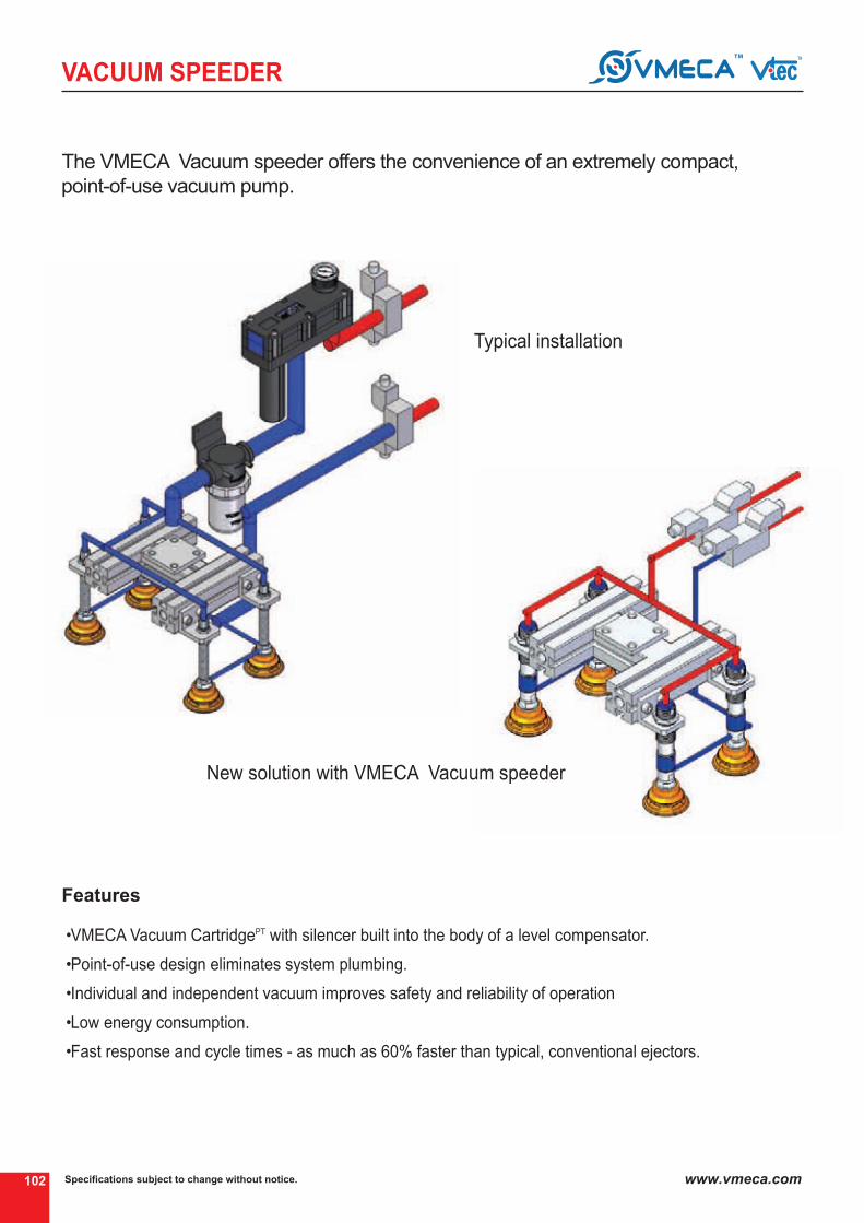
Specifications subject to change without notice.102 www.vmeca.com
VACUUM SPEEDER
•VMECA Vacuum CartridgePT with silencer built into the body of a level compensator.
•Point-of-use design eliminates system plumbing.
•Individual and independent vacuum improves safety and reliability of operation
•Low energy consumption.
•Fast response and cycle times - as much as 60% faster than typical, conventional ejectors.
The VMECA Vacuum speeder offers the convenience of an extremely compact,
point-of-use vacuum pump.
Features
Typical installation
④
New solution with VMECA Vacuum speeder ④

VA
CU
UM
P
UM
PS
VACUUM
PUMPS
VACUUM
PUMPSVTeC VaCuuM PuMP TeCHnOLOgy P.105~121
Midi Turtle Pump P.122~141 Mega Turtle Pump P.122~131P.144~153
V-Pump MD-PumpP.156~165 P.168~177
Premium Pump P.180~193 Mini Keyboard Pump P.196~199 Midi Keyboard Pump Mega Keyboard PumpP.200~211 P.212~223
Mini Pump P.226~231 One-Line Pump P.232~235 Minimultiple Pump Midimultiple PumpP.236~241 P.242~247
Duplex Pump P.248~255 L-Classic PumpVL-Classic PumpM-Classic PumpX-Classic PumpH-Classic Pump
P.256~259
Mega PumpP.292~297P.298~303
Conveying Pump
P.304~309
MM-Midiflex PumpMX-Midiflex PumpH-Midiflex Pump
L-Maxflex PumpM-Maxflex Pump
P.262~265P.266~269P.270~273P.274~277P.286~289
P.278~281P.282~285P.286~291

105
VACUUM PUMP
Specifications subject to change without notice. www.vmeca.com
VA
CU
UM
P
UM
PS
Sealed system
How to select the proper vacuum pump
For sealed system the capacity of the pump is determined by how fast the system can be evacuated to
a certain vacuum level. This capacity is called the evacuation time of the pump and is normally specified in
sec/I. This value is multiplied by the volume of the system in order to obtain the evacuation time to the
desired vacuum level.
Non-sealed system
With non-sealed system (lifting of porous material) the case is different. To maintain the desired vacuum
level the pump must have the capacity to pump away the air-leaking in by establishing the leaking flow ; it
is possible, by reading the pump data, to find the right pump for the application in question. If the leakage
occurs via a known aperture, the flow can be established according to the diagram.
When the leakage occurs through a porous material or in an unknown way, the flow can be established by a
test with a vacuum pump. The pump is connected to the system and the obtained vacuum level is read.
(It should be at least -20kPa)
AS-KIT (Air saving system)
electrically driven, mechanical vacuum pumps normally work during the whole working period and the
vacuum requirements are controlled by a valve on the vacuum side. In system with compressed air-driven
vacuum pumps it is often possible to save a lot of energy. as these pumps have a faster reaction time (fast
start-up) the pump can be shut off when the vacuum is no longer needed. Many pumps can be delivered
with an air saving system as option.
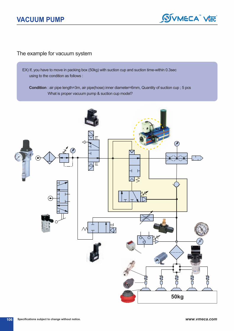
Specifications subject to change without notice.106 www.vmeca.com
VACUUM PUMP
⓳
⓳
⓳
⓳
⓳
⓳
⓳
The example for vacuum system
eX) If, you have to move in packing box (50kg) with suction cup and suction time-within 0.3sec
using to the condition as follows :
Condition : air pipe length=3m, air pipe(hose) inner diameter=6mm, Quantity of suction cup ; 5 pcs
What is proper vacuum pump & suction cup model?
50kg
⓳
⓳
⓳
⓳
⓳
⓳

107
VACUUM PUMP
Specifications subject to change without notice. www.vmeca.com
VA
CU
UM
P
UM
PS
VTM25L : 0.795(ℓ) X 0.66 = 0.53
VTM50L : 0.795(ℓ) X 0.33 = 0.27
VTM75L : 0.795(ℓ) X 0.248 = 0.20
VTM100L : 0.795(ℓ) X 0.166 = 0.13
⓳ Moving weight (kg)
⓳ Suction time
⓳ Selected suction cup
⓳ Suction cup material
⓳ Suction cup quantity (Pcs)
⓳ Diameter of suction cup (mm)
⓳ air vacuum hose length (m)
⓳ Inner diameter of air hose (mm)
⓳ Volume of suction cup (nl)
⓳ Volume of vacuum air hose (nl)
⓳ Selected vacuum Pump
⓳ air supply control valve
⓳ Vacuum release control valve
⓳ Selected vacuum filter(you can to be select to size of a vacuum filter according to capability of infected material.)
⓳ Vacuum switch (transiton singal for next movement)
⓳ Ball joint (to use in curve or uneven objects)
⓳ Level spring (to use to compensater differences in level)
⓳ needle valve (vacuum level controlling valve)
⓳ Vacuum manifold
⓳ air filter / regulator (remove to dust, water, rust, etc.)
⓳ Hand valve (using to manual)
: 50
: 0.3 second
: VB75(B) Pu-12F
: Pu
: 5
: 75
: 3
: 6
: 0.55
: 0.085
: VTM 50L - 1834 - aS
: VMS14D-3-2
: VMS18D-3-2
: VTF 34 - 2
: VP20C..
: BJ 12
: L1230T
: VTDC34-14X5
⓳
⓳
⓳
⓳
HOW TO SELECT SUCTION CUP SIZE
WHAT IS PROPER SUCTION CUP SIZE
D=113XMXn
uXS=113 X = 65.2 mm
50 X 2
60 X 5
•V = =πXd2xL
4
1
1000X
1
1000X
3.14X0.62X300
4
D = diameter size of suction cup (mm)
M = weight (kg)
u = vacuum level (-kPa, %)
n = safety factor (2)
S = quantity of suction cup
VB75 = (you are desirable to select a little big size suction cup than the actual they size)⓳
VTM50L or VTM75L⓳
■ needed vacuum capacit = the capacity of suction cup + the capacity of air pipe + the vacuum filter
0795ℓ= 0.55ℓ + 0.085ℓ + 0.16ℓ
THE SELECTION OF VACUUM PUMP
AIR PIPE, SUCTION CUP & VACUUM FILTER
Because when there is a vacuum leak from the work
piece or the piping and a drop in vacuum pressure
which causes the air pressure drop.
VB75 (110cm3) = 0.11ℓ X 5 (Pcs) = 0.55ℓ 4⓳Please refer to page 18.19 for the Volume of suction cup)
• 0.55 ℓ (Quantity of vacuum pad : 5 Pcs)
•Filter (VTF34-2) : 160cm3 = 0.16ℓ
0.085ℓ⓳V = Capacity (liter)
d = inside diameter of air pipe (cm)
L = the length of air pipe (cm)

Specifications subject to change without notice.108 www.vmeca.com
VACUUM PUMP
AS - KIT
Air SavingHas anyone ever told you that air is free? Well, think again because compressed air still uses energy and costsmoney to use it. VMeCa / VTeC ′s ongoing principle on saving air and giving you the highest performance havealways been our standard.
In case the vacuum level drops below the working level (requried vacuum level), then the air Saving-Kit reactivatesthe vacuum pump allowing for safe handling of product. The air Saving-Kit is the most suitable in sealed systems(applications).
Air Saving KitVMeCa / VTeC have always offered various ranges of compressedair-driven vacuum pumps in the market.VMeCa / VTeC ensures the best solutions to customers by offeringthe most efficient products in the market.
VMeCa / VTeC ′s air Saving-Kit(aS-Kit) effectively preventscompressed air loss. air Saving-Kit is a pneumatic control systemthat cuts off the vacuum pump once the desired vacuum level hasbeen achieved, thus minimizing the energy (compressed air)consumption of the vacuum pump.
AS - Kit - Turtle Pump
⓳ Pneumatical vacuum switch, VPS-01 nC
⓳ Pneumatical air On/OFF Valve, 1/4 ″
⓳ Hose of Poly-urethane, D=4/1.5
⓳ Turtle Vacuum pump, non-return type
Functiona vacuum control valve shuts off the flow of compressed air
to the pump when the pre-set vacuum level is reached (1).
The vacuum level is set by a screw. Because of minor
leakage in a vacuum system the vacuum level drops and
after a while the start up level of the valve is reached (2).
Then the pump will start and work until the shut off level is
reached again (3), etc.
(the section (a) is possible to be changed depending on the
level of airtight.)

VACUUM PUMP
VA
CU
UM
P
UM
PS
AS - KIT
AS - Kit Products line-up

Specifications subject to change without notice.110 www.vmeca.com
VACUUM PUMP
Pump Characteristics
Model
Air supply Vacuum Exhaust
Noise level(dBa)
Air consumption
(nl/m)
Max.Vacuum Flow(nl/m)
Supply Airpressure
(MPa)
MAX.Vacuum
- kPa (-inHg)
VTC 3021
VTC 3031
VTCL 3021
VTCL 3031
VTC 3022
VTC 3032
VTCL 3022
VTCL 3032
VTC 3122
VTC 3123
VTC 3124
VTC 3132
VTC 3133
VTC 3134
VTCL 3122
VTCL 3123
VTCL 3124
VTCL 3132
VTCL 3133
VTCL 3134
75 (22.15)
93 (27.46)
93 (27.46)
75 (22.15)
93 (27.46)
93 (27.46)
60 (17.72)
70 (20.67)
75 (22.15)
60 (17.72)
70 (20.67)
75 (22.15)
75 (22.15)
93 (27.46)
93 (27.46)
75 (22.15)
93 (27.46)
93 (27.46)
60 (17.72)
70 (20.67)
75 (22.15)
60 (17.72)
70 (20.67)
75 (22.15)
75 (22.15)
93 (27.46)
93 (27.46)
75 (22.15)
93 (27.46)
93 (27.46)
75 (22.15)
93 (27.46)
93 (27.46)
75 (22.15)
93 (27.46)
93 (27.46)
75 (22.15)
93 (27.46)
93 (27.46)
75 (22.15)
93 (27.46)
93 (27.46)
60 (17.72)
70 (20.67)
75 (22.15)
60 (17.72)
70 (20.67)
75 (22.15)
60 (17.72)
70 (20.67)
75 (22.15)
60 (17.72)
70 (20.67)
75 (22.15)
60 (17.72)
70 (20.67)
75 (22.15)
60 (17.72)
70 (20.67)
75 (22.15)
0.22
0.3
0.4
0.22
0.3
0.4
0.4
0.5
0.6
0.4
0.5
0.6
0.22
0.3
0.4
0.22
0.3
0.4
0.4
0.5
0.6
0.4
0.5
0.6
0.22
0.3
0.4
0.22
0.3
0.4
0.22
0.3
0.4
0.22
0.3
0.4
0.22
0.3
0.4
0.22
0.3
0.4
0.4
0.5
0.6
0.4
0.5
0.6
0.4
0.5
0.6
0.4
0.5
0.6
0.4
0.5
0.6
0.4
0.5
0.6
164
170
171
302
338
341
188
195
200
302
344
362
328
340
342
604
676
682
376
390
400
604
688
724
328
340
342
492
510
513
656
680
684
604
676
682
902
1014
1023
1208
1352
1364
376
390
400
564
585
600
752
780
800
604
688
724
906
1032
1086
1208
1376
1448
Min. hose inner ø
(within 2m)
6
6
6
6
8
8
6
6
8
10
10
8
10
10
8
10
10
8
10
10
8
8
8
8
12
12
12
12
15
19
22
15
19
22
15
19
22
15
19
22
10
10
10
10
18
18
18
18
15
22
32
15
22
32
15
22
32
15
22
32
97
118
152
97
118
152
70
85
104
70
85
104
194
236
304
194
236
304
140
170
208
140
170
208
194
236
304
291
354
456
388
472
608
194
236
304
291
354
456
388
472
608
140
170
208
210
255
312
280
340
416
140
170
208
210
255
312
280
340
416
60~65
60 ~65
50 ~60
60 ~65
132 ~ 137
134 ~ 137
134 ~ 137
138 ~ 143
138 ~ 143
140 ~ 143
140 ~ 143
144 ~ 153
144 ~ 153
144 ~ 153
144 ~ 153
144 ~ 153
144 ~ 153
148 ~ 153
148 ~ 153
148 ~ 153
148 ~ 153
148 ~ 153
148 ~ 153
132 ~ 137

VS 146
VLS 144
VLS 148
MD 303
MDL 303
PM 303 X 2
PM 303 X 4
PML 303 X 2
PML 303 X 4
111
VACUUM PUMP
Specifications subject to change without notice. www.vmeca.com
VA
CU
UM
P
UM
PS
Pump Characteristics
Model
Air supply Vacuum Exhaust
Noise level(dBa)
Air consumption
(nl/m)
Max.Vacuum Flow(nl/m)
Supply Airpressure
(MPa)
MAX.Vacuum
-kPa (-inHg)
VS 144
VS 148
VLS 146
MD 302
MDL 302
PM 303 X 1
PM 303 X 3
PML 303 X 1
PML 303 X 3
75 (22.15)
93 (27.46)
93 (27.46)
75 (22.15)
93 (27.46)
93 (27.46)
75 (22.15)
93 (27.46)
93 (27.46)
60 (17.72)
70 (20.67)
75 (22.15)
60 (17.72)
70 (20.67)
75 (22.15)
60 (17.72)
70 (20.67)
75 (22.15)
75 (22.15)
93 (27.46)
93 (27.46)
75 (22.15)
93 (27.46)
93 (27.46)
60 (17.72)
70 (20.67)
75 (22.15)
60 (17.72)
70 (20.67)
75 (22.15)
75 (22.15)
93 (27.46)
93 (27.46)
75 (22.15)
93 (27.46)
93 (27.46)
75 (22.15)
93 (27.46)
93 (27.46)
75 (22.15)
93 (27.46)
93 (27.46)
60 (17.72)
70 (20.67)
75 (22.15)
60 (17.72)
70 (20.67)
75 (22.15)
60 (17.72)
70 (20.67)
75 (22.15)
60 (17.72)
70 (20.67)
75 (22.15)
0.22
0.3
0.4
0.22
0.3
0.4
0.22
0.3
0.4
0.4
0.5
0.6
0.4
0.5
0.6
0.4
0.5
0.6
0.22
0.3
0.4
0.22
0.3
0.4
0.4
0.5
0.6
0.4
0.5
0.6
0.22
0.3
0.4
0.22
0.3
0.4
0.22
0.3
0.4
0.22
0.3
0.4
0.4
0.5
0.6
0.4
0.5
0.6
0.4
0.5
0.6
0.4
0.5
0.6
302
338
341
302
338
341
302
338
341
302
344
362
302
344
362
302
344
362
164
170
171
302
338
341
188
195
200
302
344
362
302
338
341
604
676
682
902
1014
1023
1208
1352
1364
302
344
362
604
688
724
906
1032
1086
1208
1376
1448
97
118
152
97
118
152
97
118
152
70
85
104
70
85
104
70
85
104
97
118
152
97
118
152
70
85
104
70
85
114
97
118
158
194
236
304
291
354
456
388
472
608
70
85
104
140
170
208
210
255
312
280
340
416
Min. hose inner ø
(within 2m)
6
6
6
6
6
6
6
6
6
6
8
8
10
10
8
8
10
10
8
8
8
8
8
8
8
8
8
8
12
15
19
22
12
15
19
22
10
10
10
10
10
10
10
10
10
10
12
15
22
32
12
15
22
32
50 ~ 60
50 ~ 60
60 ~ 65
60 ~ 65
50 ~ 60
159 ~ 165
159 ~ 165
159 ~ 165
161 ~ 165
161 ~ 165
161 ~ 165
171 ~ 177
171 ~ 177
173 ~ 177
173 ~ 177
184 ~ 193
184 ~ 193
184 ~ 193
184 ~ 193
188 ~ 193
188 ~ 193
188 ~ 193
188 ~ 193

Specifications subject to change without notice.112 www.vmeca.com
VACUUM PUMP
Pump Characteristics
Model
Air supply Vacuum Exhaust
Noise level(dBa)
Capacityequivaient to
electricity moterpump size(kw)
Air consumption
(nl/m)
Max.Vacuum Flow(nl/m)
Supply Airpressure
(bar)
MAX.Vacuum
-kPa (-inHg)
VKX5
VKM5
VKM61
VKM62
VKX61
VKX62
VKX73
VKX74
VKM73
VKM74
VTOM5-(n)Stack
VTOM10-(n)Stack
VTOX5-(n)Stack
VTOX10-(n)Stack
VTM5-(n)Stack
VTM10-(n)Stack
VTM10X(n)B(Ba,...nC)
VTM20X(n)B(Ba,...nC)
VTM30X(n)B(C,...nC)
VTM5-a(B,...nC)
VTM10-a(B,...nC)
VTM20-B(C,...nC)
VTM30-B(C,...nC)
VTM20KD
VTM30KD
VTM40KD
VTM50KD
VTM60KD
VTM25L
VTM50L
VTM75L
VTM100L
VTM125L
VTM150L
VTL25
VTL50
VTL75
VTL100
VTL125
VTL150
VTL175
VTL200
VTM25
VTM50
VTM75
VTM100
VTM125
VTM150
VTM175
VTM200
3-6
3-6
3-6
3-6
3-6
3-6
3-6
3-6
3-6
3-6
5.5
5.5
5.5
5.5
5.5
5.5
5.5
5.5
5.5
5.5
5.5
5.5
5.5
5.5
5.5
5.5
5.5
5.5
3.4
3.4
3.4
3.4
3.4
3.4
6
6
6
6
6
6
6
6
5.8
5.8
5.8
5.8
5.8
5.8
5.8
5.8
23
26
37
74
31
62
94
109
111
135
27Xn
35Xn
24Xn
32Xn
27Xn
35Xn
74
149
220
37
74
149
220
149
220
292
341
390
365
622
841
1060
1195
1370
379
650
820
990
1090
1303
1682
2061
389
647
890
1100
1200
1380
1490
1580
0.03
0.03
0.05
0.1
0.05
0.1
0.15
0.2
0.15
0.2
0.05 X n
0.1 X n
0.05 X n
0.1 X n
0.05 X n
0.1 X n
0.1
0.2
0.3
0.05
0.1
0.2
0.3
0.2
0.3
0.4
0.5
0.6
0.25
0.5
0.75
1.0
1.25
1.5
0.25
0.5
0.75
1
1.25
1.5
1.75
2
0.25
0.5
0.75
1
1.25
1.5
1.75
2
›2
›2
›4~10
›4~10
›4~10
›4~10
›4~10
›4~10
›4~10
›4~10
›8~10
›8~10
›8~10
›8~10
›8~10
›8~10
›8~10
›8~10
›8~10
›2
›2
›4
›6
›4
›6
›6
›8
›8
›4
›6
›8
›8
›10
›10
›4
›6
›8
›8
›10
›10
›10
›10
›4
›6
›8
›8
›8
›10
›10
›10
›2
›2
›6
›6
›6
›6
›8
›8
›8
›8
›2.5
›4
›2.5
›4
›2.5
›4
›8
›10
›12
›5
›8
›10
›12
›10
›10
›12
›12
›15
›12
›15
›19
›19
›25
›25
›12
›15
›19
›19
›25
›25
›32
›32
›12
›15
›19
›19
›25
›25
›32
›32
›10
›10
›10
›10
›12
›12
›12
›12
›10
›12
›10
›12
›10
›12
›10x(n)
›12x(n)
›12x(n)
›8
›10
›12
›15
›12
›15
›15
›18
›18
›12
›15
›22
›22
›32
›32
›12
›15
›22
›22
›32
›32
›40
›40
›12
›15
›22
›22
›32
›32
›40
›40
13-22
12-21
15-21
30-42
21.6-24
43.2-48
49-66
66-88
40-58
54-78
15 X n-21 X n
30 X n-42 X n
21.6 X n-24 X n
43.2X n-48 X n
15 X n-21 X n
30 X n-42 X n
30 X n-42 X n
60 X n-84 X n
90 X n-126 X n
15-25
30-42
60-84
90-126
60-84
90-126
120-168
150-216
180-252
114
228
342
456
570
684
78-105
156-210
234-315
312-420
390-528
468-630
546-735
624-840
78-108
150-210
228-318
300-420
378-528
450-630
528-738
600-840
Min. hose inner ø
(within 2m)
92 (27.17)
85 (25.1)
85 (25.1)
92 (27.17)
92 (27.17)
85 (25.1)
85 (25.1)
92 (27.17)
85 (25.1)
85
(25.1)
85
(25.1)
85
(25.1)
91
(26.87)
80
(23.62)
92
(27.17)
50-65
50-65
50-65
50-65
50-65
50-65
50-65
50-65
50-65
50-65
50-65
50-65
50-65
50-65
196 ~ 199
200 ~ 211
200 ~ 211
212 ~ 223
212 ~ 223
232 ~ 235
232 ~ 235
236 ~ 241
242 ~ 247
226 ~ 231
248 ~ 255
262 ~ 265
266 ~ 269
270 ~ 273

113
VACUUM PUMP
Specifications subject to change without notice. www.vmeca.com
VA
CU
UM
P
UM
PS
Pump Characteristics
Model
Air supply Vacuum Exhaust
Noise level(dBa)
Capacityequivaient to
electricity moterpump size(kw)
Air consumption
(nl/m)
Max.Vacuum Flow(nl/m)
Supply Airpressure
(bar)
MAX.Vacuum
-kPa (-inHg)
VTMM100
VTMM150
VTMM200
VTMM200F
VTM150LeF
VTM200LeF
VTM300LeF
VTM400LeF
VTM500LeF
VTM600LeF
VTM800LeF
VTMM200eF
VTMM300eF
VTMM400eF
VTMM500eF
VTMM600eF
VTMM800eF
VTMM1000eF
VTML200
VTML400
VTML600
VTML800
VTML1000
VTML1200
VTX5-(n)Stack
VTX10-(n)Stack
VTX10x(n-B(Ba,...nC)
VTX20x(n-B(Ba,...nC)
VTX30x(n-B(Ba,...nC)
VTX5-a(B,...nC)
VTX10-a(B,...nC)
VTX20-B(C,...nC)
VTX30-B(C,...nC)
VTX20KD
VTX30KD
VTX40KD
VTX50KD
VTX60KD
VTX25
VTX50
VTX75
VTMX100
VTMX200
VTMX300
VTH50
VTH150
VTH300
5.8
5.8
5.8
5.8
3.4
3.4
3.4
3.4
3.4
3.4
3.4
6
6
6
6
6
6
6
6
6
6
6
6
6
6
6
5.3
5.3
5.3
5.3
5.3
5.3
5.3
5.3
5.3
5.3
5.3
5.3
6
6
6
6
6
6
6
6
6
1290
1740
2150
2200
1680
2100
2600
3180
4200
5010
6100
2200
3300
4400
5500
6600
8800
11000
2410
4820
7230
9640
12050
14460
24xn
32xn
62
124
185
32
62
124
185
124
185
247
290
332
185
365
521
695
1037
1355
185
521
1042
1
1.5
2
2
1.5
2
3
4
5
6
8
2
3
4
5
6
8
10
2
4
6
8
10
12
0.05xn
0.1xn
0.1
0.2
0.3
0.05
0.1
0.2
0.3
0.2
0.3
0.4
0.5
0.6
0.4
0.8
1.2
1
2
3
0.3
0.9
1.2
›8
›10
›10
›10
›8
›10
›12
›12
›14
›14
›15
›10
›12
›12
›14
›14
›15
›18
›10
›12
›14
›15
›18
›20
›8~10
›8~10
›8~10
›8~10
›8~10
›2
›2
›4
›6
›4
›6
›6
›6
›6
›4
›6
›8
›8
›8
›10
›6
›8
›10
›19
›25
›32
›32
›25
›32
›40
›40
›45
›50
›50
›32
›40
›40
›45
›50
›50
›65
›32
›40
›50
›50
›65
›75
›2.5
›4
›8
›10
›12
›5
›8
›10
›12
›10
›10
›12
›12
›15
›12
›15
›19
›19
›25
›32
›12
›15
›19
›22
›32
›40
›40
›32
›40
›60
›60
›70
›70
›75
›40
›60
›60
›70
›70
›75
›95
›40
›60
›70
›75
›90
›100
›12
›12
›10xn
›12xn
›12xn
›8
›10
›12
›15
›12
›15
›15
›18
›18
›12
›15
›22
›22
›32
›40
›12
›15
›22
300-420
450-630
600-780
600-780
684
912
1368
1824
2280
2736
3648
600-780
900-1260
1200-1680
1500-2100
1800-2520
2400-3360
3000-4200
600-780
1200-1680
1800-2520
2400-3360
3000-4140
3600-4920
21.6xn-24xn
43.2xn-48xn
43.2xn-48xn
86.4xn-96xn
129.6xn-144xn
21.6-24
43.2-48
86.4-96
129.6-144
86.4-96
129.6-144
172.8-192
216-240
259.2-288
150-210
228-318
300-420
504-600
756-900
1008-1200
120-156
420-456
870-912
Min. hose inner ø
(within 2m)
92
(27.17)
91
(26.87)
92
(27.17)
92
(27.17)
92
(27.17)
92
(27.17)
92
(27.17)
92
(27.17)
97
(28.64)
97
(28.64)
100.8
(29.76)
55-65
55-68
55-68
68-76
55-65
50-65
50-68
55-65
57-65
63-68
55-65
60-65
278 ~ 281
292 ~ 297
298 ~ 303
306 ~ 309
228 ~ 231
238 ~ 241
244 ~ 247
250 ~ 255
274 ~ 277
282 ~ 285
286 ~ 291

Specifications subject to change without notice.114 www.vmeca.com
VACUUM PUMP
Feed pressure (MPa)
Vacuum flow (Nl/m) at different vacuum level (-kPa)
Model0
0
10 20 30 40 50 60 70 80 90
2.95 5.9 8.85 11.8 14.76 17.7 20.67 23.62 26.57
(-kPa)(-inHg)
MAX.Vacuum
-kPa (-inHg)
VTC 3021
VTC 3031
VTCL 3021
VTCL 3031
VTC 3022
VTC 3032
VTCL 3022
VTCL 3032
VTC 3122
VTC 3123
VTC 3124
VTC 3132
VTC 3133
VTC 3134
VTCL 3122
VTCL 3123
VTCL 3124
VTCL 3132
VTCL 3133
VTCL 3134
75 (22.15)
93 (27.46)
93 (27.46)
75 (22.15)
93 (27.46)
93 (27.46)
60 (17.72)
70 (20.67)
75 (22.15)
60 (17.72)
70 (20.67)
75 (22.15)
75 (22.15)
93 (27.46)
93 (27.46)
75 (22.15)
93 (27.46)
93 (27.46)
60 (17.72)
70 (20.67)
75 (22.15)
60 (17.72)
70 (20.67)
75 (22.15)
75 (22.15)
93 (27.46)
93 (27.46)
75 (22.15)
93 (27.46)
93 (27.46)
75 (22.15)
93 (27.46)
93 (27.46)
75 (22.15)
93 (27.46)
93 (27.46)
75 (22.15)
93 (27.46)
93(27.46)
75 (22.15)
93 (27.46)
93 (27.46)
60 (17.72)
70 (20.67)
75 (22.15)
60 (17.72)
70 (20.67)
75 (22.15)
60 (17.72)
70 (20.67)
75 (22.15)
60 (17.72)
70 (20.67)
75 (22.15)
60 (17.72)
70 (20.67)
75 (22.15)
60 (17.72)
70 (20.67)
75 (22.15)
0.22
0.3
0.4
0.22
0.3
0.4
0.4
0.5
0.6
0.4
0.5
0.6
0.22
0.3
0.4
0.22
0.3
0.4
0.4
0.5
0.6
0.4
0.5
0.6
0.22
0.3
0.4
0.22
0.3
0.4
0.22
0.3
0.4
0.22
0.3
0.4
0.22
0.3
0.4
0.22
0.3
0.4
0.4
0.5
0.6
0.4
0.5
0.6
0.4
0.5
0.6
0.4
0.5
0.6
0.4
0.5
0.6
0.4
0.5
0.6
164
170
171
302
338
341
188
195
200
302
344
362
328
340
342
604
676
682
376
390
400
604
688
724
328
340
342
492
510
513
656
680
684
604
676
682
902
1014
1023
1208
1352
1364
376
390
400
564
585
600
752
780
800
604
688
724
906
1032
1086
1208
1376
1448
122.5
152
154
122.5
152
154
158
176
183
176
200
194
245
304
308
245
304
308
316
352
366
352
392
415
245
304
308
367
456
462
490
608
616
245
304
308
368
456
462
490
608
616
316
352
366
474
528
549
632
704
732
344
392
415
516
588
621
688
784
828
88
106
127.5
88
106
127.5
110
130
154
110
130
154
176
212
255
176
212
255
220
260
308
220
260
308
176
212
255
264
318
383
352
424
510
176
212
255
264
318
383
352
424
510
220
260
308
330
390
462
440
520
616
220
260
308
330
390
462
440
520
616
53
64
94
53
64
94
70
82
100
70
82
100
106
128
188
106
128
188
140
164
200
140
164
200
106
128
188
159
192
282
212
256
376
106
128
188
159
192
282
212
256
376
140
164
200
210
246
300
280
328
400
140
164
200
210
246
300
280
328
400
31.4
33
69
31.4
33
69
46
50
52
46
50
52
62.8
66
138
62.8
66
138
92
100
104
92
100
104
62.8
66
138
94
99
207
126
132
276
62.8
66
138
94
99
207
126
132
276
92
100
104
138
150
156
184
200
208
92
100
104
138
150
156
184
200
208
28.5
32
43
28.5
32
43
28
37.5
38
28
37.5
38
57
64
86
57
64
86
56
75
76
56
75
76
57
64
86
86
96
129
114
128
172
57
64
86
86
96
129
114
128
172
56
75
76
84
112.5
114
112
150
152
56
75
76
84
112.5
114
112
150
152
16.5
22
23.3
16.5
22
23.3
6.8
23
32
6.8
23
32
33
44
46.6
33
44
46.6
13.6
46
64
13.6
46
64
33
44
46.6
50
66
70
66
88
93
33
44
46.6
50
66
70
66
88
93
13.6
46
64
20.4
69
96
27.2
92
128
13.6
46
64
20.4
69
96
27
92
128
4.6
16.5
17.3
4.6
16.5
17.3
-
11.3
22
-
11.3
22
9.2
33
34.6
9.2
33
34.6
-
23.8
44
-
23.8
44
9.2
33
34.6
14
50
52
18
66
69
9.2
33
34.6
14
50
52
18
66
69
-
23.8
44
-
33.9
66
-
45.2
88
-
23.8
44
-
34
66
-
45
88
-
6.4
6.9
-
6.4
6.9
-
-
-
-
-
-
-
12.8
13.8
-
12.8
13.8
-
-
-
-
-
-
-
12.8
13.8
-
19
21
-
26
28
-
12.8
13.8
-
19
21
-
26
28
-
-
-
-
-
-
-
-
-
-
-
-
-
-
-
-
-
-
-
1.9
2.1
-
1.9
2.1
-
-
-
-
-
-
-
3.8
4.2
-
3.8
4.2
-
-
-
-
-
-
-
3.8
4.2
-
6
6.3
-
7.6
8.4
-
3.8
4.2
-
6
6.3
-
7.6
8.4
-
-
-
-
-
-
-
-
-
-
-
-
-
-
-
-
-
-
132 ~ 137
134 ~ 137
134 ~ 137
138 ~ 143
138 ~ 143
140 ~ 143
140 ~ 143
144 ~ 153
144 ~ 153
144 ~ 153
144 ~ 153
144 ~ 153
144 ~ 153
148 ~ 153
148 ~ 153
148 ~ 153
148 ~ 153
148 ~ 153
148 ~ 153
132 ~ 137

PM 303X2
PM 303X4
PML 303X2
PML 303X4
VS 146
VLS 144
VLS 148
MD 303
MDL 303
115
VACUUM PUMP
Specifications subject to change without notice. www.vmeca.com
VA
CU
UM
P
UM
PS
Feed pressure (MPa)
Vacuum flow (Nl/m) at different vacuum level (-kPa)
Model
(-kPa)(-inHg)
MAX.Vacuum
-kPa (-inHg)
VS 144
VS 148
VLS 146
MD 302
MDL 302
PM 303X1
PM 303X3
PML 303X1
PML 303X3
75 (22.15)
93 (27.46)
93 (27.46)
75 (22.15)
93 (27.46)
93 (27.46)
75 (22.15)
93 (27.46)
93 (27.46)
60 (17.72)
70 (20.67)
75 (22.15)
60 (17.72)
70 (20.67)
75 (22.15)
60 (17.72)
70 (20.67)
75 (22.15)
75 (22.15)
93 (27.46)
93 (27.46)
75 (22.15)
93 (27.46)
93 (27.46)
60 (17.72)
70 (20.67)
75 (22.15)
60 (17.72)
70 (20.67)
75 (22.15)
75 (22.15)
93 (27.46)
93 (27.46)
75 (22.15)
93 (27.46)
93 (27.46)
75 (22.15)
93 (27.46)
93 (27.46)
75 (22.15)
93 (27.46)
93 (27.46)
60 (17.72)
70 (20.67)
75 (22.15)
60 (17.72)
70 (20.67)
75 (22.15)
60 (17.72)
70 (20.67)
75 (22.15)
60 (17.72)
70 (20.67)
75 (22.15)
0.22
0.3
0.4
0.22
0.3
0.4
0.22
0.3
0.4
0.4
0.5
0.6
0.4
0.5
0.6
0.4
0.5
0.6
0.22
0.3
0.4
0.22
0.3
0.4
0.4
0.5
0.6
0.4
0.5
0.6
0.22
0.3
0.4
0.22
0.3
0.4
0.22
0.3
0.4
0.22
0.3
0.4
0.4
0.5
0.6
0.4
0.5
0.6
0.4
0.5
0.6
0.4
0.5
0.6
302
338
341
302
338
341
302
338
341
302
344
362
302
344
362
302
344
362
164
170
171
302
338
341
188
195
200
302
344
362
302
338
341
604
676
682
902
1014
1023
1208
1352
1364
302
344
362
604
688
724
906
1032
1086
1208
1376
1448
122.5
152
154
122.5
152
154
122.5
152
154
176
200
194
176
200
194
176
200
194
122.5
152
154
122.5
152
154
158
176
183
176
200
194
122.5
152
154
245
304
308
368
456
462
490
608
616
176
200
194
344
392
415
516
588
621
688
784
828
88
106
127.5
88
106
127.5
88
106
127.5
110
130
154
110
130
154
110
130
154
88
106
127.5
88
106
127.5
110
130
154
110
130
154
88
106
127.5
176
212
255
264
318
383
352
424
510
110
130
154
220
260
308
330
390
462
440
520
616
53
64
94
53
64
94
53
64
94
70
82
100
70
82
100
70
82
100
53
64
94
53
64
94
70
82
100
70
82
100
53
64
94
106
128
188
159
192
282
212
256
376
70
82
100
140
164
200
210
246
300
280
328
400
31.4
33
69
31.4
33
69
31.4
33
69
46
50
52
46
50
52
46
50
52
31.4
33
69
31.4
33
69
46
50
52
46
50
52
31.4
33
69
62.8
66
138
94
99
207
126
132
276
46
50
52
92
100
104
138
150
156
184
200
208
28.5
32
43
28.5
32
43
28.5
32
43
28
37.5
38
28
37.5
38
28
37.5
38
28.5
32
43
28.5
32
43
2.8
37.5
38
28
37.5
38
28.5
32
43
57
64
86
86
96
129
114
128
172
28
37.5
38
56
75
76
84
112.5
114
112
150
152
16.5
22
23.3
16.5
22
23.3
16.5
22
23.3
6.8
23
32
6.8
23
32
6.8
23
32
16.5
22
23.3
16.5
22
23.3
6.8
23
32
6.8
23
32
16.5
22
23.3
33
44
46.6
50
66
70
66
88
93
6.8
23
32
13.6
46
64
20.4
69
96
27
92
128
4.6
16.5
17.3
4.6
16.5
17.3
4.6
16.5
17.3
-
11.3
22
-
11.3
22
-
11.3
22
4.6
16.5
17.3
4.6
16.5
17.3
-
11.3
22
-
11.3
22
4.6
16.5
17.3
9.2
33
34.6
14
50
52
18
66
69
-
11.3
22
-
23.8
44
-
34
66
-
45
88
-
6.4
6.9
-
6.4
6.9
-
6.4
6.9
-
-
-
-
-
-
-
-
-
-
6.4
6.9
-
6.4
6.9
-
-
-
-
-
-
-
6.4
6.9
-
12.8
13.8
-
19
21
-
26
28
-
-
-
-
-
-
-
-
-
-
-
-
-
1.9
2.1
-
1.9
2.1
-
1.9
2.1
-
-
-
-
-
-
-
-
-
-
1.9
2.1
-
1.9
2.1
-
-
-
-
-
-
-
1.9
2.1
-
3.8
4.2
-
6
6.3
-
7.6
8.4
-
-
-
-
-
-
-
-
-
-
-
-
0
0
10 20 30 40 50 60 70 80 90
2.95 5.9 8.85 11.8 14.76 17.7 20.67 23.62 26.57
159 ~ 165
159 ~ 165
159 ~ 165
161 ~ 165
161 ~ 165
161 ~ 165
171 ~ 177
171 ~ 177
173 ~ 177
173 ~ 177
184 ~ 193
184 ~ 193
184 ~ 193
184 ~ 193
188 ~ 193
188 ~ 193
188 ~ 193
188 ~ 193

Specifications subject to change without notice.116 www.vmeca.com
VACUUM PUMP
VKX5
VKM5
VKM61
VKM62
VKX61
VKX62
VKX73
VKX74
VKM73
VKM74
VTOM5-(n)Stack
VTOM10-(n)Stack
VTOX5-(n)Stack
VTOX10-(n)Stack
VTM5-(n)Stack
VTM10-(n)Stack
VTM10X(n)B(Ba,...nC)
VTM20X(n)B(Ba,...nC)
VTM30X(n)B(C,...nC)
VTM5-a(B,...nC)
VTM10-a(B,...nC)
VTM20-B(C,...nC)
VTM30-B(C,...nC)
VTM20KD
VTM30KD
VTM40KD
VTM50KD
VTM60KD
VTM25L
VTM50L
VTM75L
VTM100L
VTM125L
VTM150L
VTL25
VTL50
VTL75
VTL100
VTL125
VTL150
VTL175
VTL200
VTM25
VTM50
VTM75
VTM100
VTM125
VTM150
VTM175
VTM200
Vacuum flow (Nl/m) at different vacuum levels (-kPa)
Model29.23
MAX.Vacuum-kPa (-inHg)
28.0526.5723.6220.6717.7114.7611.818.855.92.950
99959080706050403020100
23
26
37
74
31
62
94
109
111
135
27
35
24
32
27
35
74
149
220
37
74
149
220
149
220
292
341
390
365
622
841
1060
1195
1370
379
650
820
990
1090
1303
1682
2061
389
647
890
1100
1200
1380
1490
1580
12
15
26
52
18
36
54
72
78
99
16
29
13
21
16
29
52
99
147
26
52
99
147
99
147
200
228
256
169
327
481
634
789
937
200
374
490
607
750
907
1060
1217
220
400
600
750
900
1020
1120
1200
8
12
16
31
9
18
27
35
47
62
13
25
9
17
13
25
31
62
92
16
31
62
92
62
92
110
135
259
124
236
354
449
522
589
139
266
370
473
547
614
678
729
149
279
366
453
530
597
654
701
7
11
14
28
8
16
24
32
42
54
12
23
8
15
12
23
28
54
73
14
28
54
73
54
73
93
115
137
76
149
221
293
360
418
94
176
245
323
390
456
515
574
74
146
220
291
356
416
471
521
6
10
10
20
7
13
21
27
30
40
11
19
7
14
11
19
20
40
60
10
20
40
60
40
60
80
100
119
43
83
122
161
193
237
51
102
138
197
241
282
314
363
37
73
110
146
182
218
254
290
5
8
8
16
5
11
17
22
24
32
8
16
5
11
8
16
16
32
47
8
16
32
47
32
47
63
79
94
33
65
97
129
152
187
40
77
116
152
192
228
267
294
27
54
82
109
135
162
189
216
4
5.5
6
12
4
9
13.5
18
18
24
6
12
4
9
6
12
12
22
32
6
12
22
32
22
32
43
60
64
25
49
73
96
120
144
28
56
92
109
138
162
189
218
18
36
54
72
90
108
126
144
2.7
2.8
2.4
4.8
2.7
5.4
9
12
7.2
9.6
2.4
4.8
2.7
5.4
2.4
4.8
4.8
10.5
16
2.4
4.8
10.5
16
10.5
16
21
24
32
17
33
49
64
80.6
97.2
18
36
49
69
87
102
118
134
10
20
30
40
50
60
70
80
1.2
0.7
0.66
1.32
1.2
2.4
3.6
4.8
1.98
2.64
0.66
1.32
1.2
2.4
0.66
1.32
1.32
2.7
4.1
0.66
1.32
2.7
4.1
2.7
4.1
5.4
6.6
8.5
7
14
21
27
33.3
39.6
5
10
15
20
25
30
35
40
92 (27.17)
85 (25.1)
85 (25.1)
92 (27.17)
92 (27.17)
85 (25.1)
85 (25.1)
92 (27.17)
85 (25.1)
85
(25.1)
85
(25.1)
85
(25.1)
91
(26.87)
80
(23.62)
90
(26.57)
-kPa-inHg
- (n)Stack
- (n)Stack
- (n)Stack
- (n)Stack
- (n)Stack
- (n)Stack
- (n)Stack
0.45
0.46
0.9
1.35
1.8
0.45
0.9
0.8
1.6
2.4
3.2
3.8
4.32
0.8
1.6
2.4
3.2
4
4.8
5.6
6.4
- (n)Stack
- (n)Stack
196 ~ 199
200 ~ 211
200 ~ 211
212 ~ 223
212 ~ 223
232 ~ 235
232 ~ 235
236 ~ 241
242 ~ 247
226 ~ 231
248 ~ 255
262 ~ 265
266 ~ 269
270 ~ 273

117
VACUUM PUMP
Specifications subject to change without notice. www.vmeca.com
VA
CU
UM
P
UM
PS
VTMM100
VTMM150
VTMM200
VTMM200F
VTM150LeF
VTM200LeF
VTM300LeF
VTM400LeF
VTM500LeF
VTM600LeF
VTM800LeF
VTMM200eF
VTMM300eF
VTMM400eF
VTMM500eF
VTMM600eF
VTMM800eF
VTMM1000eF
VTML200
VTML400
VTML600
VTML800
VTML1000
VTML1200
VTX5-(n)Stack
VTX10-(n)Stack
VTX10x(n-B(Ba,...nC)
VTX20x(n-B(Ba,...nC)
VTX30x(n-B(Ba,...nC)
VTX5-a(B,...nC)
VTX10-a(B,...nC)
VTX20-B(C,...nC)
VTX30-B(C,...nC)
VTX20KD
VTX30KD
VTX40KD
VTX50KD
VTX60KD
VTX25
VTX50
VTX75
VTMX100
VTMX200
VTMX300
VTH50
VTH150
VTH300
Vacuum flow (Nl/m) at different vacuum levels (-kPa)
1290
1740
2150
2200
1680
2100
2600
3100
4200
5010
6100
2200
3300
4400
5500
6600
8800
11000
2410
4820
7230
9640
12050
14460
24
32
62
124
185
32
62
124
185
124
185
247
290
332
185
365
521
695
1037
1355
185
521
1042
844
1206
1530
1540
838
1260
1800
2400
2950
3450
4200
1540
2310
3080
3850
4620
6164
7700
1688
3376
5064
6752
8440
10128
13
21
36
72
108
18
36
72
108
72
108
144
171
198
148
292
424
568
844
1096
147
423
846
562
700
1010
1016
642
900
1260
1608
2020
2450
3340
1016
1781
2036
2545
3055
4076
5090
1116
2232
3348
4464
5580
6696
9
17
18
35
52
9
18
35
52
35
52
69
86
102
105
207
309
411
615
813
106
307
614
291
420
520
528
439.2
585.6
878.4
1171
1464
1757
2342
528
793
1058
1323
1588
2119
2646
580
1160
1740
2320
2900
3480
8
15
16
32
47
8
16
32
47
32
47
63
78
93
66
132
198
260
398
530
66
198
396
146
216
290
290
244.8
326.4
489.6
652.8
816
979.2
1306
290
435
580
725
870
1160
1450
290
580
870
1160
1450
1740
7
14
14
27
41
7
14
27
41
27
41
54
66
78
35
69
102
139
211
289
32
105
210
109
162
216
216
190.8
254.4
381.6
508.8
636
763.2
1018
216
324
432
540
648
864
1080
216
432
648
864
1080
1296
5
11
11
22
33
6
11
22
33
22
33
44
55
65
27
54
81
108
162
216
21
78
156
72
180
144
144
144
192
288
384
480
576
768
144
216
288
360
432
576
720
144
288
432
576
720
864
4
9
9
18
26
5
9
18
26
18
26
35
43
51
21
42
63
84
126
168
15
54
108
40
60
80
80
97.2
129.6
194.4
259.2
324
388.8
518.4
80
120
160
200
240
320
400
80
160
240
320
400
480
2.7
5.4
6
12
18
3
6
12
18
12
18
23
29
34
15
30
45
60
90
120
9.6
39
78
20
27
40
40
39.6
52.8
92
105.6
132
158.4
211.2
40
60
80
100
120
160
200
40
80
120
160
200
240
1.2
2.4
2.4
4.8
7.2
1.2
2.4
4.8
7.2
4.8
7.2
9.6
12
14.4
12
23
35
45
69
92
7.2
27
54
90
(26.57)
91
(26.87)
92
(27.17)
92
(27.17)
92
(27.17)
92
(27.17)
97
(28.64)
97
(28.64)
92
(27.17)
92
(27.17)
100.8
(29.76)
- (n)Stack
- n)Stack
- (n)Stack
- (n)Stack
- (n)Stack
3.2
4.5
6.4
6.4
4.32
5.76
8.67
11.52
14.4
17.28
23
6.4
9.6
12.8
16
19.2
25.6
32
6.4
12.8
19.2
25.6
32
38.4
0.45
0.9
0.9
1.8
2.7
0.45
0.9
1.8
2.7
1.8
2.7
3.6
4.5
5.4
4.2
8.4
12.6
17
26
33
3.6
7.8
15.6
1.5
3
4.5
6
9
12
1.2
3.6
7.2
0.3
0.48
0.96
Model MAX.Vacuum-kPa (-inHg)
99959080706050403020100-kPa
-inHg29.2328.0526.5723.6220.6717.7114.7611.818.855.92.950
278 ~ 281
292 ~ 297
298 ~ 303
306 ~ 309
228 ~ 231
238 ~ 241
244 ~ 247
250 ~ 255
274 ~ 277
282 ~ 285
286 ~ 291
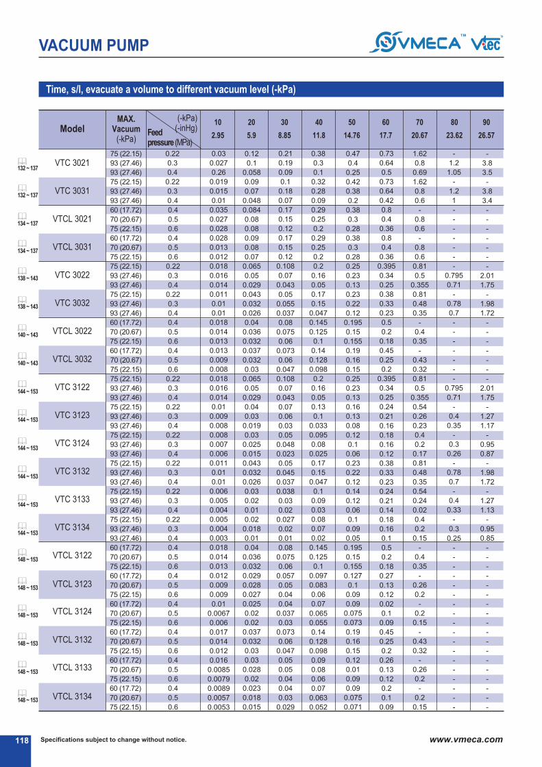
VTCL 3123
VTCL 3132
VTCL 3134
VTC 3031
VTCL 3031
VTC 3032
VTCL 3032
VTC 3123
VTC 3132
VTC 3134
Specifications subject to change without notice.118 www.vmeca.com
VACUUM PUMP
Time, s/l, evacuate a volume to different vacuum level (-kPa)
Model2.95 5.9 8.85 11.8 14.76 17.7 20.67 23.62 26.57
10 20 30 40 50 60 70 80 90
Feed pressure (MPa)
MAX.Vacuum
(-kPa)
VTC 3021
VTCL 3021
VTC 3022
VTCL 3022
VTC 3122
VTC 3124
VTC 3133
VTCL 3122
VTCL 3124
VTCL 3133
75 (22.15)
93 (27.46)
93 (27.46)
75 (22.15)
93 (27.46)
93 (27.46)
60 (17.72)
70 (20.67)
75 (22.15)
60 (17.72)
70 (20.67)
75 (22.15)
75 (22.15)
93 (27.46)
93 (27.46)
75 (22.15)
93 (27.46)
93 (27.46)
60 (17.72)
70 (20.67)
75 (22.15)
60 (17.72)
70 (20.67)
75 (22.15)
75 (22.15)
93 (27.46)
93 (27.46)
75 (22.15)
93 (27.46)
93 (27.46)
75 (22.15)
93 (27.46)
93 (27.46)
75 (22.15)
93 (27.46)
93 (27.46)
75 (22.15)
93 (27.46)
93 (27.46)
75 (22.15)
93 (27.46)
93 (27.46)
60 (17.72)
70 (20.67)
75 (22.15)
60 (17.72)
70 (20.67)
75 (22.15)
60 (17.72)
70 (20.67)
75 (22.15)
60 (17.72)
70 (20.67)
75 (22.15)
60 (17.72)
70 (20.67)
75 (22.15)
60 (17.72)
70 (20.67)
75 (22.15)
0.22
0.3
0.4
0.22
0.3
0.4
0.4
0.5
0.6
0.4
0.5
0.6
0.22
0.3
0.4
0.22
0.3
0.4
0.4
0.5
0.6
0.4
0.5
0.6
0.22
0.3
0.4
0.22
0.3
0.4
0.22
0.3
0.4
0.22
0.3
0.4
0.22
0.3
0.4
0.22
0.3
0.4
0.4
0.5
0.6
0.4
0.5
0.6
0.4
0.5
0.6
0.4
0.5
0.6
0.4
0.5
0.6
0.4
0.5
0.6
0.03
0.027
0.26
0.019
0.015
0.01
0.035
0.027
0.028
0.028
0.013
0.012
0.018
0.016
0.014
0.011
0.01
0.01
0.018
0.014
0.013
0.013
0.009
0.008
0.018
0.016
0.014
0.01
0.009
0.008
0.008
0.007
0.006
0.011
0.01
0.01
0.006
0.005
0.004
0.005
0.004
0.003
0.018
0.014
0.013
0.012
0.009
0.009
0.01
0.0067
0.006
0.017
0.014
0.012
0.016
0.0085
0.0079
0.0089
0.0057
0.0053
0.12
0.1
0.058
0.09
0.07
0.048
0.084
0.08
0.08
0.09
0.08
0.07
0.065
0.05
0.029
0.043
0.032
0.026
0.04
0.036
0.032
0.037
0.032
0.03
0.065
0.05
0.029
0.04
0.03
0.019
0.03
0.025
0.015
0.043
0.032
0.026
0.03
0.02
0.01
0.02
0.018
0.01
0.04
0.036
0.032
0.029
0.028
0.027
0.025
0.02
0.02
0.037
0.032
0.03
0.03
0.028
0.02
0.023
0.018
0.015
0.21
0.19
0.09
0.1
0.18
0.07
0.17
0.15
0.12
0.17
0.15
0.12
0.108
0.07
0.043
0.05
0.055
0.037
0.08
0.075
0.06
0.073
0.06
0.047
0.108
0.07
0.043
0.07
0.06
0.03
0.05
0.048
0.023
0.05
0.045
0.037
0.038
0.03
0.02
0.027
0.02
0.01
0.08
0.075
0.06
0.057
0.05
0.04
0.04
0.037
0.03
0.073
0.06
0.047
0.05
0.05
0.04
0.04
0.03
0.029
0.38
0.3
0.1
0.32
0.28
0.09
0.29
0.25
0.2
0.29
0.25
0.2
0.2
0.16
0.05
0.17
0.15
0.047
0.145
0.125
0.1
0.14
0.128
0.098
0.2
0.16
0.05
0.13
0.1
0.033
0.095
0.08
0.025
0.17
0.15
0.047
0.1
0.09
0.03
0.08
0.07
0.02
0.145
0.125
0.1
0.097
0.083
0.06
0.07
0.065
0.055
0.14
0.128
0.098
0.09
0.08
0.06
0.07
0.063
0.052
0.47
0.4
0.25
0.42
0.38
0.2
0.38
0.3
0.28
0.38
0.3
0.28
0.25
0.23
0.13
0.23
0.22
0.12
0.195
0.15
0.155
0.19
0.16
0.15
0.25
0.23
0.13
0.16
0.13
0.08
0.12
0.1
0.06
0.23
0.22
0.12
0.14
0.12
0.06
0.1
0.09
0.05
0.195
0.15
0.155
0.127
0.1
0.09
0.09
0.075
0.073
0.19
0.16
0.15
0.12
0.01
0.09
0.09
0.075
0.071
0.73
0.64
0.5
0.73
0.64
0.42
0.8
0.4
0.36
0.8
0.4
0.36
0.395
0.34
0.25
0.38
0.33
0.23
0.5
0.2
0.18
0.45
0.25
0.2
0.395
0.34
0.25
0.24
0.21
0.16
0.18
0.16
0.12
0.38
0.33
0.23
0.24
0.21
0.14
0.18
0.16
0.1
0.5
0.2
0.18
0.27
0.13
0.12
0.02
0.1
0.09
0.45
0.25
0.2
0.26
0.13
0.12
0.2
0.1
0.09
1.62
0.8
0.69
1.62
0.8
0.6
-
0.8
0.6
-
0.8
0.6
0.81
0.5
0.355
0.81
0.48
0.35
-
0.4
0.35
-
0.43
0.32
0.81
0.5
0.355
0.54
0.26
0.23
0.4
0.2
0.17
0.81
0.48
0.35
0.54
0.24
0.02
0.4
0.2
0.15
-
0.4
0.35
-
0.26
0.2
-
0.2
0.15
-
0.43
0.32
-
0.26
0.2
-
0.2
0.15
-
1.2
1.05
-
1.2
1
-
-
-
-
-
-
-
0.795
0.71
-
0.78
0.7
-
-
-
-
-
-
-
0.795
0.71
-
0.4
0.35
-
0.3
0.26
-
0.78
0.7
-
0.4
0.33
-
0.3
0.25
-
-
-
-
-
-
-
-
-
-
-
-
-
-
-
-
-
-
-
3.8
3.5
-
3.8
3.4
-
-
-
-
-
-
-
2.01
1.75
-
1.98
1.72
-
-
-
-
-
-
-
2.01
1.75
-
1.27
1.17
-
0.95
0.87
-
1.98
1.72
-
1.27
1.13
-
0.95
0.85
-
-
-
-
-
-
-
-
-
-
-
-
-
-
-
-
-
-
(-kPa)(-inHg)
132 ~ 137
134 ~ 137
134 ~ 137
138 ~ 143
138 ~ 143
140 ~ 143
140 ~ 143
144 ~ 153
144 ~ 153
144 ~ 153
144 ~ 153
144 ~ 153
144 ~ 153
148 ~ 153
148 ~ 153
148 ~ 153
148 ~ 153
148 ~ 153
148 ~ 153
132 ~ 137
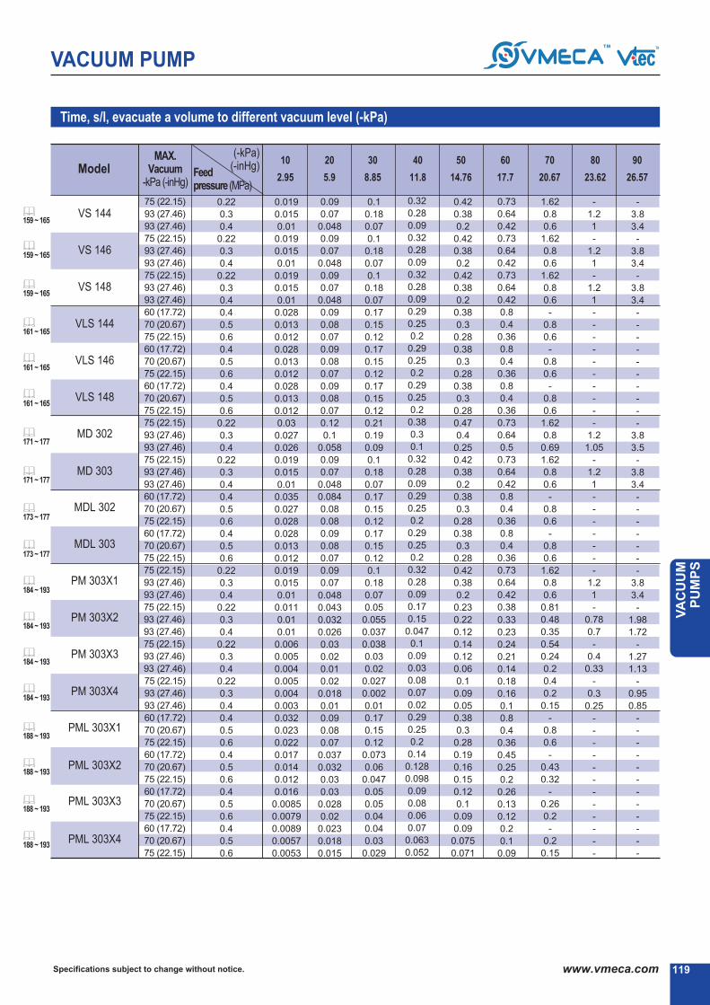
PML 303X4
VS 146
VLS 144
VLS 148
MD 303
MDL 303
PM 303X2
119
VACUUM PUMP
Specifications subject to change without notice. www.vmeca.com
VA
CU
UM
P
UM
PS
Feed pressure (MPa)
Time, s/l, evacuate a volume to different vacuum level (-kPa)
Model
(-kPa)(-inHg)
MAX.Vacuum
-kPa (-inHg)
VS 144
VS 148
VLS 146
MD 302
MDL 302
PM 303X1
PM 303X3
PM 303X4
PML 303X1
PML 303X2
PML 303X3
75 (22.15)
93 (27.46)
93 (27.46)
75 (22.15)
93 (27.46)
93 (27.46)
75 (22.15)
93 (27.46)
93 (27.46)
60 (17.72)
70 (20.67)
75 (22.15)
60 (17.72)
70 (20.67)
75 (22.15)
60 (17.72)
70 (20.67)
75 (22.15)
75 (22.15)
93 (27.46)
93 (27.46)
75 (22.15)
93 (27.46)
93 (27.46)
60 (17.72)
70 (20.67)
75 (22.15)
60 (17.72)
70 (20.67)
75 (22.15)
75 (22.15)
93 (27.46)
93 (27.46)
75 (22.15)
93 (27.46)
93 (27.46)
75 (22.15)
93 (27.46)
93 (27.46)
75 (22.15)
93 (27.46)
93 (27.46)
60 (17.72)
70 (20.67)
75 (22.15)
60 (17.72)
70 (20.67)
75 (22.15)
60 (17.72)
70 (20.67)
75 (22.15)
60 (17.72)
70 (20.67)
75 (22.15)
0.22
0.3
0.4
0.22
0.3
0.4
0.22
0.3
0.4
0.4
0.5
0.6
0.4
0.5
0.6
0.4
0.5
0.6
0.22
0.3
0.4
0.22
0.3
0.4
0.4
0.5
0.6
0.4
0.5
0.6
0.22
0.3
0.4
0.22
0.3
0.4
0.22
0.3
0.4
0.22
0.3
0.4
0.4
0.5
0.6
0.4
0.5
0.6
0.4
0.5
0.6
0.4
0.5
0.6
0.019
0.015
0.01
0.019
0.015
0.01
0.019
0.015
0.01
0.028
0.013
0.012
0.028
0.013
0.012
0.028
0.013
0.012
0.03
0.027
0.026
0.019
0.015
0.01
0.035
0.027
0.028
0.028
0.013
0.012
0.019
0.015
0.01
0.011
0.01
0.01
0.006
0.005
0.004
0.005
0.004
0.003
0.032
0.023
0.022
0.017
0.014
0.012
0.016
0.0085
0.0079
0.0089
0.0057
0.0053
0.09
0.07
0.048
0.09
0.07
0.048
0.09
0.07
0.048
0.09
0.08
0.07
0.09
0.08
0.07
0.09
0.08
0.07
0.12
0.1
0.058
0.09
0.07
0.048
0.084
0.08
0.08
0.09
0.08
0.07
0.09
0.07
0.048
0.043
0.032
0.026
0.03
0.02
0.01
0.02
0.018
0.01
0.09
0.08
0.07
0.037
0.032
0.03
0.03
0.028
0.02
0.023
0.018
0.015
0.1
0.18
0.07
0.1
0.18
0.07
0.1
0.18
0.07
0.17
0.15
0.12
0.17
0.15
0.12
0.17
0.15
0.12
0.21
0.19
0.09
0.1
0.18
0.07
0.17
0.15
0.12
0.17
0.15
0.12
0.1
0.18
0.07
0.05
0.055
0.037
0.038
0.03
0.02
0.027
0.002
0.01
0.17
0.15
0.12
0.073
0.06
0.047
0.05
0.05
0.04
0.04
0.03
0.029
0.32
0.28
0.09
0.32
0.28
0.09
0.32
0.28
0.09
0.29
0.25
0.2
0.29
0.25
0.2
0.29
0.25
0.2
0.38
0.3
0.1
0.32
0.28
0.09
0.29
0.25
0.2
0.29
0.25
0.2
0.32
0.28
0.09
0.17
0.15
0.047
0.1
0.09
0.03
0.08
0.07
0.02
0.29
0.25
0.2
0.14
0.128
0.098
0.09
0.08
0.06
0.07
0.063
0.052
0.42
0.38
0.2
0.42
0.38
0.2
0.42
0.38
0.2
0.38
0.3
0.28
0.38
0.3
0.28
0.38
0.3
0.28
0.47
0.4
0.25
0.42
0.38
0.2
0.38
0.3
0.28
0.38
0.3
0.28
0.42
0.38
0.2
0.23
0.22
0.12
0.14
0.12
0.06
0.1
0.09
0.05
0.38
0.3
0.28
0.19
0.16
0.15
0.12
0.1
0.09
0.09
0.075
0.071
-
1.2
1
-
1.2
1
-
1.2
1
-
-
-
-
-
-
-
-
-
-
1.2
1.05
-
1.2
1
-
-
-
-
-
-
-
1.2
1
-
0.78
0.7
-
0.4
0.33
-
0.3
0.25
-
-
-
-
-
-
-
-
-
-
-
-
-
3.8
3.4
-
3.8
3.4
-
3.8
3.4
-
-
-
-
-
-
-
-
-
-
3.8
3.5
-
3.8
3.4
-
-
-
-
-
-
-
3.8
3.4
-
1.98
1.72
-
1.27
1.13
-
0.95
0.85
-
-
-
-
-
-
-
-
-
-
-
-
1.62
0.8
0.6
1.62
0.8
0.6
1.62
0.8
0.6
-
0.8
0.6
-
0.8
0.6
-
0.8
0.6
1.62
0.8
0.69
1.62
0.8
0.6
-
0.8
0.6
-
0.8
0.6
1.62
0.8
0.6
0.81
0.48
0.35
0.54
0.24
0.2
0.4
0.2
0.15
-
0.8
0.6
-
0.43
0.32
-
0.26
0.2
-
0.2
0.15
0.73
0.64
0.42
0.73
0.64
0.42
0.73
0.64
0.42
0.8
0.4
0.36
0.8
0.4
0.36
0.8
0.4
0.36
0.73
0.64
0.5
0.73
0.64
0.42
0.8
0.4
0.36
0.8
0.4
0.36
0.73
0.64
0.42
0.38
0.33
0.23
0.24
0.21
0.14
0.18
0.16
0.1
0.8
0.4
0.36
0.45
0.25
0.2
0.26
0.13
0.12
0.2
0.1
0.09
2.95 5.9 8.85 11.8 14.76 17.7 20.67 23.62 26.57
10 20 30 40 50 60 70 80 90
159 ~ 165
159 ~ 165
159 ~ 165
161 ~ 165
161 ~ 165
161 ~ 165
171 ~ 177
171 ~ 177
173 ~ 177
173 ~ 177
184 ~ 193
184 ~ 193
184 ~ 193
184 ~ 193
188 ~ 193
188 ~ 193
188 ~ 193
188 ~ 193

Specifications subject to change without notice.120 www.vmeca.com
VACUUM PUMP
VKX5
VKM5
VKM61
VKM62
VKX61
VKX62
VKX73
VKX74
VKM73
VKM74
VTOM5-(n)Stack
VTOM10-(n)Stack
VTOX5-(n)Stack
VTOX10-(n)Stack
VTM5-(n)Stack
VTM10-(n)Stack
VTM10X(n)B(Ba,...nC)
VTM20X(n)B(Ba,...nC)
VTM30X(n)B(C,...nC)
VTM5-a(B,...nC)
VTM10-a(B,...nC)
VTM20-B(C,...nC)
VTM30-B(C,...nC)
VTM20KD
VTM30KD
VTM40KD
VTM50KD
VTM60KD
VTM25L
VTM50L
VTM75L
VTM100L
VTM125L
VTM150L
VTL25
VTL50
VTL75
VTL100
VTL125
VTL150
VTL175
VTL200
VTM25
VTM50
VTM75
VTM100
VTM125
VTM150
VTM175
VTM200
Time, s/l, evacuate a volume to different vacuum level (-kPa)
Model
0.26
0.22
0.218
0.109
0.258
0.129
0.1
0.06
0.08
0.05
0.247
0.177
0.277
0.187
0.218
0.109
0.109
0.054
0.041
0.218
0.109
0.054
0.041
0.054
0.041
0.027
0.023
0.018
0.02
0.013
0.01
0.007
0.0061
0.0051
0.017
0.012
0.008
0.0069
0.0058
0.0049
0.0047
0.0043
0.019
0.012
0.009
0.006
0.0055
0.0052
0.0050
0.0048
0.80
0.56
0.556
0.278
0.796
0.398
0.3
0.2
0.21
0.14
0.628
0.408
0.848
0.508
0.556
0.278
0.278
0.139
0.104
0.556
0.278
0.139
0.014
0.139
0.104
0.069
0.058
0.046
0.056
0.032
0.024
0.016
0.0147
0.0134
0.045
0.027
0.021
0.015
0.014
0.013
0.012
0.011
0.048
0.030
0.023
0.015
0.0143
0.0135
0.0127
0.0113
1.52
1.18
1
0.5
1.516
0.758
0.57
0.38
0.38
0.25
1.128
0.678
1.619
0.912
1
0.5
0.5
0.25
0.186
1
0.5
0.25
0.186
0.25
0.186
0.125
0.104
0.083
0.12
0.062
0.047
0.031
0.0302
0.0294
0.09
0.05
0.04
0.03
0.026
0.022
0.021
0.019
0.110
0.066
0.050
0.033
0.0311
0.0296
0.0279
0.0258
2.4
1.58
1.576
0.788
2.4
1.2
0.9
0.6
0.59
0.39
1.748
1.018
2.688
1.388
1.576
0.788
0.788
0.394
0.295
1.576
0.788
0.394
0.295
0.394
0.295
0.197
0.164
0.131
0.24
0.12
0.09
0.06
0.053
0.046
0.18
0.1
0.08
0.05
0.044
0.037
0.035
0.033
0.239
0.125
0.094
0.063
0.055
0.047
0.039
0.027
3.38
2.36
2.356
1.178
3.56
1.78
1.34
0.89
0.88
0.59
2.529
1.429
3.889
1.989
2.356
1.178
1.178
0.589
0.441
2.356
1.178
0.589
0.441
0.589
0.441
0.294
0.245
0.196
0.425
0.212
0.159
0.106
0.089
0.071
0.34
0.18
0.13
0.09
0.076
0.062
0.057
0.051
0.416
0.209
0.157
0.105
0.092
0.078
0.065
0.054
4.91
3.44
3.44
1.72
4.91
2.455
1.84
1.23
1.29
0.86
3.63
1.98
5.46
2.65
3.44
1.72
1.72
0.86
0.647
3.44
1.72
0.86
0.647
0.86
0.647
0.431
0.359
0.286
0.66
0.33
0.248
0.165
0.143
0.115
0.53
0.27
0.20
0.14
0.118
0.095
0.087
0.078
0.686
0.345
0.259
0.173
0.151
0.129
0.108
0.090
6.89
5.27
5.27
2.635
6.896
3.445
2.58
1.72
1.98
1.32
5.45
2.89
7.45
3.64
5.27
2.635
2.635
1.317
0.898
5.27
2.635
1.317
0.898
1.317
0.898
0.658
0.549
0.439
1.02
0.51
0.383
0.255
0.215
0.175
0.85
0.43
0.32
0.22
0.19
0.15
0.14
0.12
1.122
0.593
0.445
0.297
0.260
0.223
0.186
0.153
10.16
10.22
10.216
5.158
10.16
5.08
3.81
2.54
3.87
2.58
10.4
5.41
13.95
5.29
10.216
5.158
5.158
2.579
1.935
10.216
5.158
2.579
1.935
2.579
1.935
1.289
1.074
0.859
1.64
0.82
0.621
0.41
0.36
0.31
1.91
1.05
0.788
0.526
0.460
0.394
0.329
0.274
19
19.19
5.594
7.2
4.8
20.53
9.79
4.6
2.3
1.73
1.15
1.01
0.87
4.210
2.190
1.644
1.097
1.960
0.823
0.686
0.67
92 (27.17)
85 (25.1)
85
(25.1)
92
(27.17)
92
(27.17)
85
(25.1)
85
(25.1)
92
(27.17)
85
(25.1)
85
(25.1)
85
(25.1)
85
(25.1)
91
(26.87)
80
(23.62)
90
(26.57)
/ (n)Stack
/ (n)Stack
/ (n)Stack
/ (n)Stack
/ (n)Stack
MAX.Vacuum-kPa (-inHg)
-kPa-inHg 9995908070605040302010
29.2328.0526.5723.6220.6717.7114.7611.818.855.92.95
196 ~ 199
200 ~ 211
200 ~ 211
212 ~ 223
212 ~ 223
232 ~ 235
232 ~ 235
236 ~ 241
242 ~ 247
226 ~ 231
248 ~ 255
262 ~ 265
266 ~ 269
270 ~ 273

121
VACUUM PUMP
Specifications subject to change without notice. www.vmeca.com
VA
CU
UM
P
UM
PS
VTMM100
VTMM150
VTMM200
VTMM200F
VTM150LeF
VTM200LeF
VTM300LeF
VTM400LeF
VTM500LeF
VTM600LeF
VTM800LeF
VTMM200eF
VTMM300eF
VTMM400eF
VTMM500eF
VTMM600eF
VTMM800eF
VTMM1000eF
VTML200
VTML400
VTML600
VTML800
VTML1000
VTML1200
VTX5-(n)Stack
VTX10-(n)Stack
VTX10x(n-B(Ba,...nC)
VTX20x(n-B(Ba,...nC)
VTX30x(n-B(Ba,...nC)
VTX5-a(B,...nC)
VTX10-a(B,...nC)
VTX20-B(C,...nC)
VTX30-B(C,...nC)
VTX20KD
VTX30KD
VTX40KD
VTX50KD
VTX60KD
VTX25
VTX50
VTX75
VTMX100
VTMX200
VTMX300
VTH50
VTH150
VTH300
Time, s/l, evacuate a volume to different vacuum level (-kPa)
Model
0.0053
0.0046
0.0032
0.0031
0.0033
0.00250
0.0017
0.0013
0.001
0.0008
0.0006
0.0031
0.0023
0.0015
0.0013
0.0012
0.0008
0.0007
0.0021
0.0011
0.0009
0.0006
0.0005
0.0004
0.258
0.129
0.129
0.064
0.048
0.258
0.129
0.064
0.048
0.064
0.048
0.032
0.027
0.021
0.028
0.014
0.011
0.0093
0.0064
0.0049
0.029
0.011
0.006
0.0144
0.011
0.0076
0.0075
0.009
0.007
0.005
0.004
0.003
0.0023
0.0018
0.0075
0.0056
0.0038
0.0033
0.0028
0.0019
0.0016
0.0055
0.0027
0.0021
0.0014
0.0012
0.0009
0.796
0.398
0.398
0.199
0.149
0.796
0.398
0.199
0.149
0.199
0.149
0.099
0.083
0.067
0.068
0.035
0.023
0.017
0.012
0.009
0.07
0.025
0.013
0.031
0.025
0.0165
0.0164
0.02
0.015
0.01
0.008
0.006
0.005
0.004
0.0164
0.0123
0.0082
0.0072
0.0062
0.0041
0.0036
0.0124
0.0062
0.0047
0.0031
0.0026
0.0021
1.516
0.758
0.758
0.379
0.284
1.156
0.758
0.379
0.284
0.379
0.284
0.189
0.158
0.126
0.134
0.067
0.046
0.036
0.024
0.018
0.12
0.05
0.025
0.063
0.047
0.029
0.029
0.04
0.03
0.02
0.015
0.012
0.01
0.008
0.029
0.022
0.014
0.013
0.011
0.007
0.006
0.029
0.014
0.011
0.007
0.006
0.005
2.4
1.2
1.2
0.6
0.44
2.4
1.2
0.6
0.44
0.6
0.44
0.29
0.25
0.20
0.26
0.13
0.095
0.064
0.047
0.031
0.25
0.097
0.048
0.105
0.078
0.054
0.054
0.071
0.053
0.035
0.027
0.021
0.018
0.013
0.054
0.041
0.027
0.024
0.021
0.014
0.012
0.054
0.027
0.021
0.014
0.012
0.009
3.56
1.78
1.78
0.89
0.673
3.56
1.78
0.89
0.673
0.89
0.673
0.445
0.371
0.297
0.49
0.25
0.167
0.123
0.082
0.061
0.55
0.17
0.085
0.173
0.129
0.090
0.090
0.11
0.083
0.055
0.041
0.033
0.028
0.021
0.090
0.068
0.045
0.040
0.034
0.022
0.018
0.090
0.045
0.034
0.023
0.018
0.014
4.91
2.455
2.455
1.227
0.917
4.91
2.455
1.227
0.917
1.227
0.917
0.613
0.511
0.409
0.736
0.368
0.246
0.184
0.123
0.092
0.92
0.272
0.136
0.297
0.223
0.153
0.153
0.17
0.128
0.085
0.064
0.051
0.043
0.032
0.153
0.115
0.076
0.067
0.057
0.038
0.031
0.153
0.076
0.057
0.038
0.031
0.024
6.896
3.445
3.445
1.722
1.287
6.896
3.445
1.722
1.287
1.722
1.287
0.858
0.714
0.569
1.126
0.563
0.376
0.272
0.186
0.141
1.446
0.41
0.205
0.526
0.394
0.274
0.274
0.31
0.21
0.16
0.11
0.09
0.08
0.05
0.274
0.206
0.137
0.120
0.103
0.068
0.057
0.274
0.137
0.103
0.068
0.057
0.045
10.16
5.08
5.08
2.54
1.906
10.16
5.08
2.54
1.906
2.54
1.906
1.273
1.016
0.848
1.598
0.799
0.533
0.397
0.256
0.197
2.2
0.6
0.3
1.097
0.823
0.67
0.67
0.87
0.58
0.44
0.29
0.26
0.22
015
0.67
0.503
0.335
0.294
0.252
0.168
0.147
0.67
0.335
0.252
0.168
0.147
0.125
19.19
9.594
9.594
4.797
3.595
19.19
9.594
4.797
3.595
4.797
3.595
2.398
1.999
1.599
2.7
1.35
0.9
0.674
0.448
0.336
3.39
1.17
0.585
3.76
1.88
1.264
0.948
0.631
0.473
4.986
1.82
0.91
9.18
3.586
1.798
92
(27.17)
91
(26.87)
92
(27.17)
92
(27.17)
92
(27.17)
92
(27.17)
92
(27.17)
92
(27.17)
97
(28.64)
100.8
(29.76)
97
(28.64)
(n)Stack
(n)Stack
(n)Stack
(n)Stack
(n)Stack
MAX.Vacuum-kPa (-inHg)
-kPa-inHg 9995908070605040302010
29.2328.0526.5723.6220.6717.7114.7611.818.855.92.95
278 ~ 281
292 ~ 297
298 ~ 303
306 ~ 309
228 ~ 231
238 ~ 241
244 ~ 247
250 ~ 255
274 ~ 277
282 ~ 285
286 ~ 291


TURTLE PUMPSTURTLE PUMPS

R
124
VACUUM PUMP Turtle Pump
R
Effective cost saving with VMECA improved system
VMECA Turtle pump with integral vacuum filter and silencer can be combined with the optional vacuum
On/Off control valve, vacuum release valve and vacuum switch to create an optimal vacuum solution for many
applications. The VMeCa Turtle pump and optional components, due to the compact design and size, can be
mounted close to the point of use reducing system volume and maintenance while improving cycle time.
If each items goes through under the process same as below?
Select model ⓳ Quotation ⓳ PO ⓳ Store in ⓳ Q.C ⓳ Installation ⓳ Payment
(Technical dept) (Purchase dept.) (Inventory) (QC dept.) (account)(assembly dept.)
R
VMECA Improved system
⓳
⓳
(New solution with Turtle Pump)
⓳+⓳+⓳+⓳+⓳+⓳
⓳
⓳
⓳
⓳
⓳
⓳ Vacuum pump
⓳ air control valve
⓳ Vacuum release control valve
⓳ Vacuum filter
⓳ Vacuum switch
⓳ Vacuum pipe line
⓳ Suction cup
Typical installation
(Old system)
⓳
High installation and
maintenance Costs !!
Very LOW installation and
maintenance Costs !!
Specifications subject to change without notice. www.vmeca.com

R
High operational reliability despite
fluctuating or low compressed air
pressure (Vacuum level +2%)
R
Typical installation (Old System)
VMECA Improved SystemVTC3031.. Quick evacuation timeby minimizing vacuum area withall-in-one system
R
125
VACUUM PUMP
Specifications subject to change without notice. www.vmeca.com
VA
CU
UM
P
UM
PS
VACUUM PUMP Turtle Pump
RTypical installation (Old system) VMECA Improved system(New solution with Turtle Pump)
Vacu
um
Flo
w &
Levels
Vacu
um
Flo
w &
Levels
Running Time
Month
Running Time
Month
Typical installation (Old System)
VMECA Improved System
Drop vacuum flow and levels due to easily be blocked the filter surface by dust according as the running time.
Requried periodic filter cleaning.
VMECA Turtle pump with built-in filter automatic cleaning system eliminates drop vacuum flow and vacuum levels
Constant vacuum flow & vacuum level
about 3 times faster !!
Vacuum function at running time(Vacuum flow and levels)
Vacuum function at running time(Vacuum flow and levels)
Comparison of Vacuum Efficiency
Comparison of Evacuation time at different Vacuum levels
Comparison of Vacuum level at different feed pressure
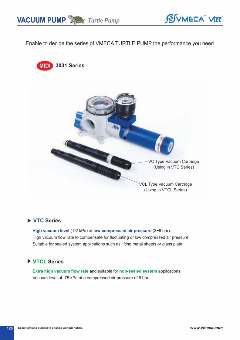
126 126
enable to decide the series of VMeCa TuRTLe PuMP the performance you need.
High vacuum level (-92 kPa) at low compressed air pressure (3~6 bar).
High vacuum flow rate to compensate for fluctuating or low compressed air pressure.
Suitable for sealed system applications such as lifting metal sheets or glass plate.
Extra high vacuum flow rate and suitable for non-sealed system applications.
Vacuum level of -75 kPa at a compressed air pressure of 6 bar.
VTC Series
VTCL Series
VC Type Vacuum Cartridge
(using in VTC Series)
VCL Type Vacuum Cartridge
(using in VTCL Series)
VACUUM PUMPVACUUM PUMP Turtle Pump
Specifications subject to change without notice. www.vmeca.com
3031 SeriesMIDI
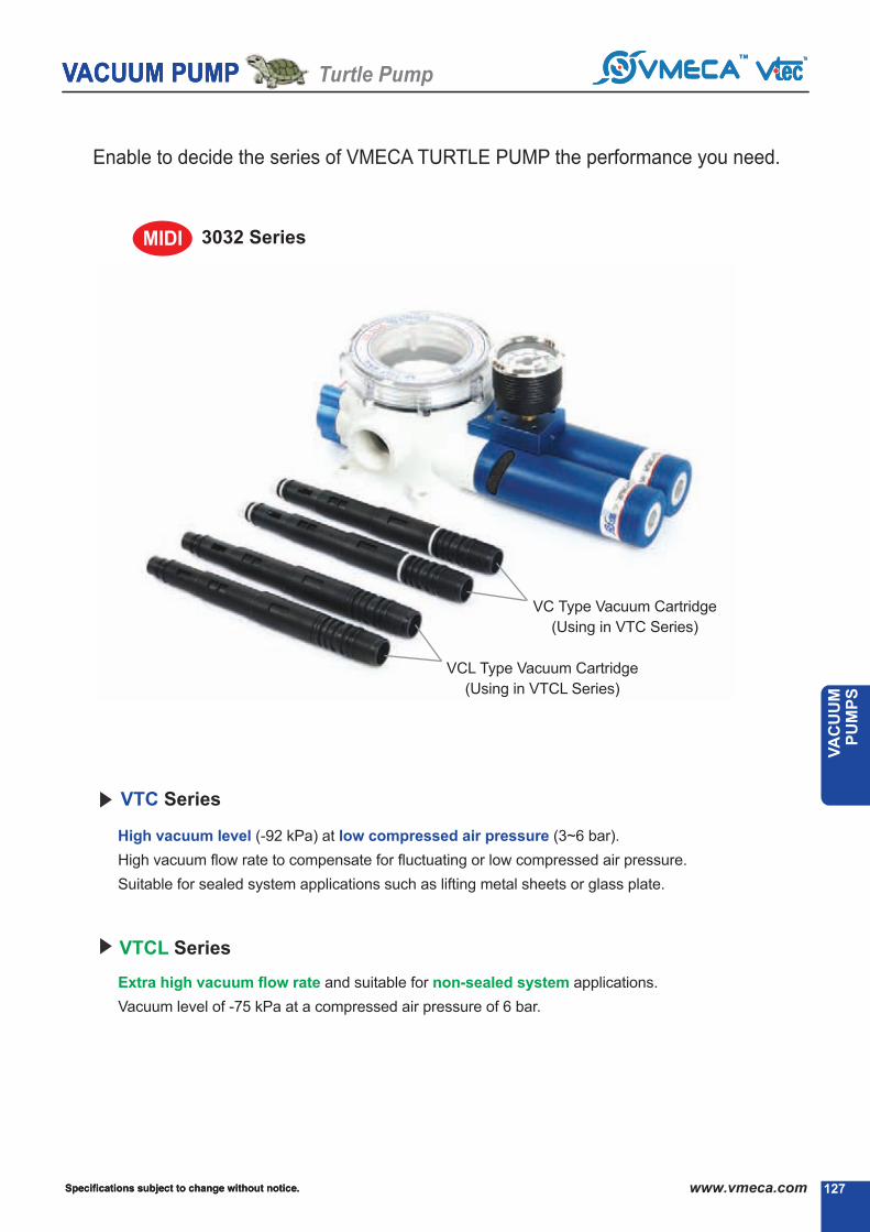
127
VACUUM PUMP
Specifications subject to change without notice.
VA
CU
UM
P
UM
PS
enable to decide the series of VMeCa TuRTLe PuMP the performance you need.
High vacuum level (-92 kPa) at low compressed air pressure (3~6 bar).
High vacuum flow rate to compensate for fluctuating or low compressed air pressure.
Suitable for sealed system applications such as lifting metal sheets or glass plate.
Extra high vacuum flow rate and suitable for non-sealed system applications.
Vacuum level of -75 kPa at a compressed air pressure of 6 bar.
VTC Series
VTCL Series
VC Type Vacuum Cartridge
(using in VTC Series)
VCL Type Vacuum Cartridge
(using in VTCL Series)
MIDI
VACUUM PUMPVACUUM PUMP Turtle Pump
127127 Specifications subject to change without notice. www.vmeca.com
3032 Series

VACUUM PUMP Turtle Pump
128
The VMeCa Turtle Pump is recommended for applications requiring a compact,complete and easy to install, minimal maintenance.
Structure and Main advantage of Midi Turtle Pump
air control valve
Vacuum release valve
Vacuum filter
Vacuum switch
Twofold silencer
Vacuum cartridge
MIDI
Specifications subject to change without notice. www.vmeca.com
Patented design
All-in-one compact design
Light weight
Multi vacuum ports
Vacuum filter self cleaning system
- eliminates periodic maintenance
VMECA Vacuum Cartridge
- High vacuum flow rate
- High operational reliability despite fluctuating or low compressed air pressure
Twofold silencer
- Designed specially assure low noise level

www.vmeca.com
VA
CU
UM
P
UM
PS
VACUUM PUMPVACUUM PUMP Turtle Pump
129Specifications subject to change without notice.
R
R
Structure and Main advantage of Mega Turtle Pump
R
R
R
R
MEGA■ VMECA vacumm filter
•Prevents dust coming into the pump
•Pleated media for high dirt holding capacity
•Moisture, oil resistant
•Washable
■ VMECA vacumm release
control valve
•Quick vacuum release
•automatic filter cleaning system
■ Body
•Durable engineering plastic material
•Corrosion resistant
•Light weight
•Two vacuum ports : 3/4″ and 1″
■ VMECA air control valve
•Single or Double solenoid valve
■ VMECA patented Vacuum Cartridge System
•Multiple Vacuum cartridge available up to 4 pcs
•High operational reliability despite fluctuating or low compressed air pressure
•Air-Saving (AS) kit available to minimize energy consumption (about 20times less)
•Easily mountable and interchangeable vacuum cartridge
■ VMECA free-flow silencer
•assures low noise level
•Free air flow design to minimize vacuum loss
due to back flow
•no dust collection
■ VMECA vacuum gauge or sensor
•Indicates vacuum level
•Digital output signal when set vacuum level
is achieved

Specifications subject to change without notice.130 www.vmeca.com
APPLICATIONS
Rotary Packaging machine (VTC3031)⓳
Packaging machine : Carton boxes opening (VTC3032)⓳VACUUM PUMP Turtle Pump

VA
CU
UM
P
UM
PS
131Specifications subject to change without notice. www.vmeca.com
APPLICATIONS
Robot arm : automobile Press stamping line (VTC3031)⓳
automobile Fuel Tank lifting (VTC3031 X 2 pcs) ⓳VACUUM PUMPVACUUM PUMP Turtle Pump

Specifications subject to change without notice.132 www.vmeca.com
⓳
VTC 3031/3021 Series
no mark - Vacuum gauge.
⓳ Remark: ⓳ S..(P)
Output type :PnP open collector
⓳ VCM8 42 : M8-4Pin connector wire.Only for type S2 or S2(P).
S2(P) - Digital display output 2points, no analog supplyM8-4Pin Connector type 0.3m lead wire.
Sg2(P) - Digital display output 2 points, no analog supplygrommet type 4-Core 2m lead wire.
Sg3(P) - Digital display output 2 points, analog supplygrommet type 5-Core 2m lead wire.
Patented design.
High operational reliability despite fluctuating or low compressed-air pressure.
Integrated high dirt holding capacity pleated filter.
VMeCa Twofold SilencerPT assures low noise levels.
Optional air-Saving(aS) kit available to minimize energy consumption.
Optional factory installed air control/Vacuum release valves and Vacuum switch available.
Compact size and light weight.
easily mountable and interchangeable vacuum cartridge.
Main advantages
Model
Voltage of air supplycontrol valve
Voltage of vacuumrelease control valve
Sealing
VTC 3021 - Two stage nozzle
VTC 3031(P) - Three stage nozzle
no mark - Standard
AS - air saving kit
no mark - Standard
V - Viton
e - ePDM
⓳ Remark:..(P)
g3/8”exhaust Port
non-return valve
no mark - Standard
N - non-return valve.
a1 - aC110V
a2 - aC220V
A3 - DC24V
D1* - aC110V
D2* - aC220V
D3* - DC24V
* D.. : Double solenoid valve isavailable only with ‘Dn’ or ‘DL’, section ⓳
1
4
5
air saving kit3
8
Vacuum switch7
9
R1 - aC110V
R2 - aC220V
R3 - DC24V
R
Max. vacuum level
Max. flow rate
Supply air pressure
Air consumption
Supply air type
Working temperature
Noise level
: -93 kPa (-27.46 inHg)
: 341 nl/min (12.04 scfm)
: 3 ~ 6 bar, max 7 bar(43.5~87 psi, max 101.5 psi)
: 97~152 nl/min (3.43~5.37 scfm)
: Dry compressed air
: -20⓳ to +80⓳
: 50~60 ⓳g
Order no.
⓳⓳ ⓳⓳
VTC 3031 - 2 - AS - A3 R3 - CL - S2 N V
⓳ ⓳ ⓳ ⓳
2
Material
Polyester (Pe)
Connection port
BSP Thread(g)
Filter element & Connection port2
⓳
Dn - DIn type without lead wire
DL - DIn type with lamp without lead wire
CL* Connector type with lamp &0.3 m lead wire
2B* DIn type with ‘2 in 1’ BuS cable(air control v/v + Vacuum release v/v)
Solenoid Terminal6
-
3B* DIn type with ‘3 in 1’ BuS cable(air control v/v + Vacuum release v/v + Digital switch)
-
-
* Can not available with double solenoid valve
⓳ Remark CL : available only with DC24V3B : available only with DC24V
available only with ‘S2’ or ‘S2P’, section ⓳
About ‘BUS cable’ ( 340, 341)
VACUUM PUMP Midi Turtle Pump
( 108)

VA
CU
UM
P
UM
PS
133Specifications subject to change without notice. www.vmeca.com
VT
C-3
021..
VT
C-3
031..
Performance Data
Model
MaX.
Vacuum
(-kPa)
Feed
pressure
(MPa)
0
(0)
0.22
0.3
0.4
0.22
0.3
0.4
164
170
171
302
338
341
122.5
152
154
122.5
152
154
88
106
127.5
88
106
127.5
53
64
94
53
64
94
31.4
33
69
31.4
33
69
28.5
32
43
28.5
32
43
16.5
22
23.3
16.5
22
23.3
4.6
16.5
17.3
4.6
16.5
17.3
-
6.4
6.9
-
6.4
6.9
-
1.9
2.1
-
1.9
2.1
Vacuum flow (nl/min) at different vacuum level -kPa(-mmHg)
VTC3021..
10(75)
80(600)
70(525)
60(450)
50(375)
40(300)
30(225)
90(675)
20(150)
VTC3031..
VTC3031..
Model
Feed
pressure
(MPa)
air
consumption
(nl/min)
97
118
152
97
118
152
Time, s/l, to evacuate a volume to different vacuum level -kPa (-mmHg)
VTC3021..
10(75)
80(600)
70(525)
60(450)
50(375)
40(300)
30(225)
90(675)
20(150)
0.03
0.027
0.026
0.019
0.015
0.01
0.12
0.1
0.058
0.09
0.07
0.048
0.21
0.19
0.09
0.1
0.18
0.07
0.38
0.3
0.1
0.32
0.28
0.09
0.47
0.4
0.25
0.42
0.38
0.2
0.73
0.64
0.5
0.73
0.64
0.42
1.62
0.8
0.69
1.62
0.8
0.6
-
1.2
1.05
-
1.2
1
-
3.8
3.5
-
3.8
3.4
75
93
93
75
93
93
0.22
0.3
0.4
0.22
0.3
0.4
VACUUM PUMP Midi Turtle Pump
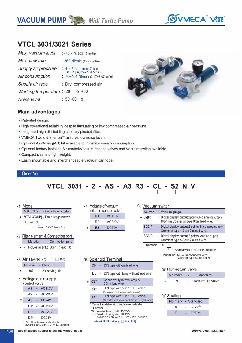
Specifications subject to change without notice.134 www.vmeca.com
VTCL 3031/3021 Series
Patented design.
High operational reliability despite fluctuating or low compressed-air pressure.
Integrated high dirt holding capacity pleated filter.
VMeCa Twofold SilencerPT assures low noise levels.
Optional air-Saving(aS) kit available to minimize energy consumption.
Optional factory installed air control/Vacuum release valves and Vacuum switch available.
Compact size and light weight.
easily mountable and interchangeable vacuum cartridge.
Main advantages
Max. vacuum level
Max. flow rate
Supply air pressure
Air consumption
Supply air type
Working temperature
Noise level
: -75 kPa (-22.15 inHg)
: 362 nl/min (12.79 scfm)
: 4 ~ 6 bar, max 7 bar(58~87 psi, max 101.5 psi)
: 70~104 nl/min (2.47~3.67 scfm)
: Dry compressed air
: -20⓳ to +80⓳
: 50~60 ⓳g
Order no.
no mark - Vacuum gauge.
⓳ Remark: ⓳ S..(P)
Output type :PnP open collector
⓳ VCM8 42 : M8-4Pin connector wire.Only for type S2 or S2(P).
S2(P) - Digital display output 2points, no analog supplyM8-4Pin Connector type 0.3m lead wire.
Sg2(P) - Digital display output 2 points, no analog supplygrommet type 4-Core 2m lead wire.
Sg3(P) - Digital display output 2 points, analog supplygrommet type 5-Core 2m lead wire.
Model
Voltage of air supplycontrol valve
Voltage of vacuumrelease control valve
Sealing
VTCL 3021 - Two stage nozzle
VTCL 3031(P) - Three stage nozzle
no mark - Standard
AS - air saving kit
no mark - Standard
V - Viton
e - ePDM
⓳ Remark:..(P)
g3/8”exhaust Port
non-return valve
no mark - Standard
N - non-return valve.
a1 - aC110V
a2 - aC220V
A3 - DC24V
D1* - aC110V
D2* - aC220V
D3* - DC24V
* D.. : Double solenoid valve isavailable only with ‘Dn’ or ‘DL’, section ⓳
1
4
5
air saving kit3
8
Vacuum switch7
9
R1 - aC110V
R2 - aC220V
R3 - DC24V
R
⓳⓳ ⓳⓳
VTCL 3031 - 2 - AS - A3 R3 - CL - S2 N V
⓳ ⓳ ⓳ ⓳
2
Material
Polyester (Pe)
Connection port
BSP Thread(g)
Filter element & Connection port2
⓳
Dn - DIn type without lead wire
DL - DIn type with lamp without lead wire
CL* Connector type with lamp &0.3 m lead wire
2B* DIn type with ‘2 in 1’ BuS cable(air control v/v + Vacuum release v/v)
Solenoid Terminal6
-
3B* DIn type with ‘3 in 1’ BuS cable(air control v/v + Vacuum release v/v + Digital switch)
-
-
* Can not available with double solenoid valve
⓳ Remark CL : available only with DC24V3B : available only with DC24V
available only with ‘S2’ or ‘S2P’, section ⓳
VACUUM PUMP Midi Turtle Pump
⓳ About ‘BUS cable’ ( 340, 341)
( 108)

VA
CU
UM
P
UM
PS
135Specifications subject to change without notice. www.vmeca.com
Performance Data
Model
MaX.
Vacuum
(-kPa)
Feed
pressure
(MPa)
0
(0)
0.4
0.5
0.6
0.4
0.5
0.6
188
195
200
302
344
362
158
176
183
176
200
194
110
130
154
110
130
154
70
82
100
70
82
100
46
50
52
46
50
52
28
37.5
38
28
37.5
38
6.8
23
32
6.8
23
32
-
11.3
22
-
11.3
22
-
-
-
-
-
-
-
-
-
-
-
-
Vacuum flow (nl/min) at different vacuum levels -kPa (-mmHg)
VTCL3021..
10(75)
80(600)
70(525)
60(450)
50(375)
40(300)
30(225)
90(675)
20(150)
VTCL3031..
VTCL3031..
Model
Feed
pressure
(MPa)
air
consumption
(nl/min)
70
85
104
70
85
104
Time, s/l, to evacuate a volume to different vacuum levels -kPa (-mmHg)
VTCL3021..
10(75)
80(600)
70(525)
60(450)
50(375)
40(300)
30(225)
90(675)
20(150)
0.035
0.027
0.028
0.028
0.013
0.012
0.084
0.08
0.08
0.09
0.08
0.07
0.17
0.15
0.12
0.17
0.15
0.12
0.29
0.25
0.2
0.29
0.25
0.2
0.38
0.3
0.28
0.38
0.3
0.28
0.8
0.4
0.36
0.8
0.4
0.36
-
0.8
0.6
-
0.8
0.6
-
-
-
-
-
-
-
-
-
-
-
-
60
70
75
60
70
75
0.4
0.5
0.6
0.4
0.5
0.6
VT
CL
-3021..
VT
CL
-3031..
VACUUM PUMP Midi Turtle Pump
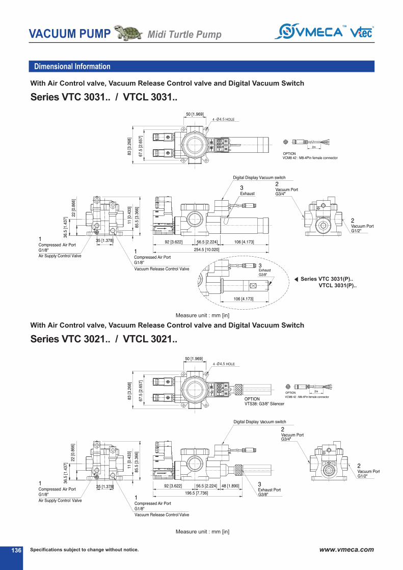
Specifications subject to change without notice.136 www.vmeca.com
Dimensional Information
With Air Control valve, Vacuum Release Control valve and Digital Vacuum Switch
With Air Control valve, Vacuum Release Control valve and Digital Vacuum Switch
Measure unit : mm [in]
Series VTC 3031(P)..VTCL 3031(P)..
Measure unit : mm [in]
Series VTC 3031.. / VTCL 3031..
Series VTC 3021.. / VTCL 3021..
VACUUM PUMP Midi Turtle Pump

VA
CU
UM
P
UM
PS
137Specifications subject to change without notice. www.vmeca.com
Standard
Standard
Series VTC 3031.. / VTCL 3031..
Series VTC 3031(P)..VTCL 3031(P)..
Series VTC 3021.. / VTCL 3021..
Dimensional Information
VACUUM PUMP Midi Turtle Pump
Measure unit : mm [in]
Measure unit : mm [in]

Specifications subject to change without notice.138 www.vmeca.com
Patented design.
High operational reliability despite fluctuating or low compressed-air pressure.
Integrated high dirt holding capacity pleated filter.
VMeCa Twofold SilencerPT assures low noise levels.
Optional air-Saving(aS) kit available to minimize energy consumption.
Optional factory installed air control/Vacuum release valves and Vacuum switch available.
Compact size and light weight.
easily mountable and interchangeable vacuum cartridge.
Max. vacuum level
Max. flow rate
Supply air pressure
Air consumption
Supply air type
Working temperature
Noise level
VTC 3032 / 3022 Series
Main advantages
Order no.
: -93 kPa (-27.46 inHg)
: 688 nl/min (24.3 scfm)
: 3 ~ 6 bar, max 7 bar(43.5~87 psi, max 101.5 psi)
: 194~304 nl/min (6.85~10.74 scfm)
: Dry compressed air
: -20⓳ to +80⓳
: 50~60 ⓳g
no mark - Vacuum gauge.
⓳ Remark: ⓳ S..(P)
Output type :PnP open collector
⓳ VCM8 42 : M8-4Pin connector wire.Only for type S2 or S2(P).
S2(P) - Digital display output 2points, no analog supplyM8-4Pin Connector type 0.3m lead wire.
Sg2(P) - Digital display output 2 points, no analog supplygrommet type 4-Core 2m lead wire.
Sg3(P) - Digital display output 2 points, analog supplygrommet type 5-Core 2m lead wire.
Model
Voltage of air supplycontrol valve
Voltage of vacuumrelease control valve
Sealing
VTC 3022 - Two stage nozzle
VTC 3032(P) - Three stage nozzle
no mark - Standard
AS - air saving kit
no mark - Standard
V - Viton
e - ePDM
⓳ Remark:..(P)
g3/8”exhaust Port
non-return valve
no mark - Standard
N - non-return valve.
a1 - aC110V
a2 - aC220V
A3 - DC24V
D1* - aC110V
D2* - aC220V
D3* - DC24V
* D.. : Double solenoid valve isavailable only with ‘Dn’ or ‘DL’, section ⓳
1
4
5
air saving kit3
8
Vacuum switch7
9
R1 - aC110V
R2 - aC220V
R3 - DC24V
R
⓳⓳ ⓳⓳
VTC 3032 - 2 - AS - A3 R3 - CL - S2 N V
⓳ ⓳ ⓳ ⓳
2
Material
Polyester (Pe)
Connection port
BSP Thread(g)
Filter element & Connection port2
⓳
Dn - DIn type without lead wire
DL - DIn type with lamp without lead wire
CL* Connector type with lamp &0.3 m lead wire
2B* DIn type with ‘2 in 1’ BuS cable(air control v/v + Vacuum release v/v)
Solenoid Terminal6
-
3B* DIn type with ‘3 in 1’ BuS cable(air control v/v + Vacuum release v/v + Digital switch)
-
-
* Can not available with double solenoid valve
⓳ Remark CL : available only with DC24V3B : available only with DC24V
available only with ‘S2’ or ‘S2P’, section ⓳
VACUUM PUMP Midi Turtle Pump
⓳ About ‘BUS cable’ ( 340, 341)
( 108)
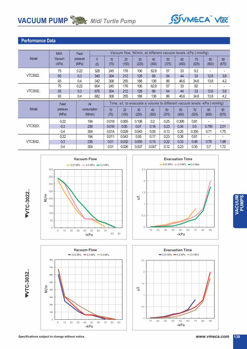
VA
CU
UM
P
UM
PS
139Specifications subject to change without notice. www.vmeca.com
Performance Data
Model
MaX.
Vacuum
(-kPa)
Feed
pressure
(MPa)
0
(0)
0.22
0.3
0.4
0.22
0.3
0.4
328
340
342
604
676
682
245
304
308
245
304
308
176
212
255
176
212
255
106
128
188
106
128
188
62.8
66
138
62.8
66
138
57
64
86
57
64
86
33
44
46.6
33
44
46.6
9.2
33
34.6
92
33
34.6
-
12.8
13.8
-
12.8
13.8
-
3.8
4.2
-
3.8
4.2
Vacuum flow, nl/min, at different vacuum levels -kPa (-mmHg)
VTC3022..
10(75)
80(600)
70(525)
60(450)
50(375)
40(300)
30(225)
90(675)
20(150)
VTC3032..
VTC3032..
Model
Feed
pressure
(MPa)
air
consumption
(nl/min)
194
236
304
194
236
304
Time, s/l, to evacuate a volume to different vacuum levels -kPa (-mmHg)
VTC3022..
10(75)
80(600)
70(525)
60(450)
50(375)
40(300)
30(225)
90(675)
20(150)
0.018
0.016
0.014
0.011
0.01
0.01
0.065
0.05
0.029
0.043
0.032
0.026
0.108
0.07
0.043
0.05
0.055
0.037
0.2
0.16
0.05
0.17
0.15
0.047
0.25
0.23
0.13
0.23
0.22
0.12
0.395
0.34
0.25
0.38
0.33
0.23
0.81
0.5
0.355
0.81
0.48
0.35
-
0.795
0.71
-
0.78
0.7
-
2.01
1.75
-
1.98
1.72
75
93
93
75
93
93
0.22
0.3
0.4
0.22
0.3
0.4
VT
C-3
022..
VT
C-3
032..
VACUUM PUMP Midi Turtle Pump

Specifications subject to change without notice.140 www.vmeca.com
VTCL 3032 / 3022 Series
Patented design.
High operational reliability despite fluctuating or low compressed-air pressure.
Integrated high dirt holding capacity pleated filter.
VMeCa Twofold SilencerPT assures low noise levels.
Optional air-Saving(aS) kit available to minimize energy consumption.
Optional factory installed air control/Vacuum release valves and Vacuum switch available.
Compact size and light weight.
easily mountable and interchangeable vacuum cartridge.
Main advantages
Max. vacuum level
Max. flow rate
Supply air pressure
Air consumption
Supply air type
Working temperature
Noise level
: -75 kPa (-22.15 inHg)
: 724 nl/min (25.57 scfm)
: 4 ~ 6 bar, max 7 bar(58~87 psi, max 101.5 psi)
: 140~208 nl/min (4.94~7.35 scfm)
: Dry compressed air
: -20⓳ to +80⓳
: 50~60 ⓳g
Order no.
no mark - Vacuum gauge.
⓳ Remark: ⓳ S..(P)
Output type :PnP open collector
⓳ VCM8 42 : M8-4Pin connector wire.Only for type S2 or S2(P).
S2(P) - Digital display output 2points, no analog supplyM8-4Pin Connector type 0.3m lead wire.
Sg2(P) - Digital display output 2 points, no analog supplygrommet type 4-Core 2m lead wire.
Sg3(P) - Digital display output 2 points, analog supplygrommet type 5-Core 2m lead wire.
Model
Voltage of air supplycontrol valve
Voltage of vacuumrelease control valve
Sealing
VTCL 3022 - Two stage nozzle
VTCL 3032(P) - Three stage nozzle
no mark - Standard
AS - air saving kit
no mark - Standard
V - Viton
e - ePDM
⓳ Remark:..(P)
g3/8”exhaust Port
non-return valve
no mark - Standard
N - non-return valve.
a1 - aC110V
a2 - aC220V
A3 - DC24V
D1* - aC110V
D2* - aC220V
D3* - DC24V
* D.. : Double solenoid valve isavailable only with ‘Dn’ or ‘DL’, section ⓳
1
4
5
air saving kit3
8
Vacuum switch7
9
R1 - aC110V
R2 - aC220V
R3 - DC24V
R
⓳⓳ ⓳⓳
VTCL 3032 - 2 - AS - A3 R3 - CL - S2 N V
⓳ ⓳ ⓳ ⓳
2
Material
Polyester (Pe)
Connection port
BSP Thread(g)
Filter element & Connection port2
⓳
Dn - DIn type without lead wire
DL - DIn type with lamp without lead wire
CL* Connector type with lamp &0.3 m lead wire
2B* DIn type with ‘2 in 1’ BuS cable(air control v/v + Vacuum release v/v)
Solenoid Terminal6
-
3B* DIn type with ‘3 in 1’ BuS cable(air control v/v + Vacuum release v/v + Digital switch)
-
-
* Can not available with double solenoid valve
⓳ Remark CL : available only with DC24V3B : available only with DC24V
available only with ‘S2’ or ‘S2P’, section ⓳
VACUUM PUMP Midi Turtle Pump
⓳ About ‘BUS cable’ ( 340, 341)
( 108)

VA
CU
UM
P
UM
PS
141Specifications subject to change without notice. www.vmeca.com
Performance Data
Model
MaX.
Vacuum
(-kPa)
Feed
pressure
(MPa)
0
(0)
0.4
0.5
0.6
0.4
0.5
0.6
376
390
400
604
688
724
316
352
366
352
392
415
220
260
308
220
260
308
140
164
200
140
164
200
92
100
104
92
100
104
56
75
76
56
75
76
13.6
46
64
13.6
46
64
-
23.8
44
-
23.8
44
-
-
-
-
-
-
-
-
-
-
-
-
-
-
-
-
-
-
-
-
-
-
-
-
Vacuum flow, nl/min, at different vacuum levels -kPa (-mmHg)
VTCL3022..
10(75)
80(600)
70(525)
60(450)
50(375)
40(300)
30(225)
90(675)
20(150)
VTCL3032..
60
70
75
60
70
75
VTCL3032
Model
Feed
pressure
(MPa)
air
consumption
(nl/min)
140
170
208
140
170
208
Time, s/l, to evacuate a volume to different vacuum levels -kPa (-mmHg)
VTCL3022
10(75)
0.018
0.014
0.013
0.013
0.009
0.006
0.04
0.036
0.032
0.037
0.032
0.03
0.08
0.075
0.06
0.073
0.06
0.047
0.145
0.125
0.1
0.14
0.128
0.098
0.195
0.15
0.155
0.19
0.16
0.15
0.5
0.2
0.18
0.45
0.25
0.2
-
0.4
0.35
-
0.43
0.32
80(600)
70(525)
60(450)
50(375)
40(300)
30(225)
90(675)
20(150)
0.4
0.5
0.6
0.4
0.5
0.6
VT
CL
-3022..
VT
CL
-3032..
VACUUM PUMP Midi Turtle Pump

Measure unit : mm [in]
Specifications subject to change without notice.142 www.vmeca.com
With air Control valve, Vacuum Release Control valve and Digital Vacuum Switch
With air Control valve, Vacuum Release Control valve and Digital Vacuum Switch
VTC 3022.. / VTCL 3022..
VTC 3032.. / VTCL 3032..
Dimensional Information
Measure unit : mm [in]
VACUUM PUMP Midi Turtle Pump

VA
CU
UM
P
UM
PS
143Specifications subject to change without notice. www.vmeca.com
Standard
Standard
VTC 3022.. / VTCL 3022..
Dimensional Information
VTC 3032.. / VTCL 3032..
Measure unit : mm [in]
VACUUM PUMP Midi Turtle Pump
Measure unit : mm [in]
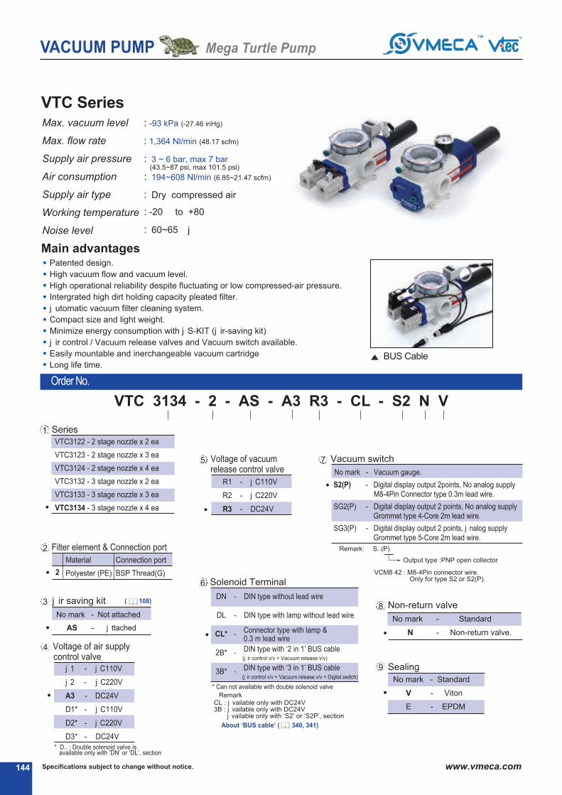
Series
VTC3122 - 2 stage nozzle x 2 ea
VTC3123 - 2 stage nozzle x 3 ea
VTC3124 - 2 stage nozzle x 4 ea
VTC3132 - 3 stage nozzle x 2 ea
VTC3133 - 3 stage nozzle x 3 ea
VTC3134 - 3 stage nozzle x 4 ea
1
Specifications subject to change without notice.144 www.vmeca.com
VTC SeriesMax. vacuum level
Max. flow rate
Supply air pressure
Air consumption
Supply air type
Working temperature
Noise level
Order No.
☞☞ ☞☞
VTC 3134 - 2 - AS - A3 R3 - CL - S2 N V
☞ ☞ ☞ ☞
: -93 kPa (-27.46 inHg)
: 1,364 Nl/min (48.17 scfm)
: 3 ~ 6 bar, max 7 bar(43.5~87 psi, max 101.5 psi)
: 194~608 Nl/min (6.85~21.47 scfm)
: Dry compressed air
: -20☞ to +80☞
: 60~65 ☞j
☞
No mark - Vacuum gauge.
☞ Remark: ☞ S..(P)
Output type :PNP open collector
☞ VCM8 42 : M8-4Pin connector wire.Only for type S2 or S2(P).
S2(P) - Digital display output 2points, No analog supplyM8-4Pin Connector type 0.3m lead wire.
SG2(P) - Digital display output 2 points, No analog supplyGrommet type 4-Core 2m lead wire.
SG3(P) - Digital display output 2 points, j nalog supplyGrommet type 5-Core 2m lead wire.
Voltage of air supplycontrol valve
Voltage of vacuumrelease control valve
Sealing
No mark - Not attached
AS - j ttached
No mark - Standard
V - Viton☞
E - EPDM
Non-return valve
No mark - Standard
N - Non-return valve.
j 1 - j C110V
j 2 - j C220V
A3 - DC24V
D1* - j C110V
D2* - j C220V
D3* - DC24V
* D.. : Double solenoid valve isavailable only with ‘DN’ or ‘DL’, section ☞
4
5
j ir saving kit 38
Vacuum switch7
9
R1 - j C110V
R2 - j C220V
R3 - DC24V
2
Material
Polyester (PE)
Connection port
BSP Thread(G)
Filter element & Connection port2
DN - DIN type without lead wire
DL - DIN type with lamp without lead wire
CL* Connector type with lamp &0.3 m lead wire
2B* DIN type with ‘2 in 1’ BUS cable(j ir control v/v + Vacuum release v/v)
Solenoid Terminal6
-
3B* DIN type with ‘3 in 1’ BUS cable(j ir control v/v + Vacuum release v/v + Digital switch)
-
-
* Can not available with double solenoid valve
☞ Remark CL : j vailable only with DC24V3B : j vailable only with DC24V
j vailable only with ‘S2’ or ‘S2P’, section ☞
Patented design.
High vacuum flow and vacuum level.
High operational reliability despite fluctuating or low compressed-air pressure.
Intergrated high dirt holding capacity pleated filter.
j utomatic vacuum filter cleaning system.
Compact size and light weight.
Minimize energy consumption with j S-KIT (j ir-saving kit)
j ir control / Vacuum release valves and Vacuum switch available.
Easily mountable and inerchangeable vacuum cartridge
Long life time.
Main advantages
BUS Cable
VACUUM PUMP Mega Turtle Pump
☞ About ‘BUS cable’ ( 340, 341)
( 108)

145Specifications subject to change without notice. www.vmeca.com
VA
CU
UM
P
UM
PS
Performance Data
Model
Mj X.
Vacuum
(-kPa)
Feed
pressure
(MPa)
0
(0)
Vacuum flow, Nl/min, at different vacuum levels -kPa (-mmHg)
VTC3122
10
(75)
80
(600)
70
(525)
60
(450)
50
(375)
40
(300)
30
(225)
90
(675)
20
(150)
VTC3123
Model
Feed
pressure
(MPa)
j ir
consumption
(Nl/min)
Time, s/l, to evacuate a volume to different vacuum levels -kPa (-mmHg)
10
(75)
80
(600)
70
(525)
60
(450)
50
(375)
40
(300)
30
(225)
90
(675)
20
(150)
75
93
93
75
93
93
75
93
93
75
93
93
75
93
93
75
93
93
0.22
0.3
0.4
0.22
0.3
0.4
0.22
0.3
0.4
0.22
0.3
0.4
0.22
0.3
0.4
0.22
0.3
0.4
0.22
0.3
0.4
0.22
0.3
0.4
0.22
0.3
0.4
0.22
0.3
0.4
0.22
0.3
0.4
0.22
0.3
0.4
194
236
304
291
354
456
388
472
608
194
236
304
291
354
456
388
472
608
0.018
0.016
0.014
0.01
0.009
0.008
0.008
0.007
0.006
0.011
0.01
0.01
0.006
0.005
0.004
0.005
0.004
0.003
0.065
0.05
0029
0.04
0.03
0.019
0.03
0.025
0.015
0.043
0.032
0.026
0.03
0.02
0.01
0.02
0.018
0.01
0.108
0.07
0.043
0.07
0.06
0.03
0.05
0.048
0.023
0.05
0.045
0.037
0.038
0.03
0.02
0.027
0.02
0.01
0.2
0.16
0.05
0.13
0.1
0.033
0.095
0.08
0.025
0.17
0.15
0.047
0.1
0.09
0.03
0.08
0.07
0.02
0.25
0.23
0.13
0.16
0.13
0.08
0.12
0.1
0.06
0.23
0.22
0.12
0.14
0.12
0.06
0.1
0.09
0.05
0.395
0.34
0.25
0.24
0.21
0.16
0.18
0.16
0.12
0.38
0.33
0.23
0.24
0.21
0.14
0.18
0.16
0.1
0.81
0.5
0.355
0.54
0.26
0.23
0.4
0.2
0.17
0.81
0.48
0.35
0.54
0.24
0.2
0.4
0.2
0.15
-
0.795
0.71
-
0.4
0.35
-
0.3
0.26
-
0.78
0.7
-
0.4
0.33
-
0.3
0.25
-
2.01
1.75
-
1.27
1.17
-
0.95
0.87
-
1.98
1.72
-
1.27
1.13
-
0.95
0.85
328
340
342
492
510
513
656
680
684
604
676
682
902
1014
1023
1208
1352
1364
245
304
308
367
456
462
490
608
616
245
304
308
368
456
462
490
608
616
176
212
255
264
318
383
352
424
510
176
212
255
264
318
383
352
424
510
106
128
188
159
192
282
212
256
376
106
128
188
159
192
282
212
256
376
62.8
66
138
94
99
207
126
132
276
62.8
66
138
94
99
207
126
132
276
57
64
86
86
96
129
114
128
172
57
64
86
86
96
129
114
128
172
33
44
46.6
50
66
70
66
88
93
33
44
46.6
50
66
70
66
88
93
9.2
33
34.6
14
50
52
18
66
69
9.2
33
34.6
14
50
52
18
66
69
-
12.8
13.8
-
19
21
-
26
28
-
12.8
13.8
-
19
21
-
26
28
-
3.8
4.2
-
6
6.3
-
7.6
8.4
-
3.8
4.2
-
6
6.3
-
7.6
8.4
VTC3124
VTC3132
VTC3133
VTC3134
VTC3122
VTC3123
VTC3124
VTC3132
VTC3133
VTC3134
VACUUM PUMP Mega Turtle Pump

Specifications subject to change without notice.146 www.vmeca.comSpecifications subject to change without notice.
VACUUM PUMP Mega Turtle Pump

147Specifications subject to change without notice. www.vmeca.com
VA
CU
UM
P
UM
PS
VACUUM PUMP Mega Turtle Pump

Patented design.
High vacuum flow and vacuum level.
High operational reliability despite fluctuating or low compressed-air pressure.
Intergrated high dirt holding capacity pleated filter.
j utomatic vacuum filter cleaning system.
Compact size and light weight.
Minimize energy consumption with j S-KIT (j ir-saving kit)
j ir control / Vacuum release valves and Vacuum switch available.
Easily mountable and inerchangeable vacuum cartridge
Long life time.
Max. vacuum level
Max. flow rate
Supply air pressure
Air consumption
Supply air type
Working temperature
Noise level
Specifications subject to change without notice.148 www.vmeca.com
VTCL - Series
Main advantages
Series
VTCL3122 - 2 stage nozzle x 2 ea
VTCL3123 - 2 stage nozzle x 3 ea
VTCL3124 - 2 stage nozzle x 4 ea
VTCL3132 - 3 stage nozzle x 2 ea
VTCL3133 - 3 stage nozzle x 3 ea
VTCL3134 - 3 stage nozzle x 4 ea
1
Order No.
: -75 kPa (-22.15 inHg)
: 1,448 Nl/min (51.13 scfm)
: 4 ~ 6 bar, max 7 bar(58~87 psi, max 101.5 psi)
: 140~416 Nl/min (4.94~14.69 scfm)
: Dry compressed air
: -20☞ to +80☞
: 60~65 ☞j
☞☞ ☞☞
VTCL 3134 - 2 - AS - A3 R3 - CL - S2 N V
☞ ☞ ☞ ☞ ☞
No mark - Vacuum gauge.
☞ Remark: ☞ S..(P)
Output type :PNP open collector
☞ VCM8 42 : M8-4Pin connector wire.Only for type S2 or S2(P).
S2(P) - Digital display output 2points, No analog supplyM8-4Pin Connector type 0.3m lead wire.
SG2(P) - Digital display output 2 points, No analog supplyGrommet type 4-Core 2m lead wire.
SG3(P) - Digital display output 2 points, j nalog supplyGrommet type 5-Core 2m lead wire.
Voltage of air supplycontrol valve
Voltage of vacuumrelease control valve
Sealing
No mark - Not attached
AS - j ttached
No mark - Standard
V - Viton☞
E - EPDM
Non-return valve
No mark - Standard
N - Non-return valve.
j 1 - j C110V
j 2 - j C220V
A3 - DC24V
D1* - j C110V
D2* - j C220V
D3* - DC24V
* D.. : Double solenoid valve isavailable only with ‘DN’ or ‘DL’, section ☞
4
5
j ir saving kit 38
Vacuum switch7
9
R1 - j C110V
R2 - j C220V
R3 - DC24V
2
Material
Polyester (PE)
Connection port
BSP Thread(G)
Filter element & Connection port2
DN - DIN type without lead wire
DL - DIN type with lamp without lead wire
CL* Connector type with lamp &0.3 m lead wire
2B* DIN type with ‘2 in 1’ BUS cable(j ir control v/v + Vacuum release v/v)
Solenoid Terminal6
-
3B* DIN type with ‘3 in 1’ BUS cable(j ir control v/v + Vacuum release v/v + Digital switch)
-
-
* Can not available with double solenoid valve
☞ Remark CL : j vailable only with DC24V3B : j vailable only with DC24V
j vailable only with ‘S2’ or ‘S2P’, section ☞
BUS Cable
VACUUM PUMP Mega Turtle Pump
☞ About ‘BUS cable’ ( 340, 341)
( 108)
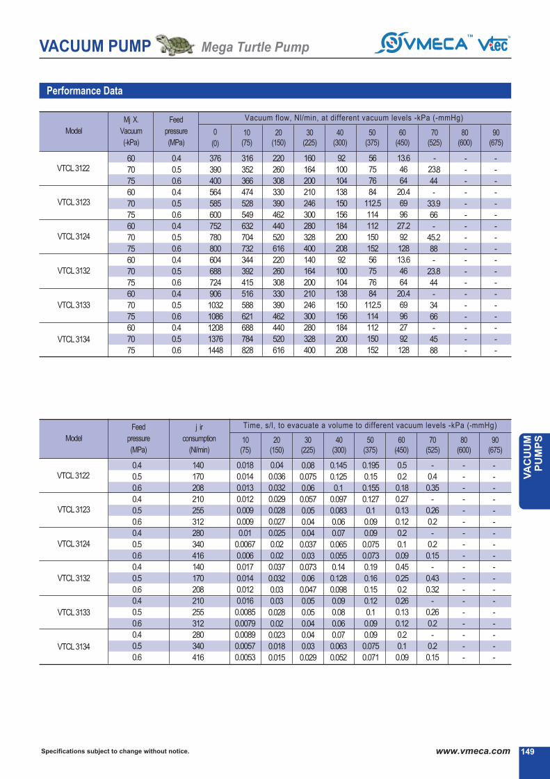
149Specifications subject to change without notice. www.vmeca.com
VA
CU
UM
P
UM
PS
Performance Data
Model
Mj X.
Vacuum
(-kPa)
Feed
pressure
(MPa)
0
(0)
Vacuum flow, Nl/min, at different vacuum levels -kPa (-mmHg)
VTCL3122
10
(75)
80
(600)
70
(525)
60
(450)
50
(375)
40
(300)
30
(225)
90
(675)
20
(150)
VTCL3123
Model
Feed
pressure
(MPa)
j ir
consumption
(Nl/min)
Time, s/l, to evacuate a volume to different vacuum levels -kPa (-mmHg)
10
(75)
80
(600)
70
(525)
60
(450)
50
(375)
40
(300)
30
(225)
90
(675)
20
(150)
60
70
75
60
70
75
60
70
75
60
70
75
60
70
75
60
70
75
0.4
0.5
0.6
0.4
0.5
0.6
0.4
0.5
0.6
0.4
0.5
0.6
0.4
0.5
0.6
0.4
0.5
0.6
0.4
0.5
0.6
0.4
0.5
0.6
0.4
0.5
0.6
0.4
0.5
0.6
0.4
0.5
0.6
0.4
0.5
0.6
140
170
208
210
255
312
280
340
416
140
170
208
210
255
312
280
340
416
0.018
0.014
0.013
0.012
0.009
0.009
0.01
0.0067
0.006
0.017
0.014
0.012
0.016
0.0085
0.0079
0.0089
0.0057
0.0053
0.04
0.036
0.032
0.029
0.028
0.027
0.025
0.02
0.02
0.037
0.032
0.03
0.03
0.028
0.02
0.023
0.018
0.015
0.08
0.075
0.06
0.057
0.05
0.04
0.04
0.037
0.03
0.073
0.06
0.047
0.05
0.05
0.04
0.04
0.03
0.029
0.145
0.125
0.1
0.097
0.083
0.06
0.07
0.065
0.055
0.14
0.128
0.098
0.09
0.08
0.06
0.07
0.063
0.052
0.195
0.15
0.155
0.127
0.1
0.09
0.09
0.075
0.073
0.19
0.16
0.15
0.12
0.1
0.09
0.09
0.075
0.071
0.5
0.2
0.18
0.27
0.13
0.12
0.2
0.1
0.09
0.45
0.25
0.2
0.26
0.13
0.12
0.2
0.1
0.09
-
0.4
0.35
-
0.26
0.2
-
0.2
0.15
-
0.43
0.32
-
0.26
0.2
-
0.2
0.15
-
-
-
-
-
-
-
-
-
-
-
-
-
-
-
-
-
-
-
-
-
-
-
-
-
-
-
-
-
-
-
-
-
-
-
-
376
390
400
564
585
600
752
780
800
604
688
724
906
1032
1086
1208
1376
1448
316
352
366
474
528
549
632
704
732
344
392
415
516
588
621
688
784
828
220
260
308
330
390
462
440
520
616
220
260
308
330
390
462
440
520
616
160
164
200
210
246
300
280
328
400
140
164
200
210
246
300
280
328
400
92
100
104
138
150
156
184
200
208
92
100
104
138
150
156
184
200
208
56
75
76
84
112.5
114
112
150
152
56
75
76
84
112.5
114
112
150
152
13.6
46
64
20.4
69
96
27.2
92
128
13.6
46
64
20.4
69
96
27
92
128
-
23.8
44
-
33.9
66
-
45.2
88
-
23.8
44
-
34
66
-
45
88
-
-
-
-
-
-
-
-
-
-
-
-
-
-
-
-
-
-
-
-
-
-
-
-
-
-
-
-
-
-
-
-
-
-
-
-
VTCL3124
VTCL3132
VTCL3133
VTCL3134
VTCL3122
VTCL3123
VTCL3124
VTCL3132
VTCL3133
VTCL3134
VACUUM PUMP Mega Turtle Pump

Specifications subject to change without notice.150 www.vmeca.com
VACUUM PUMP Mega Turtle Pump

151Specifications subject to change without notice. www.vmeca.com
VA
CU
UM
P
UM
PS
VACUUM PUMP Mega Turtle Pump

Specifications subject to change without notice.152 www.vmeca.com
Standard
With Air Control valve, Vacuum Release Control valve and Digital Vacuum Switch
Series VTC 313( ).. / VTCL 313( )..
Dimensional Information
Series VTC 313( ).. / VTCL 313( )..
VACUUM PUMP Mega Turtle Pump
Measure unit : mm [in]
Measure unit : mm [in]

153Specifications subject to change without notice. www.vmeca.com
VA
CU
UM
P
UM
PS
Standard
With Air Control valve, Vacuum Release Control valve and Digital Vacuum Switch
Series VTC 312( ).. / VTCL 312( )..
Dimensional Information
Series VTC 312( ).. / VTCL 312( )..
VACUUM PUMP Mega Turtle Pump
Measure unit : mm [in]
Measure unit : mm [in]


VV- - PUMPSPUMPS

VACUUM PUMP V - Pump
Specifications subject to change without notice.156 www.vmeca.com156156
Enable to decide the series of VMECj V-PUMP the performance you need.
Vacuum release control valve
VMECA Vacuum Cartridge
Air control valveDistributor (Manifold)
VMECA Twofold Silencer
High vacuum level (-93 kPa) at low compressed inlet air pressure (3~6 bar).
High vacuum flow rate to compensate for fluctuating or low compressed air pressure.
Suitable for sealed system applications such as lifting metal sheets of glass plate.
Vacuum level (-75 kPa) at general inlet air pressure (6 bar)
Extra high vacuum flow rate and suitable for non-sealed system application.
VS Series
VLS Series
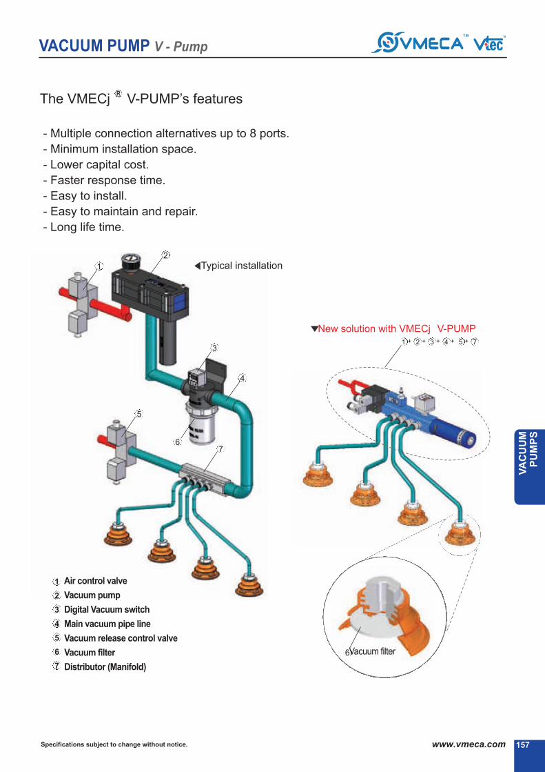
VACUUM PUMP V - Pump
157Specifications subject to change without notice. www.vmeca.com
VA
CU
UM
P
UM
PS
R
157157
The VMECj V-PUMP’s features
- Multiple connection alternatives up to 8 ports.
- Minimum installation space.
- Lower capital cost.
- Faster response time.
- Easy to install.
- Easy to maintain and repair.
- Long life time.
Typical installation
New solution with VMECj V-PUMP
Vacuum filter
Air control valve
Vacuum pump
Digital Vacuum switch
Main vacuum pipe line
Vacuum release control valve
Vacuum filter
Distributor (Manifold)
2
1
5
3
4
67
1 + 2 + 3 + 4 + 5 + 7
1
2
3
4
5
6
7
6
☞
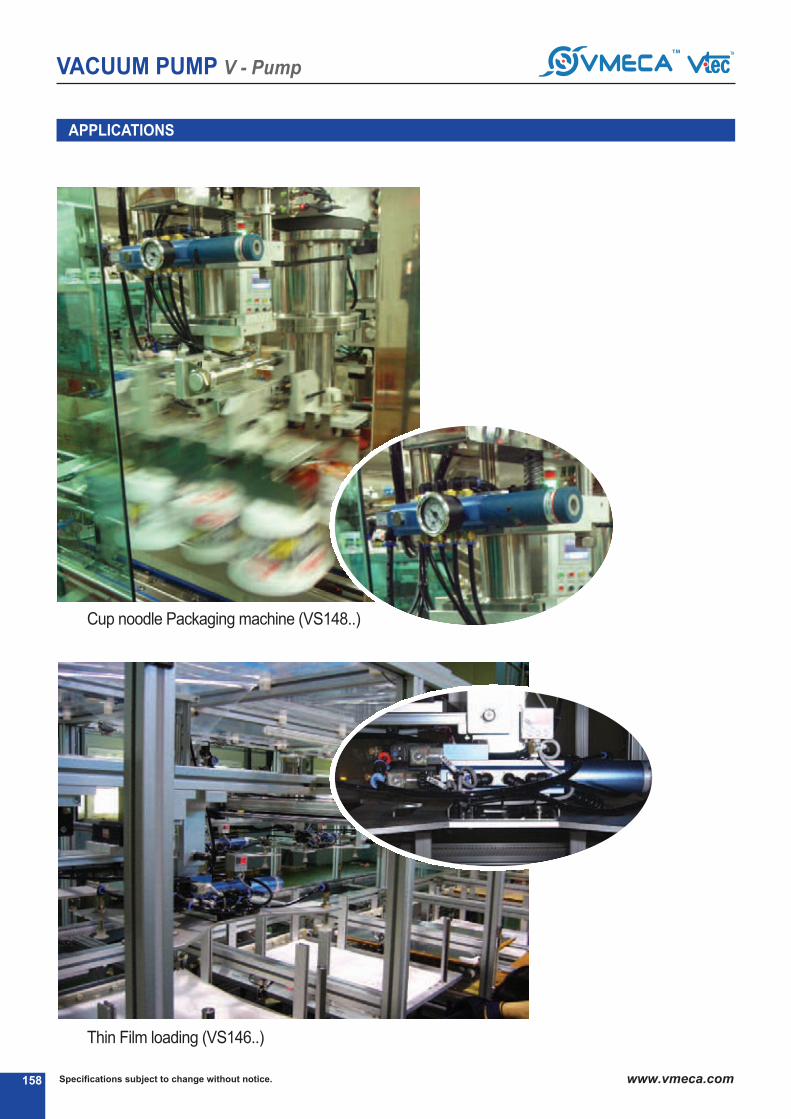
VACUUM PUMP V - Pump
Specifications subject to change without notice.158 www.vmeca.com
Thin Film loading (VS146..)☞☞
APPLICATIONS
Cup noodle Packaging machine (VS148..)

VACUUM PUMP V - Pump
159Specifications subject to change without notice. www.vmeca.com
VA
CU
UM
P
UM
PS
VS - Series
Main advantages
High operational reliability despite fluctuating.
Quick response time.
VMECj Tworfold SilencerPT assures low noise levels.
Easy to distribute vacuum. (Multiple connection alternatives up to 9 ports.)
Optional j ir-Saving(j S)kit available to minimize energy consumption.
Optional factrory installed air control/vacuum release valves and vacuum switch available.
Easily mountalbe and interchangeable vacuum cartridge.
Max. vacuum level
Max. flow rate
Supply air pressure
Air consumption
Supply air type
Working temperature
Noise level
Vacuum Port
144 - G1/4̋X 4Ej
146 - G1/4̋X 6Ej
148 - G1/4̋X 8Ej
No mark - Standard
AS - j ir saving kit
attached
1
j ir saving kit2
: -93 kPa (-27.46 inHg)
: 341 Nl/min (12.04 scfm)
: 3 ~ 6 bar, max 7 bar(43.5~87 psi, max 101.5 psi)
: 97~152 Nl/min (3.43~5.37 scfm)
: Dry compressed air
: -20☞ to +80☞
: 50~60 ☞j
Order No.
No mark - Vacuum gauge.
☞ Remark: ☞ S..(P)
Output type :PNP open collector
☞ VCM8 42 : M8-4Pin connector wire.Only for type S2 or S2(P).
S2(P) - Digital display output 2points, No analog supplyM8-4Pin Connector type 0.3m lead wire.
SG2(P) - Digital display output 2 points, No analog supplyGrommet type 4-Core 2m lead wire.
SG3(P) - Digital display output 2 points, j nalog supplyGrommet type 5-Core 2m lead wire.
Voltage of air supplycontrol valve
Vacuum release flow adjust
Sealing
No mark - Standard
V - Viton☞
E - EPDM
Non-return valve
No mark - Standard
N - Non-return valve.j 1 - j C110V
j 2 - j C220V
A3 - DC24V
D1* - j C110V
D2* - j C220V
D3* - DC24V
* D.. : Double solenoid valve isavailable only with ‘DN’ or ‘DL’, section ☞
3
6
8
Vacuum switch7
9
☞☞ ☞☞
VS 144 - AS - A3 R3 - CL A - S2 N V
☞ ☞ ☞ ☞ ☞
DN - DIN type without lead wire
DL - DIN type with lamp without lead wire
CL* Connector type with lamp &0.3 m lead wire
2B* DIN type with ‘2 in 1’ BUS cable(j ir control v/v + Vacuum release v/v)
Solenoid Terminal5
-
3B* DIN type with ‘3 in 1’ BUS cable(j ir control v/v + Vacuum release v/v + Digital switch)
-
-
* Can not available with double solenoid valve
☞ Remark CL : j vailable only with DC24V3B : j vailable only with DC24V
j vailable only with ‘S2’ or ‘S2P’, section ☞
Voltage of vacuumrelease control valve
4
R1 - j C110V
R2 - j C220V
R3 - DC24V
No mark - Standard
A - j ttached
☞ About ‘BUS cable’ ( 340, 341)
( 108)

VACUUM PUMP V - Pump
Specifications subject to change without notice.160 www.vmeca.com160
Performance Data
Series
Mj X.
Vacuum
(-kPa)
Feed
pressure
(MPa)
0
(0)
0.22
0.3
0.4
122.5
152
154
302
338
341
88
106
127.5
53
64
94
31.4
33
69
28.5
32
43
16.5
22
23.3
4.6
16.5
17.3
-
6.4
6.9
-
1.9
2.1
Vacuum flow, Nl/min, at different vacuum levels -kPa (-mmHg)
VS
10
(75)
80
(600)
70
(525)
60
(450)
50
(375)
40
(300)
30
(225)
90
(675)
20
(150)
Series
Feed
pressure
(MPa)
j ir
consumption
(Nl/min)
97
118
152
Time, s/l, to evacuate a volume to different vacuum levels -kPa (-mmHg)
VS
10
(75)
20
(150)
80
(600)
70
(525)
60
(450)
50
(375)
40
(300)
30
(225)
90
(675)
0.019
0.015
0.01
0.09
0.07
0.48
0.1
0.18
0.07
0.32
028
0.09
0.42
0.38
0.2
0.73
0.64
0.42
1.62
0.8
0.8
-
12
1
-
3.8
3.4
75
93
93
0.22
0.3
0.4

VACUUM PUMP V - Pump
161Specifications subject to change without notice. www.vmeca.com
VA
CU
UM
P
UM
PS
High operational reliability despite fluctuating.
Quick response time.
VMECj Twofold SilencerPT assures low noise levels.
Easy to distribute vacuum. (Multiple connection alternatives up to 8 ports.)
Optional j ir-Saving(j S) kit available to minimize energy consumption.
Optional factory installed air control/vacuum release valves and vacuum switch available.
Easily mountable and interchangeable vacuum cartridge.
Main Advantages
VLS-SeriesMax. vacuum level
Max. flow rate
Supply air pressure
Air consumption
Supply air type
Working temperature
Noise level
Order No.
: -75 kPa (-22.15 inHg)
: 362 Nl/min (12.79 scfm)
: 4 ~ 6 bar, max 7 bar(58~87 psi, max 101.5 psi)
: 70~104 Nl/min (2.47~3.67 scfm)
: Dry compressed air
: -20☞ to +80☞
: 50~60 ☞j
Vacuum Port
144 - G1/4̋X 4Ej
146 - G1/4̋X 6Ej
148 - G1/4̋X 8Ej
No mark - Standard
AS - j ir saving kit
attached
1
j ir saving kit2
No mark - Vacuum gauge.
☞ Remark: ☞ S..(P)
Output type :PNP open collector
☞ VCM8 42 : M8-4Pin connector wire.Only for type S2 or S2(P).
S2(P) - Digital display output 2points, No analog supplyM8-4Pin Connector type 0.3m lead wire.
SG2(P) - Digital display output 2 points, No analog supplyGrommet type 4-Core 2m lead wire.
SG3(P) - Digital display output 2 points, j nalog supplyGrommet type 5-Core 2m lead wire.
Voltage of air supplycontrol valve
Sealing
No mark - Standard
V - Viton☞
E - EPDM
Non-return valve
No mark - Standard
N - Non-return valve.j 1 - j C110V
j 2 - j C220V
A3 - DC24V
D1* - j C110V
D2* - j C220V
D3* - DC24V
* D.. : Double solenoid valve isavailable only with ‘DN’ or ‘DL’, section ☞
38
Vacuum switch7
9
☞☞ ☞☞
VLS 144 - AS - A3 R3 - CL A - S2 N V
☞ ☞ ☞ ☞ ☞
DN - DIN type without lead wire
DL - DIN type with lamp without lead wire
CL* Connector type with lamp &0.3 m lead wire
2B* DIN type with ‘2 in 1’ BUS cable(j ir control v/v + Vacuum release v/v)
Solenoid Terminal5
-
3B* DIN type with ‘3 in 1’ BUS cable(j ir control v/v + Vacuum release v/v + Digital switch)
-
-
* Can not available with double solenoid valve
☞ Remark CL : j vailable only with DC24V3B : j vailable only with DC24V
j vailable only with ‘S2’ or ‘S2P’, section ☞
Voltage of vacuumrelease control valve
4
R1 - j C110V
R2 - j C220V
R3 - DC24V
Vacuum release flow adjust6
No mark - Standard
A - j ttached
108
☞ About ‘BUS cable’ ( 340, 341)
( 108)
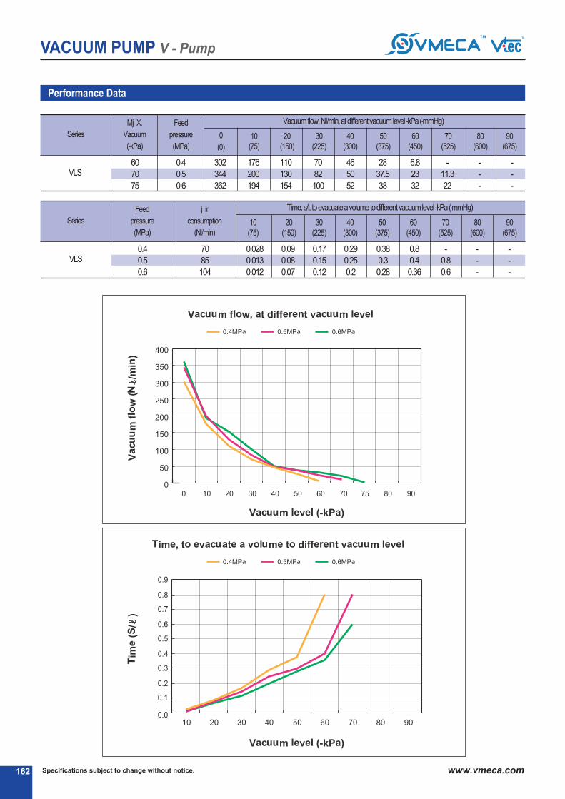
VACUUM PUMP V - Pump
Specifications subject to change without notice.162 www.vmeca.com162
Performance Data
Series
Mj X.
Vacuum
(-kPa)
Feed
pressure
(MPa)
0
(0)
0.4
0.5
0.6
176
200
194
302
344
362
110
130
154
70
82
100
46
50
52
28
37.5
38
6.8
23
32
-
11.3
22
-
-
-
-
-
-
Vacuumflow, NI/min, atdifferentvacuumlevel -kPa(-mmHg)
VLS
10
(75)
80
(600)
70
(525)
60
(450)
50
(375)
40
(300)
30
(225)
90
(675)
20
(150)
Series
Feed
pressure
(MPa)
j ir
consumption
(Nl/min)
70
85
104
Time, s/l, toevacuateavolumetodifferentvacuumlevel -kPa(-mmHg)
VLS
10
(75)
20
(150)
80
(600)
70
(525)
60
(450)
50
(375)
40
(300)
30
(225)
90
(675)
0.028
0.013
0.012
0.09
0.08
0.07
0.17
0.15
0.12
0.29
0.25
0.2
0.38
0.3
0.28
0.8
0.4
0.36
-
0.8
0.6
-
-
-
-
-
-
60
70
75
0.4
0.5
0.6

VACUUM PUMP V - Pump
163Specifications subject to change without notice. www.vmeca.com
VA
CU
UM
P
UM
PS
163
Standard
With Vacuum control valve, Vacuum release control valve and Digital Vacuum Switch
Series VS 144.. / VLS 144..
Series VS 144.. / VLS 144..
Dimensional Information
Measure unit : mm [in]
Measure unit : mm [in]

VACUUM PUMP V - Pump
Specifications subject to change without notice.164 www.vmeca.com
78 [3.07"]
285 [11.22"]
G
G
164
Standard
With Vacuum control valve, Vacuum release control valve and Digital Vacuum Switch
Series VS 146.. / VLS 146..
Series VS 146.. / VLS 146..
Dimensional Information
Measure unit : mm [in]
Measure unit : mm [in]
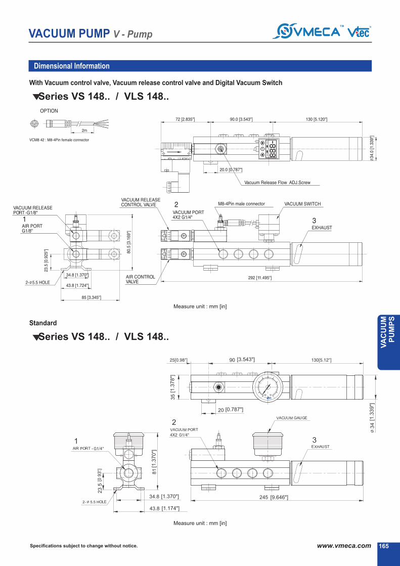
VACUUM PUMP V - Pump
165Specifications subject to change without notice. www.vmeca.com
VA
CU
UM
P
UM
PS
165
Standard
With Vacuum control valve, Vacuum release control valve and Digital Vacuum Switch
Series VS 148.. / VLS 148..
Series VS 148.. / VLS 148..
Dimensional Information
Measure unit : mm [in]
Measure unit : mm [in]


MDMD--PUMPSPUMPS
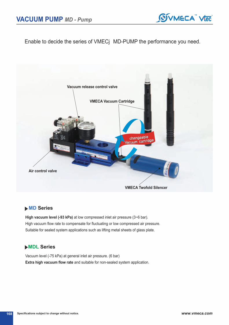
Specifications subject to change without notice.168 www.vmeca.com
VACUUM PUMP MD - Pump
168
Enable to decide the series of VMECj MD-PUMP the performance you need.
High vacuum level (-93 kPa) at low compressed inlet air pressure (3~6 bar).
High vacuum flow rate to compensate for fluctuating or low compressed air pressure.
Suitable for sealed system applications such as lifting metal sheets of glass plate.
MD Series
MDL Series
Vacuum release control valve
VMECA Vacuum Cartridge
Air control valve
VMECA Twofold Silencer
Vacuum level (-75 kPa) at general inlet air pressure. (6 bar)
Extra high vacuum flow rate and suitable for non-sealed system application.

169Specifications subject to change without notice. www.vmeca.com
VA
CU
UM
P
UM
PS
VACUUM PUMP MD - Pump
169
Lightweight design of the VMECj MD-PUMP reduces the robot size requirement through direct mount
on a robot-controlled gripper and improves the production time mounted close to the point of use.
APPLICATIONS
Vacuum filter

Specifications subject to change without notice.170 www.vmeca.com
VACUUM PUMP MD - Pump
170
APPLICATIONS
Circuit Board holding plate☞

* H22 : For direct installation
171Specifications subject to change without notice. www.vmeca.com
VA
CU
UM
P
UM
PS
VACUUM PUMP MD - Pump
171
MD-SeriesMax. vacuum level
Max. flow rate
Supply air pressure
Air consumption
Supply air type
Working temperature
Noise level
: -93 kPa (-27.46 inHg)
: 341 Nl/min (12.04 scfm)
: 3 ~ 6 bar, max 7 bar(43.5~87 psi, max 101.5 psi)
: 97~152 Nl/min (3.43~5.37 scfm)
: Dry compressed air
: -20☞ to +80☞
: 50~60 ☞j
Order No.
No mark - Vacuum gauge.
☞ Remark: ☞ S..(P)
Output type :PNP open collector
☞ VCM8 42 : M8-4Pin connector wire.Only for type S2 or S2(P).
S2(P) - Digital display output 2points, No analog supplyM8-4Pin Connector type 0.3m lead wire.
SG2(P) - Digital display output 2 points, No analog supplyGrommet type 4-Core 2m lead wire.
SG3(P) - Digital display output 2 points, j nalog supplyGrommet type 5-Core 2m lead wire.
Voltage of air supplycontrol valve
Sealing
No mark - Standard
V - Viton☞
E - EPDM
Non-return valve
No mark - Standard
N - Non-return valve.
j 1 - j C110V
j 2 - j C220V
A3 - DC24V
D1* - j C110V
D2* - j C220V
D3* - DC24V
* D.. : Double solenoid valve isavailable only with ‘DN’ or ‘DL’, section ☞
5
10
Vacuum switch9
11
☞☞ ☞☞
MD 303 S - 34 AS A3 R3 - CL A - S2 - N V
☞ ☞ ☞ ☞ ☞ ☞ ☞
Model
MD 303 - 3 stage nozzle
MD 302 - 2 stage nozzle
S* - Twofold Silencer
P - G3/8” port
1
Exhaust type2
No mark - Standard
AS - j ir saving kit
j ir saving kit4
*S : Only for MD303..
34 - G3/4˝
H22* - Ø22 Hole
Vacuum port3
Voltage of vacuumrelease control valve
6
R1 - j C110V
R2 - j C220V
R3 - DC24V
DN - DIN type without lead wire
DL - DIN type with lamp without lead wire
CL* Connector type with lamp &0.3 m lead wire
2B* DIN type with ‘2 in 1’ BUS cable(j ir control v/v + Vacuum release v/v)
Solenoid Terminal7
-
3B* DIN type with ‘3 in 1’ BUS cable(j ir control v/v + Vacuum release v/v + Digital switch)
-
-
* Can not available with double solenoid valve
☞ Remark CL : j vailable only with DC24V3B : j vailable only with DC24V
j vailable only with ‘S2’ or ‘S2P’, section ☞
Vacuum releaseflow adjust
8
No mark - Standard
A - j ttached
Located at or near the point of use thus reducing system volume, increase and reducing cycle time
Compact in size and light weight
Maintain vacuum despite fluctuations and drops in air pressure
VMECj TWOFOLD SILENCERPT assures low noise levels (about 30% lower than conventional silencer)
j djustable exhaust direction
Optional j ir-saving kit (j S-KIT) available to minimize energy consumption.
Optional factory installed air control / vacuum release valves and digital vacuum switch available.
Easily mountable and interchangeable vacuum cartridge (save the maintenance time)
Main Advantages
☞ About ‘BUS cable’ ( 340, 341)
( 108)

Specifications subject to change without notice.172 www.vmeca.com
VACUUM PUMP MD - Pump
172
MD
-302..
MD
-303..
Performance Data
Model
Mj X.
Vacuum
(-kPa)
Feed
pressure
(MPa)
0
(0)
0.22
0.3
0.4
0.22
0.3
0.4
164
170
171
302
338
341
122.5
152
154
122.5
152
154
88
106
127.5
88
106
127.5
53
64
94
53
64
94
31.4
33
69
31.4
33
69
28.5
32
43
28.5
32
43
16.5
22
23.3
16.5
22
23.3
4.6
16.5
17.3
4.6
16.5
17.3
-
6.4
6.9
-
6.4
6.9
-
1.9
2.1
-
1.9
2.1
Vacuum flow, Nl/min, at different vacuum levels -kPa (-mmHg)
MD302..
10
(75)
80
(600)
70
(525)
60
(450)
50
(375)
40
(300)
30
(225)
90
(675)
20
(150)
MD303..
MD303..
Model
Feed
pressure
(MPa)
j ir
consumption
(Nl/min)
97
118
152
97
118
152
Time, s/l, to evacuate a volume to different vacuum levels -kPa (-mmHg)
MD302..
10
(75)
80
(600)
70
(525)
60
(450)
50
(375)
40
(300)
30
(225)
90
(675)
20
(150)
0.03
0.027
0.026
0.019
0.015
0.01
0.12
0.1
0.058
0.09
0.07
0.048
0.21
0.19
0.09
0.1
0.18
0.07
0.38
0.3
0.1
0.32
0.28
0.09
0.47
0.4
0.25
0.42
0.38
0.2
0.73
0.64
0.5
0.73
0.64
0.42
1.62
0.8
0.69
1.62
0.8
1.6
-
12
1.05
-
1.2
1
-
3.8
3.5
-
3.8
3.4
75
93
93
75
93
93
0.22
0.3
0.4
0.22
0.3
0.4

173Specifications subject to change without notice. www.vmeca.com
VA
CU
UM
P
UM
PS
VACUUM PUMP MD - Pump
MDL-SeriesMax. vacuum level
Max. flow rate
Supply air pressure
Air consumption
Supply air type
Working temperature
Noise level
: -75 kPa (-22.15 inHg)
: 362 Nl/min (12.79 scfm)
: 4 ~ 6 bar, max 7 bar(58~87 psi, max 101.5 psi)
: 70~104 Nl/min (2.47~3.67 scfm)
: Dry compressed air
: -20☞ to +80☞
: 50~60 ☞j
* H22 : For direct installation
No mark - Vacuum gauge.
☞ Remark: ☞ S..(P)
Output type :PNP open collector
☞ VCM8 42 : M8-4Pin connector wire.Only for type S2 or S2(P).
S2(P) - Digital display output 2points, No analog supplyM8-4Pin Connector type 0.3m lead wire.
SG2(P) - Digital display output 2 points, No analog supplyGrommet type 4-Core 2m lead wire.
SG3(P) - Digital display output 2 points, j nalog supplyGrommet type 5-Core 2m lead wire.
Voltage of air supplycontrol valve
Sealing
No mark - Standard
V - Viton☞
E - EPDM
Non-return valve
No mark - Standard
N - Non-return valve.
j 1 - j C110V
j 2 - j C220V
A3 - DC24V
D1* - j C110V
D2* - j C220V
D3* - DC24V
* D.. : Double solenoid valve isavailable only with ‘DN’ or ‘DL’, section ☞
5
10
Vacuum switch9
11
Model
MDL 303 - 3 stage nozzle
MDL 302 - 2 stage nozzle
S* - Twofold Silencer
P - G3/8” port
Exhaust type2
No mark - Standard
AS - j ir saving kit
j ir saving kit4
*S : Only for MDL303..
34 - G3/4˝
H22* - Ø22Hole
Vacuum port3
Voltage of vacuumrelease control valve
6
R1 - j C110V
R2 - j C220V
R3 - DC24V
DN - DIN type without lead wire
DL - DIN type with lamp without lead wire
CL* Connector type with lamp &0.3 m lead wire
2B* DIN type with ‘2 in 1’ BUS cable(j ir control v/v + Vacuum release v/v)
Solenoid Terminal7
-
3B* DIN type with ‘3 in 1’ BUS cable(j ir control v/v + Vacuum release v/v + Digital switch)
-
-
* Can not available with double solenoid valve
☞ Remark CL : j vailable only with DC24V3B : j vailable only with DC24V
j vailable only with ‘S2’ or ‘S2P’, section ☞
Vacuum releaseflow adjust
8
No mark - Standard
A - j ttached
Located at or near the point of use thus reducing system volume, increase and reducing cycle time
Compact in size and light weight
Maintain vacuum despite fluctuations and drops in air pressure
VMECj TWOFOLD SILENCERPT assures low noise levels (about 30% lower than conventional silencer)
j djustable exhaust direction
Optional j ir-saving kit (j S-KIT) available to minimize energy consumption.
Optional factory installed air control / vacuum release valves and digital vacuum switch available.
Easily mountable and interchangeable vacuum cartridge (save the maintenance time)
Main Advantages
1
Order No.
☞☞ ☞☞
MDL 303 S - 34 AS A3 R3 - CL A - S2 - N V
☞ ☞ ☞ ☞ ☞ ☞ ☞
☞ About ‘BUS cable’ ( 340, 341)
( 108)

Specifications subject to change without notice.174 www.vmeca.com
VACUUM PUMP MD - Pump
174
MD
L-3
02..
MD
L-3
03..
Performance Data
Model
Mj X.
Vacuum
(-kPa)
Feed
pressure
(MPa)
0
(0)
0.4
0.5
0.6
0.4
0.5
0.6
188
195
200
302
344
362
158
176
183
176
200
194
110
130
154
110
130
154
70
82
100
70
82
100
46
50
52
46
50
52
28
37.5
38
28
37.5
38
6.8
23
32
6.8
23
32
-
11.3
22
-
11.3
22
-
-
-
-
-
-
-
-
-
-
-
-
Vacuum flow, Nl/min, at different vacuum levels -kPa (-mmHg)
MDL302..
10
(75)
80
(600)
70
(525)
60
(450)
50
(375)
40
(300)
30
(225)
90
(675)
20
(150)
MDL303..
MDL303..
Model
Feed
pressure
(MPa)
j ir
consumption
(Nl/min)
70
85
104
70
85
104
Time, s/l, to evacuate a volume to different vacuum levels -kPa (-mmHg)
MDL302..
10
(75)
80
(600)
70
(525)
60
(450)
50
(375)
40
(300)
30
(225)
90
(675)
20
(150)
0.035
0.027
0.028
0.028
0.013
0.012
0.084
0.08
0.08
0.09
0.08
0.07
0.17
0.15
0.12
0.17
0.15
0.12
0.29
0.25
0.2
0.29
0.25
0.2
0.38
0.3
0.28
0.38
0.3
0.28
0.8
0.4
0.36
0.8
0.4
0.36
-
0.8
0.6
-
0.8
0.6
-
-
-
-
-
-
-
-
-
-
-
-
60
70
75
60
70
75
0.4
0.5
0.6
0.4
0.5
0.6
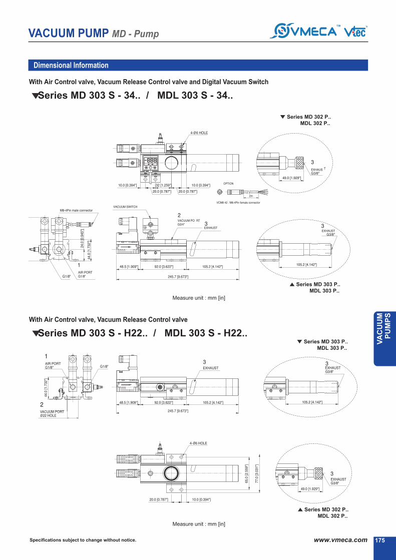
175Specifications subject to change without notice. www.vmeca.com
VA
CU
UM
P
UM
PS
VACUUM PUMP MD - Pump
175
Dimensional Information
With Air Control valve, Vacuum Release Control valve
With Air Control valve, Vacuum Release Control valve and Digital Vacuum Switch
Series MD 303 S - 34.. / MDL 303 S - 34..
Series MD 303 S - H22.. / MDL 303 S - H22..
Series MD 303 P..
MDL 303 P..
Series MD 303 P..
MDL 303 P..
Series MD 302 P..
MDL 302 P..
Series MD 302 P..
MDL 302 P..
Measure unit : mm [in]
Measure unit : mm [in]

Specifications subject to change without notice.176 www.vmeca.com
VACUUM PUMP MD - Pump
176
Dimensional Information
With Air Control valve (Double sol.type), Vacuum Release Control valve
With Air Control valve (Double sol.type), Vacuum Release Control valve and Digital Vacuum Switch
Series MD 303 S - 34.. / MDL 303 S - 34..
Series MD 303 S - H22.. / MDL 303 S - H22..
Series MD 302 P..
MDL 302 P..
Series MD 303 P..
MDL 303 P..
Series MD 303 P..
MDL 303 P..
Series MD 302 P..
MDL 302 P..
Measure unit : mm [in]
Measure unit : mm [in]

177Specifications subject to change without notice. www.vmeca.com
VA
CU
UM
P
UM
PS
VACUUM PUMP MD - Pump
177177
Dimensional Information
Standard
Standard
Series MD 303 S - 34.. / MDL 303 S - 34..
Series MD 303 S - H22.. / MDL 303 S - H22..
Series MD 302 P..
MDL 302 P..
Series MD 303 P..
MDL 303 P..
Series MD 303 P..
MDL 303 P..
Series MD 302 P..
MDL 302 P..
Measure unit : mm [in]
Measure unit : mm [in]


PREMIUM PUMPSPREMIUM PUMPS

VACUUM PUMP Premium - Pump
Specifications subject to change without notice.180 www.vmeca.com
Choose the VMECA PREMIUM PUMP that is right for your application.
High vacuum level (-93 kPa) at low compressed air pressure (3~6 bar).
High vacuum flow rate despite fluctuating or low compressed air pressure.
Suitable for sealed system applications such as lifting metal sheets or glass plate.
Extra high vacuum flow rate and suitable for non-sealed system applications.
Vacuum level of -75 kPa at a compressed air pressure of 6 bar.
PM Series
PML Series

Choose the VMECA PREMIUM PUMP that is right for your application.
VACUUM PUMP Premium - Pump
181Specifications subject to change without notice. www.vmeca.com
VA
CU
UM
P
UM
PS
The VMECA PREMIUM VACUUM PUMP can directly replace a Classic Vacuum Pump
without changing mounting holes or brackets.
APPLICATIONS

VACUUM PUMP Premium - Pump
Specifications subject to change without notice.182 www.vmeca.com182
Despite fluctuations and drops in air pressure, the PREMIUM PUMP maintains a high flow rate
along with a high and stable vacuum level eliminating lost or interrupted cycles.
This pump is excellent for non-sealed system applications or where large suction cups are used.
The VMECA PREMIUM VACUUM PUMP can be mounted directly inline to save space and is suitable
for applications requiring high suction flows or evacuation of large volumes of air (i.e. vacuum chamber)
APPLICATIONS
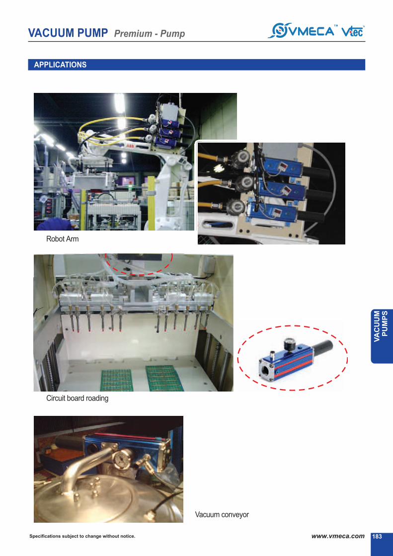
VACUUM PUMP Premium - Pump
183Specifications subject to change without notice. www.vmeca.com
VA
CU
UM
P
UM
PS
183
APPLICATIONS
Robot Arm▶
Circuit board roading▶
Vacuum conveyor
▶

Max. vacuum level
Max. flow rate
Supply air pressure
Air consumption
Supply air type
Working temperature
Noise level
* 34 : Body type B is available onlywith vacuum port 34
VACUUM PUMP Premium - Pump
Specifications subject to change without notice.184 www.vmeca.com184
Maintains vacuum despite fluctuations and drops in air pressure.
Various connection ports available.
Fast evacuation time.
Optional Air-Saving Kit (AS-KIT) available to minimize energy consumption.
Optional factory installed air control / vacuum release valves and digital vacuum switches available.
Strong aluminum body.
Easily mountable and maintainable with interchangeable vacuum cartridge.
Main Advantages
PM-Series: -93 kPa (-27.46 inHg)
: 341~1364 Nl/min (12.04~48.17 scfm)
: 3 ~ 6 bar, max 7 bar(43.5~87 psi, max 101.5 psi)
: 97~608 Nl/min (3.43~21.47 scfm)
: Dry compressed air
: -20▶ to +80▶
: 60~65
S2(P) - Digital output 2 points, No analog supply.M8-4Pin male connector. (0.3m lead wire)
SG2(P) - Digital output 2 points, No analog supply.Grommet type 4-Core 2m lead wire
SG3(P) - Digital output 2 points, Analog supply.Grommet type 5-Core 2m lead wire.
Model (Vacuum flows)
Sealing
No mark - NBR
V - Viton▶
E - EPDM
1
Body type2
Mounting bracket411
A - Vacuum port on side
B - Vacuum port on top & side
PM303 X 1 - 341 Nl/min
PM303 X 2 - 682 Nl/min
PM303 X 3 - 1023 Nl/min
PM303 X 4 - 1364 Nl/min
No mark - Not included
B1 - 4 Point surpport
B2 - 2 Point L-type
No mark - Not included
AS - Air saving kit
Air saving kit5
Voltage of air supplycontrol valve
A1 - AC110V
A2 - AC220V
A3 - DC24V
D1* - AC110V
D2* - AC220V
D3* - DC24V
* D.. : Double solenoid valve isavailable only with ‘DN’ or ‘DL’, section ▶
6
No mark - Vacuum gauge attached
▶ Remark: ▶ S..(P)
Output type :PNP open collector
▶ VCM8 42 : M8-4Pin connector wire.Only for type S2 or S2(P).
Vacuum switch9
34 * - G3/4˝
01 - G1˝
Vacuum port3
Order No.
▶▶ ▶▶
PM 303X1 A - 34 - B1 - AS - A3 R3 - CL - S2 N V
▶ ▶ ▶ ▶ ▶ ▶ ▶
Voltage of vacuumrelease control valve
7
R1 - AC110V
R2 - AC220V
R3 - DC24V
Non-return valve
No mark - Not included
N - Non-return valve
10
DN - DIN type without lead wire
DL - DIN type with lamp without lead wire
CL* Connector type with lamp &0.3 m lead wire
2B* DIN type with ‘2 in 1’ BUS cable(Air control v/v + Vacuum release v/v)
Solenoid Terminal8
-
3B* DIN type with ‘3 in 1’ BUS cable(Air control v/v + Vacuum release v/v + Digital switch)
-
-
* Can not available with double solenoid valve
▶ Remark CL : Available only with DC24V3B : Available only with DC24V
Available only with ‘S2’ or ‘S2P’, section ▶
( 108)
▶ About ‘BUS cable’ ( 340, 341)

VACUUM PUMP Premium - Pump
185Specifications subject to change without notice. www.vmeca.com
VA
CU
UM
P
UM
PS
185
Performance Data
Model
MAX.
Vacuum
(-kPa)
Feed
pressure
(MPa)
0
(0)
0.22
0.3
0.4
0.22
0.3
0.4
0.22
0.3
0.4
0.22
0.3
0.4
302
338
341
604
676
682
902
1014
1023
1208
1352
1364
122.5
152
154
245
304
308
368
456
462
490
608
616
88
106
127.5
176
212
255
264
318
383
352
424
510
53
64
94
106
128
188
159
192
282
212
256
376
31.4
33
69
62.8
66
138
94
99
207
126
132
276
28.5
32
43
57
64
86
86
96
129
114
128
172
16.5
22
23.3
33
44
46.6
50
66
70
66
88
93
4.6
16.5
17.3
9.2
3.3
34.6
14
50
52
18
66
69
-
6.4
6.9
-
12.8
13.8
-
19
21
-
26
28
-
1.9
2.1
-
3.8
4.2
-
6
6.3
-
7.6
8.4
PM303X1..
10(75)
80(600)
70(525)
60(450)
50(375)
40(300)
30(225)
90(675)
20(150)
PM303X2..
PM303X3..
PM303X4..
75
93
93
75
93
93
75
93
93
75
93
93
Vacuum flow, Nl/min, at different vacuum levels -kPa (-mmHg)
PM 303 X1 ..
PM 303 X3 .. PM 303 X4 ..
PM 303 X2 ..

VACUUM PUMP Premium - Pump
Specifications subject to change without notice.186 www.vmeca.com186
Performance Data
Model
Feed
pressure
(MPa)
Air
consumption
(Nl/min)
97
118
158
194
236
304
291
354
456
388
472
608
0.019
0.015
0.01
0.011
0.01
0.01
0.006
0.005
0.004
0.005
0.004
0.003
0.009
0.07
0.048
0.043
0.032
0.026
0.03
0.02
0.01
0.02
0.018
0.01
0.16
0.1
0.07
0.05
0.045
0.037
0.038
0.03
0.02
0.027
0.02
0.01
0.32
0.28
0.09
0.17
0.15
0.047
0.1
0.09
0.03
0.08
0.07
0.02
0.42
0.38
0.2
0.23
0.22
0.12
0.14
0.12
0.06
0.1
0.09
0.05
0.73
0.64
0.42
0.38
0.33
0.23
0.24
0.21
0.14
0.18
0.16
0.1
1.62
0.8
0.6
0.81
0.48
0.35
0.54
0.24
0.2
0.4
0.2
0.15
-
1.2
1
-
0.78
0.7
-
0.4
0.33
-
0.3
0.25
-
3.8
3.4
-
1.98
1.72
-
1.27
1.13
-
0.95
0.85
PM303X1..
PM303X2..
PM303X3..
PM303X4..
0.22
0.3
0.4
0.22
0.3
0.4
0.22
0.3
0.4
0.22
0.3
0.4
Time, s/l, to evacuate a volume to different vacuum levels -kPa (-mmHg)
PM 303 X1 .. PM 303 X2 ..
10(75)
80(600)
70(525)
60(450)
50(375)
40(300)
30(225)
90(675)
20(150)
PM 303 X3 .. PM 303 X4 ..
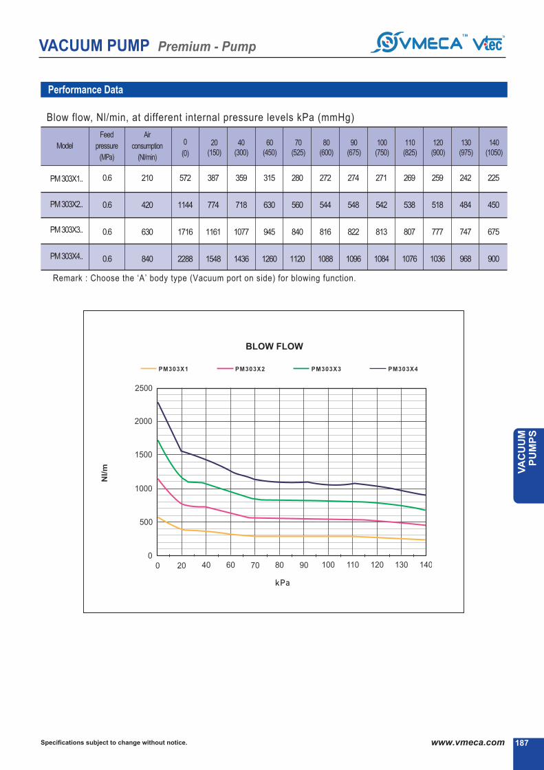
VACUUM PUMP Premium - Pump
187Specifications subject to change without notice. www.vmeca.com
VA
CU
UM
P
UM
PS
187
Performance Data
Model
Feed
pressure
(MPa)
Air
consumption
(Nl/min)
PM303X1.. 210
420
630
840
572
1144
1716
2288
387
774
1161
1548
359
718
1077
1436
315
630
945
1260
280
560
840
1120
272
544
816
1088
274
548
822
1096
271
542
813
1084
269
538
807
1076
259
518
777
1036
242
484
747
968
225
450
675
900
0.6
0.6
0.6
0.6
PM303X2..
PM303X3..
PM303X4..
Blow flow, Nl/min, at different internal pressure levels kPa (mmHg)
▶ Remark : Choose the ‘A’ body type (Vacuum port on side) for blowing function.
0
(0)
80(600)
70(525)
60(450)
40(300)
90(675)
100(750)
110(825)
120(900)
130(975)
140(1050)
20(150)
BLOW FLOW

VACUUM PUMP Premium - Pump
Specifications subject to change without notice.188 www.vmeca.com188
PML-SeriesMax. vacuum level
Max. flow rate
Supply air pressure
Air consumption
Supply air type
Working temperature
Noise level
: -75 kPa (-22.15 inHg)
: 362~1448 Nl/min (12.78~51.14 scfm)
: 4 ~ 6 bar, max 7 bar(58~87 psi, max 101.5 psi)
: 70~416 Nl/min (3.43~21.47 scfm)
: Dry compressed air
: -20▶ to +80▶
: 60~65
Order No.
Large vacuum flow rate yet low air consumption.
Various connection ports available.
Fast evacuation time.
Optional Air-Saving Kit (AS-KIT) available to minimize energy consumption.
Optional factory installed air control / vacuum release valves and digital vacuum switches available.
Strong aluminum body.
Easily mountable and maintainable with interchangeable vacuum cartridge.
Main Advantages
R
S2(P) - Digital output 2 points, No analog supply.M8-4Pin male connector. (0.3m lead wire)
SG2(P) - Digital output 2 points, No analog supply.Grommet type 4-Core 2m lead wire
SG3(P) - Digital output 2 points, Analog supply.Grommet type 5-Core 2m lead wire.
Sealing
No mark - NBR
V - Viton
E - EPDM
Body type2
Mounting bracket411
A - Vacuum port on side
B - Vacuum port on top & side
No mark - Not included
B1 - 4 Point surpport
B2 - 2 Point L-type
No mark - Not included
AS - Air saving kit
Air saving kit5
Voltage of air supplycontrol valve
A1 - AC110V
A2 - AC220V
A3 - DC24V
D1* - AC110V
D2* - AC220V
D3* - DC24V
* D.. : Double solenoid valve isavailable only with ‘DN’ or ‘DL’, section ▶
6
No mark - Vacuum gauge attached
▶ Remark: ▶ S..(P)
Output type :PNP open collector
▶ VCM8 42 : M8-4Pin connector wire.Only for type S2 or S2(P).
Vacuum switch9
Voltage of vacuumrelease control valve
7
R1 - AC110V
R2 - AC220V
R3 - DC24V
Non-return valve
No mark - Not included
N - Non-return valve
10
DN - DIN type without lead wire
DL - DIN type with lamp without lead wire
CL* Connector type with lamp &0.3 m lead wire
2B* DIN type with ‘2 in 1’ BUS cable(air control v/v + Vacuum release v/v)
Solenoid Terminal8
-
3B* DIN type with ‘3 in 1’ BUS cable(air control v/v + Vacuum release v/v) + Digital switch
-
-
* Can not available with double solenoid valve
▶ Remark
CL : Available only with DC24V3B : Available only with DC24V
Available only with ‘S2’ or ‘S2P’, section ▶
* 34 : Body type B is available only with vacuum port 34
Model (Vacuum flows)1
PML303 X 1 - 362 Nl/min
PML303 X 2 - 724 Nl/min
PML303 X 3 - 1086 Nl/min
PML303 X 4 - 1448 Nl/min
34 * - G3/4˝
01 - G1˝
Vacuum port3
▶▶ ▶▶
PML 303X1 A - 34 - B1 - AS - A3 R3 - CL - S2 N V
▶ ▶ ▶ ▶ ▶ ▶ ▶
( 108)
▶ About ‘BUS cable’ ( 340, 341)

VACUUM PUMP Premium - Pump
189Specifications subject to change without notice. www.vmeca.com
VA
CU
UM
P
UM
PS
189
Performance Data
Model
0.4
0.5
0.6
0.4
0.5
0.6
0.4
0.5
0.6
0.4
0.5
0.6
302
344
362
604
688
724
906
1032
1086
1208
1376
1448
172
196
207
344
392
415
516
588
621
688
784
828
110
130
154
220
260
308
330
390
462
440
520
616
70
82
100
140
164
200
210
246
300
280
328
400
46
50
52
92
100
104
138
150
156
184
200
208
28
37.5
38
56
75
76
84
112.5
114
112
150
152
6.8
23
32
13.6
46
64
20.4
69
96
27
92
128
-
11.3
22
-
23.8
44
-
34
66
-
45
88
-
-
-
-
-
-
-
-
-
-
-
-
-
-
-
-
-
-
-
-
-
-
-
-
PML303X1..
PML303X2..
PML303X3..
PML303X4..
60
70
75
60
70
75
60
70
75
60
70
75
Vacuum flow, Nl/min, at different vacuum levels -kPa (-mmHg)
PML 303 X1 ..
PML 303 X3 .. PML 303 X4 ..
PML 303 X2 ..
MAX.
Vacuum
(-kPa)
Feed
pressure
(MPa)
0
(0)
10(75)
80(600)
70(525)
60(450)
50(375)
40(300)
30(225)
90(675)
20(150)

VACUUM PUMP Premium - Pump
Specifications subject to change without notice.190 www.vmeca.com190
Performance Data
Model
Feed
pressure
(MPa)
Air
consumption
(Nl/min)
70
85
104
140
170
208
210
255
312
280
340
416
0.032
0.023
0.022
0.017
0.014
0.012
0.016
0.0085
0.0079
0.0089
0.0057
0.0053
0.09
0.08
0.07
0.037
0.032
0.03
0.03
0.028
0.02
0.023
0.018
0.015
0.17
0.15
0.12
0.073
0.06
0.047
0.05
0.05
0.04
0.04
0.03
0.029
0.29
0.25
0.2
0.14
0.128
0.098
0.09
0.08
0.06
0.07
0.063
0.052
0.38
0.3
0.28
0.19
0.16
0.15
0.12
0.1
0.09
0.09
0.075
0.071
0.8
0.4
0.36
0.45
0.25
0.2
0.26
0.13
0.12
0.2
0.1
0.09
-
0.8
0.6
-
0.43
0.32
-
0.26
0.2
-
0.2
0.15
-
-
-
-
-
-
-
-
-
-
-
-
-
-
-
-
-
-
-
-
-
-
-
-
PML303X1..
PML303X2..
PML303X3..
PML303X4..
0.4
0.5
0.6
0.4
0.5
0.6
0.4
0.5
0.6
0.4
0.5
0.6
PML 303 X1 ..
PML 303 X3 .. PML 303 X4 ..
PML 303 X2 ..
Time, s/l, to evacuate a volume to different vacuum levels -kPa(-mmHg)
10(75)
80(600)
70(525)
60(450)
50(375)
40(300)
30(225)
90(675)
20(150)

VACUUM PUMP Premium - Pump
191Specifications subject to change without notice. www.vmeca.com
VA
CU
UM
P
UM
PS
191
Performance Data
Model
Feed
pressure
(MPa)
Air
consumption
(Nl/min)
PML303X1.. 104
208
312
416
470
940
1404
1868
320
640
966
1284
272
544
822
1096
225
450
678
904
196
392
589
784
189
378
564
752
165
330
492
656
140
280
416
556
0.6
0.6
0.6
0.6
PML303X2..
PML303X3..
PML303X4..
▶ Remark : Choose the ‘A’ body type (Vacuum port on side) for blowing function.
Blow flow, Nl/min, at different internal pressure levels kPa (mmHg)
0
(0)
10(75)
70(525)
60(450)
50(375)
40(300)
30(225)
20(150)
BLOW FLOW
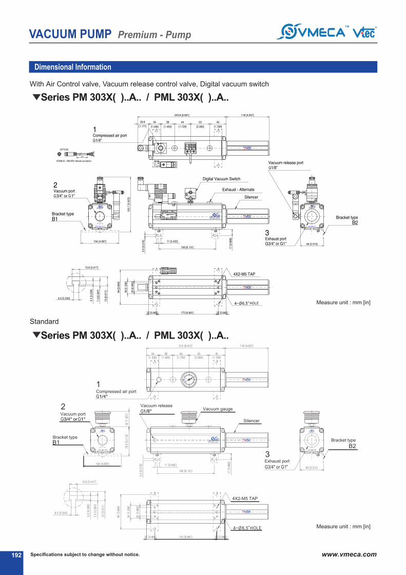
VACUUM PUMP Premium - Pump
Specifications subject to change without notice.192 www.vmeca.com192
Series PM 303X( )..A.. / PML 303X( )..A..
Dimensional Information
With Air Control valve, Vacuum release control valve, Digital vacuum switch
Measure unit : mm [in]
Standard
Series PM 303X( )..A.. / PML 303X( )..A..
Measure unit : mm [in]

VACUUM PUMP Premium - Pump
193Specifications subject to change without notice. www.vmeca.com
VA
CU
UM
P
UM
PS
193
With Air Control valve, Vacuum release control valve, Digital vacuum switch
Dimensional Information
Series PM 303X( )..B.. / PML 303X( )..B..
Measure unit : mm [in]
Standard
Series PM 303X( )..B.. / PML 303X( )..B..
Measure unit : mm [in]


KEYBOARD PUMPSKEYBOARD PUMPS

Specifications subject to change without notice.196 www.vmeca.com
VACUUM PUMP Mini Keyboard Pump
High efficiency Mini vacuum pump (Multi-Nozzle type).
Available of individual control.
Long life time and Low noise level.
Easy to install and Compact size (10mm).
Lightweight.
Built-in check valve.
Integrated Vacuum Pump, Air supply & vacuum release control valve, Vacuum Switch & Filter,
Blowing flow control valve and silencer in a body.
Main Advantages
Mini Keyboard PumpMax. vacuum level
Max. flow rate
Supply air pressure
Supply air type
Working temperature
Noise level
OnlyDC24Visavailable forvalveConnector typewith0.3mleadwire▶ lamp
4 - Ø4 (0.D: standard)
6 - Ø6 (0.D)
nomark
V
E
- standard (NBR)
- Viton▶
- EPDM
▶ Vacuum port
▶ Sealing
●
●
Air Supply Control Valve VacuumReleaseControlValve Vacuum Switch
A
B
C
D
E
F
G
H
I
J
K
▶ (N.C. : Normal Closed)
▶ (N.O. : Normal open)
▶ (N.C. : Normal Closed)
▶ (N.O. : Normal open)
▶ (N.C. : Normal Closed)
▶ (N.O. : Normal open)
▶ (N.C. : Normal Closed)
▶ (N.O. : Normal open)
▶ (N.C. : Normal Closed)
▶ (N.C. : Normal Closed)
▶ (N.C. : Normal Closed)
▶ (N.C. : Normal Closed)
▶ (N.C. : Normal Closed)
▶ (N.C. : Normal Closed)
▶
▶
▶
▶
▶
▶
▶ Valves
●
nomark
N
- standard
- nonreturnvalve●
▶ Non return valve
VKX5 - 23 Nl/min
VKM5 - 26 Nl/min
S
M
E
▶ Body type▶ Model-Vacuum Flow
● ●
1-1 Stack 6-6 Stack
2-2 Stack 7-7 Stack
3-3 Stack 8-8 Stack
4-4 Stack 9-9 Stack
5-5 Stack 10-10 Stack
▶ Vacuum Stack●
▶ Remark : A...(P)
Output type : PNP open collector
: VKX pump -92 kPa (-27.16 inHg)VKM pump -85 kPa (-25.1 inHg)
: VKX pump 23 Nl/min (0.81 scfm)VKM pump 26 Nl/min (0.91 scfm)
: 3~6 bar, Max. 7 bar(43.5~87 psi, max 101.5 psi)
: Dry compressed air
: -20▶ to +80▶
: 50~65
Order No.
▶▶ ▶▶
VKM5 - M6 - A 4 N V
▶ ▶ ▶
- singleunit
- manifoldunit
- manifoldunitwithcentralexhaustunit
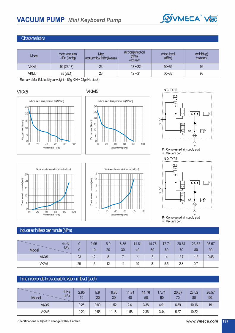
197Specifications subject to change without notice. www.vmeca.com
VACUUM PUMP Mini Keyboard Pump
Modelmax. vacuum-kPa(-inHg)
noise level(dBA)
Max. vacuumflow(Nl/m)/eachstack
airconsumption(Nl/m)/
eachstack
VKX5
VKM5
92 (27.17)
85 (25.1)
23
26
13 ~ 22
12 ~ 21
50~65
50~65
weight (g)/eachstack
96
96
VKM5VKX5
▶ Remark : Manifold unit type weight = 86g X N + 22g (N : stack)
VKX5
VKM5
0.26
0.22
0.80
0.56
1.52
1.18
2.4
1.58
3.38
2.36
4.91
3.44
6.89
5.27
10.16
10.22
19
Model
VKX5
VKM5
-inHg-kPa
23
26
0
12
15
2.95
8
12
5.9
7
11
8.85
6
10
11.81
5
8
14.76
4
5.5
17.71
2.7
2.8
20.67
1.2
0.7
23.62
0.45
26.57
0 10 20 30 40 50 60 70 80 90
2.95 5.9 8.85 11.81 14.76 17.71 20.67 23.62 26.57
Model
-inHg-kPa
Induce air in liters per minute (Nl/min) Induce air in liters per minute (Nl/min)
Tim
ein
seco
nds
toev
acua
te(s
ec/l)
Tim
ein
seco
nds
toev
acua
te(s
ec/l)
Vacu
um
flow
(Nl/m
in)
Vacu
um
flow
(Nl/m
in)
Vacuum level (-kPa)Vacuum level (-kPa)
Vacuum level (-kPa)Vacuum level (-kPa)
Induceair in litersperminute(Nl/m)
Timeinsecondstoevacuatetovacuumlevel (sec/l)
Characteristics
10 20 30 40 50 60 70 80 90
Timeinsecondstoevacuatetovacuumlevel(sec/l)Timeinsecondstoevacuatetovacuumlevel(sec/l)

Specifications subject to change without notice.198 www.vmeca.com
VACUUM PUMP Mini Keyboard Pump
Single unit
Dimensional Information
[ Measure unit : mm ]
[ Measure unit : inch ]

VACUUM PUMP Mini Keyboard Pump
199Specifications subject to change without notice. www.vmeca.com
VA
CU
UM
P
UM
PS
Manifold unit
Manifold unit with central exhaust unit
Stack A (mm)
2stack
3stack
4stack
5stack
6stack
7stack
8stack
9stack
10stack
35
45
55
65
75
85
95
105
115
Dimensional Information
[ Measure unit : mm]

VACUUM PUMP Midi Keyboard Pump
Specifications subject to change without notice.200 www.vmeca.com
Midi Keyboard PumpMax. vacuum level
Max. flow rate
Supply air pressure
Supply air type
Working temperature
Noise level
: VKX pump -92 kPa (-27.16 inHg)VKM pump -85 kPa (-25.1 inHg)
: VKX pump 62 Nl/min (2.19 scfm)VKM pump 74 Nl/min (2.61 scfm)
: 3~6 bar, Max. 7 bar(43.5~87 psi, max 101.5 psi)
: Dry compressed air
: -20▶ to +80▶
: 50~65
- 37 Nl/min
- 74 Nl/min
- 31 Nl/min
- 62 Nl/min
VKM61
VKM62
VKX61
VKX62
●
1
2
3
4
- 1 stack
- 2 stack
- 3 stack
- 4 stack
5
6
7
8
- 5 stack
- 6 stack
- 7 stack
- 8 stack●
no mark
V
E
- standard (NBR)
- Viton▶
- EPDM
▶ Sealing
●
no mark
N
- standard
- Non return valve
▶ Non return valve
●▶ Valves
A
B
C
D
E
W*
▶ (N. C. :Normal Closed)
▶ (N. O. :Normal Open)
▶ (N. C. :Normal Closed)
▶ (N. O. :Normal Open)
▶ Double solenoid valve
Air supply control valve Vacuum release control valve
●
▶ Vacuum switch
▶ Remark : (P)..
Output type : PNP open collector
▶ Model-Vacuum Flow
S - Single unit
M - Manifold unit
E - Manifold unit with
central exhaust unit
●
●
▶ Body-type
1
2
3
- AC 110V
- AC 220V
- DC 24V
▶ Voltage
●
* Only for DC24V and connector type.
Order No.
▶▶ ▶▶
VKM62 - M4 - A 3 3 - C N V
▶ ▶ ▶ ▶ ▶
High efficiency Midi vacuum pump (Multi-Nozzle type).
Available of individual control.
Vacuum filter self cleaning system.
Long life time and Low noise level.
Easy to install and Compact size (17mm).
Lightweight. Built-in check valve.
Integrated Vacuum Pump, Air supply & vacuum release control valve, Vacuum Switch & Filter, Blowing flow control
valve and silencer in a body.
Main Advantages
1* - DIN type without lead wire
2* - DIN type with lamp without lead wire
3 Connector type with lamp &0.3 m lead wire
2B* DIN type with ‘2 in 1’ BUS cable(Air control v/v + Vacuum release v/v)
▶ Solenoid Terminal
-
3B* DIN type with ‘3 in 1’ BUS cable(Air control v/v + Vacuum release v/v + Digital switch)-
-
* Can not available with double solenoid valve
▶ Remark
3 : Available only with DC24V3B : Available only with DC24V
Available only with ‘C’ or ‘PC’, section ▶
(P)C - Digital display output 2points, No analog supply
M8 4-Pin connector type.
(P)G - Digital display output 2points, No analog supply
4-Core 2m Grommet lead wire.
(P)GA - Digital display output 2points, Analog supply
5-Core 2m Grommet lead wire.
S1 - Mechanical vacuum switch
S4 - Flashing LED light display NPN output 2points,
No analog supply, 4-Core 1m lead wire.
S5 - Flashing LED light display PNP output 1point,
No analog supply, 3-Core 1m lead wire.
▶ (N. C. :Normal Closed)
▶ (N. C. :Normal Closed)
▶ (N. C. :Normal Closed)
▶ (N. C. :Normal Closed)
●
▶ Vacuum Stack
▶ About ‘BUS cable’ ( 340, 341)

VACUUM PUMP Midi Keyboard Pump
201Specifications subject to change without notice. www.vmeca.com
VA
CU
UM
P
UM
PS
The composition of the Midi Keyboard pump
Model
VKX61×(N)
VKX62×(N)
VKM61×(N)
VKM62×(N)
-inHg-kPa
0 2.95 5.9 8.85 11.81 14.76 17.71 20.67 23.62 26.57
31
62
37
74
18
36
26
52
9
18
16
31
8
16
14
28
7
13
10
20
5
11
8
16
4
9
6
12
2.7
5.4
2.7
4.8
1.2
2.4
0.66
1.32
0.46
0.9
Induce air in liters per minute (Nl/m)
Characteristics
VKX61
VKX62
VKM61
VKM62
92 (27.17)
85 (25.1)
31
62
37
74
≥4
≥4
≥4
≥4
50~65
50~65
50~65
50~65
21~24
43~48
15~21
30~42
213.5
213.5
213.5
213.5
291.5
291.5
291.5
291.5
≥8~12
≥8~12
≥8~12
≥8~12
≥6
≥6
≥6
≥6
max. vacuum-kPa(-inHg)
Max. vacuumflow(Nl/m)/
eachstack
airconsumption(Nl/m)/eachstack
noise level(dBA)
weight (g)eachstack
minhoseinnerØ(within2m)
Model air supply
single unit manifoldunitvacuum
ConnectorValve DINValve
▶ Remark: Manifoldunit typeweight= eachstackweightXN+ 56g(N: stack)
0.258
0.129
0.218
0.109
2.95
0.796
0.398
0.556
0.278
5.9
1.516
0.758
1
0.5
8.85
2.4
1.2
1.576
0.788
11.81
3.56
1.78
2.356
1.178
14.76
4.91
2.455
3.44
1.72
17.71
6.896
3.445
5.27
2.635
20.67
10.16
5.08
10.216
5.158
23.62
19.19
9.549
26.57
Model
-inHg-kPa
Timeinsecondstoevacuatetovacuumlevel (sec/l)
VKX61
VKX62
VKM61
VKM62
0 10 20 30 40 50 60 70 80 90
10 20 30 40 50 60 70 80 90

VACUUM PUMP Midi Keyboard Pump
Specifications subject to change without notice.202 www.vmeca.com
▶ See page 324~325
Flashing lamp display vacuum switch▶ See page 322~323
Electro-Mechanicalvacuum switch▶ See page 328
Digital display vacuum switch
Selectable wide range of valves and switches.
Double solenoid type control valve
Connector type control valve
DIN type control valve

VACUUM PUMP Midi Keyboard Pump
Single unit
Control valve Connector type / Digital vacuum switch
Single unit
Control valve DIN type / Digital vacuum switch
Single unit
Control valve double solenoid type / Digital vacuum switch
Dimensional Information
203Specifications subject to change without notice. www.vmeca.com
VA
CU
UM
P
UM
PS
[ Measure unit : mm ]

VACUUM PUMP Midi Keyboard Pump
Specifications subject to change without notice.204 www.vmeca.com
Single unit
Control valve Connector type / Mechanical vacuum switch
Single unitControl valve DIN type / Mechanical vacuum switch
Single unit
Control valve double solenoid type / Mechanical vacuum switch
Dimensional Information
[ Measure unit : mm]
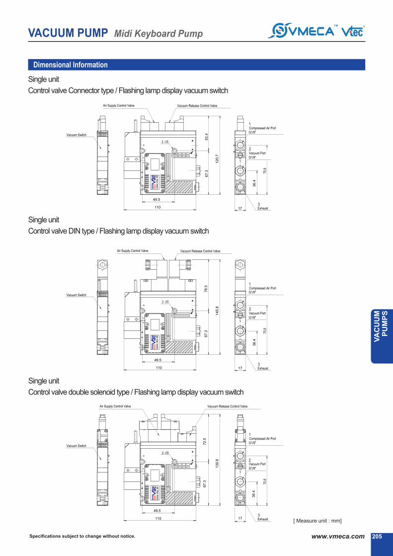
VACUUM PUMP Midi Keyboard Pump
205Specifications subject to change without notice. www.vmeca.com
VA
CU
UM
P
UM
PS
Single unit
Control valve Connector type / Flashing lamp display vacuum switch
Single unit
Control valve DIN type / Flashing lamp display vacuum switch
Single unit
Control valve double solenoid type / Flashing lamp display vacuum switch
Dimensional Information
[ Measure unit : mm]

26
4.5
17
26
4.5
17
26
4.5
17
VACUUM PUMP Midi Keyboard Pump
Specifications subject to change without notice.206 www.vmeca.com
Manifold unit
Control valve Connector type / Digital vacuum switch
Manifold unit
Control valve DIN type / Digital vacuum switch
Manifold unit
Control valve double solenoid type / Digital vacuum switch
Stack A (mm)
2stack3stack4stack5stack6stack7stack8stack
52.869.886.8103.8120.8137.8154.8
Dimensional Information
[ Measure unit : mm]

VACUUM PUMP Midi Keyboard Pump
207Specifications subject to change without notice. www.vmeca.com
VA
CU
UM
P
UM
PS
Manifold unit
Control valve Connector type / Mechanical vacuum switch
Manifold unit
Control valve DIN type / Mechanical vacuum switch
Manifold unit
Control valve double solenoid type / Mechanical vacuum switch
Stack A (mm)
2stack3stack4stack5stack6stack7stack8stack
52.869.886.8103.8120.8137.8154.8
Dimensional Information
Measure unit : [mm]

VACUUM PUMP Midi Keyboard Pump
Specifications subject to change without notice.208 www.vmeca.com
Manifold unitControl valve Connector type / Flashing lamp display vacuum switch
Manifold unit
Control valve DIN type / Flashing lamp display vacuum switch
Manifold unit
Control valve double solenoid type / Flashing lamp display vacuum switch
Stack A (mm)
2stack3stack4stack5stack6stack7stack8stack
52.869.886.8103.8120.8137.8154.8
Dimensional Information
[ Measure unit : mm]
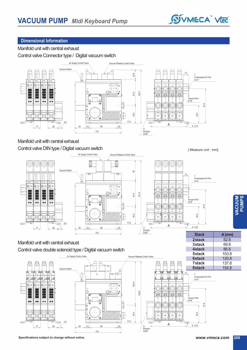
VACUUM PUMP Midi Keyboard Pump
209Specifications subject to change without notice. www.vmeca.com
VA
CU
UM
P
UM
PS
Manifold unit with central exhaust
Control valve Connector type / Digital vacuum switch
Manifold unit with central exhaust
Control valve DIN type / Digital vacuum switch
Manifold unit with central exhaust
Control valve double solenoid type / Digital vacuum switch
Stack A (mm)
2stack3stack4stack5stack6stack7stack8stack
52.869.886.8103.8120.8137.8154.8
Dimensional Information
[ Measure unit : mm]

VACUUM PUMP Midi Keyboard Pump
Specifications subject to change without notice.210 www.vmeca.com
Manifold unit with central exhaust
Control valve Connector type / Mechanical vacuum switch
Manifold unit with central exhaust
Control valve DIN type / Mechanical vacuum switch
Manifold unit with central exhaust
Control valve double solenoid type / Mechanical vacuum switch
Stack A (mm)
2stack3stack4stack5stack6stack7stack8stack
52.869.886.8103.8120.8137.8154.8
Dimensional Information
[ Measure unit : mm]

VACUUM PUMP Midi Keyboard Pump
211Specifications subject to change without notice. www.vmeca.com
VA
CU
UM
P
UM
PS
Stack A (mm)
2stack3stack4stack5stack6stack7stack8stack
52.869.886.8103.8120.8137.8154.8
Manifold unit with central exhaust
Control valve Connector type / Flashing lamp display vacuum switch
Manifold unit with central exhaust
Control valve DIN type / Flashing lamp display vacuum switch
Manifold unit with central exhaust
Control valve double solenoid type / Flashing lamp display vacuum switch
Dimensional Information
[ Measure unit : mm]

VACUUM PUMP Mega Keyboard Pump
Specifications subject to change without notice.212 www.vmeca.com
Mega Keyboard PumpMax. vacuum level
Max. flow rate
Supply air pressure
Supply air type
Working temperature
Noise level
: VKX pump -92 kPa (-27.16 inHg)VKM pump -85 kPa (-25.1 inHg)
: VKX pump 109 Nl/min (3.85 scfm)VKM pump 135 Nl/min (4.76 scfm)
: 3~6bar, max 7bar(43.5~87 psi, max 101.5psi)
: Dry compressed air
: -20▶ to +80▶
: 50~65
Order No.
▶▶ ▶▶
VKX74 - M4 - W 3 3 - C N V
▶ ▶ ▶ ▶ ▶
Main Advantages
- 94 Nl/min
- 109 Nl/min
- 111 Nl/min
- 135 Nl/min
VKX73
VKX74
VKM73
VKM74
●
1
2
3
4
- 1 stack
- 2 stack
- 3 stack
- 4 stack
5
6
7
8
- 5 stack
- 6 stack
- 7 stack
- 8 stack●
no mark
V
E
- standard (NBR)
- Viton▶
- EPDM
▶ Sealing
●
no mark
N
- standard
- Non return valve
▶ Non return valve
●▶ Valves
A
B
C
D
E
W*
▶ (N. C. :Normal Closed)
▶ (N. O. :Normal Open)
▶ (N. C. :Normal Closed)
▶ (N. O. :Normal Open)
▶ Double solenoid valve
Air supply control valve Vacuum release control valve
●
▶ Vacuum switch
▶ Remark : (P)..
Output type : PNP open collector
▶ Model-Vacuum Flow
S - Single unit
M - Manifold unit
E - Manifold unit with
central exhaust unit
●
●
▶ Body-type
▶ Vacuum Stack
1
2
3
- AC 110V
- AC 220V
- DC 24V
▶ Voltage
●
* Only for DC24V and connector type.
1* - DIN type without lead wire
2* - DIN type with lamp without lead wire
3 Connector type with lamp &0.3 m lead wire
2B* DIN type with ‘2 in 1’ BUS cable(Air control v/v + Vacuum release v/v)
▶ Solenoid Terminal
-
3B* DIN type with ‘3 in 1’ BUS cable(Air control v/v + Vacuum release v/v + Digital switch)-
-
* Can not available with double solenoid valve
▶ Remark
3 : Available only with DC24V3B : Available only with DC24V
Available only with ‘C’ or ‘PC’, section ▶
(P)C - Digital display output 2points, No analog supply
M8 4-Pin connector type.
(P)G - Digital display output 2points, No analog supply
4-Core 2m Grommet lead wire.
(P)GA - Digital display output 2points, Analog supply
5-Core 2m Grommet lead wire.
S1 - Mechanical vacuum switch
S4 - Flashing LED light display NPN output 2points,
No analog supply, 4-Core 1m lead wire.
S5 - Flashing LED light display PNP output 1point,
No analog supply, 3-Core 1m lead wire.
▶ (N. C. :Normal Closed)
▶ (N. C. :Normal Closed)
▶ (N. C. :Normal Closed)
▶ (N. C. :Normal Closed)
●
High efficiency Mega vacuum pump (Multi-Nozzle type).
Available of individual control.
Vacuum filter self cleaning system.
Long life time and Low noise level.
Easy to install and Compact size (17mm).
Lightweight. Built-in check valve.
Integrated Vacuum Pump, Air supply & vacuum release control valve, Vacuum Switch & Filter,
Blowing flow control valve and silencer in a body.
▶ About ‘BUS cable’ ( 340, 341)

VACUUM PUMP Mega Keyboard Pump
213Specifications subject to change without notice. www.vmeca.com
VA
CU
UM
P
UM
PS
Model
VKX73
VKX74
VKM73
VKM74
-inHg-kPa
0 2.95 5.9 8.85 11.81 14.76 17.71 20.67 23.62 26.57
Induce air in liters per minute (Nl/m)
Characteristics
VKX73
VKX74
VKM73
VKM74
92 (27.17)
85 (25.1)
94
109
111
135
≥4
≥4
≥4
≥4
50~65
50~65
50~65
50~65
49 ~ 66
66 ~ 88
40 ~ 58
54 ~ 78
212
212
212
212
290
290
290
290
≥8~12
≥8~12
≥8~12
≥8~12
≥8
≥8
≥8
≥8
max. vacuum-kPa(-inHg)
Max. vacuumflow(Nl/m)/
eachstack
airconsumption(Nl/m)/eachstack
noise level(dBA)
weight(g)eachstack
minhoseinnerØ(within2m)
Model air supply
single unit manifoldunitvacuum
ConnectorValve DINValve
▶ Remark: Manifoldunit typeweight= eachstackweightXN+ 56g(N: stack)
The composition of the Mega keyboard pump
0.1
0.06
0.08
0.05
94
109
111
135
54
72
78
99
27
35
47
62
24
32
42
54
21
27
30
40
17
22
24
32
13.5
18
18
24
9
12
7.2
9.6
3.6
4.8
1.98
2.64
1.35
1.8
2.95
0.3
0.2
0.21
0.14
5.9
0.57
0.38
0.38
0.25
8.85
0.9
0.6
0.59
0.39
11.81
1.34
0.89
0.88
0.59
14.76
1.84
1.23
1.29
0.86
17.71
2.58
1.72
1.98
1.32
20.67
3.81
2.54
3.87
2.58
23.62
7.2
4.8
26.57
Model
-inHg-kPa
Timeinsecondstoevacuatetovacuumlevel (sec/l)
VKX73
VKX74
VKM73
VKM74
0 10 20 30 40 50 60 70 80 90
10 20 30 40 50 60 70 80 90

Specifications subject to change without notice.214 www.vmeca.com
VACUUM PUMP Mega Keyboard Pump
DIN type control valve
▶ See page 324~325
Flashing lamp display vacuum switch▶ See page 322~323
Electro-Mechanicalvacuum switch▶ See page 328
Double solenoid type control valve
Selectable wide range of valves and switches.
Connector type control valve
Digital display vacuum switch

215Specifications subject to change without notice. www.vmeca.com
VA
CU
UM
P
UM
PS
VACUUM PUMP Mega Keyboard Pump
Single unit
Control valve Connector type / Digital vacuum switch
Single unit
Control valve DIN type / Digital vacuum switch
Single unit
Control valve double solenoid type / Digital vacuum switch
Dimensional Information
[ Measure unit : mm]

Specifications subject to change without notice.216 www.vmeca.com
VACUUM PUMP Mega Keyboard Pump
Single unit
Control valve Connector type / Mechanical vacuum switch
Single unitControl valve DIN type / Mechanical vacuum switch
Single unit
Control valve double solenoid type / Mechanical vacuum switch
Dimensional Information
[ Measure unit : mm]
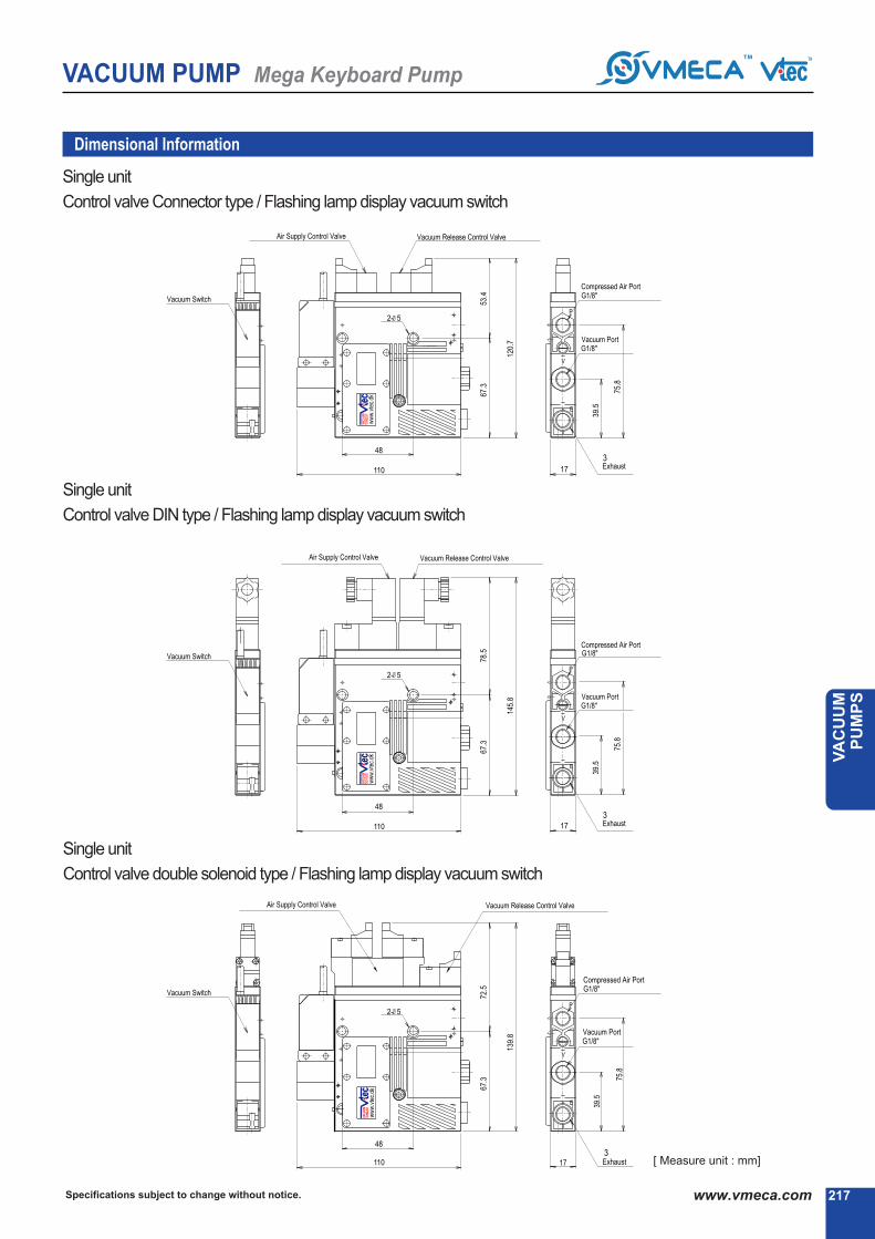
217Specifications subject to change without notice. www.vmeca.com
VA
CU
UM
P
UM
PS
VACUUM PUMP Mega Keyboard Pump
Single unit
Control valve Connector type / Flashing lamp display vacuum switch
Single unit
Control valve DIN type / Flashing lamp display vacuum switch
Single unit
Control valve double solenoid type / Flashing lamp display vacuum switch
Dimensional Information
[ Measure unit : mm]

VACUUM PUMP Mega Keyboard Pump
Specifications subject to change without notice.218 www.vmeca.com
Stack A (mm)
2stack3stack4stack5stack6stack7stack8stack
52.869.886.8103.8120.8137.8154.8
Manifold unit
Control valve Connector type / Digital vacuum switch
Manifold unit
Control valve DIN type / Digital vacuum switch
Manifold unit
Control valve double solenoid type / Digital vacuum switch
Dimensional Information
[ Measure unit : mm]
A
A
A

VACUUM PUMP Mega Keyboard Pump
219Specifications subject to change without notice. www.vmeca.com
VA
CU
UM
P
UM
PS
Stack A (mm)
2stack3stack4stack5stack6stack7stack8stack
52.869.886.8103.8120.8137.8154.8
Manifold unit
Control valve Connector type / Mechanical vacuum switch
Manifold unit
Control valve DIN type / Mechanical vacuum switch
Manifold unit
Control valve double solenoid type / Mechanical vacuum switch
Dimensional Information
[ Measure unit : mm]
A
A
A

VACUUM PUMP Mega Keyboard Pump
Specifications subject to change without notice.220 www.vmeca.com
Manifold unitControl valve Connector type / Flashing lamp display vacuum
Manifold unit
Control valve DIN type / Flashing lamp display vacuum switch
Manifold unit
Control valve double solenoid type / Flashing lamp display vacuum switch
Stack A (mm)
2stack3stack4stack5stack6stack7stack8stack
52.869.886.8103.8120.8137.8154.8
Dimensional Information
[ Measure unit : mm]
A
A
A

VACUUM PUMP Mega Keyboard Pump
221Specifications subject to change without notice. www.vmeca.com
VA
CU
UM
P
UM
PS
Manifold unit with central exhaust
Control valve Connector type / Digital vacuum switch
Manifold unit with central exhaust
Control valve DIN type / Digital vacuum switch
Manifold unit with central exhaust
Control valve double solenoid type / Digital vacuum switch
Dimensional Information
[ Measure unit : mm]
Stack A (mm)
2stack3stack4stack5stack6stack7stack8stack
52.869.886.8103.8120.8137.8154.8

VACUUM PUMP Mega Keyboard Pump
Specifications subject to change without notice.222 www.vmeca.com
Manifold unit with central exhaust
Control valve Connector type / Mechanical vacuum switch
Manifold unit with central exhaust
Control valve DIN type / Mechanical vacuum switch
Manifold unit with central exhaust
Control valve double solenoid type / Mechanical vacuum switch
Stack A (mm)
2stack3stack4stack5stack6stack7stack8stack
52.869.886.8103.8120.8137.8154.8
Dimensional Information
[ Measure unit : mm]

VACUUM PUMP Mega Keyboard Pump
223Specifications subject to change without notice. www.vmeca.com
VA
CU
UM
P
UM
PS
Manifold unit with central exhaust
Control valve Connector type / Flashing lamp display vacuum switch
Manifold unit with central exhaust
Control valve DIN type / Flashing lamp display vacuum switch
Manifold unit with central exhaust
Control valve double solenoid type / Flashing lamp display vacuum switch
Stack A (mm)
2stack3stack4stack5stack6stack7stack8stack
52.869.886.8103.8120.8137.8154.8
Dimensional Information
[ Measure unit : mm]
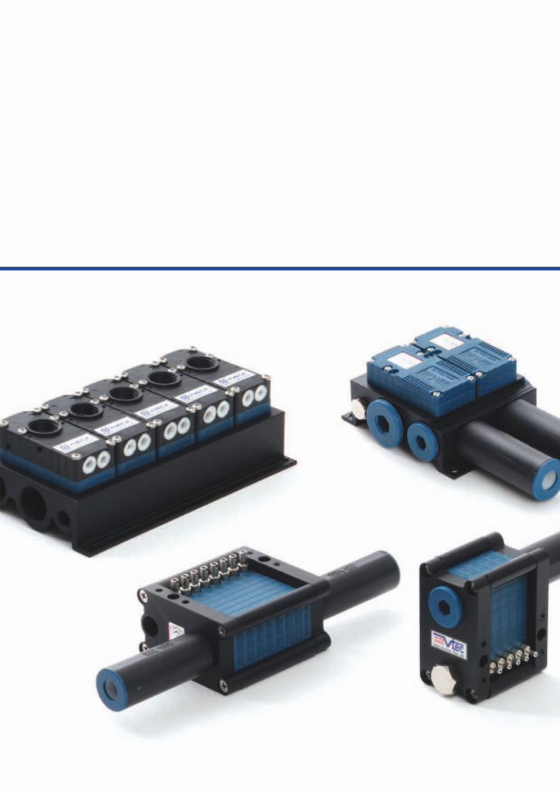

MINI PUMPSMINI PUMPS
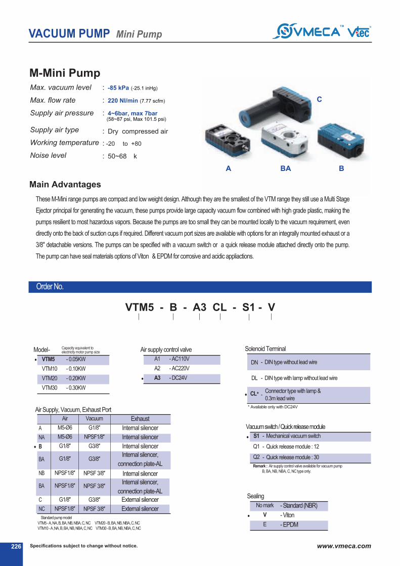
Specifications subject to change without notice.226 www.vmeca.com
Capacity equivalent toelectricity motor pump size
VACUUM PUMP Mini Pump
These M-Mini range pumps are compact and low weight design. Although they are the smallest of the VTM range they still use a Multi Stage
Ejector principal for generating the vacuum, these pumps provide large capacity vacuum flow combined with high grade plastic, making the
pumps resilient to most hazardous vapors. Because the pumps are too small they can be mounted locally to the vacuum requirement, even
directly onto the back of suction cups if required. Different vacuum port sizes are available with options for an integrally mounted exhaust or a
3/8" detachable versions. The pumps can be specified with a vacuum switch or a quick release module attached directly onto the pump.
The pump can have seal materials options of Viton④ & EPDM for corrosive and acidic appliactions.
Main Advantages
M-Mini PumpMax. vacuum level
Max. flow rate
Supply air pressure
Supply air type
Working temperature
Noise level
VTM5
VTM10
VTM20
VTM30
- 0.05KW
- 0.10KW
- 0.20KW
- 0.30KW
④ Standardpumpmodel
VTM5 - A, NA, B, BA, NB, NBA, C, NC VTM20 - B, BA, NB, NBA, C, NC
VTM10 - A,NA, B, BA, NB, NBA, C, NC VTM30 - B, BA, NB, NBA, C, NC
④ Air Supply, Vacuum, Exhaust Port
●
●
No mark
V
E
- Standard(NBR)
- Viton④
- EPDM
④Sealing
●
※ Remark : Air supply control valve available for vacuum pump
B, BA, NB, NBA, C, NC type only.
● - Mechanical vacuum switch
- Quick release module : 12④
- Quick release module : 30④
④ Vacuumswitch/ Quickreleasemodule
S1
Q1
Q2
④Air supply control valve
A1
A2
A3
- AC110V
- AC220V
- DC24V●
A
NA
B
BA
NB
BA
C
NC
Air
M5-Ø6
M5-Ø6
G1/8″
G1/8″
NPSF1/8″
NPSF1/8″
G1/8″
NPSF1/8″
Vacuum
G1/8″
NPSF1/8″
G3/8″
G3/8″
NPSF 3/8″
NPSF 3/8″
G3/8″
NPSF 3/8″
Exhaust
Internal silencer
Internal silencer
Internal silencer
Internal silencer,
connection plate-AL
Internal silencer
Internal silencer,
connection plate-AL
External silencer
External silencer
④ Model-
Order No.
④④ ④④
VTM5 - B - A3 CL - S1 - V
④ ④
: -85 kPa (-25.1 inHg)
: 220 Nl/min (7.77 scfm)
: 4~6bar, max 7bar(58~87 psi, Max 101.5 psi)
: Dry compressed air
: -20④ to +80④
: 50~68 ④k
●
④ Solenoid Terminal
DN
DL
CL*
- DIN type without lead wire
- DIN type with lamp without lead wire
Connector type with lamp &
0.3m lead wire-
* Available only with DC24V
A BA B
C

227Specifications subject to change without notice. www.vmeca.com
VA
CU
UM
P
UM
PS
VACUUM PUMP Mini Pump
Characteristics
85
(25.1)
VTM5
VTM10
VTM20
VTM30
37
74
149
220
15-21
30-42
60-84
90-126
50 - 65
55 - 68
60 - 68
60 - 68
-
-
-
-
>2
>2
>4
>6
>5
>8
>10
>12
>8
>10
>12
>15
max. vacuum-kPa(-inHg)
Max. vacuumflow(Nl/m)
airconsumption
(Nl/m)
noise level
(dBA)
weight
(g)
minhoseinnerØ(within2m)
Modelairsupply vacuum exhaust
0 2.95 5.9 8.85 11.81 14.76 17.71 20.67 23.62
Vacuum flow in (Nl/m) at different Vacuum level (-kPa)
-inHg-kPa
VTM5
VTM10
VTM20
VTM30
Model
Time in seconds to evacuate to vacuum level (sec/l)
37
74
149
220
26
52
99
147
16
31
62
92
14
28
54
73
10
20
40
60
8
16
32
47
6
12
22
32
2.4
4.8
10.5
16
0.66
1.32
2.7
4.1
2.95 5.9 8.85 11.81 14.76 17.71 20.67 23.62-inHg-kPa
VTM5
VTM10
VTM20
VTM30
Model
0.218
0.109
0.054
0.041
0.556
0.278
0.139
0.104
1
0.5
0.25
0.186
1.576
0.788
0.394
0.295
2.356
1.178
0.589
0.441
3.44
1.72
0.86
0.647
5.27
2.635
1.317
0.898
10.216
5.158
2.579
1.935
※ Remarks : type weight = VTM5-A(B,BA,NBA,C,NC) : 26g(30,56,30,56,42,42)
※ Remarks : VTM10-A(B,BA,NBA,C,NC) : 28g(32,58,32,58,44,44)
※ Remarks : VTM20-B(BA,NB,NBA,C,NC) : 41g(79,41,79,53,53)
※ Remarks : VTM30-B(BA,NB,NBA,C,NC) : 60g(98,60,98,72,72)
0 10 20 30 40 50 60 70 80
10 20 30 40 50 60 70 80
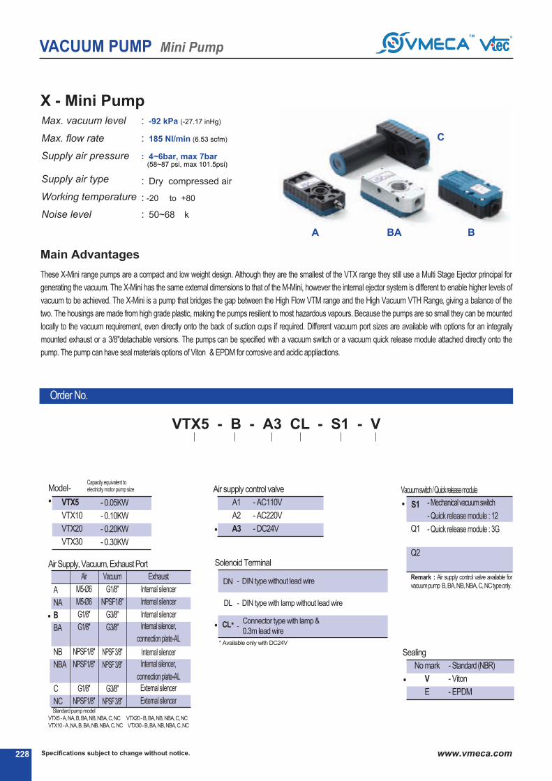
Specifications subject to change without notice.228 www.vmeca.com
VACUUM PUMP Mini Pump
④ Solenoid Terminal
DN
DL
CL*
- DIN type without lead wire
- DIN type with lamp without lead wire
Connector type with lamp &
0.3m lead wire-
* Available only with DC24V
A BA B
C
X - Mini PumpMax. vacuum level
Max. flow rate
Supply air pressure
Supply air type
Working temperature
Noise level
: -92 kPa (-27.17 inHg)
: 185 Nl/min (6.53 scfm)
: 4~6bar, max 7bar(58~87 psi, max 101.5psi)
: Dry compressed air
: -20④ to +80④
: 50~68 ④k
VTX5
VTX10
VTX20
VTX30
- 0.05KW
- 0.10KW
- 0.20KW
- 0.30KW
●
No mark
V
E
- Standard (NBR)
- Viton④
- EPDM
④Sealing
●
④ Vacuumswitch/ Quickreleasemodule
※ Remark : Air supply control valve available for
vacuumpump B, BA, NB, NBA, C, NCtypeonly.
● - Mechanicalvacuumswitch
- Quick release module : 12④
- Quick release module : 3G④
S1
Q1
Q2
④Air supply control valve
A1
A2
A3
- AC110V
- AC220V
- DC24V●
④ AirSupply, Vacuum, ExhaustPort
●
A
NA
B
BA
NB
NBA
C
NC
Air
M5-Ø6
M5-Ø6
G1/8″
G1/8″
NPSF1/8″
NPSF1/8″
G1/8″
NPSF1/8″
Vacuum
G1/8″
NPSF1/8″
G3/8″
G3/8″
NPSF3/8″
NPSF3/8″
G3/8″
NPSF3/8″
Exhaust
Internal silencer
Internal silencer
Internal silencer
Internal silencer,
connection plate-AL
Internal silencer
Internal silencer,
connection plate-AL
External silencer
External silencer
④ Model-Capacity equivalent toelectricity motor pump size
These X-Mini range pumps are a compact and low weight design. Although they are the smallest of the VTX range they still use a Multi Stage Ejector principal for
generating the vacuum. The X-Mini has the same external dimensions to that of the M-Mini, however the internal ejector system is different to enable higher levels of
vacuum to be achieved. The X-Mini is a pump that bridges the gap between the High Flow VTM range and the High Vacuum VTH Range, giving a balance of the
two. The housings are made from high grade plastic, making the pumps resilient to most hazardous vapours. Because the pumps are so small they can be mounted
locally to the vacuum requirement, even directly onto the back of suction cups if required. Different vacuum port sizes are available with options for an integrally
mounted exhaust or a 3/8"detachable versions. The pumps can be specified with a vacuum switch or a vacuum quick release module attached directly onto the
pump. The pump can have seal materials options of Viton④ & EPDM for corrosive and acidic appliactions.
Main Advantages
Order No.
④④ ④④
VTX5 - B - A3 CL - S1 - V
④ ④
④ Standardpumpmodel
VTX5 - A, NA, B, BA, NB, NBA, C, NC VTX20 - B, BA, NB, NBA, C, NC
VTX10 - A,NA, B, BA, NB, NBA, C, NC VTX30 - B, BA, NB, NBA, C, NC
●

229Specifications subject to change without notice. www.vmeca.com
VA
CU
UM
P
UM
PS
VACUUM PUMP Mini Pump
Characteristics
0 2.95 5.9 8.85 11.81 14.76 17.71 20.67 23.62 26.57
Vacuum flow in (Nl/m) at different Vacuum level (-kPa)
-inHg-kPa
VTX5
VTX10
VTX20
VTX30
Time in seconds to evacuate to vacuum level (sec/l)
32
62
124
185
18
36
72
108
9
18
35
52
8
16
32
47
7
14
27
41
6
11
22
33
5
9
18
26
3
6
12
18
1.2
2.4
4.8
7.2
0.45
0.9
1.8
2.7
2.95 5.9 8.85 11.81 14.76 17.71 20.67 23.62 26.57-inHg-kPa
VTX5
VTX10
VTX20
VTX30
0.258
0.129
0.064
0.048
0.796
0.398
0.199
0.149
1.156
0.758
0.379
0.284
2.4
1.2
0.6
0.44
3.56
1.78
0.89
0.673
4.91
2.455
1.227
0.917
6.896
3.445
1.722
1.287
10.16
5.08
2.54
1.906
19.19
9.594
4.797
3.595
Model
Model
92
(27.17)
VTX5
VTX10
VTX20
VTX30
32
62
124
185
21.6-24
43.2-48
86.4-96
129.6-144
50 - 65
55 - 68
63 - 68
60 - 68
-
-
-
-
>2
>2
>4
>6
>5
>8
>10
>12
>8
>10
>12
>15
max. vacuum-kPa(-inHg)
Max. vacuumflow(Nl/m)
airconsumption
(Nl/m)
noise level
(dBA)
weight
(g)
minhoseinnerØ(within2m)
Modelairsupply vacuum exhaust
※ Remarks : type weight = VTX5-A(B,BA,NB,NBA,C,NC) : 26g(30,56,30,56,42,42)
※ Remarks : VTX10-A(B,BA,NBA,C,NC) : 28g(32,58,32,58,44,44)
※ Remarks : VTX20-B(BA,NB,NBA,C,NC) : 41g(79,41,79,53,53)
※ Remarks : VTX30-B(BA,NB,NBA,C,NC) : 60g(98,60,98,72,72)
0 10 20 30 40 50 60 70 80
10 20 30 40 50 60 70 80
90
90

Specifications subject to change without notice.230 www.vmeca.com
VACUUM PUMP Mini Pump
※VTF 38-IN
(See page : 318)
Dimensional Information
Model L1
(mm)
VTM(X)5 20.2
VTM(X)10
VTM(X)20
VTM(X)30
20.2
27.4
34.6
5
VTM(X) (10)-B (BA, NB )
20
30
5
VTM(X) (10)-A(NA)
[ Measure unit : mm]
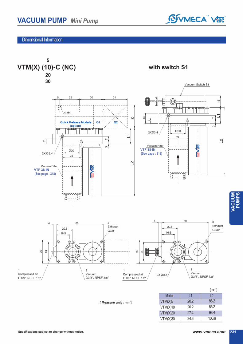
231Specifications subject to change without notice. www.vmeca.com
VA
CU
UM
P
UM
PS
VACUUM PUMP Mini Pump
Dimensional Information
VTM(X)5
VTM(X)10
VTM(X)20
VTM(X)30
L2
(mm)
86.2
86.2
93.4
100.6
5
VTM(X) (10)-C (NC)20
30
with switch S1
※VTF 38-IN
(See page : 318)
※VTF 38-IN
(See page : 318)
[ Measure unit : mm]
Model L1
20.2
20.2
27.4
34.6

VACUUM PUMP One-Line Pump
Specifications subject to change without notice.232 www.vmeca.com
Individual vacuum lines
Filter cleaning function
Efficiency and economic
Can be adjust vacuum release flow
Compact & long life time
Main Advantages
One-Line Pump
Semiconductor
Robotic Packaging
Pick & Place System
Metal Sheet Handling
Automotive
Application
Max. vacuum level
Max. flow rate
Supply air pressure
Supply air type
Working temperature
Noise level
no mark
V
E
- standard (NBR)
- Viton④
- EPDM
●
④ Sealing
●
④ Solenoid Terminal
●
④ Model-Vacuum Flow
4
5
6
7
8
9
10
- 4 stack
- 5 stack
- 6 stack
- 7 stack
- 8 stack
- 9 stack
- 10 stack
11
12
13
14
15
16
- 11 stack
- 12 stack
- 13 stack
- 14 stack
- 15 stack
- 16 stack
●
④ Remark :
•VTOX10, VTOM10 maximumstackupto12 stacks
•VTOX5, VTOM5 : above12 stackcompletewith
2 silencer
•VTOX10, VTOM10 : above6 stackcompletewith
2 silencer
④ Vacuum Stack
A1
A2
A3
- AC110V
- AC220V
- DC24V●
R1
R2
R3
- AC110V
- AC220V
- DC24V●
④ VacuumreleasecontrolValves
④ Air supply control valve
DN
DL
CL*
2B
- DIN type without lead wire
- DIN type with lamp without lead wire
Connector type with lamp &0.3m lead wire
-
DIN type with ‘2 in 1’ BUS cable(Air control v/v + Vacuum release v/v)
-
④④ ④④
VTOX5 x 6 - A3 R3 - CL - V
④ ④
This oneline model uses individual pumps to make up the complete unit,
each pump is in itself a multi stage ejector unit. Each individual pump can
be stacked to together thus creating a modular manifold based system.
The advantages of this unit is that it can be operated using just two control
valve (as to vacuum and equal vacuum release time to each vacuum
pads) whilst retaining individual vacuum lines separate to one another,
therefore if any leakage or surface deformation occurs and one pad loses it
vacuum, it does not effect the vacuum level in the other pads. Also, it can
be used vacuum port for purging work filter cleaning function. It will be
achieved long life time vacuum filter & pump. Pumps can be stacked up
from 4 - 16 unit depending upon requirements. The pumps can have seal
material options of Viton④& EPDM for corrosive and acidic applications.
Order No.
VTOX5
VTOX10
VTOM5
VTOM10
- 24 Nl/min
- 32 Nl/min
- 29 Nl/min
- 35 Nl/min
* Available only with DC24V
: VTOX pump -92 kPa (-27.17 inHg)
VTOM pump -85 kPa (-25.1 inHg)
: VTOX pump 32 Nl/min x N Stack (1.13 scfm x N stack)
VTOM pump 35 Nl/min x N Stack (1.23 scfm x N stack)
: 4~6bar, max 7bar(58~87 psi, max 101.5psi)
: Dry compressed air
: -20④ ~ 80④
: 50~65 ④k
④ About ‘BUS cable’ ( 340, 341)

VACUUM PUMP One-Line Pump
233Specifications subject to change without notice. www.vmeca.com
VA
CU
UM
P
UM
PS
2.950 5.9 8.85 11.81 14.76 17.71 20.67 23.62 26.57
Vacuum flow in (Nl/m) at different Vacuum level (-kPa)
-inHg-kPa
VTOX5
VTOX10
VTOM5
VTOM10
Model
Timeinsecondstoevacuatetovacuumlevel (sec/l)
24
32
27
35
13
21
16
29
9
17
13
25
8
15
12
23
7
14
11
19
5
11
8
16
4
9
6
12
2.7
5.4
2.4
4.8
1.2
2.4
0.66
1.32
0.45
0.9
2.95 5.9 8.85 11.81 14.76 17.71 20.67 23.62 26.57-inHg-kPa
VTOX5
VTOX10
VTOM5
VTOM10
0.258
0.129
0.218
0.109
0.796
0.398
0.556
0.278
1.516
0.758
1.00
0.50
2.4
1.2
1.576
0.788
3.38
1.78
2.356
1.178
4.91
2.455
3.44
1.72
6.896
3.455
5.27
2.635
10.16
5.08
10.216
5.158
19.19
9.594
Model
Characteristics
> 2.5
> 2.5
> 2.5
> 2.5
> 8~10
> 8~12
> 8~10
> 8~12
max. vacuum
-kPa(-inHg)
Max.
vacuumflow
(Nl/m)/eachstack
airconsumption
(Nl/m)/eachstack
noise level
(dBA)weight (g)eachstack
minhoseinnerØ(within2m)Model
airsupply vacuum
85
(25.1)
92
(27.17)
VTOX5
VTOX10
VTOM5
VTOM10
24
32
27
35
21.6~24
43.2~48
15~21
30~42
55~65
60~65
55~65
60~65
37
37
37
37
④Remark : unit weight (477g+ eachstackweight)
0 10 20 30 40 50 60 70 80
10 20 30 40 50 60 70 80
90
90

VACUUM PUMP One-Line Pump
Specifications subject to change without notice.234 www.vmeca.com
5VTOX
10
Dimensional Information
A
B
Remark : - Airsupply (vacuum) controlvavle
- Vacuumreleasecontrolvalve
(See page : 318)
VTOX 5,10 A B
(mm)
4 stack
5 stack
6 stack
7 stack
8 stack
9 stack
10 stack
11 stack
12 stack
13 stack
14 stack
15 stack
16 stack
38.3
45.5
53
60
67.5
74.8
82
88.5
96
103.2
111
118
125.2
48.3
55.5
63
70
77.5
84.8
92
98.5
106
113.2
121
128
135.8
[ Measure unit : inch ]
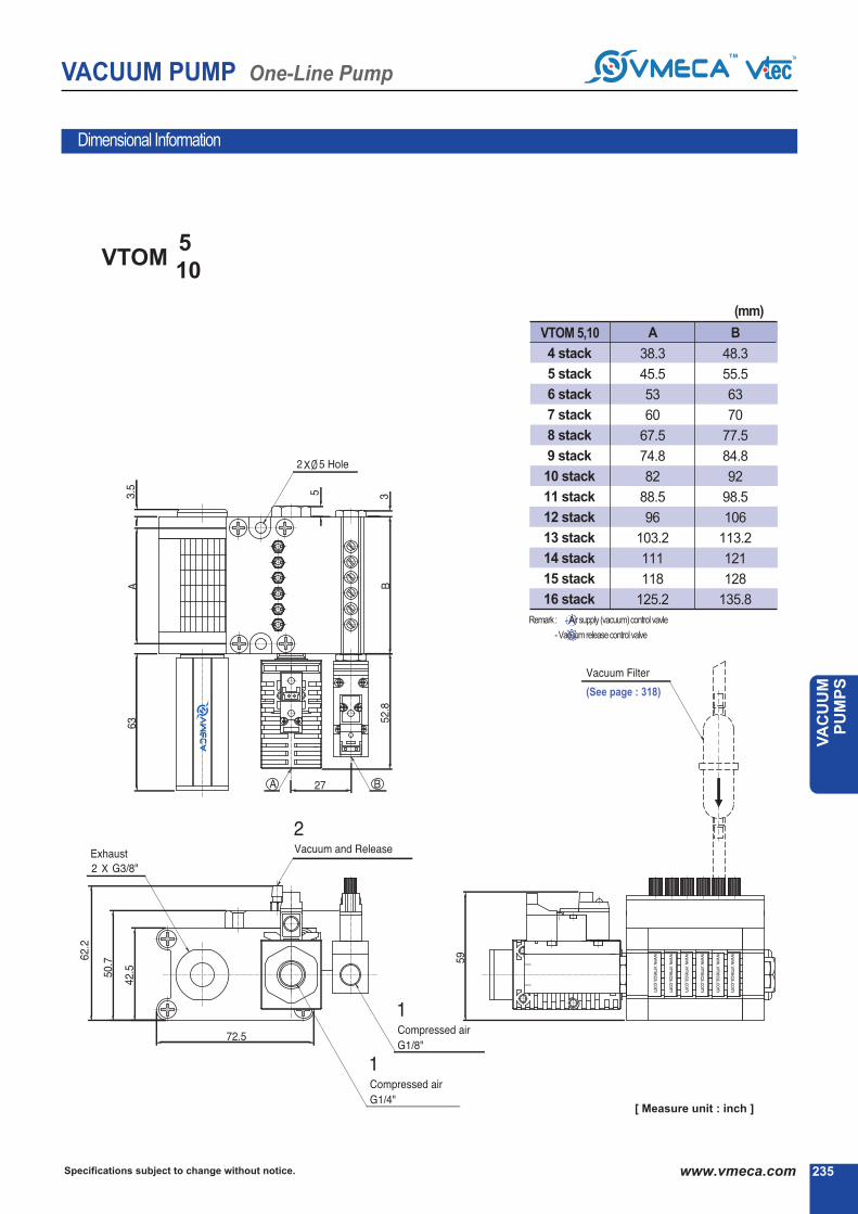
VACUUM PUMP One-Line Pump
235Specifications subject to change without notice. www.vmeca.com
VA
CU
UM
P
UM
PS
5VTOM
10
Dimensional Information
(mm)
VTOM 5,10 A B
4 stack
5 stack
6 stack
7 stack
8 stack
9 stack
10 stack
11 stack
12 stack
13 stack
14 stack
15 stack
16 stack
38.3
45.5
53
60
67.5
74.8
82
88.5
96
103.2
111
118
125.2
48.3
55.5
63
70
77.5
84.8
92
98.5
106
113.2
121
128
135.8
A
B
Remark : - Airsupply (vacuum) controlvavle
- Vacuumreleasecontrolvalve
[ Measure unit : inch ]
(See page : 318)

Capacity equivalent toelectricity motor pump size
VACUUM PUMP Minimultiple Pump
Specifications subject to change without notice.236 www.vmeca.com
This M-Minimultiple model uses individual pumps to make up the complete unit, each pump is in itself a multi stage ejector
unit. Each individual pump can be stacked to together thus creating a modular manifold based system.
The advantages of this unit is that it can be operated using just one control valve whilst retaining individual vacuum lines
separate to one another, therefore if any leakage or surface deformation occurs and one pad loses it vacuum, it does not
effect the vacuum level in the other pads. Pumps can be stacked up from 2 - 16 unit depending upon requirements. The
pumps can have seal material options of Viton④ & EPDM for corrosive and acidic applications.
Main Advantages
M-Minimultiple PumpMax. vacuum level
Max. flow rate
Supply air pressure
Supply air type
Working temperature
Noise level
VTM5
VTM10
- 0.05KW
- 0.1KW
●
④ Air supply control valve
●●
A1
A2
A3
- AC110V
- AC220V
- DC24V
●
④ Vacuumport, innerdiaoftube
2 - Ø2
4 - Ø4
Nomark
V
E
- Standard(NBR)
- Viton④
- EPDM
●
④ Sealing
2
3
4
5
6
7
8
9
- 2 stack
- 3 stack
- 4 stack
- 5 stack
- 6 stack
- 7 stack
- 8 stack
- 9 stack
10
11
12
13
14
15
16
- 10 stack
- 11 stack
- 12 stack
- 13 stack
- 14 stack
- 15 stack
- 16 stack
④ Vacuum stack
●
④ Remark :VTM5 maximum stack up to 16 stack
④ Remark : (above12 stackcompletewith2 Silencer)
④ Remark :VTM10 maximum stack up to 12 stack
④ Remark : (above6 stackcompletewith2 Silencer)
④ Model-
Order No.
④④ ④④
VTM5 x 6 - A3 CL - 4 - V
④ ④
: -85 kPa (-25.1 inHg)
: 35 Nl/min x N Stack (1.23 scfm x N stack)
: 4~6bar, max 7bar(58~87 psi, max 101.5psi)
: Dry compressed air
: -20④ ~ 80④
: 50~65 ④k
●
④ Solenoid Terminal
DN
DL
CL*
- DIN type without lead wire
- DIN type with lamp without lead wire
Connector type with lamp &
0.3m lead wire-
* Available only with DC24V

VACUUM PUMP Minimultiple Pump
237Specifications subject to change without notice. www.vmeca.com
VA
CU
UM
P
UM
PS
0 2.95 5.9 8.85 11.81 14.76 17.71 20.67 23.62
Characteristics
Vacuum flow in (Nl/m) at different Vacuum level (-kPa)
VTM5x1stack 27
VTM10x1 stack 35
16
29
13
25
12
23
11
19
8
16
6
12
2.4
4.8
0.66
1.32
2.95 5.9 8.85 11.81 14.76 17.71 20.67 23.62
Time in seconds to evacuate to vacuum level (sec/l)
VTM5x1stack
VTM10x1 stack
0.218
0.109
0.556
0.278
1
0.5
1.576
0.788
2.356
1.178
3.44
1.72
5.270
2.635
10.216
5.158
55-60 > 2 > 2.5 3/8″×1
3/8″×1
3/8″×1
3/8″×1
3/8″×1
3/8″×1
3/8″×1
3/8″×1
3/8″×1
3/8″×1
3/8″×2
3/8″×2
3/8″×2
3/8″×2
3/8″×2
3/8″×1
3/8″×1
3/8″×1
3/8″×1
3/8″×2
3/8″×2
3/8″×2
3/8″×2
3/8″×2
3/8″×2
3/8″×2
> 2.5
> 2.5
> 2.5
> 2.5
> 2.5
> 2.5
> 2.5
> 2.5
> 2.5
> 2.5
> 2.5
> 2.5
> 2.5
> 2.5
> 4
> 4
> 4
> 4
> 4
> 4
> 4
> 4
> 4
> 4
> 4
> 2
> 4
> 4
> 4
> 4
> 6
> 6
> 6
> 6
> 6
> 6
> 8
> 10
> 10
> 4
> 4
> 6
> 6
> 6
> 8
> 8
> 10
> 10
> 10
> 10
55-60
55-60
60-65
60-65
60-65
60-65
60-65
60-65
60-65
60-65
60-65
60-65
60-65
60-65
VTM10x11stack
VTM10x12stack
VTM10x9stack
VTM10x10stack
VTM10x5stack
VTM10x6stack
VTM10x7stack
VTM10x8stack
VTM10x3stack
VTM10x4stack
VTM5x16stack
VTM10x2stack
VTM5x14stack
VTM5x15stack
VTM5x12stack
VTM5x13stack
VTM5x10stack
VTM5x11stack
VTM5x8stack
VTM5x4stack
max. vacuum
-kPa(-inHg)
Max. vacuum
flow(Nl/m)airconsumption
(Nl/m)
noise level
(dBA)weight
(g)
minhoseinnerØ(within2m)
Modelairsupply vacuum exhaust
VTM5x2stack
VTM5x3stack
VTM5x5stack
VTM5x6stack
VTM5x7stack
85
(25.1)
85
(25.1)
VTM5x9stack
55-60
60-65
60-65
60-65
60-65
60-65
60-65
60-65
60-65
60-65
60-65
67
80
247
255
281
299
317
335
353
371
389
417
435
453
471
67
80
247
255
281
299
327
345
363
381
399
-inHg-kPa
Model
-inHg-kPa
Model
27x2
27x3
27x4
27x5
27x6
27x7
27x8
27x9
27x10
27x11
27x12
27x13
27x14
27x15
27x16
35x2
35x3
35x4
35x5
35x6
35x7
35x8
35x9
35x10
35x11
35x12
30-42
45-63
60-84
75-105
90-126
105-147
120-168
135-189
150-210
165-231
180-252
195-273
210-294
225-315
240-336
60-84
90-126
120-168
150-210
180-252
210-294
240-336
270-378
300-420
330-462
360-504
0 10 20 30 40 50 60 70 80
10 20 30 40 50 60 70 80

Specifications subject to change without notice.238 www.vmeca.com
VACUUM PUMP Minimultiple Pump
X - Minimultiple PumpMax. vacuum level
Max. flow rate
Supply air pressure
Supply air type
Working temperature
Noise level
④ Remark :VTX5 maximum stack up to 16 stack
④ Remark : (above12 stackcompletewith2 Silencer)
④ Remark :VTX10 maximum stack up to 12 stack
④ Remark : (above6 stackcompletewith2 Silencer)
VTX5
VTX10
- 0.05KW
- 0.1KW
●
2
3
4
5
6
7
8
9
- 2 stack
- 3 stack
- 4 stack
- 5 stack
- 6 stack
- 7 stack
- 8 stack
- 9 stack
10
11
12
13
14
15
16
- 10 stack
- 11 stack
- 12 stack
- 13 stack
- 14 stack
- 15 stack
- 16 stack
④ Vacuum stack
●
Nomark
V
E
- Standard (NBR)
- Viton④
- EPDM
●
④ Sealing
●
④ Vacuumport, innerdiaoftube
2 - Ø2
4 - Ø4
④ Air supply control valve
●●
A1
A2
A3
- AC110V
- AC220V
- DC24V
④ Model-Capacity equivalent toelectricity motor pump size
This X-Minimultiple pump model uses individual pumps to make up the complete unit, each pump is in itself a multi stage ejetor unit. The X-Minimultiple pump has the
same external dimensions to that of the M-Minimultiple pump, however the internal ejetor system is different to enable higher levels of vacuum to be achieved. The X-
Minimultiple pump is a pump that bridges the gap between the High Flow VTM pump range and the High Vacuum VTH Range, giving a balance of the two. Each
individual pump can be stacked togerher thus creating a modular manifold based system.
The advantages of this unit is that it can be operated using just one control valve whilst retaining individual vacuum lines separate to one another, therefore if any leak-
age or surface deformation occurs and one pad loses its vacuum, it does not effect the vacuum level in the other pads. Pumps can be stacked up from 2-16 units
depending upon requirements. The pumps can have seal material options of Viton④ & EPDM for corrosive and acidic applications.
Main Advantages
Order No.
④④ ④④
VTX5 x 6 - A3 CL - 4 V
④ ④
: -92 kPa (-27.17 inHg)
: 32 Nl/min x N Stack (1.13scfm x N stack)
: 4~6bar, max 7bar(58~87 psi, max 101.5psi)
: Dry compressed air
: -20④ ~ 80④
: 55~65 ④k
●
④ Solenoid Terminal
DN
DL
CL*
- DIN type without lead wire
- DIN type with lamp without lead wire
Connector type with lamp &0.3m lead wire
-
* Available only with DC24V

239Specifications subject to change without notice. www.vmeca.com
VA
CU
UM
P
UM
PS
VACUUM PUMP Minimultiple Pump
Characteristics
92
(27.17)
92
(27.17)
VTX5x2stack
VTX5x3stack
VTX5x4stack
VTX5x5stack
VTX5x6stack
VTX5x7stack
VTX5x8stack
VTX5x9stack
VTX5x10stack
VTX5x11stack
VTX5x12stack
VTX5x13stack
VTX5x14stack
VTX5x15stack
VTX5x16stack
VTX10x2stack
VTX10x3stack
VTX10x4stack
VTX10x5stack
VTX10x6stack
VTX10x7stack
VTX10x8stack
VTX10x9stack
VTX10x10stack
VTX10x11stack
VTX10x12stack
24x2
24x3
24x4
24x5
24x6
24x7
24x8
24x9
24x10
24x11
24x12
24x13
24x14
24x15
24x16
32x2
32x3
32x4
32x5
32x6
32x7
32x8
32x9
32x10
32x11
32x12
43.2-48
64.8-72
84.4-96
108-120
129.6-144
151.2-168
172.8-192
194.4-216
216-240
237.6-264
259.2-288
280.8-312
302.4-336
324-360
345.6-384
86.4-96
129.6-144
172.8-192
216-240
259.2-288
302.4-336
345.6-384
388.8-432
432-480
475.2-528
518.4-576
55-60
55-60
60-63
60-63
60-63
60-63
60-63
60-63
60-63
60-63
60-63
60-63
60-63
60-63
60-63
60-63
63-65
63-65
63-65
63-65
63-65
63-65
63-65
63-65
63-65
63-65
67
80
247
255
281
299
317
335
353
371
389
417
435
453
471
67
80
247
255
281
299
327
345
363
381
399
>2
>2
>4
>4
>4
>4
>6
>6
>6
>6
>6
>6
>8
>10
>10
>4
>4
>6
>6
>6
>6
>8
>10
>10
>10
>10
>2.5
>2.5
>2.5
>2.5
>2.5
>2.5
>2.5
>2.5
>2.5
>2.5
>2.5
>2.5
>2.5
>2.5
>2.5
>4
>4
>4
>4
>4
>4
>4
>4
>4
>4
>4
3/8″X1
3/8″X1
3/8″X1
3/8″X1
3/8″X1
3/8″X1
3/8″X1
3/8″X1
3/8″X1
3/8″X1
3/8″X2
3/8″X2
3/8″X2
3/8″X2
3/8″X2
3/8″X1
3/8″X1
3/8″X1
3/8″X1
3/8″X2
3/8″X2
3/8″X2
3/8″X2
3/8″X2
3/8″X2
3/8″X2
0 2.95 5.9 8.85 11.81 14.76 17.71 20.67 23.62 26.57
Vacuum flow in (Nl/m) at different Vacuum level (-kPa)
-inHg-kPa
VTX5x1stack
VTX10x1stack
Model
Time in seconds to evacuate to vacuum level (sec/l)
24
32
13
21
9
17
8
15
7
14
5
11
4
9
2.7
5.4
1.2
2.4
0.45
0.9
2.59 2.95 8.85 11.81 14.76 17.71 20.67 23.62 26.57-inHg-kPa
VTX5x1stack
VTX10x1stack
Model
0.258
0.129
0.796
0.398
1.516
0.758
2.4
1.2
3.56
1.78
4.91
2.455
6.896
3.445
10.16
5.08
19.19
9.594
max. vacuum-kPa(-inHg)
ModelMax. vacuum
flow(Nl/m)airconsumption
(Nl/m)
noise level
(dBA)
weight
(g)
minhoseinnerØ(within2m)
airsupply vacuum exhaust
0 10 20 30 40 50 60 70 80
10 20 30 40 50 60 70 80
90
90

VACUUM PUMP Minimultiple Pump
Specifications subject to change without notice.240 www.vmeca.com
VTM(X) 5 x (2, 3)Stack10
Dimensional Information
[ Measure unit : mm]
2stack
3stack
L1 L2
28 94
35 101
VTM5(10)
VTX5(10)
(mm)

VACUUM PUMP Minimultiple Pump
241Specifications subject to change without notice. www.vmeca.com
VA
CU
UM
P
UM
PS
VTM(X) 5 x (4~16)Stack10
VTM5(10)
VTX5(̀ 10)L1 L2
4stack
5stack
6stack
7stack
8stack
9stack
10stack
11stack
12stack
13stack
14stack
15stack
16stack
38.3
45.5
53
60
67.5
74.8
82
88.5
96
103.2
111
118
125.2
48.3
55.5
63
70
77.5
84.8
92
98.5
106
113.2
121
128
135.2
(mm)※VTF 06-IN
(See page : 318)
Dimensional Information
[ Measure unit : mm]

VACUUM PUMP Midimultiple Pump
Specifications subject to change without notice.242 www.vmeca.com
Basically this pump is similar function with mini multiple stack pump. Each individual pump can be stacked up thus creating a mod-
ular manifold based system. The advantages of this unit is that it can be operated with one supply air port and activating individual
vacuum pump which mounted on the manifold, as the result if any leakage occurs due to product surface deformation of one vacu-
um pad, it will not affect the vacuum performance in other vacuum pads. This pump can be stacked up from 2stack to 6stacks,
depending on the requirment. This pump has sealing option of VITON④ and EPDM for corrosive and acidic application. Also, can
be integrated vacuum filters directly on the pumps.
Main Advantages
M-Midimultiple PumpMax. vacuum level
Max. flow rate
Supply air pressure
Supply air type
Working temperature
Noise level
●
VTM10
VTM20
VTM30
- 0.1KW
- 0.2KW
- 0.3KW
④ Vacuumport , Exhaustport
●
④ Air supply control valve
●●
2
3
4
5
6
- 2 stack
- 3 stack
- 4 stack
- 5 stack
- 6 stack
④ Vacuum stack
● A1
A2
A3
- AC110V
- AC220V
- DC24V
B
BA
NB
NBA
C
NC
G 3/8″
G 3/8″
NPSF 3/8″
NPSF 3/8″
G 3/8″
NPSF 3/8″
Internal silencer
Internal silencer,
connection plate-AL
Internal silencer
Internal silencer,
connection plate-AL
external silencer
external silencer
Vacuum Exhaust
Nomark
V
E
- Standard(NBR)
- Viton④
- EPDM
●
④ Sealing
④ Model-Capacity equivalent toelectricity motor pump size
Order No.
④④ ④④
VTM10 x 6 - B - A3 - CL - V
④ ④
: -85 kPa (-25.1 inHg)
: 220 Nl/min x N Stack(7.77scfm x N stack)
: 4~6bar, max 7bar(58~87 psi, max 101.5psi)
: Dry compressed air
: -20④ ~ 80④
: 50~65 ④k
●
④ Solenoid Terminal
DN
DL
CL*
- DIN type without lead wire
- DIN type with lamp without lead wire
Connector type with lamp &
0.3m lead wire-
* Available only with DC24V

VACUUM PUMP Midimultiple Pump
243Specifications subject to change without notice. www.vmeca.com
VA
CU
UM
P
UM
PS
Characteristics
85
(25.1)
85
(25.1)
85
(25.1)
VTM10×2
VTM10×3
VTM10×4
VTM10×5
VTM10×6
VTM20×2
VTM20×3
VTM20×4
VTM20×5
VTM20×6
VTM30×2
VTM30×3
VTM30×4
VTM30×5
VTM30×6
74×2
74×3
74×4
74×5
74×6
149×2
149×3
149×4
149×5
149×6
220×2
220×3
220×4
220×5
220×6
60-84
90-126
120-168
150-210
180-252
120-168
180-252
240-336
300-420
360-504
180-252
270-378
360-504
450-630
540-756
50-60
50-60
55-60
60-65
60-65
50-60
55-60
60-65
60-65
60-68
55-60
60-65
60-65
60-68
60-68
>4
>6
>6
>6
>8
>6
>6
>8
>10
>10
>6
>8
>10
>10
>10
380
532
695
850
998
399
560
735
899
1058
421
587
775
947
1116
393
545
708
863
1011
412
573
748
912
1071
434
600
788
960
1129
>8
>8
>8
>8
>8
>10
>10
>10
>10
>10
>12
>12
>12
>12
>12
3/8″×2
3/8″×3
3/8″×4
3/8″×5
3/8″×6
3/8″×2
3/8″×3
3/8″×4
3/8″×5
3/8″×6
3/8″×2
3/8″×3
3/8″×4
3/8″×5
3/8″×6
max. vacuum-kPa(-inHg)
ModelMax. vacuum
flow(Nl/m)airconsumption
(Nl/m)
noise level
(dBA)
weight (g) minhoseinnerØ(within2m)
airsupplyB, NB C, NC vacuum exhaust
0 2.95 5.9 8.85 11.81 14.76 17.71 20.67 23.62
Vacuum flow in (Nl/m) at different Vacuum level (-kPa)
-inHg-kPa
VTM10x1 Stack
VTM20x1 Stack
VTM30x1 Stack
Model
Time in seconds to evacuate to vacuum level (sec/l)
74
149
220
52
99
147
31
62
92
28
54
73
20
40
60
16
32
47
12
22
32
4.8
10.5
16
1.32
2.7
4.1
2.95 5.9 8.85 11.81 14.76 17.71 20.67 23.62-inHg-kPa
VTM10x1 Stack
VTM20x1 Stack
VTM30x1 Stack
Model
0.109
0.054
0.041
0.278
0.139
0.104
0.5
0.25
0.186
0.788
0.394
0.295
1.178
0.589
0.441
1.72
0.86
0.647
2.635
1.317
0.898
5.158
2.579
1.935
※ Remarks : BA(NBA)type weight = B type weight+(26g.×stack)
0 10 20 30 40 50 60 70 80
10 20 30 40 50 60 70 80

Specifications subject to change without notice.244 www.vmeca.com
VACUUM PUMP Midimultiple Pump
X - Midimultiple PumpMax. vacuum level
Max. flow rate
Supply air pressure
Supply air type
Working temperature
Noise level
●
VTX10
VTX20
VTX30
- 0.1KW
- 0.2KW
- 0.3KW
④ Vacuumport , Exhaustport
●
④ Air supply control valve
●●
2
3
4
5
6
- 2 stack
- 3 stack
- 4 stack
- 5 stack
- 6 stack
④ Vacuum stack
●
A1
A2
A3
- AC110V
- AC220V
- DC24V
B
BA
NB
NBA
C
NC
G 3/8″
G 3/8″
NPSF 3/8″
NPSF 3/8″
G 3/8″NPSF
3/8″
Internal silencer
Internal silencer, connection plate-AL
Internal silencer
Internal silencer, connection plate-AL
External silencer
External silencer
Vacuum Exhaust
Nomark
V
E
- Standard(NBR)
- Viton④
- EPDM
●
④ Sealing
④ Model-Capacity equivalent toelectricity motor pump size
Order No.
④④ ④④
VTX10 x 6 - B - A3 CL - V
④ ④
The X-Midimultiple pump has the same external dimension to X-Midimultiple pump. It enabling it to achieve higher vacuum level.
Each individual pump can be stacked up thus creating a modular manifold based system. The advantage of this pump is that it
has a bigger vacuum port as the applications requriing large vacuum flow and high vacuum level. If any leakage occurs due to
product surface deformation of one vacuum pad, it will not affect the vacuum performance in the other pads. This pump can be
stacked up from 2 stacks to 6 stacks. Also,can be specified with an air control solenoid valve and with Viton④ or EPDM as seal
options.
Main Advantages
: -92 kPa (-27.17 inHg)
: 185 Nl/min x N Stack(6.53 scfm x N stack)
: 4~6bar, max 7bar(58~87 psi, max 101.5psi)
: Dry compressed air
: -20④ ~ 80④
: 50~65 ④k
●
④ Solenoid Terminal
DN
DL
CL*
- DIN type without lead wire
- DIN type with lamp without lead wire
Connector type with lamp &0.3m lead wire
-
* Available only with DC24V
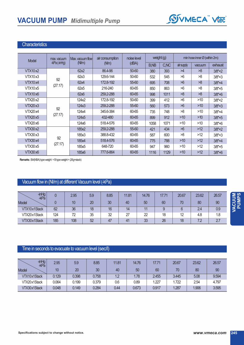
245Specifications subject to change without notice. www.vmeca.com
VA
CU
UM
P
UM
PS
VACUUM PUMP Midimultiple Pump
Characteristics
92
(27.17)
92
(27.17)
92
(27.17)
VTX10x2
VTX10x3
VTX10x4
VTX10x5
VTX10x6
VTX20x2
VTX20x3
VTX20x4
VTX20x5
VTX20x6
VTX30x2
VTX30x3
VTX30x4
VTX30x5
VTX30x6
62x2
62x3
62x4
62x5
62x6
124x2
124x3
124x4
124x5
124x6
185x2
185x3
185x4
185x5
185x6
86.4-96
129.6-144
172.8-192
216-240
259.2-288
172.8-192
259.2-288
345.6-384
432-480
518.4-576
259.2-288
388.8-432
518.4-576
648-720
777.6-864
50-60
50-60
55-60
60-65
60-65
50-60
55-60
60-65
60-65
60-65
55-60
60-65
60-65
60-65
60-65
>4
>6
>6
>6
>8
>6
>6
>8
>10
>10
>6
>8
>10
>10
>10
>8
>8
>8
>8
>8
>10
>10
>10
>10
>10
>12
>12
>12
>12
>12
3/8″×2
3/8″×3
3/8″×4
3/8″×5
3/8″×6
3/8″×2
3/8″×3
3/8″×4
3/8″×5
3/8″×6
3/8″×2
3/8″×3
3/8″×4
3/8″×5
3/8″×6
weight (g)
0 2.95 5.9 8.85 11.81 14.76 17.71 20.67 23.62
Vacuum flow in (Nl/m) at different Vacuum level (-kPa)
-inHg-kPa
VTX10x1Stack
VTX20x1Stack
VTX30x1Stack
Model
Time in seconds to evacuate to vacuum level (sec/l)
62
124
185
36
72
108
18
35
52
16
32
47
14
27
41
11
22
33
9
18
26
6
12
18
2.4
4.8
7.2
0.9
1.8
2.7
26.57
2.95 5.9 8.85 11.81 14.76 17.71 20.67 23.62
VTX10x1Stack
VTX20x1Stack
VTX30x1Stack
0.129
0.064
0.048
0.398
0.199
0.149
0.758
0.379
0.284
1.2
0.6
0.44
1.78
0.89
0.673
2.455
1.227
0.917
3.445
1.722
1.287
5.08
2.54
1.906
26.57
9.594
4.797
3.595
Model
-inHg-kPa
380
532
695
850
998
399
560
735
899
1058
421
587
775
947
1116
393
545
708
863
1011
412
573
748
912
1071
434
600
788
960
1129
B,NB C,NC
max. vacuum-kPa(-inHg)
ModelMax. vacuumflow
(Nl/m)airconsumption
(Nl/m)
noise level
(dBA)
minhoseinnerØ(within2m)
airsupply vacuum exhaust
※Remarks :BA(NBA) typeweight = Btypeweight+ (26g×stack)
0 10 20 30 40 50 60 70 80
10 20 30 40 50 60 70 80
90
90

VACUUM PUMP Midimultiple Pump
Specifications subject to change without notice.246 www.vmeca.com
VTM(X) 10 x (2~6)-NB
20
30
Dimensional Information
Model
VTM(X)10x2-B,NB
VTM(X)10x3-B,NB
VTM(X)10x4-B,NB
VTM(X)10x5-B,NB
VTM(X)10x6-B,NB
VTM(X)20x2-B,NB
VTM(X)20x3-B,NB
VTM(X)20x4-B,NB
VTM(X)20x5-B,NB
VTM(X)20x6-B,NB
VTM(X)30x2-B,NB
VTM(X)30x3-B,NB
VTM(X)30x4-B,NB
VTM(X)30x5-B,NB
VTM(X)30x6-B,NB
61
92
123
154
185
61
92
123
154
185
61
92
123
154
185
21.8
21.8
21.8
21.8
21.8
29
29
29
29
29
36.2
36.2
36.2
36.2
36.2
L1 L2
(mm)
※VTF 38-IN
(See page : 318)
1
[ Measure unit : mm]
B

VACUUM PUMP Midimultiple Pump
247Specifications subject to change without notice. www.vmeca.com
VA
CU
UM
P
UM
PS
[ Measure unit : mm]
Dimensional Information
VTM 10 x (2~6)-NC
20
30
Model
VTM(X)10x2-C,NC
VTM(X)10x3-C,NC
VTM(X)10x4-C,NC
VTM(X)10x5-C,NC
VTM(X)10x6-C,NC
VTM(X)20x2-C,NC
VTM(X)20x3-C,NC
VTM(X)20x4-C,NC
VTM(X)20x5-C,NC
VTM(X)20x6-C,NC
VTM(X)30x2-C,NC
VTM(X)30x3-C,NC
VTM(X)30x4-C,NC
VTM(X)30x5-C,NC
VTM(X)30x6-C,NC
61
92
123
154
185
61
92
123
154
185
61
92
123
154
185
21.8
21.8
21.8
21.8
21.8
29
29
29
29
29
36.2
36.2
36.2
36.2
36.2
L1 L2
(mm)
※VTF 38-IN(See page : 318)
1
2
C

VACUUM PUMP Duplex Pump
Specifications subject to change without notice.248 www.vmeca.com
M-Duplex pump is similar to the block type in that it uses the components of the mini type multi stage vacuum pump.
The pumps are mounted onto a dual station manifold. This manifold enables compact and simple installation.
The manifold can accommodate two VTM30 pumps thus producing a VTM60, which gives high flow rates in a com-
pact format. A vacuum switch can be ordered with the unit which piggy backs one of the pumps again for compact and
easy installation. There is an option for mounting the exhausts one either side or both on one end of the manifold.
There is also the option of connecting vacuum and air supply connections on either side of the manifold block, vacuum
connections are BSP 1/2″ X2.
Main Advantages
M-Duplex PumpMax. vacuum level
Max. flow rate
Supply air pressure
Supply air type
Working temperature
Noise level
: -85 kPa (-25.1 inHg)
: 390 Nl/min (13.77scfm)
: 4~6bar, max 7bar(58~87 psi, max 101.5psi)
: Dry compressed air
: -20④ ~ 80④
: 57~65 ④k
VTM20KD
VTM30KD
VTM40KD
VTM50KD
VTM60KD
- 0.2KW
- 0.3KW
- 0.4KW
- 0.5KW
- 0.6KW
● ●
④ Vacuum Switch④ Model-Capacity equivalent toelectricity motor pump size
※ Remark : (P)..Output type : PNP open collector
(P)C - Digital display output 2points, No analog supplyM8 4-Pin connector type.
(P)G - Digital display output 2points, No analog supply4-Core 2m Grommet lead wire.
(P)GA - Digital display output 2points, Analog supply5-Core 2m Grommet lead wire.
S1 - Mechanical vacuum switch
S4 - Flashing LED light display NPN output 2points,No analog supply, 4-Core 1m lead wire.
S5 - Flashing LED light display PNP output 1point,No analog supply, 3-Core 1m lead wire.
Order No.
④ ④④
VTM20KD - C - V
No mark
V
E
- Standard (NBR)
- Viton④
- EPDM
④ Sealing
●

VACUUM PUMP Duplex Pump
249Specifications subject to change without notice. www.vmeca.com
VA
CU
UM
P
UM
PS
Characteristics
85
(25.1)
VTM20KD
VTM30KD
VTM40KD
VTM50KD
VTM60KD
149
220
292
341
390
60-84
90-126
120-168
150-216
180-252
57 - 58
57 - 58
57 - 60
58 - 63
60 - 65
179
190
321
329
338
>4
>6
>6
>8
>8
>10
>10
>12
>12
>15
>12
>15
>15
>18
>18
max. vacuum-kPa(-inHg)
ModelMax. vacuum
flow(Nl/m)airconsumption
(Nl/m)
noise level
(dBA)
weight
(g)
minhoseinnerØ(within2m)
airsupply vacuum exhaust
0 2.95 5.9 8.85 11.81 14.76 17.71 20.67 23.62
Vacuum flow in (Nl/m) at different Vacuum level (-kPa)
-inHg-kPa
VTM20KD
VTM30KD
VTM40KD
VTM50KD
VTM60KD
Model
Time in seconds to evacuate to vacuum level (sec/l)
149
220
292
341
390
99
147
200
228
256
62
92
110
135
259
54
73
93
115
137
40
60
80
100
119
32
47
63
79
94
22
32
43
60
64
10.5
16
21
24
32
2.7
4.1
5.4
6.6
8.5
2.59 5.9 8.85 11.81 14.76 17.71 20.67 23.62-inHg-kPa
VTM20KD
VTM30KD
VTM40KD
VTM50KD
VTM60KD
Model
0.054
0.041
0.027
0.023
0.018
0.139
0.104
0.069
0.058
0.046
0.25
0.186
0.125
0.104
0.083
0.394
0.295
0.197
0.164
0.131
0.589
0.441
0.294
0.245
0.196
0.86
0.647
0.431
0.359
0.286
1.317
0.898
0.658
0.549
0.439
2.579
1.935
1.289
1.074
0.859
0 10 20 30 40 50 60 70 80
10 20 30 40 50 60 70 80

Specifications subject to change without notice.250 www.vmeca.com
VACUUM PUMP Duplex Pump
X - Duplex PumpMax. vacuum level
Max. flow rate
Supply air pressure
Supply air type
Working temperature
Noise level
: -92 kPa (-27.17 inHg)
: 332 Nl/min (11.72 scfm)
: 4~6bar, max 7bar(58~87 psi, max 101.5psi)
: Dry compressed air
: -20④ ~ 80④
: 57~65 ④k
VTX20KD
VTX30KD
VTX40KD
VTX50KD
VTX60KD
- 0.2KW
- 0.3KW
- 0.4KW
- 0.5KW
- 0.6KW
● ●
④ Vacuum Switch④ Model-Capacity equivalent toelectricity motor pump size
※ Remark : (P)..Output type : PNP open collector
(P)C - Digital display output 2points, No analog supplyM8 4-Pin connector type.
(P)G - Digital display output 2points, No analog supply4-Core 2m Grommet lead wire.
(P)GA - Digital display output 2points, Analog supply5-Core 2m Grommet lead wire.
S1 - Mechanical vacuum switch
S4 - Flashing LED light display NPN output 2points,No analog supply, 4-Core 1m lead wire.
S5 - Flashing LED light display PNP output 1point,No analog supply, 3-Core 1m lead wire.
The Duplex VTX type is similar to the mini block type in that it uses the components of the mini type multi stage vacuum pump. The X-
Duplex has the same external dimensions to that of the M-Duplex, however the internal ejector system is different to enable higher
levels of vacuum to be achieved. The pumps are mounted onto a dual station manifold.
This manifold enables compact and simple installation. The manifold can accommodate two VTX30 pumps thus producing a X-Duplex
60, which gives higher flow rates in a compact format. A vacuum switch can be ordered with the unit which piggy backs one of the
pumps again for compact and easy installation. There is an option for mounting the exhausts one either side, or both on one end of the
manifold. There is also the option of connecting.
Main Advantages
Order No.
④ ④④
VTX20KD - C - V
Nomark
V
E
-Standard(NBR)
- Viton④
- EPDM
④ Sealing
●

251Specifications subject to change without notice. www.vmeca.com
VA
CU
UM
P
UM
PS
VACUUM PUMP Duplex Pump
Characteristics
92
(27.17)
VTX20KD
VTX30KD
VTX40KD
VTX50KD
VTX60KD
124
185
247
290
332
86.4 - 96
129.6 - 144
172.8 - 192
216 - 240
259.2 - 288
57 - 60
57 - 63
60 - 63
60 - 65
60 - 65
179
190
321
329
338
>4
>6
>6
>8
>8
>10
>10
>12
>12
>15
>12
>15
>15
>18
>18
0 2.95 5.9 8.85 11.81 14.76 17.71 20.67 23.62 26.57
Vacuum flow in (Nl/m) at different Vacuum level (-kPa)
-inHg-kPa
VTX20KD
VTX30KD
VTX40KD
VTX50KD
VTX60KD
Time in seconds to evacuate to vacuum level (sec/l)
124
185
247
290
332
72
108
144
171
198
35
52
69
86
102
32
47
63
78
93
27
41
54
66
78
22
33
44
55
65
18
26
35
43
51
12
18
23
29
34
4.8
7.2
9.6
12
14.4
1.8
2.7
3.6
4.5
5.4
2.95 150 5.9 11.81 14.76 17.71 20.67 23.62 26.57-inHg-kPa
VTX20KD
VTX30KD
VTX40KD
VTX50KD
VTX60KD
0.064
0.048
0.032
0.027
0.021
0.199
0.149
0.099
0.083
0.067
0.379
0.284
0.189
0.158
0.126
0.6
0.44
0.29
0.25
0.2
0.89
0.673
0.445
0.371
0.297
1.227
0.917
0.613
0.511
0.409
1.722
1.287
0.858
0.714
0.569
2.54
1.906
1.273
1.016
0.848
4.797
3.595
2.398
1.999
1.599
Model
Model
max. vacuum-kPa(-inHg)
ModelMax. vacuum
flow(Nl/m)airconsumption
(Nl/m)
noise level
(dBA)
weight
(g)
minhoseinnerØ(within2m)
airsupply vacuum exhaust
0 10 20 30 40 50 60 70 80
10 20 30 40 50 60 70 80
90
90
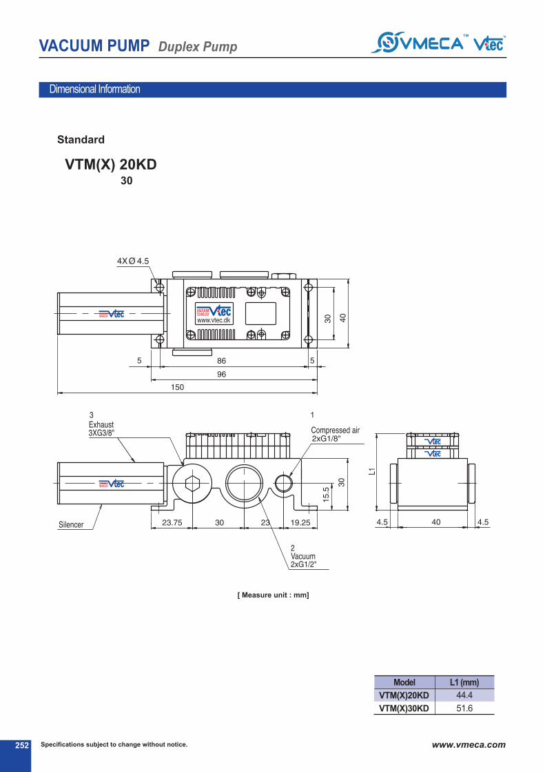
VACUUM PUMP Duplex Pump
Specifications subject to change without notice.252 www.vmeca.com
Dimensional Information
VTM(X) 20KD30
Model L1 (mm)
VTM(X)20KD
VTM(X)30KD
44.4
51.6
1
Standard
[ Measure unit : mm]

VACUUM PUMP Duplex Pump
253Specifications subject to change without notice. www.vmeca.com
VA
CU
UM
P
UM
PS
1
Dimensional Information
Model L1 (mm)
VTM(X)20KD
VTMI(X)30KD
44.4
51.6
with switch S1
with switch (P)C,(P)G, (P)GA
[ Measure unit : mm]

VACUUM PUMP Duplex Pump
Specifications subject to change without notice.254 www.vmeca.com
Dimensional Information
Model L1 (mm)
VTM(X)40KD
VTM(X)50KD
VTM(X)60KD
44.4
51.6
51.6
VTM(X) 40KD50
60
Standard
[ Measure unit : mm]

VACUUM PUMP Duplex Pump
255Specifications subject to change without notice. www.vmeca.com
VA
CU
UM
P
UM
PS
Dimensional Information
Model L1 (mm)
VTM(X)40KD
VTM(X)50KD
VTM(X)60KD
44.4
51.6
51.6
with swicth S1
with switch (P)C,(P)G, (P)GA
[ Measure unit : mm]

Specifications subject to change without notice.256 www.vmeca.com
VACUUM PUMP Conveying Pump
This is a series of adjustable flow rate single stage vacuum pumps particularly good for use in high contamination areas where
dust and small debris is likely to enter the vacuum line. The design of this pump enables particles and small debris to pass direct-
ly through the pump. High flow rates can be achieved in conjunction with vacuum levels down to -84.4Kpa whilst maintaining
a high performance to air consumption ratio.
Main Advantages
Conveying Pump (Air Movers)
Max. vacuum level
Max. flow rate
Supply air pressure
Supply air type
These pumps provide a reliable and cost effective solution for in line product transfer, particularly for transferring bulk materials,
granules, continuous strips and powders. Like the VTRA the pump has a straight through design, hence they are non-clogging and
maintenance free. High flows can be achieved with in line bore sizes up to 1 1/2″ .
Main Advantages
VTRF PumpMax. vacuum level
Max. flow rate
Supply air pressure
Supply air type
: -33.8 kPa (-9.98 inHg)
: 4670 Nl/m (164.9 scfm)
: 4~6bar, max 7bar(58~87 psi, max 101.5psi)
: Dry compressed air
④ Material
- Aluminum
- Stainless steel
AL
SS
VTRA 250
VTRA 375
VTRA 500
VTRA 750
④ Vacuum pump ④ Material④ Vacuum pump
●
●
- Aluminum
- Stainless steel
AL
SS
VTRF 2-3
VTRF 3-3
VTRF 5-6
VTRF 7-6
VTRF 15-3
VTRF 15-6
●
●
Order No.
④④
VTRA 375 - AL
④④
VTRF 5-6 - AL
VTRA Pump
: -84.4 kPa (-24.92 inHg)
: 3396 Nl/m (119.9 scfm)
: 4~6bar, max 7bar(58~87 psi, max 101.5psi)
: Dry compressed air

257Specifications subject to change without notice. www.vmeca.com
VA
CU
UM
P
UM
PS
VACUUM PUMP Conveying Pump
VTRAAir consumption vs, Vacuum level (-kPa) Nl/m, 5.5 bar
VTRAVacuum flow vs, Vacuum level (-kPa) Nl/m
VTRF series performance data
VTRA250
VTRA375
VTRA500 VTRA750
113
175
340
651
170
325
623
872
235
481
792
1245
275
594
934
1783
340
820
1274
2547
VTRF2-3
VTRF3-3
VTRF5-6
VTRF7-6
VTRF15-3
VTRF15-6
airvelocity
(ft/sec)
vacuumflow
(Nl/m)
vacuumlevel
(-kPa)
airconsumption(Nl/m)
2.8bar 5.5bar
490
328
362
326
224
272
283
424
849
1698
4670
5660
27
15.2
33.8
27
4.4
8.5
88
99
396
792
396
792
170
170
679
1358
679
1358
Model
VTRA250
VTRA375
VTRA500 VTRA750
283
849
1698
3396
243
736
1330
2462
204
623
1132
1975
164
524
991
1443
127
396
651
1132
4.99
16.9
9.98
33.8
14.97
50.7
19.93
67.5
24.92
84.4
-inHg-kPa
Model
4.99
16.9
9.98
33.8
14.97
50.7
19.93
67.5
24.92
84.4
-inHg-kPa
Model

Specifications subject to change without notice.258 www.vmeca.com
VACUUM PUMP Conveying Pump
Dimensional Information
VTRA250
VTRA375
VTRA500
VTRA75 0
6.8 (0.267″)
9.6 (0.377″)
12.7 (0.5″)
19.1 (0.751″)
18.8 (0.732″)
25.2 (0.992″)
31.4 (1.236″)
37.8 (1.488″)
31.3 (1.232″)
43.5 (1.712″)
50 (1.968″)
56.8 (2.236″)
41 (1.614″)
69.8 (2.748″)
63.5 (2.5″)
85.7 (3.374″)
31.6 (1.244″)
44.4 (1.748″)
50.8 (2″)
50.8 (2″)
22 (0.866″)
37.6 (1.480″)
38 (1.496″)
38.2 (1.503″)
3.7 (0.145″)
5 (0.196″)
5 (0.196″)
5 (0.196″)
G1/8″
G3/8″
G3/8″
G1/2″
G1/4″
G1/2″
G1/2″
G3/4″
G1/4″
G1/2″
G3/4″
G1″
ØA ØB ØC D E F T G1 G2 G3
Dimension
Model
6.4 (0.252″)
9.5 (0.374″)
12.6 (0.496″)
19 (0.748″)
38.2 (1.503″)
38.2 (1.503″)
18.4 (0.724″)
18.8 (0.740″)
24.5 (0.964″)
31.8 (1.251″)
49.6 (1.952″)
49.6 (1.952″)
31.5 (1.240″)
31.3 (1.232″)
37.6 (1.480″)
50 (1.968″)
69 (2.716″)
69 (2.716″)
45 (1.771″)
45.3 (1.783″)
82 (3.228″)
101.8 (4.007″)
101.4 (3.992″)
101.4 (3.992″)
24.9 (0.980″)
25.5 (1.003″)
31.7 (1.248″)
50.6 (1.992″)
50.8 (2″)
50.8 (2″)
19 (0.748″)
18.2 (0.716″)
26 (1.023″)
38 (1.496″)
38.2 (1.503″)
38.2 (1.503″)
88.9 (3.5″)
89 (3.503″)
139.7 (5.5″)
190.4 (7.496″)
190.4 (7.496″)
190.4 (7.496″)
G1/8″
G1/8″
G1/4″
G3/8″
G3/8″
G3/8″
ØA ØB ØC D E F L G
VTRF2-3
VTRF3-3
VTRF5-6
VTRF7-6
VTRF15-3
VTRF15-6
Dimension
Model
VTRF Series
VTRA Series

259Specifications subject to change without notice. www.vmeca.com
VA
CU
UM
P
UM
PS
VACUUM PUMP Conveying Pump
Application
④ Unloading vibrator feeders
④ Reloading hoppers with plastic Regrind
④ Transferring of engine valves in grinding operation
④ Chip removal in drilling operation
④ Transfer power detergent and caustic chemicals
④ Convey peanut husks
④ Selvedge removal in trimming operation
④ Mandrel collection system


CLASSIC PUMPSCLASSIC PUMPS

Outputtype: PNPopencollector.
Capacity equivalent toelectricity motor pump size
VACUUM PUMP L-Classic Pump
Specifications subject to change without notice.262 www.vmeca.com
This is most significant model base on the multi stage principle. Low compressed air are required for massive evacuation vol-
umes at high vacuum flow and high vacuum level rate. Vtec air saving kit is available in this pump in order to maximum
reduce the energy usage. VITON④ & EPDM seals can be also stipulated as option.
Main Advantages
L-Classic PumpMax. vacuum level
Max. flow rate
Supply air pressure
Supply air type
Working temperature
Noise level
: -91 kPa (-26.87 inHg)
: 1370 Nl/min (48.43 scfm)
: 3~6bar, max 7bar(43.5~87 psi, max 101.5psi)
: Dry compressed air
: -20④ ~ 80④
: 50~65 ④k
④ Model-
VTM25L
VTM50L
VTM75L
VTM100L
VTM125L
VTM150L
- 0.25KW
- 0.50KW
- 0.75KW
- 1.00KW
- 1.25KW
- 1.50KW
●
D..* : Double solenoid valve
Double solenoid valve is
available only with ‘DN’or’DL’, section ④
④ Air supply control valve
A1
A2
A3
D1*
D2*
D3*
- AC 110V
- AC 220V
- DC 24V
- AC 110V
- AC 220V
- DC 24V
●
No mark
N
- Standard
- Non-return valve
④ Non-return valve
●
●
④ Vacuum switch
S2(P)
SG2(P)
SG3(P)
- Digital output 2points, No analog supply
M8-4Pin male connector (0.3m lead wire)
- Digital output 2points, No analog supply
Grommet type 4-core 2m lead wire
- Digital output 2points, Analog supply
Grommet type 4-core 2m lead wire
※ Remark : ④ S..(P)
④ VCM8 42 : M8-4Pin female connector.only for type S2(P)
④ Connection plate
●
Airport
G1/4″
G1/4″
G1/4″
NPT1/4″
NPT1/4″
NPT1/4″
G1/8″
G1/8″
NPT1/8″
NPT1/8″
Vacuumport
G1/2″
G3/4″
G1″
NPT1/2″
NPT3/4″
NPT 1″
G1/2″
G3/4″
NPT1/2″
NPT3/4″
1412 A
1434 A
1401 A
N1412 A
N1434 A
N1401 A
1812 P
1834 P
N1812 P
N1834 P
Alu
min
umAll
PPS
Mat’l
Order No.
④④ ④④
VTM25L - 1434 A - AS - A3 R3 - CL SG2 N V
④ ④ ④ ④ ④
●
④ Solenoid Terminal
DN
DL
CL*
2B*
3B*
- DIN type without lead wire
- DIN type with lamp without lead wire
Connector type with lamp &0.3m lead wire
-
DIN type with ‘2 in 1’ BUS cable(Air control v/v + Vacuum release v/v)
-
DIN type with ‘3 in 1’ BUS cable(Air control v/v+ Vacuumreleasev/v+ Digital switch)
-
* Can not available with double solenoid valve
④ Remark
CL : Available only with DC24V3B : Available only with DC24V
Available only with ‘S2’ or ‘S2P’, section ④
④ Vacuum releasecontrol valve
R1
R2
R3
- AC110V
- AC220V
- DC24V●
※ Remark :
Airsupplyportwithaircontrol valveorAS-kit: G1/4″
PPSMat’l isavailableinVTM25L~ VTM100L
④ Air saving Kit
No mark
AS
- Standard
- Air saving kit attached●
No mark
V
E
- Standard (NBR)
- Viton④
- EPDM
④ Sealing
●
( 108)
④ About ‘BUS cable’ ( 340, 341)

263Specifications subject to change without notice. www.vmeca.com
VA
CU
UM
P
UM
PS
VACUUM PUMP L-Classic Pump
Characteristics
91
(26.87)
VTM25L
VTM50L
VTM75L
VTM100L
VTM125L
VTM150L
365
622
841
1060
1195
1370
114
228
342
456
570
684
50 - 65
50 - 65
50 - 65
50 - 65
60 - 65
60 - 65
643
644
760
761
877
878
>4
>6
>8
>8
>10
>10
>12
>15
>19
>19
>25
>25
>12
>15
>22
>22
>32
>32
max.vacuum-kPa(-inHg)
ModelMax. vacuum
flow(Nl/m)airconsumption
(Nl/m)
noise level
(dBA)
weight
(g)
minhoseinnerØ(within2m)
airsupply vacuum exhaust
0 2.95 5.9 8.85 11.81 14.76 17.71 20.67 23.62 26.57
④④④④④(Nl/m) Induce air in liters per minuteVacuum flow in (Nl/m) at different Vacuum level (-kPa)
-inHg-kPa
VTM25L
VTM50L
VTM75L
VTM100L
VTM125L
VTM150L
Model
Time in seconds to evacuate to vacuum level (sec/l)
365
622
841
1060
1195
1370
169
327
481
634
789
937
124
236
354
449
522
589
76
149
221
293
360
418
43
83
122
161
193
237
33
65
97
129
152
187
25
49
73
96
120
144
17
33
49
64
80.6
97.2
7
14
21
27
33.3
39.6
0.8
1.6
2.4
3.2
3.8
4.32
-inHg-kPa
VTM25L
VTM50L
VTM75L
VTM100L
VTM125L
VTM150L
Model
5.9 8.85 11.81 14.76 20.67 23.62 26.57
0.056
0.032
0.024
0.016
0.0147
0.0134
0.12
0.062
0.047
0.031
0.0302
0.0294
0.24
0.12
0.09
0.06
0.053
0.046
0.425
0.221
0.159
0.106
0.089
0.071
1.02
0.51
0.383
0.255
0.215
0.175
1.64
0.85
0.62
0.41
0.36
0.31
4.6
2.3
1.73
1.15
1.01
0.87
17.71
0.66
0.33
0.248
0.165
0.143
0.115
2.95
0.02
0.013
0.01
0.007
0.0061
0.0051
0 10 20 30 40 50 60 70 80
10 20 30 40 50 60 70 80
90
90

Specifications subject to change without notice.264 www.vmeca.com
VACUUM PUMP L-Classic Pump
Dimensional Information
Port1 : G1/4″, NPT1/4″
Port2 : G1/2″, G3/4″, G1″
NPT1/2″, NPT3/4″, NPT1″
Port3 : G3/4″
Port1 : G1/4″, NPSF1/4″
Port2 : G1/2″, G3/4″, G1″
NPT1/2″, NPT3/4″, NPT1″
Port3 : G3/4″
(mm)
VTM25L
VTM50L
VTM75L
VTM100L
VTM125L
VTM150L
45.5
45.5
65
65
84.5
84.5
203.5
203.5
223
223
242.5
242.5
Standard with AS - KIT
[ Measure unit : mm]
Model L1 L2

265Specifications subject to change without notice. www.vmeca.com
VA
CU
UM
P
UM
PS
VACUUM PUMP L-Classic Pump
Dimensional Information
Port1 : G1/4, NPSF1/4″″
Port2 : G1/2″, G3/4″, G1″
NPT1/2″, NPT3/4″, NPT1″
Port3 : G3/4″
(mm)
Model L1 L2
VTM25L
VTM50L
VTM75L
VTM100L
VTM125L
VTM150L
45.5
45.5
65
65
84.5
84.5
Air supply control valve
Vacuum release control valve
Digital display vacuum switch
A Airsupplycontrolvalve
B Vacuumreleasecontrolvalve
C Digitaldisplayvacuumswitch
206.5
206.5
226
226
245.5
245.5
Port1 : G1/4″, NPSF1/4″
Port2 : G1/2″, G3/4″, G1″
NPT1/2″, NPT3/4″, NPT1″
Port3 : G3/4″
[ Measure unit : mm]
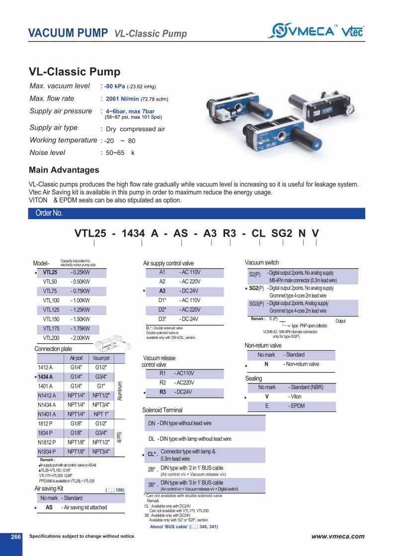
Outputtype: PNPopencollector.
Specifications subject to change without notice.266 www.vmeca.com
VACUUM PUMP VL-Classic Pump
VL-Classic PumpMax. vacuum level
Max. flow rate
Supply air pressure
Supply air type
Working temperature
Noise level
: -80 kPa (-23.62 inHg)
: 2061 Nl/min (72.78 scfm)
: 4~6bar, max 7bar(58~87 psi, max 101.5psi)
: Dry compressed air
: -20④ ~ 80④
: 50~65 ④k
Order No.
④④ ④④
VTL25 - 1434 A - AS - A3 R3 - CL SG2 N V
④ ④ ④ ④ ④
VL-Classic pumps produces the high flow rate gradually while vacuum level is increasing so it is useful for leakage system.Vtec Air Saving kit is available in this pump in order to maximum reduce the energy usage. VITON④ & EPDM seals can be also stipulated as option.
Main Advantages
Capacity equivalent toelectricity motor pump size④ Model-
VTL25
VTL50
VTL75
VTL100
VTL125
VTL150
VTL175
VTL200
- 0.25KW
- 0.50KW
- 0.75KW
- 1.00KW
- 1.25KW
- 1.50KW
- 1.75KW
- 2.00KW
●
D..* : Double solenoid valve
Double solenoid valve is
available only with ‘DN’or’DL’, section ④
④ Air supply control valve
A1
A2
A3
D1*
D2*
D3*
- AC 110V
- AC 220V
- DC 24V
- AC 110V
- AC 220V
- DC 24V
●
No mark
N
- Standard
- Non-return valve
④ Non-return valve
●
No mark
V
E
- Standard (NBR)
- Viton④
- EPDM
④ Sealing
●
●
④ Vacuum switch
S2(P)
SG2(P)
SG3(P)
- Digital output 2points, No analog supply
M8-4Pin male connector (0.3m lead wire)
- Digital output 2points, No analog supply
Grommet type 4-core 2m lead wire
- Digital output 2points, Analog supply
Grommet type 4-core 2m lead wire
※ Remark : ④ S..(P)
④ VCM8 42 : M8-4Pin female connector.only for type S2(P)
●
④ Solenoid Terminal
DN
DL
CL*
2B*
3B*
- DIN type without lead wire
- DIN type with lamp without lead wire
Connector type with lamp &
0.3m lead wire-
DIN type with ‘2 in 1’ BUS cable(Air control v/v + Vacuum release v/v)
-
DIN type with ‘3 in 1’ BUS cable(Air control v/v+ Vacuumreleasev/v+ Digital switch)
-
* Can not available with double solenoid valve
④ Remark
CL : Available only with DC24VCan not available with VTL175, VTL200
3B : Available only with DC24VAvailable only with ‘S2’ or ‘S2P’, section ④
④ Air saving Kit
No mark
AS
- Standard
- Air saving kit attached●
④ Connection plate
●
※ Remark :
Airsupplyportwithaircontrol valveorAS-kit
VTL25~VTL150 : G1/8″
VTL175~VTL200 : G3/8″
PPSMat’l isavailableinVTL25L~ VTL125
Airport
G1/4″
G1/4″
G1/4″
NPT1/4″
NPT1/4″
NPT1/4″
G1/8″
G1/8″
NPT1/8″
NPT1/8″
Vacuumport
G1/2″
G3/4″
G1″
NPT1/2″
NPT3/4″
NPT 1″
G1/2″
G3/4″
NPT1/2″
NPT3/4″
1412 A
1434 A
1401 A
N1412 A
N1434 A
N1401 A
1812 P
1834 P
N1812 P
N1834 P
Alu
min
umAll
PPS
④ Vacuum releasecontrol valve
R1
R2
R3
- AC110V
- AC220V
- DC24V●
( 108)
④ About ‘BUS cable’ ( 340, 341)

267Specifications subject to change without notice. www.vmeca.com
VA
CU
UM
P
UM
PS
VACUUM PUMP VL-Classic Pump
Characteristics
80
(23.62)
VTL25
VTL50
VTL75
VTL100
VTL125
VTL150
VTL175
VTL200
379
650
820
990
1090
1303
1682
2061
78-105
156-210
234-315
312-420
390-525
468-630
546-735
624-840
50 - 65
50 - 65
50 - 65
50 - 65
60 - 65
60 - 65
60 - 65
60 - 65
643
644
760
761
877
878
994
995
>4
>6
>8
>8
>10
>10
>10
>10
>12
>15
>19
>19
>25
>25
>32
>32
>12
>15
>22
>22
>32
>32
>40
>40
0 2.95 5.9 8.85 11.81 14.76 17.71 20.67
Vacuum flow in (Nl/m) at different Vacuum level (-kPa)
-inHg-kPa
VTL25
VTL50
VTL75
VTL100
VTL125
VTL150
VTL175
VTL200
Model
Time in seconds to evacuate to vacuum level (sec/l)
379
650
820 990
1090
1303
1682
2061
200
374
490
607
750
907
1060
1217
139
266
370
473
547
614
678
729
94
176
245
323
390
456
515
574
51
102
138
197
241
282
314
363
40
77
116
152
192
228
267
294
28
56
92
109
138
162
189
218
18
36
49
69
87
102
118
134
-inHg-kPa
VTL25
VTL50
VTL75
VTL100
VTL125
VTL150
VTL175
VTL200
Model
5.9 8.85 11.81 14.76 20.67
0.045
0.027
0.021
0.015
0.014
0.013
0.012
0.011
0.017
0.012
0.008
0.0069
0.0058
0.0049
0.0047
0.0043
0.09
0.05
0.04
0.03
0.026
0.022
0.021
0.019
0.18
0.1
0.08
0.05
0.044
0.037
0.035
0.033
0.34
0.18
0.13
0.09
0.076
0.062
0.057
0.051
0.85
0.43
0.32
0.22
0.19
0.15
0.14
0.12
17.71
0.53
0.27
0.2
0.14
0.118
0.095
0.087
0.078
2.95
max. vacuum-kPa(-inHg)
ModelMax. vacuum
flow(Nl/m)airconsumption
(Nl/m)
noise level
(dBA)
weight
(g)
minhoseinnerØ(within2m)
airsupply vacuum exhaust
0 10 20 30 40 50 60 70
10 20 30 40 50 60 70

Specifications subject to change without notice.268 www.vmeca.com
VACUUM PUMP VL-Classic Pump
Dimensional Information
(mm)
Model L1 L2
VTL25
VTL50
VTL75
VTL100
VTL125
VTL150
VTL175
VTL200
45.5
45.5
65
65
84.5
84.5
104
104
203.5
203.5
223
223
242.5
242.5
262
262
Standard with AS - KIT
Port1 : G1/4″, NPT1/4″
Port2 : G1/2″, G3/4″, G1″
NPT1/2″, NPT3/4″, NPT1″
Port3 : G3/4″
Port1 : VTL25~VTL150 : G1/4″, NPSF1/4″
Port1 : VTL175~VTL200 : G3/8″, NPSF3/8″
Port2 : G1/2″, G3/4″, G1″
NPT1/2″, NPT3/4″, NPT1″
Port3 : G3/4″
[ Measure unit : mm]

269Specifications subject to change without notice. www.vmeca.com
VA
CU
UM
P
UM
PS
A Airsupplycontrolvalve
B Vacuumreleasecontrolvalve
C Digitaldisplayvacuumswitch
VACUUM PUMP VL-Classic Pump
Dimensional Information
(mm)
Model L1 L2
VTL25
VTL50
VTL75
VTL100
VTL125
VTL150
VTL175
VTL200
45.5
45.5
65
65
84.5
84.5
104
104
206.5
206.5
226
226
245.5
245.5
265
265
Air supply control valve
Vacuum release control valve
Digital display vacuum switch
Port1 : VTL25~VTL150 : G1/4″, NPSF1/4″
Port1 : VTL175~VTL200 : G3/8″, NPSF3/8″
Port2 : G1/2″, G3/4″, G1″
NPT1/2″, NPT3/4″, NPT1″
Port3 : G3/4″
[ Measure unit : mm]

④ Air saving Kit
No mark
AS
- Standard
- Air saving kit attached●
Outputtype: PNPopencollector.
Specifications subject to change without notice.270 www.vmeca.com
VACUUM PUMP M-Classic Pump
M-Classic PumpMax. vacuum level
Max. flow rate
Supply air pressure
Supply air type
Working temperature
Noise level
: -92 kPa (-27.17 inHg)
: 1580 Nl/min (55.8 scfm)
: 4~6bar, max 7bar(58~87 psi, max 101.5psi)
: Dry compressed air
: -20④ ~ 80④
: 50~65 ④k
Order No.
④④ ④④
VTM25 - 1434 A - AS - A3 R3 - CL SG2 N V
④ ④ ④ ④ ④
Main Advantages
This Classic VTM pump is probably the most commonly used multi Stage ejector it is available in a large range of sizes and configurations. Each pump comes com-
plete with an exhaust silencer, gauge and fixing brackets. The body whilst robust is also lightweight. The housings are manufactured from PPS high grade plastic,
which means most hazardous vapors, can be accommodated. Pump sizes range from a VTM25 to the high flow VTM200.
All units are available with the option of an air saving kit and non-return valves. Viton④ and EPDM seals can also be stipulated as options.
※ Remark :
Airsupplyportwithaircontrol valveorAS-kitVTM25~VTM150 : G1/4″VTM175~VTM200 : G3/8″
PPSMat’l isavailableinVTM25 ~ VTM125
Capacity equivalent toelectricity motor pump size④ Model-
VTM25
VTM50
VTM75
VTM100
VTM125
VTM150
VTM175
VTM200
- 0.25KW
- 0.50KW
- 0.75KW
- 1.00KW
- 1.25KW
- 1.50KW
- 1.75KW
- 2.00KW
●
D..* : Double solenoid valve
Double solenoid valve is
available only with ‘DN’or’DL’, section ④
④ Air supply control valve
A1
A2
A3
D1*
D2*
D3*
- AC 110V
- AC 220V
- DC 24V
- AC 110V
- AC 220V
- DC 24V
●
No mark
N
- Standard
- Non-return valve
④ Non-return valve
●
No mark
V
E
- Standard (NBR)
- Viton④
- EPDM
④ Sealing
●
●
④ Vacuum switch
S2(P)
SG2(P)
SG3(P)
- Digital output 2points, No analog supply
M8-4Pin male connector (0.3m lead wire)
- Digital output 2points, No analog supply
Grommet type 4-core 2m lead wire
- Digital output 2points, Analog supply
Grommet type 4-core 2m lead wire
※ Remark : ④ S..(P)
④ VCM8 42 : M8-4Pin female connector.only for type S2(P)
●
④ Solenoid Terminal
DN
DL
CL*
2B*
3B*
- DIN type without lead wire
- DIN type with lamp without lead wire
Connector type with lamp &0.3m lead wire
-
DIN type with ‘2 in 1’ BUS cable(Air control v/v + Vacuum release v/v)
-
DIN type with ‘3 in 1’ BUS cable(Air control v/v+ Vacuumreleasev/v+ Digital switch)
-
* Can not available with double solenoid valve
④ Remark
CL : Available only with DC24VCan not available with VTM175, VTM200
3B : Available only with DC24VAvailable only with ‘S2’ or ‘S2P’, section ④
④ Vacuum releasecontrol valve
R1
R2
R3
- AC110V
- AC220V
- DC24V●
④ Connection plate
●
Airport
G1/4″
G1/4″
G1/4″
NPT1/4″
NPT1/4″
NPT1/4″
G1/8″
G1/8″
NPT1/8″
NPT1/8″
Vacuumport
G1/2″
G3/4″
G1″
NPT1/2″
NPT3/4″
NPT 1″
G1/2″
G3/4″
NPT1/2″
NPT3/4″
1412 A
1434 A
1401 A
N1412 A
N1434 A
N1401 A
1812 P
1834 P
N1812 P
N1834 P
Alu
min
umAll
PPS
( 108)
④ About ‘BUS cable’ ( 340, 341)
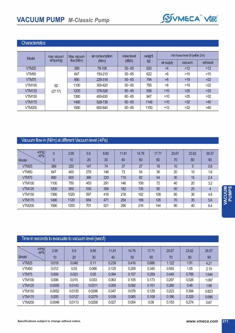
271Specifications subject to change without notice. www.vmeca.com
VA
CU
UM
P
UM
PS
VACUUM PUMP M-Classic Pump
Characteristics
92
(27.17)
VTM25
VTM50
VTM75
VTM100
VTM125
VTM150
VTM175
VTM200
389
647
890
1100
1200
1380
1490
1580
78-108
150-210
228-318
300-420
378-528
450-630
528-738
600-840
50 - 65
50 - 65
50 - 65
50 - 65
60 - 65
60 - 65
60 - 65
60 - 65
620
622
794
795
936
947
1148
1150
>4
>6
>8
>8
>10
>10
>10
>12
>12
>15
>19
>19
>25
>25
>32
>32
>12
>15
>22
>22
>32
>32
>40
>40
Vacuum flow in (Nl/m) at different Vacuum level (-kPa)
max. vacuum-kPa(-inHg)
ModelMax. vacuum
flow(Nl/m)airconsumption
(Nl/m)
noise level
(dBA)
weight
(g)
minhoseinnerØ(within2m)
airsupply vacuum exhaust
5.9 8.85 11.81 14.76 20.67 23.62 26.57
Time in seconds to evacuate to vacuum level (sec/l)
-inHg-kPa
VTM25
VTM50
VTM75
VTM100
VTM125
VTM150
VTM175
VTM200
Model
0.048
0.03
0.023
0.015
0.0143
0.0135
0.0127
0.0113
0.11
0.066
0.05
0.033
0.0311
0.0296
0.0279
0.0258
0.239
0.125
0.094
0.063
0.055
0.047
0.039
0.027
0.416
0.209
0.157
0.105
0.092
0.078
0.065
0.054
1.122
0.593
0.445
0.297
0.260
0.223
0.186
0.153
1.91
1.05
0.788
0.526
0.46
0.394
0.329
0.274
4.21
2.19
1.644
1.097
1.96
0.823
0.686
0.67
17.71
0.686
0.345
0.259
0.173
0.151
0.129
0.108
0.09
2.95
0.019
0.012
0.009
0.006
0.0055
0.0052
0.005
0.0048
0 2.95 5.9 8.85 11.81 14.76 17.71 20.67 23.62 26.57-inHg-kPa
VTM25
VTM50
VTM75
VTM100
VTM125
VTM150
VTM175
VTM200
Model
389
647
890
1100
1200
1380
1490
1580
220
400
600
750
900
1020
1120
1200
147
279
366
453
530
597
654
701
74
146
220
291
356
416
471
521
37
73
110
146
182
218
254
290
27
54
82
109
135
162
189
216
18
36
54
72
90
108
126
144
10
20
30
40
50
60
70
80
5
10
15
20
25
30
35
40
0.8
1.6
2.4
3.2
4
4.8
5.6
6.4
0 10 20 30 40 50 60 70 80
10 20 30 40 50 60 70 80
90
90

Specifications subject to change without notice.272 www.vmeca.com
VACUUM PUMP M-Classic Pump
Dimensional Information
(mm)
Model L1 L2
VTM25
VTM50
VTM75
VTM100
VTM125
VTM150
VTM175
VTM200
45.5
45.5
65
65
84.5
84.5
104
104
203.5
203.5
223
223
242.5
242.5
262
262
Standard with AS - KIT
Port1 : G1/4″, NPT1/4″
Port2 : G1/2″, G3/4″, G1″
NPT1/2″, NPT3/4″, NPT1″
Port3 : G3/4″
Port1 : VTM25~VTM150 : G1/4″, NPSF1/4″
Port1 : VTM175~VTM200 : G3/8″, NPSF3/8″
Port2 : G1/2″, G3/4″, G1″
NPT1/2″, NPT3/4″, NPT1″
Port3 : G3/4″
[ Measure unit : mm]

273Specifications subject to change without notice. www.vmeca.com
VA
CU
UM
P
UM
PS
VACUUM PUMP M-Classic Pump
Dimensional Information
(mm)
Model L1 L2
VTM25
VTM50
VTM75
VTM100
VTM125
VTM150
VTM175
VTM200
45.5
45.5
65
65
84.5
84.5
104
104
206.5
206.5
226
226
245.5
245.5
265
265
A Airsupplycontrolvalve
B Vacuumreleasecontrolvalve
C Digitaldisplayvacuumswitch
Air supply control valve
Vacuum release control valve
Digital display vacuum switch
Port1 : VTM25~VTM150 : G1/4″, NPSF1/4″
Port1 : VTM175~VTM200 : G3/8″, NPSF3/8″
Port2 : G1/2″, G3/4″, G1″
NPT1/2″, NPT3/4″, NPT1″
Port3 : G3/4″
[ Measure unit : mm]

Outputtype: PNPopencollector.
Specifications subject to change without notice.274 www.vmeca.com
VACUUM PUMP X-Classic Pump
X-Classic PumpMax. vacuum level
Max. flow rate
Supply air pressure
Supply air type
Working temperature
Noise level
: -97 kPa (-28.64 inHg)
: 521 Nl/min (18.4 scfm)
: 4~6bar, max 7bar(58~87 psi, max 101.5psi)
: Dry compressed air
: -20④ ~ 80④
: 55 ~ 65 ④k
④④ ④④
VTX25 - 1434 A - AS - A3 R3 - CL - SG2 N V
④ ④ ④ ④ ④
This Classic VTX type is a pump that bridges the gap between the High Flow VTM range and the High Vacuum VTH Range, giving a balance of the two. The X-
Classic has the same external dimensions to that of the M-Classic, however the internal ejector system is different to enable higher levels of vacuum to be achieved.
Each pump comes complete with an exhaust silencer, gauge and fixing brackets. The body whilst robust is also lightweight. The housings are manufactured from
PPS high grade plastic, which means most hazardous vapors, can be accommodated. Pump sizes range from a VTX25 to the VTX75. All units are available with
the option of an air saving kit and non-return valves. Viton④ and EPDM seals can also be stipulated as options.
Main Advantages
Order No.
※ Remark :
Airsupplyportwithaircontrol valveorAS-kit
G1/4″
Capacity equivalent toelectricity motor pump size④ Model-
VTX25
VTX50
VTX75
- 0.25KW
- 0.50KW
- 0.75KW
●
D..* : Double solenoid valve
Double solenoid valve is
available only with ‘DN’or’DL’, section ④
④ Air supply control valve
A1
A2
A3
D1*
D2*
D3*
- AC 110V
- AC 220V
- DC 24V
- AC 110V
- AC 220V
- DC 24V
●
No mark
N
- Standard
- Non-return valve
④ Non-return valve
●
No mark
V
E
- Standard (NBR)
- Viton④
- EPDM
④ Sealing
●
●
④ Vacuum switch
S2(P)
SG2(P)
SG3(P)
●
④ Solenoid Terminal
DN
DL
CL*
2B*
3B*
- DIN type without lead wire
- DIN type with lamp without lead wire
Connector type with lamp &
0.3m lead wire-
DIN type with ‘2 in 1’ BUS cable(Air control v/v + Vacuum release v/v)
-
DIN type with ‘3 in 1’ BUS cable(Air control v/v+ Vacuumreleasev/v+ Digital switch)
-
* Can not available with double solenoid valve
④ Remark
CL : Available only with DC24V3B : Available only with DC24V
Available only with ‘S2’ or ‘S2P’, section ④
④ Vacuum releasecontrol valve
R1
R2
R3
- AC110V
- AC220V
- DC24V●
- Digital output 2points, No analog supply
M8-4Pin male connector (0.3m lead wire)
- Digital output 2points, No analog supply
Grommet type 4-core 2m lead wire
- Digital output 2points, Analog supply
Grommet type 4-core 2m lead wire
※ Remark : ④ S..(P)
④ VCM8 42 : M8-4Pin female connector.only for type S2(P)
④
④ Connection plate
●
Airport
G1/4″
G1/4″
G1/4″
NPT1/4″
NPT1/4″
NPT1/4″
G1/8″
G1/8″
NPT1/8″
NPT1/8″
Vacuumport
G1/2″
G3/4″
G1″
NPT1/2″
NPT3/4″
NPT 1″
G1/2″
G3/4″
NPT1/2″
NPT3/4″
1412 A
1434 A
1401 A
N1412 A
N1434 A
N1401 A
1812 P
1834 P
N1812 P
N1834 P
Alu
min
umAll
PPS
④ Air saving Kit
No mark
AS
- Standard
- Air saving kit attached●
( 108)
④ About ‘BUS cable’ ( 340, 341)
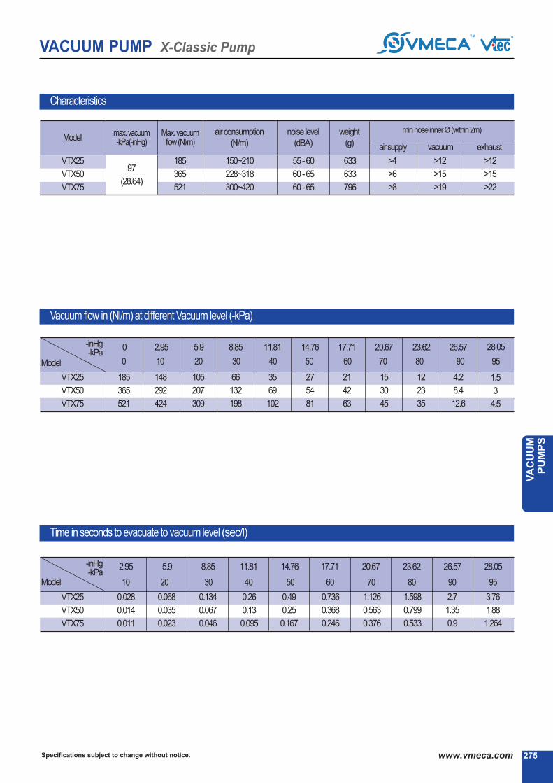
275Specifications subject to change without notice. www.vmeca.com
VA
CU
UM
P
UM
PS
VACUUM PUMP X-Classic Pump
Characteristics
97
(28.64)
VTX25
VTX50
VTX75
185
365
521
150~210
228~318
300~420
55 - 60
60 - 65
60 - 65
633
633
796
>4
>6
>8
>12
>15
>19
>12
>15
>22
0 2.95 5.9 8.85 11.81 14.76 17.71 20.67 23.62 26.57 28.05
Vacuum flow in (Nl/m) at different Vacuum level (-kPa)
-inHg-kPa
Time in seconds to evacuate to vacuum level (sec/l)
185
365
521
148
292
424
105
207
309
66
132
198
35
69
102
27
54
81
21
42
63
15
30
45
12
23
35
4.2
8.4
12.6
1.5
3
4.5
2.95 5.9 8.85 11.81 14.76 17.71 20.67 23.62 26.57-inHg-kPa
VTX25
VTX50
VTX75
0.028
0.014
0.011
0.068
0.035
0.023
0.134
0.067
0.046
0.26
0.13
0.095
0.49
0.25
0.167
0.736
0.368
0.246
1.126
0.563
0.376
1.598
0.799
0.533
2.7
1.35
0.9
28.05
3.76
1.88
1.264
Model
Model
VTX25
VTX50
VTX75
max. vacuum-kPa(-inHg)
ModelMax. vacuum
flow(Nl/m)airconsumption
(Nl/m)
noise level
(dBA)
weight
(g)
minhoseinnerØ(within2m)
airsupply vacuum exhaust
0 10 20 30 40 50 60 70 80 90
10 20 30 40 50 60 70 80
95
90 95

Specifications subject to change without notice.276 www.vmeca.com
VACUUM PUMP X-Classic Pump
Dimensional Information
Model L1
(mm)
L2
VTX25
VTX50
VTX75
45.5
45.5
65
203.5
203.5
223
Standard with AS - KIT
Port1 : G1/4″, NPSF1/4″
Port2 : G1/2″, G3/4″, G1″
NPT1/2″, NPT3/4″, NPT1″
Port3 : G3/4″
Port1 : G1/4, NPSF1/4″″
Port2 : G1/2″, G3/4″, G1″
NPT1/2″, NPT3/4″, NPT1″
Port3 : G3/4″
[ Measure unit : mm]

277Specifications subject to change without notice. www.vmeca.com
VA
CU
UM
P
UM
PS
VACUUM PUMP X-Classic Pump
Dimensional Information
Model L1 L2
VTX25
VTX50
VTX75
45.5
45.5
65
206.5
206.5
226
(mm)
A Airsupplycontrolvalve
B Vacuumreleasecontrolvalve
C Digitaldisplayvacuumswitch
Air supply control valve
Vacuum release control valve
Digital display vacuum switch
Port1 : G1/4″, NPT1/4″
Port2 : G1/2″, G3/4″, G1″
NPT1/2″, NPT3/4″, NPT1″
Port3 : G3/4″
[ Measure unit : mm]

Specifications subject to change without notice.278 www.vmeca.com
VACUUM PUMP MM-Midiflex Pump
This MM-Midiflex pump is a compact manifold based multi stage ejector multi pump arrangement. Much higher flow rates and
fast evacuation times can be achieved with this type of pump.
The pump features a pressure gauge and a vacuum gauge along with two G3/4″ ports for connecting more than one large bore
vacuum pipe. As with most of the other pumps the MM-Midiflex can be specified with an air saving kit, and with Viton④ or EPDM
as seal options. This manifold has a special design allowing you to choose between two vacuum ports suited for your applica-
tion. The pumps to achieve a combination of high flow rates and the highest vacuum levels.
MM - Midiflex PumpMax. vacuum level
Max. flow rate
Supply air pressure
Supply air type
Working temperature
Noise level
: -92 kPa (-27.17 inHg)
: 2200 Nl/min (77.69 scfm)
: 4~6bar, max 7bar(58~87 psi, max 101.5psi)
: Dry compressed air
: -20④ ~ 80④
: 55 ~ 65 ④k
④ Vacuum port
V34
V01
V02
- 2XG3/4″ (VTMM100, 150, 200)
- G1″ (VTMM100, 150, 200)
- G1 1/2″ (VTMM200F)
●
VTMM100
VTMM150
VTMM200
VTMM200F
- 1KW
- 1.5KW
- 2KW
- 2KW
●
④ Air saving kit
Nomark
AS
- Standard
- Air saving kit attach●
Nomark
N
- Standard
- Non return valve
④ Non return valve
●
④ Air supply control valve
nomarkA1
A2
A3
A4
- Without control valve
- AC110VElectricallyoperatedvalve
- AC220VElectricallyoperatedvalve
- DC24VElectricallyoperatedvalve
- Pneumatically operated valve
●
Nomark
V
E
- Standard (NBR)
- Viton④
- EPDM
④ Sealing
●
④ Model-Capacity equivalent toelectricity motor pump size
●
④ Vacuum switch
S2(P)
SG2(P)
SG3(P)
- Digitaloutput2points, NoanalogsupplyM8-4Pinmaleconnector(0.3mleadwire)
- Digitaloutput2points, NoanalogsupplyGrommettype4-core2mleadwire
- Digitaloutput2points, AnalogsupplyGrommettype4-core2mleadwire
Outputtype: PNPopencollector.
※ Remark : ④ S..(P)
④ VCM8 42 : M8-4Pinfemaleconnector.onlyfortypeS2(P)
Order No.
④④ ④④
VTMM100 - V34 - AS A3 - SG2 - N V
④ ④ ④
Main Advantages
( 108)
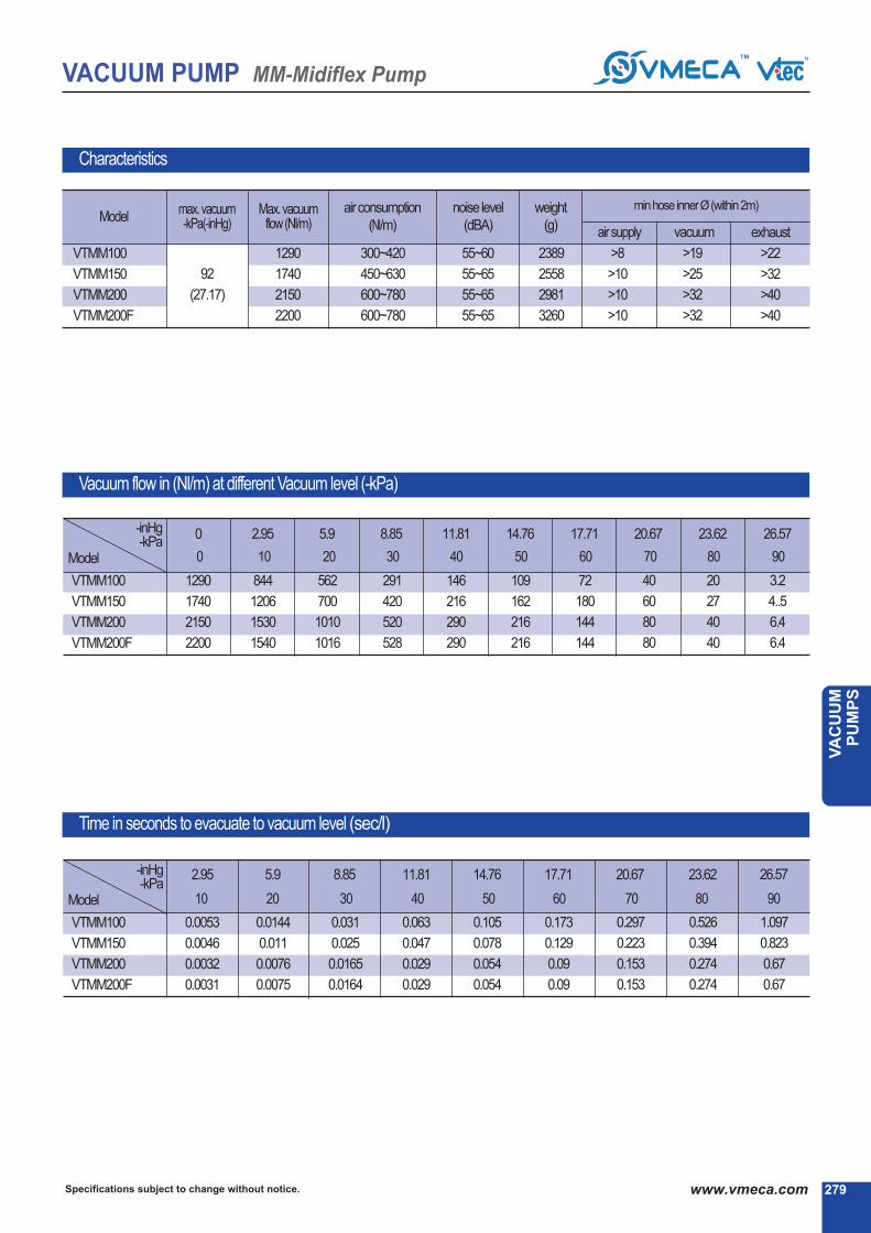
279Specifications subject to change without notice. www.vmeca.com
VA
CU
UM
P
UM
PS
VACUUM PUMP MM-Midiflex Pump
Characteristics
92
(27.17)
VTMM100
VTMM150
VTMM200
VTMM200F
1290
1740
2150
2200
300~420
450~630
600~780
600~780
55~60
55~65
55~65
55~65
2389
2558
2981
3260
>8
>10
>10
>10
>19
>25
>32
>32
max. vacuum-kPa(-inHg)
ModelMax. vacuum
flow(Nl/m)airconsumption
(Nl/m)
noise level
(dBA)
weight
(g)
minhoseinnerØ(within2m)
airsupply vacuum exhaust
0 2.95 5.9 8.85 11.81 14.76 17.71 20.67 23.62 26.57
Vacuum flow in (Nl/m) at different Vacuum level (-kPa)
-inHg-kPa
VTMM100
VTMM150
VTMM200
VTMM200F
Model
Time in seconds to evacuate to vacuum level (sec/l)
1290
1740
2150
2200
844
1206
1530
1540
562
700
1010
1016
291
420
520
528
146
216
290
290
109
162
216
216
72
180
144
144
40
60
80
80
20
27
40
40
3.2
4..5
6.4
6.4
2.95 5.9 8.85 11.81 14.76 17.71 20.67 23.62-inHg-kPa
VTMM100
VTMM150
VTMM200
VTMM200F
Model
0.0053
0.0046
0.0032
0.0031
0.0144
0.011
0.0076
0.0075
0.031
0.025
0.0165
0.0164
0.063
0.047
0.029
0.029
0.105
0.078
0.054
0.054
0.173
0.129
0.09
0.09
0.297
0.223
0.153
0.153
0.526
0.394
0.274
0.274
26.57
1.097
0.823
0.67
0.67
>22
>32
>40
>40
0 10 20 30 40 50 60 70 80
10 20 30 40 50 60 70 80
90
90

Port1 : VTMM100, 150 : G1/4″
VTMM200 : G3/8″
Port2 : 2xG3/4″(V34), G1″ (V01)
Port3 : 2xG3/4″
Specifications subject to change without notice.280 www.vmeca.com
VACUUM PUMP MM-Midiflex Pump
Dimensional Information
100
VTMM (150) 200
Port1 : G1/2″
Port2 : 2xG3/4″(V34), G1″ (V01)
Port3 : 2xG3/4″
Model L1
(mm)
VTMM100
VTMM150
VTMM200
150
169.5
189
with AS - KIT
[ Measure unit : mm ]

281Specifications subject to change without notice. www.vmeca.com
VA
CU
UM
P
UM
PS
VACUUM PUMP MM-Midiflex Pump
Dimensional Information
VTMM 200F with air supply control valve
[ Measure unit : mm]
Port1 : G3/4″
Port2 : G1 1/2″ (V02)
Port3 : 2xG3/4″

Specifications subject to change without notice.282 www.vmeca.com
VACUUM PUMP MX-Midiflex Pump
This MX-Midiflex pump is a compact manifold based multi stage ejector multi pump arrangement. The MX-Midiflex has the same
external dimensions to that of the VTMM, however the internal ejector system is different to enable higher levels of vacuum to be
achieved. A good balance between higher flow rates and higher vacuum levels with fast evacuation times can be achieved with
this type of pump. The pump features a vacuum gauge along with two 3/4″ ports for connecting more than one large bore vacuum
pipe. As with most of the other pumps the MX-Midiflex can be specified with an air saving kit, and with Viton④ or EPDM as seal
options.
Main Advantages
MX - Midiflex PumpMax. vacuum level
Max. flow rate
Supply air pressure
Supply air type
Working temperature
Noise level
: -97 kPa (-28.64 inHg)
: 1355 Nl/min (47.85 scfm)
: 4~6bar, max 7bar(58~87 psi, max 101.5psi)
: Dry compressed air
: -20④ ~ 80④
: 63 ~ 68 ④k
④ Vacuum port
V34
V01
- 2XG3/4″
- G1″
●
VTMX100
VTMX200
VTMX300
- 1KW
- 2KW
- 3KW
● nomark
N
- standard
- non return valve
④ Non return valve
●
nomark
V
E
- standard (NBR)
- Viton④
- EPDM
④ Sealing
●
④ Air saving kit
nomark
AS
- standard
- Air saving kit attach●
④ Air supply control valve
nomarkA1
A2
A3
A4
- Without control valve
- Electrically operated valve AC110V
- Electrically operated valve AC220V
- Electrically operated valve DC24V
- Pneumatically operated valve
●
●
④ Model-Capacity equivalent toelectricity motor pump size
④ Vacuum switch
S2(P)
SG2(P)
SG3(P)
- Digitaloutput2points, NoanalogsupplyM8-4Pinmaleconnector(0.3mleadwire)
- Digitaloutput2points, NoanalogsupplyGrommettype4-core2mleadwire
- Digitaloutput2points, AnalogsupplyGrommettype4-core2mleadwire
Outputtype: PNPopencollector.
※ Remark : ④ S..(P)
④ VCM8 42 : M8-4Pinfemaleconnector.onlyfortypeS2(P)
Order No.
④④ ④④
VTMX100 - V34 - AS - A3 - SG2 - N V
④ ④ ④
( 108)

283Specifications subject to change without notice. www.vmeca.com
VA
CU
UM
P
UM
PS
VACUUM PUMP MX-Midiflex Pump
Characteristics
97
(28.64)
VTMX100
VTMX200
VTMX300
695
1037
1355
504~600
756~900
1008~1200
63 ~ 68
63 ~ 68
63 ~ 68
2390
2549
3438
>8
>10
>10
>19
>25
>32
>22
>32
>40
Vacuum flow in (Nl/m) at different Vacuum level (-kPa)
Time in seconds to evacuate to vacuum level (sec/l)
0 2.95 5.9 8.85 11.81 14.76 17.71 23.62 26.57 28.05
VTMX200
VTMX300
2.95 5.9 8.85 11.81 14.76 17.71 23.62 26.57 28.05
VTMX100
VTMX200
0.0093
0.0064
VTMX300 0.0049
0.017
0.012
0.009
0.036
0.024
0.018
0.064
0.047
0.031
0.123
0.082
0.061
0.184
0.123
0.092
0.272
0.186
0.141
0.397
0.256
0.197
0.674
0.448
0.336
0.948
0.631
0.473
568
844
1096
411
615
813
260
398
530
139
211
289
108
162
216
84
126
168
60
90
120
45
69
92
17
26
33
6
9
12
20.67
20.67
-inHg-kPa
Model
Model
-inHg-kPa
VTMX100
max. vacuum-kPa(-inHg)
ModelMax. vacuum
flow(Nl/m)airconsumption
(Nl/m)
noise level
(dBA)
weight
(g)
minhoseinnerØ(within2m)
airsupply vacuum exhaust
695
1037
1355
0 10 20 30 40 50 60 70 80 90
10 20 30 40 50 60 70 80
95
90 95

VACUUM PUMP MX-Midiflex Pump
Specifications subject to change without notice.284 www.vmeca.com
Dimensional Information
100
VTMX (200) 300
Port1 : G1/2″
Port2 : 2xG3/4″ (V34), G1″ (V01)
Port3 : 2xG3/4″ Model L1 (mm)
VTMX100
VTMX200
VTMX300
150
169.5
208.5
[ Measure unit : mm]

VACUUM PUMP MX-Midiflex Pump
285Specifications subject to change without notice. www.vmeca.com
VA
CU
UM
P
UM
PS
Dimensional Information
Port1 : VTMX100: G1/4″
VTMX200, 300: G3/8″
Port2 : 2xG3/4″ (V34), G1″ (V01)
Port3 : 2xG3/4″
Model L1 (mm)
VTMX100
VTMX200
VTMX300
150
169.5
208.5
with AS - KIT
[ Measure unit : mm]

Outputtype: PNPopencollector.
Specifications subject to change without notice.286 www.vmeca.com
VACUUM PUMP H-Classic / H-Midiflex Pump
H - Classic / H - Midiflex PumpMax. vacuum level
Max. flow rate
Supply air pressure
Supply air type
Working temperature
Noise level
: -100.8 kPa (-29.76 inHg)
: 1042 Nl/min (36.8 scfm)
: 4~6bar, max 7bar(58~87 psi, max 101.5psi)
: Dry compressed air
: -20④ ~ 80④
: 60 ~ 65 ④k
Order No.
④④ ④④
VTH50 - 1434 A - AS - A3 R3 - CL - SG2 N V
④ ④ ④ ④ ④Capacity equivalent toelectricity motor pump size④ Model-
VTH50
VTH150
VTH300
- 0.30KW
- 0.90KW
- 1.00KW
●
D..* : Double solenoid valve
Double solenoid valve is
available only with ‘DN’or’DL’, section ④
④ Air supply control valve
A1
A2
A3
D1*
D2*
D3*
- AC 110V
- AC 220V
- DC 24V
- AC 110V
- AC 220V
- DC 24V
●
No mark
N
- Standard
- Non-return valve
④ Non-return valve
●
No mark
V
E
- Standard (NBR)
- Viton④
- EPDM
④ Sealing
●
●
④ Vacuum switch
S2(P)
SG2(P)
SG3(P)
- Digital output 2points, No analog supply
M8-4Pin male connector (0.3m lead wire)
- Digital output 2points, No analog supply
Grommet type 4-core 2m lead wire
- Digital output 2points, Analog supply
Grommet type 4-core 2m lead wire
※ Remark : ④ S..(P)
④ VCM8 42 : M8-4Pin female connector.only for type S2(P)
●
④ Solenoid Terminal
DN
DL
CL*
2B*
3B*
- DIN type without lead wire
- DIN type with lamp without lead wire
Connector type with lamp &
0.3m lead wire-
DIN type with ‘2 in 1’ BUS cable(Air control v/v + Vacuum release v/v)
-
DIN type with ‘3 in 1’ BUS cable(Aircontrolv/v+ Vacuumreleasev/v+ Digitalswitch)
-
* Can not available with double solenoid valve
④ Remark
CL : Available only with DC24VCan not available with VTH300
3B : Available only with DC24VAvailable only with ‘S2’ or ‘S2P’, section ④
④ Vacuum releasecontrol valve
R1
R2
R3
- AC110V
- AC220V
- DC24V●
The H-Classic / H-Midiflex range produces the very highest vacuum levels, whilst maintaining good flow rates for quick evacuation time. There are three
models to choose from two classic sharp pumps and one midiflex pump, ranging from VTH50 to the VTH300. As with most of the other pumps there are
options for an air saving kit, integral non return valve and Viton④ or EPDM seals.
Main Advantages
④ Air saving Kit
No mark
AS
- Standard
- Air saving kit attached●
VTH3
00V
TH
50, V
TH
150
※ Remark :
Airsupplyportwithaircontrol valveorAS-kitVTH50, VTH150 : G1/4″VTH300 : G3/8″
PPS Mat’l is available with VTH50, VTH150
④ Connection plate
●
Airport
G1/4″
G1/4″
G1/4″
NPT1/4″
NPT1/4″
NPT1/4″
G1/8″
G1/8″
NPT1/8″
NPT1/8″
G1/2″
G1/2″
Vacuumport
G1/2″
G3/4″
G1″
NPT1/2″
NPT3/4″
NPT 1″
G1/2″
G3/4″
NPT1/2″
NPT3/4″
2XG3/4″
G1″
1412 A
1434 A
1401 A
N1412 A
N1434 A
N1401 A
1812 P
1834 P
N1812 P
N1834 P
V34
V01
Alu
min
umAll
PPS
Mat’l
( 108)
④ About ‘BUS cable’ ( 340, 341)

287Specifications subject to change without notice. www.vmeca.com
VA
CU
UM
P
UM
PS
VACUUM PUMP H-Classic / H-Midiflex Pump
Characteristics
100.8
(29.76)
VTH50
VTH150
VTH300
185
521
1042
120-156
420-456
870-912
60-65
60-65
60-65
632
780
2682
>8
>8
>10
>12
>15
>19
>12
>15
>22
Vacuum flow in (Nl/m) at different Vacuum level (-kPa)
Time in seconds to evacuate to vacuum level (sec/l)
0 2.95 5.9 8.85 11.81 14.76 17.71 20.67 23.62 26.57 28.05 29.23
2.95 5.9 8.85 11.81 14.76 17.71 20.67 23.62 26.57 28.05 29.23
VTH50
VTH150
VTH300
VTH50
VTH150
VTH300
185
521
1042
147
423
846
106
307
614
66
198
396
32
105
210
21
78
156
15
54
108
9.6
39
78
7.8
27
54
3.6
7.8
15.6
1.2
3.6
7.2
0.3
0.48
0.96
0.029
0.011
0.006
0.07
0.025
0.013
0.12
0.05
0.025
0.25
0.097
0.048
0.55
0.17
0.085
0.92
0.272
0.136
1.446
0.41
0.205
2.2
0.6
0.3
3.39
1.17
0.585
4.986
1.82
0.91
9.18
3.586
1.798
Model
Model
-inHg-kPa
-inHg-kPa
max. vacuum-kPa(-inHg)
ModelMax. vacuum
flow(Nl/m)airconsumption
(Nl/m)
noise level
(dBA)
weight
(g)
minhoseinnerØ(within2m)
airsupply vacuum exhaust
0 10 20 30 40 50 60 70 80 90
10 20 30 40 50 60 70 80
95 99
90 95 99

Specifications subject to change without notice.288 www.vmeca.com
VACUUM PUMP H-Classic / H-Midiflex Pump
Dimensional Information
Model L1 L2
(mm)
VTH50
VTH150
45.5
65
203.5
223
Standard with AS - KIT
Port1 : G1/4″, NPSF1/4″
Port2 : G1/2″, G3/4″, G1″
NPT1/2″, NPT3/4″, NPT1″
Port3 : G3/4″
Port1 : G1/4, NPT1/4″″
Port2 : G1/2″, G3/4″, G1″
NPT1/2″, NPT3/4″, NPT1″
Port3 : G3/4″
[ Measure unit : mm]
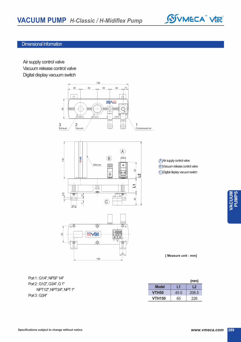
289Specifications subject to change without notice. www.vmeca.com
VA
CU
UM
P
UM
PS
VACUUM PUMP H-Classic / H-Midiflex Pump
Dimensional Information
Model L1 L2
(mm)
VTH50
VTH150
45.5
65
206.5
226
A Airsupplycontrolvalve
B Vacuumreleasecontrolvalve
C Digitaldisplayvacuumswitch
Air supply control valve
Vacuum release control valve
Digital display vacuum switch
Port1 : G1/4″, NPSF1/4″
Port2 : G1/2″, G3/4″, G1″
NPT1/2″, NPT3/4″, NPT1″
Port3 : G3/4″
[ Measure unit : mm]
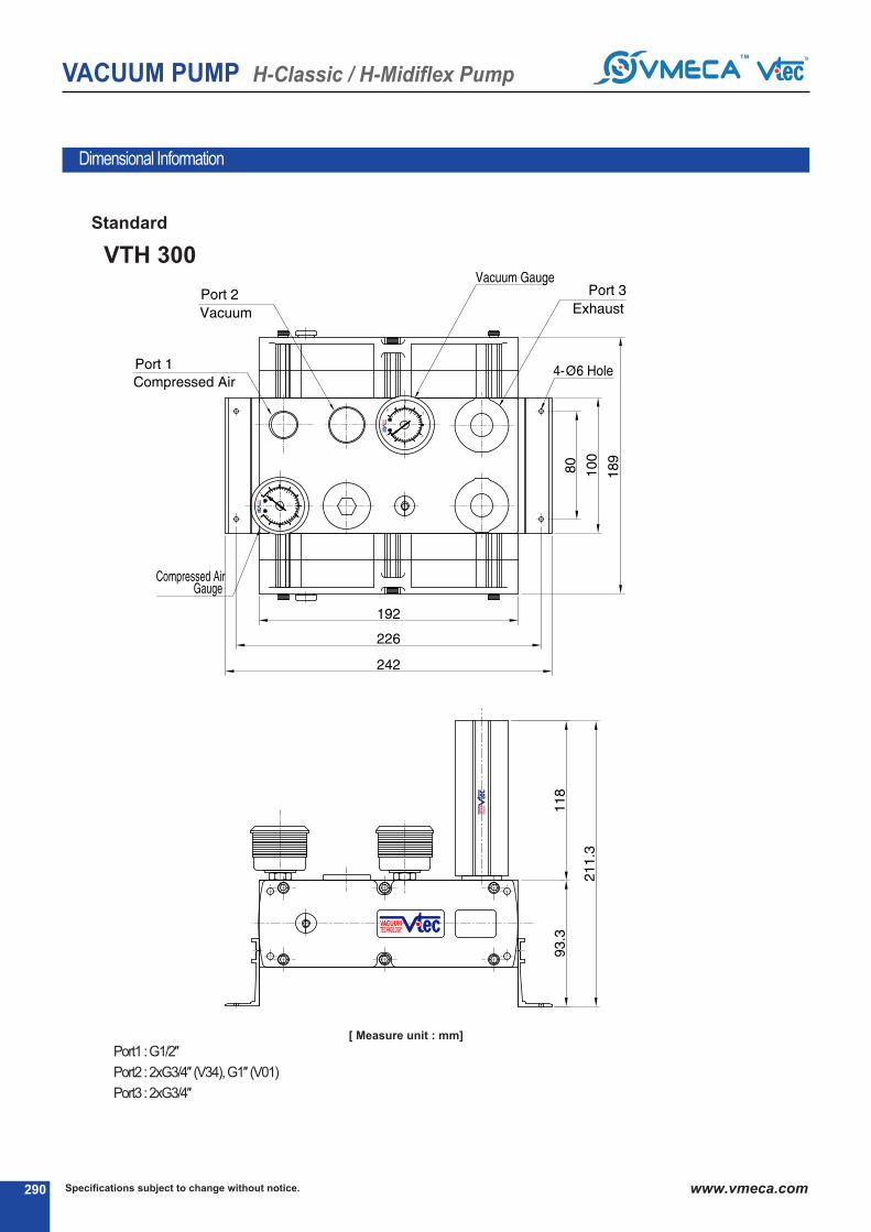
Specifications subject to change without notice.290 www.vmeca.com
VACUUM PUMP H-Classic / H-Midiflex Pump
Dimensional Information
VTH 300
Port1 : G1/2″
Port2 : 2xG3/4″ (V34), G1″ (V01)
Port3 : 2xG3/4″
Standard
[ Measure unit : mm]

291Specifications subject to change without notice. www.vmeca.com
VA
CU
UM
P
UM
PS
VACUUM PUMP H-Classic / H-Midiflex Pump
Dimensional Information
Port1 : G3/8″
Port2 : 2xG3/4″ (V34), G1″(V01)
Port3 : 2xG3/4″
with AS - KIT
[ Measure unit : mm]

Specifications subject to change without notice.292 www.vmeca.com
VACUUM PUMP L-Maxflex Pump
L - Maxflex PumpMax. vacuum level
Max. flow rate
Supply air pressure
Supply air type
Working temperature
Noise level
: -91 kPa (-26.87 inHg)
: 6100 Nl/min (215.4 scfm)
: 3~6bar, max 7bar(43.5~87 psi, max 101.5psi)
: Dry compressed air
: -20④ ~ 80④
: 55 ~ 68 ④k
VTM150LEF
VTM200LEF
VTM300LEF
VTM400LEF
VTM500LEF
VTM600LEF
VTM800LEF
- 1.5KW
- 2KW
- 3KW
- 4KW
- 5KW
- 6KW
- 8KW
● Nomark
N
- Standard
- Non return valve
④ Non return valve
●
④ Air supply control valve
NomarkA1
A2
A3
A4
- Without control valve
- AC110V Electrically operated valve
- AC220V Electrically operated valve
- DC24V Electrically operated valve
- Pneumatically operated valve
●
●
④ Air saving kit
Nomark
AS
- Standard
- Air saving kit attach●
Nomark
V
E
- Standard (NBR)
- Viton④
- EPDM
④ Sealing
●
④ Model-Capacity equivalent toelectricity motor pump size
④ Vacuum switch
S2(P)
SG2(P)
SG3(P)
- Digitaloutput2points, NoanalogsupplyM8-4Pinmaleconnector(0.3mleadwire)
- Digitaloutput2points, NoanalogsupplyGrommettype4-core2mleadwire
- Digitaloutput2points, AnalogsupplyGrommettype4-core2mleadwire
Outputtype: PNPopencollector.
※ Remark : ④ S..(P)
④ VCM8 42 : M8-4Pinfemaleconnector.onlyfortypeS2(P)
This is the most significant model based on the multi stage principle. Low compressed air are required for massive evacuation
volumes at high vacuum flow and high vacuum level rate Vtec air saving kit is available in this pump in order to maximize the
reduction of energy usage.
The pumps utilize an integrally mounted large bore air supply ON/OFF valve as an option. Viton④ & EPDM seals can be also
stipulated as an option as well.
Main Advantages
Order No.
④④ ④④
VTM150LEF - AS - A3 - SG2 - N V
④ ④
( 108)

293Specifications subject to change without notice. www.vmeca.com
VA
CU
UM
P
UM
PS
VACUUM PUMP L-Maxflex Pump
Characteristics
0 5.9 8.85 14.76 17.71 23.62 26.57
Vacuum flow in (Nl/m) at different Vacuum level (-kPa)
2.95 5.9 8.85 11.81 14.76 17.71 20.67 23.62 26.57
Time in seconds to evacuate to vacuum level (sec/l)
91
(26.87)
VTM150LEF
VTM200LEF
VTM300LEF
VTM400LEF
VTM500LEF
VTM600LEF
VTM800LEF
VTM150LEF
VTM200LEF
VTM300LEF
VTM400LEF
VTM500LEF
VTM600LEF
VTM800LEF
VTM150LEF
VTM200LEF
VTM300LEF
VTM400LEF
VTM500LEF
VTM600LEF
VTM800LEF
1680
2100
2600
3180
4200
5010
6100
1680
2100
2600
3180
4200
5010
6100
0.0033
0.0025
0.0017
0.0013
0.001
0.0008
0.0006
0.009
0.007
0.005
0.004
0.003
0.0023
0.0018
0.02
0.015
0.01
0.008
0.006
0.005
0.004
0.04
0.03
0.02
0.015
0.012
0.01
0.008
0.071
0.053
0.035
0.027
0.021
0.018
0.013
0.11
0.083
0.055
0.041
0.033
0.028
0.021
0.17
0.128
0.085
0.064
0.051
0.043
0.032
0.31
0.21
0.16
0.11
0.09
0.08
0.05
0.87
0.58
0.44
0.29
0.26
0.22
0.15
642
900
1260
1608
2020
2450
3340
439.2
585.6
878.4
1171
1464
1757
2342
190.8
254.4
381.6
508.8
636
763.2
1018
144
192
288
384
480
576
768
39.6
52.8
92
105.6
132
158.4
211.2
4.32
5.76
8.67
11.52
14.4
17.28
23
684
912
1368
1824
2280
2736
3648
55~65
55~65
55~68 55~68
60~68 60~68
60~68
3143
3260
3660
5785
6275
6641
7497
>8
>10
>12
>12
>14
>14
>15
>25
>32
>40
>40
>45
>50
>50
>32
>40
>60
>60
>70
>70
>75
Model
20.67
97.2
129.6
194.4
259.2
324
388.8
518.4
11.81
244.8
326.4
489.6
652.8
816
979.2
1306
2.95
838
1260
1800
2400
2950
3450
4200
Model
-inHg-kPa
-inHg-kPa
max. vacuum-kPa(-inHg)
ModelMax. vacuumflow
(Nl/m)airconsumption
(Nl/m)
noise level
(dBA)
weight
(g)
minhoseinnerØ(within2m)
airsupply vacuum exhaust
0 10 20 30 40 50 60 70 80
10 20 30 40 50 60 70 80
90
90

Specifications subject to change without notice.294 www.vmeca.com
VACUUM PUMP L-Maxflex Pump
Dimensional Information
VTM150LEF
[ Measure unit : mm]

295Specifications subject to change without notice. www.vmeca.com
VA
CU
UM
P
UM
PS
VACUUM PUMP L-Maxflex Pump
VTM200LEF
[ Measure unit : mm]
Dimensional Information

Specifications subject to change without notice.296 www.vmeca.com
VACUUM PUMP L-Maxflex Pump
Dimensional Information
VTM300LEF400
500
Model L1 L2
(mm)
VTM300LEF
VTM400LEF
VTM500LEF
194
233
233
44.5
44.5
64
[ Measure unit : mm]

297Specifications subject to change without notice. www.vmeca.com
VA
CU
UM
P
UM
PS
VACUUM PUMP L-Maxflex Pump
VTM600LEF800
Dimensional Information
Model L1
(mm)
VTM600LEF
VTM800LEF
44.5
64
[ Measure unit : mm]

Specifications subject to change without notice.298 www.vmeca.com
VACUUM PUMP M-Maxflex Pump
M - Maxflex PumpMax. vacuum level
Max. flow rate
Supply air pressure
Supply air type
Working temperature
Noise level
: -92 kPa (-27.17 inHg)
: 11000 Nl/min (388.5 scfm)
: 4~6bar, max 7bar(58~87 psi, max 101.5psi)
: Dry compressed air
: -20⑥ ~ 80⑥
: 55 ~ 68 ⑥V
Nomark
N
- Standard
- Non return valve
⑥ Non return valve
●
⑥ Vir supply control valve
NomarkV9
V8
A3
V5
- Without control valve
- VC110V Electrically operated valve
- VC220V Electrically operated valve
- DC25V Electrically operated valve
- Pneumatically operated valve
●
⑥ Vir saving kit
Nomark
AS
- Standard
- Vir saving kit attach●
Nomark
V
E
- Standard (NBR)
- Viton⑥
- EPDM
⑥ Sealing
●
● - 2KW
- 3KW
- 5KW
- 5KW
- 6KW
- 8KW
- 10KW
VTMM200EF
VTMM300EF
VTMM500EF
VTMM500EF
VTMM600EF
VTMM800EF
VTMM1000EF
Capacity equivalent toelectricity motor pump size⑥ Model-
●
⑥ Vacuum switch
- Digitaloutput2points, NoanalogsupplyM8-5Pinmaleconnector(0.3mleadwire)
- Digitaloutput2points, NoanalogsupplyGrommettype5-core2mleadwire
- Digitaloutput2points, VnalogsupplyGrommettype5-core2mleadwire
Outputtype: PNPopencollector.
※ Remark : ⑥ S..(P)
⑥ VCM8 52 : M8-5Pinfemaleconnector.onlyfortypeS2(P)
This range of M-Maxflex pumps produces the very highest flow rates, as the name denotes all the pumps uses a large bore
common vacuum port with port sizes up to 2⑥. This type of pump has many applications but is particularly useful for high leak-
age systems, porous materials centerising vacuum system and large vacuum circuits.
The pumps are based around a manifold design and utilize an integrally mounted large bore air supply on/off valve as option.
The pumps also come with vacuum and air pressure gauges with two options for positioning of the exhausts, mounting brackets
are also supplied. Vir saving kits and VITON⑥& EPDM seals options are also available with this pump.
Main Advantages
Order No.
⑥⑥ ⑥⑥
VTMM200EF - AS - A3 - SG2 - N V
⑥ ⑥
S2(P)
SG2(P)
SG3(P)
( 108)

299Specifications subject to change without notice. www.vmeca.com
VA
CU
UM
P
UM
PS
VACUUM PUMP M-Maxflex Pump
Characteristics
0 2.95 5.9 8.85 11.81 15.76 17.71 20.67 23.62 26.57
Vacuum flow in (Nl/m) at different Vacuum level (-kPa)
2.95 5.9 8.85 11.81 15.76 17.71 20.67 23.62 26.57
Time in seconds to evacuate to vacuum level (sec/l)
max. vacuum-kPa(-inHg)
ModelMax. vacuum
flow(Nl/m)airconsumption
(Nl/m)
noise level
(dBV)
weight
(g)
minhoseinnerØ(within2m)
airsupply vacuum exhaust
92
(27.17)
VTMM200EF
VTMM300EF
VTMM500EF
VTMM500EF
VTMM600EF
VTMM800EF
VTMM1000EF
VTMM200EF
VTMM300EF
VTMM500EF
VTMM500EF
VTMM600EF
VTMM800EF
VTMM1000EF
VTMM200EF
VTMM300EF
VTMM500EF
VTMM500EF
VTMM600EF
VTMM800EF
VTMM1000EF
2200
3300
5500
5500
6600
8800
11000
2200
3300
5500
5500
6600
8800
11000
0.0031
0.0023
0.0015
0.0013
0.0012
0.0008
0.0007
0.0075
0.0056
0.0038
0.0033
0.0028
0.0019
0.0016
0.0165
0.0123
0.0082
0.0072
0.0062
0.0051
0.0036
0.029
0.022
0.015
0.013
0.011
0.007
0.006
0.055
0.051
0.027
0.025
0.021
0.015
0.012
0.09
0.068
0.055
0.05
0.035
0.022
0.018
0.153
0.115
0.076
0.067
0.057
0.038
0.031
0.275
0.206
0.137
0.120
0.103
0.068
0.057
0.67
0.503
0.335
0.295
0.252
0.168
0.157
1550
2310
3080
3850
5620
6165
7700
1016
1781
2036
2555
3055
5076
5090
528
793
1058
1323
1588
2119
2656
290
535
580
725
870
1160
1550
216
325
532
550
658
865
1080
155
216
288
360
532
576
720
80
120
160
200
250
320
500
50
60
80
100
120
160
200
6.5
9.6
12.8
16
19.2
25.6
32
600-780
900-1260
1200-1680
1500-2100
1800-2520
2500-3360
3000-5150
55~65
55~65
55~65
65~68
65~68
65~68 65~68
5270
5585
5939
6275
11579
12300
15800
>10
>12
>12
>15
>15
>15
>18
>32
>50
>50
>55
>50
>50
>65
>50
>60
>60
>70
>70
>75
>90
-inHg-kPa
Model
-inHg-kPa
Model
0 10 20 30 50 50 60 70 80
10 20 30 50 50 60 70 80
90
90
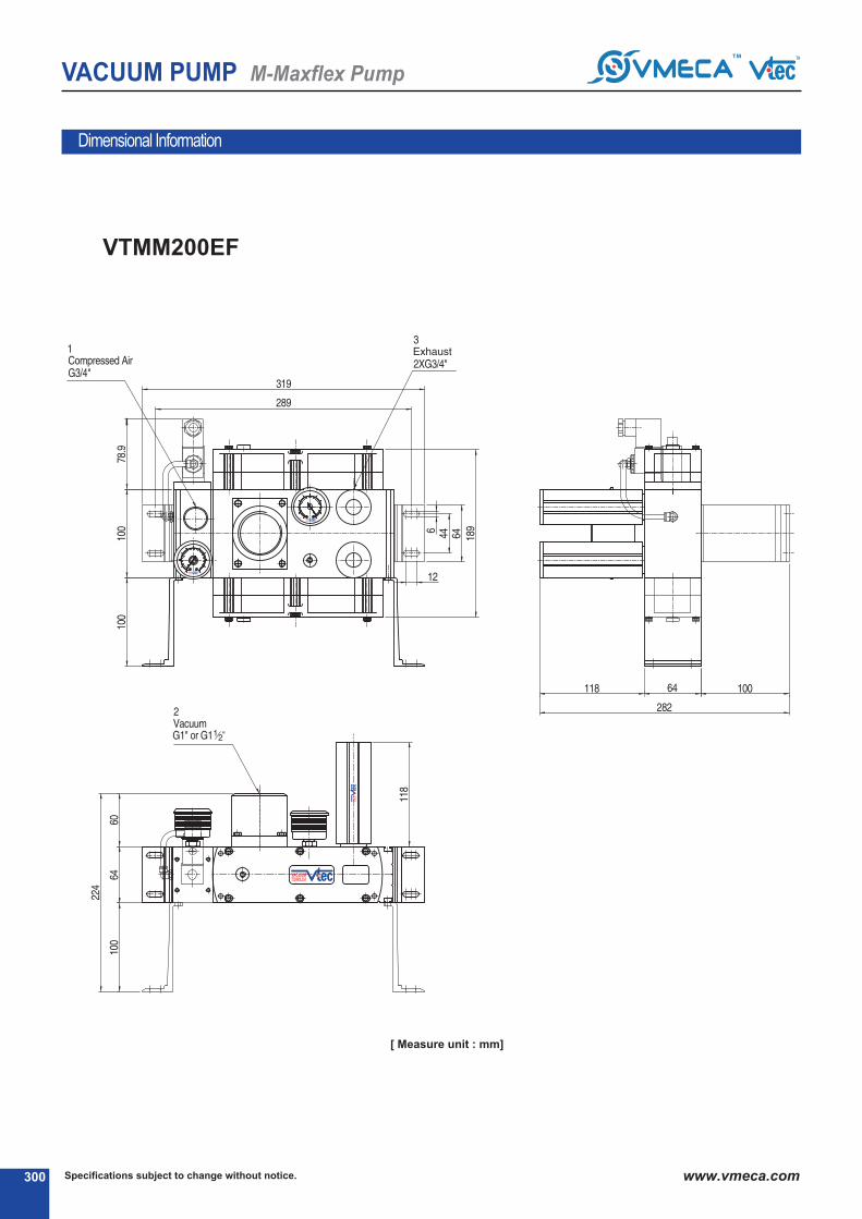
Specifications subject to change without notice.300 www.vmeca.com
VACUUM PUMP M-Maxflex Pump
Dimensional Information
VTMM200EF
[ Measure unit : mm]

301Specifications subject to change without notice. www.vmeca.com
VA
CU
UM
P
UM
PS
VACUUM PUMP M-Maxflex Pump
Dimensional Information
VTMM300EF400
500
Model L1 L2
(mm)
VTMM300-EF
VTMM400-EF
VTMM500-EF
195
233
233
55.5
55.5
55.5
[ Measure unit : mm]

Specifications subject to change without notice.302 www.vmeca.com
VACUUM PUMP M-Maxflex Pump
VTMM600EF800
Model L1 (mm)
VTMM600-EF
VTMM800-EF
55.5
65
Dimensional Information
[ Measure unit : mm]

303Specifications subject to change without notice. www.vmeca.com
VA
CU
UM
P
UM
PS
VACUUM PUMP M-Maxflex Pump
[ Measure unit : mm]
VTMM1000EF
Dimensional Information
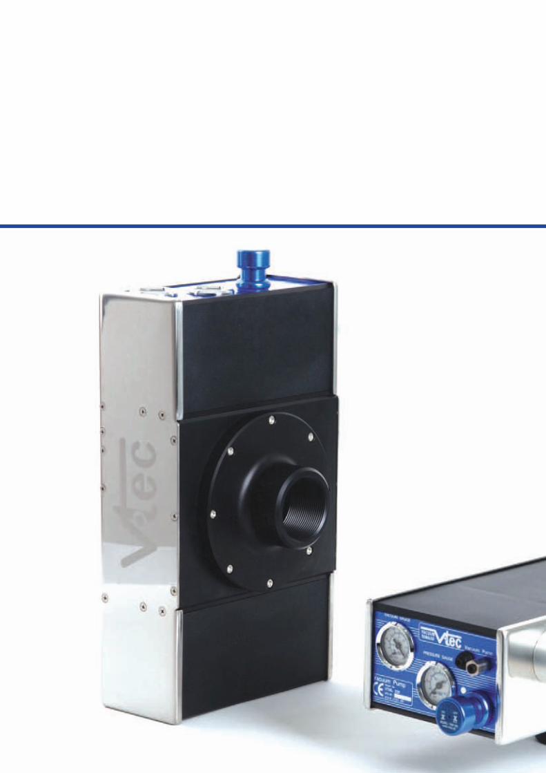
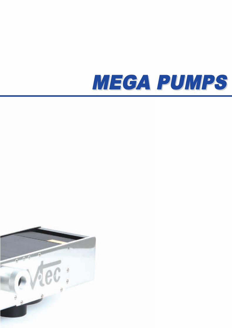
MEGA PUMPSMEGA PUMPS
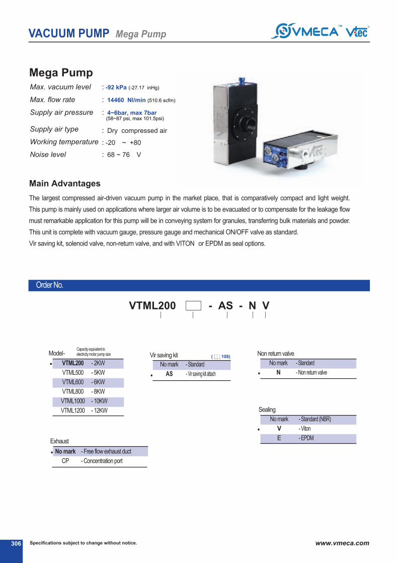
Specifications subject to change without notice.306 www.vmeca.com
VACUUM PUMP Mega Pump
Mega PumpMax. vacuum level
Max. flow rate
Supply air pressure
Supply air type
Working temperature
Noise level
: -92 kPa (-27.17 inHg)
: 14460 Nl/min (510.6 scfm)
: 4~6bar, max 7bar(58~87 psi, max 101.5psi)
: Dry compressed air
: -20⑥ ~ +80⑥
: 68 ~ 76 ⑥V
No mark
N
- Standard
- Non return valve
⑥ Non return valve
●
VTML200
VTML500
VTML600
VTML800
VTML1000
VTML1200
- 2KW
- 5KW
- 6KW
- 8KW
- 10KW
- 12KW
●
⑥ Vir saving kit
No mark
AS
- Standard
- Vir saving kit attach●
No mark
V
E
- Standard (NBR)
- Viton⑥
- EPDM
⑥ Sealing
●
⑥ Model-Capacity equivalent toelectricity motor pump size
⑥ Exhaust
No mark
CP
- Free flow exhaust duct
- Concentration port
●
The largest compressed air-driven vacuum pump in the market place, that is comparatively compact and light weight.
This pump is mainly used on applications where larger air volume is to be evacuated or to compensate for the leakage flow
must remarkable application for this pump will be in conveying system for granules, transferring bulk materials and powder.
This unit is complete with vacuum gauge, pressure gauge and mechanical ON/OFF valve as standard.
Vir saving kit, solenoid valve, non-return valve, and with VITON⑥ or EPDM as seal options.
Main Advantages
Order No.
⑥⑥ ⑥⑥
VTML200 - AS - N V
⑥
( 108)

307Specifications subject to change without notice. www.vmeca.com
VA
CU
UM
P
UM
PS
VACUUM PUMP Mega Pump
Characteristics
0 2.95 5.9 8.85 11.81 15.76 17.76 20.67 23.62 26.57
Vacuum flow in (Nl/m) at different Vacuum level (-kPa)
2.95 5.9 8.85 11.81 15.76 20.67 23.62 26.57
Time in seconds to evacuate to vacuum level (sec/l)
max. vacuum-kPa(-inHg)
ModelMax. vacuum
flow(Nl/m)airconsumption
(Nl/m)
noise level
(dBV)
weight
(g)
minhoseinnerØ(within2m)
airsupply vacuum exhaust
92
(27.17)
VTML200
VTML500
VTML600
VTML800
VTML1000
VTML1200
VTML200
VTML500
VTML600
VTML800
VTML1000
VTML1200
VTML200
VTML500
VTML600
VTML800
VTML1000
VTML1200
2510
5820
7230
9650
12050
15560
2510
5820
7230
9650
12050
15560
0.0021
0.0011
0.0009
0.0006
0.0005
0.0005
0.0055
0.0027
0.0021
0.0015
0.0012
0.0009
0.0125
0.0062
0.0057
0.0031
0.0026
0.0021
0.029
0.015
0.011
0.007
0.006
0.005
0.055
0.027
0.021
0.015
0.012
0.009
17.76
0.09
0.055
0.035
0.023
0.018
0.015
0.153
0.076
0.057
0.038
0.031
0.025
0.275
0.137
0.103
0.068
0.057
0.055
0.67
0.335
0.252
0.168
0.157
0.125
1688
3376
5065
6752
8550
10128
1116
2232
3358
5565
5580
6696
580
1160
1750
2320
2900
3580
290
580
870
1160
1550
1750
216
532
658
865
1080
1296
155
288
532
576
720
865
80
160
250
320
500
580
50
80
120
160
200
250
6.5
12.8
19.2
25.6
32
38.5
600-780
1200-1680
1800-2520
2500-3360
3000-5150
3600-5920
68-76
68-76
68-76
68-76
68-76
68-76
5926
5116
5900
6700
7800
8800
>10
>12
>15
>15
>18
>20
>32
>50
>50
>50
>65
>75
>50
>60
>70
>75
>90
>100
-inHg
-kPa
-inHg
-kPa
Model
Model
0 10 20 30 50 50 60 70 80
10 20 30 50 50 60 70 80
90
90

Specifications subject to change without notice.308 www.vmeca.com
VACUUM PUMP Mega Pump
Dimensional Information
VTML200400
[ Measure unit : mm]

309Specifications subject to change without notice. www.vmeca.com
VA
CU
UM
P
UM
PS
VACUUM PUMP Mega Pump
Dimensional Information
VTML600800
1000
1200
Model L1
VTML600
VTML800
VTML1000
VTML1200
220
285
358
512
L2
100
160
180
200
(mm)
[ Measure unit : mm]

V-GRIP
SYSTEM
V-GRIP
SYSTEM

V-G
RIP
SY
ST
EM
311311

312
V-GRIP SYSTEM
Specifications subject to change without notice.312 www.vmeca.com
VG-SeriesMax. vacuum level
Max. flow rate
Supply air pressure
Air consumption
Supply air type
Working temperature
Noise level
: -74 kPa (-21.85 inHg)
: 1,448 Nl/min (51.1 scfm)
: 4~6 bar, max 7 bar(58~87 psi, max 101.5 psi)
: 416 Nl/min (14.6 scfm)
: Dry compressed air
: -20℃ ~ + 80℃
: 55~65 ℃j
Features
Modular design gripper system integrated with high efficient multi-stage VMECj Vacuum cartridgePT
Handles various products with different shapes, sizes and porous materials
Flexible sealing foam to excellent grip both even & uneven surface products
j djustable check valve holes & perfect closure of the idle suction ports
Durable and light weight aluminum body frame
Easy installation and low maintenance
Construction of the VG Series
-
-
-
-
-
-
-
-
-
-
-
-
-
-
-
-
-
-

313
V-GRIP SYSTEM
V-G
RIP
SY
ST
EM
313Specifications subject to change without notice. www.vmeca.com
Technical data
j pplication
j ir inlet
pressure MPa (psi)TYPE
VG 130x300 L2 ES..
VG 130x300 L3 ES..
VG 130x300 L4 ES..
0.6 (87)
0.6 (87)
0.6 (87)
j ir consumption
Nl/m (scfm)
208 (7.3)
312 (11)
416 (14.6)
Max.Vacuum Flows
Nl/m (scfm)
724 (25.5)
1,086 (38.3)
1,448 (51.1)
Max.Vacuum level
-kPa (-inHg)
74 (21.85)
74 (21.85)
74 (21.85)
Holding force at 40%
Sealing (N)**TYPE
VG 130x300 L2 ES..
VG 130x300 L3 ES..
VG 130x300 L4 ES..
270
310
480
Holding force at 60%
Sealing (N)**
410
525
710
Holding force at 80%
Sealing (N)**
610
705
950
Weight (NET)
kg*
2.85
2.84
2.84
** NOTE : j ctual figures might be different according to surface and porousness of product
* Weight of Flange mount not included

℃ Remark: ℃ S..(P)
℃ VCM8 42 : M8-4Pin female connector.Option for type S2 or S2(P).
314
V-GRIP SYSTEM
Specifications subject to change without notice.314 www.vmeca.com
VG 130x300 L4 ES A3 R3 G
1 2 3 4 5 6 7 8
G - Dial gauge atatched
- - Not attached
Gripper type (width)
VG 130 - 130 mm 300 - 300 mm
220 - 220 mm
L2
L3
L4
0.6 (87)
0.6 (87)
0.6 (87)
75 (22.1)
75 (22.1)
75 (22.1)
724 (25.5)
1,086 (38.3)
1,448 (51.1)
j ir inlet pressure MPa(psi)
Max.Vacuum level-kPa(-inHg)
Max.Vacuum flowNl/min(scfm)
1 Length2
Check valves
E - Standard
j * - j djustable Check valve
*j vailable only with ‘W’, section ℃
S - Narrow Spacing
W - Wide Spacing
4 Port spacing5
j ir inlet control valve
j 1 - G3/8″, N/C, j C110V
j 2 - G3/8″, N/C, j C220V
A3 - G3/8″, N/C, DC24V
6 Vacuum relese control valve
R1 - G1/8″, N/C, j C110V
R2 - G1/8″, N/C, j C220V
R3 - G1/8″, N/C, DC24V
7
Specification of Vacuuum cartridge3
Vacuum switch8
Ordering Information
S2(P) - Digital output 2points, No analog supply.
M8-4Pin male connector.(0.3m lead wire)
SG2(P) - Digital output 2 points, No analog supply.
Grommet type 4-Core 2m lead wire.
SG3(P) - Digital output 2 points, j nalog supply.
Grommet type 5-Core 2m lead wire.
Output type :PNP open collector
Adjustable check valve
Choked

315
V-GRIP SYSTEM
V-G
RIP
SY
ST
EM
315Specifications subject to change without notice. www.vmeca.com
Dimension data
TYPE
VG 130X300...
VG 130X220...
W
130
(5.11)
84
(3.3)
300
(11.8)
276
(10.86)
29
(1.14)
72.5
(2.85)
20
(0.78)
8.2
(0.32)
13.5
(0.53)
4.5
(0.17)
7
(0.27)
130
(5.11)
84
(3.3)
220
(8.66)
196
(7.72)
29
(1.14)
72.5
(2.85)
20
(0.78)
8.2
(0.32)
13.5
(0.53)
4.5
(0.17)
7
(0.27)
W2 L1 L2 L3 H1
SIZE mm (inch)
H2 S1 S2 S3 S4

AC
CE
SS
OR
IES
ACCESSORIESACCESSORIES
P.337-339Silencers Air/Vacuum
Manifold
Pressure Gauge Vacuum Gauge P.336P.334 P.335
BUS Cables P.340,341
Vacuum filter Vacuum switch Air / & Vacuum Control ValveP.318-321 P.322-329 P.330-333

ACCESSORIES
Specifications subject to change without notice.318 www.vmeca.com
LineVacuumFilter (LV-filter)
Operating specifications
Model Port SizeInternalVolume
(cm3)
Removalefficiency
(μ)Material Workingtemperature
Weight
(g)
Ø4 (inner) 4 20 PP, PE 0 ℃ ~ 80 ℃
0 ℃ ~ 80 ℃
4VTF06-IN
VTF06-IN
VTF38-IN
VTF38-IN
These filters provide a cost effective in line vacuum
filteration method. The 6mm push fit version is useful for
individual lines particularly with the Oneline pump &
Multiple stack pumps.
The 3/8″Version can be screwed directly into the Mini type
vacuum pump as well as any other port using a 3/8″-BSP
connection, when used with the mini pumps & midimultiple
pumps it provides a very compact set up.
LineVacuumFilter (LV-filter)
3/8″ 20 20 PP, PE 14
ModelTubesize Removal efficiency
(μ)
Working
temperature
Weight
(g)Filter Element Model
VTFE-0706
VTFE-1208
25
39.5
Filtration area
(mm2)
7.5
12.5
6
8
10
10
0 ℃ ~ +60 ℃
0 ℃ ~ +60 ℃
VTF-0706
VTF-1208
VTF06-IN
VTF38-IN
(O.D)
Simply pushing the tube into the LV-filter(no other operation is required)
Excellent filtering (minimum particle, 10 micron)
Easy to check and replaceable filter element inside
Model L
55.5
65.2
D1
Ø6
Ø8
D2
Ø18.5
Ø22.5
F1
10
14
F2
20
44
VTF-0706
VTF-1208
(mm)
[ Measure unit : mm]
Operating specifications

ACCESSORIES
AC
CE
SS
OR
IES
319Specifications subject to change without notice. www.vmeca.com
TurtleFilter
Model
VTF38-1(2) 37
57
57
33
52
52
50
76
76
13.5
19
19
10
10
10
30
47
47
VTF12-1(2)
VTF34-1(2)
G3/8℃
G1/2℃
G3/4℃
L1 L2 L3 L4 L5 L6 G
•Patented design
•Pleated Media for High Dirt Holding Capacity
•Available PE & Paper elements
•Can be ordered element only
•Compact size
•Easy to disassemble
•Moisture resistant*
•Washable filter element-lukewarm water & mild
detergent * * Only for PE element
Characteristics
Model Port SizeInternal Volume
(cm3)RemovalEfficiency
(μ)
VTF38 - 1
VTF38 - 2
VTF12 - 1
VTF12 - 2
VTF34 - 1
VTF34 - 2
VTFE341
VTFE342
VTFE501
VTFE502
VTFE501
VTFE502
G3/8℃ 35
35
150
150
160
160
0.08
0.08
0.22
0.22
0.2
0.2
G3/8℃
G1/2℃
G1/2℃
G3/4℃
G3/4℃
PA
PC-26 ℃~ +104 ℃
PE
Paper
Paper:2
Polyester:5
MaterialWeight
(g)Filter Element ModelWorking Temperature
Order no.
℃
2-
℃
VTF34 ① Element material
1
2
- Paper
- Polyester(PE)
① Model
●
●
VTF38
VTF12
VTF34
(mm)

ACCESSORIES
Specifications subject to change without notice.320 www.vmeca.com
BowlVacuumFilter
Operating specifications
Model GInternalVolume
(cm3)Removal Efficiency
(μ)Material WorkingTemperature
Weight
(g)Filter Element Model
226
286
230
269
213
258
620
690
565
636
205
269
205
269
205
269
495
675
495
675
3/8″
1/2″
3/4″
1″
1 1/2″
VTF 38-96
VTF 38-141
VTF 12-96
VTF 12-141
VTF 34-96
VTF 34-141
VTF 01-118
VTF 01-154
VTF 02-118
VTF 02-154
L1 L2 L3 L4 L5 L6
140
185
140
185
140
185
183
219
183
219
18.5
18.5
18.5
18.5
18.5
18.5
31
31
31
31
90
90
90
90
90
90
125
125
125
125
44.5
44.5
44.5
44.5
44.5
44.5
70
70
70
70
52
52
52
52
52
52
65
65
65
65
47
47
47
47
47
47
67
67
67
67
-20 ℃ ~
+100 ℃20
PA
PC
PE
VTFE27.5-39096
VTFE27.5-39141
VTFE27.5-39096
VTFE27.5-39141
VTFE27.5-39096
VTFE27.5-39141
VTFE47.4-62118
VTFE47.4-62154
VTFE47.4-62118
VTFE47.4-62154
Dimensional Information
There filters are useful in conjunction with the larger pumps which
use bigger conjunction parts i.e. 3/8″. All filters use a detachable
bowl and a replaceable element inside.
The housing of the filter comes complete with a surface mounting
bracket, this bracket can be mounted either side of the housing.
There are five connection sizes available with each size having
the option of a standard length bowl and filter or a long style bowl
and filter. Elements for all filters can be ordered separately.
[ MeasureUnit : mm]

ACCESSORIES
AC
CE
SS
OR
IES
321Specifications subject to change without notice. www.vmeca.com
MegaVacuumFilter
Operating specifications
Model Port SizeInternal Volume
(cm3)
Removalefficiency
(μ)Material Working temperature
Weight
(kg)
Filter Element Model
VFSE34
VFSE34
VFSE02
VFSE03
VFSPE34
VFSPE34
VFSPE02
VFSPE03
1
1
2.1
4.9
-26 ℃ ~ 104 ℃paper
polyester
: 2
: 5
1200
1200
3000
6500
NPT 3/4″
NPT 1″
NPT 1 1/2″
NPT 2″
VFS34
VFS01
VFS02
VFS03
Steel
paperor
polyester
Model ØA ØB
VFS34
VFS01
VFS02
VFS03
129
129
173
194
147
147
187
222
L1
111
111
172
257
L2
68
68
118
127
G
NPT 3/4″
NPT 1″
NPT 1 1/2″
NPT 2″
℃
P-
℃
VFS34
① Element material
no mark
P
- paper
- polyester(PE)
paper polyester
① Model
●
●
VFS34
VFS01
VFS02
VFS03
Dimensional Information / Order no.
This particular vacuum filter is made by steel Hosing, Clip on
Bracket and filter element available in PE material or paper.
This enable the element can be blown of with compressed air
before replaced. This range of Mega filters are useful in
conjunction with the larger pumps need highest filter
capacity.
[ MeasureUnit : mm]

ACCESSORIES
Specifications subject to change without notice.322 www.vmeca.com
Envir
onm
ent
Order No.
- -
℃
V16 031
℃
Operating specifications
SpecificationsModel V16 - 1 - 02 V16 - 1 - 03
- Negative pressure
(-101 ~ 0 kPa)
02
03
1
- PNP Open Collector
- NPN Open Collector●
●
℃ Pressure range
℃ Output type
Applicablefluid
Pressurerange
Withstandpressure
Pressureport
Powersupplyvoltage
Powerconsumption
Output
Repeatability(switchoutput)
Responsetime
Protectionstructure
Operatingambienttemp. (℃)
Operatinghumidity
Vibrationresistance
Shockresistance
Temperaturecharacteristic
Hysteresismode
Indicator
Cable
Weight
Max.25mA
NPN : open collector 2 outputMax. load currunt : 80mA
Max. supply volatage : 30VDC
Max.21mA
PNP : open collector 1 outputMax. load currunt : 80mA
3% F.S. or less (Fixed)
Light at ON (output 1 : Red, Output2 2 : Green)
Oil-resistance 4-core 1m lead wire
1~`10% of setting pressure (Adjustalble)
Light at ON(Red)
Oil-resistance 3-core 1m lead wire
Air, Non corrosive gases, Incombustible gases
-101.0 ~ 0 kPa
300 kPa
1/8” PT, M5 Female
12~24 VDC ±10%, Ripple (P-P) 10% or less
≤±1% F.S
≤5ms
IP40
Operation : 0 ℃ ~ 50℃, Storage : -20℃ ~ 60 ℃ (No condensation or freezing)
Operation / Storage : 35~85% RH (No condensation)
Total amplitude 1.5mm, 10Hz-55Hz-10Hz scan for 1minute, two hours each direction of X, y and Z
980 m/s2 (100G), 3 times each in direction of X, Y and Z
≤±3% F.S. at temp. (25 ℃)
50g (Including 1m lead wire)

ACCESSORIES
AC
CE
SS
OR
IES
323Specifications subject to change without notice. www.vmeca.com
Circuit diagram
Dimension
[ MeasureUnit : mm]

ACCESSORIES
Specifications subject to change without notice.324 www.vmeca.com
Envir
onm
ent
Order No.
-
℃
V17 CP
℃ ℃
specifications
SpecificationsModel V17 - ℃ G V17 - ℃ C V17 - ℃ GA
- Negative pressure
(-101.3 ~ 0 kPa)
V17 - NPN Open Collector
- PNP Open Collector●
●
℃ Pressure range
- Noanalogsupply. M8, 4-Pinmaleconnector
- Noanalogsupply. Grommettype4-Core2mleadwire
- Analogsupply. Grommettype5-Core2mleadwire
●
℃ Analog output & Cable specification
℃ Output type
C
G
GA
Applicablefluid
Pressurerange
Withstandpressure
Pressureport
Powersupplyvoltage
Powerconsumption
Output
Analogoutput
Repeatability(switchoutput)
Responsetime
Protectionstructure
Operatingambienttemp. (℃)
Operatinghumidity
Vibrationresistance
Shockresistance
Temperaturecharacteristic
Hysteresismode
Windowcomparatormode
Indicatoraccuracy
Cable
Weight(g)
Outputvoltage: 1~5V≤ ±2.5%F.S.
(Within ratedpressurerange)
Linearity: ≤ ± 1% F.S.-
2 : 2MLeadwire
4 : 4 Pinconnector
VCM8 : M8-Femalethreadconnector
VCM8 4 2 (Female Connector)
No mark
P
NPN : open collector 2 output
Max. load currunt : 80mA
Max. supply volatage : 30VDC
Residual voltage : ≤1V(load currunt 80mA)
PNP : open collector 2 output
Max. load currunt : 80mA
Max. supply volatage : 24VDC
Residual voltage : ≤1V(load currunt 80mA)
Air, Non corrosive gases, Incombustible gases
-101.3 ~ 0 kPa
kPa:0.1, MPa:-, kgf/℃:0.001,bar:0.001, psi:0.01, InHg:0.1, mmHg:1, mmH20:0.1
M5 Female(Nylon material)
12~24 VDC ±10%, Ripple (P-P) 10% or less
≤ 55 m A
≤±0.2% F.S. ±1digit
≤25ms (chattering-proof function: 24ms, 192 and 768ms selections)
IP40
Operation : 0℃ ~ 50℃, Storage : -20℃ ~ 60℃ (No condensation or freezing)
Operation / Storage : 35~85% RH (No condensation)
Total amplitude 1.5mm, 10Hz-55Hz-10Hz scan for 1minute, two hours each direction of X, Y and Z
980 m/s2 (100G), 3 times each in direction of X, Y and Z
≤±2% F.S. of detected pressure (25℃) at temp. Range
Adjustable
Fixed (3digit)
≤±2% F.S. ±1 digit (ambient temp.:25±3℃ )
Oil-resistance cable (0.15℃)
75 35 75

ACCESSORIES
AC
CE
SS
OR
IES
325Specifications subject to change without notice. www.vmeca.com
Operating mode
Circuit diagram
Dimension
Hysteresis mode :
Output hysteresis value can be pre-setted.
Window comparator mode :
Within pressure setting range,Pressuetransfer output can be ON or OFF.
[ MeasureUnit : mm]

ACCESSORIES
Specifications subject to change without notice.326 www.vmeca.com
VACUUMSwitch
Order No.
Operating specifications
- Compound Pressure (-100.0 ~ 100.0 kPa)- Negative Pressure (-101.3 ~ 0 kPa)- Positive Pressure (0.00 ~ 1.00 MPa)
- 1/8 PT
C
V
P
F1●
●
℃
F1 C--
℃
VP20 C 01
℃℃
℃℃
℃ Pressurerange
0103
- 2 NPN output- 2 PNP output
●
●
NomarkA①
: Without analog output: Analog output
℃ Outputtype ℃ Analogoutput
●
NomarkC
: Lead wire type (2M): M8-4 Pin male connector
℃ CableSpecification
℃ PressurePort
Non-corrosive gases
-100.0 ~ 100.0 kPa 0.0 ~ -101.3 kPa 0.000 ~ 1.000 MPa
3 time of rated pressure range 1.5 time of rated pressure range
0.1 kPa 0.01 MPa
135 g (with 2m lead wire)
Zn die casting
12~24VDC±10% , Ripple (P-P)10% or less
55mA or less
NPN or PNP open collector 2 outputs, Max. 80mA
≤±0.2% F.S. ±1 digit
≤2.5ms (chattering-proof fuction: 24ms, 192ms and 768ms selections
IP 65
Operation : 0℃ ~ 50℃ , Storage : -20℃ ~ 60 No condensation freezing)
35~85% RH
≤±2% F.S. of detected pressure (25℃ ) at temp. Range of 0℃ ~ 50℃
Total amplitude 1.5mm, 10Hz-55Hz,-10Hz scan for 1minute, two hours each direction of X, Y and Z
980m/s2(100G), 3times each in direction of X, Y and Z
Adjustable
Fixed (3digits)
≤±2% F.S. ±1digit (ambient temperature : 25±3
oil-resistance cable (0.15℃)
Applicablefluid
Pressurerange
Pressureproofforce
Indicatorresolution
Weight
Materialofpressureport
Powersupplyvoltage
Powerconsumption
Output
Analogoutput
℃(OnlytypeVP20
Repeatability
Responsetime
Protectionstructure
Operatingambienttemperature(℃)
Operatinghumidity
Temperaturecharacteristic
Vibrationresistance
Shockresistance
Hysteresis
Indicatoraccuracy
Cable
SpecificationsModel VP20C-℃-℃ VP20V-℃-℃ VP20P-℃-℃
Output voltage: 1~5V ≤±5%(within rated pressure range) Linearity:≤±
1%F.S
Output voltage: 1~5V ≤±2.5%(within rated pressure range) Linearity:≤±1%F.S
Hysteresis modeWindow comparator mode
Operating mode
2 : 2MLeadwire
4 : 4Pinconnector
VCM8 : M8-Femalethreadconnector
VCM8 4 2 (Female Connector)
℃Only for wire type

ACCESSORIES
AC
CE
SS
OR
IES
327Specifications subject to change without notice. www.vmeca.com
Circuit diagram and examples of connection
Dimensional information
NPNoutput NPNoutputwithanalogsupply PNPoutputwithanalogsupplyPNPoutput
℃Body ℃Installation
℃Mounting bracket[ MeasureUnit : mm]
℃Panel type

ACCESSORIES
Specifications subject to change without notice.328 www.vmeca.com
Order no.
Electro-MechanicalVacuumSwitches
Function Adjustable
NO/ NC Black
NC : NormallyClosed
(Red)
NO : NormallyOpen
(White)
℃ Bracket style℃ Model
01B
02B
℃
01B-
℃
VES
VES
VES-01B VES-02B
Dimensional Information
●
These switches use a vacuum actuated membrane to
operate a mechanical micro switch. All switches can be wired
normally closed or normally open. The vacuum level to which
the switch operates can be set with the manually adjustable
and lockable screw. The VES-02B comes with two fixing
holes molded into the housing, whereas the VES-01B comes
with fixings in two extended ears.
Features
Operating specifications
VES-01B, VES-02B
Air (noncorrosive, inflammablegaseousbody)
NO/ NC
10 ~ 90 kPa(29.5 ~ 26.5 inHg)
±5
-10 ~ +80℃
3 X0.75mm2 X0.5m
30
85% RHor less
MAX. 250V/AC(30V/DC)
7A
Ø6 (Hoseoutdiameter) orM5
Fluidused
Output function
Pressurerange
Hystresis, kPa
Rangeofoperatingtemperature (℃) Cable
Weight (g)
Operatinghumidity
Linevoltage
OutputcurrentMax.
Vacuumconnection
Type
[ MeasureUnit : mm]
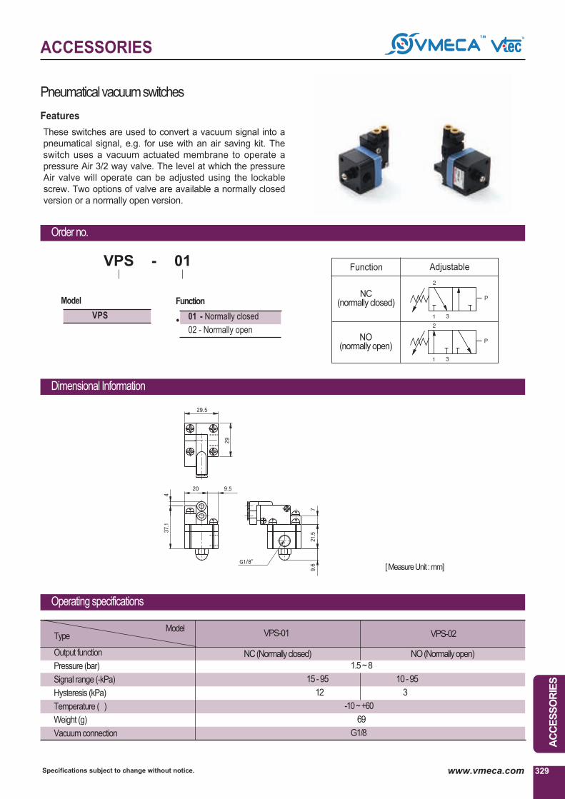
ACCESSORIES
AC
CE
SS
OR
IES
329Specifications subject to change without notice. www.vmeca.com
Pneumaticalvacuumswitches
Order no.
Operating specifications
VPS-01
NC(Normallyclosed) NO(Normallyopen)
VPS-02
1.5 ~ 8
15 - 95 10 - 95
12 3
-10 ~ +60℃
69
G1/8℃
ModelType
Output function
Pressure (bar)
Signal range (-kPa)
Hysteresis (kPa)
Temperature (℃)
Weight (g)
Vacuum connection
① Function① Model
01 - Normally closed
02 - Normally open
℃
01-
℃
VPS
VPS
Dimensional Information
●
Function Adjustable
NC(normally closed)
NO(normally open)
These switches are used to convert a vacuum signal into a
pneumatical signal, e.g. for use with an air saving kit. The
switch uses a vacuum actuated membrane to operate a
pressure Air 3/2 way valve. The level at which the pressure
Air valve will operate can be adjusted using the lockable
screw. Two options of valve are available a normally closed
version or a normally open version.
Features
[ MeasureUnit : mm]

ACCESSORIES
Specifications subject to change without notice.330 www.vmeca.com
VMS18DControlValves
Dimensional Information
Order No.
Type
Connection
Normal flow (Nl/m)
Pressure range (bar)
Temperature range
Materials
Standard voltages
Power consumption
Weight (g)
G1/8″
516
2.5 ~ 7 bar
0℃ ~ +60℃
Ni, Al, SS, POM, CuZn, NBR, PA66, PUR, PPS
•DC: 24V •AC: 110V, 220V- 50/60Hz
0.85W, 1.3W
20
VMS18D
Operating specifications
-
℃
-
℃
VMS18D 3 2
℃
2/2 way solenoid valve G1/8℃(for air control) indirectly
operated with spring return.
This valve are compact and can control high flow rate of air.
Features
●
●
① Voltage
1
2
3
- AC110V
- AC220V
- DC24V
① Model
VMS 18D (DiaphragmValve)
DIN type Connector type
① Remark : Connector type control valve DC24V Only.
1
2
3
- DINtypewithout leadwire
- DINtypewithlampwithoutleadwire
- Connectortypewith0.3mleadwire℃
lamp: DC24V
●
① Solenoid terminal
[ MeasureUnit : mm]
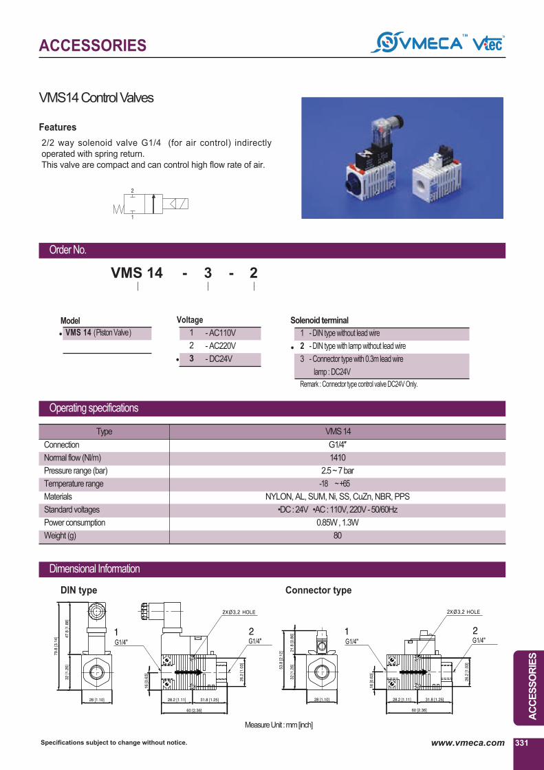
ACCESSORIES
AC
CE
SS
OR
IES
331Specifications subject to change without notice. www.vmeca.com
VMS14 ControlValves
Type
Connection
Normal flow (Nl/m)
Pressure range (bar)
Temperature range
Materials
Standard voltages
Power consumption
Weight (g)
G1/4″
1410
2.5 ~ 7 bar
-18 ℃ ~ +65 ℃
NYLON, AL, SUM, Ni, SS, CuZn, NBR, PPS
•DC: 24V •AC: 110V, 220V- 50/60Hz
0.85W, 1.3W
80
VMS14
Operating specifications
Dimensional Information
Order No.
℃
--
℃
VMS 14 3 2
℃
DIN type Connector type
Features
●
① Model
VMS 14 (PistonValve)
℃ Remark : Connector type control valve DC24V Only.
1
2
3
- DIN type without lead wire
- DIN type with lamp without lead wire
- Connector type with 0.3m lead wire ℃
lamp : DC24V
●
① Solenoid terminal
●
① Voltage
1
2
3
- AC110V
- AC220V
- DC24V
2/2 way solenoid valve G1/4℃(for air control) indirectly
operated with spring return.
This valve are compact and can control high flow rate of air.
MeasureUnit : mm[inch]

ACCESSORIES
Specifications subject to change without notice.332 www.vmeca.com

GERMANY / ASIA /
VTEC / KPS Co.,Ltd.RM206.Saehan Venture World B/D113-15, Shiheung-dong, Geumcheon-gu,Seoul, KoreaTel: +82-2-2617-5008 (Rep.) Fax: +82-2-2617-5009http://www.vmeca.come-mail: [email protected]
VTEC / KPS Co.,Ltd.RM206.Saehan Venture World B/D113-15, Shiheung-dong, Geumcheon-gu,Seoul, KoreaTel: +82-2-2617-5008 (Rep.) Fax: +82-2-2617-5009http://www.vmeca.come-mail: [email protected]
•Argentina •Australia •Austria •Belgium
•Canada •China •Colombia •Denmark
•France •India •Indonesia •Iran
•Israel •Italy •Lebanon •Malaysia
•Mexico •Netherlands •New Zealand•Norway
•Philippine •Poland •Spain •Sweden
•Switzerland •Singapore •Taiwan •Thailand
•Turkey •UK •Japan
USA /
VtecUSA, Inc.1305 N. San Gabriel Bl., #203,South San Gabriel, CA 91770Tel: +1-213-258-7114(Rep.)Fax: +1-626-569-9978http://www.vtecusa.come-mail: [email protected]
Distributor
(1001342 i)
www.vmeca.com
V’tec Vakuum Technologie GmbHAuf dem Bruhl 6D-72658 Bempflingen, GermanyTel. +49(0)7123/932834Fax. +49(0)7123/932865http://www.vmeca.come-mail : [email protected]
ISO 9001 CERTIFIEDVer. 4.10i
Ver. 4
.10i www.vmeca.com


![USER MANUAL Ver 1.0 - [Online Application]](https://static.fdokumen.com/doc/165x107/6318e5bc4cd7b3442408cf60/user-manual-ver-10-online-application.jpg)