
ARM User's Manual Ver. 8.6 - AudioCodes
194
User's Manual One Voice Operations Center AudioCodes Routing Manager (ARM) Version 8.6
-
Upload
khangminh22 -
Category
Documents
-
view
4 -
download
0
Transcript of ARM User's Manual Ver. 8.6 - AudioCodes
User's Manual
One Voice Operations Center
AudioCodes RoutingManager (ARM)
Version 8.6

Notice ARM | User's Manual
Notice
Information contained in this document is believed to be accurate and reliable at the time ofprinting. However, due to ongoing product improvements and revisions, AudioCodes can-not guarantee accuracy of printed material after the Date Published nor can it acceptresponsibility for errors or omissions. Updates to this document can be downloaded fromhttps://www.audiocodes.com/library/technical-documents.
This document is subject to change without notice.Date Published: April-10-2019
WEEE EU DirectivePursuant to the WEEE EU Directive, electronic and electrical waste must not be disposed of withunsorted waste. Please contact your local recycling authority for disposal of this product.
Customer SupportCustomer technical support and services are provided by AudioCodes or by an authorizedAudioCodes Service Partner. For more information on how to buy technical support for AudioCodesproducts and for contact information, please visit our website athttps://www.audiocodes.com/services-support/maintenance-and-support.
Documentation FeedbackAudioCodes continually strives to produce high quality documentation. If you have any comments(suggestions or errors) regarding this document, please fill out the Documentation Feedback formon our website at https://online.audiocodes.com/documentation-feedback.
Stay in the Loop with AudioCodes
Related Documentation
Manual Name
ARM InstallationManual
ARMUser's Manual
Mediant 9000 SBC User's Manual
Mediant 4000 SBC User's Manual
Mediant 3000Gateway User's Manual
- ii -

Notice ARM | User's Manual
Manual Name
Mediant 2600 E-SBC User's Manual
Mediant SE SBC User's Manual
Mediant SE-H SBC User's Manual
Mediant VE SBC User's Manual
Mediant VE-H SBC User's Manual
Mediant 1000B Gateway and E-SBC User's Manual
Mediant 800B Gateway and E-SBC User's Manual
Mediant 500Gateway and E-SBC User's Manual
Mediant 500MSBR User's Manual
Mediant 500LGateway and E-SBC User's Manual
Mediant 500LMSBR User's Manual
MP-1288 High-Density AnalogMedia Gateway User's Manual
One Voice Operations Center Server Installation, Operation andMaintenanceManual
One Voice Operations Center Integration with Northbound Interfaces
One Voice Operations Center User’s Manual
One Voice Operations Center Product Description
One Voice Operations Center Alarms Guide
One Voice Operations Center Security Guidelines
Document Revision Record
LTRT Description
41880 Initial release
41881 New features: Adding ADs, Users and Users Groups, Adding an LDAP Property,Adding a User, Adding a User Property, Adding a User Group, Configuring Settings,Adding Operators, Adding Routing Servers, Configuring a Syslog Server, Adding aNumberManipulation Group, Adding a Prefix Group, Adding an NTP Server, Adding aSoftware License, Routing
41882 New: MigratingMedia Gateway Routing
41883 Modified performance capability, added new GUI screens, deleted Network Tableview, added Time-Base Routing, added Policy Studio, other minor additions.
- iii -

Notice ARM | User's Manual
LTRT Description
41884 Version Release 7.4. Quality-based routing (MOS / ASR). Call Discard. SIP Reason.Test Route Details. Top 5 Routes. Layers. Center Map. Save Items Location.Configure directly inWeb interface. Web interface 7.2. Other SIP Request Types.
41885 Time-based routing condition; PconWeight; Detach (Pcons); Routing Rules HitsCounting; Load Balancing; Single Sign On; New ARM login; Router Lock/Unlock;Test Routing Rule.
41886 Offline Provisioning | Alarms Journal | Call Detail Records | Add Connection |Advanced Condition: Call Preemption for Emergency Calls
41887 Support for 3rd party nodes. Manually added AudioCodes nodes. Statistics page andreports. Collapse/Expand nodes' associated VoIP peers. Class of Service. Morerobust node’s state machine. Multiple Routing Attempts in Load Balancing RoutingRule Action. Routing Based on Call Trigger. New ARM LicenseModel. SIP P-Asserted-Identity Manipulation in ARM Policy Studio. Upgrade of ARMMachines OSto CentOS 6.9. Enforcement of Memory Requirements for ARM VMs. CDRenhancements. LDAP operator authentication. Saving ARM configuration from GUI.
41888 Redesigned Network Mapwith new capabilities and extended capacity: largernetworks, more elements, higher numbers of edges; multiple elements can beselected-repositioned simultaneously; lighter hoovers; new Actions menus. newways to add a connection. Animated path for Test Route and Top Routes. ExtendedVoIP Peers collapse, expand and clustering capabilities. Operator login authenticationwith an external RADIUS server. Operators Permission Level. Test Route with aspecific ARM Router. Improvements to the Prefix Groups UI design. Centralized LogCollection Utility. ARMMachine OS Upgraded with Latest CentOS6.9 SecurityPatches.
41889 Managed AudioCodes Devices. ARM Integrated into OVOC: ARM Status, ARMAlarms and Events Report to OVOC. Increased Number of ARMRouters. PlatformNumber Portability andWeb-Based Pre-Routing Advisory Service. Extended ARMRouter Survivability. Users Dictionary Attribute Triggered (Combined) by TwoOtherAttributes. Destination Prefix/Prefix Groups as a Condition. Notification on CallsMatching a Rule. Calling Number Privacy. Configuring Credentials for RESTCommunications. New Network MapCapabilities: Indication of the AggregatedOperative State of a Connection, New Option to Search for a Node by IP Address inNetwork Map, Number of VoIP Peers / Peer Connections Indicated in ClusterSummary, Adding VoIP Peers to an Existing Cluster, Limited Node/VoIP Peer LabelLengths in Network Map. ExtendedGUI Capabilities: Selecting Source Node / PeerConnection when Configuring a Routing Rule. Error Messages Display Name ofRouting Rule | Users Group. Test Route Results Preserved Even if Moving to AnotherTab. Optimized ARMUI for Huge Dial Plans. Indication of Operator’s Security(Permission) Level. QoS (MOS and ASR) Displayed in Peer Connections Page.
41890 Hostname (FQDN). Certificate validation. Subject name verification. Open LDAP.Routing Server-Credentials. Routing Servers Group. SIP headers. Calls ForkingRoutingMethod. CDRs. Call Details. Limiting number of CDRs.
- iv -

Content ARM | User's Manual
Table of Contents
1 Overview 8Features 9Benefits 10Simplicity 10ARM-Routed Devices 10Third-Party Open-Source Software 11
2 Getting Started with the ARM 12Logging in 12Getting Acquainted with the ARMGUI 13
Getting Acquainted with the Network Map Topology Layer 16Getting Acquainted with the Network MapQuality Layer 18Getting Acquainted with Network Map Page Actions 21
Node Information and Actions 21VoIP Peer Information and Actions 27Connection Information and Actions 29Peer Connection Information and Actions 30Repositioning Elements in the Network Map Page 33
Peer Connections Page Actions 33Connections Page Actions 34Viewing Network Summary Panes 35
Overall Network Statistics 35Statistics on a Selected Entity 39
3 Defining a Network Topology 40Adding an AudioCodesNode to the ARM 40Adding a Third-Party Node to the ARM 41Adding Connections 44Synchronizing Topology 45Building a Star Topology 45Testing a Route 47
4 Designing a Network Topology in the Offline Planning Page 52Performing Actions in the Offline Planning Page 53
Adding a Virtual Entity 53Adding a Virtual Peer Connection to the Offline Planning Page 54Adding a Virtual Connection 55Importing a Full Topology 55Importing a Node from the Live Topology 55Deleting a Virtual Entity 55Testing a Route 56Exporting a Node from theOffline Page to the Live Topology 56
5 Viewing Statistics and Reports 576 Performing User-Related Administration 61
- v -

Content ARM | User's Manual
Adding a User Not Listed in an AD to the ARM 61Adding UsersGroups to the ARM 63Adding an LDAP Server to the ARM 68Adding a Property Dictionary to the ARM 73
Adding a Users Dictionary Attribute Triggered (Combined) by TwoOther Attributes 75
7 Configuring Settings 76Administration Settings 77
Activating Your License 77Viewing License Details 78Securing the ARM 78
Determining ARMCommunications with Other Entities 80Strengthening Security: Certificate Validation 81
Provisioning Operators 82Manually Provisioning anOperator in the ARM's Operators Page 83Node Credentials 83Router Credentials 85Configurator Credentials 87Provisioning Operators using an LDAP Server 90
Authenticating Operator Login using Open LDAP 93Provisioning Operators using a RADIUS Server 93RemoteManager 96
Network Services Settings 97Editing a Syslog Server 97Adding/Editing an NTP Server 99Prioritizing Traffic Per Class of Service 99Enabling CDRs 102
Call Flow Settings 102Adding a Normalization Group 103Using Prefix Groups 105
Adding a Prefix Group 105Searching for a Prefix Group 106Searching for a Specific Prefix within a Prefix Group 106Editing a Specific Prefix within a Prefix Group 107
Normalization Before Routing 107Policy Studio 108
Example 1 of a Policy Studio Rule 111Example 2 of a Policy Studio Rule 111
Web-based Services 112Routing Settings 114
Configuring Criteria for a Quality Profile 114Configuring a Time-Based Routing Condition 115Configuring SIP Alternative Route Reason 118Configuring Global Routing Settings 120
Adding a Routing Server 120Editing a Routing Server 122
- vi -

Content ARM | User's Manual
Locking/Unlocking a Routing Server 123Adding a Routing Server Group with Internal and External Priorities 124
8 Defining Calls Routing 128Adding a Routing Group 128
Editing a Routing Group 129Moving a Routing Group 130Deleting a Routing Group 132
Adding a New Routing Rule 133Moving a Routing Rule 148Deleting a Rule 149
Testing a Route 150Using the Routing Rules Table View Page 150
9 Viewing CDRs and Call Details 151Call Details 153Disabling, Limiting the Number of CDRs 155
10 Viewing Alarms 157Active Alarms | History Alarms 157Journal Page 158Collecting Info via SNMP to Enhance IP Network Telephony Performance 158Locating a Specific Alarm 159
11 Migrating Device Routing to the ARM 161AudioCodesDevice Application Types 161ARMNetwork Routing Logic 161
SBC Routing Logic 161Gateway Routing Logic 161Hybrid Device Routing Logic 162
Connecting the Device to the ARMTopology Server 162Defining an IP Interface Dedicated to ARMTraffic 164Migrating SBC/Gateway/Hybrid Routing to the ARM 165Migrating SBC Routing to the ARM 166MigratingMedia GatewayRouting to the ARM 170Migrating Hybrid Routing to the ARM 171
12 Checklist for Migrating SBC Routing to the ARM 17513 Prefixes 17814 Examples of Normalization Rules 17915 Call Routing 18216 Configuring an SBC to Send SIP Requests other than INVITE to ARM 18317 Opening Firewall Ports for the ARM 18418 About CDRs Sent by ARM to CDR Server 188
- vii -

CHAPTER 1 Overview ARM | User's Manual
1 OverviewThis document shows how to use the AudioCodes Routing Manager (ARM). The ARM is a LINUX-based, software- only, telephony management product which expedites and streamlines IPtelephony routing for enterprises with multiple globally distributed branches. The ARM determinesthe quickest, least expensive, and best call quality routes in packet networks.Routing data, previously located on the SBC, Unified Communications (UC) application (e.g.,Microsoft's Skype for Business), or Media Gateway, is now located on the ARM server. If anenterprise has an SBC in every branch, a single ARM, deployed in HQ, can route all calls in theglobally distributed corporate network to PSTN, the local provider, enterprise headquarters, or tothe IP network. Routing rules, configured by the IT manager in the ARM's Routing Table, performthe routing.If an enterprise has only one or two branches, its IT manager can easily independently implementmaintenance changes. In globally distributed enterprises, IT managers until now had to laboriouslyimplement changes, multiple times, per branch. With the ARM, IT managers implement changesonly once, saving significant labor and time resources and costs.The following figure shows a typical, globally-distributed, multi-branch enterprise VoIP network.
VoIP networks like this typically require:■ Distributed routing & policy enforcement■ Distributed PSTN■ Multiple VoIP network entities' configurations (i.e., SBC, Media Gateway)■ Multiple Dial Plans■ SIP Interworking between IP PBXs■ Large number of end user policies■ Efficient ARM routingmanagement
- 8 -
CHAPTER 1 Overview ARM | User's Manual
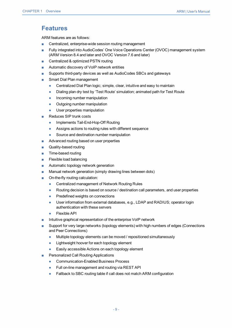
FeaturesARM features are as follows:■ Centralized, enterprise-wide session routingmanagement■ Fully integrated into AudioCodes’ One Voice Operations Center (OVOC)management system
(ARM Version 8.4 and later andOVOC Version 7.6 and later)■ Centralized & optimized PSTN routing■ Automatic discovery of VoIP network entities■ Supports third-party devices as well as AudioCodes SBCs and gateways■ Smart Dial Planmanagement
● Centralized Dial Plan logic; simple, clear, intuitive and easy tomaintain● Dialing plan dry test by ‘Test Route’ simulation; animated path for Test Route● Incoming numbermanipulation● Outgoing numbermanipulation● User properties manipulation
■ Reduces SIP trunk costs● Implements Tail-End-Hop-Off Routing● Assigns actions to routing rules with different sequence● Source and destination numbermanipulation
■ Advanced routing based on user properties■ Quality-based routing■ Time-based routing■ Flexible load balancing■ Automatic topology network generation■ Manual network generation (simply drawing lines between dots)■ On-the-fly routing calculation:
● Centralizedmanagement of Network Routing Rules● Routing decision is based on source / destination call parameters, and user properties● Predefined weights on connections● User information from external databases, e.g., LDAP and RADIUS; operator login
authentication with these servers● Flexible API
■ Intuitive graphical representation of the enterprise VoIP network■ Support for very large networks (topology elements) with high numbers of edges (Connections
and Peer Connections)● Multiple topology elements can bemoved / repositioned simultaneously● Lightweight hoover for each topology element● Easily accessible Actions on each topology element
■ Personalized Call Routing Applications● Communication-Enabled Business Process● Full on-linemanagement and routing via REST API● Fallback to SBC routing table if call does not match ARM configuration
- 9 -

CHAPTER 1 Overview ARM | User's Manual
BenefitsThe ARM benefits users as follows:■ Reduces operational time spent on designing and provisioning network topology■ Reduces OPEX, avoiding routing configuration of VoIP network entities■ Reduces time spent implementing network evolutions such as:
● Adding new connections to PSTN (e.g., SIP trunks)● Adding new branches to the enterprise VoIP network● Modifying user voice services privileges
Simplicity■ VoIP network entities registering in the ARM■ Auto-discovery of VoIP peers■ One-click topology network creation, star formation■ Customized topology network
● Configuring a connection is as simple as drawing a line● Modify by adding, deleting and changing connections
■ ARM connects to user data base
ARM-Routed DevicesThe following devices can be routed by the ARM:■ Mediant 9000 SBC■ Mediant 4000 SBC■ Mediant 2600 SBC■ Mediant SE/VE SBC■ Mediant 1000B Gateway and E-SBC■ Mediant 800B Gateway and E-SBC■ Mediant 800C■ Mediant 500 E-SBC■ Mediant 500L SBC■ Mediant SBC CE (Cloud Edition)■ Mediant 3000Gateway only
- 10 -

CHAPTER 1 Overview ARM | User's Manual
Third-Party Open-Source SoftwareThe following third-party open-source software is supported by the ARM:■ CentOS Linux 6.6■ Spring Framework (released under version 2.0)■ MariaDB relational databasemanagement system■ ActiveMQ (using the Apache 2.0 license)■ HiberNate (projects licensed under Lesser General Public License (LGPL) v2.1)■ Log4J (Apache License 2.0)■ Guava (Google core libraries - Apache License 2.0)■ jackson-core■ Apache Commons Logging™■ HttpClient - Apache■ XStream (Group: com.thoughtworks.xstream)■ Jersey client■ Joda-Time■ SLF4J (Simple Logging Facade for Java)■ HikariCP Java 6■ Aspectj™ extension to Java■ SNMP4J (Open Source SNMP API for Java)■ Mockito
- 11 -

CHAPTER 2 Getting Started with the ARM ARM | User's Manual
2 Getting Started with the ARMAfter installing the ARM and performing initial configuration (see the ARM Installation Manual), youcan get startedmanaging routing with the ARM.
Logging inLogging in is a prerequisite to getting started with the ARM.
➢ To log in:1. Point your web browser to the ARM's IP address and press Enter.
2. In the Login to ARM screen, log in using the default Operator andOperator username andpassword. It's advisable to change these as soon as possible (see Provisioning Operators onpage 82 for instructions on how to change them).
The ARM opens in the Network page, Map view (default) in your browser. By default, all VoIPentities managed in the network are displayed.
- 12 -

CHAPTER 2 Getting Started with the ARM ARM | User's Manual
Getting Acquainted with the ARM GUIThe ARM’s internet browser based graphic user interface visualizes VoIP network topology and itscomponents, providing centralized, dynamic network management and router rules and logicmanagement. After logging in, the Network page, Map view opens by default.
Figure 2-1: ARM GUI - Network Page - Map View
Use the following legend as a reference to the preceding figure.
Table 2-1: ARM GUI – Map View
# GUI Area Description
1 ActionsBar
■ Sync Topology■ AddConnection■ Drag Connection■ Edit■ Delete■ Lock/Unlock■ Test Route■ Refresh■ Layers
✔ topology✔ quality
- 13 -

CHAPTER 2 Getting Started with the ARM ARM | User's Manual
# GUI Area Description
2 Toolbar Toolbar icons let you navigate to the following ARM pages:NETWORK, ROUTING, USERS, ALARMS, STATISTICS andSETTINGS.
Located in the uppermost right corner of the page on the toolbar.
■ View the name of the operator currently logged in and their security /permission level
■ Save logs (GUI logs)■ Lock (Terminates user's ARMGUI session)■ Log out■ Display the ARM version (About)■ Save Configuration: The ARM_Configuration.zip file (ARM database) is
saved locally in the client’s 'Downloads' directory. You can send it toAudioCodes for troubleshooting. In parallel, basic ARM backup isperformed and the backup file is stored in the configurator’s/home/backup directory. You can use it to restore the configuration onthe samemachine using standard ARM restore procedure.
■ Display how much time remains before the session terminates
3 Save items collapse state and location (saves entities' positions in theNetwork Map after they're moved).
3 Diagrams Configurations (opens theMap Settings pop-upmenu):
■ Formore information about Hide edges on drag, see RepositioningElements in the Network Map Page on page 33
■ Select Animate path drawing for animated visualizations of TestRoute and Top Route actions.
- 14 -

CHAPTER 2 Getting Started with the ARM ARM | User's Manual
# GUI Area Description
■ Select Limit labels length to limit the lengths of the labels of thedisplayed Nodes and VoIP Peers to a predefined number of characters,useful with large networks and long Node and / or VoIP Peer nameswhich clutter the Network Map. If selected, the parameter ‘Max labellength’ is displayed in which themaximum number of characters allowedis defined.
3 Center Map (centers the Network Map in themiddle of the page)
3 Search Enables you to locate specific information in the Network Map view, Routingpage, Users page, Alarms page and Settings page.1. Click ^ adjacent to ‘Enter search string’.
2. Define search parameters: Name and/or Administrative State and/orOperative State. At least one itemmust be selected.
3. You can also search for a Node by the Node’s IP address, not only bythe Node’s name, which is an essential functionality in very large deploy-ments with high numbers of Nodes.
4 MainScreen
The Network page displays aMap view of network entities.
5 SummaryPanes
The Network page, Map view, displays these summary panes:■ Network Summary
✔ Nodes (Available, Unavailable, Locked)✔ Peer Connections (Available, Unavailable, Locked)✔ Connections (Available, Unavailable)
■ General Statistics✔ Routing Attempts per 5Minutes✔ Unsuccessful Routes per 5Minutes✔ Unsuccessful Routes (Alternative Attempts / Destinations Not
Routable)✔ Calls per 5Minutes (Destination Calls / Transient Calls)
■ Top 5 Routes (with animation)■ Test Route
- 15 -

CHAPTER 2 Getting Started with the ARM ARM | User's Manual
Getting Acquainted with the Network Map Topology LayerIn the Network page, Map view, you can view node information and perform network map actions.Network Map view shows the four main entities that comprise the network topology:■ Nodes■ VoIP Peers■ Peer Connections■ ConnectionsThe following table explains each.
Table 2-2: Network Map view – Network Entities
NetworkEntity Icon Explanation
Node Indicates an AudioCodes SBC communicating with the ARM. It'spart of the ARM network topology.Blue = operative state available/logging inRed = operative state unavailable/unrouteableOrange = operative state logged outStrikethrough = lockedNo strikethrough = unlocked
Indicates an AudioCodes gateway communicating with the ARM.It's part of the ARM network topology.Blue = operative state availableRed = operative state unavailableINVALID CONFIGURATIONOrange = operative state logged outStrikethrough = lockedNo strikethrough = unlocked
Indicates a hybrid AudioCodes device (AudioCodes' Gateway andSBC in one).Blue = operative state availableRed = operative state unavailableINVALID CONFIGURATIONOrange = operative state logged outStrikethrough = lockedNo strikethrough = unlocked
Indicates a third-party, non-AudioCodes device (SBC or gateway)communicating with the ARM. It's part of the ARM networktopology.
- 16 -

CHAPTER 2 Getting Started with the ARM ARM | User's Manual
NetworkEntity Icon Explanation
VoIP Peer Indicates a non-AudioCodes device or entity that is also part of theARM network topology: PBXs, SIP trunks, other vendors' SBCs /gateways. These devices participate in processing ARM networkcalls and are connected to Nodes by 'Peer Connections'. The ARMoperator can configure one of six VoIP Peer types.
SIP trunk
PSTN
IP phones
Legacy PBX | IP PBX
N/A Not applicable
Connection Indicated by a blue line (available) or a red line (unavailable). Joinstwo Nodes. Calls can be routed between two Nodes only if there is aConnection between them. Defined by adding an IP Group (at Nodelevel). From AudioCodes' gateway/SBC perspective, a ‘Connection’is an 'IP Group'. Connections between Nodes are added by the ARMoperator.
PeerConnection
Indicated by a black line between a Node and a VoIP Peer.Represents a group of routing destinations/sources (connections toa VoIP Peer), ‘last mile’ connectivity. From AudioCodes'gateway/SBC perspective, a Peer Connection is a ‘PSTN TrunkGroup’ or ‘IP Group’.Red line = administrative state is unlocked / operative state isunavailable (no connection between the AudioCodes device and theremote device) / predeleted (IP Group was deleted from the device)Black line through a red sphere = unavailable and lockedBlack line through a black sphere = available but locked
- 17 -

CHAPTER 2 Getting Started with the ARM ARM | User's Manual
Getting Acquainted with the Network Map Quality LayerThe Network Map view displays a Layers tab that allows the operator to choose topology and / orquality.
Figure 2-2: Network Map – Topology Layer
The topology layer displays the availability status of network entities.The quality layer displays the quality status of network Connections and Peer Connections.When both the topology layer and the quality layer are selected, the Network Map displays theaggregated availability status and quality status.
Figure 2-3: Network Map – Quality Layer
The figure above shows the Network Mapwhen theQuality Layer is applied.The following table describes the different quality color codes.
Table 2-3: Quality Color Codes
Color Description
Blue GOOD quality Connection
- 18 -

CHAPTER 2 Getting Started with the ARM ARM | User's Manual
Color Description
Grey GOOD quality Peer Connection
Orange FAIR quality Connection / Peer Connection
Red BAD quality Connection / Peer Connection
Dottedgrey
UNKNOWN quality, i.e., there is insufficient data to determine quality statistics.After enough calls are routed by the Connection / Peer Connection, the colorchanges from grey to the color of the determined quality static.
A glance at the page reveals the quality of each Connection and Peer Connection, indicated bycolor code.
➢ To view a summary of a Connection, including quality:1. In the Network Map page, select topology layer and/or quality layer and then click (select)
the Connection whose summary you want to view.
Figure 2-4: Connection Summary Including Quality
2. View a summary of the connection in the Connection Summary pane on the right side of theNetwork Map page. The figure above shows the Connection Summary pane for the Connectionbetween the nodeParis_2 andNew_York_1. The 'Quality' parameter for both nodes is‘GOOD'.
3. Use each direction's MOS and ASR values to tune the threshold for quality-based routing[Settings > Routing > Quality Based Routing] and optimize network quality.
➢ To view a summary of a Peer Connection, including quality:1. In the Network Map page, select topology layer and/or quality layer and then click (select)
the Peer Connection whose summary you want to view.
- 19 -

CHAPTER 2 Getting Started with the ARM ARM | User's Manual
Figure 2-5: Quality Layer - Peer Connection
2. In the Peer Connection Summary pane on the right side of the Network Map page, view thePeer Connection Summary for the Peer Connection you clicked (selected). The figure aboveshows the Peer Connection whose name is 'IpGrp0'. The 'Quality' parameter is 'FAIR'.
3. Use each direction's MOS and ASR values to tune the threshold for quality-based routing[Settings > Routing > Quality Based Routing] and optimize network quality.
- 20 -

CHAPTER 2 Getting Started with the ARM ARM | User's Manual
Getting Acquainted with Network Map Page Actions
Node Information and Actions
In the Network page, Map view, you can view node information and perform node actions.
➢ To view node information:1. Point your cursor over the node whose information you want to view.
2. Use the following table as reference.
Table 2-4: Node Information
Item Description
Name The name of the Node
Address The IP address of the Node
State Available / Unavailable / Unrouteable / Logged out / Logging in. The ARM providesa robust node StateMachine based on the node’s connectivity to the ARMcomponent. When determining a node’s connectivity and ability to process a call inthe StateMachine, the ARM factors in the node’s connectivity to the ARMConfigurator (both ways), the node’s connectivity to ARMRouters (from the node’sperspective) and the node’s connectivity to ARMRouters (from the ARMRoutersperspective). The ARMRouters attempt to serve the node’s routing requests evenif the node is reported as disconnected from the ARMConfigurator. In this case, theARMRouter routes calls based on last available information about the nodes'interfaces, their availability and quality. This node’s ‘Unknown’ state is reported viaARM alarms. A node becomes Unrouteable only if all ARM Routers report that thenode does not communicate with them (neither ‘keep-alive’ nor ‘Get Route’requests). To help you localize a network issue, the Node Summary screendisplays a detailed view of the node’s connectivity status, as shown in the followingfigure.
- 21 -

CHAPTER 2 Getting Started with the ARM ARM | User's Manual
Figure 2-6: Node Summary – Operative State
The example below shows a node’s ‘Unknown’ state when the ARM Configurator is unable toaccess the SBC 'Texas-7'. Note that in this state, call routing requests coming from this node tothe ARMRouters will be served.
Figure 2-7: Node’s ‘Unknown’ State
- 22 -

CHAPTER 2 Getting Started with the ARM ARM | User's Manual
➢ To perform an action on a node:1. Right-click the node on which to perform an action.
Figure 2-8: Node Actions
2. From the popupmenu, choose:a. Drag connection. Allows you to draw (drag) a connection between two nodes In the ARM
Map (Paris_2 and Italy-9 in the following figure, whereParis_2 is the node you right-clicked and from where you begin dragging, and Italy-9 is the node in which you end thedrag).
Figure 2-9: Drag Connection
b. Add Connection [also available by selecting a node and then clicking theAddConnection button]
- 23 -

CHAPTER 2 Getting Started with the ARM ARM | User's Manual
Figure 2-10: Add Connection
◆ Make sure the relevant SIP interface in the SBC is provisioned and configured as‘Used by routing server’
◆ In the Add Connection screen shown in the figure above, Node-1 will be configured(the node you initially selected). From the ‘Node-2’ drop-downmenu, select the nodeto which to make the connection, and then click OK. See Adding an AudioCodesNode to the ARM on page 40 for more information.
c. Configure. Lets you directly configure a node (or SIP module) in the node's Web interfacewithout needing to provide the node’s credentials (Single Sign-on). See the AudioCodesdevice's User's Manual for detailed information. Nodes version 7.2.150 and later aresupported. Earlier node versions do not support single sign-on; youmust providecredentials before you can access theirWeb interface.Choose the option; the node's Web interface opens without prompting the operator forcredentials.
d. Edit [also available by selecting the node and then clicking theEdit button]◆ In the Edit Node dialog that opens - see the following figure - update the credentials of
the device if necessary.
- 24 -

CHAPTER 2 Getting Started with the ARM ARM | User's Manual
Figure 2-11: Edit Node
◆ From the 'Protocol' drop-downmenu, select the protocol that the ARMConfigurator(server) uses when communicating with this node. Default: HTTPS. If you don't wantto encrypt the traffic – e.g., when debugging – useHTTP.
◆ From the 'Routing server group' drop-down, select the Routing Server Group to whichyou attached the node, described under Adding a Routing Server Group with Internaland External Priorities on page 124.
e. Sync Nodef. Lock/Unlockg. Collapse. In Network Map view, you can collapse VoIP Peers associated with a node. In
large networks containingmultiple VoIP Peers with each VoIP Peer connected to a node,this can significantly simplify (unclutter) the view, facilitatingmore effectivemanagement.To apply a collapse:◆ Select theCollapse action from themenu that pops up after right-clicking the node; all
VoIP Peers associated with the node collapse.
Figure 2-12: Collapsed VoIP Peers
- 25 -

CHAPTER 2 Getting Started with the ARM ARM | User's Manual
◆ [Refer to the preceding figure] The cluster's label in the Network Map as well as theCluster Summary indicate the number of collapsed VoIP Peers / Peer Connections inthe cluster.
◆ [Refer to the figure following] The Cluster Summary can also indicate the aggregatednumber of collapsed VoIP Peers / Peer Connections in a cluster.
Figure 2-13: Peer Connection Aggregation Summary: Number of Peer Connections
◆ Add to cluster. You can add an additional VoIP Peer or multiple VoIP Peers to anexisting cluster: (1) Select the target cluster to which to add (2) press theCtrl keyclick one or multiple VoIP Peers to add to the target cluster (3) right-click and from thepop-upmenu select the actionAdd to cluster.
Figure 2-14: Add to cluster
◆ VoIP Peers associated with more than one node are included in the collapsed cluster.If a test route is performed that terminates on a collapsed VoIP Peer, the VoIP Peerwill not be expanded automatically and the path displayed in the GUI will terminate onthe cluster icon.
- 26 -

CHAPTER 2 Getting Started with the ARM ARM | User's Manual
Figure 2-15: Test Route Path Terminates on Collapsed VoIP Peer
h. After collapsing VoIP Peers, you can expand them again by right-clicking the cluster iconand then choosing theExpand action from the popupmenu.
Figure 2-16: Expand Cluster of VoIP Peers
i. Delete. Only available if the Node has been Locked and no routing rules and Policy Studiorules are associated with it. If routing rules are associated with the Node or its PeerConnections and you want to delete it, update or delete the rule so it does not refer to thetopology entity which is going to be deleted.
j. Build Star (Topology)
VoIP Peer Information and Actions
In the Network page, Map view, you can view VoIP Peer information and perform VoIP Peeractions. There are six types of VoIP Peers:■ SIP Trunk■ PBX■ IP PBX■ PSTN■ IP Phone■ N/A (default)
➢ To view VoIP Peer information:1. Point your cursor over the VoIP Peer whose information you want to view.
- 27 -

CHAPTER 2 Getting Started with the ARM ARM | User's Manual
Figure 2-17: SIP Trunk
Figure 2-18: PBX | IP PBX
Figure 2-19: PSTN
Figure 2-20: IP Phone
➢ To edit a VoIP Peer:■ Right-click the VoIP Peer icon and chooseEdit from the popup.
Figure 2-21: Edit VoIP Peer
- 28 -

CHAPTER 2 Getting Started with the ARM ARM | User's Manual
◆ You can edit the 'Name' of the VoIP Peer and/or select the 'Peer Type' from the drop-downmenu.
➢ To delete a VoIP Peer:■ Right-click the VoIP Peer icon and then chooseDelete from the popupmenu.
TheDelete option is only available if no Peer Connection or routing rules are associatedwith the VoIP Peer. If there are, you must first update / delete routing rules before youcan delete the VoIP Peer. You must then associate the Peer Connection with anotherVoIP Peer.
Connection Information and Actions
In the Network page, Map view, you can view connection information and perform connectionactions.
➢ To view connection information:1. Point your cursor over the connection whose information you want to view.
Figure 2-22: Connection Information
2. View the Name and the State of the connection.
➢ To perform an action on a connection:1. In the popupmenu, click Edit -or-Delete. [Note that Add connection, Edit andDelete are
also available as action buttons in the Network Map page].
- 29 -

CHAPTER 2 Getting Started with the ARM ARM | User's Manual
Figure 2-23: Edit Connection
2. You can edit the:● name of the connection● Weight (Range: 0-100. Default: 50)● Transport Type (Default: UDP)
3. Leave the option use global at its default for quality-based routing to be applied using global(ARM level) settings. Select use specific to overwrite the global settings of quality-basedrouting condition for a specific connection, and then select the enabled 'MOS' and/or 'ASR'option (see Routing Settings on page 114 for related information).
Peer Connection Information and Actions
In the Network page, Map view, you can view Peer Connection information and perform peerconnection actions.
➢ To view peer connection information:1. Point your cursor over the peer connection whose information you want to view.
- 30 -

CHAPTER 2 Getting Started with the ARM ARM | User's Manual
Figure 2-24: Peer Connection Information
2. View the Peer Connection's Name and State.
➢ To perform an action on a peer connection:1. Right-click the Peer Connection and choose Test route from the popupmenu (see Testing a
Route on page 47 for more information)
Figure 2-25: Peer Connection Actions
2. ChooseEdit from the popupmenu.
- 31 -

CHAPTER 2 Getting Started with the ARM ARM | User's Manual
● The Delete option will be available only for Peer Connections in locked and pre-deleted state, unassociated with routing rules or with a Policy Studio rule.
● The Detach option will be available only if the Peer Connection is connected to aVoIP Peer that is connected tomore than one Peer Connection.
● Action buttons Edit, Delete and Lock/Unlock are also available in the Network Mappage.
Figure 2-26: Edit Peer Connection
a. Modify the weight (Range: 0-100; Default: 50) for the ARM to calculate the optimal callpath. Use if you have a VoIP Peer as a Routing Rule action and you want to prioritize aspecific Peer Connection (e.g., SIP trunk) to be chosen for calls routing. Also use to reflectPeer Connection cost or bandwidth.
b. From the drop-downmenu, select the VoIP Peer that this Peer Connection is connectedto.
c. From the drop-downmenus, select the Normalization Rule for Source and Destination URIUser if pre-routingmanipulation is required for a specific Peer Connection (configured asshown in Adding a Normalization Group on page 103).
d. Leave use global quality definitions selected (default) for this Peer Connection to usethe global quality profile configured as shown in Configuring Criteria for a Quality Profile onpage 114.Select use specific quality definitions for this Peer Connection to use only the 'MOS' orthe 'ASR' criteria of the quality profile configured as shown in Configuring Criteria for aQuality Profile on page 114.
3. Delete the Peer Connection. Only Peer Connections in locked and pre-deleted state,unassociated with routing rules or with a Policy Studio rule, can be deleted.
4. If the Peer Connection is connected to a VoIP Peer that is connected tomore than one PeerConnection, you can click Detach. You'll be prompted to define a name for a new VoIP Peer.
- 32 -

CHAPTER 2 Getting Started with the ARM ARM | User's Manual
Repositioning Elements in the Network Map Page
The ARM's Network Map page allows you to move and reposition multiple selected elements -Nodes and VoIP Peers – simultaneously to facilitate a friendlier operator experience and todecrease operator vulnerability to routing configuration errors.You can select a combination of elements and move and reposition them simultaneously with yourmouse device. After moving / repositioning elements, you need to perform a save else they’ll berestored to their original position in the following session.Even when managing very large networks with extended numbers of topology elements (Nodesand VoIP Peers), the ARM agilely performs relocations in the page.When moving / repositioning elements in the page, you can also use the hide edges on dragoption available from the ‘Diagram Configurations’ icon.
Figure 2-27: Hide Edges on Drag
When selected, Connections and Peer Connections are not displayed in the page when an element(or multiple elements) is moved and repositioned. The option provides a less cluttered view ofnetwork elements in the page, facilitatingmore effective relocation.
Peer Connections Page ActionsIn the Peer Connections page (Network page > Peer Connections) you can view the PeerConnections.
Figure 2-28: Peer Connections
You can view the following information on each Peer Connection:■ Status■ Node■ Name■ VoIP Peer■ IP Group■ Operative State■ Administrative State■ Quality■ MOS■ ASR
- 33 -

CHAPTER 2 Getting Started with the ARM ARM | User's Manual
The information displayed in the Network page's Peer Connection view is identical to that displayedin the Network Map view described under Peer Connection Information and Actions on page 30.You can search for the name of a Node associated with the Peer Connection, its name, or a VoIPPeer name. It's useful to find, for example, all Peer Connections of a specific Node.You can perform the following actions:■ Sync Topology■ Edit (after selecting the row of the Peer Connection to edit)■ Delete (after selecting the row of the Peer Connection to delete)■ Lock/Unlock (after selecting the row of the Peer Connection to lock/unlock)Multiple rows can be selected; multiple actions (delete, lock/unlock, etc.) are supported. For moreinformation about Sync Topology, see Synchronizing Topology on page 45. For more informationabout the Edit, Delete and Lock/Unlock actions, see under Peer Connection Information andActions on page 30.
Connections Page ActionsIn the Connections page (Network > Connections) you can view the connections you defined.
Figure 2-29: Connections
You can view the following information on each connection:■ Status■ Node 1■ Routing Interface 1■ Name■ Node 2■ Routing Interface 2■ Weight■ QualityThe Search functionality is allowed for all the relevant information fields: Node Name, ConnectionName, Weight or Routing Interface.The information displayed in the Network page's Connections view is identical to that displayed inthe Network Map view described under Connection Information and Actions on page 29.You can perform the following actions:■ Sync Topology■ AddConnection (after selecting the row of the connection to edit)■ Edit Connection (after selecting the row of the connection to edit)■ Delete Connection (after selecting the row of the connection to edit)■ Refresh
- 34 -

CHAPTER 2 Getting Started with the ARM ARM | User's Manual
Multiple rows can be selected and multiple delete is supported. For more information about SyncTopology, see Synchronizing Topology on page 45. For more information about the Add, Edit andDelete Connection, see under Connection Information and Actions on page 29.Do not modify the SBC-level / gateway-level configuration of the connections created by the ARM.It will disrupt routing decisions/performance.
Viewing Network Summary PanesNetwork Summary panes viewed in the right margin of the Network Map page can inform you howto optimize call routing in the network. You can choose to display:■ Overall Network Statistics - statistics related to the entire network are displayed by default; no
entity in the Network Map is selected. SeeOverall Network Statistics below.■ Statistics on a network entity – select the network entity in the Network Map for which to
display statistics. See Statistics on a Selected Entity on page 39.
Overall Network Statistics
Statistics related to the entire network are by default displayed. No entity in the Network Map isselected. This pane displays four sections:■ Network Summary (see below)■ General Statistics (seeGeneral Statistics on the next page)■ Top 5 Routes (see Top 5 Routes Pane on page 37)■ Test Route (see Test Route on page 38)
Network Summary
The Network Summary pane displays routing statistics and availability network statuses whichhelp operators optimize routing in their telephony networks, reducing unnecessary consumption ofresources and decreasing expenses.
Figure 2-30: Network Summary
The pane displays:■ Network Entities Statuses (left to right):
● The total number of nodes/Peer Connections/Connections in the network● The number of nodes/Peer Connections/Connections in the network that are unlocked and
available, i.e., 'normal'
- 35 -

CHAPTER 2 Getting Started with the ARM ARM | User's Manual
● The number of nodes//Peer Connections/Connections in the network that are 'fault', i.e.,unavailable
● The number of nodes/Peer Connections in the network that are 'locked' (Connectionscannot be locked/unlocked)
When Quality Layer is selected, the 'Faulty' counters for Peer Connections and Connections canchange. All red (bad), orange (fair) or unknown Connections / Peer Connections are considered'Faulty' because they less than perfect.
General Statistics
You can display statistics related to the entire network.
➢ To display statistics related to the entire network:■ Open the ARM's Network Map and in the Network Summary window, click theGeneral
Statistics tab if it isn’t activated already.
Figure 2-31: General Statistics Pane
Three graphs are displayed (top to bottom):■ The number of routing attempts made in the entire network every fiveminutes■ The number of unsuccessful routes made every fiveminutes, including the number of
alternative attempts and the number of unrouteable destinations
- 36 -

CHAPTER 2 Getting Started with the ARM ARM | User's Manual
■ The number of calls made every fiveminutes, including the number of destination calls and thenumber of transient calls.
➢ To facilitate your analysis:■ Click the expand icon next to any of the three graphs to project a zoomed-in graph to the front.
Figure 2-32: Projecting a Zoomed-in Graph to the Front
Top 5 Routes Pane
The Top 5 Routes pane under the Top 5 Routes tab in the Network Summary pane gives operatorsvisibility into the routes most frequently used over the last three hours.
Figure 2-33: Top 5 Routes
Select a route to display its details. In the preceding figure, Route 1 is selected by default afteropening the Top 5 Routes tab. In the figure following, Route 5 is selected. Details displayedinclude Source Node / Peer Connection and Destination Node / Peer Connection.
- 37 -

CHAPTER 2 Getting Started with the ARM ARM | User's Manual
Figure 2-34: Top 5 Routes – Details of Route 5
Selecting Route 1-5 (one of the top five routes) visualizes the path in bold purple in the NetworkMap as shown in the preceding two figures.
Test Route
See Testing a Route on page 47 for detailed information.
- 38 -

CHAPTER 2 Getting Started with the ARM ARM | User's Manual
Statistics on a Selected Entity
When you select one of the entities in the map, the Network Summary window displays statisticsrelated to that selected entity.
Figure 2-35: Summary Pane Displaying Information Related to a Selected Entity - Connection
Note in the figure above that the entity selected, the connection between Paris_2 andNew_York_1 , is shaded. Information on the selected entity is displayed in theSummary pane on the right side of the page.
- 39 -
CHAPTER 3 Defining a Network Topology ARM | User's Manual
3 Defining a Network TopologyPart of the ARM's network topology is automatically discovered and added to the ARM's NetworkMap.Other entities must be provisioned by you.
Adding an AudioCodes Node to the ARMAudioCodes nodes (SBCs and gateways) are automatically detected and displayed in the ARM'sNetwork Map, allowing you to begin configuring actions immediately after auto-detection.When a new node is added either by auto- detection or manually to the ARM, the ARMautomatically detects Peer Connections and Routing interfaces associated with the node.
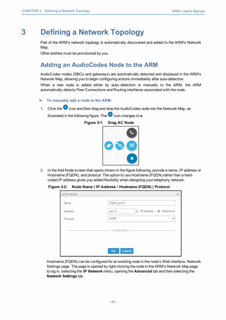
➢ To manually add a node to the ARM:
1. Click the icon and then drag and drop the AudioCodes node into the Network Map, as
illustrated in the following figure. The icon changes to x.
Figure 3-1: Drag AC Node
2. In the Add Node screen that opens shown in the figure following, provide a name, IP address orHostname (FQDN), and protocol. The option to use Hostname (FQDN) rather than a hard-coded IP address gives you added flexibility when designing your telephony network.
Figure 3-2: Node Name | IP Address / Hostname (FQDN) | Protocol
Hostname (FQDN) can be configured for an existing node in the node’s Web interface, NetworkSettings page. The page is opened by right-clicking the node in the ARM’s Network Map pageto log in, selecting the IP Networkmenu, opening theAdvanced tab and then selecting theNetwork Settings tab.
- 40 -

CHAPTER 3 Defining a Network Topology ARM | User's Manual
Figure 3-3: Node’s Web Interface - Network Settings Page – Host Name (FQDN)
This triggers a new loginmessage from the node to the ARM; the ARM consequently updatesthe address to the newly added Hostname (FQDN). If the ARM detects a node configured withboth Hostname (FQDN) and IP address, Hostname (FQDN) is used. You can changeHostname (FQDN) or IP address. The ARM displays the device’s address, i.e., Hostname(FQDN) if it exists, or IP address (if Hostname (FQDN) doesn't exist).
3. View the added AudioCodes node in the Topology Map; all elements associated with the nodeare automatically provisioned and displayed in the Network Map.
● Peer Connections are displayed in Locked state; you need to perform an unlock forthem to provide a service.
● Node provisioning by auto-detection is described inMigrating Device Routing to theARM on page 161.
Adding a Third-Party Node to the ARMThe ARM allows you to add third-party, non-AudioCodes nodes (SBCs andMedia Gateways) to theNetwork Map so that the ARM can be used for call routing in heterogeneous environments with amix of AudioCodes and non-AudioCodes nodes as part of your network.
Figure 3-4: Third-Party Device Added to the Network Map
➢ To add a third-party device:
1. Click the icon and then drag and drop the third-party node icon into the NetworkMap.
- 41 -

CHAPTER 3 Defining a Network Topology ARM | User's Manual
2. Provide the third-party device's properties. The third-party device's remote IP address is usedas the destination address of the connection from the AudioCodes device.
3. Add a VoIP Peer per type, e.g., SIP trunk or PBX, and attach it to the third-party node bydragging and dropping it from the 'add voippeer' menu.
Figure 3-5: Adding a VoIP Peer
4. In the 'Add VoIP Peer' screen, give the VoIP Peer a name.
Figure 3-6: Adding a VoIP Peer – Giving the VoIP Peer a Name
5. Associate the VoIP Peer with the third-party node using a Peer Connection, by drawing a linebetween the VoIP Peer and the third-party node by right-clicking the node and selecting theactionAdd Peer Connection.
- 42 -

CHAPTER 3 Defining a Network Topology ARM | User's Manual
Figure 3-7: Add Peer Connection
The action Add Peer Connection is available only to third-party, non-AudioCodes SBCs or MediaGateways. It's not applicable to AudioCodes SBCs orMedia Gateways.
Figure 3-8: Edit Peer Connection
6. You need to connect the third-party device to the ARM topology, to an AudioCodes node or to aSIP module, for end-to-end routing capabilities.
The ARM uses standard SIP TGRP capabilities to communicate with a third-partydevice interface that does not support AudioCodes nodes' REST API, so when addinga Peer Connection to a third-party device, you're prompted to provide TGRP. TheTGRP must match the configuration in the third-party device. When the ARM choosesto route a call towards a specific Peer Connection of the third-party device, it installsinto the SIP Invite the TGRP name configured in the ARM.
The ARM performs routing to Peer Connections attached to third-party devices. In the RoutingRules definition, choose the Peer Connection or VoIP Peer associated with the third-party deviceand in this way, achieve end-to-end routing in a heterogeneous network.
- 43 -

CHAPTER 3 Defining a Network Topology ARM | User's Manual
Adding ConnectionsYou can configure a connection between two nodes.
➢ To add a connection:1. In the Network Map view, right-click the node from which to configure the connection and in the
popupmenu click Add Connection.
Figure 3-9: Add Connection
Alternatively, in the Network Map view (1) select the node to which to add a connection and thenclick the action buttonAdd connection or (2) use theDrag Connection button.
Figure 3-10: Add Connection
2. Provide an intuitive name for the connection, to later facilitate user-friendly management in theARMGUI.
3. Select the weight. Default: 50. Range: 1-100.4. From the 'Transport Type' drop-downmenu, select UDP (default), TCP or TLS.
- 44 -
CHAPTER 3 Defining a Network Topology ARM | User's Manual
5. From the 'Node-1' drop-downmenu, select the name of the node and from the 'RoutingInterface-1' drop-downmenu, select its routing interface
6. From the 'Node-2' drop-downmenu, select the name of the node and from the 'RoutingInterface-2' drop-downmenu, select its routing interface
7. To define Advanced Conditions (quality-based routing), see Routing Settings on page 114.8. Click OK; the connection is made.
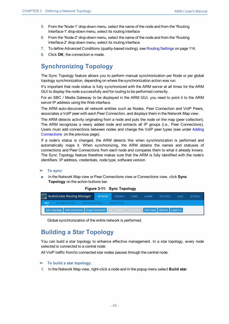
Synchronizing TopologyThe Sync Topology feature allows you to perform manual synchronization per Node or per globaltopology synchronization, depending on where the synchronization action was run.It's important that node status is fully synchronized with the ARM server at all times for the ARMGUI to display the node successfully and for routing to be performed correctly.For an SBC / Media Gateway to be displayed in the ARM GUI, you need to point it to the ARMserver IP address using theWeb interface.The ARM auto-discovers all network entities such as Nodes, Peer Connection and VoIP Peers,associates a VoIP peer with each Peer Connection, and displays them in the Network Map view.The ARM detects activity originating from a node and puts the node on the map (peer collection).The ARM recognizes a newly added node and extracts all IP groups (i.e., Peer Connections).Users must add connections between nodes and change the VoIP peer types (see under AddingConnections on the previous page).If a node's status is changed, the ARM detects this when synchronization is performed andautomatically maps it. When synchronizing, the ARM obtains the names and statuses ofconnections and Peer Connections from each node and compares them to what it already knows.The Sync Topology feature therefore makes sure that the ARM is fully identified with the node'sidentifiers: IP address, credentials, node type, software version.
➢ To sync:■ In the Network Map view or Peer Connections view or Connections view, click Sync
Topology on the action buttons bar.
Figure 3-11: Sync Topology
Global synchronization of the entire network is performed.
Building a Star TopologyYou can build a star topology to enhance effective management. In a star topology, every nodeselected is connected to a central node:All VoIP traffic from/to connected star nodes passes through the central node.
➢ To build a star topology:1. In the Network Map view, right-click a node and in the popupmenu select Build star.
- 45 -

CHAPTER 3 Defining a Network Topology ARM | User's Manual
Figure 3-12: Build Star
Figure 3-13: Build Star Topology
2. In the left pane of the Build Star Topology screen select the nodes that you want to connect tothe star and then click
3. Configure the screen using the following table as reference.
Table 3-1: Build Star Topology
Parameter Description
Star center The node you pointed your cursor to before selecting the 'Build Star' menu optionis displayed in the field; it'll be at the center of the star. To select another node tobe at the center of the star instead of this node, from the drop-downmenu ofnodes select the node.
RoutingI/F
Select one of the SIP interfaces from which connections will bemade from thisnode in the star center, to the other nodes in the star.
- 46 -

CHAPTER 3 Defining a Network Topology ARM | User's Manual
Parameter Description
Example:■ SIP-c■ SIP-0■ SIP-1■ SIP-2
Defaultweight
Enter the weight 1-100 to be applied to all connections in the star topology build.Later, you can prioritize per connection (see under Connection Information andActions on page 29 for more information). The ARM uses this setting to select themost optimal routing path for each call. The parameter therefore facilitates moreeffective network management.
The builderpanes
Use the builder panes to build your topology star. From the left pane, select thenodes to include in the star, and then click >> tomove them to the right pane. Ifyou select a single node at a time, select it and then click >. To remove a nodefrom the build, in the right pane click <, or << to removemultiple modes afterselecting them.
4. Click OK; the topology is built. You can view it in Topology Map view.
Testing a RouteYou can configure and test a route to make sure the call routing rule, the manipulation rule, thetopology status, etc., all perform per expectations, without impacting live calls traffic.
➢ To test a route:1. In the Network Map view, right-click the connection between a node and a VoIP Peer (Peer
Connection). [Alternatively, you can select the connection and then click the Test Routebutton on the Actions Bar].
Figure 3-14: Test Route
2. From the popupmenu, select Test route.
- 47 -

CHAPTER 3 Defining a Network Topology ARM | User's Manual
Figure 3-15: Test Route
3. [Optional] Enter the Source and Destination Route. From the drop-downmenu, select thePeerConnection.
4. Under 'AdvancedOptions', select the routing rules mode:● Live. When a new call destination is calculated, the Routing Rule is taken into
consideration and live traffic may be impacted.● Test. Tests the Routing Rule or Dial Plan offlinewithout impacting or disrupting live calls
traffic.● Live and Test selected together. The Routing Rule is considered when:
◆ calculating the live routing path -and-◆ testing a route in the live topology map and in the offline planning page
Each routing rule can be enabled or disabled separately for Live mode and / or Testmode (seealso under Adding a New Routing Rule on page 133).
5. Under 'AdvancedOptions', select the call trigger. By default, the Initial option is enabled. Seestep 11 under Adding a New Routing Rule on page 133 for more information about call triggers.
6. Optionally, test the route with a specific ARM Router (also supported in 'Test Route' activatedfrom ‘Offline Planning’): Under 'AdvancedOptions', select from the 'Router' drop-down:● Any (default) = the ARMConfigurator contacts any ARMRouter to perform a ‘Test Route’
and get the results; the ARMRouter is chosen randomly.● Select a specific ARM Router for a test call.Use this feature for debugging and locating potential issues.
7. Click Find Routes. Test routing is performed as if a real call is occurring, taking OperativeState and Admin State of topology entities (Connections, nodes, Peer Connections), and theAdmin State of routing rules, into account. In addition, the entity's Quality or Time/Date criteriaare taken into consideration if required by the Routing Rule (Advanced Condition). The RoutePath is highlighted purple (shown in the following figure); the panes on the right of the pagedisplay detailed information.
- 48 -

CHAPTER 3 Defining a Network Topology ARM | User's Manual
Figure 3-16: Test Route Paths
8. In the Test Route pane shown in the preceding figure, click theDetails button.
Figure 3-17: Test Route Details
9. In the example above:● Compare the columnORIGINAL to the columnNEW; the number changed because of a
normalization rule that was applied. The normalization rule was configured in theNormalization Group rules attached to the Peer Connection.For related information, see also under Peer Connections Page Actions on page 33 andExamples of Normalization Rules on page 179.
- 49 -

CHAPTER 3 Defining a Network Topology ARM | User's Manual
Figure 3-18: Strip + from the Number
● ColumnWHEN indicates whenmanipulation was performed, i.e., before or after routing. Inthe example above, manipulation was performed before routing.
● Column ENTITY indicates which part of the SIP Request was manipulated.◆ Possible values: Source URI User, Source URI Host, Destination URI User,
Destination URI Host, Destination IP Address, Destination Port, DestinationProtocol, User Credential User Name, User Credential Password
● ColumnCHANGED BY – the first row indicates by global Normalization Group – seeunder Adding a Normalization Group on page 103 and Normalization Before Routing onpage 107 for detailed information; the second row indicates that the normalization wasattached to a Peer Connection - see under Peer Connection Information and Actions onpage 30 for detailed information.
● ColumnNORMALIZATION/MANIPULATION GROUP indicates which 'ManipulationGroup' the entity passed through, according to which regular expression the entity waschanged.
● A new Routing Rule is by default added in ‘Test Mode’ (not 'Live'). To test the rulebefore switching it to live, use the ‘Test’ option of ‘Test Route’.
● After performing Test Route, the results (including the selected path) are preservedin the Network Map even if you switch to another tab. This is convenient whendebugging a Dial Plan, after fixing a Routing Rule and reverting to testing it in theNetwork Mapwith the ‘Test Route’ feature.
- 50 -

CHAPTER 3 Defining a Network Topology ARM | User's Manual
- 51 -

CHAPTER 4 Designing a Network Topology in the Offline Planning Page ARM | User's Manual
4 Designing a Network Topology in the OfflinePlanning PageThe ARM gives operators an add-on to design an IP network in the Offline Planning page startingfrom the beginning.Operators can alternatively import an existing live topology into the page, make changes to entities'configuration and statuses, and test how the changes impact network functionality.Feature benefits:■ Saves expenses in the network design phase | maintenance phase■ Prevents routing errors from occurring■ Decreases maintenance windowsThe Offline Planning page is essentially a Map view that can be used as a sandbox for networkdesign and testing purposes.
Figure 4-1: Offline Planning
In the view, the operator can create virtual nodes, Peer Connections, VoIP Peers, andConnections. The operator can import a full, currently-used topology, or part of one, e.g., a specificnode, for making changes and testing offline.The operator can 'play' with the Administrative State, Operative State, Quality and Weight - ifavailable - of each virtual entity and test how the changes impact call traffic.After entities are added to the Offline Planning page they can be used in Routing Rules in testingmode; live network traffic will not be impacted.The feature allows operators to test almost any scenario before transposing the configuration to thelive topology.The following figure shows theOperative State andQuality settings per peer connection.
- 52 -

CHAPTER 4 Designing a Network Topology in the Offline Planning Page ARM | User's Manual
Figure 4-2: Edit Peer Connection
After designing virtual VoIP network entities, you can export them to the live topology. When youexport a newly defined node to the live topology, the node configuration downloads to AudioCodes'device which automatically connects to the live topology.
When exporting an offline node to the live ARM topology, only the connections in thelive node are provisioned; you need to manually provision Peer Connections in thenode.
Performing Actions in the Offline Planning PageIn the Offline Planning page, you can perform the following actions:■ Add a virtual entity to the Offline Planning page■ Import an existing node and all entities associated with it from the live topology■ Import a full topology from the live topology■ Combine a virtual configuration with an imported one
Adding a Virtual EntityTwo types of virtual entities can be added to the Offline Planning page:■ Nodes■ VoIP Peers
- 53 -

CHAPTER 4 Designing a Network Topology in the Offline Planning Page ARM | User's Manual
➢ To add a virtual node:
1. In the Offline Planning page, click and then click ; then select the virtual node type orthird-party node type using the following table as reference.
Table 4-1: Add a Virtual Node
Icon Used to
Drag and drop a third-party Node onto the Offline Planning page.
Drag and drop a virtual hybrid device onto the Offline Planning page.
Drag and drop a virtual gateway onto the Offline Planning page.
Drag and drop a virtual SBC onto the Offline Planning page.
2. Drag the selected type of device to themap and configure its name.
➢ To add a virtual VoIP Peer:
1. Click and then ; then select the VoIP Peer type using the following table as reference.
Table 4-2: Add a Virtual VoIP Peer
Icon Used to
Drag and drop aPSTN entity onto the Offline Planning page.
Drag and drop aPBX onto the Offline Planning page.
Drag and drop an IP PBX onto the Offline Planning page.
Drag and drop aSIP Trunk onto the Offline Planning page.
Drag and drop an IP phone onto the Offline Planning page.
2. Drag the icon to themap and configure the name of the VoIP Peer.
Adding a Virtual Peer Connection to the Offline Planning PageYou can add a virtual Peer Connection to the Offline Planning page.
- 54 -

CHAPTER 4 Designing a Network Topology in the Offline Planning Page ARM | User's Manual
➢ To add a virtual Peer Connection:■ Drag a line from the center of a node to a VoIP Peer and then configure it in the Add Peer
Connection screen that opens:
Figure 4-3: Add Peer Connection
Adding a Virtual ConnectionYou can add a virtual Connection to the Offline Planning page.
➢ To add a virtual connection to the Offline Planning page:■ Click theAdd Connection button to add a connection between two offline nodes; the same
screen as the ‘Add Connection’ screen shown under Adding Connections on page 44 isdisplayed; the procedure is identical to that performed in the live topology.
Importing a Full TopologyYou can import a full topology from the live topology map to the Offline Planning page.
➢ To import a full topology:■ Click the Import topology button; all network entities in the live topology including nodes,
VoIP Peers, Peer Connections and Connections will be imported.
Importing a Node from the Live TopologyYou can import a node from the live topology to the Offline Planning page.
➢ To import a node from the live topology:■ Click the Import nodes button and select a relevant node from the list that pops up; the node
will be added to the Offline Planningmap together with Peer Connections and VoIP Peersassociated with that node.
Deleting a Virtual EntityYou can delete a virtual entity from theOffline Planning page.
➢ To delete a virtual entity from the Offline Planning page:■ Select an entity and then click Delete.
- 55 -

CHAPTER 4 Designing a Network Topology in the Offline Planning Page ARM | User's Manual
■ Click Clear Map to delete all entities from the page.
Testing a RouteYou can test a route in the Offline Planning page.
➢ To test a route:■ To test a route in a virtual network, select the Peer Connection and then select Test Route
(see Testing a Route on page 47). Testing a route in the Offline Planning page factors in allentities configured in the Offline Planning page and their status and voice quality.
Exporting a Node from the Offline Page to the Live TopologyYou can export a node from theOffline Planning page to the live topology.
➢ To export a node from the Offline Page to the live topology:
Before exporting a node to the live topology, make sure it's correctly configured in theOffline Planning page. If a node with the same IP address already exists in the livetopology, the entire configuration of the node will be transferred to that node in the livetopology. Before exporting a node to the live topology, make sure all Peer Connections(IPGroups) are configured on that node.
■ In the Offline Planning page, right-click the node and from the popupmenu select Exportnode.
Figure 4-4: Export Node
- 56 -

CHAPTER 5 Viewing Statistics and Reports ARM | User's Manual
5 Viewing Statistics and ReportsThe ARM provides a Statistics Graphs page and ARM-embedded statistics reports, allowing you todebug, monitor and optimize your network and routing. Statistics charts provide you with a clearview of your network and routing performance, helping you better understand, analyze, debug andoptimize network routing and resources usage.
➢ To use statistics graphs:■ Open the Statistics Graphs page (Statistics > Graphs).
Figure 5-1: Statistics Graphs Page – ARM over time
The page is divided into three sections.
Table 5-1: Statistics Graphs Page (From Left to Right)
Element Filters GraphicalRepresentation
Statistics are displayed perelement. Select either:■ ARM■ Router (Routers over time, Top
routers, Top routers over time)■ Node (Nodes over time, Top
nodes, Top nodes over time,Nodes by peer connections,Top nodes by peerconnections)
■ Peer Connection (Peerconnections over time, Toppeer connections, Top peerconnections over time)
■ Connection (Connections overtime, Top connections, Topconnections over time)
Filters differ depending onthe element selected. Forall elements exceptRouting Group and RoutingRule, select from:■ 'Date' ('Range' or
'Relative')■ Statistics Type:
✔ Routing attempts✔ Alternative
attempts✔ Unsuccessful
routes✔ Destinations Not
Routable✔ Destination calls
Graphic representation ofthe statistics of theselected element in achart, with a range ofgraph functionalities:■ Refresh■ Chart type (line, area
or stacked area)Export chart
- 57 -

CHAPTER 5 Viewing Statistics and Reports ARM | User's Manual
Element Filters GraphicalRepresentation
■ Routing Group (Routing groupsover time, Top routing groups,Top routing groups over time,Top routing groups by rules,Top routing groups by rules)
■ Routing Rule (Routing rulesover time, Top routing rules,Top routing rules over time,Routing rules by actions, Toprouting rules by actions)
✔ Transient calls(does not apply toPeer Connection)(for Connection,only this filterapplies)
✔ Drop routingrequest
✔ Nomatch rule■ Elements
✔ Search✔ Number
■ Stacked Elements✔ Search✔ Number
■ Statistics Type (onlyapplies to RoutingGroup and RoutingRule)✔ Routing rules
attempts✔ Routing first match✔ Routing second
match✔ Routing third
match✔ Routing rules
failures
Figure 5-2: Top Routers Filtered by Routing Attempts Displayed as a Pie Chart
- 58 -

CHAPTER 5 Viewing Statistics and Reports ARM | User's Manual
■ A glance at the chart immediately reveals the top router. Point your cursor over a segment todisplay the number of routing attempts attempted by that router.
■ You can print the chart or download the statistics in a format of your choice.
Figure 5-3: Downloading Statistics in a Format of Choice
■ You can select your preferred graphical representation – bar chart, column chart or pie chart.An icon 'Select chart type' allows you to present statistics according to your preferred graphicalrepresentation.
Figure 5-4: Top Routers Filtered by Routing Attempts Displayed as a Bar Chart
■ A glance at this chart also immediately reveals the top router. Point the cursor over a bar todisplay the number of routing attempts attempted by that router. The following figure shows theelements that hold statistics information.
- 59 -

CHAPTER 5 Viewing Statistics and Reports ARM | User's Manual
Figure 5-5: Elements that Hold Statistics Information
Each element displays subcategories. Under Routing Rule, for example, you can select 'TopRouting rules over time’ or ‘Top Routing rules by action’.In addition, in the Filters section of the page, you can select 'Number of elements'.
Figure 5-6: Top Routing rules over time
- 60 -

CHAPTER 6 Performing User-Related Administration ARM | User's Manual
6 Performing User-Related AdministrationThe Users page in the ARM allows the ARM operator to:■ Add users to the ARM (see Adding a User Not Listed in an AD to the ARM below)■ AddUsers Groups to the ARM (see Adding Users Groups to the ARM on page 63)■ Add an LDAP Server to the ARM (see Adding an LDAP Server to the ARM on page 68)■ Add a Property Dictionary to the ARM (see Adding a Property Dictionary to the ARM on
page 73)
Adding a User Not Listed in an AD to the ARMEnterprises have databases in which employee information is stored. Enterprises generally storeinformation related to employees on Microsoft's Active Directory (AD) server. The ARM supportsmultiple ADs. The ARM's user administration feature can connect to an AD and import user callsrouting related information into the ARM database. Operators can alternatively add users who arenot listed in an AD database, to the ARM database.Enterprises that store their users in another format (Excel, for example) can also import these usersinto the ARM as local ARM users using the ARM northbound REST API. For more information andassistance, contact AudioCodes Professional Services.To view the users listed in the AD database and their AD attributes, you need to provision theLDAP server as shown under Adding an LDAP Server to the ARM on page 68.
➢ To add a user who is not listed in an AD database, to the ARM database:1. In the ARM's Users page, click theUsers tab under the Users menu.
Figure 6-1: Users Page – Users tab
2. Click Add.
- 61 -

CHAPTER 6 Performing User-Related Administration ARM | User's Manual
Figure 6-2: User Details
User Details are taken from the Property Dictionary screen. If a property is added in theProperty Dictionary screen, it appears here. To add a property, see Adding a PropertyDictionary to the ARM on page 73.
If an LDAP server is provisioned, the ARM automatically brings users from it to theARM database, and displays them in the GUI under theUser tab.
3. Click OK; the user is added and displayed in the Users page. To view and/or edit, select theuser's row and click Edit; the screen shown below is displayed.
- 62 -

CHAPTER 6 Performing User-Related Administration ARM | User's Manual
Figure 6-3: User Details
Grayed fields in the figure above indicate that the origin of this user isn’t ARM andcannot be edited. Non-grayed fields indicate that the origin of the user is ARM and canbe edited.
Adding Users Groups to the ARMYou can define Users Groups by defining a set of criteria in the user properties. The ARMautomatically associates users with the defined Users Group, based on the conditions you define.You can then use the Users Groups in your Routing Rules as match conditions. Each Users Grouphas one 'Dialable Number' attribute. When a route request is received with a source or destinationURI matching the group’s 'Dialable Number' property for one of the users in the group, the RoutingRules with this source or destination Users Group arematched.A Users Group can have a single attribute condition or a combination of attributes conditions. For auser to be a part of the Users Group, all the conditions must be matched. A single condition canhave a set of values to compare to. If any of the values of the condition are matched, the conditionis considered amatch.Example: You can define a Users Group where the 'Dialable Number' attribute is 'Mobile phonenumber' and the conditions are Country equals Germany and Department equals Marketing orSales.
- 63 -
CHAPTER 6 Performing User-Related Administration ARM | User's Manual
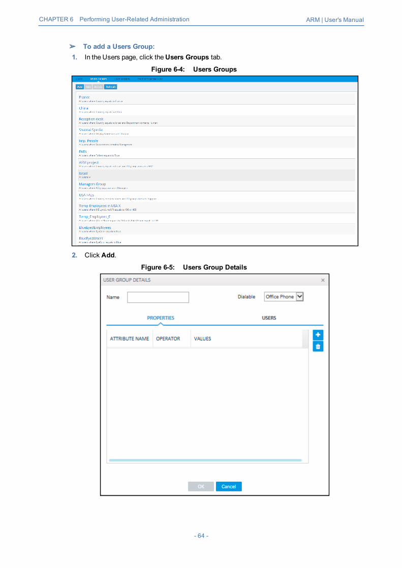
➢ To add a Users Group:1. In the Users page, click theUsers Groups tab.
Figure 6-4: Users Groups
2. Click Add.
Figure 6-5: Users Group Details
- 64 -

CHAPTER 6 Performing User-Related Administration ARM | User's Manual
3. Configure the details using this table as reference.
Table 6-1: Users Group Details
Setting Description
Name Enter a name for the group for intuitive future reference.
Dialable From the drop-downmenu, select one of the Dialable Numberproperties. This is the user’s property that is compared to thereceived source or destination URI to determine if the routerequest is from/to one of the users in this User Group. Example:'Office phone number'.
Attribute Name Click the field and from the drop-downmenu, select a userattribute according to which the user will be associated with thegroup. Example: Country.Click the plus button + to addmore attributes. All attributes mustmatch for the user to be amember of the group.
equals / not equalscontains / not contains
From the drop-downmenu, select the operation to be used todefine the criterion.
Value Enter a value for the attribute, according to which the user will beassociated with the group. Example: Sweden. Press enter to addmore values. At least one of the values must match for theattribute to be considered amatch.
- 65 -
CHAPTER 6 Performing User-Related Administration ARM | User's Manual
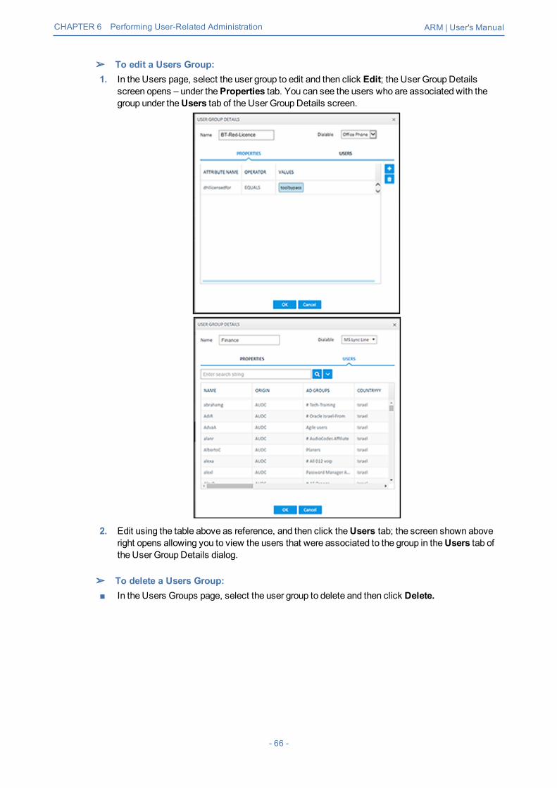
➢ To edit a Users Group:1. In the Users page, select the user group to edit and then click Edit; the User Group Details
screen opens – under theProperties tab. You can see the users who are associated with thegroup under theUsers tab of the User Group Details screen.
2. Edit using the table above as reference, and then click theUsers tab; the screen shown aboveright opens allowing you to view the users that were associated to the group in theUsers tab ofthe User Group Details dialog.
➢ To delete a Users Group:■ In the Users Groups page, select the user group to delete and then click Delete.
- 66 -

CHAPTER 6 Performing User-Related Administration ARM | User's Manual
An error message is displayed if you attempt to remove a group with which routing rulesare associated. For example:
The message indicates the names of the routing rule/s associated with the group so it'seasy to find and remove them before deleting the group.
- 67 -

CHAPTER 6 Performing User-Related Administration ARM | User's Manual
Adding an LDAP Server to the ARMNetwork administrators can add multiple Active Directories (ADs) to the ARM database usingLDAP protocol.
➢ To add an LDAP server:1. In the Users page, click the LDAP Servers tab.
Figure 6-6: Users Page – LDAP Servers tab
2. Click Add.
Figure 6-7: LDAP Server Settings
- 68 -

CHAPTER 6 Performing User-Related Administration ARM | User's Manual
3. Configure the settings using this table as reference.
Table 6-2: LDAP Server Settings
Setting Description
Servername
Enter an intuitive name for the LDAP server.
Host IP address or DNS name of the LDAP server on which the AD is located.
Port The LDAP port. Default: 389
BaseObject Consult your IT manager responsible for the Active Directory in your enterprise.The setting defines the full path (DN) to the object in the AD tree where theuser's information is located. The valid value is a string of up to 256 characters.Example (read from right to left):ou=Users;ou=APC;ou=Israel;ou=AudioCodes;dc=corp;dc=audiocodes;dc=comTheDN path is defined by the LDAP names OU (organizational unit) and DC(domain component).
SearchFilter
An LDAP search filter used when fetching the users from the LDAP serverunder the base DN. The default is 'objectClass=user'.
Security Settings
Bind DN The DN (distinguished name) or username of the user used to bind to the LDAPserver. For example: [email protected]
Password Defines the LDAP password used to connect.
Enable SSL Enables or disables the connection over SSL. Default: Disable. When disabled,communications with the AD server will be open, i.e., unencoded/unencrypted.When left unchanged at the default; theBrowse button adjacent to 'CertificateFile to Upload' will be unavailable; when enabled, theBrowse button becomesavailable.
Certificatefile
Enables verification that it is the AD server and no other entity that iscommunicating with the ARM server. Allows you to browse for a rootcertificate. When the AD server then sends a certificate, the ARM server usesthe root certificate to verify that it is the AD server and no other entity on theother side. Following verification, communications are SSL-encoded.
Updates
Check forupdatesevery nminutes
Defines how frequently the ARM server checks the AD server for updates.Note that during the update, the ARM only obtains new AD users or relevantuser information updates (only the delta).
Perform fullupdateevery ndays at
Defines how frequently the ARM server performs a full update from the ADserver. Note that a full update is mainly required to remove users deleted fromthe organization's AD (this information cannot be obtained by an AD update).
- 69 -

CHAPTER 6 Performing User-Related Administration ARM | User's Manual
Setting Description
Updatestimeout
If the AD server doesn't answer within the period set, the ARM serverdetermines that the AD server is disconnected and a refresh is sent.
TestConnectivity
Click the button to test the connectivity between the ARM server and the ADserver.
4. Click OK now or click it after theNext button. You can also click Test connectivity; the LDAPProperties page opens:
Figure 6-8: LDAP Properties
Properties that have LDAP mappings will be synced from the LDAP server. Properties that donot have LDAP mappings can be configured locally.
- 70 -
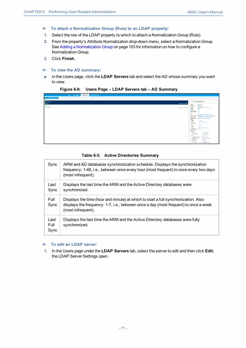
CHAPTER 6 Performing User-Related Administration ARM | User's Manual
➢ To attach a Normalization Group (Rule) to an LDAP property:1. Select the row of the LDAP property to which to attach a Normalization Group (Rule).2. From the property's Attribute Normalization drop-downmenu, select a Normalization Group.
See Adding a Normalization Group on page 103 for information on how to configure aNormalization Group.
3. Click Finish.
➢ To view the AD summary:■ In the Users page, click the LDAP Servers tab and select the AD whose summary you want
to view.
Figure 6-9: Users Page – LDAP Servers tab – AD Summary
Table 6-3: Active Directories Summary
Sync ARM and AD databases synchronization schedule. Displays the synchronizationfrequency: 1-48, i.e., between once every hour (most frequent) to once every two days(most infrequent).
LastSync
Displays the last time the ARM and the Active Directory databases weresynchronized.
FullSync
Displays the time (hour andminute) at which to start a full synchronization. Alsodisplays the frequency: 1-7, i.e., between once a day (most frequent) to once a week(most infrequent).
LastFullSync
Displays the last time the ARM and the Active Directory databases were fullysynchronized.
➢ To edit an LDAP server:1. In the Users page under the LDAP Servers tab, select the server to edit and then click Edit;
the LDAP Server Settings open.
- 71 -

CHAPTER 6 Performing User-Related Administration ARM | User's Manual
Figure 6-10: LDAP Server Settings
2. Edit the LDAP Server Settings screen, click Test Connectivity to test the connection settingsand then click Next; the LDAP Properties screen opens.
3. For each LDAP property's LDAP Mapping drop-downmenu, select amapping. Properties thathave LDAP mappings will be synced from the LDAP server. Properties that do not have LDAPmappings can be configured locally.
4. Select the row of the LDAP property to which to attach a Normalization Group (Rule) and thenfrom the property's Attribute Normalization drop-downmenu, select a Normalization Group.See Adding a Normalization Group on page 103 for information about how to configure aNormalization Group.
5. Click Finish.After updating an LDAP server, a full sync is started. After a short while (depending on the sizeand responsiveness of the LDAP server), you can view the updated users in the Users page.
- 72 -

CHAPTER 6 Performing User-Related Administration ARM | User's Manual
Adding a Property Dictionary to the ARMThe Users page's Property Dictionary tab lets the operator administer the Property Dictionary, aset of all the properties that a user can have.
Figure 6-11: Users Page – Property Dictionary tab
After adding a property to the dictionary, you can add it to some or all your LDAP servers.Properties added to an LDAP server will automatically be read from the LDAP server. Propertiesnot added can be set locally in the ARM for each user. The Properties from the dictionary can thenbe used as User Group conditions as well as in 'Policy Studio'.
➢ To add / edit a property:1. Open the Property Dictionary page (Usersmenu > Property Dictionary tab).2. Click Add or Edit.
Figure 6-12: Property
3. Use the following table as reference.
Table 6-4: Add Property
Setting Description
Name Define an intuitive name for the property, for intuitive future reference.
Description Enter a brief description of the property, for intuitive future reference.
Dialable Defines if this property is a dialable number. Only dialable numbers are used formatching with a received source or destination URI in a route request.
- 73 -

CHAPTER 6 Performing User-Related Administration ARM | User's Manual
Setting Description
Examples of dialable number properties: Office phone number, mobile phonenumber, Skype number, etc.
Display inUsersTable
Select the option to display the user property in the Users page. The option canbe used to reduce clutter on the Users page. By default, the option is selected.
Combinedattribute
Select this option to configure a new attribute in the Users Dictionary as acombined attribute, i.e., triggered by a combination of two other UsersDictionary attributes. If any of the basic attributes [that the new attribute iscombined of] changes, the new attribute will change.In the preceding figure, the new attribute whose name is configured asCombinedNumberwill be composed of the existing attributes Office Phoneandmobile phone, with the delimiter ‘_’ (not shown in the preceding figure). Achange to the value of any of the comprising attributes will trigger a change inCombinedNumber. The combined attribute will automatically be created foreach user.
The feature allows a Users Group to be configured for routing based on acombination of other attributes. Additionally, you can configure rules using oneof the combined attributes (phone numbers) with the option to apply post-routingmanipulation to remove any unnecessary prefix or suffix from the combinednumber.
- 74 -

CHAPTER 6 Performing User-Related Administration ARM | User's Manual
Adding a Users Dictionary Attribute Triggered (Combined) byTwo Other AttributesThe ARM provides the capability to add an attribute in the Users Dictionary triggered by a com-bination of two other Users Dictionary attributes with a predefined delimiter. If any of the basic attrib-utes [that the new attribute is combined of] changes, the new attribute will change. To accomplishthis, youmust configure the new attribute as Combined attribute.
Figure 6-13: Property – Combined Attribute
[Refer to the example in the figure above] The new attribute whose name is configured as Com-binedNumber will be composed of the existing attributes Office Phone andmobile phone, with thedelimiter ‘_’ (off-screen in the figure above). A change to the value of any of the comprising attrib-utes will trigger a change in CombinedNumber. The combined attribute will automatically be cre-ated for each user.
Figure 6-14: Combined Number
The feature allows a Users Group to be configured for routing based on a combination of other attrib-utes. In addition, the operator can configure rules using one of the combined attributes (phone num-bers) with the option to apply post-routingmanipulation to remove any unnecessary prefix or suffixfrom the combined number.
- 75 -

CHAPTER 7 Configuring Settings ARM | User's Manual
7 Configuring SettingsThe Settings page (under the Settings menu) lets you configure■ Administration
● License (see Activating Your License on the next page)● Security (see Securing the ARM on page 78)● Operators (see Provisioning Operators on page 82)● NodeCredentials (see Node Credentials on page 83)● Router Credentials (see Router Credentials on page 85)● Configurator Credentials (see Configurator Credentials on page 87)● LDAP Authentication (see Provisioning Operators using an LDAP Server on page 90)● RADIUS Authentication (see Provisioning Operators using a RADIUS Server on page 93)● RemoteManager (see RemoteManager on page 96)● Certificates (see Uploading Trusted Certificates on page 81)
■ Network Services● Syslog server (see Editing a Syslog Server on page 97)● NTP server (see Adding/Editing an NTP Server on page 99)● QoS (see Prioritizing Traffic Per Class of Service on page 99)● CDRs (see Enabling CDRs on page 102)● Calls (see Disabling, Limiting the Number of CDRs on page 155)
■ Call Flow Configurations● Normalization Groups (see Adding a Normalization Group on page 103)● Prefix Groups (see Adding a Prefix Group on page 105)● Normalization Before Routing (see Normalization Before Routing on page 107)● Policy Studio (see Policy Studio on page 108)● WebServices (seeWeb-based Services on page 112)
■ Routing● Configuring aQuality Based Routing Condition (see Configuring Criteria for a Quality
Profile on page 114)● Configuring a Time-Based Routing Condition (see Configuring a Time-Based Routing
Condition on page 115)● Configuring SIP Alternative Route Reason (see Configuring SIP Alternative Route
Reason on page 118)● Configuring Global Routing Settings (see Configuring Global Routing Settings on
page 120)■ Routing Servers
● Servers◆ Adding a Routing Server (see Adding a Routing Server on page 120)◆ Editing a Routing Server (see Editing a Routing Server on page 122)◆ Locking/Unlocking a Routing Server (see Locking/Unlocking a Routing Server on
page 123)● Groups
◆ Adding a Routing Server Group (see Adding a Routing Server Group with Internal andExternal Priorities on page 124)
- 76 -

CHAPTER 7 Configuring Settings ARM | User's Manual
Administration SettingsThe ARM enables the following administrative tasks to be performed:■ Configure a software license (see Activating Your License below)■ Manage security (see Securing the ARM on the next page)■ Add an operator (see Provisioning Operators on page 82)
Activating Your LicenseThe ARMmust be licensed with a valid license for the product to become fully operational.
➢ To activate your license:1. Open the License page (Settingsmenu > Administration tab License item).
Figure 7-1: License Page
2. Select and copy the 'License Key' shown in the figure above.3. Activate the product through the AudioCodes License Activation tool at
www.audiocodes.com/swactivation. You'll need your Product Key and the Configurator'sMachine ID for the activation process. An email will subsequently be sent to you with yourLicense Key.
4. Copy and paste the License Key string that AudioCodes sends you into the 'License Key' field,and then click Submit; the number of sessions purchased and the license expiry date aredisplayed.
- 77 -

CHAPTER 7 Configuring Settings ARM | User's Manual
5. Make sure the license details (the number of sessions purchased and the license's expiry date)match those that you purchased.
Viewing License DetailsLicense policy is based on the following aspects of ARM functionality and capacity:■ Expiration Date■ Number of Sessions■ Number of Users■ Number of Routing Rules■ Tune Based Routing (can be either enabled or disabled)■ Quality Based Routing (can be either enabled or disabled)■ Test Route (can be either enabled or disabled)■ Network Planner (can be either enabled or disabled)■ Policy Studio (can be either enabled or disabled)
➢ To view information about the license applied to your ARM:■ Open the License Details page (Settings > Administration > License).
Figure 7-2: License Details
Securing the ARMThis ARM enables operators to secure routingmanagement.
- 78 -

CHAPTER 7 Configuring Settings ARM | User's Manual
➢ To secure the ARM:1. Open the Security page (Settingsmenu > Administration tabSecurity item).
Figure 7-3: Security Page
2. Use the following table as reference.
Table 7-1: Security Settings
Setting Description
Sessiontimeout(hours)
Closes the session timeout and forces the user to reenter their password (toreopen the session) if the timeout you define (in hours) expires. Note that thissetting only takes effect after logging out and then re-logging in.
Inactivityperiod(minutes)
Suspends the user's account if the user does not log in to the ARM over theperiod you define. 0 disables the feature; users accounts will then never besuspended due to inactivity. Note that this setting only takes effect after loggingout and then re-logging in.
http/httpsenabled
Enables an HTTP/HTTPS connection between the ARM server and the SBC /Gateway.
General Node Credentials
Username Username and Password are the default credentials that ARM uses whencommunicating with the node. Default: Admin/Admin.The ARM uses this Username if in the EDIT NODE screen (see under NodeInformation and Actions on page 21 for more information), you select Usegeneral credentials. Change the Username only if the credentials of the nodearen’t Admin/Admin.
- 79 -

CHAPTER 7 Configuring Settings ARM | User's Manual
Setting Description
Password Username and Password are the default credentials that ARM uses whencommunicating with the node. Default: Admin/Admin.The ARM uses this Password if in the EDIT NODE screen (see under (see underNode Information and Actions on page 21 for more information), you select Usegeneral credentials. Change the Password only if the credentials of the nodearen’t Admin/Admin.
3. Click Submit; the security configuration is saved.
Determining ARM Communications with Other Entities
Operators can determine the way ARM communicates with other entities, e.g., routers and nodes.The ARMConfigurator’s address configured in these entities can be the Configurator’s IP addressor Hostname (FQDN).
➢ To configure the way the ARM communicates with other entities:1. Open the Security page (Settings > Administration > Security).
Figure 7-4: Security
Figure 7-5:2. Under ‘ARM Configuration’, configure the:
● ARM IP Address [Drop-down list of available hard-coded IP addresses that the ARMextracted from themachine’s local network interfaces]
● ARMHostname [The hostname of the ARM’s machine; by default, identical to that of themachine’s hostname]
● Communicationmethod [drop-down list to select whether the ARM should configure its IPaddress or Hostname (FQDN) for the other entities]
This actionmay take some time depending on the number of nodes in the network andthe number of configured ARMRouters. The action will cause entities to be temporarilydisconnected. Peer Connections, VoIP Peers and other entities do not impact on theaction.
- 80 -

CHAPTER 7 Configuring Settings ARM | User's Manual
Strengthening Security: Certificate Validation
Certificate validation allows stronger ARM communications security. The ARM can validate eitherthe Subject name of the certificate or the entire client certificate that’s loaded to the ARM. Wheninitiating TLS communications from the ARM, the ARMwill then only accept validated certificates.
Uploading Trusted Certificates
Operators must first upload trusted certificates to the ARM.
➢ To upload trusted certificates:1. Open the Add Certificate screen (Settings > Administration > Certificates > Add).
Figure 7-6: Add Certificate
2. In the ‘Alias’ field, enter the name of the certificate.3. Click the browse icon adjacent to the ‘Certificate file’ field, and then navigate to and select a
valid Base64-encoded certificate file.
This setting is system wide; youmust upload all certificates for all entities (nodes, ARMrouters) communicating over TLS / SSL / HTTPS. The ARM is by default released withthe default ARM Router certificate trusted, but if this certificate is changed, you mustre-upload the changed certificate.
Enabling Certificate Subject Name Verification
The ARM supports capability to validate the subject name received in the server certificate, againstthe Hostname / IP Address of the entity to which the communication was initiated.
➢ To enable certificate subject name verification:1. Open the Security page (Settings > Administration > Security) and locate the section
‘Certificate Verification’.2. Select the optionVerify certificate subject name when ARM performs https requests to
enable the feature.
- 81 -

CHAPTER 7 Configuring Settings ARM | User's Manual
Figure 7-7: Verify certificate subject name when ARM performs https requests
Before enabling the option, make sure all entities communicating over TLS / SSL /HTTPS have a valid certificate with appropriate subject names.
Enabling Client Side Certificate Validation
Operators should only enable validation of certificates after uploading certificates as shown under‘Uploading Trusted Certificates’, else the ARM will not be able to communicate with any of theelements which the ARM communicates with over SSL / TLS.
➢ To enable validation of certificates:1. Open the Security page (Settings > Administration > Security) and locate the section
‘Certificate Verification’.
Figure 7-8: Certificate Verification
2. Select the optionVerify certificate when ARM performs https requests.
Provisioning OperatorsOperators, i.e., network administrators or IT managers, and operator credentials can be provisionedin four ways:■ Using the ARM's Operators page – seeManually Provisioning anOperator in the ARM's
Operators Page on the next page■ Using the enterprise's LDAP authentication server – see Provisioning Operators using an
LDAP Server on page 90■ Using the enterprise's RADIUS authentication server – see Provisioning Operators using a
RADIUS Server on page 93■ Using the enterprise's Open LDAP authentication server – see Authenticating Operator Login
using Open LDAP on page 93If LDAP / RADIUS is used, the order will be:■ LDAP / RADIUS■ Local storage (database)If an LDAP / RADIUS authentication server is used but it is down or the operator can't beauthenticated with it because either the operator isn't found or the password doesn't match, thelocal operators table is used.
- 82 -

CHAPTER 7 Configuring Settings ARM | User's Manual
The LDAP / RADIUS method of provisioning operators therefore coexists with the local storage(database) method.
Manually Provisioning an Operator in the ARM's Operators PageOperators can bemanually provisioned using the ARM's Operators Page.
➢ To manually add an operator:1. Open theOperators page (Settingsmenu > Administration tabOperators item).
Figure 7-9: Operators
2. Click Add.
Figure 7-10: Add Operator
3. Configure the operator details using the following table as reference.
Table 7-2: Add Operator
Setting Description
Name Enter a name for the operator to log in with.
Password Enter a password for the operator to log in with.
Passwordconfirm
Confirm the password.
SecurityLevel
Select a Security Level for the operator: ADMIN orSECURITY_ ADMIN.ADMIN cannot (for example) change passwords, add or change operators, orperform licensing.
4. Click OK; the operator is added to the local ARM database.
Node CredentialsOperators can apply credentials per Node for ARM Configurator- Node communications.
- 83 -
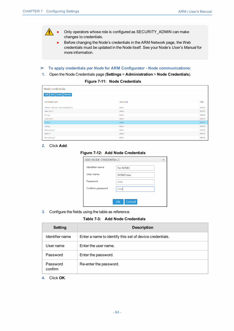
CHAPTER 7 Configuring Settings ARM | User's Manual
● Only operators whose role is configured as SECURITY_ADMIN canmakechanges to credentials.
● Before changing the Node’s credentials in the ARMNetwork page, theWebcredentials must be updated in the Node itself. See your Node’s User’s Manual formore information.
➢ To apply credentials per Node for ARM Configurator - Node communications:1. Open the Node Credentials page (Settings > Administration > Node Credentials).
Figure 7-11: Node Credentials
2. Click Add.
Figure 7-12: Add Node Credentials
3. Configure the fields using the table as reference.
Table 7-3: Add Node Credentials
Setting Description
Identifier name Enter a name to identify this set of device credentials.
User name Enter the user name.
Password Enter the password.
Passwordconfirm
Re-enter the password.
4. Click OK.
- 84 -

CHAPTER 7 Configuring Settings ARM | User's Manual
● After adding credentials you can Delete or Edit.● You can apply one of the previously configured settings to a specific Node (or use
the default setting) in the Edit Node screen (Network >Map > <select the specificnode> > Edit). Expand the ‘Credentials’ section first.
Figure 7-13: Edit Node - Credentials - Configurator>Node
5. [Optionally] You can apply the same to 'Add Node' and 'Offline Planner'.
Router CredentialsThe operator can change the ARMRouters credentials to be used for ARMConfigurator - ARMRouting Server communications.
➢ To configure new credentials:1. Open the ‘Router Credentials’ page (Settings > Administration > Router credentials).
- 85 -

CHAPTER 7 Configuring Settings ARM | User's Manual
Figure 7-14: Router Credentials
Only operators whose role is configured as SECURITY_ADMIN can make changes tocredentials.
2. Click Add.
Figure 7-15: Add Router Credentials
3. Configure the fields using the table as reference.
Table 7-4: Add Router Credentials
Setting Description
Identifier name Enter a name to identify this set of router credentials.
User name Enter the user name.
Password Enter the password.
Passwordconfirm
Re-enter the password.
4. Click OK and then view in the Router Credentials page (shown previously) the new entry forConfigurator - Router communications of type ‘Router’.
5. To associate the Routing Server with a specific ARM Router, open the Routing Servers page(Settings > Routing Servers) and then Add or Edit the specific ARM Router. Expand the‘Credentials’ section of the screen to do this.
- 86 -

CHAPTER 7 Configuring Settings ARM | User's Manual
Figure 7-16: Edit Server: Configurator - Router Credentials
Configurator CredentialsYou can configure new ARM Configurator credentials to be used for communications between:■ Node - ARM Configurator
and■ ARM Router - ARM Configurator
➢ To configure new credentials:1. Open the Configurator Credentials page (Settings > Administration > Configurator
Credentials).
Figure 7-17: Configurator Credentials
Only operators whose role is configured as SECURITY_ADMIN canmake changes tocredentials.
2. Click Add.
- 87 -

CHAPTER 7 Configuring Settings ARM | User's Manual
Figure 7-18: Add Credentials - Device
● If you're configuring credentials forNode - ARM Configurator communications, thenfrom the 'Type' drop-down select Device as shown in the preceding figure.
● If you're configuring credentials forARM Router - ARM Configurator communications,then from the 'Type' drop-down select Router as shown in the following figure.
Figure 7-19: Add Credentials - Router
3. Configure the fields using the table as reference.
Table 7-5: Add Credentials - Device | Router
Setting Description
User name Enter the user name.
Password Enter the password.
Passwordconfirm
Re-enter the password.
Type ■ If you're configuring credentials for Node - ARMConfiguratorcommunications, select Device.
■ If you're configuring credentials for ARMRouter - ARM Configuratorcommunications, select Router.
4. Click OK.
- 88 -

CHAPTER 7 Configuring Settings ARM | User's Manual
5. [Optionally] Apply one of the previously defined settings to a specific● Node (or use the default Node): Open the Edit Node screen (Network >Map > <select the
node> > Edit) and expand ‘Credentials’.
Figure 7-20: Node - Configurator | Configurator - Node
[The same applies to ‘Add Node’ and ‘Offline Planner’]● Router: Open the Routing Servers page (Settings > Routing Servers), click Add orEdit
for the specific ARM Router and then expand ‘Credentials’.
After applying newly configured ARMConfigurator credentials to a specific Node, view theNode automatically displayed in the ‘Configurator credentials’ page in the ‘Used inElements’ column, shown previously.After applying newly configured ARMConfigurator credentials to a specific Router, viewthe Router automatically displayed in the ‘Configurator credentials’ page in the appropriate‘Used in Elements’ column, shown previously.
- 89 -

CHAPTER 7 Configuring Settings ARM | User's Manual
Provisioning Operators using an LDAP ServerARM allows using the enterprise's LDAP server for operator login authentication. This feature is inaddition to local operator login authentication described under Manually Provisioning an Operator inthe ARM's Operators Page on page 83.
➢ To add an LDAP operator login authentication server:1. Open the Authentication page (Settings > Administration > LDAP Authentication).
Figure 7-21: LDAP Authentication
Only operators with a security level of Admin can edit LDAP authentication serverparameters.
2. Configure the LDAP Authentication Server parameters using the following table as reference.
Table 7-6: LDAP Authentication Server Parameters
Parameter Description
Enable LDAPAuthentication
Select or clear this option to enable or disable operator loginauthentication using an LDAP-compliant authentication server.
LDAPAuthenticationServer Host
Enter the IP address of the LDAP server's host.
LDAPAuthenticationServer Port
Enter the LDAP server's port number. Default: 389
LDAPConnectivity DN
Configure the 'LDAP Connectivity DN' parameter as required.
- 90 -

CHAPTER 7 Configuring Settings ARM | User's Manual
Parameter Description
LDAPConnectivityPassword
Configure the 'LDAP Connectivity Password' as required.
User DN SearchBase
Configure the 'User DN Search Base' as required.
3. Configure the SSL parameters to secure the connection to the LDAP server, using thefollowing table as reference.
Table 7-7: SSL Parameters
Parameter Description
SSL Select the 'SSL' option to secure the connection with the LDAP server over SSL.If left unselected (default), the connection with the LDAP server will be non-secured.
Certificatefile
Click the 'Certificate file' browse button to browse to and select the certificate filethat you want to use to secure the connection with the LDAP server over SSL.If SSL is selected and a certificate is also selected, an HTTPS connectionbetween the ARM and the LDAP server will be opened. The ARM authenticatesthe SSL connection using the certificate.
4. Configure the Test Connectivity parameters to test the connection to the LDAP server. Usethe following table as reference.
Table 7-8: Test Connectivity
Parameter Description
Name If 'Name' is undefined (empty), the connectivity test checks if the LDAPauthentication server can be logged into per the values defined under the 'LDAPAuthentication Server' parameters.If you enter a user name, the connectivity test checks that it's valid for logginginto the ARM. Enter the user name assigned to the LDAP server.
Password If 'Password' is undefined (empty), the connectivity test checks if the LDAPauthentication server can be logged into per the values defined under the 'LDAPAuthentication Server' parameters.If you enter a user password, the connectivity test checks that it's valid forlogging into the ARM. Enter the password required for accessing the LDAPserver.
- 91 -

CHAPTER 7 Configuring Settings ARM | User's Manual
Figure 7-22: LDAP Connectivity Test Result
5. View the result of the LDAP server connectivity test; the figure uppermost shows a failed testwhile the lowermost figure shows a successful connection.
6. Under page section 'Authorization Level Settings', you can providemapping of the ARM'saccess rules (‘Security Admin’ and ‘Admin’) into the LDAP server’s values.Use the following table as reference.
Table 7-9: Test Connectivity
Parameter Description
User NameAttribute
The name of the LDAP-complaint server's directory | folder in which theenterprise's user names are located. Default: sAMAccountName. When theoperator logs in, the authentication feature checks in this directory | folder thatthe operator's name exists.
PermissionsAttribute
The name of the LDAP-complaint server's directory | folder in which thepermissions are located. Default: memberOf. When the operator logs in, theauthentication feature checks in this directory | folder if they have permission tolog in.
SecurityAdminMapping
The name of the LDAP-complaint server's directory | folder in which the ARM'saccess rule is mapped. Default: ARM_SecurityAdmin. When the operator logsin, the authentication feature checks against this directory | folder if login isallowed or not.
AdminMapping
The name of the LDAP-complaint server's directory | folder in which the ARM'saccess rule is mapped. Default: Default: ARM_Admin. When the operator logsin, the authentication feature checks against this directory | folder if login isallowed or not.
If LDAP authentication is enabled, the order used to authenticate operator login is:● LDAP● Local storage (Database)If the LDAP server is down or if the operator can't be authenticated with the LDAP serverbecause either the operator isn't found or the password doesn't match, the local operators tableis used.
7. Click Submit.
- 92 -

CHAPTER 7 Configuring Settings ARM | User's Manual
Authenticating Operator Login using Open LDAP
Operator login can optionally be authenticated using Open LDAP.
➢ To configure operator login authentication using Open LDAP:1. Open the LDAP Authentication page (Settings > Administration > LDAP Authentication)
and then select Open LDAP under ‘Authorization Level Settings’.
Figure 7-23: Authenticating Operator Login using Open LDAP
2. Configure the LDAP Authentication settings; the settings under ‘Open LDAP’ are the same asunder ‘Active Directory’.● User Name Attribute [The LDAP attribute used to identify the username]● GroupMembership Attribute [The LDAP attribute used to list themembers of the LDAP
group]● Security Admin Group Name [The name of the LDAP group containing operators with
Admin security level access to ARM]● Admin Group Name [The name of the LDAP group containing operators with Admin
access to ARM]● Monitor Group Name [The name of the LDAP group containing operators with Monitor
access to ARM]● Group NameAttribute [The LDAP attribute used to identify the LDAP group name]● GroupObjectClass Attribute [The value of the ObjectClass attribute that identifies a user
group LDAP object]
Figure 7-24: Authorization Level Settings
Provisioning Operators using a RADIUS ServerARM allows using the enterprise's external RADIUS server for operator login authentication. Thisfeature is available in addition to local operator login authentication described under ManuallyProvisioning an Operator in the ARM's Operators Page on page 83. Only operators with a securitylevel of 'Security_Admin' can edit RADIUS authentication server attributes.
- 93 -

CHAPTER 7 Configuring Settings ARM | User's Manual
● The default AudioCodes dictionary definitionmust be used with the RADIUSauthentication server for the operator’s role definition (same as for the SBC orOVOC).
● Enabling and using both the LDAP server and the RADIUS server forauthentication is not allowed.
➢ To add a RADIUS operator login authentication server:1. Open the RADIUS Authentication page (Settings > Administration > RADIUS
Authentication).
Figure 7-25: RADIUS Authentication
Only operators with a security level of Admin can edit RADIUS authentication serverparameters.
2. Configure the RADIUS Authentication Server parameters using the following table asreference.
Table 7-10: RADIUS Authentication Server Parameters
Parameter Description
Enable RADIUSAuthentication
Drag the slider to the 'On' position to enable operator loginauthentication using a RADIUS authentication server. Default: 'Off'position (disabled).
Server IP Enter the IP address of the RADIUS authentication server host (indotted-decimal notation).
Server port Enter the RADIUS authentication server's port number. Default: 1812
Server secret
Enter the 'secret' for authenticating the RADIUS server: it should be acryptically strong password. The secret is used by the ARMConfigurator to verify authentication of RADIUS messages sent by theRADIUS server (i.e., message integrity). By default, no value isdefined.
- 94 -

CHAPTER 7 Configuring Settings ARM | User's Manual
Parameter Description
RADIUS retransmittimeout (msec)
If no response is received from the RADIUS authentication server, theARMConfigurator can be configured to resend packets to it. Enter thetime (in milliseconds) the ARMConfigurator must wait for the RADIUSserver to respond before sending a retransmission.
RADIUS auth num-ber of retries
Enter themaximum number of retransmissions the ARMConfiguratorperforms if no response is received from the RADIUS authenticationserver.
Default Auth level
Select either:■ Security_Admin [in the SBC / gateway, the equivalent value is 200]■ Admin [mandatory level to edit RADIUS authentication server
parameters; in the SBC / gateway, the equivalent value is 100]■ Monitor [user level; in the SBC / gateway, the equivalent value is
50]■ Reject [no permission; in the SBC / gateway, the equivalent value
is any other number besides 200, 100 or 50]
3. Connectivity with the RADIUS authentication server can be tested. Configure the TestConnectivity parameters described in the following table to test the connection with theRADIUS server.
Table 7-11: Test Connectivity
Parameter Description
Name
If 'Name' is undefined (empty), the connectivity test checks if theRADIUS authentication server can be logged into per the valuesdefined under the 'RADIUS Authentication Server' parameters.If you enter a user name, the connectivity test checks that it's valid forlogging into the ARM. Enter the user name assigned to the RADIUSserver.
Password
If 'Password' is undefined (empty), the connectivity test checks if theRADIUS authentication server can be logged into per the valuesdefined under the 'RADIUS Authentication Server' parameters.If you enter a user password, the connectivity test checks that it's validfor logging into the ARM. Enter the password required for accessing theRADIUS server.
Figure 7-26: RADIUS Connectivity Test Result
- 95 -

CHAPTER 7 Configuring Settings ARM | User's Manual
4. View the result of the RADIUS server connectivity test; the uppermost figure shows a failedtest while the lowermost figure shows a successful connection.If RADIUS authentication is enabled, the order used to authenticate operator login is:● RADIUS● Local storage (Database)If the RADIUS server is down or if the operator can't be authenticated with the RADIUS serverbecause either the operator isn't found or the password doesn't match, the local operators tableis used.
5. Click Submit.
Remote ManagerFor ARM status to be indicated in AudioCodes' One Voice Operations Center (OVOC)man-agement platform, ARM-related information such as the IP address of the ARMConfigurator, ARMcredentials, etc., must be configured in the OVOC (System > Configuration > External Applic-ations > ARM) - see theOVOC User's Manual for more information.When theOVOC is connected to the ARM, read-only OVOC information is shown in the ARM (Set-tings > Administration > Remote Manager).
Figure 7-27: Read-Only OVOC Information Displayed in the ARM's Remote Manager Page
ARM-generated alarms and events can be displayed in the OVOC but the featuremust be enabledin the ARM (assuming the ARM is already connected to the OVOC).
- 96 -

CHAPTER 7 Configuring Settings ARM | User's Manual
➢ To enable ARM alarms and events reports to be sent to the OVOC:■ In the RemoteManager page (Settings > Administration > Remote Manager) under 'OVOC
Server', drag theEnable Alarms/Events forwarding slider to the 'on' position and clickSubmit.
Figure 7-28: Remote Manager
After enabling the feature, the ARM forwards alarms and events to the OVOC allowingoperators to receive all the benefits of ARM-sourced alarms and events handling that alreadyexist in the OVOC such as Active Alarms, History Alarms, Carrier Grade Alarms, AlarmsForwarding (via e-mail or syslog).ARM status (as well as the statuses of other applications) can then be viewed in the OVOCafter the ARM updates the OVOC with its status.See theOVOC User's Manual for more information.
Network Services SettingsThe Syslog Server configuration settings can be edited as shown in Editing a Syslog Server below.An NTP server can be added and its configuration settings edited as shown in Adding/Editing anNTP Server on page 99.
Editing a Syslog ServerThe Syslog Server configuration settings can be edited to comply with your requirements.
➢ To edit a Syslog Server:1. Open the Syslogs page (Settings > Network Services > Syslog).
Figure 7-29: Network Services
- 97 -

CHAPTER 7 Configuring Settings ARM | User's Manual
2. Select the Router or Topology row and then click the enabledEdit button.
Figure 7-30: Syslog Details
3. Configure the syslog details using this table as reference.
Table 7-12: Syslog Details
Setting Description
Host IP address or host name of the remote syslog server to whichmessages are sent.
Port Port of the remote syslog server to whichmessages are sent.
Protocol Leave at default (UDP).
DebugLevel
From the 'Debug Level' drop-downmenu select either:■ TRACE (default level for the Router; only messages whose debug level is
TRACE are sent to the syslog server)■ DEBUG (default level for Topology; only messages whose debug level is
DEBUG and higher are sent to the syslog server)■ WARN■ ERROR
- 98 -

CHAPTER 7 Configuring Settings ARM | User's Manual
When enabling syslog for a Router, there's a single syslog server for all Routing serversin the ARM. All ARM Routers send their syslog to this syslog server (at the same'Debug Level'). This is necessary for proper calls debugging, as a single call can beprocessed by several different ARM Routers (they are state- less). For the ARMConfigurator, however, you can assign a different syslog server.
Adding/Editing an NTP ServerAnNTP server can be added and its configuration settings edited.
➢ To add an NTP server:1. Open the NTP Servers page (Settingsmenu > Network Services tab > NTP Servers item).
Figure 7-31: NTP Servers
2. Click Add.
Figure 7-32: NTP Server Details
3. Configure the NTP server details using the following table as reference. The same details openwhen editing the server.
Table 7-13: NTP Server Details
Setting Description
Name Enter a name for the NTP server.
Address Enter the IP address or host name of the NTP server.
4. Click OK.
Prioritizing Traffic Per Class of ServiceThe ARM supports Differentiated Services (DiffServ) protocol for specifying and controllingnetwork traffic by class, so that certain types of traffic get priority over others.
- 99 -

CHAPTER 7 Configuring Settings ARM | User's Manual
DiffServ uses a 6-bit differentiated services code point (DSCP) in the 8-bit differentiated servicesfield (DS field) in the IP header for packet classification purposes.The ARM lets you configure the DSCP value for outgoing packets coming from the ARMConfigurator and from the ARM Routers. Different values for Gold, Silver and Bronze can beconfigured. The following table shows how protocols aremapped to class of service.
Table 7-14: Protocols Mapped to Class of Service
ApplicationProtocol
Class ofService(Priority)
Traffic Type
HTTP/HTTPs Gold ■ Signaling/Control■ Communication between node and ARMConfigurator,
node and ARMConfigurators■ Some communication between ARMRouters and ARM
Configurator
JMS Gold Management affecting signaling. Critical communicationbetween ARMConfigurator and ARMRouters.
NTP Gold Control andManagement
SNMP Silver Management (SNMP traps)
CDRs andSyslog
Silver Management
LDAP Silver Management (for ARM users)
SSH Bronze Management
- 100 -

CHAPTER 7 Configuring Settings ARM | User's Manual
➢ To configure the feature:1. Open theQoS page (Settings > Network Services > QOS).
Figure 7-33: QoS
2. Configure QoS values using this table as reference.
Table 7-15: QoS Settings
Setting Description
Gold [Application protocol: HTTP/S, JMS, NTP] You can change the default value of 46 tosuit the requirements of your IP network. As part of IP network planning andoptimization, the value can be changed to a value in the range between 0-63. Thevalue determines priority of IP packets related to 'Gold' service.
Silver [Application protocol: SNMP, CDR, Syslog, LDAP] You can change the defaultvalue of 24 to suit the requirements of your IP network. As part of IP networkplanning and optimization, the value can be changed to a value in the range between0-63. The value determines priority of IP packets related to 'Silver' service.
Bronze [Application protocol: SSH] You can change the default value of 12 to suit therequirements of your IP network. As part of IP network planning and optimization, thevalue can be changed to a value in the range between 0-63. The value determinespriority of IP packets related to 'Bronze' service.
- 101 -

CHAPTER 7 Configuring Settings ARM | User's Manual
Enabling CDRsThe ARM allows you to enable Call Detail Records (CDRs) containing information on all callsrouted by the ARM, including source and destination users, call duration and the call path. CDRsare sent as Syslog packets to a server IP address that you need to configure.
➢ To enable CDRs:1. Open the CDR page (Settings > Network Services > CDR).
Figure 7-34: CDR
2. Configure the parameters using the following table as reference.
Table 7-16: CDR Parameters
Setting Description
Enabled Select or clear the option to enable or disable CDRs.
Host Enter the IP address of the server.
Port Enter the server port.
Protocol From the drop-downmenu, select UDP (default) or TCP over which the CDRs willbe sent.
Format From the drop-downmenu, select a format. You can select to have CDRs in cleartext, JSON format, or in both.
Call Flow SettingsThe ARM's Call Flow Configurations tab under the Settings menu allows operators to configure■ Normalization Groups (see Adding a Normalization Group on the next page)■ Prefix Groups (see Adding a Prefix Group on page 105)■ Normalization before Routing (see Normalization Before Routing on page 107)■ Policy Studio (see Policy Studio on page 108)
- 102 -

CHAPTER 7 Configuring Settings ARM | User's Manual
Adding a Normalization GroupYou can add a Normalization Group. A Normalization Group can comprise one rule or multiple rules.If there are multiple rules in a group, manipulation is performed in the order the rules are listed. Theoutput of the first rule will be the input of the next.
➢ To add a Normalization Group:1. Open the Normalization Groups page (Settings menu > Call Flow Configurations tab >
Normalization Groups).
Figure 7-35: Normalization Groups
2. Click Add.
- 103 -

CHAPTER 7 Configuring Settings ARM | User's Manual
Figure 7-36: Normalization Groups
3. Use the following table as reference.
Table 7-17: Normalization Groups
Setting Description
Group Name Enter a Group Name for intuitive future reference.
NormalizationRules
1. Click the + button adjacent to the pane as shown in the figure above.2. In the left textbox, enter a regular expression. For more information about
regular expressions, refer to online tutorials or see Examples of Normal-ization Rules on page 179.
3. In the replace by field, enter the text that will replace the found regex. Youcan use groups collected by brackets (…) in the regex in the replacementstring using $1, $2,…See a regex tutorial for more information.
RulesSimulation:Test
Use the rules simulation to test different possible inputs and verify that theregex sequence you entered produces the result you intended.■ Enter any value you want to test and click Test; the result of each
individual rule is displayed to the right; the result of all the rules together isdisplayed lowermost right.
- 104 -

CHAPTER 7 Configuring Settings ARM | User's Manual
After a Normalization Group is defined, you can attach it to a:● Peer connection (see Peer Connection Information and Actions on page 30).● Globally (see Normalization Before Routing on page 107)● Routing Rule action (see Adding a New Routing Rule on page 133)● LDAP attribute (see Adding an LDAP Server to the ARM on page 68)
The same Normalization Group can be reused/attached several times in any of theabove cases.
Using Prefix GroupsPrefix Groups make routing management and Dial Plan management easier, more efficient andmore convenient for telephony network operators. The feature also makes it possible to import anexisting customer’s Dial Plan into the ARM using the northbound REST API.Every routing rule can have dozens of prefixes. Grouping prefixes and then associating groups withrouting rules reduces visual complexity and allows for more effective management. Prefix Groupssave operators from repeatedly having to add prefixes to rules.Once defined, the Prefix Group comprising multiple prefixes is associated with a routing rule (seeAdding a New Routing Rule on page 133 for information on how define a routing rule). If, forexample, an enterprise has distributed offices, the following can be defined: If a caller calls fromsource prefix x, the call is sent from SBC 1; if a caller calls from source prefix 2, the call is sentfrom SBC 2.To develop a customer-specific Dial Plan into an ARM Prefix Group, the REST API is available.This can significantly facilitate ARM provisioning.
Adding a Prefix Group
The ARMGUI conveniently allows the network telephony operator to add a Prefix Group.
➢ To add a Prefix Group:1. Open the Prefix Groups page (Settings menu > Call Flow Configurations tab > Prefix
Groups item).
Figure 7-37: Prefix Groups
- 105 -

CHAPTER 7 Configuring Settings ARM | User's Manual
2. Click theAdd button.
Figure 7-38: Add Prefix Group
3. Define a Prefix Group using the following table as reference.
Table 7-18: Add Prefix Group
Setting Description
Name Enter a name for the prefix group; theOK button is activated.
Prefixes ■ Click the field to add a prefix and then enter a single prefix or multiple prefixes:✔ The syntax for prefixes in a Prefix Group is the same as for a single prefix in
a Routing Rule (see Prefixes on page 178 for more information).✔ Multiple prefixes can be copied from an external file and pasted into this
field.✔ Using the ‘Copy to clipboard’ feature, you can copy multiple existing
prefixes in this field to the clipboard and then paste into an external filewhere you can view (for example) all prefix strings at once or count (forexample) how many prefixes exist in the group.
4. Click OK; the Prefixes Group is created.● Associate the group with a rule’s condition in the Routing page● The group can be associated with Source, Destination or both
Searching for a Prefix Group
The telephony network may include dozens of prefix groups and multiple prefixes within eachgroup. The ‘Enter search string’ field in the Prefix Groups page allows the operator to quickly locatea group. After locating a group, the operator can view it and/or edit it.
Searching for a Specific Prefix within a Prefix Group
After locating a group in the Prefix Groups page using the ‘Enter search string’ field (for example),the operator can conveniently search in that group for a specific prefix (string).
- 106 -
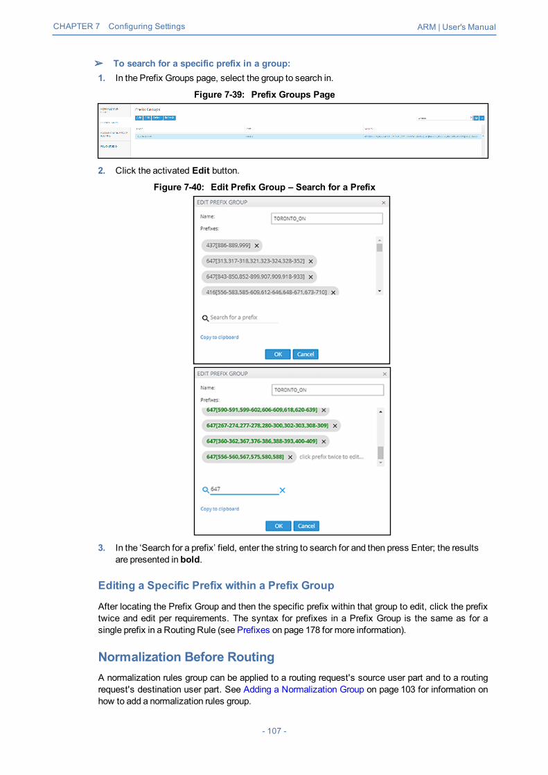
CHAPTER 7 Configuring Settings ARM | User's Manual
➢ To search for a specific prefix in a group:1. In the Prefix Groups page, select the group to search in.
Figure 7-39: Prefix Groups Page
2. Click the activated Edit button.
Figure 7-40: Edit Prefix Group – Search for a Prefix
3. In the ‘Search for a prefix’ field, enter the string to search for and then press Enter; the resultsare presented in bold.
Editing a Specific Prefix within a Prefix Group
After locating the Prefix Group and then the specific prefix within that group to edit, click the prefixtwice and edit per requirements. The syntax for prefixes in a Prefix Group is the same as for asingle prefix in a Routing Rule (see Prefixes on page 178 for more information).
Normalization Before RoutingA normalization rules group can be applied to a routing request's source user part and to a routingrequest's destination user part. See Adding a Normalization Group on page 103 for information onhow to add a normalization rules group.
- 107 -
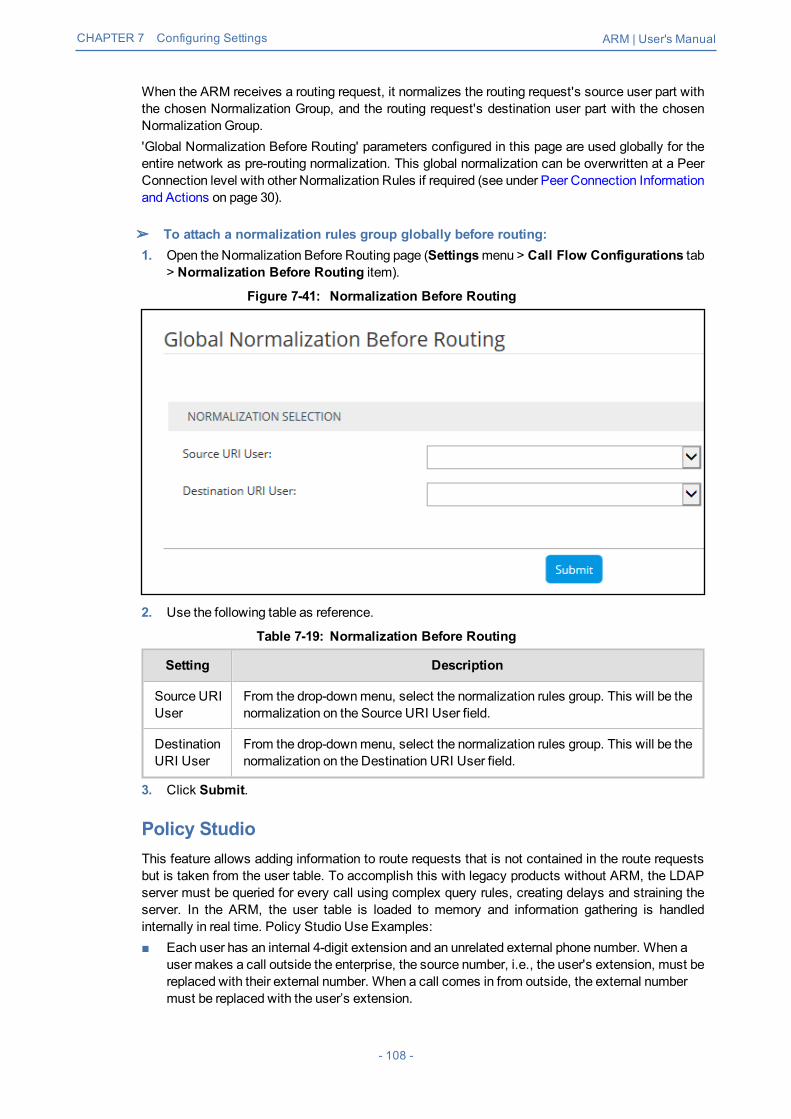
CHAPTER 7 Configuring Settings ARM | User's Manual
When the ARM receives a routing request, it normalizes the routing request's source user part withthe chosen Normalization Group, and the routing request's destination user part with the chosenNormalization Group.'Global Normalization Before Routing' parameters configured in this page are used globally for theentire network as pre-routing normalization. This global normalization can be overwritten at a PeerConnection level with other Normalization Rules if required (see under Peer Connection Informationand Actions on page 30).
➢ To attach a normalization rules group globally before routing:1. Open the Normalization Before Routing page (Settingsmenu > Call Flow Configurations tab
> Normalization Before Routing item).
Figure 7-41: Normalization Before Routing
2. Use the following table as reference.
Table 7-19: Normalization Before Routing
Setting Description
Source URIUser
From the drop-downmenu, select the normalization rules group. This will be thenormalization on the Source URI User field.
DestinationURI User
From the drop-downmenu, select the normalization rules group. This will be thenormalization on the Destination URI User field.
3. Click Submit.
Policy StudioThis feature allows adding information to route requests that is not contained in the route requestsbut is taken from the user table. To accomplish this with legacy products without ARM, the LDAPserver must be queried for every call using complex query rules, creating delays and straining theserver. In the ARM, the user table is loaded to memory and information gathering is handledinternally in real time. Policy Studio Use Examples:■ Each user has an internal 4-digit extension and an unrelated external phone number. When a
user makes a call outside the enterprise, the source number, i.e., the user's extension, must bereplaced with their external number. When a call comes in from outside, the external numbermust be replaced with the user’s extension.
- 108 -

CHAPTER 7 Configuring Settings ARM | User's Manual
■ Same as the previous example but, in addition, there can bemore than one user with the sameextension, and what differentiates them is their hostname. The ARM can locate the user basedon a combination of the extension and hostname attributes.
Policy Studio is a set of rules. Each rule contains a match condition and an action. The matchcondition is a set of route request fields to be compared, and a set of user properties to becompared to. The match condition also has a source node or Peer Connection or set of sourcenodes or Peer Connections. The action is a set of route request or response fields to be replaced,and a set of user fields to replace them with. For every route request received, the ARM processesall the rules from top to bottom. For each, the ARM searches in the users table for a user thatmatches all the fields. If a user is not found, the ARM proceeds to the next rule. If a user is found,the ARM stops parsing the rules and performs the action in this rule. The action is to replace all thelisted fields with the properties of the user, as configured.
➢ To add a Policy Studio rule:1. Open the Policy Studio page (Settingsmenu > Call Flow Configurations tab > Policy
Studio item).
Figure 7-42: Policy Studio
2. Click Add.
Figure 7-43: Add Call Item
3. Configure the settings using the following table as reference.
Table 7-20: Policy Studio Settings
Setting Description
Name Defines the name of the Policy Studio rule to add, to facilitatemanagement of the feature.
User / Number Portability Policy Studio supports two uses:■ User (default). Select this option to use Policy Studio
based on information taken from ARMUsers Data.
- 109 -

CHAPTER 7 Configuring Settings ARM | User's Manual
Setting Description
■ Number Portability. Select this option to implementNumber Portability as a pre-routingWeb service. SeeWeb-based Services on page 112 for more information.
MATCH The set of match conditions for finding a user from the Userstable. Click + to addmore conditions.
Source Nodes / PeerConnections
Select a Node or Peer Connection - or set of Nodes or PeerConnections - for which this rule will be used. If left empty,the rule is used regardless of the origin of the call.
Destination Prefix / Groups [Optionally] Add an additional condition for users’ information-based pre-routing.
Request field Select a route REQUEST field from the following availablefields (this is a field from the route REQUEST that iscompared with the user properties):■ SOURCE_URI_USER■ SOURCE_URI_HOST■ DEST_URI_USER■ DEST_URI_HOST■ CONTACT_URI_USER■ CONTACT_URI_HOST■ CONTACT_URI_HOSTIf a call matches the selected criterion, themanipulativeaction you select will be performed. For a SIP fieldmanipulation example, see Example 2 under Example 2 of aPolicy Studio Rule on the next page.
Action The set of replacement actions that will be performed on theroute request and route response fields for a found user.
Action field Select a route request or route response field from thefollowing available fields (when a user is found, this field willbe replaced with the value of the configured user properties):■ SOURCE_URI_USER■ SOURCE_URI_HOST■ DEST_URI_USER■ DEST_URI_HOST■ DEST_IP_ADDR■ DEST_PORT■ DEST_PROTOCOL [the P-ASSERTED_IDENTITY_
USER will be replaced by company site main numberP-ASSERTED_IDENTITY_DISPLAY_NAME]
■ USER_CREDENTIALS_USER_NAME■ USER_CREDENTIALS_PASSWORDMultiple actions can be defined. Click + to define anotheraction.
- 110 -

CHAPTER 7 Configuring Settings ARM | User's Manual
Setting Description
Note: If either USER_CREDENTIALS_USER_NAME orUSER_CREDENTIALS_PASSWORD is used in an action,youmust add both.For a SIP field manipulation example, see Example 2 underExample 2 of a Policy Studio Rule below.
Request User Property Select a set of user properties. The request field is comparedto these properties of the users. If any of the properties of auser is equal to the value of the field, then this condition isconsidered amatch.
Replacement User Property Select a set of user properties. The action is to replace thevalue in the request or response field with the value of thisuser property. If the found user has no value for this property,then no action is done on this field. If theremore than oneproperty is listed here, then ARM replaces the field with thefirst property if the user has it. If the user does not have it,ARM proceeds to the next property in the list, in theconfigured order.
Example 1 of a Policy Studio Rule
Refer to the defined Policy Studio rule shown in the figure depicting the Call Item Settings screen:■ For every route request, ARM will search for a user whose extension property is equal to the
value of the SOURCE_URI_USER field and whose domain property is equal to theSOURCE_URI_HOST field.
■ ARMwill then replace the SOURCE_URI_USER field with the value of the found user’sexternal phone number property.
Figure 7-44: Policy Studio Rule Example 1
Example 2 of a Policy Studio Rule
The ARM's Policy Studio Rule allows you to manipulate a rule to provide Location BasedEmergency calls routing in a CCE environment with ARM capabilities. Refer to the defined PolicyStudio Rule shown in the following figure.
- 111 -

CHAPTER 7 Configuring Settings ARM | User's Manual
Figure 7-45: Policy Studio Rule Example 2
In the rule above.■ The node sends a route request to the ARM. The request includes the two fields under MATCH
and the values configured for them; if one and/or the other exists and their values are thoseconfigured, then themanipulations configured under ACTION will be used in response to theroute request:● DEST_URI_USER will be replaced by branch emergency number● P-ASSERTED_IDENTITY_USER will be replaced by company site main number● P-ASSERTED_IDENTITY_DISPLAY_NAME will be replaced by empty column
Web-based ServicesThe ARM supports number portability solutions for querying an external source for additional inform-ation about each call. It also provides a general infrastructure for any futureWeb-based service thatcan impact ARM call routing. The prominent example is to query a number portability server thatcontains a database of every phone number in the country, and the actual carrier network that it cur-rently belongs to.
● The feature is invisible in the ARM unless enabled in the License Key.● The feature can conform to any protocol or design using a plug-in which
AudioCodes will provide per the protocol required by the customer.
➢ To configure a Web service:1. Open theWeb Services page (Settings > Call Flow Configurations >Web Services)
Figure 7-46: Web Services
2. Click Add.
- 112 -

CHAPTER 7 Configuring Settings ARM | User's Manual
3. Configure theWeb service you require in the New Implementation screen.
Parameters in the screen are per customer and therefore differ from one customer to thenext. Contact your AudioCodes representative if necessary for clarifications.
4. Click Submit.5. Apply the service: Open the Policy Studio (Settings > Call Flow Configurations > Policy
Studio) and click Add. See also Policy Studio on page 108.
Figure 7-47: Policy Studio - Add Call Item
6. Select number portability as shown in the preceding figure. The default is User to preserve theexisting functionality of Policy Studio.
7. NumberManipulation can be applied to specific conditions (see under MATCH in the precedingfigure):
- 113 -

CHAPTER 7 Configuring Settings ARM | User's Manual
● Source Nodes and/or Peer Connectionsand
● Specific Destination Prefixes or Prefix Groups
Routing Settings
Configuring Criteria for a Quality ProfileYou can configure criteria for a quality profile for bad, fair or good call paths based on the calculationof MOS and ASR. You can configure a specific Peer Connection to exclude either the MOS or theASR criterion (see Peer Connection Information and Actions on page 30). After enabling 'UseQuality Based Routing' (see the following figure), the quality status of Peer Connections andConnections will be displayed in the network map's Quality Layer. The configured quality profilecan be associated with a Routing Rule (see Adding a New Routing Rule on page 133) which will beapplied only if all Peer Connections and Connections in the routemeet the criteria.
The quality of voice on a line is calculated based on the quality of voice measured inmultiple calls over a period. The ARM issues alarm indications for quality change.
➢ To configure a quality based routing condition:1. Open the Advanced Conditions screen (Settings > Routing > Quality Based Routing). By
default, Use Quality Based Routing is selected. If it isn't, select it.
Figure 7-48: Configuring Criteria for a Quality Profile
2. Activate either MOS, ASR or both and then configure criteria by dragging the range indicatorsto the lower and upper limit you require. Use the following table as reference.
- 114 -

CHAPTER 7 Configuring Settings ARM | User's Manual
Table 7-21: Configuring Criteria for a Quality Profile
QualityCondition Description
MOS(MeanOpinionScore)
Specified by ITU-T Recommendation P.800, MOS is the average grade on a qual-ity scale of Good to Failed, given to voice calls made over a VoIP network, aftertesting.MOS-LQ = listening quality, i.e., the quality of audio for listening purposes; itdoesn't take bi-directional effects, such as delay and echo into account. MOS-CQ= conversational quality; it takes listening quality in both directions into account,as well as the bi-directional effects.
ASR(Answer-SeizureRatio)
Measurement of network quality and rate of successful calls. % of answered callsrelative to the total call volume.
3. Click Submit; a quality profile is generated which you can associate with a Routing Rule (seeAdding a New Routing Rule on page 133).
Configuring a Time-Based Routing ConditionThe time-based routing feature allows you to configure a routing rule activated only at the timespecified in a time condition. You can configure a condition and then associate it with a routinggroup or a routing rule, or both (see Adding a New Routing Rule on page 133 under 'AdvancedConditions').
➢ To configure a time-based routing condition:1. Open the Time-Based Routing screen (Settings > Routing > Time Based Routing).
Figure 7-49: Time Based Routing
2. Add a time-based routing condition: Click Add; the TimeCondition screen is displayed.
- 115 -

CHAPTER 7 Configuring Settings ARM | User's Manual
Figure 7-50: Time Condition
- 116 -

CHAPTER 7 Configuring Settings ARM | User's Manual
Figure 7-51: Time Condition - Example
3. Configure a time-based routing condition. Use the following table as reference. See thepreceding figure for an example.
Table 7-22: Time Condition
TimeCondition Description
Daily/Weekly Select either Daily orWeekly.Daily - This is a daily recurring period.Weekly - This is a period recurring on given days of the week.The figure above shows a configured weekly condition. Green 'day' button:activated on that day. Blue 'day' button: selected to configure it.
Name Enter an intuitive name to later easily identify the condition when applying it.
Start time From the drop-downs, select the hour and theminutes past the hour. The timesare configured in UTC (Coordinated Universal Time).
End time From the drop-downs, select the hour and theminutes past the hour
All day Select this option to base the routing condition on the entire day.
- 117 -

CHAPTER 7 Configuring Settings ARM | User's Manual
TimeCondition Description
Enable period Select this option to base the routing condition on a period.
Start ofperiod
From the calendar icon, select the date on which the period will start.From the drop-downs, select the hour and theminutes past the hour.
End of period From the calendar icon, select the date on which the period will end.From the drop-downs, select the hour and theminutes past the hour.
4. Click OK; a profile is generated which you can associate with a Routing Rule (see Adding aNew Routing Rule on page 133 under 'Advanced Conditions'). Also, you can associate theconfigured time condition with a Routing Group. In this case, it will apply to all Routing Rules inthe Group. Note that the same time condition profile can be reusedmultiple times.
Configuring SIP Alternative Route ReasonThe ARM operator can configure SIP responses in the SIP Alternative Route Reason page, whichwill cause the ARM to apply alternative routing paths if available.
If a call fails and the SIP response received from the remote side is not configured in theSIP Alternative Route Reason page, the ARM will not apply an alternative route for thecall.
The page allows operators to change the default ARM behavior for an Alternative Routing decision.
➢ To configure a SIP Alternative Route Reason:1. Open the Alternative Routing SIP Reasons page (Settings > Routing > Alternative Routing
SIP Reasons).
Figure 7-52: Alternative Routing SIP Reasons Page
2. Click theAdd tab.
- 118 -

CHAPTER 7 Configuring Settings ARM | User's Manual
Figure 7-53: Adding an Alternative Routing SIP Reason
3. Enter the SIP Response number (200-600).4. Provide a description of the reason.5. Select theActive option to activate the configuration.6. Click the now-enabledOK button.
➢ To edit a SIP Alternative Route Reason:1. In the Alternative Routing SIP Reasons screen, select the SIP response to edit.
SIP responses are listed in numerical order. You can browse to the next page or to thelast page of responses. You can browse to the page before the page you are on, ifyou're not on the first page, or you can browse to the first page.
2. Click Edit.
Figure 7-54: Editing an Alternative Routing SIP Reason
3. Edit per your requirements and click OK.
By clearing the 'Active' option, the operator can 'deactivate' a SIP reason withoutdeleting its row in the table. If a SIP reason is 'deactivated', the ARM will not apply analternative route. The ARM will function as if there is no row at all. The 'deactivated'row, however, remains in the table, and if the operator re-decides, it can be 'reactivated'by selecting the 'Active' option.
➢ To delete a SIP Alternative Route Reason:1. In the Alternative Routing SIP Reasons screen, select the SIP response to delete.
- 119 -

CHAPTER 7 Configuring Settings ARM | User's Manual
Figure 7-55: Deleting an Alternative Routing SIP Reason
2. Click Delete.
Configuring Global Routing SettingsThe ARM enables global routing settings to be configured.
➢ To configure global routing settings:1. Open the Routing Settings page (Settingsmenu > Routing tab > Routing Settings item).
Figure 7-56: Global Routing Settings
2. Configure the parameters using the following table as reference.
Table 7-23: Routing Settings
Setting Description
Maximumnumber ofRoutingAttempts
Defines themaximum number of routing attempts per call. If themaximumnumber of routing attempts has not yet been reached, the ARM searchesfor an alternative routing possibility for the specific call.
Maximumnumber of routingattempts perPeer Connection
Defines themaximum number of routing attempts per Peer Connection. Ifthemaximum number of routing attempts has not yet been reached, theARM tries to re-route the call to a preferable Peer Connection. Default: 2attempts.
3. Click Submit.
Adding a Routing ServerA Routing Server can be added to the ARM for handling calls coming from SBCs andGateways.
- 120 -

CHAPTER 7 Configuring Settings ARM | User's Manual
● ARM Version 8.4 supports up to 40 Routing Servers - a necessary feature in verylargeARM deployments of almost unlimited scale.
● ARM Version 8.2 and earlier supported up to 10 ARMRouting Servers.● In average size deployments, an ARMRouting Server can be deployed close to
each Node (or small group of Nodes), providing additional Node Survivability. If anetwork disconnection occurs, a Node’s Routing requests are then served by theadjacent, almost co-existing Routing Server.
● If a very high number of Routing Servers is used for survivability purposes, it’srecommended to apply the ‘Sticky primary’ routing policy for a Node (see underNode Information and Actions on page 21 for more information) and to provide theadjacent Routing Server as the priority for handling the Node’s routing requests.
➢ To add a Routing Server to the ARM:1. Open the Routing Servers page (Settings > Routing Servers).
Figure 7-57: Routing Servers
2. Click Add.
Figure 7-58: Server Details
Adding a Routing Server without adding it to a Routing Server Group will have no effectas Routing Servers are as of ARM Version 8.6 not attached directly to nodes (see underAdding a Routing Servers Group with Internal and External Priorities).
3. Configure the routing server using the following table as reference.
- 121 -

CHAPTER 7 Configuring Settings ARM | User's Manual
Table 7-24: Routing Server Details
Setting Description
Name Enter a name for the ARMRouter (routing server).
Address Enter the IP address or host name for the ARMRouter (routing server).
Port [Read only] ARM Router (routing server) port number. Default: 443
Protocol [Read only] HTTPS
Credentials Allows you to specify the credentials which the Configurator will use to com-municate with the router and vice versa.
4. Click OK; the routing server is added.
Editing a Routing ServerAfter a routing server is added to the ARM, its configuration can be edited if necessary.
➢ To edit a Routing Server:1. Open the Routing Servers page (Settings > Routing Servers).
Figure 7-59: Routing Servers
2. Select the row of the routing server to edit, and then click Edit.
Figure 7-60: Edit Server
3. Edit the server using the following table as reference.
- 122 -

CHAPTER 7 Configuring Settings ARM | User's Manual
Table 7-25: Edit Server
Setting Description
Name [Read-only] The name of the ARMRouter (routing server).
Address Enter the IP address or host name for the ARMRouter (routing server).
Port [Read only] ARM Router (routing server) port number. Default: 443.
Protocol [Read only] HTTPS
Nodes [Read only] The Nodes (SBCs or Gateways) to which the router wasadded.
Advanced Configuration
Configurator –Routing Protocol
To display this parameter, click adjacent to Advanced Configuration andthen from the parameter's drop-downmenu, select the protocol betweenthe Configurator and the Router (HTTP or HTTPS). Default: HTTPS.HTTP can temporarily be used for debugging purposes.
Credentials
Configurator >Router
To display this parameter, click adjacent to Credentials. Allows you tospecify the credentials which the Configurator will use to communicatewith the router.
Router >Configurator
To display this parameter, click adjacent to Credentials. Allows you tospecify the credentials which the router will use to communicate with theConfigurator.
Locking/Unlocking a Routing ServerThe ARM allows users to lock routing servers, for troubleshooting or maintenance purposes.Locking a routing server causes the devices to disconnect from the locked routing server, causingall traffic to divert to the other unlocked and available servers. Unlocking a routing server causesthe devices to reconnect, andmakes the routing server fully functional.A locked routing server can also be associated with ARM Nodes without participation in callsrouting. This can be useful during the preparation phase for network setup.
➢ To lock or unlock a Routing Server:1. Open the Routing Servers page (Settings > Routing Servers).
Figure 7-61: Routing Servers - Administrative State
2. Determine from the icon under the 'Administrative State' columnwhether a routing server islocked or unlocked, and then click the Lock / Unlock button.An unlock performs a restart of the RoutingManager software. The action takes a few seconds,during which time the RoutingManager is unavailable due to the restart.A lock action is immediate.
- 123 -

CHAPTER 7 Configuring Settings ARM | User's Manual
These actions can be applied to any particular ARM router. The functionality lets you gracefullytake a router temporarily out of service. A locked router responds to all keep-alive and loginrequests, from all nodes, with a standard 'Service Unavailable' HTML error. This behaviorcauses all nodes to be disconnected from the router, effectively taking the router out of service.The router still responds to any other request from the nodes or the configurator, whichmakesthe lock action graceful since calls, statistical calculations and software upgrades areunaffected.
Adding a Routing Server Group with Internal andExternal PrioritiesThe ARM allows you to add a single group of routing servers. The ARM also allows you to addmul-tiple groups of ARMRouters with a policy between them. This may be necessary when an ARMdeployment is geographically distributed. ARM customers in circumstances like this prefer having(for example) one of the group of the nearest ARM Routers with Round Robin policy and to switchto another group of ARMRouters in case all the nearest ARM Routers fail (or become inac-cessible). Customers can configure an ARMRouting Servers Group with internal policies (within agroup) and external policies (between groups).
➢ To add a Routing Servers Group:1. Open the ‘Routing server groups’ page (Settings > Routing Servers > Groups).
Figure 7-62: Routing Server Groups
2. When prompted, configure the:● Name of the group to be attached to a node or to multiple nodes● Routing Policy to be applied between groups; ‘Sticky primary’ is the default. Two routing
policies between Routing Groups are available:◆ ‘Sticky primary’ [the node reverts to the primary group when at least one ARMRouter
is available]◆ ‘Sticky Last’ [after a node switches to the next Routing Group, it uses its ARM
Routers while at least one of them is available]3. Apply a Routing Policy between the ARMRouters inside the Routing Group (‘Round Robin’ is
the default). Three are available: Round Robin, Sticky Primary and Sticky Last.
Figure 7-63: Routing Policy Options
4. Attach one or more ARMRouting Servers to the Routing Group.
- 124 -

CHAPTER 7 Configuring Settings ARM | User's Manual
Figure 7-64: Attaching Routing Server/s to a Routing Group
5. To use a single group of routers for a node (or nodes) with a policy between them, one list ofselected routing servers is sufficient. When providingmultiple sub-groups of Routing Servers,click +.
The maximum number of routing servers allowed for the entire server group is 10, so ifyou have five sub-groups, each can have up to two routing servers inside).
Figure 7-65: Multiple Sub-Groups of Routing Servers
6. Configure a new sub-group of routers with the sameRouting Policy inside the group.
Figure 7-66: Sub-Group of Routing Server with the Same Routing Policy
- 125 -

CHAPTER 7 Configuring Settings ARM | User's Manual
Up to five sub-groups can be configured under the sameName.
7. After configuring an ARMRouting Servers group, attach it to a single node or to multiple nodes(SBCs or Gateways). To do this, apply anEdit action on the node.
Figure 7-67: Edit Node
8. From the drop-down, select the Routing Server Group (one of the previously configuredgroups).
Figure 7-68: Edit Node – Selecting Routing Server Group
The ARM provides the corresponding configuration (per ARM-level definitions) to each nodeand configures the Routing Servers (per Groups and policies) within the SBC orMediaGateway.
- 126 -

CHAPTER 7 Configuring Settings ARM | User's Manual
● Support for Routing Server Groups is available from node software version7.20A.240. If your deployment includes nodes whose software version is earlierthan 7.20A.240, the ARM provides a backward-compatible way to define routingservers by creating Routing Server Groups with a single sub-group; Routing ServerGroups which havemultiple sub-groups are not shown in the drop-downmenu.
● When upgrading from previous version releases (when Routing Server Groupswere not supported), the ARM upgrade process automatically converts already-configured routers to a Routing Server Group and that group is attached to thenode. For example, if a customer has three nodes (N1, N2 and N3), where N1 andN2 use ARMRouters R1 and R2 (Round Robin) and node N3 uses ARMRoutersR2 and R3 (Sticky Primary), the ARM during the upgrade automatically creates twoRouting Server Groups (N1_group with R1 and R2with Round Robin, and N3_group with R2 and R3with Sticky Primary). The N1_group is automaticallyassigned to nodes N1 and N2. N3_group is automatically assigned to node N3.
- 127 -

CHAPTER 8 Defining Calls Routing ARM | User's Manual
8 Defining Calls RoutingThe ARM lets IT managers, responsible for enterprise VoIP, define call routing. ARM routingprovides a comprehensive call routing solution for a telephony network.
➢ To define calls routing:■ Open the Routing page ('Routing' menu); the page opens under theRouting Groups tab by
default.
Figure 8-1: Routing – Routing Groups
➢ Follow this procedure when defining calls routing policy (ARM Dial Plan):1. Add a new Routing Group (see Adding a Routing Group below)2. Add a new Routing Rule (see Adding a New Routing Rule on page 133)3. Test the route (see Testing a Route on page 47)
Adding a Routing GroupBefore adding a rule, you must add a Routing Group. Routing Groups help present rules in theGUI in an organized fashion, enhancing user experience. Routing Groups also allow you tomove a group of Routing Rules, collectively changing their routing priority.
➢ To add a Routing Group:1. In the Routing page under theRouting Groups tab, click Add Group.
Figure 8-2: Add Group
The AddGroup screen opens.
- 128 -

CHAPTER 8 Defining Calls Routing ARM | User's Manual
Figure 8-3: Add Group
2. Define a name for the Routing Group to be added. Define a user-friendly name to facilitateintuitivemanagement by administrators. Some example of groups you can add are 'RestrictedCalls', 'Calls to Europe', 'Calls to Far East', 'Calls to ROW', etc.
The routing group's name must be distinct from names of other routing group names,andmust be between 1-999 characters.
3. Select the use time conditions option to attach a time condition to the Routing Group. SeeConfiguring a Time-Based Routing Condition on page 115 for related information on how toattach a time condition to a Routing Rule. You can attachmultiple time conditions. Theseconditions will apply to all rules in the group. Note that if you attach a time condition to a group,it's indicated visually in the Routing Groups page as follows:
4. Click OK; the new Routing Group is added to the list.
Routing Groups listed higher take precedence over those lower. Routing Groups in thelist can be reordered (see Moving a Routing Group on the next page). Priority iscalculated internally, based on Previous and Next groups.
Editing a Routing GroupYou can edit a Routing Group if necessary.
➢ To edit a Routing Group:1. In the Routing page under theRouting Groups tab, select the Routing Group to edit, and then
either:a. Click Edit Group
- 129 -

CHAPTER 8 Defining Calls Routing ARM | User's Manual
Figure 8-4: Edit Group
b. [Alternatively] Click the group's edit icon in the row
Figure 8-5: Edit Group
2. Edit the 'Name' field. Enter a user-friendly name to facilitate intuitivemanagement by networkadministrators.
3. Edit the time condition. You can clear the use time conditions option to remove the condition.See Configuring a Time-Based Routing Condition on page 115 for related information. You canalternatively remove a single condition if multiple time conditions are attached.
4. Click OK.
Moving a Routing GroupYou can promote or demote a Routing Group listed in the Routing Groups page. When moving aRouting Group, all its Routing Rules are moved and the routing priority of all the Routing Rules inthe group are collectively changed at once. Routing Groups listed higher in the page takeprecedence over those listed lower.
➢ To move a routing group:1. In the Routing page, under theRouting Groups tab, either drag and drop the Routing Group to
where you want to locate it, or select it and then click the then-enabledMove icon next to it.TheMove Routing Group dialog opens:
- 130 -

CHAPTER 8 Defining Calls Routing ARM | User's Manual
Figure 8-6: Move Routing Group
2. Select Before orAfter, click the Routing Group before which / after which tomove the RoutingGroup you want to promote/demote, and then click OK.Alternatively, you canmove a Routing Group by clicking the icon shown in the following figure,and then dragging it and dropping it in the Routing Groups page.
Figure 8-7: Moving a Routing Group by Dragging and Dropping
- 131 -

CHAPTER 8 Defining Calls Routing ARM | User's Manual
Deleting a Routing GroupYou can delete a Routing Group if necessary, including rules associated with the group.
➢ To delete a Routing Group:1. In the Routing page under theRouting Group icon, select the Routing Group to delete and
then either:a. Click Delete Group:
Figure 8-8: Delete Routing Group
-or-
b. Click theDelete icon in its row which is then enabled. You're prompted to confirm:
2. Click Delete.
- 132 -

CHAPTER 8 Defining Calls Routing ARM | User's Manual
Adding a New Routing RuleAfter adding a Routing Group, add a new Routing Rule to associate with the Group. Each RoutingRule is given a unique priority within the Routing Group. A rule listed higher than another, even if inthe sameRouting Group, takes precedence.
● Routing rules are defined within Routing Groups.✔ To view a specific Routing Group's Routing Rules, click that Group.✔ To view all Routing Rules, click the Routing Rules tab.
● Any modification to the routing configuration (adding, deleting or modifying) takeseffect within 60 seconds after themodification request is answered by theconfigurator and does not affect active calls.
● Any modification to routing logic because of an operational state change to a nodeor Peer Connection takes effect within 60 seconds after the status change isidentified by the configurator.
● Any modification to routing logic because of a node or Peer Connectionadministrative state change takes effect within 60 seconds after the status changeis identified by the configurator.
● Changes in users or user groups take effect within 60 seconds after themodification is identified by the configurator.
Routing Rules include:■ Conditions: [Optional]Define the characteristics of the route request, e.g., the User Group
and phone prefix of the originator/destination.■ Actions: [Mandatory] Define actions performed if the call matches the rule conditions i.e.,
routes the call to the specified destination, or discards it specifying a SIP reason.
Figure 8-9: Example of a Routing Rule
The ARM parses from the top Routing Group listed, to the bottom Routing Group listed, andwithin each Routing Group from the top Routing Rule listed to the bottom Routing Rule listed. Ifit finds a matching rule and if devices and Connections/Peer Connections are available, it sendsthe call to the destination configured for that rule. If it doesn't find a matching rule, it indicates that aroute for the call has not been found.Alternative RoutingThe ARM performs alternative routing as follows:■ The ARM attempts to build an alternative path for the sameRouting Rule action (Node, Peer
Connection, VoIP Peer), if available.■ ARM attempts to build an alternative action (Node, Peer Connection, VoIP Peer), if available,
for this call, in the order that actions are listed in the Routing Rule.■ All routing alternatives are sorted by weighted path, cost and then by number of hops.Load BalancingThe ARM can balance call traffic between multiple destinations of the same Action. Call traffic canbe distributed equally between destinations, or the distribution can be defined by the operator.Multiple routing attempts can be configured. Default: 1. Max: 3. The max can't exceed the numberof destinations in the load balancing action. If a call to a destination configured in a load balancingaction fails, the ARM will try to route it to one of the destinations configured in load balancing beforesearching for a new rule or action for it.
- 133 -

CHAPTER 8 Defining Calls Routing ARM | User's Manual
Discard Call - the ARM can be configured to discard calls matching specific conditions as a singleaction, or as the last action of a rule if previous destinations were unavailable.
➢ To add a new Routing Rule to a Routing Group:1. In the Routing Groups page under theRouting Groups tab, select the Routing Group with
which to associate the rule, and then click Add Rule.
Figure 8-10: Add Rule
This screen opens:
Figure 8-11: Add Routing Rule
- 134 -

CHAPTER 8 Defining Calls Routing ARM | User's Manual
2. Enter a name for the routing rule that is distinct from the names of the other routing rules in thesame group. Define a user-friendly name to facilitate intuitivemanagement by networkadministrators. The name can be between 1-999 characters.
3. Enable Live and/or Test mode. See Testing a Route on page 47.● Live. The rule will be taken into consideration for live calls traffic.● Test. The route will be tested offline without impacting live calls traffic.By default, new routing rules are added with Testmode enabled and Live mode disabled. It ishighly recommended to test the newly added routing rule before enabling it for live calls.The following table shows the combinations that are supported for a Routing Rule:
Table 8-1: Live | Test Mode Combinations
Live | TestCombination Explanation
Live is enabled |Test is enabled
The rule will be considered for both test and live traffic.
Live is enabled |Test is disabled
The rule will be considered only for live traffic. Test mode won't beimpacted. Select this option to simulate rule removal.
Live is disabled| Test is enabled
The rule will only be considered only for test mode. Live traffic won't beimpacted. Select this option to simulate and test a newly added rule.
Live is disabled| Test isdisabled
The rule will not be considered for test nor live traffic. Select this option toprepare a Dial Plan.
4. Configure the settings under 'Source' - use the following table as reference.
Table 8-2: Source Settings
Setting Description
Prefixes/PrefixGroups
Enter a source number prefix, or list of prefixes. You can also enter the nameof a prefix group, or from the drop-down menu select a prefix group or list ofprefix groups.
Hosts Enter a source hostname, or list of hostnames.
User Groups Enter the name of a source user group or list of source user groups, or selectuser groups from the drop-downmenu. See Adding Users Groups to theARM on page 63.
Nodes/PeerConnections
Enter names of source nodes or peer connections, or a list of nodes or peerconnections, or select nodes or peer connections from the drop-downmenu,
or click the icon and visually and easily select the element from theChoose Topology Item screen shown in the figure following this table. Thissetting is mandatory if you want to define a routing rule applicable to specificcall sources rather than (globally) to the entire network.
- 135 -

CHAPTER 8 Defining Calls Routing ARM | User's Manual
Figure 8-12: Choose Topology Item
5. In the Routing Rule Settings screen, click Destination.
- 136 -

CHAPTER 8 Defining Calls Routing ARM | User's Manual
Figure 8-13: Destination
6. Configure the 'Destination' settings using the following table as reference.
Table 8-3: Destination Settings
Setting Description
Prefix/PrefixGroups
Enter a destination number prefix, or list of prefixes. You can also enter thenames of a prefix group or select prefix groups from the drop-downmenu.
Hosts Enter a destination hostname or list of hostnames.
UserGroups
Enter the names of a user group, or list of destination user groups or select usergroups from the drop-downmenu.
7. In the Routing Rule Settings screen, click Advanced Conditions.
- 137 -

CHAPTER 8 Defining Calls Routing ARM | User's Manual
Figure 8-14: Advanced Conditions
8. Under 'Quality Based Routing', select the option include paths with the following quality;the drop-downmenu becomes available. From it, select the quality criteria that you defined asshown in Routing Settings on page 114. Criteria for bad, fair and good quality, based on thecalculation of MOS and ASR, can be defined. This screen lets you associate the criteria youdefined with the Routing Rule.
9. Under 'Time Based Routing', select the option use time conditions; the pane becomesavailable. From the drop-downmenu, select the time on which routing will be based, configuredunderSettings > Routing > Time Based Routing (see Routing Settings on page 114 forinformation about configuring a time range).
● More than one TimeCondition can be associated with the sameRouting Rule.Activation of the Routing Rule is then performed in ‘or’ between TimeConditions.
● A TimeCondition can be attached to a Routing Rule which belongs to a RoutingGroup with an already-associated period; the ARM's calculation of this RoutingRule's activation will then be ‘and’; the rule will be activated during the periodassigned to the Routing Group and the period assigned to the Routing Rule.
- 138 -

CHAPTER 8 Defining Calls Routing ARM | User's Manual
Figure 8-15: Advanced Conditions - Use Time Condition
10. Select Prioritize call when this rule is selected to prioritize emergency calls over regularcalls. The ARM supports emergency call preemption for SBC and gateway calls. If one of thedevices is unavailable to process an emergency call because of lack of resources, a regularcall will be preempted to free up resources so that the emergency call will be established. TheARMmay preempt more than one active call to provide sufficient resources for processing theemergency call. Emergency calls can be identified by thematching rules parameters in theRouting Rule Settings screen.
Figure 8-16: Advanced Conditions – Prioritize call when this rule is selected
- 139 -

CHAPTER 8 Defining Calls Routing ARM | User's Manual
11. Under ‘Advanced Conditions', select aCall Trigger to activate the rule for a specific Invitereason (i.e., alternative routing). By default, all 'Call Trigger' options are selected, so routing bydefault is based on all Call Triggers. At least onemust be selected. The node applies to theARM for a routing decision when it is triggered by another condition – such as a fax call or aBroken RTP connection. You can configure a rule to be triggered for example only for a fax callor for a ‘Refer call’. Call Trigger options are:● 3xx [Re-routes the request if it was triggered because of a SIP 3xx response]● REFER [Re-routes the INVITE if it was triggered because of a REFER request]● Initial [This routing rule is used for regular requests that the device forwards to the
destination]● Broken Connection [If the Node detects a broken RTP connection during the call and the
Broken RTP Connection feature is enabled in Pcon Ip-Profile (IP Profile > BrokenConnectionMode = Reroute), you can use this option as an explicit matchingcharacteristic to route the call to an alternative destination.Note that it's not supported for an incoming call from a third-party Pcon.
● Fax rerouting [This trigger will be used if the Node detects a call as a fax and the faxrecognition feature is enabled on the Peer Connection. To enable the feature, the deviceWeb interface's 'RoutingMode' parameter must be configured toRerouting withoutdelay (IP Profile > ReroutingMode). Make sure this IP Profile is associated with therelevant IP Group. You can use this option as an explicit matching characteristic to routethe call to an alternative fax destination.
Fax call trigger is unsupported for incoming calls from third-party Peer Connection.
12. Each rule is by default relevant in all circumstances because all Call Triggers are selected bydefault, but if you want to provide specific routing, for example, for fax calls only, select it asfollows:
Figure 8-17: Trigger/s Selected
In this case, the initial call is routed according to the generic Routing Rules (followed by the SIPInvite message). When the SBC categorizes this call as a fax call, another request for routing issent to the ARMwith the ‘Fax Rerouting’ trigger. This routing request matches another ARMRouting Rule dedicated for fax rerouting. In this way, you can route fax calls to a ‘Fax-to Mail’server (for example).
13. Under 'RuleMatch' , select Notify when activated to enable a notification on a call (forexample, a 911 emergency call) if the call matches a specific rule.
Figure 8-18: Rule Match: Notify when activated
When the ARM receives a call matching this rule condition, a notification (event) with relatedinformation is issued by the ARMConfigurator. At the ARM level, the event can be sent to anSNMP target. With the ARM integrated into the OVOC, the call notification can trigger theissuance of an email by the OVOC, for example:
***** Event Info *****Alarm Name: General Alarm
- 140 -

CHAPTER 8 Defining Calls Routing ARM | User's Manual
Date & Time: 09:24:16 AM September 6, 2018Source: Router#172.17.113.23Source Description:Severity: infoUnique ID: 67Alarm Type: otherAlarm Probable Cause: otherDescription: Routing Rule 911 was matchedAdditional Info 1:Additional Info 2: Routing Rule "911" of Group "911" ismatched.Call from Pcon "Pcon Pcon-1" , Node "Node 16161104" - Fromnumber "+12345", To number "911".Additional Info 3:***** ARM Info *****ARM IP Address 172.17.113.23
Notifications are typically required and used for 911 emergency calls, which should typically bereported via an email application or another notification application. The notification engine,however, can be used for any other matching rule.
14. Under ‘Advanced Conditions' in the 'Privacy' section of the Edit Routing Rule screen, you canconfigure Calling Number Privacy. The ARM supports calling number privacy with differentflavors (Privacy policy). The policy is applied per Routing Rule.
Figure 8-19: Edit Routing Rule - Privacy policy
If a call matches the rule, the Privacy Policy is applied. Based on the Privacy Policy of thematching rule, the ARM instructs the SBC or Gateway how to handle calling number privacy interms of SIP headers. Privacy Policy options are:
Table 8-4: Privacy Policy Options
ARM Value SBC Value Comment
Transparent [0] Transparent Default. Leave as is.
Transparent withPrivacy ID
[1] Don't changeprivacy
■ Regular call = regular call (as is)■ Anonymous = Anonymous +
Normalization of URI
Anonymous caller [2] Restrict Turn the call into anonymous
Identify caller [3] Remove Restriction ■ If a regular call, stay as is■ If anonymous, make it exposed in
the SIP ‘From’ header
15. 15. [Optional] You can route calls based on any SIP Invite header value as a Routing Rulematching criterion, for example, based on specific SDP information or on a TGRP value; anyinformation present in the SIP Invite can be used as a condition in the ARMRouting Rule. Thefeaturemust be configured at both ARM and SBC level.
16. SIP Headers● Configure the ‘name’ field, i.e., the SIP header name
- 141 -

CHAPTER 8 Defining Calls Routing ARM | User's Manual
● Configure the ‘value’ field, i.e., one or more possible values for rule match. Thematchwithin the same SIP header name is handled as OR and between the headers as AND. Inthe following ARM rule, thematch is detected when the ARM gets X-ARM-DETAIL-Xheaders which include: (“tgrp=100” OR “tgrp=200”) AND (“coder=711” OR “coder=729”).
When the SBC gets a new call (SIP Invite), it sends a REST routing request toward the ARM.This routing request includes parsed SIP information, for example, X-Header. In this way, usingSBC-level manipulation, the X-Header can include any information operators want to pass tothe ARM (for further routing decisions). This is the pre-agreed way to pass any SIP headerinformation.After applying SBC-level manipulation, the operator can configure ARM-level Routing Ruleswith a condition related to the required attributes and value (pre-installed using SBC-levelmanipulation).The ARM is aware of the information followed by the preconfigured ‘X-ARM-DETAIL-N’ headerand ready to use it for routing.
17. [SBC-Level Configuration] To send a parsed information request, add a new header with name“X-ARM-DETAIL-1”, “X-ARM-DETAIL-2”… “X-ARM-DETAIL-N” and with information insidetaken from the SDP or any other SIP header. X-ARM-DETAIL-X format is “X-ARM-DETAIL-1:<name=value>”For example:● X-ARM-DETAIL-1: “tgrp=100”● X-ARM-DETAIL-2: “coder=711”To create a new header in the SBC, add a new ‘Call Setup Rules Set ID’ in ‘IPGroup’ or in ‘SIPInterface’ in the device’s Web interface. The figure below shows ‘IPGroup’.
Figure 8-20: [Web Interface] Call Setup Rules Set ID
Setup rules can then be associated with the same Set ID. In the following figure, themanipulation added is ‘tgrp=100’. In general, you can use a condition with RegEx and take theattributes into the Action Value.
- 142 -
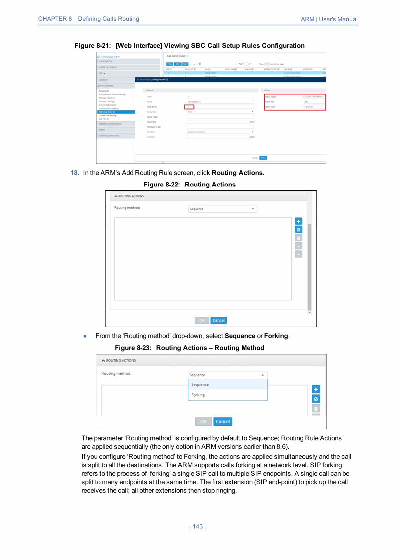
CHAPTER 8 Defining Calls Routing ARM | User's Manual
Figure 8-21: [Web Interface] Viewing SBC Call Setup Rules Configuration
18. In the ARM’s Add Routing Rule screen, click Routing Actions.
Figure 8-22: Routing Actions
● From the ‘Routingmethod’ drop-down, select Sequence or Forking.
Figure 8-23: Routing Actions – Routing Method
The parameter ‘Routingmethod’ is configured by default to Sequence; Routing Rule Actionsare applied sequentially (the only option in ARM versions earlier than 8.6).If you configure ‘Routingmethod’ to Forking, the actions are applied simultaneously and the callis split to all the destinations. The ARM supports calls forking at a network level. SIP forkingrefers to the process of ‘forking’ a single SIP call to multiple SIP endpoints. A single call can besplit to many endpoints at the same time. The first extension (SIP end-point) to pick up the callreceives the call; all other extensions then stop ringing.
- 143 -

CHAPTER 8 Defining Calls Routing ARM | User's Manual
Forking implementation in the ARM is designed to split specific calls (matching preconfiguredcondition) between several network-wide destinations (Peer Connections, VoIP Peers ornodes). Forking is integrated into ARMRouting Rules logic. Forking is applied if a call matchesthe Routing Rule condition.Forking implementation in ARM utilizes SBC forking capabilities. When a call matches an ARMrouting rule condition with forking, the ARM instructs the SBC to perform forking per the actionsconfigured in ARMRouting Rule.
Figure 8-24: Calls Forking – Routing method
The ARM supports up to three forking legs (different actions). If one or more of the actions withForking Routingmethods includes load balancing betweenmultiple destinations, the loadbalancing (with configured percentages) will be applied to choose the correct destination of theforking leg.
Figure 8-25: Calls Forking Routing Rule
During the upgrade to ARM version 8.6, all Routing Rules are translated with the Sequenceroutingmethod (the default).
● In ARM version 8.6, forking capabilities can only be applied to SBCs. MediaGateways aren’t supported.
● Forking in the ARM is supported on SBC software 7.20.252GA or later (releasepending). For earlier SBC versions, Forking functions like ‘Sequence’.
19. In themain pane under ‘Routing Actions’ (Add Routing Rule screen > AdvancedConditions), select an action or set of actions to be taken if the Routing Rulematches; clickthe + icon (recommended). [Alternatively, select an action from the drop-downmenu]. The'Choose Topology Item' screen opens.
- 144 -
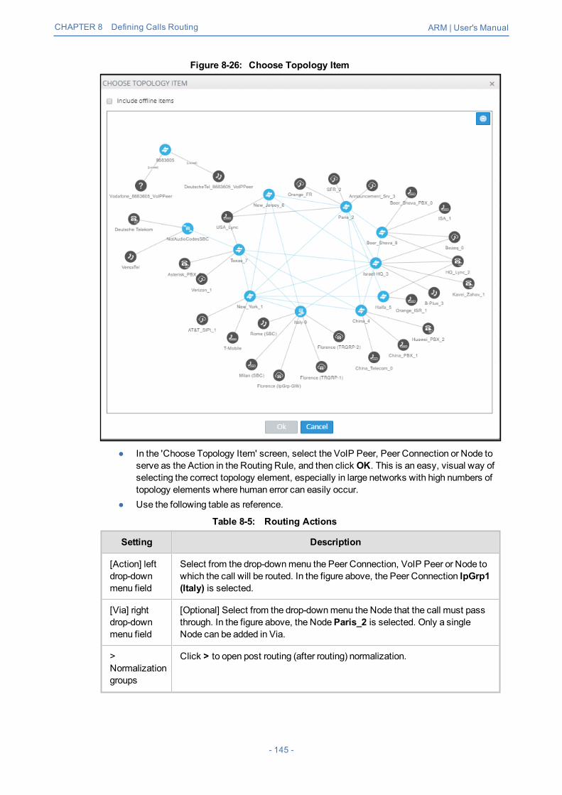
CHAPTER 8 Defining Calls Routing ARM | User's Manual
Figure 8-26: Choose Topology Item
● In the 'Choose Topology Item' screen, select the VoIP Peer, Peer Connection or Node toserve as the Action in the Routing Rule, and then click OK. This is an easy, visual way ofselecting the correct topology element, especially in large networks with high numbers oftopology elements where human error can easily occur.
● Use the following table as reference.
Table 8-5: Routing Actions
Setting Description
[Action] leftdrop-downmenu field
Select from the drop-downmenu the Peer Connection, VoIP Peer or Node towhich the call will be routed. In the figure above, the Peer Connection IpGrp1(Italy) is selected.
[Via] rightdrop-downmenu field
[Optional] Select from the drop-downmenu the Node that the call must passthrough. In the figure above, the NodeParis_2 is selected. Only a singleNode can be added in Via.
>Normalizationgroups
Click > to open post routing (after routing) normalization.
- 145 -

CHAPTER 8 Defining Calls Routing ARM | User's Manual
Setting Description
Sourcenormalizationgroup
Select a normalization group (see Adding a Normalization Group on page 103)to manipulate the source number in the outgoing call to the peer connection.The source normalization group can only be connected to an IP Group or VoIPPeer. It cannot be connected to a Node.
Destinationnormalizationgroup
Select a normalization group (see Adding a Normalization Group on page 103)to manipulate the destination number in the outgoing call to the peerconnection. The destination normalization group can only be connected to anIP Group or VoIP Peer. It cannot be connected to a Node.
20. Click Add loading balancing.
Figure 8-27: Routing Actions – Load Balancing - Equally Balanced (Default)
Load balancing is added betweenmore than one Peer Connection, Node or VoIP Peer. Bydefault, these are equally balanced, i.e., the same percentage is assigned for each option, asshown in the figure above.You can optionally define your own percentage by clearing the 'Equally Balance' option. Anydistribution can be chosen, i.e., any percentage of calls can be handled by a specific routingoption. Several routing destinations (more than two) are supported using the Add load balancingbutton shown in the figure ‘Routing Actions’ following.
21. Enter the percentage of routes that will take this action when load balancing is configured andEqually Balance is cleared. Make sure you have 100% in the Action's calls destinationssummary else you won't be allowed to enable the action.
- 146 -
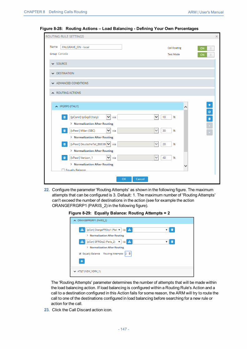
CHAPTER 8 Defining Calls Routing ARM | User's Manual
Figure 8-28: Routing Actions – Load Balancing - Defining Your Own Percentages
22. Configure the parameter 'Routing Attempts' as shown in the following figure. Themaximumattempts that can be configured is 3. Default: 1. Themaximum number of 'Routing Attempts'can't exceed the number of destinations in the action (see for example the actionORANGEFRGRP1 (PARIS_2) in the following figure).
Figure 8-29: Equally Balance: Routing Attempts = 2
The 'Routing Attempts' parameter determines the number of attempts that will bemade withinthe load balancing action. If load balancing is configured within a Routing Rule's Action and acall to a destination configured in this Action fails for some reason, the ARMwill try to route thecall to one of the destinations configured in load balancing before searching for a new rule oraction for the call.
23. Click the Call Discard action icon.
- 147 -

CHAPTER 8 Defining Calls Routing ARM | User's Manual
Figure 8-30: Routing Actions – Call Discard
24. Configure using the following table as reference
Table 8-6: Routing Actions – Call Discard
Setting Description
DiscardAction
In a routing rule, you can apply a policy to attempt multiple routing options and todiscard the call if none succeed. TheDiscard call routing action can be used - inaddition to other routing actions of the same rule - as a last routing rule action or as asole action. You can provide a specific SIP reason for 'Discard Call' as well as usethe last SIP reason received from the SBC or the Gateway.
SIPReason
Enter the SIP reason to be returned to the source peer connection when rejecting thecall. Must be a valid SIP reason.
If any field is left empty (Prefix Group/Host/User Group/Nodes/Peer Connections), therule will not check it.
Moving a Routing RuleYou can move a rule within the group under which it is defined, or you can move it to another group,above or below a rule defined within that group.
➢ To move a rule:1. Click the Routing Group under which the rule is defined and then
● Drag and drop the rule to the Routing Group you want to move it to -OR-● Select the rule to move and then click the now-enabledMove icon; theMove Routing Rule
dialog is displayed.
Figure 8-31: Move icon
- 148 -

CHAPTER 8 Defining Calls Routing ARM | User's Manual
Figure 8-32: Move Routing Rule
2. From the 'Group' drop-downmenu, select the group to which tomove the rule.3. Select eitherBefore (default) orAfter and then select the rule before which or after which you
want to move the rule.4. Click OK; the rule is moved to the location you defined.
Deleting a RuleYou can delete a rule if necessary.
➢ To delete a rule:1. Click the group under which the rule is defined and then adjacent to the defined rule that you
want to delete, click the now-enabledDelete icon shown in the following figure –OR- click thenow enabledDelete Route button also shown in the following figure.
Figure 8-33: Delete Icon
2. In the Confirmation prompt 'Are you sure you want to delete this rule?' shown in the followingfigure, click Delete.
- 149 -

CHAPTER 8 Defining Calls Routing ARM | User's Manual
Figure 8-34: Delete Icon
The rule is deleted.
Testing a RouteYou can test a route to make sure it performs according to expectations. See Testing a Route onpage 47 for more information.
Using the Routing Rules Table View PageSome network administrators prefer to manage routing rules in the Routing Rules table view page.The page offers a significant advantage: Administrators can select multiple rules and perform amultiple-action on the selection.
➢ To open the page:1. In the Routing page, click theRouting Rulesmenu.
Figure 8-35: Routing Rules Table View Page
2. Select a rule or select multiple rules; the actions buttons are activated. Administrators can:● Edit a rule● Delete rules● Lock / Unlock rules● Duplicate a rule (allows administrators to conveniently and easily add a rule based on an
already defined rule)● Move rules
3. In the 'Search' field, enter a search string. The functionality allows administrators to search inall the defined rules, not just in a Rules Group.
- 150 -

CHAPTER 9 Viewing CDRs and Call Details ARM | User's Manual
9 Viewing CDRs and Call DetailsThe ARM features the capability to store calls information and call-detail records (CDRs). Theapplication displays ARM-routed calls information in the Calls List page. The page helps operatorsdebug call routing. The page displays routing information collected and correlated from multiplerouters. Information displayed includes unsuccessful routing attempts, number manipulationinformation, call routing paths, SIP reason, call session ID, etc. The page helps operators betterunderstand andmonitor call routing in their network.
➢ To view CDRs and Call Details:1. Click the Calls menu to open the Calls List page.
Figure 9-1: Calls List
Each row in the page represents an ARM-routed end-to-end call which can pass multiple nodes(SBCs or Gateways) andmultiple Connections and Peer Connections. Information on a call iscollected by the ARMConfigurator from ARMRouters, and then correlated to display a singlecall record.During call processing, each ARMRouter periodically sends a bulk of call information (CDRs)to the Configurator for processing. The received CDRs are processed and transformed /correlated into a single call record for each ARM end-to-end call. These records are stored in theARMConfigurator’s database (MongoDB).The page displays:● Filters on the left side of the page, used to facilitate searching for calls and to exclude
unwanted calls from the Calls List● Calls List to the right of the filters, with a predefined call digest (information)
2. Use the following table as reference when using filters:
Table 9-1: Filter Descriptions
Filter Description
Source Enables filtering the Calls List per URI beforemanipulation.
Destination Enables filtering the Calls List per URI beforemanipulation.
Session ID Enables filtering the Calls List per Unique Session ID identifying a specific call.
- 151 -

CHAPTER 9 Viewing CDRs and Call Details ARM | User's Manual
Filter Description
IncomingNode
Enables filtering the Calls List per the node from where a call was initiated;selected from the drop-downmenu.
IncomingPeerConnection
Enables filtering the Calls List per the Peer Connection from where the call wasinitiated; selected from the drop-downmenu. If an incoming node is selected, theincoming Peer Connection option in the filter will include only relevant PeerConnections, associated with the selected node.
OutgoingNode
Enables filtering the Calls List per the node from where the call exited the ARMnetwork (terminated); selected from the drop-downmenu.
OutgoingPeerConnection
From the drop-downmenu select an Outgoing Node; the Outgoing PeerConnection option in the filter will include only relevant Peer Connectionsassociated with the selected node.
Routingrule
Enables filtering the Calls List per the name of the Routing Rulematching thecall and used for its routing; selected from drop-downmenu and organized perthe Routing Groups.
SIP reason Enables filtering the Calls List per the SIP reason for why the call wasterminated.
Date range Enables filtering the Calls List per a range of dates specified.
If you enter a name in a drop-down (e.g., routing rule or incoming node), options are autopopulated.You can remove a filter by clicking x.
Figure 9-2: Calls List Filters
The following columns (call digest) is shown for CDRs / Calls in the Calls List:● Source● Destination● Date● Incoming node● Incoming Peer connection● Outgoing node● Outgoing Peer Connection● Routing rule● SIP reason
- 152 -

CHAPTER 9 Viewing CDRs and Call Details ARM | User's Manual
● Session ID
Figure 9-3: Call Columns in the Calls List
Call DetailsThe details of a specific call can be viewed. In the Calls List page, filter the list and then double-click a specific call for the Call Details page to open.
Figure 9-4: Call Details
The page displays detailed information on most routing aspects of the call and shows each routingpath the ARM attempted.The Call Summary pane displays the following routing information about the call:
Figure 9-5: ‘Call Summary’ Pane
The Paths pane displays the list of paths the ARM attempted when routing the call.
Figure 9-6: ‘Paths’ Pane
Select a path (routing attempt) to view detailed information about that path. After selecting a path,it’s highlighted in the ARM Topology map. The Path Summary pane (shown below) changes per theselected path.
- 153 -

CHAPTER 9 Viewing CDRs and Call Details ARM | User's Manual
Figure 9-7: ‘Path Summary’ PaneUse the table as reference to the Path Summary.
Table 9-2: Path Summary
Setting Description
Status Displays whether the path was Success or Failure.
Start time Displays the ARM setup time.
Duration Displays the call duration; non-zero if ‘Status’ is Success.
Router IP Displays the IP of the Router which handled the initial Routing request.
Routing rule Displays the call matching Routing rule used by the ARM to apply aspecific routing path.
Source URI aftermanipulation
Displays the Source URI after manipulation.
Destination URIaftermanipulation
Displays the Destination URI after manipulation.
Terminationreason
Displays the reason why the specific path was terminated.
SIP reason Displays the specific path’s SIP termination reason.
If Source or Destination URI manipulation was applied for a specific path, the manipulationinformation will be accessible from the displayedMore option. The pane’s More option allows youto review the details of the appliedmanipulation rules.
Figure 9-8: ‘More’ Pane Displaying Details of Applied Manipulation Rules
This figure shows the path of a call’s routing attempt whose status was Failure:
- 154 -
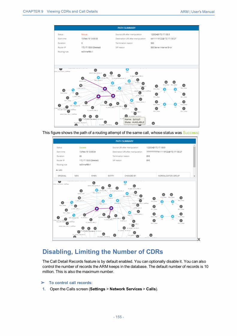
CHAPTER 9 Viewing CDRs and Call Details ARM | User's Manual
This figure shows the path of a routing attempt of the same call, whose status was Success:
X
Disabling, Limiting the Number of CDRsThe Call Detail Records feature is by default enabled. You can optionally disable it. You can alsocontrol the number of records the ARM keeps in the database. The default number of records is 10million. This is also themaximum number.
➢ To control call records:1. Open the Calls screen (Settings > Network Services > Calls).
- 155 -

CHAPTER 9 Viewing CDRs and Call Details ARM | User's Manual
Figure 9-9: Calls
2. Use the following table as reference.
Table 9-3: Calls
Setting Description
Enable CDRCalls
Optionally disable CDRs by clearing the selection. By default, theparameter is selected (enabled). If you’re runningmore than 150 CAPStraffic, it’s recommended to disable CDRs.
Keep raw CDRsfor calls withpartial data
If selected, the ARM saves all CDRs processed to create ‘end-to-endcalls’ for calls terminated before all information about them was received.This parameter impacts database size so the default is unselected; you’llnot be able to save 10million calls. Enable the parameter for debuggingpurposes only.
Keep raw CDRsfor calls with fulldata
If selected, the ARM saves all CDRs processed to create ‘end-to-endcalls’ for calls terminated successfully. This parameter impacts databasesize so the default is unselected; you’ll not be able to save 10million calls.Enable the parameter for debugging purposes only.
Limit number ofCDR calls to
Enter the number of CDRs to limit the ARM to. If you’re runningmore than150 CAPS traffic, it’s recommended to disable CDRs.
Calls cleanupfrequency
Determines how often the ARM checks the size / number of calls. Default:Every 10minutes. The parameter depends on the number of CAPs. Afterchanging the parameter, restart the ARMConfigurator.
- 156 -

CHAPTER 10 Viewing Alarms ARM | User's Manual
10 Viewing AlarmsThe Alarms page shown in the figures below displays alarms generated in the enterprise's networktopology, e.g., SBC disconnected. In the page, you can view alarms information displayed undertwo tabs:■ Active Alarms (default)■ History Alarms
Active Alarms | History AlarmsThe Active Alarms and the History Alarms pages under the Alarms menu display these columnheaders:■ SEVERITY■ DATE AND TIME■ NAME■ ALARM SOURCE■ DESCRIPTION
Figure 10-1: Alarms – Active Alarms + Alarm Summary
Figure 10-2: Alarms – History Alarms
Click any alarm listed on any page; that alarm's ALARM SUMMARY pane, shown in the precedingfigure, displays the column information as well as:■ ALARM TYPE■ PROBABLE CAUSE■ ADDITIONAL INFO1■ ADDITIONAL INFO2■ ACKNOWLEDGEDIn the Active Alarms and History Alarms pages you can:■ Sort alarms, according to column header■ Use the 'Search' feature to locate specific alarms (see Locating a Specific Alarm on page 159
below).■ Refresh the page / Stop Auto Refresh
- 157 -

CHAPTER 10 Viewing Alarms ARM | User's Manual
■ Acknowledge Alarm [Applies only to the Active Alarms page] Click the button to clear aselected alarm from the page. Note that after acknowledging it, the alarm can be still viewed inthe History Alarms page.
Journal PageThe Journal page allows you to view historical actions and activities performed in the ARM by alloperators, up to the present time.The page can help you determine if another operator's action or activity may have changed networkfunctionality and been responsible for an active alarm.
Figure 10-3: Journal Page
The page helps you 'debug' a routing issue that may occur in the network. Each row chronologicallyindicates an operator action | activity. Selecting a row displays the details of that action | activity ina Journal Summary pane located on the right side of the page.
Collecting Info via SNMP to Enhance IP NetworkTelephony PerformanceThis feature provides enterprise network administrators the option to collect information on devicesvia Operations Support Systems (OSS) traps sent over Simple Network Management Protocol(SNMP). Network administrators can then modify that information to enhance telephony networkperformance.
➢ To collect information via SNMP:1. In the Alarms page, click theSNMP Destinations tab and then click Add.
Figure 10-4: SNMP Destination Details
- 158 -

CHAPTER 10 Viewing Alarms ARM | User's Manual
2. Use the following table as reference.
Table 10-1: SNMP Destination Details
Setting Description
Host Enter the IP address of the OSS host.
Port Enter the number of the port to which to sendOSS traps.
Community SNMP Community String. Sent with eachGet-Request as a type of passwordto allow or deny access.
Locating a Specific AlarmThe search feature helps administrators quickly and easily locate specific alarms. This facilitateseffectivemanagement which in turn leads to improved network performance.
➢ To search for a specific alarm:1. Enter a search string in the search field shown in the following figure. To perform an advanced
search, click the drop-downmenu arrow; the figure shown after the next figure is displayed.
Figure 10-5: Search Field
- 159 -

CHAPTER 10 Viewing Alarms ARM | User's Manual
Figure 10-6: Searching for a Specific Alarm
2. Enter any information about the alarm you know. Youmust enter information in at least onefield.● The 'Name' field is identical to the simple search string field.● From the 'Severity' drop-downmenu, select Clear, Indeterminate, Warning, Minor, Major
or Critical. All alarms whose severity level match your selection will be displayed.● For the alarm 'Source', enter the node name or the Peer Connection name, if you know it.
All alarms originating from that source will be displayed.● In the 'Description' field, enter a key word used to describe the alarm.● Select eitherBetween Times, Last 24 hours, Last week or Last 30 days. All alarms
whose timestampmatches your selection will be displayed.3. Click Search.
- 160 -

CHAPTER 11 Migrating Device Routing to the ARM ARM | User's Manual
11 Migrating Device Routing to the ARMExisting device routing can bemigrated to the ARM.
● Familiarity is assumedwith the AudioCodes device whose routing is to bemigratedto the ARM. See Related Documentation for references to AudioCodes' devicedocumentation.
● The screenshots shown here are of Web interface version 7.2. If you're usingWebinterface version 7.0 or earlier, refer to earlier versions of this document.
AudioCodes Device Application TypesBefore migrating device routing to the ARM, it's best to first get acquainted with the routing logic ofAudioCodes' device application types. The routing logic of the three AudioCodes device applicationtypes are described:■ SBC device application■ Gateway device application■ Hybrid device running both aGetaway application and an SBC application
ARM Network Routing LogicAudioCodes device's routing logic is centralized in its local routing table independently of the ARM.The SBC's routing logic is centralized in the IP-to-IP Routing Table. The Gateway's routing logic iscentralized in the Tel-to-IP and IP-to-Tel routing table.To integrate a device into the ARM network, the routing logic must bemigrated to the ARM so that:■ All calls will be routed by the ARM.■ If a device disconnects from the ARM, calls will bemanaged by the device's internal routing
table.■ If the ARM cannot find any route that matches a specific call, the call will bemanaged by the
device's internal routing table.■ If the device fails to establish a call according to the ARM's routing directive (for example, a
SIP error is received), the call will be discontinued.
SBC Routing LogicAudioCodes' SBC routes and handles IP-to-IP calls. The SBC routing logic is centralized in the IP-to-IP Routing Table. For the ARM to route calls, you must configure a related routing rule in theSBC's internal IP-to-IP Routing Table as described in Migrating SBC Routing to the ARM onpage 166.
Gateway Routing LogicAudioCodes' Media Gateway routes and handles IP-to-Tel, Tel-to-IP and Tel-to-Tel calls using aninternal loopback IP Group.Gateway routing logic is configured in the device's internal IP-to-Tel and Tel-to-IP tables. Tomigrate the gateway application's routing logic to the ARM network, you must set the routingparameter 'Gateway Routing Server' to Enable. When this configuration is applied in the gateway,all its routing goes through the ARM and internal routing configuration is ignored.
- 161 -

CHAPTER 11 Migrating Device Routing to the ARM ARM | User's Manual
Hybrid Device Routing LogicThe ARM routes calls from the hybrid device's PSTN (gateway application) to IP (SBC application)or vice versa.Calls cannot be routed from an IP Group (PCon in ARM) associated with a gateway application, toan IP Group associated with an SBC application on the same hybrid device.To support a hybrid device, two internal IP Groups must be configured:■ From the SBC application to theMedia Gateway application■ From theMedia Gateway application to the SBC applicationThe ARM GUI does not display these two internal IP Groups. Routing is performed per the logicdescribed under SBC Routing Logic on the previous page and Gateway Routing Logic on theprevious page, respectively.See Migrating Hybrid Routing to the ARM on page 171 for information about how to migrate hybriddevice routing to the ARM.
Connecting the Device to the ARM Topology ServerYou need to connect the device to the ARM Topology Server.
AudioCodes recommends starting a migration by manually adding a device in the ARMNetwork page as shown in Adding an AudioCodes Node to the ARM on page 40.
For auto-discovery provisioning, take the steps below to connect the device to the ARM network.
➢ To connect the device:1. In your internet browser, enter the device's IP address in the Address bar, and then in the login
page that opens, enter the User Name and Password (Admin, Admin are the defaults).2. In the device's Web interface that opens, check theSetup menu and then navigate to the
HTTP Remote Services page (IP Network >Web Services > Remote Web Services).
Figure 11-1: Services
3. Click +New or click here to add new row.
- 162 -

CHAPTER 11 Migrating Device Routing to the ARM ARM | User's Manual
Figure 11-2: Web Interface - HTTP Remote Services – Add Row
4. Configure the dialog using the figure above as reference, and click Apply.
Figure 11-3: Web Interface - Remote Web Services – HTTP Remote Hosts
5. Click theHTTP Remote Hosts link shown in the figure above.6. In the HTTP Remote Hosts page that opens, click theAdd tab.
Figure 11-4: Web Interface - Remote Web Services - HTTP Remote Hosts - Add
- 163 -

CHAPTER 11 Migrating Device Routing to the ARM ARM | User's Manual
7. Define the IP Address of the ARM Topology Server to which you want to point the device anddefine the ARM Topology Server settings, and then click Save; wait until connected.
Figure 11-5: Web Interface – Device Connected to ARM Topology Server
8. Make sure in the RemoteWeb Services – HTTP Remote Hosts screen shown in the figureabove that the status of the host, i.e., of the ARM Topology Server, is Connected.
9. Connect to the router/s.
Figure 11-6: Web Interface – Remote Web Services - Routers
10. Make sure that the device is connected to all HTTP ARM services i.e., ARM Topology Serverand router/s, as shown in the figure above.
Defining an IP Interface Dedicated to ARM TrafficARM version 7.8 and nodes (SBC or Gateway) version 7.20A.154.044 and later support thecapability to define on AudioCodes devices additional IP interfaces for management on anyapplication type (Media and/or Control, not OAMP) and different TLS contexts for each IP interface.Defining a dedicated IP interface on the device for ARM traffic allows keeping ARM traffic internal,if required, separating ARM traffic from other device management traffic such as Web, SNMP andNTP.When defining ARM on the node, you must assign an IP interface to the remote host (ARM) and aTLS context for the HTTP Service. The ARM automatically adds its routers to all nodes. When theARM does this, it uses the same IP interface and TLS context that you defined for the ARMConfigurator HTTP Service. If either the IP interface or the TLS context of the ARM Configuratorwill be changed, the ARMwill synchronize the new values to the ARM routers.
- 164 -
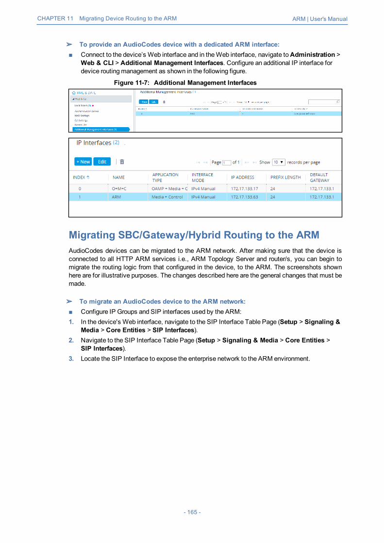
CHAPTER 11 Migrating Device Routing to the ARM ARM | User's Manual
➢ To provide an AudioCodes device with a dedicated ARM interface:■ Connect to the device’s Web interface and in theWeb interface, navigate toAdministration >
Web & CLI > Additional Management Interfaces. Configure an additional IP interface fordevice routingmanagement as shown in the following figure.
Figure 11-7: Additional Management Interfaces
Migrating SBC/Gateway/Hybrid Routing to the ARMAudioCodes devices can be migrated to the ARM network. After making sure that the device isconnected to all HTTP ARM services i.e., ARM Topology Server and router/s, you can begin tomigrate the routing logic from that configured in the device, to the ARM. The screenshots shownhere are for illustrative purposes. The changes described here are the general changes that must bemade.
➢ To migrate an AudioCodes device to the ARM network:■ Configure IP Groups and SIP interfaces used by the ARM:1. In the device's Web interface, navigate to the SIP Interface Table Page (Setup > Signaling &
Media > Core Entities > SIP Interfaces).2. Navigate to the SIP Interface Table Page (Setup > Signaling & Media > Core Entities >
SIP Interfaces).3. Locate the SIP Interface to expose the enterprise network to the ARM environment.
- 165 -

CHAPTER 11 Migrating Device Routing to the ARM ARM | User's Manual
Figure 11-8: Web Interface – SIP Interfaces
Figure 11-9: Web Interface – SIP Interfaces Table - Configuring a SIP Interface
4. Set the 'Used by Routing Server' parameter toUsed.5. Click Save.
Migrating SBC Routing to the ARMSBC routing can be migrated to the ARM network. After making sure the SBC is connected to allHTTP ARM services i.e., ARM Topology Server and router/s, you can begin to migrate the routinglogic from that configured in the SBC, to the ARM. The screenshots shown here are for illustrativepurposes only.
● See also Checklist for Migrating SBC Routing to the ARM on page 175.● 'IP Group' and 'Trunk Group' in theWeb are called 'Peer Connection' in the ARM.
➢ To migrate routing logic to the ARM:1. In theWeb interface, navigate to the IP Groups page (Setup > Signaling & Media > Core
Entities > IP Groups).2. Locate the IP Group to expose the enterprise network to the ARM environment. Make sure the
SIP interface associated with this IP Group is configured as ‘used by routing server'. SeeMigrating SBC/Gateway/Hybrid Routing to the ARM on the previous page.
- 166 -
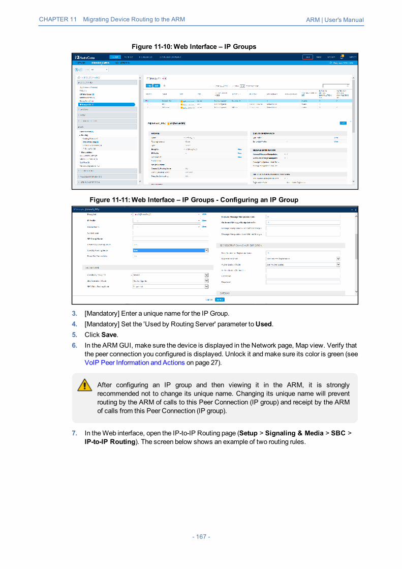
CHAPTER 11 Migrating Device Routing to the ARM ARM | User's Manual
Figure 11-10:Web Interface – IP Groups
Figure 11-11:Web Interface – IP Groups - Configuring an IP Group
3. [Mandatory] Enter a unique name for the IP Group.4. [Mandatory] Set the 'Used by Routing Server' parameter toUsed.5. Click Save.6. In the ARMGUI, make sure the device is displayed in the Network page, Map view. Verify that
the peer connection you configured is displayed. Unlock it andmake sure its color is green (seeVoIP Peer Information and Actions on page 27).
After configuring an IP group and then viewing it in the ARM, it is stronglyrecommended not to change its unique name. Changing its unique name will preventrouting by the ARM of calls to this Peer Connection (IP group) and receipt by the ARMof calls from this Peer Connection (IP group).
7. In theWeb interface, open the IP-to-IP Routing page (Setup > Signaling & Media > SBC >IP-to-IP Routing). The screen below shows an example of two routing rules.
- 167 -

CHAPTER 11 Migrating Device Routing to the ARM ARM | User's Manual
Figure 11-12:Web Interface – IP-to-IP Routing
Figure 11-13:Web Interface – IP-to-IP Routing Table – Add Row – Rule tab
8. Define a 'Name' and for 'Request Type', define INVITE (see Configuring an SBC to Send SIPRequests other than INVITE to ARM on page 183 if you need to use the ARM to route otherSIP Request Types such as MESSAGE or NOTIFY). Leave all other conditions fieldsundefined (i.e., No Conditions, or Any).
9. From the 'Destination Type' drop-downmenu, select Routing Server. This rule will serve toperform routing via the ARM.
10. Leave all other fields undefined, and then click Add.At this point, your routing service will still be operating according to that defined in the IP-to-IPRouting page in the SBC's Web interface.
11. In the ARMGUI's Routing page, configure a rule parallel to one of the rules configured in theWeb interface's IP-to-IP Routing page (see Adding a Routing Group on page 128).
Figure 11-14:Configuring a Routing Rule in the ARM
12. In the ARMGUI, switchON the routing rule; rule is now activated in the ARM.
- 168 -

CHAPTER 11 Migrating Device Routing to the ARM ARM | User's Manual
13. In theWeb interface, delete the routing rule. The transition is now complete.14. Perform a Test Route (see Testing a Route on page 150 for detailed information).15. Make a call andmake sure it was established by the ARM.
Configuremanually using the ini file, or in theWeb interface's 'Admin' page, configure'SendAcSessionIDHeader' = 1 for the SBC/Gateway to preserve the Call ID when a callpasses throughmultiple SBCs/Gateways.
See also Checklist for Migrating SBC Routing to the ARM on page 175.
- 169 -

CHAPTER 11 Migrating Device Routing to the ARM ARM | User's Manual
Migrating Media Gateway Routing to the ARMAfter making sure that the device (the gateway in this case) is connected to all HTTP ARMservices i.e., ARM Topology Server and router/s, you can begin to migrate the routing rules fromthose defined in theWeb interface to the ARM. Screenshots are for illustrative purposes.
'Trunk Group' and 'IP Group' in theWeb are called 'Peer Connection' in the ARM.
➢ To migrate gateway routing rules to the ARM:1. In theWeb interface, navigate to the Routing Settings page, and set the parameter 'Gateway
Routing Server' toEnable.
Figure 11-15:Web Interface - Routing Settings Page
2. Navigate in theWeb interface to the IP Groups page.3. Locate the IP Group to expose the enterprise network to the ARM environment.4. [Mandatory] Enter a unique name for the IP Group as shown in the following figure.5. Set the 'Used by Routing Server' parameter toUsed as shown in the following figure, and then
click Apply.
Figure 11-16:Web Interface - IP Groups Page
6. Navigate to the Trunk Group Settings page (Setup > Signaling & Media > Gateway > TrunkGroup Settings) shown in the following figure.
7. Locate the Trunk Group to expose the enterprise network to the ARM environment.
- 170 -

CHAPTER 11 Migrating Device Routing to the ARM ARM | User's Manual
8. [Mandatory] Enter a unique name for the Trunk Group.9. Set the 'Used by Routing Server' parameter toUsed, and then click Apply.
Figure 11-17:Web Interface - Trunk Group Settings
10. In the ARMGUI, make sure the device is displayed in the Network page, Map view. Make surethe Peer Connection you configured is displayed. Unlock it andmake sure its color is green.
After viewing the trunk group or IP Group in the ARM, it is strongly recommended not tochange its unique name. Changing its unique name will prevent routing by the ARM ofcalls to this Peer Connection (trunk / IP group) and receipt by the ARM of calls from thisPeer Connection (trunk / IP group).
At this point, your routing service will still be operating per that defined in the Tel- to-IP Routingand IP-to-Tel Routing pages in the gateway's Web interface.In the ARMGUI's Routing page, configure a rule parallel to one of the rules configured in theWeb interface's Tel-to-IP Routing or IP-to-Tel Routing pages.
11. Unlock the configured gateway Routing Rule in the ARM and check using the Test Routefeature that the rules are functioning as required.
12. Delete the parallel rules configured in theWeb interface's Tel-to-IP Routing or IP-to-TelRouting pages.
Migrating Hybrid Routing to the ARMAfter making sure that the hybrid device is connected to all HTTP ARM services i.e., ARMTopology Server and router/s, you can begin to migrate the routing rules from those defined in theWeb interface to the ARM.
➢ To migrate hybrid routing rules to the ARM:1. Perform migration of the SBC per the instructions in Migrating SBC Routing to the ARM on
page 166.2. Perform migration of theMedia Gateway per the instructions in MigratingMedia Gateway
Routing to the ARM on the previous page.3. Open the hybrid device's Web interface.4. Create an IP Group (Peer Connection) for the SBC application:
a. Open the Proxy Sets page (Setup > Signaling & Media > Core Entities > Proxy Sets)and then add a Proxy Set for the SBC application:
- 171 -
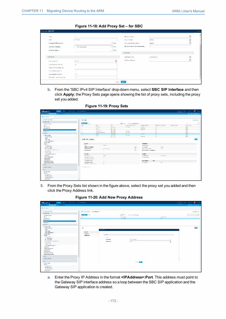
CHAPTER 11 Migrating Device Routing to the ARM ARM | User's Manual
Figure 11-18:Add Proxy Set – for SBC
b. From the 'SBC IPv4 SIP Interface' drop-downmenu, select SBC SIP Interface and thenclick Apply; the Proxy Sets page opens showing the list of proxy sets, including the proxyset you added.
Figure 11-19: Proxy Sets
5. From the Proxy Sets list shown in the figure above, select the proxy set you added and thenclick the Proxy Address link.
Figure 11-20:Add New Proxy Address
a. Enter the Proxy IP Address in the format <IPAddress>:Port. This address must point tothe Gateway SIP interface address so a loop between the SBC SIP application and theGateway SIP application is created.
- 172 -

CHAPTER 11 Migrating Device Routing to the ARM ARM | User's Manual
b. Open the IP Groups page (Setup > Signaling & Media > IP Groups), add an IP Group(click New) and associate it with the Proxy Set you added in Step 4a.
Figure 11-21: IP Group for the SBC Application
6. Create an IP Group (Peer Connection) for theMedia Gateway application:a. Open the Proxy Sets page (Setup > Signaling & Media > Core Entities > Proxy Sets)
and then add a Proxy Set (click New) for theMedia Gateway application:
Figure 11-22:New Proxy Set for Media Gateway Application
b. Select Gateway SIP Interface from the 'Gateway IPv4 SIP Interface' drop-downmenuand then click Apply; the Proxy Sets page opens showing the list of proxy sets, includingthe proxy set you added.
Figure 11-23: Proxy Sets
7. From the Proxy Sets list shown in the figure above, select the proxy set you added and thenclick the Proxy Address link.
- 173 -
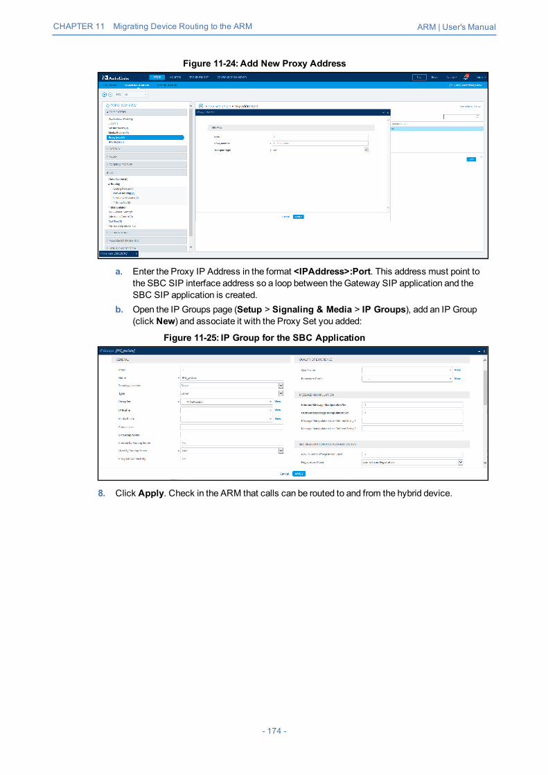
CHAPTER 11 Migrating Device Routing to the ARM ARM | User's Manual
Figure 11-24:Add New Proxy Address
a. Enter the Proxy IP Address in the format <IPAddress>:Port. This address must point tothe SBC SIP interface address so a loop between theGateway SIP application and theSBC SIP application is created.
b. Open the IP Groups page (Setup > Signaling & Media > IP Groups), add an IP Group(click New) and associate it with the Proxy Set you added:
Figure 11-25: IP Group for the SBC Application
8. Click Apply. Check in the ARM that calls can be routed to and from the hybrid device.
- 174 -

CHAPTER 12 Checklist for Migrating SBC Routing to the ARM ARM | User's Manual
12 Checklist for Migrating SBC Routing to theARMAdministrators can use the checklist shown in the following table when migrating SBC routing tothe ARM. Tick off the items in the list as you proceed.
The screen shots shown here are of Web interface version 7.2. If you're using Webinterface version 7.0 or earlier, refer to earlier versions of this document.
Table 12-1: SBC Migration Checklist
Item SBC-Level What should be viewed in theARM
1 Configure the SBC in the way you used to,including all the IP Groups for connectivity withexternal SIP trunks and PBXs.
Unrelated to ARM
2 Configure the IP address of the ARM's'Configurator'Note: Do not configure Routers independently.Only configure 'Configurator' IP address andcredentials:■ Configure in the SBC's Web interface (Setup >
IP Network >Web Services > Remote WebServices):✔ IP address of the Configurator✔ User name and Password for connecting
to the Configurator. Default: Admin/Admin
■ Make sure the status of each ARM service is'Connected'.
View the new Node.Make sure it becomes green-coded, indicating that it's avail-able.
3 Choose the SIP interfaces you want to use in theARM (for ARM Peer Connections and ARMCon-nections) to be 'Used by Routing Server'.■ Open the SBC Web interface (Setup >
Signaling & Media > Core Entities > SIPInterfaces)
You're able to select the chosenSIP Interfaces as ARM 'RoutingInterfaces' for ARM Connectionsbetween the Nodes (SBCs)
- 175 -

CHAPTER 12 Checklist for Migrating SBC Routing to the ARM ARM | User's Manual
Item SBC-Level What should be viewed in theARM
4 Select each IP Group you want to use in the ARMas a Peer Connection for routing, to beUsed byRouting Server. These should be, for example,SIP trunks and connections to IP PBXs.■ Open the IP Groups page (Setup > Signaling
& Media > Core Entities > IP Groups).
View the selected IP Groups asARM Peer Connections andattached VoIP Peers.View their availability status(green/red).In the ARM, unlock these Peerconnections.
5 At this stage, the ARM does not route calls,though you can apply a ‘test route’ at the ARMlevel. The Node (SBC) does not send a routingrequest to the ARM after a SIP invite.
In the ARM you can now:■ View and create ARM
topology (connectionsbetween the Nodes)
■ Add ARM routing groups andRouting rules, manipulationgroups, etc.
■ Test yourself using theARM's ‘test route’
6 Command the SBC to route calls using the ARM:■ Open the SBC Web interface IP-to-IP Routing
(Setup > Signaling & Media > SBC > IP-to-IP Routing).
Calls are now routed by the ARM:■ SBC gets an INVITE■ Sends routing Request to
ARM■ Get reply from ARM
- 176 -

CHAPTER 12 Checklist for Migrating SBC Routing to the ARM ARM | User's Manual
Item SBC-Level What should be viewed in theARM
■ Make sure the rule that routes all INVITErequests to the ARM is configured. Thefollowing parameters aremandatory: 'RequestType' = INVITE; 'Destination Type' = RoutingServer.
■ Sends INVITE furtheraccording to the ARM'sinstructions
7 Configuremanually using the ini file (or in the'Admin' Web interface page):SendAcSessionIDHeader = 1
Causes the SBC to preserve CallID when a call passes through sev-eral SBCs.
- 177 -

CHAPTER 13 Prefixes ARM | User's Manual
13 PrefixesUse the following table as reference when defining prefixes.
Table 13-1: Prefixes
Notation Description Examples
[n-m] Represents a range ofnumbers.Note: numbers “n” and “m”should be of the same length.
[5551200-5551300]#: represents allnumbers from 5551200 to 5551300.123[100-200]: represents all numbersfrom 123100 to 123200.
[n,m,...] orn,m,l, …
Represents multiple numbersor strings.
[2,3,4,5,6]#: represents a one-digitnumber starting with 2, 3, 4, 5, or 6.[11,22,33]XXX#: represents a five-digitnumber that starts with 11, 22, or 33.[111,222]XXX#: represents a six-digitnumber that starts with 111 or 222.[2X,3X,4X,50,54]XXXXXX#: representsa 8 digit number starting with 2, 3, 4, 50 or54aaa,bbb,ce,field : represents names thatstart with one of the strings: aaa, bbb, ceor field.
[n1-m1,n2-m2,a,b,c,n3-m3]
Represents amixed notationof multiple ranges and singlenumbers.
[123-130,455,766,780-790]: representsnumbers 123 to 130, 455, 766, and 780 to790.
X (capital only) Represents any single digit orcharacter.
BobX: represents names starting withbob1 or [email protected]#: represents names of 6-characterlength, starting with Alice, such asAlice1.
Pound sign (#)at the end of anumber
Represents the end of anumber.
54324XX#: represents a 7-digit numberthat starts with 54324.
Empty Represents any number orstring
- 178 -

CHAPTER 14 Examples of Normalization Rules ARM | User's Manual
14 Examples of Normalization RulesHere are some examples of Normalization Rules and regular expressions for your reference.■ Remove any non-number text from the prefix of the number:
- 179 -

CHAPTER 14 Examples of Normalization Rules ARM | User's Manual
■ Strip the + from the number.
■ Skype for Business: Remove “tel:” from the prefix and any text from the number's suffix. In theTest field, the full number is tel:+97239762938 (ext:2938).
- 180 -

CHAPTER 14 Examples of Normalization Rules ARM | User's Manual
■ If the fourth digit from the right is 4, change it to 8, and if the first digit is 0, change it to +972.
■ Click OK and then click Submit.
- 181 -

CHAPTER 15 Call Routing ARM | User's Manual
15 Call RoutingThe following describes call routing:■ A routing request results in an HTTP error response if no routing is available.■ A routing request from a source node which has an alternate route option returns the next
alternate route option. The call route is not recalculated. If the alternate route list is empty, a404 result is returned.
■ A routing request from a node which is not the source node returns the next hop in the routingchain according to the original route selection. The routing logic is not performed again.
- 182 -

CHAPTER 16 Configuring an SBC to Send SIP Requests other than INVITE to ARM ARM | User's Manual
16 Configuring an SBC to Send SIP Requestsother than INVITE to ARMThe SBC can be configured to send MESSAGE and NOTIFY SIP requests to the ARM. To get notonly INVITE but also NOTIFY and MESSAGE, create a new Condition in the Condition table withthe value: "header.request-uri.methodtype == '5' or header.request-uri.methodtype == '13' orheader.request-uri.methodtype == '14'".
➢ To configure the SBC to send SIP Requests other than INVITE to the ARM:1. Open theMessage Conditions page (Setup > Signaling & Media >Message Manipulation
>Message Conditions) and click Add.
Figure 16-1: Web Interface – Message Conditions
2. Add the condition as shown in the figure above, and click Apply.3. Open the IP-to-IP Routing page (Setup > Signaling & Media > SBC > Routing > IP-to-IP
Routing), select the row of the Routing Rule that directs calls to the ARM, and click Edit.
Figure 16-2: Web Interface – IP-to-IP Routing
4. Edit the Routing Rule (see the preceding figure):● Change 'Request Type' from Invite toAll.● Select the 'Message Condition' you configured.
5. Click Apply.6. Make a call andmake sure the call was established by the ARM.
Configuremanually using the ini file, or in theWeb interface's 'Admin' page, configure'SendAcSessionIDHeader' = 1. Note that this step is temporary and that a permanent solutionis pending. It causes the SBC/Gateway to preserve Call ID when a call passes through severalSBC/Gateways.
- 183 -

CHAPTER 17 Opening Firewall Ports for the ARM ARM | User's Manual
17 Opening Firewall Ports for the ARMPorts for the ARMmust be opened in the Firewall. Use the following table as reference.
Table 17-1: Opening Firewall Ports for the ARM
Connection PortType
SecuredConnection
PortNumber Purpose
Port side /
FlowDirection
ARM andDevices (SBCs / Gateways / Hybrid nodes)
Device↔ARMConfigurator(REST)
TCP(HTTPS)- default
ü 443 Topology Auto-discovery,TopologyStatus update,Qualityinformation,long callsessionsinformation (forlicensing)
Bi-Directional
TCP(HTTP)– debugonly
û 80 Topology Auto-discovery,TopologyStatus update,Qualityinformation,long callssessioninformation (forlicensing)
Bi-directional
Device↔ARMRouter (REST)
TCP(HTTPS)- default
ü 443 Routingrequests andcalls status
Bi-Directional
TCP(HTTP)– debugonly
û 80 Routingrequests andcalls status
Bi-directional
ARM and LDAP Active Directory Server
ARMConfigurator↔Active DirectoryLDAP server
TCP(LDAP)
û 389(Default,can beconfiguredat ARM)
Getting of ARMAD users andupdating ARMuser database
Bi-directional
TCP(TLS -LDAPS)
ü 6363268 for‘Globalcatalog’
Getting of ARMAD users andupdating ARMuser database
Bi-directional
- 184 -

CHAPTER 17 Opening Firewall Ports for the ARM ARM | User's Manual
Connection PortType
SecuredConnection
PortNumber Purpose
Port side /
FlowDirection
Default, canbeconfiguredat ARM)
LDAPS (TLS)is configured atARM
ARMGUI and North bound Interface
UI (RESTcommunication)→ARMConfigurator
TCP(HTTPS)
ü 443 ARMcomponentstatus updates,GUI,Provisioning,Alarmsindications
Incoming(from ARMConfiguratorperspective)
Third-partyapplication (viaofficial RESTAPI)→ARMConfigurator
TCP(HTTPS)
ü 443 ARMcomponentstatus updates,GUI,Provisioning,Alarmsindications
Incoming(from ARMConfiguratorperspective)
ARMConfigurator→SNMP Target
UDP(SNMP)
û 161, 162 orconfigurable
ARMgeneratesSNMPtraps/alarmstowardpredefinedSNMP Target.
Outgoing
ARMManagement / Maintenance Interfaces
ARMConfigurator↔NTP Server
UDP(NTPserver)
û 123 ARMConfiguratoracts as NTPclient towardexternal (pre-configured)NTP server.It also acts asNTP Servertoward ARMRouters.
Bi-directional
ARM Router→NTP Server(ARMConfigurator)
UDP(NTP)
û 123 ARMRouteracts as NTPclient
Outgoing
- 185 -

CHAPTER 17 Opening Firewall Ports for the ARM ARM | User's Manual
Connection PortType
SecuredConnection
PortNumber Purpose
Port side /
FlowDirection
ARMConfigurator↔Client PC(SSH)
TCP ü 22 SSHcommunicationbetween ARMConfiguratorand externalPC initiated byclient PC:For ARMmaintenance
Bi-directional
ARM Router↔Client PC(SSH)
TCP ü 22 SSHcommunicationbetween ARMRouter andexternal PCinitiated byclient PC:For ARMmaintenance
Bi-directional
ARMConfigurator→Syslog server
TCP û 514 (bydefault) orconfigurable
ARMConfiguratorlogs can beforwarded toexternal syslogserver.
Outgoing
ARMRouter→Syslog server
TCP û 514 (bydefault) orconfigurable
ARMRouterslogs can beforwarded toexternal syslogserver.
Outgoing
ARM Inter-Components Communication (Configurator↔Routers)
- 186 -

CHAPTER 17 Opening Firewall Ports for the ARM ARM | User's Manual
Connection PortType
SecuredConnection
PortNumber Purpose
Port side /
FlowDirection
ARMConfigurator↔ARMRouters
TCP(HTTPS)
ü 443 Getting callstatistics fromthe ARMConfigurator;getting callsessionsinformation forARM licensing
Bi-directional
TCP(HTTP) -debugonly
û 80 Getting callstatistics fromthe ARMConfigurator;getting callsessionsinformation forARM licensing
Bi-directional
ARMConfigurator←JMS Broker
TCP(TLS)
ü 8080 Informing ARMRouters abouttopologychanges(includingtopology statusand qualitychanges)
Incoming
ARMRouter→JMS Broker
TCP(TLS)
ü 8080 GettingTopologyupdates fromARM
Outgoing
- 187 -

CHAPTER 18 About CDRs Sent by ARM to CDR Server ARM | User's Manual
18 About CDRs Sent by ARM to CDR ServerARM Routers send CDRs (Call Detail Records) to a CDR Server. CDR messages containinformation about all calls routed by the ARM, for example, source and destination users, callduration and call path. CDR messages also provide billing details. CDRs are sent as syslogpackets to a predefined IP address configured by the operator. CDR syslog messages comply withRFC 3164 and are identified by Facility 17 (local1) and Severity 6 (Informational). CDR messagesare built using getRoute and CallStatus_callEnd messages, by the first node in the paths. CDRtypes are CALL_START and CALL_END.Calls from an SBC node:1. OneCALL_STARTmessage is sent per route (path)2. TwoCALL_END messages are sent at the end of the callCalls from a gateway node:1. OneCALL_STARTmessage is sent per route (path)2. OneCALL_END message is sent at the end of the call (not per route)SessionId is identical for all CDR messages related to the same call.The routeSeq:1. Represents the route (path) the ARM attempts2. The count starts from 03. For example, for an SBC call, when there are three paths to attempt, the ARM sends:
a. First route (path): One CALL_STARTmessage and one CALL_END (outgoing leg)message. routeSeq = 0.
b. Second route (path): One CALL_STARTmessage and one CALL_END (outgoing leg)message. routeSeq = 1.
c. Third route (path): One CALL_START and two CALL_END (incoming and outgoing legs)messages. routeSeq = 2.
The following table describes all CDR fields.
Table 18-1: CDR Field Descriptions
CDR Field Description CDR ReportType Format
RouterIp IP address of the Router thatsends the CDR.
All String(15)
Seq Each router sends its ownsequence CDR staring with 1.
All String(10)
CreationDate The creation date of the CDR. All String(40)
CdrReportType Report type:■ "CALL_START": CDR is
sent upon an getRoutemessage on the first node.
■ "CALL_END": CDR is sentupon a CALL_STATUS_END_CALLmessage fromthe node.
- String(13)
- 188 -

CHAPTER 18 About CDRs Sent by ARM to CDR Server ARM | User's Manual
CDR Field Description CDR ReportType Format
AppType Endpoint type:■ "SBC”■ “GW”■ “HYBRID”■ “THIRD_PARTY”
All String(13)
SessionId Unique Session ID All String(20)
callId CallId of the relevant leg "CALL_START" –incoming leg."CALL_END"– both legs.
String(55)
direction Direction of the call:Incoming or Outgoing
"CALL_START"
String(10)
pconOrConnectionName Pcon or connection name All String(35)
nodeId ARM node database ID address All String(11)
nodeName Node name as described in theGUI
All String(25)
nodeIp Node IP address All String(20)
pconId Pcon database ID "CALL_START"
String(10)
conId Connection database ID "CALL_START"
String(10)
pconOrConnectionType Pcon or connection type "CALL_START"
String(25)
outPconId Outgoing Peer Connectiondatabase ID
"CALL_START"
String(10)
outConId Outgoing Connection databaseID
"CALL_START"
String(10)
outPconOrConType Outgoing leg type "CALL_START"
String(25)
lastNodeId ID of the last node "CALL_START"
String(10)
- 189 -

CHAPTER 18 About CDRs Sent by ARM to CDR Server ARM | User's Manual
CDR Field Description CDR ReportType Format
lastNodeName Name of the last node "CALL_START"
String(25)
lastPconId ID of the last Peer Connection "CALL_START"
String(10)
lastPconName Name of the last PeerConnection
"CALL_START"
String(35)
srcUri Source URI as actually sent(after manipulation).
All String(50)
srcUriBeforeMap Source beforemanipulation. "CALL_START"
String(50)
dstUri Destination URI as actuallysent (after manipulation).
All String(50)
dstUriBeforeMap Destination beforemanipulation.
"CALL_START"
String(50)
armSetupTime ARMRouter time when sendingCALL_START.
"CALL_START"
String(30)
armReleaseTime ARMRouter time when sendingCALL_END.
"CALL_END" String(30)
sbcSetupTime Gateway / SBC time when starthandling Invite message.
"CALL_END" String(40)
sbcConnectTime Gateway / SBC time when 200OK response (i.e., call isestablished)
"CALL_END" String(40)
sbcReleaseTime Gateway / SBC time when aBYE message (i.e., call ends)
"CALL_END" String(40)
sbcAlertTime Gateway / SBC time when startringing
"CALL_END" String(40)
alertDuration Time of ringing in milliseconds(should be configured in theSBC /gateway to send inmilliseconds)
"CALL_END" String(13)
voiceDuration Time of voice streamed inmilliseconds (should beconfigured in the SBC /Gatewayto send inmilliseconds)
"CALL_END" String(13)
- 190 -

CHAPTER 18 About CDRs Sent by ARM to CDR Server ARM | User's Manual
CDR Field Description CDR ReportType Format
completeDuration Time of the whole call inmilliseconds (from the firstincoming Invite until ending thecall)
"CALL_END" String(16)
sipTerminationReason SIP termination reason "CALL_END" String(20)
sipTerminationReasonDesc SIP termination reason –moredetailed
"CALL_END" String(35)
routeSeq Each route (path) of a call has anumber. Starting from 0.
"CALL_START"
String(8)
sipInterface sipInterface ID of theConnection or Peer Connectionin the SBC / Gateway
"CALL_START"
String(20)
legId Leg id of the SBC / Gateway "CALL_END" String(11)
routingRuleId The Routing Rule ID of thematch rule
"CALL_START"
String(13)
routingRuleName The Routing Rule name of thematch rule
"CALL_START"
String(30)
discardingByRoutingRule The Routing Rule ID in case ofdiscarding rule
"CALL_START"
String(24)
Path String – describes the path. "CALL_START"
String(200)
TwoCDR format options are available:■ Clear text (separating each value with “|”)■ As JSON
- 191 -

CHAPTER 18 About CDRs Sent by ARM to CDR Server ARM | User's Manual
Here's an example of an ARM signaling CDR as clear text, sent at the end of a call (which wasterminated normally):Format:
|routerIp |seq |creationDate |cdrReportType |appType |sessionId |callId |direction|pconOrConName |nodeId |nodeName |nodeIp |pconId |conId |pconOrConType |sipInterface|outPconId |outConId |outPconOrConType |lastPconId |lastNodeId |lastNodeName|lastPconName |srcUri |srcUriBeforeMap |dstUri |dstUriBeforeMap |armSetupTime|armReleaseTime |sbcSetupTime |sbcConnectTime |sbcReleaseTime |sbcAlertTime|alertDuration |voiceDuration |completeDuration |sipTerminationReason|sipTerminationReasonDesc |routeSeq |legId |routingRuleId |routingRuleName|discardingByRoutingRule |path
Value:
|10.7.6.102 | 2 | 2019-02-21T08:53:15.123Z | CALL_END | SBC | 7018782a40c69c13 |75aed8-8802070a-13c4-55013-16cc4-7c2dd6ce-16cc4 | RMT | 102 | 4 | SBC_97 | 10.7.12.97|null |null |IPGroup | |null |null |IPGroup |null |null | | |[email protected] | |[email protected] | ||2019-02-21T08:53:15.116Z |23:27:10.537 UTC Wed Feb 07 2018 |23:27:13.554 UTC WedFeb 07 2018 |23:27:18.842 UTC Wed Feb 07 2018 |23:27:10.837 UTC Wed Feb 07 2018|2717 |5288 |8305 |BYE |BYE |0 |1 |-1 | |-1 |null
Here's an example of an ARM signaling CDR as JSON, sent at the end of a call (that wasterminated normally):
jsonCdr={"creationDate":"2019-02-21T08:53:15.123Z","sessionKey":"47018782a40c69c13","routerIp":"10.7.6.102","seq":2,"cdrReportType":"CALL_END","cdrApplicationType":"SBC","sessionId":"7018782a40c69c13","callId":"75aed8-8802070a-13c4-55013-16cc4-7c2dd6ce-16cc4","callOrig":"RMT","pconOrConName":"102","nodeId":"4","nodeName":"SBC_97","nodeIp":"10.7.12.97","pconId":null,"conId":null,"pconOrConType":"IPGroup","sipInterface":"","outPconId":null,"outConId":null,"outPconOrConType":"IPGroup","lastPconId":null,"lastNodeId":null,"lastNodeName":"","lastPconName":"","srcUri":"[email protected]","srcUriBeforeMap":"","dstUri":"[email protected]","dstUriBeforeMap":"","armSetupTime":"","armReleaseTime":"2019-02-21T08:53:15.116Z","sbcSetupTime":"23:27:10.537 UTC Wed Feb07 2018","sbcConnectTime":"23:27:13.554 UTC Wed Feb 072018","sbcReleaseTime":"23:27:18.842 UTC Wed Feb 072018","sbcAlertTime":"23:27:10.837 UTC Wed Feb 072018","alertDuration":"2717","voiceDuration":"5288","completeDuration":"8305","sipTerminationReason":"BYE","sipTerminationReasonDesc":"BYE","routeSeq":0,"legId":1,"routingRuleId":-1,"routingRuleName":"","path":null,"discardingByRoutingRule":-1,"httpResponse":200,"description":""}
- 192 -

This page is intentionally left blank.
CHAPTER 18 About CDRs Sent by ARM to CDR Server ARM | User's Manual
- 193 -

International Headquarters1 Hayarden Street,Airport CityLod 7019900, IsraelTel: +972-3-976-400s0Fax: +972-3-976-4040
AudioCodes Inc.200 Cottontail LaneSuite A101ESomerset NJ 08873Tel: +1-732-469-0880Fax: +1-732-469-2298
Contact us: https://www.audiocodes.com/corporate/offices-worldwideWebsite: https://www.audiocodes.com/
©2019 AudioCodes Ltd. All rights reserved. AudioCodes, AC, HD VoIP, HD VoIP Sounds Better,IPmedia, Mediant, MediaPack, What’s Inside Matters, OSN, SmartTAP, User Management Pack,VMAS, VoIPerfect, VoIPerfectHD, Your Gateway To VoIP, 3GX, VocaNom, AudioCodes OneVoice and CloudBond are trademarks or registered trademarks of AudioCodes Limited. All otherproducts or trademarks are property of their respective owners. Product specifications are sub-ject to change without notice.
Document #: LTRT-41890