Venewood AT
12
This product is originally designed for the Japanese market. For more details, please contact our local agent. Motorized Wooden Blind Venewood AT
-
Upload
khangminh22 -
Category
Documents
-
view
0 -
download
0
Transcript of Venewood AT

This product is originally designed for the Japanese market. For more details, please contact our local agent.
Motorized Wooden Blind
Venewood AT

2
OPENLift blinds
STOPStop
CLOSELower blinds
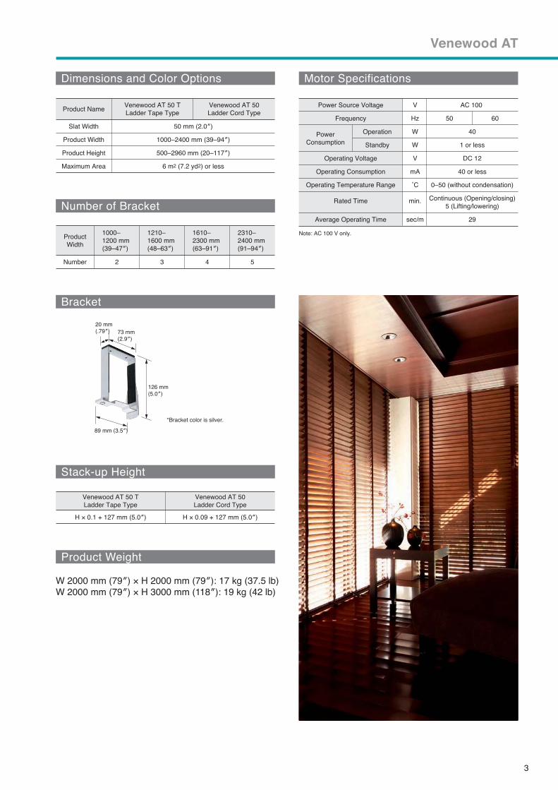
Venewood AT
Motorized wooden blinds
Two separate motors for lift/lowering and tilting operations.
Bigger than ever 2 2
A Wide Variety of Slats and Ladder Tapes
No troublesome wiring
Exceptionally quiet
Automatic safety stop
Easy height adjustment
5-button Switch
TIOS-I Single Switch for IB
3
Venewood AT
Venewood AT 50Venewood AT 50 T
Venewood AT 50 T Venewood AT 50
2 2
2 3 5
V
V
Power

4
Venewood AT
Structure Drawing
Materials/Specifications ColorProduct NameNo.
Head Rail
Side Cover
Slat
Ladder Cord, Ladder Tape
Lift Tape
Bottom Rail
Bracket
Power Supply
Connecting Cord
Bottom Cover
Silver
Silver, Gray White
White
Silver
White
White
Aluminum
Molded resin
Basswood
Chemical fiber
Chemical fiber
Basswood
Steel
Zinc die-casting

5
Venewood AT
Installation Dimensions and Diagram
AC100V Power Outlet (Separate work)
20 mm
Box width = Product width (W) +
Product width (W)
Inlay Modular Connector (with Terminal)MO Switch Plate 1-Button 1 Row
Pipping, Wiring
(Separate work)
Box width = Product width (W) +
Product width (W)
Switch Box for One (Separate work)
70 mm
150–180 mm 150–180 mm
66 mm
165 mm
106 mm
90 mm
49 mm 12 mm
57 mm
Window side
Room side
Windowside
Roomside Blind
stack-up
6
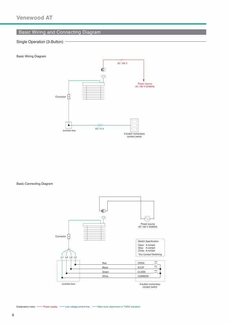
DC 12 V
Power sourceAC 100 V 50/60Hz
Junction box
AC 100 V
3-button momentarycontact switch
Connector
Connector
Red
Black
Green
White
Venewood AT
Basic Wiring and Connecting Diagram
Basic Wiring Diagram
Single Operation (3-Button)
L1 L4 L2 L3L1 L4 L2 L3
Junction box
Power sourceAC 100 V 50/60Hz
3-button momentarycontact switch
OPEN
STOP
CLOSE
COMMON
Switch Specification
Open: Stop: Close:
*Dry Contact Switching
A contactA contactA contact
Basic Connecting Diagram
Explanatory notes: Power supply, Low voltage control line, Main body attachment or TOSO standard
7
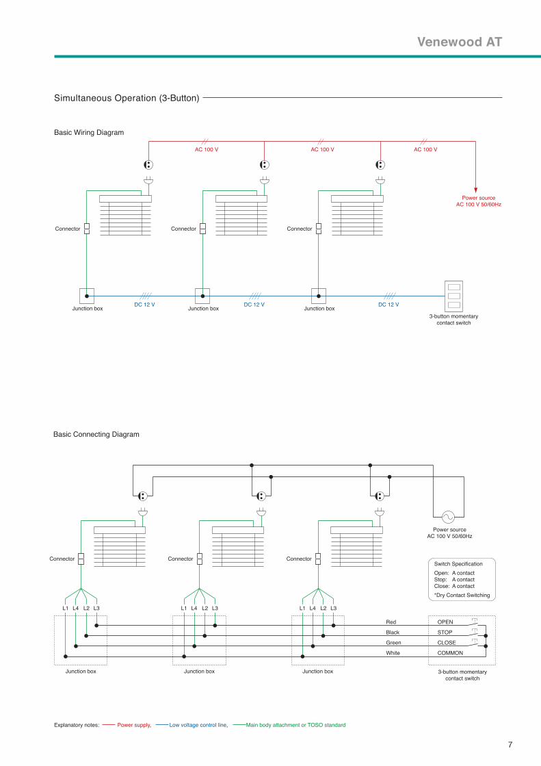
Basic Connecting Diagram
Junction boxDC 12 VDC 12 VDC 12 V
AC 100 V
Power sourceAC 100 V 50/60Hz
Junction box
AC 100 V
Junction box
AC 100 V
Basic Wiring Diagram
Simultaneous Operation (3-Button)
L1 L4 L2 L3L1 L4 L2 L3 L1 L4 L2 L3L1 L4 L2 L3 L1 L4 L2 L3L1 L4 L2 L3
Junction box
Power sourceAC 100 V 50/60Hz
3-button momentarycontact switch
OPEN
STOP
CLOSE
COMMON
Junction box Junction box
Switch Specification
Open: Stop: Close:
*Dry Contact Switching
A contactA contactA contact
3-button momentarycontact switch
Connector
Connector Connector Connector
Connector Connector
Red
Black
Green
White
Venewood AT
Explanatory notes: Power supply, Low voltage control line, Main body attachment or TOSO standard

8
FM Remote-control Transmitter 2.4G
FM Remote-controlReceiver 2.4G
FM Remote-control Connector Non Voltage type
2
2
FM Remote-control Connector Non Voltage type
FM Remote-control Transmitter 2.4G
FM Remote-controlReceiver 2.4G
WhiteBlackGreenRed
Terminal Block
WhiteBlackGreenRed
Venewood AT
Explanatory notes: Power supply, Main body attachment or TOSO standard
FM Remote-Control Receiver 2.4G
AC 100 V
Power sourceAC 100 V 50/60Hz
Basic Wiring Diagram
Basic Connecting Diagram
Power sourceAC 100 V 50/60Hz

9
Venewood AT
Basic Wiring Diagram (5-Button)
Single Operation (5-Button)
←To 100 V AC power source
VVF 1.6×2C (separate work)VVF 1.6×6C or CVV2.0□×6C (separate work)
100 V AC power outlet (separate work)
Power Cord →
Junction box
Basic Connecting Diagram (5-Button)
←To 100 V AC power source
Explanatory notes: Power supply, Low voltage control line, Main body attachment or TOSO standard
Connector
TIOS- Single Switch for IB
I
Junction box
Connector
1 2 3 4 5 6 7 8 9 10 11
TIOS- Single Switch for IB
I
Sla
t tilting
CL
OS
ES
lat tiltin
g O
PE
N
CL
OS
EO
PE
NS
TO
PC
OM
MO
N
Blu
eB
row
n
Gre
en
Re
dB
lack
Wh
ite

10
Venewood AT
Simultaneous Operation (5-Button)
Basic Wiring Diagram (5-Button)
Basic Connecting Diagram (5-Button)
←To 100 V AC power source
VCTF0.75□×4C or CVV1.25□×4C (separate work)
100 V AC power outlet (separate work)
Power Cord →
VVF 1.6×2C (separate work)
←To 100 V AC power source
TIOS- Single Switch for IB
I
Junction box
Connector
Junction box
Connector
Junction box
Connector
Junction box
Connector
Sla
t tilting
CL
OS
ES
lat tiltin
g O
PE
N
CL
OS
EO
PE
NS
TO
PC
OM
MO
N
1 2 3 4 5 6 7 8 9 10 11
TIOS- Single Switch for IB
I
Junction box
Connector
Junction box
Connector
Wh
iteB
lack
Re
dG
ree
nB
row
nB
lue
Wh
iteB
lack
Re
dG
ree
nB
row
nB
lue
Wh
iteB
lack
Re
dG
ree
nB
row
nB
lue
Explanatory notes: Power supply, Low voltage control line, Main body attachment or TOSO standard
Blu
eB
row
n
Gre
en
Re
dB
lack
Wh
ite

11
Venewood AT
Wood Slat Color List
TM-1003 Grayish Mocha
Bottom Rail TM-1007
TM-1002 Shabby WhiteTM-1001 Off White
Bottom Rail TM-1001
Bottom Rail TM-1001
TM-1006 Deep Brown
Bottom Rail TM-1006
TM-1005 Dark Brown
Bottom Rail TM-1005
TM-1004
Bottom Rail TM-1004
TM-1007 Natural
Bottom Rail TM-1007
TM-1008 Cherry
Bottom Rail TM-1008
TM-1009 Grayish Brown
Bottom Rail TM-1009
TM-1012 Bitter Brown
Bottom Rail TM-1012
TM-1010 Soft Brown
Bottom Rail TM-1010
TM-1011
Bottom Rail TM-1011
7 8 9
1 2
4 5 6
3
10 11 12

12
L-001
L-014
L-002
L-015
L-004
L-016
L-005
L-017
L-007
L-008 L-009 L-010 L-011 L-012
L-013
Ladder Tape List
Venewood AT
201602E