Vehicles With: Electronic (EMTC) Manual Temperature Control
149
11/2/2020 Electronic Manual Temperature Control (EMTC) (Heating and Air Conditioning) - ALLDATA Repair https://my.alldata.com/repair/#/repair/article/54382/component/5/itype/377/nonstandard/11117/selfRefLink/true#g1751540p0.9350190807058071 1/149 2015 Ford Fusion FWD L4-2.5L Vehicle > Heating and Air Conditioning > Testing and Inspection > Initial Inspection and Diagnostic Overview ELECTRONIC MANUAL TEMPERATURE CONTROL (EMTC) 412-00 Climate Control System - General Information 2015 Fusion Diagnosis and Testing Climate Control System - Vehicles With: Electronic (EMTC) Manual Temperature Control DTC Chart: Front Controls Interface Module (FCIM) - Electronic Manual Temperature Control (EMTC) Diagnostics in this manual assume a certain skill level and knowledge of Ford-specific diagnostic practices. For information about these practices, REFER to: (100-00 General Information, Description and Operation) . Diagnostic Methods Network Diagnostic Trouble Codes (DTCs) (U-codes) are often a result of intermittent concerns such as damaged wiring or low battery voltage occurrences. Additionally, vehicle repair procedures, such as module reprogramming, often set network Diagnostic Trouble Codes (DTCs). Replacing a module to resolve a network DTC is unlikely to resolve the concern. To prevent repeat network DTC concerns, inspect all network wiring, especially connectors. Test the vehicle battery. REFER to: (414-01 Battery, Mounting and Cables, Diagnosis and Testing) . Battery FCIM - EMTC DIAGNOSTIC TROUBLE CODE (DTC) CHART DTC Description Action B105A:12 Fan: Circuit Short To Battery Cabin Temperature Sensor GO to Pinpoint Test M B105A:14 Cabin Fan: Circuit Short To Ground or Open Temperature Sensor GO to Pinpoint Test M B1081:07 Left Temperature : Mechanical Failure Damper Motor INSPECT for binding or damaged linkage or door. REPAIR as necessary. If no condition is found, INSTALL a new passenger side temperature door actuator. REFER to: Passenger Side Temperature Door Actuator - LHD FWD (412-00 Climate Control System - General Information) . B1081:11 Left Temperature Motor: Circuit Short To Ground Damper GO to Pinpoint Test I
-
Upload
khangminh22 -
Category
Documents
-
view
1 -
download
0
Transcript of Vehicles With: Electronic (EMTC) Manual Temperature Control
11/2/2020 Electronic Manual Temperature Control (EMTC) (Heating and Air Conditioning) - ALLDATA Repair
https://my.alldata.com/repair/#/repair/article/54382/component/5/itype/377/nonstandard/11117/selfRefLink/true#g1751540p0.9350190807058071 1/149
2015 Ford Fusion FWD L4-2.5LVehicle > Heating and Air Conditioning > Testing and Inspection > Initial Inspection and Diagnostic Overview
ELECTRONIC MANUAL TEMPERATURE CONTROL (EMTC)
412-00 Climate Control System - General Information 2015 FusionDiagnosis and Testing
Climate Control System - Vehicles With:Electronic
(EMTC)Manual Temperature Control
DTC Chart: Front Controls Interface Module (FCIM) - Electronic Manual Temperature Control (EMTC)
Diagnostics in this manual assume a certain skill level and knowledge of Ford-specific diagnostic practices. Forinformation about these practices, REFER to: (100-00 General Information, Description and Operation) . Diagnostic Methods
Network Diagnostic Trouble Codes (DTCs) (U-codes) are often a result of intermittent concerns such as damagedwiring or low battery voltage occurrences. Additionally, vehicle repair procedures, such as module reprogramming,often set network Diagnostic Trouble Codes (DTCs). Replacing a module to resolve a network DTC is unlikely toresolve the concern. To prevent repeat network DTC concerns, inspect all network wiring, especially connectors. Testthe vehicle battery. REFER to: (414-01 Battery, Mounting and Cables, Diagnosis and Testing) . Battery
FCIM - EMTC DIAGNOSTIC TROUBLE CODE (DTC) CHART
DTC Description Action
B105A:12 Fan:Circuit Short To BatteryCabin Temperature Sensor GO to Pinpoint Test M
B105A:14 Cabin Fan:Circuit Short To Ground or Open
Temperature Sensor GO to Pinpoint Test M
B1081:07 Left Temperature :Mechanical Failure
Damper Motor INSPECT for binding or damagedlinkage or door. REPAIR asnecessary. If no condition is found,INSTALL a new passenger sidetemperature door actuator. REFER to: Passenger SideTemperature Door Actuator - LHDFWD (412-00 Climate ControlSystem - General Information) .
B1081:11 Left Temperature Motor:Circuit Short To Ground
Damper GO to Pinpoint Test I

11/2/2020 Electronic Manual Temperature Control (EMTC) (Heating and Air Conditioning) - ALLDATA Repair
https://my.alldata.com/repair/#/repair/article/54382/component/5/itype/377/nonstandard/11117/selfRefLink/true#g1751540p0.9350190807058071 2/149
DTC Description Action
B1081:12 Left Temperature Damper Motor:Circuit Short To Battery
GO to Pinpoint Test I
B1081:13 Left Temperature Damper Motor:Circuit Open
GO to Pinpoint Test I
B1083:07 Recirculation Damper Motor:Mechanical Failure
INSPECT for binding or damagedlinkage or door. REPAIR asnecessary. If no condition is found,INSTALL a new
. REFER to: (412-00 Climate Control System -General Information, Removal andInstallation) .
air inlet mode dooractuator
Air Inlet Door Actuator
B1083:11 Recirculation Damper Motor: CircuitShort To Ground
GO to Pinpoint Test D
B1083:12 Recirculation Damper Motor: CircuitShort To Battery
GO to Pinpoint Test D
B1083:13 Recirculation Damper Motor: CircuitOpen
GO to Pinpoint Test D
B1086:07 Air Distribution Damper Motor:Mechanical Failure
INSPECT for binding or damagedlinkage or door. REPAIR asnecessary. If no condition is found,INSTALL a new air distribution dooractuator. REFER to:
(412-00 Climate ControlSystem - General Information,Removal and Installation) .
Air Distribution DoorActuator
B1086:11 Air Distribution Damper Motor:Circuit Short To Ground
GO to Pinpoint Test E
B1086:12 Air Distribution Damper Motor:Circuit Short To Battery
GO to Pinpoint Test E
B1086:13 Air Distribution Damper Motor:Circuit Open
GO to Pinpoint Test E
B10AF:11 : Circuit Short ToGroundBlower Fan Relay GO to Pinpoint Test J
B10AF:12 Blower Fan Relay: Circuit Short ToBattery
GO to Pinpoint Test K
B10AF:13 Blower Fan Relay: Circuit Open GO to Pinpoint Test J
B10B5:11 Left Panel Air DischargeTemperature: Circuit Short ToGround
GO to Pinpoint Test L
B10B5:15 Left Panel Air DischargeTemperature: Circuit Short ToBattery or Open
GO to Pinpoint Test L

11/2/2020 Electronic Manual Temperature Control (EMTC) (Heating and Air Conditioning) - ALLDATA Repair
https://my.alldata.com/repair/#/repair/article/54382/component/5/itype/377/nonstandard/11117/selfRefLink/true#g1751540p0.9350190807058071 3/149
DTC Description Action
B10B6:11 Left Floor Air DischargeTemperature: Circuit Short ToGround
GO to Pinpoint Test L
B10B6:15 Left Floor Air DischargeTemperature: Circuit Short ToGround
GO to Pinpoint Test L
B10B8:63 Push Buttons: Circuit / ComponentProtection Time-Out
Buttons held too long may setthis DTC . ATTEMPT to cleanbuttons. CLEAR the DiagnosticTrouble Codes (DTCs) andREPEAT the self-test. If the DTCdoes not return, IGNORE theDTC and CONTINUE diagnosingother Diagnostic Trouble Codes(DTCs) or symptoms. If the DTCreturns, INSTALL a new FCIM .For vehicles equipped withSony® Audio System, REFER to: Information andEntertainment System (415-00Information and EntertainmentSystem - General Information -Vehicles With:AM/FM/CD/SYNC/Sony AudioSystem) . For vehicles equipped withTouchscreen Display, REFER to:
(415-00BInformation and EntertainmentSystem - General Information -Vehicles With: SYNC2/Touchscreen Display,Diagnosis and Testing) .
Information andEntertainment System
For all other audio systems, REFER to: Information andEntertainment System (415-00Information and EntertainmentSystem - General Information -Vehicles With:AM/FM/CD/SYNC) .
B10B9:12 : Circuit Short ToBatteryBlower Control For an inoperative ,blower motor
GO to Pinpoint Test JFor all other blower motorsymptoms, GO to Pinpoint TestK

11/2/2020 Electronic Manual Temperature Control (EMTC) (Heating and Air Conditioning) - ALLDATA Repair
https://my.alldata.com/repair/#/repair/article/54382/component/5/itype/377/nonstandard/11117/selfRefLink/true#g1751540p0.9350190807058071 4/149
DTC Description Action
B10B9:14 Blower Control: Circuit Short ToGround or Open
For an inoperative blower motor,GO to Pinpoint Test JFor all other blower motorsymptoms, GO to Pinpoint TestK
B11E5:11 Left Damper Position Sensor:Circuit Short To Ground
HVAC GO to Pinpoint Test I
B11E5:15 Left HVAC Damper Position Sensor:Circuit Short To Battery or Open
GO to Pinpoint Test I
B11E7:11 Air Distribution Damper PositionSensor: Circuit Short To Ground
GO to Pinpoint Test E
B11E7:15 Air Distribution Damper PositionSensor: Circuit Short To Battery orOpen
GO to Pinpoint Test E
B11F0:11 Air Intake Damper Position Sensor:Circuit Short To Ground
GO to Pinpoint Test D
B11F0:15 Air Intake Damper Position Sensor:Circuit Short To Battery or Open
GO to Pinpoint Test D
B1A61:11 Cabin Temperature Sensor: CircuitShort To Ground
GO to Pinpoint Test M
B1A61:15 Cabin Temperature Sensor: CircuitShort To Battery or Open
GO to Pinpoint Test M
B1A69:11 : Circuit Short ToGroundHumidity Sensor GO to Pinpoint Test M
B1A69:15 Humidity Sensor: Circuit Short ToBattery or Open
GO to Pinpoint Test M
B1B71:11 :Circuit Short To GroundEvaporator Temperature Sensor GO to Pinpoint Test N
B1B71:15 Temperature Sensor:Circuit Short To Battery or OpenEvaporator GO to Pinpoint Test N
C1B14:11 Sensor Supply Voltage A: CircuitShort To Ground
GO to Pinpoint Test O
C1B14:12 Sensor Supply Voltage A: CircuitShort To Battery
GO to Pinpoint Test O
All Other FCIM Diagnostic TroubleCodes (DTCs) not listed in this chart
— Refer to the appropriate section inGroup 415 for the procedure.
DTC Chart: Powertrain Control Module (PCM)
Diagnostics in this manual assume a certain skill level and knowledge of Ford-specific diagnostic practices. Forinformation about these practices, REFER to: (100-00 General Information, Description and Operation) . Diagnostic Methods

11/2/2020 Electronic Manual Temperature Control (EMTC) (Heating and Air Conditioning) - ALLDATA Repair
https://my.alldata.com/repair/#/repair/article/54382/component/5/itype/377/nonstandard/11117/selfRefLink/true#g1751540p0.9350190807058071 5/149
Powertrain Control Module (PCM) DTC Chart
DTC Description Action
P0532 A/C “A”Circuit Low
Refrigerant Pressure Sensor GO to Pinpoint Test A
P0533 A/C “A”Circuit High
Refrigerant Pressure Sensor GO to Pinpoint Test A
P0645 A/C Clutch Relay Control Circuit GO to Pinpoint Test B
P06A0 Variable A/C Circuit
Compressor Control GO to Pinpoint Test Q
P1464 A/C Demand Out Of Self Test Range If the HVAC selector was notpowered off, POWER the HVAC off,CLEAR the Diagnostic TroubleCodes (DTCs) and REPEAT the self-test. If the DTC does not return,IGNORE the DTC and continuediagnosing other Diagnostic TroubleCodes (DTCs) or symptoms. If theDTC returns, GO to Pinpoint Test H
P2601 Coolant Pump "A" Control CircuitPerformance/Stuck Off
GO to Pinpoint Test P
P2602 Coolant Pump "A" Control CircuitLow
GO to Pinpoint Test P
P2603 Coolant Pump "A" Control CircuitHigh
GO to Pinpoint Test P
All Other PCM Diagnostic TroubleCodes (DTCs)
— For 1.5L Powertrain ControlModule (PCM) DTC Chart REFER to: Electronic EngineControls (303-14 ElectronicEngine Controls - 1.5L EcoBoost(118kW/160PS)) . For 2.0L Powertrain ControlModule (PCM) DTC Chart REFER to: (303-14B ElectronicEngine Controls - 2.0L EcoBoost(184kW/250PS) - MI4, Diagnosisand Testing) . For 2.5L Powertrain ControlModule (PCM) DTC Chart REFER to:
(303-14C ElectronicEngine Controls - 2.5L Duratec(125kW/170PS), Diagnosis andTesting) .
Electronic EngineControls

11/2/2020 Electronic Manual Temperature Control (EMTC) (Heating and Air Conditioning) - ALLDATA Repair
https://my.alldata.com/repair/#/repair/article/54382/component/5/itype/377/nonstandard/11117/selfRefLink/true#g1751540p0.9350190807058071 6/149
Symptom Chart(s)
Symptom Chart: Climate Control - Electronic Manual Temperature Control (EMTC)
Diagnostics in this manual assume a certain skill level and knowledge of Ford-specific diagnostic practices. Forinformation about these practices, REFER to: (100-00 General Information, Description and Operation) . Diagnostic Methods
Symptom Chart
Condition Possible Sources Actions
A module does not communicatewith the diagnostic scan tool
Fuse(s)Wiring, terminals or connectorsFCIM
REFER to: CommunicationsNetwork (418-00 ModuleCommunications Network) .
Externally Controlled VariableDisplacement (EVDC)poor performance/does not operatecorrectly
CompressorRefer to Pinpoint Test GO to Pinpoint Test Q
Unable To Duplicate The CustomerConcern And No Diagnostic TroubleCodes (DTCs) Present
Refer to Pinpoint Test GO to Pinpoint Test C
HVAC functions are inoperative ordo not operate correctly fromtouchscreen only
Communication networkFCIMAPIM
REFER to: (415-00B
Information and EntertainmentSystem - General Information -Vehicles With: SYNC 2/TouchscreenDisplay, Diagnosis and Testing) .
Information andEntertainment System
Reduced outlet airflow Plugged cabin air filter Inspect the cabin air filter. REFER to: Cabin Air Filter (412-00Climate Control System - GeneralInformation) . If OK, DIAGNOSE for low refrigerantcharge, AC always commanded onor blower motor not operatingcorrectly.
Improper refrigerant level CARRY OUT the refrigerant systemtests. REFER to: (412-00 Climate Control System -General Information, GeneralProcedures) . If refrigerant charge is OK,
Refrigerant System Tests
GO toPinpoint Test H
Blower motor GO to Pinpoint Test K

11/2/2020 Electronic Manual Temperature Control (EMTC) (Heating and Air Conditioning) - ALLDATA Repair
https://my.alldata.com/repair/#/repair/article/54382/component/5/itype/377/nonstandard/11117/selfRefLink/true#g1751540p0.9350190807058071 7/149
Condition Possible Sources Actions
The is inoperativeair inlet door Refer to Pinpoint Test GO to Pinpoint Test D
Incorrect/erratic direction of airflowfrom outlets
Refer to Pinpoint Test GO to Pinpoint Test E
Insufficient, erratic or no heat Refer to Pinpoint Test GO to Pinpoint Test F
Insufficient heat in Auto Start-Stopmode only
Refer to Pinpoint Test GO to Pinpoint Test P
The A/C is inoperative Refer to Pinpoint Test GO to Pinpoint Test G
Insufficient A/C cooling Improper refrigerant level CARRY OUT the refrigerant systemtests. REFER to: (412-00 Climate Control System -General Information, GeneralProcedures) . If OK, DIAGNOSE for a temperaturedoor actuator not operatingcorrectly.
Refrigerant System Tests
Temperature door actuator GO to Pinpoint Test I
The A/C is always on — A/C modealways commanded ON
Refer to Pinpoint Test GO to Pinpoint Test H
Temperature control isinoperative/does not operatecorrectly
Refer to Pinpoint Test GO to Pinpoint Test I
The blower motor is inoperative Refer to Pinpoint Test GO to Pinpoint Test J
The blower motor does not operatecorrectly
Refer to Pinpoint Test GO to Pinpoint Test K

11/2/2020 Electronic Manual Temperature Control (EMTC) (Heating and Air Conditioning) - ALLDATA Repair
https://my.alldata.com/repair/#/repair/article/54382/component/5/itype/377/nonstandard/11117/selfRefLink/true#g1751540p0.9350190807058071 8/149
Condition Possible Sources Actions
A/C pressure relief valvedischarging
A/C pressure relief valve CHECK the high side systempressure. REFER to: (412-00 Climate Control System -General Information,Specifications) . If the pressure is below the A/Cpressure relief valve openpressure, INSTALL a new A/CCompressor.
Specifications
For 1.5L, REFER to: (412-00 ClimateControl System - GeneralInformation, Removal andInstallation) . For 2.0L, REFER to: (A/C)Compressor - 2.0L EcoBoost(184kW/250PS) - MI4 (412-00Climate Control System -General Information) .
Air Conditioning
For 2.5L, REFER to:
(412-00 ClimateControl System - GeneralInformation, Removal andInstallation) .
Air Conditioning (A/C)Compressor - 2.5L Duratec(125kW/170PS)
High system pressure CHECK the high side systempressure. REFER to: (412-00Climate Control System - GeneralInformation, Specifications) . If the system pressure is above theA/C pressure relief valve openpressure, REPAIR the A/C systemfor a restriction.
Specifications

11/2/2020 Electronic Manual Temperature Control (EMTC) (Heating and Air Conditioning) - ALLDATA Repair
https://my.alldata.com/repair/#/repair/article/54382/component/5/itype/377/nonstandard/11117/selfRefLink/true#g1751540p0.9350190807058071 9/149
Condition Possible Sources Actions
Climate control does not operateonly when remote start is used
IPC information display settingsNon-Ford approved remote startsystem installed
VERIFY Remote Start - MessageCenter Set To Auto, or RemoteStart - Message Center Set ToLast User Settings. REFER to: Climate ControlSystem - Vehicles With:Electronic Manual TemperatureControl (EMTC) (412-00 ClimateControl System - GeneralInformation) . VERIFY modulecommunications networkoperation. DIAGNOSEDiagnostic Trouble Codes(DTCs) if present.
Symptom Chart: Noise, Vibration, and Harshness (NVH)
Diagnostics in this manual assume a certain skill level and knowledge of Ford-specific diagnostic practices. Forinformation about these practices, REFER to: (100-00 General Information, Description and Operation) . Diagnostic Methods
Symptom Chart
Condition Possible Sources Actions
Noisy A/C compressor A/C compressor pulley bearing worn INSPECT the A/C compressor pulleybearing for roughness. If bearingroughness is found, INSTALL a newA/C clutch and A/C clutch field coil. REFER to:
(412-00 ClimateControl System - GeneralInformation, General Procedures) .
Air Conditioning (A/C)Clutch and Air Conditioning (A/C)Clutch Field Coil
Excessive hissing from the plenumwhen the A/C is on
Incorrect A/C refrigerant level CHECK the A/C refrigerant level REFER to: (412-00Climate Control System - GeneralInformation, Specifications) .
Specifications
Pinpoint Test(s)
P0532, P0533

11/2/2020 Electronic Manual Temperature Control (EMTC) (Heating and Air Conditioning) - ALLDATA Repair
https://my.alldata.com/repair/#/repair/article/54382/component/5/itype/377/nonstandard/11117/selfRefLink/true#g1751540p0.9350190807058071 10/149
Refer to Wiring Diagrams Cell 54 for schematic and connector information.
Normal operation and Fault Conditions
The A/C receives a ground from the PCM . A 5-volt reference voltage is supplied to the A/Cpressure transducer from the PCM . The A/C pressure transducer then sends a voltage to the PCM to indicate theA/C pressure.
pressure transducer
DTC Fault Trigger Conditions
DTC Description Fault Trigger Conditions
P0532 A/C Refrigerant Pressure Sensor "A"Circuit Low
The A/C pressure transducer inputsa feedback voltage to the PCM . ThisDTC sets if the feedback voltage isless than 0.26 volt for at least 2seconds and the ambient airtemperature is greater than 0°C(32°F).
P0533 A/C Refrigerant Pressure Sensor "A"Circuit High
The A/C pressure transducer inputsa feedback voltage to the PCM . ThisDTC sets if the feedback voltage isgreater than 4.95 volts for at least 2seconds and the ambient airtemperature is greater than 0°C(32°F).
Possible Sources
Wiring, terminals or connectorsA/C pressure transducerPCM
Visual Inspection and Diagnostic Pre-checks
Inspect for loose or corroded PCM and A/C pressure transducer connections.
PINPOINT TEST A : P0532, P0533
NOTICE: Use the correct probe adapter(s) when making measurements. Failure to use the correct probeadapter(s) may damage the connector.A1 COMPARE THE PCM (POWERTRAIN CONTROL MODULE) PRESSURE SENSOR ( _PRESS) PID(PARAMETER IDENTIFICATION) WITH THE MANIFOLD GAUGE SET READINGS
ACP
11/2/2020 Electronic Manual Temperature Control (EMTC) (Heating and Air Conditioning) - ALLDATA Repair
https://my.alldata.com/repair/#/repair/article/54382/component/5/itype/377/nonstandard/11117/selfRefLink/true#g1751540p0.9350190807058071 11/149
Allow the A/C system to stabilize to the outside ambient temperature.
Ignition ON.
Using a diagnostic scan tool, view PCM Parameter Identifications (PIDs).
With the manifold gauge set connected, compare the pressure readings of the manifold gauge set and thePCM ACP_PRESS PID .
Are the pressure values of the manifold gauge set and the ACP_PRESS PCM PID within ± 15 psi (103 kPa)?
Yes IGNORE the Diagnostic Trouble Codes (DTCs). REFER to the Symptom Chart in this section.
No GO to A2
A2 CHECK THE A/C (AIR CONDITIONING) PRESSURE SENSOR CIRCUITS FOR A SHORT TO VOLTAGE
11/2/2020 Electronic Manual Temperature Control (EMTC) (Heating and Air Conditioning) - ALLDATA Repair
https://my.alldata.com/repair/#/repair/article/54382/component/5/itype/377/nonstandard/11117/selfRefLink/true#g1751540p0.9350190807058071 12/149
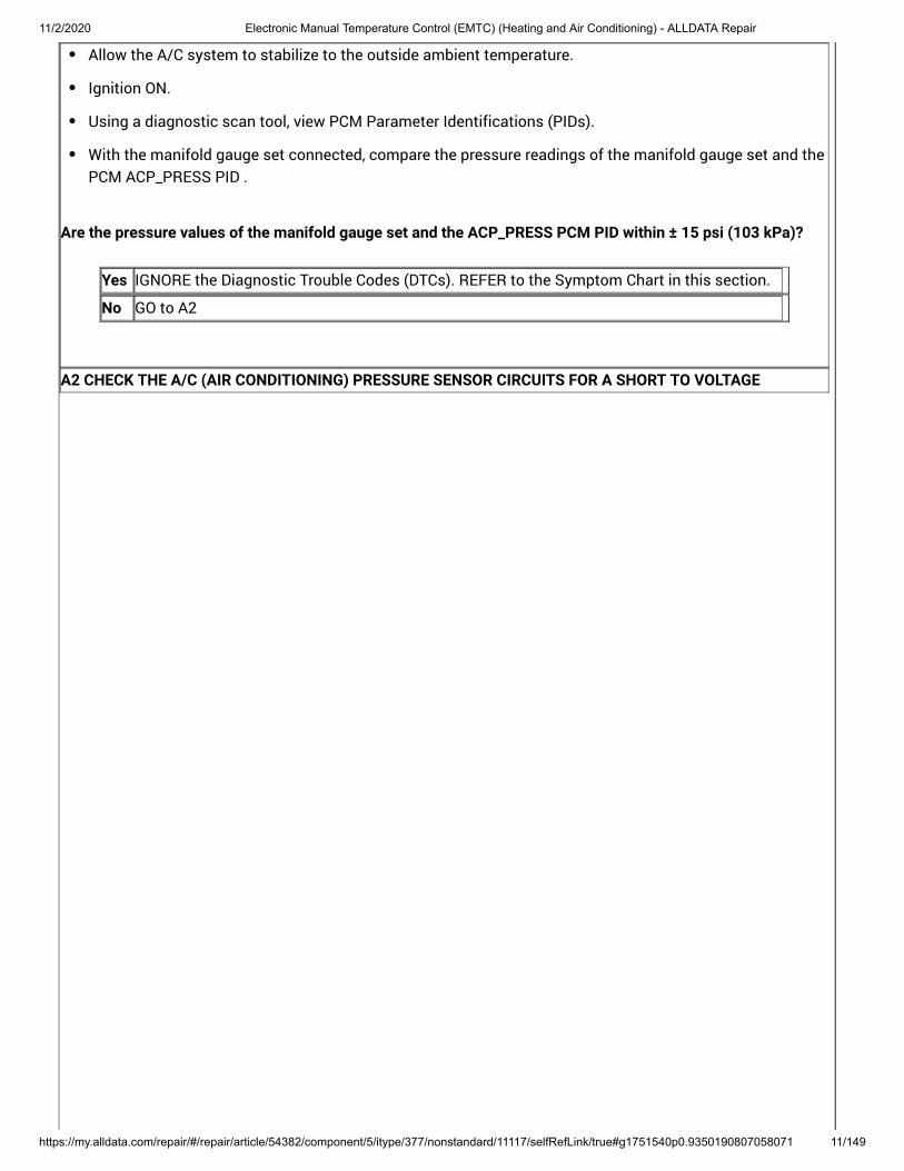
Ignition OFF.
Disconnect PCM 1.5L C1915B , 2.0L C1381B or 2.5L C1551B .
Disconnect A/C pressure transducer C1260 .
Disconnect Generator current sensor C1645 .
Ignition ON.
Measure:
Connectors:
AIR CONDITIONING (A/C) PRESSURETRANSDUCER
123
Positive Lead Measurement / Action Negative Lead
C1260-1 Ground
C1260-2 Ground
C1260-3 Ground
Is any voltage present?
Yes REPAIR the circuit.
No GO to A3
A3 CHECK THE A/C (AIR CONDITIONING) PRESSURE SENSOR CIRCUITS FOR A SHORT TO GROUND
11/2/2020 Electronic Manual Temperature Control (EMTC) (Heating and Air Conditioning) - ALLDATA Repair
https://my.alldata.com/repair/#/repair/article/54382/component/5/itype/377/nonstandard/11117/selfRefLink/true#g1751540p0.9350190807058071 13/149
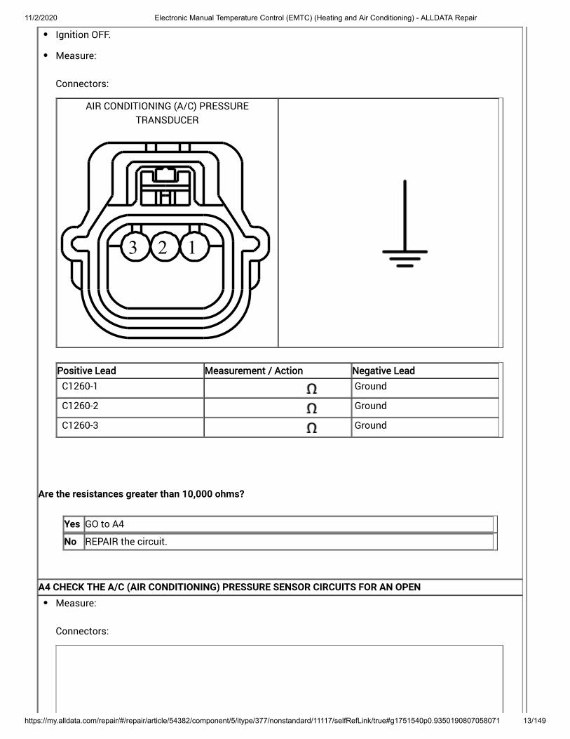
Ignition OFF.
Measure:
Connectors:
AIR CONDITIONING (A/C) PRESSURETRANSDUCER
123
Positive Lead Measurement / Action Negative Lead
C1260-1 Ground
C1260-2 Ground
C1260-3 Ground
Are the resistances greater than 10,000 ohms?
Yes GO to A4
No REPAIR the circuit.
A4 CHECK THE A/C (AIR CONDITIONING) PRESSURE SENSOR CIRCUITS FOR AN OPENMeasure:
Connectors:

11/2/2020 Electronic Manual Temperature Control (EMTC) (Heating and Air Conditioning) - ALLDATA Repair
https://my.alldata.com/repair/#/repair/article/54382/component/5/itype/377/nonstandard/11117/selfRefLink/true#g1751540p0.9350190807058071 14/149
AIR CONDITIONING (A/C) PRESSURETRANSDUCER
123
POWERTRAIN CONTROL MODULE (PCM)
103102
101100
9998
9796
95949392919089888786858483828180797877
76757473727170696867666564636261605958
57565554535251504948474645444342414039
38373635343332313029282726252423222120
19181716151413121110987654321
1.5L
Positive Lead Measurement / Action Negative Lead
C1260-1 C1915B-18
C1260-2 C1915B-52
C1260-3 C1915B-11
Connectors:
11/2/2020 Electronic Manual Temperature Control (EMTC) (Heating and Air Conditioning) - ALLDATA Repair
https://my.alldata.com/repair/#/repair/article/54382/component/5/itype/377/nonstandard/11117/selfRefLink/true#g1751540p0.9350190807058071 15/149
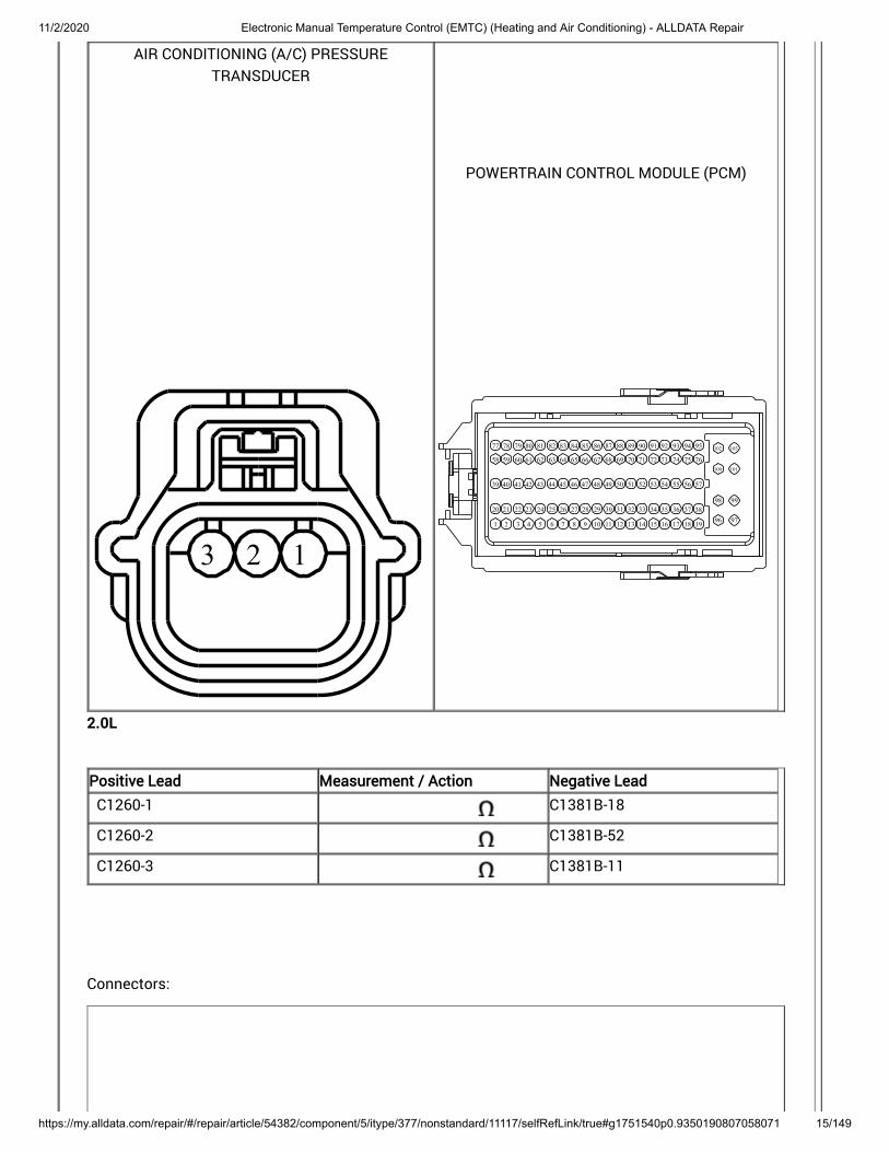
AIR CONDITIONING (A/C) PRESSURETRANSDUCER
123
POWERTRAIN CONTROL MODULE (PCM)
103102
101100
9998
9796
95949392919089888786858483828180797877
76757473727170696867666564636261605958
57565554535251504948474645444342414039
38373635343332313029282726252423222120
19181716151413121110987654321
2.0L
Positive Lead Measurement / Action Negative Lead
C1260-1 C1381B-18
C1260-2 C1381B-52
C1260-3 C1381B-11
Connectors:

11/2/2020 Electronic Manual Temperature Control (EMTC) (Heating and Air Conditioning) - ALLDATA Repair
https://my.alldata.com/repair/#/repair/article/54382/component/5/itype/377/nonstandard/11117/selfRefLink/true#g1751540p0.9350190807058071 16/149
AIR CONDITIONING (A/C) PRESSURETRANSDUCER
123
POWERTRAIN CONTROL MODULE (PCM)
1
2
3
4
5
6
7
8
9
10
11
12
13
14
15
16
17
18
19
20
21
22
23
24
25
26
27
28
29
30
31
32
33
34
35
36
37
38
39
40
41
42
43
44
45
46
47
48
49
50
51
52
53
54
55
56
57
58
59
60
61
62
63
64
65
66
67
68
69
70
2.5L
Positive Lead Measurement / Action Negative Lead
C1260-1 C1551B-56
C1260-2 C1551B-31
C1260-3 C1551B-52
Is the resistance less than 3 ohms?
Yes GO to A5
No REPAIR the circuit.
A5 CHECK THE A/C (AIR CONDITIONING) PRESSURE SENSOR CIRCUITS FOR A SHORT TOGETHERMeasure:
Connectors:

11/2/2020 Electronic Manual Temperature Control (EMTC) (Heating and Air Conditioning) - ALLDATA Repair
https://my.alldata.com/repair/#/repair/article/54382/component/5/itype/377/nonstandard/11117/selfRefLink/true#g1751540p0.9350190807058071 17/149
AIR CONDITIONING (A/C) PRESSURE TRANSDUCER
123
Positive Lead Measurement / Action Negative Lead
C1260-1 C1260-2
C1260-1 C1260-3
C1260-2 C1260-3
Are the resistances greater than 10,000 ohms?
Yes INSTALL a new A/C pressure transducer. REFER to: (412-00 Climate Control System -General Information, Removal and Installation) . TEST the system for normal operation. If the concern is still present, GO to
Air Conditioning (A/C) Pressure Transducer
A6
No REPAIR the circuits.

11/2/2020 Electronic Manual Temperature Control (EMTC) (Heating and Air Conditioning) - ALLDATA Repair
https://my.alldata.com/repair/#/repair/article/54382/component/5/itype/377/nonstandard/11117/selfRefLink/true#g1751540p0.9350190807058071 18/149
A6 CHECK FOR CORRECT PCM (POWERTRAIN CONTROL MODULE) OPERATIONIgnition OFF.
Disconnect and inspect all PCM connectors.
Repair:corrosion (install new connector or terminals – clean module pins)damaged or bent pins – install new terminals/pinspushed-out pins – install new pins as necessary
Connect the PCM connectors. Make sure they seat and latch correctly.
Operate the system and determine if the concern is still present.
Is the concern still present?
Yes CHECK OASIS for any applicable Technical Service Bulletins (TSBs). If a TSB exists for thisconcern, DISCONTINUE this test and FOLLOW TSB instructions. If no Technical ServiceBulletins (TSBs) address this concern, INSTALL a new PCM . For 1.5L, REFER to: (303-14A Electronic Engine Controls - 1.5L EcoBoost (118kW/160PS), Removaland Installation) .
For 2.0L, REFER to: (303-14B Electronic Engine Controls - 2.0L EcoBoost (184kW/250PS) - MI4,Removal and Installation) .
For 2.5L, REFER to: (303-14C Electronic Engine Controls - 2.5LDuratec (125kW/170PS), Removal and Installation) .
Powertrain Control Module (PCM)
No The system is operating correctly at this time. The concern may have been caused by aloose or corroded connector. ADDRESS the root cause of any connector or pin issues.
P0645
Refer to Wiring Diagrams Cell 54 for schematic and connector information.
Normal Operation and Fault Conditions
Voltage is provided to the A/C clutch relay coil. When A/C is requested and A/C line pressures allow, a ground isprovided to the A/C clutch relay coil from the PCM , energizing the A/C clutch relay.
DTC Fault Trigger Conditions

11/2/2020 Electronic Manual Temperature Control (EMTC) (Heating and Air Conditioning) - ALLDATA Repair
https://my.alldata.com/repair/#/repair/article/54382/component/5/itype/377/nonstandard/11117/selfRefLink/true#g1751540p0.9350190807058071 19/149
DTC Description Fault Trigger Conditions
P0645 A/C Clutch Relay Control Circuit The DTC sets when the PCMgrounds the relay circuit and morevoltage than expected is detectedon the relay circuit. The DTC alsosets when the relay circuit is off andno voltage is detected on the relaycircuit. The PCM expects to detectvoltage coming through the relaycoil to the relay circuit when it is notgrounding it.
Possible Sources
Wiring, terminals or connectorsA/C clutch relayPCM
Visual Inspection and Diagnostic Pre-checks
Inspect BJB fuse 22 (10A).
PINPOINT TEST B : P0645
NOTICE: Use the correct probe adapter(s) from the Flex Probe Kit when taking measurements. Failure to usethe correct probe adapter(s) may damage the connector.B1 CHECK THE VOLTAGE TO THE A/C (AIR CONDITIONING) CLUTCH RELAY COIL VOLTAGE SUPPLY CIRCUITFOR AN OPEN

11/2/2020 Electronic Manual Temperature Control (EMTC) (Heating and Air Conditioning) - ALLDATA Repair
https://my.alldata.com/repair/#/repair/article/54382/component/5/itype/377/nonstandard/11117/selfRefLink/true#g1751540p0.9350190807058071 20/149
Ignition OFF.
Disconnect A/C clutch relay.
Ignition ON.
Measure:
Connectors:
Positive Lead Measurement / Action Negative Lead
A/C clutch relay socket 2 Ground
Is the voltage greater than 11 volts?
Yes GO to B2
No REPAIR the circuit.
B2 CHECK THE A/C (AIR CONDITIONING) CLUTCH RELAYIgnition OFF.
Check the A/C clutch relay. Refer to Wiring Diagrams Cell 149 for schematic and connector information.
Does the relay pass the component test?
Yes GO to B3
No INSTALL a new A/C clutch relay.
B3 CHECK THE A/C (AIR CONDITIONING) CLUTCH RELAY CONTROL CIRCUIT FOR A SHORT TO VOLTAGE

11/2/2020 Electronic Manual Temperature Control (EMTC) (Heating and Air Conditioning) - ALLDATA Repair
https://my.alldata.com/repair/#/repair/article/54382/component/5/itype/377/nonstandard/11117/selfRefLink/true#g1751540p0.9350190807058071 21/149
Ignition OFF.
Disconnect A/C clutch relay.
Disconnect PCM 1.5L C1915B , 2.0L C1381B or 2.5L C1551B .
Ignition ON.
Measure:
Connectors:
Positive Lead Measurement / Action Negative Lead
A/C clutch relay socket 1 Ground
Is any voltage present?
Yes REPAIR the circuit.
No GO to B4
B4 CHECK THE A/C (AIR CONDITIONING) CLUTCH RELAY CONTROL CIRCUIT FOR A SHORT TO GROUND

11/2/2020 Electronic Manual Temperature Control (EMTC) (Heating and Air Conditioning) - ALLDATA Repair
https://my.alldata.com/repair/#/repair/article/54382/component/5/itype/377/nonstandard/11117/selfRefLink/true#g1751540p0.9350190807058071 22/149
Ignition OFF.
Measure:
Connectors:
Positive Lead Measurement / Action Negative Lead
A/C clutch relay socket 1 Ground
Is the resistance greater than 10,000 ohms?
Yes GO to B5
No REPAIR the circuit.
B5 CHECK THE A/C (AIR CONDITIONING) CLUTCH RELAY CONTROL CIRCUIT FOR AN OPENMeasure:
Connectors:
POWERTRAIN CONTROL MODULE (PCM)
103102
101100
9998
9796
95949392919089888786858483828180797877
76757473727170696867666564636261605958
57565554535251504948474645444342414039
38373635343332313029282726252423222120
19181716151413121110987654321
1.5L

11/2/2020 Electronic Manual Temperature Control (EMTC) (Heating and Air Conditioning) - ALLDATA Repair
https://my.alldata.com/repair/#/repair/article/54382/component/5/itype/377/nonstandard/11117/selfRefLink/true#g1751540p0.9350190807058071 23/149
Positive LeadPositive Lead Measurement / ActionMeasurement / Action Negative LeadNegative Lead
A/C clutch relay socket 1 C1915B-2
Connectors:
POWERTRAIN CONTROL MODULE (PCM)
103102
101100
9998
9796
95949392919089888786858483828180797877
76757473727170696867666564636261605958
57565554535251504948474645444342414039
38373635343332313029282726252423222120
19181716151413121110987654321
2.0L
Positive Lead Measurement / Action Negative Lead
A/C clutch relay socket 1 C1381B-2
Connectors:

11/2/2020 Electronic Manual Temperature Control (EMTC) (Heating and Air Conditioning) - ALLDATA Repair
https://my.alldata.com/repair/#/repair/article/54382/component/5/itype/377/nonstandard/11117/selfRefLink/true#g1751540p0.9350190807058071 24/149
POWERTRAIN CONTROL MODULE (PCM)
1
2
3
4
5
6
7
8
9
10
11
12
13
14
15
16
17
18
19
20
21
22
23
24
25
26
27
28
29
30
31
32
33
34
35
36
37
38
39
40
41
42
43
44
45
46
47
48
49
50
51
52
53
54
55
56
57
58
59
60
61
62
63
64
65
66
67
68
69
70
2.5L
Positive Lead Measurement / Action Negative Lead
A/C clutch relay socket 1 C1551B-12

11/2/2020 Electronic Manual Temperature Control (EMTC) (Heating and Air Conditioning) - ALLDATA Repair
https://my.alldata.com/repair/#/repair/article/54382/component/5/itype/377/nonstandard/11117/selfRefLink/true#g1751540p0.9350190807058071 25/149
Is the resistance less than 3 ohms?
Yes GO to B6
No REPAIR the circuit.
B6 CHECK FOR CORRECT PCM (POWERTRAIN CONTROL MODULE) OPERATIONIgnition OFF.
Disconnect and inspect all the PCM connectors.
Repair:corrosion (install new connector or terminals – clean module pins)damaged or bent pins – install new terminals/pinspushed-out pins – install new pins as necessary
Connect the PCM connectors. Make sure they seat and latch correctly.
Operate the system and determine if the concern is still present.
Is the concern still present?
Yes CHECK OASIS for any applicable Technical Service Bulletins (TSBs). If a TSB exists for thisconcern, DISCONTINUE this test and FOLLOW TSB instructions. If no Technical ServiceBulletins (TSBs) address this concern, INSTALL a new PCM . For 1.5L, REFER to: (303-14A Electronic Engine Controls - 1.5L EcoBoost (118kW/160PS), Removaland Installation) .
For 2.0L, REFER to: (303-14B Electronic Engine Controls - 2.0L EcoBoost (184kW/250PS) - MI4,Removal and Installation) .
For 2.5L, REFER to: (303-14C Electronic Engine Controls - 2.5LDuratec (125kW/170PS), Removal and Installation) .
Powertrain Control Module (PCM)
No The system is operating correctly at this time. The concern may have been caused by aloose or corroded connector. ADDRESS the root cause of any connector or pin issues.
Unable To Duplicate The Customer Concern And No Diagnostic Trouble Codes (DTCs) Present
This diagnostic procedure tests the functions of the HVAC system and identifies the correct HVAC symptompinpoint test.
Normal Operation and Fault Conditions

11/2/2020 Electronic Manual Temperature Control (EMTC) (Heating and Air Conditioning) - ALLDATA Repair
https://my.alldata.com/repair/#/repair/article/54382/component/5/itype/377/nonstandard/11117/selfRefLink/true#g1751540p0.9350190807058071 26/149
System Operation, REFER to: Climate Control System - Vehicles With: Electronic Manual Temperature Control (EMTC) (412-00 ClimateControl System - General Information) .
PINPOINT TEST C : UNABLE TO DUPLICATE THE CUSTOMER CONCERN AND NO DIAGNOSTIC TROUBLECODES (DTCS) PRESENT
C1 CHECK THE PCM (POWERTRAIN CONTROL MODULE) FOR DIAGNOSTIC TROUBLE CODES (DTCS)Ignition ON.
Using a diagnostic scan tool, carry out the PCM KOEO self-test.
Are any climate control related Diagnostic Trouble Codes (DTCs) present?
Yes REFER to the PCM DTC chart in this section.
No GO to C2
C2 CHECK THE FCIM (FRONT CONTROLS INTERFACE MODULE) FOR DIAGNOSTIC TROUBLE CODES (DTCS)Ignition ON.
Using a diagnostic scan tool, carry out the FCIM self-test.
Are any Diagnostic Trouble Codes (DTCs) present?
Yes REFER to the FCIM DTC chart in this section.
No GO to C3
C3 CHECK THE BLOWER MOTOR OPERATIONIgnition ON.
Select panel mode.
Observe blower motor operation and select each blower motor speed.
Does the blower motor operate in all ranges?
Yes GO to C4
No If the blower motor does not operate in any setting, If the blower motor does not correctly change speeds or shut off,
GO to Pinpoint Test J GO to Pinpoint Test K
C4 CHECK AIRFLOW OPERATION
11/2/2020 Electronic Manual Temperature Control (EMTC) (Heating and Air Conditioning) - ALLDATA Repair
https://my.alldata.com/repair/#/repair/article/54382/component/5/itype/377/nonstandard/11117/selfRefLink/true#g1751540p0.9350190807058071 27/149
Select the highest blower motor setting.
While observing the airflow, select each of the airflow positions (panel, panel/floor, floor, floor/defrost,defrost).
Is the airflow directed to the correct outlets?
Yes GO to C5
No GO to Pinpoint Test E
C5 VERIFY TEMPERATURE CONTROL OPERATIONStart the vehicle and allow it to reach normal operating temperature.
With the A/C off, select panel mode.
Change the driver and passenger temperature settings from the coldest to the warmest and back to thecoldest.
Does the temperature change between very warm to cool?
Yes GO to C6
No If the temperature does not get very warm, If the temperature does not change at all,
GO to Pinpoint Test F GO to Pinpoint Test I
C6 VERIFY THE A/C (AIR CONDITIONING) COMPRESSOR DOES NOT ENGAGE WITH A/C (AIR CONDITIONING)OFF
With the engine running and the A/C off, select panel mode.
Select the coldest temperature setting.
Is the outlet temperature close to ambient air temperature?
Yes GO to C7
No If the outlet air temperature is warmer than ambient air temperature, If the outlet temperature is significantly colder than ambient air temperature and the A/C
is engaged,
GO to Pinpoint Test I
compressor clutch GO to Pinpoint Test H
C7 VERIFY THE A/C (AIR CONDITIONING) COMPRESSOR IS OPERATIONAL IN THE A/C (AIR CONDITIONING)MODE

11/2/2020 Electronic Manual Temperature Control (EMTC) (Heating and Air Conditioning) - ALLDATA Repair
https://my.alldata.com/repair/#/repair/article/54382/component/5/itype/377/nonstandard/11117/selfRefLink/true#g1751540p0.9350190807058071 28/149
Make sure the ambient air temperature is above 2°C (36°F).
With the engine running, select panel mode.
Press the A/C button (indicator on).
Is the A/C compressor operational when the panel and A/C button (indicator on) is pressed?
Yes GO to C8
No GO to Pinpoint Test G
C8 CHECK THE RECIRCULATED AIR OPERATIONWith the engine running, press the recirculated air button (indicator off).
Select panel mode.
Select the highest blower motor setting.
Observe airflow noise.
Press the recirculated air button (indicator on).
Does the airflow noise increase when the recirculated air mode is selected (indicator on)?
Yes GO to C9
No GO to Pinpoint Test D
C9 CHECK THE FCIM (FRONT CONTROLS INTERFACE MODULE) LEFT DISCHARGE FLOOR TEMPERATURE(LDFTEMP) PID (PARAMETER IDENTIFICATION)
Using a diagnostic scan tool, view the FCIM Parameter Identifications (PIDs).
Monitor the LDFTEMP PID .
Is the temperature coming out of the driver footwell similar to the PID ? vent
Yes GO to C10
No GO to Pinpoint Test L
C10 CHECK THE FCIM (FRONT CONTROLS INTERFACE MODULE) LEFT DISCHARGE PANEL VENTTEMPERATURE (LDPT) PID (PARAMETER IDENTIFICATION)

11/2/2020 Electronic Manual Temperature Control (EMTC) (Heating and Air Conditioning) - ALLDATA Repair
https://my.alldata.com/repair/#/repair/article/54382/component/5/itype/377/nonstandard/11117/selfRefLink/true#g1751540p0.9350190807058071 29/149
Using a diagnostic scan tool view the FCIM Parameter Identifications (PIDs).
Monitor the LDPT PID .
Is the temperature coming out of the driver side register similar to the PID ?
Yes GO to C11
No GO to Pinpoint Test L
C11 CHECK THE FCIM (FRONT CONTROLS INTERFACE MODULE) (INT_TEMP) PID (PARAMETER IDENTIFICATION)
INTERIOR TEMPERATURE SENSOR
Using a diagnostic scan tool view the FCIM Parameter Identifications (PIDs).
Monitor the INT_TEMP PID .
Is the air temperature at the cabin temperature sensor similar to the PID ?
Yes GO to C12
No GO to Pinpoint Test M
C12 CHECK THE TOUCHSCREEN CONTROLS OPERATIONUsing the touchscreen controls, select each climate control function.
Using the touchscreen controls, select each audio control function.
Do all touchscreen controls operate?
Yes The system is operating correctly.
NoREFER to: (415-00B Information and EntertainmentSystem - General Information - Vehicles With: SYNC 2/Touchscreen Display, Diagnosis andTesting) .
Information and Entertainment System
The Air Inlet Door Is Inoperative
Refer to Wiring Diagrams Cell 54 for schematic and connector information.
Normal Operation and Fault Conditions
To rotate the air inlet door actuator, the FCIM supplies voltage and ground to the air inlet door actuator through thedoor actuator motor circuits. To reverse the air inlet door actuator rotation, the FCIM reverses the voltage andground circuits. The air inlet door actuator feedback resistors are supplied a ground from the FCIM by the air inlet

11/2/2020 Electronic Manual Temperature Control (EMTC) (Heating and Air Conditioning) - ALLDATA Repair
https://my.alldata.com/repair/#/repair/article/54382/component/5/itype/377/nonstandard/11117/selfRefLink/true#g1751540p0.9350190807058071 30/149
door actuator return circuits and a 5-volt reference voltage on the air inlet door actuator reference circuits. The FCIMreads the voltage on the air inlet door actuator feedback circuits to determine the air inlet door actuator position bythe position of the actuator feedback wiper arm.resistor
During an actuator calibration cycle, the FCIM drives the air inlet door until the door reaches both internal stops inthe FCIM case. If the air inlet is temporarily obstructed or binding during a calibration cycle, the FCIMmay interpret this as the actual end of travel for the door. When this condition occurs and the FCIM commands theactuator to its end of travel, the air intake may not be from the expected source.
mode door
DTC Fault Trigger Conditions
DTC Description Fault Trigger Conditions
B1083:11 Recirculation Damper Motor: CircuitShort To Ground
This DTC sets when the modulesenses lower than expected voltageon an actuator motor circuit whenvoltage is applied to drive the motor,indicating a short to ground.
B1083:12 Recirculation Damper Motor: CircuitShort To Battery
This DTC sets when the modulesenses higher than expectedvoltage on the actuator motorcircuit when ground is applied todrive the motor, indicating a short tovoltage.
B1083:13 Recirculation Damper Motor: CircuitOpen
This DTC sets when the modulesenses no voltage on the actuatormotor circuit when ground is appliedto drive the motor, indicating a opencircuit.
B11F0:11 Air Intake Damper Position Sensor:Circuit Short to Ground
This DTC sets when the modulesenses less than 1 volt on theactuator feedback circuit, indicatinga short to ground.
B11F0:15 Air Intake Damper Position Sensor:Circuit Short to Battery or Open
This DTC sets when the modulesenses greater than 4 volts on theactuator feedback circuit, indicatingan open circuit or a short to voltage.
Possible Sources
Wiring, terminals or connectorsAir inlet door actuatorAir inlet door binding or stuckFCIM
PINPOINT TEST D : THE AIR INLET DOOR IS INOPERATIVE
11/2/2020 Electronic Manual Temperature Control (EMTC) (Heating and Air Conditioning) - ALLDATA Repair
https://my.alldata.com/repair/#/repair/article/54382/component/5/itype/377/nonstandard/11117/selfRefLink/true#g1751540p0.9350190807058071 31/149
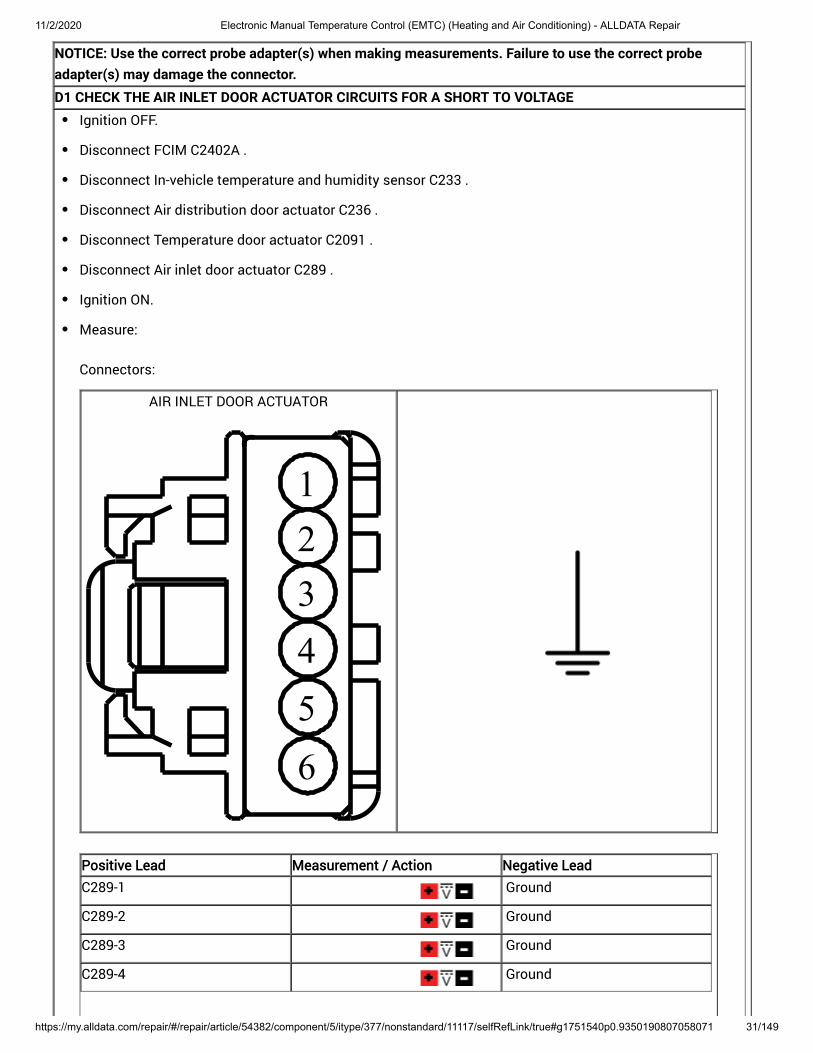
NOTICE: Use the correct probe adapter(s) when making measurements. Failure to use the correct probeadapter(s) may damage the connector.D1 CHECK THE AIR INLET DOOR ACTUATOR CIRCUITS FOR A SHORT TO VOLTAGE
Ignition OFF.
Disconnect FCIM C2402A .
Disconnect In-vehicle temperature and humidity sensor C233 .
Disconnect Air distribution door actuator C236 .
Disconnect Temperature door actuator C2091 .
Disconnect Air inlet door actuator C289 .
Ignition ON.
Measure:
Connectors:
AIR INLET DOOR ACTUATOR
123456
Positive Lead Measurement / Action Negative Lead
C289-1 Ground
C289-2 Ground
C289-3 Ground
C289-4 Ground

11/2/2020 Electronic Manual Temperature Control (EMTC) (Heating and Air Conditioning) - ALLDATA Repair
https://my.alldata.com/repair/#/repair/article/54382/component/5/itype/377/nonstandard/11117/selfRefLink/true#g1751540p0.9350190807058071 32/149
Positive Lead Measurement / Action Negative Lead
C289-6 Ground
Is there any voltage present?
Yes REPAIR the circuit.
No GO to D2
D2 CHECK THE AIR INLET DOOR ACTUATOR CIRCUITS FOR A SHORT TO GROUND

11/2/2020 Electronic Manual Temperature Control (EMTC) (Heating and Air Conditioning) - ALLDATA Repair
https://my.alldata.com/repair/#/repair/article/54382/component/5/itype/377/nonstandard/11117/selfRefLink/true#g1751540p0.9350190807058071 33/149
Ignition OFF.
Measure:
Connectors:
AIR INLET DOOR ACTUATOR
123456
Positive Lead Measurement / Action Negative Lead
C289-1 Ground
C289-2 Ground
C289-3 Ground
C289-4 Ground
C289-6 Ground
Are the resistances greater than 10,000 ohms?
Yes GO to D3
No REPAIR the circuit.
D3 CHECK THE AIR INLET DOOR ACTUATOR CIRCUITS FOR AN OPEN

11/2/2020 Electronic Manual Temperature Control (EMTC) (Heating and Air Conditioning) - ALLDATA Repair
https://my.alldata.com/repair/#/repair/article/54382/component/5/itype/377/nonstandard/11117/selfRefLink/true#g1751540p0.9350190807058071 34/149
Measure:
Connectors:
AIR INLET DOOR ACTUATOR
123456
FRONT CONTROLS INTERFACE MODULE (FCIM)
12345678910111213
14151617181920212223242526
Positive Lead Measurement / Action Negative Lead
C289-1 C2402A-24
C289-2 C2402A-2
C289-3 C2402A-3
C289-4 C2402A-16
C289-6 C2402A-25
Are the resistances less than 3 ohms?
Yes GO to D4
No REPAIR the circuit.
D4 CHECK THE AIR INLET DOOR ACTUATOR CIRCUITS FOR A SHORT TOGETHERMeasure:

11/2/2020 Electronic Manual Temperature Control (EMTC) (Heating and Air Conditioning) - ALLDATA Repair
https://my.alldata.com/repair/#/repair/article/54382/component/5/itype/377/nonstandard/11117/selfRefLink/true#g1751540p0.9350190807058071 35/149
Connectors:
AIR INLET DOOR ACTUATOR
123456
Positive Lead Measurement / Action Negative Lead
C289-1 C289-2
C289-1 C289-3

11/2/2020 Electronic Manual Temperature Control (EMTC) (Heating and Air Conditioning) - ALLDATA Repair
https://my.alldata.com/repair/#/repair/article/54382/component/5/itype/377/nonstandard/11117/selfRefLink/true#g1751540p0.9350190807058071 36/149
Positive Lead Measurement / Action Negative Lead
C289-1 C289-4
C289-1 C289-6
C289-2 C289-3
C289-2 C289-4
C289-2 C289-6
C289-3 C289-4
C289-3 C289-6
C289-4 C289-6
Are the resistances greater than 10,000 ohms?
Yes INSTALL a new air inlet door actuator. REFER to: (412-00 Climate Control System - General Information,Removal and Installation) . TEST the system for normal operation. If the concern is still present, GO to
Air Inlet Door Actuator
D5
No REPAIR the circuit.
D5 CHECK FOR CORRECT FRONT CONTROLS INTERFACE MODULE OPERATION

11/2/2020 Electronic Manual Temperature Control (EMTC) (Heating and Air Conditioning) - ALLDATA Repair
https://my.alldata.com/repair/#/repair/article/54382/component/5/itype/377/nonstandard/11117/selfRefLink/true#g1751540p0.9350190807058071 37/149
Ignition OFF.
Disconnect and inspect all the FCIM connectors.
Repair:corrosion (install new connector or terminals – clean module pins)damaged or bent pins – install new terminals/pinspushed-out pins – install new pins as necessary
Connect the FCIM connectors. Make sure they seat and latch correctly.
Operate the system and determine if the concern is still present.
Is the concern still present?
Yes CHECK OASIS for any applicable Technical Service Bulletins (TSBs). If a TSB exists for thisconcern, DISCONTINUE this test and FOLLOW TSB instructions. If no Technical ServiceBulletins (TSBs) address this concern, INSTALL a new FCIM . For vehicles equipped with Sony® Audio System, REFER to: (415-00C Information and EntertainmentSystem - General Information - Vehicles With: Sony Audio System, Removal and Installation).
For vehicles equipped with Touchscreen Display, REFER to: (415-00B Information and EntertainmentSystem - General Information - Vehicles With: SYNC 2/Touchscreen Display, Removal andInstallation) .
For all other audio systems, REFER to: (415-00A Information and EntertainmentSystem - General Information - Vehicles With: SYNC, Removal and Installation) .
Front Controls Interface Module (FCIM)
Front Controls Interface Module (FCIM)
Front Controls Interface Module (FCIM)
No The system is operating correctly at this time. The concern may have been caused by aloose or corroded connector. ADDRESS the root cause of any connector or pin issues.
Incorrect Or Erratic Direction Of Airflow From Outlets
Refer to Wiring Diagrams Cell 54 for schematic and connector information.
Normal Operation and Fault Conditions
To rotate the air distribution door actuator, the FCIM supplies voltage and ground to the air distribution dooractuator through the door actuator motor circuits. To reverse the air distribution door actuator rotation, the FCIMreverses the voltage and ground circuits. The air distribution door actuator feedback resistors are supplied a groundfrom the FCIM by the air distribution door actuator return circuits and a 5-volt reference voltage on the airdistribution door actuator reference circuits. The FCIM reads the voltage on the air distribution door actuatorfeedback circuits to determine the air distribution door actuator position by the position of the actuator feedbackresistor wiper arm.

11/2/2020 Electronic Manual Temperature Control (EMTC) (Heating and Air Conditioning) - ALLDATA Repair
https://my.alldata.com/repair/#/repair/article/54382/component/5/itype/377/nonstandard/11117/selfRefLink/true#g1751540p0.9350190807058071 38/149
During an actuator calibration cycle, the FCIM drives the air distribution door until the door reaches both internalstops in the FCIM case. If the air distribution door is temporarily obstructed or binding during a calibration cycle, theFCIM may interpret this as the actual end of travel for the door. When this condition occurs and the FCIM commandsthe actuator to its end of travel, the airflow may not be from the expected outlets.
DTC Fault Trigger Conditions
DTC Description Fault Trigger Conditions
B1086:11 Air Distribution Damper Motor:Circuit Short to Ground
This DTC sets when the modulesenses no changes in the feedbackcircuit when motor movement iscommanded and no motor electricalDiagnostic Trouble Codes (DTCs)are present.
B1086:12 Air Distribution Damper Motor:Circuit Short to Battery
This DTC sets when the modulesenses no changes in the feedbackcircuit when motor movement iscommanded and no motor electricalDiagnostic Trouble Codes (DTCs)are present.
B1086:13 Air Distribution Damper Motor:Circuit Open
This DTC sets when the modulesenses no voltage on the actuatormotor circuit when ground is appliedto drive the motor, indicating a opencircuit.
B11E7:11 Air Distribution Damper PositionSensor: Circuit Short to ground
This DTC sets when the modulesenses less than 1 volt on theactuator feedback circuit, indicatinga short to ground.
B11E7:15 Air Distribution Damper PositionSensor: Circuit Short to Battery orOpen
This DTC sets when the modulesenses greater than 4 volts on theactuator feedback circuit, indicatingan open circuit or a short to voltage.
Possible Sources
Wiring, terminals or connectorsAir distribution door actuatorAir distribution door binding or stuckFCIM
PINPOINT TEST E : INCORRECT OR ERRATIC DIRECTION OF AIRFLOW FROM OUTLETS
NOTICE: Use the correct probe adapter(s) when making measurements. Failure to use the correct probeadapter(s) may damage the connector.

11/2/2020 Electronic Manual Temperature Control (EMTC) (Heating and Air Conditioning) - ALLDATA Repair
https://my.alldata.com/repair/#/repair/article/54382/component/5/itype/377/nonstandard/11117/selfRefLink/true#g1751540p0.9350190807058071 39/149
E1 CHECK THE AIR DISTRIBUTION DOOR ACTUATOR CIRCUITS FOR A SHORT TO VOLTAGEIgnition OFF.
Disconnect FCIM C2402A .
Disconnect In-vehicle temperature and humidity sensor C233 .
Disconnect Air inlet door actuator C289 .
Disconnect Temperature door actuator C2091 .
Disconnect Air distribution door actuator C236 .
Ignition ON.
Measure:
Connectors:
AIR DISTRIBUTION DOOR ACTUATOR
123456
Positive Lead Measurement / Action Negative Lead
C236-1 Ground
C236-2 Ground
C236-3 Ground
C236-4 Ground
C236-6 Ground

11/2/2020 Electronic Manual Temperature Control (EMTC) (Heating and Air Conditioning) - ALLDATA Repair
https://my.alldata.com/repair/#/repair/article/54382/component/5/itype/377/nonstandard/11117/selfRefLink/true#g1751540p0.9350190807058071 40/149
Is there any voltage present?
Yes REPAIR the circuit.
No GO to E2
E2 CHECK THE AIR DISTRIBUTION DOOR ACTUATOR CIRCUITS FOR A SHORT TO GROUND

11/2/2020 Electronic Manual Temperature Control (EMTC) (Heating and Air Conditioning) - ALLDATA Repair
https://my.alldata.com/repair/#/repair/article/54382/component/5/itype/377/nonstandard/11117/selfRefLink/true#g1751540p0.9350190807058071 41/149
Ignition OFF.
Measure:
Connectors:
AIR DISTRIBUTION DOOR ACTUATOR
123456
Positive Lead Measurement / Action Negative Lead
C236-1 Ground
C236-2 Ground
C236-3 Ground
C236-4 Ground
C236-6 Ground
Are the resistances greater than 10,000 ohms?
Yes GO to E3
No REPAIR the circuit.
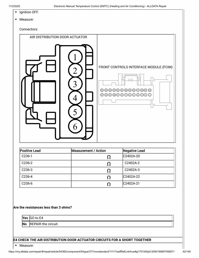
E3 CHECK THE AIR DISTRIBUTION DOOR ACTUATOR CIRCUITS FOR AN OPEN
11/2/2020 Electronic Manual Temperature Control (EMTC) (Heating and Air Conditioning) - ALLDATA Repair
https://my.alldata.com/repair/#/repair/article/54382/component/5/itype/377/nonstandard/11117/selfRefLink/true#g1751540p0.9350190807058071 42/149
Ignition OFF.
Measure:
Connectors:
AIR DISTRIBUTION DOOR ACTUATOR
123456
FRONT CONTROLS INTERFACE MODULE (FCIM)
12345678910111213
14151617181920212223242526
Positive Lead Measurement / Action Negative Lead
C236-1 C2402A-20
C236-2 C2402A-2
C236-3 C2402A-3
C236-4 C2402A-22
C236-6 C2402A-21
Are the resistances less than 3 ohms?
Yes GO to E4
No REPAIR the circuit.
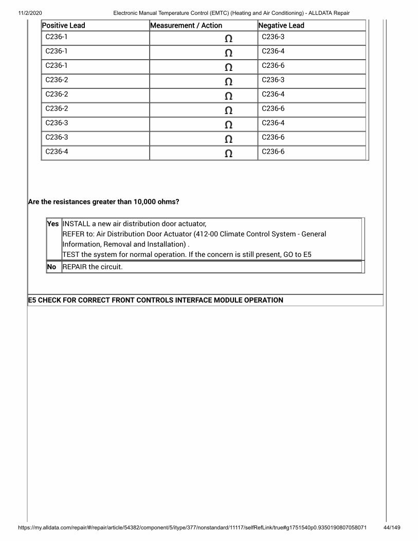
E4 CHECK THE AIR DISTRIBUTION DOOR ACTUATOR CIRCUITS FOR A SHORT TOGETHERMeasure:

11/2/2020 Electronic Manual Temperature Control (EMTC) (Heating and Air Conditioning) - ALLDATA Repair
https://my.alldata.com/repair/#/repair/article/54382/component/5/itype/377/nonstandard/11117/selfRefLink/true#g1751540p0.9350190807058071 43/149
Connectors:
AIR DISTRIBUTION DOOR ACTUATOR
123456
Positive Lead Measurement / Action Negative Lead
C236-1 C236-2
11/2/2020 Electronic Manual Temperature Control (EMTC) (Heating and Air Conditioning) - ALLDATA Repair
https://my.alldata.com/repair/#/repair/article/54382/component/5/itype/377/nonstandard/11117/selfRefLink/true#g1751540p0.9350190807058071 44/149
Positive Lead Measurement / Action Negative Lead
C236-1 C236-3
C236-1 C236-4
C236-1 C236-6
C236-2 C236-3
C236-2 C236-4
C236-2 C236-6
C236-3 C236-4
C236-3 C236-6
C236-4 C236-6
Are the resistances greater than 10,000 ohms?
Yes INSTALL a new air distribution door actuator, REFER to: (412-00 Climate Control System - GeneralInformation, Removal and Installation) . TEST the system for normal operation. If the concern is still present, GO to
Air Distribution Door Actuator
E5
No REPAIR the circuit.
E5 CHECK FOR CORRECT FRONT CONTROLS INTERFACE MODULE OPERATION

11/2/2020 Electronic Manual Temperature Control (EMTC) (Heating and Air Conditioning) - ALLDATA Repair
https://my.alldata.com/repair/#/repair/article/54382/component/5/itype/377/nonstandard/11117/selfRefLink/true#g1751540p0.9350190807058071 45/149
Ignition OFF.
Disconnect and inspect all the FCIM connectors.
Repair:corrosion (install new connector or terminals – clean module pins)damaged or bent pins – install new terminals/pinspushed-out pins – install new pins as necessary
Connect the FCIM connectors. Make sure they seat and latch correctly.
Operate the system and determine if the concern is still present.
Is the concern still present?
Yes CHECK OASIS for any applicable Technical Service Bulletins (TSBs). If a TSB exists for thisconcern, DISCONTINUE this test and FOLLOW TSB instructions. If no Technical ServiceBulletins (TSBs) address this concern, INSTALL a new FCIM . For vehicles equipped with Sony® Audio System, REFER to: (415-00C Information and EntertainmentSystem - General Information - Vehicles With: Sony Audio System, Removal and Installation).
For vehicles equipped with Touchscreen Display, REFER to: (415-00B Information and EntertainmentSystem - General Information - Vehicles With: SYNC 2/Touchscreen Display, Removal andInstallation) .
For all other audio systems, REFER to: (415-00A Information and EntertainmentSystem - General Information - Vehicles With: SYNC, Removal and Installation) .
Front Controls Interface Module (FCIM)
Front Controls Interface Module (FCIM)
Front Controls Interface Module (FCIM)
No The system is operating correctly at this time. The concern may have been caused by aloose or corroded connector. ADDRESS the root cause of any connector or pin issues.
Insufficient, Erratic, or No Heat
Normal Operation and Fault Conditions
When the engine is at operating temperature hot coolant flows from the engine through the and back tothe engine. Correct coolant temperatures are critical for good heater performance.
heater core
Possible Sources
Wiring, terminals or connectorstemperature door actuator(s)heater core
Visual Inspection and Diagnostic Pre-checks
Inspect for low engine coolant level.
11/2/2020 Electronic Manual Temperature Control (EMTC) (Heating and Air Conditioning) - ALLDATA Repair
https://my.alldata.com/repair/#/repair/article/54382/component/5/itype/377/nonstandard/11117/selfRefLink/true#g1751540p0.9350190807058071 46/149
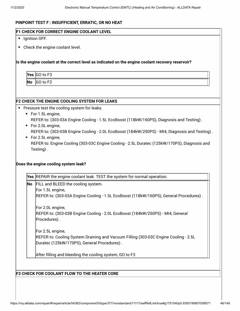
PINPOINT TEST F : INSUFFICIENT, ERRATIC, OR NO HEAT
F1 CHECK FOR CORRECT ENGINE COOLANT LEVELIgnition OFF.
Check the engine coolant level.
Is the engine coolant at the correct level as indicated on the engine coolant recovery reservoir?
Yes GO to F3
No GO to F2
F2 CHECK THE ENGINE COOLING SYSTEM FOR LEAKSPressure test the cooling system for leaks.
For 1.5L engine, REFER to: (303-03A Engine Cooling - 1.5L EcoBoost (118kW/160PS), Diagnosis and Testing) . For 2.0L engine, REFER to: (303-03B Engine Cooling - 2.0L EcoBoost (184kW/250PS) - MI4, Diagnosis and Testing) . For 2.5L engine, REFER to: (303-03C Engine Cooling - 2.5L Duratec (125kW/170PS), Diagnosis andTesting) .
Engine Cooling
Does the engine cooling system leak?
Yes REPAIR the engine coolant leak. TEST the system for normal operation.
No FILL and BLEED the cooling system. For 1.5L engine, REFER to: (303-03A Engine Cooling - 1.5L EcoBoost (118kW/160PS), General Procedures) .
For 2.0L engine, REFER to: (303-03B Engine Cooling - 2.0L EcoBoost (184kW/250PS) - MI4, GeneralProcedures) .
For 2.5L engine, REFER to: (303-03C Engine Cooling - 2.5LDuratec (125kW/170PS), General Procedures) .
After filling and bleeding the cooling system, GO to
Cooling System Draining and Vacuum Filling
F3
F3 CHECK FOR COOLANT FLOW TO THE HEATER CORE

11/2/2020 Electronic Manual Temperature Control (EMTC) (Heating and Air Conditioning) - ALLDATA Repair
https://my.alldata.com/repair/#/repair/article/54382/component/5/itype/377/nonstandard/11117/selfRefLink/true#g1751540p0.9350190807058071 47/149
Run the motor until it reaches normal operating temperature. Select the floor position on the . Set the temperature control to full warm and the blower to the lowest setting.
controlassembly
Using a suitable temperature measuring device, check the heater core inlet hose to see if it is hot.
Is the heater core inlet hose hot?
Yes GO to F4
No For 1.5L engine, REFER to: (303-03A Engine Cooling - 1.5L EcoBoost (118kW/160PS), Diagnosis and Testing).
For 2.0L engine, REFER to: (303-03B Engine Cooling - 2.0L EcoBoost (184kW/250PS) - MI4, Diagnosis andTesting) .
For 2.5L engine, REFER to: (303-03C Engine Cooling - 2.5L Duratec (125kW/170PS), Diagnosisand Testing) .
Engine Cooling
F4 CHECK FOR A PLUGGED OR RESTRICTED HEATER COREUsing a suitable temperature measuring device, measure the heater core outlet hose temperature.
Is the heater core outlet hose temperature similar to the inlet hose temperature (within approximately 6-17°C[10-30°F])?
Yes DIAGNOSE for a not operating correctly. blend door actuator GO to Pinpoint Test I
No INSTALL a new heater core. REFER to: (412-00 Climate Control System - General Information, Removal andInstallation) .
Heater Core
THE A/C IS INOPERATIVE
Refer to Wiring Diagrams Cell 54 for schematic and connector information.
Normal Operation and Fault Conditions
Control System Logic REFER to: Climate Control System - Vehicles With: Electronic Manual Temperature Control (EMTC) (412-00 ClimateControl System - General Information) .
Possible Sources
Wiring, terminals or connectorsCommunication network

11/2/2020 Electronic Manual Temperature Control (EMTC) (Heating and Air Conditioning) - ALLDATA Repair
https://my.alldata.com/repair/#/repair/article/54382/component/5/itype/377/nonstandard/11117/selfRefLink/true#g1751540p0.9350190807058071 48/149
Ambient Air Temperature (AAT) sensorA/C pressure transducerEvaporator temperature sensorElectric cooling fanIntake Air Temperature (IAT) / Mass Air Flow (MAF) sensorActive grille shutters (if equipped)FCIMPCM
Visual Inspection and Diagnostic Pre-checks
Inspect BJB fuse 22 (10A).
PINPOINT TEST G : THE A/C (AIR CONDITIONING) IS INOPERATIVE
NOTICE: Use the correct probe adapter(s) when making measurements. Failure to use the correct probeadapter(s) may damage the connector.G1 CHECK THE A/C (AIR CONDITIONING) SYSTEM PRESSURE
Ignition OFF.
With the R-134a manifold gauge set connected, check the A/C system pressure.
Is the A/C system pressure above 290 kPa (42 psi)?
Yes GO to G2
No CHECK the A/C system for leaks.
REFER to: (412-00 Climate Control System - GeneralInformation, General Procedures) .
REFER to: (412-00 Climate Control System - General Information,General Procedures) .
After leak is repaired, RECHARGE the A/C system. REFER to: (412-00 ClimateControl System - General Information, General Procedures) .
Fluorescent Dye Leak Detection
Electronic Leak Detection
Air Conditioning (A/C) System Recovery, Evacuation and Charging
G2 CHECK THE COMMUNICATION NETWORK

11/2/2020 Electronic Manual Temperature Control (EMTC) (Heating and Air Conditioning) - ALLDATA Repair
https://my.alldata.com/repair/#/repair/article/54382/component/5/itype/377/nonstandard/11117/selfRefLink/true#g1751540p0.9350190807058071 49/149
Ignition ON.
Using a diagnostic scan tool, carry out the network test.
Do the FCIM and the PCM pass the network test?
Yes GO to G3
No DIAGNOSE the FCIM or PCM does not communicate with the diagnostic scan tool. REFER to: Communications Network (418-00 Module Communications Network) .
G3 CHECK THE PCM (POWERTRAIN CONTROL MODULE) A/C (AIR CONDITIONING) PRESSURE SENSOR(ACP_PRESS) PID (PARAMETER IDENTIFICATION)
Ignition ON.
Using a diagnostic scan tool, view PCM Parameter Identifications (PIDs).
With a manifold gauge set connected, compare the pressure readings of the manifold gauge set and thePCM ACP_PRESS PID .
Are the pressure values of the manifold gauge set and the ACP_PRESS PCM PID within ± 15 psi (103 kPa)?
Yes GO to G4
No INSTALL a new A/C pressure transducer. REFER to: (412-00 Climate Control System -General Information, Removal and Installation) .
Air Conditioning (A/C) Pressure Transducer
G4 ELECTRIC COOLING FAN FUNCTIONAL CHECKIgnition ON.
Using a diagnostic scan tool, carry out the PCM KOEO self-test.
Does the electric cooling fan operate sometime during the KOEO self-test?
Yes GO to G5
No DIAGNOSE the electric cooling fan operation. REFER to Powertrain Control/EmissionsDiagnosis (PC/ED) manual. Section 3 Symptom Charts.
G5 COMPARE THE PCM (POWERTRAIN CONTROL MODULE) INTAKE AIR TEMPERATURE (IAT) PID(PARAMETER IDENTIFICATION) AND THE OTHER TEMPERATURE SENSOR READINGS TO THE PCM(POWERTRAIN CONTROL MODULE) AMBIENT AIR TEMPERATURE (AAT) PID (PARAMETER IDENTIFICATION)
11/2/2020 Electronic Manual Temperature Control (EMTC) (Heating and Air Conditioning) - ALLDATA Repair
https://my.alldata.com/repair/#/repair/article/54382/component/5/itype/377/nonstandard/11117/selfRefLink/true#g1751540p0.9350190807058071 50/149
NOTE: Compare multiple engine sensor readings to the ambient temperature to determine sensors are readingcorrectly. A faulty sensor can cause the PCM to disable the A/C with or without a DTC .
Allow the vehicle exterior and interior to stabilize to ambient temperature. This can take a soak period ofat least 6 hours.
Using a diagnostic scan tool, view PCM Parameter Identifications (PIDs).
Monitor the CHT, ECT, IAT, MAPT, and AAT Parameter Identifications (PIDs) (as applicable).
Are the temperature values similar (typically within 18ºC (32.4ºF)?
Yes GO to G6
No DIAGNOSE the suspect temperature sensor. REFER to Powertrain Control/EmissionsDiagnosis (PC/ED) manual.
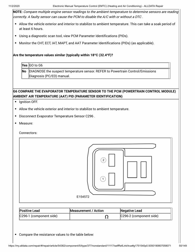
G6 COMPARE THE EVAPORATOR TEMPERATURE SENSOR TO THE PCM (POWERTRAIN CONTROL MODULE)AMBIENT AIR TEMPERATURE (AAT) PID (PARAMETER IDENTIFICATION)
Ignition OFF.
Allow the vehicle exterior and interior to stabilize to ambient temperature.
Disconnect Evaporator Temperature Sensor C296 .
Measure:
Connectors:
Positive Lead Measurement / Action Negative Lead
C296-1 (component side) C296-2 (component side)
Compare the resistance values to the table below:

11/2/2020 Electronic Manual Temperature Control (EMTC) (Heating and Air Conditioning) - ALLDATA Repair
https://my.alldata.com/repair/#/repair/article/54382/component/5/itype/377/nonstandard/11117/selfRefLink/true#g1751540p0.9350190807058071 51/149
Ambient Temperature °F (°C) Approximate Resistance
-4.0°F (-20°C) 14 K ohms — 14.1 K ohms
32.0°F (°C) 4.8 K ohms — 4.9 K ohms
68.0°F (20°C) 1.5 K ohms — 1.9 K ohms
77.0°F (25°C) 1.3 K ohms — 1.7 K ohms
103.9°F (40°C) 650 ohms — 1 K ohms
139.9°F (60°C) 230 ohms — 550 ohms
Ignition ON.
Using a diagnostic scan tool, view PCM Parameter Identifications (PIDs).
Monitor the AAT PID .
Is the resistance within the specified values for the temperatures?
Yes If equipped with the active grille shutter system, GO to If not equipped with the active grille shutter system, GO to
G7 G8
No INSTALL a new evaporator temperature sensor. REFER to: Evaporator Temperature Sensor (412-00 Climate Control System - GeneralInformation) .
G7 VERIFY THE GRILLE SHUTTER OPERATION USING THE PCM (POWERTRAIN CONTROL MODULE) GRILLSHUTTER A POSITION - COMMANDED (GRILL_A_CMD) PID (PARAMETER IDENTIFICATION)
Start the engine and allow it to idle for at least 30 seconds to allow for the grille shutter calibration tocomplete.
Using a diagnostic scan tool, view PCM PID .
Using a diagnostic scan tool, select the PCM PID GRILL_A_CMD and command the grille shutter from100% (open) to 0% (closed) while observing the grille shutter operation from the front of the vehicle.
Does the grill shutter fully open and close when commanded by the scan tool?
Yes GO to G8
No DIAGNOSE the active grille shutter is inoperative or does not operate correctly. REFER to: (501-02 Front End Body Panels, Diagnosis and Testing) . Active Grille Shutter
G8 CHECK THE FCIM (FRONT CONTROLS INTERFACE MODULE) A/C (AIR CONDITIONING) SWITCH(CC_SW_AC) PID (PARAMETER IDENTIFICATION) WITH THE A/C (AIR CONDITIONING) ON

11/2/2020 Electronic Manual Temperature Control (EMTC) (Heating and Air Conditioning) - ALLDATA Repair
https://my.alldata.com/repair/#/repair/article/54382/component/5/itype/377/nonstandard/11117/selfRefLink/true#g1751540p0.9350190807058071 52/149
Using a diagnostic scan tool, view FCIM Parameter Identifications (PIDs).
Monitor the CC_SW_AC PID .
Does the PID display Active?
Yes GO to G9
No GO to G17
G9 CHECK THE PCM (POWERTRAIN CONTROL MODULE) A/C (AIR CONDITIONING) REQUEST SIGNAL(AC_REQ) PID (PARAMETER IDENTIFICATION) WITH THE A/C (AIR CONDITIONING) ON
Start the engine.
Using a diagnostic scan tool, monitor the PCM AC_REQ PID .
On the HVAC controls, select PANEL and then press the A/C button (indicator on).
Does the PID display Yes when the button is pressed?
Yes GO to G11
No GO to G10
G10 RESET THE AMBIENT AIR TEMPERATURE (AAT) SENSOROn the HVAC controls, press the A/C (air conditioning) and Recirc buttons simultaneously, then releaseboth. Within 2 seconds press A/C button again.
Start the engine.
On the HVAC controls, set the temperature to full cold, select PANEL and select the A/C button (indicatoron).
Does the A/C compressor turn on?
Yes RETEST the A/C system for normal operation. REFER to: (412-00 Climate Control System - General Information,General Procedures) .
Refrigerant System Tests
No GO to G11
G11 CHECK THE PCM (POWERTRAIN CONTROL MODULE) A/C (AIR CONDITIONING) COMPRESSORCOMMANDED STATE (ACC_CMD) PID (PARAMETER IDENTIFICATION) WITH THE A/C (AIR CONDITIONING)COMMANDED ON

11/2/2020 Electronic Manual Temperature Control (EMTC) (Heating and Air Conditioning) - ALLDATA Repair
https://my.alldata.com/repair/#/repair/article/54382/component/5/itype/377/nonstandard/11117/selfRefLink/true#g1751540p0.9350190807058071 53/149
Using a diagnostic scan tool, activate the PCM ACC_CMD PID .
Does the A/C compressor turn on?
Yes GO to G18
No GO to G12
G12 CHECK THE VOLTAGE TO THE A/C (AIR CONDITIONING) CLUTCH RELAYIgnition OFF.
Disconnect the A/C clutch relay.
Ignition ON.
Measure:
Connectors:
Positive Lead Measurement / Action Negative Lead
A/C clutch relay socket 2 Ground
A/C clutch relay socket 3 Ground
Are the voltages greater than 11 volts?
Yes GO to G13
No VERIFY BJB C1035C-1 has voltage hot at all times and the PCM power relay is energizedwith ignition on. If not OK, REFER to the Wiring Diagrams manual to identify the possible causes of the circuitshort.
G13 BYPASS THE A/C (AIR CONDITIONING) CLUTCH RELAY

11/2/2020 Electronic Manual Temperature Control (EMTC) (Heating and Air Conditioning) - ALLDATA Repair
https://my.alldata.com/repair/#/repair/article/54382/component/5/itype/377/nonstandard/11117/selfRefLink/true#g1751540p0.9350190807058071 54/149
Ignition OFF.
Connect a fused jumper wire:
Connectors:
Positive Lead Measurement / Action Negative Lead
A/C clutch relay socket 3 A/C clutch relay socket 5
Ignition ON.
Does the A/C compressor clutch engage?
Yes REMOVE the fused jumper wire. INSTALL a new A/C clutch relay.
No LEAVE the fused jumper wire installed. GO to G14
G14 CHECK THE A/C (AIR CONDITIONING) COMPRESSOR CLUTCH FIELD COIL VOLTAGE SUPPLY CIRCUITFOR AN OPEN
Disconnect A/C compressor clutch field coil C100 .
Measure:
Connectors:

11/2/2020 Electronic Manual Temperature Control (EMTC) (Heating and Air Conditioning) - ALLDATA Repair
https://my.alldata.com/repair/#/repair/article/54382/component/5/itype/377/nonstandard/11117/selfRefLink/true#g1751540p0.9350190807058071 55/149
AIR CONDITIONING (A/C) COMPRESSOR
21
Positive Lead Measurement / Action Negative Lead
C100-1 Ground
Is the voltage greater than 11 volts?
Yes REMOVE the fused jumper wire. GO to G15
No REMOVE the fused jumper wire. VERIFY BJB fuse 22 (10A) is OK. If not OK, REFER to the Wiring Diagrams manual to identifythe possible causes of the circuit short. If OK, REPAIR the circuit.
G15 CHECK THE A/C (AIR CONDITIONING) COMPRESSOR CLUTCH FIELD COIL GROUND CIRCUIT FOR ANOPEN

11/2/2020 Electronic Manual Temperature Control (EMTC) (Heating and Air Conditioning) - ALLDATA Repair
https://my.alldata.com/repair/#/repair/article/54382/component/5/itype/377/nonstandard/11117/selfRefLink/true#g1751540p0.9350190807058071 56/149
Ignition OFF.
Measure:
Connectors:
AIR CONDITIONING (A/C) COMPRESSOR
21
Positive Lead Measurement / Action Negative Lead
C100-2 Ground
Is the resistance less than 3 ohms?
Yes GO to G16
No REPAIR the circuit.
G16 CHECK THE A/C (AIR CONDITIONING) COMPRESSOR CLUTCH AIR GAP

11/2/2020 Electronic Manual Temperature Control (EMTC) (Heating and Air Conditioning) - ALLDATA Repair
https://my.alldata.com/repair/#/repair/article/54382/component/5/itype/377/nonstandard/11117/selfRefLink/true#g1751540p0.9350190807058071 57/149
Measure the A/C compressor clutch air gap at 3 equally spaced locations between the clutch hub and theA/C compressor clutch pulley. REFER to: (412-00 Climate Control System - GeneralInformation, General Procedures) .
Air Conditioning (A/C) Clutch Air Gap Adjustment
Is the A/C compressor clutch air gap greater than 0.6 mm (0.0236 in)?
Yes ADJUST the A/C compressor clutch air gap. REFER to: (412-00 Climate Control System- General Information, General Procedures) .
Air Conditioning (A/C) Clutch Air Gap Adjustment
No INSTALL a new A/C Clutch and A/C Clutch Field Coil. REFER to: (412-00Climate Control System - General Information, General Procedures) .
Air Conditioning (A/C) Clutch and Air Conditioning (A/C) Clutch Field Coil
G17 CHECK FOR CORRECT FCIM (FRONT CONTROLS INTERFACE MODULE) OPERATION
11/2/2020 Electronic Manual Temperature Control (EMTC) (Heating and Air Conditioning) - ALLDATA Repair
https://my.alldata.com/repair/#/repair/article/54382/component/5/itype/377/nonstandard/11117/selfRefLink/true#g1751540p0.9350190807058071 58/149
Ignition OFF.
Disconnect and inspect all the FCIM connectors.
Repair:corrosion (install new connector or terminals – clean module pins)damaged or bent pins – install new terminals/pinspushed-out pins – install new pins as necessary
Connect the FCIM connectors. Make sure they seat and latch correctly.
Operate the system and determine if the concern is still present.
Is the concern still present?
Yes CHECK OASIS for any applicable Technical Service Bulletins (TSBs). If a TSB exists for thisconcern, DISCONTINUE this test and FOLLOW TSB instructions. If no Technical ServiceBulletins (TSBs) address this concern, INSTALL a new FCIM . For vehicles equipped with Sony® Audio System, REFER to: (415-00C Information and EntertainmentSystem - General Information - Vehicles With: Sony Audio System, Removal and Installation).
For vehicles equipped with Touchscreen Display, REFER to: (415-00B Information and EntertainmentSystem - General Information - Vehicles With: SYNC 2/Touchscreen Display, Removal andInstallation) .
For all other audio systems, REFER to: (415-00A Information and EntertainmentSystem - General Information - Vehicles With: SYNC, Removal and Installation) .
Front Controls Interface Module (FCIM)
Front Controls Interface Module (FCIM)
Front Controls Interface Module (FCIM)
No The system is operating correctly at this time. The concern may have been caused by aloose or corroded connector. ADDRESS the root cause of any connector or pin issues.
G18 CHECK FOR CORRECT PCM (POWERTRAIN CONTROL MODULE) OPERATION

11/2/2020 Electronic Manual Temperature Control (EMTC) (Heating and Air Conditioning) - ALLDATA Repair
https://my.alldata.com/repair/#/repair/article/54382/component/5/itype/377/nonstandard/11117/selfRefLink/true#g1751540p0.9350190807058071 59/149
Ignition OFF.
Disconnect and inspect the PCM connectors.
Repair:corrosion (replace connector or terminals – clean module pins)damaged or bent pins – replace terminals/pinspushed-out pins – replace pins as necessary
Connect the PCM connectors. Make sure they seat and latch correctly.
Operate the system and verify the concern is still present.
Is the concern still present?
Yes CHECK OASIS for any applicable Technical Service Bulletins (TSBs). If a TSB exists for thisconcern, DISCONTINUE this test and FOLLOW TSB instructions. If no Technical ServiceBulletins (TSBs) address this concern, INSTALL a new PCM . For 1.5L, REFER to: (303-14A Electronic Engine Controls - 1.5L EcoBoost (118kW/160PS), Removaland Installation) .
For 2.0L, REFER to: (303-14B Electronic Engine Controls - 2.0L EcoBoost (184kW/250PS) - MI4,Removal and Installation) .
For 2.5L, REFER to: (303-14C Electronic Engine Controls - 2.5LDuratec (125kW/170PS), Removal and Installation) .
Powertrain Control Module (PCM)
No The system is operating correctly at this time. The concern may have been caused bymodule connections. ADDRESS the root cause of any connector or pin issues.
The A/C Is Always On - A/C Mode Always Commanded On
Refer to Wiring Diagrams Cell 54 for schematic and connector information.
Normal Operation and Fault Conditions
Control System Logic REFER to: Climate Control System - Vehicles With: Electronic Manual Temperature Control (EMTC) (412-00 ClimateControl System - General Information) .
Possible Sources
A/C clutch relayWiring, terminals or connectorsPCMFCIM

11/2/2020 Electronic Manual Temperature Control (EMTC) (Heating and Air Conditioning) - ALLDATA Repair
https://my.alldata.com/repair/#/repair/article/54382/component/5/itype/377/nonstandard/11117/selfRefLink/true#g1751540p0.9350190807058071 60/149
PINPOINT TEST H : THE A/C (AIR CONDITIONING) IS ALWAYS ON - A/C (AIR CONDITIONING) MODE ALWAYSCOMMANDED ON
NOTICE: Use the correct probe adapter(s) when making measurements. Failure to use the correct probeadapter(s) may damage the connector.H1 CHECK THE A/C (AIR CONDITIONING) CLUTCH RELAY
Carry out the component test on the A/C clutch relay. Refer to Wiring Diagrams Cell 149 for schematic and connector information.
Did the relay pass the component test?
Yes GO to H2
No INSTALL a new A/C clutch relay.
H2 CHECK THE A/C (AIR CONDITIONING) COMPRESSOR CLUTCH FIELD COIL VOLTAGE SUPPLY CIRCUIT FORA SHORT TO VOLTAGE
Ignition OFF.
Disconnect A/C compressor clutch field coil C100 .
Disconnect the A/C clutch relay.
Ignition ON.
Measure:
Connectors:

11/2/2020 Electronic Manual Temperature Control (EMTC) (Heating and Air Conditioning) - ALLDATA Repair
https://my.alldata.com/repair/#/repair/article/54382/component/5/itype/377/nonstandard/11117/selfRefLink/true#g1751540p0.9350190807058071 61/149
AIR CONDITIONING (A/C) COMPRESSOR
21
Positive Lead Measurement / Action Negative Lead
C100-1 Ground

11/2/2020 Electronic Manual Temperature Control (EMTC) (Heating and Air Conditioning) - ALLDATA Repair
https://my.alldata.com/repair/#/repair/article/54382/component/5/itype/377/nonstandard/11117/selfRefLink/true#g1751540p0.9350190807058071 62/149
Is any voltage present?
Yes REPAIR the circuit.
No GO to H3
H3 COMPARE THE EVAPORATOR TEMPERATURE SENSOR TO THE PCM (POWERTRAIN CONTROL MODULE)AMBIENT AIR TEMPERATURE (AAT) PID (PARAMETER IDENTIFICATION)
Ignition OFF.
Allow the vehicle exterior and interior to stabilize to ambient temperature.
Disconnect Evaporator Temperature Sensor C296 .
Measure:
Connectors:
Positive Lead Measurement / Action Negative Lead
C296-1 (component side) C296-2 (component side)
Compare the resistance values to the table below:
Ambient Temperature °F (°C) Approximate Resistance
-4.0°F (-20°C) 14 K ohms — 14.1 K ohms
32.0°F (°C) 4.8 K ohms — 4.9 K ohms
68.0°F (20°C) 1.5 K ohms — 1.9 K ohms
77.0°F (25°C) 1.3 K ohms — 1.7 K ohms
103.9°F (40°C) 650 ohms — 1 K ohms
139.9°F (60°C) 230 ohms — 550 ohms

11/2/2020 Electronic Manual Temperature Control (EMTC) (Heating and Air Conditioning) - ALLDATA Repair
https://my.alldata.com/repair/#/repair/article/54382/component/5/itype/377/nonstandard/11117/selfRefLink/true#g1751540p0.9350190807058071 63/149
Ignition ON.
Using a diagnostic scan tool, view PCM Parameter Identifications (PIDs).
Monitor the AAT PID .
Is the resistance within the specified values for the temperatures?
Yes GO to H4
No INSTALL a new evaporator temperature sensor. REFER to: Evaporator Temperature Sensor (412-00 Climate Control System - GeneralInformation) .
H4 CHECK THE FCIM (FRONT CONTROLS INTERFACE MODULE) A/C (AIR CONDITIONING) SWITCH STATUS(CC_SW_AC) PID (PARAMETER IDENTIFICATION)
Ignition ON.
Using a diagnostic scan tool, view FCIM Parameter Identifications (PIDs).
Monitor the CC_SW_AC PID .
Select panel mode, press and release the A/C button (indicator off) on the FCIM controls.
Does the PID display Active when pressed and Inactive when released?
Yes GO to H5
No GO to H8
H5 CHECK THE A/C (AIR CONDITIONING) PRESSURE SENSOR (ACP_PRESS) PARAMETER IDENTIFICATION(PID)
Using a diagnostic scan tool, view the PCM Parameter Identification (PIDs).
With a manifold gauge set connected, compare the pressure readings of the manifold gauge set and thePCM Parameter Identification (PID) ACP_PRESS.
Are the pressure values of the manifold gauge set and the ACP_PRESS PCM PID within ± 15 psi (103 kPa)?
Yes GO to H6
No INSTALL a new A/C pressure transducer. REFER to: (412-00 Climate Control System -General Information, Removal and Installation) .
Air Conditioning (A/C) Pressure Transducer

11/2/2020 Electronic Manual Temperature Control (EMTC) (Heating and Air Conditioning) - ALLDATA Repair
https://my.alldata.com/repair/#/repair/article/54382/component/5/itype/377/nonstandard/11117/selfRefLink/true#g1751540p0.9350190807058071 64/149
H6 CHECK THE PCM (POWERTRAIN CONTROL MODULE) A/C (AIR CONDITIONING) REQUEST SIGNAL(AC_REQ) PID (PARAMETER IDENTIFICATION) WITH THE A/C (AIR CONDITIONING) OFF
Using a diagnostic scan tool, view PCM Parameter Identifications (PIDs).
Monitor the AC_REQ PID .
While in panel mode, release the A/C button (indicator off) on the FCIM controls.
Does the PID display off?
Yes GO to H9
No GO to H7
H7 CHECK THE PCM (POWERTRAIN CONTROL MODULE) A/C (AIR CONDITIONING) REQUEST SIGNAL(AC_REQ) PID (PARAMETER IDENTIFICATION) WITH FCIM (FRONT CONTROLS INTERFACE MODULE)DISCONNECTED
Ignition OFF.
Disconnect FCIM C2402A .
Ignition ON.
Using a diagnostic scan tool, view PCM Parameter Identifications (PIDs).
Monitor the AC_REQ PID .
Does the PID display off?
Yes GO to H9
No GO to H8
H8 CHECK FOR CORRECT FCIM (FRONT CONTROLS INTERFACE MODULE) OPERATION

11/2/2020 Electronic Manual Temperature Control (EMTC) (Heating and Air Conditioning) - ALLDATA Repair
https://my.alldata.com/repair/#/repair/article/54382/component/5/itype/377/nonstandard/11117/selfRefLink/true#g1751540p0.9350190807058071 65/149
Ignition OFF.
Disconnect and inspect all the FCIM connectors.
Repair:corrosion (install new connector or terminals – clean module pins)damaged or bent pins – install new terminals/pinspushed-out pins – install new pins as necessary
Connect the FCIM connectors. Make sure they seat and latch correctly.
Operate the system and determine if the concern is still present.
Is the concern still present?
Yes CHECK OASIS for any applicable Technical Service Bulletins (TSBs). If a TSB exists for thisconcern, DISCONTINUE this test and FOLLOW TSB instructions. If no Technical ServiceBulletins (TSBs) address this concern, INSTALL a new FCIM . For vehicles equipped with Sony® Audio System, REFER to: (415-00C Information and EntertainmentSystem - General Information - Vehicles With: Sony Audio System, Removal and Installation).
For vehicles equipped with Touchscreen Display, REFER to: (415-00B Information and EntertainmentSystem - General Information - Vehicles With: SYNC 2/Touchscreen Display, Removal andInstallation) .
For all other audio systems, REFER to: (415-00A Information and EntertainmentSystem - General Information - Vehicles With: SYNC, Removal and Installation) .
Front Controls Interface Module (FCIM)
Front Controls Interface Module (FCIM)
Front Controls Interface Module (FCIM)
No The system is operating correctly at this time. The concern may have been caused by aloose or corroded connector. ADDRESS the root cause of any connector or pin issues.
H9 CHECK FOR CORRECT PCM (POWERTRAIN CONTROL MODULE) OPERATION

11/2/2020 Electronic Manual Temperature Control (EMTC) (Heating and Air Conditioning) - ALLDATA Repair
https://my.alldata.com/repair/#/repair/article/54382/component/5/itype/377/nonstandard/11117/selfRefLink/true#g1751540p0.9350190807058071 66/149
Ignition OFF.
Disconnect and inspect the PCM connectors.
Repair:corrosion (replace connector or terminals – clean module pins)damaged or bent pins – replace terminals/pinspushed-out pins – replace pins as necessary
Connect the PCM connectors. Make sure they seat and latch correctly.
Operate the system and verify the concern is still present.
Is the concern still present?
Yes CHECK OASIS for any applicable Technical Service Bulletins (TSBs). If a TSB exists for thisconcern, DISCONTINUE this test and FOLLOW TSB instructions. If no Technical ServiceBulletins (TSBs) address this concern, INSTALL a new PCM . For 1.5L, REFER to: (303-14A Electronic Engine Controls - 1.5L EcoBoost (118kW/160PS), Removaland Installation) .
For 2.0L, REFER to: (303-14B Electronic Engine Controls - 2.0L EcoBoost (184kW/250PS) - MI4,Removal and Installation) .
For 2.5L, REFER to: (303-14C Electronic Engine Controls - 2.5LDuratec (125kW/170PS), Removal and Installation) .
Powertrain Control Module (PCM)
No The system is operating correctly at this time. The concern may have been caused bymodule connections. ADDRESS the root cause of any connector or pin issues.
The Temperature Control Is Inoperative Or Does Not Operate Correctly
Refer to Wiring Diagrams Cell 54 for schematic and connector information.
Normal Operation and Fault Conditions
Temperature Door Actuator, REFER to: Climate Control System - Vehicles With: Electronic Manual Temperature Control (EMTC) (412-00 ClimateControl System - General Information) .
During an actuator calibration cycle, the module drives the temperature door until the door reaches both internalstops in the HVAC case. If the temperature door is temporarily obstructed or binding during a calibration cycle, themodule may interpret this as the actual end of travel for the door. When this condition occurs and the modulecommands the actuator to its end of travel, the airflow may not be the expected temperature.

11/2/2020 Electronic Manual Temperature Control (EMTC) (Heating and Air Conditioning) - ALLDATA Repair
https://my.alldata.com/repair/#/repair/article/54382/component/5/itype/377/nonstandard/11117/selfRefLink/true#g1751540p0.9350190807058071 67/149
DTC Fault Trigger Conditions
NOTE: The manual climate control system has one temperature door actuator and it is located on the passengerside of the Heating, Ventilation and air conditioning (HVAC) case. For this temperature door actuator, the DiagnosticTrouble Codes (DTCs) referenced by the Front Controls Interface Module (FCIM) set the driver side temperature doorDiagnostic Trouble Codes (DTCs). The wiring circuits and connectors for the temperature door actuator utilize thedriver side temperature door actuator inputs to the Front Controls Interface Module (FCIM).
DTC Description Fault Trigger Conditions
B1081:11 Left Temperature Damper Motor:Circuit Short To Ground
This DTC sets when the modulesenses lower the expected voltageon an actuator motor circuit whenvoltage is applied to drive the motor,indicating a short to ground. Themotor can move only in onedirection.
B1081:12 Left Temperature Damper Motor:Circuit Short To Battery
This DTC sets when the modulesenses higher than expectedvoltage on the actuator motorcircuit when ground is applied todrive the motor, indicating a short tovoltage. The motor can move only inone direction.
B1081:13 Left Temperature Damper Motor:Open Circuit
This DTC sets when the modulesenses no voltage on the actuatormotor circuit when ground is appliedto drive the motor, indicating a opencircuit. The motor can not move.
B11E5:11 Left HVAC Damper Position Sensor:Circuit Short to Ground
This DTC sets when the modulesenses less than 1 volt on theactuator feedback circuit, indicatinga short to ground.
B11E5:15 Left HVAC Damper Position Sensor:Circuit Short to Battery or Open
This DTC sets when the modulesenses greater than 4 volts on theactuator feedback circuit, indicatingan open circuit or a short to voltage.
Possible Sources
Wiring, terminals or connectorsTemperature door actuatorFCIM
PINPOINT TEST I : THE TEMPERATURE CONTROL IS INOPERATIVE OR DOES NOT OPERATE CORRECTLY
NOTICE: Use the correct probe adapter(s) when making measurements. Failure to use the correct probeadapter(s) may damage the connector.

11/2/2020 Electronic Manual Temperature Control (EMTC) (Heating and Air Conditioning) - ALLDATA Repair
https://my.alldata.com/repair/#/repair/article/54382/component/5/itype/377/nonstandard/11117/selfRefLink/true#g1751540p0.9350190807058071 68/149
I1 CHECK THE TEMPERATURE DOOR ACTUATOR CIRCUITS FOR A SHORT TO VOLTAGEIgnition OFF.
Disconnect FCIM C2402A .
Disconnect In-vehicle temperature and humidity sensor C233 .
Disconnect Air distribution door actuator C236 .
Disconnect Air inlet door actuator C289 .
Disconnect Temperature door actuator C2091 .
Ignition ON.
Measure:
Connectors:
DRIVER TEMPERATURE DOOR ACTUATOR
123456
Positive Lead Measurement / Action Negative Lead
C2091-1 Ground
C2091-2 Ground
C2091-3 Ground
C2091-4 Ground
C2091-6 Ground

11/2/2020 Electronic Manual Temperature Control (EMTC) (Heating and Air Conditioning) - ALLDATA Repair
https://my.alldata.com/repair/#/repair/article/54382/component/5/itype/377/nonstandard/11117/selfRefLink/true#g1751540p0.9350190807058071 69/149
Is any voltage present?
Yes REPAIR the circuit.
No GO to I2
I2 CHECK THE TEMPERATURE DOOR ACTUATOR CIRCUITS FOR A SHORT TO GROUND

11/2/2020 Electronic Manual Temperature Control (EMTC) (Heating and Air Conditioning) - ALLDATA Repair
https://my.alldata.com/repair/#/repair/article/54382/component/5/itype/377/nonstandard/11117/selfRefLink/true#g1751540p0.9350190807058071 70/149
Ignition OFF.
Measure:
Connectors:
DRIVER TEMPERATURE DOOR ACTUATOR
123456
Positive Lead Measurement / Action Negative Lead
C2091-1 Ground
C2091-2 Ground
C2091-3 Ground
C2091-4 Ground
C2091-6 Ground
Are the resistances greater than 10,000 ohms?
Yes GO to I3
No REPAIR the circuit.
I3 CHECK THE TEMPERATURE DOOR ACTUATOR CIRCUITS FOR AN OPEN
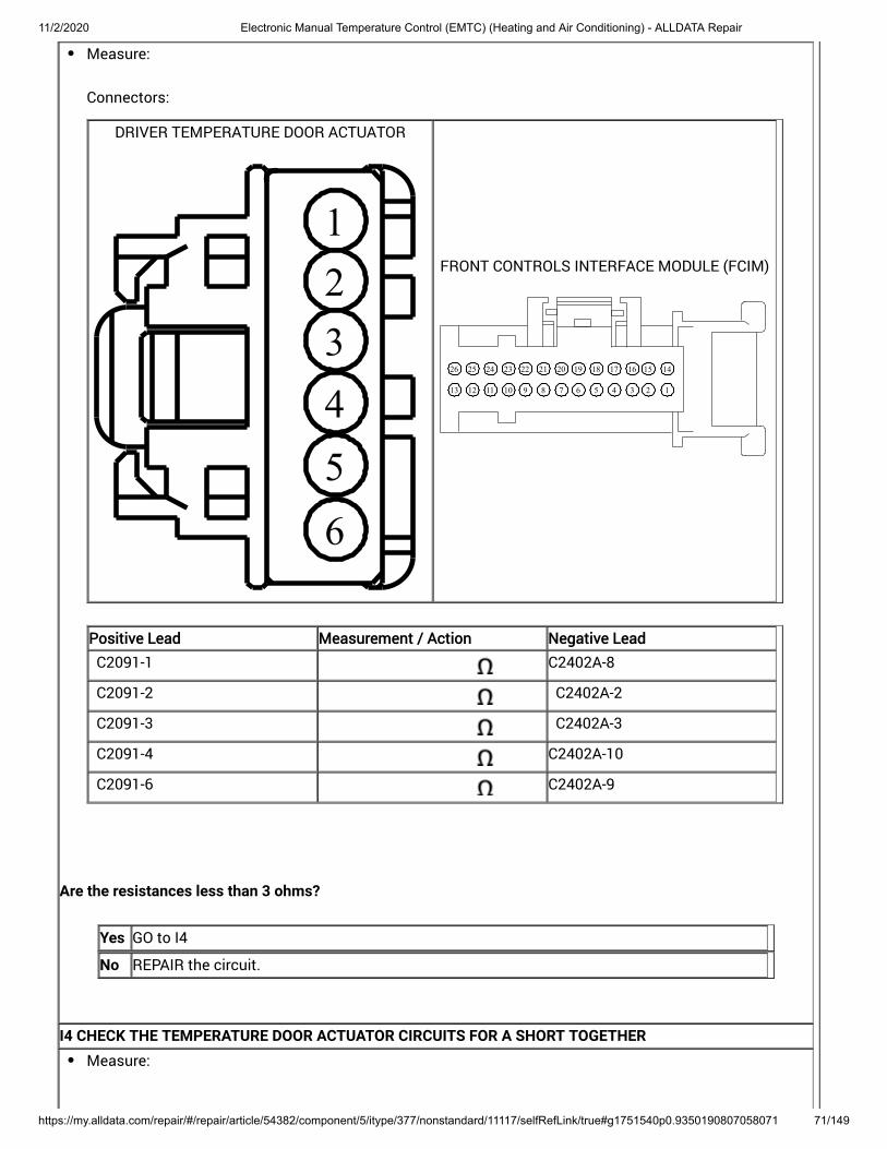
11/2/2020 Electronic Manual Temperature Control (EMTC) (Heating and Air Conditioning) - ALLDATA Repair
https://my.alldata.com/repair/#/repair/article/54382/component/5/itype/377/nonstandard/11117/selfRefLink/true#g1751540p0.9350190807058071 71/149
Measure:
Connectors:
DRIVER TEMPERATURE DOOR ACTUATOR
123456
FRONT CONTROLS INTERFACE MODULE (FCIM)
12345678910111213
14151617181920212223242526
Positive Lead Measurement / Action Negative Lead
C2091-1 C2402A-8
C2091-2 C2402A-2
C2091-3 C2402A-3
C2091-4 C2402A-10
C2091-6 C2402A-9
Are the resistances less than 3 ohms?
Yes GO to I4
No REPAIR the circuit.
I4 CHECK THE TEMPERATURE DOOR ACTUATOR CIRCUITS FOR A SHORT TOGETHERMeasure:

11/2/2020 Electronic Manual Temperature Control (EMTC) (Heating and Air Conditioning) - ALLDATA Repair
https://my.alldata.com/repair/#/repair/article/54382/component/5/itype/377/nonstandard/11117/selfRefLink/true#g1751540p0.9350190807058071 72/149
Connectors:
DRIVER TEMPERATURE DOOR ACTUATOR
123456
Positive Lead Measurement / Action Negative Lead
C2091-1 C2091-2
C2091-1 C2091-3

11/2/2020 Electronic Manual Temperature Control (EMTC) (Heating and Air Conditioning) - ALLDATA Repair
https://my.alldata.com/repair/#/repair/article/54382/component/5/itype/377/nonstandard/11117/selfRefLink/true#g1751540p0.9350190807058071 73/149
Positive Lead Measurement / Action Negative Lead
C2091-1 C2091-4
C2091-1 C2091-6
C2091-2 C2091-3
C2091-2 C2091-4
C2091-2 C2091-6
C2091-3 C2091-4
C2091-3 C2091-6
C2091-4 C2091-6
Are the resistances greater than 10,000 ohms?
Yes INSTALL a new passenger side temperature door actuator. REFER to: Passenger Side Temperature Door Actuator - LHD FWD (412-00 Climate ControlSystem - General Information) . TEST the system for normal operation. If the concern is still present, GO to I5
No REPAIR the circuit.
I5 CHECK FOR CORRECT FRONT CONTROLS INTERFACE MODULE (FCIM) OPERATION
11/2/2020 Electronic Manual Temperature Control (EMTC) (Heating and Air Conditioning) - ALLDATA Repair
https://my.alldata.com/repair/#/repair/article/54382/component/5/itype/377/nonstandard/11117/selfRefLink/true#g1751540p0.9350190807058071 74/149
Ignition OFF.
Disconnect and inspect all the FCIM connectors.
Repair:corrosion (install new connector or terminals – clean module pins)damaged or bent pins – install new terminals/pinspushed-out pins – install new pins as necessary
Connect the FCIM connectors. Make sure they seat and latch correctly.
Operate the system and determine if the concern is still present.
Is the concern still present?
Yes CHECK OASIS for any applicable Technical Service Bulletins (TSBs). If a TSB exists for thisconcern, DISCONTINUE this test and FOLLOW TSB instructions. If no Technical ServiceBulletins (TSBs) address this concern, INSTALL a new FCIM . For vehicles equipped with Sony® Audio System, REFER to: (415-00C Information and EntertainmentSystem - General Information - Vehicles With: Sony Audio System, Removal and Installation).
For vehicles equipped with Touchscreen Display, REFER to: (415-00B Information and EntertainmentSystem - General Information - Vehicles With: SYNC 2/Touchscreen Display, Removal andInstallation) .
For all other audio systems, REFER to: (415-00A Information and EntertainmentSystem - General Information - Vehicles With: SYNC, Removal and Installation) .
Front Controls Interface Module (FCIM)
Front Controls Interface Module (FCIM)
Front Controls Interface Module (FCIM)
No The system is operating correctly at this time. The concern may have been caused by aloose or corroded connector. ADDRESS the root cause of any connector or pin issues.
The Blower Motor Is Inoperative
Refer to Wiring Diagrams Cell 54 for schematic and connector information.
Normal Operation and Fault Conditions
Voltage is supplied to the from the BJB . When the blower motor relay coil receives power fromthe FCIM , the relay coil is energized and voltage is delivered to the . Power and groundfor the blower motor is provided by the blower motor speed control. The FCIM sends a Pulse Width Modulated(PWM) signal to the blower motor speed control to control the blower speed.
blower motor relayblower motor speed control
DTC Fault Trigger Conditions
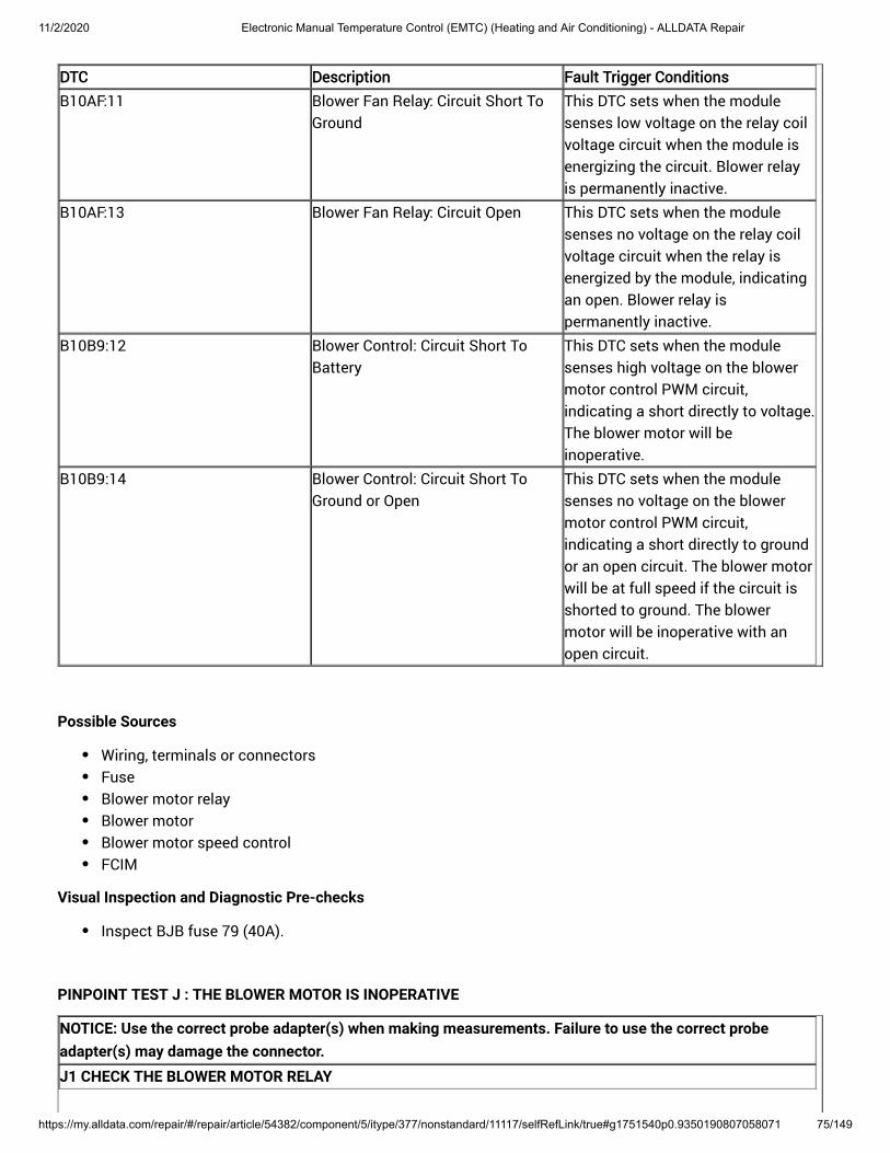
11/2/2020 Electronic Manual Temperature Control (EMTC) (Heating and Air Conditioning) - ALLDATA Repair
https://my.alldata.com/repair/#/repair/article/54382/component/5/itype/377/nonstandard/11117/selfRefLink/true#g1751540p0.9350190807058071 75/149
DTC Description Fault Trigger Conditions
B10AF:11 Blower Fan Relay: Circuit Short ToGround
This DTC sets when the modulesenses low voltage on the relay coilvoltage circuit when the module isenergizing the circuit. is permanently inactive.
Blower relay
B10AF:13 Blower Fan Relay: Circuit Open This DTC sets when the modulesenses no voltage on the relay coilvoltage circuit when the relay isenergized by the module, indicatingan open. Blower relay ispermanently inactive.
B10B9:12 Blower Control: Circuit Short ToBattery
This DTC sets when the modulesenses high voltage on the blowermotor control PWM circuit,indicating a short directly to voltage.The blower motor will beinoperative.
B10B9:14 Blower Control: Circuit Short ToGround or Open
This DTC sets when the modulesenses no voltage on the blowermotor control PWM circuit,indicating a short directly to groundor an open circuit. The blower motorwill be at full speed if the circuit isshorted to ground. The blowermotor will be inoperative with anopen circuit.
Possible Sources
Wiring, terminals or connectorsFuseBlower motor relayBlower motorBlower motor speed controlFCIM
Visual Inspection and Diagnostic Pre-checks
Inspect BJB fuse 79 (40A).
PINPOINT TEST J : THE BLOWER MOTOR IS INOPERATIVE
NOTICE: Use the correct probe adapter(s) when making measurements. Failure to use the correct probeadapter(s) may damage the connector.J1 CHECK THE BLOWER MOTOR RELAY

11/2/2020 Electronic Manual Temperature Control (EMTC) (Heating and Air Conditioning) - ALLDATA Repair
https://my.alldata.com/repair/#/repair/article/54382/component/5/itype/377/nonstandard/11117/selfRefLink/true#g1751540p0.9350190807058071 76/149
Ignition OFF.
Disconnect Blower motor relay.
Check the blower motor relay. Refer to Wiring Diagrams Cell 149 for schematic and connector information.
Does the relay pass the component test?
Yes GO to J2
No INSTALL a new blower motor relay.
J2 CHECK THE BLOWER MOTOR RELAY SWITCH CONTACT SUPPLY VOLTAGEMeasure:
Connectors:
Positive Lead Measurement / Action Negative Lead
Blower motor relay socket 3 Ground
Is the voltage greater than 11 volts?
Yes GO to J3
No VERIFY BJB fuse 79 (40A) is OK. If OK, REPAIR the circuit. If not OK, REFER to the WiringDiagrams manual to identify the possible causes of the circuit short.
J3 CHECK THE BLOWER MOTOR RELAY COIL GROUND CIRCUIT FOR AN OPEN

11/2/2020 Electronic Manual Temperature Control (EMTC) (Heating and Air Conditioning) - ALLDATA Repair
https://my.alldata.com/repair/#/repair/article/54382/component/5/itype/377/nonstandard/11117/selfRefLink/true#g1751540p0.9350190807058071 77/149
Measure:
Connectors:
Positive Lead Measurement / Action Negative Lead
Blower motor relay socket 2 Ground
Is the resistance less than 3 ohms?
Yes GO to J4
No REPAIR the circuit.
J4 CHECK THE BLOWER MOTOR RELAY COIL CONTROL CIRCUIT FOR A SHORT TO GROUND

11/2/2020 Electronic Manual Temperature Control (EMTC) (Heating and Air Conditioning) - ALLDATA Repair
https://my.alldata.com/repair/#/repair/article/54382/component/5/itype/377/nonstandard/11117/selfRefLink/true#g1751540p0.9350190807058071 78/149
Ignition OFF.
Disconnect FCIM C2402A .
Measure:
Connectors:
Positive Lead Measurement / Action Negative Lead
Blower motor relay socket 1 Ground
Is the resistance greater than 10,000 ohms?
Yes GO to J5
No REPAIR the circuit.
J5 CHECK THE BLOWER MOTOR RELAY COIL CONTROL CIRCUIT FOR AN OPEN

11/2/2020 Electronic Manual Temperature Control (EMTC) (Heating and Air Conditioning) - ALLDATA Repair
https://my.alldata.com/repair/#/repair/article/54382/component/5/itype/377/nonstandard/11117/selfRefLink/true#g1751540p0.9350190807058071 79/149
Measure:
Connectors:
FRONT CONTROLS INTERFACE MODULE (FCIM)
12345678910111213
14151617181920212223242526
Positive Lead Measurement / Action Negative Lead
Blower motor relay socket 1 C2402A-11
Is the resistance less than 3 ohms?
Yes GO to J6
No REPAIR the circuit.
J6 CHECK THE BLOWER MOTOR SPEED CONTROL VOLTAGE CIRCUITIgnition OFF.
Disconnect Blower motor speed control C297A .
Connect Blower motor relay.
Connect FCIM C2402A .
Ignition ON.
Select PANEL on the HVAC controls.
Select the highest blower motor setting.
Measure:
Connectors:

11/2/2020 Electronic Manual Temperature Control (EMTC) (Heating and Air Conditioning) - ALLDATA Repair
https://my.alldata.com/repair/#/repair/article/54382/component/5/itype/377/nonstandard/11117/selfRefLink/true#g1751540p0.9350190807058071 80/149
BLOWER MOTOR CONTROL MODULE
1234
56
Positive Lead Measurement / Action Negative Lead
C297A-6 Ground
Is the voltage greater than 11 volts?
Yes GO to J7
No REPAIR the circuit.
J7 CHECK THE BLOWER MOTOR SPEED CONTROL GROUND CIRCUIT FOR AN OPEN

11/2/2020 Electronic Manual Temperature Control (EMTC) (Heating and Air Conditioning) - ALLDATA Repair
https://my.alldata.com/repair/#/repair/article/54382/component/5/itype/377/nonstandard/11117/selfRefLink/true#g1751540p0.9350190807058071 81/149
Ignition OFF.
Measure:
Connectors:
BLOWER MOTOR CONTROL MODULE
1234
56
Positive Lead Measurement / Action Negative Lead
C297A-5 Ground
Is the resistance less than 3 ohms?
Yes GO to J8
No REPAIR the circuit.
J8 CHECK THE BLOWER MOTOR CONTROL PWM (PULSE WIDTH MODULATION) CIRCUIT FOR A SHORT TOVOLTAGE

11/2/2020 Electronic Manual Temperature Control (EMTC) (Heating and Air Conditioning) - ALLDATA Repair
https://my.alldata.com/repair/#/repair/article/54382/component/5/itype/377/nonstandard/11117/selfRefLink/true#g1751540p0.9350190807058071 82/149
Ignition OFF.
Disconnect FCIM C2402A .
Ignition ON.
Measure:
Connectors:
FRONT CONTROLS INTERFACE MODULE (FCIM)
12345678910111213
14151617181920212223242526
Positive Lead Measurement / Action Negative Lead
C2402A-23 Ground
Is any voltage present?
Yes REPAIR the circuit.
No GO to J9
J9 CHECK THE BLOWER MOTOR CONTROL PWM (PULSE WIDTH MODULATION) CIRCUIT FOR AN OPENMeasure:
Connectors:

11/2/2020 Electronic Manual Temperature Control (EMTC) (Heating and Air Conditioning) - ALLDATA Repair
https://my.alldata.com/repair/#/repair/article/54382/component/5/itype/377/nonstandard/11117/selfRefLink/true#g1751540p0.9350190807058071 83/149
FRONT CONTROLS INTERFACE MODULE (FCIM)
12345678910111213
14151617181920212223242526
BLOWER MOTOR CONTROL MODULE
1234
56
Positive Lead Measurement / Action Negative Lead
C2402A-23 C297A-3
Is the resistance less than 3 ohms?
Yes GO to J10
No REPAIR the circuit.
J10 CHECK THE OUTPUTS TO THE BLOWER MOTORDisconnect Blower Motor C2004 .

11/2/2020 Electronic Manual Temperature Control (EMTC) (Heating and Air Conditioning) - ALLDATA Repair
https://my.alldata.com/repair/#/repair/article/54382/component/5/itype/377/nonstandard/11117/selfRefLink/true#g1751540p0.9350190807058071 84/149
Connect Blower Motor Speed Control C297A .
Connect FCIM C2402A .
Ignition ON.
Select PANEL on the HVAC controls.
Select the highest blower motor setting.
Measure:
Connectors:
BLOWER MOTOR
2
1
Positive Lead Measurement / Action Negative Lead
C2004-1 C2004-2

11/2/2020 Electronic Manual Temperature Control (EMTC) (Heating and Air Conditioning) - ALLDATA Repair
https://my.alldata.com/repair/#/repair/article/54382/component/5/itype/377/nonstandard/11117/selfRefLink/true#g1751540p0.9350190807058071 85/149
Is the voltage greater than 11 volts?
Yes INSTALL a new blower motor. REFER to: (412-00 Climate Control System - General Information, Removal andInstallation) .
Blower Motor
No GO to J11
J11 CHECK THE CIRCUITS TO THE BLOWER MOTOR FOR AN OPEN

11/2/2020 Electronic Manual Temperature Control (EMTC) (Heating and Air Conditioning) - ALLDATA Repair
https://my.alldata.com/repair/#/repair/article/54382/component/5/itype/377/nonstandard/11117/selfRefLink/true#g1751540p0.9350190807058071 86/149
Ignition OFF.
Disconnect Blower Motor Speed Control C297B .
Measure:
Connectors:
BLOWER MOTOR CONTROL MODULE
2
1
BLOWER MOTOR
2
1
Positive Lead Measurement / Action Negative Lead
C297B-2 C2004-1
C297B-1 C2004-2
Are the resistances less than 3 ohms?
Yes GO to J12
No REPAIR the circuit in question.
J12 CHECK THE BLOWER MOTOR CIRCUITS FOR A SHORT TOGETHERMeasure:
Connectors:

11/2/2020 Electronic Manual Temperature Control (EMTC) (Heating and Air Conditioning) - ALLDATA Repair
https://my.alldata.com/repair/#/repair/article/54382/component/5/itype/377/nonstandard/11117/selfRefLink/true#g1751540p0.9350190807058071 87/149
BLOWER MOTOR CONTROL MODULE
2
1
Positive Lead Measurement / Action Negative Lead
C297B-1 C297B-2
Is the resistance greater than 10,000 ohms?

11/2/2020 Electronic Manual Temperature Control (EMTC) (Heating and Air Conditioning) - ALLDATA Repair
https://my.alldata.com/repair/#/repair/article/54382/component/5/itype/377/nonstandard/11117/selfRefLink/true#g1751540p0.9350190807058071 88/149
Yes INSTALL a new blower motor speed control. REFER to: (412-00 Climate Control System - GeneralInformation, Removal and Installation) . TEST the system for normal operation. If the concern is still present, GO to
Blower Motor Speed Control
J13
No REPAIR the circuits.
J13 CHECK FOR CORRECT FRONT CONTROLS INTERFACE MODULE (FCIM) OPERATIONIgnition OFF.
Disconnect and inspect all the FCIM connectors.
Repair:corrosion (install new connector or terminals – clean module pins)damaged or bent pins – install new terminals/pinspushed-out pins – install new pins as necessary
Reconnect the FCIM connectors. Make sure they seat and latch correctly.
Operate the system and determine if the concern is still present.
Is the concern still present?
Yes CHECK On-Line Automotive Service Information System (OASIS) for any applicable TechnicalService Bulletins (TSBs). If a Technical Service Bulletin (TSB) exists for this concern,DISCONTINUE this test and FOLLOW Technical Service Bulletin (TSB) instructions. If noTechnical Service Bulletins (TSBs) address this concern, INSTALL a new FCIM . Refer to theappropriate section in Group 415 for the procedure.
No The system is operating correctly at this time. The concern may have been caused by aloose or corroded connector. ADDRESS the root cause of any connector or pin issues.
The Blower Motor Does Not Operate Correctly
Refer to Wiring Diagrams Cell 54 for schematic and connector information.
Normal Operation and Fault Conditions
Voltage is supplied to the blower motor relay switch contacts from the BJB . The blower motor relay coil is suppliedvoltage by the FCIM . When the relay coil is energized and voltage is delivered to the blower motor control module.Power and ground for the blower motor is provided by the blower motor speed control. The FCIM sends a PulseWidth Modulated (PWM) signal to the blower motor speed control to control the blower speed.
DTC Fault Trigger Conditions
DTC Description Fault Trigger Conditions

11/2/2020 Electronic Manual Temperature Control (EMTC) (Heating and Air Conditioning) - ALLDATA Repair
https://my.alldata.com/repair/#/repair/article/54382/component/5/itype/377/nonstandard/11117/selfRefLink/true#g1751540p0.9350190807058071 89/149
DTC Description Fault Trigger Conditions
B10AF:12 Blower Fan Relay: Circuit Short ToBattery
This DTC sets when the modulesenses voltage on the relay coilvoltage circuit when the relay is notenergized by the module, indicatinga short directly to voltage. Theblower motor relay will be active atall times.
B10B9:14 Blower Control: Circuit Short ToGround or Open
This DTC sets when the modulesenses no voltage on the blowermotor control PWM circuit,indicating a short directly to groundor an open circuit. The blower motorwill be at full speed if the circuit isshorted to ground. The blowermotor will be inoperative with anopen circuit.
Possible Sources
Wiring, terminals or connectorsBlower motor relayBlower motor speed controlFCIM
PINPOINT TEST K : THE BLOWER MOTOR DOES NOT OPERATE CORRECTLY
NOTICE: Use the correct probe adapter(s) when making measurements. Failure to use the correct probeadapter(s) may damage the connector.K1 VERIFY THE BLOWER MOTOR OPERATION
Ignition ON.
Select panel on the FCIM controls. Adjust the blower motor setting to the minimum and maximumsettings.
Does the blower motor operate at any setting?
Yes GO to K2
No GO to Pinpoint Test J
K2 CHECK THE BLOWER MOTOR CONTROL PWM (PULSE WIDTH MODULATION) CIRCUIT FOR A SHORT TOVOLTAGE

11/2/2020 Electronic Manual Temperature Control (EMTC) (Heating and Air Conditioning) - ALLDATA Repair
https://my.alldata.com/repair/#/repair/article/54382/component/5/itype/377/nonstandard/11117/selfRefLink/true#g1751540p0.9350190807058071 90/149
Ignition OFF.
Disconnect Blower motor speed control C297A .
Disconnect FCIM C2402A .
Ignition ON.
Measure:
Connectors:
FRONT CONTROLS INTERFACE MODULE (FCIM)
12345678910111213
14151617181920212223242526
Positive Lead Measurement / Action Negative Lead
C2402A-23 Ground
Is any voltage present?
Yes REPAIR the circuit.
No GO to K3
K3 CHECK THE BLOWER MOTOR CONTROL PWM (PULSE WIDTH MODULATION) CIRCUIT FOR A SHORT TOGROUND
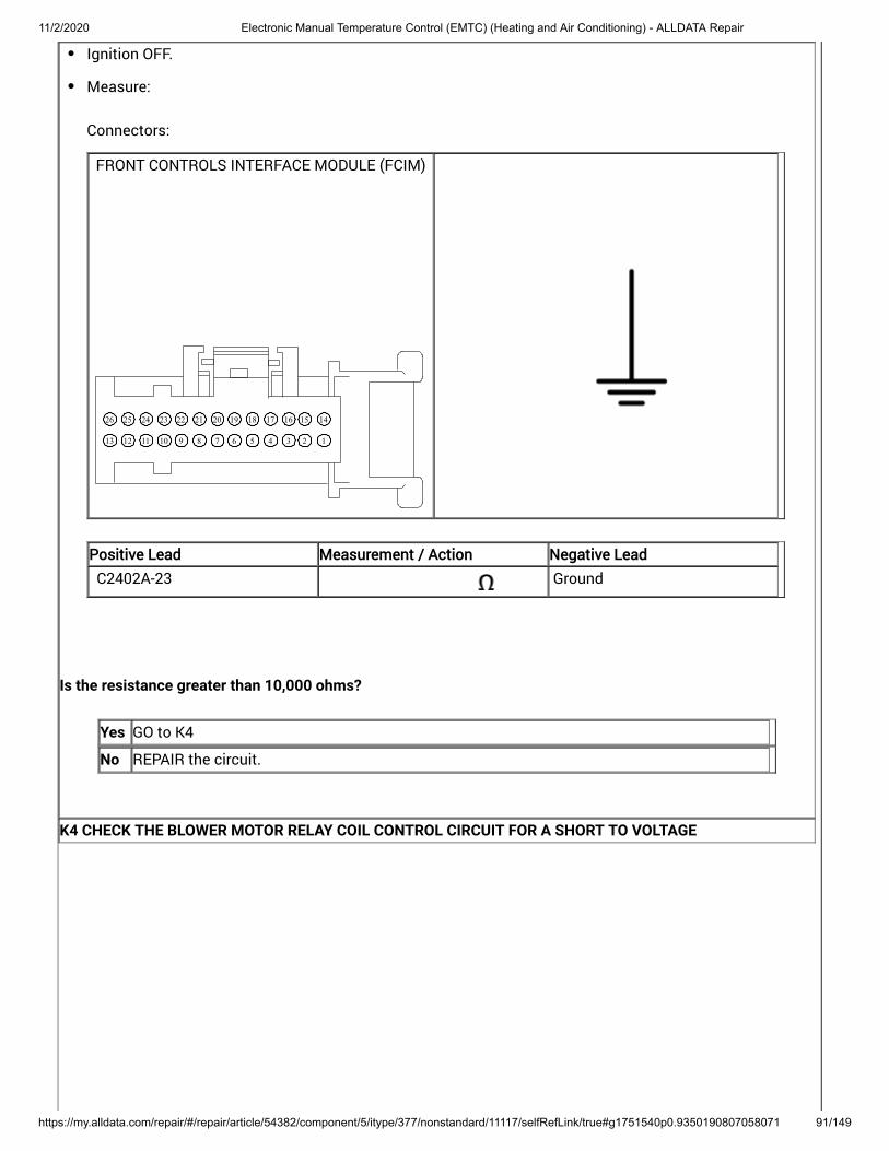
11/2/2020 Electronic Manual Temperature Control (EMTC) (Heating and Air Conditioning) - ALLDATA Repair
https://my.alldata.com/repair/#/repair/article/54382/component/5/itype/377/nonstandard/11117/selfRefLink/true#g1751540p0.9350190807058071 91/149
Ignition OFF.
Measure:
Connectors:
FRONT CONTROLS INTERFACE MODULE (FCIM)
12345678910111213
14151617181920212223242526
Positive Lead Measurement / Action Negative Lead
C2402A-23 Ground
Is the resistance greater than 10,000 ohms?
Yes GO to K4
No REPAIR the circuit.
K4 CHECK THE BLOWER MOTOR RELAY COIL CONTROL CIRCUIT FOR A SHORT TO VOLTAGE

11/2/2020 Electronic Manual Temperature Control (EMTC) (Heating and Air Conditioning) - ALLDATA Repair
https://my.alldata.com/repair/#/repair/article/54382/component/5/itype/377/nonstandard/11117/selfRefLink/true#g1751540p0.9350190807058071 92/149
Ignition OFF.
Disconnect Blower Motor Relay.
Ignition ON.
Measure:
Connectors:
Positive Lead Measurement / Action Negative Lead
Blower motor relay socket 1 Ground
Is any voltage present?
Yes REPAIR the circuit.
No GO to K5
K5 CHECK THE BLOWER MOTOR OPERATION WITH THE BLOWER MOTOR RELAY DISCONNECTEDIgnition OFF.
Connect Blower motor speed control C297A .
Connect FCIM C2402A .
Ignition ON.
Operate the system and determine if the concern is still present.
Does the fan still operate all the time?
Yes REPAIR the blower motor speed control voltage circuit CH402 (YE/GN) for a short to voltage.
No GO to K6

11/2/2020 Electronic Manual Temperature Control (EMTC) (Heating and Air Conditioning) - ALLDATA Repair
https://my.alldata.com/repair/#/repair/article/54382/component/5/itype/377/nonstandard/11117/selfRefLink/true#g1751540p0.9350190807058071 93/149
K6 CHECK FOR CORRECT BLOWER MOTOR SPEED CONTROL OPERATIONIgnition OFF.
Disconnect and inspect all the blower motor speed control connectors.
Repair:corrosion (install new connector or terminals – clean module pins)damaged or bent pins – install new terminals/pinspushed-out pins – install new pins as necessary
Connect the blower motor speed control connectors. Make sure they seat and latch correctly.
Operate the system and determine if the concern is still present.
Is the concern still present?
Yes INSTALL a new blower motor speed control. REFER to: (412-00 Climate Control System - GeneralInformation, Removal and Installation) . TEST the system for normal operation. If the concern is still present, GO to
Blower Motor Speed Control
K7
No The system is operating correctly at this time. The concern may have been caused by aloose or corroded connector. ADDRESS the root cause of any connector or pin issues.
K7 CHECK FOR CORRECT FRONT CONTROLS INTERFACE MODULE (FCIM) OPERATION

11/2/2020 Electronic Manual Temperature Control (EMTC) (Heating and Air Conditioning) - ALLDATA Repair
https://my.alldata.com/repair/#/repair/article/54382/component/5/itype/377/nonstandard/11117/selfRefLink/true#g1751540p0.9350190807058071 94/149
Ignition OFF.
Disconnect and inspect all the FCIM connectors.
Repair:corrosion (install new connector or terminals – clean module pins)damaged or bent pins – install new terminals/pinspushed-out pins – install new pins as necessary
Connect the FCIM connectors. Make sure they seat and latch correctly.
Operate the system and determine if the concern is still present.
Is the concern still present?
Yes CHECK OASIS for any applicable Technical Service Bulletins (TSBs). If a TSB exists for thisconcern, DISCONTINUE this test and FOLLOW TSB instructions. If no Technical ServiceBulletins (TSBs) address this concern, INSTALL a new FCIM . For vehicles equipped with Sony® Audio System, REFER to: (415-00C Information and EntertainmentSystem - General Information - Vehicles With: Sony Audio System, Removal and Installation).
For vehicles equipped with Touchscreen Display, REFER to: (415-00B Information and EntertainmentSystem - General Information - Vehicles With: SYNC 2/Touchscreen Display, Removal andInstallation) .
For all other audio systems, REFER to: (415-00A Information and EntertainmentSystem - General Information - Vehicles With: SYNC, Removal and Installation) .
Front Controls Interface Module (FCIM)
Front Controls Interface Module (FCIM)
Front Controls Interface Module (FCIM)
No The system is operating correctly at this time. The concern may have been caused by aloose or corroded connector. ADDRESS the root cause of any connector or pin issues.
B10B6:11, B10B6:15
Refer to Wiring Diagrams Cell 54 for schematic and connector information.
Normal Operation and Fault Conditions
The contains a . The sensor varies its resistance with the temperature.As the temperature rises, the resistance falls. As the temperature falls, the resistance rises.
air discharge temperature sensor thermistor
DTC Fault Trigger Conditions
DTC Description Fault Trigger Conditions

11/2/2020 Electronic Manual Temperature Control (EMTC) (Heating and Air Conditioning) - ALLDATA Repair
https://my.alldata.com/repair/#/repair/article/54382/component/5/itype/377/nonstandard/11117/selfRefLink/true#g1751540p0.9350190807058071 95/149
DTC Description Fault Trigger Conditions
B10B6:11 Left Floor Air DischargeTemperature: Circuit Short ToGround
This DTC sets when the FCIMsenses erratic voltages from the leftfloor air discharge temperaturesensor.
B10B6:15 Left Floor Air DischargeTemperature: Circuit Short ToBattery or Open
This DTC sets when the FCIMsenses erratic voltages from the leftfloor air discharge temperaturesensor.
Possible Sources
Wiring, terminals or connectorsAir discharge temperature sensor(s)FCIM
PINPOINT TEST L : B10B6:11, B10B6:15
L1 CHECK THE AIR DISCHARGE TEMPERATURE SENSOR OUTPUT VOLTAGE CIRCUITNOTICE: Use the correct probe adapter(s) when making measurements. Failure to use the correct probeadapter(s) may damage the connector.
Ignition OFF.
Disconnect: the appropriate air discharge temperature sensor:Disconnect the driver side footwell air discharge temperature sensor C2436
Ignition ON.
Turn the HVAC system on.
Measure:
Connectors:

11/2/2020 Electronic Manual Temperature Control (EMTC) (Heating and Air Conditioning) - ALLDATA Repair
https://my.alldata.com/repair/#/repair/article/54382/component/5/itype/377/nonstandard/11117/selfRefLink/true#g1751540p0.9350190807058071 96/149
DRIVER SIDE FOOTWELL AIR DISCHARGE TEMPERATURE SENSOR
123
11/2/2020 Electronic Manual Temperature Control (EMTC) (Heating and Air Conditioning) - ALLDATA Repair
https://my.alldata.com/repair/#/repair/article/54382/component/5/itype/377/nonstandard/11117/selfRefLink/true#g1751540p0.9350190807058071 97/149
Driver side footwell air discharge temperature sensor
Positive Lead Measurement / Action Negative Lead
C2436-1 C2436-3
Is the voltage between 4.7 and 5.1 volts?
Yes INSTALL a new driver side footwell air discharge temperature sensor. REFER to: Driver Side Footwell Air Discharge Temperature Sensor (412-00 Climate ControlSystem - General Information) . CLEAR the Diagnostic Trouble Codes (DTCs). REPEAT the self-test. If Diagnostic TroubleCode (DTC) returns, GO to L9
No GO to L2
L2 CHECK THE AIR DISCHARGE TEMPERATURE SENSOR SIGNAL CIRCUIT FOR A SHORT TO VOLTAGEIgnition OFF.
Disconnect FCIM C2402A .
Disconnect FCIM C2402B .
Ignition ON.
Measure:
Connectors:

11/2/2020 Electronic Manual Temperature Control (EMTC) (Heating and Air Conditioning) - ALLDATA Repair
https://my.alldata.com/repair/#/repair/article/54382/component/5/itype/377/nonstandard/11117/selfRefLink/true#g1751540p0.9350190807058071 98/149
DRIVER SIDE FOOTWELL AIR DISCHARGETEMPERATURE SENSOR
123
Driver side footwell air discharge temperature sensor
Positive Lead Measurement / Action Negative Lead
C2436-1 Ground
Is any voltage present?
Yes REPAIR the circuit.

11/2/2020 Electronic Manual Temperature Control (EMTC) (Heating and Air Conditioning) - ALLDATA Repair
https://my.alldata.com/repair/#/repair/article/54382/component/5/itype/377/nonstandard/11117/selfRefLink/true#g1751540p0.9350190807058071 99/149
No GO to L3
L3 CHECK THE AIR DISCHARGE TEMPERATURE SENSOR SIGNAL RETURN CIRCUIT FOR A SHORT TOVOLTAGE
Measure:
Connectors:
DRIVER SIDE FOOTWELL AIR DISCHARGETEMPERATURE SENSOR
123
Driver side footwell air discharge temperature sensor
Positive Lead Measurement / Action Negative Lead
C2436-3 Ground
Is any voltage present?
Yes REPAIR the circuit.
No GO to L4
L4 CHECK THE AIR DISCHARGE TEMPERATURE SENSOR SIGNAL CIRCUIT FOR A SHORT TO GROUND

11/2/2020 Electronic Manual Temperature Control (EMTC) (Heating and Air Conditioning) - ALLDATA Repair
https://my.alldata.com/repair/#/repair/article/54382/component/5/itype/377/nonstandard/11117/selfRefLink/true#g1751540p0.9350190807058071 100/149
Ignition OFF.
Measure:
Connectors:
DRIVER SIDE FOOTWELL AIR DISCHARGETEMPERATURE SENSOR
123
Driver side footwell air discharge temperature sensor
Positive Lead Measurement / Action Negative Lead
C2436-1 Ground
Are the resistances greater than 10,000 ohms?
Yes GO to L5
No REPAIR the circuit.
L5 CHECK THE AIR DISCHARGE TEMPERATURE SENSOR SIGNAL RETURN CIRCUIT FOR A SHORT TOGROUND

11/2/2020 Electronic Manual Temperature Control (EMTC) (Heating and Air Conditioning) - ALLDATA Repair
https://my.alldata.com/repair/#/repair/article/54382/component/5/itype/377/nonstandard/11117/selfRefLink/true#g1751540p0.9350190807058071 101/149
Measure:
Connectors:
DRIVER SIDE FOOTWELL AIR DISCHARGETEMPERATURE SENSOR
123
Driver side footwell air discharge temperature sensor
Positive Lead Measurement / Action Negative Lead
C2436-3 Ground
Are the resistances greater than 10,000 ohms?
Yes GO to L6
No REPAIR the circuit.
L6 CHECK THE AIR DISCHARGE TEMPERATURE SENSOR SIGNAL CIRCUIT FOR AN OPEN

11/2/2020 Electronic Manual Temperature Control (EMTC) (Heating and Air Conditioning) - ALLDATA Repair
https://my.alldata.com/repair/#/repair/article/54382/component/5/itype/377/nonstandard/11117/selfRefLink/true#g1751540p0.9350190807058071 102/149
Measure:
Connectors:
DRIVER SIDE FOOTWELL AIR DISCHARGETEMPERATURE SENSOR
123
FRONT CONTROLS INTERFACE MODULE (FCIM)
1234567891011121314151617
18192021222324252627282930
Driver side footwell air discharge temperature sensor
Positive Lead Measurement / Action Negative Lead
C2436-1 C2402B-4
Are the resistances less than 3 ohms?
Yes GO to L7
No REPAIR the circuit.
L7 CHECK THE AIR DISCHARGE TEMPERATURE SENSOR SIGNAL RETURN CIRCUIT FOR AN OPEN

11/2/2020 Electronic Manual Temperature Control (EMTC) (Heating and Air Conditioning) - ALLDATA Repair
https://my.alldata.com/repair/#/repair/article/54382/component/5/itype/377/nonstandard/11117/selfRefLink/true#g1751540p0.9350190807058071 103/149
Measure:
Connectors:
DRIVER SIDE FOOTWELL AIR DISCHARGETEMPERATURE SENSOR
123
FRONT CONTROLS INTERFACE MODULE (FCIM)
12345678910111213
14151617181920212223242526
Driver side footwell air discharge temperature sensor
Positive Lead Measurement / Action Negative Lead
C2436-3 C2402A-2
Is the resistance less than 3 ohms?
Yes GO to L8
No REPAIR the circuit.
L8 CHECK AIR DISCHARGE TEMPERATURE SENSOR SIGNAL CIRCUIT AND THE SIGNAL RETURN FOR ASHORT TO TOGETHER
Measure:
Connectors:
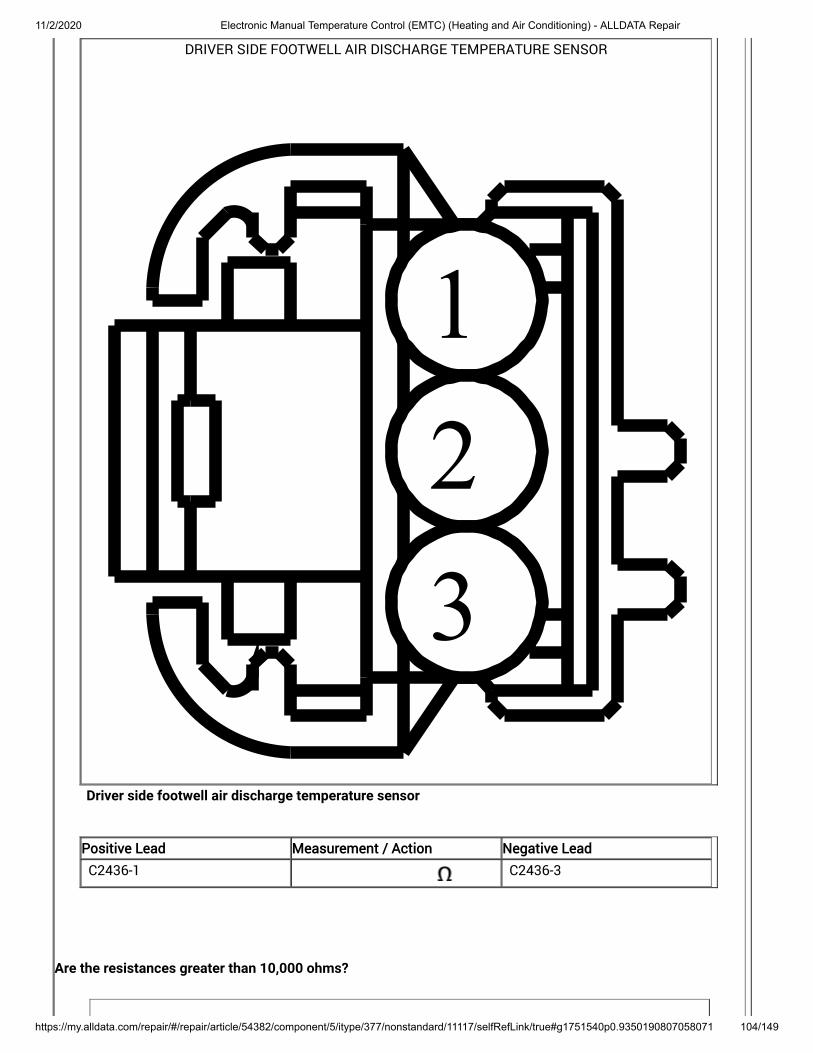
11/2/2020 Electronic Manual Temperature Control (EMTC) (Heating and Air Conditioning) - ALLDATA Repair
https://my.alldata.com/repair/#/repair/article/54382/component/5/itype/377/nonstandard/11117/selfRefLink/true#g1751540p0.9350190807058071 104/149
DRIVER SIDE FOOTWELL AIR DISCHARGE TEMPERATURE SENSOR
123
Driver side footwell air discharge temperature sensor
Positive Lead Measurement / Action Negative Lead
C2436-1 C2436-3
Are the resistances greater than 10,000 ohms?
11/2/2020 Electronic Manual Temperature Control (EMTC) (Heating and Air Conditioning) - ALLDATA Repair
https://my.alldata.com/repair/#/repair/article/54382/component/5/itype/377/nonstandard/11117/selfRefLink/true#g1751540p0.9350190807058071 105/149
Yes INSTALL a new driver side footwell air discharge temperature sensor. REFER to: Driver Side Footwell Air Discharge Temperature Sensor (412-00 Climate ControlSystem - General Information) . CLEAR the Diagnostic Trouble Codes (DTCs). REPEAT the self-test. If Diagnostic TroubleCode (DTC) returns, GO to L9
No REPAIR the circuit.
L9 CHECK FOR CORRECT FRONT CONTROLS INTERFACE MODULE (FCIM) OPERATIONIgnition OFF.
Disconnect and inspect all the FCIM connectors.
Repair:corrosion (install new connector or terminals – clean module pins)damaged or bent pins – install new terminals/pinspushed-out pins – install new pins as necessary
Connect the FCIM connectors. Make sure they seat and latch correctly.
Operate the system and determine if the concern is still present.
Is the concern still present?
Yes CHECK OASIS for any applicable Technical Service Bulletins (TSBs). If a TSB exists for thisconcern, DISCONTINUE this test and FOLLOW TSB instructions. If no Technical ServiceBulletins (TSBs) address this concern, INSTALL a new FCIM . For vehicles equipped with Sony® Audio System, REFER to: (415-00C Information and EntertainmentSystem - General Information - Vehicles With: Sony Audio System, Removal and Installation).
For vehicles equipped with Touchscreen Display, REFER to: (415-00B Information and EntertainmentSystem - General Information - Vehicles With: SYNC 2/Touchscreen Display, Removal andInstallation) .
For all other audio systems, REFER to: (415-00A Information and EntertainmentSystem - General Information - Vehicles With: SYNC, Removal and Installation) .
Front Controls Interface Module (FCIM)
Front Controls Interface Module (FCIM)
Front Controls Interface Module (FCIM)
No The system is operating correctly at this time. The concern may have been caused by aloose or corroded connector. ADDRESS the root cause of any connector or pin issues.
B105A:12, B105A:14, B1A61:11, B1A61:15, B1A69:11, B1A69:15
Refer to Wiring Diagrams Cell 54 for schematic and connector information.

11/2/2020 Electronic Manual Temperature Control (EMTC) (Heating and Air Conditioning) - ALLDATA Repair
https://my.alldata.com/repair/#/repair/article/54382/component/5/itype/377/nonstandard/11117/selfRefLink/true#g1751540p0.9350190807058071 106/149
Normal Operation and Fault Conditions
In-Vehicle Temperature and Humidity Sensor, REFER to: Climate Control System - Vehicles With: Electronic Manual Temperature Control (EMTC) (412-00 ClimateControl System - General Information) .
DTC Fault Trigger Conditions
DTC Description Fault Trigger Conditions
B105A:12 Cabin Temperature Sensor Fan:Circuit Short To Battery
This DTC sets when the modulesenses higher than expectedvoltage on the in-vehicletemperature and humidity sensor
circuit. The in-vehicletemperature and humidity sensorfan motor is inactive.
fan motor
B105A:14 Cabin Temperature Sensor Fan:Circuit Short To Ground or Open
This DTC sets when the modulesenses no voltage on the in-vehicletemperature and humidity sensorfan motor circuit, indicating an openor a short directly to ground. The in-vehicle temperature and humiditysensor fan motor is active.
B1A61:11 Cabin Temperature Sensor: CircuitShort to Ground
This DTC sets when the modulesenses lower than expected voltageon the in-vehicle temperature andhumidity sensor feedback circuit,indicating a short to ground.
B1A61:15 Cabin Temperature Sensor: CircuitShort to Battery or Open
This DTC sets when the modulesenses greater than expectedvoltage on the in-vehicletemperature and humidity sensorfeedback circuit, indicating a shortto voltage or an open circuit orsensor.
B1A69:11 Humidity Sensor: Circuit Short ToGround
This DTC sets when the modulesenses lower than expected voltageon the in-vehicle temperature andhumidity sensor humidity inputcircuit, indicating a short to ground.

11/2/2020 Electronic Manual Temperature Control (EMTC) (Heating and Air Conditioning) - ALLDATA Repair
https://my.alldata.com/repair/#/repair/article/54382/component/5/itype/377/nonstandard/11117/selfRefLink/true#g1751540p0.9350190807058071 107/149
DTC Description Fault Trigger Conditions
B1A69:15 Humidity Sensor: Circuit Short ToBattery or Open
This DTC sets when the modulesenses greater than expectedvoltage on the in-vehicletemperature and humidity sensorhumidity input circuit, indicating ashort to voltage or an open circuit orsensor.
Possible Sources
Wiring, terminals or connectorsIn-vehicle temperature and humidity sensorFCIM
Visual Inspection and Diagnostic Pre-checks
Make sure the in-vehicle temperature and humidity sensor harness is not chaffed.
PINPOINT TEST M : B105A:12, B105A:14, B1A61:11, B1A61:15, B1A69:11, B1A69:15
NOTICE: Use the correct probe adapter(s) when making measurements. Failure to use the correct probeadapter(s) may damage the connector.M1 CHECK THE IN-VEHICLE TEMPERATURE AND HUMIDITY SENSOR CIRCUITS FOR A SHORT TO VOLTAGE
Ignition OFF.
Disconnect FCIM C2402A .
Disconnect FCIM C2402B .
Disconnect BCM fuse 21 (5A) .
Disconnect Air distribution door actuator C236 .
Disconnect Air inlet door actuator C289 .
Disconnect Temperature door actuator C2091 .
Disconnect In-vehicle temperature and humidity sensor C233 .
Ignition ON.
Measure:
Connectors:

11/2/2020 Electronic Manual Temperature Control (EMTC) (Heating and Air Conditioning) - ALLDATA Repair
https://my.alldata.com/repair/#/repair/article/54382/component/5/itype/377/nonstandard/11117/selfRefLink/true#g1751540p0.9350190807058071 108/149
IN-VEHICLE TEMPERATURE AND HUMIDITYSENSOR
123456
Positive Lead Measurement / Action Negative Lead
C233-1 Ground
C233-2 Ground
C233-3 Ground
C233-4 Ground
C233-5 Ground
C233-6 Ground
Is any voltage present?
Yes REPAIR the circuit.
No GO to M2

11/2/2020 Electronic Manual Temperature Control (EMTC) (Heating and Air Conditioning) - ALLDATA Repair
https://my.alldata.com/repair/#/repair/article/54382/component/5/itype/377/nonstandard/11117/selfRefLink/true#g1751540p0.9350190807058071 109/149
M2 CHECK THE IN-VEHICLE TEMPERATURE AND HUMIDITY SENSOR CIRCUITS FOR A SHORT TO GROUNDIgnition OFF.
Measure:
Connectors:
IN-VEHICLE TEMPERATURE AND HUMIDITYSENSOR
123456
Positive Lead Measurement / Action Negative Lead
C233-1 Ground
C233-2 Ground
C233-3 Ground
C233-4 Ground
C233-5 Ground
C233-6 Ground
Are the resistances greater than 10,000 ohms?
Yes GO to M3
No REPAIR the circuit.

11/2/2020 Electronic Manual Temperature Control (EMTC) (Heating and Air Conditioning) - ALLDATA Repair
https://my.alldata.com/repair/#/repair/article/54382/component/5/itype/377/nonstandard/11117/selfRefLink/true#g1751540p0.9350190807058071 110/149
M3 CHECK THE IN-VEHICLE TEMPERATURE AND HUMIDITY SENSOR CIRCUITS FOR AN OPENMeasure:
Connectors:
IN-VEHICLE TEMPERATURE AND HUMIDITYSENSOR
123456
FRONT CONTROLS INTERFACE MODULE (FCIM)
12345678910111213
14151617181920212223242526
Positive Lead Measurement / Action Negative Lead
C233-3 C2402A-3
C233-5 C2402A-2
Connectors:

11/2/2020 Electronic Manual Temperature Control (EMTC) (Heating and Air Conditioning) - ALLDATA Repair
https://my.alldata.com/repair/#/repair/article/54382/component/5/itype/377/nonstandard/11117/selfRefLink/true#g1751540p0.9350190807058071 111/149
IN-VEHICLE TEMPERATURE AND HUMIDITYSENSOR
123456
FRONT CONTROLS INTERFACE MODULE (FCIM)
1234567891011121314151617
18192021222324252627282930
Positive Lead Measurement / Action Negative Lead
C233-1 C2402B-27
C233-2 C2402B-29
C233-4 C2402B-19
Positive Lead Measurement / Action Negative Lead
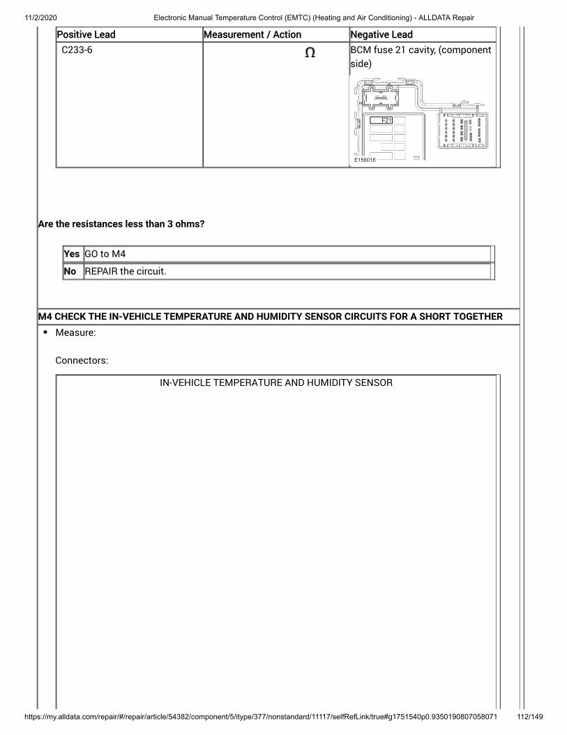
11/2/2020 Electronic Manual Temperature Control (EMTC) (Heating and Air Conditioning) - ALLDATA Repair
https://my.alldata.com/repair/#/repair/article/54382/component/5/itype/377/nonstandard/11117/selfRefLink/true#g1751540p0.9350190807058071 112/149
Positive Lead Measurement / Action Negative Lead
C233-6 BCM fuse 21 cavity, (componentside)
Are the resistances less than 3 ohms?
Yes GO to M4
No REPAIR the circuit.
M4 CHECK THE IN-VEHICLE TEMPERATURE AND HUMIDITY SENSOR CIRCUITS FOR A SHORT TOGETHERMeasure:
Connectors:
IN-VEHICLE TEMPERATURE AND HUMIDITY SENSOR

11/2/2020 Electronic Manual Temperature Control (EMTC) (Heating and Air Conditioning) - ALLDATA Repair
https://my.alldata.com/repair/#/repair/article/54382/component/5/itype/377/nonstandard/11117/selfRefLink/true#g1751540p0.9350190807058071 113/149
123456
Positive Lead Measurement / Action Negative Lead
C233-1 C233-2
C233-1 C233-3
C233-1 C233-4
C233-1 C233-5

11/2/2020 Electronic Manual Temperature Control (EMTC) (Heating and Air Conditioning) - ALLDATA Repair
https://my.alldata.com/repair/#/repair/article/54382/component/5/itype/377/nonstandard/11117/selfRefLink/true#g1751540p0.9350190807058071 114/149
Positive Lead Measurement / Action Negative Lead
C233-1 C233-6
C233-2 C233-3
C233-2 C233-4
C233-2 C233-5
C233-2 C233-6
C233-3 C233-4
C233-3 C233-5
C233-3 C233-6
C233-4 C233-5
C233-4 C233-6
C233-5 C233-6
Are the resistances greater than 10,000 ohms?
Yes GO to M5
No REPAIR the circuit.
M5 CHECK FOR CORRECT IN-VEHICLE TEMPERATURE AND HUMIDITY SENSOR OPERATION

11/2/2020 Electronic Manual Temperature Control (EMTC) (Heating and Air Conditioning) - ALLDATA Repair
https://my.alldata.com/repair/#/repair/article/54382/component/5/itype/377/nonstandard/11117/selfRefLink/true#g1751540p0.9350190807058071 115/149
Ignition OFF.
Inspect the disconnected connectors.
Repair:corrosion (install new connector or terminals – clean module pins)damaged or bent pins – install new terminals/pinspushed-out pins – install new pins as necessary
Connect all disconnected connectors. Make sure they seat and latch correctly.
Operate the system and determine if the concern is still present.
Is the concern still present?
Yes INSTALL a new in-vehicle temperature sensor. REFER to: In-Vehicle Temperature and Humidity Sensor (412-00 Climate Control System -General Information) . TEST the system for normal operation. If the concern is still present, GO to M6
No The system is operating correctly at this time. The concern may have been caused by aloose or corroded connector. ADDRESS the root cause of any connector or pin issues.
M6 CHECK FOR CORRECT FRONT CONTROLS INTERFACE MODULE (FCIM) OPERATION

11/2/2020 Electronic Manual Temperature Control (EMTC) (Heating and Air Conditioning) - ALLDATA Repair
https://my.alldata.com/repair/#/repair/article/54382/component/5/itype/377/nonstandard/11117/selfRefLink/true#g1751540p0.9350190807058071 116/149
Ignition OFF.
Disconnect and inspect all the FCIM connectors.
Repair:corrosion (install new connector or terminals – clean module pins)damaged or bent pins – install new terminals/pinspushed-out pins – install new pins as necessary
Connect the FCIM connectors. Make sure they seat and latch correctly.
Operate the system and determine if the concern is still present.
Is the concern still present?
Yes CHECK OASIS for any applicable Technical Service Bulletins (TSBs). If a TSB exists for thisconcern, DISCONTINUE this test and FOLLOW TSB instructions. If no Technical ServiceBulletins (TSBs) address this concern, INSTALL a new FCIM . For vehicles equipped with Sony® Audio System, REFER to: (415-00C Information and EntertainmentSystem - General Information - Vehicles With: Sony Audio System, Removal and Installation).
For vehicles equipped with Touchscreen Display, REFER to: (415-00B Information and EntertainmentSystem - General Information - Vehicles With: SYNC 2/Touchscreen Display, Removal andInstallation) .
For all other audio systems, REFER to: (415-00A Information and EntertainmentSystem - General Information - Vehicles With: SYNC, Removal and Installation) .
Front Controls Interface Module (FCIM)
Front Controls Interface Module (FCIM)
Front Controls Interface Module (FCIM)
No The system is operating correctly at this time. The concern may have been caused by aloose or corroded connector. ADDRESS the root cause of any connector or pin issues.
B1B71:11, B1B71:15
Refer to Wiring Diagrams Cell 54 for schematic and connector information.
Normal Operation and Fault Conditions
Evaporator Temperature Sensor, REFER to: Climate Control System - Vehicles With: Electronic Manual Temperature Control (EMTC) (412-00 ClimateControl System - General Information) .
DTC Fault Trigger Conditions
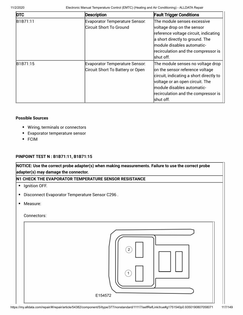
11/2/2020 Electronic Manual Temperature Control (EMTC) (Heating and Air Conditioning) - ALLDATA Repair
https://my.alldata.com/repair/#/repair/article/54382/component/5/itype/377/nonstandard/11117/selfRefLink/true#g1751540p0.9350190807058071 117/149
DTCDTC DescriptionDescription Fault Trigger ConditionsFault Trigger Conditions
B1B71:11 Evaporator Temperature Sensor:Circuit Short To Ground
The module senses excessivevoltage drop on the sensorreference voltage circuit, indicatinga short directly to ground. Themodule disables automatic-recirculation and the compressor isshut off.
B1B71:15 Evaporator Temperature Sensor:Circuit Short To Battery or Open
The module senses no voltage dropon the sensor reference voltagecircuit, indicating a short directly tovoltage or an open circuit. Themodule disables automatic-recirculation and the compressor isshut off.
Possible Sources
Wiring, terminals or connectorsEvaporator temperature sensorFCIM
PINPOINT TEST N : B1B71:11, B1B71:15
NOTICE: Use the correct probe adapter(s) when making measurements. Failure to use the correct probeadapter(s) may damage the connector.N1 CHECK THE EVAPORATOR TEMPERATURE SENSOR RESISTANCE
Ignition OFF.
Disconnect Evaporator Temperature Sensor C296 .
Measure:
Connectors:

11/2/2020 Electronic Manual Temperature Control (EMTC) (Heating and Air Conditioning) - ALLDATA Repair
https://my.alldata.com/repair/#/repair/article/54382/component/5/itype/377/nonstandard/11117/selfRefLink/true#g1751540p0.9350190807058071 118/149
Positive Lead Measurement / Action Negative Lead
C296-1 (component side) C296-2 (component side)
Compare the resistance values to the table below:
Ambient Temperature °F (°C) Approximate Resistance
-4.0°F (-20°C) 14 K ohms — 14.1 K ohms
32.0°F (°C) 4.8 K ohms — 4.9 K ohms
68.0°F (20°C) 1.5 K ohms — 1.9 K ohms
77.0°F (25°C) 1.3 K ohms — 1.7 K ohms
103.9°F (40°C) 650 ohms — 1 K ohms
139.9°F (60°C) 230 ohms — 550 ohms
Is the resistance within the specified values for the temperatures?
Yes GO to N2
No INSTALL a new evaporator temperature sensor. REFER to: Evaporator Temperature Sensor (412-00 Climate Control System - GeneralInformation) .
N2 CHECK THE EVAPORATOR TEMPERATURE SENSOR INPUT CIRCUIT FOR A SHORT TO VOLTAGE

11/2/2020 Electronic Manual Temperature Control (EMTC) (Heating and Air Conditioning) - ALLDATA Repair
https://my.alldata.com/repair/#/repair/article/54382/component/5/itype/377/nonstandard/11117/selfRefLink/true#g1751540p0.9350190807058071 119/149
Disconnect FCIM C2402A .
Ignition ON.
Measure:
Connectors:
FRONT CONTROLS INTERFACE MODULE (FCIM)
12345678910111213
14151617181920212223242526
Positive Lead Measurement / Action Negative Lead
C2402A-19 Ground
Is any voltage present?
Yes REPAIR the circuit.
No GO to N3
N3 CHECK THE EVAPORATOR TEMPERATURE SENSOR INPUT CIRCUIT FOR A SHORT TO GROUND

11/2/2020 Electronic Manual Temperature Control (EMTC) (Heating and Air Conditioning) - ALLDATA Repair
https://my.alldata.com/repair/#/repair/article/54382/component/5/itype/377/nonstandard/11117/selfRefLink/true#g1751540p0.9350190807058071 120/149
Ignition OFF.
Measure:
Connectors:
FRONT CONTROLS INTERFACE MODULE (FCIM)
12345678910111213
14151617181920212223242526
Positive Lead Measurement / Action Negative Lead
C2402A-19 Ground
Is the resistance greater than 10,000 ohms?
Yes GO to N4
No REPAIR the circuit.
N4 CHECK THE EVAPORATOR TEMPERATURE SENSOR INPUT CIRCUIT FOR AN OPEN

11/2/2020 Electronic Manual Temperature Control (EMTC) (Heating and Air Conditioning) - ALLDATA Repair
https://my.alldata.com/repair/#/repair/article/54382/component/5/itype/377/nonstandard/11117/selfRefLink/true#g1751540p0.9350190807058071 121/149
Measure:
Connectors:
FRONT CONTROLS INTERFACE MODULE (FCIM)
12345678910111213
14151617181920212223242526
EVAPORATOR TEMPERATURE SENSOR
1
2
Positive Lead Measurement / Action Negative Lead
C2402A-19 C296-2
Is the resistance less than 3 ohms?
Yes GO to N5
No REPAIR the circuit.
N5 CHECK THE EVAPORATOR TEMPERATURE SENSOR SIGNAL AND SIGNAL RETURN CIRCUITS FOR ASHORT TOGETHER
Measure:
Connectors:
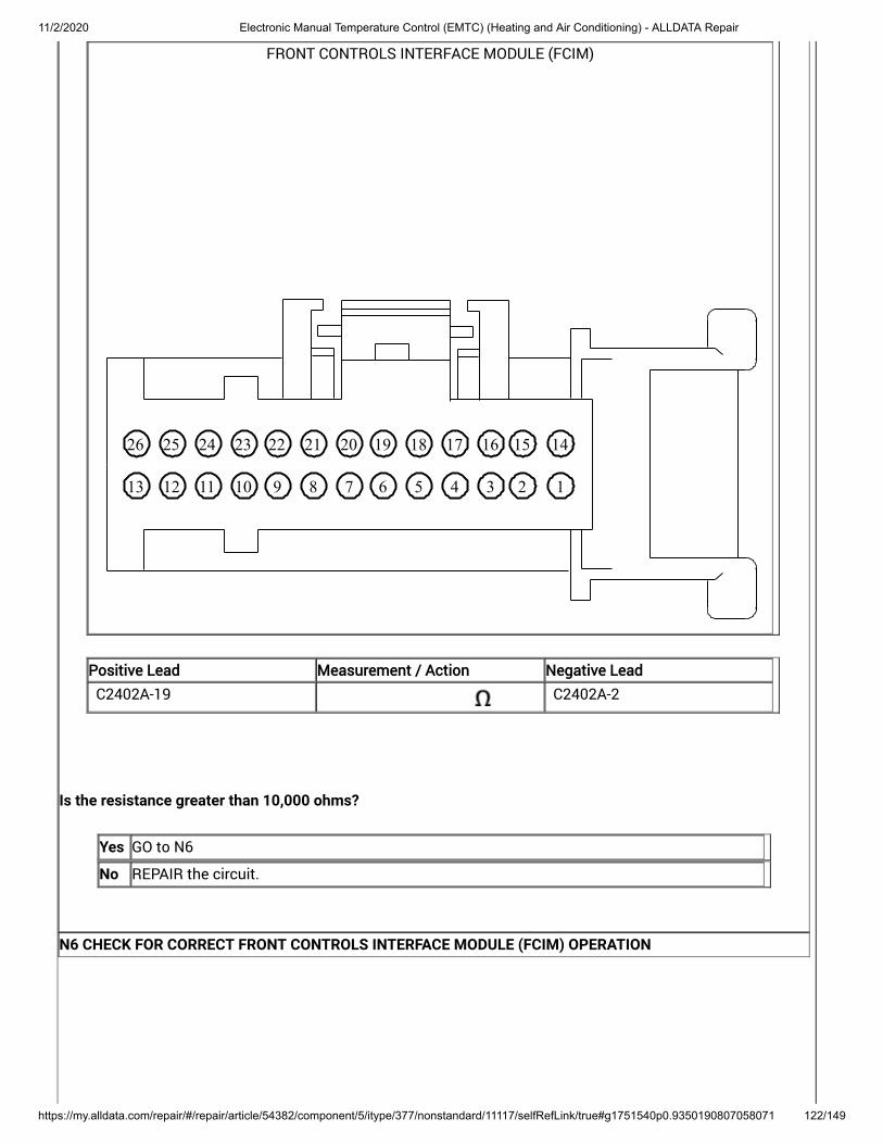
11/2/2020 Electronic Manual Temperature Control (EMTC) (Heating and Air Conditioning) - ALLDATA Repair
https://my.alldata.com/repair/#/repair/article/54382/component/5/itype/377/nonstandard/11117/selfRefLink/true#g1751540p0.9350190807058071 122/149
FRONT CONTROLS INTERFACE MODULE (FCIM)
12345678910111213
14151617181920212223242526
Positive Lead Measurement / Action Negative Lead
C2402A-19 C2402A-2
Is the resistance greater than 10,000 ohms?
Yes GO to N6
No REPAIR the circuit.
N6 CHECK FOR CORRECT FRONT CONTROLS INTERFACE MODULE (FCIM) OPERATION

11/2/2020 Electronic Manual Temperature Control (EMTC) (Heating and Air Conditioning) - ALLDATA Repair
https://my.alldata.com/repair/#/repair/article/54382/component/5/itype/377/nonstandard/11117/selfRefLink/true#g1751540p0.9350190807058071 123/149
Ignition OFF.
Disconnect and inspect all the FCIM connectors.
Repair:corrosion (install new connector or terminals – clean module pins)damaged or bent pins – install new terminals/pinspushed-out pins – install new pins as necessary
Connect the FCIM connectors. Make sure they seat and latch correctly.
Operate the system and determine if the concern is still present.
Is the concern still present?
Yes CHECK OASIS for any applicable Technical Service Bulletins (TSBs). If a TSB exists for thisconcern, DISCONTINUE this test and FOLLOW TSB instructions. If no Technical ServiceBulletins (TSBs) address this concern, INSTALL a new FCIM . For vehicles equipped with Sony® Audio System, REFER to: (415-00C Information and EntertainmentSystem - General Information - Vehicles With: Sony Audio System, Removal and Installation).
For vehicles equipped with Touchscreen Display, REFER to: (415-00B Information and EntertainmentSystem - General Information - Vehicles With: SYNC 2/Touchscreen Display, Removal andInstallation) .
For all other audio systems, REFER to: (415-00A Information and EntertainmentSystem - General Information - Vehicles With: SYNC, Removal and Installation) .
Front Controls Interface Module (FCIM)
Front Controls Interface Module (FCIM)
Front Controls Interface Module (FCIM)
No The system is operating correctly at this time. The concern may have been caused by aloose or corroded connector. ADDRESS the root cause of any connector or pin issues.
C1B14:11, C1B14:12
Refer to Wiring Diagrams Cell 54 for schematic and connector information.
Normal Operation and Fault Conditions
A 5-volt reference voltage and ground is supplied to the climate control sensors and actuators from the FCIM .
DTC Fault Trigger Conditions
DTC Description Fault Trigger Conditions

11/2/2020 Electronic Manual Temperature Control (EMTC) (Heating and Air Conditioning) - ALLDATA Repair
https://my.alldata.com/repair/#/repair/article/54382/component/5/itype/377/nonstandard/11117/selfRefLink/true#g1751540p0.9350190807058071 124/149
DTC Description Fault Trigger Conditions
C1B14:11 Sensor Supply Voltage A: CircuitShort To Ground
This DTC sets when the modulesenses less than 5 volts on thesensor reference voltage circuit,indicating a short to ground.
C1B14:12 Sensor Supply Voltage A: CircuitShort To Battery
This DTC sets when the modulesenses greater than 5 volts on thesensor reference voltage circuit,indicating a short to voltage.
Possible Sources
Wiring, terminals or connectorsFCIM
PINPOINT TEST O : C1B14:11, C1B14:12
NOTICE: Use the correct probe adapter(s) when making measurements. Failure to use the correct probeadapter(s) may damage the connector.O1 CHECK THE FCIM (FRONT CONTROLS INTERFACE MODULE) DTCS
Ignition ON.
Using a diagnostic scan tool, carry out the FCIM self-test.
Is DTC C1B14:11 present?
Yes GO to O2
No GO to O5
O2 CHECK THE REFERENCE VOLTAGE CIRCUIT FOR A SHORT TO GROUND

11/2/2020 Electronic Manual Temperature Control (EMTC) (Heating and Air Conditioning) - ALLDATA Repair
https://my.alldata.com/repair/#/repair/article/54382/component/5/itype/377/nonstandard/11117/selfRefLink/true#g1751540p0.9350190807058071 125/149
Ignition OFF.
Disconnect FCIM C2402A .
Measure:
Connectors:
FRONT CONTROLS INTERFACE MODULE (FCIM)
12345678910111213
14151617181920212223242526
Positive Lead Measurement / Action Negative Lead
C2402A-3 Ground
Is the resistance greater than 10,000 ohms?
Yes GO to O3
No REPAIR the circuit.
O3 CHECK THE REFERENCE VOLTAGE CIRCUIT AND THE SIGNAL RETURN CIRCUIT FOR A SHORT TOGETHER
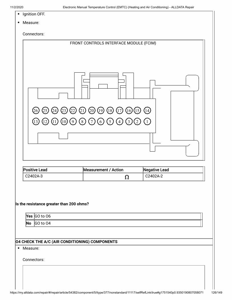
11/2/2020 Electronic Manual Temperature Control (EMTC) (Heating and Air Conditioning) - ALLDATA Repair
https://my.alldata.com/repair/#/repair/article/54382/component/5/itype/377/nonstandard/11117/selfRefLink/true#g1751540p0.9350190807058071 126/149
Ignition OFF.
Measure:
Connectors:
FRONT CONTROLS INTERFACE MODULE (FCIM)
12345678910111213
14151617181920212223242526
Positive Lead Measurement / Action Negative Lead
C2402A-3 C2402A-2
Is the resistance greater than 200 ohms?
Yes GO to O6
No GO to O4
O4 CHECK THE A/C (AIR CONDITIONING) COMPONENTSMeasure:
Connectors:
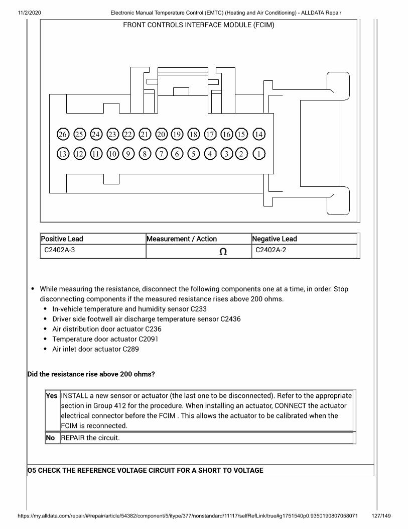
11/2/2020 Electronic Manual Temperature Control (EMTC) (Heating and Air Conditioning) - ALLDATA Repair
https://my.alldata.com/repair/#/repair/article/54382/component/5/itype/377/nonstandard/11117/selfRefLink/true#g1751540p0.9350190807058071 127/149
FRONT CONTROLS INTERFACE MODULE (FCIM)
12345678910111213
14151617181920212223242526
Positive Lead Measurement / Action Negative Lead
C2402A-3 C2402A-2
While measuring the resistance, disconnect the following components one at a time, in order. Stopdisconnecting components if the measured resistance rises above 200 ohms.
In-vehicle temperature and humidity sensor C233Driver side footwell air discharge temperature sensor C2436Air distribution door actuator C236Temperature door actuator C2091Air inlet door actuator C289
Did the resistance rise above 200 ohms?
Yes INSTALL a new sensor or actuator (the last one to be disconnected). Refer to the appropriatesection in Group 412 for the procedure. When installing an actuator, CONNECT the actuatorelectrical connector before the FCIM . This allows the actuator to be calibrated when theFCIM is reconnected.
No REPAIR the circuit.
O5 CHECK THE REFERENCE VOLTAGE CIRCUIT FOR A SHORT TO VOLTAGE

11/2/2020 Electronic Manual Temperature Control (EMTC) (Heating and Air Conditioning) - ALLDATA Repair
https://my.alldata.com/repair/#/repair/article/54382/component/5/itype/377/nonstandard/11117/selfRefLink/true#g1751540p0.9350190807058071 128/149
Ignition OFF.
Disconnect FCIM C2402A .
Measure:
Connectors:
FRONT CONTROLS INTERFACE MODULE (FCIM)
12345678910111213
14151617181920212223242526
Positive Lead Measurement / Action Negative Lead
C2402A-3 Ground
Is any voltage present?
Yes REPAIR the circuit.
No GO to O6
O6 CHECK FOR CORRECT FCIM (FRONT CONTROLS INTERFACE MODULE) OPERATION

11/2/2020 Electronic Manual Temperature Control (EMTC) (Heating and Air Conditioning) - ALLDATA Repair
https://my.alldata.com/repair/#/repair/article/54382/component/5/itype/377/nonstandard/11117/selfRefLink/true#g1751540p0.9350190807058071 129/149
Ignition OFF.
Disconnect and inspect all the FCIM connectors.
Repair:corrosion (install new connector or terminals – clean module pins)damaged or bent pins – install new terminals/pinspushed-out pins – install new pins as necessary
Connect the FCIM connectors. Make sure they seat and latch correctly.
Operate the system and determine if the concern is still present.
Is the concern still present?
Yes CHECK OASIS for any applicable Technical Service Bulletins (TSBs). If a TSB exists for thisconcern, DISCONTINUE this test and FOLLOW TSB instructions. If no Technical ServiceBulletins (TSBs) address this concern, INSTALL a new FCIM . For vehicles equipped with Sony® Audio System, REFER to: (415-00C Information and EntertainmentSystem - General Information - Vehicles With: Sony Audio System, Removal and Installation).
For vehicles equipped with Touchscreen Display, REFER to: (415-00B Information and EntertainmentSystem - General Information - Vehicles With: SYNC 2/Touchscreen Display, Removal andInstallation) .
For all other audio systems, REFER to: (415-00A Information and EntertainmentSystem - General Information - Vehicles With: SYNC, Removal and Installation) .
Front Controls Interface Module (FCIM)
Front Controls Interface Module (FCIM)
Front Controls Interface Module (FCIM)
No The system is operating correctly at this time. The concern may have been caused by aloose or corroded connector. ADDRESS the root cause of any connector or pin issues.
Insufficient Heat In Auto Start-Stop Mode Only
Refer to Wiring Diagrams Cell 40 for schematic and connector information.
Normal Operation and Fault Conditions
Cabin Heater Coolant Pump - vehicles equipped with Auto Start-Stop, REFER to: Climate Control System - Vehicles With: Electronic Manual Temperature Control (EMTC) (412-00 ClimateControl System - General Information) .
DTC Fault Trigger Conditions

11/2/2020 Electronic Manual Temperature Control (EMTC) (Heating and Air Conditioning) - ALLDATA Repair
https://my.alldata.com/repair/#/repair/article/54382/component/5/itype/377/nonstandard/11117/selfRefLink/true#g1751540p0.9350190807058071 130/149
DTCDTC DescriptionDescription Fault Trigger ConditionsFault Trigger Conditions
P2601 Coolant Pump "A" Control CircuitPerformance/Stuck Off
This DTC sets when the PCMsenses any of the followingconditions:Dry-Run leads to cabin heatercoolant pump running withoutresistanceOver TemperatureOver/Under VoltageImpeller StallImpeller Speed below minimumspeedInternal Error
P2602 Coolant Pump "A" Control CircuitLow
This DTC sets when the PCM senseslow voltage on the PWM circuitwhen commanding it high,indicating a short to ground to thecabin heater coolant pump.
P2603 Coolant Pump "A" Control CircuitHigh
This DTC sets when the PCM senseslow voltage on the PWM circuitwhen commanding it high,indicating an open circuit to thecabin heater coolant pump.
Possible Causes
Wiring, terminals or connectorsLow coolant or air in the coolant systemCabin heater coolant pumpPCM
PINPOINT TEST P : INSUFFICIENT HEAT IN AUTO START-STOP MODE ONLY
NOTICE: Use the correct probe adapter(s) when making measurements. Failure to use the correct probeadapter(s) may damage the connector.P1 CHECK THE CABIN HEATER COOLANT PUMP

11/2/2020 Electronic Manual Temperature Control (EMTC) (Heating and Air Conditioning) - ALLDATA Repair
https://my.alldata.com/repair/#/repair/article/54382/component/5/itype/377/nonstandard/11117/selfRefLink/true#g1751540p0.9350190807058071 131/149
NOTE: The engine must be auto-stopped to request the cabin heater coolant pump on. Further informationcan be found in the Owner's Literature for full Auto Start-Stop enabling and disabling.
Start the vehicle and allow engine to reach normal operating temperatures.
Using the HVAC controls, select panel mode, set temperature to full hot and set blower speed to low.
Drive the vehicle above 3 mph (4 km/h).
Stop the vehicle on a level surface.
Make sure that the steering wheel is set to the straight ahead position.
Keep the transmission selector lever in position D, brake pedal pressed and doors closed.
Using a diagnostic scan tool, view PCM Parameter Identifications (PIDs).
Monitor the PCM coolant pump status (COOLPMP_A_STAT) PID for at least 1 minute.
Does the cabin heater coolant pump turn on?
Yes GO to P6
No GO to P2
P2 CHECK THE CABIN HEATER COOLANT PUMP CIRCUITS FOR A SHORT TO VOLTAGEDisconnect BJB fuse 12 (15A) .
Disconnect PCM 1.5L C1915B .
Disconnect Cabin heater coolant pump C163 .
Ignition ON.
Measure:
Connectors:
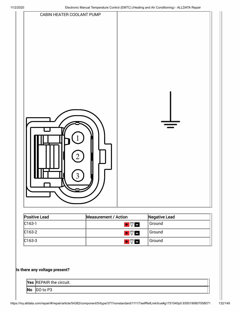
11/2/2020 Electronic Manual Temperature Control (EMTC) (Heating and Air Conditioning) - ALLDATA Repair
https://my.alldata.com/repair/#/repair/article/54382/component/5/itype/377/nonstandard/11117/selfRefLink/true#g1751540p0.9350190807058071 132/149
CABIN HEATER COOLANT PUMP
1
2
3
Positive Lead Measurement / Action Negative Lead
C163-1 Ground
C163-2 Ground
C163-3 Ground
Is there any voltage present?
Yes REPAIR the circuit.
No GO to P3
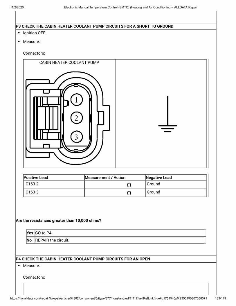
11/2/2020 Electronic Manual Temperature Control (EMTC) (Heating and Air Conditioning) - ALLDATA Repair
https://my.alldata.com/repair/#/repair/article/54382/component/5/itype/377/nonstandard/11117/selfRefLink/true#g1751540p0.9350190807058071 133/149
P3 CHECK THE CABIN HEATER COOLANT PUMP CIRCUITS FOR A SHORT TO GROUNDIgnition OFF.
Measure:
Connectors:
CABIN HEATER COOLANT PUMP
1
2
3
Positive Lead Measurement / Action Negative Lead
C163-2 Ground
C163-3 Ground
Are the resistances greater than 10,000 ohms?
Yes GO to P4
No REPAIR the circuit.
P4 CHECK THE CABIN HEATER COOLANT PUMP CIRCUITS FOR AN OPENMeasure:
Connectors:

11/2/2020 Electronic Manual Temperature Control (EMTC) (Heating and Air Conditioning) - ALLDATA Repair
https://my.alldata.com/repair/#/repair/article/54382/component/5/itype/377/nonstandard/11117/selfRefLink/true#g1751540p0.9350190807058071 134/149
CABIN HEATER COOLANT PUMP
1
2
3
Positive Lead Measurement / Action Negative Lead
C163-1 Ground
Connectors:
CABIN HEATER COOLANT PUMP
1
2
3

11/2/2020 Electronic Manual Temperature Control (EMTC) (Heating and Air Conditioning) - ALLDATA Repair
https://my.alldata.com/repair/#/repair/article/54382/component/5/itype/377/nonstandard/11117/selfRefLink/true#g1751540p0.9350190807058071 135/149
Positive LeadPositive Lead Measurement / ActionMeasurement / Action Negative LeadNegative Lead
C163-2 BJB fuse 12 cavity, componentside
Connectors:
CABIN HEATER COOLANT PUMP
1
2
3
POWERTRAIN CONTROL MODULE (PCM)
103102
101100
9998
9796
95949392919089888786858483828180797877
76757473727170696867666564636261605958
57565554535251504948474645444342414039
38373635343332313029282726252423222120
19181716151413121110987654321
1.5L
Positive Lead Measurement / Action Negative Lead
C163-3 C1915B-3
Are the resistances less than 3 ohms?
Yes GO to P5
No REPAIR the circuit.
P5 CHECK THE CABIN HEATER COOLANT PUMP CIRCUITS FOR A SHORT TOGETHERMeasure:
Connectors:

11/2/2020 Electronic Manual Temperature Control (EMTC) (Heating and Air Conditioning) - ALLDATA Repair
https://my.alldata.com/repair/#/repair/article/54382/component/5/itype/377/nonstandard/11117/selfRefLink/true#g1751540p0.9350190807058071 136/149
CABIN HEATER COOLANT PUMP
1
2
3
Positive Lead Measurement / Action Negative Lead
C163-1 C163-2
C163-1 C163-3
C163-2 C163-3
Is the resistance greater than 10,000 ohms?
Yes GO to P6

11/2/2020 Electronic Manual Temperature Control (EMTC) (Heating and Air Conditioning) - ALLDATA Repair
https://my.alldata.com/repair/#/repair/article/54382/component/5/itype/377/nonstandard/11117/selfRefLink/true#g1751540p0.9350190807058071 137/149
No REPAIR the circuit.
P6 CHECK THE ENGINE COOLANT LEVELNOTE: Allow the engine to cool before checking the engine coolant level.
Visually inspect the engine coolant level at the degas bottle.
Is the engine coolant level within specifications?
Yes GO to P7
NoREFER to: Engine Cooling (303-03 Engine Cooling - 1.6L EcoBoost (132kW/180PS) - Sigma) .
P7 CLEAR ALL PCM (POWERTRAIN CONTROL MODULE) DIAGNOSTIC TROUBLE CODES

11/2/2020 Electronic Manual Temperature Control (EMTC) (Heating and Air Conditioning) - ALLDATA Repair
https://my.alldata.com/repair/#/repair/article/54382/component/5/itype/377/nonstandard/11117/selfRefLink/true#g1751540p0.9350190807058071 138/149
Connect all disconnected connectors. Make sure they seat and latch correctly.
Ignition ON.
Using a diagnostic scan tool, CLEAR all PCM Diagnostic Trouble Codes (DTCs).
Start the vehicle andallow engine to reach normal operating temperatures.
NOTE: The engine must be auto-stopped to request the cabin heater coolant pump on. Further informationcan be found in the Owner's Literature for full Auto Start-Stop enabling/disabling.
Using the HVAC controls, select panel mode, set temperature to full hot and set blower speed to low.
Drive the vehicle above 3 mph (4 km/h).
Stop the vehicle on a level surface.
Make sure that the steering wheel is set to the straight ahead position.
Keep the transmission selector lever in position D, brake pedal pressed and doors closed.
Using a diagnostic scan tool, view PCM Parameter Identifications (PIDs).
Monitor the PCM coolant pump status (COOLPMP_A_STAT) PID for at least 1 minute.
Does the cabin coolant pump turn on?
Yes If the cabin coolant pump runs for 10 seconds on and 10 seconds off, PURGE the air fromthe coolant system. REFER to: (303-03A Engine Cooling - 1.5L EcoBoost (118kW/160PS), General Procedures) . REFER to: Cooling System Draining and Vacuum Filling (303-03 Engine Cooling - 1.6LEcoBoost (132kW/180PS) - Sigma) .
If the cabin coolant pump runs normally, the system is operating correctly at this time. Theconcern may have been caused by pump connections. ADDRESS the root cause of anyconnector or pin issues.
No INSTALL a new cabin heater coolant pump. For 1.5L, REFER to: (412-00 Climate Control System - General Information, Removal and Installation) .
If the concern is still present, GO to P8
P8 CHECK FOR CORRECT PCM (POWERTRAIN CONTROL MODULE) OPERATION

11/2/2020 Electronic Manual Temperature Control (EMTC) (Heating and Air Conditioning) - ALLDATA Repair
https://my.alldata.com/repair/#/repair/article/54382/component/5/itype/377/nonstandard/11117/selfRefLink/true#g1751540p0.9350190807058071 139/149
Ignition OFF.
Disconnect and inspect the PCM connectors.
Repair:corrosion (replace connector or terminals – clean module pins)damaged or bent pins – replace terminals/pinspushed-out pins – replace pins as necessary
Connect the PCM connectors. Make sure they seat and latch correctly.
Operate the system and verify the concern is still present.
Is the concern still present?
Yes CHECK OASIS for any applicable Technical Service Bulletins (TSBs). If a TSB exists for thisconcern, DISCONTINUE this test and FOLLOW TSB instructions. If no Technical ServiceBulletins (TSBs) address this concern, INSTALL a new PCM . For 1.5L, REFER to: (303-14A Electronic Engine Controls - 1.5L EcoBoost (118kW/160PS), Removaland Installation) .
No The system is operating correctly at this time. The concern may have been caused bymodule connections. ADDRESS the root cause of any connector or pin issues.
P06A0
Refer to Wiring Diagrams Cell 54 for schematic and connector information.
Normal Operation and Fault Conditions
The externally controlled variable displacement compressor is electronically controlled by the PCM . The PCM pulsewidth modulates the ground to the externally controlled variable displacement compressor to change thedisplacement of the A/C compressor.
DTC Fault Trigger Conditions
DTC Description Fault Trigger Conditions
P06A0 Variable A/C Compressor ControlCircuit
The PCM senses greater thanexpected voltage on the sensorfeedback circuit, indicating a shortto voltage or an open circuit orsensor.
Possible Sources

11/2/2020 Electronic Manual Temperature Control (EMTC) (Heating and Air Conditioning) - ALLDATA Repair
https://my.alldata.com/repair/#/repair/article/54382/component/5/itype/377/nonstandard/11117/selfRefLink/true#g1751540p0.9350190807058071 140/149
Wiring, terminals or connectorsA/C compressorPCM
Visual Inspection and Diagnostic Pre-checks
BJB fuse 12 (15A)Inspect for loose or corroded PCM and A/C compressor connections.
PINPOINT TEST Q : P06A0
NOTICE: Use the correct probe adapter(s) when making measurements. Failure to use the correct probeadapter(s) may damage the connector.Q1 EXTERNALLY CONTROLLED VARIABLE DISPLACEMENT COMPRESSOR (EVDC) PERFORMANCE CHECK

11/2/2020 Electronic Manual Temperature Control (EMTC) (Heating and Air Conditioning) - ALLDATA Repair
https://my.alldata.com/repair/#/repair/article/54382/component/5/itype/377/nonstandard/11117/selfRefLink/true#g1751540p0.9350190807058071 141/149
NOTE: Variable displacement compressors operate at lower pressures (compared to fixed compressors) anddepend on correct system charge for normal operation.
NOTE: The performance check test is used to determine if the Externally Controlled Variable DisplacementCompressor (EVDC) is able to change the displacement by measuring the amperage to the solenoid andmonitoring the manifold pressure gauges soon after the is engaged.air conditioning clutch
Ignition OFF.
Disconnect BJB fuse 12 (15A).
Measure:
Connectors:
Positive Lead Measurement / Action Negative Lead
C BJB fuse 12 (15A) C BJB fuse 12 (15A)
With a manifold gauge set connected, monitor the low side and high side pressures.
Start the engine. Run the engine until it reaches normal operating temperature.
Select the floor position on the HVAC controls. Set the temperature control to full warm and the blower tothe lowest setting. Set the A/C to off. Run for 5 minutes to heat up the climate control housing.
Monitor the multi meter and the manifold gauges. Select the PANEL position on the HVAC controls. Setthe temperature control to full cold and the blower to the highest setting. Set the A/C to on.
Record the highest amperage measurement and the A/C pressures.
Did the amperage initially increase approximately 0.8A, and did the low side pressure decrease and the highside pressure increase and after a few minutes did the amperage and high side pressure decrease and lowside pressure increase?
Yes The Externally Controlled Variable Displacement Compressor (EVDC) is able to change thedisplacement. CHECK refrigerant charge amount. REFER to: (412-00 Climate Control System - General Information,Specifications) .
Specifications
No GO to Q2
Q2 CHECK FOR VOLTAGE TO THE A/C (AIR CONDITIONING) COMPRESSOR CONTROL SOLENOID

11/2/2020 Electronic Manual Temperature Control (EMTC) (Heating and Air Conditioning) - ALLDATA Repair
https://my.alldata.com/repair/#/repair/article/54382/component/5/itype/377/nonstandard/11117/selfRefLink/true#g1751540p0.9350190807058071 142/149
Ignition OFF.
Connect BJB fuse 12 (15A).
Disconnect A/C Compressor Control Solenoid C1110 .
Ignition ON.
Measure:
Connectors:
AIR CONDITIONING (A/C) COMPRESSORCONTROL SOLENOID
21
Positive Lead Measurement / Action Negative Lead
C1110-2 Ground
Is the voltage greater than 11 volts?
Yes GO to Q3
No VERIFY the BJB fuse 12 (15A) is OK. If OK, REPAIR the circuit. If not OK, REFER to the WiringDiagrams manual to identify the possible causes of the circuit short.
Q3 CHECK THE A/C (AIR CONDITIONING) COMPRESSOR DISPLACEMENT CONTROL SOLENOID PWM (PULSEWIDTH MODULATION) CIRCUIT FOR A SHORT TO GROUND

11/2/2020 Electronic Manual Temperature Control (EMTC) (Heating and Air Conditioning) - ALLDATA Repair
https://my.alldata.com/repair/#/repair/article/54382/component/5/itype/377/nonstandard/11117/selfRefLink/true#g1751540p0.9350190807058071 143/149
Ignition OFF.
Disconnect PCM 1.5L C1915B , 2.0L C1381B or 2.5L C1551B .
Measure:
Connectors:
AIR CONDITIONING (A/C) COMPRESSORCONTROL SOLENOID
21
Positive Lead Measurement / Action Negative Lead
C1110-1 Ground
Is the resistance greater than 10,000 ohms?
Yes GO to Q4
No REPAIR the circuit.
Q4 CHECK THE A/C (AIR CONDITIONING) COMPRESSOR DISPLACEMENT CONTROL SOLENOID PWM (PULSEWIDTH MODULATION) CIRCUIT FOR A SHORT TO VOLTAGE

11/2/2020 Electronic Manual Temperature Control (EMTC) (Heating and Air Conditioning) - ALLDATA Repair
https://my.alldata.com/repair/#/repair/article/54382/component/5/itype/377/nonstandard/11117/selfRefLink/true#g1751540p0.9350190807058071 144/149
Ignition ON.
Measure:
Connectors:
AIR CONDITIONING (A/C) COMPRESSORCONTROL SOLENOID
21
Positive Lead Measurement / Action Negative Lead
C1110-1 Ground
Is any voltage present?
Yes REPAIR the circuit.
No GO to Q5
Q5 CHECK THE A/C (AIR CONDITIONING) COMPRESSOR DISPLACEMENT CONTROL SOLENOID PWM (PULSEWIDTH MODULATION) CIRCUIT FOR AN OPEN
Ignition OFF.
Measure:
Connectors:

11/2/2020 Electronic Manual Temperature Control (EMTC) (Heating and Air Conditioning) - ALLDATA Repair
https://my.alldata.com/repair/#/repair/article/54382/component/5/itype/377/nonstandard/11117/selfRefLink/true#g1751540p0.9350190807058071 145/149
AIR CONDITIONING (A/C) COMPRESSORCONTROL SOLENOID
21
POWERTRAIN CONTROL MODULE (PCM)
103102
101100
9998
9796
95949392919089888786858483828180797877
76757473727170696867666564636261605958
57565554535251504948474645444342414039
38373635343332313029282726252423222120
19181716151413121110987654321
1.5L
Positive Lead Measurement / Action Negative Lead
C1110-1 C1915B-41
Connectors:

11/2/2020 Electronic Manual Temperature Control (EMTC) (Heating and Air Conditioning) - ALLDATA Repair
https://my.alldata.com/repair/#/repair/article/54382/component/5/itype/377/nonstandard/11117/selfRefLink/true#g1751540p0.9350190807058071 146/149
AIR CONDITIONING (A/C) COMPRESSORCONTROL SOLENOID
21
POWERTRAIN CONTROL MODULE (PCM)
103102
101100
9998
9796
95949392919089888786858483828180797877
76757473727170696867666564636261605958
57565554535251504948474645444342414039
38373635343332313029282726252423222120
19181716151413121110987654321
2.0L
Positive Lead Measurement / Action Negative Lead
C1110-1 C1381B-41
Connectors:
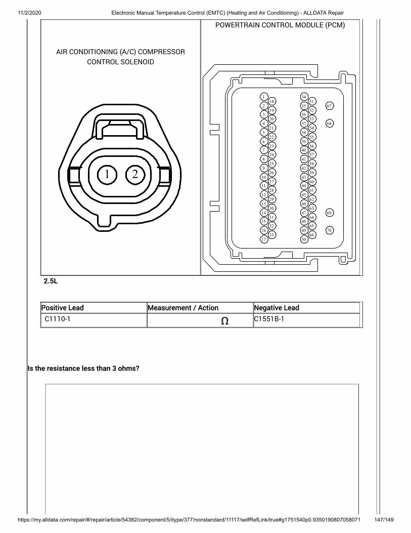
11/2/2020 Electronic Manual Temperature Control (EMTC) (Heating and Air Conditioning) - ALLDATA Repair
https://my.alldata.com/repair/#/repair/article/54382/component/5/itype/377/nonstandard/11117/selfRefLink/true#g1751540p0.9350190807058071 147/149
AIR CONDITIONING (A/C) COMPRESSORCONTROL SOLENOID
21
POWERTRAIN CONTROL MODULE (PCM)
1
2
3
4
5
6
7
8
9
10
11
12
13
14
15
16
17
18
19
20
21
22
23
24
25
26
27
28
29
30
31
32
33
34
35
36
37
38
39
40
41
42
43
44
45
46
47
48
49
50
51
52
53
54
55
56
57
58
59
60
61
62
63
64
65
66
67
68
69
70
2.5L
Positive Lead Measurement / Action Negative Lead
C1110-1 C1551B-1
Is the resistance less than 3 ohms?

11/2/2020 Electronic Manual Temperature Control (EMTC) (Heating and Air Conditioning) - ALLDATA Repair
https://my.alldata.com/repair/#/repair/article/54382/component/5/itype/377/nonstandard/11117/selfRefLink/true#g1751540p0.9350190807058071 148/149
Yes INSTALL a new A/C compressor. For 1.5L, REFER to: (412-00 Climate Control System - General Information, Removal and Installation) .
For 2.0L REFER to: Air Conditioning (A/C) Compressor - 2.0L EcoBoost (184kW/250PS) - MI4 (412-00Climate Control System - General Information) .
For 2.5L REFER to: (412-00 ClimateControl System - General Information, Removal and Installation) .
CLEAR the DTC and REPEAT the self-test. If the DTC returns, GO to
Air Conditioning (A/C) Compressor - 2.5L Duratec (125kW/170PS)
Q6
No REPAIR the circuit.
Q6 CHECK FOR CORRECT PCM (POWERTRAIN CONTROL MODULE) OPERATION

11/2/2020 Electronic Manual Temperature Control (EMTC) (Heating and Air Conditioning) - ALLDATA Repair
https://my.alldata.com/repair/#/repair/article/54382/component/5/itype/377/nonstandard/11117/selfRefLink/true#g1751540p0.9350190807058071 149/149
Ignition OFF.
Disconnect and inspect all PCM connectors.
Repair:corrosion (install new connector or terminals – clean module pins)damaged or bent pins – install new terminals/pinspushed-out pins – install new pins as necessary
Connect the PCM connectors. Make sure they seat and latch correctly.
Operate the system and determine if the concern is still present.
Is the concern still present?
Yes CHECK OASIS for any applicable Technical Service Bulletins (TSBs). If a TSB exists for thisconcern, DISCONTINUE this test and FOLLOW TSB instructions. If no Technical ServiceBulletins (TSBs) address this concern, INSTALL a new PCM . For 1.5L, REFER to: (303-14A Electronic Engine Controls - 1.5L EcoBoost (118kW/160PS), Removaland Installation) .
For 2.0L, REFER to: (303-14B Electronic Engine Controls - 2.0L EcoBoost (184kW/250PS) - MI4,Removal and Installation) .
For 2.5L, REFER to: (303-14C Electronic Engine Controls - 2.5LDuratec (125kW/170PS), Removal and Installation) .
Powertrain Control Module (PCM)
No The system is operating correctly at this time. The concern may have been caused by aloose or corroded connector. ADDRESS the root cause of any connector or pin issues.