CH C C C C C C C C C C C C C C C C C N C C C C C C C C N N C C C C C C
Upload
khangminh22Category
view
0download
0
USER'S GUIDE
Version 6.4

New editions of this guide incorporate all material added or changed since the previous edition.Update packages may be used between editions. The manual printing date changes when a newedition is printed. The contents and format of this manual are subject to change without notice.
Generated: 10/1/2017, 8:10 PM
Rev: cb0043d
Part Number: User's Guide for VectorCAST/C++ RSP v.6.4
VectorCAST is a trademark of Vector Software, Inc.
© Copyright 2017, Vector Software, Inc. All rights reserved. No part of the material protected bythis copyright notice may be reproduced or utilized in any form or by any means, electronic ormechanical, including photocopying, recording, or by any informational storage and retrievalsystem, without written permission from the copyright owner.
U.S. Government Restricted Rights
This computer software and related documentation are provided with Restricted Rights. Use,duplication or disclosure by the Government is subject to restrictions as set forth in thegoverning Rights in Technical Data and Computer Software clause of
DFARS 252.227-7015 (June 1995) and DFARS 227.7202-3(b).
Manufacturer is Vector Software, Inc. East Greenwich RI 02818, USA.
Vector Software reserves the right to make changes in specifications and other informationcontained in this document without prior notice. Contact Vector Software to determine whethersuch changes have been made.
Third-Party copyright notices are contained in the file: 3rdPartyLicenses.txt, located in theVectorCAST installation directory.
2

Table of Contents
INTRODUCTION 10
About This Manual 11Introduction 11
Overview 11
VectorCAST/RSP Concepts 11Harness Architecture 11RSP Communication Overview 12RSP Communication Details 13
Execute Commands 14
Flags 18
Execution Methods 21
USING VECTORCAST/RSP 22
Introduction 23Combining Host- and Target-based Testing 23
CLICAST - Command Line VectorCAST 23QuickStart 23Command Format 24The C/C++ Options 26The Target Options 29CLICAST-Only Options 41
TARGET REFERENCE 43
Analog Devices VisualDSP 44Configuration 44Target Execution 46
ARM RVDS 48Configuration 48Target Execution 48Target Debug Execution 50
Code Composer Studio 52Configuration 52Target Execution with Code Composer Studio 4.0 53Target Execution with Code Composer Studio 3.3 55Target Execution with Code Composer Studio 2 57
DSP/BIOS support on Code Composer Studio 3.3 and 4.x 61Configuration 61
3

DSP/BIOS Configuration 61
Code Composer Studio on ezDSP28335 target board 65Configuration 65Target Execution with Code Composer Studio 3.3 67Target Execution with Debug in Code Composer Studio 3.3 68
Code Composer Studio on DSK 6713 target board 69Configuration 69DSP/BIOS Configuration 69Target Execution with Code Composer Studio 3.3 73Target Execution with Debug in Code Composer Studio 3.3 74
Code Composer Studio on OMAP 35x EVM target board 75Configuration 75DSP/BIOS Configuration 75Running in a Heterogeneous Multi-core environment with Code Composer Studio 3.3 79Target Execution with Code Composer Studio 3.3 81Target Execution with Debug in Code Composer Studio 3.3 82
Code Composer Studio v4.2.4 on TI Stellaris EKT-LM3S9B92 EVB 83Target Configuration 83Configuration 83Target Execution with Code Composer Studio 4.2 85Target Debug Execution in Code Composer Studio 4.x 87
Code Composer Studio v4.2.4 on TI TMS570LS31xHercules USB Stick 91Target Configuration 91Configuration 91Target Execution with CCS 4.2 on the TMS570LS31x USB Stick 94Target Debug Execution in Code Composer Studio 4.x 96
CodeWarrior DSP56800E 103Configuration 103Target Execution 105Target Debug Execution 106
CodeWarrior StarCore SC140e 108Configuration 108Target Execution 109Target Debug Execution 109
CodeWarrior for HC12 113Configuration 113Banked Memory Model 116Target Execution 117Target Debug Execution 118
CodeWarrior for HCS08 119Configuration 119Target Simulator Execution 123Target Simulator Debug Execution 124
CodeWarrior for MPC 5554 126Configuration 126
4

Target Execution 127Target Debug Execution 128
CodeWarrior for MPC 8315 129CodeWarrior USB TAP Installation 129Configuration 133Target Execution 134Target Debug Execution 136
CodeWarrior for MPC5121 138Configuration 138Target Execution 139Target Debug Execution 142
Cosmic 68HC12 and HCS12X 143Configuration for 68HC12 143Configuration for HCS12X 145Target Execution 149Target Debug Execution 151
Cosmic STM8 152Configuration for Cosmic STM8 on ZAP Simulator 152Configuration for Cosmic STM8 on STVD Simulator 153Target Execution 154Target Debug Execution 155
EVP for VD3204x 156Configuration 156
Fujitsu Softune for FFMC Chips 159Configuration 159Target Execution 160Target Debug Execution 160
Fujitsu Softune Simulator 161Configuration 161Target Execution 162Target Debug Execution 162
Green Hills Simulator/Bare Target 163Configuration 163Configuration for a Target Board 163Target Execution 164Target Execution with Green Hills Multi Debugger 164Improving Target Execution Speed 165
Green Hills INTEGRITY Simulator 167Configuration 167Target Execution 167Target Execution with Green Hills Multi Debugger 168Improving Target Execution Speed 168
Green Hills INTEGRITY mpserv 169Configuration 169Target Execution 171
5

Target Execution with Green Hills Multi Debugger 171Improving Target Execution Speed 171
Green Hills INTEGRITY rtserv 172Configuration 172Target Execution 174Target Execution with Green Hills Multi Debugger 175Improving Target Execution Speed 176
HighTec TriCore-gcc 178Configuration 178Target Execution 181Target Debug Execution 182
IAR Embedded Workbench 3.x MSP430 183Configuration 183Target Execution 184Target Debug Execution 185
IAR Embedded Workbench 6.0MSP430X Large Memory Model 5.x 187Configuration 187Target Execution 189Target Debug Execution 189
IAR Embedded Workbench 4.x ARM 9 192Configuration 192Target Execution 194Target Debug Execution 195
IAR Embedded Workbench 5.x ARM 9 198Configuration 198Target Execution 200Target Debug Execution 201
IAR Embedded Workbench v6.3for Amtel SAM3N 204Configuration 204Target Execution 206Target Debug Execution 207
IAR Embedded Workbench for dsPIC 209Configuration 209Target Execution 211Target Debug Execution 212
IAR Embedded Workbench for PIC24 target 214Configuration 214Target Execution 215Target Debug Execution 217
IAR Embedded Workbench 5.x for Amtel AVR 220Configuration 220Target Execution 221Target Debug Execution 222
Keil 224
6

Configuration for the C166 224Configuration for the C51 227Target Execution 229Target Debug Execution 229
Keil for ARM 231Configuration 231Target Execution 232Target Debug Execution 233
Keil for ARM Cortex M3 235Configuration 235Instrumentation Trace Macrocell (ITM) Configuration 236Integration Notes 238Target Execution 239Target Debug Execution 239
Lauterbach TRACE32 242Configuration 242Target Execution 244Target Debug Execution 244
Microchip MPLAB dsPIC (PIC30) and PIC24 246Configuration 246Target Execution 247Target Debug Execution 248
Microchip MPLAB C30for PIC24 on Explorer 16 249Configuration 249Target Execution 250Target Debug Execution 253
NEC V850 254Configuration 254Target Execution 257Target Debug Execution 257
Paradigm for 80186 259Configuration 259Target Execution 261Target Debug Execution 262
Paradigm for SC520 264Configuration 264Target Connections and Configuration 264Target Execution 267Target Debug Execution 268
QNX Neutrino & QNX Momentics 270Configuration 270Target Execution 271Target Debug Execution 271
Renesas HEW – M16C/R8C 273Configuring for Renesas HEW – M16C/R8C 273
7

Target Execution 273Target Debug Execution 282Troubleshooting 283Compatibility 283
Renesas HEW SuperH (SH) chips 285Configuration for Renesas HEW - SH 285Target Execution 286Target Debug Execution 288Troubleshooting 288Compatibility 290
TASKING 56k C Compiler 291Configuration 291Target Execution 291Target Debug Execution 292
TASKING 563xx C Compiler 293Configuration 293Target Execution 293Target Debug Execution 294
TASKING C166 Classic 296Configuration 296Target Execution 297Target Debug Execution 297
TASKING C166 VX 298Configuration 298Target Execution 299Target Debug Execution 299
TASKING TriCore 300Configuration 300Target Execution 301Target Debug Execution 301
Tasking C166 Classic withTRACE32 Simulator on Linux 302Configuration 302Target Execution 302Target Debug Execution 303
TriMedia 305Configuration 305Target Execution 307Target Debug Execution 307
Wind River Diab/SingleStep Simulator 309Configuration 309Target Execution 309
Wind River Diab withTRACE32 Simulator on Linux 312Configuration 312Target Execution 313Target Debug Execution 313
8

Wind River vxWorks 315Overview 315Starting vxSim in Tornado 315Setting up the Command Line Tools for Tornado 316Starting vxSim in Workbench 316Setting up the Command Line Tools for Workbench 317Configuration 318Target Execution 318Target Execution with vxWorks 653 319Example Using vxSim 320Example Using SBC 323Troubleshooting a vxWorks Target Connection 326Improving I/O Performance 331Debugging with Tornado Crosswind on Windows 333
EXECUTION METHODS 336
EXECUTION VIA A REMOTE SHELL 337
Introduction 337
Execution via a Remote Shell 337Introduction 337Setting Up NFS 337Setting Up Anonymous FTP 338Setting Up scp 339Setting Up rsh 339Setting Up ssh 340VectorCAST Configuration for Remote Shell Execution 342Target Execution Using a Remote Shell 345Target Debug Execution 345
Standard I/O 347Introduction 347Configuring to Use Stdin and Stdout 347Target Execution - Stdin/Stdout (Automatic) 349Target Execution - Stdin/Stdout (Manual) 349Configuring to Use Stdout Only 350Target Execution - Stdout (Automatic) 352Target Execution - Stdout (Manual) 352
VectorCAST Monitor 353
INDEX 354
9

Introduction

ABOUT THIS MANUAL 11
About This ManualThis section of the VectorCAST/RSP User's Guide contains information that you will need to useVectorCAST/RSP to test your software on an embedded target processor. This section is formatted withits own table of contents and index. The following topics are covered:
l VectorCAST/RSP concepts
l Creating target environments
l Target reference
IntroductionWelcome to VectorCAST/RSP.
Congratulations! You have just taken the first step towards increasing your productivity testing yourC/C++ language programs on embedded targets. The VectorCAST/RSP User’s Guide is intended to be acompanion to the VectorCAST/C++ User’s Guide. This user guide assumes a familiarity with theVectorCAST product and its features.
This user guide has four sections. The first section, which you are currently reading, introduces theproduct and RSP concepts. The second section describes creating target environments. The third sectioncontains a target reference, with specific information on configuring and executing tests on each target.
OverviewVectorCAST/RSP is an extension of the VectorCAST product. It provides an interface layer that allowsyou to use the VectorCAST testing techniques and methods on an embedded target processor. TheVectorCAST/RSP product will always run on your host platform (the same platform as the compiler).Only the VectorCAST generated test harness will be downloaded to, and executed on, the embeddedtarget.
The VectorCAST/RSP product is always customized to a particular Target CPU, Cross Compiler, andRun-Time environment (or kernel). As such, the information presented here contains sections for severaldifferent compiler and kernel combinations.
VectorCAST/RSP ConceptsVectorCAST/RSP complements the basic VectorCAST functionality. This section provides a conceptualoverview of the VectorCAST/RSP functionality and architecture.
VectorCAST allows for the automation of software testing in a self-host environment. That is, testing ofthe software by running the VectorCAST Test Harnesses on the software development platform –generally a commercial workstation.
The VectorCAST/RSP package allows you to extend your testing one step further and execute yourVectorCAST test cases in an embedded Target Environment. This allows you to easily verify that the testresults generated in each environment are the same. It also allows you to test software that cannot beexecuted in the host environment due to target dependencies.
Harness ArchitectureThe VectorCAST architecture is centered on the executable test harness that is constructed using the

VECTORCAST/RSP CONCEPTS 12
VectorCAST environment constructor. The source code for this harness is custom built each time a newversion of your application is built. The test harness code is compiled and linked into an executableprogram using the same cross-compiler and linker that you are using for your application code. The resultis a complete executable program that can be downloaded to any target architecture your cross-compilation tools support. There is complete compatibility with whatever processor and board theapplication is intended to run on. The components of the test harness are illustrated in the followinggraphic:
RSP Communication OverviewThe VectorCAST harness is data driven, which means that no changes are required to the harness sourcecode in order to change how the harness stimulates the code under test. VectorCAST uses ASCII textbased test data sets to stimulate the test harness. All data produced by the harness during a test run islikewise ASCII text. All IO that the harness performs is funneled through the VectorCAST IO facility.

VECTORCAST/RSP CONCEPTS 13
The VectorCAST architecture allows the VectorCAST application to run on a Host platform while thetest harness executable runs on the same host platform, OR on a remote target platform. The architectureof the target is not important, all that matters to VectorCAST is that there is some mechanism to sendASCII test data into the harness and to retrieve ASCII test result data back from the harness. WithVectorCAST/RSP this mechanism is the IO link that is used for down-loading the target processor fromthe host platform, or some other dedicated communications link.
VectorCAST supports a variety of different IO mechanisms. The mechanism that you will use isdependent on the compiler and the RTOS (if any) that you are using.
The version of VectorCAST that you are using has been customized for the real-time operating system (orkernel) that is running on your target, and for the IO link that exists between your host and target. Foreach compiler that is supported by VectorCAST, there is a default IO mechanism.
RSP Communication DetailsThe IO mechanism is controlled using the “Execute Command” field in the C/C++ tab of theVectorCAST options dialog. This dialog is accessed via the Tools => Options menu choice.

VECTORCAST/RSP CONCEPTS 14
There are two types of entries that can be put into this field. One is the actual command sequence thatshould be used to execute the cross-compiled program; the other is a “flag” command that tellsVectorCAST to use one of a series of built-in command sequences to execute the target program.
Execute Commands
The command sequence method is used for Instruction Set Simulators (ISS) which have a shell, orcommand line interface, that can be used to run target programs. For instance the Green Hills PPCcompiler has an ISS for the PowerPC called simppc. The default “Execute Command” field for thiscompiler is simppc -ppc603 because the way you can run target programs under the simulator is to issuethe shell command simppc -ppc603 my_program.exe.
The current list of execute commands is as follows:
Compiler Execute command
ARM C 1.x armsd –E
ARM C 3.x armsd –E
CodeWarrior for PowerPC Comm
cmdIDE
CodeWarrior StarCore runsim

VECTORCAST/RSP CONCEPTS 15
Compiler Execute command
CodeWarrior StarCoreSDMA
runsim –d sc140e
Diab/rtasim rtasim
EVP VD32040 vrun.bat
EVP VD32041 vrun.bat -tgt vd32041
HighTec TriCore$(VECTORCAST_DIR)DATA\tricore-gcc\simulator.bat
Green Hills 68000Simulator
grun s68 68881 --
Green Hills ARMSimulator
simarm
Green Hills BlackfinINTEGRITY Simulator grun isimbf –X83 --
Green Hills ColdFireSimulator grun sim68 -cpu=cf547x --
Green Hills ColdFireINTEGRITY Simulator grun isimcf -X83 --
Green Hills MIPSSimulator
simmips
Green Hills NEC 850Simulator
sim850
Green Hills PPCINTEGRITY 178BSimulator (C Static Link)
grun isimppc -X83 ppc603 --
Green Hills PPCINTEGRITY 178BSimulator (C MonolithLink)
$(VECTORCAST_DIR)\IO\pty $(VECTORCAST_DIR)\IO\monitor_stdout grun isimppc -X83 ppc603--
Green Hills PPCINTEGRITY 178B A400PPC Board
grun mpserv -setup W:\TARGET\00-ghs-map-os\cca-147\cca-147.dbs 192.168.0.21 --

VECTORCAST/RSP CONCEPTS 16
Compiler Execute command
Green Hills PPCINTEGRITY MBX860mpserv
grun mpserv -setupC:\GHS\int408\mbx800\mbx800_mp.dbs ghprobe--
Green Hills PPCINTEGRITY MBX860rtserv
rtserv -port udp@mbx860 -X8 -X14
Green Hills PPC BareMBX860 mpserv
grun -setup=C:\GHS\PPC423\target\ppc\mbx860\mpserv_standard.mbs mpserv ghprobe --
Green Hills PPC BarePPC403 hpserv
grun -setup=C:\ghs\ppc423\target\ppc\core403\ hpserv_standard.mbs hpserv hpprobe --
Green Hills PPC BareMBX860 mpserv (C++)
grun mpserv -setupC:\GHS\int408\mbx800\mbx800_mp.dbs ghprobe--
Green Hills PPCINTEGRITY 178BSimulator
grun isimppc -X83 ppc603 --
Green Hills PPCINTEGRITY (FAB-TC++)
rtserv -loaddir
C:\tftpboot -port udp@fabtsil222 -X8 -X14
Green Hills PPCINTEGRITY 82XX rtserv rtserv -port [email protected]
Green Hills PPCINTEGRITY Simulator grun isimppc -X83 –-
Green Hills PPCINTEGRITY Simulator(Monolith Link)
$(VECTORCAST_DIR)\IO\pty
$(VECTORCAST_DIR)\IO\monitor_stdout isimppc
Green Hills PPCINTEGRITY Simulator(C++ static link)
grun isimppc -X83 --
Green Hills PPCINTEGRITY Simulator(C/C++ dynamic link)
rtserv -port udp@localhost -X8 -X14

VECTORCAST/RSP CONCEPTS 17
Compiler Execute command
Green Hills INTEGRITYARM Simulator (Static) grun isimarm -X83 --
Green Hills INTEGRITYARM Simulator(Dynamic)
rtserv -port udp@localhost -X8 -X14
Green Hills INTEGRITYARM IMX31 mpserv(C++)
grun -setup=C:\ghs\int508\imx31litekit\imx31litekit.mbsmpserv ghprobe --
Green Hills INTEGRITYARM IMX31 rtserv(C++)
rtserv -port udp@imx31 -X8 -X14
Green Hills PPCSimulator simppc
Green Hills x86Simulator grun simx86 --
Green Hills x86INTEGRITY Safeplex rtserv2 -port [email protected] -X8 -X14
Mercury Computer PPC runmc –ce 2
MetaWare ARC 4.5 scarc -cl -run
MetaWare ARC 6.5.3 scarc -cl –run
Microchip MPLAB C30for dsPIC (PIC30) &PIC24 MCU
$(VECTORCAST_DIR)\DATA\pic\pic30_sim_c.bat
QNX Windows host onlive x86 target
QNX Windows host onlive SH target
QNX Windows host onlive PowerPC target
QNX Windows host onlive MIPS target
QNX Windows host onlive ARM target
$(VECTORCAST_DIR)\DATA\qnx\qnx_windows.bat192.168.2.171 root u: /home/vcast_files

VECTORCAST/RSP CONCEPTS 18
Compiler Execute command
QNX Linux host on livex86 target
QNX Linux host on liveSH target
QNX Linux host on livePowerPC target
QNX Linux host on liveMIPS target
QNX Linux host on liveARM target
sh $(VECTORCAST_DIR)DATA/qnx/qnx_linux.sh192.168.2.171 root /mnt/qnx/ /home/vcast_files
TriMedia tmsim
Flags
The flag technique is used for more complex mechanisms that require VectorCAST customization. Thecurrent list of IO mechanism flags is as follows:
Compiler Flag
CodeWarrior DSP56800E <<codewarrior_56k>>
CodeWarrior HC12 S12XDT512 <<codewarrior_hc12_xdt>>
CodeWarrior HC12 S12E128 <<codewarrior_hc12_e128>>
CodeWarrior HC12 SIM S12XDT512 <<codewarrior_hc12_xdt_sim>>
CodeWarrior HC12 S12XDP512 <<codewarrior_hc12_xdp>>
CodeWarrior HC12 S12XEP100 EVB <<codewarrior_hc12_xep>>
CodeWarrior HC12 S12XEP100 IVY <<codewarrior_hc12_xep_ivy>>
CodeWarrior HC12 SIM S12XDP512 <<codewarrior_hc12_xdp_sim>>
CodeWarrior HC12 SIM S12E128 <<codewarrior_hc12_e128_sim>>
CodeWarrior HCS08 SIM 9S08AC128 <<codewarrior_hcs08_9s08ac128_sim>>
Cosmic 68HC12 <<cosmic_auto>>
Cosmic 68HC12 Paged <<cosmic_paged_auto>>
Cosmic 68HC12 ICD <<cosmic_auto>>

VECTORCAST/RSP CONCEPTS 19
Compiler Flag
Cosmic 68HC12 ICD Paged <<cosmic_paged_auto>>
Cosmic S12X <<cosmic_auto>>
Cosmic S12X Simulator <<cosmic_auto>>
Diab/Single Step 68K <<singlestep_68>>
Diab/Single Step PPC <<singlestep_ppc>>
GNU Target PA-Semi <<gdbserver>>
GNU ARM vxWorks <<vxworks>>
GNU MIPS vxWorks <<vxworks>>
GNU PPC vxWorks <<vxworks>>
GNU 68K vxWorks <<vxworks>>
GNU x86 vxWorks <<vxworks>>
Green Hills PPC vxWorks <<vxworks>>
Green Hills vxSim Win32 <<vxworks>>
Green Hills vxSim UNIX <<vxworks>>
Green Hills INTEGRITY ARM Civic Board (stdout) <<stdout>>
Green Hills INTEGRITY ARM Civic Board (multi) <<multi_cli>>
Hard Hat PPC <<hard_hat>>
IAR 68HC12 1.x <<iar>>
IAR MSP430 1.x <<iar>>
IAR for ARM 7 version 3.x <<iar_3x>>
IAR for ARM 7 version 5.x <<iar_3x>>
IAR for ARM 9 version 3.x <<iar_3x>>
IAR for ARM 9 version 4.x <<iar_4x_tgt>>
IAR for ARM 9 version 5.x <<iar_5x_tgt>>
IAR M16C 3.x <<iar_3x>>
IAR M16C 3.x TGT <<iar_3x_tgt>>
IAR M32C 2.x <<iar_3x>>

VECTORCAST/RSP CONCEPTS 20
Compiler Flag
IAR M32C 3.x <<iar_3x>>
IAR MSP430 3.x <<iar_3x>>
IAR MSP430 4.x <<iar_3x>>
Microtec/Xray <<xray>>
Paradigm <<paradigm>>
Keil C166 <<keil_c166>>
Keil C51 <<keil_c51>>
Keil C51_TGT <<keil_c51_tgt>>
NEC V850 f3359 <<nec>>
NEC V850 f3378 <<nec>>
Paradigm C++ <<paradigm_80186>>
Paradigm SC520 <<paradigm_SC520>>
Renesas M16C 3.x <<stdout>>
SCORE Target 2.4 <<score>>
SCORE Target <<score>>
SCORE c3x4x <<score>>
ST ST-20 <<stdout>>
Tasking 56K <<tasking_56k>>
Tasking C166 Classic <<tasking_c166_classic>>
Tasking 68K <<tasking_68k>>
Tasking 8051 <<tasking_8051>>
TI Code Composer 3.3 F2812 DSP ezDSP <<composer_perl>>
TI Code Composer 3.3 F28XX DSP C2000 <<composer_perl>>
TI Code Composer 3.3 F2407 DSP <<composer_perl>>
TI Code Composer 3.3 DSP C55xx <<composer_perl>>
TI Code Composer 3.3 DSP C64xx <<composer_perl>>
VisualDSP++ ADSP-21xx <<visualdsp>>
VisualDSP++ Blackfin <<visualdsp>>

VECTORCAST/RSP CONCEPTS 21
Compiler Flag
VisualDSP++ TigerSHARC <<visualdsp>>
Visual DSP++ (2.0) <<visualdsp2>
vxSim Unix <<vxworks>>
vxSim Win32 (Tornado 2.0) <<vxworks>>
vxSim Win32 (Tornado 2.20) <<vxworks>>
vxSim Win32 (Tornado 2.21) <<vxworks>>
vxSim Win32 (Tornado 3.x) <<vxworks>>
Diab vxWorks 6.x <<vxworks>>
vxSim (Workbench) <<vxworks>>
vxSim rtp (Workbench) <<vxworks>>
vxSim 653 v1.8 Win32 <<vxworks>>
PPC vxWorks 653 v1.8 Win32 <<vxworks>>
vxSim 653 v2.1 Win32 <<vxworks>>
PPC vxWorks 653 v2.1 Win32 <<vxworks>>
PPC vxWorks 653 v2.2 vxSim <<vxworks>>
PPC vxWorks 653 v2.2 SBC <<vxworks>>
PPC vxWorks PSC v2.2 <<vxworks>>
Each compiler that is supported by VectorCAST has a default I/O mechanism. For instance, the TexasInstruments TMS320 compiler uses Code Composer as its default mechanism. You may override thisdefault by choosing a different “Execute Command” from the list of available commands, or typing in thecommand string that should be used to execute the target program.
Execution Methods
The following execution methods can be used with any compiler:
Execution Method Flag
Execute via Remote Shell <<remote_execution_rsh>>
Execute via Secure Shell <<remote_execution_ssh>>
Execute via Standard IO <<stdio>>
Execute via Standard Out <<stdout>>

Using VectorCAST/RSP
INTRODUCTION 23
IntroductionThe VectorCAST/RSP product allows you to use all of the VectorCAST functionality on an embeddedtarget, emulator or simulator. The steps involved in creating a VectorCAST environment for target testingare exactly the same as for host testing. You specify the compiler and target in the Tools => Optionsdialog. When creating a target environment make sure that the directories entered into the Search Listcontain cross-compiled code for your target.
After the environment is created, VectorCAST must interact with the target (or simulator) in order topopulate a VectorCAST database with target-specific information such as type ranges and sizes of storageunits, and information on type ranges on the target and other target specific information. For eachcompiler and RTOS this is slightly different.
Note: VectorCAST will invoke the target two separate times to retrieve target-specific data.
The speed at which a test case runs on the target is based the amount of processing done by the codeunder test and on the amount of data that you ask VectorCAST to capture to the test results. A way todecrease the amount of data captured is to turn off the Expand Report Parameters and Expand ReportObjects options in the Tools => Options dialog box, Execute tab.
Combining Host- and Target-based TestingIf you are doing both Host- and Target-based testing, you should use different directories to store yourVectorCAST/C and VectorCAST/RSP directories. All instances of VectorCAST that are started from thesame directory will share the same configuration file (CCAST_.CFG). If you run the target product andthe host product from the same directory, options saved for the target environments will over-write theoptions saved from the host environment, which may not be desirable.
CLICAST - Command Line VectorCASTQuickStart
The following is a list of useful commands to get online CLICAST help. Each command is preceded by$VECTORCAST_DIR/ (Unix) or %VECTORCAST_DIR%\ (Windows).
To see a list of all commands, type:
clicast -lc help all
To see a list of categories, type:
clicast -lc help
To see a list of commands in a single category, type:
clicast -lc help <category>
where <category> is one of the following:

CLICAST - COMMAND LINE VECTORCAST 24
l ENvironment (or just “EN”)
l EXecute
l Report
l TEst
l TOol
l Option
l Get_option
l Language
l Cover
To see a list of all options, type:
clicast –lc help options all
To see a list of option categories, type:
clicast –lc help options
To see a list of options in a single category, type:
clicast –lc help options <category>
where <category> is one of the following:
l Language
l Builder
l Execute
l Report
l Target
l Coverage
l Prqa
To find out the value of an option, type:
clicast –lc get_option <option>
In this manual, the VectorCAST/RSP User’s Guide, only the Target Options are listed. See theVectorCAST/C++ User’s Guide for a complete description of commands and other options.
Command FormatCLICAST is invoked using the following syntax:

CLICAST - COMMAND LINE VECTORCAST 25
Unix systems:
$VECTORCAST_DIR/clicast –lc –eenv –uunit –ssub –ttestcase command arguments
Windows systems:
%VECTORCAST_DIR%\clicast /l:C /e:env /u:unit /s:sub /t:testcase commandarguments
where env is the name of the environment, unit is the name of a unit under test, sub is the name of asubprogram, and testcase is the name of a testcase. If the environment has only one UUT, then -u unit isoptional.
Throughout this User Guide, the corresponding CLICAST command is presented after each feature oroption available in the VectorCAST application. The CLICAST command uses the following format:
clicast -lc -e <env> command | option arguments
Description of the command, option, and arguments.
The following conventions are used:
l -lc indicates that VectorCAST/C++ should be used. If -lc is not present, CLICAST defaults toVectorCAST/Ada. If the command contains -e <env> then -lc is not necessary.
l The vertical bar | stands for “or”, indicating that one of several choices is to be included in thecommand.
l Square brackets around a parameter indicate that a parameter is optional. For example,-e <env> [-u <unit>]indicates that the environment name must be specified, but the unit name can optionally bespecified on the command line.
l Angle brackets indicate that a source file name or script file name must be substituted. For example, <output file>
indicates that an output file name must be provided.
l Square brackets and angle brackets can be combined to indicate that a substitution is optional. Forexample,[<output file>]indicates that if the optional output filename is not present, standard output is used.
l Capital letters in a command name indicate the minimum that needs to be typed to uniquelyidentify the command. For example,clicast ENvironment Build <scriptfile>indicates that the abbreviated command clicast EN B <scriptfile> can be used.
To specify <<COMPOUND>> or <<INIT>> as the subprogram or when used in a testcase name, enclosethe name in quotes, as in:
clicast –lc -e DM6B -s "<<COMPOUND>>" -t “<<COMPOUND>>.001” exec run

CLICAST - COMMAND LINE VECTORCAST 26
The C/C++ OptionsOnce VectorCAST is running, you should select the Tools => Options from the main menu to bring upthe Options dialog. The C/C++ tab contains options that enable you to configure the interface betweenVectorCAST and the compiler.
Each compiler and target has a separate entry in the compiler templates list. By pulling down on this listyou can select from the available target and host compilers, and the appropriate execute command.
The “Execute Command” option controls how VectorCAST interfaces with your specific compiler andtarget. This field is set to the correct value for the specific compiler you are using and you should nothave to change this setting.
l If you are building an environment with C source code files, choose a template name ending with“C”.Example: GNU Native => 3.3 => C
l If you are building an environment with C++ source files (or a mixture of C++ and C files), choosea template name ending with “C++”.Example: GNU Native => 3.3 => C++
clicast -lc template <template>
Initialize C/C++ Compiler options based on standard values for known C andC++ compilers. Selecting a template automatically sets other options, such asC_COMPILER_NAME, C_COMPILE_CMD, C_EXECUTE_CMD, and any other options that are

CLICAST - COMMAND LINE VECTORCAST 27
needed for the compiler chosen.
Note: See the VectorCAST/C++ User’s Guide for information on the template settings for theother C/C++ compiler options.
Compiler Integration Tab
The first four options on the Compiler Integration tab on the C/C++ tab provide default commands for theCompiler Integration Wizard, used to create a build-settings repository. Each option here is set by thecompiler template, but can be fine-tuned as desired.
The second group of options provides some startup options for target compilers. These options, too, areset by the compiler template, but may be modified.
Assembler Command
Choose Tools => Options, and click the C/C++ tab. Then click the Compiler Integration tab.
The command and options to call the assembler with the startup file.
clicast –lc option ASSEMBLER_CMD <command>
<command> is the command to call the assembler. Its default value is set bythe compiler template.

CLICAST - COMMAND LINE VECTORCAST 28
Precompile Command
Choose Tools => Options, and click the C/C++ tab. Then click the Compiler Integration tab.
The command called before compiling the C/C++ test harness files. This command is only used if yourcompiler has a two-stage compilation process. After the precompile command is run, a file with the pre-compile extension is produced, and then the compile command is run on that file.
clicast –lc option PRECOMPILE_CMD <command>
<command> is called before compiling the C/C++ test harness files. Itsdefault value is set by the compiler template.
Precompile Extension
Choose Tools => Options, and click the C/C++ tab. Then click the Compiler Integration tab.
Extension of files resulting from the precompile command.
clicast –lc option PRECOMPILE_EXT <command>
The files resulting from calling the precompile command have a file extension<ext>. Its default value is set by the compiler template.
Startup File
Choose Tools => Options, and click the C/C++ tab. Then click the Compiler Integration tab. This optionspecifies the file(s) containing startup code for your target. The default value is set by the compilertemplate. For some compilers, this option’s value includes several files.
To add a path, click the Add Path button . Browse to the location of the startup file, and click OK.To modify a path, double-click it to make it editable. You can include environment variables in theformat $(ENV_VAR) by editing the CCAST_.CFG file. To delete a path, select it and click the Remove
Path button .
clicast –lc option STARTUP_FILE <path> [<path> ... ]
<path> is the full path to a startup file containing initialization orstartup code for your target. Multiple paths are separated by a space. Itsdefault value is set by the compiler template.

CLICAST - COMMAND LINE VECTORCAST 29
Misc Tab
Environment Files
Choose Tools => Options, and click the C/C++ tab. Then click the Misc tab. This option specifies thefiles that need to be copied into the environment directory during environment build. Its default value isset by the compiler template.
To add a path, click the Add Path button . Browse to the location of the startup file, and click OK.To modify a path, double-click it to make it editable. You can include environment variables in theformat $(ENV_VAR) by editing the CCAST_.CFG file. To delete a path, select it and click the Remove
Path button .
clicast –lc option VCAST_ENVIRONMENT_FILES <path> [, <path> ... ]
<path> is the full path to a file that needs to be copied into theenvironment directory during environment build. Multiple paths are separatedby a comma. Its default value is set by the compiler template.
The Target OptionsThe Target Options are accessed via the Tools => Options dialog, Target tab.

CLICAST - COMMAND LINE VECTORCAST 30
Board name: For vxWorks, the board name is the name of the target server. For other targets, the boardname is the hostname or the IP address of the target. This option is used for Ethernet type downloads, totell VectorCAST the name of the target server (vxWorks) or its IP address.
clicast –lc option TARGET_BOARD_NAME <target_name>
Name of target board.
Harness file prefix: By default, VectorCAST assumes that a run-time environment is set up with a defaultworking directory, and therefore uses an unqualified path name to open and create files from the testharness. However, in some run-time environments, it is necessary to use a fully qualified path name forthese files. This option enables you to add a prefix in order to fully qualify the path name. For example, ifyou set the prefix to “/tgtsvr/”, then the test harness prepends “/tgtsvr/” to all filenames. Therefore, whenthe test harness tries to open TESTDATA.DAT, it uses the fully qualified path: /tgtsvr/TESTDATA.DAT.This option is useful when testing environments with Wind River vxWorks or Green Hills.
clicast –lc option VCAST_FILE_PREFIX <file prefix>
This text is prepended to any filename the test harness opens.
I/O Directory: This is used for vxWorks targets to select a directory other than the environment directorywhere all target I/O will take place. If this option is blank, I/O takes place in the environment directory.

CLICAST - COMMAND LINE VECTORCAST 31
This option should be used when the target does not have read/write permission for the directory.
clicast –lc option TARGET_IO_DIRECTORY <directory>
Directory where Input/Output files for target test execution are stored.
Boot hostname: If this option is not specified, then the network hostname of the host machine is thetarget’s boot hostname. Otherwise, the name specified is the name the target knows as the boot host. Thisoption is used for vxWorks.
clicast –lc option TARGET_BOOT_HOSTNAME <hostname>
For vxWorks. This is the name that the target knows the boot host as.
Maximum string length: This option specifies the size of temporary character arrays that VectorCASTcreates in the test harness. It also sets the maximum length of a string that can be used as an input valuein the parameter tree. If you are running in a target environment with limited heap and stack resources,making this value smaller will reduce the VectorCAST test harness use of heap and stack. Changes to thisvalue take effect after the environment is recompiled.
clicast –lc option VCAST_MAX_STRING_LENGTH <integer number>
The size of temporary character arrays that VectorCAST creates in the testharness.
Header Options
Compiler lacks limits.h: This option is turned on when your compiler does not have a 'limits.h' headerfile.
clicast –lc option VCAST_NO_LIMITS True | False
This option should be turned on if your compiler does not have a "limits.h"header file.
Compiler lacks signal.h: This option is turned on when your compiler does not have a 'signal.h' headerfile.

CLICAST - COMMAND LINE VECTORCAST 32
clicast –lc option VCAST_NO_SIGNAL True | False
This option should be turned on if your compiler does not have a "signal.h"header file.
No stdin, stdout, or stderr defined: This option indicates that the standard file handles: STDIN,STDOUT, and STDERR, are not defined for your compiler.
clicast –lc option VCAST_NO_STD_FILES True | False
This option indicates that the standard file handles STDIN, STDOUT, andSTDERR, are not defined for the compiler you are using.
Compiler lacks setjmp.h: This option is turned on if your compiler does not have a 'setjmp.h' header file.
clicast –lc option VCAST_NO_SETJMP True | False
This option should be turned on if your compiler does not have a "setjmp.h"header file.
Compiler lacks stdlib.h: This option is turned on if your compiler does not have a 'stdlib.h' header file.
clicast –lc option VCAST_NO_STDLIB True | False
This option should be turned on if your compiler does not have a "stdlib.h"header file.
vxWorks Options
Running with vxWorks headers: This option indicates that you are running with the vxWorks RTOS,causing specific compilation switches (-D VCAST_VXWORKS) to be set to allow the test harness to rununder vxWorks.
clicast –lc option VCAST_VXWORKS True | False
For running with the vxWorks RTOS.
Execute with windsh.bat: Check this option to force the use of windsh.bat to connect to the target. If thisoption is not set, VectorCAST will use windsh.exe (if available) and windsh.bat otherwise.

CLICAST - COMMAND LINE VECTORCAST 33
clicast –lc option VCAST_USE_WINDSH_DOT_BAT True | False
In stdout mode, to pass .bat files to a tcl-based windsh script, set thisoption to true.
Use windsh I/O redirection: This option causes VectorCAST to insert TCL commands into thewindsh.src file to force vxWorks to use a /vio device for stdout. This option can be helpful when thetarget stdout is going to the target console, rather than the windsh stdout.
clicast –lc option VCAST_USE_WINDSH_IO_REDIRECTION True | False
Insert TCL commands into the windsh.scr file to force vxWorks to use a /viodevice for stdout.
Use the 'cmd-shell' interpreter in windsh scripts: By default VectorCAST uses the 'c-shell' interpreterwhen creating the windh script that controls download and execution of the test harness. In some cases,the 'c-shell' is not supported, and the 'command-shell' syntax must be used. For example, 64-bit vxSimrequires this option to be set.
clicast –lc option VCAST_VXWORKS_NO_CSHELL True | False
By default VectorCAST uses the 'c-shell' interpreter when creating the windhscript that controls download and execution of the test harness. In somecases, the 'c-shell' is not supported, and the 'command-shell' syntax must beused. For example, 64-bit vxSim requires this option to be set.
Load executable as a Real-Time Process (RTP): This option runs VxWorks executables as a Real-Timeprocess via the 'rtpSp' command rather than as a standard process via the 'ld' and 'sp' commands.
clicast –lc option VCAST_VXWORKS_RTP_MODE True | False
Set this option to run VxWorks executables as a Real-Time process (via the'rtpSp' command) rather than as a standard process (via the 'ld' and 'sp'commands.
Create Tornado/Workbench constructor call source file: This option is used to tell VectorCAST tocreate a constructor call source file. This is only for use with the WindRiver Tornado or Workbenchcompiler with C++. If this option is not set, global class objects will not be constructed properly.
clicast –lc option VCAST_TORNADO_CONSTRUCTOR_CALL_FILE True | False
This is only for use with the Tornado/Workbench compilers.
Build test harness into a vxWorks PSC partition: This option is only used with the vxWorks Platformfor Safety Critical (PSC). This option causes VectorCAST to build a monolithic boot image for the target,with the test harness located in an address space, as opposed to the coreOS.
clicast –lc option VCAST_PSC_USE_ADDRESS_SPACE True | False
This option causes VectorCAST to build a monolithic boot image for the
CLICAST - COMMAND LINE VECTORCAST 34
target, with the test harness located in an address space, as opposed to thecoreOS.
Use RAM payload: This option is only used with the vxWorks Platform for Safety Critical (PSC), andonly if the VectorCAST option: “Build test harness into a vxWorks PSC partition” is also set. This optiontells VectorCAST that it should run a test case by rebooting the PSC address space, via thepartitionModeSet command. If this option is not set, then VectorCAST will start the partition using thearincSchedSet command to run each test case.
clicast –lc option VCAST_PSC_RAM_PAYLOAD True | False
This option tells VectorCAST that it should run a test case by rebooting thePSC address space, via the partitionModeSet command. If this option is NOTset, then VectorCAST will start the partition using the arincSchedSet commandto run each test case.
clicast –lc option VCAST_PSC_RAM_PAYLOAD_REBOOT_CMD <command to reboot targetbefore execution>
This CLICAST-only option tells VectorCAST what command to issue to reboot thetarget hardware when it is required to do so. This option is only used withthe vxWorks Platform for Safety Critical (PSC), and only if the VectorCASToption VCAST_PSC_USE_ADDRESS_SPACE is also set.
clicast –lc option VCAST_IGNORE_PSC_RAM_PAYLOAD_REBOOT_STATUS True | False
This CLICAST-only option tells VectorCAST to treat a non-zero target rebootstatus as a warning and to not require user interaction to continue. Thisoption is used only with the vxWorks Platform for Safety Critical (PSC), andonly if the VectorCAST options VCAST_PSC_USE_ADDRESS_SPACE and VCAST_PSC_RAM_PAYLOAD_REBOOT_CMD are also set.
clicast –lc option VCAST_RELINK_PROMPT_FOR_PSC_RAM_PAYLOAD True | False
By default, when the RAM Payload partition flag is set, VectorCAST relinksthe environment upon opening to ensure that the target boot image matches thecurrent environment. If this CLICAST-only option is set to True, VectorCASTwill prompt the user before performing these steps, offering the user thechance to skip these steps if the target is known to be properly loaded.
vxWorks 653 Build directory: This option provides the path to the vxWorks 653 build directorycontaining the existing partition build. This directory should contain a directory (with the same name asthe Target Board option) containing the files necessary to complete an executable build.

CLICAST - COMMAND LINE VECTORCAST 35
Input/Output Options
I/O uses stdin/stdout: This option indicates that you are running tests on a target board and do not havefile I/O capability. In this case, STDIN and STDOUT will be used to perform I/O. VectorCAST will readall of the input data from STDIN and write all of the output data to STDOUT. The STDIN of the targetshould be mapped to the file VCAST_STDIN.DAT, and the STDOUT of the target should be mapped tothe file VCAST_STDOUT.DAT.
clicast –lc option VCAST_STDIO True | False
This option indicates that you are running tests on a target board and do nothave file I/O capability.
Execute using stdin and stdout: This option tells VectorCAST to execute the test harness with standardinput mapped to file VCAST_STDIN.DAT, and standard output mapped to VCAST_STDOUT.DAT. Thenormal Execute Command is still used to execute the test.
clicast –lc option VCAST_EXECUTE_WITH_STDIO True | False
Execute the test harness with standard input mapped to file VCAST_STDIN.DAT,and standard output mapped to VCAST_STDOUT.DAT.
I/O uses stdout only: This option indicates that you are running tests on a target board that does not havea STDIN capability. In this case, VectorCAST will compile and link the test case data into the testharness so that no data has to be “read” by the test harness.
clicast –lc option VCAST_NO_STDIN True | False
For running tests on a target board that does not have "STDIN" capability.
Execute using stdout only: This option tells VectorCAST to compile input test data into the harness, andmap standard output to the file VCAST_STDOUT.DAT. The normal Execute Command is still used toexecute the test.
CLICAST - COMMAND LINE VECTORCAST 36
clicast –lc option VCAST_EXECUTE_WITH_STDOUT True | False
Compile input test data into the harness and map standard output to VCAST_STDOUT.DAT.
Enable file indexing mode: This option tells VectorCAST to create output lines which use the file indexrather than the file name as a prefix for each line. Using this option will reduce the length of each outputline by 10 characters, which can help with the size on small memory targets.
clicast –lc option VCAST_FILE_INDEX True | False
Enable this option to cause VectorCAST to use a file indexing mode thatsignificantly reduces the file I/O required for running coverage or unittests.
Buffer I/O: This option indicates that you are running tests on a target board that does not have STDINcapability and cannot write to files. In this case, VectorCAST compiles and links the test case data intothe test harness, so that no data has to be “read” by the test harness. Output data is stored in a buffer inthe test harness.
clicast –lc option VCAST_BUFFER_OUTPUT True | False
For running tests on a target board that does not have STDIN capability, andcannot write to files.
Dump Buffer: If this option is set, VectorCAST will dump the test result data using a single printf call atthe end of the test execution (or when the buffer is full). On some targets, reducing the output to a single“write” will result in a dramatic speed improvement. Requires “Buffer I/O” to be on.
clicast -lc option VCAST_DUMP_BUFFER True | False
Dump the test result buffer using a single printf call at the end of testexecution. Requires VCAST_BUFFER_OUTPUT to be True.
Output buffer size: This option indicates the size of the buffer allocated for test results in the testharness. This value is used if the option Buffer I/O is set.
clicast –lc option VCAST_OUTPUT_BUFFER_SIZE <integer>
Size of buffer allocated for test results in the harness.
Read from serial port: Use utility to read from serial port
clicast –lc option COMREADER_ENABLED True | False
Use utility to read data from serial port.
Port name: Name of serial port (for example, 'COM1').

CLICAST - COMMAND LINE VECTORCAST 37
clicast –lc option COMREADER_COMPORT <comport name>
Name of serial port (e.g. 'COM1').
Baud rate: Serial port baud rate.
clicast –lc option COMREADER_BAUD <baud rate>
Serial port baud rate.
Parity: Communication protocol uses parity bits.
clicast –lc option COMREADER_PARITY Y | N
Communication protocol uses parity bits.
Number of data bits: Number of data bits in communication protocol.
clicast –lc option COMREADER_DATA_BITS number of data bits
Number of data bits in communication protocol.
Number of stop bits: Number of stop bits in communication protocol.
clicast –lc option COMREADER_STOP_BITS number of stop bits
Number of stop bits in communication protocol.
Harness Size Options
Omit User-Globals Unit: This option will omit the User Global Unit from the test harness, which willgreatly reduce the test harness size.
clicast –lc option VCAST_FORCE_NO_USERGLOBALS True | False
Omit User Global Unit from the test harness.
Omit code to process bit fields: This option disables type processing for bit-fields in order to reduce thesize of the harness. User code is required to set and check values of parameters, returns, and global

CLICAST - COMMAND LINE VECTORCAST 38
objects.
clicast –lc option VCAST_DISABLE_TI_BITFIELD True | False
Disable type processing for bit-fields.
Omit code to process 'string' types: This option disables type processing of char* types as 'strings' inorder to reduce the size of the harness. You can still use array mode to set the individual characters of achar* type.
clicast –lc option VCAST_DISABLE_TI_STRING True | False
Disable type processing of char* types as 'strings'.
Omit code to process 'float' types: This option disables type processing for 'float' types in order to reducethe size of the harness. User code is required to set and check values of parameters, returns, and globalobjects.
clicast –lc option VCAST_NO_FLOAT True | False
Disable type processing for 'float' types.
Disable ALL type processing in the harness: This option disables ALL type processing in order toreduce the size of the harness. User code is required to set all data items. Only use on VERY small targets(less than 32k program space / 2k RAM). Setting this option automatically sets the options to omitBitField, String, and Float Types.
clicast –lc option VCAST_NO_TYPE_SUPPORT True | False
Disable all type processing.
Perform minimal test harness termination processing: This option removes most of the clean-upprocessing normally performed at the end of the test harness 'main()'. Omitted processing includes closingof files, printing status messages and calling of 'exit()'. Omitting this processing will reduce the size of theharness. This option is only honored when using STDIO or STDOUT mode for harness I/O.
clicast –lc option VCAST_MINIMAL_TERMINATION True | False
Remove clean-up processing. Option is only honored when using STDIO or STDOUTmode for harness I/O.
Maximum varied parameters: Maximum number of scalars that can be varied in one test case. Changesto this value will take effect after the environment is rebuilt. Reducing this value to 0 will completelyremove list and range processing from the test harness, significantly reducing the size of the harness.
clicast –lc option MAX_VARY_RANGE <integer number>
Maximum number of scalars that can be varied in one test. Changes to valuetake effect after environment is rebuilt.

CLICAST - COMMAND LINE VECTORCAST 39
Disable the use of syslib 'malloc()': This option removes the harness dependency on syslib 'malloc()'.
clicast –lc option VCAST_NO_MALLOC True | False
Disable use of syslib 'malloc()'.
Maximum size of the VectorCAST Heap:When using the VectorCAST Heap in place of the syslibheap, this value controls the pre-allocated size of the heap.
clicast –lc option VCAST_MAX_HEAP_SIZE <integer number>
Control the pre-allocated size of the VectorCAST Heap.
Other Options
Use compound test for batch execution: This option enables you to run all of your test cases during asingle test driver execution. This is useful if there are many steps involved in running on your targetplatform. When this option is set, and you select the Test => Batch Execute All menu item, VectorCASTgenerates a temporary compound test case to execute all of the simple test cases (including <<INIT>> testcases and <<COMPOUND>> test cases (VectorCAST v5.1 and greater).
When this option is set, the Event Limit does not start over at 1 for each test case; instead, the event tallyis summed, as for compound test cases. Note that in the execution results report, each test case still has itsown result data (starting at Event 1) and coverage data.
clicast –lc option VCAST_USE_COMPOUND_FOR_BATCH True | False
This option allows you to run all of your test cases during a single testdriver execution.
Omit code to trap explicit calls to syslib 'exit()': This option disables the trapping of calls by the codeunder test to the syslib 'exit()' function which will reduce the size of the harness.
clicast –lc option VCAST_NO_EXIT True | False
Disable trapping of calls to the syslib 'exit()' function.
Use 'vcast-main()' in place of 'main ()': This option changes the name of the 'main' function of theVectorCAST test harness from 'main' to 'vcast_main'. This is useful when your target environment requires

CLICAST - COMMAND LINE VECTORCAST 40
some startup processing prior to the start of the test. If you set this option, then you must provide yourown 'main()' that calls 'vcast_main()' as part of its processing.
clicast –lc option VCAST_MAIN True | False
Change the name of the 'main' function of the VectorCAST test harness to'vcast_main'. When this option is set, you must provide your own 'main()'that calls 'vcast_main()' as part of its processing.
Post-run delay: This option causes a delay, in seconds, after test execution completes and before resultprocessing begins. For use with <<stdio>> execution method.
clicast –lc option VCAST_POST_RUN_DELAY <seconds>
Delay in seconds between test execution and result processing.
Testcase timeout: This option sets the maximum amount of time, in seconds, to wait before VectorCASTterminates a test execution. The default value is 0, which means wait 'forever'.
clicast –lc option TEST_CASE_TIMEOUT <integer number>
Set the maximum amount of time in seconds to wait before VectorCASTterminates a text execution. Default value is 0, meaning to wait 'forever'.
Maximum target files: This option limits the total number of files that the test harness is allowed toopen while running a test. If set too low, test execution for that test does not start. This option is used forcompound tests with more than 12 slots; it automatically sets the VCAST_MAX_FILE macro in theharness. Environment must be recompiled for changes to take effect.
clicast –lc option VCAST_MAX_TARGET_FILES <integer number>
Maximum number of files that the test harness is allowed to open whilerunning a test. Used for compound tests with more than 12 slots. Environmentmust be recompiled for changes to take effect.
Pre-test execution command:When set, this command causes VectorCAST to execute the OS command,script file, or batch file before the test harness is called for each test case execution. This option is usefulfor cycling power to your target, for example.
When specifying the path to a script file or batch file, a full or relative (to the environment directory) canbe used. If a relative path to this command is used, it should be relative to the environment directory.
clicast -lc option VCAST_PRE_EXECUTE_CMD <path to script | OS command>
When set, this command causes VectorCAST to execute the OS command, scriptfile, or batch file before the test harness is called for each test caseexecution.
TFTP boot directory: For Green Hills rtserv only. This is the directory to which the executable files arecopied so that the target can be booted via tftp.

CLICAST - COMMAND LINE VECTORCAST 41
clicast –lc option TARGET_TFTP_DIR <directory>
Directory to which the executable files are copied so that the target can bebooted via tftp.
CLICAST-Only OptionsThese options cannot be enabled or disabled in the Tools => Options dialog, on the Target tab. They arecurrently available only as CLICAST options.
clicast –lc option SCORE_DEBUG_CMD <SCORE debug command>
Command used to debug on a SCORE target. This option is not available in theOptions dialog.
clicast –lc option SCORE_EXECUTE_CMD <SCORE execution command>
Command used to execute on a SCORE target. This option is not available inthe Options dialog.
clicast –lc option SUBSTITUTE_CODE_FOR_C_FILE <True | False
This option is for certain target debuggers that cannot handle #included .cfiles. When set, this option causes VectorCAST to copy the #included .c filesand user code directly into the S000009.c and I000009.c files so that theyare visible to the debugger. This option is not available in the Optionsdialog.
clicast –lc option TARGET_SIM_CMD <simulator command>
Command used to execute on the target or simulator.
clicast –lc option VCAST_ENVIRONMENT_FILES <files>
These files will be copied into the environment directory during anenvironment build or rebuild.
clicast –lc option VCAST_FAR_STDIN_DATA True | False
This option should be used when executing on small-memory targets if yourcompiler supports the __far segment modifier.
clicast –lc option VCAST_GH_INTEX_CMD <intex command>
When set, VectorCAST will invoke the Green Hills intex utility with thiscommand immediately after linking the test harness. Refer to the VCAST_GH_INT_FILE environment variable for information on how to specify a customintegrate file.Example: intex -kernel=C:\GHS\int408\sim800\kernel -bspdir=C:\GHS\int408\sim800 -target=C:\GHS\int408\sim800\default.bsp

CLICAST - COMMAND LINE VECTORCAST 42
vcast.int
clicast –lc option VCAST_GH_INT_FILE <intex filename>
This is the custom integrate file passed to the Green Hills 'intex' command.This file should follow the general format of the default file found in theVectorCAST installation directory, which means it should contain a 'Filename'line with the text VCAST_FILE (to be replaced with the VectorCAST executablename) and a 'Starit' line with the value 'true'
clicast –lc option VCAST_MONITOR True | False
This option indicates that the VectorCAST host-based monitor utility is beingused to control the I/O to the target.
clicast –lc option VCAST_NO_FFLUSH True | False
This option indicates that the stdio.h function fflush, is not defined forthe compiler you are using.

Target Reference

ANALOG DEVICES VISUALDSP 44
Analog Devices VisualDSPConfiguration
This section provides details about configuring VectorCAST to run with Analog Devices’VisualDSP.
First, on the Tools => Options dialog, C/C++ tab, choose Compilers => Analog Devices => VisualDSP,and then one of the three choices: ADSP21xx, Blackfin, or TigerSHARC. The picture below shows thecompiler settings for the VisualDSP ADSP-21060.
If you are testing on another DSP processor from the ADSP 21K family, edit the preprocessor, compilerand linker commands to specify the specific processor you are using as shown in the example below forthe ADSP-21363. Change the preprocessor command to:
cc21k -E -C -proc ADSP-21363
and the compiler command to be:
cc21k -c -w -O1 -Ov100 -g -double-size-32 -proc ADSP-21363
Then, switch to the Linker tab, and change the Linker command to:
cc21k -g -proc ADSP-21363
Second, ensure that the directories containing the VisualDSP binaries are included in your PATHenvironment variable. These are most likelyC:\Program Files\Analog Devices\VisualDSP 4.0 and C:\Program Files\Analog Devices\VisualDSP4.0\System,

ANALOG DEVICES VISUALDSP 45
but may be slightly different on your particular system.
The first path puts the compiler on your PATH; the second puts idde.exe on your PATH, whichVectorCAST calls.
If your source code contains static initialization, set the Coverage I/O Type to “Buffered” on theCoverage tab. For example:
#ifndef _MY_EXAMPLE_HPP
#define _MY_EXAMPLE_HPP
class Example
{
public:
Example();
~Example();
};
#endif
#include "MyExample.hpp"
Example g_example; // Example *g_example;
` // and you don't have to use buffered coverage
Example::Example()
{
}
Example::~Example()
{
}

ANALOG DEVICES VISUALDSP 46
Target ExecutionThere are two execution methods available. The default mode is <<visualdsp>>. For the Analog DevicesVisualDSP debugger/simulator VectorCAST will create and use a visualdsp.tcl script file to start thesimulator, load the appropriate executable image, start the program running, and wait for the program tocomplete. The script file that VectorCAST creates is similar to the following:
dspload visualdsp.exe
dsprun
dspwaitforhalt
exit
A template version of the VisualDSP script is saved in a file called “visualdsp.tmp”. If you need tocustomize the VisualDSP script that VectorCAST is using, you can make changes to the template scriptfile. Upon the next execution of the target program, VectorCAST will use the modified template file.
As long as you maintain the four commands shown above, you may add any legal VisualDSP scriptingcommands to the template script.
In this mode, you will see the VisualDSP GUI pop up during the test, and then go away after the test isrun. The VisualDSP GUI will look similar to the following:

ANALOG DEVICES VISUALDSP 47
If you do not want to see the GUI during test execution, use the <<visualdsp_api>> executionmethod. On the Tools => Options dialog, C/C++ tab, change your Execute method to <<visualdsp_api>>. Go to the $VECTORCAST_DIR/DATA directory and edit the visualdsp.vbs script. Changethe line
Set session = app.CreateSession(@
"VectorCAST Session", @
"ADSP-BF5xx Blackfin Family Simulators", @
"ADSP-BF535 Simulator", @
"ADSP-BF535" )
to use your processor and platform. For example, if you are using the SHARC simulator with a singleADSP-21065L processor, you would use:
Set session = app.CreateSession(@
"VectorCAST Session", @
"ADSP-2106x Family Simulator", @
"ADSP-2106x Simulator", @
"ADSP-21065L" )
You can run cscript $VECTORCAST_DIR/util/targ_list.vbs from the command line to get a list of targetsand platforms available for your installation. Unless there is an existing copy of the visualdsp.vbs scriptin your environment directory, the script is copied there prior to test execution. Since this is a VBScriptfile, it is run with the cscript command. Make sure that cscript is available in your PATH environmentvariable. It is typically in c:/WINDOWS/system32.

ARM RVDS 48
ARM RVDSConfiguration
This section provides details about configuring VectorCAST to integrate with the ARMRealView Development Suite (RVDS). The default configuration for all versions of this compiler willsupport execution on a simulator. In the case of ARM RVDS 4.0, execution on a board is also supported.
In VectorCAST, select the appropriate template from the Compilers menu. It should be noted that uponinstalling the compiler under Windows, a number of environment variables were set up automatically, sothere is no need for compiler setup before using VectorCAST. Please consult your ARM RVDSdocumentation for more details about how to set up your compiler if you have questions about this.
Target Execution
ARM Version 3.x and earlierUnder version 3.x and all previous versions, only the simulator is supported. During environment build orexecution, VectorCAST will launch armsd, which is a utility of ARM RVDS, to execute on the simulator.For board support, please contact your VectorCAST representative.
ARM Version 4.xUnder version 4.x, the default integration provided uses the simulator for ARM7TDMI. However, it ispossible to execute under simulator and board for all ARM chips that are supported by the ARMRealView Debugger. The following explains how to adapt the template to run under different chips.
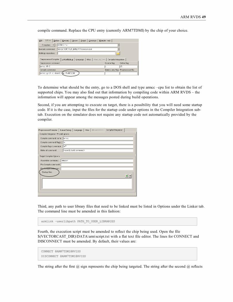
First, the compile command may need to be amended. Under Options, in the C/C++ sub-tab, locate the
ARM RVDS 49
compile command. Replace the CPU entry (currently ARM7TDMI) by the chip of your choice.
To determine what should be the entry, go to a DOS shell and type armcc –cpu list to obtain the list ofsupported chips. You may also find out that information by compiling code within ARM RVDS – theinformation will appear among the messages posted during build operations.
Second, if you are attempting to execute on target, there is a possibility that you will need some startupcode. If it is the case, input the files for the startup code under options in the Compiler Integration sub-tab. Execution on the simulator does not require any startup code not automatically provided by thecompiler.
Third, any path to user library files that need to be linked must be listed in Options under the Linker tab.The command line must be amended in this fashion:
armlink –userlibpath PATH_TO_USER_LIBRARIES
Fourth, the execution script must be amended to reflect the chip being used. Open the file$(VECTORCAST_DIR)\DATA\arm\script.txt with a flat text file editor. The lines for CONNECT andDISCONNECT must be amended. By default, their values are:
CONNECT @ARM7TDMI@RVISS
DISCONNECT @ARM7TDMI@RVISS
The string after the first @ sign represents the chip being targeted. The string after the second @ reflects

ARM RVDS 50
the category under which that simulator or target template is listed in ARM RealView Debugger. Tolearn what should be the values, launch ARM RealView Debugger and select Target => Connect toTarget. The following menu appears:
Here, to execute on the ARM926 simulator, the value for the entire string should be @ARM926EJ-S@RVISS_1. If you want to use the ARM_Cortex template to execute on a physical target, then the rightstring value is @ARM_Cortex-A8_0@ISSM.
It should be noted that a similar amendment must be made to the file debug.txt, also located under$(VECTORCAST_DIR)\DATA\arm\, to set VectorCAST to run test cases with the ARM RealViewDebugger.
Target Debug ExecutionTest Execution with Debug functions similarly to normal execution, except a breakpoint is set in themain function so execution stops there. You can manually set breakpoints, step through source anddisassembly, and view data as you would during a normal debug session.
Launching a debug execution of the test harness under ARM 4.x will launch the ARM RealViewDebugger. You will thereafter be able to run a test case under the control of the debugger . Test case datawill be saved automatically, so you need only close the instance of the debugger to return toVectorCAST. Please note that if the test harness is not allowed to run until the end, incomplete results

ARM RVDS 51
will be sent to VectorCAST, resulting in an error.
Under previous versions of ARM RVDS, upon executing a test case with debug, VectorCAST willlaunch axd, another utility of ARM RVDS, to execute the test case. Please consult documentation tolearn how to use this facility to execute test cases with VectorCAST.

CODE COMPOSER STUDIO 52
Code Composer StudioConfiguration
This section provides details about configuring VectorCAST to integrate with TI Code Composer.
If you are using Code Composer Studio 4.0, set the environment variable VCAST_CCS_INSTALL_DIRto your Code Composer installation directory. Usually Code Composer is installed inC:\Progra~1\TexasI~1\ccsv4, but it may be different for your system.
Add the directory containing the binary for the compiler to your PATH environment variable. Forexample, if you are using Code Composer Studio 4.0 with the 55xx chip, add $VCAST_CCS_INSTALL_DIR\tools\compiler\c5500\bin to your PATH.
If you are using Code Composer Studio 3.1 or 3.3 with the <<composer_gel>> execution method,you must also add the directory containing the cc_app executable to your PATH environment variable.The default location for the cc_app executable is C:\CCStudio_v3.1\cc\bin or C:\CCStudio_v3.3\cc\bin,respectively.
In VectorCAST, select Tools => Options from the main toolbar. Choose the C/C++ tab to select the entryfor the version of Code Composer that you are using. In the following figure Code Composer 6x isselected:
Special Configuration for Code Composer version 4.1
If you are using the Code Composer C3x version 4.1 simulator with VectorCAST you need to change the

CODE COMPOSER STUDIO 53
default composer.cmd file that is delivered with VectorCAST.
Edit the composer.cmd file located in VectorCAST's installation DATA directory (%VECTORCAST_DIR\DATA%\composer.cmd).
By default, the line you want to change is:
EXTRAM : org = 0x900000, len = 0x40000
Change this to read:
EXTRAM : org = 0x800000, len = 0x40000
In addition, you must configure the memory map in the Code Composer Simulator to enable the samerange of memory. To do this, open the Code Composer application, and select the “Option” menu,“Memory Map…” choice.
This will bring up a dialog similar to the following:
Use this dialog to allocate a memory section using the following steps:
1. Enable Memory Mapping, using the check box
2. Select the Starting Address to be 0x800000
3. Select the Length to be 0x40000
4. Select the Attributes to be RAM - Read and Write
5. Click Add to add this memory section to the simulator
6. Click Done to close the dialog.
Once this is accomplished, you will be able link and run VectorCAST test cases with the Code ComposerC3x simulator.
Target Execution with Code Composer Studio 4.0Code Composer Studio version 4.0 uses the script found at $VCAST_CCS_INSTALL_

CODE COMPOSER STUDIO 54
DIR\scripting\examples\loadti\loadti.bat to run tests. You can specify a different chip by creating a ccxmlfile for it. Inside Code Composer Studio 4.0, go to Target => New Target Configuration to select yourprocessor and save that to a file.
In VectorCAST, go to Tools => Options dialog, C/C++ tab, and change the Execute Command to specifythat file along with the path to it. So instead of:
$(VCAST_CCS_INSTALL_DIR)\scripting\examples\loadti\loadti.bat -c
$(VCAST_CCS_INSTALL_DIR)\scripting\examples\C64\tisim_c64xple.ccxml
use
$(VCAST_CCS_INSTALL_DIR)\scripting\examples\loadti\loadti.bat -c C:\your_dir\your_file.ccxml
Note that the loadti.bat script cannot read a .ccxml file over a network drive. You can either copy the fileto your machine or specify the file with the VCAST_ENVIRONMENT_FILES configuration option so itgets copied automatically into your environment.
Special Considerations for Some CCS v4.0 Targets
Some of the VectorCAST templates for Code Composer v4.0 targets require using the VectorCAST-supplied loadti.bat file and main.js JavaScript instead of those provided in the Texas Instruments release.

CODE COMPOSER STUDIO 55
The VectorCAST CCS templates that do require this will copy all the required script files andJavaScripts from the $(VECTORCAST_DIR/DATA/code_composer directory into your test environmentdirectory and will reference these versions as opposed to the TI versions. An example of such a case is thefor Spectrum Digital DSK-EVM-eZdsp F28335 (TI Code Composer 4.0 F28335 DSP C2000) whichrequires that gel scripts get run at the appropriate time to disable the WatchDog timer and enable theexternal RAM, from which the harness code gets loaded and executed. See the main.js JavaScript in the$(VECTORCAST_DIR/DATA/code_composer directory for details regarding any target-specificprocessing that occurs inside this script.
When using the VectorCAST-supplied loadti.bat file with some CCS v4.0 targets, you must set thefollowing environment variables before creating a test environment: VCAST_CCS_INSTALL_DIR,PATH, and DEBUGSERVER_ROOT. Note that the DEBUGSERVER_ROOT environment variable mustbe set here because the TI release version of the loadti.bat file sets this using relative paths, which willnot work because VectorCAST will change the location of the loadti.bat file. Also be sure that you donot have the TI release location (%VCAST_CCS_INSTALL_DIR%\scripting\examples\loadti) on yourPATH, as it will cause you to use the wrong loadti.bat file.
set VCAST_CCS_INSTALL_DIR=C:\Progra~1\TexasI~1\ccsv4
set PATH=%VCAST_CCS_INSTALL_DIR%\tools\compiler\c2000\bin;c:\perl\bin;%PATH%
set DEBUGSERVER_ROOT=C:\Progra~1\TexasI~1\ccsv4\DebugServer
Target Execution with Code Composer Studio 3.3Code Composer Studio versions 3.1 and 3.3 require some configuration for test case execution inVectorCAST. From the start menu, run Programs => Texas Instruments => Code Composer Studio v3.3=> Setup Code Composer Studio v3.3. In the System Configuration column, right click on the CPU namebeneath the board specification and select Properties.
Remove the default GEL file and leave the field blank.

CODE COMPOSER STUDIO 56
Click OK. Removing the GEL file allows VectorCAST to invoke cc_app with your own StartUp()function in a GEL script. No data is lost since the default GEL script had an empty StartUp() function.VectorCAST invokes cc_app with a GEL script when executing tests with debug.
The default execution method is <<composer_gel>>. With this method, VectorCAST automaticallystarts Code Composer Studio, loads the executable using a GEL script, and runs it. When the “VCAST isDone!” message appears in the Stdout window, you must manually exit Code Composer Studio to returnto VectorCAST. The GEL script is called composer.gel and is located in your environment directory. Thecontents should be similar to the following:
StartUp()
{
GEL_Reset();
GEL_Load("C:/BASIC_TUTORIAL/vcast.out");
GEL_Run();
}
If you would like completely automated test execution, you can change your Execute Command in theVectorCAST Tool => Options dialog, C/C++ tab to <<composer_perl>>. This execution method usesCCStudio Scripting so you should only select it if you can install this feature. CCStudio Scripting allowsVectorCAST to start Code Composer Studio, load the executable, run it, and then exit Code ComposerStudio when the executable has finished.
The <<composer_perl>> execution method requires installation of ActivePerl 5.8 and CCS Scriptingv1.5. ActivePerl 5.8 is available for free at http://www.activestate.com/activeperl/ .
More recent versions of ActivePerl do not work with CCS Scripting so please check that you haveActivePerl v5.8. Before you can use the Perl execution method, follow these steps:
1. Add the location of the Perl utilities to your PATH environment variable. This is usually C:\Perl\binbut may be different for your system.
set PATH=C:\Perl\bin;%PATH%
2. Obtain the patch for CCS Scripting v1.5 by starting up Code Composer Studio and selecting Help=> Update Advisor => Check for Updates.

CODE COMPOSER STUDIO 57
3. Add the CCStudio Scripting libraries to your PATH environment variable. This is usuallyC:\CCStudio_v3.1\bin\utilities\ccs_scripting.
set PATH=C:\CCStudio_v3.1\bin\utilities\ccs_scripting;%PATH%
4. Finally, set a new environment variable, PERL5LIB, to the same directory as mentioned in theprevious step.
set PERL5LIB=C:\CCStudio_v3.1\bin\utilities\ccs_scripting
The <<composer_perl>> execution method works by calling the composer.pl Perl script inside theenvironment directory to handle the test harness execution. You can change this file if necessary. If youwould like the changes to apply to all future environments, change the template for the file in$VECTORCAST_DIR/DATA/composer.pl. Note that when you execute a test case, it is normal for CodeComposer Studio to start with an initial status of “HALTED” displayed in the bottom left hand corner.Just wait a few seconds, and the status will switch to “RUNNING”.
The <<composer_gel>> and <<composer_perl>> execution methods both use a GEL script tohandle execution with debugging. The GEL script used is composer.dbg.gel, and it is located inside theenvironment directory. This script loads the harness executable.
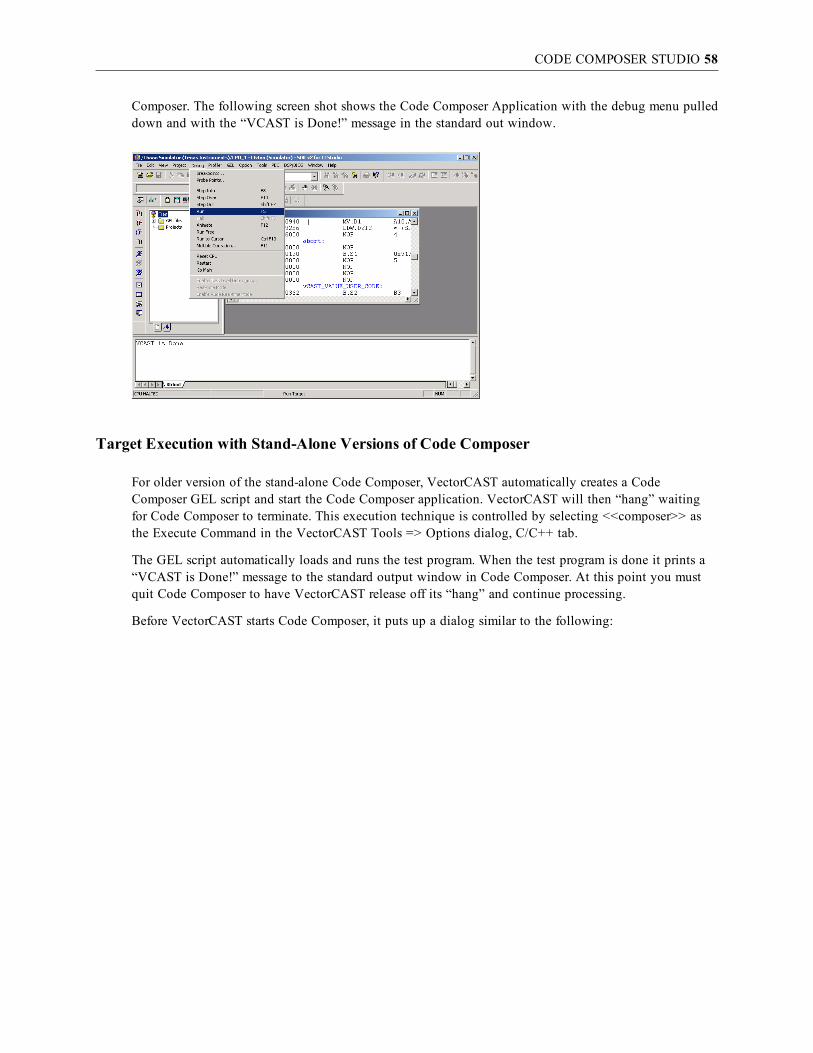
Target Execution with Code Composer Studio 2The previous incarnation of the Code Composer product is Code Composer Studio 2. This is theintegrated product that combines the TI compiler with Code Composer. If you are using the pre-studioversion of Code Composer, see the section “Target Execution with Stand-Alone Versions of CodeComposer” on page 58.
The execution technique described in this section, is controlled by selecting: <<composer_sdk>> asthe Execute Command in the VectorCAST Tool => Options dialog, C/C++ tab.
For Code Composer Studio, VectorCAST starts Code Composer Studio (if it is not running) or connects toit (if it is already running). When VectorCAST is ready to run an executable, it puts up a dialog similar tothe following:
The dialog details the manual steps involved in test execution. After you click OK in this dialog, theCode Composer application is activated, and the test driver is loaded. You will need to select Run fromthe Debug, menu. When the test execution has finished, you will see the message: “VCAST is Done!” inthe standard output window in Code Composer. To force control back to VectorCAST, you should select:Halt and then Reset CPU from the Debug menu of Code Composer. You do not need to exit from Code
CODE COMPOSER STUDIO 58
Composer. The following screen shot shows the Code Composer Application with the debug menu pulleddown and with the “VCAST is Done!” message in the standard out window.
Target Execution with Stand-Alone Versions of Code Composer
For older version of the stand-alone Code Composer, VectorCAST automatically creates a CodeComposer GEL script and start the Code Composer application. VectorCAST will then “hang” waitingfor Code Composer to terminate. This execution technique is controlled by selecting <<composer>> asthe Execute Command in the VectorCAST Tools => Options dialog, C/C++ tab.
The GEL script automatically loads and runs the test program. When the test program is done it prints a“VCAST is Done!” message to the standard output window in Code Composer. At this point you mustquit Code Composer to have VectorCAST release off its “hang” and continue processing.
Before VectorCAST starts Code Composer, it puts up a dialog similar to the following:

CODE COMPOSER STUDIO 59
After you click OK, VectorCAST will start Code Composer and put up a second acknowledgment dialogsimilar to the following:
When the target execution is complete, quit code composer and then click OK on the above dialog.
The Default Memory Map
VectorCAST is delivered with a “stock” linker command file that is used to build VectorCAST testenvironments. This memory map is located in the VectorCAST installation directory and is calledcomposer.cmd. You should ensure that this file is consistent with your target hardware before testing.You may make changes to this file in the VectorCAST installation directory, and those changes will bereflected in any environments built subsequent to the change. If you need to control the memory map foreach environment separately, you may edit the composer.cmd file that exists in the environment and thendo a VectorCAST Environment => Relink command.

CODE COMPOSER STUDIO 60
Debugging with Code Composer
If you wish to debug with code composer, simply use Code Composer to halt the DSP, and then restartthe execution using the standard Code Composer controls.

DSP/BIOS SUPPORT ON CODE COMPOSER STUDIO 3.3 AND 4.X 61
DSP/BIOS support on Code Composer Studio 3.3 and 4.xConfiguration
This section provides details about how VectorCAST provides DSP/BIOS support for customersthat require DSP/BIOS support running on either target boards or simulators. Currently this integration issupported for Code Composer Studio version 3.3 and 4.x
DSP/BIOS ConfigurationVectorCAST relies on the installation and setup of DSP/BIOS on the system on which you will becreating your test environments. The environment variable BIOS_INSTALL_DIR is used by CodeComposer Studio and VectorCAST to determine which version of DSP/BIOS is being used and its installlocation on your system. You must set up this environment variable accordingly as the example belowshows.
set BIOS_INSTALL_DIR=C:\CCStudio_v3.3\bios_5_33_06
Note: You may have multiple versions of DSP BIOS installed on your machine, be sure that theBIOS_INSTALL_DIR environment variable points to the version you want to be using.
As with any CCS v3.3 environment, you must run CCS Setup to configure the appropriatetarget/simulator you wish to use. The sample screenshot below shows configuration for the C64xxsimulator, which we will use throughout this chapter as an example. If you are using CCS v4.x or later,you do not need to run the CCS Setup as the target configuration in CCS versions after 4.0 are handledthrough the use of target configuration files (*.ccxml files).
By default, VectorCAST will build new unit test environments with DSP/BIOS support disabled for allCCS targets that a user can select through the compiler pull down menu in VectorCAST.
You should build a simple unit test environment without DSP/BIOS support to be sure that all othercompiler settings and environment variables are properly configured, then turn on DSP/BIOS support inVectorCAST as described below.
To determine if VectorCAST currently provides support for DSP/BIOS on the particular CCS target you

DSP/BIOS SUPPORT ON CODE COMPOSER STUDIO 3.3 AND 4.X 62
have selected, select Tools => Options dialog, C/C++ tab, and the new Code Composer Options sub-tabis displayed. (This tab exists only when a TI Code Composer compiler has been selected in the compilerpull-down menu.)
VectorCAST sets the environment variable VCAST_CCS_INSTALL_DIR to the default install path basedon the compiler template you have selected and it is displayed on the Code Composer tab as shownbelow.
For CCS v3.3 templates, the default install directory is “C:\CCStudio_v3.3”. If you have installed CodeComposer Studio in a different location then you specify the path by editing it in the “CCS InstallationDirectory” edit box or use the directory browser button to select the correct install directory.
If the checkbox named “DSP/BIOS” is available (not greyed out), then this means that VectorCAST hasbuilt-in support for DSP/BIOS for the selected compiler template. You can enable this DSP/BIOS for thetest environment, by checking this box. If the checkbox is greyed out, then VectorCAST does notcurrently support DSP/BIOS on the target you have selected and you should contact VectorCAST [email protected] for help in adding DSP/BIOS support.
Customization of the DSP/BIOS support for your particular target or simulator is handled by pointing to aTCF file. Starting with v3.3, CCS uses TCF files to describe the resources and memory allocation detailsrelated to your target application. Details about the CCS graphical configuration tool are beyond thescope of this document, so please refer to your TI documentation for details about the graphicalDSP/BIOS configuration tool, which will produce a TCF file as output. (DSP/BIOS 5.40 TextualConfiguration (Tconf) User’s Guide http://www.ti.com/lit/ug/spru007i/spru007i.pdf)
Here is a small excerpt from that TI documentation that describes the DSP/BIOS configuration tool:
Typically, you use the graphical DSP/BIOS Configuration Tool to create your initial configuration.This tool acts as a macro recorder for Tconf scripts (TCF files). You see the script change in the rightpane of the tool as you change the configuration graphically. Later, you can edit the Tconf scriptgenerated by the DSP/BIOS Configuration Tool with a text editor. (p. 1-4)
Tconf scripts are now the source files for DSP/BIOS configurations. The CDB files previously used asconfiguration source files can now only be opened in read-only mode or converted to TCF files. (p. 1-3)
Users will typically have developed such a TCF file for their project and desired target in the CCS

DSP/BIOS SUPPORT ON CODE COMPOSER STUDIO 3.3 AND 4.X 63
application environment, and now you must simply point to that TCF file inside VectorCAST to allowVectorCAST to generate the necessary supporting files based on the TCF file contents. VectorCASTprovides a default TCF file as part of the RSP for the selected target which can be used or modified bythe user in lieu of providing their own TCF configuration file.
After selecting the TCF file the user should click the “Apply” button to initialize the VectorCASTenvironment data with the selected TCF file. This action will also cause the “Generate DSP BIOS Files”button to become enabled as shown in the figure below.
You can now click the “Generate DSP BIOS Files…” button, which causes VectorCAST to generate thenecessary DSP/BIOS files based on the selected TCF file, compile those files, and relink with the currentenvironment. VectorCAST runs a .bat file (vcast_cc_tconf.bat) to execute the necessary operations. Youwill see a “processing…” status box during that execution phase as shown below.
Other fields of interest on the Code Composer Options tab include the following:
CCS Installation Directory is the installation directory for Code Composer Studio. You may edit thedefault path to point to the location of where CCS is installed on your system.
BIOS_INSTALL_DIR option displays the current version setting for DSP BIOS. You should confirm itis properly set. Because the CCS tools and the VectorCAST tools both use this variable, you must exitVectorCAST to change this variable at the Operating System level, and then restart VectorCAST.

DSP/BIOS SUPPORT ON CODE COMPOSER STUDIO 3.3 AND 4.X 64
TI CC DSP BIOS Linker Options contains the DSP BIOS-specific linker options that are automaticallygenerated by VectorCAST based on the TCF filename and the contents of the TI Code Composertemplate provided by VectorCAST (TI_CC_TEMPLATES.DAT). You can edit these options if you needto add additional linker options.
TI CC normal (non-DSP BIOS) Linker Options displays the linker options that are used if DSP BIOSsupport is turned off by unchecking the DSP/BIOS checkbox.
Linker Command Preview is a read-only Linker Command Preview box that allows you to see thecompletely constructed linker command that will be executed to build the target/simulator image. Thispane changes when the DSP/BIOS checkbox is selected or unselected. If the DSP/BIOS or normal linkeroptions change, this pane will update in real-time to reflect those changes.

CODE COMPOSER STUDIO ON EZDSP28335 TARGET BOARD 65
Code Composer Studio on ezDSP28335 target boardConfiguration
This section provides details about configuring VectorCAST to integrate with TI Code Composerv3.3 on the Spectrum Digital ezDSP 28335 development board.
You should install the latest drivers for the ezDSP 28335 from the Spectrum Digital website that aredesigned to work with Code Composer v3.3.
Code Composer Setup
The hardware connection method used for this RSP support is a direct USB connection to the onboardJTAG connection on the ezDSP 28335 development board; i.e., no external Spectrum Digital emulator isused.
Prior to running VectorCAST, you need to run Setup Code Composer Studio. Set the board to F28335ezDSP. It should display the driver location as C:\CCStudio_v3.3\drivers\sdgo28xxeZdspusb.dvr and thegel script at C:\CCStudio_v3.3\cc\gel\f28335.gel based on the default location for CCStudio v3.3 installdirectory.
Note: The f28335.gel file must be modified to enable external memory before the program loadoccurs by making call to the XINTF_Enable() gel function in the OnPreFileLoaded() function. Ifyou fail to make this change you will get a data verification error when VectorCAST tries to loadthe program on the 28335 like the one shown below.
See the screen shots below to confirm that you are properly setup for the ezDSP 28335 board.
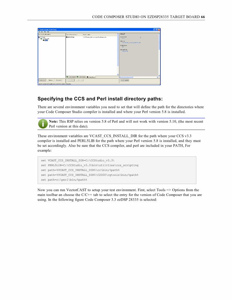
CODE COMPOSER STUDIO ON EZDSP28335 TARGET BOARD 66
Specifying the CCS and Perl install directory paths:There are several environment variables you need to set that will define the path for the directories whereyour Code Composer Studio compiler is installed and where your Perl version 5.8 is installed.
Note: This RSP relies on version 5.8 of Perl and will not work with version 5.10, (the most recentPerl version at this date).
These environment variables are VCAST_CCS_INSTALL_DIR for the path where your CCS v3.3compiler is installed and PERL5LIB for the path where your Perl version 5.8 is installed, and they mustbe set accordingly. Also be sure that the CCS compiler, and perl are included in your PATH, Forexample:
set VCAST_CCS_INSTALL_DIR=C:\CCStudio_v3.3\
set PERL5LIB=C:\CCStudio_v3.3\bin\utilities\ccs_scripting
set path=%VCAST_CCS_INSTALL_DIR%\cc\bin;%path%
set path=%VCAST_CCS_INSTALL_DIR%\C2000\cgtools\bin;%path%
set path=c:\perl\bin;%path%
Now you can run VectorCAST to setup your test environment. First, select Tools => Options from themain toolbar an choose the C/C++ tab to select the entry for the version of Code Composer that you areusing. In the following figure Code Composer 3.3 ezDSP 28335 is selected:

CODE COMPOSER STUDIO ON EZDSP28335 TARGET BOARD 67
Target Execution with Code Composer Studio 3.3If you would like completely automated test execution, you can select the Execute Command by rightclicking on the desired test case or clicking the Execute test case button from the toolbar. This executionmethod uses CCStudio Scripting so you should only select it if you can install this feature. CCStudioScripting allows VectorCAST to start Code Composer Studio, load the executable, run it, and then exitCode Composer Studio when the executable has finished.
The <<composer_perl>> execution method requires installation of ActivePerl 5.8 and CCS Scriptingv1.5. ActivePerl 5.8 is available for free at http://www.activestate.com/activeperl/ . Add the location ofthe Perl utilities to your PATH environment variable. This is usually C:\Perl\bin but may be different foryour system. Obtain the patch for CCS Scripting v1.5 by starting up Code Composer Studio and selectingHelp => Update Advisor => Check for Updates. Add the CCStudio Scripting libraries to your PATHenvironment variable. This is usually C:\CCStudio_v3.3\bin\utilities\ccs_scripting. Also set thePERL5LIB environment variable to the same directory.
The <<composer_perl>> execution method works by calling the composer.pl Perl script inside theenvironment directory to handle the test harness execution. When the Perl script is running, VectorCASTwill display the following progress/abort dialog box.
If you wish to abort the Perl script you may do so by selecting the Abort button, which will exit the perlscript processing and typically make your test case fail as you have exited prior to test case execution

CODE COMPOSER STUDIO ON EZDSP28335 TARGET BOARD 68
completion.
You can change the Perl script file (composer.pl) if necessary. If you would like the changes to apply toall future environments, change the template for the file in
$VECTORCAST_DIR/DATA/composer.pl
or
$VECTORCAST_DIR/DATA/composer_debug.pl
if you which to change the behavior of the debug script. Note that when you execute a test case, it isnormal for Code Composer Studio to start with an initial status of “HALTED” displayed in the bottomleft hand corner. Just wait a few seconds, and after the application is loaded you will see the status switchto “RUNNING.”
Target Execution with Debug in Code Composer Studio 3.3If you select Execute With Debug command, then VectorCAST automatically calls the composer_debug.pl Perl script, which will load the application but won’t automatically run so as to give you theopportunity to set breakpoints, single step and debug in the typical fashion when using the CCS IDEdebugger. Before VectorCAST starts Code Composer, it puts up a dialog similar to the following:
When the test program is done it prints a “VCAST is Done!” message to the standard output window inCode Composer. At this point you must quit Code Composer to have VectorCAST release off its “hang”and continue processing.
After completing your debug session and quitting out of Code Composer, then click OK on the abovedialog and control will be passed back to VectorCAST to display your test results.

CODE COMPOSER STUDIO ON DSK 6713 TARGET BOARD 69
Code Composer Studio on DSK 6713 target boardConfiguration
This section provides details about configuring VectorCAST to integrate with TI Code Composerv3.3 on the Spectrum Digital 6713 DSK (DSP Starter Kit) development board. This particular exampledescribes an application example that utilizes the DSP/BIOS features.
You should install the latest drivers for the 6713 DSK from the Spectrum Digital website that aredesigned to work with Code Composer v3.3.
Other C6713 based targets can also use this template to configure a unit test environment, provided therequired changes are made to accommodate the connection method specified in Code Composer Setup,including what type of emulator you are connecting to and target specific GEL files, also specified in theCode Composer Setup. In addition the user may have to provide their own TCF file to configure the DSPBIOS options according to their desired link configuration. See more details regarding the TCF file in thefollowing sections.
DSP/BIOS ConfigurationThe RSP (Run-Time Support Package) that supports this particular board also provides DSP/BIOS support.The CCS 6713 compiler template will reference a TCF file used to enable and create the appropriate DSPBIOS support. The default TCF file will get copied to your test environment directory and will be usedas the default TCF file when building your test environment with DSP BIOS support turned on. This TCFfile can be used or a customer provided TCF file may be used in its place. See the chapter on DSP/BIOSconfiguration for Code Composer v3.3 for more details on how VectorCAST provides DSP/BIOS support.
VectorCAST relies on the installation and setup of DSP/BIOS on the system you will be creating yourtest environments. The environment variable BIOS_INSTALL_DIR is used by Code Composer Studio andVectorCAST to determine which version of DSP/BIOS is being used and its install location on yoursystem. The user must setup this environment variable accordingly as the example below shows.
set BIOS_INSTALL_DIR=C:\CCStudio_v3.3\bios_5_33_06
Note: You may have multiple versions of DSP_BIOS installed on your machine, be sure that theBIOS_INSTALL_DIR environment variable points to the version you want to be using.
You should also check the Component Manager and confirm that you have selected the appropriateversion of BIOS for this DSP family (TMS32067xx). See the screen shot below.

CODE COMPOSER STUDIO ON DSK 6713 TARGET BOARD 70
Code Composer Setup
Prior to running VectorCAST, you need to run Setup Code Composer Studio. Set the board to C6713DSK. It should display the driver location as C:\CCStudio_v3.3\drivers\sdgo6713dsk.dvr based on thedefault location for CCStudio v3.3 install directory. See the screen shots below to confirm that you areproperly setup for the DSK 6713 board.
Note: The GEL file specified in the CCS Setup for the C6713DSK made be modified by the user
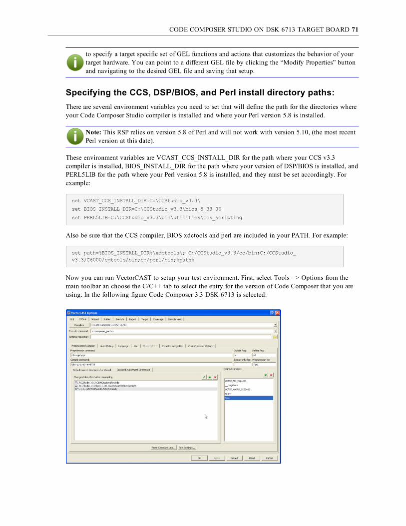
CODE COMPOSER STUDIO ON DSK 6713 TARGET BOARD 71
to specify a target specific set of GEL functions and actions that customizes the behavior of yourtarget hardware. You can point to a different GEL file by clicking the “Modify Properties” buttonand navigating to the desired GEL file and saving that setup.
Specifying the CCS, DSP/BIOS, and Perl install directory paths:There are several environment variables you need to set that will define the path for the directories whereyour Code Composer Studio compiler is installed and where your Perl version 5.8 is installed.
Note: This RSP relies on version 5.8 of Perl and will not work with version 5.10, (the most recentPerl version at this date).
These environment variables are VCAST_CCS_INSTALL_DIR for the path where your CCS v3.3compiler is installed, BIOS_INSTALL_DIR for the path where your version of DSP/BIOS is installed, andPERL5LIB for the path where your Perl version 5.8 is installed, and they must be set accordingly. Forexample:
set VCAST_CCS_INSTALL_DIR=C:\CCStudio_v3.3\
set BIOS_INSTALL_DIR=C:\CCStudio_v3.3\bios_5_33_06
set PERL5LIB=C:\CCStudio_v3.3\bin\utilities\ccs_scripting
Also be sure that the CCS compiler, BIOS xdctools and perl are included in your PATH. For example:
set path=%BIOS_INSTALL_DIR%\xdctools\; C:/CCStudio_v3.3/cc/bin;C:/CCStudio_v3.3/C6000/cgtools/bin;c:/perl/bin;%path%
Now you can run VectorCAST to setup your test environment. First, select Tools => Options from themain toolbar an choose the C/C++ tab to select the entry for the version of Code Composer that you areusing. In the following figure Code Composer 3.3 DSK 6713 is selected:

CODE COMPOSER STUDIO ON DSK 6713 TARGET BOARD 72
To enable DSP/BIOS support for this target you must check the DSP/BIOS checkbox on the CodeComposer Options tab as shown below.
By default the VectorCAST 6713 tempalte will point to the TCF file for the 6713 simulator (vcast_cc_6713_sim.tcf). To enable running on the 6713 DSK target you must select the target version of the TCFfile. This file is available in the VectorCAST installation area (e.g. DATA\code_composer\64xx). Youcan either navigate to this file using the “navigate” button, or simply edit the field and change “sim” to“tgt”. You may also select an alternate TCF file that you have created for your project and customhardware configuration.
After selecting the desired TCF file, click the “Apply” button to save it as the current TCF file, whichwill store it in your VectorCAST environment data and then click the “Generate” button to haveVectorCAST create the necessary DSP BIOS files, and compile and link them into the test harness. Youwill see a progress dialog box come up indicating that VectorCAST is running the internal bat file it usesto perform these DSP BIOS operations, as shown below.

CODE COMPOSER STUDIO ON DSK 6713 TARGET BOARD 73
After that bat file completes successfully you are now ready to create your test cases and execute themwith DSP BIOS support.
Target Execution with Code Composer Studio 3.3If you would like completely automated test execution, you can select the Execute Command by rightclicking on the desired test case or clicking the Execute test case button from the toolbar. This executionmethod uses CCStudio Scripting so you should only select it if you can install this feature. CCStudioScripting allows VectorCAST to start Code Composer Studio, load the executable, run it, and then exitCode Composer Studio when the executable has finished.
The <<composer_perl>> execution method requires installation of ActivePerl 5.8 and CCS Scriptingv1.5. ActivePerl 5.8 is available for free at http://www.activestate.com/activeperl/ . Add the location ofthe Perl utilities to your PATH environment variable. This is usually C:\Perl\bin but may be different foryour system. Obtain the patch for CCS Scripting v1.5 by starting up Code Composer Studio and selectingHelp => Update Advisor => Check for Updates. Add the CCStudio Scripting libraries to your PATHenvironment variable. This is usually C:\CCStudio_v3.3\bin\utilities\ccs_scripting. Also set thePERL5LIB environment variable to the same directory.
The <<composer_perl>> execution method works by calling the composer.pl Perl script inside theenvironment directory to handle the test harness execution. When the perl script is running, VectorCASTwill display the following progress/abort dialog box.
If you wish to abort the Perl script you may do so by selecting the Abort button, which will exit the Perlscript processing and typically make your test case fail as you have exited prior to test case execution

CODE COMPOSER STUDIO ON DSK 6713 TARGET BOARD 74
completion.
You can change the Perl script file (composer.pl) if necessary. If you would like the changes to apply toall future environments, change the template for the file in $VECTORCAST_DIR/DATA/composer.pl or$VECTORCAST_DIR/DATA/composer_debug.pl if you which to change the behavior of the debugscript. Note that when you execute a test case, it is normal for Code Composer Studio to start with aninitial status of “HALTED” displayed in the bottom left hand corner. Just wait a few seconds, and afterthe application is loaded you will see the status switch to “RUNNING.”
Target Execution with Debug in Code Composer Studio 3.3If you select the Execute With Debug command, then VectorCAST automatically calls the composer_debug.pl Perl script, which will load the application but won’t automatically run so as to give you theopportunity to set breakpoints, single step and debug in the typical fashion when using the CCS IDEdebugger. Before VectorCAST starts Code Composer, it puts up a dialog similar to the following:
When the test program is done it prints a “VCAST is Done!” message to the standard output window inCode Composer. At this point you must quit Code Composer to have VectorCAST release off its “hang”and continue processing.
After completing your debug session and quitting out of Code Composer, then click OK on the abovedialog and control will be passed back to VectorCAST to display your test results.

CODE COMPOSER STUDIO ON OMAP 35X EVM TARGET BOARD 75
Code Composer Studio on OMAP 35x EVM target boardConfiguration
This section provides details about configuring VectorCAST to integrate with TI Code Composerv3.3 on the TI/Mistral OMAP 35x EVM development board. This particular example describes anapplication that is configured to utilize the DSP/BIOS features.
This target configuration requires the use of a Spectrum Digital XDS560R emulator to connect from thehost PC to the target EVM. You should install the latest drivers from the Spectrum Digital website thatare designed to work with Code Composer v3.3.
DSP/BIOS ConfigurationThe RSP (Run-Time Support Package) that supports this particular board also provides DSP/BIOS support.The CCS OMAP 35x compiler template will reference a TCF file used to enable and create theappropriate DSP BIOS support. The default TCF files will get copied to your test environment directoryand will be used as the default TCF file when building your test environment with DSP BIOS supportturned on. This TCF file can be used or a customer provided TCF file may be used in its place. See thechapter on DSP/BIOS configuration for Code Composer v3.3 for more details on how VectorCASTprovides DSP/BIOS support.
VectorCAST relies on the installation and setup of DSP/BIOS on the system you will be creating yourtest environments. The environment variable BIOS_INSTALL_DIR is used by Code Composer Studio andVectorCAST to determine which version of DSP/BIOS is being used and its install location on yoursystem. The user must setup this environment variable accordingly as the example below shows.
set BIOS_INSTALL_DIR=C:\CCStudio_v3.3\bios_5_33_06
Note: You may have multiple versions of DSP_BIOS installed on your machine, be sure that theBIOS_INSTALL_DIR environment variable points to the version you want to be using.
You should also click the Component Manager button and confirm that you have selected the appropriateversion of BIOS for this DSP family (TMS32064xx). See the screen shot below.

CODE COMPOSER STUDIO ON OMAP 35X EVM TARGET BOARD 76
Code Composer Setup
Prior to running VectorCAST, you need to run Setup Code Composer Studio. Select the board andemulator configuration that matches your setup. Here we have selected the omap3530_SDXDS560R asshown below.
Take time to configure the appropriate gel file for each of the processors on the omap 35x. You canchange the specified gel file by selecting the processor, right-clicking and edit the gel file accordingly.The default gel files will work fine for this example. They are:
C:\CCStudio_v3.3\cc\gel\omap3430_c64plus.gel
C:\CCStudio_v3.3\cc\gel\omap3530_cortexA.gel

CODE COMPOSER STUDIO ON OMAP 35X EVM TARGET BOARD 77
Specifying the CCS, DSP/BIOS, and Perl install directory paths:
There are several environment variables you need to set that will define the path for the directories whereyour Code Composer Studio compiler is installed and where your Perl version 5.8 is installed.
Note: This RSP relies on version 5.8 of Perl and will not work with version 5.10, (the most recentPerl version at this date).
These environment variables are VCAST_CCS_INSTALL_DIR for the path where your CCS v3.3compiler is installed, BIOS_INSTALL_DIR for the path where your version of DSP/BIOS is installed, andPERL5LIB for the path where your Perl version 5.8 is installed, and they must be set accordingly. Forexample:
set VCAST_CCS_INSTALL_DIR=C:\CCStudio_v3.3\
set BIOS_INSTALL_DIR=C:\CCStudio_v3.3\bios_5_33_06
set PERL5LIB=C:\CCStudio_v3.3\bin\utilities\ccs_scripting
Also be sure that the CCS compiler, BIOS xdctools and perl are included in your PATH. For example:
set path=%BIOS_INSTALL_DIR%\xdctools\; C:/CCStudio_v3.3/cc/bin;C:/CCStudio_v3.3/C6000/cgtools/bin;c:/perl/bin;%path%
Now you can run VectorCAST to setup your test environment. First, select Tools => Options from themain toolbar an choose the C/C++ tab to select the entry for the version of Code Composer that you areusing. In the following figure Code Composer 3.3 OMAP35x C64x+ is selected:

CODE COMPOSER STUDIO ON OMAP 35X EVM TARGET BOARD 78
To enable DSP/BIOS support for this target you must check the DSP/BIOS checkbox on the CodeComposer Options tab as shown below.
By default the VectorCAST omap35x template will point to the TCF file for the 64x+ simulator (vcast_cc_64Pxx_sim.tcf). To enable running on the omap 35x EVM target you must select the target versionof the TCF file. This file is available in the VectorCAST installation area (e.g. DATA\code_composer\64xx). You can either navigate to this file using the “navigate” button, or simply edit the fieldand change “sim” to “tgt”. You may also select an alternate TCF file that you have created for yourproject.
After selecting the desired TCF file, click the “Apply” button to save it as the current TCF file, whichwill store it in your VectorCAST environment data and then click the “Generate” button to haveVectorCAST create the necessary files and compile and link them into the test harness. You will see a

CODE COMPOSER STUDIO ON OMAP 35X EVM TARGET BOARD 79
progress dialog box come up indicating that VectorCAST is running the internal bat file it uses toperform these DSP BIOS operations, as shown below.
After that bat file completes successfully you are now ready to create your test cases and execute themwith DSP BIOS support.
Running in a Heterogeneous Multi-core environment with CodeComposer Studio 3.3
The OMAP 35x EVM board is a multi-core board that contains a master CortexA8 ARM processor and aC6400+ DSP processor. The VectorCAST RSP is designed to build and test UUT code that is targeted toexecute on the C6400+ DSP. To prepare your test environment to connect to, download and run theexecutable, you must first perform a few manual steps to ensure that the C64x+ DSP has been releasedfrom reset by the master ARM processor.
The steps required to do so are as follows:
1. After setting up the omap 35x in the Code Composer Setup as described above, start up CodeComposer Studio, which will bring up the Parallel Debug Manager, as shown below.
2. Connect to the CortexA_0 ARM processor be selecting, right-clicking and choosing “Connectdevice…”, then right-clicking again and choosing “Open…”
Note: If you have trouble connecting to the CortexA_0 ARM processor you may have toreboot the omap35x target and Spectrum Digital emulator. It is helpful to have a serial port

CODE COMPOSER STUDIO ON OMAP 35X EVM TARGET BOARD 80
connection from the omap35x serial port uart 1 connected to the host PC HyperTerminal appso you can see boot up debug messaging appear in the HyperTerminal window. Note thatthis board comes with a Linux kernel installed and while that kernel is booting up you mayexperience problems trying to connect to the ARM with the emulator. If you type “reboot”at the linux console prompt you will have better luck getting the connection to the ARMprocessor. You will also notice that when you disconnect from the ARM processor in CCS,the linux kernel will take control and auto boot.
3. Note that the C6400+ DSP is held in reset by the ARM processor. You must release the c64x+ fromreset by selecting GEL => IVA2200_Startup => IVA22_GEM_Startup from the GEL pull downmenu as shown below.
4. You should see the Output window appear and a message displayed indicating that the C64x+ hasbeen released from reset, as below.
5. You are now ready to run test cases from your test environment. The perl script that gets run,(composer.pl), when each test case is executed will open a connection to the C64x+ DSP, load the
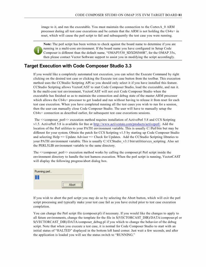
CODE COMPOSER STUDIO ON OMAP 35X EVM TARGET BOARD 81
image to it, and run the executable. You must maintain the connection to the CortexA_0 ARMprocessor during all test case executions and be certain that the ARM is not holding the C64x+ inreset, which will cause the perl script to fail and subsequently the test case you were running.
Note: The perl script has been written to check against the board name to determine if you arerunning in a multi-core environment. If the board name you have configured in Setup CodeComposer is different than the default name, “OMAP3530_SDXDS560R”, for the OMAP 35x,then please contact Vector Software support to assist you in modifying the script accordingly.
Target Execution with Code Composer Studio 3.3If you would like a completely automated test execution, you can select the Execute Command by rightclicking on the desired test case or clicking the Execute test case button from the toolbar. This executionmethod uses the CCStudio Scripting API so you should only select it if you have installed this feature.CCStudio Scripting allows VectorCAST to start Code Composer Studio, load the executable, and run it.In the multi-core test environment, VectorCAST will not exit Code Composer Studio when theexecutable has finished so as to maintain the connection and debug state of the master ARM processorwhich allows the C64x+ processor to get loaded and run without having to release it from reset for eachtest case execution. When you have completed running all the test cases you wish to run for a session,then the user can manually close Code Composer Studio. The user will have to manually setup theC64x+ connection as described earlier, for subsequent test case executions sessions.
The <<composer_perl>> execution method requires installation of ActivePerl 5.8 and CCS Scriptingv1.5. ActivePerl 5.8 is available for free at http://www.activestate.com/products/activeperl/. Add thelocation of the Perl utilities to your PATH environment variable. This is usually C:\Perl\bin but may bedifferent for your system. Obtain the patch for CCS Scripting v1.5 by starting up Code Composer Studioand selecting Help => Update Advisor => Check for Updates. Add the CCStudio Scripting libraries toyour PATH environment variable. This is usually C:\CCStudio_v3.1\bin\utilities\ccs_scripting. Also setthe PERL5LIB environment variable to the same directory.
The <<composer_perl>> execution method works by calling the composer.pl Perl script inside theenvironment directory to handle the test harness execution. When the perl script is running, VectorCASTwill display the following progress/abort dialog box.
If you wish to abort the perl script you may do so by selecting the Abort button, which will exit the perlscript processing and typically make your test case fail as you have exited prior to test case executioncompletion.
You can change the Perl script file (composer.pl) if necessary. If you would like the changes to apply toall future environments, change the template for the file in $(VECTORCAST_DIR)/DATA/composer.pl or$(VECTORCAST_DIR)/DATA/composer_debug.pl if you which to change the behavior of the debugscript. Note that when you execute a test case, it is normal for Code Composer Studio to start with aninitial status of “HALTED” displayed in the bottom left hand corner. Just wait a few seconds, and afterthe application is loaded you will see the status switch to “RUNNING.”

CODE COMPOSER STUDIO ON OMAP 35X EVM TARGET BOARD 82
Target Execution with Debug in Code Composer Studio 3.3If you select Execute With Debug command, then VectorCAST automatically calls the composer_debug.pl Perl script, which will load the application but won’t automatically run so as to give you theopportunity to set breakpoints, single step and debug in the typical fashion when using the CCS IDEdebugger. Before VectorCAST starts Code Composer, it puts up a dialog similar to the following:
When the test program is done it prints a “VCAST is Done!” message to the standard output window inCode Composer. At this point you must quit Code Composer to have VectorCAST release off its “hang”and continue processing.
After completing your debug session and quitting out of Code Composer, then click OK on the abovedialog and control will be passed back to VectorCAST to display your test results.

CODE COMPOSER STUDIO V4.2.4 ON TI STELLARIS EKT-LM3S9B92 EVB 83
Code Composer Studio v4.2.4 on TI Stellaris EKT-LM3S9B92 EVBTarget Configuration
The RSP described in this section is designed to interface to the Stellaris EKT-LM3S9B92evaluation kit which includes a BD-ICDI-B debug board. Refer to the TI instructions for connecting thetarget and debug board to each other with the two supplied flat ribbon cables and then connecting theUSB cable to the host PC. This procedure will install the proper drivers for the evb/debug boardcombination. Upon completion of the driver install, check the Device Manager of your PC to see that theStellaris ICDI com port, Stellaris ICDI Board A and Stellaris ICDI Board B appear as in the screen shotbelow.
ConfigurationThis section provides details about configuring VectorCAST to integrate with TI Code Composer Studio(CCS) v4.2.4 and the LM3S9B92 evaluation board.
If you are using Code Composer Studio 4.2, set the environment variable VCAST_CCS_INSTALL_DIRto your Code Composer Studio installation directory. By default, Code Composer is installed inC:\Progra~1\TexasI~1\ccsv4, but it may be different for your system. VectorCAST will set the VCAST_CCS_INSTALL_DIR environment variable for any TI CCS version 4.x target toC:\Progra~1\TexasI~1\ccsv4 by default. This default location can be modified by the user insideVectorCAST on the Tools => Options dialog, C/C++ tab, Code Composer Options sub-tab as shownbelow when first creating your unit test environment.

CODE COMPOSER STUDIO V4.2.4 ON TI STELLARIS EKT-LM3S9B92 EVB 84
Add the directory containing the binary for the compiler to your PATH environment variable. Here arethe environment variables that should be set for integrating with the CCS v4.2.4 tool chain for an ARMLM3S9B92 target processor.
Note: In this example the CCS v4.2.4 was installed in the directory C:\CCS_v4.2.4\ccsv4. Also besure to set the DEBUGSERVER_ROOT environment variable, as the base install directory for theDebugServer may vary in different versions of CCS.
set VCAST_CCS_INSTALL_DIR=C:\CCS_v4.2.4\ccsv4
set path=%VCAST_CCS_INSTALL_DIR%\scripting\examples\loadti;%path%
set path=%VCAST_CCS_INSTALL_DIR%\tools\compiler\tms470\bin;%windir%\system32;%path%
set DEBUGSERVER_ROOT=C:\CCS_v4.2.4\ccsv4\DebugServer
In VectorCAST, select Tools => Options from the main toolbar. Choose the C/C++ tab to select the entryfor the version of Code Composer that you are using. In the following figure TI Code Composer v4.2ARM LM3S9B92 EVB (C) is selected:

CODE COMPOSER STUDIO V4.2.4 ON TI STELLARIS EKT-LM3S9B92 EVB 85
Target Execution with Code Composer Studio 4.2Code Composer Studio version 4.2 uses the script found at %VCAST_CCS_INSTALL_DIR%\scripting\examples\loadti\loadti.bat to run the target executable. VectorCAST uses this sameloadti.bat file to execute test cases and passes a target configuration file as a parameter to the loadti.batcommand. VectorCAST provides the appropriate target config file (lm3s9b92_evb.ccxml) for theLM3S9B92 evaluation board as part of the VectorCAST release and is copied to your test environmentdirectory during test environment creation time. You can specify a different target by creating a newccxml file for it. Inside Code Composer Studio 4.2, go to Target => New Target Configuration to selectyour processor and save that to a file.

CODE COMPOSER STUDIO V4.2.4 ON TI STELLARIS EKT-LM3S9B92 EVB 86
Note that the loadti.bat script cannot read a .ccxml file over a network drive.
During test case execution you will see the following progress dialog box displayed while the harness isrunning on the target.
Target execution can take on the order of minutes in some cases depending on the complexity of the testcase and UUT code, prematurely selecting the “Abort” button will cause the test case to fail.

CODE COMPOSER STUDIO V4.2.4 ON TI STELLARIS EKT-LM3S9B92 EVB 87
Special Considerations for Some CCS v4.x Targets
Some of the VectorCAST templates for Code Composer v4.x targets require using the VectorCAST-supplied loadti.bat file and main.js JavaScript instead of those provided in the Texas Instruments release.The VectorCAST CCS templates that do require these files will copy all the required script files andJavaScripts from the $(VECTORCAST_DIR/DATA/code_composer directory into your test environmentdirectory and will reference these versions as opposed to the TI versions. This is not required for theLM3S9B92 EVB target template.
Target Debug Execution in Code Composer Studio 4.xCode Composer Studio 4.x uses the Eclipse framework to support its debugging environment. When youexecute a test with debug by right-clicking a selected test case and choosing “Execute With Debug,”VectorCAST will automatically pop up a dialog box with instructions for how to download and run theharness on your target using Eclipse. Below is the dialog box you will see the first time you run a testwith debug; subsequent debug test case executions in the same unit test environment will not show thisdialog box.
The following screen shots itemize the sequence of the events described above. First you will beprompted to select a workspace.

CODE COMPOSER STUDIO V4.2.4 ON TI STELLARIS EKT-LM3S9B92 EVB 88
On your first invocation of the Eclipse debugger environment you will need to create aNewTargetConfiguration by selecting Target => NewTargetConfiguration… from the pull-down menuinside the debugger environment, where you will define the Connection and Device type as shown in thescreen shot below.
Save this target configuration and on subsequent debug sessions you will simply select this target debugconfiguration that you have already created from the Debug history pull-down icon as shown below forthe LM3S9B92 Stellaris In-Circuit Debug Interface_0.
Next you must connect to the target by selecting Target => Connect Target and then Target => LoadProgram… to download the image to the target which will prompt you to point to the program file youwant to download. Navigate to your test environment directory and select the UUT_INTE.out image fileas shown in the example below.

CODE COMPOSER STUDIO V4.2.4 ON TI STELLARIS EKT-LM3S9B92 EVB 89
Upon completion of the program load you will see the first line of main() displayed in the debuggerwindow as shown below, since the debugger is configured by default to run to main() after program load.At this point you may begin single stepping, setting breakpoints, examining variables and memory as youwould in any normal debug session.
When you have run to completion of the harness executable you will see the “VCAST is Done!” messagedisplayed in the console window as shown below. Now you can simply exit the debugger and controlwill be released back to VectorCAST where you will see your test results displayed.

CODE COMPOSER STUDIO V4.2.4 ON TI STELLARIS EKT-LM3S9B92 EVB 90

CODE COMPOSER STUDIO V4.2.4 ON TI TMS570LS31XHERCULES USB STICK 91
Code Composer Studio v4.2.4 on TI TMS570LS31xHercules USB StickTarget Configuration
The RSP described in this section is designed to interface to the TMS570LS31x Hercules USBDevelopment kit. This TMS570LS31x development board has dual Cortex-R4F ARM CPU's running inlockstep, 3MB of on-chip Flash, 256KB of RAM, and an enhanced set of peripheral modules. Refer to theTI documentation for more detailed information on the development kit itself, including the installationof the appropriate drivers for the board, which should be installed automatically upon plugging in theUSB connection for the board. Upon completion of the driver install, check the Device Manager of yourPC to see that your system displays the TI XDS100 USB Channel A and Channel B as in the screen shotbelow.
ConfigurationThis section provides details about configuring VectorCAST to integrate with TI TMS570LS31x HerculesUSB Development Stick.
If you are using Code Composer Studio 4.2, set the environment variable VCAST_CCS_INSTALL_DIRto your Code Composer Studio installation directory. By default, Code Composer is installed inC:\Progra~1\TexasI~1\ccsv4, but it may be different for your system. VectorCAST will set the VCAST_CCS_INSTALL_DIR environment variable for any TI CCS version 4.x target toC:\Progra~1\TexasI~1\ccsv4 by default. This default location can be modified by the user insideVectorCAST on the Tools => Options dialog, C/C++ tab, Code Composer Options sub-tab as shownbelow when first creating your unit test environment.

CODE COMPOSER STUDIO V4.2.4 ON TI TMS570LS31XHERCULES USB STICK 92
Add the directory containing the binary for the compiler to your PATH environment variable. Here arethe environment variables that should be set for integrating with the CCS v4.2.4 tool chain for theTMS570LS31x target processor.
Note: In this example the CCS v4.2.4 was installed in the default directory,C:\PROGRA~1\TEXASI~1\ccsv4. Also be sure to set the DEBUGSERVER_ROOT environmentvariable, as the base install directory for the DebugServer may vary in different versions of CCS.
set VCAST_CCS_INSTALL_DIR=C:\PROGRA~1\TEXASI~1\ccsv4
set path=%VCAST_CCS_INSTALL_DIR%\scripting\examples\loadti;%path%
set path=%VCAST_CCS_INSTALL_DIR%\tools\compiler\tms470\bin;%path%
set DEBUGSERVER_ROOT=%VCAST_CCS_INSTALL_DIR%\DebugServer
In VectorCAST, select Tools => Options from the main toolbar. Choose the C/C++ tab to select the entryfor the version of Code Composer that you are using. In the following figure TI Code Composer v4.2ARM TMS570LS31X (C) is selected:

CODE COMPOSER STUDIO V4.2.4 ON TI TMS570LS31XHERCULES USB STICK 93
Note that this template contains startup files that were generated with TI’s Halcogen code generationtool. The startup code included represent the minimum initialization required to configure the processorregisters, memory, stack, etc to allow the user to then jump to and execute the application main(). Youwill find the list of these startup files on the Tools => Options=> C/C++ Compiler integration tab. Ifyou have generated a more extensive list of startup files to initialize other peripherals/components ofARM Cortex R4F processor for their application, then you should specify any extra startup files inVectorCAST on the compiler tab.

CODE COMPOSER STUDIO V4.2.4 ON TI TMS570LS31XHERCULES USB STICK 94
Target Execution with CCS 4.2 on the TMS570LS31x USB StickCode Composer Studio version 4.2 uses the script found at %VCAST_CCS_INSTALL_DIR%\scripting\examples\loadti\loadti.bat to run the target executable. VectorCAST uses this sameloadti.bat file to execute test cases and passes a target configuration file as a parameter to the loadti.batcommand. VectorCAST provides the appropriate target configuration file (tms570LS31x_tgt.ccxml) forthe TMS570LS31x USB stick as part of the VectorCAST release and it is copied to your test environmentdirectory during unit test environment creation time. You can specify a different target by creating a newccxml file for it. Inside Code Composer Studio 4.2, go to Target => New Target Configuration to selectyour processor and save that to a file.

CODE COMPOSER STUDIO V4.2.4 ON TI TMS570LS31XHERCULES USB STICK 95
Note: The loadti.bat script cannot read a .ccxml file over a network drive.
Also note that test case execution on the TMS570LS31X USB development stick requires downloadingthe target executable and burning into flash, which can take minutes. If the time required to execute yourfirst test case seems excessive it is recommended you execute the test case in debug mode to verify thatyou are at least connecting to the target, burning the image into flash, and executing the startup code andgetting to main(). The user should have a good idea of the length of time required to successfully burn animage into flash on the device from working with their own application outside of VectorCAST andinterfacing directly through your CCS development environment. During normal test case execution youwill see the following progress dialog box displayed while the harness is running on the target.

CODE COMPOSER STUDIO V4.2.4 ON TI TMS570LS31XHERCULES USB STICK 96
Occasionally the target loading will fail on the hardware, and VectorCAST will exit out of the loadti.batfile and the test case will obviously fail as a result. The user can get debug information from VectorCASTby selecting Environment => View => Target Output after such failures. See the output below as anexample of the case where the download and Flash burning fails.
The recommended action for such cases involves rebooting the target and retrying the program download.If the failure persists, be sure that you can connect from inside CCS, while not running VectorCAST, todetermine if you have target connection or hardware problems.
Special Considerations for Some CCS v4.x Targets
Some of the VectorCAST templates for Code Composer v4.x targets require using the VectorCAST-supplied loadti.bat file and main.js JavaScript instead of those provided in the Texas Instruments release.The VectorCAST CCS templates that do require these files will copy all the required script files andJavaScripts from the $(VECTORCAST_DIR/DATA/code_composer directory into your test environmentdirectory and will reference these versions as opposed to the TI versions. This is not required for theTMS570LS31X USB target template.
Target Debug Execution in Code Composer Studio 4.xCode Composer Studio 4.x uses the Eclipse framework to support its debugging environment. When youexecute a test with debug by right-clicking a selected test case and choosing “Execute With Debug,”VectorCAST will automatically popup a dialog box with instructions for how to download and run theharness on your target using Eclipse. Below is the dialog box you will see the first time you run a testwith debug; subsequent debug test case executions in the same unit test environment will not show thisdialog box.

CODE COMPOSER STUDIO V4.2.4 ON TI TMS570LS31XHERCULES USB STICK 97
The following screen shots itemize the sequence of the events described above. First you will beprompted to select a workspace.
On your first invocation of the Eclipse debugger environment you will need to create aNewTargetConfiguration by selecting Target => NewTargetConfiguration… from the pull-down menuinside the debugger environment, where you will define the Connection and Device type as shown in thescreen shot below. Be sure to select the TMS570LS3137 as the target device.

CODE COMPOSER STUDIO V4.2.4 ON TI TMS570LS31XHERCULES USB STICK 98
Save this target configuration and on subsequent debug sessions you will simply select this target debugconfiguration that you have already created from the Debug history pull-down menu. There are othertarget configuration options that you can modify to customize the target debug session, which you canaccess by selecting Target->Debug… from inside Eclipse development environment. Recommendeddebug options include specifying “Fast verification”, programming only the necessary flash sectorsinstead of the entire flash, and deselecting any Auto Run Options which usually defaults to running tomain() on program load or restart. This will allow you to debug the startup code if necessary. You can seea sample of these debug options in the screenshots below for the TI XDS100v2 USB Emulator embeddedon this target.

CODE COMPOSER STUDIO V4.2.4 ON TI TMS570LS31XHERCULES USB STICK 99
This particular target configuration specifies automatically connecting to the target upon launching thedebugger. After successfully connecting to the target you should see the following screen in the debugsession.

CODE COMPOSER STUDIO V4.2.4 ON TI TMS570LS31XHERCULES USB STICK 100
Next you must download the executable and burn it into flash on the target by selecting Target => LoadProgram. Navigate to your test environment directory and select the UUT_INTE.out image file as shownin the example below.
This can take a few minutes, if you expand the Loading dialog window by clicking the “Details>>”button you can see the progress on the flash erase and reprogramming as it occurs with the percentagecomplete displayed in the lower right corner of the debug window.

CODE COMPOSER STUDIO V4.2.4 ON TI TMS570LS31XHERCULES USB STICK 101
Assuming you have deselected the Auto Run Options for this debug session, then upon completion of theprogram load you will see the first line of _c_int00() displayed in the debugger window as shown below.At this point you may begin single stepping, setting breakpoints, examining variables and memory as youwould in any normal debug session and verify the startup code before jumping to main at the end of the_c_int00() routine.
When you have run to completion of the harness executable you will see the “VCAST is Done!” messagedisplayed in the console window and the main thread has reached the loader_exit() function as shownbelow. Now you can simply exit the debugger by selecting “Terminate All” button in the debugger,closing the debugger window and control will be released back to VectorCAST where you will see yourtest results displayed.

CODE COMPOSER STUDIO V4.2.4 ON TI TMS570LS31XHERCULES USB STICK 102

CODEWARRIOR DSP56800E 103
CodeWarrior DSP56800EConfiguration
This section provides details about configuring VectorCAST to integrate withFreescale’s CodeWarrior C compiler and debugger/simulator for Motorola’s DSP56800E.
First, select Tools => Options from the main toolbar. Choose the C/C++ tab to select the entry for“CodeWarrior DSP56800e” under the “Compiler” drop-down menu, as shown here:
Second, ensure that the directories containing the CodeWarrior binaries are included in your PATHenvironment variable. These are most commonly C:\Program Files\Freescale\CodeWarrior\DSP56800x_EABI_Tools\command_line_tools and C:\Program Files\Freescale\CodeWarrior\bin, but may be slightlydifferent on your particular system.
Note: The default CodeWarrior installation adds only the first of these directories to your system%PATH% variable - you must add the second one manually.
To specify a different CodeWarrior installation directory:1. On the Preprocessor/Compiler tab, change the Library Include Directory entry to match the location
of the “M56800E Support” directory on your system. Use DOS formatted short-paths (8.3/nospaces).

CODEWARRIOR DSP56800E 104
2. On the Linker tab, change the Linker Options entry to match the location of the “M56800ESupport” directory on your system. Use DOS formatted short-paths (8.3/no spaces).
3. Click Apply to save the changes.
The default command settings should be sufficient to run the Tutorial example in the VectorCAST/CUser’s Guide, and it is strongly recommended that you do so before trying to test your application code.
It is your responsibility to customize these settings for your particular device and developmentenvironment. This potentially includes modifying or specifying an alternative linker command file. Thedefault mwcw_56800e_sim_linker.cmd file is located in VectorCAST’s installation DATA directory(most commonly C:\VCAST\DATA). Whichever command file is used must accommodate the size of thecode under test plus the VectorCAST test harness that is used to drive the code under test.
Note: The size of the test harness is not static – it is dependent on the size and composition of thespecific code under test. Refer to the CodeWarrior documentation for more information oncustomizing linker command files.
To specify a linker command file other than the default, edit the Linker Options field on the Linker tab.Use DOS formatted short-paths (8.3/no spaces).

CODEWARRIOR DSP56800E 105
The “Preprocessor/Compiler” tab contains the compiler commands and options that will be used tocompile the test harness. The “Linker” tab contains the linker commands and options that will be used tolink the test harness.When you are ready to begin testing your application code, a good starting pointfor these settings would be the actual values used to compile and link the code you are about to test.
Specific details and discussion of the options that mwcc56800e.exe and mwld56800e.exe accept isoutside the scope of this document. Refer to CodeWarrior’s compiler and linker documentation for moreinformation on this topic.
Lastly, click OK to save the settings and close the options dialog.
Target ExecutionFor execution with the CodeWarrior IDE simulator/debugger, VectorCAST will create a Tcl control scriptin the environment directory, and will automatically execute the “Debugger Command” that is set in theVectorCAST Compiler Options dialog. The script file that VectorCAST creates is called “mwcw_execute.tcl” and is similar to the following:
cd C:/vcast_tutorial/DEMO/
if { ![file exists UUT_INTE.elf.mcp] } {
project -o UUT_INTE.elf
}
debug UUT_INTE.elf.mcp
bp all off
source mwcw_user_exe.tcl
go
kill
project -c
quitIDE
The above script runs the harness executable UUT_INTE.elf in the CodeWarrior IDE debugger. It isloaded upon startup of the IDE, first setting the working directory to the current environment directory.Next it checks for the existence of a .mcp project file associated with the executable to be run – if the
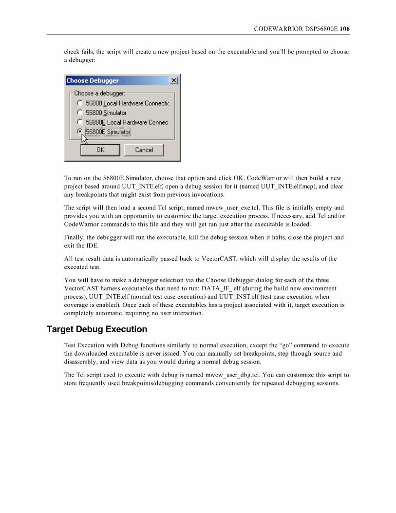
CODEWARRIOR DSP56800E 106
check fails, the script will create a new project based on the executable and you’ll be prompted to choosea debugger:
To run on the 56800E Simulator, choose that option and click OK. CodeWarrior will then build a newproject based around UUT_INTE.elf, open a debug session for it (named UUT_INTE.elf.mcp), and clearany breakpoints that might exist from previous invocations.
The script will then load a second Tcl script, named mwcw_user_exe.tcl. This file is initially empty andprovides you with an opportunity to customize the target execution process. If necessary, add Tcl and/orCodeWarrior commands to this file and they will get run just after the executable is loaded.
Finally, the debugger will run the executable, kill the debug session when it halts, close the project andexit the IDE.
All test result data is automatically passed back to VectorCAST, which will display the results of theexecuted test.
You will have to make a debugger selection via the Choose Debugger dialog for each of the threeVectorCAST harness executables that need to run: DATA_IF_.elf (during the build new environmentprocess), UUT_INTE.elf (normal test case execution) and UUT_INST.elf (test case execution whencoverage is enabled). Once each of these executables has a project associated with it, target execution iscompletely automatic, requiring no user interaction.
Target Debug ExecutionTest Execution with Debug functions similarly to normal execution, except the “go” command to executethe downloaded executable is never issued. You can manually set breakpoints, step through source anddisassembly, and view data as you would during a normal debug session.
The Tcl script used to execute with debug is named mwcw_user_dbg.tcl. You can customize this script tostore frequently used breakpoints/debugging commands conveniently for repeated debugging sessions.
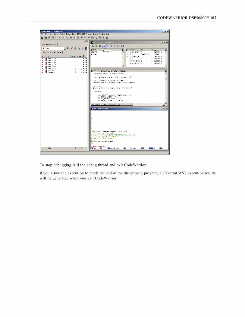
CODEWARRIOR DSP56800E 107
To stop debugging, kill the debug thread and exit CodeWarrior.
If you allow the execution to reach the end of the driver main program, all VectorCAST execution resultswill be generated when you exit CodeWarrior.

CODEWARRIOR STARCORE SC140E 108
CodeWarrior StarCore SC140eConfiguration
This section provides details about configuring VectorCAST to integrate withFreescale’s CodeWarrior compiler and debugger/simulator for StarCore SC140e.
First, select Tools => Options from the main toolbar. Choose the C/C++ tab to select the entry for“CodeWarrior StarCore SDMA” or “CodeWarrior StarCore SDMA (C++)” under the “Compiler” drop-down menu, as shown here:
Second, ensure that the directory containing the CodeWarrior binaries is included in your PATHenvironment variable. This is most likelyC:\Program Files\Freescale\CodeWarrior for StarCore And SDMA 1.2\StarCore_Support\compiler\bin,but may be slightly different on your particular system.
Third, set your SCTOOLS_HOME and SC100_HOME environment variables to your StarCoreinstallation directory. This is most likelyC:\Program Files\Freescale\CodeWarrior for StarCore And SDMA 1.2\StarCore_Support\compiler,but again may be slightly different on your particular system.
To specify a different CodeWarrior installation directory:
1. On the Preprocessor/Compiler tab, change the Library Include directories entry to match the locationof the “StarCore_Support\compiler\include” directory on your system. Use DOS formatted short-paths (8.3/no spaces).

CODEWARRIOR STARCORE SC140E 109
2. Click Apply to save the changes.
The default command settings should be sufficient to run the Tutorial example in the VectorCAST/C++User’s Guide, and it is strongly recommended that you do so before trying to test your application code.
It is your responsibility to customize these settings for your particular device and developmentenvironment.
The “Preprocessor/Compiler” tab contains the compiler commands and options that will be used tocompile the test harness. The “Linker” tab contains the linker commands and options that will be used tolink the test harness. When you are ready to begin testing your application code, a good starting point forthese settings would be the actual values used to compile and link the code you are about to test.
Specific details and discussion of the options that scc.exe accepts is outside the scope of this document.Refer to CodeWarrior’s compiler and linker documentation for more information on this topic.
Lastly, click OK to save the settings and close the options dialog.
Target ExecutionFor execution with the CodeWarrior IDE simulator/debugger, VectorCAST runs the execute commandspecified in the Tools => Options dialog, C/C++ tab. By default, the execute command is:
runsim -d sc140e
If different options are needed for the command line simulator, make a change to the Execute command.
Target Debug ExecutionFor execution with the CodeWarrior IDE simulator/debugger, VectorCAST will create a Tcl control scriptin the environment directory, and will automatically execute the “Debugger Command” that is set in theTools => Options dialog, C/C++ tab, Debug sub-tab. The script file that VectorCAST creates is called“mwcw_debug.tcl” and is similar to the following:

CODEWARRIOR STARCORE SC140E 110
cd C:/vcast_tutorial/DEMO/
if { ![file exists UUT_INTE.EXE.mcp] } {
project -o UUT_INTE.EXE
}
debug UUT_INTE.EXE.mcp
bp all off
source mwcw_user_dbg.tcl
The above script runs the harness executable UUT_INTE.EXE in the CodeWarrior IDE debugger. It isloaded upon startup of the IDE, first setting the working directory to the current environment directory.Next it checks for the existence of a .mcp project file associated with the executable to be run – if thecheck fails, the script will create a new project based on the executable and you’ll be prompted to choosea debugger:
To run on the SC100 Simulator, choose that option and click OK.
Next you will get a dialog asking you to find the startup__startup_.asm file.

CODEWARRIOR STARCORE SC140E 111
Click Cancel. On the File Not Found dialog, select “Ignore all unknown files” and click OK.
CodeWarrior will then build a new project based around UUT_INTE.EXE, open a debug session for it(named UUT_INTE.EXE.mcp), and clear any breakpoints that might exist from previous invocations.
The script will then load a second Tcl script named mwcw_user_dbg.tcl. This file is initially empty andprovides you with an opportunity to customize the target execution process. If necessary, add Tcl and/orCodeWarrior commands to this file and they will get run just after the executable is loaded.
To stop debugging, kill the debug thread and exit CodeWarrior.
If you allow the execution to reach the end of the driver main program, all VectorCAST execution resultswill be generated when you exit CodeWarrior. When the "STDIO: Shared Console" window displays“VCAST is Done!”, the driver has finished.
You will have to make a debugger selection via the Choose Debugger dialog for each of the twoVectorCAST harness executables that need to run:
l UUT_INTE.EXE (normal test case execution)

CODEWARRIOR STARCORE SC140E 112
l UUT_INST.EXE (test case execution when coverage is enabled).
Once each of these executables has a project associated with it, target execution is completely automatic,requiring no user interaction.

CODEWARRIOR FOR HC12 113
CodeWarrior for HC12Configuration
This section provides details about configuring VectorCAST to integrate withFreescale’s CodeWarrior C/C++ compiler and debugger for targets or simulators of the HC12(X) family ofprocessors.
First, select Tools => Options from the main toolbar. Choose the C/C++ tab to select the entry for“CodeWarrior HC12” under the “Compiler” drop-down menu, as shown here:
Second, ensure that the directory containing the CodeWarrior binaries is included in your PATHenvironment variable. This is most commonly C:\Program Files\Freescale\Codewarrior for HC12V4.6\Prog, but may be slightly different on your particular system.
To specify a different CodeWarrior installation directory:1. On the Preprocessor/Compiler tab, change the Default search list for Wizard entry to match the
location of the lib\hc12c\include directory on your system. Use DOS formatted short-paths (8.3/nospaces).

CODEWARRIOR FOR HC12 114
2. On the Linker tab, change the Linker Options entry to match the location of the lib/hc12c/libdirectory on your system. Use DOS formatted short-paths (8.3/no spaces).
3. On the Compiler Integration tab, change the “Startup file” entry to match the location of the startupfiles listed. (e.g. start12.c, mc9s12xdt512.c, termio.c, and datapage.c)

CODEWARRIOR FOR HC12 115
4. Click Apply to save the changes.
The default command settings should be sufficient to run the Tutorial example in the VectorCASTInteractive Tutorials, and it is strongly recommended that you do so before trying to test your applicationcode.
It is your responsibility to customize these settings for your particular device and developmentenvironment. This potentially includes modifying the linker command file. The default hc12_link.prmfile and hc12_link_cpp.prm file for C++ are located in VectorCAST’s installation DATA\codewarriordirectory (most commonly C:\VCAST\DATA\codewarrior). Based on the target or simulator selected, theappropriate linker file (*.prm), debugger command files (*.cmd), and project file (project.ini) will getcopied to your test environment directory as you create the new environment from within VectorCAST.The linker settings used must accommodate the size of the code under test plus the VectorCAST testharness that is used to drive the code under test.
Note: The size of the test harness is not static – it is dependent on the size and composition of thespecific code under test. Refer to the CodeWarrior documentation for more information oncustomizing linker command files.
If you change your compile options, you need to make the corresponding changes to the Parser flagssection of the Misc tab. Each compiler option must also be specified with the --active_option flag. Forexample, if you add –Or to your compile command, add --active_option =-Or to your parser flags.

CODEWARRIOR FOR HC12 116
The CodeWarrior project file may also need customization. The templates for this file are in$VECTORCAST_DIR\DATA\codewarrior, and are named to indicate the target type and whether or notit is a simulation. (e.g. hc12_s12xdp_project.ini, hc12_s12xdp_sim_project.ini, hc12_s12xep_project.ini )The appropriate file is copied to the environment directory and renamed project.ini.
The “Preprocessor/Compiler” tab contains the compiler commands and options that will be used tocompile the test harness. The “Linker” tab contains the linker commands and options that will be used tolink the test harness. When you are ready to begin testing your application code, a good starting point forthese settings would be the actual values used to compile and link the code you are about to test.
Specific details and discussion of the options that chc12.exe and linker.exe accept is outside the scope ofthis document. Refer to CodeWarrior’s compiler and linker documentation for more information on thistopic.
Lastly, click OK to save the settings and close the options dialog.
Banked Memory ModelThere are a few things to be aware of when configuring your HC12 test environment using the bankedmemory model. The CodeWarrior HC12 S12XEP100 PROTECH compiler template was developed for acustom RSP on a customer board (Protech) that utilizes the banked memory model and is a good exampleof the settings required to enable the use of the banked memory model. In order to enable VectorCASTto support the banked memory model the user must set an environment variable named VCAST_CUSTOM_QUALIFIERS and add a #define variable of the same name that will insert a pointer qualifierin the declaration of pointers that ensures that objects allocated in RAM pages to be properly addressed.Adding the following #define in the Tools => Options dialog, C/C++ tab, Preprocess/Compiler tab,“Defined variables” is an example of such:
VCAST_CUSTOM_QUALIFIERS=__far
Other configuration related to the use of the banked memory model includes the following items:

CODEWARRIOR FOR HC12 117
1. set the “-Mb” compiler switch to compile for the banked memory model
2. select the appropriate lib in the .prm file to link into your application. Code Warrior provides alist and description of the libraries available and how they were built in the <code_warrior_install_dir>/lib/hc12c/readme.txt file. VectorCAST’s CodeWarrior HC12 S12XEP100PROTECH compiler template specifies ansixb.lib by default.
It is also very important to note that default RAM, as defined in the .prm file, cannot get mapped intoRAM pages. The following example entries from the .prm file show a valid mapping and theaforementioned illegal mapping for DEFAULT_RAM. If you make this illegal mapping, it will compileand link successfully, but fail in unpredictable fashion at run time.
/* non-paged RAM */
RAM = READ_WRITE 0x2000 TO 0x3FFF;
/* paged RAM: 0x1000 TO 0x1FFF; addressed through RPAGE */
RAM_F0 = READ_WRITE 0xF01000 TO 0xF01FFF;
RAM_F1 = READ_WRITE 0xF11000 TO 0xF11FFF;
VALID => DEFAULT_RAM INTO RAM;
NOT VALID => DEFAULT_RAM INTO RAM, RAM_F0, RAM_F1;
Note that if you get an “out of allocation space” for RAM linker error, you must relocate some of theobjects that are being allocated into default RAM by the linker into RAM pages to allow the applicationto link properly. This can be done by identifying large data objects and using #pragmas to direct them toget stored into RAM pages instead of non-paged RAM. See the example below.
#pragma DATA_SEG __RPAGE_SEG PAGED_RAM
unsigned int LargeDataArray[1000];
#pragma DATA_SEG DEFAULT
Target ExecutionBecause the HC12 board uses a COM port connection, the $VECTORCAST_DIR\IO\comreader.exeexecutable is used to record the results of target execution. The default settings are port "COM1", baud9600, no parity, 8 data bits, and 1 stop bit. If you need other settings, you can specify a configuration filewith the VCAST_SERIAL_CFG environment variable. The file specified by VCAST_SERIAL_CFGshould have each option on a separate line. For example, to use the COM2 port, you could use thesesettings:
COM2
9600
N
8
1
The comreader is started before test execution and stops when the debugger exits. Remember to closeany other applications, such as HyperTerminal, that are reading from the same port, before executing tests.
For execution with the CodeWarrior IDE debugger, VectorCAST will create a control script in theenvironment directory, and will automatically execute the “Debugger Command” that is set in theVectorCAST Compiler Options dialog. The script file that VectorCAST creates is called hc12_exec.cm”

CODEWARRIOR FOR HC12 118
and is similar to the following:
load "hc12.abs" AUTOERASEANDFLASH
bs vCAST_END
g
wait ;s
exit
The above script runs the harness executable hc12.abs in the CodeWarrior IDE debugger. It is loadedupon startup of the IDE. The debugger will start the executable, wait for execution to complete, and exitthe IDE. The template for the script is in $VECTORCAST_DIR\DATA\codewarrior. If you change thetemplate, any new environments you build will use the modified version. Note that the script must useWindows line terminations.
All test result data is automatically passed back to VectorCAST, which will display the results of theexecuted test.
Target Debug ExecutionTest Execution with Debug functions similarly to normal execution, except a breakpoint is set in themain function so execution stops there. You can manually set breakpoints, step through source anddisassembly, and view data as you would during a normal debug session.
The script used to execute with debug is named hc12_debug.cmd. You can customize this script to storefrequently used breakpoints/debugging commands conveniently for repeated debugging sessions. Thetemplate for the script is in $VECTORCAST_DIR\DATA\codewarrior. If you change the template, anynew environments you build will use the modified version. Note that the script must use Windows lineterminations.
To stop debugging, kill the debug thread and exit CodeWarrior.
If you allow the execution to reach the end of the driver main program, all VectorCAST execution resultswill be generated when you exit CodeWarrior.

CODEWARRIOR FOR HCS08 119
CodeWarrior for HCS08Configuration
This section provides details about configuring VectorCAST to integrate withFreescale’s CodeWarrior C/C++ compiler and debugger for targets or simulators of the HCS08 family ofprocessors.
First, select Tools => Options from the main toolbar. Choose the C/C++ tab to select the entry for“CodeWarrior HCS08 SIM 9S08AC128” under the “Compiler” drop-down menu, as shown below.
Second, ensure that the directory containing the CodeWarrior binaries is included in your PATHenvironment variable. This is most commonly C:\Program Files\Freescale\CodeWarrior forMicrocontrollers V6.2\prog, but may be slightly different on your particular system.
To specify a different CodeWarrior installation directory:1. On the Preprocessor/Compiler tab, change the Default search list for Wizard entry to match the
location of the \lib\hc08c\include directory on your system. Use DOS formatted short-paths(8.3/no spaces).

CODEWARRIOR FOR HCS08 120
2. On the Linker tab, change the Linker Options entry to match the location of the lib/hc08c/libdirectory on your system. Use DOS formatted short-paths (8.3/no spaces).
3. On the Compiler Integration tab, change the “Startup file” entry to match the location of thestartup files listed. (e.g. start08.c, mc9s08ac128.c, and termio.c)

CODEWARRIOR FOR HCS08 121
The text for the Startup file by default reads:
$(VECTORCAST_DIR)\DATA\codewarrior\start08.c
C:\PROGRA~1\FREESC~1\CODEWA~1.2\lib\hc08c\device\src\mc9s08ac128.c $(VECTORCAST_DIR)\DATA\codewarrior\termio.c
4. Click Apply to save the changes.
The default command settings should be sufficient to run the Tutorial example in the VectorCASTInteractive Tutorials, and it is strongly recommended that you do so before trying to test your applicationcode.
It is your responsibility to customize these settings for your particular device and developmentenvironment. This potentially includes modifying the linker command file. The default hc08_link.prmfile is located in VectorCAST’s installation DATA\codewarrior directory (most commonlyC:\VCAST\DATA\codewarrior). Based on the target or simulator selected, the appropriate linker file(*.prm), debugger command files (*.cmd), and project file (project.ini) will get copied to your testenvironment directory as you create the new environment from within VectorCAST. The linker settingsused must accommodate the size of the code under test plus the VectorCAST test harness that is used todrive the code under test.
Note: The size of the test harness is not static – it is dependent on the size and composition of thespecific code under test. Refer to the CodeWarrior documentation for more information oncustomizing linker command files.
If you change your compile options, you need to make the corresponding changes to the Parser flagssection of the Misc tab. Each compiler option must also be specified with the --active_option flag. Forexample, if you add –Or to your compile command, add --active_option =-Or to your parser flags.

CODEWARRIOR FOR HCS08 122
The text for the Parser flags by default reads:
-w
--c
--code_warrior
--code_warrior_version=hcs08
--unsigned_chars
--define_macro=__HIWARE__
--define_macro=__MWERKS__=1
--define_macro=__BIG_ENDIAN__
--define_macro=__PRODUCT_HICROSS_PLUS__
--define_macro=__VERSION__=5025
--define_macro=__SIZE_T_IS_UINT__
--define_macro=__PTRDIFF_T_IS_INT__
--define_macro=__WCHAR_T_IS_UCHAR__
--define_macro=__ELF_OBJECT_FILE_FORMAT__
--define_macro=__BITFIELD_LSBIT_FIRST__
--define_macro=__BITFIELD_MSBYTE_FIRST__
--define_macro=__BITFIELD_MSWORD_FIRST__
--define_macro=__BITFIELD_TYPE_SIZE_REDUCTION__
--define_macro=__PLAIN_BITFIELD_IS_SIGNED__
--define_macro=__CHAR_IS_UNSIGNED__
--define_macro=__CHAR_IS_8BIT__
--define_macro=__SHORT_IS_16BIT__
--define_macro=__INT_IS_16BIT__
--define_macro=__ENUM_IS_16BIT__
--define_macro=__ENUM_IS_SIGNED__
--define_macro=__LONG_IS_32BIT__
--define_macro=__LONG_LONG_IS_32BIT__
--define_macro=__FLOAT_IS_IEEE32__
--define_macro=__DOUBLE_IS_IEEE64__
--define_macro=__LONG_DOUBLE_IS_IEEE64__

CODEWARRIOR FOR HCS08 123
--define_macro=__LONG_LONG_DOUBLE_IS_IEEE64__
--define_macro=__VTAB_DELTA_IS_16BIT__
--define_macro=__PTRMBR_OFFSET_IS_16BIT__
--define_macro=__HC08__
--define_macro=__HCS08__
--define_macro=__BANKED__
--define_macro=__MMU__
The CodeWarrior project file may also need customization. The templates for this file are in$VECTORCAST_DIR\DATA\codewarrior, and are named to indicate the target type and whether or notit is configured for a simulator connection, such as hcs08_9s08ac128_sim_project.ini. The appropriate fileis copied to the environment directory and renamed project.ini.
The “Preprocessor/Compiler” tab contains the compiler commands and options that will be used tocompile the test harness. The “Linker” tab contains the linker commands and options that will be used tolink the test harness. When you are ready to begin testing your application code, a good starting point forthese settings would be the actual values used to compile and link the code you are about to test.
Specific details and discussion of the options that chc08.exe and linker.exe accept is outside the scope ofthis document. Refer to CodeWarrior’s compiler and linker documentation for more information on thistopic.
Lastly, click OK to save the settings and close the options dialog.
Target Simulator ExecutionVectorCAST supports the hcs08 simulator and execution of a test case on the simulator is performed byright-clicking on the desired test case and selecting “Execute.” This will cause VectorCAST to invoke thedebugger (hiwave.exe).
Note: Because Freescale does not support the Terminal component of the debugger for the hcs08family, VectorCAST must capture the test data using the buffered I/O mode and then write thecaptured buffer data out to a file that VectorCAST will then examine for the expected results. Thebuffered I/O mode is automatically selected when you select the HCS08 target template. You canconfirm that this mode is properly selected by examining the Target tab under the Options page asshown below.

CODEWARRIOR FOR HCS08 124
The writing of the buffered test data is performed through the use of special commands inside thedebugger cmd files. The necessary command files are provided by VectorCAST and copied to your testenvironment, such as hcs08_sim_debug.cmd, hcs08_sim_exec.cmd, and hcs08_fcs_postload.cmd. Theappropriate command file is passed to the debugger when it is invoked through the “Execute” or“Execute with Debug” methods. No special action is required on the part of the user.
Target Simulator Debug ExecutionTest Execution with Debug functions similarly to normal execution, except a breakpoint is set in themain function so execution stops there. You can manually set breakpoints, step through source anddisassembly, and view data as you would during a normal debug session.
The script used to execute with debug is named hcs08_sim_debug.cmd. You can customize this script tostore frequently used breakpoints/debugging commands conveniently for repeated debugging sessions.The template for the script is in $VECTORCAST_DIR\DATA\codewarrior. If you change the template,any new environments you build will use the modified version. Note that the script must use Windowsline terminations.
You will notice that when the debugger is opened, that there is a wait loop cycling in the commandwindow. This is required for VectorCAST to know when to write out the buffered data, whereby it waitsfor a flag to be set in the harness code that indicates that all the required test data has been captured, andit can write out to the file. The command window data will look like that shown below.

CODEWARRIOR FOR HCS08 125
When you have successfully reached the end of test case execution which is indicated by reaching thevCAST_END breakpoint, then the command window loop will end and display the following:
To stop debugging, kill the debug thread and exit CodeWarrior.
If you allow the execution to reach the end of the driver main program, all VectorCAST execution resultswill be generated when you exit CodeWarrior.

CODEWARRIOR FOR MPC 5554 126
CodeWarrior for MPC 5554Configuration
This section provides details about configuring VectorCAST to integrate withFreescale’s CodeWarrior compiler for MPC chips. During the last revision of this text, the only chipsupported is the MPC5554 through Lauterbach TRACE32 debugger. However, integration with otherchips (MPC555x, MPC55xx, MPC8xx and others), either through the TRACE32 debugger orCodeWarrior’s integrated debugger, is quite possible. To inquire about the latest chips supported or toarrange for other physical targets to be supported, please contact your VectorCAST representative.
VectorCAST uses the command line interface of Code Warrior to compile the test harness. To enable it, anumber of environment variables must be set properly. An example of a DOS script setting these variablescould look like this.
set PATH=C:\Program Files\Freescale\CodeWarrior for MPC55xx V2.4\PowerPC_EABI_Tools\Command_Line_Tools;%PATH%
REM This must link to the compiler’s header files
set MWCIncludes=C:\Program Files\Freescale\CodeWarrior for MPC55xx V2.4\PowerPC_EABI_Support\MSL\MSL_C\PPC_EABI\Include;
set MWCIncludes=C:\Program Files\Freescale\CodeWarrior for MPC55xx V2.4\PowerPC_EABI_Support\MSL\MSL_C\MSL_Common\Include;%MWCIncludes%
set MWCIncludes=C:\Program Files\Freescale\CodeWarrior for MPC55xx V2.4\PowerPC_EABI_Support\MSL\MSL_C\MSL_Common_Embedded\Include;%MWCIncludes%
set MWCIncludes=C:\Program Files\Freescale\CodeWarrior for MPC55xx V2.4\PowerPC_EABI_Support\Runtime\Include;%MWCIncludes%
REM This must link to the libraries and library files associated with the headers
set MWLibraries=C:\Program Files\Freescale\CodeWarrior for MPC55xx V2.4\PowerPC_EABI_Support\Runtime\Lib
set MWLibraries=C:\Program Files\Freescale\CodeWarrior for MPC55xx V2.4\PowerPC_EABI_Support\MSL\MSL_C\PPC_EABI\Lib;%MWLibraries%
set MWLibraryFiles=C:\Program Files\Freescale\CodeWarrior for MPC55xx V2.4\PowerPC_EABI_Support\Runtime\Lib\Runtime.PPCEABI.S.UC.a
set MWLibraryFiles=C:\Program Files\Freescale\CodeWarrior for MPC55xx V2.4\PowerPC_EABI_Support\MSL\MSL_C\PPC_EABI\Lib\MSL_C.PPCEABI.bare.S.UC.a;%MWLibraryFiles%
In addition, if your code includes assembly code, other environment variables must be set. Please consultyour CodeWarrior documentation to learn how.
Also, if you are using Lauterbach TRACE32 to execute the test harness on the board, the path toLauterbach TRACE32 must become part of the PATH environment variable as follows:
set PATH=C:\T32;%PATH%
You should remember to either (1) set these environment variables permanently in your OS or (2) setthese temporarily in an OS shell. In the latter case, remember to launch VectorCAST from within thatshell.
Thereafter, select the appropriate template from VectorCAST/C++.

CODEWARRIOR FOR MPC 5554 127
In VectorCAST, just select the appropriate compiler template (Compilers => CodeWarrior => MPC).Please note that depending on your installation, the template may need amendments. Particularly, thelibrary includes (all three of them) and the link to certain startup files will need to be changed if you areusing any other version of the compiler except 2.4 and/or if you installed the compiler in a differentdirectory than the default one.
It is your responsibility to customize these settings for your particular device and developmentenvironment. Please note that these changes will be saved as long as you will be using the same workingdirectory. For more information about this, please contact your Vector Software representative.
Target ExecutionAt this point in time, the only template provided by default will execute the harness using the TRACE32debugger. Integration to CodeWarrior’s integrated debugger is also possible. Please contact your VectorSoftware representative to learn more.
Upon successful compilation and linkage, VectorCAST will automatically launch (1) comreader.exe (apart of VectorCAST), and (2) the TRACE32 debugger interface. It will execute the programautomatically, and then shut down TRACE32. The comreader program will capture any data sent to thehost’s serial port and make it available to VectorCAST.
Thus, a serial cable must be connected between the board and the host. If the host does not have a serialport, a serial-to-USB cable can be used.
Because this integration uses a COM port connection, the $VECTORCAST_DIR\IO\comreader.exe

CODEWARRIOR FOR MPC 5554 128
executable is used to record the results of target execution. The default settings are port "COM1", baud9600, no parity, 8 data bits, and 1 stop bit.
If you need other settings, you can specify a configuration file with the VCAST_SERIAL_CFGenvironment variable. The file specified by VCAST_SERIAL_CFG should have each option on a separateline. For example, to use the COM2 port, you could use these settings:
COM2
9600
N
8
1
The comreader is started before test execution and stops when the debugger exits. Remember to close anyother applications, such as HyperTerminal, that are reading from the same port, before executing tests.
Target Debug ExecutionTest Execution with Debug functions similarly to normal execution, except a breakpoint is set in themain function so execution stops there. You can manually set breakpoints, step through source anddisassembly, and view data as you would during a normal debug session.
Launching a debug execution of the test harness under CodeWarrior will launch the TRACE32 interface.A breakpoint is already set at the end of the test harness for your convenience. Once finished, merelyclose the instance of TRACE32 that VectorCAST launched and the results of the test will be readautomatically by VectorCAST. If the test harness is not allowed to run until the end, an error may occur.

CODEWARRIOR FOR MPC 8315 129
CodeWarrior for MPC 8315This section provides details about configuring VectorCAST to integrate withFreescale’s CodeWarrior compiler for the EPPC MPC8315E chip. This particular RSPis designed to support interfacing with the Freescale MPC8315 RDB evaluationboard using a CodeWarrior USB CodeTAP for a connection to the target board. The Freescale compilerversion required is the Freescale CodeWarrior for Power Architecture v8.8. In addition the user mustinstall and run the v8.8.5 patch from Freescale. The downloaded compiler and patch executable names areprovided below.
CW_Power_Architecture_V8.8_Build_80229.exe
PA_8.8.5_110607.exe
It is important to install the patch, otherwise you will likely have problems connecting to the target.There were several versions of the drivers for the CodeWarrior USB CodeTAP available, not all of whichworked, so details about the driver install and verification are provided in the following section to helpensure proper driver installation.
CodeWarrior USB TAP Installation
Note: This installation was tested on a Windows XP machine; other platforms and OSs mayrequire a slightly different driver install procedure.
1. Install CodeWarrior for Power Architecture v8.8 from Freescale.
2. Run the v8.8.5 patch update (PA_8.8.5_110607.exe).
3. Now run the setup.bat from C:\Program Files\Freescale\CodeWarrior PA V8.8\ccs\drivers\usbdirectory. See the results of that operation in the DOS screenshot below. This operation resultsin the “Device Driver Installation Wizard” getting run to install the LibUSB driver.
Now you can plug in the CodeWarrior USB TAP into an available USB port on the host PC and plug theother end into the target board with target power applied. See the Freescale user guide for information onproperly connecting the flat ribbon connector to the target.

CODEWARRIOR FOR MPC 8315 130
The Windows XP machine used for testing recognized the device being plugged in and invoked the“Found New Hardware Wizard” as shown in the screenshots below. Do not install softwareautomatically, but rather manually point to the driver install directory.
After clicking Next, choose “Don’t search. I will choose the driver to install.” Click Next again, andchoose “Have Disk...”:
Point to the C:\Program Files\Freescale\CodeWarrior PA V8.8\ccs\drivers\usb\x32 directory whichcontains the usbtap.inf file needed and the driver install will begin as shown below.

CODEWARRIOR FOR MPC 8315 131
Now you can bring up the device manager and you should see the CodeWarrior USB TAP appear under“LibUSB-Win32 Devices.”
At this point you have successfully installed the drivers for the CodeWarrior USB TAP.

CODEWARRIOR FOR MPC 8315 132
Troubleshooting
When VectorCAST attempts to execute a test case, it must connect to the target through the USB TAP,download the harness executable, and then run that executable. If VectorCAST has any troubleconnecting to the target during this process you may see an error dialog box displayed like the oneshown below.
To resolve such connectivity issues try pressing the power button on the target to power cycle the board.After a minute or so you can try to rerun the test case and VectorCAST will attempt to reconnect to thetarget.
To monitor the reboot progress of the board, you can temporarily bring up the HyperTerminal windowsapplication to display the serial port output from the target. Wait for the board to boot up and get to the“freescale login:” prompt.
Note: This won’t work when just pressing the “reset” button on the target; you have to powercycle the board by pressing the “power” button in the back of the 8315 RDB unit.
Once the board has rebooted and displayed the “freescale login:” prompt, you must disconnect theHyperTerminal connection so that VectorCAST can connect tothe serial port of the board during test case execution. Now try rerunning the test case.
Below is a snapshot of the serial port output from the board after power cycling the board and the defaultLinux kernel installed on the evaluation board reboots.
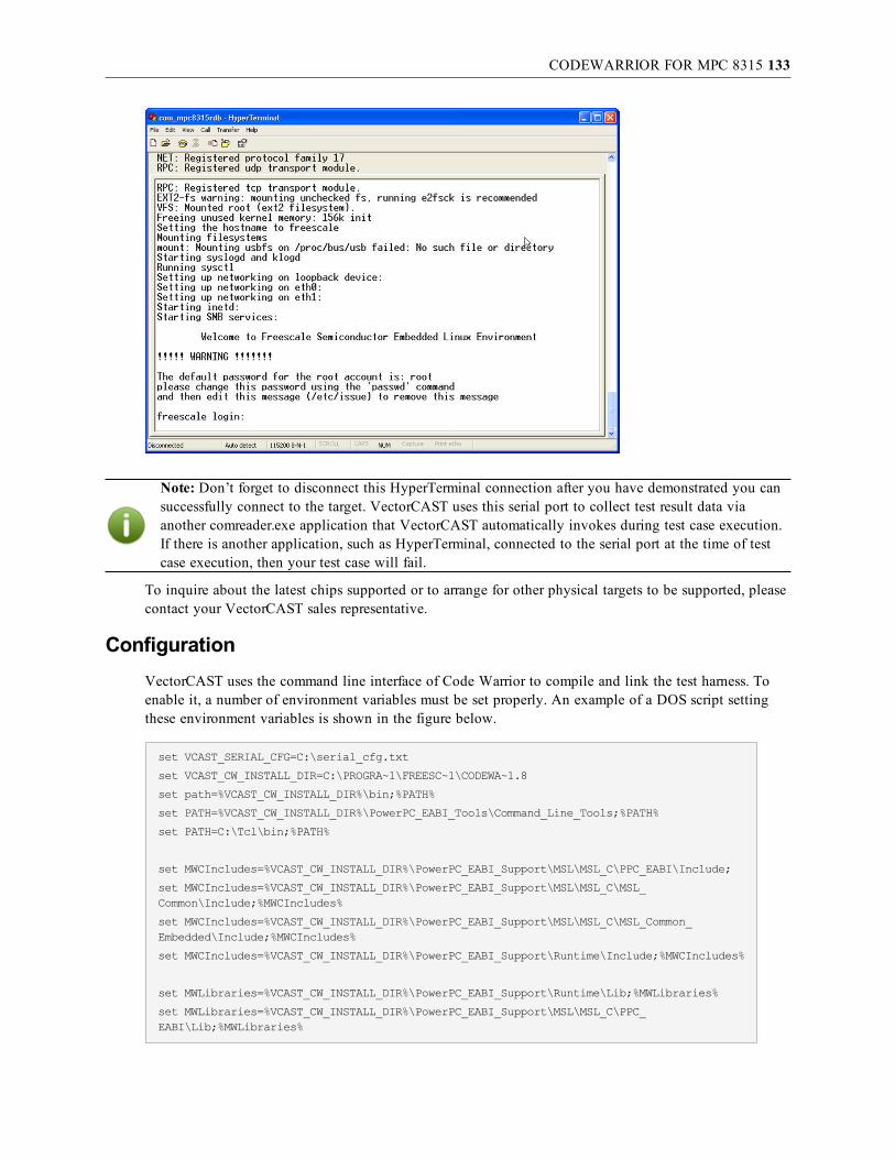
CODEWARRIOR FOR MPC 8315 133
Note: Don’t forget to disconnect this HyperTerminal connection after you have demonstrated you cansuccessfully connect to the target. VectorCAST uses this serial port to collect test result data viaanother comreader.exe application that VectorCAST automatically invokes during test case execution.If there is another application, such as HyperTerminal, connected to the serial port at the time of testcase execution, then your test case will fail.
To inquire about the latest chips supported or to arrange for other physical targets to be supported, pleasecontact your VectorCAST sales representative.
ConfigurationVectorCAST uses the command line interface of Code Warrior to compile and link the test harness. Toenable it, a number of environment variables must be set properly. An example of a DOS script settingthese environment variables is shown in the figure below.
set VCAST_SERIAL_CFG=C:\serial_cfg.txt
set VCAST_CW_INSTALL_DIR=C:\PROGRA~1\FREESC~1\CODEWA~1.8
set path=%VCAST_CW_INSTALL_DIR%\bin;%PATH%
set PATH=%VCAST_CW_INSTALL_DIR%\PowerPC_EABI_Tools\Command_Line_Tools;%PATH%
set PATH=C:\Tcl\bin;%PATH%
set MWCIncludes=%VCAST_CW_INSTALL_DIR%\PowerPC_EABI_Support\MSL\MSL_C\PPC_EABI\Include;
set MWCIncludes=%VCAST_CW_INSTALL_DIR%\PowerPC_EABI_Support\MSL\MSL_C\MSL_Common\Include;%MWCIncludes%
set MWCIncludes=%VCAST_CW_INSTALL_DIR%\PowerPC_EABI_Support\MSL\MSL_C\MSL_Common_Embedded\Include;%MWCIncludes%
set MWCIncludes=%VCAST_CW_INSTALL_DIR%\PowerPC_EABI_Support\Runtime\Include;%MWCIncludes%
set MWLibraries=%VCAST_CW_INSTALL_DIR%\PowerPC_EABI_Support\Runtime\Lib;%MWLibraries%
set MWLibraries=%VCAST_CW_INSTALL_DIR%\PowerPC_EABI_Support\MSL\MSL_C\PPC_EABI\Lib;%MWLibraries%

CODEWARRIOR FOR MPC 8315 134
set MWLibraryFiles=%VCAST_CW_INSTALL_DIR%\PowerPC_EABI_Support\Runtime\Lib\Runtime.PPCEABI.H.UC.a;%MWLibraryFiles%
set MWLibraryFiles=%VCAST_CW_INSTALL_DIR%\PowerPC_EABI_Support\MSL\MSL_C\PPC_EABI\Lib\MSL_C.PPCEABI.bare.H.UC.a;%MWLibraryFiles%
set MWLibraryFiles=%VCAST_CW_INSTALL_DIR%\PowerPC_EABI_Tools\CodeWarriorTRK\Transport\processor\ppc\serial\8315_RDB_serial\Bin\UART1_8315_RDB.UC.a;%MWLibraryFiles%
You should either set these environment variables permanently in your operating system or set thesetemporarily in a system shell. In the latter case, remember to launch VectorCAST from within that shell.
After starting VectorCAST, select the appropriate template from VectorCAST/C++. For a unit testenvironment for the CodeWarrior MPC8315 RDB evaluation board, go to the Tools => Options dialog,C/C++ tab. Select Compilers => CodeWarrior => EPPC => MPC8315 => C.
Note: Depending on your installation, the template may need amendments to default paths.Particularly, the library includes and the link to certain startup files will need to be changed if youinstalled your Freescale CodeWarrior PA v8.8 somewhere other than the default directory asshown below.
It is your responsibility to customize these settings for your particular device and developmentenvironment. Please note that these changes will be saved as long as you will be using the same workingdirectory. For more information about this, please contact your Vector Software representative.
Target ExecutionThe test harness image will be downloaded and executed on the target using the CodeWarrior debugger.

CODEWARRIOR FOR MPC 8315 135
Upon successful compilation and linkage, VectorCAST will automatically launch the comreader.exeprogram during test case execution. The comreader.exe program will capture any data sent to the host’sserial port and make it available to VectorCAST.
A serial cable must be connected between the board and the host. If the host does not have a serial port, aserial-to-USB cable can be used. Connect the provided serial port cable to the DB15 connector on theback of the MPC8315 RDB unit labeled “RS-232-1”.
Because this integration uses a COM port connection, the $VECTORCAST_DIR\IO\comreader.exeexecutable is used to record the results of target execution. The default settings are port "COM1", baud9600, no parity, 8 data bits, and 1 stop bit.
The specific settings required for the MPC8315 RDB board should be specified in a configuration filethat is pointed to by the VCAST_SERIAL_CFG environment variable. The file specified by VCAST_SERIAL_CFG should have each option on a separate line. For example, to use the COM8 port and 57600baud, the settings for receiving serial port data from the MPC8315 RDB serial port are as follows:
COM8
57600
N
8
1
The comreader is started before test execution and stops when the debugger exits. Remember to close anyother applications, such as HyperTerminal, that are reading from the same port, before executing tests.
Note that if you have a test case with abnormal termination, you may have to manually kill thecomreader.exe process if the harness did not run to completion. You can use the Windows Task managerto do so and select the comreader.exe from the process list and kill the process.
VectorCAST uses a codewarrior target project file (vcast_tgt.elf.mcp) to define the debugger configurationand connection type to the target. You can examine the debugger configuration inside the project settingsof the CodeWarrior IDE. The debugger connection settings should match the configuration below andshould not require any user modifications.

CODEWARRIOR FOR MPC 8315 136
Target Debug ExecutionTest Execution with Debug functions similarly to normal execution, except a breakpoint is set in themain function so execution stops there. You can manually set breakpoints, step through source anddisassembly, and view data as you would during a normal debug session.
Launching a debug execution of the test harness will launch the CodeWarrior debugger interface andautomatically download the target image.

CODEWARRIOR FOR MPC 8315 137
You can begin the debug session by single stepping, setting breakpoints, and examining variables andmemory as you would in any normal debug session. Once you have run to the completion of the testharness you will see the following line in the command window of the debugger.
thread exit: Running, 0x0, 0x0, cpuPowerPCBig, vcast_tgt.elf (state, tid, pid, cpu,target)
Now, merely exit out of the CodeWarrior debugger and the results of the test will be read automaticallyby VectorCAST. If the test harness is not allowed to run until the end, an error may occur.
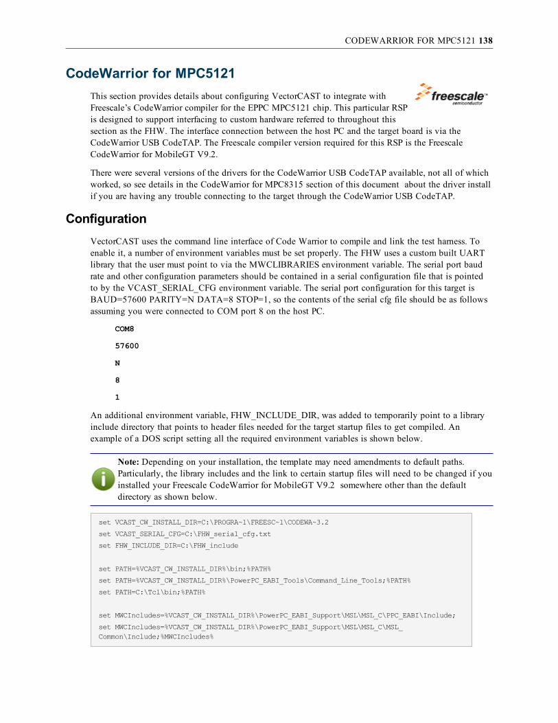
CODEWARRIOR FOR MPC5121 138
CodeWarrior for MPC5121This section provides details about configuring VectorCAST to integrate withFreescale’s CodeWarrior compiler for the EPPC MPC5121 chip. This particular RSPis designed to support interfacing to custom hardware referred to throughout thissection as the FHW. The interface connection between the host PC and the target board is via theCodeWarrior USB CodeTAP. The Freescale compiler version required for this RSP is the FreescaleCodeWarrior for MobileGT V9.2.
There were several versions of the drivers for the CodeWarrior USB CodeTAP available, not all of whichworked, so see details in the CodeWarrior for MPC8315 section of this document about the driver installif you are having any trouble connecting to the target through the CodeWarrior USB CodeTAP.
ConfigurationVectorCAST uses the command line interface of Code Warrior to compile and link the test harness. Toenable it, a number of environment variables must be set properly. The FHW uses a custom built UARTlibrary that the user must point to via the MWCLIBRARIES environment variable. The serial port baudrate and other configuration parameters should be contained in a serial configuration file that is pointedto by the VCAST_SERIAL_CFG environment variable. The serial port configuration for this target isBAUD=57600 PARITY=N DATA=8 STOP=1, so the contents of the serial cfg file should be as followsassuming you were connected to COM port 8 on the host PC.
COM8
57600
N
8
1
An additional environment variable, FHW_INCLUDE_DIR, was added to temporarily point to a libraryinclude directory that points to header files needed for the target startup files to get compiled. Anexample of a DOS script setting all the required environment variables is shown below.
Note: Depending on your installation, the template may need amendments to default paths.Particularly, the library includes and the link to certain startup files will need to be changed if youinstalled your Freescale CodeWarrior for MobileGT V9.2 somewhere other than the defaultdirectory as shown below.
set VCAST_CW_INSTALL_DIR=C:\PROGRA~1\FREESC~1\CODEWA~3.2
set VCAST_SERIAL_CFG=C:\FHW_serial_cfg.txt
set FHW_INCLUDE_DIR=C:\FHW_include
set PATH=%VCAST_CW_INSTALL_DIR%\bin;%PATH%
set PATH=%VCAST_CW_INSTALL_DIR%\PowerPC_EABI_Tools\Command_Line_Tools;%PATH%
set PATH=C:\Tcl\bin;%PATH%
set MWCIncludes=%VCAST_CW_INSTALL_DIR%\PowerPC_EABI_Support\MSL\MSL_C\PPC_EABI\Include;
set MWCIncludes=%VCAST_CW_INSTALL_DIR%\PowerPC_EABI_Support\MSL\MSL_C\MSL_Common\Include;%MWCIncludes%

CODEWARRIOR FOR MPC5121 139
set MWCIncludes=%VCAST_CW_INSTALL_DIR%\PowerPC_EABI_Support\MSL\MSL_C\MSL_Common_Embedded\Include;%MWCIncludes%
set MWCIncludes=%VCAST_CW_INSTALL_DIR%\PowerPC_EABI_Support\Runtime\Include;%MWCIncludes%
set MWLibraries=%VCAST_CW_INSTALL_DIR%\PowerPC_EABI_Support\Runtime\Lib;%MWLibraries%
set MWLibraries=%VCAST_CW_INSTALL_DIR%\PowerPC_EABI_Support\MSL\MSL_C\PPC_EABI\Lib;%MWLibraries%
set MWLibraryFiles=%VCAST_CW_INSTALL_DIR%\PowerPC_EABI_Support\Runtime\Lib\Runtime.PPCEABI.H.UC.a;%MWLibraryFiles%
set MWLibraryFiles=%VCAST_CW_INSTALL_DIR%\PowerPC_EABI_Support\MSL\MSL_C\PPC_EABI\Lib\MSL_C.PPCEABI.bare.H.UC.a;%MWLibraryFiles%
set MWLibraryFiles=%VECTORCAST_DIR%\DATA\codewarrior\EPPC\FHW\UART1_5121_ADS.UC.a;%MWLibraryFiles%
You should either set these environment variables permanently in your operating system or set thesetemporarily in a system shell. In the latter case, remember to launch VectorCAST from within that shell.
After starting VectorCAST, select the appropriate template from VectorCAST/C++. For a unit testenvironment for the CodeWarrior MPC5121 FHW board, go to the Tools => Options dialog, C/C++ tab.Select Compilers => CodeWarrior => EPPC => MPC5121 => FHW => C.
It is your responsibility to customize these settings for your particular device and developmentenvironment. Please note that these changes will be saved as long as you will be using the same workingdirectory. For more information about this, please contact your Vector Software representative.
Target ExecutionThe test harness image will be downloaded and executed on the target using the CodeWarrior debugger.
Upon successful compilation and linkage, VectorCAST will automatically launch the comreader.exe
CODEWARRIOR FOR MPC5121 140
program during test case execution. The comreader.exe program will capture any data sent to the host’sserial port and make it available to VectorCAST.
A serial cable must be connected between the board and the host. If the host does not have a serial port, aserial-to-USB cable can be used.
Because this integration uses a COM port connection, the $VECTORCAST_DIR\IO\comreader.exeexecutable is used to record the results of target execution. The default settings are port "COM1", baud9600, no parity, 8 data bits, and 1 stop bit.
The specific settings required for the FHW board should be specified in a configuration file that ispointed to by the VCAST_SERIAL_CFG environment variable. The file specified by VCAST_SERIAL_CFG should have each option on a separate line. For example, to use the COM8 port and 57600 baud,the settings for receiving serial port data from the FHW serial port are as follows:
COM8
57600
N
8
1
The comreader is started before test execution and stops when the debugger exits. Remember to close anyother applications, such as HyperTerminal, that are reading from the same port, before executing tests.
Note that if you have a test case with abnormal termination, you may have to manually kill thecomreader.exe process if the harness did not run to completion. You can use the Windows Task managerto do so and select the comreader.exe from the process list and kill the process.
VectorCAST uses a CodeWarrior target project file (vcast_tgt.elf.mcp) to define the debuggerconfiguration and connection type to the target. You can examine the debugger configuration inside theproject settings of the CodeWarrior IDE. The debugger connection settings should match theconfiguration below and should not require any user modifications.

CODEWARRIOR FOR MPC5121 141
Also be sure that the debugger settings indicates using the Target Initialization File FHW_int.cfg, whichVectorCAST will automatically copy to you test environment directory during test environment creationtime. To check this is set in the project settings, select the Debugger->EPPC Debugger Settings inside theCodeWarrior IDE as shown below.

CODEWARRIOR FOR MPC5121 142
Target Debug ExecutionTest Execution with Debug functions similarly to normal execution, except a breakpoint is set in themain function so execution stops there. You can manually set breakpoints, step through source anddisassembly, and view data as you would during a normal debug session.
Launching a debug execution of the test harness will launch the CodeWarrior debugger interface andautomatically download the target image.
You can begin the debug session by single stepping, setting breakpoints, and examining variables andmemory as you would in any normal debug session. Once you have run to the completion of the testharness you will see the following line in the command window of the debugger.
thread exit: Running, 0x0, 0x0, cpuPowerPCBig, vcast_tgt.elf (state, tid, pid, cpu,target)
Now, simply exit out of the CodeWarrior debugger and the results of the test case will be read anddisplayed automatically by VectorCAST. If the test harness is not allowed to run to completion, an errormay occur.

COSMIC 68HC12 AND HCS12X 143
Cosmic 68HC12 and HCS12XConfiguration for 68HC12
This section provides details about configuring VectorCAST to integrate with CosmicSoftware’s C Cross Compiler for Motorola MC68HC12 and ZAP Simulator or ICD.
First, select Tools => Options from the main toolbar. Choose the C/C++ tab to select the entry for“Cosmic 68HC12” under the “Compiler” drop-down menu, as shown here:
Note: If you are planning on utilizing banked memory or the ZAP debugger to download to actualtarget hardware, you’ll need to choose one of the other Cosmic Compiler Template entries. Thespecifics of these alternative choices are discussed briefly at the end of this section.
Second, check the version of the ZAP Debugger you’ll be running. If it is version 3.72e or greater, you’llwant to ensure the Execute Command is set to <<cosmic_auto>>. Otherwise revert this setting to themanual <<cosmic>> command. This will affect whether or not you’ll need to manually open and run the“cosmic.scr” script as described in the section Target Execution with Cosmic.
Third, ensure that the directories containing the Cosmic binaries are included in your PATH environmentvariable. These are most commonly C:\COSMIC\CX12 and C:\COSMIC\zapicd12 orC:\COSMIC\zapsim12 (depending on which debugger version you’d like to use), but may be slightlydifferent on your particular system.

COSMIC 68HC12 AND HCS12X 144
To specify a different Cosmic installation directory:1. Using a text editor open cosmic.cmd and cosmicp.cmd, located in the VectorCAST DATA
directory (most commonly C:\VCAST\DATA).
2. Replace all occurrences of C:\COSMIC with the DOS-formatted path to your specific Cosmicinstallation (no spaces).
3. Save the files and exit the text editor.
These default settings should be sufficient to run the Tutorial example in the VectorCAST/C User’sGuide, and it is strongly recommended that you do so before trying to test your application code. Thepreprocess, compile, and link options are initially set to match the examples provided in Cosmic’sdocumentation.
It is your responsibility to customize these settings for your particular device and developmentenvironment. This potentially includes modifying the cosmic.cmd and/or cosmicp.cmd (paged) linkercommand file templates (most commonly located in C:\VCAST\DATA\cosmic) to accommodate the sizeof the code under test plus the VectorCAST test harness that is used to drive the code under test.
Note: The size of the test harness is not static – it is dependent on the size and composition of thespecific code under test. Refer to the Cosmic documentation for more information on customizinglinker command files.
The “Preprocessor/Compiler” tab contains the compiler options that will be used to compile the testharness. The “Linker” tab contains the linker options that will be used to link the test harness. When youare ready to begin testing your application code, a good starting point for these settings would be theactual values used to compile and link the code you are about to test.
Specific details and discussion of the options that cx6812.exe and clnk.exe accept is outside the scope ofthis document. Refer to Cosmic’s compiler and linker documentation for more information on this topic.
Customizing Linker Command File Templates
If you encounter problems when VectorCAST attempts to link the harness executable, the first thing toinvestigate is the linker command file. VectorCAST builds two command files that are used to link theexecutables needed to invoke the test harness: uut.lkf and inst.lkf. They are based on one of two templatefiles located in the VectorCAST installation DATA directory (cosmicp.cmd is used if a “Paged” CompilerTemplate is selected, otherwise cosmic.cmd is used).
The most common cause for a link failure is a segment overflow – this is because the default VectorCASTcommand files allocate enough space for our tutorial program and is not intended to be a general purposecommand file. Best results are achieved by adapting the command file used for your application to theVectorCAST test harness, as it has most likely been customized to fit your specific source code.
For example, assume you are building an environment with the “Cosmic 68HC12” Compiler Template(no banked memory, simulated target). If UUT_INTE.EXE fails to link, you would want to edit the linkercommand file template “cosmic.cmd” that exists in the local environment directory. To handle the codeand data that is required by your particular application, plus additional space required by theVectorCAST test harness wrapper code, you’ll most likely want to replace the default segment definitionsat the top of the file. The segments that your actual code requires is a good place to start to attemptlinking the VectorCAST harness code. Be sure to leave the “#VECTORCAST OBJECT FILES” tag alone,

COSMIC 68HC12 AND HCS12X 145
as this gets replaced with the object files for the test.
Once you’ve modified the cosmic.cmd file, run the Environment => Relink command. A new and uut.lkffile will be created from the cosmic.cmd template and the linker command will be executed again.Continue tweaking the linker file template until all executables link successfully. If you have Coverageinitialized, the inst.lkf file will be used to link UUT_INST.EXE. Once an appropriate linker command filetemplate has been built, it is possible to copy this file into the VectorCAST installation’s DATA\cosmicdirectory so that all future new environments will use this new template. It is strongly recommended thatyou back up the existing template file.
Alternative Compiler Templates
There are three templates other than “Cosmic 68HC12” that are built into VectorCAST. If the code undertest uses banked memory, you’ll need to select one of the “Paged” templates. If you’re planning on usingthe ZAP Debugger with physical target hardware, you’ll need to select one of the “ICD” templates.
The following table summarizes these settings:
Compiler Template Banked Memory Target Debugger Command
Cosmic68HC12 No Simulated zaps12.exe
Cosmic 68HC12 Paged Yes Simulated zaps12p.exe
Cosmic 68HC12 ICD No Physical zapbg12.exe
Cosmic 68HC12 ICD Paged Yes Physical zapbg12p.exe
Configuration for HCS12XThis section provides details about configuring VectorCAST to integrate with Cosmic Software’s C CrossCompiler for Freescale HCS12X.
First, select Tools => Options from the main toolbar. Choose the C/C++ tab to select the entry for“Cosmic S12X” if you are running on hardware or “Cosmic S12X Simulator” if you are using thesimulator. This is located under the “Compiler” drop-down menu, as shown here:

COSMIC 68HC12 AND HCS12X 146
Second, check the version of the ZAP Debugger you’ll be running. If it is version 3.72e or greater, you’llwant to ensure the Execute Command is set to <<cosmic_auto>>. Otherwise revert this setting to themanual <<cosmic>> command. This will affect whether or not you’ll need to manually open and run the“cosmic.scr” script as described in the section “Target Execution with Cosmic.”
Third, ensure that the directories containing the Cosmic binaries are included in your PATH environmentvariable. These are most commonly C:\Program Files\COSMIC\CXS12X and C:\ProgramFiles\COSMIC\ZAPSIMS12X, but may be slightly different on your particular system.
To specify a different Cosmic installation directory:1. Using a text editor open s12x\cosmic.cmd and s12x_sim\cosmic.cmd, located in the
VectorCAST Cosmic DATA directory (most commonly C:\VCAST\DATA\cosmic).
2. Replace all occurrences of C:\Program Files\COSMIC with the path to your specific Cosmicinstallation.
3. Save the files and exit the text editor.
In VectorCAST, select Tools => Options from the main toolbar. Choose the C/C++ tab. On thePreprocessor/Compiler tab, change the “Library Include directories” entry to match the location of the“CXS12X\Hs12x” directory on your system.

COSMIC 68HC12 AND HCS12X 147
Fourth, if you are running on hardware, specify the file containing your start up code. On the CompilerIntegration tab, go to the Target Compiler Options group and navigate to the file you want to use by theStartup file option.

COSMIC 68HC12 AND HCS12X 148
These default settings should be sufficient to run the Tutorial example in the VectorCAST/C User’sGuide, and it is strongly recommended that you do so before trying to test your application code. Thepreprocess, compile and link options are initially set to match the examples provided in Cosmic’sdocumentation.
It is your responsibility to customize these settings for your particular device and developmentenvironment. This potentially includes modifying the s12x\cosmic.cmd and/or s12x_sim\cosmic.cmd(simulator) linker command file templates (most commonly located in C:\VCAST\DATA\cosmic) toaccommodate the size of the code under test plus the VectorCAST test harness that is used to drive thecode under test.
Note: The size of the test harness is not static – it is dependent on the size and composition of thespecific code under test. Refer to the Cosmic documentation for more information on customizinglinker command files.
The “Preprocessor/Compiler” tab contains the compiler options that will be used to compile the testharness. The “Linker” tab contains the linker options that will be used to link the test harness. When youare ready to begin testing your application code, a good starting point for these settings would be theactual values used to compile and link the code you are about to test.
Specific details and discussion of the options that cxs12x.exe and clnk.exe accept is outside the scope ofthis document. Refer to Cosmic’s compiler and linker documentation for more information on this topic.
Customizing Linker Command File Templates
If you encounter problems when VectorCAST attempts to link the harness executable, the first thing toinvestigate is the linker command file. VectorCAST builds two command files that are used to link theexecutables needed to invoke the test harness: uut.lkf and inst.lkf. They are based on one of two templatefiles located in the VectorCAST installation DATA directory (cosmic_s12x.lkf is used if a Cosmic S12Xis selected, otherwise cosmic_s12x_sim.lkf is used).
The most common cause for a link failure is a segment overflow – this is because the default VectorCASTcommand files allocate enough space for our tutorial program and is not intended to be a general purposecommand file. Best results are achieved by adapting the command file used for your application to theVectorCAST test harness, as it has most likely been customized to fit your specific source code.
For example, assume you are building an environment using Cosmic S12X. If UUT_INTE.EXE fails tolink, you would want to edit the linker command file template “cosmic.cmd” that exists in the localenvironment directory. To handle the code and data that is required by your particular application, plusadditional space required by the VectorCAST test harness wrapper code, you’ll most likely want toreplace the default segment definitions at the top of the file. The segments that your actual code requiresis a good place to start to attempt linking the VectorCAST harness code. Be sure to leave the“#VECTORCAST OBJECT FILES” tag alone, as this gets replaced with the object files for the test.
Once you’ve modified the cosmic.cmd file, run the Environment => Relink command. A new uut.lkf filewill be created from the cosmic.cmd template and the linker command will be executed again. Continuetweaking the linker file template until all executables link successfully. If you have Coverage initialized,the inst.lkf file will be used to link UUT_INST.EXE. Once an appropriate linker command file templatehas been built, it is possible to copy this file into the cosmic_s12x.lkf file in the VectorCASTinstallation’s DATA directory so that all future new environments will use this new template. It isstrongly recommended that you back up the existing template file.

COSMIC 68HC12 AND HCS12X 149
Target ExecutionFor the Cosmic Software ZAP Debugger, VectorCAST will copy a control script into the environmentdirectory, and will automatically execute the “Debugger Command” that is set in the VectorCASTCompiler Options dialog. The default script file that VectorCAST uses is $VECTORCAST_DIR\DATA\cosmic\cosmic.scr and is similar to the following:
load cosmic.h12
fopen /c:1 VCAST_STDIN.DAT
fopen /c:2 VCAST_STDOUT.DAT
watch getchar():VCAST_INCH { fread /c:1 "%c"input }
watch putchar():VCAST_OUTCH { fwrite /c:2 "%c"character }
break main():VCAST_END_MAIN
go
fclose /c:1
fclose /c:2
quit
If you need to customize this script, you may add any legal Cosmic scripting commands to the templatescript, as long as the commands shown above are maintained.
To ensure that ZAP is configured correctly and has the correct target and/or communication settings, runit at least once on its own. Choose the appropriate configuration options, then exit. All settings will besaved and restored the next time it is started by VectorCAST.
Automatic Execution
If you are using ZAP 3.72e or later, choose the <<cosmic_auto>> Execute Command in the VectorCASTCompiler Options dialog. This will completely automate the interaction between VectorCAST and ZAP –when you execute a test case, VectorCAST will start the ZAP debugger, ZAP will automatically load thecosmic.scr command script, and execution will begin. When the test completes, all data files will beclosed, ZAP will terminate, and VectorCAST will display the results of the executed test case.
Manual Execution
Versions of ZAP previous to 3.72e do not have the ability to load a command file automatically. Forthese versions, it is necessary for you to load the cosmic.scr command file into the debugger manuallyusing ZAP’s “Command” window. To set this method of execution, choose the <<cosmic_auto>>Execute Command in the VectorCAST Compiler Option dialog, then edit the tag to read “<<cosmic>>”and click Ok.
When VectorCAST is ready to run on the target, it will put up a dialog describing the executionsequence.

COSMIC 68HC12 AND HCS12X 150
When you select “OK” VectorCAST will start ZAP, using the VectorCAST “Debugger Command”option.
Once ZAP comes up, you must use the “Command” window to load the command script which willcontrol the execution of the test. If it is not visible, select the “Show” menu, and check the “Command”item to display the window. To load the script file, use the “File” menu in the command window, andselect “File Input”, then navigate to the environment directory, and choose the file “cosmic.scr.”Alternatively you can type the command “input cosmic.scr” at the Zap> prompt.

COSMIC 68HC12 AND HCS12X 151
The script will cause the program to be loaded and execution to begin. When finished, all data files willbe closed, ZAP will terminate and VectorCAST will display the results of the executed test case.
Target Debug ExecutionTest Execution with Debug functions similarly to normal execution, except the “go” command to executethe downloaded executable is never issued. You can manually set breakpoints, step through source anddisassembly, and view data as you would during a normal debug session.
To stop debugging, VectorCAST has built a convenient script to close the I/O files and quit ZAP withone command. To load this script, use the “File” menu in the command window, and select “File Input,”then navigate to the environment directory, and choose the file “cosmic.quit.” Alternatively you can typethe command “input cosmic.quit” at the Zap> prompt.
Manual Execution with Debug
Versions of ZAP previous to 3.72e (or any version using the <<cosmic>> Execute Command) will againrequire the startup script to be manually loaded – for Execution with Debug, then name of the script is“cosmic_dbg.scr.” You’ll need to load this script before you can begin normal debugging of the testharness.
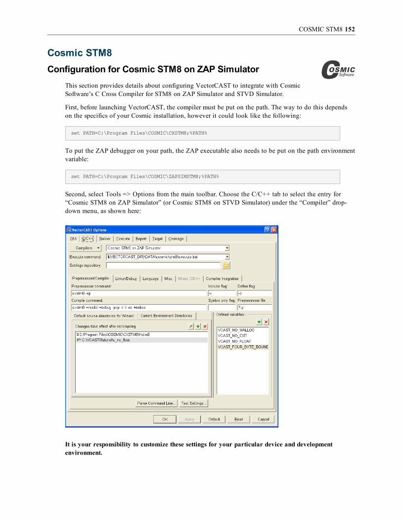
COSMIC STM8 152
Cosmic STM8Configuration for Cosmic STM8 on ZAP Simulator
This section provides details about configuring VectorCAST to integrate with CosmicSoftware’s C Cross Compiler for STM8 on ZAP Simulator and STVD Simulator.
First, before launching VectorCAST, the compiler must be put on the path. The way to do this dependson the specifics of your Cosmic installation, however it could look like the following:
set PATH=C:\Program Files\COSMIC\CXSTM8;%PATH%
To put the ZAP debugger on your path, the ZAP executable also needs to be put on the path environmentvariable:
set PATH=C:\Program Files\COSMIC\ZAPSIMSTM8;%PATH%
Second, select Tools => Options from the main toolbar. Choose the C/C++ tab to select the entry for“Cosmic STM8 on ZAP Simulator” (or Cosmic STM8 on STVD Simulator) under the “Compiler” drop-down menu, as shown here:
It is your responsibility to customize these settings for your particular device and developmentenvironment.

COSMIC STM8 153
Note: The linker files used for this integration apportion a larger section to RAM data and thestack that what would usually be found on a board (but runs correctly on the compiler). Reducingthe size of these sections is inadvisable, as typical RAM space on STM8 targets is insufficient tohost the VectorCAST unit test harness, even in minimal configuration. Likewise, this integrationwill only work on simulator.
Configuration for Cosmic STM8 on STVD SimulatorThis section provides details about configuring VectorCAST to integrate with Cosmic Software’s C CrossCompiler for STM8 on ST Visual Develop (STVD) Simulator.
First, before launching VectorCAST, the compiler must be put on the path. The way to do this dependson the specifics of your Cosmic installation. However, it could look like the following:
set PATH=C:\Program Files\COSMIC\CXSTM8;%PATH%
set PATH= C:\Program Files\STMicroelectronics\st_toolset\stvd\sim;%PATH%
The first line puts the compiler executable files on the path. The second further puts the simulatorexecutable files on the path.
Second, select Tools => Options from the main toolbar. Choose the C/C++ tab to select the entry for“Cosmic STM8 on STVD Simulator” under the “Compiler” drop-down menu, as shown here:
It is your responsibility to customize these settings for your particular device and developmentenvironment.

COSMIC STM8 154
Note: The linker files used for this integration apportion a larger section to RAM data and thestack that what would usually be found on a board (but runs correctly on the compiler). Reducingthe size of these sections is inadvisable, as typical RAM space on STM8 targets is insufficient tohost the VectorCAST unit test harness, even in minimal configuration. Likewise, this integrationwill only work on simulator.
Customizing Linker Command File Templates
If you are using custom libraries, you will need to add the name of the libraries to the two linker files,which you will find in $(VECTORCAST)/DATA/cosmic/stm8. The name of the two files is uut.lkf andinst.lkf, respectively, and the libraries must be added to both files. Please consult your Cosmicdocumentation for more information regarding linker files.
Please note that at this time, the RSP integration does not support integration testing (i.e. putting two ormore units under test). This is because the name of the files that make up the test harness is hard-codedinto the uut.lkf and inst.lkf files. If you need to do integration testing, please contact your VectorSoftware Representative.
Create a Simulator Entry for STM8VectorCAST Virtual Chip
Prior to using Cosmic STM8 on the STVD simulator, you must edit the simstm8.cnf file (located insidethe STVD simulator) and create a simulator entry for a virtual chip called STM8VectorCAST. This isaccomplished by doing the following:
1. Navigate to the simstm8.cnf configuration file located inside the STVD simulator and open thefile in any text editor.
2. Open a second instance of the text editor and open the configuration file located on the followingpath: %VECTORCAST_DIR%/DATA/st/stm8/simstm8.cnf. Copy the contents of this file.
3. Paste the contents of %VECTORCAST_DIR%/DATA/st/stm8/simstm8.cnf at the end of the firstconfiguration file (simstm8.cnf) and save. That will create an entry for a virtual MCU calledSTM8VectorCAST.
Note: Failure to follow these steps will result in a message printed in the execution output that theMCU name is unknown to the simulator.
Target ExecutionFor the Cosmic Software ZAP Debugger, VectorCAST will copy a control script into the environmentdirectory, and will automatically execute the “Debugger Command” that is set in the VectorCASTCompiler Options dialog. The script is automatically generated during execution and saved in a filenamed cosmic.scr, which you may find in your work directory. It is similar to the following:
b vCAST_END()
fopen /c:1 stdout.txt
watch VCAST_OUTCH { fwrite /c:1 "%c"VCAST_OUTCH }
watch change { fwrite /c:1 "%c"VCAST_OUTCH }
go

COSMIC STM8 155
fclose /c:1
reset
quit
On STVD, a similar process will occur and generate a file called gdbscript.txt as shown below:
file PATH_TO_HARNESS\harness.elf
target gdi -dll sim\st7sim.dll -config_file simstm8.cnf –mcunameSTM8VectorCAST -no_port_logfile
load PATH_TO_HARNESS%\harness.elf
watch vcast_exit
run
printf "%%s",vcast_output_buffer
quit
Target Debug ExecutionTest Execution with Debug functions similarly to normal execution, except the “go” command to executethe downloaded executable is never issued. You can manually set breakpoints, step through source anddisassembly, and view data as you would during a normal debug session.
To stop debugging, you simply need to close the result file by typing fclose /c:1, and then typing quit atthe ZAP command line. Please note that if the test harness was not allowed to run to its completion, theresults will be partial. To ensure that the test case runs to its completion, please make sure that the testharness runs to vCAST_END() function (or the value on vcast_exit variable changes, which happens onlyat the end of the test harness in the STVD integration).

EVP FOR VD3204X 156
EVP for VD3204xConfiguration
This section provides details about configuring VectorCAST to integrate with NXP’s EVP C compilerand debugger for VD3204x and the Adelante Software Development Kit.
First, select Tools => Options from the main toolbar. Choose the C/C++ tab to select the template for“EVP” under the “Compiler” drop-down menu, as shown here:
Specify either VD32040 or VD32041 depending on your core.
The compiler template for the EVP compiler uses the environment variable EVP_INSTALL_BASE, whichpoints to the EVP compiler’s installation directory. You must set this environment variable outside ofVectorCAST to point to the appropriate directory. For example:
set EVP_INSTALL_BASE “C:\adelante_sdk\vd3204x\r11b1_ixn”.
Second, ensure that the directory containing the EVP binaries is included in your PATH environmentvariable. This is most commonly C:\adelante_sdk\vd3204x\r11b1_ixn\bin, but may be slightly differenton your particular system.

EVP FOR VD3204X 157
To specify a different EVP installation directory:1. On the Preprocessor/Compiler tab, change the Default source directories for Wizard entry to
match the location of the “adelante_sdk\vd3204x\r11b1_ixn\include” directory on your system.If you have set the environment variable EVP_INSTALL_BASE correctly, this path will resolveitself when the Options dialog is opened, and therefore will be correct.
2. On the Linker tab, change the Linker Options entry to match the location of the $(EVP_INSTALL_BASE)/lib/vcom_vd32040 directory if you are using VD32040 or the $(EVP_INSTALL_BASE)/lib/vcom_vd32041 directory if you are using VD32041. Use DOS formattedshort-paths (8.3/no spaces).

EVP FOR VD3204X 158
3. Click Apply to save the changes.
It is your responsibility to customize these settings for your particular device and developmentenvironment. The “Preprocessor/Compiler” tab contains the compiler commands and options that will beused to compile the test harness. The “Linker” tab contains the linker commands and options that will beused to link the test harness. When you are ready to begin testing your application code, a good startingpoint for these settings would be the actual values used to compile and link the code you are about totest.
Specific details and discussion of the options that vcom.bat accepts is outside the scope of this document.Refer to NXP’s compiler and linker documentation for more information on this topic.
Lastly, click OK to save the settings and close the options dialog.
The default command settings should be sufficient to run the Tutorial example in the VectorCAST/C++User’s Guide, and it is strongly recommended that you do so before trying to test your application code.Be sure to use the code in
$(VECTORCAST_DIR)\examples\alternate_tutorial_versions\c_tutorial_no_floating_point
since the code in $(VECTORCAST_DIR)\tutorial uses the float type.

FUJITSU SOFTUNE FOR FFMC CHIPS 159
Fujitsu Softune for FFMC ChipsConfiguration
This section provides details about configuring VectorCAST to integrate with the FujitsuSoftune IDE.
First, before launching VectorCAST, the compiler must be put on the path. The way to do this dependson the specifics of your Fujitsu Softune installation, however it could look like the following:
set PATH=C:\Softune\BIN;%PATH%
set FETOOL=C:\Softune
set INC907=C:\Softune\LIB\907\INCLUDE
set LIB907=C:\Softune\LIB\907
set FELANG=ASCII
set OPT907=C:\Softune\LIB\907
set OPT=C:\Softune\LIB
set TMP=C:\Temp
Note: All of these environment variables must be set before VectorCAST/C++ can use them. Youcan make these environment variables permanently part of the Windows operating system, or youcan launch VectorCAST from a batch file that first sets these environment variables correctly.
FELANG indicates the encoding that is used by the code files on your computer. The value is likely to

FUJITSU SOFTUNE FOR FFMC CHIPS 160
be different if your code base is saved using another encoding, such as Shift-JIS (for Japanese). For moredetails, please consult your Fujitsu Softune documentation.
It is your responsibility to customize these settings for your particular device and developmentenvironment.
Target ExecutionThe Fujitsu Softune environment has a command line interface to the compiler and linker. However, itdoes not provide a command line interface to the debugger. The VectorCAST/RSP integration to FujitsuSoftune interfaces directly with the Windows API to automate the unit testing process. Because of this,users are advised not to interact with the Softune window spawned by VectorCAST unless the executiondoes not complete after several seconds. A typical execution time for this integration may range up to 10seconds. Likewise, it is recommended not to keep any instance of Fujitsu Softune open during executionwith VectorCAST, as the execution program may lock on to the existing Fujitsu Softune instance to runthe test harness, which may have unpredictable results.
A script file is created containing all the commands that should be issued to the debugger for successfulexecution. VectorCAST will then launch a Softune template and attempt to execute the script there.Result data can be captured in either of two ways – through a UART/Serial port (in the case of boards)and an OUTPORT, which is a designated variable whose value is saved to a file by the simulator. Themechanism is automatically implemented during template selection.
Target Debug ExecutionWhen executing under the control of the debugger, VectorCAST will open the Fujitsu Softune IDEtemplate and advance execution to the entry of the main function. From there, you will be able to executethe test harness manually, using your usual debugger command. For your convenience, VectorCAST willalso automatically put a break point at the end of the test harness. However, you will need to manuallyload the file you wish to debug by clicking File => Open, and then, in the working directory, opens0000003.c (for the main function) or the file of your choice. You should refrain from interacting with thedebugger until the SCRIPT command has been issued and processed by Fujitsu Softune.

FUJITSU SOFTUNE SIMULATOR 161
Fujitsu Softune SimulatorConfiguration
This section provides details about configuring VectorCAST to integrate with the FujitsuSoftune IDE.
First, before launching VectorCAST, the compiler must be put on the path. The way to do this dependson the specifics of your Fujitsu Softune installation, however it could look like the following:
set PATH=C:\Softune\BIN;%PATH%
set FETOOL=C:\Softune
set INC911=C:\Softune\LIB\911\INCLUDE
set LIB911=C:\Softune\LIB\911
set FELANG=ASCII
set OPT911=C:\Softune\LIB\911
set OPT=C:\Softune\LIB
set TMP=C:\Temp
Note: All of these environment variables must be set before VectorCAST/C++ can use them. Youcan make these environment variables permanently part of the Windows operating system, or youcan launch VectorCAST from a batch file that first sets these environment variables correctly.
FELANG indicates the encoding that is used by the code files on your computer. The value is likely to

FUJITSU SOFTUNE SIMULATOR 162
be different if your code base is saved using another encoding, such as Shift-JIS (for Japanese). For moredetails, please consult your Fujitsu Softune documentation.
It is your responsibility to customize these settings for your particular device and developmentenvironment.
Target ExecutionThe Fujitsu Softune environment has a command line interface to the compiler and linker. However, itdoes not provide a command line interface to the debugger. The VectorCAST/RSP integration to FujitsuSoftune interfaces directly with the Windows API to automate the unit testing process. Because of this,users are advised not to interact with the Softune window spawned by VectorCAST unless the executiondoes not complete after several seconds. A typical execution time for this integration may range up to 10seconds. Likewise, it is recommended not to keep any instance of Fujitsu Softune open during executionwith VectorCAST, as the execution program may lock on to the existing Fujitsu Softune instance to runthe test harness, which may have unpredictable results.
A script file is created containing all the commands that should be issued to the debugger for successfulexecution. VectorCAST will then launch a Softune template and attempt to execute the script there.Result data can be captured in either of two ways – through a UART/Serial port (in the case of boards)and an OUTPORT, which is a designated variable whose value is saved to a file by the simulator. Themechanism is automatically implemented during template selection.
When executing on the simulator, the buffer location may differ between executions, therefore the linkermap is always analyzed. The linker map format also varies between versions of Softune. Both Version 3(for FFMC-16 and Version 6 (FR) have been successfully integrated with VectorCAST. To integrate witha different version of Softune, please contact your VectorCAST representative.
Target Debug ExecutionWhen executing under the control of the debugger, VectorCAST will open the Fujitsu Softune IDEtemplate and advance execution to the entry of the main function. From there, you will be able to executethe test harness manually, using your usual debugger command. For your convenience, VectorCAST willalso automatically put a break point at the end of the test harness. However, you will need to manuallyload the file you wish to debug by clicking File => Open, and then, in the working directory, opens0000003.c (for the main function) or the file of your choice. You should refrain from interacting with thedebugger until the SCRIPT command has been issued and processed by Fujitsu Softune.

GREEN HILLS SIMULATOR/BARE TARGET 163
Green Hills Simulator/Bare TargetConfiguration
This section provides details about configuring VectorCAST to work with the GreenHills compiler running with a Green Hills Simulator or bare target board (the board is not running aRTOS).
Select Tools => Options from the Main Menu. Choose the C/C++ tab to select the correct entry for yourcompiler. There are templates available for several different Green Hills simulators, including: PowerPC,x86, ARM, and 68k. Additional templates are added as customers request them. The templates that endwith (C++) should be used when the code under test is C++ code. In the following example we havechosen the template for the Green Hills PPC Simulator (C++):
In this case, by default, the Execute command defaults to: simppc.
Configuration for a Target BoardIn cases where you want to use a live target board rather than the simulator, you should first choose thecorrect simulator template for the chip you are using, and then change the Compiler command and theExecute command options to reflect the target board you are using.
For example, to run on an MBX860 board using the Green Hills probe (mpserv), you would add the cpu

GREEN HILLS SIMULATOR/BARE TARGET 164
flag: "-cpu=ppc860" to the compile command, and set the Execute command to something similar to thefollowing:
grun mpserv -mode=download
-setup=C:\GHS\PPC402\target\ppc\mbx860\mpserv_standard.mbs ghprobe –-
The format required for this command is the name of the Green Hills grun utility followed by the remotetarget connection string, followed by double dashes.
In this command string, the -setup option should be the setup script that is appropriate for your board, andthe ghprobe option should be replaced with the name of your target board or its IP address.
The easiest way to determine the correct target execution command is to connect to your target using theMulti GUI. The command string you use to establish a remote connection in Multi should be used toconfigure the VectorCAST Execute Command.
Target ExecutionWhen running a test with a Green Hills simulator or bare target, the VectorCAST will issue the commandspecified in the Execute command option.
VectorCAST interfaces with the target at two different times: The first time that an environment is openedafter it is created (this is to build the VectorCAST range databases); and when VectorCAST interfaceswith the target to run a test case.
Note: For the target I/O to work between the test harness and the host system, the Green Hills-setup script (mpserv_standard.mbs) must contain the option: "syscalls on"
Target Execution with Green Hills Multi DebuggerWhen you choose Execute with Debug for a VectorCAST test, VectorCAST will launch the Multidebugger, using the Debugger Command option that has been set in the Misc sub-tab of the C/C++ tab ofthe Tool => Options dialog.
When the Multi GUI comes up, you should use the “Remote” or “Target” menu in Multi (the menu titleis different in different versions of Multi) to connect to your target. Enter your target connectioncommand, or select a previously used command from the list. For example: enter simppc for the simulator.

GREEN HILLS SIMULATOR/BARE TARGET 165
Once the target connection has been established, you can use the debug features of Multi as you normallywould. When the VectorCAST test harness has completed, the Multi debugger will display the status:‘Name_of_Executable’ has terminated normally.
At this point, you can quit from Multi, and VectorCAST will build its test execution report.
Improving Target Execution SpeedFor Green Hills targets, the VectorCAST test harness uses file I/O to read stimulus data, and to write theresults data. The Green Hills run time uses a "syscall" mechanism to service I/O operations from thetarget. Depending on the target connection and board that you are using, this syscall mechanism canresult in slow test case execution.

GREEN HILLS SIMULATOR/BARE TARGET 166
If your test cases are running slowly, please see the section "Standard I/O" on page 347, particularly thesection that describes how to configure the test harness to use standard output only for test execution"Configuring to Use Stdout Only" on page 350).

GREEN HILLS INTEGRITY SIMULATOR 167
Green Hills INTEGRITY SimulatorConfiguration
You can configure VectorCAST to work with a live board, or with the INTEGRITYsimulator. Choose the Tool => Options dialog, and select the C/C++ tab. VectorCAST has severalcompiler templates for INTEGRITY. In the following screen shot, we have chosen the template for PPCINTEGRITY Simulator C++. This is for version 4.x of INTEGRITY.
By default, the template has all of the options set that are required to build a test environment and run atest case using the INTEGRITY simulator. This template will build a kernel space application where theINTEGRITY operating system and the test harness code will be linked into the kernel address space. Thisis also called a statically-linked executable. We suggest that you run VectorCAST in this defaultconfiguration at least once to become familiar with the tool before attempting a more complex simulatoror target board configuration.
Target ExecutionTarget execution with the INTEGRITY simulator is exactly the same as with any of the other simulatorsor bare Green Hills targets. See the previous section on page 164 for details.

GREEN HILLS INTEGRITY SIMULATOR 168
Target Execution with Green Hills Multi DebuggerExecution with the Multi debugger is the same as described in the previous section on page 164. Simplycreate a target connection to the "isim" simulator. The only additional option required for isim for usewith VectorCAST is the "-X83" option. This option enables I/O to work with the simulator.
Improving Target Execution SpeedFor Green Hills targets, the VectorCAST test harness uses file I/O to read stimulus data, and to write theresults data. The Green Hills run time uses a "syscall" mechanism to service I/O operations from thetarget. Depending on the target connection and board that you are using, this syscall mechanism canresult in slow test case execution.
If your test cases are running slowly, please see the section “"Standard I/O" on page 347”, particularly thesection that describes how to configure the test harness to use standard output only for test execution.

GREEN HILLS INTEGRITY MPSERV 169
Green Hills INTEGRITY mpservConfiguration
This section describes how to configure VectorCAST for target board execution, usingthe Green Hills probe and mpserv. The particular example that we present here makes use of an MBX860board and version 4.0.8 of INTEGRITY. It should be easy for you to extend the example presented for adifferent version of INTEGRITY, or for different target hardware. Also, for this example we are building amonolithic kernel space application (i.e. the INTEGRITY OS kernel and the test harness application arelinked into one kernel space application.
VectorCAST has a built in compiler template for the combination used in this example as shown in thefollowing screen capture:
Some modification of the default template options will be required, to match your particular hardware.
Compile commandThe Compile command is located on the C/C++ tab of the Tool Options dialog, as shown in thefollowing screen capture:

GREEN HILLS INTEGRITY MPSERV 170
The default Compile command is:
ccppc -c -G -w -cpu=ppc860 :cx_option=exceptions
You should change the -cpu=option to reflect the CPU on your board.
Linker commandThe Linker command is located on the Linker sub-tab of the C/C++ tab of the Tool Options dialog, asshown in the following screen capture:
The default Link command is:
build -driver mbx800 :integrity_option=kernel -ldebug :language=cxx :cx_lib=sce
You should change "mbx800" to the correct value for your BSP.
Execute commandThe Execute command is located on the C/C++ tab of the Tool Options dialog, as shown in thefollowing screen capture:

GREEN HILLS INTEGRITY MPSERV 171
The default Execute command is:
grun mpserv -setup C:\GHS\int408\mbx800\mbx800_mp.dbs ghprobe –-
The execute command should always start with grun, and end with "two dashes". These two stringsdelimit the target connection string that is used to connect to your target. The connection string is thesame one that you would use in the Multi debugger to connect to your target. The -setup option providesa full path to the board initialization file for your board. "ghprobe" should be replaced with the hostnameof your target board or its IP address.
Target ExecutionTarget execution with the Green Hills probe is completely automatic. VectorCAST will automaticallyinvoke "mpserv" using the Execute command that you have configured, with no manual interventionrequired.
Note: For the target I/O to work between the test harness and the host system, the Green Hills-setup script mbx800_mp.dbs) must contain the option: "syscalls on"
Target Execution with Green Hills Multi DebuggerExecution with the Multi debugger is the same as described in the previous section on page 164. Simplycreate a target connection using the correct mpserv command sequence.
Improving Target Execution SpeedFor Green Hills targets, the VectorCAST test harness uses file I/O to read stimulus data, and to write theresults data. The Green Hills run time uses a "syscall" mechanism to service I/O operations from thetarget. Depending on the target connection and board that you are using, this syscall mechanism canresult in slow test case execution.
If your test cases are running slowly, please see the section “Standard I/O” on page 347, particularly thesection that describes how to configure the test harness to use standard output only for test execution(page 350).

GREEN HILLS INTEGRITY RTSERV 172
Green Hills INTEGRITY rtservConfiguration
This section describes how to configure VectorCAST for target board execution, withthe test harness running in a separate address space from the kernel and being dynamically downloadedusing rtserv. The particular example that we present here makes use of an MBX860 board and version4.0.8 of INTEGRITY. It should be easy for you to extend the example presented for a different version ofINTEGRITY or for different target hardware.
VectorCAST has a built in compiler template for the combination used in this example as shown in thefollowing screen capture:
Some modification of the default template options will be required, to match your particular hardware.
Compile commandThe Compile command is located on the C/C++ tab of the Tool Options dialog, as shown in thefollowing screen capture:
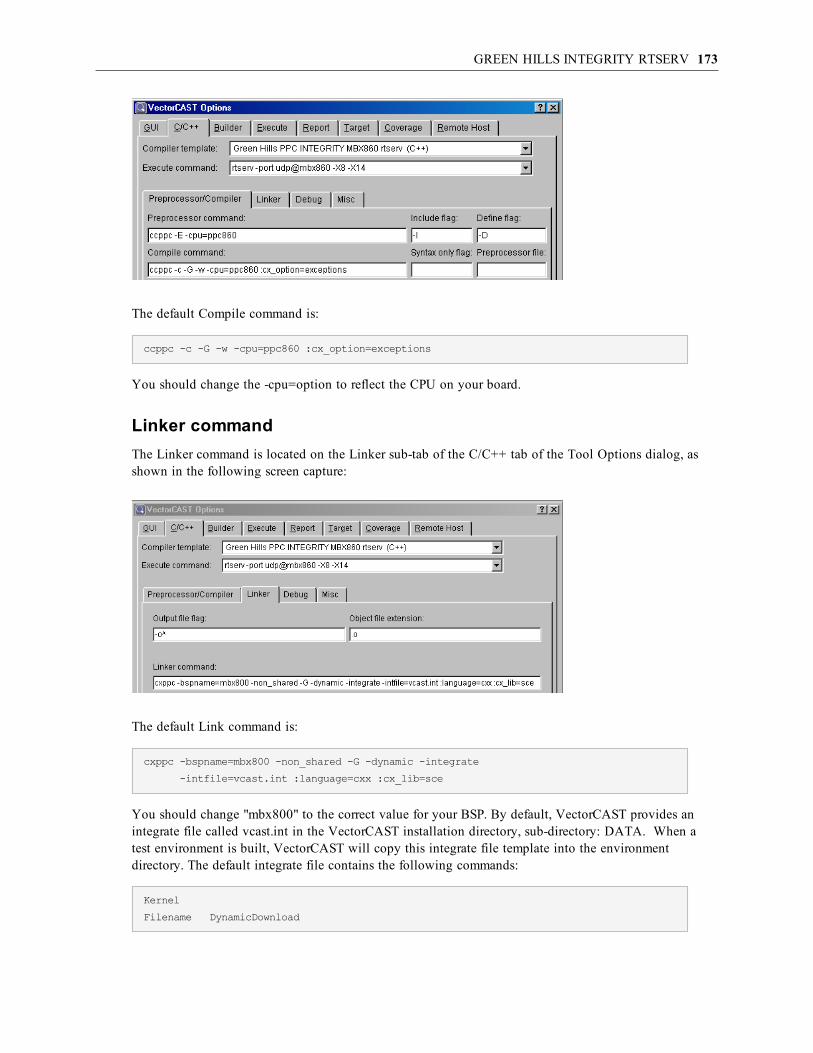
GREEN HILLS INTEGRITY RTSERV 173
The default Compile command is:
ccppc -c -G -w -cpu=ppc860 :cx_option=exceptions
You should change the -cpu=option to reflect the CPU on your board.
Linker commandThe Linker command is located on the Linker sub-tab of the C/C++ tab of the Tool Options dialog, asshown in the following screen capture:
The default Link command is:
cxppc -bspname=mbx800 -non_shared -G -dynamic -integrate
-intfile=vcast.int :language=cxx :cx_lib=sce
You should change "mbx800" to the correct value for your BSP. By default, VectorCAST provides anintegrate file called vcast.int in the VectorCAST installation directory, sub-directory: DATA. When atest environment is built, VectorCAST will copy this integrate file template into the environmentdirectory. The default integrate file contains the following commands:
Kernel
Filename DynamicDownload

GREEN HILLS INTEGRITY RTSERV 174
EndKernel
AddressSpace
FilenameVCAST_FILE
MemoryPoolSize0x30000
LanguageC++
Task Initial
StackLength0x8000
StartIt false
EndTask
EndAddressSpace
There are two ways to customize the integrate file that is used. One way is to edit the vcast.int file that isdelivered with VectorCAST, in the install area. Subsequent environment builds will then use this file.The second, and more flexible way is to provide the full path to a custom integrate file using theenvironment variable: VCAST_GH_INT_FILE. For example, if you set the value of this environmentvariable to be c:\my_project\my_integrate_file.int, VectorCAST will copy this file into the environmentdirectory, name it vcast.int, and use it when linking the test harness. The only requirement of a customintegrate file, is that it have an address space for the test harness, and the Filename line for this addressspace, must be VCAST_FILE. At link time, VectorCAST will replace VCAST_FILE with the actualfilename of the VectorCAST test harness.
All integrate file commands required for your application should be added to the VectorCAST integratefile, especially commands related to the creation of needed kernel space data objects and devices.
Execute commandThe Execute command is located on the C/C++ tab of the Tool Options dialog, as shown in thefollowing screen capture:
The default Execute command is:
rtserv -port udp@mbx860 -X8 -X14
The execute command should always start with rtserv. The connection string is the same one that youwould use in the Multi debugger to connect to your target. The udp@mbx860 should be replaced withthe correct name for your board.
Target ExecutionTarget execution of a dynamic download application with rtserv requires some manual steps. The mostimportant requirement is that the target board be booted with a running INTEGRITY kernel before anytest cases are executed.

GREEN HILLS INTEGRITY RTSERV 175
Once the board is booted, each VectorCAST test execution will create an rtserv connection to the target.This will cause the download and execution of the test harness address space. Test execution occurs withno manual intervention.
Common ways to boot the target are using tftp or mpserv. The Green Hills INTEGRITY documentationhas complete information on booting targets with an INTEGRITY kernel.
Target Execution with Green Hills Multi DebuggerExecution with the Multi debugger is similar to what is described in the previous section on page 164.However, you must manually load the test harness executable to the target after creating your rtservconnection. The following series of screen captures demonstrate a nominal sequence.
When you select Execute with debug, VectorCAST will put up a dialog similar to the following:
The dialog tells you the complete path to the executable file that should be loaded on to the target.When you select OK, VectorCAST will start the Multi debugger. After the Multi debugger starts, createan rtserv connection to your board. When the connection is made, you will get a task window showingthe kernel running on the board.

GREEN HILLS INTEGRITY RTSERV 176
Using the Target menu, Load command, load the VectorCAST test harness executable file that was namedin the VectorCAST pop-up. In this case, we will load the file: C:\test\c\mbx860\rtserv\TEST\UUT_INST.mod as indicated.
Note: It is important that you load the .mod file, as this is the "Integrated" application. There willalso be an .exe file with the same name, this file will not run on the target.
After the program is loaded, the task window, will show the VectorCAST task:
To debug the program, double click on the "Initial" task under UUT_INST.EXE. Doing this will result ina new Multi debug window being displayed. Use this window to debug your test case. When you’redone, close the debugger, and VectorCAST will create the test execution report.
Improving Target Execution SpeedFor Green Hills targets, the VectorCAST test harness uses file I/O to read stimulus data, and to write the

GREEN HILLS INTEGRITY RTSERV 177
results data. The Green Hills run time uses a "syscall" mechanism to service I/O operations from thetarget. Depending on the target connection and board that you are using, this syscall mechanism canresult in slow test case execution.
If your test cases are running slowly, please see the section “Standard I/O” on page 347, particularly thesection that describes how to configure the test harness to use standard output only for test execution(page 350).

HIGHTEC TRICORE-GCC 178
HighTec TriCore-gccConfiguration
This section provides details about configuring VectorCAST to integrate with TriCore-gcccompiler and debugger for the TriCore simulator or JTAG server.
First, the compiler must be on the path. If it is not already done, the following directory
(HighTec compiler directory)\TriCore\bin
must be put on the PATH environment variable before VectorCAST is launched.
Second, the simulator or JTAG server (in the case of a physical target) needs to be launched. UnderWindows, this can be done by accessing Start => PXROS TriCore System Development Platform. Boththe simulator and JTAG server can be activated by clicking the appropriate selection.
For instance, after selecting the simulator, the following DOS prompt will appear. This window must stayopen for as long as VectorCAST is executing test cases.
Please note the port number provided to you (usually 6785) and your host ID, which you can obtain bytyping ipconfig in a DOS prompt. Then, open the following file in an editor: $(VECTORCAST_DIR)/DATA/tricore-gcc/simulator.bat
@echo target tricore-remote 6785@localhost > script.txt
@echo load %1 >> script.txt
@TYPE %VECTORCAST_DIR%\DATA\tricore-gcc\simulator_commands.txt >> script.txt
@tricore-gdb --quiet --silent --command=script.txt
On the first line, modify the text 6785@localhost with the port number@host name that are pertinent toyour host. Then save the file.
Then within VectorCAST select the appropriate template you wish to use (either C or C++).

HIGHTEC TRICORE-GCC 179
TriCore installation and target customizations:The integration for this compiler was originally designed on a simulator for the TriCore 1775. To changethis for your target, modify the following options:
1. On the Preprocessor/Compiler tab, the –mcpu option on the preprocessor and compilecommands, and on the Linker tab, the Linker command refers to the 1775. The –mcpu needs tobe changed to your target.
2. To obtain the correct values, launch the compiler IDE (called Code::Blocks) and build yourproject. Take a look at the build log, which will report the value used for the -mcpu option.Modify your VectorCAST template accordingly.

HIGHTEC TRICORE-GCC 180
3. Likewise, the defined variable TRIBOARD_TC1775 must be changed with the macro related toyour target. This information can also be obtained in Code::Blocks as shown above.
If your project relies on any startup code, these files must be specified in VectorCAST’s Tools =>Options dialog, C/C++ tab, Compiler Integration sub-tab, in the option “Startup file.”

HIGHTEC TRICORE-GCC 181
Please note that this integration uses the virtual I/O capability of the environment to communicate testharness data. Use of Serial I/O is also possible, but not supported at this time. Please contact your VectorSoftware representative if your needs include the use of Serial I/O.
Target ExecutionTarget execution in the TriCore-gcc environment is straightforward. The only prerequisite to environmentbuilding and test case execution is to launch either the JTAG-server or TriCore version 1.x Simulatorprograms. These programs are available, under Windows, by clicking Start => All Programs => PXROS.These programs can also be launched from the command line. Under Windows default installation, theJTAG server can be accessed at:
C:\HighTec\TriCore\bin\tricore-jtagsrv.exe
and the simulator at:
C:\HighTec\TriCore\bin\tricore-tsimd.exe
These two programs will open a port (by default, port 6785) to listen for incoming requests from programsto execute TriCore-compatible programs on a board or a simulator. VectorCAST uses these facilities fortarget execution. You must therefore ensure that one of them is launched before generating anenvironment or running a test case.

HIGHTEC TRICORE-GCC 182
Target Debug ExecutionTest Execution with Debug functions similarly to normal execution, except a breakpoint is set in themain function so execution stops there. You can manually set breakpoints, step through source anddisassembly, and view data as you would during a normal debug session.
tricore-gcc uses a port of gdb for debug capabilities. Running a test case with the debugger will invoketricore-insight and charge the test harness. If you prefer to use gdb, go to Tools => Options dialog,C/C++ tab, Debug sub-tab, and replace tricore-insight with tricore-gdb.
Please consult the compiler’s manual to learn how to use the debugger.

IAR EMBEDDED WORKBENCH 3.X MSP430 183
IAR Embedded Workbench 3.x MSP430Configuration
This section provides details about configuring VectorCAST to integrate with IAR’sEmbedded Workbench version 3.10A and C-SPY debugger for Texas Instruments’ MSP430. (Futurereleases of Embedded Workbench might require slight configuration changes.)
First, select Tools => Options from the main toolbar. Choose the C/C++ tab to select the entry for “IARMSP430 3.x” under the “Compiler” drop-down menu, as shown here:
Second, ensure that the directories containing the IAR binaries are included in your PATH environmentvariable. These are most commonly c:\Progra~1\IARSys~1\Embedd~1\common\bin andC:\Progra~1\IARSys~1\Embedd~1\430\bin but may be slightly different on your particular system.
To specify a different IAR installation directory:1. Ensure that the “Preprocessor/Compiler” tab is selected.
2. The “Include Dirs” text box contains the installation path in two places. All occurrences ofC:\PROGRA~1\IARSYS~1\EMBEDD~1 should be replaced with the DOS-formatted path toyour IAR installation (no spaces).
3. Click the “Linker” tab.

IAR EMBEDDED WORKBENCH 3.X MSP430 184
4. The “Linker Options” text box contains the installation path in three places. All occurrences ofC:\PROGRA~1\IARSYS~1\EMBEDD~1 should be replaced with the DOS-formatted path toyour IAR installation (no spaces).
These default settings should be sufficient to run the Tutorial example in the VectorCAST/C User’sGuide, and it is strongly recommended that you do so before trying to test your application code. Thecompile and link options are initially set to match the defaults provided by IAR’s Embedded Workbenchwhen you create a new project, selecting “Generic Device” as your target.
It is your responsibility to customize these settings for your particular device, including modifying alinker file that will accommodate the size of the code under test plus the VectorCAST test harness that isused to drive the code under test.
Note: The size of the test harness is not static – it is dependent on the size and composition of thecode under test. Refer to IAR’s documentation for more information on customizing linker files.
The “Preprocessor/Compiler” tab contains the compiler options that will be used to compile the testharness. The “Linker” tab contains the linker options, libraries to be linked, linker file specification, heapand stack size that will be used to link the test harness. When you are ready to begin testing yourapplication code, a good starting point for these settings would be the actual values used to compile andlink the code you are about to test.
For example, if you are using the F149 target device, you would change the “Linker Options” entry toreference “C:\PROGRA~1\IARSYS~1\EMBEDD~1\430\config\lnk430F149.xcl” instead of the default“C:\PROGRA~1\IARSYS~1\EMBEDD~1\430\config\lnk430.xcl.” If you find that the test harness isn’tlinking properly and plan on modifying lnk430F149.xcl, it is strongly recommended that you make acopy of lnk430F149.xcl and name it something unique, like “lnk430F149_vcast.xcl.” Don’t forget tochange the Linker Options to reference lnk430F149_vcast.xcl instead of the original.
Specific details and discussion of the options that icc430.exe and xlink.exe accept is outside the scope ofthis document. Refer to IAR’s compiler and linker documentation for more information on this topic.
Target ExecutionBefore executing tests with IAR Embedded Workbench version 3.10A, you must specify the IARCompiler and Execute Command through the Options dialog. Also, ensure that the IAR binary directories(most commonly C:\Progra~1\IARSys~1\Embedd~1\common\bin andC:\Progra~1\IARSys~1\Embedd~1\430\bin) are included in the host platform’s PATH environmentvariable.
See the previous section for detailed instructions on these requirements.
VectorCAST utilizes the IAR application “cspybat.exe” to execute the test harness on the C-Spysimulator. This application allows target simulation and execution to occur without the requirement ofstarting IAR Embedded Workbench IDE or C-Spy debugger. The execution occurs automatically andrequires no input from the user.
When executing a test case (for example, PLACE_ORDER.001 in the User’s Guide Tutorial) you shouldsee the following output in the Message tab across the bottom of VectorCAST:
Running C-SPY Debugger to Execute Program...
Building Execution History Data for Event: 1
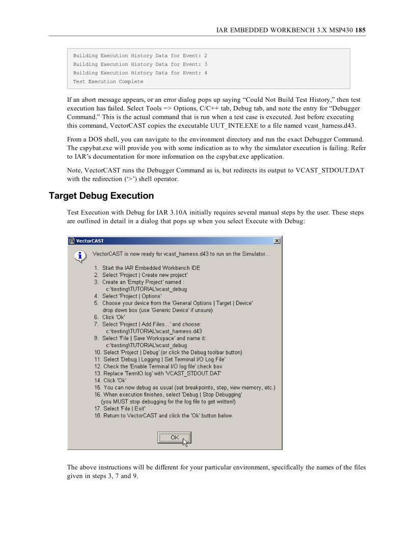
IAR EMBEDDED WORKBENCH 3.X MSP430 185
Building Execution History Data for Event: 2
Building Execution History Data for Event: 3
Building Execution History Data for Event: 4
Test Execution Complete
If an abort message appears, or an error dialog pops up saying “Could Not Build Test History,” then testexecution has failed. Select Tools => Options, C/C++ tab, Debug tab, and note the entry for “DebuggerCommand.” This is the actual command that is run when a test case is executed. Just before executingthis command, VectorCAST copies the executable UUT_INTE.EXE to a file named vcast_harness.d43.
From a DOS shell, you can navigate to the environment directory and run the exact Debugger Command.The cspybat.exe will provide you with some indication as to why the simulator execution is failing. Referto IAR’s documentation for more information on the cspybat.exe application.
Note, VectorCAST runs the Debugger Command as is, but redirects its output to VCAST_STDOUT.DATwith the redirection (‘>’) shell operator.
Target Debug ExecutionTest Execution with Debug for IAR 3.10A initially requires several manual steps by the user. These stepsare outlined in detail in a dialog that pops up when you select Execute with Debug:
The above instructions will be different for your particular environment, specifically the names of the filesgiven in steps 3, 7 and 9.

IAR EMBEDDED WORKBENCH 3.X MSP430 186
The C-Spy simulator is built-in to IAR’s Embedded Workbench 3.10A. To debug an executable with C-Spy, you need to setup an Embedded Workbench Project, configure the project settings, and add the fileyou want to debug to this project.
It is recommended that you save the IAR Workspace in the current environment directory as “vector_debug” because VectorCAST looks for this file on future debug executions.
To report the results of a debugged test case back to VectorCAST, you must enable Terminal I/O loggingonce the debugger has started. If you’d like to see these results in realtime, you can select “View |Terminal I/O” and an additional window will open in C-Spy.
You can now debug the test harness using the functionality that C-Spy provides. When you are finisheddebugging, allow the application to run to completion and select “Stop Debugging” to ensure that theI/O log file gets written to disk. If the message “Test case execution aborted” appears in VectorCAST’sMessage tab, it is most likely because the I/O log file was never written.
Once you have set up an IAR Project and Workspace for debugging and saved them in the currentenvironment directory, VectorCAST will recognize this and prompt you with a smaller set of instructions:
The above instructions will be different for your particular environment, specifically the name of the filegiven in step 2.
In fact, if you plan on debugging several test cases, you do not need to close Embedded Workbench.Each time you Execute with Debug, simply switch back to IAR and select “Project | Debug.” The I/Ologging will already be set up, so you can immediately start debugging.

IAR EMBEDDED WORKBENCH 6.0MSP430X LARGE MEMORY MODEL 5.X 187
IAR Embedded Workbench 6.0MSP430X Large Memory Model 5.xConfiguration
This section provides details about configuring VectorCAST to integrate with IAR’sEmbedded Workbench version 6.0, MSP430 compiler version 5.1, and C-SPY debugger for TexasInstruments’ MSP430. This RSP was designed to utilize the IAR simulator and Large memory model.(Future releases of Embedded Workbench might require slight configuration changes.)
Specifying the IAR install directory paths:The user must set an environment variable that defines the path to where your IAR compiler is installedon your host. This variable is named VCAST_IAR_INSTALL_DIR and must be set accordingly. Forexample:
set VCAST_IAR_INSTALL_DIR=C:\PROGRA~1\IARSYS~1\EMBEDD~2.0\430
Also ensure that the directories containing the IAR binaries are included in your PATH environmentvariable. These are most commonly located at …
C:\Program Files\IAR Systems\Embedded Workbench 6.0\common\bin
C:\Program Files\IAR Systems\Embedded Workbench 6.0\430\bin
but may be slightly different on your particular system so set the PATH environment variableaccordingly.
First select Tools => Options from the main toolbar. Choose the C/C++ tab to select the entry for “IAR=> MSP430 5.1 => LargeMem => C” under the “Compiler” drop-down menu, as shown here:

IAR EMBEDDED WORKBENCH 6.0MSP430X LARGE MEMORY MODEL 5.X 188
These default settings should be sufficient to run the Tutorial example in the VectorCAST/C++ User’sGuide, and it is strongly recommended that you do so before trying to test your application code. Thecompile and link options are initially set to match the defaults provided by IAR’s Embedded Workbenchwhen you create a new project, selecting the MSP430X processor as your target and specifying the largememory model.
It is your responsibility to customize these settings for your particular device, including modifying alinker file that will accommodate the size of the code under test plus the VectorCAST test harness that isused to drive the code under test.
Note: The size of the test harness is not static – it is dependent on the size and composition of thecode under test. Refer to IAR’s documentation for more information on customizing linker files.The default linker command file used for the MSP430X template is the lnk430x.xcl which islocated at $(VCAST_IAR_INSTALL_DIR)\config\lnk430x.xcl.
The “Preprocessor/Compiler” tab contains the compiler options that will be used to compile the UUTcode and test harness. The target processor core and memory model are specified on the compilecommand with the following compiler switches
--data_model=large --core=430X
The “Linker/Debug” tab contains the linker options, libraries to be linked, linker file specification, heapand stack size that will be used to link the test harness. When you are ready to begin testing your

IAR EMBEDDED WORKBENCH 6.0MSP430X LARGE MEMORY MODEL 5.X 189
application code you may choose to modify some of these settings. We recommend using the defaultvalues provided in the MSP430X template and only modify as needed. Depending on the size andcomplexity of your UUT code, it may be necessary to increase the default stack and heap sizes, whichyou will find specified on the linker options, as shown below:
-D_STACK_SIZE=1024 -D_HEAP_SIZE=3072 -D_DATA16_HEAP_SIZE=500-D_DATA20_HEAP_SIZE=500
Specific details and discussion of the options that the IAR compiler and linker will accept are outside thescope of this document. Refer to IAR’s compiler and linker documentation for more information on thistopic.
Target ExecutionVectorCAST utilizes the IAR application “cspybat.exe” to execute the test harness on the C-Spysimulator. This application allows target simulation and execution to occur without the requirement ofstarting IAR Embedded Workbench IDE or C-Spy debugger. The execution occurs automatically andrequires no input from the user. The default cspy command that is executed to run a test case on the 430simulator can be found on the Tools => Options => C/C++ tab in the Debugger command edit box:
cspybat.exe 430proc.dll 430sim.dll vcast_debug.out --plugin 430bat.dll --backend-B --core=430X
When executing a test case (for example, PLACE_ORDER.001 in the User’s Guide Tutorial) you shouldsee the following output in the Message tab across the bottom of VectorCAST:
Preparing Test Data
Running Test Case
Compiling and Linking Input Data File...
Compiling file Test Case Data
Linking Environment
Running C-SPY Debugger to execute program
Building Execution Report
Created Execution Report
Test Execution Complete
If an abort message appears, or an error dialog pops up saying “Could Not Build Test History,” then testexecution has failed. Select Tools => Options, C/C++ tab, Debug tab, and note the entry for “DebuggerCommand.” This is the actual command that is run when a test case is executed. Just before executingthis command, VectorCAST copies the executable UUT_INTE.EXE to a file named vcast_debug.out.
From a DOS shell, you can navigate to the environment directory and run the exact Debugger Command.The cspybat.exe will provide you with some indication as to why the simulator execution is failing. Referto IAR’s documentation for more information on the cspybat.exe application.
Note, VectorCAST runs the Debugger Command as is, but redirects its output to VCAST_STDOUT.DATwith the redirection (‘>’) shell operator.
Target Debug ExecutionTest case Execution with Debug can be performed by right-clicking on a particular test case and selecting

IAR EMBEDDED WORKBENCH 6.0MSP430X LARGE MEMORY MODEL 5.X 190
“Execute with Debug”. VectorCAST will automatically invoke the IAR Embedded Workbench IDE witha default project and workspace setup. In addition, on the first time the user Executes With Debug, anInformation dialog box will pop up (shown below) that describes what VectorCAST will be doing on theuser’s behalf and the user’s required actions, which basically involves clicking the Download & Debugbutton to initiate the debug session.
Click OK in the Information dialog box and VectorCAST will then bring up the IAR IDE by running theIarIdePm.exe and you will see a “Processing… Abort “ progress box also appear with the IDE as shownbelow.
At this point you can just click the Download & Debug button and begin your debug session. You can

IAR EMBEDDED WORKBENCH 6.0MSP430X LARGE MEMORY MODEL 5.X 191
now debug the test harness and UUT code using the functionality that C-Spy provides. When you arefinished debugging, allow the application to run to completion and select “Stop Debugging” to ensurethat the I/O log file gets written to disk. Upon exiting the debug session and returning control toVectorCAST, if the message “Test case execution aborted” appears in VectorCAST’s Message tab, it ismost likely because the I/O log file was never written. Upon successful completion of the test case youshould see the follow messages appear in VectorCAST’s Message tab.
Preparing Test Data
Running Test Case
Compiling and Linking Input Data File...
Compiling file Test Case Data
Linking Environment
Running IAR IDE to execute program
Building Execution Report
Created Execution Report
Test Execution Complete
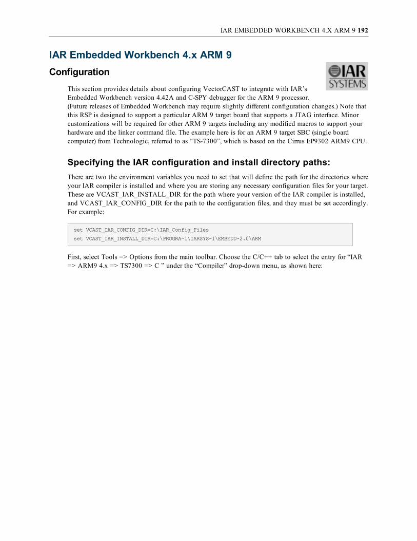
IAR EMBEDDED WORKBENCH 4.X ARM 9 192
IAR Embedded Workbench 4.x ARM 9Configuration
This section provides details about configuring VectorCAST to integrate with IAR’sEmbedded Workbench version 4.42A and C-SPY debugger for the ARM 9 processor.(Future releases of Embedded Workbench may require slightly different configuration changes.) Note thatthis RSP is designed to support a particular ARM 9 target board that supports a JTAG interface. Minorcustomizations will be required for other ARM 9 targets including any modified macros to support yourhardware and the linker command file. The example here is for an ARM 9 target SBC (single boardcomputer) from Technologic, referred to as “TS-7300”, which is based on the Cirrus EP9302 ARM9 CPU.
Specifying the IAR configuration and install directory paths:There are two the environment variables you need to set that will define the path for the directories whereyour IAR compiler is installed and where you are storing any necessary configuration files for your target.These are VCAST_IAR_INSTALL_DIR for the path where your version of the IAR compiler is installed,and VCAST_IAR_CONFIG_DIR for the path to the configuration files, and they must be set accordingly.For example:
set VCAST_IAR_CONFIG_DIR=C:\IAR_Config_Files
set VCAST_IAR_INSTALL_DIR=C:\PROGRA~1\IARSYS~1\EMBEDD~2.0\ARM
First, select Tools => Options from the main toolbar. Choose the C/C++ tab to select the entry for “IAR=> ARM9 4.x => TS7300 => C ” under the “Compiler” drop-down menu, as shown here:

IAR EMBEDDED WORKBENCH 4.X ARM 9 193
IAR installation and target customizations:1. Click the “Linker” tab.
2. The “Linker Options” text box contains references to all the startup objects required for yourtarget.
$(VCAST_IAR_CONFIG_DIR)\UIC_Debug.r79 $(VCAST_IAR_CONFIG_DIR)\TS7300_cstartup.r79
$(VCAST_IAR_CONFIG_DIR)\EP9302.r79
$(VCAST_IAR_CONFIG_DIR)\TS7300.r79
-l UIC_LDR.map -xmsn -IC:\PROGRA~1\IARSYS~1\EMBEDD~2.0\ARM\LIB\
-f $(VCAST_IAR_CONFIG_DIR)\UIC_Debug.xcl
-HFF -h(CODE)ROMSTART-ROMEND -J4,crc32,1,__checksum, CHECKSUM,1,0=ROMSTART-ROMEND
-e_PrintfSmall=_Printf -e_ScanfSmall=_Scanf -rt $(VCAST_IAR_INSTALL_DIR)
\LIB\dl4tptinl8n.r79 -e__write_buffered=__write
The startup objects for your target should be compiled outside of VectorCAST and the resultant.r79 object files should be placed in the VCAST_IAR_CONFIG_DIR you set up earlier. Replacethe startup objects for the TS7300 with the appropriate startup objects required for your target.Also in the Linker Options text box, replace the UIC_Debug.xcl linker file for the TS7300 withyour target .xcl file in the VCAST_IAR_CONFIG_DIR.
3. Click the “Debug” tab.
4. In the “Debugger command:” edit box, replace the –cpu ARM920T argument with the ARM9

IAR EMBEDDED WORKBENCH 4.X ARM 9 194
CPU type for your target, as well as the appropriate processor device description file in place ofthe default ioep9302.ddf specified for the TS7300:
cspybat armproc.dll armjlink.dll vcast_debug.out
--plugin armbat.dll --backend -B --endian little
--cpu ARM920T --fpu None
--proc_device_desc_file ioep9302.ddf
--proc_driver jlink --jlink_connection USB:0
--jlink_reset_strategy "1000,0"
--jlink_initial_speed 32
--jlink_catch_exceptions 0x000
--jlink_update_breakpoints main
These default settings should be sufficient to run the Tutorial example in the VectorCAST/C++ User’sGuide, and it is strongly recommended that you do so before trying to test your application code. Thecompile and link options are initially set to match the defaults provided by IAR’s Embedded Workbenchwhen you create a new project, selecting EP9302 as your target.
It is your responsibility to customize these settings for your particular device, including modifying alinker file that will accommodate the size of the code under test plus the VectorCAST test harness that isused to drive the code under test. Note that the size of the test harness is not static – it is dependent onthe size and composition of the code under test. Refer to IAR’s documentation for more information oncustomizing linker files.
The “Preprocessor/Compiler” tab contains the compiler options that will be used to compile the testharness. The “Linker” tab contains the linker options, libraries to be linked, linker file specification, heapand stack size that will be used to link the test harness. When you are ready to begin testing yourapplication code, a good starting point for these settings would be the actual values used to compile andlink the code you are about to test.
For example, if you are not using the E9302 target device, you would change the “Linker Options” entryto reference your particular target .xcl file instead of the default UIC_Debug.xcl.
Specific details and discussion of the options that the iccarm.exe compiler and the xlink.exe linker acceptare outside the scope of this document. Refer to IAR’s compiler and linker documentation for moreinformation on this topic.
Target ExecutionVectorCAST utilizes the IAR application “cspybat.exe” to execute the test harness on the target throughthe J-Link interface. This application allows target execution to occur without the requirement of startingIAR Embedded Workbench IDE or C-Spy debugger. The execution occurs automatically and requires noinput from the user. This test case execution is invoked using the command specified in the DebuggerCommand that is found in the Tools => Options, C/C++ tab, Debug tab, edit box “Debugger Command.”The default command specifies using a J-Link connection to the target, as well as other J-Link optionspecific to your target. Review these options shown below and change as appropriate for your target.Refer to IAR documentation for more information regarding the command line options for runningcspybat.exe.

IAR EMBEDDED WORKBENCH 4.X ARM 9 195
When executing a test case (for example, PLACE_ORDER.001 in the User’s Guide Tutorial) you shouldsee the following output in the Message tab in VectorCAST’s main window:
Running C-SPY Debugger to execute program
Building Execution Report
Created Execution Report
Updating Coverage Data
Test Execution Complete
Just prior to test case execution, VectorCAST copies the test harness executable, UUT_INTE.EXE or theUUT_INST.EXE, depending on whether you have coverage enabled, to a file named vcast_debug.out. Incases of failed test case execution, one can possibly get more information as to the nature of the failure byrunning this command from a DOS shell. To do so, navigate to the environment directory and run theexact same Debugger Command that is found in the Tools => Options, C/C++ tab, Debug tab, edit box“Debugger Command.” The cspybat.exe will provide you with some indication as to why the targetexecution is failing. Refer to IAR’s documentation for more information on the cspybat.exe application.
Note: VectorCAST runs the Debugger Command as is, but redirects its output to VCAST_STDOUT.DAT with the redirection (‘>’) shell operator.
Target Debug ExecutionTest case Execution with Debug can be performed by right-clicking on a particular test case and selecting

IAR EMBEDDED WORKBENCH 4.X ARM 9 196
“Execute with Debug”. VectorCAST will automatically invoke the IAR Embedded Workbench IDE witha default project and workspace setup. In addition, on the first time the user Executes With Debug, anInformation dialog box will pop up (shown below) that describes what VectorCAST will be doing on theuser’s behalf and the user’s required actions, which basically involves clicking the Download & Debugbutton to initiate the debug session.
Click OK in the Information dialog box and VectorCAST will then bring up the IAR IDE by running theIarIdePm.exe and you will see a “Processing… Abort “ progress box also appear with the IDE as shownbelow.
At this point you can just click the Download & Debug button and begin your debug session. You can
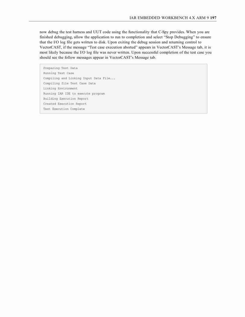
IAR EMBEDDED WORKBENCH 4.X ARM 9 197
now debug the test harness and UUT code using the functionality that C-Spy provides. When you arefinished debugging, allow the application to run to completion and select “Stop Debugging” to ensurethat the I/O log file gets written to disk. Upon exiting the debug session and returning control toVectorCAST, if the message “Test case execution aborted” appears in VectorCAST’s Message tab, it ismost likely because the I/O log file was never written. Upon successful completion of the test case youshould see the follow messages appear in VectorCAST’s Message tab.
Preparing Test Data
Running Test Case
Compiling and Linking Input Data File...
Compiling file Test Case Data
Linking Environment
Running IAR IDE to execute program
Building Execution Report
Created Execution Report
Test Execution Complete

IAR EMBEDDED WORKBENCH 5.X ARM 9 198
IAR Embedded Workbench 5.x ARM 9Configuration
This section provides details about configuring VectorCAST to integrate with IAR’sEmbedded Workbench version 5.2 and C-SPY debugger for the ARM 9 processor. (Futurereleases of Embedded Workbench might require slight configuration changes.) Note that this RSP isdesigned to support a particular ARM 9 target board that supports a JTAG interface. Minorcustomizations will be required for other ARM 9 targets including modifications to the macro thatsupports your hardware and the linker command file. The example here is for a target referred to as“Madison” that has the ARM926EJ-S CPU on board.
Specifying the IAR configuration and install directory paths:There are two the environment variables you need to set that will define the path for the directories whereyour IAR compiler is installed and where you are storing any necessary configuration files for your target.These are VCAST_IAR_INSTALL_DIR for the path where your version of the IAR compiler is installed,and VCAST_IAR_CONFIG_DIR for the path to the configuration files, and they must be set accordingly.For example:
set VCAST_IAR_CONFIG_DIR=C:\IAR_Config_Files
set VCAST_IAR_INSTALL_DIR=C:\PROGRA~1\IARSYS~1\EMBEDD~1.0\ARM
First, select Tools => Options from the main toolbar. Choose the C/C++ tab to select the entry for “IAR=> ARM9 5.x => Madison => C” under the “Compiler” drop-down menu, as shown here:

IAR EMBEDDED WORKBENCH 5.X ARM 9 199
IAR installation and target customizations:1. Click the “Linker” tab.
2. The “Linker Options” text box contains a reference to the linker .icf file. Replace theAT91SAM9261_iRAM.icf linker file with the appropriate .icf file for your particular target.
--config
$(VCAST_IAR_CONFIG_DIR)\AT91SAM9261_iRAM.icf
--semihosting
--entry __iar_program_start
3. Click the “Debug” tab.
4. In the “Debugger command:” edit box, replace the optional AT91SAM9261_iRAM.mac macrofile with the appropriate macro for your particular target.
cspybat armproc.dll armjlink.dll vcast_debug.out
--plugin armbat.dll
--macro $(VCAST_IAR_CONFIG_DIR)\AT91SAM9261_iRAM.mac
--backend -d jlink -B
These default settings should be sufficient to run the Tutorial example in the VectorCAST/C++ User’sGuide, and it is strongly recommended that you do so before trying to test your application code. The

IAR EMBEDDED WORKBENCH 5.X ARM 9 200
compile and link options are initially set to match the defaults provided by IAR’s Embedded Workbenchwhen you create a new project, selecting “ARM926EJ-S” as your target.
It is your responsibility to customize these settings for your particular device, including changing the –cpu compiler switch to match your target CPU, and modifying a linker file that will accommodate thesize of the code under test plus the VectorCAST test harness that is used to drive the code under test.
Note: The size of the test harness is not static – it is dependent on the size and composition of thecode under test. Refer to IAR’s documentation for more information on customizing linker files.
The “Preprocessor/Compiler” tab contains the compiler options that will be used to compile the testharness. The “Linker” tab contains the linker options, libraries to be linked, linker file specification, heapand stack size that will be used to link the test harness. When you are ready to begin testing yourapplication code, a good starting point for these settings would be the actual values used to compile andlink the code you are about to test.
For example, if you are using a target other than the default ARM926EJ-S target device, you wouldchange the “Linker Options” entry to reference the appropriate .icf linker file instead of the default“AT91SAM9261_iRAM.icf .” If you find that the test harness isn’t linking properly and plan onmodifying AT91SAM9261_iRAM.icf, it is strongly recommended that you make a copy ofAT91SAM9261_iRAM.icf and name it something unique, like “AT91SAM9261_iRAM.icf.save.”
Specific details and discussion of the options that ilinkarm.exe accept are outside the scope of thisdocument. Refer to IAR’s compiler and linker documentation for more information on this topic.
Target ExecutionVectorCAST utilizes the IAR application “cspybat.exe” to execute the test harness on the target. Thisapplication allows target execution to occur without the requirement of starting IAR EmbeddedWorkbench IDE or C-Spy debugger. The execution occurs automatically and requires no input from theuser. This test case execution is invoked using the command specified in the Debugger command: editbox which can be found in the Tools->Options dialog box, selecting the C/C++ Debug tab. The defaultcommand specifies using a J-Link connection to the target and a startup macro “AT91SAM9261_iRAM.mac” that you may need to replace with a macro customized for your target. See the view below:
When executing a test case (for example, PLACE_ORDER.001 in the User’s Guide Tutorial) you shouldsee a progress bar indicating the test case is being downloaded and executed on the target.
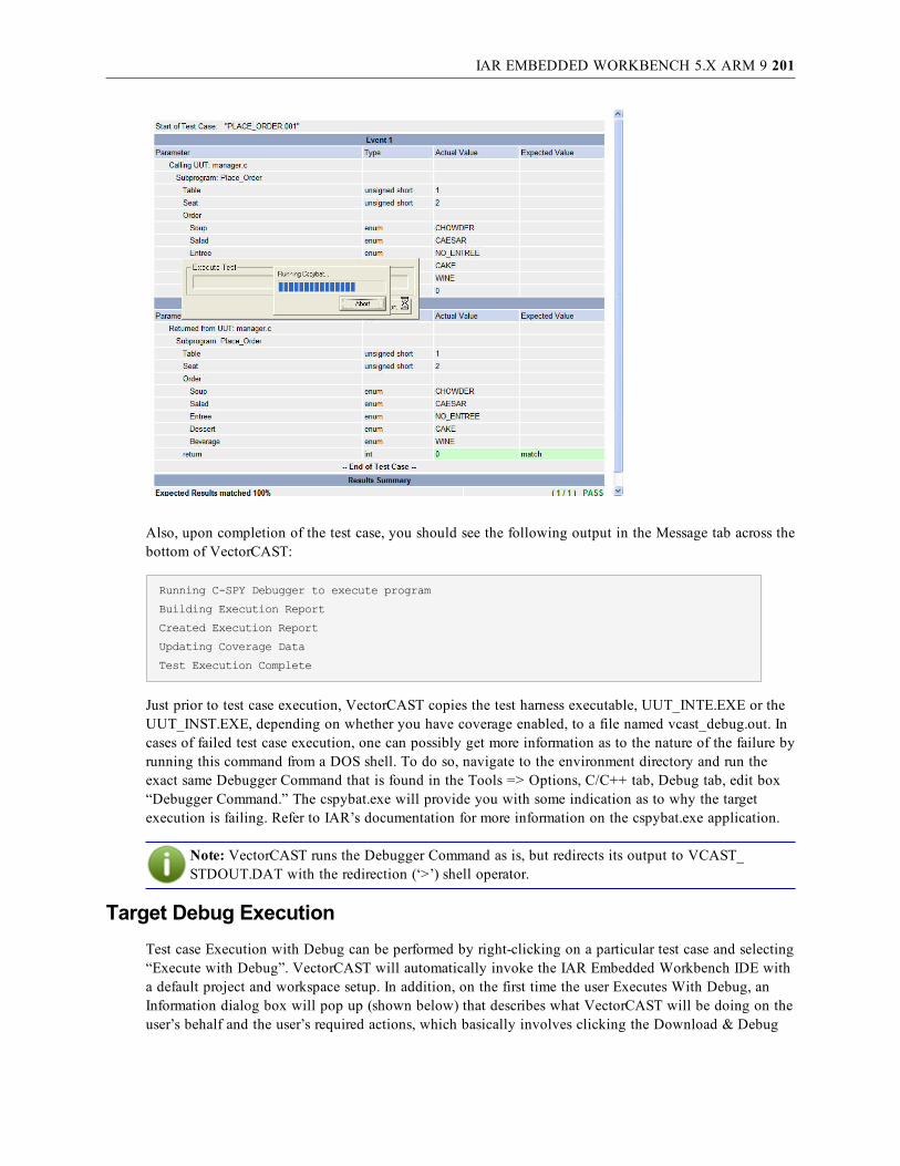
IAR EMBEDDED WORKBENCH 5.X ARM 9 201
Also, upon completion of the test case, you should see the following output in the Message tab across thebottom of VectorCAST:
Running C-SPY Debugger to execute program
Building Execution Report
Created Execution Report
Updating Coverage Data
Test Execution Complete
Just prior to test case execution, VectorCAST copies the test harness executable, UUT_INTE.EXE or theUUT_INST.EXE, depending on whether you have coverage enabled, to a file named vcast_debug.out. Incases of failed test case execution, one can possibly get more information as to the nature of the failure byrunning this command from a DOS shell. To do so, navigate to the environment directory and run theexact same Debugger Command that is found in the Tools => Options, C/C++ tab, Debug tab, edit box“Debugger Command.” The cspybat.exe will provide you with some indication as to why the targetexecution is failing. Refer to IAR’s documentation for more information on the cspybat.exe application.
Note: VectorCAST runs the Debugger Command as is, but redirects its output to VCAST_STDOUT.DAT with the redirection (‘>’) shell operator.
Target Debug ExecutionTest case Execution with Debug can be performed by right-clicking on a particular test case and selecting“Execute with Debug”. VectorCAST will automatically invoke the IAR Embedded Workbench IDE witha default project and workspace setup. In addition, on the first time the user Executes With Debug, anInformation dialog box will pop up (shown below) that describes what VectorCAST will be doing on theuser’s behalf and the user’s required actions, which basically involves clicking the Download & Debug

IAR EMBEDDED WORKBENCH 5.X ARM 9 202
button to initiate the debug session.
Click OK in the Information dialog box and VectorCAST will then bring up the IAR IDE by running theIarIdePm.exe and you will see a “Processing… Abort “ progress box also appear with the IDE as shownbelow.
At this point you can just click the Download & Debug button and begin your debug session. You cannow debug the test harness and UUT code using the functionality that C-Spy provides. When you arefinished debugging, allow the application to run to completion and select “Stop Debugging” to ensurethat the I/O log file gets written to disk. Upon exiting the debug session and returning control toVectorCAST, if the message “Test case execution aborted” appears in VectorCAST’s Message tab, it ismost likely because the I/O log file was never written. Upon successful completion of the test case youshould see the follow messages appear in VectorCAST’s Message tab.

IAR EMBEDDED WORKBENCH 5.X ARM 9 203
Preparing Test Data
Running Test Case
Compiling and Linking Input Data File...
Compiling file Test Case Data
Linking Environment
Running IAR IDE to execute program
Building Execution Report
Created Execution Report
Test Execution Complete

IAR EMBEDDED WORKBENCH V6.3FOR AMTEL SAM3N 204
IAR Embedded Workbench v6.3for Amtel SAM3NConfiguration
This section provides details about configuring VectorCAST to integrate with IAR’sEmbedded Workbench version 5.5 or v6.3 and C-SPY debugger for the Atmel SAM3Nprocessor. (Other releases of Embedded Workbench might require slight configuration changes.) Note thatthis RSP is designed specifically to support the Atmel sam3n_ek evaluation board, referred to as theSAM3N-EK, with the Atmel SAM3N processor and JTAG interface. Minor customizations will berequired for other target processors including, but not limited to, modifications to the macro that supportsyour hardware and the linker command file.
Specifying the IAR configuration and install directory paths:There are two the environment variables you need to set that will define the path for the directories whereyour IAR compiler is installed and where you are storing any necessary configuration files for your target.These are VCAST_IAR_INSTALL_DIR, for the path where your version of the IAR compiler is installed,and VCAST_SERIAL_CFG, for the path to the serial port configuration file. This RSP receives test resultdata via the serial port connection from the target back to the host PC. See below for examples of settingthese environment variables:
set VCAST_SERIAL_CFG=C:\sam3n_ek_serial_cfg.txt
set VCAST_IAR_INSTALL_DIR=C:\PROGRA~1\IARSYS~1\EMBEDD~1.0\ARM
IAR Embedded Workbench v6.3/v5.5 standard library configuration:
Note: You can modify this template to also work with the older IAR EW v5.5 simply bychanging the location of the Dlib config file referenced on the compiler options. This location haschanged between IAR EW v5.5 and v6.3. For IAR EW v6.3, you can leave the Dlib config filelocation as the default setup in the template, which is
--dlib_config $(VCAST_IAR_INSTALL_DIR)\inc\c\DLib_Config_Full.h
For IAR EW v 5.5 the location is as follows:
--dlib_config $(VCAST_IAR_INSTALL_DIR)\inc\DLib_Config_Full.h
The two libraries that are included in the linker options for this target are the board and chip libraries(libboard_sam3n_ek_ewarm_dbg.a libchip_sam3n4_ewarm_dbg.a respectively ) that were built in theexample projects provided for the sam3n-ek board for IAR for ARM EW v5.5. No example projects wereprovided for v6.3 at the time of this writing, but the v5.5 libs worked fine with the VectorCAST and IAREW v6.3 integration.
First, select Tools => Options from the main toolbar. Choose the C/C++ tab to select the entry for “IAR=> ARM CORTEX-M3 6.3 => SAM3N-EK => C” under the “Compiler” drop-down menu, as shownhere:

IAR EMBEDDED WORKBENCH V6.3FOR AMTEL SAM3N 205
IAR installation and target customizations:The default compiler and linker settings in the template for the SAM3N-EK should work as is for mosttest cases. Occasionally the user may need to customize these settings for their particular target and sourcecode under test. Additionally, the cspybat command that is used to download the harness executableimage onto the target may need to be modified. Details related to modifying these default settings aredescribed below.
1. Select Tools => Options and Click the “Linker” tab.
2. The “Linker Options” text box contains all the linker options used during the link processinvoked by VectorCAST. The linker options, includes a reference to the linker .icf file andlibraries for the board and chip you are using. Replace the sam3n_ek_flash.icf linker file withthe appropriate .icf file for your particular target and the board/chip libraries as needed.
libboard_sam3n_ek_ewarm_dbg.a libchip_sam3n4_ewarm_dbg.a
--config sam3n_ek_flash.icf
3. Open the ExecCspyJlinkCortex.bat file that has been copied to your test environment directoryand edit the cspybat.exe command line as needed. Entries in bold on the command line beloware likely candidates for modifications by the user. Note that the device description file ispassed in as parameter %1 and the executable is parameter %2
cspybat.exe armproc.dll armjlink.dll %2 --plugin armbat.dll --macro sam3n-ek-flash.mac --flash_loader sam3n4-flash.board --backend -B "--endian=little" "--cpu=Cortex-M3" "--fpu=None" "-p" %1 "--drv_verify_download" "--semihosting=none""--device=SAM3N4" "--drv_communication=USB0" "--jlink_speed=adaptive" "--jlink_reset_strategy=0,0" "--drv_catch_exceptions=0x000"
It is your responsibility to customize these settings for your particular device, including changing the –

IAR EMBEDDED WORKBENCH V6.3FOR AMTEL SAM3N 206
cpu compiler switch to match your target CPU, and modifying a linker file that will accommodate thesize of the code under test plus the VectorCAST test harness that is used to drive the code under test.
Note: The size of the test harness is not static – it is dependent on the size and composition of thecode under test. Refer to IAR’s documentation for more information on customizing linker files.
Specific details and discussion of the options that ilinkarm.exe accept are outside the scope of thisdocument. Refer to IAR’s compiler and linker documentation for more information on this topic.
Target ExecutionVectorCAST utilizes the IAR application “cspybat.exe” to execute the test harness on the target. Thisapplication allows target execution to occur without the requirement of starting IAR EmbeddedWorkbench IDE or C-Spy debugger. The execution occurs automatically and requires no input from theuser.
The SAM3N_EK board uses a COM port connection to deliver test result data and VectorCAST willautomatically start the $VECTORCAST_DIR\IO\comreader.exe executable on the host to capture theresults of target execution. The default serial port settings for the comreader are port "COM1", baud 9600,no parity, 8 data bits, and 1 stop bit. If you need other settings, you can specify a configuration file withthe VCAST_SERIAL_CFG environment variable as mentioned above in the configuration section. Thecontents of the file specified by VCAST_SERIAL_CFG should have each option on a separate line. Forexample, to use the COM2 port, and the default BAUD rate settings for the SAM3N-EK board you coulduse these settings:
COM2
115200
N
8
1
The comreader is started before test execution and stops when the debugger exits. Remember to close anyother applications, such as HyperTerminal, that are reading from the same port, before executing tests.
Test case execution is invoked using the ExecCspyJlinkCortex.bat file specified in the “executecommand:” on the Tools->Options C/C++ tab. The default command specifies using a J-Link connectionto the target and a startup macro “sam3n-ek-flash.mac” that you may need to replace with a macrocustomized for your target.
When executing a test case (for example, PLACE_ORDER.001 in the User’s Guide Tutorial) you shouldsee a progress bar indicating the test case is being downloaded and executed on the target by running theExecCspyJlinkCortex.bat file.

IAR EMBEDDED WORKBENCH V6.3FOR AMTEL SAM3N 207
Also, upon successful completion of the test case, you should see the following output in the Messagetab across the bottom of VectorCAST:
Running Test Case
Compiling file Test Case Data
Linking Environment
Running ExecCspyJlinkCortex.batC:\PROGRA~2\IARSYS~1\EMBEDD~1.0\ARM\config\debugger\Atmel\iosam3n.ddf C:\bub\vcast\iar_arm_63_gambro_01_cpp\T1\UUT_INTE.out to execute program
Building Execution Report
Created Execution Report
Test Execution Complete
Target Debug ExecutionTest case Execution with Debug can be performed by right-clicking on a particular test case and selecting“Execute with Debug”. VectorCAST will automatically invoke the IAR Embedded Workbench IDE witha default project and workspace setup. In addition, an Information dialog box will pop up (shown below)that describes what VectorCAST will be doing on the user’s behalf and the user’s required actions. Thisbasically involves configuring the JTAG connection and clicking the Download & Debug button toinitiate the debug session.
Click OK in the Information dialog box and VectorCAST will then bring up the IAR IDE by running theIarIdePm.exe and you will see a “Processing… Abort “ progress box also appear with the IDE as shown
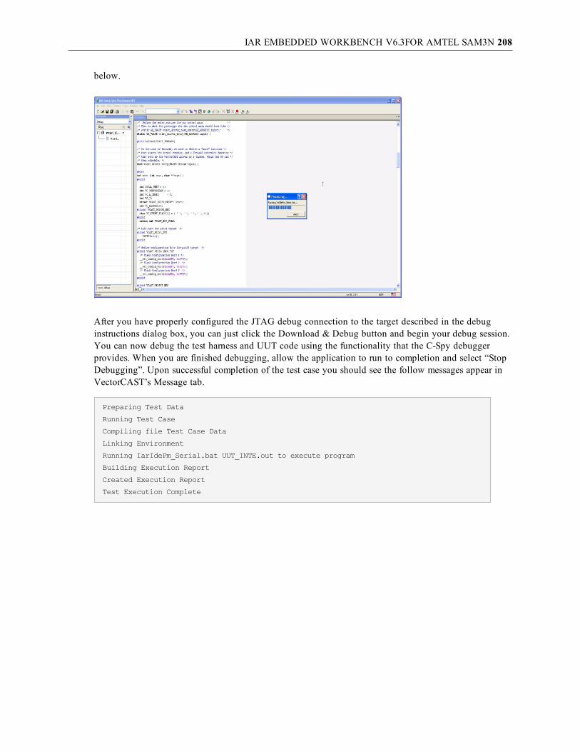
IAR EMBEDDED WORKBENCH V6.3FOR AMTEL SAM3N 208
below.
After you have properly configured the JTAG debug connection to the target described in the debuginstructions dialog box, you can just click the Download & Debug button and begin your debug session.You can now debug the test harness and UUT code using the functionality that the C-Spy debuggerprovides. When you are finished debugging, allow the application to run to completion and select “StopDebugging”. Upon successful completion of the test case you should see the follow messages appear inVectorCAST’s Message tab.
Preparing Test Data
Running Test Case
Compiling file Test Case Data
Linking Environment
Running IarIdePm_Serial.bat UUT_INTE.out to execute program
Building Execution Report
Created Execution Report
Test Execution Complete
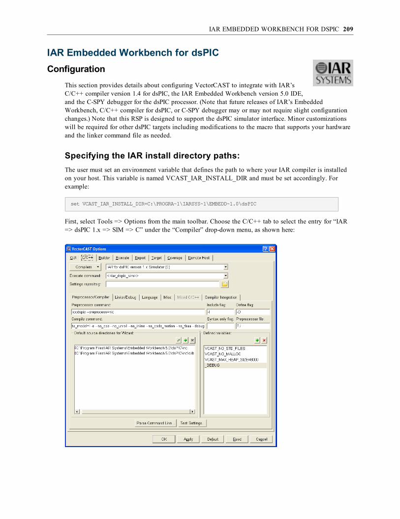
IAR EMBEDDED WORKBENCH FOR DSPIC 209
IAR Embedded Workbench for dsPICConfiguration
This section provides details about configuring VectorCAST to integrate with IAR’sC/C++ compiler version 1.4 for dsPIC, the IAR Embedded Workbench version 5.0 IDE, and the C-SPY debugger for the dsPIC processor. (Note that future releases of IAR’s EmbeddedWorkbench, C/C++ compiler for dsPIC, or C-SPY debugger may or may not require slight configurationchanges.) Note that this RSP is designed to support the dsPIC simulator interface. Minor customizationswill be required for other dsPIC targets including modifications to the macro that supports your hardwareand the linker command file as needed.
Specifying the IAR install directory paths:The user must set an environment variable that defines the path to where your IAR compiler is installedon your host. This variable is named VCAST_IAR_INSTALL_DIR and must be set accordingly. Forexample:
set VCAST_IAR_INSTALL_DIR=C:\PROGRA~1\IARSYS~1\EMBEDD~1.0\dsPIC
First, select Tools => Options from the main toolbar. Choose the C/C++ tab to select the entry for “IAR=> dsPIC 1.x => SIM => C” under the “Compiler” drop-down menu, as shown here:

IAR EMBEDDED WORKBENCH FOR DSPIC 210
IAR installation and target customizations:1. Click the “Linker/Debug” tab.
2. The “Linker Options” text box contains a reference to the linker .xcl file. Replace the iar_lnkdspic_16kRAM.xcl linker file with the appropriate .xcl file for your particular simulatorconfiguration. Note that the default .xcl file provided specifies 16K of RAM, which is theminimum required to support VectorCAST with this compiler.
-B -l vcast_debug.map –xmsnio
$(VCAST_IAR_INSTALL_DIR)\LIB\clib\cldspic2lf.r59
-I$(VCAST_IAR_INSTALL_DIR)\LIB\ -f iar_lnkdspic_16kRAM.xcl
-D_HEAP_SIZE=800 -D_STACK_SIZE=600 -rt -s __program_start
3. You may also adjust the HEAP and STACK size in the same “Linker Options” text box.
4. Modify the device description file as needed in the “Debugger command:” text box. Note thatby default it is set to $(VCAST_IAR_INSTALL_DIR)\Config\io24hj256gp610.ddf.
cspybat dspicproc.dll dspicsim.dll vcast_debug.out
--plugin dspicbat.dll
--backend -B
-p $(VCAST_IAR_INSTALL_DIR)\Config\io24hj256gp610.ddf
-d sim --sim_guard_stacks
These default settings should be sufficient to run the Tutorial example in the VectorCAST/C++ User’sGuide, and it is strongly recommended that you do so before trying to test your application code. Thecompile and link options are initially set to match the defaults provided by IAR’s Embedded Workbenchwhen you create a new project, selecting dsPIC as your target.
It is your responsibility to customize these settings for your particular device, including changing the –cpu compiler switch to match your target CPU, and modifying a linker file that will accommodate thesize of the code under test plus the VectorCAST test harness that is used to drive the code under test.
Note: The size of the test harness is not static – it is dependent on the size and composition of thecode under test. Refer to IAR’s documentation for more information on customizing linker files.
The “Preprocessor/Compiler” tab contains the compiler options that will be used to compile the testharness. The “Linker” tab contains the linker options, libraries to be linked, linker file specification, heapand stack size that will be used to link the test harness. When you are ready to begin testing yourapplication code, a good starting point for these settings would be the actual values used to compile andlink the code you are about to test.
For example, if you are using a target other than the default pic24 target device, you would need tochange the --cpu= option and possibly the –-data model= option on the “Compile Command:”text box.
Specific details and discussion of the options that iccdspic.exe accepts are outside the scope of thisdocument. Refer to IAR’s compiler and linker documentation for more information on this topic.

IAR EMBEDDED WORKBENCH FOR DSPIC 211
Target ExecutionVectorCAST utilizes the IAR application “cspybat.exe” to execute the test harness on the simulator. Thisapplication allows simulator execution to occur without the requirement of manually starting up the IAREmbedded Workbench IDE. The execution occurs automatically and requires no input from the user. Thistest case execution is invoked using the command specified in the “Debugger command” edit box whichcan be found in the Tools => Options dialog box, selecting the C/C++ tab, then the Linker/Debug tab.The default command specifies using the simulator connection by virtue of specifying the dspicsim.dlland passing the –d sim argument.
cspybat dspicproc.dll dspicsim.dll vcast_debug.out
--plugin dspicbat.dll
--backend -B
-p $(VCAST_IAR_INSTALL_DIR)\Config\io24hj256gp610.ddf
-d sim --sim_guard_stacks
After executing a test case on the C-SPY simulator, you see the results displayed in the execution reportwindow. Also, upon completion of the test case, you should also see the following output in the Messagetab across the bottom of VectorCAST:
Running C-SPY Debugger to execute program
Building Execution Report
Created Execution Report
Updating Coverage Data
Test Execution Complete
Just prior to test case execution, VectorCAST copies the test harness executable to a file named vcast_debug.out. The test case executable is UUT_INTE.EXE if you don’t have coverage enabled or UUT_INST.EXE if coverage is enabled. In cases of failed test case execution, the user can possibly get moreinformation as to the nature of the failure by running the debugger command from a DOS shell. To do so,navigate to the environment directory and run the exact same Debugger Command that is found in theTools => Options, C/C++ tab, Linker/Debug tab, edit box “Debugger Command.” The cspybat.exe willprovide you with some indication as to why the target execution is failing. Refer to IAR’s documentationfor more information on the cspybat.exe application.

IAR EMBEDDED WORKBENCH FOR DSPIC 212
Note: VectorCAST runs the Debugger Command as is, but redirects its output to VCAST_STDOUT.DAT with the redirection (‘>’) shell operator.
Target Debug ExecutionTest case Execution with Debug can be performed by right-clicking on a particular test case and selecting“Execute with Debug”. VectorCAST will automatically invoke the IAR Embedded Workbench IDE witha default project and workspace setup. In addition, on the first time the user Executes With Debug, anInformation dialog box will pop up (shown below) that describes what VectorCAST will be doing on theuser’s behalf and the user’s required actions, which basically involves clicking the Download & Debugbutton to initiate the debug session.
Click OK in the Information dialog box and VectorCAST will then bring up the IAR IDE by running theIarIdePm.exe and you will see a “Processing… Abort “ progress box also appear with the IDE as shownbelow.

IAR EMBEDDED WORKBENCH FOR DSPIC 213
At this point you can just click the Download & Debug button and begin your debug session. You cannow debug the test harness and UUT code using the functionality that C-Spy provides. When you arefinished debugging, allow the application to run to completion and select “Stop Debugging” to ensurethat the I/O log file gets written to disk. Upon exiting the debug session and returning control toVectorCAST, if the message “Test case execution aborted” appears in VectorCAST’s Message tab, it ismost likely because the I/O log file was never written. Upon successful completion of the test case youshould see the follow messages appear in VectorCAST’s Message tab.
Preparing Test Data
Running Test Case
Compiling and Linking Input Data File...
Compiling file Test Case Data
Linking Environment
Running IAR IDE to execute program
Building Execution Report
Created Execution Report
Test Execution Complete

IAR EMBEDDED WORKBENCH FOR PIC24 TARGET 214
IAR Embedded Workbench for PIC24 targetConfiguration
This section provides details about configuring VectorCAST to integrate with IAR’sC/C++ compiler version 1.4 for dsPIC, the IAR Embedded Workbench version 5.0 IDE, and the C-SPY debugger for the dsPIC processor. (Note that future releases of IAR’s EmbeddedWorkbench, C/C++ compiler for dsPIC, or C-SPY debugger may or may not require slight configurationchanges.) Note that this RSP is designed to support the dsPIC PIC24 target interface to a custom targetprototype (LMCOTGT). Minor customizations will be required for other PIC24 targets includingmodifications to the macro that supports your hardware and the linker command file as needed.
Specifying the IAR install directory paths:The user must set an environment variable that defines the path to where your IAR compiler is installedon your host. This variable is named VCAST_IAR_INSTALL_DIR and must be set accordingly. Forexample:
set VCAST_IAR_INSTALL_DIR=C:\PROGRA~1\IARSYS~1\EMBEDD~1.0\dsPIC
First, select Tools => Options from the main toolbar. Choose the C/C++ tab to select the entry for “IAR=> dsPIC 1.x => LMCOTGT => C” under the “Compiler” drop-down menu, as shown here:

IAR EMBEDDED WORKBENCH FOR PIC24 TARGET 215
IAR installation and target customizations:1. Click the “Linker/Debug” tab.
2. The “Linker Options” text box contains a reference to the linker .xcl file. Replace the iar_pic24_lnkdspic.xcl linker file with the appropriate .xcl file for your particular targetconfiguration. Note that the default .xcl file provided specifies 16K of RAM, which is theminimum required to support VectorCAST with this compiler. The linker option default settingsare shown below.
-B -l vcast_debug.map -xmsnio -I$(VCAST_IAR_INSTALL_DIR)\LIB\ -f $(VECTORCAST_DIR)\DATA\iar\dspic\tgt\iar_pic24_lnkdspic.xcl
$(VCAST_IAR_INSTALL_DIR)\LIB\dlib\dldspic2lf.r59 -e_ScanfSmall=_Scanf -D_HEAP_SIZE=800 -D_STACK_SIZE=800 -rt -Ocoff=vcast_debug.cof -s __program_start
3. You may also adjust the HEAP and STACK size in the same “Linker Options” text box.
4. Modify the device description file as needed in the “Debugger command:” text box. Note thatby default it is set to $(VCAST_IAR_INSTALL_DIR)\Config\io24hj256gp610.ddf.
cspybat dspicproc.dll dspicemu_ri.dll vcast_debug.out --plugin dspicbat.dll --backend -B -p
$(VECTORCAST_DIR)\DATA\iar\dspic\tgt\io24fj256gb110.ddf -d "emuRealIce"
These default settings should be sufficient to run the Tutorial example in the VectorCAST/C++ User’sGuide, and it is strongly recommended that you do so before trying to test your application code. Thecompile and link options are initially set to match the defaults provided by IAR’s Embedded Workbenchwhen you create a new project, selecting dsPIC as your target.
It is your responsibility to customize these settings for your particular device, including changing the –cpu compiler switch to match your target CPU, and modifying a linker file that will accommodate thesize of the code under test plus the VectorCAST test harness that is used to drive the code under test.
Note: The size of the test harness is not static – it is dependent on the size and composition of thecode under test. Refer to IAR’s documentation for more information on customizing linker files.
The “Preprocessor/Compiler” tab contains the compiler options that will be used to compile the testharness. The “Linker” tab contains the linker options, libraries to be linked, linker file specification, heapand stack size that will be used to link the test harness. When you are ready to begin testing yourapplication code, a good starting point for these settings would be the actual values used to compile andlink the code you are about to test.
For example, if you are using a target other than the default pic24 target device, you would need tochange the -cpu= option and possibly the –data model= option on the “Compile Command:” textbox.
Specific details and discussion of the options that iccdspic.exe accepts are outside the scope of thisdocument. Refer to IAR’s compiler and linker documentation for more information on this topic.
Target ExecutionThe warning dialog shown below is displayed the first time you execute a test case on the target to warn

IAR EMBEDDED WORKBENCH FOR PIC24 TARGET 216
the user about the slow I/O mechanism utilized through the JTAG interface on this target.
VectorCAST utilizes the IAR application “cspybat.exe” to execute the test harness on the target. Notethat the connection to the target in this case was through a Microchip MPLAB Real-ICE emulator. Thisapplication allows target execution to occur without the requirement of manually starting up the IAREmbedded Workbench IDE. The execution occurs automatically and requires no input from the user. Thistest case execution is invoked using the command specified in the “Debugger command” edit box whichcan be found in the Tools => Options dialog box, selecting the C/C++ tab, then the Linker/Debug tab.The default command specifies using the target emulator connection by virtue of specifying thedspicemu_ri.dll and passing the –d "emuRealIce" argument.
cspybat dspicproc.dll dspicemu_ri.dll vcast_debug.out --plugin dspicbat.dll --backend -B -p $(VECTORCAST_DIR)\DATA\iar\dspic\tgt\io24fj256gb110.ddf -d "emuRealIce"
After executing a test case you see the results displayed in the execution report window. Also, uponcompletion of the test case, you should also see the following output in the Message tab across thebottom of VectorCAST:
Running C-SPY Debugger to execute program

IAR EMBEDDED WORKBENCH FOR PIC24 TARGET 217
Building Execution Report
Created Execution Report
Updating Coverage Data
Test Execution Complete
Just prior to test case execution, VectorCAST copies the test harness executable to a file named vcast_debug.out. The test case executable is UUT_INTE.EXE if you don’t have coverage enabled or UUT_INST.EXE if coverage is enabled. In cases of failed test case execution, the user can possibly get moreinformation as to the nature of the failure by running the debugger command from a DOS shell. To do so,navigate to the environment directory and run the exact same Debugger Command that is found in theTools => Options, C/C++ tab, Linker/Debug tab, edit box “Debugger Command.” The cspybat.exe willprovide you with some indication as to why the target execution is failing. Refer to IAR’s documentationfor more information on the cspybat.exe application.
Note: VectorCAST runs the Debugger Command as is, but redirects its output to VCAST_STDOUT.DAT with the redirection (‘>’) shell operator.
Target Debug ExecutionThe warning dialog shown below is displayed the first time you execute a test case on the target to warnthe user about the slow I/O mechanism utilized through the JTAG interface on this target.
Test case Execution with Debug can be performed by right-clicking on a particular test case and selecting“Execute with Debug”. VectorCAST will automatically invoke the IAR Embedded Workbench IDE witha default project and workspace setup. In addition, on the first time the user Executes With Debug, anInformation dialog box will pop up (shown below) that describes what VectorCAST will be doing on theuser’s behalf and the user’s required actions, which basically involves clicking the Download & Debugbutton to initiate the debug session.

IAR EMBEDDED WORKBENCH FOR PIC24 TARGET 218
Click OK in the Information dialog box and VectorCAST will then bring up the IAR IDE by running theIarIdePm.exe and you will see a “Processing… Abort “ progress box also appear with the IDE as shownbelow.
At this point you can just click the Download & Debug button and begin your debug session. You cannow debug the test harness and UUT code using the functionality that C-Spy provides. When you arefinished debugging, allow the application to run to completion and select “Stop Debugging” to ensurethat the I/O log file gets written to disk. Upon exiting the debug session and returning control toVectorCAST, if the message “Test case execution aborted” appears in VectorCAST’s Message tab, it ismost likely because the I/O log file was never written. Upon successful completion of the test case youshould see the follow messages appear in VectorCAST’s Message tab.

IAR EMBEDDED WORKBENCH FOR PIC24 TARGET 219
Preparing Test Data
Running Test Case
Compiling and Linking Input Data File...
Compiling file Test Case Data
Linking Environment
Running IAR IDE to execute program
Building Execution Report
Created Execution Report
Test Execution Complete

IAR EMBEDDED WORKBENCH 5.X FOR AMTEL AVR 220
IAR Embedded Workbench 5.x for Amtel AVRConfiguration
This section provides details about configuring VectorCAST to integrate with IAR’sEmbedded Workbench version 5.51 and C-SPY debugger for the Amtel AVR family ofmicrocontrollers. (Future releases of Embedded Workbench might require slight configuration changes.)Note that this RSP is designed to support the simulator for the generic –v3 enhanced core version of theAVR processor family. Minor customizations will be required for other AVR target simulations includingmodifications to the macro that supports your hardware and the linker command file.
Specifying the IAR install directory paths:The user must set an environment variable, VCAST_IAR_INSTALL_DIR, that defines the directorywhere your version of the IAR compiler is installed. The user must also be sure that the compiler andlinker commands are on your path as shown in the example below. Adjust the path as needed for theinstall location on your machine.
set VCAST_IAR_INSTALL_DIR=C:\PROGRA~1\IARSYS~1\EMBEDD~1.4\
set path=C:\PROGRA~1\IARSYS~1\EMBEDD~1.4\avr\bin;%path%
set path=C:\PROGRA~1\IARSYS~1\EMBEDD~1.4\common\bin;%path%
First, select Tools => Options from the main toolbar. Choose the C/C++ tab to select the entry for “IAR=> AMTEL AVR 5.51 => C” under the “Compiler” drop-down menu, as shown here:
These default settings should be sufficient to run the Tutorial example in the VectorCAST/C++ User’sGuide, and it is strongly recommended that you do so before trying to test your application code. Thecompile and link options are initially set to match the defaults provided by IAR’s Embedded Workbenchwhen you create a new project, selecting “-v3 –enhanced_core” as your processor configuration.

IAR EMBEDDED WORKBENCH 5.X FOR AMTEL AVR 221
It is your responsibility to customize these settings for your particular device, including changing the –cpu compiler switch or the generic processor switch setting –v4 to match your target processor, andmodifying a linker file that will accommodate the size of the code under test plus the VectorCAST testharness that is used to drive the code under test.
Note: The size of the test harness is not static – it is dependent on the size and composition of thecode under test. Refer to IAR’s C/C++ Compiler Reference Guide documentation for moreinformation on customizing linker files, the desired memory model, and the C runtimeenvironment.
After determining what the appropriate settings are for your desired processor target, then you can makethe changes required in VectorCAST on the compiler and linker command lines which you can get to byselecting Tools=>Options=>C/C++ tab and editing in the “Preprocessor/Compiler” and “Linker/Debug”tabs.
As an example of such a processor customization, to change the default settings to –v4 processor andlarge memory model, the user would change the following settings in on the compiler and linkercommand lines. The user must also modify the ExecCspySimAvr.bat file to specify the desired processortype.
l Change -v3 to -v4 on the compiler command
l Change lnk3s.xcl to lnk4l.xcl on the linker command
l Change -v3 to -v4 in the ExecCspySimAvr.bat file
Target ExecutionVectorCAST utilizes the IAR application “cspybat.exe” to execute the test harness on the simulator. Thisapplication allows target simulator execution to occur without the requirement of starting IAR EmbeddedWorkbench IDE or C-Spy debugger. The execution occurs automatically and requires no input from theuser. The test case execution is invoked using the bat file, ExecCspySimAvr.bat, which is specified in theexecution method for this compiler template. The default ExecCspySimAvr.bat specifies using a simulatorconnection to the –v3 processor target. The contents of the ExecCspySimAvr.bat are shown below thatyou may need to customize for your target.
@echo off
cspybat.exe avrproc.dll avrsim.dll %1 --plugin avrlibsupportbat.dll --backend -B "-v3" "--enhanced_core" "--disable_internal_eeprom" "-d" "sim"
Upon completion of the test case, you should see the following output in the Message tab across thebottom of VectorCAST:
Running ExecCspySimAvr.bat C:\bub\vcast\iar_avr_5x_sim03\S1\UUT_INTE.EXE > VCAST_STDOUT.DAT to execute program
Building Execution Report
Created Execution Report
Test Execution Complete

IAR EMBEDDED WORKBENCH 5.X FOR AMTEL AVR 222
Target Debug ExecutionTest case Execution with Debug can be performed by right-clicking on a particular test case and selecting“Execute with Debug”. VectorCAST will automatically run the debugger bat file, IarIdePm.bat, whichinvokes the IAR Embedded Workbench IDE with a default project and workspace setup. In addition, onthe first time the user Executes With Debug, VectorCAST will display a text file that describes whatVectorCAST will be doing on the user’s behalf and the user’s required actions to initiate the debugsession.
VectorCAST will then bring up the IAR IDE by running the IarIdePm.exe and you will see a“Processing… Abort “ progress box also appear with the IDE as shown below. Follow the instructionsdescribed in the text file to configure the terminal I/O, and download and debug the executable.

IAR EMBEDDED WORKBENCH 5.X FOR AMTEL AVR 223
You can now debug the test harness and UUT code using the functionality that C-Spy provides. Whenyou are finished debugging, allow the application to run to completion and select “Stop Debugging” toensure that the I/O log file gets written to disk. Upon exiting the debug session and returning control toVectorCAST, if the message “Test case execution aborted” appears in VectorCAST’s Message tab, it ismost likely because the I/O log file was never written. Upon successful completion of the test case youshould see the follow messages appear in VectorCAST’s Message tab.
Preparing Test Data
Running Test Case
Compiling file Test Case Data
Linking Environment
Running IarIdePm.bat C:\bub\vcast\iar_avr_5x_sim03\S1\UUT_INTE.EXE > VCAST_STDOUT.DAT toexecute program
Building Execution Report
Created Execution Report
Test Execution Complete
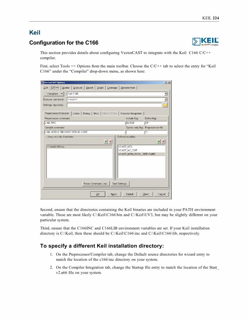
KEIL 224
KeilConfiguration for the C166
This section provides details about configuring VectorCAST to integrate with the Keil C166 C/C++compiler.
First, select Tools => Options from the main toolbar. Choose the C/C++ tab to select the entry for “KeilC166” under the “Compiler” drop-down menu, as shown here:
Second, ensure that the directories containing the Keil binaries are included in your PATH environmentvariable. These are most likely C:\Keil\C166\bin and C:\Keil\UV3, but may be slightly different on yourparticular system.
Third, ensure that the C166INC and C166LIB environment variables are set. If your Keil installationdirectory is C:\Keil, then these should be C:\Keil\C166\inc and C:\Keil\C166\lib, respectively.
To specify a different Keil installation directory:1. On the Preprocessor/Compiler tab, change the Default source directories for wizard entry to
match the location of the c166\inc directory on your system.
2. On the Compiler Integration tab, change the Startup file entry to match the location of the Start_v2.a66 file on your system.

KEIL 225
3. Click Apply to save the changes.
The default command settings should be sufficient to run the Tutorial example in the VectorCAST/C++User’s Guide, and it is strongly recommended that you do so before trying to test your application code.
It is your responsibility to customize these settings for your particular device and developmentenvironment.
The “Preprocessor/Compiler” and “Compiler Integration” tabs contain the compiler commands andoptions that will be used to compile the test harness. The startup file on the Compiler Integration tab iscopied into the environment directory as start.a6. The assembler command on the Compiler Integrationtab is used to assemble the startup file. The size of the memory pool is controlled by the defined variableVCAST_MEM_POOL_SIZE. It is set to 0x800 by default. The memory pool and some configurationflags are set up in the vcast_keil_setup function in the vcast_keil_setup.h file in the environmentdirectory. The template of the vcast_keil_setup.h file is in the DATA directory of your VectorCASTinstallation. If you change this version of the setup file, all future environments will be affected.
If you are using C++, the Pre-compile command on the Compiler Integration tab specifies the commandfor the EC166 compiler. The Pre-compile extension specifies the file extension of the intermediate filegenerated by the EC166 Compiler. After that file is generated, the Compile command from thePreprocessor/Compiler tab is invoked to obtain an object file.

KEIL 226
The “Linker” tab contains the linker commands and options that will be used to link the test harness.
When you are ready to begin testing your application code, a good starting point for these settings wouldbe the actual values used to compile and link the code you are about to test.
Specific details and discussion of the options that c166.exe and ec166.exe accept is outside the scope ofthis document. Refer to Keil Software’s compiler and linker documentation for more information on thistopic.

KEIL 227
Lastly, click OK to save the settings and close the options dialog.
Configuration for the C51This section provides details about configuring VectorCAST to integrate with the Keil C51 C/C++compiler.
First, select Tools => Options from the main toolbar. Choose the C/C++ tab to select the entry for “KeilC51” under the “Compiler” drop-down menu, as shown here:
Second, ensure that the directories containing the Keil binaries are included in your PATH environmentvariable. These are most likely C:\Keil\C51\bin and C:\Keil\UV3, but may be slightly different on yourparticular system.
To specify a different Keil installation directory:1. On the Preprocessor/Compiler tab, change the Default source directories for wizard entry to
match the location of the c51\inc directory on your system.
2. On the Compiler Integration tab, change the Startup file entry to match the location of theSTARTUP.A51 file on your system.

KEIL 228
3. Click Apply to save the changes.
The default command settings should be sufficient to run the Tutorial example in the VectorCAST/C++User’s Guide, and it is strongly recommended that you do so before trying to test your application code.
It is your responsibility to customize these settings for your particular device and developmentenvironment.
The “Preprocessor/Compiler” and “Compiler Integration” tabs contain the compiler commands andoptions that will be used to compile the test harness. The startup file on the Compiler Integration tab iscopied into the environment directory. The assembler command on the Compiler Integration tab is used toassemble the startup file. The size of the memory pool is controlled by the defined variable VCAST_MEM_POOL_SIZE. It is set to 0x950 by default. The memory pool and some configuration flags are setup in the vcast_keil_setup function in the vcast_keil_setup.h file in the environment directory. Thetemplate of the vcast_keil_setup.h file is in the DATA directory of your VectorCAST installation. If youchange this version of the setup file, all future environments will be affected.
The “Linker” tab contains the linker commands and options that will be used to link the test harness.

KEIL 229
When you are ready to begin testing your application code, a good starting point for these settings wouldbe the actual values used to compile and link the code you are about to test.
Specific details and discussion of the options that c51.exe and lx51.exe accept is outside the scope of thisdocument. Refer to Keil Software’s compiler and linker documentation for more information on this topic.
Lastly, click OK to save the settings and close the options dialog.
Target ExecutionFor execution with the Keil mvision debugger, VectorCAST copies the executable to a file calledkeil.exe. Then it will automatically invoke the mvision debugger with the project file keil.uv2 if you areusing the C166 or keil_c51.uv2 for the C51. The project file invokes a script file called keil_execute.iniwhich is similar to the following:
reset
load keil.exe
slog > VCAST_STDOUT.DAT
bs vCAST_END
g
slog off
bk *
reset
reset map
exit
The script loads the executable, sends output to a file, runs the executable, and exits the debugger. Thetemplate for the keil_execute.ini script is in the DATA\keil directory of your VectorCAST installation. Ifyou change this version of the script, all future environments will be affected. The template for thekeil.uv2 file is also in the DATA directory.
Target Debug ExecutionFor debugging with the Keil mvision debugger, VectorCAST copies the executable to a file calledkeil.exe. Then it will automatically invoke the mvision debugger with the project file keil_debug.uv2 forthe C166 or keil_c51_debug.uv2 for the C51. The project file invokes a script file called keil_debug.iniwhich is similar to the following:
reset
load keil.exe
slog > VCAST_STDOUT.DAT
bs vCAST_END
bs vCAST_END__Fv
The script loads the executable, starts sending output to a file, and sets a breakpoint at the end of theprogram. The template for the keil_debug.ini script is in the DATA directory of your VectorCASTinstallation. If you change this version of the script, all future environments will be affected. Thetemplates for the keil_debug.uv2 file and the keil_c51_debug.uv2 file are also in the DATA directory.
If you allow the execution to reach the end of the driver main program, you can get the execution resultsby calling

KEIL 230
slog off
in the debugger to close the output file before exiting. The first time you execute with debug, you willget a reminder of how to do this:

KEIL FOR ARM 231
Keil for ARMConfiguration
This section provides details about configuring VectorCAST to integrate with the Keil compiler for ARMchips. Two types of chips are supported out-of-the-box on a simulator: the LPC2106 from Phillips and theLM3S6911 from Luminary Micro (now Texas Instruments). Support for additional chips from the same orother families of chips can also be arranged. For support for other targets, please contact yourVectorCAST representative.
Before launching VectorCAST, please ensure that Keil for ARM is correctly set. When using Keil forARM with VectorCAST, this is not done automatically. There are a total of three different directories thatneed to become part of your PATH environment variable. An example script under DOS could look likethe following:
set RVCT31INC=C:\Keil\ARM\RV31\INC
set RVCT31LIB=C:\Keil\ARM\RV31\lib
set PATH=C:\Keil\ARM\BIN31;C:\Keil\UV3;%PATH%
You should remember to either (1) set these directories permanently in your PATH environment variableor (2) set these temporarily in an OS shell. In the latter case, please remember to launch VectorCAST fromwithin that shell.
Thereafter, please select the appropriate template from VectorCAST/C++.

KEIL FOR ARM 232
In VectorCAST, just select the appropriate compiler template (Keil => ARM). Please note that dependingon your installation, the template may need amendments. For instance, the Assembler command (locatedon the Compiler Integration subtab) lists an include directory (for instance, -I"C:\Keil\ARM\INC\Luminary"). This needs to be changed if this directory does not exist in yourenvironment.
Likewise, the following steps are or may be required in the case of the following types of boards:
Luminary Micro boards (such as the LM3S6911)The integration requires that the StellarisWare is downloaded and installed on your host. This freedownload from https://www.luminarymicro.com/ (search for “StellarisWare”) contains additional librariesthat make it possible, among other things, to communicate through UART. VectorCAST leverages theselibraries. It is therefore important they are installed.
Depending on where the StellarisWare libraries are installed, the linker command (Linker/Debug sub-tab)may also need to be amended (please find --userlibpath "C:\StellarisWare\driverlib\rvmdk" within thelinker command and amend the path as needed).
For C++ on versions of Keil before 3.4It was found on version 3.2 that the Assembler command is incorrect, and will cause a failure in codestartup sequence. Please use this assembler command, which does not specify MICROLIB.
armasm --device DLM -g --apcs=interwork
-I "C:\Keil\ARM\INC\Luminary" –xref
For C++ on Keil 3.4For version 3.4 of the compiler, the full Assembler command line should be:
armasm --device DLM -g --apcs=interwork
--pd "__MICROLIB SETA 1"
-I "C:\Keil\ARM\INC\Luminary" –xref
Please note that not specifying MICROLIB under version 3.4 will cause a failure in code startup.
It is your responsibility to customize these settings for your particular device and developmentenvironment. Please note that these changes will be saved as long as you will be using the same workingdirectory. For more information about this, please contact your Vector Software representative.
Target ExecutionUpon successful compilation and linkage, VectorCAST will automatically launch Keil microVision IDEto execute the test harness on a board or simulator.

KEIL FOR ARM 233
Unless there is an error, there is no need for you to close Keil – it should close automatically. If theexecution fails, you may need to forcefully close Keil for ARM by pressing the red stop button in theupper left corner of the Keil debugger interface. If all else fails, press Ctrl-Alt-Del (under Windows) andshut down the Uv3.exe process.
If the execution fails, you may consider trying to run a test case from the debugger (next section).
Target Debug ExecutionTest Execution with Debug functions similarly to normal execution, except a breakpoint is set in themain function so execution stops there. You can manually set breakpoints, step through source anddisassembly, and view data as you would during a normal debug session.
Launching a debug execution of the test harness under Keil will launch the Keil IDE. You can thereforeexecute using the execute button at the top right (highlighted in red). A breakpoint is already set at theend of the test harness for your convenience. Once finished, merely close the instance of the Keil IDEVectorCAST launched and the results of the test will be read automatically by VectorCAST. If the testharness is not allowed to run until the end, an error may occur.

KEIL FOR ARM 234

KEIL FOR ARM CORTEX M3 235
Keil for ARM Cortex M3Configuration
This section provides details about configuring VectorCAST to integrate with the Keil for ARM CortexM3 compiler. This chapter describes the RSP implementation for a custom target with a STM32f103ZEprocessor on board. Support for additional chips from the same or other families of chips can also bearranged. This RSP was implemented using the Keil uVision4 IDE. (Version:µVision V4.21.0.0). Forsupport on other targets, or other versions of the Keil IDE, please contact your VectorCASTrepresentative.
Before launching VectorCAST, you must ensure that Keil for ARM configuration is correctly set. Whenusing Keil for ARM with VectorCAST, this is not done automatically. The user should set the followingenvironment variables according to the installation location of Keil on your host PC before runningVectorCAST.
set RVCT31INC=C:\Keil\ARM\RV31\INC
set RVCT31LIB=C:\Keil\ARM\RV31\lib
set PATH=C:\Keil\ARM\BIN40;C:\Keil\UV4;%PATH%
set VCAST_KEIL_ARM_INSTALL_DIR=C:\Keil\
You should remember to either (1) set these directories permanently in your PATH environment variableor (2) set these temporarily in an OS shell. In the latter case, please remember to launch VectorCAST fromwithin that shell.
Thereafter, please select the appropriate template from VectorCAST/C++ when building your new testenvironment.

KEIL FOR ARM CORTEX M3 236
In VectorCAST, select the appropriate compiler template (Keil => ARM => STM32F10x => uVision4=> 4.2 => HwTgt => C). Please note that depending on your installation, the template may needamendments.
Instrumentation Trace Macrocell (ITM) ConfigurationThe ARM Cortex M3 processor core provides several system debug components. One of those systemdebug components is the Instrumentation Trace Macocell (ITM). The ITM allows for application-driventrace source that supports printf style debugging. Debug control and data access occurs through theAdvanced High-performanceBus-Access Port (AHB-AP) interface. This interface is driven by either theSerial Wire Debug Port (SW-DP) or Serial Wire JTAG Debug Port (SWJ-DP) components. This RSPintegration utilizes the capabilities of the ITM to capture test result data from the target. Theconfiguration of the ITM stimulus ports and the Flash programming algorithm for this target is providedinside the Keil uVision project file that is copied to your test environment directory automatically byVectorCAST during the test environment creation process. The project file name is STM32_tgt.uvproj.The relevant project settings with respect to the target connection and ITM configuration are shown inthe series of screen shots below. The specific settings displayed here may have to be modified to supportyour specific target clock speeds and selected debugger probe.
It is your responsibility to customize these settings for your particular device and developmentenvironment. Please note that these changes will be saved as long as you will be using the same workingdirectory. For more information about this, please contact your Vector Software representative.
The following dialog is accessed from the Project => Options Menu.

KEIL FOR ARM CORTEX M3 237
If you switch to the Utilities tab and then click “Settings” button, you will get the following view, whichallows you to set up the Debug connection:
Trace:

KEIL FOR ARM CORTEX M3 238
and Flash Download Parameters:
Integration NotesThis RSP integration involved using the Keil Ulink Pro debugger probe to connect to the target board.This probe receives power from the USB connection to the host PC. Note that if you experiencedifficulties connecting to the target, try removing other USB connections from your host PC, and be surethat you are not going through a USB hub. On some host PC’s the USB connections in the front of themachine may go through an internal USB hub, and you may have better luck trying the USB connectionsin the back of the machine that may go directly to the USB interfaces on the motherboard.
Note that two of the environment files that are included in the default template for this RSP, itm.h andconfig.h, are included so that a sample tutorial build will work to demonstrate the RSP functionality.Occasionally the user may choose to delete these files and point to their own configuration including

KEIL FOR ARM CORTEX M3 239
something other than the default itm.h and config.h which were derived from the base install directory ofthe keil compiler tool chain.
Target ExecutionUpon successful compilation and linkage, VectorCAST will automatically launch the Keil uVision IDEto execute the test harness on the board. VectorCAST uses a bat file to control both the “Execute” andthe “Execute with Debug” methods. The bat file accepts several parameters, the first for the Keil projectfile that will be used when VectorCAST invokes the uVision IDE, and the second, a flag to indicate ifyou are executing in EXECUTE or DEBUG mode. The command for the execute mode is
keil_stm32_execute.bat STM32_tgt.uvproj EXECUTE
VectorCAST will automatically invoke the uVision IDE, download/program the harness executable intotarget Flash, run the executable, and exit the IDE upon successful completion of the harness. VectorCASTwill automatically copy the appropriate execute .ini file (keil_stm32_tgt_exec.ini) to the project ini file(keil_stm32_tgt.ini) to enable the execute capability. Unless there is an error, there is no need for you toclose Keil – it should close automatically. If the execution fails, you may need to forcibly close Keil forARM by pressing the red stop button in the upper left corner of the Keil debugger interface. If all elsefails, press Ctrl-Alt-Del (under Windows) and shut down the Uv4.exe process.
If the execution fails, you may consider trying to run a test case from the debugger (next section).
Target Debug ExecutionTest Execution with Debug functions similarly to normal execution, except VectorCAST will not run theexecutable automatically. The “Execute with Debug” command that gets executed is the following:
keil_stm32_execute.bat STM32_tgt.uvproj DEBUG

KEIL FOR ARM CORTEX M3 240
VectorCAST will automatically copy the appropriate debug .ini file (keil_stm32_tgt_debug.ini) to theproject ini file (keil_stm32_tgt.ini) to enable the debug capability. You can manually set breakpoints,step through source and disassembly, and view data as you would during a normal debug session.
Launching a debug execution of the test harness under Keil will launch the Keil IDE and you canexecute using the execute button at the top right (highlighted in red). A breakpoint is already set at theend of the test harness for your convenience. Once finished, merely close the instance of the Keil IDEthat VectorCAST launched and the results of the test will be read automatically by VectorCAST. If thetest harness is not allowed to run until the end, an error may occur.
While debugging, the user can view test result data that is getting transmitted back to the host via theITM stimulus ports by selecting the “View => Serial Windows => Debug (printf) Viewer” in the uVisionIDE as shown below.

KEIL FOR ARM CORTEX M3 241
When you reach the end of the harness execution, i.e. reached the vCAST_END breakpoint that was setfor this debug environment, you can simply exit out of the debugger and control will be switched back toVectorCAST to display your test results.
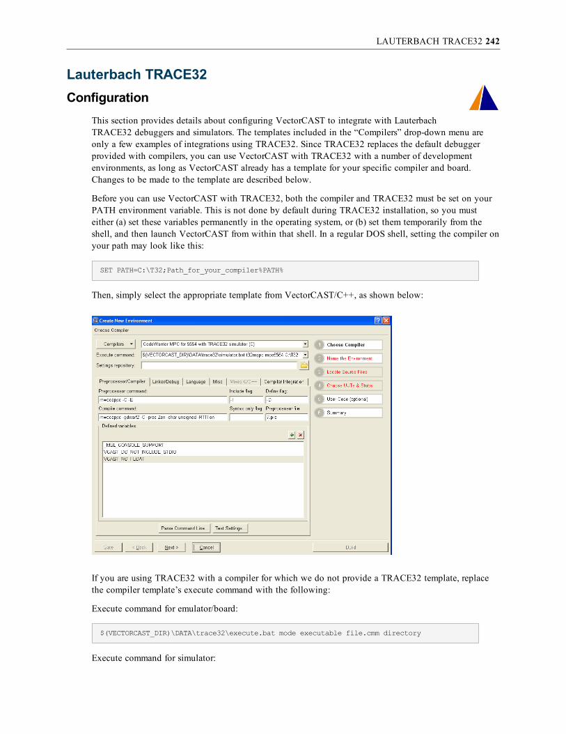
LAUTERBACH TRACE32 242
Lauterbach TRACE32Configuration
This section provides details about configuring VectorCAST to integrate with LauterbachTRACE32 debuggers and simulators. The templates included in the “Compilers” drop-down menu areonly a few examples of integrations using TRACE32. Since TRACE32 replaces the default debuggerprovided with compilers, you can use VectorCAST with TRACE32 with a number of developmentenvironments, as long as VectorCAST already has a template for your specific compiler and board.Changes to be made to the template are described below.
Before you can use VectorCAST with TRACE32, both the compiler and TRACE32 must be set on yourPATH environment variable. This is not done by default during TRACE32 installation, so you musteither (a) set these variables permanently in the operating system, or (b) set them temporarily from theshell, and then launch VectorCAST from within that shell. In a regular DOS shell, setting the compiler onyour path may look like this:
SET PATH=C:\T32;Path_for_your_compiler%PATH%
Then, simply select the appropriate template from VectorCAST/C++, as shown below:
If you are using TRACE32 with a compiler for which we do not provide a TRACE32 template, replacethe compiler template’s execute command with the following:
Execute command for emulator/board:
$(VECTORCAST_DIR)\DATA\trace32\execute.bat mode executable file.cmm directory
Execute command for simulator:

LAUTERBACH TRACE32 243
$(VECTORCAST_DIR)\DATA\trace32\simulator.bat executable chip directory
where:
mode is SERIAL | NON_SERIAL If a serial port is available on your board and that you have thenecessary code to initialize the serial port, replace mode with SERIAL. In addition, in Options => Targettab, both “Execute using stdout only” and “I/O uses stdout only” should be turned on.
If a serial port is not available, replace mode with NON_SERIAL. In addition, in Options =>Target tab,turn on both “Execute using stdout only” and “Buffer I/O.”
executable: The name of the executable to be used to invoke TRACE32. This depends on your chip. Forinstance, the name of the executable to be used with PPC/MPC chip is t32mppc.exe, so you can pass int32mppc. To learn which executable should be used, select the Start menu entry you usually use tolaunch TRACE32, right-click on the entry and note the name of the executable.
file.cmm: The name of the .cmm script file to be used. To generate this, you must (1) look at the .cmm fileyou are using during regular development, (2) copy any parts prior to the download of the image, and (3)copy from MPC5554.cmm (which is installed in %VECTORCAST_DIR%\DATA\trace32 directory) thelast parts, from the download of the data to the end of the file. Then, provide the name of your file in theexecute command.
chip: The name of the chip that is to be simulated. This information can be retrieved from the .cmm fileassociated with the simulator.
directory: The path to the TRACE32 installation, usually C:\T32.
An example of a valid execute command would look like this:
Example command for the emulator/board:
$(VECTORCAST_DIR)\DATA\trace32\execute.bat SERIAL t32mppc mpc5554.cmm C:\T32
Example command for the simulator:
$(VECTORCAST_DIR)\DATA\trace32\simulator.bat t32mppc mpc5554 C:\T32
In addition, you should also make similar modifications to the debug command, which can be retrievedfrom the Options => C/C++ => Linker/Debug tab:
Debugger command for emulator/board:
$(VECTORCAST_DIR)\DATA\trace32\execute.bat mode executable file.cmm directory
However, the file.cmm file that is passed in should be another file which includes (1) the parts used forenvironment initialization, which come from the .cmm file used for ordinary development and (2) thelatest part from MPC5554_debug.cmm (which is installed in %VECTORCAST_DIR%\DATA\trace32directory), from the download of the target to the end of the file.
Debugger command for simulator:
$(VECTORCAST_DIR)\DATA\trace32\simulator_debug.bat executable chip directory

LAUTERBACH TRACE32 244
Note that you must use simulator_debug.bat, not simulator.bat. The arguments are the same as above.
In addition, in the case of emulators and boards, you must copy the .cmm file in your environment. Go toOptions => C/C++ => Misc and select both the regular and debug version of the .cmm files describedabove.
Finally, some compiler templates need some tune-in to work with TRACE32. For instance, Wind RiverCompiler (ex-Diab) requires the user to pass in the –Xelf argument to the linker command to generate anELF executable file. Refer to your compiler manual to learn how to guarantee your compiler will generatean ELF or another file format compatible with TRACE32.
It is your responsibility to customize these settings for your particular device and developmentenvironment. Please note that these changes will be saved as long as you will be using the same workingdirectory. For more information about this, please contact your Vector Software representative.
Target ExecutionIn SERIAL mode, the $VECTORCAST_DIR\IO\comreader.exe executable is used to record the results oftarget execution. The default settings are port "COM1", baud 9600, no parity, 8 data bits, and 1 stop bit.If you need other settings, you can specify a configuration file with the VCAST_SERIAL_CFGenvironment variable. The file specified by VCAST_SERIAL_CFG should have each option on a separateline. For example, to use the COM2 port, you could use these settings:
COM2
9600
8
N
1
The comreader is started before test execution and stops when the debugger exits. Remember to close anyother applications, such as HyperTerminal, that are reading from the same port, before executing tests.
Regular target execution will open a TRACE32 window, execute the code, save the data andautomatically close the TRACE32 window upon harness termination. In the case of a problem, TRACE32will generate an error and interrupt script execution. This will help you (or VectorCAST TechnicalSupport) to troubleshoot the situation. However, in order to return to VectorCAST you must close theTRACE32 instance that was open during execution.
In addition, if using TRACE32 on a board using the SERIAL mode, another executable calledcomreader.exe will be launched. In case of problems, comreader.exe will wait for data to come from theserial port. However, the data may never come. Use the Windows Task Manager to kill this process.
Also, keep in mind that in the SERIAL mode, comreader.exe will use the default settings for serial portmonitoring.
The test harness will execute on the TASKING Script Debugger entirely automatically. The ScriptDebugger’s interface will not be launched.
Target Debug ExecutionTest Execution with Debug functions similarly to normal execution, except a breakpoint is set in the
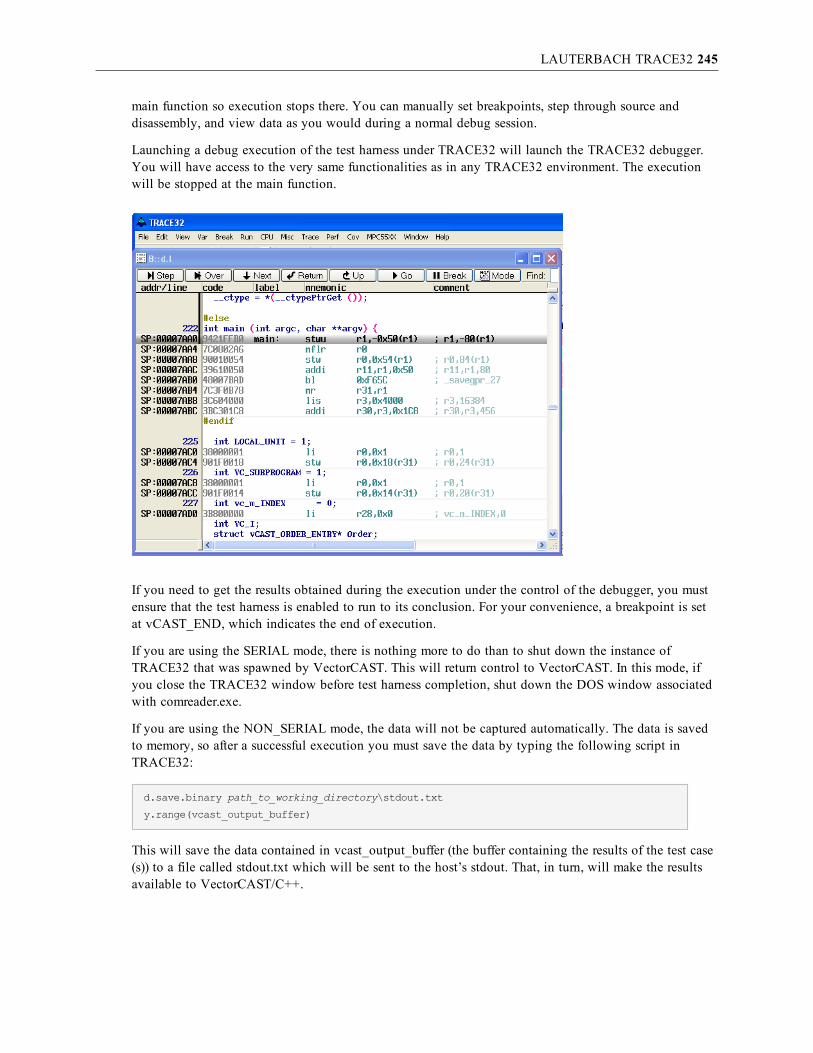
LAUTERBACH TRACE32 245
main function so execution stops there. You can manually set breakpoints, step through source anddisassembly, and view data as you would during a normal debug session.
Launching a debug execution of the test harness under TRACE32 will launch the TRACE32 debugger.You will have access to the very same functionalities as in any TRACE32 environment. The executionwill be stopped at the main function.
If you need to get the results obtained during the execution under the control of the debugger, you mustensure that the test harness is enabled to run to its conclusion. For your convenience, a breakpoint is setat vCAST_END, which indicates the end of execution.
If you are using the SERIAL mode, there is nothing more to do than to shut down the instance ofTRACE32 that was spawned by VectorCAST. This will return control to VectorCAST. In this mode, ifyou close the TRACE32 window before test harness completion, shut down the DOS window associatedwith comreader.exe.
If you are using the NON_SERIAL mode, the data will not be captured automatically. The data is savedto memory, so after a successful execution you must save the data by typing the following script inTRACE32:
d.save.binary path_to_working_directory\stdout.txt
y.range(vcast_output_buffer)
This will save the data contained in vcast_output_buffer (the buffer containing the results of the test case(s)) to a file called stdout.txt which will be sent to the host’s stdout. That, in turn, will make the resultsavailable to VectorCAST/C++.

MICROCHIP MPLAB DSPIC (PIC30) AND PIC24 246
Microchip MPLAB dsPIC (PIC30) and PIC24Configuration
This section provides details about configuring VectorCAST to integrate withMicrochip MPLAB C30 for dsPIC DSCs and PIC24 MCUs.
Specifying the Microchip install directory path:
The user must configure an environment variable that will define the path for the directory where yourMicrochip compiler is installed. This environment variable is named VCAST_MICROCHIP_INSTALL_DIR, and should be set accordingly. For example:
set VCAST_MICROCHIP_INSTALL_DIR=C:\PROGRA~1\MICROC~1\MPLABC~1
Inside VectorCAST/C++, select Tools => Options from the main toolbar. Choose the C/C++ tab to selectthe entry for “Microchip MPLAB C30” under the “Compiler” drop-down menu, as shown here:
Microchip target customizations:1. Select Tools => Options from the main toolbar and choose the C/C++.
2. Click the “Preprocessor/Compiler” tab.

MICROCHIP MPLAB DSPIC (PIC30) AND PIC24 247
3. The “Compile command:” text box contains the compiler switch settings for your target.Replace the -mcpu=24HJ256GP610 setting with the appropriate cpu device for your target, andmodify the designated memory model accordingly (e.g. -mlarge-data). Refer to the Microchipdocumentation for descriptions on the available devices, memory models, and their respectiveswitch settings.
4. Select the “Linker/Debug” tab and modify the default linker command and linker options to suitthe desired linker options for the target you wish to simulate.
It is your responsibility to customize these settings for your particular device and developmentenvironment.
Target ExecutionThe Microchip RSP executes the code using the command-line simulator (called sim30). An RSP thatexecutes on a particular target board is also possible. For more information, please contact a VectorSoftware representative.
After inserting a test case and initializing the parameters, the user can execute the test case in the usualmanner. You should see the following messages appear in the Message window indicating that the testdata has been compiled and executed on the simulator.
Preparing Test Data
Running Test Case
Compiling and Linking Input Data File...
Compiling file Test Case Data
Linking Environment
Running MPLAB Simulator Debugger to execute program
Building Execution Report
During test case execution, the sim30 simulator is invoked by VectorCAST and passed a command scriptnamed vcast_pic30_exec.txt, which has been created and copied to your test environment directory. Youmay modify this command script to perform other operations supported by the sim30 command linesimulator, or create your own script. If you choose to create your own script, you should use the samename, but put your custom script at another location. You can then point to this location by editing thepath for this script file which can be found on the Tools => Options dialog, C/C++ tab, Misc sub-tab.Double-click on the desired file in the “Environment files:” area of the dialog box, and edit the path, asshown below:

MICROCHIP MPLAB DSPIC (PIC30) AND PIC24 248
Target Debug ExecutionCurrently, VectorCAST does not support the Test Execution with Debug feature for the Microchip RSP.Contact Vector Software for updated status on this.

MICROCHIP MPLAB C30FOR PIC24 ON EXPLORER 16 249
Microchip MPLAB C30for PIC24 on Explorer 16Configuration
This section provides details about configuring VectorCAST to integrate withMicrochip MPLAB C30 for PIC24 on the Explorer 16 development board using the PICkit 3 emulator forthe target connection. The default target type of pic24FJ128GA010 is used for this RSP, which is thetarget that the Explorer 16 comes configured with by default.
Specifying the Microchip install directory path:You must configure an environment variable that will define the path for the directory where yourMicrochip compiler is installed as well as include the location of the compiler tool chain on your path.The environment variable is named VCAST_MICROCHIP_INSTALL_DIR, and should be setaccordingly, see example below.
set VCAST_MICROCHIP_INSTALL_DIR=C:\PROGRA~1\MICROC~1\MPLABC~2
set path=C:\PROGRA~1\MICROC~1\MPLABC~2\bin;%PATH%
set path=C:\PROGRA~1\MICROC~1\MPLABI~2\Core;%PATH%
Specifying the serial port configuration:This target uses an RS232 serial port to pass back test data results to VectorCAST running on the host.VectorCAST runs a comreader.exe application that will capture the serial port data from the target. Youmust configure an environment variable, VCAST_SERIAL_CFG, to point to a serial port configurationfile which VectorCAST uses to properly initialize the UART device on the target board. Be sure that youhave the right COM port number and baud rate specified in this file. The formatting of this data is shownin the example contents below, with a single entry per line.
set VCAST_SERIAL_CFG=C:\vcast\serial_cfg.txt
The contents of the serial port config file should be formatted as follows.
COM8
19200
N
8
1
Inside VectorCAST/C++, select Tools => Options from the main toolbar and select the entry for“Microchip MPLAB C30 => PIC24 => Explorer 16 => C” under the “Compiler” drop-down menu, asshown here:

MICROCHIP MPLAB C30FOR PIC24 ON EXPLORER 16 250
Microchip target customizations:1. Select Tools => Options from the main toolbar and choose the C/C++ tab.
2. Click the “Preprocessor/Compiler” sub-tab.
3. The Compile command: text box contains the compiler switch settings for your target. Replacethe -mcpu=24FJ128GA010 setting with the appropriate cpu device for your target, and modifythe designated memory model accordingly (e.g. -mlarge-data). Refer to the Microchipdocumentation for descriptions on the available devices, memory models, and their respectiveswitch settings.
4. Select the “Linker/Debug” sub-tab and modify the default linker command and linker options tosuit the desired linker options for the target you wish to simulate.
It is your responsibility to customize these settings for your particular device and developmentenvironment. Note that selecting processor variants with insufficient on-chip RAM resources may causelinker errors due to insufficient RAM to fit the image and RAM variables.
Target ExecutionThe Microchip RSP executes the code by downloading and programming the executable harness imageon the development board. Microchip’s MPLAB IDE does not currently support any scripting feature toautomate this process so the user must manually select that target image to download, program and finallyRun that executable by selecting the appropriate commands in the IDE after VectorCAST starts up theMPLAB IDE for you.
After inserting a test case and initializing the parameters, the user can execute the test case in the usualmanner. When a test case is first created the IDE will be invoked to initialize the range data for your test

MICROCHIP MPLAB C30FOR PIC24 ON EXPLORER 16 251
environment. This is the same procedure that you will follow to execute the test case. VectorCAST willbring up a dialog box to outline the steps you must perform to execute the harness as shown below.
Click OK and VectorCAST will start up the MPLAB IDE and you should confirm that you havesuccessfully connected to the target by examining that Output window in the MPLAB IDE which shouldlook like as follows:
Now import the harness by selecting File => Import and navigating to your test environment directoryand choosing the vcast_pic24_tgt.cof . After loading this image, program it on the target by selectingDebugger => Program, you should then see that the image was successfully programmed by examiningthe status in the Output window again.

MICROCHIP MPLAB C30FOR PIC24 ON EXPLORER 16 252
Now you can run the executable, (select NO when prompted to rebuild the project) and after it runs tocompletion you will see the following in the Call Stack window, at which point you can exit out of theMPLAB IDE debugger and control will automatically be returned back to VectorCAST and the results ofyour test case will be displayed.
The successful execution of the tutorial test case PLACE_ORDER.001 result is shown below:

MICROCHIP MPLAB C30FOR PIC24 ON EXPLORER 16 253
Target Debug ExecutionTest Execution with Debug follows the same procedure as described above for Target Execution exceptthe user will set breakpoints before running the executable and then proceed with the typical debugprocess during that debug session and the exit out of the debugger again after you have completed yourdebug session and reached the end of the harness executable.

NEC V850 254
NEC V850Configuration
This section provides details about configuring VectorCAST to integrate with the NECElectronics Tools C compiler for the V850 Series.
First, select Tools => Options from the main toolbar. Choose the C/C++ tab to select the entry for “NECV850” under the “Compiler” drop-down menu, as shown here:
Second, ensure that the directories containing the NEC binaries are included in your PATH environmentvariable. These are most likely C:\devapps\tools\nec_v850\c\nec\2.72\win\BIN andC:\Program Files\NEC Electronics Tools\ID850QB\V3.40\bin,but may be slightly different on your particular system.
To specify a different NEC installation directory:1. On the Preprocessor/Compiler tab, change the “Library Include directories” entry to match the
location of the “inc850” directory on your system. Use DOS formatted short-paths (8.3/nospaces).
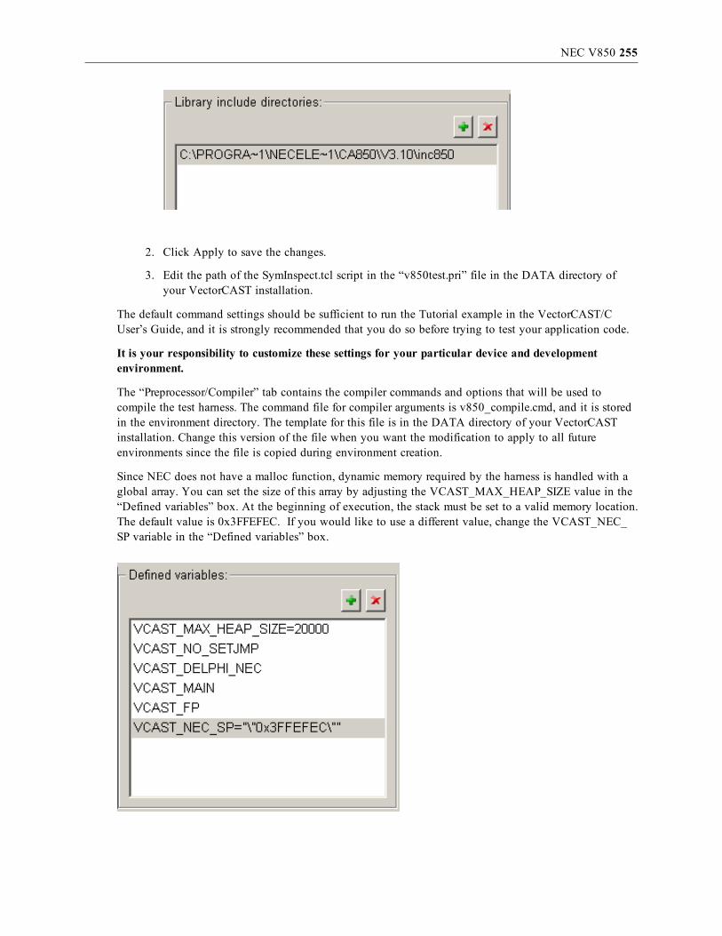
NEC V850 255
2. Click Apply to save the changes.
3. Edit the path of the SymInspect.tcl script in the “v850test.pri” file in the DATA directory ofyour VectorCAST installation.
The default command settings should be sufficient to run the Tutorial example in the VectorCAST/CUser’s Guide, and it is strongly recommended that you do so before trying to test your application code.
It is your responsibility to customize these settings for your particular device and developmentenvironment.
The “Preprocessor/Compiler” tab contains the compiler commands and options that will be used tocompile the test harness. The command file for compiler arguments is v850_compile.cmd, and it is storedin the environment directory. The template for this file is in the DATA directory of your VectorCASTinstallation. Change this version of the file when you want the modification to apply to all futureenvironments since the file is copied during environment creation.
Since NEC does not have a malloc function, dynamic memory required by the harness is handled with aglobal array. You can set the size of this array by adjusting the VCAST_MAX_HEAP_SIZE value in the“Defined variables” box. At the beginning of execution, the stack must be set to a valid memory location.The default value is 0x3FFEFEC. If you would like to use a different value, change the VCAST_NEC_SP variable in the “Defined variables” box.

NEC V850 256
The “Linker” tab contains the linker commands and options that will be used to link the test harness.This tab is where you specify the object files containing your board startup code. Be sure to specify thefull paths to all the object files that you need to link in.
If you have a link command file, enter it under “Linker options”. For example, if you have a linkcommand file in the C:\vcast_nec directory named v850_test.plk, you would enter @C:\vcast_nec\v850_test.plk.
A link command file contains the names of the object files with their full paths as well as the linkoptions you wish to use. For example, if you have startup code in the object files startup.o, rom_hdr.o,and vectors.o, and they are in the directory c:\vcast_nec, your link command file might look like this:
c:\vcast_nec\startup.o
c:\vcast_nec\rom_hdr.o
c:\vcast_nec\vectors.o
-cpu
f3359
-A
-m
-v
-mask_reg
-lc
-lr
c:\devapps\tools\nec_v850\c\nec\2.72\win\lib850\r32\rompcrt.o
VectorCAST provides a default link directive file, v850_link.dir. The template for this file is in theDATA directory of your VectorCAST installation. Change this version of the file when you want themodification to apply to all future environments since the file is copied during environment creation. Ifyou only want the changes to apply to the current environment, edit the v850_link.dir file inside theenvironment directory. When you are ready to begin testing your application code, a good starting pointfor these settings would be the actual values used to compile and link the code you are about to test.
Specific details and discussion of the options that ca850.exe and ld850.exe accept is outside the scope ofthis document. Refer to NEC’s compiler and linker documentation for more information on this topic.
Lastly, click OK to save the settings and close the options dialog.

NEC V850 257
Target ExecutionFor execution with the NEC target, VectorCAST will invoke romp850 on the executable to create aromp.out file in the environment directory. Then it will create a Tcl control script in the environmentdirectory and automatically invoke the Integrated Debugger ID850QB to run test cases. The script filethat VectorCAST creates is called “execute.tcl” and is similar to the following:
breakpoint vCAST_END
go -wait
go -wait
upload -force -binary VCAST_STDOUT.DAT vcast_output_buffer vcast_output_buffer+0x1388
breakpoint -delete 1
breakpoint -delete 2
dbgexit
The harness stores execution results in a buffer, and the execute.tcl script sends the contents of the bufferto a file. You can adjust the size of this buffer by changing the “Output buffer size” option on the Targettab.
The template for the execute.tcl script is in the DATA directory of your VectorCAST installation. If youchange this version of the script, all future environments will be affected.
The project file used with the debugger is called “v850test.prj” and is found in the environment directory.The template for this file is in the DATA directory of your VectorCAST installation. If you change thisversion of the project file, all future environments will be affected since the file is copied duringenvironment creation. The default project file uses a settings file, “v850test.pri”, which is copied into theenvironment directory from the DATA directory as well.
Target Debug ExecutionFor debugging on the NEC target, VectorCAST will invoke romp850 on the executable to create aromp.out file in the environment directory. Then it will create a Tcl control script in the environmentdirectory and automatically invoke the Integrated Debugger ID850QB with it to load the executable. Thescript file that VectorCAST creates is called “execute_debug.tcl” and is similar to the following:
breakpoint vCAST_END
The template for the execute_debug.tcl script is in the DATA directory of your VectorCAST installation.If you change this version of the script, all future environments will be affected. If you only want changesto apply to the current environment, edit the execute_template.tcl file in the environment directory.
If you allow the execution to reach the end of the driver main program, you can get the execution resultsby calling:

NEC V850 258
upload -force -binary VCAST_STDOUT.DAT vcast_output_buffer /
vcast_output_buffer+<OUTPUT_BUFFER_SIZE>
in the debugger before exiting (change <OUTPUT_BUFFER_SIZE> to be the size in hexadecimalnotation of your buffer). The first time you execute with debug, you will get a reminder of how to dothis:

PARADIGM FOR 80186 259
Paradigm for 80186Configuration
This section provides details about configuring VectorCAST to integrate with ParadigmC++ compiler for an 80186 hardware target.
First, select Tools => Options from the main toolbar. Choose the C/C++ tab and then select the entry forParadigm => 80186EB => CPP under the “Compilers” drop-down menu, as shown here:
Second, ensure that the directory containing the Paradigm binaries is included in your PATH environmentvariable as well as the path to the WinIdea application which is used to download and debug theapplication.
set PATH=C:\Program Files\Paradigm\bin;C:\winIDEA\2008;%PATH%
You can modify the path as appropriate on your particular system.
Target-specific startup files:VectorCAST integration with 80186 target-specific startup files requires that the user point to thedirectory that contains all the precompiled startup files (*.obj) that will get linked in with theVectorCAST test harness files and the UUT code. The user must configure the environment variable P_186_STARTUP_FILES to point to these startup files.

PARADIGM FOR 80186 260
An example list of startup files that VectorCAST expects to find are listed in the directory listing below,where the environment variable is set as follows:
P_186_STARTUP_FILES=C:\80186_Startup_Files
The user may also wish to include the source code for the startup code to assist in debug sessions wherethey may want to step through this code.
LinkingThe user can modify the list of startup files to be linked in by editing the list included on the “LinkerOptions:” line which can be found by selecting the Tools => Options dialog, C/C++ tab, Linker sub-tab.See below for an example. It is your responsibility to customize these settings for your particulardevice and development environment.

PARADIGM FOR 80186 261
VectorCAST will automatically invoke the Paradigm linker, plink.exe, and the locate utility, locate.exe,to produce a paradigm_186.axe executable image. This is the image that will be downloaded onto thetarget and executed when you run a test case.
Target ExecutionAs the test environment is being built by VectorCAST, it will invoke the WinIdea debugger to run anexecutable on the target that initializes range data. You must have a serial cable from your targetconnected to your test PC machine. VectorCAST collects range data and test data information from thisserial port interface.
The $VECTORCAST_DIR\IO\comreader.exe executable is used to record the results of target execution.The default settings are port "COM1", baud 9600, no parity, 8 data bits, and 1 stop bit.
The comreader is started before test execution and stops when the debugger exits. Remember to closeany other applications, such as HyperTerminal, that are reading from the same port, before executing tests.
If you forget to power up your target and/or the In-Circuit-Emulator (ICE), or don’t have the USB cableconnected from your PC to the emulator, you will likely get an error dialog box displayed like the oneshown below.

PARADIGM FOR 80186 262
The connection method to your target may vary depending on the emulator or target capabilities. As anexample, if you are connected via an ICE with a USB connection to your PC that communicates with theWinIdea application, then you will see a download progress window like the one below as VectorCASTinvokes WinIdea to download the target image and run it on your target.
Target Debug ExecutionTest Execution with Debug functions in a manner similar to normal execution, except a breakpoint is setin the main function so execution stops there. You can manually set breakpoints, step through source anddisassembly, and view data as you would during a normal debug session.
The script used to execute with debug is named p186_download_debug.isl. You can customize this scriptto store frequently used breakpoints/debugging commands conveniently for repeated debugging sessions.The template for the script is in $VECTORCAST_DIR\DATA\paradigm, and it will automatically becopied to your test environment when you select the “Execute with Debug” option for running your testcase. The user should refer to the WinIdea documentation for more information on the API and supportedfunctions that can be used in your .isl script.
To stop debugging, kill the debug thread and exit WinIdea.

PARADIGM FOR 80186 263
If you allow the execution to reach the end of the driver main program, all VectorCAST execution resultswill be generated when you exit WinIdea.

PARADIGM FOR SC520 264
Paradigm for SC520Configuration
This section provides details about configuring VectorCAST to integrate with ParadigmC/C++ compiler for an SC520 HW target. The target board is the 586-Drive (5D) fromTern Inc. which is a C/C++ programmable controller based on the 32-bit 133 MHz AMD SC520microcontroller. The ÉlanSC520 microcontroller combines a 32-bit Am5x86® CPU with a complete set ofintegrated peripherals for embedded application development. This board and RSP are designed to workwith the Paradigm C++Tern Edition, Version 5.00 of the compiler.
Target Connections and ConfigurationThe 5D board comes with a +12V power cable and 2 flat ribbon serial port cables. Connect serial port 0(SER0) cable to the COM1 port on your PC (DB9 connector) and use the Device Manager to configurethat serial port communication interface for 115200 bits per second, 8 data bits, N (no parity), 1 (1 stopbit), and No flow control. This SER0 interface is used by the debugger to communicate/control the boardand download your application for debug. Connect the other serial port cable (SER1) to COM2 port onyour PC. You may need to use a USB-to-DB9 adaptor if your PC only supports a single DB9 connector(typical PC configuration). Use the Device Manager again to configure COM2 for 19200 8 N 1.VectorCAST uses this serial port interface to collect test data results. Note that these baud rate settingsassume the default settings for the SC520 board. If the user changes these settings on the SC520 end, thenthe same settings should obviously be mirrored in the host PC port settings.
First, ensure that the directory containing the Paradigm binaries is included in your PATH environmentvariable. (For example, set path=C:\Paradigm\bin;%path%).
Note:When installing the Paradigm Tern edition of the Paradigm compiler, you should accept allthe default options listed during the install, including the default directory locations for installingthe Tern libraries.
You will also need to configure an environment variable, VCAST_SERIAL_CFG, to point to a serial portconfiguration file which VectorCAST creates for you and installs in the DATA\paradigm directory in theVectorCAST install directory.
set VCAST_SERIAL_CFG=<vectorcast_dir>\DATA\paradigm\p586_serial_cfg.txt
The contents of this file should be as follows.
COM2
19200
N
8
1
If the serial cable from the SER1 port on the SC520 is connected up to a COM port other than COM2 onyour host PC, then modify the contents of p586_serial_cfg.txt file to point to the appropriate serial COMport (e.g. COM6 instead of COM2). You can identify the COM port by using the Device Manager on thePC to display the connected serial ports, (expand the Ports (COM & LPT) menu item). see figure below as
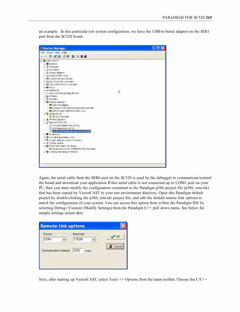
PARADIGM FOR SC520 265
an example. In this particular test system configuration, we have the USB-to-Serial adaptor on the SER1port from the SC520 board.
Again, the serial cable from the SER0 port on the SC520 is used by the debugger to communicate/controlthe board and download your application If this serial cable is not connected up to COM1 port on yourPC, then you must modify the configuration contained in the Paradigm p586 project file (p586_tern.ide)that has been copied by VectorCAST to your test environment directory. Open this Paradigm defaultproject by double-clicking the p586_tern.ide project file, and edit the default remote link options tomatch the configuration of your system. You can access this option from within the Paradigm IDE byselecting Debug->Connect (Modify Settings) from the Paradigm C++ pull down menu. See below forsample settings screen shot.
Next, after starting up VectorCAST, select Tools => Options from the main toolbar. Choose the C/C++

PARADIGM FOR SC520 266
tab and then select the entry for Paradigm => SC520 => C under the “Compilers” drop-down menu, asshown here:
Paradigm startup scripts:The Paradigm integrated debugger will always run a few startup scripts automatically when you start upthe Paradigm IDE. These include the startup.spp and the personal.spp scripts. Before running any of yourtest cases, you should copy the VectorCAST-generated script, p586_personal.spp, into thec:\Paradigm\script directory and rename it personal.spp. You will find the p586_personal.spp script in the$VECTORCAST_DIR/DATA/paradigm directory. You will want to save off the original personal.sppthat comes with the Paradigm installation for reference. The VectorCAST modified script will not try toload recent project files like the default script does, as this may cause problems when running in debugmode. You may examine the differences between these scripts and modify as you wish in terms ofinitializing the debugger default windows that come up when VectorCAST invokes the debugger(“Execute with Debug”), but we don’t recommend loading recent project settings for the reason statedabove.
Stack size:The default stack size is defined in the c0.asm startup file from the Paradigm release and defaults to a sizeof 1024 bytes. For small test environments this is typically enough stack, but should your testenvironment require additional stack size, the user can increase the stack size by defining the desiredstack size in the stklen.asm file, which is included in your test environment, and generating a stklen.obj

PARADIGM FOR SC520 267
object file. The user would subsequently include stklen.obj in the link process by adding it to the linkeroptions by selecting Tools->Options->C/C++ Linker/Debug Tab as shown below.
A stklen.obj file is also included in your test environment which has been built to increase the stack sizeto 8K bytes, which can simply be included on the linker options line to increase the stack size to 8KB. Ifyou want a different stack size, then edit the stklen.asm accordingly, build with the Paradigm assemblerby running the “pasm /m3 /mx stklen.asm” command, and link the newly generated stklen.obj into yourexecutable by selecting Environment->Relink.
Linking:VectorCAST will automatically invoke the Paradigm linker, plink.exe, and the locate utility, locate.exe,to produce a paradigm_586.axe executable image. This is the image that will be downloaded onto thetarget and executed when you run a test case.
Target ExecutionAfter the test environment has been built by VectorCAST, it will invoke the Paradigm debugger to run anexecutable on the target that initializes range data. You must have a serial cable from your targetconnected to your test PC machine as VectorCAST collects range data and test data information throughthis serial port interface. (SER1)
The $VECTORCAST_DIR\IO\comreader.exe executable is used to record the results of target execution.The comreader is configured to match the baud rate settings on the 5D board via the serial configuration

PARADIGM FOR SC520 268
file mentioned earlier. These settings are port "COM2", 19200 bits per second, N (no parity), 8 data bits, 1stop bit, and No flow control.
The comreader is started before test execution and stops when the debugger exits. Remember to closeany other applications, such as HyperTerminal, that are reading from the same port, before executing tests.
If you experience any connectivity problems with the target, like forgetting to connect serial port cables,or accidentally running another application that was already connected to that COM port, you shouldconnect all the necessary cables, close the other application, and reboot the board as the state machinerunning on the 5D board needs to get synced up now.
In VectorCAST, you may run any test case by selecting the test case, right-clicking, and selecting“Execute”, or clicking the Execute button in the toolbar. VectorCAST will then invoke the debugger viathe command line interface and download the executable, run to completion, and then exit the debugger,returning control back to VectorCAST for test case result display.
Target Debug ExecutionTest Execution with Debug functions in a manner similar to normal execution, except that the debuggerwill download the application but not run it automatically like it does in the Execute mode. You mayrun any test case in debug mode by selecting the test case, right-clicking, and selecting “Execute withDebug”. This allows you the opportunity to set breakpoints, step through source code, and view data asyou would during any normal debug session.
The script used to execute with debug is named p586_load_dbg.spp. VectorCAST will create this debugscript on the fly when you select the “Execute With Debug” option for running your test case, and thefile does not already exist in the test environment. You can customize this script thereafter to storefrequently used breakpoints/debugging commands conveniently for repeated debugging sessions. Thedebugger will come up, load the executable, and stop at the startup code execution entry point, asillustrated below.

PARADIGM FOR SC520 269
You may step through the startup code at this point or hit the Run button which will cause you to run tomain() and stop there. Again you may step through code or set breakpoints at this point as with anytypical debug session.
Refer to the Paradigm documentation for more information on the cscript Object Scripting features andAPI.
When VectorCAST reaches the vCAST_END function in the S0000003.c file, it has completed the testdata gathering and processing. You may now exit the debugger manually at this point to see the resultsof your test case displayed in the VectorCAST GUI.

QNX NEUTRINO & QNX MOMENTICS 270
QNX Neutrino & QNX MomenticsConfiguration
This section provides details about configuring VectorCAST to integrate with QNXNeutrino and QNX Momentics compiler and debugger for a live x86 board.
Once both the target and the host have been properly set up (see next section to learn how to do a propersetup), launch VectorCAST. Select Tools => Options from the main toolbar. Choose the C/C++ tab toselect the entry for “QNX” under the “Compiler” drop-down menu, as shown here:
The command line has the following parameters that must be changed if need be:
Under Windows:
$(VECTORCAST_DIR)\DATA\gnu_target\execute_rsh.bat IP -lusername
The IP is the name or IP address of your target running QNX Neutrino.
The username is the username on QNX Neutrino which will let you execute remote command (throughrsh) without any password.
QNX NEUTRINO & QNX MOMENTICS 271
Under Linux:Integration under Linux is also possible using shell scripts. Please consult your VectorCASTrepresentative to learn how.
It is your responsibility to customize these settings for your particular device and developmentenvironment. Please note that these changes will be saved as long as you will be using the same workingdirectory. For more information about this, please contact your Vector Software representative.
Target ExecutionTarget execution on a QNX live x86 board requires a few steps. Please note that all of these steps can bemade automatic, so that each time the target is booted, it will immediately be ready for unit testing. Toknow how, please consult your QNX Neutrino documentation.
Setting up the Target
It should be noted that at this point in time, the RSP method of communication is through TCP/IP to atarget that is already running a full-fledged version of QNX Neutrino. This RSP does not supportcommunication through the serial port. If you are interested in communicating with the target through theserial port, please contact a Vector Software representative.
Before running a test case, you must configure the target board to be accessed through NFS and RSH.Here are the steps that need to be taken in order to enable both daemons:
1. Edit the file /etc/inetd.conf and uncomment the line describing the rshd and ftpd daemons byremoving the ‘#’ sign at the beginning of that line.
2. Boot up inetd by typing ‘inetd’ at the command prompt. inetd will in turn boot up the rshddaemon whenever a rsh communication is initiated on the proper port. You can also make thechange permanent by putting inetd in /etc/rc.d/local.rc file – this will have the effect oflaunching inetd each time the OS is booted up.
3. Make a directory where temporary files can be saved. This must be /tmp from the root level.
4. Also, create a /home/ftp directory, otherwise the FTP server may not launch properly.
At this point in time, listing the services currently running (by typing ‘ps’ at the command prompt)should list inetd as being up and running. If this is not up, please revisit the previous steps. You may alsotry to rsh from your host to the target to see if commands can be successfully passed into the target. Incase of problems, consult your QNX Neutrino documentation.
It should be noted that communication with the target that is described here requires the existence of ausername in Neutrino that has no password. We used ‘root’, but you may want to use something else. Inany case, this username should not require you to input any password, and should have read and writeprivileges into the temporary file directory (/tmp).
Note that all these steps can be automated, so when the target is rebooted both rshd and inetd will be upby default. For more details on how to do this, consult your QNX Neutrino User Manual.
Target Debug ExecutionTest Execution with Debug functions similarly to normal execution, except a breakpoint is set in themain function so execution stops there. You can manually set breakpoints, step through source and

QNX NEUTRINO & QNX MOMENTICS 272
disassembly, and view data as you would during a normal debug session.
The default debugger for QNX Momentics is gdb; however other debuggers can be used. Refer to theQNX documentation for more details.

RENESAS HEW – M16C/R8C 273
Renesas HEW – M16C/R8CConfiguring for Renesas HEW – M16C/R8C
This section provides details about configuring VectorCAST to integrate with Renesas HEW IDE withMitsubishi chips. For the moment, the only target supported is M16C/62 on simulator, but this templatecan be used to perform unit testing on R8C-based programs. Support for other targets and simulators isquite possible, including for the M16C, M32C, and several other Mitsubishi-based targets. Please contactyour Vector Software representative for more details.
Please note that the Renesas HEW integration requires a few steps before it is possible to runVectorCAST with that IDE. This step is made mandatory on simulator by the fact that the Renesasenvironment writes files to the user directory, and that the RSP uses an API that must be first activated inthe Renesas HEW environment. Thus, you must first create a Renesas HEW template for VectorCAST touse. Furthermore, you will need to set up the Renesas IDE correctly to interface with our COM program.
These steps only need to be done once, and then the template can be used across work directories. See thesection on Target Execution for more details.
Putting the compiler on the pathFirst, before launching VectorCAST, the compiler must be put on the path. The way to do this dependson the specifics of your Renesas installation. However, it could look like the following:
SET BIN30=C:\Program Files\Renesas\Hew\Tools\Renesas\nc30wa\v545r00\bin
SET LIB30=C:\Program Files\Renesas\Hew\Tools\Renesas\nc30wa\v545r00\lib30
SET INC30=C:\Program Files\Renesas\Hew\Tools\Renesas\nc30wa\v545r00\inc30
SET TMP30=C:\Program Files\Renesas\Hew\Tools\Renesas\nc30wa\v545r00\tmp
SET PATH=%BIN30%;%LIB30%;C:\Program Files\Renesas\Hew\;%PATH%
Please note that all of these environment variables must be set before VectorCAST/C++ can use them.You can make these environment variables to be permanently part of the Windows operating system, oryou can launch VectorCAST from a batch file that first sets these environment variables correctly. It isyour responsibility to customize these settings for your particular device and developmentenvironment.
Target Execution
Enabling the HEW Target ServerAs explained in the previous chapter, a number of steps must be followed before being able to run theRenesas RSP. Most of these steps need only to be taken once.
First, you must enable the Renesas HEW Target Server on the machine that will host the testenvironments. Follow these steps:
1. Launch Renesas HEW.
2. Then, you need to make sure that the HEW Target Server is installed. When the welcome screenappears, click on Administration.If the welcome screen does not appear, then select Tools => Administration from the menu bar.

RENESAS HEW – M16C/R8C 274
Expand Extension Components. Click on Search Disk, and then Start. HEW will list all thecomponents you can register. Select HewTargetServer and then click on Register. You can nowclose the Tools Administration menu.
3. Then, if you want the execution of test cases to be entirely automated, you must disable RenesasHEW optional pop-ups and splash screens. Go to Setup => Options, and then the Confirmationtab. Click on Clear All, and then OK. Please note this change will affect all of your Renesasenvironments.
Creating a Renesas HEW IDE template projectSecond, you must create a Renesas HEW IDE template project for VectorCAST to use. Follow thesesteps:
1. Launch Renesas HEW.
2. Select File => New Workspace. Select Application, and enter the appropriate information. ClickOK.
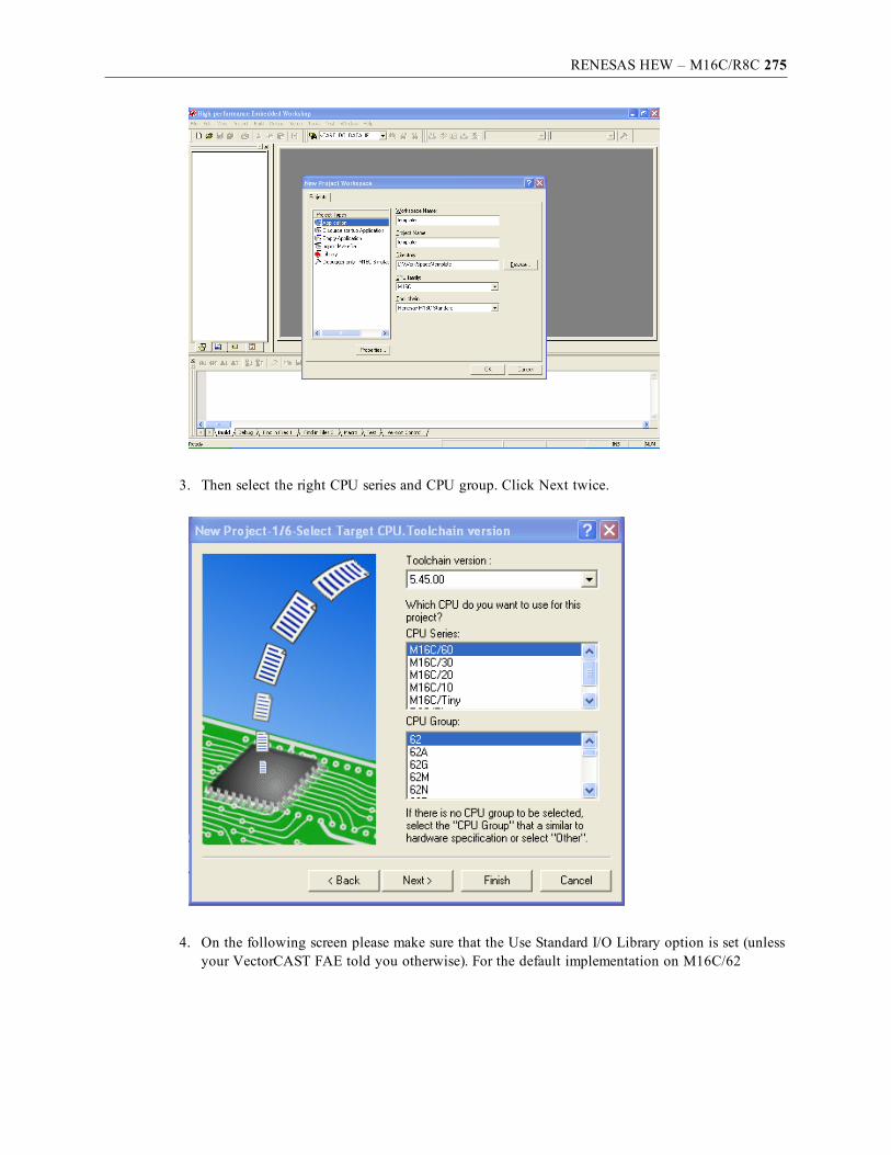
RENESAS HEW – M16C/R8C 275
3. Then select the right CPU series and CPU group. Click Next twice.
4. On the following screen please make sure that the Use Standard I/O Library option is set (unlessyour VectorCAST FAE told you otherwise). For the default implementation on M16C/62

RENESAS HEW – M16C/R8C 276
simulator, please select 128K of ROM. Click Next twice.
5. Select the target you need, and then click Next twice, then Finish.

RENESAS HEW – M16C/R8C 277
At this point in time, you should see the following:
6. Select the appropriate session from the Session selection dropdown box (up and right). A popupwill appear for simulator environments. Click on the Refer button. Select the appropriate MCU(here, M16c6x.mcu). Also, to ensure that test cases can run without user input, please make surethat option “Do not show this dialog box again” is checked. Click OK.
7. If you are using the simulator for Mitsubishi chips, you also need to set up the OutputPortwindow. Go to View => CPU => OutputPort.

RENESAS HEW – M16C/R8C 278
8. In the window that appears, click the first icon (Set). Set the Printf to UART1, and OutputFormat for Window and File to TEXT. Click OK.
9. Then click the second icon (Column). Please set both Window Column and File Column to1000, and then click OK.

RENESAS HEW – M16C/R8C 279
10. Finally, right-click on ncrt.a30 (the startup code), and build the file.
11. Kill the HEW environment. When asked to, save the environment.
Please note that all of these steps only need to be made once.
Use VectorCASTYou can now create a VectorCAST environment. Select Tools => Options from the main toolbar. Choose

RENESAS HEW – M16C/R8C 280
the C/C++ tab to select the entry for “Renesas HEW 5.4x on M16C (62) Simulator” under the “Compiler”drop-down menu, as shown below.
1. On the Execute command line, replace the path following execute.bat with the path to thetemplate you created before. Depending on your Renesas installation, you may need to changethe default source directories for the Wizard.
2. Then, make sure the same change has been changed for the debugger command. located on theLinker/Debug tab.

RENESAS HEW – M16C/R8C 281
3. Finally, provide the path to the ncrt.r30 file from your template file in the option “EnvironmentFiles,” located on the Misc tab.

RENESAS HEW – M16C/R8C 282
Note: In order to use VectorCAST/C++ with Renesas HEW, no other HEW instance can be open.The only instance of HEW that should be open when using VectorCAST is the one used byVectorCAST.
By default, VectorCAST will launch HEW, download the test harness to the HEW debugger, run a testcase, and shut HEW down. There is a way to keep the template up to accelerate execution by changingthe fourth argument on both the execute command and debug command lines from SHUTDOWN toCONTINUOUS. However, if you choose to do so, you must make this change to both the execute anddebug command lines. Also, upon rebuilding the environment, you must shut down the HEW instancestill open, otherwise the rebuild with fail.
Target Debug ExecutionWhen executing under the control of the debugger, VectorCAST will open the HEW template andadvance execution to the entry of the main function. From there, you will be able to execute the testharness manually, using your usual debugger command. For your convenience, VectorCAST will alsoautomatically put a break point at the end of the test harness.
During execution on simulator for the M16C/62, the test results are saved automatically. In order for theresults to be complete, the inscription VCAST.END:END should appear in the output window. That willhappen when the test harness hits the break point on vCAST_END(), indicating that you reached the endof the test harness. Then, you can close the HEW instance – by shutting down HEW or by clicking onthe popup provided to that end by the RSP, and control will be returned to VectorCAST.
Upon exiting, do not save the HEW template. Close HEW or click on the OK button on the popup open

RENESAS HEW – M16C/R8C 283
for that specific purpose.
Troubleshooting
Corruption during simulator executionProblems may sometimes occur during simulator execution. If this happens, it is possible that HEW willrefuse to normally load the project template. The message displayed in the pop-up will likely show thatHEW cannot open additional I/O files. If this happens, you must go the Windows Task Manager and shutdown all of the executables related to Renesas, including HEW (HEW2.exe), the HEW Target Server(HEWTAR~1.exe) and the simulator executable (sim30.exe). You may also need to regenerate a HEWtemplate to use with VectorCAST if yours has somehow been damaged during your last execution.
Execution not fully automaticIf HEW hangs during the load of the main file (either S00000003.c or I00000003.c), it may mean that theintegration program is not able to dismiss the window popup associated with the loading of that file inRenesas HEW. This may occur because VectorCAST operates in a Windows environment in which thelanguage is not English. The solution is to change the language on both the execute and debugcommands from ENGLISH to your language. At this time, only English and Korean are supported. Pleasecall VectorCAST Technical Support to learn how to add support for your language.
On the other hand, if HEW hangs on splash windows or other pop-ups, it is possible you did not disablethese pop-ups during target setup. Please Go to Setup => Options, and then the Confirmation tab. Clickon Clear All, and then OK. Please note this change will affect all of your Renesas environments.
CompatibilityThis integration has received final testing with version 4.07 of HEW. Previous versions may or may notbe compatible with this RSP. In case of any problems executing with other versions, please contact

RENESAS HEW – M16C/R8C 284
VectorCAST Technical Support.
RENESAS HEW SUPERH (SH) CHIPS 285
Renesas HEW SuperH (SH) chipsConfiguration for Renesas HEW - SH
This section provides details about configuring VectorCAST to integrate with Renesas HEW IDE and theSuperH (SH) compiler. Integrations exist with both the HEW native debugger and the LauterbachTRACE32 debugger.
Note: The Renesas HEW integration with HEW native debugger requires a few steps before it ispossible to run VectorCAST with that IDE. These steps only need to be done once, and then thetemplate can be used across work directories. See the Target Execution section for more details.
Putting the compiler on the pathFirst, before launching VectorCAST, the compiler must be put on the path. The way to do this dependson the specifics of your Renesas installation. However, it could look like the following:
set VCAST_RENESAS_INSTALL_DIR=C:\Program Files\Renesas\Hew\Tools\Renesas\Sh\9_3_2
SET SHC_LIB=C:\Program Files\Renesas\Hew\Tools\Renesas\Sh\9_3_2\bin
SET SHC_INC=C:\Program Files\Renesas\Hew\Tools\Renesas\Sh\9_3_2\include
SET SHC_TMP=C:\Program Files\Renesas\Hew\Tools\Renesas\Sh\9_3_2\Ctemp
SET HLNK_LIBRARY1=C:\Program Files\Renesas\Hew\Tools\Renesas\Sh\9_3_2\lib\shdsplib.lib
SET PATH=C:\Program Files\Renesas\Hew\Tools\Renesas\Sh\9_3_2\bin;%PATH%
Please note that all of these environment variables must be set before VectorCAST/C++ can use them.You can make these environment variables to be permanently part of the Windows operating system, oryou can launch VectorCAST from a batch file that first sets these environment variables correctly.
Please also note that SHC_LIB must be pointing to the bin directory of your compiler, not the libdirectory. If this environment variable points to the lib directory, the compiler will report an error whenusing VectorCAST.
Finally, if using a virtual I/O method for simulator integration under HEW native compiler (theSH4/SH7750 integration is based on that model), you must set an extra environment variable VCAST_IO_DIRECTORY to a directory where VectorCAST can write a IO file. This path must be pointingoutside VectorCAST’s working directory, as the HEW simulator virtual I/O capability will not write intothe working directory. By default, this directory is C:\Workspace.
set VCAST_IO_DIRECTORY=C:\WORKSPACE
If you must put the IO directory somewhere else, you will also need to change the file folder_path.haccordingly, which is located in the %VECTORCAST_DIR%\DATA\renesas\sh folder:
#ifndef VCAST_STDOUT_FOLDER
char *VCAST_STDOUT_FOLDER = "C:\\WorkSpace\\stdout.txt";
#endif
Please note that in this header file, the path to the stdout.txt file must have double backspaces.
If you are using the Lauterbach TRACE32 debugger, you will need to set the TRACE32 executable in

RENESAS HEW SUPERH (SH) CHIPS 286
your PATH environment variable. The rest of this section is not relevant to an integration withLauterbach TRACE32. Please consult the appropriate section in this user guide.
It is your responsibility to customize these settings for your particular device and developmentenvironment.
Target Execution
Enabling the HEW Target ServerIf using the HEW native debugger, you must enable the Renesas HEW Target Server on the machine thatwill host the test environments. Follow these steps:
1. Launch Renesas HEW.
2. Then, you need to make sure that the HEW Target Server is installed. When the welcome screenappears, click on Administration.If the welcome screen does not appear, then select Tools => Administration from the menu bar.Expand Extension Components. Click on Search Disk, and then Start. HEW will list all thecomponents you can register. Please select HewTargetServer and then click on Register. Youcan now close the Tools Administration menu.
3. Then, if you want the execution of test cases to be entirely automated, you must disable RenesasHEW optional pop-ups and splash screens. Go to Setup => Options, and then the Confirmationtab. Click on Clear All, and then OK. Please note this change will affect all of your Renesasenvironments.
Reset the HEW template (.hws)Before using the HEW integration, you must first go to %VECTORCAST_DIR%\DATA\renesas\sh

RENESAS HEW SUPERH (SH) CHIPS 287
directory, and from there go to the chip being supported (for instance, SH4/SH7750), and open the .hwsfile listed. This will open the project in the HEW IDE. You must then close the HEW IDE and save theproject. This will reset the internal path of this project to the specifics of your environment.
Failure to do so will cause the execution of the VectorCAST integration to hang.
Use VectorCASTYou can then create a VectorCAST environment. Select Tools => Options from the main toolbar. Choosethe C/C++ tab to select the entry for the Renesas template of your choice.
Note: In order to use VectorCAST/C++ with Renesas HEW debugger, no other HEW instance canbe open. The only instance of HEW that should be open when using VectorCAST is the one usedby VectorCAST.
By default, VectorCAST will launch HEW, download the test harness to the HEW debugger, run a testcase, and shut HEW down. There is a way to keep the template up to accelerate execution by changingthe fourth argument on both the execute command and debug command lines from SHUTDOWN toCONTINUOUS. However, if you choose to do so, you must make this change to both the execute anddebug command lines. Also, upon rebuilding the environment, you must shut down the HEW instancestill open, otherwise the rebuild with fail.

RENESAS HEW SUPERH (SH) CHIPS 288
Target Debug ExecutionWhen executing under the control of the debugger, VectorCAST will open the HEW template andadvance execution to the entry of the main function. From there, you will be able to execute the testharness manually, using your usual debugger command. For your convenience, VectorCAST will alsoautomatically put a break point at the end of the test harness.
Upon exiting, do not save the HEW template. Close HEW or click on the OK button on the popup openfor that specific purpose.
TroubleshootingRunning out of heap space
By default, VectorCAST/RSP for Hitachi chips will use static memory in lieu of a heap. The amount ofspace reserved for these operations is controlled by the VCAST_MAX_HEAP_SIZE variable. If the heapspace is insufficient, the following error will occur:

RENESAS HEW SUPERH (SH) CHIPS 289
The solution to this problem is to increase VCAST heap space by defining another value for VCAST_MAX_HEAP_SIZE (the default size is 1000). For instance, placing VCAST_MAX_HEAP_SIZE=2000among the macros will enable you to do integration testing on the tutorial code (with manager.c anddatabase.c) at Level A code coverage, while not defining VCAST_MAX_HEAP_SIZE will result in theerror message displayed above.
On the other hand, if your program uses malloc, the default template provided might not have sufficientheap space for you to run your program. The default HEW value of 0x400 was used for the heap. Pleaseconsult your Vector Software representative to learn how we can customize this integration to suit yourneeds.
Execution not fully automaticIf HEW hangs during the load of the main file (either S00000003.c or I00000003.c), it may mean that theintegration program is not able to dismiss the window popup associated with the loading of that file inRenesas HEW. This may occur because VectorCAST operates in a Windows environment whichlanguage is not English. The solution is to change the language on both the execute and debugcommands from ENGLISH to your language. At this time, only English and Korean are supported. Pleasecall VectorCAST Technical Support to learn how to add support for your language.
On the other hand, if HEW hangs on splash windows or other pop-ups, it is possible you did not disablethese pop-ups during target setup. Please Go to Setup->Options, and then the Confirmation tab. Click onClear All, and then OK. Please note this change will affect all of your Renesas environments.
Environment will not execute when using the simulatorThe template provided by VectorCAST for execution on HEW is valid only with version 4.07 of HEWand Compiler package for SH version 3.3. You may need to upgrade this template to your version ofHEW by (1) clicking on %VECTORCAST_DIR%\DATA\renesas\sh_sim.hws, and then (2) save andclose this template.
The template may also refuse to execute if you installed VectorCAST anywhere but in C:\VCAST. This isbecause HEW templates define absolute links to a number of files. Fortunately, HEW is also generallyable to redraw its dependencies. Open %VECTORCAST_DIR%\DATA\renesas\sh_sim.hws in HEW, saveand close the template.
Please note that in both cases you will need to do this quick operation each time you reinstall or upgradeVectorCAST.

RENESAS HEW SUPERH (SH) CHIPS 290
CompatibilityThis integration has received final testing with version 4.07 of HEW. Previous versions may or may notbe compatible with this RSP. In case of any problems executing with other versions, please contactVectorCAST Technical Support.
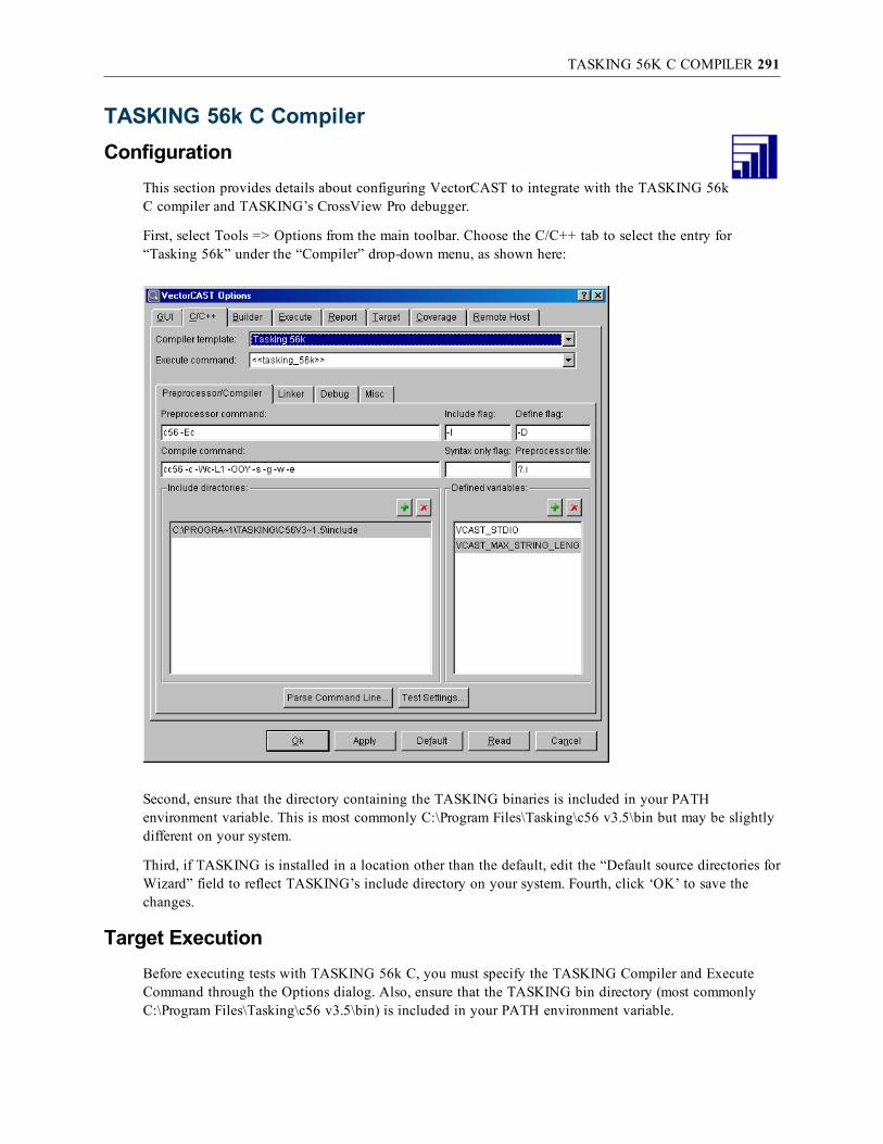
TASKING 56K C COMPILER 291
TASKING 56k C CompilerConfiguration
This section provides details about configuring VectorCAST to integrate with the TASKING 56kC compiler and TASKING’s CrossView Pro debugger.
First, select Tools => Options from the main toolbar. Choose the C/C++ tab to select the entry for“Tasking 56k” under the “Compiler” drop-down menu, as shown here:
Second, ensure that the directory containing the TASKING binaries is included in your PATHenvironment variable. This is most commonly C:\Program Files\Tasking\c56 v3.5\bin but may be slightlydifferent on your system.
Third, if TASKING is installed in a location other than the default, edit the “Default source directories forWizard” field to reflect TASKING’s include directory on your system. Fourth, click ‘OK’ to save thechanges.
Target ExecutionBefore executing tests with TASKING 56k C, you must specify the TASKING Compiler and ExecuteCommand through the Options dialog. Also, ensure that the TASKING bin directory (most commonlyC:\Program Files\Tasking\c56 v3.5\bin) is included in your PATH environment variable.

TASKING 56K C COMPILER 292
See the previous section “Configuration” for detailed instructions on these requirements.
When a test case is executed with TASKING, VectorCAST will automatically execute a command toinvoke the CrossView simulator. The command passes the following initialization command script via the-p (playback) option:
FSS 0<"C:\vcast_tutorial\DEMO\VCAST_STDIN.DAT"
FSS 1>"C:\vcast_tutorial\DEMO\VCAST_STDOUT.DAT"
break delete all
F_exit bi
R
q y
The first two lines configure CrossView’s simulated I/O, setting standard input (stdin/FSS 0) to the fileVCAST_STDIN.DAT and standard output (stdout/FSS 1) to VCAST_STDOUT.DAT.
Next, all break points are deleted (to ensure an uninterrupted execution) and a break point is then set onthe assembly label “F_exit” (the end of the program).
Lastly, the Run command is issued so that CrossView will open, initialize, run and complete without anyrequired user input. Upon completion, CrossView will quit and VectorCAST will display the test’sresults.
The initialization script is named .xfw_exeinit.cmd and gets created in the VectorCAST environmentdirectory. This file will not be overwritten, so any changes made by you are maintained from oneexecution to the next. As long as the simulated I/O setup commands are maintained, you may add anylegal CrossView commands to this file. If you wish to make a change to the script for all futureenvironments, you can edit $VECTORCAST_DIR\DATA\tasking\.xfw_exeinit.cmd.
Target Debug ExecutionTest Execution with Debug is similar to normal execution except that the CrossView initializationcommand script does not contain a Run command. Because no Run command has been given toCrossView, it will wait for user input – debugging can proceed from this point as normal.
The debug initialization script is named .xfw_dbginit.cmd and gets created in the VectorCASTenvironment directory. This file will not be overwritten, so any changes made by you are maintained fromone execution to the next, making it useful for setting frequently used breakpoints.
For example, if you are attempting to uncover when a particular variable “my_counter” is being changed,you would edit .xfw_dbginit.cmd to read as follows:
FSS 0<"C:\vcast_tutorial\DEMO\VCAST_STDIN.DAT"
FSS 1>"C:\vcast_tutorial\DEMO\VCAST_STDOUT.DAT"
break delete all
break data &my_counter, access_type=w
R
By adding the data breakpoint and a Run command, when you select “Execute With Debug,” the UUTwill execute via CrossView and halt at any point where the variable my_counter is written. If you wishto make a change to the script for all future environments, you can edit $VECTORCAST_DIR\DATA\tasking\.xfw_dbginit.cmd.

TASKING 563XX C COMPILER 293
TASKING 563xx C CompilerConfiguration
This section provides details about configuring VectorCAST to integrate with the TASKING563xx C compiler and TASKING’s CrossView Pro debugger. Note that this uses a different Taskingcompiler toolset than the Tasking 56K.
Before starting VectorCAST the user must configure the following environment variable to point to theTASKING install directory. This is most commonly C:\Program Files\Tasking\c563 v3.5\bin but may beslightly different on your system. Use DOS 8.3 pathnames when defining your environment variables asthe compiler does not like whitespace in path defines. Also, ensure that the directory containing theTASKING binaries is included in your PATH environment variable.
set VCAST_TASKING_INSTALL_BASE=C:\PROGRA~1\TASKING\C563V3~1.5
set path=%VCAST_TASKING_INSTALL_BASE%\bin;%path%
Start up VectorCAST and create a new test environment and select “Tasking 563xx” under the“Compiler” drop-down menu, as shown here:
Target ExecutionBefore executing tests with TASKING 563xx C, you must specify the TASKING Compiler and Execute

TASKING 563XX C COMPILER 294
Command through the Options dialog. Also, ensure that the TASKING bin directory (most commonlyC:\Program Files\Tasking\c563 v3.5\bin) is included in your PATH environment variable.
See the previous section “Configuration” for detailed instructions on these requirements.
When a test case is executed with TASKING, VectorCAST will automatically execute a command toinvoke the CrossView simulator. The command passes the following initialization command script via the-p (playback) option:
FSS 0<"C:\vcast_tutorial\DEMO\VCAST_STDIN.DAT"
FSS 1>"C:\vcast_tutorial\DEMO\VCAST_STDOUT.DAT"
break delete all
F_exit bi
R
q y
The first two lines configure CrossView’s File System Simulation (FSS), setting standard input (stdin/FSS0) to the file VCAST_STDIN.DAT and standard output (stdout/FSS 1) to VCAST_STDOUT.DAT,located in the environment directory DEMO in c:\vcast_tutorial.
Next, all break points are deleted (to ensure an uninterrupted execution) and a break point is then set onthe assembly label “F_exit” (the end of the program).
Lastly, the Run command is issued so that CrossView will open, initialize, run and complete without anyrequired user input. Upon completion, CrossView will quit and VectorCAST will display the test’sresults.
The initialization script is named .xfw_exeinit.cmd and gets created in the VectorCAST environmentdirectory. This file will not be overwritten, so any changes made by you are maintained from oneexecution to the next. As long as the simulated I/O setup commands are maintained, you may add anylegal CrossView commands to this file. If you wish to make a change to the script for all futureenvironments, you can edit $VECTORCAST_DIR\DATA\tasking\.xfw_exeinit.cmd.
Target Debug ExecutionTest Execution with Debug is similar to normal execution except that the CrossView initializationcommand script does not contain a Run command. Because no Run command has been given toCrossView, it will wait for user input – debugging can proceed from this point as normal.
The debug initialization script is named .xfw_dbginit.cmd and gets created in the VectorCASTenvironment directory. This file will not be overwritten, so any changes made by you are maintained fromone execution to the next, making it useful for setting frequently used breakpoints.
For example, if you are attempting to uncover when a particular variable “my_counter” is being changed,you would edit .xfw_dbginit.cmd to read as follows:
FSS 0<"C:\vcast_tutorial\DEMO\VCAST_STDIN.DAT"
FSS 1>"C:\vcast_tutorial\DEMO\VCAST_STDOUT.DAT"
break delete all
break data &my_counter, access_type=w
R
By adding the data breakpoint and a Run command, when you select “Execute With Debug,” the UUT

TASKING 563XX C COMPILER 295
will execute via CrossView and halt at any point where the variable my_counter is written. If you wishto make a change to the script for all future environments, you can edit %VECTORCAST_DIR%\DATA\tasking\.xfw_dbginit.cmd.

TASKING C166 CLASSIC 296
TASKING C166 ClassicConfiguration
This section provides details about configuring VectorCAST to integrate with the TASKINGcompiler for C166 classic chips.
Before you can use VectorCAST, the compiler must be set on your PATH environment variable, and theenvironment variable VCAST_TASKING_INSTALL_BASE should also be set. This is not done bydefault during TASKING installation, so you must either (a) set these variables permanently in theoperating system, or (b) set them temporarily from the shell, and then launch VectorCAST from withinthat shell. In a regular DOS shell, setting the compiler on your path and setting VCAST_TASKING_INSTALL_BASE may look like this:
SET PATH=C:\Program Files\TASKING\c166 v8.8r1\bin;%PATH%
SET VCAST_TASKING_INSTALL_BASE=c:\Progra~1\TASKING\C166V8~1.8.R1
As shown, VCAST_TASKING_INSTALL_BASE should be set with the DOS short path to theTASKING installation directory. Then, simply select the appropriate template from VectorCAST/C++ onthe Tools => Options dialog, C/C++ tab.

TASKING C166 CLASSIC 297
It is your responsibility to customize these settings for your particular device and developmentenvironment. Please note that these changes will be saved as long as you will be using the same workingdirectory. For more information about this, please contact your Vector Software representative.
Target ExecutionWhen a test case is executed with TASKING, VectorCAST will automatically execute the commandspecified by “Debugger command” in the C/C++ tab of the Options dialog: xfw166 by default, toinvoke the CrossView simulator. The command passes the following initialization command script via the-p (playback) option:
FSS 0<"C:\vcast_tutorial\DEMO\VCAST_STDIN.DAT"
FSS 1>"C:\vcast_tutorial\DEMO\VCAST_STDOUT.DAT"
break delete all
R
q y
The first two lines configure CrossView’s simulated I/O, setting standard input (stdin/FSS 0) to the fileVCAST_STDIN.DAT and standard output (stdout/FSS 1) to VCAST_STDOUT.DAT.
Next, all break points are deleted (to ensure an uninterrupted execution).
Lastly, the Run command (R) is issued so that CrossView will open, initialize, run and complete withoutany required user input. Upon completion, CrossView will quit and VectorCAST will display the test’sresults.
The initialization script is named .xfw_exeinit.cmd and gets created in the VectorCAST environmentdirectory. This file will not be overwritten, so any changes made by you are maintained from oneexecution to the next. As long as the simulated I/O setup commands are maintained, you may add anylegal CrossView commands to this file. If you wish to make a change to the script for all futureenvironments, you can edit $VECTORCAST_DIR/DATA/tasking/c166_classic/.xfw_exeinit.cmd.
Options passed to CrossView are read from the C_DEBUG_OPTIONS field of the CCAST_.CFGconfiguration file. If that line is not specified, then the default options,“-tcfg c167.cfg --load_application_use_map_file=true”, are used. The c167.cfg file is copied into theenvironment when it is built. This file will not be overwritten, so any changes made by you aremaintained from one execution to the next. If you wish to make a change to the file for all futureenvironments, you can edit $VECTORCAST_DIR/DATA/tasking/c166_classic/c167.cfg.
Target Debug ExecutionTest Execution with Debug is similar to normal execution except that the CrossView initializationcommand script does not contain a Run command. Because no Run command has been given toCrossView, it will wait for user input – debugging can proceed from this point as normal.
The debug initialization script is named .xfw_dbginit.cmd and gets created in the VectorCASTenvironment directory. This file will not be overwritten, so any changes made by you are maintained fromone execution to the next, making it useful for setting frequently used breakpoints. If you wish to make achange to the file for all future environments, you can edit $VECTORCAST_DIR\DATA\tasking\c166_classic\.xfw_dbginit.cmd.

TASKING C166 VX 298
TASKING C166 VXConfiguration
This section provides details about configuring VectorCAST to integrate with the TASKINGcompiler for C166 VX chips.
Before you can use VectorCAST, the compiler must be set on your PATH environment variable. This isnot done by default during TASKING installation, so you must either (a) set these variables permanentlyin the operating system, or (b) set them temporarily from the shell, and then launch VectorCAST fromwithin that shell. In a regular DOS shell, setting the compiler on your path may look like this:
SET PATH=C:\Program Files\TASKING\C166-VX v2.3r3\bin;%PATH%
SET VCAST_TASKING_INSTALL_BASE=C:\Progra~1\TASKING\C166-V~1.4R2
Then, simply select the appropriate template from VectorCAST/C++, as shown below:
Please note that the template relies on an include directory to the compiler’s includes. That directory maychange depending on the version of TASKING you are using.
It is your responsibility to customize these settings for your particular device and development

TASKING C166 VX 299
environment. Please note that these changes will be saved as long as you will be using the same workingdirectory. For more information about this, please contact your Vector Software representative.
Target ExecutionDuring the last revision of this text, only the simulator is supported, albeit across several chips. However,board support is possible. Please contact your VectorCAST representative for more details.
The test harness will execute on the TASKING Script Debugger entirely automatically. The ScriptDebugger’s interface will not be launched.
Target Debug ExecutionTest Execution with Debug functions similarly to normal execution, except a breakpoint is set in themain function so execution stops there. You can manually set breakpoints, step through source anddisassembly, and view data as you would during a normal debug session.
Launching a debug execution of the test harness under TASKING C166 will launch the TASKING ScriptDebugger. To debug, you will need to edit a script. To help you get started, you can use the debug.dscrscript file (located in %VECTORCAST_DIR%\DATA\tasking). Consult TASKING’s user manual to learnmore about how to use the TASKING Script Debugger.
The harness must be allowed to complete its execution in order for the test case results to be captured.

TASKING TRICORE 300
TASKING TriCoreConfiguration
This section provides details about configuring VectorCAST to integrate with the TASKINGcompiler for TriCore chips.
Before you can use VectorCAST, the compiler must be set on your PATH environment variable, and theenvironment variable VCAST_TASKING_TRICORE_INSTALL_BASE should also be set. This is notdone by default during TASKING installation, so you must either (a) set these variables permanently inthe operating system, or (b) set them temporarily from the shell, and then launch VectorCAST from withinthat shell. In a regular DOS shell, setting the compiler on your path and setting VCAST_TASKING_TRICORE_INSTALL_BASE may look like this:
SET PATH=c:\Progra~1\TASKING\TRICOR~1.4R1\ctc\bin;%PATH%
SET VCAST_TASKING_TRICORE_INSTALL_BASE=C:\Progra~1\TASKING\TRICOR~1.4R1
As shown, VCAST_TASKING_TRICORE_INSTALL_BASE should be set with the DOS short path tothe TASKING installation directory. Then, simply select the appropriate template fromVectorCAST/C++, Tools => Options dialog, C/C++ tab.

TASKING TRICORE 301
It is your responsibility to customize these settings for your particular device and developmentenvironment. Please note that these changes will be saved as long as you will be using the same workingdirectory. For more information about this, please contact your Vector Software representative.
Target ExecutionFor execution with the Tasking simulator, VectorCAST uses the command specified by “Executecommand” in the C/C++ tab of the Options dialog: $(VECTORCAST_DIR)\DATA\tasking\execute.batdbgtc <.dcf file name>. The .dcf file is specific to your chip and is copied into the environment at buildtime. If you wish to make a change to the .dcf file for all future environments, edit the copy in$(VECTORCAST_DIR)\DATA\tasking\tricore or produce a new .dcf file using the tasking IDE.
Target Debug ExecutionFor debugging with the Tasking simulator, VectorCAST uses the command specified by “Debuggercommand” in the C/C++ tab of the Options dialog: $(VECTORCAST_DIR)\DATA\tasking\debug.batdbgtc.

TASKING C166 CLASSIC WITHTRACE32 SIMULATOR ON LINUX 302
Tasking C166 Classic withTRACE32 Simulator on LinuxConfiguration
This section provides details about configuring VectorCAST to work with Linux version of theTasking C166 Classic compiler v7.5r5 with the Trace32 debugger/simulator. This particularsetup is designed to work for the st10x280 chip. (Hence the “F280” cpu type argument passed to theexecute/debug command.)
Before you can use VectorCAST with TRACE32, both the compiler and TRACE32 must be set on yourPATH environment variable. This is not done by default during TRACE32 installation, so you musteither (a) set these variables permanently in the operating system, or (b) set them temporarily from theshell, and then launch VectorCAST from within that shell. Prior to running VectorCAST, the user mustexport the following environment variables. (modify these paths as necessary to match the installdirectories on your system.
export VCAST_TASKING_INSTALL_BASE=/home/TOOLS/tasking_c166/7.5r5
export A166INC=/home/TOOLS/tasking_c166/7.5r5/include
export C166INC=/home/TOOLS/tasking_c166/7.5r5/include
export PATH=$VCAST_TASKING_INSTALL_BASE/bin:$PATH
export Path=/opt/t32:$PATH
export VCAST_TRACE32=/opt/t32
export T32SYS=/opt/t32
export T32TMP=/tmp
export T32ID=T32
In the Tools => Options dialog, C/C++ tab, choose Tasking => C166_Classic => Linux => Simulator=> F280=>C.
Target ExecutionFor the Trace32 debugger/simulator VectorCAST will create the necessary script file to start the simulator,load the appropriate executable image, set-up the input and output data for the target execution, and startthe program running. The execution command for the c166 simulator using trace32 is as follows:
$(VCAST_TRACE32)/bin/pc_linux/t32m166 -c $(VCAST_TRACE32)/configsim.t32,$(VECTORCAST_DIR)/DATA/trace32/simulator_linux_c166.cmm F280
Note that the last argument “F280” specifies the cpu type, (st10x280). Regular target execution will opena TRACE32 window, execute the code, save the data and automatically close the TRACE32 windowupon harness termination. In the case of a problem, TRACE32 will generate an error and interrupt scriptexecution. This will help you (or VectorCAST Technical Support) to troubleshoot the situation. However,in order to return to VectorCAST you must close the TRACE32 instance that was open during execution.
It is your responsibility to customize these settings for your particular device and developmentenvironment. Please note that these changes will be saved as long as you will be using the same workingdirectory. For more information about this, please contact your Vector Software representative.

TASKING C166 CLASSIC WITHTRACE32 SIMULATOR ON LINUX 303
Target Debug ExecutionTest Execution with Debug functions similarly to normal execution, except a breakpoint is set in themain function so execution stops there. You can manually set breakpoints, step through source anddisassembly, and view data as you would during a normal debug session.
Launching a debug execution of the test harness under TRACE32 will launch the TRACE32 debugger.You will have access to the very same functionality as in any TRACE32 environment. The executionwill be stopped at the main function as shown below.
If you need to get the results obtained during the execution under the control of the debugger, you mustensure that the test harness is enabled to run to its conclusion. For your convenience, a breakpoint is setat vCAST_END, which indicates the end of execution.
The test data will not be captured automatically. Debug by single stepping through any code you wish toanalyze. After the harness code reaches the breakpoint set at vCAST_END, you have completed harnessprocessing but the data is only saved to memory at this point. You must save the data by typing thefollowing script in TRACE32 command window, see TRACE32 screen shot below.
d.save.binary path_to_working_directory\VCAST_STDOUT.DAT
Y.range(vcast_output_buffer)
This will save the data contained in vcast_output_buffer (the buffer containing the results of the test case(s)) to a file called VCAST_STDOUT.DAT which is the file that VectorCAST expects to contain the test

TASKING C166 CLASSIC WITHTRACE32 SIMULATOR ON LINUX 304
results.

TRIMEDIA 305
TriMediaConfiguration
This section provides details about configuring VectorCAST to integrate with theTriMedia C/C++ compiler.
First, select Tools => Options from the main toolbar. Choose the C/C++ tab to select the entry for“Trimedia” under the “Compiler” drop-down menu, as shown here:
Next, ensure that the directories containing the TriMedia binaries are included in your PATHenvironment variable. These are most likely C:\Trimedia\bin and C:\Trimedia\tmComm\bin, but may beslightly different on your particular system.
To specify a different TriMedia installation directory:On the Preprocessor/Compiler tab, change the “Library Include Directories” entry to match the location ofthe include, libdev\include, libdev\include\tml, and include\ops directories on your system. Use DOSformatted short-paths (8.3/no spaces).

TRIMEDIA 306
Click Apply to save the changes.
The default command settings should be sufficient to run the Tutorial example in the VectorCAST/C++User’s Guide, and it is strongly recommended that you do so before trying to test your application code.
It is your responsibility to customize these settings for your particular device and developmentenvironment.
The Preprocessor/Compiler tab contains the compiler commands and options that will be used to compilethe test harness. Since the TriMedia preprocessor does not support retaining comments in preprocessedcode, the “Use new generation preprocessor” option is selected by default (on the Misc tab). Having thisoption on allows you to use the “Provide code coverage in header files” feature (on the Coverage tab).For the new generation preprocessor to work, the predefined macros must be set in the Defined variablesbox. Use the macros that are defined for your set of compiler options. For example, if you add thecompile option “-eb”, remove __LITTLE_ENDIAN__=1 and add __BIG_ENDIAN__=1.

TRIMEDIA 307
The “Linker” tab contains the linker commands and options that will be used to link the test harness.
When you are ready to begin testing your application code, a good starting point for these settings wouldbe the actual values used to compile and link the code you are about to test.
Specific details and discussion of the options that tmcc.exe accepts is outside the scope of this document.Refer to TriMedia’s compiler and linker documentation for more information on this topic.
Lastly, click OK to save the settings and close the options dialog.
Target ExecutionFor execution with the TriMedia simulator, VectorCAST uses the command specified by “Executecommand” in the C/C++ tab of the Options dialog: tmsim.
Target Debug ExecutionFor debugging with the TriMedia debugger, VectorCAST invokes tmdbg with the “-v0” option todetermine the java command used to run the debugger. Then it runs this command to bring up thedebugger. At the tmdbg> prompt, use the load command to load the harness executable. The executableis uut_inte.exe or uut_inst.exe if you have coverage enabled.
The first time you execute with debug, you will get a reminder of how to do this:

TRIMEDIA 308
When you are done debugging, exit the debugger to return to VectorCAST.

WIND RIVER DIAB/SINGLESTEP SIMULATOR 309
Wind River Diab/SingleStep SimulatorConfiguration
This section provides details about configuring VectorCAST to work with Wind River’s Diab/SingleStepdebugger. In the Tools => Options dialog, C/C++ tab, choose Diab/Single Step PPC or Diab/Single Step68k.
Target ExecutionFor the SingleStep debugger/simulator VectorCAST will create and use a singlestep.scr script file to startthe simulator, load the appropriate executable image, set-up the input and output data for the targetexecution, and start the program running. The script file that VectorCAST creates is similar to thefollowing:
debug -V 68332 C:\TEST\singlestep.exe
targetio –I C:\TEST\vcast_stdin.dat
–O C:\TEST\vcast_stdout.dat
Go
A template version of the SingleStep script is saved in a file called “singlestep.tmp”. If you need tocustomize the SingleStep script that VectorCAST is using, you can make changes to the template script

WIND RIVER DIAB/SINGLESTEP SIMULATOR 310
file. Upon the next execution of the target program, VectorCAST will use the modified template file.
As long as you keep the “targetio” command the same, and load “singlestep.exe” as the target executableyou may add any legal SingleStep commands to the template script.
Because SingleStep does not currently offer a “quiet mode” command line interface to the targetsimulator, you will see the SingleStep GUI pop up and be required to manually exit from SingleStepwhen the target execution is complete. The following is an overview of this process.
When VectorCAST is ready to run on the target it will put up a dialog similar to the following:
When you click “OK” VectorCAST will automatically start the SingleStep simulator. Note that the pathto the simulator must be on your path!
The main SingleStep application window will appear.
You may open a command window in SingleStep to see the commands that have been executed by the“singlestep.scr” start-up script. This is started using the CMD icon in the icon tool bar at the top of thescreen:
When the program completes you will see a "<singlestep>" prompt in the command window. At thispoint, exit out of SingleStep and select OK in the VectorCAST dialog:

WIND RIVER DIAB/SINGLESTEP SIMULATOR 311

WIND RIVER DIAB WITHTRACE32 SIMULATOR ON LINUX 312
Wind River Diab withTRACE32 Simulator on LinuxConfiguration
This section provides details about configuring VectorCAST to work with Wind River’s Diab v5.6compiler with the Trace32 debugger/simulator.
Before you can use VectorCAST with TRACE32, both the compiler and TRACE32 must be set on yourPATH environment variable. This is not done by default during TRACE32 installation, so you musteither (a) set these variables permanently in the operating system, or (b) set them temporarily from theshell, and then launch VectorCAST from within that shell. Prior to running VectorCAST, the user mustexport the following environment variables. (modify these paths as necessary to match the installdirectories on your system.
export Path=/home/blduser/WindRiver/diab/5.6.0.0/LINUX386/bin:$PATH
export Path=/opt/t32:$PATH
export WIND_PREFERRED_PACKAGES=diab-5.6.0.0
export WIND_HOME=/home/blduser/WindRiver
export WIND_DIAB_PATH=/home/blduser/WindRiver/diab/5.6.0.0
export WRSD_LICENSE_FILE=/home/blduser/WindRiver/license/WRSLicense.lic
export VECTORCAST_DIR=/home/blduser/52
export LM_LICENSE_FILE=7650@licenseserver
export VCAST_T32=/opt/t32
In the Tools => Options dialog, C/C++ tab, choose Diab => PPC => Linux host => TRACE32 Simulator=> C.

WIND RIVER DIAB WITHTRACE32 SIMULATOR ON LINUX 313
Target ExecutionFor the Trace32 debugger/simulator VectorCAST will create the necessary script file to start the simulator,load the appropriate executable image, set-up the input and output data for the target execution, and startthe program running. The execution command for the PPC 5554 using TRACE32 is as follows:
$(VCAST_TRACE32)/bin/pc_linux/t32mppc -c $(VCAST_TRACE32)/configsim.t32,$(VECTORCAST_DIR)/DATA/trace32/simulator_linux.cmm MPC5554
Regular target execution will open a TRACE32 window, execute the code, save the data andautomatically close the TRACE32 window upon harness termination. In the case of a problem, TRACE32will generate an error and interrupt script execution. This will help you (or VectorCAST TechnicalSupport) to troubleshoot the situation. However, in order to return to VectorCAST you must close theTRACE32 instance that was open during execution.
It is your responsibility to customize these settings for your particular device and developmentenvironment. Please note that these changes will be saved as long as you will be using the same workingdirectory. For more information about this, please contact your Vector Software representative.
Target Debug ExecutionTest Execution with Debug functions similarly to normal execution, except a breakpoint is set in themain function so execution stops there. You can manually set breakpoints, step through source anddisassembly, and view data as you would during a normal debug session.

WIND RIVER DIAB WITHTRACE32 SIMULATOR ON LINUX 314
Launching a debug execution of the test harness under TRACE32 will launch the TRACE32 debugger.You will have access to the very same functionality as in any TRACE32 environment. The executionwill be stopped at the main function.
If you need to get the results obtained during the execution under the control of the debugger, you mustensure that the test harness is enabled to run to its conclusion. For your convenience, a breakpoint is setat vCAST_END, which indicates the end of execution.
The test data will not be captured automatically. Debug by single stepping through any code you wish toanalyze. After the harness code reaches the breakpoint set at vCAST_END, you have completed harnessprocessing but the data is only saved to memory at this point. You must save the data by typing thefollowing script in TRACE32 command window.
d.save.binary path_to_working_directory\VCAST_STDOUT.DAT
Y.range(vcast_output_buffer)
This will save the data contained in vcast_output_buffer (the buffer containing the results of the test case(s)) to a file called VCAST_STDOUT.DAT which is the file that VectorCAST expects to contain the testresults.

WIND RIVER VXWORKS 315
Wind River vxWorksOverview
VectorCAST supports vxWorks 5.x and 6.x.The former is generally used with the Tornado host tools,while version 6.x is generally used with the newer WRS Workbench environment. The following sectionsdescribe how to configure VectorCAST and run test cases in each environment. Some of the sections arecommon to both environments, others are specific to either Tornado or Workbench, and are labeledappropriately. The VectorCAST-vxWorks RSP works the same way, regardless of the underlying CPUbeing targeted. Although the examples used in this section are specific to a PPC target, they can easily beadapted to other target CPUs.
Before using VectorCAST with vxWorks, you must have a vxWorks target or a vxSim simulator booted,and a target server running. Additionally, you must be able to attach to the target using the “windsh”shell application.
All of the variations involved in booting and configuring a vxWorks target are beyond the scope of thisguide. For the sake of simplicity, we will use an example with vxSim.
Starting vxSim in TornadoFrom the Tornado IDE, choose Tools => Simulator... .
Select either the standard simulator, or a custom simulator that you have previously built. Whenprompted, allow Tornado to start a target server, by clicking “OK” in the following dialog.

WIND RIVER VXWORKS 316
It is important to note the target server name showing in this dialog, as this name will be required in theconfiguration of VectorCAST.
Setting up the Command Line Tools for TornadoBefore you can start using VectorCAST, you need to ensure that the compiler and associated WRS toolsare on your default path. It is also required that a number of Tornado-specific environment variables areset.
The easiest way to set this up properly is to use the WRS supplied torvars.bat file. A common location forthis file is in C:\Tornado\host\x86-win32\bin. It may be in a slightly different location for yourinstallation of Tornado.
You can see how this works if you open a DOS window, and “run” the torvars.bat file. After running thetorvars.bat file you will be able to execute tornado commands like windsh. You should try this, to ensurethat it works properly.
The easiest way to set the command line tools up for VectorCAST to use is to create a small .bat file thatwill start VectorCAST. Here is an example:
cd c:\test\c\vxsim
call C:\Tornado\host\x86-win32\bin\torvars.bat
start %VECTORCAST_DIR%\vcastqt.exe -lc
If you save these commands to a file named start_vcast_for_vxworks.bat for example, double-clicking this.bat file will set up your environment and start VectorCAST.
Starting vxSim in WorkbenchFrom the Workbench IDE, choose Target => New Connection... .
Select the appropriate options in the resultant dialog, and then open a host shell by high-lighting thevxsim0 item in the Target Manager window and selecting Target => Host Shell from the main menu.

WIND RIVER VXWORKS 317
This will result in a host shell window opening, which looks like this:
Note the target server name that is displayed in the title bar of the window. In this example, it isvxsim0@wintester1. This name will be required in the configuration of VectorCAST.
Setting up the Command Line Tools for WorkbenchBefore you can start using VectorCAST, you need to ensure that the compiler and associated WRS toolsare on you default path. It is also required that a number of WRS environment variables are set.
The easiest way to set this up properly is to use the WRS supplied wrenv.exe file. A common location forthis file is in C:\windriver. It may be in a slightly different location for your installation of vxWorks.
You can see how this works if you open a DOS windows, and “run” the wrenv.exe file. After runningthe wrenv.exe file you will be able to execute vxWorks commands like windsh. You should try this toensure that it works properly.

WIND RIVER VXWORKS 318
Note: The wrenv.exe program requires a “–p product_code” option. A common product codewould be “vxworks-6.5”. Your product code may be slightly different.
The easiest way to set up the command line tools for VectorCAST, is to create a small .bat file that willstart VectorCAST. Here is an example:
cd c:\test\vxworks
C:\windriver\wrenv.exe -p vxworks-6.5 -o run %VECTORCAST_DIR%\vcastqt -lc
If you save these commands into a file named start_vcast_for_vxworks.bat for example, double-clickingthis .bat file will set up your environment and start VectorCAST.
ConfigurationNow that you have identified how to set up the command line tools for the version of vxWorks that youare using and to start VectorCAST with visibility to these tools, you are ready to configure theVectorCAST options for vxWorks.
After starting VectorCAST, you should select Tools => Options dialog, C/C++ tab, to configure theVectorCAST compiler interface, choose Compilers => WindRiver and then one of the many choices.
The only additional modification that needs to be made to this tab is to add the path to the vxWorkstarget include directory to the VectorCAST “Include Directories” option. This path will normally be:
For Tornado: C:\Tornado\target\h
For Workbench: C:\WindRiver\vxworks-6.5\target\h
Next, choose the Tools => Options dialog, Target tab, and insert the name of the target server for yourtarget in the “Board Name” option. Note that the target server name is case sensitive.
Target ExecutionBefore running with vxWorks, you must tell VectorCAST the name of the target server to be used toexecute on the target. This information is provided via the “Target Options” dialog which is described ina previous section.
Note: The name of the target server is case sensitive.
For vxWorks, VectorCAST will automatically create a WindSh script (windsh.scr) in the environment

WIND RIVER VXWORKS 319
directory and use this script file to execute the target program using the Wind River WindSh shell. Asample windsh.scr file is shown here:
chdir "john:C:/test/c/vxworks/TEST/"
cd "C:\test\c\vxworks\TEST\"
?
set r [wtxObjModuleLoad windsh.dat]
set r [lreplace $r 0 3]
if { [llength $r] != 0 } {
set fd [open "vxworks_undef_sym.txt" w]
puts $fd "Undefined symbols:"
foreach i $r {
puts $fd $i
}
close $fd
wtxObjModuleUnload windsh.dat
exit -1
}
?
ld < windsh.dat
vcastid = sp (vcast_main)
?
while { [file exists VCAST.END] != 1 } {after 1000}
?
td vcastid
unld "windsh.dat"
exit
A template version of the windsh script is saved in a file called windsh.<entry_point>, where <entry_point> is the entry point that the vxWorks spawn command operates on. For instance in the aboveexample, a template script will be saved in windsh.vcast_main. If you need to customize the windshscript that VectorCAST is using, you can make changes to the template script file. Upon the nextexecution of the target program, it will use the modified template file.
Note: UNIX Only. VectorCAST cannot be run in the background on Unix when running withvxWorks. This is because the Tornado "windsh" application cannot run in the background. If yourun VectorCAST in the background, processing will hang when you attempt to run a test case. Asimple solution is to type "fg" in the command window to put VectorCAST back in theforeground.
Note: If the target execution seems to hang at any point when using VectorCAST with vxWorks,you can use the Unix "ps" command or the Windows task manager to kill the "windsh"executable.
Target Execution with vxWorks 653VectorCAST has three compiler templates related to vxWorks 653; there are templates for versions 1.8,2.1, and 2.2. The templates for versions 1.8 and 2.1 only support executing tests in the kernel

WIND RIVER VXWORKS 320
partition. The template for version 2.2 supports executing tests in an application partition. If you areusing vxWorks 653 version 2.2 or higher and you want to run tests in the kernel partition, then youshould choose the 2.1 template. If you want to execute tests in an application partition, you shouldchoose the 2.2 template. If you are using a vxWorks 653 version that is older than version 2.2 and youwant to execute tests in an application partition, please contact Vector Software Technical Support.
The table below summarizes which compiler template to choose.
To run inkernel partition
To run inapplication partition
Using vxWorks 653 v1.8 Choose templateWindRiver => vxWorks653 v1.8
not supported;
contact Vector Software TechnicalSupport
Using vxWorks 653 v2.1 Choose templateWindRiver => vxWorks653 v2.1
not supported;
contact Vector Software TechnicalSupport
Using vxWorks 653 v2.2 Choose templateWindRiver => vxWorks653 v2.1
Choose templateWindRiver => vxWorks653 v2.2
Because vxWorks 653 does not support C++ applications being run in the kernel partition, if you arebuilding a C++ application then you must execute your VectorCAST test cases in an applicationpartition.
For both kernel partition and application partition testing, VectorCAST communicates with the target byusing the vxWorks windsh tool. For kernel partition testing, you boot the kernel on the target, and thenVectorCAST uses the "ld" command to load the test driver onto the target and execute it. This is the sameway things work for "normal" vxWorks 5.x and 6.x environments.
For application partition testing, things are more complicated. You cannot dynamically downloadan application into an application partition. It has to be built, together with the kernel, into a monolithicimage that the target boots. To support this, VectorCAST delivers two vxWorks 653 projects with theVectorCAST distribution that you can use to easily create your test environments.
To run with vxWorks 653, use one of the two .zip files provided in the VectorCAST installationdirectory (%VECTORCAST_DIR%\DATA\WindRiver). The VectorCAST_SinglePartition.zip file enablesyou to build an application partition and execute on the vxSim simulator; the VectorCAST_SinglePartition_RAM_payload.zip file supports RAM payload testing on a live board (SBC).
Note: You may notice a pair of .bat files associated with the .zip files in the directory.VectorCAST uses these files internally when running the make command.
Example Using vxSimThe following section takes you through the steps required to use the single partition project to build andexecute a VectorCAST test environment with vxSim.
In preparation, create a new directory (such as c:\vcast_target_testing), copy the file VectorCAST_SinglePartition.zip to this directory, and then unzip it.

WIND RIVER VXWORKS 321
1. Start a new vxWorks 653 Development shell (Start => WindRiver => vxWorks 653 2.2 for PPC=> vxWorks Development Shell)
2. In the shell window, execute the following commands (click “Yes” to allow overwriting if yousee any errors regarding that) :
cd c:\vcast_target_testing\singlepartition
make BSP=simpc CPU=SIMNT PARTADDR=0x28000000 create
make BSP=simpc CPU=SIMNT PARTADDR=0x28000000 create mosbuild posbuild
set VCAST_PSC_MAKE_FILE_BASE_DIRECTORY=c:\vcast_target_testing\singlepartition
set VCAST_PSC_USE_ADDRESS_SPACE=true
mkdir c:\vcast_target_testing\io_directory
cd \vcast_target_testing
3. Start VectorCAST (%VECTORCAST_DIR%\vcastqt)
4. In VectorCAST’s Options dialog, C/C++ tab, select the compiler WindRiver => vxWorks 653v. 2.2 => vxSim => C++.
5. Switch to the Target tab and set the “Board name” to vxsim0@<hostname> where <hostname>is the hostname of the machine you are working on.
Note: The name of your target server will be different. You will only know the exact target servername after Step 12. We use the name vxsim0@<hostname> as a placeholder.
6. Set the “I/O Directory” to C:\vcast_target_testing\IO_Directory
7. Build a simple test environment using the manager.c file from the VectorCAST Tutorialdirectory. Insert a test case and execute it.
8. When VectorCAST is ready to execute on the target, you see this message:
Once you have completed the following steps to create the target connection, come back to thisdialog and click OK.

WIND RIVER VXWORKS 322
9. Open the Wind River WorkBench IDE, and create a new target connection for a vxWorks 653Simulator.
10. For the boot filename, browse to:C:\vcast_target_testing\SinglePartition\simpc_SinglePartition\integration\boot.txt
and then click Next.
11. For the Target Server Options, you need to change the -R option to match the VectorCASToption for IO_Directory. It should be:-R C:\vcast_target_testing\IO_Directory

WIND RIVER VXWORKS 323
12. Click Next four times to accept the default options for everything else, and then click Finish tocreate the target.
13. Right-click on the new target, and select “Connect.”
Note: If the target server name is not vxsim0@<hostname> you will need to go back to theVectorCAST Tools => Options dialog, Target tab, and change the board name to the correctvalue.
14. In VectorCAST, click OK in the previously displayed dialog.
At this point the test executes. To run the next test case, you do not have to recreate the vxWorks target,you simply can type reboot into the vxSim shell window when prompted by VectorCAST to reboot thetarget.
Example Using SBCThe following section takes you through the steps required to use the single partition project to build andexecute a VectorCAST test environment with a WRS SBC83XX PowerQUICC II Pro development board.
In preparation, create a new directory (such as c:\vcast_target_testing), copy the file VectorCAST_SinglePartition.zip to this directory, and then unzip it.
1. Start a new vxWorks 653 Development shell (Start => WindRiver => vxWorks 653 2.2 for PPC=> vxWorks Development Shell).
2. In the shell window, execute the following commands (click “Yes” to allow overwriting if yousee any errors regarding that):

WIND RIVER VXWORKS 324
cd c:\vcast_target_testing\singlepartition
make BSP=wrSbc834x CPU=PPC603 PARTADDR=0x40000000 create
make BSP=wrSbc834x CPU=PPC603 PARTADDR=0x40000000 create mosbuild posbuild
set VCAST_PSC_MAKE_FILE_BASE_DIRECTORY=c:\vcast_target_testing\singlepartition
set VCAST_PSC_USE_ADDRESS_SPACE=true
mkdir c:\vcast_target_testing\io_directory
cd \vcast_target_testing
3. Start VectorCAST (%VECTORCAST_DIR%\vcastqt).
4. In VectorCAST’s Options dialog, C/C++ tab, select the compiler WindRiver => vxWorks 653v. 2.2 => SBC83xx => C++.
5. Switch to the Target tab and set the “Board name” to tgt_wrsbc@<hostname> where<hostname> is the hostname of the machine you are working on.
Note: The name of your target server will be different. You will only know the exacttarget server name after Step 12. We use the name tgt_wrsbc@<hostname> as aplaceholder.
6. Set the “I/O Directory” to C:\vcast_target_testing\IO_Directory
7. Build a simple test environment using the manager.c file from the VectorCAST Tutorialdirectory. Insert a test case and execute it.
8. When VectorCAST is ready to execute on the target, you see this message:
Once you have completed the following steps to create the target connection, come back to thisdialog and click OK.
9. Open the Wind River WorkBench IDE, and create a new target connection for a vxWorks 653Target Server.

WIND RIVER VXWORKS 325
10. For the boot filename, browse to:
C:\vcast_target_testing\SinglePartition\wrSbc834x_SinglePartition\integration\boot.txt
and then click Next.
11. For the Target Server Options, you need to change the -R option to match the VectorCASToption for IO_Directory. It should be:

WIND RIVER VXWORKS 326
-R C:\vcast_target_testing\IO_Directory
12. Click Next four times to accept the default options for everything else, and then click Finish tocreate the target.
13. Now you need to boot the target with the same boot.txt that was configured into the targetserver. In general, this is accomplished by starting an FTP server on the boot host, and using thebuilt in boot program on the target point to the boot.txt file.
14. When you see the vxWorks banner on the target terminal, right-click on the “tgt_wrsbc” targetentry in WorkBench, and select “Connect.”
Note: If the target server name is not tgt_wrsbc@<hostname> you will need to go backto the VectorCAST Tools => Options dialog, Target tab, and change the board name tothe correct value.
15. In VectorCAST, click OK in the previously displayed dialog.
At this point the test executes. To run the next test case, you do not have to recreate the vxWorks target,you simply can type reboot into the vxSim shell window when prompted by VectorCAST to reboot thetarget.
Troubleshooting a vxWorks Target ConnectionThere are multiple things that can go wrong when trying to run on a vxWorks target. This section willaddress some of the more common issues.
A good place to start when diagnosing problems with a target connection is in the target output file. Thisis the file that contains a log of the windsh session that VectorCAST uses to communicate with thetarget. If there is a problem this file will contain the information required to determine a solution. Thetarget output file can be viewed from the VectorCAST GUI under the Environment => View => TargetOutput menu choice. The actual file being viewed is in the Test Environment directory, and is named

WIND RIVER VXWORKS 327
“windsh.out”
The following is what this file looks like after a successful execution:
chdir "john:C:/test/c/vxworks/TEST/"
value = 0 = 0x0
cd "C:\test\c\vxworks\TEST\"
value = 0 = 0x0
?
set r [wtxObjModuleLoad windsh.dat]
0xe75020 0x13c220 0x14cf48 0x14d0b0
set r [lreplace $r 0 3]
if { [llength $r] != 0 } {
set fd [open "vxworks_undef_sym.txt" w]
puts $fd "Undefined symbols:"
foreach i $r {
puts $fd $i
}
close $fd
wtxObjModuleUnload windsh.dat
exit -1
}
?
ld < windsh.dat
Loading C:/test/c/vxworks/TEST/windsh.dat _|_/
value = 15159328 = 0xe75020
vcastid = sp (vcast_main)
task spawned: id = 573238, name = s2u0
vcastid = 0x13b210: value = 5714488 = 0x573238
?
while { [file exists VCAST.END] != 1 } {after 1000}
?
td vcastid
Task not found.
value = -1 = 0xffffffff
unld "windsh.dat"
value = 0 = 0x0
exit
Problems Connecting to the Target
The first obstacle to overcome is the attachment to the target server. If there is a problem with windshattaching to the target server, VectorCAST will appear to hang, and you will have to kill the “windsh”process as detailed in the previous section. In this case, the target output file will contain:
Waiting to attach to target server

WIND RIVER VXWORKS 328
(press CTRL+Break to stop)
In this case the most likely cause is that the name of the target server has not been entered properly in theVectorCAST Target options dialog. The name of the target server should be checked against the namedisplayed in the Tornado GUI. Note that the upper and lower case letters in the name must match(vxsim@MyHost is not the same as vxsim@myhost).
Problems with Input/Output Devices
The next most common error is that the “chdir” command in the “windsh script” script created byVectorCAST is not accepted by the windsh. In this case the “value” returned by vxWorks for the faultycommand will be non-zero.
chdir "host:C:/TEST/C/vxsim/TEST/"
value = 0 = 0x0
In this example the “chdir” command has been issued by the script and accepted by vxWorks, so thereturned “value” is 0. If the returned value is not 0, then there was an error.
The “chdir” command tells vxWorks to use an alternate IO device for default file IO. The format of thecommand is: “chdir <device>:<path>” where <device> is replaced with the name of a vxWorks device,and <path> is replaced with a path on that device.
The default script that VectorCAST creates, uses the “hostname” of the machine you are running on asthe default <device> and the environment directory as the default <path>.
If you are having trouble with the “chdir” command you need to check if it is the <device> or <path>that is faulty. To check the device, simply connect to the target using a windsh window from the TornadoGUI, and issue the “devs” command. This vxWorks command will print out all of the valid devices asshown in the following example:
-> devs
drv name
0 /null
1 /tyCo/0
3 host:
4 /vio
5 /tgtsvr
value = 0 = 0x0
If your hostname is not in the list, then it probably means that the target was booted from a differentmachine than the one you are currently using. To solve this problem you may reboot the target from yourcurrent machine, or use the Boot Hostname option on the Target tab of the Tools => Options dialog toenter the current boot host device name.
Problems with Input/Output Paths
Another problem that you can have with the “chdir” command is that the <path> used in the defaultcommand, is cannot be “read” or “written” by the target.
WIND RIVER VXWORKS 329
This is most often a problem on a Unix system when the “User” that has booted the target is not the sameuser who is using the target. There are two solutions to this problem: either reboot the target using adifferent Username, or use the VectorCAST “I/O Directory” option to provide a directory path to be usedfor all file I/O with the target. This “I/O Directory” would have world “read” and “write” permission. Ifthis option is used, VectorCAST will use this directory in place of the environment directory to performall I/O with the target.
Using the /tgtsvr Device for Input/Output
As an option to the above described host I/O mechanism, you can configure VectorCAST to use the/tgtsvr device for I/O.
By default, VectorCAST is configured to use unqualified filenames for its target I/O. Unqualified nameswill be fully qualified by vxWorks using the value provided with the chdir command.
As an alternative, you can configure VectorCAST to use the /tgtsvr device for I/O. In this case, theassociation between the /tgtsvr device and the physical directory on the host machine, will be made whenyou configure the Tornado Target Server.
You can use this technique, if when you type: “devs” in any windsh window, “/tgtsvr” is one of thelisted devices. This method works by having the target (vxWorks) create an association between thelogical device “/tgtsvr” and a physical directory on the host machine.
There are three steps involved in configuring this mechanism for I/O:
1. In Tornado, when you create your target server, you need to provide a “Root I/O” directory asshown in the following (Windows) screen shot. Note that we have chosen c:\vcast_io as theRoot file system directory.

WIND RIVER VXWORKS 330
2. In VectorCAST, you need set Harness File Prefix option to the value “/tgtsrv/”.
3. Also in VectorCAST, you need to configure the Target I/O directory to match the directory thatyou chose in the Target Server dialog.

WIND RIVER VXWORKS 331
Improving I/O PerformanceWith some target boards file I/O between the target board and the host system may be slow. In this case,the slowness is generally caused by the file open and file close commands being slow.
To reduce the number of file open and close commands that are needed, you need to set two options. Oneis set via the defined variable: VCAST_USE_FILES. This variable is set in the C/C++ tab of the Tools=> Options dialog as shown here:

WIND RIVER VXWORKS 332
The other option is set via the Target option: I/O uses stdin/stdout. This option is located on the Targettab of the Tools => Options dialog as shown here:

WIND RIVER VXWORKS 333
After these two options are set, you must recompile any existing environments for these options to takeeffect. Use the Environment => Recompile => Automatic menu option to recompile.
If your test cases are running slowly (more than a few seconds to execute a test for the tutorial example)then please try this option.
Debugging with Tornado Crosswind on WindowsIn order to execute test cases using the Crosswind debugger on a Windows platform, some manual stepsare required. The manual steps are required because it is not possible to invoke the Crosswind debuggerfrom outside of the Tornado IDE. On Unix, it is possible to invoke Crosswind directly. The followingsteps will take you through the process of debugging using Crosswind for a vxSim executable.Debugging with a live board is very similar.
1. At the time that you want to debug, go to the Tools => Options dialog, select the C/C++ tab,and then the Debug sub-tab. By default, for the vxSim compiler template, the value forDebugger command will be: gdbsimnt, as shown in the following screen shot:

WIND RIVER VXWORKS 334
2. Change the Debugger command to be "cmd". This will cause a DOS command shell window tobe popped up when VectorCAST is ready to debug.
3. Check that the linker command has the option string:
ccsimpc –g –r -nostdlib -Wl,--force-stabs-reloc
as shown in the following screen shot (this option is critical for debugging).
4. To debug a test case, right click on the test case name in the VectorCAST GUI, and select:Execute with debug. This will cause VectorCAST to run a windsh debug script that will loadthe executable image onto the simulator (or live target board). The script that VectorCAST usesto do this is called windsh.dbg and is located in the environment directory. Also, because youhave changed the Debugger command option to be cmd, VectorCAST will spawn a DOS shellwindow, and hang until this window is closed. This gives you the opportunity to switch to theTornado IDE and debug using Crosswind.
5. In the Tornado IDE, click on the "Bug" toolbar icon (A) to start up the debugger, and then clickon the "Running Man" toolbar icon (B) to start the test execution.
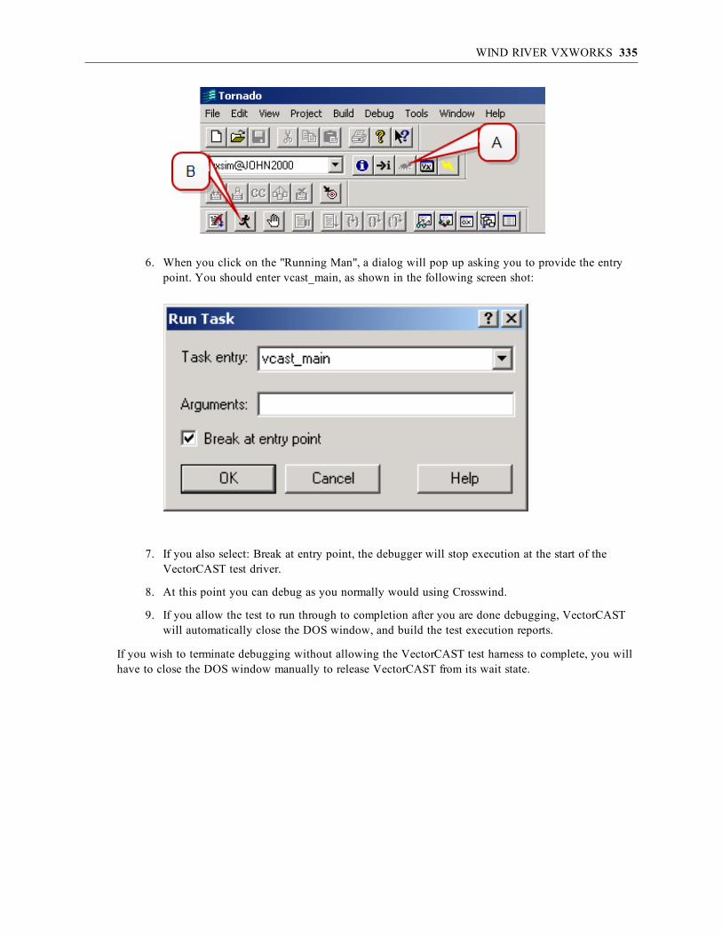
WIND RIVER VXWORKS 335
6. When you click on the "Running Man", a dialog will pop up asking you to provide the entrypoint. You should enter vcast_main, as shown in the following screen shot:
7. If you also select: Break at entry point, the debugger will stop execution at the start of theVectorCAST test driver.
8. At this point you can debug as you normally would using Crosswind.
9. If you allow the test to run through to completion after you are done debugging, VectorCASTwill automatically close the DOS window, and build the test execution reports.
If you wish to terminate debugging without allowing the VectorCAST test harness to complete, you willhave to close the DOS window manually to release VectorCAST from its wait state.

Execution Methods

INTRODUCTION 337
Execution via a Remote ShellIntroduction
In some cases, it may be necessary to execute test cases on a remote machine via a remote or secure shell.VectorCAST allows this through the execute commands <<remote_execution_rsh>>, <<remote_execution_ssh>>, execute_rsh.bat and execute_scp.sh. We shall refer to the two machines involved inthis process as local_machine (the host machine running VectorCAST) and remote_machine (the targetmachine where execution will occur). There should be a user account common to both machines whichwe’ll refer to as vcast_user.
These execute commands require the following:
1. The chosen VectorCAST compiler template has either no execute command associated with it orone of the <<remote_execution_xxx>> commands;
2. The chosen VectorCAST compiler template refers to a compiler that compiles and buildsexecutables compatible with remote_machine’s operating system and architecture;
3. The operating system on remote_machine supports either mounting a directory via the Network FileSystem (NFS), transferring files via anonymous ftp or transferring files via scp (secure copy).
4. The operating system on remote_machine is running an rsh or ssh server through which vcast_usercan login from local_machine without requiring a password.
Execution via a Remote ShellIntroduction
In some cases, it may be necessary to execute test cases on a remote machine via a remote or secure shell.VectorCAST allows this through the execute commands <<remote_execution_rsh>>, <<remote_execution_ssh>>, execute_rsh.bat and execute_scp.sh. We shall refer to the two machines involved in thisprocess as local_machine (the host machine running VectorCAST) and remote_machine (the targetmachine where execution will occur). There should be a user account common to both machines whichwe’ll refer to as vcast_user.
These execute commands require the following:
1. The chosen VectorCAST compiler template has either no execute command associated with it orone of the <<remote_execution_xxx>> commands;
2. The chosen VectorCAST compiler template refers to a compiler that compiles and buildsexecutables compatible with remote_machine’s operating system and architecture;
3. The operating system on remote_machine supports either mounting a directory via the NetworkFile System (NFS), transferring files via anonymous ftp or transferring files via scp (secure copy).
4. The operating system on remote_machine is running an rsh or ssh server through which vcast_user can login from local_machine without requiring a password.
Setting Up NFSNFS is most convenient as a way to transfer the files between the local_machine and the remote_machine.If your target does not support NFS, or if your host system is Windows, then skip to the next section forinformation on setting up anonymous ftp to transfer files.

EXECUTION VIA A REMOTE SHELL 338
The examples in this section assume that local_machine and remote_machine are both running a UNIXvariant operating system. On each machine, there exists a user named vcast_user whose home directory is/home/vcast_user.
Login to local_machine and create a test directory.
[vcast_user@local_machine ~]$ mkdir test_dir
[vcast_user@local_machine ~]$ touch test_dir/test_file_from_local
Login to remote_machine as vcast_user and create the exact same directory (the full path to the directorymust be identical on each machine).
[vcast_user@remote_machine ~]$ mkdir /home/vcast_user/test_dir
Next, login as root and mount the contents of the directory from local_machine using the Network FileSystem (NFS).
[root@remote_machine /]# mount local_machine:/home/vcast_user/test_dir/home/vcast_user/test_dir -t nfs
Note: This mount will not persist over a reboot. If remote_machine is rebooted frequently, you’llwant to add an entry to remote_machine’s /etc/fstab file. Contact your system administrator orVector Software technical support for assistance.
Now verify that remote_machine can see the test file that exists on local_machine:
[vcast_user@remote_machine ~]$ cd test_dir
[vcast_user@remote_machine ~/test_dir]$ ls
test_file_from_local
Finally you should verify that vcast_user has permission to write to this directory from remote_machine:
[vcast_user@remote_machine ~/test_dir]$ touch test_file_from_remote
Login to local_machine as vcast_user and verify that /home/vcast_user/test_dir/test_file_from_remoteexists.
Note: All VectorCAST environments must be built inside this common directory for execution viaa remote shell to succeed!
Setting Up Anonymous FTPIf your target does not support NFS or if your host system is Windows, then anonymous ftp is a suitablealternative to allow the transfer of files between the local_machine and the remote_machine.
First, you should verify that you can create a file in the /tmp directory on remote_machine:
[vcast_user@remote_machine ~]$ touch /tmp/test_file_from_remote
If you cannot create a file in /tmp, or if /tmp does not exist, you will need to change the permissions on,or create this directory.

EXECUTION VIA A REMOTE SHELL 339
Next, check if anonymous ftp is supported by the remote_machine. Open a shell window on the local_machine and type:
[vcast_user@local_machine ~]$ ftp remote_machine
User (remote_machine.server): anonymous
Password:
When prompted for a username, enter: anonymous. The remote_machine should indicate that anonymousaccess is allowed, and to enter an email address as a password. Once logged in, you should be able totype:
ftp> ls /tmp/test_file_from_remote
/tmp/test_file_from_remote
Setting Up scpIf your target does not support NFS but is running an ssh server and your host supports the scp command,then secure copy is a suitable alternative to allow the transfer of files between the local_machine and theremote_machine.
First, you should verify that you can create a file in the /tmp directory on remote_machine:
[vcast_user@remote_machine ~]$ touch /tmp/test_remote
If you cannot create a file in /tmp, or if /tmp does not exist, you will need to change the permissions on,or create this directory.
Next, check if scp is supported by the remote_machine. Open a shell window on the local_machine andtype:
[vcast_user@local_machine ~]$ touch test_local
[vcast_user@local_machine ~]$ scp test_local remote_machine:/tmp/
[vcast_user@local_machine ~]$ ssh vcast_user@remote_machine ls
/tmp/test_local
If you are prompted for a password during either the scp or ssh commands, follow the steps documentedin “Setting Up ssh” on page 340 to enable automatic authentication.
Setting Up rshIf remote_machine is running an rsh server, you can use the <<remote_execution_rsh>> executecommand to run test cases on remote_machine from local_machine.
Note: The required rsh.exe binary is not included in Windows 7 installations. Please see ouronline knowledgebase for information on how to resolve this issue.
From local_machine, run the following command:
[vcast_user@local_machine ~]$ rsh remote_machinePassword:

EXECUTION VIA A REMOTE SHELL 340
If you’re immediately logged into remote_machine without needing to enter a password, yourconfiguration is already set up – skip to the section “Target Execution Using a Remote Shell” on page345.
If you receive a “remote_machine: Connection refused” message, then remote_machine’s rsh server is notfunctioning. Contact your system administrator or skip to the section “Setting Up ssh” on page 340 to trya secure shell.
If you are prompted for a password, enter it and press Enter. Once you are logged on to remote_machine,edit or create the file ~/.rhosts adding the following line:
local_machine vcast_user
This will give vcast_user permission to rsh into remote_machine from local_machine without requiring apassword. Login again to confirm this behavior.
[vcast_user@remote_machine ~]$ exit
rlogin: connection closed.
[vcast_user@local_machine ~]$ rsh remote_machine
[vcast_user@remote_machine ~]$
If you are prompted for a password, review the above steps making sure you’ve done everything correctly.Contact your system administrator or Vector Software technical support for further assistance.
The last thing to ensure is that you can navigate to the common NFS mounted directory OR the /tmpdirectory, with permission to read, write and execute files. If you are using NFS for file sharing then type:
[vcast_user@remote_machine ~]$ cd test_dir
If you are using FTP for file sharing then type:
[vcast_user@remote_machine ~]$ cd /tmp
Next, verify that you can create a file:
[vcast_user@remote_machine ~/test_dir]$ touch test_file_via_rsh
If you receive a “touch: test_file_via_rsh: Permission denied” message you will have to adjust thepermissions on the directory.
If all of these tests have succeeded, you should now be able to skip to the “VectorCAST Configurationfor Remote Shell Execution” section on page 342 and choose <<remote_execution_rsh>> as your executecommand.
Setting Up sshIf remote_machine is running an ssh server, you can use the <<remote_execution_ssh>> executecommand to run test cases on remote_machine from local_machine.
From local_machine, run the following command:

EXECUTION VIA A REMOTE SHELL 341
[vcast_user@local_machine ~]$ ssh remote_machine
vcast_user@local_machine’s password:
If you’re immediately logged into remote_machine without needing to enter a password, yourconfiguration is already set up – skip to the section “Target Execution Using a Remote Shell” on page345.
If you receive a message similar to:
The authenticity of host 'local_machine (xxx.xxx.xx.xx)' can't be established.
RSA key fingerprint is xx:xx:xx:xx:xx:xx:xx:xx:xx:xx:xx:xx:xx:xx:xx:xx.
Are you sure you want to continue connecting (yes/no)?
…type yes and press Enter, followed by your password and Enter.
Once you’re able to login to remote_machine via ssh, you’ll need to automate the process so you’re notprompted for a password each time you run a test case. Logoff of remote_machine:
[vcast_user@remote_machine ~]$ exit
Connection to remote_machine closed.
Note: Disclaimer:The following documents one potential way to automate a secure shell login. In no way does itassume to account for all possible scenarios involving versions of ssh past, present or future. Bewarned that the following actions decrease the security level of the target machine and VectorSoftware takes no responsibility in doing so, nor in any or all behavior occurring as a result ofthese actions. Please consult your system administrator and/or management before continuing!
First, generate an authentication key on local_machine:
[vcast_user@local_machine ~]$ ssh-keygen -t rsa
Generating public/private rsa key pair.
Enter file to save the key (/home/vcast_user/.ssh/id_rsa): <Enter>
Enter passphrase (empty for no passphrase): <Enter>
Enter same passphrase again: <Enter>
Your identification has been saved in /home/vcast_user/.ssh/id_rsa.
Your public key has been saved in /home/vcast_user/.ssh/id_rsa.pub.
The key fingerprint is: xx:xx:xx:xx:xx:xx:xx vcast_user@local_machine
Then copy the key to remote_machine using secure copy (other methods are also fine, for example nfs,ftp, etc.):
[vcast_user@local_machine ~]$ scp ~/.ssh/id_rsa.pub remote_machine:~
vcast_user@remote_machine's password: [password]
Now login to remote_machine and add the new key to your ~/.ssh/authorized_keys file:
[vcast_user@local_machine ~]$ ssh remote_machine
vcast_user@remote_machine's password: [password]
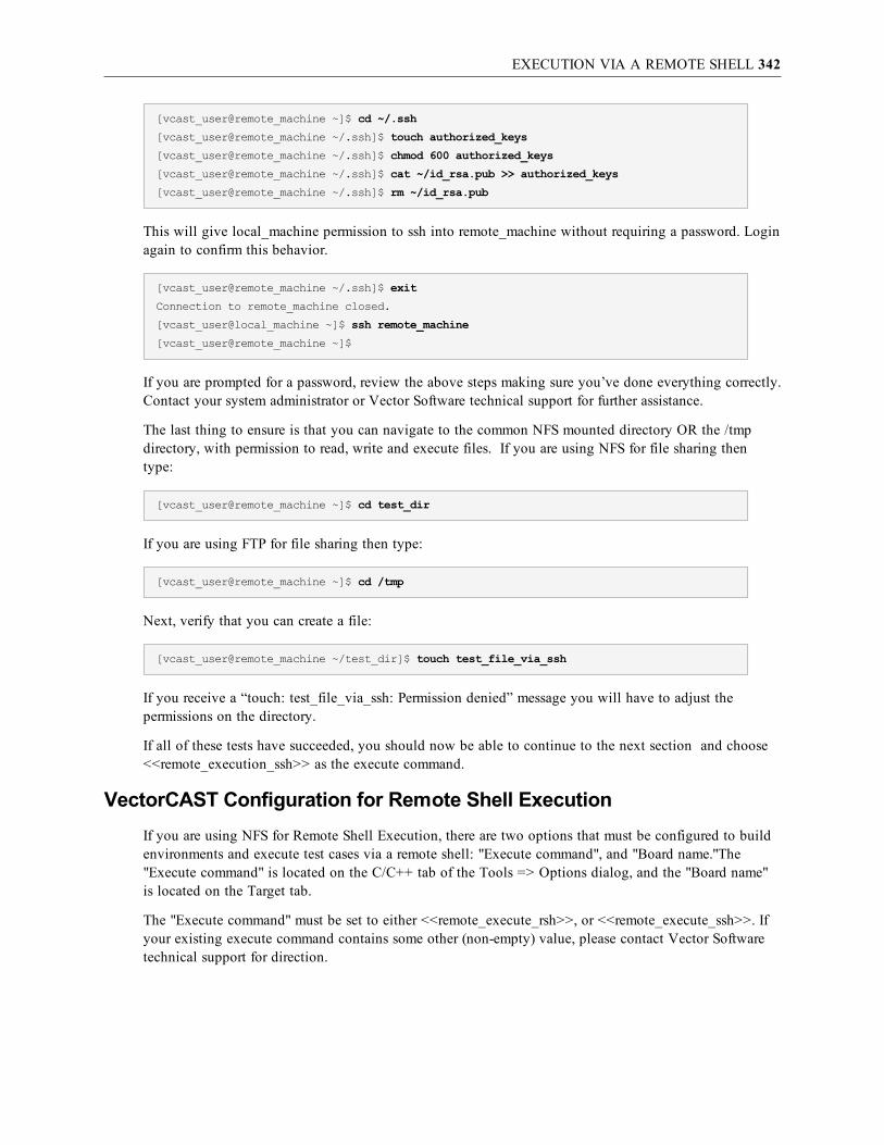
EXECUTION VIA A REMOTE SHELL 342
[vcast_user@remote_machine ~]$ cd ~/.ssh
[vcast_user@remote_machine ~/.ssh]$ touch authorized_keys
[vcast_user@remote_machine ~/.ssh]$ chmod 600 authorized_keys
[vcast_user@remote_machine ~/.ssh]$ cat ~/id_rsa.pub >> authorized_keys
[vcast_user@remote_machine ~/.ssh]$ rm ~/id_rsa.pub
This will give local_machine permission to ssh into remote_machine without requiring a password. Loginagain to confirm this behavior.
[vcast_user@remote_machine ~/.ssh]$ exit
Connection to remote_machine closed.
[vcast_user@local_machine ~]$ ssh remote_machine
[vcast_user@remote_machine ~]$
If you are prompted for a password, review the above steps making sure you’ve done everything correctly.Contact your system administrator or Vector Software technical support for further assistance.
The last thing to ensure is that you can navigate to the common NFS mounted directory OR the /tmpdirectory, with permission to read, write and execute files. If you are using NFS for file sharing thentype:
[vcast_user@remote_machine ~]$ cd test_dir
If you are using FTP for file sharing then type:
[vcast_user@remote_machine ~]$ cd /tmp
Next, verify that you can create a file:
[vcast_user@remote_machine ~/test_dir]$ touch test_file_via_ssh
If you receive a “touch: test_file_via_ssh: Permission denied” message you will have to adjust thepermissions on the directory.
If all of these tests have succeeded, you should now be able to continue to the next section and choose<<remote_execution_ssh>> as the execute command.
VectorCAST Configuration for Remote Shell ExecutionIf you are using NFS for Remote Shell Execution, there are two options that must be configured to buildenvironments and execute test cases via a remote shell: "Execute command", and "Board name."The"Execute command" is located on the C/C++ tab of the Tools => Options dialog, and the "Board name"is located on the Target tab.
The "Execute command" must be set to either <<remote_execute_rsh>>, or <<remote_execute_ssh>>. Ifyour existing execute command contains some other (non-empty) value, please contact Vector Softwaretechnical support for direction.

EXECUTION VIA A REMOTE SHELL 343
The “Board name” field must be set to the target machine's IP address or resolvable hostname.
Note: Hostnames are case sensitive.
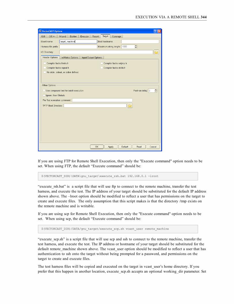
EXECUTION VIA A REMOTE SHELL 344
If you are using FTP for Remote Shell Execution, then only the "Execute command" option needs to beset. When using FTP, the default “Execute command” should be:
$(VECTORCAST_DIR)\DATA\gnu_target\execute_rsh.bat 192.168.0.1 -lroot
“execute_rsh.bat” is a script file that will use ftp to connect to the remote machine, transfer the testharness, and execute the test. The IP address of your target should be substituted for the default IP addressshown above. The –lroot option should be modified to reflect a user that has permissions on the target tocreate and execute files. The only assumption that this script makes is that the directory /tmp exists onthe remote machine and is writable.
If you are using scp for Remote Shell Execution, then only the "Execute command" option needs to beset. When using scp, the default “Execute command” should be:
$(VECTORCAST_DIR)/DATA/gnu_target/execute_scp.sh vcast_user remote_machine
“execute_scp.sh” is a script file that will use scp and ssh to connect to the remote machine, transfer thetest harness, and execute the test. The IP address or hostname of your target should be substituted for thedefault remote_machine shown above. The vcast_user option should be modified to reflect a user that hasauthentication to ssh onto the target without being prompted for a password, and permissions on thetarget to create and execute files.
The test harness files will be copied and executed on the target in vcast_user’s home directory. If youprefer that this happen in another location, execute_scp.sh accepts an optional working_dir parameter. Set

EXECUTION VIA A REMOTE SHELL 345
the “Execute command” field appropriately:
$(VECTORCAST_DIR)/DATA/gnu_target/execute_scp.sh vcast_user remote_machine working_dir
The working directory is relative to vcast_user’s home directory unless a full path is provided (passing in“tmp” would copy the test harness to /home/vcast_user/tmp whereas passing in “/tmp” would use /tmp).
Target Execution Using a Remote ShellBefore running test cases on a remote machine via a remote or secure shell, you must setup NFS ORanonymous ftp, setup automatic login with either rsh or ssh, choose the appropriate Execute command,and enter the target machine’s IP or hostname in the Tools => Options dialog, Target tab, Board namefield. See the above setup and configuration sections for details and additional requirements.
When a test case is executed via remote execution, VectorCAST will automatically execute an rsh or sshcommand to login to the target, cd to the environment directory and run the required program.
When running a test case, VectorCAST will output a message to the status window, similar to thefollowing:
Connecting to Target 'remote_machine' to Execute Program:
rsh remote_machine 'cd /home/vcast_user/test_dir/DEMO/; ./UUT_INTE'
A successful execution is followed by a “Test Execution Complete” message.
If you see a “Test Execution Failed” message in the Message window or receive a pop-up dialog with asimilar message, then your configuration is incorrect.
To help diagnose the problem, in the status window, highlight the command VectorCAST is trying torun, right-click and select Copy. Now paste that text into a shell on the host machine and run thecommand from there. You’ll receive more information about the problem, which will fall into one of threecategories:
l Automatic login via rsh/ssh is not setup properly (see page 338 or 340);
l Common directory is not NFS-mounted properly or has incorrect permissions (see page 337);
l The program VectorCAST is trying to run isn’t compatible with the target’s operating systemand/or machine architecture.
All of the above problems can be resolved by carefully going through the above setup and configurationsections. If you’ve successfully passed each section and are still having problems executing, contactVector Software support.
If you had previously built an environment on the host, you’ll want to rebuild the range data to acquirethe target’s type range information. Once you can successfully execute test cases, select Environment =>Rebuild Range Data. (This is only necessary if you modify the execute command after the environmenthas been built.)
Target Debug ExecutionDebugging the test harness on a remote machine via a remote or secure shell is similar to normalexecution. Ensure that the normal target execution is functioning properly before continuing (see the

EXECUTION VIA A REMOTE SHELL 346
preceding section).
To configure debug execution, choose Tools => Options from the main menu bar. Select the C/C++ tabfollowed by the Linker/Debug tab. The “Debugger command” field contains the debugger executable thatwill be invoked on the program VectorCAST is running. If you need to pass any specific arguments tothe debugger such as a startup file or target parameters, do so here:
The text from this field is copied exactly and inserted before the program in the remote command. Again,the command is displayed in the status window:
Connecting to Target 'remote_machine' to Execute Program:rsh remote_machine 'cd /home/vcast_user/test_dir/DEMO/; gdb ./UUT_INTE'
If this command succeeds, the debugger will start and you’ll be able to set breakpoints, step through thecode and view variables as usual. If the command fails, as the above section suggests, copy the exactcommand VectorCAST is running and run it on a local shell.
One problem that can arise specifically when trying execute with a graphical debugger is the DISPLAYvariable might not be set correctly for you to log into the target machine. A possible solution would beto set it in the Debugger command field: DISPLAY=local_machine:0.0 gvd.
If problems persist and you’ve reviewed all the above configuration settings, please contact VectorSoftware technical support for further assistance.

STANDARD I/O 347
Standard I/OIntroduction
When running a VectorCAST test, the test harness needs to read in the test stimulus data, and create thetest results via some Input Output (I/O) mechanism. For all host (native) environments and many targetenvironments, the I/O takes place via file operations. When the test harness needs to read the stimulusdata, it will open the input data file, and read the stimulus data. Similarly, when the test harness needs towrite the results data, it will create an output data file, and write to that file. The input data is actuallycontained in several files, and the output data is actually written to several files.
In some target test environments, file operations, while supported, may be slow. The slowness is generallya function of the underlying connection mechanism that is used to connect the target to your network, theoperating system being used, or some other unknown factor. In this case, or where there is no file IOcapability from the target, the last resort solution is to use the Standard I/O mechanism to improveperformance.
There are two methods for customizing file I/O. One method uses the test harness standard input (stdin)and standard output (stdout) for the input and output data. VectorCAST will concatenate all input into asingle file before the test is run (VCAST_STDIN.DAT). After the test is run, VectorCAST expects all ofthe output data to exist in the file: VCAST_STDOUT.DAT. The second method uses the compiler tocompile the input test data directly into the test harness, and uses standard output for the output data.
Using either of these methods requires configuration options to be set for both the VectorCASTapplication and for the test harness. The following sections describe the configuration process in detail.
Configuring to Use Stdin and StdoutTo configure the test harness to use stdin and stdout for I/O, you must set the option: "I/O usesstdin/stdout". This option is located on the "Target" tab of the Tools => Options dialog, as shown in thefollowing screen shot:

STANDARD I/O 348
This option causes the defined variable VCAST_STDIO to be set when the VectorCAST I/O module iscompiled. If you set this option after a test environment is already built, you will need to use theEnvironment => Recompile => Automatic command to recompile the test harness with this setting active.When this option is active, the test harness will read input data from stdin, and all output data will bewritten to stdout.
VectorCAST can be configured for manual or automatic text execution. To configure for automatic testexecution, set the environment variable VCAST_EXECUTE_WITH_STDIO to True. This environmentvariable must be set at the operating system level before VectorCAST is started.
To configure for manual test execution, set the option: Execute Command to “<<stdio>>.” This option islocated on the Tools => Options dialog, C/C++ tab, as shown below.

STANDARD I/O 349
Target Execution - Stdin/Stdout (Automatic)When the environment variable VCAST_EXECUTE_WITH_STDIO is set to True, VectorCAST willexecute test cases automatically using the Execute Command specified on the Tools => Options dialog,C/C++ tab. (For example, the execute command simppc is used for Green Hills PPC Simulator C++.)VectorCAST automatically redirects the stdin of the process to the file VCAST_STDIN.DAT, and theoutput to the file VCAST_STDOUT.DAT.
Target Execution - Stdin/Stdout (Manual)Setting the “Execute Command” string to be “<<stdio>>” tells VectorCAST to concatenate all input datafor the harness into a single file that can be mapped to stdin for the target, and to expect all output datato be available in a single file after the target executes. The input filename is VCAST_STDIN.DAT andthe output filename is VCAST_STDOUT.DAT. Both of these files are in the VectorCAST environmentdirectory.
All the steps in between are performed by you. The nominal sequence to run in this mode is as follows:
1. VectorCAST creates VCAST_STDIN.DAT.
2. VectorCAST puts up the following dialog and “hangs” waiting for you to run the targetprogram:

STANDARD I/O 350
3. Run the target program (in this case UUT_INST.EXE) on your host machine, simulator, ortarget, with the stdin mapped to the file VCAST_STDIN.DAT and the output mapped toVCAST_STDOUT.DAT. (For example, execute the command “UUT_INST < VCAST_STDIN.DAT > VCAST_STDOUT.DAT”.)
4. When the target program is done, click OK in this dialog.
5. VectorCAST will come off its “hang” and post process the VCAST_STDOUT.DAT file tocreate all of the normal VectorCAST execution reports.
Configuring to Use Stdout OnlyTo configure the test harness to use stdout, you must set the option: “I/O uses stdout only” in addition to"I/O uses stdin/stdout". These options are located on the "Target" tab of the Tools => Options dialog, asshown in the following screen shot:

STANDARD I/O 351
This additional option causes the defined variable VCAST_STDOUT to be set, when the VectorCASTI/O module is compiled. If you set these options after a test environment is already built, you will need touse the Environment => Recompile => Automatic command to recompile the test harness with thissetting active. When these options are active, the test harness will read input data compiled into theharness, and all output data will be written to stdout.
VectorCAST can be configured for manual or automatic text execution. To configure for automatic testexecution, set the environment variable VCAST_EXECUTE_WITH_STDOUT to True. This environmentvariable must be set at the operating system level before VectorCAST is started. To configure for manualtest execution, set the option: Execute Command to “<<stdout>>”. This option is located on the Tools=> Options dialog, C/C++ tab, as shown below.

STANDARD I/O 352
Target Execution - Stdout (Automatic)When the environment variable VCAST_EXECUTE_WITH_STDOUT is set to True, VectorCAST willexecute test cases automatically using the Execute Command specified on the Tools => Options dialog,C/C++ tab. (For example, the execute command simppc is used for Green Hills PPC Simulator C++.)VectorCAST automatically redirects the output to the file VCAST_STDOUT.DAT.
Target Execution - Stdout (Manual)Setting the “Execute Command” string to be “<<stdout>>” tells VectorCAST to write all output data to afile after the target executes. The output filename is VCAST_STDOUT.DAT. This file is located in theVectorCAST environment directory.
All the steps in between are performed by you the tester. The nominal sequence to run in this mode is asfollows:
1. VectorCAST puts up the following dialog and “hangs” waiting for you to run the targetprogram:

VECTORCAST MONITOR 353
2. Run the target program (in this case UUT_INST.EXE) on your host machine, simulator, ortarget, with the output mapped to VCAST_STDOUT.DAT. (For example, execute the command“UUT_INST > VCAST_STDOUT.DAT”.)
3. When the target program is done, click OK in this dialog.
4. VectorCAST will come off its “hang” and post process the VCAST_STDOUT.DAT file tocreate all of the normal VectorCAST execution reports.
For more information on using this functionality please contact Vector Technical Support via e-mail [email protected].
VectorCAST MonitorIf there exists a command line interface that allows downloading of the target via a serial port, it may bepossible to use the VectorCAST monitor functionality.
For information on using this functionality please contact Vector Software Technical Support via e-mailat [email protected].

Index: <<STDIO>> – CLICAST
Index
<<stdio>> 348
<<stdout>> 352
Adelante Software Development Kit 156
Analog Devices' Visual DSP 46
application partition 320
ARM
configuring 48
armsd 14
assembler command 27
ASSEMBLER_CMD 27
banked memory 143
banked memory model
CodeWarrior HC12 116
batch execute all 39
Board Name 30
Boot Hostname 31
Buffer I/O 36, 243
C/C++
options 26
cannot open additional I/O files
Renesas HEW - M16C/R8C 283
CLICAST
accessing in Unix 24
accessing in Windows 24
command format 24
command format, compound or init 25
option
Target_Board_Name 30
options
ASSEMBLER_CMD 27
COMREADER_BAUD 37
COMREADER_COMPORT 37
COMREADER_DATA_BITS 37
COMREADER_ENABLED 36
COMREADER_PARITY 37
COMREADER_STOP_BITS 37
MAX_VARY_RANGE 38
PRECOMPILE_CMD 28
PRECOMPILE_EXT 28
SCORE_DEBUG_CMD 41
SCORE_EXECUTE_CMD 41
STARTUP_FILE 28
SUBSTITUTE_CODE_FOR_C_FILE 41
TARGET_BOOT_HOSTNAME 31
TARGET_IO_DIRECTORY 31
TARGET_SIM_CMD 41
TEST_CASE_TIMEOUT 40
VCAST_BUFFER_OUTPUT 36
VCAST_DISABLE_TI_BITFIELD 38
VCAST_DISABLE_TI_STRING 38
VCAST_DUMP_BUFFER 36
VCAST_ENVIRONMENT_FILES 29, 41
VCAST_EXECUTE_WITH_STDIO 35
VCAST_EXECUTE_WITH_STDOUT 36
VCAST_FAR_STDIN_DATA 41
VCAST_FILE_INDEX 36
VCAST_FILE_PREFIX 30
VCAST_FORCE_NO_USERGLOBALS 37
VCAST_GH_INT_FILE 42
VCAST_GH_INTEX_CMD 41
VCAST_IGNORE_PSC_RAM_PAYLOAD_REBOOT_STATUS 34
VCAST_MAIN 40
VCAST_MAX_HEAP_SIZE 39
- 354 -

Index: CMDIDE – CODEWARRIOR HC12
VCAST_MAX_STRING_LENGTH 31
VCAST_MAX_TARGET_FILES 40
VCAST_MINIMAL_TERMINATION 38
VCAST_MONITOR 42
VCAST_NO_EXIT 39
VCAST_NO_FFLUSH 42
VCAST_NO_FLOAT 38
VCAST_NO_LIMITS 31
VCAST_NO_MALLOC 39
VCAST_NO_SETJMP 32
VCAST_NO_SIGNAL 32
VCAST_NO_STD_FILES 32
VCAST_NO_STDIN 35
VCAST_NO_STDLIB 32
VCAST_NO_TYPE_SUPPORT 38
VCAST_OUTPUT_BUFFER_SIZE 36
VCAST_POST_RUN_DELAY 40
VCAST_PRE_EXECUTE_CMD 40
VCAST_PSC_RAM_PAYLOAD 34
VCAST_PSC_RAM_PAYLOAD_REBOOT_CMD 34
VCAST_PSC_USE_ADDRESS_SPACE 33
VCAST_RELINK_PROMPT_FOR_PSC_RAM_PAYLOAD 34
VCAST_STDIO 35
VCAST_TORNADO_CONSTRUCTOR_CALL_FILE 33
VCAST_USE_COMPOUND_FOR_BATCH 39
VCAST_USE_WINDSH_DOT_BAT 33
VCAST_USE_WINDSH_IO_REDIRECTION 33
VCAST_VXWORKS 32
VCAST_VXWORKS_NO_CSHELL 33
VCAST_VXWORKS_RTP_MODE 33
template 26
cmdIDE 14
Code Composer
C3x v4.1, configuring 52
debugging with 60
default memory map 59
stand-alone, target execution 58
Studio 2, target execution 57
Studio 3.1, 3.3, target execution 55
Studio 4.0, target execution 53
Studio 4.2, target execution 85, 94
Studio 4.2.4, configuring for LM3S9B92 evalboard 83, 91
Studio 6x, configuring 52
Studio, configuring for 6713 target board 65, 69
Studio, configuring for DSP/BIOS 61
Studio, configuring for OMAP 35x EVM targetboard 75
CodeWarrior DSP56800E
configuring 103
target debug execution 106
target execution 105
CodeWarrior for MPC
configuring 126
target debug execution 128
target execution 127
CodeWarrior for MPC 8315
configuring 129, 138
port settings 135, 140
target debug execution 136, 142
target execution 134, 139
CodeWarrior for USB TAP
installation 129
CodeWarrior HC12
configuring 113
- 355 -
Index: CODEWARRIOR HCS08 – ENVIRONMENT VARIABLES
configuring for banked memory model 116
target debug execution 118
target execution 117
CodeWarrior HCS08
configuring 119
target debug execution 124
CodeWarrior StarCore SC140e
configuring 108
target debug execution 109
target execution 109
combining host- and target-based testing 23
communication details 13
communication overview 12
Compiler lacks limits.h 31
Compiler lacks setjmp.h 32
Compiler lacks signal.h 31
Compiler lacks stdlib.h 32
concepts 11
Cosmic
target debug execution 151
Cosmic 68HC12
configuring 143
target execution 149
Cosmic HCS12X
configuring 145
target execution 149
Cosmic STM8 on STVD
configuring 153
target debug execution 155
target execution 155
Cosmic STM8 on ZAP
configuring 152
target debug execution 155
target execution 154
Create a Tornado constructor call source file 33
cscript 47
data driven test harness 12
Diab with TRACE32
configuring 312
target debug execution 303, 313
target execution 313
Diab/SingleStep
configuring 309
target execution 309
dump buffer 36
environment creation 23
environment does not execute
Renesas HEW - SH 289
environment files 29
environment variables
$(ENV_VAR) in CCAST_.CFG file 28-29
A166INC 302
BIOS_INSTALL_DIR 66, 71, 77
C166INC 224, 302
C166LIB 224
CCStudio Scripting libraries on PATH 56, 67,73, 81
CodeWarrior binaries on PATH 103, 108,113, 119
CodeWarrior for MPC 8315 on PATH 133,138
CodeWarrior for MPC on PATH 126
Cosmic binaries on PATH 143, 146
cscript on PATH 47
DEBUGSERVER_ROOT 84, 92
Diab binaries on PATH 312
EVP binaries on PATH 156
EVP_INSTALL_BASE 156
HighTec compiler on PATH 178
HLNK_LIBRARY 285
IAR binaries on PATH 183-184, 187
Keil binaries on PATH 224, 227
Keil for ARM on PATH 231, 235
- 356 -

Index: EXECUTE COMMAND – FILES
Lauterbach TRACE32 debugger on PATH 126
MicroChip compiler on PATH 246, 249
MWCINCLUDES 126, 133, 138
MWCLIBRARIES 126, 133, 138
MWCLIBRARYFILES 126, 133, 138
NEC binaries on PATH 254
P_186_STARTUP_FILES 259
Paradigm binaries on PATH 259
Perl utilities on PATH 56, 67, 73, 81
PERL5LIB 56, 66-67, 71, 73, 77, 81
Renesas compiler on PATH 285
RVCT31INC 231, 235
RVCT31LIB 231, 235
SC100_HOME 108
SCTOOLS_HOME 108
SHC_INC 285
SHC_LIB 285
SHC_TMP 285
T32ID 302
T32SYS 302
T32TMP 302
Tasking binaries on PATH 291, 293, 302
Tornado-specific 316
Tornado binaries on PATH 316
TriMedia binaries on PATH 305
VCAST_CCS_INSTALL_DIR 66, 71, 77, 83,91
VCAST_CUSTOM_QUALIFIERS 116
VCAST_CW_INSTALL_DIR 133, 138
VCAST_EXECUTE_WITH_STDIO 348-349
VCAST_EXECUTE_WITH_STDOUT 351-352
VCAST_GH_INT_FILE 174
VCAST_IAR_CONFIG_DIR 187, 192-193,198-199, 204-205, 209, 214, 220
VCAST_IAR_INSTALL_DIR 187, 192-193,198, 204, 209, 214, 220
VCAST_KEIL_ARM_INSTALL_DIR 235
VCAST_MICROCHIP_INSTALL_DIR 246,249
VCAST_RENESAS_INSTALL_DIR 285
VCAST_SERIAL_CFG 117, 128, 133, 135,138, 140, 206, 244, 249, 264
VCAST_T32 312
VCAST_TASKING_INSTALL_BASE 296, 298,302
VCAST_TRACE32 302
VisualDSP binaries on PATH 44
WIND_DIAB 312
WIND_HOME 312
WIND_PREFERRED_PACKAGES 312
WRS-specific 317
WRS binaries on PATH 317
WRSD_LICENSE_FILE 312
execute command
list of 14
Execute using stdin and stdout 35
Execute using stdout only 35, 243
Execute with windsh.bat 32
execution hangs
Renesas HEW - M16C/R8C 283
Renesas HEW - SH 289
execution methods 21, 337
Explorer16
configuring MicroChip MPLAB for PIC24on 249
files
#included .c files 41
.xfw_dbginit.cmd 297
.xfw_exeinit.cmd 297
c167.cfg 297
debug.dscr 299
dspicsimldll 211, 216
execute_rsh.bat 344
execute_scp.sh 344
- 357 -
Index: FLAGS – IAR EMBEDDED WORKBENCH 4.X
IAR device description file 210, 215
iar_lnkdspic_16kRAM.xcl 210, 215
limits.h 31
lm3s9b92_evb.ccxml 85, 94
loadti.bat 85-86, 94-95
main.js 87, 96
MPC5554.cmm 243
MPC5554_debug.cmm 243
prepend /tgtsvr/ to names of 30
setjmp.h 32
signal.h 31
stdlib.h 32
target cannot write to 36
TESTDATA.DAT 30
Tornado constructor source call 33
UUT_INST.mod 176
UUT_INTE.out 88, 100
vcast.int 173
vcast_debug.out 211, 217
VCAST_STDIN.DAT 35, 347
VCAST_STDOUT.DAT 35, 347
VectorCAST_SinglePartition.zip 323
windsh.bat 32
windsh.scr 318
windsh.src 33
flags
list of 18
ftp
setting up to execute tests remotely 338
Fujitsu Softune
configuring 159, 161
target execution 160, 162
Green Hills Bare Board
configuring 163
Green Hills INTEGRITY mpserv
configuring 169
target execution 171
Green Hills INTEGRITY rtserv
configuring 172
target execution 174
Green Hills INTEGRITY Simulator
configuring 167
Green Hills Simulator
configuring 163
Green Hills targets
improving target execution speed 165, 168,171, 176
target execution 164
grun 15
harness architecture 11
Harness File Prefix 30
heap resources, limited 31
Hightec TriCore-gcc
configuring 178
target debug execution 182
HyperTerminal 117, 128, 135, 140, 244, 261, 268
I/O devices
problems with 328
I/O Directory 30
I/O paths
problems with 328
I/O performance 331
I/O uses stdin/stdout 35, 332, 347
I/O uses stdout only 35, 243, 350
IAR 1.4 for dsPIC
target debug execution 215, 217
IAR Embedded Workbench 3.x
configuring 183
target debug execution 185, 195, 201, 212,217, 222
target execution 184
IAR Embedded Workbench 4.x
configuring 192
- 358 -

Index: IAR EMBEDDED WORKBENCH 5.X – OPTIONS
IAR Embedded Workbench 5.x
configuring 198, 209, 214, 220
IAR Embedded Workbench 6.x
MSP430X 5.1 Large Memory Model
configuring 187
target debug execution 189
target execution 189
IAR Embedded Workbench v5.5 configuring 204
IAR Embedded Workbench v6.3
default serial port settings 206
HyperTerminal 206
IAR installation and target customizations 205
target debug execution 207
target execution 206
IAR Embedded Workbench v6.3.
configuring 204
insufficient heap
Renesas HEW - SH 288
IO link to target 13
IO mechanisms 13
execute command 13
flags 18
JTAG server 178
Keil C166
configuring 224
target execution 229
Keil C51
configuring 227
target execution 229
Keil for ARM
configuring 231
target debug execution 233
Keil for ARM Corex M3
environment files 238
integration notes 238
Keil for ARM Cortex M3
configuring 235
ITM 236
Instrumentation Trace Macrocell 236
ITM 236
itm.h, config.h 238
target debug execution 239
target execution 239
uVision project file 236
kernel partition 320
Load executable as a Real_Time Process (RTP) 33
making your tests run faster 23
Max string length 31
MicroChip MPLAB for dsPIC
configuring 246
MicroChip MPLAB for PIC24 on Explorer16
configuring 249
mpserv 15
NEC V850
configuring 254
target execution 257
NFS
setting up to execute tests remotely 338
No stdin, stdout, or stderr defined 32
NXP EVP C compiler for VD3204x
configuring 156
options
assembler command 27
board name 30
boot hostname 31
Buffer I/O 36, 243
Build test harness into a vxWorks PSCpartition 33
C/C++ 26
CLICAST-only 41
Compiler Integration tab 27
- 359 -

Index: OUTPUT BUFFER SIZE – REMOTE SHELL EXECUTION
Compiler lacks limits.h 31
Compiler lacks setjmp.h 32
Compiler lacks signal.h 31
Compiler lacks stdlib.h 32
Create a Tornado constructor call sourcefile 33
dump buffer 36
environment files 29
Execute using stdio and stdout 35
Execute using stdout only 35, 243
Execute with windsh.bat 32
far stdin data 41
file index 36
File indexing mode 36
gh intex command 41
gh intex filename 42
Harness file prefix 30
I/O directory 30
I/O uses stdin/stdout 35, 347
I/O uses stdout only 35, 243, 350
Load executable as a Real-Time Process 33
Maximum string length 31
Maximum target files 40
no fflush 42
No stdin, stdout, or stderr defined 32
Omit code to trap explicit calls to syslib 'exit()' 39
output buffer size 36-39
Post-run delay 40
Pre-test execution command 40
precompile command 28
precompile extension 28
Running with vxWorks headers 32
SCORE debug command 41
SCORE execution command 41
startup file 28
substitute code for .c file 41
target
I/O uses stdin/stdout 332
Target 29
target simulator command 41
Testcase timeout 40
TFTP boot directory 40
Use 'vcast-main()' in place of 'main()' 39
use compound test for batch execution 39
Use RAM payload 34
use serial line I/O 42
Use windsh I/O redirection 33
vcast environment files 41
vxWorks 653 Build directory 34
output buffer size 36-39
overview 11
Paradigm
configuring 259, 264
target debug execution 262, 268
partition
application, running vxWorks in 320
kernel, running vxWorks in 320
Post-run delay 40
precompile command 28
precompile extension 28
PRECOMPILE_CMD 28
PRECOMPILE_EXT 28
PXROS TriCore System DevelopmentPlatform 178
QNX
target debug execution 271
QNX Momentics
configuring 270
QNX Neutrino
configuring 270
remote shell execution
configuring 342, 344
- 360 -

Index: REMOTE TEST EXECUTION – TARGET DEBUG EXECUTION
of target 345
of target, debug 345
remote test execution
requirements for 337
setting up anonymous ftp for 338-339
setting up NFS for 338
setting up rsh for 339
setting up ssh for 340
Renesas HEW - M16C/R8
cannot open additional I/O files 283
execution hangs 283
Renesas HEW - M16C/R8C
configuring 273
target execution 282
troubleshooting 283
Renesas HEW - SH
environment does not execute 289
execution hangs 289
insufficient heap 288
target execution 288
troubleshooting 288
Renesas HEW - SuperH
configuring 285
rsh
setting up to execute tests remotely 339
under Windows 7 339
rtasim 15
rtserv 41
runmc 17
Running with vxWorks headers 32
runsim 14
SBC
vxWorks 653 example 323
SBC83XX PowerQUICC II Pro developmentboard 323
scarc 17
scp
setting up to execute tests remotely 339
sim850 15
simarm 15
simmips 15
ssh
setting up to execute tests remotely 340
stack resources, limited 31
Standard I/O
configuring 347
target execution 349
Standard out
target execution 352
startup file 28
STARTUP_FILE 28
target
problems connecting to 327
target debug execution
ARM 50
CodeWarrior DSP56800E 106
CodeWarrior for MPC 128
CodeWarrior for MPC 83 136, 142
CodeWarrior HC12 118
CodeWarrior HCS08 124
CodeWarrior StarCore SC 140e” 109
Cosmic 151
Cosmic STM8 on STVD 155
Cosmic STM8 on ZAP 155
Diab with TRACE32 303, 313
Embedded Workbench 3.x 185, 195, 201, 212,217, 222
Embedded Workbench v6.3 207
Green Hills Multi Debugger 164
Hightec TriCore-gcc 182
IAR 1.4 for dsPIC 215, 217
IAR Embedded Workbench 6.x 189
Keil for ARM 233
- 361 -

Index: TARGET EXECUTION – TASKING C166 CLASSIC
Keil for ARM Cortex M3 239
Paradigm 262, 268
QNX 271
remote shell 345
Tasking 563xx 294
Tasking 56K 292
Tasking C166 Classic 297
Tasking C166 VX 299
Tasking Tricore 301
with TRACE32 debugger 244
target execution
a graphical debugger 346
Code Composer 58
Code Composer Studio 3.1, 3.3 55
Code Composer Studio 4.0 53
Code Composer Studio 4.2 85, 94
Code Composer Studio2 57
CodeWarrior DSP56800E” 105
CodeWarrior for MPC 127
CodeWarrior for MPC 8315 134, 139
CodeWarrior HC12” 117
CodeWarrior StarCore SC140e” 109
Cosmic 68HC12 149
Cosmic HCS12X 149
Cosmic STM8 on STVD 155
Cosmic STM8 on ZAP 154
Diab with TRACE32 313
Fujitsu Softune 160, 162
Green Hills INTEGRITY mpserv 171
Green Hills INTEGRITY rtserv 174
Green Hills targets 164
IAR Embedded Workbench 3.x 184
IAR Embedded Workbench 6.x 189
improving speed of 165, 168, 171, 176, 347
Keil C166 229
Keil C51 229
NEC V850 257
remote shell 345
Renesas HEW - M16C/R8C 282
Renesas HEW - SH 288
SingleStep 309
Standard IO 349
stdout 352
Tasking 563xx 293
Tasking 56K 291
Tasking C166 Classic 297
Tasking C166 VX 299
Tasking Tricore 301
Tasking with TRACE32 302
TriMedia 307
Visual DSP 46
vxWorks 318
vxWorks 653 319
with the VectorCAST Monitor 353
target interaction after environment creation 23
target testing
combining host and target based testing 23
TARGET_BOARD_NAME 30
TARGET_BOOT_HOSTNAME 31
TARGET_IO_DIRECTORY 30
TARGET_TFTP_DIRECTORY 40-41
Tasking 563xx
configuring 293
target debug execution 294
target execution 293
Tasking 56K
configuring 291
target debug execution 292
target execution 291
Tasking C166 Classic
configuring 296
target debug execution 297
- 362 -

Index: TASKING C166 VX – VISUAL DSP
target execution 297
Tasking C166 VX
configuring 298
target debug execution 299
target execution 299
Tasking Tricore
configuring 300
target debug execution 301
target execution 301
Tasking with TRACE32
configuring 302
target execution 302
templates 26
test harness
architecture 13
data driven 12
TEST_CASE_TIMEOUT 40
tmsim 18
Tornado constructor call file
creating 33
TRACE32 debugger 126
configuring 242
target debug execution 244
TriMedia
configuring 305
target execution 307
troubleshooting
Renesas HEW - M16C/R8C 283
Renesas HEW - SH 288
trserv 16
USB TAP, CodeWarrior
installation 129
Use compound test for batch execution 39
Use windsh I/O redirection 33
VCAST_BUFFER_OUTPUT 36
VCAST_ENVIRONMENT_FILES 29
VCAST_EXECUTE_WITH_STDIO 35, 348-349
VCAST_EXECUTE_WITH_STDOUT 35, 351-352
VCAST_FILE 174
VCAST_FILE_INDEX 36
VCAST_FILE_PREFIX 30
VCAST_GH_INT_FILE 174
VCAST_MAIN 39
VCAST_MAX_STRING_LENGTH 31
VCAST_MAX_TARGET_FILES 40
VCAST_NO_EXIT 39
VCAST_NO_LIMITS 31
VCAST_NO_SETJMP 32
VCAST_NO_SIGNAL 31
VCAST_NO_STD_FILES 32
VCAST_NO_STDIN 35
VCAST_NO_STDLIB 32
VCAST_OUTPUT_BUFFER_SIZE 36-39
VCAST_POST_RUN_DELAY 40
VCAST_PRE_EXECUTE_CMD 40
VCAST_PSC_RAM_PAYLOAD 34
VCAST_PSC_USE_ADDRESS_SPACE 33
VCAST_STDIO 35
vcast_tgt.elf.mcp file 135, 140
VCAST_TORNADO_CONSTRUCTOR_CALL_FILE 33
VCAST_USE_COMPOUND_FOR_BATCH 39
VCAST_USE_WINDSH_DOT_BAT 32
VCAST_USE_WINDSH_IO_REDIRECTION 33
VCAST_VXWORKS 32
VCAST_VXWORKS_RTP_MODE 33
VectorCAST Monitor 353
VectorCAST/RSP
configuring for Code Composer C3x v4.1 52
configuring for Standard I/O 347
VECTORCAST_DIR 24
Visual DSP
list targets and platforms 47
- 363 -

Index: VISUALDSP – ZAP DEBUGGER
target execution 46
VisualDSP
configuring 44
vrun.bat 15
vxSim 315
vxWorks 653 example 320
vxWorks 30
configuring 318
overview 315
target execution 318
troubleshooting connection to the target 326
vxWorks 653
example using SBC 323
example using vxSim 320
target execution 319
Wind River
ELF executable file for TRACE32 244
Windows 7
support for rsh 339
windsh 315
ZAP debugger 143
- 364 -
Copyright © 2022 FDOKUMEN