NTC Thermistor for Automotive: TSM-C Series
77
-
Upload
khangminh22 -
Category
Documents
-
view
0 -
download
0
Transcript of NTC Thermistor for Automotive: TSM-C Series
DHTSCKTGMTSMTSM-CTTC03TTC05TTC05TTFTTS
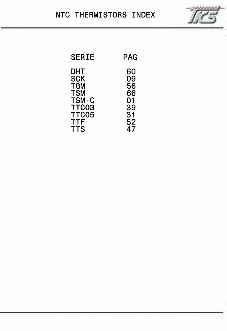
SERIE PAG
DHT 60SCK 09TGM 56TSM 66TSM-C 01TTC03TTC03 39TTC05 31TTF 52TTS 47
NTC THERMISTORS INDEX

NTC Thermistor for Automotive: TSM-C Series
SMD NTC Thermistor for Temperature Sensing
THINKING ELECTRONIC INDUSTRIAL CO., LTD. 1 www.thinking.com.tw 2011.06
All specifications are subject to change without notice.
Features 1. Qualification based on AEC-Q200 Rev-C
2. Operating temperature range: -50 ~ +150
3. Superior stability in high-temperature and high-humidity environment
4. RoHS compliant
Recommended Applications 1. Car audio, car navigation
2. Various engine control units
3. Circuits for ETC equipment
4. Various motor driving circuits
5. Temperature compensation for various circuits
Part Number Code
Structure and Dimensions
(Unit: mm)
1 2 3 4 5 6 7 8 9 10 11 12 13 14 15 16
Part No. Size L1. W H max. L2 & L3
TSM1 0603 1.60±0.15 0.80±0.15 0.95 0.40±0.15
TSM2 0805 2.00±0.20 1.25±0.20 1.20 0.40±0.20
Product Type
TSM THINKING
NTC Thermistor TSM Series
Size (EIA) A 0201 0 0402 1 0603 2 0805
Definition of
B Value C B25/85 D B25/50
Zero Power Resistance at 25 (R25)
102 10x102Ω= 1 KΩ
103 10x103Ω=10 KΩ
473 47x103Ω=47KΩ
Tolerance of R25
F ±1% G ±2% H ±3% J ±5% K ±10%
First Two Digits of B Value
30 31 32 : ︰ 40 41 ︰
30 31 32 : ︰ 40 41
︰
Last Two Digits of B Value
0 A 1 B 2 ︰ H 8 J 9 K
00 05 10 15 20 ︰ 75 80 85 90 95
Tolerance of B Value
1 ±1% 2 ±2% 3 ±3%
Packaging
R Reel B Bulk
Optional Suffix
NTC Thermistor for Automotive: TSM-C Series
SMD NTC Thermistor for Temperature Sensing
THINKING ELECTRONIC INDUSTRIAL CO., LTD. 2 www.thinking.com.tw 2011.06
All specifications are subject to change without notice.
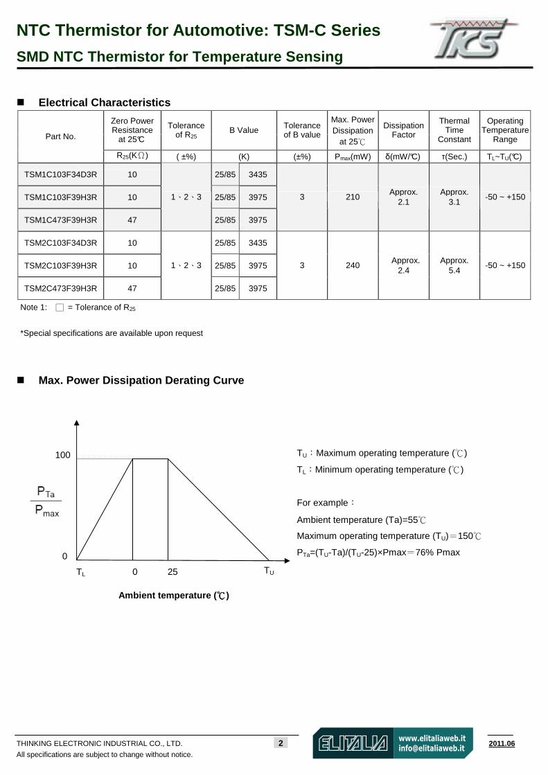
Electrical Characteristics
Zero Power Resistance
at 25°C
Tolerance of R25
B Value Tolerance of B value
Max. Power Dissipation
at 25
Dissipation Factor
Thermal Time
Constant
Operating Temperature
Range Part No.
R25(KΩ) ( ±%) (K) (±%) Pmax(mW) δ(mW/°C) τ(Sec.) TL~TU(°C)
TSM1C103F34D3R 10 25/85 3435
TSM1C103F39H3R 10 25/85 3975
TSM1C473F39H3R 47
1、2、3
25/85 3975
3 210 Approx.
2.1 Approx.
3.1 -50 ~ +150
TSM2C103F34D3R 10 25/85 3435
TSM2C103F39H3R 10 25/85 3975
TSM2C473F39H3R 47
1、2、3
25/85 3975
3 240 Approx.
2.4 Approx.
5.4 -50 ~ +150
Note 1: = Tolerance of R25
*Special specifications are available upon request
Max. Power Dissipation Derating Curve
100
0 25 TU
0
TL
Ambient temperature ( )
TU:Maximum operating temperature ()
TL:Minimum operating temperature ()
For example:
Ambient temperature (Ta)=55
Maximum operating temperature (TU)=150
PTa=(TU-Ta)/(TU-25)×Pmax=76% Pmax
NTC Thermistor for Automotive: TSM-C Series
SMD NTC Thermistor for Temperature Sensing
THINKING ELECTRONIC INDUSTRIAL CO., LTD. 3 www.thinking.com.tw 2011.06
All specifications are subject to change without notice.
Temperature ( )
Temperature ( )
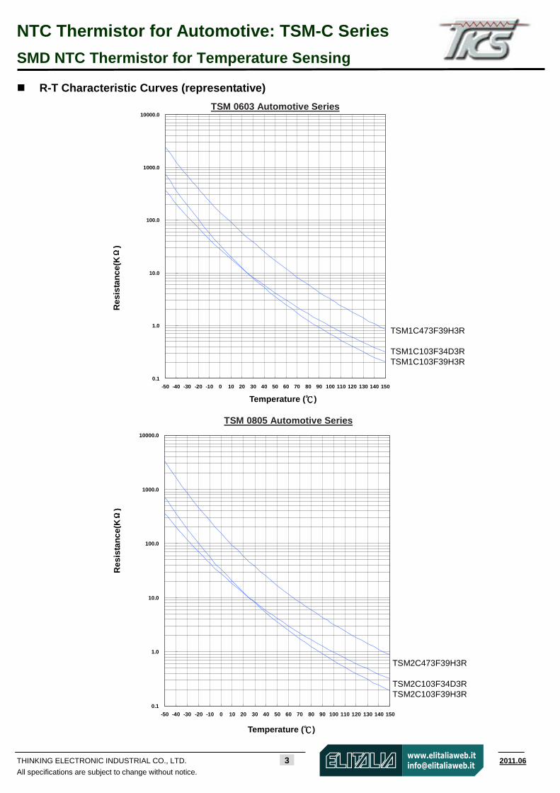
R-T Characteristic Curves (representative)
0.1
1.0
10.0
100.0
1000.0
10000.0
-50 -40 -30 -20 -10 0 10 20 30 40 50 60 70 80 90 100 110 120 130 140 150
TSM 0805 Automotive Series
Res
ista
nce
(KΩΩ ΩΩ
) TSM 0603 Automotive Series
Res
ista
nce
(KΩΩ ΩΩ
)
TSM1C473F39H3R TSM1C103F34D3R TSM1C103F39H3R
0.1
1.0
10.0
100.0
1000.0
10000.0
-50 -40 -30 -20 -10 0 10 20 30 40 50 60 70 80 90 100 110 120 130 140 150
TSM2C473F39H3R TSM2C103F34D3R TSM2C103F39H3R

NTC Thermistor for Automotive: TSM-C Series
SMD NTC Thermistor for Temperature Sensing
THINKING ELECTRONIC INDUSTRIAL CO., LTD. 4 www.thinking.com.tw 2011.06
All specifications are subject to change without notice.
Soldering Recommendation
IR-reflow Soldering Profile
Reworking Conditions with Soldering Iron
Item Conditions
Temperature of Soldering Iron-tip 360(max.)
Soldering Time 3 sec (max.)
Diameter of Soldering Iron-tip Φ3mm (max.)
Caution: Do not touch the component surface with soldering iron directly to
prevent it from damage.
Recommended Soldering Pad Dimensions
Size Z (mm) G (mm) X (mm) Y (mm)
0603 3.0 1.0 1.0 1.0
0805 3.4 1.0 1.4 1.2
Y
G
X
Z
3°C /sec (max.)
60~180 sec
20~40 sec
150±20
Time
255~260°C
150~200°C
Tamb
3°C/sec
(max.)
217°C 60~150 sec
t
8 minutes max
Preheating Cooling
6°C /sec (max.)
Tem
pera
ture
Peak temp
NTC Thermistor for Automotive: TSM-C Series
SMD NTC Thermistor for Temperature Sensing
THINKING ELECTRONIC INDUSTRIAL CO., LTD. 5 www.thinking.com.tw 2011.06
All specifications are subject to change without notice.
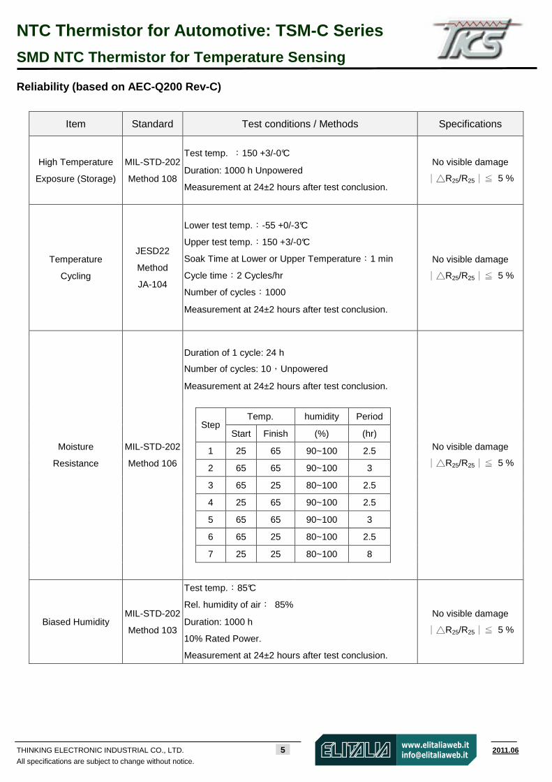
Reliability (based on AEC-Q200 Rev-C)
Item Standard Test conditions / Methods Specifications
High Temperature
Exposure (Storage)
MIL-STD-202
Method 108
Test temp. :150 +3/-0°C
Duration: 1000 h Unpowered
Measurement at 24±2 hours after test conclusion.
No visible damage
∣R25/R25∣≦ 5 %
Temperature
Cycling
JESD22
Method
JA-104
Lower test temp.:-55 +0/-3°C
Upper test temp.:150 +3/-0°C
Soak Time at Lower or Upper Temperature:1 min
Cycle time:2 Cycles/hr
Number of cycles:1000
Measurement at 24±2 hours after test conclusion.
No visible damage
∣R25/R25∣≦ 5 %
Duration of 1 cycle: 24 h
Number of cycles: 10,Unpowered
Measurement at 24±2 hours after test conclusion.
Temp. humidity Period
Step
Start Finish (%) (hr)
1 25 65 90~100 2.5
2 65 65 90~100 3
3 65 25 80~100 2.5
4 25 65 90~100 2.5
5 65 65 90~100 3
6 65 25 80~100 2.5
7 25 25 80~100 8
Moisture
Resistance
MIL-STD-202
Method 106
No visible damage
∣R25/R25∣≦ 5 %
Biased Humidity MIL-STD-202
Method 103
Test temp.:85°C
Rel. humidity of air: 85%
Duration: 1000 h
10% Rated Power.
Measurement at 24±2 hours after test conclusion.
No visible damage
∣R25/R25∣≦ 5 %
NTC Thermistor for Automotive: TSM-C Series
SMD NTC Thermistor for Temperature Sensing
THINKING ELECTRONIC INDUSTRIAL CO., LTD. 6 www.thinking.com.tw 2011.06
All specifications are subject to change without notice.
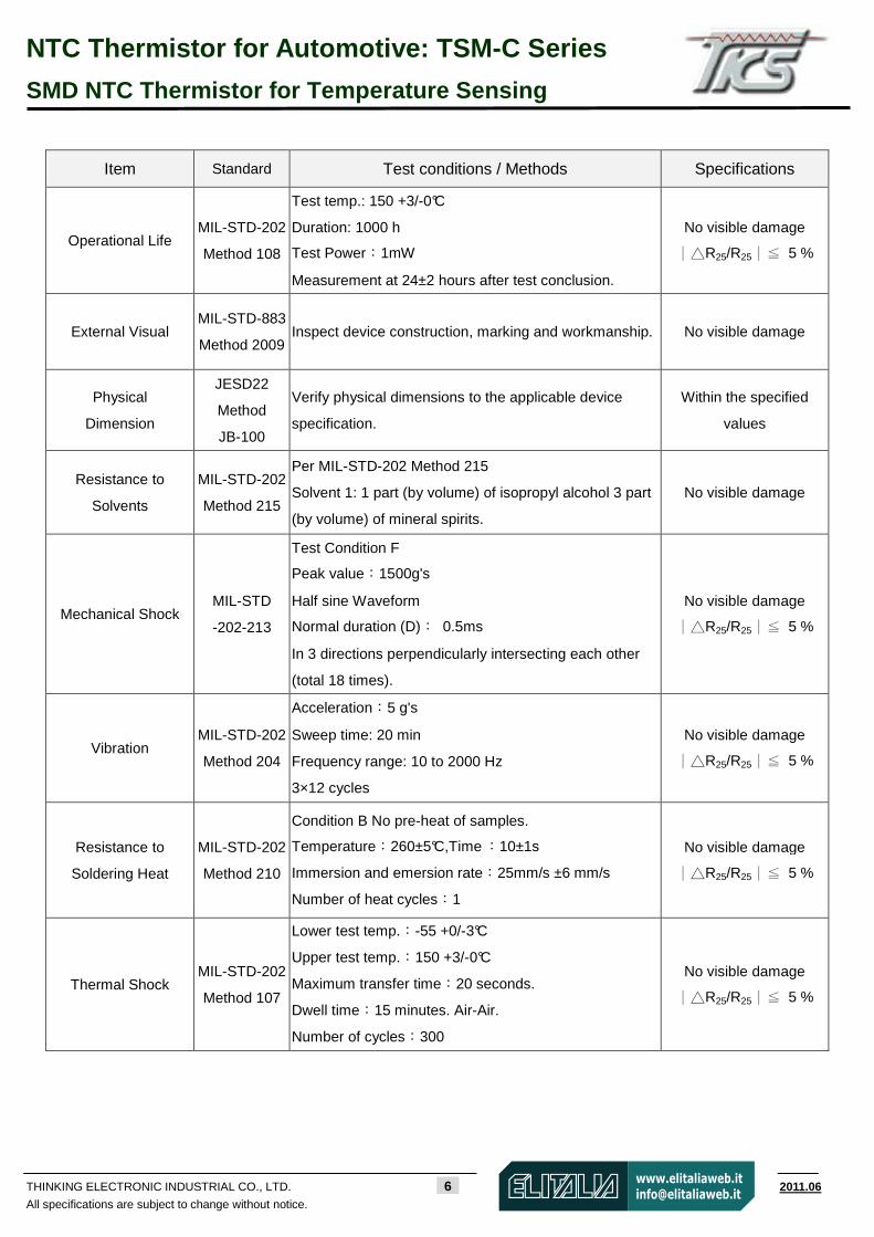
Item Standard Test conditions / Methods Specifications
Operational Life MIL-STD-202
Method 108
Test temp.: 150 +3/-0°C
Duration: 1000 h
Test Power:1mW
Measurement at 24±2 hours after test conclusion.
No visible damage
∣R25/R25∣≦ 5 %
External Visual MIL-STD-883
Method 2009 Inspect device construction, marking and workmanship. No visible damage
Physical
Dimension
JESD22
Method
JB-100
Verify physical dimensions to the applicable device
specification.
Within the specified
values
Resistance to
Solvents
MIL-STD-202
Method 215
Per MIL-STD-202 Method 215
Solvent 1: 1 part (by volume) of isopropyl alcohol 3 part
(by volume) of mineral spirits.
No visible damage
Mechanical Shock MIL-STD
-202-213
Test Condition F
Peak value:1500g's
Half sine Waveform
Normal duration (D): 0.5ms
In 3 directions perpendicularly intersecting each other
(total 18 times).
No visible damage
∣R25/R25∣≦ 5 %
Vibration MIL-STD-202
Method 204
Acceleration:5 g's
Sweep time: 20 min
Frequency range: 10 to 2000 Hz
3×12 cycles
No visible damage
∣R25/R25∣≦ 5 %
Resistance to
Soldering Heat
MIL-STD-202
Method 210
Condition B No pre-heat of samples.
Temperature:260±5°C,Time :10±1s
Immersion and emersion rate:25mm/s ±6 mm/s
Number of heat cycles:1
No visible damage
∣R25/R25∣≦ 5 %
Thermal Shock MIL-STD-202
Method 107
Lower test temp.:-55 +0/-3°C
Upper test temp.:150 +3/-0°C
Maximum transfer time:20 seconds.
Dwell time:15 minutes. Air-Air.
Number of cycles:300
No visible damage
∣R25/R25∣≦ 5 %
NTC Thermistor for Automotive: TSM-C Series
SMD NTC Thermistor for Temperature Sensing
THINKING ELECTRONIC INDUSTRIAL CO., LTD. 7 www.thinking.com.tw 2011.06
All specifications are subject to change without notice.
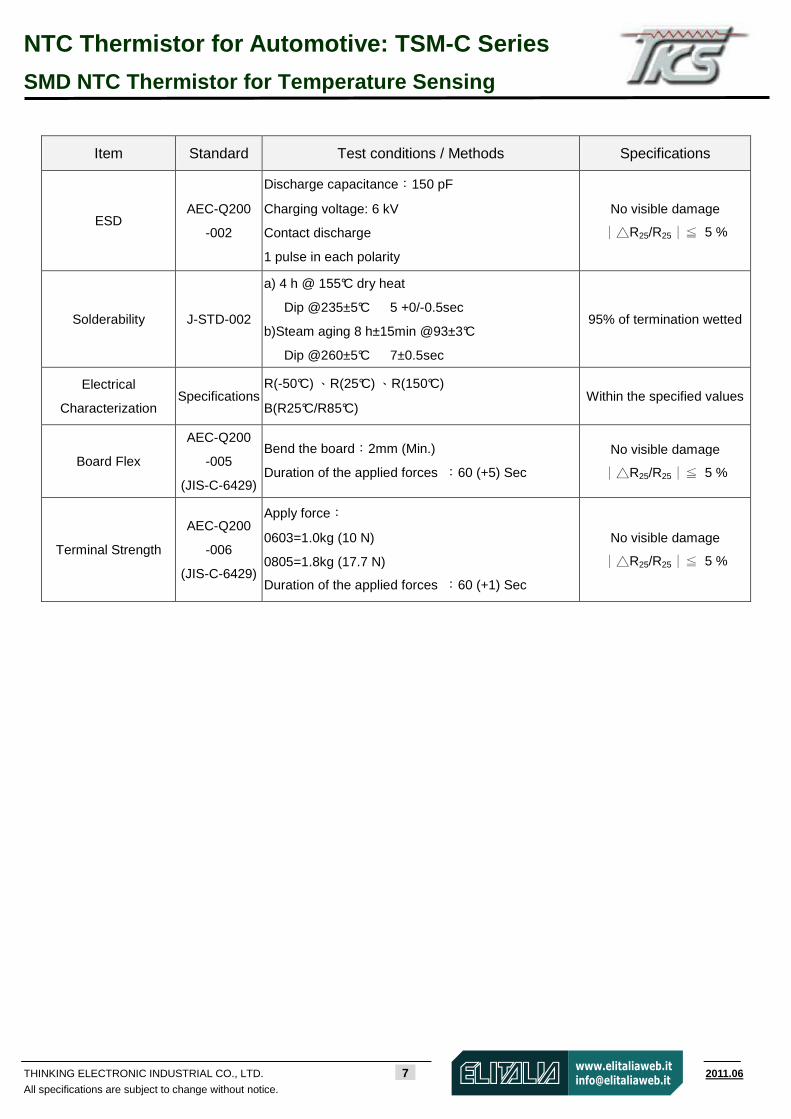
Item Standard Test conditions / Methods Specifications
ESD AEC-Q200
-002
Discharge capacitance:150 pF
Charging voltage: 6 kV
Contact discharge
1 pulse in each polarity
No visible damage
∣R25/R25∣≦ 5 %
Solderability J-STD-002
a) 4 h @ 155°C dry heat
Dip @235±5°C 5 +0/-0.5sec
b)Steam aging 8 h±15min @93±3°C
Dip @260±5°C 7±0.5sec
95% of termination wetted
Electrical
Characterization Specifications
R(-50°C) 、R(25°C) 、R(150°C)
B(R25°C/R85°C) Within the specified values
Board Flex
AEC-Q200
-005
(JIS-C-6429)
Bend the board:2mm (Min.)
Duration of the applied forces :60 (+5) Sec
No visible damage
∣R25/R25∣≦ 5 %
Terminal Strength
AEC-Q200
-006
(JIS-C-6429)
Apply force:
0603=1.0kg (10 N)
0805=1.8kg (17.7 N)
Duration of the applied forces :60 (+1) Sec
No visible damage
∣R25/R25∣≦ 5 %
NTC Thermistor for Automotive: TSM-C Series
SMD NTC Thermistor for Temperature Sensing
THINKING ELECTRONIC INDUSTRIAL CO., LTD. 8 www.thinking.com.tw 2011.06
All specifications are subject to change without notice.
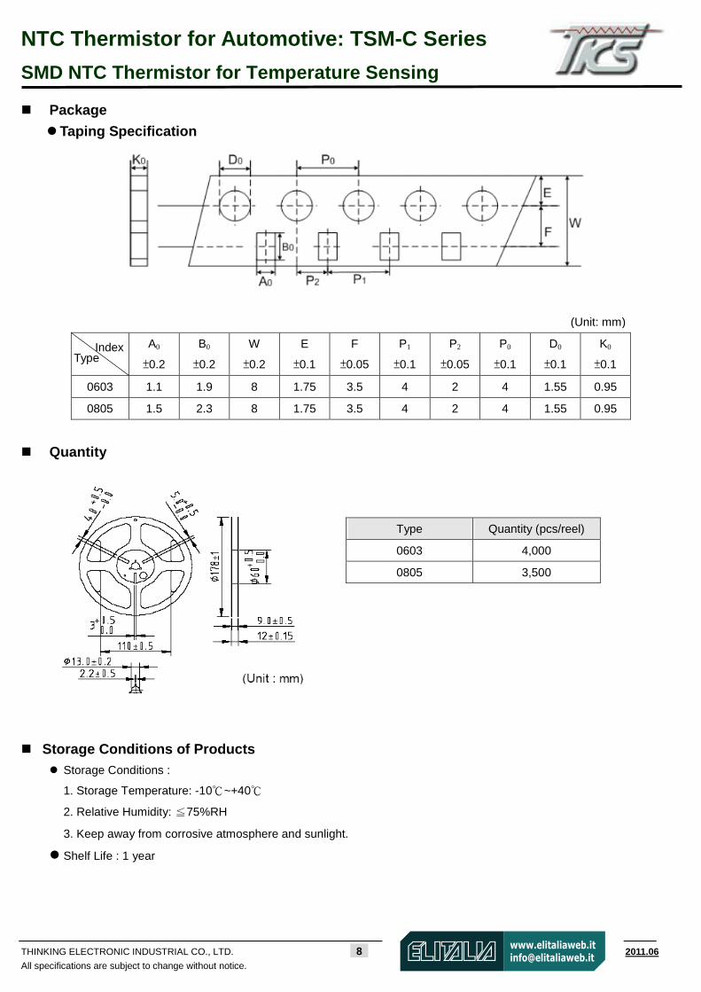
Package
Taping Specification
A0
±0.2
B0
±0.2
W
±0.2
E
±0.1
F
±0.05
P1
±0.1
P2
±0.05
P0
±0.1
D0
±0.1
K0
±0.1
0603 1.1 1.9 8 1.75 3.5 4 2 4 1.55 0.95
0805 1.5 2.3 8 1.75 3.5 4 2 4 1.55 0.95
Quantity
Storage Conditions of Products Storage Conditions :
1. Storage Temperature: -10~+40
2. Relative Humidity: ≦75%RH
3. Keep away from corrosive atmosphere and sunlight.
Shelf Life : 1 year
Index Type
(Unit: mm)
Type Quantity (pcs/reel)
0603 4,000
0805 3,500
NTC Thermistor:SCK Series Power Thermistor for Limiting Inrush Current
THINKING ELECTRONIC INDUSTRIAL CO., LTD. 9 www.thinking.com.tw 2012.08
All specifications are subject to change without notice.
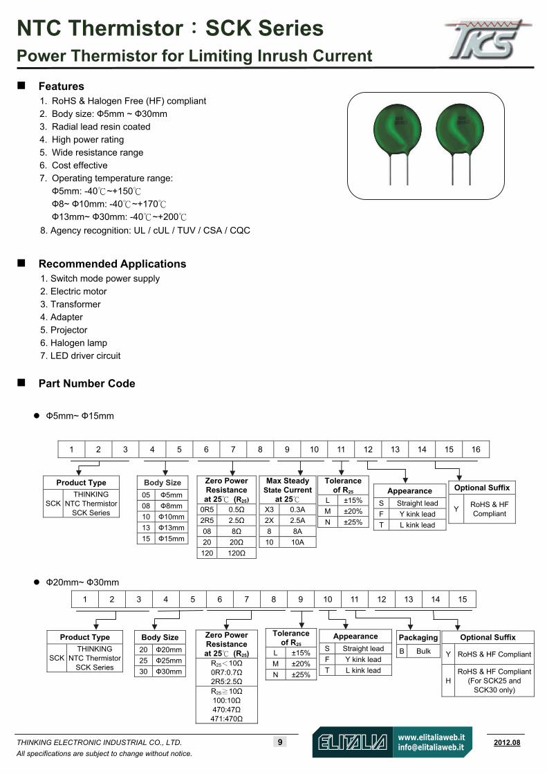
Features 1. RoHS & Halogen Free (HF) compliant
2. Body size: Ф5mm ~ Ф30mm 3. Radial lead resin coated 4. High power rating
5. Wide resistance range 6. Cost effective 7. Operating temperature range:
Ф5mm: -40~+150 Ф8~ Ф10mm: -40~+170 Ф13mm~ Ф30mm: -40~+200
8. Agency recognition: UL / cUL / TUV / CSA / CQC
Recommended Applications 1. Switch mode power supply 2. Electric motor
3. Transformer 4. Adapter 5. Projector
6. Halogen lamp 7. LED driver circuit
Part Number Code
Ф5mm~ Ф15mm
1 2 3 4 5 6 7 8 9 10 11 12 13 14 15 16
Ф20mm~ Ф30mm
1 2 3 4 5 6 7 8 9 10 11 12 13 14 15
Optional Suffix
YRoHS & HFCompliant
Product Type
SCK THINKING
NTC Thermistor SCK Series
Body Size 05 Ф5mm
08 Ф8mm
10 Ф10mm
13 Ф13mm
15 Ф15mm
Zero PowerResistance at 25 (R25)
0R5 0.5Ω
2R5 2.5Ω
08 8Ω
20 20Ω
120 120Ω
Max SteadyState Current
at 25 X3 0.3A
2X 2.5A
8 8A
10 10A
Toleranceof R25
L ±15%
M ±20%
N ±25%
Appearance S Straight lead
F Y kink lead T L kink lead
Optional Suffix
Y RoHS & HF Compliant
H RoHS & HF Compliant
(For SCK25 and SCK30 only)
Product Type
SCK THINKING
NTC Thermistor SCK Series
Tolerance of R25
L ±15%
M ±20%
N ±25%
Appearance
S Straight lead
F Y kink lead T L kink lead
Body Size 20 Ф20mm
25 Ф25mm
30 Ф30mm
Zero Power Resistance at 25 (R25)
R25<10Ω 0R7:0.7Ω 2R5:2.5Ω R25 10Ω≧ 100:10Ω 470:47Ω 471:470Ω
Packaging B Bulk
NTC Thermistor:SCK Series Power Thermistor for Limiting Inrush Current
THINKING ELECTRONIC INDUSTRIAL CO., LTD. 10 www.thinking.com.tw 2012.08
All specifications are subject to change without notice.
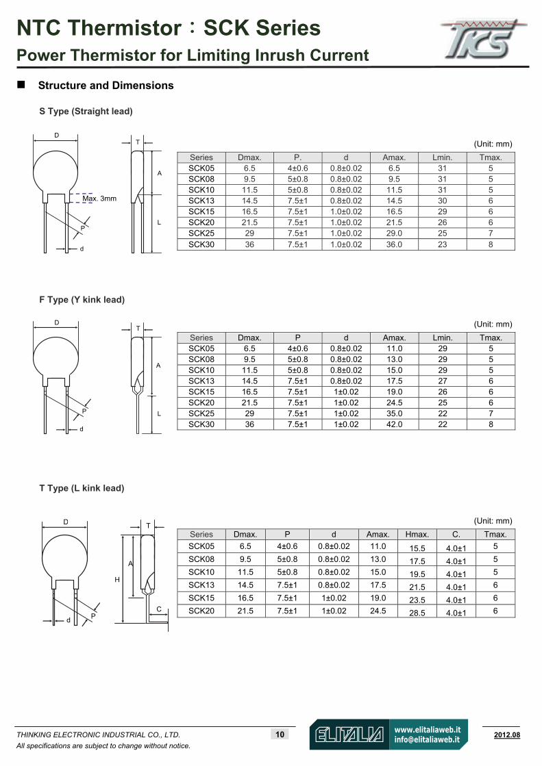
Structure and Dimensions
(Unit: mm)
Series Dmax. P. d Amax. Lmin. Tmax. SCK05 6.5 4±0.6 0.8±0.02 6.5 31 5 SCK08 9.5 5±0.8 0.8±0.02 9.5 31 5 SCK10 11.5 5±0.8 0.8±0.02 11.5 31 5 SCK13 14.5 7.5±1 0.8±0.02 14.5 30 6 SCK15 16.5 7.5±1 1.0±0.02 16.5 29 6 SCK20 21.5 7.5±1 1.0±0.02 21.5 26 6 SCK25 29 7.5±1 1.0±0.02 29.0 25 7 SCK30 36 7.5±1 1.0±0.02 36.0 23 8
F Type (Y kink lead)
(Unit: mm)
Series Dmax. P d Amax. Lmin. Tmax. SCK05 6.5 4±0.6 0.8±0.02 11.0 29 5 SCK08 9.5 5±0.8 0.8±0.02 13.0 29 5 SCK10 11.5 5±0.8 0.8±0.02 15.0 29 5 SCK13 14.5 7.5±1 0.8±0.02 17.5 27 6 SCK15 16.5 7.5±1 1±0.02 19.0 26 6 SCK20 21.5 7.5±1 1±0.02 24.5 25 6 SCK25 29 7.5±1 1±0.02 35.0 22 7 SCK30 36 7.5±1 1±0.02 42.0 22 8
S Type (Straight lead)
(Unit: mm)
Series Dmax. P d Amax. Hmax. C. Tmax.
SCK05 6.5 4±0.6 0.8±0.02 11.0 15.5 4.0±1 5
SCK08 9.5 5±0.8 0.8±0.02 13.0 17.5 4.0±1 5
SCK10 11.5 5±0.8 0.8±0.02 15.0 19.5 4.0±1 5
SCK13 14.5 7.5±1 0.8±0.02 17.5 21.5 4.0±1 6
SCK15 16.5 7.5±1 1±0.02 19.0 23.5 4.0±1 6
SCK20 21.5 7.5±1 1±0.02 24.5 28.5 4.0±1 6
T Type (L kink lead)
DT
A
L
d
P
T
A
L
d
P
D
T
A
H
d P
D
C
Max. 3mm
NTC Thermistor:SCK Series Power Thermistor for Limiting Inrush Current
THINKING ELECTRONIC INDUSTRIAL CO., LTD. 11 www.thinking.com.tw 2012.08
All specifications are subject to change without notice.
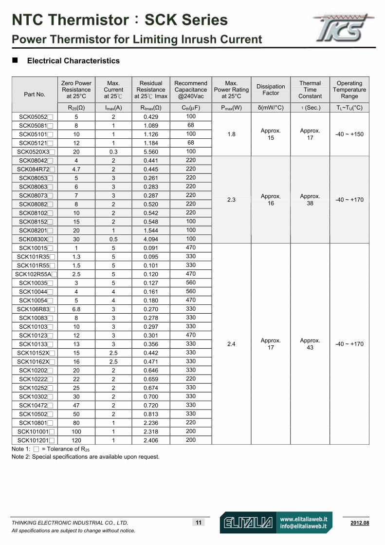
Electrical Characteristics
Note 1: = Tolerance of R25 Note 2: Special specifications are available upon request.
Zero Power Resistance
at 25°C
Max. Current at 25
Residual Resistance
at 25 Imax
RecommendCapacitance
@240Vac
Max. Power Rating
at 25°C
Dissipation Factor
Thermal Time
Constant
Operating Temperature
Range Part No.
R25(Ω) Imax(A) RImax(Ω) Cth(F) Pmax(W) δ(mW/°C) τ(Sec.) TL~TU(°C)
SCK05052 5 2 0.429 100
SCK05081 8 1 1.089 68
SCK05101 10 1 1.126 100
SCK05121 12 1 1.184 68
SCK0520X3 20 0.3 5.560 100
1.8 Approx.
15 Approx.
17 -40 ~ +150
SCK08042 4 2 0.441 220
SCK084R72 4.7 2 0.445 220
SCK08053 5 3 0.261 220
SCK08063 6 3 0.283 220
SCK08073 7 3 0.287 220
SCK08082 8 2 0.520 220
SCK08102 10 2 0.542 220
SCK08152 15 2 0.548 100
SCK08201 20 1 1.544 100
SCK0830X 30 0.5 4.094 100
2.3 Approx.
16 Approx.
38 -40 ~ +170
SCK10015 1 5 0.091 470
SCK101R35 1.3 5 0.095 330
SCK101R55 1.5 5 0.101 330
SCK102R55A 2.5 5 0.120 470
SCK10035 3 5 0.127 560
SCK10044 4 4 0.161 560
SCK10054 5 4 0.180 470
SCK106R83 6.8 3 0.270 330
SCK10083 8 3 0.278 330
SCK10103 10 3 0.297 330
SCK10123 12 3 0.301 470
SCK10133 13 3 0.356 330
SCK10152X 15 2.5 0.442 330
SCK10162X 16 2.5 0.471 330
SCK10202 20 2 0.646 330
SCK10222 22 2 0.659 220
SCK10252 25 2 0.674 330
SCK10302 30 2 0.700 330
SCK10472 47 2 0.720 330
SCK10502 50 2 0.813 330
SCK10801 80 1 2.236 220
SCK101001 100 1 2.318 200
SCK101201 120 1 2.406 200
2.4 Approx.
17 Approx.
43 -40 ~ +170
NTC Thermistor:SCK Series Power Thermistor for Limiting Inrush Current
THINKING ELECTRONIC INDUSTRIAL CO., LTD. 12 www.thinking.com.tw 2012.08
All specifications are subject to change without notice.
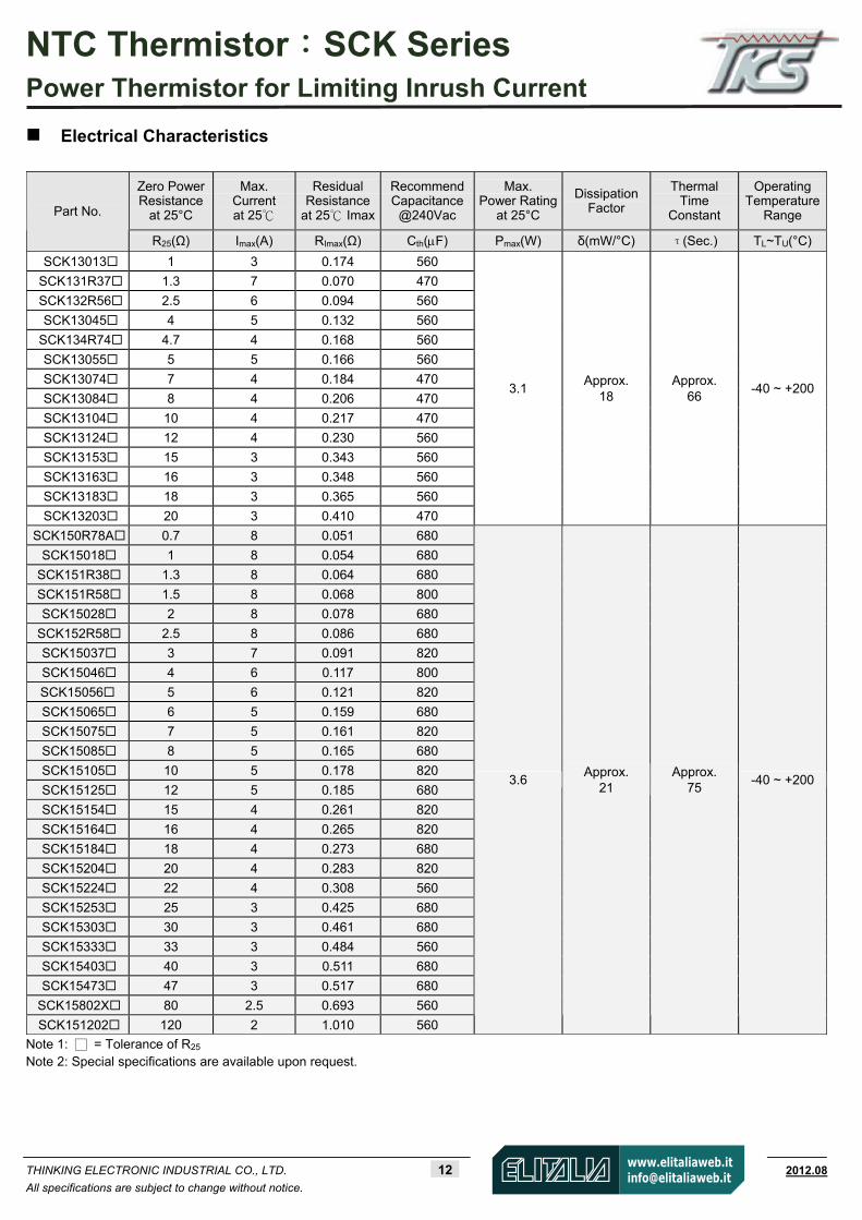
Electrical Characteristics
Note 1: = Tolerance of R25 Note 2: Special specifications are available upon request.
Zero Power Resistance
at 25°C
Max. Current at 25
Residual Resistance
at 25 Imax
RecommendCapacitance
@240Vac
Max. Power Rating
at 25°C
Dissipation Factor
Thermal Time
Constant
Operating Temperature
Range Part No.
R25(Ω) Imax(A) RImax(Ω) Cth(F) Pmax(W) δ(mW/°C) τ(Sec.) TL~TU(°C)
SCK13013 1 3 0.174 560
SCK131R37 1.3 7 0.070 470
SCK132R56 2.5 6 0.094 560
SCK13045 4 5 0.132 560
SCK134R74 4.7 4 0.168 560
SCK13055 5 5 0.166 560
SCK13074 7 4 0.184 470
SCK13084 8 4 0.206 470
SCK13104 10 4 0.217 470
SCK13124 12 4 0.230 560
SCK13153 15 3 0.343 560
SCK13163 16 3 0.348 560
SCK13183 18 3 0.365 560
SCK13203 20 3 0.410 470
3.1 Approx.
18 Approx.
66 -40 ~ +200
SCK150R78A 0.7 8 0.051 680
SCK15018 1 8 0.054 680
SCK151R38 1.3 8 0.064 680
SCK151R58 1.5 8 0.068 800
SCK15028 2 8 0.078 680
SCK152R58 2.5 8 0.086 680
SCK15037 3 7 0.091 820
SCK15046 4 6 0.117 800
SCK15056 5 6 0.121 820
SCK15065 6 5 0.159 680
SCK15075 7 5 0.161 820
SCK15085 8 5 0.165 680
SCK15105 10 5 0.178 820
SCK15125 12 5 0.185 680
SCK15154 15 4 0.261 820
SCK15164 16 4 0.265 820
SCK15184 18 4 0.273 680
SCK15204 20 4 0.283 820
SCK15224 22 4 0.308 560
SCK15253 25 3 0.425 680
SCK15303 30 3 0.461 680
SCK15333 33 3 0.484 560
SCK15403 40 3 0.511 680
SCK15473 47 3 0.517 680
SCK15802X 80 2.5 0.693 560
SCK151202 120 2 1.010 560
3.6 Approx.
21 Approx.
75 -40 ~ +200
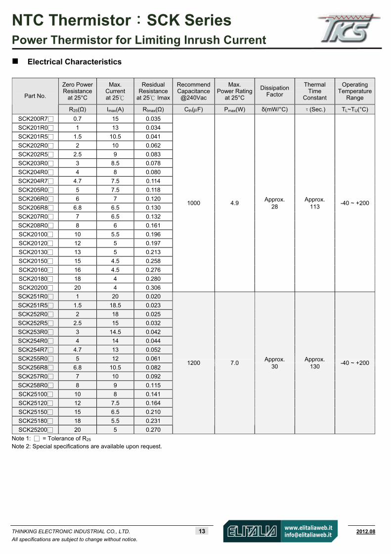
NTC Thermistor:SCK Series Power Thermistor for Limiting Inrush Current
THINKING ELECTRONIC INDUSTRIAL CO., LTD. 13 www.thinking.com.tw 2012.08
All specifications are subject to change without notice.
Electrical Characteristics
Note 1: = Tolerance of R25 Note 2: Special specifications are available upon request.
Zero Power Resistance
at 25°C
Max. Current at 25
Residual Resistance
at 25 Imax
RecommendCapacitance
@240Vac
Max. Power Rating
at 25°C
Dissipation Factor
Thermal Time
Constant
Operating Temperature
Range Part No.
R25(Ω) Imax(A) RImax(Ω) Cth(F) Pmax(W) δ(mW/°C) τ(Sec.) TL~TU(°C)
SCK200R7 0.7 15 0.035
SCK201R0 1 13 0.034
SCK201R5 1.5 10.5 0.041
SCK202R0 2 10 0.062
SCK202R5 2.5 9 0.083
SCK203R0 3 8.5 0.078
SCK204R0 4 8 0.080
SCK204R7 4.7 7.5 0.114
SCK205R0 5 7.5 0.118
SCK206R0 6 7 0.120
SCK206R8 6.8 6.5 0.130
SCK207R0 7 6.5 0.132
SCK208R0 8 6 0.161
SCK20100 10 5.5 0.196
SCK20120 12 5 0.197
SCK20130 13 5 0.213
SCK20150 15 4.5 0.258
SCK20160 16 4.5 0.276
SCK20180 18 4 0.280
SCK20200 20 4 0.306
1000 4.9 Approx.
28 Approx.
113 -40 ~ +200
SCK251R0 1 20 0.020
SCK251R5 1.5 18.5 0.023
SCK252R0 2 18 0.025
SCK252R5 2.5 15 0.032
SCK253R0 3 14.5 0.042
SCK254R0 4 14 0.044
SCK254R7 4.7 13 0.052
SCK255R0 5 12 0.061
SCK256R8 6.8 10.5 0.082
SCK257R0 7 10 0.092
SCK258R0 8 9 0.115
SCK25100 10 8 0.141
SCK25120 12 7.5 0.164
SCK25150 15 6.5 0.210
SCK25180 18 5.5 0.231
SCK25200 20 5 0.270
1200 7.0 Approx.
30 Approx.
130 -40 ~ +200
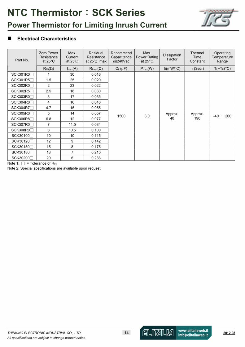
NTC Thermistor:SCK Series Power Thermistor for Limiting Inrush Current
THINKING ELECTRONIC INDUSTRIAL CO., LTD. 14 www.thinking.com.tw 2012.08
All specifications are subject to change without notice.
Electrical Characteristics
Note 1: = Tolerance of R25 Note 2: Special specifications are available upon request.
Zero Power Resistance
at 25°C
Max. Current at 25
Residual Resistance
at 25 Imax
RecommendCapacitance
@240Vac
Max. Power Rating
at 25°C
Dissipation Factor
Thermal Time
Constant
Operating Temperature
Range Part No.
R25(Ω) Imax(A) RImax(Ω) Cth(F) Pmax(W) δ(mW/°C) τ(Sec.) TL~TU(°C)
SCK301R0 1 30 0.016
SCK301R5 1.5 25 0.020
SCK302R0 2 23 0.022
SCK302R5 2.5 18 0.030
SCK303R0 3 17 0.035
SCK304R0 4 16 0.048
SCK304R7 4.7 15 0.055
SCK305R0 5 14 0.057
SCK306R8 6.8 12 0.077
SCK307R0 7 11.5 0.084
SCK308R0 8 10.5 0.100
SCK30100 10 10 0.115
SCK30120 12 9 0.142
SCK30150 15 8 0.175
SCK30180 18 7 0.210
SCK30200 20 6 0.233
1500 8.0 Approx.
40 Approx.
190 -40 ~ +200
NTC Thermistor:SCK Series Power Thermistor for Limiting Inrush Current
THINKING ELECTRONIC INDUSTRIAL CO., LTD. 15 www.thinking.com.tw 2012.08
All specifications are subject to change without notice.
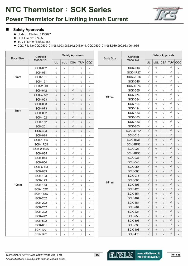
Safety Approvals UL&cUL File No: E138827 CSA File No: 97495 TUV File No: R 50050155 CQC File No:CQC05001011984,993,985,942,943,944, CQC05001011988,989,990,963,964,965
Safety Approvals Safety Approvals Body Size Certified
Model No. UL cUL CSA TUV CQC
Body Size Certified Model No.
UL cUL CSA TUV CQC
SCK-052 SCK-013
SCK-081 SCK-1R37
SCK-101 SCK-2R56
SCK-121 SCK-045
5mm
SCK-20X3 SCK-4R74
SCK-042 SCK-055
SCK-4R72 SCK-074
SCK-053 SCK-084
SCK-063 SCK-104
SCK-073 SCK-124
SCK-082 SCK-153
SCK-102 SCK-163
SCK-152 SCK-183
SCK-201
13mm
SCK-203
8mm
SCK-30X SCK-0R78A SCK-015 SCK-018
SCK-1R35 SCK-1R38 SCK-1R55 SCK-1R58
SCK-2R55A SCK-028 SCK-035 SCK-2R58 SCK-044 SCK-037 SCK-054 SCK-046
SCK-6R83 SCK-056 SCK-083 SCK-065
SCK-103 SCK-075
SCK-123 SCK-085
SCK-133 SCK-105
SCK-152X SCK-125
SCK-162X SCK-154
SCK-202 SCK-164
SCK-222 SCK-184
SCK-252 SCK-204
SCK-302 SCK-224 SCK-472 SCK-253 SCK-502 SCK-303 SCK-801 SCK-333
SCK-1001 SCK-403
10mm
SCK-1201
15mm
SCK-473

NTC Thermistor:SCK Series Power Thermistor for Limiting Inrush Current
THINKING ELECTRONIC INDUSTRIAL CO., LTD. 16 www.thinking.com.tw 2012.08
All specifications are subject to change without notice.
Safety Approvals Safety Approvals Body Size Certified
Model No. UL cUL TUV CQC
Body Size Certified Model No.
UL cUL TUV CQC
SCK200R7 SCK301R0
SCK201R0 SCK301R5
SCK201R5 SCK302R0
SCK202R0 SCK302R5
SCK202R5 SCK303R0
SCK203R0 SCK304R0
SCK204R0 SCK304R7
SCK204R7 SCK305R0
SCK205R0 SCK306R8
SCK206R0 SCK307R0
SCK206R8 SCK308R0
SCK207R0 SCK30100
SCK208R0 SCK30120
SCK20100 SCK30150
SCK20120 SCK30180
SCK20130
30mm
SCK30200
SCK20150 SCK20160 SCK20180
20mm
SCK20200 SCK251R0 SCK251R5 SCK252R0 SCK252R5
SCK253R0
SCK254R0
SCK254R7
SCK255R0
SCK256R8
SCK257R0
SCK258R0
SCK25100
SCK25120 SCK25150 SCK25180
25mm
SCK25200

NTC Thermistor:SCK Series Power Thermistor for Limiting Inrush Current
THINKING ELECTRONIC INDUSTRIAL CO., LTD. 17 www.thinking.com.tw 2012.08
All specifications are subject to change without notice.
0.1
1
10
100
1000
-40 -30 -20 -10 0 10 20 30 40 50 60 70 80 90 100 110 120 130 140 1500.1
1
10
100
1000
-40 -30 -20 -10 0 10 20 30 40 50 60 70 80 90 100 110 120 130 140 150 160 170
Max. Current Derating Curve
R-T Characteristic Curves
SCK05052~SCK0520X3
Temperature ( )
Res
ista
nc
e(Ω
)
SCK08042~SCK0830X
SCK0830X SCK08201 SCK08152 SCK08102 SCK08082 SCK08073 SCK08063 SCK08053 SCK084R72 SCK08042
Temperature ( )
TU: Maximum operating temperature ()
TL: Minimum operating temperature ()
For example:
Ambient temperature(Ta) = 60
Maximum operating temperature(TU) = 200
ITa = [1-(Ta-25)/(Tu-25)]×Imax = 80%Imax
SCK05121 SCK05101 SCK05081
SCK0520X3
SCK05052
100%
0TL 0 25 TU
Ambient temperature ()
ITa
Imax
Res
ista
nc
e(Ω
)
0 25
NTC Thermistor:SCK Series Power Thermistor for Limiting Inrush Current
THINKING ELECTRONIC INDUSTRIAL CO., LTD. 18 www.thinking.com.tw 2012.08
All specifications are subject to change without notice.
0.01
0.1
1
10
100
1000
10000
-40 -30 -20 -10 0 10 20 30 40 50 60 70 80 90 100 110 120 130 140 150 160 170
0.01
0.1
1
10
100
1000
10000
-40 -30 -20 -10 0 10 20 30 40 50 60 70 80 90 100 110 120 130 140 150 160 170
0.01
0.1
1
10
100
1000
-40 -30 -20 -10 0 10 20 30 40 50 60 70 80 90 100 110 120 130 140 150 160 170 180 190 200
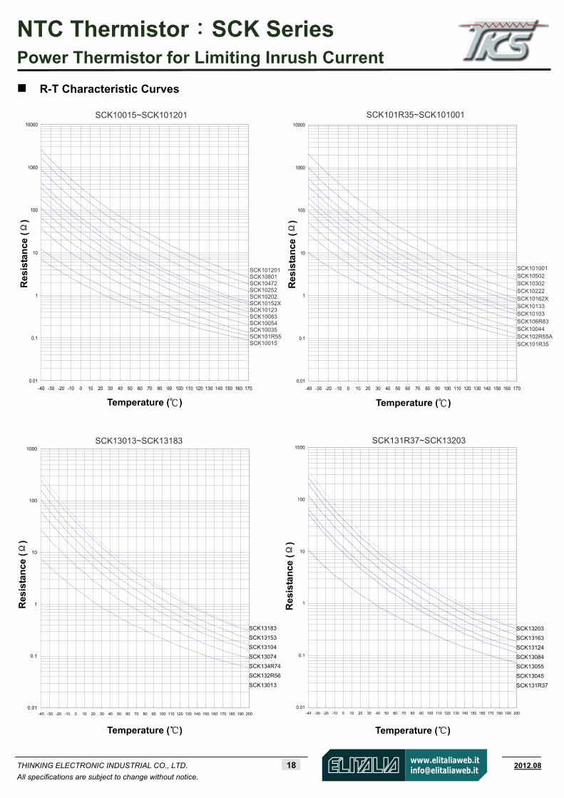
R-T Characteristic Curves
0.01
0.1
1
10
100
1000
-40 -30 -20 -10 0 10 20 30 40 50 60 70 80 90 100 110 120 130 140 150 160 170 180 190 200
Temperature ( )
SCK10015~SCK101201 SCK101R35~SCK101001
Res
ista
nce
(Ω
)
Temperature ( )
SCK101001 SCK10502 SCK10302 SCK10222 SCK10162X SCK10133 SCK10103 SCK106R83 SCK10044 SCK102R55A SCK101R35
Temperature ()
SCK13183
SCK13153
SCK13104
SCK13074
SCK134R74
SCK132R56
SCK13013
SCK13013~SCK13183
Temperature ()
SCK13203
SCK13163
SCK13124
SCK13084
SCK13055
SCK13045
SCK131R37
SCK131R37~SCK13203
Res
ista
nce
(Ω
)
SCK101201 SCK10801 SCK10472 SCK10252 SCK10202 SCK10152X SCK10123 SCK10083 SCK10054 SCK10035 SCK101R55 SCK10015
Res
ista
nce
(Ω
) R
esis
tan
ce (Ω
)

NTC Thermistor:SCK Series Power Thermistor for Limiting Inrush Current
THINKING ELECTRONIC INDUSTRIAL CO., LTD. 19 www.thinking.com.tw 2012.08
All specifications are subject to change without notice.
0.01
0.1
1
10
100
1000
10000
-40 -30 -20 -10 0 10 20 30 40 50 60 70 80 90 100 110 120 130 140 150 160 170 180 190 200
0.01
0.1
1
10
100
1000
10000
-40 -30 -20 -10 0 10 20 30 40 50 60 70 80 90 100 110 120 130 140 150 160 170 180 190 200
0.01
0.1
1
10
100
1000
10000
-40 -30 -20 -10 0 10 20 30 40 50 60 70 80 90 100 110 120 130 140 150 160 170 180 190 2000.01
0.1
1
10
100
1000
10000
-40 -30 -20 -10 0 10 20 30 40 50 60 70 80 90 100 110 120 130 140 150 160 170 180 190 200
R-T Characteristic Curves
Res
ista
nce
(Ω)
Temperature ()
SCK151202
SCK15403
SCK15224
SCK15164
SCK15105
SCK15065
SCK15037
SCK151R58
SCK150R78A
Res
ista
nce
(Ω)
Temperature ()
SCK150R78A~SCK151202 SCK15016~SCK15473
SCK15473
SCK15253
SCK15184
SCK15125
SCK15075
SCK15046
SCK15028
SCK15016
Res
ista
nce
(Ω)
Temperature ()
SCK200R7~SCK20180
SCK20180
SCK20150
SCK20120
SCK208R0
SCK206R8
SCK205R0
SCK204R0
SCK202R5
SCK201R5
SCK200R7
Res
ista
nce
(Ω)
Temperature ()
SCK151R38~SCK15802X
SCK15802X
SCK15303
SCK15204
SCK15154
SCK15085
SCK15056
SCK152R58
SCK151R38

NTC Thermistor:SCK Series Power Thermistor for Limiting Inrush Current
THINKING ELECTRONIC INDUSTRIAL CO., LTD. 20 www.thinking.com.tw 2012.08
All specifications are subject to change without notice.
0.01
0.1
1
10
100
1000
-40 -30 -20 -10 0 10 20 30 40 50 60 70 80 90 100 110 120 130 140 150 160 170 180 190 2000.01
0.1
1
10
100
1000
-40 -30 -20 -10 0 10 20 30 40 50 60 70 80 90 100 110 120 130 140 150 160 170 180 190 200
0.01
0.1
1
10
100
1000
-40 -30 -20 -10 0 10 20 30 40 50 60 70 80 90 100 110 120 130 140 150 160 170 180 190 200
0.01
0.1
1
10
100
1000
-40 -30 -20 -10 0 10 20 30 40 50 60 70 80 90 100 110 120 130 140 150 160 170 180 190 200
R-T Characteristic Curves
Res
ista
nce
(Ω)
Temperature ()
SCK20200
SCK20160
SCK20130
SCK20100
SCK207R0
SCK206R0
SCK204R7
SCK203R0
SCK202R0
SCK201R0
SCK201R0~SCK20200
Res
ista
nce
(Ω)
Temperature ()
SCK251R0~SCK25180
SCK25180
SCK25120
SCK258R0
SCK256R8
SCK254R7
SCK253R0
SCK252R0
SCK251R0
SCK301R0~SCK30180
SCK30180
SCK30120
SCK308R0
SCK306R8
SCK304R7
SCK303R0
SCK302R0
SCK301R0
Temperature ()
Res
ista
nce
(Ω)
Res
ista
nce
(Ω)
Temperature ()
SCK251R5~SCK25200
SCK25200
SCK25150
SCK25100
SCK257R0
SCK255R0
SCK254R0
SCK252R5
SCK251R5

NTC Thermistor:SCK Series Power Thermistor for Limiting Inrush Current
THINKING ELECTRONIC INDUSTRIAL CO., LTD. 21 www.thinking.com.tw 2012.08
All specifications are subject to change without notice.
0.01
0.1
1
10
100
1000
-40 -30 -20 -10 0 10 20 30 40 50 60 70 80 90 100 110 120 130 140 150 160 170 180 190 200
R-T Characteristic Curves
Res
ista
nce
(Ω)
SCK30200
SCK30150
SCK30100
SCK307R0
SCK305R0
SCK304R0
SCK302R5
SCK301R5
SCK301R5~SCK30200
Temperature ()

NTC Thermistor:SCK Series Power Thermistor for Limiting Inrush Current
THINKING ELECTRONIC INDUSTRIAL CO., LTD. 22 www.thinking.com.tw 2012.08
All specifications are subject to change without notice.
0.1
1
10
0.01 0.1 1 10 100
2
5
0.5
0.2
0.02 0.05 0.2 0.5 2 5 20 50
0.1
1
10
0.01 0.1 1 10 100
2
5
0.5
0.2
0.02 0.05 0.2 0.5 2 5 20 50
V-I Characteristic Curves (representative)
Vo
ltag
e (V
)
Current (A)
SCK05052~SCK0520X3
Vo
ltag
e (V
)
Current (A)
SCK08042~SCK08201
NTC Thermistor:SCK Series Power Thermistor for Limiting Inrush Current
THINKING ELECTRONIC INDUSTRIAL CO., LTD. 23 www.thinking.com.tw 2012.08
All specifications are subject to change without notice.
0.1
1
10
0.01 0.1 1 10 1000.02 0.05 0.2 0.5 2 5 20 50
2
5
0.5
0.2
SCK1001
5
SCK1015
2X
SCK102R
55A
SCK1005
4
0.1
1
10
0.01 0.1 1 10 100
2
5
0.5
0.2
0.02 0.05 0.2 0.5 2 5 20 50
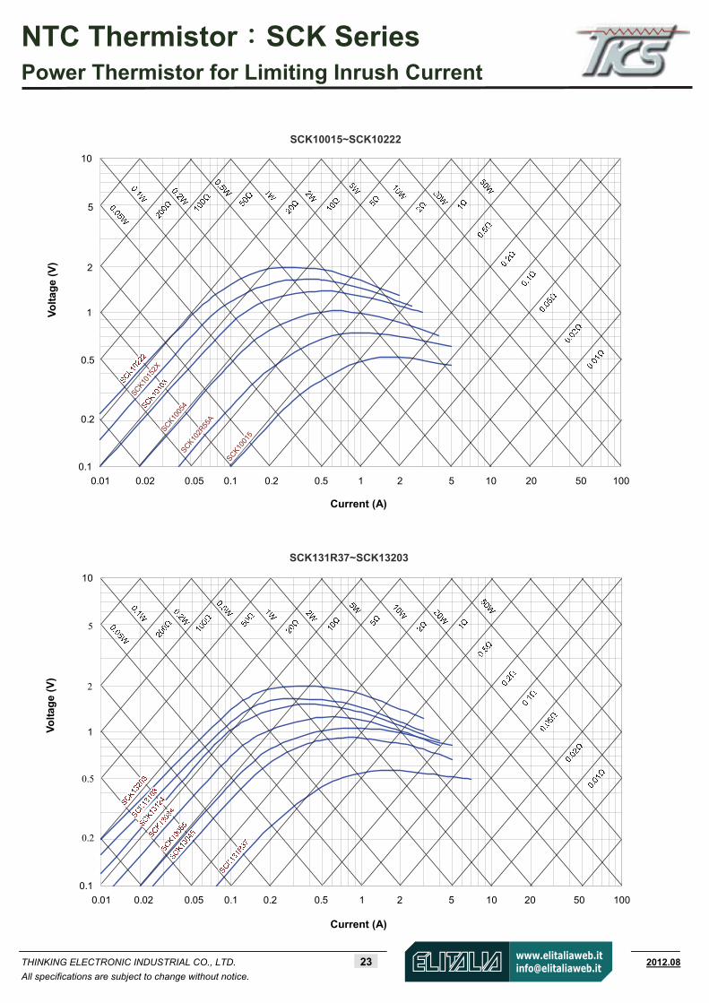
SCK10015~SCK10222
Vo
ltag
e (V
)
Current (A)
SCK131R37~SCK13203
Vo
ltag
e (V
)
Current (A)

NTC Thermistor:SCK Series Power Thermistor for Limiting Inrush Current
THINKING ELECTRONIC INDUSTRIAL CO., LTD. 24 www.thinking.com.tw 2012.08
All specifications are subject to change without notice.
0.1
1
10
0.01 0.1 1 10 100
2
5
0.5
0.2
0.02 0.05 0.2 0.5 2 5 20 50
0.1
1
10
0.01 0.1 1 10 100
2
5
0.5
0.2
0.02 0.05 0.2 0.5 2 5 20 50
SCK151R38~SCK15303
Vo
ltag
e (V
)
Current (A)
SCK200R7~SCK20200
Vo
ltag
e (V
)
Current (A)

NTC Thermistor:SCK Series Power Thermistor for Limiting Inrush Current
THINKING ELECTRONIC INDUSTRIAL CO., LTD. 25 www.thinking.com.tw 2012.08
All specifications are subject to change without notice.
0.1
1
10
0.01 0.1 1 10 1000.02 0.05 0.2 0.5 2 5 20 50
0.2
0.5
2
5
0.1
1
10
0.01 0.1 1 10 1000.02 0.05 0.2 0.5 2 5 20 50
0.2
0.5
2
5
SCK251R0~SCK25121
Vo
ltag
e (V
)
Current (A)
SCK301R0~SCK30200
Vo
ltag
e (V
)
Current (A)

NTC Thermistor:SCK Series Power Thermistor for Limiting Inrush Current
THINKING ELECTRONIC INDUSTRIAL CO., LTD. 26 www.thinking.com.tw 2012.08
All specifications are subject to change without notice.
Soldering Recommendation
Wave Soldering Profile
Recommended Reworking Conditions with Soldering Iron
Item Condition
Temperature of Soldering Iron-tip 360 (max.)
Soldering Time 3 sec. (max.)
Distance from Thermistor 2 mm (min.)
Tem
pera
ture
130±20
260 Max
Tamb
Cooling
Time
Soldering Preheating
30~90 sec. <1 sec. <10 sec.
Note 1
Note 2 Note 3
Note 1: (1~3)/sec.
Note 2: Approx. 200/sec.
Note 3: 5/sec. (Max.)

NTC Thermistor:SCK Series Power Thermistor for Limiting Inrush Current
THINKING ELECTRONIC INDUSTRIAL CO., LTD. 27 www.thinking.com.tw 2012.08
All specifications are subject to change without notice.
Reliability
Item Standard Test conditions / Methods Specifications
Tensile Strength of Terminals IEC 60068-2-21
Gradually apply the specified force and keep the unit fixed for 10±1 sec.
Terminal diameter Force
(mm) (Kg)
0.5<d 0.80 ≦ 1.0
0.8<d 1.25 ≦ 2.0
No visible damage
Solderability IEC 60068-2-20 245 ±3 , 3 ± 0.3 sec. At least 95% of terminalelectrode is covered by
new solder
Resistance to Soldering Heat
IEC 60068-2-20 260 ± 3 , 10 ± 1 sec. No visible damage ∣R25/R25 10 %∣≦
High Temperature Storage IEC 60068-2-2 Tu ± 5 , 1000± 24 hrs
No visible damage ∣R25/R25 20 %∣≦
Damp Heat, Steady State
IEC 60068-2-78 40 ± 2 , 90~95% RH, 1000 ± 24 hrs No visible damage ∣R25/R25 20 %∣≦
Rapid Change of Temperature
IEC 60068-2-14
The conditions shown below shall be repeated 5 cycles.
Step Temperature ( ) Period (minutes)
1 TL ± 5 30 ± 3
2 Room temperature 5 ± 3
3 TU ± 5 30 ± 3
4 Room temperature 5 ± 3
No visible damage
∣R25/R25 20 %∣≦
Max. Current IEC 60539-1 25 ± 5 , Imax . , 1000± 24 hrs No visible damage ∣R25/R25 20 %∣≦
Endurance Specification Standard
25 ± 5 , Imax. , C th, 1min ON / 5 mins OFF x 1000 cycles
Cth= Capacitance at 240 Vac No visible damage
∣R25/R25 20 %∣≦
Insulation Test MIL-STD-202F-Method 302 1000 VDC , 1 min
No visible damage 500 MΩ≧

NTC Thermistor:SCK Series Power Thermistor for Limiting Inrush Current
THINKING ELECTRONIC INDUSTRIAL CO., LTD. 28 www.thinking.com.tw 2012.08
All specifications are subject to change without notice.
Packaging Taping Specification
S (Straight lead) Type
Figure A Figure B Figure C
P0 F P P1 H H1 d W0 W1 W2 W P h L1 D0 T Taping
Dimension Disc Size ±0.3 ±1 ±1 ±0.7 +2/-0 Max. ±0.02 ±1
+0.75
/-0.5Max.
+1/ -0.5
Max. Max. Max. ±0.2 ±0.2Figure
05 12.7 4.0 12.7 4.35 18 28 0.8 12 9 3 18 1 2 0.5 4 0.6 A
08 12.7 5.0 12.7 3.85 18 30 0.8 12 9 3 18 1 2 0.5 4 0.6 A
10 12.7 5.0 12.7 3.85 18 32 0.8 12 9 3 18 1 2 0.5 4 0.6 A
13 12.7 7.5 25.4 8.95 18 35 0.8 12 9 3 18 1 2 0.5 4 0.6 B
15 12.7 7.5 25.4 8.95 18 37 1.0 12 9 3 18 1 2 0.5 4 0.6 B
P0:12.7
20 12.7 7.5 25.4 8.95 18 42 1.0 12 9 3 18 1 2 0.5 4 0.6 B
05 15.0 4.0 15.0 5.50 18 28 0.8 12 9 3 18 1 2 0.5 4 0.6 A
08 15.0 5.0 15.0 5.00 18 30 0.8 12 9 3 18 1 2 0.5 4 0.6 A
10 15.0 5.0 15.0 5.00 18 32 0.8 12 9 3 18 1 2 0.5 4 0.6 A
13 15.0 7.5 30.0 3.75 18 35 0.8 12 9 3 18 1 2 0.5 4 0.6 C
15 15.0 7.5 30.0 3.75 18 37 1.0 12 9 3 18 1 2 0.5 4 0.6 C
P0:15.0
20 15.0 7.5 30.0 3.75 18 42 1.0 12 9 3 18 1 2 0.5 4 0.6 C
P
H1d
L1 D0P0
H
F
W2
W1
WW0
P1
P
P1
(Unit: mm)
P
P1
h h
T
p p

NTC Thermistor:SCK Series Power Thermistor for Limiting Inrush Current
THINKING ELECTRONIC INDUSTRIAL CO., LTD. 29 www.thinking.com.tw 2012.08
All specifications are subject to change without notice.
F Kink Type
Figure A Figure B Figure C
P0 F P P1 H0 H1 d W0 W1 W2 W P h L1 D0 T Taping
Dimension Disc Size ±0.3 ±1 ±1 ±0.7 ±0.5 Max. ±0.02 ±1
+0.75
/-0.5 Max.
+1/
-0.5 Max. Max. Max. ±0.2 ±0.2
Figure
05 12.7 4.0 12.7 4.35 16 28 0.8 12 9 3 18 1 2 0.5 4 0.6 A
08 12.7 5.0 12.7 3.85 16 30 0.8 12 9 3 18 1 2 0.5 4 0.6 A
10 12.7 5.0 12.7 3.85 16 32 0.8 12 9 3 18 1 2 0.5 4 0.6 A
13 12.7 7.5 25.4 8.95 16 35 0.8 12 9 3 18 1 2 0.5 4 0.6 B
15 12.7 7.5 25.4 8.95 16 37 1.0 12 9 3 18 1 2 0.5 4 0.6 B
P0:12.7
20 12.7 7.5 25.4 8.95 16 42 1.0 12 9 3 18 1 2 0.5 4 0.6 B
05 15.0 4.0 15.0 5.50 16 28 0.8 12 9 3 18 1 2 0.5 4 0.6 A
08 15.0 5.0 15.0 5.00 16 30 0.8 12 9 3 18 1 2 0.5 4 0.6 A
10 15.0 5.0 15.0 5.00 16 32 0.8 12 9 3 18 1 2 0.5 4 0.6 A
13 15.0 7.5 30.0 3.75 16 35 0.8 12 9 3 18 1 2 0.5 4 0.6 C
15 15.0 7.5 30.0 3.75 16 37 1.0 12 9 3 18 1 2 0.5 4 0.6 C
P0:15.0
20 15.0 7.5 30.0 3.75 16 42 1.0 12 9 3 18 1 2 0.5 4 0.6 C
P
P1
(Unit: mm)
P
H1d
L1 D0P0
H0
F
W2
W1
WW0
P1
P
P1
T
p p
NTC Thermistor:SCK Series Power Thermistor for Limiting Inrush Current
THINKING ELECTRONIC INDUSTRIAL CO., LTD. 30 www.thinking.com.tw 2012.08
All specifications are subject to change without notice.
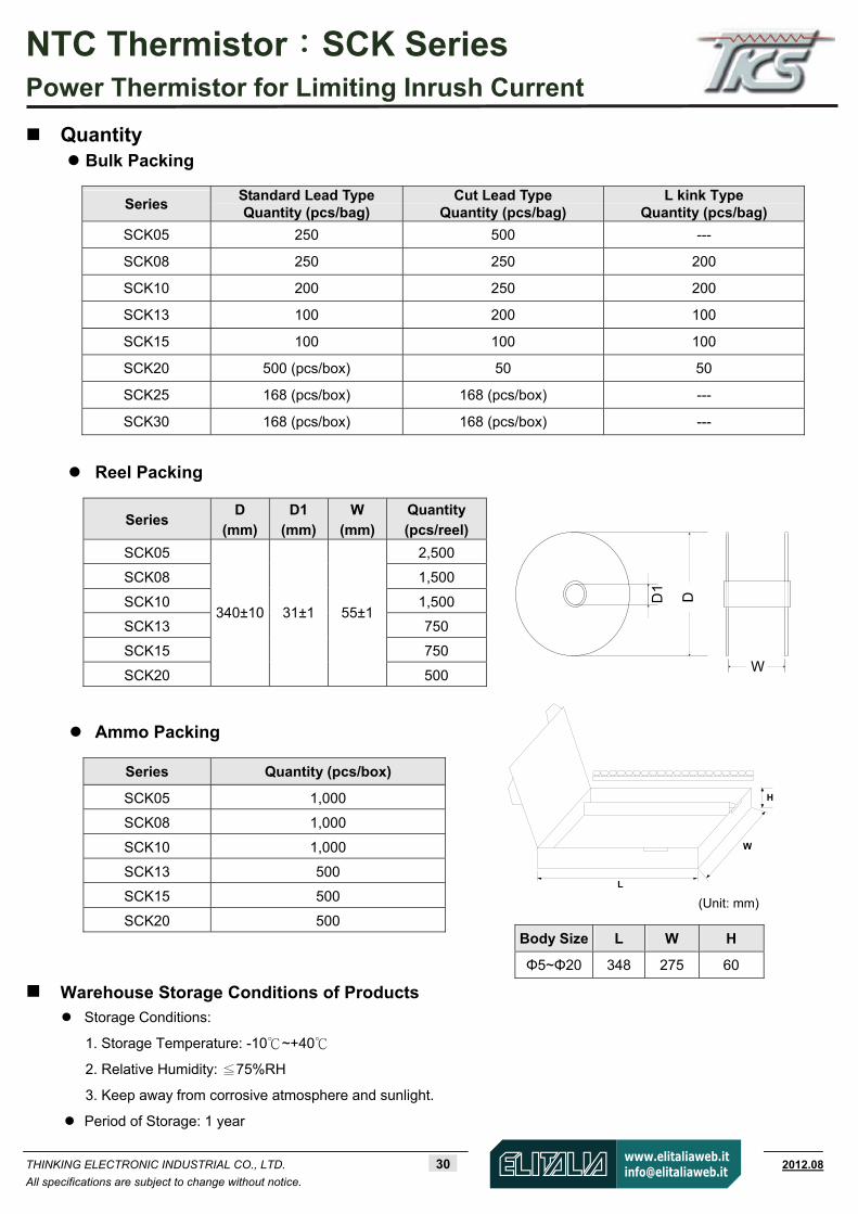
Quantity Bulk Packing
Reel Packing
Ammo Packing
Warehouse Storage Conditions of Products Storage Conditions:
1. Storage Temperature: -10~+40
2. Relative Humidity: ≦75%RH
3. Keep away from corrosive atmosphere and sunlight.
Period of Storage: 1 year
Series Standard Lead Type Quantity (pcs/bag)
Cut Lead Type Quantity (pcs/bag)
L kink Type Quantity (pcs/bag)
SCK05 250 500 ---
SCK08 250 250 200
SCK10 200 250 200
SCK13 100 200 100
SCK15 100 100 100
SCK20 500 (pcs/box) 50 50
SCK25 168 (pcs/box) 168 (pcs/box) ---
SCK30 168 (pcs/box) 168 (pcs/box) ---
Series D
(mm)
D1
(mm)
W
(mm)
Quantity
(pcs/reel)
SCK05 2,500
SCK08 1,500
SCK10 1,500
SCK13 750
SCK15 750
SCK20
340±10 31±1 55±1
500
Series Quantity (pcs/box)
SCK05 1,000
SCK08 1,000
SCK10 1,000
SCK13 500
SCK15 500
SCK20 500 Body Size L W H
Φ5~Φ20 348 275 60
(Unit: mm)
D1
D
W
W
H
L
NTC Thermistor:TTC05 Series Ф5 mm Lead Type for Temperature Sensing/Compensation
THINKING ELECTRONIC INDUSTRIAL CO., LTD. 31 www.thinking.com.tw 2012.08
All specifications are subject to change without notice.
Features 1. RoHS compliant
2. Halogen-Free (HF) series are available 3. Body size: Ф5mm 4. Radial lead resin coated
5. Operating temperature range: -30~+125 6. Wide resistance range 7. Cost effective
8. Agency recognition: UL / cUL / CSA / TUV / CQC
Recommended Applications 1. Home appliances 2. Automotive electronics
3. Computers 4. Switch mode power supplies 5. Adapters
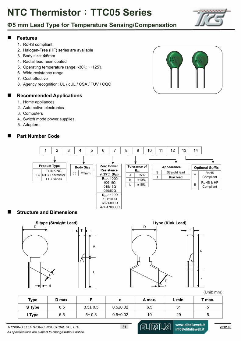
Part Number Code
Structure and Dimensions
Type D max. P d A max. L min. T max.
S Type 6.5 3.5± 0.5 0.5±0.02 6.5 31 5
I Type 6.5 5± 0.8 0.5±0.02 10 29 5
1 2 3 4 5 6 7 8 9 10 11 12 13 14
Product Type
TTC THINKING
NTC Thermistor TTC Series
Body Size 05 Ф5mm
Zero PowerResistance
at 25 (R25)R25<100Ω
005: 5Ω 015:15Ω 050:50Ω
R25 100Ω≧101:100Ω 682:6800Ω
474:470000Ω
Tolerance ofR25
J ±5%
K ±10%
L ±15%
Appearance S Straight lead
I Kink lead
Optional Suffix
Y RoHS
Compliant
E RoHS & HFCompliant
S type (Straight Lead) I type (Kink Lead)
(Unit: mm)
DT
A
L
d
P
T
A
L
d
P
D

NTC Thermistor:TTC05 Series Ф5 mm Lead Type for Temperature Sensing/Compensation
THINKING ELECTRONIC INDUSTRIAL CO., LTD. 32 www.thinking.com.tw 2012.08
All specifications are subject to change without notice.
Electrical Characteristics
Safety Approvals Zero Power Resistance
at 25°C
Tolerance of
R25
B25/50 Value
Max. Power
Dissipation at 25
Dissipation Factor
ThermalTime
Constant
Operating Temperature
Range Part No.
R25(Ω) ( ±%) (K) Pmax(mW) δ(mW/°C) τ(Sec.) TL~TU(°C)
UL /cUL
CSA TUV CQC
TTC05005 5 2400 TTC05010 10 2800 TTC05015 15 2800 TTC05020 20 2800 TTC05025 25 2900 TTC05045 45 3100 TTC05050 50 3100 TTC05060 60 3100 TTC05085 85 3200 TTC05090 90 3200 TTC05101 100 3200 TTC05121 120 3300 TTC05151 150 3300 TTC05201 200 3500 TTC05221 220 3500 TTC05251 250 3500 TTC05301 300 3800 TTC05471 470 3500 TTC05501 500 3700 TTC05681 680 3800 TTC05701 700 3800 TTC05102 1000 3800 TTC05152 1500 3950 TTC05202 2000 4000 TTC05222 2200 4000 TTC05252 2500 4000 TTC05302 3000 4000 TTC05332 3300 4000 TTC05402 4000 4000 TTC05472 4700 4050 TTC05502 5000 3950 TTC05602 6000 4050 TTC05682 6800 4050 TTC05802 8000 4050 TTC05103 10000 4050 TTC05123 12000 4050 TTC05153 15000 4150 TTC05203 20000 4250 TTC05303 30000 4250 TTC05473 47000 4300 TTC05503 50000 4300 TTC05104 100000 4400 TTC05154 150000 4500 TTC05204 200000 4600 TTC05224 220000 4600 TTC05474 470000
5, 10, 15
4750
450 Approx. 4.5
Approx.20
-30~+125
Note 1: = Tolerance of R25 Note 2: UL File No: E138827 CSA File No: 97495 TUV File No: R 50050155 CQC File No: CQC05001011991;CQC05001011994
Note 3: Special specifications are available upon request.
NTC Thermistor:TTC05 Series Ф5 mm Lead Type for Temperature Sensing/Compensation
THINKING ELECTRONIC INDUSTRIAL CO., LTD. 33 www.thinking.com.tw 2012.08
All specifications are subject to change without notice.
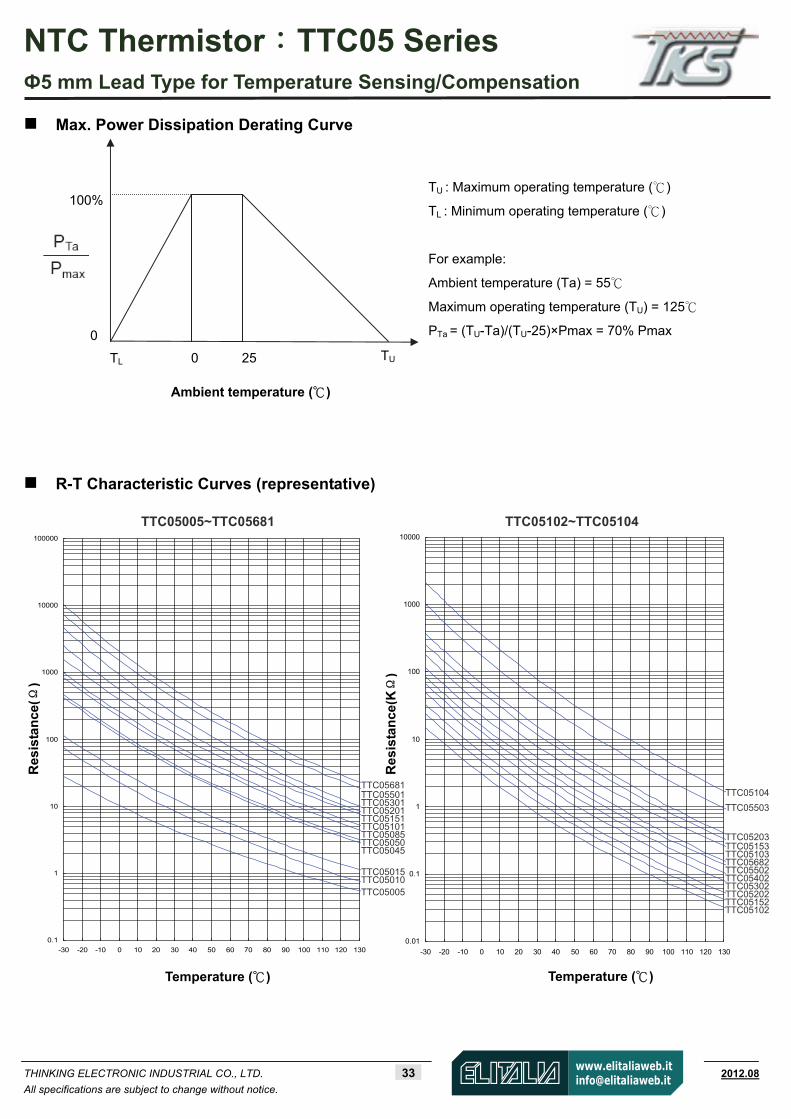
Max. Power Dissipation Derating Curve
R-T Characteristic Curves (representative)
0.01
0.1
1
10
100
1000
10000
-30 -20 -10 0 10 20 30 40 50 60 70 80 90 100 110 120 130
Temperature ( )
0.1
1
10
100
1000
10000
100000
-30 -20 -10 0 10 20 30 40 50 60 70 80 90 100 110 120 130
Temperature ( )
TTC05102~TTC05104
Res
ista
nce
(Ω)
100%
0 25 TU
0
TL
Ambient temperature ( )
TU : Maximum operating temperature ()
TL : Minimum operating temperature ()
For example:
Ambient temperature (Ta) = 55
Maximum operating temperature (TU) = 125
PTa = (TU-Ta)/(TU-25)×Pmax = 70% Pmax
TTC05005~TTC05681
TTC05681 TTC05501 TTC05301 TTC05201 TTC05151 TTC05101 TTC05085 TTC05050 TTC05045 TTC05015 TTC05010 TTC05005
TTC05104
TTC05503
TTC05203 TTC05153 TTC05103 TTC05682 TTC05502 TTC05402 TTC05302 TTC05202 TTC05152 TTC05102
Res
ista
nce
(KΩ
)

NTC Thermistor:TTC05 Series Ф5 mm Lead Type for Temperature Sensing/Compensation
THINKING ELECTRONIC INDUSTRIAL CO., LTD. 34 www.thinking.com.tw 2012.08
All specifications are subject to change without notice.
V-I Characteristic Curves (representative)
Vo
ltag
e(V
)
Current (mA)
Vo
ltag
e(V
)
Current (mA)
TTC05102~TTC05104
TTC05005~TTC05681
0.1
1
10
100
1 10 100 1000 10000 100000
0.2
2 5 20 50 200 500 2000 5000 20000 50000
0.5
2
5
20
50
TTC-045
TTC-015
TTC-005TTC-0
10
TTC-050
TTC-085
TTC-101
TTC-151
TTC-201
TTC-301TTC-5
01TTC-6
81
1
10
100
1000
0.1 1 10 100 1000 100000.2
TTC-103
TTC-682
TTC-302
0.5 2 5 20 50 200 500 2000 5000
2
20
50
TTC-402
TTC-153
TTC-152
TTC-102
TTC-503
TTC-502
TTC-202
TTC-104
5
200
500

NTC Thermistor:TTC05 Series Ф5 mm Lead Type for Temperature Sensing/Compensation
THINKING ELECTRONIC INDUSTRIAL CO., LTD. 35 www.thinking.com.tw 2012.08
All specifications are subject to change without notice.
Soldering Recommendation
Wave Soldering Profile
Recommended Reworking Conditions with Soldering Iron
Item Conditions
Temperature of Soldering Iron-tip 360 (max.)
Soldering Time 3 sec. (max.)
Distance from Thermistor 2 mm (min.)
Tem
pera
ture
130±20
260 Max
Tamb
Cooling
Time
Soldering Preheating
30~90 sec. <1 sec. <10 sec.
Note 1
Note 2 Note 3
Note 1: (1~3)/sec.
Note 2: Approx. 200/sec.
Note 3: 5/sec. (Max.)
NTC Thermistor:TTC05 Series Ф5 mm Lead Type for Temperature Sensing/Compensation
THINKING ELECTRONIC INDUSTRIAL CO., LTD. 36 www.thinking.com.tw 2012.08
All specifications are subject to change without notice.
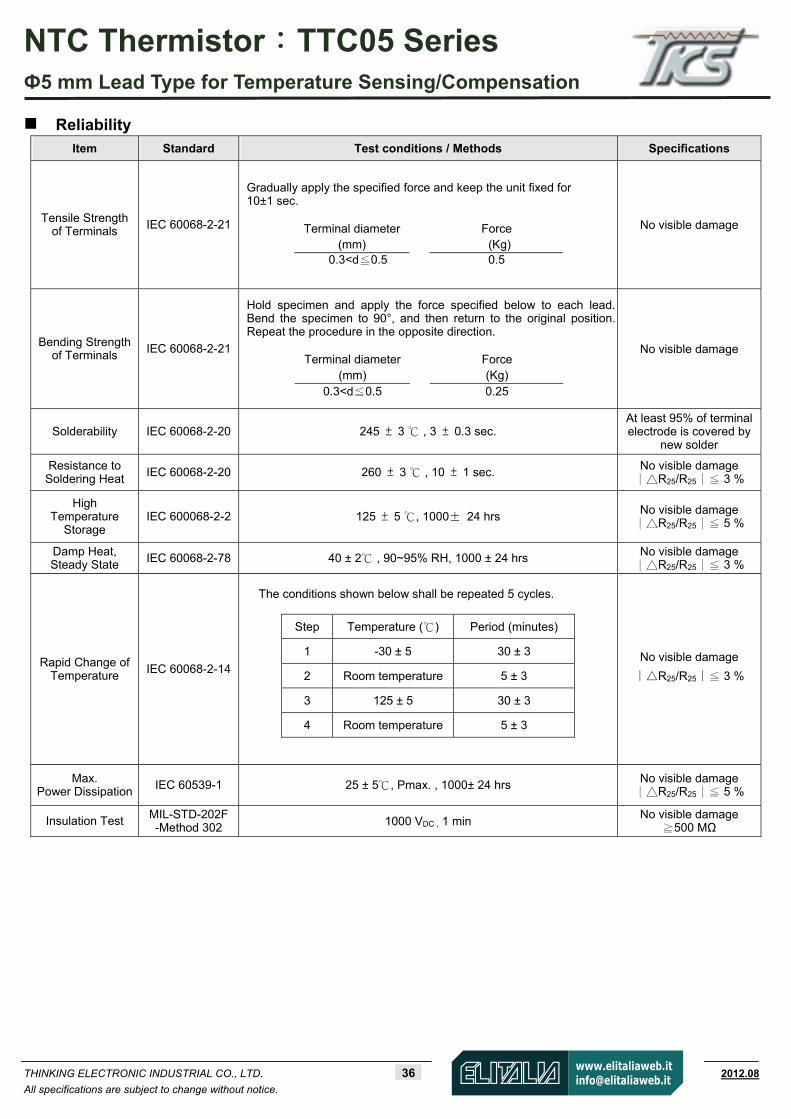
Reliability
Item Standard Test conditions / Methods Specifications
Tensile Strength of Terminals IEC 60068-2-21
Gradually apply the specified force and keep the unit fixed for 10±1 sec.
Terminal diameter Force
(mm) (Kg) 0.3<d 0.5 ≦ 0.5
No visible damage
Bending Strength of Terminals IEC 60068-2-21
Hold specimen and apply the force specified below to each lead. Bend the specimen to 90°, and then return to the original position. Repeat the procedure in the opposite direction.
Terminal diameter Force
(mm) (Kg) 0.3<d 0.5≦ 0.25
No visible damage
Solderability IEC 60068-2-20 245 ± 3 , 3 ± 0.3 sec. At least 95% of terminalelectrode is covered by
new solder
Resistance to Soldering Heat
IEC 60068-2-20 260 ± 3 , 10 ± 1 sec. No visible damage ∣R25/R25∣ 3 %≦
High Temperature
Storage IEC 600068-2-2 125 ± 5 , 1000± 24 hrs
No visible damage ∣R25/R25∣ 5 %≦
Damp Heat, Steady State IEC 60068-2-78 40 ± 2 , 90~95% RH, 1000 ± 24 hrs No visible damage
∣R25/R25∣ 3 %≦
Rapid Change of Temperature
IEC 60068-2-14
The conditions shown below shall be repeated 5 cycles.
Step Temperature ( ) Period (minutes)
1 -30 ± 5 30 ± 3
2 Room temperature 5 ± 3
3 125 ± 5 30 ± 3
4 Room temperature 5 ± 3
No visible damage
∣R25/R25∣ 3 %≦
Max. Power Dissipation IEC 60539-1 25 ± 5 , Pmax. , 1000± 24 hrs No visible damage
∣R25/R25∣ 5 %≦
Insulation Test MIL-STD-202F -Method 302 1000 VDC , 1 min
No visible damage 500 MΩ≧
NTC Thermistor:TTC05 Series Ф5 mm Lead Type for Temperature Sensing/Compensation
THINKING ELECTRONIC INDUSTRIAL CO., LTD. 37 www.thinking.com.tw 2012.08
All specifications are subject to change without notice.
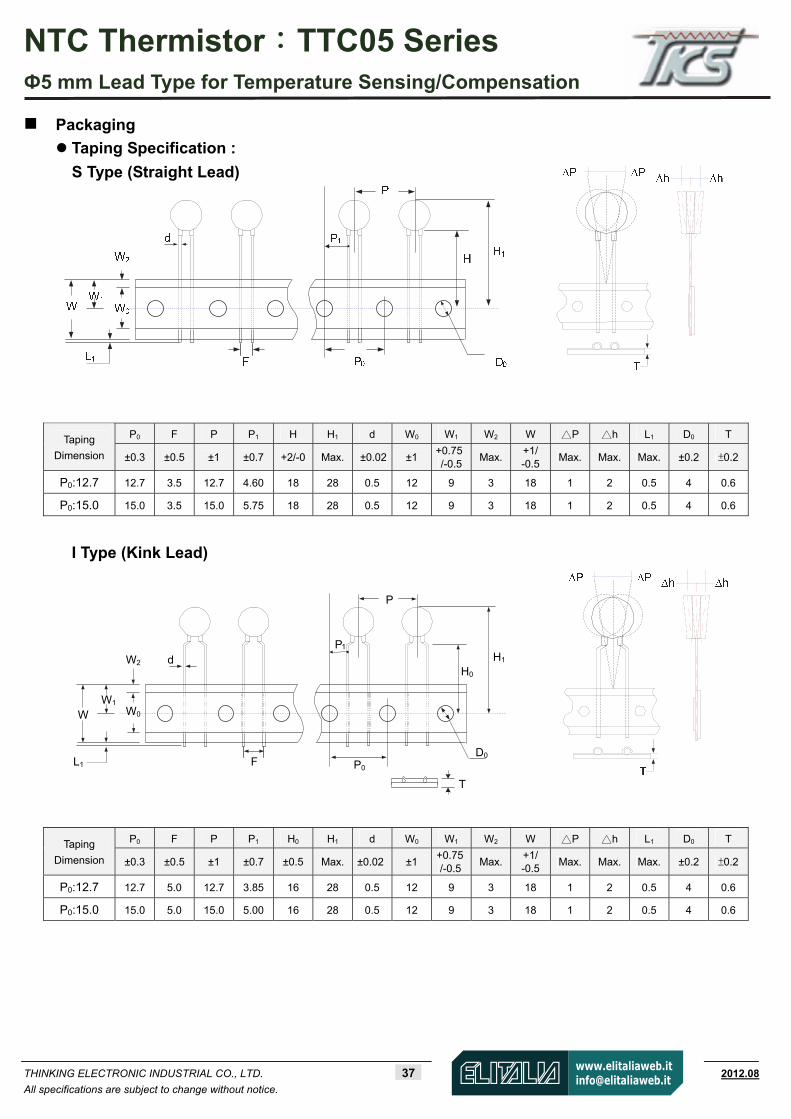
Packaging
Taping Specification :
S Type (Straight Lead)
P0 F P P1 H H1 d W0 W1 W2 W P h L1 D0 T Taping
Dimension ±0.3 ±0.5 ±1 ±0.7 +2/-0 Max. ±0.02 ±1 +0.75/-0.5
Max.+1/ -0.5
Max. Max. Max. ±0.2 ±0.2
P0:12.7 12.7 3.5 12.7 4.60 18 28 0.5 12 9 3 18 1 2 0.5 4 0.6
P0:15.0 15.0 3.5 15.0 5.75 18 28 0.5 12 9 3 18 1 2 0.5 4 0.6
I Type (Kink Lead)
P0 F P P1 H0 H1 d W0 W1 W2 W P h L1 D0 T Taping
Dimension ±0.3 ±0.5 ±1 ±0.7 ±0.5 Max. ±0.02 ±1 +0.75/-0.5
Max.+1/ -0.5
Max. Max. Max. ±0.2 ±0.2
P0:12.7 12.7 5.0 12.7 3.85 16 28 0.5 12 9 3 18 1 2 0.5 4 0.6
P0:15.0 15.0 5.0 15.0 5.00 16 28 0.5 12 9 3 18 1 2 0.5 4 0.6
D0
T
WW1
H0
P1
P0L1
P
F
d H1W2
W0

NTC Thermistor:TTC05 Series Ф5 mm Lead Type for Temperature Sensing/Compensation
THINKING ELECTRONIC INDUSTRIAL CO., LTD. 38 www.thinking.com.tw 2012.08
All specifications are subject to change without notice.
Quantity
Bulk Packing
Reel Packing:
Ammo Packing:
Warehouse Storage Conditions of Products Storage Conditions:
1. Storage Temperature: -10~+40
2. Relative Humidity: ≦75%RH
3. Keep away from corrosive atmosphere and sunlight.
Period of Storage: 1 year
Series Standard Lead Type
Quantity (pcs/bag)
Cut Lead Type
Quantity (pcs/bag)
TTC05 250 500
Series D
(mm) D1
(mm) W
(mm) Quantity (pcs/reel)
TTC05 340±10 31±1 55±1 2,500
Series Quantity (pcs/box)
TTC05 2,000
L W H
348mm 275mm 60mm
W
H
L
D1
D
W
NTC Thermistor:TTC3 Series Ф3 mm Lead Type for Temperature Sensing/Compensation
THINKING ELECTRONIC INDUSTRIAL CO., LTD. 39 www.thinking.com.tw 2012.08
All specifications are subject to change without notice.
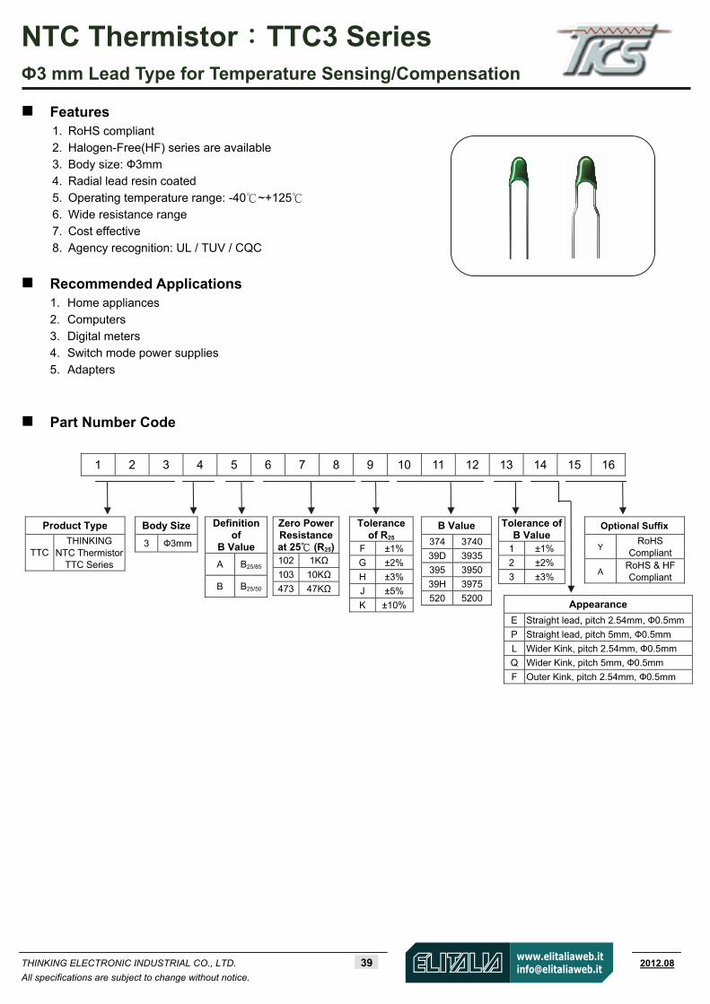
Features 1. RoHS compliant
2. Halogen-Free(HF) series are available 3. Body size: Ф3mm 4. Radial lead resin coated
5. Operating temperature range: -40~+125 6. Wide resistance range 7. Cost effective
8. Agency recognition: UL / TUV / CQC
Recommended Applications 1. Home appliances
2. Computers 3. Digital meters 4. Switch mode power supplies
5. Adapters
Part Number Code
1 2 3 4 5 6 7 8 9 10 11 12 13 14 15 16
Product Type
TTC THINKING
NTC Thermistor TTC Series
Body Size 3 Ф3mm
Definition of
B Value
A B25/85
B B25/50
Zero PowerResistanceat 25 (R25)102 1KΩ
103 10KΩ
473 47KΩ
Tolerance of R25
F ±1%
G ±2%
H ±3%
J ±5%
K ±10%
Tolerance of B Value
1 ±1%
2 ±2% 3 ±3%
Optional Suffix
Y RoHS
Compliant
A RoHS & HFCompliant
Appearance
E Straight lead, pitch 2.54mm, Ф0.5mm
P Straight lead, pitch 5mm, Ф0.5mm
L Wider Kink, pitch 2.54mm, Ф0.5mm
Q Wider Kink, pitch 5mm, Ф0.5mm
F Outer Kink, pitch 2.54mm, Ф0.5mm
B Value
374 3740
39D 3935
395 3950
39H 3975
520 5200
NTC Thermistor:TTC3 Series Ф3 mm Lead Type for Temperature Sensing/Compensation
THINKING ELECTRONIC INDUSTRIAL CO., LTD. 40 www.thinking.com.tw 2012.08
All specifications are subject to change without notice.
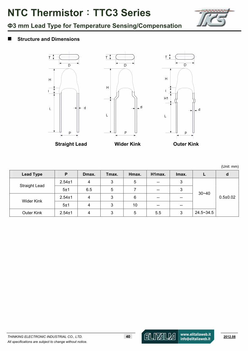
Structure and Dimensions
Straight Lead Wider Kink Outer Kink
(Unit: mm)
Lead Type P Dmax. Tmax. Hmax. H1max. Imax. L d
2.54±1 4 3 5 -- 3 Straight Lead
5±1 6.5 5 7 -- 3
2.54±1 4 3 6 -- -- Wider Kink
5±1 4 3 10 -- --
30~40
Outer Kink 2.54±1 4 3 5 5.5 3 24.5~34.5
0.5±0.02

NTC Thermistor:TTC3 Series Ф3 mm Lead Type for Temperature Sensing/Compensation
THINKING ELECTRONIC INDUSTRIAL CO., LTD. 41 www.thinking.com.tw 2012.08
All specifications are subject to change without notice.
Electrical Characteristics Safety
Approvals Zero Power Resistance
at 25°C
Tolerance of
R25
B Value
Toleranceof
B value
Max. PowerDissipation
at 25
Dissipation Factor
Thermal Time
Constant
OperatingTemperature
Range Part No.
R25 (KΩ) ( ±%) (K) (±%) Pmax(mW) δ(mW/°C) τ(Sec.) TL~TU(°C)
ULcUL
TUV CQC
TTC3A90139D* 0.9 3935
TTC3A10239D* 1 3935
TTC3A15239D* 1.5 3935
2、3
TTC3A20239H* 2 3975
TTC3A22239H* 2.2 3975
TTC3A27239H* 2.7 3975
TTC3A30239H* 3 3975
TTC3A33239H* 3.3 3975
TTC3A47239H* 4.7 3975
TTC3A482395* 4.8 3950
TTC3A48239H* 4.8 3975
TTC3A50239H* 5 3975
TTC3A68239H* 6.8 3975
TTC3A10334D* 10 3435
TTC3A103374* 10 3740
TTC3A10339H* 10 3975
TTC3A123374* 12 3740
TTC3A153374* 15 3740
1、2、3
TTC3A203374* 20 3740
TTC3A203426* 20 4260
TTC3A223374* 22 3740
2、3
TTC3A333409* 33 4090
TTC3A473409* 47 4090
TTC3A50339H* 50 3975
TTC3A503406* 50 4060
1、2、3
TTC3A683419* 68 4190
TTC3A104419* 100 4190
TTC3A104436* 100 4360
TTC3A154437* 150 4370
TTC3A204385* 200 3850
TTC3A224437* 220 4370
TTC3A334457* 330 4570
TTC3A474457* 470 4570
2、3
TTC3A474520* 470
25/85
5200 3
TTC3B202350* 2 3500 2、3
TTC3B47339D* 47 3935 1、2、3
TTC3B503440* 50 4400
TTC3B434507* 430 50702、3
TTC3B474520* 470
1、2、3、 5
25/50
5200 3
150 ≧2.5 ≦18 -40~+125
Note 1: = Tolerance of R25 * = Tolerance of B value
Note 2: UL File No: E138827, TUV File No: R50050155 CQC File No: CQC04001011945, CQC04001011966
Note 3: Special specifications are available upon request.
NTC Thermistor:TTC3 Series Ф3 mm Lead Type for Temperature Sensing/Compensation
THINKING ELECTRONIC INDUSTRIAL CO., LTD. 42 www.thinking.com.tw 2012.08
All specifications are subject to change without notice.
0.01
0.1
1
10
100
1000
10000
100000
-40 -30 -20 -10 0 10 20 30 40 50 60 70 80 90 100 110 120 130
0.01
0.1
1
10
100
1000
10000
100000
-40 -30 -20 -10 0 10 20 30 40 50 60 70 80 90 100 110 120 130
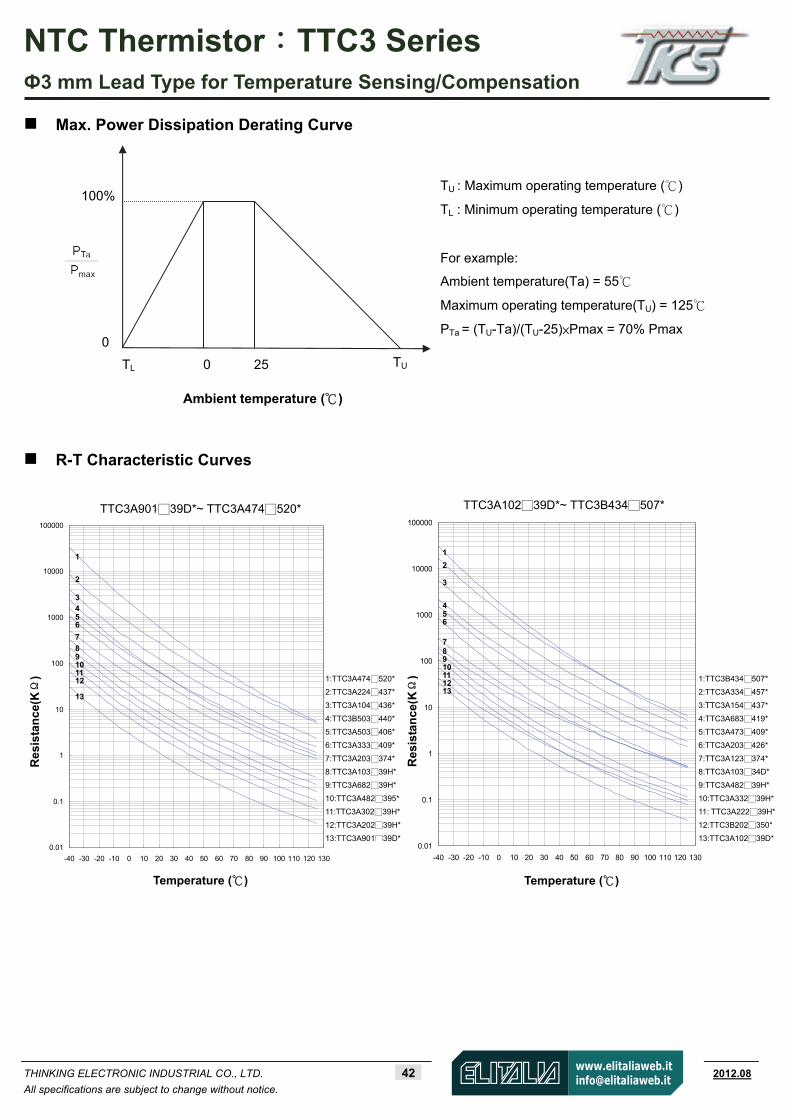
1:TTC3A474520*
2:TTC3A224437*
3:TTC3A104436*
4:TTC3B503440*
5:TTC3A503406*
6:TTC3A333409*
7:TTC3A203374*
8:TTC3A10339H*
9:TTC3A68239H*
10:TTC3A482395*
11:TTC3A30239H*
12:TTC3A20239H*
13:TTC3A90139D*
Max. Power Dissipation Derating Curve
R-T Characteristic Curves
100%
0 25 TU
0
TL
Ambient temperature ( )
TU : Maximum operating temperature ()
TL : Minimum operating temperature ()
For example:
Ambient temperature(Ta) = 55
Maximum operating temperature(TU) = 125
PTa = (TU-Ta)/(TU-25)×Pmax = 70% Pmax
1:TTC3B434507*
2:TTC3A334457*
3:TTC3A154437*
4:TTC3A683419*
5:TTC3A473409*
6:TTC3A203426*
7:TTC3A123374*
8:TTC3A10334D*
9:TTC3A48239H*
10:TTC3A33239H*
11: TTC3A22239H*
12:TTC3B202350*
13:TTC3A10239D*
Res
ista
nc
e(KΩ
)
Res
ista
nc
e (KΩ
)
TTC3A90139D*~ TTC3A474520* TTC3A10239D*~ TTC3B434507*
Temperature ( ) Temperature ( )
1
2 3 4 5 6
7
8 9 10 11 12 13
1
2 3
4 5 6
7 8 9 10 11 12 13
NTC Thermistor:TTC3 Series Ф3 mm Lead Type for Temperature Sensing/Compensation
THINKING ELECTRONIC INDUSTRIAL CO., LTD. 43 www.thinking.com.tw 2012.08
All specifications are subject to change without notice.
0.01
0.1
1
10
100
1000
10000
100000
-40 -30 -20 -10 0 10 20 30 40 50 60 70 80 90 100 110 120 130
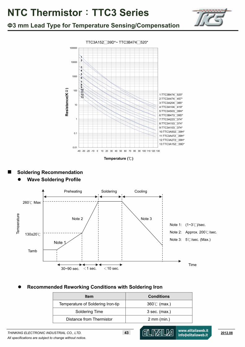
Soldering Recommendation
Wave Soldering Profile
Recommended Reworking Conditions with Soldering Iron
Item Conditions
Temperature of Soldering Iron-tip 360 (max.)
Soldering Time 3 sec. (max.)
Distance from Thermistor 2 mm (min.)
Tem
pera
ture
130±20
260 Max
Tamb
Cooling
Time
Soldering Preheating
30~90 sec. <1 sec. <10 sec.
Note 1
Note 2 Note 3
Note 1: (1~3)/sec.
Note 2: Approx. 200/sec.
Note 3: 5/sec. (Max.)
Res
ista
nc
e(KΩ
)
Temperature ( )
1:TTC3B474520*
2:TTC3A474457*
3:TTC3A204385*
4:TTC3A104419*
5:TTC3A50339H*
6:TTC3B47339D*
7:TTC3A223374*
8:TTC3A153374*
9:TTC3A103374*
10:TTC3A50239H*
11:TTC3A47239H*
12:TTC3A27239H*
13:TTC3A15239D*
TTC3A15239D*~ TTC3B474520*
1 2 3 4
5
6
7 8 9 10 11 12 13

NTC Thermistor:TTC3 Series Ф3 mm Lead Type for Temperature Sensing/Compensation
THINKING ELECTRONIC INDUSTRIAL CO., LTD. 44 www.thinking.com.tw 2012.08
All specifications are subject to change without notice.
Reliability
Item Standard Test conditions / Methods Specifications
Tensile Strength of
Terminations IEC 60068-2-21
Gradually apply the specified force and keep the unit fixed for 10±1 sec.
Terminal diameter Force
(mm) (Kg)
0.3<d 0.5 ≦ 0.5
No visible damage
Bending Strength of
Terminations IEC 60068-2-21
Hold specimen and apply the force specified below to each lead. Bend the specimen to 90°, and then return to the original position. Repeat the procedure in the opposite direction.
Terminal diameter Force
(mm) (Kg)
0.3<d 0.5≦ 0.25
No visible damage
Solderability IEC 60068-2-20 245±3 , 3±0.3 sec.
At least 95% of terminal electrode
is covered by new solder
Resistance to Soldering
Heat IEC 60068-2-20 260 ± 3 , 10 ± 1 sec . No visible damage
R∣ 25/R25 3 %∣≦
High Temperature
Storage IEC 60068-2-2 125 ± 5 , 1000 ± 24 hrs No visible damage
R∣ 25/R25 5 %∣≦
Damp Heat, Steady State IEC 60068-2-3 40 ± 2 , 90~95% RH , 1000 ± 24 hrs No visible damage
R∣ 25/R25 3 %∣≦
Rapid Change of
Temperature IEC 60068-2-14
The conditions shown below shall be repeated 5 cycles
Step Temperature ( ) Period (minutes) 1 -40 ± 5 30 ± 3 2 Room temperature 5 ± 3 3 125 ± 5 30 ± 3 4 Room temperature 5 ± 3
No visible damage
∣R25/R25∣ 3 %≦
Max. Power Dissipation
IEC 60539-1 25 ± 5 , Pmax. , 1000 ± 24 hrs No visible damage R∣ 25/R25 5 %∣≦
NTC Thermistor:TTC3 Series Ф3 mm Lead Type for Temperature Sensing/Compensation
THINKING ELECTRONIC INDUSTRIAL CO., LTD. 45 www.thinking.com.tw 2012.08
All specifications are subject to change without notice.
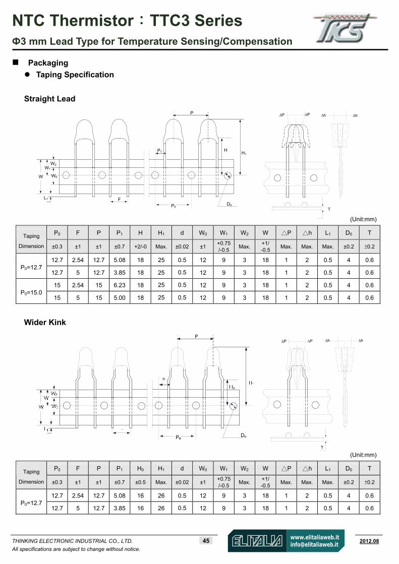
Packaging
Taping Specification
Straight Lead
(Unit:mm)
P0 F P P1 H H1 d W0 W1 W2 W P h L1 D0 T Taping
Dimension ±0.3 ±1 ±1 ±0.7 +2/-0 Max. ±0.02 ±1 +0.75/-0.5
Max.+1/ -0.5
Max. Max. Max. ±0.2 ±0.2
12.7 2.54 12.7 5.08 18 25 0.5 12 9 3 18 1 2 0.5 4 0.6P0=12.7
12.7 5 12.7 3.85 18 25 0.5 12 9 3 18 1 2 0.5 4 0.6
15 2.54 15 6.23 18 25 0.5 12 9 3 18 1 2 0.5 4 0.6P0=15.0
15 5 15 5.00 18 25 0.5 12 9 3 18 1 2 0.5 4 0.6
Wider Kink
(Unit:mm)
P0 F P P1 H0 H1 d W0 W1 W2 W P h L1 D0 T Taping
Dimension ±0.3 ±1 ±1 ±0.7 ±0.5 Max. ±0.02 ±1 +0.75/-0.5
Max.+1/ -0.5
Max. Max. Max. ±0.2 ±0.2
12.7 2.54 12.7 5.08 16 26 0.5 12 9 3 18 1 2 0.5 4 0.6P0=12.7
12.7 5 12.7 3.85 16 26 0.5 12 9 3 18 1 2 0.5 4 0.6
W
L1 F
HH1
D0
P1
P
P0
W1
W2
W0
∆h
T
∆P ∆P ∆h
T
∆h∆P ∆P ∆h

NTC Thermistor:TTC3 Series Ф3 mm Lead Type for Temperature Sensing/Compensation
THINKING ELECTRONIC INDUSTRIAL CO., LTD. 46 www.thinking.com.tw 2012.08
All specifications are subject to change without notice.
Outer Kink
(Unit:mm)
P0 F P P1 H0 H1 d W0 W1 W2 W P h L1 D0 T Taping
Dimension ±0.3 ±1 ±1 ±0.7 ±0.5 Max. ±0.02 ±1 +0.75/-0.5
Max.+1/ -0.5
Max. Max. Max. ±0.2 ±0.2
P0=12.7 12.7 2.54 12.7 5.08 16 26 0.5 12 9 3 18 1 2 0.5 4 0.6
Quantity
Bulk Packing
Reel Packing
Ammo Packing
Warehouse Storage Conditions of Products Storage Conditions:
1. Storage Temperature: -10~+40
2. Relative Humidity: ≦75%RH
3. Keep away from corrosive atmosphere and sunlight.
Period of Storage : 1 year
Series Quantity (pcs/bag)
TTC3 500
Series Quantity (pcs/reel)
TTC3 2,500
Series Quantity (pcs/box)
TTC3 2,500
(Unit: mm)
46±131±1
340±10
n n n n n n n n n n n
50±5
275±
5
348±5
NTC Thermistor:TTS Series Epoxy Bead Type for Temperature Sensing/Compensation
THINKING ELECTRONIC INDUSTRIAL CO., LTD. 47 www.thinking.com.tw 2012.08
All specifications are subject to change without notice.
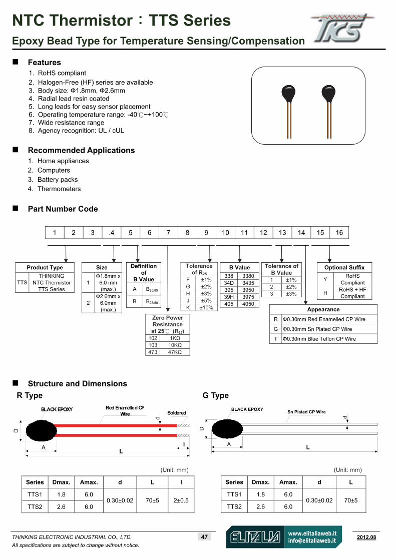
Optional Suffix
Y RoHS
Compliant
H RoHS + HFCompliant
B Value
338 338034D 3435395 395039H 3975405 4050
Size
1 Ф1.8mm x
6.0 mm (max.)
2 Ф2.6mm x
6.0mm (max.)
Zero Power Resistance at 25 (R25)
102 1KΩ 103 10KΩ 473 47KΩ
Product Type
TTS THINKING
NTC Thermistor TTS Series
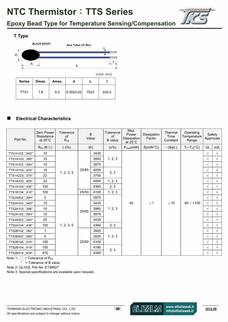
Features 1. RoHS compliant
2. Halogen-Free (HF) series are available 3. Body size: Ф1.8mm, Ф2.6mm 4. Radial lead resin coated 5. Long leads for easy sensor placement 6. Operating temperature range: -40 ~ +100 7. Wide resistance range 8. Agency recognition: UL / cUL
Recommended Applications 1. Home appliances
2. Computers 3. Battery packs 4. Thermometers
Part Number Code
1 2 3 .4 5 6 7 8 9 10 11 12 13 14 15 16
Structure and Dimensions
(Unit: mm)
R Type G Type
D
L
Red Enamelled CP Wire
BLACK EPOXY
A I
d
Soldered
Series Dmax. Amax. d L I
TTS1 1.8 6.0
TTS2 2.6 6.0 0.30±0.02 70±5 2±0.5
D
L
Sn Plated CP WireBLACK EPOXY
A
d
Series Dmax. Amax. d L
TTS1 1.8 6.0
TTS2 2.6 6.0 0.30±0.02 70±5
Tolerance of R25
F ±1%G ±2%H ±3%J ±5%K ±10%
Tolerance of B Value 1 ±1% 2 ±2% 3 ±3%
Definition of
B Value
A B25/85
B B25/50
Appearance
R Φ0.30mm Red Enamelled CP Wire
G Φ0.30mm Sn Plated CP Wire
T Φ0.30mm Blue Teflon CP Wire
(Unit: mm)
NTC Thermistor:TTS Series Epoxy Bead Type for Temperature Sensing/Compensation
THINKING ELECTRONIC INDUSTRIAL CO., LTD. 48 www.thinking.com.tw 2012.08
All specifications are subject to change without notice.
Electrical Characteristics
Zero Power Resistance
at 25°C
Tolerance of
R25
B Value
Toleranceof
B value
Max. Power
Dissipationat 25°C
DissipationFactor
Thermal Time
Constant
Operating Temperature
Range
Safety ApprovalsPart No.
R25 (KΩ) ( ±%) (K) (±%) Pmax(mW) δ(mW/°C) τ(Sec.) TL~TU(°C) UL cUL
TTS1A10334D* 10 3435 TTS1A103395* 10 3950 TTS1A10339H* 10 3975
1, 2, 3
TTS1A103425* 10 4250 TTS1A223370* 22 3700
2, 3
TTS1A333405* 33 4050 1, 2, 3 TTS1A104436* 100
25/85
4360 2, 3 TTS1B104410* 100
1, 2, 3, 5
25/50 4100 1, 2, 3 TTS2A50239H* 5 3975 TTS2A10334D* 10 3435 TTS2A103396* 10 3960 TTS2A10339H* 10 3975 TTS2A20334D* 20 3435
1, 2, 3
TTS2A104436* 100
25/85
4360 2, 3 TTS2B102392* 1 3920 TTS2B50239D* 5 3935 TTS2B104410* 100 4100
1, 2, 3
TTS2B104419* 100 4190 TTS2B474439* 470
1, 2, 3, 5
25/50
43902, 3
45 ≧1 ≦10 -40 ~ +100
Note 1: = Tolerance of R25
* = Tolerance of B value Note 2: UL/cUL File No: E138827 Note 3: Special specifications are available upon request.
T Type
D
L
Blue Teflon CP WireBLACK EPOXY
A I
d
Series Dmax. Amax. d L I
TTS1 1.8 6.0 0.30±0.02 70±5 2±0.5
(Unit: mm)

NTC Thermistor:TTS Series Epoxy Bead Type for Temperature Sensing/Compensation
THINKING ELECTRONIC INDUSTRIAL CO., LTD. 49 www.thinking.com.tw 2012.08
All specifications are subject to change without notice.
0.1
1
10
100
1000
10000
-40 -30 -20 -10 0 10 20 30 40 50 60 70 80 90 100
Max. Power Dissipation Derating Curve
R-T Characteristic Curves
0.01
0.1
1
10
100
1000
10000
100000
-40 -30 -20 -10 0 10 20 30 40 50 60 70 80 90 100
100%
0 25 TU
0
TL
Ambient temperature ( )
TU : Maximum operating temperature ()
TL : Minimum operating temperature ()
For example:
Ambient temperature(Ta) = 55
Maximum operating temperature(TU) = 100
PTa=(TU-Ta)/(TU-25)×Pmax = 60% Pmax
1:TTS1A104436*
2:TTS1B104410*
3:TTS1A333405*
4:TTS1A223370*
5:TTS1A103425*
6:TTS1A10339H*
7:TTS1A103395*
8:TTS1A10334D*
1:TTS2B474439*
2:TTS2A104436*
3:TTS2B104419*
4:TTS2A20334D*
5:TTS2A10339H*
6:TTS2A10334D*
7:TTS2A50239H*
8:TTS2B102392*
Res
ista
nc
e(KΩ
)
TTS1A10334D*~ TTS1B104436*
Res
ista
nc
e(KΩ
)
TTS2B102392*~ TTS2B474439*
Temperature ( ) Temperature ( )
1
2
3 4 5 6 7
8
1
2 3 4 5 6 7 8
NTC Thermistor:TTS Series Epoxy Bead Type for Temperature Sensing/Compensation
THINKING ELECTRONIC INDUSTRIAL CO., LTD. 50 www.thinking.com.tw 2012.08
All specifications are subject to change without notice.
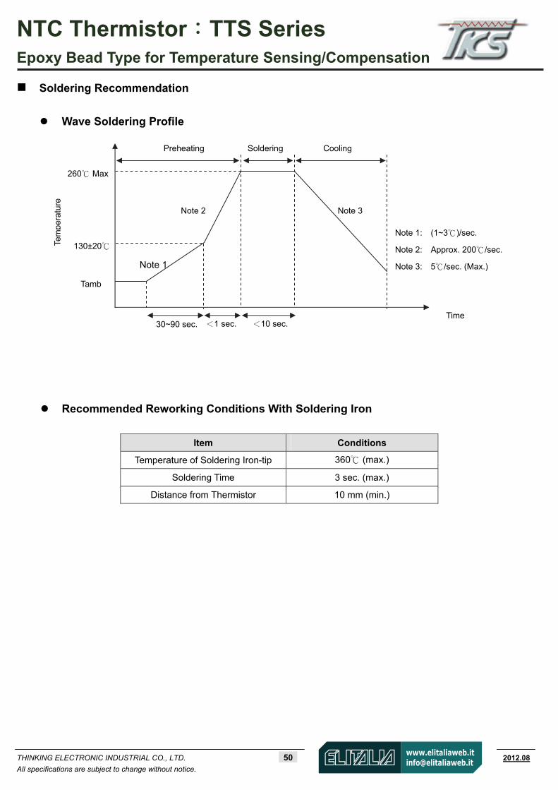
Soldering Recommendation
Wave Soldering Profile
Recommended Reworking Conditions With Soldering Iron
Item Conditions
Temperature of Soldering Iron-tip 360 (max.)
Soldering Time 3 sec. (max.)
Distance from Thermistor 10 mm (min.)
Tem
pera
ture
130±20
260 Max
Tamb
Cooling
Time
Soldering Preheating
30~90 sec. <1 sec. <10 sec.
Note 1
Note 2 Note 3
Note 1: (1~3)/sec.
Note 2: Approx. 200/sec.
Note 3: 5/sec. (Max.)

NTC Thermistor:TTS Series Epoxy Bead Type for Temperature Sensing/Compensation
THINKING ELECTRONIC INDUSTRIAL CO., LTD. 51 www.thinking.com.tw 2012.08
All specifications are subject to change without notice.
Reliability
Item Standard Test conditions / Methods Specifications
Tensile Strength of Terminations IEC 60068-2-21
Gradually apply the specified force and keep the unit fixed for 10±1 sec.
Terminal diameter Force
(mm) (Kg)
d 0.25≦ 0.10
0.25<d 0.3≦ 0.25
0.3<d 0.5≦ 0.5
No visible damage
Bending Strength of
Terminations IEC 60068-2-21
Hold specimen and apply the force specified below to each lead. Bend the specimen to 90°, and then return to the original position. Repeat the procedure in the opposite direction.
Terminal diameter Force
(mm) (Kg)
d 0.25≦ 0.05
0.25<d 0.3≦ 0.125
0.3<d 0.5≦ 0.25
No visible damage
Solderability IEC 60068-2-20 245 ± 3 , 3 ± 0.3 sec. At least 95% of terminalelectrode is covered by
new solder
Resistance to Soldering Heat
IEC 60068-2-20 260 ± 3 , 10 ± 1 sec . No visible damage R∣ 25/R25 3 %∣≦
High Temperature
Storage IEC 60068-2-2 100 ± 5 , 1000 ± 24 hrs
No visible damage ∣ R 25/R25 5 %∣≦
Damp Heat, Steady State IEC 60068-2-78 40 ± 2 , 90~95% RH, 1000 ± 24 hrs No visible damage
R∣ 25/R25 3 %∣≦
Rapid Change of Temperature
IEC 60068-2-14
The conditions shown below shall be repeated 5 cycles.
Step Temperature ( ) Period (minutes) 1 -40 ± 5 30 ± 3 2 Room temperature 5 ± 3 3 100 ± 5 30 ± 3 4 Room temperature 5 ± 3
No visible damage
R∣ 25/R25 3 %∣≦
Max. Power
Dissipation IEC 60539-1 25 ± 5 , Pmax. , 1000 ± 24 hrs No visible damage
R∣ 25/R25 5 %∣≦
Packaging Bulk Packing: 500 pcs/bag
Warehouse Storage Conditions of Products Storage Conditions :
1. Storage Temperature: -10~+40
2. Relative Humidity: ≦75%RH
3. Keep away from corrosive atmosphere and sunlight.
Period of Storage : 1 [email protected]
NTC Thermistor::::TTF Series Insulation Film Type for Temperature Sensing/Compensation
THINKING ELECTRONIC INDUSTRIAL CO., LTD. 52 www.thinking.com.tw 2013.08
All specifications are subject to change without notice.
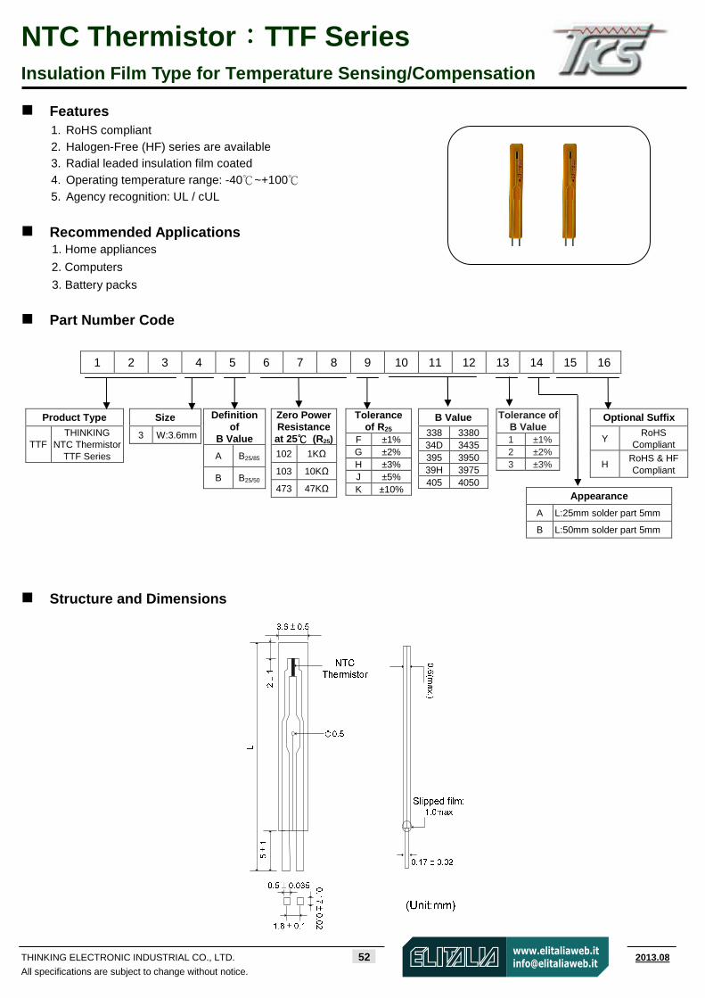
Features 1. RoHS compliant 2. Halogen-Free (HF) series are available 3. Radial leaded insulation film coated 4. Operating temperature range: -40 ~ +100 5. Agency recognition: UL / cUL
Recommended Applications 1. Home appliances
2. Computers
3. Battery packs
Part Number Code
1 2 3 4 5 6 7 8 9 10 11 12 13 14 15 16
Structure and Dimensions
Product Type
TTF THINKING
NTC Thermistor TTF Series
Size 3 W:3.6mm
Zero Power Resistance at 25 (R25) 102 1KΩ
103 10KΩ
473 47KΩ
Tolerance of R25
F ±1% G ±2% H ±3% J ±5% K ±10%
Tolerance of B Value 1 ±1% 2 ±2% 3 ±3%
Optional Suffix Y
RoHS Compliant
H RoHS & HF Compliant
Appearance
A L:25mm solder part 5mm
B L:50mm solder part 5mm
Definition of
B Value
A B25/85
B B25/50
B Value
338 3380 34D 3435 395 3950 39H 3975 405 4050
NTC Thermistor::::TTF Series Insulation Film Type for Temperature Sensing/Compensation
THINKING ELECTRONIC INDUSTRIAL CO., LTD. 53 www.thinking.com.tw 2013.08
All specifications are subject to change without notice.
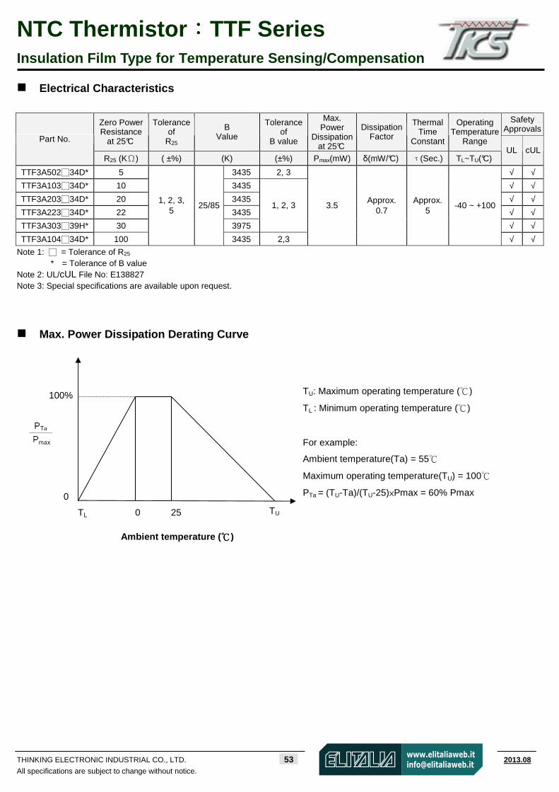
Electrical Characteristics
Safety
Approvals Zero Power Resistance
at 25°C
Tolerance of
R25
B Value
Tolerance of
B value
Max. Power
Dissipation at 25°C
Dissipation Factor
Thermal Time
Constant
Operating Temperature
Range Part No.
R25 (KΩ) ( ±%) (K) (±%) Pmax(mW) δ(mW/°C) τ(Sec.) TL~TU(°C) UL cUL
TTF3A50234D* 5 3435 2, 3 √ √
TTF3A10334D* 10 3435 √ √
TTF3A20334D* 20 3435 √ √
TTF3A22334D* 22 3435 √ √
TTF3A30339H* 30 3975
1, 2, 3
√ √
TTF3A10434D* 100
1, 2, 3, 5
25/85
3435 2,3
3.5 Approx.
0.7 Approx.
5 -40 ~ +100
√ √
Note 1: = Tolerance of R25 * = Tolerance of B value
Note 2: UL/cUL File No: E138827 Note 3: Special specifications are available upon request.
Max. Power Dissipation Derating Curve
100%
0 25 TU
0
TL
Ambient temperature ( )
TU: Maximum operating temperature ()
TL : Minimum operating temperature ()
For example:
Ambient temperature(Ta) = 55
Maximum operating temperature(TU) = 100
PTa = (TU-Ta)/(TU-25)×Pmax = 60% Pmax
NTC Thermistor::::TTF Series Insulation Film Type for Temperature Sensing/Compensation
THINKING ELECTRONIC INDUSTRIAL CO., LTD. 54 www.thinking.com.tw 2013.08
All specifications are subject to change without notice.
0.1
1
10
100
1000
10000
-40 -30 -20 -10 0 10 20 30 40 50 60 70 80 90 100
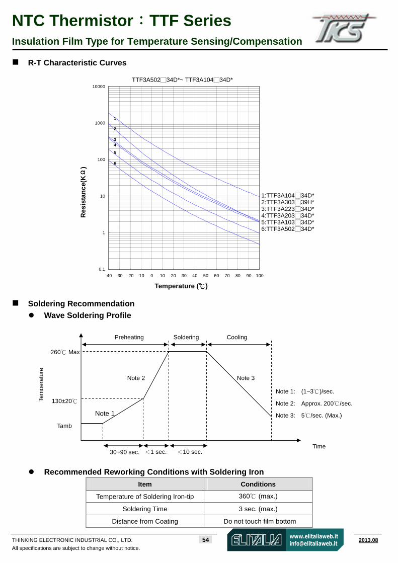
R-T Characteristic Curves
Soldering Recommendation Wave Soldering Profile
Recommended Reworking Conditions with Soldering Iron Item Conditions
Temperature of Soldering Iron-tip 360 (max.)
Soldering Time 3 sec. (max.)
Distance from Coating Do not touch film bottom
Res
ista
nce
(KΩΩ ΩΩ
)
Temperature ()
TTF3A50234D*~ TTF3A10434D*
1:TTF3A10434D* 2:TTF3A30339H* 3:TTF3A22334D* 4:TTF3A20334D* 5:TTF3A10334D* 6:TTF3A50234D*
Tem
pera
ture
130±20
260 Max
Tamb
Cooling
Time
Soldering Preheating
30~90 sec. <1 sec. <10 sec.
Note 1
Note 2 Note 3
Note 1: (1~3)/sec.
Note 2: Approx. 200/sec.
Note 3: 5/sec. (Max.)
1
2 3 4
5 6
NTC Thermistor::::TTF Series Insulation Film Type for Temperature Sensing/Compensation
THINKING ELECTRONIC INDUSTRIAL CO., LTD. 55 www.thinking.com.tw 2013.08
All specifications are subject to change without notice.
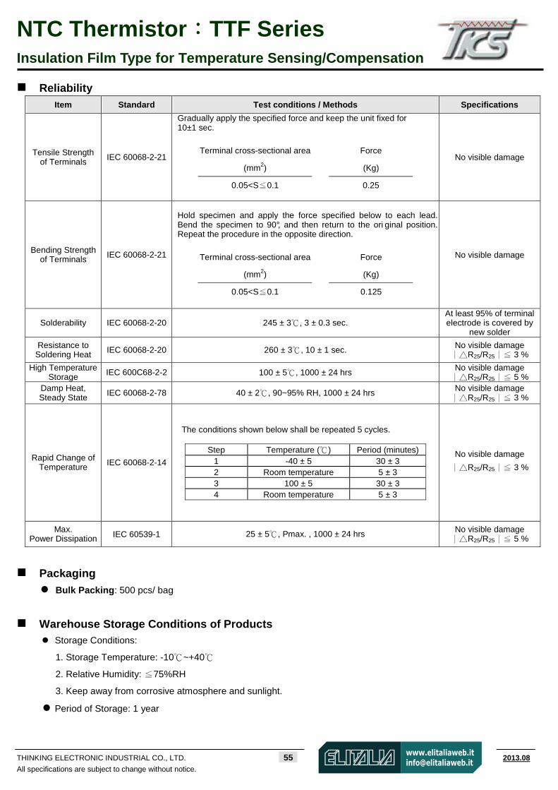
Reliability
Item Standard Test conditions / Methods Specifications
Tensile Strength of Terminals IEC 60068-2-21
Gradually apply the specified force and keep the unit fixed for 10±1 sec.
Terminal cross-sectional area Force
(mm2) (Kg)
0.05<S 0.1≦ 0.25
No visible damage
Bending Strength of Terminals IEC 60068-2-21
Hold specimen and apply the force specified below to each lead. Bend the specimen to 90°, and then return to the ori ginal position. Repeat the procedure in the opposite direction.
Terminal cross-sectional area Force
(mm2) (Kg)
0.05<S 0.1≦ 0.125
No visible damage
Solderability IEC 60068-2-20 245 ± 3 , 3 ± 0.3 sec . At least 95% of terminal electrode is covered by
new solder
Resistance to Soldering Heat IEC 60068-2-20 260 ± 3 , 10 ± 1 sec . No visible damage
R∣∣ 25/R25 3 %∣≦
High Temperature Storage IEC 600C68-2-2 100 ± 5 , 1000 ± 24 hrs No visible damage
R∣∣ 25/R25 5 %∣≦ Damp Heat, Steady State IEC 60068-2-78 40 ± 2 , 90~95% RH, 1000 ± 24 hrs No visible damage
R∣∣ 25/R25 3 ∣≦ %
Rapid Change of Temperature IEC 60068-2-14
The conditions shown below shall be repeated 5 cycles.
Step Temperature ( ) Period (minutes) 1 -40 ± 5 30 ± 3 2 Room temperature 5 ± 3 3 100 ± 5 30 ± 3 4 Room temperature 5 ± 3
No visible damage
R∣∣ 25/R25 3 %∣≦
Max. Power Dissipation IEC 60539-1 25 ± 5 , Pmax. , 1000 ± 24 hrs No visible damage
R∣∣ 25/R25 5 %∣≦
Packaging Bulk Packing: 500 pcs/ bag
Warehouse Storage Conditions of Products Storage Conditions:
1. Storage Temperature: -10~+40
2. Relative Humidity: ≦75%RH
3. Keep away from corrosive atmosphere and sunlight.
Period of Storage: 1 year

NTC Thermistor:TGM Series Glass Encapsulated Type for Temperature Sensing/Compensation
THINKING ELECTRONIC INDUSTRIAL CO., LTD. 56 www.thinking.com.tw 2012.08
All specifications are subject to change without notice.
Features 1. RoHS compliant
2. Glass-encapsulated and heat-resistive 3. Body size: Ф2.5mm 4. Operating temperature range: -40 ~ +250
Recommended Applications 1. Home appliances 2. Automotive electronics
Structure and Dimensions
(Unit: mm)
Series D H L d
TGMA 2.5±0.2 3.8±0.5 ≧40 0.30±0.02
NTC Thermistor:TGM Series Glass Encapsulated Type for Temperature Sensing/Compensation
THINKING ELECTRONIC INDUSTRIAL CO., LTD. 57 www.thinking.com.tw 2012.08
All specifications are subject to change without notice.
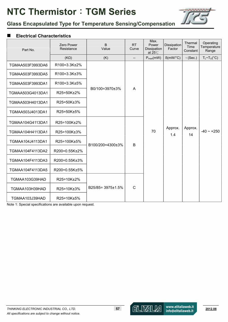
Electrical Characteristics
Zero Power Resistance
B Value
RT Curve
Max. Power
Dissipation at 25
Dissipation Factor
ThermalTime
Constant
OperatingTemperature
Range Part No.
(KΩ) (K) -- Pmax(mW) δ(mW/°C) τ(Sec.) TL~TU(°C)
TGMAA503F3993DA6 R100=3.3K±2%
TGMAA503F3993DA5 R100=3.3K±3%
TGMAA503F3993DA1 R100=3.3K±5%
TGMAA503G4013DA1 R25=50K±2%
TGMAA503H4013DA1 R25=50K±3%
TGMAA503J4013DA1 R25=50K±5%
B0/100=3970±3% A
TGMAA104G4113DA1 R25=100K±2%
TGMAA104H4113DA1 R25=100K±3%
TGMAA104J4113DA1 R25=100K±5%
TGMAA104F4113DA2 R200=0.55K±2%
TGMAA104F4113DA3 R200=0.55K±3%
TGMAA104F4113DA5 R200=0.55K±5%
B100/200=4300±3% B
TGMAA103G39HAD R25=10K±2%
TGMAA103H39HAD R25=10K±3%
TGMAA103J39HAD R25=10K±5%
B25/85= 3975±1.5% C
70 Approx.
1.4
Approx.
14 -40 ~ +250
Note 1: Special specifications are available upon request.

NTC Thermistor:TGM Series Glass Encapsulated Type for Temperature Sensing/Compensation
THINKING ELECTRONIC INDUSTRIAL CO., LTD. 58 www.thinking.com.tw 2012.08
All specifications are subject to change without notice.
Max. Power Dissipation Derating Curve
R-T Characteristic Curves (representative)
Temperature ()
Res
ista
nce
(KΩ
)
0.01
0.1
1
10
100
1000
10000
-40 -30 -20 -10 0 10 20 30 40 50 60 70 80 90 100 110 120 130 140 150 160 170 180 190 200 210 220 230 240 250
A
B
C
A
B
C
TU : Maximum operating temperature ()
TL : Minimum operating temperature ()
For example:
Ambient temperature (Ta) = 60
Maximum operating temperature (TU) = 200
PTa = (TU-Ta)/(TU-25)×Pmax = 80% Pmax
100%
0 25 TU
0
TL
Ambient temperature ( )

NTC Thermistor:TGM Series Glass Encapsulated Type for Temperature Sensing/Compensation
THINKING ELECTRONIC INDUSTRIAL CO., LTD. 59 www.thinking.com.tw 2012.08
All specifications are subject to change without notice.
Reliability
Item Standard Test conditions / Methods Specifications
High Temperature
Storage IEC 60068-2-2 Tu ± 5 , 1000 ± 24 hrs
No visible damage R∣ 25/R25 5 %∣≦
Damp Heat, Steady State
IEC 60068-2-78 40 ± 2 , 90~95% RH, 1000 ± 24 hrs No visible damage R∣ 25/R25 5 %∣≦
Rapid Change of
Temperature IEC 60068-2-14
The conditions shown below shall be repeated 5 cycles.
Step Temperature ( ) Period (minutes)
1 TL ± 5 30 ± 3
2 Room temperature 5 ± 3
3 TU ± 5 30 ± 3
4 Room temperature 5 ± 3
No visible damage
R∣ 25/R25 5 %∣≦
Max. Power Dissipation
IEC 60539-1 25 ± 5 , Pmax. X 1000 ± 24 hrs No visible damage R∣ 25/R25 5 %∣≦
Warehouse Storage Conditions of Products Storage Conditions :
1. Storage Temperature: -10~+40
2. Relative Humidity: ≦75%RH
3. Keep away from corrosive atmosphere and sunlight.
Period of Storage : 1 year
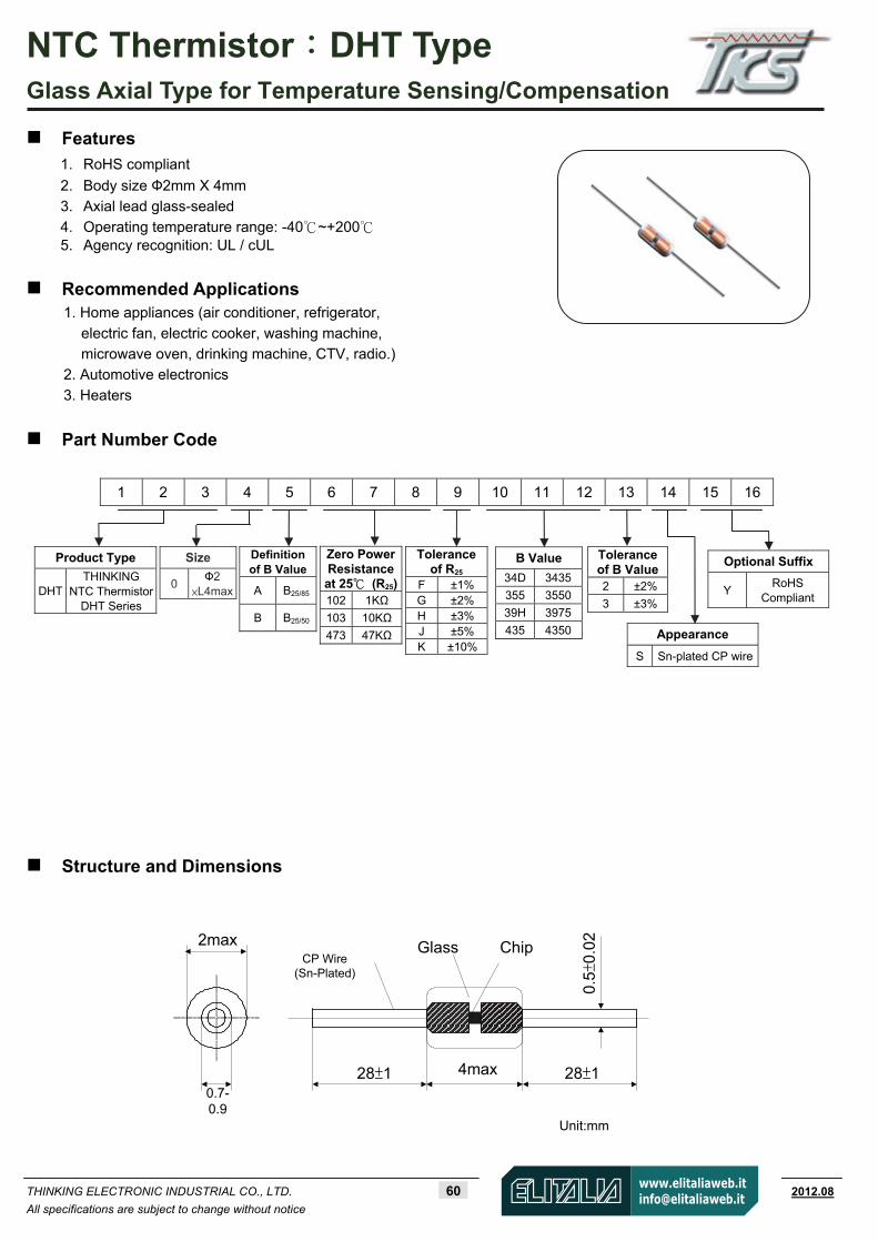
NTC Thermistor:DHT Type Glass Axial Type for Temperature Sensing/Compensation
THINKING ELECTRONIC INDUSTRIAL CO., LTD. 60 www.thinking.com.tw 2012.08
All specifications are subject to change without notice
Features
1. RoHS compliant
2. Body size Ф2mm X 4mm 3. Axial lead glass-sealed
4. Operating temperature range: -40~+200 5. Agency recognition: UL / cUL
Recommended Applications 1. Home appliances (air conditioner, refrigerator,
electric fan, electric cooker, washing machine, microwave oven, drinking machine, CTV, radio.)
2. Automotive electronics
3. Heaters
Part Number Code
1 2 3 4 5 6 7 8 9 10 11 12 13 14 15 16
Structure and Dimensions
0.7-0.9
2max
28±1 4max
Unit:mm
28±1
0.5±
0.02ChipGlass
CP Wire(Sn-Plated)
Product Type
DHT THINKING
NTC Thermistor DHT Series
Size 0
Ф2 ×L4max
Definition of B Value
A B25/85
B B25/50
Zero PowerResistanceat 25 (R25)102 1KΩ
103 10KΩ
473 47KΩ
Tolerance of R25
F ±1%G ±2%H ±3%J ±5%K ±10%
Tolerance of B Value 2 ±2% 3 ±3%
Optional Suffix
Y RoHS
Compliant
Appearance
S Sn-plated CP wire
B Value
34D 3435
355 3550
39H 3975
435 4350

NTC Thermistor:DHT Type Glass Axial Type for Temperature Sensing/Compensation
THINKING ELECTRONIC INDUSTRIAL CO., LTD. 61 www.thinking.com.tw 2012.08
All specifications are subject to change without notice
Electrical Characteristics
Zero Power Resistance
at 25°C
Tolerance of
R25
B Value
Toleranceof
B Value
Max. Power
Dissipationat 25
Dissipation Factor
Thermal Time
Constant
Operating Temperature
Range
Safety ApprovalsPart No.
R25 (KΩ) ( ±%) (K) (±%) Pmax(mW) δ(mW/°C) τ(Sec.) TL~TU(°C) UL cUL
DHT0A502355* 5 25/85 3550 DHT0B103355* 10 25/50 3550 DHT0A10334D* 10 25/85 3435 DHT0A103347* 10 25/85 3470 DHT0A10339H* 10 25/85 3975 DHT0B203395* 20 25/50 3950 DHT0B303395* 30 25/50 3950 DHT0B473395* 47 25/50 3950 DHT0B503395* 50 25/50 3950 DHT0B104400* 100 25/50 4000 DHT0A10439H* 100 25/85 3975 DHT0A104430* 100 25/85 4300 DHT0B204395* 200 25/50 3950 DHT0A204400* 200 25/85 4000 DHT0B204435* 200
1、2、3、 5、10
25/50 4350
2、3 120 2≧ 10≦ -40~+200
Note 1: = Tolerance of R25
* = Tolerance of B value Note 2: UL/cUL File No: E138827 Note 3: Special specifications are available upon request.
Max. Power Dissipation Derating Curve
100%
0 25 TU
0
TL
Ambient temperature ( )
TU : Maximum operating temperature ()
TL : Minimum operating temperature ()
For example:
Ambient temperature (Ta) = 55
Maximum operating temperature (TU) = 200
PTa = (TU-Ta)/(TU-25)×Pmax 83% Pmax

NTC Thermistor:DHT Type Glass Axial Type for Temperature Sensing/Compensation
THINKING ELECTRONIC INDUSTRIAL CO., LTD. 62 www.thinking.com.tw 2012.08
All specifications are subject to change without notice
R-T Characteristic Curves
0
0
1
10
100
1,000
10,000
-40 -20 0 20 40 60 80 100 120 140 160 180 200
Temperature ()
Re
sist
an
ce(KΩ
)
DHT0A104_39H_SY
DHT0B303_395_SY
DHT0A103_34D_SY
DHT0A103_39H_SY DHT0A502_355_SY
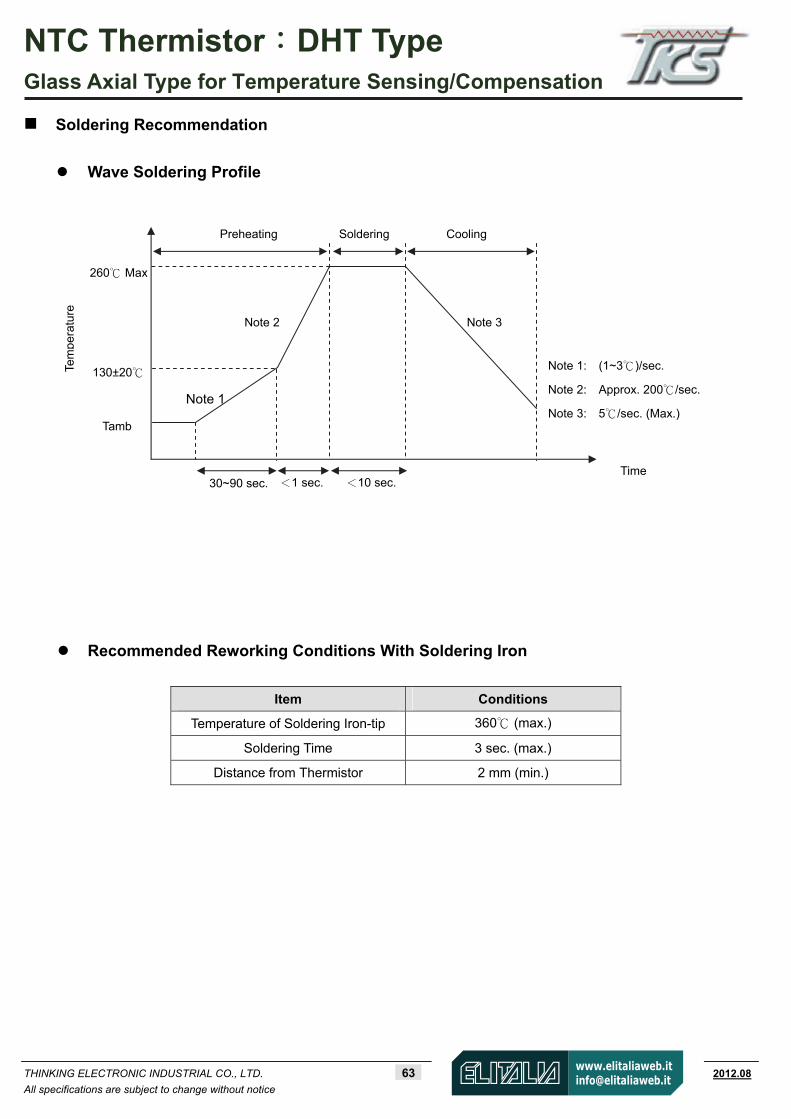
NTC Thermistor:DHT Type Glass Axial Type for Temperature Sensing/Compensation
THINKING ELECTRONIC INDUSTRIAL CO., LTD. 63 www.thinking.com.tw 2012.08
All specifications are subject to change without notice
Soldering Recommendation
Wave Soldering Profile
Recommended Reworking Conditions With Soldering Iron
Item Conditions
Temperature of Soldering Iron-tip 360 (max.)
Soldering Time 3 sec. (max.)
Distance from Thermistor 2 mm (min.)
Tem
pera
ture
130±20
260 Max
Tamb
Cooling
Time
Soldering Preheating
30~90 sec. <1 sec. <10 sec.
Note 1
Note 2 Note 3
Note 1: (1~3)/sec.
Note 2: Approx. 200/sec.
Note 3: 5/sec. (Max.)

NTC Thermistor:DHT Type Glass Axial Type for Temperature Sensing/Compensation
THINKING ELECTRONIC INDUSTRIAL CO., LTD. 64 www.thinking.com.tw 2012.08
All specifications are subject to change without notice
Reliability
Item Standard Test conditions / Methods Specifications
Tensile Strength of
Terminations IEC 60068-2-21
Gradually apply the force specified and keep the unit fixed for 10±1 sec.
Terminal diameter Force
(mm) (Kg)
0.3<d 0.5≦ 0.5
No visible damage
Bending Strength of
Terminations IEC 60068-2-21
Hold specimen and apply the force specified below to each lead. Bend the specimen to 90°, and then return to the original position. Repeat the procedure in the opposite direction.
Terminal diameter Force
(mm) (Kg)
0.3<d 0.5≦ 0.25
No visible damage
Solderability IEC 60068-2-20 245 ± 3 , 3 ± 0.3 sec At least 95% of terminalelectrode is covered by
new solder
Resistance to Soldering
Heat IEC 60068-2-20 260 ± 3 , 10 ± 1 sec No visible damage
R∣ 25/R25 3 %∣≦
High Temperature
Storage IEC 60068-2-2 200 ± 5 , 1000 ± 24 hrs
No visible damage R∣ 25/R25 5 %∣≦
Damp Heat, Steady State
IEC 60068-2-78 40 ± 2 , 90~95% RH , 1000 ± 24 hrs No visible damage R∣ 25/R25 3 %∣≦
Rapid Change of
Temperature IEC 60068-2-14
The conditions shown below shall be repeated 5 cycles.
Step Temperature ( ) Period (minutes)
1 -40 ± 5 30 ± 3
2 Room temperature 5 ± 3
3 200 ± 5 30 ± 3
4 Room temperature 5 ± 3
No visible damage
R∣ 25/R25 3 %∣≦
Max. Power
Dissipation
IEC 60539-1 25 ± 5 , Pmax. , 1000 ± 24 hrs No visible damage R∣ 25/R25 5 %∣≦

NTC Thermistor:DHT Type Glass Axial Type for Temperature Sensing/Compensation
THINKING ELECTRONIC INDUSTRIAL CO., LTD. 65 www.thinking.com.tw 2012.08
All specifications are subject to change without notice
Packaging
Taping Specification
Item W P |L1-L2| T Z S
Max. 53 5.5 1 7 1.2 0.8
Min. 51 4.5 0 5 0 0
Quantity
Bulk Packing: 500 pcs/bag
Reel Packing: 5,000 pcs/reel Ammo Packing: 5,000 pcs/box
Warehouse Storage Conditions of Products Storage Conditions :
1. Storage Temperature: -10~+40
2. Relative Humidity: ≦75%RH
3. Keep away from corrosive atmosphere and sunlight.
Period of Storage : 1 year
L1 L2
WS
TT
S
Z
P
Tape Tape
83±2
255±
2
80±275±1
31±1
340±10
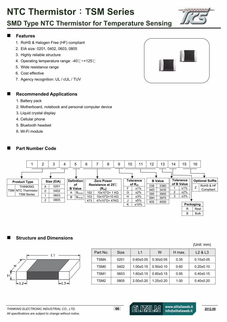
NTC Thermistor:TSM Series SMD Type NTC Thermistor for Temperature Sensing
THINKING ELECTRONIC INDUSTRIAL CO., LTD. 66 www.thinking.com.tw 2012.08
All specifications are subject to change without notice.
Features
1. RoHS & Halogen Free (HF) compliant
2. EIA size: 0201, 0402, 0603, 0805
3. Highly reliable structure
4. Operating temperature range: -40 ~ +125
5. Wide resistance range
6. Cost effective
7. Agency recognition: UL / cUL / TUV
Recommended Applications
1. Battery pack
2. Motherboard, notebook and personal computer device
3. Liquid crystal display
4. Cellular phone
5. Bluetooth headset
6. Wi-Fi module
Part Number Code
Structure and Dimensions (Unit: mm)
1 2 3 4 5 6 7 8 9 10 11 12 13 14 15 16
Part No. Size L1 W H max. L2 & L3
TSMA 0201 0.60±0.05 0.30±0.05 0.35 0.15±0.05
TSM0 0402 1.00±0.15 0.50±0.10 0.60 0.20±0.10
TSM1 0603 1.60±0.15 0.80±0.15 0.95 0.40±0.15
TSM2 0805 2.00±0.20 1.25±0.20 1.00 0.40±0.20
Product Type
TSM THINKING
NTC Thermistor TSM Series
Size (EIA) A 0201
0 0402
1 0603
2 0805
Definition of
B Value A B25/85
B B25/50
Zero Power Resistance at 25
(R25) 102 10x102Ω= 1 KΩ103 10x103Ω=10 KΩ473 47x103Ω= 47KΩ
Tolerance of R25
F ±1%G ±2%H ±3%J ±5%K ±10%
B Value
338 3380 34D 3435 395 3950 39H 3975 405 4050
Tolerance of B Value
1 ±1% 2 ±2% 3 ±3%
PackagingR Reel
B Bulk
Optional Suffix
ZRoHS & HFCompliant

NTC Thermistor:TSM Series SMD Type NTC Thermistor for Temperature Sensing
THINKING ELECTRONIC INDUSTRIAL CO., LTD. 67 www.thinking.com.tw 2012.08
All specifications are subject to change without notice.
Electrical Characteristics
Safety
Approvals Zero PowerResistance
at 25°C
Tolerance of
R25
B Value
Toleranceof
B value
Max. PowerDissipation
at 25
Dissipation Factor
Thermal Time
Constant
Operating Temperature
Range Part No. Size
R25(KΩ) ( ±%) (K) (±%) Pmax(mW) δ(mW/°C) τ(Sec.) TL~TU(°C)
UL/cUL
TUV CQC
TSMAB103338* 10 3380 TSMAB683425* 68 4250 TSMAB104425*
0201
100
1, 2, 3, 5, 10
25/50
4250
1, 2, 3 140 Approx.
1.4 Approx.
1.2 -40 ~ +125
TSM0A10334D* 10 3435 TSM0A103395* 10 3950 TSM0A223395* 22 3950 TSM0A333405* 33 4050 TSM0A683410* 68 4100 TSM0A104405* 100 4050 TSM0A104436* 100
25/85
4360 TSM0B103338* 10 3380 TSM0B473405* 47 4050 TSM0B104354* 100 3540 TSM0B104480* 100 4800 TSM0B224470* 220
1, 2, 3, 5, 10
4700
1, 2, 3
TSM0B474470*
0402
470 5, 10
25/50
4700 3
170 Approx.
1.7 Approx.
2.0 -40 ~ +125
TSM1A202340* 2 3400 TSM1A47234D* 4.7 3435 TSM1A472370* 4.7 3700 TSM1A50234D* 5 3435 TSM1A502385* 5 3850 TSM1A68234D* 6.8 3435 TSM1A682395* 6.8 3950 TSM1A10334D* 10 3435 TSM1A10339H* 10
1, 2, 3, 5, 10
3975
1, 2, 3
TSM1A103430* 10 5, 10 4300 3 TSM1A223392* 22 3920 TSM1A47339H* 47 3975 TSM1A68339H* 68 3975 TSM1A104405* 100 4050 TSM1A104436* 100 4360 TSM1A154406* 150 4060 TSM1A204410* 200 4100 TSM1A474415* 470
1, 2, 3, 5, 10
25/85
4150
1, 2, 3
TSM1B221350* 0.22 3500 TSM1B222395* 2.2 3950 TSM1B472425* 4.7
5, 10
4250
3
TSM1B103338* 10 3380 TSM1B103420* 10 4200 TSM1B104355* 100 3550 TSM1B224460*
0603
220
1, 2, 3, 5, 10
25/50
4600
1, 2, 3
210 Approx.
2.1 Approx.
3.1 -40~+125
TSM2A 50234D* 5 3435 TSM2A10334D* 10 3435 TSM2A103395* 10 3950 TSM2A47339H* 47 3975 TSM2A104405* 100
1, 2, 3, 5, 10
4050
1, 2, 3
TSM2A684450*
0805
680 5, 10
25/85
4500 3
240 Approx.
2.4 Approx.
5.4 -40~+125
Note 1: = Tolerance of R25
* = Tolerance of B value Note 2: UL&cUL File No. E138827 / TUV File No. R 50167657 Note 3: Special specifications are available upon request
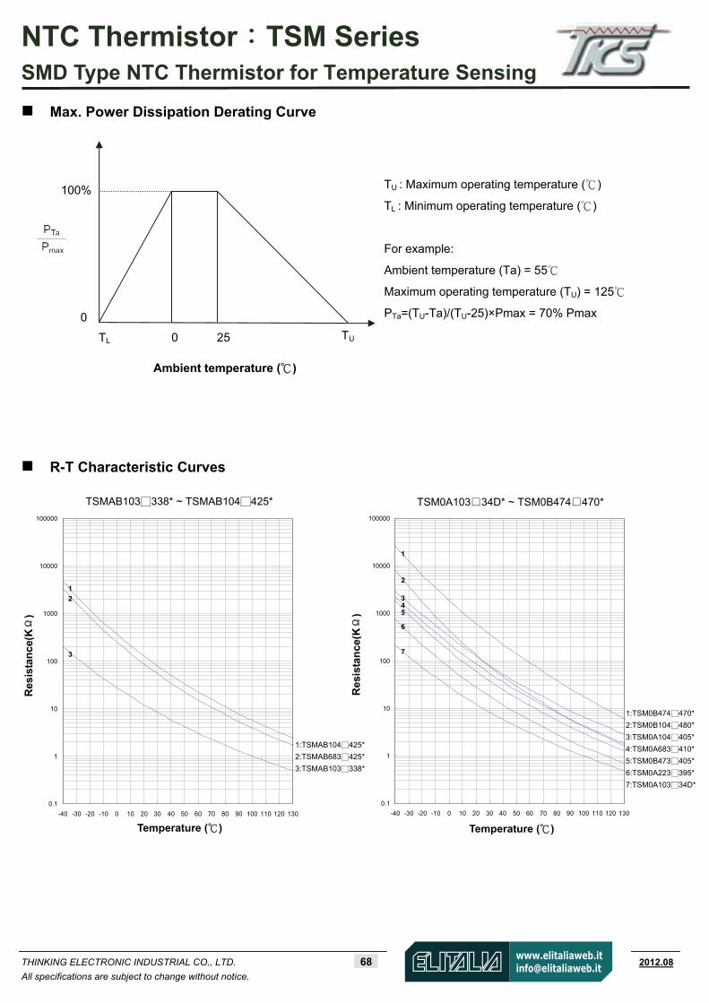
NTC Thermistor:TSM Series SMD Type NTC Thermistor for Temperature Sensing
THINKING ELECTRONIC INDUSTRIAL CO., LTD. 68 www.thinking.com.tw 2012.08
All specifications are subject to change without notice.
Res
ista
nc
e(KΩ
)
TSMAB103338* ~ TSMAB104425*
Temperature ( )
Max. Power Dissipation Derating Curve
R-T Characteristic Curves
TU : Maximum operating temperature ()
TL : Minimum operating temperature ()
For example:
Ambient temperature (Ta) = 55
Maximum operating temperature (TU) = 125
PTa=(TU-Ta)/(TU-25)×Pmax = 70% Pmax
100%
0 25 TU
0
TL
Ambient temperature ( )
0.1
1
10
100
1000
10000
100000
-40 -30 -20 -10 0 10 20 30 40 50 60 70 80 90 100 110 120 130
1:TSMAB104425*
2:TSMAB683425*
3:TSMAB103338*
1
2
3
Res
ista
nc
e(KΩ
)
TSM0A10334D* ~ TSM0B474470*
Temperature ( )
0.1
1
10
100
1000
10000
100000
-40 -30 -20 -10 0 10 20 30 40 50 60 70 80 90 100 110 120 130
1
2
3 4 5 6 7
1:TSM0B474470*
2:TSM0B104480*
3:TSM0A104405*
4:TSM0A683410*
5:TSM0B473405*
6:TSM0A223395*
7:TSM0A10334D*

NTC Thermistor:TSM Series SMD Type NTC Thermistor for Temperature Sensing
THINKING ELECTRONIC INDUSTRIAL CO., LTD. 69 www.thinking.com.tw 2012.08
All specifications are subject to change without notice.
0.01
0.1
1
10
100
1000
10000
100000
-40 -30 -20 -10 0 10 20 30 40 50 60 70 80 90 100 110 120 130
1:TSM1A204410*
2:TSM1A104436*
3:TSM1A68339H*
4:TSM1A223392*
5:TSM1A10339H*
6:TSM1A682395*
7:TSM1A472370*
8:TSM1A502385*
9:TSM1A202340*
Res
ista
nc
e(KΩ
)
TSM1A202340* ~ TSM1A204410* TSM0B103338* ~ TSM0B224470*
Temperature ( ) Temperature ( )
0.1
1
10
100
1000
10000
100000
-40 -30 -20 -10 0 10 20 30 40 50 60 70 80 90 100 110 120 130
Res
ista
nc
e(KΩ
)
Temperature ( )
TSM1A47234D* ~ TSM1A474415* TSM1B221350* ~ TSM1B224460*
0.001
0.01
0.1
1
10
100
1000
10000
100000
-40 -30 -20 -10 0 10 20 30 40 50 60 70 80 90 100 110 120 130
1:TSM0B224470*
2:TSM0A104436*
3:TSM0B104354*
4:TSM0A333405*
5:TSM0A103395*
6:TSM0B103338*
Temperature ( )
R
esis
tan
ce(K
Ω)
1:TSM1B224460*
2:TSM1B104355*
3:TSM1B103420*
4:TSM1B103338*
5:TSM1B472425*
6:TSM1B222395*
7:TSM1B221350*
0.1
1
10
100
1000
10000
100000
-40 -30 -20 -10 0 10 20 30 40 50 60 70 80 90 100 110 120 130
1:TSM1A474415*
2:TSM1A154406*
3:TSM1A104405*
4:TSM1A47339H*
5:TSM1A10334D*
6:TSM1A68234D*
7:TSM1A50234D*
8:TSM1A103430*
9:TSM1A47234D*
R
esis
tan
ce(K
Ω)
1
2 3 4
5 6
1 2 3
4
5 6 7 8 9
1 2 3 4
5
6 7 8 9
1 2 3 4 5 6 7

NTC Thermistor:TSM Series SMD Type NTC Thermistor for Temperature Sensing
THINKING ELECTRONIC INDUSTRIAL CO., LTD. 70 www.thinking.com.tw 2012.08
All specifications are subject to change without notice.
TSM2A50234D* ~ TSM2A684450*
Res
ista
nc
e(KΩ
)
Temperature ( )
0.1
1
10
100
1000
10000
100000
-40 -30 -20 -10 0 10 20 30 40 50 60 70 80 90 100 110 120 130
Soldering Recommendation
IR-reflow Soldering Profile
1:TSM2A684450*
2:TSM2A104405*
3:TSM2A47339H*
4:TSM2A103395*
5:TSM2A10334D*
6:TSM2A50234D*
3/sec
(max.)60~180
sec
20~40
sec
150±20
Time
CoolingPeak temp
Te
mp
era
ture
255~260
150~200
Tamb
3/sec
(max.)6/sec
(max.)
21760~150 sec
t
8 minutes max.
Preheating
1 2 3 4 5 6
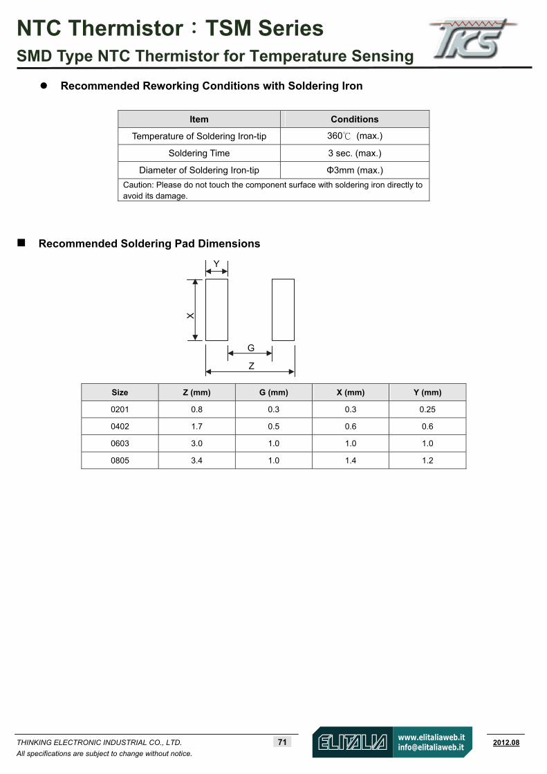
NTC Thermistor:TSM Series SMD Type NTC Thermistor for Temperature Sensing
THINKING ELECTRONIC INDUSTRIAL CO., LTD. 71 www.thinking.com.tw 2012.08
All specifications are subject to change without notice.
Recommended Reworking Conditions with Soldering Iron
Item Conditions
Temperature of Soldering Iron-tip 360 (max.)
Soldering Time 3 sec. (max.)
Diameter of Soldering Iron-tip Φ3mm (max.)
Caution: Please do not touch the component surface with soldering iron directly to avoid its damage.
Recommended Soldering Pad Dimensions
Size Z (mm) G (mm) X (mm) Y (mm)
0201 0.8 0.3 0.3 0.25
0402 1.7 0.5 0.6 0.6
0603 3.0 1.0 1.0 1.0
0805 3.4 1.0 1.4 1.2
Y
G
X
Z
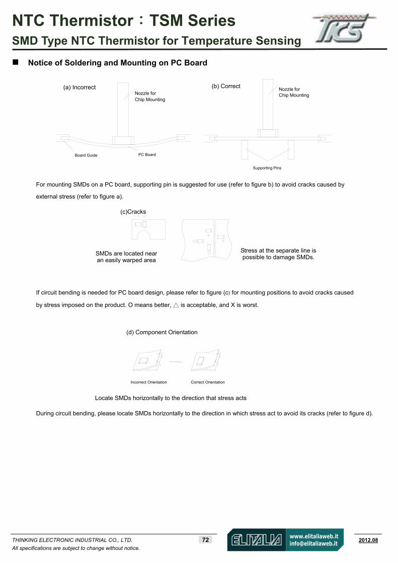
NTC Thermistor:TSM Series SMD Type NTC Thermistor for Temperature Sensing
THINKING ELECTRONIC INDUSTRIAL CO., LTD. 72 www.thinking.com.tw 2012.08
All specifications are subject to change without notice.
Notice of Soldering and Mounting on PC Board
For mounting SMDs on a PC board, supporting pin is suggested for use (refer to figure b) to avoid cracks caused by
external stress (refer to figure a).
If circuit bending is needed for PC board design, please refer to figure (c) for mounting positions to avoid cracks caused
by stress imposed on the product. O means better, is acceptable, and X is worst.
During circuit bending, please locate SMDs horizontally to the direction in which stress act to avoid its cracks (refer to figure d).
SMDs are located near an easily warped area
Stress at the separate line is possible to damage SMDs.
Locate SMDs horizontally to the direction that stress acts
Nozzle forChip Mounting
Supporting Pins
(b) CorrectNozzle for Chip Mounting
PC Board Board Guide
(a) Incorrect
(c)Cracks
(d) Component Orientation
Incorrect Orientation Correct Orientation
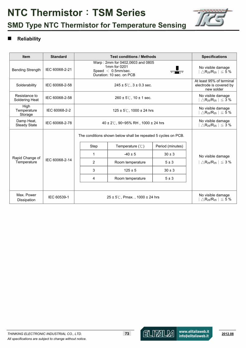
NTC Thermistor:TSM Series SMD Type NTC Thermistor for Temperature Sensing
THINKING ELECTRONIC INDUSTRIAL CO., LTD. 73 www.thinking.com.tw 2012.08
All specifications are subject to change without notice.
Reliability
Item Standard Test conditions / Methods Specifications
Bending Strength IEC 60068-2-21
Warp : 2mm for 0402,0603 and 0805 1mm for 0201
Speed < 0.5mm/sec. Duration: 10 sec. on PCB
No visible damage R∣ 25/R25 5 %∣≦
Solderability IEC 60068-2-58 245 ± 5, 3 ± 0.3 sec. At least 95% of terminalelectrode is covered by
new solder
Resistance to Soldering Heat IEC 60068-2-58 260 ± 5 , 10 ± 1 sec. No visible damage
R∣ 25/R25 3 %∣≦
High Temperature
Storage IEC 60068-2-2 125 ± 5 , 1000 ± 24 hrs
No visible damage R∣ 25/R25 5 %∣≦
Damp Heat, Steady State
IEC 60068-2-78 40 ± 2 , 90~95% RH , 1000 ± 24 hrs No visible damage R∣ 25/R25 3 %∣≦
Rapid Change of Temperature IEC 60068-2-14
The conditions shown below shall be repeated 5 cycles on PCB.
Step Temperature ( ) Period (minutes)
1 -40 ± 5 30 ± 3
2 Room temperature 5 ± 3
3 125 ± 5 30 ± 3
4 Room temperature 5 ± 3
No visible damage
R∣ 25/R25 3 %∣≦
Max. Power Dissipation
IEC 60539-1 25 ± 5 , Pmax. , 1000 ± 24 hrs No visible damage R∣ 25/R25 5 %∣≦
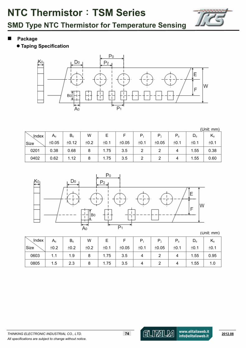
NTC Thermistor:TSM Series SMD Type NTC Thermistor for Temperature Sensing
THINKING ELECTRONIC INDUSTRIAL CO., LTD. 74 www.thinking.com.tw 2012.08
All specifications are subject to change without notice.
Package
Taping Specification
A0
±0.05
B0
±0.12
W
±0.2
E
±0.1
F
±0.05
P1
±0.1
P2
±0.05
P0
±0.1
D0
±0.1
K0
±0.1
0201 0.38 0.68 8 1.75 3.5 2 2 4 1.55 0.38
0402 0.62 1.12 8 1.75 3.5 2 2 4 1.55 0.60
A0
±0.2
B0
±0.2
W
±0.2
E
±0.1
F
±0.05
P1
±0.1
P2
±0.05
P0
±0.1
D0
±0.1
K0
±0.1
0603 1.1 1.9 8 1.75 3.5 4 2 4 1.55 0.95
0805 1.5 2.3 8 1.75 3.5 4 2 4 1.55 1.0
Index
Size
(Unit: mm)
Index
Size
(Unit: mm)

NTC Thermistor:TSM Series SMD Type NTC Thermistor for Temperature Sensing
THINKING ELECTRONIC INDUSTRIAL CO., LTD. 75 www.thinking.com.tw 2012.08
All specifications are subject to change without notice.
Quantity
Warehouse Storage Conditions of Products Storage Conditions :
1. Storage Temperature: -10~+40
2. Relative Humidity: ≦75%RH
3. Keep away from corrosive atmosphere and sunlight.
Period of Storage : 1 year
Size Quantity (pcs/reel)
0201 15,000
0402 10,000
0603 4,000
0805 3,500