Using IR Cameras Beyond Outreach: Motivational Projects for ...
13
Boise State University ScholarWorks Electrical and Computer Engineering Faculty Publications and Presentations Department of Electrical and Computer Engineering 6-24-2017 Using IR Cameras Beyond Outreach: Motivational Projects for Engineering Students Cameron H.G. Wright University of Wyoming ad B. Welch Boise State University © 2017, American Society for Engineering Education, Proceedings of ASEE Annual Conference Columbus, Ohio.
-
Upload
khangminh22 -
Category
Documents
-
view
4 -
download
0
Transcript of Using IR Cameras Beyond Outreach: Motivational Projects for ...

Boise State UniversityScholarWorksElectrical and Computer Engineering FacultyPublications and Presentations
Department of Electrical and ComputerEngineering
6-24-2017
Using IR Cameras Beyond Outreach: MotivationalProjects for Engineering StudentsCameron H.G. WrightUniversity of Wyoming
Thad B. WelchBoise State University
© 2017, American Society for Engineering Education, Proceedings of ASEE Annual Conference Columbus, Ohio.

Paper ID #19308
Using IR Cameras beyond outreach: motivational projects for engineeringstudents
Dr. Cameron H. G. Wright P.E., University of Wyoming
Cameron H. G. Wright, Ph.D., P.E., is a Professor with the Department of Electrical and Computer En-gineering at the University of Wyoming, Laramie, WY. He was previously Professor and Deputy De-partment Head in the Department of Electrical Engineering at the United States Air Force Academy, andserved as an R&D engineering officer in the U.S. Air Force for over 20 years. He received the B.S.E.E.(summa cum laude) from Louisiana Tech University in 1983, the M.S.E.E. from Purdue University in1988, and the Ph.D. from the University of Texas at Austin in 1996. Cam’s research interests includesignal and image processing, real-time embedded computer systems, biomedical instrumentation, andengineering education. He is a member of ASEE, IEEE, SPIE, BMES, NSPE, Tau Beta Pi, and EtaKappa Nu. His teaching awards include the University of Wyoming Ellbogen Meritorious ClassroomTeaching Award (2012), the Tau Beta Pi WY-A Undergraduate Teaching Award (2011), the IEEE UWStudent Branch’s Outstanding Professor of the Year (2005 and 2008), the UW Mortar Board ”Top Prof”award (2005, 2007, and 2015), the Outstanding Teaching Award from the ASEE Rocky Mountain Section(2007), the John A. Curtis Lecture Award from the Computers in Education Division of ASEE (1998,2005, and 2010), and the Brigadier General Roland E. Thomas Award for outstanding contribution tocadet education (both 1992 and 1993) at the U.S. Air Force Academy. He is an active ABET evaluatorand an NCEES PE exam committee member.
Dr. Thad B. Welch, Boise State University
Thad B. Welch, Ph.D., P.E. received the B.E.E., M.S.E.E., E.E., and Ph.D. degrees from the GeorgiaInstitute of Technology, Naval Postgraduate School, Naval Postgraduate School, and the University ofColorado in 1979, 1989, 1989, and 1997, respectively. He was commissioned in the U.S. Navy in 1979and has been assigned to three submarines and a submarine repair tender. He has deployed in the AtlanticOcean, Mediterranean Sea, and the Arctic Ocean.
From 1994-1997 he was an Instructor and Assistant Professor teaching in the Electrical EngineeringDepartment at the U.S. Air Force Academy, Colorado Springs, CO. During 1996-1997 he was recognizedas the Outstanding Academy Educator for the Electrical Engineering Department.
From 1997-2007 he was an Assistant Professor, Associate Professor, and Permanent Military Professorteaching in the Electrical Engineering Department at the U.S. Naval Academy, Annapolis, MD. During2000-2001 he was recognized as the Outstanding Academy Educator for the Electrical Engineering De-partment. During 2001-2002 he received the Raouf outstanding engineering educator award. During2002-2003 he was recognized as the Outstanding Researcher for the Electrical Engineering Department.He was an invited scholar at the University of Wyoming, fall 2004, where he was recognized as an emi-nent engineer and inducted into tau beta pi. In 2006 he co-authored ”Real-time Digital Signal Processing,from MATLAB to C with the TMS320C6x DSK” which was translated into Chinese in 2011. The secondedition of this text was published in 2012 and the third edition was published in 2017.
From 2007-2010 he was Professor and Chair of the Electrical and Computer Engineering Department atBoise State University, Boise, ID. From 2011-2012 he was the inaugural Signal Processing EducationNetwork (SPEN) Fellow. From 2012-2014 he and his wife lived with 20 engineering students in theengineering residential college (ERC) on the Boise State campus.
His research interests include real-time digital signal processing (DSP), the implementation of DSP-basedsystems, and sustainable energy systems.
c©American Society for Engineering Education, 2017

Using IR Cameras beyond outreach: motivationalprojects for engineering students
Abstract
Affordable infrared (IR) cameras provide a unique opportunity to motivate and enhance theeducation of engineering students. We used both IR and visible images from a FLIR E60 cam-era as an instructional vehicle in a digital image processing course, where students came fromseveral engineering majors. These IR and visible images were used as the basis for an open-ended final project in the course. Assessment via both pre- and post-project questionnairesshowed the project was a positive experience for the students, and helped motivate them tolearn the material. This paper discusses the course, the camera, the project, and how effectiveit was to add this project to the course.
1 Introduction
Digital signal processing (DSP), and the closely related area of digital image processing (DIP),have become very popular courses for engineering students. Once mainly intended for electricaland computer engineering (ECE) students, the pervasive use of DSP and DIP in wide range ofresearch and industrial areas has caused other engineering and science majors to seek out thesecourses. If the student has a solid mathematical background and a familiarity with topics suchas linear systems theory, they can master the material in DSP and DIP courses, albeit sometimeswith a higher degree of required effort than an ECE major. Having a class with a more diversebackground such as this increases the challenge to help the students learn the material.
Many research projects need to acquire data using cameras or other imaging systems, and usuallyneed to manipulate and process this image data in various ways. This is no longer just an area forECE students, and we have students from most other engineering departments, along with studentsfrom some of the science departments (such as Molecular Biology, Physics, and Kinesiology) whoneed to master these concepts just to perform their research. In support of this, the ECE Departmentat the University of Wyoming offers four courses listed below, taught as a sequence by the sameprofessor to ensure consistency across the courses.
1. Digital cameras, image formation, and image acquisition (graduate-level),
2. Digital image processing (senior-level and graduate-level combined section),
3. Advanced digital image processing (graduate-level), and
4. Object and pattern recognition (graduate-level).

This paper concentrates on course number 2 above, and in particular focuses on the final projectassigned in the course.
Engineering educators generally agree that interactive learning, exercises, and demonstrations arevery useful for helping students to build an initial mental model of a given concept.1–5 Usingpreviously learned mental models to segue to new concepts is very effective variation on thistechnique.6, 7 However, demonstrations can only help so much; actual hands-on exercises andprojects have been shown to be one of the most reliable methods that lead to improved studentlearning.8–14 There are even specific books and websites that support this approach.15, 16
With relatively recent price drops for high-quality infrared (IR) cameras, we have started to in-troduce this tool as part of various courses and outreach efforts, in an attempt to increase studententhusiasm and motivation to learn the course material.17 The open-ended project we describe inthis paper used images from an IR camera.
2 The Course
The first of the two digital image processing courses we offer is provided as a senior-level and agraduate-level combined section, as some seniors request this topic for one of their electives. Thegraduate students in the course have more requirements for the course projects, but otherwise bothgroups of students are treated equally. The text is the excellent Gonzalez and Woods book,18 andthe first course covers approximately the first half of the book (the second course then finishes thebook). The topics covered by the first course are:
• Introduction to Digital Image Processing (Chap. 1–2)
– What is it, why do we do it? Origins and examples of image processing (DIP)– Fundamental steps in DIP, components of a DIP system– Perception, image formation and optics, pixelization, quantization– Basic pixel descriptions, measures, and operators
• Image enhancement in the spatial domain (Chap. 3)
– Gray level transformations and histograms– Using arithmetic and logic operations on images– Spatial filters: smoothing, sharpening, other
• Image enhancement in the frequency domain (Chap. 4)
– The 1-D Fourier transform, the DFT and FFT, in time and in space– The 2-D Fourier transform in space and its inverse– Filtering in the frequency domain: smoothing, sharpening, other
• Image restoration (Chap. 5, up to Sec. 5.10)
– Types of image degradation

– Spatial domain and frequency domain noise reduction– Reducing other forms of degradation: inverse filtering, Weiner filtering, other– Introduction to image reconstruction from projections (computed tomography)
• Final Project: current industry problem
One point pertinent to the final project is that this course deals primarily with grayscale images.Color models and color images are presented in Chapter 6, and are therefore part of the secondcourse. The 30 students enrolled in the course for Fall 2016 included 18 seniors, all EE or Com-puter Engineering majors, and 12 MS/PhD students (8 EE majors and 4 ME majors).
3 The Camera
Infrared (IR) is the region of the electromagnetic spectrum has longer wavelengths than the vis-ible light that humans can see. The visible spectrum spans wavelengths of approximately 400–700 nm.19, 20 One representation of the electromagnetic spectrum is shown in Figure 1, where theIR wavelengths can be seen on the left of the visible spectrum. Humans can’t see IR; any IRenergy can only be directly sensed by humans as heat. Thus, an IR camera must assign a rangeof false colors that we are able see to represent the IR energy. This false color method is oftencalled pseudocolor in the literature.18 Capturing images in the IR wavelengths challenges cameradesigners. For example, normal glass appropriate for visible wavelengths tends to reflect ratherthan pass IR wavelengths, and normal camera imaging sensors (CMOS or CCD) have IR-blockingfilters to prevent saturation.21–23 This latter point is required because the silicon-based sensor ar-rays respond strongly to what are called the near-IR wavelengths, as can be seen in Figure 2. Theseand other challenges have been overcome by camera designers, and IR cameras are now availablethat combine reasonable price with acceptable image measurement quality.
700 nm 600 nm 500 nm 400 nm
Infrared (IR)
Ultraviolet (UV)
longer wavelengths lower frequencies
shorter wavelengths higher frequencies
Visible Light
AM radio
FM radio TV radar
microwave
IR UV
x-raysgamma
rayscosmic
rays
106 109 1012 1015 1018 1021103
Wi-Fi
frequency (Hz)wavelength
10 m 10 mm 10 µm 10 nm10 km 10 pm
LWIR
Figure 1: Regions of the electromagnetic spectrum pertinent to this discussion.

300 400 500 600 700 800 900 1000 1100
0
10
20
30
40
50CCD
Red Cone
Green Cone
Blue Cone
Wavelength (nm)
Ap
pro
xim
ate
Qu
an
tum
Eff
icie
ncy (
%)
Figure 2: Comparison of a typical silicon-based image sensor to human photoreceptors.
Figure 3: The model E60 IR camera from FLIR. Left image courtesy of FLIR, Inc.24 Note: MSXis an image fusion technique proprietary to FLIR.
The particular camera we used in this course was the model E60 by FLIR.24 See Figure 3. The E60,like many IR cameras, actually provides two independent cameras: a primary IR camera, and asecondary visible wavelength camera. Each camera has its own optics and image sensor, optimizedfor the appropriate wavelengths. Note in Figure 3 that the image resolution for the two cameras isquite different, since high resolution IR sensors would be very expensive. This difference, plus thedifferent field-of-view (FOV) and the different optical axis for image formation between the twocameras, provide significant challenges for the final project in the image processing course.
A typical image from an infrared camera (a FLIR model C2) is shown in Figure 4, with the MSXimage fusion option enabled. The model C2 is more compact than the E60, but also provides theMSX image fusion option. Note the key for the pseudocolor assignment of color to temperature(in degrees Celsius) is shown in a vertical bar on the right edge of the image. The temperature ofthe center of the image is displayed at the upper left of the image. Image fusion takes some salient

Figure 4: A typical IR image taken with a FLIR C2, with the MSX image fusion option enabled.The image shows a kitchen backsplash on a wall with a poorly insulated fireplace behind it. Thedark area in the upper left indicates a colder region, due to insufficient or missing insulation.
features, such as edge information, from the associated visible image, and combines those featuresto provide an enhanced IR image.25 Without image fusion, many IR images lack sufficient visualcues for the observer to know just what the image is showing.
4 The Project
As an open-ended final project in our digital image processing course, we challenged the studentsto come up with their own version of a current engineering technique: how to use images fromboth an IR sensor and a visible-light sensor on the same unit to provide a greatly enhanced IRimage using salient features (that they choose) from the visible-light image. This is a state-of-the-art technique, and is considered to be one type of “image fusion.”25 The proprietary methodused by FLIR is called MSX, but the specific details of MSX were unavailable to the students.In order to make image fusion work for this scenario, an engineer must take into account thedifferent resolutions, field of view (FOV), and other aspects that differ between the two types ofimage sensors. Coming up with a workable approach to image fusion is a difficult problem, andit draws upon all of the foundational image processing techniques the students have learned in thecourse. The students were told about this end-of-semester challenge project at the beginning of thesemester, and its direct tie to current industrial practice both excited and motivated the students.
A simple scene, shown in Figure 5, was used to provide the sample images for the students. The IRimage is lower resolution, much more narrow FOV, and was obtained using different optics whichhad an optical axis that was offset from the optical axis of the visible-light camera. One additionalstep was needed before the students could be given the images for the project. Since this first DIP

(a) Image from visible-light camera. (b) Image from IR camera.
Figure 5: Scene used to create sample images for the final project. Left: a 2048 × 1536 visible-wavelength image. Right: a 320× 240 IR-wavelength image of the same scene.
(a) Image from visible-light camera. (b) Image from IR camera.
Figure 6: Grayscale versions of sample images for the final project.
course deals only with grayscale images, the images shown in Figure 5 were converted to grayscale(using a standard NTSC weighting scheme to convert RGB to luminance), as shown in Figure 6.Note the temperature annotations overlaid by the FLIR software on the IR image in Figure 5 havebeen turned off in Figure 6. The IR image on the right in Figure 6 is rather featureless, and istherefore an excellent example of why image fusion can enhance many IR images.
The students, in teams of two, were told to come up with a solution on their own for image fusion.The project instructions stated that their solution should be generalized to work with any scene,and not be a solution that works only for one given scene. They were shown IR images with andwithout image fusion from the FLIR E60, and were allowed to use the FLIR E60 during severalclass periods to familiarize themselves with details about the camera and the images it takes. Theywere then provided the images shown in Figure 6 and turned loose.
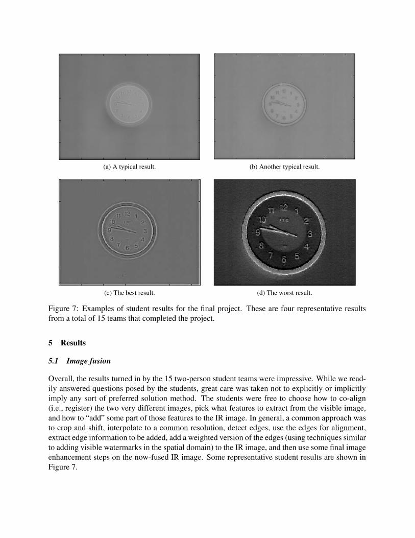
(a) A typical result. (b) Another typical result.
(c) The best result. (d) The worst result.
Figure 7: Examples of student results for the final project. These are four representative resultsfrom a total of 15 teams that completed the project.
5 Results
5.1 Image fusion
Overall, the results turned in by the 15 two-person student teams were impressive. While we read-ily answered questions posed by the students, great care was taken not to explicitly or implicitlyimply any sort of preferred solution method. The students were free to choose how to co-align(i.e., register) the two very different images, pick what features to extract from the visible image,and how to “add” some part of those features to the IR image. In general, a common approach wasto crop and shift, interpolate to a common resolution, detect edges, use the edges for alignment,extract edge information to be added, add a weighted version of the edges (using techniques similarto adding visible watermarks in the spatial domain) to the IR image, and then use some final imageenhancement steps on the now-fused IR image. Some representative student results are shown inFigure 7.

Most team results were similar to the top row of Figure 7, which are reasonably good enhancementsof the original IR image. The difference comes from the different choices the students made. Thebest result is shown on the bottom left of Figure 7, which is very close to what the proprietary FLIRMSX technique would have produced. The worst result is shown on the bottom right of Figure 7.This team failed to get the images to line up or even be the same FOV; you can see the IR versionof the clock inside the superimposed clock detail. In their defense, this team claimed to have “runout of time” before they could perfect their method. But all teams had the same amount of time.
5.2 Assessment
To assess the effectiveness of this project for both helping the students learn and motivating them,two anonymous questionnaires were administered: one before the project, and one after the project.Both questionnaires had a 100% response rate of N = 30, and used a 5-point Likert scale shownbelow.
1. Strongly disagree
2. Disagree
3. Neutral
4. Agree
5. Strongly agree
The questionnaire before the project contained the following items, and Figure 8 shows the results.
1. I am already familiar with infrared cameras and images.
2. I already have a solid understanding of why image fusion is desirable for infrared images.
3. I already know how to implement image fusion for infrared images.
4. Being told we will be investigating the industrial challenge of image fusion for infraredimages motivates me to better understand the topic of digital image processing.
5. Using current industrial challenges as the basis for a class project is a good idea.
The questionnaire after the project contained the following items, and Figure 9 shows the results.
1. I am now familiar with infrared cameras and images.
2. I now have a solid understanding of why image fusion is desirable for infrared images.
3. I now know at least one way how to implement image fusion for infrared images.
4. Investigating the industrial challenge of image fusion for infrared images helped me betterunderstand the overall topic of digital image processing.
5. Using current industrial challenges as the basis for a class project is a good idea.

Figure 8: The results of the “before the project” questionnaire.
Figure 9: The results of the “after the project” questionnaire.

As can be seen from the results, the questions that assessed how students learned new concepts asa result of the project (questions 1, 2, and 3) showed significant gain from before the project toafter it. The questions that assessed the level of motivation the project provided (questions 4 and5) were very high both before and after the project. Both of these results are what we had hopedto see.
6 Conclusions
High quality, affordable IR cameras can be used in the classroom to provide an additional motiva-tion for students to learn various concepts in engineering courses. We found that incorporating anopen-ended final project, using IR images to solve a contemporary engineering challenge, providedenhanced learning and significant motivation for the students. This was confirmed by assessmentdata provided by questionnaires.
The course has been offered nine times since 2004, but this was the first time such an open-endedfinal project has been used. Anecdotally, the authors observed an obvious increase in excitementand enjoyment on the part of the students due to this project. We plan to continue to use suchprojects in the future.
References
[1] C. S. Burrus, “Teaching filter design using MATLAB,” in Proceedings of the IEEE International Con-ference on Acoustics, Speech, and Signal Processing, pp. 20–30, Apr. 1993.
[2] R. F. Kubichek, “Using MATLAB in a speech and signal processing class,” in Proceedings of the 1994ASEE Annual Conference, pp. 1207–1210, June 1994.
[3] R. G. Jacquot, J. C. Hamann, J. W. Pierre, and R. F. Kubichek, “Teaching digital filter design usingsymbolic and numeric features of MATLAB,” ASEE Comput. Educ. J., pp. 8–11, January–March 1997.
[4] J. H. McClellan, C. S. Burrus, A. V. Oppenheim, T. W. Parks, R. W. Schafer, and S. W. Schuessler,Computer-Based Exercises for Signal Processing Using MATLAB 5. MATLAB Curriculum Series,Upper Saddle River, NJ (USA): Prentice Hall, 1998.
[5] J. W. Pierre, R. F. Kubichek, and J. C. Hamann, “Reinforcing the understanding of signal processingconcepts using audio exercises,” in Proceedings of the IEEE International Conference on Acoustics,Speech, and Signal Processing, vol. 6, pp. 3577–3580, Mar. 1999.
[6] A. Rothenbuhler, C. H. G. Wright, T. B. Welch, and M. G. Morrow, “DSP see-through: Going beyondtalk-through,” in Proceedings of the IEEE International Conference on Acoustics, Speech, and SignalProcessing, pp. 2247–2251, May 2014.
[7] C. H. G. Wright, T. B. Welch, and M. G. Morrow, “Using student knowledge of linear systems theoryto facilitate the learning of optical engineering,” in Proceedings of the 2015 ASEE Annual Conference,pp. 26.1683.1–26.1683.11, June 2015. DOI: 10.18260/p.25019.

[8] C. H. G. Wright and T. B. Welch, “Teaching real-world DSP using MATLAB,” ASEE Comput. Educ. J.,pp. 1–5, January–March 1999.
[9] T. B. Welch, M. G. Morrow, and C. H. G. Wright, “Teaching practical hands-on DSP with MATLABand the C31 DSK,” in Proceedings of the 2000 ASEE Annual Conference, June 2000. Paper 1320-03.
[10] C. H. G. Wright, T. B. Welch, D. M. Etter, and M. G. Morrow, “Teaching DSP: Bridging the gap fromtheory to real-time hardware,” ASEE Comput. Educ. J., pp. 14–26, July–September 2003.
[11] T. B. Welch, R. W. Ives, M. G. Morrow, and C. H. G. Wright, “Using DSP hardware to teach modemdesign and analysis techniques,” in Proceedings of the IEEE International Conference on Acoustics,Speech, and Signal Processing, vol. III, pp. 769–772, Apr. 2003.
[12] C. H. G. Wright, M. G. Morrow, M. C. Allie, and T. B. Welch, “Using real-time DSP to enhance studentretention and engineering outreach efforts,” ASEE Comput. Educ. J., pp. 64–73, October–December2008.
[13] T. B. Welch, C. H. G. Wright, and M. G. Morrow, “The DSP of money,” in Proceedings of the IEEEInternational Conference on Acoustics, Speech, and Signal Processing, pp. 2309–2312, Apr. 2009.
[14] C. H. G. Wright, T. B. Welch, and M. G. Morrow, “Leveraging student knowledge of DSP for opticalengineering,” in Proceedings of the 2015 IEEE Signal Processing and Signal Processing EducationWorkshop, pp. 148–153, Aug. 2015.
[15] T. B. Welch, C. H. G. Wright, and M. G. Morrow, Real-Time Digital Signal Processing: From MAT-LAB to C with C6x DSPs. Boca Raton, FL (USA): CRC Press, 3rd ed., 2017.
[16] “RT-DSP website.” http://www.rt-dsp.com.
[17] T. B. Welch, C. H. G. Wright, T. N. Kimmey, A. V. Delgado, S. O’Rorke, M. Brimstein, A. G. Norris,D. Buckmiller, R. Schwartz, D. R. Welch, and R. J. Edwards, “Seeing in the dark and through walls:using IR cameras in outreach,” in Proceedings of the 2016 ASEE Annual Conference, June 2016. PaperAC2016-15631.
[18] R. C. Gonzalez and R. E. Woods, Digital Image Processing. Upper Saddle River, NJ (USA): PrenticeHall, 3rd ed., 2008.
[19] R. Sekuler and R. Blake, Perception. New York: McGraw-Hill, 3rd ed., 1994.
[20] J. D. Bronzino, The Biomedical Engineering Handbook. Boca Raton, FL (USA): CRC Press, 1995.
[21] A. Daniels, Field Guide to Infrared Systems, Detectors, and FPAs. Bellingham WA (USA): SPIEPress, 2nd ed., 2010.
[22] M. Bass, ed., Handbook of Optics, vol. I. New York: McGraw-Hill, 2nd ed., 1995.
[23] G. C. Holst and T. S. Lomheim, CMOS/CCD Sensors and Camera Systems. Bellingham, WA (USA):SPIE Press, 2nd ed., 2011.
[24] “FLIR website, Exx-series IR cameras.” http://flir.com/instruments/exx-series/.
[25] “Infrared resolution and contrast enhancement with fusion,” 2013. U.S. patent 8,520,970 and8,565,547.