User's manual ACB530 - Bearings & Drives Inc
254
12/12 Installation & Operating Manual MN796-ACB530 User’s manual ACB530
-
Upload
khangminh22 -
Category
Documents
-
view
0 -
download
0
Transcript of User's manual ACB530 - Bearings & Drives Inc

12/12 Installation & Operating Manual MN796-ACB530
User’s manual
ACB530

Any trademarks used in this manual are the property of their respective owners.
Important:Be sure to check www.baldor.com for the latest software, fi rmware and drivers for your VS1GV product. Also you can download the latest version of this manual in Adobe Acrobat PDF format.

iMN796 - ACB530
Chapter 1Introduction
1.1 Manual Introduction . . . . . . . . . . . . . . . . . . . . . . . . . . . . . . . . . . . . . . . . . . . . . . . . . . . . . . . . . . . . . . 1-1 1.1.1 What This Chapter Contains . . . . . . . . . . . . . . . . . . . . . . . . . . . . . . . . . . . . . . . . . . . . . . . . . . . 1-1 1.1.2 Applicable Firmware Versions . . . . . . . . . . . . . . . . . . . . . . . . . . . . . . . . . . . . . . . . . . . . . . . . . . 1-1 1.1.3 Purpose of the Manual . . . . . . . . . . . . . . . . . . . . . . . . . . . . . . . . . . . . . . . . . . . . . . . . . . . . . . . . 1-1 1.1.2 Related Documents . . . . . . . . . . . . . . . . . . . . . . . . . . . . . . . . . . . . . . . . . . . . . . . . . . . . . . . . . . 1-1 1.1.3 Categorization by Frame Size . . . . . . . . . . . . . . . . . . . . . . . . . . . . . . . . . . . . . . . . . . . . . . . . . . 1-11.2 Safety Notices . . . . . . . . . . . . . . . . . . . . . . . . . . . . . . . . . . . . . . . . . . . . . . . . . . . . . . . . . . . . . . . . . . . 1-11.3 Use of Warnings . . . . . . . . . . . . . . . . . . . . . . . . . . . . . . . . . . . . . . . . . . . . . . . . . . . . . . . . . . . . . . . . . . 1-11.4 Safety Related to Installation and Maintenance . . . . . . . . . . . . . . . . . . . . . . . . . . . . . . . . . . . . . . . . . 1-1 1.4.1 Electrical Safety . . . . . . . . . . . . . . . . . . . . . . . . . . . . . . . . . . . . . . . . . . . . . . . . . . . . . . . . . . . . 1-1 1.4.2 General Safety . . . . . . . . . . . . . . . . . . . . . . . . . . . . . . . . . . . . . . . . . . . . . . . . . . . . . . . . . . . . . 1-21.5 Unpacking . . . . . . . . . . . . . . . . . . . . . . . . . . . . . . . . . . . . . . . . . . . . . . . . . . . . . . . . . . . . . . . . . . . . . . 1-21.6 Inspection . . . . . . . . . . . . . . . . . . . . . . . . . . . . . . . . . . . . . . . . . . . . . . . . . . . . . . . . . . . . . . . . . . . . . . 1-31.7 Type Designation Label . . . . . . . . . . . . . . . . . . . . . . . . . . . . . . . . . . . . . . . . . . . . . . . . . . . . . . . . . . . . 1-3 1.7.1 Serial Number Explanation . . . . . . . . . . . . . . . . . . . . . . . . . . . . . . . . . . . . . . . . . . . . . . . . . . . . 1-31.8 Safe Start-Up and Operation . . . . . . . . . . . . . . . . . . . . . . . . . . . . . . . . . . . . . . . . . . . . . . . . . . . . . . . . 1-3 1.8.1 Electrical Safety . . . . . . . . . . . . . . . . . . . . . . . . . . . . . . . . . . . . . . . . . . . . . . . . . . . . . . . . . . . . . 1-3 1.8.2 General Safety . . . . . . . . . . . . . . . . . . . . . . . . . . . . . . . . . . . . . . . . . . . . . . . . . . . . . . . . . . . . . . 1-41.9 Terms and Abbreviations . . . . . . . . . . . . . . . . . . . . . . . . . . . . . . . . . . . . . . . . . . . . . . . . . . . . . . . . . . . 1-41.10 Operation Principle and Hardware Description . . . . . . . . . . . . . . . . . . . . . . . . . . . . . . . . . . . . . . . . . 1-6
Chapter 2
General Information and Ratings
2.1 Type Designation . . . . . . . . . . . . . . . . . . . . . . . . . . . . . . . . . . . . . . . . . . . . . . . . . . . . . . . . . . . . . . . . . 2-1 2.1.1 Serial Number . . . . . . . . . . . . . . . . . . . . . . . . . . . . . . . . . . . . . . . . . . . . . . . . . . . . . . . . . . . . . . 2-2 2.1.2 Ratings and Frame Size . . . . . . . . . . . . . . . . . . . . . . . . . . . . . . . . . . . . . . . . . . . . . . . . . . . . . . . 2-22.2 Degrees of Protection . . . . . . . . . . . . . . . . . . . . . . . . . . . . . . . . . . . . . . . . . . . . . . . . . . . . . . . . . . . . . 2-5
Chapter 3
Installing the Drive
3.1 Mechanical Installation . . . . . . . . . . . . . . . . . . . . . . . . . . . . . . . . . . . . . . . . . . . . . . . . . . . . . . . . . . . . 3-1 3.1.1 What This Chapter Contains . . . . . . . . . . . . . . . . . . . . . . . . . . . . . . . . . . . . . . . . . . . . . . . . . . . 3-1 3.1.2 Checking the Installation Site . . . . . . . . . . . . . . . . . . . . . . . . . . . . . . . . . . . . . . . . . . . . . . . . . . 3-1 3.1.3 Requirements for the Installation Site . . . . . . . . . . . . . . . . . . . . . . . . . . . . . . . . . . . . . . . . . . . . 3-1 3.1.4 Location Instructions . . . . . . . . . . . . . . . . . . . . . . . . . . . . . . . . . . . . . . . . . . . . . . . . . . . . . . . . 3-1 3.1.5 Confi rm That the Enclosure is Appropriate Based on the Site Contamination Level . . . . . . . . 3-1 3.1.6 Confi rm That the Mounting Location Meets the Following Guidelines . . . . . . . . . . . . . . . . . . . 3-2 3.2 Tools Required . . . . . . . . . . . . . . . . . . . . . . . . . . . . . . . . . . . . . . . . . . . . . . . . . . . . . . . . . . . . . . . . . . . 3-2 3.3 Watts-Loss Data . . . . . . . . . . . . . . . . . . . . . . . . . . . . . . . . . . . . . . . . . . . . . . . . . . . . . . . . . . . . . . . . . 3-23.4 Dimensions and Weights . . . . . . . . . . . . . . . . . . . . . . . . . . . . . . . . . . . . . . . . . . . . . . . . . . . . . . . . . . . 3-3 3.4.1 Dimensions and Weights . . . . . . . . . . . . . . . . . . . . . . . . . . . . . . . . . . . . . . . . . . . . . . . . . . . . . 3-3 3.4.2 Weight . . . . . . . . . . . . . . . . . . . . . . . . . . . . . . . . . . . . . . . . . . . . . . . . . . . . . . . . . . . . . . . . . . . . 3-5 3.5 Prepare to Mount the Drive . . . . . . . . . . . . . . . . . . . . . . . . . . . . . . . . . . . . . . . . . . . . . . . . . . . . . . . . . . 3-6 3.5.1 Remove the Front Cover . . . . . . . . . . . . . . . . . . . . . . . . . . . . . . . . . . . . . . . . . . . . . . . . . . . . . . 3-6 3.6 Mount the Drive . . . . . . . . . . . . . . . . . . . . . . . . . . . . . . . . . . . . . . . . . . . . . . . . . . . . . . . . . . . . . . . . . . 3-8 3.6.1 IP21 / UL type 1 . . . . . . . . . . . . . . . . . . . . . . . . . . . . . . . . . . . . . . . . . . . . . . . . . . . . . . . . . . . . 3-8 3.6.2 IP54 / UP type 12 . . . . . . . . . . . . . . . . . . . . . . . . . . . . . . . . . . . . . . . . . . . . . . . . . . . . . . . . . . . 3-8
Table of Contents

ii MN796 - ACB530
Chapter 4
Power Wiring 4.1 Electrical Installation . . . . . . . . . . . . . . . . . . . . . . . . . . . . . . . . . . . . . . . . . . . . . . . . . . . . . . . . . . . . . . 4-1 4.1.1 What this Chapter Contains . . . . . . . . . . . . . . . . . . . . . . . . . . . . . . . . . . . . . . . . . . . . . . . . . . . . 4-14.2 Checking the Insulation of the Assembly . . . . . . . . . . . . . . . . . . . . . . . . . . . . . . . . . . . . . . . . . . . . . . . 4-1 4.2.1 Drive . . . . . . . . . . . . . . . . . . . . . . . . . . . . . . . . . . . . . . . . . . . . . . . . . . . . . . . . . . . . . . . . . . . . . . 4-14.3 Planning the Electrical Installation . . . . . . . . . . . . . . . . . . . . . . . . . . . . . . . . . . . . . . . . . . . . . . . . . . . . 4-1 4.3.1 What this Section Contains . . . . . . . . . . . . . . . . . . . . . . . . . . . . . . . . . . . . . . . . . . . . . . . . . . . . 4-1 4.3.2 Implementing the AC Power Line Connection . . . . . . . . . . . . . . . . . . . . . . . . . . . . . . . . . . . . . . 4-1 4.3.3 Disconnecting Device for Isolation . . . . . . . . . . . . . . . . . . . . . . . . . . . . . . . . . . . . . . . . . . . . . . . 4-14.4 Grounding the Drive . . . . . . . . . . . . . . . . . . . . . . . . . . . . . . . . . . . . . . . . . . . . . . . . . . . . . . . . . . . . . . . 4-2 4.4.1 Ground Connections . . . . . . . . . . . . . . . . . . . . . . . . . . . . . . . . . . . . . . . . . . . . . . . . . . . . . . . . . 4-2 4.4.2 Ground Fault Protection . . . . . . . . . . . . . . . . . . . . . . . . . . . . . . . . . . . . . . . . . . . . . . . . . . . . . . . 4-2 4.4.3 Grounding and Routing . . . . . . . . . . . . . . . . . . . . . . . . . . . . . . . . . . . . . . . . . . . . . . . . . . . . . . . . 4-24.5 Wiring Overview . . . . . . . . . . . . . . . . . . . . . . . . . . . . . . . . . . . . . . . . . . . . . . . . . . . . . . . . . . . . . . . . . . 4-3 4.5.1 Conduit/Gland Kit . . . . . . . . . . . . . . . . . . . . . . . . . . . . . . . . . . . . . . . . . . . . . . . . . . . . . . . . . . . . 4-3 4.5.2 Wiring Requirements . . . . . . . . . . . . . . . . . . . . . . . . . . . . . . . . . . . . . . . . . . . . . . . . . . . . . . . . . . 4-4 4.5.3 Install the Wiring . . . . . . . . . . . . . . . . . . . . . . . . . . . . . . . . . . . . . . . . . . . . . . . . . . . . . . . . . . . . . 4-4 4.5.4 Wiring IP21 / UL Type 1 Enclosure with Cables . . . . . . . . . . . . . . . . . . . . . . . . . . . . . . . . . . . . . 4-4 4.5.5 Wiring IP21 / UL Type 1 Enclosure with Conduit . . . . . . . . . . . . . . . . . . . . . . . . . . . . . . . . . . . . 4-6 4.5.6 Wiring IP54 / UL Type 12 Enclosure with Cables . . . . . . . . . . . . . . . . . . . . . . . . . . . . . . . . . . . . 4-7 4.5.7 Wiring IP54 / UL Type 12 Enclosure with Conduit . . . . . . . . . . . . . . . . . . . . . . . . . . . . . . . . . . . 4-8 4.5.8 Power Connection Diagrams . . . . . . . . . . . . . . . . . . . . . . . . . . . . . . . . . . . . . . . . . . . . . . . . . . . 4-9 4.5.9 Disconnecting the Internal EMC Filter . . . . . . . . . . . . . . . . . . . . . . . . . . . . . . . . . . . . . . . . . . . . 4-104.6 Drive’s Power Connection Terminals . . . . . . . . . . . . . . . . . . . . . . . . . . . . . . . . . . . . . . . . . . . . . . . . . . 4-11 4.6.1 Power Terminal Considerations - R6 Frame Size . . . . . . . . . . . . . . . . . . . . . . . . . . . . . . . . . . . . 4-11 4.6.2 Crimp-On Ring Lugs . . . . . . . . . . . . . . . . . . . . . . . . . . . . . . . . . . . . . . . . . . . . . . . . . . . . . . . . . . 4-11 4.6.3 Screw-On Terminal Lugs . . . . . . . . . . . . . . . . . . . . . . . . . . . . . . . . . . . . . . . . . . . . . . . . . . . . . . . 4-124.7 Input Power Connections . . . . . . . . . . . . . . . . . . . . . . . . . . . . . . . . . . . . . . . . . . . . . . . . . . . . . . . . . . 4-13 4.7.1 Input Power Specifi cations . . . . . . . . . . . . . . . . . . . . . . . . . . . . . . . . . . . . . . . . . . . . . . . . . . . . . 4-13 4.7.2 Input Power Cables/Wiring . . . . . . . . . . . . . . . . . . . . . . . . . . . . . . . . . . . . . . . . . . . . . . . . . . . . . 4-134.8 Brake Components . . . . . . . . . . . . . . . . . . . . . . . . . . . . . . . . . . . . . . . . . . . . . . . . . . . . . . . . . . . . . . . . 4-14 4.8.1 Compatibility . . . . . . . . . . . . . . . . . . . . . . . . . . . . . . . . . . . . . . . . . . . . . . . . . . . . . . . . . . . . . . . . 4-14 4.8.2 Selecting the Braking Resistors (Frame Sizes R1 and R2) . . . . . . . . . . . . . . . . . . . . . . . . . . . . . 4-14 4.8.3 Symbols . . . . . . . . . . . . . . . . . . . . . . . . . . . . . . . . . . . . . . . . . . . . . . . . . . . . . . . . . . . . . . . . . . . 4-16 4.8.4 Installing and Wiring Resistors . . . . . . . . . . . . . . . . . . . . . . . . . . . . . . . . . . . . . . . . . . . . . . . . . . 4-16 4.8.5 Mandatory Circuit Protection . . . . . . . . . . . . . . . . . . . . . . . . . . . . . . . . . . . . . . . . . . . . . . . . . . . 4-16 4.8.6 Parameter Set-Up . . . . . . . . . . . . . . . . . . . . . . . . . . . . . . . . . . . . . . . . . . . . . . . . . . . . . . . . . . . . 4-164.9 Motor Connections . . . . . . . . . . . . . . . . . . . . . . . . . . . . . . . . . . . . . . . . . . . . . . . . . . . . . . . . . . . . . . . . 4-16 4.9.1 Motor Connection Specifi cations . . . . . . . . . . . . . . . . . . . . . . . . . . . . . . . . . . . . . . . . . . . . . . . . 4-17 4.9.2 Motor Cable Lengths . . . . . . . . . . . . . . . . . . . . . . . . . . . . . . . . . . . . . . . . . . . . . . . . . . . . . . . . . 4-17 4.9.3 Motor Thermal Protection . . . . . . . . . . . . . . . . . . . . . . . . . . . . . . . . . . . . . . . . . . . . . . . . . . . . . . 4-18 4.9.4 Emergency Stop Devices . . . . . . . . . . . . . . . . . . . . . . . . . . . . . . . . . . . . . . . . . . . . . . . . . . . . . . 4-184.10 Fuses . . . . . . . . . . . . . . . . . . . . . . . . . . . . . . . . . . . . . . . . . . . . . . . . . . . . . . . . . . . . . . . . . . . . . . . . . . 4-194.11 Check Installation . . . . . . . . . . . . . . . . . . . . . . . . . . . . . . . . . . . . . . . . . . . . . . . . . . . . . . . . . . . . . . . . 4-20

iiiMN796 - ACB530
Chapter 5
Control Wiring 5.1 Control Connection Specifi cations . . . . . . . . . . . . . . . . . . . . . . . . . . . . . . . . . . . . . . . . . . . . . . . . . . . 5-1 5.1.1 What this chapter contains . . . . . . . . . . . . . . . . . . . . . . . . . . . . . . . . . . . . . . . . . . . . . . . . . . . . 5-15.2 Selecting the Control Cables . . . . . . . . . . . . . . . . . . . . . . . . . . . . . . . . . . . . . . . . . . . . . . . . . . . . . . . . 5-1 5.2.1 General Rules . . . . . . . . . . . . . . . . . . . . . . . . . . . . . . . . . . . . . . . . . . . . . . . . . . . . . . . . . . . . . . . 5-1 5.2.2 Drive’s Control Connection Terminals . . . . . . . . . . . . . . . . . . . . . . . . . . . . . . . . . . . . . . . . . . . . 5-2 5.2.3 Control Terminals Table . . . . . . . . . . . . . . . . . . . . . . . . . . . . . . . . . . . . . . . . . . . . . . . . . . . . . . . . 5.25.3 Reinstall the Cover . . . . . . . . . . . . . . . . . . . . . . . . . . . . . . . . . . . . . . . . . . . . . . . . . . . . . . . . . . . . . . . . 5-3 5.3.2 IP54 / UL Type 12 . . . . . . . . . . . . . . . . . . . . . . . . . . . . . . . . . . . . . . . . . . . . . . . . . . . . . . . . . . . . 5-45.4 Application Operating Modes . . . . . . . . . . . . . . . . . . . . . . . . . . . . . . . . . . . . . . . . . . . . . . . . . . . . . . . . 5-4 5.4.1 ABB 2-Wire Operating Mode . . . . . . . . . . . . . . . . . . . . . . . . . . . . . . . . . . . . . . . . . . . . . . . . . . . 5-5 5.4.2 ABB 3-Wire Operating Mode . . . . . . . . . . . . . . . . . . . . . . . . . . . . . . . . . . . . . . . . . . . . . . . . . . . 5-6 5.4.3 Baldor 2-Wire Operating Mode . . . . . . . . . . . . . . . . . . . . . . . . . . . . . . . . . . . . . . . . . . . . . . . . . . 5-7 5.4.4 Motor Potentiometer Operating Mode . . . . . . . . . . . . . . . . . . . . . . . . . . . . . . . . . . . . . . . . . . . . 5-8 5.4.5 Hand-Auto Operating Mode . . . . . . . . . . . . . . . . . . . . . . . . . . . . . . . . . . . . . . . . . . . . . . . . . . . . 5-9 5.4.6 PID Control Operating Mode . . . . . . . . . . . . . . . . . . . . . . . . . . . . . . . . . . . . . . . . . . . . . . . . . . . 5-105.6 Operating Mode Default Values for Parameters . . . . . . . . . . . . . . . . . . . . . . . . . . . . . . . . . . . . . . . . . 5-12
Chapter 6
Using the Keypad
6.1 Keypads . . . . . . . . . . . . . . . . . . . . . . . . . . . . . . . . . . . . . . . . . . . . . . . . . . . . . . . . . . . . . . . . . . . . . . . . 6-1 6.1.1 About Keypads . . . . . . . . . . . . . . . . . . . . . . . . . . . . . . . . . . . . . . . . . . . . . . . . . . . . . . . . . . . . . 6-16.2 Assistant Keypad . . . . . . . . . . . . . . . . . . . . . . . . . . . . . . . . . . . . . . . . . . . . . . . . . . . . . . . . . . . . . . . . . 6-1 6.2.1 About Keypads . . . . . . . . . . . . . . . . . . . . . . . . . . . . . . . . . . . . . . . . . . . . . . . . . . . . . . . . . . . . . 6-1 6.2.2 Overview . . . . . . . . . . . . . . . . . . . . . . . . . . . . . . . . . . . . . . . . . . . . . . . . . . . . . . . . . . . . . . . . . . . 6-2 6.2.3 Status Line . . . . . . . . . . . . . . . . . . . . . . . . . . . . . . . . . . . . . . . . . . . . . . . . . . . . . . . . . . . . . . . . . 6-3 6.2.4 Operation . . . . . . . . . . . . . . . . . . . . . . . . . . . . . . . . . . . . . . . . . . . . . . . . . . . . . . . . . . . . . . . . . . 6-3 6.2.5 Output Mode . . . . . . . . . . . . . . . . . . . . . . . . . . . . . . . . . . . . . . . . . . . . . . . . . . . . . . . . . . . . . . . . 6-5 6.2.6 Parameter Mode . . . . . . . . . . . . . . . . . . . . . . . . . . . . . . . . . . . . . . . . . . . . . . . . . . . . . . . . . . . . . 6-7 6.2.7 Assistants Mode . . . . . . . . . . . . . . . . . . . . . . . . . . . . . . . . . . . . . . . . . . . . . . . . . . . . . . . . . . . . . 6-9 6.2.8 Changed Parameters Mode . . . . . . . . . . . . . . . . . . . . . . . . . . . . . . . . . . . . . . . . . . . . . . . . . . . . 6-11 6.2.9 Fault Logger Mode . . . . . . . . . . . . . . . . . . . . . . . . . . . . . . . . . . . . . . . . . . . . . . . . . . . . . . . . . . . 6-12 6.2.10 Time and Date Mode . . . . . . . . . . . . . . . . . . . . . . . . . . . . . . . . . . . . . . . . . . . . . . . . . . . . . . . . 6-12 6.2.11 Parameter Backup Mode . . . . . . . . . . . . . . . . . . . . . . . . . . . . . . . . . . . . . . . . . . . . . . . . . . . . . 6-14 6.2.12 I/O Settings Mode . . . . . . . . . . . . . . . . . . . . . . . . . . . . . . . . . . . . . . . . . . . . . . . . . . . . . . . . . . . 6-17
Chapter 7
Parameter Descriptions
7.1 Parameters . . . . . . . . . . . . . . . . . . . . . . . . . . . . . . . . . . . . . . . . . . . . . . . . . . . . . . . . . . . . . . . . . . . . . . 7-1

iv MN796 - ACB530
Chapter 8
Start-Up, Motor Model Calc & Customizing Your Application
8.1 Starting Up the Drive . . . . . . . . . . . . . . . . . . . . . . . . . . . . . . . . . . . . . . . . . . . . . . . . . . . . . . . . . . . . . . 8-1 8.1.1 Starting up the Drive without a Keypad . . . . . . . . . . . . . . . . . . . . . . . . . . . . . . . . . . . . . . . . . . . 8-1 8.1.2 Performing a Manual Start-up . . . . . . . . . . . . . . . . . . . . . . . . . . . . . . . . . . . . . . . . . . . . . . . . . . 8-1 8.1.3 Performing a Guided Start-Up . . . . . . . . . . . . . . . . . . . . . . . . . . . . . . . . . . . . . . . . . . . . . . . . . . 8-58.2 Controlling the Drive through the I/O Interface . . . . . . . . . . . . . . . . . . . . . . . . . . . . . . . . . . . . . . . . . . . 8-6 8.2.1 Preliminary Settings . . . . . . . . . . . . . . . . . . . . . . . . . . . . . . . . . . . . . . . . . . . . . . . . . . . . . . . . . . 8-6 8.2.2 Starting and Controlling the Speed of the Motor . . . . . . . . . . . . . . . . . . . . . . . . . . . . . . . . . . . . 8-7 8.2.3 Changing the Direction of the Motor Rotation . . . . . . . . . . . . . . . . . . . . . . . . . . . . . . . . . . . . . . 8-7 8.2.4 Stopping the Motor . . . . . . . . . . . . . . . . . . . . . . . . . . . . . . . . . . . . . . . . . . . . . . . . . . . . . . . . . . . 8-78.3 Performing Motor Model Calc. . . . . . . . . . . . . . . . . . . . . . . . . . . . . . . . . . . . . . . . . . . . . . . . . . . . . . . . 8-7 8.3.1 Motor Model Calc . . . . . . . . . . . . . . . . . . . . . . . . . . . . . . . . . . . . . . . . . . . . . . . . . . . . . . . . . . . . 8-88.4 Program features 8.4.1 Start-up assistant . . . . . . . . . . . . . . . . . . . . . . . . . . . . . . . . . . . . . . . . . . . . . . . . . . . . . . . . . . . . 8-88.5 Local control vs. external control . . . . . . . . . . . . . . . . . . . . . . . . . . . . . . . . . . . . . . . . . . . . . . . . . . . . . 8-10 8.5.1 Local control . . . . . . . . . . . . . . . . . . . . . . . . . . . . . . . . . . . . . . . . . . . . . . . . . . . . . . . . . . . . . . . . 8-11 8.5.2 External control . . . . . . . . . . . . . . . . . . . . . . . . . . . . . . . . . . . . . . . . . . . . . . . . . . . . . . . . . . . . . . 8-11 8.5.3 Settings . . . . . . . . . . . . . . . . . . . . . . . . . . . . . . . . . . . . . . . . . . . . . . . . . . . . . . . . . . . . . . . . . . . . 8-11 8.5.4 Diagnostics . . . . . . . . . . . . . . . . . . . . . . . . . . . . . . . . . . . . . . . . . . . . . . . . . . . . . . . . . . . . . . . . . 8-11 8.5.6 Block diagram: Reference source for EXT1 . . . . . . . . . . . . . . . . . . . . . . . . . . . . . . . . . . . . . . . . 8-128.6 Reference types and processing . . . . . . . . . . . . . . . . . . . . . . . . . . . . . . . . . . . . . . . . . . . . . . . . . . . . . 8-12 8.6.1 Settings . . . . . . . . . . . . . . . . . . . . . . . . . . . . . . . . . . . . . . . . . . . . . . . . . . . . . . . . . . . . . . . . . . . . 8-138.7 Programmable analog inputs . . . . . . . . . . . . . . . . . . . . . . . . . . . . . . . . . . . . . . . . . . . . . . . . . . . . . . . . 8-13 8.7.1 Settings . . . . . . . . . . . . . . . . . . . . . . . . . . . . . . . . . . . . . . . . . . . . . . . . . . . . . . . . . . . . . . . . . . . . 8-13 8.7.2 Diagnostics . . . . . . . . . . . . . . . . . . . . . . . . . . . . . . . . . . . . . . . . . . . . . . . . . . . . . . . . . . . . . . . . . 8-138.8 Programmable analog output . . . . . . . . . . . . . . . . . . . . . . . . . . . . . . . . . . . . . . . . . . . . . . . . . . . . . . . . 8-13 8.8.1 Settings . . . . . . . . . . . . . . . . . . . . . . . . . . . . . . . . . . . . . . . . . . . . . . . . . . . . . . . . . . . . . . . . . . . . 8-14 8.8.2 Diagnostics . . . . . . . . . . . . . . . . . . . . . . . . . . . . . . . . . . . . . . . . . . . . . . . . . . . . . . . . . . . . . . . . . 8-148.9 Programmable digital inputs . . . . . . . . . . . . . . . . . . . . . . . . . . . . . . . . . . . . . . . . . . . . . . . . . . . . . . . . . 8-14 8.9.1 Settings . . . . . . . . . . . . . . . . . . . . . . . . . . . . . . . . . . . . . . . . . . . . . . . . . . . . . . . . . . . . . . . . . . . . 8-148.10 Programmable relay output . . . . . . . . . . . . . . . . . . . . . . . . . . . . . . . . . . . . . . . . . . . . . . . . . . . . . . . . 8-14 8.10.1 Settings . . . . . . . . . . . . . . . . . . . . . . . . . . . . . . . . . . . . . . . . . . . . . . . . . . . . . . . . . . . . . . . . . . . 8-14 8.10.2 Diagnostics . . . . . . . . . . . . . . . . . . . . . . . . . . . . . . . . . . . . . . . . . . . . . . . . . . . . . . . . . . . . . . . . 8-148.11 Actual signals . . . . . . . . . . . . . . . . . . . . . . . . . . . . . . . . . . . . . . . . . . . . . . . . . . . . . . . . . . . . . . . . . . . 8-15 8.11.1 Settings . . . . . . . . . . . . . . . . . . . . . . . . . . . . . . . . . . . . . . . . . . . . . . . . . . . . . . . . . . . . . . . . . . . 8-15 8.11.2 Diagnostics . . . . . . . . . . . . . . . . . . . . . . . . . . . . . . . . . . . . . . . . . . . . . . . . . . . . . . . . . . . . . . . . 8-158.12 Motor identifi cation . . . . . . . . . . . . . . . . . . . . . . . . . . . . . . . . . . . . . . . . . . . . . . . . . . . . . . . . . . . . . . . 8-15 8.12.1 Settings . . . . . . . . . . . . . . . . . . . . . . . . . . . . . . . . . . . . . . . . . . . . . . . . . . . . . . . . . . . . . . . . . . . 8-15 8.13 Power loss ride-through . . . . . . . . . . . . . . . . . . . . . . . . . . . . . . . . . . . . . . . . . . . . . . . . . . . . . . . . 8-158.13 Power loss ride-through . . . . . . . . . . . . . . . . . . . . . . . . . . . . . . . . . . . . . . . . . . . . . . . . . . . . . . . . . . . 8-15 8.13.1 Settings . . . . . . . . . . . . . . . . . . . . . . . . . . . . . . . . . . . . . . . . . . . . . . . . . . . . . . . . . . . . . . . . . . . 8-168.14 DC magnetizing. . . . . . . . . . . . . . . . . . . . . . . . . . . . . . . . . . . . . . . . . . . . . . . . . . . . . . . . . . . . . . . . . . 8-16 8.14.1 Settings . . . . . . . . . . . . . . . . . . . . . . . . . . . . . . . . . . . . . . . . . . . . . . . . . . . . . . . . . . . . . . . . . . . 8-16 8.15 DC hold . . . . . . . . . . . . . . . . . . . . . . . . . . . . . . . . . . . . . . . . . . . . . . . . . . . . . . . . . . . . . . . . . . . . 8-16 8.15.1 Settings . . . . . . . . . . . . . . . . . . . . . . . . . . . . . . . . . . . . . . . . . . . . . . . . . . . . . . . . . . . . . . . . . . . 8-168.16 Flux braking . . . . . . . . . . . . . . . . . . . . . . . . . . . . . . . . . . . . . . . . . . . . . . . . . . . . . . . . . . . . . . . . . . . . 8-17 8.16.1 Settings . . . . . . . . . . . . . . . . . . . . . . . . . . . . . . . . . . . . . . . . . . . . . . . . . . . . . . . . . . . . . . . . . . . 8-188.17 Flux optimization . . . . . . . . . . . . . . . . . . . . . . . . . . . . . . . . . . . . . . . . . . . . . . . . . . . . . . . . . . . . . . . . . 8-18 8.17.1 Settings . . . . . . . . . . . . . . . . . . . . . . . . . . . . . . . . . . . . . . . . . . . . . . . . . . . . . . . . . . . . . . . . . . . 8-18
vMN796 - ACB530
8.18 Acceleration and deceleration ramps . . . . . . . . . . . . . . . . . . . . . . . . . . . . . . . . . . . . . . . . . . . . . . . . . 8-18 8.18.1 Settings . . . . . . . . . . . . . . . . . . . . . . . . . . . . . . . . . . . . . . . . . . . . . . . . . . . . . . . . . . . . . . . . . . . 8-188.19 Critical speeds . . . . . . . . . . . . . . . . . . . . . . . . . . . . . . . . . . . . . . . . . . . . . . . . . . . . . . . . . . . . . . . . . . 8-18 8.19.1 Settings . . . . . . . . . . . . . . . . . . . . . . . . . . . . . . . . . . . . . . . . . . . . . . . . . . . . . . . . . . . . . . . . . . . 8-188.20 Constant speeds . . . . . . . . . . . . . . . . . . . . . . . . . . . . . . . . . . . . . . . . . . . . . . . . . . . . . . . . . . . . . . . . . 8-18 8.20.1 Settings . . . . . . . . . . . . . . . . . . . . . . . . . . . . . . . . . . . . . . . . . . . . . . . . . . . . . . . . . . . . . . . . . . . 8-198.21 Speed controller tuning . . . . . . . . . . . . . . . . . . . . . . . . . . . . . . . . . . . . . . . . . . . . . . . . . . . . . . . . . . . . 8-19 8.21.1 Settings . . . . . . . . . . . . . . . . . . . . . . . . . . . . . . . . . . . . . . . . . . . . . . . . . . . . . . . . . . . . . . . . . . . 8-20 8.21.2 Diagnostics . . . . . . . . . . . . . . . . . . . . . . . . . . . . . . . . . . . . . . . . . . . . . . . . . . . . . . . . . . . . . . . . 8-208.22 V/F control . . . . . . . . . . . . . . . . . . . . . . . . . . . . . . . . . . . . . . . . . . . . . . . . . . . . . . . . . . . . . . . . . . . . . . 8-20 8.22.1 Settings . . . . . . . . . . . . . . . . . . . . . . . . . . . . . . . . . . . . . . . . . . . . . . . . . . . . . . . . . . . . . . . . . . . 8-208.23 Programmable protection functions . . . . . . . . . . . . . . . . . . . . . . . . . . . . . . . . . . . . . . . . . . . . . . . . . . 8-20 8.23.1 AI<Min . . . . . . . . . . . . . . . . . . . . . . . . . . . . . . . . . . . . . . . . . . . . . . . . . . . . . . . . . . . . . . . . . . . . 8-20 8.23.2 Settings . . . . . . . . . . . . . . . . . . . . . . . . . . . . . . . . . . . . . . . . . . . . . . . . . . . . . . . . . . . . . . . . . . . 8-20 8.23.3 Panel loss . . . . . . . . . . . . . . . . . . . . . . . . . . . . . . . . . . . . . . . . . . . . . . . . . . . . . . . . . . . . . . . . . 8-20 8.23.4 External fault . . . . . . . . . . . . . . . . . . . . . . . . . . . . . . . . . . . . . . . . . . . . . . . . . . . . . . . . . . . . . . . 8-21 8.23.5 Stall protection . . . . . . . . . . . . . . . . . . . . . . . . . . . . . . . . . . . . . . . . . . . . . . . . . . . . . . . . . . . . . 8-21 8.23.6 Motor thermal protection . . . . . . . . . . . . . . . . . . . . . . . . . . . . . . . . . . . . . . . . . . . . . . . . . . . . . 8-21 8.23.7 Earth fault protection . . . . . . . . . . . . . . . . . . . . . . . . . . . . . . . . . . . . . . . . . . . . . . . . . . . . . . . . 8-21 8.23.8 Incorrect wiring . . . . . . . . . . . . . . . . . . . . . . . . . . . . . . . . . . . . . . . . . . . . . . . . . . . . . . . . . . . . . 8-228.24 Pre-programmed faults . . . . . . . . . . . . . . . . . . . . . . . . . . . . . . . . . . . . . . . . . . . . . . . . . . . . . . . . . . . . 8-22 8.24.1 Overcurrent . . . . . . . . . . . . . . . . . . . . . . . . . . . . . . . . . . . . . . . . . . . . . . . . . . . . . . . . . . . . . . . . 8-22 8.24.2 DC overvoltage . . . . . . . . . . . . . . . . . . . . . . . . . . . . . . . . . . . . . . . . . . . . . . . . . . . . . . . . . . . . . 8-22 8.24.3 DC undervoltage . . . . . . . . . . . . . . . . . . . . . . . . . . . . . . . . . . . . . . . . . . . . . . . . . . . . . . . . . . . . 8-22 8.24.4 Drive temperature . . . . . . . . . . . . . . . . . . . . . . . . . . . . . . . . . . . . . . . . . . . . . . . . . . . . . . . . . . . 8-22 8.24.5 Short-circuit . . . . . . . . . . . . . . . . . . . . . . . . . . . . . . . . . . . . . . . . . . . . . . . . . . . . . . . . . . . . . . . 8-22 8.24.6 Internal fault . . . . . . . . . . . . . . . . . . . . . . . . . . . . . . . . . . . . . . . . . . . . . . . . . . . . . . . . . . . . . . . 8-228.25 Operation limits . . . . . . . . . . . . . . . . . . . . . . . . . . . . . . . . . . . . . . . . . . . . . . . . . . . . . . . . . . . . . . . . . . 8-22 8.25.1 Settings . . . . . . . . . . . . . . . . . . . . . . . . . . . . . . . . . . . . . . . . . . . . . . . . . . . . . . . . . . . . . . . . . . . 8-228.26 Power limit . . . . . . . . . . . . . . . . . . . . . . . . . . . . . . . . . . . . . . . . . . . . . . . . . . . . . . . . . . . . . . . . . . . . . 8-228.27 Automatic resets . . . . . . . . . . . . . . . . . . . . . . . . . . . . . . . . . . . . . . . . . . . . . . . . . . . . . . . . . . . . . . . . . 8-22 8.27.1 Settings . . . . . . . . . . . . . . . . . . . . . . . . . . . . . . . . . . . . . . . . . . . . . . . . . . . . . . . . . . . . . . . . . . . 8-22 8.27.2 Diagnostics . . . . . . . . . . . . . . . . . . . . . . . . . . . . . . . . . . . . . . . . . . . . . . . . . . . . . . . . . . . . . . . . 8-238.28 Supervisions . . . . . . . . . . . . . . . . . . . . . . . . . . . . . . . . . . . . . . . . . . . . . . . . . . . . . . . . . . . . . . . . . . . . 8-23 8.28.1 Settings . . . . . . . . . . . . . . . . . . . . . . . . . . . . . . . . . . . . . . . . . . . . . . . . . . . . . . . . . . . . . . . . . . . 8-23 8.28.2 Diagnostics . . . . . . . . . . . . . . . . . . . . . . . . . . . . . . . . . . . . . . . . . . . . . . . . . . . . . . . . . . . . . . . . 8-238.29 Parameter lock . . . . . . . . . . . . . . . . . . . . . . . . . . . . . . . . . . . . . . . . . . . . . . . . . . . . . . . . . . . . . . . . . . 8-23 8.29.1 Settings . . . . . . . . . . . . . . . . . . . . . . . . . . . . . . . . . . . . . . . . . . . . . . . . . . . . . . . . . . . . . . . . . . . 8-238.30 PID control . . . . . . . . . . . . . . . . . . . . . . . . . . . . . . . . . . . . . . . . . . . . . . . . . . . . . . . . . . . . . . . . . . . . . 8-23 8.30.1 Block diagrams . . . . . . . . . . . . . . . . . . . . . . . . . . . . . . . . . . . . . . . . . . . . . . . . . . . . . . . . . . . . . 8-24 8.30.2 Settings . . . . . . . . . . . . . . . . . . . . . . . . . . . . . . . . . . . . . . . . . . . . . . . . . . . . . . . . . . . . . . . . . . . 8-26 8.30.3 Diagnostics . . . . . . . . . . . . . . . . . . . . . . . . . . . . . . . . . . . . . . . . . . . . . . . . . . . . . . . . . . . . . . . . 8-268.31 Sleep function for the process PID (PID1) control . . . . . . . . . . . . . . . . . . . . . . . . . . . . . . . . . . . . . . . 8-26 8.31.1 Example . . . . . . . . . . . . . . . . . . . . . . . . . . . . . . . . . . . . . . . . . . . . . . . . . . . . . . . . . . . . . . . . . . 8-27 8.31.2 Settings . . . . . . . . . . . . . . . . . . . . . . . . . . . . . . . . . . . . . . . . . . . . . . . . . . . . . . . . . . . . . . . . . . 8-278.32 Motor temperature measurement through the standard I/O . . . . . . . . . . . . . . . . . . . . . . . . . . . . . . . . 8-28 8.32.1 Settings . . . . . . . . . . . . . . . . . . . . . . . . . . . . . . . . . . . . . . . . . . . . . . . . . . . . . . . . . . . . . . . . . . . 8-29 8.32.4 Diagnostics . . . . . . . . . . . . . . . . . . . . . . . . . . . . . . . . . . . . . . . . . . . . . . . . . . . . . . . . . . . . . . . . 8-298.33 Jogging . . . . . . . . . . . . . . . . . . . . . . . . . . . . . . . . . . . . . . . . . . . . . . . . . . . . . . . . . . . . . . . . . . . . . . . . 8-29 8.33.1 Settings . . . . . . . . . . . . . . . . . . . . . . . . . . . . . . . . . . . . . . . . . . . . . . . . . . . . . . . . . . . . . . . . . . . 8-30 8.33.2 Diagnostics . . . . . . . . . . . . . . . . . . . . . . . . . . . . . . . . . . . . . . . . . . . . . . . . . . . . . . . . . . . . . . . . 8-30

vi MN796 - ACB530
8.34 Brake components . . . . . . . . . . . . . . . . . . . . . . . . . . . . . . . . . . . . . . . . . . . . . . . . . . . . . . . . . . . . . . . 8-31 8.34.1 Availability . . . . . . . . . . . . . . . . . . . . . . . . . . . . . . . . . . . . . . . . . . . . . . . . . . . . . . . . . . . . . . . . . 8-31 8.34.2 Selecting the braking resistors (frame sizes R1 and R2) . . . . . . . . . . . . . . . . . . . . . . . . . . . . . 8-31 8.34.3 Installing and wiring resistors . . . . . . . . . . . . . . . . . . . . . . . . . . . . . . . . . . . . . . . . . . . . . . . . . . 8-34 8.34.4 Mandatory circuit protection . . . . . . . . . . . . . . . . . . . . . . . . . . . . . . . . . . . . . . . . . . . . . . . . . . . 8-34 8.34.5 Parameter set-up . . . . . . . . . . . . . . . . . . . . . . . . . . . . . . . . . . . . . . . . . . . . . . . . . . . . . . . . . . . 8-34
Chapter 9
Troubleshooting and Maintenance
9.1 Fault Tracing . . . . . . . . . . . . . . . . . . . . . . . . . . . . . . . . . . . . . . . . . . . . . . . . . . . . . . . . . . . . . . . . . . . . . 9-1 9.1.1. . . . . . . . . . . . . . . . . . . . . . . . . . . . . . . . . . . . . . . . . . . . . . . . . . . . . . . . . . . . . . . . . . . . . . . . . . . 9-19.2 Safety . . . . . . . . . . . . . . . . . . . . . . . . . . . . . . . . . . . . . . . . . . . . . . . . . . . . . . . . . . . . . . . . . . . . . . . . . . 9-19.3 Diagnostic displays . . . . . . . . . . . . . . . . . . . . . . . . . . . . . . . . . . . . . . . . . . . . . . . . . . . . . . . . . . . . . . . . 9-1 9.3.1 Red – Faults . . . . . . . . . . . . . . . . . . . . . . . . . . . . . . . . . . . . . . . . . . . . . . . . . . . . . . . . . . . . . . . . 9-1 9.3.2 Flashing green – Alarms . . . . . . . . . . . . . . . . . . . . . . . . . . . . . . . . . . . . . . . . . . . . . . . . . . . . . . . 9-19.4 Alarm and Fault Indications . . . . . . . . . . . . . . . . . . . . . . . . . . . . . . . . . . . . . . . . . . . . . . . . . . . . . . . . . 9-19.5 How to Reset . . . . . . . . . . . . . . . . . . . . . . . . . . . . . . . . . . . . . . . . . . . . . . . . . . . . . . . . . . . . . . . . . . . . 9-2 9.5.1 Fault Resetting . . . . . . . . . . . . . . . . . . . . . . . . . . . . . . . . . . . . . . . . . . . . . . . . . . . . . . . . . . . . . . 9-2 9.5.2 Correcting alarms . . . . . . . . . . . . . . . . . . . . . . . . . . . . . . . . . . . . . . . . . . . . . . . . . . . . . . . . . . . . 9-29.6 Fault History . . . . . . . . . . . . . . . . . . . . . . . . . . . . . . . . . . . . . . . . . . . . . . . . . . . . . . . . . . . . . . . . . . . . . 9-49.7 Diagnostics . . . . . . . . . . . . . . . . . . . . . . . . . . . . . . . . . . . . . . . . . . . . . . . . . . . . . . . . . . . . . . . . . . . . . . 9-4 9.7.2 Correcting faults . . . . . . . . . . . . . . . . . . . . . . . . . . . . . . . . . . . . . . . . . . . . . . . . . . . . . . . . . . . . . 9-49.8 Embedded Fieldbus Faults . . . . . . . . . . . . . . . . . . . . . . . . . . . . . . . . . . . . . . . . . . . . . . . . . . . . . . . . . . 9-8 9.8.1 No Master Device . . . . . . . . . . . . . . . . . . . . . . . . . . . . . . . . . . . . . . . . . . . . . . . . . . . . . . . . . . . . 9-8 9.8.2 Same Device Address . . . . . . . . . . . . . . . . . . . . . . . . . . . . . . . . . . . . . . . . . . . . . . . . . . . . . . . . . 9-8 9.8.3 Incorrect Wiring . . . . . . . . . . . . . . . . . . . . . . . . . . . . . . . . . . . . . . . . . . . . . . . . . . . . . . . . . . . . . . 9-89.9 Maintenance . . . . . . . . . . . . . . . . . . . . . . . . . . . . . . . . . . . . . . . . . . . . . . . . . . . . . . . . . . . . . . . . . . . . . 9-9 9.9.1 Maintenance Intervals . . . . . . . . . . . . . . . . . . . . . . . . . . . . . . . . . . . . . . . . . . . . . . . . . . . . . . . . . 9-9 9.9.2 Heatsink . . . . . . . . . . . . . . . . . . . . . . . . . . . . . . . . . . . . . . . . . . . . . . . . . . . . . . . . . . . . . . . . . . . 9-9 9.9.3 Main fan replacement . . . . . . . . . . . . . . . . . . . . . . . . . . . . . . . . . . . . . . . . . . . . . . . . . . . . . . . . . 9-9 9.9.4 Internal Enclosure Cooling Fan . . . . . . . . . . . . . . . . . . . . . . . . . . . . . . . . . . . . . . . . . . . . . . . . . . 9-11 9.9.5 Capacitors . . . . . . . . . . . . . . . . . . . . . . . . . . . . . . . . . . . . . . . . . . . . . . . . . . . . . . . . . . . . . . . . . . 9-12 9.9.6 Power Connections . . . . . . . . . . . . . . . . . . . . . . . . . . . . . . . . . . . . . . . . . . . . . . . . . . . . . . . . . . . 9-12 9.9.7 Keypad . . . . . . . . . . . . . . . . . . . . . . . . . . . . . . . . . . . . . . . . . . . . . . . . . . . . . . . . . . . . . . . . . . . . 9-12
Appendix A
Technical Specifi cations
A.1 Standards . . . . . . . . . . . . . . . . . . . . . . . . . . . . . . . . . . . . . . . . . . . . . . . . . . . . . . . . . . . . . . . . . . . . . . A-1 A.1.1 Design and Test Standards . . . . . . . . . . . . . . . . . . . . . . . . . . . . . . . . . . . . . . . . . . . . . . . . . . . . . A-1 A.1.2 Environmental Test Standards . . . . . . . . . . . . . . . . . . . . . . . . . . . . . . . . . . . . . . . . . . . . . . . . . . A-1A.2 Applicable standards . . . . . . . . . . . . . . . . . . . . . . . . . . . . . . . . . . . . . . . . . . . . . . . . . . . . . . . . . . . . . . A-1 A.2.1 CE Marking . . . . . . . . . . . . . . . . . . . . . . . . . . . . . . . . . . . . . . . . . . . . . . . . . . . . . . . . . . . . . . . . . A-2 A.2.2 C-Tick Marking . . . . . . . . . . . . . . . . . . . . . . . . . . . . . . . . . . . . . . . . . . . . . . . . . . . . . . . . . . . . . . A-2 A.2.3 UL/CSA markings . . . . . . . . . . . . . . . . . . . . . . . . . . . . . . . . . . . . . . . . . . . . . . . . . . . . . . . . . . . . A-3A.3 Ambient Conditions . . . . . . . . . . . . . . . . . . . . . . . . . . . . . . . . . . . . . . . . . . . . . . . . . . . . . . . . . . . . . . . A-3A.4 Materials . . . . . . . . . . . . . . . . . . . . . . . . . . . . . . . . . . . . . . . . . . . . . . . . . . . . . . . . . . . . . . . . . . . . . . . . A-4A.5 Effi ciency . . . . . . . . . . . . . . . . . . . . . . . . . . . . . . . . . . . . . . . . . . . . . . . . . . . . . . . . . . . . . . . . . . . . . . . A-4

viiMN796 - ACB530
A.2 Design and Test Standards . . . . . . . . . . . . . . . . . . . . . . . . . . . . . . . . . . . . . . . . . . . . . . . . . . . . . . . . . A-4A.3 Identifying the Drive by Model Number . . . . . . . . . . . . . . . . . . . . . . . . . . . . . . . . . . . . . . . . . . . . . . . . A-5A.4 Storage Guidelines . . . . . . . . . . . . . . . . . . . . . . . . . . . . . . . . . . . . . . . . . . . . . . . . . . . . . . . . . . . . . . . A-6A.5 VS1GV Drive Ratings, Model Numbers and Frame Sizes . . . . . . . . . . . . . . . . . . . . . . . . . . . . . . . . . . A-6 A.6 VS1GV Terminal Wire Gauge Specifi cations . . . . . . . . . . . . . . . . . . . . . . . . . . . . . . . . . . . . . . . . . . . . A-10 A.7 Drive Dimensions and Weights . . . . . . . . . . . . . . . . . . . . . . . . . . . . . . . . . . . . . . . . . . . . . . . . . . . . . . A-12
Appendix B
Parameter Tables
B.1 Parameter Settings by Group . . . . . . . . . . . . . . . . . . . . . . . . . . . . . . . . . . . . . . . . . . . . . . . . . . . . . . . B-1
Appendix C
CE Guidelines
C.1 IEC/EN 61800-3 (2004) Defi nitions . . . . . . . . . . . . . . . . . . . . . . . . . . . . . . . . . . . . . . . . . . . . . . . . . . C-1C.2 Compliance with the IEC/EN 61800-3 (2004) . . . . . . . . . . . . . . . . . . . . . . . . . . . . . . . . . . . . . . . . . . . C-1 C.2.1 First environment (drives of category C2) . . . . . . . . . . . . . . . . . . . . . . . . . . . . . . . . . . . . . . . . . C-1 C.2.2 Second environment (drives of category C3) . . . . . . . . . . . . . . . . . . . . . . . . . . . . . . . . . . . . . . . C-1C.3 Motor cable requirements for CE & C-Tick compliance . . . . . . . . . . . . . . . . . . . . . . . . . . . . . . . . . . . . C-1 C.3.1 Minimum requirement (CE & C-Tick) . . . . . . . . . . . . . . . . . . . . . . . . . . . . . . . . . . . . . . . . . . . . . C-1 C.3.2 Recommendation for conductor layout . . . . . . . . . . . . . . . . . . . . . . . . . . . . . . . . . . . . . . . . . . . C-2 C.3.3 Effective motor cable shields . . . . . . . . . . . . . . . . . . . . . . . . . . . . . . . . . . . . . . . . . . . . . . . . . . . C-2 C.3.4 EN 61800-3 compliant motor cables . . . . . . . . . . . . . . . . . . . . . . . . . . . . . . . . . . . . . . . . . . . . . C-3C.4 Product protection in the USA . . . . . . . . . . . . . . . . . . . . . . . . . . . . . . . . . . . . . . . . . . . . . . . . . . . . . . . C-4
Appendix D
Options and Kits
D.1 Options and Kits for the ACB530 . . . . . . . . . . . . . . . . . . . . . . . . . . . . . . . . . . . . . . . . . . . . . . . . . . . . D-1D.2 Optional Equipment and Accessories . . . . . . . . . . . . . . . . . . . . . . . . . . . . . . . . . . . . . . . . . . . . . . . . . D-1 D.2.1 Option . . . . . . . . . . . . . . . . . . . . . . . . . . . . . . . . . . . . . . . . . . . . . . . . . . . . . . . . . . . . . . . . . . . . . D-1
Appendix E
Embedded Fieldbus
E.1 What This Chapter Contains . . . . . . . . . . . . . . . . . . . . . . . . . . . . . . . . . . . . . . . . . . . . . . . . . . . . . . . . . E-1E.2 Overview . . . . . . . . . . . . . . . . . . . . . . . . . . . . . . . . . . . . . . . . . . . . . . . . . . . . . . . . . . . . . . . . . . . . . . . . E-1 E.2.1 Control Interface . . . . . . . . . . . . . . . . . . . . . . . . . . . . . . . . . . . . . . . . . . . . . . . . . . . . . . . . . . . . . E-1E.3 Planning . . . . . . . . . . . . . . . . . . . . . . . . . . . . . . . . . . . . . . . . . . . . . . . . . . . . . . . . . . . . . . . . . . . . . . . . E-1E.4 Mechanical and Electrical Installation - EFB . . . . . . . . . . . . . . . . . . . . . . . . . . . . . . . . . . . . . . . . . . . . E-2E.5 Communication Set-Up - EFB . . . . . . . . . . . . . . . . . . . . . . . . . . . . . . . . . . . . . . . . . . . . . . . . . . . . . . . E-3 E.5.1 Serial Communication Selection . . . . . . . . . . . . . . . . . . . . . . . . . . . . . . . . . . . . . . . . . . . . . . . . . E-3 E.5.2 Serial Communication Confi guration . . . . . . . . . . . . . . . . . . . . . . . . . . . . . . . . . . . . . . . . . . . . . . E-3E.6 Activate Drive Control Functions - EFB . . . . . . . . . . . . . . . . . . . . . . . . . . . . . . . . . . . . . . . . . . . . . . . . E-3 E.6.1 Controlling the Drive . . . . . . . . . . . . . . . . . . . . . . . . . . . . . . . . . . . . . . . . . . . . . . . . . . . . . . . . . . E-3 E.6.2 Start/Stop Direction Control . . . . . . . . . . . . . . . . . . . . . . . . . . . . . . . . . . . . . . . . . . . . . . . . . . . . E-4 E.6.3 Input Reference Selection . . . . . . . . . . . . . . . . . . . . . . . . . . . . . . . . . . . . . . . . . . . . . . . . . . . . . . E-4 E.6.4 Miscellaneous Drive Control . . . . . . . . . . . . . . . . . . . . . . . . . . . . . . . . . . . . . . . . . . . . . . . . . . . . E-4 E.6.5 Relay Output Control . . . . . . . . . . . . . . . . . . . . . . . . . . . . . . . . . . . . . . . . . . . . . . . . . . . . . . . . . . E-5 E.6.6 Analog Output Control . . . . . . . . . . . . . . . . . . . . . . . . . . . . . . . . . . . . . . . . . . . . . . . . . . . . . . . . . E-5 E.6.7 PID Control Setpoint Source . . . . . . . . . . . . . . . . . . . . . . . . . . . . . . . . . . . . . . . . . . . . . . . . . . . . E-5

viii MN796 - ACB530
E.6.8 Communication Fault . . . . . . . . . . . . . . . . . . . . . . . . . . . . . . . . . . . . . . . . . . . . . . . . . . . . . . . . . . E-6E.7 Information from the Drive - EFB . . . . . . . . . . . . . . . . . . . . . . . . . . . . . . . . . . . . . . . . . . . . . . . . . . . . . E-6 E.7.1 Pre-defi ned Feedback . . . . . . . . . . . . . . . . . . . . . . . . . . . . . . . . . . . . . . . . . . . . . . . . . . . . . . . . . E-6 E.7.2 Actual Value Scaling . . . . . . . . . . . . . . . . . . . . . . . . . . . . . . . . . . . . . . . . . . . . . . . . . . . . . . . . . . E-6E.8 Diagnostics - EFB . . . . . . . . . . . . . . . . . . . . . . . . . . . . . . . . . . . . . . . . . . . . . . . . . . . . . . . . . . . . . . . . . E-7 E.8.1 Fault Queue for Drive Diagnostics . . . . . . . . . . . . . . . . . . . . . . . . . . . . . . . . . . . . . . . . . . . . . . . . E-7 E.8.2 Serial Communication Diagnostics . . . . . . . . . . . . . . . . . . . . . . . . . . . . . . . . . . . . . . . . . . . . . . . E-7 E.8.3 Diagnostic Situations . . . . . . . . . . . . . . . . . . . . . . . . . . . . . . . . . . . . . . . . . . . . . . . . . . . . . . . . . . E-7E.9 Modbus Protocol Technical Data . . . . . . . . . . . . . . . . . . . . . . . . . . . . . . . . . . . . . . . . . . . . . . . . . . . . . E-8 E.9.1 Overview . . . . . . . . . . . . . . . . . . . . . . . . . . . . . . . . . . . . . . . . . . . . . . . . . . . . . . . . . . . . . . . . . . . E-8 E.9.2 Modbus Addressing . . . . . . . . . . . . . . . . . . . . . . . . . . . . . . . . . . . . . . . . . . . . . . . . . . . . . . . . . . . E-9E.10 ABB Control Profi les Technical Data . . . . . . . . . . . . . . . . . . . . . . . . . . . . . . . . . . . . . . . . . . . . . . . . . E-14 E.10.1 Overview . . . . . . . . . . . . . . . . . . . . . . . . . . . . . . . . . . . . . . . . . . . . . . . . . . . . . . . . . . . . . . . . . . E-14 E.10.2 Control Word . . . . . . . . . . . . . . . . . . . . . . . . . . . . . . . . . . . . . . . . . . . . . . . . . . . . . . . . . . . . . . . E-14 E.10.3 Status Word . . . . . . . . . . . . . . . . . . . . . . . . . . . . . . . . . . . . . . . . . . . . . . . . . . . . . . . . . . . . . . . . E-16 E.10.4 State Diagram . . . . . . . . . . . . . . . . . . . . . . . . . . . . . . . . . . . . . . . . . . . . . . . . . . . . . . . . . . . . . . E-18 E.10.5 Reference Scaling . . . . . . . . . . . . . . . . . . . . . . . . . . . . . . . . . . . . . . . . . . . . . . . . . . . . . . . . . . . E-20E.11 Fieldbus Adapter. . . . . . . . . . . . . . . . . . . . . . . . . . . . . . . . . . . . . . . . . . . . . . . . . . . . . . . . . . . . . . . . . E-21 E.11.1 Control Interface . . . . . . . . . . . . . . . . . . . . . . . . . . . . . . . . . . . . . . . . . . . . . . . . . . . . . . . . . . . . E-21 E.11.2 Control Word . . . . . . . . . . . . . . . . . . . . . . . . . . . . . . . . . . . . . . . . . . . . . . . . . . . . . . . . . . . . . . . E-22E.12 Mechanical and Electrical Installation - FBA . . . . . . . . . . . . . . . . . . . . . . . . . . . . . . . . . . . . . . . . . . . E-23E.13 Communication Set-Up - FBA . . . . . . . . . . . . . . . . . . . . . . . . . . . . . . . . . . . . . . . . . . . . . . . . . . . . . . E-23E.14 Activate Drive Control Functions- FBA . . . . . . . . . . . . . . . . . . . . . . . . . . . . . . . . . . . . . . . . . . . . . . . . E-24 E.14.1 Start/Stop Direction Control . . . . . . . . . . . . . . . . . . . . . . . . . . . . . . . . . . . . . . . . . . . . . . . . . . . E-24 E.14.2 Input Reference Select . . . . . . . . . . . . . . . . . . . . . . . . . . . . . . . . . . . . . . . . . . . . . . . . . . . . . . . E-24 E.14.3 System Control . . . . . . . . . . . . . . . . . . . . . . . . . . . . . . . . . . . . . . . . . . . . . . . . . . . . . . . . . . . . . E-24 E.14.4 Relay Output Control . . . . . . . . . . . . . . . . . . . . . . . . . . . . . . . . . . . . . . . . . . . . . . . . . . . . . . . . . E-25 E.14.5 Analog Output Control . . . . . . . . . . . . . . . . . . . . . . . . . . . . . . . . . . . . . . . . . . . . . . . . . . . . . . . . E-25 E.14.6 PID Control Setpoint Source . . . . . . . . . . . . . . . . . . . . . . . . . . . . . . . . . . . . . . . . . . . . . . . . . . . E-25 E.14.7 Communication Fault . . . . . . . . . . . . . . . . . . . . . . . . . . . . . . . . . . . . . . . . . . . . . . . . . . . . . . . . . E-26 E.15 Feedback from the Drive - FBA . . . . . . . . . . . . . . . . . . . . . . . . . . . . . . . . . . . . . . . . . . . . . . . . . . . . . E-26E.16 Diagnostics . . . . . . . . . . . . . . . . . . . . . . . . . . . . . . . . . . . . . . . . . . . . . . . . . . . . . . . . . . . . . . . . . . . . . E-26 E.16.1 Fault Handling . . . . . . . . . . . . . . . . . . . . . . . . . . . . . . . . . . . . . . . . . . . . . . . . . . . . . . . . . . . . . . E-26 E.16.2 Serial Communications Diagnostics . . . . . . . . . . . . . . . . . . . . . . . . . . . . . . . . . . . . . . . . . . . . . E-27E.17 ABB Drives Profi le Technical Data . . . . . . . . . . . . . . . . . . . . . . . . . . . . . . . . . . . . . . . . . . . . . . . . . . . E-28 E.17.1 Overview . . . . . . . . . . . . . . . . . . . . . . . . . . . . . . . . . . . . . . . . . . . . . . . . . . . . . . . . . . . . . . . . . . E-28 E.17.2 Control Word . . . . . . . . . . . . . . . . . . . . . . . . . . . . . . . . . . . . . . . . . . . . . . . . . . . . . . . . . . . . . . . E-28 E.17.3 Status Word . . . . . . . . . . . . . . . . . . . . . . . . . . . . . . . . . . . . . . . . . . . . . . . . . . . . . . . . . . . . . . . . E-29 E.17.4 Status Word . . . . . . . . . . . . . . . . . . . . . . . . . . . . . . . . . . . . . . . . . . . . . . . . . . . . . . . . . . . . . . . . E-30 E.17.5 Reference Scaling . . . . . . . . . . . . . . . . . . . . . . . . . . . . . . . . . . . . . . . . . . . . . . . . . . . . . . . . . . . E-31 E.17.6 Actual Value Scaling . . . . . . . . . . . . . . . . . . . . . . . . . . . . . . . . . . . . . . . . . . . . . . . . . . . . . . . . . E-32

Introduction 1-1MN796 - ACB530
Chapter 1Introduction
1.1 Manual Introduction
1.1.1 What This Chapter Contains
This chapter contains introductory information related to the ACB530 variable frequency drive. This drive provides functionality that can be used to control many variable speed applications.This manual contains information on:
• Delivery inspection• Safety instructions (put in after delivery)• Installing and wiring the ACB530 drive• Programming the drive• References related to manuals
The reader is expected to know the fundamentals of electricity, wiring, electrical components and electrical schematic symbols.
The manual is intended for both US and global use.
1.1.2 Applicable Firmware Versions
The manual is applicable to the ACB530 drive fi rmware version XXXXX or later. See Parameter 3301 Firmware to confi rm.
1.1.3 Purpose of the Manual
This manual provides information needed for planning the installation, installing, start-up, operating and servicing the drive.
1.1.4 Related Documents
See List of related manuals on page 2 (inside of the front cover).
1.1.5 Categorization by Frame Size
The ACB530 is manufactured in frame sizes R1 through R6. Frame site specifi c information is identifi ed in this manual with the text R1 through R6. To identify the frame size of your drive, see the table in section Ratings.
1.2 Safety Notices
This equipment contains voltages that may be as high as 1000 volts! Electrical shock can cause serious or fatal injury. Only qualifi ed personnel should attempt the start-up procedure or troubleshoot this equipment. This equipment may be connected to other machines that have rotating parts or parts that are driven by this equipment. Improper use can cause serious or fatal injury. Only qualifi ed personnel should attempt the start-up procedure or troubleshoot this equipment.
1.3 Use of Warnings
Warnings caution you about conditions which can result in serious injury or death and/or damage to the equipment, and advise on how to avoid the danger. The following types of warnings are used in this manual:
Electricity warning warns of hazards from electricity which can cause physical injury and/or damage to theequipment.
General warning warns about conditions, other than those caused by electricity, which can result inphysical injury and/or damage to the equipment.
1.4 Safety Related to Installation and Maintenance
These warnings are intended for anyone who works on the drive, power cables or motor.
1.4.1 Electrical Safety
WARNING! Ignoring the following instructions can cause physical injury or death, or damage to theequipment.
Only qualifi ed electricians are allowed to install and maintain the drive!

1-2 Introduction MN796 - ACB530
• Never work on the drive, power cables or motor when input power is applied. After disconnecting the input power, always wait for 5 minutes to let the internal circuit capacitors discharge before you start working on the drive, motor or power cables.
Always ensure by measuring with a multimeter (impedance at least 1 Mohm) that1. there is no voltage between the drive input phases U1, V1 and W1 and the ground2. there is no voltage between terminals BRK+ and BRK- and the ground.
• Do not work on the control cables when power is applied to the drive or to the external control circuits. Externally supplied control circuits may carry dangerous voltage even when the input power of the drive is switched off.
• Do not make any insulation or voltage withstand tests on the drive.• Disconnect the internal EMC fi lter when installing the drive on an IT system (an ungrounded power system or a
high-resistance-grounded [over 30 ohms] power system), otherwise the system will be connected to ground potential through the EMC fi lter capacitors. This may cause danger or damage the drive.
• Note: When the internal EMC fi lter is disconnected, the drive is not EMC compatible without an external fi lter.• Disconnect the internal EMC fi lter when installing the drive on a corner-grounded TN system, otherwise the drive will
be damaged. Note: When the internal EMC fi lter is disconnected, the drive is not EMC compatible without an external fi lter.
• All ELV (extra low voltage) circuits connected to the drive must be used within a zone of equipotential bonding, i.e. within a zone where all simultaneously accessible conductive parts are electrically connected to prevent hazardous voltages appearing between them. This is accomplished by a proper factory grounding.
Note:• Even when the motor is stopped, dangerous voltage is present at the power circuit terminals U1, V1, W1 and U2, V2,
W2 and BRK+ and BRK-.
Before installation and maintenance work on the drive:• Stop the motor.• Ensure that there is no voltage on the drive power terminals according to step 1 or 2, or if possible, according to the both steps.1. Disconnect the motor from the drive with a safety switch or by other means. Measure that there is no voltage present
on the drive input or output terminals (U1, V1, W1, U2, V2, W2, BRK+, BRK-).2. Ensure that the motor cannot rotate during work. Make sure that no other system, like hydraulic crawling drives, is
able to rotate the motor directly or through any mechanical connection like felt, nip, rope, etc. Measure that there is no voltage present on the drive input or output terminals (U1, V1, W1, U2, V2, W2, BRK+, BRK-). Ground the drive output terminals temporarily by connecting them together as well as to the PE.
1.4.2 General Safety
WARNING! Ignoring the following instructions can cause physical injury or death, or damage to theequipment.
• The drive is not fi eld repairable. Never attempt to repair a malfunctioning drive; contact your local Baldor representative or Authorized Service Center for replacement.
• Make sure that dust from drilling does not enter the drive during the installation. Electrically conductive dust inside the drive may cause damage or lead to malfunction.
• Ensure suffi cient cooling.
1.5 Unpacking
The drive is delivered in a package that also contains the following items (frame size R1 shown in the fi gure below):
• assistant keypad (not shown)• mounting template,• user’s manual
Lift the drive only by the metal chassis.

Introduction 1-3MN796 - ACB530
1.6 Inspection
Check that there are no signs of damage. Notify the shipper immediately if damanged components are found.
Before attempting installation and operation, check the information on the type designation label of the drive to verify that the drive is of the correct type. See section Type Designation Label.
1.7 Type Designation Label
The type designation label is attached to the left side of the drive. An example label and explanation of the label contents are shown below.
Serial number
Type designation
Serial numberType designation
Type designation
Serial number
1.7.1 Serial Number Explanation
The format of the drive serial number shown on the labels is described below.
Serial number is of format CYYWWXXXXX, where
C: Country of manufacture
YY: Year of manufacture
WW: Week of manufacture; 01, 02, 03, .... for week 1, week 2, week 3
XXXXX: Integer starting every week from 00001
1.8 Safe Start-Up and Operation
These warnings are intended for all who plan the operation, start up or operate the drive.
1.8.1 Electrical Safety
WARNING! It is not recommended to run the permanent magnet synchronous motor over 1.2 times the rated speed. Motor overspeed may lead to overvoltage which may permanently damage the drive.

1-4 Introduction MN796 - ACB530
1.8.2 General Safety
WARNING! Ignoring the following instructions can cause physical injury or death, or damage to the equipment.
• Before adjusting the drive and putting it into service, make sure that the motor and all driven equipment are suitable for operation throughout the speed range provided by the drive. The drive can be adjusted to operate the motor at speeds above and below the speed provided by connecting the motor directly to the power line.
• Do not activate automatic fault reset functions if dangerous situations can occur. When activated, these functions will reset the drive and resume operation after a fault.
• Do not control the motor with an AC contactor or disconnecting device (disconnecting means); use instead the keypad start and stop keys and or external commands (I/O or fi eldbus). The maximum allowed number of charging cycles of the DC capacitors (ie power-ups by applying power) is 5 in 10 minutes.
• Even when power is switched off from the input terminals of the ACB530, there may be dangerous voltage (from external sources) on the terminals of the relay outputs RO1 through RO3.
• When the control terminals of two or more drives are connected in parallel, the auxiliary voltage for these control connections must be taken from a single source which can either be one of the drives or an external supply.
• Do not attempt to install or remove EM1, EM3, F1 or F2 screws while power is applied to the drive’s input terminals.
• The ACB530-01/U1 is not fi eld repairable. Never attempt to repair a malfuctioning drive; contact your local Baldor representative for replacement.
• The ACB530 will start up automatically after an input voltage interruption if the external run command is on.
• The heat sink may reach a high temperature. See informtion on Technical data.
Note:
• When the control location is not set to local (LOC not shown on the display), the stop key on the keypad will not stop the drive. To stop the drive using the keypad, fi rst press the LOC/REM key.
1.9 Terms and Abbreviations
Term/abbreviation Explanation
ACB-CP-BA Assistant keypad, advanced operator keypad for communicationwith the drive
Brake chopper Conducts the surplus energy from the intermediate circuit of the drive to the brake resistor when necessary. The chopper operates when the DC link voltage exceeds a certain maximum limit. The voltage rise istypically caused by deceleration (braking) of a high inertia motor.
Brake resistor Dissipates the drive surplus braking energy conducted by the brakechopper to heat. Essential part of the brake circuit. See Brake chopper.
Capacitor bank See DC link capacitors.
Control board Circuit board in which the control program runs.
CRC Cyclic redundancy check
DC link DC circuit between rectifi er and inverter
DC link capacitors Energy storage which stabilizes the intermediate circuit DC voltage.
DCU Drive control unit
Drive Frequency converter for controlling AC motors
EMC Electromagnetic compatibility
EFB Embedded fi eldbus
FBA Fieldbus adapter
FCAN Optional CANopen adapter module
FDNA Optional DeviceNet adapter module

Introduction 1-5MN796 - ACB530
Term/abbreviation Explanation
FECA Optional EtherCAT adapter module
FENA Optional Ethernet adapter module for EtherNet/IP, Modbus TCP andPROFINET IO protocols
FMBA Optional Modbus RTU adapter module
FPBA Optional PROFIBUS DP adapter module
Frame (size) Refers to drive physical size, for example R1 and R2. To determine theframe size of a drive, refer to the rating table in chapter Technical data.
FRSA RSA-485 adapter board
I/O Input/Output
ID run Identifi cation run
IGBT Insulated gate bipolar transistor
Intermediate circuit
See DC link.
Inverter Converts direct current and voltage to alternating current and voltage.
IT system Type of supply system that has no (low-impedance) connection to ground/earth.
LRFI Series of optional EMC fi lters
LSW Least signifi cant word
Macro Pre-defi ned default values of parameters in drive control program. Each macro is intended for a specifi c application. See Parameter.
MPOT Potentiometer module
MPOW Auxiliary power extension module
MSW Most signifi cant word
MUL1-R1 Option kit for R1 frame sizes for compliance with NEMA 1
MUL1-R3 Option kit for R3 frame sizes for compliance with NEMA 1
MUL1-R4 Option kit for R4 frame sizes for compliance with NEMA 1
Parameter User-adjustable operation instruction to the drive, or signal measured or calculated by the drive
PLC Programmable logic controllerPMSM Permanent magnet synchronous motorPROFIBUS,PROFIBUS DP,PROFINET IO
Registered trademarks of PI - PROFIBUS & PROFINET International
R1, R2, ... Frame (size)
RCD Residual current device
Rectifi er Converts alternating current and voltage to direct current and voltage.
RFI Radio-frequency interference
RTU Remote terminal unit
SIL Safety integrity level. See Appendix: Safe torque off (STO).
STO Safe torque off. See Appendix: Safe torque off (STO).
TN system Type of supply system that provides a direct connection to ground/earth.

1-6 Introduction MN796 - ACB530
1.10 Operation Principle and Hardware Description
1.10.1 Operation Principle
The ACB530 is a wall or cabinet mountable drive for controlling asynchronous AC induction motors and permanent magnet synchronous motors.
The fi gure below shows the simplifi ed main circuit diagram of the drive. The rectifi er converts three-phase AC voltage to DC voltage. The capacitor bank of the intermediate circuit stabilizes the DC voltage. The inverter converts the DC voltage back to AC voltage for the AC motor. The brake chopper connects the external brake resistor to the intermediate DC circuit when the voltage in the circuit exceeds its maximum limit.

General Information and Ratings 2-1MN796 - ACB530
Chapter 2General Information and Ratings
2.1 Type Designation
Use the following chart to interpret the type designation found on both the type designation and the serial number label.
Figure 2-1
ACB530-U108A8-4+
AC, Standard Drive - 530 product series
Construction (region specific)U1 = Setup and parts specific to US installation and UL compliance
Output current ratinge.g. 08A8 = 8.8 A, see section Ratings for details
Voltage Rating2 = 208 - 240 V AC4 = 380 - 480 V AC6 = 500 - 600 V AC
B055*
OptionsExamples of options:B055 = IP54 / UL type 12(no specification = IP21 / UL type 1).UL type 12 is not available for type ACB530-01-290A-4.*Note: The ACB530 is provided in a UL type 1 enclosure as standard.
If the “+B055 appended to the end of the catalog #, a UL type 12 drive will be provided.
1) The ACB530 is compatible with keypads that have the following revisions.
Keypad Type Type code Keypad Revision Keypad Firmware
Assistant Keypad ACB-CP-BA For later 2.04 or later
2.1.1 Serial Number
The format of the drive serial number shown on the labls is described below.
Serial number is of format CYYWWXXXXX, whereC: Country of manufactureYY: Year of manufactureWW: Week of manufacture: 01, 02, 03, - for week 1, week 2, week 3, etc.XXXXX: Integer starting every week from 00001.

2-2 General Information and Ratings MN796 - ACB530
2.1.1 Ratings and Frame Size
The tables below lists technical specifi cations and identifi es the drive’s frame size — signifi cant, since some instructions in this document vary, depending on the drive’s frame size. To read the ratings table, you need the “Output current rating” entry from the type designation. Also, when using the ratings table, note that the table is broken into sections based on the drive’s “Voltage rating”.
By type designation, the table below provides ratings for the ACB530 adjustable speed AC drive, including:
• IEC ratings • NEMA ratings (shaded columns) • frame size.
Table 2-1 Ratings, 208 - 240V Drives
Abbreviated column headers are described in section Symbols.
Type Normal use Heavy-duty use
Frame SizeACB530-U1-
see below
I2N
A
PN
kW
PN
hp
I2hd
A
Phd
kW
Phd
hp
Three-phase supply voltage, 208 - 240V-07A5-2 7.5 1.5 2 6.6 1.1 1.5 R1-012A-2 11.8 2.2 3 7.5 1.5 2 R1-017A-2 16.7 4 5 11.8 2.2 3 R1-024A-2 24.2 5.5 7.5 16.7 4 5 R2-031A-2 30.8 7.5 10 24.2 5.5 7.5 R2-046A-2 46.2 11 15 30.8 7.5 10 R3-059A-2 59.4 15 20 46.2 11 15 R3-075A-2 74.8 18.5 25 59.4 15 20 R4-088A-2 88.0 22 30 74.8 18.5 25 R4-114A-2 114 30 40 88.0 22 30 R4-143A-2 143 37 50 114 30 40 R6-178A-2 178 45 60 150 37 50 R6-221A-2 221 55 75 178 45 60 R6-248A-2 248 75 100 192 55 75 R6

General Information and Ratings 2-3MN796 - ACB530
Table 2-2 Ratings, 380 - 480V Drives
Abbreviated column headers are described in section Symbols.
Type Normal use Heavy-duty use
Frame SizeACB530-U1-see below
I2N
A
PN
kW
PN
hp
I2hd
A
Phd
kW
Phd
hp
Three-phase supply voltage, 380 - 480V-04A1-4 4.1 1.5 2 3.3 1.1 1.5 R1-05A4-4 5.4 2.2 Note 1 4.1 1.5 Note 1 R1
-06A9-4 6.9 3 3 5.4 2.2 3 R1-08A8-4 8.8 4 5 6.9 3 3 R1-012A-4 11.9 5.5 7.5 8.8 4 5 R1-015A-4 15.4 7.5 10 11.9 5.5 7.5 R2-023A-4 23 11 15 15.4 7.5 10 R2-031A-4 31 15 20 23 11 15 R3-038A-4 38 18.5 25 31 15 20 R3-045A-4 45 22 30 38 18.5 25 R3-059A-4 59 30 40 44 22 30 R4-072A-4 72 37 50 59 30 40 R4-078A-4 77 Note 2 60 72 Note 2 50 R4
-087A-4 87 45 Note 1 72 37 Note 1 R4
-097A-4 97 Note 2 75 77 Note 2 60 R4
-125A-4 125 55 Note 1 87 45 Note 1 R5
-125A-4 125 Note 2 100 98 Note 2 75 R5
-157A-4 157 75 125 124 55 100 R6
-180A-4 180 90 150 156 75 125 R6-195A-4 205 110 Note 1 162 90 Note 1 R6-246A-4 246 132 200 192 110 150 R6-290A-4 290 160 Note 1 246 132 200 R6
1. Not available in ACB530-U1 series.2. Not available in ACB530-01 series.

2-4 General Information and Ratings MN796 - ACB530
Table 2-3 Ratings, 500 - 600V Drives
Abbreviated column headers are described in section Symbols.
Type Normal use Heavy-duty use
Frame SizeACB530-U1-see below
I2N
A
PN
kW
PN
hp
I2hd
A
Phd
kW
Phd
hp
Three-phase supply voltage, 500 - 600V (Note 1)-02A7-6 2.7 1.5 2 2.4 1.1 1.5 R2-03A9-6 3.9 2.2 3 2.7 1.5 2 R2-06A1-6 6.1 4 5 3.9 2.2 3 R2-09A0-6 9.0 5.5 7.5 6.1 4 5 R2-011A-6 11 7.5 10 9.0 5.5 7.5 R2-017A-6 17 11 15 11 7.5 10 R2-022A-6 22 15 20 17 11 15 R3-027A-6 27 18.5 25 22 15 20 R3-032A-6 32 22 30 27 18.5 25 R4-041A-6 41 30 40 32 22 30 R4-052A-6 52 37 50 41 30 40 R4-062A-6 62 45 60 52 37 50 R4-077A-6 77 55 75 62 45 60 R6-099A-6 99 75 100 77 55 75 R6-125A-6 125 90 125 99 75 100 R6-144A-6 144 110 150 125 90 125 R6
1. Not available in ACB530-01 series.
2.1.1.1 Defi nitions
Typical ratings:
Normal use (10% overload capability)I2N continuous rms current. 10% overload is allowed for one minute in ten minutes.
PN typical motor power in normal use. The kilowatt power ratings apply to most IEC, 4-pole motors. The
horsepower ratings apply to most 4-pole NEMA motors. Heavy-duty use (50% overload capability)I2hd continuous rms current. 50% overload is allowed for one minute in ten minutes.
Phd
typical motor power in heavy duty use. The kilowatt power ratings apply to most IEC, 4-pole motors. The horsepower ratings apply to most 4-pole NEMA motors.
2.1.1.2 Sizing
The current ratings are the same regardless of the supply voltage within one voltage range. To achieve the rated motor power given in the table, the rated current of the drive must be higher than or equal to the rated motor current. Also note that:• the ratings apply for ambient temperature of 40°C (104°F) • the maximum allowed motor shaft power is limited to 1.5 · P
hd. If the limit is exceeded, motor torque and current are
automatically restricted. The function protects the input bridge of the drive against overload.
In multimotor systems, the output current of the drive must be equal to or greater than the calculated sum of the input currents of all motors.
2.1.1.1 Derating
The load capacity (current and power) decreases for certain situations, as defi ned below. In such situations, where full motor power is required, oversize the drive so that the derated value provides suffi cient capacity.
For example, if your application requires 15.4 A of motor current and a 8 kHz switching frequency, calculate the appropriate drive size requirement as follows:
The minimum size required = 15.4 A / 0.80 = 19.25 A Where: 0.80 is the derating for 8 kHz switching frequency (see section Switching frequency derating).

General Information and Ratings 2-5MN796 - ACB530
Referring to I2N in the ratings tables, the following drives exceed the I2N requirement of 19.25 A: ACB530-x1-023A-4, or ACB530-x1-024A-2.
Temperature Derating
In the temperature range +40°C - 50°C (+104°F - 122°F), the rated output current is decreased 1% for every 1°C (1.8°F) above +40°C (+104°F). Calculate the output current by multiplying the current given in the rating table by the derating factor.
Example If the ambient temperature is 50°C (+122°F), the derating factor is 100% - 1%/°C · 10°C=90% or 0.90. The output current is then 0.90 · I2N or 0.90 · I2hd.
Altitude Derating
In altitudes 1000 - 4000m (3300 - 13,200ft) above sea level, the derating is 1% for every 100m (330ft). If the installation site is higher than 2000m (6600ft) above sea level, contact your local Baldor District Offi ce for further information.
Single Phase Supply Derating
For 208 - 240 V series drives, a single phase supply can be used. In that case, the derating is 50%.
Switching Frequency Derating
When using the 8 kHz switching frequency (parameter 2606),• derate all rated currents and powers (including drive’s overload currents) to 80%.
When using the 12 kHz switching frequency (parameter 2606),• derate all rated currents and powers (including drive’s overload currents) to 65% (to 50% for 600 V, R4 frame sizes, that
is for ACB530-U1-032A-6 - ACB530-U1-062A-6),
• derate ambient temperature maximum to 30°C (86°F).• Note: The continuous maximum current is limited to I2hd.
Note: Setting parameter 2607 SWITCH FREQ CTRL = 1 (ON) allows the drive to reduce the switching frequency if/ when the drive’s internal temperature exceeds 80°C (with 12kHz switching frequency) or 90°C (with 8kHz switching frequency). See the parameter description for 2607 for details.
2.2 Degrees of Protection
Available enclosures:• IP21 / UL type 1 enclosure. The site must be free of airborne dust, corrosive gases or liquids, and conductive
contaminants such as condensation, carbon dust and metallic particles.• IP54 / UL type 12 enclosure. This enclosure provides protection from airborne dust and light sprays or splashing water
from all directions. Note: UL type 12 enclosure is not available for type ACB530-01-290A-4.
Compared to the IP21 / UL type 1 enclosure, the IP54 / UL type 12 enclosure has:• the same internal plastic shell as the IP21 enclosure• a different outer plastic cover• an additional internal fan to improve cooling • larger dimensions• the same rating (does not require a derating).

2-6 General Information and Ratings MN796 - ACB530

Installing the Drive 3-1MN796 - ACB530
Chapter 3Installing the Drive
3.1 Mechanical Installation
3.1.1 What This Chapter Contains
The chapter tells how to check the installation site, inspect the drive and install the drive mechanically.
3.1.2 Checking the Installation Site
The drive may be installed on the wall or in a cabinet.
The drive must be installed in an upright position.Check the installation site according to the requirements below. Refer to the following pages for dimension drawings of drives.
3.1.3 Requirements for the Installation Site
It is important to ensure that the drive’s environment and operating conditions comply with the drive specifi cations. The area behind the drive must be kept clear of all control and power wiring. Power connections may create electromagnetic fi elds that may interfere with control wiring or components when run in close proximity to the drive.
Read the recommendations in the following sections before continuing with the drive installation.
3.1.4 Location Instructions
Before deciding on an installation site, consider the following guidelines:• Protect the cooling fan by avoiding dust or metallic particles.• Do not expose the drive to a corrosive atmosphere.• Protect the drive from moisture and direct sunlight.• Verify that the drive location will meet the environmental conditions specifi ed in Table 3-1.
Table 3-1 ACB530 Ambient Environment Requirements
Installation SiteStorage and Transportation in the
Protective Package
Altitude
• 0 - 1000m (0 - 3300ft)
• 1000 - 2000m (3300 - 6600ft) if PN and I2N derated 1% every 100m above 1000m (300ft above 3300ft)
Ambient Temperature
• Min. -15°C (5°F) – no frost allowed
-40 - 70°C (-40 - 158°F)
• Max. (fsw = 1 or 4) 40°C (104°F);50°C (122°F) if PN and I2N derated to 90%
• Max. (fsw = 8) 40°C (104°F) if PN and I2N derated to 80%
• Max. (fsw = 12) 30°C (86°F) if PN and I2N derated to 65% (to 50% for 600V, R4 frame sizes, that is for ACB530-U1-032A-6 - ACB530-U1-062A-6)
Relative Humidity 5 - 95%, non-condensing
3.1.5 Confi rm that the enclosure is appropriate, based on the site contamination level:
• IP21 / UL type 1 enclosure: The site must be free of airborne dust, corrosive gases or liquids, and conductive contaminants such as dripping water, condensation, carbon dust and metallic particles.
• IP54 / UL type 12 enclosure: This enclosure provides protection from airborne dust and light sprays or splashing water from all directions.
• If, for some reason, an IP21 drive needs to be installed without the conduit box or cover, or an IP54 drive without the conduit plate or hood, see the note in chapter Technical data.

3-2 Installing the Drive MN796 - ACB530
3.1.6 Confi rm that the mounting location meets the following guidelines:
• The drive must be mounted vertically on a smooth, solid surface, and in a suitable environment as defi ned above. For horizontal installation, contact your local Baldor District Offi ce for more information.
• The minimum space requirements for the drive are the outside dimensions (see section Dimensions and Weights), plus air fl ow space around the drive (see section Watts-Loss below).
• The distance between the motor and the drive is limited by the maximum motor cable length. See section Motor connection specifi cations.
• The mounting site must support the drive’s weight. See section Weight.
3.2 Tools RequiredTo install the drive you need the following tools:
• screwdrivers (as appropriate for the mounting hardware used)• wire stripper• tape measure• drill (if the drive will be installed with screws/bolts)• mounting hardware: screws or bolts (if the drive will be installed with screws/bolts). For the number of screws/bolts, see
Section Prepare to Mount the Drive.
3.3 Watts-Loss Data
Table 3-2 Cooling Specifi cations
Method Internal fan, fl ow direction from bottom to top.
Requirement
Free space above and below the ACB530 drive: 200mm (8 in.)
Free space is not required on the drive’s sides - ACB530 drives can be mounted side-by-side
Table 3-3 Air Flow, 208 - 240V Drives
The following table lists heat loss and air fl ow data for 208-240V drives.
Drive Heat Loss Air Flow
ACB530-U1- Frame Size W BTU/hr m3/h ft3/min
-07A5-2 R1 81 276 44 26-012A-2 R1 118 404 44 26-017A-2 R1 161 551 44 26-024A-2 R2 227 776 88 52-031A-2 R2 285 973 88 52-046A-2 R3 420 1434 134 79-059A-2 R3 536 1829 134 79-075A-2 R4 671 2290 280 165-088A-2 R4 786 2685 280 165-114A-2 R4 1014 3463 280 165-143A-2 R6 1268 4431 405 238-178A-2 R6 1575 5379 405 238-221A-2 R6 1952 6666 405 238-248A-2 R6 2189 7474 405 238

Installing the Drive 3-3MN796 - ACB530
Table 3-4 Air Flow, 380 - 480V Drives
The following table lists heat loss and air fl ow data for 380-480V drives.
Drive Heat Loss Air Flow
ACB530-U1- Frame Size W BTU/hr m3/h ft3/min
-04A1-4 R1 52 178 44 26-05A4-4 R1 73 249 44 26-06A9-4 R1 97 331 44 26-08A8-4 R1 127 434 44 26-012A-4 R1 172 587 44 26-015A-4 R2 232 792 88 52-023A-4 R2 337 1151 88 52-031A-4 R3 457 1561 134 79-038A-4 R3 562 1919 134 79-045A-4 R3 667 2278 134 79-059A-4 R4 907 3098 280 165-072A-4 R4 1120 3825 280 165-078A-4 R4 1295 4423 250 147-087A-4 R4 1440 4918 280 165-097A-4 R4 1440 4918 280 165-125A-4 R5 1940 6625 350 205-157A-4 R6 2310 7889 405 238-180A-4 R6 1810 9597 405 238-195A-4 R6 3050 10416 405 238-246A-4 R6 3260 11134 405 238-290A-4 R6 3850 13125 405 238
Table 3-5 Air Flow, 500 - 600V Drives
The following table lists heat loss and air fl ow data for 500-600V drives.
Drive Heat Loss Air Flow
ACB530-U1- Frame Size W BTU/hr m3/h ft3/min
-02A7-6 R2 52 178 88 52-03A9-6 R2 73 249 88 52-06A1-6 R2 127 434 88 52-09A0-6 R2 172 587 88 52-011A-6 R2 232 792 88 52-017A-6 R2 337 1151 88 52-022A-6 R3 457 1561 134 79-027A-6 R3 562 1919 134 79-032A-6 R4 667 2278 280 165-041A-6 R4 907 3098 280 165-052A-6 R4 1117 3815 280 165-062A-6 R4 1357 4634 280 165-077A-6 R6 2310 7889 405 238-099A-6 R6 2310 7889 405 238-125A-6 R6 2310 7889 405 238-144A-6 R6 2310 7889 405 238

3-4 Installing the Drive MN796 - ACB530
3.4 Dimensions and Weights
3.4.1 Dimensions and Weights
The dimensions for the ACB530 depend on the frame size and enclosure type. If unsure of the frame size, fi rst, fi nd the “Type” designation on the drive labels (see sections Type designation on and Drive labels). Then locate that type designation in the rating tables (see Appendix A - Technical Specs), to determine the frame size.
Figure 3-1 Mounting Dimensions
b
H1
See detail A
a
W1
See detail B
W2
c
d
Detail BDetail A
Table 3-6 IP21/UL type 1 and IP54 / UL type 12 - Dimensions for each Frame Size
Ref.R1 R2 R3 R4 R5 R6
mm in mm in mm in mm in mm in mm in
W11 98.0 3.9 98.0 3.9 160 6.3 160 6.3 238 9.4 263 10.4W21 - - - - 09.0 3.9 09.0 3.9 - - - -H11 318 12.5 418 16.4 473 18.6 578 22.8 588 23.2 675 26.6a 5.5 0.2 5.5 0.2 6.5 0.25 6.5 0.25 6.5 0.25 9.0 0.35b 10.0 0.4 10.0 0.4 13.0 0.5 13.0 0.5 14.0 0.55 18.0 0.71c 5.5 0.2 5.5 0.2 8.0 0.3 8.0 0.3 8.5 0.3 8.5 0.3d 5.5 0.2 5.5 0.2 6.5 0.25 6.5 0.25 6.5 0.25 9.0 0.35
1. Center to center dimension.
Figure 3-2 Outside Dimensions - Drives with IP21 / UL type 1 Enclosures
H H2
W
H3
D
X0031
D
H
Types ACB530-x1-246A-4 and ACB530-01-290A-4, frame size R6
W
H3
D W
H
H3
H2

Installing the Drive 3-5MN796 - ACB530
IP21/UL type 1 - Dimensions for each Frame Size
Ref.R1 R2 R3 R4 R5 R6
mm in mm in mm in mm in mm in mm in
W 125 4.9 125 4.9 203 8.0 203 8.0 265 10.4 302 11.9H 330 13.0 430 16.9 490 19.3 596 23.5 602 23.7 700 27.6H2 315 12.4 415 16.3 478 18.8 583 23.0 578 22.8 698 27.5H3 369 14.5 469 18.5 583 23.0 689 27.1 736 29.0 8881 35.01
D 212 8.3 222 8.7 231 9.1 262 10.3 286 11.3 400 15.8
1. ACB530-x1-246A-4 and ACB530-01-290A-4: 979mm / 38.5 in.
Figure 3-3 Outside Dimensions - Drives with IP54 / UL type 12 Enclosures
H3
W D
W2
Type ACB530-01-290A-4, IP54 (UL type 12 not available), frame size R6
W2
H3
W D
Table 3-7 IP54/UL type 12 - Dimensions for each Frame Size
Ref.R1 R2 R3 R4 R5 R6
mm in mm in mm in mm in mm in mm in
W 213 8.4 213 8.4 257 10.1 369 14.5 369 14.5 410 16.1W2 222 8.8 222 8.8 267 10.5 369 14.5 369 14.5 410 16.1H3 461 18.2 561 22.1 629 29.9 775 30.5 775 30.5 9241 36.41
D 234 9.2 245 9.7 254 11.2 309 12.2 309 12.2 423 16.7
1. ACB530-01-290A-4: 1119mm / 44.1 in.2. UL type 12 not available for ACB530-01-290A-4.
3.4.2 Weight
The following table lists typical maximum weights for each frame size. Variations within each frame size (due to components associated with ratings or options) are minor.
Table 3-8
EnclosureR1 R2 R3 R4 R5 R6
kg lb kg lb kg lb kg lb kg lb kg lb
IP21/UL type 1 6.5 14.3 9.0 19.8 16.0 35.0 24.0 53.0 34.0 75.0 69.01 152.01
IP54/UL type 12 8.0 17.6 11.0 24.3 17.0 37.5 26.0 57.3 42.0 93.0 86.02 190.02
1. ACB530-x1-246A-4, IP21/UL type 1: 70 kg / 154 lb ACB530-01-290A-4, IP21/UL type 1: 80 kg / 176 lb
2. ACB530-x1-246A-4, IP54/UL type 12: 80 kg / 176 lb ACB530-01-290A-4, IP54: 90 kg / 198 lb (UL type 12 not available)

3-6 Installing the Drive MN796 - ACB530
Table 3-9
Frame Size Mounting Hardware
R1 - R4 M5 #10R5 M6 1/4 inR6 M8 5/16 in
WARNING: Before installing the ACB530, ensure the input power supply to the drive is off.
For fl ange mounting (mounting the drive in a cooling air duct), see the appropriate Flange Mounting Instructions:
Table 3-10
Frame sizeIP21 / UL type 1 IP54 / UL type 12
Kit Code (English) Kit Code (English)
R1 FMK-A-R1 100000982 FMK-B-R1 100000990
R2 FMK-A-R2 100000984 FMK-B-R2 100000992
R3 FMK-A-R3 100000986 FMK-B-R3 100000994
R4 FMK-A-R4 100000988 FMK-B-R4 100000996
R5 AC8-FLNGMT-R5 1
ACS800-PNTG01UEN- -
R6 AC8-FLNGMT-R6 1 - -
1. Not available in ACB530-01 series.
3.5 Prepare to Mount the Drive
1. Mark the position of the mounting holes with the help of the mounting template provided with the drive.2. Drill the holes.
Figure 3-4
1
Note: Frame sizes R3 and R4 have four holes along the top. Use only two. If possible, use the two outside holes (to allow room to remove the fan for maintenance).
3.5.1 Remove the Front Cover
3.5.1.1 IP21 / UL type 1
1. Remove the control panel, if attached.2. Loosen the captive screw at the top.3. Pull near the top to remove the cover.
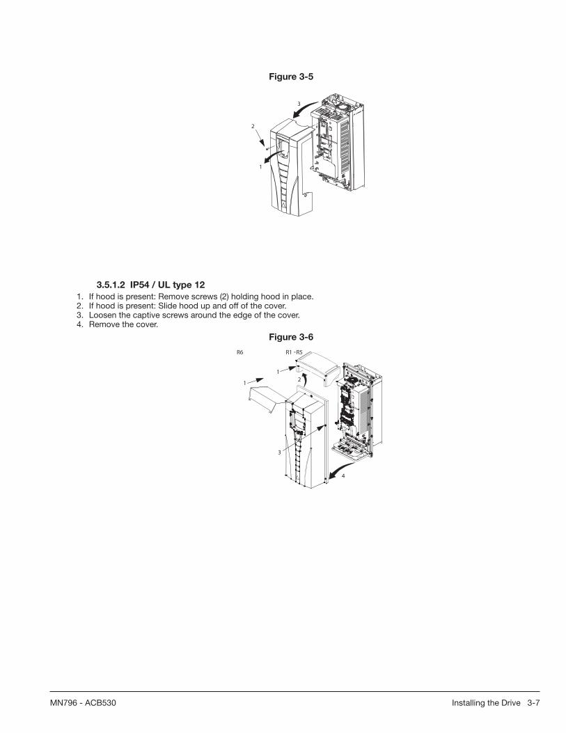
Installing the Drive 3-7MN796 - ACB530
Figure 3-5
3
1
2
3.5.1.2 IP54 / UL type 12
1. If hood is present: Remove screws (2) holding hood in place.2. If hood is present: Slide hood up and off of the cover.3. Loosen the captive screws around the edge of the cover. 4. Remove the cover.
Figure 3-6
3
4
12
R6
1
R1 -R5

3-8 Installing the Drive MN796 - ACB530
3.6 Mount the Drive
3.6.1 IP21 / UL type 1
1. Position the ACB530 onto the mounting screws or bolts and securely tighten in all four corners.Note: Lift the ACB530 by its metal chassis (frame size R6 by the lifting holes on both sides at the top).2. Non-English speaking locations: Add a warning sticker in the appropriate language over the existing warning on the top
of the module.
Figure 3-7 IP21/UL type 1
1
2
3.6.2 IP54 / UL type 12
For the IP54 / UL type 12 enclosures, rubber plugs are required in the holes provided for access to the drive mounting slots.1. As required for access, remove the rubber plugs. Push plugs out from the back of the drive.2. R5 & R6: Align the sheet metal hood (not shown) in front of the drive’s top mounting holes. (Attach as part of next step.)3. Position the ACB530 onto the mounting screws or bolts and securely tighten in all four corners.Note: Lift the ACB530 by its metal chassis (frame size R6 by the lifting holes on both sides at the top).4. Reinstall the rubber plugs.5. Non-English speaking locations: Add a warning sticker in the appropriate language over the existing warning on the top
of the module.
Figure 3-8 IP54/UL type 12
3
1, 4
5

Power Wiring 4-1MN796 - ACB530
Chapter 4Power Wiring
4.1 Electrical installation
4.1.1 What this chapter contains
This chapter describes how to connect the power cables (incoming main power lines and motor power cabling) to the ACB530 Drive. It also addresses compatibility of the ACB530 with certain special power systems including IT (ungrounded) and corner-grounded TN Systems.
WARNING! The work described in this chapter may only be carried out by a qualifi ed electrician. Follow the instructions in chapter 1 regarding safety.
• Ignoring the safety instructions can cause injury or death.• Make sure that the drive is disconnected from the input power during installation. • If the drive is already connected to the input power, wait for 5 minutes after disconnecting the input power.
4.2 Checking the insulation of the assembly
4.2.1 Drive
Do not make any voltage tolerance or insulation resistance tests (for example hi-pot or megger) on any part of the drive as testing can damage the drive. Every drive has been tested for insulation between the main circuit and the chassis at the factory.
Also, there are voltage-limiting circuits inside the drive which reduce the testing voltage automatically.
4.3 Planning the electrical installation
4.3.1 What this section contains
This section contains the instructions that you must follow when checking the compatibility of the motor and drive, and selecting cables, protections, cable routing and way of operation for the drive.
Note: The installation must always be designed and made according to applicable local laws and regulations. Baldor does not assume any liability whatsoever for any installation which breaches the local laws and/or other regulations. Furthermore, if the recommendations given by Baldor are not followed, the drive may experience problems that the warranty does not cover.
4.3.2 Implementing the AC power line connection
See the requirements in section Electric power supply specifi cation. Use a fi xed connection to the AC power line.
WARNING! As the leakage current of the device typically exceeds 3.5 mA, a fi xed installation is required according to IEC 61800-5-1.
4.3.2.1 Using a line reactor
An line reactor should be used in cases where unstable supply networks exist. A line reactor can also be used to decrease the input fault current in case of an internal drive failure.
4.3.3 Disconnecting Device for Isolation
Install a hand-operated input disconnect (disconnecting means) between the AC power source and the drive. The disconnecting device must be of a type that can be locked to the open position for installation and maintenance work.
• Europe: To meet the European Union Directives, according to standard EN 60204-1, Safety of Machinery, the disconnecting device must be one of the following types:
– a switch-disconnector of utilization category AC-23B (EN 60947-3) – a disconnector having an auxiliary contact that in all cases causes switching devices to break the load circuit before the opening of the main contacts of the disconnector (EN 60947-3).
– a circuit breaker suitable for isolation in accordance with EN 60947-2.• Other regions: The disconnecting device must conform to regional applicable safety regulations.
Motor Compatibility
The motor, drive and supply power must be compatible:

4-2 Power Wiring MN796 - ACB530
Table 4-1
Motor Specifi cation
Verify Reference
Motor Type 3-phase induction motor -
Nominal current Motor current is within this range: 0.2…2.0 · I2hd (I2hd = drive heavy duty current)
Type designation label on drive, entry for Output I2hd, or
Type designation on drive and rating table inchapter Technical data on page 271.
Nominal frequency 10…500 Hz
Voltage range Motor is compatible with the ACB530 voltage range.
208…240 V (for ACB530-X1-XXXX-2) or380…480 V (for ACB530-X1-XXXX-4) or500…600 V (for ACB530-U1-XXXX-6)
Insulation 500…600 V drives: Either the motor complies with NEMA MG1 Part 31, or a dv/dt fi lter is used between the motor and drive.
For ACB530-U1-XXXX-6
4.4 Grounding the Drive
4.4.1 Ground Connections
For personnel safety, proper operation and reduction of electromagnetic emission/immunity, the drive and the motor must be grounded at the installation site.
• Conductors must be adequately sized as required by safety regulations.• Power cable shields must be connected to the drive PE terminal in order to meet safety regulations.• Power cable shields are suitable for use as equipment grounding conductors only when the shield conductors are
adequately sized as required by safety regulations.• In multiple drive installations, do not connect drive terminals in series.
4.4.2 Ground Fault Protection
ACB530 internal fault logic detects ground faults in the drive, motor, or motor cable.This fault logic:• is NOT a personal safety or fi re protection feature• can be disabled using parameter 3017 EARTH FAULTNote: Disabling earth fault (ground fault) may void the warranty.• could be tripped by leakage currents (input power to ground) associated with long high capacitance motor cables.
4.4.3 Grounding and Routing
4.4.3.1 Motor Cable Shielding
Motor cables require shielding using conduit, armored cable or shielded cable.• Conduit – When using conduit:
– Bridge joints with a ground conductor bonded to the conduit on each side of the joint.– Bond conduit run to the drive enclosure.– Use a separate conduit run for motor cables (also separate input power and control cables).– Use a separate conduit run for each drive.
• Armored cable – When using armored cable:– Use six-conductor (3 phases and 3 grounds), type MC continuous corrugated aluminium armor cable with symmetrical grounds.– Armored motor cable can share a cable tray with input power cables, but not with control cables.
• Shielded cable – For shielded cable details, see section Motor cable requirements for CE & C-Tick compliance.
4.4.3.2 Grounding
See section Ground Connections.
For CE compliant installations and installations where EMC emissions must be minimized, see section Effective motor cable shields.

Power Wiring 4-3MN796 - ACB530
4.4.3.3 Corner Grounded TN Systems
WARNING! Do not attempt to install or remove the EMC fi lter screws EM1, EM3, F1 or F2 while power is applied to the drive’s input terminals.
Corner grounded TN systems are defi ned in the following table. In such systems, disconnect the internal ground connection through the EMC fi lter capacitors (do this also if the grounding confi guration of the system is unknown), see section Disconnecting the internal EMC fi lter.
Table 4-1
Corner grounded TN systems – EMC fi lter must be disconnected
Grounded at the corner of the delta L1
L2L3
Grounded at the mid point of a delta leg L1
L2L3
Single phase, grounded at an end point L1
N
Three phase “Variac” without solidly grounded neutral L1
L1
L2L2
L3L3
The EMC fi lter capacitors make an internal ground connection that reduces electro-magnetic emission. Where EMC (electro-magnetic compatibility) is a concern, and the system is symmetrically grounded, the EMC fi lter may be connected. For reference, the diagram on the right illustrates a symmetrically grounded TN system (TN-S system).
L1
L2L3
4.4.3.4 IT Systems
WARNING! Do not attempt to install or remove the EMC fi lter screws EM1, EM3, F1 or F2 while power is applied to the drive’s input terminals.
For IT systems (an ungrounded power system or a high-resistance-grounded [over 30ohm] power system):
• Disconnect the ground connection to the internal EMC fi lter, see section Disconnecting the internal EMC fi lter. • Where EMC requirements exist, check for excessive emission propagated to neighboring low voltage networks. In some
cases, the natural suppression in transformers and cables is suffi cient. If in doubt, use a supply transformer with static screening between the primary and secondary windings.
• Do NOT install an external RFI/EMC fi lter. Using an EMC fi lter grounds the input power through the fi lter capacitors, which could be dangerous and could damage the drive.
4.5 Wiring Overview
4.5.1 Conduit/Gland Kit
Wiring drives with the IP21 / UL type 1 enclosure requires a conduit/gland kit with the following items:
• conduit/gland box• screws• cover.The kit is included with IP21 / UL type 1 enclosures.

4-4 Power Wiring MN796 - ACB530
4.5.2 Wiring Requirements
WARNING! Ensure the motor is compatible for use with the ACB530. The drive must be installed by a competent person in accordance with the considerations defi ned in section Preparing for Installation. If in doubt, contact your local Baldor District Offi ce.
As you install the wiring, observe the following:
• There are four sets of wiring instructions – one set for each combination of drive enclosure type (IP21 / UL type and IP54 / UL type 12) and wiring type (conduit or cable). Be sure to select the appropriate procedure.
• Determine electro-magnetic compliance (EMC) requirements per local codes. See section Motor cable requirements for CE & C-Tick compliance - Appendix C.
In general:• Follow local codes for cable size.• Keep these four classes of wiring separated: input power wiring, motor wiring, control/communications wiring and braking
unit wiring.• When installing input power and motor wiring, refer to the following, as appropriate:
Table 4-1
Terminal Description
U1, V1, W11 3-Phase Power Supply InputPE Protective Guard
U2, V2, W2 Power Output to Motor
1 The ACB530-U1-xxxx-2 (208 - 240V series) can be used with a single phase supply, if output current is derated by 50%. For single phase supply voltage, connect power at U1 and W1.
• For frame size R6, see section Power Terminal Considerations – R6 frame size to install the appropriate cable lugs.• For drives using braking (optional), refer to the following, as appropriate:
Table 4-2
Frame Size Terminal Description Braking Accessory
R1, R2 BRK+, BRK- Braking Resistor Braking resistor. See section Brake Components.
R3, R4, R5, R6 UDC+, UDC- DC Bus
Contact your local Baldor District Offi ce to order either:• braking unit or• chopper and resistor
4.5.3 Install the Wiring
4.5.3.1 Checking Motor and Motor Cable Insulation
WARNING! Check the motor and motor cable insulation before connecting the drive to input power. For this test, make sure that motor cables are NOT connected to the drive.
1. Complete motor cable connections to the motor, but NOT to the drive output terminals (U2, V2, W2).2. Measure the insulation resistance between each phase conductor and the Protective Earth conductor using a measuring
voltage of 500VDC. The insulation resistance of an ABB motor must exceed 10Mohm (reference value at 25°C or 77°F). For the insulation resistance of other motors, please consult the manufacturer’s instructions. Note: Moisture inside the motor casing will reduce the insulation resistance. If moisture is suspected, dry the motor and repeat the measurement.
Figure 4-1
ohm
M3~
U1
V1
W1 PE
4.5.4 Wiring IP21 / UL Type 1 Enclosure with Cables
1. Open the appropriate knockouts in the conduit/gland box. (See section Conduit/Gland kit.)2. Install the cable clamps for the power/motor cables.3. On the input power cable, strip the sheathing back far enough to route individual wires.4. On the motor cable, strip the sheathing back far enough to expose the copper wire shield so that the shield can be
twisted into a bundle (pig-tail). Keep the bundle not longer than fi ve times its width to minimize noise radiation.

Power Wiring 4-5MN796 - ACB530
360° grounding under the clamp is recommended for the motor cable to minimize noise radiation. In this case, remove the sheathing at the cable clamp.
5. Route both cables through the clamps.6. Strip and connect the power/motor wires and the power ground wire to the drive terminals. See the table on the right for
tightening torques.
Note: For R6 frame size, refer to section Power terminal considerations – R6 frame size.
7. Connect the bundle (pig-tail) created from the motor cable shield to the GND terminal.
Figure 4-2 Frame Size
Tightening Torque
1
2
6
3
6
7
4
8
N-m lb-ft
R1, R2 1.4 1R3 2.5 1.8R4 5.6; PE: 2 4; PE: 1.5R5 15 11R6 40; PE: 8 30; PE: 6
8. Install conduit/gland box and tighten the cable clamps.9. Install the cable clamp(s) for the control cable(s). (Power/motor cables and clamps not shown in the fi gure.)10. Strip control cable sheathing and twist the copper shield into a bundle (pig-tail).11. Route control cable(s) through clamp(s) and tighten clamp(s).12. Connect the ground shield bundle (pig-tail) for digital and analog I/O cables at X1-1. (Ground only at the drive end.)13. Strip and connect the individual control wires to the drive terminals. See section Control terminals table. Use a tightening
torque of 0.4 N·m (0.3 lb·ft).14. Install the conduit/gland box cover (1 screw).
Figure 4-3
8
9
12
11
13

4-6 Power Wiring MN796 - ACB530
4.5.5 Wiring IP21 / UL Type 1 Enclosure with Conduit
1. Open the appropriate knockouts in the conduit/gland box. (See section Conduit/Gland kit.)2. Install thin-wall conduit clamps (not supplied).3. Install conduit/gland box.4. Connect conduit runs to box.5. Route input power and motor wiring through conduits (must be separate conduit runs).6. Strip wires.7. Connect power, motor and ground wires to the drive terminals. See the table on the right for tightening torques.
Figure 4-4 Frame Size
Tightening Torque
2
3
4
7
7
5
N-m lb-ft
R1, R2 1.4 1R3 2.5 1.8R4 5.6; PE: 2 4; PE: 1.5R5 15 11R6 40; PE: 8 30; PE: 6
Note: For R6 frame size, refer to section Power Terminal Considerations – R6 frame size.
8. Route the control cable through the conduit (must be separate from input power and motor conduit runs).9. Strip the control cable sheathing and twist the copper shield into a bundle (pig-tail). 10. Connect the ground shield bundle (pig-tail) for digital and analog I/O cables at X1-1. (Ground only at the drive end.)11. Strip and connect the individual control wires to the drive terminals. See section Control terminals table. Use a tightening
torque of 0.4N·m (0.3lb·ft).12. Install the conduit/gland box cover (1screw).
Figure 4-5
10
8
11

Power Wiring 4-7MN796 - ACB530
4.5.6 Wiring IP54 / UL Type 12 Enclosure with Cables
1. Cut the cable seals as needed for the power, motor and control cables. The cable seals are cone-shaped, rubber seals on the bottom of the drive. The conical part of the seals must face downwards when the seals are inserted in the lead-through plate holes.
2. On the input power cable, strip the sheathing back far enough to route individual wires.3. On the motor cable, strip the sheathing back far enough to expose the copper wire shield so that the shield can be
twisted into a bundle (pig-tail). Keep the bundle not longer than fi ve times its width to minimize noise radiation.
360° grounding under the clamp is recommended for the motor cable to minimize noise radiation. In this case, remove the sheathing at the cable clamp.
4. Route both cables through the clamps and tighten the clamps.5. Strip and connect the power/motor wires and the power ground wire to the drive terminals. See the table below on the
right for tightening torques.
Figure 4-6 Frame Size
Tightening Torque
1
4
5
2 34
N-m lb-ft
R1, R2 1.4 1R3 2.5 1.8R4 5.6; PE: 2 4; PE: 1.5R5 15 11R6 40; PE: 8 30; PE: 6
Note: For R6 frame size, refer to section Power terminal considerations – R6 frame size.
6. Connect the bundle (pig-tail) created from the motor cable shield to the GND terminal.7. Strip control cable sheathing and twist the copper shield into a bundle (pig-tail). 8. Route control cable(s) through clamp(s) and tighten clamp(s).9. Connect the ground shield bundle (pig-tail) for digital and analog I/O cables at X1-1. (Ground only at the drive end.)10. Strip and connect the individual control wires to the drive terminals. See section Control terminals table. Use a tightening
torque of 0.4N·m (0.3lb·ft).
Figure 4-7
8
9, 10

4-8 Power Wiring MN796 - ACB530
4.5.7 Wiring IP54 / UL Type 12 Enclosure with Conduit
1. Remove and discard the cable seals where conduit will be installed. (The cable seals are cone-shaped, rubber seals on the bottom of the drive.)
2. For each conduit run, install water tight conduit connectors (not supplied).3. Route the power wiring through the conduit.4. Route the motor wiring through the conduit.5. Strip the wires.6. Connect the power, motor and ground wires to the drive terminals. See the table on the right for tightening torques.
Figure 4-8 Frame Size
Tightening Torque
N-m lb-ft
R1, R2 1.4 1R3 2.5 1.8R4 5.6; PE: 2 4; PE: 1.5R5 15 11R6 40; PE: 8 30; PE: 6
Note: For R6 frame size, refer to section Power terminal considerations – R6 frame size.
7. Route the control cable through the conduit.8. Strip the control cable sheathing and twist the copper shield into a bundle (pig-tail). 9. Connect the ground shield bundle (pig-tail) for digital and analog I/O cables at X1-1. (Ground only at the drive end.)10. Strip and connect the individual control wires to the drive terminals. See section Control terminals table. Use a tightening
torque of 0.4N·m (0.3lb·ft).

Power Wiring 4-9MN796 - ACB530
4.5.8 Power Connection Diagrams
The following diagram shows the terminal layout for frame size R3, which, in general, applies to frame sizes R1 through R6, except for the R5/R6 power and ground terminals.
Figure 4-9 R3 Terminal Layout
Panel connector
Fault LED (red)
Optional module 1J2 – DIP switch
X1 – Communications
Optional module 2
GND
Power output to motorPower input
EM1
X1 – Analog inputs and outputs
X1 – Digital inputs
X1 – Relay outputs
J2
ON
off position on position
for RS485 termination
(and 10 V ref. voltage output)
(and 24 V aux. voltage output)
PE
(U1, V1, W1) (U2, V2, W2)
Optional braking
Frame size
Terminal labels Brake options
R1, R2 BRK+, BRK- Brake resistorR3, R4 UDC+, UDC- • Braking unit
• Chopper and resistor
(RS485)
R5/R6 differ. See
Frame sizes
next page.
Diagram shows the R3 frame.
J2
ON
Other frames have similar layouts. J1
AI1: (in voltage position)AI2: (in current position)
ON
ON
J1 – DIP switches for analog inputs (two types can be used)
ON
12
J1
Power LED (green)
EM3
WARNING! To avoid danger, or damage to the drive, on IT systems and corner grounded TN systems, see section Disconnecting the Internal EMC Filter.

4-10 Power Wiring MN796 - ACB530
The following diagram shows the power and ground terminal layout for frame sizes R5 and R6.
Figure 4-10 R5 and R6 Power and Ground Terminal Layout
GND
Power input
PE
(U1, V1, W1)
Optional braking
Frame size
Terminal labels Brake options
R5, R6 UDC+, UDC- • Braking unit • Chopper and resistor
X0011
F2
Power input
PE
(U1, V1, W1)
F1
F2
X0013
Power output to motor(U2, V2, W2)
6R5R
GND
GND
Power output to motor(U2, V2, W2)
F1
WARNING! To avoid danger, or damage to the drive, on IT systems and corner grounded TN systems, see section Disconnecting the Internal EMC Filter.
4.5.9 Disconnecting the Internal EMC Filter
On certain types of systems, you must disconnect the internal EMC fi lter, otherwise the system will be connected to ground potential through the EMC fi lter capacitors, which might cause danger, or damage the drive.
Note: When the internal EMC fi lter is disconnected, the drive is not EMC compatible.
The following table shows the installation rules for the EMC fi lter screws in order to connect or disconnect the fi lter, depending on the system type and the frame size. For more information on the different system types, see IT Systems on and Corner Grounded TN Systems. The locations of screws EM1 and EM3 are shown in Figure 4-1.
The locations of screws F1 and F2 are shown in Figure 4-2.

Power Wiring 4-11MN796 - ACB530
Table 4-3
Frame sizes ScrewSymmetrically grounded TN
systems (TN-S systems)Corner grounded
TN systems
IT systems (ungrounded or high-resistance grounded
[> 30 ohm])
R1 - R3EM1 x x •
EM31 x • •
R4EM1 x x –
EM31 x – –
R5 - R6F1 x x –
F2 x x –
x = Install the screw. (EMC fi lter will be connected.)• = Replace the screw with the provided polyamide screw. (EMC fi lter will be disconnected.)– = Remove the screw. (EMC fi lter will be disconnected.)1 = ACB530-U1 drives are shipped with screw EM3 already removed.
4.6 Drive’s Power Connection TerminalsThe following table provides specifi cations for the drive’s power connection terminals.
Table 4-4
Frame Size
U1, V1, W1U2, V2, W2
Brk±, UDC± TerminalsEarthing PE Terminal
Minimum Wire Size Maximum Wire Size Tightening Torque Maximum Wire Size Tightening Torque
mm2 AWG mm2 AWG N-m lb-ft mm2 AWG N-m lb-ft
R11 0.75 18 10.0 8 1.4 1.0 10.0 8 1.4 1.0R21 0.75 18 10.0 8 1,4 1.0 10.0 8 1.4 1.0R31 2.5 14 25.0 3 2.5 1.8 16.0 6 1.8 1.3R41 6.0 10 50.0 1/0 5.6 4.0 25.0 3 2.0 1.5R51 6.0 10 70.0 2/0 15.0 11.0 70.0 2/0 15.0 11.0R62 95.03 3/03 240.0 350 MCM 40.0 30.0 95.0 3/0 8.0 6.0
1 Aluminum cable cannot be used with frame sizes R1 - R5 because of its lower capacity.2 Aluminum cable cannot be used with type ACB530-U1-290A-4 because of the terminal size.3 See section Power Terminal Considerations - R6 Frame Size.Note: See the recommended cable sizes for different load currents in section Input Power Cables/Wiring.
4.6.1 Power Terminal Considerations - R6 Frame Size
WARNING! For R6 power terminals, if screw-on terminal lugs are supplied, they can only be used for wire sizes that are 95mm2 (3/0AWG) or larger. Smaller wires will loosen and may damage the drive. They require crimp-on ring lugs as described below.
4.6.2 Crimp-On Ring Lugs
On the R6 frame size, if screw-on terminal lugs are supplied but the cable size used is less than 95 mm2 (3/0 AWG), or if no screw-on terminal lugs are supplied at all, use crimp-on ring lugs according to the following procedure.1. Select appropriate ring lugs from the following table.2. Remove the screw-on terminal lugs, if supplied.3. Attach the ring lugs to the drive end of the cables.4. Isolate the ends of the ring lugs with insulating tape or shrink tubing.5. Attach the ring lugs to the drive.

4-12 Power Wiring MN796 - ACB530
Figure 4-11 Crimp-On Ring Lugs
Table 4-5
Wire Size
Manufacturer Ring Lug Crimping Tool No. of Crimpsmm2 kcmil/
AWG
16 6Burndy YAV6C-L2 MY29-3 1
Ilsco CCL-6-38 ILC-10 2
25 4Burndy YA4C-L4BOX MY29-3 1
Ilsco CCL-4-38 MT-25 1
35 2
Burndy YA2C-L4BOX MY29-3 2Ilsco CRC-2 IDT-12 1Ilsco CCL-2-38 MT-25 1
50 1
Burndy YA1C-L4BOX MY29-3 2Ilsco CRA-1-38 IDT-12 1Ilsco CCL-1-38 MT-25 1
Thomas & Betts 54148 TBM-8 3
55 1/0
Burndy YA25-L4BOX MY29-3 2Ilsco CRB-0 IDT-12 1Ilsco CCL-1/0-38 MT-25 1
Thomas & Betts 54109 TBM-8 3
70 2/0
Burndy YAL26T38 MY29-3 2Ilsco CRA-2/0 IDT-12 1Ilsco CCL-2/0-38 MT-25 1
Thomas & Betts 54110 TBM-8 3
95 3/0
Burndy YAL27T38 MY29-3 2Ilsco CRA-3/0 IDT-12 1Ilsco CCL-3/0-38 MT-25 1
Thomas & Betts 54111 TBM-8 3
95 3/0
Burndy YA28R4 MY29-3 2Ilsco CRA-4/0 IDT-12 1Ilsco CCL-4/0-38 MT-25 2
Thomas & Betts 54112 TBM-8 4
4.6.3 Screw-On Terminal Lugs
Use the following procedure to attach cables if screw-on terminal lugs are supplied and the cable size is 95 mm2 (3/0 AWG) or larger. 1. Attach the supplied screw-on lugs to the drive end of the cables.2. Attach screw-on lugs to the drive.
Figure 4-12 Screw-On Terminal Lugs
12
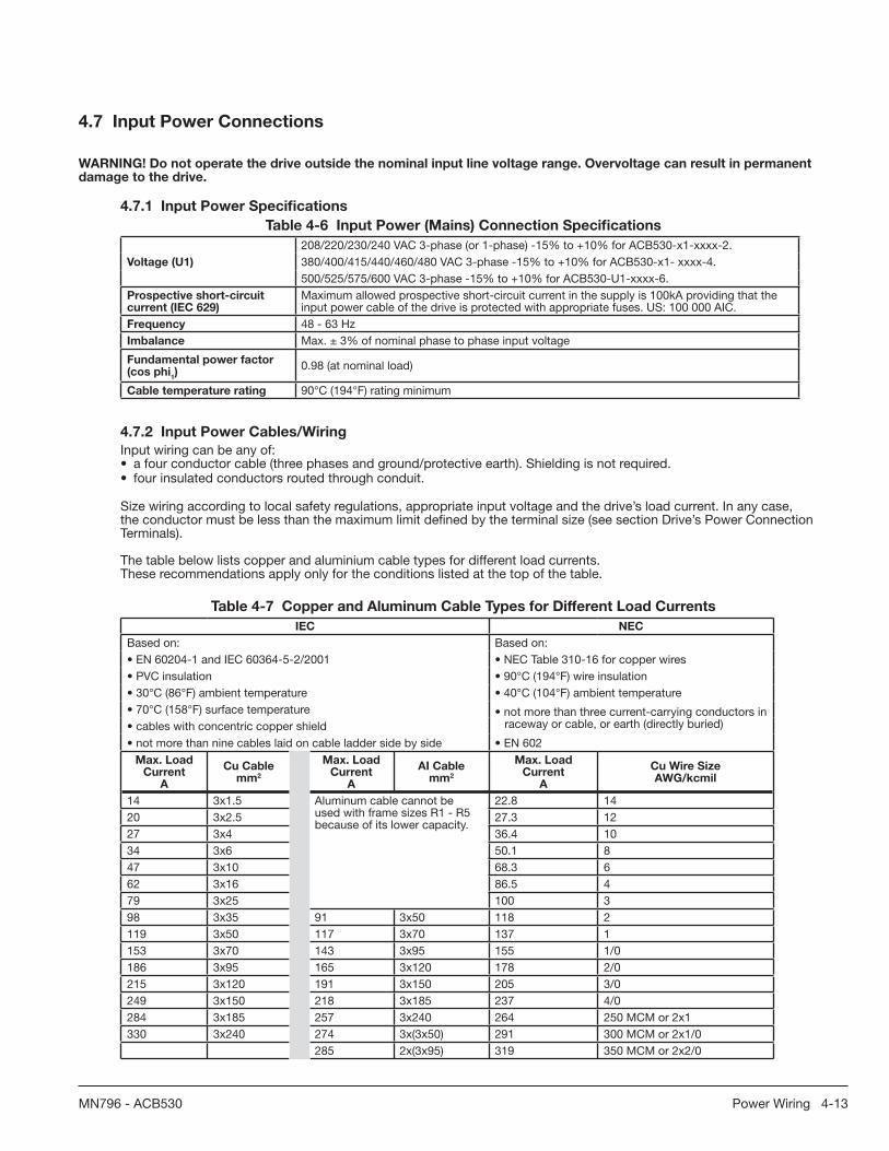
Power Wiring 4-13MN796 - ACB530
4.7 Input Power Connections
WARNING! Do not operate the drive outside the nominal input line voltage range. Overvoltage can result in permanent damage to the drive.
4.7.1 Input Power Specifi cations
Table 4-6 Input Power (Mains) Connection Specifi cations
Voltage (U1)
208/220/230/240 VAC 3-phase (or 1-phase) -15% to +10% for ACB530-x1-xxxx-2.380/400/415/440/460/480 VAC 3-phase -15% to +10% for ACB530-x1- xxxx-4.500/525/575/600 VAC 3-phase -15% to +10% for ACB530-U1-xxxx-6.
Prospective short-circuit current (IEC 629)
Maximum allowed prospective short-circuit current in the supply is 100kA providing that the input power cable of the drive is protected with appropriate fuses. US: 100 000 AIC.
Frequency 48 - 63 HzImbalance Max. ± 3% of nominal phase to phase input voltage
Fundamental power factor (cos phi
1)
0.98 (at nominal load)
Cable temperature rating 90°C (194°F) rating minimum
4.7.2 Input Power Cables/Wiring
Input wiring can be any of:• a four conductor cable (three phases and ground/protective earth). Shielding is not required.• four insulated conductors routed through conduit.
Size wiring according to local safety regulations, appropriate input voltage and the drive’s load current. In any case, the conductor must be less than the maximum limit defi ned by the terminal size (see section Drive’s Power Connection Terminals).
The table below lists copper and aluminium cable types for different load currents.These recommendations apply only for the conditions listed at the top of the table.
Table 4-7 Copper and Aluminum Cable Types for Different Load Currents
IEC NEC
Based on: Based on:• EN 60204-1 and IEC 60364-5-2/2001 • NEC Table 310-16 for copper wires• PVC insulation • 90°C (194°F) wire insulation• 30°C (86°F) ambient temperature • 40°C (104°F) ambient temperature• 70°C (158°F) surface temperature • not more than three current-carrying conductors in
raceway or cable, or earth (directly buried)• cables with concentric copper shield• not more than nine cables laid on cable ladder side by side • EN 602
Max. Load Current
A
Cu Cable mm2
Max. Load Current
A
AI Cable mm2
Max. Load Current
A
Cu Wire Size AWG/kcmil
14 3x1.5 Aluminum cable cannot be used with frame sizes R1 - R5 because of its lower capacity.
22.8 1420 3x2.5 27.3 1227 3x4 36.4 1034 3x6 50.1 847 3x10 68.3 662 3x16 86.5 479 3x25 100 398 3x35 91 3x50 118 2119 3x50 117 3x70 137 1153 3x70 143 3x95 155 1/0186 3x95 165 3x120 178 2/0215 3x120 191 3x150 205 3/0249 3x150 218 3x185 237 4/0284 3x185 257 3x240 264 250 MCM or 2x1330 3x240 274 3x(3x50) 291 300 MCM or 2x1/0
285 2x(3x95) 319 350 MCM or 2x2/0

4-14 Power Wiring MN796 - ACB530
4.8 Brake Components
4.8.1 Compatibility
Braking availability for ACB530 drives, varies by frame size as shown below:
• R1 and R2 – a built-in brake chopper is standard equipment. Add appropriate resistor, as determined using the following section. Resistors are available from Baldor.
• R3 through R6 – does not include an internal brake chopper. Connect a chopper and a resistor, or a brake unit to the DC link terminals on the drive. Contact your Baldor District Offi ce for appropriate parts.
4.8.2 Selecting the Braking Resistors (Frame Sizes R1 and R2)
Braking resistor must meet three requirements:• Resistance must be always higher than the minimum value RMIN defi ned for the drive type in the following tables. Never
use resistance below this value.• Resistance must be low enough to be able to produce the desired braking torque. To achieve the maximum braking
torque (the larger of 150% of heavy duty or 110% of nominal duty), the resistance must not exceed RMAX. If maximum braking torque is not necessary, resistor values can exceed RMAX.
• The resistor power rating must be high enough to dissipate the braking power.This requirement involves many factors:
– the maximum continuous power rating for the resistor(s) – the rate at which the resistor changes temperature (resistor thermal time constant) – maximum braking time ON – If the regeneration (braking) power is larger than the resistor rated power, there is a limit to the ON time, or the resistor overheats before the OFF period begins.
– minimum braking time OFF – If the regeneration (braking) power is larger than the resistor rated power, the OFF time must be large enough for the resistor to cool between ON periods.
Figure 4-13
TimeBraking ON
Braking OFF
ON time OFF time
Cycle time Cycle timeON time
Duty cycle =
– the peak braking power requirement – type of braking (deceleration to zero vs. overhauling load) – During deceleration to zero, the generated power steadily – for example) and the braking power is constant. The total heat generated from an overhauling load is double the heat generated from deceleration to zero speed (for the same peak torque and ON time).
Figure 4-14
Time
Power Deceleration curve Overhauling loadcurve
Time
Temperature
Avg. braking power during deceleration
Avg. braking power –overhauling load
x
2x
to zero
The many variables in the last requirement above are most easily dealt with using the following tables.
• First, determine your maximum braking time ON (ONMAX), minimum braking time OFF (OFFMIN) and load type (deceleration or overhauling load).
• Calculate duty cycle:
Duty cycle =(ON MAX + OFF MIN )
· 100%ON MAX

Power Wiring 4-15MN796 - ACB530
• In the appropriate table, fi nd the column that best matches your data: – ONMAX ≤ column specifi cation and – Duty cycle ≤ column specifi cation
• Find the row that matches your drive.• The minimum power rating for deceleration to zero is the value in the selected row/column.• For overhauling loads, double the rating in the selected row/column, or use the “Continuous ON” column.
Table 4-8 208 - 240V Drives
Type ACB530-U1-see below
ResistanceResistor1 Minimum Continuous Power Rating
Deceleration-to-Zero Rating PrcontContinuous ON> 60 s ON
> 25% DutyR
MAXR
MIN
Pr3≤ 3 s ON≥ 27 s OFF≤ 10% Duty
Pr10≤ 10 s ON≥ 50 s OFF≤ 17% Duty
Pr30≤ 30 s ON≥ 180 s OFF≤ 14% Duty
Pr60≤ 60 s ON≥ 180 s OFF≤ 25% Duty
ohm ohm W W W W W
Three-phase supply voltage, 208 - 240V
-04A6-2 234 80 45 80 120 200 1100-06A6-2 160 80 65 120 175 280 1500-07A5-2 117 44 85 160 235 390 2200-012A-2 80 44 125 235 345 570 3000-017A-2 48 44 210 390 575 950 4000-024A-2 32 30 315 590 860 1425 5500-031A-2 23 22 430 800 1175 1940 7500
1 Resistor time constant specifi cation must be ≥ 85 seconds.
Table 4-9 380 - 480V Drives
Type ACB530-U1-see below
ResistanceResistor1 Minimum Continuous Power Rating
Deceleration-to-Zero Rating PrcontContinuous ON> 60 s ON
> 25% DutyR
MAXR
MIN
Pr3≤ 3 s ON≥ 27 s OFF≤ 10% Duty
Pr10≤ 10 s ON≥ 50 s OFF≤ 17% Duty
Pr30≤ 30 s ON≥ 180 s OFF≤ 14% Duty
Pr60≤ 60 s ON≥ 180 s OFF≤ 25% Duty
ohm ohm W W W W W
Three-phase supply voltage, 380 - 480V
-03A3-4 641 120 65 120 175 285 1100-04A1-4 470 120 90 160 235 390 1500-05A4-4 320 120 125 235 345 570 2200-06A9-4 235 80 170 320 470 775 3000-08A8-4 192 80 210 400 575 950 4000-012A-4 128 80 315 590 860 1425 5500-015A-4 94 63 425 800 1175 1950 7500-023A-4 64 63 625 1175 1725 2850 11000
1 Resistor time constant specifi cation must be ≥ 85 seconds.
Table 4-10 500 - 600V Drives
Type ACB530-U1-see below
ResistanceResistor1 Minimum Continuous Power Rating
Deceleration-to-Zero Rating PrcontContinuous ON> 60 s ON
> 25% DutyR
MAXR
MIN
Pr3≤ 3 s ON≥ 27 s OFF≤ 10% Duty
Pr10≤ 10 s ON≥ 50 s OFF≤ 17% Duty
Pr30≤ 30 s ON≥ 180 s OFF≤ 14% Duty
Pr60≤ 60 s ON≥ 180 s OFF≤ 25% Duty
ohm ohm W W W W W
Three-phase supply voltage, 500 - 600V
-02A7-6 548 80 93 175 257 425 1462-03A6-6 373 80 137 257 377 624 2144-06A1-6 224 80 228 429 639 1040 3573-06A0-6 149 80 342 643 943 1560 5359-011A-6 110 60 467 877 1286 2127 7308-017A-6 75 60 685 1286 1886 3119 10718
1 Resistor time constant specifi cation must be ≥ 85 seconds.

4-16 Power Wiring MN796 - ACB530
WARNING! Never use a brake resistor with a resistance below the minimum value specifi ed for the particular drive. The drive and the internal chopper are not able to handle the overcurrent caused by the low resistance.
4.8.3 Symbols
RMIN
– Minimum allowed resistance of the braking resistor.
RMAX
– Maximum resistance to provide maximum breaking torque.
Prx – Duty-cycle based resistor power rating (watts), where “x” is ON time.
4.8.4 Installing and Wiring Resistors
All resistors must be installed outside the drive module in a place where they can dissipate heat.
WARNING! The surface temperature of the resistor is very high, and air fl owing from the resistor is very hot. Materials near the brake resistor must be non-fl ammable. Provide protection from accidental contact with the resistor.
To ensure that the input fuses protect the resistor cable, use resistor cables with the same rating as used for the power input to the drive.
The maximum length of the resistor cable(s) is 10 m (33 ft). See section Power Connection diagrams for the resistor cable connection points.
4.8.5 Mandatory Circuit Protection
The following setup is required for safety – it interrupts the main supply in fault situations involving dynamic breaking chopper shorts:
• Equip the drive with a main contactor.• Wire the contactor so that it opens if the resistor thermal switch opens (an overheated resistor opens the contactor).
Below is a simple wiring diagram example.
Figure 4-15
ACB530
U1 V1 W1
L1 L2 L3
1
2
3
4
5
6
13
14
3
4
1
2
K1
Q Thermal switch (standard in ABB resistors)
On
OffFuses
4.8.6 Parameter Set-Up
To enable dynamic braking, switch off the drive’s overvoltage control [Set parameter 2005 = 0 (DISABLE)].
4.9 Motor Connections
WARNING! Never connect line power to the drive output terminals: U2, V2 or W2. Line voltage applied to the output can result in permanent damage to the drive. If frequent bypassing is required, use mechanically interlocked switches or contactors.
WARNING! Do not connect any motor with a nominal voltage less than one half of the drive’s nominal input voltage.
WARNING! Disconnect the drive before conducting any voltage tolerance (Hi-Pot) test or insulation resistance (Megger) test on the motor or motor cables. Do not conduct these tests on the drive.

Power Wiring 4-17MN796 - ACB530
4.9.1 Motor Connection Specifi cations
Table 4-1 Motor Connection Specifi cations
Voltage (U2) 0 - U1, 3-phase symmetrical, Umax at the fi eld weakening point
Frequency 0 - 500 HzFrequency Resolution 0.01 HzCurrent See section RatingsField Weakening Point 10 - 500 HzSwitching Frequency Selectable. See the availability in the table below.
1, 2, 4 and 8 kHz 12 kHz
208 - 240V All types Frame sizes R1 - R4 in scalar control mode
380 - 480V All types Frame sizes R1 - R4 (except ACB530-01-097A-4) in scalar control mode
500 - 600V All types Frame sizes R2 - R4 in scalar control mode
Cable Temperature Rating 90°C (194°F) rating minimum.Maximum Motor Cable Length See section Motor Cable Lengths.
4.9.2 Motor Cable Lengths
Maximum motor cable lengths for 460V and 600V drives are given in the sections below.In multimotor systems, the calculated sum of all motor cable lengths must not exceed the maximum motor cable length given in the appropriate table below.
4.9.2.1 Motor Cable Length for 460V DrivesThe table below shows the maximum motor cable lengths for 460V drives with different switching frequencies. Examples for using the table are also given.
Table 4-2 Maximum Cable Length for 460V Drives
Frame Size
EMC Limits Operational Limits
Second Environment (Category C31) First Environment (Category C21) Basic Unit With du/dt fi lters1 kHz 4 kHz 8 kHz 1 kHz 4 kHz 8 kHz 1/4 kHz 8/12 kHz
m ft m ft m ft m ft m ft m ft m ft m ft m ft
R1 300 980 300 980 300 980 300 980 300 980 300 980 100 330 100 330 150 490R2 300 980 300 980 300 980 300 980 100 330 30 98 200 660 100 330 250 820R3 300 980 300 980 300 980 300 980 75 245 75 245 200 660 100 330 250 820R4 300 980 300 980 300 980 300 980 75 245 75 245 200 660 100 330 300 980R5 100 330 100 330 100 330 100 330 100 330 100 330 300 980 1502 4902 300 980R6 100 330 100 330 3 3 100 330 100 330 3 3 300 980 1502 4902 300 980
1 See the new terms in section IEC/EN 61800-3 (2004) Defi nitions.2 12 kHz switching frequency is not available.3 Not tested.Sine fi lters further extend the cable lengths.
Under heading “Operational limits”, the “Basic unit” columns defi ne the cable lengths with which the basic drive unit works without problems within the drive specifi cation, without installing any further options. Column “With du/dt fi lters” defi nes the cable lengths when an external du/dt fi lter is used.The columns under heading “EMC limits” show the maximum cable lengths with which the units have been tested for EMC emissions. The factory guarantees that these cable lengths meet the EMC standard requirements.If external sine fi lters are installed, longer cable lengths can be used. With sine fi lters the limiting factors are the voltage drop of the cable, which has to be taken into account in engineering, as well as the EMC limits (where applicable).The default switching frequency is 4 kHz.
WARNING! Using a motor cable longer than specifi ed in the table above may cause permanent damage to the drive.

4-18 Power Wiring MN796 - ACB530
Examples for using the table:Requirements Checking and Conclusions
R1 frame size, 8 kHz fsw, Category C2, 150 m (490 ft) cable
Check operational limits for R1 and 8 kHz -> for a 150 m (490 ft) cable a du/dt fi lter is needed.
Check EMC limits -> EMC requirements for Category C2 are met with a 150 m (490 ft) cable.
R3 frame size,4 kHz fsw,Category C3,150 m (490 ft) cable
Check operational limits for R3 and 4 kHz -> a 300 m (980 ft) cable cannot be used even with a du/dt fi lter. A sine fi lter must be used and the voltage drop of the cable must be taken into account in the installation.
Check EMC limits -> EMC requirements for Category C3 are ment with a 300 m (980 ft) cable.
R5 frame size,8 kHz fsw,Category C3,150 m (490 ft) cable
Check operational limits for R5 and 8 kHz -> for a 150 m (490 ft) cable the basic unit is suffi cient.
Check EMC limits -> EMC requirements for Category C3 cannot be met with a 300 m (980 ft) cable. The installation confi guration is not possible. An EMC plan is recommended to overcome the situation.
R6 frame size,4 kHz fsw,EMC limits not applicable,150 m (490 ft) cable
Check operational limits for R6 and 4 kHz -> for a 150 m (490 ft) cable the basic unit is suffi cient.
EMC limits do not need to be checked as there are no EMC requirements.
4.9.2.2 Motor Cable Length for 600V Drives The table below shows the maximum motor cable lengths for 600 V drives with different switching frequencies. As the 600V drives are not CE approved, cable lengths for EMC limits are not given.
Table 4-3 Maximum Cable Length for 600V Drives
Frame Size
Operational Limits
Basic Unit
1/4 kHz 8/12 kHz
m ft m ft
R2 100 330 100 330R3 - R4 200 660 100 330
R6 300 980 1502 4902
2 12 kHz switching frequency is not available.
WARNING! Using a motor cable longer than specifi ed in the table above may cause permanent damage to the drive.
4.9.3 Motor Thermal Protection
According to regulations, the motor must be protected against thermal overload and the current must be switched off when overload is detected. The drive includes a motor thermal protection function that protects the motor and switches off the current when necessary. Depending on a drive parameter value (see parameter 3501 SENSOR TYPE), the function either monitors a calculated temperature value (based on a motor thermal model, see parameters 3005 MOT THERM PROT through 3009 BREAK POINT FREQ) or an actual temperature indication given by motor temperature sensors (see Group: MOTOR TEMP MEAS). The user can tune the thermal model further by feeding in additional motor and load data.
4.9.4 Emergency Stop Devices
The overall design of the installation must include emergency stop devices and any other safety equipment that may be needed. Pressing STOP on the drive’s control panel does NOT:
• generate an emergency stop of the motor• separate the drive from dangerous incoming voltage

Power Wiring 4-19MN796 - ACB530
4.10 Fuses
Branch circuit protection must be provided by the end user and sized per national and local electric codes. The following tables provide fuse recommendations for short circuit protection on the drive’s input power.
The rated fuse currents given in the tables are the maximums for the mentioned fuse types. If smaller fuse ratings are used, check that the fuse rms current rating is larger than the input current.
Check that the operating time of the fuse is below 0.5 seconds. The operating time depends on the fuse type, the supply network impedance as well as the crosssectional area, material and length of the supply cable. In case the 0.5 secondsoperating time is exceeded with the gG or T fuses, ultra rapid (aR) fuses will in most cases reduce the operating time to an acceptable level.
Table 4-4 Fuses, 208 - 240V Drives
ACB530-U1-see below
Input Current A
Input Power (mains) Fuses
IEC 60269 gG (A) UL Class T (A) Bussmann Type
-04A6-2 4.610 10 JJS-10-06A6-2 6.6
-07A5-2 7.5-012A-2 11.8 16 15 JJS-15-017A-2 16.7
2525 JJS-25
-024A-2 24.2 30 JJS-30-031A-2 30.8 40 40 JJS-40-046A-2 46.2
6360 JJS-60
-059A-2 59.4 80 JJS-80-075A-2 74.8 80 100 JJS-100-088A-2 88.0 100 110 JJS-110-114A-2 114 125 150 JJS-150-143A-2 143 200 200 JJS-200-178A-2 178 250 250 JJS-250-221A-2 221
315300 JJS-300
-248A-2 248 350 JJS-350
Table 4-5 Fuses, 380 - 480V Drives
ACB530-U1-see below
Input Current A
Input Power (mains) Fuses
IEC 60269 gG (A) UL Class T (A) Bussmann Type
-03A3-4 3.3
1010 JJS-10
-04A1-4 4.1-05A4-4 5.4-06A9-4 6.9-08A8-4 8.8
15 JJS-15-012A-4 11.9
16-015A-4 15.4 20 JJS-20-023A-4 23 25 30 JJS-30-031A-4 31 35 40 JJS-40-038A-4 38
5050 JJS-50
-045A-4 45 60 JJS-60-059A-4 59 63 80 JJS-80-072A-4 72
8090 JJS-90
-078A-4 77 100 JJS-100-087A-4 87
125 125 JJS-125-097A-4 97-125A-4 125 160 175 JJS-175-157A-4 157 200 200 JJS-200-180A-4 180
250 250 JJS-250-195A-4 205-246A-4 246
315 350 JJS-350-290A-4 290

4-20 Power Wiring MN796 - ACB530
Table 4-6 Fuses, 500 - 600V Drives
ACB530-U1-see below
Input Current A
Input Power (mains) Fuses
IEC 60269 gG (A) UL Class T (A) Bussmann Type
-02A7-6 2.710 10 JJS-10-03A9-6 3.9
-06A1-6 6.1-09A0-6 9.0
16 15 JJS-15-011A-6 11-017A-6 17
25 25 JJS-25-022A-6 22-027A-6 27
35 40 JJS-40-032A-6 32-041A-6 41 50 50 JJS-50-052A-6 52 60 60 JJS-60-062A-6 62
8080 JJS-80
-077A-6 77 100 JJS-100-099A-6 99 125 150 JJS-150-125A-6 125 160 175 JJS-175-144A-6 144 200 200 JJS-200
4.11 Check Installation
Before applying power, perform the following checks.
√ Check
Installation environment conforms to the drive’s specifi cations for ambient conditions.The drive is mounted securely.Space around the drive meets the drive’s specifi cations for cooling.The motor and driven equipment are ready for start.For IT systems and corner grounded TN systems: The internal EMC fi lter is disconnected (see section Disconnecting the internal EMC fi lter).The drive is properly grounded.The input power (mains) voltage matches the drive nominal input voltage.The input power (mains) connections at U1, V1 and W1 are connected and tightened as specifi ed.The input power (mains) fuses are installed.The motor connections at U2, V2 and W2 are connected and tightened as specifi ed.The motor cable is routed away from other cables.NO power factor compensation capacitors are in the motor cable.The control connections are connected and tightened as specifi ed.NO tools or foreign objects (such as drill shavings) are inside the drive.NO alternate power source for the motor (such as a bypass connection) is connected – no voltage is applied to the output of the drive.

Control Wiring 5-1MN796 - ACB530
Chapter 5Control Wiring
5.1 Control Connection Specifi cations
5.1.1 What this chapter contains
This chapter describes how to connect control signals (such as run and stop commands, analog references, digital outputs, etc.) to the ACB530. Typically these signals would connect the ACB530 to supervisory control equipment (such as a PLC) or to hand operators (such as push buttons, selector switches and indicator lights).
Table 5-1 Control Connection Specifi cation Analog Inputs and Outputs See section Control Terminals table.
Digital Inputs Digital input impedance 1.5 kohm. Maximum voltage for digital inputs is 30V.
Relays (Digital Outputs)
• Max. contact voltage: 30VDC, 250VAC• Max. contact current / power: 6A, 30VDC; 1500VA, 250VAC• Max. continuous current: 2Arms (cos 1),1Arms (cos = 0.4)• Minimum load: 500mW (12V, 10mA)• Contact material: Silver-nickel (AgN)• Isolation between relay digital outputs, test voltage: 2.5kVrms, 1 minute
Cable Specifi cations See section Control Terminals table.
5.2 Selecting the Control Cables
5.2.1 General Rules
Use multi-core cables with a braided copper wire shield, temperature rated at 60°C (140°F) or above:
Figure 5-1
Double shielded Single shieldedExample: JAMAK by Draka NK Cables Example: NOMAK by Draka NK Cables
For digital and analog I/O cables, twist the shield together into a bundle (pig-tail) not longer than fi ve times its width and connect it to terminal X1-1 at the drive end. Leave the other end of the cable shield unconnected.For connecting the shield wires of the RS485 cable, see the instructions (and notes) in section Mechanical and electrical installation – EFB.
Route control cables to minimize radiation to the cable:
• Route as far away as possible from the input power and motor cables (at least 20cm [8 in]). • Where control cables must cross power cables, make sure they are at an angle as near 90° as possible.• Stay at least 20cm (8 in) from the sides of the drive.
Use care in mixing signal types on the same cable:
• Do not mix relay-controlled signals using more than 30V and other control signals in the same cable.• Run relay-controlled signals as twisted pairs (especially if voltage > 48V). Relay-controlled signals using less than 48V can
be run in the same cables as digital input signals.
Note: Never mix 24VDC and 115/230VAC signals in the same cable.
5.2.1.1 Analog Cables
Recommendations for analog signal runs:
• Use double shielded, twisted pair cable.• Use one individually shielded pair for each signal. • Do not use a common return for different analog signals.
5.2.1.2 Digital Cables
Recommendation for digital signal runs: A double shielded cable is the best alternative, but single-shielded, twisted, multi pair cable is also usable.

5-2 Control Wiring MN796 - ACB530
5.2.1.3 Keypad Cable
If the keypad is connected to the drive with a cable, use only Category 5 Patch Ethernet cable. The maximum length that is tested to meet EMC specifi cations is 3 m (9.8 ft). Longer cables are susceptible to electromagnetic noise and must be user-tested to verify that EMC requirements are met. Where long runs are required (especially for runs longer than about 12 m [40 ft]), use a RS232/RS485 converter at each end and run RS485 cable.
5.2.2 Drive’s Control Connection Terminals
The following table provides specifi cations for the drive’s control terminals
Table 5-2
Frame Size
Control
Maximum Wire Size 1 Tightening Torque
mm2 AWG N-m lb-ft
All 1.5 16 0.4 0.31 Values given for solid wires. For stranded wires, the maximum size is 1 mm2.
5.2.3 Control Terminals Table
The following provides information for connecting control wiring at X1 on the drive.
Table 5-3
Analog I/O
X1 Hardware Description
1 SCR Terminal for signal cable shield (screen). (Connected internally to chassis ground.)
2 AI1
Analog input channel 1, programmable. Default2 = frequency reference. Resolution 0.1%, accuracy ±1.Two different DIP switch types can be used.
ON 1 ON
ON 1 ON
J1: AI1 OFF: 0 - 10V (Ri = 312 kohm)
J1: AI1 ON: 0 - 20mA (Ri = 100 kohm)
3 AGND Analog input circuit common (connected internally to chassis gnd. through 1 Mohm.)4 +10V Potentiometer reference source: 10V ±2%, max. 10mA (1 kohm ≤ R ≤ 10 kohm.)
5 AI2
Analog input channel 2, programmable. Default2 = not used. Resolution 0.1%, accuracy ±1%.Two different DIP switch types can be used.
ON 1 ON
ON 1 ON
J1: AI2 OFF: 0 - 10V (Ri = 312 kohm)
J1: AI2 ON: 0 - 20mA (Ri = 100 kohm)
6 AGND Analog input circuit common (connected internally to chassis gnd. through 1 Mohm).7 AO1 Analog output, programmable. Default2 = frequency. 0 - 20mA (load < 500 ohm). Accuracy ±3%.8 AO2 Analog output, programmable. Default2 = current. 0 - 20mA (load < 500 ohm). Accuracy ±3%.9 AGND Analog output circuit common (connected internally to chassis gnd. through 1 Mohm).
Digital Inputs1
10 +24V Auxiliary voltage output 24VDC / 250mA (reference to GND), short circuit protected.11 GND Auxiliary voltage output common (connected internally as fl oating).
12 DCOMDigital input common. To activate a digital input, there must be ≥ +10V (or ≤ -10V) between that input and DCOM. The 24V may be provided be the ACB530 (X1-10) or be an external 12 - 24V source of either polarity.
13 DI1 Digital input 1, programmable. Default2 = start/stop.14 DI2 Digital input 2, programmable. Default2 = fwd/rev.15 DI3 Digital input 3, programmable. Default2 = constant speed sel (code).16 DI4 Digital input 4, programmable. Default2 = constant speed sel (code).17 DI5 Digital input 5, programmable. Default2 = ramp pair selection (code).18 DI6 Digital input 6, programmable. Default2 = not used.

Control Wiring 5-3MN796 - ACB530
Relay Outputs
19 RO1C Relay output 1, programmable. Default2 = ready.
20 RO1A Maximum: 250VAC / 30VDC, 2A
21 RO1B Minimum: 500mW (12V, 10mA)
22 RO2C Relay output 2, programmable. Default2 = running.
23 RO2A Maximum: 250VAC / 30VDC, 2A
24 RO2B Minimum: 500mW (12V, 10mA)
25 RO3C Relay output 3, programmable. Default2 = fault (-1).
26 RO3A Maximum: 250VAC / 30VDC, 2A
27 RO3B Minimum: 500mW (12V, 10mA)1 Digital input impedance 1.5 kohm. Maximum voltage for digital inputs is 30V.2 Default values depend on the operating mode used. Values specifi ed are for the default operating mode. See Application Operation Modes.
Note: Terminals 3, 6 and 9 are at the same potential.Note: For safety reasons the fault relay signals a “fault” when the ACB530 is powered down.
WARNING! All ELV (Extra Low Voltage) circuits connected to the drive must be used within a zone of equipotential bonding, i.e. within a zone where all simultaneously accessible conductive parts are electrically connected to prevent hazardous voltages appearing between them. This is accomplished by a proper factory grounding.
The terminals on the control board as well as on the optional modules attachable to the board fulfi l the Protective Extra Low Voltage (PELV) requirements stated in EN50178, provided that the external circuits connected to the terminals also fulfi l the requirements and the installation site is below 2000m (6562 ft).
You can wire the digital input terminals in either a PNP or NPN confi guration.
Figure 5-2
NPN Connection (Sink)PNP Connection (Source) 10 +24V11 GND12 DCOM13 DI114 DI215 DI316 DI417 DI518 DI6
10 +24V11 GND12 DCOM13 DI114 DI215 DI316 DI417 DI518 DI6
X1X1
5.3 Reinstall the Cover
5.3.1 IP21 / UL Type 1
1. Align the cover and slide it on.2. Tighten the captive screw.3. Reinstall the keypad.4. Continue with start-up. See chapter Start-up, control with I/O and ID Run.
Figure 5-3
3
1
2

5-4 Control Wiring MN796 - ACB530
5.3.2 IP54 / UL Type 12
1. Align the cover and slide it on.2. Tighten the captive screws around the edge of the cover.3. Slide the hood down over the top of the cover. (Only needed for UL type 12 installations.)4. Install the two screws that attach the hood. (Only needed for UL type 12 installations.)5. Install the keypad.
Note: The keypad window must be closed to comply with IP54 / UL type 12.
6. Optional: Add a lock (not supplied) to secure the keypad window.7. Continue with start-up. See chapter Start-up, control with I/O and ID Run.
Figure 5-4
R6
4
R1 - R5
2
1
43
5
6
5.4 Application Operating Modes
Operating modes change a group of parameters to new, predefi ned values. Use operating modes to minimize the need for manual editing of parameters. Selecting an operating mode sets all other parameters to their default values, except:• Group: START-UP DATA parameters (except parameter 9904)• 1602 PARAMETER LOCK • 1607 PARAM SAVE• 3018 COMM FAULT FUNC and 3019 COMM FAULT TIME• 9802 COMM PROT SEL• Group 51: EXT COMM MODULE through Group 53: EFB PROTOCOL parameters
After selecting an operating mode, you can make additional parameter changes manually with the keypad.
You enable application operating modes by setting the value for parameter 9902 APPLIC OPERATING MODE. By default, 1, ABB 2-Wire, is the enabled operating mode.
The following sections describe each of the application operating modes and provide a connection example for each operating mode.
The last section in this chapter, Operating mode default values for parameters, lists the parameters that the operating modes change and the default values established by each operating mode.
The ACB530 has six standard Operating Modes. The table below provides a summary of the Operating Modes and describes typical applications.

Control Wiring 5-5MN796 - ACB530
Macro Suitable applications
ABB 2-wire Ordinary speed control applications where no, one, two or three constant speeds are used. Start/stop is controlled with one digital input (level start and stop). It is possible to switch between two acceleration and deceleration times.
ABB 3-wire Ordinary speed control applications where no, one, two or three constant speeds are used. The drive is started and stopped with push buttons.
Baldor 2-wire Speed control applications where no, one, two or three constant speeds are used. Start, stop and direction are controlled by two digital inputs (combination of the input states determines the operation).
Motorpotentiometer
Speed control applications where no or one constant speed is used. The speed is controlled by two digital inputs (increase / decrease / keep unchanged).
Hand/Auto Speed control applications where switching between two control devices is needed. Some control signal terminals are reserved for one device, the rest for the other. One digital input selects between the terminals (devices) in use.
PID control Process control applications, for example different closed loop control systems such as pressure control, level control and fl ow control. It is possible to switch between process and speed control: Some control signal terminals are reserved for process control, others for speed control. One digital input selects between process and speed control.
5.4.1 ABB 2-Wire Operating Mode
This is the default operating mode. It provides a general purpose, 2-wire I/O confi guration, with three (3) constant speeds. Parameter values are the default values defi ned in section Complete parameter list.
Figure 5-5 ABB 2-Wire Operating Mode Connection Example
Input signals Output signals Jumper setting• Analog reference (AI1)• Start, stop and direction (DI1,2)• Constant speed selection (DI3,4)• Ramp pair (1 of 2) selection (DI5)
• Analog output AO1: Frequency• Analog output AO2: Current• Relay output 1: Ready• Relay output 2: Running• Relay output 3: Fault (-1)
or
External frequency reference 1: 0 -10 V 11 SCR2 AI13 AGND4 10V5 AI26 AGND7 AO18 AO29 AGND
10 24V11 GND12 DCOM13 DI114 DI215 DI316 DI417 DI518 DI6
19 RO1C20 RO1A21 RO1B22 RO2C23 RO2A24 RO2B25 RO3C26 RO3A27 RO3B
Reference voltage 10 V DC
Output frequency: 0 - 20 mA
Start/Stop: Activate to startFwd/Rev: Activate to reverse rotation directionConstant speed selection2
Constant speed selection2
Ramp pair selection: Activate to select 2nd acc/dec ramp pair
Relay output 1, programmableDefault operation:
Relay output 2, programmableDefault operation:
Relay output 3, programmableDefault operation:
Note 1. The external reference is used as a speed reference if a vector mode is selected.Note 2. Code: 0 = open, 1 = connected
DI3 DI4 Output0 0 Reference through AI11 0 CONST SPEED 1 (1202)0 1 CONST SPEED 2 (1203)1 1 CONST SPEED 3 (1204)
Output current: 0 - 20 mA
Not used
Ready =>19 connected to 21
Running =>22 connected to 24
Fault (-1) =>25 connected to 27
Analog input circuit common
Not used
Analog output circuit common
Auxiliary voltage output +24 V DCAuxiliary voltage output commonDigital input common for all
Signal cable shield (screen)
Analog input circuit common
(Fault => 25 connected to 26)
1 - 10 kohm
X1
J1AI1: 0 - 10 VAI2: 0(4) - 20 mA
ON
ON
AI1: 0 - 10 VAI2: 0(4) - 20 mA
ON
12
J1

5-6 Control Wiring MN796 - ACB530
5.4.2 ABB 3-Wire Operating Mode
This operating mode is used when the drive is controlled using momentary push-buttons. It provides three (3) constant speeds. To enable, set the value of parameter 9902 to 2(3-WIRE).Note: When the stop input (DI2) is deactivated (no input), the keypad start/stop buttons are disabled.
Figure 5-6 ABB 3-Wire Operating Mode Connection Example
Input signals Output signals Jumper setting• Analog reference (AI1)• Start, stop and direction (DI1,2,3)• Constant speed selection (DI4,5)
• Analog output AO1: Speed• Analog output AO2: Current• Relay output 1: Ready• Relay output 2: Running• Relay output 3: Fault (-1)
or
1 SCR2 AI13 AGND4 10V5 AI26 AGND7 AO18 AO29 AGND
10 24V11 GND12 DCOM13 DI114 DI215 DI316 DI417 DI518 DI6
19 RO1C20 RO1A21 RO1B22 RO2C23 RO2A24 RO2B25 RO3C26 RO3A27 RO3B
External speed reference 1: 0 - 10 V
Reference voltage 10 V DC
Motor output speed: 0 - 20 mA
Constant speed selection 1
Constant speed selection 1
Relay output 1, programmableDefault operation:
Relay output 2, programmableDefault operation:
Relay output 3, programmableDefault operation:
Output current: 0 - 20 mA
Ready =>19 connected to 21
Running =>22 connected to 24
Fault (-1) =>25 connected to 27
Analog input circuit common
Not used
Analog output circuit common
Auxiliary voltage output +24 V DCAuxiliary voltage output commonDigital input common for all
Signal cable shield (screen)
Analog input circuit common
Note 1. Code:0 = open, 1 = connected
DI4 DI5 Output0 0 Reference through AI11 0 CONST SPEED 1 (1202)0 1 CONST SPEED 2 (1203)1 1 CONST SPEED 3 (1204)
Start: Momentary activation with DI2 activated starts the driveStop: Momentary deactivation stops the driveFwd/Rev: Activation reverses rotation direction
Not used
(Fault => 25 connected to 26)
X11 - 10 kohm
J1AI1: 0 -10 VAI2: 0(4) - 20 mA
ON
ON
AI1: 0 - 10 VAI2: 0(4) - 20 mA
ON
12
J1

Control Wiring 5-7MN796 - ACB530
5.4.3 Baldor 2-Wire Operating Mode
This operating mode provides an I/O confi guration adopted to a sequence of DI control signals used when alternating the rotation direction of the motor. To enable, set the value of parameter 9902 to 3 (Baldor 2-Wire).
Figure 5-7 Baldor 2-Wire Operating Mode Connection Example
Input signals Output signals Jumper setting• Analog reference (AI1)• Start, stop and direction (DI1,2)• Constant speed se lection (DI3,4)• Ramp pair 1/2 selection (DI5)• Run enable (DI6)
• Analog output AO1: Speed• Analog output AO2: Current• Relay output 1: Ready• Relay output 2: Running• Relay output 3: Fault (-1)
or
1 SCR2 AI13 AGND4 10V5 AI26 AGND7 AO18 AO29 AGND
10 24V11 GND12 DCOM13 DI114 DI215 DI316 DI417 DI518 DI6
19 RO1C20 RO1A21 RO1B22 RO2C23 RO2A24 RO2B25 RO3C26 RO3A27 RO3B
External speed reference 1: 0 - 10 V
Reference voltage 10 V DC
Motor output speed: 0 - 20 mA
Constant speed selection 1
Constant speed selection 1
Relay output 1, programmableDefault operation:
Relay output 2, programmableDefault operation:
Relay output 3, programmableDefault operation:
Output current: 0 - 20 mA
Ready =>19 connected to 21
Running =>22 connected to 24
Fault (-1) =>25 connected to 27
Analog input circuit common
Not used
Analog output circuit common
Auxiliary voltage output +24 V DCAuxiliary voltage output commonDigital input common for all
Signal cable shield (screen)
Analog input circuit common
Note 1. Code:0 = open, 1 = connected
DI3 DI4 Output0 0 Reference through AI11 0 CONST SPEED 1 (1202)0 1 CONST SPEED 2 (1203)1 1 CONST SPEED 3 (1204)
Start fwd: If DI1 state is the same as DI2, the drive stops Start reverse
Ramp pair selection: Activation selects 2nd acc/dec ramp pair Run enable: Deactivation always stops the drive
(Fault => 25 connected to 26)
X11 - 10 kohm
J1AI1: 0 - 10 VAI2: 0(4) - 20 mA
ON
ON
AI1: 0 - 10 VAI2: 0(4) - 20 mA
ON
12
J1

5-8 Control Wiring MN796 - ACB530
5.4.4 Motor Potentiometer Operating Mode
This operating mode provides a cost-effective interface for PLCs that vary the speed of the motor using only digital signals. To enable, set the value of parameter 9902 to 4(MOTOR POT).
Figure 5-8 Motor Potentiometer Operating Mode Connection Example
Input signals Output signals Jumper setting• Start, stop and direction (DI1,2)• Reference up/down (DI3,4)• Constant speed selection (DI5)• Run enable (DI6)
• Analog output AO1: Speed• Analog output AO2: Current• Relay output 1: Ready• Relay output 2: Running• Relay output 3: Fault (-1)
or
1 SCR2 AI13 AGND4 10V5 AI26 AGND7 AO18 AO29 AGND
10 24V11 GND12 DCOM13 DI114 DI215 DI316 DI417 DI518 DI6
19 RO1C20 RO1A21 RO1B22 RO2C23 RO2A24 RO2B25 RO3C26 RO3A27 RO3B
Not used
Reference voltage 10 V DC
Motor output speed: 0 - 20 mA
Reference up: Activation increases the reference 1 Reference down: Activation decreases the reference 1
Relay output 1, programmableDefault operation:
Relay output 2, programmableDefault operation:
Relay output 3, programmableDefault operation:
Output current: 0 - 20 mA
Ready =>19 connected to 21
Running =>22 connected to 24
Fault (-1) =>25 connected to 27
Analog input circuit common
Not used
Analog output circuit common
Auxiliary voltage output +24 V DCAuxiliary voltage output commonDigital input common for all
Signal cable shield (screen)
Analog input circuit common
Note 1. For DI3 and DI4:• If both are active or inactive the
speed reference is unchanged.• The existing speed reference is
stored during stop or power down.Note 2.• Settings of the ramp times with
acceleration and deceleration time 2 (parameters 2205 and 2206).
Start/stop: Activation starts the drive.Forward/reverse: Activation reverses rotation direction.
Constant speed 1: 1202 Run enable: Deactivation always stops the drive.
(Fault => 25 connected to 26)
X1
J1AI1: 0 - 10 VAI2: 0(4) - 20 mA
ON
ON
AI1: 0 - 10 VAI2: 0(4) - 20 mA
ON
12
J1

Control Wiring 5-9MN796 - ACB530
5.4.5 Hand-Auto Operating Mode
This operating mode provides an I/O confi guration that is typically used in HVAC applications. To enable, set the value of parameter 9902 to 5(HAND/AUTO).Note: Parameter 2108 START INHIBIT must remain in the default setting, 0(OFF).
Figure 5-9 Hand-Auto Operating Mode Connection Example
Input signals Output signals Jumper setting• Two analog references (AI1, 2)• Start/stop – hand/auto (DI1, 6)• Direction – hand/auto (DI2, 5)• Control location selection (DI3)• Run enable (DI4)
• Analog output AO1: Speed• Analog output AO2: Current• Relay output 1: Ready• Relay output 2: Running• Relay output 3: Fault (-1)
or
1 SCR2 AI13 AGND4 10V5 AI26 AGND7 AO18 AO29 AGND
10 24V11 GND12 DCOM13 DI114 DI215 DI316 DI417 DI518 DI6
19 RO1C20 RO1A21 RO1B22 RO2C23 RO2A24 RO2B25 RO3C26 RO3A27 RO3B
Start/Stop (Hand): Activation starts the driveForward/Reverse (Hand): Activation reverses rotation directionEXT1/EXT2 Selection: Activation selects auto control
Forward/Reverse (Auto): Activation reverses rotation direction Start/Stop (Auto): Activation starts the drive
Run enable: Deactivation always stops the drive
External reference 1: 0 - 10 V (Hand Control)
Reference voltage 10 V DC
Motor output speed: 0 - 20 mAOutput current: 0 - 20 mA
Analog input circuit common
Analog output circuit common
Auxiliary voltage output +24 V DCAuxiliary voltage output commonDigital input common for all
Signal cable shield (screen)
Analog input circuit common External reference 2: 0 - 20 mA (Auto Control)
Relay output 1, programmableDefault operation:
Relay output 2, programmableDefault operation:
Relay output 3, programmableDefault operation:
Ready =>19 connected to 21
Running =>22 connected to 24
Fault (-1) =>25 connected to 27(Fault => 25 connected to 26)
1
Note 1. The sensor for AI2 is powered externally. See the manufacturer’s instructions. To use sensors supplied by the drive aux. voltage output.
X11 -10 kohm
J1AI1: 0 - 10 VAI2: 0(4) - 20 mA
ON
ON
AI1: 0 - 10 VAI2: 0(4) - 20 mA
ON
12
J1

5-10 Control Wiring MN796 - ACB530
5.4.6 PID Control Operating Mode
This operating mode provides parameter settings for closed-loop control systems such as pressure control, fl ow control, etc. To enable, set the value of parameter 9902 to 6 (PROCESS CONTROL). Note: Parameter 2108 START INHIBIT must remain in the default setting, 0(OFF).
Figure 5-10 PID Control Operating Mode Connection Example
Input signals Output signals Jumper setting• Analog reference (AI1)• Actual value (AI2)• Start/stop – hand/PID (DI1, 6)• EXT1/EXT2 selection (DI2)• Constant speed selection (DI3, 4)• Run enable (DI5)
• Analog output AO1: Speed• Analog output AO2: Current• Relay output 1: Ready• Relay output 2: Running• Relay output 3: Fault (-1)
or
Note: Use the following switch-on order:1. EXT1/EXT2
2. Run Enable
3. Start.
1 SCR2 AI13 AGND4 10V5 AI26 AGND7 AO18 AO29 AGND
10 24V11 GND12 DCOM13 DI114 DI215 DI316 DI417 DI518 DI6
19 RO1C20 RO1A21 RO1B22 RO2C23 RO2A24 RO2B25 RO3C26 RO3A27 RO3B
Start/Stop (Hand): Activation starts the drive
Constant speed selection 1: (Not used in PID control) 2EXT1/EXT2 selection: Activation selects PID control
Constant speed selection 2: (Not used in PID control) 2
Start/Stop (PID): Activation starts the driveRun enable: Deactivation always stops the drive
External ref. 1 (Manual) or Ext ref. 2 (PID): 0 - 10 V 1
Reference voltage 10 V DC
Motor output speed: 0 - 20 mAOutput current: 0 - 20 mA
Analog input circuit common
Analog output circuit common
Auxiliary voltage output +24 V DCAuxiliary voltage output commonDigital input common for all
Signal cable shield (screen)
Analog input circuit common
Relay output 1, programmableDefault operation:
Relay output 2, programmableDefault operation:
Relay output 3, programmableDefault operation:
Ready =>19 connected to 21
Running =>22 connected to 24
Fault (-1) =>25 connected to 27
Note 2. Code:0 = open, 1 = connected
DI3 DI4 Output0 0 Reference through AI11 0 CONST SPEED 1 (1202)0 1 CONST SPEED 2 (1203)1 1 CONST SPEED 3 (1204)
Note 1. Manual: 0 - 10V => speed referencePID: 0 - 10V => 0 - 100% PID setpoint
(Fault => 25 connected to 26)
Note 3. The sensor for AI2 is powered exter-nally. See the manufacturer’s instruc-tions. To use sensors supplied by the drive aux. voltage output.
3
X11 -10 kohm
Actual signal (PID): 4 - 20 mA
J1AI1: 0 - 10 VAI2: 0(4) - 20 mA
ON
ON
AI1: 0 - 10 VAI2: 0(4) - 20 mA
ON
12
J1

Control Wiring 5-11MN796 - ACB530
5.5 Connection Examples of Two-Wire and Three-Wire Sensors
Many applications use process PI(D) and need a feedback signal from the process. The feedback signal is typically connected to analog input 2(AI2). The operating mode wiring diagrams for each operating mode in this chapter use an externally powered sensor (connections not shown). The fi gures below give examples of connections using a two-wire or three-wire sensor/transmitter supplied by the drive auxiliary voltage output.
Figure 5-11 Two-Wire Sensor/Transmitter
X1 / control board5 AI2 Process actual value measurement,
0(4) - 20 mA , R in = 100 ohm6 AGND…X1 / control board10 +24 V Auxiliary voltage output, non-isolated,
24 V DC, 250mA11 GND
PI
4 - 20 mA–+
Note: The sensor is supplied through its current output and the drive feeds the supply voltage (+24V).Thus the output signal must be 4 - 20mA, not 0 - 20mA.
Figure 5-12 Three-Wire Sensor/Transmitter
X1 / control board5 AI2 Process actual value measurement,
0(4) - 20 mA , R in = 100 ohm6 AGND…X1 / control board10 +24 V Auxiliary voltage output, non-isolated,
24 V DC, 250mA11 GND
P 0(4) - 20mA
I
OUT–
+

5-12 Control Wiring MN796 - ACB530
5.6 Operating Mode Default Values for Parameters
Parameter default values are listed in section Complete parameter list. Changing from the default operating mode (ABB Standard), that is, editing the value of parameter 9902, changes the parameter default values as defi ned in the following table.
Table 5-4
Parameter ABB 2-Wire ABB 3-Wire Baldor 2-WireMotor
PotentiometerHand-Auto PID Control
9902 Operating Mode 1 = ABB 2-WIRE 2 = ABB 3-WIRE 3 = BALDOR 2-WIRE 4 = MOTOR POT 5 = HAND/AUTO 6 = PID CONTROL
9904 Control Type 2 = V/F CONTROL 1 = OPEN VECTOR 1 = OPEN VECTOR
1 = OPEN VECTOR
1 = OPEN VECTOR 1 = OPEN VECTOR
1001 EXT1 COMMANDS 2 = DI1,2 4 = DI1P,2P,3 9 = DI1F, 2R 2 = DI1,2 2 = DI1,2 1 = DI1
1002 EXT2 COMMANDS 0 = NOT SEL 0 = NOT SEL 0 = NOT SEL 0 = NOT SEL 7 = DI6,5 6 = DI6,5
1003 DIRECTION 3 = REQUEST 3 = REQUEST 3 = REQUEST 3 = REQUEST 3 = REQUEST 1 = FORWARD
1102 EXT1/EXT2 SEL 0 = EXT1 0 = EXT1 0 = EXT1 0 = EXT1 3 = DI3 2 = DI2
1103 RE1 SELECT 1 = AI1 1 = AI1 1 = AI1 12 = DI3U,4D(NC) 1 = AI1 1 = AI1
1106 REF2 SELECT 2 = AI2 2 = AI2 2 = AI2 2 = AI2 2 = AI2 19 = PID1OUT
1201 CONST SPEED SEL 9 = DI3,4 10 = DI4.5 9 = DI3,4 5 = DI5 0 = NOT SEL 9 = DI3,4
1304 MINIMUM AI2 0.0% 0.0% 0.0% 0.0% 20.0% 20.0%
1401 RELAY OUTPUT 1 1 = READY 1 = READY 1 = READY 1 = READY 1 = READY 1 = READY
1402 RELAY OUTPUT 2 2 = RUN 2 = RUN 2 = RUN 2 = RUN 2 = RUN 2 = RUN
1403 RELAY OUTPUT 3 3 = FAULT(-1) 3 = FAULT(-1) 3 = FAULT(-1) 3 = FAULT(-1) 3 = FAULT(-1) 3 = FAULT(-1)
1501 AO1 CONTENT SEL 103 = 0103 OUTPUT FREQ 102 = 0102 SPEED 102 = 0102 SPEED 102 = 0102 SPEED 102 = 0102 SPEED 102 = 0102 SPEED
1507 AO2 CONTENT SEL 104 = CURRENT 104 = CURRENT 104 = CURRENT 104 = CURRENT 104 = CURRENT 104 = CURRENT
1510 MINIMUM AO2 0.0mA 0.0mA 0.0mA 0.0mA 0.0mA 0.0mA
1601 RUN ENABLE 0 = NOT SEL 0 = NOT SEL 6 = DI6 6 = DI6 4 = DI4 5 = DI5
2201 ACC/DEC 1/2 SEL 5 = DI5 0 = NOT SEL 5 = DI5 0 = NOT SEL 0 = NOT SEL 0 = NOT SEL
3201 SUPERV 1 PARAM 103 = 0103 OUTPUT FREQ 102 = 0102 SPEED 102 = 0102 SPEED 102 = 0102 SPEED 102 = 0102 SPEED 102 = 0102 SPEED
3401 SIGNAL 1 PARAM 103 = 0103 OUTPUT FREQ 102 = 0102 SPEED 102 = 0102 SPEED 102 = 0102 SPEED 102 = 0102 SPEED 102 = 0102 SPEED
4001 GAIN 1.0 1.0 1.0 1.0 1.0 1.0
4002 INTEGRATION TIME 60.0 s 60.0 s 60.0 s 60.0 s 60.0 s 60.0 s

Using the Keypad 6-1MN796 - ACB530
Chapter 6Using the Keypad
6.1 Keypads
6.1.1 About Keypads
Use a keypad to control the drive, read status data and adjust parameters. • Assistant Keypad – This keypad (described below) includes pre-programmed assistants to automate the most common
parameter setups. The keypad provides language support. It is available with different language sets.
The manual is applicable to keypads with the keypad revisions and the keypad fi rmware versions given in the table below
Keypad Type Type Code Keypad Revision Keypad Firmware Version
Assistant Keypad ACB-CP-BA F or later 2.04 or later
To fi nd out the keypad revision, see the label on the back of the keypad. An example label and explanation of the label contents are shown below.
1 Keypad type code
Serial number of format MYYWWRXXXX, where
2 M: YY: WW: R: XXXX:
Manufacturer09, 10, 11, …, for 2009, 2010, 2011, …01, 02, 03, … for week 1, week 2, week 3, …A, B, C, … for keypad revisionInteger starting every week from 0001
3 RoHS mark
(the label of your drive shows the valid markings)
To fi nd out the keypad fi rmware version of your assistant keypad.
See parameter 9901 LANGUAGE to fi nd out the languages supported by the assistant keypad.
6.2 Assistant Keypad
6.2.1 Features
The assistant keypad features:• alpha numeric keypad with an LCD display• language selection for the display• start-up assistant to ease drive commissioning• copy function – parameters can be copied to the keypad memory for later transfer to other drives or for backup of a
particular system• context-sensitive help• real time clock
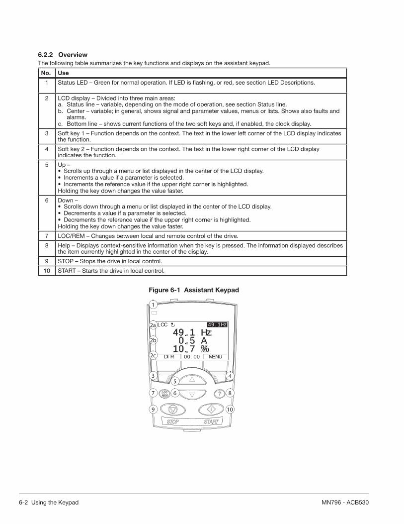
6-2 Using the Keypad MN796 - ACB530
6.2.2 Overview
The following table summarizes the key functions and displays on the assistant keypad.
No. Use
1 Status LED – Green for normal operation. If LED is fl ashing, or red, see section LED Descriptions.
2 LCD display – Divided into three main areas:a. Status line – variable, depending on the mode of operation, see section Status line.b. Center – variable; in general, shows signal and parameter values, menus or lists. Shows also faults and
alarms.c. Bottom line – shows current functions of the two soft keys and, if enabled, the clock display.
3 Soft key 1 – Function depends on the context. The text in the lower left corner of the LCD display indicates the function.
4 Soft key 2 – Function depends on the context. The text in the lower right corner of the LCD display indicates the function.
5 Up –• Scrolls up through a menu or list displayed in the center of the LCD display.• Increments a value if a parameter is selected.• Increments the reference value if the upper right corner is highlighted.Holding the key down changes the value faster.
6 Down –• Scrolls down through a menu or list displayed in the center of the LCD display.• Decrements a value if a parameter is selected.• Decrements the reference value if the upper right corner is highlighted.Holding the key down changes the value faster.
7 LOC/REM – Changes between local and remote control of the drive.
8 Help – Displays context-sensitive information when the key is pressed. The information displayed describes the item currently highlighted in the center of the display.
9 STOP – Stops the drive in local control.
10 START – Starts the drive in local control.
Figure 6-1 Assistant Keypad
LOC
DIR 12:45 MENU
400RPM1200 RPM12.4 A
405 dm3/s
3 45
67 8
9 10
5 A1 Hz
7 %10.0.
49.49.1HzLOC
DIR MENU00:00
1
2a
2b
2c

Using the Keypad 6-3MN796 - ACB530
6.2.3 Status Line
The top line of the LCD display shows the basic status information of the drive.
Figure 6-2 Status Line
49.1HzLOC
1 2 4
LOC MAIN MENU 1
1 2 3 4
No. Field Alternatives Signifi cance
1 Control location LOC Drive control is local, that is, from the keypad.
REM Drive control is remote, such as the drive I/O or fi eldbus.
2 State Forward shaft direction.
Reverse shaft direction.
Rotating arrow Drive is running at setpoint.
Dotted rotating arrow Drive is running but not at setpoint.
Stationary arrow Drive is stopped.
Dotted stationary arrow Start command is present, but the motor is not running, e.g. because start enable is missing.
3 Keypad operationmode
• Name of the current mode.• Name of the list or menu shown.• Name of the operation state, eg PAR EDIT.
4 Reference value or number of the selected item
• Reference value in the Output mode.• Number of the highlighted item, e.g. mode, parameter group
or fault.
6.2.4 Operation
You operate the keypad with menus and keys. The keys include two context-sensitive soft keys, whose current function is indicated by the text shown in the display above each key.
You select an option, e.g. operation mode or parameter, by scrolling the and arrow keys until the option is
highlighted and then pressing the relevant soft key. With the right soft key you usually enter a mode, accept an option
or save the changes. The left soft key is used to cancel the made changes and return to the previous operation level.
The assistant keypad has nine keypad modes: Output mode, Parameter mode, Assistants mode, Changed parameters mode, Fault logger mode, Time and date mode, Parameter backup mode, I/O settings mode and Fault mode. The operation in the fi rst eight modes is described in this chapter. When a fault or alarm occurs, the panel goes automatically to the Fault mode showing the fault or alarm. You can reset it in the Output or Fault mode (see chapter 9 - Troubleshooting and Maintenance).
Initially, the keypad is in the Output mode, where you can start, stop, change the direction, switch between local and remote control, modify the reference value and monitor up to three actual values.
To do other tasks, go fi rst to the Main menu and select the appropriate mode on the menu. The status line (see section Status line) shows the name of the current menu, mode, item or state.
PARAMETERS ASSISTANTSCHANGED PAREXIT ENTER00:00
MAIN MENU 1LOC
5 A1 Hz
7 %10.0.
49.49.1HzLOC
DIR MENU00:00

6-4 Using the Keypad MN796 - ACB530
6.2.4.1 How to do Common Tasks
The table below lists common tasks, the mode in which you can perform them and the page number where the steps to do the task are described in detail.
Task Mode Section
How to get help Any 6.2.4.2
How to fi nd out the keypad version At power up 6.2.4.3
How to adjust the display contrast Output 6.2.5.3
How to switch between local and remote control Any 6.2.4.4
How to start and stop the drive Any 6.2.4.4
How to change the direction of the motor rotation Output 6.2.5.1
How to set the speed, frequency or torque reference Output 6.2.5.2
How to change the value of a parameter Parameters 6.2.6.1
How to select the monitored signals Parameters 6.2.6.2
How to do guided tasks (specifi cation of related parameter sets) with assistants Assistants 6.2.7.1
How to view and edit changed parameters Changed parameters 6.2.8.1
How to view faults Fault logger 6.2.9.1
How to reset faults and alarms Output, Fault Chapter 9
How to show/hide the clock, change date and time formats, set the clock and enable/disable automatic clock transitions according to the daylight saving changes
Time and date 6.2.10.1
How to copy parameters from the drive to the keypad Parameter backup 6.2.11.1
How to restore parameters from the keypad to the drive Parameter backup 6.2.11.1
How to view backup information Parameter backup 6.2.11.2
How to edit and change parameter settings related to I/O terminals I/O settings 6.2.12.1
6.2.4.2 How to Get Help
Step Action Display
1Press ? to read the context-sensitive help text for the item that is highlighted.
If help text exists for the item, it is shown on the display.
01 OPERATING DATA03 FB ACTUAL SIGNALS04 FAULT HISTORY10 START/STOP/DIR11 REFERENCE SELECT
PAR GROUPS 10
EXIT SEL00:00
LOC
EXIT 00:00
This group definesexternal sources(EXT1 and EXT2) forcommands that enablestart, stop and
HELPLOC
2If the whole text is not visible, scroll the lines with keys and .
EXIT 00:00
external sources(EXT1 and EXT2) forcommands that enablestart, stop anddirection changes.
HELPLOC
3After reading the text, return to the previous display by pressing .
01 OPERATING DATA03 FB ACTUAL SIGNALS04 FAULT HISTORY10 START/STOP/DIR11 REFERENCE SELECT
PAR GROUPS 10
EXIT SEL00:00
LOC

Using the Keypad 6-5MN796 - ACB530
6.2.4.3 How to Find out the Panel Version
Step Action Display
1 If the power is switched on, switch it off
2 Keep key ? pressed down while you switch on the power and read the information. The display shows the following keypad information:Panel SW: keypad fi rmware versionROM CRC: keypad ROM check sumFlash Rev: fl ash content versionFlash content comment.When you release the ? key, the panel goes to the Output mode.
Panel FW: x.xxROM CRC: xxxxxxxxxxFlash Rev: x.xxxxxxxxxxxxxxxxxxxxxxx
PANEL VERSION INFO
6.2.4.4 How to Start, Stop and Switch Between Local and Remote Control
You can start, stop and switch between local and remote control in any mode. To be able to start or stop the drive, the drive must be in local control.
Step Action Display
1 • To switch between remote control (REM shown on the status line) and local control (LOC shown on the status line), press .
Note: Switching to local control can be disabled with parameter 1606 LOCAL LOCK.
The very fi rst time the drive is powered up, it is in remote control (REM) and controlled through the drive I/O terminals. To switch to local control (LOC) and control the drive using the keypad, press .
The result depends on how long you press the key:• If you release the key immediately (the display fl ashes “Switching to the local
control mode”), the drive stops. Set the local control reference.• If you press the key for about two seconds, the drive continues as before.
The drive copies the current remote values for the run/stop status and the reference, and uses them as the initial local control settings.
• To stop the drive in local control, press .
• To start the drive in local control, press .
00:00
Switching to thelocal control mode.
MESSAGELOC
The arrow ( or ) on thestatus line stops rotating.
The arrow ( or ) on thestatus line starts rotating. It is dotted until the drive reaches the setpoint.
6.2.5 Output Mode
In the Output mode, you can:• monitor actual values of up to three signals in group 01 OPERATING DATA• change the direction of the motor rotation• set the speed, frequency or torque reference• adjust the display contrast• start, stop, change the direction and switch between local and remote control.
You get to the Output mode by pressing repeatedly.
The top right corner of the display shows the referencevalue. The center can be confi gured to show up to threesignal values or bar graphs. If just one or two signals are selected for display, the number and name of each displayed signal are shown in addition to the value or bar graph. See instructions on selecting and modifying the monitored signals in parameters 3401 - 3421 in Chapter 7.
5 A1 Hz
7 %10.0.
49.49.1HzLOC
DIR MENU00:00
4 A
4 %24.0.
5.0HzLOC
DIR MENU00:00
HZ 50%

6-6 Using the Keypad MN796 - ACB530
6.2.5.1 How to Change the Direction of the Motor Rotation
Step Action Display
1 If you are not in the Output mode, press repeatedly until you get there.
5 A1 Hz
7 %10.0.
49.49.1HzREM
DIR MENU00:00
2 If the drive is in remote control (REM shown on the status line), switch to local control by pressing . The display briefl y shows a message about changing
the mode and then returns to the Output mode.
5 A1 Hz
7 %10.0.
49.49.1HzLOC
DIR MENU00:00
3 To change the direction from forward ( shown on the status line) to reverse ( shown on the status line), or vice versa, press .
Note: Parameter 1003 DIRECTION must be set to 3 (REQUEST).
5 A1 Hz
7 %10.0.
49.49.1HzLOC
DIR MENU00:00
6.2.5.2 How to Set the Speed, Frequency or Torque Reference
Step Action Display
1If you are not in the Output mode, press repeatedly until you get there.
5 A1 Hz
7 %10.0.
49.49.1HzREM
DIR MENU00:00
2 If the drive is in remote control (REM shown on the status line), switch to local control by pressing . The display briefl y shows a message about changing
the mode and then returns to the Output mode.
Note: With group 11 REFERENCE SELECT, you can allow the reference modifi cation in remote control.
5 A1 Hz
7 %10.0.
49.49.1HzLOC
DIR MENU00:00
3 • To increase the highlighted reference value shown in the top right corner of the display, press . The value changes immediately. It is stored in the drive permanent memory and restored automatically after power switch-off.
• To decrease the value, press .
5 A0 Hz
7 %10.0.
50.50.0HzLOC
DIR MENU00:00
6.2.5.3 How to Adjust the Display Contrast
Step Action Display
1If you are not in the Output mode, press repeatedly until you get there.
5 A1 Hz
7 %10.0.
49.49.1HzLOC
DIR MENU00:00
2• To increase the contrast, press keys and simultaneously.• To decrease the contrast, press keys and simultaneously.
5 A1 Hz
7 %10.0.
49.49.1HzLOC
DIR MENU00:00

Using the Keypad 6-7MN796 - ACB530
6.2.6 Parameter Mode
In the Parameter mode, you can:• view and change parameter values• start, stop, change the direction and switch between local and remote control.
6.2.6.1 How to Select a Parameter and Change its Value
Step Action Display
1Go to the Main menu by pressing if you are in the Output mode, otherwise by pressing repeatedly until you get to the Main menu.
PARAMETERS ASSISTANTSCHANGED PAREXIT ENTER00:00
MAIN MENU 1LOC
2 Go to the Parameters mode by selecting PARAMETERSon the menu with keys and , and pressing
.
01 OPERATING DATA03 FB ACTUAL SIGNALS04 FAULT HISTORY10 START/STOP/DIR11 REFERENCE SELECTEXIT SEL00:00
PAR GROUPS 01LOC
3 Select the appropriate parameter group with keysand .
Press .
99 START-UP DATA01 OPERATING DATA03 FB ACTUAL SIGNALS04 FAULT HISTORY10 START/STOP/DIREXIT SEL00:00
PAR GROUPS 99LOC
9901 LANGUAGE
ENGLISH9902 APPLIC MACRO9904 MOTOR CTRL MODE9905 MOTOR NOM VOLT
PARAMETERS
EXIT EDIT00:00
LOC
4Select the appropriate parameter with keys and . The current
value of the parameter is shown below the selected parameter.
Press .
9901 LANGUAGE9902 APPLIC MACRO
ABB STANDARD9904 MOTOR CTRL MODE9905 MOTOR NOM VOLT
PARAMETERS
EXIT EDIT00:00
LOC
9902 APPLIC MACRO
PAR EDIT
ABB STANDARD
CANCEL SAVE00:00[1]
LOC
5 Specify a new value for the parameter with keys and .
Pressing the key once increments or decrements the value. Holding the key down changes the value faster.Pressing the keys simultaneously replaces the displayed value with the default value.
9902 APPLIC MACRO
PAR EDIT
3-WIRE
CANCEL SAVE00:00[2]
LOC
6• To save the new value, press .• To cancel the new value and keep the original, press .
9901 LANGUAGE9902 APPLIC MACRO
3-WIRE9904 MOTOR CTRL MODE9905 MOTOR NOM VOLT
PARAMETERS
EXIT EDIT00:00
LOC

6-8 Using the Keypad MN796 - ACB530
6.2.6.2 How to Select the Monitored Signals
Step Action Display
1 You can select which signals are monitored in the Output mode and how they are displayed with group PANEL DISPLAY parameters. See detailed instructions on changing parameter values.
By default, the display shows three signals. The particular default signalsdepend on the value of parameter 9902 Operating Mode: For operating modes whose default value of parameter 9904 Control Type is 1 (Open Vector), thedefault for signal 1 is 0102 SPEED, otherwise 0103 OUTPUT FREQ. The defaultsfor signals 2 and 3 are always 0104 CURRENT and 0105 TORQUE, respectively.
Signal 1: 0102 SPEED for operating modes ABB 3-Wire, Baldor 2-Wire, Motor Potentiometer, Hand/Auto and Process control; 0103 OUTPUT FREQ for operating mode ABB 2-WireSignal 2: 0104 CURRENTSignal 3: 0105 TORQUE.
To change the default signals, select up to three signals from group OPERATING DATA to be shown.Signal 1: Change the value of parameter 3401 SIGNAL1 PARAM to the index of the signal parameter in group OPERATING DATA (= number of the parameter withoutthe leading zero), e.g. 105 means parameter 0105 TORQUE. Value 100 means that no signal is displayed.
Repeat for signals 2 (3408 SIGNAL2 PARAM) and 3 (3415 SIGNAL3 PARAM).
3401 SIGNAL1 PARAM
PAR EDIT
OUTPUT FREQ
CANCEL SAVE00:00[103]
LOC
3408 SIGNAL2 PARAM
PAR EDIT
CURRENT
CANCEL SAVE00:00[104]
LOC
3415 SIGNAL3 PARAM
PAR EDIT
TORQUE
CANCEL SAVE00:00[105]
LOC
2 Select how you want the signals to be displayed: as a decimal number or a bar graph. For decimal numbers, you can specify the decimal point location, or use thedecimal point location and unit of the source signal (setting 9 [DIRECT]). For details, see parameter 3404.
Signal 1: parameter 3404 OUTPUT1 DSP FORMSignal 2: parameter 3411 OUTPUT2 DSP FORMSignal 3: parameter 3418 OUTPUT3 DSP FORM.
3404 OUTPUT1 DSP FORM
PAR EDIT
DIRECT
CANCEL SAVE00:00[9]
LOC
3 Select the units to be displayed for the signals. This has no effect if parameter 3404/3411/3418 is set to 9 (DIRECT). For details, see parameter 3405.
Signal 1: parameter 3405 OUTPUT1 UNITSignal 2: parameter 3412 OUTPUT2 UNITSignal 3: parameter 3419 OUTPUT3 UNIT.
3405 OUTPUT1 UNIT
PAR EDIT
Hz
CANCEL SAVE00:00[3]
LOC
4 Select the scalings for the signals by specifying the minimum and maximum display values. This has no effect if parameter 3404/3411/3418 is set to 9 (DIRECT).For details, see parameters 3406 and 3407.
Signal 1: parameters 3406 OUTPUT1 MIN and 3407 OUTPUT1 MAXSignal 2: parameters 3413 OUTPUT2 MIN and 3414 OUTPUT2 MAXSignal 3: parameters 3420 OUTPUT3 MIN and 3421 OUTPUT3 MAX.
3406 OUTPUT1 MIN
PAR EDIT
0.0 Hz
CANCEL SAVE00:00
LOC
3407 OUTPUT1 MAX
PAR EDIT
500.0 Hz
CANCEL SAVE00:00
LOC

Using the Keypad 6-9MN796 - ACB530
6.2.7 Assistants Mode
When the drive is fi rst powered up, the Start-up assistant guides you through the setup of the basic parameters. The Start-up assistant is divided into assistants, each of which is responsible for the specifi cation of a related parameter set, for example Motor set-up or PID control. The Start-up assistant activates the assistants one after the other. You may also use the assistants independently. For more information on the tasks of the assistants, see section Start-up assistant.
In the Assistants mode, you can:
• use assistants to guide you through the specifi cation of a set of basic parameters.• start, stop, change the direction and switch between local and remote control.
6.2.7.1 How to Use an Assistant
The table below shows the basic operation sequence which leads you through assistants. The Motor set-up assistant is used as an example.
Step Action Display
1Go to the Main menu by pressing if you are in the Output mode, otherwise by pressing repeatedly until you get to the Main menu.
PARAMETERS ASSISTANTSCHANGED PAREXIT ENTER00:00
MAIN MENU 1LOC
2 Go to the Assistants mode by selecting ASSISTANTS on the menu keys and , and pressing .
Start-up assistantMotor Set-upApplicationSpeed control EXT1Speed control EXT2EXIT SEL00:00
ASSISTANTS 1LOC
3Select the assistant with keys and , and press .
If you select any other assistant than the Start-up assistant, it guides you through the task of specifi cation of its parameter set as shown in steps 4 and 5 below.After that you can select another assistant on the Assistants menu or exit the Assistants mode. The Motor set-up assistant is used here as an example.
If you select the Start-up assistant, it activates the fi rst assistant, which guides you through the task of specifi cation of its parameter set as shown in steps 4 and 5 below. The Start-up assistant then asks if you want to continue with the next assistant or skip it – select the appropriate answer with keys and , and press . If you choose to skip, the Start-up assistant asks the same question about the next assistant, and so on.
Do you want tocontinue withapplication setup?ContinueSkipEXIT OK00:00
CHOICELOC
4 • To specify a new value, press keys and .
• To ask for information on the requested parameter, press key . Scroll the help text with keys and . Close the help by pressing .
EXIT 00:00
Set as given on themotor nameplate.Voltage value mustcorrespond to motorD/Y connection.
HELPLOC
5 • To accept the new value and continue to the setting of the next parameter, press .
• To stop the assistant, press .
9905 MOTOR NOM VOLT
CANCEL SAVE00:00
PAR EDIT
[1]240 V
REM

6-10 Using the Keypad MN796 - ACB530
The table below lists the tasks of the assistants and the relevant drive parameters. Depending on the selection made in the Application task (parameter 9902 Operating Mode), the Start-up Assistant decides which consequent tasks it suggests.
Name Description Set Parameters
Language Select
Selecting the language 9901
Motor Set-Up Setting the motor dataPerforming the motor identifi cation. (If the speed limits are not in the allowed range: Setting the limits.)
9904 - 99099910
Application Selecting the operating mode 9902, parameters associated to the operating mode
Option Modules Activating the option modules Group: Motor Temp MeasGroup: Panel Comm9802
Speed Control EXT1
Selecting the source for the speed reference(If AI1 is used: Setting analog input AI1 limits, scale, inversion)Setting the reference limitsSetting the speed frequency limitsSetting the acceleration and deceleration times
1103(1301 - 1303, 3001)1104, 11052001, 2002, (2007, 2008)2202, 2203
Speed ControlEXT2
Selecting the source for the speed reference(If AI1 is used: Setting analog input AI1 limits, scale, inversion)Setting the reference limits
1106(1301 - 1303, 3001)1107, 1108
Process Control
Selecting the source for the process reference(If AI1 is used: Setting analog input AI1 limits, scale, inversion)Setting the reference limitsSetting the speed (reference) limitsSetting the source and limits for the process actual value
1106(1301 - 1303, 30011107, 11082001, 2002, (2007, 2008)4016, 4018, 4019
Start/ Stop Control
Selecting the source for start and stop signals of the two external control locations, EXT1 and EXT2Selecting between EXT1 and EXT2Defi ning the direction controlDefi ning the start and stop modesSelecting the use of Run Enable signalSelecting timed function status indicated through relay output ROSelecting timed PID1 parameter set 1/2 control
1001, 1002
110210032101 - 2103160114014027
Protections Setting the current and torque limits 2003, 2017
Output Signals Selecting the signals indicated through relay output ROSelecting the signals indicated through analog output AOSetting the minimum, maximum, scaling and inversion
Group: Relay OutputsGroup: Analog Outputs

Using the Keypad 6-11MN796 - ACB530
6.2.8 Changed Parameters Mode
In the Changed parameters mode, you can:
• view a list of all parameters that have been changed from the macro default values• change these parameters• start, stop, change the direction and switch between local and remote control.
6.2.8.1 How to View and Edit Changed Parameters
Step Action Display
1Go to the Main menu by pressing if you are in the Output mode, otherwise by pressing repeatedly until you get to the Main menu.
PARAMETERS ASSISTANTSCHANGED PAREXIT ENTER00:00
MAIN MENU 1LOC
2 Go to the Changed parameters mode by selecting CHANGED PAR on the menu with keys and , and pressing .
1202 CONST SPEED 1 10.0 Hz1203 CONST SPEED 21204 CONST SPEED 39902 APPLIC MACRO
CHANGED PAR
EXIT EDIT00:00
LOC
3 Select the changed parameter on the list with keys and . The value of the selected parameter is shown below it. Press to modify the value.
1202 CONST SPEED 1
PAR EDIT
10.0 Hz
CANCEL SAVE00:00
LOC
4 Specify a new value for the parameter with keys and .
Pressing the key once increments or decrements the value. Holding the key down changes the value faster. Pressing the keys simultaneously replaces the displayedvalue with the default value.
1202 CONST SPEED 1
PAR EDIT
15.0 Hz
CANCEL SAVE00:00
LOC
5• To accept the new value, press . If the new value is the default value, the parameter is removed from the list of changed parameters.
• To cancel the new value and keep the original, press .
1202 CONST SPEED 1 15.0 Hz1203 CONST SPEED 21204 CONST SPEED 39902 APPLIC MACRO
CHANGED PAR
EXIT EDIT00:00
LOC

6-12 Using the Keypad MN796 - ACB530
6.2.9 Fault Logger Mode
In the Fault logger mode, you can:
• view the drive fault history of maximum ten faults (after a power off, only the three latest faults are kept in the memory)• see the details of the three latest faults (after a power off, the details of only the most recent fault is kept in the memory)• read the help text for the fault• start, stop, change the direction and switch between local and remote control.
6.2.9.1 How to View Faults
Step Action Display
1 Go to the Main menu by pressing if you are in the Output mode, otherwise by pressing repeatedly until you get to the Main menu.
PARAMETERS ASSISTANTSCHANGED PAREXIT ENTER00:00
MAIN MENU 1LOC
2 Go to the Fault logger mode by selecting FAULT LOGGER on the menu with keys
and , and pressing . The display shows the fault log starting with the latest fault.
The number on the row is the fault code according to which the causes and corrective actions are listed in chapter Fault tracing.
10: PANEL LOSS
19.03.05 13:04:576: DC UNDERVOLT6: AI1 LOSS
FAULT LOGGER
EXIT DETAIL00:00
LOC
3 To see the details of a fault, select it with keys and , and press .
FAULT 10FAULT TIME 1 13:04:57FAULT TIME 2
PANEL LOSS
EXIT DIAG00:00
LOC
4 To show the help text, press . Scroll the help text with keys and .
After reading the help, press to return to the previous display.
EXIT OK00:00
Check: Comm linesand connections,parameter 3002,parameters in groups10 and 11.
DIAGNOSTICSLOC
6.2.10 Time and Date Mode
In the Time and date mode, you can:
• show or hide the clock• change date and time display formats• set the date and time• enable or disable automatic clock transitions according to the daylight saving changes• start, stop, change the direction and switch between local and remote control.The assistant keypad contains a battery to ensure the function of the clock when the panel is not powered by the drive.

Using the Keypad 6-13MN796 - ACB530
6.2.10.1 How to Show or Hide the Clock, Change Display Formats, Set the Date and Time and Enable or Disable Clock Transitions due to Daylight Saving Changes.
Step Action Display
1Go to the Main menu by pressing if you are in the Output mode, otherwise by pressing repeatedly until you get to the Main menu.
PARAMETERS ASSISTANTSCHANGED PAREXIT ENTER00:00
MAIN MENU 1LOC
2 Go to the Time and date mode by selecting TIME & DATE on the menu with keys and , and pressing .
CLOCK VISIBILITYTIME FORMATDATE FORMATSET TIMESET DATEEXIT SEL00:00
TIME & DATE 1LOC
3• To show (hide) the clock, select CLOCK VISIBLILITY on the menu, press ,
select Show clock (Hide clock) and press , or, if you want to return to theprevious display without making changes, press .
• To specify the date format, select DATE FORMAT on the menu, press and select a suitable format. Press to save or to cancel your changes.
• To specify the time format, select TIME FORMAT on the menu, press and select a suitable format. Press to save or to cancel your changes.
• To set the time, select SET TIME on the menu and press . Specify the hours with keys and , and press .Then specify the minutes. Press to save or to cancel your changes.
• To set the date, select SET DATE on the menu and press . Specify the fi rst part of the date (day or month depending on the selected date format) with keys and , and press . Repeat for the second part. After specifying the year, press . To cancel your changes, press .
• To enable or disable the automatic clock transitions according to the daylight saving changes, select DAYLIGHT SAVING on the menu and press . Pressing opens the help that shows the beginning and end dates of the period during which daylight saving time is used in each country or area whose daylight saving changes you can select to be followed. Scroll the help text with keys and .• To disable automatic clock transitions according to the daylight saving
changes, select Off and press .• To enable automatic clock transitions, select the country or area whose
daylight saving changes are followed and press .• To return to the previous display without making changes, press .
Show clockHide clock
EXIT SEL00:00
CLOCK VISIB 1LOC
dd.mm.yymm/dd/yydd.mm.yyyymm/dd/yyyy
CANCEL OK00:00
DATE FORMAT 1LOC
24-hour12-hour
CANCEL OK00:00
TIME FORMAT 1LOC
SET TIME
CANCEL OK00:00
LOC
15:41
SET DATE
CANCEL OK00:00
LOC
19.03.05
OffEUUSAustralia1:NSW,Vict..Australia2:Tasmania..EXIT SEL00:00
DAYLIGHT SAV 1LOC
EXIT 00:00
EU:On: Mar last SundayOff: Oct last Sunday
US:
HELPLOC

6-14 Using the Keypad MN796 - ACB530
6.2.11 Parameter Backup Mode
The Parameter backup mode is used to export parameters from one drive to another or to make a backup of the drive parameters. Uploading to the panel stores all drive parameters, including up to three user sets, to the assistant keypad. The full set, partial parameter set (application) and user sets can then be downloaded from the keypad to another drive or the same drive. Uploading and downloading can be performed in local control.
The keypad memory is non-volatile and does not depend on the panel battery.
In the Parameter backup mode, you can:• Copy all parameters from the drive to the keypad (UPLOAD TO PANEL). This includes all defi ned user sets of parameters
and internal (not adjustable by the user) parameters such as those created by the ID run.• View the information about the backup stored to the keypad with UPLOAD TO PANEL (BACKUP INFO). This includes eg
the type and rating of the drive where the backup was made. It is useful to check this information when you are going to copy the parameters to another drive with DOWNLOAD FULL SET to ensure that the drives match.
• Restore the full parameter set from the keypad to the drive (DOWNLOAD FULL SET). This writes all parameters, including the internal non-user-adjustable motor parameters, to the drive. It does not include the user sets of parameters.
Note: Only use this function to restore a drive from a backup or to transfer parameters to systems that are identical to the original system.
• Copy a partial parameter set (part of the full set) from the keypad to a drive (DOWNLOAD APPLICATION). The partial set does not include user sets, internal motor parameters, parameters 9905 - 9909, 1607, 5201, nor any group: EXT COMM MODULE and EFB PROTOCOL parameters. The source and target drives and their motor sizes do not need to be the same.
• Copy user set 1 parameters from the keypad to the drive (DOWNLOAD USER SET1). A user set includes group START-UP DATA parameters and the internal motor parameters. The function is only shown on the menu when user set 1 has been fi rst saved using parameter 9902 OPERATING MODE (see section user Operating Modes) and then uploaded to the keypad with UPLOAD TO PANEL.
• Copy user set 2 parameters from the keypad to the drive (DOWNLOAD USER SET2). As DOWNLOAD USER SET1 above.• Copy user set 3 parameters from the keypad to the drive (DOWNLOAD USER SET3). As DOWNLOAD USER SET1 above.• Start, stop, change the direction and switch between local and remote control.

Using the Keypad 6-15MN796 - ACB530
6.2.11.1 How to Upload and Download Parameters
For the upload and download functions available, see above. Note that the drive has to be in local control for uploading and downloading.
Step Action Display
1Go to the Main menu by pressing if you are in the Output mode, otherwise by pressing repeatedly until you get to the Main menu. – If REM is shown onthe status line, press fi rst to switch to local control.
PARAMETERS ASSISTANTSCHANGED PAREXIT ENTER00:00
MAIN MENU 1LOC
2 Go to the Par backup mode by selecting PAR BACKUP on the menu with keys and , and pressing .
UPLOAD TO PANELBACKUP INFODOWNLOAD FULL SETDOWNLOAD APPLICATIONDOWNLOAD USER SET1EXIT SEL00:00
PAR BACKUP 1LOC
3 • To copy all parameters (including user sets and internal parameters) from the drive to the keypad, select UPLOAD TO PANEL on the Par backup menu with keys and , and press . During the transfer, the display shows the transfer status as a percentage of completion. Press if you want to stop the operation.
After the upload is completed, the display shows a message about the completion. Press to return to the Par backup menu.
• To perform downloads, select the appropriate operation (here DOWNLOAD FULL SET is used as an example) on the Par backup menu with keys and
, and press . The display shows the transfer status as a percentage of completion. Press if you want to stop the operation.
After the download is completed, the display shows a message about the completion. Press to return to the Par backup menu.
ABORT 00:00
PAR BACKUPLOC
50%Copying parameters
OK 00:00
Parameter uploadsuccessful.
MESSAGELOC
ABORT 00:00
PAR BACKUPLOC
50%
Downloadingparameters (fullset)
OK 00:00
Parameter downloadsuccessfullycompleted.
MESSAGELOC

6-16 Using the Keypad MN796 - ACB530
6.2.11.2 How to View Information about the Backup
Set Action Display
1Go to the Main menu by pressing if you are in the Output mode, otherwise by pressing repeatedly until you get to the Main menu.
PARAMETERS ASSISTANTSCHANGED PAREXIT ENTER00:00
MAIN MENU 1LOC
2 Go to the Par backup mode by selecting PAR BACKUP on the menu with keys and , and pressing .
UPLOAD TO PANELBACKUP INFODOWNLOAD FULL SETDOWNLOAD APPLICATIONDOWNLOAD USER SET1EXIT SEL00:00
PAR BACKUP 1LOC
3 Select BACKUP INFO on the Par backup menu with keys and , and press . The display shows the following information about the drive where the backup was made:
EXIT 00:00
DRIVE TYPE ACS5503304 DRIVE RATING 4A62i3301 FIRMWARE
BACKUP INFOLOC
EXIT 00:00
ACS5503304 DRIVE RATING 4A62i3301 FIRMWARE 300F hex
BACKUP INFOLOC
DRIVE TYPEDRIVE RATING:
FIRMWARE:
type of the driverating of the drive in format XXXYZ, where XXX: Nominal current rating. If present, an “A” indicates a decimal point, e.g. 4A6 means 4.6 A. Y: 2 = 200 V 4 = 400 V 6 = 600 V Z : i = European loading package n = US loading packagefi rmware version of the drive
You can scroll the information with keys and .
4Press to return to the Par backup menu.
UPLOAD TO PANELBACKUP INFODOWNLOAD FULL SETDOWNLOAD APPLICATIONDOWNLOAD USER SET1EXIT SEL00:00
PAR BACKUP 1LOC

Using the Keypad 6-17MN796 - ACB530
6.2.12 I/O Settings Mode
In the I/O settings mode, you can:
• check the parameter settings related to any I/O terminal• edit the parameter setting. For example, if “1103: REF1” is listed under Ain1 (Analog input 1), that is, parameter 1103
REF1 SELECT has value AI1, you can change its value to e.g. AI2. You cannot, however, set the value of parameter 1106 REF2 SELECT to AI1.
• start, stop, change the direction and switch between local and remote control.
6.2.12.1 How to Edit and Change Parameter Settings Related to I/O Terminals
Step Action Display
1Go to the Main menu by pressing if you are in the Output mode, otherwise by pressing repeatedly until you get to the Main menu.
PARAMETERS ASSISTANTSCHANGED PAREXIT ENTER00:00
MAIN MENU 1LOC
2 Go to the I/O settings mode by selecting I/O SETTINGS on the menu with keys and , and pressing .
DIGITAL INPUTS (DI)ANALOG INPUTS (AI)RELAY OUTPUTS (ROUT)ANALOG OUTPUTS (AOUT)PANELEXIT SEL00:00
I/O SETTINGS 1LOC
3 Select the I/O group, e.g. DIGITAL INPUTS, with keys and , and press . After a brief pause, the display shows the current settings for the selection.
—DI1—1001:START/STOP (E1)—DI2—
—DI3—
I/O SETTINGSLOC
EXIT 00:00
4 Select the setting (line with a parameter number) with keys and , and press .
1001 EXT1 COMMANDS
PAR EDIT
DI1
CANCEL SAVE00:00[1]
LOC
5 Specify a new value for the setting with keys and . Pressing the key once increments or decrements the value. Holding the key down changes the value faster.
Pressing the keys simultaneously replaces the displayed value with the default value.
1001 EXT1 COMMANDS
PAR EDIT
DI1,2
CANCEL SAVE00:00[2]
LOC
6• To save the new value, press .• To cancel the new value and keep the original, press .
—DI1—1001:START/STOP (E1)—DI2—1001:DIR (E1)—DI3—EXIT 00:00
I/O SETTINGSLOC

6-18 Using the Keypad MN796 - ACB530

Parameter Descriptions 7-1MN796 - ACB530
Chapter 7Parameter Descriptions
7.1 Parameters
Table 7-1 Parameter Defi nitions
GroupParameter (Number)
Selection (Value)Parameter Name and Description
START-UP DATA
LANGUAGE (9901) Default: 0 (English)Range: 0 - 2
0 English
1 Spanish
2 French
Selects the display language. There are two different Assistant Control Panels, each supporting a different language set.
OPERATING MODE (9902) Default: 1Range: 1 - 6
1 ABB 2-Wire
2 ABB 3-Wire
3 Baldor 2-Wire
4 Motor Pot
5 Hand/Auto
6 PID Control
Selects an application operating mode. Application macros automatically edit parameters to confi gure the ACB530 for a particular application.NOTE: OPERATING MODE (9902) can only be modifi ed if the drive is stopped.
CONTROL TYPE (9904) Default: 2Range: 1 - 2
1
Open Vector – sensorless vector control mode.• Reference 1 is speed reference in rpm.• Reference 2 is speed reference in % (100% is absolute maximum speed, equal to the value of parameter 2002 MAXIMUM SPEED, or 2001 MINIMUM SPEED if the absolute value of the minimum speed is greater than the maximum speed).
2
V/F Control – scalar control mode.• Reference 1 is frequency reference in Hz.• Reference 2 is frequency reference in % (100% is absolute maximum frequency, equal to the value of parameter 2008 MAXIMUM FREQ, or 2007 MINIMUM FREQ if the absolute value of the minimum speed is greater than the maximum speed).
Selects the motor control mode.NOTE: CONTROL TYPE (9904) can only be modifi ed if the drive is stopped.
MOTOR RATED VOLTS (9905)
Default: -U1-yyyy-2:230V -U1-yyyy-4: 460 V -U1-yyyy-6: 575 VRange: -U1-yyyy-2: 115…345 V -U1-yyyy-4: 230…690 V -U1-yyyy-6: 288…862 V
P 9907
P 9905
Outputfrequency
Output voltage
Defi nes the nominal motor voltage.• Must equal the value on the motor rating plate.• The ACB530 cannot supply the motor with a voltage greater than the input power (mains) voltage.NOTE: MOTOR RATED VOLT (9905) can only be modifi ed if the drive is stopped.

7-2 Parameter Descriptions MN796 - ACB530
GroupParameter (Number)
Selection (Value)Parameter Name and Description
START-UP DATA
(Continued)
MOTOR RATED AMPS (9906)
Default: 1.0 · /2hd
Range: 0.2 · /2hd - 2.0 · /2hd (where /2hd is drive current)
Defi nes the nominal motor current.• Must equal the value on the motor rating plate.NOTE: MOTOR RATED AMPS (9906) can only be modifi ed if the drive is stopped.
MOTOR RATED FREQ (9907)
Default: -01: 50.0 Hz -U1: 60.0 HzRange: 10.0 - 500.0 Hz (typically 50 or 60 Hz)
Defi nes the nominal motor frequency.• Sets the frequency at which output voltage equals the MOTOR RATED FREQ.• Field weakening point = Nom Freq · Supply Volt / Mot Rated FreqNOTE: MOTOR RATED FREQ (9907) can only be modifi ed if the drive is stopped.
MOTOR RATED SPEED (9908)
Default: Dependent Upon SizeRange: 50 - 30,000 RPM
Defi nes the nominal motor speed.• Must equal the value on the motor rating plate.NOTE: MOTOR RATED RPM (9908) can only be modifi ed if the drive is stopped.
MOTOR RATED HP (9909) Default: 1.0 · Phd
Range: 0.2· Phd - 3.0 · Phd
Defi nes the nominal motor power.• Must equal the value on the motor rating plate. NOTE: MOTOR RATED HP (9909) can only be modifi ed if the drive is stopped.
CALC MOTOR MODEL (9910)
Default: 0Range: 0 - 1
0
NO – The CALC MOTOR MODEL process is not run. Identifi cation magnetization is performed, depending on parameter 9904 and 2101 settings. In identifi cation magnetization, the motor model is calculated at fi rst start by magnetizing the motor for 10 to 15 s at zero speed (motor not rotating). The model is recalculated always at start after motor parameter changes.• Parameter 9904 = 1 (OPEN VECTOR): Identifi cation magnetization is performed.• Parameter 9904 = 2 (V/F CONTROL) and parameter 2101 = 3 (SCALAR FLYST) or 5 (FLY + BOOST): Identifi cation magnetization is performed.• Parameter 9904 = 2 (V/F CONTROL) and parameter 2101 has other value than 3 (SCALAR FLYST) or 5 (FLY + BOOST): Identifi cation magnetization is not performed.
1YES – Enables the CALC MOTOR MODEL, during which the motor is rotating, at the next start command. After run completion, this value automatically changes to 0.
This parameter controls a self-calibration process called the CALC MOTOR MODEL. During this process, the drive operates the motor (motor rotating) and makes measurements in order to identify motor characteristics and create a model used for internal calculations. A CALC MOTOR MODEL is especially effective when:• vector control mode is used [parameter 9904 = 1 (OPEN VECTOR) or 2 (V/F CONTROL], and/or - operation point is near zero speed, and/or - operation requires a torque range above the motor nominal torque, over a wide speed range, and without any measured speed feedback (i.e. without a pulse encoder).NOTE: The motor must be de-coupled from the driven equipment.NOTE: If motor parameters are changed after ID Run, repeat the CALC MOTOR MODEL.WARNING! The motor will run at up to approximately 50-80% of the nominal speed during the CALC MOTOR MODEL. The motor will rotate in the forward direction. Ensure that it is safe to run the motor before performing the CALC MOTOR MODEL! See also section How to perform the CALC MOTOR MODEL.NOTE: CALC MOTOR MODEL (9910) can only be modifi ed if the drive is stopped.
Table 7-1 Parameter Defi nitions Continued

Parameter Descriptions 7-3MN796 - ACB530
GroupParameter (Number)
Selection (Value)Parameter Name and Description
OPERATING DATA
(Continued)
MOTOR COSPHI (9915) Default: 0Range: 0 - 0.97
0 IDENTIFIED – Drive identifi es the cos phi automatically by estimation.
0.01 - 0.97 Value entered used as the cos phi.
Defi nes the nominal motor cos phi (power factor). The parameter improves performance especially with high effi ciency motors.NOTE: MOTOR COSPHI (9915) can only be modifi ed if the drive is stopped.
SPEED & DIR (0101) Read OnlyRange: -30000 to 30000 RPM
The calculated signed speed of the motor (rpm). The absolute value of 0101 SPEED & DIR is the same as the value of 0102 SPEED.• The value of 0101 SPEED & DIR is positive if the motor runs in the forward direction.• The value of 0101 SPEED & DIR is negative if the motor runs in the reverse direction.
SPEED (0102) Read Only Range: 0 to 30000 RPM
The calculated speed of the motor (rpm). (Parameter 0102 or 0103 is shown by default in the control panel Output mode.)
OUTPUT FREQ (0103) Read Only Range: 0.0 - 500.0 Hz
The frequency (Hz) applied to the motor. (Parameter 0102 or 0103 is shown by default in the control panel Output mode.)
CURRENT (0104) Read OnlyRange: 0.0 - 2.0 · /2hd
The motor current, as measured by the ACB530. (Shown by default in the control panel Output mode.)
TORQUE (0105) Read OnlyRange: -200.0 to 200.0%
Output torque. Calculated value of torque on motor shaft in % of motor nominal torque. (Shown by default in the control panel Output mode.)
POWER (0106) Read Only Range: -2.0 · Phd to 2.0 · Phd
The measured motor power in kW.
DC BUS VOLTAGE (0107) Read Only Range: 0 · VdN to 2.5 · VdN
The DC bus voltage in V DC, as measured by the ACB530.
OUTPUT VOLTAGE (0109) Default: Range: 0 · VdN to 2.0 · VdN
The voltage applied to the motor.
DRIVE TEMP (0110) Read Only Range: 0.0 - 150.0°C
The temperature of the drive power transistors in degrees Celsius.
EXTERNAL REF 1 (0111) Read Only Range: 0.0 - 500.0 Hz / 0 - 30000 RPM
External reference, REF1, in rpm or Hz – units determined by parameter 9904.
EXTERNAL REF 2 (0112) Read Only Range: 0.0 - 100.0% (0.0 - 600.0% for torque)
External reference, REF2, in %.
Table 7-1 Parameter Defi nitions Continued

7-4 Parameter Descriptions MN796 - ACB530
GroupParameter (Number)
Selection (Value)Parameter Name and Description
OPERATING DATA
(Continued)
CTRL LOCATION (0113) Read Only Range: 0 - 2
0 LOCAL
1 EXT1
2 EXT2
Active control location.
RUN TIME (R) (0114) Read Only Range: 0 - 9999 h
The drive’s accumulated running time in hours (h).• Can be reset by pressing UP and DOWN keys simultaneously when the control panel is in the Parameters mode.
KWH COUNTER (0115) Read Only Range: 0 - 65535 kWh
The drive’s accumulated power consumption in kilowatt hours.• The counter value is accumulated till it reaches 65535 after which the counter rolls over and starts again from 0.• Can be reset by pressing UP and DOWN keys simultaneously when the control panel is in the Parameters mode.
APPL BLK OUTPUT (0116) Read Only Range: 0.0 - 100.0% (0.0 - 600.0% for torque)
Application block output signal. Value is from either:• PFC control, if PFC Control is active, or• Parameter 0112 EXTERNAL REF 2.
DI 1-3 STATUS (0118) Read Only Range: 000 - 111 (0 - 7 decimal)
Status of the three digital inputs.• Status is displayed as a binary number.• 1 indicates that the input is activated.• 0 indicates that the input is deactivated.
DI 4-6 STATUS (0119) Read Only Range: 000 - 111 (0 - 7 decimal)
Status of the three digital inputs.• See parameter 0118 DI 1-3 STATUS.
AI 1 (0120) Read OnlyRange: 0.0 - 100.0%
The relative value of analog input 1 in %.
AI 2 (0121) Read Only Range: 0.0 - 100.0%
The relative value of analog input 2 in %.
RO 1-3 STATUS (0122) Read Only Range: 000 - 111 (0 - 7 decimal)
Status of the three relay outputs.• 1 indicates that the relay is energized.• 0 indicates that the relay is de-energized.
AO 1 (0124) Read Only Range: 0.0 - 20.0mA
The analog output 1 value in milliamperes.
AO 2 (0125) Read Only Range: 0.0 - 20.0mA
The analog output 2 value in milliamperes.
Table 7-1 Parameter Defi nitions Continued
DI 1 DI 2 DI 3
RELAY 1 STATUS
RELAY 2 STATUS
RELAY 3 STATUS

Parameter Descriptions 7-5MN796 - ACB530
GroupParameter (Number)
Selection (Value)Parameter Name and Description
OPERATING DATA
(Continued)
PID 1 OUTPUT (0126) Read Only Range: -1000.0 to 1000.0%
The PID controller 1 output value in %.
PID 1 SETPNT (0128) Read Only Range: Unit and scale defi ned by par. 4006/4106 and 4007/4107
The PID 1 controller setpoint signal.• Units and scale defi ned by PID parameters.
PID 1 FBK (0130) Read Only Range: Unit and scale defi ned by par. 4006/4106 and 4007/4107
The PID 1 controller feedback signal.• Units and scale defi ned by PID parameters.
PID 1 DEVIATION (0132) Read OnlyRange: Unit and scale defi ned by par. 4006/4106 and 4007/4107
The difference between the PID 1 controller reference value and actual value.• Units and scale defi ned by PID parameters.
COMM RO WORD (0134) Read OnlyRange: 0 - 65535
Free data location that can be written from serial link.• Used for relay output control.• See parameter 1401.
COMM VALUE 1 (0135) Read OnlyRange: -32768 to +32767
Free data location that can be written from serial link.
COMM VAULE 2 (0136) Read OnlyRange: -32768 to +32767
Free data location that can be written from serial link.
PROCESS VAR 1 (0137) Read OnlyRange:
Process variable 1• Defi ned by parameters in Group: PANEL DISPLAY.
PROCESS VAR 2 (0138) Read Only Range:
Process variable 2• Defi ned by parameters in Group: PANEL DISPLAY.
PROCESS VAR 3 (0139) Read Only Range:
Process variable 3• Defi ned by parameters in Group: PANEL DISPLAY.
RUN TIME (0140) Read OnlyRange: 0.00 - 499.99 kh
The drive’s accumulated running time in thousands of hours (kh).• Cannot be reset.
MWH COUNTER (0141) Read OnlyRange: 0 - 65535 MWh
The drive’s accumulated power consumption in megawatt hours.• The counter value is accumulated till it reaches 65535 after which the counter rolls over and starts again from 0.• Cannot be reset.
REVOLUTION CNTR (0142) Read Only Range: 0 - 65535 Mrev
The motor’s accumulated revolutions in millions of revolutions.• Can be reset by pressing UP and DOWN keys simultaneously when the control panel is in the Parameters mode.
Table 7-1 Parameter Defi nitions Continued

7-6 Parameter Descriptions MN796 - ACB530
GroupParameter (Number)
Selection (Value)Parameter Name and Description
OPERATING DATA
(Continued)
DRIVE ON TIME HI (0143) Read OnlyRange: 0 - 65535 days
The drive’s accumulated power-on time in days.• Cannot be reset.
DRIVE ON TIME LO (0144) Read Only Range: 00:00:00 - 23:59:58
The drive’s accumulated power-on time in 2 second ticks (30 ticks = 60 seconds).• Shown in format hh.mm.ss.• Cannot be reset.
MOTOR TEMP (0145) Read Only Range: Par. 3501 = 1 to 3: -10 to 200°C Par. 3501 = 4: 0 to 5000 ohm Par. 3501 = 5 to 6: 0 to 1
Motor temperature in degrees Celsius / PTC resistance in ohms.• Applies only if motor temperature sensor is set up.• See parameter 3501.
CB TEMP (0150) Read Only Range: -20.0 to 150.0°C
Temperature of the drive control board in degrees Celsius.Note: Some drives have a control board (OMIO) that does not support this feature. These drives always show the constant value of 25.0°C.
MOT THERM STRESS (0153)
Read Only Range: 0.0 - 100.0%
Estimated rise of the motor temperature. Value equals to the estimated motor thermal stress as a percentage of the motor temperature trip level.
PID COMM VALUE 1 (0158) Read OnlyRange: -32768 to +32767
Data received from fi eldbus for PID control PID1.
PID COMM VALUE 2 (0159) Read Only Range: -32768 to +32767
Data received from fi eldbus for PID control PID1.
SAVED KWH (0174) Read Only Range: 0.0 - 999.9 kWh
Energy saved in kWh compared to the energy used when the pump is connected directly to the supply. Note: The values of saved energy parameters 0174 SAVED KWH, 0175 SAVED MWH, 0176 SAVED AMOUNT 1, 0177 SAVED AMOUNT 2 CO2 are derived from subtracting the drive’s energy econsumed from the direct-on-line (DOL) consumption calculated on the basis of parameter 4508 PUMP POWER. As such, the accuracy of the values is dependent on the accuracy of the power estimate entered in that parameter.• The counter value is accumulated till it reaches 999.9 after which the counter rolls over and starts again from 0.0.• Can be reset with parameter 4509 ENERGY RESET (resets all energy calculators at the same time).• See Group: ENERGY SAVING.
Table 7-1 Parameter Defi nitions Continued

Parameter Descriptions 7-7MN796 - ACB530
GroupParameter (Number)
Selection (Value)Parameter Name and Description
OPERATING DATA
(Continued)
SAVED MWH (0175) Read Only Range: 0 - 65535 MWh
Energy saved in MWh compared to the energy used when the pump is connected directly to the supply. Note: The values of saved energy parameters 0174 SAVED KWH, 0175 SAVED MWH, 0176 SAVED AMOUNT 1, 0177 SAVED AMOUNT 2 CO2 are derived from subtracting the drive’s energy econsumed from the direct-on-line (DOL) consumption calculated on the basis of parameter 4508 PUMP POWER. As such, the accuracy of the values is dependent on the accuracy of the power estimate entered in that parameter.• The counter value is accumulated till it reaches 65535 after which the counter rolls over and starts again from 0.• Can be reset with parameter 4509 ENERGY RESET (resets all energy calculators at the same time).• See Group: ENERGY SAVING.
SAVED AMOUNT 1 (0176) Read Only Range: 0.0 - 999.9
Energy saved in local currency (remainder when the total saved energy is divided by 1000). Note: The values of saved energy parameters 0174 SAVED KWH, 0175 SAVED MWH, 0176 SAVED AMOUNT 1, 0177 SAVED AMOUNT 2 CO2 are derived from subtracting the drive’s energy econsumed from the direct-on-line (DOL) consumption calculated on the basis of parameter 4508 PUMP POWER. As such, the accuracy of the values is dependent on the accuracy of the power estimate entered in that parameter.• To fi nd out the total saved energy in currency units, add the value of parameter 0177 multiplied by 1000 to the value of parameter 0176. Example: 0176 SAVED AMOUNT 1 = 123.4 0177 SAVED AMOUNT 2 = 5 Total saved energy = 5 · 1000 + 123.4 = 5123.4 currency units.• The counter value is accumulated till it reaches 999.9 (the counter does not roll over).• Can be reset with parameter 4509 ENERGY RESET (resets all energy calculators at the same time).• Local energy price is set with parameter 4502 ENERGY PRICE.• See Group: ENERGY SAVING.
SAVED AMOUNT 2 (0177) Read Only Range: 0 - 65535
Energy saved in local currency in thousand currency units. Eg value 5 means 5000 currency units. Note: The values of saved energy parameters 0174 SAVED KWH, 0175 SAVED MWH, 0176 SAVED AMOUNT 1, 0177 SAVED AMOUNT 2 CO2 are derived from subtracting the drive’s energy econsumed from the direct-on-line (DOL) consumption calculated on the basis of parameter 4508 PUMP POWER. As such, the accuracy of the values is dependent on the accuracy of the power estimate entered in that parameter.• The counter value is accumulated till it reaches 65535 (the counter does not roll over).• See parameter 0176 SAVED AMOUNT 1.
Table 7-1 Parameter Defi nitions Continued

7-8 Parameter Descriptions MN796 - ACB530
GroupParameter (Number)
Selection (Value)Parameter Name and Description
OPERATING DATA
(Continued)
SAVED CO2 (0178) Read Only Range: 0.0 - 6553.5 tn
Reduction on carbon dioxide emissions in tn. Note: The values of saved energy parameters 0174 SAVED KWH, 0175 SAVED MWH, 0176 SAVED AMOUNT 1, 0177 SAVED AMOUNT 2 CO2 are derived from subtracting the drive’s energy econsumed from the direct-on-line (DOL) consumption calculated on the basis of parameter 4508 PUMP POWER. As such, the accuracy of the values is dependent on the accuracy of the power estimate entered in that parameter.• The counter value is accumulated till it reaches 6553.5 (the counter does not roll over).• Can be reset with parameter 4509 ENERGY RESET (resets all energy calculators at the same time).• CO2 conversion factor is set with parameter 4507 CO2 CONV FACTOR.• See Group: ENERGY SAVING.
FB ACTUAL SIGNALS
FB CMD WORD 1 (0301) Read Only Range:
Read-only copy of the FieldbusCommand Word 1.• The fi eldbus command is the principal means for controlling the drive from a fi eldbus controller. The command consists of two Command Words. Bit coded instructions in the Command Words switch the drive between states.• To control the drive, using the Command Words, an external location (EXT1 or EXT2) must be active and set to COMM. (See parameters 1001 and 1002.)• The control panel displays the word in hex. For example, all zeros and a 1 in Bit 0 displays as 0001. All zeros and a 1 in Bit 15 displays as 8000.
FB CMD WORD 2 (0302) Read OnlyRange:
Read-only copy of the Fieldbus Command Word 2.• See parameter 0301.
FB STS WORD 1 (0303) Read Only Range:
Read-only copy of the Status Word 1.• The drive sends status information to the fi eldbus controller. The status consists of two Status Words.• The control panel displays the word in hex. For example, all zeros and a 1 in Bit 0 displays as 0001. All zeros and a 1 in Bit 15 displays as 8000.
FB STS WORD 2 (0304) Read Only Range:
Read-only copy of the Status Word 2.• See parameter 0303.
Table 7-1 Parameter Defi nitions Continued
Bit # 0301, FB CMD
WORD 1 0302, FB CMD
WORD 2
0 STOP FBLOCAL_CTL
1 START FBLOCAL_REF
2 REVERSE START_DISABLE1
3 LOCAL START_DISABLE2
4 RESET Reserved
5 EXT2 Reserved
6 RUN_DISABLE Reserved
7 STPMODE_R Reserved
8 STPMODE_EM Reserved
9 STPMODE_C Reserved
10 RAMP_2 Reserved
11 RAMP_OUT_0 REF_CONST
12 RAMP_HOLD REF_AVE
13 RAMP_IN_0 LINK_ON
14 RREQ_LOCALLOC REQ_STARTINH
15 TORQLIM2 OFF_INTERLOCK
Bit # 0303, FB STS
WORD 1 0304, FB STS
WORD 2
0 READY ALARM 1 ENABLED NOTICE 2 STARTED DIRLOCK 3 RUNNING LOCALLOCK 4 ZERO_SPEED CTL_MODE 5 ACCELERATE Reserved 6 DECELERATE Reserved 7 AT_SETPOINT CPY_CTL 8 LIMIT CPY_REF1 9 SUPERVISION CPY_REF2 10 REV_REF REQ_CTL 11 REV_ACT REQ_REF1 12 PANEL_LOCAL REQ_REF2 13 FIELDBUS_LOCAL REQ_REF2EXT 14 EXT2_ACT ACK_STARTINH 15 FAULT ACK_OFF_ILCK

Parameter Descriptions 7-9MN796 - ACB530
GroupParameter (Number)
Selection (Value)Parameter Name and Description
FB ACTUAL SIGNALS
(Continued)
FAULT WORD 1 (0305) Read OnlyRange:
Read-only copy of the Fault Word 1.• When a fault is active, the corresponding bit for the active fault is set in the Fault Words.• Each fault has a dedicated bit allocated within Fault Words.• See section Fault listing for a description of the faults.• The control panel displays the word in hex. For example, all zeros and a 1 in Bit 0 displays as 0001. All zeros and a 1 in Bit 15 displays as 8000.
FAULT WORD 2 (0306) Read OnlyRange:
Read-only copy of the Fault Word 2.• See parameter 0305.
FAULT WORD 3 (0307) Read Only Range:
Read-only copy of the Fault Word 3.• See parameter 0305.
ALARM WORD 1 (0308) Read Only Range:
• When an alarm is active, the corresponding bit for the active alarm is set in the Alarm Words.• Each alarm has a dedicated bit allocated within Alarm Words.• Bits remain set until the whole alarm word is reset. (Reset by writing zero to the word.)• The control panel displays the word in hex. For example, all zeros and a 1 in Bit 0 displaysl as 0001. All zeros and a 1 in Bit 15 displays as 8000.
ALARM WORD 2 (0309) Read OnlyRange:
See parameter 0308.
Table 7-1 Parameter Defi nitions Continued
Bit #
0305, FAULT WORD 1
0306, FAULT WORD 2
0307, FAULT WORD 3
0 OVERCURRENT Obsolete EFB 1
1 DC OVERVOLT THERM FAIL EFB 2
2 DEV OVERTEMP OPEX LINK EFB 3
3 SHORT CIRC OPEX PWR INCOMPATIBLE SW
4 Reserved CURR MEAS USER LOAD CURVE
5 DC UNDERVOLT SUPPLY PHASE Reserved
6 AI1 LOSS ENCODER ERR Reserved
7 AI2 LOSS OVERSPEED Reserved
8 MOT OVERTEMP Reserved Reserved
9 PANEL LOSS DRIVE ID Reserved
10 ID RUN FAIL CONFIG FILE System error
11 MOTOR STALL SERIAL 1 ERR System error
12 CB OVERTEMP EFB CON FILE System error
13 EXT FAULT 1 FORCE TRIP System error
14 EXT FAULT 2 MOTOR PHASE System error
15 EARTH FAULT OUTP WIRING Param. setting fault
Bit # 0308, ALARM WORD 1 0309, ALARM WORD 2
0 OVERCURRENT Reserved
1 OVERVOLTAGE PID SLEEP
2 UNDERVOLTAGE ID RUN
3 DIR LOCK Reserved
4 IO COMM START ENABLE 1 MISSING
5 AI1 LOSS START ENABLE 2 MISSING
6 AI2 LOSS EMERGENCY STOP
7 PANEL LOSS ENCODER ERROR
8 DEVICE OVERTEMP FIRST START
9 MOTOR TEMP Reserved
10 Reserved USER LOAD CURVE
11 MOTOR STALL START DELAY
12 AUTORESET Reserved
13 AUTOCHANGE Reserved
14 PFC I LOCK Reserved
15 Reserved Reserved

7-10 Parameter Descriptions MN796 - ACB530
GroupParameter (Number)
Selection (Value)Parameter Name and Description
FAULT HISTORY
LAST FAULT (0401) Read Only Range: Fault codes (panel displays as text)
0 Clear the fault history (on panel = NO RECORD).
n
Fault code of the last recorded fault. The fault code is displayed as a name. See section Fault listing for the fault codes and names. The fault name shown for this parameter may be shorter than the corresponding name in the fault listing, which shows the names as they are shown in the fault display.
FAULT TIME 1 (0402) Read OnlyRange: Date dd.mm.yy / power-on time in days
The day on which the last fault occurred. Either as:• A date – if real time clock is operating.• The number of days after power on – if real time clock is not used, or was not set.
FAULT TIME 2 (0403) Read Only Range: Time hh.mm.ss
The time at which the last fault occurred. Either as:• Real time, in format hh:mm:ss – if real time clock is operating.• The time since power on (minus the whole days reported in 0402), in format hh:mm:ss – if real time clock is not used, or was not set.• Format on the Basic Control Panel: The time since power on in 2-second ticks (minus the whole days reported in 0402). 30 ticks = 60 seconds. E.g. Value 514 equals 17 minutes and 8 seconds (= 514/30).
SPEED AT FLT (0404) Read Only Range: -32768 to +32767
The motor speed (rpm) at the time the last fault occurred.
FREQ AT FLT (0405) Read Only Range: -3276.8 to +3276.7
The frequency (Hz) at the time the last fault occurred.
VOLTAGE AT FLT (0406) Read OnlyRange: 0.0 - 6553.5
The DC bus voltage (V) at the time the last fault occurred.
CURRENT AT FLT (0407) Read OnlyRange: 0.0 - 6553.5
The motor current (A) at the time the last fault occurred.
TORQUE AT FLT (0408) Read OnlyRange: -3276.8 to +3276.7
The motor torque (%) at the time the last fault occurred.
STATUS AT FLT (0409) Read OnlyRange: 0000 - FFFF hex
The drive status (hex code word) at the time the last fault occurred.
DI 1-3 AT FLT (0410) Read OnlyRange: 000 - 111 (0 - 7 decimal)
The status of digital inputs 1…3 at the time the last fault occurred.
DI 4-6 AT FLT (0411) Read OnlyRange: 000 - 111 (0 - 7 decimal)
The status of digital inputs 4…6 at the time the last fault occurred.
PREVIOUS FAULT 1 (0412) Read OnlyRange: As par. 0401
Fault code of the second last fault. Read-only.
PREVIOUS FAULT 2 (0413)
Read Only Range: As par. 0401
Fault code of the third last fault. Read-only.
Table 7-1 Parameter Defi nitions Continued

Parameter Descriptions 7-11MN796 - ACB530
GroupParameter (Number)
Selection (Value)Parameter Name and Description
START/STOP/DIR
EXT1 COMMANDS (1001) Default: 2 (DI1, 2)Range: 0 - 10
0 NOT SEL – No external start, stop and direction command source.
1
DI1 – Two-wire Start/Stop.• Start/Stop is through digital input DI1 (DI1 activated = Start; DI1 de-activated = Stop).• Parameter 1003 defi nes the direction. Selecting 1003 = 3 (REQUEST) is the same as 1003 = 1 (FORWARD).
2
DI1, 2 – Two-wire Start/Stop, Direction.• Start/Stop is through digital input DI1 (DI1 activated = Start; DI1 de-activated = Stop).• Direction control [requires parameter 1003 = 3 (REQUEST)] is through digital input DI2(DI2 activated = Reverse; de-activated = Forward).
3
DI1P, 2P – Three-wire Start/Stop.• Start/Stop commands are through momentary push-buttons (the P stands for “pulse”).• Start is through a normally open push-button connected to digital input DI1. In order to start the drive, the digital input DI2 must be activated prior to the pulse in DI1.• Connect multiple Start push-buttons in parallel.• Stop is through a normally closed push-button connected to digital input DI2.• Connect multiple Stop push-buttons in series.• Parameter 1003 defi nes the direction. Selecting 1003 = 3 (REQUEST) is the same as 1003 = 1 (FORWARD).
4
DI1P, 2P, 3 – Three-wire Start/Stop, Direction.• Start/Stop commands are through momentary push-buttons, as described for DI1P, 2P.• Direction control [requires parameter 1003 = 3 (REQUEST)] is through digital input DI3(DI3 activated = Reverse; de-activated = Forward).
5
DI1P, 2P, 3P – Start Forward, Start Reverse and Stop.• Start and Direction commands are given simultaneously with two separate momentary push-buttons (the P stands for “pulse”).• Start Forward command is through a normally open push-button connected to digital input DI1. In order to start the drive, the digital input DI3 must be activated prior to the pulse in DI1.• Start Reverse command is through a normally open push-button connected to digital input DI2. In order to start the drive, the digital input DI3 must be activated during the pulse in DI2.• Connect multiple Start push-buttons in parallel.• Stop is through a normally closed push-button connected to digital input DI3.• Connect multiple Stop push-buttons in series.• Requires parameter 1003 = 3 (REQUEST).
6
DI6 – Two-wire Start/Stop.• Start/Stop is through digital input DI6 (DI6 activated = Start; DI6 de-activated = Stop).• Parameter 1003 defi nes the direction. Selecting 1003 = 3 (REQUEST) is the same as 1003 = 1 (FORWARD).
7
DI6, 5 – Two-wire Start/Stop/Direction.• Start/Stop is through digital input DI6 (DI6 activated = Start; DI6 de-activated = Stop).• Direction control [requires parameter 1003 = 3 (REQUEST)] is through digital input DI5.(DI5 activated = Reverse; de-activated = Forward).
8
KEYPAD – Control Panel.• Start/Stop and Direction commands are through the control panel when EXT1 is active.• Direction control requires parameter 1003 = 3 (REQUEST).
Table 7-1 Parameter Defi nitions Continued

7-12 Parameter Descriptions MN796 - ACB530
GroupParameter (Number)
Selection (Value)Parameter Name and Description
START/STOP/DIR
(Continued)
EXT1 COMMANDS (1001)(Continued)
Default: 2 (DI1, 2)Range: 0 - 10
9
DI1F,2R – Start/Stop/Direction commands through DI1 and DI2 combinations.• Start forward = DI1 activated and DI2 de-activated.• Start reverse = DI1 de-activated and DI2 activated.• Stop = both DI1 and DI2 activated, or both de-activated.• Requires parameter 1003 = 3 (REQUEST).
10
COMM – Assigns the fi eldbus Command Word as the source for the start/stop and direction commands.• Bits 0,1, 2 of Command Word 1 (parameter 0301) activates the start/stop and direction commands.• See Fieldbus user’s manual for detailed instructions.
Defi nes external control location 1 (EXT1) – the confi guration of start, stop and direction commands.NOTE: EXT1 COMMANDS (1001) can only be modifi ed if the drive is stopped.
EXT2 COMMANDS (1002) Default: 0 (NOT SEL)Range: 0 - 14
Defi nes external control location 2 (EXT2) – the confi guration of start, stop and direction commands.• See parameter 1001 EXT1 COMMANDS above.NOTE: EXT2 COMMANDS (1002) can only be modifi ed if the drive is stopped.
DIRECTION (1003) Default: 3 Range: 1 - 3
1 FORWARD – Rotation is fi xed in the forward direction.
2 REVERSE – Rotation is fi xed in the reverse direction.
3 REQUEST – Rotation direction can be changed on command.
Defi nes the control of motor rotation direction.NOTE: DIRECTION (1003) can only be modifi ed if the drive is stopped.
JOGGING SEL (1004) Default: 0 (NOT SEL)Range: -6 to 6
0 NOT SEL – Disables the jogging function.
1 DI1 – Activates/de-activates jogging based on the state of DI1 (DI1 activated = jogging active; DI1 de-activated = jogging inactive).
2 to 6 DI2 - DI6 – Activates jogging based on the state of the selected digital input. See DI1 above.
-1 DI1 (INV) – Activates jogging based on the state of DI1 (DI1 activated = jogging inactive; DI1 de-activated = jogging active).
-2 to -6 DI2 (INV) - DI6 (INV) – Activates jogging based on the state of the selected digital input. See DI1 (INV) above.
Defi nes the signal that activates the jogging function. Jogging uses Constant Speed 7 (parameter 1208) for speed reference and ramp pair 2 (parameters 2205 and 2206) for accelerating and decelerating. When the jogging activation signal is lost, the drive uses ramp stop to decelerate to zero speed, even if coast stop is used in normal operation (parameter 2102). The jogging status can be parameterized to relay outputs (parameter 1401). The jogging status is also seen in DCU Profi le status bit 21.NOTE: JOGGING SEL (1004) can only be modifi ed if the drive is stopped.
Table 7-1 Parameter Defi nitions Continued

Parameter Descriptions 7-13MN796 - ACB530
GroupParameter (Number)
Selection (Value)Parameter Name and Description
REFERENCE SELECT
KEYPAD REF SEL (1101) Default: 1 Range: 1 - 2
1[REF1(Hz/rpm)] – Reference type depends on parameter 9904 CONTROL TYPE.• Speed reference (rpm) if 9904 = 1 (OPEN VECTOR).• Frequency reference (Hz) if 9904 = 2 (V/F CONTROL).
2 REF2(%)
Selects the reference controlled in local control mode.
EXT1/EXT2 SEL (1102) Default: 0 Range: -6 to 8,
0EXT1 – Selects external control location 1 (EXT1).• See parameter 1001 EXT1 COMMANDS for EXT1’s Start/Stop/Dir defi nitions.• See parameter 1103 REF1 SELECT for EXT1’s reference defi nitions.
1 DI1 – Assigns control to EXT1 or EXT2 based on the state of DI1 (DI1 activated = EXT2; DI1 de-activated = EXT1).
2 to 6 DI2 - DI6 – Assigns control to EXT1 or EXT2 based on the state of the selected digital input. See DI1 above.
7EXT2 – Selects external control location 2 (EXT2).• See parameter 1002 EXT2 COMMANDS for EXT2’s Start/Stop/Dir defi nitions.• See parameter 1106 REF2 SELECT for EXT2’s reference defi nitions.
8
COMM – Assigns control of the drive via external control location EXT1 or EXT2 based on the fi eldbus control word.• Bit 5 of the Command Word 1 (parameter 0301) defi nes the active external control location (EXT1 or EXT2).• See Fieldbus user’s manual for detailed instructions.
-1 DI1 (INV) – Assigns control to EXT1 or EXT2 based on the state of DI1 (DI1 activated = EXT1; DI1 de-activated = EXT2).
-2 to -6 DI2 (INV) to DI6 (INV) – Assigns control to EXT1 or EXT2 based on the state of the selected digital input. See DI1 (INV) above.
Defi nes the source for selecting between the two external control locations EXT1 or EXT2. Thus, defi nes the source for Start/Stop/Direction commands and reference signals.NOTE: EXT1/EXT2 SEL (1102) can only be modifi ed if the drive is stopped.
Table 7-1 Parameter Defi nitions Continued

Parameter Descriptions 7-14MN796 - ACB530
GroupParameter (Number)
Selection (Value)Parameter Name and Description
REFERENCE SELECT
(Continued)
REF1 SELECT (1103) Default: 1Range: 0 - 17, 20 - 21
0 KEYPAD – Defi nes the control panel as the reference source.
1 AI1 – Defi nes analog input 1 (AI1) as the reference source.
2 AI2 – Defi nes analog input 2 (AI2) as the reference source.
3
AI1/JOYST – Defi nes analog input 1 (AI1), confi gured forjoystick operation, as the reference source.• The minimum input signal runs the drive at the maximum reference in the reverse direction. Defi ne the minimum using parameter 1104.• The maximum input signal runs the drive at maximum reference in the forward direction. Defi ne the maximum using parameter 1105.• Requires parameter 1003 = 3 (REQUEST).
WARNING! Because the low end of the reference range commands full reverse operation, do not use 0 V as the lower end of the reference range. Doing someans that if the control signal is lost (which is a 0 V input) the result is full reverse operation. Instead, use the following set-up so that loss of the analog input triggers a fault, stopping the drive:• Set parameter 1301 MINIMUM AI1 (1304 MINIMUM AI2) at 20% (2V or 4mA).• Set parameter 3021 AI1 FAULT LIMIT to a value 5% or higher.• Set parameter 3001 AI<MIN FUNCTION to 1 (FAULT).
4AI2/JOYST – Defi nes analog input 2 (AI2), confi gured for joystick operation, as the reference source.• See above (AI1/JOYST) description.
5
DI3U, 4D(R) – Defi nes digital inputs as the speed reference source (motor potentiometer control).• Digital input DI3 increases the speed (the U stands for “up”).• Digital input DI4 decreases the speed (the D stands for “down”).• A Stop command resets the reference to zero (the R stands for “reset”).• Parameter 2205 ACCELER TIME 2 controls the reference signal’s rate of change.
6
DI3U, 4D – Same as above (DI3U,4D(R)), except:• A Stop command does not reset the reference to zero. The reference is stored.• When the drive restarts, the motor ramps up (at the selected acceleration rate) to the stored reference.
7 DI5U, 6D – Same as above (DI3U,4D), except that DI5 and DI6 are the digital inputs used.
8 COMM – Defi nes the fi eldbus as the reference source.
9 COMM+AI1 – Defi nes a fi eldbus and analog input 1 (AI1) combination as the reference source. See Analog input reference correction below.
10 COMM*AI1 – Defi nes a fi eldbus and analog input 1 (AI1) combination as the reference source. See Analog input reference correction below.
11DI3U, 4D(RNC) – Same as DI3U,4D(R) above, except that:• Changing the control source (EXT1 to EXT2, EXT2 to EXT1, LOC to REM) does not copy the reference.
12DI3U, 4D(NC) – Same as DI3U,4D above, except that:• Changing the control source (EXT1 to EXT2, EXT2 to EXT1, LOC to REM) does not copy the reference.
13DI5U, 6D(NC) – Same as DI5U,6D above, except that:• Changing the control source (EXT1 to EXT2, EXT2 to EXT1, LOC to REM) does not copy the reference.
14 AI1+AI2 – Defi nes an analog input 1 (AI1) and analog input 2 (AI2) combination as the reference source. See Analog input reference correction below.
Table 7-1 Parameter Defi nitions Continued
+2%-2%
10 V /
Hysteresis 4% of full scale
EXT REF 1 MIN
- EXT REF 1 MIN
- EXT REF 1 MAX
EXT REF 1 MIN
EXT REF 1 MAX
- EXT REF 1 MIN
2 V / 4 mA0 V / 0 mA
20 mA

Parameter Descriptions 7-15MN796 - ACB530
GroupParameter (Number)
Selection (Value)Parameter Name and Description
REFERENCE SELECT
(Continued)
REF1 SELECT (1103)(Continued)
Default: 1Range: 0 - 17, 20 - 21
15 AI1*AI2 – Defi nes an analog input 1 (AI1) and analog input 2 (AI2) combination as the reference source. See Analog input reference correction below.
16 AI1-AI2 – Defi nes an analog input 1 (AI1) and analog input 2 (AI2) combination as the reference source. See Analog input reference correction below.
17 AI1/AI2 – Defi nes an analog input 1 (AI1) and analog input 2 (AI2) combination as the reference source. See Analog input reference correction below.
20
KEYPAD(RNC) – Defi nes the control panel as the reference source.• A Stop command resets the reference to zero (the R stands for reset.).• Changing the control source (EXT1 to EXT2, EXT2 to EXT1) does not copy the reference.
21
KEYPAD(NC) – Defi nes the control panel as the reference source.• A Stop command does not reset the reference to zero. The reference is stored.• Changing the control source (EXT1 to EXT2, EXT2 to EXT1) does not copy the reference.
Selects the signal source for external reference REF1.
Analog input reference correctionParameter values 9, 10 and 14 - 17 use the formula in the following table.
Value Setting Calculation of the AI Reference
C + B C value + (B value - 50% of reference value) C * B C value · (B value / 50% of reference value) C - B (C value + 50% of reference value) - B value C / B (C value · 50% of reference value) / B value
Where:• C = Main reference value( = COMM for values 9, 10 and= AI1 for values 14 - 17).• B = Correcting reference( = AI1 for values 9, 10 and= AI2 for values 14 - 17).Example:The fi gure shows the reference source curves for value settings 9, 10 and 14 - 17, where:• C = 25%.• P 4012 SETPOINT MIN = 0.• P 4013 SETPOINT MAX = 0.• B varies along the horizontal axis.NOTE: REF1 SELECT (1103) can only be modifi ed if the drive is stopped.
Table 7-1 Parameter Defi nitions Continued
120
100
80
60
40
20
00 100%
9, 14 (+)
16 (-)
10, 15 (*)
17 (/)
B

7-16 Parameter Descriptions MN796 - ACB530
GroupParameter (Number)
Selection (Value)Parameter Name and Description
REFERENCE SELECT
(Continued)
REF1 MIN (1104) Default: 0.0 Hz / 0 RPMRange: 0.0 - 500.0 Hz / 0 - 30000 RPMSets the minimum for external reference 1.• The minimum analog input signal (as a percent of the full signal in volts or amperes) corresponds to REF1 MIN in Hz/rpm.• Parameter 1301 MINIMUM AI1 or 1304 MINIMUM AI2 sets the minimum analog input signal.• These parameters (reference and analog min. and max. settings) provide scale and offset adjustment for the reference.
REF1 MAX (1105) Default: 60.0 (62.0) Hz / 1800 RPMRange: 0.0 - 500.0 Hz / 0 - 30000 RPMSets the maximum for external reference 1.• The maximum analog input signal (as a percent of full the signal in volts or amperes) corresponds to REF1 MAX in Hz/rpm.• Parameter 1302 MAXIMUM AI1 or 1305 MAXIMUM AI2 sets the maximum analog input signal.
REF2 SELECT (1106) Default: 2Range: 0 - 17, 19 - 21
0 KEYPAD – Defi nes the control panel as the reference source.
1 AI1 – Defi nes analog input 1 (AI1) as the reference source.
2 AI2 – Defi nes analog input 2 (AI2) as the reference source.
3
AI1/JOYST – Defi nes analog input 1 (AI1), confi gured for joystick operation, as the reference source.• The minimum input signal runs the drive at the maximum reference in the reverse direction. Defi ne the minimum using parameter 1104.• The maximum input signal runs the drive at maximum reference in the forward direction. Defi ne the maximum using parameter 1105.• Requires parameter 1003 = 3 (REQUEST).
WARNING! Because the low end of the reference range commands full reverse operation, do not use 0 V as the lower end of the reference range. Doing someans that if the control signal is lost (which is a 0 V input) the result is full reverse operation. Instead, use the following set-up so that loss of the analog input triggers a fault, stopping the drive:• Set parameter 1301 MINIMUM AI1 (1304 MINIMUM AI2) at 20% (2V or 4mA).• Set parameter 3021 AI1 FAULT LIMIT to a value 5% or higher.• Set parameter 3001 AI<MIN FUNCTION to 1 (FAULT).
4AI2/JOYST – Defi nes analog input 2 (AI2), confi gured for joystick operation, as the reference source.• See above (AI1/JOYST) description.
5
DI3U, 4D(R) – Defi nes digital inputs as the speed reference source (motor potentiometer control).• Digital input DI3 increases the speed (the U stands for “up”).• Digital input DI4 decreases the speed (the D stands for “down”).• A Stop command resets the reference to zero (the R stands for “reset”).• Parameter 2205 ACCELER TIME 2 controls the reference signal’s rate of change.
+2%-2%
10 V /
Hysteresis 4% of full scale
EXT REF 1 MIN
- EXT REF 1 MIN
- EXT REF 1 MAX
EXT REF 1 MIN
EXT REF 1 MAX
- EXT REF 1 MIN
2 V / 4 mA0 V / 0 mA
20 mA
Table 7-1 Parameter Defi nitions Continued
Ext ref
Analog
P 1105
P 1104
P 1301 P 1302
input signal
P 1301 P 1302 input signal
Analog
Ext ref
or 1304 or 1305
or 1304 or 1305
(MAX )
(MIN )
P 1105
P 1104
(MAX )
(MIN )

Parameter Descriptions 7-17MN796 - ACB530
GroupParameter (Number)
Selection (Value)Parameter Name and Description
REFERENCE SELECT
(Continued)
REF2 SELECT (1106) (Continued)
Default: 2Range: 0 - 17, 19 - 21
6
DI3U, 4D – Same as above (DI3U,4D(R)), except:• A Stop command does not reset the reference to zero. The reference is stored.• When the drive restarts, the motor ramps up (at the selected acceleration rate) to the stored reference.
7 DI5U, 6D – Same as above (DI3U,4D), except that DI5 and DI6 are the digital inputs used.
8 COMM – Defi nes the fi eldbus as the reference source.
9 COMM+AI1 – Defi nes a fi eldbus and analog input 1 (AI1) combination as the reference source. See Analog input reference correction below.
10 COMM*AI1 – Defi nes a fi eldbus and analog input 1 (AI1) combination as the reference source. See Analog input reference correction below.
11DI3U, 4D(RNC) – Same as DI3U,4D(R) above, except that:• Changing the control source (EXT1 to EXT2, EXT2 to EXT1, LOC to REM) does not copy the reference.
12DI3U, 4D(NC) – Same as DI3U,4D above, except that:• Changing the control source (EXT1 to EXT2, EXT2 to EXT1, LOC to REM) does not copy the reference.
13DI5U, 6D(NC) – Same as DI5U,6D above, except that:• Changing the control source (EXT1 to EXT2, EXT2 to EXT1, LOC to REM) does not copy the reference.
14 AI1+AI2 – Defi nes an analog input 1 (AI1) and analog input 2 (AI2) combination as the reference source. See Analog input reference correction below.
15 AI1*AI2 – Defi nes an analog input 1 (AI1) and analog input 2 (AI2) combination as the reference source. See Analog input reference correction below.
16 AI1-AI2 – Defi nes an analog input 1 (AI1) and analog input 2 (AI2) combination as the reference source. See Analog input reference correction below.
17 AI1/AI2 – Defi nes an analog input 1 (AI1) and analog input 2 (AI2) combination as the reference source. See Analog input reference correction below.
19 PID1OUT – The reference is taken from the PID1 output. See Group: PROCESS PID SET 1 and Group: PROCESS PID SET 2.
20
KEYPAD(RNC) – Defi nes the control panel as the reference source.• A Stop command resets the reference to zero (the R stands for reset.).• Changing the control source (EXT1 to EXT2, EXT2 to EXT1) does not copy the reference.
21
KEYPAD(NC) – Defi nes the control panel as the reference source.• A Stop command does not reset the reference to zero. The reference is stored.• Changing the control source (EXT1 to EXT2, EXT2 to EXT1) does not copy the reference.
Selects the signal source for external reference REF2.
NOTE: REF2 SELECT (1106) can only be modifi ed if the drive is stopped.
Table 7-1 Parameter Defi nitions Continued
19 =PID1 REF 2SELECT
LIMIT
MAX (1107, 1108)
MIN (1107, 1108)
PFC
If PFC is used
1 - 1720 - 21

7-18 Parameter Descriptions MN796 - ACB530
GroupParameter (Number)
Selection (Value)Parameter Name and Description
REFERENCE SELECT
(Continued)
REF2 MIN (1107) Default: 0.0% Range: 0.0 - 100.0% (0.0 - 600.0% for torque)
Sets the minimum for external reference 2.• The minimum analog input signal (in volts or amperes) corresponds to REF2 MIN in %.• Parameter 1301 MINIMUM AI1 or 1304 MINIMUM AI2 sets the minimum analog input signal.• This parameter sets the minimum frequency reference.• The value is a percentage of the: – maximum frequency or speed – maximum process reference – nominal torque.
REF2 MAX (1108) Default: 100.0% Range: 0.0 - 100.0% (0.0 - 600.0% for torque)
Sets the maximum for external reference 2.• The maximum analog input signal (in volts or amperes) corresponds to REF2 MAX in %.• Parameter 1302 MAXIMUM AI1 or 1305 MAXIMUM AI2 sets the maximum analog input signal.• This parameter sets the maximum frequency reference.• The value is a percentage of the: – maximum frequency or speed – maximum process reference – nominal torque.
CONSTANT SPEEDS
CONST SPEED SEL (1201) Default: 9Range -14 to 19
0 NOT SEL – Disables the constant speed function.
1 DI1 – Selects Constant Speed 1 with digital input DI1.• Digital input activated = Constant Speed 1 activated.
2 - 6 DI2 - DI6 – Selects Constant Speed 1 with digital input DI2 - DI6. See above.
7
DI1, 2 – Selects one of three Constant Speeds (1 - 3) using DI1 and DI2.• Uses two digital inputs, as defi ned below (0 = DI de-activated, 1 = DI activated):
DI1 DI2 Function
0 0 No constant speed 1 0 Constant speed 1 (1202) 0 1 Constant speed 2 (1203) 1 1 Constant speed 3 (1204)
• Can be set up as a so-called fault speed, which is activated if the control signal is lost. Refer to parameter 3001 AI<MIN function and parameter 3002 PANEL COMM ERR.
8 DI2, 3 – Selects one of three Constant Speeds (1 - 3) using DI2 and DI3.• See above (DI1, 2) for code.
9 DI3, 4 – Selects one of three Constant Speeds (1 - 3) using DI3 and DI4.• See above (DI1, 2) for code.
10 DI4, 5 – Selects one of three Constant Speeds (1 - 3) using DI4 and DI5.• See above (DI1, 2) for code.
11 DI5, 6 – Selects one of three Constant Speeds (1 - 3) using DI5 and DI6.• See above (DI1, 2) for code.
Table 7-1 Parameter Defi nitions Continued

Parameter Descriptions 7-19MN796 - ACB530
GroupParameter (Number)
Selection (Value)Parameter Name and Description
CONSTANT SPEEDS
(Continued)
CONST SPEED SEL (1201)(Continued)
Default: 9Range -14 to 19
12
DI1, 2, 3 – Selects one of seven Constant Speeds (1 - 7) using DI1, DI2 and DI3.• Uses three digital inputs, as defi ned below (0 = DI de-activated, 1 = DI activated):
DI1 DI2 D3 Function
0 0 0 No constant speed 1 0 0 Constant speed 1 (1202) 0 1 0 Constant speed 2 (1203) 1 1 0 Constant speed 3 (1204) 0 0 1 Constant speed 4 (1205) 1 0 1 Constant speed 5 (1206) 0 1 1 Constant speed 6 (1207) 1 1 1 Constant speed 7 (1208)
13 DI3, 4, 5 – Selects one of seven Constant Speeds (1 - 7) using DI3, DI4 and DI5.• See above (DI1, 2, 3) for code.
14 DI4, 5, 6 – Selects one of seven Constant Speeds (1 - 7) using DI4, DI5 and DI6.• See above (DI1, 2, 3) for code.
-1 DI1 (INV) – Selects Constant Speed 1 with digital input DI1.• Inverse operation: Digital input de-activated = Constant Speed 1 activated.
-2 to -6 DI2 (INV) - DI6 (INV) – Selects Constant Speed 1 with digital input. See above.
-7
DI1, 2 (INV) – Selects one of three Constant Speeds (1 - 3) using DI1 and DI2.• Inverse operation uses two digital inputs, as defi ned below (0 = DI de-activated, 1 = DI activated):
DI1 DI2 Function
1 1 No constant speed 0 1 Constant speed 1 (1202) 1 0 Constant speed 2 (1203) 0 0 Constant speed 3 (1204)
-8 DI2, 3 (INV) – Selects one of three Constant Speeds (1 - 3) using DI2 and DI3.• See above (DI1, 2 (INV)) for code.
-9 DI3, 4 (INV) – Selects one of three Constant Speeds (1 - 3) using DI3 and DI4.• See above (DI1, 2 (INV)) for code.
-10 DI4, 5 (INV) – Selects one of three Constant Speeds (1 - 3) using DI4 and DI5.• See above (DI1, 2 (INV)) for code.
-11 DI5, 6 (INV) – Selects one of three Constant Speeds (1 - 3) using DI5 and DI6.• See above (DI1, 2 (INV)) for code.
-12
DI1, 2, 3 (INV) – Selects one of seven Constant Speeds (1 - 7) using DI1, DI2 and DI3.• Inverse operation uses three digital inputs, as defi ned below (0 = DI de-activated, 1 = DI activated):
DI1 DI2 D3 Function
1 1 1 No constant speed 0 1 1 Constant speed 1 (1202) 1 0 1 Constant speed 2 (1203) 0 0 1 Constant speed 3 (1204) 1 1 0 Constant speed 4 (1205) 0 1 0 Constant speed 5 (1206) 1 0 0 Constant speed 6 (1207) 0 0 0 Constant speed 7 (1208)
-13DI3, 4, 5 (INV) – Selects one of seven Constant Speeds (1 - 7) using DI3, DI4 and DI5. • See above (DI1, 2, 3 (INV)) for code.
Table 7-1 Parameter Defi nitions Continued

7-20 Parameter Descriptions MN796 - ACB530
GroupParameter (Number)
Selection (Value)Parameter Name and Description
CONSTANT SPEEDS
(Continued)
CONST SPEED SEL (1201)(Continued)
Default: 9Range -14 to 19
-14DI4, 5, 6 (INV) – Selects one of seven Constant Speeds (1 - 7) using DI4, DI5 and DI6. • See above (DI1, 2, 3 (INV)) for code.
Defi nes the digital inputs used to select Constant Speeds. See general comments in introduction.NOTE: CONST SPEED SEL (1201) can only be modifi ed if the drive is stopped.
CONST SPEED 1 (1202) Default: 6.0 Hz / 360 RPMRange: 0.0 - 500.0 Hz / 0 - 30000 RPM
Sets value for Constant Speed 1.• The range and units depend on parameter 9904 CONTROL TYPE.• Range: 0 - 30000 rpm when 9904 = 1 (OPEN VECTOR).• Range: 0 - 500 Hz when 9904 = 2 (V/F CONTROL).
CONST SPEED 2 (1203) Default: 12.0 Hz / 720 RPMRange: 0.0 - 500.0 Hz / 0 - 30000 RPM
Each sets a value for a Constant Speed. See CONST SPEED 1 above. Constant Speed 7 is used also as jogging speed. See parameter 1004 JOGGING SEL.
CONST SPEED 3 (1204) Default: 18.0 Hz / 1080 RPM Range: 0.0 - 500.0 Hz / 0 - 30000 RPM
Each sets a value for a Constant Speed. See CONST SPEED 1 above. Constant Speed 7 is used also as jogging speed. See parameter 1004 JOGGING SEL.
CONST SPEED 4 (1205) Default: 24.0 Hz / 1440 RPM Range: 0.0 - 500.0 Hz / 0 - 30000 RPM
Each sets a value for a Constant Speed. See CONST SPEED 1 above. Constant Speed 7 is used also as jogging speed. See parameter 1004 JOGGING SEL.
CONST SPEED 5 (1206) Default: 30.0 Hz / 1800 RPM Range: 0.0 - 500.0 Hz / 0 - 30000 RPM
Each sets a value for a Constant Speed. See CONST SPEED 1 above. Constant Speed 7 is used also as jogging speed. See parameter 1004 JOGGING SEL.
CONST SPEED 6 (1207) Default: 48.0 Hz / 2880 RPM Range: 0.0 - 500.0 Hz / 0 - 30000 RPM
Each sets a value for a Constant Speed. See CONST SPEED 1 above. Constant Speed 7 is used also as jogging speed. See parameter 1004 JOGGING SEL.
CONST SPEED 7 (1208) Default: 60.0 Hz / 3600 RPMRange: 0.0 - 500.0 Hz / 0 - 30000 RPM
Each sets a value for a Constant Speed. See CONST SPEED 1 above. Constant Speed 7 is used also as jogging speed. See parameter 1004 JOGGING SEL.
ANALOG INPUTS
MINIMUM AI1 (1301) Default: 0.0%Range: 0.0 - 100.0%
Defi nes the minimum value of the analog input.• Defi ne value as a percent of the full analog signal range. See example below.• The minimum analog input signal corresponds to 1104 REF1 MIN or 1107 REF2 MIN.• MINIMUM AI cannot be greater than MAXIMUM AI.• These parameters (reference and analog min. and max. settings) provide scale and offset adjustment for the reference.• See the fi gure at parameter 1104.Example: To set the minimum analog input value to 4 mA: • Confi gure the analog input for 0…20 mA current signal. • Calculate the minimum (4 mA) as a percent of full range (20 mA) = 4mA / 20mA · 100% = 20%
Table 7-1 Parameter Defi nitions Continued

Parameter Descriptions 7-21MN796 - ACB530
GroupParameter (Number)
Selection (Value)Parameter Name and Description
ANALOG INPUTS
(Continued)
MAXIMUM AI1 (1302) Default: 100.0% Range: 0.0 - 100.0%
Defi nes the maximum value of the analog input.• Defi ne value as a percent of the full analog signal range.• The maximum analog input signal corresponds to 1105 REF1 MAX or 1108 REF2 MAX.• See the fi gure at parameter 1104.
FILTER AI1 (1303) Default: 0.1 s Range: 0.0 - 10.0 s
Defi nes the fi lter time constant for analog input 1 (AI1).• The fi ltered signal reaches 63% of a step change within the time specifi ed.
MINIMUM AI2 (1304) Default: 0.0%Range: 0.0 - 100.0%
Defi nes the minimum value of the analog input.• See MINIMUM AI1 above.
MAXIMUM AI2 (1305) Default: 100.0% Range: 0.0 - 100.0%
Defi nes the maximum value of the analog input.• See MAXIMUM AI1 above.
FILTER AI2 (1306) Default: 0.1 s Range: 0.0 - 10.0 s
Defi nes the fi lter time constant for analog input 2 (AI2).• See FILTER AI1 above.
RELAY OUTPUTS
RELAY OUTPUT 1 (1401) Default: 1 Range: 0 - 36, 46, 47, 52
0 NOT SEL – Relay is not used and is de-energized.
1
READY – Energize relay when drive is ready to function. Requires:• Run enable signal present.• No faults exist.• Supply voltage is within range.• Emergency Stop command is not on.
2 RUN – Energize relay when the drive is running.
3 FAULT(-1) – Energize relay when power is applied. De-energizes when a fault occurs.
4 FAULT – Energize relay when a fault is active.
5 ALARM – Energize relay when an alarm is active.
6 REVERSED – Energize relay when motor rotates in reverse direction.
7STARTED – Energize relay when drive receives a start command (even if Run Enable signal is not present). De-energized relay when drive receives a stop command or a fault occurs.
8SUPRV1 OVER – Energize relay when fi rst supervised parameter (3201) exceeds the limit (3203).• See Group: SUPERVISION.
9SUPRV1 UNDER – Energize relay when fi rst supervised parameter (3201) drops below the limit (3202).• See Group: SUPERVISION.
10SUPRV2 OVER – Energize relay when second supervised parameter (3204) exceeds the limit (3206).• See Group: SUPERVISION.
Table 7-1 Parameter Defi nitions Continued
100
63
% Unfiltered signal
Filtered signal
Time constantt

7-22 Parameter Descriptions MN796 - ACB530
GroupParameter (Number)
Selection (Value)Parameter Name and Description
RELAY OUTPUTS(Continued)
RELAY OUTPUT 1 (1401)(Continued)
Default: 1 Range: 0 - 36, 46, 47, 52
11SUPRV2 UNDER – Energize relay when second supervised parameter (3204) drops below the limit (3205).• See Group: SUPERVISION.
12SUPRV3 OVER – Energize relay when third supervised parameter (3207) exceeds the limit (3209).• See Group: SUPERVISION.
13SUPRV3 UNDER – Energize relay when third supervised parameter (3207) drops below the limit (3208).• See Group: SUPERVISION.
14 AT SET POINT – Energize relay when the output frequency is equal to the reference frequency.
15FAULT(RST) – Energize relay when the drive is in a fault condition and will reset after the programmed auto-reset delay.• See parameter 3103 DELAY TIME.
16 FLT/ALARM – Energize relay when fault or alarm occurs.
17 EXT CTRL – Energize relay when external control is selected.
18 REF 2 SEL – Energize relay when EXT2 is selected.
19 CONST FREQ – Energize relay when a constant speed is selected.
20 REF LOSS – Energize relay when reference or active control place is lost.
21 OVERCURRENT – Energize relay when an overcurrent alarm or fault occurs.
22 OVERVOLTAGE – Energize relay when an overvoltage alarm or fault occurs.
23 DRIVE TEMP – Energize relay when a drive or control board overtemperature alarm or fault occurs.
24 UNDERVOLTAGE – Energize relay when an undervoltage alarm or fault occurs.
25 AI1 LOSS – Energize relay when AI1 signal is lost.
26 AI2 LOSS – Energize relay when AI2 signal is lost.
27 MOTOR TEMP – Energize relay when a motor overtemperature alarm or fault occurs.
28 STALL – Energize relay when a stall alarm or fault exists.
30 PID SLEEP – Energize relay when the PID sleep function is active.
33 FLUX READY – Energize relay when the motor is magnetized and able to supply nominal torque (motor has reached nominal magnetizing).
35
COMM – Energize relay based on input from fi eldbus communication.• Fieldbus writes binary code in parameter 0134 that can energize relay 1 - relay 6 according to the following: Par. 0134 Binary RO6 RO5 RO4 RO3 RO2 RO1
0 000000 0 0 0 0 0 0 1 000001 0 0 0 0 0 1 2 000010 0 0 0 0 1 0 3 000011 0 0 0 0 1 1 4 000100 0 0 0 1 0 0
5 - 62 … … … … … … … 63 111111 1 1 1 1 1 1
• 0 = De-energize relay, 1 = Energize relay.
Table 7-1 Parameter Defi nitions Continued

Parameter Descriptions 7-23MN796 - ACB530
GroupParameter (Number)
Selection (Value)Parameter Name and Description
RELAY OUTPUTS(Continued)
RELAY OUTPUT 1 (1401)(Continued)
Default: 1 Range: 0 - 36, 46, 47, 52
36
COMM(-1) – Energize relay based on input from fi eldbus communication.• Fieldbus writes binary code in parameter 0134 that can energize relay 1 - relay 6 according to the following: Par. 0134 Binary RO6 RO5 RO4 RO3 RO2 RO1
0 000000 1 1 1 1 1 1 1 000001 1 1 1 1 1 0 2 000010 1 1 1 1 0 1 3 000011 1 1 1 1 0 0 4 000100 1 1 1 0 1 1
5 - 62 … … … … … … … 63 111111 0 0 0 0 0 0
• 0 = De-energize relay, 1 = Energize relay.
46 START DELAY – Energize relay when a start delay is active.
47 USER LOAD C – Energize relay when a user load curve fault or alarm occurs.
52 JOG ACTIVE – Energize relay when the jogging function is active.
Defi nes the event or condition that activates relay 1 – what relay output 1 means.
RELAY OUTPUT 2 (1402) Default: 2 Range: 0 - 36, 46, 47, 52
Defi nes the event or condition that activates relay 2 – what relay output 2 means.• See 1401 RELAY OUTPUT 1.
RELAY OUTPUT 3 (1403) Default: 3Range: 0 - 36, 46, 47, 52
Defi nes the event or condition that activates relay 3 – what relay output 3 means.• See 1401 RELAY OUTPUT 1.
RO 1 ON DELAY (1404) Default: 0.0 sRange: 0.0 - 3600.0 s
Defi nes the switch-on delay for relay 1.• On / off delays are ignored when relay output 1401 is set to PFC.
RO 1 OFF DELAY (1405) Default: 0.0 sRange: 0.0 - 3600.0 s
Defi nes the switch-off delay for relay 1.• On / off delays are ignored when relay output 1401 is set to PFC.
RO 2 ON DELAY (1406) Default: 0.0 sRange: 0.0 - 3600.0 s
Defi nes the switch-on delay for relay 2.• See RO 1 ON DELAY.
RO 2 OFF DELAY (1407) Default: 0.0 sRange: 0.0 - 3600.0 s
Defi nes the switch-off delay for relay 2.• See RO 1 OFF DELAY.
RO 3 ON DELAY (1408) Default: 0.0 sRange: 0.0 - 3600.0 s
Defi nes the switch-on delay for relay 3.• See RO 1 ON DELAY.
Table 7-1 Parameter Defi nitions Continued
1404 ON DELAY 1405 OFF DELAY
Control event
Relay status

7-24 Parameter Descriptions MN796 - ACB530
GroupParameter (Number)
Selection (Value)Parameter Name and Description
RELAY OUTPUTS(Continued)
RO 3 OFF DELAY (1409) Default: 0.0 sRange: 0.0 - 3600.0 s
Switch-off delay for relay 3.• See RO 1 OFF DELAY.
ANALOG OUTPUTS
AO1 CONTENT SEL (1501) Default: 103 (Parameter 0103 OUPUT FREQ)Range: 99 - 178
99 EXCITE PTC – Provides a current source for sensor type PTC. Output = 1.6mA. See Group: MOTOR TEMP MEAS.
100 EXCITE PT100 – Provides a current source for sensor type PT100. Output = 9.1mA. See Group: MOTOR TEMP MEAS.
101 - 178 Output corresponds to a parameter in Group: OPERATING DATA.• Parameter defi ned by value (value 102 = parameter 0102)
Defi nes the content for analog output AO1.
AO1 CONTENT MIN (1502) Default: Depends on the signal selected with Parameter 1501.Range:
Sets the minimum content value.• Content is the parameter selected by parameter 1501.• Minimum value refers to the minimum content value that will be converted to an analog output.• These parameters (content and current min. and max. settings) provide scale and offset adjustment for the output. See the fi gure.
AO1 CONTENT MAX (1503) Default: Depends on the signal selected with Parameter 1501.Range: -
Sets the maximum content value• Content is the parameter selected by parameter 1501.• Maximum value refers to the maximum content value that will be converted to an analog output.
MINIMUM AO1 (1504) Default: 0.0mARange: 0.0 - 20.0mA
Sets the minimum output current.
MAXIMUM AO1 (1505) Default: 20.0mARange: 0.0 - 20.0mA
Sets the maximum output current.
FILTER AO1 (1506) Default: 0.0 sRange: 0.0 - 10.0 s
Defi nes the fi lter time constant for AO1.• The fi ltered signal reaches 63% of a step change within the time specifi ed.• See the fi gure in parameter 1303.
AO2 CONTENT SEL (1507) Default: 104 (Parameter 0104 CURRENT)Range: 99 - 178
Defi nes the content for analog output AO2. See AO1 CONTENT SEL above.
Table 7-1 Parameter Defi nitions Continued
AO (mA)
AO CONTENTP 1504 /
P 1502 / 1508P 1503 / 1509
AO (mA)
AO CONTENT
P 1505 /
P 1504 /
P 1503 / 1509P 1502 / 1508
P 1505 /P 1511
P 1510
P 1511
P 1510

Parameter Descriptions 7-25MN796 - ACB530
GroupParameter (Number)
Selection (Value)Parameter Name and Description
ANALOG OUTPUTS (Continued)
AO2 CONTENT MIN (1508) Default: Depends on the signal selected with Parameter 1507.Range: -
Sets the minimum content value. See AO1 CONTENT MIN above.
AO2 CONTENT MAX (1509) Default: Depends on the signal selected with Parameter 1507.Range: -
Sets the maximum content value. See AO1 CONTENT MAX above.
MINIMUM AO2 (1510) Default: 0.0mARange: 0.0 - 20.0mA
Sets the maximum content value. See AO1 CONTENT MAX above.
MAXIMUM AO2 (1511) Default: 20.0mARange: 0.0 - 20.0mA
Sets the maximum output current. See MAXIMUM AO1 above.
FILTER AO2 (1512) Default: 0.1 sRange: 0.0 - 10.0 s
Defi nes the fi lter time constant for AO2. See FILTER AO1 above.
SYSTEM CONTROLS
RUN ENABLE (1601) Default: 0 (NOT SEL)Range: -6 to 7
0 NOT SEL – Allows the drive to start without an external run enable signal.
1
DI1 – Defi nes digital input DI1 as the run enable signal.• This digital input must be activated for run enable.• If the voltage drops and de-activates this digital input, the drive will coast to stop and not start until the run enable signal resumes.
2 to 6 DI2 - DI6 – Defi nes digital input DI2 - DI6 as the run enable signal.• See DI1 above.
7
COMM – Assigns the fi eldbus Command Word as the source for the run enable signal.• Bit 6 of the Command Word 1 (parameter 0301) activates the run disable signal.• See fi eldbus user’s manual for detailed instructions.
-1
DI1 (INV) – Defi nes an inverted digital input DI1 as the run enable signal.• This digital input must be de-activated for run enable.• If this digital input activates, the drive will coast to stop and not start until the run enable signal resumes.
-2 to -6DI2 (INV) - DI6 (INV) – Defi nes an inverted digital input DI2 - DI6 as the run enable signal.• See DI1 (INV) above.
Selects the source of the run enable signal.NOTE: RUN ENABLE (1601) can only be modifi ed if the drive is stopped.
PARAMETER LOCK (1602) Default: 1 (OPEN)Range: 0 - 2
0 LOCKED – You cannot use the control panel to change parameter values.• The lock can be opened by entering the valid pass code to parameter 1603.
1 OPEN – You can use the control panel to change parameter values.
2
NOT SAVED – You can use the control panel to change parameter values, but they are not stored in permanent memory.• Set parameter 1607 PARAM SAVE to 1 (SAVE) to store changed parameter values to memory.
Determines if the control panel can change parameter values.• This lock does not limit parameter changes made by macros.• This lock does not limit parameter changes written by fi eldbus inputs.• This parameter value can be changed only if the correct pass code is entered. See parameter 1603 PASS CODE.
Table 7-1 Parameter Defi nitions Continued

7-26 Parameter Descriptions MN796 - ACB530
GroupParameter (Number)
Selection (Value)Parameter Name and Description
SYSTEM CONTROLS(Continued)
PASS CODE (1603) Default: 0Range: 0 - 65535
Entering the correct pass code allows you to change the parameter lock.• See parameter 1602 above.• The code 358 allows you to change the value of the parameter 1602 once.• This entry reverts back to 0 automatically.
FAULT RESET SEL (1604) Default: 0 (KEYPAD)Range: -6 to 8
0 KEYPAD – Defi nes the control panel as the only fault reset source.• Fault reset is always possible with control panel.
1 DI1 – Defi nes digital input DI1 as a fault reset source.• Activating the digital input resets the drive.
2 to 6 DI2 - DI6 – Defi nes digital input DI2 - DI6 as a fault reset source.• See DI1 above.
7START/STOP – Defi nes the Stop command as a fault reset source.• Do not use this option when fi eldbus communication provides the start, stop and direction commands.
8COMM – Defi nes the fi eldbus as a fault reset source.• The Command Word is supplied through fi eldbus communication.• The bit 4 of the Command Word 1 (parameter 0301) resets the drive.
-1 DI1 (INV) – Defi nes an inverted digital input DI1 as a fault reset source.• De-activating the digital input resets the drive.
-2 to -6DI2 (INV) - DI6 (INV) – Defi nes an inverted digital input DI2 - DI6 as a fault reset source.• See DI1 (INV) above.
Selects the source for the fault reset signal. The signal resets the drive after a fault trip if the cause of the fault no longer exists.
LOCAL LOCK (1606) Default: 0 (NOT SEL)Range: -6 to 7
0 NOT SEL – Disables the lock. The control panel can select LOC and control the drive.
1DI1 – Defi nes digital input DI1 as the control for setting the local lock.• Activating the digital input locks out local control.• De-activating the digital input enable the LOC selection.
2 to 6 DI2 - DI6 – Defi nes digital input DI2 - DI6 as the control for setting the local lock.• See DI1 above.
7 ON – Sets the lock. The control panel cannot select LOC and cannot control the drive.
8
COMM – Defi nes bit 14 of the Command Word 1 as the control for setting the local lock.• The Command Word is supplied through fi eldbus communication.• The Command Word is 0301.
-1
DI1 (INV) – Defi nes an inverted digital input DI1 as the control for setting the local lock.• De-activating the digital input locks out local control.• Activating the digital input enable the LOC selection.
-2 to -6DI2 (INV) - DI6 (INV) – Defi nes an inverted digital input DI2 - DI6 as the control for setting the local lock.• See DI1(INV) above.
Defi nes control for the use of the LOC mode. The LOC mode allows drive control from the control panel.• When LOCAL LOCK is active, the control panel cannot change to LOC mode.
Table 7-1 Parameter Defi nitions Continued

Parameter Descriptions 7-27MN796 - ACB530
GroupParameter (Number)
Selection (Value)Parameter Name and Description
SYSTEM CONTROLS(Continued)
PARAM SAVE (1607) Default: 0 (DONE)Range: 0 - 1
0 DONE – Value changes automatically when all parameters are saved.
1 SAVE… – Saves altered parameters to permanent memory.
Saves all altered parameters to permanent memory.• Parameters altered through a fi eldbus are not automatically saved to permanent memory. To save, you must use this parameter.• If 1602 PARAMETER LOCK = 2 (NOT SAVED), parameters altered from the control panel are not saved. To save, you must use this parameter.• If 1602 PARAMETER LOCK = 1 (OPEN), parameters altered from the control panel are stored immediately to permanent memory.
START ENABLE 1 (1608) Default: 0 (NOT SEL)Range: -6 to 7
0 Selects the source of the start enable 1 signal.Note: Start enable functionality differs from the run enable functionality.
1
SDI1 – Defi nes digital input DI1 as the start enable 1 signal.• This digital input must be activated for start enable 1 signal.• If the voltage drops and de-activates this digital input, the drive will coast to stop and show alarm 2021 on the panel display. The drive will not start until start enable 1 signal resumes.
2 to 6 DI2 - DI6 – Defi nes digital input DI2 - DI6 as the start enable 1 signal.• See DI1 above.
7
COMM – Assigns the fi eldbus Command Word as the source for the start enable 1 signal.• Bit 2 of the Command word 2 (parameter 0302) activates the start disable 1 signal.• See fi eldbus user’s manual for detailed instructions.
-1 DI1 (INV) – Defi nes an inverted digital input DI1 as the start enable 1 signal.
-2 to -6DI2 (INV) - DI6 (INV) – Defi nes an inverted digital input DI2 - DI6 as the start enable 1 signal.• See DI1 (INV) above.
Selects the source of the start enable 1 signal.Note: Start enable functionality differs from the run enable functionality.
Drive startedSTART/STOPCOMMAND(Group 10)
1608 & 1609)
Relay energizedRelayde-energized
Damper open
Damper
time
Damper closingtime
STARTEDRELAY STATUS(Group 14)
DAMPER STATUS
Damperclosed
RUN ENABLE SIGNALfrom the damper end switch when the damper is fully opened.(Parameter 1601)
MOTOR STATUS
Acceleration time
START ENABLE SIGNAL(Parameters
Damperclosed
opening
(Par 2202)
Drive coaststo stop
NOTE: START ENABLE 1 (1608) can only be modifi ed if the drive is stopped.
Table 7-1 Parameter Defi nitions Continued

7-28 Parameter Descriptions MN796 - ACB530
GroupParameter (Number)
Selection (Value)Parameter Name and Description
SYSTEM CONTROLS(Continued)
START ENABLE 2 (1609) Default: 0 (NOT SEL)Range: -6 to 7
0 NOT SEL – Allows the drive to start without an external start enable signal.
1
DI1 – Defi nes digital input DI1 as the start enable 2 signal.• This digital input must be activated for start enable 2 signal.• If the voltage drops and de-activates this digital input, the drive will coast to stop and show alarm 2022 on the panel display. The drive will not start until start enable 2 signal resumes.
2 to 6 DI2 - DI6 – Defi nes digital input DI2 - DI6 as the start enable 2 signal.• See DI1 above.
7
COMM – Assigns the fi eldbus Command Word as the source for the start enable 2 signal. Bit 3 of the Command word 2 (parameter 0302) activates the start disable 2 signal.• See fi eldbus user’s manual for detailed instructions.
-1 DI1 (INV) – Defi nes an inverted digital input DI1 as the start enable 2 signal.
-2 to -6DI2 (INV) - DI6 (INV) – Defi nes an inverted digital input DI2 - DI6 as the start enable 2 signal.• See DI1 (INV) above.
Selects the source of the start enable 2 signal.Note: Start enable functionality differs from the run enable functionality.NOTE: START ENABLE 2 (1609) can only be modifi ed if the drive is stopped.
DISPLAY ALARMS (1610) Default: 0 (NO)Range: 0 - 1
0 NO – The above alarms are suppressed.
1 YES – All of the above alarms are enabled.
Controls the visibility of the following alarms:• 2001, Overcurrent alarm• 2002, Overvoltage alarm• 2003, Undervoltage alarm• 2009, Device overtemperature alarm.For more information, see section Alarm listing.
LIMITS MINIMUM SPEED (2001) Default: 0 RPMRange: -30000 to 30000 RPM
Defi nes the minimum speed (rpm) allowed.• A positive (or zero) minimum speed value defi nes two ranges,one positive and one negative.• A negative minimum speed value defi nes one speed range.• See the fi gure.NOTE: MINIMUM SPEED (2001) can only be modifi ed if the drive is stopped.
MAXIMUM SPEED (2002) Default: -01: 1500 RPM/ -U1: 1800 RPMRange: 0 to 30000 RPM
Defi nes the maximum speed (rpm) allowed.NOTE: MAXIMUM SPEED (2002) can only be modifi ed if the drive is stopped.
MAX CURRENT (2003) Default: 1.8 · /2hd
Range: 0 - 1.8 · /2hd
Defi nes the maximum output current (A) supplied by the drive to the motor.NOTE: MAX CURRENT (2003) can only be modifi ed if the drive is stopped.
Table 7-1 Parameter Defi nitions Continued
P 2001
P 2002Speed
-(P 2001)
-(P 2002)
P 2002
P 2001
Speed range allowed
Speed range allowed
Speed range allowed
Time
Speed
Time
2001 value is > 0
0
0
2001 value is < 0

Parameter Descriptions 7-29MN796 - ACB530
GroupParameter (Number)
Selection (Value)Parameter Name and Description
LIMITS(Continued)
OVERVOLT CTRL (2005) Default: 1 (ENABLE)Range: 0 - 1
0 DISABLE – Disables controller.
1
ENABLE – Enables controller.Note: If a braking chopper or a braking resistor is connected to the drive, this parameter value must be set to 0 (DISABLE) to ensure proper operation of the chopper.
Sets the DC overvoltage controller on or off.• Fast braking of a high inertia load causes the DC bus voltage to rise to the overvoltage control limit. To prevent the DC voltage from exceeding the trip limit, the overvoltage controller automatically decreases the braking torque by increasing output frequency.
UNDERVOLT CTRL (2006) Default: 1 [ENABLE (TIME)]Range: 0 - 2
0 DISABLE – Disables controller.
1 ENABLE (TIME) – Enables controller with 500 ms time limit for operation.
2 ENABLE – Enables controller without maximum time limit for operation.
Sets the DC undervoltage controller on or off. When on:• If the DC bus voltage drops due to loss of input power, the undervoltage controller decreases the motor speed in order to keep the DC bus voltage above the lower limit.• When the motor speed decreases, the inertia of the load causes regeneration back into the drive, keeping the DC bus charged and preventing an undervoltage trip.• The DC undervoltage controller increases power loss ride-through on systems with a high inertia, such as a centrifuge or a fan.
MINIMUM FREQ (2007) Default: 0.0 HzRange: -500.0 to 500.0 Hz
Defi nes the minimum limit for the drive output frequency.• A positive or zero minimum frequency value defi nes two ranges, one positive and one negative.• A negative minimum frequency value defi nes one speed range.See the fi gure.NOTE: Keep MINIMUM FREQ ≤ MAXIMUM FREQ.NOTE: MINIMUM FREQ (2007) can only be modifi ed if the drive is stopped.
MAXIMUM FREQ (2008) Default: 60.0 (62.0) HzRange: 0.0 to 500.0 Hz
Defi nes the maximum limit for the drive output frequency.NOTE: MAXIMUM FREQ (2008) can only be modifi ed if the drive is stopped.
MIN TORQUE 1 (2015) Default: -300.0%Range: -600.0 to 0.0%
Sets the fi rst minimum limit for torque (%). Value is a percent of the motor nominal torque.
MAX TORQUE 1 (2017) Default: 300.0%Range: 0.0 to 600.0
Sets the fi rst maximum limit for torque (%). Value is a percent of the motor nominal torque.
Table 7-1 Parameter Defi nitions Continued
P 2007
P 2008Freq
-(P 2007)
-(P 2008)
P 2008
P 2007
Frequency range allowed
Frequency range allowed
Frequency range allowed
Time
Freq
Time
2007 value is > 0
0
0
2007 value is < 0

7-30 Parameter Descriptions MN796 - ACB530
GroupParameter (Number)
Selection (Value)Parameter Name and Description
START/STOP START FUNCTION (2101) Default: 8 (RAMP)Range: 0.0 to 600.0
1
AUTO – Selects the automatic start mode.• Vector control modes: Optimal start in most cases. The drive automatically selects the correct output frequency to start a rotating motor.• V/F CONTROL mode: Immediate start from zero frequency. Identical to selection 8 = RAMP.
2
DC MAGN – Selects the DC Magnetizing start mode.Note: The DC Magnetizing start mode cannot start a rotating motor.Note: The drive starts when the set pre-magnetizing time (parameter 2103 DC MAGN TIME) has passed, even if motor magnetization is not complete.• Vector control modes: Magnetizes the motor within the time determined by the parameter 2103 DC MAGN TIME using DC current. The normal control is released exactly after the magnetizing time. This selection guarantees the highest possible break-away torque.• V/F CONTROL mode: Magnetizes the motor within the time determined by the parameter 2103 DC MAGN TIME using DC current. The normal control is released exactly after the magnetizing time.
3
SCALAR FLYST – Selects the fl ying start mode.• Vector control modes: Not applicable.• V/F CONTROL mode: The drive automatically selects the correct output frequency to start a rotating motor – useful if the motor is already rotating and if the drive will start smoothly at the current frequency.• Cannot be used in multimotor systems.
4
TORQ BOOST – Selects the automatic torque boost mode (V/F CONTROL mode only).• May be necessary in drives with high starting torque.• Torque boost is only applied at start, ending when output frequency exceeds 20 Hz or when output frequency is equal to reference.• In the beginning the motor magnetizes within the time determined by the parameter 2103 DC MAGN TIME using DC current.• See parameter 2110 TORQ BOOST CURR.
5
FLY + BOOST – Selects both the fl ying start and the torque boost mode (V/F CONTROL mode only).• Flying start routine is performed fi rst and the motor is magnetized. If the speed is found to be zero, the torque boost is done.
8 RAMP – Immediate start from zero frequency.
Selects the motor start method. The valid options depend on the value of parameter 9904 CONTROL TYPE.NOTE: START FUNCTION (2101) can only be modifi ed if the drive is stopped.
STOP FUNCTION (2102) Default: 1 (COAST)Range: 1 - 2
1 COAST – Selects cutting off the motor power as the stop method. The motor coasts to stop.
2RAMP – Selects using a deceleration ramp.• Deceleration ramp is defi ned by 2203 DECELER TIME 1 or 2206 DECELER TIME 2 (whichever is active).
Selects the motor stop method.
DC MAGN TIME (2103) Default: 0.30 sRange: 0.00 - 10.00 s
Defi nes the pre-magnetizing time for the DC Magnetizing start mode.• Use parameter 2101 to select the start mode.• After the start command, the drive pre-magnetizes the motor for the time defi ned here and then starts the motor.• Set the pre-magnetizing time just long enough to allow full motor magnetization. Too long a time heats the motor excessively.
Table 7-1 Parameter Defi nitions Continued

Parameter Descriptions 7-31MN796 - ACB530
GroupParameter (Number)
Selection (Value)Parameter Name and Description
START/STOP(Continued)
DC HOLD CTL (2104) Default: 0 (NOT SEL)Range: 0 - 2
0 NOT SEL – Disables the DC current operation.
1
DC HOLD – Enables the DC Hold function. See the diagram.• Requires parameter 9904 CONTROL TYPE = 1 (OPEN VECTOR)• Stops generating sinusoidal current and injects DC into the motor when both the reference and the motor speed drop below the value of parameter 2105.• When the reference rises above the level of parameter 2105 the drive resumes normal operation.
2
DC BRAKING – Enables the DC Injection Braking after modulation has stopped.• If parameter 2102 STOP FUNCTION is 1 (COAST), braking is applied after start is removed.• If parameter 2102 STOP FUNCTION is 2 (RAMP), braking is applied after ramp.
Selects whether DC current is used for braking or DC Hold.NOTE: DC HOLD CTL (2104) can only be modifi ed if the drive is stopped.
DC HOLD SPEED (2105) Default: 5 RPMRange: 0 - 360 RPM
Sets the speed for DC Hold. Requires that parameter 2104 DC HOLD CTL = 1 (DC HOLD).
DC CURR REF (2106) Default: 30%Range: 0 - 100%
Defi nes the DC current control reference as a percentage of parameter 9906 MOTOR NOM CURR.
DC BRAKE TIME (2107) Default: 0.0 sRange: 0.0 - 250.0 s
Defi nes the DC brake time after modulation has stopped, if parameter 2104 is 2 (DC BRAKING).
START INHIBIT (2108) Default: 0 (OFF)Range: 0 - 1
0 OFF – Disables the Start inhibit function.
1 ON – Enables the Start inhibit function.
Sets the Start inhibit function on or off. If the drive is not actively started and running, the Start inhibit function ignores a pending start command in any of the following situations and a new start command is required:• A fault is reset.• Run Enable (parameter 1601) activates while start command is active.• Mode changes from local to remote.• Control switches from EXT1 to EXT2.• Control switches from EXT2 to EXT1.
Table 7-1 Parameter Defi nitions Continued
speed
Ref
DC hold
DC hold
Motor
speed T
T
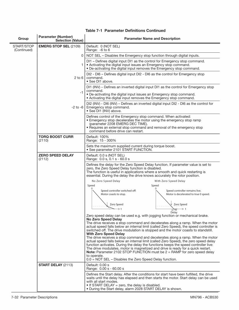
7-32 Parameter Descriptions MN796 - ACB530
GroupParameter (Number)
Selection (Value)Parameter Name and Description
START/STOP(Continued)
EMERG STOP SEL (2109) Default: 0 (NOT SEL)Range: -6 to 6
0 NOT SEL – Disables the Emergency stop function through digital inputs.
1DI1 – Defi nes digital input DI1 as the control for Emergency stop command.• Activating the digital input issues an Emergency stop command.• De-activating the digital input removes the Emergency stop command.
2 to 6DI2 - DI6 – Defi nes digital input DI2 - DI6 as the control for Emergency stop command.• See DI1 above.
-1
DI1 (INV) – Defi nes an inverted digital input DI1 as the control for Emergency stop command.• De-activating the digital input issues an Emergency stop command.• Activating the digital input removes the Emergency stop command.
-2 to -6DI2 (INV) - DI6 (INV) – Defi nes an inverted digital input DI2 - DI6 as the control for Emergency stop command.• See DI1 (INV) above.
Defi nes control of the Emergency stop command. When activated:• Emergency stop decelerates the motor using the emergency stop ramp (parameter 2208 EMERG DEC TIME).• Requires an external stop command and removal of the emergency stop command before drive can restart.
TORQ BOOST CURR (2110)
Default: 100%Range: 15 - 300%
Sets the maximum supplied current during torque boost.• See parameter 2101 START FUNCTION.
ZERO SPEED DELAY (2112)
Default: 0.0 s (NOT SEL)Range: 0.0 s, 0.1 s - 60.0 s
Defi nes the delay for the Zero Speed Delay function. If parameter value is set to zero, the Zero Speed Delay function is disabled.The function is useful in applications where a smooth and quick restarting is essential. During the delay the drive knows accurately the rotor position.
Speed
t
Zero Speed
Speed
t
Zero Speed
Delay
yaleD deepS oreZ htiWyaleD deepS oreZ oN
Speed controller switched off: Motor coasts to stop.
Speed controller remains live. Motor is decelerated to true 0 speed.
Zero speed delay can be used e.g. with jogging function or mechanical brake.No Zero Speed DelayThe drive receives a stop command and decelerates along a ramp. When the motor actual speed falls below an internal limit (called Zero Speed), the speed controller is switched off. The drive modulation is stopped and the motor coasts to standstill.With Zero Speed DelayThe drive receives a stop command and decelerates along a ramp. When the motor actual speed falls below an internal limit (called Zero Speed), the zero speed delay function activates. During the delay the functions keeps the speed controller live: The drive modulates, motor is magnetized and drive is ready for a quick restart.Note: Parameter 2102 STOP FUNCTION must be 2 = RAMP for zero speed delay to operate.0.0 = NOT SEL – Disables the Zero Speed Delay function.
START DELAY (2113) Default: 0.00 sRange: 0.00 s - 60.00 s
Defi nes the Start delay. After the conditions for start have been fulfi lled, the drive waits until the delay has elapsed and then starts the motor. Start delay can be used with all start modes.• If START DELAY = zero, the delay is disabled.• During the Start delay, alarm 2028 START DELAY is shown.
Table 7-1 Parameter Defi nitions Continued

Parameter Descriptions 7-33MN796 - ACB530
GroupParameter (Number)
Selection (Value)Parameter Name and Description
ACCEL/DECEL ACC/DEC 1/2 SEL (2201) Default: 5 (DI5)Range: -6 to 7
0 NOT SEL – Disables selection, the fi rst ramp pair is used.
1DI1 – Defi nes digital input DI1 as the control for ramp pair selection.• Activating the digital input selects ramp pair 2.• De-activating the digital input selects ramp pair 1.
2 DI2 - DI6 – Defi nes digital input DI2 - DI6 as the control for ramp pair selection.• See DI1 above.
7
COMM – Defi nes bit 10 of the Command Word 1 as the control for ramp pair selection.• The Command Word is supplied through fi eldbus communication.• The Command Word is parameter 0301.
-1
DI1 (INV) – Defi nes an inverted digital input DI1 as the control for ramp pair selection.• De-activating the digital input selects ramp pair 2• Activating the digital input selects ramp pair 1.
-2 to -6DI2 (INV) - DI6 (INV) – Defi nes an inverted digital input DI2 - DI6 as the control for ramp pair selection.• See DI1 (INV) above.
Defi nes control for selection of acceleration/deceleration ramps.• Ramps are defi ned in pairs, one each for acceleration and deceleration.• See below for the ramp defi nition parameters.
ACCELER TIME 1 (2202) Default: 5.0 sRange: 0.0 - 1800.0 s
Sets the acceleration time for zero to maximum frequency for ramp pair 1. See A inthe fi gure.• Actual acceleration time also depends on 2204 RAMP SHAPE 1.• See 2008 MAXIMUM FREQ.
DECELER TIME 1 (2203) Default: 5.0 sRange: 0.0 - 1800.0 s
Sets the deceleration time for maximum frequency to zero for ramp pair 1.• Actual deceleration time also depends on 2204 RAMP SHAPE 1.• See 2008 MAXIMUM FREQ.
RAMP SHAPE 1 (2204) Default: 0.0 sRange: 0.0 = LINEAR, 0.1 to 1000.0 s
Selects the shape of the acceleration/deceleration ramp for ramp pair 1. See B in the fi gure.• Shape is defi ned as a ramp, unless additional time is specifi ed here to reach the maximum frequency. A longer time provides a softer transition at each end of the slope. The shape becomes an s-curve.• Rule of thumb: 1/5 is a suitable relation between the ramp shape time and the acceleration ramp time.0.0 = LINEAR – Specifi es linear acceleration/deceleration ramps for ramp pair 1.0.1 - 1000.0 = S-CURVE – Specifi es s-curve acceleration/deceleration ramps for ramp pair 1.
Table 7-1 Parameter Defi nitions Continued
FREQ
MAXFREQ
Linear
S-curve
AA = 2202 ACCELER TIME 1
B
B (=0)
B = 2204 RAMP SHAPE 1
MAX
T
T

7-34 Parameter Descriptions MN796 - ACB530
GroupParameter (Number)
Selection (Value)Parameter Name and Description
ACCEL/DECEL(Continued)
ACCELER TIME 2 (2205) Default: 60.0 sRange: 0.0 - 1800.0 s
Sets the acceleration time for zero to maximum frequency for ramp pair 2.• See 2202 ACCELER TIME 1.• Used also as jogging acceleration time. See 1004 JOGGING SEL.
DECELER TIME 2 (2206) Default: 60.0 sRange: 0.0 - 1800.0 s
Sets the deceleration time for maximum frequency to zero for ramp pair 2.• See 2203 DECELER TIME 1.• Used also as jogging deceleration time. See 1004 JOGGING SEL.
RAMP SHAPE 2 (2207) Default: 0.0 sRange: 0.0 = LINEAR, 0.1 to 1000.0 s
Selects the shape of the acceleration/deceleration ramp for ramp pair 2.• See 2204 RAMP SHAPE 1.
EMERG DEC TIME (2208) Default: 1.0 sRange: 0.0 - 1800.0 s
Sets the deceleration time for maximum frequency to zero for an emergency.• See parameter 2109 EMERG STOP SEL.• Ramp is linear.
RAMP INPUT 0 (2209) Default: 0 (NOT SEL)Range: -6 to 7
0 NOT SEL – Not selected.
1
DI1 – Defi nes digital input DI1 as the control for forcing the speed to 0.• Activating the digital input forces the speed to zero, after which the speed will stay at 0.• De-activating the digital input: speed control resumes normal operation.
2 to 6 DI2 - DI6 – Defi nes digital input DI2 - DI6 as the control for forcing the speed to 0.• See DI1 above.
7
COMM – Defi nes bit 13 of the Command Word 1 as the control for forcing the speed to 0.• The Command Word is supplied through fi eldbus communication.• The Command Word is parameter 0301.
-1
DI1 (INV) – Defi nes inverted digital input DI1 as the control for forcing the speed to 0.• De-activating the digital input forces the speed to 0.• Activating the digital input: speed control resumes normal operation.
-2 to -6DI2 (INV) - DI6 (INV) – Defi nes an inverted digital input DI2 - DI6 as the control for forcing the speed to 0.• See DI1 (INV) above.
Defi nes control for forcing the speed to 0 with the currently used deceleration ramp (see parameters 2203 DECELER TIME 1 and 2206 DECELER TIME 2).
SPEED CONTROL
PROP GAIN (2301) Default: 5.00Range: 0.00 - 200.00
Sets the relative gain for the speed controller.• Larger values may cause speed oscillation.• The fi gure shows the speed controller outputafter an error step (error remains constant).Note: You can use parameter 2305 AUTOTUNE RUN to automatically set the proportional gain.
Table 7-1 Parameter Defi nitions Continued
Gain = K p = 1T I = Integration time = 0TD= Derivation time = 0
Error value
Controller output
%
e = Error value
t
Controlleroutput =
K p · e

Parameter Descriptions 7-35MN796 - ACB530
GroupParameter (Number)
Selection (Value)Parameter Name and Description
SPEED CONTROL(Continued)
INTEGRATION TIME (2302) Default: 0.50 sRange: 0.00 - 600.00 s
Sets the integration time for the speedcontroller.• The integration time defi nes the rate at which the controller output changes for a constant error value.• Shorter integration times correct continuous errors faster.• Control becomes unstable if the integration time is too short.• The fi gure shows the speed controller output after an error step (error remains constant).Note: You can use parameter 2305 AUTOTUNE RUN to automatically set the integration time.
DERIVATION TIME (2303) Default: 0 msRange: 0 - 10000 ms
Sets the derivation time for the speed controller.• Derivative action makes the control more responsive to error value changes.• The longer the derivation time, the more the speed controller output is boosted during the change.• If the derivation time is set to zero, the controller works as a PI controller, otherwise as a PID controller.The fi gure below shows the speed controller output after an error step when the error remains constant.
Gain = K p = 1T I = Integration time > 0TD = Derivation time > 0Ts= Sample time period = 2 msΔe = Error value change between two samples T I
K p · e
Error value
Controller output
%
e = Error value
K p · TD ·Δe
T s K p · e
t
ACC COMPENSATION (2304)
Default: 0.00 sRange: 0.00 - 600.00 s
Sets the derivation time for acceleration compensation.• Adding a derivative of the reference to the output of the speed controller compensates for inertia during acceleration.• 2303 DERIVATION TIME describes the principle of derivative action.• Rule of thumb: Set this parameter between 50 and 100% of the sum of the mechanical time constants for the motor and the driven machine.• The fi gure shows the speed responses when a high inertia load is accelerated along a ramp.
Speed referenceActual speed
* No acceleration compensation Acceleration compensation
%%
tt
*Note: You can use parameter 2305 AUTOTUNE RUN to automatically set acceleration compensation.
Table 7-1 Parameter Defi nitions Continued
T I
Controller output%
Gain = K p = 1T I = Integration time > 0TD= Derivation time = 0K p · e
e = Error valueK p · e
t

7-36 Parameter Descriptions MN796 - ACB530
GroupParameter (Number)
Selection (Value)Parameter Name and Description
SPEED CONTROL(Continued)
AUTOTUNE RUN (2305) Default: 0 (OFF)Range: 0 - 1
0 OFF – Disables the Autotune creation process. (Does not disable the operation of Autotune settings.)
1 ON – Activates speed controller autotuning. Automatically reverts to OFF.
Starts automatic tuning of the speed controller.Procedure:Note: The motor load must be connected.• Run the motor at a constant speed of 20 to 40% of the rated speed.• Change the autotuning parameter 2305 to ON.The drive:• Accelerates the motor.• Calculates values for proportional gain, integration time and acceleration compensation.• Changes parameters 2301, 2302 and 2304 to these values.• Resets 2305 to OFF.
CRITICAL SPEEDS
CRIT SPEED SEL (2501) Default: 0 (OFF)Range: 0 - 1
0 OFF – Disables the critical speeds function.
1 ON – Enables the critical speeds function.
Sets the critical speeds function on or off. The critical speed function avoids specifi cspeed ranges.Example: To avoid speeds at which a fansystem vibrates badly:• Determine problem speed ranges. Assume they are found to be: 18 - 23 Hz and 46 - 52 Hz.• Set 2501 CRIT SPEED SEL = 1.• Set 2502 CRIT SPEED 1 LO = 18 Hz.• Set 2503 CRIT SPEED 1 HI = 23 Hz.• Set 2504 CRIT SPEED 2 LO = 46 Hz.• Set 2505 CRIT SPEED 2 HI = 52 Hz.
CRIT SPEED 1 LO (2502) Default: 0.0 Hz / 0 RPMRange: 0.0 - 500.0 Hz / 0 - 30000 RPM
Sets the minimum limit for critical speed range 1.• The value must be less than or equal to 2503 CRIT SPEED 1 HI.• Units are rpm, unless 9904 CONTROL TYPE = 2 (V/F CONTROL), then units are Hz.
CRIT SPEED 1 HI (2503) Default: 0.0 Hz / 0 RPMRange: 0.0 - 500.0 Hz / 0 - 30000 RPM
Sets the maximum limit for critical speed range 1.• The value must be greater than or equal to 2502 CRIT SPEED 1 LO.• Units are rpm, unless 9904 CONTROL TYPE = 2 (V/F CONTROL), then units are Hz.
CRIT SPEED 2 LO (2504) Default: 0.0 Hz / 0 RPMRange: 0.0 - 500.0 Hz / 0 - 30000 RPM
Sets the minimum limit for critical speed range 2.• See parameter 2502.
CRIT SPEED 2 HI (2505) Default: 0.0 Hz / 0 RPMRange: 0.0 - 500.0 Hz / 0 - 30000 RPM
Sets the maximum limit for critical speed range 2.• See parameter 2503.
CRIT SPEED 3 LO (2506) Default: 0.0 Hz / 0 RPMRange: 0.0 - 500.0 Hz / 0 - 30000 RPM
Sets the minimum limit for critical speed range 3.• See parameter 2502.
Table 7-1 Parameter Defi nitions Continued
5246
2318
f1L18
f2L46
f1H23
f2H52
foutput
fREF (Hz)

Parameter Descriptions 7-37MN796 - ACB530
GroupParameter (Number)
Selection (Value)Parameter Name and Description
CRITICAL SPEEDS
(Continued)
CRIT SPEED 3 HI (2507) Default: 0.0 Hz / 0 RPMRange: 0.0 - 500.0 Hz / 0 - 30000 RPM
Sets the maximum limit for critical speed range 3.• See parameter 2503.
MOTOR CONTROL
FLUX OPT ENABLE (2601) Default: 0 (OFF)Range: 0 - 1
0 OFF – Disables the feature.
1 ON – Enables the feature.
Changes the magnitude of the fl ux depending on the actual load. Flux Optimization can reduce the total energy consumption and noise, and it should be enabled for drives that usually operate below nominal load.
FLUX BRAKING (2602) Default: 0 (OFF)Range: 0 - 1
0 OFF – Disables the feature.
1 ON – Enables the feature.
Provides faster deceleration by raising the level of magnetization in the motor when needed, insteadof limiting the deceleration ramp. By increasing thefl ux in the motor, the energyof the mechanical system is changed to thermal energy in the motor.• Requires parameter 9904 CONTROL TYPE = 1 (OPEN VECTOR).
IR COMP VOLT (2603) Default: Size DependentRange: 0.0 - 100.0 V
Sets the IR compensation voltage used for 0 Hz.• Requires parameter 9904 CONTROL TYPE = 2 (V/F CONTROL).• Keep IR compensation as low as possible to prevent overheating.• Typical IR compensation values are:
380 - 480 V drives
PN (kW) 3 7.5 15 37 132 IR comp (V) 18 15 12 8 3
IR compensation• When enabled, IR compensation provides an extra voltage boost to the motor at low speeds. Use IR compensation, for example, in applications that require a high breakaway torque.
Table 7-1 Parameter Defi nitions Continued
120%
80
40
0
Without flux braking
50
With flux braking
5 10 20 30 40
120%
80
40
0505 10 20 30 40
1
234
5
1
23
45
1
2
3
4
5
2.2 kW15 kW37 kW75 kW250 kW
Rated motor powerBraking torque (%)
f (Hz)
f (Hz)
Motor
A
B
voltage
A = IR compensated B = No compensation
P 2603
P 2604
f (Hz)

7-38 Parameter Descriptions MN796 - ACB530
GroupParameter (Number)
Selection (Value)Parameter Name and Description
MOTOR CONTROL(Continued)
IR COMP FREQ (2604) Default: 80%Range: 0 - 100%
Sets the frequency at which IR compensation is 0 V (in % of motor frequency).
U/F RATIO (2605) Default: 1 (LINEAR)Range: 1 - 2
1 LINEAR – Preferred for constant torque applications.
2 SQUARED – Preferred for centrifugal pump and fan applications. (SQUARED is more silent for most operating frequencies.)
Selects the form for the U/f (voltage to frequency) ratio below fi eld weakening point.
SWITCHING FREQ (2606) Default: 4 kHzRange: 1, 2, 4, 8, 12 kHz
Sets the switching frequency for the drive. Also see parameter 2607 SWITCH FREQ CTRL and section Switching frequency derating.• Higher switching frequencies mean less noise.• 12 kHz switching frequency is available in scalar control mode, that is when parameter 9904 CONTROL TYPE = 2 (V/F CONTROL).• See the availability of switching frequencies for different drive types in the table below.
1, 2, 4 and 8 kHz 12 kHz
208 - 240 V All types Frame sizes R1 - R4 in scalar control mode
380 - 480 V All types Frame sizes R1 - R4 (except ACB530-01-097A-4) in scalar control mode
500 - 600 V All types Frame sizes R2 - R4 in scalar control mode
SWITCH FREQ CTRL (2607)
Default: 1 (ON)Range: 0 - 1
0 OFF – The function is disabled.
1 ON – The switching frequency is limitedaccording to the fi gure.
The switching frequency may be reduced if the ACB530 internal temperature rises above a limit. See the fi gure. This function allows the highest possible switchingfrequency to be used based on operatingconditions. Higher switching frequencyresults in lower acoustic noise.
SLIP COMP RATIO (2608) Default: 0%Range: 0 - 200%
Sets gain for slip compensation (in %).• A squirrel-cage motor slips under load. Increasing the frequency as the motor torque increases compensates for the slip.• Requires parameter 9904 CONTROL TYPE = 2 (V/F CONTROL).0 – No slip compensation.1 - 200 – Increasing slip compensation. 100% means full slip compensation.
NOISE SMOOTHING (2609) Default: 0 (DISABLE)Range: 0 - 1
0 DISABLE
1 ENABLE
This parameter introduces a random component to the switching frequency. Noise smoothing distributes the acoustic motor noise over a range of frequencies instead of a single tonal frequency resulting in lower peak noise intensity.The random component has an average of 0 Hz. It is added to the switching frequency set by parameter 2606 SWITCHING FREQ. This parameter has no effect if parameter 2606 = 12 kHz.
Table 7-1 Parameter Defi nitions Continued
80 °C 100 °C
4 kHz
12 kHz
8 kHz
90 °C
fswlimit
T
R1…R4 drives, see par 2606
R5…R6 drives, see par 2606
Drivetemperature

Parameter Descriptions 7-39MN796 - ACB530
GroupParameter (Number)
Selection (Value)Parameter Name and Description
MOTOR CONTROL(Continued)
DC STABILIZER (2619) Default: 0 (DISABLE)Range: 0 - 1
0 DISABLE – Disables DC stabilizer.
1 ENABLE – Enables DC stabilizer.
Enables or disables the DC voltage stabilizer. The DC stabilizer is used in scalar control mode to prevent possible voltage oscillations in the drive DC bus caused by motor load or weak supply network. In case of voltage variation the drive tunes the frequency reference to stabilize the DC bus voltage and therefore the load torque oscillation.
FAULT FUNCTIONS
AI<MIN FUNCTION (3001) Default: 0 (NOT SEL)Range: 0 - 3
0 NOT SEL – No response.
1 FAULT – Displays a fault (7, AI1 LOSS or 8, AI2 LOSS) and the drive coasts to stop.
2 CONST SP 7 – Displays an alarm (2006, AI1 LOSS or 2007, AI2 LOSS) and sets speed using 1208 CONST SPEED 7.
3LAST SPEED – Displays an alarm (2006, AI1 LOSS or 2007, AI2 LOSS) and sets speed using the last operating level.This value is the average speed over the last 10 seconds.
Defi nes the drive response if the analog input (AI) signal drops below the fault limits and AI is used• as the active reference source (Group: REFERENCE SELECT)• as the Process or External PID controllers’ feedback or setpoint source (Group: PROCESS PID SET 1, Group: PROCESS PID SET 2. 3021 AI1 FAULT LIMIT and 3022 AI2 FAULT LIMIT set the fault limits.
WARNING! If you select CONST SP 7 or LAST SPEED, make sure that continued operation is safe when the analog input signal is lost.
PANEL COMM ERR (3002) Default: 1 (FAULT)Range: 1 - 3
1 FAULT – Displays a fault (10, PANEL LOSS) and the drive coasts to stop.
2 CONST SP 7 – Displays an alarm (2008, PANEL LOSS) and sets speed using 1208 CONST SPEED 7.
3 LAST SPEED – Displays an alarm (2008, PANEL LOSS) and sets speed using the last operating level. This value is the average speed over the last 10 seconds.
Defi nes the drive response to a control panel communication error.Note: When either of the two external control locations are active, and start, stop and/or direction are through the control panel – 1001 EXT1 COMMANDS / 1002 EXT2 COMMANDS = 8 (KEYPAD) – the drive follows speed/frequency reference according to the confi guration of the external control locations, instead of the value of the last speed or parameter 1208 CONST SPEED 7.
WARNING! If you select CONST SP 7 or LAST SPEED, make sure that continued operation is safe when the control panel communication is lost.
Table 7-1 Parameter Defi nitions Continued

7-40 Parameter Descriptions MN796 - ACB530
GroupParameter (Number)
Selection (Value)Parameter Name and Description
FAULT FUNCTIONS(Continued)
EXTERNAL FAULT 1 (3003) Default: 0 (NOT SEL)Range: -6 to 6
0 NOT SEL – External fault signal is not used.
1DI1 – Defi nes digital input DI1 as the external fault input.• Activating the digital input indicates a fault. The drive displays a fault (14, EXT FAULT 1) and the drive coasts to stop.
2 to 6 DI2 - DI6 – Defi nes digital input DI2 - DI6 as the external fault input.• See DI1 above.
-1DI1 (INV) – Defi nes an inverted digital input DI1 as the external fault input.• De-activating the digital input indicates a fault. The drive displays a fault (14, EXT FAULT 1) and the drive coasts to stop.
-2 to -6DI2 (INV) - DI6 (INV) – Defi nes an inverted digital input DI2 - DI6 as the external fault input.• See DI1 (INV) above.
Defi nes the External Fault 1 signal input and the drive response to an external fault.
EXTERNAL FAULT 2 (3004) Default: 0 (NOT SEL)Range: -6 to 6
Defi nes the External Fault 2 signal input and the drive response to an external fault.• See parameter 3003 above.
MOT THERM PROT (3005) Default: 1 (FAULT)Range: 1 - 2
0 NOT SEL – No response and/or motor thermal protection not set up.
1FAULT – When the calculated motor temperature exceeds 90°C, displays an alarm (2010, MOTOR TEMP). When the calculated motor temperature exceeds 110°C, displays a fault (9, MOT OVERTEMP) and the drive coasts to stop.
2 ALARM – When the calculated motor temperature exceeds 90°C, displays an alarm (2010, MOTOR TEMP).
Defi nes the drive response to motor overheating.
MOT THERM TIME (3006) Default: 500 sRange: 256 - 9999 s
Sets the motor thermal time constant for the motor temperature model.• This is the time required for the motor to reach 63% of the fi nal temperature with steady load.• For thermal protection according to UL requirements for NEMA class motors, use the rule of thumb: MOTOR THERM TIME equals 35 times t6, where t6 (in seconds) is specifi ed by the motor manufacturer as the time that the motor can safely operate at six times its rated current.• The thermal time for a Class 10 trip curve is 350 s, for a Class 20 trip curve 700 s, and for a Class 30 trip curve 1050 s.
Table 7-1 Parameter Defi nitions Continued
Temp. rise100%
63%
}
P 3006
Motor load
t
t

Parameter Descriptions 7-41MN796 - ACB530
GroupParameter (Number)
Selection (Value)Parameter Name and Description
FAULT FUNCTIONS(Continued)
MOT LOAD CURVE (3007) Default: 100%Range: 50 - 150%
Sets the maximum allowable operatingload of the motor.• With the default value 100%, motor overload protection is functioning when the constant current exceeds 127% of the parameter 9906 MOTOR NOM CURR value.• The default overloadability is at the same level as what motor manufacturers typically allow below 30°C (86°F) ambient temperature and below 1000 m (3300 ft) altitude. When the ambient temperature exceeds 30°C (86°F) or the installation altitude is over 1000 m (3300 ft), decrease the parameter 3007 value according to the motor manufacturer’s recommendation.Example: If the constant protection level needs to be 115% of the motor nominal current, set parameter 3007 value to 91% (= 115/127·100%).
ZERO SPEED LOAD (3008) Default: 70%Range: 25 - 150%
Sets the maximum allowable current at zero speed.• Value is relative to 9906 MOTOR NOM CURR.
BREAK POINT FREQ (3009)
Default: 35 HzRange: 1 - 250 Hz
Sets the break point frequency for the motor load curve.Example: Thermal protection trip times when parameters 3006 MOT THERM TIME, 3007 MOT LOAD CURVE and 3008 ZERO SPEED LOAD have default values.
60 s
3.5
IO = Output current IN = Nominal motor currentfO = Output frequencyfBRK = Break point frequencyA = Trip time
3.0
2.5
2.0
1.5
1.0
0.5
00 0.2 0.4 0.8 1.0 1.2
90 s
180 s
300 s
600 s
0.6
180 s
A
∞
IO/IN
fO/fBRK
Table 7-1 Parameter Defi nitions Continued
Frequency
150
50
P 3007
P 3008
P 3009
100 =127%
Output current relative to 9906 MOTOR NOM CURR
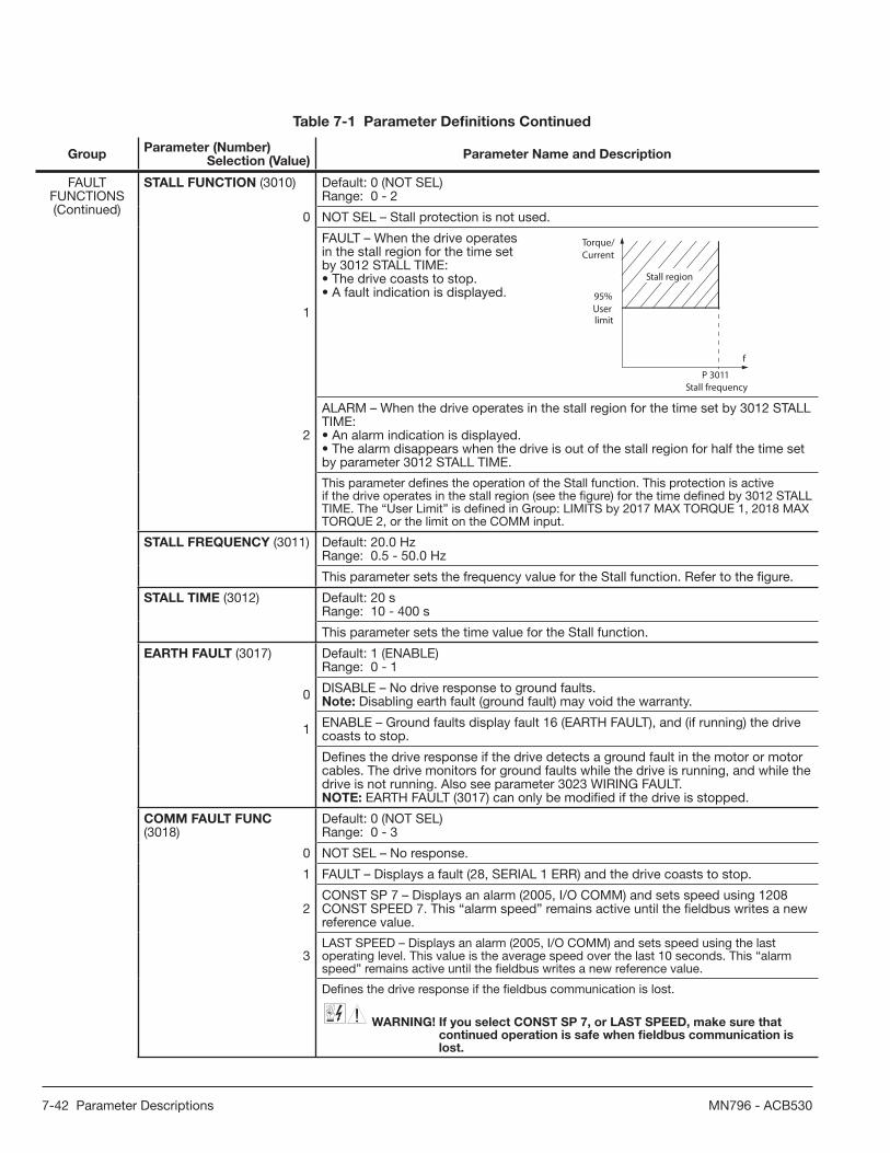
7-42 Parameter Descriptions MN796 - ACB530
GroupParameter (Number)
Selection (Value)Parameter Name and Description
FAULT FUNCTIONS(Continued)
STALL FUNCTION (3010) Default: 0 (NOT SEL)Range: 0 - 2
0 NOT SEL – Stall protection is not used.
1
FAULT – When the drive operatesin the stall region for the time setby 3012 STALL TIME:• The drive coasts to stop.• A fault indication is displayed.
2
ALARM – When the drive operates in the stall region for the time set by 3012 STALL TIME:• An alarm indication is displayed.• The alarm disappears when the drive is out of the stall region for half the time set by parameter 3012 STALL TIME.
This parameter defi nes the operation of the Stall function. This protection is active if the drive operates in the stall region (see the fi gure) for the time defi ned by 3012 STALL TIME. The “User Limit” is defi ned in Group: LIMITS by 2017 MAX TORQUE 1, 2018 MAX TORQUE 2, or the limit on the COMM input.
STALL FREQUENCY (3011) Default: 20.0 HzRange: 0.5 - 50.0 Hz
This parameter sets the frequency value for the Stall function. Refer to the fi gure.
STALL TIME (3012) Default: 20 sRange: 10 - 400 s
This parameter sets the time value for the Stall function.
EARTH FAULT (3017) Default: 1 (ENABLE)Range: 0 - 1
0 DISABLE – No drive response to ground faults.Note: Disabling earth fault (ground fault) may void the warranty.
1 ENABLE – Ground faults display fault 16 (EARTH FAULT), and (if running) the drive coasts to stop.
Defi nes the drive response if the drive detects a ground fault in the motor or motor cables. The drive monitors for ground faults while the drive is running, and while the drive is not running. Also see parameter 3023 WIRING FAULT.NOTE: EARTH FAULT (3017) can only be modifi ed if the drive is stopped.
COMM FAULT FUNC (3018)
Default: 0 (NOT SEL)Range: 0 - 3
0 NOT SEL – No response.
1 FAULT – Displays a fault (28, SERIAL 1 ERR) and the drive coasts to stop.
2CONST SP 7 – Displays an alarm (2005, I/O COMM) and sets speed using 1208 CONST SPEED 7. This “alarm speed” remains active until the fi eldbus writes a new reference value.
3LAST SPEED – Displays an alarm (2005, I/O COMM) and sets speed using the last operating level. This value is the average speed over the last 10 seconds. This “alarm speed” remains active until the fi eldbus writes a new reference value.
Defi nes the drive response if the fi eldbus communication is lost.
WARNING! If you select CONST SP 7, or LAST SPEED, make sure that continued operation is safe when fi eldbus communication is lost.
Table 7-1 Parameter Defi nitions Continued
95%
limitUser
Stall region
Torque/Current
f
Stall frequencyP 3011

Parameter Descriptions 7-43MN796 - ACB530
GroupParameter (Number)
Selection (Value)Parameter Name and Description
FAULT FUNCTIONS(Continued)
COMM FAULT TIME (3019) Default: 3.0 sRange: 0.0 - 600.0 s
Sets the communication fault time used with 3018 COMM FAULT FUNC.• Brief interruptions in the fi eldbus communication are not treated as faults if they are less than the COMM FAULT TIME value.
AI1 FAULT LIMIT (3021) Default: 0.0%Range: 0.0 - 100.0%
Sets a fault level for analog input 1.• See 3001 AI<MIN FUNCTION.
AI2 FAULT LIMIT (3022) Default: 0.0%Range: 0.0 - 100.0%
Sets a fault level for analog input 2.• See 3001 AI<MIN FUNCTION.
WIRING FAULT (3023) Default: 1 (ENABLE)Range: 0 - 1
0 DISABLE – No drive response to either of the above monitoring results.Note: Disabling wiring fault (ground fault) may void the warranty.
1 ENABLE – The drive displays faults when this monitoring detects problems.
Defi nes the drive response to cross wiring faults and to ground faults detected when the drive is NOT running. When the drive is not running it monitors for:• Improper connections of input power to the drive output (the drive can display fault 35, OUTPUT WIRING if improper connections are detected).• Ground faults (the drive can display fault 16, EARTH FAULT if a ground fault is detected). Also, see parameter 3017 EARTH FAULT.NOTE: WIRING FAULT (3023) can only be modifi ed if the drive is stopped.
CB TEMP FAULT (3024) Default: 1 (ENABLE)Range: 0 - 1
0 DISABLE – No response.
1 ENABLE – Displays fault 37 (CB OVERTEMP) and the drive coasts to stop.
Defi nes the drive response to control board overheating. Not for drives with an OMIO control board.
AUTOMATIC RESET
NUMBER OF TRIALS (3101)
Default: 0Range: 0 - 5
Sets the number of allowed automatic resets within a trial period defi ned by 3102 TRIAL TIME.• If the number of automatic resets exceeds this limit (within the trial time), the drive prevents additional automatic resets and remains stopped.• Starting then requires a successful reset performed from the control panel or from a source selected by 1604 FAULT RESET SEL.Example: Three faults have occurred in the trial time. The last is reset only if thevalue for 3101 NUMBER OF TRIALS is 3 or more.
X X XTime
Trial time
x = Automatic reset
TRIAL TIME (3102) Default: 30.0 sRange: 1.0 - 600.0 s
Sets the time period used for counting and limiting the number of resets.• See 3101 NUMBER OF TRIALS.
DELAY TIME (3103) Default: 0.0 sRange: 0.0 - 120.0 s
Sets the delay time between a fault detection and attempted drive restart.• If DELAY TIME = zero, the drive resets immediately.
Table 7-1 Parameter Defi nitions Continued

7-44 Parameter Descriptions MN796 - ACB530
GroupParameter (Number)
Selection (Value)Parameter Name and Description
AUTOMATIC RESET
(Continued)
AR OVERCURRENT (3104) Default: 0 (DISABLE)Range: 0 - 1
0 DISABLE – Disables automatic reset.
1ENABLE – Enables automatic reset.• Automatically resets the fault (OVERCURRENT) after the delay set by 3103 DELAY TIME, and the drive resumes normal operation.
Sets the automatic reset for the overcurrent function on or off.
AR OVERVOLTAGE (3105) Default: 0 (DISABLE)Range: 0 - 1
0 DISABLE – Disables automatic reset.
1ENABLE – Enables automatic reset.• Automatically resets the fault (DC OVERVOLT) after the delay set by 3103 DELAY TIME, and the drive resumes normal operation.
Sets the automatic reset for the overvoltage function on or off.
AR UNDERVOLTAGE (3106)
Default: 0 (DISABLE)Range: 0 - 1
0 DISABLE – Disables automatic reset.
1ENABLE – Enables automatic reset.• Automatically resets the fault (DC UNDERVOLT) after the delay set by 3103 DELAY TIME, and the drive resumes normal operation.
Sets the automatic reset for the undervoltage function on or off.
AR AI<MIN (3107) Default: 0 (DISABLE)Range: 0 - 1
0 DISABLE – Disables automatic reset.
1ENABLE – Enables automatic reset.• Automatically resets the fault (AI<MIN) after the delay set by 3103 DELAY TIME, and the drive resumes normal operation.
Sets the automatic reset for the analog input less than minimum value function on or off.
WARNING! When the analog input signal is restored, the drive may restart, even after a long stop. Make sure that automatic, long delayed starts will not cause physical injury and/or damage equipment.
AR EXTERNAL FLT (3108) Default: 0 (DISABLE)Range: 0 - 1
0 DISABLE – Disables automatic reset.
1ENABLE – Enables automatic reset.• Automatically resets the fault (EXT FAULT 1 or EXT FAULT 2) after the delay set by 3103 DELAY TIME, and the drive resumes normal operation.
Sets the automatic reset for external faults function on or off.
Table 7-1 Parameter Defi nitions Continued

Parameter Descriptions 7-45MN796 - ACB530
GroupParameter (Number)
Selection (Value)Parameter Name and Description
SUPERVISION SUPERV 1 PARAM (3201) Default: 103 (Parameter 0103 OUTPUT FREQ)Range: 100 = NOT SELECTED, 101 - 178
100 NOT SELECTED – No parameter selected.
101 - 178 Selects parameter 0101 - 0178.
Selects the fi rst supervised parameter.• Must be a parameter number from Group: OPERATING DATA.• If the supervised parameter passes a limit, a relay output is energized.• The supervision limits are defi ned in this group.• The relay outputs are defi ned in Group: RELAY OUTPUTS (defi nition also specifi es which supervision limit is monitored).LO ≤ HIOperating data supervision using relay outputs, when LO≤HI.• Case A = Parameter 1401 RELAY OUTPUT 1 (or 1402 RELAY OUTPUT 2, etc.) value is SUPRV1 OVER or SUPRV2 OVER. Use for monitoring when/if the supervised signal exceeds a given limit. The relay remains active until the supervised value drops below the low limit.• Case B = Parameter 1401 RELAY OUTPUT 1 (or 1402 RELAY OUTPUT 2, etc.) value is SUPRV1 UNDER or SUPRV2 UNDER. Use for monitoring when/if the supervised signal falls below a given limit. The relay remains active until the supervised value rises above the high limit.LO > HIOperating data supervision using relay outputs, when LO>HI.The lowest limit (HI 3203) is active initially and remains active until the supervised parameter goes above the highest limit (LO 3202), makingthat limit the active limit. That limit remains active until the supervised parameter goes below the lowestlimit (HI 3203), making that limit active.• Case A = Parameter 1401 RELAY OUTPUT 1 (or 1402 RELAY OUTPUT 2, etc.) value is SUPRV1 OVER or SUPRV2 OVER. Initially the relay is de-energized. It is energized whenever the supervised parameter goes above the active limit.• Case B = Parameter 1401 RELAY OUTPUT 1 (or 1402 RELAY OUTPUT 2, etc.) value is SUPRV1 UNDER or SUPRV2 UNDER. Initially the relay is energized. It is de-energized whenever the supervised parameter goes below the active limit.
SUPERV 1 LIM LO (3202) Default: Depends on the signal selected with par. 3201Range:
Sets the low limit for the fi rst supervised parameter. See3201 SUPERV 1 PARAM above.
SUPERV 1 LIM HI (3203) Default: Depends on the signal selected with par. 3201Range:
Sets the high limit for the fi rst supervised parameter. See3201 SUPERV 1 PARAM above.
Table 7-1 Parameter Defi nitions Continued
LO ≤ HINote: Case LO ≤ HI represents a normal hysteresis.
LO > HINote: Case LO>HI represents a special hysteresis with
two separate supervision limits.
Value of supervised parameter
Case A
0
Energized (1)
0
HI (3203)LO (3202)
Case BEnergized (1)
t
t
t
LO (3202)
HI (3203)
Value of supervised parameter
Case A
0
Energized (1)
0
Case BEnergized (1)
Active limit
t
t
t

7-46 Parameter Descriptions MN796 - ACB530
GroupParameter (Number)
Selection (Value)Parameter Name and Description
SUPERVISION(Continued)
SUPERV 2 PARAM (3204) Default: 104 (Parameter 0104 CURRENT)Range: 100 = NOT SELECTED, 101 - 178
100 NOT SELECTED – No parameter selected.
101 - 178 Selects parameter 0101 - 0178.
Selects the second supervised parameter. See 3201 SUPERV 1 PARAM above.
SUPERV 2 LIM LO (3205) Default: Depends on the signal selected with par. 3204Range:
Sets the low limit for the second supervised parameter. See 3204 SUPERV 2 PARAM above.
SUPERV 2 LIM HI (3206) Default: Depends on the signal selected with par. 3204Range:
Sets the high limit for the second supervised parameter. See 3204 SUPERV 2 PARAM above.
SUPERV 3 PARAM (3207) Default: 105 (Parameter 0105 TORQUE)Range: 100 = NOT SELECTED, 101 - 178
100 NOT SELECTED – No parameter selected.
101 - 178 Selects parameter 0101 - 0178.
Selects the third supervised parameter. See 3201 SUPERV 1 PARAM above.
SUPERV 3 LIM LO (3208) Default: Depends on the signal selected with par. 3207Range:
Sets the low limit for the third supervised parameter. See 3207 SUPERV 3 PARAM above.
SUPERV 3 LIM HI (3209) Default: Depends on the signal selected with par. 3207Range:
Sets the high limit for the third supervised parameter. See 3207 SUPERV 3 PARAM above.
INFORMATION FIRMWARE (3301) Default: Firmware versionRange: 0000 - FFFF hex
Contains the version of the drive’s fi rmware.
LOADING PACKAGE (3302) Default: Type dependentRange: 0000 - FFFF hex
Contains the version of the loading package.
TEST DATE (3303) Default: Range: yy.ww
Contains the test date (yy.ww).
DRIVE RATING (3304) Default: Type dependentRange:
Indicates the drive’s current and voltage rating. The format is XXXY, where:• XXX = The nominal current rating of the drive in amperes. If present, an “A” indicates a decimal point in the rating for the current. For example XXX = 8A8 indicates a nominal current rating of 8.8 A.• Y = The voltage rating of the drive, where Y = : • 2 indicates a 208…240 V rating. • 4 indicates a 380…480 V rating. • 6 indicates a 500…600 V rating.
PARAMETER TABLE (3305) Default: Type dependentRange: 0000 - FFFF hex
Contains the version of the parameter table used in the drive.
Table 7-1 Parameter Defi nitions Continued

Parameter Descriptions 7-47MN796 - ACB530
GroupParameter (Number)
Selection (Value)Parameter Name and Description
PANEL DISPLAY
SIGNAL1 PARAM (3401) Default: 103 (Parameter 0103 OUTPUT FREQ)Range: 100 = NOT SELECTED, 101 - 178
100 NOT SELECTED – First parameter not displayed.
101 - 178 Displays parameter 0101 - 0178. If parameter does not exist, the display shows “n.a.”
Selects the fi rst parameter (by number) displayed on the control panel.• Defi nitions in this group defi ne display content when the control panel is in the control mode.• Any parameter number in Group: OPERATING DATA can be selected.• Using the following parameters, the display value can be scaled, converted to convenient units and/or displayed as a bar graph.• The fi gure identifi es selections made by parameters in this group.• If just one or two parameters are selected for display, that is just one or two of the values of parameters 3401 SIGNAL1 PARAM, 3408 SIGNAL2 PARAM and 3415 SIGNAL3 PARAM are other than 100 (NOT SELECTED), the number and name of each displayed parameter are shown in addition to the value.
SIGNAL1 MIN (3402) Default: Depends on the signal selected with par. 3401Range:
Defi nes the minimum expected valuefor the fi rst display parameter.Use parameters 3402, 3403, 3406 and3407, for example to convert a Group: OPERATING DATA parameter, such as 0102 SPEED (in rpm) to the speed of a conveyor driven by the motor (in ft/min). For such a conversion, the source values in the fi gure are the min. and max. motor speed, and the display values are the corresponding min. and max. conveyor speed. Use parameter 3405 to select the proper units for the display.Note: Selecting units does not convert values. Parameter is not effective if parameter 3404 OUTPUT1 DSP FORM = 9 (DIRECT).
SIGNAL1 MAX (3403) Default: Depends on the signal selected with par. 3401Range:
Defi nes the maximum expected value for the fi rst display parameter.Note: Parameter is not effective if parameter 3404 OUTPUT1 DSP FORM = 9 (DIRECT).
Table 7-1 Parameter Defi nitions Continued
5 A1 Hz
7 %10.0.
49.49.1HzLOC
DIR MENU00:00
P 3404 P 3405
4 A
4 %24.0.
5.0HzLOC
DIR MENU00:00
HZ 50%
P 3404
P 3401 (=137)P 3408 (=138)P 3415 (=139)
Source value
P 3407
P 3406
P 3403P3402
Display value

7-48 Parameter Descriptions MN796 - ACB530
GroupParameter (Number)
Selection (Value)Parameter Name and Description
PANEL DISPLAY
(Continued)
OUTPUT1 DSP FORM (3404)
Default: 9 (DIRECT)Range: 0 - 9
0 - 7
Defi nes the decimal point location.• Enter the number of digits desired to the right of the decimal point.• See the table for an example using pi (3.14159).
8 BAR METER – Specifi es a bar meter display.
9
DIRECT – Decimal point location and units of measure are identical to the source signal. See Group: OPERATING DATA parameter listing in section Complete parameter list for resolution (which indicates the decimal point location) and the units of measure.
Defi nes the decimal point location for the fi rst display parameter.
OUTPUT1 UNIT (3405) Default: Depends on the signal selected with par. 3401Range: 0 - 127
Selects the units used with the fi rst display parameter.Note: Parameter is not effective if parameter 3404 OUTPUT1 DSP FORM = 9 (DIRECT). 0 = NO UNIT 9 = °C 18 = MWh 27 = ft 36 = l/s 45 = Pa 54 = lb/m 63 = Mrev
1 = A 10 = lb ft 19 = m/s 28 = MGD 37 = l/min 46 = GPS 55 = lb/h 64 = d
2 = V 11 = mA 20 = m3/h 29 = inHg 38 = l/h 47 = gal/s 56 = FPS 65 = inWC
3 = Hz 12 = mV 21 = dm3/s 30 = FPM 39 = m3/s 48 = gal/m 57 = ft/s 66 = m/min
4 = % 13 = kW 22 = bar 31 = kb/s 40 = m3/m 49 = gal/h 58 = inH2O 67 = Nm
5 = s 14 = W 23 = kPa 32 = kHz 41 = kg/s 50 = ft3/s 59 = in wg 68 = Km3/h
6 = h 15 = kWh 24 = GPM 33 = ohm 42 = kg/m 51 = ft3/m 60 = ft wg
7 = rpm 16 = °F 25 = PSI 34 = ppm 43 = kg/h 52 = ft3/h 61 = lbsi
8 = kh 17 = hp 26 = CFM 35 = pps 44 = mbar 53 = lb/s 62 = ms
The following units are useful for the bar display.
117 = %ref 119 = %dev 121 = % SP 123 = Iout 125 = Fout 127 = Vdc
118 = %act 120 = % LD 122 = %FBK 124 = Vout 126 = Tout
OUTPUT1 MIN (3406) Default: Depends on the signal selected with par. 3401Range: -
Sets the minimum value displayed for the fi rst display parameter.Note: Parameter is not effective if parameter 3404 OUTPUT1 DSP FORM = 9 (DIRECT).
OUTPUT1 MAX (3407) Default: Depends on the signal selected with par. 3401Range: -
Sets the maximum value displayed for the fi rst display parameter.Note: Parameter is not effective if parameter 3404 OUTPUT1 DSP FORM = 9 (DIRECT).
Table 7-1 Parameter Defi nitions Continued
3404 value
Display Range
0 ± 3 -32768 to +32767(Signed)
1 ± 3.1 2 ± 3.14 3 ± 3.142 4 3
0 - 65535 (Unsigned)
5 3.1 6 3.14 7 3.142 8 Bar meter displayed
9 Decimal point location and
units as for the source signal

Parameter Descriptions 7-49MN796 - ACB530
GroupParameter (Number)
Selection (Value)Parameter Name and Description
PANEL DISPLAY
(Continued)
SIGNAL2 PARAM (3408) Default: 104 (Parameter 0104 CURRENT)Range: 100 = NOT SELECTED, 101 - 178
100 NOT SELECTED – First parameter not displayed.
101 - 178 Displays parameter 0101 - 0178. If parameter does not exist, the display shows “n.a.”
Selects the second parameter (by number) displayed on the control panel. See parameter 3401.
SIGNAL2 MIN (3409) Default: Depends on the signal selected with par. 3408Range: -
Defi nes the minimum expected value for the second display parameter. See parameter 3402.
SIGNAL2 MAX (3410) Default: Depends on the signal selected with par. 3408Range: -
Defi nes the maximum expected value for the second display parameter. See parameter 3403.
OUTPUT2 DSP FORM (3411)
Default: 9 (DIRECT)Range: 0 - 9
Defi nes the decimal point location for the second display parameter. See parameter 3404.
OUTPUT2 UNIT (3412) Default: Depends on the signal selected with par. 3408Range: 0 - 127
Selects the units used with the second display parameter. See parameter 3405.
OUTPUT2 MIN (3413) Default: Depends on the signal selected with par. 3408Range: -
Sets the minimum value displayed for the second display parameter. See parameter 3406.
OUTPUT2 MAX (3414) Default: Depends on the signal selected with par. 3408Range: -
Sets the maximum value displayed for the second display parameter. See parameter 3407.
SIGNAL3 PARAM (3415) Default: 105 (Parameter 0105 TORQUE)Range: 100 = NOT SELECTED, 101 - 178
100 NOT SELECTED – First parameter not displayed.
101 - 178 Displays parameter 0101 - 0178. If parameter does not exist, the display shows “n.a.”
Selects the third parameter (by number) displayed on the control panel. See parameter 3401.
SIGNAL3 MIN (3416) Default: Depends on the signal selected with par. 3415Range:
Defi nes the minimum expected value for the third display parameter. See parameter 3402.
SIGNAL3 MAX (3417) Default: Depends on the signal selected with par. 3415Range:
Defi nes the maximum expected value for the third display parameter. See parameter 3403.
Table 7-1 Parameter Defi nitions Continued

7-50 Parameter Descriptions MN796 - ACB530
GroupParameter (Number)
Selection (Value)Parameter Name and Description
PANEL DISPLAY
(Continued)
OUTPUT3 DSP FORM (3418)
Default: 9 (DIRECT)Range: 0 - 9
Defi nes the decimal point location for the third display parameter. See parameter 3404.
OUTPUT3 UNIT (3419) Default: Depends on the signal selected with par. 3415Range: 0 - 127
Selects the units used with the third display parameter. See parameter 3405.
OUTPUT3 MIN (3420) Default: Depends on the signal selected with par. 3415Range:
Sets the minimum value displayed for the third display parameter. See parameter 3406.
OUTPUT3 MAX (3421) Default: Depends on the signal selected with par. 3415Range:
Sets the maximum value displayed for the third display parameter. See parameter 3407.
MOTOR TEMP MEAS
SENSOR TYPE (3501) Default: 0 (NONE)Range: 0 - 6
0 NONE
1
1 x PT100 – Sensor confi guration uses one PT100 sensor.• Analog output AO1 or AO2 feeds constant current through the sensor.• The sensor resistance increases as the motor temperature rises, as does the voltage over the sensor.• The temperature measurement function reads the voltage through analog input AI1 or AI2 and converts it to degrees Celsius.
2 2 x PT100 – Sensor confi guration uses two PT100 sensors.• Operation is the same as for above 1 x PT100.
3 3 x PT100 – Sensor confi guration uses three PT100 sensors.• Operation is the same as for above 1 x PT100.
4
PTC – Sensor confi guration uses one PTC.• The analog output feeds a constant current through the sensor.• The resistance of the sensor increases sharply as the motor temperature rises over the PTC reference temperature (Tref), as does the voltage over the resistor. The temperature measurement function reads the voltage through analog input AI1 and converts it into ohms.• The table below and the graph show typical PTC sensor resistance as a function of the motor operating temperature.
Temperature Resistance
Normal < 1.5 kohm Excessive > 4 kohm
Table 7-1 Parameter Defi nitions ContinuedTable 7-1 Parameter Defi nitions Continued
T
Excessive
Normal

Parameter Descriptions 7-51MN796 - ACB530
GroupParameter (Number)
Selection (Value)Parameter Name and Description
MOTOR TEMP MEAS
(Continued)
SENSOR TYPE (3501) (Continued)
Default: 0 (NONE)Range: 0 - 6
5
THERM(0) – Sensor confi guration uses a thermistor.• Motor thermal protection is activated through a digital input. Connect either a PTC sensor or a normally closed thermistor relay to a digital input.• When the digital input is ‘0’, the motor is overheated.• See the connection fi gure below.
MotorT
MotorT
Thermistorrelay Control board
DI6
+24 V DC
Control board
DI6
+24 V DC
3.3 nF
Thermistor relay3501 SENSOR TYPE = 5 ( THERM (0)) or 6 ( THERM (1))
PTC sensor3501 SENSOR TYPE = 5 ( THERM (0))
• The table below and the graph show the resistance requirements for a PTC sensor connected between 24V and a digital input as a function of the motor operating temperature.
Temperature Resistance
Normal < 3 kohm Excessive > 28 kohm
6
THERM(1) – Sensor confi guration uses a thermistor.• Motor thermal protection is activated through a digital input. Connect a normally open thermistor relay to a digital input.• When the digital input is ‘1’, the motor is overheated.• See the connection fi gure above.
Identifi es the type of the motor temperature sensor used, PT100 (°C), PTC (ohm) or thermistor.See parameters 1501 AO1 CONTENT SEL and 1507 AO2 CONTENT SEL.
INPUT SELECTION (3502) Default: 1 (AI1)Range: 1 - 8
1 AI1 – PT100 and PTC.
2 AI2 – PT100 and PTC.
3 - 8 DI1 - DI6 – Thermistor and PTC.
Defi nes the input used for the temperature sensor.
ALARM LIMIT (3503) Default: 110°C / 1500 ohm / 0Range: Par. 3501 = 1 to 3: -10 to 200°C Par. 3501 = 4: 0 to 5000 ohm Par. 3501 = 5 to 6: 0 to 1
0 De-activated
1 Activated
Defi nes the alarm limit for motor temperature measurement.• At motor temperatures above this limit, the drive displays an alarm (2010, MOTOR TEMP) For thermistors or PTC connected to a digital input.
FAULT LIMIT (3504) Default: 130°C / 4000 ohm / 0Range: Par. 3501 = 1 to 3: -10 to 200°C Par. 3501 = 4: 0 to 5000 ohm Par. 3501 = 5 to 6: 0 to 1
0 De-activated
1 Activated
Defi nes the fault limit for motor temperature measurement.• At motor temperatures above this limit, the drive displays a fault (9, MOT OVERTEMP) and stops the drive.For thermistors or PTC connected to a digital input.
Table 7-1 Parameter Defi nitions Continued

7-52 Parameter Descriptions MN796 - ACB530
GroupParameter (Number)
Selection (Value)Parameter Name and Description
USER LOAD CURVE
USER LOAD C MODE (3701)
Default: 0 (NOT SEL)Range: 0 - 3
0 NOT SEL – Supervision is not active.
1 UNDERLOAD – Supervision for the torque dropping below the underload curve.
2 OVERLOAD – Supervision for the torque exceeding the overload curve.
3 BOTH – Supervision for the torque dropping below the underload curve or exceeding the overload curve.
Supervision mode for the user Overload area
Underload area
Allowed operating area
P3706
P3705
P3704
P3709
P3708
P3707
P3712
P3711
P3710
P3715P3714
P3713
P3718P3717
P3716
Motor torque (%)
Output frequency (Hz)
adjustable load curves.This functionality replaces the former underload supervision in Group: FAULT FUNCTIONS. To emulate it, see Correspondence with the obsolete underload supervision on next page.
Correspondence with the obsolete underload supervisionThe now obsolete parameter 3015 UNDERLOAD CURVE provided fi ve selectablecurves shown in the fi gure. The parameter characteristics were as described below.• If the load drops below the set curve for longer than the time
80
60
40
20
02.4 · ƒN
3
2
1 5
4
TM
70%
50%
30%
ƒN
(%) Underload curve types
f
set by parameter 3014 UNDERLOAD TIME (obsolete), the underload protection is activated.• Curves 1 - 3 reach maximum at the motor rated frequency set by parameter 9907 MOTOR NOM FREQ.• TM = nominal torque of the motor.• ƒN = nominal frequency of the motor.If you want to emulate the behavior of an old underload curve with parameters as inthe shaded columns, set the new parameters as in the white columns in the twotables below:
Underload supervision with parameters 3013 - 3015 (obsolete)
Obsolete parameters New parameters
3013 UNDERLOAD
FUNCTION
3014 UNDERLOAD
TIME
3701 USER LOAD
C MODE
3702 USER LOAD
C FUNC
3703 USER LOAD
C TIME
No underload functionality 0 - 0 - -Underload curve, fault generated 1 t 1 1 t
Underload curve, alarm generated 2 t 1 2 2 · t
Obs. par. New parameters
3015 UNDER LOAD
CURVE
3704 LOAD
FREQ 1 (Hz)
3705 LOAD TORQ LOW 1
(%)
3707 LOAD
FREQ 2 (Hz)
3708 LOAD TORQ LOW 2
(%)
3710 LOAD
FREQ 3 (Hz)
3711 LOAD TORQ LOW 3
(%)
3713 LOAD
FREQ 4 (Hz)
3714 LOAD TORQ LOW 4
(%)
3716 LOAD FREQ 5
(Hz)
3717 LOAD TORQ LOW 5
(%)
EU US EU US EU US EU US EU US
1 5 6 10 32 38 17 41 50 23 50 60 30 500 500 30 2 5 6 20 31 37 30 42 50 40 50 60 50 500 500 50 3 5 6 30 31 37 43 42 50 57 50 60 70 500 500 70 4 5 6 10 73 88 17 98 117 23 120 144 30 500 500 30 5 5 6 20 71 86 30 99 119 40 120 144 50 500 500 50
Table 7-1 Parameter Defi nitions Continued

Parameter Descriptions 7-53MN796 - ACB530
GroupParameter (Number)
Selection (Value)Parameter Name and Description
USER LOAD CURVE
(Continued)
USER LOAD C FUNC (3702)
Default: 1 (FAULT)Range: 1 - 2
1 FAULT – A fault is generated when the condition defi ned by 3701 USER LOAD C MODE has been valid longer than the time set by 3703 USER LOAD C TIME.
2ALARM – An alarm is generated when the condition defi ned by 3701 USER LOAD C MODE has been valid longer than half of the time defi ned by 3703 USER LOAD C TIME.
Action wanted during load supervision.
USER LOAD C TIME (3703) Default: 20 sRange: 10 - 400 s
Defi nes the time limit for generating a fault.• Half of this time is used as the limit for generating an alarm.
LOAD FREQ 1 (3704) Default: 5 HzRange: 0 - 500 Hz
Defi nes the frequency value of the fi rst load curve defi nition point.• Must be smaller than 3707 LOAD FREQ 2.
LOAD TORQ LOW 1 (3705) Default: 10%Range: 0 - 600%
Defi nes the torque value of the fi rst underload curve defi nition point.• Must be smaller than 3706 LOAD TORQ HIGH 1.
LOAD TORQ HIGH 1 (3706) Default: 300%Range: 0 - 600%
Defi nes the torque value of the fi rst overload curve defi nition point.
LOAD FREQ 2 (3707) Default: 25 HzRange: 0 - 500 Hz
Defi nes the frequency value of the second load curve defi nition point.• Must be smaller than 3710 LOAD FREQ 3.
LOAD TORQ LOW 2 (3708) Default: 15%Range: 0 - 600%
Defi nes the torque value of the second underload curve defi nition point.• Must be smaller than 3709 LOAD TORQ HIGH 2.
LOAD TORQ HIGH 2 (3709) Default: 300%Range: 0 - 600%
Defi nes the torque value of the second overload curve defi nition point.
LOAD FREQ 3 (3710) Default: 43 HzRange: 0 - 500 Hz
Defi nes the frequency value of the third load curve defi nition point.• Must be smaller than 3713 LOAD FREQ 4.
LOAD TORQ LOW 3 (3711) Default: 25%Range: 0 - 600%
Defi nes the torque value of the third underload curve defi nition point.• Must be smaller than 3712 LOAD TORQ HIGH 3.
LOAD TORQ HIGH 3 (3712) Default: 300%Range: 0 - 600%
Defi nes the torque value of the third overload curve defi nition point.
LOAD FREQ 4 (3713) Default: 50 HzRange: 0 - 500 Hz
Defi nes the frequency value of the fourth load curve defi nition point.• Must be smaller than 3716 LOAD FREQ 5.
Table 7-1 Parameter Defi nitions Continued

7-54 Parameter Descriptions MN796 - ACB530
GroupParameter (Number)
Selection (Value)Parameter Name and Description
USER LOAD CURVE
(Continued)
LOAD TORQ LOW 4 (3714) Default: 30%Range: 0 - 600%
Defi nes the torque value of the fourth underload curve defi nition point.• Must be smaller than 3715 LOAD TORQ HIGH 4.
LOAD TORQ HIGH 4 (3715) Default: 300%Range: 0 - 600%
Defi nes the torque value of the fourth overload curve defi nition point.
LOAD FREQ 5 (3716) Default: 500 HzRange: 0 - 500 Hz
Defi nes the frequency value of fi fth load curve defi nition point.
LOAD TORQ LOW 5 (3717) Default: 30%Range: 0 - 600%
Defi nes the torque value of the fi fth underload curve defi nition point.• Must be smaller than 3718 LOAD TORQ HIGH 5.
LOAD TORQ HIGH 5 (3718) Default: 300%Range: 0 - 600%
Defi nes the torque value of the fi fth overload curve defi nition point.
PROCESS PID SET 1
GAIN (4001) Default: 1.0Range: 0.1 - 100.0
Defi nes the PID controller’s gain.• The setting range is 0.1 - 100.• At 0.1, the PID controller output changes one-tenth as much as the error value.• At 100, the PID controller output changes one hundred times as much as the error value.Use the proportional gain and integration time values to adjust the responsiveness of the system.• A low value for proportional gain and a high value for integral time ensures stable operation, but provides sluggish response.If the proportional gain value is too large or the integral time too short, the system can become unstable.Procedure: • Initially, set: • 4001 GAIN = 0.1. • 4002 INTEGRATION TIME = 20 seconds.• Start the system and see if it reaches the setpoint quickly while maintaining stable operation. If not, increase GAIN (4001) until the actual signal (or drive speed) oscillates constantly. It may be necessary to start and stop the drive to induce this oscillation.• Reduce GAIN (4001) until the oscillation stops.• Set GAIN (4001) to 0.4 to 0.6 times the above value.• Decrease the INTEGRATION TIME (4002) until the feedback signal (or drive speed) oscillates constantly. It may be necessary to start and stop the drive to induce this oscillation.• Increase INTEGRATION TIME (4002) until the oscillation stops.• Set INTEGRATION TIME (4002) to 1.15 to 1.5 times the above value.• If the feedback signal contains high frequency noise, increase the value of parameter 1303 FILTER AI1 or 1306 FILTER AI2 until the noise is fi ltered from the signal.
Table 7-1 Parameter Defi nitions Continued

Parameter Descriptions 7-55MN796 - ACB530
GroupParameter (Number)
Selection (Value)Parameter Name and Description
PROCESS PID SET 1
(Continued)
INTEGRATION TIME (4002) Default: 60.0 sRange: 0.0 = (NOT SEL), 0.1 - 3600.0 s
0.0 NOT SEL – Disables integration(I-part of controller).
0.1 - 3600.0 s Integration time (seconds).
Defi nes the PID controller’s integration
P 4002
A
C (P 4001 = 1)
B
A = ErrorB = Error value stepC = Controller output with Gain = 1 D = Controller output with Gain = 10
D (P 4001 = 10)
t
time.Integration time is, by defi nition,the time required to increase theoutput by the error value:• Error value is constant and 100%.• Gain = 1.• Integration time of 1 second denotes that a 100% change is achieved in 1 second.• See 4001 for adjustment procedure.
DERIVATION TIME (4003) Default: 0.0 sRange: 0.0 - 10.0 s
Defi nes the PID controller’s derivation time.
100%
Gain
Process error value
P 4003
D-part of controller outputPID output
Error
0%
P 4001
t
t
• You can add the derivative of the error to the PID controller output. The derivative is the error value’s rate of change. For example, if the process error value changes linearly, the derivative is a constant added to the PID controller output.• The error-derivative is fi ltered with a 1-pole fi lter. The time constant of the fi lter is defi ned by parameter 4004 PID DERIV FILTER.0.0 - 10.0 – Derivation time (seconds).
PID DERIV FILTER (4004) Default: 1.0 sRange: 0.0 - 10.0 s
Defi nes the fi lter time constant for the error-derivative part of the PID controller output.• Before being added to the PID controller output, the error-derivative is fi ltered with a 1-pole fi lter.• Increasing the fi lter time smooths the error-derivative, reducing noise.0.0 - 10.0 – Filter time constant (seconds).
ERROR VALUE INV (4005) Default: 0 (NO)Range: 0 - 1
0 NO – Normal, a decrease in feedback signal increases drive speed. Error = Ref - Fbk
1 YES – Inverted, a decrease in feedback signal decreases drive speed. Error = Fbk - Ref
Selects either a normal or inverted relationship between the feedback signal and the drive speed.
UNITS (4006) Default: 4 (%)Range: 0 - 127
Selects the unit for the PID controller actual values. (PID1 parameters 0128, 0130 and 0132).• See parameter 3405 for list of available units.
Table 7-1 Parameter Defi nitions Continued

7-56 Parameter Descriptions MN796 - ACB530
GroupParameter (Number)
Selection (Value)Parameter Name and Description
PROCESS PID SET 1
(Continued)
UNIT SCALE (4007) Default: 1Range: 0 - 4
Defi nes the decimal point location in PID controller actual values.• Enter the decimal point location counting in from the right end of the entry.• See the table for an example using pi (3.14159).
4007 value Entry Display
0 00003 3 1 00031 3.1 2 00314 3.14 3 03142 3.142 4 31416 3.1416
0% VALUE (4008) Default: 0.0Range: Unit and scale defi ned by par. 4006 and 4007
0% VALUEDefi nes (together with the next
REG BYPASS CTRL ).
Internal scale (%)
P 4009
P 4008
100% 0%
Units (P4006)Scale (P4007)
-1000.0%
+1000.0%
parameter) the scaling applied tothe PID controller’s actual values (PID1 parameters 0128, 0130and 0132).• Units and scale are defi ned by parameters 4006 and 4007.
100% VALUE (4009) Default: 100.0Range: Unit and scale defi ned by par. 4006 and 4007
0% VALUEDefi nes (together with the previous parameter) the scaling applied to the PID controller’s actual values.• Units and scale are defi ned by parameters 4006 and 4007.
SET POINT SEL (4010) Default: (1) Al1 Range: 0 - 2, 8 - 17, 19
0 KEYPAD - Keypad
1 Al1 - Analog Input Al1
2 Al2 - Analog Input Al2
8 COMM - Fieldbus reference REF 2
9 COMM+ Al1- Summation of fi eldbus reference REF2 and analog input Al1.
10 COMM*Al2 -Multiplication of fi eldbus reference REF2 and analog input Al1.
11 DI3U, 4D (RNC) -Digital Input DI3: Reference increase. Digital Input DI4: Reference decrease. Stop command resets the reference to zero. The reference is not saved if the control source is changed from EXT1 to EXT2, from EXT2 to EXT1 or from LOC to REM.
12 DI3U, 4D (NC) - Digital Input DI3: Reference increase. Digital Input DI4: Reference decrease. The program stores the reference (not reset by a stop command). The reference is not saved if the control source is changed from EXT1 to EXT2, from EXT2 to EXT1 or from LOC to REM.
14 Al1+Al2 - Reference is calculated with the following equation:REF = AI1(%) + AI2(%) - 50%
15 Al1*Al2 -Reference is calculated with the following equation:REF = AI1(%) * AI2(%) - 50%
16 Al1-Al2 - Reference is calculated with the following equation:REF = AI1(%) + 50% - AI2(%)
17 Al1/Al2 - Reference is calculated with the following equation:REF = AI1(%) + (50% / AI2(%))
19 INTERNAL - A constant value defi ned by parameter 4011 INTERNAL SETPNT.
Selects the source for the process PID controller reference signal.
Table 7-1 Parameter Defi nitions Continued

Parameter Descriptions 7-57MN796 - ACB530
GroupParameter (Number)
Selection (Value)Parameter Name and Description
PROCESS PID SET 1
(Continued)
INTERNAL SETPNT (4011) Default: 40.0Range: Unit and scale defi ned by par. 4006 and 4007
Sets a constant value used for the process reference.• Units and scale are defi ned by parameters 4006 and 4007.
SETPOINT MIN (4012) Default: 0.0%Range: -500.0 to 500.0
Sets the minimum value for the reference signal source.• See parameter 4010.
SETPOINT MAX (4013) Default: 100.0%Range: -500.0 to 500.0
Sets the maximum value for the reference signal source.• See parameter 4010.
FBK SEL (4014) Default: 1 (ACT1)Range: 1 - 13
1 ACT1 – Actual value 1 (ACT1) provides the feedback signal.
2 ACT1-ACT2 – ACT1 minus ACT2 provides the feedback signal.
3 ACT1+ACT2 – ACT1 plus ACT2 provides the feedback signal.
4 ACT1*ACT2 – ACT1 times ACT2 provides the feedback signal.
5 ACT1/ACT2 – ACT1 divided by ACT2 provides the feedback signal.
6 MIN(ACT1,2) – The smaller of ACT1 or ACT2 provides the feedback signal.
7 MAX(ACT1,2) – The greater of ACT1 or ACT2 provides the feedback signal.
8 sqrt(ACT1-2) – Square root of the value for ACT1 minus ACT2 provides the feedback signal.
9 sqA1+sqA2 – Square root of ACT1 plus the square root of ACT2 provides the feedback signal.
10 sqrt(ACT1) – Square root of ACT1 provides the feedback signal.
11 COMM FBK 1 – Signal 0158 PID COMM VALUE 1 provides the feedback signal.
12 COMM FBK 2 – Signal 0159 PID COMM VALUE 2 provides the feedback signal.
13 AVE(ACT1,2) – The average of ACT1 and ACT2 provides the feedback signal.
Defi nes the PID controller feedback (actual signal).• You can defi ne a combination of two actual values (ACT1 and ACT2) as the feedback signal.• Use parameter 4016 to defi ne the source for actual value 1 (ACT1).• Use parameter 4017 to defi ne the source for actual value 2 (ACT2).
FBK MULTIPLIER (4015) Default: 0.000 (NOT SEL)Range: 0.000 = (NOT SEL), -32.768 to 32.767
0.000 NOT SEL – The parameter has no effect (1.000 used as the multiplier).
-32.768 to 32.767 Multiplier applied to the signal defi ned by parameter 4014 FBK SEL.Example: FBK = Multiplier × √A1 – A2
Defi nes an extra multiplier for the PID feedback value FBK defi ned by parameter 4014.• Used mainly in applications where the fl ow is calculated from the pressure difference.
Table 7-1 Parameter Defi nitions Continued

7-58 Parameter Descriptions MN796 - ACB530
GroupParameter (Number)
Selection (Value)Parameter Name and Description
PROCESS PID SET 1
(Continued)
ACT1 INPUT (4016) Default: 2 (AI2)Range: 1 - 7
1 AI1 – Uses analog input 1 for ACT1.
2 AI2 – Uses analog input 2 for ACT1.
3 CURRENT – Uses current for ACT1.
4 TORQUE – Uses torque for ACT1.
5 POWER – Uses power for ACT1.
6 COMM ACT 1 – Uses value of signal 0158 PID COMM VALUE 1 for ACT1.
7 COMM ACT 2 – Uses value of signal 0159 PID COMM VALUE 2 for ACT1.
Defi nes the source for actual value 1 (ACT1). See also parameter 4018 ACT1 MINIMUM.NOTE: ACT1 INPUT (4016) can only be modifi ed if the drive is stopped.
ACT2 INPUT (4017) Default: 2 (AI2)Range: 1 - 7
1 AI1 – Uses analog input 1 for ACT2.
2 AI2 – Uses analog input 2 for ACT2.
3 CURRENT – Uses current for ACT2.
4 TORQUE – Uses torque for ACT2.
5 POWER – Uses power for ACT2.
6 COMM ACT 1 – Uses value of signal 0158 PID COMM VALUE 1 for ACT2.
7 COMM ACT 2 – Uses value of signal 0159 PID COMM VALUE 2 for ACT2.
Defi nes the source for actual value 2 (ACT2). See also parameter 4020 ACT2 MINIMUM.NOTE: ACT2 INPUT (4017) can only be modifi ed if the drive is stopped.
ACT1 MINIMUM (4018) Default: 0%Range: -1000 to 1000%
Sets the minimum value for ACT1.• Scales the source signal used as the actual value ACT1 (defi ned by parameter 4016 ACT1 INPUT). For parameter 4016 values 6 (COMM ACT 1) and 7 (COMM ACT 2) scaling is not done. Par 4016 Source Source min. Source max.
1 Analog input 1 1301 MINIMUM AI1 1302 MAXIMUM AI1
2 Analog input 2 1304 MINIMUM AI2 1305 MAXIMUM AI2
3 Current 0 2 · nominal current
4 Torque -2 · nominal torque 2 · nominal torque
5 Power -2 · nominal power 2 · nominal power
P 4019
P 4018
ACT 1 (%) A
B
Source signalSource min. Source max.
P 4018
P 4019
ACT 1 (%)
Source signalSource min. Source max.
ACT1 MAXIMUM (4019) Default: 100%Range: -1000 to 1000%
Sets the maximum value for ACT1.• See 4018 ACT1 MINIMUM.
ACT2 MINIMUM (4020) Default: 0%Range: -1000 to 1000%
Sets the minimum value for ACT2.• See 4018 ACT1 MINIMUM.
Table 7-1 Parameter Defi nitions Continued

Parameter Descriptions 7-59MN796 - ACB530
GroupParameter (Number)
Selection (Value)Parameter Name and Description
PROCESS PID SET 1
(Continued)
ACT2 MAXIMUM (4021) Default: 100%Range: -1000 to 1000%
Sets the maximum value for ACT2.• See 4018 ACT1 MINIMUM.
SLEEP SELECTION (4022) Default: 0 (NOT SEL)Range: -6 to 7
0 NOT SEL– Disables the PID sleep control function.
1DI1 – Defi nes digital input DI1 as the control for the PID sleep function.• Activating the digital input activates the sleep function.• De-activating the digital input restores PID control.
2 to 6 DI2 - DI6 – Defi nes digital input DI2 - DI6 as the control for the PID sleep function.• See DI1 above.
7INTERNAL – Defi nes the output rpm/frequency, process reference and process actual value as the control for the PID sleep function. Refer to parameters 4025 WAKE-UP DEV and 4023 PID SLEEP LEVEL.
-1
DI1 (INV) – Defi nes an inverted digital input DI1 as the control for the PID sleep function.• De-activating the digital input activates the sleep function.• Activating the digital input restores PID control.
-2 to -6DI2 (INV) - DI6 (INV) – Defi nes an inverted digital input DI2 - DI6 as the control for the PID sleep function.• See DI1 (INV) above.
Defi nes the control for the PID sleep function.
PID SLEEP LEVEL (4023) Default: 0.0 Hz / 0 RPMRange: 0.0 - 500.0 Hz / 0 - 30000 RPM
Sets the motor speed / frequency that enables the PID sleep function – a motor speed / frequency below this level, for at least the time period 4024 PID SLEEP DELAY enables the PID sleep function (stopping the drive).• Requires 4022 = 7 (INTERNAL).• See the fi gure: A = PID output level; B = PID process feedback.
Start
t < P 4024
t > P 4024
Stop
P 4023
P 4025
P 4026Setpoint
A
B
t
t
P 4025Setpoint
P 4025C
D
}}4005 = 1
4005 = 0
t
P 4025Setpoint
P 4025C
D
P 4026
E
F
P 4026
t
Table 7-1 Parameter Defi nitions Continued

7-60 Parameter Descriptions MN796 - ACB530
GroupParameter (Number)
Selection (Value)Parameter Name and Description
PROCESS PID SET 1
(Continued)
PID SLEEP DELAY (4024) Default: 60.0 sRange: 0.0 - 3600.0 s
Sets the time delay for the PID sleep function – a motor speed / frequency below 4023 PID SLEEP LEVEL for at least this time period enables the PID sleep function (stopping the drive).• See 4023 PID SLEEP LEVEL above.
WAKE-UP DEV (4025) Default: 0.0sRange: Unit and scale defi ned by par. 4006 and 4007
Defi nes the wake-up deviation – a deviation from the setpoint greater than this value, for at least the time period 4026 WAKE-UP DELAY, re-starts the PID controller.• Parameters 4006 and 4007 defi ne the units and scale.• Parameter 4005 = 0, Wake-up level = Setpoint - Wake-up deviation.• Parameter 4005 = 1, Wake-up level = Setpoint + Wake-up deviation.• Wake-up level can be above or below setpoint. See the fi gures:• C = Wake-up level when parameter 4005 = 1• D = Wake-up level when parameter 4005 = 0• E = Feedback is above wake-up level and lasts longer than 4026 WAKE-UP DELAY – PID function wakes up.• F = Feedback is below wake-up level and lasts longer than 4026 WAKE-UP DELAY – PID function wakes up.
WAKE-UP DELAY (4026) Default: 0.50 sRange: 0.0 - 60.00 s
Defi nes the wake-up delay – a deviation from the setpoint greater than 4025 WAKE-UP DEV, for at least this time period, re-starts the PID controller.
ENERGY SAVING
ENERGY PRICE (4502) Default: 0.00Range: 0.00 - 655.35
Price of energy per kWh.• Used for reference when energy savings are calculated.• See parameters 0174 SAVED KWH, 0175 SAVED MWH, 0176 SAVED AMOUNT 1, 0177 SAVED AMOUNT 2 and 0178 SAVED CO2 (reduction on carbon dioxide emissions in tn).
CO2 CONV FACTOR (4507) Default: 0.5 tn/MWhRange: 0.00 - 10.0 tn/MWh
Conversion factor for converting energy into CO2 emissions (kg/kWh or tn/MWh). Used for multiplying the saved energy in MWh to calculate the value of parameter 0178 SAVED CO2 (reduction on carbon dioxide emissions in tn).
PUMP POWER (4508) Default: 100.0%Range: 0.0 - 1000.0%
Pump power (as a percentage of the nominal motor power) when connected directly to supply (DOL).• Used for reference when energy savings are calculated.• See parameters 0174 SAVED KWH, 0175 SAVED MWH, 0176 SAVED AMOUNT 1, 0177 SAVED AMOUNT 2 and 0178 SAVED CO2.• It is possible to use this parameter as the reference power also for other applications than pumps. The reference power can also be some other constant power than a motor connected directly online.
ENERGY RESET (4509) Default: 0 (DONE)Range: 0 - 1
0 DONE
1 RESET
Resets energy calculators 0174 SAVED KWH, 0175 SAVED MWH, 0176 SAVED AMOUNT 1, 0177 SAVED AMOUNT 2 and 0178 SAVED CO2.
Table 7-1 Parameter Defi nitions Continued

7-61 Parameter Descriptions MN796 - ACB530
GroupParameter (Number)
Selection (Value)Parameter Name and Description
EXT COMM MODULE
FBA TYPE (5101) Default: READ ONLYRange: -
0 NOT DEFINED – Module not found, or not properly connected, or parameter 9802 is not set to 4 (EXT FBA).
1 PROFIBUS-DP
32 CANopen
37 DEVICENET
101 CONTROLNET
128 ETHERNET
132 PROFINET
135 EtherCAT
136 EPL – Ethernet POWERLINK
Displays the type of the connected fi eldbus adapter module.
FB PAR 2 - FB PAR 26 (5102 - 5106)
Default: 0Range: 0 - 65535
Refer to communication module documentation for more information on these parameters.
FBA PAR REFRESH (5127) Default: 0 (DONE)Range: 0 - 1
0 DONE – Refreshing done.
1 REFRESH – Refreshing.• After refreshing, the value reverts automatically to DONE.
Validates any changed fi eldbus parameter settings.NOTE: FBA PAR REFRESH (5127) can only be modifi ed if the drive is stopped.
FILE CPI FW REV (5128) Default: READ ONLYRange: -
Displays the CPI fi rmware revision of the drive’s fi eldbus adapter confi guration fi le. Format is xyz where:• x = major revision number• y = minor revision number• z = correction numberExample: 107 = revision 1.07.
FILE CONFIG ID (5129) Default: READ ONLYRange: -
Displays the revision of the drive’s fi eldbus adapter module’s confi guration fi le identifi cation.• File confi guration information is drive application program-dependent.
FILE CONFIG REV (5130) Default: READ ONLYRange: -
Contains the revision of the drive’s fi eldbus adapter module confi guration fi le.Example: 1 = revision 1
Table 7-1 Parameter Defi nitions Continued

7-62 Parameter Descriptions MN796 - ACB530
GroupParameter (Number)
Selection (Value)Parameter Name and Description
EXT COMM MODULE
(Continued)
FBA STATUS (5131) Default: READ ONLYRange: -
0 IDLE – Adapter not confi gured.
1 EXECUT INIT – Adapter is initializing.
2 TIME OUT – A timeout has occurred in the communication between the adapter and the drive.
3CONFIG ERROR – Adapter confi guration error.• The revision code of the adapter’s CPI fi rmware revision is older than required CPI fi rmware version defi ned in the drive’s confi guration fi le (parameter 5132 < 5128).
4 OFF-LINE – Adapter is off-line.
5 ON-LINE – Adapter is on-line.
6 RESET – Adapter is performing a hardware reset.
Contains the status of the adapter module.
FBA CPI FW REV (5132) Default: READ ONLYRange: -
Contains the revision of the module’s CPI program. Format is xyz where:• x = major revision number• y = minor revision number• z = correction numberExample: 107 = revision 1.07
FBA APPL FW REV (5133) Default: READ ONLYRange: -
Contains the revision of the module’s application program. Format is xyz (see parameter 5132).
PANEL COMM STATION ID (5201) Default: 1Range: 1 - 247
Defi nes the address of the drive.• Two units with the same address are not allowed on-line.
BAUD RATE (5202) Default: 9.6 kbits/sRange: 9.6, 19.2, 38.4, 57.6, 115.2 kbits/s
Defi nes the communication speed of the drive in kbits per second (kb/s).
PARITY (5203) Default: 0 (8 NONE 1)Range: 0 - 3
0 8 NONE 1 – 8 data bits, no parity, one stop bit.
1 8 NONE 2 – 8 data bits, no parity, two stop bits.
2 8 EVEN 1 – 8 data bits, even parity, one stop bit.
3 8 ODD 1 – 8 data bits, odd parity, one stop bit.
Sets the character format to be used with the panel communication.
OK MESSAGES (5204) Default: READ ONLYRange: -
Contains a count of valid Modbus messages received by the drive.• During normal operation, this counter is increasing constantly.
PARITY ERRORS (5205) Default: READ ONLYRange: -
Contains a count of the characters with a parity error that is received from the bus. For high counts, check:• Parity settings of devices connected on the bus – they must not differ.• Ambient electro-magnetic noise levels – high noise levels generate errors.
Table 7-1 Parameter Defi nitions Continued

Parameter Descriptions 7-63MN796 - ACB530
GroupParameter (Number)
Selection (Value)Parameter Name and Description
PANEL COMM(Continued)
FRAME ERRORS (5206) Default: READ ONLYRange: -
Contains a count of the characters with a framing error that the bus receives. For high counts, check:• Communication speed settings of devices connected on the bus – they must not differ.• Ambient electro-magnetic noise levels – high noise levels generate errors.
BUFFER OVERRUNS (5207)
Default: READ ONLYRange: -
Contains a count of the characters received that cannot be placed in the buffer.• Longest possible message length for the drive is 128 bytes.• Received messages exceeding 128 bytes overfl ow the buffer. The excess characters are counted.
CRC ERRORS (5208) Default: READ ONLYRange: -
Contains a count of the messages with a CRC error that the drive receives. For high counts, check:• Ambient electro-magnetic noise levels – high noise levels generate errors.• CRC calculations for possible errors.
EFB PROTOCOL
EFB PROTOCOL ID (5301) Default: 0Range: 0 - 0 x FFFF
Contains the identifi cation and program revision of the protocol.• Format: XXYY, where xx = protocol ID, and YY = program revision.
EFB STATION ID (5302) Default: 1Range: 0 - 65535
Defi nes the node address of the RS485 link.• The node address on each unit must be unique.NOTE: EFB STATION ID (5302) can only be modifi ed if the drive is stopped.
EFB BAUD RATE (5303) Default: 9.6 kbits/sRange: 1.2, 2.4, 4.8, 9.6, 19.2, 38.4, 57.6, 76.8 kbits/s
Defi nes the communication speed of the RS485 link in kbits per second (kb/s).
EFB PARITY (5304) Default: 0 (8 NONE 1)Range: 0 - 3
0 8 NONE 1 – 8 data bits, no parity, one stop bit.
1 8 NONE 2 – 8 data bits, no parity, two stop bits.
2 8 EVEN 1 – 8 data bits, even parity, one stop bit.
3 8 ODD 1 – 8 data bits, odd parity, one stop bit.
Defi nes the data length, parity and stop bits to be used with the RS485 link communication.• The same settings must be used in all on-line stations.
EFB CTRL PROFILE (5305) Default: 0 (ABB DRV LIM)Range: 0 - 2
0 ABB DRV LIM – Operation of Control/Status Words conforms to ABB Drives Profi le, as used in ACS400.
1 DCU PROFILE – Operation of Control/Status Words conforms to 32-bit DCU Profi le.
2 ABB DRV FULL – Operation of Control/Status Words conforms to ABB Drives Profi le, as used in ACS600/800.
Selects the communication profi le used by the EFB protocol.
EFB OK MESSAGES (5306) Default: READ ONLYRange: -
Contains a count of valid messages received by the drive.• During normal operation, this counter is increasing constantly.
Table 7-1 Parameter Defi nitions Continued
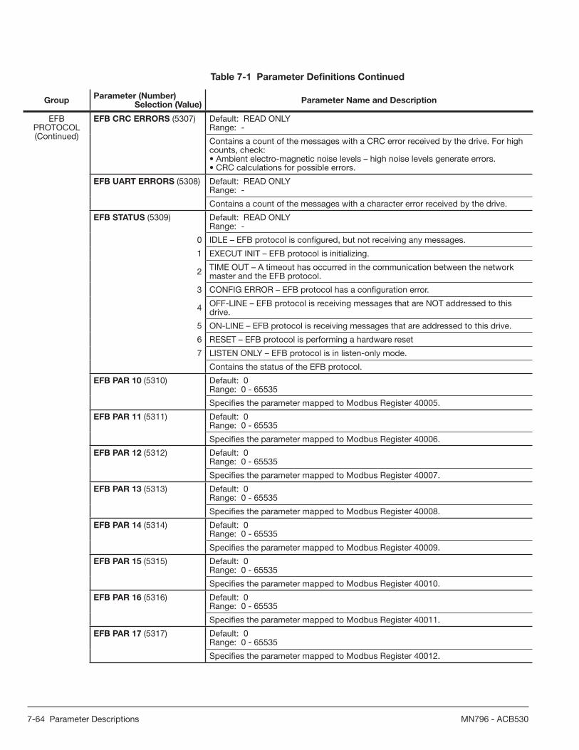
7-64 Parameter Descriptions MN796 - ACB530
GroupParameter (Number)
Selection (Value)Parameter Name and Description
EFB PROTOCOL(Continued)
EFB CRC ERRORS (5307) Default: READ ONLYRange: -
Contains a count of the messages with a CRC error received by the drive. For high counts, check:• Ambient electro-magnetic noise levels – high noise levels generate errors.• CRC calculations for possible errors.
EFB UART ERRORS (5308) Default: READ ONLYRange: -
Contains a count of the messages with a character error received by the drive.
EFB STATUS (5309) Default: READ ONLYRange: -
0 IDLE – EFB protocol is confi gured, but not receiving any messages.
1 EXECUT INIT – EFB protocol is initializing.
2 TIME OUT – A timeout has occurred in the communication between the network master and the EFB protocol.
3 CONFIG ERROR – EFB protocol has a confi guration error.
4 OFF-LINE – EFB protocol is receiving messages that are NOT addressed to this drive.
5 ON-LINE – EFB protocol is receiving messages that are addressed to this drive.
6 RESET – EFB protocol is performing a hardware reset
7 LISTEN ONLY – EFB protocol is in listen-only mode.
Contains the status of the EFB protocol.
EFB PAR 10 (5310) Default: 0Range: 0 - 65535
Specifi es the parameter mapped to Modbus Register 40005.
EFB PAR 11 (5311) Default: 0Range: 0 - 65535
Specifi es the parameter mapped to Modbus Register 40006.
EFB PAR 12 (5312) Default: 0Range: 0 - 65535
Specifi es the parameter mapped to Modbus Register 40007.
EFB PAR 13 (5313) Default: 0Range: 0 - 65535
Specifi es the parameter mapped to Modbus Register 40008.
EFB PAR 14 (5314) Default: 0Range: 0 - 65535
Specifi es the parameter mapped to Modbus Register 40009.
EFB PAR 15 (5315) Default: 0Range: 0 - 65535
Specifi es the parameter mapped to Modbus Register 40010.
EFB PAR 16 (5316) Default: 0Range: 0 - 65535
Specifi es the parameter mapped to Modbus Register 40011.
EFB PAR 17 (5317) Default: 0Range: 0 - 65535
Specifi es the parameter mapped to Modbus Register 40012.
Table 7-1 Parameter Defi nitions Continued

Parameter Descriptions 7-65MN796 - ACB530
GroupParameter (Number)
Selection (Value)Parameter Name and Description
EFB PROTOCOL(Continued)
EFB PAR 18 (5318) Default: 0Range: 0 - 65535
For Modbus: Sets additional delay in milliseconds before the ACB530 begins transmitting response to the master request.
EFB PAR 19 (5319) Default: 0Range: 0000 - FFFF hex
Baldor Drives profi le (Baldor DRV LIM or Baldor DRV FULL) Control Word. Read only copy of the Fieldbus Control Word.
EFB PAR 20 (5320) Default: 0Range: 0000 - FFFF hex
Baldor Drives profi le (Baldor DRV LIM or Baldor DRV FULL) Status Word. Read only copy of the Fieldbus Status Word.
LOAD ANALYZER
PVL SIGNAL (6401) Default: 103 (parameter 0103 OUTPUT FREQ)Range: 100 - 178
100 NOT SELECTED – No signal (parameter) logged for the peak value.
101 - 178 Logs parameter 0101 - 0178.
Defi nes (by number) the signal logged for the peak value.• Any parameter number in Group: OPERATING DATA can be selected. Eg 102 = parameter 0102 SPEED.
PVL FILTER TIME (6402) Default: 0.1 sRange: 0.0 - 120.0 s
Defi nes the fi lter time in seconds for peak value logging.
LOGGERS RESET (6403) Default: 0 (NOT SEL)Range: -6 to 7
0 NOT SEL – No reset selected.
1 DI1 – Reset loggers on the rising edge of digital input DI1.
2 to 6 DI2 - DI6 – Reset loggers on the rising edge of digital input DI2 - DI6.
7 RESET – Reset loggers. Parameter is set to NOT SEL.
-1 DI1 (INV) – Reset loggers on the falling edge of digital input DI1.
-2 to -6 DI2 (INV) - DI6 (INV) – Reset loggers on the falling edge of digital input DI2 - DI6.
Defi nes the source for the reset of peak value logger and amplitude logger 2.
AL2 SIGNAL (6404) Default: 103 (parameter 0103 OUTPUT FREQ)Range: 100 - 178
100 NOT SELECTED – No signal (parameter) logged for amplitude distribution (amplitude logger 2).
101 - 178 Logs parameter 0101 - 0178.
Defi nes the signal logged for amplitude logger 2.• Any parameter number in Group: OPERATING DATA can be selected. Eg 102 = parameter 0102 SPEED.
AL2 SIGNAL BASE (6405) Default: Depends on the signal selected with par. 6404Range:
Defi nes the base value from which the percentage distribution is calculated.• Representation and default value depends on the signal selected with parameter 6404 AL2 SIGNAL.
PEAK VALUE (6406) Default: Range:
Detected peak value of the signal selected with parameter 6401 PVL SIGNAL.
Table 7-1 Parameter Defi nitions Continued

7-66 Parameter Descriptions MN796 - ACB530
GroupParameter (Number)
Selection (Value)Parameter Name and Description
LOAD ANALYZER(Continued)
PEAK TIME 1 (6407) Default: Range: Date dd.mm.yy / power-on time in days
Date of the peak value detection.• Format: Date if the real time clock is operating (dd.mm.yy). / The number of days elapsed after the power-on if the real time clock is not used, or was not set (xx d).
PEAK TIME 2 (6408) Default: Range: Time hh.mm.ss
Time of the peak value detection.• Format: hours:minutes:seconds.
CURRENT AT PEAK (6409) Default: Range: 0.0 - 6553.5 A
Current at the moment of the peak value (amperes).
UDC AT PEAK (6410) Default: Range: 0 - 65535 V
DC voltage at the moment of the peak value (volts).
FREQ AT PEAK (6411) Default: Range: 0.0 - 6553.5 Hz
Output frequency at the moment of the peak value (hertz).
TIME OF RESET 1 (6412) Default: Range: Date dd.mm.yy / power-on time in days
Last reset date of the peak logger and amplitude logger 2.• Format: Date if the real time clock is operating (dd.mm.yy). / The number of days elapsed after the power-on if the real time clock is not used, or was not set (xx d).
TIME OF RESET 2 (6413) Default: Range: Time hh.mm.ss
Last reset time of the peak logger and amplitude logger 2.• Format: hours:minutes:seconds.
AL1RANGE0TO10 (6414) Default: Range: 0.0 - 100.0%
Amplitude logger 1 (current in percent of nominal current I2N) 0 - 10% distribution.
AL1RANGE10TO20 (6415) Default: Range: 0.0 - 100.0%
Amplitude logger 1 (current in percent of nominal current I2N) 10 - 20% distribution.
AL1RANGE20TO30 (6416) Default: Range: 0.0 - 100.0%
Amplitude logger 1 (current in percent of nominal current I2N) 20 - 30% distribution.
AL1RANGE30TO40 (6417) Default: Range: 0.0 - 100.0%
Amplitude logger 1 (current in percent of nominal current I2N) 30 - 40% distribution.
AL1RANGE40TO50 (6418) Default: Range: 0.0 - 100.0%
Amplitude logger 1 (current in percent of nominal current I2N) 40 - 50% distribution.
AL1RANGE50TO60 (6419) Default: Range: 0.0 - 100.0%
Amplitude logger 1 (current in percent of nominal current I2N) 50 - 60% distribution.
AL1RANGE60TO70 (6420) Default: Range: 0.0 - 100.0%
Amplitude logger 1 (current in percent of nominal current I2N) 60 - 70% distribution.
Table 7-1 Parameter Defi nitions Continued

Parameter Descriptions 7-67MN796 - ACB530
GroupParameter (Number)
Selection (Value)Parameter Name and Description
LOAD ANALYZER(Continued)
AL1RANGE70TO80 (6421) Default: Range: 0.0 - 100.0%
Amplitude logger 1 (current in percent of nominal current I2N) 70 - 80% distribution.
AL1RANGE80TO90 (6422) Default: Range: 0.0 - 100.0%
Amplitude logger 1 (current in percent of nominal current I2N) 80 - 90% distribution.
AL1RANGE90TO (6423) Default: Range: 0.0 - 100.0%
Amplitude logger 1 (current in percent of nominal current I2N) over 90% distribution.
AL2RANGE0TO10 (6424) Default: Range: 0.0 - 100.0%
Amplitude logger 2 (signal selection with parameter 6404) 0 - 10% distribution.
AL2RANGE10TO20 (6425) Default: Range: 0.0 - 100.0%
Amplitude logger 2 (signal selection with parameter 6404) 10 - 20% distribution.
AL2RANGE20TO30 (6426) Default: Range: 0.0 - 100.0%
Amplitude logger 2 (signal selection with parameter 6404) 20 - 30% distribution.
AL2RANGE30TO40 (6427) Default: Range: 0.0 - 100.0%
Amplitude logger 2 (signal selection with parameter 6404) 30 - 40% distribution.
AL2RANGE40TO50 (6428) Default: Range: 0.0 - 100.0%
Amplitude logger 2 (signal selection with parameter 6404) 40 - 50% distribution.
AL2RANGE50TO60 (6429) Default: Range: 0.0 - 100.0%
Amplitude logger 2 (signal selection with parameter 6404) 50 - 60% distribution.
AL2RANGE60TO70 (6430) Default: Range: 0.0 - 100.0%
Amplitude logger 2 (signal selection with parameter 6404) 60 - 70% distribution.
AL2RANGE70TO80 (6431) Default: Range: 0.0 - 100.0%
Amplitude logger 2 (signal selection with parameter 6404) 70 - 80% distribution.
AL2RANGE80TO90 (6432) Default: Range: 0.0 - 100.0%
Amplitude logger 2 (signal selection with parameter 6404) 80 - 90% distribution.
AL2RANGE90TO (6433) Default: Range: 0.0 - 100.0%
Amplitude logger 2 (signal selection with parameter 6404) over 90% distribution.
Table 7-1 Parameter Defi nitions Continued

7-68 Parameter Descriptions MN796 - ACB530
GroupParameter (Number)
Selection (Value)Parameter Name and Description
OPTIONS COMM PROT SEL (9802) Default: 0 (NOT SEL)Range: 0, 1, 4
0 NOT SEL – No communication protocol selected.
1STD MODBUS – The drive communicates with Modbus via the RS485 channel (X1-communications, terminal).• See also Group: EFB PROTOCOL.
4EXT FBA – The drive communicates via a fi eldbus adapter module in option slot 2 of the drive.• See also Group: EXT COMM MODULE.
Selects the communication protocol.NOTE: COMM PROT SEL (9802) can only be modifi ed if the drive is stopped.
Table 7-1 Parameter Defi nitions Continued

Start-Up, Motor Model Calc & Customizing Your Application 8-1MN796 - ACB530
Chapter 8Start-Up, Motor Model Calc & Customizing Your Application
This chapter contains information on how to perform the start-up; start, stop, change the direction of the motor rotation and adjust the speed of the motor through the I/O interface; and perform a motor model calculation on the drive.
The chapter also describes program features. For each feature, there is a list of related user settings, actual signals, and fault and alarm messages.
8.1 Starting up the drive
WARNING! The start-up may only be carried out by a qualifi ed electrician. The safety instructions given in Chapter 1 must be followed during the start-up procedure.
WARNING! The drive will start up automatically at power-up if the external run command is on and the drive is in the remote control mode.
WARNING! Failure to correctly start up the motor may cause damage. De-couple the driven machine if: • there is a risk of damage in case of incorrect direction of rotation, or • a motor model calc needs to be performed during the drive start-up. Motor model calc is essential only in applications
that require the ultimate in motor control accuracy.
The drive start up uses the assisant keypad.
The Start-up assistant, which is included in the assistant keypad only, guides you through all essential settings to be done. In the manual start-up, the drive gives no guidance; you go through the very basic settings by following the instructions given in section Performing a manual start-up below.
8.1.1 Starting up the drive without a keypad
POWER-UP
1. Apply input power and wait for a moment.2. Check that the red LED is not lit and the green LED is lit but not blinking.The drive is now ready for use.
8.1.2 Performing a manual start-upFor the manual start-up, you can use the assistant keypad.
Before you start, ensure that you have obtained the motor nameplate data.
8.1.2.1 POWER-UP
Apply input power.
The assistant keypad asks if you want to run the Start-up assistant. If you press , the Start-up assistant is not run, and you can continue with the manual start-up procedure described below.
8.1.2.2 MANUAL ENTRY OF START-UP DATA (parameter group 99)
On the assistant keypad, select the needed language from parameter 9901 for the values of the available language alternatives.
See Chapter 6 for assistance on editing parameters.
Select the operating mode (parameter 9902) according to how the control cables are connected.
The default value ABB 2-wire is suitable in most cases.

8-2 Start-Up, Motor Model Calc & Customizing Your Application MN796 - ACB530
Select the control type (parameter 9904).
OPEN VECTOR: SPEED is suitable in most cases.V/F: CONTROL is recommended
• for multimotor drives when the number of the motors connected to the drive is variable
• when the nominal motor current is less than 20% of the nominal current of the drive
• when the drive is used for test purposes with no motor connected.
Enter the motor data from the motor nameplate.
Asynchronous motor nameplate example:
M2AA 200 MLA 4
147514751470147014751770
32.55634595459
0.830.830.830.830.830.83
3GAA 202 001 - ADA
180
IEC 34-1
6210/C36312/C3
Cat. no 35 30 30 30 30 3050
5050505060
690 Y400 D660 Y380 D415 D440 D
V Hz kW r/min A cos IA/IN t E/sIns.cl. F IP 55
NoIEC 200 M/L 55
3 motor
ABB Motors
Note: Set the motor data to exactly the same value as on the motor nameplate.
For example, if the motor nominal speed is 1470 rpm on the nameplate, setting the value of parameter 9908 MOTOR NOM SPEED to 1500 rpm results in the wrong operation of the drive.

8-3 Start-Up, Motor Model Calc & Customizing Your Application MN796 - ACB530
Enter the motor data from the motor nameplate. (Continued)
• motor rated voltage (parameter 9905).Use motor rated voltage and perform motor model calc.If the voltage is given as voltage per rpm, eg 60 V per 1000 rpm, the voltage for 3000 rpm nominal speed is 3 · 60 V = 180 V.
• motor rated amps (parameter 9906)Allowed range: 0.2…2.0 · I2N A
• motor rated frequency (parameter 9907)
• motor rated speed (parameter 9908)
• motor rated hp (parameter 9909)
Select the calc motor model method (parameter 9910)
The default value 0 using the identifi cation magnetization is suitable for most applications. it is applied in this basic set-up procedure. Note that this requires parameter 9904 to be set to Vector: Speed.
If your selection is NO, move to the next step.
Value YES should be selected if:• the operation point is near zero speed, and/or• operation at torque range above the motor nominal torque over a
wide speed range and without any measured speed feedback is required.

8-4 Start-Up, Motor Model Calc & Customizing Your Application MN796 - ACB530
8.1.2.3 IDENTIFICATION MAGNETIZATION WITH MOTOR MODEL CALC SELECTION ON
Press to switch to local control (LOC shown on the left).
Press to start the drive. The motor model is now calculated by magnetizing the motor for 10 to 15 seconds at zero speed.
8.1.2.4 Direction of the motor Rotation
Check the direction of the motor rotation.
• If the drive is in remote control (REM shown on the left), switch to local control by pressing .
• Increase the frequency reference from zero to a small value with key .
• Press to start the motor.
• Check that the actual direction of the motor is the same as indicated on the display (FWD (forward) or REV (reverse)).
• Press to stop the motor.
To change the direction of the motor rotation:
• Invert the phases by changing the value of parameter 9914 to the opposite (From 0 (NO) to 1 ( YES) or vice versa)
• Verify your work by applying input power and repeating the check as described above.
8.1.2.5 Speed Limits and Acceleration/Deceleration Times
Set the minimum speed (parameter 2001).
Set the maximum speed (parameter 2002).
Set the acceleration time 1 (parameter 2202).
NOTE: Acceleration time 2 (parameter 2205) must also be set if two acceleration times will be used in the application.

Start-Up, Motor Model Calc & Customizing Your Application 8-5MN796 - ACB530
Set the deceleration time 1 (parameter 2204).
NOTE: Deceleration time 2 (parameter 2205) must also be set if two deceleration times will be used in the application.
8.1.2.6 Saving a user mode and fi nal check
The start-up is now complete.
You can now set the parameters required by your application and save the settings as a user mode.
Check that the drive state is OK.
Assistant Keypad: Check that there are not faults or alarms shown on the display.
1. Verify that the panel LED is green and does not blink.
THE DRIVE IS NOW READY FOR USE.
8.1.3 Performing a Guided Start-Up
To be able to perform the guided start-up, you need the assistant keypad. Guided start-up is applicable to AC induction motors.
Before you start, ensure that you have the motor nameplate data on hand.
8.1.3.1 POWER-UP
Apply input power. The keypad will ask if you want to use the Start-up assistant.
• Press (when YES is highlighted) to run the Start-up assistant.• Press if you do not want to run the Start-up assistant.
• Press to highlight NO and then press to select if the panel asks you to run the Start-up assistant on next drive start up.
8.1.3.2 SELECTING THE LANGUAGE
If you run the Start-up assistant, the display then asks you to select the language. Scroll to the desired language with keys and press to accept.
If you press , the Start-up assistant is stopped.

8-6 Start-Up, Motor Model Calc & Customizing Your Application MN796 - ACB530
8.1.3.3 STARTING THE GUIDED SET-UP
The Start-up assistant now guides you through the set-up tasks, starting with the motor set-up. Set the motor data to exactly the same value as on the motornameplate.
Scroll to the desired parameter value with keys and press to accept and continue with the Start-up assistant.
Note: At any time, if you press , the Start-up assistant is stopped and the display goes to the Output mode.
The basic startup is now complete. To continue setup with another Assistant, please select the desired Assistant from the menu now showing on the keypad and press .
8.1.3.4 DIRECTION OF THE MOTOR ROTATION
Press to switch to local control (LOC shown on the left).• If the drive is in remote control (REM shown on the status line), switch to local
control by pressing .
• If you are not in the Output mode, press repeatedly until you get there.
• Increase the frequency reference from zero to a small value with key .
• Press to start the motor.
• Check that the actual direction of the motor is the same as indicated on the display ( means forward and reverse).
• Press to stop the motor.
To change the direction of the motor rotation:
• Invert the phases by changing the value of parameter 9914 to the opposite, ie from 0 (NO) to 1 (YES), or vice versa.
• Verify your work by applying input power and repeating the check as described above.
8.1.3.5 FINAL CHECK
After the whole set-up is completed, check that there are no faults or alarms shown on the display and the panel LED is green and does not blink.
THE DRIVE IS NOW READY FOR USE.
8.2 Controlling the Drive through the I/O Interface
This section gives instructions on how to operate the drive through the digital and analog inputs when:• the motor start-up is performed, and• the default (standard) parameter settings are valid.Displays of the basic keypad are shown as an example.
8.2.1 PRELIMINARY SETTINGS
If you need to change the direction of rotation, check that parameter 1003 DIRECTION is set to 3 (REQUEST).
Ensure that the control connections are wired according to the connection diagram given for standard mode.
Ensure that the drive is in remote control. Press key to switch between remote and
local control.
In remote control, the panel display shows text REM.

Start-Up, Motor Model Calc & Customizing Your Application 8-7MN796 - ACB530
8.2.2 STARTING AND CONTROLLING THE SPEED OF THE MOTOR
Start by switching digital input DI1 to ON.
Assistant Keypad: The arrow starts rotating. It is dotted until the setpoint is reached.
Basic Control Panel: Text FWD starts fl ashing fast and stops after the setpoint is reached.
Regulate the drive output frequency (motor speed) by adjusting the voltage of analog input AI1.
8.2.3 CHANGING THE DIRECTION OF THE MOTOR ROTATION
Reverse direction: Switch digital input DI2 on.
Forward direction: Switch digital input DI2 off.
8.2.4 STOPPING THE MOTOR
Switch digital input DI1 off. The motor stops.
Assistant keypad: The arrow stops rotating.
Basic Control Panel: Text FWD starts fl ashing slowly.
8.3 Performing Motor Model Calc
The drive estimates motor characteristics automatically when the drive is started for the fi rst time and after any motor parameter (group 99 START-UP DATA) is changed. This is valid when parameter 9910 Motor model calc has value NO.
In most applications there is no need to perform a Calc Motor Model. Should be set to YES if:• vector control mode is used (parameter 9904 = OPEN VECTOR• operation point is near zero speed and/or• permanent magnet synchronous motor is used and the back emf voltage is unknown.
Note: If motor parameters (group: START-UP DATA) are changed after the motor model calc, it must be repeated.

8-8 Start-Up, Motor Model Calc & Customizing Your Application MN796 - ACB530
8.3.1 Motor Model Calc
The general parameter setting procedure is not repeated here. The motor model calc cannot be performed without a keypad.
8.3.1.1 PRE-CHECK
WARNING! The motor will run at up to approximately 50 - 80% of the nominal speed during the motor model calc. The motor will rotate in the forward direction. Ensure that it is safe to run the motor before performing the motor model calc!
De-couple the motor from the driven equipment.
If parameter values (group: OPERATING DATA to group: OPTIONS) are changed before the motor model calc, check that the new settings meet the following conditions:
• 2001 MINIMUM SPEED < 0 rpm
• 2002 MAXIMUM SPEED > 80% of the motor rated speed
• 2003 MAX CURRENT > I2N
• 2017 MAX TORQUE 1 > 50%
Check that the Run enable signal is on (parameter 1601).
Ensure that the panel is in local control (LOC shown at the top). Press key to switch between local and remote control.
8.3.1.2 MOTOR MODEL CALC WITH THE ASSISTANT KEYPAD
Change parameter 9910 Calc Motor Model YES. Save the new setting by pressing .
If you want to monitor actual values during the Motor Model Calc, go to the Output mode by pressing repeatedly until you get there.
Press to start the Motor Model Calc. The panel keeps switching between the display that was shown when you started the Motor Model Calc and the alarm display presented on the right.
In general, it is recommended not to press any keypad keys during the Motor Model Calc. However, you can stop the Motor Model Calc at any time by pressing .
After the Motor Model Calc is completed, the alarm display is not shown any more.
If the Motor Model Calc fails, the fault display presented on the right is shown.
8.4 Program features
The section describes program features. For each feature, there is a list of related user settings, actual signals, and fault and alarm messages.
8.4.1 Start-up assistant
8.4.1.1 Introduction
The Start-up assistant (requires the assistant keypad) guides the user through the start-up procedure, helping to enter the requested data (parameter values) to the drive. The Start-up assistant also checks that the entered values are valid, ie within the allowed range.
The Start-up assistant calls other assistants, each of which guides the user through the task of specifying a related parameter set. At the fi rst start, the drive suggests entering the fi rst task, Language select, automatically. The user may activate the tasks either one after the other as the Start-up assistant suggests, or independently. The user may also adjust the drive parameters in the conventional way without using the assistant at all.
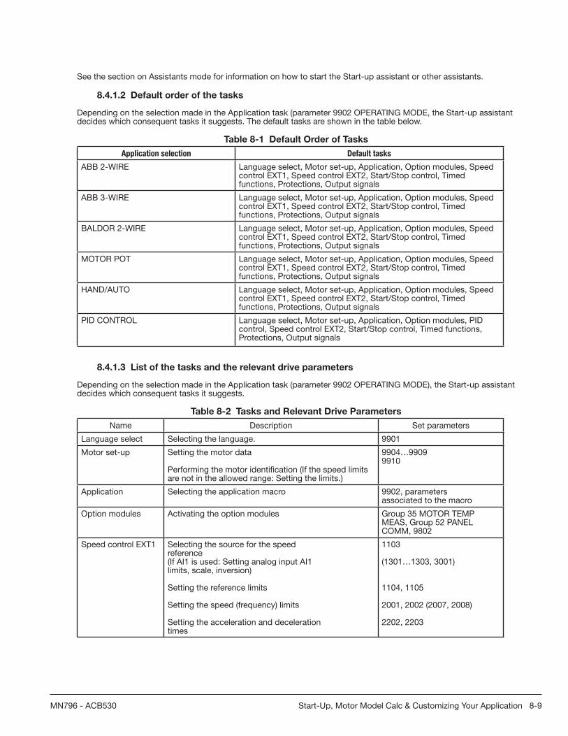
Start-Up, Motor Model Calc & Customizing Your Application 8-9MN796 - ACB530
See the section on Assistants mode for information on how to start the Start-up assistant or other assistants.
8.4.1.2 Default order of the tasks
Depending on the selection made in the Application task (parameter 9902 OPERATING MODE, the Start-up assistant decides which consequent tasks it suggests. The default tasks are shown in the table below.
Table 8-1 Default Order of Tasks
Application selection Default tasks
ABB 2-WIRE Language select, Motor set-up, Application, Option modules, Speed control EXT1, Speed control EXT2, Start/Stop control, Timedfunctions, Protections, Output signals
ABB 3-WIRE Language select, Motor set-up, Application, Option modules, Speed control EXT1, Speed control EXT2, Start/Stop control, Timedfunctions, Protections, Output signals
BALDOR 2-WIRE Language select, Motor set-up, Application, Option modules, Speed control EXT1, Speed control EXT2, Start/Stop control, Timedfunctions, Protections, Output signals
MOTOR POT Language select, Motor set-up, Application, Option modules, Speed control EXT1, Speed control EXT2, Start/Stop control, Timedfunctions, Protections, Output signals
HAND/AUTO Language select, Motor set-up, Application, Option modules, Speed control EXT1, Speed control EXT2, Start/Stop control, Timedfunctions, Protections, Output signals
PID CONTROL Language select, Motor set-up, Application, Option modules, PID control, Speed control EXT2, Start/Stop control, Timed functions,Protections, Output signals
8.4.1.3 List of the tasks and the relevant drive parameters
Depending on the selection made in the Application task (parameter 9902 OPERATING MODE), the Start-up assistant decides which consequent tasks it suggests.
Table 8-2 Tasks and Relevant Drive Parameters
Name Description Set parameters
Language select Selecting the language. 9901
Motor set-up Setting the motor data
Performing the motor identifi cation (If the speed limits are not in the allowed range: Setting the limits.)
9904…99099910
Application Selecting the application macro 9902, parametersassociated to the macro
Option modules Activating the option modules Group 35 MOTOR TEMPMEAS, Group 52 PANELCOMM, 9802
Speed control EXT1 Selecting the source for the speedreference(If AI1 is used: Setting analog input AI1limits, scale, inversion)
Setting the reference limits
Setting the speed (frequency) limits
Setting the acceleration and decelerationtimes
1103
(1301…1303, 3001)
1104, 1105
2001, 2002 (2007, 2008)
2202, 2203

8-10 Start-Up, Motor Model Calc & Customizing Your Application MN796 - ACB530
Speed control EXT2 Selecting the source for the speed reference(If AI1 is used: Setting analog input AI1limits, scale, inversion)
Setting the reference limits
1106
(1301…1303, 3001)
1107, 1108
PID control Selecting the source for the processreference(If AI1 is used: Setting analog input AI1limits, scale, inversion)
Setting the reference limits
Setting the speed (frequency) limits
Setting the source and limits for theprocess actual value
1106
(1301…1303, 3001)
1107, 1108
2001, 2002 (2007, 2008)
4016, 4018, 4019
Start/Stop control Selecting the source for start and stopsignals of the two external controllocations, EXT1 and EXT2
Selecting between EXT1 and EXT2
Defi ning the direction control
Defi ning the start and stop modes
Selecting the use of Run enable signal
1001, 1002
1102
1003
2101…2103
1601
Protections Setting the current and torque limits 2003, 2017
Output signals Selecting the signals indicated throughrelay output RO1 and, if MREL-01 outputrelay module is in use, RO2…RO4.
Selecting the signals indicated throughanalog output AO
Setting the minimum, maximum, scalingand inversion
Group 14 RELAYOUTPUTS
Group 15 ANALOGOUTPUTS
8.4.1.4 Contents of the assistant displays
There are two types of displays in the Start-up assistant: Main displays and information displays. The main displays prompt the user to feed in information. The assistant steps through the main displays. The information displays contain help texts for the main displays. The fi gure below shows a typical example of both and explanations of the contents.
12
ParameterFeed-in fi eld
Help text ...... help text continued
8.5 Local control vs. external control
The drive can receive start, stop and direction commands and reference values from the keypad or through digital and analog inputs. Embedded fi eldbus or an optional fi eldbus adapter enables control over an open fi eldbus link. A PC equipped with the DriveWindow Light 2 PC tool can also control the drive.

Start-Up, Motor Model Calc & Customizing Your Application 8-11MN796 - ACB530
8.5.1 Local control
The control commands are given from the keypad keypad when the drive is inlocal control. LOC indicates local control on the panel display.
The keypad always overrides the external control signal sources when used inlocal control.
8.5.2 External control
When the drive is in external (remote) control, the commands are given through the standard I/O terminals (digital and analog inputs) and/or the fi eldbus interface. In addition, it is also possible to set the keypad as the source for the external control.
External control is indicated with REM on the panel display.
The user can connect the control signals to two external control locations, EXT1 or EXT2. Depending on the user selection, either one is active at a time.
8.5.3 Settings
Panel Key Additional Information
LOC/REM Selection between local and external (remote control)
Parameter
1102 Selection between EXT1 and EXT2
1001/1002 Start, stop, direction source for EXT1/EXT2
1103/1106 Reference source for EXT1/EXT2
8.5.4 Diagnostics
Actual Signal Additional Information
0111/0112 EXT1/EXT2 reference
8.5.5 Block diagram: Start, stop, direction source for EXT1
The fi gure below shows the parameters that select the interface for start, stop, and direction for external control location EXT1.

8-12 Start-Up, Motor Model Calc & Customizing Your Application MN796 - ACB530
Figure 8-1 Start, Stop, Direction source for EXT1
8.5.6 Block diagram: Reference source for EXT1The fi gure below shows the parameters that select the interface for the speed reference of external control location EXT1.
Figure 8-2 Reference Source for EXT1
8.6 Reference types and processing
The drive can accept a variety of references in addition to the conventional analog input and keypad signals.• The drive reference can be given with two digital inputs: One digital input increases the speed, the other decreases it.• The drive can form a reference out of two analog input signals by using mathematical functions: addition, subtraction,
multiplication and division.• The drive can form a reference out of an analog input signal and a signal received through a serial communication
interface by using mathematical functions: addition and multiplication.• The drive reference can be given with frequency input.• In external control location EXT1/2, the drive can form a reference out of an analog input signal and a signal received
through Sequence programming by using a mathematical function: addition.

Start-Up, Motor Model Calc & Customizing Your Application 8-13MN796 - ACB530
It is possible to scale the external reference so that the signal minimum and maximum values correspond to a speed other than the minimum and maximum speed limits.
8.6.1 Settings
Parameter Additional information
Group 11 REFERENCE SELECT External reference source, type and scaling
Group 20 LIMITS Operating limits
Group 22 ACCEL/DECEL Speed reference acceleration/deceleration ramps
Group 24 TORQUE CONTROL Torque reference ramp times
Group 32 SUPERVISION Reference supervision
8.6.2 Diagnostics
Actual signal Additional information
0111/0112 REF1/REF2 reference
Group 03 FB ACTUAL SIGNALS References in different stages of the reference processing chain
8.7 Programmable analog inputs
The drive has two programmable analog voltage/current inputs. The inputs can be inverted, fi ltered and the maximum and minimum values can be adjusted.
8.7.1 Settings
Parameter Additional information
Group 11 REFERENCE SELECT REF1/2 selection
Group 13 ANALOG INPUTS Trimming function settings
3001, 3021, 3022, 3107 AI loss supervision
Group 35 MOTOR TEMP MEAS AI in motor temperature measurement
Groups 40 PROCESS PID SET 1…42 EXT / TRIM PID
AI as PID process control reference or actual value source
8.7.2 Diagnostics
Actual signal Additional information
0120, 0121 Analog input values
1401 AI1/AI2 signal loss through RO 1
1402/1403/1410 AI1/AI2 signal loss through RO 2…4. With option
Alarm
AI1 LOSS / AI2 LOSS AI1/AI2 signal below limit 3021 AI1 FAULT LIMIT /3022 AI2 FAULT LIMIT
Fault
AI1 LOSS / AI2 LOSS AI1/AI2 signal below limit 3021 AI1 FAULT LIMIT /3022 AI2 FAULT LIMIT
PAR AI SCALE Incorrect AI signal scaling (1302 < 1301 or 1305 <1304)
8.8 Programmable analog output
Two programmable current outputs (0 (4)…20 mA) are available. Analog output signal can be inverted, fi ltered and the maximum and minimum values can be adjusted. The analog output signals can be proportional to motor speed, output frequency, output current, motor torque, motor power, etc.

8-14 Start-Up, Motor Model Calc & Customizing Your Application MN796 - ACB530
8.8.1 Settings
Parameter Additional information
Group 15 ANALOG OUTPUTS AO value selection and processing
Group 35 MOTOR TEMP MEAS AO in motor temperature measurement
8.8.2 Diagnostics
Actual signal Additional information
0124 AO 1 value
0125 AO 2 value
Fault
PAR AO SCALE Incorrect AO signal scaling (1505L1504 or 1511L1510)
8.9 Programmable digital inputs
The drive has six programmable digital inputs. The update time for the digital inputs is 2 ms.One digital input (DI5) can be programmed as a frequency input.
8.9.1 Settings
Parameter Additional information
Group 10 START/STOP/DIR DI as start, stop, direction
Group 11 REFERENCE SELECT DI in reference selection, or reference source
Group 12 CONSTANT SPEEDS DI in constant speed selection
Group 16 SYSTEM CONTROLS DI as external Run enable, fault reset or user mode change signal
2109 DI as external emergency stop command source
2201 DI as acceleration and deceleration ramp selection signal
2209 DI as zero ramp force signal
3003 / 3004 DI as external fault source
Group 35 MOTOR TEMP MEAS DI in motor temperature measurement
4010 DI as PID controller reference signal source
4022 DI as sleep function activation signal in PID1
8.10 Programmable relay output
The drive has three programmable relay outputs. With a parameter setting it is possible to choose what information to indicate through the relay output: Ready, running, fault, alarm, etc.
A value can be written to a relay output through a serial communication link.
8.10.1 Settings
Parameter Additional information
Group 14 RELAY OUTPUTS RO value selections and operation times
8.10.2 Diagnostics
Actual signal Additional information
0134 RO Control word through fi eldbus control
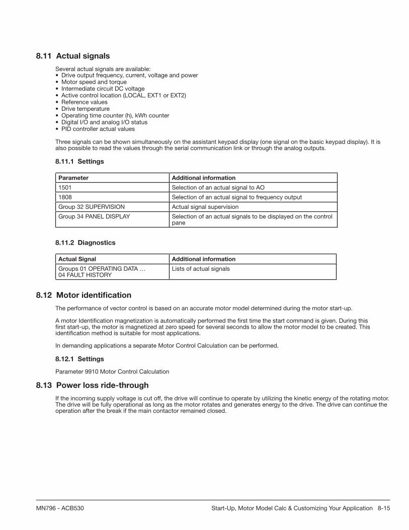
Start-Up, Motor Model Calc & Customizing Your Application 8-15MN796 - ACB530
8.11 Actual signals
Several actual signals are available:• Drive output frequency, current, voltage and power• Motor speed and torque• Intermediate circuit DC voltage• Active control location (LOCAL, EXT1 or EXT2)• Reference values• Drive temperature• Operating time counter (h), kWh counter• Digital I/O and analog I/O status• PID controller actual values
Three signals can be shown simultaneously on the assistant keypad display (one signal on the basic keypad display). It is also possible to read the values through the serial communication link or through the analog outputs.
8.11.1 Settings
Parameter Additional information
1501 Selection of an actual signal to AO
1808 Selection of an actual signal to frequency output
Group 32 SUPERVISION Actual signal supervision
Group 34 PANEL DISPLAY Selection of an actual signals to be displayed on the control pane
8.11.2 Diagnostics
Actual Signal Additional information
Groups 01 OPERATING DATA …04 FAULT HISTORY
Lists of actual signals
8.12 Motor identifi cation
The performance of vector control is based on an accurate motor model determined during the motor start-up.
A motor Identifi cation magnetization is automatically performed the fi rst time the start command is given. During this fi rst start-up, the motor is magnetized at zero speed for several seconds to allow the motor model to be created. This identifi cation method is suitable for most applications.
In demanding applications a separate Motor Control Calculation can be performed.
8.12.1 Settings
Parameter 9910 Motor Control Calculation
8.13 Power loss ride-through
If the incoming supply voltage is cut off, the drive will continue to operate by utilizing the kinetic energy of the rotating motor. The drive will be fully operational as long as the motor rotates and generates energy to the drive. The drive can continue the operation after the break if the main contactor remained closed.

8-16 Start-Up, Motor Model Calc & Customizing Your Application MN796 - ACB530
Figure 8-1 Power Loss Ride-Through
UDC = Intermediate circuit voltage of the drive, fout = Output frequency of the drive, TM = Motor torque
Loss of supply voltage at nominal load (fout = 40 Hz). The intermediate circuit DC voltage drops to the minimum limit. The controller keeps the voltage steady as long as the input power is switched off. The drive runs the motor in generator mode. The motor speed falls but the drive is operational as long as the motor has enough kinetic energy.
8.13.1 Settings
Parameter 2006 UNDERVOLT CTRL
8.14 DC magnetizing
When DC magnetizing is activated, the drive automatically magnetizes the motor before starting. This feature guarantees the highest possible break-away torque, up to 180% of the motor nominal torque. By adjusting the premagnetizing time, it is possible to synchronize the motor start and eg a mechanical brake release. The Automatic start feature and DC magnetizing cannot be activated at the same time.
8.14.1 Settings
Parameters 2101 START FUNCTION and 2103 DC MAGN TIME
8.15 DC hold
With the motor DC hold feature, it is possible to lock the rotor at zero speed. When both the reference and the motor speed fall below the preset DC hold speed, the drive stops the motor and starts to inject DC into the motor. When the reference speed again exceeds theDC hold speed, the normal drive operation resumes.
8.15.1 Settings
Parameters 2101…2106

Start-Up, Motor Model Calc & Customizing Your Application 8-17MN796 - ACB530
8.16 Flux brakingThe drive can provide greater deceleration by raising the level of magnetization in the motor. By increasing the motor fl ux, the energy generated by the motor during braking can be converted to motor thermal energy.
Figure 8-1 Flux Braking Charts
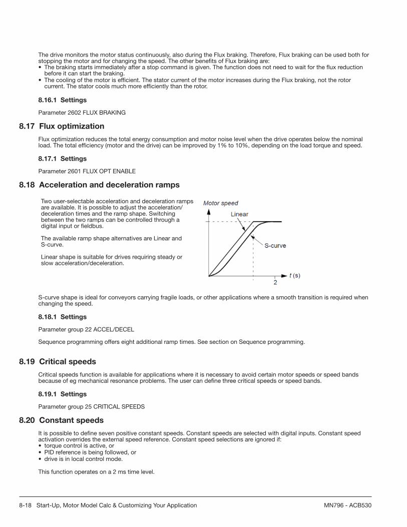
8-18 Start-Up, Motor Model Calc & Customizing Your Application MN796 - ACB530
The drive monitors the motor status continuously, also during the Flux braking. Therefore, Flux braking can be used both for stopping the motor and for changing the speed. The other benefi ts of Flux braking are:• The braking starts immediately after a stop command is given. The function does not need to wait for the fl ux reduction
before it can start the braking.• The cooling of the motor is effi cient. The stator current of the motor increases during the Flux braking, not the rotor
current. The stator cools much more effi ciently than the rotor.
8.16.1 Settings
Parameter 2602 FLUX BRAKING
8.17 Flux optimization
Flux optimization reduces the total energy consumption and motor noise level when the drive operates below the nominal load. The total effi ciency (motor and the drive) can be improved by 1% to 10%, depending on the load torque and speed.
8.17.1 Settings
Parameter 2601 FLUX OPT ENABLE
8.18 Acceleration and deceleration ramps
Two user-selectable acceleration and deceleration ramps are available. It is possible to adjust the acceleration/deceleration times and the ramp shape. Switching between the two ramps can be controlled through a digital input or fi eldbus.
The available ramp shape alternatives are Linear and S-curve.
Linear shape is suitable for drives requiring steady or slow acceleration/deceleration.
S-curve shape is ideal for conveyors carrying fragile loads, or other applications where a smooth transition is required when changing the speed.
8.18.1 Settings
Parameter group 22 ACCEL/DECEL
Sequence programming offers eight additional ramp times. See section on Sequence programming.
8.19 Critical speeds
Critical speeds function is available for applications where it is necessary to avoid certain motor speeds or speed bands because of eg mechanical resonance problems. The user can defi ne three critical speeds or speed bands.
8.19.1 Settings
Parameter group 25 CRITICAL SPEEDS
8.20 Constant speeds
It is possible to defi ne seven positive constant speeds. Constant speeds are selected with digital inputs. Constant speed activation overrides the external speed reference. Constant speed selections are ignored if:• torque control is active, or• PID reference is being followed, or• drive is in local control mode.
This function operates on a 2 ms time level.

Start-Up, Motor Model Calc & Customizing Your Application 8-19MN796 - ACB530
8.20.1 Settings
Parameter Additional information
Group 12 CONSTANT SPEEDS Constant speed settings
1208 Constant speed 7. Used also for fault functions (see group 30 FAULT FUNCTIONS) and for jogging function.
8.21 Speed controller tuning
It is possible to manually adjust the controller gain, integration time and derivation time, or let the drive perform a separate speed controller Autotune run (parameter 2305 AUTOTUNE RUN). In Autotune run, the speed controller is tuned based on the load and inertia of the motor and the machine. The fi gure below shows speed responses at a speed reference step (typically, 1 to 20%).
Figure 8-2 Speed Controller Tuning
The fi gure below is a simplifi ed block diagram of the speed controller. The controller output is the reference for the torque controller.

8-20 Start-Up, Motor Model Calc & Customizing Your Application MN796 - ACB530
NOTE: The speed controller can be used in vector control, ie when 9904 MOTOR CTRL MODE setting is VECTOR: SPEED or VECTOR: TORQ.
8.21.1 Settings
Parameter groups 23 SPEED CONTROL and 20 LIMITS
8.21.2 Diagnostics
Actual signal 0102 SPEED
8.22 V/F control
It is possible to select V/F control as the motor control method instead of vector control. In the V/F control mode, the drive is controlled with a frequency reference.
It is recommended to activate the V/F control mode in the following special applications:
• In multimotor drives: 1) if the load is not equally shared between the motors, 2) if the motors are of different sizes, or 3) if the motors are going to be changed after the motor identifi cation.
• If the nominal motor current is less than 20% of the nominal output current of the drive.• When the drive is used for test purposes with no motor connected.
The V/F control mode is not recommended for permanent magnet synchronous motors.
In the V/F control mode, some standard features are not available.
8.22.1 Settings
Parameter 9904 CONTROL TYPE
IR compensation for a scalar controlled drive IR compensation is active only when the motor control mode is V/F. When IR compensation is activated, the drive gives an extra voltage boost to the motor at low speeds. IR compensation is useful in applications that require high breakaway torque. In vector control, no IR compensation is possible/needed.
Parameter 2603 IR COMP VOLT
8.23 Programmable protection functions
8.23.1 AI<Min
AI<Min function defi nes the drive operation if an analog input signal falls below the set minimum limit.
8.23.2 Settings
Parameters 3001 AI<MIN FUNCTION, 3021 AI1 FAULT LIMIT and 3022 AI2 FAULT LIMIT
8.23.3 Panel loss
Panel loss function defi nes the operation of the drive if the keypad selected as the control location for the drive stops communicating.

Start-Up, Motor Model Calc & Customizing Your Application 8-21MN796 - ACB530
8.23.3.1 Settings
Parameter 3002 PANEL COMM ERR
8.23.4 External fault
External faults (1 and 2) can be supervised by defi ning one digital input as a source for an external fault indication signal.
8.23.4.1 Settings
Parameters 3003 EXTERNAL FAULT 1 and 3004 EXTERNAL FAULT 2
8.23.5 Stall protection
The drive protects the motor in a stall situation. It is possible to adjust the supervision limits (frequency, time) and choose how the drive reacts to the motor stall condition (alarm indication / fault indication & drive stop / no reaction).
8.23.5.1 Settings
Parameters 3010 STALL FUNCTION, 3011 STALL FREQUENCY and 3012 STALL TIME
8.23.6 Motor thermal protection
The motor can be protected against overheating by activating the Motor thermal protection function.
The drive calculates the temperature of the motor on the basis of the following assumptions:• The motor is in the ambient temperature of 30 °C (86°F) when power is applied to the drive.• Motor temperature is calculated using either the user-adjustable or automatically calculated motor thermal time constant
and motor load curve (see the fi gures below). The load curve should be adjusted if the ambient temperature exceeds 30 °C (86°F).
8.23.6.1 Settings
Parameters 3005 MOT THERM PROT, 3006 MOT THERM TIME, 3007 MOT LOAD CURVE, 3008 ZERO SPEED LOAD and 3009 BREAK POINT FREQ
NOTE: It is also possible to use the motor temperature measurement function. See section Motor temperature measurement through the standard I/O on page 160.
8.23.6.1 Settings
Parameters 3013 UNDERLOAD FUNC, 3014 UNDERLOAD TIME and 3015 UNDERLOAD CURVE
8.23.7 Earth fault protection
The Earth fault protection detects earth faults in the motor or motor cable. The protection can be selected to be active during start and run or during start only.
An earth fault in the input power line does not activate the protection.

8-22 Start-Up, Motor Model Calc & Customizing Your Application MN796 - ACB530
8.23.7.1 Settings
Parameter 3017 EARTH FAULT
8.23.8 Incorrect wiring
Defi nes the operation when incorrect input power cable connection is detected.
8.23.8.1 Settings
Parameter 3023 WIRING FAULT
8.24 Pre-programmed faults 8.24.1 Overcurrent
The overcurrent trip limit for the drive is 325% of the drive nominal current.
8.24.2 DC overvoltage
The DC overvoltage trip limit is 420 V (for 200 V drives) and 840 V (for 400 V drives).
8.24.3 DC undervoltage
The DC undervoltage trip limit is adaptive. See parameter 2006 UNDERVOLT CTRL.
8.24.4 Drive temperature
The drive supervises the IGBT temperature. There are two supervision limits: Alarm limit and fault trip limit.
8.24.5 Short-circuit
If a short-circuit occurs, the drive will not start and a fault indication is given.
8.24.6 Internal fault
If the drive detects an internal fault, the drive is stopped and a fault indication is given.
8.25 Operation limits
The drive has adjustable limits for speed, current (maximum), torque (maximum) and DC voltage.
8.25.1 Settings
Parameter group 20 LIMITS
8.26 Power limit
Power limitation is used to protect the input bridge and the DC intermediate circuit. If the maximum allowed power is exceeded, the drive torque is automatically limited. Maximum overload and continuous power limits depend on the drive hardware.
For specifi c values, see Technical data.
8.27 Automatic resets
The drive can automatically reset itself after overcurrent, overvoltage, undervoltage, external and “analog input below a minimum” faults. The Automatic resets must be activated by the user.
8.27.1 Settings
Parameter Additional information
Group 31 AUTOMATIC RESET Automatic reset settings

Start-Up, Motor Model Calc & Customizing Your Application 8-23MN796 - ACB530
8.27.2 Diagnostics
Alarm Additional information
AUTORESET Automatic reset alarm
8.28 Supervisions
The drive monitors whether certain user selectable variables are within the user defi ned limits. The user may set limits for speed, current etc. The supervision status can be indicated through relay or digital output.
The supervision functions operate on a 2 ms time level.
8.28.1 Settings
Parameter group 32 SUPERVISION
8.28.2 Diagnostics
Actual signal Additional information
1401 Supervision status through RO 1
1402/1403/1410 Supervision status through RO 2…4. With optionMREL-01 only.
1805 Supervision status through DO
8425, 8426 / 8435, 8436 /…/8495,8496
Sequence programming state change according to supervision functions
8.29 Parameter lock
The user can prevent parameter adjustment by activating the parameter lock.
8.29.1 Settings
Parameters 1602 PARAMETER LOCK and 1603 PASS CODE
8.30 PID control
There is one built-in PID controller in the drive:• Process PID (PID1)
The PID controller can be used when the motor speed needs to be controlled based on process variables such as pressure, fl ow or temperature.
When the PID control is activated, a process reference (setpoint) is connected to the drive instead of a speed reference. An actual value (process feedback) is also brought back to the drive. The drive compares the reference and the actual values, and automatically adjusts the drive speed in order to keep the measured process quantity (actual value) at the desired level (reference).

8-24 Start-Up, Motor Model Calc & Customizing Your Application MN796 - ACB530
8.30.1 Block diagrams
The fi gure below shows an application example: The controller adjusts the speed of a pressure boost pump according to the measured pressure and the set pressure reference.

Start-Up, Motor Model Calc & Customizing Your Application 8-25MN796 - ACB530
The following fi gure presents the speed/scalar control block diagram for process controller PID1.

8-26 Start-Up, Motor Model Calc & Customizing Your Application MN796 - ACB530
8.30.2 Settings
Parameter Additional information
1101 Local control mode reference type selection
1102 EXT1/EXT2 selection
1106 PID1 activation
1107 REF2 minimum limit
1501 PID2 output (external controller) connection to AO
9902 PID control macro selection
Groups 40 PROCESS PID SET1…
PID1 settings
8.30.3 Diagnostics
Actual signal Additional information
0126 PID 1 output value
0128 PID 1 setpoint value
0130 PID 1 feedback value
0132 PID 1 deviation
8.31 Sleep function for the process PID (PID1) control
The sleep function operates on a 2 ms time level.
The block diagram below illustrates the sleep function enable/disable logic. The sleep function can be put into use only when the PID control is active.

Start-Up, Motor Model Calc & Customizing Your Application 8-27MN796 - ACB530
8.31.1 Example
The time scheme below visualizes the operation of the sleep function.
Sleep function for a PID controlled pressure boost pump (when parameter 4022 SLEEP SELECTION is set to INTERNAL): The water consumption falls at night. As a consequence, the PID process controller decreases the motor speed. However, due to natural losses in the pipes and the low effi ciency of the centrifugal pump at low speeds, the motor does not stop but keeps rotating. The sleep function detects the slow rotation, and stops the unnecessary pumping after the sleep delay has passed.The drive shifts into sleep mode, still monitoring the pressure. The pumping restarts when the pressure falls under the allowed minimum level and the wake-up delay has passed.
8.31.2 Settings
Parameter Additional information
9902 PID control activation
4022…4026 Sleep function settings

8-28 Start-Up, Motor Model Calc & Customizing Your Application MN796 - ACB530
8.32 Motor temperature measurement through the standard I/O
This section describes the temperature measurement of one motor when the drive I/O terminals are used as the connection interface.
Motor temperature can be measured using Pt100 or PTC sensors connected to analog input and output.
WARNING! According to IEC 664, the connection of the motor temperature sensor requires double or reinforced insulation between motor live parts and the sensor. Reinforced insulation entails a clearance and creepage distance of 8 mm (0.3 in) (400/500 V AC equipment).
If the assembly does not fulfi ll the requirement, the I/O board terminals must be protected against contact and they may not be connected to other equipment, or the temperature sensor must be isolated from the I/O terminals.
It is also possible to monitor motor temperature by connecting a PTC sensor anda thermistor relay between the +24 V DC voltage supply offered by the drive and adigital input. The fi gure below displays the connection.
WARNING! According to IEC 664, the connection of the motor thermistor to the digital input requires double or reinforced insulation between motor live parts and the thermistor. Reinforced insulation entails a clearance and creeping distance of 8 mm (0.3 in) (400/500 V AC equipment).
If the thermistor assembly does not fulfi ll the requirement, the other I/O terminals of the drive must be protected against contact, or a thermistor relay must be used to isolate the thermistor from the digital input.
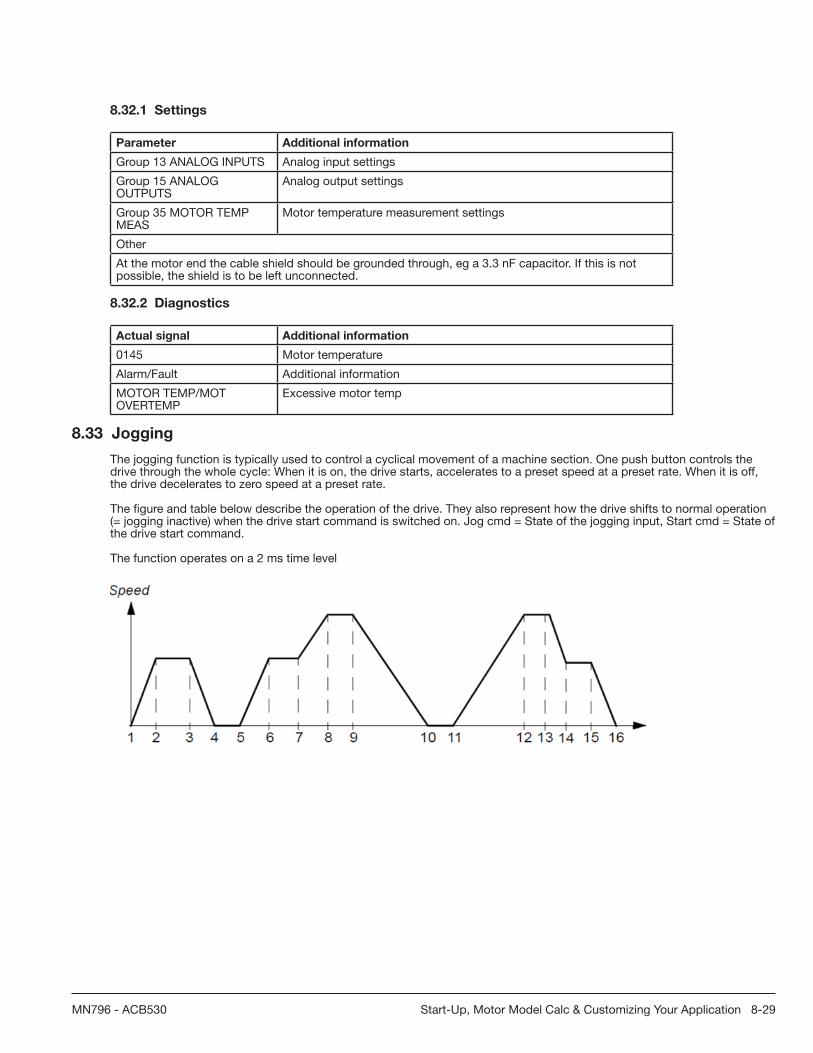
Start-Up, Motor Model Calc & Customizing Your Application 8-29MN796 - ACB530
8.32.1 Settings
Parameter Additional information
Group 13 ANALOG INPUTS Analog input settings
Group 15 ANALOG OUTPUTS
Analog output settings
Group 35 MOTOR TEMP MEAS
Motor temperature measurement settings
Other
At the motor end the cable shield should be grounded through, eg a 3.3 nF capacitor. If this is not possible, the shield is to be left unconnected.
8.32.2 Diagnostics
Actual signal Additional information
0145 Motor temperature
Alarm/Fault Additional information
MOTOR TEMP/MOT OVERTEMP
Excessive motor temp
8.33 Jogging
The jogging function is typically used to control a cyclical movement of a machine section. One push button controls the drive through the whole cycle: When it is on, the drive starts, accelerates to a preset speed at a preset rate. When it is off, the drive decelerates to zero speed at a preset rate.
The fi gure and table below describe the operation of the drive. They also represent how the drive shifts to normal operation (= jogging inactive) when the drive start command is switched on. Jog cmd = State of the jogging input, Start cmd = State of the drive start command.
The function operates on a 2 ms time level

8-30 Start-Up, Motor Model Calc & Customizing Your Application MN796 - ACB530
Phase Jog cmd
Start cmd
Description
1-2 1 0 Drive accelerates to the jogging speed along the acceleration ramp of the jogging function.
2-3 1 0 Drive runs at the jogging speed.
3-4 0 0 Drive decelerates to zero speed along the deceleration ramp of the jogging function.
4-5 0 0 Drive is stopped.
5-6 1 0 Drive accelerates to the jogging speed along the acceleration ramp of the jogging function.
6-7 1 0 Drive runs at the jogging speed.
7-8 x 1 Normal operation overrides the jogging. Drive accelerates to the speed reference along the active acceleration ramp.
8-9 x 1 Normal operation overrides the jogging. Drive follows the speed reference.
9-10 0 0 Drive decelerates to zero speed along the active deceleration ramp.
10-11 0 0 Drive is stopped.
11-12 x 1 Normal operation overrides the jogging. Drive accelerates to the speed reference along the active acceleration ramp.
12-13 x 1 Normal operation overrides the jogging. Drive follows the speed reference.
13-14 1 0 Drive decelerates to the jogging speed along the deceleration ramp of the jogging function.
14-15 1 0 Drive runs at the jogging speed.
15-16 0 0 Drive decelerates to zero speed along the deceleration ramp of the jogging function.
x = state can be either 1 or 0
Note: The jogging is not operational when the drive start command is on.
Note: The jogging speed overrides the constant speeds.
Note: The jogging uses ramp stop even if parameter 2102 STOP FUNCTION selection is COAST.
Note: The ramp shape time is set to zero during the jogging (ie linear ramp).
Jogging function uses constant speed 7 as jogging speed and acceleration/deceleration ramp pair 2.
It is also possible to activate jogging function 1 or 2 through fi eldbus. Jogging function 1 uses constant speed 7 and jogging function 2 uses constant speed 6. Both functions use acceleration/deceleration ramp pair 2.
8.33.1 Settings
Parameter Additional information
1004 Jogging activation
1208 Jogging speed
2112 Zero speed delay
2205, 2206 Acceleration and deceleration times
2207 Acceleration and deceleration ramp shape time: Set to zero during the jogging (ie linear ramp).
8.33.2 Diagnostics
Actual signal Additional information
1401 Jogging function status through RO 1
1402/1406 Jogging function status through RO 2…6

Start-Up, Motor Model Calc & Customizing Your Application 8-31MN796 - ACB530
8.34 Brake components
8.34.1 Availability
Braking availability for ACB530 drives, by frame size is:
• R1 and R2 – a built-in brake chopper is standard equipment. Add appropriate resistor, as determined using the following section. Resistors are available from Baldor.
• R3…R6 – does not include an internal brake chopper. Connect a chopper and a resistor, or a brake unit to the DC link terminals on the drive. Contact your Baldor representative for appropriate parts.
8.34.2 Selecting the braking resistors (frame sizes R1 and R2)
Braking resistor must meet three requirements:
• Resistance must be always higher than the minimum value RMIN defi ned for the drive type in the following tables. Never use resistance below this value.
• Resistance must be low enough to be able to produce the desired braking torque. To achieve the maximum braking torque (the larger of 150% of heavy duty or 110% of nominal duty), the resistance must not exceed RMAX. If maximum braking torque is not necessary, resistor values can exceed RMAX.
• The resistor power rating must be high enough to dissipate the braking power.
This requirement involves many factors:
– the maximum continuous power rating for the resistor(s) – the rate at which the resistor changes temperature (resistor thermal time constant) – maximum braking time ON – If the regeneration (braking) power is larger than the resistor rated power, there is a limit to the ON time, or the resistor overheats before the OFF period begins.
– minimum braking time OFF – If the regeneration (braking) power is larger than the resistor rated power, the OFF time must be large enough for the resistor to cool between ON periods.
– the peak braking power requirement – type of braking (deceleration to zero vs. overhauling load) – During deceleration to zero, the generated power steadily decreases, averaging half of the peak power. For an overhauling load, the braking is countering an external force (gravity for example) and the braking power is constant. The total heat generated from an overhauling load is double the heat generated
– from deceleration to zero speed (for the same peak torque and ON time).
– the peak braking power requirement – type of braking (deceleration to zero vs. overhauling load) – During deceleration to zero, the generated power steadily decreases, averaging half of the peak power. For an overhauling load, the braking is countering an external force (gravity for example) and the braking power is constant. The total heat generated from an overhauling load is double the heat generated from deceleration to zero speed (for the same peak torque and ON time).

8-32 Start-Up, Motor Model Calc & Customizing Your Application MN796 - ACB530
The many variables in the last requirement above are most easily dealt with usingthe following tables.
• First, determine your maximum braking time ON (ONMAX), minimum braking time OFF (OFFMIN) and load type (deceleration or overhauling load).
• Calculate duty cycle:
Duty Cycle =ONMAX
· 100%(ONMAX + OFFMIN)
• In the appropriate table, fi nd the column that best matches your data: – – ONMAX < column specifi cation and – – Duty cycle < column specifi cation
• Find the row that matches your drive.• The minimum power rating for deceleration to zero is the value in the selected row/column.• For overhauling loads, double the rating in the selected row/column, or use the “Continuous ON” column.
208…240 V drives
TypeACB530-01/U1-
see below
Resistance Resistor1 minimum continuous power rating
Deceleration-to-zero rating Prcont
Continuous ON
> 60 s ON
> 25% Duty
RMAX
RMIN
Pr3
< 3 s ON> 27 s OFF< 10% Duty
Pr10
< 10 s ON> 50 s OFF< 17% Duty
Pr30
< 30 s ON> 180 s OFF< 14% Duty
Pr60
< 60 s ON> 180 s OFF< 25% Duty
ohm ohm W W W W W
Three-phase supply voltage, 208…240 V
-04A6-2 234 80 45 80 120 200 1100
-06A6-2 160 80 65 120 175 280 1500
-07A5-2 117 44 85 160 235 390 2200
-012A-2 80 44 125 235 345 570 3000
-017A-2 48 44 210 390 575 950 4000
-024A-2 32 30 315 590 860 1425 5500
-031A-2 23 22 430 800 1175 1940 7500
1 Resistor time constant specifi cation must be > 85 seconds.

Start-Up, Motor Model Calc & Customizing Your Application 8-33MN796 - ACB530
380…480 V drives
TypeACB530-01/U1-
see below
Resistance Resistor1 minimum continuous power rating
Deceleration-to-zero rating Prcont
Continuous ON
> 60 s ON
> 25% Duty
RMAX
RMIN
Pr3
< 3 s ON> 27 s OFF< 10% Duty
Pr10
< 10 s ON> 50 s OFF< 17% Duty
Pr30
< 30 s ON> 180 s OFF< 14% Duty
Pr60
< 60 s ON> 180 s OFF< 25% Duty
ohm ohm W W W W W
Three-phase supply voltage, 380…480 V
-03A3-4 641 120 65 120 175 285 1100
-04A1-4 470 120 90 160 235 390 1500
-05A4-4 320 120 125 235 345 570 2200
-06A9-4 235 80 170 320 470 775 3000
-08A8-4 192 80 210 400 575 950 4000
-012A-4 128 80 315 590 860 1425 5500
-015A-4 94 63 425 800 1175 1950 7500
-023A-4 64 63 625 1175 1725 2850 11000
1 Resistor time constant specifi cation must be > 85 seconds.
500...600 V drives
TypeACB530-01/U1-
see below
Resistance Resistor1 minimum continuous power rating
Deceleration-to-zero rating Prcont
Continuous ON
> 60 s ON
> 25% Duty
RMAX
RMIN
Pr3
< 3 s ON> 27 s OFF< 10% Duty
Pr10
< 10 s ON> 50 s OFF< 17% Duty
Pr30
< 30 s ON> 180 s OFF< 14% Duty
Pr60
< 60 s ON> 180 s OFF< 25% Duty
ohm ohm W W W W W
Three-phase supply voltage, 500...600 V
-02A7-6 548 80 93 175 257 425 1462
-03A9-6 373 80 137 257 377 624 2144
-06A1-6 224 80 228 429 629 1040 3573
-09A0-6 149 80 342 643 943 1560 5359
-011A-6 110 60 467 877 1286 2127 7308
-017A-6 75 60 685 1286 1886 3119 10718
1 Resistor time constant specifi cation must be > 85 seconds.
WARNING! Never use a brake resistor with a resistance below the minimum value specifi ed for the particular drive. The drive and the internal chopper are not able to handle the overcurrent caused by the low resistance.
SymbolsR
MIN– Minimum allowed resistance of the braking resistor.
RMAX
– Maximum resistance allowed if maximum braking torque is necessary.
Prx
– Duty-cycle based resistor power rating in deceleration braking, where “x” is ONMAX
time.

8-34 Start-Up, Motor Model Calc & Customizing Your Application MN796 - ACB530
8.34.3 Installing and wiring resistors
All resistors must be installed outside the drive module in a place where they can dissipate heat.
WARNING! The surface temperature of the resistor is very high, and air fl owing from the resistor is very hot. Materials near the brake resistor must be non-fl ammable. Provide protection from accidental contact with the resistor.
To ensure that the input fuses protect the resistor cable, use resistor cables with the same rating as used for the power input to the drive.
The maximum length of the resistor cable(s) is 10 m (33 ft). See Power connection diagrams for the resistor cable connection points.
8.34.4 Mandatory circuit protection
The following setup is essential for safety – it interrupts the main supply in fault situations involving chopper shorts:
• Equip the drive with a main contactor.• Wire the contactor so that it opens if the resistor thermal switch opens (an overheated resistor opens the contactor).
Below is a simple wiring diagram example.
8.34.5 Parameter set-up
To enable dynamic braking, switch off the drive’s overvoltage control [Set parameter 2005 = 0 (DISABLE)].

Troubleshooting and Maintenance 9-1MN796 - ACB530
Chapter 9Troubleshooting and Maintenance
9.1 Fault Tracing
9.1.1 In this Chapter
The chapter explains how to reset faults and view the fault history. It also lists all alarm and fault messages including the possible cause and corrective actions.
9.2 Safety
WARNING! Only qualifi ed electricians are allowed to maintain the drive. Read the Safety Notices before you work on the drive.
9.3 Diagnostic displays
The drive detects error situations and reports them using:• the green and red LED on the body of the drive• the status LED on the control panel (if an Assistant Control Panel is attached to the drive)• the control panel display (if a control panel is attached to the drive)• the Fault Word and Alarm Word parameter bits (parameters 0305 to 0309). See Group 03: FB ACTUAL
SIGNALS for the bit defi nitions.The form of the display depends on the severity of the error. You can specify the severity for many errors by directing the drive to:• ignore the error situation• report the situation as an alarm• report the situation as a fault.
9.3.1 Red – Faults
The drive signals that it has detected a severe error, or fault, by:• enabling the red LED on the drive (LED is either steady on or blinking)• showing the steady red status LED on the control panel (if attached to the drive)• setting an appropriate bit in a Fault Word parameter (0305 to 0307)
• overriding the control panel display with the display of a fault code in the Fault mode (fi gure on the right)
• stopping the motor (if it was on).The fault code on the control panel display is temporary. Pressing any of the following keys removes the fault message: MENU, ENTER, UP, or DOWN key.
The message reappears after a few seconds if the control panel is not touched and the fault is still active.
9.3.2 Flashing green – Alarms
For less severe errors, called alarms, the diagnostic display is advisory. For thesesituations, the drive is simply reporting that it had detected something “unusual.” Inthese situations, the drive:• fl ashes the green LED on the drive (does not apply to alarms that arise from
control panel operation errors)• fl ashes the green LED on the control panel (if attached to the drive)• sets an appropriate bit in an Alarm Word parameter (0308 or 0309). See Group
03: FB ACTUAL SIGNALS for the bit defi nitions
• • overrides the control panel display with the display of an alarm code and/or name in the Fault mode (fi gures on the right).
Alarm messages disappear from the control panel display after a few seconds. The message returns periodically as long as the alarm condition exists.
9.4 Alarm and Fault Indications
A fault is indicated with a red LED. See section LEDs.
An alarm or fault message on the panel display indicates an abnormal drive status.Using the information given in this chapter, most alarm and fault causes can be identifi ed and corrected. If not, contact your local Baldor District Offi ce.

Troubleshooting and Maintenance 9-2MN796 - ACB530
To display the alarms on the keypad, set parameter 1610 DISPLAY ALARMS to value 1 (YES).
The four-digit code number in parenthesis after the fault is for the fi eldbus communication. See Appendix E for Fieldbus control with embedded fi eldbus and Fieldbus control with fi eldbus adapter.
9.5 How to Reset
The drive can be reset either by pressing the keypad key RESET
(assistant keypad), through digital input or fi eldbus, or by turning the supply voltage off for a short time. The source for the fault reset signal is selected by parameter 1604 FAULT RESET SEL. When the fault has been removed, the motor can be restarted.
9.5.1 Fault resetting
The ACB530 can be confi gured to automatically reset certain faults. Refer to parameter Group 31: AUTOMATIC RESET.
WARNING! If an external source for start command is selected and it is active, the ACB530 may start immediately after fault reset.
9.5.1.1 Flashing red LED
To reset the drive for faults indicated by a fl ashing red LED:• Turn the power off for 5 minutes.
9.5.1.2 Red LED
To reset the drive for faults indicated by a red LED (on, not fl ashing), correct the problem and do one of the following:• Press RESET from the control panel.• Turn the power off for 5 minutes.Depending on the value of 1604 FAULT RESET SEL, the following could also be used toreset the drive:• digital input• serial communication.When the fault has been corrected, the motor can be started.
9.5.1.3 History
For reference, the last three fault codes are stored into parameters 0401, 0412, 0413. For the most recent fault (identifi ed by parameter 0401), the drive stores additional data (in parameters 0402…0411) to aid in troubleshooting a problem. Forexample, parameter 0404 stores the motor speed at the time of the fault.
The Assistant Control Panel provides additional information about the fault history.See section Fault Logger mode for more information.
To clear the fault history (all of the Group 04: FAULT HISTORY parameters):
1. Using the control panel in the Parameters mode, select parameter 0401.2. Press EDIT.3. Press UP and DOWN at the same time.4. Press SAVE.
9.5.2 Correcting alarms
The recommended corrective action for alarms is:• Determine if the alarm requires any corrective action (action is not alwaysrequired).• Use the table in section Alarm listing following to fi nd and address the root cause of the problem.

Troubleshooting and Maintenance 9-3MN796 - ACB530
Table 9-1 Alarm Listing
Alarm Code
Display Description
2001 OVERCURRENT Current limiting controller is active. Check for and correct:• Excessive motor load.• Insuffi cient acceleration time (parameters 2202 ACCELER TIME 1 and 2205
ACCELER TIME 2).• Faulty motor, motor cables or connections.
2002 OVERVOLTAGE Overvoltage controller is active. Check for and correct:• Static or transient overvoltages in the input power supply.• Insuffi cient deceleration time (parameters 2203 DECELER TIME 1 and 2206
DECELER TIME 2).2003 UNDERVOLTAGE Undervoltage controller is active. Check for and correct:
• Undervoltage on mains.2004 DIR LOCK The change in direction being attempted is not allowed. Either:
• Do not attempt to change the direction of motor rotation, or• Change parameter 1003 DIRECTION to allow direction change (if reverse
operation is safe).2005 IO COMM Fieldbus communication has timed out. Check for and correct:
• Fault setup (3018 COMM FAULT FUNC and 3019 COMM FAULT TIME).• Communication settings (Group 51: EXT COMM MODULE or Group 53: EFB
PROTOCOL as appropriate).• Poor connections and/or noise on line.
2006 AI1 LOSS Analog input 1 is lost, or value is less than the minimum setting. Check:• Input source and connections.• Parameter that sets the minimum (3021).• Parameter that sets the alarm/fault operation (3001),
2007 AI2 LOSS Analog input 2 is lost, or value is less than the minimum setting. Check:• Input source and connections.• Parameter that sets the minimum (3022).• Parameter that sets the alarm/fault operation (3001).
2008 PANEL LOSS Panel communication is lost and either:• Drive is in local control mode (the control panel displays LOC), or• Drive is in remote control mode (REM) and is parameterized to accept start/stop,
direction or reference from the control panel.To correct check:• Communication lines and connections.• Parameter 3002 PANEL COMM ERR.• Parameters in Group 10: START/STOP/DIR and Group 11: REFERENCE SELECT
(if drive operation is REM).2009 DEVICE
OVERTEMPDrive heatsink is hot. This alarm warns that a DEVICE OVERTEMP fault may be near.R1 through R4: 100 °C (212 °F)R5, R6: 110 °C (230 °F)Check for and correct:• Fan failure.• Obstructions in the air fl ow.• Dirt or dust coating on the heat sink.• Excessive ambient temperature.• Excessive motor load.
2010 MOTOR TEMP Motor is hot, based on either the drive’s estimate or on temperature feedback. This alarm warns that a MOT OVERTEMP fault trip may be near. Check:• Check for overloaded motor.• Adjust the parameters used for the estimate (3005…3009).• Check the temperature sensors and Group 35: MOTOR TEMPMEAS.
2011 UNDERLOAD Not used.2012 MOTOR STALL Motor is operating in the stall region. This alarm warns that a MOTOR STALL fault
trip may be near.

Troubleshooting and Maintenance 9-4MN796 - ACB530
Table 9-1 Alarm Listing
Alarm Code
Display Description
2013 1)
AUTORESET This alarm warns that the drive is about to perform an automatic fault reset, which may start the motor.• To control automatic reset, use Group 31: AUTOMATIC RESET.
2016/2017
RESERVED Not used.
2018 (Note 1)
PID SLEEP This alarm warns that the PID sleep function is active, which means that the motor could accelerate when the PID sleep function ends.• To control PID sleep, use parameters 4022…4026 or 4122…4126.
2019 MOTOR MODEL CALC
Performing Motor Model Calc Run.
2020 RESERVED Not used.2021 START ENABLE 1
MISSING This alarm warns that the Start Enable 1 signal is missing.• To control Start Enable 1 function, use parameter 1608.To correct, check:• Digital input confi guration.• Communication settings.
2022 START ENABLE 2 MISSING
This alarm warns that the Start Enable 2 signal is missing.• To control Start Enable 2 function, use parameter 1609.To correct, check:• Digital input confi guration.• Communication settings.
2023 EMERGENCY STOP
Emergency stop activated.
2025 FIRST START Signals that a the drive is performing a First Start evaluation of motor characteristics. This is normal the fi rst time the motor is run after motor parameters are entered or changed. See parameter 9910 ID RUN for a description of motor models.
2026 RESERVED Not used.
2027 USER LOADCURVE
This alarm warns that the condition defi ned by parameter 3701 USER LOAD C MODE has been valid longer than half of the time defi ned by 3703 USER LOAD C TIME.
2028 START DELAY Shown during the Start delay. See parameter 2113 START DELAY.1. Even when the relay output is confi gured to indicate alarm conditions (e.g. parameter1401 RELAY
OUTPUT 1 = 5 (ALARM) or 16 (FLT/ALARM)), this alarm is not indicated by a relayoutput.
9.6 Fault History
When a fault is detected, it is stored in the fault history. The latest faults are stored together with the time stamp.
Parameters 0401 LAST FAULT, 0412 PREVIOUS FAULT 1 and 0413 PREVIOUS FAULT 2 store the most recent faults. Parameters 0404 - 0409 show drive operation data at the time the latest fault occurred. The assistant keypad provides additional information about the fault history. See section Fault logger mode for more information.
9.7 Diagnostics
WARNING! Do not attempt any measurement, parts replacement or other service procedure not described in this manual. Such action will void the warranty, may endanger correct operation and increase downtime and expense.
WARNING! All electrical installation and maintenance work described in this chapter should only be undertaken by qualifi ed service personnel. The safety instructions must be followed.
9.7.3 Correcting faults
The recommended corrective action for faults is:• Use the table in section Fault listing below to fi nd and address the root cause of the problem.• Reset the drive. See section Fault resetting.

Troubleshooting and Maintenance 9-5MN796 - ACB530
9.7.3.1 Fault listing
The following table lists the faults by code number and describes each. The fault name is the long form shown in the Fault mode of the Assistant Control Panel when the fault occurs. The fault names shown (for Assistant Control Panel only) in theFault Logger mode and the fault names for parameter 0401 LAST FAULT may be shorter.
Table 9-1 Fault Listing
Faultcode
Fault name inpanel
Description and recommended corrective action
1 OVERCURRENT Output current is excessive. Check for and correct:• Excessive motor load.• Insuffi cient acceleration time (parameters 2202 ACCELER TIME 1 and 2205
ACCELER TIME 2).• Faulty motor, motor cables or connections.
2 DC OVERVOLT Intermediate circuit DC voltage is excessive. Check for and correct:• Static or transient overvoltages in the input power supply.• Insuffi cient deceleration time (parameters 2203 DECELER TIME 1 and 2206
DECELER TIME 2).• Undersized brake chopper (if present).• Verify that overvoltage controller is ON (using parameter 2005).
3 DEV OVERTEMP Drive heatsink is overheated. Temperature is at or above limit.R1 through R4: 115 °C (239 °F)R5, R6: 125 °C (257 °F)Check for and correct:• Fan failure.• Obstructions in the air fl ow.• Dirt or dust coating on the heat sink.• Excessive ambient temperature.• Excessive motor load.
4 SHORT CIRC Fault current. Check for and correct:• A short-circuit in the motor cable(s) or motor.• Supply disturbances.
5 RESERVED Not used.
6 DC UNDERVOLT Intermediate circuit DC voltage is not suffi cient. Check for and correct:• Missing phase in the input power supply.• Blown fuse.• Undervoltage on mains.
7 AI1 LOSS Analog input 1 loss. Analog input value is less than AI1 FAULT LIMIT (3021).Check for and correct:• Source and connection for analog input.• Parameter settings for AI1 FAULT LIMIT (3021) and 3001 AI<MIN FUNCTION.
8 AI2 LOSS Analog input 2 loss. Analog input value is less than AI2 FAULT LIMIT (3022).Check for and correct:• Source and connection for analog input.• Parameter settings for AI2 FAULT LIMIT (3022) and 3001 AI<MIN FUNCTION.
9 MOT OVERTEMP Motor is too hot, based on either the drive’s estimate or on temperaturefeedback.• Check for overloaded motor.• Adjust the parameters used for the estimate (3005…3009).• Check the temperature sensors and Group 35: MOTOR TEMP MEASparameters.
10 PANEL LOSS Panel communication is lost and either:• Drive is in local control mode (the control panel displays LOC), or• Drive is in remote control mode (REM) and is set to accept start/stop, direction
or reference from the control panel.To correct check:• Communication lines and connections.• Parameter 3002 PANEL COMM ERR.• Parameters in Group 10: START/STOP/DIR and Group 11:• REFERENCE SELECT (if drive operation is REM).

Troubleshooting and Maintenance 9-6MN796 - ACB530
Faultcode
Fault name inpanel
Description and recommended corrective action
11 ID RUN FAIL The Motor ID Run was not completed successfully. Check for and correct:• Motor connections.• Motor parameters 9905…9909.
12 MOTOR STALL Motor or process stall. Motor is operating in the stall region. Check for andcorrect:• Excessive load.• Insuffi cient motor power.• Parameters 3010…3012.
13 RESERVED Not used.
14 EXT FAULT 1 Digital input defi ned to report fi rst external fault is active. See parameter3003 EXTERNAL FAULT 1.
15 EXT FAULT 2 Digital input defi ned to report second external fault is active. See parameter3004 EXTERNAL FAULT 2.
16 EARTH FAULT Possible ground fault detected in the motor or motor cables. The drivemonitors for ground faults while the drive is running and while the drive isnot running. Detection is more sensitive when the drive is not running andcan produce false positives.Possible corrections:• Check for/correct faults in the input wiring.• Verify that motor cable does not exceed maximum specifi ed length.• A delta grounded input power supply and motor cables with highcapacitance
may result in erroneous error reports during non-runningtests. To disable response to fault monitoring when the drive is notrunning, use parameter 3023 WIRING FAULT. To disable response to allground fault monitoring, use parameter 3017 EARTH FAULT.
Note: Disabling earth fault (ground fault) may void the warranty.
17 OBSOLETE Not used.
18 THERM FAIL Internal fault. The thermistor measuring the internal temperature of thedrive is open or shorted. Contact your local Baldor representative.
19 OPEX LINK Internal fault. A communication-related problem has been detected on thefi ber optic link between the control and OINT boards. Contact your localBaldor representative.
20 OPEX PWR Internal fault. Exceptionally low voltage detected on the OINT power supply.Contact your local Baldor representative.
21 CURR MEAS Internal fault. Current measurement is out of range. Contact your local Baldorrepresentative.
22 SUPPLY PHASE Ripple voltage in the DC link is too high. Check for and correct:• Missing mains phase.• Blown fuse.
24 OVERSPEED Motor speed is greater than 120% of the larger (in magnitude) of 2001MINIMUM SPEED or 2002 MAXIMUM SPEED. Check for and correct:• Parameter settings for 2001 and 2002.• Adequacy of motor braking torque.• Applicability of torque control.• Brake chopper and resistor.
25 RESERVED Not used.
26 DRIVE ID Internal fault. Confi guration Block Drive ID is not valid. Contact your localBaldor representative.
27 CONFIG FILE Internal confi guration fi le has an error. Contact your local Baldor representative.
28 SERIAL 1 ERR Fieldbus communication has timed out. Check for and correct:• Fault setup (3018 COMM FAULT FUNC and 3019 COMM FAULT TIME).• Communication settings (Group 51: EXT COMM MODULE or Group 53:EFB
PROTOCOL as appropriate).• Poor connections and/or noise on line.
29 EFB CON FILE Error in reading the confi guration fi le for the embedded fi eldbus.
30 FORCE TRIP Fault trip forced by the fi eldbus. See the fi eldbus User’s Manual.

Troubleshooting and Maintenance 9-7MN796 - ACB530
Faultcode
Fault name inpanel
Description and recommended corrective action
31 EFB 1 Fault code reserved for the embedded fi eldbus (EFB) protocol application.The meaning is protocol dependent32 EFB 2
33 EFB 3
34 MOTOR PHASE Fault in the motor circuit. One of the motor phases is lost. Check for andcorrect:• Motor fault.• Motor cable fault.• Thermal relay fault (if used).• Internal fault.
35 OUTP WIRING Possible power wiring error detected. When the drive is not running it monitors for an improper connection between the drive input power and the drive output. Check for and correct:• Proper input wiring – line voltage is NOT connected to drive output.• The fault can be erroneously declared if the input power is a deltaground ed
system and motor cable capacitance is large. This fault can be disabled using parameter 3023 WIRING FAULT.
36 INCOMPATIBLESW
The drive cannot use the software.• Internal fault.• The loaded software is not compatible with the drive.• Call support representative.
37 CB OVERTEMP Drive control board is overheated. The fault trip limit is 88 °C. Check for andcorrect:• Excessive ambient temperature.• Fan failure.• Obstructions in the air fl ow.
38 USER LOADCURVE
Condition defi ned by parameter 3701 USER LOAD C MODE has been validlonger than the time defi ned by 3703 USER LOAD C TIME.
101…199
SYSTEM ERROR Error internal to the drive. Contact your local Baldor representative and reportthe error number.
201…299
SYSTEM ERROR Error in the system. Contact your local Baldor representative and report theerror number.
– UNKNOWNDRIVE TYPE:ACB530SUPPORTEDDRIVES: X
Wrong type of panel, i.e. panel that supports drive X but not the ACB530,has been connected to the ACB530.
Faults that indicate confl icts in the parameter settings are listed below.
Fault code
Fault name in panel
Description and recommended corrective action
1000 PAR HZRPM Parameter values are inconsistent. Check for any of the following:• 2001 MINIMUM SPEED > 2002 MAXIMUM SPEED.• 2007 MINIMUM FREQ > 2008 MAXIMUM FREQ.• 2001 MINIMUM SPEED / 9908 MOTOR NOM SPEED is outside proper range
(> 50).• 2002 MAXIMUM SPEED / 9908 MOTOR NOM SPEED is outside proper range
(> 50).• 2007 MINIMUM FREQ / 9907 MOTOR NOM FREQ is outside proper range
(> 50).• 2008 MAXIMUM FREQ / 9907 MOTOR NOM FREQ is outside proper range
(> 50).
1002 RESERVED Not used.
1003 PAR AI SCALE Parameter values are inconsistent. Check for any of the following:• 1301 MINIMUM AI1 > 1302 MAXIMUM AI1.• 1304 MINIMUM AI2 > 1305 MAXIMUM AI2.
1004 PAR AO SCALE Parameter values are inconsistent. Check for any of the following:• 1504 MINIMUM AO1 > 1505 MAXIMUM AO1.• 1510 MINIMUM AO2 > 1511 MAXIMUM AO2.

Troubleshooting and Maintenance 9-8MN796 - ACB530
Faultcode
Fault name inpanel
Description and recommended corrective action
1005 PAR PCU 2 Parameter values for power control are inconsistent: Improper motornominal kVA or motor nominal power. Check for the following:• 1.1 < (9906 MOTOR NOM CURR · 9905 MOTOR NOM VOLT · 1.73 / PN) < 3.0
where: PN = 1000 · 9909 MOTOR NOM POWER (if units are kW) or PN = 746 · 9909 MOTOR NOM POWER (if units are hp, e.g. in US)
1007 PAR FIELDBUSMISSING
Parameter values are inconsistent. Check for and correct:• A parameter is set for fi eldbus control (e.g. 1001 EXT1 COMMANDS = 10
(COMM)), but 9802 COMM PROT SEL = 0.
1009 PAR PCU 1 Parameter values for power control are inconsistent: Improper motornominal frequency or speed. Check for both of the following:• 1 < (60 · 9907 MOTOR NOM FREQ / 9908 MOTOR NOM SPEED < 16• 0.8 < 9908 MOTOR NOM SPEED / (120 · 9907 MOTOR NOM FREQ / Motor
Poles) < 0.992
1010/1011
RESERVED Not used.
1015 RESERVED Not used.
1016 PAR USER LOAD C
Parameter values for the user load curve are inconsistent. Check that thefollowing conditions are met:• 3704 LOAD FREQ 1 < 3707 LOAD FREQ 2 < 3710 LOAD FREQ 3 < 3713 LOAD
FREQ 4 < 3716 LOAD FREQ 5.• 3705 LOAD TORQ LOW 1 < 3706 LOAD TORQ HIGH 1.• 3708 LOAD TORQ LOW 2 < 3709 LOAD TORQ HIGH 2.• 3711 LOAD TORQ LOW 3 < 3712 LOAD TORQ HIGH 3.• 3714 LOAD TORQ LOW 4 < 3715 LOAD TORQ HIGH 4.• 3717 LOAD TORQ LOW 5 < 3718 LOAD TORQ HIGH 5.
9.8 Embedded Fieldbus Faults
Embedded fi eldbus faults can be traced by monitoring group EFB PROTOCOL parameters. See also fault/alarm SERIAL 1 ERR (0028).
9.8.1 No Master Device
If there is no master device on line, parameter 5306 EFB OK MESSAGES and 5307 EFB CRC ERRORS values remain unchanged.What to do:• Check that the network master is connected and properly confi gured.• Check the cable connection.
9.8.2 Same Device Address
If two or more devices have the same address, parameter 5307 EFB CRC ERRORS value increases with every read/write command.What to do:• Check the device addresses. No two devices on line may have the same address.
9.8.3 Incorrect Wiring
If the communication wires are swapped (terminal A on one device is connected to terminal B on another device), parameter 5306 EFB OK MESSAGESS value remains unchanged and parameter 5307 EFB CRC ERRORS increases.What to do:• Check the RS-232/EIA-485 interface connection.

Troubleshooting and Maintenance 9-9MN796 - ACB530
9.9 Maintenance
9.9.1 Maintenance Intervals
If installed in an appropriate environment, the drive requires very little maintenance. The table lists the routine maintenance intervals recommended by Baldor.
Table 9-2 Maintenance Interval Instruction
Maintenance Interval Instruction
Heatsink temperature checkand cleaning
Depends on the dustiness of theenvironment (every 6…12 months)
See Heatsink
Main cooling fan replacement Every six years See Main fan replacement onInternal enclosure cooling fanreplacement(IP54 / UL type 12 drives)
Every three years. See Internal enclosure fanreplacement
Capacitor reforming Every year when stored See ReformingCapacitor replacement(frame sizes R5 and R6)
Every nine years See Replacement
Replace battery in the Assistant Control Panel
Every ten years See Battery
Consult your local Baldor District Offi ce for more details on the maintenance. On the Internet, go to http://www.baldor.com.
9.9.2 Heatsink
The heatsink fi ns accumulate dust from the cooling air. Since a dusty heatsink is less effi cient at cooling the drive, overtemperature faults become more likely. In a “normal” environment (not dusty, not clean) check the heatsink annually, in a dusty environment check more often.
Clean the heatsink as follows (when necessary):1. Remove power from the drive.2. Remove the cooling fan (see section Main fan replacement).3. Blow clean compressed air (not humid) from bottom to top and simultaneously use a vacuum cleaner at the air outlet to
trap the dust.
Note: If there is a risk of the dust entering adjoining equipment, perform the cleaning in another room.
4. Reinstall the cooling fan.5. Restore power.
9.9.3 Main fan replacement
The drive’s main cooling fan has a life span of about 60 000 operating hours at maximum rated operating temperature and drive load. The expected life span doubles for each 10 °C (18 °F) drop in the fan temperature (fan temperature is afunction of ambient temperatures and drive loads).
Fan failure can be predicted by the increasing noise from fan bearings and the gradual rise in the heatsink temperature in spite of heatsink cleaning. If the drive is operated in a critical part of a process, fan replacement is recommended once thesesymptoms start appearing. Replacement fans are available from Baldor. Do not use other than Baldor specifi ed spare parts.

Troubleshooting and Maintenance 9-10MN796 - ACB530
9.9.3.1 Frame sizes R1 through R4
Frame sizes R1 through R4To replace the fan:
1. Remove power from the drive.2. Remove drive cover.3. For frame size:
• R1, R2: Press together the retaining clips on the fan cover sides, and lift.
• R3, R4: Press in on the lever located on the left side of the fan mount, and rotate the fan up and out.
4. Disconnect the fan cable.5. Reinstall the fan in reverse order.6. Restore power.
9.9.3.2 Frame size R5
To replace the fan:1. Remove power from drive.2. Remove the screws attaching the fan.3. Remove the fan: Swing the fan out on its hinges.4. Disconnect the fan cable.5. Reinstall the fan in reverse order.6. Restore power.
Arrows in the fan show the directions of the rotation and air fl ow.
9.9.3.3 Frame size R6
To replace the fan:1. Remove power from the drive.2. Remove the screw attaching the fan casing and let the casing lean
down against the limiters.3. Slide out the cable connector and disconnect it.4. Take off the casing and replace the fan onto the casing’s pins.5. Reinstall the casing in reverse order.6. Restore power.

Troubleshooting and Maintenance 9-11MN796 - ACB530
9.9.4 Internal Enclosure Cooling Fan
IP54 / UL type 12 enclosures have an additional internal fan to circulate air inside the enclosure.
9.9.4.1 Frame sizes R1 - R4
To replace the internal enclosure fan in frame sizes R1 to R3 (located at the top of the drive) and R4 (located in front of the drive):
1. Remove power from the drive.2. Remove the front cover.3. The housing that holds the fan in place has barbed retaining clips
at each corner. Press all four clips toward the center to release the barbs.
4. When the clips/barbs are free, pull the housing up to remove from the drive.
5. Disconnect the fan cable.6. Install the fan in reverse order, noting that:
• The fan air fl ow is up (refer to the arrow on fan).• The fan wire harness is toward the front.• The notched housing barb is located in the right-rear corner.• The fan cable connects just forward of the fan at the top of the
drive.
9.9.4.2 Frame sizes R5 and R6
To replace the internal enclosure fan in frame sizes R5 or R6:1. Remove power from the drive. 2. Remove the front cover. 3. Lift the fan out and disconnect the cable.4. Install the fan in reverse order.5. Restore power.

9-12 Troubleshooting and Maintenance MN796 - ACB530
9.9.5 Capacitors
9.9.5.1 Reforming the Capacitors
The capacitors must be reformed if the drive has been stored for a year. See section Type designation label to fi nd the manufacturing date from the serial number. For information on reforming the capacitors, refer to Guide for capacitor reforming in ACB530 available on the Internet (go to http://www.baldor.com).
9.9.6 Power Connections
WARNING! Read and follow all Safety Notices. Ignoring the Safety Notices can cause physical injury or death, or damage to the equipment.
1. Stop the drive and disconnect it from the power line. Wait for fi ve minutes to let the drive DC capacitors discharge. Ensure by measuring with a multimeter (impedance at least 1 Mohm) that there is no voltage present.
2. Check the tightness of the power cable connections. Use the tightening torques given. Terminal and lead-through data for the power cables.
3. Restore power.
9.9.7 Keypad
9.9.7.1 Cleaning the Keypad
Use a soft damp cloth to clean the keypad. Avoid harsh cleaners which could scratch the display window.
9.9.7.2 Changing the Battery in the Assistant Keypad
A battery is only used in assistant keypads that have the clock function available and enabled. The battery keeps the clock operating in memory during power interruptions.
The expected life for the battery is greater than ten years. To remove the battery, use a coin to rotate the battery holder on the back of the keypad. Replace the battery with type CR2032.
Note: The battery is NOT required for any keypad or drive functions, except the clock.

Technical Specifi cations A-1MN796 - ACB530
Chapter ATechnical Specifi cations
A.1 Standards
Drive compliance with the following standards is identifi ed by the standard “marks” on the type designation label.
A.1.1 Design and Test Standards
• EN 50178: Electronic equipment for use in power installations.• IEC/EN 60204-1: Safety of machinery. Electrical equipment of machines. Part 1: General requirements. Provisions for compliance: The fi nal assembler of the machine is responsible for installing: - an emergency-stop device - a supply disconnecting device.• IEC/EN 60529: Degrees of protection provided by enclosures (IP code).• IEC 60664-1: Insulation coordination for equipment within low-voltage systems. Part 1: Principles, requirements and tests• IEC/EN 61800-5-1: Adjustable speed electrical power drive systems. Part 5-1: Safety requirements. Electrical, thermal and energy.• IEC/EN 61800-3: Adjustable speed electrical power drive systems. Part 3: EMC requirements and specifi c test methods.• IEC/EN 61000-3-12: Electromagnetic compatibility (EMC). Part 3-12: Limits - Limits for harmonic currents produced by equipment connected to public low-voltage systems with input current > 16 A and = 75 A per phase UL508C: Standard for Safety, Power Conversion Equipment.• CSA C22.2 No. 14: Standard for Industrial Control Equipment.
A.1.2 Environmental Test Standards
A.1.3 Marks
See also Appendix C for general recommendations for CE compliance.
A CE mark is attached to the drive to verify that the drive follows the provisions of the European Low Voltage and EMC Directives.
Note: The 600V ACB530-U1 drives are not CE approved.
A.2 Applicable standards
Drive compliance with the following standards is identifi ed by the standard “marks” on the type designation label.
Table A-1 Marks
Mark Applicable standards
EN 50178 (1997) Electronic equipment for use in power installations
IEC/EN 60204-1 (2005) Safety of machinery. Electrical equipment of machines.Part 1: General requirements. Provisions for compliance: The fi nal assembler of the machine is responsible for installing:• an emergency-stop device• a supply disconnecting device.
IEC/EN 60529 (2004) Degrees of protection provided by enclosures (IP code)
IEC 60664-1 (2002) Insulation coordination for equipment within low-voltage systems. Part 1: Principles, requirements and tests
IEC/EN 61800-5-1 (2003) Adjustable speed electrical power drive systems.Part 5-1: Safety requirements. Electrical, thermal and energy
IEC/EN 61800-3 (2004) Adjustable speed electrical power drive systems.Part 3: EMC requirements and specifi c test methods

A-2 Technical Specifi cations MN796 - ACB530
Table A-1 Marks
Mark Applicable standards
IEC/EN 61000-3-12 Electromagnetic compatibility (EMC).Part 3-12: Limits - Limits for harmonic currents produced byequipment connected to public low-voltage systems with input current > 16 A and = 75 A per phase
IEC/EN 61800-3 (2004) Adjustable speed electrical power drive systems.Part 3: EMC requirements and specifi c test methods
UL 508C UL Standard for Safety, Power Conversion Equipment, third edition
C22.2 No. 14 CSA Standard for Industrial Control Equipment (for ACB530-U1 drives only)
A.2.1 CE Marking
A CE mark is attached to the drive to verify that the drive follows the provisions of the European Low Voltage and EMC Directives.
Note: The 600 V ACB530-U1 drives are not CE approved.
A.2.1.1 Compliance with the EMC Directive
The Directive defi nes the requirements for immunity and emissions of electrical equipment used within the European Union. The EMC product standard (IEC/EN 61800-3 [2004]) covers requirements stated for drives.
A.2.1.1 Compliance with IEC/EN 61800-3 (2004)
Refer to Appendix C for information.
A.2.2 C-Tick Marking
The drive carries C-Tick marking.
C-Tick marking is required in Australia and New Zealand. A C-Tick mark is attached to the drive to verify compliance with the relevant standard (IEC 61800-3 (2004) – Adjustable speed electrical power drive systems – Part 3: EMC product standard including specifi c test methods), mandated by the Trans-Tasman Electromagnetic Compatibility Scheme.
The Trans-Tasman Electromagnetic Compatibility Scheme (EMCS) was introduced by the Australian Communication Authority (ACA) and the Radio Spectrum Management Group (RSM) of the New Zealand Ministry of Economic Development (NZMED) in November 2001. The aim of the scheme is to protect the radio frequency spectrum by introducing technical limits for emission from electrical/ electronic products.
A.2.2.1 Compliance with IEC/EN 61800-3 (2004)
Refer to Appendix C for information.

Technical Specifi cations A-3MN796 - ACB530
A.2.3 UL/CSA markings
An UL mark is attached to ACB530 drives to verify that the drive follows the provisions of UL 508C.
A CSA mark is attached to ACB530-U1 type drives to verify that the drive follows the provisions of C22.2 NO. 14.
The ACB530 is suitable for use in a circuit capable of delivering not more than 100 kA RMS symmetrical amperes, 600 V maximum. The ampere rating is based on tests done according to UL 508.
Branch circuit protection must be provided in accordance with local codes.
The ACB530 has an electronic motor protection feature that complies with the requirements of UL 508C and, for ACB530-U1, C22.2 No. 14. When this feature is selected and properly adjusted, additional overload protection is not required unless more than one motor is connected to the drive or unless additional protection is required by applicable safety regulations. See parameters 3005 (MOT THERM PROT) and 3006 (MOT THERM RATE).
The drives are to be used in a controlled environment. See section Ambient conditions on page 300 for specifi c limits.
Note: For open type enclosures, i.e. drives without the conduit box and/or cover for IP21 / UL type 1 drives, or without the conduit plate and/or hood for IP54 / UL type 12 drives, the drive must be mounted inside an enclosure in accordance with National Electric Code and local electrical codes.
Brake choppers, when applied with appropriately sized brake resistors, will allow the drive to dissipate regenerative energy (normally associated with quickly decelerating a motor). Frame sizes R1 and R2 have a built-in brake chopper as standard equipment. For frame sizes R3…R6, contact your Baldor representative for appropriate parts. See section Brake components.
A.3 Ambient Conditions
The following table lists the ACB530 environmental requirements.
Table A-1 Ambient Environmental Requirements
Installation siteStorage and transportation in the
protective package
Altitude • 0…1000 m (0…3 300 ft)• 1000…2000 m (3 300…6 600 ft) if PN and I2N
derated 1% every 100 m above 1000 m (300 ft above 3 300 ft)
Ambient temperature • Min. -15 °C (5 °F) – no frost allowed• Max. (fsw = 1 or 4) 40 °C (104 °F); 50 °C (122 °F)
if PN and I2N derated to 90%• Max. (fsw = 8) 40 °C (104 °F) if PN and I2N
derated to 80%• Max. (fsw = 12) 30 °C (86 °F) if PN and I2N
derated to 65% (to 50% for 600 V, R4 frame sizes, that is for ACB530-U1-032A-6 … ACB530-U1- 062A-6)
-40…70 °C (-40…158 °F)
Relative humidity 5…95%, no condensation allowed

A-4 Technical Specifi cations MN796 - ACB530
Table A-1 Ambient Environmental Requirements
Installation siteStorage and transportation in the
protective package
Contamination levels(IEC 721-3-3)
• No conductive dust allowed.• The ACS550 should be installed in clean air
according to enclosure classifi cation.• Cooling air must be clean, free from corrosive
materials and free from electrically conductive dust.
• Chemical gases: Class 3C2• Solid particles: Class 3S2
Storage• No conductive dust allowed.• Chemical gases: Class 1C2• Solid particles: Class 1S2Transportation• No conductive dust allowed.• Chemical gases: Class 2C2• Solid particles: Class 2S2
The following table lists the standard stress testing that the ACS550 passes.
Stress tests
Without shipping package Inside shipping package
Sinusoidal vibration Mechanical conditions: In accordance with IEC 60721-3-3, Class 3M4• 2…9 Hz 3.0 mm (0.12 in)• 9…200 Hz 10 m/s2 (33 ft/s2)
In accordance with ISTA 1A and 1B specifi cations.
Shock Not allowed In accordance with IEC 68-2-29:max. 100 m/s2 (330 ft/s2), 11ms
Free fall Not allowed • 76 cm (30 in), frame size R1• 61 cm (24 in), frame size R2• 46 cm (18 in), frame size R3• 31 cm (12 in), frame size R4• 25 cm (10 in), frame size R5• 15 cm (6 in), frame size R6
A.4 Materials
Table A-1 Material Specifi cations
Drive enclosure • PC/ABS 2.5 mm, color NCS 1502-Y or NCS 7000-N• Hot-dip zinc coated steel sheet 1.5…2 mm, thickness of coating 20 micrometers. If
the surface is painted, the total thickness of the coating (zinc and paint) is 80…100 micrometers.
• Cast aluminium AlSi• Extruded aluminium AlSi
Package Corrugated board, expanded polystyrene, plywood, raw wood (heat dried).Package wrap consists of one or more of the following: PE-LD plastic wrap, PP or steel bands.
Disposal The drive contains raw materials that should be recycled to preserve energy and natural resources. The package materials are environmentally compatible and recyclable. All metal parts can be recycled. The plastic parts can either be recycled or burned under controlled circumstances, according to local regulations. Most recyclable parts are marked with recycling marks.
If recycling is not feasible, all parts excluding electrolytic capacitors and printed circuit boards can be landfi lled. The DC capacitors contain electrolyte and, if the drive is not provided with the RoHS marking, the printed circuit boards contain lead, both of which are classifi ed as hazardous waste within the EU. They must be removed and handled according to local regulations.
For further information on environmental aspects and more detailed recycling instructions, please contact your local Baldor distributor.
A.5 Effi ciency
Approximately 98% at nominal power level.

Parameter Tables B-1MN796 - ACB530
Chapter BParameter Tables
B.1 Parameter Settings by Group
Table B-1 Parameter Settings by Group
GroupParameter (Number)
Selection (Value)Parameter Name and Description User Setting
START-UP DATA
LANGUAGE (9901) Default: 0 (English)Range: 0 - 2
OPERATING MODE (9902) Default: 1Range: 1 - 6
CONTROL TYPE (9904) Default: 2Range: 1 - 2
MOTOR RATED VOLTS (9905)
Default: -U1-yyyy-2:230V -U1-yyyy-4: 460 V -U1-yyyy-6: 575 VRange: -U1-yyyy-2: 115…345 V -U1-yyyy-4: 230…690 V -U1-yyyy-6: 288…862 V
MOTOR RATED AMPS (9906)
Default: 1.0 · /2hd
Range: 0.2 · /2hd - 2.0 · /2hd (where /2hd is drive current)
MOTOR RATED FREQ (9907)
Default: -U1: 60.0 HzRange: 10.0 - 500.0 Hz (typically 50 or 60 Hz)
MOTOR RATED SPEED (9908)
Default: Dependent Upon SizeRange: 50 - 30,000 RPM
MOTOR RATED HP (9909) Default: 1.0 · Phd
Range: 0.2· Phd - 3.0 · Phd
CALC MOTOR MODEL (9910)
Default: 0Range: 0 - 1
MOTOR COSPHI (9915) Default: 0Range: 0 - 0.97
SPEED & DIR (0101) Read OnlyRange: -30000 to 30000 RPM
SPEED (0102) Read Only Range: 0 to 30000 RPM
OUTPUT FREQ (0103) Read Only Range: 0.0 - 500.0 Hz
CURRENT (0104) Read OnlyRange: 0.0 - 2.0 · /2hd
TORQUE (0105) Read OnlyRange: -200.0 to 200.0%
POWER (0106) Read Only Range: -2.0 · Phd to 2.0 · Phd
DC BUS VOLTAGE (0107) Read Only Range: 0 · VdN to 2.5 · VdN
OUTPUT VOLTAGE (0109) Default: Range: 0 · VdN to 2.0 · VdN
DRIVE TEMP (0110) Read Only Range: 0.0 - 150.0°C
EXTERNAL REF 1 (0111) Read Only Range: 0.0 - 500.0 Hz / 0 - 30000 RPM

B-2 Parameter Tables MN796 - ACB530
GroupParameter (Number)
Selection (Value)Parameter Name and Description User Setting
START-UP DATA
(Continued)
EXTERNAL REF 2 (0112) Read Only Range: 0.0 - 100.0% (0.0 - 600.0% for torque)
CTRL LOCATION (0113) Read Only Range: 0 - 2
RUN TIME (R) (0114) Read Only Range: 0 - 9999 h
KWH COUNTER (0115) Read Only Range: 0 - 65535 kWh
APPL BLK OUTPUT (0116) Read Only Range: 0.0 - 100.0% (0.0 - 600.0% for torque)
DI 1-3 STATUS (0118) Read Only Range: 000 - 111 (0 - 7 decimal)
DI 4-6 STATUS (0119) Read Only Range: 000 - 111 (0 - 7 decimal)
AI 1 (0120) Read OnlyRange: 0.0 - 100.0%
AI 2 (0121) Read Only Range: 0.0 - 100.0%
RO 1-3 STATUS (0122) Read Only Range: 000 - 111 (0 - 7 decimal)
AO 1 (0124) Read Only Range: 0.0 - 20.0mA
AO 2 (0125) Read Only Range: 0.0 - 20.0mA
PID 1 OUTPUT (0126) Read Only Range: -1000.0 to 1000.0%
PID 1 SETPNT (0128) Read Only Range: Unit and scale defi ned by par. 4006/4106 and 4007/4107
PID 1 FBK (0130) Read Only Range: Unit and scale defi ned by par. 4006/4106 and 4007/4107
PID 1 DEVIATION (0132) Read OnlyRange: Unit and scale defi ned by par. 4006/4106 and 4007/4107
COMM RO WORD (0134) Read OnlyRange: 0 - 65535
COMM VALUE 1 (0135) Read OnlyRange: -32768 to +32767
COMM VAULE 2 (0136) Read OnlyRange: -32768 to +32767
PROCESS VAR 1 (0137) Read OnlyRange:
PROCESS VAR 2 (0138) Read Only Range:
PROCESS VAR 3 (0139) Read Only Range:
RUN TIME (0140) Read OnlyRange: 0.00 - 499.99 kh
MWH COUNTER (0141) Read OnlyRange: 0 - 65535 MWh

Parameter Tables B-3MN796 - ACB530
GroupParameter (Number)
Selection (Value)Parameter Name and Description User Setting
START-UP DATA
(Continued)
REVOLUTION CNTR (0142) Read Only Range: 0 - 65535 Mrev
DRIVE ON TIME HI (0143) Read OnlyRange: 0 - 65535 days
DRIVE ON TIME LO (0144) Read Only Range: 00:00:00 - 23:59:58
MOTOR TEMP (0145) Read Only Range: Par. 3501 = 1 to 3: -10 to 200°C Par. 3501 = 4: 0 to 5000 ohm Par. 3501 = 5 to 6: 0 to 1
CB TEMP (0150) Read Only Range: -20.0 to 150.0°C
MOT THERM STRESS (0153)
Read Only Range: 0.0 - 100.0%
PID COMM VALUE 1 (0158) Read OnlyRange: -32768 to +32767
PID COMM VALUE 2 (0159) Read Only Range: -32768 to +32767
SAVED KWH (0174) Read Only Range: 0.0 - 999.9 kWh
SAVED MWH (0175) Read Only Range: 0 - 65535 MWh
SAVED AMOUNT 1 (0176) Read Only Range: 0.0 - 999.9
SAVED AMOUNT 2 (0177) Read Only Range: 0 - 65535
SAVED CO2 (0178) Read Only Range: 0.0 - 6553.5 tn
FB ACTUAL SIGNALS
FB CMD WORD 1 (0301) Read Only Range:
FB CMD WORD 2 (0302) Read OnlyRange:
FB STS WORD 1 (0303) Read Only Range:
FB STS WORD 2 (0304) Read Only Range:
FAULT WORD 1 (0305) Read OnlyRange:
FAULT WORD 2 (0306) Read OnlyRange:
FAULT WORD 3 (0307) Read Only Range:
ALARM WORD 1 (0308) Read Only Range:
ALARM WORD 2 (0309) Read OnlyRange:
FAULT HISTORY
LAST FAULT (0401) Read Only Range: Fault codes (panel displays as text)
FAULT TIME 1 (0402) Read OnlyRange: Date dd.mm.yy / power-on time in days
FAULT TIME 2 (0403) Read Only Range: Time hh.mm.ss

B-4 Parameter Tables MN796 - ACB530
GroupParameter (Number)
Selection (Value)Parameter Name and Description User Setting
FAULT HISTORY
(Continued)
SPEED AT FLT (0404) Read Only Range: -32768 to +32767
FREQ AT FLT (0405) Read Only Range: -3276.8 to +3276.7
VOLTAGE AT FLT (0406) Read OnlyRange: 0.0 - 6553.5
CURRENT AT FLT (0407) Read OnlyRange: 0.0 - 6553.5
TORQUE AT FLT (0408) Read OnlyRange: -3276.8 to +3276.7
STATUS AT FLT (0409) Read OnlyRange: 0000 - FFFF hex
DI 1-3 AT FLT (0410) Read OnlyRange: 000 - 111 (0 - 7 decimal)
DI 4-6 AT FLT (0411) Read OnlyRange: 000 - 111 (0 - 7 decimal)
PREVIOUS FAULT 1 (0412) Read OnlyRange: As par. 0401
PREVIOUS FAULT 2 (0413)
Read Only Range: As par. 0401
START/STOP/DIR
EXT1 COMMANDS (1001) Default: 2 (DI1, 2)Range: 0 - 10
EXT2 COMMANDS (1002) Default: 0 (NOT SEL)Range: 0 - 14
DIRECTION (1003) Default: 3 Range: 1 - 3
JOGGING SEL (1004) Default: 0 (NOT SEL)Range: -6 to 6
REFERENCE SELECT
KEYPAD REF SEL (1101) Default: 1 Range: 1 - 2
EXT1/EXT2 SEL (1102) Default: 0 Range: -6 to 8,
REF1 SELECT (1103) Default: 1Range: 0 - 17, 20 - 21
REF1 MIN (1104) Default: 0.0 Hz / 0 RPMRange: 0.0 - 500.0 Hz / 0 - 30000 RPM
REF1 MAX (1105) Default: 60.0 (62.0) Hz / 1800 RPMRange: 0.0 - 500.0 Hz / 0 - 30000 RPM
REF2 SELECT (1106) Default: 2Range: 0 - 17, 19 - 21
REF2 MIN (1107) Default: 0.0% Range: 0.0 - 100.0% (0.0 - 600.0% for torque)
REF2 MAX (1108) Default: 100.0% Range: 0.0 - 100.0% (0.0 - 600.0% for torque)
CONSTANT SPEEDS
CONST SPEED SEL (1201) Default: 9Range -14 to 19
CONST SPEED 1 (1202) Default: 6.0 Hz / 360 RPMRange: 0.0 - 500.0 Hz / 0 - 30000 RPM
CONST SPEED 2 (1203) Default: 12.0 Hz / 720 RPMRange: 0.0 - 500.0 Hz / 0 - 30000 RPM

Parameter Tables B-5MN796 - ACB530
GroupParameter (Number)
Selection (Value)Parameter Name and Description User Setting
CONSTANT SPEEDS
(Continued)
CONST SPEED 3 (1204) Default: 18.0 Hz / 1080 RPM Range: 0.0 - 500.0 Hz / 0 - 30000 RPM
CONST SPEED 4 (1205) Default: 24.0 Hz / 1440 RPM Range: 0.0 - 500.0 Hz / 0 - 30000 RPM
CONST SPEED 5 (1206) Default: 30.0 Hz / 1800 RPM Range: 0.0 - 500.0 Hz / 0 - 30000 RPM
CONST SPEED 6 (1207) Default: 48.0 Hz / 2880 RPM Range: 0.0 - 500.0 Hz / 0 - 30000 RPM
CONST SPEED 7 (1208) Default: 60.0 Hz / 3600 RPMRange: 0.0 - 500.0 Hz / 0 - 30000 RPM
ANALOG INPUTS
MINIMUM AI1 (1301) Default: 0.0%Range: 0.0 - 100.0%
MAXIMUM AI1 (1302) Default: 100.0% Range: 0.0 - 100.0%
FILTER AI1 (1303) Default: 0.1 s Range: 0.0 - 10.0 s
MINIMUM AI2 (1304) Default: 0.0%Range: 0.0 - 100.0%
MAXIMUM AI2 (1305) Default: 100.0% Range: 0.0 - 100.0%
FILTER AI2 (1306) Default: 0.1 s Range: 0.0 - 10.0 s
RELAY OUTPUTS
RELAY OUTPUT 1 (1401) Default: 1 Range: 0 - 36, 46, 47, 52
RELAY OUTPUT 2 (1402) Default: 2 Range: 0 - 36, 46, 47, 52
RELAY OUTPUT 3 (1403) Default: 3Range: 0 - 36, 46, 47, 52
RO 1 ON DELAY (1404) Default: 0.0 sRange: 0.0 - 3600.0 s
RO 1 OFF DELAY (1405) Default: 0.0 sRange: 0.0 - 3600.0 s
RO 2 ON DELAY (1406) Default: 0.0 sRange: 0.0 - 3600.0 s
RO 2 OFF DELAY (1407) Default: 0.0 sRange: 0.0 - 3600.0 s
RO 3 ON DELAY (1408) Default: 0.0 sRange: 0.0 - 3600.0 s
RO 3 OFF DELAY (1409) Default: 0.0 sRange: 0.0 - 3600.0 s
ANALOG OUTPUTS
AO1 CONTENT SEL (1501) Default: 103 (Parameter 0103 OUPUT FREQ)Range: 99 - 178
AO1 CONTENT MIN (1502) Default: Depends on the signal selected with Parameter 1501.Range:
AO1 CONTENT MAX (1503) Default: Depends on the signal selected with Parameter 1501.Range: -
MINIMUM AO1 (1504) Default: 0.0mARange: 0.0 - 20.0mA
MAXIMUM AO1 (1505) Default: 20.0mARange: 0.0 - 20.0mA

B-6 Parameter Tables MN796 - ACB530
GroupParameter (Number)
Selection (Value)Parameter Name and Description User Setting
ANALOG OUTPUTS (Continued)
FILTER AO1 (1506) Default: 0.0 sRange: 0.0 - 10.0 s
AO2 CONTENT SEL (1507) Default: 104 (Parameter 0104 CURRENT)Range: 99 - 178
AO2 CONTENT MIN (1508) Default: Depends on the signal selected with Parameter 1507.Range: -
AO2 CONTENT MAX (1509) Default: Depends on the signal selected with Parameter 1507.Range: -
MINIMUM AO2 (1510) Default: 0.0mARange: 0.0 - 20.0mA
MAXIMUM AO2 (1511) Default: 20.0mARange: 0.0 - 20.0mA
FILTER AO2 (1512) Default: 0.1 sRange: 0.0 - 10.0 s
SYSTEM CONTROLS
RUN ENABLE (1601) Default: 0 (NOT SEL)Range: -6 to 7
PARAMETER LOCK (1602) Default: 1 (OPEN)Range: 0 - 2
PASS CODE (1603) Default: 0Range: 0 - 65535
FAULT RESET SEL (1604) Default: 0 (KEYPAD)Range: -6 to 8
LOCAL LOCK (1606) Default: 0 (NOT SEL)Range: -6 to 7
PARAM SAVE (1607) Default: 0 (DONE)Range: 0 - 1
START ENABLE 1 (1608) Default: 0 (NOT SEL)Range: -6 to 7
START ENABLE 2 (1609) Default: 0 (NOT SEL)Range: -6 to 7
DISPLAY ALARMS (1610) Default: 0 (NO)Range: 0 - 1
LIMITS MINIMUM SPEED (2001) Default: 0 RPMRange: -30000 to 30000 RPM
MAXIMUM SPEED (2002) Default: -01: 1500 RPM/-U1: 1800 RPMRange: 0 to 30000 RPM
MAX CURRENT (2003) Default: 1.8 · /2hd
Range: 0 - 1.8 · /2hd
OVERVOLT CTRL (2005) Default: 1 (ENABLE)Range: 0 - 1
UNDERVOLT CTRL (2006) Default: 1 [ENABLE (TIME)]Range: 0 - 2
MINIMUM FREQ (2007) Default: 0.0 HzRange: -500.0 to 500.0 Hz
MAXIMUM FREQ (2008) Default: 60.0 (62.0) HzRange: 0.0 to 500.0 Hz
MIN TORQUE 1 (2015) Default: -300.0%Range: -600.0 to 0.0%

Parameter Tables B-7MN796 - ACB530
GroupParameter (Number)
Selection (Value)Parameter Name and Description User Setting
START/STOP MAX TORQUE 1 (2017) Default: 300.0%Range: 0.0 to 600.0
START FUNCTION (2101) Default: 8 (RAMP)Range: 0.0 to 600.0
STOP FUNCTION (2102) Default: 1 (COAST)Range: 1 - 2
DC MAGN TIME (2103) Default: 0.30 sRange: 0.00 - 10.00 s
DC HOLD CTL (2104) Default: 0 (NOT SEL)Range: 0 - 2
DC HOLD SPEED (2105) Default: 5 RPMRange: 0 - 360 RPM
DC CURR REF (2106) Default: 30%Range: 0 - 100%
DC BRAKE TIME (2107) Default: 0.0 sRange: 0.0 - 250.0 s
START INHIBIT (2108) Default: 0 (OFF)Range: 0 - 1
EMERG STOP SEL (2109) Default: 0 (NOT SEL)Range: -6 to 6
TORQ BOOST CURR (2110)
Default: 100%Range: 15 - 300%
ZERO SPEED DELAY (2112)
Default: 0.0 s (NOT SEL)Range: 0.0 s, 0.1 s - 60.0 s
START DELAY (2113) Default: 0.00 sRange: 0.00 s - 60.00 s
ACCEL/DECEL ACC/DEC 1/2 SEL (2201) Default: 5 (DI5)Range: -6 to 7
ACCELER TIME 1 (2202) Default: 5.0 sRange: 0.0 - 1800.0 s
DECELER TIME 1 (2203) Default: 5.0 sRange: 0.0 - 1800.0 s
RAMP SHAPE 1 (2204) Default: 0.0 sRange: 0.0 = LINEAR, 0.1 to 1000.0 s
ACCELER TIME 2 (2205) Default: 60.0 sRange: 0.0 - 1800.0 s
DECELER TIME 2 (2206) Default: 60.0 sRange: 0.0 - 1800.0 s
RAMP SHAPE 2 (2207) Default: 0.0 sRange: 0.0 = LINEAR, 0.1 to 1000.0 s
EMERG DEC TIME (2208) Default: 1.0 sRange: 0.0 - 1800.0 s
RAMP INPUT 0 (2209) Default: 0 (NOT SEL)Range: -6 to 7
SPEED CONTROL
PROP GAIN (2301) Default: 5.00Range: 0.00 - 200.00
INTEGRATION TIME (2302) Default: 0.50 sRange: 0.00 - 600.00 s

B-8 Parameter Tables MN796 - ACB530
GroupParameter (Number)
Selection (Value)Parameter Name and Description User Setting
SPEED CONTROL(Continued)
DERIVATION TIME (2303) Default: 0 msRange: 0 - 10000 ms
ACC COMPENSATION (2304)
Default: 0.00 sRange: 0.00 - 600.00 s
AUTOTUNE RUN (2305) Default: 0 (OFF)Range: 0 - 1
CRITICAL SPEEDS
CRIT SPEED SEL (2501) Default: 0 (OFF)Range: 0 - 1
CRIT SPEED 1 LO (2502) Default: 0.0 Hz / 0 RPMRange: 0.0 - 500.0 Hz / 0 - 30000 RPM
CRIT SPEED 1 HI (2503) Default: 0.0 Hz / 0 RPMRange: 0.0 - 500.0 Hz / 0 - 30000 RPM
CRIT SPEED 2 LO (2504) Default: 0.0 Hz / 0 RPMRange: 0.0 - 500.0 Hz / 0 - 30000 RPM
CRIT SPEED 2 HI (2505) Default: 0.0 Hz / 0 RPMRange: 0.0 - 500.0 Hz / 0 - 30000 RPM
CRIT SPEED 3 LO (2506) Default: 0.0 Hz / 0 RPMRange: 0.0 - 500.0 Hz / 0 - 30000 RPM
CRIT SPEED 3 HI (2507) Default: 0.0 Hz / 0 RPMRange: 0.0 - 500.0 Hz / 0 - 30000 RPM
MOTOR CONTROL
FLUX OPT ENABLE (2601) Default: 0 (OFF)Range: 0 - 1
FLUX BRAKING (2602) Default: 0 (OFF)Range: 0 - 1
IR COMP VOLT (2603) Default: Size DependentRange: 0.0 - 100.0 V
IR COMP FREQ (2604) Default: 80%Range: 0 - 100%
U/F RATIO (2605) Default: 1 (LINEAR)Range: 1 - 2
SWITCHING FREQ (2606) Default: 4 kHzRange: 1, 2, 4, 8, 12 kHz
SWITCH FREQ CTRL (2607)
Default: 1 (ON)Range: 0 - 1
SLIP COMP RATIO (2608) Default: 0%Range: 0 - 200%
NOISE SMOOTHING (2609) Default: 0 (DISABLE)Range: 0 - 1
DC STABILIZER (2619) Default: 0 (DISABLE)Range: 0 - 1
FAULT FUNCTIONS
AI<MIN FUNCTION (3001) Default: 0 (NOT SEL)Range: 0 - 3
PANEL COMM ERR (3002) Default: 1 (FAULT)Range: 1 - 3
EXTERNAL FAULT 1 (3003) Default: 0 (NOT SEL)Range: -6 to 6
EXTERNAL FAULT 2 (3004) Default: 0 (NOT SEL)Range: -6 to 6
MOT THERM PROT (3005) Default: 1 (FAULT)Range: 1 - 2

Parameter Tables B-9MN796 - ACB530
GroupParameter (Number)
Selection (Value)Parameter Name and Description User Setting
FAULT FUNCTIONS(Continued)
MOT THERM TIME (3006) Default: 500 sRange: 256 - 9999 s
MOT LOAD CURVE (3007) Default: 100%Range: 50 - 150%
ZERO SPEED LOAD (3008) Default: 70%Range: 25 - 150%
BREAK POINT FREQ (3009)
Default: 35 HzRange: 1 - 250 Hz
STALL FUNCTION (3010) Default: 0 (NOT SEL)Range: 0 - 2
STALL FREQUENCY (3011) Default: 20.0 HzRange: 0.5 - 50.0 Hz
STALL TIME (3012) Default: 20 sRange: 10 - 400 s
EARTH FAULT (3017) Default: 1 (ENABLE)Range: 0 - 1
COMM FAULT FUNC (3018)
Default: 0 (NOT SEL)Range: 0 - 3
COMM FAULT TIME (3019) Default: 3.0 sRange: 0.0 - 600.0 s
AI1 FAULT LIMIT (3021) Default: 0.0%Range: 0.0 - 100.0%
AI2 FAULT LIMIT (3022) Default: 0.0%Range: 0.0 - 100.0%
WIRING FAULT (3023) Default: 1 (ENABLE)Range: 0 - 1
CB TEMP FAULT (3024) Default: 1 (ENABLE)Range: 0 - 1
AUTOMATIC RESET
NUMBER OF TRIALS (3101)
Default: 0Range: 0 - 5
TRIAL TIME (3102) Default: 30.0 sRange: 1.0 - 600.0 s
DELAY TIME (3103) Default: 0.0 sRange: 0.0 - 120.0 s
AR OVERCURRENT (3104) Default: 0 (DISABLE)Range: 0 - 1
AR OVERVOLTAGE (3105) Default: 0 (DISABLE)Range: 0 - 1
AR UNDERVOLTAGE (3106)
Default: 0 (DISABLE)Range: 0 - 1
AR AI<MIN (3107) Default: 0 (DISABLE)Range: 0 - 1
AR EXTERNAL FLT (3108) Default: 0 (DISABLE)Range: 0 - 1
SUPERVISION SUPERV 1 PARAM (3201) Default: 103 (Parameter 0103 OUTPUT FREQ)Range: 100 = NOT SELECTED, 101 - 178
SUPERV 1 LIM LO (3202) Default: Depends on the signal selected with par. 3201Range:
SUPERV 1 LIM HI (3203) Default: Depends on the signal selected with par. 3201Range:
SUPERV 2 PARAM (3204) Default: 104 (Parameter 0104 CURRENT)Range: 100 = NOT SELECTED, 101 - 178
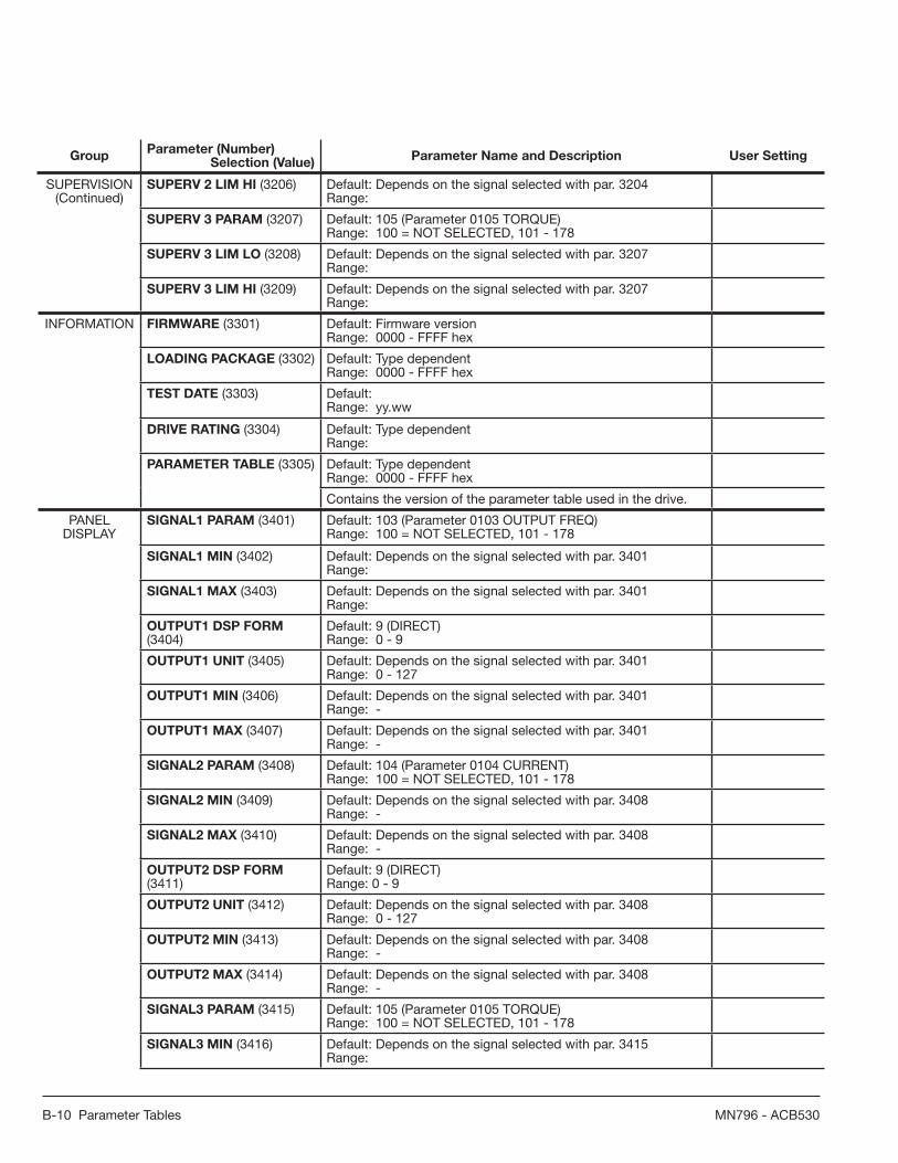
B-10 Parameter Tables MN796 - ACB530
GroupParameter (Number)
Selection (Value)Parameter Name and Description User Setting
SUPERVISION(Continued)
SUPERV 2 LIM HI (3206) Default: Depends on the signal selected with par. 3204Range:
SUPERV 3 PARAM (3207) Default: 105 (Parameter 0105 TORQUE)Range: 100 = NOT SELECTED, 101 - 178
SUPERV 3 LIM LO (3208) Default: Depends on the signal selected with par. 3207Range:
SUPERV 3 LIM HI (3209) Default: Depends on the signal selected with par. 3207Range:
INFORMATION FIRMWARE (3301) Default: Firmware versionRange: 0000 - FFFF hex
LOADING PACKAGE (3302) Default: Type dependentRange: 0000 - FFFF hex
TEST DATE (3303) Default: Range: yy.ww
DRIVE RATING (3304) Default: Type dependentRange:
PARAMETER TABLE (3305) Default: Type dependentRange: 0000 - FFFF hex
Contains the version of the parameter table used in the drive.
PANEL DISPLAY
SIGNAL1 PARAM (3401) Default: 103 (Parameter 0103 OUTPUT FREQ)Range: 100 = NOT SELECTED, 101 - 178
SIGNAL1 MIN (3402) Default: Depends on the signal selected with par. 3401Range:
SIGNAL1 MAX (3403) Default: Depends on the signal selected with par. 3401Range:
OUTPUT1 DSP FORM (3404)
Default: 9 (DIRECT)Range: 0 - 9
OUTPUT1 UNIT (3405) Default: Depends on the signal selected with par. 3401Range: 0 - 127
OUTPUT1 MIN (3406) Default: Depends on the signal selected with par. 3401Range: -
OUTPUT1 MAX (3407) Default: Depends on the signal selected with par. 3401Range: -
SIGNAL2 PARAM (3408) Default: 104 (Parameter 0104 CURRENT)Range: 100 = NOT SELECTED, 101 - 178
SIGNAL2 MIN (3409) Default: Depends on the signal selected with par. 3408Range: -
SIGNAL2 MAX (3410) Default: Depends on the signal selected with par. 3408Range: -
OUTPUT2 DSP FORM (3411)
Default: 9 (DIRECT)Range: 0 - 9
OUTPUT2 UNIT (3412) Default: Depends on the signal selected with par. 3408Range: 0 - 127
OUTPUT2 MIN (3413) Default: Depends on the signal selected with par. 3408Range: -
OUTPUT2 MAX (3414) Default: Depends on the signal selected with par. 3408Range: -
SIGNAL3 PARAM (3415) Default: 105 (Parameter 0105 TORQUE)Range: 100 = NOT SELECTED, 101 - 178
SIGNAL3 MIN (3416) Default: Depends on the signal selected with par. 3415Range:

Parameter Tables B-11MN796 - ACB530
GroupParameter (Number)
Selection (Value)Parameter Name and Description User Setting
PANEL DISPLAY
(Continued)
SIGNAL3 MAX (3417) Default: Depends on the signal selected with par. 3415Range:
OUTPUT3 DSP FORM (3418)
Default: 9 (DIRECT)Range: 0 - 9
OUTPUT3 UNIT (3419) Default: Depends on the signal selected with par. 3415Range: 0 - 127
OUTPUT3 MIN (3420) Default: Depends on the signal selected with par. 3415Range:
OUTPUT3 MAX (3421) Default: Depends on the signal selected with par. 3415Range:
MOTOR TEMP MEAS
SENSOR TYPE (3501) Default: 0 (NONE)Range: 0 - 6
INPUT SELECTION (3502) Default: 1 (AI1)Range: 1 - 8
ALARM LIMIT (3503) Default: 110°C / 1500 ohm / 0Range: Par. 3501 = 1 to 3: -10 to 200°C Par. 3501 = 4: 0 to 5000 ohm Par. 3501 = 5 to 6: 0 to 1
FAULT LIMIT (3504) Default: 130°C / 4000 ohm / 0Range: Par. 3501 = 1 to 3: -10 to 200°C Par. 3501 = 4: 0 to 5000 ohm Par. 3501 = 5 to 6: 0 to 1
USER LOAD CURVE
USER LOAD C MODE (3701)
Default: 0 (NOT SEL)Range: 0 - 3
USER LOAD C FUNC (3702)
Default: 1 (FAULT)Range: 1 - 2
USER LOAD C TIME (3703) Default: 20 sRange: 10 - 400 s
LOAD FREQ 1 (3704) Default: 5 HzRange: 0 - 500 Hz
LOAD TORQ LOW 1 (3705) Default: 10%Range: 0 - 600%
LOAD TORQ HIGH 1 (3706) Default: 300%Range: 0 - 600%
LOAD FREQ 2 (3707) Default: 25 HzRange: 0 - 500 Hz
LOAD TORQ LOW 2 (3708) Default: 15%Range: 0 - 600%
LOAD TORQ HIGH 2 (3709) Default: 300%Range: 0 - 600%
LOAD FREQ 3 (3710) Default: 43 HzRange: 0 - 500 Hz
LOAD TORQ LOW 3 (3711) Default: 25%Range: 0 - 600%
LOAD TORQ HIGH 3 (3712) Default: 300%Range: 0 - 600%
LOAD FREQ 4 (3713) Default: 50 HzRange: 0 - 500 Hz

B-12 Parameter Tables MN796 - ACB530
GroupParameter (Number)
Selection (Value)Parameter Name and Description User Setting
USER LOAD CURVE
(Continued)
LOAD TORQ LOW 4 (3714) Default: 30%Range: 0 - 600%
LOAD TORQ HIGH 4 (3715) Default: 300%Range: 0 - 600%
LOAD FREQ 5 (3716) Default: 500 HzRange: 0 - 500 Hz
LOAD TORQ LOW 5 (3717) Default: 30%Range: 0 - 600%
LOAD TORQ HIGH 5 (3718) Default: 300%Range: 0 - 600%
PROCESS PID SET 1
GAIN (4001) Default: 1.0Range: 0.1 - 100.0
INTEGRATION TIME (4002) Default: 60.0 sRange: 0.0 = (NOT SEL), 0.1 - 3600.0 s
DERIVATION TIME (4003) Default: 0.0 sRange: 0.0 - 10.0 s
PID DERIV FILTER (4004) Default: 1.0 sRange: 0.0 - 10.0 s
ERROR VALUE INV (4005) Default: 0 (NO)Range: 0 - 1
UNITS (4006) Default: 4 (%)Range: 0 - 127
UNIT SCALE (4007) Default: 1Range: 0 - 4
0% VALUE (4008) Default: 0.0Range: Unit and scale defi ned by par. 4006 and 4007
100% VALUE (4009) Default: 100.0Range: Unit and scale defi ned by par. 4006 and 4007
SET POINT SEL (4010) Default: (1) Al1 Range: 0 - 2, 8 - 17, 19
INTERNAL SETPNT (4011) Default: 40.0Range: Unit and scale defi ned by par. 4006 and 4007
SETPOINT MIN (4012) Default: 0.0%Range: -500.0 to 500.0
SETPOINT MAX (4013) Default: 100.0%Range: -500.0 to 500.0
FBK SEL (4014) Default: 1 (ACT1)Range: 1 - 13
FBK MULTIPLIER (4015) Default: 0.000 (NOT SEL)Range: 0.000 = (NOT SEL), -32.768 to 32.767
ACT1 INPUT (4016) Default: 2 (AI2)Range: 1 - 7
ACT2 INPUT (4017) Default: 2 (AI2)Range: 1 - 7
ACT1 MINIMUM (4018) Default: 0%Range: -1000 to 1000%
ACT1 MAXIMUM (4019) Default: 100%Range: -1000 to 1000%
ACT2 MINIMUM (4020) Default: 0%Range: -1000 to 1000%

Parameter Tables B-13MN796 - ACB530
GroupParameter (Number)
Selection (Value)Parameter Name and Description User Setting
PROCESS PID SET 1
(Continued)
ACT2 MAXIMUM (4021) Default: 100%Range: -1000 to 1000%
SLEEP SELECTION (4022) Default: 0 (NOT SEL)Range: -6 to 7
PID SLEEP LEVEL (4023) Default: 0.0 Hz / 0 RPMRange: 0.0 - 500.0 Hz / 0 - 30000 RPM
PID SLEEP DELAY (4024) Default: 60.0 sRange: 0.0 - 3600.0 s
WAKE-UP DEV (4025) Default: 0.0sRange: Unit and scale defi ned by par. 4006 and 4007
WAKE-UP DELAY (4026) Default: 0.50 sRange: 0.0 - 60.00 s
ENERGY SAVING
ENERGY PRICE (4502) Default: 0.00Range: 0.00 - 655.35
CO2 CONV FACTOR (4507) Default: 0.5 tn/MWhRange: 0.00 - 10.0 tn/MWh
PUMP POWER (4508) Default: 100.0%Range: 0.0 - 1000.0%
ENERGY RESET (4509) Default: 0 (DONE)Range: 0 - 1
EXT COMM MODULE
FBA TYPE (5101) Default: READ ONLYRange: -
FB PAR 2 - FB PAR 26 (5102 - 5126)
Default: 0Range: 0 - 65535
FBA PAR REFRESH (5127) Default: 0 (DONE)Range: 0 - 1
FILE CPI FW REV (5128) Default: READ ONLYRange: -
FILE CONFIG ID (5129) Default: READ ONLYRange: -
FILE CONFIG REV (5130) Default: READ ONLYRange: -
FBA STATUS (5131) Default: READ ONLYRange: -
FBA CPI FW REV (5132) Default: READ ONLYRange: -
FBA APPL FW REV (5133) Default: READ ONLYRange: -
PANEL COMM STATION ID (5201) Default: 1Range: 1 - 247
BAUD RATE (5202) Default: 9.6 kbits/sRange: 9.6, 19.2, 38.4, 57.6, 115.2 kbits/s
PARITY (5203) Default: 0 (8 NONE 1)Range: 0 - 3
OK MESSAGES (5204) Default: READ ONLYRange: -
PARITY ERRORS (5205) Default: READ ONLYRange: -
FRAME ERRORS (5206) Default: READ ONLYRange: -
BUFFER OVERRUNS (5207)
Default: READ ONLYRange: -
CRC ERRORS (5208) Default: READ ONLYRange: -

B-14 Parameter Tables MN796 - ACB530
GroupParameter (Number)
Selection (Value)Parameter Name and Description User Setting
EFB PROTOCOL
EFB PROTOCOL ID (5301) Default: 0Range: 0 - 0 x FFFF
EFB STATION ID (5302) Default: 1Range: 0 - 65535
EFB BAUD RATE (5303) Default: 9.6 kbits/sRange: 1.2, 2.4, 4.8, 9.6, 19.2, 38.4, 57.6, 76.8 kbits/s
EFB PARITY (5304) Default: 0 (8 NONE 1)Range: 0 - 3
EFB CTRL PROFILE (5305) Default: 0 (ABB DRV LIM)Range: 0 - 2
EFB OK MESSAGES (5306) Default: READ ONLYRange: -
EFB CRC ERRORS (5307) Default: READ ONLYRange: -
EFB UART ERRORS (5308) Default: READ ONLYRange: -
EFB STATUS (5309) Default: READ ONLYRange: -
EFB PAR 10 (5310) Default: 0Range: 0 - 65535
EFB PAR 11 (5311) Default: 0Range: 0 - 65535
EFB PAR 12 (5312) Default: 0Range: 0 - 65535
EFB PAR 13 (5313) Default: 0Range: 0 - 65535
EFB PAR 14 (5314) Default: 0Range: 0 - 65535
EFB PAR 15 (5315) Default: 0Range: 0 - 65535
EFB PAR 16 (5316) Default: 0Range: 0 - 65535
EFB PAR 17 (5317) Default: 0Range: 0 - 65535
EFB PAR 18 (5318) Default: 0Range: 0 - 65535
EFB PAR 19 (5319) Default: 0Range: 0000 - FFFF hex
EFB PAR 20 (5320) Default: 0Range: 0000 - FFFF hex
LOAD ANALYZER
PVL SIGNAL (6401) Default: 103 (parameter 0103 OUTPUT FREQ)Range: 100 - 178
PVL FILTER TIME (6402) Default: 0.1 sRange: 0.0 - 120.0 s
LOGGERS RESET (6403) Default: 0 (NOT SEL)Range: -6 to 7
AL2 SIGNAL (6404) Default: 103 (parameter 0103 OUTPUT FREQ)Range: 100 - 178
AL2 SIGNAL BASE (6405) Default: Depends on the signal selected with par. 6404Range:
PEAK VALUE (6406) Default: Range:

Parameter Tables B-15MN796 - ACB530
GroupParameter (Number)
Selection (Value)Parameter Name and Description User Setting
LOAD ANALYZER(Continued)
PEAK TIME 1 (6407) Default: Range: Date dd.mm.yy / power-on time in days
PEAK TIME 2 (6408) Default: Range: Time hh.mm.ss
CURRENT AT PEAK (6409) Default: Range: 0.0 - 6553.5 A
UDC AT PEAK (6410) Default: Range: 0 - 65535 V
FREQ AT PEAK (6411) Default: Range: 0.0 - 6553.5 Hz
TIME OF RESET 1 (6412) Default: Range: Date dd.mm.yy / power-on time in days
TIME OF RESET 2 (6413) Default: Range: Time hh.mm.ss
AL1RANGE0TO10 (6414) Default: Range: 0.0 - 100.0%
AL1RANGE10TO20 (6415) Default: Range: 0.0 - 100.0%
AL1RANGE20TO30 (6416) Default: Range: 0.0 - 100.0%
AL1RANGE30TO40 (6417) Default: Range: 0.0 - 100.0%
AL1RANGE40TO50 (6418) Default: Range: 0.0 - 100.0%
AL1RANGE50TO60 (6419) Default: Range: 0.0 - 100.0%
AL1RANGE60TO70 (6420) Default: Range: 0.0 - 100.0%
AL1RANGE70TO80 (6421) Default: Range: 0.0 - 100.0%
AL1RANGE80TO90 (6422) Default: Range: 0.0 - 100.0%
AL1RANGE90TO (6423) Default: Range: 0.0 - 100.0%
AL2RANGE0TO10 (6424) Default: Range: 0.0 - 100.0%
AL2RANGE10TO20 (6425) Default: Range: 0.0 - 100.0%
AL2RANGE20TO30 (6426) Default: Range: 0.0 - 100.0%
AL2RANGE30TO40 (6427) Default: Range: 0.0 - 100.0%
AL2RANGE40TO50 (6428) Default: Range: 0.0 - 100.0%
AL2RANGE50TO60 (6429) Default: Range: 0.0 - 100.0%
AL2RANGE60TO70 (6430) Default: Range: 0.0 - 100.0%
AL2RANGE70TO80 (6431) Default: Range: 0.0 - 100.0%
AL2RANGE80TO90 (6432) Default: Range: 0.0 - 100.0%

B-16 Parameter Tables MN796 - ACB530
GroupParameter (Number)
Selection (Value)Parameter Name and Description User Setting
OPTIONS AL2RANGE90TO (6433) Default: Range: 0.0 - 100.0%
COMM PROT SEL (9802) Default: 0 (NOT SEL)Range: 0, 1, 4

CE Guidelines C-1MN796 - ACB530
Chapter CCE Guidelines
C.1 IEC/EN 61800-3 (2004) Defi nitions
EMC stands for Electromagnetic Compatibility. It is the ability of electrical/electronic equipment to operate without problems within an electromagnetic environment. Likewise, the equipment must not disturb or interfere with any other product or system within its locality.
First environment includes establishments connected to a low-voltage network which supplies buildings used for domestic purposes.
Second environment includes establishments connected to a network not directly supplying domestic premises.
Drive of category C2: drive of rated voltage less than 1000 V and intended to be installed and commissioned only by a professional when used in the fi rst environment.
Note: A professional is a person or organization having necessary skills in installing and/or commissioning power drive systems, including their EMC aspects.
Category C2 has the same EMC emission limits as the earlier class fi rst environment restricted distribution. EMC standard IEC/EN 61800-3 does not any more restrict the distribution of the drive, but the using, installation and commissioning are defi ned.
Drive of category C3: drive of rated voltage less than 1000 V, intended for use in the second environment and not intended for use in the fi rst environment.
Category C3 has the same EMC emission limits as the earlier class second environment unrestricted distribution.
C.2 Compliance with the IEC/EN 61800-3 (2004)
The immunity performance of the drive complies with the demands of IEC/ EN 61800-3, category C2 (see page 305 for IEC/EN 61800-3 defi nitions). The emission limits of IEC/EN 61800-3 are complied with the provisions described below.
C.2.1 First environment (drives of category C2)
1. The internal EMC fi lter is connected.2. The motor and control cables are selected as specifi ed in this manual.3. The drive is installed according to the instructions given in this manual.4. The motor cable length does not exceed the allowed maximum length specifi ed in section Motor cable length for 400 V
drives on page 284 for the frame size and switching frequency in use.
WARNING! In a domestic environment, this product may cause radio inference, in which case supplementary mitigation measures may be required.
C.2.2 Second environment (drives of category C3)
1. The internal EMC fi lter is connected.2. The motor and control cables are selected as specifi ed in this manual.3. The drive is installed according to the instructions given in this manual.4. The motor cable length does not exceed the allowed maximum length specifi ed in section Motor cable length for 400 V
drives on page 284 for the frame size and switching frequency in use.
Note: It is not allowed to install a drive with the internal EMC fi lter connected on IT (ungrounded) systems. The supply network becomes connected to ground potential through the EMC fi lter capacitors, which may cause danger or damage the drive.
Note: It is not allowed to install a drive with the internal EMC fi lter connected to a corner grounded TN system as this would damage the drive.
C.3 Motor cable requirements for CE & C-Tick compliance
The requirements in this section apply for CE or C-Tick compliance.
C.3.1 Minimum requirement (CE & C-Tick)
The motor cable must be a symmetrical three conductor cable with a concentric PE conductor or a four conductor cable with a concentric shield, however, a symmetrical constructed PE conductor is always recommended. The following fi gure shows the minimum requirement for the motor cable shield (for example, MCMK, Draka NK Cables).

C-2 CE Guidelines ACB530 - MN796
C.3.2 Recommendation for conductor layout
The following fi gure compares conductor layout features in motor cables.
C.3.3 Effective motor cable shields
The general rule for cable shield effectiveness is: the better and tighter the cable’s shield, the lower the radiated emission level. The following fi gure shows an example of an effective construction (for example Ölfl ex-Servo-FD 780 CP, Lappkabel orMCCMK, NK Cables).

CE Guidelines C-3MN796 - ACB530
C.3.4 EN 61800-3 compliant motor cables
The most effi cient EMC fi ltering can be achieved by following these rules:• Motor cables must have an effective shield as described in section Effective motor cable shields.• Motor cable shield wires must be twisted together into a bundle (pig-tail) – the bundle length must be less than fi ve times
its width – and connected to the terminal marked (at the bottom right-hand corner of the drive).• At the motor end, the motor cable shield must be earthed 360 degrees with an EMC cable gland, or the shield wires must
be twisted together into a bundle (pigtail) not longer than fi ve times its width and connected to the PE terminal of the motor.
• See section Motor cable length for 400 V drives, columns “EMC limits” to check the maximum motor cable lengths and the need for fi lters for 400 V drives for IEC/EN 61800-3 compliance.
WARNING! Do not use RFI/EMC fi lters on IT systems.
C.4 Product protection in the USA
This product is protected by one or more of the following US patents:
4,920,306 5,301,085 5,463,302 5,521,483 5,532,568 5,589,754
5,612,604 5,654,624 5,799,805 5,940,286 5,942,874 5,952,613
6,094,364 6,147,887 6,175,256 6,184,740 6,195,274 6,229,356
6,252,436 6,265,724 6,305,464 6,313,599 6,316,896 6,335,6076,370,049 6,396,236 6,448,735 6,498,452 6,552,510 6,597,148
6,600,290 6,741,059 6,774,758 6,844,794 6,856,502 6,859,3746,922,883 6,940,253 6,934,169 6,956,352 6,958,923 6,967,4536,972,976 6,977,449 6,984,958 6,985,371 6,992,908 6,999,3297,023,160 7,034,510 7,036,223 7,045,987 7,057,908 7,059,3907,067,997 7,082,374 7,084,604 7,098,623 7,102,325 7,109,7807,164,562 7,176,779 7,190,599 7,215,099 7,221,152 7,227,3257,245,197 7,250,739 7,262,577 7,271,505 7,274,573 7,279,8027,280,938 7,330,095 7,349,814 7,352,220 7,365,622 7,372,6967,388,765 D503,931 D510,319 D510,320 D511,137 D511,150D512,026 D512,696 D521,466 D541,743S D541,744S D541,745SD548,182S D548,183S
Other patents pending.

C-4 CE Guidelines ACB530 - MN796

Options and Kits D-1MN796 - ACB530
Chapter DOptions and Kits
D.1 Options and Kits for the ACB530
Several standard Options & Kits are available for the ACB530.
These include I/O Options, Keypad Mounting Kits, Flange (heat sink out) Mounting Kits and Communication Options.
D.2 Optional Equipment and Accessories
D.2.1 Option
Option Part Number Description115/230V Digital Input
InterfaceOHDI-01 The 115/230V Digital Input Interface module offers six (6) 115V or three (3)
230V rated relays mounted on a common board used to drive DI1 through DI6 of the ACB530. The 115/230V must be provided by the user."
Cabinet Keypad Mounting
OPMP-01 Control Panel Mounting Platform allows remote mounting of the keypad on a large enclosure or remote panel. The kit maintains UL Type 12 integrity of the mounting location. Adapters, 3 m (10ft) cable and mounting hardware are included in this kit. With this mounting arrangement, the keypad is removable from the panel in a fashion identical to a drive-mounted keypad.
Keypad Extension Cable
OCAT-01 7 foot CAT 5 patch cable allows remote operation of the standard panel or connection of the drive to a Personal Computer using the RJ45/DB9 Adapter which must be purchased separately.
Control Keypad Mounting
ACS/H-CP-EXT Control Panel Mounting Kit for ACB530 drives allows remote mounting of the ACB530 keypad on the door of an enclosure. The kit includes a 10 ft (3 m) CAT 5 patch cable, gasket for NEMA 12, mounting hardware and drilling template.
NEMA 4X Cabinet Keypad Mounting
ACS/H-CP-EXT-IP66 Allows remote mounting of the ACB-CP-BA Operator Panels on a larger NEMA 4X (IP66) enclosure or remote panel. The kit maintains NEMA 4X integrity of the mounting location. All necessary hardware and a mounting template are provided in addition to a 3 m panel cable. When mounted, the operator is not removable from the front of the enclosure. The operatorpanel must be purchased separately.
DeviceNet Adapter
RDNA-01 The DeviceNet network uses a linear bus topology. Terminating resistors are required on each end of the trunk line. Drop lines as long as 6 meters (20 feet) each are permitted, allowing one or more nodes to be attached. DeviceNet allows branching structures only on drop lines.
Profi bus-DP Adapter RPBA-01 PROFIBUS is an open serial communication standard that enables data exchange between all kinds of automation components. The physical transmission medium of the bus is a twisted pair cable (according to the RS-485 standard). The maximum length of the bus cable is 100 to 1200 meters, depending on the selected transmission rate. Up to 31 stations can be connected to the same PROFIBUS system without the use of repeaters.
EtherCAT Adapter
RECA-01 The RECA-01 module supports EtherCAT® network protocol. EtherCAT® is a Real Time Ethernet technology which aims to maximize the use of the full duplex Ethernet bandwidth. It overcomes the overhead normally associated with Ethernet by employing “on the fl y” processing hardware. An EtherCAT® bus consists of a master system and up to 65535 slave devices, connected together with standard Ethernet cabling. The RECA-01supports 10/100 Mbps transfer rate with network connections made with CAT 5 wiring and RJ-45 connectors. Designed for daisy chain confi guration on an EtherCAT® network.

D-2 Options and Kits MN796 - ACB530
Option Part Number DescriptionEthernet Adapter
RETA-01 The RETA-01 Adapter module supports the Modbus/TCP and EtherNet/IP network protocols. Modbus/TCP is a variant of the Modbus family of simple, vendor-neutral communication protocols intended for supervision and control of automation equipment. The implementation of the Modbus/TCP server in the RETA-01 module is done according to the Modbus/TCPSpecifi cation 1.0. The Modbus/TCP protocol allows the RETA-01 module to be used as an Ethernet bridge to control the drive. The RETA-01 module supports eight simultaneous IP connections. Ethernet/IP is based on the Common Industrial Protocol (CIP), which is also the framework for both the ControlNet and DeviceNet networks. Ethernet/IP uses standard Ethernet and TCP/IP technology to transport CIP communication packets. The module fulfi lls all requirements for certifi cation as an Ethernet/IP device.
Ethernet Adapter
RETA-02 The RETA-02 Adapter module supports the Modbus/TCP and PROFINET IO network protocols. Modbus/TCP is a variant of the Modbus family of simple, vendor neutral communication protocols intended for supervision and control of automation equipment. Specifi cally, it covers the use of Modbus messaging in an Ethernet environment using the TCP/IP protocols. The implementation of the Modbus/TCP server in the RETA-02 module is done according to the Modbus/TCP Specifi cation 1.0. The Modbus/TCP protocol allows the RETA-02 module to be used as an Ethernet bridge to control the drive. The RETA-02 module supports eight simultaneous IP connections.
PROFINET IO uses traditional Ethernet hardware and software to defi ne a network that structures the task of exchanging data, alarms and diagnostics with Programmable Controllers and other automation controllers. PROFINET IO can be thought as PROFIBUS on Ethernet. PROFINET IO uses two different communication channels to exchange data with programmable controllers and other devices. The standard TCP/IP channel is used for parameterization, confi guration and acyclic read/write operations. The RT or Real Overview Time channel is used for standard cyclic data transfer and alarms. There is no theoretical limit for the amount of connected nodes in PROFINET IO network, but in practice, the programmable controllers and number of available network addresses limits the size. The PROFINET IO protocol is specifi ed in the IEC standards 61158 and 61784. The communication with a drive is specifi ed in the PROFIdrive profi le (v4) published by PROFIBUS INTERNATIONAL.
ControlNet Adapter
RCNA-01 The ControlNet network uses an RG-6 quad shielded cable or fi bre with support for media redundancy. The RCNA-01 Adapter module supports only RG-6 quad shielded cable (coax) for the bus connection. ControlNet is fl exible in topology options (bus, tree, star) to meet various application needs. The fi eldbus speed is 5 Mbits/s. The RCNA-01 ControlNet Adapter module can not originate connections on its own, but a scanner node can open a connection towards it. The ControlNet protocol is implementedaccording to the ControlNet International specifi cation for a Communication adapter.
Flange Mounting Kits FMK-A-R1 Flange Mounting Kits for the ACB530 drives allows mounting the drive with the heatsink external to a 3rd party enclosure. Use of the fl ange kit requires removal of the drive cover, reducing protection to IP00. R1 through R4 fl ange kits can be used with 3rd party UL Type 1 & 12 (NEMA 1 & 12) enclosures. R5 and R6 kits provide NEMA 1 protection only.
FMK-A-R2
FMK-A-R3
FMK-A-R4
AC8-FLNGMT-R5
AC8-FLNGMT-R6

Fieldbus Communications E-1MN796 - ACB530
Chapter EAppendix EFieldbus Communications
E.1 What This Chapter Contains
The chapter describes how the drive can be controlled by external devices over a communication network using embedded fi eldbus.
E.2 Overview
The ACB530 can be set up to accept control from an external system using standard serial communication protocols. When using serial communication, the ACB530 can either:• receive all of its control information from the fi eldbus, or • be controlled from some combination of fi eldbus control and other available control locations, such as digital or analog inputs and the control panel.
Fieldbus
Fieldbus controller
Other devices
Connect using either:• standard embedded fieldbus (EFB) at
terminals X1:28…32
• fieldbus adapter (FBA) module mounted in slot 2 (option Rxxx).
Two basic serial communications confi gurations are available:• embedded fi eldbus (EFB) – Using the RS485 interface at terminals X1:28…32 on the control board, a control system can communicate with the drive using the Modbus® protocol. • fi eldbus adapter (FBA)
E.2.1 Control interface
In general, the basic control interface between Modbus and the drive consists of:
•Output words – Control Word – Reference1 – Reference2
•Input words – Status Word – Actual value 1 – Actual value 2 – Actual value 3 – Actual value 4 – Actual value 5 – Actual value 6 – Actual value 7 – Actual value 8
E.3 Planning
Network planning should address the following questions:1. What types and quantities of devices must be connected to the network?2. What control information must be sent down to the drives?3. What feedback information must be sent from the drives to the controlling system?
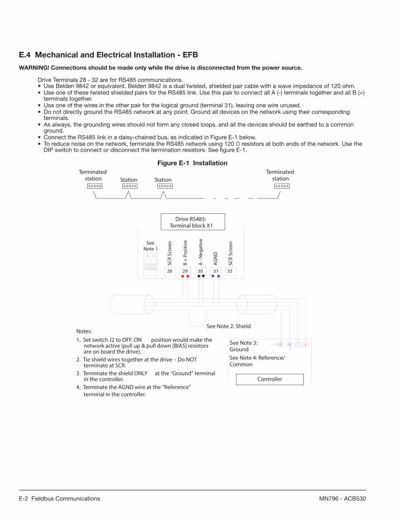
E-2 Fieldbus Communications MN796 - ACB530
E.4 Mechanical and Electrical Installation - EFB
WARNING! Connections should be made only while the drive is disconnected from the power source.
Drive Terminals 28 - 32 are for RS485 communications. • Use Belden 9842 or equivalent. Belden 9842 is a dual twisted, shielded pair cable with a wave impedance of 120 ohm.• Use one of these twisted shielded pairs for the RS485 link. Use this pair to connect all A (-) terminals together and all B (+)
terminals together. • Use one of the wires in the other pair for the logical ground (terminal 31), leaving one wire unused.• Do not directly ground the RS485 network at any point. Ground all devices on the network using their corresponding
terminals. • As always, the grounding wires should not form any closed loops, and all the devices should be earthed to a common
ground. • Connect the RS485 link in a daisy-chained bus, as indicated in Figure E-1 below. • To reduce noise on the network, terminate the RS485 network using 120 Ω resistors at both ends of the network. Use the
DIP switch to connect or disconnect the termination resistors. See fi gure E-1.
Figure E-1 Installation
Terminated Terminatedstation Station Station station
1. Use 3 Conductor Cable - Tie 3rd Wire to AGND: X1-31.
NOTES:
28 29 30 31 32
SCR
Scr
een
B +
Posi
tive
A -
Neg
ativ
e
AG
ND
SCR
Scr
een
See Note 3: Shield
See Note 2
ACH 550 RS485: Terminal Block -X1
Building AutomationController
G - +RSee Note 4: Ground
4. Terminate shield ONLY at "Ground" terminal in the Building Automation Controller!5. Terminate AGN wire at "Reference" terminal in the Building Automation Controller!
2. Set switch J2 to OFF. BUS termination is an active network: Pull Up & Pull Down (BIAS) resistors are on board the ACH550 Drive!
3. Tie shield wires together at Drive - Do Not terminate at SCR!
See Note 5: Reference/Common
PREFERRED WIRING:3 Conductor with Shield
Notes:1. Set switch J2 to OFF. ON position would make the
network active (pull up & pull down [BIAS] resistors are on board the drive).
2. Tie shield wires together at the drive – Do NOT terminate at SCR.
3. Terminate the shield ONLY at the “Ground” terminal in the controller.
4. Terminate the AGND wire at the “Reference” terminal in the controller.
SeeNote 1
SCR
Scre
en
SCR
Scre
en
B +
Posi
tive
A -
Neg
ativ
e
AG
ND
Drive RS485:Terminal block X1
Controller
See Note 2: Shield
See Note 3:GroundSee Note 4: Reference/Common

Fieldbus Communications E-3MN796 - ACB530
E.5 Communication Set-Up - EFBE.5.1 Serial Communication Selection
To activate the serial communication, set parameter 9802 COMM PROT SEL = 1 (STD MODBUS).
NOTE: If you cannot see the desired selection on the keypad, your drive does not have the protocol software in the application memory. Contact Baldor for assistance.
E.5.2 Serial Communication Confi guration
Setting 9802 automatically sets the appropriate default values in parameters that defi ne the communication process. These parameters and descriptions are defi ned below. Note that the station ID may require adjustment.
Code Description Protocol Reference - Modbus
5301 EFB PROTOCOL IDContains the indentifi cation and program revision of the protocol.
Do not edit. Any non-zero value entered for parameter 9802 COMM PROT SEL, sets this parameter automatically. The format is XXYY, where XX = protocal ID, and YY = program revision.
5302 EFB STATION ID Defi nes the station ID address of the RS485 link. No two stations on the line may have the same address.
Set each drive on the network with a unique value for this parameter. When this protocol is selected, the default value for this parameter is 1.
NOTE: For a new address to take effect, the drive power must be cycled or 5302 must fi rst be set to 0 before selecting a new address. Leaving 5302 = 0 places the RS485 channel in reset, disabling communication.
5303 EFB BAUD RATE Defi nes the communication speed of the RS485 link in kbits per second (kbits/s).
1.2 kbit/s 9.6 kbit/s 57.6 kbit/s2.4 kbit/s 19.2 kbit/s 115.2kbit/s4.8 kbit/s 38.4 kbit/s
When this protocol is selected, the default value for this parameter is 9.6.
5304 EFB PARITYDefi nes the data length, parity and stop bits to be used with the RS485 communication. • The same settings must be used in all on-line stations.
0 = 8 NONE 1-8 data bits, no parity, one stop bit.1 = 8 NONE 2-8 data bits, no parity, two stop bits.2 = 8 EVEN 1-8 data bits, even parity, one stop bit.3 = 8 ODD 1-8 data bits, odd parity, one stop bit.
When this protocol is selected, the default value for this parameter is 1.
5305 EFB CTRL PROFILESelects the communication profi le used by the EFB protocol.
0 = ABB DRV LIM - Operation of Control/Status Words conforms to ABB Drives Profi le, as used in ACS400.1 = DCU PROFILE - Operation of Control/Status Words conforms to 32-bit DCU Profi le.2 = ABB DRV FULL - Operation of Control/Status Words conforms to ABB Drives Profi le, as used in ACS600/800.
When this protocol is selected, the default value for this parameter is 0.
NOTE: After any changes to the communication settings, the protocol must be reactivated by either cycling the drive power, or by clearing and then restoring the station ID (5302).
E.6 Activate Drive Control Functions - EFBE.6.1 Controlling the Drive
Fieldbus Control of various drive functions requires confi guration to:• tell the drive to accept fi eldbus control of the function• defi ne as a fi eldbus input, any drive data required for control• defi ne as a fi eldbus output, any control data required by the drive
The following sections describe, at a general level, the confi guration required for each control function. For the protocol-specifi c details, see the document supplied with the FBA module.

E-4 Fieldbus Communications MN796 - ACB530
E.6.2 Start/Stop Direction Control
Using the fi eldbus for start/stop/direction control of the drive requires:• drive parameter values set as defi ned below• fi eldbus controller supplied command(s) in the appropriate location (The location is defi ned by the Protocol Reference,
which is protocol dependent.)
Drive Parameter Value DecriptionModbus1 Protocol Reference
ABB DRV DCU
1001 EXT1 COMMAND S 10 (COMM) Start/Stop by fi eldbus with Ext1 selected. 40001 bits 0 - 3
40031 bits 0, 1
1002 EXT2 COMMAND S 10 (COMM) Start/Stop by fi eldbus with Ext2 selected. 40001 bits 0 - 3
40031 bits 0, 1
1003 DIRECTION 3 (REQUEST) Direction by fi eldbus. 4002/40032 40031 bit 3
1. For Modbus, the protocol reference can depend on the profi le used, hence two columns in these tables. One column refers to the ABB Drive profi le, selected when parameter 5305 = 0 (ABB DRV LIM) or 5305 = 2 (ABB DRV FULL). The other column refers to the DCU profi le selected when parameter 5305 = 1 (DCU PROFILE). 2. The reference provides direction control - a negative reference provides reverse rotation.
E.6.3 Input Reference Select
Using the fi eldbus to provide input references to the drive requires:• drive parameter values set as defi ned below• fi eldbus controller supplied command(s) in the appropriate location (The location is defi ned by the Protocol Reference,
which is protocol dependent.)
Drive Parameter Value DecriptionModbus Protocol Reference
ABB DRV DCU
1102 EXT1/EXT2 SEL 8 (COMM) Reference set selection by fi eldbus. 40001 bit 11 40031 bit 5
1103 REF1 SELECT 8 (COMM) Input reference 1 by fi eldbus. 40002
1106 REF2 SELECT 8 (COMM) Input reference 2 by fi eldbus. 40003
E.6.3.1 Reference Scaling
Where required, REFERENCES can be scaled. See Modbus Register 40002 for more information.
E.6.4 Miscellaneous Drive Control
Using the fi eldbus for miscellaneous drive control requires:• drive parameter values set as defi ned below• fi eldbus controller supplied command(s) in the appropriate location (The location is defi ned by the Protocol Reference,
which is protocol dependent.)
Drive Parameter Value DecriptionModbus Protocol Reference
ABB DRV DCU
1601 RUN ENABLE 7 (COMM) Run enable by fi eldbus. 40001 bit 3 40031 bit 6
1604 FAULT RESET SEL 8 (COMM) Fault reset through by fi eldbus. 40001 bit 7 40031 bit 4
1606 LOCAL LOCK 8 (COMM) Source for local lock selection is the fi eldbus. - 40031 bit 14
1607 PARAM SAVE 1 (SAVE) Saves altered parameters to memory (than value returns to 0).
41607
1608 START ENABLE 1 7 (COMM) Source for start enable 1 is the fi eldbus Command word.
- 40032 bit 2
1609 START ENABLE 2 7 (COMM) Source for start enable 2 is the fi eldbus Command word.
- 40032 bit 3
2013 MIN TORQUE SEL 7 (COMM) Source for minimum torque selection is the fi eldbus.
- 40031 bit 15
2014 MAX TORQUE SEL 7 (COMM) Source for maximum torque selection is the fi eldbus.
- 40031 bit 15
2201 ACC/DEC 1/2 SEL 7 (COMM) Source for ramp pair selection is the fi eldbus. - 40031 bit 10

Fieldbus Communications E-5MN796 - ACB530
E.6.5 Relay Output Control
Using the fi eldbus for miscellaneous drive control requires:• drive parameter values set as defi ned below• fi eldbus controller supplied command(s) in the appropriate location (The location is defi ned by the Protocol Reference,
which is protocol dependent.)
Drive Parameter Value Decription
Modbus Protocol Reference
ABB DRV DCU
1401 RELAY OUTPUT 1 35 (COMM) Relay Output 1 controlled by fi eldbus. 40134 bit 0 or 0000033
1402 RELAY OUTPUT 2 35 (COMM) Relay Output 2 controlled by fi eldbus. 40134 bit 1 or 0000034
1403 RELAY OUTPUT 3 35 (COMM) Relay Output 3 controlled by fi eldbus. 40134 bit 2 or 0000035
14101 RELAY OUTPUT 4 35 (COMM) Relay Output 4 controlled by fi eldbus. 40134 bit 3 or 0000036
14111 RELAY OUTPUT 5 35 (COMM) Relay Output 5 controlled by fi eldbus. 40134 bit 4 or 0000037
14121 RELAY OUTPUT 6 35 (COMM) Relay Output 6 controlled by fi eldbus. 40134 bit 5 or 0000038
1. More than 3 relays requires the addition of a relay extension module.
NOTE: Relay Status Feedback occurs without confi guration as defi ned below.
Drive Parameter Decription
Modbus Protocol Reference
ABB DRV DCU
0122 Relay 1 -3 status. 40122
0123 Relay 4 - 6 status. 40123
E.6.6 Analog Output Control
Using the fi eldbus for miscellaneous drive control requires:• drive parameter values set as defi ned below• fi eldbus controller supplied command(s) in the appropriate location (The location is defi ned by the Protocol Reference,
which is protocol dependent.)
Drive Parameter Value Decription
Modbus Protocol Reference
ABB DRV DCU
1501 AO1 CONTENT SEL 135 (COMM VALUE 1) Analog Output 1 controlled by writing to parameter 0136.
-
0135 COMM VALUE 1 - 40135
1507 AO2 CONTENT SEL 136 (COMM VALUE 2) Analog Output 2 controlled by writing to parameter 0136.
-
0136 COMM VALUE 2 - 40136
E.6.7 PID Control Setpoint Source
Use the following settings to select the fi eldbus as the setpoint source for PID loops:
Drive Parameter Value Decription
Modbus Protocol Reference
ABB DRV DCU
4010 SET POINT SEL (Set 1) 8 (COMM VALUE 1)9 (COMM +Al1)10 (COMM*Al1)
Setpoint is input reference 2 (+/-/* Al1) 400034110 SET POINT SEL (Set 2)
4210 SET POINT SEL (Ext/Trim)

E-6 Fieldbus Communications MN796 - ACB530
E.6.8 Communication Fault
When using the fi eldbus control, specify the drive’s action if serial communication is lost.
Drive Parameter Value Decription
3018 COMM FAULT FUNC 0 (NOT SEL)1 (FAULT)2 (CONST SP7)3 (LAST SPEED)
Set for appropriate drive response.
3019 COMM FAULT TIME Set time delay before acting on a communication loss.
E.7 Information from the drive - EFB
E.7.1 Pre-defi ned Feedback
Inputs to the controller (drive outputs) have pre-defi ned meanings established by the protocol. Obtaining information from the drive does not require drive confi guration. The following table lists a sample of data.
Drive ParameterModbus Protocol Reference
ABB DRV DCU
0102 SPEED 40102
0103 OUTPUT FREQ 40103
0104 CURRENT 40104
0105 TORQUE 40105
0106 POWER 40106
0107 DC BUS VOLTAGE 40107
0109 OUTPUT VOLTAGE 40109
0301 FB CMD WORD1 - bit 0 (STOP) 40301 bit 0
0301 FB CMD WORD1 1 - bit 2 (REV) 40301 bit 2
0118 DI 1-3 STATUS - bit 0 (DI3) 40118
NOTE: With Modbus, any parameter can be accessed using the format: “4” followed by the parameter number.
E.7.2 Actual Value Scaling
The scaling of actual values can be protocol dependent. For actual values, scale the integer using the parameter’s resolution. The following table shows an example.
Feedback Integer Parameter Resolution (Feedback Integer) • (Parameter resolution) = Scaled Value
1 0.1 mA 1 • 0.1 mA = 0.1 mA
10 0.1% 10 • 0.1% = 1%
When parameters are in percent, the complete parameter description specifi es what parameter corresponds to 100%. In such cases, to convert from percent to engineering units, multiply by the value of the parameter that defi nes 100% and divide by 100%. The following table shows an example.
Integer Value Read from Drive
Parameter Resolution
Value of the Parameter that defi nes 100%
(Integer Value) • (Parameter resolution) • (Value of 100% Ref) / 100% = Scaled Value
10 0.1% 1500 rpm1 10 • 0.1% • 1500 RPM/ 100% = 15 RPM
100 0.1% 500 Hz2 100 • 0.1% • 500 RPM/ 100% = 50 Hz
1. Assumes that the actual value uses parameter 9908 MOT NOM SPEED as the 100% reference and that 9908 = 1500 rpm.2. Assumes that the actual value uses parameter 9907 MOT NOM FREQ as the 100% reference and that 9907 = 500 Hz.

Fieldbus Communications E-7MN796 - ACB530
E.8 Diagnostics - EFB
E.8.1 Fault Queue for Drive Diagnostics
The three most recent ACB530 faults are reported to the fi eldbus as defi ned below.
Drive ParameterModbus Protocol Reference
ABB DRV DCU
0401 LAST FAULT 40401
0412 PREVIOUS FAULT 1 40412
0413 PREVIOUS FAULT 2 40413
E.8.2 Serial Communication Diagnostics
Network problems can be caused by multiple sources. Some of these sources are:• loose connections• incorrect wiring (including swapped wires)• bad grounding• duplicate station numbers• incorrect setup of drives or other devices on the network
The major diagnostic features for fault tracing on an EFB network include EFB Protocol parameters 5306 - 5309.
E.8.3 Diagnostic situations
The sub-sections below describe various diagnostic situations – the problem symptoms and corrective actions.
Normal operationDuring normal network operation, 5306…5309 parameter values act as follows at each drive:• 5306 EFB OK MESSAGES advances (advances for each message properly received and addressed to this drive).• 5307 EFB CRC ERRORS does not advance at all (advances when an invalid message CRC is received).• 5308 EFB UART ERRORS does not advance at all (advances when character format errors are detected, such as parity or
framing errors).• 5309 EFB STATUS value varies depending on network traffi c.
Loss of communicationIf communication is lost, parameters 3018 COMM FAULT FUNC and 3019 COMM FAULT TIME can be used to reconfi gure the ACB530.
No master station on lineIf no master station is on line: Neither the EFB OK MESSAGES nor the errors (5307 EFB CRC ERRORS and 5308 EFB UART ERRORS) increase on any of the stations. To correct:• Check that a network master is connected and properly programmed on the network.• Verify that the cable is connected and that it is not cut or short circuited.
Duplicate stationsIf two or more stations have duplicate numbers:• Two or more drives cannot be addressed.• Every time there is a read or write to one particular station, the value for 5307 EFB CRC ERRORS or 5308 EFB UART
ERRORS advances.To correct: Verify the station numbers of all stations. Change confl icting station numbers.
Swapped wiresIf the communication wires are swapped (terminal A on one drive is connected to terminal B on another): • The value of 5306 EFB OK MESSAGES does not advance.• The values of 5307 EFB CRC ERRORS and 5308 EFB UART ERRORS are advancing.To correct: Check that the RS-485 lines are not swapped.
Fault 28 – Serial 1 ErrIf the drive’s control panel shows fault code 28, SERIAL 1 ERR, check for either of the following:• The master system is down. To correct, resolve problem with master system.• The communication connection is bad. To correct, check communication connection at the drive.• The time-out selection for the drive is too short for the given installation. The master is not polling the drive within the
specifi ed time-out delay. To correct, increase the time set by parameter 3019 COMM FAULT TIME.

E-8 Fieldbus Communications MN796 - ACB530
Intermittent off-line occurrencesThe problems described above are the most common problems encountered with ACB530 serial communication. Intermittent problems might also be caused by:• marginally loose connections• wear on wires caused by equipment vibrations• insuffi cient grounding and shielding on both the devices and on the communication cables.
E.9 Modbus Protocol Technical Data
E.9.1 Overview
The Modbus® protocol was introduced by Modicon, Inc. for use in control environments featuring Modicon programmable controllers. Due to its ease of use and implementation, this common PLC language was quickly adopted as a de-factostandard for integration of a wide variety of master controllers and slave devices.
Modbus is a serial, asynchronous protocol. Transactions are half-duplex, featuring a single Master controlling one or more Slaves. While RS232 can be used for point-to-point communication between a single Master and a single Slave, a more common implementation features a multi-drop RS485 network with a single Master controlling multiple Slaves. The ACB530 features RS485 for its Modbus physical interface.
RTUThe Modbus specifi cation defi nes two distinct transmission modes: ASCII and RTU. The ACB530 supports RTU only.
Feature summaryThe following Modbus function codes are supported by the ACB530.
Function Code (Hex) Additional information
Read Coil Status 0x01 Read discrete output status. For the ACB530, the individual bits of the control word are mapped to Coils 1…16. Relay outputs are mapped sequentially beginning with Coil 33 (e.g. RO1=Coil 33).
Read Discrete Input Status
0x02 Read discrete inputs status. For the ACB530, the individual bits of the status word are mapped to Inputs 1…16 or 1…32, depending on the active profi le. Terminal inputs are mapped sequentially beginning with Input 33 (e.g. DI1=Input 33).
Read MultipleHolding Registers
0x03 Read multiple holding registers. For the ACB530, the entire parameter set is mapped as holding registers, as well as command, status and reference values.
Read Multiple Input Registers
0x04 Read multiple input registers. For the ACB530, the 2 analog input channels are mapped as input registers 1 & 2.
Force Single Coil 0x05 Write a single discrete output. For the ACB530, the individual bits of the control word are mapped to Coils 1…16. Relay outputs are mapped sequentially beginning with Coil 33 (e.g. RO1=Coil 33).
Write SingleHolding Register
0x06 Write single holding register. For the ACB530, the entire parameter set is mapped as holding registers, as well as command, status and reference values.
Diagnostics 0x08 Perform Modbus diagnostics. Subcodes for Query (0x00), Restart (0x01) & Listen Only (0x04) are supported.
Force Multiple Coils 0x0F Write multiple discrete outputs. For the ACB530, the individual bits of the control word are mapped to Coils 1…16. Relay outputs are mapped sequentially beginning with Coil 33 (e.g. RO1=Coil 33).
Write MultipleHolding Registers
0x10 Write multiple holding registers. For the ACB530, the entire parameter set is mapped as holding registers, as well as command, status and reference values.
Read/WriteMultiple HoldingRegisters
0x17 This function combines functions 0x03 and 0x10 into a single command.

Fieldbus Communications E-9MN796 - ACB530
Mapping SummaryThe following table summarizes the mapping between the ACB530 (parameters and I/0) and Modbus reference space.
ACB530 Modbus Reference Supported Function Codes
• Contrast Bits• Relay Outputs
Coils (0xxxx) • 01 - Read Coil Status• 05 - Force Single Coil• 15 - Force Multiple Coils
• Status Bits• Discrete Inputs
Discrete Inputs (1xxxx) • 02 - Read Input Status
• Analog Inputs Input Registers (3xxxx) • 04 - Read Input Registers
• Parameters• Control/Status Words• References
Holding Registers (4xxxx) • 03 - Read 4X Registers• 06 - Preset Single 4X Register• 18 - Preset Multiple 4X Registers• 23 - Read/Write 4X Registers
Communication profi lesWhen communicating by Modbus, the ACB530 supports multiple profi les for control and status information. Parameter 5305 EFB CTRL PROFILE selects the profi le used.• ABB DRV LIM – The primary (and default) profi le is the ABB DRV LIM profi le. This implementation of the ABB Drives profi le
standardizes the control interface with ACS400 drives. The ABB Drives profi le is based on the PROFIBUS interface. It is discussed in detail in the following sections.• DCU PROFILE – The DCU PROFILE profi le extends the control and status interface to 32 bits. It is the internal interface
between the main drive application and the embedded fi eldbus environment.• ABB DRV FULL – ABB DRV FULL is the implementation of the ABB Drives profi le that standardizes the control interface
with ACS600 and ACS800 drives. This implementation supports two control word bits not supported by the ABB DRV LIM implementation.
E.9.2 Modbus addressing
With Modbus, each function code implies access to a specifi c Modbus reference set. Thus, the leading digit is not included in the address fi eld of a Modbus message.
Note: The ACB530 supports the zero-based addressing of the Modbus specifi cation. Holding register 40002 is addressed as 0001 in a Modbus message. Similarly, coil 33 is addressed as 0032 in a Modbus message.
Refer again to the Mapping summary above. The following sections describe, in detail, the mapping to each Modbus reference set.

E-10 Fieldbus Communications MN796 - ACB530
E.9.2.1 0xxxx Mapping – Modbus coilsThe drive maps the following information to the 0xxxx Modbus set called Modbus Coils:• bit-wise map of the CONTROL WORD (selected using parameter 5305 EFB CTRL PROFILE). The fi rst 32 coils are
reserved for this purpose.• relay output states, numbered sequentially beginning with coil 00033.The following table summarizes the 0xxxx reference set:
Modbus ReferenceInternal Location (All
Profi les)ABB DRV LIM
(5305 = 0)ABB DRV LIM
(5305 = 0)ABB DRV FULL
(5305 = 2)
00001 CONTROL WORD - Bit 0 OFF11 STOP OFF11
00002 CONTROL WORD - Bit 1 OFF21 START OFF21
00003 CONTROL WORD - Bit 2 OFF31 REVERSE OFF31
00004 CONTROL WORD - Bit 3 START LOCAL START
00005 CONTROL WORD - Bit 4 N/A RESET RAMP_OUT_ZERO1
00006 CONTROL WORD - Bit 5 RAMP_HOLD1 EXT2 RAMP_HOLD1
00007 CONTROL WORD - Bit 6 RAMP_IN_ZERO1 RUN_DISABLE RAMP_IN_ZERO1
00008 CONTROL WORD - Bit 7 RESET STPMODE_R RESET
00009 CONTROL WORD - Bit 8 N/A STPMODE_EM N/A
00010 CONTROL WORD - Bit 9 N/A STPMODE_C N/A
00011 CONTROL WORD - Bit 10 N/A RAMP_2 REMOTE_CMD1
00012 CONTROL WORD - Bit 11 EXT2 RAMP_OUT_0 EXT2
00013 CONTROL WORD - Bit 12 N/A RAMP_HOLD N/A
00014 CONTROL WORD - Bit 13 N/A RAMP_IN_0 N/A
00015 CONTROL WORD - Bit 14 N/A REQ_LOCALLOCK N/A
00016 CONTROL WORD - Bit 15 N/A TORQLIM2 N/A
00017 CONTROL WORD - Bit 16 Does not apply FBLOCAL_CTL Does not apply
00018 CONTROL WORD - Bit 17 FBLOCAL_REF
00019 CONTROL WORD - Bit 18 START_DISABLE1
00020 CONTROL WORD - Bit 19 START_DISABLE2
00021 - 00032 RESERVED Reserved Reserved Reserved
00033 RELAY OUTPUT 1 Relay Output 1 Relay Output 1 Relay Output 1
00034 RELAY OUTPUT 2 Relay Output 2 Relay Output 2 Relay Output 2
00035 RELAY OUTPUT 3 Relay Output 3 Relay Output 3 Relay Output 3
00036 RELAY OUTPUT 4 Relay Output 4 Relay Output 4 Relay Output 4
00037 RELAY OUTPUT 5 Relay Output 5 Relay Output 5 Relay Output 5
00038 RELAY OUTPUT 6 Relay Output 6 Relay Output 6 Relay Output 6
1. Active Low
For the 0xxxx registers:• Status is always readable.• Forcing is allowed by user confi guration of the drive for fi eldbus control.• Additional relay outputs are added sequentially.
The ACB530 supports the following Modbus function codes for coils:
Function Code Description
01 Read Coil status
05 Force single coil
15 (0x0F Hex) Force multiple coils

Fieldbus Communications E-11MN796 - ACB530
E.9.2.2 1xxxx Mapping – Modbus discrete inputsThe drive maps the following information to the 1xxxx Modbus set called Modbus Discrete Inputs:• bit-wise map of the STATUS WORD (selected using parameter 5305 EFB CTRL PROFILE). The fi rst 32 inputs are reserved
for this purpose.• discrete hardware inputs, numbered sequentially beginning with input 33.
The following table summarizes the 1xxxx reference set:
Modbus ReferenceInternal Location (All
Profi les)ABB DRV
(5305 = 0 OR 2)DCU PROFILE
(5305 = 1)
10001 STATUS WORD - Bit 0 RDY_ON READY
10002 STATUS WORD - Bit 1 RDY_RUN ENABLED
10003 STATUS WORD - Bit 2 RDY_REF STARTED
10004 STATUS WORD - Bit 3 TRIPPED RUNNING
10005 STATUS WORD - Bit 4 OFF_2_STA1 ZERO_SPEED
10006 STATUS WORD - Bit 5 OFF_3_STA1 ACCELERATE
10007 STATUS WORD - Bit 6 SWC_ON_INHIB DECELERATE
10008 STATUS WORD - Bit 7 ALARM AT_SETPOINT
10009 STATUS WORD - Bit 8 AT_SETPOINT LIMIT
10010 STATUS WORD - Bit 9 REMOTE SUPERVISION
10011 STATUS WORD - Bit 10 ABOVE_LIMIT REV_REF
10012 STATUS WORD - Bit 11 EXT2 REV_ACT
10013 STATUS WORD - Bit 12 RUN_ENABLE PANEL_LOCAL
10014 STATUS WORD - Bit 13 N/A FIELDBUS_LOCAL
10015 STATUS WORD - Bit 14 N/A EXT2_ACT
10016 STATUS WORD - Bit 15 N/A FAULT
10017 STATUS WORD - Bit 16 Reserved ALARM
10018 STATUS WORD - Bit 17 Reserved REQ_MAINT
10019 STATUS WORD - Bit 18 Reserved DIRLOCK
10020 STATUS WORD - Bit 19 Reserved LOCALLOCK
10021 STATUS WORD - Bit 20 Reserved CTL_MODE
10022 STATUS WORD - Bit 21 Reserved Reserved
10023 STATUS WORD - Bit 22 Reserved Reserved
10024 STATUS WORD - Bit 23 Reserved Reserved
10025 STATUS WORD - Bit 24 Reserved Reserved
10026 STATUS WORD - Bit 25 Reserved Reserved
10027 STATUS WORD - Bit 26 Reserved Reserved
10028 STATUS WORD - Bit 27 Reserved REQ_REF1
10029 STATUS WORD - Bit 28 Reserved REQ_REF2
10030 STATUS WORD - Bit 29 Reserved REQ_REF2EXT
10031 STATUS WORD - Bit 30 Reserved ACK_STARTINH
10032 STATUS WORD - Bit 31 Reserved ACK_OFF_ILCK
00033 DI1 DI1 DI1
00034 DI2 DI2 DI2
00035 DI3 DI3 DI3
00036 DI4 DI4 DI4
00037 DI5 DI5 DI5
00038 DI6 DI6 DI6
1. Active Low

E-12 Fieldbus Communications MN796 - ACB530
For the 1xxxx registers:• Additional discrete inputs are added sequentially.
The ACB530 supports the following Modbus function codes for discrete inputs:
Function Code Description
02 Read input status
E.9.2.3 3xxxx Mapping – Modbus inputs. The drive maps the following information to the 3xxxx Modbus addresses called Modbus input registers:• any user defi ned analog inputs.The following table summarizes the input registers:
Modbus Reference ACB530 All Profi les Remarks
30001 AI1 This register shall report the level of Analog Input 1 (0 - 100%).
30002 AI2 This register shall report the level of Analog Input 2 (0 - 100%).
The ACB530 supports the following Modbus function codes for 3xxxx registers:
Function Code Description
04 Read 3xxxx input status
E.9.2.4 4xxxx Register mappingThe drive maps its parameters and other data to the 4xxxx holding registers as follows:• 40001…40099 map to drive control and actual values. These registers are described in the table below.• 40101…49999 map to drive parameters 0101…9999. Register addresses that do not correspond to drive parameters are
invalid. If there is an attempt to read or write outside the parameter addresses, the Modbus interface returns an exception code to the controller
The following table summarizes the 4xxxx drive control registers 40001…40099 (for 4xxxx registers above 40099, see the drive parameter list, e.g. 40102 is parameter 0102):
Modbus register Access Information
40001 Control word R/W Maps directly to the profi le‘S CONTROL WORD. Supported only if 5305 = 0 or 2 (ABB Drives profi le). Parameter 5319 holds a copy in hex format.
40002 Reference 1 R/W Range = 0…+20000 (scaled to 0…1105 REF1 MAX), or -20000…0 (scaled to 1105 REF1 MAX…0).
40003 Reference 2 R/W Range = 0…+10000 (scaled to 0…1108 REF2 MAX), or -10000…0 (scaled to 1108 REF2 MAX…0).
40004 Status word R Maps directly to the profi le‘S STATUS WORD. Supported only if 5305 = 0 or 2 (ABB Drives profi le). Parameter 5320 holds a copy in hex format.
40005 Actual 1 (select using 5310)
R By default, stores a copy of 0103 OUTPUT FREQ. Use parameter 5310 to select a different actual value for this register.
40006 Actual 2 (select using 5311)
R By default, stores a copy of 0104 CURRENT. Use parameter 5311 to select a different actual value for this register.
40007 Actual 3(select using 5312)
R By default, stores nothing. Use parameter 5312 to select an actual value for this register.
40008 Actual 4(select using 5313)
R By default, stores nothing. Use parameter 5313 to select an actual value for this register.
40009 Actual 5(select using 5314)
R By default, stores nothing. Use parameter 5314 to select an actual value for this register.
40010 Actual 6(select using 5315)
R By default, stores nothing. Use parameter 5315 to select an actual value for this register.
40011 Actual 7 (select using 5316)
R By default, stores nothing. Use parameter 5316 to select an actual value for this register.
40012 Actual 8(select using 5317)
R By default, stores nothing. Use parameter 5317 to select an actual value for this register.
40031 Control word LSW R/W Maps directly to the Least Signifi cant Word of the DCU profi le‘s CONTROL WORD. Supported only if 5305 = 1. See parameter 0301.
40032 Control word MSW R/W Maps directly to the Most Signifi cant Word of the DCU profi le‘s CONTROL WORD. Supported only if 5305 = 1. See parameter 0302.

Fieldbus Communications E-13MN796 - ACB530
Modbus register Access Information
40033 Status word LSW R Maps directly to the Least Signifi cant Word of the DCU profi le‘s STATUS WORD. Supported only if 5305 = 1. See parameter 0303.
40034 ACS355 Statusword MSW
R Maps directly to the Most Signifi cant Word of the DCU profi le‘s STATUS WORD. Supported only if 5305 = 1. See parameter 0304.
For the Modbus protocol, drive parameters in EFB PROTOCOL report the parameter mapping to 4xxxx Registers.
Code Description
5310 EFB PAR 10 - Specifi es the parameter mapped to Modbus register 40005.
5311 EFB PAR 11 - Specifi es the parameter mapped to Modbus register 40006.
5312 EFB PAR 12 - Specifi es the parameter mapped to Modbus register 40007.
5313 EFB PAR 13 - Specifi es the parameter mapped to Modbus register 40008.
5314 EFB PAR 14 - Specifi es the parameter mapped to Modbus register 40009.
5315 EFB PAR 15 - Specifi es the parameter mapped to Modbus register 40010.
5316 EFB PAR 16 - Specifi es the parameter mapped to Modbus register 40011.
5317 EFB PAR 17 - Specifi es the parameter mapped to Modbus register 40012.
5318 EFB PAR 18 - Sets additional delay in milliseconds before the ACB530 beginstransmitting response to the master request.
5319 EFB PAR 19 - Holds a copy (in hex) of the CONTROL WORD, Modbus register 40001.
5320 EFB PAR 20 - Holds a copy (in hex) of the STATUS WORD, Modbus register 40004.
Except where restricted by the drive, all parameters are available for both reading and writing. The parameter writes are verifi ed for the correct value and for a valid register addresses.
Note: Parameter writes through standard Modbus are always volatile i.e. modifi ed values are not automatically stored to permanent memory. Use parameter 1607 PARAM SAVE to save all altered values.
The ACB530 supports the following Modbus function codes for 4xxxx registers:
Function Code Description
03 Read holding 4xxxx registers
06 Preset single 4xxxx register
16 (0x10 Hex) Preset multiple 4xxxx registers
23 (0x17 Hex) Read/write 4xxxx registers
Actual valuesThe contents of the register addresses 40005…40012 are ACTUAL VALUES and are:• specifi ed using parameters 5310…5317• Read-only values containing information on the operation of the drive• 16-bit words containing a sign bit and a 15-bit integer• when negative values, written as the two’s complement of the corresponding positive value• scaled as described earlier in section Actual value scaling on page 207.
Exception codesException codes are serial communication responses from the drive. The ACB530 supports the standard Modbus exception codes defi ned below.
Exception Code Name Meaning
01 ILLEGAL FUNCTION Unsupported Command
02 ILLEGAL DATA ADDRESS
The data address received in the query is not allowable. It is not a defi ned, parameter/group.
03 ILLEGAL DATA VALUE A value contained in the query data fi eld is not an allowablevalue for the ACB530, because it is one of the following:• Outside min. or max. limits.• Parameter is read-only.• Message is too long.• Parameter write not allowed when start is active.• Parameter write not allowed when factory macro is selected.

E-14 Fieldbus Communications MN796 - ACB530
E.10 ABB control profi les technical data
E.10.1 Overview
ABB Drives profi leThe ABB Drives profi le provides a standard profi le that can be used on multiple protocols, including Modbus and the protocols available via FBA modules. Two implementations of the ABB Drives profi le are available:• ABB DRV FULL – This implementation standardizes the control interface with ACS600 and ACS800 drives.• ABB DRV LIM – This implementation standardizes the control interface with ACS400 drives. This implementation does not
support two control word bits supported by ABB DRV FULL.Except as noted, the following “ABB Drives Profi le” descriptions apply to both implementations.
DCU profi leThe DCU profi le extends the control and status interface to 32 bits. It is the internal interface between the main drive application and the embedded fi eldbus environment.
E.10.2 Control Word
The CONTROL WORD is the principal means for controlling the drive from a fi eldbus system. The fi eldbus master station sends the CONTROL WORD to the drive. The drive switches between states according to the bit-coded instructions in the CONTROL WORD. Using the CONTROL WORD requires that:• The drive is in remote (REM) control.• The serial communication channel is defi ned as the source for controlling commands (set using parameters such as 1001
EXT1 COMMANDS, 1002 EXT2 COMMANDS and 1102 EXT1/EXT2 SEL).• The serial communication channel used is confi gured to use an ABB control profi le. For example, to use the control profi le
ABB DRV FULL requires both parameter 9802 COMM PROT SEL = 1 (STD MODBUS) and parameter 5305 EFB CTRL PROFILE = 2 (ABB DRV FULL).
ABB Drives profi leThe following table and the state diagram later in this sub-section describe the CONTROL WORD content for the ABB Drives profi le.
ABB drives profi le Control word, parameter 5319 EFB PAR 19
Bit Name Value Commanded State Comments
0 OFF1CONTROL
1 READY TO OPERATE Enter READY TO OPERATE.0 EMERGENCY OFF Drive ramps to stop according to currently active
deceleration ramp (2203 or 2205).Normal command sequence:• Enter OFF1 ACTIVE• Proceed to READY TO SWITCH ON, unless other interlocks (OFF2, OFF3) are active.
1 OFF2CONTROL
1 OPERATING Continue operation (OFF2 inactive).0 EMERGENCY OFF Drive coasts to stop. Normal command sequence:
• Enter OFF2 ACTIVE• Proceed to SWITCHON INHIBITED
2 OFF3CONTROL
1 OPERATING Continue operation (OFF3 inactive).0 EMERGENCY STOP Drive stops within time specifi ed by parameter 2208.
Normal command sequence:• Enter OFF3 ACTIVE• Proceed to SWITCH ON INHIBITEDWARNING! Ensure motor and driven machine can bestopped using this stop mode.
3 INHIBITOPERATION
1 OPERATION ENABLED Enter OPERATION ENABLED. (Note: The Run enablesignal must be active; see parameter 1601. If par. 1601 isset to COMM, this bit also activates the Run enable signal.)
0 OPERATION INHIBITED
Inhibit operation. Enter OPERATION INHIBITED.
4 Note: Bit 4 is supported only by ABB DRV FULL profi le.RAMP_OUT_ZERO(ABB DRVFULL)
1 NORMAL OPERATION Enter RAMP FUNCTION GENERATOR: OUTPUT ENABLED.0 RFG OUT ZERO Force Ramp function generator output to zero.
Drive ramps to stop (current and DC voltage limits in force).
5 RAMP_HOLD 1 RFG OUT ENABLED Enable ramp function. Enter RAMP FUNCTION GENERATOR: ACCELERATOR ENABLED.
0 RFG OUT HOLD Halt ramping (Ramp function generator output held).

Fieldbus Communications E-15MN796 - ACB530
ABB drives profi le Control word, parameter 5319 EFB PAR 19
Bit Name Value Commanded State Comments
6 RAMP_IN_ZERO
1 RFG INPUT ENABLED Normal operation. Enter OPERATING.
0 RFG INPUT ZERO Force Ramp function generator input to zero.7 RESET 0=>1 RESET Fault reset if an active fault exists. Enter SWITCH-ON
INHIBITED. Effective if par. 1604 is set to COMM.0 OPERATING Continue normal operation.
8 - 9 Not in use10 Note: Bit 10 is supported only by ABB DRV FULL.
REMOTE_CMD(ABB DRVFULL)
1 Fieldbus control enabled.0 • Control word 0 or reference 0: Retain last Control word
and reference.• Control word = 0 and reference = 0: Fieldbus control enabled.• Reference decceleration/acceleration ramp are locked
11 EXT CTRL LOC 1 EXT2 SELECT Select external control location EXT2. Effective if par. 1102is set to COMM.
0 EXT1 SELECT 0 Select external control location EXT1. Effective if par. 1102is set to COMM.
12 - 15 Not in use
DCU Profi leThe following tables describe the Control word content for the DCU profi le.
ADCU profi le Control word, parameter 0301 FB CMD WORD 1
Bit Name Value Command/Req Information
0 STOP 1 Stop Stops according to either the stop mode parameter (2102) or the stop mode requests (bits 7 and 8).
Note: Simultaneous STOP and START commands result in a stop command.
0 (no op)1 START 1 Stop
0 (no op)2 REVERSE 1 Reverse direction This bit XOR’d with the sign of the reference defi nes direction.
0 Forward direction3 LOCAL 0…1 Local Mode When the fi eldbus sets this bit, it steals control and the drive
moves to fi eldbus local control mode.0 External Mode4 RESET -> 1 Reset Edge sensitive.
other (no op)5 EXT2 1 Switch to EXT2
0 Switch to EXT16 RUN_DISABLE 1 Run disable Inverted run enable.
0 Run enable on7 STPMODE_R 1 1 Normal Ramp stop mode
0 (no op)8 STPMODE_EM 1 1 Emergency Ramp stop
mode0 (no op)
9 STPMODE_C 1 1 Coast stop mode0 (no op)
10 RAMP_2 1 Ramp pair 20 Ramp pair 1
11 RAMP_OUT_0 1 Ramp output to 00 (no op)
12 RAMP_HOLD 1 Ramp freeze0 (no op)
13 RAMP_IN_0 1 Ramp input to 00 (no op)
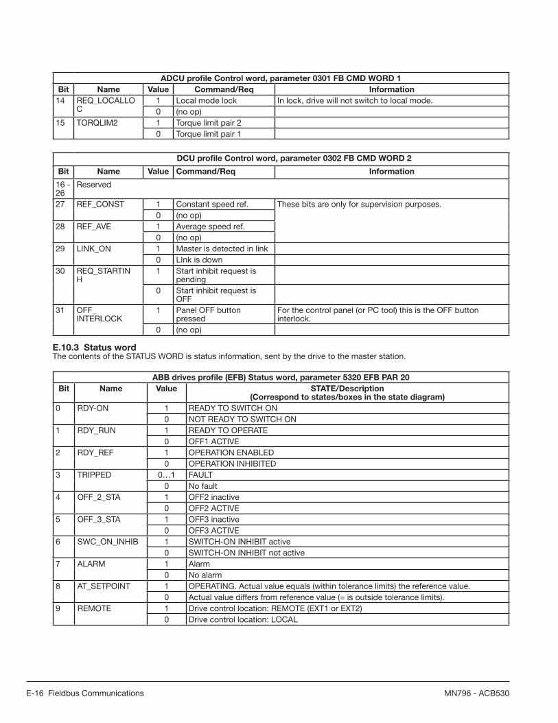
E-16 Fieldbus Communications MN796 - ACB530
ADCU profi le Control word, parameter 0301 FB CMD WORD 1
Bit Name Value Command/Req Information
14 REQ_LOCALLOC
1 Local mode lock In lock, drive will not switch to local mode.0 (no op)
15 TORQLIM2 1 Torque limit pair 20 Torque limit pair 1
DCU profi le Control word, parameter 0302 FB CMD WORD 2
Bit Name Value Command/Req Information
16 - 26
Reserved
27 REF_CONST 1 Constant speed ref. These bits are only for supervision purposes.0 (no op)
28 REF_AVE 1 Average speed ref.0 (no op)
29 LINK_ON 1 Master is detected in link0 LInk is down
30 REQ_STARTINH
1 Start inhibit request is pending
0 Start inhibit request is OFF
31 OFF_INTERLOCK
1 Panel OFF button pressed
For the control panel (or PC tool) this is the OFF button interlock.
0 (no op)
E.10.3 Status wordThe contents of the STATUS WORD is status information, sent by the drive to the master station.
ABB drives profi le (EFB) Status word, parameter 5320 EFB PAR 20
Bit Name Value STATE/Description(Correspond to states/boxes in the state diagram)
0 RDY-ON 1 READY TO SWITCH ON0 NOT READY TO SWITCH ON
1 RDY_RUN 1 READY TO OPERATE0 OFF1 ACTIVE
2 RDY_REF 1 OPERATION ENABLED0 OPERATION INHIBITED
3 TRIPPED 0…1 FAULT0 No fault
4 OFF_2_STA 1 OFF2 inactive0 OFF2 ACTIVE
5 OFF_3_STA 1 OFF3 inactive0 OFF3 ACTIVE
6 SWC_ON_INHIB 1 SWITCH-ON INHIBIT active0 SWITCH-ON INHIBIT not active
7 ALARM 1 Alarm0 No alarm
8 AT_SETPOINT 1 OPERATING. Actual value equals (within tolerance limits) the reference value.0 Actual value differs from reference value (= is outside tolerance limits).
9 REMOTE 1 Drive control location: REMOTE (EXT1 or EXT2)0 Drive control location: LOCAL

Fieldbus Communications E-17MN796 - ACB530
ABB drives profi le (EFB) Status word, parameter 5320 EFB PAR 20
Bit Name Value STATE/Description(Correspond to states/boxes in the state diagram)
10 ABOVE_LIMIT 1 Supervised parameter value exceeds the supervision high limit. Bit value is 1 until the supervised parameter value falls below the supervision low limit. See parameter group 32 SUPERVISION, parameter 3201 SUPERV 1 PARAM.
0 Supervised parameter value falls below the supervision low limit. Bit value is 0 until the supervised parameter value exceeds the supervision high limit. See parameter group 32 SUPERVISION, parameter 3201 SUPERV 1 PARAM.
11 EXT CTRL LOC 1 External control location EXT2 selected0 External control location EXT1 selected
12 EXT RUNENABLE
1 External Run enable signal received0 No external Run enable received
13 - 15 Not in use
DCU Profi le
The following tables describe the Status word content for the DCU profi le.
DCU profi le Status word, parameter 0303 FB STS WORD 1
Bit Name Value Status
0 READY 1 Drive is ready to receive start command.0 Drive is not ready.
1 ENABLED 1 External Run enable signal received.0 No external Run enable signal received.
2 STARTED 1 Drive has received start command.0 Drive has not received start command.
3 RUNNING 1 Drive is modulating.0 Drive is not modulating.
4 ZERO_SPEED 1 Drive is at zero speed.0 Drive has not reached zero speed.
5 ACCELERATE 1 Drive is accelerating.0 Drive is not accelerating.
6 DECELERATE 1 Drive is decelerating.0 Drive is not decelerating.
7 AT_SETPOINT 1 Drive is at setpoint. Actual value equals reference value (ie is within tolerance limits).
0 Drive has not reached setpoint.8 LIMIT 1 Operation is limited by internal protection limits or group 20 LIMITS settings.
0 Operation is within internal protection limits and according group 20 LIMITS settings.
9 SUPERVISION 1 A supervised parameter (group 32 SUPERVISION) isoutside its limits.
0 All supervised parameters are within limits.10 REV_REF 1 Drive reference is in reverse direction.
0 Drive reference is in forward direction.11 REV_ACT 1 Drive is running in reverse direction.
0 Drive is running in forward direction.12 PANEL_LOCAL 1 Control is in keypad (or PC tool) local mode.
0 Control is not in keypad local mode.13 FIELDBUS_LOCAL 1 Control is in fi eldbus local mode
0 Control is not in fi eldbus local mode.14 EXT2_ACT 1 Control is in EXT2 mode.
0 Control is in EXT1 mode.15 FAULT 1 Drive is in a fault state.
0 1 0 Drive is not in a fault state.

E-18 Fieldbus Communications MN796 - ACB530
DCU profi le Status word, parameter 0304 FB STS WORD 2
Bit Name Value Status
16 ALARM 1 An alarm is on.
0 No alarms are on.
17 NOTICE 1 A maintenance request is pending. 0 No maintenance request
18 DIRLOCK 1 Direction lock is ON. (Direction change is locked.)0 Direction lock is OFF.
19 LOCALLOCK 1 Local mode lock is ON. (Local mode is locked.)0 Local mode lock is OFF
20 CTL_MODE 1 1 Drive is in vector control mode.
0 0 Drive is in scalar control mode.
21 JOGGING ACTIVE 1 Jogging function is active.
0 Jogging function is not active.22 - 25 Reserved
26 REQ_CTL 1 Control word requested from fi eldbus0 No operation
27 REQ_REF1 1 Reference 1 requested from fi eldbus0 Reference 1 is not requested from fi eldbus.
28 REQ_REF2 1 Reference 2 requested from fi eldbus0 Reference 2 is not requested from fi eldbus.
29 REQ_REF2EXT 1 External PID reference 2 requested from fi eldbus0 External PID reference 2 is not requested from
fi eldbus.30 ACK_STARTINH 1 Start inhibit from fi eldbus
0 No start inhibit from fi eldbus31 Reserved
E.10.4 State diagram
ABB Drives profi leTo illustrate the operation of the state diagram, the following example (ABB DRV LIM implementation of the ABB Drives profi le) uses the control word to start the drive:• First, the requirements for using the CONTROL WORD must be met. See above.• When the power is fi rst connected, the state of the drive is not ready to switch on. See dotted lined path ( ) in the state
diagram below.• Use the CONTROL WORD to step through the state machine states until the OPERATING state is reached, meaning that
the drive is running and follows the given reference. See the table below.
Step CONTROL WORD Value Description
1 CW = 0000 0000 0000 0110 (Bit 15) (Bit 0)
This CW value changes the drive state to READY TO SWITCH ON.
2 Wait at least 100 ms before proceeding.3 CW = 0000 0000 0000 0111 This CW value changes the drive state to READY TO OPERATE.
4 CW = 0000 0000 0000 1111 This CW value changes the drive state to OPERATION ENABLED.The drive starts, but will not accelerate.
5 CW = 0000 0000 0010 1111 This CW value releases the ramp function generator (RFG)output and changes the drive state to RFG: ACCELERATORENABLED.
6 CW = 0000 0000 0110 1111 This CW value releases the ramp function generator (RFG) output and changes the drive state to OPERATING. The drive accelerates to the given reference and follows the reference.

Fieldbus Communications E-19MN796 - ACB530
The state diagram below describes the start-stop function of CONTROL WORD (CW) and STATUS WORD (SW) bits for the ABB Drives profi le.

E-20 Fieldbus Communications MN796 - ACB530
E.10.5 Reference scaling
ABB Drives and DCU profi lesThe following table describes REFERENCE scaling for the ABB Drives and DCU profi les.
Reference Range Reference
typeScaling
Remarks
REF1 -32767 -+32767
Speed orfrequency
-20000 = -(par. 1105)0 = 0 +20000 = (par. 1105) (20000 corresponds to 100%)
Final reference limited by 1104/1105. Actual motor speed limited by 2001/2002 (speed) or2007/2008 (frequency).
REF2 -32767 -+32767
Speed orfrequency
-10000 = -(par. 1108)0 = 0 +10000 = (par. 1108) (10000 corresponds to 100%)
Final reference limited by 1107/1108. Actual motor speed limited by 2001/2002 (speed) or2007/2008 (frequency).
Torque -10000 = -(par. 1108)0 = 0 +10000 = (par. 1108) (10000 corresponds to 100%)
Final reference limited by 2015/2017 (torque 1) or 2016/2018 (torque 2).
PIDreference
-10000 = -(par. 1108) 0 = 0+10000 = (par. 1108)(10000 corresponds to 100%)
Final reference limited by 4012/4013 (PID set 1) or 4112/4113 (PID set 2).
Note: The setting of parameter 1104 REF1 MIN and 1107 REF2 MIN has no effect on the scaling of references.
When parameter 1103 REF1 SELECT or 1106 REF2 SELECT is set to COMM+AI1 or COMM*AI1, the reference is scaled as follows:
ABB Drives and DCU Profi les
Reference Value Setting AI Reference Scaling
REF1 COMMM+AI1 COMM(%) + (AI(%) - 0.5 · REF1 MAX (%))
REF1 COMM·AI1 COMM(%) · (AI(%) / 0.5 · REF1 MAX (%))
REF2 COMM+AI1 COMM(%) + (AI(%) - 0.5 · REF2 MAX (%))
REF2 COMM·AI1 COMM(%) · (AI(%) / 0.5 · REF2 MAX (%))

Fieldbus Communications E-21MN796 - ACB530
Reference handlingUse START/STOP/DIR parameters to confi gure for control of rotation direction for each control location (EXT1 and EXT2). The following diagrams illustrate how group 10 parameters and the sign of the fi eldbus reference interact to produceREFERENCE values (REF1 and REF2). Note, fi eldbus references are bipolar, that is they can be positive or negative.
ABB Drives and DCU Profi les
Reference Value Setting AI Reference Scaling
1003 DIRECTION
1 (FORWARD)
1003 DIRECTION
2 (REVERSE)
1003 DIRECTION
3 (REQUEST)
E.11 Fieldbus Adapter
As mentioned earlier in this Appendix, two basic serial communications confi gurations are available:• embedded fi eldbus (EFB) • fi eldbus adapter (FBA) - With one of the optional FBA modules in the drive’s expansion slot 2, the drive can communicate
to a control system using one of the following protocols:• PROFIBUS DP• Ethernet (Modbus/TCP, Ethernet/IPTM, EtherCAT, PROFINET 10, POWERLINK)• CANopen• DeviceNetTM
• ControlNetTM
The ACB530 detects automatically which communication protocol is used by the plug-in fi eldbus adapter. The default settings for each protocol assume that the profi le used is the protocol’s industry-standard drive profi le (e.g. PROFIdrive forPROFIBUS, AC/DC Drive for DeviceNet). All of the FBA protocols can also be confi gured for the ABB Drives profi le. Confi guration details depend on the protocol and profi le used.These details are provided in a user’s manual supplied with the FBA module.
E.11.1 Control interface
In general, the basic control interface between the fi eldbus system and the drive consists of:
• Output Words: – CONTROL WORD – REFERENCE (speed or frequency) – Others: The drive supports a maximum of 15 output words. Protocols limits may further restrict the total.
• Input Words: – STATUS WORD – Actual Value (speed or frequency) – Others: The drive supports a maximum of 15 input words. Protocols limits may further restrict the total.
Note: The words “output” and “input” are used as seen from the fi eldbus controller point of view. For example an output describes data fl ow from the fi eldbus controller to the drive and appears as an input from the drive point of view.

E-22 Fieldbus Communications MN796 - ACB530
The meanings of the controller interface words are not restricted by the ACB530. However, the profi le used may set particular meanings.
E.11.2 Control WordThe CONTROL WORD is the principal means for controlling the drive from a fi eldbus system. The fi eldbus controller sends the CONTROL WORD to the drive. The drive switches between states according to the bit-coded instructions in the CONTROL WORD. Using the CONTROL WORD requires that:• The drive is in remote (REM) control.• The serial communication channel is defi ned as the source for controlling commands from EXT1 (set using parameters
1001 EXT1 COMMANDS and 1102 EXT1/EXT2 SEL).• The external plug-in fi eldbus adapter is activated: – Parameter 9802 COMM PROT SEL = 4 (EXT FBA). – The external plug-in fi eldbus adapter is confi gured to use the drive profi le mode or drive profi le objects.The content of the CONTROL WORD depends on the protocol/profi le used.
Status WordThe STATUS WORD is a 16-bit word containing status information, sent by the drive to the fi eldbus controller. The content of the STATUS WORD depends on the protocol/profi le used.
ReferenceThe contents of each REFERENCE word:• can be used, as speed or frequency reference• is a 16-bit word comprised of a sign bit and a 15-bit integer• Negative references (indicating reversed rotation direction) are indicated by the two’s complement of the corresponding
positive reference value.The use of a second reference (REF2) is supported only when a protocol is confi gured for the ABB Drives profi le.
Reference scaling is fi eldbus type specifi c. See the user’s manual provided with the FBA module.
Actual ValuesActual Values are 16-bit words containing information on selected operations of the drive. Drive Actual Values (for example, START/STOP/DIR parameters) can be mapped to Input Words using Group 51: EXT COMM MODULE parameters(protocol-dependent, but typically parameters 5104…5126).

Fieldbus Communications E-23MN796 - ACB530
E.12 Mechanical and Electrical Installation - FBA
WARNING! Connections should be made only while the drive is disconnected from the power source.
OverviewThe FBA (fi eldbus adapter) is a plug-in module that fi ts in the drive’s expansion slot 2. The module is held in place with plastic retaining clips and two screws. The screws also ground the shield for the module cable and connect the module GNDsignals to the drive control board.
On installation of the module, electrical connection to the drive is automatically established through the 34-pin connector.
Mounting procedure
Note: Install the input power and motor cables fi rst. 1. Insert the module carefully into the drive expansion slot 2 until the retaining clips lock the module into position.
2. Fasten the two screws (included) to the stand-offs. Note: Correct installation of the screws is essential for fulfi lling the EMC requirements and for proper operation of the module.
3. Open the appropriate knockout in the conduit box and install the cable clamp for the network cable.
4. Route the network cable through the cable clamp.
5. Connect the network cable to the module’s network connector.
6. Tighten the cable clamp.
7. Install the conduit box cover (1 screw).
8. For confi guration information see the protocol specifi c documentation provided with the module.
E.13 Communication Set-up - FBA
Serial communication selectionTo activate the serial communication, use parameter 9802 COMM PROT SEL. Set 9802 = 4 (EXT FBA).
Serial communication confi gurationSetting 9802, together with mounting a particular FBA module, automatically sets the appropriate default values in parameters that defi ne the communication process. These parameters and descriptions are defi ned in the user’s manual supplied with the FBA module.• Parameter 5101 is automatically confi gured.• Parameters 5102…5126 are protocol-dependent and defi ne, for example, the profi le used and additional I/O words. These
parameters are referred to as the fi eldbus confi guration parameters. See the user’s manual provided with the FBA module for details on the fi eldbus confi guration parameters.
• Parameter 5127 forces the validation of changes to parameters 5102…5126. If parameter 5127 is not used, changes to parameters 5102…5126 take affect only after the drive power is cycled.
• Parameters 5128…5133 provide data about the FBA module currently installed (e.g. component versions and status).

E-24 Fieldbus Communications MN796 - ACB530
E.14 Activate Drive Control Functions – FBA
Fieldbus control of various drive functions requires confi guration to:• tell the drive to accept fi eldbus control of the function• defi ne as a fi eldbus input, any drive data required for control• defi ne as a fi eldbus output, any control data required by the drive.
The following sections describe, at a general level, the confi guration required for each control function. The last column in each table below is deliberately blank. See the user’s manual supplied with the FBA module for the appropriate entry.
E.14.1 Start/Stop Direction controlUsing the fi eldbus for start/stop/direction control of the drive requires:• drive parameter values set as defi ned below• fi eldbus controller supplied command(s) in the appropriate location. (The location is defi ned by the Protocol Reference, which is protocol dependent.)
Drive Parameter Value Description Protocol Reference
1001 EXT1 COMMANDS 10 (COMM) Start/Stop controlled by fi eldbus with EXT1 selected.
1002 EXT2 COMMANDS 10 (COMM) Start/Stop by controlled fi eldbus with Ext2 selected.
1003 DIRECTION 3 (REQUEST) Direction controlled by fi eldbus.
E.14.2 Input reference select
Using the fi eldbus to provide input reference to the drive requires:• drive parameter value set as defi ned below• fi eldbus controller supplied reference word(s) in the appropriate location. (The location is defi ned by the Protocol
Reference, which is protocol dependent.)
Drive Parameter Value Description Protocol Reference
1102 EXT1/EXT2 SEL 8 (COMM) Ref. selected by fi eldbus. (Required only if 2 references used.)
1103 REF1 SELECT 8 (COMM)9 COMM+AI1)10 (COMM*AI1)
Input reference 1supplied by fi eldbus.
1106 REF2 SELECT 8 (COMM)9 COMM+AI1)10 (COMM*AI1)
Input reference 2 supplied by fi eldbus.(Required only if 2 references used.)
NOTE: Multiple references are supported only when using the ABB Drives profi le.NOTE: Scaling - Where required, REFERENCES can be scaled.
E.14.3 System control
Using the fi eldbus for miscellaneous drive control requires:• drive parameter values set as defi ned below• fi eldbus controller command(s) in the appropriate location. (The location is defi ned by the Protocol Reference, which is
protocol dependent.)
Drive Parameter Value Description Protocol Reference
1601 RUN ENABLE 7 (COMM) Run enable by fi eldbus.
1604 FAULT RESET SEL 8 (COMM) Fault reset by fi eldbus.
1607 PARAM SAVE 1 (SAVE) Saves altered parameters to memory (then value returns to 0).

Fieldbus Communications E-25MN796 - ACB530
E.14.4 Relay output control
Using the fi eldbus for relay output control requires:• drive parameter values set as defi ned below• fi eldbus controller command(s) in the appropriate location. (The location is defi ned by the Protocol Reference, which is
protocol dependent.)
Drive Parameter Value Description Protocol Reference
1401 RELAY OUTPUT 1 35 (COMM)36 (COMM (-1))
Relay Output 1 controlled by fi eldbus.
1402 RELAY OUTPUT 2 Relay Output 2 controlled by fi eldbus.
1403 RELAY OUTPUT 3 Relay Output 3 controlled by fi eldbus.
14101 RELAY OUTPUT 4 Relay Output 4 controlled by fi eldbus.
14111 RELAY OUTPUT 5 Relay Output 5 controlled by fi eldbus.
14121 RELAY OUTPUT 6 Relay Output 6 controlled by fi eldbus.
1. More than 3 relays requires the addition of a relay extension module.
Note: Relay status feedback occurs without confi guration as defi ned below.
Drive Parameter Value Protocol Reference
0122 RO 1-3 STATUS Relay 1-3 status.
0123 RO 4-6 STATUS Relay 4-6 status.
E.14.5 Analog output control
Using the fi eldbus for analog output control (e.g. PID setpoint) requires:• drive parameter values set as defi ned below• fi eldbus controller command(s) in the appropriate location. (The location is defi ned by the Protocol Reference, which is
protocol dependent.)
Drive Parameter Value Description Protocol Reference
1501 AO1 CONTENT SEL 135 (COMM) Analog Output 1 controlled by writing to parameter 0135.
-
0135 COMM VALUE 1 -
1502 - 1505
AO1 CONTENT MIN - MAXIMUM AO1
Set appropriate values.
Used for scaling. -
1506 FILTER AO1 Filter time constant for AO1. -
1507 AO2 CONTENT SEL 136 (COMM) Analog Output 2 controlled by writing to parameter 0136.
-
0136 COMM VALUE 2 -
1508 - 1511
AO2 CONTENT MIN - MAXIMUM AO2
Set appropriate values.
Used for scaling. -
1512 FILTER AO2 Filter time constant for AO2. -
E.14.6 PID Control setpoint source
Using the following settings to select the fi eldbus as the setpoint source for PID loops:
Drive Parameter Value Description Protocol Reference
4010 SET POINT SEL (Set 1) 8 (COMM VALUE 1)9 (COMM+AI1)10 (COMM*AI1)
Setpoint is input reference 2 (+/-/* AI1)
4110 SET POINT SEL (Set 2)
4210 SET POINT SEL (Ext/Trim)
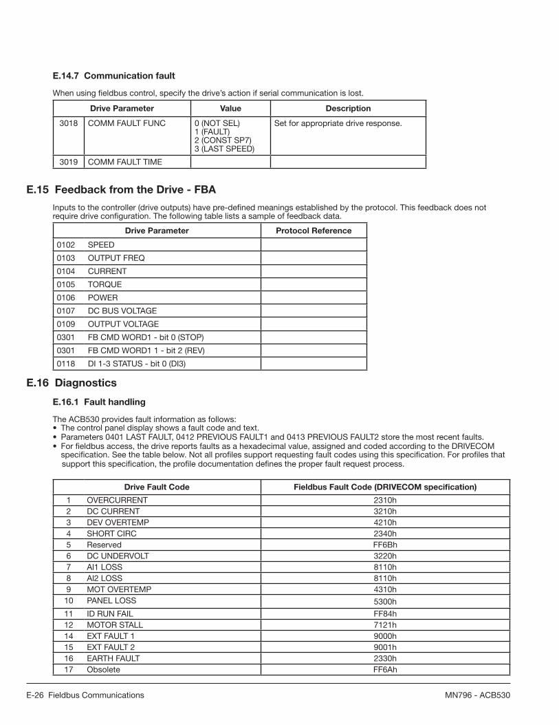
E-26 Fieldbus Communications MN796 - ACB530
E.14.7 Communication fault
When using fi eldbus control, specify the drive’s action if serial communication is lost.
Drive Parameter Value Description
3018 COMM FAULT FUNC 0 (NOT SEL)1 (FAULT)2 (CONST SP7)3 (LAST SPEED)
Set for appropriate drive response.
3019 COMM FAULT TIME
E.15 Feedback from the Drive - FBA
Inputs to the controller (drive outputs) have pre-defi ned meanings established by the protocol. This feedback does not require drive confi guration. The following table lists a sample of feedback data.
Drive Parameter Protocol Reference
0102 SPEED
0103 OUTPUT FREQ
0104 CURRENT
0105 TORQUE
0106 POWER
0107 DC BUS VOLTAGE
0109 OUTPUT VOLTAGE
0301 FB CMD WORD1 - bit 0 (STOP)
0301 FB CMD WORD1 1 - bit 2 (REV)
0118 DI 1-3 STATUS - bit 0 (DI3)
E.16 Diagnostics
E.16.1 Fault handling
The ACB530 provides fault information as follows:• The control panel display shows a fault code and text. • Parameters 0401 LAST FAULT, 0412 PREVIOUS FAULT1 and 0413 PREVIOUS FAULT2 store the most recent faults.• For fi eldbus access, the drive reports faults as a hexadecimal value, assigned and coded according to the DRIVECOM
specifi cation. See the table below. Not all profi les support requesting fault codes using this specifi cation. For profi les that support this specifi cation, the profi le documentation defi nes the proper fault request process.
Drive Fault Code Fieldbus Fault Code (DRIVECOM specifi cation)
1 OVERCURRENT 2310h2 DC CURRENT 3210h3 DEV OVERTEMP 4210h4 SHORT CIRC 2340h5 Reserved FF6Bh6 DC UNDERVOLT 3220h7 Al1 LOSS 8110h8 Al2 LOSS 8110h9 MOT OVERTEMP 4310h10 PANEL LOSS 5300h
11 ID RUN FAIL FF84h12 MOTOR STALL 7121h14 EXT FAULT 1 9000h15 EXT FAULT 2 9001h16 EARTH FAULT 2330h17 Obsolete FF6Ah

Fieldbus Communications E-27MN796 - ACB530
Drive Fault Code Fieldbus Fault Code (DRIVECOM specifi cation)
18 THERM FAIL 5210h19 OPEX LINK 7500h20 OPEX PWR 5414h21 CURR MEAS 2211h22 SUPPLY PHASE 3130h23 ENCODER ERR 7301h24 OVERSPEED 7310h25 Reserved FF80h26 DRIVE ID 5400h27 CONFIG FILE 630Fh28 SERIAL 1 ERR 7510h29 EFB CON FILE 6306h30 FORCE TRIP FF90h31 EFB 1 FF92h32 EFB 2 FF93h33 EFB 3 FF94h34 MOTOR PHASE FF56h35 OUTP WIRING FF95h36 INCOMPATIBLE SW 630Fh37 CB OVERTEMP 4110h38 USER LOAD CURVE FF6Bh101 SERF CORRUPT FF55h102 Reserved FF55h103 SERF MACRO FF55h104 Reserved FF55h105 Reserved FF55h201 DSP T1 OVERLOAD 6100h202 DSP T2 OVERLOAD 6100h203 DSP T3 OVERLOAD 6100h204 DSP STACK ERROR 6100h205 Reserved (obsolete) 5000h206 CB ID ERROR 5000h207 EFB LOAD ERROR 6100h1000 PAR HZRPM 6320h1001 PAR PFC REF NEG 6320h1002 Reserved (obsolete) 6320h1003 PAR Al SCALE 6320h1004 PAR AO SCALE 6320h1005 PAR PCU 2 6320h1006 PAR EXT RO 6320h1007 PAR FIELDBUS MISSING 6320h1008 PAR PFC MODE 6320h1009 PAR PCU 1 6320h1012 PAR PFC IO 1 6320h1013 PAR PFC IO 2 6320h1014 PAR PFC IO3 6320h1015 PAR USER LOAD C 6320h
E.16.2 Serial Communications Diagnostics
The FBA has diagnostic tools in addition to the drive fault codes. Refer to the user manual shipped with the FBA module.
E.17 ABB Drives Profi le Technical Data

E-28 Fieldbus Communications MN796 - ACB530
E.17.1 Overview
The ABB Drives profi le provides a standard profi le that can be used on multiple protocols, including protocols available on the FBA module. This section describes the ABB Drives profi le implemented for FBA modules.
E.17.2 Control Word
As described earlier, the CONTROL WORD is the principal means for controlling the drive from a fi eldbus system.The following table and the state diagram (shown later) describe the CONTROL WORD content for the ABB Drives profi le.
ABB Drives Profi le (FBA) CONTROL WORD
Bit Name Value Commanded State Comments
0 OFF1CONTROL
1 READY TO OPERATE Enter READY TO OPERATE.0 EMERGENCY OFF Drive ramps to stop according to currently active deceleration
ramp (2203 or 2205).Normal command sequence:• Enter OFF1 ACTIVE• Proceed to READY TO SWITCH ON, unless other interlocks (OFF2, OFF3) are active.
1 OFF2CONTROL
1 OPERATING Continue operation (OFF2 inactive).0 EMERGENCY OFF Drive coasts to stop. Normal command sequence:
• Enter OFF2 ACTIVE• Proceed to SWITCHON INHIBITED
2 OFF3CONTROL
1 OPERATING Continue operation (OFF3 inactive).0 EMERGENCY STOP Drive stops within time specifi ed by parameter 2208.
Normal command sequence:• Enter OFF3 ACTIVE• Proceed to SWITCH ON INHIBITEDWARNING! Ensure motor and driven machine can bestopped using this stop mode.
3 INHIBITOPERATION
1 OPERATION ENABLED Enter OPERATION ENABLED. (Note: The Run enablesignal must be active; see parameter 1601. If par. 1601 isset to COMM, this bit also activates the Run enable signal.)
0 OPERATION INHIBITED Inhibit operation. Enter OPERATION INHIBITED.4 Note: Bit 4 is supported only by ABB DRV FULL profi le.
RAMP_OUT_ZERO(ABB DRVFULL)
1 NORMAL OPERATION Enter RAMP FUNCTION GENERATOR: ACCELERATION ENABLED.
0 RFG OUT ZERO Force Ramp function generator output to zero.Drive ramps to stop (current and DC voltage limits in force).
5 RAMP_HOLD 1 RFG OUT ENABLED Enable ramp function. Enter RAMP FUNCTION GENERATOR: ACCELERATOR ENABLED.
0 RFG OUT HOLD Halt ramping (Ramp function generator output held).6 RAMP_IN_
ZERO1 RFG INPUT ENABLED Normal operation. Enter OPERATING.0 RFG INPUT ZERO Force Ramp function generator input to zero.
7 RESET 0=>1 RESET Fault reset if an active fault exists. Enter SWITCH-ONINHIBITED. Effective if par. 1604 is set to COMM.
0 OPERATING Continue normal operation.8 - 9 Not in use10 Note: Bit 10 is supported only by ABB DRV FULL.
REMOTE_CMD(ABB DRVFULL)
1 Fieldbus control enabled.0 • Control word 0 or reference 0: Retain last Control word
and reference.• Control word = 0 and reference = 0: Fieldbus control enabled.• Reference decceleration/acceleration ramp are locked
11 EXT CTRL LOC 1 EXT2 SELECT Select external control location EXT2. Effective if par. 1102is set to COMM.
0 EXT1 SELECT 0 Select external control location EXT1. Effective if par. 1102is set to COMM.
12 - 15 Not in use
E.17.3 Status Word

Fieldbus Communications E-29MN796 - ACB530
As described earlier, the contents of the STATUS WORD is status information, sent by the drive to the master station. Thefollowing table and the state diagram later in this sub-section describe the status word content.
ABB Drives Profi le (FBA) STATUS WORD
Bit Name Value STATE/Description(Correspond to states/boxes in the state diagram)
0 RDY-ON 1 READY TO SWITCH ON0 NOT READY TO SWITCH ON
1 RDY_RUN 1 READY TO OPERATE0 OFF1 ACTIVE
2 RDY_REF 1 OPERATION ENABLED0 OPERATION INHIBITED
3 TRIPPED 0…1 FAULT0 No fault
4 OFF_2_STA 1 OFF2 inactive0 OFF2 ACTIVE
5 OFF_3_STA 1 OFF3 inactive0 OFF3 ACTIVE
6 SWC_ON_INHIB 1 SWITCH-ON INHIBITED
0 Switch-on inhibit not active7 ALARM 1 Alarm
0 No alarm8 AT_SETPOINT 1 OPERATING. Actual value equals (within tolerance limits) the reference value.
0 Actual value differs from reference value (= is outside tolerance limits).9 REMOTE 1 Drive control location: REMOTE (EXT1 or EXT2)
0 Drive control location: LOCAL10 ABOVE_LIMIT 1 Supervised parameter value exceeds the supervision high limit. Bit value is 1
until the supervised parameter value falls below the supervision low limit. 0 Supervised parameter value falls below the supervision low limit. Bit value is
0 until the supervised parameter value exceeds the supervision high limit. 11 EXT CTRL LOC 1 External control location EXT2 selected
0 External control location EXT1 selected12 EXT RUN
ENABLE1 External Run enable signal received0 No external Run enable received
13-15 Not in use
E.17.4 State diagram

E-30 Fieldbus Communications MN796 - ACB530
The state diagram below describes the start-stop function of Control word (CW) and Status word (SW) bits for the ABB drives profi le.
E.17.5 Reference Scaling

Fieldbus Communications E-31MN796 - ACB530
Fieldbus references REF1 and REF2 are scaled for the Baldor drives profi le as shown in the following table.
Reference Range Reference
typeScaling
Remarks
REF1 -32767 - +32767
Speed orfrequency
-20000 = -(par. 1105)0 = 0 +20000 = (par. 1105) (20000 corresponds to 100%)
Final reference limited by 1104/1105. Actual motor speed limited by 2001/2002 (speed) or2007/2008 (frequency).
REF2 -32767 -+32767
Speed orfrequency
-10000 = -(par. 1108)0 = 0 +10000 = (par. 1108) (10000 corresponds to 100%)
Final reference limited by 1107/1108. Actual motor speed limited by 2001/2002 (speed) or2007/2008 (frequency).
Torque -10000 = -(par. 1108)0 = 0 +10000 = (par. 1108) (10000 corresponds to 100%)
Final reference limited by 2015/2017 (torque 1) or 2016/2018 (torque 2).
PIDreference
-10000 = -(par. 1108) 0 = 0+10000 = (par. 1108)(10000 corresponds to 100%)
Final reference limited by 4012/4013 (PID set 1) or 4112/4113 (PID set 2).
Note: The setting of parameter 1104 REF1 MIN and 1107 REF2 MIN has no effect on the scaling of references.
When parameter 1103 REF1 SELECT or 1106 REF2 SELECT is set to COMM+AI1 or COMM*AI1, the reference is scaled as follows:
ABB Drives and DCU Profi les
Reference Value Setting AI Reference Scaling
REF1 COMMM+AI1 COMM(%) + (AI(%) - 0.5 · REF1 MAX (%))
REF1 COMM·AI1 COMM(%) · (AI(%) / 0.5 · REF1 MAX (%))
REF2 COMM+AI1 COMM(%) + (AI(%) - 0.5 · REF2 MAX (%))
REF2 COMM·AI1 COMM(%) · (AI(%) / 0.5 · REF2 MAX (%))
Reference handling

E-32 Fieldbus Communications MN796 - ACB530
Use START/STOP/DIR parameters to confi gure for control of rotation direction for each control location (EXT1 and EXT2). The following diagrams illustrate how parameters and the sign of the fi eldbus reference interact to produceREFERENCE values (REF1 and REF2). Note, fi eldbus references are bipolar, that is they can be positive or negative.
ABB Drives Profi le
Reference Value Setting AI Reference Scaling
1003 DIRECTION
1 (FORWARD)
1003 DIRECTION
2 (REVERSE)
1003 DIRECTION
3 (REQUEST)
E.17.6 Actual Value Scaling
The scaling of the integers sent to the fi eldbus as Actual Values depends on the resolution of the selected drive parameter. Except as noted for ACT1 and ACT2 below, scale the feedback integer using the resolution listed for the parameter in section. For example
Feedback Integer Parameter Resolution Scaled Value
1 0.1 mA 1 • 0.1 mA = 0.1 mA
10 0.1% 10 • 0.1% = 1%
Data words 5 and 6 are scaled as follows:
Contents Scaling
ACT1 ACTUAL SPEED -20000 … +20000 = -(par. 1105) … +(par. 1105)
ACT2 TORQUE -10000 … +10000 = -100% … +100%
Virtual addresses of the drive controlThe virtual address area of the drive control is allocated as follows:
1 Control Word
2 Reference 1 (REF1)
3 Reference 2 (REF2)
4 Status Word
5 Actual Value 1 (ACT1)
6 Actual Value 2 (ACT2)

Baldor Sales Offi cesOHIO (Continued)
CLEVELAND
8929 FREEWAY DRIVE MACEDONIA, OH 44056 PHONE: 330-468-4777 FAX: 330-468-4778
OKLAHOMA
TULSA
5555 E. 71ST ST., SUITE 9100 TULSA, OK 74136 PHONE: 918-366-9320 FAX: 918-366-9338
OREGON
PORTLAND
12651 SE CAPPS ROAD CLACKAMAS, OR 97015 PHONE: 503-691-9010 FAX: 503-691-9012
PENNSYLVANIA
PHILADELPHIA
1035 THOMAS BUSCH MEMORIAL HIGHWAY PENNSAUKEN, NJ 08110 PHONE: 856-661-1442 FAX: 856-663-6363
PITTSBURGH
159 PROMINENCE DRIVE NEW KENSINGTON, PA 15068 PHONE: 724-889-0092 FAX: 724-889-0094
TENNESSEE
MEMPHIS
4000 WINCHESTER ROAD MEMPHIS, TN 38118 PHONE: 901-365-2020 FAX: 901-365-3914
TEXAS
DALLAS
2920 114TH STREET SUITE 100 GRAND PRAIRIE, TX 75050 PHONE: 214-634-7271 FAX: 214-634-8874
HOUSTON
10355 W. LITTLE YORK ROAD SUITE 300 HOUSTON, TX 77041 PHONE: 281-977-6500 FAX: 281-977-6510
UTAH
SALT LAKE CITY
2230 SOUTH MAIN STREET SALT LAKE CITY, UT 84115 PHONE: 801-832-0127 FAX: 801-832-8911
WISCONSIN
MILWAUKEE
1960 SOUTH CALHOUN ROAD NEW BERLIN, WI 53151 PHONE: 262-784-5940 FAX: 262-784-1215
IOWA
DES MOINES
1943 HULL AVENUE DES MOINES, IA 50313 PHONE: 515-263-6929 FAX: 515-263-6515
MARYLAND
BALTIMORE
6660 SANTA BARBARA RD. SUITES 22-24 ELKRIDGE, MD 21075 PHONE: 410-579-2135 FAX: 410-579-2677
MASSACHUSETTS
BOSTON
6 PULLMAN STREET WORCESTER, MA 01606 PHONE: 508-854-0708 FAX: 508-854-0291
MICHIGAN
DETROIT
5993 PROGRESS DRIVE STERLING HEIGHTS, MI 48312 PHONE: 586-978-9800 FAX: 586-978-9969
MINNESOTA
MINNEAPOLIS
13098 GEORGE WEBER DR, SUITE 400 ROGERS, MN 55374 PHONE: 763-428-3633 FAX: 763-428-4551
MISSOURI
ST LOUIS
13678 LAKEFRONT DRIVE EARTH CITY, MO 63045 PHONE: 314-373-3032 FAX: 314-373-3038
KANSAS CITY
1501 BEDFORD AVENUE NORTH KANSAS CITY, MO 64116 PHONE: 816-587-0272 FAX: 816-587-3735
NEW YORK
AUBURN
ONE ELLIS DRIVE AUBURN, NY 13021 PHONE: 315-255-3403 FAX: 315-253-9923
NORTH CAROLINA
GREENSBORO
1220 ROTHERWOOD ROAD GREENSBORO, NC 27406 PHONE: 336-272-6104 FAX: 336-273-6628
OHIO
CINCINNATI
2929 CRESCENTVILLE ROAD WEST CHESTER, OH 45069 PHONE: 513-771-2600 FAX: 513-772-2219
INTERNATIONAL SALES
FORT SMITH, AR
P.O. BOX 2400 FORT SMITH, AR 72902 PHONE: 479-646-4711 FAX: 479-648-5895
CANADA
EDMONTON, ALBERTA
4053-92 STREET EDMONTON, ALBERTA T6E 6R8 PHONE: 780-434-4900 FAX: 780-438-2600
TORONTO
OAKVILLE, ONTARIO
2750 COVENTRY ROAD OAKVILLE, ONTARIO L6H 6R1 PHONE: 905-829-3301 FAX: 905-829-3302
MONTREAL, QUEBEC
5155 J-ARMAND BOMBARDIER SAINT-HUBERT, QUÉBEC CANADA J3Z 1G4 PHONE: 514-933-2711 FAX: 514-933-8639
VANCOUVER,
BRITISH COLUMBIA
1538 KEBET WAY PORT COQUITLAM, BRITISH COLUMBIA V3C 5M5 PHONE 604-421-2822 FAX: 604-421-3113
WINNIPEG, MANITOBA
54 PRINCESS STREET WINNIPEG, MANITOBA R3B 1K2 PHONE: 204-942-5205 FAX: 204-956-4251
MEXICO
LEON, GUANAJUATO
KM. 2.0 BLVD. AEROPUERTO LEON, GUANAJUATO, CP37545 MEXICO FAX: +52 477 761 2010
UNITED STATES
ARIZONA
PHOENIX
4211 S 43RD PLACE PHOENIX, AZ 85040 PHONE: 602-470-0407 FAX: 602-470-0464
ARKANSAS
CLARKSVILLE
706 WEST MAIN STREET CLARKSVILLE, AR 72830 PHONE: 479-754-9108 FAX: 479-754-9205
CALIFORNIA
LOS ANGELES
6480 FLOTILLA STREET COMMERCE, CA 90040 PHONE: 323-724-6771 FAX: 323-721-5859
HAYWARD
21056 FORBES STREET HAYWARD, CA 94545 PHONE: 510-785-9900 FAX: 510-785-9910
COLORADO
DENVER
3855 FOREST STREET DENVER, CO 80207 PHONE: 303-623-0127 FAX: 303-595-3772
CONNECTICUT
WALLINGFORD
65 SOUTH TURNPIKE ROAD WALLINGFORD, CT 06492 PHONE: 203-269-1354 FAX: 203-269-5485
FLORIDA
TAMPA/PUERTO RICO/
VIRGIN ISLANDS
3906 EAST 11TH AVENUE TAMPA, FL 33605 PHONE: 813-248-5078 FAX: 813-241-9514
GEORGIA
ATLANTA
62 TECHNOLOGY DRIVE ALPHARETTA, GA 30005 PHONE: 770-772-7000 FAX: 770-772-7200
ILLINOIS
CHICAGO
340 REMINGTON BLVD. BOLINGBROOK, IL 60440 PHONE: 630-296-1400 FAX: 630-226-9420
INDIANA
INDIANAPOLIS
5525 W. MINNESOTA STREET INDIANAPOLIS, IN 46241 PHONE: 317-246-5100 FAX: 317-246-5110

P.O. Box 2400, Fort Smith, AR 72902-2400 U.S.A., Ph: (1) 479.646.4711, Fax (1) 479.648.5792, International Fax (1) 479.648.5895Baldor - Dodge
6040 Ponders Court, Greenville, SC 29615-4617 U.S.A., Ph: (1) 864.297.4800, Fax: (1) 864.281.2433www.baldor.com
© Baldor Electric CompanyMN796 - ACB530
!796-ACB530-1212*
All Rights Reserved. 12/12