USER MANUAL UFC 430 - RSF Elektronik
32
USER MANUAL UFC 430 USB-INTERFACE MODULE 12/2017
-
Upload
khangminh22 -
Category
Documents
-
view
0 -
download
0
Transcript of USER MANUAL UFC 430 - RSF Elektronik

USER MANUAL UFC 430
USB-INTERFACE MODULE
12/2017

02
TABLE OF CONTENTS1. General Information ....................................................................................................................................................031.1 Important information ....................................................................................................................................................................................031.2 Application .......................................................................................................................................................................................................031.3 Items supplied ..................................................................................................................................................................................................03
2. Specifications ............................................................................................................................................................042.1 Mechanical Design and Ambient Conditions ...............................................................................................................................................042.2 USB Bus ...........................................................................................................................................................................................................042.3 Counter Interface (X1, X2, X3) .......................................................................................................................................................................042.4 I/O Interface (X4) .............................................................................................................................................................................................042.5 Counter Operating Modes ...............................................................................................................................................................................042.6 Latch Logic .......................................................................................................................................................................................................05
3. Hardware ...................................................................................................................................................................063.1 Connecting Elements and "Ready" LED .......................................................................................................................................................063.2 Connector Pin Assignments ...........................................................................................................................................................................07
4. DescriptionoftheFunctions ........................................................................................................................................084.1 Counter Interface .............................................................................................................................................................................................084.2 I/O Interface .....................................................................................................................................................................................................104.2.1 Delay Timer for external Sync-In ....................................................................................................................................................................114.2.2 DC Parameters .................................................................................................................................................................................................12
5. InstructionsforInstallation .........................................................................................................................................135.1 Installing the Hardware ..................................................................................................................................................................................135.2 Installing the Drivers .......................................................................................................................................................................................135.3 Installing the enclosed Demonstration Software .......................................................................................................................................13
6. DLLFunctions .............................................................................................................................................................14 6.1 Overview of the DLL functions .......................................................................................................................................................................146.1.1 General Functions ............................................................................................................................................................................................146.1.2 Functions for Counter and Encoder Mode ....................................................................................................................................................146.1.3 Functions for Error Messages and Status ....................................................................................................................................................156.1.4 Functions for load and clear Counter ............................................................................................................................................................156.1.5 Functions for latching and reading out Count Values .................................................................................................................................156.1.6 Functions for referencing ...............................................................................................................................................................................166.1.7 Functions for external Inputs and Outputs ...................................................................................................................................................166.1.8 Functions for the Timer ..................................................................................................................................................................................166.2 Reference of the DLL Functions .....................................................................................................................................................................176.2.1 General Functions ............................................................................................................................................................................................176.2.2 Functions for Counter and Encoder Mode ....................................................................................................................................................196.2.3 Functions for Messages and Status ..............................................................................................................................................................216.2.4 Functions for load and clear Counter ............................................................................................................................................................226.2.5 Functions for latching and reading out Count Values .................................................................................................................................236.2.6 Funcions for referencing .................................................................................................................................................................................256.2.7 Functions for external Inputs and Outputs ...................................................................................................................................................276.2.8 Functions for the Timer ..................................................................................................................................................................................29
List of Figures ................................................................................................................................................................................................................30
List of Tables .................................................................................................................................................................................................................30
History ............................................................................................................................................................................................................................31
List of the DLL Functions .............................................................................................................................................................................................32

03
www.rsf.at
1. GENERAL INFORMATION1.1 Important Information
� Dangertocomponentsifthesenotesarenotobserved � PleaseobservethesafetyprecautionsaccordingtoDINEN100015
whenhandlingESDcomponents(electrostaticdischarge) � Onlyuseantistaticpackagingmaterial � Formountingobservethattheworkingplaceisproperlygrounded � Donotengageordisengageanyconnectorswhilethepowersupplyisswitchedon
1.2 Application
The UFC 430 module serves to record and evaluate encoder signals. It can also be used as an event counter.
1.3 Itemssupplied
� UFC 430 (interface module) � Wall power supply (option) � CD with operating instructions, demo program and driver software

04
2. SPECIFICATIONS2.1 MechanicalDesignandAmbientConditions
� Dimensions of the UFC 430 module: approx. 200 x 100 x 25 mm � Maximum permissible ambient temperature: + 40 °C � 3 D-Sub terminal strips, female, 15-pin (HD) for counter Inputs � 1 D-Sub terminal strip, male, 15-pin (HD) fot I/O signals � USB connector, type B � Low-voltage socket
2.2 USBBus
� USB interface 2.0 � The functions of a USB bus are not described in this manual

05
www.rsf.at
2.3 CounterInterface(X1,X2,X3)
Thedefinitionsbelowapplyforeachoftheencoderinputs! � 3 RS422 (line driver) or analog Inputs (1 Vpp) for square-wave encoder signals and reference marks; � Input frequency:
Encoders with TTL signals: max. 500 kHz (aslopetime≥0.5µs) Encoders with analog signals (1Vpp): • max. 200 kHz at times 20 interpolation • max. 160 kHz at times 25 interpolation • max. 200 kHz at times 40 interpolation • max. 160 kHz at times 50 interpolation • max. 200 kHz at times 80 interpolation • max. 160 kHz at times 100 interpolation • max. 80 kHz at times 200 interpolation • max. 40 kHz at times 400 interpolation
� 1 TTL input for encoder interference signal � 2 TTL inputs for encoder trigger signals � Encoder power supply: 5.2 V; max. 0.2 A
2.4 I/OInterface(X4)
� 8 inputs (3–30 V) that can be used for ref. pulse inhibit, counter load signal, synchrones or asynchrones latch signal or for special assignment
� 4 outputs (TTL) to cascade several cards or for special assignment
2.5 CounterOperatingModes
� 3 counter channels, 32 bits each; one load and two latch registers for each channel � To count the square-wave signals of encoders with TTL signals � To count square-wave signals and additional interpolation of encoders with analog signals (1 Vpp) � Event counter � Integrated timer for pulse widths, frequency and speed measurements as well
as cyclic storage of counter values in the latch registers
2.6 LatchLogic
� Asynchronous latching of the counter values for each encoder channel by software, reference mark of the encoder or external hardware signal
� Synchronous storage of several counters by software, timer or external signal � Output signal for cascading several modules; can be programmed for software,
timer or external hardware synchronisation � Storing time: 62.5 ns

06
3. HARDWARE
3.1 ConnectingElementsand"Ready"LED
Fig. 1: Connecting elements and "Ready" LED
No. Description
1a; 1b; 1c X1; X2; X3 = D-Sub terminal strip, female, 15-pin for counter interface2 X4 = D-Sub terminal strip, male, 15-pin for I/O interface3 X5 = USB connector, type B4 X6 = Low-voltage connector for external power supply
Note!
Table 1: Overview of the connecting elements
No. Description
5 Rdy: Lights up as soon as the UFC430 module is ready for operation
6 Pwr: Lights up as soon as the external power is present
Table 2: Overview of the "Ready" LED
V+
GND
3
45
6
1a 1b 1c 2

07
www.rsf.at
3.2 ConnectorPinAssignments
Connector pin assignment X1, X2, X3:
Pin Signal
1 Input A+
2 Input A-
3 Input B+
4 Input B-
5 Input R+
6 Input R-
7 Power supply +5V
8 GND
9 Shield
10 Trigger signal S1
11 Trigger signal S2
12 Power supply +5V sensor
13 GND sensor
14 Interference signal S-
15 not connected Table 3: Connector pin assignment X1, X2, X3
Connector pin assignment X4:
Pin Signal
1 IN 1
2 IN 2
3 IN 3
4 IN 4
5 IN 5
6 IN 6
7 IN 7
8 IN 8
9 Power supply +5V
10 GND
11 Out 1
12 Out 2
13 Out 3
14 Out 4
15 GND Table 4: Connector pin assignment X4

08
4 DESCRIPTION OF THE FUNCTIONS4.1 CounterInterface
Fig. 2: Block diagram
The UFC 430 module features three equivalent counter channels (X1, X2, and X3) each with an interpolator,a counter, two latch registers, one load register, one control and one status register.
Counter operating modesThree counter operating modes are available:
� Event counter with direction input and clear input � Counting of square-wave signals with times 1, times 2 or times 4 evaluation for encoders with TTL signals � Counting of square-wave signals with times 1, times 2 or times 4 evaluation and additional times 20,
25, 50 or times 100 interpolation can be programmed.
Used DLL function:
Name Page Function
UFC_SetInterpolMode 19 Switch between the three operating modes and simultaneously set the interpolation factor
Table 5: DLL functions, counter operating modes

09
www.rsf.at
LoadregisterFor each counter channel a 32-bit load register is available. The counter preset value must be writtento the load register from where it is transferred to the counter by means of a software command or by a hardware event.
Used DLL functions:
Name Page Function
UFC_SetLoadReg 23 Write to load register
UFC_LoadCounter 23 Software commend to transfer the value from the load register to the counter
UFC_SetLoadClearMode 22 Select a hardware source to transfer the contents of the load register to the counter
Table 6: DLL functions, load register
LatchregisterFor each counter channel two latch registers are available. Before the count values can be read out,they must be stored in one of the latch registers. The values can be stored either individually for each counter channel or simultaneously for several counter channels, either by a software command or by a hardware event.
Used DLL functions:
Name Page Function
UFC_SetLatchMode 23 Select a hardware source to transfer the contents of the count value to the latch register
UFC_LatchImpuls 24 Generates a pulse that can be applied simultaneously to alllatch registers and to the OUT 4 output (X4, pin 14)
UFC_LatchCounter 24 Software command to transfer a count value into a latch register
Table 7: DLL functions, latch register
StatusregisterThe following information can be obtained from the status register:
� Counter input signals (tracks A, B and R) � Encoder interference signals (that may be present on encoders with TTL signals) � Encoder amplitude monitoring (only active for encoders with 1 Vpp signals and integrated in the UFC 430 module) � Encoder trigger signals (option for linear encoders) � Monitoring of the encoder chain of steps � Reference status (1st or 2nd reference mark traversed)

10
4.2 I/O Interface
The UFC430 module features an external I/O port (X4) with 8 inputs and 4 outputs. All inputs of the port are assigned special functions. If you do not need these special functions, the inputs are available to your requirements. The outputs of the port have no special functions (exception: OUT 4) and therefore they are always available. If OUT 4 is not required, it is also at your dispostion.The special functions of the external I/O port are listed in the table below:
PIN Signal Specialfunction
1 IN 1 Ref. pulse inhibit for X1
2 IN 2 Asynchronous latch signal for X1
3 IN 3 Ref. pulse inhibit for X2
4 IN 4 Asynchronous latch signal for X2
5 IN 5 Ref. pulse inhibit for X3
6 IN 6 Asynchronous latch signal for X3
7 IN 7 Load signal for X1…X3
8 IN 8 Synchronous latch signal for X1...X3 (SyncIN)
11 OUT 1 Free
12 OUT 2 Free
13 OUT 3 Free
14 OUT 4 Cascading signal to cascade several modules (CascOUT)
Table 8: I/O functions
The following DLL functions are used to set the I/O functions:
Name Page Function
UFC_SetLoadClearMode 22 Select a hardware source to transfer the contents ofthe load register to the counter
UFC_SetRefInit 25 Activates ref. pulse inhibit
UFC_SetExtInit 27 Initializing of I/O port
UFC_SetLatchMode 23 Select a hardware source to transfer the contents ofthe count value to the latch register
UFC_SetExtOut 28 Sets the outputs
Table 9: DLL functions, external I/O port

11
www.rsf.at
4.2.1DelayTimerforexternalSync-In
Timervalue(8-bit) Timer
0 Timer off
1...255 Timer on
Table 10: Delay-Timer
Fig. 3: Delay timer
t1 < t3 < t2
t3=timervalue*128µs
The delay timer serves to activate a drop-out delay and thus a debouncing of the Sync-In input.If the timer value is zero, the delay timer is in active and the Sync signal directly follows the input.If the timer value is "<> 0", the timer is triggered each time the input signal is activated.If the input signal (t2) is inactive longer than the timer (t3), the Sync signal is deactivated as soon as the timer has run off.
Notes!The time t3 must be programmed longer than the time for the signal drops (t1).If the CascOUT output (X4, pin 14) is programmed such that it is triggered in synchronism with SyncIN (X4, pin 8) (see DLL function "UFC_SetExtInit" on page 27), the delay timer can be measured at CascOUT.

12
4.2.2DCParameters
Parameter Symbol min max Unit
Input voltage LOW VIL 0 0.7 V
HIGH VIH 2.8 30 V
Output voltage LOW VOL - 1 V
HIGH VOH 2.8 - V
Output voltage LOW IOL -5 - mA
HIGH IOH 5 - mA
Table 11: DC Parameters

13
www.rsf.at
5 INSTRUCTIONS FOR INSTALLATION5.1 InstallingtheHardware
BeforeinstallationpleaseobservethesafetyprecautionsaccordingtoDINEN100015whenhandlingESDcomponents(electrostaticdischarge)!
� Connect the encoder and possibly available I/Os to the UFC 430 module. Before doing so make sure that you have disconnected the UFC 430 module from the main supply, since otherwise the encoders or the UFC 430 module may be damaged
� Connect the UFC 430 module to a personal computer using a USB cable � Connect the UFC 430 module to the main supply via a wall power supply (12 VDC)
5.2 InstallingtheDrivers
WINDOWSXP/VISTA/7/8
After the booting procedure the operating system automatically detects the UFC430 module.Now the appropriate drivers need to be installed.
� Insert the CD labelled "UFC430 Driver" into your CD-ROM drive � Follow the instuctions on the screen
After the drivers were successfully installed, an entry is made to the registry andthefollowingfilesarecopiedtothesystemdirectory:
e.g. C:\WINdows\System32\Drivers\ UFC430.SYS
The enclosed disk contains also the DLLs. The corresponding DLL should be included directly in the application.
5.3 InstallingtheenclosedDemonstrationSoftware
The demonstration program uses the previously installed drivers.No software installation is required here. You can start the demonstration programimmediately from the CD-ROM or - after having copied it - from your computer hard disk.

14
6 DLL FUNCTIONS6.1 OverviewoftheDLLFunctions
6.1.1GeneralFunctions
Description Brief reference
Open device driver integer UFC_OpenDrv (void)
Close device driver integer UFC_CloseDrv (void)
Generate reset integer UFC_SetReset (unsigned char card)
Readoutfirmwareversion
integer UFC_GetFirmwareVersion (unsigned char card, unsigned char *major, unsigned char *minor, unsigned char *version, unsigned char *revision)
Read out hardware version integer UFC_GetHardwareVersion (unsigned char card, unsigned long *Version)
Read out serial number(USB ID expansion)
integer UFC_GetSerialNumber (unsigned char card, unsigned long *Number)
Read out external supply voltage
integer UFC_GetVoltExtern (unsigned char card, unsigned short *Volt)
Read out encodersupply voltage
integer UFC_GetVoltEncoder (unsigned char card, unsigned short *Volt)
Table 12: General functions
6.1.2FunctionsforCounterandEncoderMode
Description Brief reference
Write interpolation factorinteger UFC_SetInterpolMode (unsigned char module, unsigned char axis, unsigned char mode)
Read out interpolation factorinteger UFC_GetInterpolMode (unsigned char card, unsigned char Axis, unsigned char *Mode)
Write counting directioninteger UFC_SetDirectionMode (unsigned char card, unsigned char Axis, unsigned char Mode)
Read out counting directioninteger UFC_GetDirectionMode (unsigned char card, unsigned char Axis, unsigned char *Mode)
Initialize encoder switch limit integer UFC_SetSwitchInit (unsigned char card, unsigned char Axis, unsigned char Init)
Read out encoder limit switch initialization
integer UFC_GetSwitchInit (unsigned char card, unsigned char Axis, unsigned char *Init)
Table 13: Functions for counter and encoder mode

15
www.rsf.at
6.1.3FunctionsforErrorMessagesandStatus
Description Brief reference
Clear error messages integer UFC_ClearError (unsigned char card, unsigned char Clear)
Read out counter statusinteger UFC_GetCounterStatus (unsigned char card, unsigned char Axis, unsigned short *Status)
Table 14: Functions for error messages and status
6.1.4FunctionsforloadandclearCounter
Description Brief reference
Write counter load and clear modeinteger UFC_SetLoadClearMode (unsigned char module, unsigned char axis, unsigned char mode)
Read out counter load andclear mode
integer UFC_GetLoadClearMode (unsigned char card, unsigned char Axis, unsigned char *Mode)
Clear counter integer UFC_ClearCounter (unsigned char card, unsigned char Clear)
Load contents of load register to counter
integer UFC_LoadCounter (unsigned char card, unsigned char Load)
Write load registerinteger UFC_SetLoadReg (unsigned char card, unsigned char Axis, unsigned long Data)
Table 15: Functions for load and clear counter
6.1.5FunctionsforlatchingandreadingoutCountValues
Description Brief reference
Write latch register mode
integer UFC_SetLatchMode (unsigned char module, unsigned char axis, unsigned char reg, unsigned char mode)
Read out latch register mode
integer UFC_GetLatchMode (unsigned char card, unsigned char Axis, unsigned char Reg, unsigned char *Mode)
Generate latch pulse integer UFC_LatchImpuls (unsigned char card)
Copy count value tolatch register
integer UFC_LatchCounter (unsigned char card, unsigned char Latch)
Read out latch register
integer UFC_GetLatchReg (unsigned char card, unsigned char Axis, unsigned char Reg, unsigned long *Data)
Table 16: Functions for latching and reading out count values

16
6.1.6Functionsforreferencing
Description Brief reference
Initialize reference modeinteger UFC_SetRefINit (unsigned char card, unsigned char Axis, unsigned char Init)
Read out reference modeinteger UFC_GetRefINit (unsigned char card, unsigned char axis, unsigned char *Init)
Enable reference pulse(s) integer UFC_ClearRef (unsigned char card, unsigned char Clear)
Write to parameters for encoders with distance-coded referencemarks
integer UFC_RefPar (unsigned char card, unsigned char Axis, unsigned short RefDis, unsigned short RefOffset, long Ref1, long Ref2, long PosOffset, long *EncOffset)
Read out count values in consider-ation of the distance-coded refernce mark
integer UFC_GetPosRef (unsigned char card, unsigned char Axis, unsigned long *Data)
Table 17: Functions for referencing
6.1.7FunctionsforexternalInputsandOutputs
Description Brief reference
Initialize mode of external inputs/outputs (X4)
integer UFC_SetExtINit (unsigned char card, unsigned short Init)
Read out mode of externalinputs/outputs (X4)
integer UFC_GetExtINit (unsigned char card, unsigned short *Init)
Write external outputs (X4) integer UFC_SetExtOUT (unsigned char card, unsigned char Out)
Read out external inputs (X4) integer UFC_GetExtIN (unsigned char card, unsigned short *Input)
Table 18: Functions for external inputs and outputs
6.1.8FunctionsfortheTimer
Description Brief reference
Write timer value integer UFC_SetTimer (unsigned char card, unsigned short Timer)
Read out timer value integer UFC_GetTimer (unsigned char card, unsigned short *Timer)
Table 19: Functions for the timer

17
www.rsf.at
6.2 ReferenceoftheDLLFunctions
The DLL uses the following data types: � unsigned char: 8 bits (no sign) � unsigned char *: Pointer to 8 bits (no sign) � unsigned short: 16 bits (no sign) � unsigned short *: Pointer to 16 bits (no sign) � integer: 16 bits (no sign) � unsigned long: 32 bits (no sign) � unsigned long *: Pointer to 32 bits (no sign)
Every function returns a 16-bit integer: return=(integer) return = 0 a Data transfer faulty or module time-out
return = 1 a Data transfer successful
return = -1 a Driver not open
return = -2 a Driver still open but UFC430 module no longer connected
Up to 8 modules (cards 0-7) can be connected: card=(unsignedchar)
Each module features three counter inputs (axes 0–2). Axis=(unsignedchar)
6.2.1GeneralFunctions
UFC_OpenDrv Open device driver
Prototype: return=UFC_OpenDrv(void); return: 0 = Driver not found 1 = Driver opened
UFC_CloseDrv Close device driver
Prototype: return=UFC_CloseDrv(void); return: 1 = Driver closed
UFC_SetReset Createsasoftwareresetinthespecifiedmodule
Prototype: return=UFC_SetReset(unsignedcharcard); return: (-2…1) card: Number of the module (0…7)

18
UFC_GetFirmwareVersion ProvidesthefirmwareversionoftheUFC430module
Prototype: return=UFC_GetFirmwareVersion(unsignedcharcard,unsignedchar*major, unsignedchar*mINor,unsignedchar*version,unsignedchar*revision); return: (-2…1) card: Number of the module (0…7) *major: Firmware major *mINor: Firmware minor *version: Firmware version *revision Firmware revision
UFC_GetHardwareVersion Provides the hardware version of the UFC430 module
Prototype: return=UFC_GetHardwareVersion(unsignedcharcard,unsignedlong*Version); return: (-2…1) card: Number fo the module (0…7) *Version: Hardware version
UFC_GetSerialNumber Provides the serial numer of the UFC430 module (USB ID expansion)
Prototype: return=UFC_GetSerialNumber(unsignedcharcard,unsignedlong*Number); return: (-2…1) card: Number of the module (0…7) *Number: Serial number of the module
UFC_GetVoltExtern Provides the voltage (read out external power supply)
Prototype: return=UFC_GetVoltExtern(unsignedcharcard,unsignedshort*Volt); return: (-2…1) card: Number of the module (0…7) *Volt: Suppy voltage of the module [0.1 V]
UFC_GetVoltEncoder Provides the amplitude of the encoder supply voltage
Prototype: return=UFC_GetVoltEncoder(unsignedcharcard,unsignedshort*Volt); return: (-2…1) card: Number of the module (0…7) *Volt Encoder supply voltage [0.1 V]

19
www.rsf.at
6.2.2FunctionsforCounterandEncoderMode
UFC_SetInterpolMode Write interpolation factor
Prototype: return=UFC_SetInterpolMode(unsignedcharcard,unsignedcharAxis, unsignedcharMode); return: (-2…1) card: Number of the module (0…7) Axis: Number of the axis (0…2) Mode: Counter operating mode (0–11) operating mode 0: Counter input without phase dicriminator (event counter) Track A = Counting-direction signal Track B = Counter clock signal Track R = Counter load or latch signal operating mode 1–3: Counter input with phase discriminiator (for encoders with TTL signals only) 1 = times1 evaluation 2 = times2 evaluation 3 = times4 evaluation operating mode 4–11: Counter input with phase disriminator (only for encoders with 1 Vpp signals) 4 = times20 interpolation 5 = times25 interpolation 6 = times40 interpolation 7 = times50 interpolation 8 = times80 interpolation 9 = times100 interpolation 10 = times200 interpolation 11 = times400 interpolation
UFC_GetInterpolMode Read out interpolation factor
Prototype: return=UFC_GetInterpolMode(unsignedcharcard,unsignedcharAxis, unsignedchar*Mode); return: (-2…1) card: Number of the module (0…7) Axis: Number of the axis (0…2) *Mode: Selected counter operating mode (0–11)

20
UFC_SetDirectionMode Write counting direction
Prototype: return=UFC_SetDirectionMode(unsignedcharcard,unsignedcharAxis, unsignedcharMode); return: (-2…1) card: Number of the module (0…7) Axis: Number of the axis (0…2) Mode: Counting direction 0 = normal 1 = inverted
UFC_GetDirectionMode Read out counting direction
Prototype: return=UFC_GetDirectionMode(unsignedcharcard,unsignedcharAxis, unsignedchar*Mode); return: (-2…1) card: Number of the module (0…7) Axis: Number of the axis (0…2) *Mode: Selected counting direction
UFC_SetSwitchInit Initialization of the encoder limit switches
Prototype: return=UFC_SetSwitchInit(unsignedcharcard,unsignedcharAxis,unsignedcharINit); return: (-2…1) card: Number of the module (0…7) Axis: Number of the axis (0…2) INit: 0 a Encoder limit switch LO-active 1 aEncoder limit switch HI-active
UFC_GetSwitchInit Read out initialization of the encoder limit switches
Prototype: return=UFC_GetSwitchInit(unsignedcharcard,unsignedcharAxis,unsignedchar*Init); return: (-2…1) card: Number of the module (0…7) Axis: Number of the axis (0…2) *Init: Setting of encoder limit switch (0 or 1)

21
www.rsf.at
6.2.3FunctionsforErrorMessagesandStatus
UFC_ClearError Clear error messages (status bit 4)
Prototype: return=UFC_ClearError(unsignedcharcard,unsignedcharClear); return: (-2…1) card: Number of the module (0…7) Clear: Bit 0 = 0 a Do not clear error for counter 1 (axis 0) 1 a Clear error for counter 1 (axis 0)
Bit 1 = 0 a Do not clear error for counter 2 (axis 0) 1 a Clear error for counter 2 (axis 1)
Bit 2 = 0 a Do not clear error for counter 3 (axis 0) 1 a Clear error for counter 3 (axis 2)
UFC_GetCounterStatus Read out counter status
Prototype: return=UFC_GetCounterStatus(unsignedcharcard,unsignedcharAxis, unsignedshort*Status); return: (-2…1) card: Number of the module (0…7) Axis: Number of the axis (0…2) *Status: Bit 0 = 0 a Encoder track A inactive 1 a Encoder track A active
Bit 1 = 0 a Encoder track B inactive 1 a Encoder track B active
Bit 2 = 0 a Encoder track R inactive 1 a Encoder track R active
Bit 3 = 0 a Encoder signal monitoring inactive 1 a Encoder signal monitoring active (Encoder input pin 14 of encoders with TTL signals, amplitude monitoring for encoders with analog input (1 Vpp))
Bit 4 = 0 a Encoder frequency monitoring inactive 1 a Encoder frequency monitoring active
Bit 5 = 0 a First reference mark not traversed 1 a First reference mark traversed
Bit 6 = 0 a Second reference mark not traversed 1 aSecond reference mark traversed
Bit 7 = 0 a Reference pulse inhibit inacitve 1 a Reference pulse inhibit active
Bit 8 = 0 a Encoder trigger signal S1 inactive 1 a Encoder trigger signal S1 active
Bit 9 = 0 a Encoder trigger signal S2 inactive 1 a Encoder trigger signal S2 active

22
6.2.4 .FunctionsforloadandclearCounter
UFC_SetLoadClearMode Write counter load and clear mode
Prototype: return=UFC_SetLoadClearMode(unsignedcharcard,unsignedcharAxis, unsignedcharMode); return: (-2…1) card: Number of the module (0…7) Axis: Number of the axis (0…2) Mode: Counter load/clear mode (0–7) with hardware signal 0 = Hardware signals locked 1 = Clear counter with next encoder reference pulse 2 = Clear counter all encoder reference pulses 3 = Clear counter with integrated timer 4 = Load counter with next encoder reference pulse 5 = Load counter all encoder reference pulses 6 = Clear counter with all encoder reference pulses and additionally load counter on negative zero crossover 7 = Load counter with external signal (X4 pin 8)
UFC_GetLoadClearMode Read out counter and clear mode
Prototype: return=UFC_GetLoadClearMode(unsignedcharcard,unsignedcharAxis, unsignedchar*Mode); return: (-2…1) card: Number of the module (0…7) Axis: Number of the axis (0…2) *Mode: Selected counter load/clear mode (0–7)
UFC_ClearCounter Clear counter
Prototype: return=UFC_ClearCounter(unsignedcharcard,unsignedcharClear); return: (-2…1) card: Number of the module (0…7) Clear: Bit 0 = 0 a Do not clear counter 1 (axis 0) 1 a Clear counter 1 (axis 0)
Bit 1 = 0 a Do not clear counter 2 (axis 1) 1 a Clear counter 2 (axis 1)
Bit 2 = 0 a Do not clear counter 3 (axis 2) 1 a Clear counter 3 (axis 2)

23
www.rsf.at
UFC_LoadCounter
A seperate load register is available for each counter channel. With this function the individual counters can be loaded with the contents of these registers. The counters can also be loaded by a number of hardware sources (see UFC_SetLoadClearMode on page 22).
Prototype: return=UFC_LoadCounter(unsignedcharcard,unsignedcharLoad); return: (-2…1) card: Number of the module (0…7) Load: Bit 0 = 1 a Counter 1 (axis 0) is loaded with the contents of its load register Bit 1 = 1 a Counter 2 (axis 1) is loaded with the contents of its load register Bit 2 = 1 a Counter 3 (axis 2) is loaded with the contents of its load register
UFC_SetLoadReg Write to load register
Prototype: return=UFC_SetLoadReg(unsignedcharcard,unsignedcharAxis,unsignedlongData); return: (-2…1) card: Number of the module (0…7) Axis: Number of the axis (0…2) Data: 32-Bit value for load register
6.2.5Functionsforlatchingandreadingoutcountvalues
UFC_SetLatchMode Write latch register mode
Prototype: return=UFC_SetLatchMode(unsignedcharcard,unsignedcharAxis, unsignedcharReg,unsignedcharMode); return: (-2…1) card: Number of the module (0…7) Axis: Number of the axis (0…2) Reg: Latch register (0 or 1) Mode: Counter latch mode (0–7) with hardware signal 0 = Hardware signals locked 1 = Latch current count with software pulse (UFC_LatchImpuls) 2 = Latch current count with integral timer 3 = Latch current count via external Sync-In at X4 (pIN 8) 4 = Latch current count via external signal at X4 IN 2 (Pin 2) for counter channel 1 (axis 0) IN 4 (Pin 4) for counter channel 2 (axis 1) IN 6 (Pin 6) for counter channel 3 (axis 2) 5 = Latch current count with next encoder reference pulse 6 = Latch current count with second encoder reference pulse 7 = Latch current count with all encoder reference pulses

24
UFC_GetLatchMode Read out latch register mode
Prototype: return=UFC_GetLatchMode(unsignedcharcard,unsignedcharAxis, unsignedcharReg,unsignedchar*Mode); return: (-2…1) card: Number of the module (0…7) Axis: Number of the axis (0…2) Reg: Latch register (0 or 1) *Mode: Selected counter latch mode (0–7)
UFC_LatchImpuls Generate latch pulse
Prototype: return=UFC_LatchImpuls(unsignedcharcard); return: (-2…1) card: Number of the module (0…7)
UFC_LatchCounter
For each counter channel two seperate latch registers (reg. 0 and 1) are available. With this function the individual count values can be loaded into the latch registers by software. The count values can also be loaded into a latch register by a number of hardware sources (see UFC_SetLatchMode on page 23).
Prototype: return=UFC_LatchCounter(unsignedcharcard,unsignedcharLatch); return: (-2…1) card: Number of the module (0…7) Latch: Bit 0 = 1 a Store value of counter 1 (axis 0) in the corresponding latch reg. 0 Bit 1 = 1 a Store value of counter 1 (axis 0) in the corresponding latch reg. 1 Bit 2 = 1 a Store value of counter 2 (axis 1) in the corresponding latch reg. 0 Bit 3 = 1 a Store value of counter 2 (axis 1) in the corresponding latch reg. 1 Bit 4 = 1 a Store value of counter 3 (axis 2) in the corresponding latch reg. 0 Bit 5 = 1 a Store value fo counter 3 (axis 2) in the corresponding latch reg. 1
UFC_GetLatchReg Read out latch register
Prototype: return=UFC_GetLatchReg(unsignedcharcard,unsignedcharAxis, unsignedcharReg,unsignedlong*Data); return: (-2…1) card: Number of the module (0…7) Axis: Number of the axis (0…2) Reg: Latch register (0 or 1) *Data: Contents of the latch register

25
www.rsf.at
6.2.6Functionsforreferencing
UFC_SetRefInit Initializing of external inputs as reference-pulse inhibitor.
Prototype: return=UFC_SetRefInit(unsignedcharcard,unsignedcharAxis,unsignedcharInit); return: (-2…1) card: Number of the module (0…7) Axis: Number of the axis (0…2) INit: 0 a External input has no influence on the reference pulse 1 a External input acts as reference pulse inhibitor IN 1 (pin 1) for counter channel 1 (axis 0) IN 3 (pin 3) for counter channel 2 (axis 1) IN 5 (pin 5) for counter channel 3 (axis 2)
UFC_GetRefInit Read out initialization of the external inputs for ref. pulse inhibit
Prototype: return=UFC_GetRefINit(unsignedcharcard,unsignedcharAxis,unsignedchar*Init); return: (-2…1) card: Number fo the module (0…7) Axis: Number of the axis (0…2) *Init: Setting for ref. pulse inhibit (0 or 1)
UFC_ClearRef Ref. pulse enable (deletes the reference status)
Prototype: return=UFC_ClearRef(unsignedcharcard,unsignedcharClear); return: (-2…1) card: Number fo the module (0…7) Clear: Bit 0 = 0 a Do not clear ref. status of counter 1 (axis 0) 1 a Clear ref. status for counter 1 (axis 0)
Bit 1 = 0 a Do not clear ref. status of counter 2 (axis 1) 1 a Clear ref. status for counter 2 (axis 1)
Bit 2 = 0 a Do not clear ref. status of counter 3 (axis 2) 1 a Clear ref. status for counter 3 (axis 2)
26
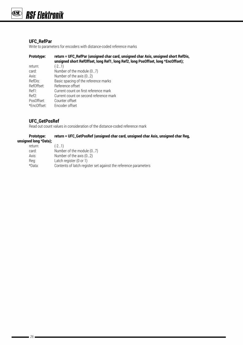
UFC_RefPar Write to parameters for encoders with distance-coded reference marks
Prototype: return=UFC_RefPar(unsignedcharcard,unsignedcharAxis,unsignedshortRefDis, unsignedshortRefOffset,longRef1,longRef2,longPosOffset,long*EncOffset); return: (-2…1) card: Number of the module (0…7) Axis: Number of the axis (0…2) RefDis: Basic spacing of the reference marks RefOffset: Reference offset Ref1: Currentcountonfirstreferencemark Ref2: Current count on second reference mark PosOffset: Counter offset *EncOffset: Encoder offset
UFC_GetPosRef Read out count values in consideration of the distance-coded reference mark
Prototype: return=UFC_GetPosRef(unsignedcharcard,unsignedcharAxis,unsignedcharReg, unsignedlong*Data); return: (-2…1) card: Number of the module (0…7) Axis: Number of the axis (0…2) Reg: Latch register (0 or 1) *Data: Contents of latch register set against the reference parameters

27
www.rsf.at
6.2.7FunctionsforexternalInputsandOutputs
UFC_SetExtInit Initialization of the polarity for the external inputs and outputs at X4
Prototype: return=UFC_SetExtInit(unsignedcharcard,unsignedshortInit); return: (-2…1) card: Number of the module (0…7) Init: Bit 0 = 0 a Output 4 (Casc-Out) not triggered by software latch impuls 1 a Output 4 (Casc-Out) triggered by software latch pulse
Bit 1 = 0 a Output 4 (Casc-Out) not triggered by internal timer 1 a Output 4 (Casc-Out) triggered by internal timer
Bit 2 = 0 a Output 4 (Casc-Out) not triggered X4/pin 8 (Sync-In) 1 a Output 4 (Casc-Out) triggered by X4/pin 8 (Sync-In)
Bit 3 = 0 a Output 4 (Casc-Out) LO-active 1 a Output 4 (Casc-Out) HI-active
Bit 4 = 0 a Input 1 LO-active 1 a Input 1 HI-active
Bit 5 = 0 a Input 2 LO-active 1 a Input 2 HI-active
Bit 6 = 0 a Input 3 LO-active 1 a Input 3 HI-active
Bit 7 = 0 a Input 4 LO-active 1 a Input 4 HI-active
Bit 8 = 0 a Input 5 LO-active 1 a Input 5 HI-active
Bit 9 = 0 a Input 6 LO-active 1 a Input 6 HI-active
Bit 10 = 0 a Input 7 LO-active 1 a Input 7 HI-active
Bit 11 = 0 a Input 8 LO-active 1 a Input 8 HI-active
UFC_GetExtInit Read out initialization of the polarities for the external inputs and outputs at X4
Prototype: return=UFC_GetExtInit(unsignedcharcard,unsignedshort*Init); return: (-2…1) card: Number of the module (0…7) *INit: Setting the polarities (0…65535)

28
UFC_SetExtOut Write external outputs (X4)
Prototype: return=UFC_SetExtOut(unsignedcharcard,unsignedcharOut); return: (-2…1) card: Number fo the module (0…7) OUT: Bit 0 = 0 a Output 1 inactive 1 a Output 1 active
Bit 1 = 0 a Output 2 inactive 1 a Output 2 active
Bit 2 = 0 a Output 3 inactive 1 a Output 3 active
Bit 3 = 0 a Output 4 inactive 1 a Output 4 active
UFC_GetExtIn Read out external inputs (X4)
Prototype: return=UFC_GetExtIn(unsignedcharcard,unsignedshort*Input); return: (-2…1) card: Number fo the module (0…7) *Input: Bit 0 = 0 a Input 1 inactive 1 a Input 1 active
Bit 1 = 0 a Input 2 inactive 1 a Input 2 active
Bit 2 = 0 a Input 3 inactive 1 a Input 3 active
Bit 3 = 0 a Input 4 inactive 1 a Input 4 active
Bit 4 = 0 a Input 5 inactive 1 a Input 5 active
Bit 5 = 0 a Input 6 inactive 1 a Input 6 active
Bit 6 = 0 a Input 7 inactive 1 a Input 7 active
Bit 7 = 0 a Input 8 inactive 1 a Input 8 active

29
www.rsf.at
6.2.8FunctionsfortheTimer
UFC_SetTimer Sets the preload value for the timer. If the preload value is set to "0", a running timer is stopped at the next zero crossover. If the preload value is <> 0, a non-running timer is immediately started withthespecifiedvalue;arunningtimerreceivesthenewvalueatthenextzerocrossover. Time=(Preloadvalue+1)*5µs
Prototype: return=UFC_SetTimer(unsignedcharcard,unsignedshortTimer); return: (-2…1) card: Number fo the module (0…7) Timer: Preload value (0…65535)
UFC_GetTimer
Returns the run time remaining until the next zero crossover of the timer. During the zero crossover of the timer a signal is generated that can be used for a variety of functions depending on the initialization e.g. synchronous latching of count values, load counter or generating a pulse at the CascOut output.
Prototype: return=UFC_GetTimer(unsignedcharcard,unsignedshort*Timer); return: (-2…1) card: Number fo the module (0…7) *Timer Remaining the time (0…65535)

30
LIST OF FIGURESFig. 1: Connecting elements and "Ready" LED .................................................................................................................................................... 6Fig. 2: Block diagram ............................................................................................................................................................................................. 8Fig. 3: Delay timer .................................................................................................................................................................................................11
LIST OF TABLESTable 1: Overview of the connecting elements .................................................................................................................................................. 6Table 2: Overview of the "Ready" LED ................................................................................................................................................................. 6Table 3: Connector pin assignment X1; X2; X3 .................................................................................................................................................. 7Table 4: Connector pin assignment X4 ............................................................................................................................................................... 7Table 5: DLL functions, counter operating modes ............................................................................................................................................ 8Table 6: DLL functions, load register ................................................................................................................................................................... 9Table 7: DLL functions, latch register ................................................................................................................................................................. 9Table 8: I/O functions ..........................................................................................................................................................................................10Table 9: DLL functions, external I/O port ..........................................................................................................................................................10Table 10: Delay timer ..........................................................................................................................................................................................11Table 11: DC Parameters ....................................................................................................................................................................................12Table 12: General functions ...............................................................................................................................................................................14Table 13: Functions for counter and encoder mode ....................................................................................................................................... 14Table 14: Functions for error messages and status ....................................................................................................................................... 15Table 15: Functions for load and clear counter ............................................................................................................................................... 15Table 16: Functions latching and reading out count values .......................................................................................................................... 15Table 17: Functions for referencing .................................................................................................................................................................. 16Table 18: Functions for external inputs and outputs ...................................................................................................................................... 16Table 19: Functions for the timer ......................................................................................................................................................................16

31
www.rsf.at
HISTORY
Date Revision Seite
10/2006Revision of the user manual 05/2006 - 12/2006
� accurate listing of input frequencys for encoders with TTL signals and analog signals (1Vpp) � corrected the formular for the timer
0529
01/2007Revision of the user manual 12/2006 - 01/2007
� corrected input frequency for encoders with analog signals (1Vpp) 05
02/2013
Revision of the user manual 01/2007 - 02/2013 � insert table of history � insert technical drawing of UFC 430-controller housing � update of the installation instructions
310413
09/2017 Revision of distribution contacts 32
UFC_ClearCounter ...............................................................15, 22UFC_ClearError ....................................................................15, 21UFC_ClearRef .......................................................................16, 25UFC_CloseDrv ......................................................................14, 17UFC_GetCounterStatus ......................................................15, 21UFC_GetDirectionMode ......................................................14, 20UFC_GetExtI .........................................................................16, 28UFC_GetExtInit ....................................................................16, 27UFC_GetFirmwareVersion ..................................................14, 18UFC_GetHardwareVersion..................................................14, 18UFC_GetInterpolMode ........................................................14, 19UFC_GetLatchMode ............................................................15, 24UFC_GetLatchReg ...............................................................15, 24UFC_GetLoadClearMode ....................................................15, 22UFC_GetPosRef ...................................................................16, 26UFC_GetRefInit ....................................................................16, 25UFC_GetSerialNumber ........................................................14, 18UFC_GetSwitchInit ..............................................................14, 20UFC_GetTimer .....................................................................16, 29
UFC_GetVoltEncoder ............................................................................. 14, 18UFC_GetVoltExtern ................................................................................ 14, 18UFC_LatchCounter ................................................................................. 15, 24UFC_LatchImpuls ................................................................................... 15, 24UFC_LoadCounter .................................................................................. 15, 23UFC_OpenDrv .......................................................................................... 14, 17UFC_RefPar ............................................................................................. 16, 26UFC_SetDirectionMode ......................................................................... 14, 20UFC_SetExtInit ........................................................................................ 16, 27UFC_SetExtOut ....................................................................................... 16, 28UFC_SetInterpolMode ............................................................................ 14, 19UFC_SetLatchMode ............................................................................... 15, 23UFC_SetLoadClearMode ........................................................................ 15, 22UFC_SetLoadReg ................................................................................... 15, 23UFC_SetRefInit ....................................................................................... 16, 25UFC_SetReset ......................................................................................... 14, 17UFC_SetSwitchInit ................................................................................. 14, 20UFC_SetTimer ......................................................................................... 16, 29
LIST OF THE DLL FUNCTIONS

DISTRIBUTION CONTACTS
A-5121 Tarsdorf +43 (0)6278 / 8192-0 FAX +43 (0)6278 / 8192-79 e-mail: [email protected] internet: www.rsf.at
Certifiedacc.toDIN EN ISO 9001
DIN EN ISO 14001
Linear EncodersCable SystemsPrecision GraduationsDigital Readouts
Ges.m.b.H.
Date 12/2017 � Art. N0.1063885-01 � Doc. N0. D1063885-01-A-01 �Technicaladjustmentsinreserve!
AUSTRIACorporate Head Quarters
RSF Elektronik Ges.m.b.H. A-5121 Tarsdorf 93 +4362 7881 92-0 +4362 7881 92-79
e-mail: [email protected]: www.rsf.at
BELGIUM HEIDENHAIN NV/SA Pamelse Klei 471760 Roosdaal
+32 (54) 34 3158 +32 (54) 34 3173
e-mail: [email protected] internet: www.heidenhain.be
FRANCE HEIDENHAIN FRANCE sarl 2 Avenue de la Christallerie92310 Sèvres
+33 1 41 14 30 00 +33 1 41 14 30 30
e-mail: [email protected] internet: www.heidenhain.fr
GREAT BRITAIN HEIDENHAIN (GB) Ltd. 200 London RoadBurgess HillWest Sussex RH15 9RD
+44 1444 247711 +44 1444 870024
e-mail: [email protected] internet: www.heidenhain.co.uk
ITALY HEIDENHAIN ITALIANA S.r.l. Via Asiago, 1420128 Milan
+39 02 27075-1 +39 02 27075-210
e-mail: [email protected]: www.heidenhain.it
NETHERLANDS HEIDENHAIN NEDERLAND B.V. Copernicuslaan 34 6716 BM EDE
+31 318-581800 +31318-581870
e-mail: [email protected]: www.heidenhain.nl
SPAIN FARRESA ELECTRONICA S.A Les Corts 36-3808028 Barcelona
+34 93 4 092 491 +34933395117
e-mail: [email protected] internet: www.farresa.es
SWEDEN HEIDENHAIN Scandinavia AB Storsätragränd 5SE-12739 Skärholmen
+468 531 933 50 +468 531 933 77
e-mail: [email protected]: www.heidenhain.se
SWITZERLAND HEIDENHAIN (SCHWEIZ) AG Vieristrasse 148603 Schwerzenbach
+41 44806 27 27 +41 44806 27 28
e-mail: [email protected]: www.heidenhain.ch
CHINA DR. JOHANNES HEIDENHAIN (CHINA) Co., Ltd
Tian Wei San Jie, Area A, Beijing Tianzhu Airport Industrial ZoneShunyi District, Beijing 101312
+86 10 80 42-0000 e-mail: [email protected]: www.heidenhain.com.cn
HONG KONG SAR HEIDENHAIN LIMITED Unit 2007-2010 Apec Plaza 49 Hoi Yuen Road, Kwun TongKowloon, Hong Kong
+85227591920 +85227591961
e-mail: [email protected]
ISRAEL MEDITAL Hi-Tech 7 Leshem Str.47170 Petach Tikva
+972 0 3 923 33 23 +972 0 3 923 16 66
e-mail: [email protected] internet: www.medital.co.il
JAPAN HEIDENHAIN K.K. Hulic Kojimachi Bldg., 9F 3-2 Kojimachi, Chiyoda-kuTokyo, 102-0083
+81 3 3234 7781 +81 3 3262 2539
e-mail: [email protected]: www.heidenhain.co.jp
KOREA HEIDENHAIN LTD. 202 Namsung Plaza, 9th Ace Techno Tower, 130, Digital-Ro, Geumcheon-Gu, Seoul, Korea 153-782
+82 2 20 28 74 30 e-mail: [email protected]: www.rsf.co.kr
RUSSIA ООО «HEIDENHAIN» ul. Goncharnaya, d. 21
115172 Moscow
+7 (495) 777 34 66 +7 (499) 702 33 31
e-mail: [email protected] internet: www.heidenhain.ru
SINGAPORE HEIDENHAIN PACIFIC PTE LTD. 51, Ubi Crescent
408593 Singapore
+65 67 49 32 38 +65 67 49 39 22
e-mail: [email protected] internet: www.heidenhain.com.sg
TAIWAN HEIDENHAIN CO., LTD. No. 29, 33rd Road; Taichung Industrial Park Taichung 40768
+886423588977 +886423588978
e-mail: [email protected]: www.heidenhain.com.tw
USA HEIDENHAIN CORPORATION 333 East State ParkwaySchaumburg, IL 60173-5337
+1 847 490 11 91 e-mail: [email protected]: www.rsf.net