User Manual - Tecate Group
11
7520 Mission Valley Road ● San Diego, CA 92108-4400 ● USA ● Tel: 619.398.9700 ● Fax: 619.398.9777 ● www.tecategroup.com User Manual TPLC™/PBLC™ Series
-
Upload
khangminh22 -
Category
Documents
-
view
1 -
download
0
Transcript of User Manual - Tecate Group
7520 Mission Valley Road ● San Diego, CA 92108-4400 ● USA ● Tel: 619.398.9700 ● Fax: 619.398.9777 ● www.tecategroup.com
User Manual
TPLC™/PBLC™ Series
7520 Mission Valley Road ● San Diego, CA 92108-4400 ● USA ● Tel: 619.398.9700 ● Fax: 619.398.9777 ● www.tecategroup.com
9101840000.f.docx.INSERT DOC #DOCX PAGE 2
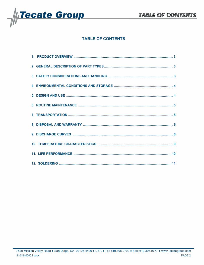
TABLE OF CONTENTS
1. PRODUCT OVERVIEW ............................................................................................................ 3
2. GENERAL DESCRIPTION OF PART TYPES ........................................................................... 3
3. SAFETY CONSIDERATIONS AND HANDLING ....................................................................... 3
4. ENVIRONMENTAL CONDITIONS AND STORAGE ................................................................ 4
5. DESIGN AND USE .................................................................................................................... 4
6. ROUTINE MAINTENANCE ....................................................................................................... 5
7. TRANSPORTATION .................................................................................................................. 5
8. DISPOSAL AND WARRANTY .................................................................................................. 5
9. DISCHARGE CURVES ............................................................................................................. 6
10. TEMPERATURE CHARACTERISTICS .................................................................................. 9
11. LIFE PERFORMANCE .......................................................................................................... 10
12. SOLDERING .......................................................................................................................... 11
7520 Mission Valley Road ● San Diego, CA 92108-4400 ● USA ● Tel: 619.398.9700 ● Fax: 619.398.9777 ● www.tecategroup.com
9101840000.f.docx.INSERT DOC #DOCX PAGE 3
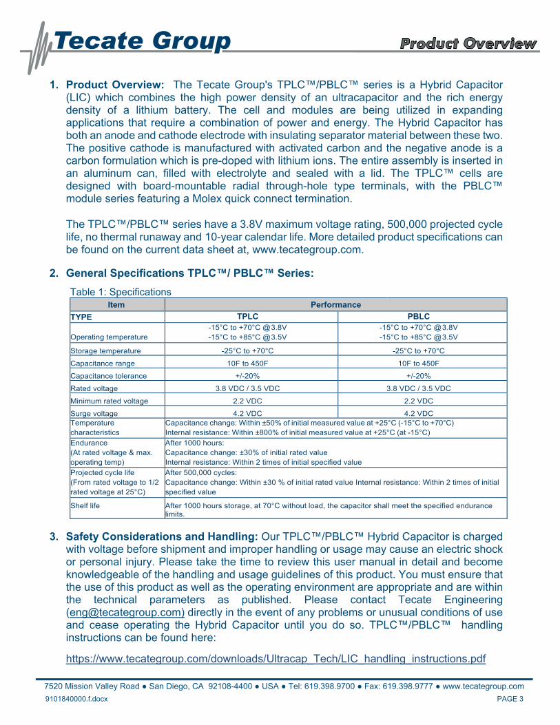
1. Product Overview: The Tecate Group's TPLC™/PBLC™ series is a Hybrid Capacitor (LIC) which combines the high power density of an ultracapacitor and the rich energy density of a lithium battery. The cell and modules are being utilized in expanding applications that require a combination of power and energy. The Hybrid Capacitor has both an anode and cathode electrode with insulating separator material between these two. The positive cathode is manufactured with activated carbon and the negative anode is a carbon formulation which is pre-doped with lithium ions. The entire assembly is inserted in an aluminum can, filled with electrolyte and sealed with a lid. The TPLC™ cells are designed with board-mountable radial through-hole type terminals, with the PBLC™ module series featuring a Molex quick connect termination.
The TPLC™/PBLC™ series have a 3.8V maximum voltage rating, 500,000 projected cycle life, no thermal runaway and 10-year calendar life. More detailed product specifications can be found on the current data sheet at, www.tecategroup.com.
2. General Specifications TPLC™/ PBLC™ Series:
Table 1: Specifications Item Performance
TYPE TPLC PBLC
Operating temperature
-15°C to +70°C @ 3.8V -15°C to +85°C @ 3.5V
-15°C to +70°C @ 3.8V -15°C to +85°C @ 3.5V
Storage temperature -25°C to +70°C -25°C to +70°C
Capacitance range 10F to 450F 10F to 450F
Capacitance tolerance +/-20% +/-20%
Rated voltage 3.8 VDC / 3.5 VDC 3.8 VDC / 3.5 VDC
Minimum rated voltage 2.2 VDC 2.2 VDC
Surge voltage 4.2 VDC 4.2 VDC Temperature characteristics
Capacitance change: Within ±50% of initial measured value at +25°C (-15°C to +70°C) Internal resistance: Within ±800% of initial measured value at +25°C (at -15°C)
Endurance (At rated voltage & max. operating temp)
After 1000 hours: Capacitance change: ±30% of initial rated value Internal resistance: Within 2 times of initial specified value
Projected cycle life (From rated voltage to 1/2 rated voltage at 25°C)
After 500,000 cycles: Capacitance change: Within ±30 % of initial rated value Internal resistance: Within 2 times of initial specified value
Shelf life After 1000 hours storage, at 70°C without load, the capacitor shall meet the specified endurance limits.
3. Safety Considerations and Handling: Our TPLC™/PBLC™ Hybrid Capacitor is charged with voltage before shipment and improper handling or usage may cause an electric shock or personal injury. Please take the time to review this user manual in detail and become knowledgeable of the handling and usage guidelines of this product. You must ensure that the use of this product as well as the operating environment are appropriate and are within the technical parameters as published. Please contact Tecate Engineering ([email protected]) directly in the event of any problems or unusual conditions of use and cease operating the Hybrid Capacitor until you do so. TPLC™/PBLC™ handling instructions can be found here:
https://www.tecategroup.com/downloads/Ultracap_Tech/LIC_handling_instructions.pdf
7520 Mission Valley Road ● San Diego, CA 92108-4400 ● USA ● Tel: 619.398.9700 ● Fax: 619.398.9777 ● www.tecategroup.com
9101840000.f.docx.INSERT DOC #DOCX PAGE 4
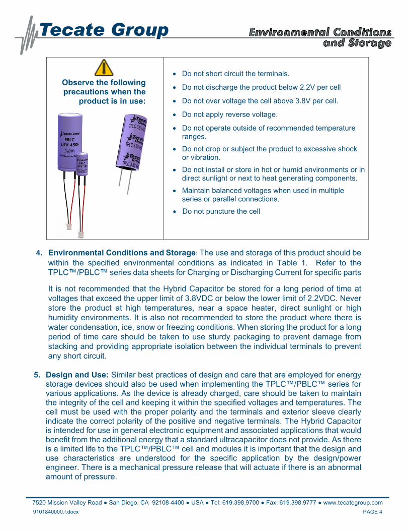
Observe the following precautions when the
product is in use:
Do not short circuit the terminals.
Do not discharge the product below 2.2V per cell
Do not over voltage the cell above 3.8V per cell.
Do not apply reverse voltage.
Do not operate outside of recommended temperature ranges.
Do not drop or subject the product to excessive shock or vibration.
Do not install or store in hot or humid environments or in direct sunlight or next to heat generating components.
Maintain balanced voltages when used in multiple series or parallel connections.
Do not puncture the cell
4. Environmental Conditions and Storage: The use and storage of this product should be within the specified environmental conditions as indicated in Table 1. Refer to the TPLC™/PBLC™ series data sheets for Charging or Discharging Current for specific parts
It is not recommended that the Hybrid Capacitor be stored for a long period of time at voltages that exceed the upper limit of 3.8VDC or below the lower limit of 2.2VDC. Never store the product at high temperatures, near a space heater, direct sunlight or high humidity environments. It is also not recommended to store the product where there is water condensation, ice, snow or freezing conditions. When storing the product for a long period of time care should be taken to use sturdy packaging to prevent damage from stacking and providing appropriate isolation between the individual terminals to prevent any short circuit.
5. Design and Use: Similar best practices of design and care that are employed for energy
storage devices should also be used when implementing the TPLC™/PBLC™ series for various applications. As the device is already charged, care should be taken to maintain the integrity of the cell and keeping it within the specified voltages and temperatures. The cell must be used with the proper polarity and the terminals and exterior sleeve clearly indicate the correct polarity of the positive and negative terminals. The Hybrid Capacitor is intended for use in general electronic equipment and associated applications that would benefit from the additional energy that a standard ultracapacitor does not provide. As there is a limited life to the TPLC™/PBLC™ cell and modules it is important that the design and use characteristics are understood for the specific application by the design/power engineer. There is a mechanical pressure release that will actuate if there is an abnormal amount of pressure.
7520 Mission Valley Road ● San Diego, CA 92108-4400 ● USA ● Tel: 619.398.9700 ● Fax: 619.398.9777 ● www.tecategroup.com
9101840000.f.docx.INSERT DOC #DOCX PAGE 5
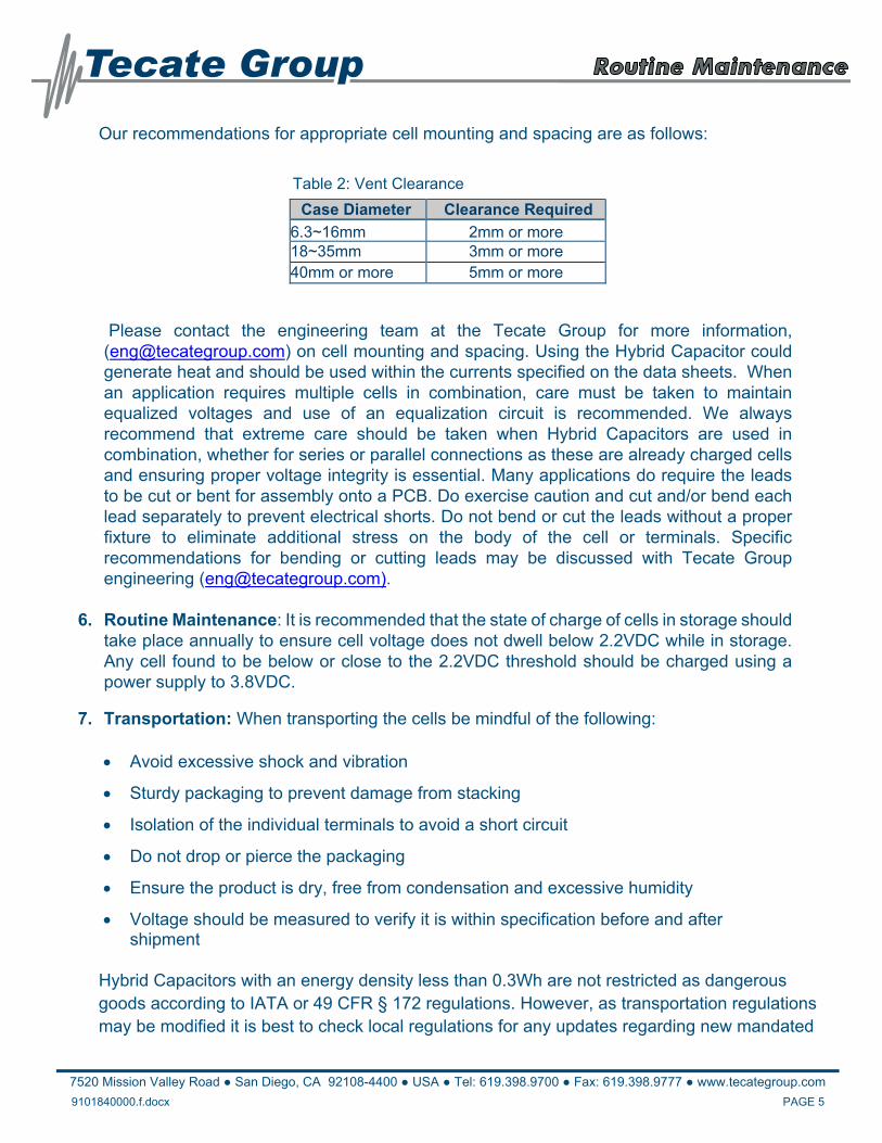
Our recommendations for appropriate cell mounting and spacing are as follows:
Table 2: Vent Clearance
Case Diameter Clearance Required
6.3~16mm 2mm or more 18~35mm 3mm or more 40mm or more 5mm or more
Please contact the engineering team at the Tecate Group for more information, ([email protected]) on cell mounting and spacing. Using the Hybrid Capacitor could generate heat and should be used within the currents specified on the data sheets. When an application requires multiple cells in combination, care must be taken to maintain equalized voltages and use of an equalization circuit is recommended. We always recommend that extreme care should be taken when Hybrid Capacitors are used in combination, whether for series or parallel connections as these are already charged cells and ensuring proper voltage integrity is essential. Many applications do require the leads to be cut or bent for assembly onto a PCB. Do exercise caution and cut and/or bend each lead separately to prevent electrical shorts. Do not bend or cut the leads without a proper fixture to eliminate additional stress on the body of the cell or terminals. Specific recommendations for bending or cutting leads may be discussed with Tecate Group engineering ([email protected]).
6. Routine Maintenance: It is recommended that the state of charge of cells in storage should
take place annually to ensure cell voltage does not dwell below 2.2VDC while in storage. Any cell found to be below or close to the 2.2VDC threshold should be charged using a power supply to 3.8VDC.
7. Transportation: When transporting the cells be mindful of the following: Avoid excessive shock and vibration
Sturdy packaging to prevent damage from stacking
Isolation of the individual terminals to avoid a short circuit
Do not drop or pierce the packaging
Ensure the product is dry, free from condensation and excessive humidity
Voltage should be measured to verify it is within specification before and after shipment
Hybrid Capacitors with an energy density less than 0.3Wh are not restricted as dangerous goods according to IATA or 49 CFR § 172 regulations. However, as transportation regulations may be modified it is best to check local regulations for any updates regarding new mandated
7520 Mission Valley Road ● San Diego, CA 92108-4400 ● USA ● Tel: 619.398.9700 ● Fax: 619.398.9777 ● www.tecategroup.com
9101840000.f.docx.INSERT DOC #DOCX PAGE 6
shipping requirements. Hybrid capacitors are regulated for transportation according to UN 3508, we recommend that you consult your local logistics authority for specific requirements.
8. Disposal and Warranty: When disposing of the product comply with all local, regional, federal and national requirements. In most jurisdictions the cell can be disposed of by industrial waste organizations. You will need to insulate the terminals to avoid any short circuit possibility. Our product warranty may be found under our standard Terms and Conditions for sale. This product warranty and is limited to the actual product and does not constitute any liability for damages that may be a direct result from improper use or defects in our products.
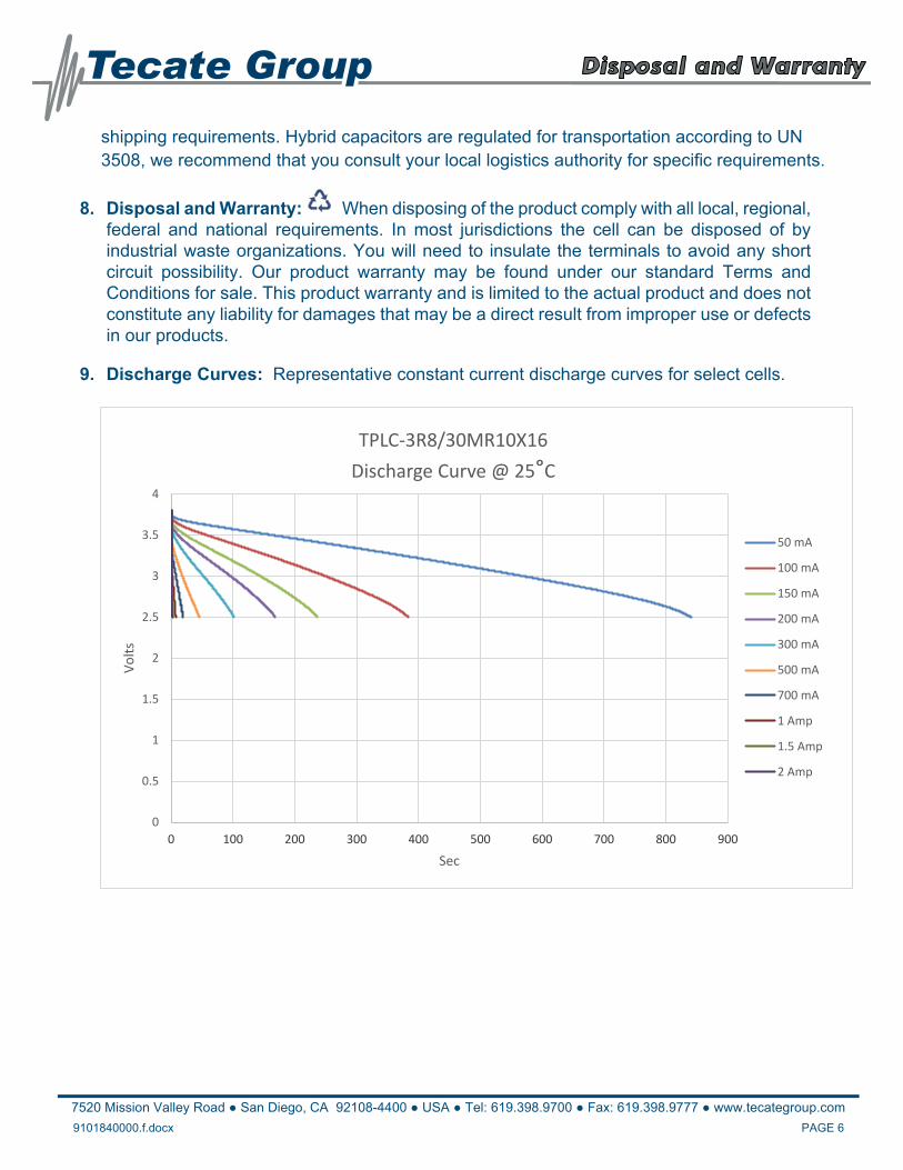
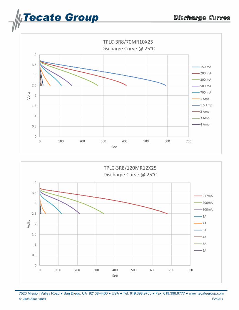
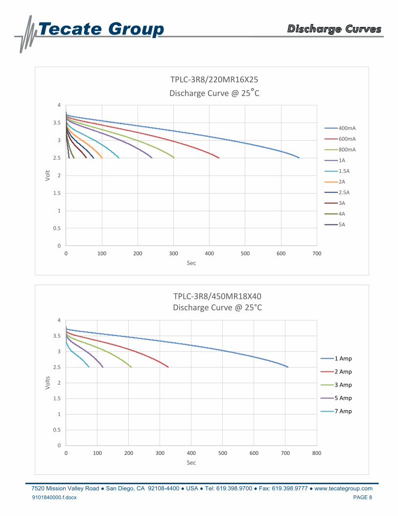
9. Discharge Curves: Representative constant current discharge curves for select cells.
0
0.5
1
1.5
2
2.5
3
3.5
4
0 100 200 300 400 500 600 700 800 900
Volts
Sec
TPLC‐3R8/30MR10X16
Discharge Curve @ 25°C
50 mA
100 mA
150 mA
200 mA
300 mA
500 mA
700 mA
1 Amp
1.5 Amp
2 Amp
7520 Mission Valley Road ● San Diego, CA 92108-4400 ● USA ● Tel: 619.398.9700 ● Fax: 619.398.9777 ● www.tecategroup.com
9101840000.f.docx.INSERT DOC #DOCX PAGE 7
0
0.5
1
1.5
2
2.5
3
3.5
4
0 100 200 300 400 500 600 700
Volts
Sec
TPLC‐3R8/70MR10X25Discharge Curve @ 25°C
150 mA
200 mA
300 mA
500 mA
700 mA
1 Amp
1.5 Amp
2 Amp
3 Amp
4 Amp
0
0.5
1
1.5
2
2.5
3
3.5
4
0 100 200 300 400 500 600 700 800
Volts
Sec
TPLC‐3R8/120MR12X25Discharge Curve @ 25°C
217mA
400mA
600mA
1A
2A
3A
4A
5A
6A
7520 Mission Valley Road ● San Diego, CA 92108-4400 ● USA ● Tel: 619.398.9700 ● Fax: 619.398.9777 ● www.tecategroup.com
9101840000.f.docx.INSERT DOC #DOCX PAGE 8
0
0.5
1
1.5
2
2.5
3
3.5
4
0 100 200 300 400 500 600 700
Volt
Sec
TPLC‐3R8/220MR16X25
Discharge Curve @ 25°C
400mA
600mA
800mA
1A
1.5A
2A
2.5A
3A
4A
5A
0
0.5
1
1.5
2
2.5
3
3.5
4
0 100 200 300 400 500 600 700 800
Volts
Sec
TPLC‐3R8/450MR18X40Discharge Curve @ 25°C
1 Amp
2 Amp
3 Amp
5 Amp
7 Amp
7520 Mission Valley Road ● San Diego, CA 92108-4400 ● USA ● Tel: 619.398.9700 ● Fax: 619.398.9777 ● www.tecategroup.com
9101840000.f.docx.INSERT DOC #DOCX PAGE 9
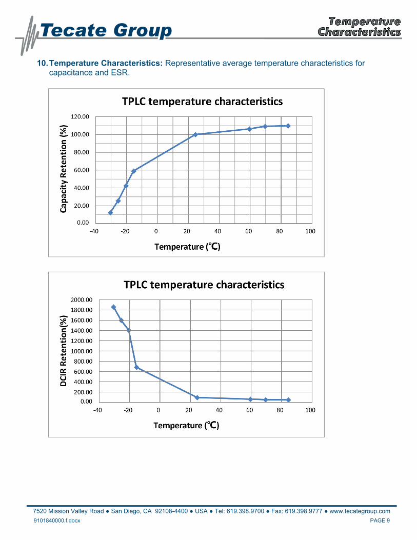
10. Temperature Characteristics: Representative average temperature characteristics for capacitance and ESR.
7520 Mission Valley Road ● San Diego, CA 92108-4400 ● USA ● Tel: 619.398.9700 ● Fax: 619.398.9777 ● www.tecategroup.com
9101840000.f.docx.INSERT DOC #DOCX PAGE 10
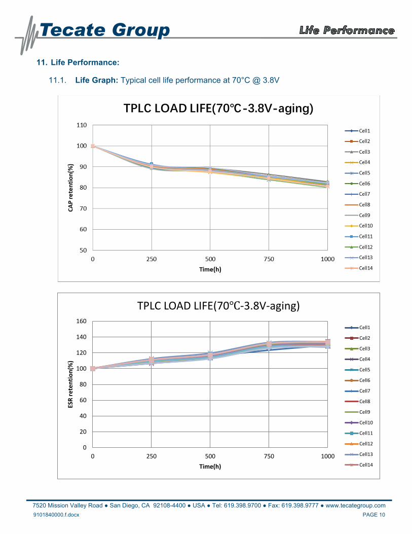
11. Life Performance:
11.1. Life Graph: Typical cell life performance at 70°C @ 3.8V
0
20
40
60
80
100
120
140
160
0 250 500 750 1000
ESR retention(%
)
Time(h)
TPLC LOAD LIFE(70℃‐3.8V‐aging)
Cell1
Cell2
Cell3
Cell4
Cell5
Cell6
Cell7
Cell8
Cell9
Cell10
Cell11
Cell12
Cell13
Cell14
7520 Mission Valley Road ● San Diego, CA 92108-4400 ● USA ● Tel: 619.398.9700 ● Fax: 619.398.9777 ● www.tecategroup.com
9101840000.f.docx.INSERT DOC #DOCX PAGE 11
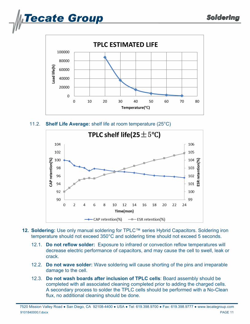
11.2. Shelf Life Average: shelf life at room temperature (25°C)
12. Soldering: Use only manual soldering for TPLC™ series Hybrid Capacitors. Soldering iron temperature should not exceed 350°C and soldering time should not exceed 5 seconds.
12.1. Do not reflow solder: Exposure to infrared or convection reflow temperatures will decrease electric performance of capacitors, and may cause the cell to swell, leak or crack.
12.2. Do not wave solder: Wave soldering will cause shorting of the pins and irreparable damage to the cell.
12.3. Do not wash boards after inclusion of TPLC cells: Board assembly should be completed with all associated cleaning completed prior to adding the charged cells. A secondary process to solder the TPLC cells should be performed with a No-Clean flux, no additional cleaning should be done.
0
20000
40000
60000
80000
100000
0 10 20 30 40 50 60 70 80
Load
life(h)
Temperature(℃)
TPLC ESTIMATED LIFE