User Manual - Ingersoll Rand
28
49207947 Revision A November 2015 Save These Instructions Airscout dP Flow Meter Insertion Probe User Manual
-
Upload
khangminh22 -
Category
Documents
-
view
1 -
download
0
Transcript of User Manual - Ingersoll Rand

49207947Revision A
November 2015
Save These Instructions
Airscout dP Flow Meter Insertion Probe
User Manual
� 49�07947Rev.A
TAble oF conTenTS
1.0 SAFeTY InFoRMATIon . . . . . . . . . 3 1.1 SAFETY SYMBOLS . . . . . . . . . . . . . . . . . . . . . . . 3
2.0 InTRoDUcTIon. . . . . . . . . . . . . . . . .43.0 PRoDUcT oveRvIew. . . . . . . . . . . .43.1 CONFiguRATiON . . . . . . . . . . . . . . . . . . . . . . . . . 5
3.2 AiRSCOuT dP PROBE wiTh CONNECTOR CAP . . . . . . . . . . . . . . . . . . . . . . . . . . . . . . . . . . . . . . . . . 5
3.3 AiRSCOuT dP PROBE wiTh diSPLAY . . . . . . 5
3.4 AiRSCOuT dP PROBE wiTh ThE AiRSCOuT TERMiNAL . . . . . . . . . . . . . . . . . . . . . . . . . . . . . . . . . . . 5
4.0 QUIcK START. . . . . . . . . . . . . . . . . . . 65.0 MeASUReMenT. . . . . . . . . . . . . . . . . 65.1 FLOw . . . . . . . . . . . . . . . . . . . . . . . . . . . . . . . . . . . . 6
5.2 PRESSuRE . . . . . . . . . . . . . . . . . . . . . . . . . . . . . . . . 7
5.3 TEMPERATuRE . . . . . . . . . . . . . . . . . . . . . . . . . . . 7
5.4 TOTALizER . . . . . . . . . . . . . . . . . . . . . . . . . . . . . . . 7
6.0 MecHAnIcAl InSTAllATIon 76.1 PiPiNg TABLE . . . . . . . . . . . . . . . . . . . . . . . . . . . 11
7.0 DISPlAY. . . . . . . . . . . . . . . . . . . . . . . 127.1 diSPLAY STATuS iCONS . . . . . . . . . . . . . . . . . 12
7.2 LCd diSPLAY . . . . . . . . . . . . . . . . . . . . . . . . . . . . 12
7.3 dATA LOggER . . . . . . . . . . . . . . . . . . . . . . . . . . . 12
7.4 KEY PAd . . . . . . . . . . . . . . . . . . . . . . . . . . . . . . . . 12
7.5 MENu . . . . . . . . . . . . . . . . . . . . . . . . . . . . . . . . . . . 12
8.0 AIRScoUT STUDIo SoFTwARe. . . . . . . . . . . . . . . . . . . . . . . . . . . . . . . . . .14
9.0 elecTRIcAl connecTIonS. . . . 159.1 4..20 MA OuTPuT . . . . . . . . . . . . . . . . . . . . . . . 15
9.2 PuLSE OuTPuT . . . . . . . . . . . . . . . . . . . . . . . . . 16
9.3 MOdBuS iNTERFACE . . . . . . . . . . . . . . . . . . . . 17
9.5 CONNECTiON TO X-SERiES CONTROLLER . . . . . . . . . . . . . . . . . . . . . . . . . . . . . . . . . . . . . . . . . . . . . . . 20
10.0 SeRvIce. . . . . . . . . . . . . . . . . . . . . .2110.1 RECALiBRATiON . . . . . . . . . . . . . . . . . . . . . . . 21
10.2 FiLTER SET REPLACEMENT . . . . . . . . . . . . . 21
11.0 SPecIFIcATIonS. . . . . . . . . . . . . .22
12.0 oRDeR InFoRMATIon AnD AcceSSoRIeS. . . . . . . . . . . . . . . . . . . . . 2313.0 APPenDIX A -Ul. . . . . . . . . . . . . . 24
49�07947Rev.A �
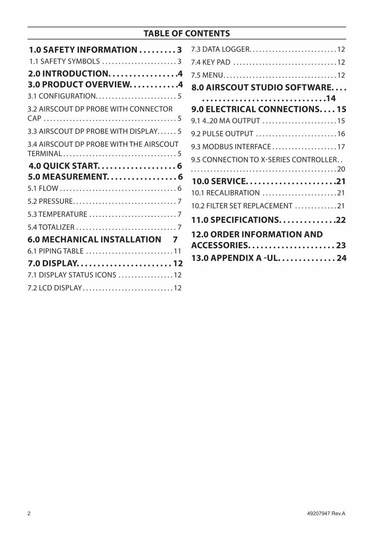
1.0 SAFeTY InFoRMATIon1.1 SAFeTY SYMbolS
The Airscout dP is designed for use in wet air applications. It can handle 100% saturated air, where condensation may occur from time to time. However, the Airscout dP is noT a water or multiphase flow meter. A too high water content which causes flooding of the compressed air network with liquid water will cause misreadings and may damage the instrument.
The Airscout dP has a small dynamic range. You cannot use it to detect small flows or small leakages.
Stabilization time: when exposed to large pressure changes, for example during installation of the sensor, the dP sensor element needs to stabilize. This takes up to 15 minutes. during this time, readings may have a larger error.
The actual installation location has a great influence on the amount of water in the pipe. Too much water will result in reading errors. The unit has to be exposed to gas at all times. Exposure/ submersion in liquids should be avoided! Condensate should be able to drip off and out of the probe freely.
Avoid insertion in vertical (rising) pipelines.
Avoid horizontal pipe lines at the lowest point of the wet air installation, as water may flood this part of the pipe.
Avoid situations where freezing/ icing may occur from time to time.
ChECK the amount of condensate BEFORE insertion of the probe!
Consider to add a drain point when flooding is likely under certain circumstances.
NEVER mount the unit upside down, always keep the unit under a 1 0 - 2 clock position.
NEVER mount the unit straight downward, as drops will be collected around the probe tip.
After the audit, it is very important to let the unit dry out completely. water will condense after the unit cools down, and condensate might build up internally. This condensate can cause trouble when the unit is used again: it will be pushed into the probe by the air when repressurized.
disassemble the probe from the transmitter and let everything dry out completely.
inspect the two hydrophobic filters, replace when dirty or when cracked.
Make sure no water remains in the probe. in case of doubt, remove the filters and purge with air.
Re-assemble the dried out components according to the service instructions, which can be found in the user manual.
•
•
•
•
•
•
•
•
•
•
•
4 49�07947Rev.A
congratulations! You purchased the easiest to use and most complete compressed air measurement tool in the world. with the Airscout dP probe, you can monitor and record flow, pressure, temperature, and total air consumption, simultaneously.
great products deserve great user manuals. we have done our best to make this user manual as complete as possible. New users, please read it carefully to familiarize yourself with our products.
2.0 InTRoDUcTIon
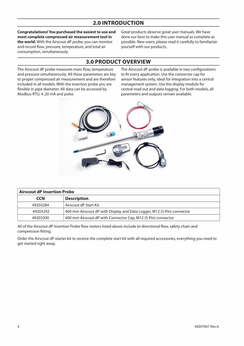
3.0 PRoDUcT oveRvIewThe Airscout dP probe measures mass flow, temperature and pressure simultaneously. All these parameters are key to proper compressed air measurement and are therefore included in all models. with the insertion probe you are flexible in pipe diameter. All data can be accessed by Modbus RTu, 4..20 mA and pulse.
The Airscout dP probe is available in two configurations to fit every application. use the connector cap for sensor features only, ideal for integration into a central management system. use the display module for central read out and data logging. For both models, all parameters and outputs remain available.
Airscout dP Insertion Probeccn Description
49203284 Airscout dP Start Kit
49203292 400 mm Airscout dP with display and data Logger, M12 (5-Pin) connector
49203300 400 mm Airscout dP with Connector Cap, M12 (5-Pin) connector
All of the Airscout dP insertion Probe flow meters listed above include bi-directional flow, safety chain and compression fitting.
Order the Airscout dP starter kit to receive the complete start kit with all required accessories, everything you need to get started right away.
49�07947Rev.A �
3.1 configuration
The instruments needs only one step to be ready for operation. it needs to know the exact inner pipe diameter for accurate measurement, wrong inner diameter will lead to very significant errors. The pipe diameter can be programmed with the key pad on the display module or with the Airscout Studio configuration software. This software suite is also used for configuration of the outputs and data logger.
3.2 Airscout dP probe with connector cap
The Airscout dP probe with connector cap can be used in applications where local read-out and data logging is not required. with it’s various outputs the Airscout dP probe can be connected to remote data loggers.
3.3 Airscout dP probe with display
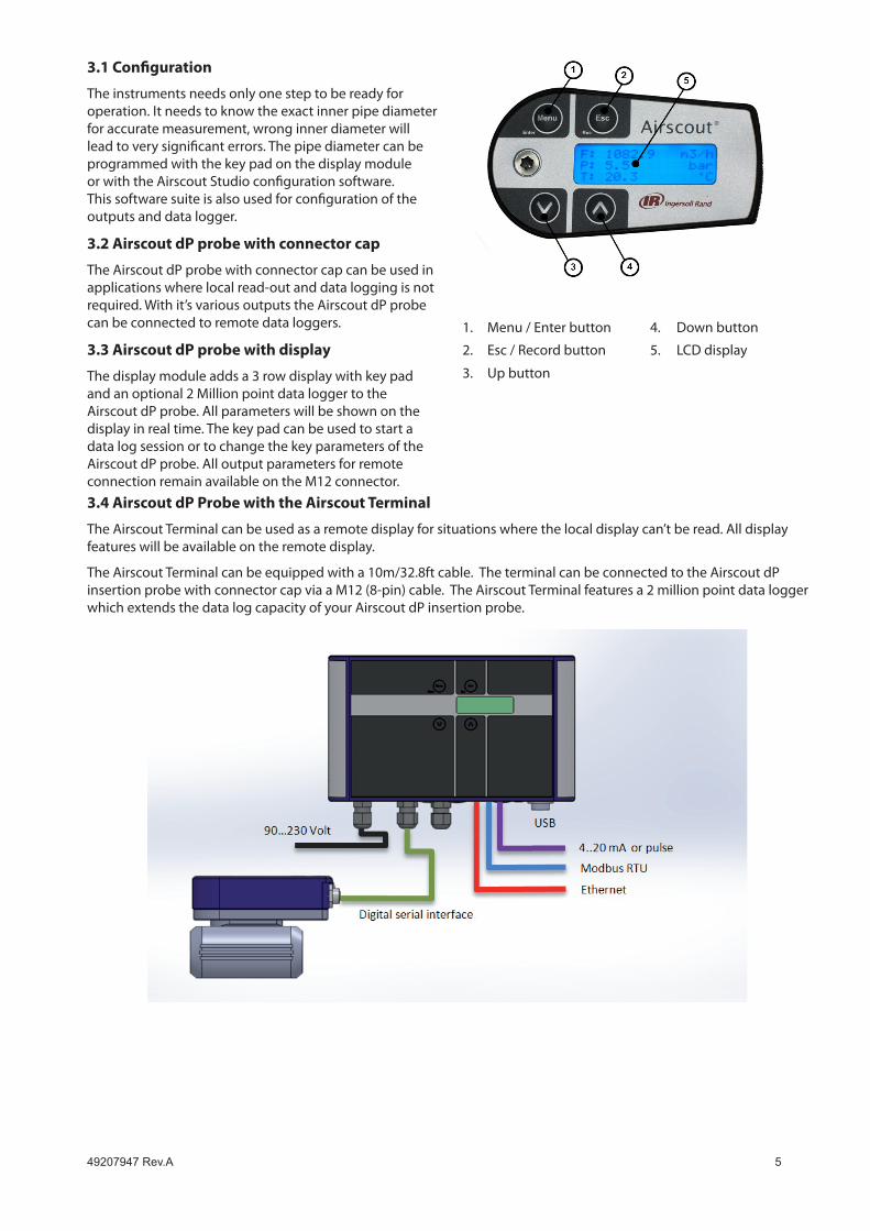
The display module adds a 3 row display with key pad and an optional 2 Million point data logger to the Airscout dP probe. All parameters will be shown on the display in real time. The key pad can be used to start a data log session or to change the key parameters of the Airscout dP probe. All output parameters for remote connection remain available on the M12 connector.
1. Menu / Enter button 4. down button
2. Esc / Record button 5. LCd display
3. up button
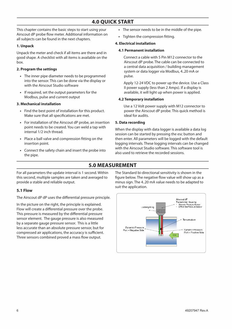
3.4 Airscout dP Probe with the Airscout Terminal
The Airscout Terminal can be used as a remote display for situations where the local display can’t be read. All display features will be available on the remote display.
The Airscout Terminal can be equipped with a 10m/32.8ft cable. The terminal can be connected to the Airscout dP insertion probe with connector cap via a M12 (8-pin) cable. The Airscout Terminal features a 2 million point data logger which extends the data log capacity of your Airscout dP insertion probe.
� 49�07947Rev.A
4.0 QUIcK STARTThis chapter contains the basic steps to start using your Airscout dP probe flow meter. Additional information on all subjects can be found in the next chapters.
1. Unpack
unpack the meter and check if all items are there and in good shape. A checklist with all items is available on the box.
2. Program the settings
The inner pipe diameter needs to be programmed into the sensor. This can be done via the display or with the Airscout Studio software
if required, set the output parameters for the Modbus, pulse and current output
3. Mechanical installation
Find the best point of installation for this product. Make sure that all specifications are met.
For installation of the Airscout dP probe, an insertion point needs to be created. You can weld a tap with internal 1/2 inch thread.
Place a ball valve and compression fitting on the insertion point.
Connect the safety chain and insert the probe into the pipe.
•
•
•
•
•
•
The sensor needs to be in the middle of the pipe.
Tighten the compression fitting.
4. electrical installation
4.1 Permanent installation
Connect a cable with 5 Pin M12 connector to the Airscout dP probe. The cable can be connected to a central data acquisition / building management system or data logger via Modbus, 4..20 mA or pulse.
Apply 12-24 VdC to power up the device. use a Class ii power supply (less than 2 Amps). if a display is available, it will light up when power is applied.
4.2 Temporary installation
use a 12 Volt power supply with M12 connector to power the Airscout dP probe. This quick method is ideal for audits.
5. Data recording
when the display with data logger is available a data log session can be started by pressing the esc button and then enter. All parameters will be logged with the default logging intervals. These logging intervals can be changed with the Airscout Studio software. This software tool is also used to retrieve the recorded sessions.
•
•
5.0 MeASUReMenTFor all parameters the update interval is 1 second. within this second, multiple samples are taken and averaged to provide a stable and reliable output.
5.1 Flow
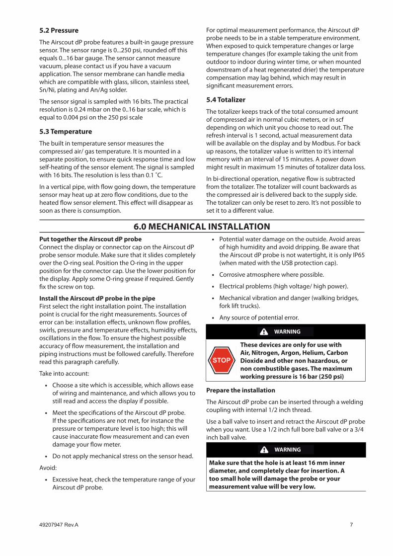
The Airscout dP dP uses the differential pressure principle.
in the picture on the right, the principle is explained. Flow will create a differential pressure over the probe. This pressure is measured by the differential pressure sensor element. The gauge pressure is also measured by a separate gauge pressure sensor. This is a little less accurate than an absolute pressure sensor, but for compressed air applications, the accuracy is sufficient. Three sensors combined proved a mass flow output.
The Standard bi-directional sensitivity is shown in the figure below. The negative flow value will show up as a minus sign. The 4..20 mA value needs to be adapted to suit the application.
49�07947Rev.A 7
5.2 Pressure
The Airscout dP probe features a built-in gauge pressure sensor. The sensor range is 0...250 psi, rounded off this equals 0...16 bar gauge. The sensor cannot measure vacuum, please contact us if you have a vacuum application. The sensor membrane can handle media which are compatible with glass, silicon, stainless steel, Sn/Ni, plating and An/Ag solder.
The sensor signal is sampled with 16 bits. The practical resolution is 0.24 mbar on the 0..16 bar scale, which is equal to 0.004 psi on the 250 psi scale
5.3 Temperature
The built in temperature sensor measures the compressed air/ gas temperature. it is mounted in a separate position, to ensure quick response time and low self-heating of the sensor element. The signal is sampled with 16 bits. The resolution is less than 0.1 ˚C.
in a vertical pipe, with flow going down, the temperature sensor may heat up at zero flow conditions, due to the heated flow sensor element. This effect will disappear as soon as there is consumption.
For optimal measurement performance, the Airscout dP probe needs to be in a stable temperature environment. when exposed to quick temperature changes or large temperature changes (for example taking the unit from outdoor to indoor during winter time, or when mounted downstream of a heat regenerated drier) the temperature compensation may lag behind, which may result in significant measurement errors.
5.4 Totalizer
The totalizer keeps track of the total consumed amount of compressed air in normal cubic meters, or in scf depending on which unit you choose to read out. The refresh interval is 1 second, actual measurement data will be available on the display and by Modbus. For back up reasons, the totalizer value is written to it’s internal memory with an interval of 15 minutes. A power down might result in maximum 15 minutes of totalizer data loss.
in bi-directional operation, negative flow is subtracted from the totalizer. The totalizer will count backwards as the compressed air is delivered back to the supply side. The totalizer can only be reset to zero. it’s not possible to set it to a different value.
Put together the Airscout dP probe Connect the display or connector cap on the Airscout dP probe sensor module. Make sure that it slides completely over the O-ring seal. Position the O-ring in the upper position for the connector cap. use the lower position for the display. Apply some O-ring grease if required. gently fix the screw on top.
Install the Airscout dP probe in the pipe First select the right installation point. The installation point is crucial for the right measurements. Sources of error can be: installation effects, unknown flow profiles, swirls, pressure and temperature effects, humidity effects, oscillations in the flow. To ensure the highest possible accuracy of flow measurement, the installation and piping instructions must be followed carefully. Therefore read this paragraph carefully.
Take into account:
Choose a site which is accessible, which allows ease of wiring and maintenance, and which allows you to still read and access the display if possible.
Meet the specifications of the Airscout dP probe. if the specifications are not met, for instance the pressure or temperature level is too high; this will cause inaccurate flow measurement and can even damage your flow meter.
do not apply mechanical stress on the sensor head.
Avoid:
Excessive heat, check the temperature range of your Airscout dP probe.
•
•
•
•
Potential water damage on the outside. Avoid areas of high humidity and avoid dripping. Be aware that the Airscout dP probe is not watertight, it is only iP65 (when mated with the uSB protection cap).
Corrosive atmosphere where possible.
Electrical problems (high voltage/ high power).
Mechanical vibration and danger (walking bridges, fork lift trucks).
Any source of potential error.
WARNING
These devices are only for use with Air, nitrogen, Argon, Helium, carbon Dioxide and other non hazardous, or non combustible gases. The maximum working pressure is 16 bar (250 psi)
Prepare the installation
The Airscout dP probe can be inserted through a welding coupling with internal 1/2 inch thread.
use a ball valve to insert and retract the Airscout dP probe when you want. use a 1/2 inch full bore ball valve or a 3/4 inch ball valve.
WARNING
Make sure that the hole is at least 16 mm inner diameter, and completely clear for insertion. A too small hole will damage the probe or your measurement value will be very low.
•
•
•
•
•
6.0 MecHAnIcAl InSTAllATIon

� 49�07947Rev.A
The installation
Insertion depth
generally the insertion depth of the Airscout dP probe is 0.5 times the inner pipe diameter, where the bottom of the sensor tip must be in the middle of the pipe (see picture).
The Airscout dP probe is shaped to make alignment with the flow direction easy. Alignment “by the eye” is sufficient.
See installation note on Figure 1.
exception
Between pipe sizes of 1” and 2”: be aware that the field accuracy is +/- 10%; installation errors are bigger. Airscout dP in-line is recommended for application up to 2”.
SAFeTY FIRST: START wITH MoUnTInG THe SAFeTY lIne!
The Airscout dP probe is mounted with a 1/2 inch compression fitting. The probe is sealed with a PTFe ferrule instead of a stainless steel ferrule. PTFe may become slippery. The safety line will keep the sensor secure when it accidentally moves out of the compression fitting. neveR over-tight the fitting, because it might damage the sensor tube.
Gravity helps tokeep the sensor clean
Avoid condensation: use gravity!
Troubleshooting Humidity (thermal sensors)
Good practice Bad practiceFlooding: Pressure sensor over-readingPressure sensor gets clogged over time
Figure 1

49�07947Rev.A 9
basic installation steps1. insert the compression fitting in the welding tap. use PTFE tape or liquid
sealant.
2. Keep the ball valve closed!
3. insert the Airscout dP probe.
4. Mount the safety line. hook the safety line up in the ring of the Airscout dP probe. For extra safety, you can add a luggage strap (like for suitcases).

10 49�07947Rev.A
5. Place a mark on the probe, to identify the place where it is safe to close the ball valve when retrieving the Airscout dP probe.
6. Open the ball valve and slowly push the Airscout dP probe completely in.
7. Push the probe in till it hits the bottom of the pipe. Now place another mark on the probe.
8. Retrieve the probe half the pipe diameter. Adjust the safety line (and strap) to keep the Airscout dP probe in place. Keep in mind to align the Airscout dP probe with the flow direction.
9. gently tighten the compression fitting. do not over tighten to prevent damage to the probe. Pull the probe to check if the compression fitting is tight enough.
10. Now your Airscout dP probe is installed.
49�07947Rev.A 11
Picture Description Upstream length
Downstream length effect
Complex feed-in situation (header) 40 * d1 10 * d1 Flow profile will be
distorted
double elbow, multiple elbows following each other 40 * d1 10 * d1 distorted profile + swirl
diameter change from small to large (gradual or instant) 40 * d1 5 * d1 Jet shaped flow
diameter change from large to small (gradual change, between 7 and 15 degrees)
10 * d1 5 * d1 Flattened flow profile
Single elbow 30 * d1 10 * d1 distorted flow profile
6.1 Piping table
At least 20 times the pipe diameter upstream and at least 5 times the pipe diameter downstream needs to be applied, to avoid any distortion of the flow profile. gas flow in pipes follows certain rules, which must be observed for optimal measurement results. For some exceptions the upstream length needs to be longer, or can be shorter. Check the piping table below for your application.
Example: Pipe diameter - 4” 80” upstream of flow meter, 20” downstream
If possible, you can always choose a longer upstream length, as these are minimum values. The up- and downstream lengths are used industry wide as guidelines, but will never be a guarantee for obtaining the “true value”. So always be careful and try to build up your own experience from practical measurements
The following table provides a guideline for proper distances between upstream or downstream objects and the Airscout dP probe. The upstream length is the length between the last non-straight object and the Airscout dP probe. if the upstream length is straight, and the distortion is downstream of the Airscout dP probe, you can use the column “downstream length” as a guideline. in very complex situations, with multiple up- and downstream objects, you should consider another location. This table is a practical guideline and is not exact science. Practical situations can have multiple sources of distortion, therefore Ingersoll Rand does not take any responsibility for the correctness.
1� 49�07947Rev.A
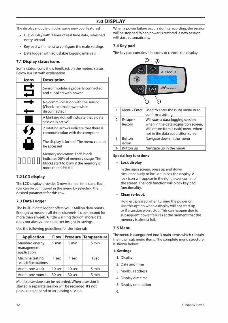
7.0 DISPlAYThe display module unlocks some new cool features!
LCd display with 3 lines of real time data, refreshed every second
Key pad with menu to configure the main settings
data logger with adjustable logging intervals
7.1 Display status icons
Some status icons show feedback on the meters’ status. Below is a list with explanation.
Icons Description
Sensor module is properly connected and supplied with power
No communication with the sensor [Check external power when disconnected]
A blinking dot will indicate that a data session is active
2 rotating arrows indicate that there is communication with the computer
The display is locked. The menu can not be accessed
Memory indication. Each block indicates 20% of memory usage. The blocks start to blink if the memory is more then 95% full
7.2 lcD display
The LCd display provides 3 rows for real time data. Each row can be configured in the menu by selecting the desired parameter for this row.
7.3 Data logger
The built-in data logger offers you 2 Million data points. Enough to measure all three channels 1 x per second for more than a week. A little warning though: more data does not always lead to better insight in savings!
use the following guidelines for the intervals
Application Flow Pressure TemperatureStandard energy management application
5 min 5 min 5 min
Machine testing -quick fluctuations
1 sec 1 sec 1 sec
Audit -one week 10 sec 10 sec 5 min
Audit -one month 30 sec 30 sec 5 min
Multiple sessions can be recorded. when a session is started, a separate session will be recorded. it’s not possible to append to an existing session.
•
•
•
when a power failure occurs during recording, the session will be stopped. when power is restored, a new session will start automatically.
7.4 Key pad
The key pad contains 4 buttons to control the display.
1 Menu / Enter used to enter the (sub) menu or to confirm a setting
2 Escape / Record
will start a data logging session when in the data acquisition screen. will return from a (sub) menu when not in the data acquisition screen
3 Button down
Navigate down in the menu
4 Button up Navigate up in the menu
Special key functions
lock display
in the main screen, press up and down simultaneously to lock or unlock the display. A lock icon will appear in the right lower corner of the screen. The lock function will block key pad functionality.
clean re-boot.
hold esc pressed when turning the power on. use this option when a display will not start up or if a session won’t stop. This can happen due to subsequent power failures at the moment that the memory is almost full.
7.5 Menu
The menu is categorized into 3 main items which contain their own sub menu items. The complete menu structure is shown below:
1. Settings
display
date and Time
Modbus address
display dim time
display orientation
•
•
1.
2.
3.
4.
5.
6.

49�07947Rev.A 1�
2. DAQ Sessions
New Session
delete all
3. Advanced
Reset
1. Settings
The settings menu can be used to change both functional parameters as display settings.
1.1 Display
The main screen of the display contains 3 rows to display measurement values. Via this menu measurement values can be assigned to these rows. Available options in the menu are:
Measurand Available units Description
Empty - Leave this display row empty
Flow mn/sec m3
n/h ln/min CFM m3/min sfps
Normalized
Pressure Bar Psi
gauge
Temperature ˚C ˚F
Totalizer m3n Normalized
Custom 5 available units to be configured with Airscout Studio. Multiply an existing unit with a user defined factor.
1.2 Date and Time
Adjust date and time settings. First enter the menu option and set the date with the key pad. The date is formatted as: dd-MM-YYYY. After setting the date, confirm with enter and then enter the time settings in format: hh:MM:SS, again confirm with enter. The new date will become active immediately.
date/time settings are kept actual by the real time clock until long power down. date and time will also be synchronized with the computer when used with Airscout Studio.
1.
2.
1.
1.3 Modbus address
The Modbus address can be changed with this option. use the up and down buttons to change the number. Available numbers 1 – 247.
After setting the number press enter to save the address. The power of the Airscout dP probe needs to be cycled to activate the new address.
1.4 Display dim time
The display backlight dim time can be adjusted here. The default dim time is set to 10 seconds. Other Available options are:
Fading off. The backlight will remain on.
5 till 30 seconds with steps of 5 seconds.
Confirming with menu will make this setting immediately active.
1.5 Display orientation
The text on the display can be set upside down for installations were the Airscout dP probe is installed in this way. Enter the menu item and select the desired orientation with the arrow keys. Confirm with enter to make these settings active.
All keys will maintain their function.
2. DAQ Sessions
The Airscout dP probe display contains an optional 2 million point data logger. when equipped, the menu is set to start and stop the sessions or to delete all present data.
2.1 Start session
The session will be started when you push the enter button after selecting this option. when the session is started, the menu will close and the main screen will be shown. A blinking dot in the right upper corner will indicate the running session. The menu will be blocked when a session is active. The session can be stopped by pressing the esc button.
2.2 Delete all
All sessions will be deleted. it is not possible to delete just a single session.
3 Advanced
3.1 Reset
Reset the device. All peripherals will be re initialized. This option is also needed when updating the display firmware.
•
•

14 49�07947Rev.A
8.0 AIRScoUT STUDIo SoFTwAReThe Airscout dP probe can be read out and configured with the Airscout Studio software.
in case of basic configuration and read out, use the free edition. if real time logging is required, registration keys are available for purchase.
A quick start is shown below.
WARNING
The sensor module needs to be connected to the displaying order to read out the display. It is not possible to read out sessions when the Airscout dP probe sensor is not connected.
connect the Airscout dP probe to the computer
The Airscout dP probe can be connected to the computer with the M12 connector through the JB5 interface box. This interface box combines the power and data signals. Power up the device by connecting the 12VdC power supply to the JB5 interface box. An RS485 to uSB converter can be used to connect the JB5 interface box to the computer.
Install USb drivers
install uSB converter driver A driver needs to be installed for the RS485 to uSB converter. The driver might be installed automatically by your windows system or need to be installed manually.
configure the Airscout dP probe
Start the Airscout Studio software
in the left white window, right click to open the menu. Now click add device
Click the scan button to search for the right COM port. Select it and click add
Enter a name for the device
Now select serial for RS485 converter or uSB if the meter is connected with uSB
Set the communication parameters if available
Click add.
Airscout dP probe sensor read out
Click on the device in the explorer window to read out the settings
The status tab provides general information
The installation tab is used to configure the settings
Airscout dP probe display read out [option]
Click on the plus icon to unfold the display icon
Click on display to read out the display settings
The status tab provides general information
The installation tab is used to configure the settings
Click sessions below display to retrieve session data.
•
•
•
•
•
•
•
•
•
•
•
•
•
•
•
49�07947Rev.A 1�
9.0 elecTRIcAl connecTIonS
Tip: use a shielded cable of good quality to connect the meter. Connect shield to safety ground on one point. For portable, non-critical applications, a switched mode 12 V dC, 1A power adapter may be used. Switched mode power supplies that are of poor quality, might affect the accuracy.
WARNING
neveR USe Ac PoweR. THIS wIll voID wARRAnTY AnD bRInG PeRMAnenT DAMAGe To THe elecTRonIcS. THe InSTRUMenT MIGHT be DAMAGeD beYonD RePAIR.
connecT THe M12 connecToR beFoRe PoweRInG UP THe InSTRUMenTS.
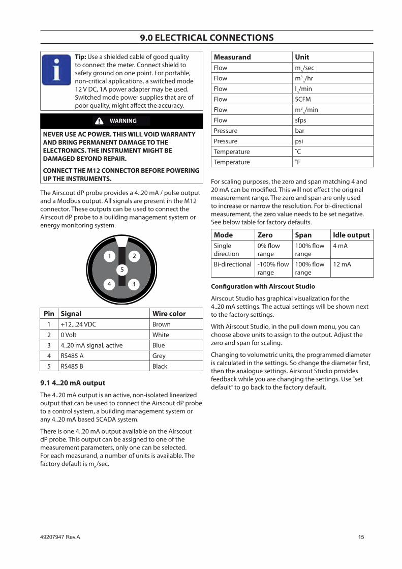
The Airscout dP probe provides a 4..20 mA / pulse output and a Modbus output. All signals are present in the M12 connector. These outputs can be used to connect the Airscout dP probe to a building management system or energy monitoring system.
1 2
5
4 3
Pin Signal wire color1 +12...24 VdC Brown
2 0 Volt white
3 4..20 mA signal, active Blue
4 RS485 A grey
5 RS485 B Black
9.1 4..20 mA output
The 4..20 mA output is an active, non-isolated linearized output that can be used to connect the Airscout dP probe to a control system, a building management system or any 4..20 mA based SCAdA system.
There is one 4..20 mA output available on the Airscout dP probe. This output can be assigned to one of the measurement parameters, only one can be selected. For each measurand, a number of units is available. The factory default is mn/sec.
Measurand Unit Flow mn/sec
Flow m3n/hr
Flow ln/min
Flow SCFM
Flow m3n/min
Flow sfps
Pressure bar
Pressure psi
Temperature ˚C
Temperature ˚F
For scaling purposes, the zero and span matching 4 and 20 mA can be modified. This will not effect the original measurement range. The zero and span are only used to increase or narrow the resolution. For bi-directional measurement, the zero value needs to be set negative. See below table for factory defaults.
Mode Zero Span Idle outputSingle direction
0% flow range
100% flow range
4 mA
Bi-directional -100% flow range
100% flow range
12 mA
configuration with Airscout Studio
Airscout Studio has graphical visualization for the 4..20 mA settings. The actual settings will be shown next to the factory settings.
with Airscout Studio, in the pull down menu, you can choose above units to assign to the output. Adjust the zero and span for scaling.
Changing to volumetric units, the programmed diameter is calculated in the settings. So change the diameter first, then the analogue settings. Airscout Studio provides feedback while you are changing the settings. use “set default” to go back to the factory default.
1� 49�07947Rev.A
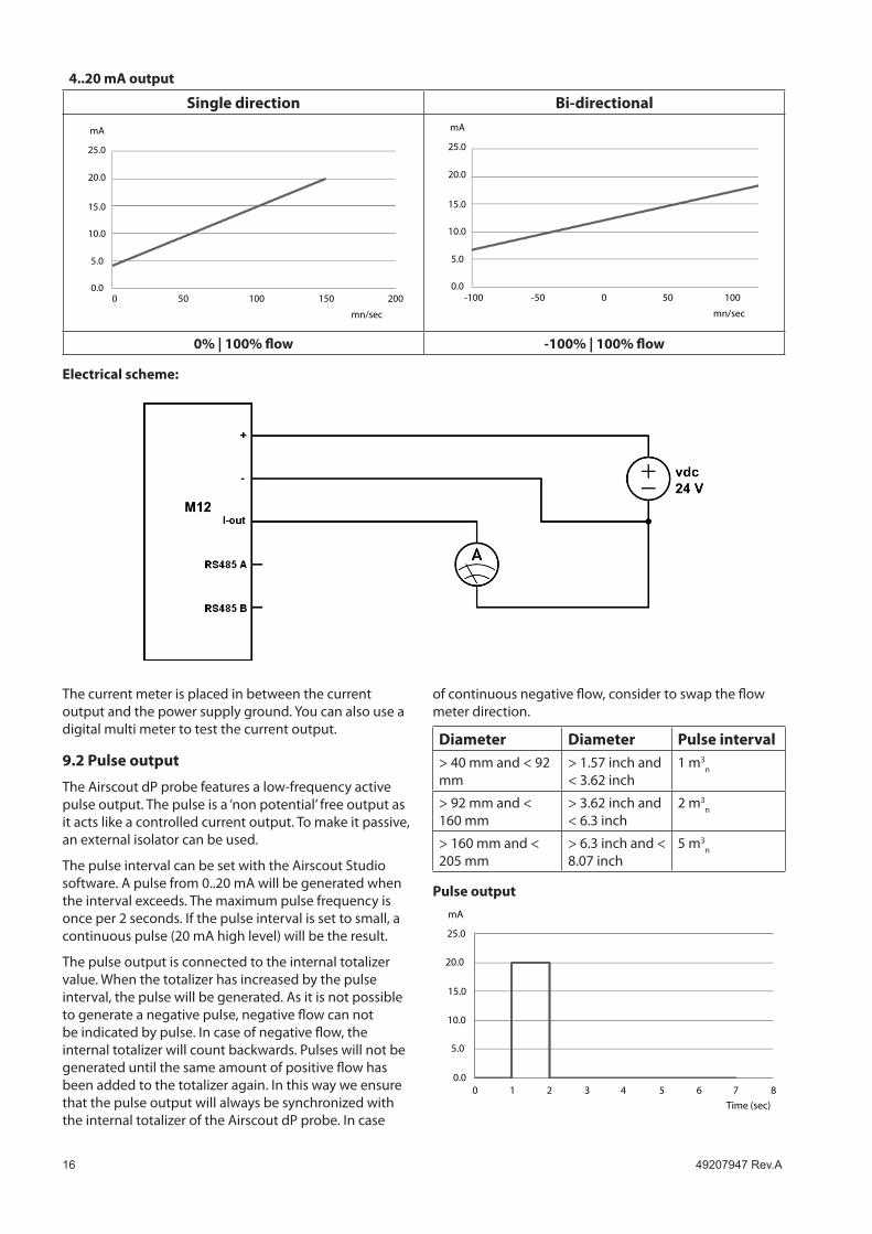
4..20 mA output
Single direction bi-directional
0.0
5.0
10.0
15.0
20.0
25.0
mA
0 50 100 150 200
mn/sec
0.0
5.0
10.0
15.0
20.0
25.0
mA
-100 -50 500 100
mn/sec
0% | 100% flow -100% | 100% flow
electrical scheme:
The current meter is placed in between the current output and the power supply ground. You can also use a digital multi meter to test the current output.
9.2 Pulse output
The Airscout dP probe features a low-frequency active pulse output. The pulse is a ‘non potential’ free output as it acts like a controlled current output. To make it passive, an external isolator can be used.
The pulse interval can be set with the Airscout Studio software. A pulse from 0..20 mA will be generated when the interval exceeds. The maximum pulse frequency is once per 2 seconds. if the pulse interval is set to small, a continuous pulse (20 mA high level) will be the result.
The pulse output is connected to the internal totalizer value. when the totalizer has increased by the pulse interval, the pulse will be generated. As it is not possible to generate a negative pulse, negative flow can not be indicated by pulse. in case of negative flow, the internal totalizer will count backwards. Pulses will not be generated until the same amount of positive flow has been added to the totalizer again. in this way we ensure that the pulse output will always be synchronized with the internal totalizer of the Airscout dP probe. in case
of continuous negative flow, consider to swap the flow meter direction.
Diameter Diameter Pulse interval> 40 mm and < 92 mm
> 1.57 inch and < 3.62 inch
1 m3n
> 92 mm and < 160 mm
> 3.62 inch and < 6.3 inch
2 m3n
> 160 mm and < 205 mm
> 6.3 inch and < 8.07 inch
5 m3n
Pulse output
0.00 1 2 3 4 5 6 7
Time (sec)
8
5.0
10.0
15.0
20.0
25.0
mA

49�07947Rev.A 17
9.3 Modbus interface
Introduction to Modbus
For new users, a complete introduction on the Modbus standard can be found on www.modbus.org. See the document Modbus_over_serial_line_V1_02.pdf, which can be downloaded from their website. we strongly recommend to download and read this information carefully.
The Airscout dP probe can be used in multidrop Modbus networks. upto 247 Airscout dP inline’s can be placed into one daisy chain. however, due to bandwidth restrictions we recommend to split up daisy chains. For a data polling rate of once per second, the maximum number of Airscout dP probe’s is 8, when flow, pressure, temperature and totalizer are read out.
All measurement parameters are available through Modbus in floating point and integer format. The data will be refreshed every second. Maximum polling interval is 10ms.
Placing multiple devices in a multidrop network will cause voltage drops. The minimum supply voltage is 12vDc. In networks with more then 8 devices or longer then 200 meter, ask your local contractor for advice.
communication settings
The RS485 communication settings can be changed with Airscout Studio. Below shows the available options
Baud rate: 9600 | 19200 | 38400
Stop bits: 1 | 2
Parity: None | Even | Odd
The Modbus settings can be changed with Airscout Studio, the hardware address can also be changed with the key pad when available. Below shows all available options
hardware address: 1-247
integer multiplier: 1-1000
data format Function code 0x03 for reading (holding register) Function code 0x10 for writing (holding register) 32-bit Floating point Little endian 32-bit signed integer Little endian
Register map
The actual measurement data is placed in holding registers. To read out data, you will need to use the corresponding holding register. All data is stored in 2 16-bit registers with below register number as start address.
•
•
•
•
•
electrical scheme:
1� 49�07947Rev.A
Read out the data with this start address and length 2.
Decimal HeX Description Type Read / write16 0x10 Flow in mn/sec 32-bit integer (x10) Read 17 0x11 Flow in m3
n/hr 32-bit integer (x10) Read 18 0x12 Flow in ln/min 32-bit integer (x10) Read 19 0x13 Flow in SCFM 32-bit integer (x10) Read 20 0x14 Flow in m3
n/min 32-bit integer (x10) Read 21 0x15 Flow in sfps 32-bit integer (x10) Read
32 0x20 Pressure in bar 32-bit integer (x10) Read 33 0x21 Pressure in psi 32-bit integer (x10) Read
64 0x40 Temperature in ˚C 32-bit integer (x10) Read 65 0x41 Temperature in ˚F 32-bit integer (x10) Read
128 0x80 Totalizer in m3n 32-bit integer (x10) Read / write*
8 0x08 diameter 32-bit Floating point Read 9 0x09 4..20 mA Max 32-bit Floating point Read / write
10 0x0A 4..20 mA Min 32-bit Floating point Read / write 11 0x0B 4..20 mA unit 32-bit Floating point Read / write
24 0x18 Flow in mn/sec 32-bit Floating point Read 25 0x19 Flow in m3
n/hr 32-bit Floating point Read 26 0x1A Flow in ln/min 32-bit Floating point Read 27 0x1B Flow in SCFM 32-bit Floating point Read 28 0x1C Flow in m3
n/min 32-bit Floating point Read 29 0x1d Flow in sfps 32-bit Floating point Read
40 0x28 Pressure in bar 32-bit Floating point Read 41 0x29 Pressure in psi 32-bit Floating point Read
72 0x48 Temperature in ˚C 32-bit Floating point Read 73 0x49 Temperature in ˚F 32-bit Floating point Read
136 0x88 Totalizer in m3n 32-bit Floating point Read / write*
* writing to the totalizer will reset the totalizer to zero.
Available write operations
option Data Description 4..20 mA unit 0
1 2 3 4 5 6 7 8 9 Other
mn/sec m3
n/hr ln/min SCFM m3
n/min sfps bar psi °C °F mn/sec
4..20 mA min decimal value
4..20 mA max decimal value
Totalizer integer or floating point type depending on register type
will reset the totalizer to zero

49�07947Rev.A 19
electrical scheme:
For a one-to-one connection with a PLC or a different type of RS485 converter, please see the wiring scheme below. when short wiring is used, a termination resistor is not needed. For longer wires (>10 m), please read RS485 related literature. The ground (common) should be connected to the read out device, so you will need three wires to establish the connection.
Modbus chain:
if multiple Modbus devices are connected in one chain, the configuration as shown below needs to be used. The trunk line goes from the master to all devices making a drop down to each device. The cable length from the trunk line to the Modbus device needs to be as small as possible. Junction boxes are used to make the T junction. The end of the trunk line needs to be terminated with a 120 Ohm resistor. This termination is easily made with the jumper switch and pre-installed resistor inside the junction box. wARNiNg: make sure that only ONE termination resistor is active and all others are inactive, otherwise the Modbus power consumption will dramatically increase and the signal will be lost.
5 meter, 5 wire shielded cable with moulded M12Default color scheme
AB
0 Volt+ 12..24 VDC
4-20+(not required)A
B
12..24 VDC
0 V
Modbus connectorWith M12, 5 PinPin assignmentIdentical to Airscout display module
JunctionBox
�0 49�07947Rev.A
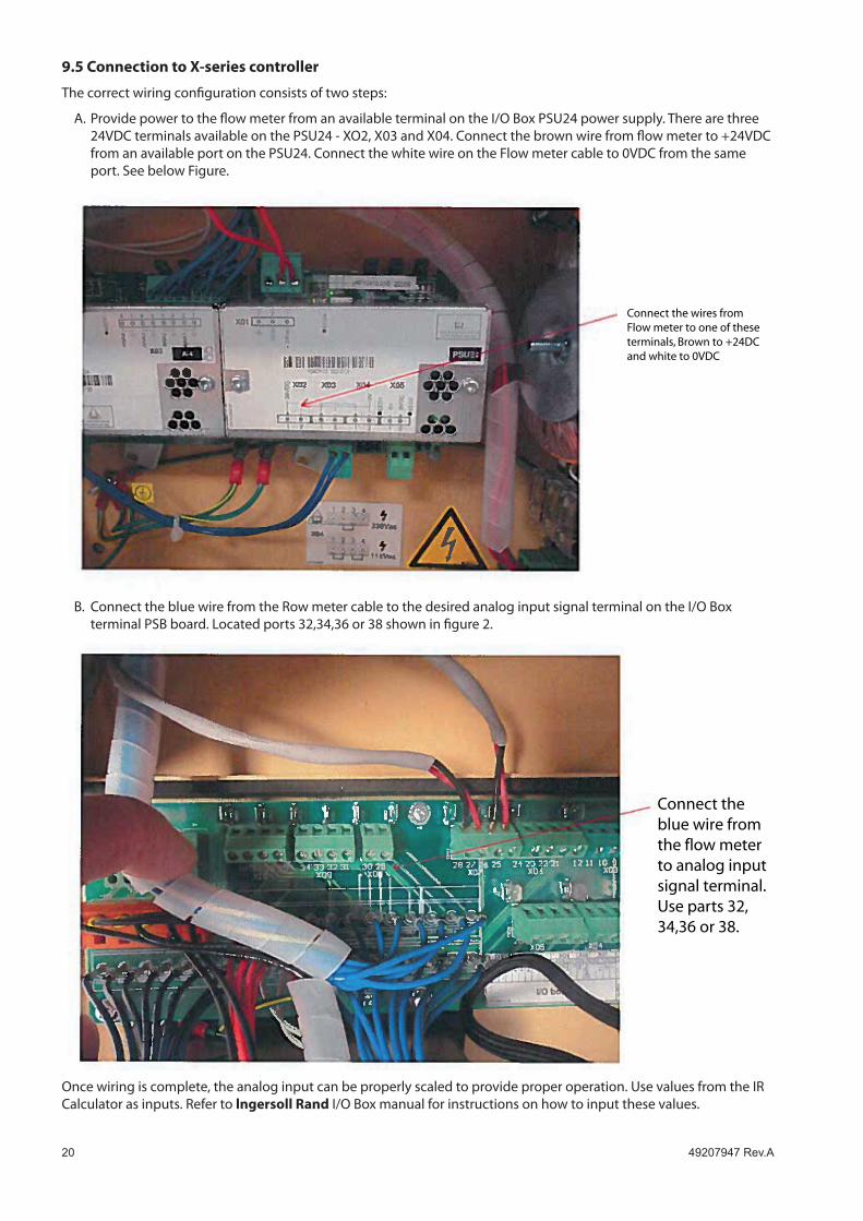
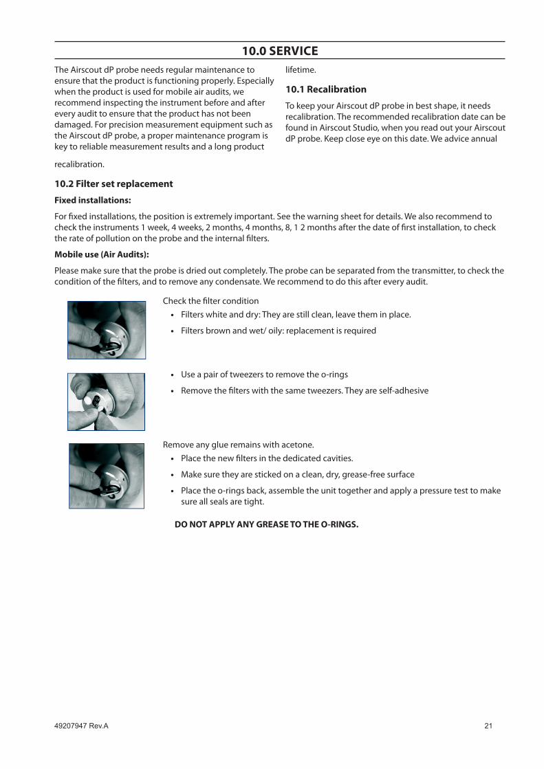
9.5 connection to X-series controller
The correct wiring configuration consists of two steps:
A. Provide power to the flow meter from an available terminal on the i/O Box PSu24 power supply. There are three 24VdC terminals available on the PSu24 - XO2, X03 and X04. Connect the brown wire from flow meter to +24VdC from an available port on the PSu24. Connect the white wire on the Flow meter cable to 0VdC from the same port. See below Figure.
Connect the wires fromFlow meter to one of theseterminals, Brown to +24DCand white to 0VDC
B. Connect the blue wire from the Row meter cable to the desired analog input signal terminal on the i/O Box terminal PSB board. Located ports 32,34,36 or 38 shown in figure 2.
Connect theblue wire fromthe flow meterto analog inputsignal terminal.Use parts 32,34,36 or 38.
Once wiring is complete, the analog input can be properly scaled to provide proper operation. use values from the iR Calculator as inputs. Refer to lngersoll Rand i/O Box manual for instructions on how to input these values.
49�07947Rev.A �1
10.0 SeRvIceThe Airscout dP probe needs regular maintenance to ensure that the product is functioning properly. Especially when the product is used for mobile air audits, we recommend inspecting the instrument before and after every audit to ensure that the product has not been damaged. For precision measurement equipment such as the Airscout dP probe, a proper maintenance program is key to reliable measurement results and a long product
lifetime.
10.1 Recalibration
To keep your Airscout dP probe in best shape, it needs recalibration. The recommended recalibration date can be found in Airscout Studio, when you read out your Airscout dP probe. Keep close eye on this date. we advice annual
recalibration.
10.2 Filter set replacement
Fixed installations:
For fixed installations, the position is extremely important. See the warning sheet for details. we also recommend to check the instruments 1 week, 4 weeks, 2 months, 4 months, 8, 1 2 months after the date of first installation, to check the rate of pollution on the probe and the internal filters.
Mobile use (Air Audits):
Please make sure that the probe is dried out completely. The probe can be separated from the transmitter, to check the condition of the filters, and to remove any condensate. we recommend to do this after every audit.
Check the filter conditionFilters white and dry: They are still clean, leave them in place.
Filters brown and wet/ oily: replacement is required
•
•
use a pair of tweezers to remove the o-rings
Remove the filters with the same tweezers. They are self-adhesive
•
•
Remove any glue remains with acetone.Place the new filters in the dedicated cavities.
Make sure they are sticked on a clean, dry, grease-free surface
Place the o-rings back, assemble the unit together and apply a pressure test to make sure all seals are tight.
•
•
•
Do noT APPlY AnY GReASe To THe o-RInGS.
�� 49�07947Rev.A
11.0 SPecIFIcATIonS
Please always check the label of your product for the specifications. Specifications are subject to change as we are continuously improving our products. Please contact us to obtain the latest specification sheet.
Flow sensor (minimum detection level and max flow rate shown)Flow range 20...200 mn/sec 65…650 sfpsAccuracy 2% of reading under calibration condition Recommended
pipe diameter: 50 mm | 2 inch and upReference conditions 0 °C, 1013.25 mbar -diN1343 32 °F, 14.65 psi gas temperature -40....150°C -40..302°F icing should
be avoided gases Compressed air, nitrogen, inert gases, 95% non condensing
gasesPressure sensorRange 0...16 bar gauge 0…250 psi gauge Accuracy +/-1.5% FSS (0...60 °C) +/-1.5% FSS (32..140 °F)Temperature sensorRange -40....150°C -40…302°F Accuracy +/-1°
DisplayTechnology Liquid crystal Back light Blue with auto power save Memory 2,000,000 point memory
MechanicalProbe length 400 mm 15 inchProbe diameter 12.7 mm 0.5 inchProcess connection Compression fittings, 0.5 inch, NPT threadPressure rating PN10, PN20: See product labeliP grade iP52 when mated to display module
iP63 when mated to connector capwetted materials Alu, SS316, epoxyAmbient temperature 0..60 °C 32 .. 140 °FAmbient humidity 10 -95%. Avoid condensation at all timesInputs and outputsAnalog 4..20 mA or pulse, selectable via installation software
Serial iO Modbus RTu
Supply 12..24 VdC +-10% CLASS 2 (uL)
Power consumption 150 mA at 24 VdC

49�07947Rev.A ��
Airscout dP Insertion Probeccn Description
49203284 Airscout dP Start Kit
49203292 400 mm Airscout dP with display and data Logger, M12 (5-Pin) connector
49203300 400 mm Airscout dP with Connector Cap, M12 (5-Pin) connector
Insertion Probe Replacement Parts and Accessories
23808967 Cable, 10 m / 32.9 ft with M12 5-pin connector on one side, open wires on other side
49099245 Power supply ( 12V, 5-pin )
23132913 RS485 to uSB converter
49099252 JB5 interface box with 5m / 16.4ft cable + 12 VdC power supply
49203318 Replacement insertion probe (probe only)
23500846 Connector cap with M12 5-pin socket
23132806 display with data logger
49099179 Safety chain
49099187 Compression fitting, 0.5” NPT
49099195 Replacement PTFE ferrules for compresion fitting (5)
23771991 Air Scout Explorer Case
49203326 Kit, dP Self Service
Terminal and Accessories
23818065 Terminal wall-mount display with cable and power supply
49099260 Connector cap with M12 8-pin socket
49099302 Replacement cable, 10m / 32.9 ft with M12 8-pin connector on one side, open wires on other side
49099310 Replacement Power supply, 1.9m / 6.3 ft, VS power plug on one side, open wires on other side
12.0 oRDeR InFoRMATIon AnD AcceSSoRIeS
�4 49�07947Rev.A
13.0 APPenDIX A -UlThe Airscout dP complies with the CE requirements as stated in the CE declaration. CE compliance can only be achieved when grounding and shielding directions are followed and proper cables and connector assemblies are used.
electrical connection guidelines- Ul 508 listing for USA & canada (check label to see if product is Ul marked)
The Airscout dP is intended to be used with a Class 2 power source or Class 2 transformer in accordance with uL1310 or uL1585. As an alternative a LVLC (Low Voltage Limited Current) power source, with the following properties can be used:
The device shall be used with a suitable isolating source such that the maximum open circuit voltage potential available? to the product is not more than 24 VdC and the current is limited to a value not exceeding 8 amperes measured after 1 minute of operation;
A fuse in accordance with the uL248 series and rated max 4A, shall be installed in the 24VdC power supply to the device? in order to limit the available current.
electrical connection guidelines: general remarks
Make sure that the following conditions are met:
For portable, non-critical applications, a switched mode 12 VdC, 1A power adapter may be used. Switched mode power supplies that are of poor quality, might affect the accuracy.
Le Airscout dP est conforme aux exigences CE, comme indiqué dans la déclaration CE. La conformité CE ne peut être atteinte que lorsque les directives de mise à la terre et d’isolation sont suivies et que les les câbles et raccords appropriés sont utilisés.
lignes directrices pour branchements électriques – Ul508 pour le canada et les États-Unis (voir sur l’étiquettesi le produit est marqué Ul)
Le Airscout dP est prévu pour être utilisé avec une source d’alimentation Classe 2 ou avec un transformateur de Classe 2 en accord avec uL1310 ou uL1585. Comme alternative, une source d’alimentation BTCL (Basse Tension Courant Limité) avec les propriétés suivante peut être utilisée :
Le dispositif doit être utilisé avec une source d’isolation appropriée afin que le voltage maximal en circuit ouvert disponible pour le produit ne dépasse pas 24VdC, et que le courant soit limité à une valeur de 8 ampères après 1 minute de fonctionnement.
un fusible de 4Amaximum, et conforme à la série uL248 doit être installé dans la source d’alimentation de l’appareil afin de limiter le courant disponible.
Directives pour le raccordement électrique : remarques générales
Assurez-vous que les conditions suivantes sont remplies :
Pour les applications mobiles, un adapteur de type alimentation à découpage 12VdC, 1Apeut-être
utilisée. Cependant, un adapteur de mauvaise qualité pourra affecter la précision.
•
•
•
•
•
•


ingersollrandproducts.com© 2015 Ingersoll Rand