Air Chain Hoist_Product Parts Information - Ingersoll Rand
28
Save These Instructions Edition 2 March 2020 CCN 47112669 Air Chain Hoist MLK Series y Product Parts Information
-
Upload
khangminh22 -
Category
Documents
-
view
1 -
download
0
Transcript of Air Chain Hoist_Product Parts Information - Ingersoll Rand

Save These Instructions
Edition 2March 2020
CCN 47112669
Air Chain HoistMLK Series
yProduct Parts Information
2
When product life has expired, it is recommended to:
• disassemble the product
• degrease the product
• separate product parts by material for correct recycling
Product repair and maintenance should be conducted by an authorized service center.
Refer all communications to the nearest Ingersoll Rand office or distributor.
Manuals are available at ingersollrandproducts.com
Table 1. Product Information Manuals
Publication CCN
Product Safety Information Manual MHD56295
Product Information Manual 47112677
Product Maintenance Information Manual 47099007
3
Table of ContentsParts Ordering Information . . . . . . . . . . . . . . . . . . . . . . . . . . . . . . . . . . . . . . . . . . . . . . . . . . . . . . . . . . . . . . . . . . . . 4
Return Goods Policy . . . . . . . . . . . . . . . . . . . . . . . . . . . . . . . . . . . . . . . . . . . . . . . . . . . . . . . . . . . . . . . . . . . . . . . . . 4
Disposal . . . . . . . . . . . . . . . . . . . . . . . . . . . . . . . . . . . . . . . . . . . . . . . . . . . . . . . . . . . . . . . . . . . . . . . . . . . . . . . . . . . . 4
Hoist Assembly. . . . . . . . . . . . . . . . . . . . . . . . . . . . . . . . . . . . . . . . . . . . . . . . . . . . . . . . . . . . . . . . . . . . . . . . . . . . . . . . 5
Hoist Sub-Assembly. . . . . . . . . . . . . . . . . . . . . . . . . . . . . . . . . . . . . . . . . . . . . . . . . . . . . . . . . . . . . . . . . . . . . . . . . . 11
Pendant and Hose Assembly . . . . . . . . . . . . . . . . . . . . . . . . . . . . . . . . . . . . . . . . . . . . . . . . . . . . . . . . . . . . . . . . . 14
Single Line Hoist Hook Assembly . . . . . . . . . . . . . . . . . . . . . . . . . . . . . . . . . . . . . . . . . . . . . . . . . . . . . . . . . . . . 16
Single Line Hoist Hook Assembly (spark resistant) . . . . . . . . . . . . . . . . . . . . . . . . . . . . . . . . . . . . . . . . . . . 18
Double Line Hoist Hook Assembly. . . . . . . . . . . . . . . . . . . . . . . . . . . . . . . . . . . . . . . . . . . . . . . . . . . . . . . . . . . . 19
Trolley Assembly. . . . . . . . . . . . . . . . . . . . . . . . . . . . . . . . . . . . . . . . . . . . . . . . . . . . . . . . . . . . . . . . . . . . . . . . . . . . . 21
Installation Instructions for Fabric Container Kits . . . . . . . . . . . . . . . . . . . . . . . . . . . . . . . . . . . . . . . . . . . . . 23
Accessories . . . . . . . . . . . . . . . . . . . . . . . . . . . . . . . . . . . . . . . . . . . . . . . . . . . . . . . . . . . . . . . . . . . . . . . . . . . . . . . . . . 25
Repair and Conversion Kits. . . . . . . . . . . . . . . . . . . . . . . . . . . . . . . . . . . . . . . . . . . . . . . . . . . . . . . . . . . . . . . . . . . 26
4
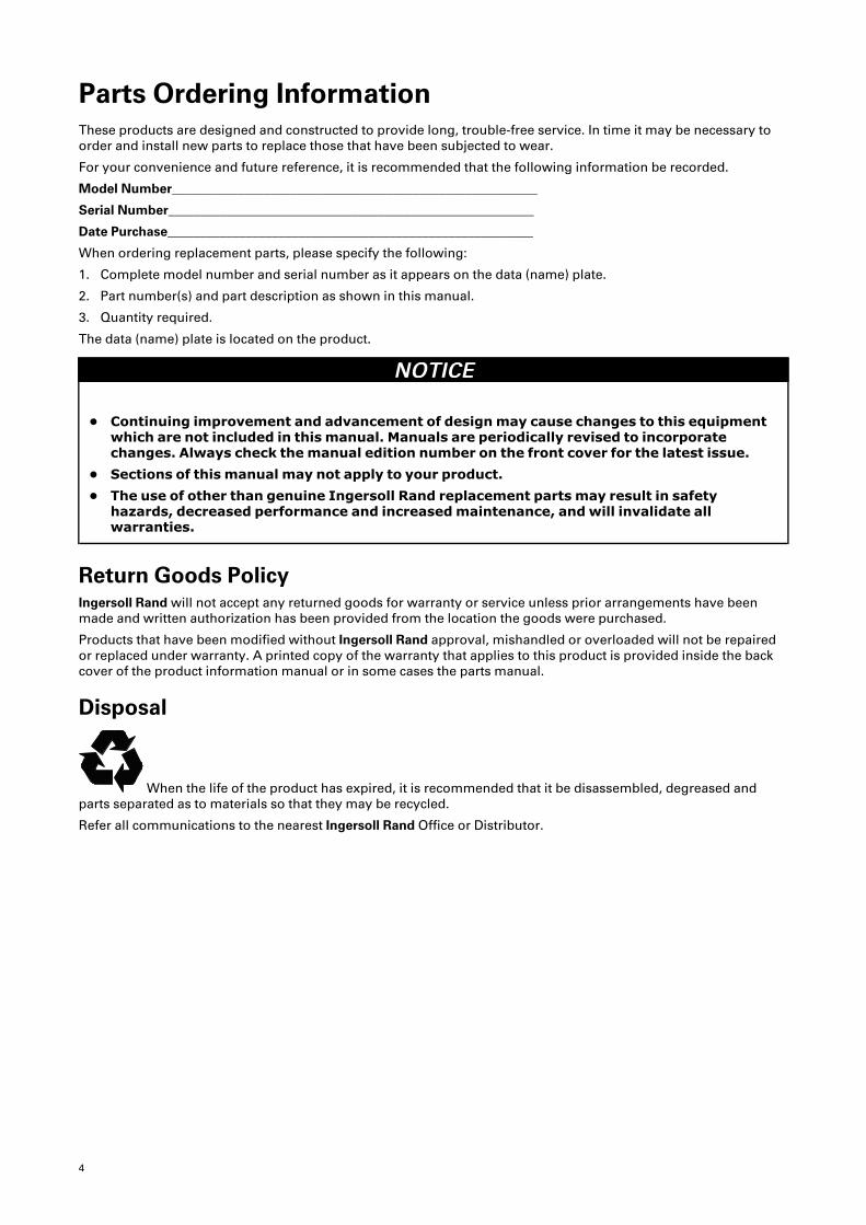
Parts Ordering InformationThese products are designed and constructed to provide long, trouble-free service. In time it may be necessary toorder and install new parts to replace those that have been subjected to wear.
For your convenience and future reference, it is recommended that the following information be recorded.
Model Number________________________________________________________
Serial Number________________________________________________________
Date Purchase________________________________________________________
When ordering replacement parts, please specify the following:
1. Complete model number and serial number as it appears on the data (name) plate.
2. Part number(s) and part description as shown in this manual.
3. Quantity required.
The data (name) plate is located on the product.
NNOOTTIICCEE
• Continuing improvement and advancement of designmay cause changes to this equipmentwhich are not included in this manual. Manuals are periodically revised to incorporatechanges. Always check themanual edition number on the front cover for the latest issue.
• Sections of this manual may not apply to your product.• The use of other than genuine Ingersoll Rand replacement parts may result in safetyhazards, decreased performance and increasedmaintenance, andwill invalidate allwarranties.
Return Goods PolicyIngersoll Rand will not accept any returned goods for warranty or service unless prior arrangements have beenmade and written authorization has been provided from the location the goods were purchased.
Products that have been modified without Ingersoll Rand approval, mishandled or overloaded will not be repairedor replaced under warranty. A printed copy of the warranty that applies to this product is provided inside the backcover of the product information manual or in some cases the parts manual.
Disposal
When the life of the product has expired, it is recommended that it be disassembled, degreased andparts separated as to materials so that they may be recycled.
Refer all communications to the nearest Ingersoll Rand Office or Distributor.
5
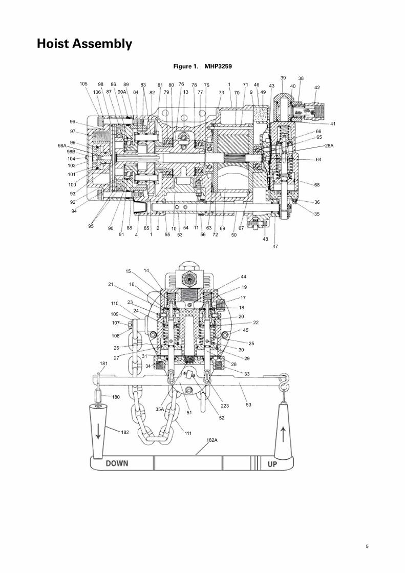
Hoist Assembly
Figure 1. MHP3259
105
106
98
87
86
90A
89
84
83
82
817980 76
1378
7775
73
1
70
71
9
46
4943
39
40
38
42
41
6665
64
68
28A
47
44
19
17
18
2022
45
2530
2928
33
53223
52
111
5135A
182
182A
181
180
27
26
108
107
109
110 23
24
21 16
31
34
15 14
48
6750
6972
6356
115453
1055
21
854
8891
9095
94
92
93
100
101
10310498B
99
97
96
98A
36
35
6
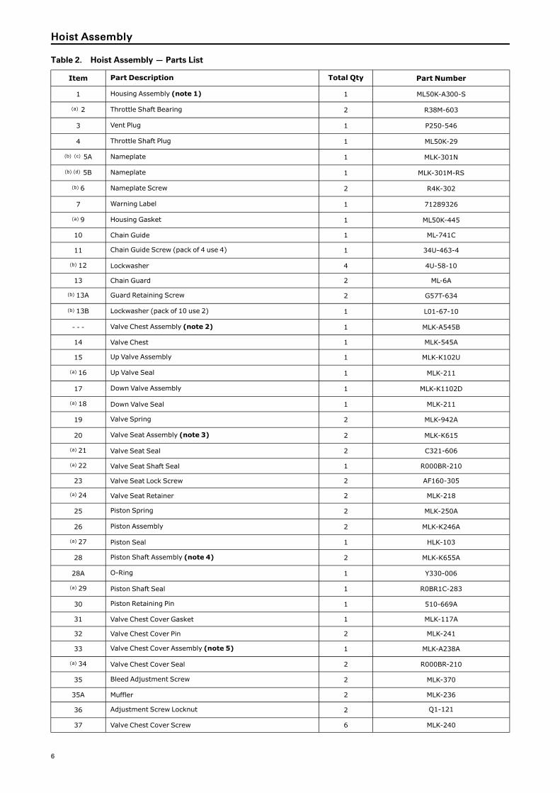
Table 2. Hoist Assembly — Parts List
Item Part Description Total Qty Part Number
1 Housing Assembly (note 1) 1 ML50K-A300-S
(a) 2 Throttle Shaft Bearing 2 R38M-603
3 Vent Plug 1 P250-546
4 Throttle Shaft Plug 1 ML50K-29
(b) (c) 5A Nameplate 1 MLK-301N
(b) (d) 5B Nameplate 1 MLK-301M-RS
(b) 6 Nameplate Screw 2 R4K-302
7 Warning Label 1 71289326
(a) 9 Housing Gasket 1 ML50K-445
10 Chain Guide 1 ML-741C
11 Chain Guide Screw (pack of 4 use 4) 1 34U-463-4
(b) 12 Lockwasher 4 4U-58-10
13 Chain Guard 2 ML-6A
(b) 13A Guard Retaining Screw 2 G57T-634
(b) 13B Lockwasher (pack of 10 use 2) 1 L01-67-10
- - - Valve Chest Assembly (note 2) 1 MLK-A545B
14 Valve Chest 1 MLK-545A
15 Up Valve Assembly 1 MLK-K102U
(a) 16 Up Valve Seal 1 MLK-211
17 Down Valve Assembly 1 MLK-K1102D
(a) 18 Down Valve Seal 1 MLK-211
19 Valve Spring 2 MLK-942A
20 Valve Seat Assembly (note 3) 2 MLK-K615
(a) 21 Valve Seat Seal 2 C321-606
(a) 22 Valve Seat Shaft Seal 1 R000BR-210
23 Valve Seat Lock Screw 2 AF160-305
(a) 24 Valve Seat Retainer 2 MLK-218
25 Piston Spring 2 MLK-250A
26 Piston Assembly 2 MLK-K246A
(a) 27 Piston Seal 1 HLK-103
28 Piston Shaft Assembly (note 4) 2 MLK-K655A
28A O-Ring 1 Y330-006
(a) 29 Piston Shaft Seal 1 R0BR1C-283
30 Piston Retaining Pin 1 510-669A
31 Valve Chest Cover Gasket 1 MLK-117A
32 Valve Chest Cover Pin 2 MLK-241
33 Valve Chest Cover Assembly (note 5) 1 MLK-A238A
(a) 34 Valve Chest Cover Seal 2 R000BR-210
35 Bleed Adjustment Screw 2 MLK-370
35A Muffler 2 MLK-236
36 Adjustment Screw Locknut 2 Q1-121
37 Valve Chest Cover Screw 6 MLK-240
HHooiisstt AAsssseemmbbllyy
7
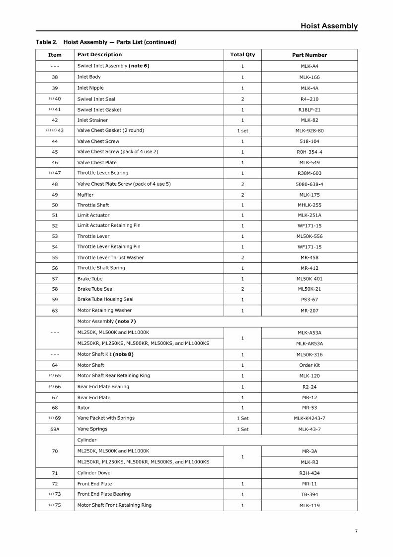
Table 2. Hoist Assembly — Parts List (continued)
Item Part Description Total Qty Part Number
- - - Swivel Inlet Assembly (note 6) 1 MLK-A4
38 Inlet Body 1 MLK-166
39 Inlet Nipple 1 MLK-4A
(a) 40 Swivel Inlet Seal 2 R4–210
(a) 41 Swivel Inlet Gasket 1 R18LF-21
42 Inlet Strainer 1 MLK-82
(a) (c) 43 Valve Chest Gasket (2 round) 1 set MLK-928-80
44 Valve Chest Screw 1 518-104
45 Valve Chest Screw (pack of 4 use 2) 1 R0H-354-4
46 Valve Chest Plate 1 MLK-549
(a) 47 Throttle Lever Bearing 1 R38M-603
48 Valve Chest Plate Screw (pack of 4 use 5) 2 5080-638-4
49 Muffler 2 MLK-175
50 Throttle Shaft 1 MHLK-255
51 Limit Actuator 1 MLK-251A
52 Limit Actuator Retaining Pin 1 WF171-15
53 Throttle Lever 1 ML50K-556
54 Throttle Lever Retaining Pin 1 WF171-15
55 Throttle Lever Thrust Washer 2 MR-458
56 Throttle Shaft Spring 1 MR-412
57 BrakeTube 1 ML50K-401
58 BrakeTube Seal 2 ML50K-21
59 BrakeTube Housing Seal 1 PS3-67
63 Motor Retaining Washer 1 MR-207
- - -
Motor Assembly (note 7)
ML250K, ML500K and ML1000K1
MLK-A53A
ML250KR, ML250KS, ML500KR, ML500KS, and ML1000KS MLK-AR53A
- - - Motor Shaft Kit (note 8) 1 ML50K-316
64 Motor Shaft 1 Order Kit
(a) 65 Motor Shaft Rear Retaining Ring 1 MLK-120
(a) 66 Rear End Plate Bearing 1 R2-24
67 Rear End Plate 1 MR-12
68 Rotor 1 MR-53
(a) 69 Vane Packet with Springs 1 Set MLK-K4243-7
69A Vane Springs 1 Set MLK-43-7
70
Cylinder
ML250K, ML500K and ML1000K1
MR-3A
ML250KR, ML250KS, ML500KR, ML500KS, and ML1000KS MLK-R3
71 Cylinder Dowel R3H-434
72 Front End Plate 1 MR-11
(a) 73 Front End Plate Bearing 1 TB-394
(a) 75 Motor Shaft Front Retaining Ring 1 MLK-119
HHooiisstt AAsssseemmbbllyy
8
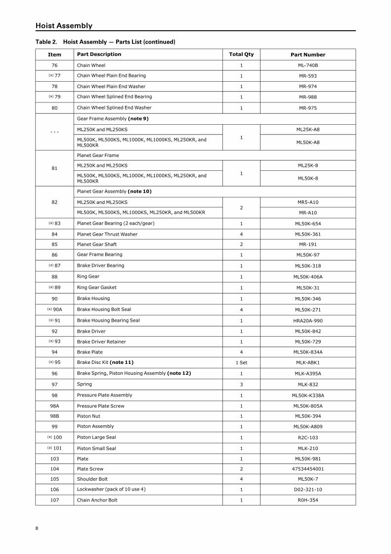
Table 2. Hoist Assembly — Parts List (continued)
Item Part Description Total Qty Part Number
76 Chain Wheel 1 ML-740B
(a) 77 Chain Wheel Plain End Bearing 1 MR-593
78 Chain Wheel Plain End Washer 1 MR-974
(a) 79 Chain Wheel Splined End Bearing 1 MR-988
80 Chain Wheel Splined End Washer 1 MR-975
- - -
Gear Frame Assembly (note 9)
ML250K and ML250KS
1
ML25K-A8
ML500K, ML500KS, ML1000K, ML1000KS, ML250KR, andML500KR ML50K-A8
81
Planet Gear Frame
ML250K and ML250KS
1
ML25K-8
ML500K, ML500KS, ML1000K, ML1000KS, ML250KR, andML500KR ML50K-8
82
Planet Gear Assembly (note 10)
ML250K and ML250KS2
MR5-A10
ML500K, ML500KS, ML1000KS, ML250KR, and ML500KR MR-A10
(a) 83 Planet Gear Bearing (2 each/gear) 1 ML50K-654
84 Planet Gear Thrust Washer 4 ML50K-361
85 Planet Gear Shaft 2 MR-191
86 Gear Frame Bearing 1 ML50K-97
(a) 87 Brake Driver Bearing 1 ML50K-318
88 Ring Gear 1 ML50K-406A
(a) 89 Ring Gear Gasket 1 ML50K-31
90 Brake Housing 1 ML50K-346
(a) 90A Brake Housing Bolt Seal 4 ML50K-271
(a) 91 Brake Housing Bearing Seal 1 HRA20A-990
92 Brake Driver 1 ML50K-842
(a) 93 Brake Driver Retainer 1 ML50K-729
94 Brake Plate 4 ML50K-834A
(a) 95 Brake Disc Kit (note 11) 1 Set MLK-ABK1
96 Brake Spring, Piston Housing Assembly (note 12) 1 MLK-A395A
97 Spring 3 MLK-832
98 Pressure Plate Assembly 1 ML50K-K338A
98A Pressure Plate Screw 1 ML50K-805A
98B Piston Nut 1 ML50K-394
99 Piston Assembly 1 ML50K-A809
(a) 100 Piston Large Seal 1 R2C-103
(a) 101 Piston Small Seal 1 MLK-210
103 Plate 1 ML50K-981
104 Plate Screw 2 47534454001
105 Shoulder Bolt 4 ML50K-7
106 Lockwasher (pack of 10 use 4) 1 D02-321-10
107 Chain Anchor Bolt 1 R0H-354
HHooiisstt AAsssseemmbbllyy
9
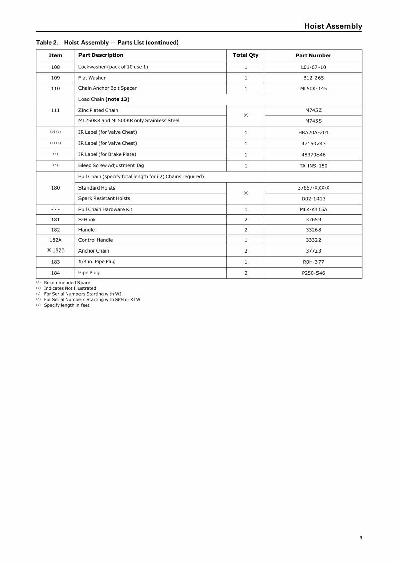
Table 2. Hoist Assembly — Parts List (continued)
Item Part Description Total Qty Part Number
108 Lockwasher (pack of 10 use 1) 1 L01-67-10
109 Flat Washer 1 B12-265
110 Chain Anchor Bolt Spacer 1 ML50K-145
111
Load Chain (note 13)
Zinc Plated Chain(e)
M745Z
ML250KR and ML500KR only Stainless Steel M745S
(b) (c) IR Label (for Valve Chest) 1 HRA20A-201
(b) (d) IR Label (for Valve Chest) 1 47150743
(b) IR Label (for Brake Plate) 1 48379846
(b) Bleed Screw Adjustment Tag 1 TA-INS-150
180
Pull Chain (specify total length for (2) Chains required)
Standard Hoists(e)
37657-XXX-X
Spark Resistant Hoists D02-1413
- - - Pull Chain Hardware Kit 1 MLK-K415A
181 S-Hook 2 37659
182 Handle 2 33268
182A Control Handle 1 33322
(b) 182B Anchor Chain 2 37723
183 1/4 in. Pipe Plug 1 R0H-377
184 Pipe Plug 2 P250-546
(a) Recommended Spare(b) Indicates Not Illustrated(c) For Serial Numbers Starting with WI(d) For Serial Numbers Starting with SPH or KTW(e) Specify length in feet
HHooiisstt AAsssseemmbbllyy

10
Table 3. Kits and Notes Information
Item Part Description Total Qty Part Number
Note 1 Housing Assembly (includes 2–7) 1 ML50K-A300-S
Note 2 Valve Chest Assembly (includes 14–42) 1 MLK-A545B
Note 3 Valve Seat Assembly (includes 21 and 22) 2 MLK-K615
Note 4 Piston Shaft Assembly (includes 28A, 29, and 30) 2 MLK-K655A
Note 5 Valve Chest Cover Assembly (includes 34) 1 MLK-A238A
Note 6 Swivel Inlet Assembly (includes 38–42) 1 MLK-A4
Note 7
Motor Assembly (includes 64–73, and 75)
1
- - -
ML250K, ML500K and ML1000K MLK-A53A
ML250KR, ML250KS, ML500KR, ML500KS, and ML1000KS MLK-AR53A
Note 8 Motor Shaft Kit (includes 64, 65, 75, and 93) 1 ML50K-316
Note 9
Gear Frame Assembly (includes 81–87)
1
- - -
ML250K, ML500K and ML1000K ML25K-A8
ML250KR, ML250KS, ML500KR, ML500KS, and ML1000KS ML50K-A8
Note 10
Planet Gear Assembly (includes 83)
1
- - -
ML250K, ML500K and ML1000K MR5-A10
ML250KR, ML250KS, ML500KR, ML500KS, and ML1000KS MR-A10
Note 11 Brake Disc Kit (includes 97, 100, and 101) 1 MLK-ABK1
Note 12 Brake Spring and Piston Housing Assembly (includes 97–104) 1 MLK-A395A
Note 13
When ordering “Length as Specified ”chain for ML250KS, ML500KS orML250KR Hoists, specify a chain length 2 feet longer than the required lift.When ordering “ Length as specified “ for ML1000KS or ML500KR Hoistsspecify a length 3 feet longer than twice the required lift.Chains for the ML1000KS and ML500KR Hoists must contain an evennumber of Links when installed on the hoist.
- - -
HHooiisstt AAsssseemmbbllyy

11
Hoist Sub-Assembly
Figure 2. Exploded View—MHP3242
88
8987
86
81
85
848382
83
84
Figure 3. Exploded View—MHP3243
95
93
92
90
64
59
58
91
5758
90A
90A
9996
98
94
94
9594
9497
104 103
105
106
98B 100
101
98A

12
Figure 4. Motor Parts Exploded View—MHP3240
66
63
73
72
75
64
71
70
69
68
67
6569A
Figure 5. Chain Wheel Assembly Exploded View—MHP3239
79
80
76
78
77
HHooiisstt SSuubb--AAsssseemmbbllyy

13
Figure 6. Exploded View—MHP3238
For
Pull Chain Control For Pendant
Control
For Pendant Control
ForPull Chain Control
221
183
223
35A
28A
222
184
15
16
22
37
34
36
35
50
51
52
48
47
17
19
23
45
44
1443
23
4649
9
41
38
4240
39
21
25
26
30
29
31
32
32
33
28
27
24
20
18
HHooiisstt SSuubb--AAsssseemmbbllyy
14
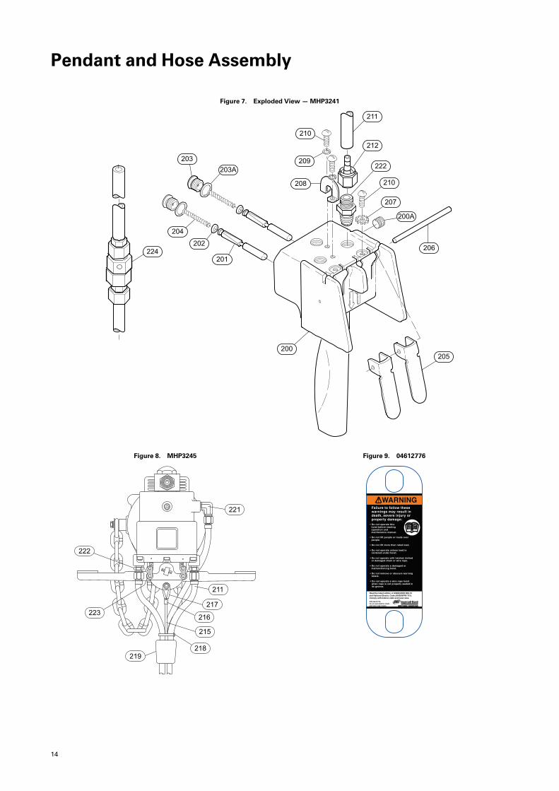
Pendant and Hose Assembly
Figure 7. Exploded View—MHP3241
224
211
212
222
210
207
200A
206
205200
201
202
204
203
203A
208
209
210
Figure 8. MHP3245
221
222
223
219218
215
216
217
211
Figure 9. 04612776

15
Table 4. Pendant and Hose Assembly — Parts List
Item Part Description Total Qty Part Number
200 Pendant Handle Assembly 1 MLK-K269C
200A Plug 1 502-95
201 Pendant Throttle Valve Assembly 2 MLK-K264B
(a) 202 Throttle Valve O-Ring 2 R000BR1C-283
203 Pendant Throttle Valve Cap 2 MLK-K266A
203A Pendant Throttle Valve Cap Gasket 1 MLK-504
(a) 204 Pendant Throttle Valve Spring 1 MLK-51A
205 Pendant Throttle Lever 2 MLK-273
206 Throttle Lever Pin 1 DLC-120A
207 Pin Lockwasher 2 D02-138
208 Strain Relief Support 1 MLK-450
209 Relief Support Lock Washer (Pack of 10 use 1) 1 H54U-352-10
210 Handle Screw 4 HRE20A-68
211 Hose (b) 50923
212 Swivel Fitting 6 51029
- - - Strain Relief Assembly 1 MLK-LWR3A
215 Strain Relief Cable (b) 33323-XXX-XX
(c) 216 Clamping Sleeve 2 32356
217 Clamping Thimble 2 31477
(d) 218 Hose Tie (b) HRE20A-283
219 Warning Tag 1 04612776
(e) Spark Resistant Tag 1 MLKR-33
(e) Spark Resistant Tag Fastener 2 CE110-4
(a) 221 Elbow 1/4” NPT to 7/16”- 20 1 UWD-161
222 Adapter 5 MLK-165
223 Pendant Link — MLK-224
(f) 224 Quick-Exhaust Valve 2 MLK-A939
(a) Recommended Spare(b) Specify length in feet(c) A crimping tool [(Nicropress Tool with Groove Size G or compatible crimping tool) is required to install the Clamping Sleeves (216).](d) Use 3 per 5 feet of Pendant hose length and 2 per each additional feet of hose.(e) Indicates Not Illustrated(f) Refer to Form P6778 for parts information on Pendant Throttle Handle Assemblies for Two and Three motor functions.
PPeennddaanntt aanndd HHoossee AAsssseemmbbllyy
16
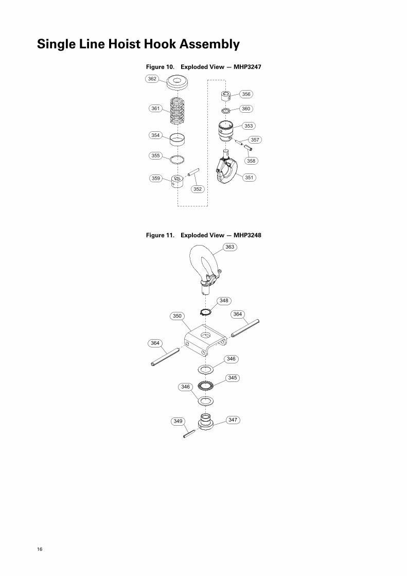
Single Line Hoist Hook Assembly
Figure 10. Exploded View—MHP3247
358
356
360
353
357
351
352
359
355
354
361
362
Figure 11. Exploded View—MHP3248
363
348
350
364
364
346
345
347349
346
17
Table 5. Single Line Hoist Hook Assembly — Parts List
Item Part Description Total Qty
Part Number
Standard (1/2t max)
ML250K, ML250KS, ML500K and ML500KS
Standard Steel Bullard Burnham
Bottom Block Assembly MLK-K378 MLK-KBB378
(a) 351 Hook Assembly (includes Latch Kit) 1 35006-ARO 35201
(a) Latch Kit 1 35023 - - -
352 Pin 1 MLK-553
353 Bucket 1 47114277
354 Sleeve 1 35017
355 Retaining Ring 1 35016
(a) 356 Collar 1 35010
357 Pin 1 Y178-77
358 Pin 1 Y178-114
359 Chain Connector 13 47114269
(a) 360 Ball 1 Y16-6
361 Spring 1 MLK-25
362 Stop Ring 1 MLK-259
Top Hook Assembly
(a) 363 Hook Assembly (Includes 345-349) 1 MLK-KS304 CE110-KBB377
- - - Hook 1 CE110-KS304 CE120-BB377X
(a) Latch Kit 1 35023 - - -
(a) 345 Bearing 1 R4810-105
346 Thrust Washer 2 CE110-596
347 Hook Nut (includes 348 and 349) 1 - - - CA105-R305A
(a) 348 Retainer 1 MR10-375 (b)
349 Hook Pin 1 - - - MLK-826
350 Hook Yoke 1 MR10-590B
(a) 364 Pin 2 MR-964
Label for BottomHook Assembly
(c) for 1/4 ton ML250K and ML250KS 2 48379929
(c) for 1/2 ton ML500K and ML500KS 2 48379937
(a) Recommended Spare(b) Also used on the bottom block assembly on hoist versions prior to 02/2010.(c) Indicates Not Illustrated
Notes:
• For ML250K and ML500K: Stop Ring (362) and Spring (361) are required to prevent damage to the Hoist.
• For models ML250KS, ML250KR and ML500KS: Stop Ring (362) and Spring (361), are not necessary forthese units due to reduced operating speeds. This will decrease the minimum hook to beam distance infull UP position by approximately 4 in. (100 mm).
SSiinnggllee LLiinnee HHooiisstt HHooookk AAsssseemmbbllyy
18
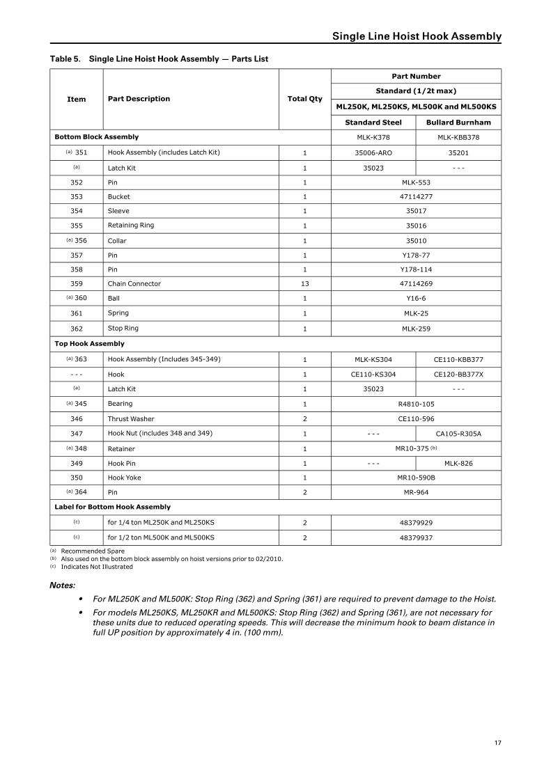
Single Line Hoist Hook Assembly (spark resistant)
Figure 12. MHP3252
111
115
114
112
113
122
123
120
121119
118
Table 6. Single Line Hoist Hook Assembly — Parts List
Item Part Description Total QtyPart Number
Spark Resistant (1/2 t max)
Bottom Hook and Block Assembly 1 MLK-KR463
(a) Hook Assembly (includes 118 and 119) 1 CA-SR304N
112 Hook Block 2 MLK-R463 (stainless)
113 Bolt 2 MLK-461
114 Spring 1 MLK-25 (plated)
115 Stop Ring 1 MLK-R259 (aluminum)
118 Hook 1 CA-R304N (bronze)
(b) 119 Latch kit 1 D01-S4055N
(b) 120 Bearing 1 R4810-105
(b) 121 Thrust Washer 2 CE110-596
122 Hook Nut 1 CA105-R305A
(b) 123 Nut Pin 1 MLK-826
(a) Indicates Not Illustrated(b) Recommended Spare
Notes:
1. For ML250K and ML500K: Stop Ring (115) and Spring (114) are required to prevent damage to the Hoist.For models ML250KS, ML250KR and ML500KS: Stop Ring (115) and Spring (114), are not necessary forthese units due to reduced operating speeds. This will decrease the minimum hook to beam distance infull UP position by approximately 4 in. (100 mm).
2. Refer to Figure 11, p. 16 and Parts List for top hook.
19
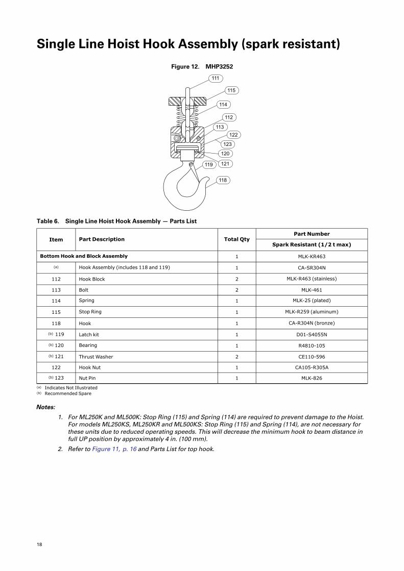
Double Line Hoist Hook Assembly
Figure 13. MHP3254
130
138
137
111
130127
128
129
126
141
139
140
142
125
22.6 - 26.0 Nm16.7 - 19.2 ft-Ib
OFF
Figure 14. MHP3253
138
137
131
143
132
133
134
135136
32.5 - 40.7 Nm24 - 30 ft-Ib
OFF
Table 7. Double Line Hoist Hook Assembly — Parts List
Item Part Description Total Qty
Part Number
Standard(1 t max)
SparkResistant(1/2 t max)
Bronze(1 t max)
Bullard(1 t max)
ML1000K andML1000KS ML500KR ML1000K and
ML1000KSML1000K andML1000KS
Bottom Block Assembly(includes 125-130, 137-142) 1 ML100K-A378 CA110-AR378 47683214001 ML1000K-KBB378
125 Hook Block 2CE120-B378(Aluminum)
CA110-BR378(Aluminum)
CE120-B378(Aluminum)
CE120-B378(Aluminum)
(a) Nameplate 2 - - - CA110SR-99 - - - - - -
(a) Drive Screw (pack of 12) 8 - - - R4K-302- 12 - - - - - -
(b) 126 Bearing 2 0C9-593
127 Thread Inserts 3 CE120-38
128 Thrust Washer 2 CE120-80
129 Pocket Wheel 1 CE120-380
130 Bolt 3 CE120-312
Top Hook Assembly(includes 131-143) 1 ML1000K-K590A ML500KR-K590A ML500KR-K590A ML1000K-KBB590A
131 Hook Yoke 1 ML1000K-590A
132 Pin 2 ML1000K-964
133 Lockwasher 2 UW50A30-58
134 Bolt 2 51766
(b) 135 Cotter Pin 2 D02-524
(b) 136 Pin 1 ML20-962A
Top/Bottom Hook Assembly(includes 137-143) 1 ML1000K-KS377 ML500KR-K377 ML500KR-K377 CE120-KBB377
137 Hook (Includes 138) 1 HRA20A-S377CA-SR304N(Bronze)
CA-SR304N(Bronze) CE120-BB377X
20
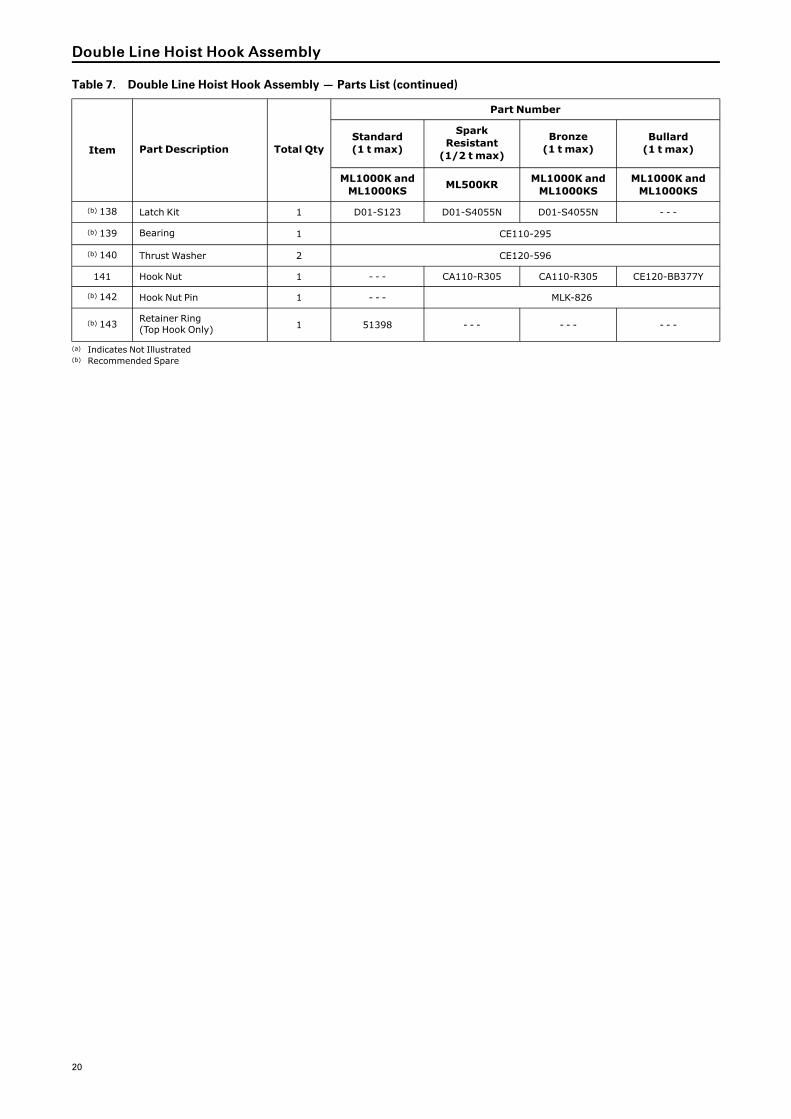
Table 7. Double Line Hoist Hook Assembly — Parts List (continued)
Item Part Description Total Qty
Part Number
Standard(1 t max)
SparkResistant(1/2 t max)
Bronze(1 t max)
Bullard(1 t max)
ML1000K andML1000KS ML500KR ML1000K and
ML1000KSML1000K andML1000KS
(b) 138 Latch Kit 1 D01-S123 D01-S4055N D01-S4055N - - -
(b) 139 Bearing 1 CE110-295
(b) 140 Thrust Washer 2 CE120-596
141 Hook Nut 1 - - - CA110-R305 CA110-R305 CE120-BB377Y
(b) 142 Hook Nut Pin 1 - - - MLK-826
(b) 143 Retainer Ring(Top Hook Only) 1 51398 - - - - - - - - -
(a) Indicates Not Illustrated(b) Recommended Spare
DDoouubbllee LLiinnee HHooiisstt HHooookk AAsssseemmbbllyy
21
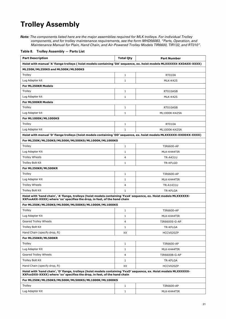
Trolley Assembly
Note: The components listed here are the major assemblies required for MLK trolleys. For individual Trolleycomponents, and for trolley maintenance requirements, see the formMHD56083, “Parts, Operation, andMaintenance Manual for Plain, Hand Chain, and Air-Powered Trolley Models TIR6600, TIR132, and RT010”.
Table 8. Trolley Assembly — Parts List
Part Description Total Qty Part Number
Hoist with manual ‘A’ flange trolleys ( hoist models containing ‘DA’ sequence, ex. hoist models MLXXXXXX-XXDAXX-XXXX)
ML250K/ML250KS andML500K/ML500KS
Trolley 1 RT010A
Lug Adapter kit 1 MLK-K425
For ML250KRModels
Trolley 1 RT010ASB
Lug Adapter kit 1 MLK-K425
For ML500KRModels
Trolley 1 RT010ASB
Lug Adapter kit 1 ML1000K-K425A
For ML1000K/ML1000KS
Trolley 1 RT010A
Lug Adapter kit 1 ML1000K-K425A
Hoist with manual ‘D’ flange trolleys (hoist models containing ‘DD’ sequence, ex. hoist models MLXXXXXX-XXDDXX-XXXX)
For ML250K/ML250KS/ML500K/ML500KS/ML1000K/ML1000KS
Trolley 1 TIR6600-AP
Lug Adapter Kit 1 MLK-K444TIR
Trolley Wheels 4 TR-A431U
Trolley Bolt Kit 1 TR-KFLGD
For ML250KR/ML500KR
Trolley 1 TIR6600-AP
Lug Adapter Kit 1 MLK-K444TIR
Trolley Wheels 4 TR-A1431U
Trolley Bolt Kit 1 TR-KFLGA
Hoist with ‘hand chain’, ‘A’ flange, trolleys (hoist models containing ‘FxxA’ sequence, ex. Hoist models MLXXXXXX-XXFxxAXX-XXXX) where ‘xx’ specifies the drop, in feet, of the hand chain
For ML250K/ML250KS/ML500K/ML500KS/ML1000K/ML1000KS
Trolley 1 TIR6600-AP
Lug Adapter Kit 1 MLK-K444TIR
Geared Trolley Wheels 4 TIR6600S-G-AP
Trolley Bolt Kit 1 TR-KFLGA
Hand Chain (specify drop, ft) XX HCCV020ZP
For ML250KR/ML500KR
Trolley 1 TIR6600-AP
Lug Adapter Kit 1 MLK-K444TIR
Geared Trolley Wheels 4 TIR6600B-G-AP
Trolley Bolt Kit 1 TR-KFLGA
Hand Chain (specify drop, ft) XX HCCV020ZP
Hoist with ‘hand chain’, ‘D’ flange, trolleys (hoist models containing ‘FxxD’ sequence, ex. Hoist models MLXXXXXX-XXFxxDXX-XXXX) where ‘xx’ specifies the drop, in feet, of the hand chain
For ML250K/ML250KS/ML500K/ML500KS/ML1000K/ML1000KS
Trolley 1 TIR6600-AP
Lug Adapter Kit 1 MLK-K444TIR
22
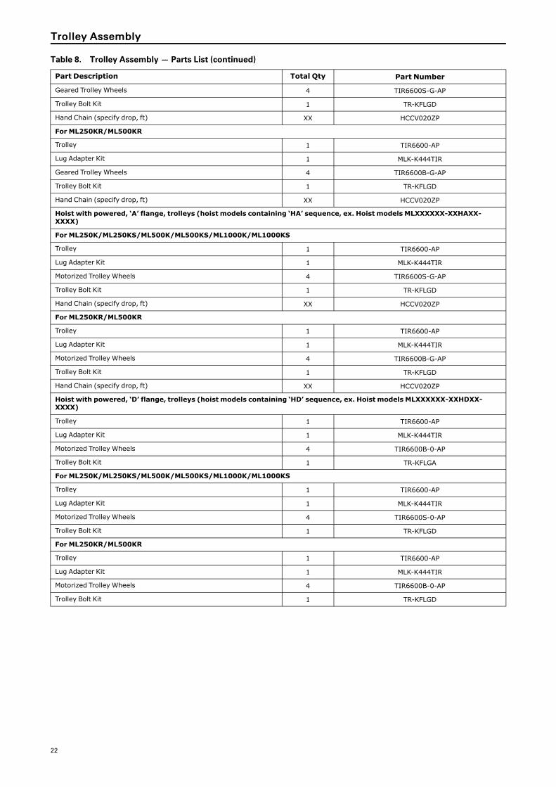
Table 8. Trolley Assembly — Parts List (continued)
Part Description Total Qty Part Number
Geared Trolley Wheels 4 TIR6600S-G-AP
Trolley Bolt Kit 1 TR-KFLGD
Hand Chain (specify drop, ft) XX HCCV020ZP
For ML250KR/ML500KR
Trolley 1 TIR6600-AP
Lug Adapter Kit 1 MLK-K444TIR
Geared Trolley Wheels 4 TIR6600B-G-AP
Trolley Bolt Kit 1 TR-KFLGD
Hand Chain (specify drop, ft) XX HCCV020ZP
Hoist with powered, ‘A’ flange, trolleys (hoist models containing ‘HA’ sequence, ex. Hoist models MLXXXXXX-XXHAXX-XXXX)
For ML250K/ML250KS/ML500K/ML500KS/ML1000K/ML1000KS
Trolley 1 TIR6600-AP
Lug Adapter Kit 1 MLK-K444TIR
Motorized Trolley Wheels 4 TIR6600S-G-AP
Trolley Bolt Kit 1 TR-KFLGD
Hand Chain (specify drop, ft) XX HCCV020ZP
For ML250KR/ML500KR
Trolley 1 TIR6600-AP
Lug Adapter Kit 1 MLK-K444TIR
Motorized Trolley Wheels 4 TIR6600B-G-AP
Trolley Bolt Kit 1 TR-KFLGD
Hand Chain (specify drop, ft) XX HCCV020ZP
Hoist with powered, ‘D’ flange, trolleys (hoist models containing ‘HD’ sequence, ex. Hoist models MLXXXXXX-XXHDXX-XXXX)
Trolley 1 TIR6600-AP
Lug Adapter Kit 1 MLK-K444TIR
Motorized Trolley Wheels 4 TIR6600B-0-AP
Trolley Bolt Kit 1 TR-KFLGA
For ML250K/ML250KS/ML500K/ML500KS/ML1000K/ML1000KS
Trolley 1 TIR6600-AP
Lug Adapter Kit 1 MLK-K444TIR
Motorized Trolley Wheels 4 TIR6600S-0-AP
Trolley Bolt Kit 1 TR-KFLGD
For ML250KR/ML500KR
Trolley 1 TIR6600-AP
Lug Adapter Kit 1 MLK-K444TIR
Motorized Trolley Wheels 4 TIR6600B-0-AP
Trolley Bolt Kit 1 TR-KFLGD
TTrroolllleeyy AAsssseemmbbllyy

23
Installation Instructions for Fabric Container Kits
Refer to Figure 15, p. 23 and Figure 16, p. 23.
WWAARRNNIINNGG
Disconnect the hoist from the air supply before installing a chain container kit.
Figure 15. MHP3236
592
308
304
305
307
308
300
1. Insert a container bolt (305) through the boss on the hoist housing and into the brackets (301 and 302). Retainthe container with the bracket bolt nuts (304).
NNOOTTIICCEE
If the container is to be allowed to swing outward, tighten the nuts to within one turn of beingfully tight. This will allow the container to swing away from a load.
2. Apply the balance chain (307) to the container and hoist using the S-Hooks (308). Adjust the length of the chainto prevent the load chain from rubbing on the container.
Figure 16. Top View of Chain Container (MHP3237)
303
304
301
300
302
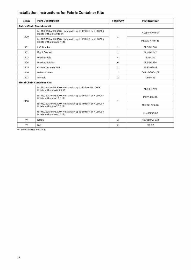
24
Item Part Description Total Qty Part Number
Fabric Chain Container Kit
300
for ML250K or ML500K Hoists with up to 17 ft lift or ML1000KHoists with up to 9 ft lift
1
ML50K-K749-I7
for ML250K or ML500K Hoists with up to 45 ft lift or ML1000KHoists with up to 23 ft lift ML50K-K749-45
301 Left Bracket 1 ML50K-748
302 Right Bracket 1 ML50K-747
303 Bracket Bolt 4 R2N-103
304 Bracket Bolt Nut 6 ML50K-394
305 Chain Container Bolt 2 5080-638-4
306 Balance Chain 1 CA110-240-1/2
307 S-Hook 2 D02-421
Metal Chain Container Kits
300
for ML250K or ML500K Hoists with up to 13 ft or ML1000KHoists with up to 6.5 ft lift
1
ML10-K749
for ML250K or ML500K Hoists with up to 26 ft lift or ML1000KHoists with up to 13 ft lift ML20-K749A
for ML250K or ML500K Hoists with up to 40 ft lift or ML1000KHoists with up to 20 ft lift ML20K-749-20
for ML250K or ML500K Hoists with up to 80 ft lift or ML1000KHoists with up to 40 ft lift MLK-K750-80
(a) Screw 2 M0V010AA-634
(a) Nut 2 MR-37
(a) Indicates Not Illustrated
IInnssttaallllaattiioonn IInnssttrruuccttiioonnss ffoorr FFaabbrriicc CCoonnttaaiinneerr KKiittss

25
Accessories
FRL KitPart
Number
Filter Part NumberRegulatorPart Number
Lubricator Part NumberSize NPTFPolycarbonate
Bowl Metal Bowl PolycarbonateBowl Metal Bowl
C38341-810 F35341-400 F35341-410 R37341-600 L36341-100 L36341-110 1/2”
C38451-810 - - - F35451-410 R37451-600 - - - L36451-110 3/4”
C38461-810 - - - F35461-410 R37461-600 - - - L36461-110 1”
Note:Metal bowls include sight gauges. Polycarbonate bowls include a metal bowl guard.

26
Repair and Conversion Kits
Recommended Spare Part Kit: MHLK-HSK includes all recommended spare parts for MLK hoists.
Fabric Chain Container:
• Includes chain container, brackets and all hardware necessary for installation on a hoist.
• No. ML50K-K749-17 (03551066) for use on a single line hoist with up to a 17 ft (5 m) lift and on a double line hoistwith up to a 9 ft (2.7 m) lift.
• No. ML50K-K749-45 (03551074) for use on a single line hoist with up to a 45 ft (14 m) lift and on a double linehoist with up to a 23 ft (7 m) lift.
Metal Chain Containers:
• No. ML10-K749 for use on a single line hoist with up to 13 ft (4 m) lift and on a double line hoist with up to 6.5 ft(2 m) lift.
• No. ML20-K749A for use on a single line hoist with up to 26 ft (8 m) lift and on a double line hoist with up to 13 ft(4 m) lift.
• No. ML20-K749-20 for use on a single line hoist with up to 40 ft (12 m) lift and on a double line hoist with up to20 ft (6 m) lift.
• No. MLK-K750-80 for use on a single line hoist with up to 80 ft (24 m) lift and on a double line hoist with up to 40ft (12 m) lift.
Pendant Conversion Kit:
• Includes all components including hose and strain relief cable necessary to convert a pull chain throttle hoist topendant control operation.
• Length of pendant hose must be specified when ordering. No. MLK-AL269C-XX for use on all MLK hoists.Pendant length is normally 5 ft (1.5 m) shorter than lift.
Pull Chain Conversion Kit:
• Includes all components necessary, except the pull chains, to convert a pendant throttle hoist to pull chaincontrol operation.
• No. MLK-K415A for use on all MLK hoists. Order pull chains separately.
• No. 37657-XXX-X (04081154) pull chain for use on standard MLK hoists. Specify total length of two required pullchains.
• No. D02-1413 (03170685) pull chain for use on spark resistant MLK hoists. Specify total length of two requiredpull chains.
Valve Chest Conversion Kit:
• Includes all components necessary to convert Valve Chests used on Hoists with second letter of the SerialNumber A through G or with second and third letters of the Serial Number HA, HB or HC to the same style ValveChest used on Hoists with second letter of the Serial Number other than A through G or with second and thirdletters of the Serial Number other than HA, HB or HC. No. MLK-K545B (03835519).
Manual Brake Release Kit:
• Includes all the components for a manual release brake and/or 200% brake capability. No. MLK-K390 (03721685)for use on all MLK Hoists.
For All MLK Hoists:
• Pendant No. MLK-K122B (04306551) Strain-relief chain CA110-B240 (03457769) Specify feet of lift.
• Motor hose (2 required) 50923 (03990215) Specify feet of lift.
• Hoist hose (3 required) BH6C (04306510) Specify feet of lift.
• (For lift length greater than 20 ft, 2 pieces each of hose quick exhausts 20417(71069579) and MR-939 (03195484)are required).
• (Double quantity for lift length greater than 50 ft)
Three-Motor Pendant :
For All MLK Hoists:
• Pendant No. MLK-K1312B (04306544) Strain-relief chain CA110-B240 (03457769) Specify feet of lift.
• Motor hose (2 required) 50923 (03990215) Specify feet of lift.
• Hoist hose (3 required) BH6C (04306510) Specify feet of lift.
• (For lift length greater than 20 ft, 2 pieces each of hose quick exhausts 20417(71069579) and MR-939 (03195484)are required).
• (Double quantity for lift length greater than 50 ft)
27
Quick-Exhaust Valves:
• Must be used on all Hoists with pendant control when hoses exceed 50 ft. (15 m) in length and includes allfittings and clamps. No. MLK-A939 (03619681) for all MLK Hoists.
Overhaul Gasket Kit:
• Includes gaskets, O-Rings and seals for ML250K, ML250KR, ML500K, ML500K, and ML1000K hoists.
• No. MLK-K445 (03713740)
Bullard-Burnham Gate Hooks:
• No. CE110-KBB377 (03504537) for ML250K and ML500K.
• No. CE120-KBB377 (03504545) for ML1000K.
Vane and Spring Retrofit Kit:
• This kit will improve starting and low speed control on hoists not currently so equipped with, No. MLK-KVSR1(03835451) Retrofit Kit includes illustrated parts 17, 31, 65, 93, and MLK-42 (7), MLK-43 (7), and HLK-640.
Vane/spring Kit:
• No. MLK-K4243-7 Kit includes illustrated parts 69 (7) and 69A (7).
Vane Spring Packet:
• No. MLK-43-7 Kit includes illustrated part 69A (7).
Down Valve Assembly:
• No. MLK-K1102D Assembly includes illustrated part 17.
Valve Chest Repair Kit:
• No. MLK-VCK1 Kit includes illustrated parts 18, 19 (2), 21 (4), 22 (2), 24 (2), 25 (2), 27 (2), 29 (2), 30 (2), 31 (2), 33(2), 40 (2), 41, 42, 43 and 223.
Brake Kit:
• No. MLK-ABK1 Kit includes illustrated parts 95 (2), 97 (3), 100, and 101.
Chain Wheel Kit:
• No. MLK-CWK1 Kit includes illustrated parts 76, 77, 78, 79, 80, and non-illustrated part ML-741C.
RReeppaaiirr aanndd CCoonnvveerrssiioonn KKiittss

ingersollrandproducts.com
© 2020 Ingersoll Rand