
User-Driven Mapping of XML Schemas to SQL - Univerzita Karlova
57
Univerzita Karlova v Praze Matematicko-fyzikální fakulta BAKALÁŘSKÁ PRÁCE Miloš Chaloupka User-Driven Mapping of XML Schemas to SQL Katedra softwarového inženýrství Vedoucí bakalářské práce: Mgr. Martin Nečaský, Ph.D. Studijní program: Informatika, programování 2010
-
Upload
khangminh22 -
Category
Documents
-
view
2 -
download
0
Transcript of User-Driven Mapping of XML Schemas to SQL - Univerzita Karlova

Univerzita Karlova v Praze Matematicko-fyzikální fakulta
BAKALÁŘSKÁ PRÁCE
Miloš Chaloupka
User-Driven Mapping of XML Schemas to SQL
Katedra softwarového inženýrství
Vedoucí bakalářské práce: Mgr. Martin Nečaský, Ph.D.
Studijní program: Informatika, programování
2010
2
Rád bych poděkoval všem, kteří mě jakkoliv podpořili při psaní této bakalářské práce. Zejména děkuji mému vedoucímu Mgr. Martinu Nečaskému, Ph.D. za možnost podrobných konzultací ohledně náplně mé práce. Prohlašuji, že jsem svou bakalářskou práci napsal samostatně a výhradně s použitím citovaných pramenů. Souhlasím se zapůjčením práce a jejím zveřejňováním. V Praze dne Miloš Chaloupka
3
Content 1 Introduction .............................................................................. 5
1.1 Motivation ...................................................................................................... 5 1.2 Contribution .................................................................................................. 6 1.3 The document structure ............................................................................... 6
2 Technical background ............................................................... 8 2.1 XML ................................................................................................................. 8 2.2 XML Schema ................................................................................................ 11 2.3 Relational Database ..................................................................................... 25 2.4 MS SQL ......................................................................................................... 27 2.5 Mapping of XML Schema to SQL ............................................................. 30
3 Overview of existing user-driven mapping techniques .......... 32 3.1 Mapping Definition Framework ............................................................... 32 3.2 XCacheDB .................................................................................................... 38
4 Implementation ....................................................................... 41 4.1 Used technologies ........................................................................................ 41 4.2 XML Schema representation and schema parsing .................................. 43 4.3 Mapping and relational schema representation ...................................... 44 4.4 Annotation representation ......................................................................... 44 4.5 Project representation ................................................................................. 44 4.6 Implementation of mapping strategies ..................................................... 44 4.7 Graphical user interface implementation ................................................. 47
5 User guide ................................................................................ 50 5.1 Installation guide ......................................................................................... 50 5.2 Application start .......................................................................................... 50 5.3 Using application ......................................................................................... 51
6 Conclusion ............................................................................... 53 6.1 Future work .................................................................................................. 53
Literature ..................................................................................... 55
Appendix ...................................................................................... 57

4
Název práce: User-Driven Mapping of XML Schemas to SQL Autor: Miloš Chaloupka Katedra (ústav): Katedra softwarového inženýrství Vedoucí bakalářské práce: Mgr. Martin Nečaský, Ph.D. e-mail vedoucího: [email protected] Abstrakt: Používání relačních databází k ukládání a dotazování XML dat, je velmi atraktivní cesta ke zvýšení efektivity technik pro správu těchto dat. Kvůli velkým rozdílům mezi datovým modelem relačních databází a XML dokumentů je nezbytné nejdříve vytvořit mapování mezi schématem XML dokumentu a relační databáze. V předložené práci studujeme uživatelsky řízené techniky pro odvození relačního schéma z daného XML Schema (vyjádřeném v XML Schema language) a tyto znalosti poté použijeme k implementaci nástroje, který využívá vybrané techniky k odvození schéma relační databáze za asistence databázového designéra v uživatelsky přívětivém GUI. Klíčová slova: mapování mezi XML schéma a schéma relační databáze, techniky řízené uživatelem, nástroj k odvození schéma relační databáze Title: User-Driven Mapping of XML Schemas to SQL Author: Miloš Chaloupka Department: Department of software engineering Supervisor: Mgr. Martin Nečaský, Ph.D. Supervisor’s e-mail address: [email protected] Abstract: The use of relational databases to store and query XML data is a very attractive way to increase efficiency of techniques for managing these data. Due to the big differences between the relational and XML data models, it is essential to create mapping between the XML and the relational schema. In the presented work we study user-driven techniques for deriving relational database schema from a given XML Schema (expressed in XML Schema language) and apply the acquired knowledge in implementation of an experimental tool which uses the selected technique to derive relational database schema with assistance of a database designer in a user-friendly GUI. Keywords: XML-to-relational mapping, user-driven technique, relational database schema derivation tool
5
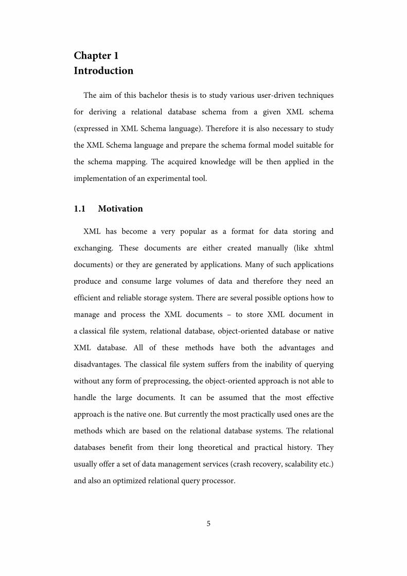
Chapter 1 Introduction
The aim of this bachelor thesis is to study various user-driven techniques
for deriving a relational database schema from a given XML schema
(expressed in XML Schema language). Therefore it is also necessary to study
the XML Schema language and prepare the schema formal model suitable for
the schema mapping. The acquired knowledge will be then applied in the
implementation of an experimental tool.
1.1 Motivation
XML has become a very popular as a format for data storing and
exchanging. These documents are either created manually (like xhtml
documents) or they are generated by applications. Many of such applications
produce and consume large volumes of data and therefore they need an
efficient and reliable storage system. There are several possible options how to
manage and process the XML documents – to store XML document in
a classical file system, relational database, object-oriented database or native
XML database. All of these methods have both the advantages and
disadvantages. The classical file system suffers from the inability of querying
without any form of preprocessing, the object-oriented approach is not able to
handle the large documents. It can be assumed that the most effective
approach is the native one. But currently the most practically used ones are the
methods which are based on the relational database systems. The relational
databases benefit from their long theoretical and practical history. They
usually offer a set of data management services (crash recovery, scalability etc.)
and also an optimized relational query processor.

6
In order to store the XML documents in a relational database, its tree-
structure must be first mapped into an equivalent, flat relational schema. But
there are many different ways how to derive this mapping. There are several
mapping possibilities for every single attribute or element and the correctness
of the choice depends on many factors like for example the expected query
load or simply on the meaning of data.
One strategy is to let a database designer decide how the XML elements
should be stored in the relational database. But this requires a skilled database
designer in both XML and relational technologies and also it can be very
demanding to define the whole mapping. The user-driven approach is
a solution for the second problem – it provides a default mapping that can be
redefined by the designer so the database designer just corrects the final
mapping.
1.2 Contribution
To summarize, our main contributions are:
- We propose a formal model of an XML schema
- On this XML schema formal model we build a framework for deriving
a relational database schema from a given XML schema (and implement
selected user-driven techniques on that framework)
- We analyze the possibilities of selected user-driven techniques
1.3 The document structure
The second chapter introduces the technical background and used
technologies. The formal model of XML Schema and other used terms are also
defined there.
7
The third chapter describes the selected user-driven mapping techniques
that are implemented in the experimental tool for the relational schema
derivation.
In the fourth chapter there is a description of the experimental tool
implementation and in the fifth chapter, there is a user guide which introduces
the tool for the users.
8
Chapter 2 Technical background
2.1 XML
The Extensible Markup Language (formally described in [1]) was designed
as a subset of the SGML to be used on the Web like HTML. Nowadays it is
used for representing almost any kind of data.
For the purpose of mapping the XML Schema to the SQL it is not necessary
to consider full specification. Objects like CDATA, commentaries, document
declaration and namespaces are not important. In this work, we consider only
“data containers”, that means only elements and attributes. CDATA section
may contain data but it is just a mark which is used to escape a block of
characters which would be otherwise recognized as markup.
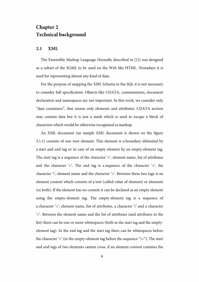
An XML document (an sample XML document is shown on the figure
2.1.1) consists of one root element. This element is a boundary delimited by
a start and end tag or in case of an empty element by an empty-element tag.
The start tag is a sequence of the character ‘<’, element name, list of attributes
and the character ‘>’. The end tag is a sequence of the character ‘<’, the
character ‘\’, element name and the character ‘>’. Between these two tags is an
element content which consists of a text (called value of element) or elements
(or both). If the element has no content it can be declared as an empty element
using the empty-element tag. The empty-element tag is a sequence of
a character ‘<’, element name, list of attributes, a character ‘\’ and a character
‘>’. Between the element name and the list of attributes (and attributes in the
list) there can be one or more whitespaces (both in the start tag and the empty-
element tag). In the end tag and the start tag there can be whitespaces before
the character ‘>’ (in the empty-element tag before the sequence “\>”). The start
and end tags of two elements cannot cross, if an element content contains the
9
start tag of another element then also the end tag must be inside of the element
content.
The attribute is a sequence of an attribute name, the character ‘=’ (there can
be whitespaces around the character ‘=’) and an attribute value (surrounded by
quotation marks).
This simplified definition implies, that the logical structure of the XML
document is a tree where elements and attributes are nodes and their values
are leafs. Each element is connected by an edge with each assigned attributes
and elements it contains (they are called children, all subelements – also
children of children etc. – are called descentants). If the element (or attribute
or value) 𝐸1 is descendant of the element 𝐸2, then 𝐸2 is ascendant of the
element 𝐸1, and especially if the relationship is direct (𝐸1 is one of the
children of the element 𝐸2) then 𝐸2 is the parent of 𝐸1. The edge is directed
from parent to child.
For example XML document on Figure 2.1.1 can be described by the graph
on Figure 2.1.2
<orders> <order id=“123456“ status=“delivered“> <date>2010-04-29</date> <purchased-by> <name>Miloš Chaloupka</name> <email>[email protected]</email> <address>Some address</address> </purchased-by> <order-items> <item code=“123“ count=“3“> <label>Some books</label> <type>Book</type> <price>300</price> </item> <item code=“456“ count=“1“> <label>Some Movies</label> <type>DVD</type> <price>50</price> </item> </order-items> </order> </orders>
Figure 2.1.1 Sample XML document

10
Figure 2.1.2 Graph representation of sample XML document on Figure 2.1.1
Definition 2.1.1 introduces the notion of XML document formally.
Definition 2.1.1 An XML document is a directed labeled tree 𝑇 = (𝑉,𝐸, Σ𝐸 , Σ𝐴, Γ, 𝑙𝑎𝑏, 𝑣𝑎𝑙, 𝑟), where
- 𝑉 is a finite set of nodes - 𝐸 ⊆ 𝑉 × 𝑉 is a set of edges - Σ𝐸 is a finite set of element names - Σ𝐴 is a finite set of attribute names - Γ is a finite set of text values - 𝑙𝑎𝑏 ∶ 𝑉 → Σ𝐸 ∪ Σ𝐴 ∪ {𝑃𝑐𝑑𝑎𝑡𝑎} is a function which assigns a label to
each 𝑣 ∈ 𝑉, whereas 𝑣 is an element if 𝑙𝑎𝑏(𝑣) ∈ Σ𝐸, an attribute if 𝑙𝑎𝑏(𝑣) ∈ Σ𝐴, or a text node if 𝑙𝑎𝑏(𝑣) = 𝑃𝑐𝑑𝑎𝑡𝑎
- 𝑣𝑎𝑙:𝑉 → Γ is a function which assigns a text value to every text node - 𝑟 is the root node of the tree
orders order
id 123456
status delivered
date 2010-04-29
puchased-by
name Miloš Chaloupka
email [email protected]
address Some address
order-items
item
code 123
count 3
label Some books
type Book
price 300
item
code 456
count 1
label Some Movies
type DVD
price 50
11
2.2 XML Schema
The XML document can describe all types of data. For the purpose of data
management it is very useful to specify the type of XML document, i.e. to
specify the set of available elements and attributes and theirs types. If
a document contains only elements specified in this set, it is valid against this
set (it is an instance of this set). Description of this set is called XML Schema.
In this work the XML Schema Language is used (described in [2][3][4]) to
define XML Schema. XML Schema Language is also an XML document of
a specified format (from the namespace http://www.w3.org/2001/XMLSchema
– in samples namespace descriptor xs will be used). A definition is composed
of definitions of data types and their assignment to elements and attributes.
Although the values in the XML document are only character data, it is
possible to define restrictions. For example it is possible to say that a value
must be an integer value between 0 and 100. The types are divided into two
groups – simple types and complex types.
A simple type is some of the built-in types (like string, boolean, decimal,
double, dateTime etc.) or it is also possible to define more restrictive type
(derived from another simple type). For example, we can restrict the length of
a string, restrict allowed strings by a regular expression or define the type by
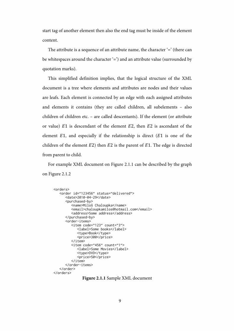
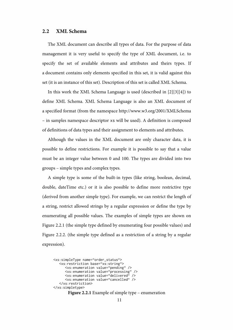
enumerating all possible values. The examples of simple types are shown on
Figure 2.2.1 (the simple type defined by enumerating four possible values) and
Figure 2.2.2. (the simple type defined as a restriction of a string by a regular
expression).
<xs:simpleType name=“order_status“> <xs:restriction base=“xs:string“> <xs:enumeration value=“pending“ /> <xs:enumeration value=“processing“ /> <xs:enumeration value=“delivered“ /> <xs:enumeration value=“cancelled“ /> </xs:restriction> </xs:simpletype>
Figure 2.2.1 Example of simple type – enumeration
12
<xs:simpleType name=“email“> <xs:restriction base=“xs:string“> <xs:pattern value=“^[A-Z0-9._%+-]+@[A-Z0-9.-]+\.[A-Z]{2,4}$“ /> </xs:restriction> </xs:simpleType>
Figure 2.2.2 Example of simple type – simple e-mail address
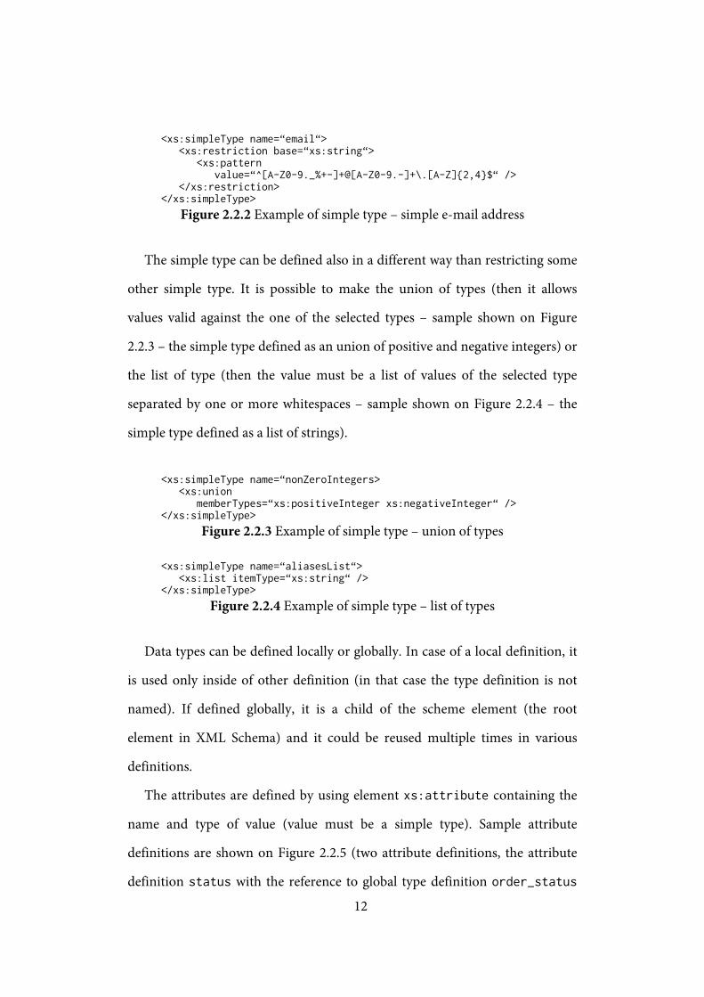
The simple type can be defined also in a different way than restricting some
other simple type. It is possible to make the union of types (then it allows
values valid against the one of the selected types – sample shown on Figure
2.2.3 – the simple type defined as an union of positive and negative integers) or
the list of type (then the value must be a list of values of the selected type
separated by one or more whitespaces – sample shown on Figure 2.2.4 – the
simple type defined as a list of strings).
<xs:simpleType name=“nonZeroIntegers> <xs:union memberTypes=“xs:positiveInteger xs:negativeInteger“ /> </xs:simpleType>
Figure 2.2.3 Example of simple type – union of types
<xs:simpleType name=“aliasesList“> <xs:list itemType=“xs:string“ /> </xs:simpleType>
Figure 2.2.4 Example of simple type – list of types
Data types can be defined locally or globally. In case of a local definition, it
is used only inside of other definition (in that case the type definition is not
named). If defined globally, it is a child of the scheme element (the root
element in XML Schema) and it could be reused multiple times in various
definitions.
The attributes are defined by using element xs:attribute containing the
name and type of value (value must be a simple type). Sample attribute
definitions are shown on Figure 2.2.5 (two attribute definitions, the attribute
definition status with the reference to global type definition order_status

13
and the attribute definition count with locally defined type). It is also possible
to define whether an attribute is optional or required. We can moreover define
a default value for a required (used if the attribute is not present).
<xs:attribute name=“status“ type=“order_status“ /> <xs:attribute name=“count“> <xs:simpleType> <xs:restriction base=“xs:integer“> <xs:minInclusive value=“1“ /> <xs:maxExclusive value=“100“ /> </xs:restriction> <xs:simpleType> </xs:attribute>
Figure 2.2.5 The samples of attribute definition
Elements are defined very similarly using xs:element. It also contains the
name and type of element. But in the opposite of the attributes the elements
can contain not only a simple type but also a complex type. It is also possible to
define whether the element can be empty (using nillable attribute). Every
element which is defined globally can be used as the root element of XML
document.
Complex types are used to describe more complex elements. The simplest
complex type is the complex type with a simple content – it is used to define
an element with a simple type but with an attribute or to restrict another
complex type with a simple content.
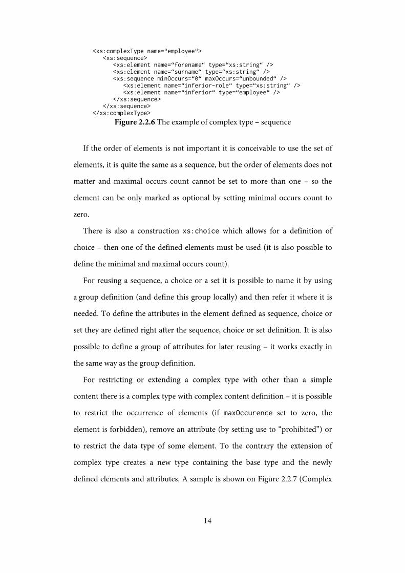
A complex type can also define an element containing a sequence of
elements (it is possible to control occurrence count as well – default is only one
is allowed simultaneously required) – sample shown on Figure 2.2.6 (the
complex type definition containing a sequence of elements forename,
surname and then an arbitrary count of repetition of sequence containing
elements inferior-role and inferior).
14
<xs:complexType name=“employee“> <xs:sequence> <xs:element name=“forename“ type=“xs:string“ /> <xs:element name=“surname“ type=“xs:string“ /> <xs:sequence minOccurs=“0“ maxOccurs=“unbounded“ /> <xs:element name=“inferior-role“ type=“xs:string“ /> <xs:element name=“inferior“ type=“employee“ /> </xs:sequence> </xs:sequence> </xs:complexType>
Figure 2.2.6 The example of complex type – sequence
If the order of elements is not important it is conceivable to use the set of
elements, it is quite the same as a sequence, but the order of elements does not
matter and maximal occurs count cannot be set to more than one – so the
element can be only marked as optional by setting minimal occurs count to
zero.
There is also a construction xs:choice which allows for a definition of
choice – then one of the defined elements must be used (it is also possible to
define the minimal and maximal occurs count).
For reusing a sequence, a choice or a set it is possible to name it by using
a group definition (and define this group locally) and then refer it where it is
needed. To define the attributes in the element defined as sequence, choice or
set they are defined right after the sequence, choice or set definition. It is also
possible to define a group of attributes for later reusing – it works exactly in
the same way as the group definition.
For restricting or extending a complex type with other than a simple
content there is a complex type with complex content definition – it is possible
to restrict the occurrence of elements (if maxOccurence set to zero, the
element is forbidden), remove an attribute (by setting use to “prohibited”) or
to restrict the data type of some element. To the contrary the extension of
complex type creates a new type containing the base type and the newly
defined elements and attributes. A sample is shown on Figure 2.2.7 (Complex

15
type named dvd and the extension of that type named dvd-movie – it adds one
more element movie-length to the sequence of elements).
<xs:complexType name=“dvd“> <xs:sequence> <xs:element name=“label“ type=“xs:string“ /> <xs:element name=“price“ type=“xs:decimal“ /> </xs:sequence> </xs:complexType> <xs:complexType name=“dvd-movie“> <xs:complexContent> <xs:extension base=“dvd“> <xs:sequence> <xs:element name=“movie-length“ type=“xs:decimal“ /> </xs:sequence> </xs:extension> </xs:complexContent> </xs:complexType>
Figure 2.2.7 Sample complex type with complex content definition
Every definition of the logical structure of the XML document which is
mentioned before, is quite restrictive – It is maximally the list of the suitable
elements. And what if the content is any element? Therefore there is a special
syntax to specify that the element of any type can be placed there (or restricted
by namespace) – by using the element xs:any.
It is sometimes useful to define the data types outside of the main file. It
tends to be more transparent and it also enables reusing of these types in
another schemas. For using the types (or other definitions) from the external
schemas, these schemas are supposed to be included (it means just to “copy”
them in the place of the include element) or to be imported (it enables the
reuse of the schema of any namespace)
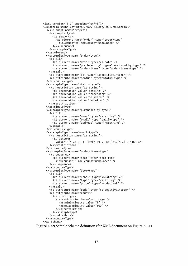
The XML Schema Language can describe the valid documents very
precisely (the options mentioned before is only the subset of all the possible
options) and because of that, the definition can be very complicated. For
example – the schema definition for the document in the sample on the figure
2.1.1 is much longer than the document itself (shown on figure 2.2.9).

16
Similar to the formal definition of the XML as a directed labeled tree, it is
also possible to transform the XML schema to a graph, but therefore it is
necessary to state several terms first.
In the rest of this section, we introduce the notion of XML schema formally.
The following definitions introduce the conception of a regular expression.
Regular expression will be used later as a content model.
Definition 2.2.1 The set of regular expression 𝑅𝐸(𝑋) over a non-empty, finite set 𝑋 is a smallest set which:
- 𝜖 ∈ 𝑅𝐸(𝑋) - ∀𝑥 ∈ 𝑋: 𝑥 ∈ 𝑅𝐸(𝑋) - ∀𝛼1,𝛼2 ∈ 𝑅𝐸(𝑋): (𝛼1 + 𝛼2) ∈ 𝑅𝐸(𝑋) - ∀𝛼1,𝛼2 ∈ 𝑅𝐸(𝑋): (𝛼1,𝛼2) ∈ 𝑅𝐸(𝑋) - ∀𝛼 ∈ 𝑅𝐸(𝑋): 𝛼∗ ∈ 𝑅𝐸(𝑋) - ∀𝛼 ∈ 𝑅𝐸(𝑋):𝛼? ∈ 𝑅𝐸(𝑋)
The set of regular expression 𝑅𝐸(𝑋) means the set of all possible regular
expression with operands from the set 𝑋. For example, for 𝑋 = {𝑎} is
𝑅𝐸(𝑋) = {𝜖, 𝑎,𝑎∗,𝑎?, 𝑎𝑎, 𝑎𝑎𝑎,𝑎𝑎𝑎𝑎, … }.
The following definition introduces the meaning of words. The word
definition will be used later to define the value of regular expression.
Definition 2.2.2 A word over a set 𝑋 is a sequence 𝑥1𝑥2 … 𝑥𝑛, where ∀𝑖: 𝑥𝑖 ∈𝑋. The empty word (sequence with zero length) is marked 𝜖. The set of all words over the set 𝑋 is marked 𝑋∗.
A word means a sequence of items from the specified set. For example, for
𝑋 = {𝑎, 𝑏} the set of all words over the set 𝑋∗ = {𝜖,𝑎, 𝑏, 𝑎𝑎, 𝑎𝑏, 𝑏𝑎, 𝑏𝑏, … }.
17
<?xml version="1.0" encoding="utf-8"?> <xs:schema xmlns:xs="http://www.w3.org/2001/XMLSchema"> <xs:element name="orders"> <xs:complexType> <xs:sequence> <xs:element name="order" type="order-type" minOccurs="0" maxOccurs="unbounded" /> </xs:sequence> </xs:complexType> </xs:element> <xs:complexType name="order-type"> <xs:all> <xs:element name="date" type="xs:date" /> <xs:element name="purchased-by" type="purchased-by-type" /> <xs:element name="order-items" type="order-items-type" /> </xs:all> <xs:attribute name="id" type="xs:positiveInteger" /> <xs:attribute name="status" type="status-type" /> </xs:complexType> <xs:simpleType name="status-type"> <xs:restriction base="xs:string"> <xs:enumeration value="pending" /> <xs:enumeration value="processing" /> <xs:enumeration value="delivered" /> <xs:enumeration value="cancelled" /> </xs:restriction> </xs:simpleType> <xs:complexType name="purchased-by-type"> <xs:all> <xs:element name="name" type="xs:string" /> <xs:element name="email" type="email-type" /> <xs:element name="address" type="xs:string" /> </xs:all> </xs:complexType> <xs:simpleType name="email-type"> <xs:restriction base="xs:string"> <xs:pattern value="^[A-Z0-9._%+-]+@[A-Z0-9._%+-]+\.[A-Z]{2,4}$" /> </xs:restriction> </xs:simpleType> <xs:complexType name="order-items-type"> <xs:sequence> <xs:element name="item" type="item-type" minOccurs="1" maxOccurs="unbounded" /> </xs:sequence> </xs:complexType> <xs:complexType name="item-type"> <xs:all> <xs:element name="label" type="xs:string" /> <xs:element name="type" type="xs:string" /> <xs:element name="price" type="xs:decimal" /> </xs:all> <xs:attribute name="code" type="xs:positiveInteger" /> <xs:attribute name="count"> <xs:simpleType> <xs:restriction base="xs:integer"> <xs:minInclusive value="1" /> <xs:maxExclusive value="100" /> </xs:restriction> </xs:simpleType> </xs:attribute> </xs:complexType> </xs:schema>
Figure 2.2.9 Sample schema definition (for XML document on Figure 2.1.1)
18
The concatenation of two words is simple concatenation of two sequences
(placing the items of second sequence after the items of first sequence, possibly
handling the empty 𝜖 word – 𝜖𝑥 = 𝑥, 𝑥𝜖 = 𝑥, 𝜖𝜖 = 𝜖). The following
definition introduces the concatenation of two sets of words.
Definition 2.2.3 Sets concatenation operator “,” 𝑃(𝑋∗) × 𝑃(𝑋∗) → 𝑃(𝑋∗) is defined as follows: 𝐴,𝐵 ⊆ 𝑋∗ 𝐴,𝐵 → {𝑎𝑏|∀𝑎 ∈ 𝐴,∀𝑏 ∈ 𝐵}
The concatenation of two words sets results in a set of concatenated words
(where the first part is from the first set and the other part is from the other
set). For example {𝜖,𝑎, 𝑎𝑏, 𝑎𝑎}, {𝑏} = {𝑏, 𝑎𝑏, 𝑎𝑏𝑏, 𝑎𝑎𝑏}.
The following definition introduces the notion a value of regular
expression. The value of a regular expression will be used later to define
whether a word matches a regular expression.
Definition 2.2.4 The value of a regular expression 𝛼 ∈ 𝑅𝐸(𝑋) is a set [𝛼] ⊆ 𝑋∗ defined as follows:
- [𝜖] = {𝜖} - ∀𝑥 ∈ 𝑋: [𝑥] = {𝑥} - ∀𝛼1,𝛼2 ∈ 𝑅𝐸(𝑋): [𝛼1 + 𝛼2] = [𝛼1] ∪ [𝛼2] - ∀𝛼1,𝛼2 ∈ 𝑅𝐸(𝑋): [𝛼1,𝛼2] = [𝛼1], [𝛼2] where the operator “,” stands
for sets concatenation - ∀𝛼 ∈ 𝑅𝐸(𝑋): [𝛼∗] = [𝜖 + (𝛼,𝛼∗)] - ∀𝛼 ∈ 𝑅𝐸(𝑋): [𝛼?] = [𝜖 + 𝛼]
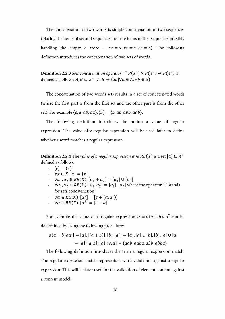
For example the value of a regular expression 𝛼 = 𝑎(𝑎 + 𝑏)𝑏𝑎? can be
determined by using the following procedure:
[𝑎(𝑎 + 𝑏)𝑏𝑎?] = [𝑎], [(𝑎 + 𝑏)], [𝑏], [𝑎?] = {𝑎}, [𝑎] ∪ [𝑏], {𝑏}, [𝜖] ∪ [𝑎]
= {𝑎}, {𝑎, 𝑏}, {𝑏}, {𝜖,𝑎} = {𝑎𝑎𝑏,𝑎𝑎𝑏𝑎, 𝑎𝑏𝑏, 𝑎𝑏𝑏𝑎}
The following definition introduces the term a regular expression match.
The regular expression match represents a word validation against a regular
expression. This will be later used for the validation of element content against
a content model.
19
Definition 2.2.5 A word 𝑥 ∈ 𝑋∗ matches a regular expression 𝛼 ∈ 𝑅𝐸(𝑋) when 𝑥 ∈ [𝛼]
For example the words 𝑎𝑎𝑏,𝑎𝑎𝑏𝑎,𝑎𝑏𝑏,𝑎𝑏𝑏𝑎 matches the regular
expression 𝑎(𝑎 + 𝑏)𝑏𝑎? (and no another word matches).
The paper [5] presents a definition of a regular tree grammar and shows the
relationship with W3C XML Schema language. For the purposes of this work
we introduce the definition of an extended regular tree grammar that has
separated content models for attributes and elements.
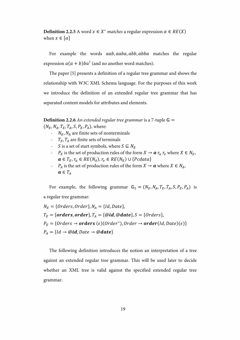
Definition 2.2.6 An extended regular tree grammar is a 7-tuple 𝔾 =(𝑁𝐸 ,𝑁𝐴,𝑇𝐸 ,𝑇𝐴, 𝑆,𝑃𝐸 ,𝑃𝐴), where:
- 𝑁𝐸 ,𝑁𝐴 are finite sets of nonterminals - 𝑇𝐸 ,𝑇𝐴 are finite sets of terminals - 𝑆 is a set of start symbols, where 𝑆 ⊆ 𝑁𝐸 - 𝑃𝐸 is the set of production rules of the form 𝑋 → 𝒂 𝑟𝑎 𝑟𝑒 where 𝑋 ∈ 𝑁𝐸 ,
𝒂 ∈ 𝑇𝐸, 𝑟𝑎 ∈ 𝑅𝐸(𝑁𝐴), 𝑟𝑒 ∈ 𝑅𝐸(𝑁𝐸) ∪ {𝑃𝑐𝑑𝑎𝑡𝑎} - 𝑃𝐴 is the set of production rules of the form 𝑋 → 𝒂 where 𝑋 ∈ 𝑁𝐴,
𝒂 ∈ 𝑇𝐴
For example, the following grammar 𝔾1 = (𝑁𝐸 ,𝑁𝐴,𝑇𝐸 ,𝑇𝐴, 𝑆,𝑃𝐸 ,𝑃𝐴) is
a regular tree grammar:
𝑁𝐸 = {𝑂𝑟𝑑𝑒𝑟𝑠,𝑂𝑟𝑑𝑒𝑟},𝑁𝐴 = {𝐼𝑑,𝐷𝑎𝑡𝑒},
𝑇𝐸 = {𝒐𝒓𝒅𝒆𝒓𝒔,𝒐𝒓𝒅𝒆𝒓},𝑇𝐴 = {@𝒊𝒅, @𝒅𝒂𝒕𝒆}, 𝑆 = {𝑂𝑟𝑑𝑒𝑟𝑠},
𝑃𝐸 = {𝑂𝑟𝑑𝑒𝑟𝑠 → 𝒐𝒓𝒅𝒆𝒓𝒔 (𝜖)(𝑂𝑟𝑑𝑒𝑟∗),𝑂𝑟𝑑𝑒𝑟 → 𝒐𝒓𝒅𝒆𝒓(𝐼𝑑,𝐷𝑎𝑡𝑒)(𝜖)}
𝑃𝐴 = {𝐼𝑑 → @𝒊𝒅,𝐷𝑎𝑡𝑒 → @𝒅𝒂𝒕𝒆}
The following definition introduces the notion an interpretation of a tree
against an extended regular tree grammar. This will be used later to decide
whether an XML tree is valid against the specified extended regular tree
grammar.
20
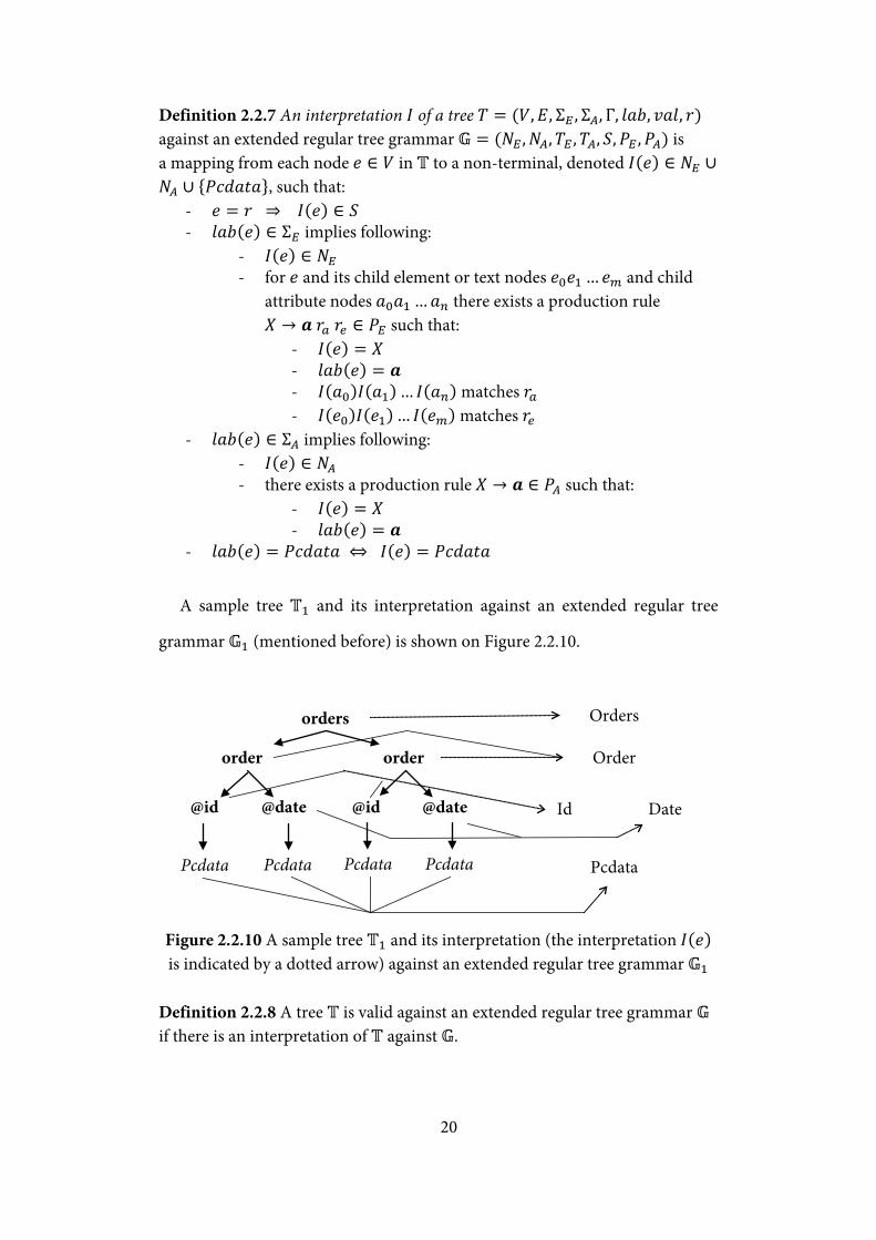
Definition 2.2.7 An interpretation 𝐼 of a tree 𝑇 = (𝑉,𝐸, Σ𝐸 , Σ𝐴, Γ, 𝑙𝑎𝑏, 𝑣𝑎𝑙, 𝑟) against an extended regular tree grammar 𝔾 = (𝑁𝐸 ,𝑁𝐴,𝑇𝐸 ,𝑇𝐴, 𝑆,𝑃𝐸 ,𝑃𝐴) is a mapping from each node 𝑒 ∈ 𝑉 in 𝕋 to a non-terminal, denoted 𝐼(𝑒) ∈ 𝑁𝐸 ∪𝑁𝐴 ∪ {𝑃𝑐𝑑𝑎𝑡𝑎}, such that:
- 𝑒 = 𝑟 ⇒ 𝐼(𝑒) ∈ 𝑆 - 𝑙𝑎𝑏(𝑒) ∈ Σ𝐸 implies following:
- 𝐼(𝑒) ∈ 𝑁𝐸 - for 𝑒 and its child element or text nodes 𝑒0𝑒1 … 𝑒𝑚 and child
attribute nodes 𝑎0𝑎1 … 𝑎𝑛 there exists a production rule 𝑋 → 𝒂 𝑟𝑎 𝑟𝑒 ∈ 𝑃𝐸 such that:
- 𝐼(𝑒) = 𝑋 - 𝑙𝑎𝑏(𝑒) = 𝒂 - 𝐼(𝑎0)𝐼(𝑎1) … 𝐼(𝑎𝑛) matches 𝑟𝑎 - 𝐼(𝑒0)𝐼(𝑒1) … 𝐼(𝑒𝑚) matches 𝑟𝑒
- 𝑙𝑎𝑏(𝑒) ∈ Σ𝐴 implies following: - 𝐼(𝑒) ∈ 𝑁𝐴 - there exists a production rule 𝑋 → 𝒂 ∈ 𝑃𝐴 such that:
- 𝐼(𝑒) = 𝑋 - 𝑙𝑎𝑏(𝑒) = 𝒂
- 𝑙𝑎𝑏(𝑒) = 𝑃𝑐𝑑𝑎𝑡𝑎 ⇔ 𝐼(𝑒) = 𝑃𝑐𝑑𝑎𝑡𝑎
A sample tree 𝕋1 and its interpretation against an extended regular tree
grammar 𝔾1 (mentioned before) is shown on Figure 2.2.10.
Figure 2.2.10 A sample tree 𝕋1 and its interpretation (the interpretation 𝐼(𝑒) is indicated by a dotted arrow) against an extended regular tree grammar 𝔾1
Definition 2.2.8 A tree 𝕋 is valid against an extended regular tree grammar 𝔾 if there is an interpretation of 𝕋 against 𝔾.
order
orders
@id @date
Pcdata
order
@id @date
Pcdata Pcdata
Orders
Order
Pcdata
Id Date
Pcdata

21
For example, the sample tree 𝕋1 is valid against an extended regular tree
grammar 𝔾1 (both mentioned before).
The following definition introduces the notion an XML Schema. This
definition is just an extension to an extended regular tree grammar – it
provides moreover group and attribute group definitions and it corresponds
better to possibilities of W3C XML Schema language.
Definition 2.2.9 An XML Schema is a 12-tuple 𝕊 = (𝐷𝐸 ,𝐷𝐴,𝑇,𝐺𝐸 ,𝐺𝐴, Σ𝐸 , Σ𝐴, 𝑡𝑦𝑝𝑒,Δ𝐸 ,Δ𝐴, 𝑙𝑎𝑏, 𝑆), where:
- 𝐷𝐸 is a set of element definitions - 𝐷𝐴 is a set of attribute definitions - 𝑇 is a set of type definitions - 𝐺𝐸 is a set of group definitions - 𝐺𝐴 is a set of attribute group definitions - Σ𝐸 is a set of element names - Σ𝐴 is a set of attribute names - 𝑡𝑦𝑝𝑒 is a function 𝐷𝐸 → 𝑇 that assigns a type for every element
definition - Δ𝐸 is a function 𝑇 ∪ 𝐺𝐸 → 𝑅𝐸(𝐷𝐸 ∪ 𝐺𝐸) ∪ {𝑃𝑐𝑑𝑎𝑡𝑎} that assigns a
content model of children elements (or child text node) for every type or group definition
- Δ𝐴 is a function 𝑇 ∪ 𝐺𝐴 → 𝑅𝐸(𝐷𝐴 ∪ 𝐺𝐴) that assigns a content model of attributes for every type or attribute group definition
- 𝑙𝑎𝑏 is a function 𝐷𝐸 ∪ 𝐷𝐴 → Σ𝐸 ∪ Σ𝐴 that assigns a label for every element or attribute definition
- 𝑆 is a set of global element definitions, 𝑆 ⊆ 𝐷𝐸
To prove that the definition of an XML Schema is just an extension of
an extended regular tree grammar, it is necessary to define a function that will
find an equivalent content model for a specified type, but without group
definitions. This function is defined in the following definition.

22
Definition 2.2.10 For an XML Schema 𝕊 = (𝐷𝐸 ,𝐷𝐴,𝑇,𝐺𝐸 ,𝐺𝐴, Σ𝐸 ,Σ𝐴, 𝑡𝑦𝑝𝑒, Δ𝐸 ,Δ𝐴, 𝑙𝑎𝑏, 𝑆) there exists an iterative function Δ𝐸∗ :𝑇 ∪ 𝐺𝐸 → 𝑅𝐸(𝐷𝐸) ∪{𝑃𝑐𝑑𝑎𝑡𝑎} defined ∀𝑥 ∈ 𝑇 ∪ 𝐺 as Δ𝐸∗ (𝑥) = 𝑥′ when there exists 𝑥1 … 𝑥𝑛 where:
- Δ(𝑥) = 𝑥1 - 𝑥𝑖+1 results from expression 𝑥𝑖 by replacing 𝑦 ∈ 𝐺 with Δ𝐸(𝑦) - 𝑥𝑛 ∈ 𝑅𝐸(𝐷𝐸) ∪ {𝑃𝑐𝑑𝑎𝑡𝑎}, 𝑥′ = 𝑥𝑛
From Δ𝐴 is analogically defined Δ𝐴∗ :𝑇 ∪ 𝐺𝐴 → 𝑅𝐸(𝐷𝐴) Theorem 2.2.11 For every XML Schema 𝕊 = (𝐷𝐸 ,𝐷𝐴,𝑇,𝐺𝐸 ,𝐺𝐴, Σ𝐸 ,Σ𝐴, 𝑡𝑦𝑝𝑒, Δ𝐸 ,Δ𝐴, 𝑙𝑎𝑏, 𝑆) there is a regular tree grammar 𝔾 = (𝑁𝐸 ,𝑁𝐴,𝑇𝐸 ,𝑇𝐴, 𝑆′,𝑃𝐸 ,𝑃𝐴) for the validation of XML documents. Proof: We prove the theorem by constructing the regular tree grammar from the XML Schema. The regular tree grammar is constructed as follows:
- 𝑁𝐸 = 𝐷𝐸 - 𝑁𝐴 = 𝐷𝐴 - 𝑇𝐸 = Σ𝐸 ,𝑇𝐴 = Σ𝐴 - 𝑆′ = 𝑆 - 𝑃𝐸 is a set of following rules:
- ∀𝑋 ∈ 𝐷𝐸:𝑋 → 𝒂 𝑟𝑎 𝑟𝑒 where 𝒂 = 𝑙𝑎𝑏(𝑋), 𝑟𝑎 = Δ𝐴∗ �𝑡𝑦𝑝𝑒(𝑋)�, 𝑟𝑒 = Δ𝐸∗ �𝑡𝑦𝑝𝑒(𝑋)�
- 𝑃𝐴 is a set of following rules: - ∀𝑋 ∈ 𝐷𝐴:𝑋 → 𝒂 where 𝒂 = 𝑙𝑎𝑏(𝑋)
This theorem proves that a XML Schema defined in the definition 2.2.9 is
an extension of an extended regular tree grammar and it is possible to find
an equivalent regular tree grammar for a specified XML Schema. Therefore it
is not necessary to define the valid XML trees against an XML Schema.
It is easy to observe that this formal definition of the XML Schema does not
have the same expressing power, it does not allow the mixed content elements1
1 Mixed content element is the element which child nodes are both elements and text nodes
(and possibly also attributes)
and it also does not support any-element or any-attribute option. The division
of the content model for attributes and elements results in the simpler
document validation, but it also decreases the expressing power – it is not
possible to describe a choice between attribute and element (it is also not
23
possible in W3C XML Schema Language, but it is possible for example in
Relax NG Language [6]).
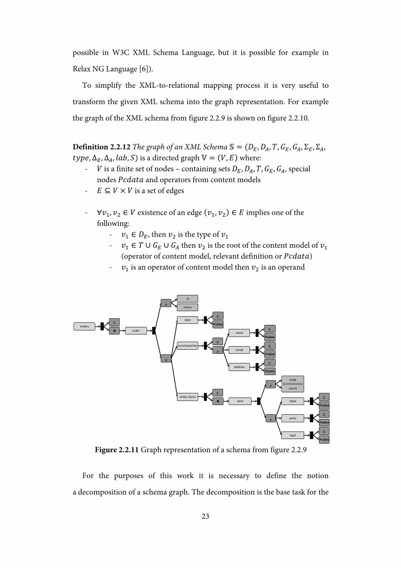
To simplify the XML-to-relational mapping process it is very useful to
transform the given XML schema into the graph representation. For example
the graph of the XML schema from figure 2.2.9 is shown on figure 2.2.10.
Definition 2.2.12 The graph of an XML Schema 𝕊 = (𝐷𝐸 ,𝐷𝐴,𝑇,𝐺𝐸 ,𝐺𝐴, Σ𝐸 , Σ𝐴, 𝑡𝑦𝑝𝑒,Δ𝐸 ,Δ𝐴, 𝑙𝑎𝑏, 𝑆) is a directed graph 𝕍 = (𝑉,𝐸) where:
- 𝑉 is a finite set of nodes – containing sets 𝐷𝐸 ,𝐷𝐴,𝑇,𝐺𝐸 ,𝐺𝐴, special nodes 𝑃𝑐𝑑𝑎𝑡𝑎 and operators from content models
- 𝐸 ⊆ 𝑉 × 𝑉 is a set of edges
- ∀𝑣1, 𝑣2 ∈ 𝑉 existence of an edge (𝑣1, 𝑣2) ∈ 𝐸 implies one of the following:
- 𝑣1 ∈ 𝐷𝐸 , then 𝑣2 is the type of 𝑣1 - 𝑣1 ∈ 𝑇 ∪ 𝐺𝐸 ∪ 𝐺𝐴 then 𝑣2 is the root of the content model of 𝑣1
(operator of content model, relevant definition or 𝑃𝑐𝑑𝑎𝑡𝑎) - 𝑣1 is an operator of content model then 𝑣2 is an operand
Figure 2.2.11 Graph representation of a schema from figure 2.2.9
For the purposes of this work it is necessary to define the notion
a decomposition of a schema graph. The decomposition is the base task for the
ordersε
* order
,id
status
,
dateε
Pcdata
purchased-byε
,
nameε
Pcdata
emailε
Pcdata
addressε
Pcdata
order-itemsε
* item
,code
count
,
labelε
Pcdata
priceε
Pcdata
typeε
Pcdata

24
schema mapping process – fragments of a schema graph are mapped to
relational tables.
Definition 2.2.13 A fragment 𝑓 of a schema graph 𝕍 is each of its connected subgraphs. Definition 2.2.14 A decomposition of a schema graph 𝕍 = (𝑉,𝐸) is a set of its fragments {𝑓1,𝑓2, … ,𝑓𝑛} where ∀𝑣 ∈ 𝑉 ∃! 𝑖: 𝑣 ∈ 𝑓𝑖
25
2.3 Relational Database
The relational database model is based on the branches of mathematics
called the set theory and the predicate logic2
The relational model reflects also the dependencies of the attributes. If
values of attributes from a set {𝐴1, … ,𝐴𝑙} determine values for all attributes
from a set {𝐴𝑘, … ,𝐴𝑚} then we say that the set {𝐴𝑘, … ,𝐴𝑚} depends on the set
{𝐴1, … ,𝐴𝑙}. If the set of attributes {𝐴1, … ,𝐴𝑙} determines all other attributes
from the relevant relation, it is called superkey. If there is no subset of the
superkey, which is also a superkey, than it is a key.
. The basic element of a relational
database is a table (or relation) 𝑅 ⊆ 𝐷1 × 𝐷2 × … × 𝐷𝑛 where 𝐷𝑖 is an attribute
domain (the type of attribute – the set of all possible values). A relational
schema is an enumeration of attributes and their types:
𝑅 = (𝐴1:𝐷1,𝐴2:𝐷2, … ,𝐴𝑛:𝐷𝑛). Then 𝑅 is called a table, 𝐴1, … ,𝐴𝑛 are
columns (𝐷1, … ,𝐷𝑛 are their types) and 𝑟 ∈ 𝑅∗ (𝑅∗ is a relation valid to the
relational schema 𝑅) is a row.
The relational model requires that every row in a table is unique (otherwise
there is no way to address a given row). This is often solved by creating
a specific column (attribute) – a primary key – containing the unique value.
The real benefit of the primary key in one column is the ability to be
referenced from other tables (or from the same one) in a very simple way. This
is made by using so called foreign keys – it is a column with the same type as
referenced key (from the same or another table).
For example the relations from figure 2.3.1 (schema shown on figure 2.3.2
in tables) can represent something very similar to the data from figure 2.1.1.
Relation 𝑜𝑟𝑑𝑒𝑟 contains the set of all orders and it is possible to find
a purchaser (by using the foreign key 𝑝𝑢𝑟𝑐ℎ𝑎𝑠𝑒𝑟) and also in relation 𝑖𝑡𝑒𝑚
2 Cited from [11]

26
where all items can be found, that are referencing the order (by using the
foreign key 𝑜𝑟𝑑𝑒𝑟).
person(id: integer
, name: string, e-mail: string, address: string)
order(id: integer
, purchaser: integer, date: date, status: string)
item(id: integer
, order: integer, count: integer, label: string, type: string, price: money)
primary keys are underlined, foreign keys are highlighted by an arrow pointing to the associated key
Figure 2.3.1 Sample relations
item
order id integer
person
(primary key) id integer order integer
id integer (primary key) (foreign key) (primary key) purchaser integer count integer name string (foreign key) label string e-mail string date date type string address string status string price money
Figure 2.3.2 Sample relational schema (in tables)
Definition 2.3.1 A table is a relation 𝑅∗ ⊆ 𝐷1 × 𝐷2 × … × 𝐷𝑛, where 𝐷𝑖 is an attribute domain (the set of all possible values). 𝑟 ∈ 𝑅∗ is called a row. Definition 2.3.2 A table schema is a tuple 𝑅 = (𝐴1:𝐷1, … ,𝐴𝑛:𝐷𝑛) where 𝐴1 …𝐴𝑛 are attribute (column) names, 𝐷1 …𝐷𝑛 are their types (domains). Definition 2.3.3 A relational schema is a set of table schemas ℝ ={𝑇1:𝑅1, … ,𝑇𝑛:𝑅𝑛} where 𝑇1 …𝑇𝑛 are table names and 𝑅1 …𝑅𝑛 are their schemas Definition 2.3.4 A valid relational schema is a schema where:
- table names are distinct - each table has at least one field which is its key - field names within the same table are distinct
27
2.4 MS SQL
MS SQL is a relational database management system made by Microsoft.
For the purposes of this work it is necessary to mention only very small part of
the features that MS SQL offers – column types (the available domains of
attributes) and the language for data definition.
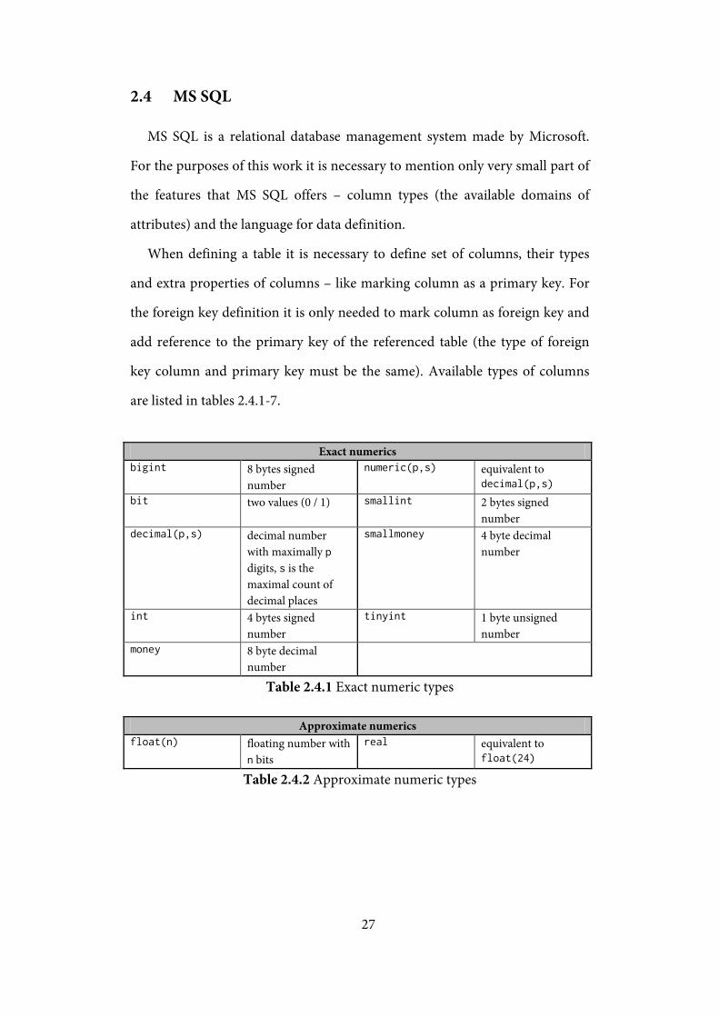
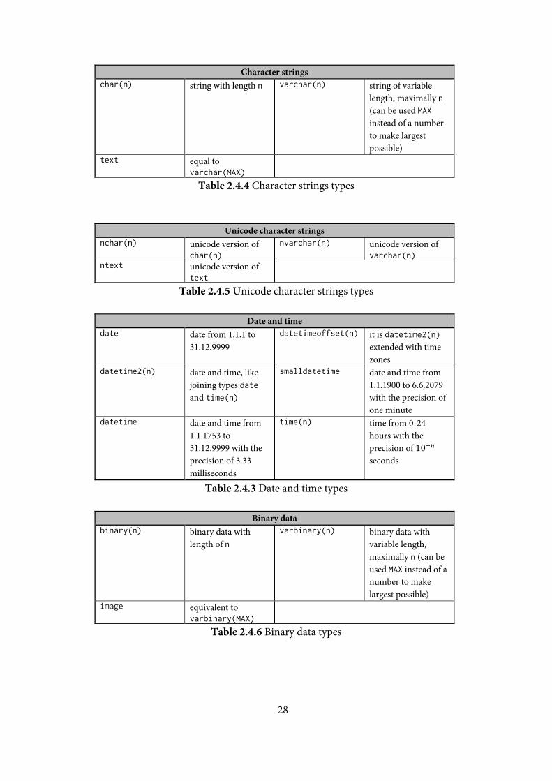
When defining a table it is necessary to define set of columns, their types
and extra properties of columns – like marking column as a primary key. For
the foreign key definition it is only needed to mark column as foreign key and
add reference to the primary key of the referenced table (the type of foreign
key column and primary key must be the same). Available types of columns
are listed in tables 2.4.1-7.
Exact numerics bigint 8 bytes signed
number numeric(p,s) equivalent to
decimal(p,s) bit two values (0 / 1) smallint 2 bytes signed
number decimal(p,s) decimal number
with maximally p digits, s is the maximal count of decimal places
smallmoney 4 byte decimal number
int 4 bytes signed number
tinyint 1 byte unsigned number
money 8 byte decimal number
Table 2.4.1 Exact numeric types
Approximate numerics float(n) floating number with
n bits real equivalent to
float(24)
Table 2.4.2 Approximate numeric types
28
Character strings char(n) string with length n varchar(n) string of variable
length, maximally n (can be used MAX instead of a number to make largest possible)
text equal to varchar(MAX)
Table 2.4.4 Character strings types
Unicode character strings nchar(n) unicode version of
char(n) nvarchar(n) unicode version of
varchar(n) ntext unicode version of
text
Table 2.4.5 Unicode character strings types
Date and time date date from 1.1.1 to
31.12.9999 datetimeoffset(n) it is datetime2(n)
extended with time zones
datetime2(n) date and time, like joining types date and time(n)
smalldatetime date and time from 1.1.1900 to 6.6.2079 with the precision of one minute
datetime date and time from 1.1.1753 to 31.12.9999 with the precision of 3.33 milliseconds
time(n) time from 0-24 hours with the precision of 10−𝑛 seconds
Table 2.4.3 Date and time types
Binary data binary(n) binary data with
length of n varbinary(n) binary data with
variable length, maximally n (can be used MAX instead of a number to make largest possible)
image equivalent to varbinary(MAX)
Table 2.4.6 Binary data types
29
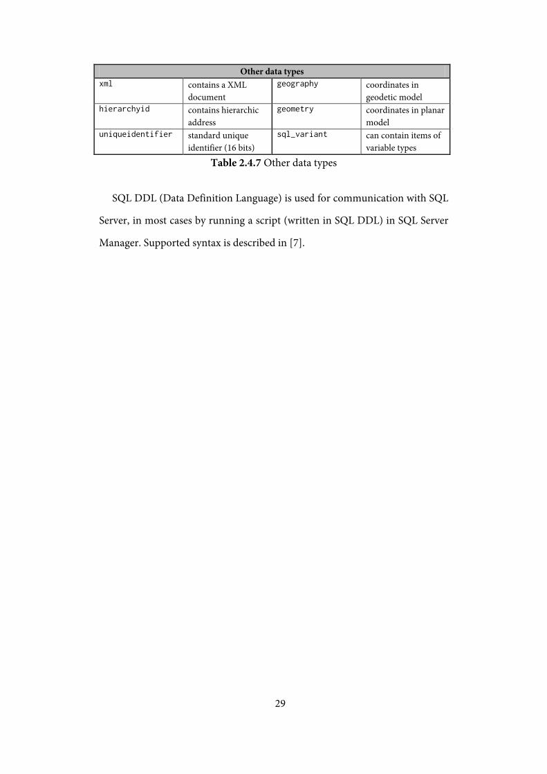
Other data types xml contains a XML
document geography coordinates in
geodetic model hierarchyid contains hierarchic
address geometry coordinates in planar
model uniqueidentifier standard unique
identifier (16 bits) sql_variant can contain items of
variable types
Table 2.4.7 Other data types
SQL DDL (Data Definition Language) is used for communication with SQL
Server, in most cases by running a script (written in SQL DDL) in SQL Server
Manager. Supported syntax is described in [7].
30
2.5 Mapping of XML Schema to SQL
The XML document as described before is a data representation in a file.
Other option is to store the document in a relational database – it allows more
sophisticated storage and retrieval, but the data representation of an XML
document and a relational database is very different. For that reason it is
necessary to create mapping between the world of XML and the world of
relational databases.
There are two fundamental approaches of this mapping – storing data
unstructured in one column (typed as CLOB or BLOB – character / binary
large object – therefore there are in MSSQL there types text and image) or
storing shredded into tables.
Storing as a large object preserves the textual fidelity, but it is very
ineffective to perform queries on a document – it can be always returned just
as a whole document. Still, this representation can be reasonable when the
documents are kept untouched (or only a few updates are expected), the
typical query is for an entire document and the documents are not searched or
identified by documents content (maybe by using timestamps stored in
another column etc.).
When shredding document into table(s), a XML document is decomposed
into columns of one or more tables. Therefore, there must be a mapping that
in fact determines the corresponding table definitions. This mapping can be
non-trivial especially for documents with a complicated schema.
It is also possible to combine those two approaches – shred the document
but some fragments of document store in a large object instead of shredding.
31
2.5.1 Mapping strategies
Generic mapping strategies do not rely on any schema definition, so they
enable to store any document independently of the structure of its document
type. They are used for schema-less documents or documents with a too
general schema. They often exploit the definition of the XML document as
a directed labeled tree and store edges between elements, attributes and values.
On the other hand, schema-driven strategies take advantage of the structure
information from a schema definition. They usually create separate tables for
repetitions and the sub-elements (non-repeated) are “inlined” in the table.
Therefore the document reconstruction requires table joins. The schema-
driven strategies are divided into two groups – fixed and flexible. The fixed
ones only exploit the information given from a schema and use the fixed rules
to determine the final relational schema. The flexible ones contain a set of
possible rules to determine the final relational schema and also a cost function
that decides which rule will be used.
Another possible approach is also to leave the whole mapping process in the
hands of a user – those strategies are called user-defined. But it requires quite
deep knowledge for the database architect – he must be skilled in both
relational databases and XML. To simplify this, there is also another group of
mapping strategies – user-driven. The user-driven strategy works without any
user input (then it often works as a standard fixed schema-driven strategy) but
this behavior can be influenced by a user. The possibilities are limited but still
enough powerful.
32
Chapter 3 Overview of existing user-driven mapping techniques
User-driven mapping techniques offer the flexibility of user-defined
mapping strategies but a user does not need to define the whole mapping.
A user just influences a default fixed mapping strategy. The user options are
limited but usually still enough powerful to reach various schema mappings.
A user can control the required mapping using annotation.
In the paper [8], the user-driven mapping techniques are separated to direct
and indirect mapping strategies. The direct mapping techniques are based on
a simple algorithm – not annotated schema fragments are mapped by using
a default mapping; annotated schema fragments are mapped by using the
specified mappings. The indirect mapping techniques (for example UserMap
described in the paper[9]) try to utilize the user-provided annotations as much
as possible – the annotations are applied not only on particular schema
fragments but they can influence the mapping of the remaining schema
fragments.
For the purposes of this work it is suitable to select mapping techniques that
are quite similar – the similar algorithm results in the similar implementation
and the same mapping tool GUI can be used. So representatives from the
direct user-driven mapping techniques have been selected.
3.1 Mapping Definition Framework
Mapping Definition Framework (MDF – described in [10]) allows a user to
control the required mapping using annotation of input XML Schema with
pre-defined annotations. That offers a great flexibility and extensibility (we can
define additional annotations), the annotation is portable – it does not depend
on target relational database. And last but not least – the annotation can be
33
used by some other tool, for example to analyze the mapping or by
an application that translates XQuery queries into SQL.
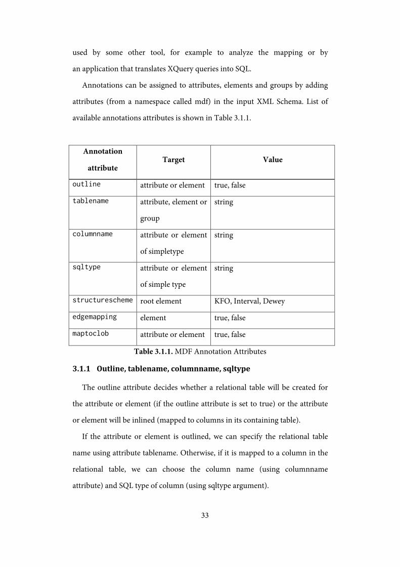
Annotations can be assigned to attributes, elements and groups by adding
attributes (from a namespace called mdf) in the input XML Schema. List of
available annotations attributes is shown in Table 3.1.1.
Annotation
attribute Target Value
outline attribute or element true, false
tablename attribute, element or
group
string
columnname attribute or element
of simpletype
string
sqltype attribute or element
of simple type
string
structurescheme root element KFO, Interval, Dewey
edgemapping element true, false
maptoclob attribute or element true, false
Table 3.1.1. MDF Annotation Attributes
3.1.1 Outline, tablename, columnname, sqltype
The outline attribute decides whether a relational table will be created for
the attribute or element (if the outline attribute is set to true) or the attribute
or element will be inlined (mapped to columns in its containing table).
If the attribute or element is outlined, we can specify the relational table
name using attribute tablename. Otherwise, if it is mapped to a column in the
relational table, we can choose the column name (using columnname
attribute) and SQL type of column (using sqltype argument).
34
3.1.2 Structurescheme
Structurescheme attribute can be specified at the root element for selecting
the structure mapping to capture element identity, document structure and
order. We have three available options: KFO, Interval and Dewey.
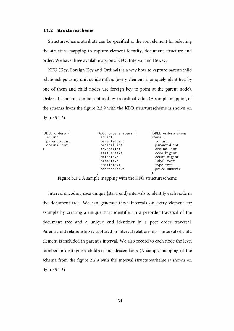
KFO (Key, Foreign Key and Ordinal) is a way how to capture parent/child
relationships using unique identifiers (every element is uniquely identified by
one of them and child nodes use foreign key to point at the parent node).
Order of elements can be captured by an ordinal value (A sample mapping of
the schema from the figure 2.2.9 with the KFO structurescheme is shown on
figure 3.1.2).
TABLE orders ( id:int parentid:int ordinal:int )
TABLE orders-items ( id:int parentid:int ordinal:int id2:bigint status:text date:text name:text email:text address:text )
TABLE orders-items-items ( id:int parentid:int ordinal:int code:bigint count:bigint label:text type:text price:numeric )
Figure 3.1.2 A sample mapping with the KFO structurescheme
Interval encoding uses unique {start, end} intervals to identify each node in
the document tree. We can generate these intervals on every element for
example by creating a unique start identifier in a preorder traversal of the
document tree and a unique end identifier in a post order traversal.
Parent/child relationship is captured in interval relationship – interval of child
element is included in parent’s interval. We also record to each node the level
number to distinguish children and descendants (A sample mapping of the
schema from the figure 2.2.9 with the Interval structurescheme is shown on
figure 3.1.3).
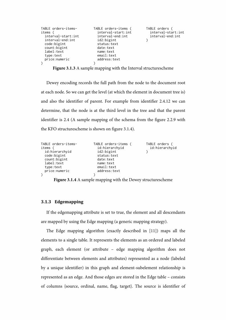
TABLE orders-items-items ( interval-start:int interval-end:int code:bigint count:bigint label:text type:text price:numeric )
TABLE orders-items ( interval-start:int interval-end:int id2:bigint status:text date:text name:text email:text address:text )
TABLE orders ( interval-start:int interval-end:int )
Figure 3.1.3 A sample mapping with the Interval structurescheme
Dewey encoding records the full path from the node to the document root
at each node. So we can get the level (at which the element in document tree is)
and also the identifier of parent. For example from identifier 2.4.12 we can
determine, that the node is at the third level in the tree and that the parent
identifier is 2.4 (A sample mapping of the schema from the figure 2.2.9 with
the KFO structurescheme is shown on figure 3.1.4).
TABLE orders-items-items ( id:hierarchyid code:bigint count:bigint label:text type:text price:numeric )
TABLE orders-items ( id:hierarchyid id2:bigint status:text date:text name:text email:text address:text )
TABLE orders ( id:hierarchyid )
Figure 3.1.4 A sample mapping with the Dewey structurescheme
3.1.3 Edgemapping
If the edgemapping attribute is set to true, the element and all descendants
are mapped by using the Edge mapping (a generic mapping strategy).
The Edge mapping algorithm (exactly described in [11]) maps all the
elements to a single table. It represents the elements as an ordered and labeled
graph, each element (or attribute – edge mapping algorithm does not
differentiate between elements and attributes) represented as a node (labeled
by a unique identifier) in this graph and element-subelement relationship is
represented as an edge. And those edges are stored in the Edge table – consists
of columns {source, ordinal, name, flag, target}. The source is identifier of
36
parent, the ordinal is an ordinal number to preserve document order, the
name contains the element name, the flag contains information about type (if
it is a reference to another element or a value type) and the target where
an identifier of referenced element or an identifier in a separate value table is.
There are also other versions of this algorithm – described in [11].
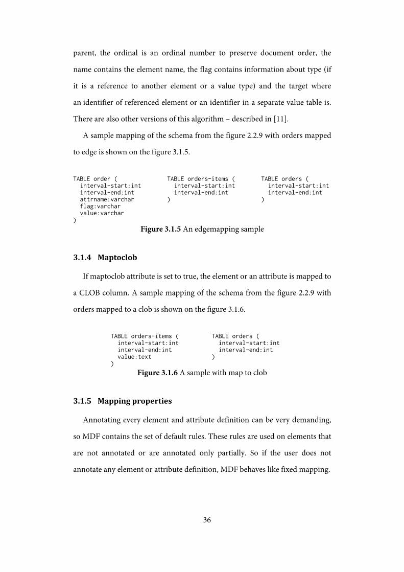
A sample mapping of the schema from the figure 2.2.9 with orders mapped
to edge is shown on the figure 3.1.5.
TABLE order ( interval-start:int interval-end:int attrname:varchar flag:varchar value:varchar )
TABLE orders-items ( interval-start:int interval-end:int )
TABLE orders ( interval-start:int interval-end:int )
Figure 3.1.5 An edgemapping sample
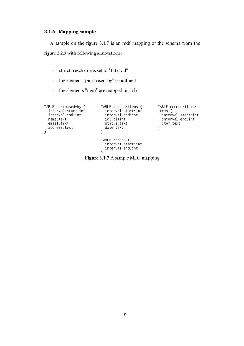
3.1.4 Maptoclob
If maptoclob attribute is set to true, the element or an attribute is mapped to
a CLOB column. A sample mapping of the schema from the figure 2.2.9 with
orders mapped to a clob is shown on the figure 3.1.6.
TABLE orders-items ( interval-start:int interval-end:int value:text )
TABLE orders ( interval-start:int interval-end:int )
Figure 3.1.6 A sample with map to clob
3.1.5 Mapping properties
Annotating every element and attribute definition can be very demanding,
so MDF contains the set of default rules. These rules are used on elements that
are not annotated or are annotated only partially. So if the user does not
annotate any element or attribute definition, MDF behaves like fixed mapping.
37
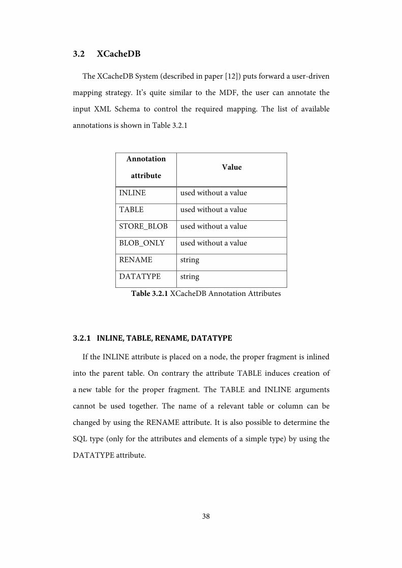
3.1.6 Mapping sample
A sample on the figure 3.1.7 is an mdf mapping of the schema from the
figure 2.2.9 with following annotations:
- structurescheme is set to “Interval”
- the element “purchased-by” is outlined
- the elements “item” are mapped to clob
TABLE purchased-by ( interval-start:int interval-end:int name:text email:text address:text )
TABLE orders-items ( interval-start:int interval-end:int id2:bigint status:text date:text ) TABLE orders ( interval-start:int interval-end:int )
TABLE orders-items-items ( interval-start:int interval-end:int item:text )
Figure 3.1.7 A sample MDF mapping
38
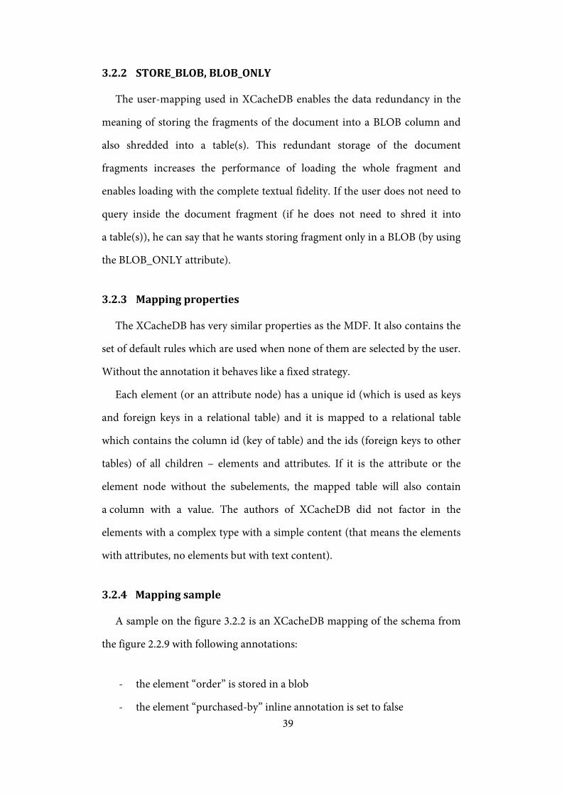
3.2 XCacheDB
The XCacheDB System (described in paper [12]) puts forward a user-driven
mapping strategy. It’s quite similar to the MDF, the user can annotate the
input XML Schema to control the required mapping. The list of available
annotations is shown in Table 3.2.1
Annotation
attribute Value
INLINE used without a value
TABLE used without a value
STORE_BLOB used without a value
BLOB_ONLY used without a value
RENAME string
DATATYPE string
Table 3.2.1 XCacheDB Annotation Attributes
3.2.1 INLINE, TABLE, RENAME, DATATYPE
If the INLINE attribute is placed on a node, the proper fragment is inlined
into the parent table. On contrary the attribute TABLE induces creation of
a new table for the proper fragment. The TABLE and INLINE arguments
cannot be used together. The name of a relevant table or column can be
changed by using the RENAME attribute. It is also possible to determine the
SQL type (only for the attributes and elements of a simple type) by using the
DATATYPE attribute.
39
3.2.2 STORE_BLOB, BLOB_ONLY
The user-mapping used in XCacheDB enables the data redundancy in the
meaning of storing the fragments of the document into a BLOB column and
also shredded into a table(s). This redundant storage of the document
fragments increases the performance of loading the whole fragment and
enables loading with the complete textual fidelity. If the user does not need to
query inside the document fragment (if he does not need to shred it into
a table(s)), he can say that he wants storing fragment only in a BLOB (by using
the BLOB_ONLY attribute).
3.2.3 Mapping properties
The XCacheDB has very similar properties as the MDF. It also contains the
set of default rules which are used when none of them are selected by the user.
Without the annotation it behaves like a fixed strategy.
Each element (or an attribute node) has a unique id (which is used as keys
and foreign keys in a relational table) and it is mapped to a relational table
which contains the column id (key of table) and the ids (foreign keys to other
tables) of all children – elements and attributes. If it is the attribute or the
element node without the subelements, the mapped table will also contain
a column with a value. The authors of XCacheDB did not factor in the
elements with a complex type with a simple content (that means the elements
with attributes, no elements but with text content).
3.2.4 Mapping sample
A sample on the figure 3.2.2 is an XCacheDB mapping of the schema from
the figure 2.2.9 with following annotations:
- the element “order” is stored in a blob
- the element “purchased-by” inline annotation is set to false

40
- the element “item” is stored in a blob and only in a blob
TABLE orders ( id:int parent-id:int ) TABLE purchased-by ( id:int parent-id:int name:text email:text address:text )
TABLE orders-items ( id:int parent-id:int order:text id2:bigint status:text date:text )
TABLE orders-items-items ( id:int parent-id:int item:text )
Figure 3.2.2 A sample XCacheDB mapping

41
Chapter 4 Implementation
One of the main purposes of this thesis is also the implementation of
an experimental tool for deriving a relational database schema from a given
XML schema which meets the following requirements:
- the derivation will be assisted by a database designer
- the XML schemas and their SQL counterparts will be organized in
projects and it will be possible to save the current state of a project
- derivation results will be exported to SQL DDL scripts conforming MS
SQL
- user-friendly GUI
The tool (called the XML Mapper) offers the derivation by using MDF or
XCacheDB strategy – these both user-driven strategies uses annotation to
enable a user to control the derivation. It has unified GUI that enables to use
both strategies in a very similar way.
4.1 Used technologies
The C# 4.0 (running on the .NET Framework 4.0) was selected as the
programming language. It is a modern language that enables using of various
paradigms – imperative, declarative, generic, object-oriented and event-driven
programming. The disadvantage of this selection is that the .NET Framework
4.0 runs nowadays only on Windows XP SP3, Windows Server 2003 SP2,
Windows Vista SP1 and later, Windows Server 2008 (R2) – not supported on
Server Core Role – and on Windows 7.

42
4.1.1 WPF (Windows Presentation Foundation)
There are two common technologies in the .NET Framework 4 which are
used to build GUI – the WinForms and the WPF. The difference between
those technologies is very radical. The WinForms is based on the WinAPI and
the GDI+, everything is written in code and without an extra framework it is
quite difficult to separate a GUI from background data.
On the other hand, the WPF is based primarily on the DirectX (the WinAPI
is used only for necessary system operations) and a GUI can be described not
only in code, but it is also possible to write a special XML file to describe a GUI
in a declarative way – the XML format is called XAML. But the biggest
advantage is that the separation of a GUI from background data can be done in
a very simple way by using binding – it is only the description of a path to
a property that holds the same data as the bounded control – the update
processes are shown on figures 4.1.1 (the update process from a GUI Control
to a bounded property) and 4.1.2 (the update process from a bounded property
to a GUI Control).
Figure 4.1.1 Binding – update source process
Figure 4.1.2 Binding – update target process
The binding mechanism enables a complete separation of a GUI and
background data. It was the most important reason why to choose the WPF
GUI Controlchanged
Bindingvalue conversion
Bindingupdate source
Bound propertysetter called
Bound propertychanged
Bindingvalue conversion
Bindingupdate target
GUI Controlset value
43
(the other one is that the WPF is also much simpler for more complex
graphical designs).
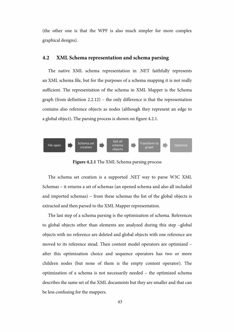
4.2 XML Schema representation and schema parsing
The native XML schema representation in .NET faithfully represents
an XML schema file, but for the purposes of a schema mapping it is not really
sufficient. The representation of the schema in XML Mapper is the Schema
graph (from definition 2.2.12) – the only difference is that the representation
contains also reference objects as nodes (although they represent an edge to
a global object). The parsing process is shown on figure 4.2.1.
Figure 4.2.1 The XML Schema parsing process
The schema set creation is a supported .NET way to parse W3C XML
Schemas – it returns a set of schemas (an opened schema and also all included
and imported schemas) – from these schemas the list of the global objects is
extracted and then parsed to the XML Mapper representation.
The last step of a schema parsing is the optimization of schema. References
to global objects other than elements are analyzed during this step –global
objects with no reference are deleted and global objects with one reference are
moved to its reference stead. Then content model operators are optimized –
after this optimization choice and sequence operators has two or more
children nodes (but none of them is the empty content operator). The
optimization of a schema is not necessarily needed – the optimized schema
describes the same set of the XML documents but they are smaller and that can
be less confusing for the mappers.
File open Schema set creation
Get all schema objects
Transform to graph Optimize

44
4.3 Mapping and relational schema representation
A relational schema is represented according to the definition 2.3.3. It is
a set of tables (accessible by name) and every table contains a set of column
definitions. Tables and columns are identified by a name, so the schema
mapping is only a mapping from schema objects to table names (and
optionally also column names).
4.4 Annotation representation
The annotation mechanism has to be implemented universally in order to
meet the requirements of the MDF and the XCacheDB annotations. It must
enable a mapping from the schema objects to the list of annotation items.
An annotation item is a pair of name and value –names and possible values are
defined by the mapping strategy.
4.5 Project representation
The project is a container of an XML Schema, a relational schema, a schema
annotation and a mapping of schema. It also contains a reference to a mapping
strategy processor. This container has also the ability to save and load from
files.
4.6 Implementation of mapping strategies
The application is designed to give every mapping strategy the full range of
options. It needs to implement only methods of two types –initialization
methods and annotation items setters. But because of the fact, that the both
mapping strategies MDF and XCacheDB are quite similar, the common
mapping mechanism has been abstracted.

45
4.6.1 The common mapping mechanism
The common mapping mechanism encapsulates everything that is used in
both MDF and XCacheDB mapping strategies. It handles a mapping strategy,
traversing through a XML Schema graph and calls specialized mapping
methods – these are exactly defined in mapping strategies.
Figure 4.6.1 Schema object mapping process
The mapping process (shown on figure 4.6.1) is segregated to five steps. At
the beginning it is necessary to find the schema object that is the topmost and
mapped to the same table as the parent of the specified object. Thanks to that it
is not needed any more to solve what is really needed to be remapped. After
that, in two following steps, mapping is cleared for the whole fragment which
has to be remapped and then all unused tables are deleted. If it is the first-time
mapping, the first three steps are done with no result.
The fourth step is just a preparation of parameters for calling a specialized
mapping method from a selected mapping strategy. It gets the parent object,
the annotation of the parent object and of the selected object, the reference to
table in which the parent object is mapped and the flag whether the presence
of the selected object is optional or not. In the last mapping step the
corresponding (based on the type of the schema object) specialized mapping
method (with parameters collected in the step four) is called.
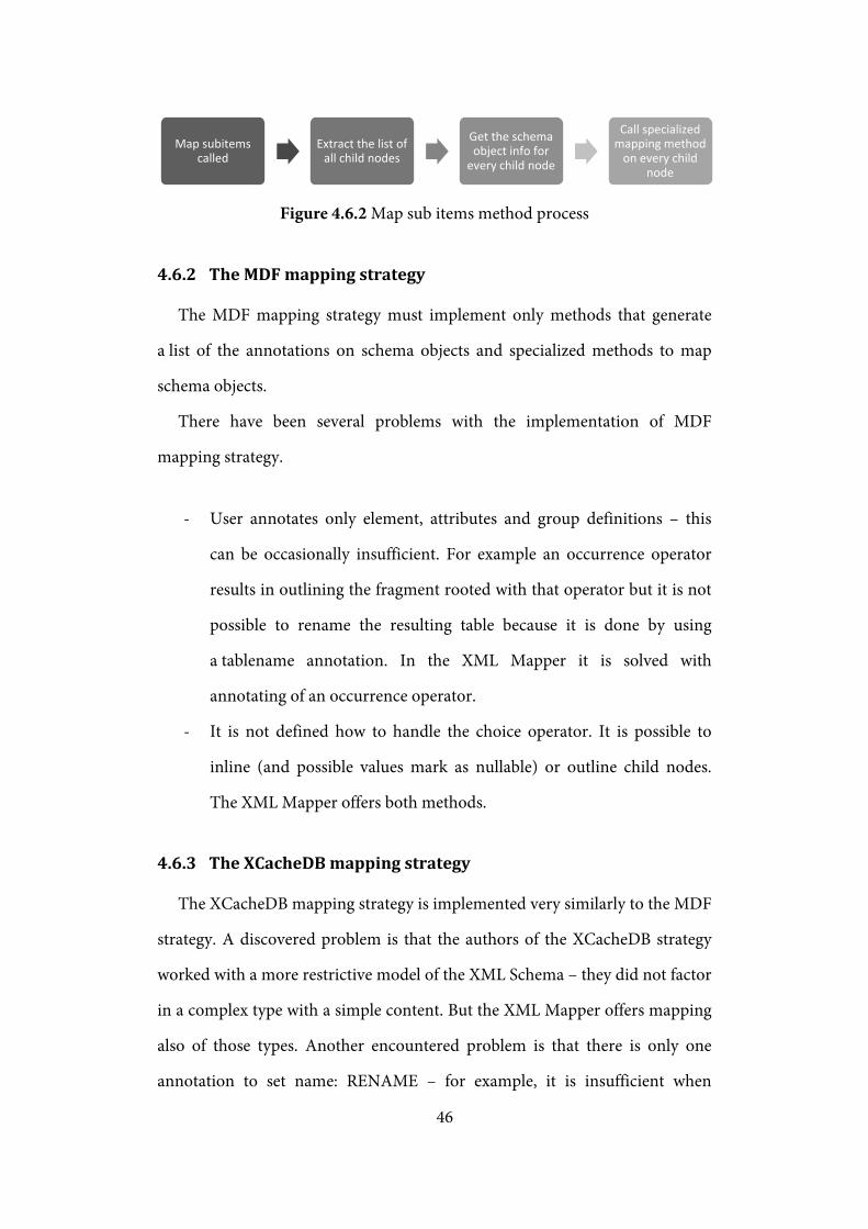
The common mapping mechanism also offers a method to map all children.
This method (their process is shown on the figure 4.6.2) just extracts all child
nodes of the specified schema object and proceeds the mapping mechanism on
them.
Find table root
Unmap object and all descendants
Deleta all unused tables
Get schema object info
Call specialized mapping method
46
Figure 4.6.2 Map sub items method process
4.6.2 The MDF mapping strategy
The MDF mapping strategy must implement only methods that generate
a list of the annotations on schema objects and specialized methods to map
schema objects.
There have been several problems with the implementation of MDF
mapping strategy.
- User annotates only element, attributes and group definitions – this
can be occasionally insufficient. For example an occurrence operator
results in outlining the fragment rooted with that operator but it is not
possible to rename the resulting table because it is done by using
a tablename annotation. In the XML Mapper it is solved with
annotating of an occurrence operator.
- It is not defined how to handle the choice operator. It is possible to
inline (and possible values mark as nullable) or outline child nodes.
The XML Mapper offers both methods.
4.6.3 The XCacheDB mapping strategy
The XCacheDB mapping strategy is implemented very similarly to the MDF
strategy. A discovered problem is that the authors of the XCacheDB strategy
worked with a more restrictive model of the XML Schema – they did not factor
in a complex type with a simple content. But the XML Mapper offers mapping
also of those types. Another encountered problem is that there is only one
annotation to set name: RENAME – for example, it is insufficient when
Map subitems called
Extract the list of all child nodes
Get the schema object info for
every child node
Call specialized mapping method
on every child node

47
an element is outlined and mapped to a clob at once. The XML Mapper solves
that by setting a default name for a column for an element that is outlined and
has a simple content (or is mapped to a clob).
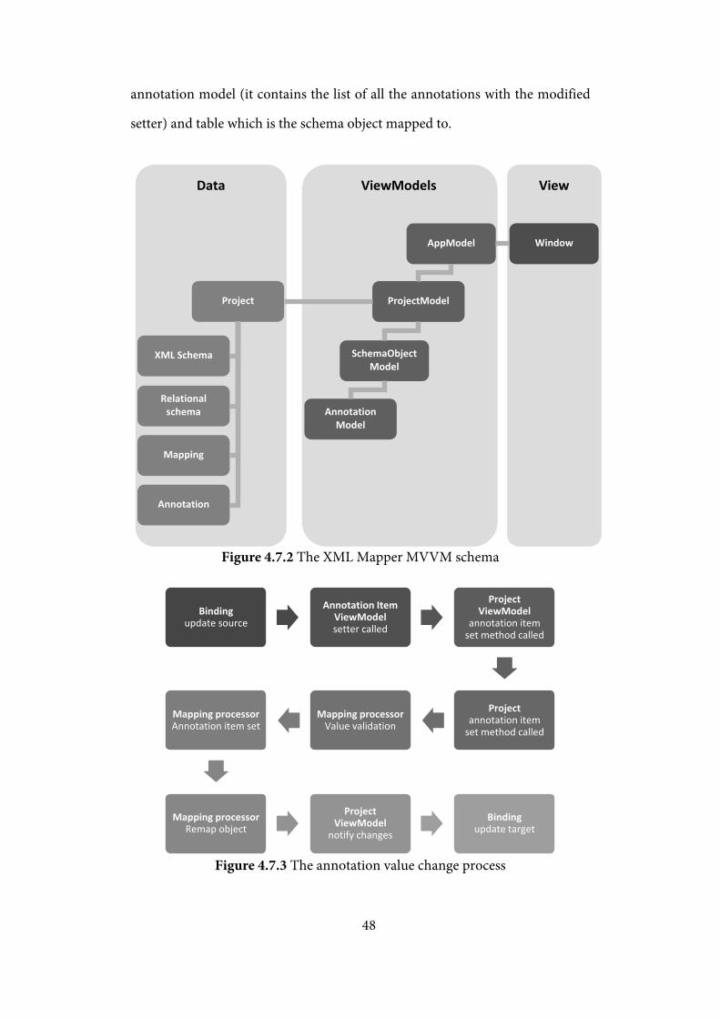
4.7 Graphical user interface implementation
As mentioned before the XML Mapper GUI is made by using the WPF
technology. That enables to separate the interface from the data background –
it is commonly made with the MVVM (Model-View-ViewModel) design
pattern[13] (the principle is shown on the figure 4.7.1) and the XML Mapper
application is not an exception (the XML Mapper MVVM schema is shown on
figure 4.7.2).
Figure 4.7.1 The MVVM principle
The topmost ViewModel is the AppModel – this model handles the
management of projects. The single project is represented by the
ProjectModel – it provides the XML Schema, set of all tables and the schema
annotation and also it handles the currently selected object – also this objects
visual model is accessible for the view. The schema object visual model
contains information about the object itself (description of type etc.), the
View (Window, Control, Template)
ViewModel class implementing
INotifyPropertyChanged
Model Arbitrary .NET class
View and ViewModel communicate by using databinding
ViewModel adapts model for simpler databinding
48
annotation model (it contains the list of all the annotations with the modified
setter) and table which is the schema object mapped to.
Figure 4.7.2 The XML Mapper MVVM schema
Figure 4.7.3 The annotation value change process
Bindingupdate source
Annotation ItemViewModelsetter called
ProjectViewModel
annotation itemset method called
Projectannotation item
set method called
Mapping processorValue validation
Mapping processorAnnotation item set
Mapping processorRemap object
ProjectViewModel
notify changes
Bindingupdate target
AppModel Window
ProjectModel
SchemaObject Model
Project
XML Schema
Relational schema
Mapping
Annotation
Annotation Model
Data ViewModels View
49
The only input that can be made by a user is the one provided through the
change of the annotation item value. The process itself (shown on the figure
4.7.3) has to be fully controlled by a mapping strategy – it is the only instance
that has information about valid values and about what to do after the
annotation value is changed. But after the control is returned to
the ProjectModel it notifies to View that there have been some changes.
50
Chapter 5 User guide
5.1 Installation guide
The XML Mapper application is written for windows based systems
(supported OS are listed in chapter 4.1) and requires .NET Framework 4
(Client profile). The setup file XMLMapperSetup.msi checks the requirements
and if your system meets all of them, the XML Mapper application is installed
in the selected folder. The setup file XMLMapperSetup.exe is the installation
helper – it checks the system requirements and if needed it offers the
installation of .NET Framework 4 Client Profile. Then it runs the setup file
XMLMapperSetup.msi.
5.2 Application start
After the installation the application can be started by using shortcut in
start menu or execution the file XMLMapper.exe in the application folder (by
default is this folder “XML Mapper” located in Program Files (x86 in 64-bit
OS).
5.2.1 Create new MDF (or XCacheDB) project
For creating a new project, user has to select the file with the W3C XML
Schema. After that, the schema is loaded and parsed and it is displayed in the
window.
5.2.2 Open project, save project, save project as
The XML Mapper application allows users to save the current state of work
– saved is everything except of the information of currently selected object in

51
schema. The user can return to the semi-finished work simply by opening the
project file (by default with the *.xmproj extension).
5.2.3 Close project, exit application
After finishing (or saving) the work, user can close the current project (the
XML Mapper then returns to the state of just started application) or close the
whole application.
5.3 Using application
After creating or opening project, user can begin (or continue) the work.
On the left side of the window the schema graph is shown, on the other side
the details of currently selected schema object or the list of all tables are shown.
In the schema object detail, there is also the list of annotation items – these are
changeable by user.
5.3.1 Changing annotation
There are three types of inputs for annotations:
- Combo box – used for annotations that have list of possible values
defined and nothing else can be selected (true / false annotations,
structurescheme) – the change is used right after the value is
selected.
- Auto complete text box – used for annotations that have defined list
of hint values (sqltype, datatype). When user writes input the hint
values are shown below the textbox. The change is used only after
clicking the “Apply” button.
52
- Text box – used for annotations with no hint values (tablename,
columnname, rename). The change is used only after clicking the
“Apply” button.
After the change of the annotation item value, there are two possible
scenarios. If some mistake is made by the user (invalid name, invalid sql
identifier) the error will be shown in red box below the annotations. If the
annotation item change is correct then the schema is remapped and the result
is shown in both schema details and the all tables section.

53
Chapter 6 Conclusion
In this bachelor thesis we presented a formal model for an XML Schema
and then provided an implementation of selected user-driven mapping
strategies on this formal model. Although this formal model does not have the
same expressing power as the W3C XML Schema language it seems to be
satisfactory for the both MDF and XCacheDB mapping strategies (the
XCacheDB strategy uses an even simpler schema model).
We have found several problems with the selected mapping strategies –
these problems are not critical but they mean fewer options for a database
designer. For example in the MDF strategy it is not possible to annotate
a sequence operator, but it is actually possible after transforming it to a group
definition. Although the schema describes the same document, the possibilities
differ. And the XCacheDB mapping strategy suffers from the simpler schema
model.
6.1 Future work
The both selected techniques are using annotations to control the
derivation on elements, attributes or group definitions (or eventually on
content model operators) but it might be better to annotate types, content
model operators and special 𝑃𝑐𝑑𝑎𝑡𝑎 operands. A new user-driven strategy can
be developed, that will offer this type of annotation.
Currently, the proposed formal model of an XML Schema and the
framework implementation is done only partially – only a relational schema
derivation is implemented but there are tasks to do: a document shredder and
a query evaluator.

54
The complete implementation of the framework will also test the qualities
of the proposed schema formal model. Also the object model derived from this
model should be remade. It is currently not so comfortable to work with. The
schema formal model could be also refined – to support mixed content
elements and the any-element or any-attribute rules.
It is also necessary for a document shredder to validate given documents,
the proposed formal model can be easily converted back to the W3C XML
Schema Language format, but it would be more efficient to develop a new
document validator based on the proposed formal model.
55
Literature
1. Bray, T., Paoli, J., Sperberg-McQueen, C. M., Maler, E. and Yergeau, F. Extensible Markup Language (XML) 1.0 (Fifth Edition). W3C Recommendation 26 November 2008. Available at http://www.w3.org/TR/2008/REC-xml-20081126/.
2. Fallside, D. C. and Walmsley, P. XML Schema Part 0: Primer Second Edition. W3C Recommendation 28 October 2004. 2004. Available at http://www.w3.org/TR/2004/REC-xmlschema-0-20041028/.
3. Thompson, H. S., Beech, D., Maloney, M. and Mendelsohn, N. XML Schema Part 1: Structures Second Edition. W3C Recommendation 28 October 2004. 2004. Available at http://www.w3.org/TR/2004/REC-xmlschema-1-20041028/.
4. Biron, P. V. a Malhotra, A. XML Schema Part 2: Datatypes Second Edition. W3C Recommendation 28 October 2004. 2004. Available at http://www.w3.org/TR/2004/REC-xmlschema-2-20041028/.
5. Murata, M., Lee, D., Mani, M. a Kawaguchi, K. Taxonomy of XML Schema Languages Using Formal Language Theory. ACM Transactions of Internet Technology, Vol. 5, No. 4. 2005.
6. J. Clar, M. Makoto. Relax NG Specification. Committee Specification 3 December 2001. s.l. : OASIS, December 3, 2001. Available at http://www.relaxng.org/spec-20011203.html.
7. Transact-SQL Reference (Database Engine). SQL Server 2008 Books Online (November 2009). Available at http://msdn.microsoft.com/en-us/library/bb510741(v=SQL.100).aspx.
8. Closing the Gap between XML and Relational Database Technologies: State-of-the-Practice, State-of-the-Art and Future Directions. Malloy, M. A. and Mlynkova, I. s.l. : Idea Group Publishing - Information Science Reference, April 2009, Open and Novel Issues in XML Database Applicatios: Future Directions and Advanced Technologies, pp. 1-27. 978-0-387-84809-9.
9. UserMap - an Adaptive Enhancing of User-Driven XML-to-Relational Mapping Strategies. Mlynkova, I. and Pokorny, J. Vol. 75, s.l. : Australian Computer Society, Inc., 2008, Vol. Conferences in Research and Practice in Information Technology.
10. Amer-Yahia, S., Du, F. and Freire, J. A Generic and Flexible Framework for Mapping XML Documents into Relations. VLDB'04: Proceedings of 30th International Conference on Very Large Data Bases. Toronto : Morgan Kaufmann Publishers Inc., 2004.

56
11. Florescu, D. and Kossman, D. Storing and Querying XML data using an RDBMS. IEEE Data Engineering Bulletin, 22(3), p. 27-34. 1999.
12. Balmin, A. and Papakonstantinou, Y. Storing and Querying XML Data Using Denormalized Relational Databases. The VLDB Journal 14(1), p. 30-49. 2005.
13. Smith, J. WPF Apps With The Model-View-ViewModel Design Pattern. MSDN Magazine. [Online] February 2009. [Citace: 22. July 2010.] http://msdn.microsoft.com/en-us/magazine/dd419663.aspx.
14. Mlýnková, I. and Pokorný, J. Adaptability of Methods for Processing XML Data using Relational Databases - the State of the Art and Open Problems. Technical Report 2006/9. Prague : Charles University, 2006. Available at http://www.ksi.mff.cuni.cz/~mlynkova/doc/tr2006-9.pdf.
15. Mlýnková, I., Pokorný, J., Richta, K., Toman, K. a Toman, V. Technologie XML. Prague : Karolinum, 2006.
16. Berglund, A., Boag, S., Chamberlin, D., Fernández, M. F., Kay, M., Robie, J. a Siméon, J. XML Path Language (XPath) 2.0. W3C Recommendation 23 January 2007. 2007. Available at http://www.w3.org/TR/2007/REC-xpath20-20070123/.
17. Litwin, P. Fundamentals of Relational Database Design. Deep training. [Online] 2005. [Cited: May 2, 2010.] http://www.deeptraining.com/litwin/dbdesign/FundamentalsOfRelationalDatabaseDesign.aspx.
18. Date, C. J. An Introduction to Database Systems Volume 1 4th edition. Massachusetts : Addison-Wesley Publishing Co., Inc., Reading, 1996.
19. Amer-Yahia, S. and Fernandez, M. Overview of Existing XML Storage Techniques. s.l. : AT&T Labs, 2001.
20. Petzold, Ch. Applications = Code + Markup: A Guide to the Microsoft Windows Presentation Foundation (Pro - Developer). s.l. : Microsoft Press, 2006. 0735619573.
21. Troelsen, A. Pro C# 2010 and the .NET 4 Platform, Fifth Edition. s.l. : Apress, 2010. 1430225491.
57
Appendix
The enclosed CD contains this document in the portable document format,
installation files for the experimental tool (in the folder Setup), the source
codes of the tool (in the folder Source), the user guide (in the folder UserDoc)
and the software documentation (in the folder ProgDoc). The folder Samples
contain the schema definition from the figure 2.2.9.