Urban Storm Drainage Criteria Manual - Observatori de l'Aigua
591
-
Upload
khangminh22 -
Category
Documents
-
view
1 -
download
0
Transcript of Urban Storm Drainage Criteria Manual - Observatori de l'Aigua

Urban Storm Drainage Criteria Manual Volume 3, Best Management Practices
Updated November 2010 Originally Published September 1992
Urban Drainage and Flood Control District
2480 West 26th Avenue, Suite 156B Denver, Colorado 80211
www.udfcd.org
Distributed by Water Resources Publications, LLC Colorado
Urban Storm Drainage Criteria Manual Volume 3, Stormwater Best Management Practices
By Urban Drainage and Flood Control District
Cover Design: Elisa Hindman
ISBN-13: 978-1-887201-66-7 ISBN-10: 1-887201-66-1
Library of Congress Control Number: 201192351
Copyright 2011 by the Urban Drainage and Flood Control District (UDFCD). All rights reserved. Printed and bound in the United States of America. Unless in conformance with the Permission to Use Statement below, no part of this publication may be reproduced, copied, transmitted, transcribed or stored in any form such as mechanical, electric, optical, chemical, manual or otherwise, without written permission from UDFCD or without the prior written permission of UDFCD. Requests for permission shall be directed to UDFCD at [email protected].
Permission to Use
Permission granted to user by UDFCD for: 1. Individual, personal single copy reproduction for an individual use only, not for resale; or 2. Public agency, private organization, or trade association, in-house multi-copy reproduction for distribution
and use within a single public agency, private organization, or trade association, not for resale. Prior written approval of UDFCD is required by user for any other use.
Restrictions Applicable to Commercial Reproduction
Commercial reproduction of individual or multiple copies, or portions thereof, is strictly prohibited without the prior written approval of UDFCD. Requests for permission shall be directed to UDFCD at: [email protected].
This publication is printed and bound in the United States of America.
i
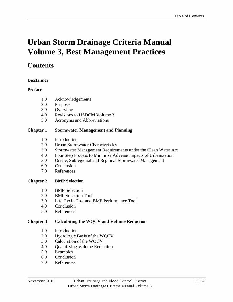
Table of Contents
November 2010 Urban Drainage and Flood Control District TOC-1 Urban Storm Drainage Criteria Manual Volume 3
Urban Storm Drainage Criteria Manual Volume 3, Best Management Practices Contents
Disclaimer
Preface
1.0 Acknowledgements 2.0 Purpose 3.0 Overview 4.0 Revisions to USDCM Volume 3 5.0 Acronyms and Abbreviations
Chapter 1 Stormwater Management and Planning
1.0 Introduction 2.0 Urban Stormwater Characteristics 3.0 Stormwater Management Requirements under the Clean Water Act 4.0 Four Step Process to Minimize Adverse Impacts of Urbanization 5.0 Onsite, Subregional and Regional Stormwater Management 6.0 Conclusion 7.0 References
Chapter 2 BMP Selection
1.0 BMP Selection 2.0 BMP Selection Tool 3.0 Life Cycle Cost and BMP Performance Tool 4.0 Conclusion 5.0 References
Chapter 3 Calculating the WQCV and Volume Reduction
1.0 Introduction 2.0 Hydrologic Basis of the WQCV 3.0 Calculation of the WQCV 4.0 Quantifying Volume Reduction 5.0 Examples 6.0 Conclusion 7.0 References
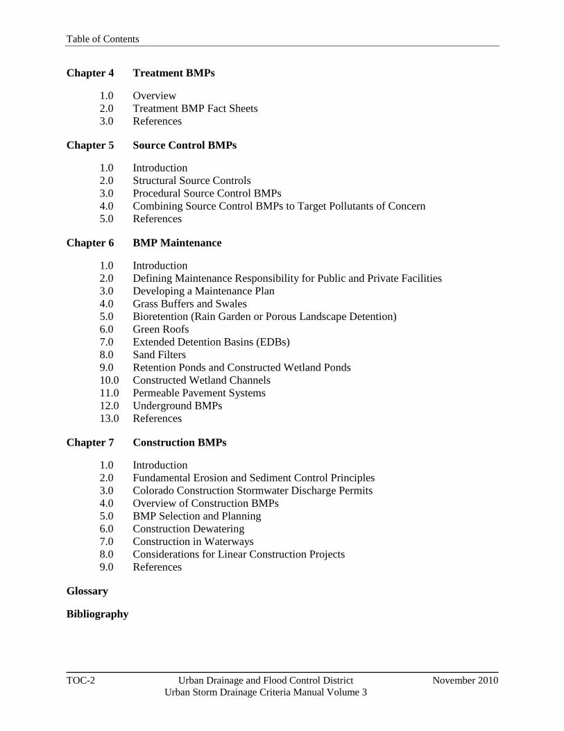
Table of Contents
TOC-2 Urban Drainage and Flood Control District November 2010 Urban Storm Drainage Criteria Manual Volume 3
Chapter 4 Treatment BMPs
1.0 Overview 2.0 Treatment BMP Fact Sheets 3.0 References
Chapter 5 Source Control BMPs
1.0 Introduction 2.0 Structural Source Controls 3.0 Procedural Source Control BMPs 4.0 Combining Source Control BMPs to Target Pollutants of Concern 5.0 References
Chapter 6 BMP Maintenance
1.0 Introduction 2.0 Defining Maintenance Responsibility for Public and Private Facilities 3.0 Developing a Maintenance Plan 4.0 Grass Buffers and Swales 5.0 Bioretention (Rain Garden or Porous Landscape Detention) 6.0 Green Roofs 7.0 Extended Detention Basins (EDBs) 8.0 Sand Filters 9.0 Retention Ponds and Constructed Wetland Ponds 10.0 Constructed Wetland Channels 11.0 Permeable Pavement Systems 12.0 Underground BMPs 13.0 References
Chapter 7 Construction BMPs
1.0 Introduction 2.0 Fundamental Erosion and Sediment Control Principles 3.0 Colorado Construction Stormwater Discharge Permits 4.0 Overview of Construction BMPs 5.0 BMP Selection and Planning 6.0 Construction Dewatering 7.0 Construction in Waterways 8.0 Considerations for Linear Construction Projects 9.0 References
Glossary
Bibliography
November 2010 Urban Drainage and Flood Control District Disclaimer-1
Urban Storm Drainage Criteria Manual Volume 3
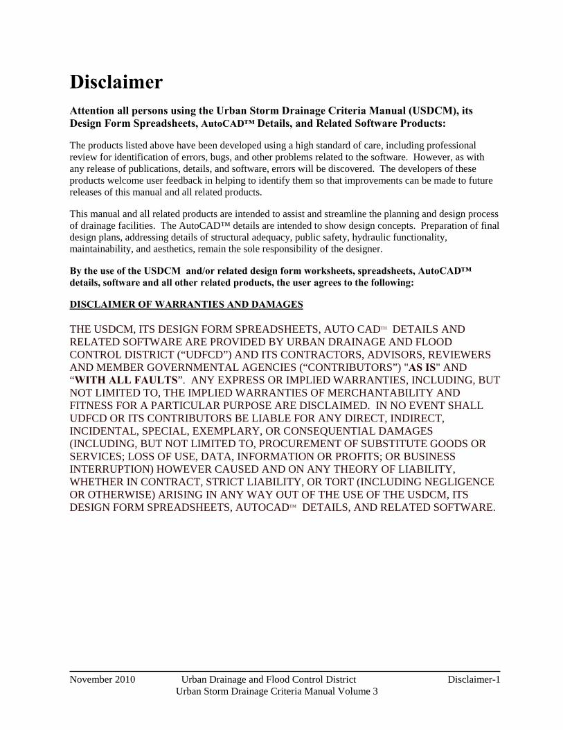
Disclaimer Attention all persons using the Urban Storm Drainage Criteria Manual (USDCM), its Design Form Spreadsheets, AutoCAD™ Details, and Related Software Products:
The products listed above have been developed using a high standard of care, including professional review for identification of errors, bugs, and other problems related to the software. However, as with any release of publications, details, and software, errors will be discovered. The developers of these products welcome user feedback in helping to identify them so that improvements can be made to future releases of this manual and all related products.
This manual and all related products are intended to assist and streamline the planning and design process of drainage facilities. The AutoCAD™ details are intended to show design concepts. Preparation of final design plans, addressing details of structural adequacy, public safety, hydraulic functionality, maintainability, and aesthetics, remain the sole responsibility of the designer.
By the use of the USDCM and/or related design form worksheets, spreadsheets, AutoCAD™ details, software and all other related products, the user agrees to the following:
THE USDCM, ITS DESIGN FORM SPREADSHEETS, AUTO CADTH DETAILS AND RELATED SOFTWARE ARE PROVIDED BY URBAN DRAINAGE AND FLOOD CONTROL DISTRICT (“UDFCD”) AND ITS CONTRACTORS, ADVISORS, REVIEWERS AND MEMBER GOVERNMENTAL AGENCIES (“CONTRIBUTORS”) "AS IS" AND “WITH ALL FAULTS”. ANY EXPRESS OR IMPLIED WARRANTIES, INCLUDING, BUT NOT LIMITED TO, THE IMPLIED WARRANTIES OF MERCHANTABILITY AND FITNESS FOR A PARTICULAR PURPOSE ARE DISCLAIMED. IN NO EVENT SHALL UDFCD OR ITS CONTRIBUTORS BE LIABLE FOR ANY DIRECT, INDIRECT, INCIDENTAL, SPECIAL, EXEMPLARY, OR CONSEQUENTIAL DAMAGES (INCLUDING, BUT NOT LIMITED TO, PROCUREMENT OF SUBSTITUTE GOODS OR SERVICES; LOSS OF USE, DATA, INFORMATION OR PROFITS; OR BUSINESS INTERRUPTION) HOWEVER CAUSED AND ON ANY THEORY OF LIABILITY, WHETHER IN CONTRACT, STRICT LIABILITY, OR TORT (INCLUDING NEGLIGENCE OR OTHERWISE) ARISING IN ANY WAY OUT OF THE USE OF THE USDCM, ITS DESIGN FORM SPREADSHEETS, AUTOCADTM DETAILS, AND RELATED SOFTWARE.
DISCLAIMER OF WARRANTIES AND DAMAGES

August 2011 Urban Drainage and Flood Control District i-i Urban Storm Drainage Criteria Manual Volume 3
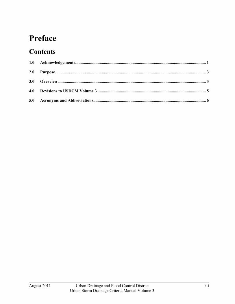
Preface Contents 1.0 Acknowledgements ........................................................................................................................... 1
2.0 Purpose .............................................................................................................................................. 3
3.0 Overview ........................................................................................................................................... 3
4.0 Revisions to USDCM Volume 3 ...................................................................................................... 5
5.0 Acronyms and Abbreviations .......................................................................................................... 6

Preface
i-1 Urban Drainage and Flood Control District August 2011
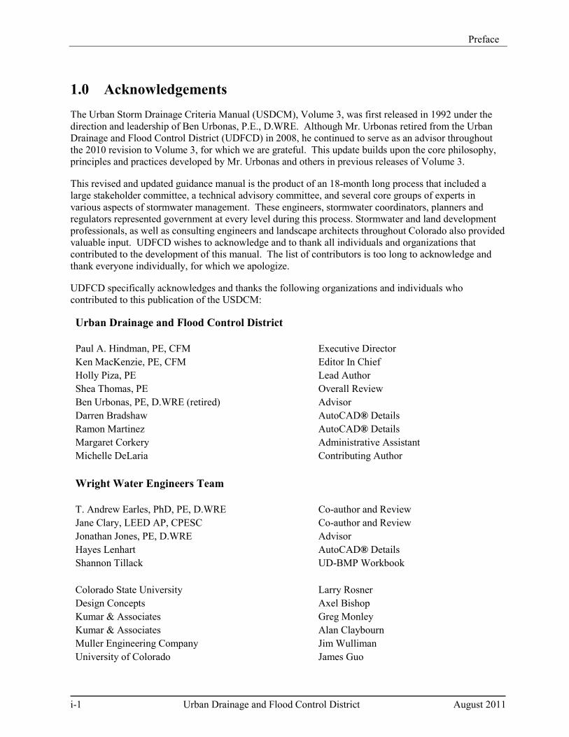
1.0 Acknowledgements The Urban Storm Drainage Criteria Manual (USDCM), Volume 3, was first released in 1992 under the direction and leadership of Ben Urbonas, P.E., D.WRE. Although Mr. Urbonas retired from the Urban Drainage and Flood Control District (UDFCD) in 2008, he continued to serve as an advisor throughout the 2010 revision to Volume 3, for which we are grateful. This update builds upon the core philosophy, principles and practices developed by Mr. Urbonas and others in previous releases of Volume 3.
This revised and updated guidance manual is the product of an 18-month long process that included a large stakeholder committee, a technical advisory committee, and several core groups of experts in various aspects of stormwater management. These engineers, stormwater coordinators, planners and regulators represented government at every level during this process. Stormwater and land development professionals, as well as consulting engineers and landscape architects throughout Colorado also provided valuable input. UDFCD wishes to acknowledge and to thank all individuals and organizations that contributed to the development of this manual. The list of contributors is too long to acknowledge and thank everyone individually, for which we apologize.
UDFCD specifically acknowledges and thanks the following organizations and individuals who contributed to this publication of the USDCM:
Urban Drainage and Flood Control District Paul A. Hindman, PE, CFM Executive Director Ken MacKenzie, PE, CFM Editor In Chief Holly Piza, PE Lead Author Shea Thomas, PE Overall Review Ben Urbonas, PE, D.WRE (retired) Advisor Darren Bradshaw AutoCAD® Details Ramon Martinez AutoCAD® Details Margaret Corkery Administrative Assistant Michelle DeLaria Contributing Author Wright Water Engineers Team T. Andrew Earles, PhD, PE, D.WRE Co-author and Review Jane Clary, LEED AP, CPESC Co-author and Review Jonathan Jones, PE, D.WRE Advisor Hayes Lenhart AutoCAD® Details Shannon Tillack UD-BMP Workbook Colorado State University Larry Rosner Design Concepts Axel Bishop Kumar & Associates Greg Monley Kumar & Associates Alan Claybourn Muller Engineering Company Jim Wulliman University of Colorado James Guo
Preface
August 2011 Urban Drainage and Flood Control District i-2 Urban Storm Drainage Criteria Manual Volume 3
Public Agency Review/Contributors Adams County Environmental Protection Agency, Region 8 Arapahoe County City of Fort Collins City of Arvada City of Golden City of Aurora City of Greenwood Village Boulder County Jefferson County City and County of Broomfield City of Lakewood City of Castle Rock City of Littleton Cherry Creek Basin Water Quality Authority City of Loveland Colorado Department of Public Health and Environment City of Lone Tree Colorado State University City of Northglenn Colorado Stormwater Council Town of Parker City and County of Denver Southeast Metro Stormwater Authority
Denver Botanic Gardens University of Colorado Douglas County City of Westminster Additional Contributors/Reviewers Adam Nelson David Bennetts Mark Fusco Alan Searcy David Smith Matthew Czahor Amy Schneider Debbie Kula Mike Sarmento Ashley Byerley Dennis Welker Nancy Arthur Basil Hamdan Eric Nelson Nathan Moore Ben Mehmen Frank Kemme Nicole Johnson Bernie Cawley Fred Bromberger Pam Acre Bill McCormick George Cotton Peggy Graham Bill Ruzzo Greg Davis Pieter Van Ry Bill Wenk Gregory Weeks Rich Borchardt Billy Grigg Herman Feissner Robert Krehbiel Bob Harberg James McCarthy Saeed Farahmandi Brian Campbell Jay Peters Stacey Thompson Brian Schram Jennifer Bousselot Suzanne Moore
Bryan Kohlenberg Jim Lenhart Tanna Boisvert Chris Carlson Joanna Czarnecka Ted Christianson Cindy Thrush Joe Chaplin Terri Kohls Dan Hartman Joe Kerrigan Terry Baus Danny Elsner John Burke Tom Williams Darin Duran Laddie Fromelius Walt Hime Darren Mollendor Laura Kroeger Ward Mahanke
Preface
i-3 Urban Drainage and Flood Control District August 2011
The Four-Step Process for Stormwater Quality Management
Step 1 Employ Runoff Reduction Practices: To reduce runoff peaks, volumes, and pollutant loads from urbanizing areas, implement Low Impact Development (LID) strategies, including measures to "minimize directly connected impervious areas" (MDCIA). These practices reduce unnecessary impervious areas and route runoff from impervious surfaces over permeable areas to slow runoff (increase time of concentration) and promote onsite storage and infiltration.
Step 2 Implement BMPs that Provide a Water Quality Capture Volume (WQCV) with Slow Release: After runoff has been reduced, the remaining runoff must be treated through capture and slow release of the WQCV. WQCV facilities may provide both water quality and runoff reduction benefits, depending on the BMP selected. This manual provides design guidance for BMPs providing treatment of the WQCV.
Step 3 Stabilize Drainageways: During and following urban development, natural drainageways are often subject to bed and bank erosion due to increases in the frequency, rate, duration, and volume of runoff. Although Steps 1 and 2 help to minimize these effects, some degree of drainageway stabilization is required. Many drainageways within UDFCD boundaries are included in major drainageway or outfall systems plans, identifying recommended channel stabilization measures. If this can be done early, it is far more likely that natural drainageway functions can be maintained with the addition of grade control to accommodate future development. It is also less costly to stabilize a relatively stable drainageway rather than to repair an unraveled channel.
Step 4 Implement Site Specific and Other Source Control BMPs: Frequently, site-specific needs or operations require source control BMPs. This refers to implementation of both structural and procedural BMPs.
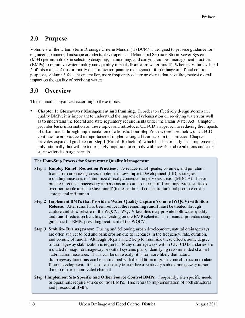
2.0 Purpose Volume 3 of the Urban Storm Drainage Criteria Manual (USDCM) is designed to provide guidance for engineers, planners, landscape architects, developers, and Municipal Separate Storm Sewer System (MS4) permit holders in selecting designing, maintaining, and carrying out best management practices (BMPs) to minimize water quality and quantity impacts from stormwater runoff. Whereas Volumes 1 and 2 of this manual focus primarily on stormwater quantity management for drainage and flood control purposes, Volume 3 focuses on smaller, more frequently occurring events that have the greatest overall impact on the quality of receiving waters.
3.0 Overview This manual is organized according to these topics:
Chapter 1: Stormwater Management and Planning. In order to effectively design stormwater quality BMPs, it is important to understand the impacts of urbanization on receiving waters, as well as to understand the federal and state regulatory requirements under the Clean Water Act. Chapter 1 provides basic information on these topics and introduces UDFCD’s approach to reducing the impacts of urban runoff through implementation of a holistic Four Step Process (see inset below). UDFCD continues to emphasize the importance of implementing all four steps in this process. Chapter 1 provides expanded guidance on Step 1 (Runoff Reduction), which has historically been implemented only minimally, but will be increasingly important to comply with new federal regulations and state stormwater discharge permits.
Preface
August 2011 Urban Drainage and Flood Control District i-4 Urban Storm Drainage Criteria Manual Volume 3
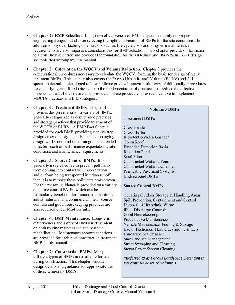
Volume 3 BMPs
Treatment BMPs
Grass Swale Grass Buffer Bioretention/Rain Garden* Green Roof Extended Detention Basin Retention Pond Sand Filter Constructed Wetland Pond Constructed Wetland Channel Permeable Pavement Systems Underground BMPs
Source Control BMPs
Covering Outdoor Storage & Handling Areas Spill Prevention, Containment and Control Disposal of Household Waste Illicit Discharge Controls Good Housekeeping Preventative Maintenance Vehicle Maintenance, Fueling & Storage Use of Pesticides, Herbicides and Fertilizers Landscape Maintenance Snow and Ice Management Street Sweeping and Cleaning Storm Sewer System Cleaning *Referred to as Porous Landscape Detention in Previous Releases of Volume 3
Chapter 2: BMP Selection. Long-term effectiveness of BMPs depends not only on proper engineering design, but also on selecting the right combination of BMPs for the site conditions. In addition to physical factors, other factors such as life cycle costs and long-term maintenance requirements are also important considerations for BMP selection. This chapter provides information to aid in BMP selection and provides the foundation for the UD-BMP and BMP-REALCOST design aid tools that accompany this manual.
Chapter 3: Calculation the WQCV and Volume Reduction. Chapter 3 provides the computational procedures necessary to calculate the WQCV, forming the basis for design of many treatment BMPs. This chapter also covers the Excess Urban Runoff Volume (EURV) and full spectrum detention, developed to best replicate predevelopment peak flows. Additionally, procedures for quantifying runoff reduction due to the implementation of practices that reduce the effective imperviousness of the site are also provided. These procedures provide incentive to implement MDCIA practices and LID strategies.
Chapter 4: Treatment BMPs. Chapter 4 provides design criteria for a variety of BMPs, generally categorized as conveyance practices and storage practices that provide treatment of the WQCV or EURV. A BMP Fact Sheet is provided for each BMP, providing step-by-step design criteria, design details, an accompanying design worksheet, and selection guidance related to factors such as performance expectations, site conditions and maintenance requirements.
Chapter 5: Source Control BMPs. It is generally more effective to prevent pollutants from coming into contact with precipitation and/or from being transported in urban runoff than it is to remove these pollutants downstream. For this reason, guidance is provided on a variety of source control BMPs, which can be particularly beneficial for municipal operations and at industrial and commercial sites. Source controls and good housekeeping practices are also required under MS4 permits.
Chapter 6: BMP Maintenance. Long-term effectiveness and safety of BMPs is dependent on both routine maintenance and periodic rehabilitation. Maintenance recommendations are provided for each post-construction treatment BMP in this manual.
Chapter 7: Construction BMPs. Many different types of BMPs are available for use during construction. This chapter provides design details and guidance for appropriate use of these temporary BMPs.
Preface
i-5 Urban Drainage and Flood Control District August 2011
Glossary: A glossary is included to provide users of Volume 3 with a basic understanding of terms used in this manual.
Bibliography: Many references have been used to develop this Manual. The Bibliography provides a listing of these references for more detailed information on key topics.
4.0 Revisions to USDCM Volume 3 Volume 3 of the USDCM has been updated and expanded several times since it was first published in 1992 as our understanding of urban hydrology and BMP performance expanded, and as the design of various BMPs has been refined. Updates will continue as the needs of communities and regulatory requirements change, and as UDFCD continues to build, use, and monitor BMPs. In 2010, this major revision to Volume 3 was completed, including the following:
Increased emphasis on runoff reduction, which is Step 1 of the Four Step Process. Although UDFCD has previously included runoff reduction as the first step in stormwater management, this step has not been routinely implemented. A significant change to the manual includes quantifying stormwater management facility sizing credits using quantitative methods when MDCIA and LID practices are implemented.
Substantial revision to design criteria for several BMPs already in this manual and inclusion of BMPs not previously in this manual. Green roofs and Underground BMPs were added. Although UDFCD continues to strongly recommend treatment of runoff above ground, we also recognize the need to provide guidance related to underground BMPs when surface treatment is not practicable.
Revision and expansion of the Construction BMPs chapter.
Addition of supplemental guidance to promote more effective implementation of BMPs. This information is typically provided in the form of “call-out” boxes. While this manual remains focused on engineering design criteria, UDFCD also recognizes that it is helpful for designers to be aware of why certain criteria have been developed, how various practices can best be implemented on a site, opportunities to consider, and common problems to avoid.
New Excel® worksheets to assist in BMP selection based on site-specific conditions, BMP design including integration of the EURV for use with full spectrum detention, and BMP performance expectations and life cycle costs.
Preface
August 2011 Urban Drainage and Flood Control District i-6 Urban Storm Drainage Criteria Manual Volume 3
5.0 Acronyms and Abbreviations > Greater Than
< Less Than
ASCE American Society of Civil Engineers
ASTM American Society for Testing and Materials
BOD Biochemical Oxygen Demand
BMPs Best Management Practices
CDPHE Colorado Department of Public Health and Environment
CDPS Colorado Discharge Permit System
cfs Cubic Feet Per Second
COD Chemical Oxygen Demand
CRS Colorado Revised Statutes
CSO Combined Sewer Overflow
CUHP Colorado Urban Hydrograph Procedure
CWC Constructed Wetland Channel
CWCB Colorado Water Conservation Board
CWQCC Colorado Water Quality Control Commission
CWQCD Colorado Water Quality Control Division
DCIA Directly Connected Impervious Areas
DO Dissolved Oxygen
DRCOG Denver Regional Council of Governments
DRURP Denver Regional Urban Runoff Program
EDB Extended Detention Basin
EMC Event Mean Concentration
EPA U.S. Environmental Protection Agency
ET Evapotranspiration
EURV Excess Urban Runoff Volume
Preface
i-7 Urban Drainage and Flood Control District August 2011
fps Feet per second
ft Feet
FHWA Federal Highway Administration
GB Grass Buffer
GS Grass Swale
H:V Horizontal to Vertical Ratio of a Slope
HSG Hydrologic Soil Group
i Impervious Ratio of a Catchment (Ia/100)
Ia Percent Imperviousness of Catchment
LEED Leadership in Energy and Environmental Design
LID Low Impact Development
MCM Minimum Control Measure
mg/L Milligrams per Liter
μg/L Micrograms per Liter
MDCIA Minimize Directly Connected Impervious Areas
MS4 Municipal Separate Storm Sewer System
MSDS Material Safety Data Sheets
MWCOG Metropolitan Washington Council of Governments
N/A Not applicable
NPDES National Pollution Discharge Elimination System
NPV Net Present Value
NRCS Natural Resources Conservation Services
NTIS National Technical Information Service
NTU Nephelometric turbidity units
NURP Nationwide Urban Runoff Program
NVDPC Northern Virginia District Planning Commission
PA Porous Asphalt
Preface
August 2011 Urban Drainage and Flood Control District i-8 Urban Storm Drainage Criteria Manual Volume 3
PC Pervious Concrete
PICP Permeable Interlocking Concrete Pavers
PLD Porous Landscape Detention (term replaced by Bioretention in 2010 update)
PPS Pervious Pavement System
ppm Parts Per Million
RP Retention Pond
RPA Receiving Pervious Area
SCS Soil Conservation Service (now the NRCS)
SEWRPC Southeastern Wisconsin Regional Planning Commission
SF Sand Filter Extended Detention
SPA Separate Pervious Area
SWMM Stormwater Management Model (EPA)
TOC Total Organic Carbon
TMDL Total Maximum Daily Load
TP Total Phosphorus
TSS Total Suspended Solids
UDFCD Urban Drainage and Flood Control District
UIA Unconnected Impervious Area
USCC United States Composting Council
USDCM Urban Storm Drainage Criteria Manual
USGS United States Geological Survey
WERF Water Environment Research Foundation
WQCV Water Quality Capture Volume
August 2011 Urban Drainage and Flood Control District 1-i
Urban Storm Drainage Criteria Manual Volume 3
Chapter 1 Stormwater Management and Planning Contents 1.0 Introduction ...................................................................................................................................... 1
2.0 Urban Stormwater Characteristics ................................................................................................ 1
3.0 Stormwater Management Requirements under the Clean Water Act ........................................ 7 3.1 Clean Water Act Basics............................................................................................................................. 7 3.2 Colorado's Stormwater Permitting Program .............................................................................................. 7
3.2.1 Construction Site Stormwater Runoff Control ............................................................................ 10 3.2.2 Post-construction Stormwater Management ............................................................................... 10 3.2.3 Pollution Prevention/Good Housekeeping .................................................................................. 11
3.3 Total Maximum Daily Loads and Stormwater Management .................................................................. 11
4.0 Four Step Process to Minimize Adverse Impacts of Urbanization ............................................ 13 4.1 Step 1. Employ Runoff Reduction Practices .......................................................................................... 13 4.2 Step 2. Implement BMPs That Provide a Water Quality Capture Volume with Slow Release .............. 17 4.3 Step 3. Stabilize Drainageways .............................................................................................................. 17 4.4 Step 4. Implement Site Specific and Other Source Control BMPs ........................................................ 18
5.0 Onsite, Subregional and Regional Stormwater Management .................................................... 18
6.0 Conclusion ....................................................................................................................................... 19
7.0 References ....................................................................................................................................... 19
Figures Figure 1-1. Physical Effects of Urbanization on Streams and Habitat ........................................................ 2Figure 1-2. The Four Step Process for Stormwater Quality Management ................................................ 13
Tables Table 1-1. Common Urban Runoff Pollutant Sources ................................................................................. 3Table 1-2. Event Mean Concentrations (mg/L) of Constituents in Denver Metropolitan Area Runoff ...... 4


Chapter 1 Stormwater Management and Planning
August 2011 Urban Drainage and Flood Control District 1-1
Urban Storm Drainage Criteria Manual Volume 3
1.0 Introduction The physical and chemical characteristics of stormwater runoff change as urbanization occurs, requiring comprehensive planning and management to reduce adverse effects on receiving waters. As stormwater flows across roads, rooftops, and other hard surfaces, pollutants are picked up and then discharged to streams and lakes. Additionally, the increased frequency, flow rate, duration, and volume of stormwater discharges due to urbanization can result in the scouring of rivers and streams, degrading the physical integrity of aquatic habitats, stream function, and overall water quality (EPA 2009). This chapter provides information fundamental to effective stormwater quality management and planning, including:
An overview of the potential adverse impacts of urban stormwater runoff.
A summary of key regulatory requirements for stormwater management in Colorado. These regulations set the minimum requirements for stormwater quality management. It is essential that those involved with stormwater management understand these requirements that shape stormwater management decisions at the construction and post-construction stages of development and redevelopment.
UDFCD's Four Step Process to reduce the impacts of urban runoff.
Discussion of on-site, sub-regional, and regional stormwater management alternatives at a planning level.
UDFCD highly recommends that engineers and planners begin the development process with a clear understanding of the seriousness of stormwater quality management from regulatory and environmental perspectives, and implement a holistic planning process that incorporates water quality upfront in the overall site development process. Chapters 2 and 3 provide BMP selection tools and detailed calculation procedures based on the concepts introduced in this chapter.
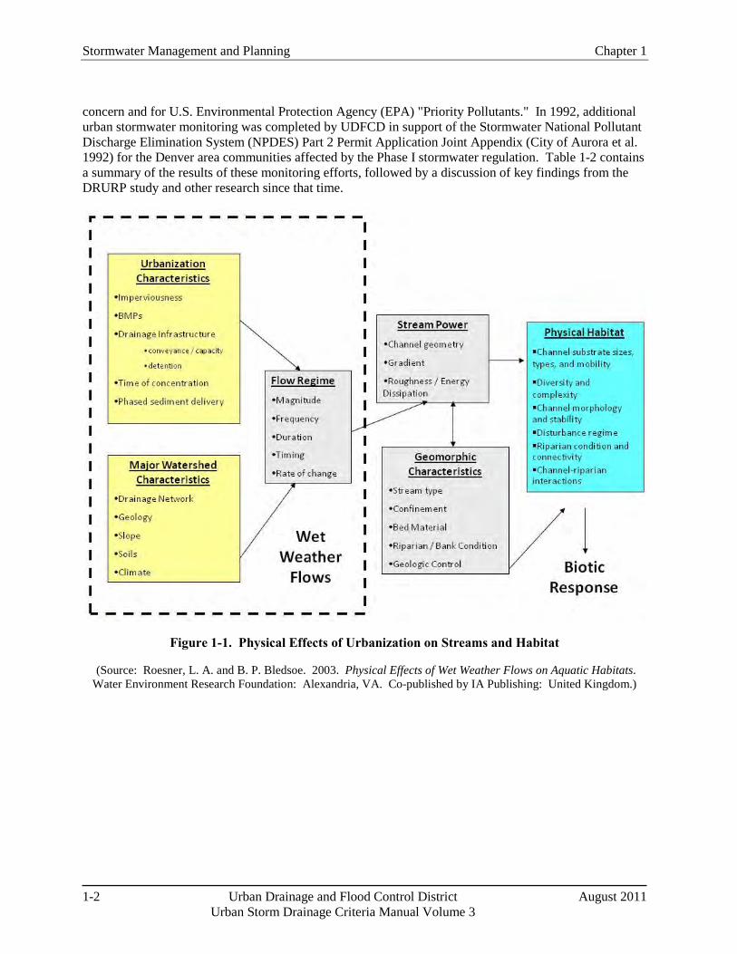
2.0 Urban Stormwater Characteristics Numerous studies conducted since the late 1970s show stormwater runoff from urban and industrial areas can be a significant source of pollution (EPA 1983; Driscoll et al. 1990; Pitt et al. 2008). Stormwater impacts can occur during both the construction and post-construction phases of development. As a result, federal, state, and local regulations have been promulgated to address stormwater quality. Although historical focus of stormwater management was either flooding or chemical water quality, more recently, the hydrologic and hydraulic (physical) changes in watersheds associated with urbanization are recognized as significant contributors to receiving water degradation. Whereas only a few runoff events per year may occur prior to development, many runoff events per year may occur after urbanization (Urbonas et al. 1989). In the absence of controls, runoff peaks and volumes increase due to urbanization. This increased runoff is environmentally harmful, causing erosion in receiving streams and generating greater pollutant loading downstream. Figure 1-1 illustrates the many physical factors associated with stormwater runoff and the responses of receiving waters.
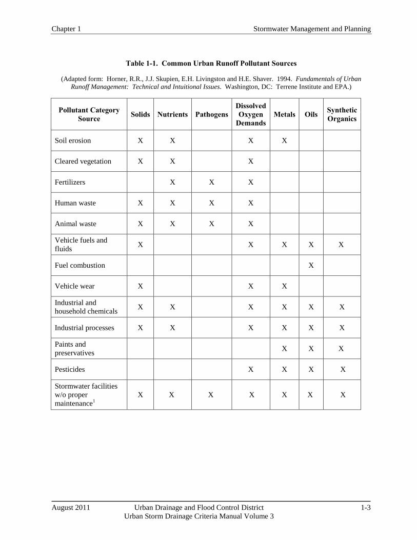
With regard to chemical water quality, Table 1-1 identifies a variety of pollutants and sources often found in urban settings such as solids, nutrients, pathogens, dissolved oxygen demands, metals, and oils. Several national data sources are available characterizing the chemical quality of urban runoff (e.g., EPA 1983; Pitt 2004). For purposes of this manual, Denver metro area data are the primary focus. In 1983, the Denver Regional Urban Runoff Program (DRURP) conducted by the Denver Regional Council of Governments (DRCOG), provided data for nine watersheds with various land uses for 15 constituents of
Stormwater Management and Planning Chapter 1
1-2 Urban Drainage and Flood Control District August 2011 Urban Storm Drainage Criteria Manual Volume 3
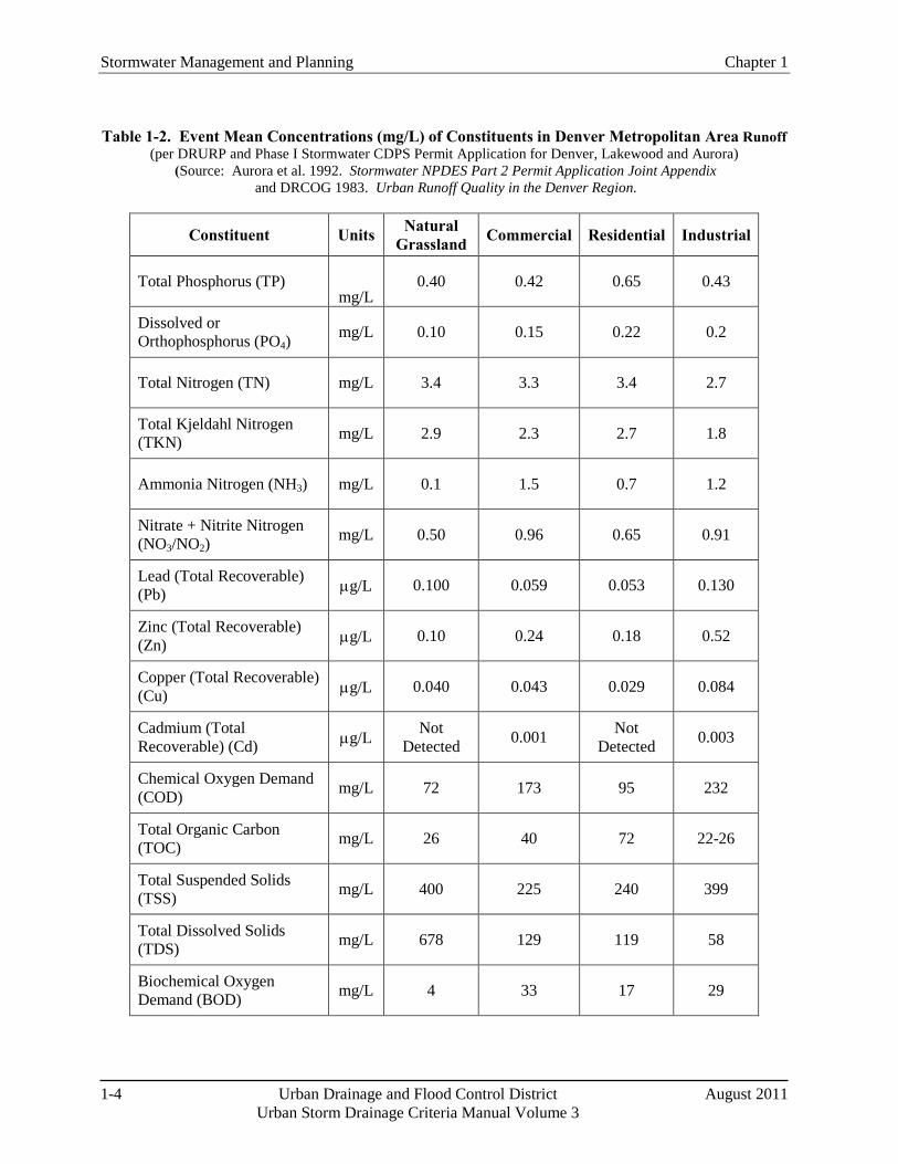
concern and for U.S. Environmental Protection Agency (EPA) "Priority Pollutants." In 1992, additional urban stormwater monitoring was completed by UDFCD in support of the Stormwater National Pollutant Discharge Elimination System (NPDES) Part 2 Permit Application Joint Appendix (City of Aurora et al. 1992) for the Denver area communities affected by the Phase I stormwater regulation. Table 1-2 contains a summary of the results of these monitoring efforts, followed by a discussion of key findings from the DRURP study and other research since that time.
Figure 1-1. Physical Effects of Urbanization on Streams and Habitat
(Source: Roesner, L. A. and B. P. Bledsoe. 2003. Physical Effects of Wet Weather Flows on Aquatic Habitats. Water Environment Research Foundation: Alexandria, VA. Co-published by IA Publishing: United Kingdom.)
Chapter 1 Stormwater Management and Planning
August 2011 Urban Drainage and Flood Control District 1-3 Urban Storm Drainage Criteria Manual Volume 3
Table 1-1. Common Urban Runoff Pollutant Sources
(Adapted form: Horner, R.R., J.J. Skupien, E.H. Livingston and H.E. Shaver. 1994. Fundamentals of Urban Runoff Management: Technical and Intuitional Issues. Washington, DC: Terrene Institute and EPA.)
Pollutant Category Source Solids Nutrients Pathogens
Dissolved Oxygen
Demands Metals Oils Synthetic
Organics
Soil erosion X X X X
Cleared vegetation X X X
Fertilizers X X X
Human waste X X X X
Animal waste X X X X
Vehicle fuels and fluids X X X X X
Fuel combustion X
Vehicle wear X X X
Industrial and household chemicals X X X X X X
Industrial processes X X X X X X
Paints and preservatives X X X
Pesticides X X X X
Stormwater facilities w/o proper maintenance1
X X X X X X X
Stormwater Management and Planning Chapter 1
1-4 Urban Drainage and Flood Control District August 2011 Urban Storm Drainage Criteria Manual Volume 3
Table 1-2. Event Mean Concentrations (mg/L) of Constituents in Denver Metropolitan Area Runoff (per DRURP and Phase I Stormwater CDPS Permit Application for Denver, Lakewood and Aurora)
(Source: Aurora et al. 1992. Stormwater NPDES Part 2 Permit Application Joint Appendix and DRCOG 1983. Urban Runoff Quality in the Denver Region.
Constituent Units Natural Grassland Commercial Residential Industrial
Total Phosphorus (TP) mg/L
0.40 0.42 0.65 0.43
Dissolved or Orthophosphorus (PO4)
mg/L 0.10 0.15 0.22 0.2
Total Nitrogen (TN) mg/L 3.4 3.3 3.4 2.7
Total Kjeldahl Nitrogen (TKN) mg/L 2.9 2.3 2.7 1.8
Ammonia Nitrogen (NH3) mg/L 0.1 1.5 0.7 1.2
Nitrate + Nitrite Nitrogen (NO3/NO2)
mg/L 0.50 0.96 0.65 0.91
Lead (Total Recoverable) (Pb) µg/L 0.100 0.059 0.053 0.130
Zinc (Total Recoverable) (Zn) µg/L 0.10 0.24 0.18 0.52
Copper (Total Recoverable) (Cu) µg/L 0.040 0.043 0.029 0.084
Cadmium (Total Recoverable) (Cd) µg/L Not
Detected 0.001 Not Detected 0.003
Chemical Oxygen Demand (COD) mg/L 72 173 95 232
Total Organic Carbon (TOC) mg/L 26 40 72 22-26
Total Suspended Solids (TSS) mg/L 400 225 240 399
Total Dissolved Solids (TDS) mg/L 678 129 119 58
Biochemical Oxygen Demand (BOD) mg/L 4 33 17 29
Chapter 1 Stormwater Management and Planning
August 2011 Urban Drainage and Flood Control District 1-5 Urban Storm Drainage Criteria Manual Volume 3
Selected findings of DRURP include:
Urban runoff was identified as a significant source of stormwater pollutants including sediment, fecal indicator bacteria, nutrients, organic matter, and heavy metals (e.g., lead, zinc, cadmium). Sediment loading occurred regardless of the existence of major land disturbances causing erosion. In addition, nutrients from urban runoff were identified as a concern for lakes and reservoirs.
Very few EPA Priority Pollutants were detected in runoff samples. Organic pollutants found were particularly sparse; the most commonly occurring was a pesticide. The most significant non-priority pollutant found was 2,4-D, which is an herbicide.
Pollutant loading was not closely related to basin imperviousness or land use. Vague relationships between event mean concentrations and imperviousness were noted, but proved statistically insignificant. Concentrations of pollutants did not vary in a predictable or anticipated pattern.
Non-storm urban runoff (e.g., dry weather discharges such as irrigation runoff) was also identified as a source of pollutants. This was not expected and was determined indirectly in the study analysis.
In addition to these pollutants, Urbonas and Doerfer (2003) have reported that atmospheric fallout is a significant contributor to urban runoff pollution in the Denver area. Snow and ice management activities also affect the quality of urban runoff since snow and ice may be contaminated by hydrocarbons, pet waste, deicing chemicals and sand.
Although Table 1-2 indicates that constituent concentrations in urban runoff in the metro Denver area are not necessarily greater than that for natural grasslands (background) for some constituents (e.g., TSS, TDS, TKN), it is important to recognize that the table does not provide data on pollutant loads, which are the product of runoff volume and pollutant concentrations. Runoff volume from urbanized areas is much greater than that from a natural grassland; therefore, resultant differences in pollutant loads are generally greater than the difference in concentrations.
Stormwater runoff issues can be discussed in general terms for both streams and lakes; however, there are some unique effects with regard to lakes. Some of these include:
Lakes respond to cumulative pollutant loading over time in terms of days, weeks, and longer time frames, unlike streams, which typically show effects within hours or days.
Floating trash and shore damage are notable visible impacts of stormwater on lakes.
Nutrient enrichment from stormwater runoff can have a significant water quality impact on lakes. This can result in the undesirable growth of algae and aquatic plants, increasing BOD and depleting dissolved oxygen.
Lakes do not flush contaminants as quickly as streams and act as sinks for nutrients, metals, and sediments. This means that lakes take longer to recover once contaminated.
With regard to construction-phase stormwater runoff, EPA reports sediment runoff rates from construction sites can be much greater than those from agricultural lands and forestlands, contributing large quantities of sediment over a short period of time, causing physical and biological harm to receiving waters (EPA 2005). Fortunately, a variety of construction-phase and post-construction BMPs are available to help minimize the impacts of urbanization. Proper selection, design, construction and maintenance of these practices are the focus of the remainder of this manual.
Stormwater Management and Planning Chapter 1
1-6 Urban Drainage and Flood Control District August 2011 Urban Storm Drainage Criteria Manual Volume 3
Additional Resources Regarding Urban Stormwater Issues and Management
American Society of Civil Engineers and Water Environment Federation. 1992. Design and Construction of Urban Stormwater Management Systems. ASCE Manual and Reports of Engineering Practice No. 77 and WEF Manual of Practice FD-20. Alexandria, VA: WEF.
Burton and Pitt. 2001. Stormwater Effects Handbook: A Toolbox for Watershed Managers, Scientists, and Engineers. Lewis Publishers. http://www.epa.gov/ednnrmrl/publications/books/handbook/index.htm
Center for Watershed Protection Website: http://www.cwp.org
Debo, T. and A. Reese. 2002. Municipal Stormwater Management. 2nd Edition. Boca Raton, FL: Lewis Publishers.
EPA Stormwater Program Website: http://cfpub.epa.gov/npdes/home.cfm?program_id=6
International Stormwater Best Management Practices Database: www.bmpdatabase.org
Low Impact Development (LID) Center Website: http://www.lid-stormwater.net/
National Research Council. 2008. Urban Stormwater Management in the United States. National Academies Press. http://www.epa.gov/npdes/pubs/nrc_stormwaterreport.pdf
Oregon State University et al. 2006. Evaluation of Best Management Practices for Highway Runoff Control. Transportation Research Board. NCHRP-565. http://www.trb.org/news/blurb_detail.asp?id=7184
Pitt, R., Maestre, A., and R. Morquecho. 2004. The National Stormwater Quality Database (NSQD). Version 1.1. http://unix.eng.ua.edu/~rpitt/Research/ms4/Paper/Mainms4paper.html
Shaver et al. 2007. Fundamentals of Urban Runoff Management: Technical and Institutional Issues, Second Edition. EPA and North American Lake Management Society. http://www.nalms.org/Resources/PDF/Fundamentals/Fundamentals_full_manual.pdf
Water Environment Federation and American Society of Civil Engineers. 1998. Urban Runoff Quality Management. WEF Manual of Practice No. 23 and ASCE Manual and Report on Engineering Practice No. 87. Alexandria, VA: Water Environment Federation.
Watershed Management Institute. 1997. Operation, Maintenance and Management of Stormwater Management Systems. Ingleside, MD: Watershed Management Institute.
Chapter 1 Stormwater Management and Planning
August 2011 Urban Drainage and Flood Control District 1-7 Urban Storm Drainage Criteria Manual Volume 3
3.0 Stormwater Management Requirements under the Clean Water Act
3.1 Clean Water Act Basics
The Federal Water Pollution Control Act of 1972, as amended (33 U.S.C. 1251 et seq.) is commonly known as the Clean Water Act and establishes minimum stormwater management requirements for urbanized areas in the United States. At the federal level, the EPA is responsible for administering and enforcing the requirements of the Clean Water Act. Section 402(p) of the Clean Water Act requires urban and industrial stormwater be controlled through the NPDES permit program. Requirements affect both construction and post-construction phases of development. As a result, urban areas must meet requirements of Municipal Separate Storm Sewer System (MS4) permits, and many industries and institutions such as state departments of transportation must also meet NPDES stormwater permit requirements. MS4 permittees are required to develop a Stormwater Management Program that includes measurable goals and to implement needed stormwater management controls (i.e., BMPs). MS4 permittees are also required to assess controls and the effectiveness of their stormwater programs and to reduce the discharge of pollutants to the "maximum extent practicable." Although it is not the case for every state, the EPA has delegated Clean Water Act authority to the State of Colorado. The State must meet the minimum requirements of the federal program.
3.2 Colorado's Stormwater Permitting Program
The Colorado Water Quality Control Act (25-8-101 et seq., CRS 1973, as amended) established the Colorado Water Quality Control Commission (CWQCC) within the Colorado Department of Public Health and Environment (CDPHE) to develop water quality regulations and standards, classifications of state waters for designated uses, and water quality control regulations. The Act also established the Colorado Water Quality Control Division (CWQCD) to administer and enforce the Act and administer the discharge permit system, among other responsibilities. Violations of the Act are subject to significant monetary penalties, as well as criminal prosecution in some cases.
Colorado's stormwater management regulations have been implemented in two phases and are included in Regulation No. 61 Colorado Discharge Permit System (CDPS) Regulations (CWQCC 2009). After the 1990 EPA "Phase I" stormwater regulation became effective, Colorado was required to develop a stormwater program that covered specific types of industries and storm sewer systems for municipalities with populations of more than 100,000. Phase I affected Denver, Aurora, Lakewood, Colorado Springs, and the Colorado Department of Transportation (CDOT). Phase 1 requirements included inventory of stormwater outfalls, monitoring and development of municipal stormwater management requirements, as well as other requirements. Construction activities disturbing five or more acres of land were required to obtain construction stormwater discharge permits.
Phase II of Colorado's stormwater program was finalized in March 2001, establishing additional stormwater permitting requirements. Two major changes included regulation of small municipalities (≥ 10,000 and <100,000 population) in urbanized areas and requiring construction permits for sites disturbing one acre or more. The Phase II regulation resulted in a large number of new permit holders including MS4 permits for almost all of the metro Denver area communities. MS4 permit holders are required to develop, implement, and enforce a CDPS Stormwater Management Program designed to reduce the discharge of pollutants from the MS4 to the maximum extent practicable, to protect water quality, and to satisfy the appropriate water quality requirements of the Colorado Water Quality Control Act (25-8-101 et seq., C.R.S.) and the Colorado Discharge Permit Regulations (Regulation 61).

Stormwater Management and Planning Chapter 1
1-8 Urban Drainage and Flood Control District August 2011 Urban Storm Drainage Criteria Manual Volume 3
Resources for More Information on Colorado's Stormwater Regulations
CDPHE Stormwater Permitting Website: http://www.cdphe.state.co.us/wq/permitsunit/ CDPHE Regulation No. 61 Colorado Discharge Permit System Regulations: http://www.cdphe.state.co.us/regulations/wqccregs/100261dischargepermitsystem.pdf Colorado's Stormwater Program Fact Sheet: http://www.cdphe.state.co.us/wq/PermitsUnit/POLICYGUIDANCEFACTSHEETS/factsheets/SWFactsheet.pdf
The CWQCD administers and enforces the requirements of the CDPS stormwater program, generally including these general permit categories:
Municipal: CDPS General Permit for Stormwater Discharges Associated with Municipal Separate Storm Sewer Systems (MS4s) (Permit No. COR-090000). The CWQCD has issued three municipal general permits:
1. A permit for MS4s within the Cherry Creek Reservoir Basin,
2. A permit for other MS4s statewide, and
3. A permit specifically for non-standard MS4s. (Non-standard MS4s are publicly owned systems for facilities that are similar to a municipality, such as military bases and large education, hospital or prison complexes.)
Construction: CDPS General Permit for Stormwater Discharges Associated with Construction Activity (Permit No. COR-030000).
Industrial: CDPS General Permits are available for light industry, heavy industry, metal mining, sand and gravel, coal mining and the recycling industries.
The Phase II municipal MS4 permits require implementation of six minimum control measures (MCM):
1. Public education and outreach on stormwater impacts
2. Public involvement/participation
3. Illicit connections and discharge detection and elimination
4. Construction site stormwater management
5. Post-construction stormwater management in new development and redevelopment
6. Pollution prevention/good housekeeping for municipal operations
This manual provides guidance to address some of the requirements for measures 4, 5, and 6.
Chapter 1 Stormwater Management and Planning
August 2011 Urban Drainage and Flood Control District 1-9 Urban Storm Drainage Criteria Manual Volume 3
Common Stormwater Management Terms
Best Management Practice (BMP): A device, practice, or method for removing, reducing, retarding, or preventing targeted stormwater runoff constituents, pollutants, and contaminants from reaching receiving waters. (Some entities use the terms "Stormwater Control Measure," "Stormwater Control," or "Management Practice.")
Low Impact Development (LID): LID is a comprehensive land planning and engineering design approach to managing stormwater runoff with the goal of mimicking the pre-development hydrologic regime. LID emphasizes conservation of natural features and use of engineered, on-site, small-scale hydrologic controls that infiltrate, filter, store, evaporate, and detain runoff close to its source. The terms Green Infrastructure and Better Site Design are sometimes used interchangeably with LID.
LID Practice: LID practices are the individual techniques implemented as part of overall LID development or integrated into traditional development, including practices such as bioretention, green roofs, permeable pavements and other infiltration-oriented practices.
Minimizing Directly Connected Impervious Area (MDCIA): MDCIA includes a variety of runoff reduction strategies based on reducing impervious areas and routing runoff from impervious surfaces over grassy areas to slow runoff and promote infiltration. The concept of MDCIA has been recommended by UDFCD as a key technique for reducing runoff peaks and volumes following urbanization. MDCIA is a key component of LID.
Maximum Extent Practicable (MEP): MS4 permit holders are required to implement stormwater programs to reduce pollutant loading to the maximum extent practicable. This narrative standard does not currently include numeric effluent limits.
Municipal Separate Storm Sewer System (MS4): A conveyance or system of conveyances (including roads with drainage systems, municipal streets, catch basins, curbs, gutters, ditches, man-made channels, or storm drains) owned or operated by an MS4 permittee and designed or used for collecting or conveying stormwater.
Nonpoint Source: Any source of pollution that is not considered a "point source.” This includes anthropogenic and natural background sources.
Point Source: Any discernible, confined and discrete conveyance from which pollutants are or may be discharged. Representative sources of pollution subject to regulation under the NPDES program include wastewater treatment facilities, most municipal stormwater discharges, industrial dischargers, and concentrated animal feeding operations. This term does not include agricultural stormwater discharges and return flows from irrigated agriculture.
Water Quality Capture Volume (WQCV): This volume represents runoff from frequent storm events such as the 80th percentile storm. The volume varies depending on local rainfall data. Within the UDFCD boundary, the WQCV is based on runoff from 0.6 inches of precipitation.
Excess Urban Runoff Volume (EURV): EURV represents the difference between the developed and pre-developed runoff volume for the range of storms that produce runoff from pervious land surfaces (generally greater than the 2-year event). The EURV is relatively constant for a given imperviousness over a wide range of storm events.
Full Spectrum Detention: This practice utilizes capture and slow release of the EURV. UDFCD found this method to better replicate historic peak discharges for the full range of storm events compared to multi-stage detention practices.
Stormwater Management and Planning Chapter 1
1-10 Urban Drainage and Flood Control District August 2011 Urban Storm Drainage Criteria Manual Volume 3
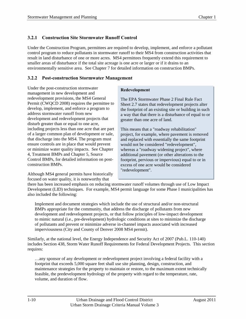
Redevelopment
The EPA Stormwater Phase 2 Final Rule Fact Sheet 2.7 states that redevelopment projects alter the footprint of an existing site or building in such a way that that there is a disturbance of equal to or greater than one acre of land.
This means that a "roadway rehabilitation" project, for example, where pavement is removed and replaced with essentially the same footprint would not be considered "redevelopment", whereas a "roadway widening project", where additional pavement (or other alterations to the footprint, pervious or impervious) equal to or in excess of one acre would be considered "redevelopment".
3.2.1 Construction Site Stormwater Runoff Control
Under the Construction Program, permittees are required to develop, implement, and enforce a pollutant control program to reduce pollutants in stormwater runoff to their MS4 from construction activities that result in land disturbance of one or more acres. MS4 permittees frequently extend this requirement to smaller areas of disturbance if the total site acreage is one acre or larger or if it drains to an environmentally sensitive area. See Chapter 7 for detailed information on construction BMPs.
3.2.2 Post-construction Stormwater Management
Under the post-construction stormwater management in new development and redevelopment provisions, the MS4 General Permit (CWQCD 2008) requires the permittee to develop, implement, and enforce a program to address stormwater runoff from new development and redevelopment projects that disturb greater than or equal to one acre, including projects less than one acre that are part of a larger common plan of development or sale, that discharge into the MS4. The program must ensure controls are in place that would prevent or minimize water quality impacts. See Chapter 4, Treatment BMPs and Chapter 5, Source Control BMPs, for detailed information on post-construction BMPs.
Although MS4 general permits have historically focused on water quality, it is noteworthy that there has been increased emphasis on reducing stormwater runoff volumes through use of Low Impact Development (LID) techniques. For example, MS4 permit language for some Phase I municipalities has also included the following:
Implement and document strategies which include the use of structural and/or non-structural BMPs appropriate for the community, that address the discharge of pollutants from new development and redevelopment projects, or that follow principles of low-impact development to mimic natural (i.e., pre-development) hydrologic conditions at sites to minimize the discharge of pollutants and prevent or minimize adverse in-channel impacts associated with increased imperviousness (City and County of Denver 2008 MS4 permit).
Similarly, at the national level, the Energy Independence and Security Act of 2007 (Pub.L. 110-140) includes Section 438, Storm Water Runoff Requirements for Federal Development Projects. This section requires:
…any sponsor of any development or redevelopment project involving a federal facility with a footprint that exceeds 5,000 square feet shall use site planning, design, construction, and maintenance strategies for the property to maintain or restore, to the maximum extent technically feasible, the predevelopment hydrology of the property with regard to the temperature, rate, volume, and duration of flow.
Chapter 1 Stormwater Management and Planning
August 2011 Urban Drainage and Flood Control District 1-11 Urban Storm Drainage Criteria Manual Volume 3
Finally, in October 2009, EPA issued a notice in the Federal Register (Federal Register Vol. 74, No. 209, 56191-56193) expressing its intent to implement new comprehensive stormwater regulations for new developments and redevelopments by 2012. EPA intends to propose requirements, including design or performance standards, for stormwater discharges from, at a minimum, newly developed and redeveloped sites. In the notice, EPA cites the National Research Council (2008) recommendations that "EPA address stormwater discharges from impervious land cover and promote practices that harvest, infiltrate and evapotranspirate stormwater to reduce or prevent it from being discharged, which is critical to reducing the volume and pollutant loading to our nation's waters."
Although it is important to be aware of increased regulatory emphasis on volume control, it is also noteworthy that UDFCD guidance has recommended volume reduction as the first step in urban stormwater quality management since the initial release of the USDCM Volume 3, in 1992. Chapter 2 of this manual provides the designer with additional tools to encourage site designs that better incorporate volume reduction, based on site-specific conditions.
3.2.3 Pollution Prevention/Good Housekeeping
Under the Pollution Prevention/Good Housekeeping requirements, permittees are required to develop and implement an operation and maintenance/training program with the ultimate goal of preventing or reducing pollutant runoff from municipal operations. Chapter 5 provides information on source controls and non-structural BMPs that can be used in support of some of these requirements. Stormwater managers must also be aware that non-stormwater discharges to MS4s are not allowed, with the exception of certain conditions specified in the MS4 permit.
3.3 Total Maximum Daily Loads and Stormwater Management
Section 303(d) of the Clean Water Act requires states to develop a list of water bodies that are not attaining water quality standards for their designated uses, and to identify relative priorities for addressing the impaired water bodies. States must then develop Total Maximum Daily Loads (TMDLs) to assign allowable pollutant loads to various sources to enable the water body to meet the designated uses established for that water body. (For more information about the TMDL program, see http://www.epa.gov/owow/tmdl.) Implementation plans to achieve the loads specified under TMDLs commonly rely on BMPs to reduce pollutant loads associated with stormwater sources.
In the context of this manual, it is important for designers, planners and other stormwater professionals to understand TMDLs because TMDL provisions can directly affect stormwater permit requirements and BMP selection and design. EPA provides this basic description of TMDLs:
A TMDL is a calculation of the maximum amount of a pollutant that a waterbody can receive and still meet water quality standards, and an allocation of that load among the various sources of that pollutant. Pollutant sources are characterized as either regulated stormwater, sometimes called "point sources" that receive a waste load allocation (WLA), or nonpoint sources that receive a load allocation (LA). Point sources include all sources subject to regulation under the NPDES program (e.g., wastewater treatment facilities, most municipal stormwater discharges and concentrated animal feeding operations). Nonpoint sources include all remaining sources of the pollutant, as well as anthropogenic and natural background sources. TMDLs must also account for seasonal variations in water quality, and include a margin of safety (MOS) to account for uncertainty in predicting how well pollutant reductions will result in meeting water quality standards.
Stormwater Management and Planning Chapter 1
1-12 Urban Drainage and Flood Control District August 2011 Urban Storm Drainage Criteria Manual Volume 3
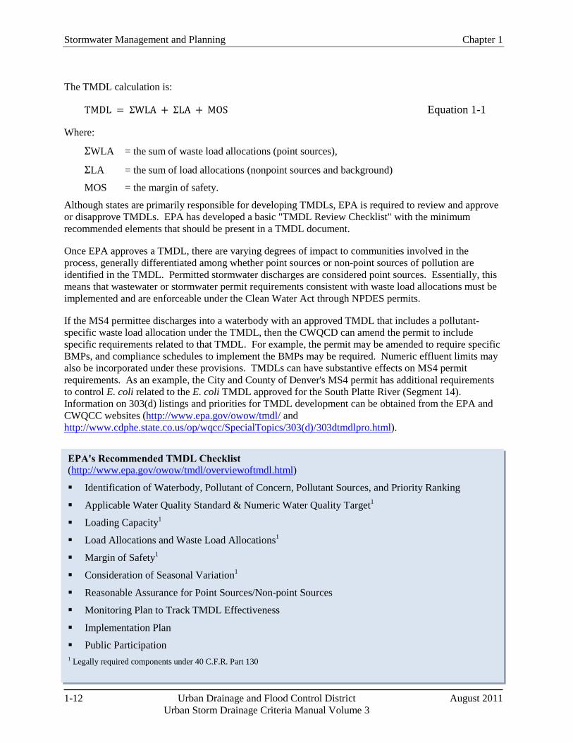
EPA's Recommended TMDL Checklist (http://www.epa.gov/owow/tmdl/overviewoftmdl.html)
Identification of Waterbody, Pollutant of Concern, Pollutant Sources, and Priority Ranking
Applicable Water Quality Standard & Numeric Water Quality Target1
Loading Capacity1
Load Allocations and Waste Load Allocations1
Margin of Safety1
Consideration of Seasonal Variation1
Reasonable Assurance for Point Sources/Non-point Sources
Monitoring Plan to Track TMDL Effectiveness
Implementation Plan
Public Participation 1 Legally required components under 40 C.F.R. Part 130
The TMDL calculation is:
TMDL = ΣWLA + ΣLA + MOS Equation 1-1
Where:
ΣWLA = the sum of waste load allocations (point sources),
ΣLA = the sum of load allocations (nonpoint sources and background)
MOS = the margin of safety.
Although states are primarily responsible for developing TMDLs, EPA is required to review and approve or disapprove TMDLs. EPA has developed a basic "TMDL Review Checklist" with the minimum recommended elements that should be present in a TMDL document.
Once EPA approves a TMDL, there are varying degrees of impact to communities involved in the process, generally differentiated among whether point sources or non-point sources of pollution are identified in the TMDL. Permitted stormwater discharges are considered point sources. Essentially, this means that wastewater or stormwater permit requirements consistent with waste load allocations must be implemented and are enforceable under the Clean Water Act through NPDES permits.
If the MS4 permittee discharges into a waterbody with an approved TMDL that includes a pollutant-specific waste load allocation under the TMDL, then the CWQCD can amend the permit to include specific requirements related to that TMDL. For example, the permit may be amended to require specific BMPs, and compliance schedules to implement the BMPs may be required. Numeric effluent limits may also be incorporated under these provisions. TMDLs can have substantive effects on MS4 permit requirements. As an example, the City and County of Denver's MS4 permit has additional requirements to control E. coli related to the E. coli TMDL approved for the South Platte River (Segment 14). Information on 303(d) listings and priorities for TMDL development can be obtained from the EPA and CWQCC websites (http://www.epa.gov/owow/tmdl/ and http://www.cdphe.state.co.us/op/wqcc/SpecialTopics/303(d)/303dtmdlpro.html).
Chapter 1 Stormwater Management and Planning
August 2011 Urban Drainage and Flood Control District 1-13 Urban Storm Drainage Criteria Manual Volume 3
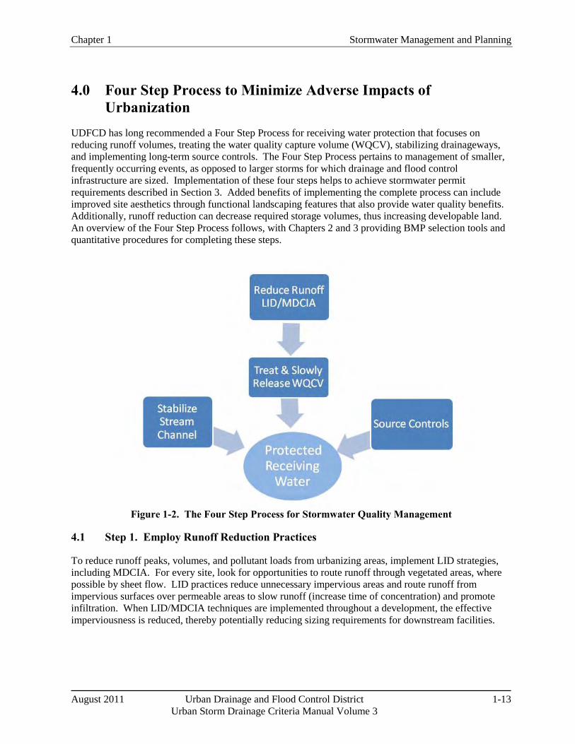
4.0 Four Step Process to Minimize Adverse Impacts of Urbanization
UDFCD has long recommended a Four Step Process for receiving water protection that focuses on reducing runoff volumes, treating the water quality capture volume (WQCV), stabilizing drainageways, and implementing long-term source controls. The Four Step Process pertains to management of smaller, frequently occurring events, as opposed to larger storms for which drainage and flood control infrastructure are sized. Implementation of these four steps helps to achieve stormwater permit requirements described in Section 3. Added benefits of implementing the complete process can include improved site aesthetics through functional landscaping features that also provide water quality benefits. Additionally, runoff reduction can decrease required storage volumes, thus increasing developable land. An overview of the Four Step Process follows, with Chapters 2 and 3 providing BMP selection tools and quantitative procedures for completing these steps.
Figure 1-2. The Four Step Process for Stormwater Quality Management
4.1 Step 1. Employ Runoff Reduction Practices
To reduce runoff peaks, volumes, and pollutant loads from urbanizing areas, implement LID strategies, including MDCIA. For every site, look for opportunities to route runoff through vegetated areas, where possible by sheet flow. LID practices reduce unnecessary impervious areas and route runoff from impervious surfaces over permeable areas to slow runoff (increase time of concentration) and promote infiltration. When LID/MDCIA techniques are implemented throughout a development, the effective imperviousness is reduced, thereby potentially reducing sizing requirements for downstream facilities.
Stormwater Management and Planning Chapter 1
1-14 Urban Drainage and Flood Control District August 2011 Urban Storm Drainage Criteria Manual Volume 3
Differences between LID and Conventional Stormwater Quality Management
Low Impact Development (LID) is a comprehensive land planning and engineering design approach to managing stormwater runoff with a goal of replicating the pre-development hydrologic regime of urban and developing watersheds. Given the increased regulatory emphasis on LID, volume reduction and mimicking pre-development hydrology, questions may arise related to the differences between conventional stormwater management and LID. For example, Volume 3 has always emphasized MDCIA as the first step in stormwater quality planning and has provided guidance on LID techniques such as grass swales, grass buffers, permeable pavement systems, bioretention, and pollution prevention (pollutant source controls). Although these practices are all key components of LID, LID is not limited to a set of practices targeted at promoting infiltration. Key components of LID, in addition to individual BMPs, include practices such as:
An overall site planning approach that promotes conservation design at both the watershed and site levels. This approach to development seeks to "fit" a proposed development to the site, integrating the development with natural features and protecting the site's natural resources. This includes practices such as preservation of natural areas including open space, wetlands, soils with high infiltration potential, and stream buffers. Minimizing unnecessary site disturbances (e.g., grading, compaction) is also emphasized.
A site design philosophy that emphasizes multiple controls distributed throughout a development, as opposed to a central treatment facility.
The use of swales and open vegetated conveyances, as opposed to curb and gutter systems.
Volume reduction as a key hydrologic objective, as opposed to peak flow reduction being the primary hydrologic objective. Volume reduction is emphasized not only to reduce pollutant loading and peak flows, but also to move toward hydrologic regimes with flow durations and frequencies closer to the natural hydrologic regime.
Even with LID practices in place, most sites will also require centralized flood control facilities. In some cases, site constraints may limit the extent to which LID techniques can be implemented, whereas in other cases, developers and engineers may have significant opportunities to integrate LID techniques that may be overlooked due to the routine nature and familiarity of conventional approaches. This manual provides design criteria and guidance for both LID and conventional stormwater quality management, and provides additional facility sizing credits for implementing Step 1, Volume Reduction, in a more robust manner.
Key LID techniques include:
Conserve Existing Amenities: During the planning phase of development, identify portions of the site that add value and should be protected or improved. Such areas may include mature trees, stream corridors, wetlands, and Type A/B soils with higher infiltration rates. In order for this step to provide meaningful benefits over the long-term, natural areas must be protected from compaction during the construction phase. Consider temporary construction fence for this purpose. In areas where disturbance cannot practically be avoided, rototilling and soil amendments should be integrated to restore the infiltration capacity of areas that will be restored with vegetation.
Minimize Impacts: Consider how the site lends itself to the desired development. In some cases, creative site layout can reduce the extent of paved areas, thereby saving on initial capital cost of pavement and then saving on pavement maintenance, repair, and replacement over time. Minimize

Chapter 1 Stormwater Management and Planning
August 2011 Urban Drainage and Flood Control District 1-15 Urban Storm Drainage Criteria Manual Volume 3
imperviousness, including constructing streets, driveways, sidewalks and parking lot aisles to the minimum widths necessary, while still providing for parking, snow management, public safety and fire access. When soils vary over the site, concentrate new impervious areas over Type C and D soils, while preserving Type A and B soils for landscape areas and other permeable surfaces. Maintaining natural drainage patterns, implementing sheet flow (as opposed to concentrated flow), and increasing the number and lengths of flow paths will all reduce the impact of the development.
Permeable pavement techniques and green roofs are common LID practices that may reduce the effects of paved areas and roofs:
o Permeable Pavement: The use of various permeable pavement techniques as alternatives to paved areas can significantly reduce site imperviousness.
o Green Roofs: Green roofs can be used to decrease imperviousness associated with buildings and structures. Benefits of green roofs vary based on design of the roof. Research is underway to assess the effectiveness of green roofs in Colorado's semi-arid climate.
Minimize Directly Connected Impervious Areas (MDCIA): Impervious areas should drain to pervious areas. Use non-hardened drainage conveyances where appropriate. Route downspouts across pervious areas, and incorporate vegetation in areas that generate and convey runoff. Three key BMPs include:
o Grass Buffers: Sheet flow over a grass buffer slows runoff and encourages infiltration, reducing effects of the impervious area.
o Grass Swales: Like grass buffers, use of grass swales instead of storm sewers slows runoff and promotes infiltration, also reducing the effects of imperviousness.
o Bioretention (rain gardens): The use of distributed on-site vegetated features such as rain gardens can help maintain natural drainage patterns by allowing more infiltration onsite. Bioretention can also treat the WQCV, as described in the Four Step Process.
Photograph 1-1. Permeable Pavement. Permeable pavement consists of a permeable pavement layer underlain by gravel and sand layers in most cases. Uses include parking lots and low traffic areas, to accommodate vehicles while facilitating stormwater infiltration near its source. Photo coustesey of Bill Wenk.
Photograph 1-2. Grass Buffer. This roadway provides sheet flow to a grass buffer. The grass buffer provides filtration, infiltration, and settling to reduce runoff pollutants.
Photograph 1-3. Grass Swale. This densely vegetated drainageway is designed with channel geometry that forces the flow to be slow and shallow, facilitating sedimentation while limiting erosion.
Stormwater Management and Planning Chapter 1
1-16 Urban Drainage and Flood Control District August 2011 Urban Storm Drainage Criteria Manual Volume 3
Practical Tips for Volume Reduction and Better Integration of Water Quality Facilities (Adapted from: Denver Water Quality Management Plan, WWE et al. 2004)
Consider stormwater quality needs early in the development process. When left to the end of the site development process, stormwater quality facilities will often be shoe-horned into the site, resulting in few options. When included in the initial planning for a project, opportunities to integrate stormwater quality facilities into a site can be fully realized. Dealing with stormwater quality after major site plan decisions have been made is too late and often makes implementation of LID designs impractical.
Take advantage of the entire site when planning for stormwater quality treatment. Stormwater quality and flood detention is often dealt with only at the low corner of the site, and ignored on the remainder of the site. The focus is on draining runoff quickly through inlets and storm sewers to the detention facility. In this "end-of-pipe" approach, all the runoff volume is concentrated at one point and designers often find it difficult to fit the required detention into the space provided. This can lead to use of underground BMPs that can be difficult to maintain or deep, walled-in basins that detract from a site and are also difficult to maintain. Treating runoff over a larger portion of the site reduces the need for big corner basins and allows implementation of LID principles.
Place stormwater in contact with the landscape and soil. Avoid routing storm runoff from pavement to inlets to storm sewers to offsite pipes or concrete channels. The recommended approach places runoff in contact with landscape areas to slow down the stormwater and promote infiltration. Permeable pavement areas also serve to reduce runoff and encourage infiltration.
Minimize unnecessary imperviousness, while maintaining functionality and safety. Smaller street sections or permeable pavement in fire access lanes, parking lanes, overflow parking, and driveways will reduce the total site imperviousness.
Select treatment areas that promote greater infiltration. Bioretention, permeable pavements, and sand filters promote greater volume reduction than extended detention basins, since runoff tends to be absorbed into the filter media or infiltrate into underlying soils. As such, they are more efficient at reducing runoff volume and can be sized for smaller treatment volumes than extended detention basins.
Historically, this critical volume reduction step has often been overlooked by planners and engineers, instead going straight to WQCV requirements, despite WQCV reductions allowed based on MDCIA. Chapter 3 extends reductions to larger events and provides a broader range of reductions to WQCV sizing requirements than were previously recommended by UDFCD, depending on the extent to which Step 1 has been implemented. Developers should anticipate more stringent requirements from local governments to implement runoff reduction/MDCIA/LID measures (in addition to WQCV capture), given changes in state and federal stormwater regulations. In addition to benefiting the environment through reduced hydrologic and water quality impacts, volume reduction measures can also have the added economic benefit to the developer of increasing the area of developable land by reducing required detention volumes and potentially reducing both capital and maintenance costs.
Chapter 1 Stormwater Management and Planning
August 2011 Urban Drainage and Flood Control District 1-17 Urban Storm Drainage Criteria Manual Volume 3
4.2 Step 2. Implement BMPs That Provide a Water Quality Capture Volume with Slow Release
After runoff has been minimized, the remaining runoff should be treated through capture and slow release of the WQCV. WQCV facilities may provide both water quality and volume reduction benefits, depending on the BMP selected. This manual provides design guidance for BMPs providing treatment of the WQCV, including permeable pavement systems with subsurface storage, bioretention, extended detention basins, sand filters, constructed wetland ponds, and retention ponds. Green roofs and some underground BMPs may also provide the WQCV, depending on the design characteristics. Chapter 3 provides background information on the development of the WQCV for the Denver metropolitan area as well as a step-by-step procedure to calculate the WQCV.
4.3 Step 3. Stabilize Drainageways
During and following development, natural drainageways are often subject to bed and bank erosion due to increases in frequency, duration, rate, and volume of runoff. Although Steps 1 and 2 help to minimize these effects, some degree of drainageway stabilization is required. Many drainageways within UDFCD boundaries are included in major drainageway or outfall systems plans, identifying needed channel stabilization measures. These measures not only protect infrastructure such as utilities, roads and trails, but are also important to control sediment loading from erosion of the channel itself, which can be a significant source of sediment and associated constituents, such as phosphorus, metals and other naturally occurring constituents. If stream stabilization is implemented early in the development process, it is far more likely that natural drainageway characteristics can be maintained with the addition of grade control to accommodate future development. Targeted fortification of a relatively stable drainageway is typically much less costly than repairing an unraveled channel. The Major Drainage chapter in Volume 2 of this manual provides guidance on several approaches to channel stabilization, including stabilized natural channels and several engineered channel approaches. Volume 3 adds a Constructed Wetland Channel approach, which may provide additional water quality and community benefits. Brief descriptions of these three approaches to stabilized channels include:
Stabilized Natural Channel. Many natural drainageways in and adjacent to new developments in the Denver area are frequently left in an undisturbed condition. While this may be positive in terms of retaining desirable riparian vegetation and habitat, urban development causes the channel to become destabilized; therefore, it is recommended that some level of stream stabilization always be provided. Small grade control structures sized for a 5-year or larger runoff event are often an effective means of establishing a mild slope for the baseflow channel and arresting stream degradation. Severe bends or cut banks may also need to be stabilized. Such efforts to stabilize a natural waterway also enhance aesthetics, riparian and stream habitat, and water quality. Always review master planning documents relevant to the drainageway prior to designing improvements.
Constructed Grass, Riprap, or Concrete-Lined Channel. The water quality benefit associated with these channels is the reduction of severe bed and bank erosion that can occur in the absence of a stabilized channel. On the other hand, the hard-lined low-flow channels that are often used do not allow for infiltration or offer much in the way of water quality enhancement or wetland habitat.
Constructed Wetland Channel: Constructed channels with wetland bottoms use dense natural vegetation to slow runoff and promote settling and biological uptake. These are particularly beneficial in treatment train approaches where pre-sedimentation occurs upstream of the wetland channel.
Stormwater Management and Planning Chapter 1
1-18 Urban Drainage and Flood Control District August 2011 Urban Storm Drainage Criteria Manual Volume 3
Whereas flood control is best handled on a regional basis, stormwater quality is best managed as a resource and distributed throughout the site.
4.4 Step 4. Implement Site Specific and Other Source Control BMPs
Site specific needs such as material storage or other site operations require consideration of targeted source control BMPs. This is often the case for new development or significant redevelopment of an industrial or commercial site. Chapter 5 includes information on source control practices such as covering storage/handling areas and spill containment and control.
5.0 Onsite, Subregional and Regional Stormwater Management Stormwater quality BMPs should be implemented as close to the source as practicable. This results in smaller BMPs (in parallel or in series) that are distributed throughout a site rather than the "end of pipe" alternative. Whereas flood control is best handled on a regional basis, stormwater quality is best managed when stormwater is viewed as a resource and distributed throughout the site. When the watershed of a BMP is so big that a base flow is present, this both limits the type of BMP appropriate for use and complicates the design. The treatment provided by a regional BMP will also vary when base flows differ from that assumed during design.
Although not preferred, WQCV facilities may be implemented regionally (serving a major drainageway with a drainage area between 130 acres and one square mile) or subregionally (serving two or more development parcels with a total drainage area less than 130 acres). Drainage master plans should be consulted to determine if regional or subregional facilities are already planned or in place for new developments or redevelopments. Life-cycle costs of onsite, subregional, and regional facilities, including long-term maintenance responsibilities, should be part of the decision-making process when selecting the combinations of facilities and channel improvements needed to serve a development or redevelopment. Potential benefits of regional/subregional facilities include consolidated maintenance efforts, economies of scale for larger facilities as opposed to multiple onsite WQCV facilities, simplified long-term adequate assurances for operation and maintenance for public facilities, and potential integration with flood control facilities. Additionally, regional storage-based facilities may be beneficial in areas where onsite BMPs are not feasible due to geotechnical or land use constraints or when retrofitting an existing flood control facility in a fully developed watershed.
One of the most common challenges regarding regional facilities relates to the timing of funding for construction of the facilities. Often, regional facilities are funded by revenues collected from new development activities. New developments (and revenues) are required to fund construction of the water quality facility, but the water quality facility is needed upfront to provide protection for new development. This timing problem can be solved by constructing onsite water quality facilities for new development that occur before a regional facility is in place. These onsite BMPs are temporary in that they can be converted to developable land once the regional facility is constructed. Another option is to build a smaller interim regional facility that can be expanded with future development.
When regional water quality facilities are selected, BMPs are still required onsite to address water quality and channel stability for the reach of the drainageway upstream of the regional facility. In accordance with MS4 permits and regulations, BMPs must be implemented prior to discharges to a State Water from areas of "New Development and Significant Redevelopment." Therefore, if a regional BMP is utilized downstream of a discharge from a development into a State Water, additional BMPs are required to protect the State Water between the development site and the regional facility. However, these BMPs
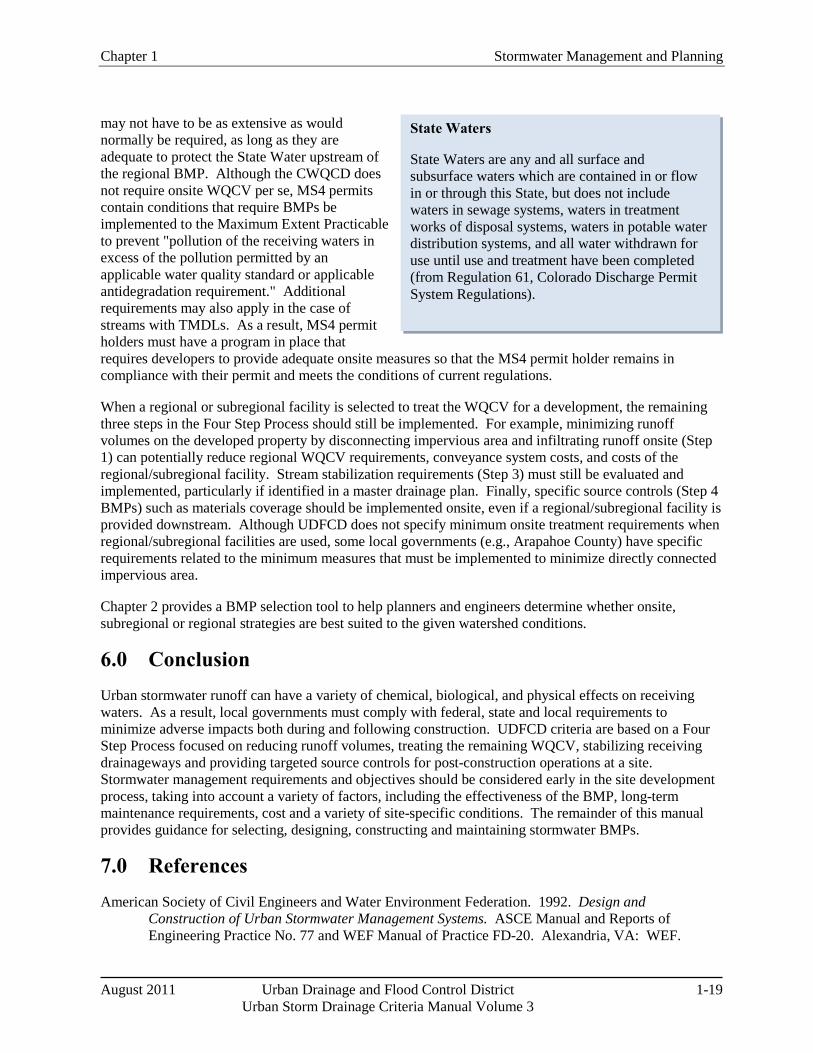
Chapter 1 Stormwater Management and Planning
August 2011 Urban Drainage and Flood Control District 1-19 Urban Storm Drainage Criteria Manual Volume 3
State Waters
State Waters are any and all surface and subsurface waters which are contained in or flow in or through this State, but does not include waters in sewage systems, waters in treatment works of disposal systems, waters in potable water distribution systems, and all water withdrawn for use until use and treatment have been completed (from Regulation 61, Colorado Discharge Permit System Regulations).
may not have to be as extensive as would normally be required, as long as they are adequate to protect the State Water upstream of the regional BMP. Although the CWQCD does not require onsite WQCV per se, MS4 permits contain conditions that require BMPs be implemented to the Maximum Extent Practicable to prevent "pollution of the receiving waters in excess of the pollution permitted by an applicable water quality standard or applicable antidegradation requirement." Additional requirements may also apply in the case of streams with TMDLs. As a result, MS4 permit holders must have a program in place that requires developers to provide adequate onsite measures so that the MS4 permit holder remains in compliance with their permit and meets the conditions of current regulations.
When a regional or subregional facility is selected to treat the WQCV for a development, the remaining three steps in the Four Step Process should still be implemented. For example, minimizing runoff volumes on the developed property by disconnecting impervious area and infiltrating runoff onsite (Step 1) can potentially reduce regional WQCV requirements, conveyance system costs, and costs of the regional/subregional facility. Stream stabilization requirements (Step 3) must still be evaluated and implemented, particularly if identified in a master drainage plan. Finally, specific source controls (Step 4 BMPs) such as materials coverage should be implemented onsite, even if a regional/subregional facility is provided downstream. Although UDFCD does not specify minimum onsite treatment requirements when regional/subregional facilities are used, some local governments (e.g., Arapahoe County) have specific requirements related to the minimum measures that must be implemented to minimize directly connected impervious area.
Chapter 2 provides a BMP selection tool to help planners and engineers determine whether onsite, subregional or regional strategies are best suited to the given watershed conditions.
6.0 Conclusion Urban stormwater runoff can have a variety of chemical, biological, and physical effects on receiving waters. As a result, local governments must comply with federal, state and local requirements to minimize adverse impacts both during and following construction. UDFCD criteria are based on a Four Step Process focused on reducing runoff volumes, treating the remaining WQCV, stabilizing receiving drainageways and providing targeted source controls for post-construction operations at a site. Stormwater management requirements and objectives should be considered early in the site development process, taking into account a variety of factors, including the effectiveness of the BMP, long-term maintenance requirements, cost and a variety of site-specific conditions. The remainder of this manual provides guidance for selecting, designing, constructing and maintaining stormwater BMPs.
7.0 References American Society of Civil Engineers and Water Environment Federation. 1992. Design and
Construction of Urban Stormwater Management Systems. ASCE Manual and Reports of Engineering Practice No. 77 and WEF Manual of Practice FD-20. Alexandria, VA: WEF.
Stormwater Management and Planning Chapter 1
1-20 Urban Drainage and Flood Control District August 2011 Urban Storm Drainage Criteria Manual Volume 3
Burton, A. and R. Pitt. 2001. Stormwater Effects Handbook: A Toolbox for Watershed Managers, Scientists, and Engineers. Lewis Publishers. http://www.epa.gov/ednnrmrl/publications/books/handbook/index.htm
Center for Watershed Protection Website: http://www.cwp.org
City of Aurora Utilities Department, City of Denver Department of Public Works, City of Lakewood Department of Planning, Permits and Public Works in cooperation with Urban Drainage and Flood Control District. 1992. Stormwater NPDES Part 3 Permit Application Joint Appendix.
Colorado Water Quality Control Division (WQCD) Website: http://www.cdphe.state.co.us/wq
Colorado Water Quality Control Division (WQCD). 2009. Authorization to Discharge under the Colorado Discharge Permit System, Permit No. COS-000001, City and County of Denver MS4 Permit.
Colorado Water Quality Control Commission (WQCC). 2009. Regulation No. 61 Colorado Discharge Permit System (CDPS) Regulations.
Colorado Water Quality Control Division (WQCD). 2008. MS4 General Permit. Permit No. COR-090000. CDPS General Permit, Stormwater Discharges Associated with Municipal Separate Storm Sewer Systems (MS4s), Authorization to Discharge under the Colorado Discharge Permit System.
Debo, T. and A. Reese. 2002. Municipal Stormwater Management. 2nd Edition. Lewis Publishers: Boca Raton, FL.
Denver Regional Council of Governments (DRCOG). 1983. Urban Runoff Quality in the Denver Region. Denver, CO.
Driscoll, E., G. Palhegyi, E. Strecker, and P. Shelley. 1990. Analysis of Storm Event Characteristics for Selected Rainfall Gauges Throughout the United States. Prepared for the U.S. Environmental Protection Agency, Woodward-Clyde Consultants: Oakland, CA.
U.S. Environmental Protection Agency (EPA) Stormwater Program Website: http://cfpub.epa.gov/npdes/home.cfm?program_id=6
U.S. Environmental Protection Agency (EPA). 2009. Federal Register Notice Regarding Stakeholder Input; Stormwater Management Including Discharges from New Development and Redevelopment. Federal Register, Vol. 74, No. 247, 68617-68622.
U.S. Environmental Protection Agency (EPA). 2005. Stormwater Phase II Final Rule: Small Construction Program Overview. Fact Sheet 3.0. Office of Water. http://www.epa.gov/region8/water/stormwater/pdf/fact3-0.pdf
U.S. Environmental Protection Agency (EPA). 1983. Results of the Nationwide Urban Runoff Program, Volume 1 – Final Report. U.S. Environmental Protection Agency, Water Planning Division, Washington D.C.
Horner, R.R., J.J. Skupien, E.H. Livingston and H.E. Shaver. 1994. Fundamental of Urban Runoff Management: Technical and Institutional Issues. Terrene Institute and EPA: Washington D.C.
Chapter 1 Stormwater Management and Planning
August 2011 Urban Drainage and Flood Control District 1-21 Urban Storm Drainage Criteria Manual Volume 3
International Stormwater Best Management Practices Database. www.bmpdatabase.org. Cosponsored by the Water Environmental Research Foundation, American Society of Civil Engineers, Environmental and Water Resources Institute, Federal Highway Administration and U.S. Environmental Protection Agency. Accessed in 2010.
Low Impact Development (LID) Center Website: http://www.lid-stormwater.net/
National Research Council. 2008. Urban Stormwater Management in the United States. National Academies Press. http://www.epa.gov/npdes/pubs/nrc_stormwaterreport.pdf
Oregon State University et al. 2006. Evaluation of Best Management Practices for Highway Runoff Control. Tramsportation Research Board. NCHRP-565. Corvallis, OR. http://www.trb.org/news/blurb_detail.asp?id=7184
Pitt, R., A. Maestre, H. Hyche, and N. Togawa. 2008. The Updated National Stormwater Quality Database, Version. Proceedings of the Water Environment Federation Technical Exposition and Conference. Chicago, IL.
Pitt, R., A. Maestre, and R. Morquecho. 2004. The National Stormwater Quality Database (NQSD), Version 1.1. University of Alabama: Tuscaloosa, AL.
Roesner, L.A. and B.P. Bledsoe. 2003. Physical Effects of Wet Weather Flows on Aquatic Habitats. Water Environment Research Foundation: Alexandria, VA. Co-published by IA Publishing: United Kingdom.
Shaver, E. R. Horner, J. Skupien, C. May, and G. Ridley. 2007. Fundamental of Urban Runoff Management: Technical and Institutional Issues, Second Edition. U.S. Environmental Protection and North American Lake Management Society.
Urbonas, B. and J. Doerfer. 2003. Some Observations on Atmospheric Dust Fallout in the Denver, Colorado Area of the United States. Flood Hazrtd News. Urban Drainage and Flood Control District: Denver, CO.
Urbonas, B., Guo, J., and L.S. Tucker. 1989. Sizing Capture Volume for Storm Water Quality Enhancement. Flood Hazard News. Urban Drainage and Flood Control District: Denver, CO.
Water Environment Federation and American Society of Civil Engineers. 1998. Urban Runoff Quality Management, WEF Manual of Practice No. 23 and ASCE Manual and Report on Engineering Practice N0; 87. Water Environment Federation (WEF): Alexandria, VA.
Watershed Management Institute. 1997. Operation, Maintenance and Management of Stormwater Management Systems. Watershed Management Institute: Ingleside, MD.

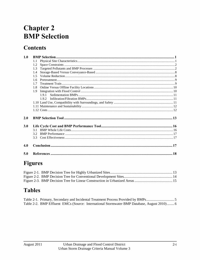
August 2011 Urban Drainage and Flood Control District 2-i Urban Storm Drainage Criteria Manual Volume 3
Chapter 2 BMP Selection Contents 1.0 BMP Selection ................................................................................................................................... 1
1.1 Physical Site Characteristics ...................................................................................................................... 1 1.2 Space Constraints ...................................................................................................................................... 2 1.3 Targeted Pollutants and BMP Processes ................................................................................................... 2 1.4 Storage-Based Versus Conveyance-Based ................................................................................................ 8 1.5 Volume Reduction ..................................................................................................................................... 8 1.6 Pretreatment ............................................................................................................................................... 9 1.7 Treatment Train ......................................................................................................................................... 9 1.8 Online Versus Offline Facility Locations ................................................................................................ 10 1.9 Integration with Flood Control ................................................................................................................ 10
1.9.1 Sedimentation BMPs ................................................................................................................... 11 1.9.2 Infiltration/Filtration BMPs ......................................................................................................... 11
1.10 Land Use, Compatibility with Surroundings, and Safety ........................................................................ 11 1.11 Maintenance and Sustainability ............................................................................................................... 12 1.12 Costs ........................................................................................................................................................ 12
2.0 BMP Selection Tool ........................................................................................................................ 13
3.0 Life Cycle Cost and BMP Performance Tool ............................................................................... 16 3.1 BMP Whole Life Costs ............................................................................................................................ 16 3.2 BMP Performance ................................................................................................................................... 17 3.3 Cost Effectiveness ................................................................................................................................... 17
4.0 Conclusion ....................................................................................................................................... 17
5.0 References ....................................................................................................................................... 18
Figures Figure 2-1. BMP Decision Tree for Highly Urbanized Sites ..................................................................... 13Figure 2-2. BMP Decision Tree for Conventional Development Sites ...................................................... 14Figure 2-3. BMP Decision Tree for Linear Construction in Urbanized Areas .......................................... 15
Tables
Table 2-1. Primary, Secondary and Incidental Treatment Process Provided by BMPs ............................... 5Table 2-2. BMP Effluent EMCs (Source: International Stormwater BMP Database, August 2010) ........ 6

Chapter 2 BMP Selection
August 2011 Urban Drainage and Flood Control District 2-1
Urban Storm Drainage Criteria Manual Volume 3
1.0 BMP Selection This chapter provides guidance on factors that should be considered when selecting BMPs for new development or redevelopment projects. This guidance is particularly useful in the planning phase of a project. BMP selection involves many factors such as physical site characteristics, treatment objectives, aesthetics, safety, maintenance requirements, and cost. Typically, there is not a single answer to the question of which BMP (or BMPs) should be selected for a site; there are usually multiple solutions ranging from stand alone BMPs to treatment trains that combine multiple BMPs to achieve the water quality objectives. Factors that should be considered when selecting BMPs are the focus of this chapter.
1.1 Physical Site Characteristics
The first step in BMP selection is identification of physical characteristics of a site including topography, soils, contributing drainage area, groundwater, baseflows, wetlands, existing drainageways, and development conditions in the tributary watershed (e.g., construction activity). A fundamental concept of Low Impact Development (LID) is preservation and protection of site features including wetlands, drainageways, soils that are conducive to infiltration, tree canopy, etc., that provide water quality and other benefits. LID stormwater treatment systems are also designed to take advantage of these natural resources. For example, if a portion of a site is known to have soils with high permeability, this area may be well-suited for rain gardens or permeable pavement. Areas of existing wetlands, which would be difficult to develop from a Section 404 permitting perspective, could be considered for polishing of runoff following BMP treatment, providing additional water quality treatment for the site, while at the same time enhancing the existing wetlands with additional water supply in the form of treated runoff.
Some physical site characteristics that provide opportunities for BMPs or constrain BMP selection include:
Soils: Soils with good permeability, most typically associated with Hydrologic Soil Groups (HSGs) A and B provide opportunities for infiltration of runoff and are well-suited for infiltration-based BMPs such as rain gardens, permeable pavement systems, sand filter, grass swales, and buffers, often without the need for an underdrain system. Even when soil permeability is low, these types of BMPs may be feasible if soils are amended to increase permeability or if an underdrain system is used. In some cases, however, soils restrict the use of infiltration based BMPs. When soils with moderate to high swell potential are present, infiltration should be avoided to minimize damage to adjacent structures due to water-induced swelling. In some cases, infiltration based designs can still be used if an impermeable liner and underdrain system are included in the design; however, when the risk of damage to adjacent infrastructure is high, infiltration based BMPs may not be appropriate. In all cases, consult with a geotechnical engineer when designing infiltration BMPs near structures. Consultation with a geotechnical engineer is necessary for evaluating the suitability of soils for different BMP types and establishing minimum distances between infiltration BMPs and structures.
Watershed Size: The contributing drainage area is an important consideration both on the site level and at the regional level. On the site level, there is a practical minimum size for certain BMPs, largely related to the ability to drain the WQCV over the required drain time. For example, it is technically possible to size the WQCV for an extended detention basin for a half-acre site; however, designing a functional outlet to release the WQCV over a 40-hour drain time is practically impossible due to the very small orifices that would be required. For this size watershed, a filtering BMP, such as a rain garden, would be more appropriate. At the other end of the spectrum, there must be a limit on the maximum drainage area for a regional facility to assure adequate treatment of rainfall events that may produce runoff from only a portion of the area draining to the BMP. If the overall drainage
BMP Selection Chapter 2
2-2 Urban Drainage and Flood Control District August 2011 Urban Storm Drainage Criteria Manual Volume 3
area is too large, events that produce runoff from only a portion of the contributing area will pass through the BMP outlet (sized for the full drainage area) without adequate residence time in the BMP. As a practical limit, the maximum drainage area contributing to a water quality facility should be no larger than one square mile.
Groundwater: Shallow groundwater on a site presents challenges for BMPs that rely on infiltration and for BMPs that are intended to be dry between storm events. Shallow groundwater may limit the ability to infiltrate runoff or result in unwanted groundwater storage in areas intended for storage of the WQCV (e.g., porous sub-base of a permeable pavement system or in the bottom of an otherwise dry facility such as an extended detention basin). Conversely, for some types of BMPs such as wetland channels or constructed wetland basins, groundwater can be beneficial by providing saturation of the root zone and/or a source of baseflow. Groundwater quality protection is an issue that should be considered for infiltration-based BMPs. Infiltration BMPs may not be appropriate for land uses that involve storage or use of materials that have the potential to contaminate groundwater underlying a site (i.e., "hot spot" runoff from fueling stations, materials storage areas, etc.). If groundwater or soil contamination exists on a site and it will not be remediated or removed as a part of construction, it may be necessary to avoid infiltration-based BMPs or use a durable liner to prevent infiltration into contaminated areas.
Base Flows: Base flows are necessary for the success of some BMPs such as constructed wetland ponds, retention ponds and wetland channels. Without baseflows, these BMPs will become dry and unable to support wetland vegetation. For these BMPs, a hydrologic budget should be evaluated. Water rights are also required for these types of BMPs in Colorado.
Watershed Development Activities (or otherwise erosive conditions): When development in the watershed is phased or when erosive conditions such as steep slopes, sparse vegetation, and sandy soils exist in the watershed, a treatment train approach may be appropriate. BMPs that utilize filtration should follow other measures to collect sediment loads (e.g., a forebay). For phased developments, these measures must be in place until the watershed is completely stabilized. When naturally erosive conditions exist in the watershed, these measures should be permanent. The designer should consider existing, interim and future conditions to select the most appropriate BMPs.
1.2 Space Constraints
Space constraints are frequently cited as feasibility issues for BMPs, especially for high-density, lot-line-to-lot-line development and redevelopment sites. In some cases, constraints due to space limitations arise because adequate spaces for BMPs are not considered early enough in the planning process. This is most common when a site plan for roads, structures, etc., is developed and BMPs are squeezed into the remaining spaces. The most effective and integrated BMP designs begin by determining areas of a site that are best suited for BMPs (e.g., natural low areas, areas with well-drained soils) and then designing the layout of roads, buildings, and other site features around the existing drainage and water quality resources of the site. Allocating a small amount of land to water quality infrastructure during early planning stages will result in better integration of water quality facilities with other site features.
1.3 Targeted Pollutants and BMP Processes
BMPs have the ability to remove pollutants from runoff through a variety of physical, chemical and biological processes. The processes associated with a BMP dictate which pollutants the BMP will be effective at controlling. Primary processes include peak attenuation, sedimentation, filtration, straining, adsorption/absorption, biological uptake and hydrologic processes including infiltration and evapotranspiration. Table 2-1 lists processes that are associated with BMPs in this manual. For many
Chapter 2 BMP Selection
August 2011 Urban Drainage and Flood Control District 2-3
Urban Storm Drainage Criteria Manual Volume 3
sites, a primary goal of BMPs is to remove gross solids, suspended sediment and associated particulate fractions of pollutants from runoff. Processes including straining, sedimentation, and infiltration/filtration are effective for addressing these pollutants. When dissolved pollutants are targeted, other processes including adsorption/absorption and biological uptake are necessary. These processes are generally sensitive to media composition and contact time, oxidation/reduction potential, pH and other factors. In addition to pollutant removal capabilities, many BMPs offer channel stability benefits in the form of reduced runoff volume and/or reduced peak flow rates for frequently occurring events. Brief descriptions of several key processes, generally categorized according to hydrologic and pollutant removal functions are listed below:
Hydrologic Processes
1. Flow Attenuation: BMPs that capture and slowly release the WQCV help to reduce peak discharges. In addition to slowing runoff, volume reduction may also be provided to varying extents in BMPs providing the WQCV.
2. Infiltration: BMPs that infiltrate runoff reduce both runoff peaks and surface runoff volumes. The extent to which runoff volumes are reduced depends on a variety of factors such as whether the BMP is equipped with an underdrain and the characteristics and long-term condition of the infiltrating media. Examples of infiltrating BMPs include (unlined) sand filters, bioretention and permeable pavements. Water quality treatment processes associated with infiltration can include filtration and sorption.
3. Evapotranspiration: Runoff volumes can be reduced through the combined effects of evaporation and transpiration in vegetated BMPs. Plants extract water from soils in the root zone and transpire it to the atmosphere. Evapotranspiration is the hydrologic process provided by vegetated BMPs, whereas biological uptake may help to reduce pollutants in runoff.
Pollutant Removal/Treatment Processes
1. Sedimentation: Gravitational separation of particulates from urban runoff, or sedimentation, is a key treatment process by BMPs that capture and slowly release runoff. Settling velocities are a function of characteristics such as particle size, shape, density, fluid density, and viscosity. Smaller particles under 60 microns in size (fine silts and clays) (Stahre and Urbonas, 1990) can account for approximately 80% of the metals in stormwater attached or adsorbed along with other contaminants and can require long periods of time to settle out of suspension. Extended detention allows smaller particles to agglomerate into larger ones (Randall et al, 1982), and for some of the dissolved and liquid state pollutants to adsorb to suspended particles, thus removing a larger proportion of them through sedimentation. Sedimentation is the primary pollutant removal mechanism for many treatment BMPs including extended detention basins, retention ponds, and constructed wetland basins.
2. Straining: Straining is physical removal or retention of particulates from runoff as it passes through a BMP. For example, grass swales and grass buffers provide straining of sediment and coarse solids in runoff. Straining can be characterized as coarse filtration.
3. Filtration: Filtration removes particles as water flows through media (often sand or engineered soils). A wide variety of physical and chemical mechanisms may occur along with filtration, depending on the filter media. Metcalf and Eddy (2003) describe processes associated with filtration as including straining, sedimentation, impaction, interception, adhesion, flocculation, chemical adsorption, physical adsorption, and biological growth. Filtration is a primary treatment process
BMP Selection Chapter 2
2-4 Urban Drainage and Flood Control District August 2011 Urban Storm Drainage Criteria Manual Volume 3
provided by infiltration BMPs. Particulates are removed at the ground surface and upper soil horizon by filtration, while soluble constituents can be absorbed into the soil, at least in part, as the runoff infiltrates into the ground. Site-specific soil characteristics, such as permeability, cation exchange potential, and depth to groundwater or bedrock are important characteristics to consider for filtration (and infiltration) BMPs. Examples of filtering BMPs include sand filters, bioretention, and permeable pavements with a sand filter layer.
4. Adsorption/Absorption: In the context of BMPs, sorption processes describe the interaction of waterborne constituents with surrounding materials (e.g., soil, water). Absorption is the incorporation of a substance in one state into another of a different state (e.g., liquids being absorbed by a solid). Adsorption is the physical adherence or bonding of ions and molecules onto the surface of another molecule. Many factors such as pH, temperature and ionic state affect the chemical equilibrium in BMPs and the extent to which these processes provide pollutant removal. Sorption processes often play primary roles in BMPs such as constructed wetland basins, retention ponds, and bioretention systems. Opportunities may exist to optimize performance of BMPs through the use of engineered media or chemical addition to enhance sorption processes.
5. Biological Uptake: Biological uptake and storage processes include the assimilation of organic and inorganic constituents by plants and microbes. Plants and microbes require soluble and dissolved constituents such as nutrients and minerals for growth. These constituents are ingested or taken up from the water column or growing medium (soil) and concentrated through bacterial action, phytoplankton growth, and other biochemical processes. In some instances, plants can be harvested to remove the constituents permanently. In addition, certain biological activities can reduce toxicity of some pollutants and/or possible adverse effects on higher aquatic species. Unfortunately, not much is understood yet about how biological uptake or activity interacts with stormwater during the relatively brief periods it is in contact with the biological media in most BMPs, with the possible exception of retention ponds between storm events (Hartigan, 1989). Bioretention, constructed wetlands, and retention ponds are all examples of BMPs that provide biological uptake.
When selecting BMPs, it is important to have realistic expectations of effluent pollutant concentrations. The International Stormwater BMP Database (www.bmpdatabase.org) provides BMP performance information that is updated periodically and summarized in Table 2-2. BMPs also provide varying degrees of volume reduction benefits. Both pollutant concentration reduction and volume reduction are key components in the whole life cycle cost tool BMP-REALCOST.xls (Roesner and Olson 2009) discussed later in this chapter.
It is critical to recognize that for BMPs to function effectively, meet performance expectations, and provide for public safety, BMPs must:
1. Be designed according to UDFCD criteria, taking into account site-specific conditions (e.g., high groundwater, expansive clays and long-term availability of water).
2. Be constructed as designed. This is important for all BMPs, but appears to be particularly critical for permeable pavements, rain gardens and infiltration-oriented facilities.
3. Be properly maintained to function as designed. Although all BMPs require maintenance, infiltration-oriented facilities are particularly susceptible to clogging without proper maintenance. Underground facilities can be vulnerable to maintenance neglect because maintenance needs are not evident from the surface without special tools and procedures for access. Maintenance is not only essential for proper functioning, but also for aesthetic and safety reasons. Inspection of facilities is an important step to identify and plan for needed maintenance.
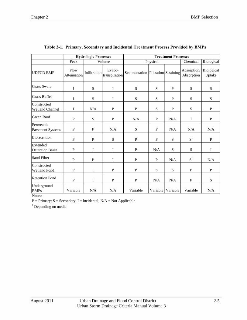
Chapter 2 BMP Selection
August 2011 Urban Drainage and Flood Control District 2-5
Urban Storm Drainage Criteria Manual Volume 3
Table 2-1. Primary, Secondary and Incidental Treatment Process Provided by BMPs
Peak Chemical Biological
Grass Swale I S I S S P S S
Grass Buffer I S I S S P S SConstructed Wetland Channel I N/A P P S P S P
Green Roof P S P N/A P N/A I PPermeable Pavement Systems P P N/A S P N/A N/A N/A
Bioretention P P S P P S S1 PExtended Detention Basin P I I P N/A S S I
Sand Filter P P I P P N/A S1 N/AConstructed Wetland Pond P I P P S S P P
Retention Pond P I P P N/A N/A P SUnderground BMPs Variable N/A N/A Variable Variable Variable Variable N/ANotes:P = Primary; S = Secondary, I = Incidental; N/A = Not Applicable1 Depending on media
Hydrologic Processes Treatment ProcessesVolume Physical
UDFCD BMP Adsorption/ Absorption
Biological Uptake
Flow Attenuation StrainingFiltrationSedimentationEvapo-
transpirationInfiltration
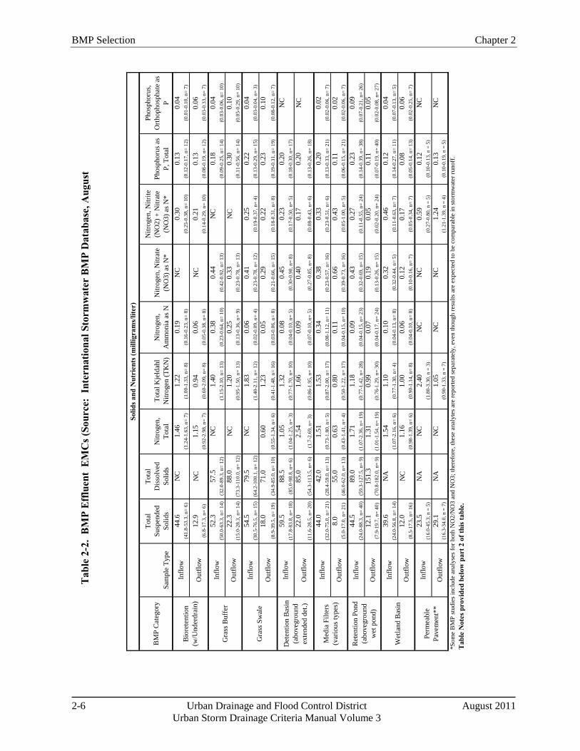
BMP Selection Chapter 2
2-6 Urban Drainage and Flood Control District August 2011 Urban Storm Drainage Criteria Manual Volume 3
BM
P C
ateg
ory
Sam
ple
Type
Tota
l Su
spen
ded
Solid
s
Tota
l D
isso
lved
So
lids
Nitr
ogen
, To
tal
Tota
l Kje
ldah
l N
itrog
en (T
KN
)N
itrog
en,
Am
mon
ia a
s NN
itrog
en, N
itrat
e (N
O3)
as N
*
Nitr
ogen
, Nitr
ite
(NO
2) +
Nitr
ate
(NO
3) a
s N*
Phos
phor
us a
s P,
Tot
al
Phos
phor
us,
Orth
opho
spha
te a
s P
44.6
NC
1.46
1.22
0.19
NC
0.30
0.13
0.04
(41.
8-53
.3, n
= 6)
(1.2
4-1.
63, n
= 7)
(1.0
0-1.
33, n
= 8)
(0.1
6-0.
23, n
= 8)
(0.2
5-0.
38, n
= 10
)(0
.12-
0.17
, n=
12)
(0.0
1-0.
10, n
= 7)
12.9
NC
1.15
0.94
0.06
NC
0.21
0.13
0.06
(6.8
-17.
3, n
= 6)
(0.9
2-2.
98, n
= 7)
(0.6
0-2.
09, n
= 8)
(0.0
5-0.
38, n
= 8)
(0.1
4-0.
29, n
= 10
)(0
.08-
0.19
, n=
12)
(0.0
3-0.
33, n
= 7)
52.3
57.5
NC
1.40
0.38
0.44
NC
0.18
0.04
(50.
0-63
.3, n
= 14
)(3
2.0-
89.3
, n=
12)
(1.1
5-2.
10, n
= 13
)(0
.23-
0.64
, n=
10)
(0.4
2-0.
92, n
= 13
)(0
.09-
0.25
, n=
14)
(0.0
3-0.
06, n
= 10
)22
.388
.0N
C1.
200.
250.
33N
C0.
300.
10(1
5.0-
28.3
, n=
14)
(73.
3-11
0.0,
n=
12)
(0.9
5-1.
50, n
= 13
)(0
.13-
0.36
, n=
9)(0
.23-
0.78
, n=
13)
(0.1
1-0.
56, n
= 14
)(0
.05-
0.29
, n=
10)
54.5
79.5
NC
1.83
0.06
0.41
0.25
0.22
0.04
(30.
5-76
.5, n
= 15
)(6
4.2-
100.
1, n
= 12
)(1
.40-
2.11
, n=
12)
(0.0
2-0.
09, n
= 4)
(0.2
3-0.
78, n
= 12
)(0
.19-
0.37
, n=
4)(0
.13-
0.29
, n=
15)
(0.0
3-0.
04, n
= 3)
18.0
71.0
0.60
1.23
0.05
0.29
0.22
0.23
0.10
(8.9
-39.
5, n
= 19
)(3
4.9-
85.0
, n=
10)
(0.5
5-1.
34, n
= 6)
(0.4
1-1.
48, n
= 16
)(0
.03-
0.06
, n=
8)(0
.21-
0.66
, n=
15)
(0.1
8-0.
31, n
= 8)
(0.1
9-0.
31, n
= 19
)(0
.08-
0.12
, n=
7)
59.5
88.5
1.05
1.32
0.08
0.45
0.23
0.20
NC
(17.
8-83
.8, n
= 18
)(8
5.0-
98.8
, n=
6)(1
.04-
1.25
, n=
3)(0
.77-
1.70
, n=
10)
(0.0
4-0.
10, n
= 5)
(0.3
0-0.
90, n
= 8)
(0.1
7-0.
50, n
= 5)
(0.1
8-0.
30, n
= 17
)22
.085
.02.
541.
660.
090.
400.
170.
20N
C(1
1.6-
28.5
, n=
20)
(54.
3-11
3.5,
n=
6)(1
.7-2
.69,
n=
3)(0
.86-
1.95
, n=
10)
(0.0
7-0.
10, n
= 5)
(0.2
7-0.
85, n
= 8)
(0.0
8-0.
43, n
= 6)
(0.1
3-0.
26, n
= 18
)
44.0
42.0
1.51
1.53
0.34
0.38
0.33
0.20
0.02
(32.
0-75
.0, n
= 21
)(2
8.4-
59.0
, n=
13)
(0.7
3-1.
80, n
= 5)
(0.8
7-2.
00, n
= 17
)(0
.08-
1.12
, n=
11)
(0.2
3-0.
57, n
= 16
)(0
.23-
0.51
, n=
6)(0
.13-
0.33
, n=
21)
(0.0
2-0.
06, n
= 7)
8.0
55.0
0.63
0.80
0.11
0.66
0.43
0.11
0.02
(5.0
-17.
0, n
= 21
)(4
6.0-
62.0
, n=
13)
(0.4
3-1.
41, n
= 4)
(0.5
0-1.
22, n
= 17
)(0
.04-
0.15
, n=
10)
(0.3
9-0.
73, n
= 16
)(0
.05-
1.00
, n=
5)(0
.06-
0.15
, n=
21)
(0.0
2-0.
06, n
= 7)
44.5
89.0
1.71
1.18
0.09
0.43
0.27
0.23
0.09
(24.
0-88
.3, n
= 40
)(5
9.3-
127.
5, n
= 9)
(1.0
7-2.
36, n
= 19
)(0
.77-
1.42
, n=
28)
(0.0
4-0.
15, n
= 23
)(0
.32-
0.69
, n=
15)
(0.1
1-0.
55, n
= 24
)(0
.14-
0.39
, n=
38)
(0.0
7-0.
21, n
= 26
)12
.115
1.3
1.31
0.99
0.07
0.19
0.05
0.11
0.05
(7.9
-19.
7, n
= 40
)(7
0.8-
182.
0, n
= 9)
(1.0
1-1.
54, n
= 19
)(0
.76-
1.29
, n=
30)
(0.0
4-0.
17, n
= 24
)(0
.13-
0.26
, n=
15)
(0.0
2-0.
20, n
= 24
)(0
.07-
0.19
, n=
40)
(0.0
2-0.
08, n
= 27
)
39.6
NA
1.54
1.10
0.10
0.32
0.46
0.12
0.04
(24.
0-56
.8, n
= 14
)(1
.07-
2.16
, n=
6)(0
.77-
1.30
, n=
4)(0
.04-
0.13
, n=
8)(0
.32-
0.44
, n=
5)(0
.11-
0.63
, n=
7)(0
.14-
0.27
, n=
11)
(0.0
7-0.
13, n
= 5)
12.0
NC
1.16
1.00
0.06
0.12
0.17
0.08
0.06
(8.5
-17.
5, n
= 16
)(0
.98-
1.39
, n=
6)(0
.90-
1.14
, n=
8)(0
.04-
0.10
, n=
8)(0
.10-
0.16
, n=
7)(0
.05-
0.34
, n=
7)(0
.05-
0.14
, n=
13)
(0.0
2-0.
25, n
= 7)
23.5
NA
NC
2.40
NC
NC
0.59
0.12
NC
(16.
0-45
.3, n
= 5
)(1
.80-
3.30
, n =
3)
(0.2
7-0.
80, n
= 5
)(0
.10-
0.13
, n =
5)
29.1
NA
NC
1.05
NC
NC
1.24
0.13
NC
(16.
3-34
.0, n
= 7
)(0
.90-
1.33
, n =
7)
(1.2
1-1.
39, n
= 4
)(0
.10-
0.19
, n =
5)
*Som
e B
MP
stud
ies i
nclu
de a
naly
ses f
or b
oth
NO
2/N
O3
and
NO
3; th
eref
ore,
thes
e an
alyt
es a
re re
porte
d se
para
tely
, eve
n th
ough
resu
lts a
re e
xpec
ted
to b
e co
mpa
rabl
e in
stor
mw
ater
runo
ff.
Solid
s and
Nut
rien
ts (m
illig
ram
s/lit
er)
Bio
rete
ntio
n (w
/Und
erdr
ain)
Inflo
w
Out
flow
Gra
ss B
uffe
rIn
flow
Out
flow
Gra
ss S
wal
eIn
flow
Out
flow
Det
entio
n B
asin
(a
bove
grou
nd
exte
nded
det
.)
Inflo
w
Out
flow
Med
ia F
ilter
s (v
ario
us ty
pes)
Inflo
w
Out
flow
Perm
eabl
e Pa
vem
ent*
*
Inflo
w
Out
flow
Tab
le N
otes
pro
vide
d be
low
par
t 2 o
f thi
s tab
le.
Ret
entio
n Po
nd
(abo
vegr
ound
w
et p
ond)
Inflo
w
Out
flow
Wet
land
Bas
inIn
flow
Out
flow
Tab
le 2
-2.
BM
P Ef
fluen
t E
MC
s (So
urce
: In
tern
atio
nal S
torm
wat
er B
MP
Dat
abas
e, A
ugus
t
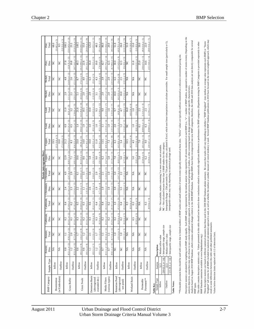
Chapter 2 BMP Selection
August 2011 Urban Drainage and Flood Control District 2-7
Urban Storm Drainage Criteria Manual Volume 3
BM
P C
ateg
ory
Sam
ple
Type
Ars
enic
, D
iss.
Ars
enic
, To
tal
Cad
miu
m,
Dis
s.C
adm
ium
, To
tal
Chr
omiu
m,
Dis
s.C
hrom
ium
, To
tal
Cop
per,
Dis
s.C
oppe
r, To
tal
Lead
, D
iss.
Lead
, To
tal
Nic
kel,
Dis
s.N
icke
l, To
tal
Zinc
, D
iss.
Zinc
, To
tal
NA
NC
NC
NC
NC
NC
NC
19.5
NC
NC
NC
NC
NC
68.0
(15.
3-35
.8, n
= 3)
(51-
68.5
, n=
5)N
AN
CN
CN
CN
CN
CN
C10
.0N
CN
CN
CN
CN
C8.
5(7
.3-1
6.8,
n=
3)(5
.0-3
5.0,
n=
5)
0.8
1.1
0.2
0.4
2.4
4.9
12.9
21.2
0.9
11.0
2.9
4.8
37.8
100.
5(0
.5-1
.2, n
= 12
)(0
.9-2
.3, n
= 12
)(0
.1-0
.2, n
= 12
)(0
.3-0
.8, n
= 12
)(1
.1-4
.5, n
= 12
)(2
.9-7
.4, n
= 13
)(6
.8-1
7.3,
n=
12)
(15.
0-41
.0, n
= 13
)(0
.5-2
.0, n
= 12
)(6
-35,
n=
13)
(1.1
-3.2
, n=
12)
(3.4
-8.4
, n=
12)
(12.
8-70
, n=
12)
(53.
0-24
5.0,
n=
13)
1.2
2.0
0.1
0.2
2.3
2.9
7.1
8.3
0.5
3.2
2.1
2.6
19.8
25.5
(0.5
-2.4
, n=
12)
(0.7
-3.0
, n=
12)
(0.1
-0.2
, n=
12)
(0.1
-0.2
, n=
12)
(1.0
-3.8
, n=
12)
(2.0
-5.5
, n=
13)
(4.8
-11.
6, n
= 12
)(6
.4-1
2.5,
n=
13)
(0.5
-1.3
, n=
12)
(1.8
-6.0
, n=
13)
(2.0
-2.3
, n=
12)
(2.2
-3.2
, n=
12)
(10.
7-24
.3, n
= 12
)(1
5.0-
57.9
, n=
13)
0.6
1.7
0.3
0.5
2.2
6.1
10.6
33.0
1.4
21.6
5.1
8.7
40.3
149.
5(0
.5-2
.2, n
= 9)
(1.6
-2.7
, n=
9)(0
.1-0
.4, n
= 13
)(0
.4-0
.9, n
= 14
)(1
.1-3
.3, n
= 7)
(3.6
-8.3
, n=
7)(8
.1-1
5.0,
n=
13)
(26-
34, n
= 13
)(0
.6-6
.7, n
= 13
)(1
2.5-
46.4
, n=
14)
(4.5
-6.6
, n=
6)(7
-12.
5, n
= 6)
(35.
3-10
9.0,
n=
13)
(43.
8-24
4.3,
n=
15)
0.6
1.2
0.2
0.3
1.1
3.5
8.6
14.0
1.0
10.5
2.0
4.0
22.6
55.0
(0.6
-1.2
, n=
8)(0
.9-1
.7, n
= 8)
(0.1
-0.2
, n=
12)
(0.2
-0.4
, n=
13)
(1.0
-3.0
, n=
6)(1
.7-5
.0, n
= 6)
(5.5
-9.7
, n=
13)
(6.7
-18.
5, n
= 17
)(0
.5-4
.1, n
= 13
)(1
.7-1
2.0,
n=
18)
(2.0
-2.3
, n=
5)(3
.1-4
.5, n
= 5)
(20.
1-33
.2, n
= 13
)(2
0.6-
65.4
, n=
19)
1.1
2.1
0.3
0.6
2.6
5.6
5.8
10.0
1.0
10.0
2.9
6.3
16.4
125.
0(0
.9-1
.2, n
= 5)
(1.3
-2.6
, n=
6)(0
.2-0
.4, n
= 8)
(0.3
-1.2
, n=
11)
(2.0
-3.2
, n=
3)(5
.0-6
.5, n
= 6)
(2.6
-11.
8, n
= 8)
(4.8
-33.
5, n
= 11
)(0
.5-1
.4, n
= 8)
(1.5
-41.
0, n
= 11
)(1
.9-3
.9, n
= 4)
(5-9
.4, n
= 5)
(6.1
-53.
5, n
= 8)
(21.
5-22
5.3,
n=
11)
1.2
1.7
0.3
0.4
1.9
2.9
9.0
11.0
1.0
9.5
3.1
4.3
19.0
48.5
(0.9
-1.2
, n=
5)(1
.1-1
.9, n
= 6)
(0.2
-0.4
, n=
9)(0
.2-0
.6, n
= 12
)(1
.7-3
.0, n
= 4)
(1.9
-3.8
, n=
6)(3
.0-1
3.0,
n=
9)(6
.2-2
0.1,
n=
12)
(0.5
-1.3
, n=
9)(1
.3-1
8.6,
n=
12)
(2.0
-3.2
, n=
5)(3
.2-5
.4, n
= 6)
(7.8
-54.
0, n
= 9)
(19.
1-94
.0, n
= 13
)
0.7
1.1
0.2
0.4
1.0
2.1
6.2
13.5
1.1
9.0
2.0
3.9
42.7
86.0
(0.5
-1.1
, n=
12)
(0.6
-1.6
, n=
12)
(0.2
-0.2
, n=
14)
(0.2
-1.0
, n=
17)
(1.0
-1.0
, n=
13)
(1.4
-4.0
, n=
13)
(5.4
-7.4
, n=
13)
(8.8
-16.
4, n
= 18
)(1
.0-2
.0, n
= 14
)(5
.3-2
2.0,
n=
17)
(2.0
-2.7
, n=
13)
(3.3
-4.8
, n=
13)
(28.
5-79
.2, n
= 14
)(5
1.8-
106.
0, n
= 19
)0.
71.
10.
20.
21.
01.
05.
87.
31.
01.
62.
02.
912
.520
.0(0
.6-1
.1, n
= 12
)(0
.7-1
.6, n
= 12
)(0
.2-0
.2, n
= 13
)(0
.1-0
.7, n
= 17
)(1
.0-1
.0, n
= 13
)(1
.0-1
.9, n
= 13
)(3
.1-8
.3, n
= 13
)(4
.3-9
.6, n
= 18
)(1
.0-1
.0, n
= 13
)(1
.0-4
.4, n
= 17
)(2
.0-2
.6, n
= 13
)(2
.0-3
.9, n
= 13
)(6
.7-4
9.0,
n=
13)
(8.6
-35.
0, n
= 19
)
NC
1.0
0.2
1.0
5.9
5.0
7.0
6.3
2.0
9.7
10.0
6.5
30.0
51.8
(1.0
-1.4
, n=
3)(0
.2-0
.4, n
= 3)
(0.3
-2.6
, n=
20)
(1.6
-10.
0, n
= 4)
(3.0
-7.4
, n=
12)
(6.0
-9.5
, n=
7)(4
.3-1
0.6,
n=
26)
(1.0
-5.1
.0, n
= 11
)(4
-28,
n=
33)
(6.2
-10.
0, n
= 3)
(3.6
-9, n
= 8)
(15.
5-42
.6, n
= 8)
(43.
9-78
.1, n
= 32
)
NC
1.0
0.2
0.4
5.5
2.2
5.0
5.4
1.2
4.7
10.0
2.5
12.5
26.0
(0.8
-1.0
, n=
3)(0
.2-0
.4, n
= 3)
(0.2
-2.5
, n=
20)
(1.0
-10.
0, n
= 4)
(1.4
-5.3
, n=
12)
(4.7
-5.8
, n=
7)(3
.0-6
.2, n
= 26
)(1
.0-4
.9, n
= 12
)(1
.6-1
0.0,
n=
33)
(7.2
-10.
0, n
= 3)
(2.0
-5.5
, n=
9)(9
.4-2
8.6,
n=
8)(1
2.0-
37.0
, n=
33)
NA
NA
NC
0.3
NA
NA
NC
10.5
NC
16.0
NA
NA
NC
51.0
(0.3
-0.4
, n=
3)(4
.3-1
5.9,
n=
4)(4
.0-2
3.8,
n=
4)(4
3.9-
120.
8, n
= 7)
NA
NA
0.5
0.3
NA
NA
5.0
4.5
1.0
1.0
NA
NA
11.0
15.0
(0.3
-0.5
, n=
3)(0
.1-0
.5, n
= 5)
(5.0
-5.7
, n=
3)(3
.3-5
.0, n
= 6)
(0.8
-1.0
, n=
3)(1
.0-2
.5, n
= 6)
(11.
0-13
.1, n
= 3)
(5.0
-28.
9, n
= 9)
NA
NC
NC
NA
NC
NC
5.0
7.0
0.1
2.5
NC
NC
25.0
50.0
(2.5
-6.4
, n =
3)(4
.5-1
9.4,
n =
3)
(0.0
3-0.
3, n
= 3
)(1
.3-1
5.1,
n =
3)
(19.
0-27
.5, n
= 3
)(4
5.0-
51.0
, n =
5)
NA
NC
NC
0.3
NC
NC
6.2
9.0
0.3
2.5
NC
NC
14.6
22.0
(0.3
-0.4
, n =
3)(4
.5-6
.4, n
=4)
(3.0
-14.
7, n
= 5
)(0
.04-
0.5,
n =
4)
(1.3
-9.5
, n =
7)
(13.
5-16
.0, n
= 4
)(2
0.0-
31.6
, n =
7)
Tab
le K
ey
Sam
ple
Type
Ana
lyte
52.3
(50-
63.3
, n=
14)
22.3
(15-
28.3
, n=
14)
= In
terq
uarti
le ra
nge,
sam
ple
size
Val
ues b
elow
det
ectio
n lim
its re
plac
ed w
ith 1
/2 o
f det
ectio
n lim
it.
= M
edia
n ou
tflow
val
ue=
Inte
rqua
rtile
rang
e, sa
mpl
e si
ze=
Med
ian
inflo
w v
alue
Des
crip
tion
Inte
rqua
rtile
Ran
ge =
25t
h pe
rcen
tile
to 7
5th
perc
entil
e va
lues
, cal
cula
ted
in E
xcel
, whi
ch u
ses l
inea
r int
erpo
latio
n to
cal
cula
te p
erce
ntile
s. F
or sm
all s
ampl
e si
zes (
parti
cula
rly n
<5),
in
terq
uarti
le v
alue
s may
var
y de
pend
ing
on st
atis
tical
pac
kage
use
d.
NA
= N
ot a
vaila
ble;
stud
ies c
onta
inin
g 3
or m
ore
stor
ms n
ot a
vaila
ble.
NC
= N
ot c
alcu
late
d be
caus
e fe
wer
than
3 B
MP
stud
ies f
or th
is c
ateg
ory.
Thes
e de
scrip
tive
stat
istic
s are
bas
ed o
n di
ffere
nt st
atis
tical
mea
sure
s tha
n th
ose
used
in th
e 20
08 B
MP
Dat
abas
e ta
bula
r sum
mar
y. B
e aw
are
that
resu
lts w
ill v
ary
depe
ndin
g on
whe
ther
a "
BM
P W
eigh
ted"
(on
e m
edia
n or
ave
rage
val
ue re
pres
ents
eac
h B
MP)
or "
Stor
m
Wei
ghte
d" (a
ll st
orm
s for
all
BM
Ps in
clud
ed in
stat
istic
al c
alcu
latio
ns) a
ppro
ach
is u
sed,
as w
ell a
s whe
ther
the
med
ian
or a
noth
er m
easu
re o
f cen
tral t
ende
ncy
is u
sed.
Sev
eral
BM
P D
atab
ase
publ
icat
ions
in 2
010
have
focu
sed
on th
e st
orm
-wei
ghte
d ap
proa
ch, w
hich
may
re
sult
in so
me
diffe
renc
es b
etw
een
this
tabl
e an
d ot
her p
ublis
hed
sum
mar
ies.
Out
flow
Det
entio
n B
asin
(a
bove
grou
nd
exte
nded
det
.)
Inflo
w
Out
flow
Med
ia F
ilter
s (v
ario
us ty
pes)
Gra
ss B
uffe
rIn
flow
Out
flow
Gra
ss S
wal
eIn
flow
Out
flow
Des
crip
tive
stat
istic
s cal
cula
ted
by w
eigh
ting
each
BM
P st
udy
equa
lly.
Each
BM
P st
udy
is re
pres
ente
d by
the
med
ian
anal
yte
valu
e re
porte
d fo
r all
stor
ms m
onito
red
at e
ach
BM
P (i.
e., "
n" =
num
ber o
f BM
P st
udie
s, as
opp
osed
to n
umbe
r of s
torm
eve
nts)
. Dep
endi
ng o
n th
e an
alys
is o
bjec
tives
, res
earc
hers
may
als
o ch
oose
to u
se a
stor
m-w
eigh
ted
anal
ysis
app
roac
h, a
uni
t tre
atm
ent p
roce
ss-b
ased
gro
upin
g of
stud
ies,
or o
ther
scre
enin
g ba
sed
on d
esig
n pa
ram
eter
s and
site
-spe
cific
cha
ract
eris
tics.
Ana
lysi
s bas
ed o
n A
ugus
t 201
0 B
MP
Dat
abas
e, w
hich
con
tain
s sub
stan
tial c
hang
es re
lativ
e to
the
2008
BM
P D
atab
ase.
Mul
tiple
BM
Ps h
ave
been
reca
tego
rized
into
new
BM
P ca
tego
ries;
ther
efor
e, th
e 20
08 a
nd 2
010
data
ana
lysi
s are
not
dire
ctly
com
para
ble
for s
ever
al
BM
P ty
pes.
Th
is ta
ble
cont
ains
des
crip
tive
stat
istic
s onl
y. V
alue
s pre
sent
ed in
this
tabl
e sh
ould
not
be
used
to d
raw
con
clus
ions
rela
ted
to st
atis
tical
ly si
gnifi
cant
diff
eren
ces i
n pe
rfor
man
ce fo
r BM
P ca
tego
ries.
(Hyp
othe
sis t
estin
g fo
r BM
P C
ateg
orie
s is p
rovi
ded
sepa
rate
ly in
oth
er
BM
P D
atab
ase
sum
mar
ies a
vaila
ble
at w
ww
.bm
pdat
abas
e.or
g.)
Out
flow
**Pe
rmea
ble
pave
men
t dat
a sh
ould
be
used
with
cau
tion
due
to li
mite
d nu
mbe
rs o
f BM
P st
udie
s and
smal
l num
bers
of s
torm
eve
nts t
ypic
ally
mon
itore
d at
thes
e si
tes.
"In
flow
" va
lues
are
typi
cally
out
flow
s mon
itore
d at
a re
fere
nce
conv
entio
nal p
avin
g si
te.
Tab
le N
otes
:
Perm
eabl
e Pa
vem
ent*
*
Inflo
w
Out
flow
Inflo
w
Ret
entio
n Po
nd
(abo
vegr
ound
w
et p
ond)
Inflo
w
Out
flow
Wet
land
Bas
inIn
flow
Inflo
w
Out
flow
Met
als (
mic
rogr
ams/
liter
)
Bio
rete
ntio
n (w
/Und
erdr
ain)
Inflo
w
Out
flow
BMP Selection Chapter 2
2-8 Urban Drainage and Flood Control District August 2011 Urban Storm Drainage Criteria Manual Volume 3
Hydromodification
The term hydromodification refers to altered hydrology due to increased imperviousness combined with constructed of conveyance systems (e.g., pipes) that convey stormwater efficiently to receiving waters. Hydromodification produces increased peaks, volume, frequency, and duration of flows, all of which can result in stream degradation, including stream bed down cutting, bank erosion, enlarged channels, and disconnection of streams from the floodplain. These factors lead to loss of stream and riparian habitat, reduced aquatic diversity, and can adversely impact the beneficial uses of our waterways.
1.4 Storage-Based Versus Conveyance-Based
BMPs in this manual generally fall into two categories: 1) storage-based and 2) conveyance-based. Storage-based BMPs provide the WQCV and include bioretention/rain gardens, extended detention basins, sand filters, constructed wetland ponds, retention ponds, and permeable pavement systems. Conveyance-based BMPs include grass swales, grass buffers, constructed wetlands channels and other BMPs that improve quality and reduce volume but only provide incidental storage. Conveyance-based BMPs can be implemented to help achieve objectives in Step 1 of the Four Step Process. Although conveyance BMPs do not satisfy Step 2 (providing the WQCV), they can reduce the volume requirements of Step 2. Storage-based BMPs are critical for Step 2 of the Four Step Process. Site plans that use a combination of conveyance-based and storage-based BMPs can be used to better mimic pre-development hydrology.
1.5 Volume Reduction
BMPs that promote infiltration or that incorporate evapotranspiration have the potential to reduce the volume of runoff generated. Volume reduction is a fundamental objective of LID. Volume reduction has many benefits, both in terms of hydrology and pollution control. While stormwater regulations have traditionally focused on runoff peak flow rates, emerging stormwater regulations require BMPs to mimic the pre-development hydrologic budget to minimize effects of hydromodification. From a pollution perspective, decreased runoff volume translates to decreased pollutant loads. Volume reduction has economic benefits, including potential reductions in storage requirements for minor and major events, reduced extent and sizing of conveyance infrastructure, and cost reductions associated with addressing channel stability issues. UDFCD has developed a computational method for quantifying volume reduction. This is discussed in detail in Chapter 3.
Infiltration-based BMPs can be designed with or without underdrains, depending on soil permeability and other site conditions. The most substantial volume reductions are generally associated with BMPs that have permeable sub-soils and allow infiltration to deeper soil strata and eventually groundwater. For BMPs that have underdrains, there is still potential for volume reduction although to a lesser degree. As runoff infiltrates through BMP soils to the underdrain, moisture is retained by soils. The moisture eventually evaporates, or is taken up by vegetation, resulting in volume reduction. Runoff that drains from these soils via gravity to the underdrain system behaves like interflow from a hydrologic perspective with a delayed response that reduces peak rates. Although the runoff collected in the underdrain system is ultimately discharged to the surface, on the time scale of a storm event, there are volume reduction benefits.
Although effects of evapotranspiration are inconsequential on the time scale of a storm event, on an annual basis, volume reduction due to evapotranspiration for vegetated BMPs such as retention and constructed wetland ponds can be an important component of the hydrologic budget. Between events, evapotranspiration lowers soil moisture content and permanent pool storage, providing additional storage capacity for subsequent events.
Chapter 2 BMP Selection
August 2011 Urban Drainage and Flood Control District 2-9
Urban Storm Drainage Criteria Manual Volume 3
Other surface BMPs also provide volume reduction through a combination of infiltration, use by the vegetation and evaporation. Volume reduction provided by a particular BMP type will be influenced by site-specific conditions and BMP design features. National research is ongoing with regard to estimating volume reduction provided by various BMP types. Based on analysis of BMP studies contained in the International Stormwater BMP Database, Geosyntec and WWE (2010) reported that normally-dry vegetated BMPs (filter strips, vegetated swales, bioretention, and grass lined detention basins) appear to have substantial potential for volume reduction on a long-term basis, on the order of 30 percent for filter strips and grass-lined detention basins, 40 percent for grass swales, and greater than 50 percent for bioretention with underdrains. Bioretention facilities without underdrains would be expected to provide greater volume reduction.
1.6 Pretreatment
Design criteria in this manual recommend forebays for extended detention basins, constructed wetland basins, and retention ponds. The purpose of forebays is to settle out coarse sediment prior to reaching the main body of the facility. During construction, source control including good housekeeping can be more effective than pre-treatment. It is extremely important that high sediment loading be controlled for BMPs that rely on infiltration, including permeable pavement systems, rain gardens, and sand filter extended detention basins. These facilities should not be brought on-line until the end of the construction phase when the tributary drainage area has been stabilized with permanent surfaces and landscaping.
1.7 Treatment Train
The term "treatment train" refers to multiple BMPs in series (e.g., a disconnected roof downspout draining to a grass swale draining to a constructed wetland basin.) Engineering research over the past decade has demonstrated that treatment trains are one of the most effective methods for management of stormwater quality (WERF 2004). Advantages of treatment trains include:
Multiple processes for pollutant removal: There is no "silver bullet" for a BMP that will address all pollutants of concern as a stand-alone practice. Treatment trains that link together complementary processes expand the range of pollutants that can be treated with a water quality system and increase the overall efficiency of the system for pollutant removal.
Redundancy: Given the natural variability of the volume, rate and quality of stormwater runoff and the variability in BMP performance, using multiple practices in a treatment train can provide more consistent treatment of runoff than a single practice and provide redundancy in the event that one component of a treatment train is not functioning as intended.
Maintenance: BMPs that remove trash, debris, coarse sediments and other gross solids are a common first stage of a treatment train. From a maintenance perspective, this is advantageous since this first stage creates a well-defined, relatively small area that can be cleaned out routinely. Downgradient components of the treatment train can be maintained less frequently and will benefit from reduced potential for clogging and accumulation of trash and debris.
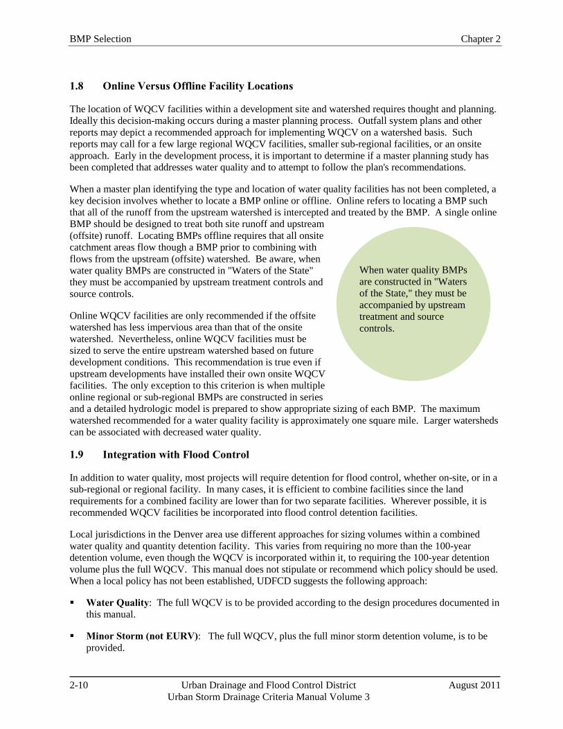
BMP Selection Chapter 2
2-10 Urban Drainage and Flood Control District August 2011 Urban Storm Drainage Criteria Manual Volume 3
When water quality BMPs are constructed in "Waters of the State," they must be accompanied by upstream treatment and source controls.
1.8 Online Versus Offline Facility Locations
The location of WQCV facilities within a development site and watershed requires thought and planning. Ideally this decision-making occurs during a master planning process. Outfall system plans and other reports may depict a recommended approach for implementing WQCV on a watershed basis. Such reports may call for a few large regional WQCV facilities, smaller sub-regional facilities, or an onsite approach. Early in the development process, it is important to determine if a master planning study has been completed that addresses water quality and to attempt to follow the plan's recommendations.
When a master plan identifying the type and location of water quality facilities has not been completed, a key decision involves whether to locate a BMP online or offline. Online refers to locating a BMP such that all of the runoff from the upstream watershed is intercepted and treated by the BMP. A single online BMP should be designed to treat both site runoff and upstream (offsite) runoff. Locating BMPs offline requires that all onsite catchment areas flow though a BMP prior to combining with flows from the upstream (offsite) watershed. Be aware, when water quality BMPs are constructed in "Waters of the State" they must be accompanied by upstream treatment controls and source controls.
Online WQCV facilities are only recommended if the offsite watershed has less impervious area than that of the onsite watershed. Nevertheless, online WQCV facilities must be sized to serve the entire upstream watershed based on future development conditions. This recommendation is true even if upstream developments have installed their own onsite WQCV facilities. The only exception to this criterion is when multiple online regional or sub-regional BMPs are constructed in series and a detailed hydrologic model is prepared to show appropriate sizing of each BMP. The maximum watershed recommended for a water quality facility is approximately one square mile. Larger watersheds can be associated with decreased water quality.
1.9 Integration with Flood Control
In addition to water quality, most projects will require detention for flood control, whether on-site, or in a sub-regional or regional facility. In many cases, it is efficient to combine facilities since the land requirements for a combined facility are lower than for two separate facilities. Wherever possible, it is recommended WQCV facilities be incorporated into flood control detention facilities.
Local jurisdictions in the Denver area use different approaches for sizing volumes within a combined water quality and quantity detention facility. This varies from requiring no more than the 100-year detention volume, even though the WQCV is incorporated within it, to requiring the 100-year detention volume plus the full WQCV. This manual does not stipulate or recommend which policy should be used. When a local policy has not been established, UDFCD suggests the following approach:
Water Quality: The full WQCV is to be provided according to the design procedures documented in this manual.
Minor Storm (not EURV): The full WQCV, plus the full minor storm detention volume, is to be provided.
Chapter 2 BMP Selection
August 2011 Urban Drainage and Flood Control District 2-11
Urban Storm Drainage Criteria Manual Volume 3
100-Year Storm: One-half the WQCV plus the full 100-year storm event volume should be provided for volumes obtained using the empirical equations or the FAA Method. When the analysis is done using hydrograph routing methods, each level of controls needs to be accounted for and the resultant 100-year control volume used in final design.
100-Year Storm using Full Spectrum Detention: The full 100-year storm event volume should be provided according to the design protocol provided in the Storage chapter of Volume 2.
The Storage chapter in Volume 2 provides design criteria for full spectrum detention, which shows more promise in controlling the peak flow rates in receiving waterways than the multi-stage designs described above. Full spectrum detention not only addresses the WQCV for controlling water quality and runoff from frequently occurring runoff events, but also extends that control for all return periods through the 100-year event and closely matches historic peak flows downstream.
Finally, designers should also be aware that water quality BMPs, especially those that promote infiltration, could result in volume reductions for flood storage. These volume reductions are most pronounced for frequently occurring events, but even in the major event, some reduction in detention storage volume can be achieved if volume-reduction BMPs are widely used on a site. Additional discussion on volume reduction benefits, including a methodology for quantifying effects on detention storage volumes, is provided in Chapter 3.
1.9.1 Sedimentation BMPs
Combination outlets are relatively straightforward for most BMPs in this manual. For BMPs that utilize sedimentation (e.g. EDBs, constructed wetland ponds, and retention ponds) see BMP Fact Sheet T-12. This Fact Sheet shows examples and details for combined quality/quantity outlet structures.
1.9.2 Infiltration/Filtration BMPs
For other types of BMPs (e.g. rain gardens, sand filters, permeable pavement systems, and other BMPs utilizing processes other than sedimentation), design of a combination outlet structure generally consists of multiple orifices to provide controlled release of WQCV as well as the minor and major storm event. Incorporation of full spectrum detention into these structures requires reservoir routing. The UD-Detention worksheet available at www.udfcd.org can be used for this design. When incorporating flood control into permeable pavement systems, the design can be simplified when a near 0% slope on the pavement surface can be achieved. The flatter the pavement the fewer structures required. This includes lateral barriers as well as outlet controls since each pavement cell typically requires its own outlet structure. When incorporating flood control into a rain garden, the flood control volume can be placed on top of or downstream of the rain garden. Locating the flood control volume downstream can reduce the total depth of the rain garden, which will result in a more attractive BMP, and also benefit the vegetation in the flood control area because inundation and associated sedimentation will be less frequent, limited to events exceeding the WQCV.
1.10 Land Use, Compatibility with Surroundings, and Safety
Stormwater quality areas can add interest and diversity to a site, serving multiple purposes in addition to providing water quality functions. Gardens, plazas, rooftops, and even parking lots can become amenities and provide visual interest while performing stormwater quality functions and reinforcing urban design goals for the neighborhood and community. The integration of BMPs and associated landforms, walls, landscape, and materials can reflect the standards and patterns of a neighborhood and help to create lively, safe, and pedestrian-oriented districts. The quality and appearance of stormwater quality facilities should
BMP Selection Chapter 2
2-12 Urban Drainage and Flood Control District August 2011 Urban Storm Drainage Criteria Manual Volume 3
reflect the surrounding land use type, the immediate context, and the proximity of the site to important civic spaces. Aesthetics will be a more critical factor in highly visible urban commercial and office areas than at a heavy industrial site. The standard of design and construction should maintain and enhance property values without compromising function (WWE et al. 2004).
Public access to BMPs should be considered from a safety perspective. The highest priority of engineers and public officials is to protect public health, safety, and welfare. Stormwater quality facilities must be designed and maintained in a manner that does not pose health or safety hazards to the public. As an example, steeply sloped and/or walled ponds should be avoided. Where this is not possible, emergency egress, lighting and other safety considerations should be incorporated. Facilities should be designed to reduce the likelihood and extent of shallow standing water that can result in mosquito breeding, which can be a nuisance and a public health concern (e.g., West Nile virus). The potential for nuisances, odors and prolonged soggy conditions should be evaluated for BMPs, especially in areas with high pedestrian traffic or visibility.
1.11 Maintenance and Sustainability
Maintenance should be considered early in the planning and design phase. Even when BMPs are thoughtfully designed and properly installed, they can become eyesores, breed mosquitoes, and cease to function if not properly maintained. BMPs can be more effectively maintained when they are designed to allow easy access for inspection and maintenance and to take into consideration factors such as property ownership, easements, visibility from easily accessible points, slope, vehicle access, and other factors. For example, fully consider how and with what equipment BMPs will be maintained in the future. Clear, legally-binding written agreements assigning maintenance responsibilities and committing adequate funds for maintenance are also critical (WWE et al. 2004). The MS4 permit holder may also require right of access to perform emergency repairs/maintenance should it become necessary.
Sustainability of BMPs is based on a variety of considerations related to how the BMP will perform over time. For example, vegetation choices for BMPs determine the extent of supplemental irrigation required. Choosing native or drought-tolerant plants and seed mixes (as recommended in the Revegetation chapter of Volume 2) helps to minimize irrigation requirements following plant establishment. Other sustainability considerations include watershed conditions. For example, in watersheds with ongoing development, clogging of infiltration BMPs is a concern. In such cases, a decision must be made regarding either how to protect and maintain infiltration BMPs, or whether to allow use of infiltration practices under these conditions.
1.12 Costs
Costs are a fundamental consideration for BMP selection, but often the evaluation of costs during planning and design phases of a project focuses narrowly on up-front, capital costs. A more holistic evaluation of life-cycle costs including operation, maintenance and rehabilitation is prudent and is discussed in greater detail in Section 4 of this chapter. From a municipal perspective, cost considerations are even broader, involving costs associated with off-site infrastructure, channel stabilization and/or rehabilitation, and protection of community resources from effects of runoff from urban areas.
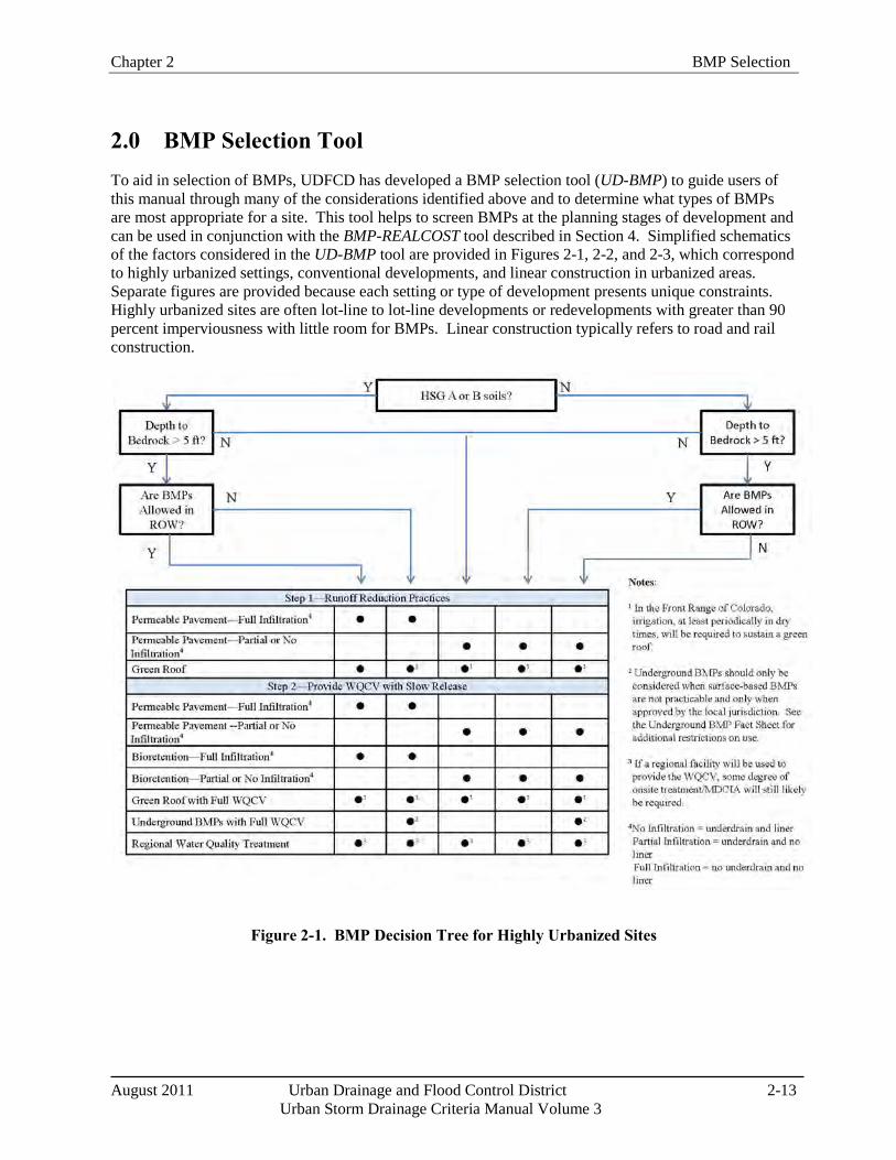
Chapter 2 BMP Selection
August 2011 Urban Drainage and Flood Control District 2-13
Urban Storm Drainage Criteria Manual Volume 3
2.0 BMP Selection Tool To aid in selection of BMPs, UDFCD has developed a BMP selection tool (UD-BMP) to guide users of this manual through many of the considerations identified above and to determine what types of BMPs are most appropriate for a site. This tool helps to screen BMPs at the planning stages of development and can be used in conjunction with the BMP-REALCOST tool described in Section 4. Simplified schematics of the factors considered in the UD-BMP tool are provided in Figures 2-1, 2-2, and 2-3, which correspond to highly urbanized settings, conventional developments, and linear construction in urbanized areas. Separate figures are provided because each setting or type of development presents unique constraints. Highly urbanized sites are often lot-line to lot-line developments or redevelopments with greater than 90 percent imperviousness with little room for BMPs. Linear construction typically refers to road and rail construction.
Figure 2-1. BMP Decision Tree for Highly Urbanized Sites
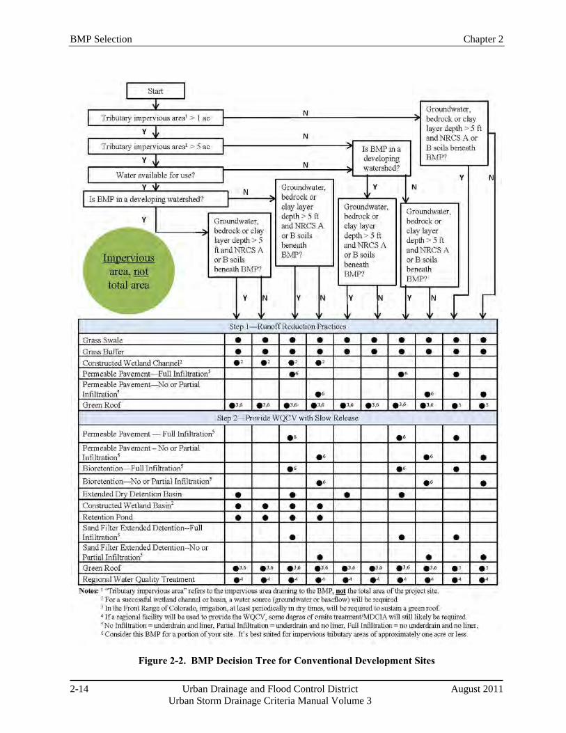
BMP Selection Chapter 2
2-14 Urban Drainage and Flood Control District August 2011 Urban Storm Drainage Criteria Manual Volume 3
Figure 2-2. BMP Decision Tree for Conventional Development Sites
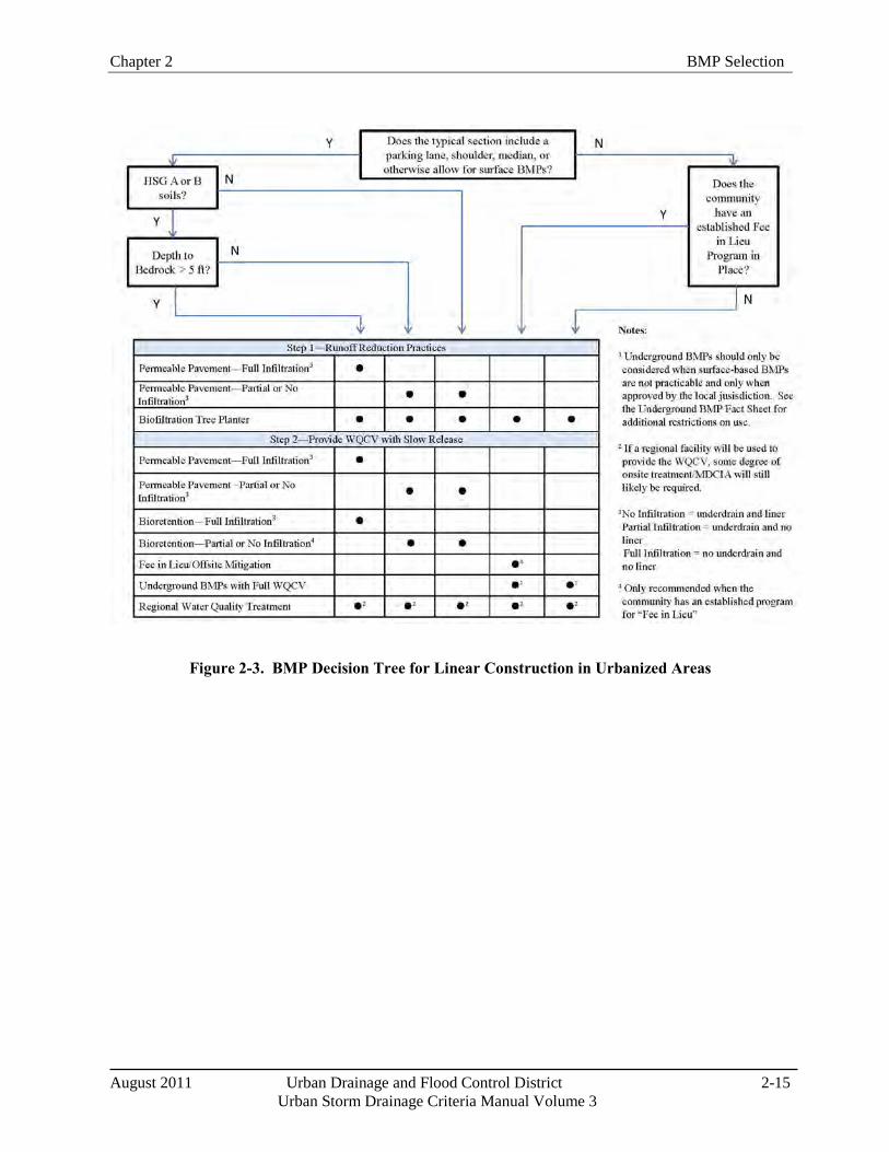
Chapter 2 BMP Selection
August 2011 Urban Drainage and Flood Control District 2-15
Urban Storm Drainage Criteria Manual Volume 3
Figure 2-3. BMP Decision Tree for Linear Construction in Urbanized Areas
BMP Selection Chapter 2
2-16 Urban Drainage and Flood Control District August 2011 Urban Storm Drainage Criteria Manual Volume 3
3.0 Life Cycle Cost and BMP Performance Tool The importance of cost effective BMP planning and selection is gaining recognition as agencies responsible for stormwater management programs continue to face stricter regulations and leaner budgets. The goal of the BMP-REALCOST tool is to help select BMPs that meet the project objectives at the lowest unit cost, where the project objectives are quantifiable measures such as reducing pollutant loads or runoff volumes to a receiving water. To do so, UDFCD has developed an approach that provides estimates for both the whole life costs and performance of BMPs. The approach was developed to be most effective at the large-scale, planning phase; however, it can also be applied to smaller scales during the design phase, perhaps with minor loss of accuracy. The BMP-REALCOST spreadsheet tool incorporates this approach and requires minimal user inputs in order to enhance its applicability to planning level evaluations. An overview of the general concepts providing the underlying basis of the tool follows.
3.1 BMP Whole Life Costs
Whole life costs (also known as life cycle costs) refer to all costs that occur during the economic life of a project. This method of cost estimating has gained popularity in the construction and engineering fields over the past few decades and the American Society of Civil Engineers (ASCE) encourages its use for all civil engineering projects. Generally, the components of the whole life cost for a constructed facility include construction, engineering and permitting, contingency, land acquisition, routine operation and maintenance, and major rehabilitation costs minus salvage value. In addition, UDFCD recommends the cost of administering a stormwater management program also be included as a long-term cost for BMPs. Reporting whole life costs in terms of net present value (NPV) is an effective method for comparing mutually exclusive alternatives (Newnan 1996).
To understand the value of using whole life cost estimating, one must first realize how the various costs of projects are generally divided amongst several stakeholders. For example, a developer is typically responsible for paying for the "up front" costs of construction, design, and land acquisition; while a homeowners' association or stormwater management agency becomes responsible for all costs that occur after construction. Many times, the ratios of these costs are skewed one way or another, with BMPs that are less expensive to design and construct having greater long-term costs, and vice versa. This promotes a bias, depending on who is evaluating the BMP cost effectiveness. Whole life cost estimating removes this bias; however, successful implementation of the concept requires a cost-sharing approach where the whole life costs are equitably divided amongst all stakeholders.
The methods incorporated into the BMP-REALCOST tool for estimating whole life costs are briefly described below. All cost estimates are considered "order-of-magnitude" approximations, hence UDFCD's recommendation of using this concept primarily at the planning level.
Construction Costs: Construction costs are estimated using a parametric equation that relates costs to a physical parameter of a BMP; total storage volume (for storage-based BMPs), peak flow capacity (for flow-based or conveyance BMPs) or surface area (for permeable pavements).
Contingency/Engineering/Administration Costs: The additional costs of designing and permitting a new BMP are estimated as a percentage of the total construction costs. For Denver-area projects, a value of 40% is recommended if no other information is available.
Land Costs: The cost of purchasing land for a BMP is estimated using a derived equation that incorporates the number of impervious acres draining to the BMP and the land use designation in which the BMP will be constructed.
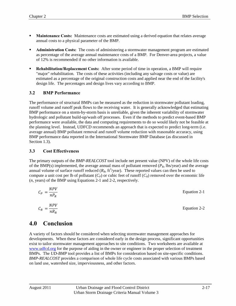
Chapter 2 BMP Selection
August 2011 Urban Drainage and Flood Control District 2-17
Urban Storm Drainage Criteria Manual Volume 3
Maintenance Costs: Maintenance costs are estimated using a derived equation that relates average annual costs to a physical parameter of the BMP.
Administration Costs: The costs of administering a stormwater management program are estimated as percentage of the average annual maintenance costs of a BMP. For Denver-area projects, a value of 12% is recommended if no other information is available.
Rehabilitation/Replacement Costs: After some period of time in operation, a BMP will require "major" rehabilitation. The costs of these activities (including any salvage costs or value) are estimated as a percentage of the original construction costs and applied near the end of the facility's design life. The percentages and design lives vary according to BMP.
3.2 BMP Performance
The performance of structural BMPs can be measured as the reduction in stormwater pollutant loading, runoff volume and runoff peak flows to the receiving water. It is generally acknowledged that estimating BMP performance on a storm-by-storm basis is unreliable, given the inherent variability of stormwater hydrologic and pollutant build-up/wash off processes. Even if the methods to predict event-based BMP performance were available, the data and computing requirements to do so would likely not be feasible at the planning level. Instead, UDFCD recommends an approach that is expected to predict long-term (i.e. average annual) BMP pollutant removal and runoff volume reduction with reasonable accuracy, using BMP performance data reported in the International Stormwater BMP Database (as discussed in Section 1.3).
3.3 Cost Effectiveness
The primary outputs of the BMP-REALCOST tool include net present value (NPV) of the whole life costs of the BMP(s) implemented, the average annual mass of pollutant removed (PR, lbs/year) and the average annual volume of surface runoff reduced (RR, ft3/year). These reported values can then be used to compute a unit cost per lb of pollutant (CP) or cubic feet of runoff (CR) removed over the economic life (n, years) of the BMP using Equations 2-1 and 2-2, respectively.
𝐶𝑃 =𝑁𝑃𝑉𝑛𝑃𝑅
Equation 2-1
𝐶𝑅 =𝑁𝑃𝑉𝑛𝑅𝑅
Equation 2-2
4.0 Conclusion A variety of factors should be considered when selecting stormwater management approaches for developments. When these factors are considered early in the design process, significant opportunities exist to tailor stormwater management approaches to site conditions. Two worksheets are available at www.udfcd.org for the purpose of aiding in the owner or engineer in the proper selection of treatment BMPs. The UD-BMP tool provides a list of BMPs for consideration based on site-specific conditions. BMP-REALCOST provides a comparison of whole life cycle costs associated with various BMPs based on land use, watershed size, imperviousness, and other factors.
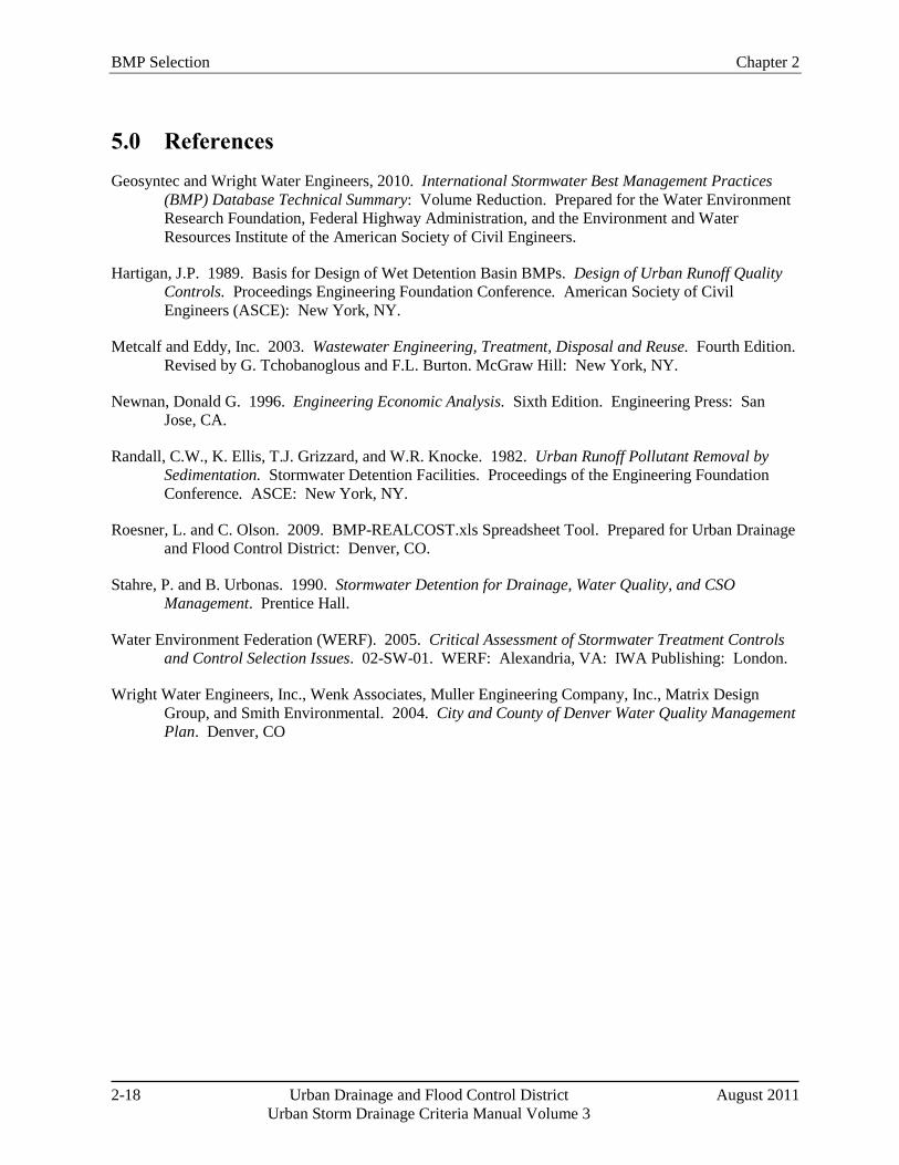
BMP Selection Chapter 2
2-18 Urban Drainage and Flood Control District August 2011 Urban Storm Drainage Criteria Manual Volume 3
5.0 References Geosyntec and Wright Water Engineers, 2010. International Stormwater Best Management Practices
(BMP) Database Technical Summary: Volume Reduction. Prepared for the Water Environment Research Foundation, Federal Highway Administration, and the Environment and Water Resources Institute of the American Society of Civil Engineers.
Hartigan, J.P. 1989. Basis for Design of Wet Detention Basin BMPs. Design of Urban Runoff Quality Controls. Proceedings Engineering Foundation Conference. American Society of Civil Engineers (ASCE): New York, NY.
Metcalf and Eddy, Inc. 2003. Wastewater Engineering, Treatment, Disposal and Reuse. Fourth Edition. Revised by G. Tchobanoglous and F.L. Burton. McGraw Hill: New York, NY.
Newnan, Donald G. 1996. Engineering Economic Analysis. Sixth Edition. Engineering Press: San Jose, CA.
Randall, C.W., K. Ellis, T.J. Grizzard, and W.R. Knocke. 1982. Urban Runoff Pollutant Removal by Sedimentation. Stormwater Detention Facilities. Proceedings of the Engineering Foundation Conference. ASCE: New York, NY.
Roesner, L. and C. Olson. 2009. BMP-REALCOST.xls Spreadsheet Tool. Prepared for Urban Drainage and Flood Control District: Denver, CO.
Stahre, P. and B. Urbonas. 1990. Stormwater Detention for Drainage, Water Quality, and CSO Management. Prentice Hall.
Water Environment Federation (WERF). 2005. Critical Assessment of Stormwater Treatment Controls and Control Selection Issues. 02-SW-01. WERF: Alexandria, VA: IWA Publishing: London.
Wright Water Engineers, Inc., Wenk Associates, Muller Engineering Company, Inc., Matrix Design Group, and Smith Environmental. 2004. City and County of Denver Water Quality Management Plan. Denver, CO
August 2011 Urban Drainage and Flood Control District 3-i
Urban Storm Drainage Criteria Manual Volume 3
Chapter 3 Calculating the WQCV and Volume Reduction Contents 1.0 Introduction ...................................................................................................................................... 1
2.0 Hydrologic Basis of the WQCV ...................................................................................................... 1 2.1 Development of the WQCV ...................................................................................................................... 1 2.2 Optimizing the Capture Volume ............................................................................................................... 3 2.3 Attenuation of the WQCV (BMP Drain Time) ......................................................................................... 4 2.4 Excess Urban Runoff Volume (EURV) and Full Spectrum Detention ..................................................... 4
3.0 Calculation of the WQCV ................................................................................................................ 5
4.0 Quantifying Volume Reduction .................................................................................................... 10 4.1 Conceptual Model for Volume Reduction BMPs—Cascading Planes .................................................... 10 4.2 Watershed/Master Planning-level Volume Reduction Method ............................................................... 11 4.3 Site-level Volume Reduction Methods ................................................................................................... 14
4.3.1 SWMM Modeling Using Cascading Planes ................................................................................ 15 4.3.2 IRF Charts and Spreadsheet ........................................................................................................ 16
4.4 Other Types of Credits for Volume Reduction BMPs/LID ..................................................................... 20
5.0 Examples ......................................................................................................................................... 21 5.1 Calculation of WQCV ............................................................................................................................. 21 5.2 Volume Reduction Calculations for Storage-based Approach ................................................................ 22 5.3 Effective Imperviousness Spreadsheet .................................................................................................... 23
6.0 Conclusion ....................................................................................................................................... 34
7.0 References ....................................................................................................................................... 35
Figures Figure 3-1. Map of the Average Runoff Producing Storm's Precipitation Depth in the United States ....... 3Figure 3-2. Water Quality Capture Volume (WQCV) Based on BMP Drain Time .................................... 6Figure 3-3. Watershed Imperviousness, Single Family Residential Ranch Style Houses ........................... 7Figure 3-4. Watershed Imperviousness, Single Family Residential Split-Level Houses ............................ 8Figure 3-5. Watershed Imperviousness, Single Family Residential Two-Story Houses ............................. 9Figure 3-6. Four Component Land Use ..................................................................................................... 11Figure 3-7. Effective Imperviousness Adjustments for Level 1 MDCIA .................................................. 13Figure 3-8. Effective Imperviousness Adjustments for Level 2 MDCIA .................................................. 14Figure 3-9. Conveyance-based Imperviousness Reduction Factor ............................................................ 18Figure 3-10. Storage-based Imperviousness Reduction Factor ................................................................. 19Figure 3-11. Colorado Green Development DCIA, UIA, RPA, and SPA ................................................. 31Figure 3-12. Colorado Green Precipitation Input Screen Shot .................................................................. 32Figure 3-13. Colorado Green Area and Infiltration Input Screen Shot ...................................................... 32Figure 3-14. Colorado Green Calculated Output Screen Shot ................................................................... 32
3-ii Urban Drainage and Flood Control District August 2011
Urban Storm Drainage Criteria Manual Volume 3
Figure 3-15. Colorado Green Imperviousness Reduction Factor Volume-based Lookup ......................... 33Figure 3-16. Colorado Green IRF Conveyance-based Lookup .................................................................. 34
Tables Table 3-1. Number of Rainfall Events in the Denver Area .......................................................................... 2Table 3-2. Drain Time Coefficients for WQCV Calculations ...................................................................... 5Table 3-3. Infiltration Rates (f) for IRF Calculations ................................................................................. 17
Chapter 3 Calculating the WQCV and Volume Reduction
August 2011 Urban Drainage and Flood Control District 3-1 Urban Storm Drainage Criteria Manual Volume 3
Using WQCV and Flood Control Hydrology
Channels are typically designed for an event that is large and infrequent, such as the 100-year event. A common misconception is that these large events are also responsible for most of the erosion within the drainageway. Instead, the effective discharge, by definition, is the discharge that transports the most bedload on an annual basis and this is, therefore, a good estimate of the channel-forming flow or the discharge that shapes the drainageway through sediment transport and erosion. The effective discharge does not correlate with a specific return period, but typically is characterized as a magnitude between the annual event and the 5-year peak, depending on reach-specific characteristics.
The typical flood control facility design may include peak reduction of the 5- or 10-year storm event as well as the 100-year event. Widespread use of this practice reduces flooding of streets and flooding along major drainageways. However, this practice does little to limit the frequency of channel-forming flows in drainageways. UDFCD recommends Full Spectrum Detention, a concept developed to replicate historic peak flows more closely for a broad spectrum of storm events. Widespread use of Full Spectrum Detention would, in theory, improve channel stability and reduce erosion; however, implementation of Full Spectrum Detention may not be feasible on all sites. Therefore, this manual provides a variety of storage-based BMPs that provide the WQCV and address hydrologic effects of urbanization through storage, infiltration, and/or evapotranspiration.
1.0 Introduction This chapter presents the hydrologic basis and calculations for the Water Quality Capture Volume (WQCV) and discusses the benefits of attenuating this volume or that of the Excess Urban Runoff Volume (EURV). This chapter also describes various methods for quantifying volume reduction when using LID practices. Use of these methods should begin during the planning phase for preliminary sizing and development of the site layout. The calculations and procedures in this chapter allow the engineer to determine effective impervious area, calculate the WQCV, and more accurately quantify potential volume reduction benefits of BMPs.
2.0 Hydrologic Basis of the WQCV
2.1 Development of the WQCV
The purpose of designing BMPs based on the WQCV is to improve runoff water quality and reduce hydromodification and the associated impacts on receiving waters. (These impacts are described in Chapter 1.) Although some BMPs can remove pollutants and achieve modest reductions in runoff volumes for frequently occurring events in a "flow through" mode (e.g., grass swales, grass buffers or wetland channels), to address hydrologic effects of urbanization, a BMP must be designed to control the volume of runoff, either through storage, infiltration, evapotranspiration or a combination of these processes (e.g., rain gardens, extended detention basins or other storage-based BMPs). This section provides a brief background on the development of the WQCV.
The WQCV is based on an analysis of rainfall and runoff characteristics for 36 years of record at the Denver Stapleton Rain Gage (1948-1984) conducted by Urbonas, Guo, and Tucker (1989) and documented in Sizing a Capture Volume for Stormwater Quality Enhancement (available at www.udfcd.org). This analysis showed that the average storm for the Denver area, based on a 6-hour separation period, has duration of 11 hours and an average time interval between storms of 11.5 days.
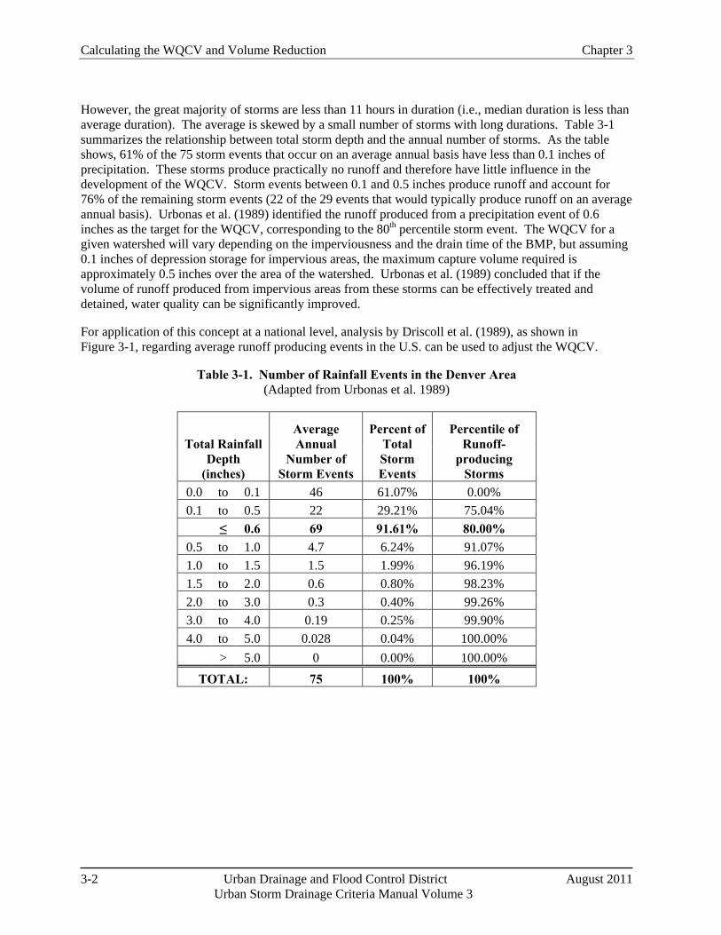
Calculating the WQCV and Volume Reduction Chapter 3
3-2 Urban Drainage and Flood Control District August 2011 Urban Storm Drainage Criteria Manual Volume 3
However, the great majority of storms are less than 11 hours in duration (i.e., median duration is less than average duration). The average is skewed by a small number of storms with long durations. Table 3-1 summarizes the relationship between total storm depth and the annual number of storms. As the table shows, 61% of the 75 storm events that occur on an average annual basis have less than 0.1 inches of precipitation. These storms produce practically no runoff and therefore have little influence in the development of the WQCV. Storm events between 0.1 and 0.5 inches produce runoff and account for 76% of the remaining storm events (22 of the 29 events that would typically produce runoff on an average annual basis). Urbonas et al. (1989) identified the runoff produced from a precipitation event of 0.6 inches as the target for the WQCV, corresponding to the 80th percentile storm event. The WQCV for a given watershed will vary depending on the imperviousness and the drain time of the BMP, but assuming 0.1 inches of depression storage for impervious areas, the maximum capture volume required is approximately 0.5 inches over the area of the watershed. Urbonas et al. (1989) concluded that if the volume of runoff produced from impervious areas from these storms can be effectively treated and detained, water quality can be significantly improved.
For application of this concept at a national level, analysis by Driscoll et al. (1989), as shown in Figure 3-1, regarding average runoff producing events in the U.S. can be used to adjust the WQCV.
Table 3-1. Number of Rainfall Events in the Denver Area (Adapted from Urbonas et al. 1989)
Total Rainfall Depth
(inches)
Average Annual
Number of Storm Events
Percent of Total Storm Events
Percentile of Runoff-
producing Storms
0.0 to 0.1 46 61.07% 0.00% 0.1 to 0.5 22 29.21% 75.04%
≤ 0.6 69 91.61% 80.00% 0.5 to 1.0 4.7 6.24% 91.07% 1.0 to 1.5 1.5 1.99% 96.19% 1.5 to 2.0 0.6 0.80% 98.23% 2.0 to 3.0 0.3 0.40% 99.26% 3.0 to 4.0 0.19 0.25% 99.90% 4.0 to 5.0 0.028 0.04% 100.00%
> 5.0 0 0.00% 100.00%
TOTAL: 75 100% 100%
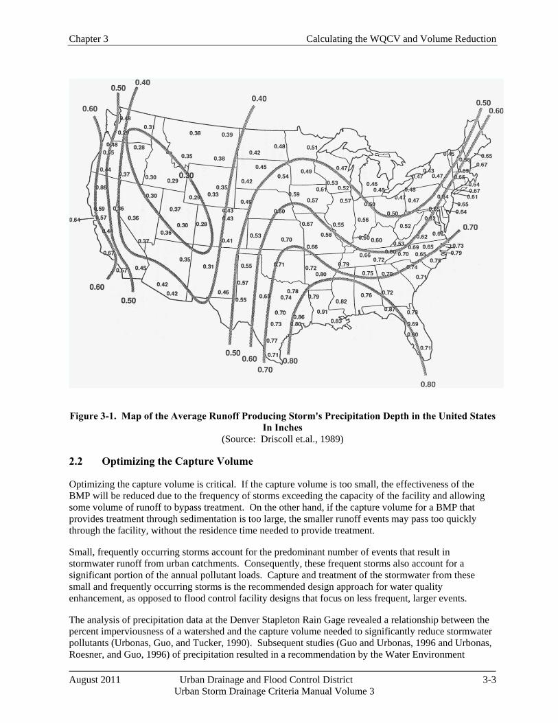
Chapter 3 Calculating the WQCV and Volume Reduction
August 2011 Urban Drainage and Flood Control District 3-3 Urban Storm Drainage Criteria Manual Volume 3
Figure 3-1. Map of the Average Runoff Producing Storm's Precipitation Depth in the United States In Inches
(Source: Driscoll et.al., 1989)
2.2 Optimizing the Capture Volume
Optimizing the capture volume is critical. If the capture volume is too small, the effectiveness of the BMP will be reduced due to the frequency of storms exceeding the capacity of the facility and allowing some volume of runoff to bypass treatment. On the other hand, if the capture volume for a BMP that provides treatment through sedimentation is too large, the smaller runoff events may pass too quickly through the facility, without the residence time needed to provide treatment.
Small, frequently occurring storms account for the predominant number of events that result in stormwater runoff from urban catchments. Consequently, these frequent storms also account for a significant portion of the annual pollutant loads. Capture and treatment of the stormwater from these small and frequently occurring storms is the recommended design approach for water quality enhancement, as opposed to flood control facility designs that focus on less frequent, larger events.
The analysis of precipitation data at the Denver Stapleton Rain Gage revealed a relationship between the percent imperviousness of a watershed and the capture volume needed to significantly reduce stormwater pollutants (Urbonas, Guo, and Tucker, 1990). Subsequent studies (Guo and Urbonas, 1996 and Urbonas, Roesner, and Guo, 1996) of precipitation resulted in a recommendation by the Water Environment
Calculating the WQCV and Volume Reduction Chapter 3
3-4 Urban Drainage and Flood Control District August 2011 Urban Storm Drainage Criteria Manual Volume 3
Federation and American Society of Civil Engineers (1998) that stormwater quality treatment facilities (i.e., post-construction BMPs) be based on the capture and treatment of runoff from storms ranging in size from "mean" to "maximized1
2.3 Attenuation of the WQCV (BMP Drain Time)
" storms. The "mean" and "maximized" storm events represent the 70th and 90th percentile storms, respectively. As a result of these studies, water quality facilities for the Colorado Front Range are recommended to capture and treat the 80th percentile runoff event. Capturing and properly treating this volume should remove between 80 and 90% of the annual TSS load, while doubling the capture volume was estimated to increase the removal rate by only 1 to 2%.
The WQCV must be released over an extended period to provide effective pollutant removal for post-construction BMPs that use sedimentation (i.e., extended detention basin, retention ponds and constructed wetland ponds). A field study of basins with extended detention in the Washington, D.C. area identified an average drain time of 24 hours to be effective for extended detention basins. This generally equates to a 40-hour drain time for the brim-full basin. Retention ponds and constructed wetland basins have reduced drain times (12 hours and 24 hours, respectively) because the hydraulic residence time of the effluent is essentially increased due to the mixing of the inflow with the permanent pool.
When pollutant removal is achieved primarily through filtration such as in a sand filter or rain garden BMP, an extended drain time is still recommended to promote stability of downstream drainageways, but it can be reduced because it is not needed for effective pollutant removal. In addition to counteracting hydromodification, attenuation in filtering BMPs can also improve pollutant removal by increasing contact time, which can aid adsorption/absorption processes depending on the media. The minimum recommended drain time for a post-construction BMP is 12 hours; however, this minimum value should only be used for BMPs that do not rely fully or partially on sedimentation for pollutant removal.
2.4 Excess Urban Runoff Volume (EURV) and Full Spectrum Detention
The EURV represents the difference between the developed and pre-developed runoff volume for the range of storms that produce runoff from pervious land surfaces (generally greater than the 2-year event). The EURV is relatively constant for a given imperviousness over a wide range of storm events. This is a companion concept to the WQCV. The EURV is a greater volume than the WQCV and is detained over a longer time. It typically allows for the recommended drain time of the WQCV and is used to better replicate peak discharge in receiving waters for runoff events exceeding the WQCV. The EURV is associated with Full Spectrum Detention, a simplified sizing method for both water quality and flood control detention. Designing a detention basin to capture the EURV and release it slowly (at a rate similar to WQCV release) results in storms smaller than the 2-year event being reduced to flow rates much less than the threshold value for erosion in most drainageways. In addition, by incorporating an outlet structure designed per the criteria in this manual including an orifice or weir that limits 100-year runoff to the allowable release rate, the storms greater than the 2-year event will be reduced to discharge rates and hydrograph shapes that approximate pre-developed conditions. This reduces the likelihood that runoff hydrographs from multiple basins will combine to produce greater discharges than pre-developed conditions.
For additional information on the EURV and Full Spectrum Detention, including calculation procedures, please refer to the Storage chapter of Volume 2. 1 The term "maximized storm" refers to the optimization of the storage volume of a BMP. The WQCV for the "maximized" storm represents the point of diminishing returns in terms of the number of storm events and volume of runoff fully treated versus the storage volume provided.
Chapter 3 Calculating the WQCV and Volume Reduction
August 2011 Urban Drainage and Flood Control District 3-5 Urban Storm Drainage Criteria Manual Volume 3
3.0 Calculation of the WQCV The first step in estimating the magnitude of runoff from a site is to estimate the site's total imperviousness. The total imperviousness of a site is the weighted average of individual areas of like imperviousness. For instance, according to Table RO-3 in the Runoff chapter of Volume 1 of this manual, paved streets (and parking lots) have an imperviousness of 100%; drives, walks and roofs have an imperviousness of 90%; and lawn areas have an imperviousness of 0%. The total imperviousness of a site can be determined taking an area-weighted average of all of the impervious and pervious areas. When measures are implemented minimize directly connected impervious area (MDCIA), the imperviousness used to calculate the WQCV is the "effective imperviousness." Sections 4 and 5 of this chapter provide guidance and examples for calculating effective imperviousness and adjusting the WQCV to reflect decreases in effective imperviousness.
The WQCV is calculated as a function of imperviousness and BMP drain time using Equation 3-1, and as shown in Figure 3-2:
WQCV = 𝑎(0.91𝐼3 − 1.19𝐼2 + 0.78𝐼) Equation 3-1
Where:
WQCV = Water Quality Capture Volume (watershed inches)
a = Coefficient corresponding to WQCV drain time (Table 3-2)
I = Imperviousness (%/100) (see Figures 3-3 through 3-5 [single family land use] and /or the Runoff chapter of Volume 1[other typical land uses])
Table 3-2. Drain Time Coefficients for WQCV Calculations
Drain Time (hrs) Coefficient, a 12 hours 0.8 24 hours 0.9 40 hours 1.0
Figure 3-2, which illustrates the relationship between imperviousness and WQCV for various drain times, is appropriate for use in Colorado's high plains near the foothills. For other portions of Colorado or United States, the WQCV obtained from this figure can be adjusted using the following relationships:
WQCVother = 𝑑6 �WQCV0.43
� Equation 3-2
Where:
WQCV = WQCV calculated using Equation 3-1 or Figure 3-2 (watershed inches)
WQCVother = WQCV outside of Denver region (watershed inches)
d6 = depth of average runoff producing storm from Figure 3-1 (watershed inches)
Calculating the WQCV and Volume Reduction Chapter 3
3-6 Urban Drainage and Flood Control District August 2011 Urban Storm Drainage Criteria Manual Volume 3
Once the WQCV in watershed inches is found from Figure 3-2 or using Equation 3-1 and/or 3-2, the required BMP storage volume in acre-feet can be calculated as follows:
𝑉 = � WQCV
12�𝐴 Equation 3-3
Where:
V = required storage volume (acre-ft)
A = tributary catchment area upstream (acres)
WQCV = Water Quality Capture Volume (watershed inches)
Figure 3-2. Water Quality Capture Volume (WQCV) Based on BMP Drain Time
Chapter 3 Calculating the WQCV and Volume Reduction
August 2011 Urban Drainage and Flood Control District 3-7 Urban Storm Drainage Criteria Manual Volume 3
Figure 3-3. Watershed Imperviousness, Single Family Residential Ranch Style Houses
(Note: approximate area based on Tax Assessor's data, not actual "footprint" of homes.)
Calculating the WQCV and Volume Reduction Chapter 3
3-8 Urban Drainage and Flood Control District August 2011 Urban Storm Drainage Criteria Manual Volume 3
Figure 3-4. Watershed Imperviousness, Single Family Residential Split-Level Houses
(Note: approximate area based on Tax Assessor's data, not actual "footprint" of homes.)
Chapter 3 Calculating the WQCV and Volume Reduction
August 2011 Urban Drainage and Flood Control District 3-9 Urban Storm Drainage Criteria Manual Volume 3
Figure 3-5. Watershed Imperviousness, Single Family Residential Two-Story Houses
(Note: approximate area based on Tax Assessor's data, not actual "footprint" of homes.)
Calculating the WQCV and Volume Reduction Chapter 3
3-10 Urban Drainage and Flood Control District August 2011 Urban Storm Drainage Criteria Manual Volume 3
Defining Effective Imperviousness
The concepts discussed in this section are dependent on the concept of effective imperviousness. This term refers to impervious areas that contribute surface runoff to the drainage system. For the purposes of this manual, effective imperviousness includes directly connected impervious area and portions of the unconnected impervious area that also contribute to runoff from a site. For small, frequently occurring events, the effective imperviousness may be equivalent to directly connected impervious area since runoff from unconnected impervious areas may infiltrate into receiving pervious areas; however, for larger events, the effective imperviousness is increased to account for runoff from unconnected impervious areas that exceeds the infiltration capacity of the receiving pervious area. This means that the calculation of effective imperviousness is associated with a specific return period.
Note: Users should be aware that some national engineering literature defines effective impervious more narrowly to include only directly connected impervious area.
4.0 Quantifying Volume Reduction Volume reduction is an important part of the Four Step Process and is fundamental to effective stormwater management. Quantifying volume reduction associated with MDCIA, LID practices and other BMPs is important for watershed-level master planning and also for conceptual and final site design. It also allows the engineer to evaluate and compare the benefits of various volume reduction practices. This section describes the conceptual model for evaluating volume reduction and provides tools for quantifying volume reduction using three different approaches, depending on the size of the watershed, complexity of the design, and experience level of the user. In this section volume reduction is evaluated at the watershed level using CUHP and on the site level using SWMM or design curves and spreadsheets developed from SWMM analysis.
4.1 Conceptual Model for Volume Reduction BMPs—Cascading Planes
The hydrologic response of a watershed during a storm event is characterized by factors including shape, slope, area, imperviousness (connected and disconnected) and other factors (Guo 2006). As previously discussed, total imperviousness of a watershed can be determined by delineating roofs, drives, walks and other impervious areas within a watershed and dividing the sum of these impervious areas by the total watershed area. In the past, total imperviousness was often used for calculation of peak flow rates for design events and storage requirements for water quality and flood control purposes. This is a reasonable approach when much of the impervious area in a watershed is directly connected to the drainage system; however, when the unconnected impervious area in a catchment is significant, using total imperviousness will result in over-calculation of peak flow rates and storage requirements.
To evaluate the effects of MDCIA and other LID practices, UDFCD has performed modeling using SWMM to develop tools for planners and designers, both at the watershed/master planning level where site-specific details have not been well defined, and at the site level, where plans are at more advanced stages. Unlike many conventional stormwater models, SWMM allows for a relatively complex evaluation of flow paths through the on-site stormwater BMP layout. Conceptually, an urban watershed can be divided into four land use areas that drain to the common outfall point as shown in Figure 3-6, including:
Directly Connected Impervious Area (DCIA)
Unconnected Impervious Area (UIA)
Receiving Pervious Area (RPA)
Separate Pervious Area (SPA)
Chapter 3 Calculating the WQCV and Volume Reduction
August 2011 Urban Drainage and Flood Control District 3-11 Urban Storm Drainage Criteria Manual Volume 3
Figure 3-6. Four Component Land Use
A fundamental concept of LID is to route runoff generated from the UIA onto the RPA to increase infiltration losses. To model the stormwater flows through a LID site, it is necessary to link flows similarly to take into consideration additional depression storage and infiltration losses over the pervious landscape. One of the more recent upgrades to SWMM allows users to model overland flow draining from the upper impervious areas onto a downstream pervious area. As illustrated in Figure 3-6, the effective imperviousness is only associated with the cascading plane from UIA to RPA, while the other two areas, DCIA and SPA, are drained independently.
For a well-designed and properly constructed LID site, the effective imperviousness will be less than the total imperviousness. This difference will be greatest for smaller, more frequently occurring events and less for larger, less-frequent events. Aided by SWMM, effective imperviousness can be determined by a runoff-volume weighting method that accounts for losses along the selected flow paths. When designing a drainage system, design criteria that account for effective imperviousness can potentially reduce stormwater costs by reducing the size of infrastructure to convey and/or store the design stormwater flows and volumes. This chapter presents methods that allow the engineer to convert between total imperviousness and effective imperviousness at both the watershed and site scales.
4.2 Watershed/Master Planning-level Volume Reduction Method
For watershed-level assessments and master planning, CUHP provides options for users to model effects of LID through the "D" and "R" curves that are embedded in the model. The "D" curve relates the ratio of DCIA to total impervious area (D = ADCIA/AImp). The "R" curve relates the ratio of RPA to total pervious area (R = ARPA/APerv). Since site-level details (i.e., specific percentages of DCIA, UIA, RPA and SPA for a parcel or site-level drainage basin) are not generally known at the master planning level, UDFCD has developed default values for D and R in CUHP based on SWMM modeling and analysis of typical developments in the Denver metropolitan area. For any given value of total imperviousness, the CUHP model assigns values of D and R based on overall imperviousness and typical development patterns for two levels of LID implementation.2
2 In previous releases of Volume 3, these levels corresponded to the extent to which MDCIA is implemented as Levels 0, 1, and 2. The terminology (MDCIA) has been replaced with LID and additional return frequencies have been added to the MDCIA curves in Figures 3-7 and 3-8.
Calculating the WQCV and Volume Reduction Chapter 3
3-12 Urban Drainage and Flood Control District August 2011 Urban Storm Drainage Criteria Manual Volume 3
1. Level 1. The primary intent is to direct the runoff from impervious surfaces to flow over grass-covered areas and/or permeable pavement, and to provide sufficient travel time to facilitate the removal of suspended solids before runoff leaves the site, enters a curb and gutter system, or enters another stormwater collection system. Thus, at Level 1, to the extent practical, impervious surfaces are designed to drain over grass buffer strips or other pervious surfaces before reaching a stormwater conveyance system.
2. Level 2. As an enhancement to Level 1, Level 2 replaces solid street curb and gutter systems with no curb or slotted curbing, low-velocity grass-lined swales and pervious street shoulders, including pervious rock-lined swales. Conveyance systems and storm sewer inlets will still be needed to collect runoff at downstream intersections and crossings where stormwater flow rates exceed the capacity of the swales. Small culverts will be needed at street crossings and at individual driveways until inlets are provided to convey the flow to storm sewer. The primary difference between Levels 1 and 2 is that for Level 2, a pervious conveyance system (i.e., swales) is provided rather than storm sewer. Disconnection of roof drains and other lot-level impervious areas is essentially the same for both Levels 1 and 2.
Figure 3-7 and Figure 3-8 can be used to estimate effective imperviousness for Level 1 and Level 2. Because rainfall intensity varies with return interval, the effective imperviousness also varies, as demonstrated by the separate curves for the 2-, 10- and 100-year return intervals (see Figure 3-7 and Figure 3-8). The effective imperviousness determined from Figure 3-7 and Figure 3-8 can be used as input for calculation of the WQCV, as the basis for looking up runoff coefficients based on imperviousness in the Runoff chapter in Volume 1 and for calculation of empirical storage volumes in accordance with the Storage chapter in Volume 2. Figure 3-7 and Figure 3-8 are intended for use at the planning level when specifics of the D and R relationships in CUHP are not yet well established.
It is notable that the reductions in effective imperviousness shown in Figure 3-7 and Figure 3-8 are relatively modest, ranging from little to no benefit for large events up to approximately 12% for Level 2 for a total imperviousness of roughly 50% (reduced to about 38% for the 2-year event). This is a function of the D and R relationships defined in CUHP. When site-level details are still in conceptual stages, the use of default D and R values for Levels 1 and 2 provides a tool for a master planning/watershed level assessment of effects of disconnected impervious area. At a more advanced stage of design, when site-specific disconnected areas, receiving pervious areas, flow paths, and other design details are available, the site-level methods in Section 4.3 can be used to better quantify volume reduction, and results will typically show greater reductions in effective imperviousness for aggressive LID implementation than reflected in the default D and R relationships used to create Figure 3-7 and Figure 3-8. Even so, it is unlikely that conveyance-based BMPs alone will provide adequate pollutant removal and volume reduction for most project sites, and a storage-based BMP (i.e., WQCV) will also be required.
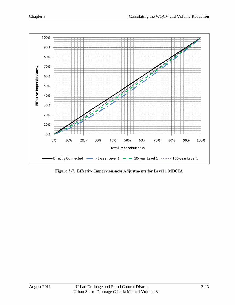
Chapter 3 Calculating the WQCV and Volume Reduction
August 2011 Urban Drainage and Flood Control District 3-13 Urban Storm Drainage Criteria Manual Volume 3
Figure 3-7. Effective Imperviousness Adjustments for Level 1 MDCIA
0%
10%
20%
30%
40%
50%
60%
70%
80%
90%
100%
0% 10% 20% 30% 40% 50% 60% 70% 80% 90% 100%
Effe
ctiv
e Im
perv
ious
ness
Total Imperviousness
Directly Connected 2-year Level 1 10-year Level 1 100-year Level 1
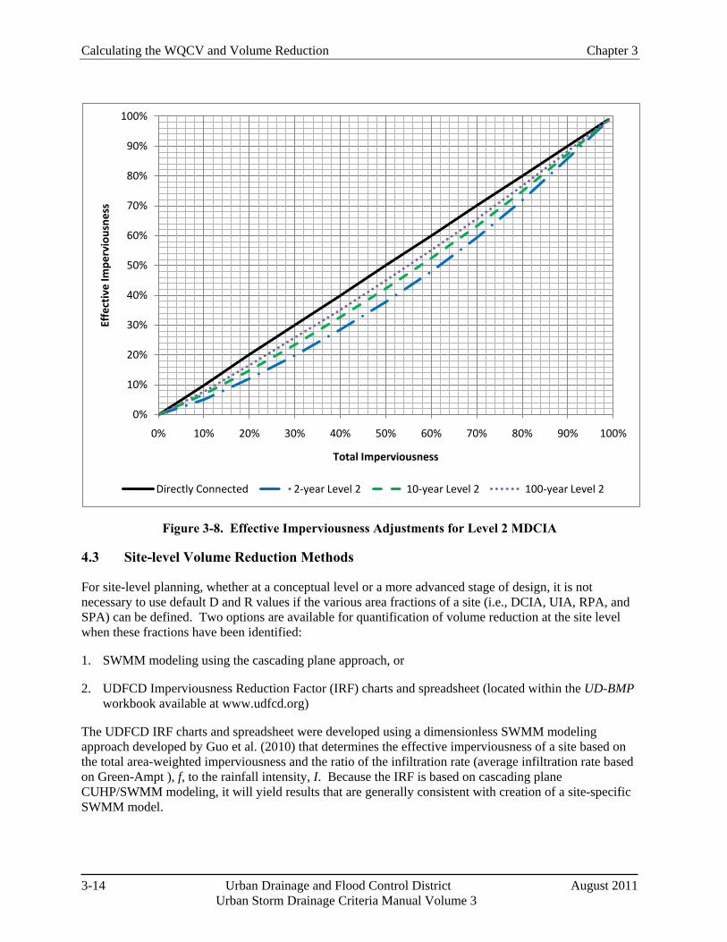
Calculating the WQCV and Volume Reduction Chapter 3
3-14 Urban Drainage and Flood Control District August 2011 Urban Storm Drainage Criteria Manual Volume 3
Figure 3-8. Effective Imperviousness Adjustments for Level 2 MDCIA
4.3 Site-level Volume Reduction Methods
For site-level planning, whether at a conceptual level or a more advanced stage of design, it is not necessary to use default D and R values if the various area fractions of a site (i.e., DCIA, UIA, RPA, and SPA) can be defined. Two options are available for quantification of volume reduction at the site level when these fractions have been identified:
1. SWMM modeling using the cascading plane approach, or
2. UDFCD Imperviousness Reduction Factor (IRF) charts and spreadsheet (located within the UD-BMP workbook available at www.udfcd.org)
The UDFCD IRF charts and spreadsheet were developed using a dimensionless SWMM modeling approach developed by Guo et al. (2010) that determines the effective imperviousness of a site based on the total area-weighted imperviousness and the ratio of the infiltration rate (average infiltration rate based on Green-Ampt ), f, to the rainfall intensity, I. Because the IRF is based on cascading plane CUHP/SWMM modeling, it will yield results that are generally consistent with creation of a site-specific SWMM model.
0%
10%
20%
30%
40%
50%
60%
70%
80%
90%
100%
0% 10% 20% 30% 40% 50% 60% 70% 80% 90% 100%
Effe
ctiv
e Im
perv
ious
ness
Total Imperviousness
Directly Connected 2-year Level 2 10-year Level 2 100-year Level 2
Chapter 3 Calculating the WQCV and Volume Reduction
August 2011 Urban Drainage and Flood Control District 3-15 Urban Storm Drainage Criteria Manual Volume 3
To apply either of the above methods, a project site must first be divided into sub-watersheds based on topography and drainage patterns. For each sub-watershed, the areas of DCIA, UIA, RPA and SPA should be calculated. Sub-watersheds (and associated BMPs) will fall into one of two categories based on the types of BMPs used:
1. Conveyance-based: Conveyance-based BMPs include grass swales, vegetated buffers, and disconnection of roof drains and other impervious areas to drain to pervious areas (UDFCD 1999a). Conveyance based BMPs may have some incidental, short-term storage in the form of channel storage or shallow ponding but do not provide the WQCV, EURV or flood-control detention volume.
2. Storage-based: Storage-based BMPs include rain gardens, permeable pavement systems as detailed in this manual, extended detention basins and other BMPs in this manual that provide the WQCV, EURV or flood control detention volume.
4.3.1 SWMM Modeling Using Cascading Planes
Because of complexities of modeling LID and other BMPs using SWMM, the cascading planes alternative for site-level volume reduction analysis is recommended only for experienced users. Guidance for conveyance- and storage-based modeling includes these steps:
1. Each sub-watershed should be conceptualized as shown in Figure 3-6. Two approaches can be used in SWMM to achieve this:
Create two SWMM sub-catchments for each sub-watershed, one with UIA 100% routed to RPA and the other with DCIA and SPA independently routed to the outlet, or
Use a single SWMM sub-catchment to represent the sub-watershed and use the SWMM internal routing option to differentiate between DCIA and UIA. This option should only be used when a large portion of the pervious area on a site is RPA and there is very little SPA since the internal routing does not have the ability to differentiate between SPA and RPA (i.e., the UIA is routed to the entire pervious area, potentially overestimating infiltration losses).
2. Once the subwatershed is set up to represent UIA, DCIA, RPA and SPA in SWMM, the rainfall distribution should be directly input to SWMM. As an alternative, SWMM can be used only for routing with rainfall-runoff handled in CUHP using sub-watershed specific D and R values to define fractions of pervious and impervious areas.
3. Parameters for infiltration, depression storage and other input parameters should be selected in accordance with the guidance in the Runoff chapter of Volume 1.
4. For storage-based BMPs, there are two options for representing the WQCV:
The pervious area depression storage value for the RPA can be increased to represent the WQCV. This approach is generally applicable to storage-based BMPs that promote infiltration such as rain gardens, permeable pavement systems with storage or sand filters. This adjustment should not be used when a storage-based BMP has a well-defined outlet and a stage-storage-discharge relationship that can be entered into SWMM.
Calculating the WQCV and Volume Reduction Chapter 3
3-16 Urban Drainage and Flood Control District August 2011 Urban Storm Drainage Criteria Manual Volume 3
The WQCV can be modeled as a storage unit with an outlet in SWMM. This option is preferred for storage-based BMPs with well defined stage-storage-discharge relationships such as extended detention basins.
These guidelines are applicable for EPA SWMM Version 5.0.018 and earlier versions going back to EPA SWMM 5.0. EPA is currently developing a version of EPA SWMM with enhanced LID modeling capabilities; however, this version had not been fully vetted at the time this manual was released.
4.3.2 IRF Charts and Spreadsheet
When UIA, DCIA, RPA, SPA and WQCV, if any, for a site have been defined, this method provides a relatively simple procedure for calculating effective imperviousness and volume reduction. Fundamentally, the IRF charts and spreadsheet are based on the following relationships.
For a conveyance-based approach:
𝐾 = Fct ��𝐹𝑑𝑃� ,𝐴𝑟� = ��Fct
𝑓𝐼� ,𝐴𝑟�
For a storage-based approach:
𝐾 = Fct ��𝐹𝑑𝑃� ,𝐴𝑟 ,𝐴𝑑
WQCV𝑃
�
Where Fct designates a functional relationship and:
K = IRF (effective imperviousness/total imperviousness)
Fd = pervious area infiltration loss (in)
P = design rainfall depth (in)
Ar = RPA/UIA
f = pervious area average infiltration rate (in/hr)
I = rainfall intensity (in/hr)
Ad = RPA
WQCV = Water Quality Capture Volume (watershed inches)
A full derivation of equations based on these functional relationships can be found in Guo et al. (2010). The results of cascading plane modeling based on these relationships is shown in Figure 3-9 for the conveyance-based approach and Figure 3-10 for the storage-based approach.
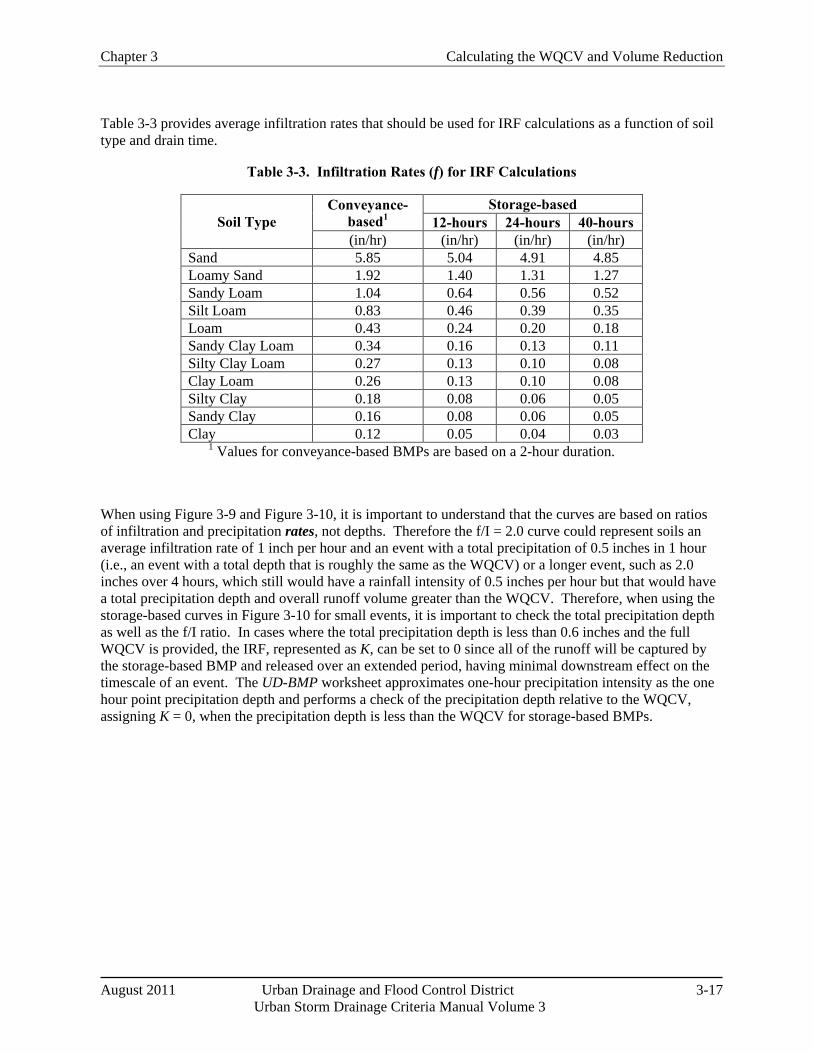
Chapter 3 Calculating the WQCV and Volume Reduction
August 2011 Urban Drainage and Flood Control District 3-17 Urban Storm Drainage Criteria Manual Volume 3
Table 3-3 provides average infiltration rates that should be used for IRF calculations as a function of soil type and drain time.
Table 3-3. Infiltration Rates (f) for IRF Calculations
Soil Type Conveyance-
based1 Storage-based
12-hours 24-hours 40-hours (in/hr) (in/hr) (in/hr) (in/hr)
Sand 5.85 5.04 4.91 4.85 Loamy Sand 1.92 1.40 1.31 1.27 Sandy Loam 1.04 0.64 0.56 0.52 Silt Loam 0.83 0.46 0.39 0.35 Loam 0.43 0.24 0.20 0.18 Sandy Clay Loam 0.34 0.16 0.13 0.11 Silty Clay Loam 0.27 0.13 0.10 0.08 Clay Loam 0.26 0.13 0.10 0.08 Silty Clay 0.18 0.08 0.06 0.05 Sandy Clay 0.16 0.08 0.06 0.05 Clay 0.12 0.05 0.04 0.03
1 Values for conveyance-based BMPs are based on a 2-hour duration.
When using Figure 3-9 and Figure 3-10, it is important to understand that the curves are based on ratios of infiltration and precipitation rates, not depths. Therefore the f/I = 2.0 curve could represent soils an average infiltration rate of 1 inch per hour and an event with a total precipitation of 0.5 inches in 1 hour (i.e., an event with a total depth that is roughly the same as the WQCV) or a longer event, such as 2.0 inches over 4 hours, which still would have a rainfall intensity of 0.5 inches per hour but that would have a total precipitation depth and overall runoff volume greater than the WQCV. Therefore, when using the storage-based curves in Figure 3-10 for small events, it is important to check the total precipitation depth as well as the f/I ratio. In cases where the total precipitation depth is less than 0.6 inches and the full WQCV is provided, the IRF, represented as K, can be set to 0 since all of the runoff will be captured by the storage-based BMP and released over an extended period, having minimal downstream effect on the timescale of an event. The UD-BMP worksheet approximates one-hour precipitation intensity as the one hour point precipitation depth and performs a check of the precipitation depth relative to the WQCV, assigning K = 0, when the precipitation depth is less than the WQCV for storage-based BMPs.
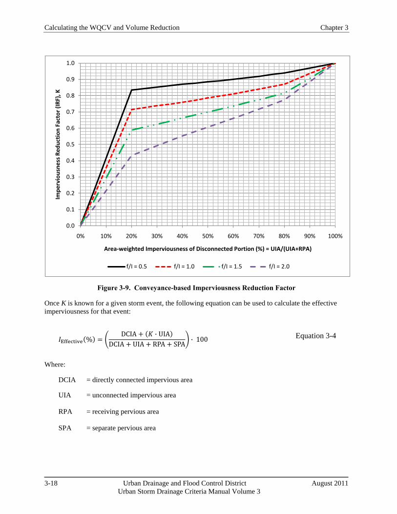
Calculating the WQCV and Volume Reduction Chapter 3
3-18 Urban Drainage and Flood Control District August 2011 Urban Storm Drainage Criteria Manual Volume 3
Figure 3-9. Conveyance-based Imperviousness Reduction Factor
Once K is known for a given storm event, the following equation can be used to calculate the effective imperviousness for that event:
𝐼Effective(%) = �DCIA + (𝐾 ∙ UIA)
DCIA + UIA + RPA + SPA� ∙ 100 Equation 3-4
Where:
DCIA = directly connected impervious area
UIA = unconnected impervious area RPA = receiving pervious area SPA = separate pervious area
0.0
0.1
0.2
0.3
0.4
0.5
0.6
0.7
0.8
0.9
1.0
0% 10% 20% 30% 40% 50% 60% 70% 80% 90% 100%
Impe
rvio
usne
ss R
educ
tion
Fac
tor (
IRF)
, K
Area-weighted Imperviousness of Disconnected Portion (%) = UIA/(UIA+RPA)
f/I = 0.5 f/I = 1.0 f/I = 1.5 f/I = 2.0
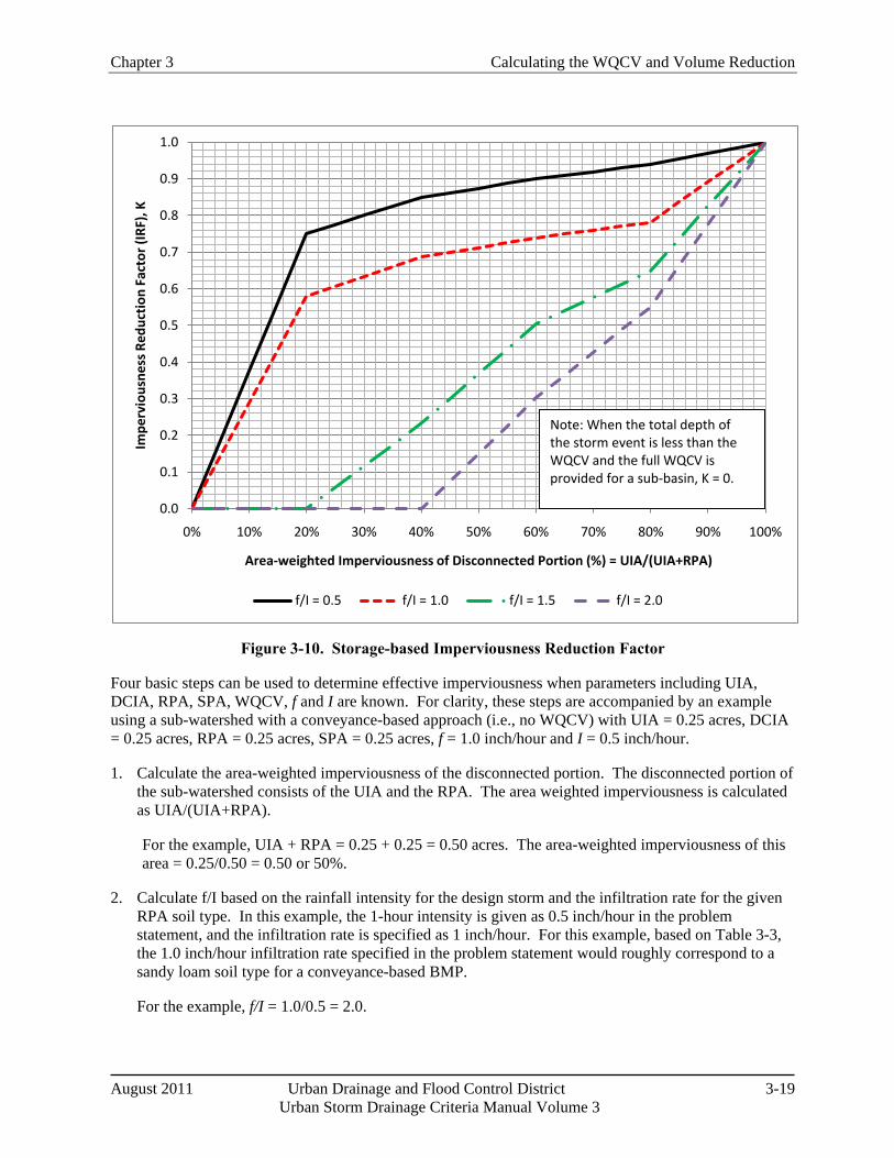
Chapter 3 Calculating the WQCV and Volume Reduction
August 2011 Urban Drainage and Flood Control District 3-19 Urban Storm Drainage Criteria Manual Volume 3
Figure 3-10. Storage-based Imperviousness Reduction Factor
Four basic steps can be used to determine effective imperviousness when parameters including UIA, DCIA, RPA, SPA, WQCV, f and I are known. For clarity, these steps are accompanied by an example using a sub-watershed with a conveyance-based approach (i.e., no WQCV) with UIA = 0.25 acres, DCIA = 0.25 acres, RPA = 0.25 acres, SPA = 0.25 acres, f = 1.0 inch/hour and I = 0.5 inch/hour.
1. Calculate the area-weighted imperviousness of the disconnected portion. The disconnected portion of the sub-watershed consists of the UIA and the RPA. The area weighted imperviousness is calculated as UIA/(UIA+RPA).
For the example, UIA + RPA = 0.25 + 0.25 = 0.50 acres. The area-weighted imperviousness of this area = 0.25/0.50 = 0.50 or 50%.
2. Calculate f/I based on the rainfall intensity for the design storm and the infiltration rate for the given RPA soil type. In this example, the 1-hour intensity is given as 0.5 inch/hour in the problem statement, and the infiltration rate is specified as 1 inch/hour. For this example, based on Table 3-3, the 1.0 inch/hour infiltration rate specified in the problem statement would roughly correspond to a sandy loam soil type for a conveyance-based BMP.
For the example, f/I = 1.0/0.5 = 2.0.
0.0
0.1
0.2
0.3
0.4
0.5
0.6
0.7
0.8
0.9
1.0
0% 10% 20% 30% 40% 50% 60% 70% 80% 90% 100%
Impe
rvio
usne
ss R
educ
tion
Fac
tor (
IRF)
, K
Area-weighted Imperviousness of Disconnected Portion (%) = UIA/(UIA+RPA)
f/I = 0.5 f/I = 1.0 f/I = 1.5 f/I = 2.0
Note: When the total depth of the storm event is less than the WQCV and the full WQCV is provided for a sub-basin, K = 0.
Calculating the WQCV and Volume Reduction Chapter 3
3-20 Urban Drainage and Flood Control District August 2011 Urban Storm Drainage Criteria Manual Volume 3
For simplicity, the 1-hour rainfall intensity can be approximated as the 1-hour point precipitation depth for a given frequency. The 1-hour point precipitation values can be determined from Rainfall Depth-Duration-Frequency figures in the Rainfall chapter of Volume 1.
3. Using the appropriate figure (Figure 3-9 for the conveyance-based approach or Figure 3-10 for the storage-based approach), determine the Imperviousness Reduction Factor, K, corresponding to where the appropriate f/I line would be intersected by the x-axis value for area-weighted imperviousness. Note: Figure 3-10 for the storage-based approach should only be used if the full WQCV is provided for the sub-watershed. If quantification of volume reduction benefits of only a fraction of the WQCV (one-half for example) is required, Figure 3-10 is not applicable and SWMM modeling will be required.
For the example, the K value corresponding to f/I = 2.0 and an area-weighted imperviousness of 50% using the conveyance-based chart, Figure 3-9, is 0.60. It is very important to note that this K value applies only to the disconnected portion of the sub-watershed (i.e., UIA + RPA).
4. Calculate the effective imperviousness of the sub-watershed. This calculation must factor in both connected and disconnected portions of the site:
𝐼Effective(%) = �DCIA + (𝐾 ∙ UIA)
DCIA + UIA + RPA + SPA� ∙ 100
For the example, with DCIA = UIA = RPA = SPA = 0.25 acres and K = 0.60:
𝐼Effectiv𝑒(%) = �0.25 + (0.60 ∙ 0.25)
0.25 + 0.25 + 0.25 + 0.25� ∙ 100 = 40%
This can be compared to the total area-weighted imperviousness for the sub-watershed = (DCIA + UIA)/ (DCIA + UIA + RPA + SPA) × 100% = 50%.
To calculate volume reduction benefits associated with conveyance- or storage-based approaches, the effective imperviousness values determined according to this procedure (or using the spreadsheet tool UD-BMP) can be used in WQCV calculations and detention storage equations, such as the empirical storage equations in the Storage chapter of Volume 1. The WQCV and detention volume requirements calculated using the effective imperviousness can be compared with the same calculations using total sub-watershed imperviousness to determine potential volume reductions.
Section 5.2 provides an example of the storage-based approach to complement the conveyance-based example above, as well as guidance for using the spreadsheet tool.
4.4 Other Types of Credits for Volume Reduction BMPs/LID
In addition to facility sizing reduction credits following the quantitative procedures in Section 4.3, communities can also consider other incentives to encourage volume reduction practices. Such incentives will depend on the policies and objectives of local governments. Representative examples that could be considered include:
Stormwater utility fee credits.
Lower stormwater system development fees when certain minimum criteria are met.
Chapter 3 Calculating the WQCV and Volume Reduction
August 2011 Urban Drainage and Flood Control District 3-21 Urban Storm Drainage Criteria Manual Volume 3
Density bonuses that allow greater residential densities with the implementation of LID techniques.
Variances for requirements such as number of required parking spaces or road widths.
Flexibility in bulk, dimensional and height restrictions, allowing greater building heights and floor area ratios, reduced setbacks and others.
Fast tracking the review process to provide priority status to LID projects with decreased time between receipt and review. If LID projects typically result in a longer review process, ensure equal status.
Publicity such as providing recognition on websites, at Council meetings and in utility mailers.
Opportunities for grant funding for large public projects serving as demonstration projects.
LEED credits for those pursuing U.S. Green Building Council certification. Other green building credit programs such as those related to the Sustainable Sites Initiative may also be applicable.
Flexibility with landscaping requirements (i.e. allowing vegetated BMPs to help satisfy landscape requirements or allowing BMPs to be located in the right-of-way.
LEED credits for those pursuing U.S. Green Building Council certification. Other credit programs such those related to the Sustainable Sites Initiative may also be applicable.
5.0 Examples
5.1 Calculation of WQCV
Calculate the WQCV for a 1.0-acre sub-watershed with a total area-weighted imperviousness of 50% that drains to a rain garden (surface area of the rain garden is included in the 1.0 acre area):
1. Determine the appropriate drain time for the type of BMP. For a rain garden, the required drain time is 12 hours. The corresponding coefficient, a, from Table 3-2 is 0.8.
2. Either calculate or use Figure 3-2 to find the WQCV based on the drain time of 12 hours (a = 0.8) and total imperviousness = 50% (I = 0.50 in Equation 3-1):
WQCV = 0.8(0.91(0.50)3 − 1.19(0.50)2 + 0.78(0.50))
WQCV = 0.17 watershed inches
3. Calculate the WQCV in cubic feet using the total area of the sub-watershed and appropriate unit conversions:
WQCV = (0.17 w. s. in. )(1 ac) �1ft
12 in� �
43560 ft2
1 ac� ≈ 600 ft3
Although this example calculated the WQCV using total area-weighted imperviousness, the same calculation can be repeated using effective imperviousness if LID BMPs are implemented to reduce runoff volume.
Calculating the WQCV and Volume Reduction Chapter 3
3-22 Urban Drainage and Flood Control District August 2011 Urban Storm Drainage Criteria Manual Volume 3
5.2 Volume Reduction Calculations for Storage-based Approach
Determine the effective imperviousness for a 1-acre sub-watershed with a total imperviousness of 50% that is served by a rain garden (storage-based BMP) for the water quality and 10-year events. Assume that the pervious area is equally-split between RPA and SPA with 0.25 acres for each and that the RPA is a rain garden with a sandy loam soil. Because a rain garden provides the WQCV, the curves for the storage-based approach can be used with UIA = 0.50 acres (1 acre ∙ 50% impervious), RPA = 0.25 acres, SPA = 0.25 acres. There is no DCIA because everything drains to the rain garden in this example. To determine f, use Table 3-3 to look up the recommended infiltration rate for a sandy loam corresponding to a 12-hour drain time—the resulting infiltration rate is 0.64 inches/hour.
1. Calculate the area-weighted imperviousness of the disconnected portion. The disconnected portion of the sub-watershed consists of the UIA and the RPA. The area weighted imperviousness is calculated as UIA/(UIA+RPA).
For the example, UIA + RPA = 0.50 + 0.25 = 0.75 acres. The area-weighted imperviousness of this area = 0.50/0.75 = 0.67 or 67%.
2. Determine rainfall intensities for calculation of f/I ratios. For the water quality event, which is roughly an 80th percentile event, there is no specified duration, so assume rainfall intensity based on a 1-hour duration, giving an intensity of approximately 0.6 inches/hour. For the water quality event, this is generally a conservative assumption since the runoff that enters the rain garden will have a mean residence time in the facility of much more than 1 hour. For the 10-year event, the 1-hour point rainfall depth from the Rainfall chapter, can be used to approximate the rainfall intensity for calculation of the f/I ratio. For this example, the 1-hour point precipitation for the 10-year event is approximately 1.55 inches, equating to an intensity of 1.55 inches/hour.
3. Calculate f/I based on the design rainfall intensity (0.6 inches/hour) and RPA infiltration rate from Table 3-3 (0.64 inches/hour).
For the water quality event, f/I = 0.64/0.6 = 1.07.
For the 10-year event, f/I = 0.64/1.55 = 0.41.
4. Using the appropriate figure (Figure 3-10 for the storage-based approach in this case), determine the Imperviousness Reduction Factor K, corresponding to where the appropriate f/I line would be intersected by the x-axis value for area-weighted imperviousness.
For the water quality event, the K value corresponding to f/I = 1.07 and an area-weighted imperviousness of 50% using the storage-based chart, Figure 3-10, would be approximately 0.64; however, because the total depth of the water quality event is provided as the WQCV for the storage-based rain garden, K is reduced to 0 for the water quality event.
For the 10-year event, the K value corresponding to f/I = 0.41 and an area-weighted imperviousness of 50% using the storage-based chart, Figure 3-10, is approximately 0.94.
It is very important to note that these K value applies only to the disconnected portion of the sub-watershed (i.e., UIA + RPA). If this example included DCIA, the total imperviousness would be higher.
Chapter 3 Calculating the WQCV and Volume Reduction
August 2011 Urban Drainage and Flood Control District 3-23 Urban Storm Drainage Criteria Manual Volume 3
5. Calculate the effective imperviousness of the sub-watershed. This calculation must factor in both connected and disconnected portions of the site:
𝐼Effective = �DCIA + (𝐾 ∙ UIA)
DCIA + UIA + RPA + SPA� ∙ 100
For the water quality event, with DCIA = 0 acres, UIA = 0.5 acres and RPA = SPA = 0.25 acres, with K = 0:
𝐼Effective = �0.00 + (0.0 ∙ 0.5)
0.0 + 0.5 + 0.25 + 0.25� ∙ 100 = 0%
For the 10-year event, with DCIA = 0 acres, UIA = 0.5 acres and RPA = SPA = 0.25 acres, with K = 0.94:
𝐼Effective = �0.00 + (0.94 ∙ 0.5)
0.0 + 0.5 + 0.25 + 0.25� ∙ 100 = 47%
These effective imperviousness values for the sub-watershed (0% for the water quality event and 47% for the 10-year event) can be compared to the total area-weighted imperviousness of 50%. These values can be used for sizing of conveyance and detention facilities.
5.3 Effective Imperviousness Spreadsheet
Because most sites will consist of multiple sub-watersheds, some using the conveyance-based approach and others using the storage-based approach, a spreadsheet capable of applying both approaches to multiple sub-watersheds to determine overall site effective imperviousness and volume reduction benefits is a useful tool. The UD-BMP workbook has this capability.
Spreadsheet inputs include the following for each sub-watershed:
Sub-watershed ID = Alphanumeric identifier for sub-watershed
Receiving Pervious Area Soil Type
Total Area (acres)
DCIA = directly connected impervious area (acres)
UIA = unconnected impervious area (acres)
RPA = receiving pervious area (acres)
SPA = separate pervious area (acres)
Infiltration rate, f, for RPA = RPA infiltration rate from Table 3-3 (based on soil type)
Sub-watershed type = conveyance-based "C" or volume-based "V"
Rainfall input = 1-hour point rainfall depths from Rainfall Depth-Duration-Frequency figures in the Rainfall chapter of Volume 1.
Calculating the WQCV and Volume Reduction Chapter 3
3-24 Urban Drainage and Flood Control District August 2011 Urban Storm Drainage Criteria Manual Volume 3
Calculated values include percentages of UIA, DCIA, RPA, and SPA; f/I values for design events; Imperviousness Reduction Factors (K values) for design events; effective imperviousness for design events for sub-watersheds and for the site as a whole; WQCV for total and effective imperviousness; and 10- and 100-year empirical detention storage volumes for total and effective imperviousness. Note that there may be slight differences in results between using the spreadsheet and the figures in this chapter due to interpolation to translate the figures into a format that can be more-easily implemented in the spreadsheet.
To demonstrate how the spreadsheet works, this section steps through two sub-basins from the Colorado Green development, shown in Figure 3-11. The Colorado Green development is a hypothetical LID development based on a real site plan. This example focuses on two sub-basins: (1) Sub-basin A which uses a volume-based approach and (2) Sub-basin E, which uses a conveyance-based LID approach. Note: For users working through this example using a calculator, to achieve results that closely agree with the spreadsheet entries, do not round interim results when used in subsequent equations.
Precipitation Input
Input data for precipitation include the following (see Figure 3-12).
1-hour point precipitation depth for the water quality event: The WQCV is relatively constant across the metropolitan Denver area, and is set at 0.60 inches. There is no specified duration for the WQCV, so for purposes of conservatively estimating the 1-hour point rainfall depth, the spreadsheet input assumes that the WQCV total precipitation depth occurs over a period of one hour. The spreadsheet input value for the 1-hour point rainfall depth for the water quality event should not change from the value in the example spreadsheet as long as the project is in the metropolitan Denver area.
10-year, 1-hour point rainfall depth: Determine the 10-year 1-hour point rainfall depths from Rainfall Depth-Duration-Frequency figures in the Rainfall chapter. For this example, the 10-year, 1-hour point rainfall depth is approximately 1.55 inches.
100-year, 1-hour point rainfall depth: Determine the 100-year 1-hour point rainfall depths from Rainfall Depth-Duration-Frequency figures in the Rainfall chapter. For this example, the 100-year, 1-hour point rainfall depth is approximately 2.60 inches.
Area and Infiltration Inputs
After precipitation data have been entered, the next step is to classify all areas of the site as UIA, RPA, DCIA, or SPA (see Figure 3-11) and to enter the areas into the spreadsheet in appropriate columns. Please note that blue bordered cells are designated for input, while black bordered cells are calculations performed by the spreadsheet. For the two sub-basins used in this example, A and E, inputs are:
Sub-basin A—DCIA = 0.00 ac, UIA = 0.56 ac, RPA =0.44 ac, SPA = 0.15 ac
Sub-basin E—DCIA = 0.00 ac, UIA = 0.11 ac, RPA =0.04 ac, SPA = 0.00 ac
The program calculates total area for each sub-basin as DCIA + UIA + RPA+ SPA and ensures that this value matches the user input value for total area:
Sub-basin A Total Area (ac) = 0.00 + 0.56 + 0.15 + 0.44 = 1.15 ac
Sub-basin E Total Area (ac) = 0.00 + 0.11 + 0.00 + 0.04 = 0.15 ac
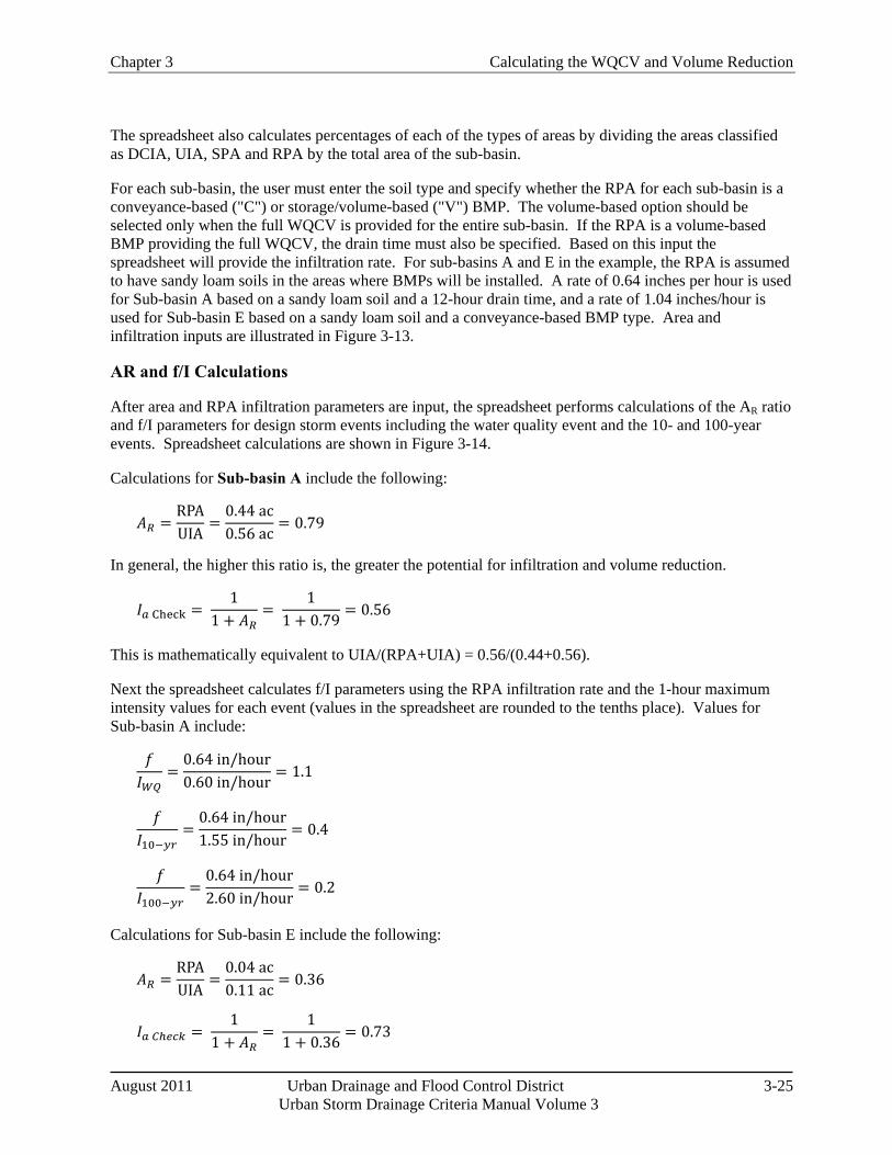
Chapter 3 Calculating the WQCV and Volume Reduction
August 2011 Urban Drainage and Flood Control District 3-25 Urban Storm Drainage Criteria Manual Volume 3
The spreadsheet also calculates percentages of each of the types of areas by dividing the areas classified as DCIA, UIA, SPA and RPA by the total area of the sub-basin.
For each sub-basin, the user must enter the soil type and specify whether the RPA for each sub-basin is a conveyance-based ("C") or storage/volume-based ("V") BMP. The volume-based option should be selected only when the full WQCV is provided for the entire sub-basin. If the RPA is a volume-based BMP providing the full WQCV, the drain time must also be specified. Based on this input the spreadsheet will provide the infiltration rate. For sub-basins A and E in the example, the RPA is assumed to have sandy loam soils in the areas where BMPs will be installed. A rate of 0.64 inches per hour is used for Sub-basin A based on a sandy loam soil and a 12-hour drain time, and a rate of 1.04 inches/hour is used for Sub-basin E based on a sandy loam soil and a conveyance-based BMP type. Area and infiltration inputs are illustrated in Figure 3-13.
AR and f/I Calculations
After area and RPA infiltration parameters are input, the spreadsheet performs calculations of the AR ratio and f/I parameters for design storm events including the water quality event and the 10- and 100-year events. Spreadsheet calculations are shown in Figure 3-14.
Calculations for Sub-basin A include the following:
𝐴𝑅 =RPAUIA
=0.44 ac0.56 ac
= 0.79
In general, the higher this ratio is, the greater the potential for infiltration and volume reduction.
𝐼𝑎 Check = 1
1 + 𝐴𝑅=
11 + 0.79
= 0.56
This is mathematically equivalent to UIA/(RPA+UIA) = 0.56/(0.44+0.56).
Next the spreadsheet calculates f/I parameters using the RPA infiltration rate and the 1-hour maximum intensity values for each event (values in the spreadsheet are rounded to the tenths place). Values for Sub-basin A include:
𝑓𝐼𝑊𝑄
=0.64 in/hour0.60 in/hour
= 1.1
𝑓𝐼10−𝑦𝑟
=0.64 in/hour1.55 in/hour
= 0.4
𝑓𝐼100−𝑦𝑟
=0.64 in/hour2.60 in/hour
= 0.2
Calculations for Sub-basin E include the following:
𝐴𝑅 =RPAUIA
=0.04 ac0.11 ac
= 0.36
𝐼𝑎 𝐶ℎ𝑒𝑐𝑘 = 1
1 + 𝐴𝑅=
11 + 0.36
= 0.73
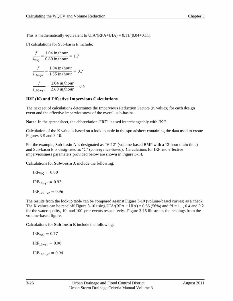
Calculating the WQCV and Volume Reduction Chapter 3
3-26 Urban Drainage and Flood Control District August 2011 Urban Storm Drainage Criteria Manual Volume 3
This is mathematically equivalent to UIA/(RPA+UIA) = 0.11/(0.04+0.11).
f/I calculations for Sub-basin E include:
𝑓𝐼𝑊𝑄
=1.04 in/hour0.60 in/hour
= 1.7
𝑓𝐼10−𝑦𝑟
=1.04 in/hour1.55 in/hour
= 0.7
𝑓𝐼100−𝑦𝑟
=1.04 in/hour2.60 in/hour
= 0.4
IRF (K) and Effective Impervious Calculations
The next set of calculations determines the Impervious Reduction Factors (K values) for each design event and the effective imperviousness of the overall sub-basins.
Note: In the spreadsheet, the abbreviation "IRF" is used interchangeably with "K."
Calculation of the K value is based on a lookup table in the spreadsheet containing the data used to create Figures 3-9 and 3-10.
For the example, Sub-basin A is designated as "V-12" (volume-based BMP with a 12-hour drain time) and Sub-basin E is designated as "C" (conveyance-based). Calculations for IRF and effective imperviousness parameters provided below are shown in Figure 3-14.
Calculations for Sub-basin A include the following:
IRFWQ = 0.00
IRF10−yr = 0.92
IRF100−yr = 0.96
The results from the lookup table can be compared against Figure 3-10 (volume-based curves) as a check. The K values can be read off Figure 3-10 using UIA/(RPA + UIA) = 0.56 (56%) and f/I = 1.1, 0.4 and 0.2 for the water quality, 10- and 100-year events respectively. Figure 3-15 illustrates the readings from the volume-based figure.
Calculations for Sub-basin E include the following:
IRFWQ = 0.77
IRF10−yr = 0.90
IRF100−yr = 0.94
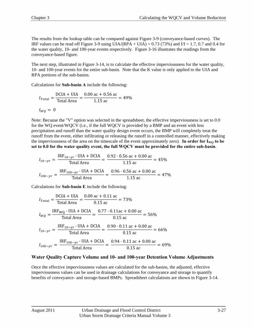
Chapter 3 Calculating the WQCV and Volume Reduction
August 2011 Urban Drainage and Flood Control District 3-27 Urban Storm Drainage Criteria Manual Volume 3
The results from the lookup table can be compared against Figure 3-9 (conveyance-based curves). The IRF values can be read off Figure 3-9 using UIA/(RPA + UIA) = 0.73 (73%) and f/I = 1.7, 0.7 and 0.4 for the water quality, 10- and 100-year events respectively. Figure 3-16 illustrates the readings from the conveyance-based figure.
The next step, illustrated in Figure 3-14, is to calculate the effective imperviousness for the water quality, 10- and 100-year events for the entire sub-basin. Note that the K value is only applied to the UIA and RPA portions of the sub-basins.
Calculations for Sub-basin A include the following:
𝐼𝑇𝑜𝑡𝑎𝑙 =DCIA + UIATotal Area
=0.00 ac + 0.56 ac
1.15 ac= 49%
𝐼𝑊𝑄 = 0
Note: Because the "V" option was selected in the spreadsheet, the effective imperviousness is set to 0.0 for the WQ event/WQCV (i.e., if the full WQCV is provided by a BMP and an event with less precipitation and runoff than the water quality design event occurs, the BMP will completely treat the runoff from the event, either infiltrating or releasing the runoff in a controlled manner, effectively making the imperviousness of the area on the timescale of the event approximately zero). In order for IWQ to be set to 0.0 for the water quality event, the full WQCV must be provided for the entire sub-basin.
𝐼10−𝑦𝑟 = IRF10−yr ∙ UIA + DCIA
Total Area=
0.92 ∙ 0.56 ac + 0.00 ac1.15 ac
= 45%
𝐼100−𝑦𝑟 = IRF100−yr ∙ UIA + DCIA
Total Area=
0.96 ∙ 0.56 ac + 0.00 ac1.15 ac
= 47%
Calculations for Sub-basin E include the following:
𝐼𝑇𝑜𝑡𝑎𝑙 =DCIA + UIATotal Area
=0.00 ac + 0.11 ac
0.15 ac= 73%
𝐼𝑊𝑄 =IRFWQ ∙ UIA + DCIA
Total Area=
0.77 ∙ 0.11ac + 0.00 ac0.15 ac
= 56%
𝐼10−𝑦𝑟 = IRF10−yr ∙ UIA + DCIA
Total Area=
0.90 ∙ 0.11 ac + 0.00 ac0.15 ac
= 66%
𝐼100−𝑦𝑟 = IRF100−yr ∙ UIA + DCIA
Total Area=
0.94 ∙ 0.11 ac + 0.00 ac0.15 ac
= 69%
Water Quality Capture Volume and 10- and 100-year Detention Volume Adjustments
Once the effective imperviousness values are calculated for the sub-basins, the adjusted, effective imperviousness values can be used in drainage calculations for conveyance and storage to quantify benefits of conveyance- and storage-based BMPs. Spreadsheet calculations are shown in Figure 3-14.
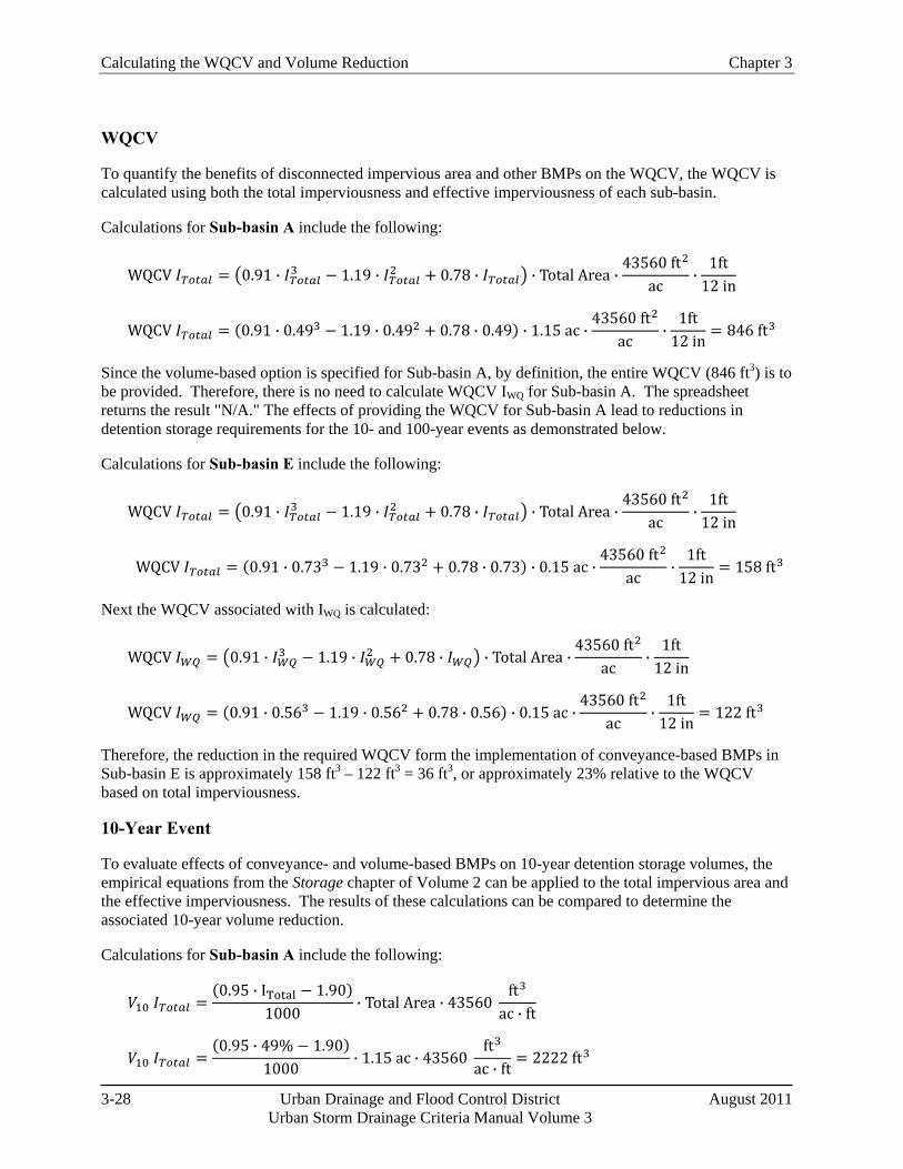
Calculating the WQCV and Volume Reduction Chapter 3
3-28 Urban Drainage and Flood Control District August 2011 Urban Storm Drainage Criteria Manual Volume 3
WQCV
To quantify the benefits of disconnected impervious area and other BMPs on the WQCV, the WQCV is calculated using both the total imperviousness and effective imperviousness of each sub-basin.
Calculations for Sub-basin A include the following:
WQCV 𝐼𝑇𝑜𝑡𝑎𝑙 = �0.91 ∙ 𝐼𝑇𝑜𝑡𝑎𝑙3 − 1.19 ∙ 𝐼𝑇𝑜𝑡𝑎𝑙2 + 0.78 ∙ 𝐼𝑇𝑜𝑡𝑎𝑙� ∙ Total Area ∙43560 ft2
ac∙
1ft12 in
WQCV 𝐼𝑇𝑜𝑡𝑎𝑙 = (0.91 ∙ 0.493 − 1.19 ∙ 0.492 + 0.78 ∙ 0.49) ∙ 1.15 ac ∙43560 ft2
ac∙
1ft12 in
= 846 ft3
Since the volume-based option is specified for Sub-basin A, by definition, the entire WQCV (846 ft3) is to be provided. Therefore, there is no need to calculate WQCV IWQ for Sub-basin A. The spreadsheet returns the result "N/A." The effects of providing the WQCV for Sub-basin A lead to reductions in detention storage requirements for the 10- and 100-year events as demonstrated below.
Calculations for Sub-basin E include the following:
WQCV 𝐼𝑇𝑜𝑡𝑎𝑙 = �0.91 ∙ 𝐼𝑇𝑜𝑡𝑎𝑙3 − 1.19 ∙ 𝐼𝑇𝑜𝑡𝑎𝑙2 + 0.78 ∙ 𝐼𝑇𝑜𝑡𝑎𝑙� ∙ Total Area ∙43560 ft2
ac∙
1ft12 in
WQCV 𝐼𝑇𝑜𝑡𝑎𝑙 = (0.91 ∙ 0.733 − 1.19 ∙ 0.732 + 0.78 ∙ 0.73) ∙ 0.15 ac ∙43560 ft2
ac∙
1ft12 in
= 158 ft3
Next the WQCV associated with IWQ is calculated:
WQCV 𝐼𝑊𝑄 = �0.91 ∙ 𝐼𝑊𝑄3 − 1.19 ∙ 𝐼𝑊𝑄
2 + 0.78 ∙ 𝐼𝑊𝑄� ∙ Total Area ∙43560 ft2
ac∙
1ft12 in
WQCV 𝐼𝑊𝑄 = (0.91 ∙ 0.563 − 1.19 ∙ 0.562 + 0.78 ∙ 0.56) ∙ 0.15 ac ∙43560 ft2
ac∙
1ft12 in
= 122 ft3
Therefore, the reduction in the required WQCV form the implementation of conveyance-based BMPs in Sub-basin E is approximately 158 ft3 – 122 ft3 = 36 ft3, or approximately 23% relative to the WQCV based on total imperviousness.
10-Year Event
To evaluate effects of conveyance- and volume-based BMPs on 10-year detention storage volumes, the empirical equations from the Storage chapter of Volume 2 can be applied to the total impervious area and the effective imperviousness. The results of these calculations can be compared to determine the associated 10-year volume reduction.
Calculations for Sub-basin A include the following:
𝑉10 𝐼𝑇𝑜𝑡𝑎𝑙 =(0.95 ∙ ITotal − 1.90)
1000∙ Total Area ∙ 43560
ft3
ac ∙ ft
𝑉10 𝐼𝑇𝑜𝑡𝑎𝑙 =(0.95 ∙ 49% − 1.90)
1000∙ 1.15 ac ∙ 43560
ft3
ac ∙ ft= 2222 ft3
Chapter 3 Calculating the WQCV and Volume Reduction
August 2011 Urban Drainage and Flood Control District 3-29 Urban Storm Drainage Criteria Manual Volume 3
The same calculation is then performed using the effective imperviousness for the 10-year event:
𝑉10 𝐼10−𝑦𝑟 𝐸𝑓𝑓𝑒𝑐𝑡𝑖𝑣𝑒 =�0.95 ∙ 𝐼10−𝑦𝑟 𝐸𝑓𝑓𝑒𝑐𝑡𝑖𝑣𝑒 − 1.90�
1000∙ Total Area ∙ 43560
ft3
ac ∙ ft
𝑉10 𝐼𝑇𝑜𝑡𝑎𝑙 =(0.95 ∙ 45% − 1.90)
1000∙ 1.15 ac ∙ 43560
ft3
ac ∙ ft= 2046 ft3
The reduction in the 10-year storage volume as a result of the conveyance-based BMPs in Sub-basin A is, therefore, 2222 ft3 – 2046 ft3 = 176 ft3, or approximately 8% relative to the 10-year storage volume based on total imperviousness.
Calculations for Sub-basin E include the following:
𝑉10 𝐼𝑇𝑜𝑡𝑎𝑙 =(0.95 ∙ 𝐼𝑇𝑜𝑡𝑎𝑙 − 1.90)
1000∙ Total Area ∙ 43560
ft3
ac ∙ ft
𝑉10 𝐼𝑇𝑜𝑡𝑎𝑙 =(0.95 ∙ 73% − 1.90)
1000∙ 0.15 ac ∙ 43560
ft3
ac ∙ ft= 443 ft3
The same calculation is then performed using the effective imperviousness for the 10-year event:
𝑉10 𝐼10−𝑦𝑟 𝐸𝑓𝑓𝑒𝑐𝑡𝑖𝑣𝑒 =�0.95 ∙ 𝐼10−𝑦𝑟 𝐸𝑓𝑓𝑒𝑐𝑡𝑖𝑣𝑒 − 1.90�
1000∙ Total Area ∙ 43560
ft3
ac ∙ ft
𝑉10 𝐼10−𝑦𝑟 𝐸𝑓𝑓𝑒𝑐𝑡𝑖𝑣𝑒 =(0.95 ∙ 66% − 1.90)
1000∙ 0.15 ac ∙ 43560
ft3
ac ∙ ft= 395 ft3
The reduction in the 10-year storage volume as a result of the conveyance-based BMPs in Sub-basin E is, therefore, 443 ft3 – 395 ft3 = 48 ft3, or approximately 11% relative to the 10-year storage volume based on total imperviousness.
100-Year Event
To evaluate effects of conveyance- and volume-based BMPs on 100-year detention storage volumes, the empirical equations from the Storage chapter of Volume 2 can be applied to the total impervious area and the effective imperviousness. The results of these calculations can be compared to determine the associated 100-year volume reduction. Please note that there are two empirical equations for the 100-year detention storage volume in the Storage chapter, one for HSG A soils and the other for HSG B, C and D soils. The spreadsheet selects the appropriate equation based on the RPA infiltration rate that is input for the sub-basin. If the RPA infiltration rate is greater than or equal to 1 inch/hour, the HSG A equation is used. Otherwise, the HSG B, C and D equation is used.
Calculations for Sub-basin A include the following:
𝑉100 𝐼𝑇𝑜𝑡𝑎𝑙 =�−0.00005501 ∙ 𝐼𝑇𝑜𝑡𝑎𝑙2 + 0.030148 ∙ 𝐼𝑇𝑜𝑡𝑎𝑙 − 0.12�
12∙ Total Area ∙ 43560
ft3
ac ∙ ft
𝑉100 𝐼𝑇𝑜𝑡𝑎𝑙 =(−0.00005501 ∙ 49%2 + 0.030148 ∙ 49% − 0.12)
12∙ 1.15 ac ∙ 43560
ft3
ac ∙ ft= 5083 𝑓𝑡3
Calculating the WQCV and Volume Reduction Chapter 3
3-30 Urban Drainage and Flood Control District August 2011 Urban Storm Drainage Criteria Manual Volume 3
The same calculation is then performed using the effective imperviousness for the 100-year event:
𝑉100 𝐼100−𝑦𝑟 𝐸𝑓𝑓𝑒𝑐𝑡𝑖𝑣𝑒
=�−0.00005501 ∙ 𝐼100−𝑦𝑟 𝐸𝑓𝑓𝑒𝑐𝑡𝑖𝑣𝑒
2 + 0.030148 ∙ 𝐼100−𝑦𝑟 𝐸𝑓𝑓𝑒𝑐𝑡𝑖𝑣𝑒 − 0.12�12
∙ Total Area ∙ 43560 ft3
ac ∙ ft
𝑉100 𝐼100−𝑦𝑟 𝐸𝑓𝑓𝑒𝑐𝑡𝑖𝑣𝑒 =(−0.00005501 ∙ 47%2 + 0.030148 ∙ 47% − 0.12)
12∙ 1.15 ac ∙ 43560
ft3
ac ∙ ft= 4865 ft3
The reduction in the 100-year storage volume, as a result of the conveyance-based BMPs in Sub-basin A, is 5083 ft3 – 4865 ft3 = 218 ft3, a reduction of approximately 4.3%.
Calculations for Sub-basin E include the following:
𝑉100 𝐼𝑇𝑜𝑡𝑎𝑙 =�−0.00005501 ∙ 𝐼𝑇𝑜𝑡𝑎𝑙2 + 0.030148 ∙ 𝐼𝑇𝑜𝑡𝑎𝑙 − 0.12�
12∙ Total Area ∙ 43560
ft3
ac ∙ ft
𝑉100 𝐼𝑇𝑜𝑡𝑎𝑙 =(−0.00005501 ∙ 73%2 + 0.030148 ∙ 73% − 0.12)
12∙ 0.15 ac ∙ 43560
ft3
ac ∙ ft= 977 ft3
The same calculation is then performed using the effective imperviousness for the 100-year event:
𝑉100 𝐼100−𝑦𝑟 𝐸𝑓𝑓𝑒𝑐𝑡𝑖𝑣𝑒
=�−0.00005501 ∙ 𝐼100−𝑦𝑟 𝐸𝑓𝑓𝑒𝑐𝑡𝑖𝑣𝑒
2 + 0.030148 ∙ 𝐼100−𝑦𝑟 𝐸𝑓𝑓𝑒𝑐𝑡𝑖𝑣𝑒 − 0.12�12
∙ Total Area ∙ 43560 ft3
ac ∙ ft
𝑉100 𝐼100−𝑦𝑟 𝐸𝑓𝑓𝑒𝑐𝑡𝑖𝑣𝑒 =(−0.00005501 ∙ 69%2 + 0.030148 ∙ 69% − 0.12)
12∙ 0.15 ac ∙ 43560
ft3
ac ∙ ft= 927 ft3
The reduction in the 100-year storage volume as a result of the volume-based BMPs in Sub-basin E is, therefore, 977ft3 – 927 ft3 = 50 ft3, a reduction of approximately 5%.
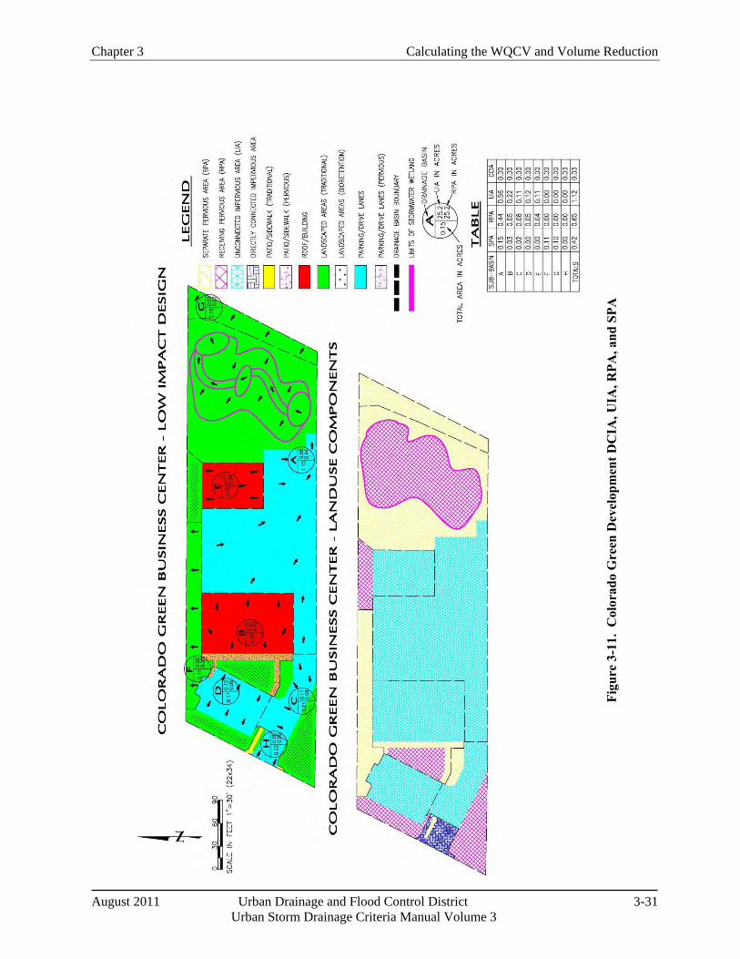
Chapter 3 Calculating the WQCV and Volume Reduction
August 2011 Urban Drainage and Flood Control District 3-31 Urban Storm Drainage Criteria Manual Volume 3
Figu
re 3
-11.
Col
orad
o G
reen
Dev
elop
men
t DC
IA, U
IA, R
PA, a
nd S
PA
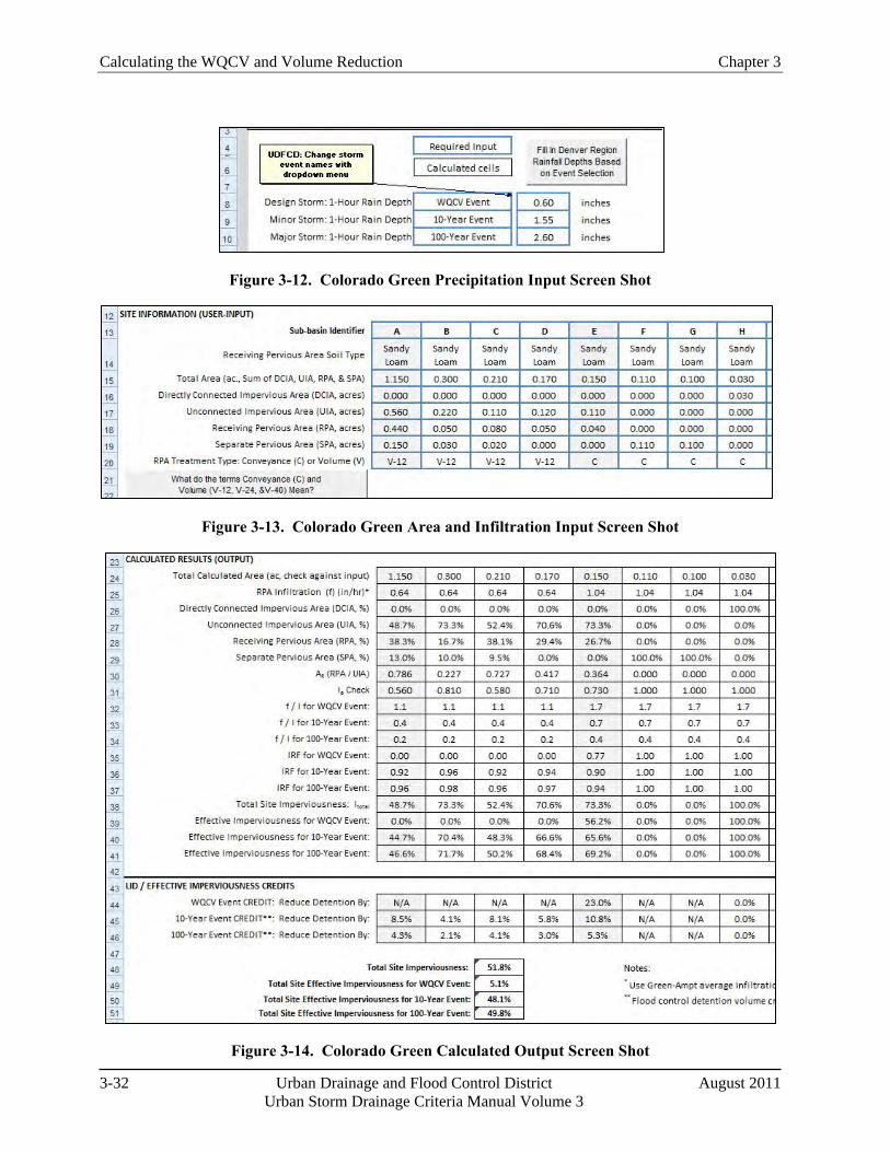
Calculating the WQCV and Volume Reduction Chapter 3
3-32 Urban Drainage and Flood Control District August 2011 Urban Storm Drainage Criteria Manual Volume 3
Figure 3-12. Colorado Green Precipitation Input Screen Shot
Figure 3-13. Colorado Green Area and Infiltration Input Screen Shot
Figure 3-14. Colorado Green Calculated Output Screen Shot
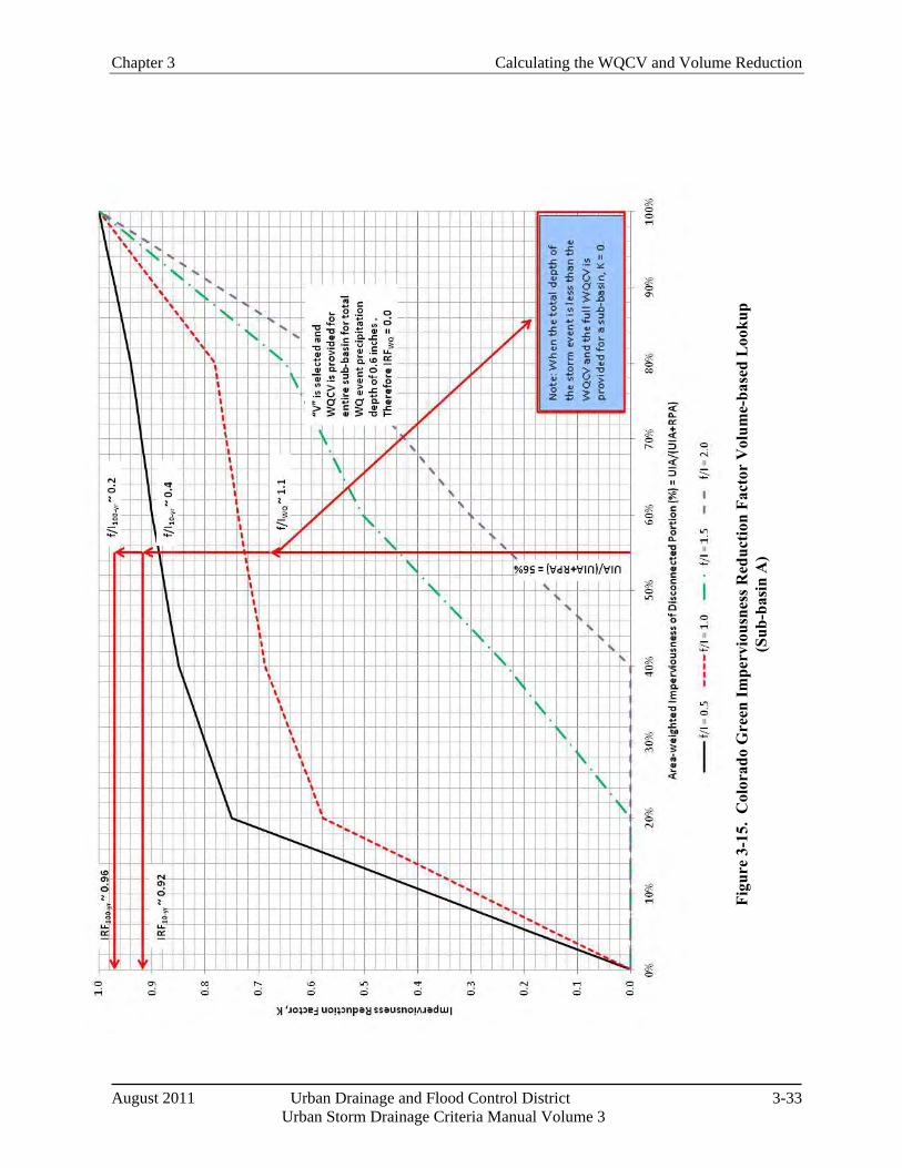
Chapter 3 Calculating the WQCV and Volume Reduction
August 2011 Urban Drainage and Flood Control District 3-33 Urban Storm Drainage Criteria Manual Volume 3
Figu
re 3
-15.
Col
orad
o G
reen
Impe
rvio
usne
ss R
educ
tion
Fact
or V
olum
e-ba
sed
Loo
kup
(Sub
-bas
in A
)
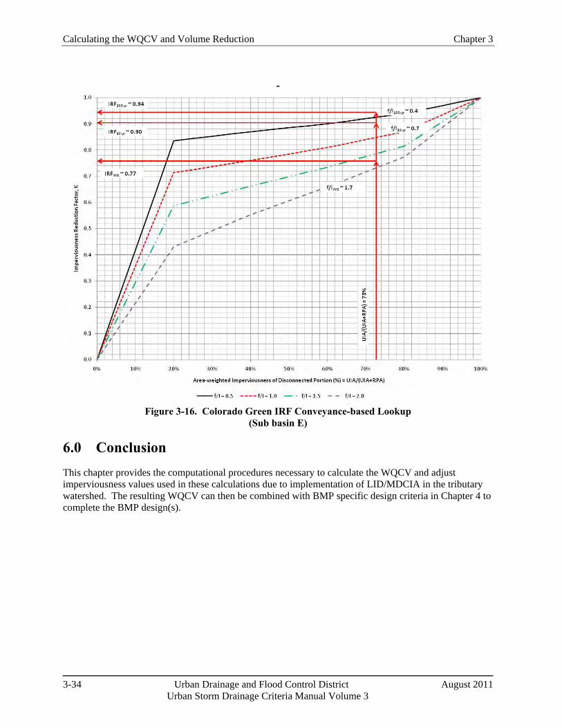
Calculating the WQCV and Volume Reduction Chapter 3
3-34 Urban Drainage and Flood Control District August 2011 Urban Storm Drainage Criteria Manual Volume 3
-
Figure 3-16. Colorado Green IRF Conveyance-based Lookup
(Sub basin E)
6.0 Conclusion This chapter provides the computational procedures necessary to calculate the WQCV and adjust imperviousness values used in these calculations due to implementation of LID/MDCIA in the tributary watershed. The resulting WQCV can then be combined with BMP specific design criteria in Chapter 4 to complete the BMP design(s).
Chapter 3 Calculating the WQCV and Volume Reduction
August 2011 Urban Drainage and Flood Control District 3-35 Urban Storm Drainage Criteria Manual Volume 3
7.0 References Driscoll, E., G. Palhegyi, E. Strecker, and P. Shelley. 1990. Analysis of Storm Event Characteristics for
Selected Rainfall Gauges Throughout the United States. Prepared for the U.S. Environmental Protection Agency (EPA). Woodward-Clyde Consultants: Oakland, CA.
Guo, James C.Y., E. G. Blackler, A. Earles, and Ken Mackenzie. Accepted 2010. Effective Imperviousness as Incentive Index for Stormwater LID Designs. Pending publication in ASCE J. of Environmental Engineering.
Guo, James C.Y. 2006. Urban Hydrology and Hydraulic Design. Water Resources Publications, LLC.: Highlands Ranch, Colorado.
Guo, James C.Y. and Ben Urbonas. 1996. Maximized Detention Volume Determined by Runoff Capture Rate. ASCE Journal of Water Resources Planning and Management, Vol. 122, No 1, January.
Urbonas, B., L. A. Roesner, and C. Y. Guo. 1996. Hydrology for Optimal Sizing of Urban Runoff Treatment Control Systems. Water Quality International. International Association for Water Quality: London, England.
Urbonas B., J. C. Y. Guo, and L. S. Tucker. 1989 updated 1990. Sizing Capture Volume for Stormwater Quality Enhancement. Flood Hazard News. Urban Drainage and Flood Control District: Denver, CO.
Water Environment Federation and American Society of Civil Engineers. 1998. Urban Runoff Quality Management. WEF Manual of Practice No. 23. ASCE Manual and Report on Engineering Practice No. 87.

November 2010 Urban Drainage and Flood Control District 4-i Urban Storm Drainage Criteria Manual Volume 3
Chapter 4 Treatment BMPs Contents 1.0 Overview ........................................................................................................................................... 1
2.0 Treatment BMP Fact Sheets ........................................................................................................... 2
3.0 References ......................................................................................................................................... 4
Treatment BMP Fact Sheets T-1 Grass Buffer T-2 Grass Swale T-3 Bioretention (Rain Garden or Porous Landscape Detention) T-4 Green Roof T-5 Extended Detention Basin (EDB) T-6 Sand Filter T-7 Retention Pond T-8 Constructed Wetland Pond T-9 Constructed Wetland Channel T-10 Permeable Pavements: T-10.1 Permeable Interlocking Concrete Pavements (PICP) T-10.2 Concrete Grid Pavement T-10.3 Pervious Concrete T-10.4 Porous Gravel Pavement T-10.5 Reinforced Grass Pavement T-11 Underground BMPs T-12 Outlet Structures
Tables Table 4.1. General Overview of Treatment BMP's Included in Volume 3 .................................................. 3

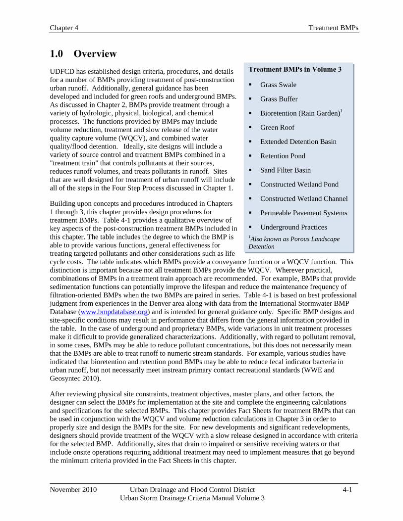
Chapter 4 Treatment BMPs
November 2010 Urban Drainage and Flood Control District 4-1 Urban Storm Drainage Criteria Manual Volume 3
Treatment BMPs in Volume 3
Grass Swale
Grass Buffer
Bioretention (Rain Garden)1
Green Roof
Extended Detention Basin
Retention Pond
Sand Filter Basin
Constructed Wetland Pond
Constructed Wetland Channel
Permeable Pavement Systems
Underground Practices 1Also known as Porous Landscape Detention
1.0 Overview UDFCD has established design criteria, procedures, and details for a number of BMPs providing treatment of post-construction urban runoff. Additionally, general guidance has been developed and included for green roofs and underground BMPs. As discussed in Chapter 2, BMPs provide treatment through a variety of hydrologic, physical, biological, and chemical processes. The functions provided by BMPs may include volume reduction, treatment and slow release of the water quality capture volume (WQCV), and combined water quality/flood detention. Ideally, site designs will include a variety of source control and treatment BMPs combined in a "treatment train" that controls pollutants at their sources, reduces runoff volumes, and treats pollutants in runoff. Sites that are well designed for treatment of urban runoff will include all of the steps in the Four Step Process discussed in Chapter 1.
Building upon concepts and procedures introduced in Chapters 1 through 3, this chapter provides design procedures for treatment BMPs. Table 4-1 provides a qualitative overview of key aspects of the post-construction treatment BMPs included in this chapter. The table includes the degree to which the BMP is able to provide various functions, general effectiveness for treating targeted pollutants and other considerations such as life cycle costs. The table indicates which BMPs provide a conveyance function or a WQCV function. This distinction is important because not all treatment BMPs provide the WQCV. Wherever practical, combinations of BMPs in a treatment train approach are recommended. For example, BMPs that provide sedimentation functions can potentially improve the lifespan and reduce the maintenance frequency of filtration-oriented BMPs when the two BMPs are paired in series. Table 4-1 is based on best professional judgment from experiences in the Denver area along with data from the International Stormwater BMP Database (www.bmpdatabase.org) and is intended for general guidance only. Specific BMP designs and site-specific conditions may result in performance that differs from the general information provided in the table. In the case of underground and proprietary BMPs, wide variations in unit treatment processes make it difficult to provide generalized characterizations. Additionally, with regard to pollutant removal, in some cases, BMPs may be able to reduce pollutant concentrations, but this does not necessarily mean that the BMPs are able to treat runoff to numeric stream standards. For example, various studies have indicated that bioretention and retention pond BMPs may be able to reduce fecal indicator bacteria in urban runoff, but not necessarily meet instream primary contact recreational standards (WWE and Geosyntec 2010).
After reviewing physical site constraints, treatment objectives, master plans, and other factors, the designer can select the BMPs for implementation at the site and complete the engineering calculations and specifications for the selected BMPs. This chapter provides Fact Sheets for treatment BMPs that can be used in conjunction with the WQCV and volume reduction calculations in Chapter 3 in order to properly size and design the BMPs for the site. For new developments and significant redevelopments, designers should provide treatment of the WQCV with a slow release designed in accordance with criteria for the selected BMP. Additionally, sites that drain to impaired or sensitive receiving waters or that include onsite operations requiring additional treatment may need to implement measures that go beyond the minimum criteria provided in the Fact Sheets in this chapter.
Treatment BMPs Chapter 4
4-2 Urban Drainage and Flood Control District November 2010 Urban Storm Drainage Criteria Manual Volume 3
2.0 Treatment BMP Fact Sheets Fact sheets for each treatment BMP are provided as stand-alone sections of this chapter. The Fact Sheets are numbered with a "T" designation, indicating "Treatment" BMP. Fact Sheets typically include the following information:
Description: Provides a basic description of the BMP.
Site Selection: Identifies site-specific factors that affect the appropriateness of the BMP for the site.
Designing for Maintenance: Identifies maintenance-related factors that should be considered during the BMP selection and design phase.
Design Procedure and Criteria: Provides quantitative procedures and criteria for BMP design.
Construction Considerations: Identifies construction-phase related factors that can affect long-term performance of the BMP.
Design Example: Provides a design example corresponding to the UDFCD design spreadsheets accompanying this manual.
Designers should review each section of the Fact Sheet because successful long-term performance of the BMP includes all of these considerations, not simply the design procedure itself. Additionally, some Fact Sheets include call-out boxes with supplemental information providing design tips or other practical guidance that can enhance the benefits and performance of the BMP.
As part of the 2010 update of this manual, underground BMPs were added as treatment BMPs. UDFCD does not provide endorsement or approval of specific practices; instead, guidance is provided identifying when use of underground BMPs may be considered and the minimum criteria that should be met when site constraints do not enable aboveground treatment of runoff or when underground devices are used to provide pretreatment for site-specific or watershed-specific purposes.
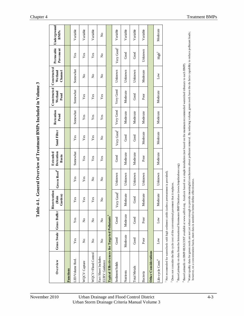
Chapter 4 Treatment BMPs
November 2010 Urban Drainage and Flood Control District 4-3 Urban Storm Drainage Criteria Manual Volume 3
Tab
le 4
-1.
Gen
eral
Ove
rvie
w o
f Tre
atm
ent B
MPs
Incl
uded
in V
olum
e 3
Ove
rvie
wG
rass
Sw
ale
Gra
ss B
uffe
r B
iore
tent
ion
(Rai
n G
arde
n)G
reen
Roo
f5E
xten
ded
Det
entio
n B
asin
Sand
Filt
er
Ret
entio
n Po
nd
Con
stru
cted
W
etla
nd
Pond
Con
stru
cted
W
etla
nd
Cha
nnel
Perm
eabl
e Pa
vem
ent
Und
ergr
ound
B
MPs
Func
tions
LID
/Vol
ume
Red
.Y
esY
esY
esY
esSo
mew
hat
Yes
Som
ewha
tSo
mew
hat
Som
ewha
tY
esV
aria
ble
WQ
CV
Cap
ture
No
No
Yes
Yes
Yes
Yes
Yes
Yes
No
Yes
Var
iabl
e
WQ
CV
+Flo
od C
ontro
lN
oN
oY
esN
oY
esY
esY
esY
esN
oY
esV
aria
ble
Fact
She
et In
clud
es
EUR
V G
uida
nce
No
No
No
No
Yes
No
Yes
Yes
No
No
No
Sedi
men
t/Sol
ids
Goo
dG
ood
Ver
y G
ood1
Unk
now
nG
ood
Ver
y G
ood1
Ver
y G
ood
Ver
y G
ood
Unk
now
nV
ery
Goo
d1V
aria
ble
Nut
rient
sM
oder
ate
Mod
erat
eM
oder
ate
Unk
now
nM
oder
ate
Goo
dM
oder
ate
Mod
erat
eU
nkno
wn
Goo
dV
aria
ble
Tota
l Met
als
Goo
dG
ood
Goo
dU
nkno
wn
Mod
erat
eG
ood
Mod
erat
eG
ood
Unk
now
nG
ood
Var
iabl
e
Bac
teria
Poor
Poor
Mod
erat
eU
nkno
wn
Poor
Mod
erat
eM
oder
ate
Poor
Mod
erat
eU
nkno
wn
Var
iabl
e
Life
-cyc
le C
osts
4Lo
wLo
wM
oder
ate
Unk
now
nM
oder
ate
Mod
erat
eM
oder
ate
Mod
erat
eLo
wH
igh2
Mod
erat
e
2 Doe
s no
t con
side
r the
life
cyc
le c
ost o
f the
con
vent
iona
l pav
emen
t tha
t it r
epla
ces.
3 Bas
ed p
rimar
ily o
n da
ta fr
om th
e In
tern
atio
nal S
torm
wat
er B
MP
Dat
abas
e (w
ww
.bm
pdat
abas
e.or
g).
4 Bas
ed p
rimar
ily o
n BM
P-RE
ALC
OST
ava
ilabl
e at
ww
w.u
dfcd
.org
. A
naly
sis
base
d on
a s
ingl
e in
stal
latio
n (n
ot b
ased
on
the
max
imum
reco
mm
ende
d w
ater
shed
trib
utar
y to
eac
h BM
P).
5 W
ater
qua
lity
data
for g
reen
roof
s ar
e no
t yet
robu
st e
noug
h to
pro
vide
mea
ning
ful c
oncl
usio
ns a
bout
pol
luta
nt re
mov
al.
By re
duci
ng v
olum
e, g
reen
roof
s ha
ve th
e de
fact
o ca
pabi
lity
to re
duce
pol
luta
nt lo
ads;
ho
wev
er, o
n a
conc
entra
tion
basi
s, m
ore
data
is n
eede
d to
bet
ter d
efin
e ef
fect
iven
ess.
1 Not
reco
men
ded
for w
ater
shed
s w
ith h
igh
sedi
men
t yie
lds
(unl
ess
pret
reat
men
t is
prov
ided
).
Typ
ical
Effe
ctiv
enes
s fo
r T
arge
ted
Pollu
tant
s3
Oth
er C
onsi
dera
tions
Treatment BMPs Chapter 4
4-4 Urban Drainage and Flood Control District November 2010 Urban Storm Drainage Criteria Manual Volume 3
3.0 References Wright Water Engineers and Geosyntec Consultants. 2010. International Stormwater Best Management Practices Database Pollutant Category Summary: Fecal Indicator Bacteria. Prepared for WERF, FHWA and EWRI-ASCE.
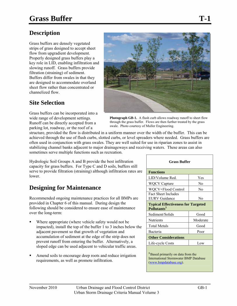
Grass Buffer T-1
November 2010 Urban Drainage and Flood Control District GB-1
Urban Storm Drainage Criteria Manual Volume 3
Photograph GB-1. A flush curb allows roadway runoff to sheet flow through the grass buffer. Flows are then further treated by the grass swale. Photo courtesy of Muller Engineering.
Description Grass buffers are densely vegetated strips of grass designed to accept sheet flow from upgradient development. Properly designed grass buffers play a key role in LID, enabling infiltration and slowing runoff. Grass buffers provide filtration (straining) of sediment. Buffers differ from swales in that they are designed to accommodate overland sheet flow rather than concentrated or channelized flow.
Site Selection Grass buffers can be incorporated into a wide range of development settings. Runoff can be directly accepted from a parking lot, roadway, or the roof of a structure, provided the flow is distributed in a uniform manner over the width of the buffer. This can be achieved through the use of flush curbs, slotted curbs, or level spreaders where needed. Grass buffers are often used in conjunction with grass swales. They are well suited for use in riparian zones to assist in stabilizing channel banks adjacent to major drainageways and receiving waters. These areas can also sometimes serve multiple functions such as recreation.
Hydrologic Soil Groups A and B provide the best infiltration capacity for grass buffers. For Type C and D soils, buffers still serve to provide filtration (straining) although infiltration rates are lower.
Designing for Maintenance Recommended ongoing maintenance practices for all BMPs are provided in Chapter 6 of this manual. During design the following should be considered to ensure ease of maintenance over the long-term:
Where appropriate (where vehicle safety would not be impacted), install the top of the buffer 1 to 3 inches below the adjacent pavement so that growth of vegetation and accumulation of sediment at the edge of the strip does not prevent runoff from entering the buffer. Alternatively, a sloped edge can be used adjacent to vehicular traffic areas.
Amend soils to encourage deep roots and reduce irrigation requirements, as well as promote infiltration.
Grass Buffer
Functions LID/Volume Red. Yes WQCV Capture No WQCV+Flood Control No Fact Sheet Includes EURV Guidance No Typical Effectiveness for Targeted Pollutants3 Sediment/Solids Good Nutrients Moderate Total Metals Good Bacteria Poor Other Considerations Life-cycle Costs Low
3 Based primarily on data from the International Stormwater BMP Database (www.bmpdatabase.org).
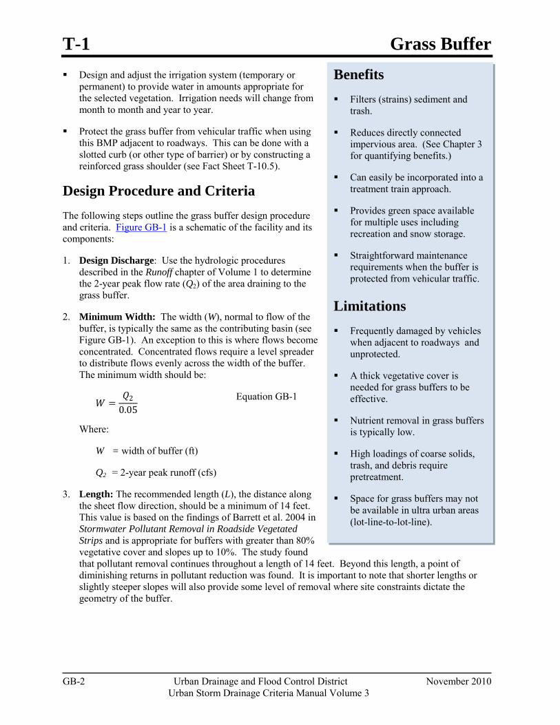
T-1 Grass Buffer
GB-2 Urban Drainage and Flood Control District November 2010 Urban Storm Drainage Criteria Manual Volume 3
Benefits Filters (strains) sediment and
trash.
Reduces directly connected impervious area. (See Chapter 3 for quantifying benefits.)
Can easily be incorporated into a treatment train approach.
Provides green space available for multiple uses including recreation and snow storage.
Straightforward maintenance requirements when the buffer is protected from vehicular traffic.
Limitations Frequently damaged by vehicles
when adjacent to roadways and unprotected.
A thick vegetative cover is needed for grass buffers to be effective.
Nutrient removal in grass buffers is typically low.
High loadings of coarse solids, trash, and debris require pretreatment.
Space for grass buffers may not be available in ultra urban areas (lot-line-to-lot-line).
Design and adjust the irrigation system (temporary or permanent) to provide water in amounts appropriate for the selected vegetation. Irrigation needs will change from month to month and year to year.
Protect the grass buffer from vehicular traffic when using this BMP adjacent to roadways. This can be done with a slotted curb (or other type of barrier) or by constructing a reinforced grass shoulder (see Fact Sheet T-10.5).
Design Procedure and Criteria The following steps outline the grass buffer design procedure and criteria. Figure GB-1 is a schematic of the facility and its components:
1. Design Discharge: Use the hydrologic procedures described in the Runoff chapter of Volume 1 to determine the 2-year peak flow rate (Q2) of the area draining to the grass buffer.
2. Minimum Width: The width (W), normal to flow of the buffer, is typically the same as the contributing basin (see Figure GB-1). An exception to this is where flows become concentrated. Concentrated flows require a level spreader to distribute flows evenly across the width of the buffer. The minimum width should be:
𝑊𝑊 =𝑄𝑄2
0.05 Equation GB-1
Where:
W = width of buffer (ft)
Q2 = 2-year peak runoff (cfs)
3. Length: The recommended length (L), the distance along the sheet flow direction, should be a minimum of 14 feet. This value is based on the findings of Barrett et al. 2004 in Stormwater Pollutant Removal in Roadside Vegetated Strips and is appropriate for buffers with greater than 80% vegetative cover and slopes up to 10%. The study found that pollutant removal continues throughout a length of 14 feet. Beyond this length, a point of diminishing returns in pollutant reduction was found. It is important to note that shorter lengths or slightly steeper slopes will also provide some level of removal where site constraints dictate the geometry of the buffer.
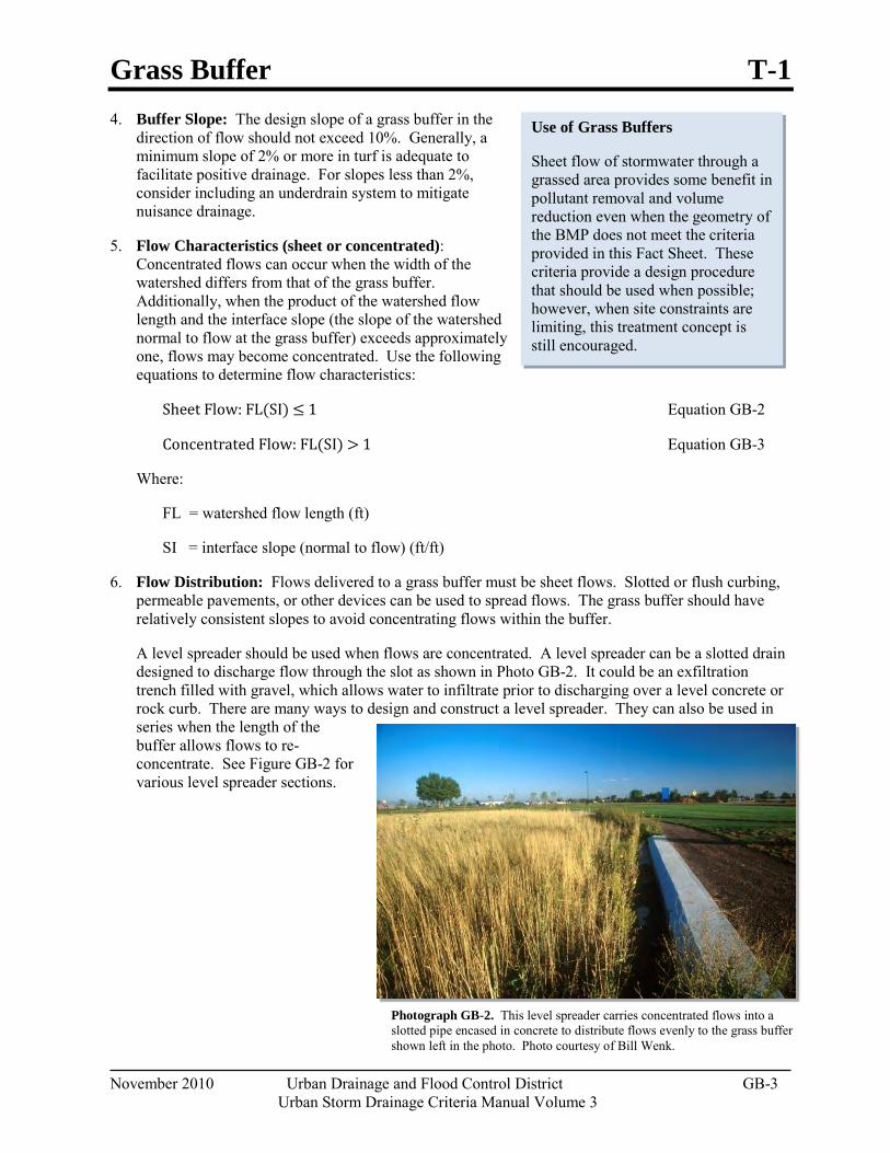
Grass Buffer T-1
November 2010 Urban Drainage and Flood Control District GB-3
Urban Storm Drainage Criteria Manual Volume 3
Photograph GB-2. This level spreader carries concentrated flows into a slotted pipe encased in concrete to distribute flows evenly to the grass buffer shown left in the photo. Photo courtesy of Bill Wenk.
Use of Grass Buffers
Sheet flow of stormwater through a grassed area provides some benefit in pollutant removal and volume reduction even when the geometry of the BMP does not meet the criteria provided in this Fact Sheet. These criteria provide a design procedure that should be used when possible; however, when site constraints are limiting, this treatment concept is still encouraged.
4. Buffer Slope: The design slope of a grass buffer in the direction of flow should not exceed 10%. Generally, a minimum slope of 2% or more in turf is adequate to facilitate positive drainage. For slopes less than 2%, consider including an underdrain system to mitigate nuisance drainage.
5. Flow Characteristics (sheet or concentrated): Concentrated flows can occur when the width of the watershed differs from that of the grass buffer. Additionally, when the product of the watershed flow length and the interface slope (the slope of the watershed normal to flow at the grass buffer) exceeds approximately one, flows may become concentrated. Use the following equations to determine flow characteristics:
Sheet Flow: FL(SI) ≤ 1 Equation GB-2
Concentrated Flow: FL(SI) > 1 Equation GB-3
Where:
FL = watershed flow length (ft)
SI = interface slope (normal to flow) (ft/ft)
6. Flow Distribution: Flows delivered to a grass buffer must be sheet flows. Slotted or flush curbing, permeable pavements, or other devices can be used to spread flows. The grass buffer should have relatively consistent slopes to avoid concentrating flows within the buffer.
A level spreader should be used when flows are concentrated. A level spreader can be a slotted drain designed to discharge flow through the slot as shown in Photo GB-2. It could be an exfiltration trench filled with gravel, which allows water to infiltrate prior to discharging over a level concrete or rock curb. There are many ways to design and construct a level spreader. They can also be used in series when the length of the buffer allows flows to re-concentrate. See Figure GB-2 for various level spreader sections.
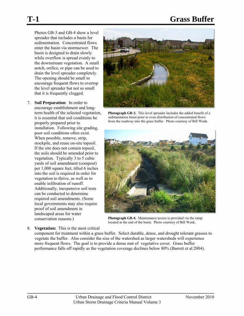
T-1 Grass Buffer
GB-4 Urban Drainage and Flood Control District November 2010 Urban Storm Drainage Criteria Manual Volume 3
Photograph GB-3. This level spreader includes the added benefit of a sedimentation basin prior to even distribution of concentrated flows from the roadway into the grass buffer. Photo courtesy of Bill Wenk.
Photograph GB-4. Maintenance access is provided via the ramp located at the end of the basin. Photo courtesy of Bill Wenk.
Photos GB-3 and GB-4 show a level spreader that includes a basin for sedimentation. Concentrated flows enter the basin via stormsewer. The basin is designed to drain slowly while overflow is spread evenly to the downstream vegetation. A small notch, orifice, or pipe can be used to drain the level spreader completely. The opening should be small to encourage frequent flows to overtop the level spreader but not so small that it is frequently clogged.
7. Soil Preparation: In order to encourage establishment and long-term health of the selected vegetation, it is essential that soil conditions be properly prepared prior to installation. Following site grading, poor soil conditions often exist. When possible, remove, strip, stockpile, and reuse on-site topsoil. If the site does not contain topsoil, the soils should be amended prior to vegetation. Typically 3 to 5 cubic yards of soil amendment (compost) per 1,000 square feet, tilled 6 inches into the soil is required in order for vegetation to thrive, as well as to enable infiltration of runoff. Additionally, inexpensive soil tests can be conducted to determine required soil amendments. (Some local governments may also require proof of soil amendment in landscaped areas for water conservation reasons.)
8. Vegetation: This is the most critical component for treatment within a grass buffer. Select durable, dense, and drought tolerant grasses to vegetate the buffer. Also consider the size of the watershed as larger watersheds will experience more frequent flows. The goal is to provide a dense mat of vegetative cover. Grass buffer performance falls off rapidly as the vegetation coverage declines below 80% (Barrett et al.2004).
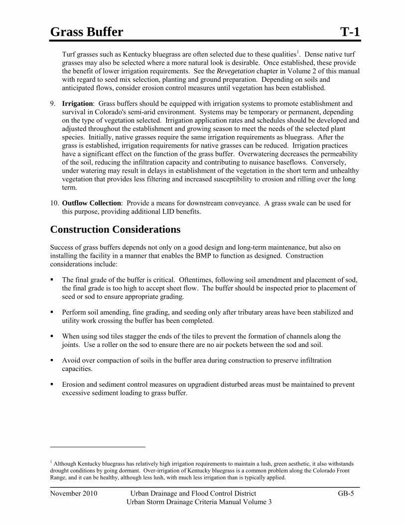
Grass Buffer T-1
November 2010 Urban Drainage and Flood Control District GB-5
Urban Storm Drainage Criteria Manual Volume 3
Turf grasses such as Kentucky bluegrass are often selected due to these qualities1
9. Irrigation: Grass buffers should be equipped with irrigation systems to promote establishment and survival in Colorado's semi-arid environment. Systems may be temporary or permanent, depending on the type of vegetation selected. Irrigation application rates and schedules should be developed and adjusted throughout the establishment and growing season to meet the needs of the selected plant species. Initially, native grasses require the same irrigation requirements as bluegrass. After the grass is established, irrigation requirements for native grasses can be reduced. Irrigation practices have a significant effect on the function of the grass buffer. Overwatering decreases the permeability of the soil, reducing the infiltration capacity and contributing to nuisance baseflows. Conversely, under watering may result in delays in establishment of the vegetation in the short term and unhealthy vegetation that provides less filtering and increased susceptibility to erosion and rilling over the long term.
. Dense native turf grasses may also be selected where a more natural look is desirable. Once established, these provide the benefit of lower irrigation requirements. See the Revegetation chapter in Volume 2 of this manual with regard to seed mix selection, planting and ground preparation. Depending on soils and anticipated flows, consider erosion control measures until vegetation has been established.
10. Outflow Collection: Provide a means for downstream conveyance. A grass swale can be used for this purpose, providing additional LID benefits.
Construction Considerations Success of grass buffers depends not only on a good design and long-term maintenance, but also on installing the facility in a manner that enables the BMP to function as designed. Construction considerations include:
The final grade of the buffer is critical. Oftentimes, following soil amendment and placement of sod, the final grade is too high to accept sheet flow. The buffer should be inspected prior to placement of seed or sod to ensure appropriate grading.
Perform soil amending, fine grading, and seeding only after tributary areas have been stabilized and utility work crossing the buffer has been completed.
When using sod tiles stagger the ends of the tiles to prevent the formation of channels along the joints. Use a roller on the sod to ensure there are no air pockets between the sod and soil.
Avoid over compaction of soils in the buffer area during construction to preserve infiltration capacities.
Erosion and sediment control measures on upgradient disturbed areas must be maintained to prevent excessive sediment loading to grass buffer.
1 Although Kentucky bluegrass has relatively high irrigation requirements to maintain a lush, green aesthetic, it also withstands drought conditions by going dormant. Over-irrigation of Kentucky bluegrass is a common problem along the Colorado Front Range, and it can be healthy, although less lush, with much less irrigation than is typically applied.
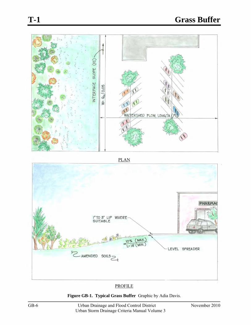
T-1 Grass Buffer
GB-6 Urban Drainage and Flood Control District November 2010 Urban Storm Drainage Criteria Manual Volume 3
PLAN
PROFILE
Figure GB-1. Typical Grass Buffer Graphic by Adia Davis.
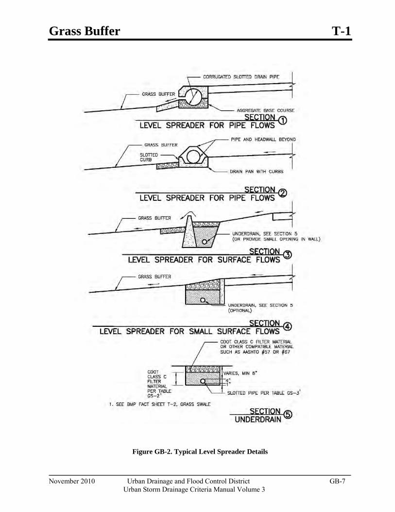
Grass Buffer T-1
November 2010 Urban Drainage and Flood Control District GB-7
Urban Storm Drainage Criteria Manual Volume 3
Figure GB-2. Typical Level Spreader Details
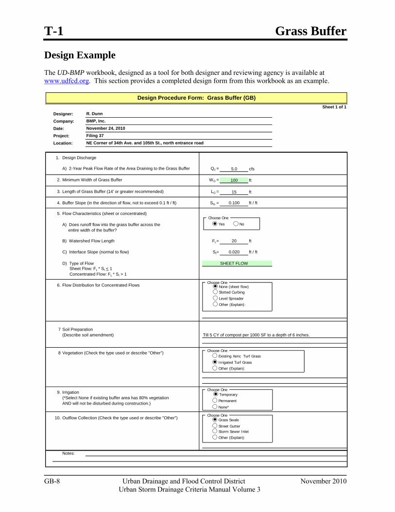
T-1 Grass Buffer
GB-8 Urban Drainage and Flood Control District November 2010 Urban Storm Drainage Criteria Manual Volume 3
Design Example The UD-BMP workbook, designed as a tool for both designer and reviewing agency is available at www.udfcd.org. This section provides a completed design form from this workbook as an example.
Sheet 1 of 1Designer:Company:Date:Project:Location:
1. Design Discharge
A) 2-Year Peak Flow Rate of the Area Draining to the Grass Buffer Q2 = 5.0 cfs
2. Minimum Width of Grass Buffer WG = 100 ft
3. Length of Grass Buffer (14' or greater recommended) LG = 15 ft
4. Buffer Slope (in the direction of flow, not to exceed 0.1 ft / ft) SG = 0.100 ft / ft
5. Flow Characteristics (sheet or concentrated)
A) Does runoff flow into the grass buffer across the entire width of the buffer?
B) Watershed Flow Length FL= 20 ft
C) Interface Slope (normal to flow) SI= 0.020 ft / ft
D) Type of Flow SHEET FLOW Sheet Flow: FL * SI < 1 Concentrated Flow: FL * SI > 1
6. Flow Distribution for Concentrated Flows
7 Soil Preparation(Describe soil amendment)
8 Vegetation (Check the type used or describe "Other")
9. Irrigation(*Select None if existing buffer area has 80% vegetation AND will not be disturbed during construction.)
10. Outflow Collection (Check the type used or describe "Other")
Notes:
Till 5 CY of compost per 1000 SF to a depth of 6 inches.
Design Procedure Form: Grass Buffer (GB)
R. DunnBMP, Inc.
Filing 37November 24, 2010
NE Corner of 34th Ave. and 105th St., north entrance road
Existing Xeric Turf Grass
Irrigated Turf Grass
Other (Explain):
Choose One
Choose OneGrass Swale
Street GutterStorm Sewer Inlet
Other (Explain):
None (sheet flow)Slotted Curbing
Level Spreader
Choose One
Other (Explain):
Choose One
Yes No
Choose One
Permanent
None*
Temporary
Grass Buffer T-1
November 2010 Urban Drainage and Flood Control District GB-9
Urban Storm Drainage Criteria Manual Volume 3
References Barrett, M., Lantin, A. and S. Austrheim-Smith. 2004. Stormwater Pollutant Removal in Roadside
Vegetated Buffer Strips. Prepared for the Transportation Research Board: Washington, DC.
California Stormwater Quality Association (CASQA). 2003. California Stormwater BMP Handbook, Vegetated Buffer Strip.

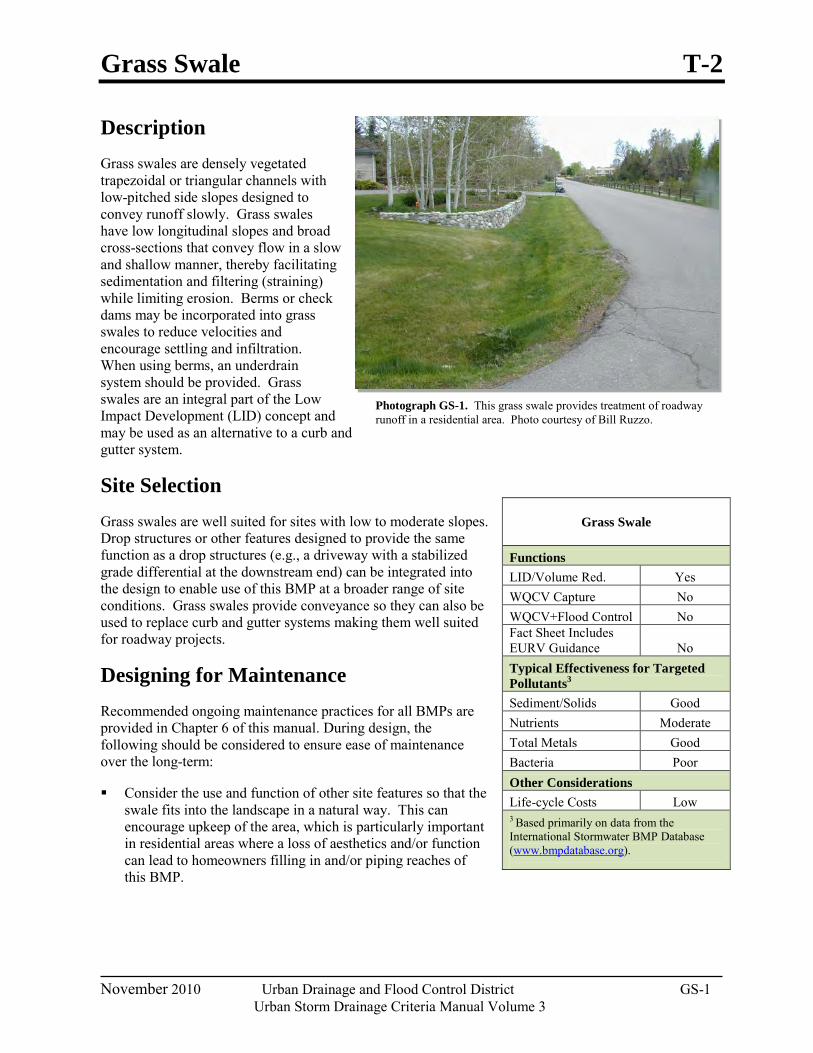
Grass Swale T-2
November 2010 Urban Drainage and Flood Control District GS-1
Urban Storm Drainage Criteria Manual Volume 3
Photograph GS-1. This grass swale provides treatment of roadway runoff in a residential area. Photo courtesy of Bill Ruzzo.
Description Grass swales are densely vegetated trapezoidal or triangular channels with low-pitched side slopes designed to convey runoff slowly. Grass swales have low longitudinal slopes and broad cross-sections that convey flow in a slow and shallow manner, thereby facilitating sedimentation and filtering (straining) while limiting erosion. Berms or check dams may be incorporated into grass swales to reduce velocities and encourage settling and infiltration. When using berms, an underdrain system should be provided. Grass swales are an integral part of the Low Impact Development (LID) concept and may be used as an alternative to a curb and gutter system.
Site Selection Grass swales are well suited for sites with low to moderate slopes. Drop structures or other features designed to provide the same function as a drop structures (e.g., a driveway with a stabilized grade differential at the downstream end) can be integrated into the design to enable use of this BMP at a broader range of site conditions. Grass swales provide conveyance so they can also be used to replace curb and gutter systems making them well suited for roadway projects.
Designing for Maintenance Recommended ongoing maintenance practices for all BMPs are provided in Chapter 6 of this manual. During design, the following should be considered to ensure ease of maintenance over the long-term:
Consider the use and function of other site features so that the swale fits into the landscape in a natural way. This can encourage upkeep of the area, which is particularly important in residential areas where a loss of aesthetics and/or function can lead to homeowners filling in and/or piping reaches of this BMP.
Grass Swale
Functions LID/Volume Red. Yes WQCV Capture No WQCV+Flood Control No Fact Sheet Includes EURV Guidance No Typical Effectiveness for Targeted Pollutants3 Sediment/Solids Good Nutrients Moderate Total Metals Good Bacteria Poor Other Considerations Life-cycle Costs Low 3 Based primarily on data from the International Stormwater BMP Database (www.bmpdatabase.org).
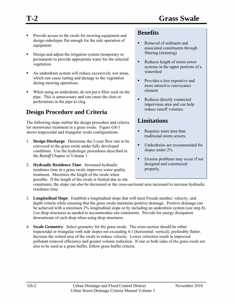
T-2 Grass Swale
GS-2 Urban Drainage and Flood Control District November 2010 Urban Storm Drainage Criteria Manual Volume 3
Provide access to the swale for mowing equipment and design sideslopes flat enough for the safe operation of equipment.
Design and adjust the irrigation system (temporary or permanent) to provide appropriate water for the selected vegetation.
An underdrain system will reduce excessively wet areas, which can cause rutting and damage to the vegetation during mowing operations.
When using an underdrain, do not put a filter sock on the pipe. This is unnecessary and can cause the slots or perforations in the pipe to clog.
Design Procedure and Criteria The following steps outline the design procedure and criteria for stormwater treatment in a grass swale. Figure GS-1 shows trapezoidal and triangular swale configurations.
1. Design Discharge: Determine the 2-year flow rate to be conveyed in the grass swale under fully developed conditions. Use the hydrologic procedures described in the Runoff Chapter in Volume 1.
2. Hydraulic Residence Time: Increased hydraulic residence time in a grass swale improves water quality treatment. Maximize the length of the swale when possible. If the length of the swale is limited due to site constraints, the slope can also be decreased or the cross-sectional area increased to increase hydraulic residence time.
3. Longitudinal Slope: Establish a longitudinal slope that will meet Froude number, velocity, and depth criteria while ensuring that the grass swale maintains positive drainage. Positive drainage can be achieved with a minimum 2% longitudinal slope or by including an underdrain system (see step 8). Use drop structures as needed to accommodate site constraints. Provide for energy dissipation downstream of each drop when using drop structures.
4. Swale Geometry: Select geometry for the grass swale. The cross section should be either trapezoidal or triangular with side slopes not exceeding 4:1 (horizontal: vertical), preferably flatter. Increase the wetted area of the swale to reduce velocity. Lower velocities result in improved pollutant removal efficiency and greater volume reduction. If one or both sides of the grass swale are also to be used as a grass buffer, follow grass buffer criteria.
Benefits Removal of sediment and
associated constituents through filtering (straining)
Reduces length of storm sewer systems in the upper portions of a watershed
Provides a less expensive and more attractive conveyance element
Reduces directly connected impervious area and can help reduce runoff volumes.
Limitations Requires more area than
traditional storm sewers.
Underdrains are recommended for slopes under 2%.
Erosion problems may occur if not designed and constructed properly.
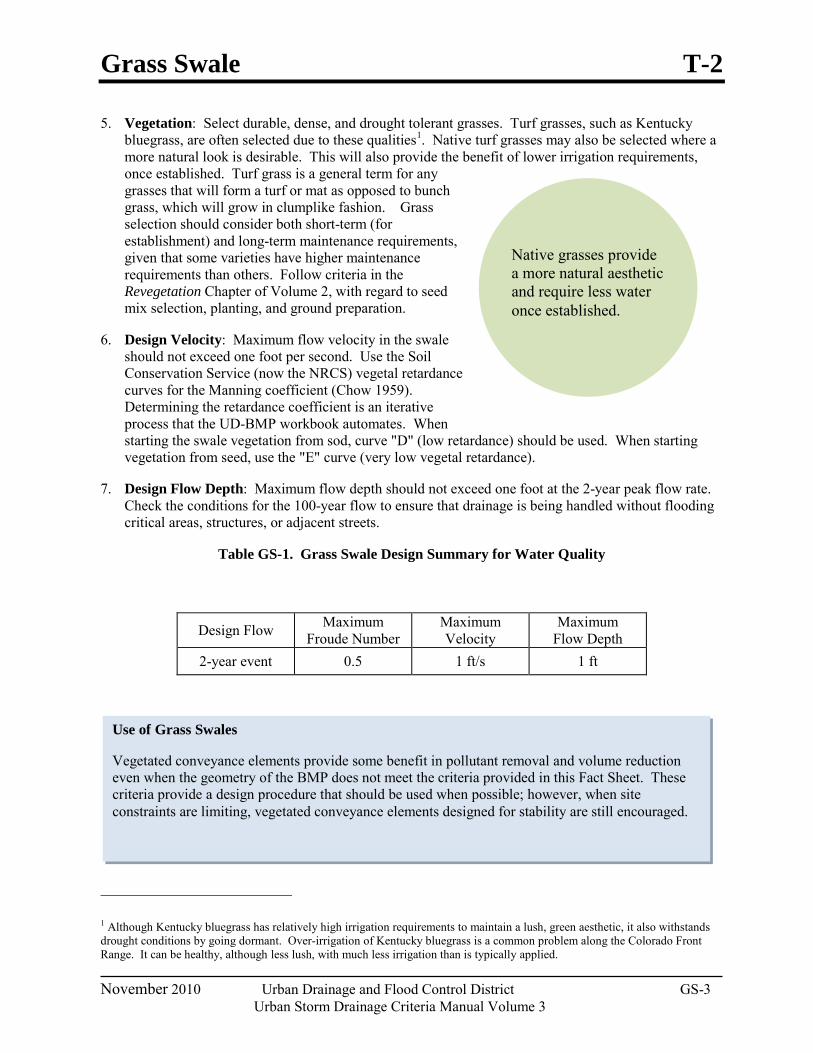
Grass Swale T-2
November 2010 Urban Drainage and Flood Control District GS-3
Urban Storm Drainage Criteria Manual Volume 3
Native grasses provide a more natural aesthetic and require less water once established.
Use of Grass Swales
Vegetated conveyance elements provide some benefit in pollutant removal and volume reduction even when the geometry of the BMP does not meet the criteria provided in this Fact Sheet. These criteria provide a design procedure that should be used when possible; however, when site constraints are limiting, vegetated conveyance elements designed for stability are still encouraged.
5. Vegetation: Select durable, dense, and drought tolerant grasses. Turf grasses, such as Kentucky bluegrass, are often selected due to these qualities1
once established. Turf grass is a general term for any grasses that will form a turf or mat as opposed to bunch grass, which will grow in clumplike fashion. Grass selection should consider both short-term (for establishment) and long-term maintenance requirements, given that some varieties have higher maintenance requirements than others. Follow criteria in the Revegetation Chapter of Volume 2, with regard to seed mix selection, planting, and ground preparation.
. Native turf grasses may also be selected where a more natural look is desirable. This will also provide the benefit of lower irrigation requirements,
6. Design Velocity: Maximum flow velocity in the swale should not exceed one foot per second. Use the Soil Conservation Service (now the NRCS) vegetal retardance curves for the Manning coefficient (Chow 1959). Determining the retardance coefficient is an iterative process that the UD-BMP workbook automates. When starting the swale vegetation from sod, curve "D" (low retardance) should be used. When starting vegetation from seed, use the "E" curve (very low vegetal retardance).
7. Design Flow Depth: Maximum flow depth should not exceed one foot at the 2-year peak flow rate. Check the conditions for the 100-year flow to ensure that drainage is being handled without flooding critical areas, structures, or adjacent streets.
Table GS-1. Grass Swale Design Summary for Water Quality
1 Although Kentucky bluegrass has relatively high irrigation requirements to maintain a lush, green aesthetic, it also withstands drought conditions by going dormant. Over-irrigation of Kentucky bluegrass is a common problem along the Colorado Front Range. It can be healthy, although less lush, with much less irrigation than is typically applied.
Design Flow Maximum Froude Number
Maximum Velocity
Maximum Flow Depth
2-year event 0.5 1 ft/s 1 ft
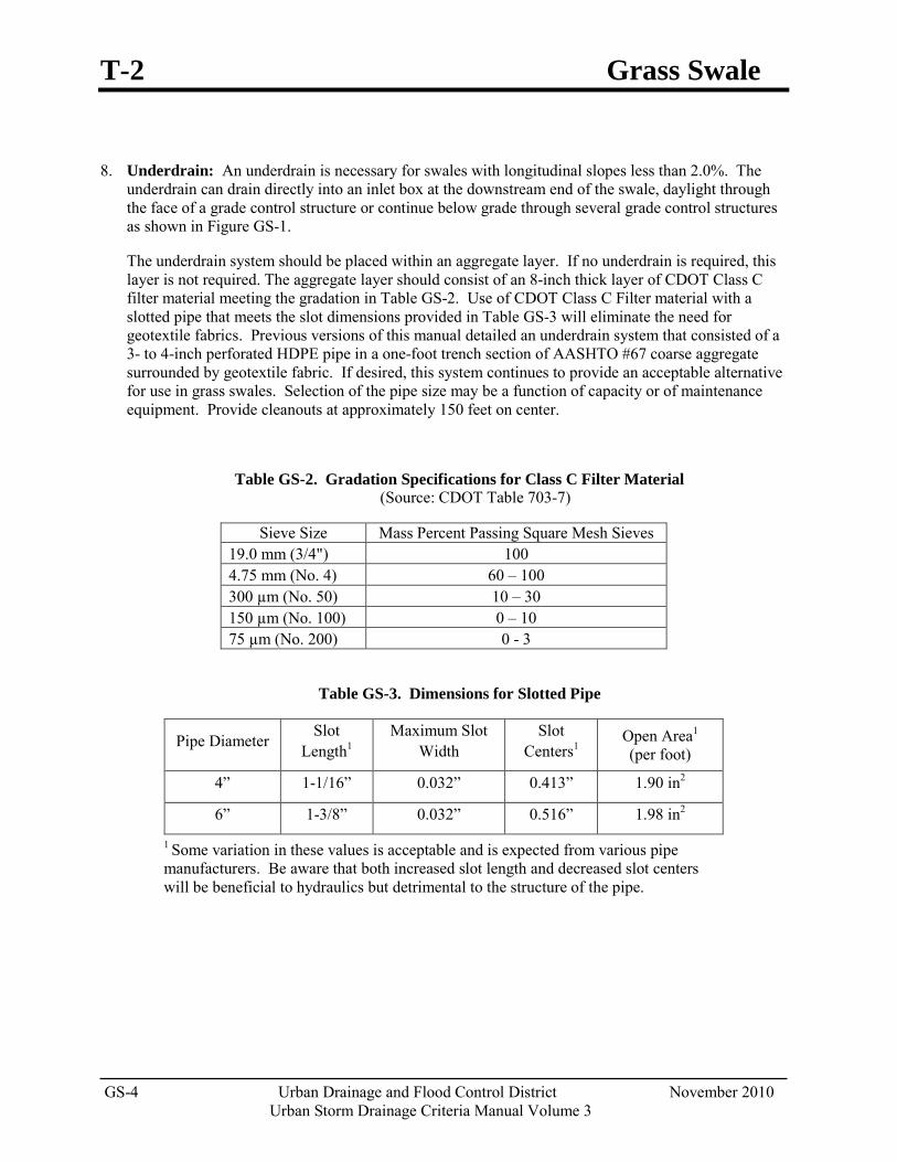
T-2 Grass Swale
GS-4 Urban Drainage and Flood Control District November 2010 Urban Storm Drainage Criteria Manual Volume 3
8. Underdrain: An underdrain is necessary for swales with longitudinal slopes less than 2.0%. The underdrain can drain directly into an inlet box at the downstream end of the swale, daylight through the face of a grade control structure or continue below grade through several grade control structures as shown in Figure GS-1.
The underdrain system should be placed within an aggregate layer. If no underdrain is required, this layer is not required. The aggregate layer should consist of an 8-inch thick layer of CDOT Class C filter material meeting the gradation in Table GS-2. Use of CDOT Class C Filter material with a slotted pipe that meets the slot dimensions provided in Table GS-3 will eliminate the need for geotextile fabrics. Previous versions of this manual detailed an underdrain system that consisted of a 3- to 4-inch perforated HDPE pipe in a one-foot trench section of AASHTO #67 coarse aggregate surrounded by geotextile fabric. If desired, this system continues to provide an acceptable alternative for use in grass swales. Selection of the pipe size may be a function of capacity or of maintenance equipment. Provide cleanouts at approximately 150 feet on center.
Table GS-2. Gradation Specifications for Class C Filter Material (Source: CDOT Table 703-7)
Sieve Size Mass Percent Passing Square Mesh Sieves 19.0 mm (3/4") 100 4.75 mm (No. 4) 60 – 100 300 µm (No. 50) 10 – 30 150 µm (No. 100) 0 – 10 75 µm (No. 200) 0 - 3
Table GS-3. Dimensions for Slotted Pipe
Pipe Diameter Slot Length1
Maximum Slot Width
Slot Centers1
Open Area1 (per foot)
4” 1-1/16” 0.032” 0.413” 1.90 in2
6” 1-3/8” 0.032” 0.516” 1.98 in2
1 Some variation in these values is acceptable and is expected from various pipe manufacturers. Be aware that both increased slot length and decreased slot centers will be beneficial to hydraulics but detrimental to the structure of the pipe.
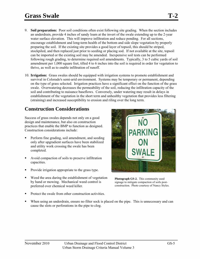
Grass Swale T-2
November 2010 Urban Drainage and Flood Control District GS-5
Urban Storm Drainage Criteria Manual Volume 3
Photograph GS-2. This community used signage to mitigate compaction of soils post-construction. Photo courtesy of Nancy Styles.
9. Soil preparation: Poor soil conditions often exist following site grading. When the section includes an underdrain, provide 4 inches of sandy loam at the invert of the swale extending up to the 2-year water surface elevation. This will improve infiltration and reduce ponding. For all sections, encourage establishment and long-term health of the bottom and side slope vegetation by properly preparing the soil. If the existing site provides a good layer of topsoil, this should be striped, stockpiled, and then replaced just prior to seeding or placing sod. If not available at the site, topsoil can be imported or the existing soil may be amended. Inexpensive soil tests can be performed following rough grading, to determine required soil amendments. Typically, 3 to 5 cubic yards of soil amendment per 1,000 square feet, tilled 4 to 6 inches into the soil is required in order for vegetation to thrive, as well as to enable infiltration of runoff.
10. Irrigation: Grass swales should be equipped with irrigation systems to promote establishment and survival in Colorado's semi-arid environment. Systems may be temporary or permanent, depending on the type of grass selected. Irrigation practices have a significant effect on the function of the grass swale. Overwatering decreases the permeability of the soil, reducing the infiltration capacity of the soil and contributing to nuisance baseflows. Conversely, under watering may result in delays in establishment of the vegetation in the short term and unhealthy vegetation that provides less filtering (straining) and increased susceptibility to erosion and riling over the long term.
Construction Considerations Success of grass swales depends not only on a good design and maintenance, but also on construction practices that enable the BMP to function as designed. Construction considerations include:
Perform fine grading, soil amendment, and seeding only after upgradient surfaces have been stabilized and utility work crossing the swale has been completed.
Avoid compaction of soils to preserve infiltration capacities.
Provide irrigation appropriate to the grass type.
Weed the area during the establishment of vegetation by hand or mowing. Mechanical weed control is preferred over chemical weed killer.
Protect the swale from other construction activities.
When using an underdrain, ensure no filter sock is placed on the pipe. This is unnecessary and can cause the slots or perforations in the pipe to clog.
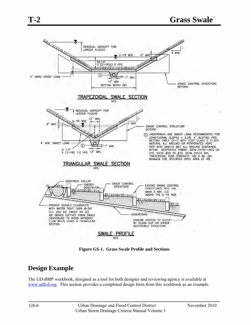
T-2 Grass Swale
GS-6 Urban Drainage and Flood Control District November 2010 Urban Storm Drainage Criteria Manual Volume 3
Figure GS-1. Grass Swale Profile and Sections
Design Example The UD-BMP workbook, designed as a tool for both designer and reviewing agency is available at www.udfcd.org. This section provides a completed design form from this workbook as an example.
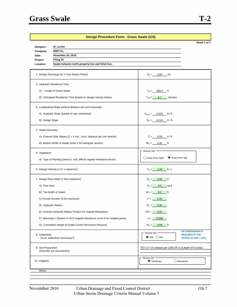
Grass Swale T-2
November 2010 Urban Drainage and Flood Control District GS-7
Urban Storm Drainage Criteria Manual Volume 3
Sheet 1 of 1Designer:Company:Date:Project:Location:
1. Design Discharge for 2-Year Return Period Q2 = 4.00 cfs
2. Hydraulic Residence Time
A) : Length of Grass Swale LS = 400.0 ft
B) Calculated Residence Time (based on design velocity below) THR= 6.7 minutes
3. Longitudinal Slope (vertical distance per unit horizontal)
A) Available Slope (based on site constraints) Savail = 0.020 ft / ft
B) Design Slope SD = 0.010 ft / ft
4. Swale Geometry
A) Channel Side Slopes (Z = 4 min., horiz. distance per unit vertical) Z = 4.00 ft / ft
B) Bottom Width of Swale (enter 0 for triangular section) WB = 4.00 ft
5. Vegetation
A) Type of Planting (seed vs. sod, affects vegetal retardance factor)
6. Design Velocity (1 ft / s maximum) V2 = 1.00 ft / s
7. Design Flow Depth (1 foot maximum) D2 = 0.62 ft
A) Flow Area A2 = 4.0 sq ft
B) Top Width of Swale WT = 9.0 ft
C) Froude Number (0.50 maximum) F = 0.26
D) Hydraulic Radius RH = 0.44
E) Velocity-Hydraulic Radius Product for Vegetal Retardance VR = 0.44
F) Manning's n (based on SCS vegetal retardance curve D for sodded grass) n = 0.088
G) Cumulative Height of Grade Control Structures Required HD = 4.00 ft
AN UNDERDRAIN IS8. Underdrain REQUIRED IF THE
(Is an underdrain necessary?) DESIGN SLOPE < 2.0%
9. Soil Preparation(Describe soil amendment)
10. Irrigation
Notes:
Design Procedure Form: Grass Swale (GS)
M. LevineBMP Inc.November 24, 2010Filing 30Swale between north property line and 52nd Ave.
Till 5 CY of compost per 1000 SF to a depth of 6 inches.
Choose OneTemporary Permanent
Choose One
Grass From Seed Grass From Sod
Choose One
YES NO
T-2 Grass Swale
GS-8 Urban Drainage and Flood Control District November 2010 Urban Storm Drainage Criteria Manual Volume 3
References Chow, Ven Te. 1959. Open Channel Flow. McGraw Hill: New York, NY.
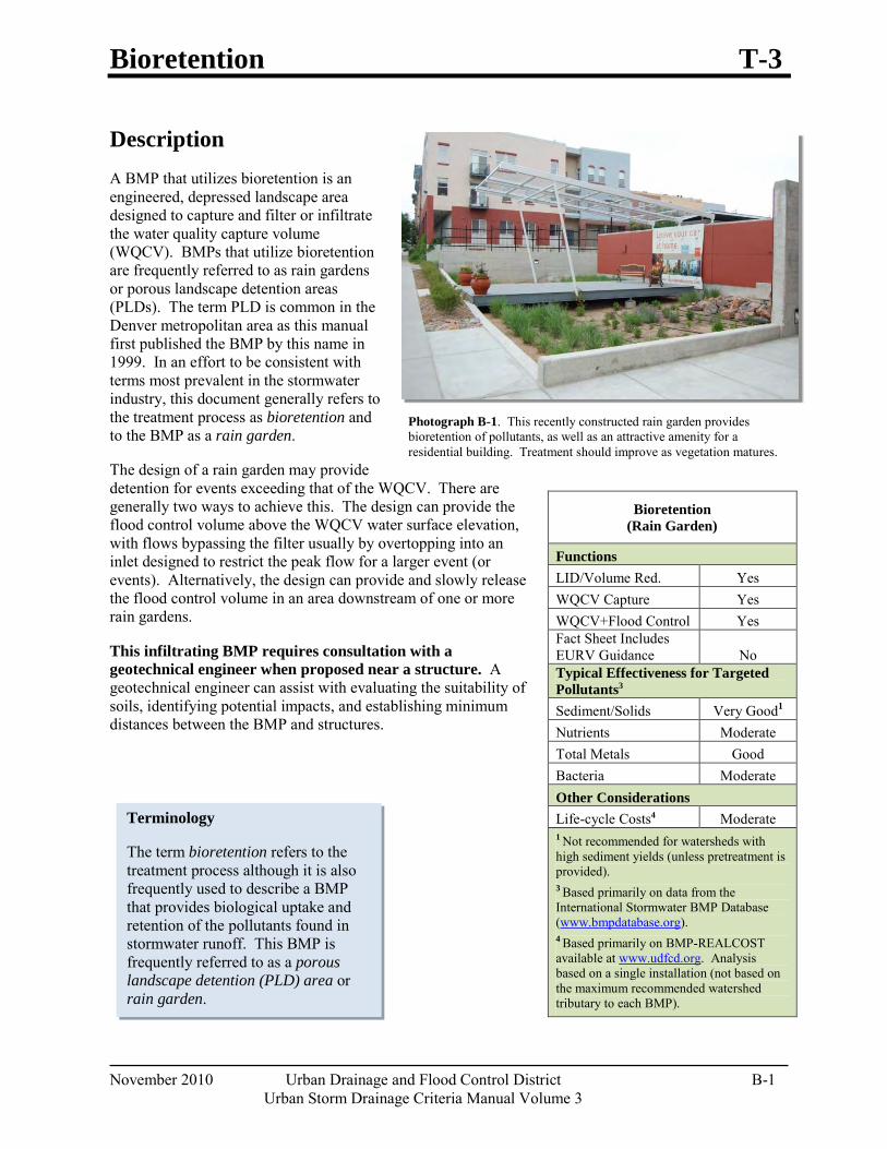
Bioretention T-3
November 2010 Urban Drainage and Flood Control District B-1 Urban Storm Drainage Criteria Manual Volume 3
Terminology
The term bioretention refers to the treatment process although it is also frequently used to describe a BMP that provides biological uptake and retention of the pollutants found in stormwater runoff. This BMP is frequently referred to as a porous landscape detention (PLD) area or rain garden.
Photograph B-1. This recently constructed rain garden provides bioretention of pollutants, as well as an attractive amenity for a residential building. Treatment should improve as vegetation matures.
Description A BMP that utilizes bioretention is an engineered, depressed landscape area designed to capture and filter or infiltrate the water quality capture volume (WQCV). BMPs that utilize bioretention are frequently referred to as rain gardens or porous landscape detention areas (PLDs). The term PLD is common in the Denver metropolitan area as this manual first published the BMP by this name in 1999. In an effort to be consistent with terms most prevalent in the stormwater industry, this document generally refers to the treatment process as bioretention and to the BMP as a rain garden.
The design of a rain garden may provide detention for events exceeding that of the WQCV. There are generally two ways to achieve this. The design can provide the flood control volume above the WQCV water surface elevation, with flows bypassing the filter usually by overtopping into an inlet designed to restrict the peak flow for a larger event (or events). Alternatively, the design can provide and slowly release the flood control volume in an area downstream of one or more rain gardens.
This infiltrating BMP requires consultation with a geotechnical engineer when proposed near a structure. A geotechnical engineer can assist with evaluating the suitability of soils, identifying potential impacts, and establishing minimum distances between the BMP and structures.
Bioretention (Rain Garden)
Functions LID/Volume Red. Yes WQCV Capture Yes WQCV+Flood Control Yes Fact Sheet Includes EURV Guidance No Typical Effectiveness for Targeted Pollutants3 Sediment/Solids Very Good1
Nutrients Moderate Total Metals Good Bacteria Moderate Other Considerations Life-cycle Costs4 Moderate 1 Not recommended for watersheds with high sediment yields (unless pretreatment is provided). 3 Based primarily on data from the International Stormwater BMP Database (www.bmpdatabase.org). 4 Based primarily on BMP-REALCOST available at www.udfcd.org. Analysis based on a single installation (not based on the maximum recommended watershed tributary to each BMP).
T-3 Bioretention
B-2 Urban Drainage and Flood Control District November 2010 Urban Storm Drainage Criteria Manual Volume 3
Site Selection Bioretention can be provided in a variety of areas within new developments, or as a retrofit within an existing site. This BMP allows the WQCV to be treated within areas designated for landscape (see design step 7 for appropriate vegetation). In this way, it is an excellent alternative to extended detention basins for small sites. A typical rain garden serves a tributary area of one impervious acre or less, although they can be designed for larger tributary areas. Multiple installations can be used within larger sites. Rain gardens should not be used when a baseflow is anticipated. They are typically small and installed in locations such as:
Parking lot islands
Street medians
Landscape areas between the road and a detached walk
Planter boxes that collect roof drains
Bioretention requires a stable watershed. Retrofit applications are typically successful for this reason. When the watershed includes phased construction, sparsely vegetated areas, or steep slopes in sandy soils, consider another BMP or provide pretreatment before runoff from these areas reaches the rain garden. The surface of the rain garden should be flat. For this reason, rain gardens can be more difficult to incorporate into steeply sloping terrain; however, terraced applications of these facilities have been successful in other parts of the country.
When bioretention (and other BMPs used for infiltration) are located adjacent to buildings or pavement areas, protective measures should be implemented to avoid adverse impacts to these structures. Oversaturated subgrade soil underlying a structure can cause the structure to settle or result in moisture-related problems. Wetting of expansive soils or bedrock can cause swelling, resulting in structural movements. A geotechnical engineer should evaluate the potential impact of the BMP on adjacent structures based on an evaluation of the subgrade soil, groundwater, and bedrock conditions at the site. Additional minimum requirements include:
In locations where subgrade soils do not allow infiltration, the growing medium should be underlain by an underdrain system.
Where infiltration can adversely impact adjacent structures, the filter layer should be underlain by an underdrain system designed to divert water away from the structure.
In locations where potentially expansive soils or bedrock exist, placement of a rain garden adjacent to structures and pavement should only be considered if the BMP includes an underdrain designed to divert water away from the structure and is lined with an essentially impermeable geomembrane liner designed to restrict seepage.
Benefits Bioretention uses multiple
treatment processes to remove pollutants, including sedimentation, filtering, adsorption, evapotranspiration, and biological uptake of constituents.
Volumetric stormwater treatment is provided within portions of a site that are already reserved for landscaping.
There is a potential reduction of irrigation requirements by taking advantage of site runoff.
Limitations Additional design and
construction steps are required for placement of any ponding or infiltration area near or upgradient from a building foundation and/or when expansive (low to high swell) soils exist. This is discussed in the design procedure section.
In developing or otherwise erosive watersheds, high sediment loads can clog the facility.
Bioretention T-3
November 2010 Urban Drainage and Flood Control District B-3 Urban Storm Drainage Criteria Manual Volume 3
Designing for Maintenance Recommended maintenance practices for all BMPs are in Chapter 6 of this manual. During design, the following should be considered to ensure ease of maintenance over the long-term:
Do not put a filter sock on the underdrain. This is not necessary and can cause the BMP to clog.
The best surface cover for a rain garden is full vegetation. Do not use rock mulch within the rain garden because sediment build-up on rock mulch tends to inhibit infiltration and require frequent cleaning or removal and replacement. Wood mulch handles sediment build-up better than rock mulch; however, wood mulch floats and may clog the overflow depending on the configuration of the outlet, settle unevenly, or be transported downstream. Some municipalities may not allow wood mulch for this reason.
Consider all potential maintenance requirements such as mowing (if applicable) and replacement of the growing medium. Consider the method and equipment for each task required. For example, in a large rain garden where the use of hand tools is not feasible, does the shape and configuration of the rain garden allow for removal of the growing medium using a backhoe?
Provide pre-treatment when it will reduce the extent and frequency of maintenance necessary to maintain function over the life of the BMP. For example, if the site is larger than 2 impervious acres, prone to debris or the use of sand for ice control, consider a small forebay.
Make the rain garden as shallow as possible. Increasing the depth unnecessarily can create erosive side slopes and complicate maintenance. Shallow rain gardens are also more attractive.
Design and adjust the irrigation system (temporary or permanent) to provide appropriate water for the establishment and maintenance of selected vegetation.
Design Procedure and Criteria The following steps outline the design procedure and criteria, with Figure B-1 providing a corresponding cross-section.
1. Basin Storage Volume: Provide a storage volume based on a 12-hour drain time.
Find the required WQCV (watershed inches of runoff). Using the imperviousness of the tributary area (or effective imperviousness where LID elements are used upstream), use Figure 3-2 located in Chapter 3 of this manual to determine the WQCV based on a 12-hour drain time.
Calculate the design volume as follows:
𝑉𝑉 = �WQCV
12 � 𝐴𝐴 Equation B-1
Where:
V= design volume (ft3)
Is Pretreatment Needed
Designing the inflow gutter to the rain garden at a minimal slope of 0.5% can facilitate sediment and debris deposition prior to flows entering the BMP. Be aware, this will reduce maintenance of the BMP, but may require more frequent sweeping of the gutter to ensure that the sediment does not impede flow into the rain garden.
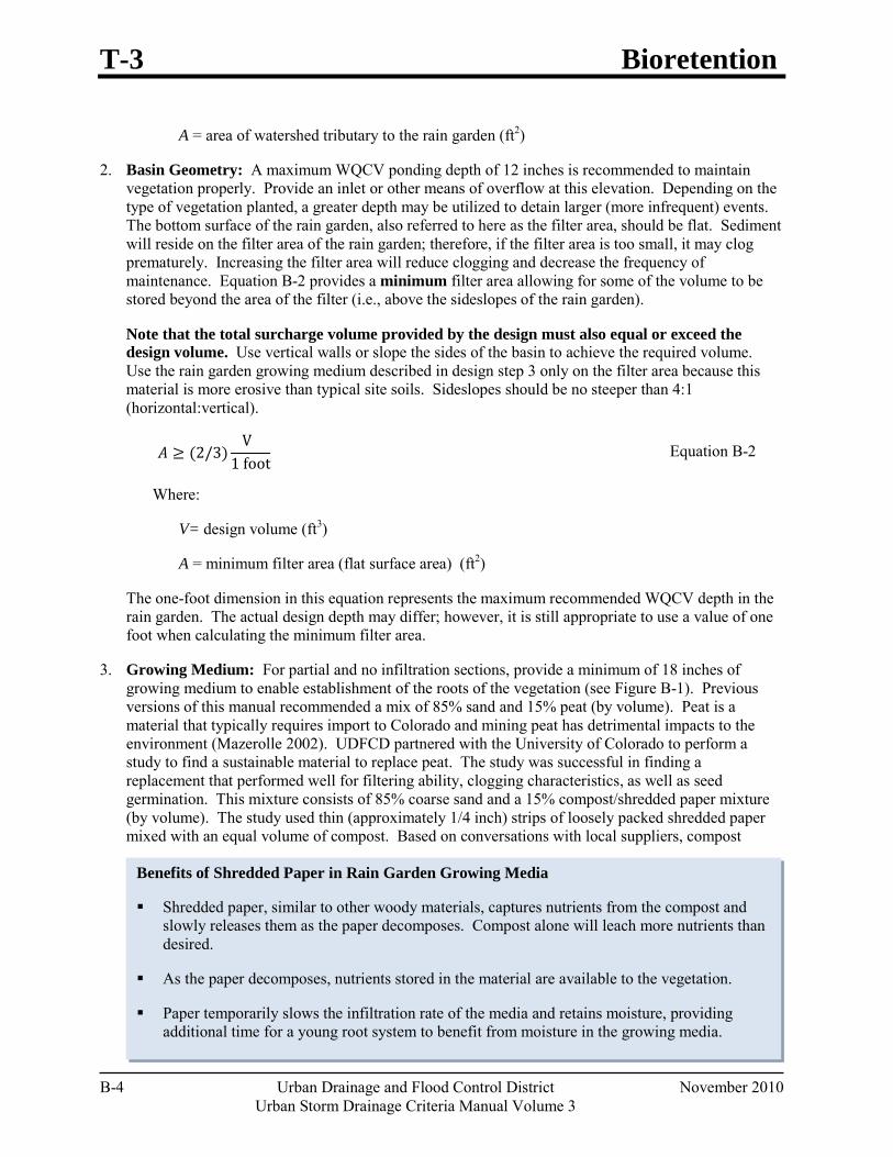
T-3 Bioretention
B-4 Urban Drainage and Flood Control District November 2010 Urban Storm Drainage Criteria Manual Volume 3
Benefits of Shredded Paper in Rain Garden Growing Media
Shredded paper, similar to other woody materials, captures nutrients from the compost and slowly releases them as the paper decomposes. Compost alone will leach more nutrients than desired.
As the paper decomposes, nutrients stored in the material are available to the vegetation.
Paper temporarily slows the infiltration rate of the media and retains moisture, providing additional time for a young root system to benefit from moisture in the growing media.
A = area of watershed tributary to the rain garden (ft2)
2. Basin Geometry: A maximum WQCV ponding depth of 12 inches is recommended to maintain vegetation properly. Provide an inlet or other means of overflow at this elevation. Depending on the type of vegetation planted, a greater depth may be utilized to detain larger (more infrequent) events. The bottom surface of the rain garden, also referred to here as the filter area, should be flat. Sediment will reside on the filter area of the rain garden; therefore, if the filter area is too small, it may clog prematurely. Increasing the filter area will reduce clogging and decrease the frequency of maintenance. Equation B-2 provides a minimum filter area allowing for some of the volume to be stored beyond the area of the filter (i.e., above the sideslopes of the rain garden).
Note that the total surcharge volume provided by the design must also equal or exceed the design volume. Use vertical walls or slope the sides of the basin to achieve the required volume. Use the rain garden growing medium described in design step 3 only on the filter area because this material is more erosive than typical site soils. Sideslopes should be no steeper than 4:1 (horizontal:vertical).
𝐴𝐴 ≥ (2/3)V
1 foot Equation B-2
Where:
V= design volume (ft3)
A = minimum filter area (flat surface area) (ft2)
The one-foot dimension in this equation represents the maximum recommended WQCV depth in the rain garden. The actual design depth may differ; however, it is still appropriate to use a value of one foot when calculating the minimum filter area.
3. Growing Medium: For partial and no infiltration sections, provide a minimum of 18 inches of growing medium to enable establishment of the roots of the vegetation (see Figure B-1). Previous versions of this manual recommended a mix of 85% sand and 15% peat (by volume). Peat is a material that typically requires import to Colorado and mining peat has detrimental impacts to the environment (Mazerolle 2002). UDFCD partnered with the University of Colorado to perform a study to find a sustainable material to replace peat. The study was successful in finding a replacement that performed well for filtering ability, clogging characteristics, as well as seed germination. This mixture consists of 85% coarse sand and a 15% compost/shredded paper mixture (by volume). The study used thin (approximately 1/4 inch) strips of loosely packed shredded paper mixed with an equal volume of compost. Based on conversations with local suppliers, compost
Bioretention T-3
November 2010 Urban Drainage and Flood Control District B-5 Urban Storm Drainage Criteria Manual Volume 3
containing shredded paper is not an uncommon request, although not typically provided in the proportions recommended in this BMP Fact Sheet. Compost suppliers have access to shredded paper through document destruction companies and can provide a mixture of Class 1 compost and shredded paper. The supplier should provide the rain garden compost mixture premixed with coarse sand. On-site mixing is not recommended.
Rain Garden Compost Mixture (by volume)
50% Class 1 STA registered compost (approximate bulk density 1000 lbs/CY)
50% loosely packed shredded paper (approximate bulk density 50 to 100 lbs/CY)
When using diamond cut shredded paper or tightly packed paper, use the bulk densities provided to mix by weight.
The supplier should premix the rain garden compost mixture (above) with coarse sand, in the following proportions, prior to delivery to the site:
Rain Garden Growing Medium
15% rain garden compost mixture described above (by volume)
85% coarse sand (either Class C Filter Material per Table B-2 or sand meeting ASTM C-33) (by volume)
Table B-1 provides detailed information on Class 1 compost. Be aware, regular testing is not required to allow a compost supplier to refer to a product as a specific STA class. However, regular testing is required and performed through the United States Compost Council (USCC) Seal of Testing Assurance (STA) Program to be a STA registered compost. To ensure Class 1 characteristics, look for a Class 1 STA registered compost.
Other Rain Garden Growing Medium Amendments
The growing medium described above is designed for filtration ability, clogging characteristics, and vegetative health. It is important to preserve the function provided by the rain garden growing medium when considering additional materials for incorporation into the growing medium or into the standard section shown in Figure B-1. When desired, amendments may be included to improve water quality or to benefit vegetative health as long as they do not add nutrients, pollutants, or modify the infiltration rate. For example, a number of products, including steel wool, capture and retain dissolved phosphorus (Erickson 2009). When phosphorus is a target pollutant, proprietary materials with similar characteristics may be considered. Do not include amendments such as top soil, sandy loam, and additional compost.
Full Infiltration Sections
A full infiltration section retains the WQCV onsite. For this section, it is not necessary to use the prescribed rain garden growing medium. Amend the soils to provide adequate nutrients to establish vegetation. Typically, 3 to 5 cubic yards of soil amendment (compost) per 1,000 square feet, tilled 6 inches into the soil, is required for vegetation to thrive. Additionally, inexpensive soil tests can be conducted to determine required soil amendments. (Some local governments may also require proof of soil amendment in landscaped areas for water conservation reasons.)
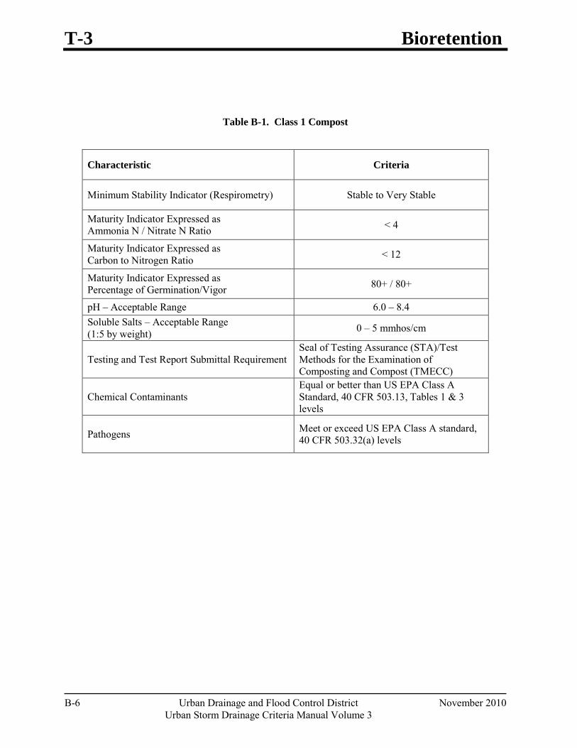
T-3 Bioretention
B-6 Urban Drainage and Flood Control District November 2010 Urban Storm Drainage Criteria Manual Volume 3
Table B-1. Class 1 Compost
Characteristic Criteria
Minimum Stability Indicator (Respirometry) Stable to Very Stable
Maturity Indicator Expressed as Ammonia N / Nitrate N Ratio < 4
Maturity Indicator Expressed as Carbon to Nitrogen Ratio < 12
Maturity Indicator Expressed as Percentage of Germination/Vigor 80+ / 80+
pH – Acceptable Range 6.0 – 8.4 Soluble Salts – Acceptable Range (1:5 by weight) 0 – 5 mmhos/cm
Testing and Test Report Submittal Requirement Seal of Testing Assurance (STA)/Test Methods for the Examination of Composting and Compost (TMECC)
Chemical Contaminants Equal or better than US EPA Class A Standard, 40 CFR 503.13, Tables 1 & 3 levels
Pathogens Meet or exceed US EPA Class A standard, 40 CFR 503.32(a) levels
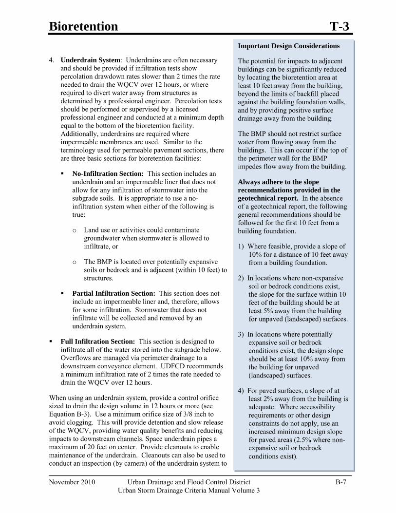
Bioretention T-3
November 2010 Urban Drainage and Flood Control District B-7 Urban Storm Drainage Criteria Manual Volume 3
4. Underdrain System: Underdrains are often necessary and should be provided if infiltration tests show percolation drawdown rates slower than 2 times the rate needed to drain the WQCV over 12 hours, or where required to divert water away from structures as determined by a professional engineer. Percolation tests should be performed or supervised by a licensed professional engineer and conducted at a minimum depth equal to the bottom of the bioretention facility. Additionally, underdrains are required where impermeable membranes are used. Similar to the terminology used for permeable pavement sections, there are three basic sections for bioretention facilities:
No-Infiltration Section: This section includes an underdrain and an impermeable liner that does not allow for any infiltration of stormwater into the subgrade soils. It is appropriate to use a no-infiltration system when either of the following is true:
o Land use or activities could contaminate groundwater when stormwater is allowed to infiltrate, or
o The BMP is located over potentially expansive soils or bedrock and is adjacent (within 10 feet) to structures.
Partial Infiltration Section: This section does not include an impermeable liner and, therefore; allows for some infiltration. Stormwater that does not infiltrate will be collected and removed by an underdrain system.
Full Infiltration Section: This section is designed to infiltrate all of the water stored into the subgrade below. Overflows are managed via perimeter drainage to a downstream conveyance element. UDFCD recommends a minimum infiltration rate of 2 times the rate needed to drain the WQCV over 12 hours.
When using an underdrain system, provide a control orifice sized to drain the design volume in 12 hours or more (see Equation B-3). Use a minimum orifice size of 3/8 inch to avoid clogging. This will provide detention and slow release of the WQCV, providing water quality benefits and reducing impacts to downstream channels. Space underdrain pipes a maximum of 20 feet on center. Provide cleanouts to enable maintenance of the underdrain. Cleanouts can also be used to conduct an inspection (by camera) of the underdrain system to
Important Design Considerations
The potential for impacts to adjacent buildings can be significantly reduced by locating the bioretention area at least 10 feet away from the building, beyond the limits of backfill placed against the building foundation walls, and by providing positive surface drainage away from the building.
The BMP should not restrict surface water from flowing away from the buildings. This can occur if the top of the perimeter wall for the BMP impedes flow away from the building.
Always adhere to the slope recommendations provided in the geotechnical report. In the absence of a geotechnical report, the following general recommendations should be followed for the first 10 feet from a building foundation.
1) Where feasible, provide a slope of 10% for a distance of 10 feet away from a building foundation.
2) In locations where non-expansive soil or bedrock conditions exist, the slope for the surface within 10 feet of the building should be at least 5% away from the building for unpaved (landscaped) surfaces.
3) In locations where potentially expansive soil or bedrock conditions exist, the design slope should be at least 10% away from the building for unpaved (landscaped) surfaces.
4) For paved surfaces, a slope of at least 2% away from the building is adequate. Where accessibility requirements or other design constraints do not apply, use an increased minimum design slope for paved areas (2.5% where non-expansive soil or bedrock conditions exist).
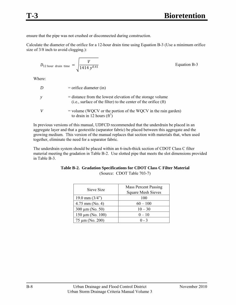
T-3 Bioretention
B-8 Urban Drainage and Flood Control District November 2010 Urban Storm Drainage Criteria Manual Volume 3
ensure that the pipe was not crushed or disconnected during construction.
Calculate the diameter of the orifice for a 12-hour drain time using Equation B-3 (Use a minimum orifice size of 3/8 inch to avoid clogging.):
𝐷𝐷12 hour drain time = �𝑉𝑉
1414 𝑦𝑦0.41 Equation B-3
Where:
D = orifice diameter (in)
y = distance from the lowest elevation of the storage volume (i.e., surface of the filter) to the center of the orifice (ft)
V = volume (WQCV or the portion of the WQCV in the rain garden) to drain in 12 hours (ft3)
In previous versions of this manual, UDFCD recommended that the underdrain be placed in an aggregate layer and that a geotextile (separator fabric) be placed between this aggregate and the growing medium. This version of the manual replaces that section with materials that, when used together, eliminate the need for a separator fabric.
The underdrain system should be placed within an 6-inch-thick section of CDOT Class C filter material meeting the gradation in Table B-2. Use slotted pipe that meets the slot dimensions provided in Table B-3.
Table B-2. Gradation Specifications for CDOT Class C Filter Material (Source: CDOT Table 703-7)
Sieve Size Mass Percent Passing Square Mesh Sieves
19.0 mm (3/4”) 100 4.75 mm (No. 4) 60 – 100 300 µm (No. 50) 10 – 30 150 µm (No. 100) 0 – 10 75 µm (No. 200) 0 - 3
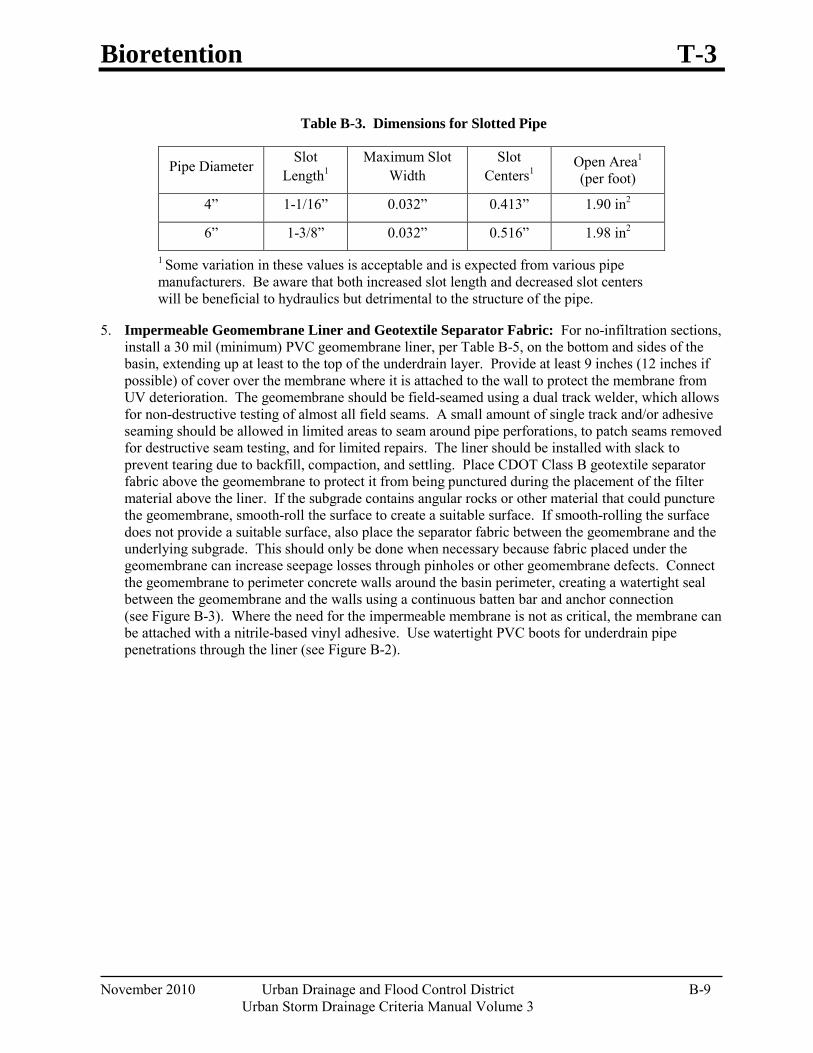
Bioretention T-3
November 2010 Urban Drainage and Flood Control District B-9 Urban Storm Drainage Criteria Manual Volume 3
Table B-3. Dimensions for Slotted Pipe
Pipe Diameter Slot Length1
Maximum Slot Width
Slot Centers1
Open Area1 (per foot)
4” 1-1/16” 0.032” 0.413” 1.90 in2
6” 1-3/8” 0.032” 0.516” 1.98 in2
1 Some variation in these values is acceptable and is expected from various pipe manufacturers. Be aware that both increased slot length and decreased slot centers will be beneficial to hydraulics but detrimental to the structure of the pipe.
5. Impermeable Geomembrane Liner and Geotextile Separator Fabric: For no-infiltration sections, install a 30 mil (minimum) PVC geomembrane liner, per Table B-5, on the bottom and sides of the basin, extending up at least to the top of the underdrain layer. Provide at least 9 inches (12 inches if possible) of cover over the membrane where it is attached to the wall to protect the membrane from UV deterioration. The geomembrane should be field-seamed using a dual track welder, which allows for non-destructive testing of almost all field seams. A small amount of single track and/or adhesive seaming should be allowed in limited areas to seam around pipe perforations, to patch seams removed for destructive seam testing, and for limited repairs. The liner should be installed with slack to prevent tearing due to backfill, compaction, and settling. Place CDOT Class B geotextile separator fabric above the geomembrane to protect it from being punctured during the placement of the filter material above the liner. If the subgrade contains angular rocks or other material that could puncture the geomembrane, smooth-roll the surface to create a suitable surface. If smooth-rolling the surface does not provide a suitable surface, also place the separator fabric between the geomembrane and the underlying subgrade. This should only be done when necessary because fabric placed under the geomembrane can increase seepage losses through pinholes or other geomembrane defects. Connect the geomembrane to perimeter concrete walls around the basin perimeter, creating a watertight seal between the geomembrane and the walls using a continuous batten bar and anchor connection (see Figure B-3). Where the need for the impermeable membrane is not as critical, the membrane can be attached with a nitrile-based vinyl adhesive. Use watertight PVC boots for underdrain pipe penetrations through the liner (see Figure B-2).
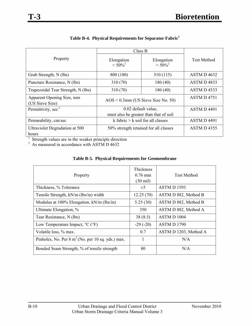
T-3 Bioretention
B-10 Urban Drainage and Flood Control District November 2010 Urban Storm Drainage Criteria Manual Volume 3
Table B-4. Physical Requirements for Separator Fabric1
Table B-5. Physical Requirements for Geomembrane
Property Thickness 0.76 mm (30 mil)
Test Method
Thickness, % Tolerance ±5 ASTM D 1593 Tensile Strength, kN/m (lbs/in) width 12.25 (70) ASTM D 882, Method B Modulus at 100% Elongation, kN/m (lbs/in) 5.25 (30) ASTM D 882, Method B Ultimate Elongation, % 350 ASTM D 882, Method A Tear Resistance, N (lbs) 38 (8.5) ASTM D 1004 Low Temperature Impact, °C (°F) -29 (-20) ASTM D 1790 Volatile loss, % max. 0.7 ASTM D 1203, Method A Pinholes, No. Per 8 m2 (No. per 10 sq. yds.) max. 1 N/A
Bonded Seam Strength, % of tensile strength 80 N/A
Property
Class B
Test Method Elongation < 50%2
Elongation > 50%2
Grab Strength, N (lbs) 800 (180) 510 (115) ASTM D 4632
Puncture Resistance, N (lbs) 310 (70) 180 (40) ASTM D 4833
Trapezoidal Tear Strength, N (lbs) 310 (70) 180 (40) ASTM D 4533
Apparent Opening Size, mm (US Sieve Size)
AOS < 0.3mm (US Sieve Size No. 50) ASTM D 4751
Permittivity, sec-1 0.02 default value, must also be greater than that of soil
ASTM D 4491
Permeability, cm/sec k fabric > k soil for all classes ASTM D 4491
Ultraviolet Degradation at 500 hours
50% strength retained for all classes ASTM D 4355
1 Strength values are in the weaker principle direction 2 As measured in accordance with ASTM D 4632
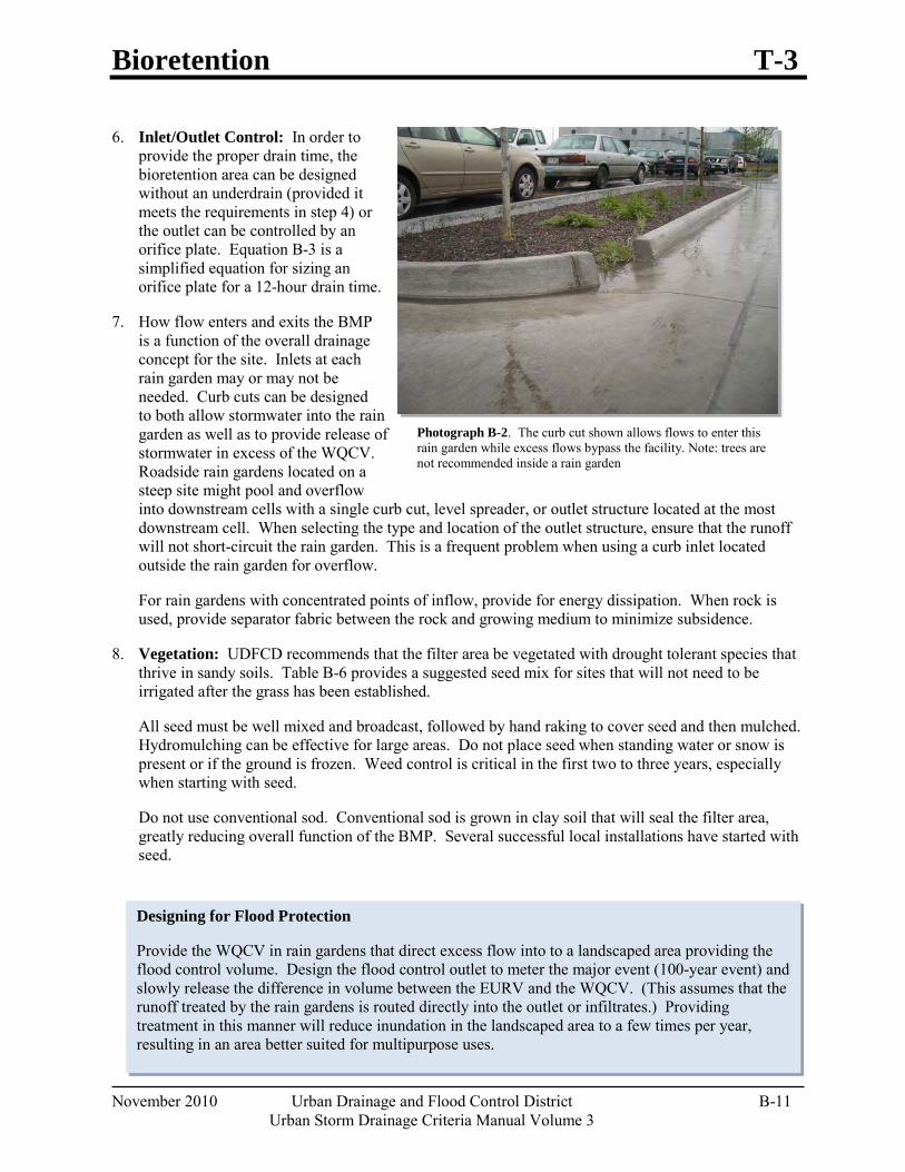
Bioretention T-3
November 2010 Urban Drainage and Flood Control District B-11 Urban Storm Drainage Criteria Manual Volume 3
Designing for Flood Protection
Provide the WQCV in rain gardens that direct excess flow into to a landscaped area providing the flood control volume. Design the flood control outlet to meter the major event (100-year event) and slowly release the difference in volume between the EURV and the WQCV. (This assumes that the runoff treated by the rain gardens is routed directly into the outlet or infiltrates.) Providing treatment in this manner will reduce inundation in the landscaped area to a few times per year, resulting in an area better suited for multipurpose uses.
6. Inlet/Outlet Control: In order to provide the proper drain time, the bioretention area can be designed without an underdrain (provided it meets the requirements in step 4) or the outlet can be controlled by an orifice plate. Equation B-3 is a simplified equation for sizing an orifice plate for a 12-hour drain time.
7. How flow enters and exits the BMP is a function of the overall drainage concept for the site. Inlets at each rain garden may or may not be needed. Curb cuts can be designed to both allow stormwater into the rain garden as well as to provide release of stormwater in excess of the WQCV. Roadside rain gardens located on a steep site might pool and overflow into downstream cells with a single curb cut, level spreader, or outlet structure located at the most downstream cell. When selecting the type and location of the outlet structure, ensure that the runoff will not short-circuit the rain garden. This is a frequent problem when using a curb inlet located outside the rain garden for overflow.
For rain gardens with concentrated points of inflow, provide for energy dissipation. When rock is used, provide separator fabric between the rock and growing medium to minimize subsidence.
8. Vegetation: UDFCD recommends that the filter area be vegetated with drought tolerant species that thrive in sandy soils. Table B-6 provides a suggested seed mix for sites that will not need to be irrigated after the grass has been established.
All seed must be well mixed and broadcast, followed by hand raking to cover seed and then mulched. Hydromulching can be effective for large areas. Do not place seed when standing water or snow is present or if the ground is frozen. Weed control is critical in the first two to three years, especially when starting with seed.
Do not use conventional sod. Conventional sod is grown in clay soil that will seal the filter area, greatly reducing overall function of the BMP. Several successful local installations have started with seed.
Photograph B-2. The curb cut shown allows flows to enter this rain garden while excess flows bypass the facility. Note: trees are not recommended inside a rain garden
T-3 Bioretention
B-12 Urban Drainage and Flood Control District November 2010 Urban Storm Drainage Criteria Manual Volume 3
When using an impermeable liner, select plants with diffuse (or fibrous) root systems, not taproots. Taproots can damage the liner and/or underdrain pipe. Avoid trees and large shrubs that may interfere with restorative maintenance. Trees and shrubs can be planted outside of the area of growing medium. Use a cutoff wall to ensure that roots do not grow into the underdrain or place trees and shrubs a conservative distance from the underdrain.
9. Irrigation: Provide spray irrigation at or above the WQCV elevation or place temporary irrigation on top of the rain garden surface. Do not place sprinkler heads on the flat surface. Remove temporary irrigation when vegetation is established. If left in place this will become buried over time and will be damaged during maintenance operations.
Irrigation schedules should be adjusted during the growing season to provide the minimum water necessary to maintain plant health and to maintain the available pore space for infiltration.
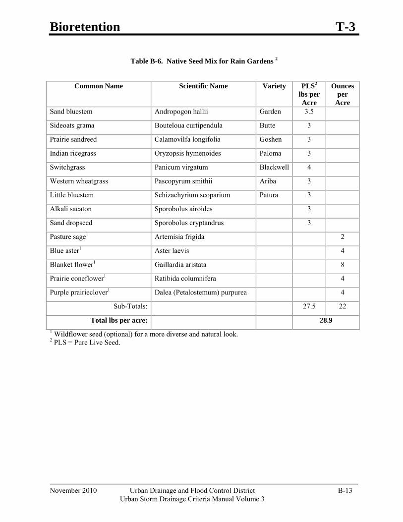
Bioretention T-3
November 2010 Urban Drainage and Flood Control District B-13 Urban Storm Drainage Criteria Manual Volume 3
Table B-6. Native Seed Mix for Rain Gardens 2
1 Wildflower seed (optional) for a more diverse and natural look. 2 PLS = Pure Live Seed.
Common Name Scientific Name Variety PLS2 lbs per Acre
Ounces per
Acre Sand bluestem Andropogon hallii Garden 3.5
Sideoats grama Bouteloua curtipendula Butte 3
Prairie sandreed Calamovilfa longifolia Goshen 3
Indian ricegrass Oryzopsis hymenoides Paloma 3
Switchgrass Panicum virgatum Blackwell 4
Western wheatgrass Pascopyrum smithii Ariba 3
Little bluestem Schizachyrium scoparium Patura 3
Alkali sacaton Sporobolus airoides 3
Sand dropseed Sporobolus cryptandrus 3
Pasture sage1 Artemisia frigida 2
Blue aster1 Aster laevis 4
Blanket flower1 Gaillardia aristata 8
Prairie coneflower1 Ratibida columnifera 4
Purple prairieclover1 Dalea (Petalostemum) purpurea 4
Sub-Totals: 27.5 22
Total lbs per acre: 28.9
T-3 Bioretention
B-14 Urban Drainage and Flood Control District November 2010 Urban Storm Drainage Criteria Manual Volume 3
Reflective Design
A reflective design borrows the characteristics, shapes, colors, materials, sizes and textures of the built surroundings. The result is a design that fits seamlessly and unobtrusively in its environment.
Aesthetic Design In addition to providing effective stormwater quality treatment, rain gardens can be attractively incorporated into a site within one or several landscape areas. Aesthetically designed rain gardens will typically either reflect the character of their surroundings or become distinct features within their surroundings. Guidelines for each approach are provided below.
Reflecting the Surrounding
Determine design characteristics of the surrounding. This becomes the context for the drainage improvement. Use these characteristics in the structure.
Create a shape or shapes that "fix" the forms surrounding the improvement. Make the improvement part of the existing surrounding.
The use of material is essential in making any new improvement an integral part of the whole. Select materials that are as similar as possible to the surrounding architectural/engineering materials. Select materials from the same source if possible. Apply materials in the same quantity, manner, and method as original material.
Size is an important feature in seamlessly blending the addition into its context. If possible, the overall size of the improvement should look very similar to the overall sizes of other similar objects in the improvement area.
The use of the word texture in terms of the structure applies predominantly to the selection of plant material. The materials used should as closely as possible, blend with the size and texture of other plant material used in the surrounding. The plants may or may not be the same, but should create a similar feel, either individually or as a mass.
Creating a Distinct Feature
Designing the rain garden as a distinct feature is limited only by budget, functionality, and client preference. There is far more latitude in designing a rain garden that serves as a distinct feature. If this is the intent, the main consideration beyond functionality is that the improvement create an attractive addition to its surroundings. The use of form, materials, color, and so forth focuses on the improvement itself and does not necessarily reflect the surroundings, depending on the choice of the client or designer.
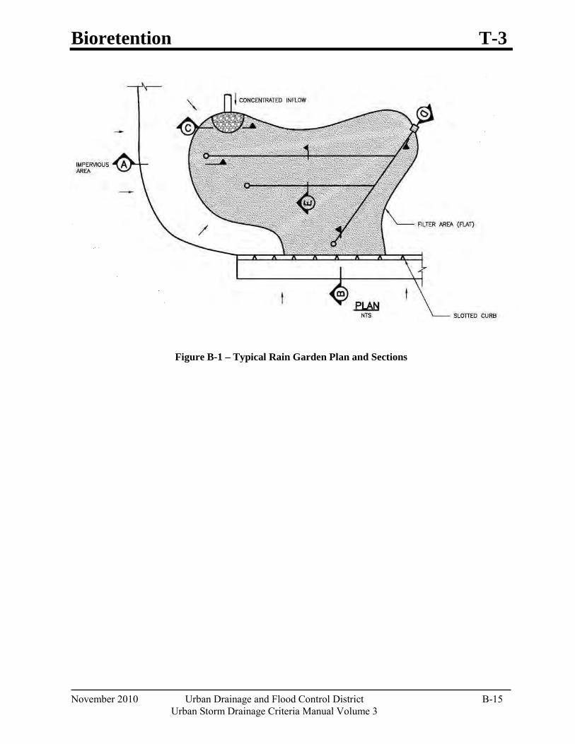
Bioretention T-3
November 2010 Urban Drainage and Flood Control District B-15 Urban Storm Drainage Criteria Manual Volume 3
Figure B-1 – Typical Rain Garden Plan and Sections
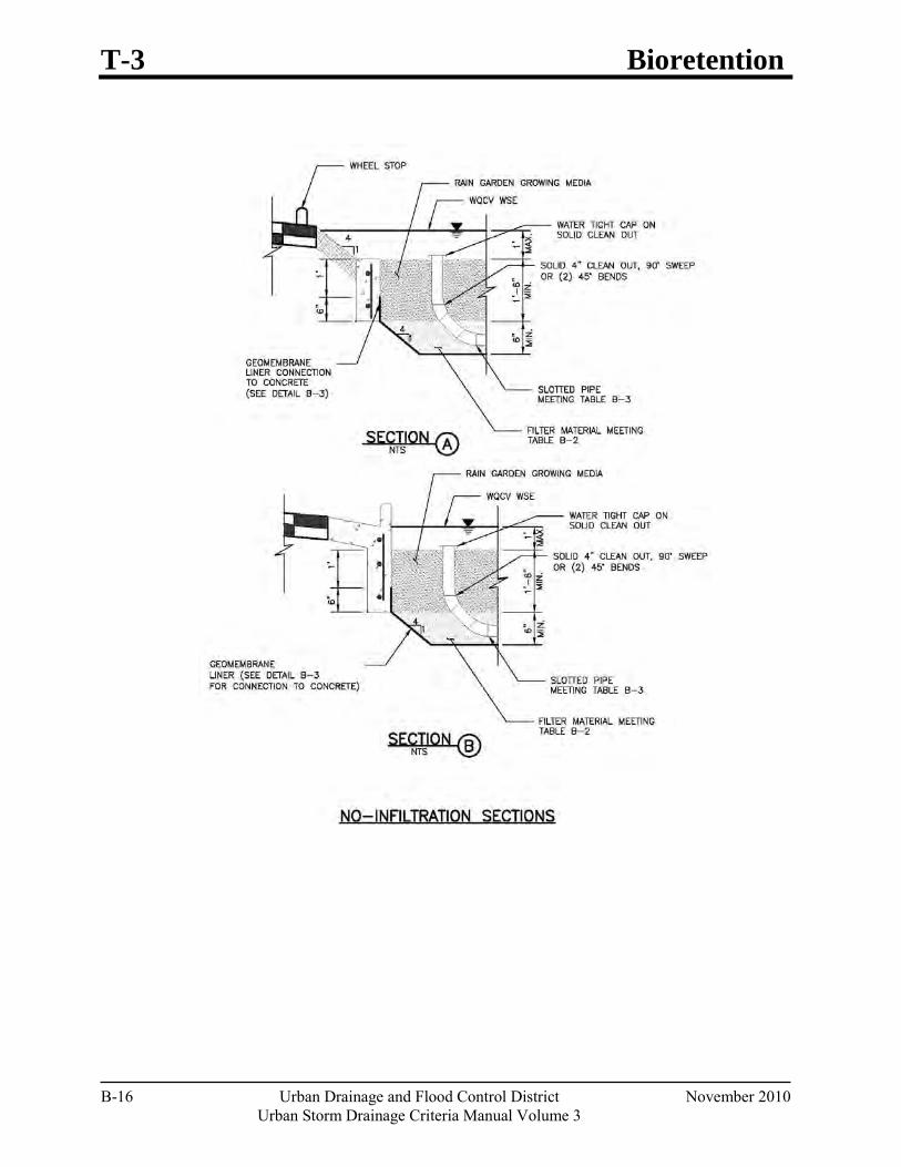
T-3 Bioretention
B-16 Urban Drainage and Flood Control District November 2010 Urban Storm Drainage Criteria Manual Volume 3
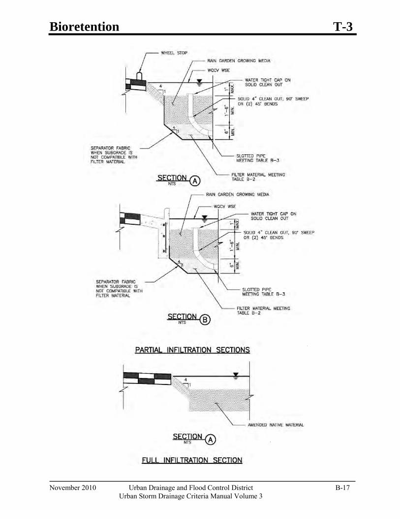
Bioretention T-3
November 2010 Urban Drainage and Flood Control District B-17 Urban Storm Drainage Criteria Manual Volume 3
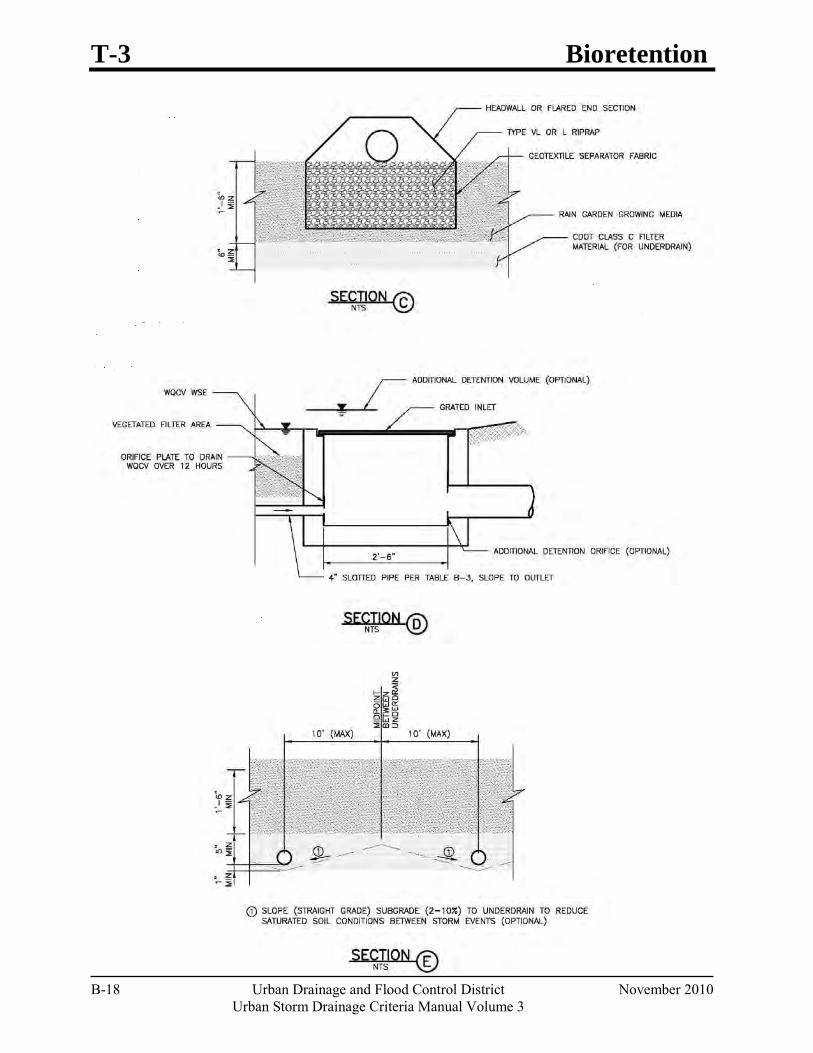
T-3 Bioretention
B-18 Urban Drainage and Flood Control District November 2010 Urban Storm Drainage Criteria Manual Volume 3
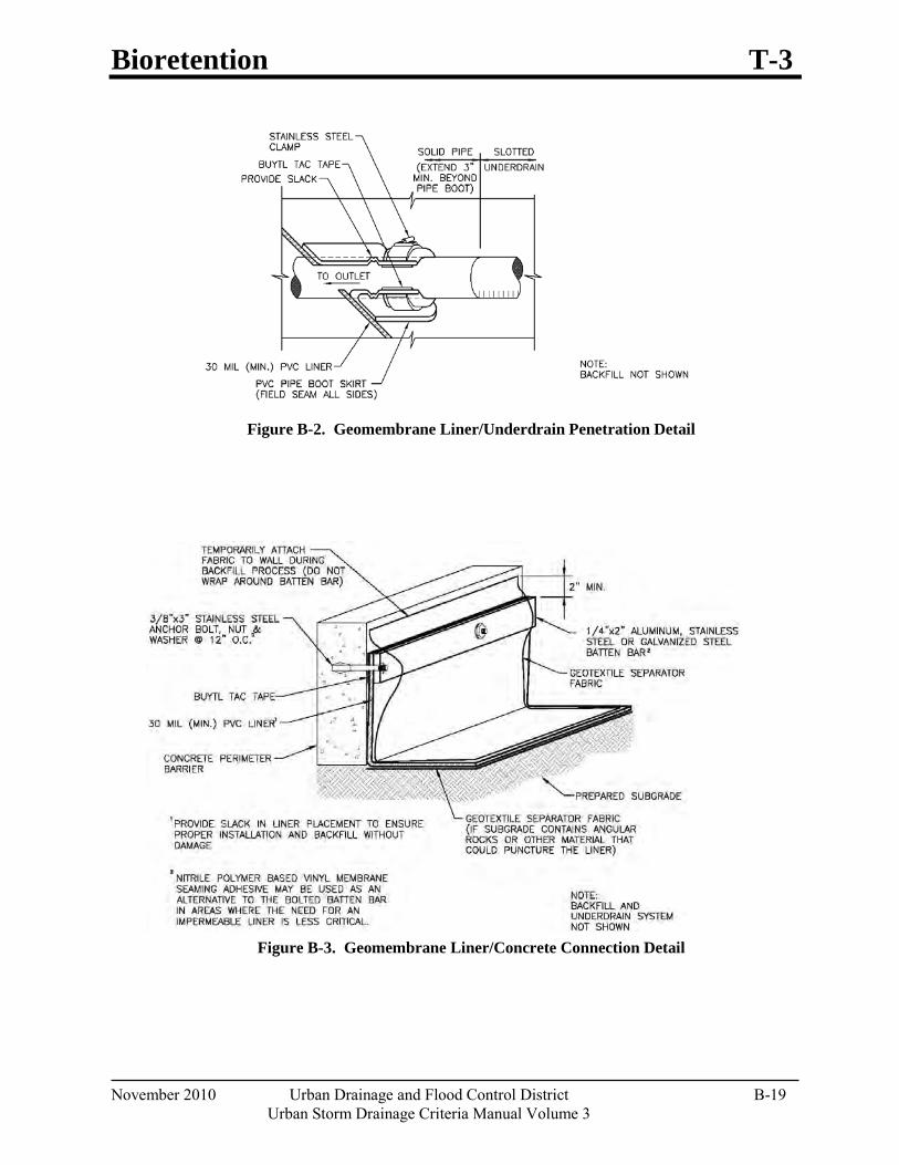
Bioretention T-3
November 2010 Urban Drainage and Flood Control District B-19 Urban Storm Drainage Criteria Manual Volume 3
Figure B-2. Geomembrane Liner/Underdrain Penetration Detail
Figure B-3. Geomembrane Liner/Concrete Connection Detail
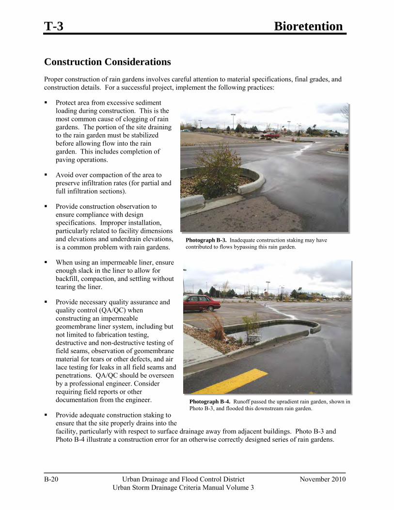
T-3 Bioretention
B-20 Urban Drainage and Flood Control District November 2010 Urban Storm Drainage Criteria Manual Volume 3
Photograph B-3. Inadequate construction staking may have contributed to flows bypassing this rain garden.
Photograph B-4. Runoff passed the upradient rain garden, shown in Photo B-3, and flooded this downstream rain garden.
Construction Considerations Proper construction of rain gardens involves careful attention to material specifications, final grades, and construction details. For a successful project, implement the following practices:
Protect area from excessive sediment loading during construction. This is the most common cause of clogging of rain gardens. The portion of the site draining to the rain garden must be stabilized before allowing flow into the rain garden. This includes completion of paving operations.
Avoid over compaction of the area to preserve infiltration rates (for partial and full infiltration sections).
Provide construction observation to ensure compliance with design specifications. Improper installation, particularly related to facility dimensions and elevations and underdrain elevations, is a common problem with rain gardens.
When using an impermeable liner, ensure enough slack in the liner to allow for backfill, compaction, and settling without tearing the liner.
Provide necessary quality assurance and quality control (QA/QC) when constructing an impermeable geomembrane liner system, including but not limited to fabrication testing, destructive and non-destructive testing of field seams, observation of geomembrane material for tears or other defects, and air lace testing for leaks in all field seams and penetrations. QA/QC should be overseen by a professional engineer. Consider requiring field reports or other documentation from the engineer.
Provide adequate construction staking to ensure that the site properly drains into the facility, particularly with respect to surface drainage away from adjacent buildings. Photo B-3 and Photo B-4 illustrate a construction error for an otherwise correctly designed series of rain gardens.
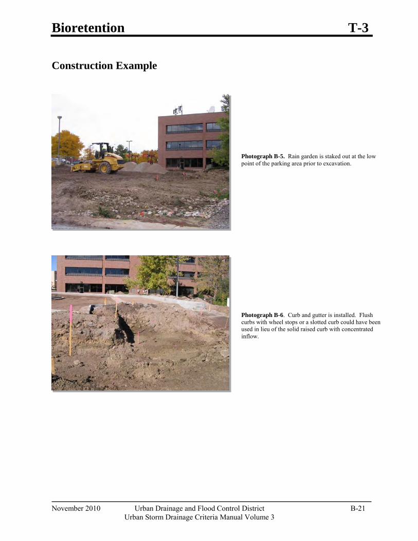
Bioretention T-3
November 2010 Urban Drainage and Flood Control District B-21 Urban Storm Drainage Criteria Manual Volume 3
Photograph B-5. Rain garden is staked out at the low point of the parking area prior to excavation.
Construction Example
Photograph B-6. Curb and gutter is installed. Flush curbs with wheel stops or a slotted curb could have been used in lieu of the solid raised curb with concentrated inflow.
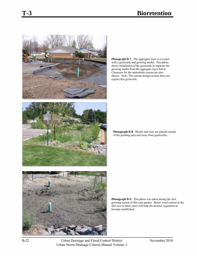
T-3 Bioretention
B-22 Urban Drainage and Flood Control District November 2010 Urban Storm Drainage Criteria Manual Volume 3
Photograph B-7. The aggregate layer is covered with a geotextile and growing media. This photo shows installation of the geotextile to separate the growing media from the aggregate layer below. Cleanouts for the underdrain system are also shown. Note: The current design section does not require this geotextile.
Photograph B-8. Shrubs and trees are placed outside of the ponding area and away from geotextiles.
Photograph B-9. This photo was taken during the first growing season of this rain garden. Better weed control in the first two to three years will help the desired vegetation to become established.

Bioretention T-3
November 2010 Urban Drainage and Flood Control District B-23 Urban Storm Drainage Criteria Manual Volume 3
Design Example The UD-BMP workbook, designed as a tool for both designer and reviewing agency is available at www.udfcd.org. This section provides a completed design form from this workbook as an example.
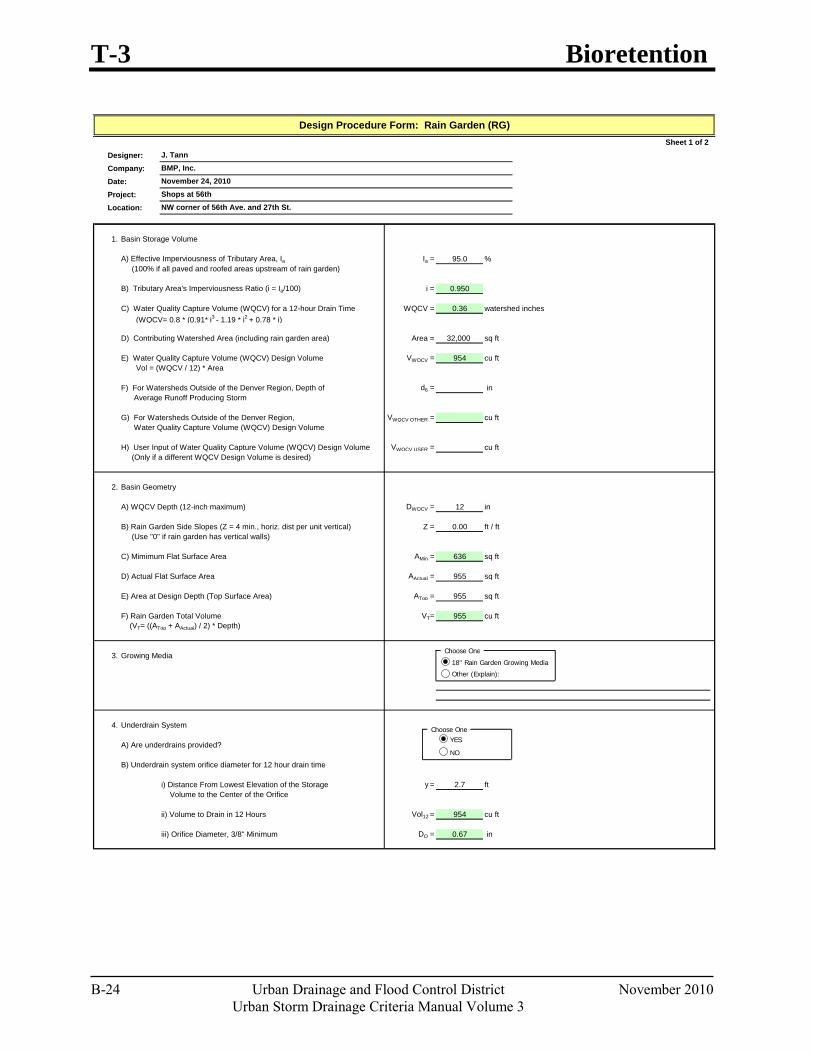
T-3 Bioretention
B-24 Urban Drainage and Flood Control District November 2010 Urban Storm Drainage Criteria Manual Volume 3
Sheet 1 of 2Designer:Company:Date:Project:Location:
1. Basin Storage Volume
A) Effective Imperviousness of Tributary Area, Ia Ia = 95.0 % (100% if all paved and roofed areas upstream of rain garden)
B) Tributary Area's Imperviousness Ratio (i = Ia/100) i = 0.950
C) Water Quality Capture Volume (WQCV) for a 12-hour Drain Time WQCV = 0.36 watershed inches (WQCV= 0.8 * (0.91* i3 - 1.19 * i2 + 0.78 * i)
D) Contributing Watershed Area (including rain garden area) Area = 32,000 sq ft
E) Water Quality Capture Volume (WQCV) Design Volume VWQCV = 954 cu ft Vol = (WQCV / 12) * Area
F) For Watersheds Outside of the Denver Region, Depth of d6 = in Average Runoff Producing Storm
G) For Watersheds Outside of the Denver Region, VWQCV OTHER = cu ft Water Quality Capture Volume (WQCV) Design Volume
H) User Input of Water Quality Capture Volume (WQCV) Design Volume VWQCV USER = cu ft (Only if a different WQCV Design Volume is desired)
2. Basin Geometry
A) WQCV Depth (12-inch maximum) DWQCV = 12 in
B) Rain Garden Side Slopes (Z = 4 min., horiz. dist per unit vertical) Z = 0.00 ft / ft (Use "0" if rain garden has vertical walls)
C) Mimimum Flat Surface Area AMin = 636 sq ft
D) Actual Flat Surface Area AActual = 955 sq ft
E) Area at Design Depth (Top Surface Area) ATop = 955 sq ft
F) Rain Garden Total Volume VT= 955 cu ft (VT= ((ATop + AActual) / 2) * Depth)
3. Growing Media
4. Underdrain System
A) Are underdrains provided?
B) Underdrain system orifice diameter for 12 hour drain time
i) Distance From Lowest Elevation of the Storage y = 2.7 ft Volume to the Center of the Orifice
ii) Volume to Drain in 12 Hours Vol12 = 954 cu ft
iii) Orifice Diameter, 3/8" Minimum DO = 0.67 in
Design Procedure Form: Rain Garden (RG)
J. TannBMP, Inc.November 24, 2010Shops at 56thNW corner of 56th Ave. and 27th St.
Choose One
Choose One
18" Rain Garden Growing Media
Other (Explain):
YES
NO
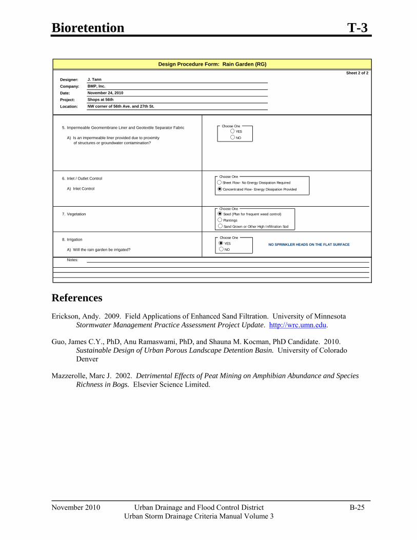
Bioretention T-3
November 2010 Urban Drainage and Flood Control District B-25 Urban Storm Drainage Criteria Manual Volume 3
References Erickson, Andy. 2009. Field Applications of Enhanced Sand Filtration. University of Minnesota
Stormwater Management Practice Assessment Project Update. http://wrc.umn.edu.
Guo, James C.Y., PhD, Anu Ramaswami, PhD, and Shauna M. Kocman, PhD Candidate. 2010. Sustainable Design of Urban Porous Landscape Detention Basin. University of Colorado Denver
Mazzerolle, Marc J. 2002. Detrimental Effects of Peat Mining on Amphibian Abundance and Species Richness in Bogs. Elsevier Science Limited.
Sheet 2 of 2Designer:Company:Date:Project:Location:
5. Impermeable Geomembrane Liner and Geotextile Separator Fabric
A) Is an impermeable liner provided due to proximity of structures or groundwater contamination?
6. Inlet / Outlet Control
A) Inlet Control
7. Vegetation
8. IrrigationNO SPRINKLER HEADS ON THE FLAT SURFACE
A) Will the rain garden be irrigated?
Notes:
November 24, 2010Shops at 56thNW corner of 56th Ave. and 27th St.
Design Procedure Form: Rain Garden (RG)
J. TannBMP, Inc.
Choose One
Choose One
Choose One
Sheet Flow- No Energy Dissipation Required
Concentrated Flow- Energy Dissipation Provided
Plantings
Seed (Plan for frequent weed control)
Sand Grown or Other High Infiltration Sod
Choose One
YES
NO
YES
NO

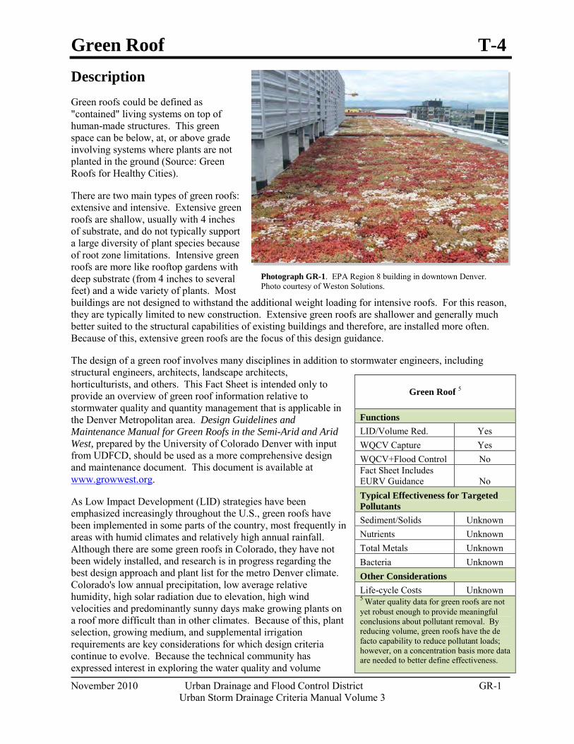
Green Roof T-4
November 2010 Urban Drainage and Flood Control District GR-1 Urban Storm Drainage Criteria Manual Volume 3
Photograph GR-1. EPA Region 8 building in downtown Denver. Photo courtesy of Weston Solutions.
Description Green roofs could be defined as "contained" living systems on top of human-made structures. This green space can be below, at, or above grade involving systems where plants are not planted in the ground (Source: Green Roofs for Healthy Cities).
There are two main types of green roofs: extensive and intensive. Extensive green roofs are shallow, usually with 4 inches of substrate, and do not typically support a large diversity of plant species because of root zone limitations. Intensive green roofs are more like rooftop gardens with deep substrate (from 4 inches to several feet) and a wide variety of plants. Most buildings are not designed to withstand the additional weight loading for intensive roofs. For this reason, they are typically limited to new construction. Extensive green roofs are shallower and generally much better suited to the structural capabilities of existing buildings and therefore, are installed more often. Because of this, extensive green roofs are the focus of this design guidance.
The design of a green roof involves many disciplines in addition to stormwater engineers, including structural engineers, architects, landscape architects, horticulturists, and others. This Fact Sheet is intended only to provide an overview of green roof information relative to stormwater quality and quantity management that is applicable in the Denver Metropolitan area. Design Guidelines and Maintenance Manual for Green Roofs in the Semi-Arid and Arid West, prepared by the University of Colorado Denver with input from UDFCD, should be used as a more comprehensive design and maintenance document. This document is available at www.growwest.org.
As Low Impact Development (LID) strategies have been emphasized increasingly throughout the U.S., green roofs have been implemented in some parts of the country, most frequently in areas with humid climates and relatively high annual rainfall. Although there are some green roofs in Colorado, they have not been widely installed, and research is in progress regarding the best design approach and plant list for the metro Denver climate. Colorado's low annual precipitation, low average relative humidity, high solar radiation due to elevation, high wind velocities and predominantly sunny days make growing plants on a roof more difficult than in other climates. Because of this, plant selection, growing medium, and supplemental irrigation requirements are key considerations for which design criteria continue to evolve. Because the technical community has expressed interest in exploring the water quality and volume
Green Roof 5
Functions LID/Volume Red. Yes WQCV Capture Yes WQCV+Flood Control No Fact Sheet Includes EURV Guidance No Typical Effectiveness for Targeted Pollutants
Sediment/Solids Unknown Nutrients Unknown Total Metals Unknown Bacteria Unknown Other Considerations Life-cycle Costs Unknown 5 Water quality data for green roofs are not yet robust enough to provide meaningful conclusions about pollutant removal. By reducing volume, green roofs have the de facto capability to reduce pollutant loads; however, on a concentration basis more data are needed to better define effectiveness.

T-4 Green Roof
GR-2 Urban Drainage and Flood Control District November 2010 Urban Storm Drainage Criteria Manual Volume 3
Green roofs provide multiple environmental, social, economic, and aesthetic benefits that extend beyond stormwater management objectives.
reduction benefits of this technique, information on green roofs is provided in this Fact Sheet based on industry literature and academic research.
It should be noted that the U.S. Green Building Council LEED rating system recognizes a second kind of green roof that includes reflective, high albedo roof materials that are not designed for stormwater purposes.
Site Selection Green roofs can be installed on commercial or residential buildings as well as on underground structures such as the parking garage shown in Photo GR-6. Green roofs may be particularly well suited for ultra urban areas where development is typically lot-line-to-lot-line and garden space is at a premium. Green roofs are particularly valuable when their use extends to a place of enjoyment for those that inhabit the building. Several Colorado examples are provided at the end of this Fact Sheet.
For existing buildings, the structural integrity of the building must be verified prior to consideration of retrofitting the building with a green roof. For both existing and new construction, it is essential that the design team be multi-disciplinary. This team may include a structural engineer, stormwater engineer, architect, landscape architect, and horticulturist. It is recommended that all members of the design team be involved early in the process to ensure the building and site conditions are appropriate for green roof installation.
Benefits Reduces runoff rates and volumes.
Reduces heat island effect in urban areas.
May qualify for multiple LEED credits.
May extend roof lifespan by reducing daily temperature fluctuations and providing shading from ultraviolet light.
May provide energy savings from additional insulation & evapotranspirative cooling.
Provides aesthetically pleasing open space in ultra urban areas.
Limitations Limited experience in Colorado.
Initial installation costs are greater than conventional roof (although lifecycle costs may be less).
Supplemental irrigation required in semi-arid climate.
Maintenance during vegetation establishment (first two years) may be significant.
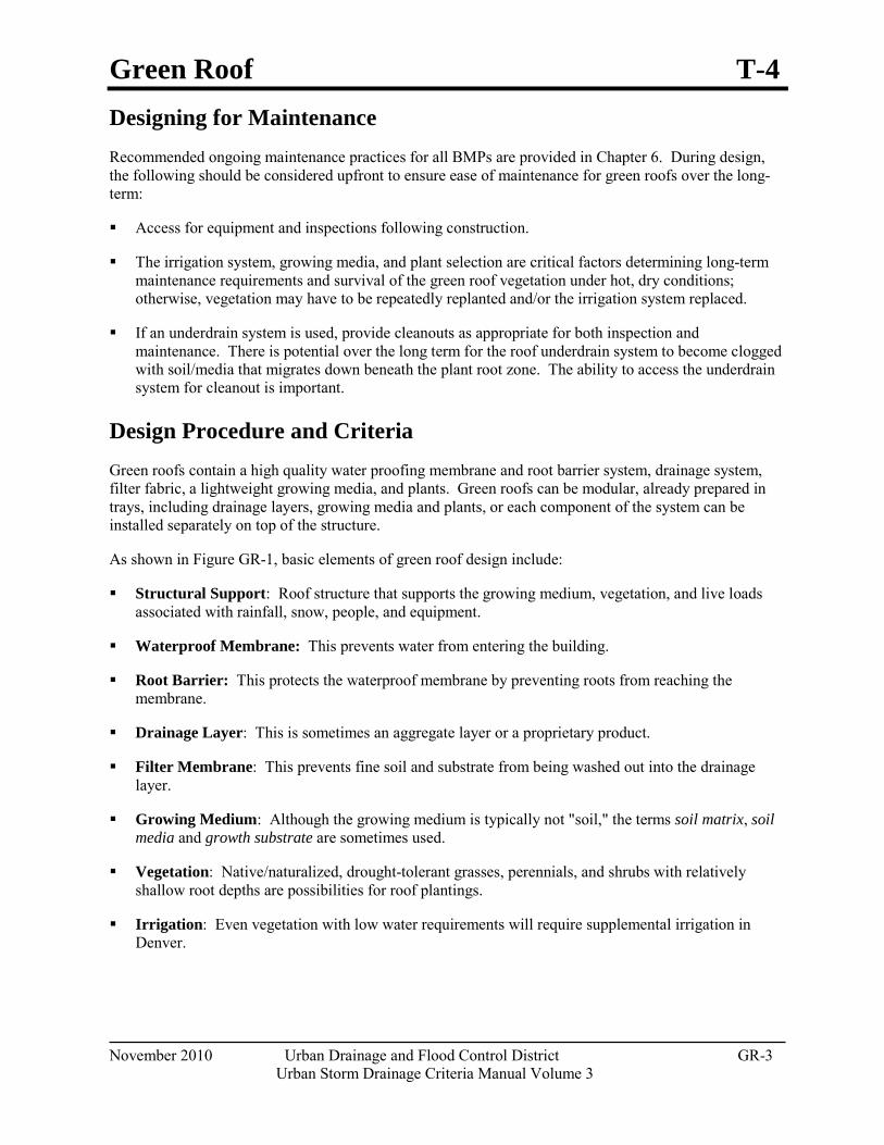
Green Roof T-4
November 2010 Urban Drainage and Flood Control District GR-3 Urban Storm Drainage Criteria Manual Volume 3
Designing for Maintenance Recommended ongoing maintenance practices for all BMPs are provided in Chapter 6. During design, the following should be considered upfront to ensure ease of maintenance for green roofs over the long-term:
Access for equipment and inspections following construction.
The irrigation system, growing media, and plant selection are critical factors determining long-term maintenance requirements and survival of the green roof vegetation under hot, dry conditions; otherwise, vegetation may have to be repeatedly replanted and/or the irrigation system replaced.
If an underdrain system is used, provide cleanouts as appropriate for both inspection and maintenance. There is potential over the long term for the roof underdrain system to become clogged with soil/media that migrates down beneath the plant root zone. The ability to access the underdrain system for cleanout is important.
Design Procedure and Criteria Green roofs contain a high quality water proofing membrane and root barrier system, drainage system, filter fabric, a lightweight growing media, and plants. Green roofs can be modular, already prepared in trays, including drainage layers, growing media and plants, or each component of the system can be installed separately on top of the structure.
As shown in Figure GR-1, basic elements of green roof design include:
Structural Support: Roof structure that supports the growing medium, vegetation, and live loads associated with rainfall, snow, people, and equipment.
Waterproof Membrane: This prevents water from entering the building.
Root Barrier: This protects the waterproof membrane by preventing roots from reaching the membrane.
Drainage Layer: This is sometimes an aggregate layer or a proprietary product.
Filter Membrane: This prevents fine soil and substrate from being washed out into the drainage layer.
Growing Medium: Although the growing medium is typically not "soil," the terms soil matrix, soil media and growth substrate are sometimes used.
Vegetation: Native/naturalized, drought-tolerant grasses, perennials, and shrubs with relatively shallow root depths are possibilities for roof plantings.
Irrigation: Even vegetation with low water requirements will require supplemental irrigation in Denver.
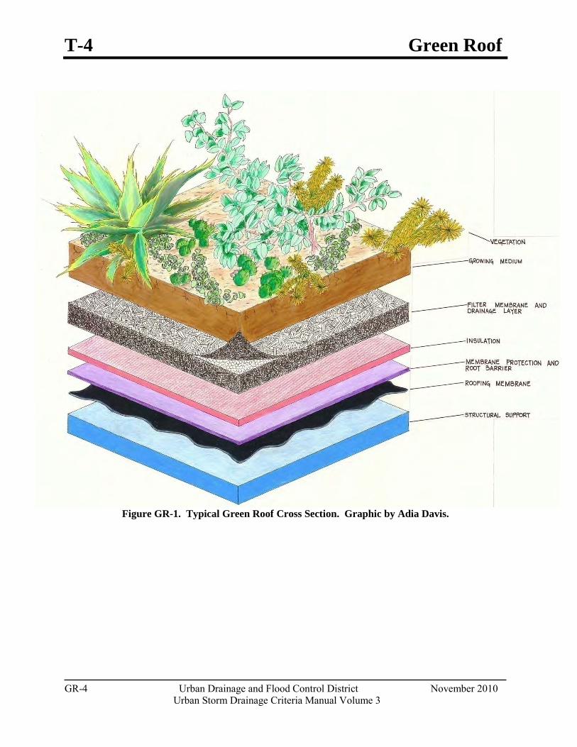
T-4 Green Roof
GR-4 Urban Drainage and Flood Control District November 2010 Urban Storm Drainage Criteria Manual Volume 3
Figure GR-1. Typical Green Roof Cross Section. Graphic by Adia Davis.
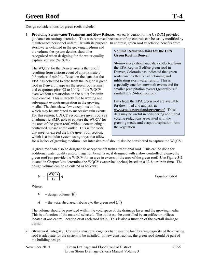
Green Roof T-4
November 2010 Urban Drainage and Flood Control District GR-5 Urban Storm Drainage Criteria Manual Volume 3
Volume Reduction Data for the EPA Green Roof in Denver
Stormwater performance data collected from the EPA Region 8 office green roof in Denver, Colorado has indicated that green roofs can be effective at detaining and infiltrating stormwater runoff. This is especially true for snowmelt events and for smaller precipitation events (generally <1" rainfall in a 24-hour period).
Data from the EPA green roof are available for download and analysis at www.epa.gov/region8/greenroof. These data may be useful in considering additional volume reductions associated with the growing media and evapotranspiration from the vegetation.
Design considerations for green roofs include:
1. Providing Stormwater Treatment and Slow Release: An early version of the USDCM provided guidance on rooftop detention. This was removed because rooftop controls can be easily modified by maintenance personnel unfamiliar with its purpose. In contrast, green roof vegetation benefits from stormwater detained in the growing medium and the volume the system detains should be recognized when designing for the water quality capture volume (WQCV).
The WQCV for the Denver area is the runoff resulting from a storm event of approximately 0.6 inches of rainfall. Based on the data that the EPA has collected to date from the Region 8 green roof in Denver, it appears the green roof retains and evapotranspires 98 to 100% of the WQCV even without a restriction on the outlet for drain time control. This is largely due to wetting and subsequent evapotranspiration in the growing media. The data show few exceptions to this, which may be attributed to successive rain events. For this reason, UDFCD recognizes green roofs as a volumetric BMP, able to capture the WQCV for the area of the green roof, without constructing a controlled release at the outlet. This is for roofs that meet or exceed the EPA green roof section, which is a modular system using trays that allow for 4 inches of growing medium. An intensive roof should also be considered to capture the WQCV.
A green roof can also be designed to accept runoff from a traditional roof. This can be done for additional water quality and/or irrigation benefits or, if designed with a slow controlled release, the green roof can provide the WQCV for an area in excess of the area of the green roof. Use Figure 3-2 located in Chapter 3 to determine the WQCV (watershed inches) based on a 12-hour drain time. The design volume can be calculated as follows:
𝑉𝑉 = �WQCV
12 � 𝐴𝐴 Equation GR-1
Where:
V = design volume (ft3)
A = the watershed area tributary to the green roof (ft2)
The volume should be provided within the void space of the drainage layer and the growing media. This is a function of the material selected. The outlet can be controlled by an orifice or orifices located at one central location or at each roof drain. This is also a function of the overall drainage design.
2. Structural Integrity: Consult a structural engineer to ensure the load bearing capacity of the existing roof is adequate for the system to be installed. If new construction, the green roof should be part of the building design.
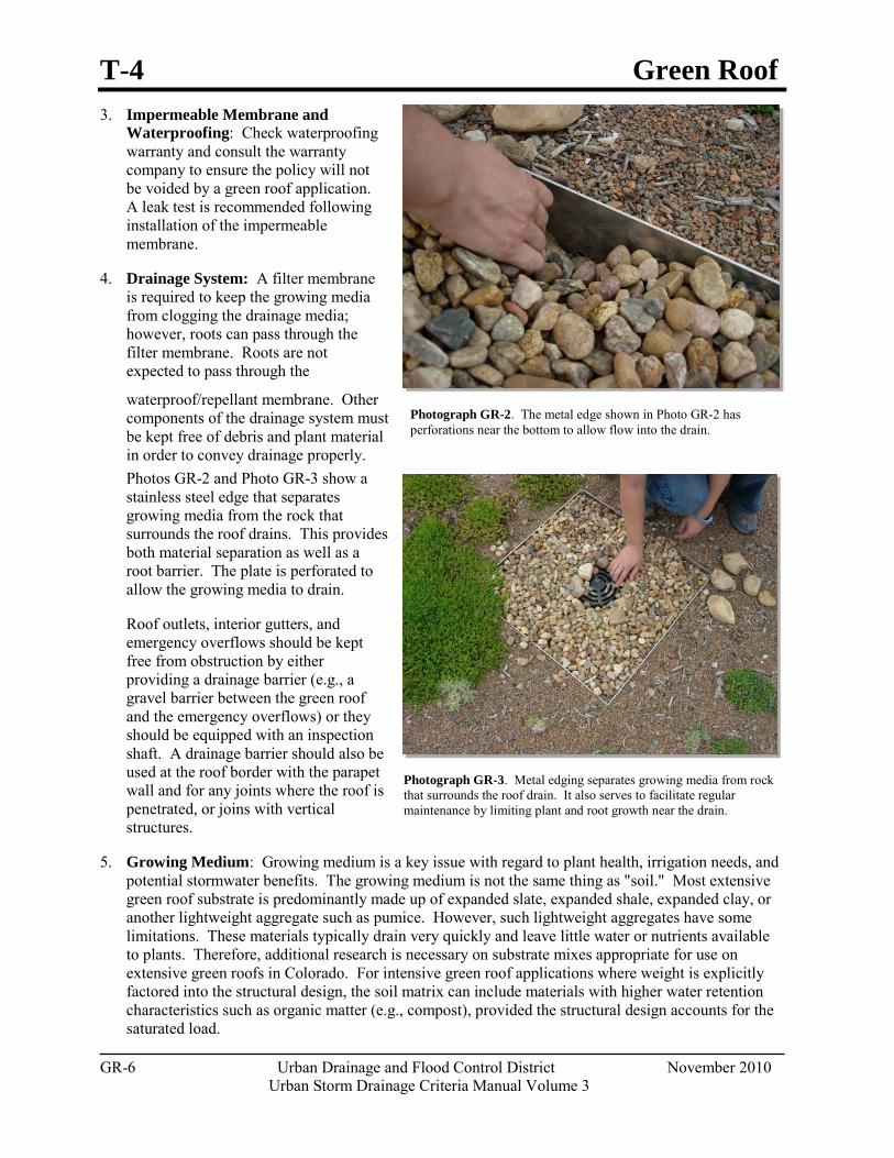
T-4 Green Roof
GR-6 Urban Drainage and Flood Control District November 2010 Urban Storm Drainage Criteria Manual Volume 3
Photograph GR-3. Metal edging separates growing media from rock that surrounds the roof drain. It also serves to facilitate regular maintenance by limiting plant and root growth near the drain.
Photograph GR-2. The metal edge shown in Photo GR-2 has perforations near the bottom to allow flow into the drain.
3. Impermeable Membrane and Waterproofing: Check waterproofing warranty and consult the warranty company to ensure the policy will not be voided by a green roof application. A leak test is recommended following installation of the impermeable membrane.
4. Drainage System: A filter membrane is required to keep the growing media from clogging the drainage media; however, roots can pass through the filter membrane. Roots are not expected to pass through the
waterproof/repellant membrane. Other components of the drainage system must be kept free of debris and plant material in order to convey drainage properly. Photos GR-2 and Photo GR-3 show a stainless steel edge that separates growing media from the rock that surrounds the roof drains. This provides both material separation as well as a root barrier. The plate is perforated to allow the growing media to drain.
Roof outlets, interior gutters, and emergency overflows should be kept free from obstruction by either providing a drainage barrier (e.g., a gravel barrier between the green roof and the emergency overflows) or they should be equipped with an inspection shaft. A drainage barrier should also be used at the roof border with the parapet wall and for any joints where the roof is penetrated, or joins with vertical structures.
5. Growing Medium: Growing medium is a key issue with regard to plant health, irrigation needs, and potential stormwater benefits. The growing medium is not the same thing as "soil." Most extensive green roof substrate is predominantly made up of expanded slate, expanded shale, expanded clay, or another lightweight aggregate such as pumice. However, such lightweight aggregates have some limitations. These materials typically drain very quickly and leave little water or nutrients available to plants. Therefore, additional research is necessary on substrate mixes appropriate for use on extensive green roofs in Colorado. For intensive green roof applications where weight is explicitly factored into the structural design, the soil matrix can include materials with higher water retention characteristics such as organic matter (e.g., compost), provided the structural design accounts for the saturated load.
Green Roof T-4
November 2010 Urban Drainage and Flood Control District GR-7 Urban Storm Drainage Criteria Manual Volume 3
6. Planting Method: In general, the planting method will be either "modular" (tray approach) or "continuous" (planted in situ).
Modular systems are self-contained trays, which can vary in size, and have relatively shallow depth (2 to 8 inches deep). When modular trays are planted with groundcover and placed close together, the roof often has the appearance of a continuous system once the vegetation is established. Due to the variations in green roof designs, it is important to consult with a multi-disciplinary team to determine the type of roof design most appropriate for the short-term and long-term conditions expected at the site.
Continuous systems are "built in place" on the roof with layers designed to work together to provide a healthy environment for plants. Continuous roof approaches range from rolled sedum mats to hand-planted buffalograss plugs.
7. Plant Selection: General categories of potentially viable plants for Colorado green roofs include native, alpine (grows in shallow rocky soils), and xeric plants (e.g., sedum). Plants must meet certain criteria to optimize their chance of survival on a green roof. Due to the shallow, well-drained materials in extensive green roof systems, plants must be drought resistant. However, not all drought resistant plants are well-suited for green roofs. For example, some plants avoid drought by rooting deeply to access a more stable supply of water. Such plants would not be suitable for a shallow green roof. Grasses with strong rhizome growth such as bamboo and varieties of Chinese reeds should be avoided, as these have the potential to compromise the roof membrane. While there are several species that could potentially adapt to extensive green roof systems, the most commonly used species are stonecrops or sedums because of their prostrate growth form, shallow root systems, and drought tolerance. Another favorable attribute of sedums is that the foliage tends to remain greener than grasses throughout the entire year, even in northern climates. However, drawbacks to a monoculture for green roofs are the same as for a monoculture in agricultural applications – risk of widespread vegetation loss if conditions (e.g., drought, disease, temperature, etc.) change from the anticipated range.
Characteristics of plants, which tend to work well on green roofs in a semi-arid climate include:
Self seeding,
Perennial,
Low or compact growth format,
Diffuse or fibrous root system,
Low water use, and
Cressulacean Acid Metabolism (CAM), which is common in sedums (stonecrops) where plant stomata are closed during the day to conserve water.
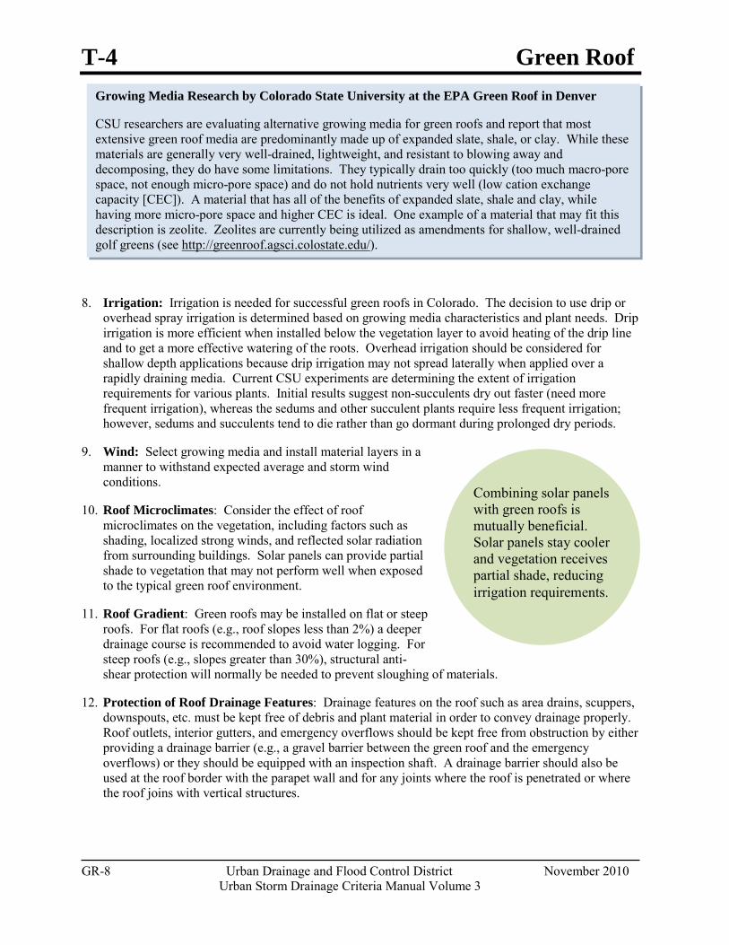
T-4 Green Roof
GR-8 Urban Drainage and Flood Control District November 2010 Urban Storm Drainage Criteria Manual Volume 3
Combining solar panels with green roofs is mutually beneficial. Solar panels stay cooler and vegetation receives partial shade, reducing irrigation requirements.
Growing Media Research by Colorado State University at the EPA Green Roof in Denver
CSU researchers are evaluating alternative growing media for green roofs and report that most extensive green roof media are predominantly made up of expanded slate, shale, or clay. While these materials are generally very well-drained, lightweight, and resistant to blowing away and decomposing, they do have some limitations. They typically drain too quickly (too much macro-pore space, not enough micro-pore space) and do not hold nutrients very well (low cation exchange capacity [CEC]). A material that has all of the benefits of expanded slate, shale and clay, while having more micro-pore space and higher CEC is ideal. One example of a material that may fit this description is zeolite. Zeolites are currently being utilized as amendments for shallow, well-drained golf greens (see http://greenroof.agsci.colostate.edu/).
8. Irrigation: Irrigation is needed for successful green roofs in Colorado. The decision to use drip or overhead spray irrigation is determined based on growing media characteristics and plant needs. Drip irrigation is more efficient when installed below the vegetation layer to avoid heating of the drip line and to get a more effective watering of the roots. Overhead irrigation should be considered for shallow depth applications because drip irrigation may not spread laterally when applied over a rapidly draining media. Current CSU experiments are determining the extent of irrigation requirements for various plants. Initial results suggest non-succulents dry out faster (need more frequent irrigation), whereas the sedums and other succulent plants require less frequent irrigation; however, sedums and succulents tend to die rather than go dormant during prolonged dry periods.
9. Wind: Select growing media and install material layers in a manner to withstand expected average and storm wind conditions.
10. Roof Microclimates: Consider the effect of roof microclimates on the vegetation, including factors such as shading, localized strong winds, and reflected solar radiation from surrounding buildings. Solar panels can provide partial shade to vegetation that may not perform well when exposed to the typical green roof environment.
11. Roof Gradient: Green roofs may be installed on flat or steep roofs. For flat roofs (e.g., roof slopes less than 2%) a deeper drainage course is recommended to avoid water logging. For steep roofs (e.g., slopes greater than 30%), structural anti-shear protection will normally be needed to prevent sloughing of materials.
12. Protection of Roof Drainage Features: Drainage features on the roof such as area drains, scuppers, downspouts, etc. must be kept free of debris and plant material in order to convey drainage properly. Roof outlets, interior gutters, and emergency overflows should be kept free from obstruction by either providing a drainage barrier (e.g., a gravel barrier between the green roof and the emergency overflows) or they should be equipped with an inspection shaft. A drainage barrier should also be used at the roof border with the parapet wall and for any joints where the roof is penetrated or where the roof joins with vertical structures.
Green Roof T-4
November 2010 Urban Drainage and Flood Control District GR-9 Urban Storm Drainage Criteria Manual Volume 3
Additional Design Guidance Until more experience is gained in Colorado with regard to green roofs, the following design guidance documents may provide additional assistance; with the understanding that the guidelines may need adjustment for Denver's climate:
"FLL Guidelines": The FLL Guidelines are green roof standards developed by the German Research Society for Landscape Development and Landscape Design. (FLL is derived from the German title: "Forschungsgesellschaft Landschaftsentwicklung Landschaftsbau e.V.") These guidelines include the planning, execution and upkeep of green-roof sites. The 2002 edition of these widely consulted guidelines is available for purchase in English through http://www.roofmeadow.com/technical/fll.php.
ASTM Book of Standards, v. 04-12, 2005:
o ASTM E2396-E2399: ASTM has recently developed a new set of standards for green roofs; however, it is important to recognize these standards were developed outside of Colorado.
o ASTM E2396-05: Standard test method for saturated water permeability of granulated drainage media (falling-head method) for green roof systems.
o ASTM E-2398-05: Standard test method for water capture and media retention of geocomposite drain layers for green roof systems.
o ASTM E2397-05: Standard practice for determination of dead loads and live loads associated with green roof systems.
BOCA Codes, International Code Council (ICC): Building Officials and Code Administrators International Inc. (BOCA), now known as the International Code Council (ICC), publish codes that establish minimum performance requirements for all aspects of the construction industry. BOCA codes at the Library of Congress are located in the Law Library Reading Room. Some state codes are available at no cost through the eCodes sections of the ICC Website, while others must be purchased http://www.iccsafe.org/.
Leadership in Energy and Environmental Design (LEED): The LEED Green Building Rating System is a voluntary, consensus-based national standard for developing high-performance, sustainable buildings. LEED standards are available through the U.S. Green Building Council: http://www.usgbc.org/DisplayPage.aspx?CategoryID=19. Attainment of a desired LEED building rating (e.g., gold, platinum) is based on accumulation of "points" achieved by implementing practices in six different credit categories. A variety of LEED points are potentially achievable through use of green roofs. For example, under the "Sustainable Sites" category, eligible points could include Site Development credits for protecting or restoring habitat and maximizing open space, Stormwater Design credits for quality and quantity, and Heat Island Effect credits for roofs. Green roofs may also contribute to achievement of "Energy and Atmosphere" points for optimizing energy performance for buildings. Green roofs may play a supporting role in a variety of other credits, as well as being eligible for "Innovation in Design" credits.
T-4 Green Roof
GR-10 Urban Drainage and Flood Control District November 2010 Urban Storm Drainage Criteria Manual Volume 3
Websites for Additional Design Ideas Colorado Colorado State University: http://greenroof.agsci.colostate.edu/ Green Roofs of Colorado: http://www.greenroofsco.com/ Denver Botanic Gardens: http://www.botanicgardens.org/content/green-roof Other Research Programs and Resources Pennsylvania State University Michigan State University North Carolina State University Southern Illinois University LBJ Wildflower Center/University of Texas at Austin Green Roofs for Healthy Cities GreenRoofs.com American Society of Landscape Architects: http://land.asla.org/050205/greenroofcentral.html Low Impact Development Center: http://www.lid-stormwater.net/
Construction Considerations Success of green roofs depends not only on a good design and maintenance, but also on construction practices that enable the BMP to function as designed. Construction considerations include:
Permit Requirements, General Coordination, and Warranties: Investigate permitting requirements for green roofs in the local jurisdiction. Significant coordination between architects, engineers, roofers, and landscapers is needed. Contractually, it is common to have the roofer warranty the impermeable membrane, whereas the landscaper would be responsible for the growing media, vegetation, and other landscaping. Typically, irrigation systems have warranties, but plants do not, with the exception of situations where a maintenance contract is in place. Where a maintenance contract is in place, some landscapers or greenhouses will provide plant warranties.
Roof Membrane: Inspect the roof membrane (the most crucial element of a green roof) and conduct a leak test prior to installing the remaining layers of the roof.
Installation Safety: Most landscapers are accustomed to working on the ground, so safety training is important. If the green roof will be accessible to the public, safety at roof edges should be of paramount concern.
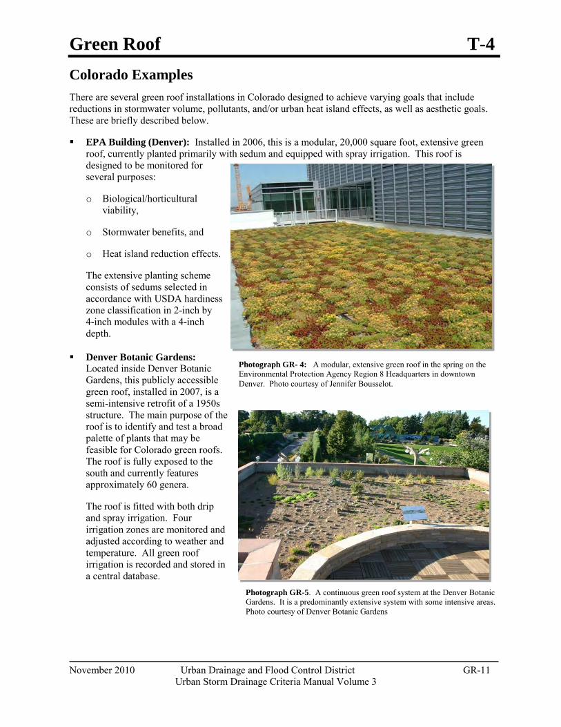
Green Roof T-4
November 2010 Urban Drainage and Flood Control District GR-11 Urban Storm Drainage Criteria Manual Volume 3
Photograph GR- 4: A modular, extensive green roof in the spring on the Environmental Protection Agency Region 8 Headquarters in downtown Denver. Photo courtesy of Jennifer Bousselot.
Photograph GR-5. A continuous green roof system at the Denver Botanic Gardens. It is a predominantly extensive system with some intensive areas. Photo courtesy of Denver Botanic Gardens
Colorado Examples There are several green roof installations in Colorado designed to achieve varying goals that include reductions in stormwater volume, pollutants, and/or urban heat island effects, as well as aesthetic goals. These are briefly described below.
EPA Building (Denver): Installed in 2006, this is a modular, 20,000 square foot, extensive green roof, currently planted primarily with sedum and equipped with spray irrigation. This roof is designed to be monitored for several purposes:
o Biological/horticultural viability,
o Stormwater benefits, and
o Heat island reduction effects.
The extensive planting scheme consists of sedums selected in accordance with USDA hardiness zone classification in 2-inch by 4-inch modules with a 4-inch depth.
Denver Botanic Gardens: Located inside Denver Botanic Gardens, this publicly accessible green roof, installed in 2007, is a semi-intensive retrofit of a 1950s structure. The main purpose of the roof is to identify and test a broad palette of plants that may be feasible for Colorado green roofs. The roof is fully exposed to the south and currently features approximately 60 genera.
The roof is fitted with both drip and spray irrigation. Four irrigation zones are monitored and adjusted according to weather and temperature. All green roof irrigation is recorded and stored in a central database.
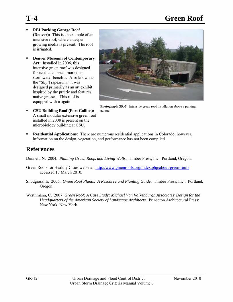
T-4 Green Roof
GR-12 Urban Drainage and Flood Control District November 2010 Urban Storm Drainage Criteria Manual Volume 3
Photograph GR-6. Intensive green roof installation above a parking garage.
REI Parking Garage Roof (Denver): This is an example of an intensive roof, where a deeper growing media is present. The roof is irrigated.
Denver Museum of Contemporary Art: Installed in 2006, this intensive green roof was designed for aesthetic appeal more than stormwater benefits. Also known as the "Sky Trapezium," it was designed primarily as an art exhibit inspired by the prairie and features native grasses. This roof is equipped with irrigation.
CSU Building Roof (Fort Collins): A small modular extensive green roof installed in 2008 is present on the microbiology building at CSU.
Residential Applications: There are numerous residential applications in Colorado; however, information on the design, vegetation, and performance has not been compiled.
References Dunnett, N. 2004. Planting Green Roofs and Living Walls. Timber Press, Inc: Portland, Oregon.
Green Roofs for Healthy Cities website. http://www.greenroofs.org/index.php/about-green-roofs accessed 17 March 2010.
Snodgrass, E. 2006. Green Roof Plants: A Resource and Planting Guide. Timber Press, Inc.: Portland, Oregon.
Werthmann, C. 2007 Green Roof: A Case Study: Michael Van Valkenburgh Associates' Design for the Headquarters of the American Society of Landscape Architects. Princeton Architectural Press: New York, New York.
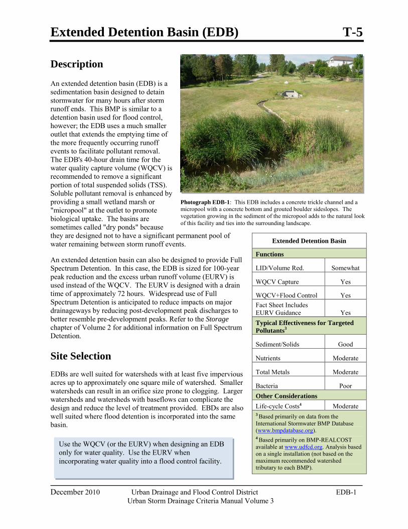
Extended Detention Basin (EDB) T-5
December 2010 Urban Drainage and Flood Control District EDB-1 Urban Storm Drainage Criteria Manual Volume 3
Photograph EDB-1: This EDB includes a concrete trickle channel and a micropool with a concrete bottom and grouted boulder sideslopes. The vegetation growing in the sediment of the micropool adds to the natural look of this facility and ties into the surrounding landscape.
Use the WQCV (or the EURV) when designing an EDB only for water quality. Use the EURV when incorporating water quality into a flood control facility.
Description
An extended detention basin (EDB) is a sedimentation basin designed to detain stormwater for many hours after storm runoff ends. This BMP is similar to a detention basin used for flood control, however; the EDB uses a much smaller outlet that extends the emptying time of the more frequently occurring runoff events to facilitate pollutant removal. The EDB's 40-hour drain time for the water quality capture volume (WQCV) is recommended to remove a significant portion of total suspended solids (TSS). Soluble pollutant removal is enhanced by providing a small wetland marsh or "micropool" at the outlet to promote biological uptake. The basins are sometimes called "dry ponds" because they are designed not to have a significant permanent pool of water remaining between storm runoff events.
An extended detention basin can also be designed to provide Full Spectrum Detention. In this case, the EDB is sized for 100-year peak reduction and the excess urban runoff volume (EURV) is used instead of the WQCV. The EURV is designed with a drain time of approximately 72 hours. Widespread use of Full Spectrum Detention is anticipated to reduce impacts on major drainageways by reducing post-development peak discharges to better resemble pre-development peaks. Refer to the Storage chapter of Volume 2 for additional information on Full Spectrum Detention.
Site Selection EDBs are well suited for watersheds with at least five impervious acres up to approximately one square mile of watershed. Smaller watersheds can result in an orifice size prone to clogging. Larger watersheds and watersheds with baseflows can complicate the design and reduce the level of treatment provided. EBDs are also well suited where flood detention is incorporated into the same basin.
Extended Detention Basin
Functions
LID/Volume Red. Somewhat
WQCV Capture Yes
WQCV+Flood Control Yes Fact Sheet Includes EURV Guidance Yes Typical Effectiveness for Targeted Pollutants3
Sediment/Solids Good
Nutrients Moderate
Total Metals Moderate
Bacteria Poor Other Considerations Life-cycle Costs4 Moderate 3 Based primarily on data from the International Stormwater BMP Database (www.bmpdatabase.org). 4 Based primarily on BMP-REALCOST available at www.udfcd.org. Analysis based on a single installation (not based on the maximum recommended watershed tributary to each BMP).
T-5 Extended Detention Basin (EDB)
EDB-2 Urban Drainage and Flood Control District December 2010 Urban Storm Drainage Criteria Manual Volume 3
Benefits The relatively simple design can
make EDBs less expensive to construct than other BMPs, especially for larger basins.
Maintenance requirements are straightforward.
The facility can be designed for multiple uses.
Limitations Ponding time and depths may
generate safety concerns.
Best suited for tributary areas of 5 impervious acres or more. EDBs are not recommended for sites less than 2 impervious acres.
Although ponds do not require more total area compared to other BMPs, they typically require a relatively large continuous area.
EDBs providing combined water quality and flood control functions can serve multiple uses such as playing fields or picnic areas. These uses are best located at higher elevation within the basin, above the WQCV pool level.
The depth of groundwater should be investigated. Groundwater depth should be 2 or more feet below the bottom of the basin in order to keep this area dry and maintainable.
Designing for Maintenance Recommended maintenance practices for all BMPs are provided in the BMP Maintenance chapter of this manual. During design the following should be considered to ensure ease of maintenance over the long-term:
Always provide a micropool (see step 7).
Provide a design slope of at least 3% in the vegetated bottom of the basin (either toward the trickle channel or toward the micropool). This will help maintain the appearance of the turf grass in the bottom of the basin and reduce the possibility of saturated areas that may produce unwanted species of vegetation and mosquito breeding conditions. Verify slopes during construction, prior to vegetation.
Follow trash rack sizing recommendations to determine the minimum area for the trash rack (see design step 9).
Provide adequate initial surcharge volume for frequent inundation (see design step 3).
Provide stabilized access to the forebay, outlet, spillway, and micropool for maintenance purposes.
Provide access to the well screen. The well screen requires maintenance more often than any other EDB component. Ensure that the screen can be reached from a point outside of the micropool. When the well screen is located inside the outlet structure, provide an access port within the trash rack or use a sloped trash rack that consists of bearing bars (not horizontal) that are 6 inches on center.
Provide a hard-bottom forebay that allows for removal of sediment.
Where baseflows are anticipated, consider providing a flow-measuring device (e.g. weir or flume with staff gage and rating curve) at the forebay to assist with future modifications of the water quality plate. Typically, the baseflow will increase as the watershed develops. It is important that the water quality plate continue to function, passing the baseflow while draining the WQCV over approximately 40 hours. Measuring the actual baseflow can be helpful in determining if and when the orifice place should be replaced.
Extended Detention Basin (EDB) T-5
December 2010 Urban Drainage and Flood Control District EDB-3 Urban Storm Drainage Criteria Manual Volume 3
Design Procedure and Criteria
The following steps outline the design procedure and criteria for an EDB:
1. Basin Storage Volume: Provide a design volume equal to 120% of the WQCV or 100% of the EURV. This volume begins at the lowest orifice in the outlet structure. The additional 20% for the WQCV is for sediment accumulation and the resultant loss in storage volume. Additional volume for sediment storage is not necessary when designing for the EURV, as the water quality perforations extend above the depth of the WQCV.
Determine the imperviousness of the watershed (or effective imperviousness where LID elements are used upstream).
Find the required storage volume. Determine the required WQCV or EURV (watershed inches of runoff) using Figure 3-2 located in Chapter 3 of this manual (for WQCV) or equations provided in the Storage chapter of Volume 2 (for EURV).
Calculate the design volume as follows:
𝑉𝑉 = �WQCV
12 �1.2 𝐴𝐴
For WQCV: Equation EDB-1
𝑉𝑉 = �EURV
12 � 𝐴𝐴
For EURV: Equation EDB-2
Where:
V = design volume (acre ft)
A = watershed area tributary to the extended detention basin (acres)
1.2 factor = multiplier to accommodate sediment accumulation
2. Basin Shape: Always maximize the distance between the inlet and the outlet. It is best to have a basin length (measured along the flow path from inlet to outlet) to width ratio of at least 2:1. A longer flow path from inlet to outlet will minimize short circuiting and improve reduction of TSS. To achieve this ratio, it may be necessary to modify the inlet and outlet points through the use of pipes or swales.
3. Basin Side Slopes: Basin side slopes should be stable and gentle to facilitate maintenance and access. Slopes that are 4:1or flatter should be used to allow for conventional maintenance equipment and for improved safety, maintenance, and aesthetics. Side slopes should be no steeper than 3:1. The use of walls is highly discouraged due to maintenance constraints.
4. Inlet: Dissipate flow energy at concentrated points of inflow. This will limit erosion and promote particle sedimentation. Inlets should be designed in accordance with UDFCD drop structure criteria
T-5 Extended Detention Basin (EDB)
EDB-4 Urban Drainage and Flood Control District December 2010 Urban Storm Drainage Criteria Manual Volume 3
for inlets above the invert of the forebay, impact basin outlet details for at grade inlets, or other types of energy dissipating structures.
5. Forebay Design: The forebay provides an opportunity for larger particles to settle out in an area that can be easily maintained. The length of the flow path through the forebay should be maximized, and the slope minimized to encourage settling. The appropriate size of the forebay may be as much a function of the level of development in the tributary area as it is a percentage of the WQCV. When portions of the watershed may remain disturbed for an extended period of time, the forebay size will need to be increased due to the potentially high sediment load. Refer to Table EDB-4 for a design criteria summary. When using this table, the designer should consider increasing the size of the forebay if the watershed is not fully developed.
The forebay outlet should be sized to release 2% of the undetained peak 100-year discharge. A soil riprap berm with 3:1 sideslopes (or flatter) and a pipe outlet or a concrete wall with a notch outlet should be constructed between the forebay and the main EDB. It is recommended that the berm/pipe configuration be reserved for watersheds in excess of 20 impervious acres to accommodate the minimum recommended pipe diameter of 8 inches. When using the berm/pipe configuration, round up to the nearest standard pipe size and use a minimum diameter of 8 inches. The floor of the forebay should be concrete or lined with grouted boulders to define sediment removal limits. With either configuration, soil riprap should also be provided on the downstream side of the forebay berm or wall if the downstream grade is lower than the top of the berm or wall. The forebay will overtop frequently so this protection is necessary for erosion control. All soil riprap in the area of the forebay should be seeded and erosion control fabric should be placed to retain the seed in this high flow area.
6. Trickle Channel: Convey low flows from the forebay to the micropool with a trickle channel. The trickle channel should have a minimum flow capacity equal to the maximum release from the forebay outlet.
Concrete Trickle Channels: A concrete trickle channel will help to establish the bottom of the basin long-term and may also facilitate regular sediment removal. It can be a "V" shaped concrete drain pan or a concrete channel with curbs. A flat-bottom channel facilitates maintenance. A slope between 0.4% - 1% is recommended to encourage settling while reducing the potential for low points within the pan.
Soft-bottom Trickle Channels: When designed and maintained properly, soft-bottom trickle channels can allow for an attractive alternative to concrete. They can also improve water quality. However, they are not appropriate for all sites. Be aware, maintenance of soft bottom trickle channels requires mechanical removal of sediment and vegetation. Additionally, this option provides mosquito habitat. For this reason, UDFCD recommends that they be considered on a case-by-case basis and with the approval of the local jurisdiction. It is recommended that soft bottom trickle channels be designed with a consistent longitudinal slope from forebay to micropool and that they not meander. This geometry will allow for reconstruction of the original design when sediment removal in the trickle channel is necessary. The trickle channel may also be located along the toe of the slope if a straight channel is not desired. The recommended minimum depth of a soft bottom trickle channel is 1.5 feet. This depth will help limit potential wetland growth to the trickle channel, preserving the bottom of the basin.
Riprap and soil riprap lined trickle channels are not recommended due to past maintenance experiences, where the riprap was inadvertently removed along with the sediment during maintenance.
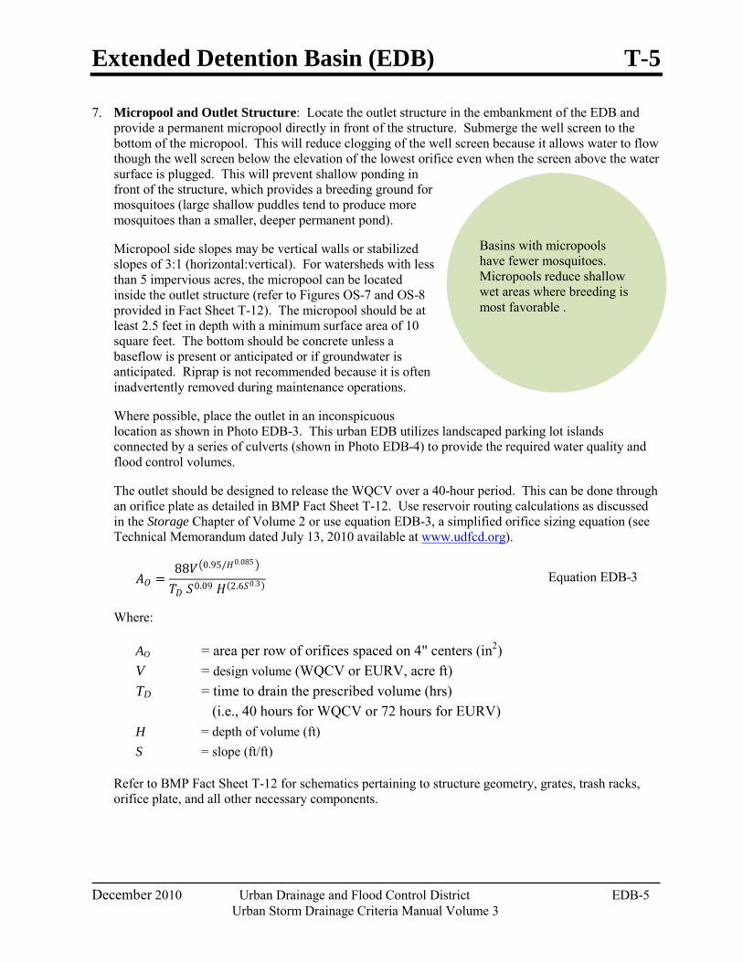
Extended Detention Basin (EDB) T-5
December 2010 Urban Drainage and Flood Control District EDB-5 Urban Storm Drainage Criteria Manual Volume 3
Basins with micropools have fewer mosquitoes. Micropools reduce shallow wet areas where breeding is most favorable .
7. Micropool and Outlet Structure: Locate the outlet structure in the embankment of the EDB and provide a permanent micropool directly in front of the structure. Submerge the well screen to the bottom of the micropool. This will reduce clogging of the well screen because it allows water to flow though the well screen below the elevation of the lowest orifice even when the screen above the water surface is plugged. This will prevent shallow ponding in front of the structure, which provides a breeding ground for mosquitoes (large shallow puddles tend to produce more mosquitoes than a smaller, deeper permanent pond).
Micropool side slopes may be vertical walls or stabilized slopes of 3:1 (horizontal:vertical). For watersheds with less than 5 impervious acres, the micropool can be located inside the outlet structure (refer to Figures OS-7 and OS-8 provided in Fact Sheet T-12). The micropool should be at least 2.5 feet in depth with a minimum surface area of 10 square feet. The bottom should be concrete unless a baseflow is present or anticipated or if groundwater is anticipated. Riprap is not recommended because it is often inadvertently removed during maintenance operations.
Where possible, place the outlet in an inconspicuous location as shown in Photo EDB-3. This urban EDB utilizes landscaped parking lot islands connected by a series of culverts (shown in Photo EDB-4) to provide the required water quality and flood control volumes.
The outlet should be designed to release the WQCV over a 40-hour period. This can be done through an orifice plate as detailed in BMP Fact Sheet T-12. Use reservoir routing calculations as discussed in the Storage Chapter of Volume 2 or use equation EDB-3, a simplified orifice sizing equation (see Technical Memorandum dated July 13, 2010 available at www.udfcd.org).
𝐴𝐴𝑂𝑂 =88𝑉𝑉�0.95/𝐻𝐻0.085 �
𝑇𝑇𝐷𝐷 𝑆𝑆0.09 𝐻𝐻(2.6𝑆𝑆0.3) Equation EDB-3
Where:
AO = area per row of orifices spaced on 4" centers (in2) V = design volume (WQCV or EURV, acre ft) TD = time to drain the prescribed volume (hrs) (i.e., 40 hours for WQCV or 72 hours for EURV) H = depth of volume (ft) S = slope (ft/ft)
Refer to BMP Fact Sheet T-12 for schematics pertaining to structure geometry, grates, trash racks, orifice plate, and all other necessary components.
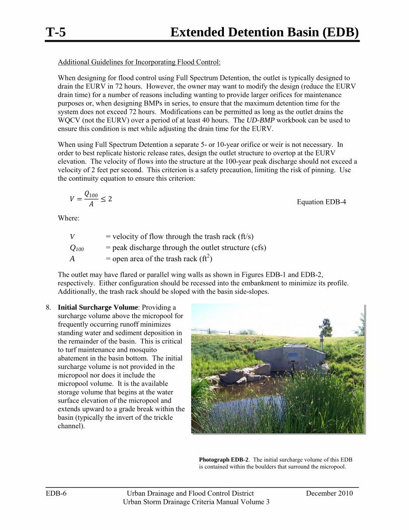
T-5 Extended Detention Basin (EDB)
EDB-6 Urban Drainage and Flood Control District December 2010 Urban Storm Drainage Criteria Manual Volume 3
Photograph EDB-2. The initial surcharge volume of this EDB is contained within the boulders that surround the micropool.
When using Full Spectrum Detention a separate 5- or 10-year orifice or weir is not necessary. In order to best replicate historic release rates, design the outlet structure to overtop at the EURV elevation. The velocity of flows into the structure at the 100-year peak discharge should not exceed a velocity of 2 feet per second. This criterion is a safety precaution, limiting the risk of pinning. Use the continuity equation to ensure this criterion:
Additional Guidelines for Incorporating Flood Control:
When designing for flood control using Full Spectrum Detention, the outlet is typically designed to drain the EURV in 72 hours. However, the owner may want to modify the design (reduce the EURV drain time) for a number of reasons including wanting to provide larger orifices for maintenance purposes or, when designing BMPs in series, to ensure that the maximum detention time for the system does not exceed 72 hours. Modifications can be permitted as long as the outlet drains the WQCV (not the EURV) over a period of at least 40 hours. The UD-BMP workbook can be used to ensure this condition is met while adjusting the drain time for the EURV.
𝑉𝑉 =𝑄𝑄100
𝐴𝐴≤ 2 Equation EDB-4
Where:
V = velocity of flow through the trash rack (ft/s) Q100 = peak discharge through the outlet structure (cfs) A = open area of the trash rack (ft2)
The outlet may have flared or parallel wing walls as shown in Figures EDB-1 and EDB-2, respectively. Either configuration should be recessed into the embankment to minimize its profile. Additionally, the trash rack should be sloped with the basin side-slopes.
8. Initial Surcharge Volume: Providing a surcharge volume above the micropool for frequently occurring runoff minimizes standing water and sediment deposition in the remainder of the basin. This is critical to turf maintenance and mosquito abatement in the basin bottom. The initial surcharge volume is not provided in the micropool nor does it include the micropool volume. It is the available storage volume that begins at the water surface elevation of the micropool and extends upward to a grade break within the basin (typically the invert of the trickle channel).
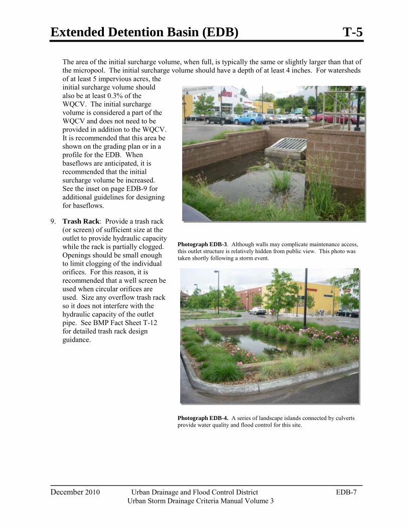
Extended Detention Basin (EDB) T-5
December 2010 Urban Drainage and Flood Control District EDB-7 Urban Storm Drainage Criteria Manual Volume 3
The area of the initial surcharge volume, when full, is typically the same or slightly larger than that of the micropool. The initial surcharge volume should have a depth of at least 4 inches. For watersheds of at least 5 impervious acres, the initial surcharge volume should also be at least 0.3% of the WQCV. The initial surcharge volume is considered a part of the WQCV and does not need to be provided in addition to the WQCV. It is recommended that this area be shown on the grading plan or in a profile for the EDB. When baseflows are anticipated, it is recommended that the initial surcharge volume be increased. See the inset on page EDB-9 for additional guidelines for designing for baseflows.
9. Trash Rack: Provide a trash rack (or screen) of sufficient size at the outlet to provide hydraulic capacity while the rack is partially clogged. Openings should be small enough to limit clogging of the individual orifices. For this reason, it is recommended that a well screen be used when circular orifices are used. Size any overflow trash rack so it does not interfere with the hydraulic capacity of the outlet pipe. See BMP Fact Sheet T-12 for detailed trash rack design guidance.
Photograph EDB-3. Although walls may complicate maintenance access, this outlet structure is relatively hidden from public view. This photo was taken shortly following a storm event.
Photograph EDB-4. A series of landscape islands connected by culverts provide water quality and flood control for this site.
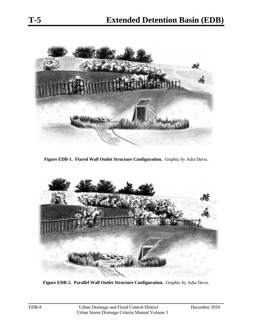
T-5 Extended Detention Basin (EDB)
EDB-8 Urban Drainage and Flood Control District December 2010 Urban Storm Drainage Criteria Manual Volume 3
Figure EDB-1. Flared Wall Outlet Structure Configuration. Graphic by Adia Davis.
Figure EDB-2. Parallel Wall Outlet Structure Configuration. Graphic by Adia Davis.
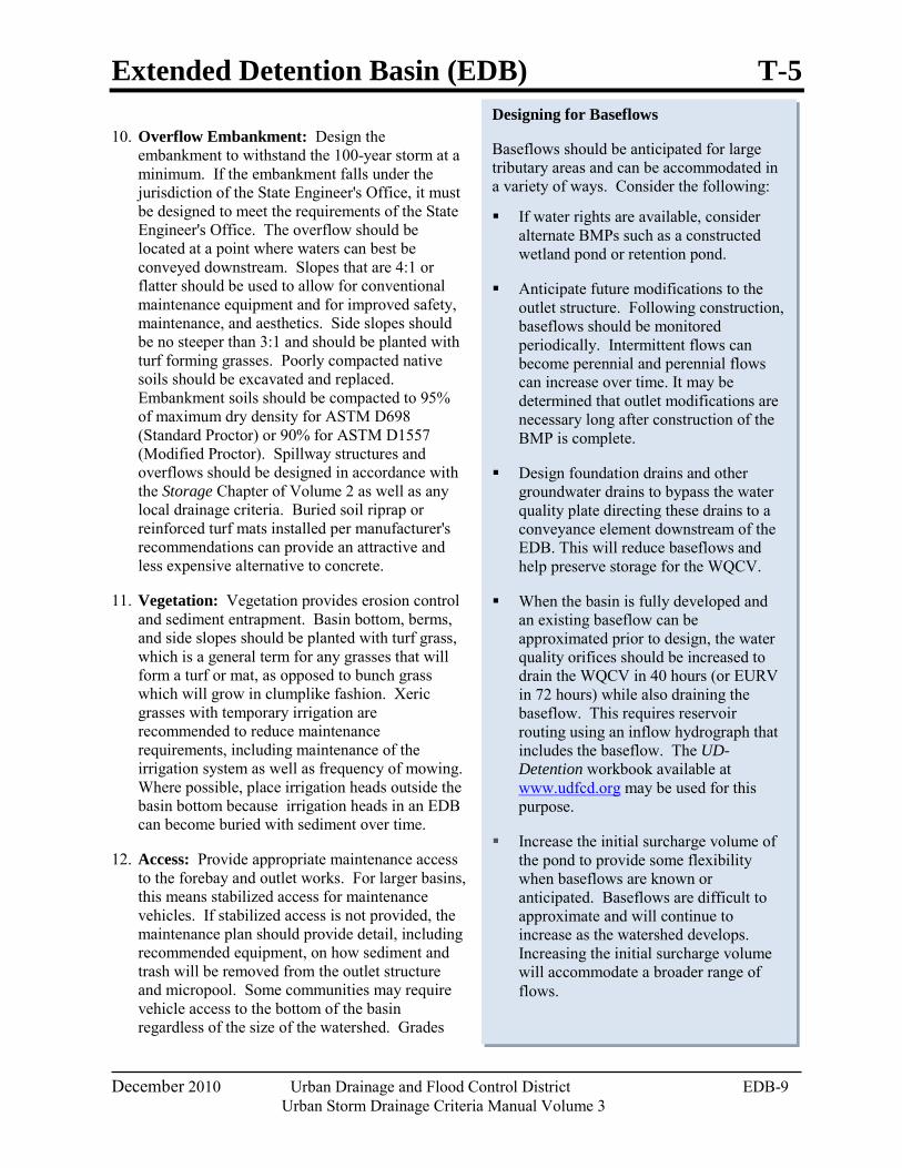
Extended Detention Basin (EDB) T-5
December 2010 Urban Drainage and Flood Control District EDB-9 Urban Storm Drainage Criteria Manual Volume 3
Designing for Baseflows
Baseflows should be anticipated for large tributary areas and can be accommodated in a variety of ways. Consider the following:
If water rights are available, consider alternate BMPs such as a constructed wetland pond or retention pond.
Anticipate future modifications to the outlet structure. Following construction, baseflows should be monitored periodically. Intermittent flows can become perennial and perennial flows can increase over time. It may be determined that outlet modifications are necessary long after construction of the BMP is complete.
Design foundation drains and other groundwater drains to bypass the water quality plate directing these drains to a conveyance element downstream of the EDB. This will reduce baseflows and help preserve storage for the WQCV.
When the basin is fully developed and an existing baseflow can be approximated prior to design, the water quality orifices should be increased to drain the WQCV in 40 hours (or EURV in 72 hours) while also draining the baseflow. This requires reservoir routing using an inflow hydrograph that includes the baseflow. The UD-Detention workbook available at www.udfcd.org may be used for this purpose.
Increase the initial surcharge volume of the pond to provide some flexibility when baseflows are known or anticipated. Baseflows are difficult to approximate and will continue to increase as the watershed develops. Increasing the initial surcharge volume will accommodate a broader range of flows.
10. Overflow Embankment: Design the embankment to withstand the 100-year storm at a minimum. If the embankment falls under the jurisdiction of the State Engineer's Office, it must be designed to meet the requirements of the State Engineer's Office. The overflow should be located at a point where waters can best be conveyed downstream. Slopes that are 4:1 or flatter should be used to allow for conventional maintenance equipment and for improved safety, maintenance, and aesthetics. Side slopes should be no steeper than 3:1 and should be planted with turf forming grasses. Poorly compacted native soils should be excavated and replaced. Embankment soils should be compacted to 95% of maximum dry density for ASTM D698 (Standard Proctor) or 90% for ASTM D1557 (Modified Proctor). Spillway structures and overflows should be designed in accordance with the Storage Chapter of Volume 2 as well as any local drainage criteria. Buried soil riprap or reinforced turf mats installed per manufacturer's recommendations can provide an attractive and less expensive alternative to concrete.
11. Vegetation: Vegetation provides erosion control and sediment entrapment. Basin bottom, berms, and side slopes should be planted with turf grass, which is a general term for any grasses that will form a turf or mat, as opposed to bunch grass which will grow in clumplike fashion. Xeric grasses with temporary irrigation are recommended to reduce maintenance requirements, including maintenance of the irrigation system as well as frequency of mowing. Where possible, place irrigation heads outside the basin bottom because irrigation heads in an EDB can become buried with sediment over time.
12. Access: Provide appropriate maintenance access to the forebay and outlet works. For larger basins, this means stabilized access for maintenance vehicles. If stabilized access is not provided, the maintenance plan should provide detail, including recommended equipment, on how sediment and trash will be removed from the outlet structure and micropool. Some communities may require vehicle access to the bottom of the basin regardless of the size of the watershed. Grades
T-5 Extended Detention Basin (EDB)
EDB-10 Urban Drainage and Flood Control District December 2010 Urban Storm Drainage Criteria Manual Volume 3
should not exceed 10% for haul road surfaces and 20% for skid-loader and backhoe access. Stabilized access includes gravel, concrete, articulated concrete block, concrete grid pavement, or reinforced grass pavement. The recommended cross slope is 2%.
Aesthetic Design Since all land owners and managers wish to use land in the most efficient manner possible, it is important that EDBs become part of a multi-use system. This encourages the design of EDBs as an aesthetic part of a naturalized environment or to include passive and/or active open space. Within each scenario, the EDB can begin to define itself as more than just a drainage facility. When this happens, the basin becomes a public amenity. This combination of public amenity and drainage facility is of much greater value to a landowner. Softened and varied slopes, interspersed irrigated fields, planting areas and wetlands can all be part of an EDB.
The design should be aesthetic whether it is considered to be an architectural or naturalized basin. Architectural basins incorporate design borrowed or reflective of the surrounding architecture or urban forms. An architectural basin is intended to appear as part of the built environment, rather than hiding the cues that identify it as a stormwater structure. A naturalized basin is designed to appear as though it is a natural part of the landscape. This section provides suggestions for designing a naturalized basin. The built environment, in contrast to the natural environment, does not typically contain the randomness of form inherent in nature. Constructed slopes typically remain consistent, as do slope transitions. Even dissipation structures are usually a hard form and have edges seldom seen in nature. If the EDB is to appear as though it is a natural part of the landscape, it is important to minimize shapes that provide visual cues indicating the presence of a drainage structure. For example, the side sides should be shaped more naturally and with varying slopes for a naturalized basin.
Suggested Methods for a Naturalized Basin
Create a flowing form that looks like it was shaped by water.
Extend one side of the basin higher than the other. This may require a berm.
Shape the bottom of the basin differently than the top.
Slope of one side of the basin more mildly than the opposing side.
Vary slope transitions both at the top of the bank and at the toe.
Use a soft-surface trickle channel if appropriate and approved.
When using rock for energy dissipation, the rock should graduate away from the area of hard edge into the surrounding landscape. Other non-functional matching rock should occur in other areas of the basin to prevent the actual energy dissipation from appearing out of context.
Design ground cover to reflect the type of water regime expected for their location within the basin.
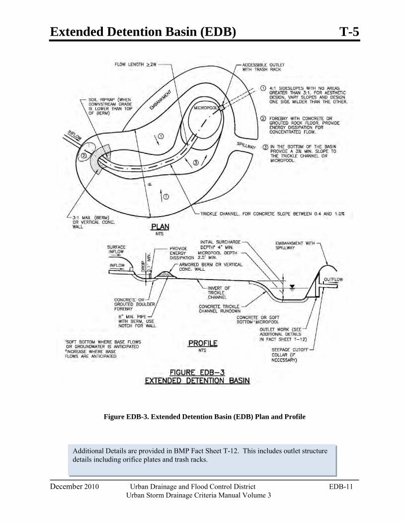
Extended Detention Basin (EDB) T-5
December 2010 Urban Drainage and Flood Control District EDB-11 Urban Storm Drainage Criteria Manual Volume 3
Additional Details are provided in BMP Fact Sheet T-12. This includes outlet structure details including orifice plates and trash racks.
Figure EDB-3. Extended Detention Basin (EDB) Plan and Profile
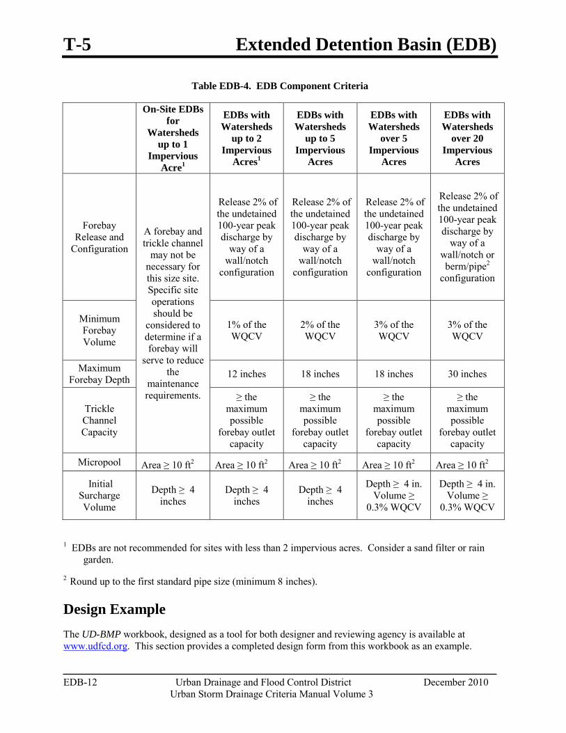
T-5 Extended Detention Basin (EDB)
EDB-12 Urban Drainage and Flood Control District December 2010 Urban Storm Drainage Criteria Manual Volume 3
Table EDB-4. EDB Component Criteria
On-Site EDBs for
Watersheds up to 1
Impervious Acre1
EDBs with Watersheds
up to 2 Impervious
Acres1
EDBs with Watersheds
up to 5 Impervious
Acres
EDBs with Watersheds
over 5 Impervious
Acres
EDBs with Watersheds
over 20 Impervious
Acres
Forebay Release and
Configuration A forebay and trickle channel
may not be necessary for this size site. Specific site operations should be
considered to determine if a forebay will
serve to reduce the
maintenance requirements.
Release 2% of the undetained 100-year peak discharge by
way of a wall/notch
configuration
Release 2% of the undetained 100-year peak discharge by
way of a wall/notch
configuration
Release 2% of the undetained 100-year peak discharge by
way of a wall/notch
configuration
Release 2% of the undetained 100-year peak discharge by
way of a wall/notch or berm/pipe2
configuration
Minimum Forebay Volume
1% of the WQCV
2% of the WQCV
3% of the WQCV
3% of the WQCV
Maximum Forebay Depth 12 inches 18 inches 18 inches 30 inches
Trickle Channel Capacity
≥ the maximum possible
forebay outlet capacity
≥ the maximum possible
forebay outlet capacity
≥ the maximum possible
forebay outlet capacity
≥ the maximum possible
forebay outlet capacity
Micropool Area ≥ 10 ft2 Area ≥ 10 ft2 Area ≥ 10 ft2 Area ≥ 10 ft2 Area ≥ 10 ft2
Initial Surcharge Volume
Depth ≥ 4 inches
Depth ≥ 4 inches
Depth ≥ 4 inches
Depth ≥ 4 in. Volume ≥
0.3% WQCV
Depth ≥ 4 in. Volume ≥
0.3% WQCV
1 EDBs are not recommended for sites with less than 2 impervious acres. Consider a sand filter or rain garden.
2 Round up to the first standard pipe size (minimum 8 inches).
Design Example The UD-BMP workbook, designed as a tool for both designer and reviewing agency is available at www.udfcd.org. This section provides a completed design form from this workbook as an example.
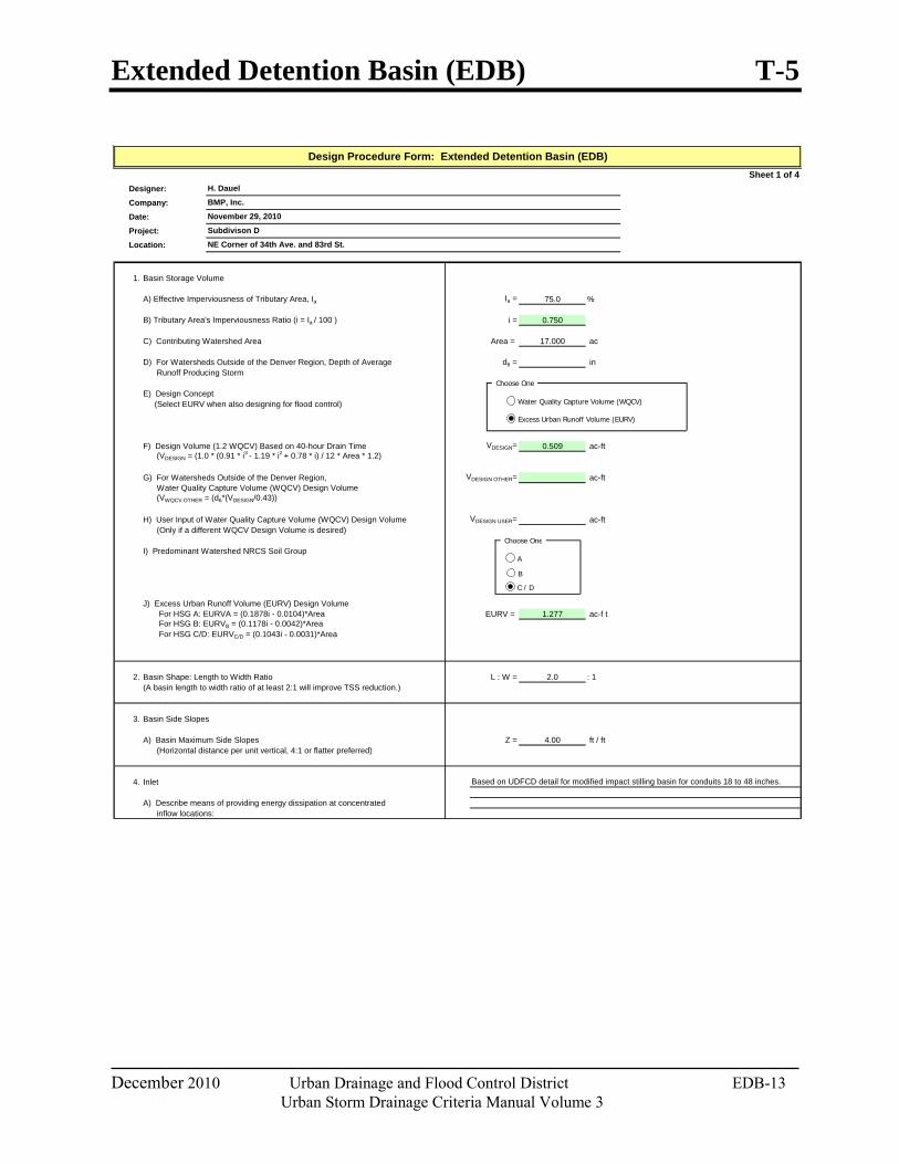
Extended Detention Basin (EDB) T-5
December 2010 Urban Drainage and Flood Control District EDB-13 Urban Storm Drainage Criteria Manual Volume 3
Sheet 1 of 4Designer:
Company:
Date:
Project:
Location:
1. Basin Storage Volume
A) Effective Imperviousness of Tributary Area, Ia Ia = 75.0 %
B) Tributary Area's Imperviousness Ratio (i = Ia / 100 ) i = 0.750
C) Contributing Watershed Area Area = 17.000 ac
D) For Watersheds Outside of the Denver Region, Depth of Average d6 = in Runoff Producing Storm
E) Design Concept (Select EURV when also designing for flood control)
F) Design Volume (1.2 WQCV) Based on 40-hour Drain Time VDESIGN= 0.509 ac-ft (VDESIGN = (1.0 * (0.91 * i3 - 1.19 * i2 + 0.78 * i) / 12 * Area * 1.2)
G) For Watersheds Outside of the Denver Region, VDESIGN OTHER= ac-ft Water Quality Capture Volume (WQCV) Design Volume (VWQCV OTHER = (d6*(VDESIGN/0.43))
H) User Input of Water Quality Capture Volume (WQCV) Design Volume VDESIGN USER= ac-ft (Only if a different WQCV Design Volume is desired)
I) Predominant Watershed NRCS Soil Group
J) Excess Urban Runoff Volume (EURV) Design Volume For HSG A: EURVA = (0.1878i - 0.0104)*Area EURV = 1.277 ac-f t For HSG B: EURVB = (0.1178i - 0.0042)*Area For HSG C/D: EURVC/D = (0.1043i - 0.0031)*Area
2. Basin Shape: Length to Width Ratio L : W = 2.0 : 1(A basin length to width ratio of at least 2:1 will improve TSS reduction.)
3. Basin Side Slopes
A) Basin Maximum Side Slopes Z = 4.00 ft / ft (Horizontal distance per unit vertical, 4:1 or flatter preferred)
4. Inlet
A) Describe means of providing energy dissipation at concentrated inflow locations:
Design Procedure Form: Extended Detention Basin (EDB)
Subdivison D
BMP, Inc.
November 29, 2010
NE Corner of 34th Ave. and 83rd St.
H. Dauel
Based on UDFCD detail for modified impact stilling basin for conduits 18 to 48 inches.
Choose One
Excess Urban Runoff Volume (EURV)
Choose One
A
B
C / D
Water Quality Capture Volume (WQCV)
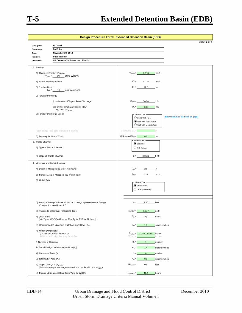
T-5 Extended Detention Basin (EDB)
EDB-14 Urban Drainage and Flood Control District December 2010 Urban Storm Drainage Criteria Manual Volume 3
Sheet 2 of 4Designer:Company:Date:Project:Location:
5. Forebay
A) Minimum Forebay Volume VFMIN = 0.013 ac-ft (VFMIN = 3% of the WQCV)
B) Actual Forebay Volume VF = 0.015 ac-ft
C) Forebay Depth DF = 12.0 in (DF = 18 inch maximum)
D) Forebay Discharge
i) Undetained 100-year Peak Discharge Q100 = 50.00 cfs
ii) Forebay Discharge Design Flow QF = 1.00 cfs (QF = 0.02 * Q100)
E) Forebay Discharge Design
F) Discharge Pipe Size (minimum 8-inches) Calculated DP = in
G) Rectangular Notch Width Calculated WN = 6.0 in
6. Trickle Channel
A) Type of Trickle Channel
F) Slope of Trickle Channel S = 0.0100 ft / ft
7. Micropool and Outlet Structure
A) Depth of Micropool (2.5-feet minimum) DM = 2.5 ft
B) Surface Area of Micropool (10 ft2 minimum) AM = 125 sq ft
C) Outlet Type
D) Depth of Design Volume (EURV or 1.2 WQCV) Based on the Design H = 2.30 feet Concept Chosen Under 1.E.
E) Volume to Drain Over Prescribed Time EURV = 1.277 ac-ft
F) Drain Time TD = 72 hours (Min TD for WQCV= 40 hours; Max TD for EURV= 72 hours)
G) Recommended Maximum Outlet Area per Row, (Ao) Ao = 1.3 square inches
H) Orifice Dimensions: i) Circular Orifice Diameter or Dorifice = 1 - 5 / 16 inch inches ii) Width of 2" High Rectangular Orifice Worifice = inches
I) Number of Columns nc = 1 number
J) Actual Design Outlet Area per Row (Ao) Ao = 1.4 square inches
K) Number of Rows (nr) nr = 6 number
L) Total Outlet Area (Aot) Aot = 9.3 square inches
M) Depth of WQCV (HWQCV) HWQCV = 0.8 feet (Estimate using actual stage-area-volume relationship and VWQCV)
N) Ensure Minimum 40 Hour Drain Time for WQCV TD WQCV = 49.7 hours
(flow too small for berm w/ pipe)
Subdivison DNovember 29, 2010BMP, Inc.
Design Procedure Form: Extended Detention Basin (EDB)
H. Dauel
NE Corner of 34th Ave. and 83rd St.
Choose One
Wall with Rect. Notch
Berm With Pipe
Choose One
Orifice Plate
Other (Describe):
Choose One
Concrete
Soft Bottom
Wall with V-Notch Weir
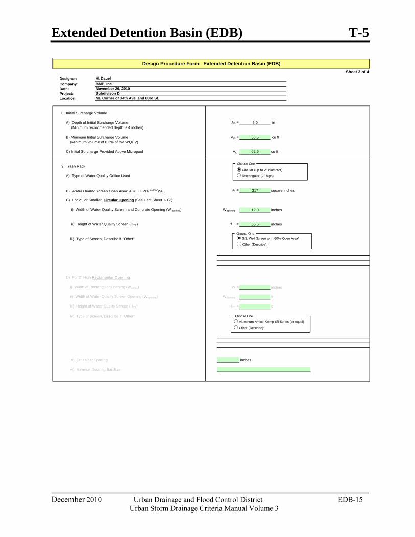
Extended Detention Basin (EDB) T-5
December 2010 Urban Drainage and Flood Control District EDB-15 Urban Storm Drainage Criteria Manual Volume 3
Sheet 3 of 4Designer:Company:Date:Project:Location:
8. Initial Surcharge Volume
A) Depth of Initial Surcharge Volume DIS = 6.0 in (Minimum recommended depth is 4 inches)
B) Minimum Initial Surcharge Volume VIS = 55.5 cu ft (Minimum volume of 0.3% of the WQCV)
C) Initial Surcharge Provided Above Micropool Vs= 62.5 cu ft
9. Trash Rack
A) Type of Water Quality Orifice Used
B) Water Quality Screen Open Area: At = 38.5*(e-0.095D)*AotAt = 317 square inches
C) For 2", or Smaller, Circular Opening (See Fact Sheet T-12):
i) Width of Water Quality Screen and Concrete Opening (Wopening) Wopening = 12.0 inches
ii) Height of Water Quality Screen (HTR) HTR = 55.6 inches
iii) Type of Screen, Describe if "Other"
D) For 2" High Rectangular Opening:
i) Width of Rectangular Opening (Worifice) W = inches
ii) Width of Water Quality Screen Opening (Wopening) Wopening = ft
iii) Height of Water Quality Screen (HTR) HTR = ft
iv) Type of Screen, Describe if "Other"
v) Cross-bar Spacing inches
vi) Minimum Bearing Bar Size
BMP, Inc.H. Dauel
Design Procedure Form: Extended Detention Basin (EDB)
November 29, 2010Subdivison DNE Corner of 34th Ave. and 83rd St.
Choose One
Circular (up to 2" diameter)
Rectangular (2" high)
Choose OneS.S. Well Screen with 60% Open Area*
Other (Describe):
Choose One
Aluminum Amico-Klemp SR Series (or equal)
Other (Describe):
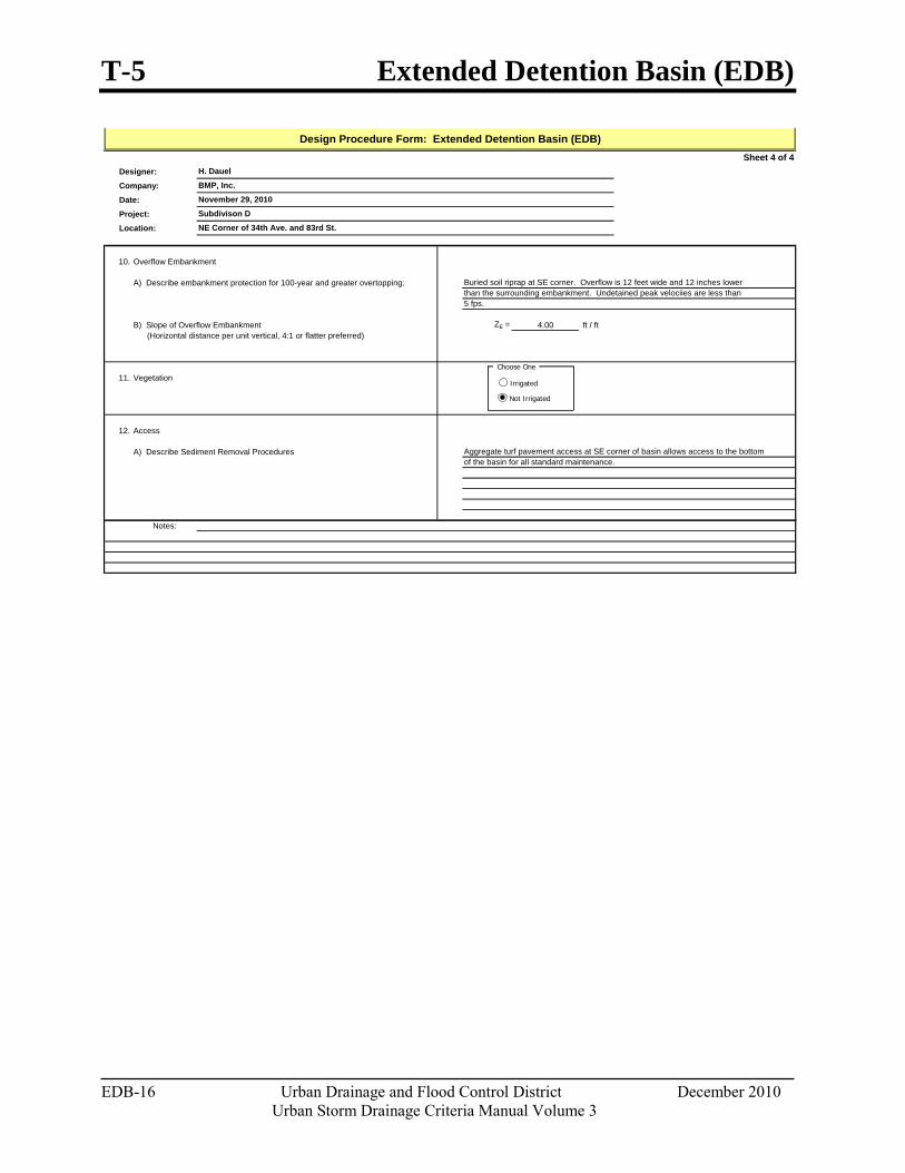
T-5 Extended Detention Basin (EDB)
EDB-16 Urban Drainage and Flood Control District December 2010 Urban Storm Drainage Criteria Manual Volume 3
Sheet 4 of 4Designer:
Company:
Date:
Project:
Location:
10. Overflow Embankment
A) Describe embankment protection for 100-year and greater overtopping:
B) Slope of Overflow Embankment ZE = 4.00 ft / ft (Horizontal distance per unit vertical, 4:1 or flatter preferred)
11. Vegetation
12. Access
A) Describe Sediment Removal Procedures
Notes:
Design Procedure Form: Extended Detention Basin (EDB)
November 29, 2010
BMP, Inc.
H. Dauel
Subdivison D
of the basin for all standard maintenance.
NE Corner of 34th Ave. and 83rd St.
Buried soil riprap at SE corner. Overflow is 12 feet wide and 12 inches lower than the surrounding embankment. Undetained peak velociies are less than 5 fps.
Aggregate turf pavement access at SE corner of basin allows access to the bottom
Choose One
Irrigated
Not Irrigated
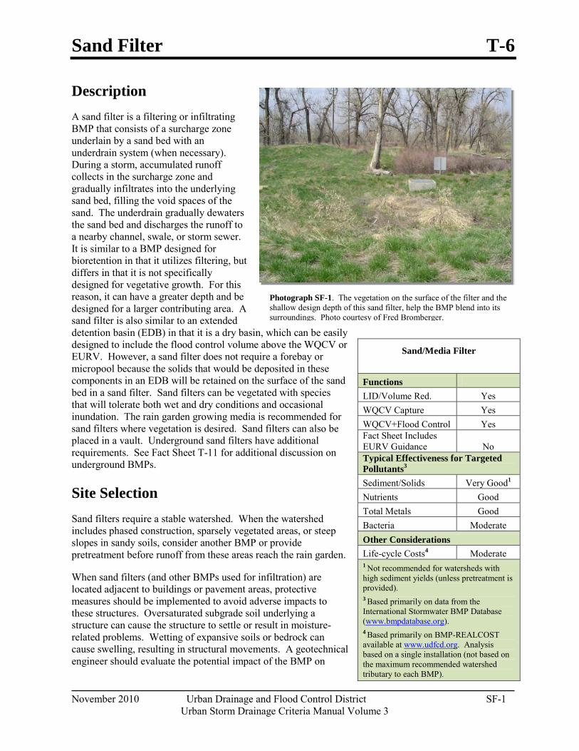
Sand Filter T-6
November 2010 Urban Drainage and Flood Control District SF-1 Urban Storm Drainage Criteria Manual Volume 3
Description A sand filter is a filtering or infiltrating BMP that consists of a surcharge zone underlain by a sand bed with an underdrain system (when necessary). During a storm, accumulated runoff collects in the surcharge zone and gradually infiltrates into the underlying sand bed, filling the void spaces of the sand. The underdrain gradually dewaters the sand bed and discharges the runoff to a nearby channel, swale, or storm sewer. It is similar to a BMP designed for bioretention in that it utilizes filtering, but differs in that it is not specifically designed for vegetative growth. For this reason, it can have a greater depth and be designed for a larger contributing area. A sand filter is also similar to an extended detention basin (EDB) in that it is a dry basin, which can be easily designed to include the flood control volume above the WQCV or EURV. However, a sand filter does not require a forebay or micropool because the solids that would be deposited in these components in an EDB will be retained on the surface of the sand bed in a sand filter. Sand filters can be vegetated with species that will tolerate both wet and dry conditions and occasional inundation. The rain garden growing media is recommended for sand filters where vegetation is desired. Sand filters can also be placed in a vault. Underground sand filters have additional requirements. See Fact Sheet T-11 for additional discussion on underground BMPs.
Site Selection Sand filters require a stable watershed. When the watershed includes phased construction, sparsely vegetated areas, or steep slopes in sandy soils, consider another BMP or provide pretreatment before runoff from these areas reach the rain garden.
When sand filters (and other BMPs used for infiltration) are located adjacent to buildings or pavement areas, protective measures should be implemented to avoid adverse impacts to these structures. Oversaturated subgrade soil underlying a structure can cause the structure to settle or result in moisture-related problems. Wetting of expansive soils or bedrock can cause swelling, resulting in structural movements. A geotechnical engineer should evaluate the potential impact of the BMP on
Sand/Media Filter
Functions LID/Volume Red. Yes WQCV Capture Yes WQCV+Flood Control Yes Fact Sheet Includes EURV Guidance No Typical Effectiveness for Targeted Pollutants3
Sediment/Solids Very Good1
Nutrients Good Total Metals Good Bacteria Moderate Other Considerations Life-cycle Costs4 Moderate 1 Not recommended for watersheds with high sediment yields (unless pretreatment is provided). 3 Based primarily on data from the International Stormwater BMP Database (www.bmpdatabase.org). 4 Based primarily on BMP-REALCOST available at www.udfcd.org. Analysis based on a single installation (not based on the maximum recommended watershed tributary to each BMP).
Photograph SF-1. The vegetation on the surface of the filter and the shallow design depth of this sand filter, help the BMP blend into its surroundings. Photo courtesy of Fred Bromberger.
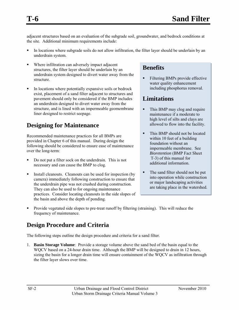
T-6 Sand Filter
SF-2 Urban Drainage and Flood Control District November 2010 Urban Storm Drainage Criteria Manual Volume 3
Benefits Filtering BMPs provide effective
water quality enhancement including phosphorus removal.
Limitations This BMP may clog and require
maintenance if a moderate to high level of silts and clays are allowed to flow into the facility.
This BMP should not be located within 10 feet of a building foundation without an impermeable membrane. See Bioretention (BMP Fact Sheet T-3) of this manual for additional information.
The sand filter should not be put into operation while construction or major landscaping activities are taking place in the watershed.
adjacent structures based on an evaluation of the subgrade soil, groundwater, and bedrock conditions at the site. Additional minimum requirements include:
In locations where subgrade soils do not allow infiltration, the filter layer should be underlain by an underdrain system.
Where infiltration can adversely impact adjacent structures, the filter layer should be underlain by an underdrain system designed to divert water away from the structure.
In locations where potentially expansive soils or bedrock exist, placement of a sand filter adjacent to structures and pavement should only be considered if the BMP includes an underdrain designed to divert water away from the structure, and is lined with an impermeable geomembrane liner designed to restrict seepage.
Designing for Maintenance Recommended maintenance practices for all BMPs are provided in Chapter 6 of this manual. During design the following should be considered to ensure ease of maintenance over the long-term:
Do not put a filter sock on the underdrain. This is not necessary and can cause the BMP to clog.
Install cleanouts. Cleanouts can be used for inspection (by camera) immediately following construction to ensure that the underdrain pipe was not crushed during construction. They can also be used to for ongoing maintenance practices. Consider locating cleanouts in the side slopes of the basin and above the depth of ponding.
Provide vegetated side slopes to pre-treat runoff by filtering (straining). This will reduce the frequency of maintenance.
Design Procedure and Criteria The following steps outline the design procedure and criteria for a sand filter.
1. Basin Storage Volume: Provide a storage volume above the sand bed of the basin equal to the WQCV based on a 24-hour drain time. Although the BMP will be designed to drain in 12 hours, sizing the basin for a longer drain time will ensure containment of the WQCV as infiltration through the filter layer slows over time.
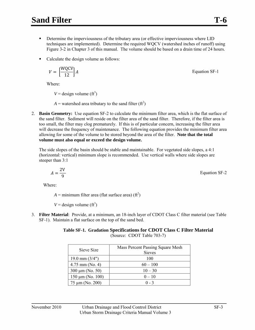
Sand Filter T-6
November 2010 Urban Drainage and Flood Control District SF-3 Urban Storm Drainage Criteria Manual Volume 3
Determine the imperviousness of the tributary area (or effective imperviousness where LID techniques are implemented). Determine the required WQCV (watershed inches of runoff) using Figure 3-2 in Chapter 3 of this manual. The volume should be based on a drain time of 24 hours.
Calculate the design volume as follows:
𝑉𝑉 = �WQCV
12 � 𝐴𝐴 Equation SF-1
Where:
V = design volume (ft3)
A = watershed area tributary to the sand filter (ft2)
2. Basin Geometry: Use equation SF-2 to calculate the minimum filter area, which is the flat surface of the sand filter. Sediment will reside on the filter area of the sand filter. Therefore, if the filter area is too small, the filter may clog prematurely. If this is of particular concern, increasing the filter area will decrease the frequency of maintenance. The following equation provides the minimum filter area allowing for some of the volume to be stored beyond the area of the filter. Note that the total volume must also equal or exceed the design volume.
The side slopes of the basin should be stable and maintainable. For vegetated side slopes, a 4:1 (horizontal: vertical) minimum slope is recommended. Use vertical walls where side slopes are steeper than 3:1
𝐴𝐴 =2V 9
Equation SF-2
Where:
A = minimum filter area (flat surface area) (ft2)
V = design volume (ft3)
3. Filter Material: Provide, at a minimum, an 18-inch layer of CDOT Class C filter material (see Table SF-1). Maintain a flat surface on the top of the sand bed.
Table SF-1. Gradation Specifications for CDOT Class C Filter Material (Source: CDOT Table 703-7)
Sieve Size Mass Percent Passing Square Mesh Sieves
19.0 mm (3/4") 100 4.75 mm (No. 4) 60 – 100 300 µm (No. 50) 10 – 30 150 µm (No. 100) 0 – 10 75 µm (No. 200) 0 - 3
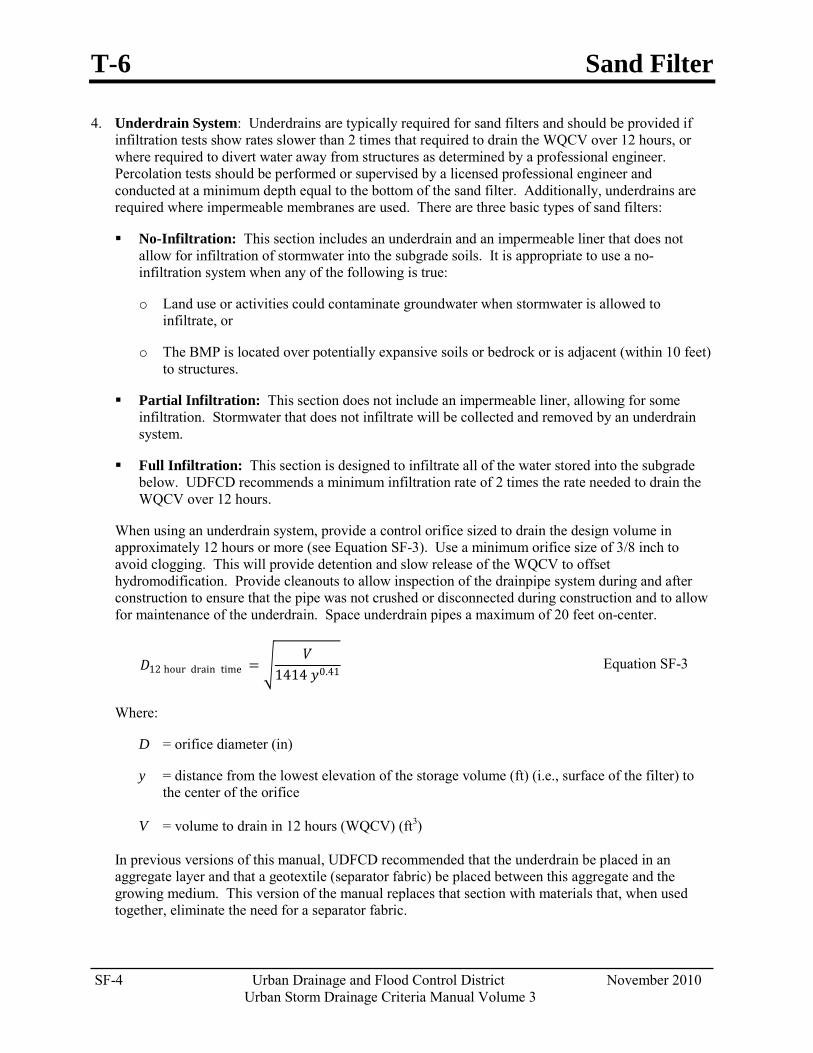
T-6 Sand Filter
SF-4 Urban Drainage and Flood Control District November 2010 Urban Storm Drainage Criteria Manual Volume 3
4. Underdrain System: Underdrains are typically required for sand filters and should be provided if infiltration tests show rates slower than 2 times that required to drain the WQCV over 12 hours, or where required to divert water away from structures as determined by a professional engineer. Percolation tests should be performed or supervised by a licensed professional engineer and conducted at a minimum depth equal to the bottom of the sand filter. Additionally, underdrains are required where impermeable membranes are used. There are three basic types of sand filters:
No-Infiltration: This section includes an underdrain and an impermeable liner that does not allow for infiltration of stormwater into the subgrade soils. It is appropriate to use a no-infiltration system when any of the following is true:
o Land use or activities could contaminate groundwater when stormwater is allowed to infiltrate, or
o The BMP is located over potentially expansive soils or bedrock or is adjacent (within 10 feet) to structures.
Partial Infiltration: This section does not include an impermeable liner, allowing for some infiltration. Stormwater that does not infiltrate will be collected and removed by an underdrain system.
Full Infiltration: This section is designed to infiltrate all of the water stored into the subgrade below. UDFCD recommends a minimum infiltration rate of 2 times the rate needed to drain the WQCV over 12 hours.
When using an underdrain system, provide a control orifice sized to drain the design volume in approximately 12 hours or more (see Equation SF-3). Use a minimum orifice size of 3/8 inch to avoid clogging. This will provide detention and slow release of the WQCV to offset hydromodification. Provide cleanouts to allow inspection of the drainpipe system during and after construction to ensure that the pipe was not crushed or disconnected during construction and to allow for maintenance of the underdrain. Space underdrain pipes a maximum of 20 feet on-center.
𝐷𝐷12 hour drain time = �𝑉𝑉
1414 𝑦𝑦0.41 Equation SF-3
Where:
D = orifice diameter (in)
y = distance from the lowest elevation of the storage volume (ft) (i.e., surface of the filter) to the center of the orifice
V = volume to drain in 12 hours (WQCV) (ft3)
In previous versions of this manual, UDFCD recommended that the underdrain be placed in an aggregate layer and that a geotextile (separator fabric) be placed between this aggregate and the growing medium. This version of the manual replaces that section with materials that, when used together, eliminate the need for a separator fabric.
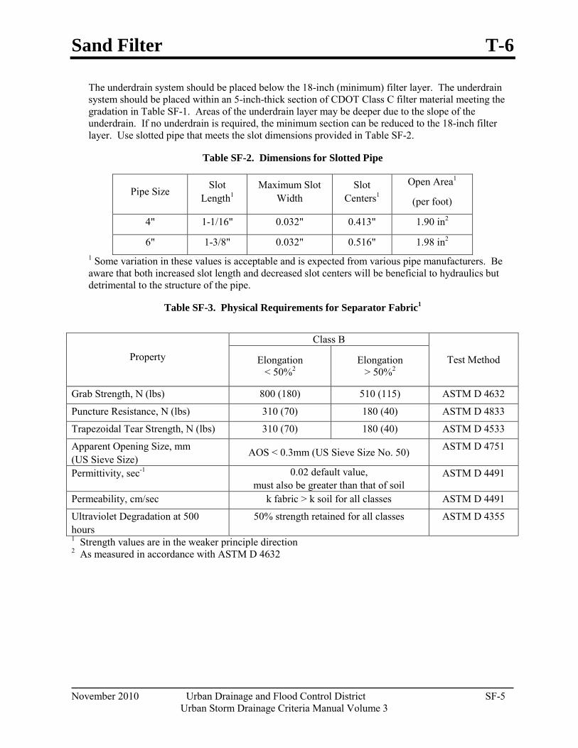
Sand Filter T-6
November 2010 Urban Drainage and Flood Control District SF-5 Urban Storm Drainage Criteria Manual Volume 3
The underdrain system should be placed below the 18-inch (minimum) filter layer. The underdrain system should be placed within an 5-inch-thick section of CDOT Class C filter material meeting the gradation in Table SF-1. Areas of the underdrain layer may be deeper due to the slope of the underdrain. If no underdrain is required, the minimum section can be reduced to the 18-inch filter layer. Use slotted pipe that meets the slot dimensions provided in Table SF-2.
Table SF-2. Dimensions for Slotted Pipe
Pipe Size Slot Length1
Maximum Slot Width
Slot Centers1
Open Area1
(per foot)
4" 1-1/16" 0.032" 0.413" 1.90 in2
6" 1-3/8" 0.032" 0.516" 1.98 in2 1 Some variation in these values is acceptable and is expected from various pipe manufacturers. Be aware that both increased slot length and decreased slot centers will be beneficial to hydraulics but detrimental to the structure of the pipe.
Table SF-3. Physical Requirements for Separator Fabric1
Property
Class B
Test Method Elongation < 50%2
Elongation > 50%2
Grab Strength, N (lbs) 800 (180) 510 (115) ASTM D 4632
Puncture Resistance, N (lbs) 310 (70) 180 (40) ASTM D 4833
Trapezoidal Tear Strength, N (lbs) 310 (70) 180 (40) ASTM D 4533
Apparent Opening Size, mm (US Sieve Size)
AOS < 0.3mm (US Sieve Size No. 50) ASTM D 4751
Permittivity, sec-1 0.02 default value, must also be greater than that of soil
ASTM D 4491
Permeability, cm/sec k fabric > k soil for all classes ASTM D 4491
Ultraviolet Degradation at 500 hours
50% strength retained for all classes ASTM D 4355
1 Strength values are in the weaker principle direction 2 As measured in accordance with ASTM D 4632
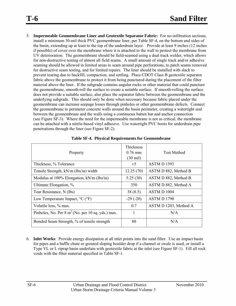
T-6 Sand Filter
SF-6 Urban Drainage and Flood Control District November 2010 Urban Storm Drainage Criteria Manual Volume 3
5. Impermeable Geomembrane Liner and Geotextile Separator Fabric: For no-infiltration sections, install a minimum 30-mil thick PVC geomembrane liner, per Table SF-4, on the bottom and sides of the basin, extending up at least to the top of the underdrain layer. Provide at least 9 inches (12 inches if possible) of cover over the membrane where it is attached to the wall to protect the membrane from UV deterioration. The geomembrane should be field-seamed using a dual track welder, which allows for non-destructive testing of almost all field seams. A small amount of single track and/or adhesive seaming should be allowed in limited areas to seam around pipe perforations, to patch seams removed for destructive seam testing, and for limited repairs. The liner should be installed with slack to prevent tearing due to backfill, compaction, and settling. Place CDOT Class B geotextile separator fabric above the geomembrane to protect it from being punctured during the placement of the filter material above the liner. If the subgrade contains angular rocks or other material that could puncture the geomembrane, smooth-roll the surface to create a suitable surface. If smooth-rolling the surface does not provide a suitable surface, also place the separator fabric between the geomembrane and the underlying subgrade. This should only be done when necessary because fabric placed under the geomembrane can increase seepage losses through pinholes or other geomembrane defects. Connect the geomembrane to perimeter concrete walls around the basin perimeter, creating a watertight seal between the geomembrane and the walls using a continuous batten bar and anchor connection (see Figure SF-3). Where the need for the impermeable membrane is not as critical, the membrane can be attached with a nitrile-based vinyl adhesive. Use watertight PVC boots for underdrain pipe penetrations through the liner (see Figure SF-2).
Table SF-4. Physical Requirements for Geomembrane
Property Thickness 0.76 mm (30 mil)
Test Method
Thickness, % Tolerance ±5 ASTM D 1593 Tensile Strength, kN/m (lbs/in) width 12.25 (70) ASTM D 882, Method B Modulus at 100% Elongation, kN/m (lbs/in) 5.25 (30) ASTM D 882, Method B Ultimate Elongation, % 350 ASTM D 882, Method A Tear Resistance, N (lbs) 38 (8.5) ASTM D 1004 Low Temperature Impact, °C (°F) -29 (-20) ASTM D 1790 Volatile loss, % max. 0.7 ASTM D 1203, Method A Pinholes, No. Per 8 m2 (No. per 10 sq. yds.) max. 1 N/A
Bonded Seam Strength, % of tensile strength 80 N/A
6. Inlet Works: Provide energy dissipation at all inlet points into the sand filter. Use an impact basin for pipes and a baffle chute or grouted sloping boulder drop if a channel or swale is used, or install a Type VL or L riprap basin underlain with geotextile fabric at the inlet (see Figure SF-1). Fill all rock voids with the filter material specified in Table SF-1.
Sand Filter T-6
November 2010 Urban Drainage and Flood Control District SF-7 Urban Storm Drainage Criteria Manual Volume 3
7. Outlet Works: Slope the underdrain into a larger outlet structure. As discussed in Step 4, use an orifice plate to drain the WQCV over approximately 12 hours. Flows exceeding the WQCV should also drain into the outlet structure. Additional flow restrictions may be incorporated to provide Full Spectrum Detention, as discussed in the Storage chapter of Volume 2, or peak reduction for other specific storm events.
For Full Spectrum Detention, perform reservoir routing calculations to design the outlet structure. The UD-Detention workbook, available at www.udfcd.org, can be used for this purpose. The design could include a second orifice located at the WQCV elevation or could include a downstream point of control designed to drain the full excess urban runoff volume (EURV) in approximately 72 hours.
Construction Considerations Proper construction of sand filters involves careful attention to material specifications and construction details. For a successful project, do the following:
Protect area from excessive sediment loading during construction. The portion of the site draining to the sand filter must be stabilized before allowing flow into the sand filter.
When using an impermeable liner, ensure enough slack in the liner to allow for backfill, compaction, and settling without tearing the liner.

T-6 Sand Filter
SF-8 Urban Drainage and Flood Control District November 2010 Urban Storm Drainage Criteria Manual Volume 3
Figure SF-1. Sand Filter Plan and Sections
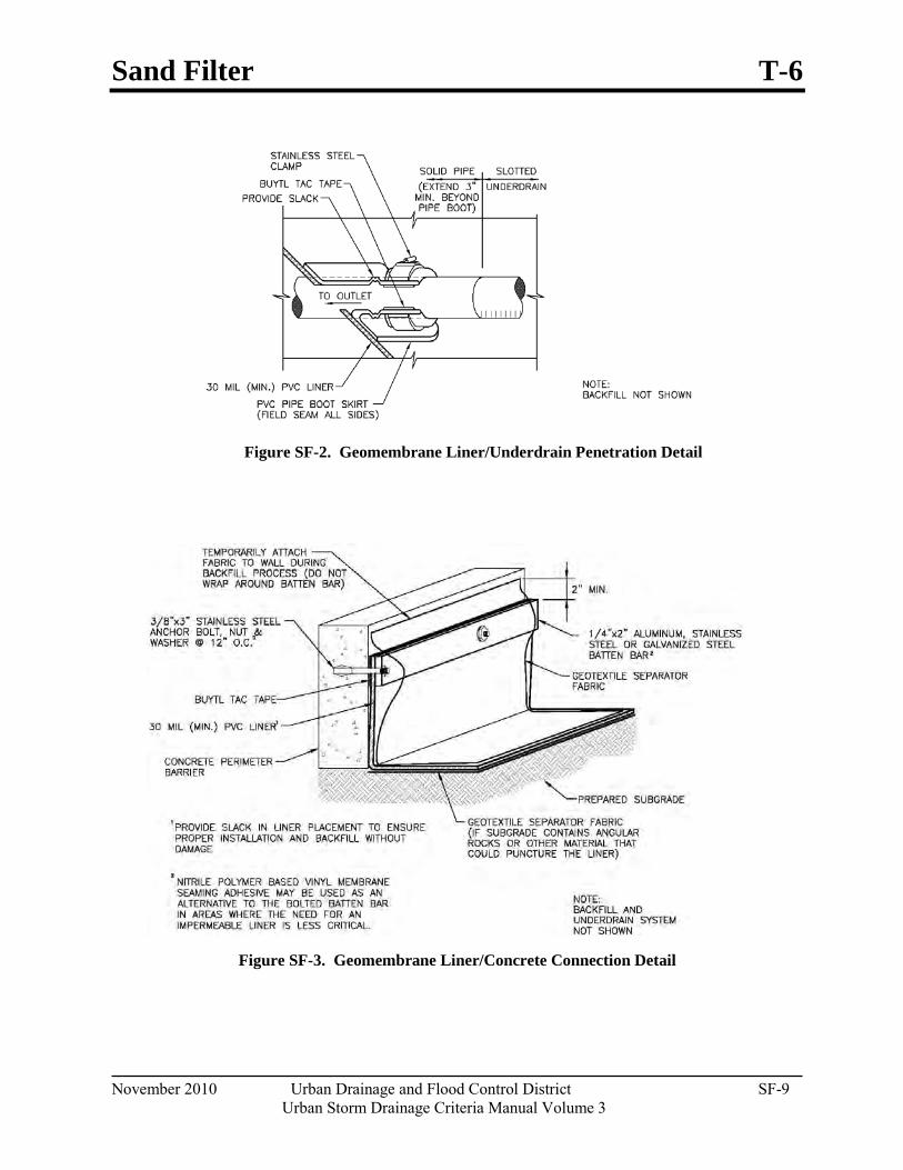
Sand Filter T-6
November 2010 Urban Drainage and Flood Control District SF-9 Urban Storm Drainage Criteria Manual Volume 3
Figure SF-2. Geomembrane Liner/Underdrain Penetration Detail
Figure SF-3. Geomembrane Liner/Concrete Connection Detail
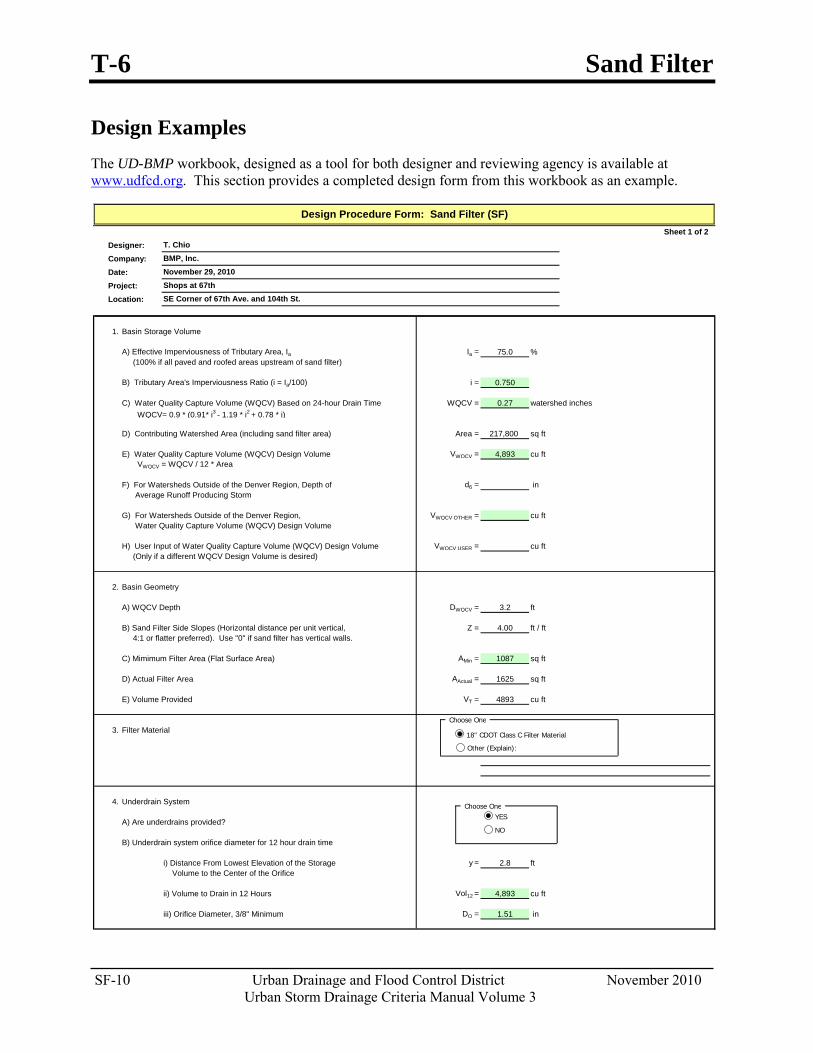
T-6 Sand Filter
SF-10 Urban Drainage and Flood Control District November 2010 Urban Storm Drainage Criteria Manual Volume 3
Design Examples The UD-BMP workbook, designed as a tool for both designer and reviewing agency is available at www.udfcd.org. This section provides a completed design form from this workbook as an example.
Sheet 1 of 2Designer:Company:Date:Project:Location:
1. Basin Storage Volume
A) Effective Imperviousness of Tributary Area, Ia Ia = 75.0 % (100% if all paved and roofed areas upstream of sand filter)
B) Tributary Area's Imperviousness Ratio (i = Ia/100) i = 0.750
C) Water Quality Capture Volume (WQCV) Based on 24-hour Drain Time WQCV = 0.27 watershed inches WQCV= 0.9 * (0.91* i3 - 1.19 * i2 + 0.78 * i)
D) Contributing Watershed Area (including sand filter area) Area = 217,800 sq ft
E) Water Quality Capture Volume (WQCV) Design Volume VWQCV = 4,893 cu ft VWQCV = WQCV / 12 * Area
F) For Watersheds Outside of the Denver Region, Depth of d6 = in Average Runoff Producing Storm
G) For Watersheds Outside of the Denver Region, VWQCV OTHER = cu ft Water Quality Capture Volume (WQCV) Design Volume
H) User Input of Water Quality Capture Volume (WQCV) Design Volume VWQCV USER = cu ft (Only if a different WQCV Design Volume is desired)
2. Basin Geometry
A) WQCV Depth DWQCV = 3.2 ft
B) Sand Filter Side Slopes (Horizontal distance per unit vertical, Z = 4.00 ft / ft 4:1 or flatter preferred). Use "0" if sand filter has vertical walls.
C) Mimimum Filter Area (Flat Surface Area) AMin = 1087 sq ft
D) Actual Filter Area AActual = 1625 sq ft
E) Volume Provided VT = 4893 cu ft
3. Filter Material
4. Underdrain System
A) Are underdrains provided?
B) Underdrain system orifice diameter for 12 hour drain time
i) Distance From Lowest Elevation of the Storage y = 2.8 ft Volume to the Center of the Orifice
ii) Volume to Drain in 12 Hours Vol12 = 4,893 cu ft
iii) Orifice Diameter, 3/8" Minimum DO = 1.51 in
Design Procedure Form: Sand Filter (SF)
T. ChioBMP, Inc.November 29, 2010Shops at 67thSE Corner of 67th Ave. and 104th St.
Choose One
Choose One
18" CDOT Class C Filter Material
Other (Explain):
YES
NO
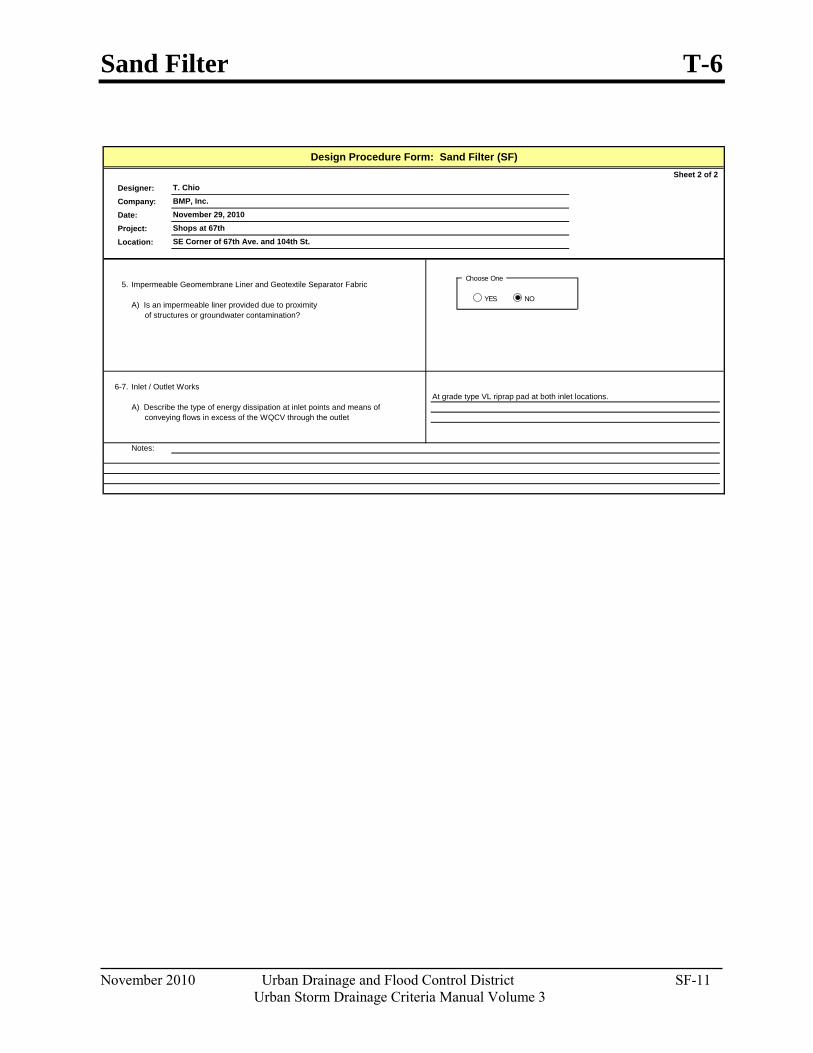
Sand Filter T-6
November 2010 Urban Drainage and Flood Control District SF-11 Urban Storm Drainage Criteria Manual Volume 3
Sheet 2 of 2Designer:Company:Date:Project:Location:
5. Impermeable Geomembrane Liner and Geotextile Separator Fabric
A) Is an impermeable liner provided due to proximity of structures or groundwater contamination?
6-7. Inlet / Outlet Works
A) Describe the type of energy dissipation at inlet points and means of conveying flows in excess of the WQCV through the outlet
Notes:
SE Corner of 67th Ave. and 104th St.
At grade type VL riprap pad at both inlet locations.
Design Procedure Form: Sand Filter (SF)
T. ChioBMP, Inc.November 29, 2010Shops at 67th
Choose One
YES NO

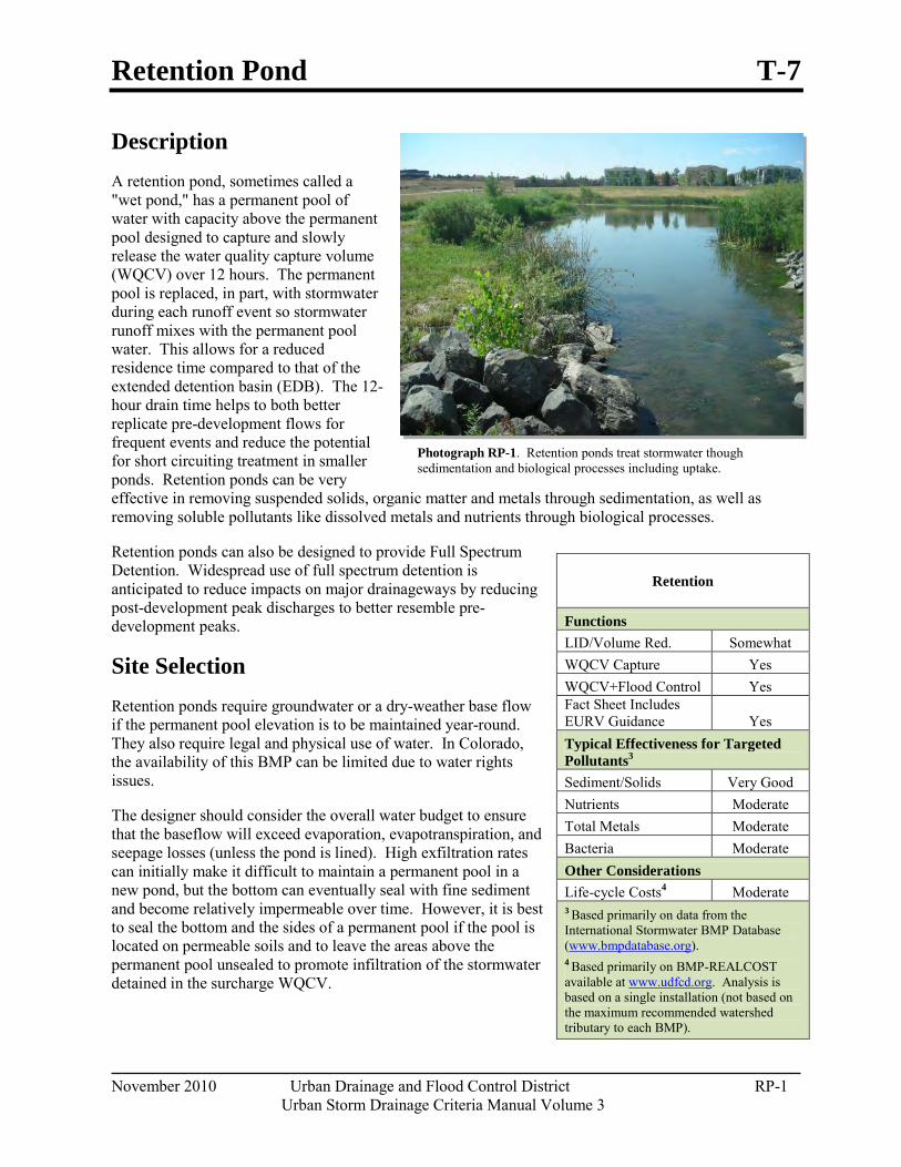
Retention Pond T-7
November 2010 Urban Drainage and Flood Control District RP-1 Urban Storm Drainage Criteria Manual Volume 3
Photograph RP-1. Retention ponds treat stormwater though sedimentation and biological processes including uptake.
Description A retention pond, sometimes called a "wet pond," has a permanent pool of water with capacity above the permanent pool designed to capture and slowly release the water quality capture volume (WQCV) over 12 hours. The permanent pool is replaced, in part, with stormwater during each runoff event so stormwater runoff mixes with the permanent pool water. This allows for a reduced residence time compared to that of the extended detention basin (EDB). The 12-hour drain time helps to both better replicate pre-development flows for frequent events and reduce the potential for short circuiting treatment in smaller ponds. Retention ponds can be very effective in removing suspended solids, organic matter and metals through sedimentation, as well as removing soluble pollutants like dissolved metals and nutrients through biological processes.
Retention ponds can also be designed to provide Full Spectrum Detention. Widespread use of full spectrum detention is anticipated to reduce impacts on major drainageways by reducing post-development peak discharges to better resemble pre-development peaks.
Site Selection Retention ponds require groundwater or a dry-weather base flow if the permanent pool elevation is to be maintained year-round. They also require legal and physical use of water. In Colorado, the availability of this BMP can be limited due to water rights issues.
The designer should consider the overall water budget to ensure that the baseflow will exceed evaporation, evapotranspiration, and seepage losses (unless the pond is lined). High exfiltration rates can initially make it difficult to maintain a permanent pool in a new pond, but the bottom can eventually seal with fine sediment and become relatively impermeable over time. However, it is best to seal the bottom and the sides of a permanent pool if the pool is located on permeable soils and to leave the areas above the permanent pool unsealed to promote infiltration of the stormwater detained in the surcharge WQCV.
Retention
Functions LID/Volume Red. Somewhat WQCV Capture Yes WQCV+Flood Control Yes Fact Sheet Includes EURV Guidance Yes Typical Effectiveness for Targeted Pollutants3
Sediment/Solids Very Good Nutrients Moderate Total Metals Moderate Bacteria Moderate Other Considerations Life-cycle Costs4 Moderate 3 Based primarily on data from the International Stormwater BMP Database (www.bmpdatabase.org). 4 Based primarily on BMP-REALCOST available at www.udfcd.org. Analysis is based on a single installation (not based on the maximum recommended watershed tributary to each BMP).
T-7 Retention Pond
RP-2 Urban Drainage and Flood Control District November 2010 Urban Storm Drainage Criteria Manual Volume 3
Benefits Creates wildlife and aquatic
habitat.
Provides recreation, aesthetics, and open space opportunities.
Can increase adjacent property values.
Cost-effective BMP for larger tributary watersheds.
Limitations Safety concerns associated with
open water.
Requires both physical supply of water and a legal availability (in Colorado) to impound water.
Sediment, floating litter, and algae blooms can be difficult to remove or control.
Ponds can attract water fowl which can add to the nutrients and bacteria leaving the pond.
Ponds increase water temperature.
Studies show that retention ponds can cause an increase in temperature from influent to effluent. Retention ponds are discouraged upstream of receiving waters that are sensitive to increases in temperature (e.g., fish spawning or hatchery areas).
Use caution when placing this BMP in a basin where development will not be completed for an extended period, or where the potential for a chemical spill is higher than typical. When these conditions exists, it is critical to provide adequate containment and/or pretreatment of flows. In developing watersheds, frequent maintenance of the forebay may be necessary.
Designing for Maintenance Recommended ongoing maintenance practices for all BMPs are provided in Chapter 6 of this manual. During design, the following should be considered to ensure ease of maintenance over the long-term.
Provide pretreatment upstream of the permanent pool.
Provide maintenance access to the outlet structure as well as the forebay.
Exceed the minimum criterion for the permanent pool volume. Greater depth will help deter algae growth by reducing temperature and the area of the pond bottom that receives sunlight.
Design Procedure and Criteria The following steps outline the retention pond design procedure and criteria, and Figure RP-1 shows a typical configuration.
1. Baseflow: Unless the permanent pool is establish by groundwater, a perennial baseflow that exceeds losses must be physically and legally available. Net influx calculations should be conservative to account for significant annual variations in hydrologic conditions. Low inflow in relation to the pond volume can result in poor water quality. Losses include evaporation, evapotranspiration, and seepage. Evaporation can be estimated from existing local studies or from the National Weather Service (NWS) Climate Prediction website. Data collected from Chatfield Reservoir from 1990 to 1997 show an average annual evaporation of 37 inches, while the NWS shows approximately 40 inches of evaporation per year in the Denver metropolitan area. Potential evapotranspiration (which occurs when water supply to both plant and soil surface is unlimited) is approximately equal to the evaporation from a large, free-water surface such as a lake (Bedient and Huber, 1992). When retention ponds are placed above the groundwater elevation, a pond liner is recommended unless evaluation by a geotechnical engineer determines this to be unnecessary.
Retention Pond T-7
November 2010 Urban Drainage and Flood Control District RP-3 Urban Storm Drainage Criteria Manual Volume 3
2. Surcharge Volume: Provide a surcharge volume based on a 12-hour drain time.
Determine the imperviousness of the watershed (or effective imperviousness where LID elements are used upstream).
Find the required storage volume. Determine the required WQCV or EURV (watershed inches of runoff) using Figure 3-2 located in Chapter 3 of this manual (for WQCV) or equations provided in the Storage chapter of Volume 2 (for EURV).
Calculate the design volume (surcharge volume above the permanent pool) as follows:
𝑉𝑉 = �WQCV
12 � 𝐴𝐴
For WQCV:
Equation RP-1
𝑉𝑉 = �EURV
12 � 𝐴𝐴
For EURV:
Equation RP-2
Where:
V = design volume (acre ft)
A = tributary catchment drainage area (acres)
3. Basin Shape: Always maximize the distance between the inlet and the outlet. A basin length to width ratio between 2:1 and 3:1 is recommended to avoid short-circuiting. It may be necessary to modify the inlet and outlet locations through the use of pipes, swales, or channels to accomplish this.
4. Permanent Pool: The permanent pool provides stormwater quality enhancement between storm runoff events through biochemical processes and continuing sedimentation.
Volume of the permanent pool:
𝑉𝑉𝑝𝑝 ≥ 1.2 �WQCV
12� 𝐴𝐴 Equation RP-3
Where:
V p = permanent pool volume (acre ft)
A = tributary catchment drainage area (acres)
T-7 Retention Pond
RP-4 Urban Drainage and Flood Control District November 2010 Urban Storm Drainage Criteria Manual Volume 3
Depth Zones: The permanent pool should have two zones:
o Safety Wetland Bench: This area should be located along the perimeter of the pond, 6 to 12 inches deep and a minimum of 4 feet wide. Aquatic plant growth along the perimeter of the permanent pool can help strain surface flow into the pond, protect the banks by stabilizing the soil at the edge of the pond, and provide biological uptake. The safety wetland bench is also constructed as a safety precaution. It provides a shallow area that allows people or animals who inadvertently enter the open water to gain footing to get out of the pond.
o Open Water Zone: The remaining pond area should be open, providing a volume to promote sedimentation and nutrient uptake by phytoplankton. To avoid anoxic conditions, the maximum depth in the pool should not exceed 12 feet.
5. Side Slopes: Side slopes should be stable and sufficiently gentle to limit rill erosion and to facilitate maintenance. Side slopes above the safety wetland bench should be no steeper than 4:1, preferably flatter. The safety wetland bench should be relatively flat with the depth between 6 to 12 inches. The side slope below this bench should be 3:1 (or flatter when access is required or when the surface could be slippery). The steeper 3:1 slope below the safety wetland bench can be beneficial to deterring algae growth as it will reduce the shallow area of the pond, thus reducing the amount of sunlight that penetrates the pond bottom.
6. Inlet: Dissipate energy at the inlet to limit erosion and to diffuse the inflow plume. Inlets should be designed in accordance with the Hydraulic Structures chapter of Volume 2. This chapter includes design of impact basins and drop structures.
7. Forebay: Forebays provide an opportunity for larger particles to settle out, which will reduce the required frequency of sediment removal in the permanent pool. Install a solid driving surface on the bottom and sides below the permanent water line to facilitate sediment removal. A soil riprap berm should be constructed to contain the forebay opposite of the inlet. This should have a minimum top width of 8 feet and side slopes no steeper than 4:1. The forebay volume within the permanent pool should be sized for anticipated sediment loads from the watershed and should be at least 3% of the WQCV. If the contributing basin is not fully developed, additional measures should be taken to maintain a relatively clean forebay. This includes more frequent maintenance of the forebay and/or providing and maintaining temporary erosion control.
8. Outlet: The outlet should be designed to release the WQCV over a 12-hour period. This can be done through an orifice place as detailed in BMP Fact Sheet T-12. Use reservoir routing calculations as discussed in the Storage chapter of Volume 2 or use equation RP-4, a simplified orifice sizing equation (see Technical Memorandum dated July 13, 2010 available at www.udfcd.org).
𝐴𝐴𝑂𝑂 =201𝑉𝑉�0.95/𝐻𝐻0.085 �
𝑇𝑇𝐷𝐷𝐻𝐻0.164 Equation RP-4
Where:
AO = area per row of orifices spaced on 4-inch centers (in2)
V = design volume (WQCV or EURV) (acre ft)
TD = time to drain the prescribed volume (hrs) (i.e., 12 for WQCV or 72 for EURV)
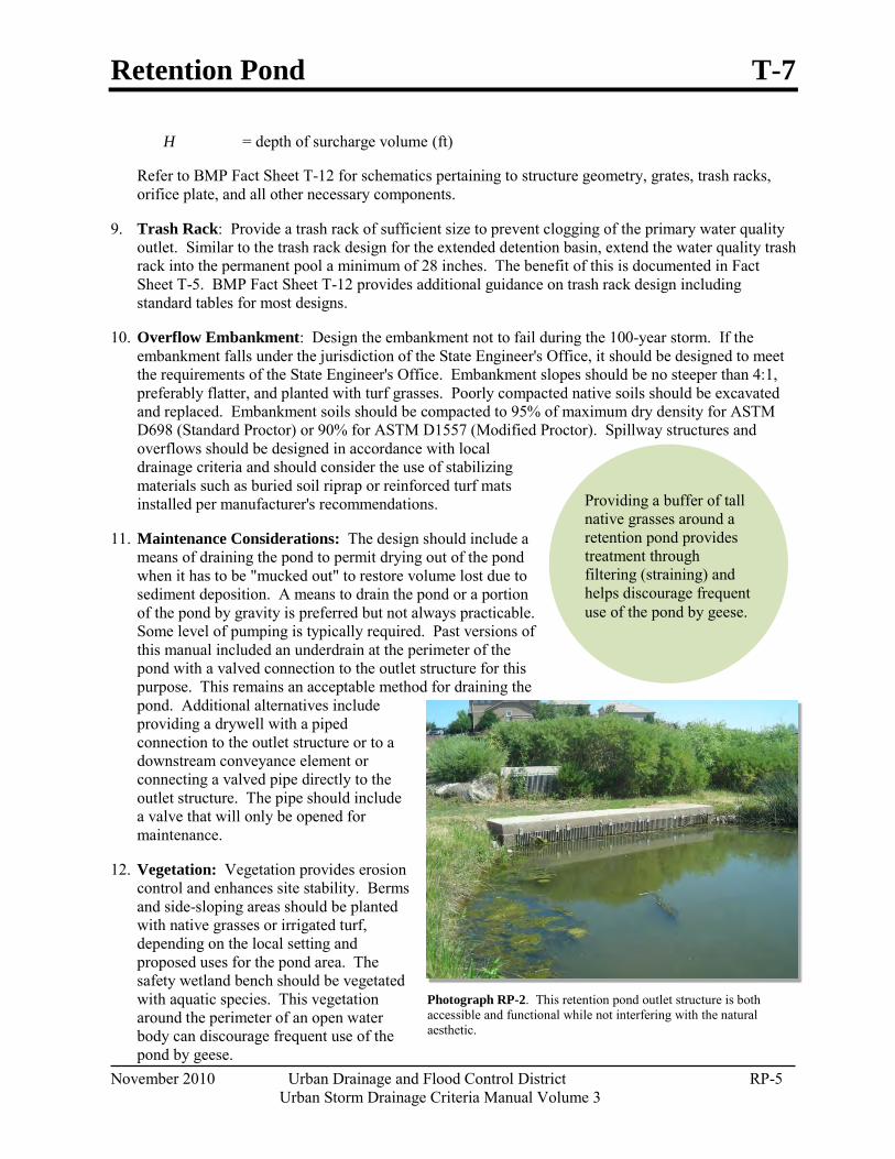
Retention Pond T-7
November 2010 Urban Drainage and Flood Control District RP-5 Urban Storm Drainage Criteria Manual Volume 3
Providing a buffer of tall native grasses around a retention pond provides treatment through filtering (straining) and helps discourage frequent use of the pond by geese.
Photograph RP-2. This retention pond outlet structure is both accessible and functional while not interfering with the natural aesthetic.
H = depth of surcharge volume (ft)
Refer to BMP Fact Sheet T-12 for schematics pertaining to structure geometry, grates, trash racks, orifice plate, and all other necessary components.
9. Trash Rack: Provide a trash rack of sufficient size to prevent clogging of the primary water quality outlet. Similar to the trash rack design for the extended detention basin, extend the water quality trash rack into the permanent pool a minimum of 28 inches. The benefit of this is documented in Fact Sheet T-5. BMP Fact Sheet T-12 provides additional guidance on trash rack design including standard tables for most designs.
10. Overflow Embankment: Design the embankment not to fail during the 100-year storm. If the embankment falls under the jurisdiction of the State Engineer's Office, it should be designed to meet the requirements of the State Engineer's Office. Embankment slopes should be no steeper than 4:1, preferably flatter, and planted with turf grasses. Poorly compacted native soils should be excavated and replaced. Embankment soils should be compacted to 95% of maximum dry density for ASTM D698 (Standard Proctor) or 90% for ASTM D1557 (Modified Proctor). Spillway structures and overflows should be designed in accordance with local drainage criteria and should consider the use of stabilizing materials such as buried soil riprap or reinforced turf mats installed per manufacturer's recommendations.
11. Maintenance Considerations: The design should include a means of draining the pond to permit drying out of the pond when it has to be "mucked out" to restore volume lost due to sediment deposition. A means to drain the pond or a portion of the pond by gravity is preferred but not always practicable. Some level of pumping is typically required. Past versions of this manual included an underdrain at the perimeter of the pond with a valved connection to the outlet structure for this purpose. This remains an acceptable method for draining the pond. Additional alternatives include providing a drywell with a piped connection to the outlet structure or to a downstream conveyance element or connecting a valved pipe directly to the outlet structure. The pipe should include a valve that will only be opened for maintenance.
12. Vegetation: Vegetation provides erosion control and enhances site stability. Berms and side-sloping areas should be planted with native grasses or irrigated turf, depending on the local setting and proposed uses for the pond area. The safety wetland bench should be vegetated with aquatic species. This vegetation around the perimeter of an open water body can discourage frequent use of the pond by geese.
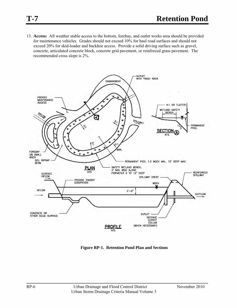
T-7 Retention Pond
RP-6 Urban Drainage and Flood Control District November 2010 Urban Storm Drainage Criteria Manual Volume 3
13. Access: All weather stable access to the bottom, forebay, and outlet works area should be provided for maintenance vehicles. Grades should not exceed 10% for haul road surfaces and should not exceed 20% for skid-loader and backhoe access. Provide a solid driving surface such as gravel, concrete, articulated concrete block, concrete grid pavement, or reinforced grass pavement. The recommended cross slope is 2%.
Figure RP-1. Retention Pond Plan and Sections
Retention Pond T-7
November 2010 Urban Drainage and Flood Control District RP-7 Urban Storm Drainage Criteria Manual Volume 3
Photograph RP-3. (altered photo) When incorporating rock into a structure, use other matching, functional rock to prevent the structure from looking out of context. Photo courtesy of Design Concepts.
Aesthetic Design Since all land owners and managers wish to use land in the most efficient manner possible, it is important that retention basins become part of a multi-use system. This encourages the design of retention ponds as an aesthetic part of a naturalized environment or to be expanded to include passive and/or active open space. Within each scenario, the retention basin can begin to define itself as more than just a drainage facility. When this happens, the basin becomes a public amenity. This combination of public amenity and drainage facility is of much greater value to a landowner. Softened and varied slopes, interspersed irrigated fields, planting areas and wetlands can all be part of a retention pond.
The design should be aesthetic whether it is considered to be an architectural or naturalized basin. Architectural basins incorporate design borrowed or reflective of the surrounding architecture or urban forms. An architectural basin is intended to appear as part of the built environment, rather than hiding the cues that identify it as a stormwater structure. A naturalized basin is designed to appear as though it is a natural part of the landscape. This section provides suggestions for designing a naturalized basin. The built environment, in contrast to the natural environment, does not typically contain the randomness of form inherent in nature. Constructed slopes typically remain consistent, as do slope transitions. Even dissipation structures are usually a hard form and have edges seldom seen in nature. If the retention pond is to appear as though it is a natural part of the landscape, it is important to minimize shapes that provide visual cues indicating the presence of a drainage structure. For example, the pond sides in the area of the surcharge volume should be shaped more naturally and with varying slopes for a naturalized pond. See Figure RP-2 for an example.
Suggested Methods for Creating the Look of a Naturalized Pond:
Create a flowing overall form that looks like it was shaped by water. This includes the banks of the retention pond, which should have an undulating outline rather than a straight line.
One side of the pond can be higher than the other side. This may require a berm.
The shape of the permanent pool should vary from the shape of the surcharge volume.
The slopes on at least three sides of the pond (above the permanent pool) should be varied and gentle. To achieve this, one or more sides of the basin may have to be stabilized by a retaining structure, i.e., stacked boulders and walls.
Vary slope transitions.
T-7 Retention Pond
RP-8 Urban Drainage and Flood Control District November 2010 Urban Storm Drainage Criteria Manual Volume 3
Photograph RP-6. Landscape elements such as vegetation and stone highlight the irregularly-shaped pond edge, making it appear more natural. Photo courtesy of Design Concepts.
Photograph RP-4. (altered photo) Variations in slope and texture around the pond are brought together by mass groupings of local stone boulders. The boulders are placed intermittently around the pond in groups and interspersed with plantings. Photo courtesy of Design Concepts. Note: A minimum 4-foot vegetated buffer (littoral zone) is recommended to strain surface flow into the pond, protect the banks by stabilizing the soil at the edge of the pond, and provide biological uptake.
Photograph RP-5. A curving stream with vegetated edges provides habitat for wildlife. Photo courtesy of Design Concepts.
Any use of rock for energy dissipation or for erosion control should graduate away from the area of hard edge into the surrounding landscape. Other functional matching rock should occur in other areas of the pond to prevent the energy dissipation structure from appearing out of context. Photo RP-3 serves as an example of this.
If concrete is required in the basin, colored concrete matching the rocks or other site features of the surrounding landscape can be used to prevent the structure from appearing out of context. Colored concrete, form liners and veneers for construction walls are preferred for outlet structures.
Adjust the vegetation to the different uses of the pond surrounding.
Ground cover should reflect the type of water regime expected for the location within the basin. For example, riparian plants would be placed around the edge of the retention pond, groups of trees and shrubs would be placed in more manicured areas that have no retention or detention function.
Retention Pond T-7
November 2010 Urban Drainage and Flood Control District RP-9 Urban Storm Drainage Criteria Manual Volume 3
Figure RP-2. Example of a Naturalized Retention Pond
Design Example The UD-BMP workbook, designed as a tool for both designer and reviewing agency is available at www.udfcd.org. This section provides a completed design form from this workbook as an example.
T-7 Retention Pond
RP-10 Urban Drainage and Flood Control District November 2010 Urban Storm Drainage Criteria Manual Volume 3
Sheet 1 of 3Designer:Company:Date:Project:Location:
1. Baseflow
A) Is the permanent pool established by groundwater?
2. Surcharge Volume
A) Effective Imperviousness of Tributary Area, Ia Ia = 80.0 %
B) Tributary Area's Imperviousness Ratio (i = Ia / 100 ) i = 0.800
C) Contributing Watershed Area Area = 50.000 ac
D) For Watersheds Outside of the Denver Region, Depth of Average d6 = in Runoff Producing Storm
E) Design Concept (Select EURV when also designing for flood control)
F) Water Quality Capture Volume (WQCV) VWQCV= 1.094 ac-ft Based on 12-hour Drain Time (VWQCV = (0.8 * (0.91 * i3 - 1.19 * i2 + 0.78 * i) / 12 * Area)
G) For Watersheds Outside of the Denver Region, VWQCV OTHER= ac-ft Water Quality Capture Volume (WQCV) (VWQCV OTHER = (d6*(VWQCV/0.43))
H) User Input of Water Quality Capture Volume (WQCV) VWQCV USER= ac-ft (Only if a different WQCV Design Volume is desired)
I) Predominant Watershed NRCS Soil Group
J) Excess Urban Runoff Volume (EURV) Design Volume For HSG A: EURVA = (0.1878i - 0.0104)*Area For HSG B: EURVB = (0.1178i - 0.0042)*Area For HSG C/D: EURVC/D = (0.1043i - 0.0031)*Area EURV = 4.017 ac-f t
3. Basin Shape L : W = 3.0 : 1(It is recommended to have a basin length to width ratio between 2:1 and 3:1)
4. Permanent Pool
A) Minimum Permanent Pool Volume VPOOL = 1.313 ac-ft
B) Depth of the Safety Wetland Bench DLZ = 6 in (Recommended to be 6 to 12 inches deep)
C) Depth of the Open Water Zone DOWZ = 12.0 ft (Maximum depth of 12 feet)
5. Side Slopes
A) Maximum Side Slopes Above the Safety Wetland Bench ZPP = 5.00 ft / ft (Horiz. dist. per unit vertical, should be no steeper than 4:1)
B) Maximum Side Slopes Below the Safety Wetland Bench ZOWZ = 3.00 ft / ft (Horiz. dist. per unit vertical, should be no steeper than 3:1)
6. Inlet
A) Describe means of providing energy dissipation at concentrated inflow locations:
L. GibsonBMP, Inc.November 29, 2010Subdivision B
Adequate tailwater during events exceeding the WQCV.
NE Corner of 67th Ave. and 88th St.
Design Procedure Form: Retention Pond (RP)
Choose One
Excess Urban Runoff Volume (EURV)
Choose OneA
BC / D
Water Quality Capture Volume (WQCV)
Choose One
YES
NO
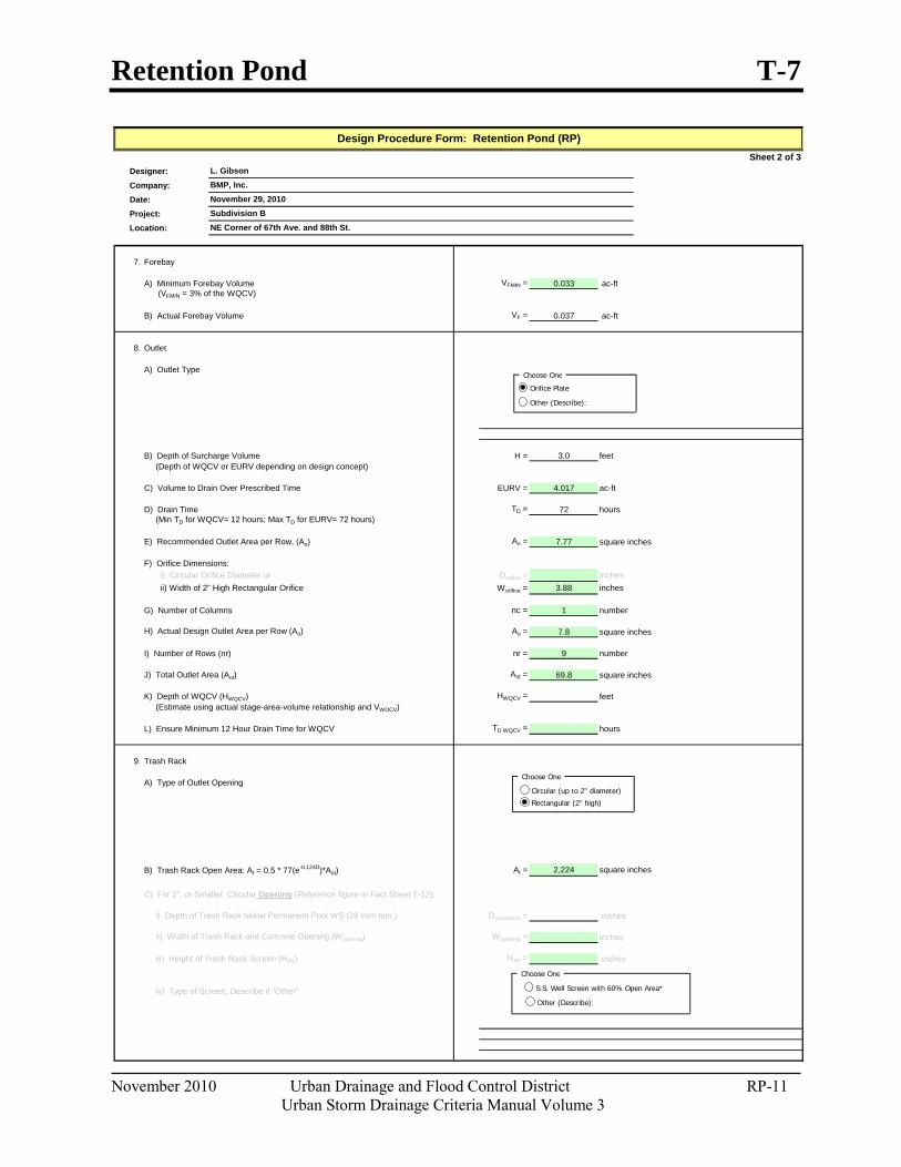
Retention Pond T-7
November 2010 Urban Drainage and Flood Control District RP-11 Urban Storm Drainage Criteria Manual Volume 3
Sheet 2 of 3Designer:Company:Date:Project:Location:
7. Forebay
A) Minimum Forebay Volume VFMIN = 0.033 ac-ft (VFMIN = 3% of the WQCV)
B) Actual Forebay Volume VF = 0.037 ac-ft
8. Outlet
A) Outlet Type
B) Depth of Surcharge Volume H = 3.0 feet (Depth of WQCV or EURV depending on design concept)
C) Volume to Drain Over Prescribed Time EURV = 4.017 ac-ft
D) Drain Time TD = 72 hours (Min TD for WQCV= 12 hours; Max TD for EURV= 72 hours)
E) Recommended Outlet Area per Row, (Ao) Ao = 7.77 square inches
F) Orifice Dimensions: i) Circular Orifice Diameter or Dorifice = inches ii) Width of 2" High Rectangular Orifice Worifice = 3.88 inches
G) Number of Columns nc = 1 number
H) Actual Design Outlet Area per Row (Ao) Ao = 7.8 square inches
I) Number of Rows (nr) nr = 9 number
J) Total Outlet Area (Aot) Aot = 69.8 square inches
K) Depth of WQCV (HWQCV) HWQCV = feet (Estimate using actual stage-area-volume relationship and VWQCV)
L) Ensure Minimum 12 Hour Drain Time for WQCV TD WQCV = hours
9. Trash Rack
A) Type of Outlet Opening
B) Trash Rack Open Area: At = 0.5 * 77(e-0.124D)*Aot) At = 2,224 square inches
C) For 2", or Smaller, Circular Opening (Reference figure in Fact Sheet T-12):
i) Depth of Trash Rack below Permanent Pool WS (28 inch min.) Dinundation = inches
ii) Width of Trash Rack and Concrete Opening (Wopening) Wopening = inches
iii) Height of Trash Rack Screen (HTR) HTR = inches
iv) Type of Screen, Describe if "Other"
L. GibsonBMP, Inc.November 29, 2010
Design Procedure Form: Retention Pond (RP)
NE Corner of 67th Ave. and 88th St.Subdivision B
Choose One
Orifice Plate
Other (Describe):
Choose One
Circular (up to 2" diameter)
Rectangular (2" high)
Choose One
S.S. Well Screen with 60% Open Area*
Other (Describe):
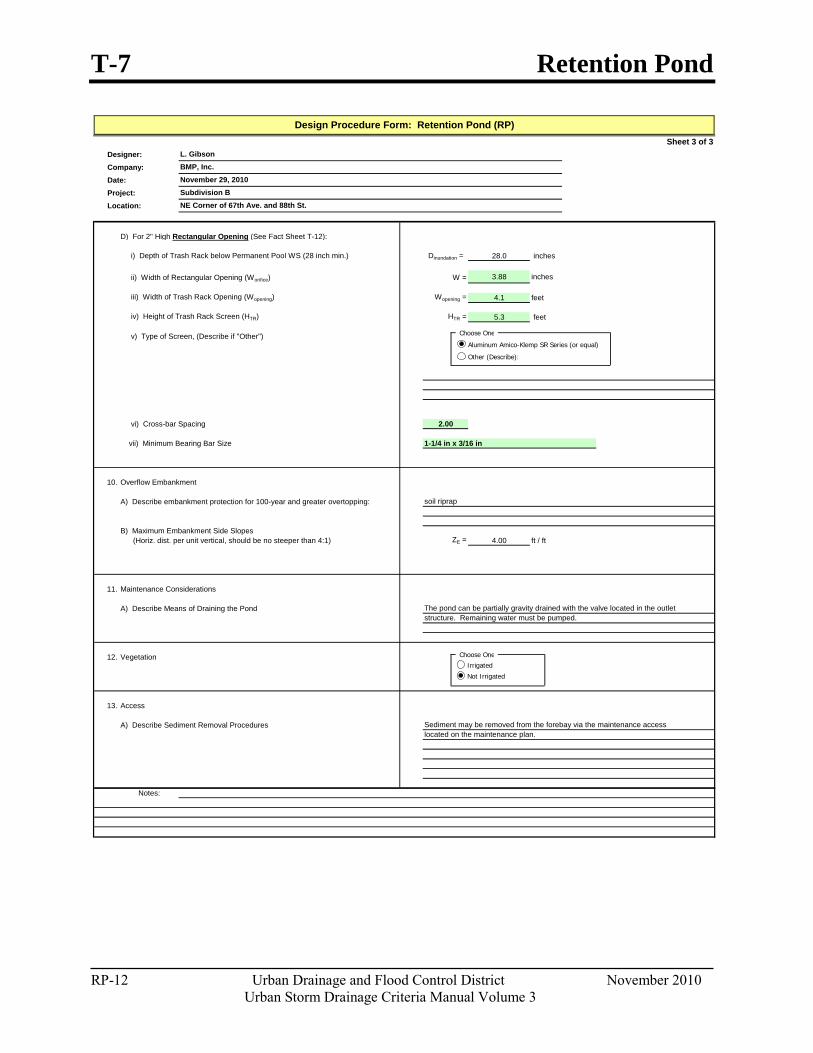
T-7 Retention Pond
RP-12 Urban Drainage and Flood Control District November 2010 Urban Storm Drainage Criteria Manual Volume 3
Sheet 3 of 3Designer:Company:Date:Project:Location:
D) For 2" High Rectangular Opening (See Fact Sheet T-12):
i) Depth of Trash Rack below Permanent Pool WS (28 inch min.) Dinundation = 28.0 inches
ii) Width of Rectangular Opening (Worifice) W = 3.88 inches
iii) Width of Trash Rack Opening (Wopening) Wopening = 4.1 feet
iv) Height of Trash Rack Screen (HTR) HTR = 5.3 feet
v) Type of Screen, (Describe if "Other")
vi) Cross-bar Spacing 2.00
vii) Minimum Bearing Bar Size 1-1/4 in x 3/16 in
10. Overflow Embankment
A) Describe embankment protection for 100-year and greater overtopping:
B) Maximum Embankment Side Slopes (Horiz. dist. per unit vertical, should be no steeper than 4:1) ZE = 4.00 ft / ft
11. Maintenance Considerations
A) Describe Means of Draining the Pond
12. Vegetation
13. Access
A) Describe Sediment Removal Procedures
Notes:
soil riprap
The pond can be partially gravity drained with the valve located in the outletstructure. Remaining water must be pumped.
L. GibsonBMP, Inc.November 29, 2010Subdivision BNE Corner of 67th Ave. and 88th St.
Design Procedure Form: Retention Pond (RP)
Sediment may be removed from the forebay via the maintenance accesslocated on the maintenance plan.
Choose One
Irrigated
Not Irrigated
Choose One
Aluminum Amico-Klemp SR Series (or equal)
Other (Describe):
Retention Pond T-7
November 2010 Urban Drainage and Flood Control District RP-13 Urban Storm Drainage Criteria Manual Volume 3
References Bedient, Philip B. and Wayne C. Huber. 1992. Hydrology and Floodplain Analysis (Second Edition).
Addison-Wesley Publishing Company.
United States Environmental Protection Agency (EPA). 1999. Storm Water Technology Fact Sheet: Wet Detention Ponds.

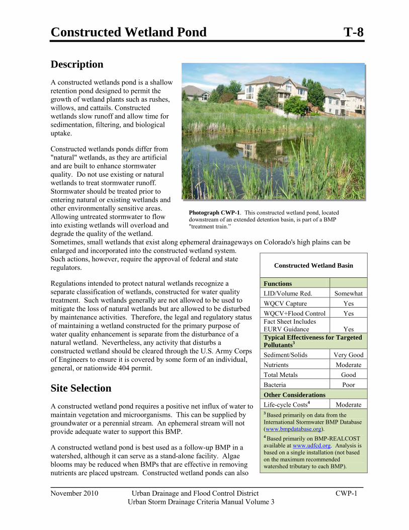
Constructed Wetland Pond T-8
November 2010 Urban Drainage and Flood Control District CWP-1
Urban Storm Drainage Criteria Manual Volume 3
Photograph CWP-1. This constructed wetland pond, located downstream of an extended detention basin, is part of a BMP "treatment train.”
Description A constructed wetlands pond is a shallow retention pond designed to permit the growth of wetland plants such as rushes, willows, and cattails. Constructed wetlands slow runoff and allow time for sedimentation, filtering, and biological uptake.
Constructed wetlands ponds differ from "natural" wetlands, as they are artificial and are built to enhance stormwater quality. Do not use existing or natural wetlands to treat stormwater runoff. Stormwater should be treated prior to entering natural or existing wetlands and other environmentally sensitive areas. Allowing untreated stormwater to flow into existing wetlands will overload and degrade the quality of the wetland. Sometimes, small wetlands that exist along ephemeral drainageways on Colorado's high plains can be enlarged and incorporated into the constructed wetland system. Such actions, however, require the approval of federal and state regulators.
Regulations intended to protect natural wetlands recognize a separate classification of wetlands, constructed for water quality treatment. Such wetlands generally are not allowed to be used to mitigate the loss of natural wetlands but are allowed to be disturbed by maintenance activities. Therefore, the legal and regulatory status of maintaining a wetland constructed for the primary purpose of water quality enhancement is separate from the disturbance of a natural wetland. Nevertheless, any activity that disturbs a constructed wetland should be cleared through the U.S. Army Corps of Engineers to ensure it is covered by some form of an individual, general, or nationwide 404 permit.
Site Selection A constructed wetland pond requires a positive net influx of water to maintain vegetation and microorganisms. This can be supplied by groundwater or a perennial stream. An ephemeral stream will not provide adequate water to support this BMP.
A constructed wetland pond is best used as a follow-up BMP in a watershed, although it can serve as a stand-alone facility. Algae blooms may be reduced when BMPs that are effective in removing nutrients are placed upstream. Constructed wetland ponds can also
Constructed Wetland Basin
Functions LID/Volume Red. Somewhat WQCV Capture Yes WQCV+Flood Control Yes Fact Sheet Includes EURV Guidance Yes Typical Effectiveness for Targeted Pollutants3 Sediment/Solids Very Good Nutrients Moderate Total Metals Good Bacteria Poor Other Considerations Life-cycle Costs4 Moderate 3 Based primarily on data from the International Stormwater BMP Database (www.bmpdatabase.org). 4 Based primarily on BMP-REALCOST available at www.udfcd.org. Analysis is based on a single installation (not based on the maximum recommended watershed tributary to each BMP).
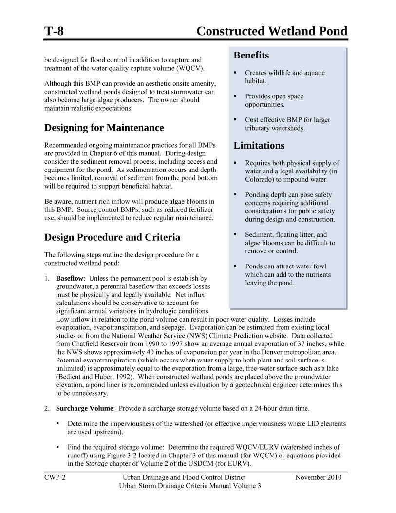
T-8 Constructed Wetland Pond
CWP-2 Urban Drainage and Flood Control District November 2010 Urban Storm Drainage Criteria Manual Volume 3
Benefits Creates wildlife and aquatic
habitat.
Provides open space opportunities.
Cost effective BMP for larger tributary watersheds.
Limitations Requires both physical supply of
water and a legal availability (in Colorado) to impound water.
Ponding depth can pose safety concerns requiring additional considerations for public safety during design and construction.
Sediment, floating litter, and algae blooms can be difficult to remove or control.
Ponds can attract water fowl which can add to the nutrients leaving the pond.
be designed for flood control in addition to capture and treatment of the water quality capture volume (WQCV).
Although this BMP can provide an aesthetic onsite amenity, constructed wetland ponds designed to treat stormwater can also become large algae producers. The owner should maintain realistic expectations.
Designing for Maintenance Recommended ongoing maintenance practices for all BMPs are provided in Chapter 6 of this manual. During design consider the sediment removal process, including access and equipment for the pond. As sedimentation occurs and depth becomes limited, removal of sediment from the pond bottom will be required to support beneficial habitat.
Be aware, nutrient rich inflow will produce algae blooms in this BMP. Source control BMPs, such as reduced fertilizer use, should be implemented to reduce regular maintenance.
Design Procedure and Criteria The following steps outline the design procedure for a constructed wetland pond:
1. Baseflow: Unless the permanent pool is establish by groundwater, a perennial baseflow that exceeds losses must be physically and legally available. Net influx calculations should be conservative to account for significant annual variations in hydrologic conditions. Low inflow in relation to the pond volume can result in poor water quality. Losses include evaporation, evapotranspiration, and seepage. Evaporation can be estimated from existing local studies or from the National Weather Service (NWS) Climate Prediction website. Data collected from Chatfield Reservoir from 1990 to 1997 show an average annual evaporation of 37 inches, while the NWS shows approximately 40 inches of evaporation per year in the Denver metropolitan area. Potential evapotranspiration (which occurs when water supply to both plant and soil surface is unlimited) is approximately equal to the evaporation from a large, free-water surface such as a lake (Bedient and Huber, 1992). When constructed wetland ponds are placed above the groundwater elevation, a pond liner is recommended unless evaluation by a geotechnical engineer determines this to be unnecessary.
2. Surcharge Volume: Provide a surcharge storage volume based on a 24-hour drain time.
Determine the imperviousness of the watershed (or effective imperviousness where LID elements are used upstream).
Find the required storage volume: Determine the required WQCV/EURV (watershed inches of runoff) using Figure 3-2 located in Chapter 3 of this manual (for WQCV) or equations provided in the Storage chapter of Volume 2 of the USDCM (for EURV).
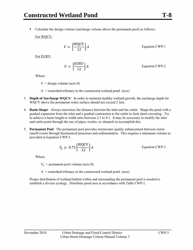
Constructed Wetland Pond T-8
November 2010 Urban Drainage and Flood Control District CWP-3
Urban Storm Drainage Criteria Manual Volume 3
Calculate the design volume (surcharge volume above the permanent pool) as follows:
𝑉𝑉 = �WQCV
12� 𝐴𝐴
For WQCV:
Equation CWP-1
𝑉𝑉 = �EURV
12� 𝐴𝐴
For EURV:
Equation CWP-2
Where:
V = design volume (acre ft)
A = watershed tributary to the constructed wetland pond (acre)
3. Depth of Surcharge WQCV: In order to maintain healthy wetland growth, the surcharge depth for WQCV above the permanent water surface should not exceed 2 feet.
4. Basin Shape: Always maximize the distance between the inlet and the outlet. Shape the pond with a gradual expansion from the inlet and a gradual contraction to the outlet to limit short-circuiting. Try to achieve a basin length to width ratio between 2:1 to 4:1. It may be necessary to modify the inlet and outlet point through the use of pipes, swales, or channels to accomplish this.
5. Permanent Pool: The permanent pool provides stormwater quality enhancement between storm runoff events through biochemical processes and sedimentation. This requires a minimum volume as provided in Equation CWP-3.
𝑉𝑉𝑝𝑝 ≥ 0.75 �WQCV
12� 𝐴𝐴 Equation CWP-3
Where:
Vp = permanent pool volume (acre ft)
A = watershed tributary to the constructed wetland pond (acre)
Proper distribution of wetland habitat within and surrounding the permanent pool is needed to establish a diverse ecology. Distribute pond area in accordance with Table CWP-1.
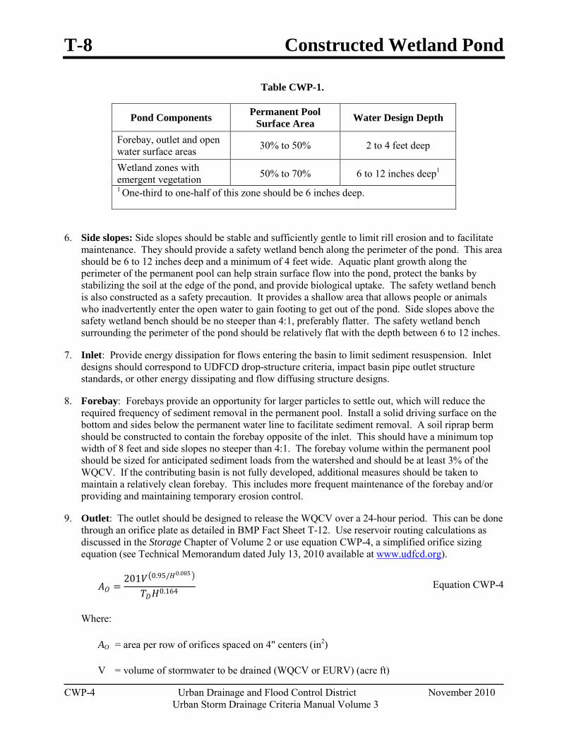
T-8 Constructed Wetland Pond
CWP-4 Urban Drainage and Flood Control District November 2010 Urban Storm Drainage Criteria Manual Volume 3
Table CWP-1.
Pond Components Permanent Pool Surface Area Water Design Depth
Forebay, outlet and open water surface areas 30% to 50% 2 to 4 feet deep
Wetland zones with emergent vegetation 50% to 70% 6 to 12 inches deep1 1 One-third to one-half of this zone should be 6 inches deep.
6. Side slopes: Side slopes should be stable and sufficiently gentle to limit rill erosion and to facilitate maintenance. They should provide a safety wetland bench along the perimeter of the pond. This area should be 6 to 12 inches deep and a minimum of 4 feet wide. Aquatic plant growth along the perimeter of the permanent pool can help strain surface flow into the pond, protect the banks by stabilizing the soil at the edge of the pond, and provide biological uptake. The safety wetland bench is also constructed as a safety precaution. It provides a shallow area that allows people or animals who inadvertently enter the open water to gain footing to get out of the pond. Side slopes above the safety wetland bench should be no steeper than 4:1, preferably flatter. The safety wetland bench surrounding the perimeter of the pond should be relatively flat with the depth between 6 to 12 inches.
7. Inlet: Provide energy dissipation for flows entering the basin to limit sediment resuspension. Inlet designs should correspond to UDFCD drop-structure criteria, impact basin pipe outlet structure standards, or other energy dissipating and flow diffusing structure designs.
8. Forebay: Forebays provide an opportunity for larger particles to settle out, which will reduce the required frequency of sediment removal in the permanent pool. Install a solid driving surface on the bottom and sides below the permanent water line to facilitate sediment removal. A soil riprap berm should be constructed to contain the forebay opposite of the inlet. This should have a minimum top width of 8 feet and side slopes no steeper than 4:1. The forebay volume within the permanent pool should be sized for anticipated sediment loads from the watershed and should be at least 3% of the WQCV. If the contributing basin is not fully developed, additional measures should be taken to maintain a relatively clean forebay. This includes more frequent maintenance of the forebay and/or providing and maintaining temporary erosion control.
9. Outlet: The outlet should be designed to release the WQCV over a 24-hour period. This can be done through an orifice plate as detailed in BMP Fact Sheet T-12. Use reservoir routing calculations as discussed in the Storage Chapter of Volume 2 or use equation CWP-4, a simplified orifice sizing equation (see Technical Memorandum dated July 13, 2010 available at www.udfcd.org).
𝐴𝐴𝑂𝑂 =201𝑉𝑉�0.95/𝐻𝐻0.085 �
𝑇𝑇𝐷𝐷𝐻𝐻0.164 Equation CWP-4
Where:
AO = area per row of orifices spaced on 4" centers (in2)
V = volume of stormwater to be drained (WQCV or EURV) (acre ft)
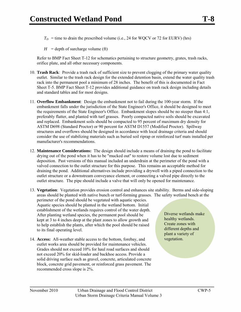
Constructed Wetland Pond T-8
November 2010 Urban Drainage and Flood Control District CWP-5
Urban Storm Drainage Criteria Manual Volume 3
Diverse wetlands make healthy wetlands. Create zones with different depths and plant a variety of vegetation.
TD = time to drain the prescribed volume (i.e., 24 for WQCV or 72 for EURV) (hrs)
H = depth of surcharge volume (ft)
Refer to BMP Fact Sheet T-12 for schematics pertaining to structure geometry, grates, trash racks, orifice plate, and all other necessary components.
10. Trash Rack: Provide a trash rack of sufficient size to prevent clogging of the primary water quality outlet. Similar to the trash rack design for the extended detention basin, extend the water quality trash rack into the permanent pool a minimum of 28 inches. The benefit of this is documented in Fact Sheet T-5. BMP Fact Sheet T-12 provides additional guidance on trash rack design including details and standard tables and for most designs.
11. Overflow Embankment: Design the embankment not to fail during the 100-year storm. If the embankment falls under the jurisdiction of the State Engineer's Office, it should be designed to meet the requirements of the State Engineer's Office. Embankment slopes should be no steeper than 4:1, preferably flatter, and planted with turf grasses. Poorly compacted native soils should be excavated and replaced. Embankment soils should be compacted to 95 percent of maximum dry density for ASTM D698 (Standard Proctor) or 90 percent for ASTM D1557 (Modified Proctor). Spillway structures and overflows should be designed in accordance with local drainage criteria and should consider the use of stabilizing materials such as buried soil riprap or reinforced turf mats installed per manufacturer's recommendations.
12. Maintenance Considerations: The design should include a means of draining the pond to facilitate drying out of the pond when it has to be "mucked out" to restore volume lost due to sediment deposition. Past versions of this manual included an underdrain at the perimeter of the pond with a valved connection to the outlet structure for this purpose. This remains an acceptable method for draining the pond. Additional alternatives include providing a drywell with a piped connection to the outlet structure or a downstream conveyance element, or connecting a valved pipe directly to the outlet structure. The pipe should include a valve that will only be opened for maintenance.
13. Vegetation: Vegetation provides erosion control and enhances site stability. Berms and side-sloping areas should be planted with native bunch or turf-forming grasses. The safety wetland bench at the perimeter of the pond should be vegetated with aquatic species. Aquatic species should be planted in the wetland bottom. Initial establishment of the wetlands requires control of the water depth. After planting wetland species, the permanent pool should be kept at 3 to 4 inches deep at the plant zones to allow growth and to help establish the plants, after which the pool should be raised to its final operating level.
14. Access: All-weather stable access to the bottom, forebay, and outlet works area should be provided for maintenance vehicles. Grades should not exceed 10% for haul road surfaces and should not exceed 20% for skid-loader and backhoe access. Provide a solid driving surface such as gravel, concrete, articulated concrete block, concrete grid pavement, or reinforced grass pavement. The recommended cross slope is 2%.
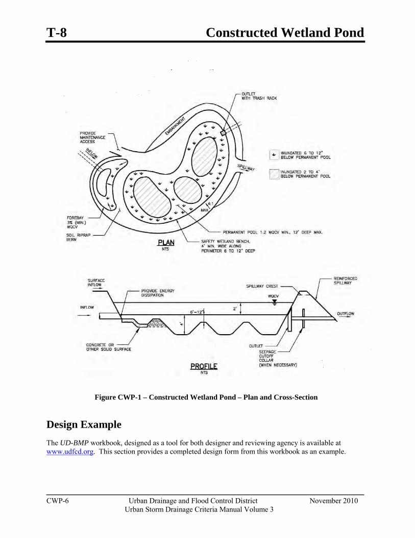
T-8 Constructed Wetland Pond
CWP-6 Urban Drainage and Flood Control District November 2010 Urban Storm Drainage Criteria Manual Volume 3
Figure CWP-1 – Constructed Wetland Pond – Plan and Cross-Section
Design Example The UD-BMP workbook, designed as a tool for both designer and reviewing agency is available at www.udfcd.org. This section provides a completed design form from this workbook as an example.
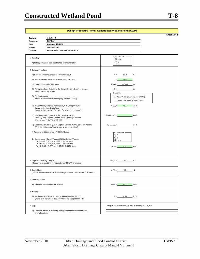
Constructed Wetland Pond T-8
November 2010 Urban Drainage and Flood Control District CWP-7
Urban Storm Drainage Criteria Manual Volume 3
Sheet 1 of 3Designer:Company:Date:Project:Location:
1. Baseflow
A) Is the permanent pool established by groundwater?
2. Surcharge Volume
A) Effective Imperviousness of Tributary Area, Ia Ia = 60.0 %
B) Tributary Area's Imperviousness Ratio (i = Ia / 100 ) i = 0.600
C) Contributing Watershed Area Area = 10.000 ac
D) For Watersheds Outside of the Denver Region, Depth of Average d6 = in Runoff Producing Storm
E) Design Concept (Select EURV when also designing for flood control)
F) Water Quality Capture Volume (WQCV) Design Volume VWQCV= 0.177 ac-ft Based on 24-hour Drain Time (VWQCV = (0.9 * (0.91 * i3 - 1.19 * i2 + 0.78 * i) / 12 * Area)
G) For Watersheds Outside of the Denver Region, VWQCV OTHER= ac-ft Water Quality Capture Volume (WQCV) Design Volume (VWQCV OTHER = (d6*(VWQCV/0.43))
H) User Input of Water Quality Capture Volume (WQCV) Design Volume VWQCV USER= ac-ft (Only if a different WQCV Design Volume is desired)
I) Predominant Watershed NRCS Soil Group
J) Excess Urban Runoff Volume (EURV) Design Volume For HSG A: EURVA = (0.1878i - 0.0104)*Area For HSG B: EURVB = (0.1178i - 0.0042)*Area For HSG C/D: EURVC/D = (0.1043i - 0.0031)*Area EURV = 0.595 ac-f t
3. Depth of Surcharge WQCV DWQCV = 2.0 ft(Should not exceed 2 feet, required even if EURV is chosen)
4. Basin Shape L : W = 4.0 : 1(It is recommended to have a basin length to width ratio between 2:1 and 4:1)
5. Permanent Pool
A) Minimum Permanent Pool Volume VPOOL = 0.133 ac-ft
6. Side Slopes
A) Maximum Side Slope Above the Safety Wetland Bench Z = 4.00 ft / ft (Horiz. dist. per unit vertical, should be no steeper than 4:1)
7. Inlet
A) Describe means of providing energy dissipation at concentrated inflow locations:
Adequate tailwater during events exceeding the WQCV.
N. CalisoffBMP Inc.
SW corner of 105th Ave. and 93rd St.
November 29, 2010Industrial Park
Design Procedure Form: Constructed Wetland Pond (CWP)
Choose One
Excess Urban Runoff Volume (EURV)
Choose One
A
BC / D
Water Quality Capture Volume (WQCV)
Choose One
YES
NO
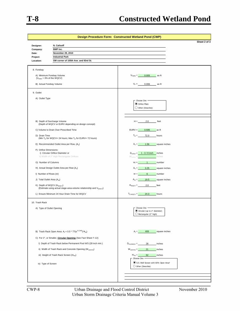
T-8 Constructed Wetland Pond
CWP-8 Urban Drainage and Flood Control District November 2010 Urban Storm Drainage Criteria Manual Volume 3
Sheet 2 of 3Designer:Company:Date:Project:Location:
8. Forebay
A) Minimum Forebay Volume VFMIN = 0.005 ac-ft (VFMIN = 3% of the WQCV)
B) Actual Forebay Volume VF = 0.006 ac-ft
9. Outlet
A) Outlet Type
B) Depth of Surcharge Volume H = 2.0 feet (Depth of WQCV or EURV depending on design concept)
C) Volume to Drain Over Prescribed Time EURV = 0.595 ac-ft
D) Drain Time TD = 72.0 hours (Min TD for WQCV= 24 hours; Max TD for EURV= 72 hours)
E) Recommended Outlet Area per Row, (Ao) Ao = 1.56 square inches
F) Orifice Dimensions: i) Circular Orifice Diameter or Dorifice = 1 - 3 / 8 inch inches ii) Width of 2" High Rectangular Orifices Worifice = inches
G) Number of Columns nc = 1 number
H) Actual Design Outlet Area per Row (Ao) Ao = 3.25 square inches
I) Number of Rows (nr) nr = 6 number
J) Total Outlet Area (Aot) Aot = 19.5 square inches
K) Depth of WQCV (HWQCV) HWQCV = 2.0 feet (Estimate using actual stage-area-volume relationship and VWQCV)
L) Ensure Minimum 24 Hour Drain Time for WQCV TD WQCV = 24.3 hours
10. Trash Rack
A) Type of Outlet Opening
B) Trash Rack Open Area: At = 0.5 * 77(e-0.124D)*Aot) At = 655 square inches
C) For 2", or Smaller, Circular Opening (See Fact Sheet T-12):
i) Depth of Trash Rack below Permanent Pool WS (28 inch min.) Dinundation = 28 inches
ii) Width of Trash Rack and Concrete Opening (Wopening) Wopening = 21 inches
iii) Height of Trash Rack Screen (HTR) HTR = 52 inches
iv) Type of Screen
BMP Inc.November 29, 2010Industrial Park
Design Procedure Form: Constructed Wetland Pond (CWP)
N. Calisoff
SW corner of 105th Ave. and 93rd St.
Choose One
Orifice Plate
Other (Describe):
Choose OneCircular (up to 2" diameter)
Rectangular (2" high)
Choose One
S.S. Well Screen with 60% Open Area*
Other (Describe):
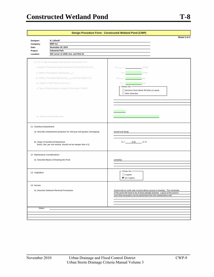
Constructed Wetland Pond T-8
November 2010 Urban Drainage and Flood Control District CWP-9
Urban Storm Drainage Criteria Manual Volume 3
Sheet 3 of 3Designer:Company:Date:Project:Location:
D) For 2" High Rectangular Opening (See Fact Sheet T-12):
i) Depth of Trash Rack below Permanent Pool WS (28 inch min.) Dinundation = inches
ii) Width of Rectangular Opening (Worifice) W = inches
iii) Width of Trashrack Opening (Wopening) from Fact Sheet T-12 Wopening = feet
iv) Height of Trash Rack Screen (HTR) HTR = feet
v) Type of Screen (based on depth H) (Describe if "Other")
vii) Minimum Bearing Bar Size
11. Overflow Embankment
A) Describe embankment protection for 100-year and greater overtopping:
B) Slope of Overflow Embankment ZE = 5.00 ft / ft (Horiz. dist. per unit vertical, should not be steeper than 4:1)
12. Maintenance Considerations
A) Describe Means of Draining the Pond
13. Vegetation
14. Access
A) Describe Sediment Removal Procedures
Notes:
of the pond will need to be at least partially drained. Layout of the pond issuch that excavation can be performed from the maintenance trail.
pumping
Gravel trail on north side of pond allows access to forebay. The remainder
buried soil riprap
N. Calisoff
Design Procedure Form: Constructed Wetland Pond (CWP)
BMP Inc.November 29, 2010Industrial ParkSW corner of 105th Ave. and 93rd St.
Choose One
Irrigated
Not Irrigated
Choose One
Aluminum Amico-Klemp SR Series (or equal)
Other (Describe):
T-8 Constructed Wetland Pond
CWP-10 Urban Drainage and Flood Control District November 2010 Urban Storm Drainage Criteria Manual Volume 3
References Bedient, Philip B. and Wayne C. Huber. 1992. Hydrology and Floodplain Analysis (Second Edition).
Addison-Wesley Publishing Company.
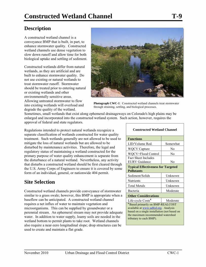
Constructed Wetland Channel T-9
November 2010 Urban Drainage and Flood Control District CWC-1
Photograph CWC-1: Constructed wetland channels treat stormwater through straining, settling, and biological processes.
Description A constructed wetland channel is a conveyance BMP that is built, in part, to enhance stormwater quality. Constructed wetland channels use dense vegetation to slow down runoff and allow time for both biological uptake and settling of sediment.
Constructed wetlands differ from natural wetlands, as they are artificial and are built to enhance stormwater quality. Do not use existing or natural wetlands to treat stormwater runoff. Stormwater should be treated prior to entering natural or existing wetlands and other environmentally sensitive areas. Allowing untreated stormwater to flow into existing wetlands will overload and degrade the quality of the wetland. Sometimes, small wetlands that exist along ephemeral drainageways on Colorado's high plains may be enlarged and incorporated into the constructed wetland system. Such action, however, requires the approval of federal and state regulators.
Regulations intended to protect natural wetlands recognize a separate classification of wetlands constructed for water quality treatment. Such wetlands generally are not allowed to be used to mitigate the loss of natural wetlands but are allowed to be disturbed by maintenance activities. Therefore, the legal and regulatory status of maintaining a wetland constructed for the primary purpose of water quality enhancement is separate from the disturbance of a natural wetland. Nevertheless, any activity that disturbs a constructed wetland should be first cleared through the U.S. Army Corps of Engineers to ensure it is covered by some form of an individual, general, or nationwide 404 permit.
Site Selection Constructed wetland channels provide conveyance of stormwater similar to a grass swale; however, this BMP is appropriate when a baseflow can be anticipated. A constructed wetland channel requires a net influx of water to maintain vegetation and microorganisms. This can be supplied by groundwater or a perennial stream. An ephemeral stream may not provide adequate water. In addition to water supply, loamy soils are needed in the wetland bottom to permit plants to take root. Wetland channels also require a near-zero longitudinal slope; drop structures can be used to create and maintain a flat grade.
Constructed Wetland Channel
Functions LID/Volume Red. Somewhat WQCV Capture No WQCV+Flood Control No Fact Sheet Includes EURV Guidance No Typical Effectiveness for Targeted Pollutants Sediment/Solids Unknown Nutrients Unknown Total Metals Unknown Bacteria Moderate Other Considerations Life-cycle Costs4 Moderate 4 Based primarily on BMP-REALCOST available at www.udfcd.org. Analysis based on a single installation (not based on the maximum recommended watershed tributary to each BMP).
T-9 Constructed Wetland Channel
CWC-2 Urban Drainage and Flood Control District November 2010
Benefits Wetland channels provide natural
aesthetic qualities, wildlife habitat, erosion control, and pollutant removal.
Provides effective follow-up treatment to onsite and source control BMPs that rely upon settling of larger sediment particles
Limitations Requires a continuous baseflow.
Without proper design, salts and scum can accumulate and be flushed out during larger storms.
Safety concerns associated with open water.
A constructed wetland channel can be used in the following two ways:
It can be established in a completely man-made channel providing conveyance and water quality enhancement.
It can be located in a treatment train configuration, downstream of a stormwater detention facility (water quality and/or flood control) where a large portion of the sediment load has been removed upstream. This allows the wetland channel to benefit from the long duration of outlet flow and reduced maintenance requirements associated with pretreatment.
Designing for Maintenance Recommended maintenance practices for all BMPs are provided in the BMP Maintenance chapter of this manual. As with many BMPs, poor maintenance of this BMP can result in reduced effectiveness (see inset). During design, the following should be considered to ensure ease of maintenance over the long-term:
Ensure a continuous dry-weather baseflow. Without adequate water supply, salts and algae can concentrate in the water column and can be released into the receiving water in higher levels.
Provide pretreatment when appropriate. If the influent concentrations are high, this BMP should be used in a treatment train approach. High levels of nutrients will overload the BMP causing algae growth. High solids will reduce capacity and increase maintenance requirements.
Design Procedure and Criteria The criteria for a wetland channel presented in the following section differ somewhat from the criteria presented in the Major Drainage chapter of Volume 1. This is because of the water quality focus of this BMP. Before selecting this BMP, assess the water budget required so that the inflow of water throughout the year is sufficient to meet all the projected losses (such as evaporation, evapotranspiration, and seepage). An insufficient baseflow could cause the wetland vegetation to dry out and die.
The following steps outline the constructed wetland channel design procedure. Refer to Figure CWC-1 for its design components.
1. Design Discharge: Calculate the 2-year peak flow rate in the wetland channel using methods discussed in the Runoff chapter of Volume 1. Unless higher flows are diverted from the wetland channel, also calculate the 100-year peak flow rate.
2. Channel Geometry: Design the mature channel geometry to pass the design 2-year flow rate at 2.0 feet per second or less with a channel depth between 1.5 to 3.0 feet. The channel cross-section should be trapezoidal with stabilized side slopes of 2.5:1 (Horizontal:Vertical) or flatter. The bottom width should be no less than 3.0 feet. Unless higher flows are diverted from the wetland channel, ensure the
Constructed Wetland Channel T-9
November 2010 Urban Drainage and Flood Control District CWC-3
100-year peak flow rate can also be safely conveyed in the channel. See the Major Drainage chapter in Volume 1.
3. Longitudinal Slope: Set the longitudinal slope to meet channel geometry criteria using Manning’s equation and a Manning’s roughness coefficient of n=0.035 for the 2-year flow. If necessary due to the existing terrain, include grade control checks or small drop structures. Tie grade control structures into the bank a minimum of 0.50 feet above the 2-year water surface elevation. Design drop structures to satisfy the drop structure criteria of the Major Drainage chapter in Volume 1.
4. Channel Capacity: Calculate the mature channel capacity during a 2-year event using a Manning’s roughness coefficient based on the method for composite channels presented in the Major Drainage chapter of Volume 1. The channel should also provide enough capacity to contain the flow during a 100-year event while maintaining one foot of free-board. Increase the bottom width of the channel when additional capacity is needed.
5. Grade Control Structures: Grade control structures are frequently required to meet longitudinal slope and velocity recommendations. The structures should extend into the bank and at least 0.5 feet above the 2-year water surface elevation.
6. Toe Protection: Provide bank toe protection using type VL soil riprap or other stabilization methods as discussed in the Major Drainage chapter of Volume 1. Channel stabilization should include protection of the side slopes extending up to the 2-year water surface elevation. Carry this protection down 3 feet below the channel invert or place soil riprap in channel invert.
7. Vegetation: Vegetate the channel bottom and side slopes to provide solids entrapment and biological nutrient uptake. Cover the channel bottom with loamy soils to enable establishment of sedges and reeds. Side slopes should be planted with grasses.
8. Maintenance Access: Provide access for maintenance along the channel length. Maximum grades for maintenance vehicles should be 10% and provide a solid driving surface.
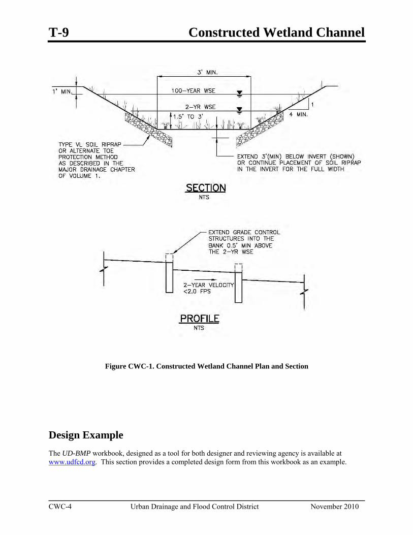
T-9 Constructed Wetland Channel
CWC-4 Urban Drainage and Flood Control District November 2010
Figure CWC-1. Constructed Wetland Channel Plan and Section
Design Example The UD-BMP workbook, designed as a tool for both designer and reviewing agency is available at www.udfcd.org. This section provides a completed design form from this workbook as an example.
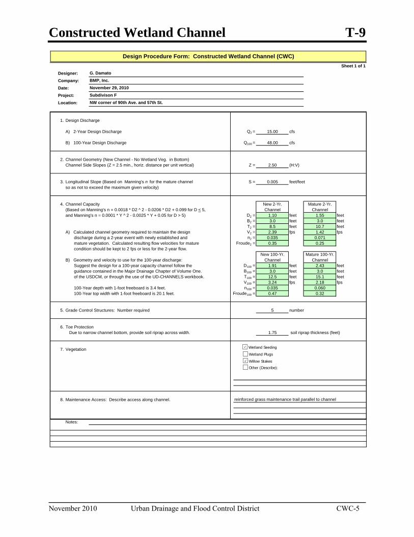
Constructed Wetland Channel T-9
November 2010 Urban Drainage and Flood Control District CWC-5
Sheet 1 of 1Designer:Company:Date:Project:Location:
1. Design Discharge
A) 2-Year Design Discharge Q2 = 15.00 cfs
B) 100-Year Design Discharge Q100 = 48.00 cfs
2. Channel Geometry (New Channel - No Wetland Veg. in Bottom)Channel Side Slopes (Z = 2.5 min., horiz. distance per unit vertical) Z = 2.50 (H:V)
3. Longitudinal Slope (Based on Manning's n for the mature channel S = 0.005 feet/feetso as not to exceed the maximum given velocity)
4. Channel Capacity New 2-Yr. Mature 2-Yr.(Based on Manning's n = 0.0018 * D2 ^ 2 - 0.0206 * D2 + 0.099 for D < 5, Channel Channeland Manning's n = 0.0001 * Y ^ 2 - 0.0025 * Y + 0.05 for D > 5) D2 = 1.10 feet 1.55 feet
B2 = 3.0 feet 3.0 feetT2 = 8.5 feet 10.7 feet
A) Calculated channel geometry required to maintain the design V2 = 2.39 fps 1.42 fps discharge during a 2-year event with newly established and n2 = 0.035 0.071 mature vegetation. Calculated resulting flow velocities for mature Froude2 = 0.35 0.25 condition should be kept to 2 fps or less for the 2-year flow.
New 100-Yr. Mature 100-Yr.B) Geometry and velocity to use for the 100-year discharge: Channel Channel Suggest the design for a 100-year capacity channel follow the D100 = 1.91 feet 2.43 feet guidance contained in the Major Drainage Chapter of Volume One. B100 = 3.0 feet 3.0 feet of the USDCM, or through the use of the UD-CHANNELS workbook. T100 = 12.5 feet 15.1 feet
V100 = 3.24 fps 2.18 fps 100-Year depth with 1-foot freeboard is 3.4 feet. n100 = 0.035 0.060 100-Year top width with 1-foot freeboard is 20.1 feet. Froude100 = 0.47 0.32
5. Grade Control Structures: Number required 5 number
6. Toe Protection Due to narrow channel bottom, provide soil riprap across width. 1.75 soil riprap thickness (feet)
7. Vegetation
8. Maintenance Access: Describe access along channel.
Notes:
reinforced grass maintenance trail parallel to channel
Design Procedure Form: Constructed Wetland Channel (CWC)
G. DamatoBMP, Inc.November 29, 2010Subdivison FNW corner of 90th Ave. and 57th St.
Wetland Seeding
Wetland Plugs
Willow Stakes
Other (Describe):

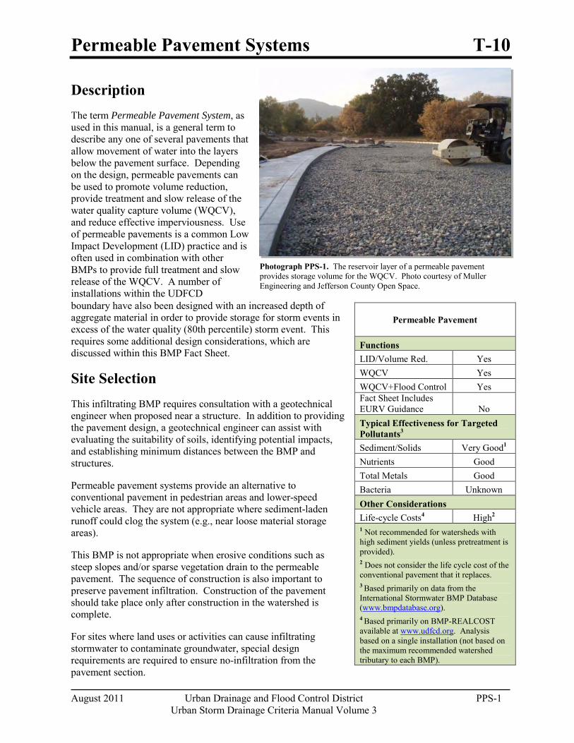
Permeable Pavement Systems T-10
August 2011 Urban Drainage and Flood Control District PPS-1 Urban Storm Drainage Criteria Manual Volume 3
Photograph PPS-1. The reservoir layer of a permeable pavement provides storage volume for the WQCV. Photo courtesy of Muller Engineering and Jefferson County Open Space.
Description The term Permeable Pavement System, as used in this manual, is a general term to describe any one of several pavements that allow movement of water into the layers below the pavement surface. Depending on the design, permeable pavements can be used to promote volume reduction, provide treatment and slow release of the water quality capture volume (WQCV), and reduce effective imperviousness. Use of permeable pavements is a common Low Impact Development (LID) practice and is often used in combination with other BMPs to provide full treatment and slow release of the WQCV. A number of installations within the UDFCD boundary have also been designed with an increased depth of aggregate material in order to provide storage for storm events in excess of the water quality (80th percentile) storm event. This requires some additional design considerations, which are discussed within this BMP Fact Sheet.
Site Selection This infiltrating BMP requires consultation with a geotechnical engineer when proposed near a structure. In addition to providing the pavement design, a geotechnical engineer can assist with evaluating the suitability of soils, identifying potential impacts, and establishing minimum distances between the BMP and structures.
Permeable pavement systems provide an alternative to conventional pavement in pedestrian areas and lower-speed vehicle areas. They are not appropriate where sediment-laden runoff could clog the system (e.g., near loose material storage areas).
This BMP is not appropriate when erosive conditions such as steep slopes and/or sparse vegetation drain to the permeable pavement. The sequence of construction is also important to preserve pavement infiltration. Construction of the pavement should take place only after construction in the watershed is complete.
For sites where land uses or activities can cause infiltrating stormwater to contaminate groundwater, special design requirements are required to ensure no-infiltration from the pavement section.
Permeable Pavement
Functions LID/Volume Red. Yes WQCV Yes WQCV+Flood Control Yes Fact Sheet Includes EURV Guidance No Typical Effectiveness for Targeted Pollutants3 Sediment/Solids Very Good1
Nutrients Good Total Metals Good Bacteria Unknown Other Considerations Life-cycle Costs4 High2
1 Not recommended for watersheds with high sediment yields (unless pretreatment is provided). 2 Does not consider the life cycle cost of the conventional pavement that it replaces. 3 Based primarily on data from the International Stormwater BMP Database (www.bmpdatabase.org). 4 Based primarily on BMP-REALCOST available at www.udfcd.org. Analysis based on a single installation (not based on the maximum recommended watershed tributary to each BMP).
T-10 Permeable Pavement Systems
PPS-2 Urban Drainage and Flood Control District August 2011
Urban Storm Drainage Criteria Manual Volume 3
Benefits Permeable pavement systems
provide water quality treatment in an area that serves more than one purpose. The depth of the pavement system can also be increased to provide flood control.
Permeable pavements can be used to reduce effective imperviousness or alleviate nuisance drainage problems.
Permeable pavements benefit tree health by providing additional air and water to nearby roots.
Permeable pavements are less likely to form ice on the surface than conventional pavements.
Some permeable pavements can be used to achieve LEED credits.
Limitations Additional design and
construction steps are required for placement of any ponding or infiltration area near or upgradient from a building foundation, particularly when potentially expansive soils exist. This is discussed in the design procedure section.
In developing or otherwise erosive watersheds, high sediment loads can clog the facility.
Permeable pavements and other BMPs used for infiltration that are located adjacent to buildings, hardscape or conventional pavement areas can adversely impact those structures if protection measures are not provided. Wetting of subgrade soil underlying those structures can cause the structures to settle or result in other moisture-related problems. Wetting of potentially expansive soils or bedrock can cause those materials to swell, resulting in structure movements. In general, a geotechnical engineer should evaluate the potential impact of the BMP on adjacent structures based on an evaluation of the subgrade soil, groundwater, and bedrock conditions at the site. In addition, the following minimum requirements should be met:
In locations where subgrade soils do not allow infiltration, the growing medium should be underlain by an underdrain system.
Where infiltration can adversely impact adjacent structures, the filter layer should be underlain by an underdrain system designed to divert water away from the structure.
In locations where potentially expansive soils or bedrock exist, placement of permeable pavement adjacent to structures and conventional pavement should only be considered if the BMP includes an underdrain designed to divert water away from the structure and is lined with an essentially impermeable geomembrane liner designed to restrict seepage.
Designing for Maintenance Recommended ongoing maintenance practices for all BMPs are provided in the BMP Maintenance chapter of this manual. During design and construction, the following should be considered to ensure ease of maintenance over the long-term:
Hold a pre-construction meeting to ensure that the contactor has an understanding of how the pavement is intended to function. Discuss the contractor’s proposed sequence of construction and look for activities that may require protection of the permeable pavement system.
Ensure that the permeable pavement is protected from construction activities following pavement construction (e.g., landscaping operations). This could include covering areas of the pavement, providing alternative construction vehicle access, and providing education to all parties working on-site.
Include an observation well to monitor the drain time of the pavement system over time. This will assist with determining the required maintenance needs. See Figure PPS-8.
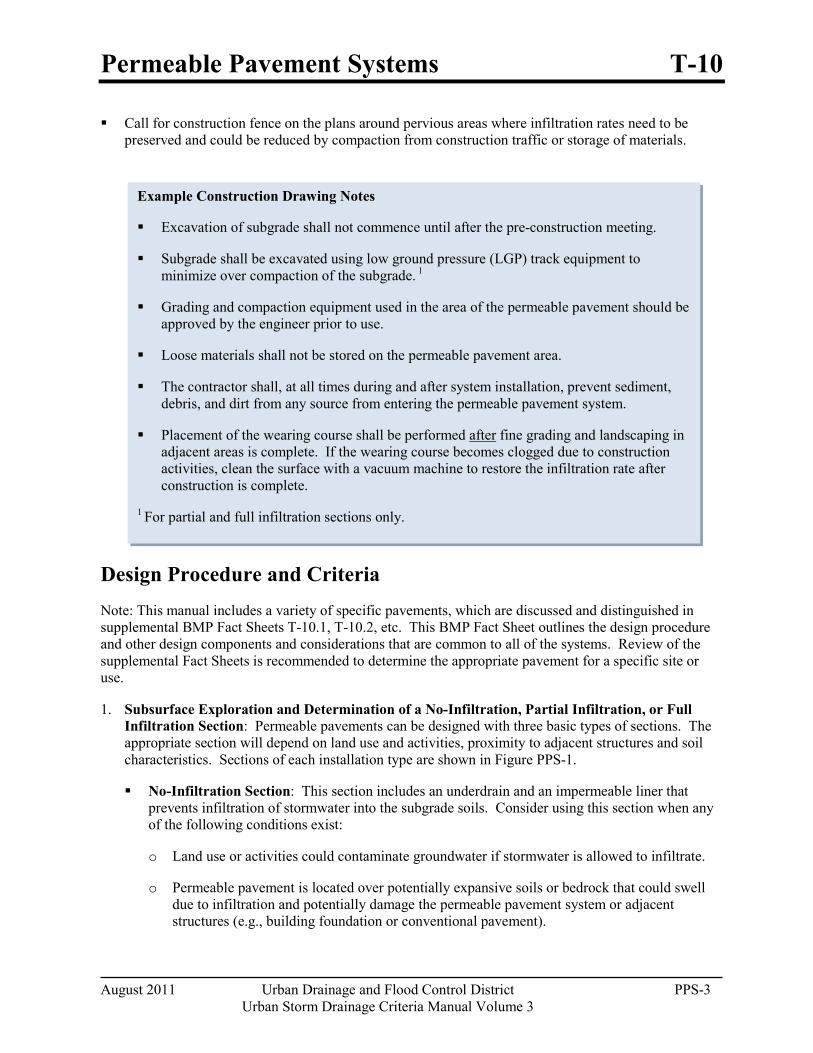
Permeable Pavement Systems T-10
August 2011 Urban Drainage and Flood Control District PPS-3 Urban Storm Drainage Criteria Manual Volume 3
Example Construction Drawing Notes
Excavation of subgrade shall not commence until after the pre-construction meeting.
Subgrade shall be excavated using low ground pressure (LGP) track equipment to minimize over compaction of the subgrade. 1
Grading and compaction equipment used in the area of the permeable pavement should be approved by the engineer prior to use.
Loose materials shall not be stored on the permeable pavement area.
The contractor shall, at all times during and after system installation, prevent sediment, debris, and dirt from any source from entering the permeable pavement system.
Placement of the wearing course shall be performed after fine grading and landscaping in adjacent areas is complete. If the wearing course becomes clogged due to construction activities, clean the surface with a vacuum machine to restore the infiltration rate after construction is complete.
1 For partial and full infiltration sections only.
Call for construction fence on the plans around pervious areas where infiltration rates need to be preserved and could be reduced by compaction from construction traffic or storage of materials.
Design Procedure and Criteria Note: This manual includes a variety of specific pavements, which are discussed and distinguished in supplemental BMP Fact Sheets T-10.1, T-10.2, etc. This BMP Fact Sheet outlines the design procedure and other design components and considerations that are common to all of the systems. Review of the supplemental Fact Sheets is recommended to determine the appropriate pavement for a specific site or use.
1. Subsurface Exploration and Determination of a No-Infiltration, Partial Infiltration, or Full Infiltration Section: Permeable pavements can be designed with three basic types of sections. The appropriate section will depend on land use and activities, proximity to adjacent structures and soil characteristics. Sections of each installation type are shown in Figure PPS-1.
No-Infiltration Section: This section includes an underdrain and an impermeable liner that prevents infiltration of stormwater into the subgrade soils. Consider using this section when any of the following conditions exist:
o Land use or activities could contaminate groundwater if stormwater is allowed to infiltrate.
o Permeable pavement is located over potentially expansive soils or bedrock that could swell due to infiltration and potentially damage the permeable pavement system or adjacent structures (e.g., building foundation or conventional pavement).
T-10 Permeable Pavement Systems
PPS-4 Urban Drainage and Flood Control District August 2011
Urban Storm Drainage Criteria Manual Volume 3
Partial Infiltration Section: This section does not include an impermeable liner, and allows some infiltration. Stormwater that does not infiltrate is collected and removed by an underdrain system.
Full Infiltration Section: This section is designed to infiltrate the water stored in the voids of the pavement into the subgrade below. UDFCD recommends a minimum infiltration rate of 2 times the rate needed to drain the WQCV over 12 hours.
Subsurface Exploration and Testing for all Sections: A geotechnical engineer should scope and perform a subsurface study. Typical geotechnical investigation needed to select and design the pavement system for handling anticipated traffic loads includes:
Prior to exploration review geologic and geotechnical information to assess near-surface soil, bedrock and groundwater conditions that may be encountered and anticipated ranges of infiltration rate for those materials. For example, if the site is located in a general area of known shallow, potentially expansive bedrock, a no-infiltration section will likely be required. It is also possible that this BMP may be infeasible, even with a liner, if there is a significant potential for damage to the pavement system or adjacent structures (e.g., areas of dipping bedrock).
Drill exploratory borings or exploratory pits to characterize subsurface conditions beneath the subgrade and develop requirements for subgrade preparation. Drill at least one boring or pit for every 40,000 ft2, and at least two borings or pits for sites between 10,000 ft2 and 40,000 ft2. The boring or pit should extend at least 5 feet below the bottom of the base, and at least 20 feet in areas where there is a potential of encountering potentially expansive soils or bedrock. More borings or pits at various depths may be required by the geotechnical engineer in areas where soil types may change, in low-lying areas where subsurface drainage may collect, or where the water table is likely within 8 feet below the planned bottom of the base or top of subgrade. Installation of temporary monitoring wells in selected borings or pits for monitoring groundwater levels over time should be considered where shallow groundwater that could impact the pavement system area is encountered.
Perform laboratory tests on samples obtained from the borings or pits to initially characterize the subgrade, evaluate the possible section type, and to assess subgrade conditions for supporting traffic loads. Consider the following tests: moisture content (ASTM D 2216); dry density (ASTM D 2936); Atterberg limits (ASTM D 4318); gradation (ASTM D 6913); swell-consolidation (ASTM D 4546); subgrade support testing (R-value, CBR or unconfined compressive strength); and hydraulic conductivity. A geotechnical engineer should determine the appropriate test method based on the soil type.
For sites where a full infiltration section may be feasible, perform on-site infiltration tests using a double-ring infiltrometer (ASTM D 3385). Perform at least one test for every 160,000 ft2 and at least two tests for sites between 40,000 ft2 and 160,000 ft2. The tests should be located near completed borings or pits so the test results and subsurface conditions encountered in the borings can be compared, and at least one test should be located near the boring or pit showing the most unfavorable infiltration condition. The test should be performed at the planned top of subgrade underlying the permeable pavement system, and that subgrade should be prepared similar to that required for support of the permeable pavement system.
Be aware that actual infiltration rates are highly variable dependent on soil type, density and moisture content and degree of compaction as well as other environmental and construction influences. Actual rates can differ an order of magnitude or more from those indicated by
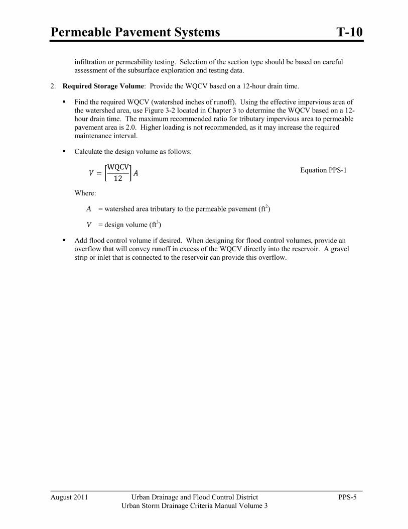
Permeable Pavement Systems T-10
August 2011 Urban Drainage and Flood Control District PPS-5 Urban Storm Drainage Criteria Manual Volume 3
infiltration or permeability testing. Selection of the section type should be based on careful assessment of the subsurface exploration and testing data.
2. Required Storage Volume: Provide the WQCV based on a 12-hour drain time.
Find the required WQCV (watershed inches of runoff). Using the effective impervious area of the watershed area, use Figure 3-2 located in Chapter 3 to determine the WQCV based on a 12-hour drain time. The maximum recommended ratio for tributary impervious area to permeable pavement area is 2.0. Higher loading is not recommended, as it may increase the required maintenance interval.
Calculate the design volume as follows:
𝑉 = �WQCV
12� 𝐴 Equation PPS-1
Where:
A = watershed area tributary to the permeable pavement (ft2)
V = design volume (ft3)
Add flood control volume if desired. When designing for flood control volumes, provide an overflow that will convey runoff in excess of the WQCV directly into the reservoir. A gravel strip or inlet that is connected to the reservoir can provide this overflow.
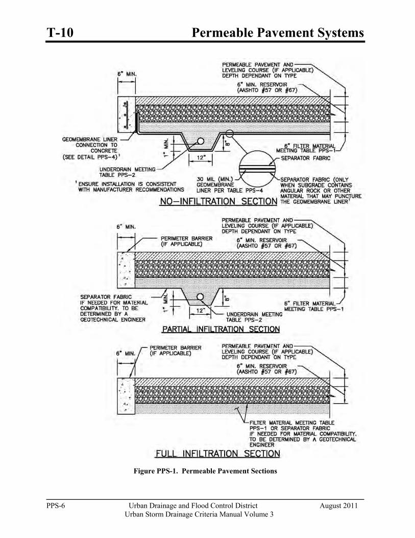
T-10 Permeable Pavement Systems
PPS-6 Urban Drainage and Flood Control District August 2011
Urban Storm Drainage Criteria Manual Volume 3
Figure PPS-1. Permeable Pavement Sections
Permeable Pavement Systems T-10
August 2011 Urban Drainage and Flood Control District PPS-7 Urban Storm Drainage Criteria Manual Volume 3
3. Depth of Reservoir: The minimum recommended depth of AASHTO No. 57 or No. 67 coarse aggregate is 6 inches. Additional depth may be required to support anticipated loads or to provide additional storage, (i.e., for flood control). This material should have all fractured faces. UDFCD recommends that void storage be calculated only for the reservoir, assuming the aggregate filter layer is saturated. With the exception of porous gravel pavement, use a porosity of 40% or less for both No. 57 and No. 67 coarse aggregate. For porous gravel pavement use a porosity of 30% or less to account for reduced volume due to sediment. Porous gravel pavements typically allow greater sediment volumes to enter the pavement. See Figures PPS-2 and PPS-3 for alternative pavement profiles. Calculate available storage using equation PPS-2 for a flat subgrade installation, and PPS-3 for a sloped subgrade installation. These equations allow for one inch of freeboard. Flat installations are preferred as the design spreads infiltration evenly over the subgrade. For sloped subgrade installations, the increased storage depth located upstream of the lateral barrier (see step 7) can increase lateral movement (parallel to the flow barrier) of water into areas adjacent to the pavement section.
When used for vehicular traffic, a pavement design should be performed by a qualified engineer experienced in the design of permeable pavements and conventional asphalt and concrete pavements. The permeable pavement should be adequately supported by a properly prepared subgrade, properly compacted filter material and reservoir material.
Reservoir aggregate should have all fractured faces. Place the aggregate in 6-inch (maximum) lifts, compacting each lift by using a 10-ton, or heavier, vibrating steel drum roller. Make at least four passes with the roller, with the initial passes made while vibrating the roller and the final one to two passes without vibration.
For flat or stepped installations (0% slope at the reservoir/subgrade interface):
𝑉 = 𝑃 �𝐷 − 1
12� 𝐴
Equation PPS-2
Where:
V = volume available in the reservoir (ft3)
P = porosity, ≤0.30 for porous gravel, ≤0.4 for all other pavements using AASHTO No. 57 or No. 67 coarse aggregate in the reservoir
D = depth of reservoir (in)
A = area of the permeable pavement (ft2)
T-10 Permeable Pavement Systems
PPS-8 Urban Drainage and Flood Control District August 2011
Urban Storm Drainage Criteria Manual Volume 3
Figure PPS-2. Permeable Pavement Profile, Stepped Installation
For sloped installations (slope of the reservoir/subgrade interface > 0%):
𝑉 = 𝑃 �𝐷 − 6𝑠𝐿 − 1
12 � 𝐴 Equation PPS-3a
While:
𝐿 < 2 WQCV𝑠𝐴𝑃
Equation PPS-3b
Where:
V = volume available in the reservoir (ft3)
P = porosity, ≤0.30 for porous gravel, ≤0.4 for all other pavements using AASHTO No. 57 or No. 67 coarse aggregate in the reservoir
s = slope of the reservoir/subgrade interface (ft/ft)
D = depth of the reservoir (in)
L = length between lateral flow barriers (see step 4) (ft)
A = area of the permeable pavement (ft2)
WQCV = water quality capture volume (ft3)
Permeable Pavement Systems T-10
August 2011 Urban Drainage and Flood Control District PPS-9 Urban Storm Drainage Criteria Manual Volume 3
Figure PPS-3. Permeable Pavement Profile, Sloped Installation.
4. Lateral Flow Barriers: Construct lateral flow cutoff barriers using concrete walls or a 30 mil (minimum) PVC geomembrane. Lateral flow barriers should be placed parallel to contours (normal to flow). This will preserve the volume available for storage and ensure that stormwater will not resurface, washing out infill material. See Figure PPS-6 and Table PPS-4 when using a PVC geomembrane for this purpose. Also include a separator fabric, per Table PPS-3, between the geomembrane and all aggregate materials. Lateral flow barriers should be installed in all permeable pavement installations that have a reservoir/subgrade interface greater than 0%. Lateral flow barriers should be spaced, as necessary, to satisfy equations PPS-3a and PPS-3b. One exception is reinforced grass pavement. Infill washout is not a concern with reinforced grass pavement.
5. Perimeter Barrier: For all no-infiltration sections, provide a reinforced concrete barrier on all sides of the pavement system. Perimeter barriers may also be recommended for other permeable pavement installations depending on the type or use of the pavement. For PICP and concrete grid pavement, a barrier is required to restrain movement of the pavers or grids. Precast, cast-in-place concrete or cut stone barriers are required for commercial vehicular areas. For residential use and commercial pedestrian use, a metal or plastic edge spiked with 3/8-inch-diameter, 10-inch-long nails provides a less expensive alternative for edge restraint.
For all pavements, consider the section beyond the permeable pavement when evaluating the perimeter design. The perimeter barrier helps force water into the underdrain and reduces lateral flow of water. Lateral flow can negatively impact the adjacent conventional pavement section, structure, or embankment (especially when the subgrade is sloped). Also consider material separation. Consider construction of the interface between the permeable pavement and the adjacent materials and how the design will prevent adjacent materials from entering the permeable pavement section. Depending on the soils, depth of pavement, and other factors, this may be achieved with fabric or may require a more formalized barrier.
When a permeable pavement section is adjacent to conventional pavement, a vertical liner may be required to separate the reservoir of the permeable pavement system from dense-graded aggregates and soils within the conventional pavement. An impermeable linear can be used to provide this vertical barrier and separate these two pavement systems.
No-Infiltration Section: For this type of section, the perimeter barrier also serves to attach the impermeable membrane. The membrane should extend up to the top of the filter layer and be firmly
T-10 Permeable Pavement Systems
PPS-10 Urban Drainage and Flood Control District August 2011
Urban Storm Drainage Criteria Manual Volume 3
Design Opportunity
Pollutant removal occurs in the filter material layer of the section. The basic permeable pavement section may be considered with other wearing courses to provide water quality as long as:
the filter layer is included in the section,
the wearing course provides adequate permeability, and
the new section does not introduce new pollutants to the runoff.
attached to the concrete perimeter barrier using batten bars to provide a leak-proof seal. A nitrile-based vinyl adhesive can be used when the need for an impermeable liner is less critical. See Figures PPS-4 and PPS-5 for installation details. For ease of construction, including the placement of geotextiles, it is suggested that the barrier extend to the bottom of the filter layer.
Partial and Full Infiltration Section:
6. Filter Material and Underdrain System: An aggregate filter layer and underdrain are required for all partial and no-infiltration sections. Without this filter layer, the section will not provide adequate pollutant removal. This is based on research performed by UDFCD monitoring sites with and without this component. A filter or separator fabric may also be necessary under the reservoir in a full infiltration section if the subgrade is not filter compatible with the reservoir material such that finer subgrade soils could enter into the voids of the reservoir.
The perimeter barrier for these sections also restricts lateral flow to adjacent areas of conventional pavement or other structures where excessive moisture and/or hydrostatic pressure can cause damage. When this is of particular concern, the perimeter barrier should be extended to a depth 12 inches or more below the underdrain. Otherwise, extend the barrier to the bottom of the filter layer.
In previous versions of the USDCM, UDFCD recommended that the underdrain be placed in an aggregate drainage layer and that a geotextile separator fabric be placed between this drainage and the filter layer. This version of the USDCM replaces that fabric, which could more easily plug or be damaged during construction, with aggregate filter material that is filter-compatible with the reservoir, and a drainpipe with perforations that are filter-compatible with the filter material. This eliminates the need for a separator fabric between the reservoir and the underdrain layer. The filter material provided below should only be used with the underdrain pipe specified within this section.
The underdrain should be placed below a 6-inch-thick layer of CDOT Class C filter material meeting the gradation in Table PPS-1. Extend the filter material around and below the underdrain as shown in Figure PPS-1.
Provide clean-outs to allow inspection (by camera) of the drainpipe system during and after construction to ensure that the pipe was not crushed or disconnected during construction and to allow for maintenance of the underdrain.
Use of Class C Filter material with a slotted PVC pipe that meets the slot dimensions provided in Table PPS-2 will eliminate the need for an aggregate layer wrapped geotextile fabric.
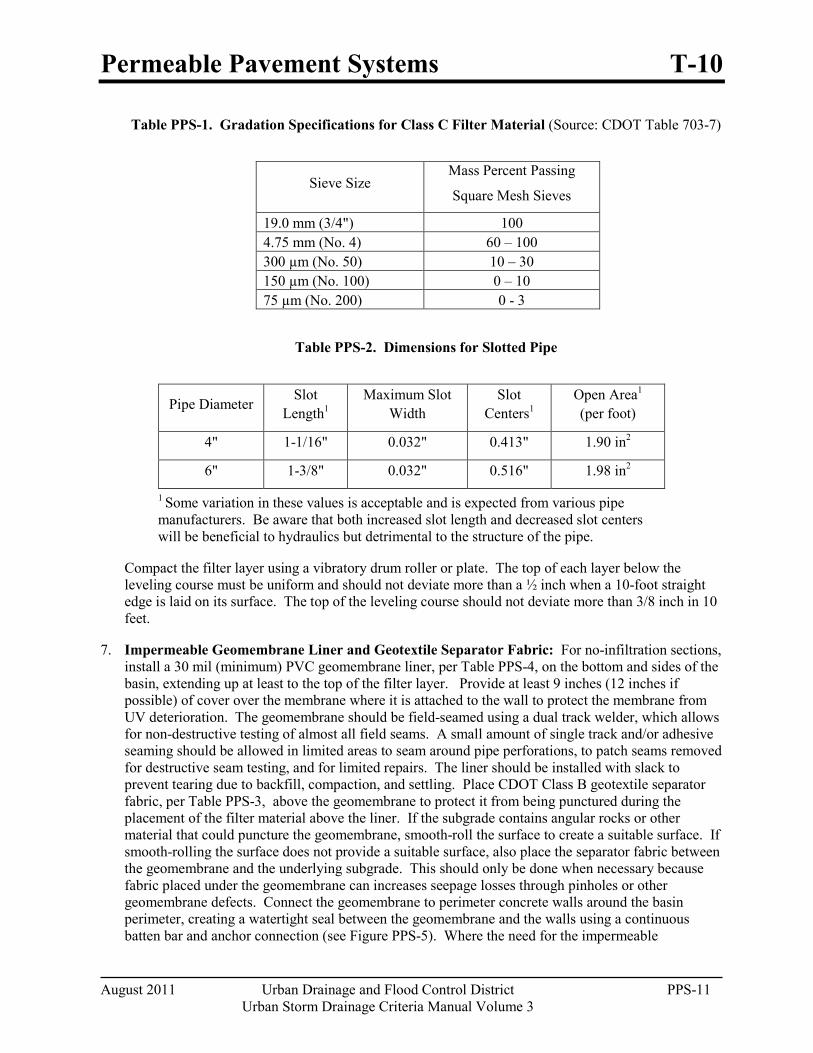
Permeable Pavement Systems T-10
August 2011 Urban Drainage and Flood Control District PPS-11 Urban Storm Drainage Criteria Manual Volume 3
Table PPS-1. Gradation Specifications for Class C Filter Material (Source: CDOT Table 703-7)
Sieve Size Mass Percent Passing
Square Mesh Sieves
19.0 mm (3/4") 100 4.75 mm (No. 4) 60 – 100 300 µm (No. 50) 10 – 30 150 µm (No. 100) 0 – 10 75 µm (No. 200) 0 - 3
Table PPS-2. Dimensions for Slotted Pipe
Pipe Diameter Slot Length1
Maximum Slot Width
Slot Centers1
Open Area1 (per foot)
4" 1-1/16" 0.032" 0.413" 1.90 in2
6" 1-3/8" 0.032" 0.516" 1.98 in2
1 Some variation in these values is acceptable and is expected from various pipe manufacturers. Be aware that both increased slot length and decreased slot centers will be beneficial to hydraulics but detrimental to the structure of the pipe.
Compact the filter layer using a vibratory drum roller or plate. The top of each layer below the leveling course must be uniform and should not deviate more than a ½ inch when a 10-foot straight edge is laid on its surface. The top of the leveling course should not deviate more than 3/8 inch in 10 feet.
7. Impermeable Geomembrane Liner and Geotextile Separator Fabric: For no-infiltration sections, install a 30 mil (minimum) PVC geomembrane liner, per Table PPS-4, on the bottom and sides of the basin, extending up at least to the top of the filter layer. Provide at least 9 inches (12 inches if possible) of cover over the membrane where it is attached to the wall to protect the membrane from UV deterioration. The geomembrane should be field-seamed using a dual track welder, which allows for non-destructive testing of almost all field seams. A small amount of single track and/or adhesive seaming should be allowed in limited areas to seam around pipe perforations, to patch seams removed for destructive seam testing, and for limited repairs. The liner should be installed with slack to prevent tearing due to backfill, compaction, and settling. Place CDOT Class B geotextile separator fabric, per Table PPS-3, above the geomembrane to protect it from being punctured during the placement of the filter material above the liner. If the subgrade contains angular rocks or other material that could puncture the geomembrane, smooth-roll the surface to create a suitable surface. If smooth-rolling the surface does not provide a suitable surface, also place the separator fabric between the geomembrane and the underlying subgrade. This should only be done when necessary because fabric placed under the geomembrane can increases seepage losses through pinholes or other geomembrane defects. Connect the geomembrane to perimeter concrete walls around the basin perimeter, creating a watertight seal between the geomembrane and the walls using a continuous batten bar and anchor connection (see Figure PPS-5). Where the need for the impermeable
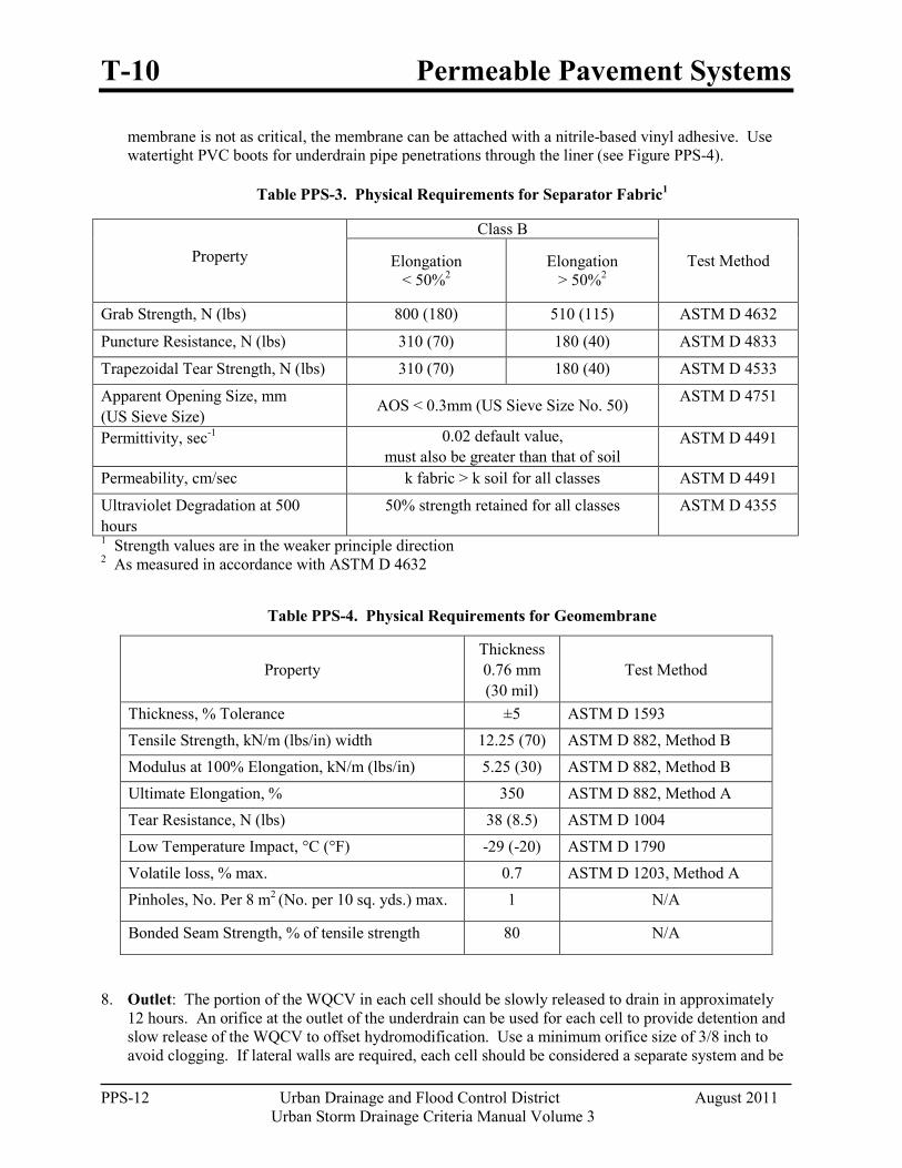
T-10 Permeable Pavement Systems
PPS-12 Urban Drainage and Flood Control District August 2011
Urban Storm Drainage Criteria Manual Volume 3
membrane is not as critical, the membrane can be attached with a nitrile-based vinyl adhesive. Use watertight PVC boots for underdrain pipe penetrations through the liner (see Figure PPS-4).
Table PPS-3. Physical Requirements for Separator Fabric1
Table PPS-4. Physical Requirements for Geomembrane
Property Thickness 0.76 mm (30 mil)
Test Method
Thickness, % Tolerance ±5 ASTM D 1593 Tensile Strength, kN/m (lbs/in) width 12.25 (70) ASTM D 882, Method B Modulus at 100% Elongation, kN/m (lbs/in) 5.25 (30) ASTM D 882, Method B Ultimate Elongation, % 350 ASTM D 882, Method A Tear Resistance, N (lbs) 38 (8.5) ASTM D 1004 Low Temperature Impact, °C (°F) -29 (-20) ASTM D 1790 Volatile loss, % max. 0.7 ASTM D 1203, Method A Pinholes, No. Per 8 m2 (No. per 10 sq. yds.) max. 1 N/A
Bonded Seam Strength, % of tensile strength 80 N/A
8. Outlet: The portion of the WQCV in each cell should be slowly released to drain in approximately 12 hours. An orifice at the outlet of the underdrain can be used for each cell to provide detention and slow release of the WQCV to offset hydromodification. Use a minimum orifice size of 3/8 inch to avoid clogging. If lateral walls are required, each cell should be considered a separate system and be
Property
Class B
Test Method Elongation < 50%2
Elongation > 50%2
Grab Strength, N (lbs) 800 (180) 510 (115) ASTM D 4632
Puncture Resistance, N (lbs) 310 (70) 180 (40) ASTM D 4833
Trapezoidal Tear Strength, N (lbs) 310 (70) 180 (40) ASTM D 4533
Apparent Opening Size, mm (US Sieve Size)
AOS < 0.3mm (US Sieve Size No. 50) ASTM D 4751
Permittivity, sec-1 0.02 default value, must also be greater than that of soil
ASTM D 4491
Permeability, cm/sec k fabric > k soil for all classes ASTM D 4491
Ultraviolet Degradation at 500 hours
50% strength retained for all classes ASTM D 4355
1 Strength values are in the weaker principle direction 2 As measured in accordance with ASTM D 4632
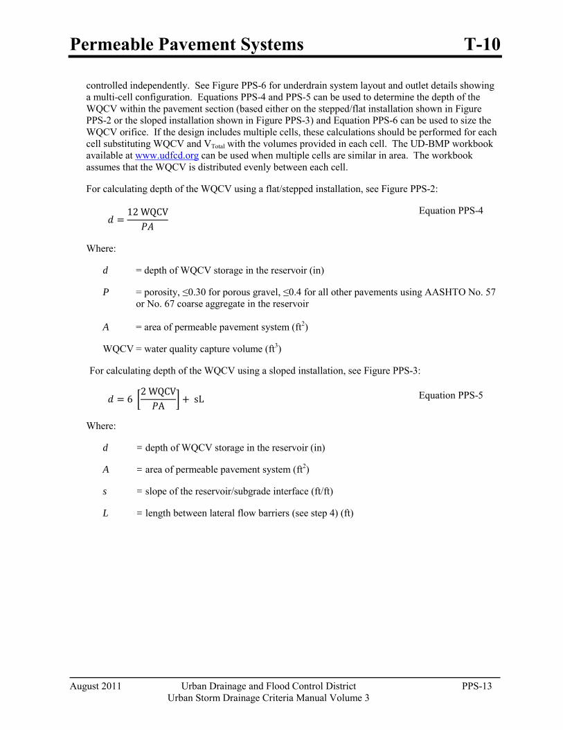
Permeable Pavement Systems T-10
August 2011 Urban Drainage and Flood Control District PPS-13 Urban Storm Drainage Criteria Manual Volume 3
controlled independently. See Figure PPS-6 for underdrain system layout and outlet details showing a multi-cell configuration. Equations PPS-4 and PPS-5 can be used to determine the depth of the WQCV within the pavement section (based either on the stepped/flat installation shown in Figure PPS-2 or the sloped installation shown in Figure PPS-3) and Equation PPS-6 can be used to size the WQCV orifice. If the design includes multiple cells, these calculations should be performed for each cell substituting WQCV and VTotal with the volumes provided in each cell. The UD-BMP workbook available at www.udfcd.org can be used when multiple cells are similar in area. The workbook assumes that the WQCV is distributed evenly between each cell.
For calculating depth of the WQCV using a flat/stepped installation, see Figure PPS-2:
𝑑 =12 WQCV
𝑃𝐴
Equation PPS-4
Where:
d = depth of WQCV storage in the reservoir (in)
P = porosity, ≤0.30 for porous gravel, ≤0.4 for all other pavements using AASHTO No. 57 or No. 67 coarse aggregate in the reservoir
A = area of permeable pavement system (ft2)
WQCV = water quality capture volume (ft3)
For calculating depth of the WQCV using a sloped installation, see Figure PPS-3:
𝑑 = 6 �2 WQCV𝑃A �+ sL Equation PPS-5
Where:
d = depth of WQCV storage in the reservoir (in)
A = area of permeable pavement system (ft2)
s = slope of the reservoir/subgrade interface (ft/ft)
L = length between lateral flow barriers (see step 4) (ft)

T-10 Permeable Pavement Systems
PPS-14 Urban Drainage and Flood Control District August 2011
Urban Storm Drainage Criteria Manual Volume 3
For calculating the diameter of the orifice for a 12-hour drain time (Use a minimum orifice size of 3/8 inch to avoid clogging.):
𝐷12 hour drain time = �𝑉
1414 𝑦0.41 Equation PPS-6
Where:
D = diameter of the orifice to drain a volume in 12 hours (in)
Y = distance from the lowest elevation of the storage volume (i.e. the bottom of the reservoir) to the center of the orifice (ft)
V = volume (WQCV or the portion of the WQCV in the cell) to drain in 12 hours (ft3)
Additional Design Considerations
Subgrade Preparation
Partial Infiltration and Full Infiltration Installations
For sites, or portions thereof, requiring excavation to the final subgrade level, compaction of the subgrade may not be needed, provided that loose materials are removed from the excavation, and a firm subgrade is provided for the support of the pavement system. A geotechnical engineer should observe the prepared subgrade. Local soft areas should be excavated and replaced with properly compacted fill. As an alternative to excavating and replacing material, stabilization consisting of geogrid and compacted granular fill material can be used to bridge over the soft area. Fill material should be free draining and have a hydraulic conductivity significantly higher than the subgrade soil. Fill is typically compacted to a level equivalent to 95% Standard Proctor compaction (ASTM D 698). The designer should specify the level of compaction required to support the pavement system.
: The subgrade should be stripped of topsoil or other organics and either excavated or filled to the final subgrade level. Unnecessary compaction or over-compaction will reduce the subgrade infiltration rate. However, a soft or loosely compacted subgrade will settle, adversely impacting the performance of the entire permeable pavement system. The following recommendations for subgrade preparation are intended to strike a balance between those competing objectives:
For sites (or portions thereof), requiring placement of fill above the existing subgrade to reach the final subgrade level, the fill should be properly compacted. Specify the hydraulic conductivity for the material that is to be placed. This should be at least one order of magnitude higher than the native material. If the type or level of compaction of fill material available for construction is different than that considered in design, additional testing should be performed to substantiate that the design infiltration rate can be met. However, additional infiltrometer testing may not be necessary, provided that it can be demonstrated by other means that the compacted fill material is more permeable than that considered for design.
Low ground pressure (LGP) track equipment should be used within the pavement area to limit over-compacting the subgrade. Wheel loads should not be allowed.
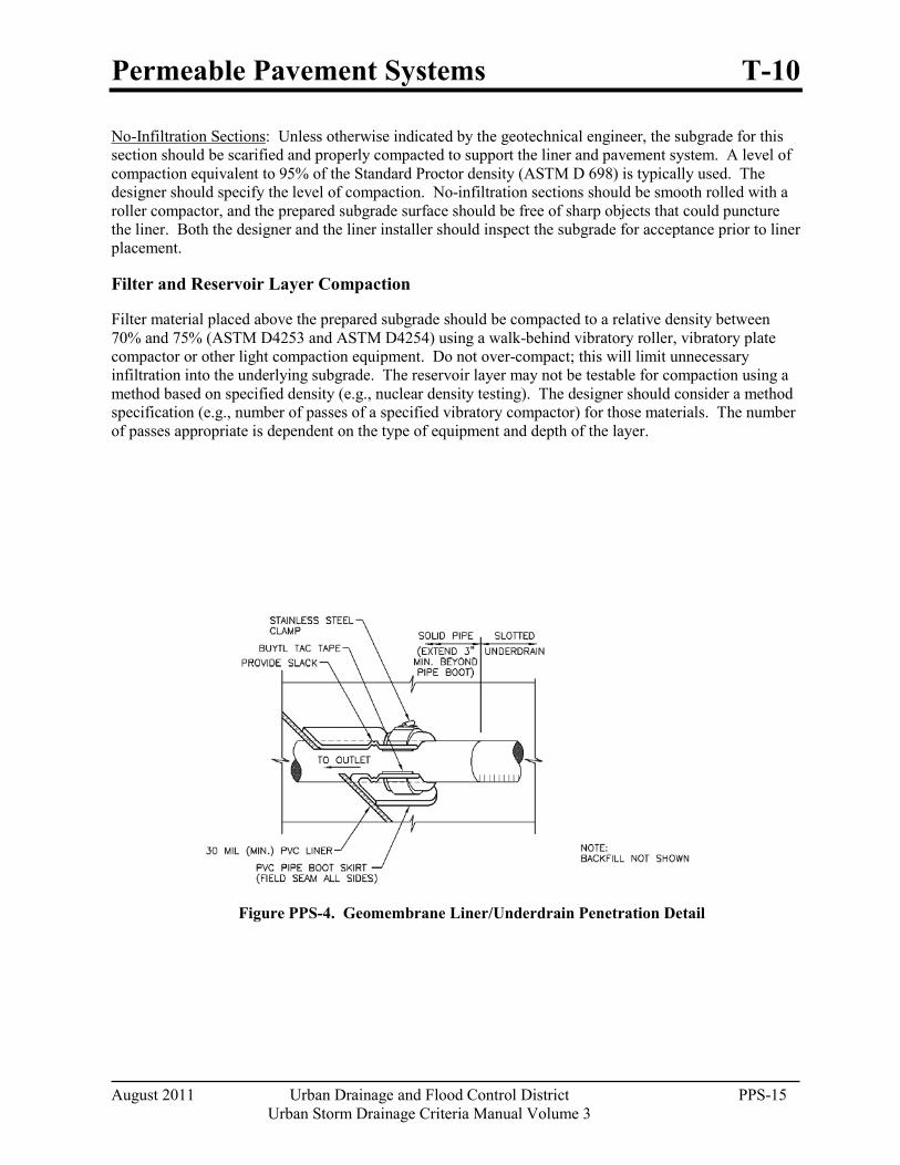
Permeable Pavement Systems T-10
August 2011 Urban Drainage and Flood Control District PPS-15 Urban Storm Drainage Criteria Manual Volume 3
No-Infiltration Sections
Filter and Reservoir Layer Compaction
: Unless otherwise indicated by the geotechnical engineer, the subgrade for this section should be scarified and properly compacted to support the liner and pavement system. A level of compaction equivalent to 95% of the Standard Proctor density (ASTM D 698) is typically used. The designer should specify the level of compaction. No-infiltration sections should be smooth rolled with a roller compactor, and the prepared subgrade surface should be free of sharp objects that could puncture the liner. Both the designer and the liner installer should inspect the subgrade for acceptance prior to liner placement.
Filter material placed above the prepared subgrade should be compacted to a relative density between 70% and 75% (ASTM D4253 and ASTM D4254) using a walk-behind vibratory roller, vibratory plate compactor or other light compaction equipment. Do not over-compact; this will limit unnecessary infiltration into the underlying subgrade. The reservoir layer may not be testable for compaction using a method based on specified density (e.g., nuclear density testing). The designer should consider a method specification (e.g., number of passes of a specified vibratory compactor) for those materials. The number of passes appropriate is dependent on the type of equipment and depth of the layer.
Figure PPS-4. Geomembrane Liner/Underdrain Penetration Detail
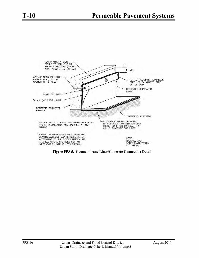
T-10 Permeable Pavement Systems
PPS-16 Urban Drainage and Flood Control District August 2011
Urban Storm Drainage Criteria Manual Volume 3
Figure PPS-5. Geomembrane Liner/Concrete Connection Detail
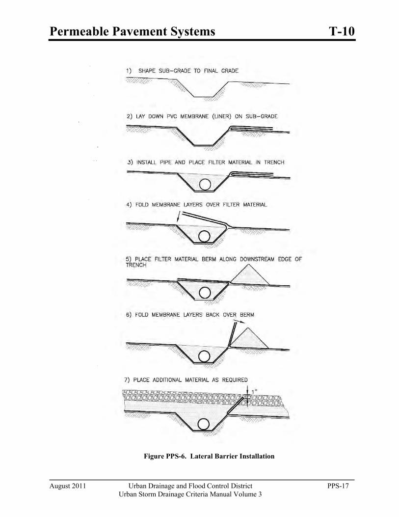
Permeable Pavement Systems T-10
August 2011 Urban Drainage and Flood Control District PPS-17 Urban Storm Drainage Criteria Manual Volume 3
Figure PPS-6. Lateral Barrier Installation
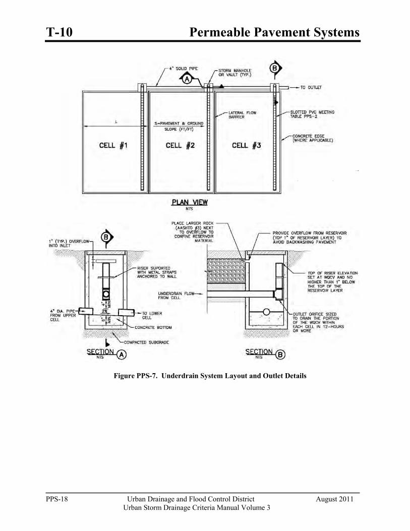
T-10 Permeable Pavement Systems
PPS-18 Urban Drainage and Flood Control District August 2011
Urban Storm Drainage Criteria Manual Volume 3
Figure PPS-7. Underdrain System Layout and Outlet Details
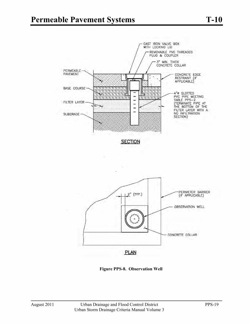
Permeable Pavement Systems T-10
August 2011 Urban Drainage and Flood Control District PPS-19 Urban Storm Drainage Criteria Manual Volume 3
Figure PPS-8. Observation Well

T-10 Permeable Pavement Systems
PPS-20 Urban Drainage and Flood Control District August 2011
Urban Storm Drainage Criteria Manual Volume 3
Construction Considerations Proper construction of permeable pavement systems requires measures to preserve natural infiltration rates (for full and partial infiltration sections) prior to placement of the pavement, as well as measures to protect the system from the time that pavement construction is complete to the end of site construction. Supplemental Fact Sheets on the specific pavements provide additional construction considerations. The following recommendations apply to all permeable pavement systems:
When using an impermeable liner, ensure enough slack in the liner to allow for backfill, compaction, and settling without tearing the liner.
Provide necessary quality assurance and quality control (QA/QC) when constructing an impermeable geomembrane liner system, including, but not limited to fabrication testing, destructive and non-destructive testing of field seams, observation of geomembrane material for tears or other defects, and air lace testing for leaks in all field seams and penetrations. QA/QC should be overseen by a professional engineer. Consider requiring field reports or other documentation from the engineer.
Keep mud and sediment-laden runoff away from the pavement area.
Temporarily divert runoff or install sediment control measures as necessary to reduce the amount of sediment run-on to the pavement.
Cover surfaces with a heavy impermeable membrane when construction activities threaten to deposit sediment onto the pavement area.
Design Example The UD-BMP workbook, designed as a tool for both designer and reviewing agency is available at www.udfcd.org. This section provides a completed design form from this workbook as an example.
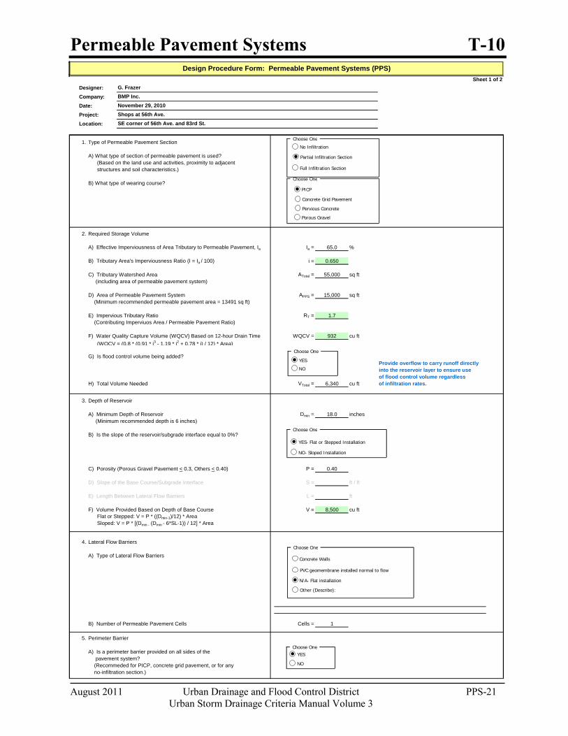
Permeable Pavement Systems T-10
August 2011 Urban Drainage and Flood Control District PPS-21 Urban Storm Drainage Criteria Manual Volume 3
Sheet 1 of 2Designer:Company:Date:Project:Location:
1. Type of Permeable Pavement Section
A) What type of section of permeable pavement is used? (Based on the land use and activities, proximity to adjacent structures and soil characteristics.)
B) What type of wearing course?
2. Required Storage Volume
A) Effective Imperviousness of Area Tributary to Permeable Pavement, Ia Ia = 65.0 %
B) Tributary Area's Imperviousness Ratio (I = Ia / 100) i = 0.650
C) Tributary Watershed Area ATotal = 55,000 sq ft (including area of permeable pavement system)
D) Area of Permeable Pavement System APPS = 15,000 sq ft (Minimum recommended permeable pavement area = 13491 sq ft)
E) Impervious Tributary Ratio RT = 1.7 (Contributing Imperviuos Area / Permeable Pavement Ratio)
F) Water Quality Capture Volume (WQCV) Based on 12-hour Drain Time WQCV = 932 cu ft (WQCV = (0.8 * (0.91 * i3 - 1.19 * i2 + 0.78 * i) / 12) * Area)
G) Is flood control volume being added?Provide overflow to carry runoff directlyinto the reservoir layer to ensure useof flood control volume regardless
H) Total Volume Needed VTotal = 6,340 cu ft of infiltration rates.
3. Depth of Reservoir
A) Minimum Depth of Reservoir Dmin = 18.0 inches (Minimum recommended depth is 6 inches)
B) Is the slope of the reservoir/subgrade interface equal to 0%?
C) Porosity (Porous Gravel Pavement < 0.3, Others < 0.40) P = 0.40
D) Slope of the Base Course/Subgrade Interface S = ft / ft
E) Length Between Lateral Flow Barriers L = ft
F) Volume Provided Based on Depth of Base Course V = 8,500 cu ft Flat or Stepped: V = P * ((Dmin-1)/12) * Area Sloped: V = P * [(Dmin - (Dmin - 6*SL-1)) / 12] * Area
4. Lateral Flow Barriers
A) Type of Lateral Flow Barriers
B) Number of Permeable Pavement Cells Cells = 1
5. Perimeter Barrier
A) Is a perimeter barrier provided on all sides of the pavement system? (Recommeded for PICP, concrete grid pavement, or for any no-infiltration section.)
Shops at 56th Ave.SE corner of 56th Ave. and 83rd St.
Design Procedure Form: Permeable Pavement Systems (PPS)
G. FrazerBMP Inc.November 29, 2010
Choose One
No Infiltration
Partial Infiltration Section
Full Infiltration Section
Choose One
YES
NO
Choose One
YES- Flat or Stepped Installation
NO- Sloped Installation
Choose One
Concrete Walls
PVC geomembrane installed normal to flow
N/A- Flat installation
Other (Describe):
Choose OneYES
NO
Choose One
PICP
Concrete Grid Pavement
Pervious Concrete
Porous Gravel
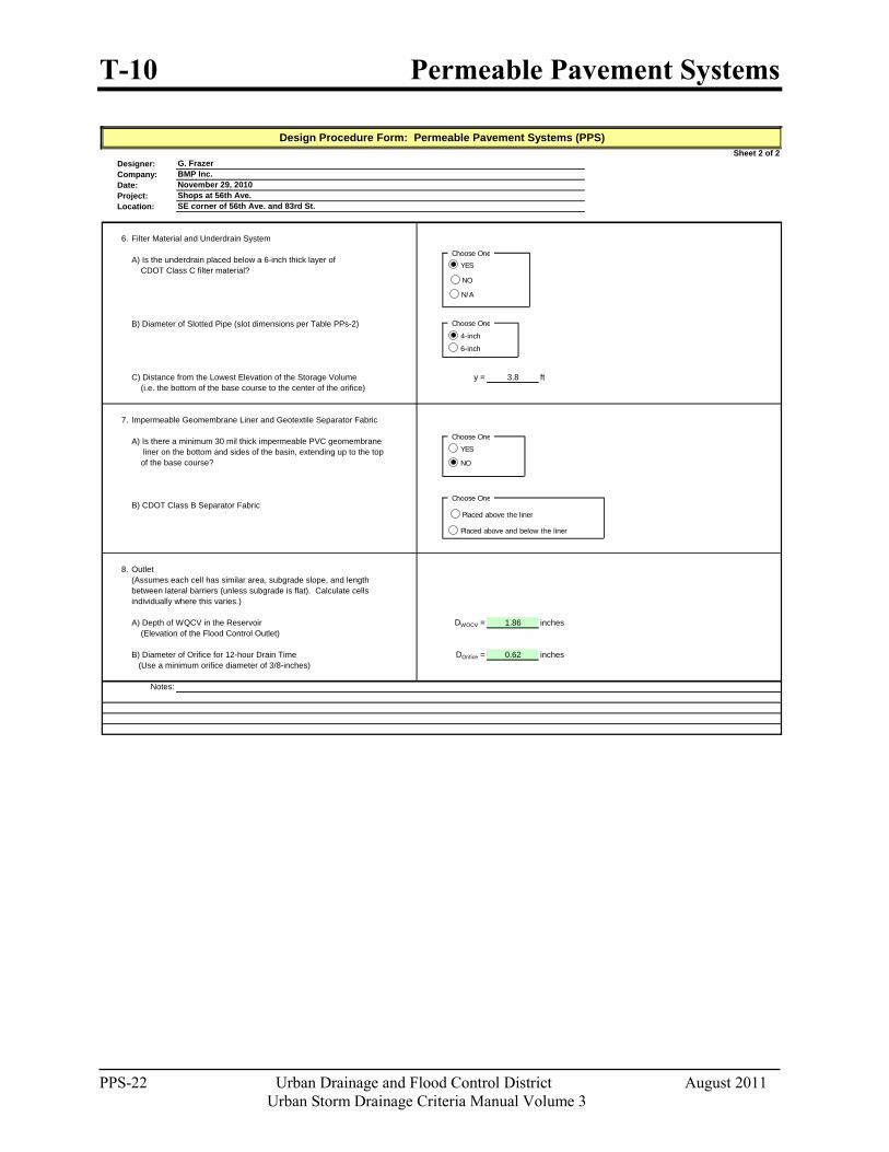
T-10 Permeable Pavement Systems
PPS-22 Urban Drainage and Flood Control District August 2011
Urban Storm Drainage Criteria Manual Volume 3
Sheet 2 of 2Designer:Company:Date:Project:Location:
6. Filter Material and Underdrain System
A) Is the underdrain placed below a 6-inch thick layer of CDOT Class C filter material?
B) Diameter of Slotted Pipe (slot dimensions per Table PPs-2)
C) Distance from the Lowest Elevation of the Storage Volume y = 3.8 ft (i.e. the bottom of the base course to the center of the orifice)
7. Impermeable Geomembrane Liner and Geotextile Separator Fabric
A) Is there a minimum 30 mil thick impermeable PVC geomembrane liner on the bottom and sides of the basin, extending up to the top of the base course?
B) CDOT Class B Separator Fabric
8. Outlet (Assumes each cell has similar area, subgrade slope, and length between lateral barriers (unless subgrade is flat). Calculate cellsindividually where this varies.)
A) Depth of WQCV in the Reservoir DWQCV = 1.86 inches (Elevation of the Flood Control Outlet)
B) Diameter of Orifice for 12-hour Drain Time DOrifice = 0.62 inches (Use a minimum orifice diameter of 3/8-inches)
Notes:
Shops at 56th Ave.
Design Procedure Form: Permeable Pavement Systems (PPS)
G. FrazerBMP Inc.November 29, 2010
SE corner of 56th Ave. and 83rd St.
Choose One
YES
NO
Choose One
4-inch
6-inch
Choose One
Choose One
YES
NO
Placed above the liner
Placed above and below the liner
N/A
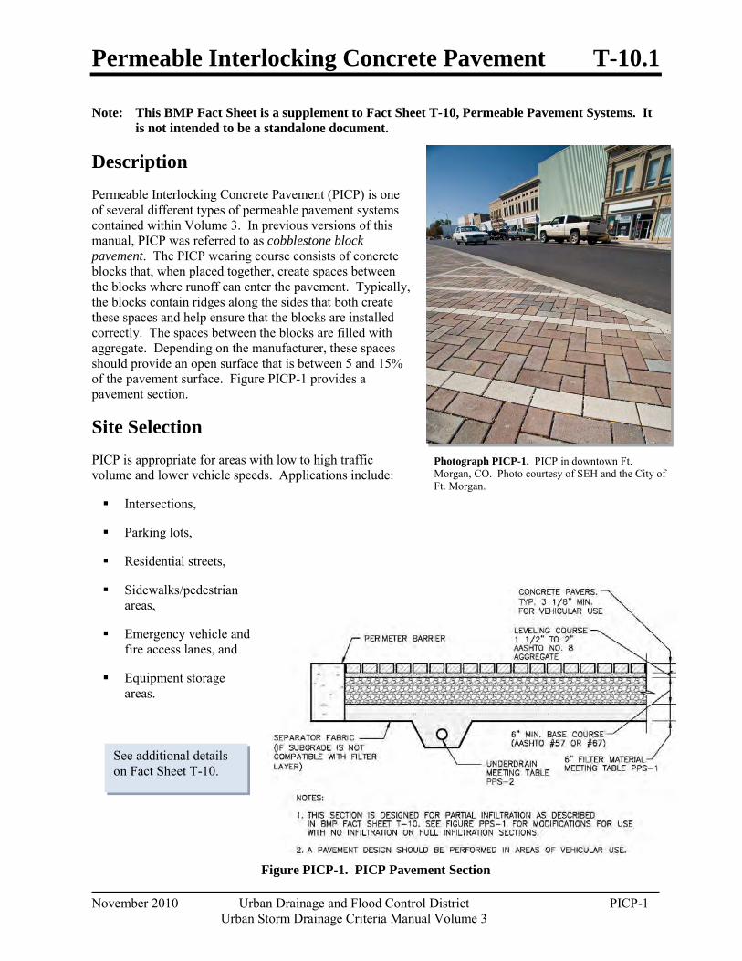
Permeable Interlocking Concrete Pavement T-10.1
November 2010 Urban Drainage and Flood Control District PICP-1 Urban Storm Drainage Criteria Manual Volume 3
Note: This BMP Fact Sheet is a supplement to Fact Sheet T-10, Permeable Pavement Systems. It is not intended to be a standalone document.
Description Permeable Interlocking Concrete Pavement (PICP) is one of several different types of permeable pavement systems contained within Volume 3. In previous versions of this manual, PICP was referred to as cobblestone block pavement. The PICP wearing course consists of concrete blocks that, when placed together, create spaces between the blocks where runoff can enter the pavement. Typically, the blocks contain ridges along the sides that both create these spaces and help ensure that the blocks are installed correctly. The spaces between the blocks are filled with aggregate. Depending on the manufacturer, these spaces should provide an open surface that is between 5 and 15% of the pavement surface. Figure PICP-1 provides a pavement section.
Site Selection PICP is appropriate for areas with low to high traffic volume and lower vehicle speeds. Applications include:
Intersections,
Parking lots,
Residential streets,
Sidewalks/pedestrian areas,
Emergency vehicle and fire access lanes, and
Equipment storage areas.
Figure PICP-1. PICP Pavement Section
Photograph PICP-1. PICP in downtown Ft. Morgan, CO. Photo courtesy of SEH and the City of Ft. Morgan.
See additional details on Fact Sheet T-10.
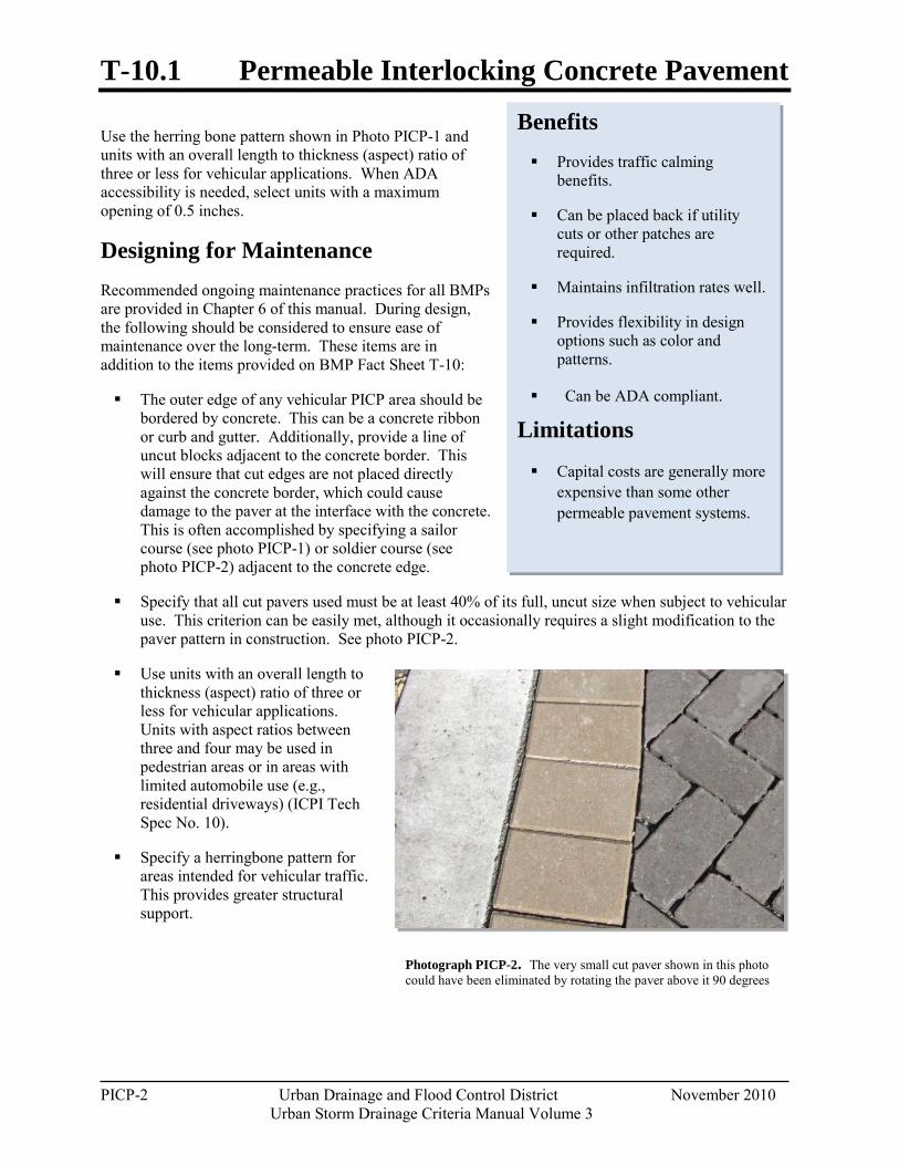
T-10.1 Permeable Interlocking Concrete Pavement
PICP-2 Urban Drainage and Flood Control District November 2010
Urban Storm Drainage Criteria Manual Volume 3
Photograph PICP-2. The very small cut paver shown in this photo could have been eliminated by rotating the paver above it 90 degrees
Use the herring bone pattern shown in Photo PICP-1 and units with an overall length to thickness (aspect) ratio of three or less for vehicular applications. When ADA accessibility is needed, select units with a maximum opening of 0.5 inches.
Designing for Maintenance Recommended ongoing maintenance practices for all BMPs are provided in Chapter 6 of this manual. During design, the following should be considered to ensure ease of maintenance over the long-term. These items are in addition to the items provided on BMP Fact Sheet T-10:
The outer edge of any vehicular PICP area should be bordered by concrete. This can be a concrete ribbon or curb and gutter. Additionally, provide a line of uncut blocks adjacent to the concrete border. This will ensure that cut edges are not placed directly against the concrete border, which could cause damage to the paver at the interface with the concrete. This is often accomplished by specifying a sailor course (see photo PICP-1) or soldier course (see photo PICP-2) adjacent to the concrete edge.
Specify that all cut pavers used must be at least 40% of its full, uncut size when subject to vehicular use. This criterion can be easily met, although it occasionally requires a slight modification to the paver pattern in construction. See photo PICP-2.
Use units with an overall length to thickness (aspect) ratio of three or less for vehicular applications. Units with aspect ratios between three and four may be used in pedestrian areas or in areas with limited automobile use (e.g., residential driveways) (ICPI Tech Spec No. 10).
Specify a herringbone pattern for areas intended for vehicular traffic. This provides greater structural support.
Benefits Provides traffic calming
benefits.
Can be placed back if utility cuts or other patches are required.
Maintains infiltration rates well.
Provides flexibility in design options such as color and patterns.
Can be ADA compliant.
Limitations
Capital costs are generally more expensive than some other permeable pavement systems.
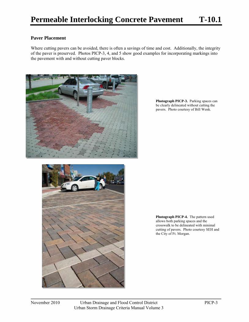
Permeable Interlocking Concrete Pavement T-10.1
November 2010 Urban Drainage and Flood Control District PICP-3 Urban Storm Drainage Criteria Manual Volume 3
Paver Placement
Where cutting pavers can be avoided, there is often a savings of time and cost. Additionally, the integrity of the paver is preserved. Photos PICP-3, 4, and 5 show good examples for incorporating markings into the pavement with and without cutting paver blocks.
Photograph PICP-3. Parking spaces can be clearly delineated without cutting the pavers. Photo courtesy of Bill Wenk.
Photograph PICP-4. The pattern used allows both parking spaces and the crosswalk to be delineated with minimal cutting of pavers. Photo courtesy SEH and the City of Ft. Morgan.
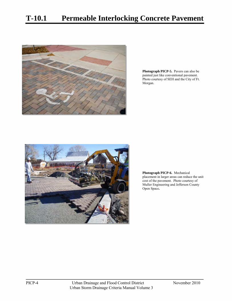
T-10.1 Permeable Interlocking Concrete Pavement
PICP-4 Urban Drainage and Flood Control District November 2010
Urban Storm Drainage Criteria Manual Volume 3
Photograph PICP-5. Pavers can also be painted just like conventional pavement. Photo courtesy of SEH and the City of Ft. Morgan.
Photograph PICP-6. Mechanical placement in larger areas can reduce the unit cost of the pavement. Photo courtesy of Muller Engineering and Jefferson County Open Space.
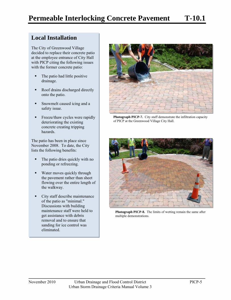
Permeable Interlocking Concrete Pavement T-10.1
November 2010 Urban Drainage and Flood Control District PICP-5 Urban Storm Drainage Criteria Manual Volume 3
Photograph PICP-7. City staff demonstrate the infiltration capacity of PICP at the Greenwood Village City Hall.
Photograph PICP-8. The limits of wetting remain the same after multiple demonstrations.
Local Installation The City of Greenwood Village decided to replace their concrete patio at the employee entrance of City Hall with PICP citing the following issues with the former concrete patio:
The patio had little positive drainage.
Roof drains discharged directly onto the patio.
Snowmelt caused icing and a safety issue.
Freeze/thaw cycles were rapidly deteriorating the existing concrete creating tripping hazards.
The patio has been in place since November 2008. To date, the City lists the following benefits:
The patio dries quickly with no ponding or refreezing.
Water moves quickly through the pavement rather than sheet flowing over the entire length of the walkway.
City staff describe maintenance of the patio as "minimal." Discussions with building maintenance staff were held to get assistance with debris removal and to ensure that sanding for ice control was eliminated.
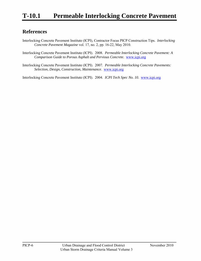
T-10.1 Permeable Interlocking Concrete Pavement
PICP-6 Urban Drainage and Flood Control District November 2010
Urban Storm Drainage Criteria Manual Volume 3
References Interlocking Concrete Pavement Institute (ICPI), Contractor Focus PICP Construction Tips. Interlocking
Concrete Pavement Magazine vol. 17, no. 2, pp. 16-22, May 2010.
Interlocking Concrete Pavement Institute (ICPI). 2008. Permeable Interlocking Concrete Pavement: A Comparison Guide to Porous Asphalt and Pervious Concrete. www.icpi.org
Interlocking Concrete Pavement Institute (ICPI). 2007. Permeable Interlocking Concrete Pavements: Selection, Design, Construction, Maintenance. www.icpi.org
Interlocking Concrete Pavement Institute (ICPI). 2004. ICPI Tech Spec No. 10. www.icpi.org
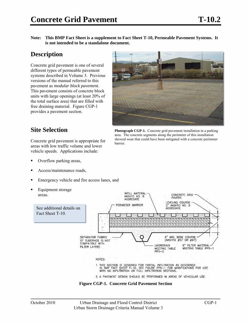
Concrete Grid Pavement T-10.2
October 2010 Urban Drainage and Flood Control District CGP-1 Urban Storm Drainage Criteria Manual Volume 3
Note: This BMP Fact Sheet is a supplement to Fact Sheet T-10, Permeable Pavement Systems. It is not intended to be a standalone document.
Description Concrete grid pavement is one of several different types of permeable pavement systems described in Volume 3. Previous versions of the manual referred to this pavement as modular block pavement. This pavement consists of concrete block units with large openings (at least 20% of the total surface area) that are filled with free draining material. Figure CGP-1 provides a pavement section.
Site Selection Concrete grid pavement is appropriate for areas with low traffic volume and lower vehicle speeds. Applications include:
Overflow parking areas,
Access/maintenance roads,
Emergency vehicle and fire access lanes, and
Equipment storage areas.
Figure CGP-1. Concrete Grid Pavement Section
Photograph CGP-1. Concrete grid pavement installation in a parking area. The concrete segments along the perimeter of this installation showed wear that could have been mitigated with a concrete perimeter barrier.
See additional details on Fact Sheet T-10.
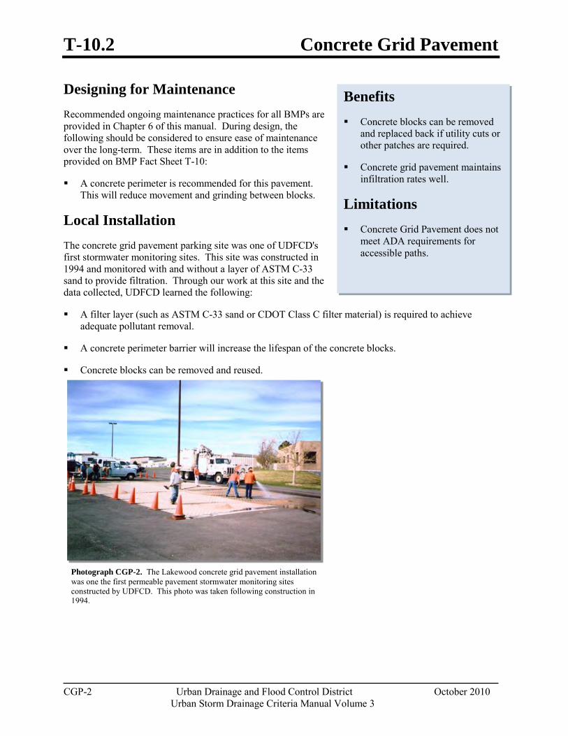
T-10.2 Concrete Grid Pavement
CGP-2 Urban Drainage and Flood Control District October 2010
Urban Storm Drainage Criteria Manual Volume 3
Designing for Maintenance Recommended ongoing maintenance practices for all BMPs are provided in Chapter 6 of this manual. During design, the following should be considered to ensure ease of maintenance over the long-term. These items are in addition to the items provided on BMP Fact Sheet T-10:
A concrete perimeter is recommended for this pavement. This will reduce movement and grinding between blocks.
Local Installation The concrete grid pavement parking site was one of UDFCD's first stormwater monitoring sites. This site was constructed in 1994 and monitored with and without a layer of ASTM C-33 sand to provide filtration. Through our work at this site and the data collected, UDFCD learned the following:
A filter layer (such as ASTM C-33 sand or CDOT Class C filter material) is required to achieve adequate pollutant removal.
A concrete perimeter barrier will increase the lifespan of the concrete blocks.
Concrete blocks can be removed and reused.
Photograph CGP-2. The Lakewood concrete grid pavement installation was one the first permeable pavement stormwater monitoring sites constructed by UDFCD. This photo was taken following construction in 1994.
Benefits Concrete blocks can be removed
and replaced back if utility cuts or other patches are required.
Concrete grid pavement maintains infiltration rates well.
Limitations Concrete Grid Pavement does not
meet ADA requirements for accessible paths.
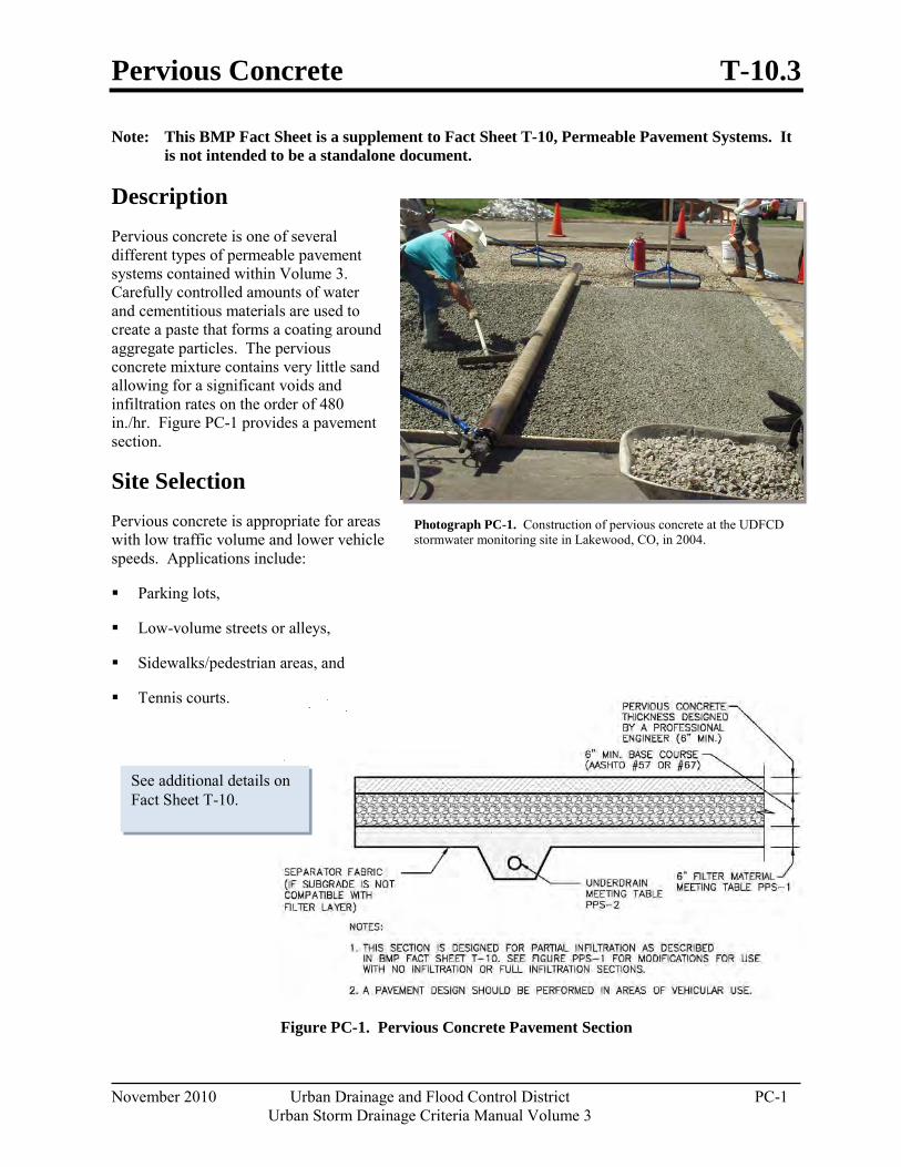
Pervious Concrete T-10.3
November 2010 Urban Drainage and Flood Control District PC-1 Urban Storm Drainage Criteria Manual Volume 3
Note: This BMP Fact Sheet is a supplement to Fact Sheet T-10, Permeable Pavement Systems. It is not intended to be a standalone document.
Description Pervious concrete is one of several different types of permeable pavement systems contained within Volume 3. Carefully controlled amounts of water and cementitious materials are used to create a paste that forms a coating around aggregate particles. The pervious concrete mixture contains very little sand allowing for a significant voids and infiltration rates on the order of 480 in./hr. Figure PC-1 provides a pavement section.
Site Selection Pervious concrete is appropriate for areas with low traffic volume and lower vehicle speeds. Applications include:
Parking lots,
Low-volume streets or alleys,
Sidewalks/pedestrian areas, and
Tennis courts.
Figure PC-1. Pervious Concrete Pavement Section
Photograph PC-1. Construction of pervious concrete at the UDFCD stormwater monitoring site in Lakewood, CO, in 2004.
See additional details on Fact Sheet T-10.
T-10.3 Pervious Concrete
PC-2 Urban Drainage and Flood Control District November 2010 Urban Storm Drainage Criteria Manual Volume 3
Designing for Maintenance Recommended ongoing maintenance practices for all BMPs are provided in Chapter 6 of the USDCM, Volume 3. During design, the following should be considered to ensure ease of maintenance over the long-term. These items are in addition to the items provided on BMP Fact Sheet T-10:
Provide adequate joints including isolation joints with expansion joint material to allow for expansion and contraction. Provide this information in the plans and/or specifications. Joint spacing should not exceed 20 feet.
Construction Considerations This BMP Fact Sheet highlights important components of a successful installation. The design engineer, contractor, and any other individual responsible for construction inspection or observation should become familiar with the Specifier's Guide for Pervious Concrete Pavement Design, prepared by the Colorado Ready Mix Concrete Association (CRMCA). That document specifically addresses Colorado's freeze-thaw cycles, seasonal temperature variations and extremely low humidity. At a minimum, those involved with selecting, designing or constructing this BMP should understand the following:
Selection of a contractor with prior experience in successful pervious concrete installation is highly recommended. The National Ready Mixed Concrete Association (NRMCA) has a certification program administered through the CRMCA. It is recommended that at least one out of three workers in the crew performing the work be certified.
Mixing and transportation of pervious concrete should be completed and discharged within one hour of the introduction of mixture water to the cement. Alternatively, concrete could be mixed on site. Hydration stabilizer may also be added.
Compaction of pervious concrete is achieved by rolling, using special equipment as shown in Photo PC-1. Do not over-compact or over-work the concrete. Cross rolling should be performed using the minimum number of passes required to achieve an acceptable surface. Overworking the surface will close voids and limit porosity.
Joints should be rolled using a "pizza cutter roller." Joints should never be cut. Sawcutting introduces clogging material and increases the probability of raveling. Provide expansion material at all isolation/construction joints.
Weather restrictions dictate that pervious concrete should only be placed between April 1 and November 1 and when the ambient temperature is between 40° and 90° Fahrenheit.
Benefits Meets ADA requirements.
Maintains high infiltration rates.
Limitations When the pavement starts to ravel,
a patch is needed quickly to limit the area of the damage.
Limited success in Colorado to date.
Shorter life span than conventional concrete as well as other permeable pavements in this manual.
Quality control during installation is critical to the success of the pavement.
A long cure time limits use of the area following construction.
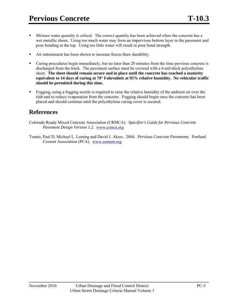
Pervious Concrete T-10.3
November 2010 Urban Drainage and Flood Control District PC-3 Urban Storm Drainage Criteria Manual Volume 3
Mixture water quantity is critical. The correct quantity has been achieved when the concrete has a wet metallic sheen. Using too much water may form an impervious bottom layer in the pavement and poor bonding at the top. Using too little water will result in poor bond strength.
Air entrainment has been shown to increase freeze-thaw durability.
Curing procedures begin immediately, but no later than 20 minutes from the time pervious concrete is discharged from the truck. The pavement surface must be covered with a 6-mil-thick polyethylene sheet. The sheet should remain secure and in place until the concrete has reached a maturity equivalent to 14 days of curing at 70° Fahrenheit at 95% relative humidity. No vehicular traffic should be permitted during this time.
Fogging, using a fogging nozzle is required to raise the relative humidity of the ambient air over the slab and to reduce evaporation from the concrete. Fogging should begin once the concrete has been placed and should continue until the polyethylene curing cover is secured.
References Colorado Ready Mixed Concrete Association (CRMCA). Specifier's Guide for Pervious Concrete
Pavement Design Version 1.2. www.crmca.org
Tennis, Paul D, Michael L. Leming and David J. Akers. 2004. Pervious Concrete Pavements. Portland Cement Association (PCA). www.cement.org

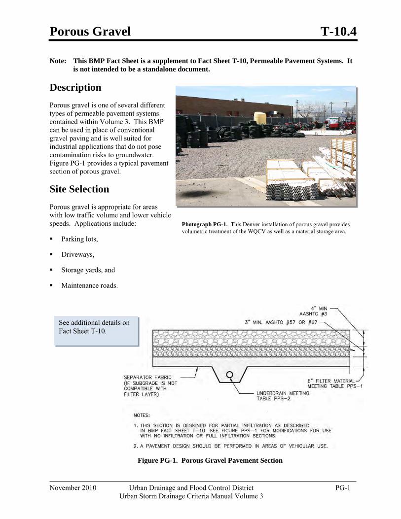
Porous Gravel T-10.4
November 2010 Urban Drainage and Flood Control District PG-1 Urban Storm Drainage Criteria Manual Volume 3
Note: This BMP Fact Sheet is a supplement to Fact Sheet T-10, Permeable Pavement Systems. It is not intended to be a standalone document.
Description Porous gravel is one of several different types of permeable pavement systems contained within Volume 3. This BMP can be used in place of conventional gravel paving and is well suited for industrial applications that do not pose contamination risks to groundwater. Figure PG-1 provides a typical pavement section of porous gravel.
Site Selection Porous gravel is appropriate for areas with low traffic volume and lower vehicle speeds. Applications include:
Parking lots,
Driveways,
Storage yards, and
Maintenance roads.
Figure PG-1. Porous Gravel Pavement Section
Photograph PG-1. This Denver installation of porous gravel provides volumetric treatment of the WQCV as well as a material storage area.
See additional details on Fact Sheet T-10.
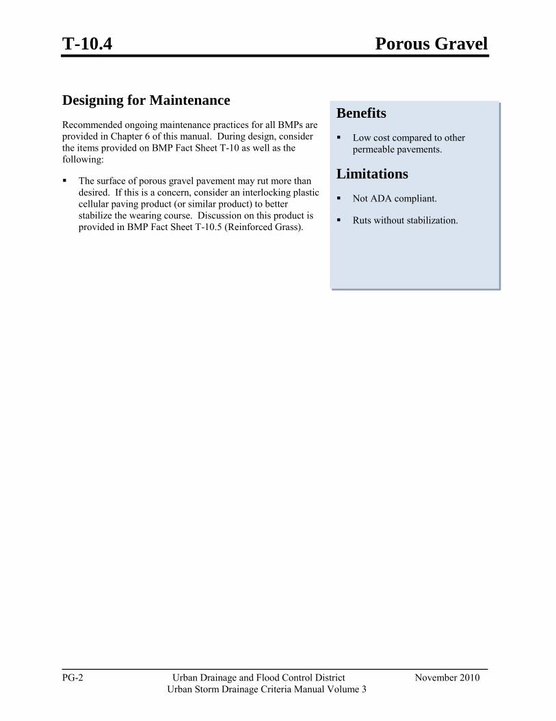
T-10.4 Porous Gravel
PG-2 Urban Drainage and Flood Control District November 2010 Urban Storm Drainage Criteria Manual Volume 3
Designing for Maintenance Recommended ongoing maintenance practices for all BMPs are provided in Chapter 6 of this manual. During design, consider the items provided on BMP Fact Sheet T-10 as well as the following:
The surface of porous gravel pavement may rut more than desired. If this is a concern, consider an interlocking plastic cellular paving product (or similar product) to better stabilize the wearing course. Discussion on this product is provided in BMP Fact Sheet T-10.5 (Reinforced Grass).
Benefits Low cost compared to other
permeable pavements.
Limitations Not ADA compliant.
Ruts without stabilization.
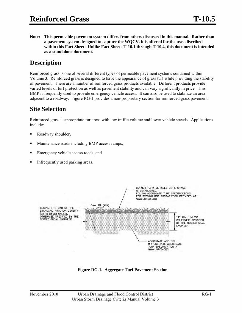
Reinforced Grass T-10.5
November 2010 Urban Drainage and Flood Control District RG-1 Urban Storm Drainage Criteria Manual Volume 3
Note: This permeable pavement system differs from others discussed in this manual. Rather than a pavement system designed to capture the WQCV, it is offered for the uses discribed within this Fact Sheet. Unlike Fact Sheets T-10.1 through T-10.4, this document is intended as a standalone document.
Description Reinforced grass is one of several different types of permeable pavement systems contained within Volume 3. Reinforced grass is designed to have the appearance of grass turf while providing the stability of pavement. There are a number of reinforced grass products available. Different products provide varied levels of turf protection as well as pavement stability and can vary significantly in price. This BMP is frequently used to provide emergency vehicle access. It can also be used to stabilize an area adjacent to a roadway. Figure RG-1 provides a non-proprietary section for reinforced grass pavement.
Site Selection Reinforced grass is appropriate for areas with low traffic volume and lower vehicle speeds. Applications include:
Roadway shoulder,
Maintenance roads including BMP access ramps,
Emergency vehicle access roads, and
Infrequently used parking areas.
Figure RG-1. Aggregate Turf Pavement Section
T-10.5 Reinforced Grass
RG-2 Urban Drainage and Flood Control District November 2010 Urban Storm Drainage Criteria Manual Volume 3
Designing for Maintenance Recommended ongoing maintenance practices for all BMPs are provided in Chapter 6. During design, the following should be considered to ensure ease of maintenance over the long-term. These items are in addition to the items provided on BMP Fact Sheet T-10:
For parking lot installations, consider a conventional pavement section in the drive aisles. These areas experience a higher volume of traffic.
Irrigation requirements increase with frequency of use.
Selection Considerations Figure RG-1 is adapted from the Federal Aviation Administration (FAA) section for aggregate turf pavement. In addition to this non-proprietary section, there are a number of products available under the name of reinforced grass or turf pavement systems. The most commonly used systems include:
Plastic Cellular Paving: This category includes interlocking plastic pavers typically designed to be filled with turf or aggregate. This system allows for a high percentage of grass surface within the pavement area.
Concrete Cellular Paving: This type of pavement consists either of interlocking pavers that have openings for the placement of grass or a similar cast-in-place system. Some systems include a reinforcement system that ties the pavers together providing greater protection from over-compaction and greater resistance to differential movement. Although some systems confine the grass area to the opening in the concrete, others are designed to provide the appearance of a fully vegetated landscape.
Consider the following variables when selecting a reinforced grass system:
Frequency of Use: For more frequently used areas, it is important to select a system that protects the root system of the turf from compaction.
Appearance: Concrete systems look different than plastic systems.
Vehicle Loading: Emergency vehicle access roads may need to be designed for high loads but will be used infrequently.
Irrigation Expectations: Some pavements rely, in part, on the turf for stability.
Optimum Drainage Capability: Where soils allow for infiltration, select a product that will bridge the subgrade providing better protection from over-compaction.
Benefits Reduces the heat island effect.
Limitations Requires irrigation.
Not recommended when frequency of use exceeds two to three uses per space (for parking stalls) per week.
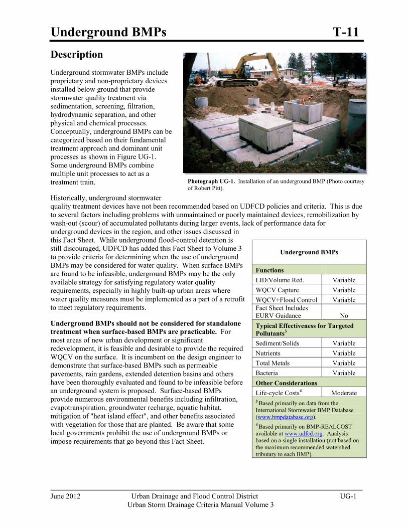
Underground BMPs T-11
June 2012 Urban Drainage and Flood Control District UG-1 Urban Storm Drainage Criteria Manual Volume 3
Photograph UG-1. Installation of an underground BMP (Photo courtesy of Robert Pitt).
Description Underground stormwater BMPs include proprietary and non-proprietary devices installed below ground that provide stormwater quality treatment via sedimentation, screening, filtration, hydrodynamic separation, and other physical and chemical processes. Conceptually, underground BMPs can be categorized based on their fundamental treatment approach and dominant unit processes as shown in Figure UG-1. Some underground BMPs combine multiple unit processes to act as a treatment train.
Historically, underground stormwater quality treatment devices have not been recommended based on UDFCD policies and criteria. This is due to several factors including problems with unmaintained or poorly maintained devices, remobilization by wash-out (scour) of accumulated pollutants during larger events, lack of performance data for underground devices in the region, and other issues discussed in this Fact Sheet. While underground flood-control detention is still discouraged, UDFCD has added this Fact Sheet to Volume 3 to provide criteria for determining when the use of underground BMPs may be considered for water quality. When surface BMPs are found to be infeasible, underground BMPs may be the only available strategy for satisfying regulatory water quality requirements, especially in highly built-up urban areas where water quality measures must be implemented as a part of a retrofit to meet regulatory requirements.
Underground BMPs should not be considered for standalone treatment when surface-based BMPs are practicable. For most areas of new urban development or significant redevelopment, it is feasible and desirable to provide the required WQCV on the surface. It is incumbent on the design engineer to demonstrate that surface-based BMPs such as permeable pavements, rain gardens, extended detention basins and others have been thoroughly evaluated and found to be infeasible before an underground system is proposed. Surface-based BMPs provide numerous environmental benefits including infiltration, evapotranspiration, groundwater recharge, aquatic habitat, mitigation of "heat island effect", and other benefits associated with vegetation for those that are planted. Be aware that some local governments prohibit the use of underground BMPs or impose requirements that go beyond this Fact Sheet.
Underground BMPs
Functions LID/Volume Red. Variable WQCV Capture Variable WQCV+Flood Control Variable Fact Sheet Includes EURV Guidance No Typical Effectiveness for Targeted Pollutants3
Sediment/Solids Variable Nutrients Variable Total Metals Variable Bacteria Variable Other Considerations Life-cycle Costs4 Moderate 3 Based primarily on data from the International Stormwater BMP Database (www.bmpdatabase.org). 4 Based primarily on BMP-REALCOST available at www.udfcd.org. Analysis based on a single installation (not based on the maximum recommended watershed tributary to each BMP).
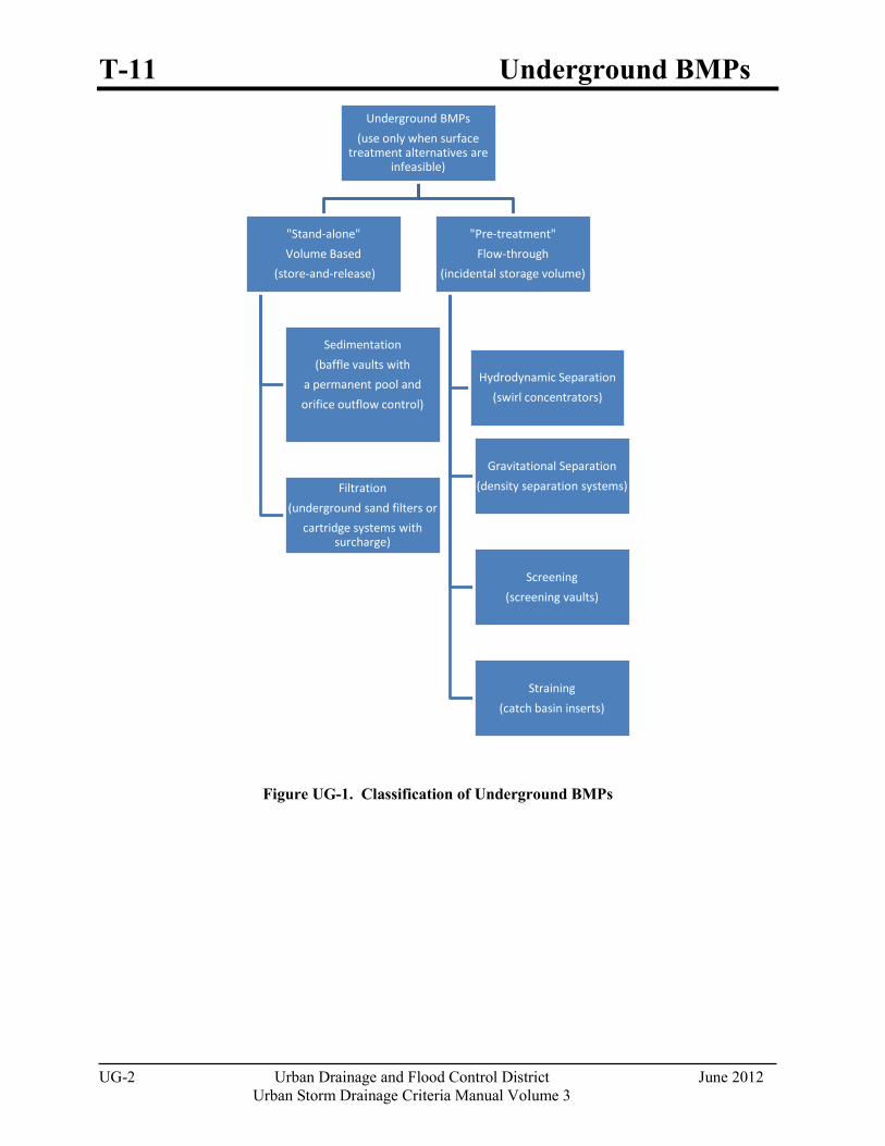
T-11 Underground BMPs
UG-2 Urban Drainage and Flood Control District June 2012 Urban Storm Drainage Criteria Manual Volume 3
Figure UG-1. Classification of Underground BMPs
Underground BMPs
(use only when surface treatment alternatives are
infeasible)
"Stand-alone"
Volume Based
(store-and-release)
Sedimentation
(baffle vaults with
a permanent pool and
orifice outflow control)
Filtration
(underground sand filters or
cartridge systems with surcharge)
"Pre-treatment"
Flow-through
(incidental storage volume)
Hydrodynamic Separation
(swirl concentrators)
Gravitational Separation
(density separation systems)
Screening
(screening vaults)
Straining
(catch basin inserts)
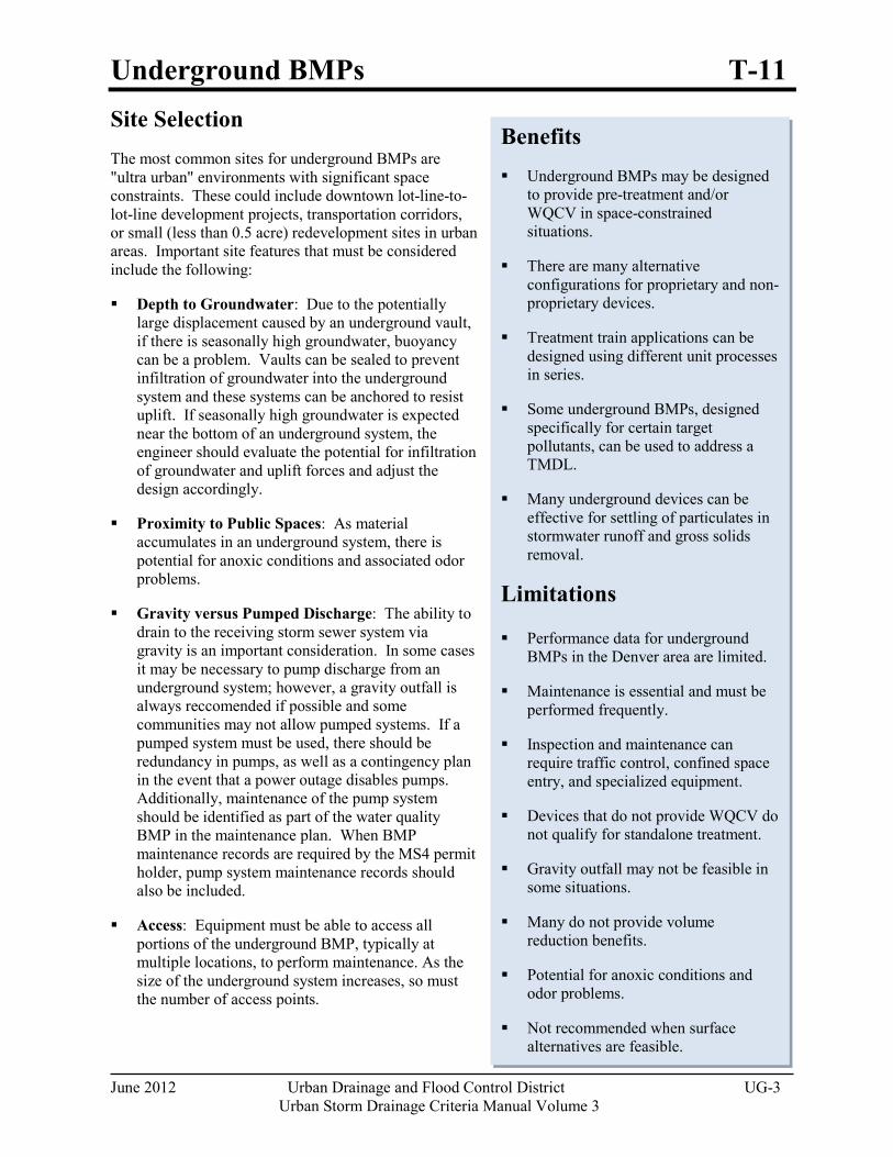
Underground BMPs T-11
June 2012 Urban Drainage and Flood Control District UG-3 Urban Storm Drainage Criteria Manual Volume 3
Site Selection The most common sites for underground BMPs are "ultra urban" environments with significant space constraints. These could include downtown lot-line-to-lot-line development projects, transportation corridors, or small (less than 0.5 acre) redevelopment sites in urban areas. Important site features that must be considered include the following:
Depth to Groundwater: Due to the potentially large displacement caused by an underground vault, if there is seasonally high groundwater, buoyancy can be a problem. Vaults can be sealed to prevent infiltration of groundwater into the underground system and these systems can be anchored to resist uplift. If seasonally high groundwater is expected near the bottom of an underground system, the engineer should evaluate the potential for infiltration of groundwater and uplift forces and adjust the design accordingly.
Proximity to Public Spaces: As material accumulates in an underground system, there is potential for anoxic conditions and associated odor problems.
Gravity versus Pumped Discharge: The ability to drain to the receiving storm sewer system via gravity is an important consideration. In some cases it may be necessary to pump discharge from an underground system; however, a gravity outfall is always reccomended if possible and some communities may not allow pumped systems. If a pumped system must be used, there should be redundancy in pumps, as well as a contingency plan in the event that a power outage disables pumps. Additionally, maintenance of the pump system should be identified as part of the water quality BMP in the maintenance plan. When BMP maintenance records are required by the MS4 permit holder, pump system maintenance records should also be included.
Access: Equipment must be able to access all portions of the underground BMP, typically at multiple locations, to perform maintenance. As the size of the underground system increases, so must the number of access points.
Benefits Underground BMPs may be designed
to provide pre-treatment and/or WQCV in space-constrained situations.
There are many alternative configurations for proprietary and non-proprietary devices.
Treatment train applications can be designed using different unit processes in series.
Some underground BMPs, designed specifically for certain target pollutants, can be used to address a TMDL.
Many underground devices can be effective for settling of particulates in stormwater runoff and gross solids removal.
Limitations
Performance data for underground BMPs in the Denver area are limited.
Maintenance is essential and must be performed frequently.
Inspection and maintenance can require traffic control, confined space entry, and specialized equipment.
Devices that do not provide WQCV do not qualify for standalone treatment.
Gravity outfall may not be feasible in some situations.
Many do not provide volume reduction benefits.
Potential for anoxic conditions and odor problems.
Not recommended when surface alternatives are feasible.
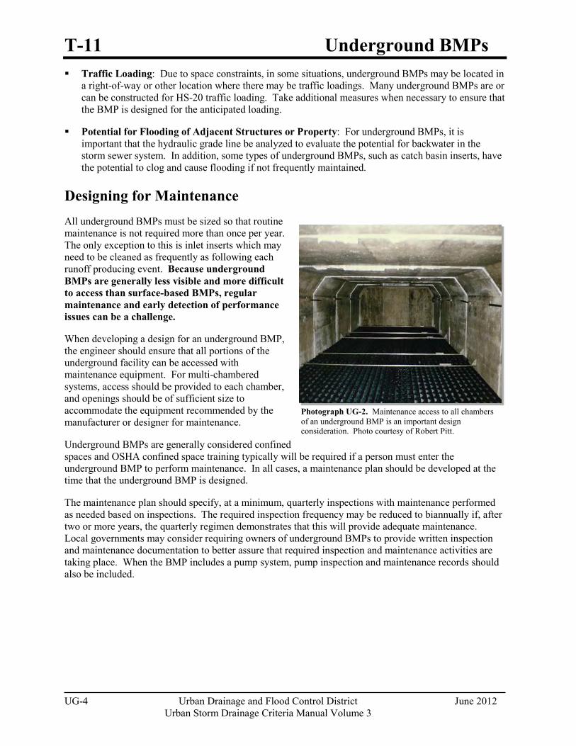
T-11 Underground BMPs
UG-4 Urban Drainage and Flood Control District June 2012 Urban Storm Drainage Criteria Manual Volume 3
Photograph UG-2. Maintenance access to all chambers of an underground BMP is an important design consideration. Photo courtesy of Robert Pitt.
Traffic Loading: Due to space constraints, in some situations, underground BMPs may be located in a right-of-way or other location where there may be traffic loadings. Many underground BMPs are or can be constructed for HS-20 traffic loading. Take additional measures when necessary to ensure that the BMP is designed for the anticipated loading.
Potential for Flooding of Adjacent Structures or Property: For underground BMPs, it is important that the hydraulic grade line be analyzed to evaluate the potential for backwater in the storm sewer system. In addition, some types of underground BMPs, such as catch basin inserts, have the potential to clog and cause flooding if not frequently maintained.
Designing for Maintenance All underground BMPs must be sized so that routine maintenance is not required more than once per year. The only exception to this is inlet inserts which may need to be cleaned as frequently as following each runoff producing event. Because underground BMPs are generally less visible and more difficult to access than surface-based BMPs, regular maintenance and early detection of performance issues can be a challenge.
When developing a design for an underground BMP, the engineer should ensure that all portions of the underground facility can be accessed with maintenance equipment. For multi-chambered systems, access should be provided to each chamber, and openings should be of sufficient size to accommodate the equipment recommended by the manufacturer or designer for maintenance.
Underground BMPs are generally considered confined spaces and OSHA confined space training typically will be required if a person must enter the underground BMP to perform maintenance. In all cases, a maintenance plan should be developed at the time that the underground BMP is designed.
The maintenance plan should specify, at a minimum, quarterly inspections with maintenance performed as needed based on inspections. The required inspection frequency may be reduced to biannually if, after two or more years, the quarterly regimen demonstrates that this will provide adequate maintenance. Local governments may consider requiring owners of underground BMPs to provide written inspection and maintenance documentation to better assure that required inspection and maintenance activities are taking place. When the BMP includes a pump system, pump inspection and maintenance records should also be included.
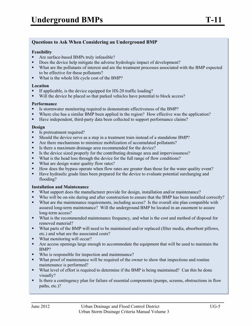
Underground BMPs T-11
June 2012 Urban Drainage and Flood Control District UG-5 Urban Storm Drainage Criteria Manual Volume 3
Questions to Ask When Considering an Underground BMP
Feasibility Are surface-based BMPs truly infeasible? Does the device help mitigate the adverse hydrologic impact of development? What are the pollutants of interest and are the treatment processes associated with the BMP expected
to be effective for these pollutants? What is the whole life cycle cost of the BMP?
Location If applicable, is the device equipped for HS-20 traffic loading? Will the device be placed so that parked vehicles have potential to block access?
Performance Is stormwater monitoring required to demonstrate effectiveness of the BMP? Where else has a similar BMP been applied in the region? How effective was the application? Have independent, third-party data been collected to support performance claims?
Design Is pretreatment required? Should the device serve as a step in a treatment train instead of a standalone BMP? Are there mechanisms to minimize mobilization of accumulated pollutants? Is there a maximum drainage area recommended for the device? Is the device sized properly for the contributing drainage area and imperviousness? What is the head loss through the device for the full range of flow conditions? What are design water quality flow rates? How does the bypass operate when flow rates are greater than those for the water quality event? Have hydraulic grade lines been prepared for the device to evaluate potential surcharging and
flooding?
Installation and Maintenance What support does the manufacturer provide for design, installation and/or maintenance? Who will be on-site during and after construction to ensure that the BMP has been installed correctly? What are the maintenance requirements, including access? Is the overall site plan compatible with
assured long-term maintenance? Will the underground BMP be located in an easement to assure long-term access?
What is the recommended maintenance frequency, and what is the cost and method of disposal for removed material?
What parts of the BMP will need to be maintained and/or replaced (filter media, absorbent pillows, etc.) and what are the associated costs?
What monitoring will occur? Are access openings large enough to accommodate the equipment that will be used to maintain the
BMP? Who is responsible for inspection and maintenance? What proof of maintenance will be required of the owner to show that inspections and routine
maintenance is performed? What level of effort is required to determine if the BMP is being maintained? Can this be done
visually? Is there a contingency plan for failure of essential components (pumps, screens, obstructions in flow
paths, etc.)?
T-11 Underground BMPs
UG-6 Urban Drainage and Flood Control District June 2012 Urban Storm Drainage Criteria Manual Volume 3
Design Procedure and Criteria Two primary options are available for underground BMPs:
1. Underground BMPs Based on a Surface BMP design: BMPs that satisfy the requirements for capture and slow release of the WQCV and that are based on and designed in substantial conformance with the criteria for surface-based BMPs described in this manual.
2. Underground Proprietary BMPs: Proprietary BMPs that satisfy the requirements for capture and slow release of the WQCV and provide a level of treatment for targeted pollutants that is comparable to that of the surface-based BMPs provided in this manual.
Underground BMPs Based on a Surface BMP Design
This class of underground BMP includes sand filter basins and retention facilities designed for below grade installation. The design must provide the WQCV and empty it over a time period of 12 hours or more. Not all of the surface-based BMPs that provide the WQCV can be adapted for underground use. For example, the vegetative components of a constructed wetland pond render it inadaptable to underground use. Underground extended detention basins are also problematic due to historical problems with remobilization of collected sediment and the difficulty of creating an effective underground micropool.
The most commonly used underground BMP to date in the UDFCD area is the underground sand filter. In addition to the criteria for an above ground sand filter, underground sand filters should meet the following criteria:
1. A pretreatment chamber for removal of coarse sediments with a volume equivalent to 0.10 times the WQCV should be provided. The pretreatment chamber must be separated from the sand filter chamber by baffles, and serves as the sediment forebay to reduce the frequency of maintenance required in the sand filter. Also consider incorporating a vertical baffle to trap oil and grease. This can be easily incorporated into the forebay and should be included where oil and grease are target constituents. Absorbent mats or booms could also be used for this purpose.
2. Where discharges from the BMP will be pumped, a separate outlet chamber is required from which the water passing through the filter layer can be pumped. The outlet pump must be sized to discharge at a rate such that the WQCV is released in no less than 12 hours.
3. For flows in excess of the water quality design event, a diversion must be sized so that excess flows bypass the sand filter chamber and the underground sand filter is not surcharged (in terms of depth or hydraulic grade line) beyond the WQCV maximum elevation.
4. Maintenance access must be provided to each chamber. Access must be sufficient to allow complete removal and replacement of the filter material. Allow for at least 6 feet of headroom (from the surface of the filter) to facilitate maintenance.
Underground Proprietary BMPs
There are numerous proprietary BMPs with wide variability in performance, design flow rates, unit processes, and volume of storage provided (if any). Sizing methodologies for proprietary devices vary from device to device—some are flow based, some are volume based, some consider surface/filter hydraulic loading, etc. As a result, this manual does not seek to provide a one-size-fits-all sizing methodology for proprietary BMPs. Instead, this manual provides a performance-based set of criteria for determining whether a proprietary BMP is acceptable for use.
Underground BMPs T-11
June 2012 Urban Drainage and Flood Control District UG-7 Urban Storm Drainage Criteria Manual Volume 3
To evaluate performance of an underground proprietary BMP, data should be provided to the local jurisdiction to demonstrate that anticipated BMP performance will be comparable to that of surface-based BMPs such as extended detention basins, constructed wetland basins, sand filter basins, or retention ponds. Underground BMPs approved for standalone treatment should be capable, on an annual basis, of producing effluent quality with a median TSS concentration of no more than 30 mg/L. This level of treatment is comparable to the long-term effluent median concentrations from the International Stormwater BMP Database for surface-based BMPs.
Data collected to substantiate performance of proprietary BMPs should meet the following criteria:
1. Testing must consist of field data (not laboratory data) collected in compliance with the criteria in Table UG-1. Laboratory studies and/or vendor-supplied studies without third party involvement or verification should not be considered. The Technology Acceptance Reciprocity Partnership (TARP) Protocol for Stormwater Best Management Practice Demonstrations may provide additional useful information on development of a monitoring program for evaluation of underground BMPs. Information on the TARP program can be found in several locations on the internet, including http://www.dep.state.pa.us/dep/deputate/pollprev/techservices/tarp/. Forthcoming field testing guidelines from the American Society of Civil Engineers Urban Water Resources Research Council (ASCE UWRRC) Task Committee developing Guidelines for Certification of Manufactured Stormwater BMPs (Sansalone et al. 2009) may also be applicable in the future.
2. Data collected in environments similar to the Colorado Front Range (i.e., semi-arid with freezing and thawing in the winter) are preferable. This is particularly important for flow based devices where differences in rainfall intensity and duration may affect performance.
3. Data should be collected and analyzed in accordance with the guidance provided in Urban Stormwater BMP Performance Monitoring (Geosyntec and WWE 2009; available online at www.bmpdatabase.org). When reviewing performance data, it is important to recognize that the use of percent removal may be more reflective of how "dirty" the influent water is rather than how well the BMP is actually performing (Jones et. al. 2008). Instead, look at effluent concentrations for a range of influent concentrations. The device should have performance data that demonstrates the ability to meet a median TSS effluent concentration of approximately 30 mg/L or lower on an annual basis.
4. Data should be collected or verified by independent third parties in accordance with good Quality Assurance/Quality Control (QA/QC) procedures.
Many studies have been conducted over the past decade to document the performance of underground BMPs. Sources of data that may be used to support using a proprietary BMP include the following:
New Jersey Corporation for Advanced Technology (NJCAT) Technology Verification Program. (http://www.njcat.org/verification/protocol.cfm).
Washington State Department of Ecology (2002). Guidance for Evaluating Emerging Stormwater Treatment Technologies, Technology Assessment Protocol – Ecology (TAPE), October 2002 (Revised June 2004), Publication Number 02-10-037. (http://www.ecy.wa.gov/biblio/0210037.html).
International Stormwater BMP Database (www.bmpdatabase.org).
University of Massachusetts Amherst Stormwater Technologies Clearinghouse (www.mastep.net).
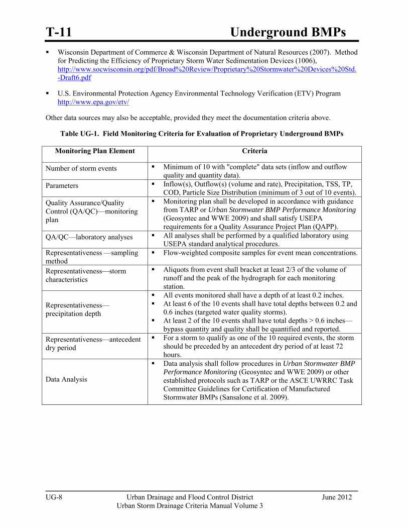
T-11 Underground BMPs
UG-8 Urban Drainage and Flood Control District June 2012 Urban Storm Drainage Criteria Manual Volume 3
Wisconsin Department of Commerce & Wisconsin Department of Natural Resources (2007). Method for Predicting the Efficiency of Proprietary Storm Water Sedimentation Devices (1006), http://www.socwisconsin.org/pdf/Broad%20Review/Proprietary%20Stormwater%20Devices%20Std.-Draft6.pdf
U.S. Environmental Protection Agency Environmental Technology Verification (ETV) Program http://www.epa.gov/etv/
Other data sources may also be acceptable, provided they meet the documentation criteria above.
Table UG-1. Field Monitoring Criteria for Evaluation of Proprietary Underground BMPs
Monitoring Plan Element Criteria
Number of storm events Minimum of 10 with "complete" data sets (inflow and outflow quality and quantity data).
Parameters Inflow(s), Outflow(s) (volume and rate), Precipitation, TSS, TP, COD, Particle Size Distribution (minimum of 3 out of 10 events).
Quality Assurance/Quality Control (QA/QC)—monitoring plan
Monitoring plan shall be developed in accordance with guidance from TARP or Urban Stormwater BMP Performance Monitoring (Geosyntec and WWE 2009) and shall satisfy USEPA requirements for a Quality Assurance Project Plan (QAPP).
QA/QC—laboratory analyses All analyses shall be performed by a qualified laboratory using USEPA standard analytical procedures.
Representativeness —sampling method
Flow-weighted composite samples for event mean concentrations.
Representativeness—storm characteristics
Aliquots from event shall bracket at least 2/3 of the volume of runoff and the peak of the hydrograph for each monitoring station.
Representativeness—precipitation depth
All events monitored shall have a depth of at least 0.2 inches. At least 6 of the 10 events shall have total depths between 0.2 and
0.6 inches (targeted water quality storms). At least 2 of the 10 events shall have total depths > 0.6 inches—
bypass quantity and quality shall be quantified and reported. Representativeness—antecedent dry period
For a storm to qualify as one of the 10 required events, the storm should be preceded by an antecedent dry period of at least 72 hours.
Data Analysis
Data analysis shall follow procedures in Urban Stormwater BMP Performance Monitoring (Geosyntec and WWE 2009) or other established protocols such as TARP or the ASCE UWRRC Task Committee Guidelines for Certification of Manufactured Stormwater BMPs (Sansalone et al. 2009).
http://www.socwisconsin.org/pdf/Broad%20Review/Proprietary%20Stormwater%20Devices%20Std.-Draft6.pdf�
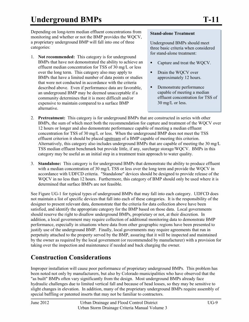
Underground BMPs T-11
June 2012 Urban Drainage and Flood Control District UG-9 Urban Storm Drainage Criteria Manual Volume 3
Stand-alone Treatment
Underground BMPs should meet three basic criteria when considered for stand-alone treatment:
Capture and treat the WQCV.
Drain the WQCV over approximately 12 hours.
Demonstrate performance capable of meeting a median effluent concentration for TSS of 30 mg/L or less.
Depending on long-term median effluent concentrations from monitoring and whether or not the BMP provides the WQCV, a proprietary underground BMP will fall into one of three categories:
1. Not recommended: This category is for underground BMPs that have not demonstrated the ability to achieve an effluent median concentration for TSS of 30 mg/L or less over the long term. This category also may apply to BMPs that have a limited number of data points or studies that were not conducted in accordance with the criteria described above. Even if performance data are favorable, an underground BMP may be deemed unacceptable if a community determines that it is more difficult and/or expensive to maintain compared to a surface BMP alternative.
2. Pretreatment: This category is for underground BMPs that are constructed in series with other BMPs, the sum of which meet both the recommendation for capture and treatment of the WQCV over 12 hours or longer and also demonstrate performance capable of meeting a median effluent concentration for TSS of 30 mg/L or less. When the underground BMP does not meet the TSS effluent criterion it should be placed upstream of a BMP capable of meeting this criterion. Alternatively, this category also includes underground BMPs that are capable of meeting the 30 mg/L TSS median effluent benchmark but provide little, if any, surcharge storage/WQCV. BMPs in this category may be useful as an initial step in a treatment train approach to water quality.
3. Standalone: This category is for underground BMPs that demonstrate the ability to produce effluent with a median concentration of 30 mg/L TSS or less over the long term and provide the WQCV in accordance with UDFCD criteria. "Standalone" devices should be designed to provide release of the WQCV in no less than 12 hours. Furthermore, this category of BMP should only be used where it is determined that surface BMPs are not feasible.
See Figure UG-1 for typical types of underground BMPs that may fall into each category. UDFCD does not maintain a list of specific devices that fall into each of these categories. It is the responsibility of the designer to present relevant data, demonstrate that the criteria for data collection above have been satisfied, and identify the appropriate category for the BMP based on those data. Local governments should reserve the right to disallow underground BMPs, proprietary or not, at their discretion. In addition, a local government may require collection of additional monitoring data to demonstrate BMP performance, especially in situations where data from other geographic regions have been presented to justify use of the underground BMP. Finally, local governments may require agreements that run in perpetuity attached to the property served by the BMP, assuring that it will be inspected and maintained by the owner as required by the local government (or recommended by manufacturer) with a provision for taking over the inspection and maintenance if needed and back charging the owner.
Construction Considerations
Improper installation will cause poor performance of proprietary underground BMPs. This problem has been noted not only by manufacturers, but also by Colorado municipalities who have observed that the "as built" BMPs often vary significantly from the design. Most underground BMPs already face hydraulic challenges due to limited vertical fall and because of head losses, so they may be sensitive to slight changes in elevation. In addition, many of the proprietary underground BMPs require assembly of special baffling or patented inserts that may not be familiar to contractors.
T-11 Underground BMPs
UG-10 Urban Drainage and Flood Control District June 2012 Urban Storm Drainage Criteria Manual Volume 3
For these reasons, it is important to discuss the installation of the underground BMP with the manufacturer prior to selecting a contractor so that the installation requirements are clearly understood. Construction observation by the design engineer, and, if possible, a manufacturer's representative is essential for proper installation. At a minimum, the installation should be inspected by the manufacturer's representative once completed. Any deficiencies of the installation identified by the manufacturer's inspection should be corrected immediately.
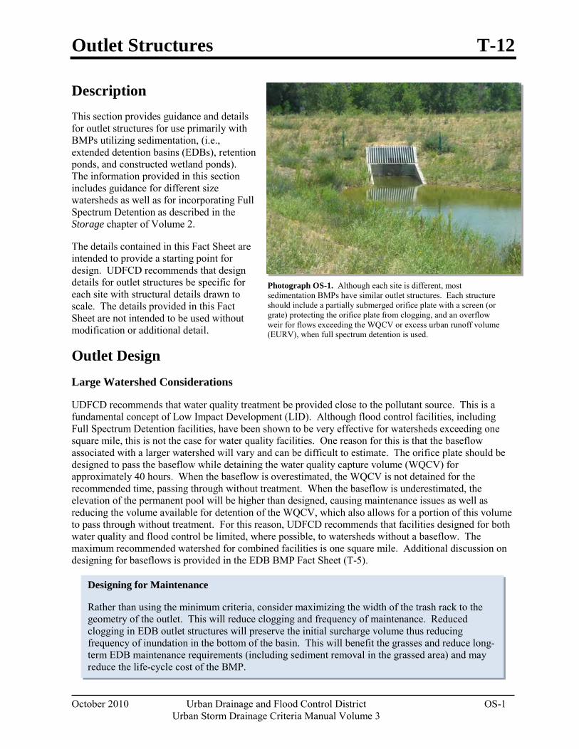
Outlet Structures T-12
October 2010 Urban Drainage and Flood Control District OS-1 Urban Storm Drainage Criteria Manual Volume 3
Designing for Maintenance
Rather than using the minimum criteria, consider maximizing the width of the trash rack to the geometry of the outlet. This will reduce clogging and frequency of maintenance. Reduced clogging in EDB outlet structures will preserve the initial surcharge volume thus reducing frequency of inundation in the bottom of the basin. This will benefit the grasses and reduce long-term EDB maintenance requirements (including sediment removal in the grassed area) and may reduce the life-cycle cost of the BMP.
Description This section provides guidance and details for outlet structures for use primarily with BMPs utilizing sedimentation, (i.e., extended detention basins (EDBs), retention ponds, and constructed wetland ponds). The information provided in this section includes guidance for different size watersheds as well as for incorporating Full Spectrum Detention as described in the Storage chapter of Volume 2.
The details contained in this Fact Sheet are intended to provide a starting point for design. UDFCD recommends that design details for outlet structures be specific for each site with structural details drawn to scale. The details provided in this Fact Sheet are not intended to be used without modification or additional detail.
Outlet Design
Large Watershed Considerations
UDFCD recommends that water quality treatment be provided close to the pollutant source. This is a fundamental concept of Low Impact Development (LID). Although flood control facilities, including Full Spectrum Detention facilities, have been shown to be very effective for watersheds exceeding one square mile, this is not the case for water quality facilities. One reason for this is that the baseflow associated with a larger watershed will vary and can be difficult to estimate. The orifice plate should be designed to pass the baseflow while detaining the water quality capture volume (WQCV) for approximately 40 hours. When the baseflow is overestimated, the WQCV is not detained for the recommended time, passing through without treatment. When the baseflow is underestimated, the elevation of the permanent pool will be higher than designed, causing maintenance issues as well as reducing the volume available for detention of the WQCV, which also allows for a portion of this volume to pass through without treatment. For this reason, UDFCD recommends that facilities designed for both water quality and flood control be limited, where possible, to watersheds without a baseflow. The maximum recommended watershed for combined facilities is one square mile. Additional discussion on designing for baseflows is provided in the EDB BMP Fact Sheet (T-5).
Photograph OS-1. Although each site is different, most sedimentation BMPs have similar outlet structures. Each structure should include a partially submerged orifice plate with a screen (or grate) protecting the orifice plate from clogging, and an overflow weir for flows exceeding the WQCV or excess urban runoff volume (EURV), when full spectrum detention is used.
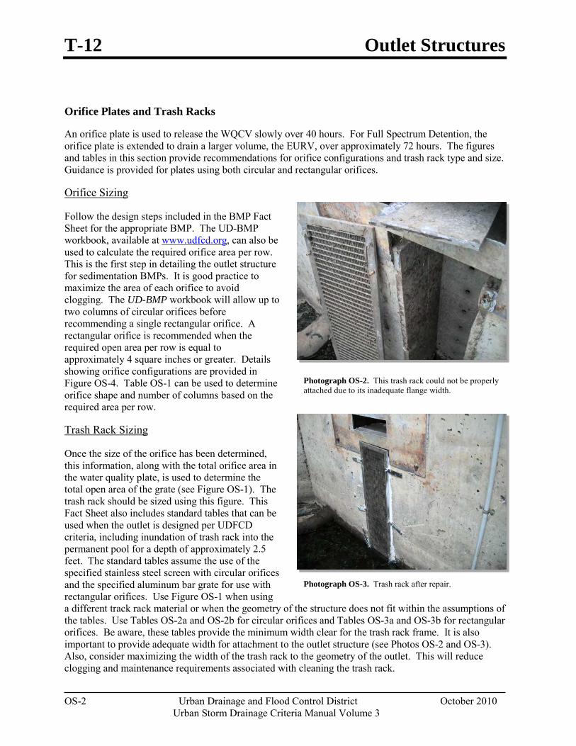
T-12 Outlet Structures
OS-2 Urban Drainage and Flood Control District October 2010
Urban Storm Drainage Criteria Manual Volume 3
Orifice Plates and Trash Racks
An orifice plate is used to release the WQCV slowly over 40 hours. For Full Spectrum Detention, the orifice plate is extended to drain a larger volume, the EURV, over approximately 72 hours. The figures and tables in this section provide recommendations for orifice configurations and trash rack type and size. Guidance is provided for plates using both circular and rectangular orifices.
Follow the design steps included in the BMP Fact Sheet for the appropriate BMP. The UD-BMP workbook, available at
Orifice Sizing
www.udfcd.org, can also be used to calculate the required orifice area per row. This is the first step in detailing the outlet structure for sedimentation BMPs. It is good practice to maximize the area of each orifice to avoid clogging. The UD-BMP workbook will allow up to two columns of circular orifices before recommending a single rectangular orifice. A rectangular orifice is recommended when the required open area per row is equal to approximately 4 square inches or greater. Details showing orifice configurations are provided in Figure OS-4. Table OS-1 can be used to determine orifice shape and number of columns based on the required area per row.
Once the size of the orifice has been determined, this information, along with the total orifice area in the water quality plate, is used to determine the total open area of the grate (see Figure OS-1). The trash rack should be sized using this figure. This Fact Sheet also includes standard tables that can be used when the outlet is designed per UDFCD criteria, including inundation of trash rack into the permanent pool for a depth of approximately 2.5 feet. The standard tables assume the use of the specified stainless steel screen with circular orifices and the specified aluminum bar grate for use with rectangular orifices. Use Figure OS-1 when using a different track rack material or when the geometry of the structure does not fit within the assumptions of the tables. Use Tables OS-2a and OS-2b for circular orifices and Tables OS-3a and OS-3b for rectangular orifices. Be aware, these tables provide the minimum width clear for the trash rack frame. It is also important to provide adequate width for attachment to the outlet structure (see Photos OS-2 and OS-3). Also, consider maximizing the width of the trash rack to the geometry of the outlet. This will reduce clogging and maintenance requirements associated with cleaning the trash rack.
Trash Rack Sizing
Photograph OS-2. This trash rack could not be properly attached due to its inadequate flange width.
Photograph OS-3. Trash rack after repair.
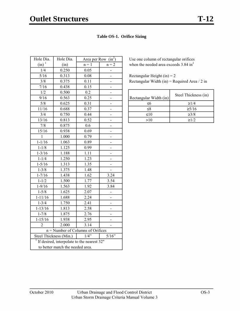
Outlet Structures T-12
October 2010 Urban Drainage and Flood Control District OS-3 Urban Storm Drainage Criteria Manual Volume 3
Table OS-1. Orifice Sizing
Hole Dia. Hole Dia. Use one column of rectangular orifices (in) 1 (in) n = 1 n = 2 when the needed area exceeds 3.84 in2
1/4 0.250 0.05 - 5/16 0.313 0.08 - Rectangular Height (in) = 2 3/8 0.375 0.11 - Rectangular Width (in) = Required Area / 2 in 7/16 0.438 0.15 - 1/2 0.500 0.2 - 9/16 0.563 0.25 - 5/8 0.625 0.31 - ≤6 ≥1/4
11/16 0.688 0.37 - ≤8 ≥5/16 3/4 0.750 0.44 - ≤10 ≥3/8
13/16 0.813 0.52 - >10 ≥1/2 7/8 0.875 0.6 -
15/16 0.938 0.69 -1 1.000 0.79 -
1-1/16 1.063 0.89 -1-1/8 1.125 0.99 -
1-3/16 1.188 1.11 -1-1/4 1.250 1.23 -
1-5/16 1.313 1.35 -1-3/8 1.375 1.48 -
1-7/16 1.438 1.62 3.241-1/2 1.500 1.77 3.54
1-9/16 1.563 1.92 3.841-5/8 1.625 2.07 -
1-11/16 1.688 2.24 -1-3/4 1.750 2.41 -
1-13/16 1.813 2.58 -1-7/8 1.875 2.76 -
1-15/16 1.938 2.95 -2 2.000 3.14 -
1/4” 5/16”
Rectangular Width (in)Steel Thickness (in)
to better match the needed area.
n = Number of Columns of OrificesSteel Thickness (Min.)
1 If desired, interpolate to the nearest 32"
Area per Row (in2)
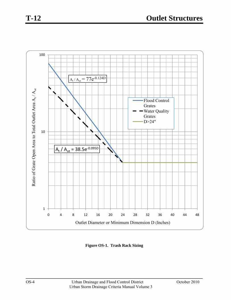
T-12 Outlet Structures
OS-4 Urban Drainage and Flood Control District October 2010
Urban Storm Drainage Criteria Manual Volume 3
Figure OS-1. Trash Rack Sizing
At / Aot = 77e-0.124D
At / Aot = 38.5e-0.095D
1
10
100
0 4 8 12 16 20 24 28 32 36 40 44 48
Rat
io o
f Gra
te O
pen
Are
a to
Tot
al O
utle
t Are
a At/
Aot
Outlet Diameter or Minimum Dimension D (Inches)
Flood Control GratesWater Quality GratesD>24"
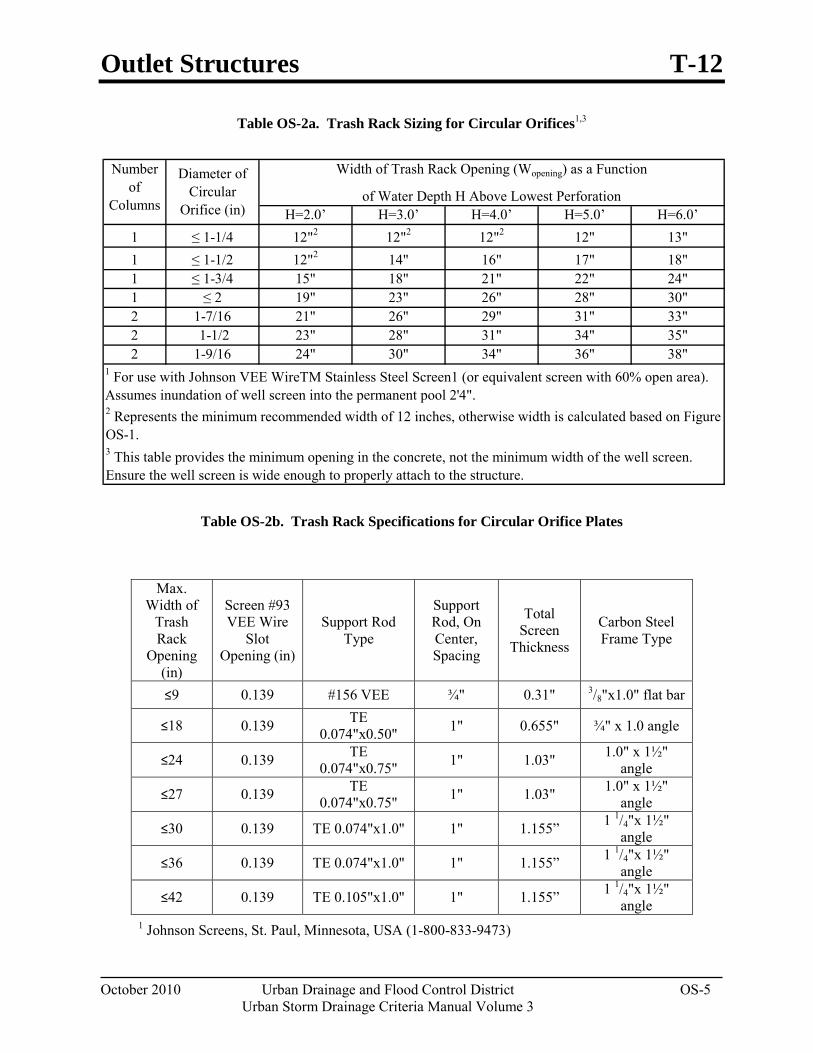
Outlet Structures T-12
October 2010 Urban Drainage and Flood Control District OS-5 Urban Storm Drainage Criteria Manual Volume 3
Table OS-2a. Trash Rack Sizing for Circular Orifices1,3
Table OS-2b. Trash Rack Specifications for Circular Orifice Plates
Max.
Width of Trash Rack
Opening (in)
Screen #93 VEE Wire
Slot Opening (in)
Support Rod Type
Support Rod, On Center, Spacing
Total Screen
Thickness
Carbon Steel Frame Type
≤9 0.139 #156 VEE ¾" 0.31" 3/8"x1.0" flat bar
≤18 0.139 TE 0.074"x0.50" 1" 0.655" ¾" x 1.0 angle
≤24 0.139 TE 0.074"x0.75" 1" 1.03" 1.0" x 1½"
angle
≤27 0.139 TE 0.074"x0.75" 1" 1.03" 1.0" x 1½"
angle
≤30 0.139 TE 0.074"x1.0" 1" 1.155” 1 1/4"x 1½" angle
≤36 0.139 TE 0.074"x1.0" 1" 1.155” 1 1/4"x 1½" angle
≤42 0.139 TE 0.105"x1.0" 1" 1.155” 1 1/4"x 1½" angle
1 Johnson Screens, St. Paul, Minnesota, USA (1-800-833-9473)
H=2.0’ H=3.0’ H=4.0’ H=5.0’ H=6.0’1 ≤ 1-1/4 12"2 12"2 12"2 12" 13"1 ≤ 1-1/2 12"2 14" 16" 17" 18"1 ≤ 1-3/4 15" 18" 21" 22" 24"1 ≤ 2 19" 23" 26" 28" 30"2 1-7/16 21" 26" 29" 31" 33"2 1-1/2 23" 28" 31" 34" 35"2 1-9/16 24" 30" 34" 36" 38"
3 This table provides the minimum opening in the concrete, not the minimum width of the well screen. Ensure the well screen is wide enough to properly attach to the structure.
1 For use with Johnson VEE WireTM Stainless Steel Screen1 (or equivalent screen with 60% open area). Assumes inundation of well screen into the permanent pool 2'4".2 Represents the minimum recommended width of 12 inches, otherwise width is calculated based on Figure OS-1.
Diameter of Circular
Orifice (in)
Width of Trash Rack Opening (Wopening) as a Function
of Water Depth H Above Lowest Perforation
Number of
Columns
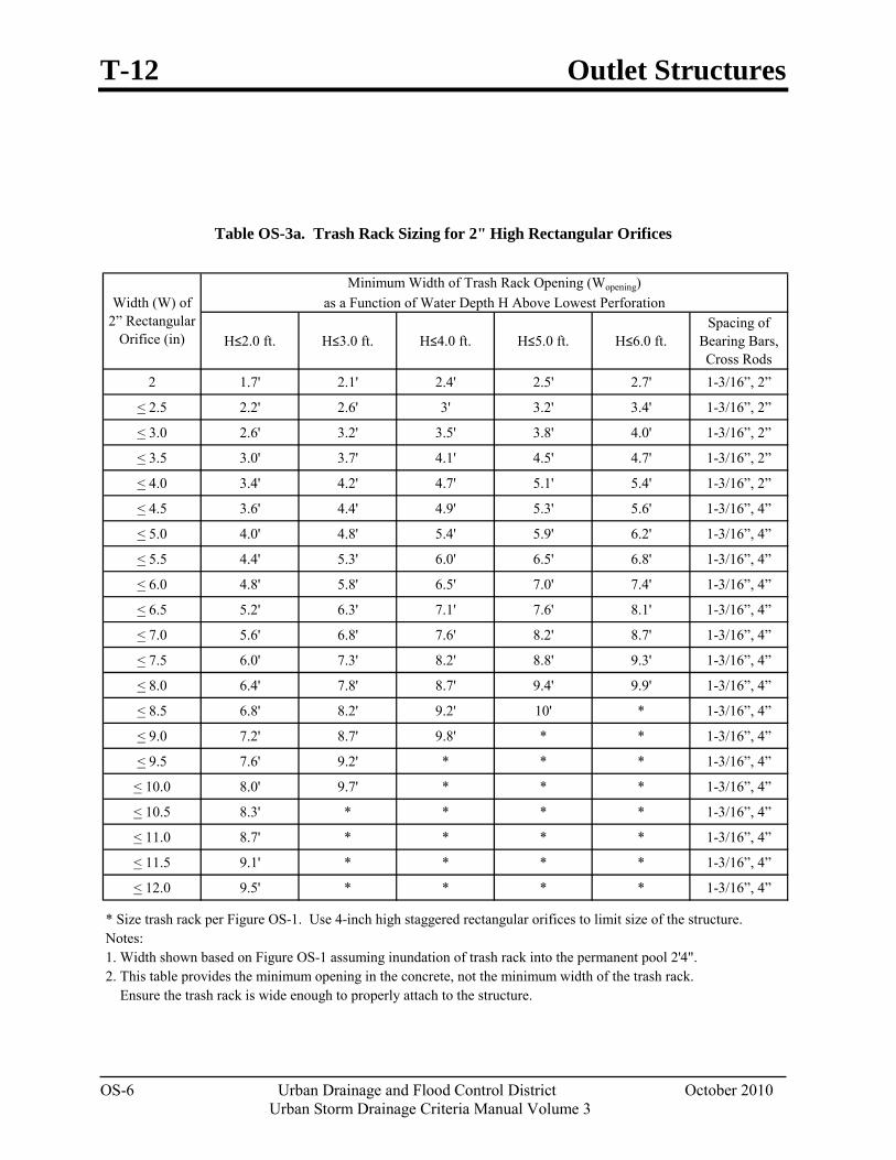
T-12 Outlet Structures
OS-6 Urban Drainage and Flood Control District October 2010
Urban Storm Drainage Criteria Manual Volume 3
Table OS-3a. Trash Rack Sizing for 2" High Rectangular Orifices
H≤2.0 ft. H≤3.0 ft. H≤4.0 ft. H≤5.0 ft. H≤6.0 ft.Spacing of
Bearing Bars, Cross Rods
2 1.7' 2.1' 2.4' 2.5' 2.7' 1-3/16”, 2”
< 2.5 2.2' 2.6' 3' 3.2' 3.4' 1-3/16”, 2”
< 3.0 2.6' 3.2' 3.5' 3.8' 4.0' 1-3/16”, 2”
< 3.5 3.0' 3.7' 4.1' 4.5' 4.7' 1-3/16”, 2”
< 4.0 3.4' 4.2' 4.7' 5.1' 5.4' 1-3/16”, 2”
< 4.5 3.6' 4.4' 4.9' 5.3' 5.6' 1-3/16”, 4”
< 5.0 4.0' 4.8' 5.4' 5.9' 6.2' 1-3/16”, 4”
< 5.5 4.4' 5.3' 6.0' 6.5' 6.8' 1-3/16”, 4”
< 6.0 4.8' 5.8' 6.5' 7.0' 7.4' 1-3/16”, 4”
< 6.5 5.2' 6.3' 7.1' 7.6' 8.1' 1-3/16”, 4”
< 7.0 5.6' 6.8' 7.6' 8.2' 8.7' 1-3/16”, 4”
< 7.5 6.0' 7.3' 8.2' 8.8' 9.3' 1-3/16”, 4”
< 8.0 6.4' 7.8' 8.7' 9.4' 9.9' 1-3/16”, 4”
< 8.5 6.8' 8.2' 9.2' 10' * 1-3/16”, 4”
< 9.0 7.2' 8.7' 9.8' * * 1-3/16”, 4”
< 9.5 7.6' 9.2' * * * 1-3/16”, 4”
< 10.0 8.0' 9.7' * * * 1-3/16”, 4”
< 10.5 8.3' * * * * 1-3/16”, 4”
< 11.0 8.7' * * * * 1-3/16”, 4”
< 11.5 9.1' * * * * 1-3/16”, 4”
< 12.0 9.5' * * * * 1-3/16”, 4”
* Size trash rack per Figure OS-1. Use 4-inch high staggered rectangular orifices to limit size of the structure.
2. This table provides the minimum opening in the concrete, not the minimum width of the trash rack. Ensure the trash rack is wide enough to properly attach to the structure.
Width (W) of 2” Rectangular
Orifice (in)
Minimum Width of Trash Rack Opening (Wopening)as a Function of Water Depth H Above Lowest Perforation
1. Width shown based on Figure OS-1 assuming inundation of trash rack into the permanent pool 2'4". Notes:
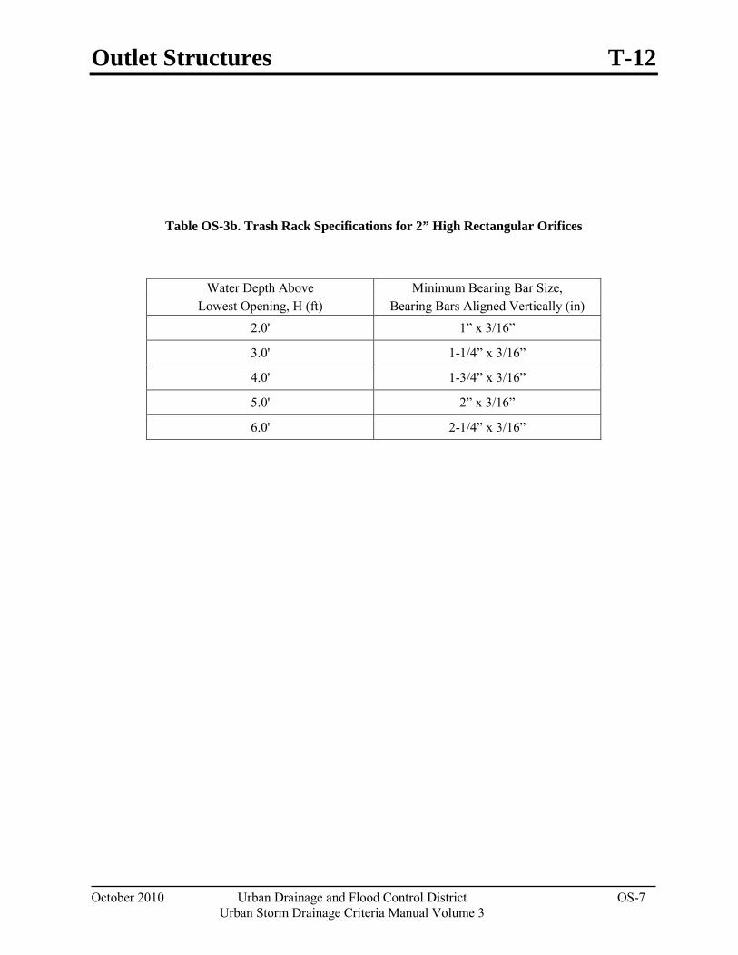
Outlet Structures T-12
October 2010 Urban Drainage and Flood Control District OS-7 Urban Storm Drainage Criteria Manual Volume 3
Table OS-3b. Trash Rack Specifications for 2” High Rectangular Orifices
Water Depth Above Minimum Bearing Bar Size, Lowest Opening, H (ft) Bearing Bars Aligned Vertically (in)
2.0' 1” x 3/16”
3.0' 1-1/4” x 3/16”
4.0' 1-3/4” x 3/16”
5.0' 2” x 3/16”
6.0' 2-1/4” x 3/16”
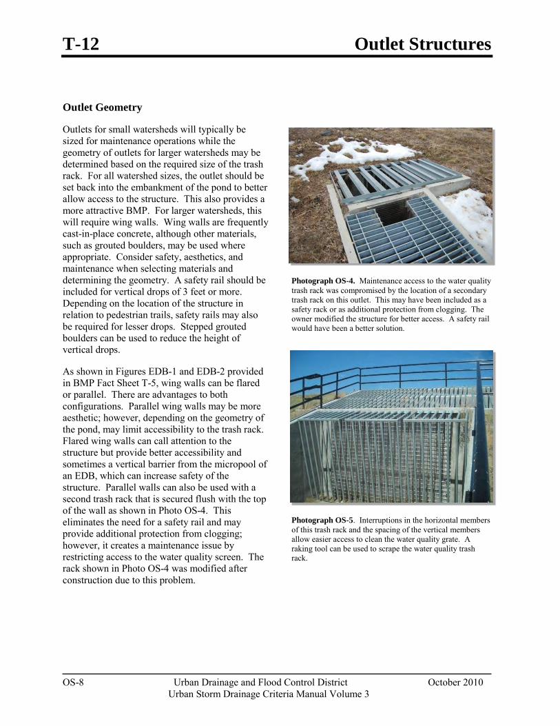
T-12 Outlet Structures
OS-8 Urban Drainage and Flood Control District October 2010
Urban Storm Drainage Criteria Manual Volume 3
Outlet Geometry
Outlets for small watersheds will typically be sized for maintenance operations while the geometry of outlets for larger watersheds may be determined based on the required size of the trash rack. For all watershed sizes, the outlet should be set back into the embankment of the pond to better allow access to the structure. This also provides a more attractive BMP. For larger watersheds, this will require wing walls. Wing walls are frequently cast-in-place concrete, although other materials, such as grouted boulders, may be used where appropriate. Consider safety, aesthetics, and maintenance when selecting materials and determining the geometry. A safety rail should be included for vertical drops of 3 feet or more. Depending on the location of the structure in relation to pedestrian trails, safety rails may also be required for lesser drops. Stepped grouted boulders can be used to reduce the height of vertical drops.
As shown in Figures EDB-1 and EDB-2 provided in BMP Fact Sheet T-5, wing walls can be flared or parallel. There are advantages to both configurations. Parallel wing walls may be more aesthetic; however, depending on the geometry of the pond, may limit accessibility to the trash rack. Flared wing walls can call attention to the structure but provide better accessibility and sometimes a vertical barrier from the micropool of an EDB, which can increase safety of the structure. Parallel walls can also be used with a second trash rack that is secured flush with the top of the wall as shown in Photo OS-4. This eliminates the need for a safety rail and may provide additional protection from clogging; however, it creates a maintenance issue by restricting access to the water quality screen. The rack shown in Photo OS-4 was modified after construction due to this problem.
Photograph OS-4. Maintenance access to the water quality trash rack was compromised by the location of a secondary trash rack on this outlet. This may have been included as a safety rack or as additional protection from clogging. The owner modified the structure for better access. A safety rail would have been a better solution.
Photograph OS-5. Interruptions in the horizontal members of this trash rack and the spacing of the vertical members allow easier access to clean the water quality grate. A raking tool can be used to scrape the water quality trash rack.
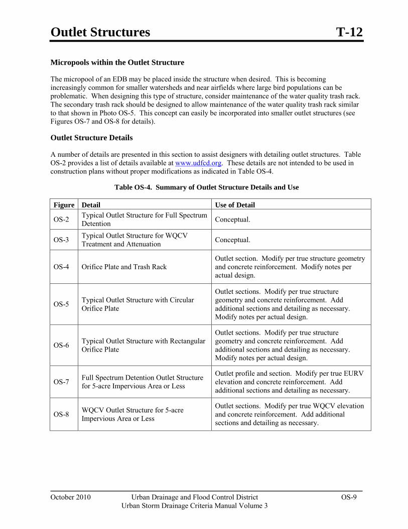
Outlet Structures T-12
October 2010 Urban Drainage and Flood Control District OS-9 Urban Storm Drainage Criteria Manual Volume 3
Micropools within the Outlet Structure
The micropool of an EDB may be placed inside the structure when desired. This is becoming increasingly common for smaller watersheds and near airfields where large bird populations can be problematic. When designing this type of structure, consider maintenance of the water quality trash rack. The secondary trash rack should be designed to allow maintenance of the water quality trash rack similar to that shown in Photo OS-5. This concept can easily be incorporated into smaller outlet structures (see Figures OS-7 and OS-8 for details).
Outlet Structure Details
A number of details are presented in this section to assist designers with detailing outlet structures. Table OS-2 provides a list of details available at www.udfcd.org. These details are not intended to be used in construction plans without proper modifications as indicated in Table OS-4.
Table OS-4. Summary of Outlet Structure Details and Use
Figure Detail Use of Detail
OS-2 Typical Outlet Structure for Full Spectrum Detention Conceptual.
OS-3 Typical Outlet Structure for WQCV Treatment and Attenuation Conceptual.
OS-4 Orifice Plate and Trash Rack Outlet section. Modify per true structure geometry and concrete reinforcement. Modify notes per actual design.
OS-5 Typical Outlet Structure with Circular Orifice Plate
Outlet sections. Modify per true structure geometry and concrete reinforcement. Add additional sections and detailing as necessary. Modify notes per actual design.
OS-6 Typical Outlet Structure with Rectangular Orifice Plate
Outlet sections. Modify per true structure geometry and concrete reinforcement. Add additional sections and detailing as necessary. Modify notes per actual design.
OS-7 Full Spectrum Detention Outlet Structure for 5-acre Impervious Area or Less
Outlet profile and section. Modify per true EURV elevation and concrete reinforcement. Add additional sections and detailing as necessary.
OS-8 WQCV Outlet Structure for 5-acre Impervious Area or Less
Outlet sections. Modify per true WQCV elevation and concrete reinforcement. Add additional sections and detailing as necessary.
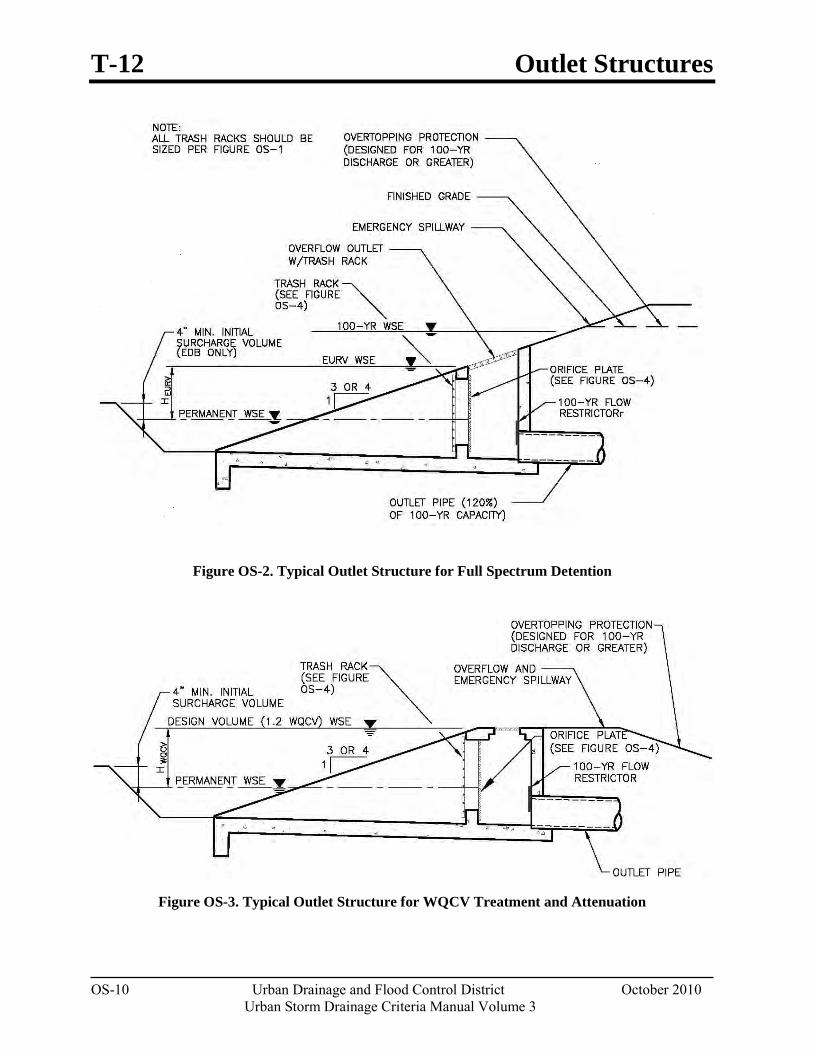
T-12 Outlet Structures
OS-10 Urban Drainage and Flood Control District October 2010
Urban Storm Drainage Criteria Manual Volume 3
Figure OS-2. Typical Outlet Structure for Full Spectrum Detention
Figure OS-3. Typical Outlet Structure for WQCV Treatment and Attenuation
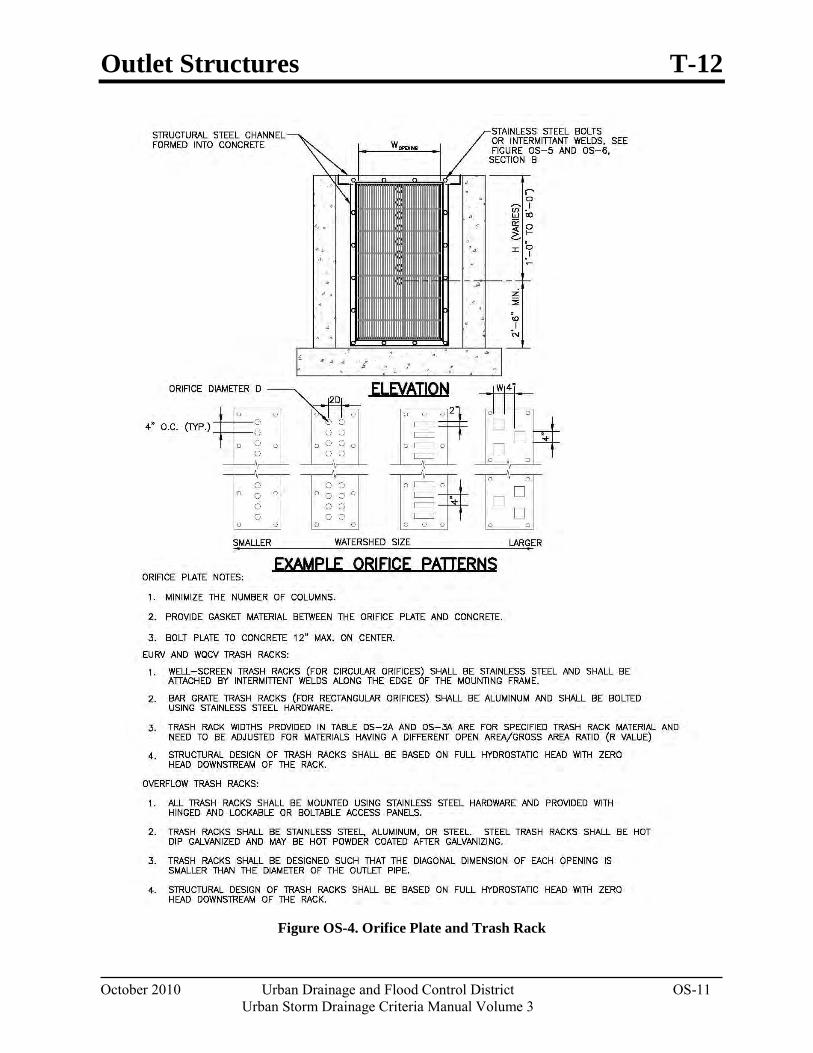
Outlet Structures T-12
October 2010 Urban Drainage and Flood Control District OS-11 Urban Storm Drainage Criteria Manual Volume 3
Figure OS-4. Orifice Plate and Trash Rack
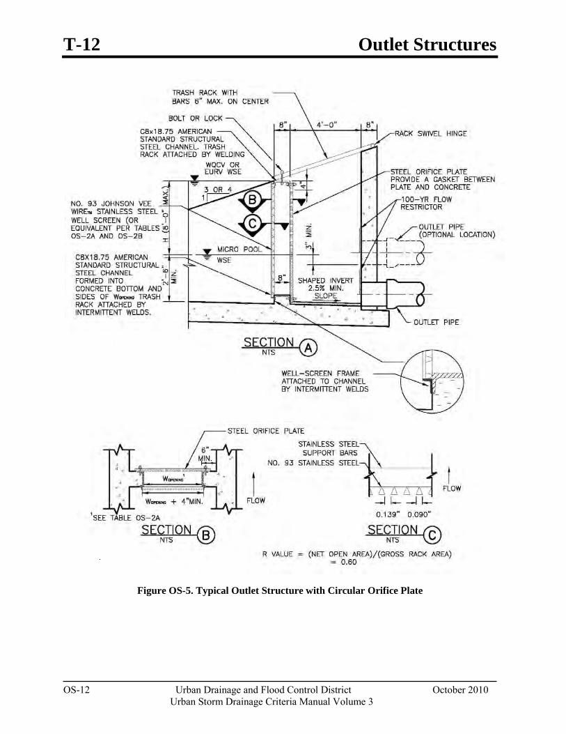
T-12 Outlet Structures
OS-12 Urban Drainage and Flood Control District October 2010
Urban Storm Drainage Criteria Manual Volume 3
Figure OS-5. Typical Outlet Structure with Circular Orifice Plate
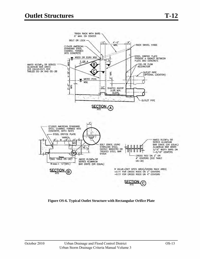
Outlet Structures T-12
October 2010 Urban Drainage and Flood Control District OS-13 Urban Storm Drainage Criteria Manual Volume 3
Figure OS-6. Typical Outlet Structure with Rectangular Orifice Plate
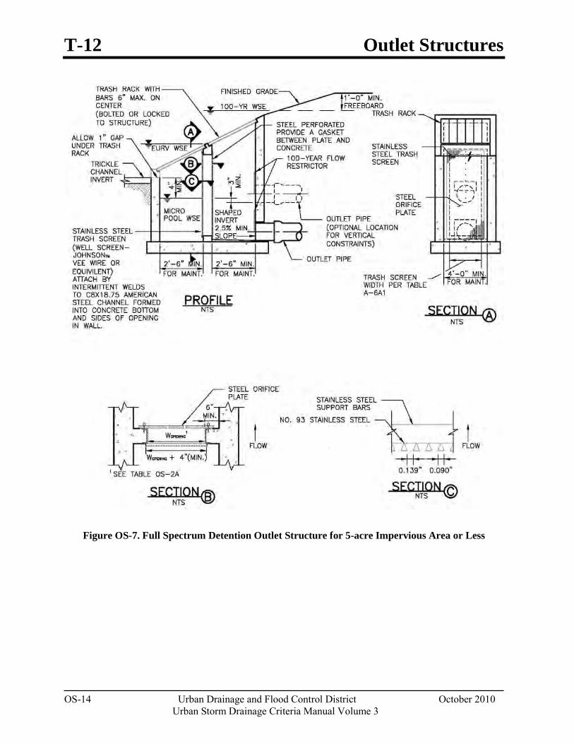
T-12 Outlet Structures
OS-14 Urban Drainage and Flood Control District October 2010
Urban Storm Drainage Criteria Manual Volume 3
Figure OS-7. Full Spectrum Detention Outlet Structure for 5-acre Impervious Area or Less
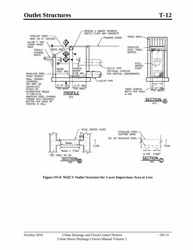
Outlet Structures T-12
October 2010 Urban Drainage and Flood Control District OS-15 Urban Storm Drainage Criteria Manual Volume 3
Figure OS-8. WQCV Outlet Structure for 5-acre Impervious Area or Less

November 2010 Urban Drainage and Flood Control District 5-i Urban Storm Drainage Criteria Manual Volume 3
Chapter 5 Source Control BMPs Contents 1.0 Introduction ...................................................................................................................................... 1
2.0 Structural Source Controls ............................................................................................................. 3
3.0 Procedural Source Control BMPs .................................................................................................. 3 3.1 Municipal Operations ................................................................................................................................ 3 3.2 Commercial and Industrial Operations ...................................................................................................... 5 3.3 Residential Activities ................................................................................................................................ 6
4.0 Combining Source Control BMPs to Target Pollutants of Concern ........................................... 6
5.0 References ......................................................................................................................................... 8
Source Control BMP Fact Sheets S-1 Covering Outdoor Storage and Handling Areas S-2 Spill Prevention, Containment and Control S-3 Disposal of Household Waste S-4 Illicit Discharge Controls S-5 Good Housekeeping S-6 Preventative Maintenance S-7 Vehicle Maintenance, Fueling and Storage S-8 Use of Pesticides, Herbicides and Fertilizers S-9 Landscape Maintenance S-10 Snow and Ice Management S-11 Street Sweeping and Cleaning S-12 Storm Sewer System Cleaning
Tables Table 5-1. Potential Pollutant Sources and Types with Applicable Source Control BMPs ........................ 2Table 5-2. Polluting Activities Associated With Common Hotspot Operations ......................................... 5Table 5-3. Example Source Control Plan Targeting Bacteria ...................................................................... 7

Chapter 5 Source Control BMPs
November 2010 Urban Drainage and Flood Control District 5-1 Urban Storm Drainage Criteria Manual Volume 3
1.0 Introduction Proactively controlling pollutants at their source is fundamental to effective stormwater quality management and is part of the Four Step Process outlined in Chapter 1 of this manual. Typically, it is easier and more cost-effective to prevent stormwater pollution than to remove contaminants once they have entered the storm sewer system or receiving water. Local governments, industries, businesses and homeowners all have opportunities to implement source control practices that help prevent pollution. A good source control BMP is one that is effective at stopping and/or redirecting pollutants prior to entering the storm sewer system. A source control BMP can be a structural component of a planned site (e.g. a covered area for material storage) or a procedural BMP. The latter depend on behavior change accomplished through public education, training and development of standard operating procedures.
This chapter provides BMP Fact Sheets for common source control practices that can be integrated into overall stormwater management plans by local governments, industries and businesses. BMPs applicable to homeowners can also be used for integration into local government public education and awareness efforts related to stormwater quality.
Effective source control also requires awareness of discharges such as commercial washing of outdoor structures, which produces process wastewater that is not appropriate for discharge to the storm drain system. Table 5-1 summarizes types of pollutants generated at various types of facilities that may be reduced from implementation of the source controls found in this chapter. General guidance for selecting source control practices follows, along with the Source Control BMP Fact Sheets.
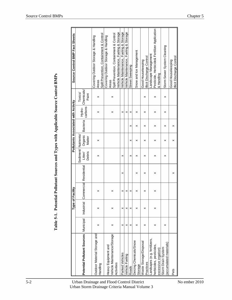
Source Control BMPs Chapter 5
5-2 Urban Drainage and Flood Control District No ember 2010 Urban Storm Drainage Criteria Manual Volume 3
Tab
le 5
-1.
Pote
ntia
l Pol
luta
nt S
ourc
es a
nd T
ypes
with
App
licab
le S
ourc
e C
ontr
ol B
MPs
Sour
ce C
ontr
ol B
MP
Fact
She
ets
Pote
ntia
l Pol
luta
nt S
ourc
esM
unic
ipal
Indu
stria
lC
omm
erci
alR
esid
entia
lS
edim
ent/
Litte
r/ D
ebris
Nut
rient
s/
Org
anic
M
atte
rB
acte
riaH
ydro
-ca
rbon
s
Toxi
cs/
Che
mic
als/
P
aint
Out
door
Mat
eria
l Sto
rage
and
H
andl
ing
xx
xx
xx
xC
over
ing
Out
door
Sto
rage
& H
andl
ing
Area
sS
pill
Pre
vent
ion,
Con
tain
men
t & C
ontro
l
Hea
vy E
quip
men
t and
Ve
hicl
e M
aint
enan
ce/S
tora
ge
Activ
ities
xx
xx
x
Cov
erin
g O
utdo
or S
tora
ge &
Han
dlin
g Ar
eas
Spi
ll P
reve
ntio
n, C
onta
inm
ent &
Con
trol
Vehi
cle
Mai
nten
ance
, Fue
ling
& S
tora
geP
arke
d Ve
hicl
esx
xx
xx
xVe
hicl
e M
aint
enan
ce, F
uelin
g &
Sto
rage
Vehi
cle
Fuel
ing
xx
xx
Vehi
cle
Mai
nten
ance
, Fue
ling
& S
tora
geR
oads
xx
xx
xx
xS
treet
Sw
eepi
ngD
eici
ng C
hem
ical
s/S
now
S
tora
gex
xx
xx
xx
xS
now
and
Ice
Man
agem
ent
Was
te S
tora
ge/D
ispo
sal
Pra
ctic
esx
xx
xx
xx
xx
Goo
d H
ouse
keep
ing
Illic
it D
isch
arge
Con
trol
Land
sape
s (e
.g. f
ertil
izer
s,
herb
icid
es, p
estic
ides
, ex
cess
ive
irrga
tion)
x
xx
xx
xx
xx
Land
scap
e M
anag
emen
tP
estic
ide,
Her
bici
de&
Fer
tiliz
er A
pplic
atio
n &
Han
dlin
gS
torm
Dra
in S
yste
m
(acc
umul
ated
mat
eria
ls)
xx
xx
xx
Sto
rm S
ewer
Sys
tem
Cle
anin
g
Pet
sx
xx
Goo
d H
ouse
keep
ing
Illic
it D
isch
arge
Con
trol
Type
of F
acili
tyPo
lluta
nts
Ass
ocia
ted
with
Act
ivity
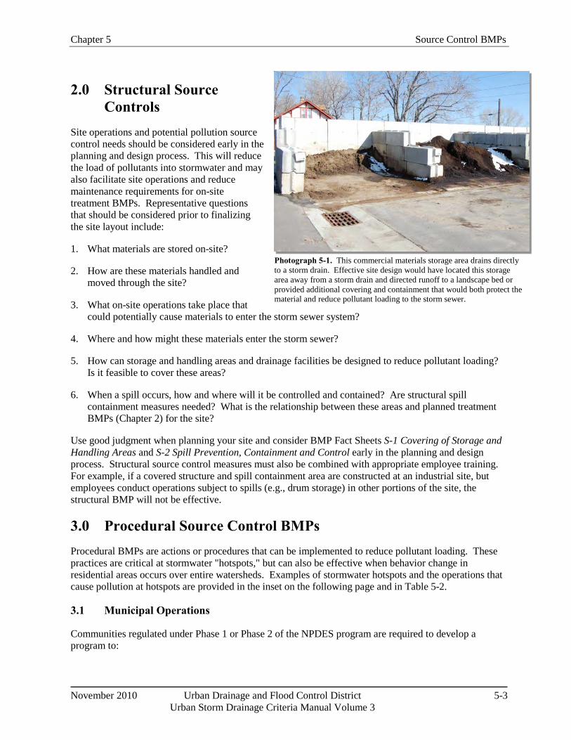
Chapter 5 Source Control BMPs
November 2010 Urban Drainage and Flood Control District 5-3 Urban Storm Drainage Criteria Manual Volume 3
Photograph 5-1. This commercial materials storage area drains directly to a storm drain. Effective site design would have located this storage area away from a storm drain and directed runoff to a landscape bed or provided additional covering and containment that would both protect the material and reduce pollutant loading to the storm sewer.
2.0 Structural Source Controls
Site operations and potential pollution source control needs should be considered early in the planning and design process. This will reduce the load of pollutants into stormwater and may also facilitate site operations and reduce maintenance requirements for on-site treatment BMPs. Representative questions that should be considered prior to finalizing the site layout include:
1. What materials are stored on-site?
2. How are these materials handled and moved through the site?
3. What on-site operations take place that could potentially cause materials to enter the storm sewer system?
4. Where and how might these materials enter the storm sewer?
5. How can storage and handling areas and drainage facilities be designed to reduce pollutant loading? Is it feasible to cover these areas?
6. When a spill occurs, how and where will it be controlled and contained? Are structural spill containment measures needed? What is the relationship between these areas and planned treatment BMPs (Chapter 2) for the site?
Use good judgment when planning your site and consider BMP Fact Sheets S-1 Covering of Storage and Handling Areas and S-2 Spill Prevention, Containment and Control early in the planning and design process. Structural source control measures must also be combined with appropriate employee training. For example, if a covered structure and spill containment area are constructed at an industrial site, but employees conduct operations subject to spills (e.g., drum storage) in other portions of the site, the structural BMP will not be effective.
3.0 Procedural Source Control BMPs Procedural BMPs are actions or procedures that can be implemented to reduce pollutant loading. These practices are critical at stormwater "hotspots," but can also be effective when behavior change in residential areas occurs over entire watersheds. Examples of stormwater hotspots and the operations that cause pollution at hotspots are provided in the inset on the following page and in Table 5-2.
3.1 Municipal Operations
Communities regulated under Phase 1 or Phase 2 of the NPDES program are required to develop a program to:
Source Control BMPs Chapter 5
5-4 Urban Drainage and Flood Control District No ember 2010 Urban Storm Drainage Criteria Manual Volume 3
Examples of Stormwater "Hotspots"
Fleet storage areas
Solid waste facilities
Wastewater treatment plants
Composting facilities
Nurseries and garden centers
Restaurants
Industrial rooftops
Recycling facilities
Maintenance facilities
Gas stations
Fast-food drive-thru areas
Airports
Developing a Municipal Program
Urban Subwatershed Restoration Series Manual 9: Municipal Pollution Prevents/Good Housekeeping Practices prepared by The Center for Watershed Protection (2008), outlines a detailed approach for developing a municipal pollution prevention/good housekeeping program. The manual is available to download at no cost at www.cwp.org.
Prevent or reduce the amount of polluted stormwater generated by municipal operations;
Educate employees to incorporate pollution prevention and good housekeeping practices into municipal operations; and
Identify BMPs and measurable goals for the prevention or reduction of the amount of polluted stormwater that is generated by municipal operations.
Developing an effective municipal pollution prevention and good housekeeping program involves implementing a program that 1) is specifically designed for a community, taking into consideration how information is communicated and how training is provided and received, and 2) incorporates sound standard practices for various operations. Many communities nationally and in the metro Denver area have developed such standard operating procedures. The Fact Sheets provided in this chapter may be used to develop such procedures or to supplement existing procedures. Development of a program that is specifically tailored to a community should begin with evaluation of the following questions (Center for Watershed Protection 2008):
1. What municipal operations are conducted within the community?
2. What stormwater pollutants are associated with the operations?
3. Who is responsible for managing each of the operations?
4. What is the primary pollutant of concern in the subwatershed?
5. Which of the operations has the greatest influence on water quality and should be the focus of the community's pollution prevention/good housekeeping efforts?
6. What specific pollution prevention/good housekeeping practices should be implemented to improve the operations?
7. How much will the pollution prevention/good housekeeping practices cost?
8. Who will be responsible for implementing the pollution prevention/good housekeeping practices?
9. How will progress made in pollution prevention/good housekeeping be evaluated?
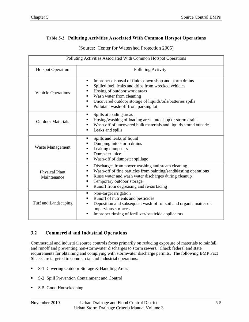
Chapter 5 Source Control BMPs
November 2010 Urban Drainage and Flood Control District 5-5 Urban Storm Drainage Criteria Manual Volume 3
Table 5-2. Polluting Activities Associated With Common Hotspot Operations
(Source: Center for Watershed Protection 2005)
Polluting Activities Associated With Common Hotspot Operations
Hotspot Operation Polluting Activity
Vehicle Operations
Improper disposal of fluids down shop and storm drains Spilled fuel, leaks and drips from wrecked vehicles Hosing of outdoor work areas Wash water from cleaning Uncovered outdoor storage of liquids/oils/batteries spills Pollutant wash-off from parking lot
Outdoor Materials Spills at loading areas Hosing/washing of loading areas into shop or storm drains Wash-off of uncovered bulk materials and liquids stored outside Leaks and spills
Waste Management
Spills and leaks of liquid Dumping into storm drains Leaking dumpsters Dumpster juice Wash-off of dumpster spillage
Physical Plant Maintenance
Discharges from power washing and steam cleaning Wash-off of fine particles from painting/sandblasting operations Rinse water and wash water discharges during cleanup Temporary outdoor storage Runoff from degreasing and re-surfacing
Turf and Landscaping
Non-target irrigation Runoff of nutrients and pesticides Deposition and subsequent wash-off of soil and organic matter on
impervious surfaces Improper rinsing of fertilizer/pesticide applicators
3.2 Commercial and Industrial Operations
Commercial and industrial source controls focus primarily on reducing exposure of materials to rainfall and runoff and preventing non-stormwater discharges to storm sewers. Check federal and state requirements for obtaining and complying with stormwater discharge permits. The following BMP Fact Sheets are targeted to commercial and industrial operations:
S-1 Covering Outdoor Storage & Handling Areas
S-2 Spill Prevention Containment and Control
S-5 Good Housekeeping
Source Control BMPs Chapter 5
5-6 Urban Drainage and Flood Control District No ember 2010 Urban Storm Drainage Criteria Manual Volume 3
S-6 Preventative Maintenance
S-7 Vehicle Maintenance, Fueling & Storage
S-10 Snow and Ice Management
Other fact sheets related to landscape management may also be helpful at commercial and industrial sites with landscaping.
3.3 Residential Activities
Although residential activities that may pollute stormwater runoff are typically conducted on a smaller scale than industrial, commercial and municipal operations, the cumulative impact of residential sources of pollution can be significant. As discussed in Section 3.1, municipal stormwater programs should include efforts to reduce pollution from residential areas within their jurisdiction. This is often accomplished through a combination of ordinances, public education efforts and incentives. BMP Fact Sheets provided in this chapter that are applicable to residential sources of pollution include:
S-3 Disposal of Household Waste
S-4 Illicit Discharge Controls
S-5 Good Housekeeping
S-8 Use of Pesticides, Herbicides and Fertilizers
S-9 Landscape Maintenance
S-10 Snow and Ice Management
4.0 Combining Source Control BMPs to Target Pollutants of Concern
In many cases, local governments will need to combine multiple source control practices and strategies to target control of specific pollutants. For impaired streams that have been assigned Total Maximum Daily Loads (TMDLs), municipal stormwater discharge permittees may receive a wasteload allocation, resulting in specific requirements to reduce pollutant loading in their stormwater permits. For example, bacteria is a leading cause of stream impairment nationally and in Colorado. Table 5-3 provides an example of a multi-faceted source control plan targeted toward reducing bacteria loading to streams. Similar combinations of source control practices can be targeted toward nutrients and other pollutants. To produce long-term behavioral change, a well-planned and executed public education campaign may be needed, combined with incentives and fines.
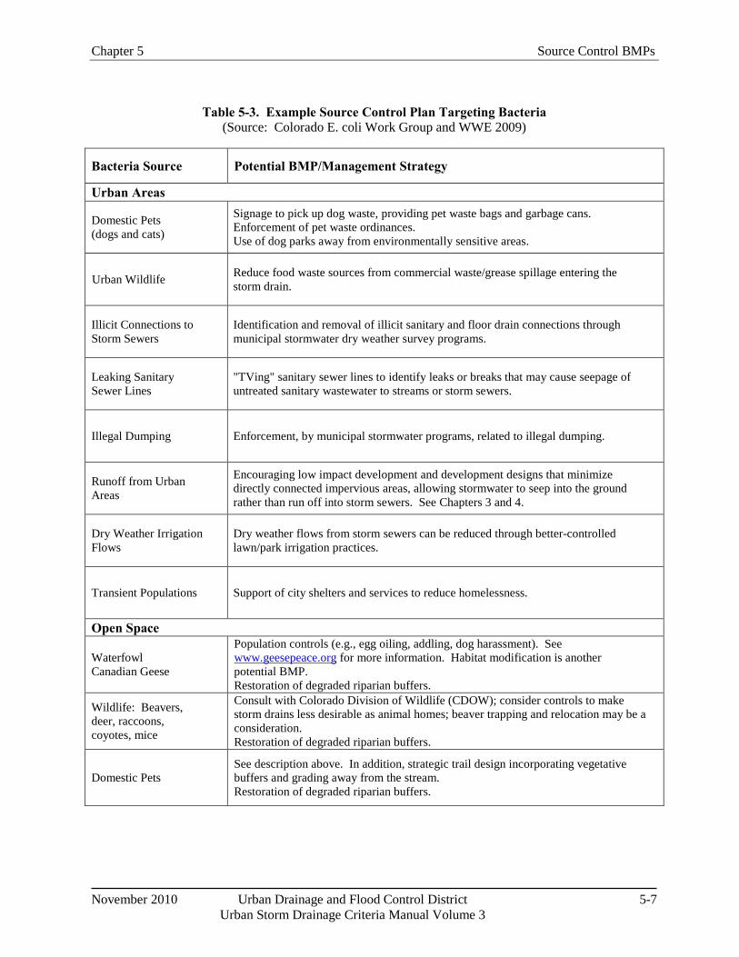
Chapter 5 Source Control BMPs
November 2010 Urban Drainage and Flood Control District 5-7 Urban Storm Drainage Criteria Manual Volume 3
Table 5-3. Example Source Control Plan Targeting Bacteria (Source: Colorado E. coli Work Group and WWE 2009)
Bacteria Source Potential BMP/Management Strategy
Urban Areas
Domestic Pets (dogs and cats)
Signage to pick up dog waste, providing pet waste bags and garbage cans. Enforcement of pet waste ordinances. Use of dog parks away from environmentally sensitive areas.
Urban Wildlife Reduce food waste sources from commercial waste/grease spillage entering the storm drain.
Illicit Connections to Storm Sewers
Identification and removal of illicit sanitary and floor drain connections through municipal stormwater dry weather survey programs.
Leaking Sanitary Sewer Lines
"TVing" sanitary sewer lines to identify leaks or breaks that may cause seepage of untreated sanitary wastewater to streams or storm sewers.
Illegal Dumping Enforcement, by municipal stormwater programs, related to illegal dumping.
Runoff from Urban Areas
Encouraging low impact development and development designs that minimize directly connected impervious areas, allowing stormwater to seep into the ground rather than run off into storm sewers. See Chapters 3 and 4.
Dry Weather Irrigation Flows
Dry weather flows from storm sewers can be reduced through better-controlled lawn/park irrigation practices.
Transient Populations Support of city shelters and services to reduce homelessness.
Open Space
Waterfowl Canadian Geese
Population controls (e.g., egg oiling, addling, dog harassment). See www.geesepeace.org for more information. Habitat modification is another potential BMP. Restoration of degraded riparian buffers.
Wildlife: Beavers, deer, raccoons, coyotes, mice
Consult with Colorado Division of Wildlife (CDOW); consider controls to make storm drains less desirable as animal homes; beaver trapping and relocation may be a consideration. Restoration of degraded riparian buffers.
Domestic Pets See description above. In addition, strategic trail design incorporating vegetative buffers and grading away from the stream. Restoration of degraded riparian buffers.
Source Control BMPs Chapter 5
5-8 Urban Drainage and Flood Control District No ember 2010 Urban Storm Drainage Criteria Manual Volume 3
5.0 References California Association of Stormwater Quality Agencies (CASQA). 2003. California Stormwater BMP
Handbook, Practice SC-70 Road and Street Maintenance.
Center for Watershed Protection. 2002. Article 121 New Developments in Street Sweeper Technology. The Practice of Watershed Protection.
Center for Watershed Protection and Robert Pitt. 2004. Illicit Discharge Detection and Elimination: A Guidance Manual for Program Development and Technical Assessments. (http://cwp.org.master.com/texis/master/search/+/form/New_IDDE.html).
Center for Watershed Protection. 2005. Urban Stormwater Restoration Manual Series 8: Pollution Source Control Practices. Version 2.0. February.
Center for Watershed Protection, 2008. Urban Stormwater Restoration Manual Series 8: Municipal Practices and Programs.
Colorado State University Turfgrass website: http://csuturf.colostate.edu/.
U.S. Environmental Protection Agency (EPA) "Menu of BMPs" website: http://cfpub.epa.gov/npdes/stormwater/menuofbmps/. Accessed April 2010.
U.S. Environmental Protection Agency (EPA). 2009. Municipal Solid Waste Generation, Recycling, and Disposal in the United States: Facts and Figures for 2008. http://www.epa.gov/epawaste/nonhaz/municipal/pubs/msw2008rpt.pdf
Fairfax County Virginia. 2005. LID BMP Fact Sheet, Street Sweeping.
GreenCO and Wright Water Engineers. 2008. GreenCO Best Management Practices for the Conservation and Protection of Water Quality in Colorado: Moving Toward Sustainability (www.greenco.org).
Mineart, P. and S. Singh. 1994. Storm Inlet Pilot Study. Prepared for Alameda County Urban Runoff Clean Water Program. Woodward-Clyde Consultants: Oakland, CA.
Pitt, R., R. Bannerman, and R Sutherland. 2004. The Role of Street Cleaning in Stormwater Management, Proceedings of World Water and Environmental Resources Conference. Environmental and Water Resources Institute of the American Society of Civil Engineers: Salt Lake City, UT.
Pitt, R. and P. Bissonette. 1984. Characterizing and Controlling Urban Runoff Through Street and Sewerage Cleaning. Bellevue Urban Runoff Program. Summary Report. U.S. Environmental Protection Agency. EPA-600/S2-85/038: Washington, DC.
The SeaCrest Group. 2001. Evaluation of Selected Deicers Based on a Review of the Literature, Report No. CDOT-DTD-2001-15. Prepared for Colorado Department of Transportation Research Branch.
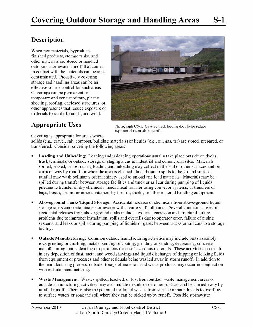
Covering Outdoor Storage and Handling Areas S-1
November 2010 Urban Drainage and Flood Control District CS-1 Urban Storm Drainage Criteria Manual Volume 3
Photograph CS-1. Covered truck loading dock helps reduce exposure of materials to runoff.
Description When raw materials, byproducts, finished products, storage tanks, and other materials are stored or handled outdoors, stormwater runoff that comes in contact with the materials can become contaminated. Proactively covering storage and handling areas can be an effective source control for such areas. Coverings can be permanent or temporary and consist of tarp, plastic sheeting, roofing, enclosed structures, or other approaches that reduce exposure of materials to rainfall, runoff, and wind.
Appropriate Uses Covering is appropriate for areas where solids (e.g., gravel, salt, compost, building materials) or liquids (e.g., oil, gas, tar) are stored, prepared, or transferred. Consider covering the following areas:
Loading and Unloading: Loading and unloading operations usually take place outside on docks, truck terminals, or outside storage or staging areas at industrial and commercial sites. Materials spilled, leaked, or lost during loading and unloading may collect in the soil or other surfaces and be carried away by runoff, or when the area is cleaned. In addition to spills to the ground surface, rainfall may wash pollutants off machinery used to unload and load materials. Materials may be spilled during transfer between storage facilities and truck or rail car during pumping of liquids, pneumatic transfer of dry chemicals, mechanical transfer using conveyor systems, or transfers of bags, boxes, drums, or other containers by forklift, trucks, or other material handling equipment.
Aboveground Tanks/Liquid Storage: Accidental releases of chemicals from above-ground liquid storage tanks can contaminate stormwater with a variety of pollutants. Several common causes of accidental releases from above-ground tanks include: external corrosion and structural failure, problems due to improper installation, spills and overfills due to operator error, failure of piping systems, and leaks or spills during pumping of liquids or gases between trucks or rail cars to a storage facility.
Outside Manufacturing: Common outside manufacturing activities may include parts assembly, rock grinding or crushing, metals painting or coating, grinding or sanding, degreasing, concrete manufacturing, parts cleaning or operations that use hazardous materials. These activities can result in dry deposition of dust, metal and wood shavings and liquid discharges of dripping or leaking fluids from equipment or processes and other residuals being washed away in storm runoff. In addition to the manufacturing process, outside storage of materials and waste products may occur in conjunction with outside manufacturing.
Waste Management: Wastes spilled, leached, or lost from outdoor waste management areas or outside manufacturing activities may accumulate in soils or on other surfaces and be carried away by rainfall runoff. There is also the potential for liquid wastes from surface impoundments to overflow to surface waters or soak the soil where they can be picked up by runoff. Possible stormwater
S-1 Covering Outdoor Storage and Handling Areas
CS-2 Urban Drainage and Flood Control District November 2010
Urban Storm Drainage Criteria Manual Volume 3
contaminants include toxic compounds, oil and grease, oxygen-demanding organics, paints and solvents, heavy metals and high levels of suspended solids. Lack of coverage of waste receptacles can result in rainwater seeping through the material and collecting contaminants or the material being blown around the site and into the stormwater collection system. Typical contaminant sources include: landfills, waste piles, wastewater and solid waste treatment and disposal, land application sites, dumpsters, or unlabeled drums.
Outside Storage of Materials: Raw materials, intermediate products, byproducts, process residuals, finished products, containers, and materials storage areas can be sources of pollutants such as metals, oils and grease, sediment and other contaminants. Pollutant transport can occur when solid materials wash off or dissolve into water, or when spills or leaks occur.
Salt Storage: Salt left exposed to rain or snow may migrate to the storm sewer or contaminate soils. Salt spilled or blown onto the ground during loading or unloading will dissolve in stormwater runoff. Stormwater contaminated with salt in high concentrations can be harmful to vegetation, aquatic life and groundwater quality. Typical contaminant sources include salt stored outside in piles or bags, salt loading and unloading areas, and salt/sand storage piles used for deicing operations.
Practice Guidelines Where practical, conduct operations indoors. Where impractical, select an appropriate temporary or
permanent covering to reduce exposure of materials to rainfall and runoff.
The type of covering selected depends on a variety of factors such as the type and size of activity being conducted and materials involved. Types of cover range from relatively inexpensive tarps and plastic sheeting to overhead structures or fully enclosed buildings equipped with ventilation, lighting, etc.
Covering practices should be combined with Good Housekeeping BMPs to be most effective. Spill containment berms are also often needed at industrial sites.
Measures such as tarps and plastic sheets typically require more frequent inspection and maintenance than constructed facilities.
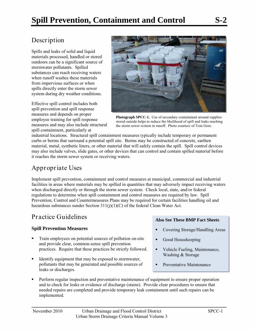
Spill Prevention, Containment and Control S-2
November 2010 Urban Drainage and Flood Control District SPCC-1 Urban Storm Drainage Criteria Manual Volume 3
Photograph SPCC-1. Use of secondary containment around supplies stored outside helps to reduce the likelihood of spill and leaks reaching the storm sewer system in runoff. Photo courtesy of Tom Gore.
Also See These BMP Fact Sheets
Covering Storage/Handling Areas
Good Housekeeping
Vehicle Fueling, Maintenance, Washing & Storage
Preventative Maintenance
Descr iption Spills and leaks of solid and liquid materials processed, handled or stored outdoors can be a significant source of stormwater pollutants. Spilled substances can reach receiving waters when runoff washes these materials from impervious surfaces or when spills directly enter the storm sewer system during dry weather conditions.
Effective spill control includes both spill prevention and spill response measures and depends on proper employee training for spill response measures and may also include structural spill containment, particularly at industrial locations. Structural spill containment measures typically include temporary or permanent curbs or berms that surround a potential spill site. Berms may be constructed of concrete, earthen material, metal, synthetic liners, or other material that will safely contain the spill. Spill control devices may also include valves, slide gates, or other devices that can control and contain spilled material before it reaches the storm sewer system or receiving waters.
Appropr iate Uses Implement spill prevention, containment and control measures at municipal, commercial and industrial facilities in areas where materials may be spilled in quantities that may adversely impact receiving waters when discharged directly or through the storm sewer system. Check local, state, and/or federal regulations to determine when spill containment and control measures are required by law. Spill Prevention, Control and Countermeasures Plans may be required for certain facilities handling oil and hazardous substances sunder Section 311(j)(1)(C) of the federal Clean Water Act.
Practice Guidelines
Spill Prevention Measures
Train employees on potential sources of pollution on-site and provide clear, common-sense spill prevention practices. Require that these practices be strictly followed.
Identify equipment that may be exposed to stormwater, pollutants that may be generated and possible sources of leaks or discharges.
Perform regular inspection and preventative maintenance of equipment to ensure proper operation and to check for leaks or evidence of discharge (stains). Provide clear procedures to ensure that needed repairs are completed and provide temporary leak containment until such repairs can be implemented.
S-2 Spill Prevention, Containment and Control
SPCC-2 Urban Drainage and Flood Control District November 2010 Urban Storm Drainage Criteria Manual Volume 3
Drain or replace motor oil and other automotive fluids in a designated area away from storm sewer inlets. Collect spent fluids and recycle or dispose of properly. Never dispose of these fluids in the storm sewer or sanitary sewer.
In fueling areas, clean up spills with dry methods (absorbents) and use damp cloths on gas pumps and damp mops on paved surfaces. Never use a hose to “wash down” a fuel spill.
Where practical, reduce stormwater contact with equipment and materials by implementing indoor or covered storage, implementing stormwater run-on control measures and following good housekeeping practices.
Identification of Spill Areas
Identify potential spill areas, potential spill volumes, material types, frequency of material use, and drainage paths from spill areas with relation to storm sewer inlets, adjacent waterbodies, structural BMPs, and containment structures. Use this information to determine the types of spill prevention and control measures needed specific to the site conditions. Examples of potential spill locations include:
Loading and unloading areas
Outdoor storage areas
Outdoor manufacturing or processing activities
Waste disposal/storage areas
Areas that generate significant dust or particulates (that may be subsequently deposited on the ground)
Salt piles
Areas prone to spills based on past experience at the site
Locations where other routine maintenance activities occur such as equipment maintenance and cleaning, pesticide/fertilizer application, etc.
Additionally, areas where smaller leaks may occur such as parking should also have basic spill cleanup procedures.
Material Handling Procedures
From a water quality perspective, the primary principle behind effective material handling practices is to minimize exposure to stormwater. This can be accomplished by storing the material indoors under weather-resistant covering, elevating the material off the ground by using pallets, and diverting stormwater around materials storage areas. Representative outdoor materials handling procedures include:
Keep bulk solid materials such as raw materials, sand, gravel, topsoil, compost, concrete, packing materials, metal products and other materials covered and protected from stormwater.
When practical, store materials on impermeable surfaces.
Store hazardous materials according to federal, state, and local hazardous materials requirements.
Spill Prevention, Containment and Control S-2
November 2010 Urban Drainage and Flood Control District SPCC-3 Urban Storm Drainage Criteria Manual Volume 3
Adopt procedures that reduce the chance of spills or leaks during filling or transfer of materials.
Substitute less toxic or non-toxic materials for toxic materials.
Store containers that are easily punctured or damaged away from high traffic areas (i.e., adopt a materials flow/plant layout plan).
Add waste-capture containers such as collection pans for lubricating fluids.
Store drums and containers with liquid materials on impermeable surfaces and provide secondary containment where appropriate. Drums stored outdoors should be located on pallets to minimize contact with runoff.
Spill Response Procedures and Equipment
Spill response procedures should be tailored to site-specific conditions and industry-specific regulatory requirements. General spill response procedures include:
Containment and cleanup of spills should begin promptly after the spill is observed.
Sweep up small quantities of dry chemical or solids to reduce exposure to runoff. Shoveling may be used for larger quantities of materials.
Absorbents should be readily accessible in fueling areas or other areas susceptible to spills.
Wipe up small spills with a shop rag, store shop rags in appropriate containers, dispose of rags properly or use a professional industrial cleaning service.
Contain medium-sized spills with absorbents (e.g., kitty litter, sawdust) and use inflatable berms or absorbent “snakes” as temporary booms for the spill. Store and dispose of absorbents properly. Wet/dry vacuums may also be used, but not for volatile fluids.
Develop procedures and locations for containing and storing leaking containers.
Install drip pans below minor equipment leaks and properly dispose of collected material until a repair can be made.
For large spills, first contain the spill and plug storm drain inlets where the liquid may migrate off-site, then clean up the spill.
Excavation of spill areas to removed contaminated material may be required where large liquid spills occur on unpaved surfaces.
An inventory of cleanup materials should be maintained onsite and strategically located based on the types and quantities of chemicals present.
Structural Spill Containment Measures
Two general approaches are often used when implementing spill containment measures. The first approach is designed to contain the entire spill. The second approach uses curbing to route spilled material to a collection basin. Both containment berming and curbing should be sized to safely contain or convey to a collection basin a spill from the largest storage tank, rail car, tank truck, or other containment device in the possible spill area. The spill containment area must have an impermeable surface (e.g.,
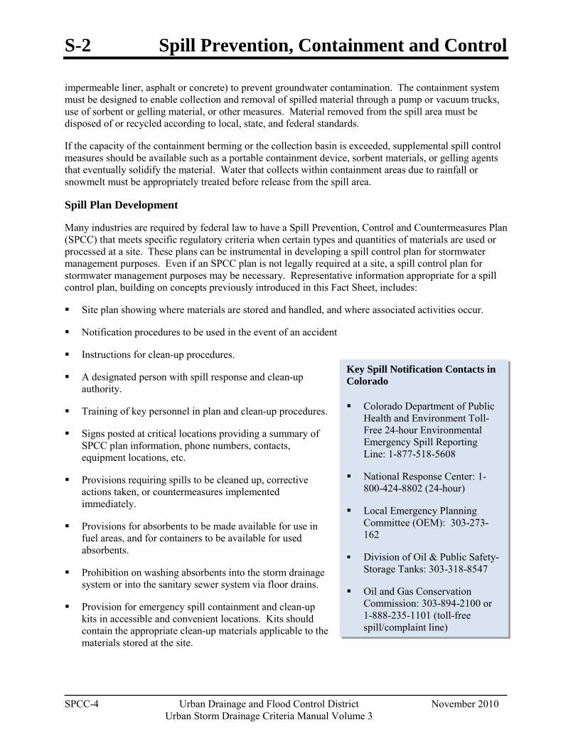
S-2 Spill Prevention, Containment and Control
SPCC-4 Urban Drainage and Flood Control District November 2010 Urban Storm Drainage Criteria Manual Volume 3
Key Spill Notification Contacts in Colorado
Colorado Department of Public Health and Environment Toll-Free 24-hour Environmental Emergency Spill Reporting Line: 1-877-518-5608
National Response Center: 1-800-424-8802 (24-hour)
Local Emergency Planning Committee (OEM): 303-273-162
Division of Oil & Public Safety-Storage Tanks: 303-318-8547
Oil and Gas Conservation Commission: 303-894-2100 or 1-888-235-1101 (toll-free spill/complaint line)
impermeable liner, asphalt or concrete) to prevent groundwater contamination. The containment system must be designed to enable collection and removal of spilled material through a pump or vacuum trucks, use of sorbent or gelling material, or other measures. Material removed from the spill area must be disposed of or recycled according to local, state, and federal standards.
If the capacity of the containment berming or the collection basin is exceeded, supplemental spill control measures should be available such as a portable containment device, sorbent materials, or gelling agents that eventually solidify the material. Water that collects within containment areas due to rainfall or snowmelt must be appropriately treated before release from the spill area.
Spill Plan Development
Many industries are required by federal law to have a Spill Prevention, Control and Countermeasures Plan (SPCC) that meets specific regulatory criteria when certain types and quantities of materials are used or processed at a site. These plans can be instrumental in developing a spill control plan for stormwater management purposes. Even if an SPCC plan is not legally required at a site, a spill control plan for stormwater management purposes may be necessary. Representative information appropriate for a spill control plan, building on concepts previously introduced in this Fact Sheet, includes:
Site plan showing where materials are stored and handled, and where associated activities occur.
Notification procedures to be used in the event of an accident
Instructions for clean-up procedures.
A designated person with spill response and clean-up authority.
Training of key personnel in plan and clean-up procedures.
Signs posted at critical locations providing a summary of SPCC plan information, phone numbers, contacts, equipment locations, etc.
Provisions requiring spills to be cleaned up, corrective actions taken, or countermeasures implemented immediately.
Provisions for absorbents to be made available for use in fuel areas, and for containers to be available for used absorbents.
Prohibition on washing absorbents into the storm drainage system or into the sanitary sewer system via floor drains.
Provision for emergency spill containment and clean-up kits in accessible and convenient locations. Kits should contain the appropriate clean-up materials applicable to the materials stored at the site.
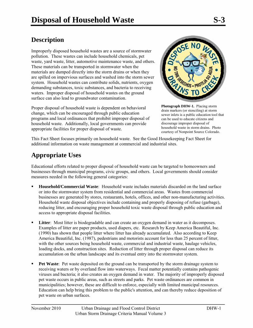
Disposal of Household Waste S-3
November 2010 Urban Drainage and Flood Control District DHW-1 Urban Storm Drainage Criteria Manual Volume 3
Photograph DHW-1. Placing storm drain markers (or stenciling) at storm sewer inlets is a public education tool that can be used to educate citizens and discourage improper disposal of household waste in storm drains. Photo courtesy of Nonpoint Source Colorado.
Description Improperly disposed household wastes are a source of stormwater pollution. These wastes can include household chemicals, pet waste, yard waste, litter, automotive maintenance waste, and others. These materials can be transported in stormwater when the materials are dumped directly into the storm drains or when they are spilled on impervious surfaces and washed into the storm sewer system. Household wastes can contribute solids, nutrients, oxygen demanding substances, toxic substances, and bacteria to receiving waters. Improper disposal of household wastes on the ground surface can also lead to groundwater contamination.
Proper disposal of household waste is dependent on behavioral change, which can be encouraged through public education programs and local ordinances that prohibit improper disposal of household waste. Additionally, local governments can provide appropriate facilities for proper disposal of waste.
This Fact Sheet focuses primarily on household waste. See the Good Housekeeping Fact Sheet for additional information on waste management at commercial and industrial sites.
Appropriate Uses Educational efforts related to proper disposal of household waste can be targeted to homeowners and businesses through municipal programs, civic groups, and others. Local governments should consider measures needed in the following general categories:
Household/Commercial Waste: Household waste includes materials discarded on the land surface or into the stormwater system from residential and commercial areas. Wastes from commercial businesses are generated by stores, restaurants, hotels, offices, and other non-manufacturing activities. Household waste disposal objectives include containing and properly disposing of refuse (garbage), reducing litter, and encouraging proper household toxic waste disposal through public education and access to appropriate disposal facilities.
Litter: Most litter is biodegradable and can create an oxygen demand in water as it decomposes. Examples of litter are paper products, used diapers, etc. Research by Keep America Beautiful, Inc. (1990) has shown that people litter where litter has already accumulated. Also according to Keep America Beautiful, Inc. (1987), pedestrians and motorists account for less than 25 percent of litter, with the other sources being household waste, commercial and industrial waste, haulage vehicles, loading docks, and construction sites. Reduction of litter through proper disposal can reduce its accumulation on the urban landscape and its eventual entry into the stormwater system.
Pet Waste: Pet waste deposited on the ground can be transported by the storm drainage system to receiving waters or by overland flow into waterways. Fecal matter potentially contains pathogenic viruses and bacteria; it also creates an oxygen demand in water. The majority of improperly disposed pet waste occurs in public areas, such as streets and parks. Pet waste ordinances are common in municipalities; however, these are difficult to enforce, especially with limited municipal resources. Education can help bring this problem to the public's attention, and can thereby reduce deposition of pet waste on urban surfaces.
S-3 Disposal of Household Waste
DHW-2 Urban Drainage and Flood Control District November 2010
Urban Storm Drainage Criteria Manual Volume 3
Composting Composting is a natural method for recycling organics such as yard trimmings and food scraps, which comprise nearly a quarter of municipal solids waste generated (Keep America Beautiful 2010). Nearly half of all U.S. states now ban yard waste from landfills because it represents such a large volume that can be productively composted. Composted yard waste used as mulch or soil amendment can provide landscape water conservation benefits, reduce the burden on landfills and is protective of water quality.
Municipal Recycling Programs
Many communities throughout the country have implemented municipal recycling programs, rather than relying on citizens to research and seek out recycling opportunities on their own. Curbside recycling programs and municipal education campaigns can improve the success of recycling programs. For more information on implementing a municipal recycling program, visit a variety of U.S. Environmental Protection Agency websites such as: http://www.epa.gov/epawaste/conserve/rrr/index.htm and http://www.epa.gov/region4/waste/rcra/mgtoolkit/index.html or review well developed local programs such as Denver Recycles.
Yard Waste: Yard waste includes limbs, leaves and grass clippings that can contribute nutrients, lawn chemicals, and oxygen demand to receiving waters when washed into storm sewers and waterways. Public education efforts on the benefits of composting and on proper disposal of yard waste can help to reduce the volume of yard waste entering the stormwater system and receiving waters. Most yard waste can be reused following composting, with the exception of weeds and diseased plant materials.
Used Oil and Automotive Fluids: Used oil and automotive fluids including antifreeze, brake fluid, transmission fluid, grease, other lubricants, and petroleum-based cleaning solvents are wastes generated during automobile maintenance by residential households and commercial businesses. These can enter the storm drainage system if poured directly into storm inlets or from residual on concrete or asphalt exposed to precipitation. Improper disposal of used oil and automotive fluids causes receiving waters to become contaminated with hydrocarbons and residual metals that can be toxic to stream organisms. Used oil and other petroleum products can be recycled and are accepted by many auto parts stores and repair shops. Public education on the location of these centers, the benefits of recycling, prevention of fluid leaks, and the importance of proper disposal for improving stormwater quality can reduce the amounts of oil and used automotive fluids reaching receiving waters.
Toxic Wastes: Toxic wastes are generated in small quantities by residential households and commercial businesses. Examples include paint, solvents, putties, cleaners, waxes, polishes, oil products, aerosols, acids, caustics, pesticides, herbicides, and certain medicines or cosmetics. These products and their containers should always be disposed of in accordance with the product label or recycled, if appropriate. When such toxic substances are improperly disposed of by dumping on impervious surfaces or into street gutters or storm inlets, stormwater can transport these materials to receiving waters.
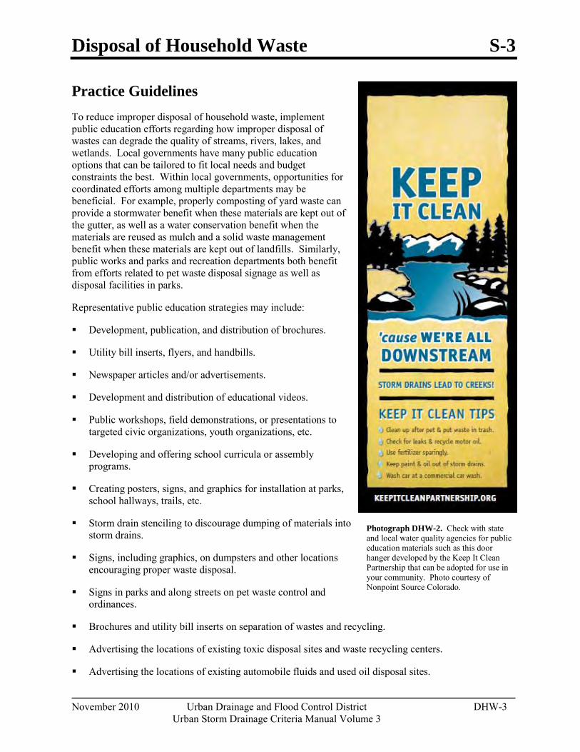
Disposal of Household Waste S-3
November 2010 Urban Drainage and Flood Control District DHW-3 Urban Storm Drainage Criteria Manual Volume 3
Photograph DHW-2. Check with state and local water quality agencies for public education materials such as this door hanger developed by the Keep It Clean Partnership that can be adopted for use in your community. Photo courtesy of Nonpoint Source Colorado.
Practice Guidelines To reduce improper disposal of household waste, implement public education efforts regarding how improper disposal of wastes can degrade the quality of streams, rivers, lakes, and wetlands. Local governments have many public education options that can be tailored to fit local needs and budget constraints the best. Within local governments, opportunities for coordinated efforts among multiple departments may be beneficial. For example, properly composting of yard waste can provide a stormwater benefit when these materials are kept out of the gutter, as well as a water conservation benefit when the materials are reused as mulch and a solid waste management benefit when these materials are kept out of landfills. Similarly, public works and parks and recreation departments both benefit from efforts related to pet waste disposal signage as well as disposal facilities in parks.
Representative public education strategies may include:
Development, publication, and distribution of brochures.
Utility bill inserts, flyers, and handbills.
Newspaper articles and/or advertisements.
Development and distribution of educational videos.
Public workshops, field demonstrations, or presentations to targeted civic organizations, youth organizations, etc.
Developing and offering school curricula or assembly programs.
Creating posters, signs, and graphics for installation at parks, school hallways, trails, etc.
Storm drain stenciling to discourage dumping of materials into storm drains.
Signs, including graphics, on dumpsters and other locations encouraging proper waste disposal.
Signs in parks and along streets on pet waste control and ordinances.
Brochures and utility bill inserts on separation of wastes and recycling.
Advertising the locations of existing toxic disposal sites and waste recycling centers.
Advertising the locations of existing automobile fluids and used oil disposal sites.
S-3 Disposal of Household Waste
DHW-4 Urban Drainage and Flood Control District November 2010
Urban Storm Drainage Criteria Manual Volume 3
Developing campaigns promoting voluntary neighborhood clean-up efforts.
Advertisements or notices of private locations accepting yard waste for composting.
Information on backyard or neighborhood composting and proper disposal of yard waste.
In addition to public education efforts, local governments can provide facilities that provide readily available proper disposal opportunities. These practices include:
Establishing and maintaining household toxics disposal sites.
Annual or curbside collection of household toxics.
Pet waste disposal bags in public parks.
Providing waste containers in problem litter areas.
Requiring waste-haulage truck covers.
Seasonal or on-going collection programs for grass clippings, tree branches, and leaves with disposal at composting or chipping facilities, paired with distribution programs for reuse of composted or chipped materials.
With regard to household toxics, local governments should be aware that collection and disposal of household wastes is expensive. Such programs require adequate training of operators, analysis of unknown materials, safe transport and containers, extensive recordkeeping and awareness of regulatory requirements (e.g., the federal Resource Conservation and Recovery Act) regarding disposal of such materials.
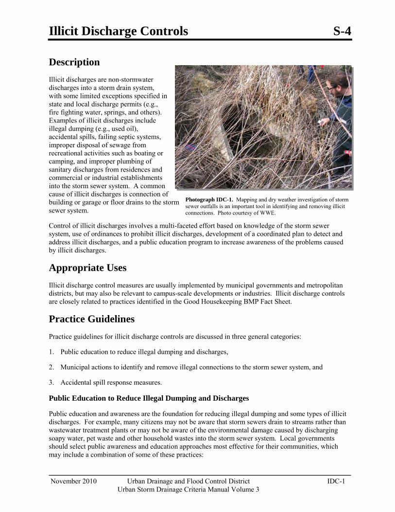
Illicit Discharge Controls S-4
November 2010 Urban Drainage and Flood Control District IDC-1 Urban Storm Drainage Criteria Manual Volume 3
Photograph IDC-1. Mapping and dry weather investigation of storm sewer outfalls is an important tool in identifying and removing illicit connections. Photo courtesy of WWE.
Description Illicit discharges are non-stormwater discharges into a storm drain system, with some limited exceptions specified in state and local discharge permits (e.g., fire fighting water, springs, and others). Examples of illicit discharges include illegal dumping (e.g., used oil), accidental spills, failing septic systems, improper disposal of sewage from recreational activities such as boating or camping, and improper plumbing of sanitary discharges from residences and commercial or industrial establishments into the storm sewer system. A common cause of illicit discharges is connection of building or garage or floor drains to the storm sewer system.
Control of illicit discharges involves a multi-faceted effort based on knowledge of the storm sewer system, use of ordinances to prohibit illicit discharges, development of a coordinated plan to detect and address illicit discharges, and a public education program to increase awareness of the problems caused by illicit discharges.
Appropriate Uses Illicit discharge control measures are usually implemented by municipal governments and metropolitan districts, but may also be relevant to campus-scale developments or industries. Illicit discharge controls are closely related to practices identified in the Good Housekeeping BMP Fact Sheet.
Practice Guidelines Practice guidelines for illicit discharge controls are discussed in three general categories:
1. Public education to reduce illegal dumping and discharges,
2. Municipal actions to identify and remove illegal connections to the storm sewer system, and
3. Accidental spill response measures.
Public Education to Reduce Illegal Dumping and Discharges
Public education and awareness are the foundation for reducing illegal dumping and some types of illicit discharges. For example, many citizens may not be aware that storm sewers drain to streams rather than wastewater treatment plants or may not be aware of the environmental damage caused by discharging soapy water, pet waste and other household wastes into the storm sewer system. Local governments should select public awareness and education approaches most effective for their communities, which may include a combination of some of these practices:
S-4 Illicit Discharge Controls
IDC-2 Urban Drainage and Flood Control District November 2010
Urban Storm Drainage Criteria Manual Volume 3
Enactment of clearly written ordinances prohibiting illegal dumping and illicit connections. Many local governments already have such ordinances; however, citizens are often unaware of these. Publicity including news articles, door hangers, utility bill inserts, radio or TV advertisements, website highlights and other measures can be used to increase awareness. Such efforts may be particularly effective when connected to a specific water quality problem such as stream or lake impairments due to bacteria and/or nutrients.
Storm drain stenciling involves placing a marker or using a stencil to paint a message on storm drains to discourage dumping down the storm drain. These messages are a public education tool so that citizens are aware that the materials that they dump down to the storm drain are discharged to a stream, as opposed to a wastewater treatment plant.
Provide citizens with readily available contact information to report illegal dumping. Install a "hotline" telephone number to handle calls from citizens reporting illegal dumping or accidental spills.
Create brochures and other guidance for businesses related to illegal discharges to the storm drain. Educational efforts should not only alert business owners that non-stormwater discharges are not allowed, but also provide guidance on BMPs to implement. For example, power washing discharges are process wastewater that may not be discharged to the storm sewer system. When power washing is conducted, storm drain inlet protection, wet vacuuming, collection systems, and/or other appropriate measures to prevent washwater from entering the storm drain system should be implemented.
Illicit Connections
Eliminating illicit connections plumbed into the storm drain system involves two different components:
1. Identifying and removing existing illicit connections; and
2. Preventing new illicit connections.
Removing Existing Connections
Existing illicit connections of sanitary sewers to the storm drainage system in existing developments can be identified by a systematic dry weather inspection of storm sewer outfalls following readily available illicit discharge detection and elimination guidance available from EPA. Initial screening typically involves mapping all storm sewer outfalls and conducting field inspections to identify suspect outfalls based on odor, sewage-related residue (e.g., toilet paper), discoloration, dry weather flows, etc. Grab samples of dry-weather discharges can be collected at suspect locations and analyzed for targeted water quality constituents (e.g., E. coli, temperature, pH, surfactants). Where illicit connections are probable, more advanced techniques can be used to isolate the likely source of the connection. Techniques such as temperature probes (to track diurnal temperature changes indicative of shower use suggesting a sanitary connection to a storm sewer), optical brightener screening (indicator of detergents), zinc chloride smoke testing, fluorometric dye testing, television camera inspections and other approaches can be used as follow-up measures. Once the illicit connection has been identified, the plumbing can be corrected and proper connections to the sanitary sewer system implemented.
Illicit Discharge Controls S-4
November 2010 Urban Drainage and Flood Control District IDC-3 Urban Storm Drainage Criteria Manual Volume 3
Additional Illicit Discharge Detection and Elimination Guidance
The Center for Watershed Protection and Robert Pitt (2004) prepared Illicit Discharge Detection and Elimination: A Guidance Manual for Program Development and Technical Assessments under EPA funding to provide guidance to communities in developing effective management programs and field guidance to reduce illicit discharges. This manual provides detailed guidance and field forms that can be used identify illicit connections.
Program elements to prevent illicit connections include:
Preventing Illicit Connections
Ensure that existing building and plumbing codes prohibit physical connections of non-stormwater discharges to the storm drain system.
Have a program in place to review and approve any proposed connection into a storm sewer.
Require visual inspection of new developments or redevelopments during the construction phase to ensure that proper plumbing connections are implemented. Train field inspectors and develop field inspection procedures that prevent new illicit connections of sanitary sewer lines to storm sewers.
Accidental Spill Response
Although the storage, transport and disposal of hazardous and toxic substances is a highly regulated activity under state and federal laws, accidents will inevitably occur, resulting in potential release of chemicals and wastes into the storm sewer system. Most local police, fire, or other departments are trained and equipped to respond to such spills. Local governments should work with response personnel to ensure current mapping of storm drains and BMPs and review training procedures for spill response and cleanup. Proper training combined with readily available knowledge of the storm sewer system and appropriate spill control materials can result in more effective protection and blocking of the drainage system during spill response.

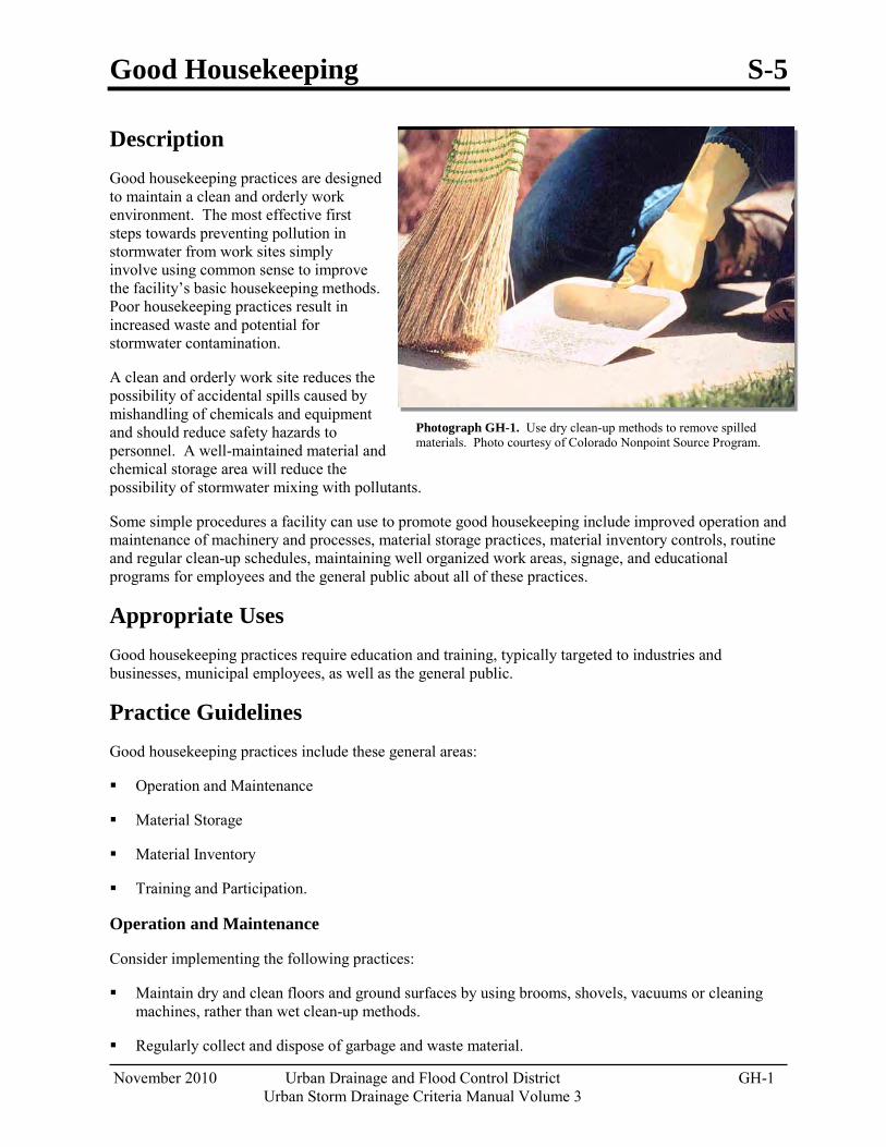
Good Housekeeping S-5
November 2010 Urban Drainage and Flood Control District GH-1 Urban Storm Drainage Criteria Manual Volume 3
Photograph GH-1. Use dry clean-up methods to remove spilled materials. Photo courtesy of Colorado Nonpoint Source Program.
Description Good housekeeping practices are designed to maintain a clean and orderly work environment. The most effective first steps towards preventing pollution in stormwater from work sites simply involve using common sense to improve the facility’s basic housekeeping methods. Poor housekeeping practices result in increased waste and potential for stormwater contamination.
A clean and orderly work site reduces the possibility of accidental spills caused by mishandling of chemicals and equipment and should reduce safety hazards to personnel. A well-maintained material and chemical storage area will reduce the possibility of stormwater mixing with pollutants.
Some simple procedures a facility can use to promote good housekeeping include improved operation and maintenance of machinery and processes, material storage practices, material inventory controls, routine and regular clean-up schedules, maintaining well organized work areas, signage, and educational programs for employees and the general public about all of these practices.
Appropriate Uses Good housekeeping practices require education and training, typically targeted to industries and businesses, municipal employees, as well as the general public.
Practice Guidelines Good housekeeping practices include these general areas:
Operation and Maintenance
Material Storage
Material Inventory
Training and Participation.
Operation and Maintenance
Consider implementing the following practices:
Maintain dry and clean floors and ground surfaces by using brooms, shovels, vacuums or cleaning machines, rather than wet clean-up methods.
Regularly collect and dispose of garbage and waste material.
S-5 Good Housekeeping
GH-2 Urban Drainage and Flood Control District November 2010 Urban Storm Drainage Criteria Manual Volume 3
Routinely inspect equipment to ensure that it is functioning properly without leaking and conduct preventative maintenance and needed repairs.
Train employees on proper clean up and spill response procedures.
Designate separate areas of the site for auto parking, vehicle refueling and routine maintenance.
Promptly clean up leaks, drips and other spills.
Cover and maintain dumpsters and waste receptacles. Add additional dumpsters or increase frequency of waste collection if overflowing conditions reoccur.
Where outdoor painting and sanding occur, implement these practices:
o Conduct these activities in designated areas that provide adequate protection to prevent overspray and uncontrolled emissions. All operations should be conducted on paved surfaces to facilitate cleanup.
o Use portable containment as necessary for outside operations.
o Clean up and properly dispose of excess paint, paint chips, protective coatings, grit waste, etc.
Maintain vegetation on facility grounds in a manner that minimizes erosion. Follow the Landscape Maintenance and Pesticide, Herbicide and Fertilizer Usage BMPs to ensure that minimum amounts of chemicals needed for healthy vegetation are applied in a manner that minimizes transport of these materials in runoff.
Material Storage Practices
Proper storage techniques include the following:
Provide adequate aisle space to facilitate material transfer and ease of access for inspection.
Store containers, drums, and bags away from direct traffic routes to reduce container damage resulting in accidental spills.
Stack containers according to manufacturer’s instructions to avoid damaging the containers from improper weight distribution. Also store materials in accordance with directions in Material Safety Data Sheets (MSDSs).
Store containers on pallets or similar devices to prevent corrosion of containers that results from containers coming in contact with moisture on the ground.
Store toxic or hazardous liquids within curbed areas or secondary containers.
Material Inventory Practices
An up-to-date materials inventory can keep material costs down by preventing overstocking, track how materials are stored and handled onsite, and identify which materials and activities pose the most risk to the environment. Assign responsibility of hazardous material inventory to individuals trained to handle such materials. A material inventory should include these steps:
Identify all chemical substances present at work site. Perform a walk-through of the site, review
Good Housekeeping S-5
November 2010 Urban Drainage and Flood Control District GH-3 Urban Storm Drainage Criteria Manual Volume 3
purchase orders, list all chemical substances used and obtain Material Safety Data Sheets (MSDS) for all chemicals.
Label all containers. Labels should provide name and type of substance, stock number, expiration date, health hazards, handling suggestions, and first aid information. Much of, this information can be found on an MSDS.
Clearly identify special handling, storage, use and disposal considerations for hazardous materials on the material inventory.
Institute a shelf-life program to improve material tracking and inventory that can reduce the amount of materials that are overstocked and ensure proper disposal of expired materials. Careful tracking of materials ordered can result in more efficient materials use. Decisions on the amounts of hazardous materials that are stored on site should include an evaluation of any emergency control systems that are in place. All storage areas for hazardous materials should be designed to contain spills.
Training and Participation
Frequent and proper training in good housekeeping techniques reduces the likelihood that chemicals or equipment will be mishandled. To promote good housekeeping, consider implementing these practices:
Discuss good housekeeping practices in training programs and meetings.
Publicize pollution prevention concepts through posters or signs.
Post bulletin boards with updated good housekeeping procedures, tips and reminders.


Preventative Maintenance S-6
November 2010 Urban Drainage and Flood Control District PM-1 Urban Storm Drainage Criteria Manual Volume 3
Photograph PM-1. Preventative maintenance can reduce the frequency and occurrence of leaked or spilled material that can be transported in stormwater runoff.
Description Preventative maintenance involves proactive routine inspection and testing of plant equipment and operational systems to prevent leaks and spills. A preventative maintenance program should also include inspections of conveyance channels, storm sewers, inlets, catch basins, stormwater detention areas, and other water quality treatment systems associated with the site.
Appropriate Uses This BMP is applicable to municipal, industrial and commercial sites. Preventative maintenance programs typically incorporate practices identified in the Good Housekeeping, Materials Storage and Handling, Vehicle Fueling, Maintenance and Storage, and other source control BMPs. See the Structural BMP Maintenance chapter for preventative maintenance for stormwater BMPs.
Practice Guidelines Elements of a good preventative maintenance program should include:
Identification of equipment or systems, which may malfunction and cause spills, leaks, or other situations that could lead to contamination of stormwater runoff. Typical equipment to inspect includes pipes, pumps, storage tanks and bins, pressure vessels, pressure release valves, process and material handling equipment.
Once equipment and areas to be inspected have been identified at the facility, establish schedules and procedures for routine inspections and scheduling repairs.
Periodic testing of plant equipment for structural soundness is a key element in a preventative maintenance program.
Promptly repair or replace defective equipment found during inspection and testing.
Keep spare parts for equipment that needs frequent repair.
Replace worn parts prior to failure.
Implement, maintain and regularly review a record keeping system for scheduling tests and documenting inspections in the preventative maintenance program. Be sure to follow inspections promptly with completion of needed repairs. Clearly record the problem and the specific actions taken to correct the problem. Photos can be helpful components of such records. An annual review of these records should be conducted to evaluate the overall effectiveness of the preventative maintenance program. Refinements to the preventative maintenance procedures and tasking should be implemented as necessary.

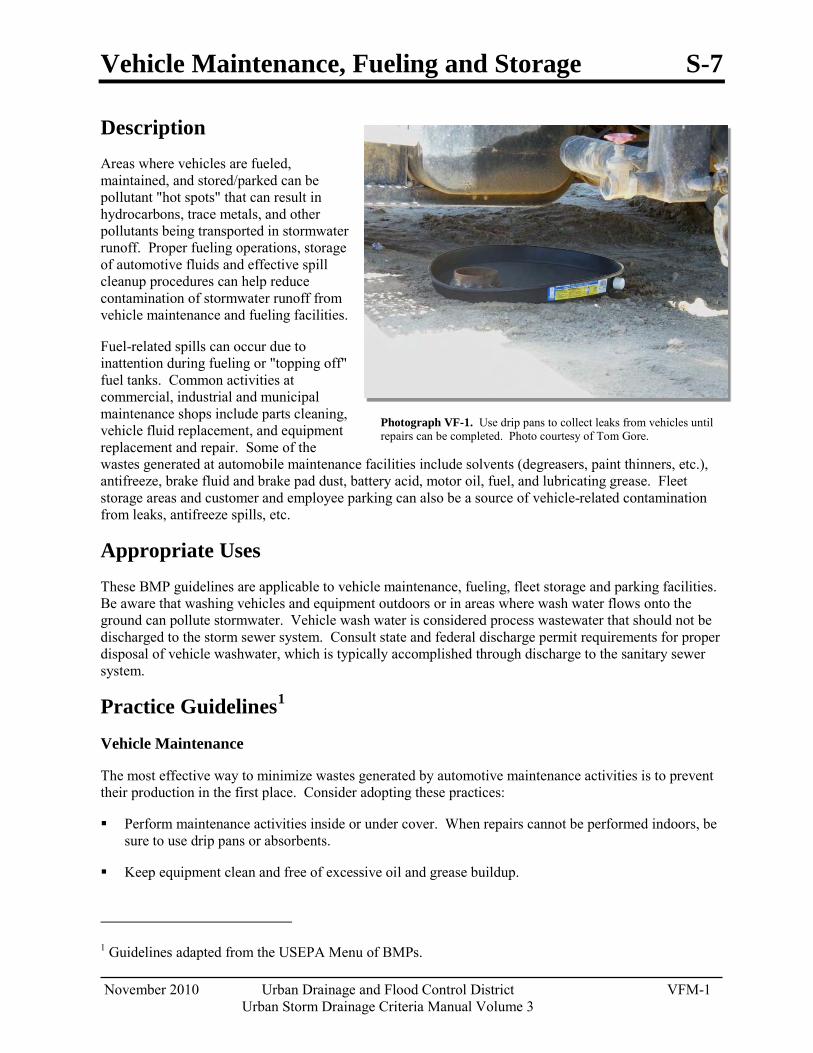
Vehicle Maintenance, Fueling and Storage S-7
November 2010 Urban Drainage and Flood Control District VFM-1 Urban Storm Drainage Criteria Manual Volume 3
Photograph VF-1. Use drip pans to collect leaks from vehicles until repairs can be completed. Photo courtesy of Tom Gore.
Description Areas where vehicles are fueled, maintained, and stored/parked can be pollutant "hot spots" that can result in hydrocarbons, trace metals, and other pollutants being transported in stormwater runoff. Proper fueling operations, storage of automotive fluids and effective spill cleanup procedures can help reduce contamination of stormwater runoff from vehicle maintenance and fueling facilities.
Fuel-related spills can occur due to inattention during fueling or "topping off" fuel tanks. Common activities at commercial, industrial and municipal maintenance shops include parts cleaning, vehicle fluid replacement, and equipment replacement and repair. Some of the wastes generated at automobile maintenance facilities include solvents (degreasers, paint thinners, etc.), antifreeze, brake fluid and brake pad dust, battery acid, motor oil, fuel, and lubricating grease. Fleet storage areas and customer and employee parking can also be a source of vehicle-related contamination from leaks, antifreeze spills, etc.
Appropriate Uses These BMP guidelines are applicable to vehicle maintenance, fueling, fleet storage and parking facilities. Be aware that washing vehicles and equipment outdoors or in areas where wash water flows onto the ground can pollute stormwater. Vehicle wash water is considered process wastewater that should not be discharged to the storm sewer system. Consult state and federal discharge permit requirements for proper disposal of vehicle washwater, which is typically accomplished through discharge to the sanitary sewer system.
Practice Guidelines1
Perform maintenance activities inside or under cover. When repairs cannot be performed indoors, be sure to use drip pans or absorbents.
Vehicle Maintenance
The most effective way to minimize wastes generated by automotive maintenance activities is to prevent their production in the first place. Consider adopting these practices:
Keep equipment clean and free of excessive oil and grease buildup.
1 Guidelines adapted from the USEPA Menu of BMPs.
S-7 Vehicle Maintenance, Fueling and Storage
VFM-2 Urban Drainage and Flood Control District November 2010 Urban Storm Drainage Criteria Manual Volume 3
Promptly cleanup spills using dry methods and properly dispose of waste. When water is required, use as little as possible to clean spills, leaks, and drips.
Use a solvent collection service to collect spent solvent used for parts cleaning. Where practical, use detergent-based, steam cleaning, or pressure-based cleaning systems instead of organic solvent degreasers when practical. (Be aware that cleaning water discharged into the sanitary sewer may require pre-treatment prior to discharge.)
When using liquids for cleaning, use a centralized station to ensure that solvents and residues stay in one area. Locate drip pans and draining boards to direct solvents back into a solvent sink or holding tank for reuse.
Store used oil for recycling in labeled tanks. Locate used oil tanks and drums away from storm drains, flowing streams, and preferably indoors.
Use non-hazardous or less hazardous alternatives when practical. For example, replace chlorinated organic solvents with non-chlorinated ones like kerosene or mineral spirits.
Properly recycle or dispose of grease, oil, antifreeze, brake fluid, cleaning solutions, hydraulic fluid, batteries, transmission fluid, worn parts, filters, and rags.
Drain and crush oil filters before recycling or disposal.
Drain all fluids and remove batteries from salvage vehicles and equipment.
Closely monitor parked vehicles for leaks and place pans under any leaks to collect the fluids for proper disposal or recycling.
Install berms or other measures to contain spills and prevent work surface runoff from entering storm drains.
Develop and follow a spill prevention plan. This includes a variety of measures such as spill kits and knowing where storm drains are located and how to protect them (e.g., drain mat, berm) when larger spills occur. (See the Spill Prevention, Containment and Control BMP for more information.)
Conduct periodic employee training to reinforce proper disposal practices.
Promptly transfer used fluids to recycling drums or hazardous waste containers.
Store cracked batteries in leak-proof secondary containers.
Inspect outdoor storage areas regularly for drips, spills and improperly stored materials (unlabeled containers, auto parts that might contain grease or fluids, etc.). This is particularly important for parking areas for vehicles awaiting repair.
Structural stormwater BMPs in vehicle hotspot areas require routine cleanout of oil and grease, sometimes monthly or more frequently. During periods of heavy rainfall, cleanout is required more often to ensure that pollutants are not washed through the trap. Sediment removal is also required on a regular basis to keep the BMP working efficiently.
Vehicle Maintenance, Fueling and Storage S-7
November 2010 Urban Drainage and Flood Control District VFM-3 Urban Storm Drainage Criteria Manual Volume 3
Vehicle Fueling
Designated fueling areas should be designed to prevent stormwater runoff and spills. For example, fuel-dispensing areas should be paved with concrete or an equivalent impervious surface, with an adequate slope to prevent ponding, and separated from the rest of the site by a grade break or berm that prevents run-on of stormwater.
Fuel dispensing areas should be covered. The cover's minimum dimensions must be equal to or greater than the area within the grade break or the fuel dispensing area so that the fueling area is completely covered. It may be necessary to install and maintain an oil capture device in catch basins that have the potential to receive runoff from the fueling area.
For facilities where equipment is being fueled with a mobile fuel truck, establish a designated fueling area. Place temporary "caps" over nearby catch basins or manhole covers so that if a spill occurs, it is prevented from entering the storm drain. A form of secondary containment should be used when transferring fuel from the tank truck to the fuel tank. Storm drains in the vicinity should also be covered. Install vapor recovery nozzles to help control drips, as well as reduce air pollution.
Keep spill response information and spill cleanup materials onsite and readily available.
Fuel-dispensing areas should be inspected regularly and repair promptly completed. Inspectors should:
o Check for external corrosion and structural failure in aboveground tanks.
o Check for spills and overfills due to operator error.
o Check for failure of any piping systems.
o Check for leaks or spills during pumping of liquids or gases from a truck or rail car to a storage facility or vice versa.
o Visually inspect new tank or container installations for loose fittings, poor welds, and improper or poorly fitted gaskets.
o Inspect tank foundations, connections, coatings, tank walls, and piping systems. Look for corrosion, leaks, cracks, scratches, and other physical damage that may weaken the tank or container system.
Aboveground and belowground tanks should be tested periodically for integrity by a qualified professional.
Dry cleanup methods should be employed when cleaning up fuel-dispensing areas. Such methods include sweeping to remove litter and debris and using rags and absorbents for leaks and spills. Water should not be used to wash these areas. During routine cleaning, use a damp cloth on the pumps and a damp mop on the pavement, rather than spraying with a hose. Fuel dispensing nozzles should be fitted with "hold-open latches" (automatic shutoff) except where prohibited by local fire departments. Signs can be posted at the fuel dispenser or island warning vehicle owners/operators against "topping off" vehicle fuel tanks.
Written procedures that describe these BMPs should be provided to employees who will be using fueling systems.

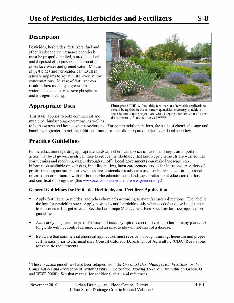
Use of Pesticides, Herbicides and Fertilizers S-8
November 2010 Urban Drainage and Flood Control District PHF-1 Urban Storm Drainage Criteria Manual Volume 3
Photograph PHF-1. Pesticide, fertilizer, and herbicide applications should be applied in the minimum quantities necessary to achieve specific landscaping objectives, while keeping chemicals out of storm drain systems. Photo courtesy of WWE.
Description Pesticides, herbicides, fertilizers, fuel and other landscape maintenance chemicals must be properly applied, stored, handled and disposed of to prevent contamination of surface water and groundwater. Misuse of pesticides and herbicides can result in adverse impacts to aquatic life, even at low concentrations. Misuse of fertilizer can result in increased algae growth in waterbodies due to excessive phosphorus and nitrogen loading.
Appropriate Uses This BMP applies to both commercial and municipal landscaping operations, as well as to homeowners and homeowner associations. For commercial operations, the scale of chemical usage and handling is greater; therefore, additional measures are often required under federal and state law.
Practice Guidelines1
Public education regarding appropriate landscape chemical application and handling is an important action that local governments can take to reduce the likelihood that landscape chemicals are washed into storm drains and receiving waters through runoff. Local governments can make landscape care information available on websites, in utility mailers, lawn care centers, and other locations. A variety of professional organizations for lawn care professionals already exist and can be contacted for additional information or partnered with for both public education and landscape professional educational efforts and certification programs (See
www.ext.colostate.edu and www.greenco.org.).
General Guidelines for Pesticide, Herbicide, and Fertilizer Application
Apply fertilizers, pesticides, and other chemicals according to manufacturer's directions. The label is the law for pesticide usage. Apply pesticides and herbicides only when needed and use in a manner to minimize off-target effects. See the Landscape Management Fact Sheet for fertilizer application guidelines.
Accurately diagnose the pest. Disease and insect symptoms can mimic each other in many plants. A fungicide will not control an insect, and an insecticide will not control a disease.
Be aware that commercial chemical applicators must receive thorough training, licensure and proper certification prior to chemical use. Consult Colorado Department of Agriculture (CDA) Regulations for specific requirements.
1 These practice guidelines have been adapted from the GreenCO Best Management Practices for the Conservation and Protection of Water Quality in Colorado: Moving Toward Sustainability (GreenCO and WWE 2008). See that manual for additional detail and references.
S-8 Use of Pesticides, Herbicides and Fertilizers
PHF-2 Urban Drainage and Flood Control District November 2010 Urban Storm Drainage Criteria Manual Volume 3
Integrated Pest Management (IPM)
Integrated pest management (IPM) (also known as Plant Health Care) is the practice of using targeted biological, chemical, cultural, and physical measures to manage pests while minimizing or eliminating the use of chemical pesticides. IPM measures benefit the landscape and help reduce the likelihood that lawn chemicals will be washed into storm drainage systems in stormwater runoff. The pros and cons of various tools should be weighed and used in an integrated manner to achieve pest control objectives in a safe, effective, and cost-effective manner. Basic IPM practices that can be adopted include:
Consider spot treatments of pests rather than treating the entire area.
Consider pest occurrence and history when developing pest management strategies.
Time pesticide application to minimize host plant damage and maximize pest control.
Rotate annual garden plants to reduce the buildup of soil-borne pests. Clean up plant litter and remove weeds before they go to seed. Remove infested plant residue from the garden in the fall so that pests do not over-winter there.
Implement cultural controls such as proper plant selection, planting time, and planting method to reduce susceptibility to insects, pests, and diseases, thereby reducing pesticide usage.
Implement mechanical and physical controls where practical as an alternative to chemical application. Examples include a wide variety of practices such as "collars" around seedlings, mulching, solar heating, syringing, handpicking, mowing, hoeing, and traps.
Use biological controls where appropriate to reduce pesticide usage. For example, introduce natural enemies of pests such as lady beetles and green lacewings. (Note: pesticides may kill these natural enemies.)
Consider applying environmentally friendly chemical alternatives such as insecticidal soaps, horticultural oils, and other such measures when practical and effective and when mechanical approaches are impractical.
Know characteristics of the application site, including soil type and depth to groundwater to avoid migration of chemicals into groundwater.
Select pesticides and herbicides best suited to the characteristics of the target site and the particular pest or weed. Half-life, solubility, and adsorption should be compared to site characteristics to determine the safest chemical. Choose least toxic and less persistent sprays whenever possible based on comparison of labels and associated material safety data sheets.
Employ application techniques that increase efficiency and allow the lowest effective application rate. Carefully calibrate application equipment and follow all label instructions.
Recognize that it is not realistic for a landscape to be completely pest-free or weed-free. Consider using Integrated Pest Management (IPM) strategies to minimize chemical usage.
Keep pesticide and fertilizer equipment properly calibrated according to the manufacturer's instructions and in good repair. Recalibrate equipment periodically to compensate for wear in pumps, nozzles and metering systems. Calibrate sprayers when new nozzles are installed.
All mixing and loading operations must occur on an impervious surface.
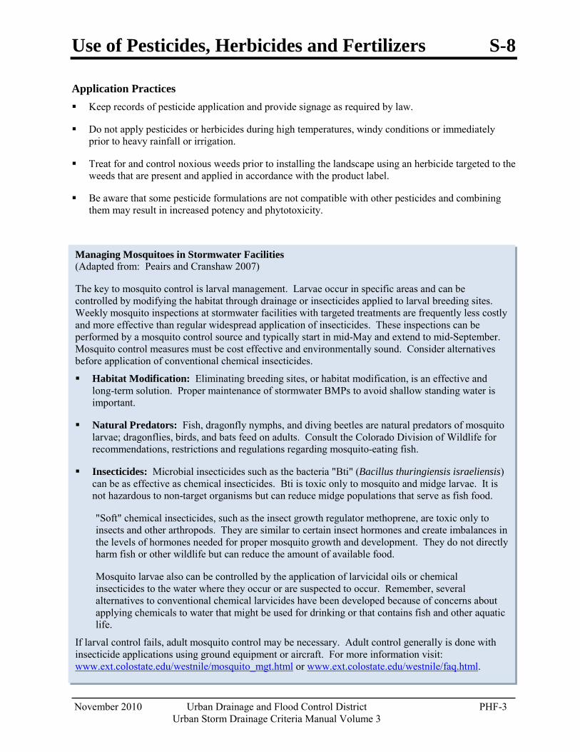
Use of Pesticides, Herbicides and Fertilizers S-8
November 2010 Urban Drainage and Flood Control District PHF-3 Urban Storm Drainage Criteria Manual Volume 3
Managing Mosquitoes in Stormwater Facilities (Adapted from: Peairs and Cranshaw 2007)
The key to mosquito control is larval management. Larvae occur in specific areas and can be controlled by modifying the habitat through drainage or insecticides applied to larval breeding sites. Weekly mosquito inspections at stormwater facilities with targeted treatments are frequently less costly and more effective than regular widespread application of insecticides. These inspections can be performed by a mosquito control source and typically start in mid-May and extend to mid-September. Mosquito control measures must be cost effective and environmentally sound. Consider alternatives before application of conventional chemical insecticides.
Habitat Modification: Eliminating breeding sites, or habitat modification, is an effective and long-term solution. Proper maintenance of stormwater BMPs to avoid shallow standing water is important.
Natural Predators: Fish, dragonfly nymphs, and diving beetles are natural predators of mosquito larvae; dragonflies, birds, and bats feed on adults. Consult the Colorado Division of Wildlife for recommendations, restrictions and regulations regarding mosquito-eating fish.
Insecticides: Microbial insecticides such as the bacteria "Bti" (Bacillus thuringiensis israeliensis) can be as effective as chemical insecticides. Bti is toxic only to mosquito and midge larvae. It is not hazardous to non-target organisms but can reduce midge populations that serve as fish food.
"Soft" chemical insecticides, such as the insect growth regulator methoprene, are toxic only to insects and other arthropods. They are similar to certain insect hormones and create imbalances in the levels of hormones needed for proper mosquito growth and development. They do not directly harm fish or other wildlife but can reduce the amount of available food.
Mosquito larvae also can be controlled by the application of larvicidal oils or chemical insecticides to the water where they occur or are suspected to occur. Remember, several alternatives to conventional chemical larvicides have been developed because of concerns about applying chemicals to water that might be used for drinking or that contains fish and other aquatic life.
If larval control fails, adult mosquito control may be necessary. Adult control generally is done with insecticide applications using ground equipment or aircraft. For more information visit: www.ext.colostate.edu/westnile/mosquito_mgt.html or www.ext.colostate.edu/westnile/faq.html.
Application Practices Keep records of pesticide application and provide signage as required by law.
Do not apply pesticides or herbicides during high temperatures, windy conditions or immediately prior to heavy rainfall or irrigation.
Treat for and control noxious weeds prior to installing the landscape using an herbicide targeted to the weeds that are present and applied in accordance with the product label.
Be aware that some pesticide formulations are not compatible with other pesticides and combining them may result in increased potency and phytotoxicity.
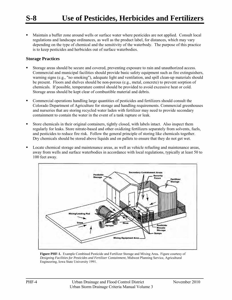
S-8 Use of Pesticides, Herbicides and Fertilizers
PHF-4 Urban Drainage and Flood Control District November 2010 Urban Storm Drainage Criteria Manual Volume 3
Figure PHF-1. Example Combined Pesticide and Fertilizer Storage and Mixing Area. Figure courtesy of Designing Facilities for Pesticides and Fertilizer Containment, Midwest Planning Service, Agricultural Engineering, Iowa State University 1991.
Maintain a buffer zone around wells or surface water where pesticides are not applied. Consult local regulations and landscape ordinances, as well as the product label, for distances, which may vary depending on the type of chemical and the sensitivity of the waterbody. The purpose of this practice is to keep pesticides and herbicides out of surface waterbodies.
Storage Practices
Storage areas should be secure and covered, preventing exposure to rain and unauthorized access. Commercial and municipal facilities should provide basic safety equipment such as fire extinguishers, warning signs (e.g., "no smoking"), adequate light and ventilation, and spill clean-up materials should be present. Floors and shelves should be non-porous (e.g., metal, concrete) to prevent sorption of chemicals. If possible, temperature control should be provided to avoid excessive heat or cold. Storage areas should be kept clear of combustible material and debris.
Commercial operations handling large quantities of pesticides and fertilizers should consult the Colorado Department of Agriculture for storage and handling requirements. Commercial greenhouses and nurseries that are storing recycled water laden with fertilizer may need to provide secondary containment to contain the water in the event of a tank rupture or leak.
Store chemicals in their original containers, tightly closed, with labels intact. Also inspect them regularly for leaks. Store nitrate-based and other oxidizing fertilizers separately from solvents, fuels, and pesticides to reduce fire risk. Follow the general principle of storing like chemicals together. Dry chemicals should be stored above liquids and on pallets to ensure that they do not get wet.
Locate chemical storage and maintenance areas, as well as vehicle refueling and maintenance areas, away from wells and surface waterbodies in accordance with local regulations, typically at least 50 to 100 feet away.
Use of Pesticides, Herbicides and Fertilizers S-8
November 2010 Urban Drainage and Flood Control District PHF-5 Urban Storm Drainage Criteria Manual Volume 3
For More Information on Legal Requirements
Many federal and state regulations address pesticide, herbicide, and other chemical usage. These sources should be consulted for the most current legal requirements related to chemical handling, storage, application, disposal, and reporting of chemical spills. Examples include the federal Insecticide, Fungicide and Rodenticide Act (FIFRA), the Superfund Amendments and Reauthorization Act (SARA), the Emergency Planning and Community-Right-to-Know Act (EPCRA), and Occupational Safety and Health Administration (OSHA) requirements, particularly the Hazard Communication Standard. Colorado-related regulations include the Colorado Pesticide Applicator's Act, and the Colorado Water Quality Control Act (25-8-601 and 25-8-606), Senate Bill 90-126, and The Agricultural Chemicals and Groundwater Protection Act, which identifies special requirements for facilities handling more than 3,000 pounds (or 500 gallons) of bulk-formulated pesticides.
Make available all Material Safety Data Sheets (MSDSs) in a readily accessible area. A list of all hazardous chemicals in the work place must be completed to ensure that all MSDSs are readily available.
Do not store large quantities of pesticides for long periods of time. Adopt the "first in, first out" principle, using the oldest products first to ensure that the shelf life does not expire. Buy smaller quantities of pesticides and fertilizers, thereby reducing storage issues.
Spills and Disposal
Never pour lawn and garden chemicals or rinse water down storm drains (or sanitary drains) and keep chemicals off impervious surfaces (e.g., streets, gutters) during application.
Follow label directions for disposal. This typically involves triple-rinsing empty containers, puncturing and crushing. All visible chemicals should be cleaned from the container prior to disposal. Use local recycling or hazardous waste collection centers to dispose of unused chemicals.
Properly manage chemical spills by cleaning them up as soon as possible, controlling actively spilling or leaking materials, containing the spilled material (e.g., with absorbents, sand), collecting the spilled material, storing or disposing of the spilled material, and following relevant spill reporting requirements. "Washing down" a spill with water is not an appropriate cleanup approach.
Commercial operations should be aware of and comply with basic spill reporting requirements required by law, and keep chemical spill cleanup equipment, personal protective equipment and emergency phone numbers available when handling chemicals and their containers.

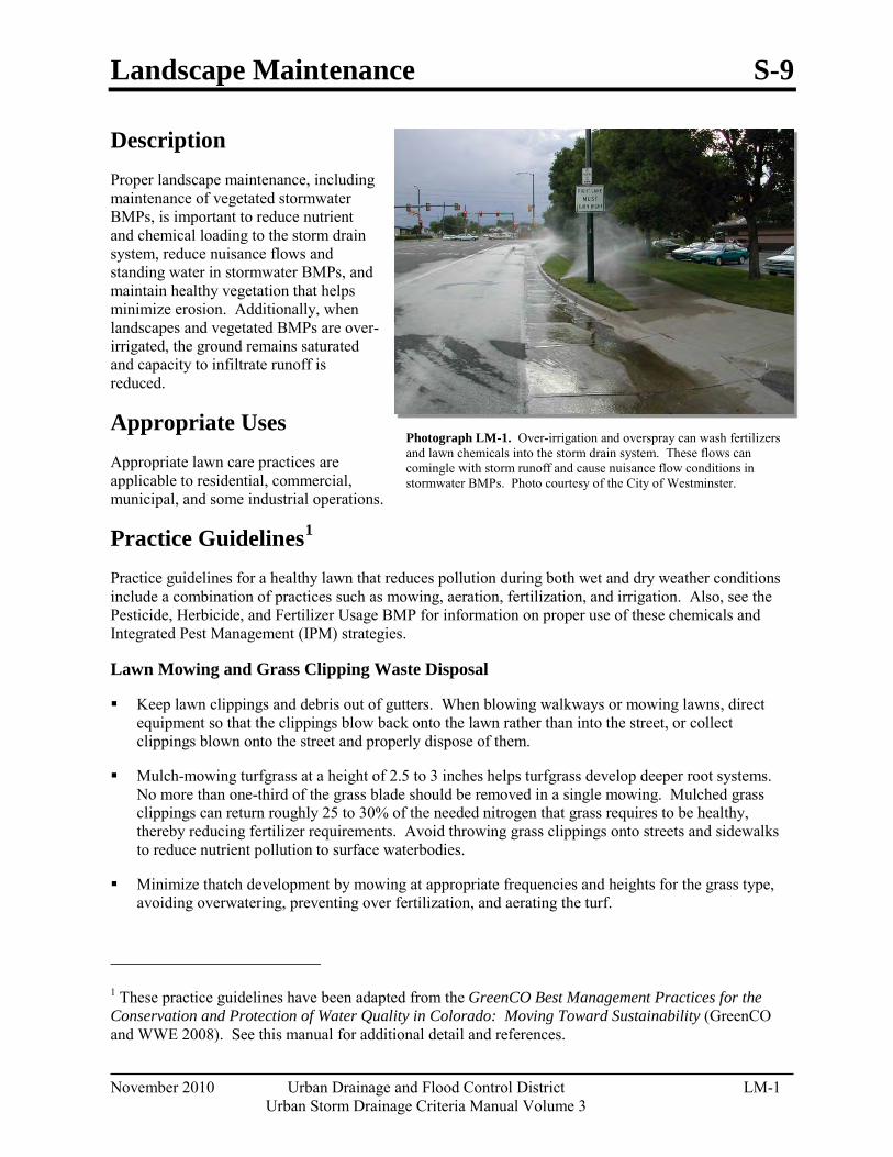
Landscape Maintenance S-9
November 2010 Urban Drainage and Flood Control District LM-1 Urban Storm Drainage Criteria Manual Volume 3
Photograph LM-1. Over-irrigation and overspray can wash fertilizers and lawn chemicals into the storm drain system. These flows can comingle with storm runoff and cause nuisance flow conditions in stormwater BMPs. Photo courtesy of the City of Westminster.
Description Proper landscape maintenance, including maintenance of vegetated stormwater BMPs, is important to reduce nutrient and chemical loading to the storm drain system, reduce nuisance flows and standing water in stormwater BMPs, and maintain healthy vegetation that helps minimize erosion. Additionally, when landscapes and vegetated BMPs are over-irrigated, the ground remains saturated and capacity to infiltrate runoff is reduced.
Appropriate Uses Appropriate lawn care practices are applicable to residential, commercial, municipal, and some industrial operations.
Practice Guidelines1
Keep lawn clippings and debris out of gutters. When blowing walkways or mowing lawns, direct equipment so that the clippings blow back onto the lawn rather than into the street, or collect clippings blown onto the street and properly dispose of them.
Practice guidelines for a healthy lawn that reduces pollution during both wet and dry weather conditions include a combination of practices such as mowing, aeration, fertilization, and irrigation. Also, see the Pesticide, Herbicide, and Fertilizer Usage BMP for information on proper use of these chemicals and Integrated Pest Management (IPM) strategies.
Lawn Mowing and Grass Clipping Waste Disposal
Mulch-mowing turfgrass at a height of 2.5 to 3 inches helps turfgrass develop deeper root systems. No more than one-third of the grass blade should be removed in a single mowing. Mulched grass clippings can return roughly 25 to 30% of the needed nitrogen that grass requires to be healthy, thereby reducing fertilizer requirements. Avoid throwing grass clippings onto streets and sidewalks to reduce nutrient pollution to surface waterbodies.
Minimize thatch development by mowing at appropriate frequencies and heights for the grass type, avoiding overwatering, preventing over fertilization, and aerating the turf.
1 These practice guidelines have been adapted from the GreenCO Best Management Practices for the Conservation and Protection of Water Quality in Colorado: Moving Toward Sustainability (GreenCO and WWE 2008). See this manual for additional detail and references.
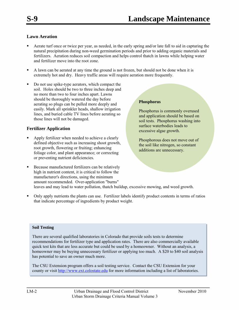
S-9 Landscape Maintenance
LM-2 Urban Drainage and Flood Control District November 2010
Urban Storm Drainage Criteria Manual Volume 3
Phosphorus
Phosphorus is commonly overused and application should be based on soil tests. Phosphorus washing into surface waterbodies leads to excessive algae growth.
Phosphorous does not move out of the soil like nitrogen, so constant additions are unnecessary.
Soil Testing
There are several qualified laboratories in Colorado that provide soils tests to determine recommendations for fertilizer type and application rates. There are also commercially available quick test kits that are less accurate but could be used by a homeowner. Without an analysis, a homeowner may be buying unnecessary fertilizer or applying too much. A $20 to $40 soil analysis has potential to save an owner much more.
The CSU Extension program offers a soil testing service. Contact the CSU Extension for your county or visit http://www.ext.colostate.edu for more information including a list of laboratories.
Lawn Aeration
Aerate turf once or twice per year, as needed, in the early spring and/or late fall to aid in capturing the natural precipitation during non-weed germination periods and prior to adding organic materials and fertilizers. Aeration reduces soil compaction and helps control thatch in lawns while helping water and fertilizer move into the root zone.
A lawn can be aerated at any time the ground is not frozen, but should not be done when it is extremely hot and dry. Heavy traffic areas will require aeration more frequently.
Do not use spike-type aerators, which compact the soil. Holes should be two to three inches deep and no more than two to four inches apart. Lawns should be thoroughly watered the day before aerating so plugs can be pulled more deeply and easily. Mark all sprinkler heads, shallow irrigation lines, and buried cable TV lines before aerating so those lines will not be damaged.
Fertilizer Application
Apply fertilizer when needed to achieve a clearly defined objective such as increasing shoot growth, root growth, flowering or fruiting; enhancing foliage color, and plant appearance; or correcting or preventing nutrient deficiencies.
Because manufactured fertilizers can be relatively high in nutrient content, it is critical to follow the manufacturer's directions, using the minimum amount recommended. Over-application "burns" leaves and may lead to water pollution, thatch buildup, excessive mowing, and weed growth.
Only apply nutrients the plants can use. Fertilizer labels identify product contents in terms of ratios that indicate percentage of ingredients by product weight.
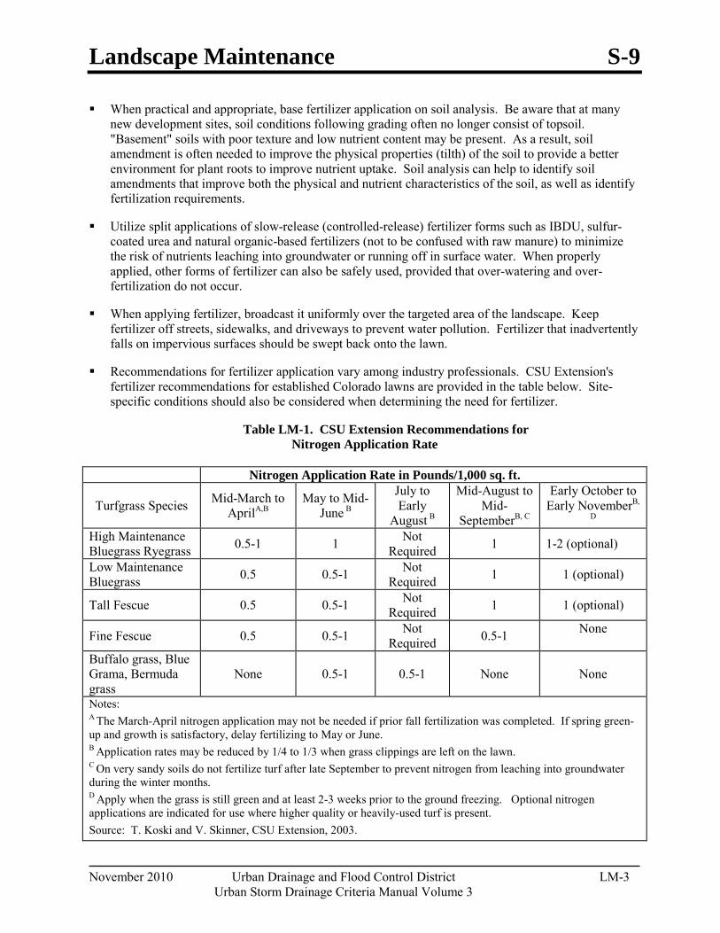
Landscape Maintenance S-9
November 2010 Urban Drainage and Flood Control District LM-3 Urban Storm Drainage Criteria Manual Volume 3
When practical and appropriate, base fertilizer application on soil analysis. Be aware that at many new development sites, soil conditions following grading often no longer consist of topsoil. "Basement" soils with poor texture and low nutrient content may be present. As a result, soil amendment is often needed to improve the physical properties (tilth) of the soil to provide a better environment for plant roots to improve nutrient uptake. Soil analysis can help to identify soil amendments that improve both the physical and nutrient characteristics of the soil, as well as identify fertilization requirements.
Utilize split applications of slow-release (controlled-release) fertilizer forms such as IBDU, sulfur-coated urea and natural organic-based fertilizers (not to be confused with raw manure) to minimize the risk of nutrients leaching into groundwater or running off in surface water. When properly applied, other forms of fertilizer can also be safely used, provided that over-watering and over-fertilization do not occur.
When applying fertilizer, broadcast it uniformly over the targeted area of the landscape. Keep fertilizer off streets, sidewalks, and driveways to prevent water pollution. Fertilizer that inadvertently falls on impervious surfaces should be swept back onto the lawn.
Recommendations for fertilizer application vary among industry professionals. CSU Extension's fertilizer recommendations for established Colorado lawns are provided in the table below. Site-specific conditions should also be considered when determining the need for fertilizer.
Table LM-1. CSU Extension Recommendations for Nitrogen Application Rate
Nitrogen Application Rate in Pounds/1,000 sq. ft.
Turfgrass Species Mid-March to AprilA,B
May to Mid-June B
July to Early
August B
Mid-August to Mid-
SeptemberB, C
Early October to Early NovemberB,
D High Maintenance Bluegrass Ryegrass 0.5-1 1 Not
Required 1 1-2 (optional)
Low Maintenance Bluegrass 0.5 0.5-1 Not
Required 1 1 (optional)
Tall Fescue 0.5 0.5-1 Not Required 1 1 (optional)
Fine Fescue 0.5 0.5-1 Not Required 0.5-1 None
Buffalo grass, Blue Grama, Bermuda grass
None 0.5-1 0.5-1 None None
Notes: A The March-April nitrogen application may not be needed if prior fall fertilization was completed. If spring green-up and growth is satisfactory, delay fertilizing to May or June. B Application rates may be reduced by 1/4 to 1/3 when grass clippings are left on the lawn. C On very sandy soils do not fertilize turf after late September to prevent nitrogen from leaching into groundwater during the winter months. D Apply when the grass is still green and at least 2-3 weeks prior to the ground freezing. Optional nitrogen applications are indicated for use where higher quality or heavily-used turf is present. Source: T. Koski and V. Skinner, CSU Extension, 2003.

S-9 Landscape Maintenance
LM-4 Urban Drainage and Flood Control District November 2010
Urban Storm Drainage Criteria Manual Volume 3
If possible, properly irrigate turf following fertilization to help grass utilize applied nutrients and to minimize the potential for fertilizer burn. Care should be taken to avoid excessive irrigation that would result in fertilizer being washed away. Similarly, avoid application of fertilizer immediately prior to heavy rainfall.
Fall is the best time of year to fertilize bluegrass lawns. Over-application of nitrogen fertilizer in April may cause grass to grow too fast before roots can support the growth, resulting in less heat tolerance.
Generally, the Colorado Nursery and Greenhouse Association recommends waiting until the second growing season to fertilize ornamental (woody) plants. Commercial fertilizer should not be used in the backfill where it comes in direct contact with the roots.
Maintain a buffer zone around wells or surface waterbodies where fertilizers are not applied to minimize pollution. Consult the fertilizer product label and local regulations and landscape ordinances for appropriate distances. Research in this area is limited; however, CSU Extension recommends a buffer of 6 to 10 feet for mowed turf areas.
In areas with sandy soils, it is particularly important to avoid over-application of fertilizer that could leach into groundwater. These areas may be particularly well suited to slow-release fertilizer forms and conservative application rates.
Lawn Irrigation
The approximate amount of water that needs to be applied each week for an average, traditional lawn to supplement normal rainfall is listed in Table 2. (Water utilities may provide additional guidance in terms of suggested run-times for various sprinkler types; http://www.denverwater.org/Conservation/.)
Table LM-2. General Guideline for Approximate Supplemental Water for an Average Traditional Lawn (inches per week)
Condition3 April1 May June July Aug Sept Oct2 Non-Drought Conditions 1/4" 1" 1½" 1½" 1¼" 1" 1/2" During Drought Restrictions (approx. 20% reduction) 1/4" 3/4" 1¼" 1¼" 1" 3/4" 1/2" 1 For established lawns, water may not be required during April. Base decision on weather conditions. 2 For established lawns, water is typically not required after Oct 15. 3Under less-than-average rainfall conditions, the amounts shown in the chart should be increased. If there is greater-than-normal rainfall, then the amount of supplemental water should be reduced.
Consult with the CSU Extension Turfgrass program for recommendations for irrigating turfgrasses with lower water requirements (e.g. blue grama, buffalo grass). For native grasses, irrigation may be unnecessary or limited to certain conditions.
Irrigate the lawn uniformly until the soil is moist to a depth of 4 to 6 inches to encourage deep roots. Frequent, light sprinklings moisten only the surface and may cause shallow-rooted turf and increase weed seed germination. Properly maintain the irrigation system to ensure that the irrigation is being applied at appropriate rates and to the turfgrass, not the sidewalk.
Landscape Maintenance S-9
November 2010 Urban Drainage and Flood Control District LM-5 Urban Storm Drainage Criteria Manual Volume 3
Maintain irrigation systems in good operating condition with uniform distribution of water. "Smart" irrigation controllers and weather sensors can reduce water waste by shutting off irrigation during storm events and helping owners water according to the needs of the plants to replace water lost to evapotranspiration (ET).
Proper irrigation can minimize the amount of fertilizer and other chemicals that are leached below the root zone of the grass or washed away by runoff.

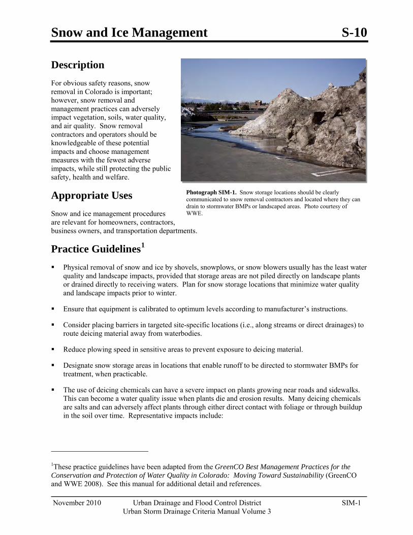
Snow and Ice Management S-10
November 2010 Urban Drainage and Flood Control District SIM-1 Urban Storm Drainage Criteria Manual Volume 3
Photograph SIM-1. Snow storage locations should be clearly communicated to snow removal contractors and located where they can drain to stormwater BMPs or landscaped areas. Photo courtesy of WWE.
Description For obvious safety reasons, snow removal in Colorado is important; however, snow removal and management practices can adversely impact vegetation, soils, water quality, and air quality. Snow removal contractors and operators should be knowledgeable of these potential impacts and choose management measures with the fewest adverse impacts, while still protecting the public safety, health and welfare.
Appropriate Uses Snow and ice management procedures are relevant for homeowners, contractors, business owners, and transportation departments.
Practice Guidelines1
Physical removal of snow and ice by shovels, snowplows, or snow blowers usually has the least water quality and landscape impacts, provided that storage areas are not piled directly on landscape plants or drained directly to receiving waters. Plan for snow storage locations that minimize water quality and landscape impacts prior to winter.
Ensure that equipment is calibrated to optimum levels according to manufacturer’s instructions.
Consider placing barriers in targeted site-specific locations (i.e., along streams or direct drainages) to route deicing material away from waterbodies.
Reduce plowing speed in sensitive areas to prevent exposure to deicing material.
Designate snow storage areas in locations that enable runoff to be directed to stormwater BMPs for treatment, when practicable.
The use of deicing chemicals can have a severe impact on plants growing near roads and sidewalks. This can become a water quality issue when plants die and erosion results. Many deicing chemicals are salts and can adversely affect plants through either direct contact with foliage or through buildup in the soil over time. Representative impacts include:
1These practice guidelines have been adapted from the GreenCO Best Management Practices for the Conservation and Protection of Water Quality in Colorado: Moving Toward Sustainability (GreenCO and WWE 2008). See this manual for additional detail and references.
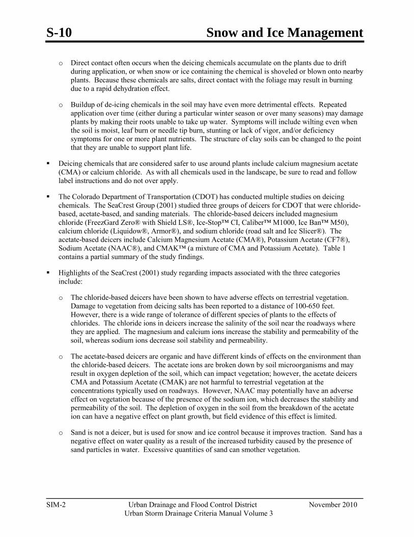
S-10 Snow and Ice Management
SIM-2 Urban Drainage and Flood Control District November 2010 Urban Storm Drainage Criteria Manual Volume 3
o Direct contact often occurs when the deicing chemicals accumulate on the plants due to drift during application, or when snow or ice containing the chemical is shoveled or blown onto nearby plants. Because these chemicals are salts, direct contact with the foliage may result in burning due to a rapid dehydration effect.
o Buildup of de-icing chemicals in the soil may have even more detrimental effects. Repeated application over time (either during a particular winter season or over many seasons) may damage plants by making their roots unable to take up water. Symptoms will include wilting even when the soil is moist, leaf burn or needle tip burn, stunting or lack of vigor, and/or deficiency symptoms for one or more plant nutrients. The structure of clay soils can be changed to the point that they are unable to support plant life.
Deicing chemicals that are considered safer to use around plants include calcium magnesium acetate (CMA) or calcium chloride. As with all chemicals used in the landscape, be sure to read and follow label instructions and do not over apply.
The Colorado Department of Transportation (CDOT) has conducted multiple studies on deicing chemicals. The SeaCrest Group (2001) studied three groups of deicers for CDOT that were chloride-based, acetate-based, and sanding materials. The chloride-based deicers included magnesium chloride (FreezGard Zero® with Shield LS®, Ice-Stop™ CI, Caliber™ M1000, Ice Ban™ M50), calcium chloride (Liquidow®, Armor®), and sodium chloride (road salt and Ice Slicer®). The acetate-based deicers include Calcium Magnesium Acetate (CMA®), Potassium Acetate (CF7®), Sodium Acetate (NAAC®), and CMAK™ (a mixture of CMA and Potassium Acetate). Table 1 contains a partial summary of the study findings.
Highlights of the SeaCrest (2001) study regarding impacts associated with the three categories include:
o The chloride-based deicers have been shown to have adverse effects on terrestrial vegetation. Damage to vegetation from deicing salts has been reported to a distance of 100-650 feet. However, there is a wide range of tolerance of different species of plants to the effects of chlorides. The chloride ions in deicers increase the salinity of the soil near the roadways where they are applied. The magnesium and calcium ions increase the stability and permeability of the soil, whereas sodium ions decrease soil stability and permeability.
o The acetate-based deicers are organic and have different kinds of effects on the environment than the chloride-based deicers. The acetate ions are broken down by soil microorganisms and may result in oxygen depletion of the soil, which can impact vegetation; however, the acetate deicers CMA and Potassium Acetate (CMAK) are not harmful to terrestrial vegetation at the concentrations typically used on roadways. However, NAAC may potentially have an adverse effect on vegetation because of the presence of the sodium ion, which decreases the stability and permeability of the soil. The depletion of oxygen in the soil from the breakdown of the acetate ion can have a negative effect on plant growth, but field evidence of this effect is limited.
o Sand is not a deicer, but is used for snow and ice control because it improves traction. Sand has a negative effect on water quality as a result of the increased turbidity caused by the presence of sand particles in water. Excessive quantities of sand can smother vegetation.
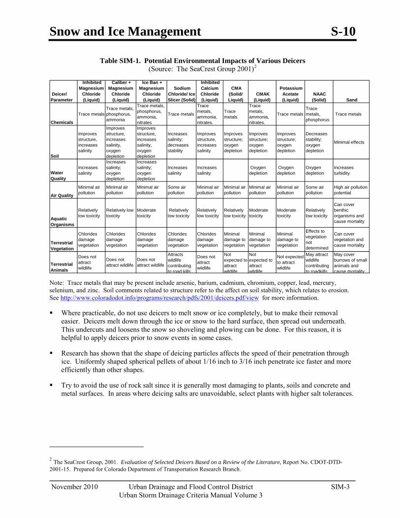
Snow and Ice Management S-10
November 2010 Urban Drainage and Flood Control District SIM-3 Urban Storm Drainage Criteria Manual Volume 3
Table SIM-1. Potential Environmental Impacts of Various Deicers (Source: The SeaCrest Group 2001)2
Deicer/ Parameter
Inhibited Magnesium
Chloride (Liquid)
Caliber + Magnesium
Chloride (Liquid)
Ice Ban + Magnesium
Chloride (Liquid)
Sodium Chloride/ Ice Slicer (Solid)
Inhibited Calcium Chloride (Liquid)
CMA (Solid/ Liquid)
CMAK (Liquid)
Potassium Acetate (Liquid)
NAAC (Solid) Sand
Chemicals
Trace metals Trace metals, phosphorus, ammonia
Trace metals, phosphorus, ammonia, nitrates
Trace metals
Trace metals, ammonia, nitrates.
Trace metals
Trace metals, ammonia, nitrates.
Trace metals Trace metals, phosphorus
Trace metals
Soil
Improves structure, increases salinity
Improves structure, increases salinity, oxygen depletion
Improves structure, increases salinity, oxygen depletion
Increases salinity; decreases stability
Improves structure, increases salinity
Improves structure; oxygen depletion
Improves structure; oxygen depletion
Improves structure; oxygen depletion
Decreases stability; oxygen depletion
Minimal effects
Water Quality
Increases salinity
Increases salinity; oxygen depletion
Increases salinity; oxygen depletion
Increases salinity
Increases salinity
Oxygen depletion
Oxygen depletion
Oxygen depletion
Increases turbidity
Air Quality
Minimal air pollution
Minimal air pollution
Minimal air pollution
Some air pollution
Minimal air pollution
Minimal air pollution
Minimal air pollution
Minimal air pollution
Some air pollution
High air pollution potential
Aquatic Organisms
Relatively low toxicity
Relatively low toxicity
Moderate toxicity
Relatively low toxicity
Relatively low toxicity
Relatively low toxicity
Moderate toxicity
Moderate toxicity
Relatively low toxicity
Can cover benthic organisms and cause mortality
Terrestrial Vegetation
Chlorides damage vegetation
Chlorides damage vegetation
Chlorides damage vegetation
Chlorides damage vegetation
Chlorides damage vegetation
Minimal damage to vegetation
Minimal damage to vegetation
Minimal damage to vegetation
Effects to vegetation not determined
Can cover vegetation and cause mortality
Terrestrial Animals
Does not attract wildlife
Does not attract wildlife
Does not attract wildlife
Attracts wildlife contributing to road kills
Does not attract wildlife
Not expected to attract wildlife
Not expected to attract wildlife
Not expected to attract wildlife
May attract wildlife contributing to roadkills
May cover burrows of small animals and cause mortality
Note: Trace metals that may be present include arsenic, barium, cadmium, chromium, copper, lead, mercury, selenium, and zinc. Soil comments related to structure refer to the affect on soil stability, which relates to erosion. See http://www.coloradodot.info/programs/research/pdfs/2001/deicers.pdf/view for more information.
Where practicable, do not use deicers to melt snow or ice completely, but to make their removal easier. Deicers melt down through the ice or snow to the hard surface, then spread out underneath. This undercuts and loosens the snow so shoveling and plowing can be done. For this reason, it is helpful to apply deicers prior to snow events in some cases.
Research has shown that the shape of deicing particles affects the speed of their penetration through ice. Uniformly shaped spherical pellets of about 1/16 inch to 3/16 inch penetrate ice faster and more efficiently than other shapes.
Try to avoid the use of rock salt since it is generally most damaging to plants, soils and concrete and metal surfaces. In areas where deicing salts are unavoidable, select plants with higher salt tolerances.
2 The SeaCrest Group, 2001. Evaluation of Selected Deicers Based on a Review of the Literature, Report No. CDOT-DTD-2001-15. Prepared for Colorado Department of Transportation Research Branch.

S-10 Snow and Ice Management
SIM-4 Urban Drainage and Flood Control District November 2010 Urban Storm Drainage Criteria Manual Volume 3
Do not plow snow directly into streams or wetlands. Snow storage and disposal areas should be located in an area where snowmelt can infiltrate into the ground, filter through a vegetated buffer or be otherwise treated prior to reaching streams and wetlands. Provide adequate storage volume to trap sediment left behind by melting snow and plan regular maintenance to remove accumulated sediment.
In areas subject to heavy chemical deicing use, flushing the soil with water after the last freeze may alleviate burn potential. Year-round proper plant care will also make plants more tolerant to salt exposure. However, for the overall health of the landscape, the goal should be to reduce or minimize the use of deicing chemicals where they are not necessary for safety reasons.
If an electric/mechanical snow melting device is used to dispose of removed snow (e.g., The Can snow melter, Snow Dragon, etc.), the owner or operator must obtain the appropriate permit prior to discharge. Snowmelt from melting machines is typically considered process wastewater.
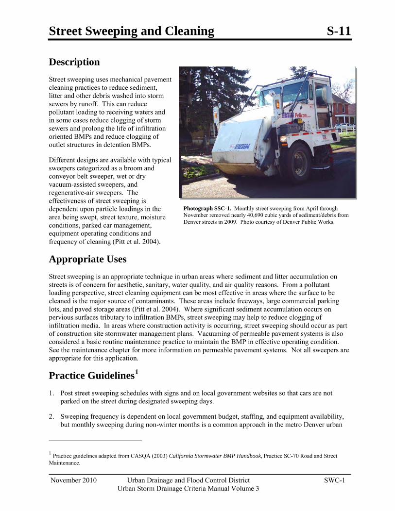
Street Sweeping and Cleaning S-11
November 2010 Urban Drainage and Flood Control District SWC-1 Urban Storm Drainage Criteria Manual Volume 3
Photograph SSC-1. Monthly street sweeping from April through November removed nearly 40,690 cubic yards of sediment/debris from Denver streets in 2009. Photo courtesy of Denver Public Works.
Description Street sweeping uses mechanical pavement cleaning practices to reduce sediment, litter and other debris washed into storm sewers by runoff. This can reduce pollutant loading to receiving waters and in some cases reduce clogging of storm sewers and prolong the life of infiltration oriented BMPs and reduce clogging of outlet structures in detention BMPs.
Different designs are available with typical sweepers categorized as a broom and conveyor belt sweeper, wet or dry vacuum-assisted sweepers, and regenerative-air sweepers. The effectiveness of street sweeping is dependent upon particle loadings in the area being swept, street texture, moisture conditions, parked car management, equipment operating conditions and frequency of cleaning (Pitt et al. 2004).
Appropriate Uses Street sweeping is an appropriate technique in urban areas where sediment and litter accumulation on streets is of concern for aesthetic, sanitary, water quality, and air quality reasons. From a pollutant loading perspective, street cleaning equipment can be most effective in areas where the surface to be cleaned is the major source of contaminants. These areas include freeways, large commercial parking lots, and paved storage areas (Pitt et al. 2004). Where significant sediment accumulation occurs on pervious surfaces tributary to infiltration BMPs, street sweeping may help to reduce clogging of infiltration media. In areas where construction activity is occurring, street sweeping should occur as part of construction site stormwater management plans. Vacuuming of permeable pavement systems is also considered a basic routine maintenance practice to maintain the BMP in effective operating condition. See the maintenance chapter for more information on permeable pavement systems. Not all sweepers are appropriate for this application.
Practice Guidelines1
1. Post street sweeping schedules with signs and on local government websites so that cars are not parked on the street during designated sweeping days.
2. Sweeping frequency is dependent on local government budget, staffing, and equipment availability, but monthly sweeping during non-winter months is a common approach in the metro Denver urban
1 Practice guidelines adapted from CASQA (2003) California Stormwater BMP Handbook, Practice SC-70 Road and Street Maintenance.

S-11 Street Sweeping and Cleaning
SWC-2 Urban Drainage and Flood Control District November 2010 Urban Storm Drainage Criteria Manual Volume 3
Changes in Street Sweeper Technology (Source: Center for Watershed Protection 2002)
At one time, street sweepers were thought to have great potential to remove stormwater pollutants from urban street surfaces and were widely touted as a stormwater treatment practice in many communities. Street sweeping gradually fell out of favor, largely as a result of performance monitoring conducted as part of the National Urban Runoff Program (NURP). These studies generally concluded that street sweepers were not very effective in reducing pollutant loads (USEPA, 1983). The primary reason for the mediocre performance was that mechanical sweepers of that era were unable to pick up fine-grained sediment particles that carry a substantial portion of the stormwater pollutant load. In addition, the performance of sweepers is constrained by that portion of a street’s stormwater pollutant load delivered from outside street pavements (e.g., pollutants that wash onto the street from adjacent areas or are directly deposited on the street by rainfall). Street sweeping technology, however, has evolved considerably since the days of the NURP testing. Today, communities have a choice in three basic sweeping technologies to clean their urban streets: traditional mechanical sweepers that utilize a broom and conveyor belt, vacuum-assisted sweepers, and regenerative-air sweepers (those that blast air onto the pavement to loosen sediment particles and vacuum them into a hopper).
For more information, see http://www.cwp.org/Resource_Library/Center_Docs/PWP/ELC_PWP121.pdf
area. Consider increasing sweeping frequency based on factors such as traffic volume, land use, field observations of sediment and trash accumulation, proximity to watercourses, etc. For example:
Increase the sweeping frequency for streets with high pollutant loadings, especially in high traffic and industrial areas.
Conduct street sweeping prior to wetter seasons to remove accumulated sediments.
Increase the sweeping frequency for streets in special problem areas such as special events, high litter or erosion zones.
3. Perform street cleaning during dry weather if possible.
4. Avoid wet cleaning the street; instead, utilize dry methods where possible.
5. Maintain cleaning equipment in good working condition and purchase replacement equipment as needed. Old sweepers should be replaced with more technologically advanced sweepers (preferably regenerative air sweepers) that maximize pollutant removal.
6. Operate sweepers at manufacturer recommended optimal speed levels to increase effectiveness.
7. Regularly inspect vehicles and equipment for leaks and repair promptly.
8. Keep accurate logs of the number of curb-miles swept and the amount of waste collected.
9. Dispose of street sweeping debris and dirt at a landfill.
10. Do not store swept material along the side of the street or near a storm drain inlet.
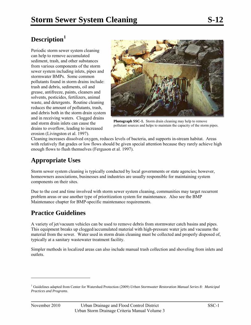
Storm Sewer System Cleaning S-12
November 2010 Urban Drainage and Flood Control District SSC-1 Urban Storm Drainage Criteria Manual Volume 3
Photograph SSC-1. Storm drain cleaning may help to remove pollutant sources and helps to maintain the capacity of the storm pipes.
Description1
Periodic storm sewer system cleaning can help to remove accumulated sediment, trash, and other substances from various components of the storm sewer system including inlets, pipes and stormwater BMPs. Some common pollutants found in storm drains include: trash and debris, sediments, oil and grease, antifreeze, paints, cleaners and solvents, pesticides, fertilizers, animal waste, and detergents. Routine cleaning reduces the amount of pollutants, trash, and debris both in the storm drain system and in receiving waters. Clogged drains and storm drain inlets can cause the drains to overflow, leading to increased erosion (Livingston et al. 1997). Cleaning increases dissolved oxygen, reduces levels of bacteria, and supports in-stream habitat. Areas with relatively flat grades or low flows should be given special attention because they rarely achieve high enough flows to flush themselves (Ferguson et al. 1997).
Appropriate Uses Storm sewer system cleaning is typically conducted by local governments or state agencies; however, homeowners associations, businesses and industries are usually responsible for maintaining system components on their sites.
Due to the cost and time involved with storm sewer system cleaning, communities may target recurrent problem areas or use another type of prioritization system for maintenance. Also see the BMP Maintenance chapter for BMP-specific maintenance requirements.
Practice Guidelines A variety of jet/vacuum vehicles can be used to remove debris from stormwater catch basins and pipes. This equipment breaks up clogged/accumulated material with high-pressure water jets and vacuums the material from the sewer. Water used in storm drain cleaning must be collected and properly disposed of, typically at a sanitary wastewater treatment facility.
Simpler methods in localized areas can also include manual trash collection and shoveling from inlets and outlets.
1 Guidelines adapted from Center for Watershed Protection (2009) Urban Stormwater Restoration Manual Series 8: Municipal Practices and Programs.
S-12 Storm Sewer System Cleaning
SSC-2 Urban Drainage and Flood Control District November 2010
Urban Storm Drainage Criteria Manual Volume 3
Frequency and prioritization of storm sewer cleaning is affected by multiple factors such as the activity and intensity of use in the tributary area (e.g., parking lot, stadium), storm sewer system design, municipal budgets (staff and equipment), and other factors.
To be most effective, storm sewer cleaning needs an effective recordkeeping system and clearly defined procedures. CWP (2009) recommends the following practices:
Tracking: The location and maintenance of storm drains should be tracked using a database and spatial referencing system (e.g., Global Positioning System or Geographic Information System). Additionally, knowing the type and era of the storm drain system may be of use since some inlets/catch basins are designed to be self-cleaning while others have some trapping capacity.
Frequency: Should be defined such that blockage of storm sewer outlet is prevented and it is recommended that the sump should not exceed 40- 50 percent of its capacity. Semi-annual cleanouts in residential streets and monthly cleanouts for industrial streets are suggested by Pitt and Bissonnett (1984) and Mineart and Singh (1994). More frequent cleanouts should be scheduled in the fall as leaves can contribute 25% of nutrient loadings in catch basins.
Technology: A variety of methods of cleaning catch basins are available, including manual cleaning, eductor vehicles, vacuum cleaning and vacuum combination jet cleaning. Choose the approach that is most effective for site conditions, taking into consideration budget, equipment, and staffing constraints.
Staff training: Operators need to be properly trained in catch basin maintenance including waste collection and disposal methods. Staff should also be trained to report water quality problems and illicit discharges.
Material disposal: Most catch basin waste is of acceptable quality for landfills. If it is suspected that catch basin waste contains hazardous material, it should be tested and disposed of accordingly. Maintenance personnel should keep a log of the amount of sediment collected and the removal date at the catch basin.
November 2010 Urban Drainage and Flood Control District 6-i Urban Storm Drainage Criteria Manual Volume 3
Chapter 6 BMP Maintenance Contents 1.0 Introduction ...................................................................................................................................... 1
2.0 Defining Maintenance Responsibility for Public and Private Facilities ...................................... 1
3.0 Developing a Maintenance Plan ...................................................................................................... 2
4.0 Grass Buffers and Swales ................................................................................................................ 5 4.1 Inspection .................................................................................................................................................. 5 4.2 Debris and Litter Removal ........................................................................................................................ 5 4.3 Aeration ..................................................................................................................................................... 5 4.4 Mowing ..................................................................................................................................................... 5 4.5 Irrigation Scheduling and Maintenance .................................................................................................... 6 4.6 Fertilizer, Herbicide, and Pesticide Application ........................................................................................ 6 4.7 Sediment Removal .................................................................................................................................... 7
5.0 Bioretention (Rain Garden or Porous Landscape Detention) ...................................................... 7 5.1 Inspection .................................................................................................................................................. 7 5.2 Debris and Litter Removal ........................................................................................................................ 7 5.3 Mowing and Plant Care ............................................................................................................................. 7 5.4 Irrigation Scheduling and Maintenance .................................................................................................... 8 5.5 Replacement of Wood Mulch ................................................................................................................... 8 5.6 Sediment Removal and Growing Media Replacement .............................................................................. 8
6.0 Green Roofs ...................................................................................................................................... 9 6.1 Inspection .................................................................................................................................................. 9 6.2 Plant Care and Media Replacement .......................................................................................................... 9 6.3 Irrigation Scheduling and Maintenance .................................................................................................. 10
7.0 Extended Detention Basins (EDBs) .............................................................................................. 10 7.1 Inspection ................................................................................................................................................ 10 7.2 Debris and Litter Removal ...................................................................................................................... 11 7.3 Mowing and Plant Care ........................................................................................................................... 11 7.4 Aeration ................................................................................................................................................... 11 7.5 Mosquito Control .................................................................................................................................... 11 7.6 Irrigation Scheduling and Maintenance .................................................................................................. 12 7.7 Sediment Removal from the Forebay, Trickle Channel, and Micropool ................................................. 12 7.8 Sediment Removal from the Basin Bottom ............................................................................................. 12 7.9 Erosion and Structural Repairs ................................................................................................................ 12
8.0 Sand Filters ..................................................................................................................................... 12 8.1 Inspection ................................................................................................................................................ 12 8.2 Debris and Litter Removal ...................................................................................................................... 13 8.3 Filter Surface Maintenance ..................................................................................................................... 13 8.4 Erosion and Structural Repairs ................................................................................................................ 13
Stormwater Management and Planning Chapter 6
6-ii Urban Drainage and Flood Control District November 2010
Urban Storm Drainage Criteria Manual Volume 3
9.0 Retention Ponds and Constructed Wetland Ponds ...................................................................... 13 9.1 Inspection ................................................................................................................................................ 13 9.2 Debris and Litter Removal ...................................................................................................................... 13 9.3 Aquatic Plant Harvesting ........................................................................................................................ 13 9.4 Mosquito Control .................................................................................................................................... 14 9.5 Sediment Removal from the Forebay...................................................................................................... 14 9.6 Sediment Removal from the Pond Bottom ............................................................................................. 14
10.0 Constructed Wetland Channels ..................................................................................................... 14 10.1 Inspection ................................................................................................................................................ 14 10.2 Debris and Litter Removal ...................................................................................................................... 14 10.3 Aquatic Plant Harvesting ........................................................................................................................ 15 10.4 Sediment Removal .................................................................................................................................. 15
11.0 Permeable Pavement Systems ........................................................................................................ 15 11.1 Inspection ................................................................................................................................................ 15 11.2 Debris Removal, Sweeping, and Vacuuming .......................................................................................... 16 11.3 Snow Removal ........................................................................................................................................ 16 11.4 Full and Partial Replacement of the Pavement or Infill Material ............................................................ 16
12.0 Underground BMPs ........................................................................................................................ 17 12.1 Inspection ................................................................................................................................................ 17 12.2 Debris Removal, Cartridge Replacement, and Vacuuming ..................................................................... 17
13.0 References ........................................................................................................................................ 18
Chapter 6 BMP Maintenance
November 2010 Urban Drainage and Flood Control District 6-1 Urban Storm Drainage Criteria Manual Volume 3
1.0 Introduction In order for stormwater BMPs to be effective, proper maintenance is essential. Maintenance includes both routinely scheduled activities, as well as non-routine repairs that may be required after large storms, or as a result of other unforeseen problems. BMP maintenance is the responsibility of the entity owning the BMP; however, local governments with municipal separate storm sewer system (MS4) permits are responsible for ensuring that maintenance of privately owned BMPs occurs within their MS4.
BMPs should be designed with maintenance as one of the key design considerations. Planning-level design guidance pertaining to maintenance is included in the individual Fact Sheets contained within this manual. This chapter focuses on maintenance of in-service BMPs and provides recommendations for private BMP owners, as well as for MS4 permittees responsible for ensuring proper maintenance for both public and private facilities within their MS4.
2.0 Defining Maintenance Responsibility for Public and Private Facilities
Identifying who is responsible for maintenance of BMPs and ensuring that an adequate budget is allocated for maintenance is critical to the long-term success of BMPs. Maintenance responsibility may be assigned in different ways:
Publically owned BMPs are maintained by the MS4 permittee.
Publically owned regional drainage facilities located within the UDFCD service area may be maintained by UDFCD when specific maintenance eligibility criteria are met (subject to funding limitations).
Privately owned BMPs typically are maintained by the property owner, homeowner’s association, or property manager.
Privately owned BMPs may be maintained by the MS4 permittee under a written agreement with the owner, with appropriate fees assessed for maintenance services.
MS4 permittees can utilize a variety of legal approaches to ensure maintenance of stormwater BMPs. Representative measures include:
Agreements establishing legally binding BMP maintenance requirements and responsibilities.
Permit obligations specifying BMP requirements; or
Municipal legislative action or rulemaking authority.
Examples of some of the specific requirements for BMP maintenance suggested for legal agreements by the Watershed Management Institute (1997) include:
General Assurances: Identify requirements for proper operation and maintenance, conditions for modification of facilities, dedicated easements, binding covenants, operation, and maintenance plans, and inspection requirements.
Warranty Period: Require the original developer to be responsible for maintenance and operation during a defined short-term period and identify the entity responsible for long-term operation. The
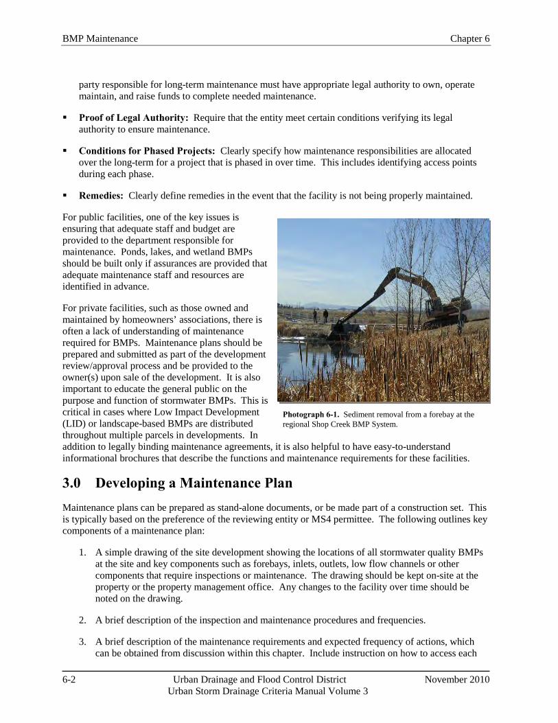
BMP Maintenance Chapter 6
6-2 Urban Drainage and Flood Control District November 2010
Urban Storm Drainage Criteria Manual Volume 3
Photograph 6-1. Sediment removal from a forebay at the regional Shop Creek BMP System.
party responsible for long-term maintenance must have appropriate legal authority to own, operate maintain, and raise funds to complete needed maintenance.
Proof of Legal Authority: Require that the entity meet certain conditions verifying its legal authority to ensure maintenance.
Conditions for Phased Projects: Clearly specify how maintenance responsibilities are allocated over the long-term for a project that is phased in over time. This includes identifying access points during each phase.
Remedies: Clearly define remedies in the event that the facility is not being properly maintained.
For public facilities, one of the key issues is ensuring that adequate staff and budget are provided to the department responsible for maintenance. Ponds, lakes, and wetland BMPs should be built only if assurances are provided that adequate maintenance staff and resources are identified in advance.
For private facilities, such as those owned and maintained by homeowners’ associations, there is often a lack of understanding of maintenance required for BMPs. Maintenance plans should be prepared and submitted as part of the development review/approval process and be provided to the owner(s) upon sale of the development. It is also important to educate the general public on the purpose and function of stormwater BMPs. This is critical in cases where Low Impact Development (LID) or landscape-based BMPs are distributed throughout multiple parcels in developments. In addition to legally binding maintenance agreements, it is also helpful to have easy-to-understand informational brochures that describe the functions and maintenance requirements for these facilities.
3.0 Developing a Maintenance Plan Maintenance plans can be prepared as stand-alone documents, or be made part of a construction set. This is typically based on the preference of the reviewing entity or MS4 permittee. The following outlines key components of a maintenance plan:
1. A simple drawing of the site development showing the locations of all stormwater quality BMPs at the site and key components such as forebays, inlets, outlets, low flow channels or other components that require inspections or maintenance. The drawing should be kept on-site at the property or the property management office. Any changes to the facility over time should be noted on the drawing.
2. A brief description of the inspection and maintenance procedures and frequencies.
3. A brief description of the maintenance requirements and expected frequency of actions, which can be obtained from discussion within this chapter. Include instruction on how to access each
Chapter 6 BMP Maintenance
November 2010 Urban Drainage and Flood Control District 6-3 Urban Storm Drainage Criteria Manual Volume 3
component of each BMP and with what equipment. It is important to identify all maintenance requirements related directly to the water quality functions of the BMP and provide information concerning future site work that could potentially impact the integrity of the BMP. This is particularly true for landscaped BMPs. For example, the following maintenance requirements may be important for a rain garden:
Provide frequent weed control in the first three years following installation and as needed for the life of the facility. Weeding should be performed mechanically, either by hand or by mowing (after establishment of the vegetation).
Remove debris from area and outlet.
Ensure cleanout caps remains watertight.
Additionally, the maintenance plans should identify constraints and considerations for future work that have the potential to affect the performance of the BMP. For example, the following prohibitions would typically be included in a maintenance plan for a rain garden:
Do not place conventional sod on the surface of the rain garden.
Do not plant trees within 10 feet of the rain garden.
Do not place fill in the rain garden.
Do not puncture impermeable liner, (if present).
4. An inspection form or checklist appropriate for the facilities in place at the site. A log of inspection forms should be kept onsite or at the property management office to demonstrate that routine inspections and maintenance are occurring.
5. Contact information for the entity responsible for maintenance of the facility. For example, this could be a homeowner's association, municipality, or other entity. (For BMPs maintained by UDFCD, the owner, rather than UDFCD, should be contacted.)
6. Copies of legally binding agreements associated with the facility that show that the facility owner is aware of, and will abide by, their maintenance responsibilities.
7. Other items as appropriate for specific conditions, which may include any of the following:
For ponds, include a permanent control point and other critical elevations, (i.e. bottom of pond, EURV, 100-year WSE, or overflow).
Provide the estimated baseflow used for the design and other hydrologic information for larger watersheds.
List information pertaining to materials testing for any contaminant testing requirements for removed sediment.
Include post-maintenance considerations, (e.g., restoration of flow paths).
Provide for long-term monitoring requirements, (e.g., 404 permit reports).
It is also important to note that the guidelines included in this manual should always be combined
BMP Maintenance Chapter 6
6-4 Urban Drainage and Flood Control District November 2010
Urban Storm Drainage Criteria Manual Volume 3
Additional References for Stormwater BMP Maintenance
City of Portland, Oregon. 2002. Maintaining Your Stormwater Management Facility: A Handbook for Private Property Owners. Portland, OR: Bureau of Environmental Services. http://www.portlandonline.com/Bes/index.cfm?a=54730&c=34980.
Low Impact Development Center. 2003. Low Impact Development Urban Design Tools. http://www.lid-stormwater.net/bio_maintain.htm; http://www.lid-stormwater.net/permpavers_maintain.htm
North Carolina State University Cooperative Extension. 2006. Bioretention Performance, Design, Construction, and Maintenance. http://www.bae.ncsu.edu/stormwater/PublicationFiles/Bioretention2006.pdf
Santa Clara Valley Urban Runoff Pollution Prevention Program Example BMP Inspection and Maintenance Checklist. http://www.scvurppp-w2k.com/bmp_om_forms.htm
Southeast Metro Stormwater Authority (SEMSWA) Stormwater Management Facility Operation and Maintenance (O&M) Manual. www.semswa.org
Watershed Management Institute. 1997. Operation, Maintenance and Management of Stormwater Management Systems. Ingleside, MD: Watershed Management Institute.
with common sense and good judgment based on field observations and practical experience. Often, there will be maintenance requirements that are specific to a given site in addition to the general maintenance guidance provided in this manual.
On a general note with regard to BMPs that have a vegetation component or involve weed and pest control, UDFCD strongly advocates the use of Integrated Pest Management (IPM) practices that help to reduce the level of chemical applications through a variety of management practices. IPM is discussed in BMP Fact Sheet S-8 located in Chapter 5.
Although water quality monitoring is not typically required as part of maintenance agreements, it is encouraged as an effective tool for determining if the BMP is functioning effectively. Stormwater quality monitoring guidelines can be downloaded from the International Stormwater BMP Database website (www.bmpdatabase.org).
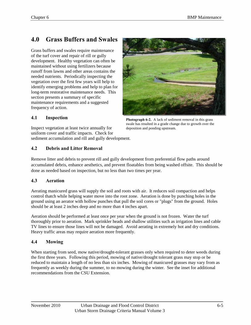
Chapter 6 BMP Maintenance
November 2010 Urban Drainage and Flood Control District 6-5 Urban Storm Drainage Criteria Manual Volume 3
Photograph 6-2. A lack of sediment removal in this grass swale has resulted in a grade change due to growth over the deposition and ponding upstream.
4.0 Grass Buffers and Swales Grass buffers and swales require maintenance of the turf cover and repair of rill or gully development. Healthy vegetation can often be maintained without using fertilizers because runoff from lawns and other areas contains the needed nutrients. Periodically inspecting the vegetation over the first few years will help to identify emerging problems and help to plan for long-term restorative maintenance needs. This section presents a summary of specific maintenance requirements and a suggested frequency of action.
4.1 Inspection
Inspect vegetation at least twice annually for uniform cover and traffic impacts. Check for sediment accumulation and rill and gully development.
4.2 Debris and Litter Removal
Remove litter and debris to prevent rill and gully development from preferential flow paths around accumulated debris, enhance aesthetics, and prevent floatables from being washed offsite. This should be done as needed based on inspection, but no less than two times per year.
4.3 Aeration
Aerating manicured grass will supply the soil and roots with air. It reduces soil compaction and helps control thatch while helping water move into the root zone. Aeration is done by punching holes in the ground using an aerator with hollow punches that pull the soil cores or "plugs" from the ground. Holes should be at least 2 inches deep and no more than 4 inches apart.
Aeration should be performed at least once per year when the ground is not frozen. Water the turf thoroughly prior to aeration. Mark sprinkler heads and shallow utilities such as irrigation lines and cable TV lines to ensure those lines will not be damaged. Avoid aerating in extremely hot and dry conditions. Heavy traffic areas may require aeration more frequently.
4.4 Mowing
When starting from seed, mow native/drought-tolerant grasses only when required to deter weeds during the first three years. Following this period, mowing of native/drought tolerant grass may stop or be reduced to maintain a length of no less than six inches. Mowing of manicured grasses may vary from as frequently as weekly during the summer, to no mowing during the winter. See the inset for additional recommendations from the CSU Extension.
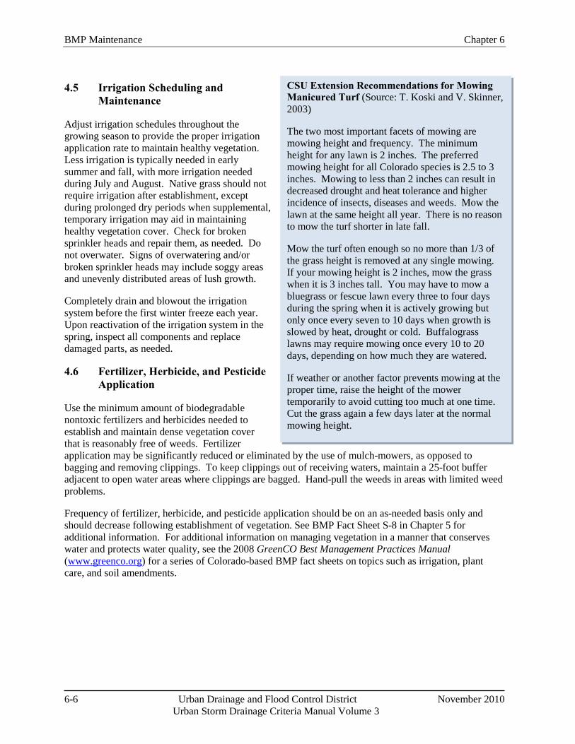
BMP Maintenance Chapter 6
6-6 Urban Drainage and Flood Control District November 2010
Urban Storm Drainage Criteria Manual Volume 3
CSU Extension Recommendations for Mowing Manicured Turf (Source: T. Koski and V. Skinner, 2003)
The two most important facets of mowing are mowing height and frequency. The minimum height for any lawn is 2 inches. The preferred mowing height for all Colorado species is 2.5 to 3 inches. Mowing to less than 2 inches can result in decreased drought and heat tolerance and higher incidence of insects, diseases and weeds. Mow the lawn at the same height all year. There is no reason to mow the turf shorter in late fall.
Mow the turf often enough so no more than 1/3 of the grass height is removed at any single mowing. If your mowing height is 2 inches, mow the grass when it is 3 inches tall. You may have to mow a bluegrass or fescue lawn every three to four days during the spring when it is actively growing but only once every seven to 10 days when growth is slowed by heat, drought or cold. Buffalograss lawns may require mowing once every 10 to 20 days, depending on how much they are watered.
If weather or another factor prevents mowing at the proper time, raise the height of the mower temporarily to avoid cutting too much at one time. Cut the grass again a few days later at the normal mowing height.
4.5 Irrigation Scheduling and Maintenance
Adjust irrigation schedules throughout the growing season to provide the proper irrigation application rate to maintain healthy vegetation. Less irrigation is typically needed in early summer and fall, with more irrigation needed during July and August. Native grass should not require irrigation after establishment, except during prolonged dry periods when supplemental, temporary irrigation may aid in maintaining healthy vegetation cover. Check for broken sprinkler heads and repair them, as needed. Do not overwater. Signs of overwatering and/or broken sprinkler heads may include soggy areas and unevenly distributed areas of lush growth.
Completely drain and blowout the irrigation system before the first winter freeze each year. Upon reactivation of the irrigation system in the spring, inspect all components and replace damaged parts, as needed.
4.6 Fertilizer, Herbicide, and Pesticide Application
Use the minimum amount of biodegradable nontoxic fertilizers and herbicides needed to establish and maintain dense vegetation cover that is reasonably free of weeds. Fertilizer application may be significantly reduced or eliminated by the use of mulch-mowers, as opposed to bagging and removing clippings. To keep clippings out of receiving waters, maintain a 25-foot buffer adjacent to open water areas where clippings are bagged. Hand-pull the weeds in areas with limited weed problems.
Frequency of fertilizer, herbicide, and pesticide application should be on an as-needed basis only and should decrease following establishment of vegetation. See BMP Fact Sheet S-8 in Chapter 5 for additional information. For additional information on managing vegetation in a manner that conserves water and protects water quality, see the 2008 GreenCO Best Management Practices Manual (www.greenco.org) for a series of Colorado-based BMP fact sheets on topics such as irrigation, plant care, and soil amendments.
Chapter 6 BMP Maintenance
November 2010 Urban Drainage and Flood Control District 6-7 Urban Storm Drainage Criteria Manual Volume 3
4.7 Sediment Removal
Remove sediment as needed based on inspection. Frequency depends on site-specific conditions. For planning purposes, it can be estimated that 3 to 10% of the swale length or buffer interface length will require sediment removal on an annual basis.
For Grass Buffers: Using a shovel, remove sediment at the interface between the impervious area and buffer.
For Grass Swales: Remove accumulated sediment near culverts and in channels to maintain flow capacity. Spot replace the grass areas as necessary.
Reseed and/or patch damaged areas in buffer, sideslopes, and/or channel to maintain healthy vegetative cover. This should be conducted as needed based on inspection. Over time, and depending on pollutant loads, a portion of the buffer or swale may need to be rehabilitated due to sediment deposition. Periodic sediment removal will reduce the frequency of revegetation required. Expect turf replacement for the buffer interface area every 10 to 20 years.
5.0 Bioretention (Rain Garden or Porous Landscape Detention) The primary maintenance objective for bioretention, also known as porous landscape detention, is to keep vegetation healthy, remove sediment and trash, and ensure that the facility is draining properly. The growing medium may need to be replaced eventually to maintain performance. This section summarizes key maintenance considerations for bioretention.
5.1 Inspection
Inspect the infiltrating surface at least twice annually following precipitation events to determine if the bioretention area is providing acceptable infiltration. Bioretention facilities are designed with a maximum depth for the WQCV of one foot and soils that will typically drain the WQCV over approximately 12 hours. If standing water persists for more than 24 hours after runoff has ceased, clogging should be further investigated and remedied. Additionally, check for erosion and repair as necessary.
5.2 Debris and Litter Removal
Remove debris and litter from the infiltrating surface to minimize clogging of the media. Remove debris and litter from the overflow structure.
5.3 Mowing and Plant Care
All vegetation: Maintain healthy, weed-free vegetation. Weeds should be removed before they flower. The frequency of weeding will depend on the planting scheme and cover. When the growing media is covered with mulch or densely vegetated, less frequent weeding will be required.
Grasses: When started from seed, allow time for germination and establishment of grass prior to mowing. If mowing is required during this period for weed control, it should be accomplished with hand-held string trimmers to minimize disturbance to the seedbed. After established, mow as desired or as needed for weed control. Following this period, mowing of native/drought tolerant grasses may stop or be reduced to maintain a length of no less than 6 inches. Mowing of manicured grasses may vary from as frequently as weekly during the summer, to no mowing during the winter. See Section 4.4 for additional guidance on mowing.
BMP Maintenance Chapter 6
6-8 Urban Drainage and Flood Control District November 2010
Urban Storm Drainage Criteria Manual Volume 3
5.4 Irrigation Scheduling and Maintenance
Adjust irrigation throughout the growing season to provide the proper irrigation application rate to maintain healthy vegetation. Less irrigation is typically needed in early summer and fall, while more irrigation is needed during the peak summer months. Native grasses and other drought tolerant plantings should not typically require routine irrigation after establishment, except during prolonged dry periods.
Check for broken sprinkler heads and repair them, as needed. Completely drain the irrigation system before the first winter freeze each year. Upon reactivation of the irrigation system in the spring, inspect all components and replace damaged parts, as needed.
5.5 Replacement of Wood Mulch
Replace wood mulch only when needed to maintain a mulch depth of up to approximately 3 inches. Excess mulch will reduce the volume available for storage.
5.6 Sediment Removal and Growing Media Replacement
If ponded water is observed in a bioretention cell more than 24 hours after the end of a runoff event, check underdrain outfall locations and clean-outs for blockages. Maintenance activities to restore infiltration capacity of bioretention facilities will vary with the degree and nature of the clogging. If clogging is primarily related to sediment accumulation on the filter surface, infiltration may be improved by removing excess accumulated sediment and scarifying the surface of the filter with a rake. If the clogging is due to migration of sediments deeper into the pore spaces of the media, removal and replacement of all or a portion of the media may be required. The frequency of media replacement will depend on site-specific pollutant loading characteristics. Based on experience to date in the metro Denver area, the required frequency of media replacement is not known. To date UDFCD is not aware of any rain gardens constructed to the recommendations of these criteria that have required full replacement of the growing media. Although surface clogging of the media is expected over time, established root systems promote infiltration. This means that mature vegetation that covers the filter surface should increase the life span of the growing media, serving to promote infiltration even as the media surface clogs.
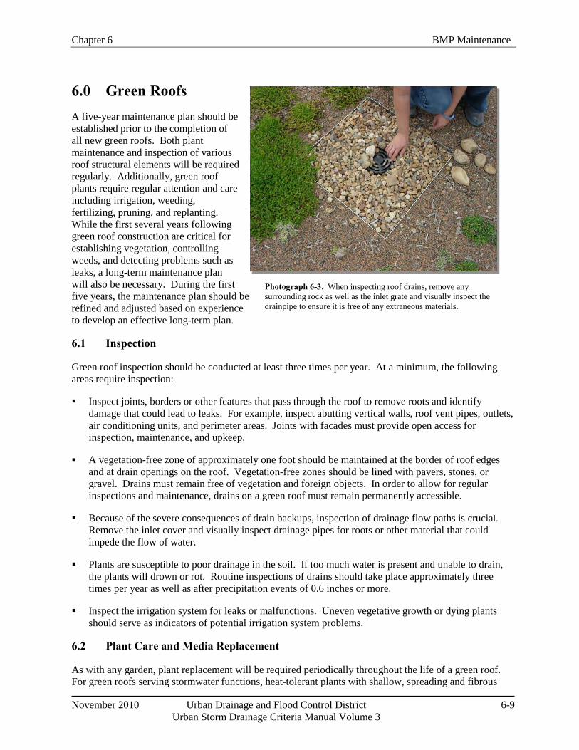
Chapter 6 BMP Maintenance
November 2010 Urban Drainage and Flood Control District 6-9 Urban Storm Drainage Criteria Manual Volume 3
6.0 Green Roofs A five-year maintenance plan should be established prior to the completion of all new green roofs. Both plant maintenance and inspection of various roof structural elements will be required regularly. Additionally, green roof plants require regular attention and care including irrigation, weeding, fertilizing, pruning, and replanting. While the first several years following green roof construction are critical for establishing vegetation, controlling weeds, and detecting problems such as leaks, a long-term maintenance plan will also be necessary. During the first five years, the maintenance plan should be refined and adjusted based on experience to develop an effective long-term plan.
6.1 Inspection
Green roof inspection should be conducted at least three times per year. At a minimum, the following areas require inspection:
Inspect joints, borders or other features that pass through the roof to remove roots and identify damage that could lead to leaks. For example, inspect abutting vertical walls, roof vent pipes, outlets, air conditioning units, and perimeter areas. Joints with facades must provide open access for inspection, maintenance, and upkeep.
A vegetation-free zone of approximately one foot should be maintained at the border of roof edges and at drain openings on the roof. Vegetation-free zones should be lined with pavers, stones, or gravel. Drains must remain free of vegetation and foreign objects. In order to allow for regular inspections and maintenance, drains on a green roof must remain permanently accessible.
Because of the severe consequences of drain backups, inspection of drainage flow paths is crucial. Remove the inlet cover and visually inspect drainage pipes for roots or other material that could impede the flow of water.
Plants are susceptible to poor drainage in the soil. If too much water is present and unable to drain, the plants will drown or rot. Routine inspections of drains should take place approximately three times per year as well as after precipitation events of 0.6 inches or more.
Inspect the irrigation system for leaks or malfunctions. Uneven vegetative growth or dying plants should serve as indicators of potential irrigation system problems.
6.2 Plant Care and Media Replacement
As with any garden, plant replacement will be required periodically throughout the life of a green roof. For green roofs serving stormwater functions, heat-tolerant plants with shallow, spreading and fibrous
Photograph 6-3. When inspecting roof drains, remove any surrounding rock as well as the inlet grate and visually inspect the drainpipe to ensure it is free of any extraneous materials.
BMP Maintenance Chapter 6
6-10 Urban Drainage and Flood Control District November 2010
Urban Storm Drainage Criteria Manual Volume 3
root systems are recommended. Plant selection is crucial on roofs with intense wind and light such as roofs of skyscrapers or roofs that receive reflected solar radiation from other structures. Additionally, certain portions of the roof may experience more intense sunlight and or reflected heat, requiring additional care or irrigation system adjustments.
Care of the plants on a green roof will require the most attention during the critical establishment phase. A horticultural professional should work with individuals caring for the new roof to organize schedules and routines for hand weeding, thinning, pruning, fertilizing, irrigation system scheduling and adjustments, and plant replacement. Watering and weeding are particularly important for the first two years of the green roof. For overall health of the green roof, weeds should be identified and removed early and often.
If the growing medium needs to be replaced, it should be replaced in accordance with the original design specifications, unless these specifications have been identified as a cause of poor plant growth or green roof performance. Any substitutions or adjustments to the original green roof media must be balanced carefully to meet loading limits, drainage requirements, and characteristics conducive to healthy plant growth.
When caring for plants or adjusting growing media, care should be taken to avoid use of materials likely to result in nutrient export from the green roof. For example, growing media and compost should have a low phosphorus index (P index). Appropriate plants with low fertilization requirements should be chosen. If used, fertilizer application should be minimized to levels necessary only for plant health.
6.3 Irrigation Scheduling and Maintenance
Green roofs in Colorado should be equipped with irrigation systems, even if the ultimate goal is for the plants to rely primarily on natural precipitation. Irrigation schedules should be based on the evapotranspiration (ET) requirements of the plants, the type of irrigation system used (e.g., drip or spray), and changing ET over the growing season. Irrigation systems equipped with advanced irrigation controllers based on soil moisture can help facilitate watering according to the changing water needs of the plants. If advanced systems are not used, irrigation should be manually adjusted during the growing season to replace water lost through ET. During the first two years of plant establishment, regular irrigation will likely be needed. After plant establishment, it may be possible to reduce supplemental irrigation during non-drought conditions.
Completely drain the irrigation system before the first winter freeze each year. Upon reactivation of the irrigation system in the spring, inspect all components and replace damaged parts, as needed.
7.0 Extended Detention Basins (EDBs) EDBs have low to moderate maintenance requirements on a routine basis, but may require significant maintenance once every 15 to 25 years. Maintenance frequency depends on the amount of construction activity within the tributary watershed, the erosion control measures implemented, the size of the watershed, and the design of the facility.
7.1 Inspection
Inspect the EDB at least twice annually, observing the amount of sediment in the forebay and checking for debris at the outlet structure.
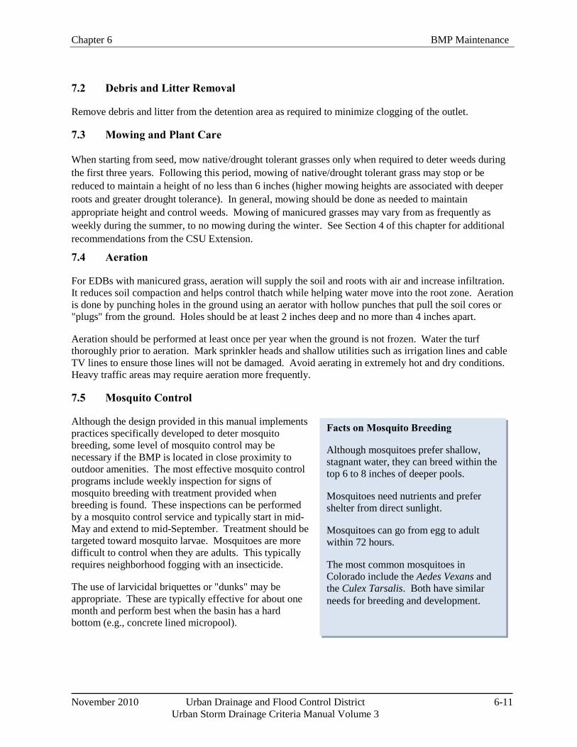
Chapter 6 BMP Maintenance
November 2010 Urban Drainage and Flood Control District 6-11 Urban Storm Drainage Criteria Manual Volume 3
Facts on Mosquito Breeding
Although mosquitoes prefer shallow, stagnant water, they can breed within the top 6 to 8 inches of deeper pools.
Mosquitoes need nutrients and prefer shelter from direct sunlight.
Mosquitoes can go from egg to adult within 72 hours.
The most common mosquitoes in Colorado include the Aedes Vexans and the Culex Tarsalis. Both have similar needs for breeding and development.
7.2 Debris and Litter Removal
Remove debris and litter from the detention area as required to minimize clogging of the outlet.
7.3 Mowing and Plant Care
When starting from seed, mow native/drought tolerant grasses only when required to deter weeds during the first three years. Following this period, mowing of native/drought tolerant grass may stop or be reduced to maintain a height of no less than 6 inches (higher mowing heights are associated with deeper roots and greater drought tolerance). In general, mowing should be done as needed to maintain appropriate height and control weeds. Mowing of manicured grasses may vary from as frequently as weekly during the summer, to no mowing during the winter. See Section 4 of this chapter for additional recommendations from the CSU Extension.
7.4 Aeration
For EDBs with manicured grass, aeration will supply the soil and roots with air and increase infiltration. It reduces soil compaction and helps control thatch while helping water move into the root zone. Aeration is done by punching holes in the ground using an aerator with hollow punches that pull the soil cores or "plugs" from the ground. Holes should be at least 2 inches deep and no more than 4 inches apart.
Aeration should be performed at least once per year when the ground is not frozen. Water the turf thoroughly prior to aeration. Mark sprinkler heads and shallow utilities such as irrigation lines and cable TV lines to ensure those lines will not be damaged. Avoid aerating in extremely hot and dry conditions. Heavy traffic areas may require aeration more frequently.
7.5 Mosquito Control
Although the design provided in this manual implements practices specifically developed to deter mosquito breeding, some level of mosquito control may be necessary if the BMP is located in close proximity to outdoor amenities. The most effective mosquito control programs include weekly inspection for signs of mosquito breeding with treatment provided when breeding is found. These inspections can be performed by a mosquito control service and typically start in mid-May and extend to mid-September. Treatment should be targeted toward mosquito larvae. Mosquitoes are more difficult to control when they are adults. This typically requires neighborhood fogging with an insecticide.
The use of larvicidal briquettes or "dunks" may be appropriate. These are typically effective for about one month and perform best when the basin has a hard bottom (e.g., concrete lined micropool).
BMP Maintenance Chapter 6
6-12 Urban Drainage and Flood Control District November 2010
Urban Storm Drainage Criteria Manual Volume 3
7.6 Irrigation Scheduling and Maintenance
Adjust irrigation throughout the growing season to provide the proper irrigation application rate to maintain healthy vegetation. Less irrigation is typically needed in early summer and fall, with more irrigation needed during July and August. Native grass and other drought tolerant plantings should not require irrigation after establishment.
Check for broken sprinkler heads and repair them, as needed. Completely drain the irrigation system before the first winter freeze each year. Upon reactivation of the irrigation system in the spring, inspect all components and replace damaged parts, as needed.
7.7 Sediment Removal from the Forebay, Trickle Channel, and Micropool
Remove sediment from the forebay and trickle channel annually. If portions of the watershed are not developed or if roadway or landscaping projects are taking place in the watershed, the required frequency of sediment removal in the forebay may be as often as after each storm event. The forebay should be maintained in such a way that it does not provide a significant source of resuspended sediment in the stormwater runoff.
Sediment removal from the micropool is required about once every one to four years, and should occur when the depth of the pool has been reduced to approximately 18 inches. Small micropools may be vacuumed and larger pools may need to be pumped in order to remove all sediment from the micropool bottom. Removing sediment from the micropool will benefit mosquito control. Ensure that the sediment is disposed of properly and not placed elsewhere in the basin.
7.8 Sediment Removal from the Basin Bottom
Remove sediment from the bottom of the basin when accumulated sediment occupies about 20% of the water quality design volume or when sediment accumulation results in poor drainage within the basin. The required frequency may be every 15 to 25 years or more frequently in basins where construction activities are occurring.
7.9 Erosion and Structural Repairs
Repair basin inlets, outlets, trickle channels, and all other structural components required for the basin to operate as intended. Repair and vegetate eroded areas as needed following inspection.
8.0 Sand Filters Sand filters have relatively low routine maintenance requirements. Maintenance frequency depends on pollutant loads in runoff, the amount of construction activity within the tributary watershed, the erosion control measures implemented, the size of the watershed, and the design of the facility.
8.1 Inspection
Inspect the detention area once or twice annually following precipitation events to determine if the sand filter is providing acceptable infiltration. Also check for erosion and repair as necessary.
Chapter 6 BMP Maintenance
November 2010 Urban Drainage and Flood Control District 6-13 Urban Storm Drainage Criteria Manual Volume 3
8.2 Debris and Litter Removal
Remove debris and litter from detention area to minimize clogging of the media. Remove debris and litter from the overflow structure.
8.3 Filter Surface Maintenance
Scarify the top 2 inches of sand on the surface of the filter. This may be required once every two to five years depending on observed drain times. After this has been done two or three times, replenish the top few inches of the filter with clean coarse sand (AASHTO C-33 or CDOT Class C filter material) to the original elevation. Maintain a minimum sand depth of 12 inches. Eventually, the entire sand layer may require replacement.
8.4 Erosion and Structural Repairs
Repair basin inlets, outlets, and all other structural components required for the BMP to operate as intended. Repair and vegetate any eroded side slopes as needed following inspection.
9.0 Retention Ponds and Constructed Wetland Ponds
9.1 Inspection
Inspect the pond at least annually. Note the amount of sediment in the forebay and look for debris at the outlet structure.
9.2 Debris and Litter Removal
Remove debris and litter from the pond as needed. This includes floating debris that could clog the outlet or overflow structure.
9.3 Aquatic Plant Harvesting
Harvesting plants will permanently remove nutrients from the system, although removal of vegetation can also resuspend sediment and leave areas susceptible to erosion. Additionally, the plants growing on the safety wetland bench of a retention pond help prevent drowning accidents by demarking the pond boundary and creating a visual barrier. For this reason, UDFCD does not recommend harvesting vegetation completely as routine maintenance. However, aquatic plant harvesting can be performed if desired to maintain volume or eliminate nuisances related to overgrowth of vegetation. When this is the case, perform this activity during the dry season (November to February). This can be performed manually or with specialized machinery.
If a reduction in cattails is desired, harvest them annually, especially in areas of new growth. Cut them at the base of the plant just below the waterline, or slowly pull the shoot out from the base. Cattail removal should be done during late summer to deprive the roots of food and reduce their ability to survive winter.
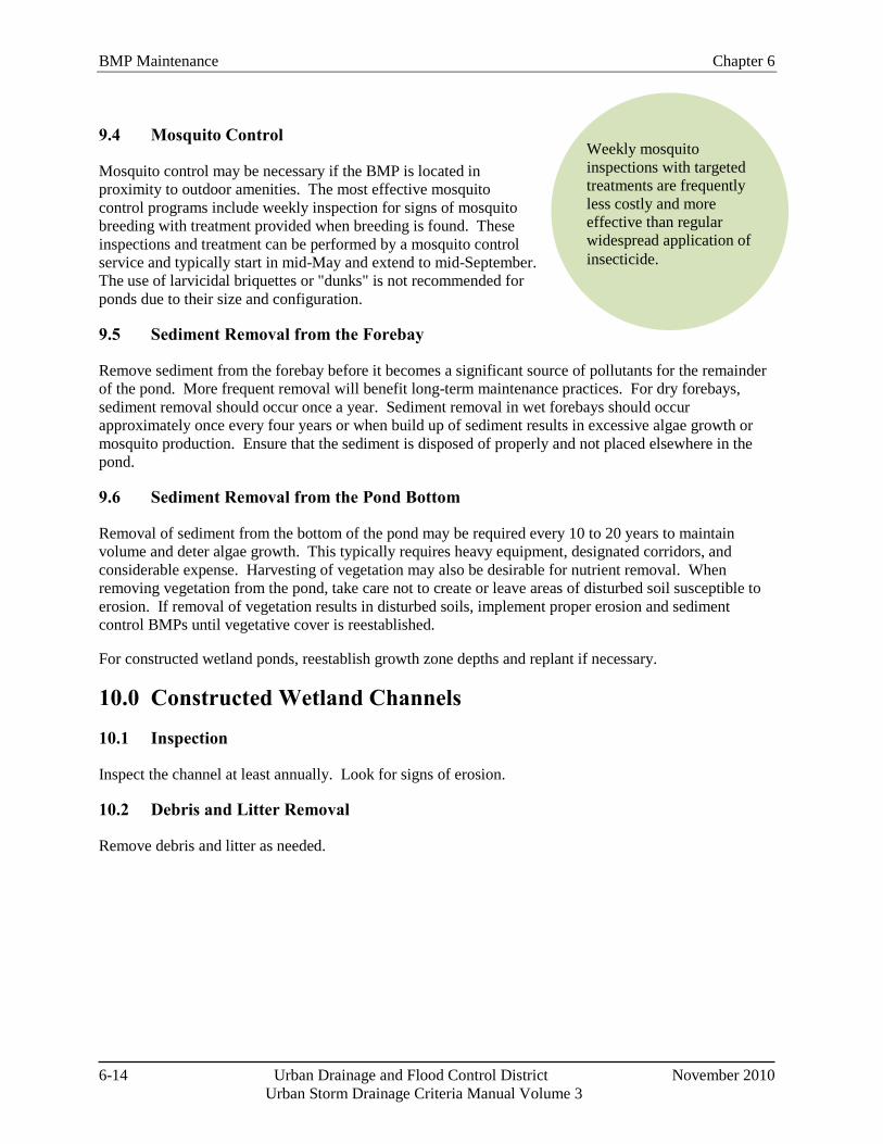
BMP Maintenance Chapter 6
6-14 Urban Drainage and Flood Control District November 2010
Urban Storm Drainage Criteria Manual Volume 3
Weekly mosquito inspections with targeted treatments are frequently less costly and more effective than regular widespread application of insecticide.
9.4 Mosquito Control
Mosquito control may be necessary if the BMP is located in proximity to outdoor amenities. The most effective mosquito control programs include weekly inspection for signs of mosquito breeding with treatment provided when breeding is found. These inspections and treatment can be performed by a mosquito control service and typically start in mid-May and extend to mid-September. The use of larvicidal briquettes or "dunks" is not recommended for ponds due to their size and configuration.
9.5 Sediment Removal from the Forebay
Remove sediment from the forebay before it becomes a significant source of pollutants for the remainder of the pond. More frequent removal will benefit long-term maintenance practices. For dry forebays, sediment removal should occur once a year. Sediment removal in wet forebays should occur approximately once every four years or when build up of sediment results in excessive algae growth or mosquito production. Ensure that the sediment is disposed of properly and not placed elsewhere in the pond.
9.6 Sediment Removal from the Pond Bottom
Removal of sediment from the bottom of the pond may be required every 10 to 20 years to maintain volume and deter algae growth. This typically requires heavy equipment, designated corridors, and considerable expense. Harvesting of vegetation may also be desirable for nutrient removal. When removing vegetation from the pond, take care not to create or leave areas of disturbed soil susceptible to erosion. If removal of vegetation results in disturbed soils, implement proper erosion and sediment control BMPs until vegetative cover is reestablished.
For constructed wetland ponds, reestablish growth zone depths and replant if necessary.
10.0 Constructed Wetland Channels
10.1 Inspection
Inspect the channel at least annually. Look for signs of erosion.
10.2 Debris and Litter Removal
Remove debris and litter as needed.
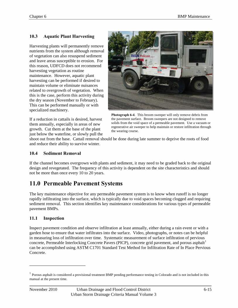
Chapter 6 BMP Maintenance
November 2010 Urban Drainage and Flood Control District 6-15 Urban Storm Drainage Criteria Manual Volume 3
Photograph 6-4. This broom sweeper will only remove debris from the pavement surface. Broom sweepers are not designed to remove solids from the void space of a permeable pavement. Use a vacuum or regenerative air sweeper to help maintain or restore infiltration through the wearing course.
10.3 Aquatic Plant Harvesting
Harvesting plants will permanently remove nutrients from the system although removal of vegetation can also resuspend sediment and leave areas susceptible to erosion. For this reason, UDFCD does not recommend harvesting vegetation as routine maintenance. However, aquatic plant harvesting can be performed if desired to maintain volume or eliminate nuisances related to overgrowth of vegetation. When this is the case, perform this activity during the dry season (November to February). This can be performed manually or with specialized machinery.
If a reduction in cattails is desired, harvest them annually, especially in areas of new growth. Cut them at the base of the plant just below the waterline, or slowly pull the shoot out from the base. Cattail removal should be done during late summer to deprive the roots of food and reduce their ability to survive winter.
10.4 Sediment Removal
If the channel becomes overgrown with plants and sediment, it may need to be graded back to the original design and revegetated. The frequency of this activity is dependent on the site characteristics and should not be more than once every 10 to 20 years.
11.0 Permeable Pavement Systems The key maintenance objective for any permeable pavement system is to know when runoff is no longer rapidly infiltrating into the surface, which is typically due to void spaces becoming clogged and requiring sediment removal. This section identifies key maintenance considerations for various types of permeable pavement BMPs.
11.1 Inspection
Inspect pavement condition and observe infiltration at least annually, either during a rain event or with a garden hose to ensure that water infiltrates into the surface. Video, photographs, or notes can be helpful in measuring loss of infiltration over time. Systematic measurement of surface infiltration of pervious concrete, Permeable Interlocking Concrete Pavers (PICP), concrete grid pavement, and porous asphalt1
1 Porous asphalt is considered a provisional treatment BMP pending performance testing in Colorado and is not included in this manual at the present time.
can be accomplished using ASTM C1701 Standard Test Method for Infiltration Rate of In Place Pervious Concrete.
BMP Maintenance Chapter 6
6-16 Urban Drainage and Flood Control District November 2010
Urban Storm Drainage Criteria Manual Volume 3
11.2 Debris Removal, Sweeping, and Vacuuming
• All Pavements: Debris should be removed, routinely, as a source control measure. Typically, sites that require frequent sweeping already plan for this activity as part of their ongoing maintenance program. For example, a grocery store may sweep weekly or monthly. Depending on the season, city streets also may have a monthly plan for sweeping. This is frequently performed with a broom sweeper such as the one shown in Photo 6-4. Although this type of sweeper can be effective at removing solids and debris from the surface, it will not remove solids from the void space of a permeable pavement. Use a vacuum or regenerative air sweeper to help maintain or restore infiltration. If the pavement has not been properly maintained, a vacuum sweeper will likely be needed.
• PICP, Concrete Grid Pavements (with aggregate infill), Pervious Concrete, and Porous Asphalt1: Use a regenerative air or vacuum sweeper after any significant site work (e.g., landscaping) and approximately twice per year to maintain infiltration rates. This should be done on a warm dry day for best results. Do not use water with the sweeper. The frequency is site specific and inspections of the pavement may show that biannual vacuuming is more frequent than necessary. After vacuuming PICP and Concrete Grid Pavers, replace infill aggregate as needed.
11.3 Snow Removal
In general, permeable pavements do not form ice to the same extent as conventional pavements. Additionally, conventional liquid treatments (deicers) will not stay at the surface of a permeable pavement as needed for the treatment to be effective. Sand should not be applied to a permeable pavement as it can reduce infiltration. Plowing is the recommended snow removal process. Conventional plowing operations should not cause damage to the pavements.
PICP and Concrete Grid: Deicers may be used on PICP and grid pavers; however, it may not be effective for the reason stated above. Sand should not be used. If sand is accidently used, use a vacuum sweeper to remove the sand. Mechanical snow and ice removal should be used.
Pervious Concrete: Do not use liquid or solid deicers or sand on pervious concrete. Deicers can damage the concrete and sand will reduce infiltration. Mechanical snow and ice removal should be used.
Porous Asphalt2
11.4 Full and Partial Replacement of the Pavement or Infill Material
: Use liquid or solid deicers sparingly; mechanical snow and ice removal is preferred. Do not apply sand to porous asphalt.
PICP and Concrete Grid: Concrete pavers, when installed correctly, should have a long service life. If a repair is required, it is frequently due to poor placement of the paver blocks. Follow industry guidelines for installation and replacement after underground repairs.
If surface is completely clogged and rendering a minimal surface infiltration rate, restoration of surface infiltration can be achieved by removing the first ½ to 1 inch of soiled aggregate infill
2 Porous asphalt is considered a provisional treatment BMP pending performance testing in Colorado and is not included in this manual at the present time.
Chapter 6 BMP Maintenance
November 2010 Urban Drainage and Flood Control District 6-17 Urban Storm Drainage Criteria Manual Volume 3
material with a vacuum sweeper. After cleaning, the openings in the PICP will need to be refilled with clean aggregate infill materials. Replacement of the infill is best accomplished with push brooms.
Porous Gravel: Remove and replace areas of excessive wear or reduced infiltration as needed. The frequency is dependent on site characteristics including site uses, vegetation, and materials.
Pervious Concrete: Partial replacement of pervious concrete should be avoided. If clogged, power washing or power blowing should be attempted prior to partial replacement because saw cutting will cause raveling of the concrete. Any patches should extend to existing isolated joints. Conventional concrete may be used in patches, provided that 90 percent of the original pervious surface is maintained.
Reinforced Grass: Remove and replace the sod cover as needed to maintain a healthy vegetative cover or when the sod layer accumulates significant amount of sediment (i.e., >1.5 inches). Maintenance and routine repairs should be performed annually, with sod replacement approximately every 10 to 25 years. When replacing sod, use a high infiltration variety such as sod grown in sandy loam.
Porous Asphalt3
12.0 Underground BMPs
: Conventional asphalt may be used in patches, provided that 90 percent of the original permeable surface is maintained.
Maintenance requirements of underground BMPs can vary greatly depending on the type of BMP. Frequent inspections (approximately every three months) are recommended in the first two years in order to determine the appropriate interval of maintenance for a given BMP. This section provides general recommendations for assorted underground BMPs. For proprietary devices, the manufacturer should provide detailed maintenance requirements specific for the BMP.
12.1 Inspection
All Underground BMPs: Inspect underground BMPs at least quarterly for the first two years of operation and then twice a year for the life of the BMP, if a reduced inspection schedule is warranted based on the initial two years. Specifically look for debris that could cause the structure to bypass water quality flows. Strong odors may also indicate that the facility is not draining properly. Inspection should be performed by a person who is familiar with the operation and configuration of the BMP.
Inlet Inserts: Inspect inlet inserts frequently; at a minimum, inspect after every storm event exceeding 0.6 inches. Removal of flow blocking debris is critical for flood control.
12.2 Debris Removal, Cartridge Replacement, and Vacuuming
All Underground BMPs: Follow the manufacturer's recommended maintenance requirements and remove any flow blocking debris as soon as possible following inspection.
3 Porous asphalt is considered a provisional treatment BMP pending performance testing in Colorado and is not included in this manual at the present time.
BMP Maintenance Chapter 6
6-18 Urban Drainage and Flood Control District November 2010
Urban Storm Drainage Criteria Manual Volume 3
Filter Cartridges: Inspection of filter cartridges is recommended twice yearly. Replacement of filter cartridges is anticipated on an annual basis. Depending on site characteristics, the replacement frequency may be extended to no less than once every three years. However, semi-annual inspection should continue to ensure that proper function of the system is maintained. Maintenance is required when any of the following conditions exist:
o If there is more than 4 inches of accumulated sediment on the vault floor.
o If there is more than ¼ inch of accumulation on the top of the cartridge.
o If there is more than 4 inches of standing water in the cartridge bay for more than 24 hours after the end of a rain event.
o If the pore space between media granules is full.
o If inspection is conducted during an average rainfall event and the system remains in bypass condition (water over the internal outlet baffle wall or submerged cartridges).
o If hazardous material release (automotive fluids or other) is reported.
o If pronounced scum line (≥ 1/4" thick) is present above top cap.
o If system has not been maintained for three years.
Hydrodynamic Separators: Vacuum units at least once annually and more frequently as needed, based on inspections.
13.0 References CONTECH Stormwater Solutions. 2007. StormFilter Inspection and Maintenance Procedures.
www.contech-cpi.org.
Koski, T. and Skinner, V. 2003. Colorado State University Extension. Fact Sheet no.7.202, Lawn Care. http://www.ext.colostate.edu/pubs/garden/07202.html.
Law, N.L., K. DiBlasi, and U. Ghosh. 2008. Deriving Reliable Pollutant Removal Rates for Municipal Street Sweeping and Storm Drain Cleanout Programs in the Chesapeake Bay Basin. Center for Watershed Protection. Prepared for U.S. EPA Chesapeake Bay Program Grant CB-973222-01: Ellicott City, MD. www.cpw.org.
Wright Water Engineers, Inc., Wenk Associates, Muller Engineering Company, Inc., Matrix Design Group, and Smith Environmental. 2004. City and County of Denver Water Quality Management Plan. Denver, CO
November 2010 Urban Drainage and Flood Control District 7-i
Urban Storm Drainage Criteria Manual Volume 3
Chapter 7 Construction BMPs Contents 1.0 Introduction ...................................................................................................................................... 1
2.0 Fundamental Erosion and Sediment Control Principles .............................................................. 2 2.1 Erosion ...................................................................................................................................................... 2 2.2 Sedimentation ............................................................................................................................................ 3 2.3 Effective Erosion and Sediment Control ................................................................................................... 3
3.0 Colorado Construction Stormwater Discharge Permits ............................................................... 4 3.1 Preparing and Implementing a Stormwater Management Plan (SWMP) .................................................. 5
3.1.1 General SWMP Recommendations ............................................................................................... 6 3.1.2 SWMP Elements ........................................................................................................................... 6
3.2 Inspections ................................................................................................................................................ 9 3.2.1 Inspection Frequency .................................................................................................................... 9 3.2.2 Inspection Records ...................................................................................................................... 10
3.3 Maintenance ............................................................................................................................................ 10 3.4 Disposition of Temporary Measures ....................................................................................................... 10 3.5 2009 Federal Effluent Limitation Guidelines .......................................................................................... 11
4.0 Overview of Construction BMPs .................................................................................................. 11 4.1 Erosion Control Measures ....................................................................................................................... 15 4.2 Sediment Control Measures .................................................................................................................... 15 4.3 Site Management ..................................................................................................................................... 16 4.4 Materials Management ............................................................................................................................ 17 4.5 Proprietary BMPs .................................................................................................................................... 17
5.0 BMP Selection and Planning ......................................................................................................... 18 5.1 Site Assessment ....................................................................................................................................... 18 5.2 Slope-Length and Runoff Considerations ............................................................................................... 20 5.3 Using the Revised Universal Soil Loss Equation .................................................................................... 21 5.4 BMP Functions ....................................................................................................................................... 22 5.5 Consistency with Other Plans ................................................................................................................. 22
5.5.1 Drainage Plans ............................................................................................................................ 22 5.5.2 Post Construction Stormwater Management ............................................................................... 22 5.5.3 Air Quality Plans ......................................................................................................................... 23
5.6 Guidelines for Integrating Site Conditions and BMPs into a SWMP...................................................... 23
6.0 Construction Dewatering ............................................................................................................... 24
7.0 Construction in Waterways ........................................................................................................... 24
8.0 Considerations for Linear Construction Projects ....................................................................... 27 8.1 General Considerations ........................................................................................................................... 27 8.2 Underground Utility Trenching Criteria .................................................................................................. 28
9.0 References ....................................................................................................................................... 29
7-ii Urban Drainage and Flood Control District November 2010
Urban Storm Drainage Criteria Manual Volume 3
Construction BMP Fact Sheets
Map Symbols
Erosion Controls EC-1 Surface Roughening (SR) EC-2 Temporary and Permanent Seeding (TS/PS) EC-3 Soil Binders (SB) EC-4 Mulching (MU) EC-5 Compost Blanket and Filter Berm (CB) EC-6 Rolled Erosion Control Products (RECP) (multiple types) EC-7 Temporary Slope Drains (TSD) EC-8 Temporary Outlet Protection (TOP) EC-9 Rough Cut Street Control (RCS) EC-10 Earth Dikes and Drainage Swales (ED/DS) EC-11 Terracing (TER) EC-12 Check Dams (CD) (multiple types) EC-13 Streambank Stabilization (SS) EC-14 Wind Erosion / Dust Control (DC)
Materials Management MM-1 Concrete Washout Area (CWA) MM-2 Stockpile Management (SP) (multiple types) MM-3 Good Housekeeping Practices (GH)
Sediment Controls SC-1 Silt Fence (SF) SC-2 Sediment Control Log (SCL) SC-3 Straw Bale Barrier (SBB) SC-4 Brush Barrier (BB) SC-5 Rock Sock (RS) SC-6 Inlet Protection (IP) (multiple types) SC-7 Sediment Basin (SB) SC-8 Sediment Trap (ST) SC-9 Vegetative Buffers (VB) SC-10 Chemical Treatment (CT)
Site Management and Other Specific Practices SM-1 Construction Phasing/Sequencing (CP) SM-2 Protection of Existing Vegetation (PV) SM-3 Construction Fence (CF) SM-4 Vehicle Tracking Control (VTC) (multiple types) SM-5 Stabilized Construction Roadway (SCR) SM-6 Stabilized Staging Area (SSA) SM-7 Street Sweeping and Vacuuming (SS) SM-8 Temporary Diversion Methods (TDM) SM-9 Dewatering Operations (DW) SM-10 Temporary Stream Crossing (TSC) (multiple types) SM-11 Temporary Batch Plant (TBP) SM-12 Paving and Grinding Operations (PGO)
November 2010 Urban Drainage and Flood Control District 7-iii
Urban Storm Drainage Criteria Manual Volume 3
Figures Figure 7-1. Components of Effective Stormwater Management at Construction Sites ............................... 1Figure 7-2. Construction Stormwater Management .................................................................................. 13
Tables Table 7-1. Comparison of State and Local Construction-Phase Stormwater Permits in Colorado ............. 5Table 7-2. Overview of Construction BMPs ............................................................................................. 14

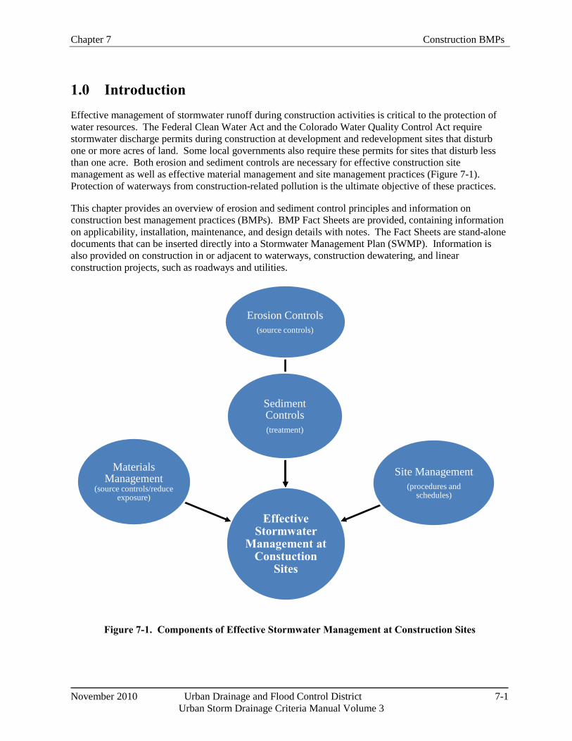
Chapter 7 Construction BMPs
November 2010 Urban Drainage and Flood Control District 7-1
Urban Storm Drainage Criteria Manual Volume 3
Effective Stormwater
Management at Constuction
Sites
Erosion Controls(source controls)
Sediment Controls(treatment)
Site Management(procedures and
schedules)
Materials Management
(source controls/reduce exposure)
1.0 Introduction Effective management of stormwater runoff during construction activities is critical to the protection of water resources. The Federal Clean Water Act and the Colorado Water Quality Control Act require stormwater discharge permits during construction at development and redevelopment sites that disturb one or more acres of land. Some local governments also require these permits for sites that disturb less than one acre. Both erosion and sediment controls are necessary for effective construction site management as well as effective material management and site management practices (Figure 7-1). Protection of waterways from construction-related pollution is the ultimate objective of these practices.
This chapter provides an overview of erosion and sediment control principles and information on construction best management practices (BMPs). BMP Fact Sheets are provided, containing information on applicability, installation, maintenance, and design details with notes. The Fact Sheets are stand-alone documents that can be inserted directly into a Stormwater Management Plan (SWMP). Information is also provided on construction in or adjacent to waterways, construction dewatering, and linear construction projects, such as roadways and utilities.
Figure 7-1. Components of Effective Stormwater Management at Construction Sites
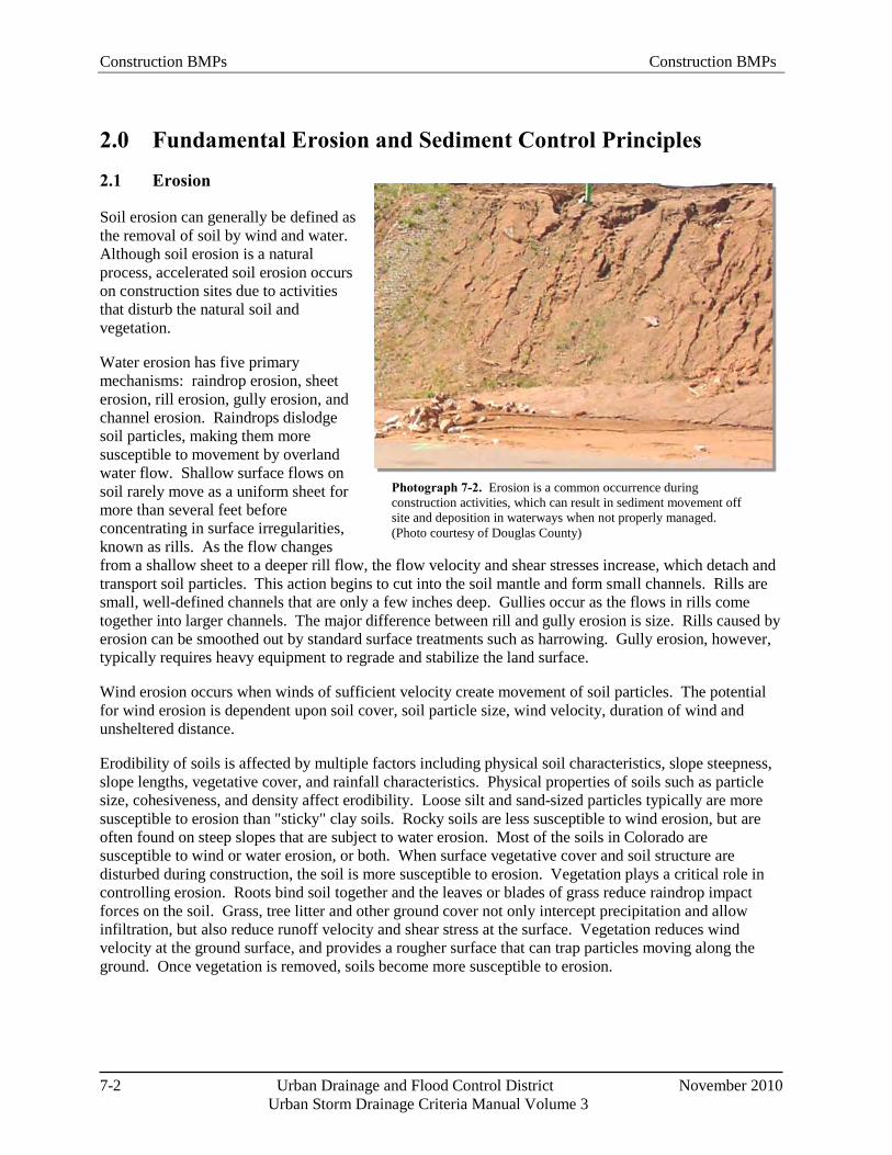
Construction BMPs Construction BMPs
7-2 Urban Drainage and Flood Control District November 2010
Urban Storm Drainage Criteria Manual Volume 3
Photograph 7-2. Erosion is a common occurrence during construction activities, which can result in sediment movement off site and deposition in waterways when not properly managed. (Photo courtesy of Douglas County)
2.0 Fundamental Erosion and Sediment Control Principles
2.1 Erosion
Soil erosion can generally be defined as the removal of soil by wind and water. Although soil erosion is a natural process, accelerated soil erosion occurs on construction sites due to activities that disturb the natural soil and vegetation.
Water erosion has five primary mechanisms: raindrop erosion, sheet erosion, rill erosion, gully erosion, and channel erosion. Raindrops dislodge soil particles, making them more susceptible to movement by overland water flow. Shallow surface flows on soil rarely move as a uniform sheet for more than several feet before concentrating in surface irregularities, known as rills. As the flow changes from a shallow sheet to a deeper rill flow, the flow velocity and shear stresses increase, which detach and transport soil particles. This action begins to cut into the soil mantle and form small channels. Rills are small, well-defined channels that are only a few inches deep. Gullies occur as the flows in rills come together into larger channels. The major difference between rill and gully erosion is size. Rills caused by erosion can be smoothed out by standard surface treatments such as harrowing. Gully erosion, however, typically requires heavy equipment to regrade and stabilize the land surface.
Wind erosion occurs when winds of sufficient velocity create movement of soil particles. The potential for wind erosion is dependent upon soil cover, soil particle size, wind velocity, duration of wind and unsheltered distance.
Erodibility of soils is affected by multiple factors including physical soil characteristics, slope steepness, slope lengths, vegetative cover, and rainfall characteristics. Physical properties of soils such as particle size, cohesiveness, and density affect erodibility. Loose silt and sand-sized particles typically are more susceptible to erosion than "sticky" clay soils. Rocky soils are less susceptible to wind erosion, but are often found on steep slopes that are subject to water erosion. Most of the soils in Colorado are susceptible to wind or water erosion, or both. When surface vegetative cover and soil structure are disturbed during construction, the soil is more susceptible to erosion. Vegetation plays a critical role in controlling erosion. Roots bind soil together and the leaves or blades of grass reduce raindrop impact forces on the soil. Grass, tree litter and other ground cover not only intercept precipitation and allow infiltration, but also reduce runoff velocity and shear stress at the surface. Vegetation reduces wind velocity at the ground surface, and provides a rougher surface that can trap particles moving along the ground. Once vegetation is removed, soils become more susceptible to erosion.
Chapter 7 Construction BMPs
November 2010 Urban Drainage and Flood Control District 7-3
Urban Storm Drainage Criteria Manual Volume 3
State Construction Phase Permitting
Stormwater runoff controls from construction sites are mandated by the Federal Water Pollution Control Act (Clean Water Act). In Colorado, the EPA has delegated authority to the Colorado Department of Public Health and Environment (CDPHE). CDPHE, specifically the Water Quality Control Division, issues stormwater and wastewater discharge permits under the Colorado Discharge Permit System (CDPS) Regulation promulgated by the Water Quality Control Commission.
2.2 Sedimentation
Sedimentation occurs when eroded soil transported in wind or water is deposited from its suspended state. During a typical rainstorm in Colorado, runoff normally builds up rapidly to a peak and then diminishes. Because the amount of sediment a watercourse can carry is dependent upon the velocity and volume of runoff, sediment is eventually deposited as runoff decreases. The deposited sediments may be resuspended when future runoff events occur. In this way, sediments are moved progressively downstream in the waterway system.
2.3 Effective Erosion and Sediment Control
It is better to minimize erosion than to rely solely on sedimentation removal from construction site runoff. Erosion control BMPs limit the amount and rate of erosion occurring on disturbed areas. Sediment control BMPs attempt to capture the soil that has been eroded before it leaves the construction site. Despite the use of both erosion control and sediment control BMPs, some amount of sediment will remain in runoff leaving a construction site, but the use of a "treatment train" of practices can help to minimize offsite transport of sediment. The last line of treatment such as inlet protection and sediment basins should be viewed as "polishing" BMPs, as opposed to the only treatment on the site. Section 4 of this chapter provides an overview of erosion and sediment controls, followed by BMP Fact Sheets providing design details and guidance for effective use of various erosion and sediment control practices. BMPs should be combined and selected to meet these objectives:
Conduct land-disturbing activities in a manner that effectively reduces accelerated soil erosion and reduces sediment movement and deposition off site.
Schedule construction activities to minimize the total amount of soil exposed at any given time.
Establish temporary or permanent cover on areas that have been disturbed as soon as practical after grading is completed.
Design and construct temporary or permanent facilities to limit the flow of water to non-erosive velocities for the conveyance of water around, through, or from the disturbed area.
Remove sediment caused by accelerated soil erosion from surface runoff water before it leaves the site.
Stabilize disturbed areas with permanent vegetative cover and provide permanent stormwater quality control measures for the post-construction condition.
Construction BMPs Construction BMPs
7-4 Urban Drainage and Flood Control District November 2010
Urban Storm Drainage Criteria Manual Volume 3
3.0 Colorado Construction Stormwater Discharge Permits Within UDFCD's boundary, development or redevelopment projects with one or more acres of potential disturbance are often required to obtain both local and state permits related to construction-phase stormwater discharges. The area of disturbance includes construction activities that are part of a larger common plan of development or sale and may include "separate" areas where construction practices will occur at different times. Areas used for staging, materials storage, temporary construction site access, off-site borrow areas and other construction related activities should also be included when determining the project area and area of disturbance permitted. In some cases, a construction discharge permit will be required by the local government, but not the state. Although CDPHE typically does not require permit coverage for construction activities that disturb less than one acre, provided the activities are not part of a large plan of development, some municipalities require stormwater permits for sites that disturb less than one acre, especially if construction is proximate to a floodplain and/or receiving water, steep slopes, and/or areas of known contamination.
The CDPHE typically issues construction permits under the CDPS General Permit for stormwater discharges associated with construction activities. Under certain conditions, CDPHE may require an individual permit. This may be required due to the size of disturbance, evidence of noncompliance under a previous permit, and/or quality and use of the receiving waters. The CDPS General Permit requires the owner and/or operator (frequently the contractor) to develop a SWMP. Although CDPHE does not require that the SWMP be submitted for approval, most local governments require submittal of a SWMP (or comparable document) which is reviewed by the local government and must be approved prior to issuance of construction-related permits (e.g., grading permit, land disturbance permit). Because SWMPs are "living documents" that must be updated and maintained as the phases of construction progress, ideally, one master document should be developed that is inclusive of both the state and local requirements, as opposed to maintaining duplicate records. Many local governments require documentation that goes beyond the state permit requirements.
Always obtain the state permit application and guidance directly from the state agency to ensure that all currently applicable requirements are met. In Colorado, this information can be obtained from the CDPHE CDPS General Permit for Stormwater Discharges Associated with Construction Activities. Also, check local government programs as they may have specific requirements more stringent than the minimum criteria specified by the state.
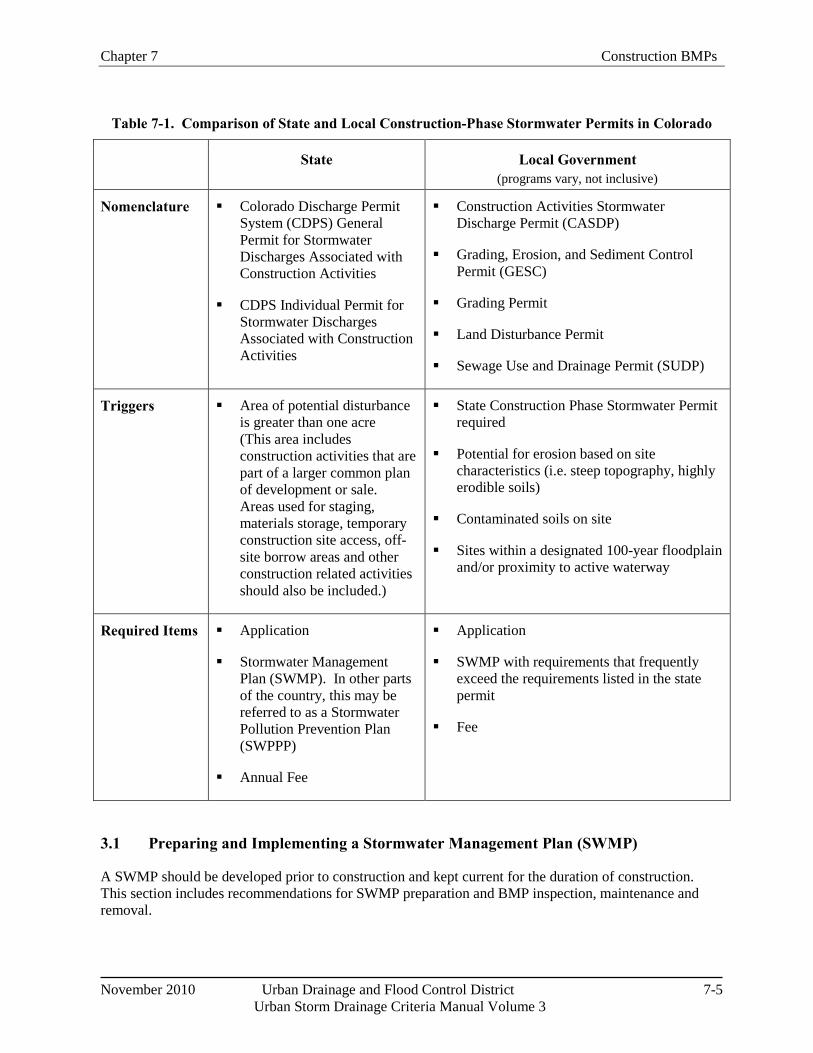
Chapter 7 Construction BMPs
November 2010 Urban Drainage and Flood Control District 7-5
Urban Storm Drainage Criteria Manual Volume 3
Table 7-1. Comparison of State and Local Construction-Phase Stormwater Permits in Colorado
State Local Government (programs vary, not inclusive)
Nomenclature Colorado Discharge Permit System (CDPS) General Permit for Stormwater Discharges Associated with Construction Activities
CDPS Individual Permit for Stormwater Discharges Associated with Construction Activities
Construction Activities Stormwater Discharge Permit (CASDP)
Grading, Erosion, and Sediment Control Permit (GESC)
Grading Permit
Land Disturbance Permit
Sewage Use and Drainage Permit (SUDP)
Triggers Area of potential disturbance is greater than one acre (This area includes construction activities that are part of a larger common plan of development or sale. Areas used for staging, materials storage, temporary construction site access, off-site borrow areas and other construction related activities should also be included.)
State Construction Phase Stormwater Permit required
Potential for erosion based on site characteristics (i.e. steep topography, highly erodible soils)
Contaminated soils on site
Sites within a designated 100-year floodplain and/or proximity to active waterway
Required Items Application
Stormwater Management Plan (SWMP). In other parts of the country, this may be referred to as a Stormwater Pollution Prevention Plan (SWPPP)
Annual Fee
Application
SWMP with requirements that frequently exceed the requirements listed in the state permit
Fee
3.1 Preparing and Implementing a Stormwater Management Plan (SWMP)
A SWMP should be developed prior to construction and kept current for the duration of construction. This section includes recommendations for SWMP preparation and BMP inspection, maintenance and removal.
Construction BMPs Construction BMPs
7-6 Urban Drainage and Flood Control District November 2010
Urban Storm Drainage Criteria Manual Volume 3
3.1.1 General SWMP Recommendations
At a minimum, a SWMP should communicate and satisfy the following:
o Identify all potential sources of pollution which may affect the quality of stormwater discharges associated with construction activity;
o Describe the practices to be used to reduce the pollutants in stormwater discharges associated with construction activity including the installation, implementation and maintenance requirements; and
o Be prepared in accordance with good engineering practices and be updated throughout construction and stabilization of the site.
Implement the provisions of the SWMP as written and updated, from commencement of construction activity until final stabilization is complete. The SWMP typically requires additions or other modifications once construction commences, and documentation of all modifications and amendments is typically required by the construction stormwater permit. UDFCD recommends that the contractor maintain records of all inspections, BMP maintenance, and communications with the owner and/or engineer. This should be kept on-site, with the SWMP. UDFCD recommends that these records be recognized as part of the SWMP but that changes to the practices identified in the SWMP should not be made without the approval of an engineer.
The SWMP should include additional discussion or plans for any special requirements of the site. Special requirements include Spill Prevention Control and Countermeasure (SPCC) plans under Section 311 of the Clean Water Act, or BMP programs otherwise required by another CDPS permit.
3.1.2 SWMP Elements
The SWMP should include the following as a minimum. When some sections are not applicable, include a statement to that effect.
Site Description: Clearly describe the construction activity, including:
o The nature of the construction activity at the site.
o The proposed sequence for major activities.
o Estimates of the total area of the site, and the area and location expected to be disturbed by clearing, excavation, grading, or other construction activities.
o A summary of any existing data used in the development of the site construction plans or SWMP that describe the soil or existing potential for soil erosion.
o A description of the existing vegetation at the site and an estimate of the percent vegetative ground cover.
o The location and description of all potential pollution sources, including ground surface disturbing activities (see CDPHE Stormwater General Permit for description), vehicle fueling, storage of fertilizers or chemicals, etc.
Chapter 7 Construction BMPs
November 2010 Urban Drainage and Flood Control District 7-7
Urban Storm Drainage Criteria Manual Volume 3
o The location and description of any anticipated allowable sources of non-stormwater discharge at the site, e.g., uncontaminated springs, landscape irrigation return flow, construction dewatering, and concrete washout.
o The name of the receiving water(s) and the size, type and location of any outfall(s). If the stormwater discharge is to a municipal separate storm sewer system, the name of that system, the location of the storm sewer discharge, and the ultimate receiving water(s).
Site Map. Include a legible site map(s), showing the entire site, identifying:
o Construction site boundaries;
o All areas of ground surface disturbance;
o Areas of cut and fill;
o Areas used for storage of building materials, equipment, soil, or waste;
o Locations of dedicated asphalt or concrete batch plants;
o Locations of all structural BMPs;
o Locations of non-structural BMPs as applicable; and
o Locations of springs, streams, wetlands and other surface waters.
Stormwater Management Controls. Include a description of all stormwater management controls that will be implemented as part of the construction activity to control pollutants in stormwater discharges. The appropriateness and priorities of stormwater management controls in the SWMP should reflect the potential pollutant sources identified at the facility. The description of stormwater management controls should address the following components, at a minimum:
o SWMP Administrator. Identify a specific individual(s), position, or title that is responsible for developing, implementing, maintaining, and revising the SWMP. This designated individual(s) should address all aspects of the facility's SWMP.
o Identification of Potential Pollutant Sources. Identify and describe sources that may contribute pollutants to runoff, and provide means of control through BMP selection and implementation. At a minimum, evaluate each of the following potential sources of pollution:
1. All disturbed and stored soils;
2. Vehicle tracking of sediments;
3. Management of contaminated soils;
4. Loading and unloading operations;
5. Outdoor storage activities (building materials, fertilizers, chemicals, etc.);
6. Vehicle and equipment maintenance and fueling;
7. Significant dust or particulate generating processes;
Construction BMPs Construction BMPs
7-8 Urban Drainage and Flood Control District November 2010
Urban Storm Drainage Criteria Manual Volume 3
8. Routine maintenance activities involving fertilizers, pesticides, detergents, fuels, solvents, oils, etc.;
9. On-site waste management practices (waste piles, liquid wastes, dumpsters, etc.);
10. Concrete truck/equipment washing, including the concrete truck chute and associated fixtures and equipment;
11. Dedicated asphalt and concrete batch plants;
12. Non-industrial waste sources such as worker trash and portable toilets; and
13. Other areas or procedures where potential spills can occur.
BMPs for Construction Stormwater Pollution Prevention. Identify and describe appropriate BMPs including those listed in this section. Provide enough detail for each BMP to ensure proper implementation, operation, and maintenance.
o Structural Practices for Erosion and Sediment Control. (e.g., wattles/sediment control logs and temporary or permanent sediment basins).
o Non-Structural Practices for Erosion and Sediment Control. (e.g., temporary vegetation and permanent vegetation).
o Phased BMP Implementation. Describe the relationship between the phases of construction, and the implementation and maintenance of both structural and non-structural stormwater management controls. Project phases might include different operations such as clearing and grubbing; road construction; utility and infrastructure installation; vertical construction; final grading; and final stabilization.
o Materials Handling and Spill Prevention. Materials of interest could include: exposed storage of building materials; paints and solvents; fertilizers or chemicals; waste material; and equipment maintenance or fueling procedures.
o Dedicated Concrete or Asphalt Batch Plants.
o Vehicle Tracking Control. This BMP includes minimizing (as practicable) the number of areas where construction vehicles are required to move from unpaved to paved areas as well as providing structural BMPs at each location.
o Waste Management and Disposal, Including Concrete Washout.
o Groundwater and Stormwater Dewatering. These activities often require a separate permit that includes sampling of processed waters. However, in some cases, these activities can be conducted without a separate permit when processed water is not discharged from the site as surface runoff or discharged into surface waters. The SWMP should describe how these waters will be used (i.e., land application, infiltration, evaporation) and how the specific practices at the site will ensure that these waters are not discharged via runoff.
Chapter 7 Construction BMPs
November 2010 Urban Drainage and Flood Control District 7-9
Urban Storm Drainage Criteria Manual Volume 3
Final Stabilization and Long-Term Stormwater Management
o The SWMP should describe the practices used to achieve final stabilization of all disturbed areas at the site and any planned practices to control pollutants in stormwater discharges that will occur after construction operations have been completed at the site.
o Final stabilization practices for obtaining a vegetative cover should include, as appropriate: seed mix selection and application methods; soil preparation and amendments; soil stabilization practices (e.g., crimped straw, hydro mulch or rolled erosion control products); and appropriate sediment control BMPs as needed until final stabilization is achieved; etc.
o Final stabilization is reached when all ground surface disturbing activities at the site have been completed, and uniform vegetative cover has been established with an individual plant density of at least 70 percent of pre-disturbance levels, or equivalent permanent, physical erosion reduction methods have been employed.
Inspection and Maintenance. The SWMP should describe the inspection and maintenance procedures implemented at the site to maintain all erosion and sediment control practices and other protective practices identified in the SWMP in good and effective operating condition. UDFCD recommends providing an inspection checklist for the project.
3.2 Inspections
Routine and post-storm inspections of BMPs are essential to identify maintenance necessary for the BMPs to remain in effective operating conditions. The frequency of inspections is typically influenced by multiple factors including the weather, the phase of construction, activities on site, and the types of BMPs. Checklists and other forms of documentation are also important to meet the requirements of a construction stormwater permit.
3.2.1 Inspection Frequency
In Colorado, the CDPS General Permit requires documented inspections on a biweekly basis and within 24 hours of a storm event, with some limited, temporary exceptions for inactive sites. UDFCD recommends spot-checking BMPs every workday. This is typically reasonable to achieve and can help to ensure that the BMPs remain in good working condition. For example, vehicle tracking of sediment onto the roadway is a common problem that often requires maintenance more frequently than weekly. Curb socks, inlet protection and silt fence are other BMPs that are prone to damage and displacement, also benefiting from more frequent inspections.
When the site or portions of the site are awaiting final stabilization (e.g., vegetative cover), where construction is essentially complete, the recommended frequency of inspection is at least once every month. Be sure that this change is documented and in accordance with relevant permit requirements prior to reducing the inspection schedule.
When snow cover exists over the entire site for an extended period, inspections are not always feasible. Document this condition, including date of snowfall and date of melting conditions, and be aware of and prepare for areas where melting conditions may pose a risk of surface erosion.
Construction BMPs Construction BMPs
7-10 Urban Drainage and Flood Control District November 2010
Urban Storm Drainage Criteria Manual Volume 3
Consider using a free internet application that provides real-time weather alerts to keep aware of inclement weather and plan ahead for staff to inspect and maintain BMPs.
Local inspection requirements may be more stringent than CDPS permit requirements. For example, many local governments require weekly, rather than bi-weekly, documented inspections. Some local governments may not allow relaxed inspection schedules for sites that have been completed, but are awaiting final stabilization or for winter conditions.
3.2.2 Inspection Records
Always check the requirements of the permit for required documentation of specific inspection items. Typically, these items can be incorporated into a checklist. Standard checklists may be developed and used for various types of construction projects (e.g., channel work, large-scale phased construction projects, or small urban sites). This kind of tool can help ensure the proper function of BMPs and provide a consistent approach to required documentation.
The checklist should always include the date and name/title of personnel making the inspection. It should include an area to note BMP failures, observed deviations from the SWMP, necessary repairs or corrective measures, corrective actions taken, and general observations.
3.3 Maintenance
Proactive maintenance is fundamental to effective BMP performance. Rather than maintaining the BMP in a reactive manner following failure, provide proactive maintenance that may help to reduce the likelihood of failure. The types and frequencies of maintenance are BMP-specific. The BMP Fact Sheets in this chapter describe the maintenance needs for each BMP, with some BMP types requiring more attention.
Maintain BMPs so that they function as intended. This includes removing accumulated sediment before it limits the effectiveness of the BMP. Identify needed maintenance activities during site inspections or during general observations of site conditions. Where BMPs have failed, repairs or changes should be initiated as soon as practical, to minimize the discharge of pollutants.
Where the BMPs specified in the SWMP are not functioning effectively at the site, modifications should be made that may include different or additional layers of BMPs. When new BMPs are installed or BMPs are replaced, check the permit for documentation requirements. This may require communication with the owner and/or engineer and, at a minimum, should be documented in the inspection and maintenance records (logbook).
3.4 Disposition of Temporary Measures
Most temporary erosion and sediment control measures must be removed within 30 days after final site stabilization is achieved. The BMP Fact Sheets in this chapter provide guidance for final disposition of temporary measures. This may be as simple as removing silt fence, or more complex such as removing accumulated sediment from a construction phase sedimentation basin that will be used as a post-construction extended detention basin. Some biodegradable BMPs, such as erosion control blankets, are designed to remain in place and would create new areas of disturbance if removed. See the BMP Fact Sheets for guidance on BMPs that may be left in place as a part of final stabilization. For some BMPs
Chapter 7 Construction BMPs
November 2010 Urban Drainage and Flood Control District 7-11
Urban Storm Drainage Criteria Manual Volume 3
such as sediment control logs/straw wattles, some materials may be biodegradable (straw), but there may be components of the BMP that biodegrade slowly (stakes) or not at all (plastic netting). Always check local requirements for guidance on construction BMPs that may remain in place.
Temporary erosion control measures should not be removed until all areas tributary to the temporary controls have achieved final stabilization. It may be necessary to maintain some of the control measures for an extended period of time, until the upgradient areas have been fully stabilized, and vegetation has sufficiently matured to provide adequate cover. Trapped sediment and disturbed soil areas resulting from the disposal of temporary measures must be returned to final plan grades and permanently stabilized to prevent further soil erosion.
Whenever post-construction BMPs are used for sediment controls during construction, the plan should include the steps and actions needed to refurbish these facilities to a fully operational form as post-construction BMPs. The final site work will not be accepted by the local jurisdiction until these BMPs are in final and acceptable form as the original design calls for, which includes lines and grades, volumes, outlet structures, trash racks, landscaping and other measures specified in the site development plans prepared by the design engineer.
3.5 2009 Federal Effluent Limitation Guidelines
On December 1, 2009, the EPA published Effluent Limitation Guidelines in the Federal Register (Volume 74, Number 229, pages 62997-63057) establishing technology-based effluent limitation guidelines (ELGs) and new source performance standards (NSPS) for the construction and development industry. This rule requires construction site owners and operators to implement a range of erosion and sediment control measures and pollution prevention practices to control pollutants in discharges from construction sites. Additionally, the rule requires monitoring and sampling of stormwater discharges and compliance with a numeric standard for turbidity in these discharges for larger construction sites (i.e., 10 acres or more). The rule, including numeric effluent limits, was legally challenged in 2010 and, as of October 2010, EPA is in the process of reconsidering the numeric effluent limits from the rule. Other portions of the rule will remain in effect while EPA reevaluates the numeric limits.
In Colorado, unless constructing a federal project or working on an Indian reservation, construction stormwater discharge permits are issued by CDPHE under the CDPS General Permit for Stormwater Discharges Associated with Construction Activity (CDPS Permit No. COR-030000). This permit was first issued in 1997, and is effective through June 30, 2012. It is anticipated that CDPHE will issue a new general permit in 2012 that will reflect the guidelines, with the possible exception of the numeric limits which may still be under reevaluation at the time that CDPHE issues the new permit. Existing state stormwater requirements will remain in effect until a new general permit is issued.
4.0 Overview of Construction BMPs Construction BMPs include not only erosion and sediment control BMPs, but also material management and site management BMPs. Related practices include dewatering and construction in waterways, which are discussed in Sections 6 and 7. The design details and notes for the BMPs identified in this section are provided in stand-alone Fact Sheets that also include guidance on applicability, design, maintenance, and final disposition. A key to effective stormwater management at construction sites is to understand how construction stormwater management requirements change over the course of a construction project, as summarized in Figure 7-2. Additionally, BMPs vary with regard to the functions they provide.

Construction BMPs Construction BMPs
7-12 Urban Drainage and Flood Control District November 2010
Urban Storm Drainage Criteria Manual Volume 3
Table 7-2 provides a qualitative characterization of the roles that various BMPs provide with regard to serving erosion control functions, sediment control functions, or site/materials management roles. In particular, it is important to understand whether the primary role of the BMP is erosion control or sediment control. Effectively managed construction sites will provide a combination of BMPs that provide both functions.
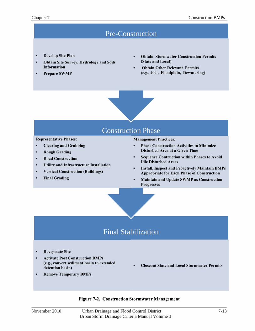
Chapter 7 Construction BMPs
November 2010 Urban Drainage and Flood Control District 7-13
Urban Storm Drainage Criteria Manual Volume 3
Final Stabilization
▪ Revegetate Site▪ Activate Post Construction BMPs
(e.g., convert sediment basin to extended detention basin)
▪ Remove Temporary BMPs
▪ Closeout State and Local Stormwater Permits
Construction PhaseRepresentative Phases:▪ Clearing and Grubbing▪ Rough Grading▪ Road Construction▪ Utility and Infrastructure Installation▪ Vertical Construction (Buildings)▪ Final Grading
Management Practices:▪ Phase Construction Activities to Minimize
Disturbed Area at a Given Time▪ Sequence Contruction within Phases to Avoid
Idle Disturbed Areas▪ Install, Inspect and Proactively Maintain BMPs
Appropriate for Each Phase of Construction▪ Maintain and Update SWMP as Construction
Progresses
Pre-Construction
▪ Develop Site Plan▪ Obtain Site Survey, Hydrology and Soils
Information▪ Prepare SWMP
▪ Obtain Stormwater Construction Permits (State and Local)
▪ Obtain Other Relevant Permits(e.g., 404 , Floodplain, Dewatering)
Figure 7-2. Construction Stormwater Management
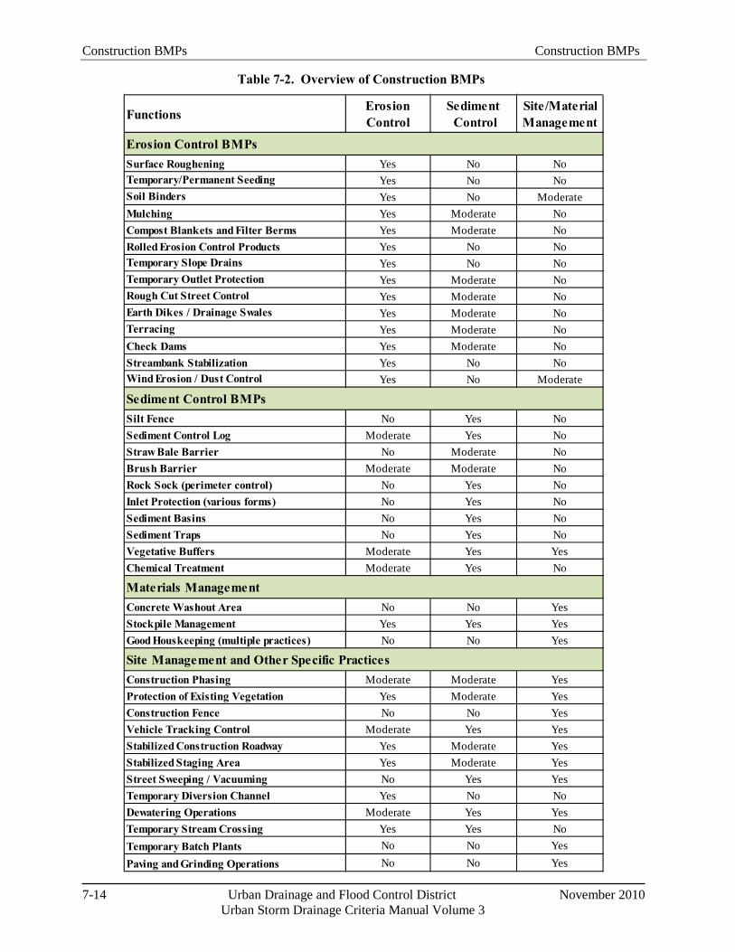
Construction BMPs Construction BMPs
7-14 Urban Drainage and Flood Control District November 2010
Urban Storm Drainage Criteria Manual Volume 3
FunctionsErosion Control
Sediment Control
Site/Material Management
Surface Roughening Yes No NoTemporary/Permanent Seeding Yes No NoSoil Binders Yes No ModerateMulching Yes Moderate NoCompost Blankets and Filter Berms Yes Moderate NoRolled Erosion Control Products Yes No NoTemporary Slope Drains Yes No NoTemporary Outlet Protection Yes Moderate NoRough Cut Street Control Yes Moderate NoEarth Dikes / Drainage Swales Yes Moderate NoTerracing Yes Moderate NoCheck Dams Yes Moderate NoStreambank Stabilization Yes No NoWind Erosion / Dust Control Yes No Moderate
Silt Fence No Yes NoSediment Control Log Moderate Yes NoStraw Bale Barrier No Moderate NoBrush Barrier Moderate Moderate NoRock Sock (perimeter control) No Yes NoInlet Protection (various forms) No Yes NoSediment Basins No Yes NoSediment Traps No Yes NoVegetative Buffers Moderate Yes YesChemical Treatment Moderate Yes No
Concrete Washout Area No No YesStockpile Management Yes Yes YesGood Houskeeping (multiple practices) No No Yes
Construction Phasing Moderate Moderate YesProtection of Existing Vegetation Yes Moderate YesConstruction Fence No No YesVehicle Tracking Control Moderate Yes YesStabilized Construction Roadway Yes Moderate YesStabilized Staging Area Yes Moderate YesStreet Sweeping / Vacuuming No Yes YesTemporary Diversion Channel Yes No NoDewatering Operations Moderate Yes YesTemporary Stream Crossing Yes Yes NoTemporary Batch Plants No No YesPaving and Grinding Operations No No Yes
Site Management and Other Specific Practices
Sediment Control BMPs
Erosion Control BMPs
Materials Management
Table 7-2. Overview of Construction BMPs
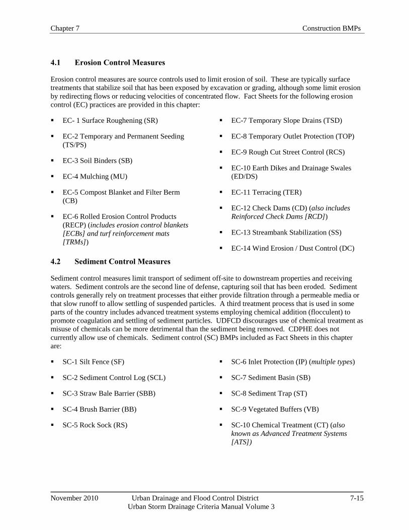
Chapter 7 Construction BMPs
November 2010 Urban Drainage and Flood Control District 7-15
Urban Storm Drainage Criteria Manual Volume 3
4.1 Erosion Control Measures
Erosion control measures are source controls used to limit erosion of soil. These are typically surface treatments that stabilize soil that has been exposed by excavation or grading, although some limit erosion by redirecting flows or reducing velocities of concentrated flow. Fact Sheets for the following erosion control (EC) practices are provided in this chapter:
EC- 1 Surface Roughening (SR)
EC-2 Temporary and Permanent Seeding (TS/PS)
EC-3 Soil Binders (SB)
EC-4 Mulching (MU)
EC-5 Compost Blanket and Filter Berm (CB)
EC-6 Rolled Erosion Control Products (RECP) (includes erosion control blankets [ECBs] and turf reinforcement mats [TRMs])
EC-7 Temporary Slope Drains (TSD)
EC-8 Temporary Outlet Protection (TOP)
EC-9 Rough Cut Street Control (RCS)
EC-10 Earth Dikes and Drainage Swales (ED/DS)
EC-11 Terracing (TER)
EC-12 Check Dams (CD) (also includes Reinforced Check Dams [RCD])
EC-13 Streambank Stabilization (SS)
EC-14 Wind Erosion / Dust Control (DC)
4.2 Sediment Control Measures
Sediment control measures limit transport of sediment off-site to downstream properties and receiving waters. Sediment controls are the second line of defense, capturing soil that has been eroded. Sediment controls generally rely on treatment processes that either provide filtration through a permeable media or that slow runoff to allow settling of suspended particles. A third treatment process that is used in some parts of the country includes advanced treatment systems employing chemical addition (flocculent) to promote coagulation and settling of sediment particles. UDFCD discourages use of chemical treatment as misuse of chemicals can be more detrimental than the sediment being removed. CDPHE does not currently allow use of chemicals. Sediment control (SC) BMPs included as Fact Sheets in this chapter are:
SC-1 Silt Fence (SF)
SC-2 Sediment Control Log (SCL)
SC-3 Straw Bale Barrier (SBB)
SC-4 Brush Barrier (BB)
SC-5 Rock Sock (RS)
SC-6 Inlet Protection (IP) (multiple types)
SC-7 Sediment Basin (SB)
SC-8 Sediment Trap (ST)
SC-9 Vegetated Buffers (VB)
SC-10 Chemical Treatment (CT) (also known as Advanced Treatment Systems [ATS])
Construction BMPs Construction BMPs
7-16 Urban Drainage and Flood Control District November 2010
Urban Storm Drainage Criteria Manual Volume 3
Resources for Construction Stormwater Management/Erosion and Sediment Control Training
Certified Professional in Erosion and Sediment Control Program (http://www.cpesc.org/)
Certified Inspector of Sediment and Erosion Control Program (http://www.cisecinc.org/)
Rocky Mountain Education Center (http://www.rrcc.edu/rmec/cetc.html)
International Erosion Control Association (http://www.ieca.org/)
Associated General Contractors of Colorado (www.agccolorado.org/)
4.3 Site Management
Site management is often ultimately the deciding factor in how effective BMPs are at a particular site. BMPs implemented at the site must not only be properly selected and installed, but also must be inspected, maintained and properly repaired for the duration of the construction project. In addition to general site management, there are a number of specific site management practices that affect construction site management. For example, effective construction scheduling (phasing and sequencing) helps minimize the duration of exposed soils. Protection of existing vegetation also minimizes exposed areas and can reduce the cost of final site stabilization. Stabilized construction entrances (vehicle tracking controls) and street sweeping are critical source control measures to minimize the amount of sediment that leaves a site. Additionally, there are several miscellaneous activities that must be carefully conducted to protect water quality such as dewatering operations, temporary batch plants, temporary stream crossings and other practices.
As part of the construction kick-off meeting for the project (or for major phases of construction), an effective strategy is to include a training component related to construction site stormwater management. Such training should provide basic education to site personnel regarding the requirements of the state and local construction stormwater permits and the serious fines and penalties than can result from failure to comply with permit requirements. The individual or individuals responsible for inspection and maintenance of construction BMPs should have a practical understanding of how to maintain construction BMPs proactively in effective operating condition and to identify conditions where failure is eminent or has already occurred. In addition to site-specific training, several training courses are available in the metro Denver area regarding construction site stormwater management.
Site management (SM) practices addressed in Fact Sheets as part of this chapter include:
SM-1 Construction Phasing/Sequencing (CP)
SM-2 Protection of Existing Vegetation (PV)
SM-3 Construction Fence (CF)
SM-4 Vehicle Tracking Control (VTC) (multiple types)
SM-5 Stabilized Construction Roadway (SCR)
SM-6 Stabilized Staging Area (SSA)
SM-7 Street Sweeping and Vacuuming (SS)
SM-8 Temporary Diversion Channel (TDC)
SM-9 Dewatering Operations (DW)
SM-10 Temporary Stream Crossing (TSC) (multiple types)
SM-11 Temporary Batch Plant (TBP)
SM-12 Paving and Grinding Operations (PGO)
Construction BMPs Chapter 7
November 2010 Urban Drainage and Flood Control District 7-17
Urban Storm Drainage Criteria Manual Volume 3
4.4 Materials Management
Materials management BMPs are source control practices intended to limit contact of runoff with pollutants commonly found at construction sites such as construction materials and equipment-related fluids. By intentionally controlling and managing areas where chemicals are handled, the likelihood of these materials being transported to waterways is reduced. Materials management (MM) BMPs provided as Fact Sheets in this chapter include:
MM-1 Concrete Washout Area (CWA)
MM-2 Stockpile Management (SP)
MM-3 Good Housekeeping Practices (GH) (including Spill Prevention and Control, Material Use, Material Delivery and Storage, Solid Waste Management, Hazardous Waste Management, Sanitary/Septic Waste Management, and Vehicle & Equipment Fueling, Maintenance and Cleaning)
4.5 Proprietary BMPs
Many proprietary BMPs are available for construction site stormwater management. This manual does not provide a list of approved products; however, some local jurisdictions may require that proprietary products go through a formal approval process prior to use within their jurisdiction. Basic questions that local governments may want to consider asking when considering approval of proprietary construction BMPs include:
General
Does the product provide equivalent or better function than the design details specified in this manual?
What are the installation procedures?
What are the maintenance requirements? Is special equipment required for maintenance?
What are the consequences of failure of the product?
Has the product been successfully implemented on other sites in the metropolitan Denver area?
Inlet Protection
Does the inlet protection enable runoff to enter the inlet without excessive ponding in traffic areas?
How does the BMP provide for overflow due to large storm events or blockages?
How is the BMP secured to the street or curb? Will it result in damage to concrete or pavement? Is it secured in a manner that prevents short-circuiting or collapsing into the inlet?
Does the BMP appear to be sturdy enough to withstand typical activities conducted at construction sites or traffic on public roadways?
Is there potential for pollutant leaching from the BMP?
Chapter 7 Construction BMPs
7-18 Urban Drainage and Flood Control District November 2010
Urban Storm Drainage Criteria Manual Volume 3
For inlet inserts, is special equipment required to remove the insert? Is the insert material strong enough to withstand tearing and/or collapse into the inlet, even when maintenance is less than ideal?
Perimeter Controls
How is the perimeter control installed (e.g., trenching, staking)? Perimeter controls that are not adequately secured may be subject to undercutting and washout.
Is the material used in the perimeter control adequately durable for the life of the construction project?
How are vehicle tracking and site access controlled where flexible perimeter controls allow vehicles to drive over the BMP?
Hydraulically Applied Products
Does the product contain chemicals, pollutants, nutrients, or other materials that could adversely impact receiving waters or groundwater?
Has the product been adequately field tested under local conditions to ensure that the service life is consistent with the manufacturer's representation?
Does use of the product require special permits?
5.0 BMP Selection and Planning Construction BMPs should be selected, designed, installed, and maintained based on site-specific conditions. BMPs should be selected based on the physical layout and site conditions that will exist during each stage of construction, because site conditions change through the various stages of construction. The number of stages that must be addressed in the SWMP depends on the type of construction activity and local jurisdiction requirements, but in general, three stages of erosion and sediment control plans can be considered. These stages include initial clearing and grading; utility, infrastructure and building construction; and final stabilization.
Effective construction site stormwater management planning involves the following:
Collecting and analyzing site-specific information to identify needed erosion and sediment controls,
Preparing a SWMP that specifies needed BMPs appropriate to each phase of construction, and
Following the SWMP, maintaining BMPs and updating the SWMP as construction progresses.
This section focuses on important factors to consider in the development of a SWMP, including site-specific conditions, BMP functions, and other site-related plans.
5.1 Site Assessment
Early awareness of site-specific factors that make a site particularly prone to erosion problems can prevent serious problems later during the construction process. A site assessment should include attention to these factors, prior to selection of BMPs:
Construction BMPs Chapter 7
November 2010 Urban Drainage and Flood Control District 7-19
Urban Storm Drainage Criteria Manual Volume 3
Slopes/Topography and Topographic Changes Due to Grading: Slope length and steepness are two key factors in identifying the types and placement of both erosion and sediment control BMPs. Slopes will change throughout the phases of construction as grading is conducted. See Sections 5.2 and 5.3 for additional guidance.
Tributary Area/Catchment Size: The overall size of sub-catchment areas prior to and following grading is a key factor in determining the types, sizes, spacing and other design requirements for sediment controls appropriate for each drainage area. The allowable tributary area for sediment controls varies, depending on the practice selected, as described in the BMP Fact Sheets.
Soils: Regardless of soil type, all disturbed soils require erosion controls; however, NRCS soil maps and geotechnical reports for the development can be used to identify soil conditions where erosion may be particularly difficult to control. In such settings, additional layers of protection for both erosion and sediment controls may be needed and planned for proactively in the SWMP.
Vegetation: Onsite vegetation that is to be left undisturbed must be clearly identified in the SWMP and/or the construction plans. Construction fence should be installed to avoid disturbance and compaction of these areas. This is particularly important for protection of mature trees, natural riparian buffers and wetlands, natural open space, or other areas specifically identified to be protected from compaction as part of Low Impact Development (LID) designs. Maintaining a vegetative buffer, in combination with other perimeter control BMPs, can be effective for minimizing transport of sediment off-site.
Drainage Infrastructure: Understanding the hydrology of a site is important in the design of sediment controls. Offsite run-on as well as drainage patterns within the site should be thoroughly assessed. The configuration of hill slope areas and waterways, in the context of planned roads and buildings, will determine which erosion and sediment controls will be needed at each phase of construction.
Sensitive Site Conditions: In cases where construction is occurring in areas of sensitive aquatic habitat, upstream of drinking water supplies, or near areas where threatened and endangered species are a concern, additional layers of protection may be specified by the local, state or federal government. These may include redundant BMPs or restrictions on times that construction activities are allowed.
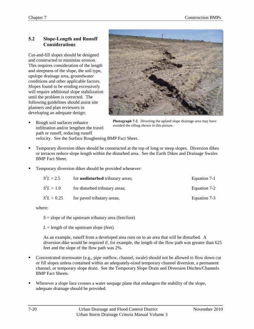
Chapter 7 Construction BMPs
7-20 Urban Drainage and Flood Control District November 2010
Urban Storm Drainage Criteria Manual Volume 3
Photograph 7-2. Diverting the upland slope drainage area may have avoided the rilling shown in this picture.
5.2 Slope-Length and Runoff Considerations
Cut-and-fill slopes should be designed and constructed to minimize erosion. This requires consideration of the length and steepness of the slope, the soil type, upslope drainage area, groundwater conditions and other applicable factors. Slopes found to be eroding excessively will require additional slope stabilization until the problem is corrected. The following guidelines should assist site planners and plan reviewers in developing an adequate design:
Rough soil surfaces enhance infiltration and/or lengthen the travel path or runoff, reducing runoff velocity. See the Surface Roughening BMP Fact Sheet.
Temporary diversion dikes should be constructed at the top of long or steep slopes. Diversion dikes or terraces reduce slope length within the disturbed area. See the Earth Dikes and Drainage Swales BMP Fact Sheet.
Temporary diversion dikes should be provided whenever:
S2L > 2.5 for undisturbed tributary areas; Equation 7-1
S2L > 1.0 for disturbed tributary areas; Equation 7-2
S2L > 0.25 for paved tributary areas; Equation 7-3
where:
S = slope of the upstream tributary area (feet/foot)
L = length of the upstream slope (feet)
As an example, runoff from a developed area runs on to an area that will be disturbed. A diversion dike would be required if, for example, the length of the flow path was greater than 625 feet and the slope of the flow path was 2%.
Concentrated stormwater (e.g., pipe outflow, channel, swale) should not be allowed to flow down cut or fill slopes unless contained within an adequately-sized temporary channel diversion, a permanent channel, or temporary slope drain. See the Temporary Slope Drain and Diversion Ditches/Channels BMP Fact Sheets.
Wherever a slope face crosses a water seepage plane that endangers the stability of the slope, adequate drainage should be provided.
Construction BMPs Chapter 7
November 2010 Urban Drainage and Flood Control District 7-21
Urban Storm Drainage Criteria Manual Volume 3
Provide sediment basins or barriers (silt fence) at or near the toe of slopes to trap sediment or to reduce slope lengths. When flows are concentrated and conveyed down a slope using a slope drain or channel, energy dissipation measures will be required at the conveyance outlet at the toe of the slope. See the Sediment Control BMP Fact Sheets for several options for controlling sediment at the base of slopes.
5.3 Using the Revised Universal Soil Loss Equation
The Revised Universal Soil Loss Equation (RUSLE) is an erosion prediction method that has evolved over time, resulting from data collection and analysis efforts extending from the 1930s through the 1970s, ultimately published in Agriculture Handbook 282 (Wischmeier and Smith, 1965), then Agriculture Handbook 537 (Wischmeier and Smith, 1978) and Agriculture Handbook 703 (Renard et al., 1997). Although originally developed for agricultural land use, it is also a useful method for estimating erosion potential on construction sites and adjusting BMPs to reduce the estimated erosion. The RUSLE is also incorporated into several modern erosion prediction models. The Modified Universal Soil Loss Equation (MUSLE) is similar to the RUSLE, but is differentiated by the fact that MUSLE is event-based while RUSLE is an annual method (with the option to calculate monthly or seasonal erosion). This section provides a brief overview of RUSLE and describes how it can be used to help select erosion control practices at construction sites.
A = RKLSCP Equation 7-4
where:
A = Computed spatial average soil loss and temporal average soil loss per unit of area, expressed in the units selected for K and for the period selected for R. Typically, A is expressed in tons per acre per year.
R = Rainfall-runoff erosivity factor – the rainfall erosion index plus a factor for any significant runoff from snowmelt.
K = Soil erodibility factor – the soil-loss rate per erosion index unit for a specified soil.
L = Slope length factor – the ratio of soil loss from the field slope length to soil loss from a 72.6 ft length under identical conditions.
S = Slope steepness factor – the ratio of soil loss from the field slope gradient to soil loss from a 9 percent slope under otherwise identical conditions.
C = Cover-management factor – the ratio of soil loss from an area with specified cover and management to soil loss from an identical area in a bare condition. Values range from 0.01 to 1.
P = Erosion control practice factor – the ratio of soil loss with a certain conservation practice (erosion control BMP) to that of no practice. Values range from 0.8 to 1.2.
The slope length, L, and steepness factor, S, are commonly combined as one variable, LS. Values for LS are quantified relative to a 72.6 ft slope length with a 9 percent slope. A slope with these two values will have an LS factor of 1.
A detailed discussion of RUSLE factors is beyond the scope of this manual; however, Agriculture Handbook 703 can be obtained at no charge from the USDA publications website and used to develop or
Chapter 7 Construction BMPs
7-22 Urban Drainage and Flood Control District November 2010
Urban Storm Drainage Criteria Manual Volume 3
obtain values for the factors in the equation. Construction managers can use the RUSLE, either by hand or by using a variety of different software programs based on the equation, to evaluate how implementing various BMPs can help reduce surface erosion. Highly erosive sites or sites with sensitive receiving waters may benefit from more rigorous analysis using the RUSLE.
Although construction managers have no control over the A and R factors, factors L, S, C and P can be altered by implementing practices that reduce sediment loading. One technique to reduce the slope length and steepness is to terrace. For example, if a portion of a construction area has a slope length of 500 feet, it can be terraced into three or four equal sections to reduce the erosivity of the water coming down the slope. This factor can also be used to guide placement distances for silt fence, wattles and other practices that serve to break up the slope length. As another example, construction managers can vary cover management practices to decrease the C factor and reduce sediment loading. C values vary, depending on the type of cover implemented. Using the reference table for the C value, managers can select cover approaches to help reduce sediment loading. Finally, the practice factor (P) serves as an index of anticipated erosion reduction associated with various erosion control BMPs.
5.4 BMP Functions
Understanding the intended function of a BMP is critical to proper BMP selection. BMPs should be selected based on both the intended function of the BMP and consideration of whether the BMP can provide the desired function based on the site-specific conditions. It is also important to understand how BMP functions are related to maintenance. For example, when silt fence is initially installed, it provides a filtration function, but over time, the fabric can become clogged, leading to ponding and sedimentation behind the fence as the primary function rather than filtration.
Sediment control BMPs such as sediment basins can provide some settling of sediment from runoff, but must be combined with erosion controls throughout the site in order to be effective. Sediment basins, inlet protection, and other sediment control BMPs should not be solely relied upon as "end-of-pipe" treatment systems.
5.5 Consistency with Other Plans
Prior to selection of BMPs for the SWMP, it is important to cross-check other construction planning documents for consistency and/or opportunities for increased efficiencies and effectiveness. As an example, landscaping plans for a site should be consistent with final stabilization measures in the SWMP.
5.5.1 Drainage Plans
The SWMP should be prepared with due consideration of the final drainage plan for a development. As permanent drainage features are constructed, temporary sediment controls should be located and designed to both protect and complement these final drainage features. Temporary controls should be staged and removed at the appropriate time relative to the completion of permanent drainage features. Special care is necessary for permanent BMPs that rely on infiltration such as bioretention, permeable pavements, sand filters and others. These BMPs will clog if they are not adequately protected during construction (or constructed after tributary areas have been stabilized).
5.5.2 Post Construction Stormwater Management
Coordination of temporary and post-construction BMPs is important for several reasons. In some cases, post construction BMPs such as extended detention basins can be modified to serve as sedimentation basins during construction. In other cases, such as in the case of rain gardens or infiltration-oriented post-
Construction BMPs Chapter 7
November 2010 Urban Drainage and Flood Control District 7-23
Urban Storm Drainage Criteria Manual Volume 3
construction BMPs, it is critically important to protect the post-construction facilities from sediment loading during construction. Also, as previously noted, if an area is targeted for preservation in an uncompacted, natural condition under a LID design, it is critical to keep heavy equipment and staging out of this area.
5.5.3 Air Quality Plans
Properly implemented erosion and sediment control BMPs are beneficial in minimizing wind erosion. For example, surface stabilization measures that help to reduce precipitation-induced erosion help to reduce windborne dust and sediment. Additional controls, such as road watering (to moisten roads but not to the extent that runoff results) and/or soil binders may be necessary to fully comply with fugitive dust regulations at a construction site. Contact the appropriate local agency for air quality requirements during construction.
5.6 Guidelines for Integrating Site Conditions and BMPs into a SWMP
The following guidelines are recommended when combining BMPs into an effective SWMP:
Determine the limits of clearing and grading: If the entire site will not undergo excavation and grading, or excavation and grading will occur in stages, the boundaries of each cut-and-fill operation should be defined. Buffer strips of natural vegetation may be utilized as a control measure. Adequate protection of both tree limbs and root systems is important when specifying limits of construction activity. Use construction fence or other barriers to protect areas that should not be compacted or disturbed.
Define the layout of buildings and roads: Typically, this will have been decided previously as a part of the general development plan. If building layout is not final, the road areas stabilized with pavement and the drainage features related to roads should be defined as they relate to the plan.
Determine permanent drainage features: The location of permanent channels, storm sewers, roadside swales and stormwater quality controls such as ponds, wetlands, grassed-lined swales, buffer strips and areas of porous pavement, if known, should be defined.
Determine extent of temporary channel diversions and crossings: If permanent channel improvements are a part of the plan, the route, sizing and lining needed for temporary channel diversions should be determined. Location and type of temporary channel crossings can be assessed.
Determine the boundaries of watersheds: The size of drainage catchments will determine the types of sediment controls to be used. Areas located offsite that contribute runoff must be assessed. Measures to limit the size of upland drainage areas, such as diversion dikes, should be considered at this stage. Routing offsite "clean" runoff around areas of disturbance in stabilized conveyances reduces the burden on onsite measures and can reduce liability of the permittee—once offsite runoff enters the permitted construction area, the permittee is responsible for erosion and sediment transport resulting from the offsite runoff.
Select erosion controls: All areas of exposed soil will require erosion control measures based on factors including the duration of exposure, soil erosivity, slope steepness, and length, and others.
Select sediment controls: Select the controls needed for each stage of the construction project. Each stage will have different demands for the control of erosion and sedimentation. For example, over-lot grading will require controls that may require different BMPs than when individual homes are being
Chapter 7 Construction BMPs
7-24 Urban Drainage and Flood Control District November 2010
Urban Storm Drainage Criteria Manual Volume 3
built and lots are disturbed after the streets and drainage systems are in place. Sediment basins are an essential part of the total plan when the tributary area exceeds one acre.
Determine sequencing of construction: The schedule of construction will determine what areas must be disturbed at various stages throughout the development plan. The opportunity for phasing cut-and-fill operations to minimize the period of exposure of soils needs to be assessed and then incorporated into the SWMP.
Identify planned locations of topsoil stockpiles: Areas for storing topsoil should be determined and proper measures to control erosion and sediment movement should be specified.
Identify planned location of temporary construction roads, vehicle tracking controls, portable toilets, waste disposal areas, and material storage areas: These elements can be determined in the context of previously defined parts of the site construction management plan.
6.0 Construction Dewatering Dewatering is typically necessary during construction activities that involve deep excavations, instream work, pumped surface diversions, and open trench operations in some cases. In Colorado, construction dewatering frequently requires a separate permit along with sample collection and the completion of Discharge Monitoring Reports (DMRs). When dewatering can be conducted without discharging surface runoff from the site, it may be possible to conduct such activities under the state Construction-phase Stormwater Permit. Some commonly used methods to handle the pumped water without surface discharge include land application to vegetated areas through a perforated discharge hose (i.e., the "sprinkler method") or dispersal from a water truck for dust control. Carefully check state and local permit requirements to determine when dewatering can be conducted without additional permitting.
Construction dewatering BMPs generally include practices to minimize turbidity in the pumped water. Representative practices that may help to reduce turbidity in various types of dewatering applications include:
Using perimeter well points outside of the excavated area to draw down the water table rather than dewatering directly from the excavation;
Placing a submersible pump in a perforated bucket filled with gravel for short-term pumping;
Constructing a filtering sump pit for pumping groundwater below the excavation grade for multiple-day operations; or
Using a flotation collar or other flotation device to pump from the surface of a sediment basin to avoid the silt that can accumulate on the bottom of the basin.
Guidance on BMPs for construction dewatering is provided on the Dewatering Operations Fact Sheet.
7.0 Construction in Waterways Construction in waterways is often required for projects including bridge construction, utility construction, streambank stabilization and grade control, and temporary or permanent stream crossings. Construction in waterways requires a high standard of care in order to avoid and minimize damage to waterways, habitat, and aquatic life. In addition to the Construction Phase Permits already discussed, this work can also require a Clean Water Act Section 404 Permit from USACE, U.S. Fish and Wildlife

Construction BMPs Chapter 7
November 2010 Urban Drainage and Flood Control District 7-25
Urban Storm Drainage Criteria Manual Volume 3
Service (USFWS) threatened and endangered species permitting, and/or other state and local permits. Some required permits may restrict construction to certain times of the year.
Many of the BMPs described in Section 4 of this chapter are used in waterway construction. This section provides guidance on factors to consider and plan for during construction in waterways, as well as guidance on specific BMPs that should be implemented, depending on site-specific conditions. Other UDFCD criteria and guidance that are closely related to in-stream work should also be referenced including:
USDCM Volume 1 Major Drainage Chapter
USDCM Volume 2 Revegetation Chapter
USDCM Volume 2 Hydraulic Structures Chapter
Stormwater Management During Construction: Best Management Practices for Construction in Waterways Training Program Student Manual (Altitude Training Associates 2008). This document is available for download on www.udfcd.org.
BMPs provided in this chapter that are commonly used when construction occurs in waterways include:
EC-1 Surface Roughening (SR)
EC-2 Temporary and Permanent Seeding (TS/PS)
EC-3 Soil Binders (SB)
EC-4 Mulching (MU)
EC-6 Rolled Erosion Control Products (RECP)
EC-10 Earth Dikes and Drainage Swale (ED/DS)
EC-13 Streambank Stabilization (SS)
SC-1 Silt Fence (SF)
SM-1 Construction Phasing/Sequencing (CP)
SM-8 Temporary Diversion Channel (TDC)
SM-10 Dewatering Operations (DW)
SM-11 Temporary Stream Crossing (TSC)
In addition to criteria specified for these BMPs, the following general principles should be followed:
Construction vehicles should be kept out of a waterway to the maximum extent practicable.
Where in-channel work is necessary, steps such as temporary channel diversions must be taken to stabilize the work area and control erosion during construction.
When in-stream work has been completed, the channel must be stabilized using revegetation practices (often, including use of erosion control matting or turf reinforced mats), riprap, or other permanent stabilization measures as required by the SWMP.
Where an actively-flowing watercourse must be crossed regularly by construction vehicles, a temporary crossing should be provided. Three primary methods are available: (1) a culvert crossing, (2) temporary bridge, and (3) a stream ford. See the Temporary Stream Crossing Fact Sheets.
A permit is required for placement of fill in a waterway under Section 404 of the Clean Water Act.

Chapter 7 Construction BMPs
7-26 Urban Drainage and Flood Control District November 2010
Urban Storm Drainage Criteria Manual Volume 3
404 Permit Basics
Section 404 of the Federal Clean Water Act established a program to regulate the discharge of dredged and fill material into waters of the United States, including wetlands. Responsibility for administering and enforcing Section 404 is shared by the U.S. Army Corps of Engineers (USACE) and EPA. USACE administers the day-to-day program, including individual permit decisions and jurisdictional determinations; develops policy and guidance; and enforces Section 404 provisions. EPA develops and interprets environmental criteria used in evaluating permit applications, identifies activities that are exempt from permitting, reviews/comments on individual permit applications, enforces Section 404 provisions, and has authority to veto USACE permit decisions.
A Section 404 permit is typically required when the following activities are conducted in waters of the U.S., including wetlands:
Construction of roads or paths
Foundations or amenities for residential, commercial, or recreational developments
Construction of ponds, dams, dikes or weirs
Placement of riprap and channel protection
Laying utility pipes or lines
The local office of the USACE should be contacted concerning the requirements for obtaining a 404 permit. In addition, a permit from USFWS may be needed if threatened or endangered species are of concern in the work area. Typically, the USFWS issues are addressed in conjunction with the 404 permit if one is required. A floodplain development permit and other local permits may also be required.
When work takes place within a channel, a temporary water diversion to bypass the work area is typically required. See the Diversion Channel/Ditch BMP Fact Sheet for criteria and design details.
To the extent practical, construction in a waterway should be sequenced to begin at the most downstream point and work progressively upstream installing required channel and grade control facilities.
Complete work in small segments, exposing as little of the channel at a time as practical. Keep equipment operators contained in immediate work area and avoid excessive compacting of the soil surface because it inhibits revegetation.
Where feasible, it is best to perform in-channel work between October 1 and March 31 in Colorado. This is the period when the chances of flash floods and flows higher than the 2-year flood peak flows are less likely.
During the process of cut and fill, avoid letting side-cast or waste material enter waterways or placing it on unstable areas. Instead, efficiently move excavated material to areas needing fill or to a stockpile. For stream restoration/stabilization projects, consulting with a fluvial geomorphologist on stream stability issues may be prudent.
Construction BMPs Chapter 7
November 2010 Urban Drainage and Flood Control District 7-27
Urban Storm Drainage Criteria Manual Volume 3
When selecting BMPs for in-stream construction, a variety of factors should be considered such as:
Hydrologic factors (tributary watershed size, length of the overland flow, roughness and slope characteristics, precipitation characteristics, imperviousness, etc.)
Baseflow conditions
Pollutants that may be delivered to the waterway from the surrounding area
Extent of existing erosion, headcutting or bank sloughing
Condition/type of vegetation and percent cover
Sources of surface runoff
Drainage pattern
Historic events
Flow regulation (ditch diversions, reservoir releases)
8.0 Considerations for Linear Construction Projects Linear projects involving utilities, streets, highways, railways, and other transportation-related projects can pose some unique stormwater management challenges during construction. Section 8.1 identifies special considerations and approaches that may be beneficial to linear projects, and Section 8.2 provides criteria for trenching for underground utility lines.
8.1 General Considerations
General considerations for linear construction projects include:
Standard Details for Typical Activities: Development of a set of standard BMP details for typical construction activities can promote consistent implementation of erosion and sediment control measures and more efficient SWMP preparation. For example, if a utility company frequently installs light poles, it may be beneficial to develop a standard detail showing the typical construction of a light pole and the associated BMPs. Typical details for construction activities can be used by contractors allowing them to know what BMPs must be used for specific construction activities. BMPs should be shown on the SWMP drawings when they are installed, or in some municipalities, it may be acceptable to reference the typical detail as an alternative to showing specific BMPs on the SWMP drawing. BMPs must be indicated on the site map if site-specific conditions vary from the conditions assumed for development of the typical construction activity BMP detail.
Construction Phasing: By nature, linear construction activities are typically phased. Phasing often will be dictated by the extent of allowable traffic closures and typical requirements for closing trenches at the end of the workday in the right-of-way. For linear construction projects in the public right-of-way, stabilization often can be achieved rapidly as each segment or phase of the project is completed, often by paving or repairing and/or installing sod. For areas where revegetation is from seed, reaching final stabilization (and inactivating stormwater permit coverage) will be a lengthier process.
Weather and Climate: Linear projects such as roadwork may need to consider seasonal weather patterns when scheduling construction. Bridgework over waterbodies should be planned during traditionally low water levels, October 1 to March 31 when possible. Utility projects should attempt to close trenches prior to inclement weather, if feasible, and at the end of each day when required by local requirements.
Chapter 7 Construction BMPs
7-28 Urban Drainage and Flood Control District November 2010
Urban Storm Drainage Criteria Manual Volume 3
Space Constraints: Select BMPs that work best under the space constraints of the project. Many utility and road construction projects in urban areas have BMPs that are located in active streets.
Durability: Particularly in active traffic areas, durability of BMPs (i.e., ability to continue to function properly, even when run over by a vehicle) is an important consideration for BMP selection.
Potential for Ponding: Creation of ponded water on roadways may also be a concern. It is important to keep in mind that inlet protection can function in two different ways: filtration and/or ponding. While both of these mechanisms can play a role in sediment removal, typically, inlet protection methods that encourage filtration and limit the amount of ponding are favorable, since ponding typically does not provide enough storage for significant residence time/settling and because ponding can impede travel in streets and highways. Ponding, which occurs to at least some degree with most types of inlet protection, can typically be addressed by selection of the appropriate type of inlet protection, frequent maintenance/sediment removal, and providing an overflow path that will not cause flooding in the event that excessive ponding occurs.
Temporary Access: Unlike a typical residential or commercial development where there are access points that will be used throughout the duration of the project, for linear construction projects, it is often necessary to access the work area for limited periods of time at multiple locations throughout the corridor. For utility projects where access through vegetated areas is necessary at multiple locations, but generally only for a limited amount of time at each location, consider alternatives to standard geotextile and rock-lined vehicle tracking control pads such as construction mats or turf reinforced mats for temporary access to avoid disturbance to vegetation and soil that is typically associated with traditional vehicle tracking control pads.
Jurisdictional Considerations: Linear projects are often multijurisdictional. In these cases, it is important to have upfront coordination with the municipalities that are involved to reduce the burden of permitting and SWMP preparation to the extent practical. For example, it may be possible to prepare a single SWMP that will satisfy the requirements of multiple municipalities rather than preparing separate SWMPs for work in each municipality.
Permitting Considerations: Some municipalities require a stormwater permit for utility construction, maintenance and/or repair activities regardless of extent of the disturbed area. It is possible that even when coverage under the CDPHE Stormwater General Permit is not required (area of disturbance under 1.0 acre), coverage under the local jurisdiction is required. Check all local requirements prior to commencing work on linear construction projects.
8.2 Underground Utility Trenching Criteria
Specific criteria for trenching activities include:
Minimize the length of trench open at one time to the extent practical. For most trenching projects, it should be feasible to phase construction so that no more than a few hundred feet of trench are open at any given time. Check local criteria, which may specify a maximum length of trench that may be open.
Where consistent with safety and space considerations, place excavated material on the upgradient side of trenches.
Construction BMPs Chapter 7
November 2010 Urban Drainage and Flood Control District 7-29
Urban Storm Drainage Criteria Manual Volume 3
Trench dewatering devices must discharge in a manner that will not cause erosion or adversely affect flowing streams, wetlands, drainage systems, or off-site property. See the Dewatering Operations BMP Fact Sheet and Section 6 of this chapter for additional guidance.
Provide storm sewer inlet protection whenever soil erosion from the excavated material has the potential to enter the storm drainage system. See Inlet Protection BMP Fact Sheet for specific guidance.
Evaluate potential for sediment contributions to inlets or receiving waters that are not in the immediate vicinity of the work area and implement inlet protection and/or other BMPs as necessary. For example, if vehicles access the construction area to remove excavated material or to deliver materials, evaluate the potential for offsite sediment tracking and implement measures such as street sweeping, inlet protection, stabilized access to the construction area, and other BMPs to protect inlets or receiving waters that could be affected by tracked sediment. As another example, perimeter controls on the upgradient side of stockpiles and inlet protection on the opposite side of the crown of the street may be necessary if stockpile height or tracking from accessing stockpiles has the potential to contribute sediment to the opposite side of the street.
9.0 References Altitude Training Associates. 2008. Stormwater Management During Construction: Best Management
Practices for Construction in Waterways Training Program Student Manual. www.udfcd.org
Colorado Department of Public Health and Environment Water Quality Control Division. 2007. CDPS General Permit, Stormwater Discharges Associated with Construction Activity.
U.S. Environmental Protection Agency (EPA). 2009. Effluent Limitations Guidelines and Standards for the Construction and Development Point Source Category, Final Rule. December 1, 2009. Federal Register, Part III Environmental Protection Agency, 40 CFR Part 450. 74 (229): 62997-63057.
Renard, K.G., G.R. Foster, G.A. Weesies, D.K. McCool, and D.C. Yoder, coordinators. 1997. Predicting Soil Erosion by Water: A Guide to Conservation Planning with the Revised Universal Soil Loss Equation. U.S. Department of Agriculture, Agriculture Handbook 703. 384pp. http://ddr.nal.usda.gov/dspace/bitstream/10113/11126/1/CAT10827029.pdf
Wischmeier, W.H. and D.D. Smith. 1965. Predicting rainfall-erosion losses from cropland east of the Rocky Mountains. Agriculture Handbook No. 282, US Dept. of Agriculture. Washington, DC.
Wischmeier, W.H. and D.D. Smith. 1978. Predicting rainfall erosion losses: A guide to conservation planning. Agriculture Handbook No. 537, US Dept. of Agriculture. Washington, DC.

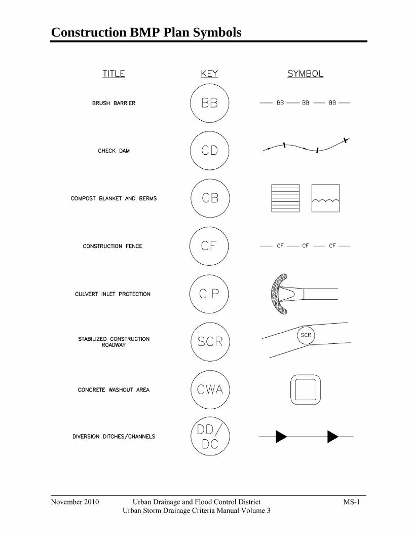
Construction BMP Plan Symbols
November 2010 Urban Drainage and Flood Control District MS-1 Urban Storm Drainage Criteria Manual Volume 3

Construction BMP Plan Symbols
MS-2 Urban Drainage and Flood Control District November 2010
Urban Storm Drainage Criteria Manual Volume 3
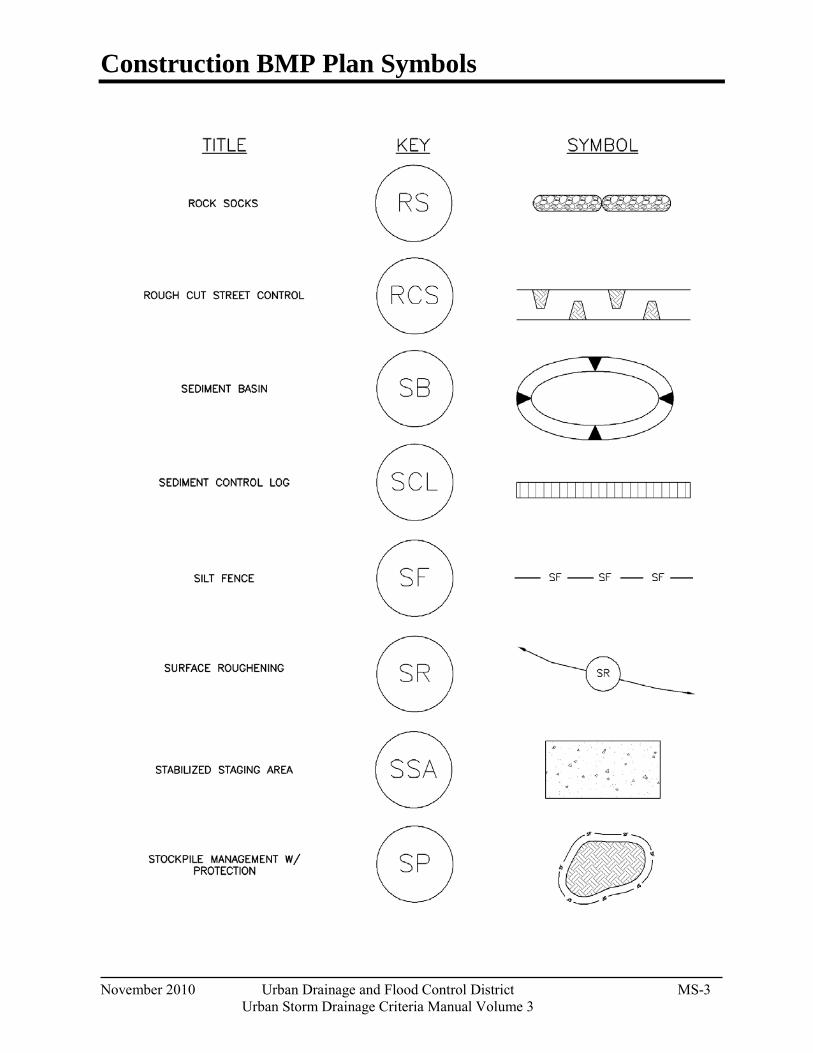
Construction BMP Plan Symbols
November 2010 Urban Drainage and Flood Control District MS-3 Urban Storm Drainage Criteria Manual Volume 3
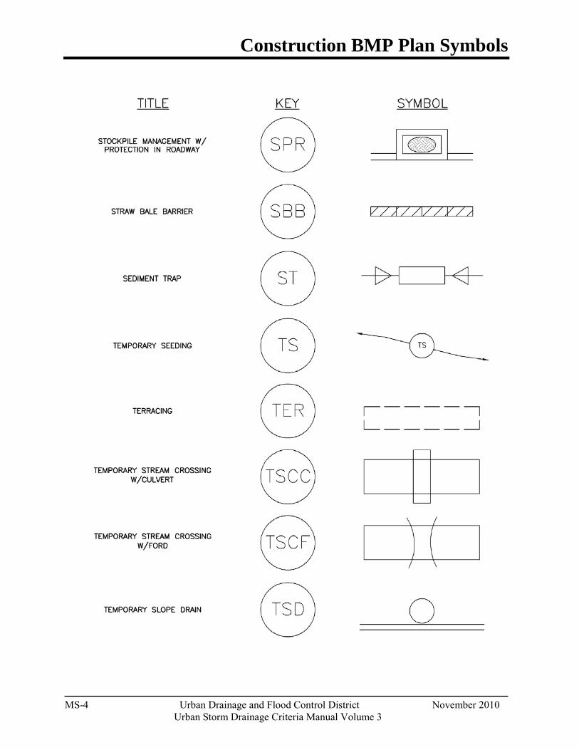
Construction BMP Plan Symbols
MS-4 Urban Drainage and Flood Control District November 2010
Urban Storm Drainage Criteria Manual Volume 3
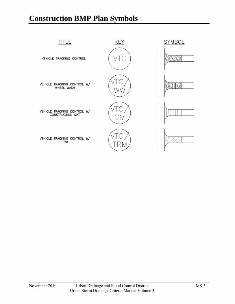
Construction BMP Plan Symbols
November 2010 Urban Drainage and Flood Control District MS-5 Urban Storm Drainage Criteria Manual Volume 3

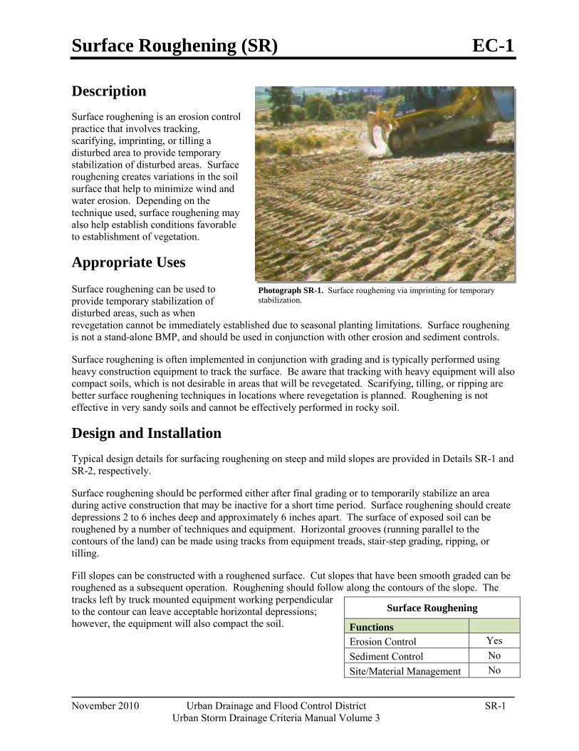
Surface Roughening (SR) EC-1
November 2010 Urban Drainage and Flood Control District SR-1 Urban Storm Drainage Criteria Manual Volume 3
Photograph SR-1. Surface roughening via imprinting for temporary stabilization.
Description Surface roughening is an erosion control practice that involves tracking, scarifying, imprinting, or tilling a disturbed area to provide temporary stabilization of disturbed areas. Surface roughening creates variations in the soil surface that help to minimize wind and water erosion. Depending on the technique used, surface roughening may also help establish conditions favorable to establishment of vegetation.
Appropriate Uses
Surface roughening can be used to provide temporary stabilization of disturbed areas, such as when revegetation cannot be immediately established due to seasonal planting limitations. Surface roughening is not a stand-alone BMP, and should be used in conjunction with other erosion and sediment controls.
Surface roughening is often implemented in conjunction with grading and is typically performed using heavy construction equipment to track the surface. Be aware that tracking with heavy equipment will also compact soils, which is not desirable in areas that will be revegetated. Scarifying, tilling, or ripping are better surface roughening techniques in locations where revegetation is planned. Roughening is not effective in very sandy soils and cannot be effectively performed in rocky soil.
Design and Installation Typical design details for surfacing roughening on steep and mild slopes are provided in Details SR-1 and SR-2, respectively.
Surface roughening should be performed either after final grading or to temporarily stabilize an area during active construction that may be inactive for a short time period. Surface roughening should create depressions 2 to 6 inches deep and approximately 6 inches apart. The surface of exposed soil can be roughened by a number of techniques and equipment. Horizontal grooves (running parallel to the contours of the land) can be made using tracks from equipment treads, stair-step grading, ripping, or tilling.
Fill slopes can be constructed with a roughened surface. Cut slopes that have been smooth graded can be roughened as a subsequent operation. Roughening should follow along the contours of the slope. The tracks left by truck mounted equipment working perpendicular to the contour can leave acceptable horizontal depressions; however, the equipment will also compact the soil.
Surface Roughening
Functions
Erosion Control Yes Sediment Control No Site/Material Management No
EC-1 Surface Roughening (SR)
SR-2 Urban Drainage and Flood Control District November 2010
Urban Storm Drainage Criteria Manual Volume 3
Maintenance and Removal Care should be taken not to drive vehicles or equipment over areas that have been surface roughened. Tire tracks will smooth the roughened surface and may cause runoff to collect into rills and gullies.
Because surface roughening is only a temporary control, additional treatments may be necessary to maintain the soil surface in a roughened condition.
Areas should be inspected for signs of erosion. Surface roughening is a temporary measure, and will not provide long-term erosion control.
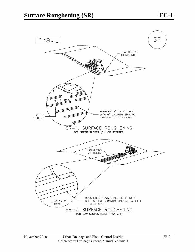
Surface Roughening (SR) EC-1
November 2010 Urban Drainage and Flood Control District SR-3 Urban Storm Drainage Criteria Manual Volume 3
EC-1 Surface Roughening (SR)
SR-4 Urban Drainage and Flood Control District November 2010
Urban Storm Drainage Criteria Manual Volume 3
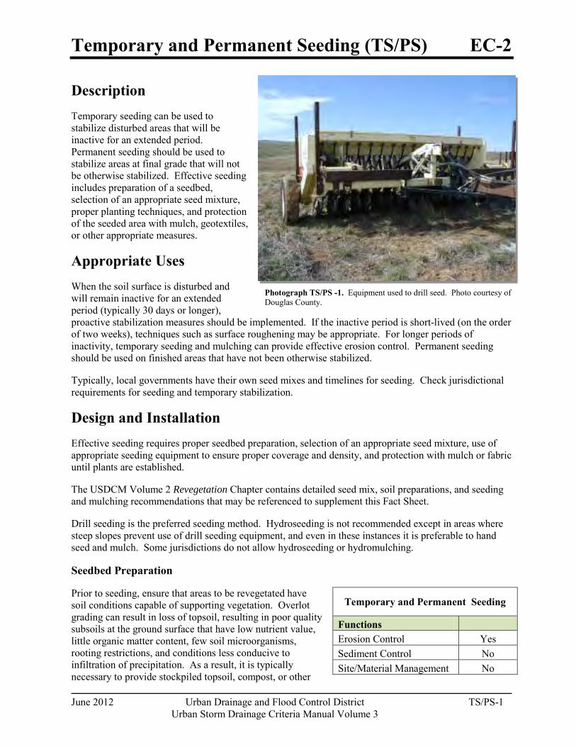
Temporary and Permanent Seeding (TS/PS) EC-2
June 2012 Urban Drainage and Flood Control District TS/PS-1 Urban Storm Drainage Criteria Manual Volume 3
Photograph TS/PS -1. Equipment used to drill seed. Photo courtesy of Douglas County.
Description Temporary seeding can be used to stabilize disturbed areas that will be inactive for an extended period. Permanent seeding should be used to stabilize areas at final grade that will not be otherwise stabilized. Effective seeding includes preparation of a seedbed, selection of an appropriate seed mixture, proper planting techniques, and protection of the seeded area with mulch, geotextiles, or other appropriate measures.
Appropriate Uses When the soil surface is disturbed and will remain inactive for an extended period (typically 30 days or longer), proactive stabilization measures should be implemented. If the inactive period is short-lived (on the order of two weeks), techniques such as surface roughening may be appropriate. For longer periods of inactivity, temporary seeding and mulching can provide effective erosion control. Permanent seeding should be used on finished areas that have not been otherwise stabilized.
Typically, local governments have their own seed mixes and timelines for seeding. Check jurisdictional requirements for seeding and temporary stabilization.
Design and Installation Effective seeding requires proper seedbed preparation, selection of an appropriate seed mixture, use of appropriate seeding equipment to ensure proper coverage and density, and protection with mulch or fabric until plants are established.
The USDCM Volume 2 Revegetation Chapter contains detailed seed mix, soil preparations, and seeding and mulching recommendations that may be referenced to supplement this Fact Sheet.
Drill seeding is the preferred seeding method. Hydroseeding is not recommended except in areas where steep slopes prevent use of drill seeding equipment, and even in these instances it is preferable to hand seed and mulch. Some jurisdictions do not allow hydroseeding or hydromulching.
Seedbed Preparation
Prior to seeding, ensure that areas to be revegetated have soil conditions capable of supporting vegetation. Overlot grading can result in loss of topsoil, resulting in poor quality subsoils at the ground surface that have low nutrient value, little organic matter content, few soil microorganisms, rooting restrictions, and conditions less conducive to infiltration of precipitation. As a result, it is typically necessary to provide stockpiled topsoil, compost, or other
Temporary and Permanent Seeding
Functions Erosion Control Yes Sediment Control No Site/Material Management No
EC-2 Temporary and Permanent Seeding (TS/PS)
TS/PS-2 Urban Drainage and Flood Control District June 2012
Urban Storm Drainage Criteria Manual Volume 3
soil amendments and rototill them into the soil to a depth of 6 inches or more.
Topsoil should be salvaged during grading operations for use and spread on areas to be revegetated later. Topsoil should be viewed as an important resource to be utilized for vegetation establishment, due to its water-holding capacity, structure, texture, organic matter content, biological activity, and nutrient content. The rooting depth of most native grasses in the semi-arid Denver metropolitan area is 6 to 18 inches. At a minimum, the upper 6 inches of topsoil should be stripped, stockpiled, and ultimately respread across areas that will be revegetated.
Where topsoil is not available, subsoils should be amended to provide an appropriate plant-growth medium. Organic matter, such as well digested compost, can be added to improve soil characteristics conducive to plant growth. Other treatments can be used to adjust soil pH conditions when needed. Soil testing, which is typically inexpensive, should be completed to determine and optimize the types and amounts of amendments that are required.
If the disturbed ground surface is compacted, rip or rototill the surface prior to placing topsoil. If adding compost to the existing soil surface, rototilling is necessary. Surface roughening will assist in placement of a stable topsoil layer on steeper slopes, and allow infiltration and root penetration to greater depth.
Prior to seeding, the soil surface should be rough and the seedbed should be firm, but neither too loose nor compacted. The upper layer of soil should be in a condition suitable for seeding at the proper depth and conducive to plant growth. Seed-to-soil contact is the key to good germination.
Seed Mix for Temporary Vegetation
To provide temporary vegetative cover on disturbed areas which will not be paved, built upon, or fully landscaped or worked for an extended period (typically 30 days or more), plant an annual grass appropriate for the time of planting and mulch the planted areas. Annual grasses suitable for the Denver metropolitan area are listed in Table TS/PS-1. These are to be considered only as general recommendations when specific design guidance for a particular site is not available. Local governments typically specify seed mixes appropriate for their jurisdiction.
Seed Mix for Permanent Revegetation
To provide vegetative cover on disturbed areas that have reached final grade, a perennial grass mix should be established. Permanent seeding should be performed promptly (typically within 14 days) after reaching final grade. Each site will have different characteristics and a landscape professional or the local jurisdiction should be contacted to determine the most suitable seed mix for a specific site. In lieu of a specific recommendation, one of the perennial grass mixes appropriate for site conditions and growth season listed in Table TS/PS-2 can be used. The pure live seed (PLS) rates of application recommended in these tables are considered to be absolute minimum rates for seed applied using proper drill-seeding equipment.
If desired for wildlife habitat or landscape diversity, shrubs such as rubber rabbitbrush (Chrysothamnus nauseosus), fourwing saltbush (Atriplex canescens) and skunkbrush sumac (Rhus trilobata) could be added to the upland seedmixes at 0.25, 0.5 and 1 pound PLS/acre, respectively. In riparian zones, planting root stock of such species as American plum (Prunus americana), woods rose (Rosa woodsii), plains cottonwood (Populus sargentii), and willow (Populus spp.) may be considered. On non-topsoiled upland sites, a legume such as Ladak alfalfa at 1 pound PLS/acre can be included as a source of nitrogen for perennial grasses.
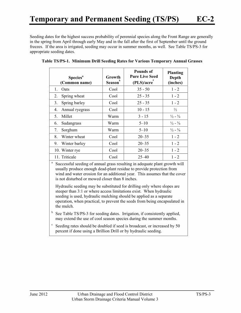
Temporary and Permanent Seeding (TS/PS) EC-2
June 2012 Urban Drainage and Flood Control District TS/PS-3 Urban Storm Drainage Criteria Manual Volume 3
Seeding dates for the highest success probability of perennial species along the Front Range are generally in the spring from April through early May and in the fall after the first of September until the ground freezes. If the area is irrigated, seeding may occur in summer months, as well. See Table TS/PS-3 for appropriate seeding dates.
Table TS/PS-1. Minimum Drill Seeding Rates for Various Temporary Annual Grasses
Speciesa (Common name)
Growth Seasonb
Pounds of Pure Live Seed
(PLS)/acrec
Planting Depth
(inches) 1. Oats Cool 35 - 50 1 - 2 2. Spring wheat Cool 25 - 35 1 - 2 3. Spring barley Cool 25 - 35 1 - 2 4. Annual ryegrass Cool 10 - 15 ½ 5. Millet Warm 3 - 15 ½ - ¾ 6. Sudangrass Warm 5–10 ½ - ¾ 7. Sorghum Warm 5–10 ½ - ¾ 8. Winter wheat Cool 20–35 1 - 2 9. Winter barley Cool 20–35 1 - 2 10. Winter rye Cool 20–35 1 - 2 11. Triticale Cool 25–40 1 - 2
a Successful seeding of annual grass resulting in adequate plant growth will usually produce enough dead-plant residue to provide protection from wind and water erosion for an additional year. This assumes that the cover is not disturbed or mowed closer than 8 inches.
Hydraulic seeding may be substituted for drilling only where slopes are steeper than 3:1 or where access limitations exist. When hydraulic seeding is used, hydraulic mulching should be applied as a separate operation, when practical, to prevent the seeds from being encapsulated in the mulch.
b See Table TS/PS-3 for seeding dates. Irrigation, if consistently applied, may extend the use of cool season species during the summer months.
c Seeding rates should be doubled if seed is broadcast, or increased by 50 percent if done using a Brillion Drill or by hydraulic seeding.
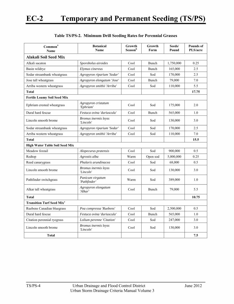
EC-2 Temporary and Permanent Seeding (TS/PS)
TS/PS-4 Urban Drainage and Flood Control District June 2012
Urban Storm Drainage Criteria Manual Volume 3
Table TS/PS-2. Minimum Drill Seeding Rates for Perennial Grasses
Commona Name
Botanical Name
Growth Seasonb
Growth Form
Seeds/ Pound
Pounds of PLS/acre
Alakali Soil Seed Mix
Alkali sacaton Sporobolus airoides Cool Bunch 1,750,000 0.25
Basin wildrye Elymus cinereus Cool Bunch 165,000 2.5
Sodar streambank wheatgrass Agropyron riparium 'Sodar' Cool Sod 170,000 2.5 Jose tall wheatgrass Agropyron elongatum 'Jose' Cool Bunch 79,000 7.0
Arriba western wheatgrass Agropyron smithii 'Arriba' Cool Sod 110,000 5.5
Total 17.75 Fertile Loamy Soil Seed Mix
Ephriam crested wheatgrass Agropyron cristatum 'Ephriam' Cool Sod 175,000 2.0
Dural hard fescue Festuca ovina 'duriuscula' Cool Bunch 565,000 1.0
Lincoln smooth brome Bromus inermis leyss 'Lincoln' Cool Sod 130,000 3.0
Sodar streambank wheatgrass Agropyron riparium 'Sodar' Cool Sod 170,000 2.5
Arriba western wheatgrass Agropyron smithii 'Arriba' Cool Sod 110,000 7.0
Total 15.5 High Water Table Soil Seed Mix Meadow foxtail Alopecurus pratensis Cool Sod 900,000 0.5
Redtop Agrostis alba Warm Open sod 5,000,000 0.25
Reed canarygrass Phalaris arundinacea Cool Sod 68,000 0.5
Lincoln smooth brome Bromus inermis leyss 'Lincoln' Cool Sod 130,000 3.0
Pathfinder switchgrass Panicum virgatum 'Pathfinder' Warm Sod 389,000 1.0
Alkar tall wheatgrass Agropyron elongatum 'Alkar' Cool Bunch 79,000 5.5
Total 10.75 Transition Turf Seed Mixc Ruebens Canadian bluegrass Poa compressa 'Ruebens' Cool Sod 2,500,000 0.5
Dural hard fescue Festuca ovina 'duriuscula' Cool Bunch 565,000 1.0 Citation perennial ryegrass Lolium perenne 'Citation' Cool Sod 247,000 3.0
Lincoln smooth brome Bromus inermis leyss 'Lincoln' Cool Sod 130,000 3.0
Total 7.5
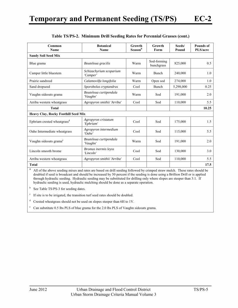
Temporary and Permanent Seeding (TS/PS) EC-2
June 2012 Urban Drainage and Flood Control District TS/PS-5 Urban Storm Drainage Criteria Manual Volume 3
Table TS/PS-2. Minimum Drill Seeding Rates for Perennial Grasses (cont.)
Common Name
Botanical Name
Growth Seasonb
Growth Form
Seeds/ Pound
Pounds of PLS/acre
Sandy Soil Seed Mix
Blue grama Bouteloua gracilis Warm Sod-forming bunchgrass 825,000 0.5
Camper little bluestem Schizachyrium scoparium 'Camper' Warm Bunch 240,000 1.0
Prairie sandreed Calamovilfa longifolia Warm Open sod 274,000 1.0
Sand dropseed Sporobolus cryptandrus Cool Bunch 5,298,000 0.25
Vaughn sideoats grama Bouteloua curtipendula 'Vaughn' Warm Sod 191,000 2.0
Arriba western wheatgrass Agropyron smithii 'Arriba' Cool Sod 110,000 5.5
Total 10.25 Heavy Clay, Rocky Foothill Seed Mix
Ephriam crested wheatgrassd Agropyron cristatum 'Ephriam' Cool Sod 175,000 1.5
Oahe Intermediate wheatgrass Agropyron intermedium 'Oahe' Cool Sod 115,000 5.5
Vaughn sideoats gramae Bouteloua curtipendula 'Vaughn' Warm Sod 191,000 2.0
Lincoln smooth brome Bromus inermis leyss 'Lincoln' Cool Sod 130,000 3.0
Arriba western wheatgrass Agropyron smithii 'Arriba' Cool Sod 110,000 5.5
Total 17.5 a All of the above seeding mixes and rates are based on drill seeding followed by crimped straw mulch. These rates should be
doubled if seed is broadcast and should be increased by 50 percent if the seeding is done using a Brillion Drill or is applied through hydraulic seeding. Hydraulic seeding may be substituted for drilling only where slopes are steeper than 3:1. If hydraulic seeding is used, hydraulic mulching should be done as a separate operation.
b See Table TS/PS-3 for seeding dates. c If site is to be irrigated, the transition turf seed rates should be doubled. d Crested wheatgrass should not be used on slopes steeper than 6H to 1V. e Can substitute 0.5 lbs PLS of blue grama for the 2.0 lbs PLS of Vaughn sideoats grama.
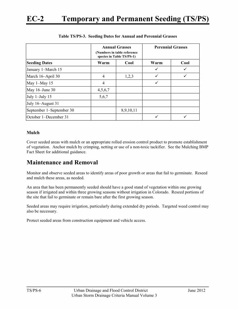
EC-2 Temporary and Permanent Seeding (TS/PS)
TS/PS-6 Urban Drainage and Flood Control District June 2012
Urban Storm Drainage Criteria Manual Volume 3
Table TS/PS-3. Seeding Dates for Annual and Perennial Grasses
Annual Grasses (Numbers in table reference
species in Table TS/PS-1)
Perennial Grasses
Seeding Dates Warm Cool Warm Cool January 1–March 15 March 16–April 30 4 1,2,3 May 1–May 15 4 May 16–June 30 4,5,6,7 July 1–July 15 5,6,7 July 16–August 31 September 1–September 30 8,9,10,11 October 1–December 31
Mulch
Cover seeded areas with mulch or an appropriate rolled erosion control product to promote establishment of vegetation. Anchor mulch by crimping, netting or use of a non-toxic tackifier. See the Mulching BMP Fact Sheet for additional guidance.
Maintenance and Removal Monitor and observe seeded areas to identify areas of poor growth or areas that fail to germinate. Reseed and mulch these areas, as needed.
An area that has been permanently seeded should have a good stand of vegetation within one growing season if irrigated and within three growing seasons without irrigation in Colorado. Reseed portions of the site that fail to germinate or remain bare after the first growing season.
Seeded areas may require irrigation, particularly during extended dry periods. Targeted weed control may also be necessary.
Protect seeded areas from construction equipment and vehicle access.
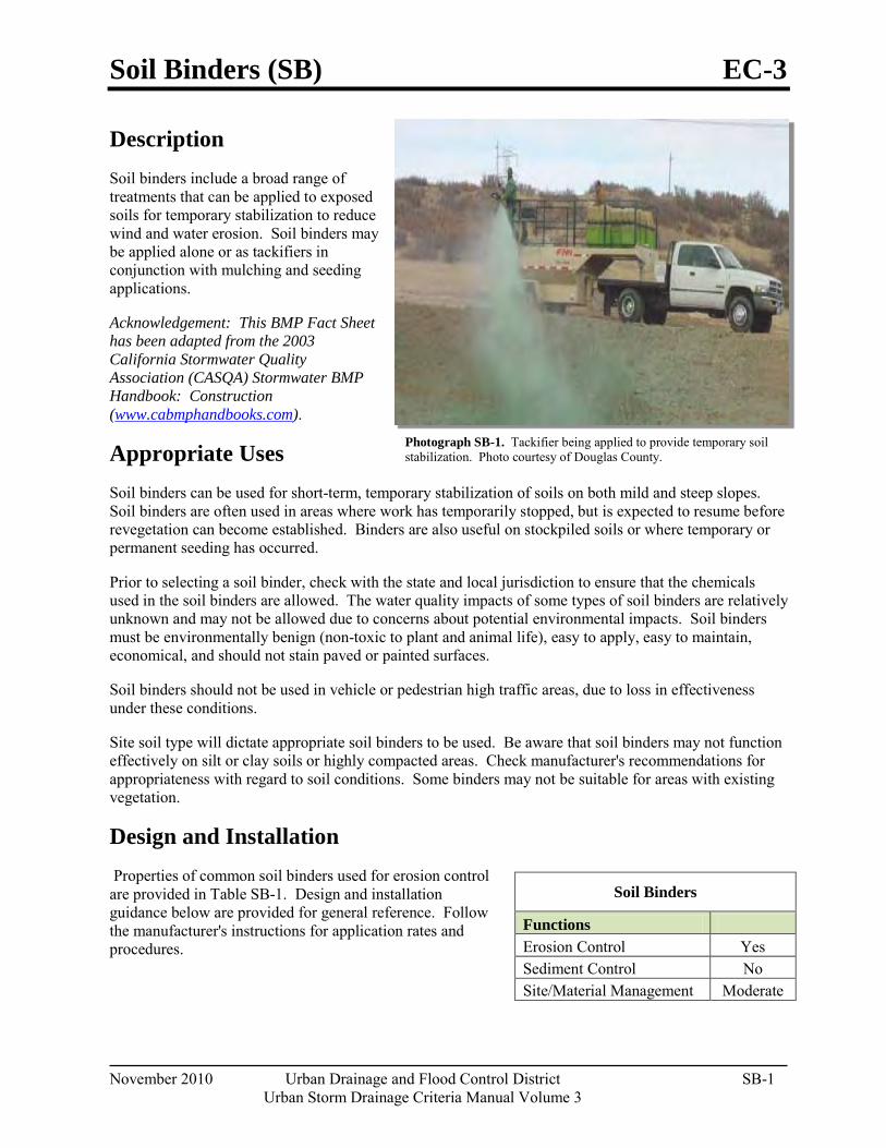
Soil Binders (SB) EC-3
November 2010 Urban Drainage and Flood Control District SB-1 Urban Storm Drainage Criteria Manual Volume 3
Description Soil binders include a broad range of treatments that can be applied to exposed soils for temporary stabilization to reduce wind and water erosion. Soil binders may be applied alone or as tackifiers in conjunction with mulching and seeding applications.
Acknowledgement: This BMP Fact Sheet has been adapted from the 2003 California Stormwater Quality Association (CASQA) Stormwater BMP Handbook: Construction (www.cabmphandbooks.com).
Appropriate Uses Soil binders can be used for short-term, temporary stabilization of soils on both mild and steep slopes. Soil binders are often used in areas where work has temporarily stopped, but is expected to resume before revegetation can become established. Binders are also useful on stockpiled soils or where temporary or permanent seeding has occurred.
Prior to selecting a soil binder, check with the state and local jurisdiction to ensure that the chemicals used in the soil binders are allowed. The water quality impacts of some types of soil binders are relatively unknown and may not be allowed due to concerns about potential environmental impacts. Soil binders must be environmentally benign (non-toxic to plant and animal life), easy to apply, easy to maintain, economical, and should not stain paved or painted surfaces.
Soil binders should not be used in vehicle or pedestrian high traffic areas, due to loss in effectiveness under these conditions.
Site soil type will dictate appropriate soil binders to be used. Be aware that soil binders may not function effectively on silt or clay soils or highly compacted areas. Check manufacturer's recommendations for appropriateness with regard to soil conditions. Some binders may not be suitable for areas with existing vegetation.
Design and Installation Properties of common soil binders used for erosion control are provided in Table SB-1. Design and installation guidance below are provided for general reference. Follow the manufacturer's instructions for application rates and procedures.
Soil Binders
Functions
Erosion Control Yes Sediment Control No Site/Material Management Moderate
Photograph SB-1. Tackifier being applied to provide temporary soil stabilization. Photo courtesy of Douglas County.
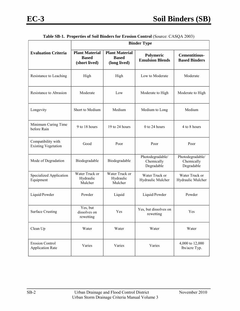
EC-3 Soil Binders (SB)
SB-2 Urban Drainage and Flood Control District November 2010
Urban Storm Drainage Criteria Manual Volume 3
Table SB-1. Properties of Soil Binders for Erosion Control (Source: CASQA 2003)
Evaluation Criteria
Binder Type
Plant Material Based
(short lived)
Plant Material Based
(long lived)
Polymeric Emulsion Blends
Cementitious-Based Binders
Resistance to Leaching High High Low to Moderate Moderate
Resistance to Abrasion Moderate Low Moderate to High Moderate to High
Longevity Short to Medium Medium Medium to Long Medium
Minimum Curing Time before Rain 9 to 18 hours 19 to 24 hours 0 to 24 hours 4 to 8 hours
Compatibility with Existing Vegetation Good Poor Poor Poor
Mode of Degradation Biodegradable Biodegradable Photodegradable/
Chemically Degradable
Photodegradable/ Chemically Degradable
Specialized Application Equipment
Water Truck or Hydraulic Mulcher
Water Truck or Hydraulic Mulcher
Water Truck or Hydraulic Mulcher
Water Truck or Hydraulic Mulcher
Liquid/Powder Powder Liquid Liquid/Powder Powder
Surface Crusting Yes, but
dissolves on rewetting
Yes Yes, but dissolves on rewetting Yes
Clean Up Water Water Water Water
Erosion Control Application Rate Varies Varies Varies 4,000 to 12,000
lbs/acre Typ.
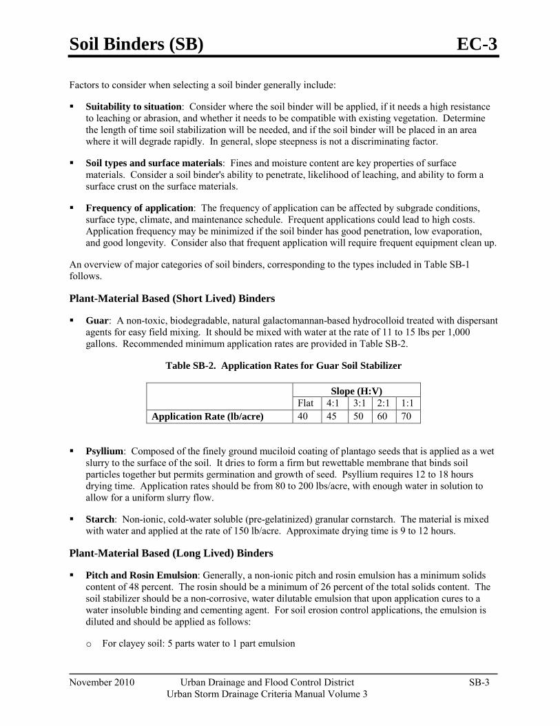
Soil Binders (SB) EC-3
November 2010 Urban Drainage and Flood Control District SB-3 Urban Storm Drainage Criteria Manual Volume 3
Factors to consider when selecting a soil binder generally include:
Suitability to situation: Consider where the soil binder will be applied, if it needs a high resistance to leaching or abrasion, and whether it needs to be compatible with existing vegetation. Determine the length of time soil stabilization will be needed, and if the soil binder will be placed in an area where it will degrade rapidly. In general, slope steepness is not a discriminating factor.
Soil types and surface materials: Fines and moisture content are key properties of surface materials. Consider a soil binder's ability to penetrate, likelihood of leaching, and ability to form a surface crust on the surface materials.
Frequency of application: The frequency of application can be affected by subgrade conditions, surface type, climate, and maintenance schedule. Frequent applications could lead to high costs. Application frequency may be minimized if the soil binder has good penetration, low evaporation, and good longevity. Consider also that frequent application will require frequent equipment clean up.
An overview of major categories of soil binders, corresponding to the types included in Table SB-1 follows.
Plant-Material Based (Short Lived) Binders
Guar: A non-toxic, biodegradable, natural galactomannan-based hydrocolloid treated with dispersant agents for easy field mixing. It should be mixed with water at the rate of 11 to 15 lbs per 1,000 gallons. Recommended minimum application rates are provided in Table SB-2.
Table SB-2. Application Rates for Guar Soil Stabilizer
Slope (H:V) Flat 4:1 3:1 2:1 1:1
Application Rate (lb/acre) 40 45 50 60 70
Psyllium: Composed of the finely ground muciloid coating of plantago seeds that is applied as a wet slurry to the surface of the soil. It dries to form a firm but rewettable membrane that binds soil particles together but permits germination and growth of seed. Psyllium requires 12 to 18 hours drying time. Application rates should be from 80 to 200 lbs/acre, with enough water in solution to allow for a uniform slurry flow.
Starch: Non-ionic, cold-water soluble (pre-gelatinized) granular cornstarch. The material is mixed with water and applied at the rate of 150 lb/acre. Approximate drying time is 9 to 12 hours.
Plant-Material Based (Long Lived) Binders
Pitch and Rosin Emulsion: Generally, a non-ionic pitch and rosin emulsion has a minimum solids content of 48 percent. The rosin should be a minimum of 26 percent of the total solids content. The soil stabilizer should be a non-corrosive, water dilutable emulsion that upon application cures to a water insoluble binding and cementing agent. For soil erosion control applications, the emulsion is diluted and should be applied as follows:
o For clayey soil: 5 parts water to 1 part emulsion
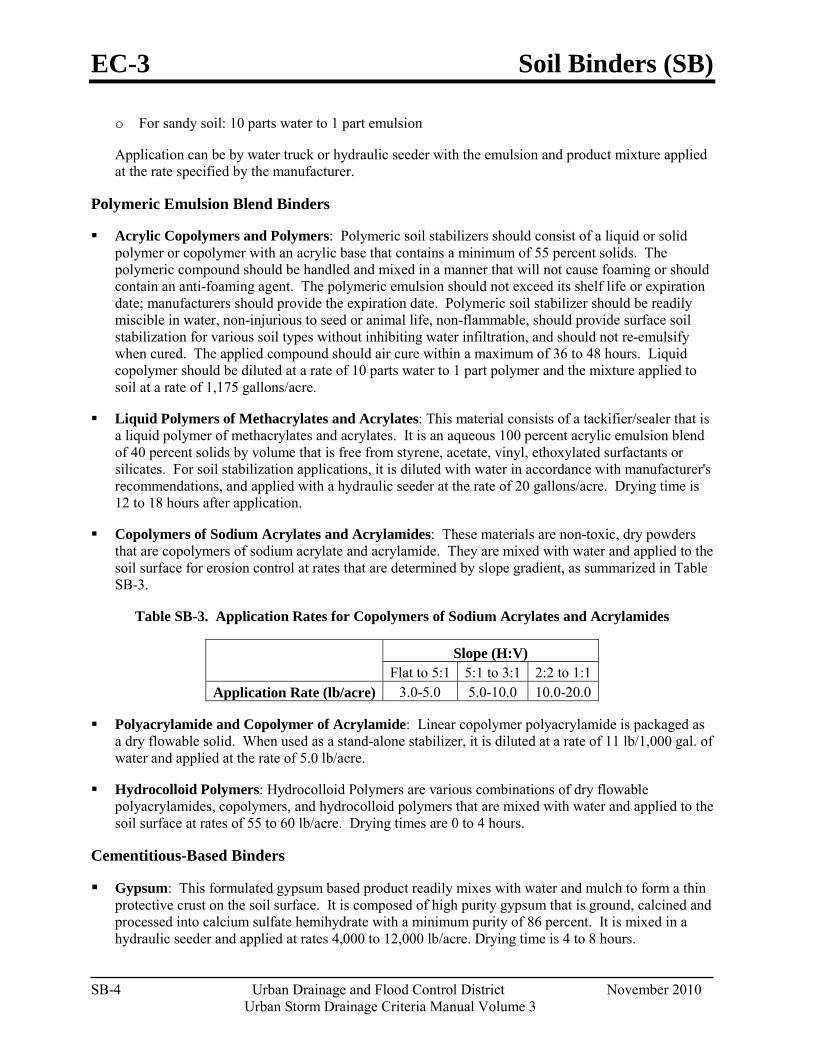
EC-3 Soil Binders (SB)
SB-4 Urban Drainage and Flood Control District November 2010
Urban Storm Drainage Criteria Manual Volume 3
o For sandy soil: 10 parts water to 1 part emulsion
Application can be by water truck or hydraulic seeder with the emulsion and product mixture applied at the rate specified by the manufacturer.
Polymeric Emulsion Blend Binders
Acrylic Copolymers and Polymers: Polymeric soil stabilizers should consist of a liquid or solid polymer or copolymer with an acrylic base that contains a minimum of 55 percent solids. The polymeric compound should be handled and mixed in a manner that will not cause foaming or should contain an anti-foaming agent. The polymeric emulsion should not exceed its shelf life or expiration date; manufacturers should provide the expiration date. Polymeric soil stabilizer should be readily miscible in water, non-injurious to seed or animal life, non-flammable, should provide surface soil stabilization for various soil types without inhibiting water infiltration, and should not re-emulsify when cured. The applied compound should air cure within a maximum of 36 to 48 hours. Liquid copolymer should be diluted at a rate of 10 parts water to 1 part polymer and the mixture applied to soil at a rate of 1,175 gallons/acre.
Liquid Polymers of Methacrylates and Acrylates: This material consists of a tackifier/sealer that is a liquid polymer of methacrylates and acrylates. It is an aqueous 100 percent acrylic emulsion blend of 40 percent solids by volume that is free from styrene, acetate, vinyl, ethoxylated surfactants or silicates. For soil stabilization applications, it is diluted with water in accordance with manufacturer's recommendations, and applied with a hydraulic seeder at the rate of 20 gallons/acre. Drying time is 12 to 18 hours after application.
Copolymers of Sodium Acrylates and Acrylamides: These materials are non-toxic, dry powders that are copolymers of sodium acrylate and acrylamide. They are mixed with water and applied to the soil surface for erosion control at rates that are determined by slope gradient, as summarized in Table SB-3.
Table SB-3. Application Rates for Copolymers of Sodium Acrylates and Acrylamides
Slope (H:V) Flat to 5:1 5:1 to 3:1 2:2 to 1:1
Application Rate (lb/acre) 3.0-5.0 5.0-10.0 10.0-20.0
Polyacrylamide and Copolymer of Acrylamide: Linear copolymer polyacrylamide is packaged as a dry flowable solid. When used as a stand-alone stabilizer, it is diluted at a rate of 11 lb/1,000 gal. of water and applied at the rate of 5.0 lb/acre.
Hydrocolloid Polymers: Hydrocolloid Polymers are various combinations of dry flowable polyacrylamides, copolymers, and hydrocolloid polymers that are mixed with water and applied to the soil surface at rates of 55 to 60 lb/acre. Drying times are 0 to 4 hours.
Cementitious-Based Binders
Gypsum: This formulated gypsum based product readily mixes with water and mulch to form a thin protective crust on the soil surface. It is composed of high purity gypsum that is ground, calcined and processed into calcium sulfate hemihydrate with a minimum purity of 86 percent. It is mixed in a hydraulic seeder and applied at rates 4,000 to 12,000 lb/acre. Drying time is 4 to 8 hours.
Soil Binders (SB) EC-3
November 2010 Urban Drainage and Flood Control District SB-5 Urban Storm Drainage Criteria Manual Volume 3
Installation
After selecting an appropriate soil binder, the untreated soil surface must be prepared before applying the soil binder. The untreated soil surface must contain sufficient moisture to assist the agent in achieving uniform distribution. In general, the following steps should be followed:
Follow manufacturer's written recommendations for application rates, pre-wetting of application area, and cleaning of equipment after use.
Prior to application, roughen embankment and fill areas.
Consider the drying time for the selected soil binder and apply with sufficient time before anticipated rainfall. Soil binders should not be applied during or immediately before rainfall.
Avoid over spray onto roads, sidewalks, drainage channels, sound walls, existing vegetation, etc.
Soil binders should not be applied to frozen soil, areas with standing water, under freezing or rainy conditions, or when the temperature is below 40°F during the curing period.
More than one treatment is often necessary, although the second treatment may be diluted or have a lower application rate.
Generally, soil binders require a minimum curing time of 24 hours before they are fully effective. Refer to manufacturer's instructions for specific cure time.
For liquid agents:
o Crown or slope ground to avoid ponding.
o Uniformly pre-wet ground at 0.03 to 0.3 gal/yd2 or according to manufacturer's recommendations.
o Apply solution under pressure. Overlap solution 6 to 12 in.
o Allow treated area to cure for the time recommended by the manufacturer, typically at least 24 hours.
o Apply second treatment before first treatment becomes ineffective, using 50 percent application rate.
o In low humidity, reactivate chemicals by re-wetting with water at 0.1 to 0.2 gal/yd2.
Maintenance and Removal Soil binders tend to break down due to natural weathering. Weathering rates depend on a variety of site-specific and product characteristics. Consult the manufacturer for recommended reapplication rates and reapply the selected soil binder as needed to maintain effectiveness.
Soil binders can fail after heavy rainfall events and may require reapplication. In particular, soil binders will generally experience spot failures during heavy rainfall events. If runoff penetrates the soil at the top of a slope treated with a soil binder, it is likely that the runoff will undercut the stabilized soil layer and discharge at a point further down slope.
EC-3 Soil Binders (SB)
SB-6 Urban Drainage and Flood Control District November 2010
Urban Storm Drainage Criteria Manual Volume 3
Areas where erosion is evident should be repaired and soil binder or other stabilization reapplied, as needed. Care should be exercised to minimize the damage to protected areas while making repairs.
Most binders biodegrade after exposure to sun, oxidation, heat and biological organisms; therefore, removal of the soil binder is not typically required.
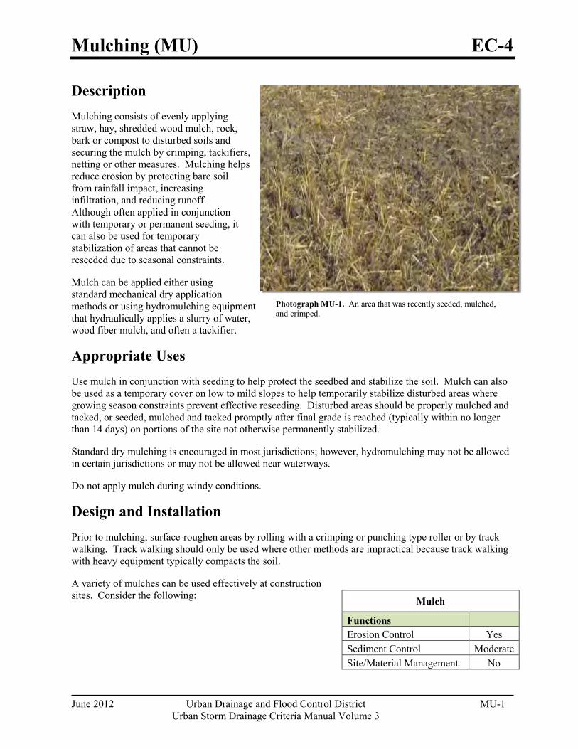
Mulching (MU) EC-4
June 2012 Urban Drainage and Flood Control District MU-1 Urban Storm Drainage Criteria Manual Volume 3
Photograph MU-1. An area that was recently seeded, mulched, and crimped.
Description Mulching consists of evenly applying straw, hay, shredded wood mulch, rock, bark or compost to disturbed soils and securing the mulch by crimping, tackifiers, netting or other measures. Mulching helps reduce erosion by protecting bare soil from rainfall impact, increasing infiltration, and reducing runoff. Although often applied in conjunction with temporary or permanent seeding, it can also be used for temporary stabilization of areas that cannot be reseeded due to seasonal constraints.
Mulch can be applied either using standard mechanical dry application methods or using hydromulching equipment that hydraulically applies a slurry of water, wood fiber mulch, and often a tackifier.
Appropriate Uses Use mulch in conjunction with seeding to help protect the seedbed and stabilize the soil. Mulch can also be used as a temporary cover on low to mild slopes to help temporarily stabilize disturbed areas where growing season constraints prevent effective reseeding. Disturbed areas should be properly mulched and tacked, or seeded, mulched and tacked promptly after final grade is reached (typically within no longer than 14 days) on portions of the site not otherwise permanently stabilized.
Standard dry mulching is encouraged in most jurisdictions; however, hydromulching may not be allowed in certain jurisdictions or may not be allowed near waterways.
Do not apply mulch during windy conditions.
Design and Installation Prior to mulching, surface-roughen areas by rolling with a crimping or punching type roller or by track walking. Track walking should only be used where other methods are impractical because track walking with heavy equipment typically compacts the soil.
A variety of mulches can be used effectively at construction sites. Consider the following:
Mulch
Functions Erosion Control Yes
Sediment Control Moderate Site/Material Management No
EC-4 Mulching (MU)
MU-2 Urban Drainage and Flood Control District June 2012
Urban Storm Drainage Criteria Manual Volume 3
Clean, weed-free and seed-free cereal grain straw should be applied evenly at a rate of 2 tons per acre and must be tacked or fastened by a method suitable for the condition of the site. Straw mulch must be anchored (and not merely placed) on the surface. This can be accomplished mechanically by crimping or with the aid of tackifiers or nets. Anchoring with a crimping implement is preferred, and is the recommended method for areas flatter than 3:1. Mechanical crimpers must be capable of tucking the long mulch fibers into the soil to a depth of 3 inches without cutting them. An agricultural disk, while not an ideal substitute, may work if the disk blades are dull or blunted and set vertically; however, the frame may have to be weighted to afford proper soil penetration.
Grass hay may be used in place of straw; however, because hay is comprised of the entire plant including seed, mulching with hay may seed the site with non-native grass species which might in turn out-compete the native seed. Alternatively, native species of grass hay may be purchased, but can be difficult to find and are more expensive than straw. Purchasing and utilizing a certified weed-free straw is an easier and less costly mulching method. When using grass hay, follow the same guidelines as for straw (provided above).
On small areas sheltered from the wind and heavy runoff, spraying a tackifier on the mulch is satisfactory for holding it in place. For steep slopes and special situations where greater control is needed, erosion control blankets anchored with stakes should be used instead of mulch.
Hydraulic mulching consists of wood cellulose fibers mixed with water and a tackifying agent and should be applied at a rate of no less than 1,500 pounds per acre (1,425 lbs of fibers mixed with at least 75 lbs of tackifier) with a hydraulic mulcher. For steeper slopes, up to 2000 pounds per acre may be required for effective hydroseeding. Hydromulch typically requires up to 24 hours to dry; therefore, it should not be applied immediately prior to inclement weather. Application to roads, waterways and existing vegetation should be avoided.
Erosion control mats, blankets, or nets are recommended to help stabilize steep slopes (generally 3:1 and steeper) and waterways. Depending on the product, these may be used alone or in conjunction with grass or straw mulch. Normally, use of these products will be restricted to relatively small areas. Biodegradable mats made of straw and jute, straw-coconut, coconut fiber, or excelsior can be used instead of mulch. (See the ECM/TRM BMP for more information.)
Some tackifiers or binders may be used to anchor mulch. Check with the local jurisdiction for allowed tackifiers. Manufacturer's recommendations should be followed at all times. (See the Soil Binder BMP for more information on general types of tackifiers.)
Rock can also be used as mulch. It provides protection of exposed soils to wind and water erosion and allows infiltration of precipitation. An aggregate base course can be spread on disturbed areas for temporary or permanent stabilization. The rock mulch layer should be thick enough to provide full coverage of exposed soil on the area it is applied.
Maintenance and Removal After mulching, the bare ground surface should not be more than 10 percent exposed. Reapply mulch, as needed, to cover bare areas.
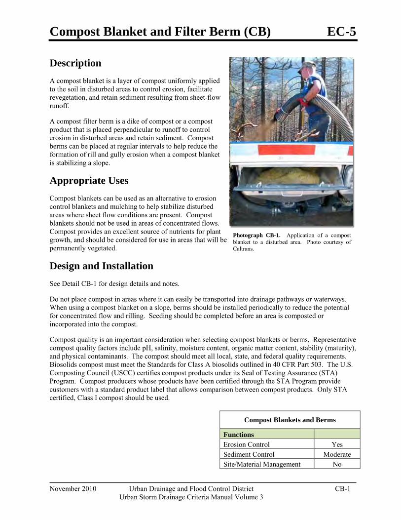
Compost Blanket and Filter Berm (CB) EC-5
November 2010 Urban Drainage and Flood Control District CB-1 Urban Storm Drainage Criteria Manual Volume 3
Photograph CB-1. Application of a compost blanket to a disturbed area. Photo courtesy of Caltrans.
Description A compost blanket is a layer of compost uniformly applied to the soil in disturbed areas to control erosion, facilitate revegetation, and retain sediment resulting from sheet-flow runoff.
A compost filter berm is a dike of compost or a compost product that is placed perpendicular to runoff to control erosion in disturbed areas and retain sediment. Compost berms can be placed at regular intervals to help reduce the formation of rill and gully erosion when a compost blanket is stabilizing a slope.
Appropriate Uses Compost blankets can be used as an alternative to erosion control blankets and mulching to help stabilize disturbed areas where sheet flow conditions are present. Compost blankets should not be used in areas of concentrated flows. Compost provides an excellent source of nutrients for plant growth, and should be considered for use in areas that will be permanently vegetated.
Design and Installation See Detail CB-1 for design details and notes.
Do not place compost in areas where it can easily be transported into drainage pathways or waterways. When using a compost blanket on a slope, berms should be installed periodically to reduce the potential for concentrated flow and rilling. Seeding should be completed before an area is composted or incorporated into the compost.
Compost quality is an important consideration when selecting compost blankets or berms. Representative compost quality factors include pH, salinity, moisture content, organic matter content, stability (maturity), and physical contaminants. The compost should meet all local, state, and federal quality requirements. Biosolids compost must meet the Standards for Class A biosolids outlined in 40 CFR Part 503. The U.S. Composting Council (USCC) certifies compost products under its Seal of Testing Assurance (STA) Program. Compost producers whose products have been certified through the STA Program provide customers with a standard product label that allows comparison between compost products. Only STA certified, Class I compost should be used.
Compost Blankets and Berms
Functions Erosion Control Yes Sediment Control Moderate Site/Material Management No
EC-5 Compost Blanket and Filter Berm (CB)
CB-2 Urban Drainage and Flood Control District November 2010
Urban Storm Drainage Criteria Manual Volume 3
Maintenance and Removal When rills or gullies develop in an area that has been composted, fill and cover the area with additional compost and install berms as necessary to help reduce erosion.
Weed control can be a maintenance challenge in areas using compost blankets. A weed control strategy may be necessary, including measures such as mechanical removal and spot application of targeted herbicides by licensed applicators.
For compost berms, accumulated sediments should be removed from behind the berm when the sediments reach approximately one third the height of the berm. Areas that have been washed away should be replaced. If the berm has experienced significant or repeated washouts, a compost berm may not be the appropriate BMP for this area.
Compost blankets and berms biodegrade and do not typically require removal following site stabilization.
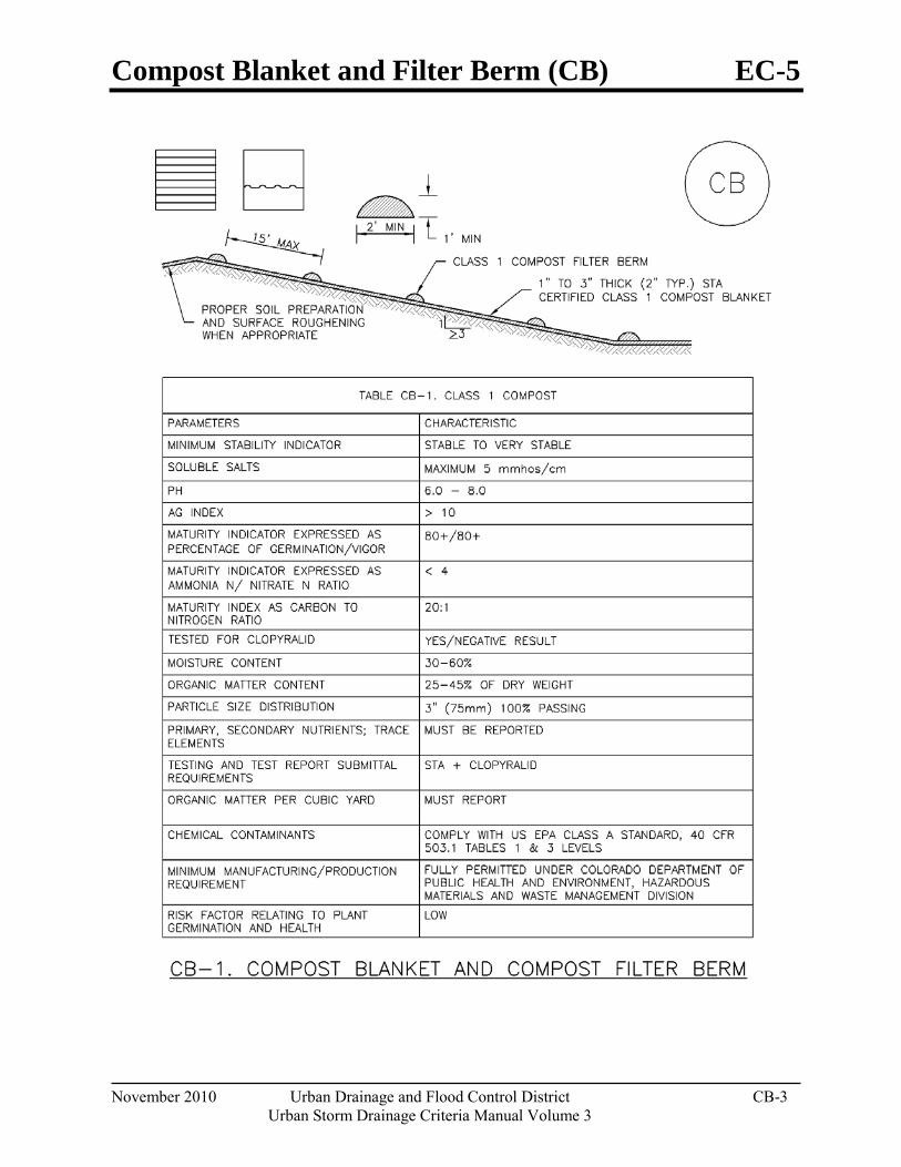
Compost Blanket and Filter Berm (CB) EC-5
November 2010 Urban Drainage and Flood Control District CB-3 Urban Storm Drainage Criteria Manual Volume 3
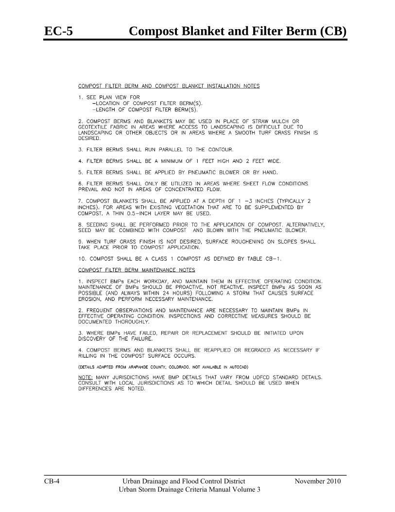
EC-5 Compost Blanket and Filter Berm (CB)
CB-4 Urban Drainage and Flood Control District November 2010
Urban Storm Drainage Criteria Manual Volume 3
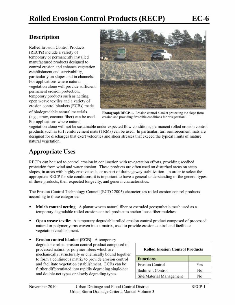
Rolled Erosion Control Products (RECP) EC-6
November 2010 Urban Drainage and Flood Control District RECP-1 Urban Storm Drainage Criteria Manual Volume 3
Photograph RECP-1. Erosion control blanket protecting the slope from erosion and providing favorable conditions for revegetation.
Description Rolled Erosion Control Products (RECPs) include a variety of temporary or permanently installed manufactured products designed to control erosion and enhance vegetation establishment and survivability, particularly on slopes and in channels. For applications where natural vegetation alone will provide sufficient permanent erosion protection, temporary products such as netting, open weave textiles and a variety of erosion control blankets (ECBs) made of biodegradable natural materials (e.g., straw, coconut fiber) can be used. For applications where natural vegetation alone will not be sustainable under expected flow conditions, permanent rolled erosion control products such as turf reinforcement mats (TRMs) can be used. In particular, turf reinforcement mats are designed for discharges that exert velocities and sheer stresses that exceed the typical limits of mature natural vegetation.
Appropriate Uses RECPs can be used to control erosion in conjunction with revegetation efforts, providing seedbed protection from wind and water erosion. These products are often used on disturbed areas on steep slopes, in areas with highly erosive soils, or as part of drainageway stabilization. In order to select the appropriate RECP for site conditions, it is important to have a general understanding of the general types of these products, their expected longevity, and general characteristics.
The Erosion Control Technology Council (ECTC 2005) characterizes rolled erosion control products according to these categories:
Mulch control netting: A planar woven natural fiber or extruded geosynthetic mesh used as a temporary degradable rolled erosion control product to anchor loose fiber mulches.
Open weave textile: A temporary degradable rolled erosion control product composed of processed natural or polymer yarns woven into a matrix, used to provide erosion control and facilitate vegetation establishment.
Erosion control blanket (ECB): A temporary degradable rolled erosion control product composed of processed natural or polymer fibers which are mechanically, structurally or chemically bound together to form a continuous matrix to provide erosion control and facilitate vegetation establishment. ECBs can be further differentiated into rapidly degrading single-net and double-net types or slowly degrading types.
Rolled Erosion Control Products
Functions Erosion Control Yes Sediment Control No Site/Material Management No
EC-6 Rolled Erosion Control Products (RECP)
RECP-2 Urban Drainage and Flood Control District November 2010
Urban Storm Drainage Criteria Manual Volume 3
Turf Reinforcement Mat (TRM): A rolled erosion control product composed of non-degradable synthetic fibers, filaments, nets, wire mesh, and/or other elements, processed into a permanent, three-dimensional matrix of sufficient thickness. TRMs, which may be supplemented with degradable components, are designed to impart immediate erosion protection, enhance vegetation establishment and provide long-term functionality by permanently reinforcing vegetation during and after maturation. Note: TRMs are typically used in hydraulic applications, such as high flow ditches and channels, steep slopes, stream banks, and shorelines, where erosive forces may exceed the limits of natural, unreinforced vegetation or in areas where limited vegetation establishment is anticipated.
Tables RECP-1 and RECP-2 provide guidelines for selecting rolled erosion control products appropriate to site conditions and desired longevity. Table RECP-1 is for conditions where natural vegetation alone will provide permanent erosion control, whereas Table RECP-2 is for conditions where vegetation alone will not be adequately stable to provide long-term erosion protection due to flow or other conditions.
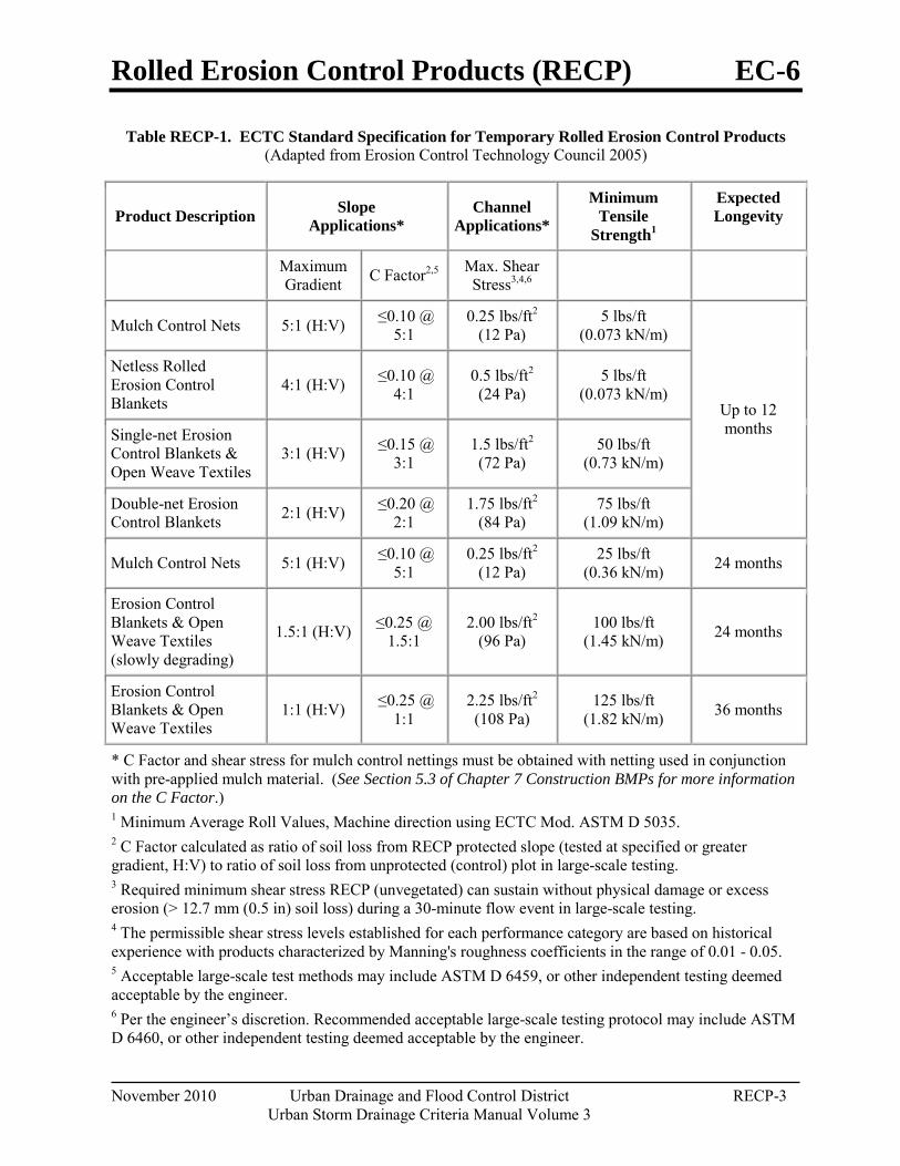
Rolled Erosion Control Products (RECP) EC-6
November 2010 Urban Drainage and Flood Control District RECP-3 Urban Storm Drainage Criteria Manual Volume 3
Table RECP-1. ECTC Standard Specification for Temporary Rolled Erosion Control Products (Adapted from Erosion Control Technology Council 2005)
Product Description Slope Applications*
Channel Applications*
Minimum Tensile
Strength1
Expected Longevity
Maximum Gradient C Factor2,5 Max. Shear
Stress3,4,6
Mulch Control Nets 5:1 (H:V) ≤0.10 @ 5:1
0.25 lbs/ft2 (12 Pa)
5 lbs/ft (0.073 kN/m)
Up to 12 months
Netless Rolled Erosion Control Blankets
4:1 (H:V) ≤0.10 @ 4:1
0.5 lbs/ft2 (24 Pa)
5 lbs/ft (0.073 kN/m)
Single-net Erosion Control Blankets & Open Weave Textiles
3:1 (H:V) ≤0.15 @ 3:1
1.5 lbs/ft2 (72 Pa)
50 lbs/ft (0.73 kN/m)
Double-net Erosion Control Blankets 2:1 (H:V) ≤0.20 @
2:1 1.75 lbs/ft2
(84 Pa) 75 lbs/ft
(1.09 kN/m)
Mulch Control Nets 5:1 (H:V) ≤0.10 @ 5:1
0.25 lbs/ft2 (12 Pa)
25 lbs/ft (0.36 kN/m) 24 months
Erosion Control Blankets & Open Weave Textiles (slowly degrading)
1.5:1 (H:V) ≤0.25 @ 1.5:1
2.00 lbs/ft2 (96 Pa)
100 lbs/ft (1.45 kN/m) 24 months
Erosion Control Blankets & Open Weave Textiles
1:1 (H:V) ≤0.25 @ 1:1
2.25 lbs/ft2 (108 Pa)
125 lbs/ft (1.82 kN/m) 36 months
* C Factor and shear stress for mulch control nettings must be obtained with netting used in conjunction with pre-applied mulch material. (See Section 5.3 of Chapter 7 Construction BMPs for more information on the C Factor.) 1 Minimum Average Roll Values, Machine direction using ECTC Mod. ASTM D 5035. 2 C Factor calculated as ratio of soil loss from RECP protected slope (tested at specified or greater gradient, H:V) to ratio of soil loss from unprotected (control) plot in large-scale testing. 3 Required minimum shear stress RECP (unvegetated) can sustain without physical damage or excess erosion (> 12.7 mm (0.5 in) soil loss) during a 30-minute flow event in large-scale testing. 4 The permissible shear stress levels established for each performance category are based on historical experience with products characterized by Manning's roughness coefficients in the range of 0.01 - 0.05. 5 Acceptable large-scale test methods may include ASTM D 6459, or other independent testing deemed acceptable by the engineer. 6 Per the engineer’s discretion. Recommended acceptable large-scale testing protocol may include ASTM D 6460, or other independent testing deemed acceptable by the engineer.
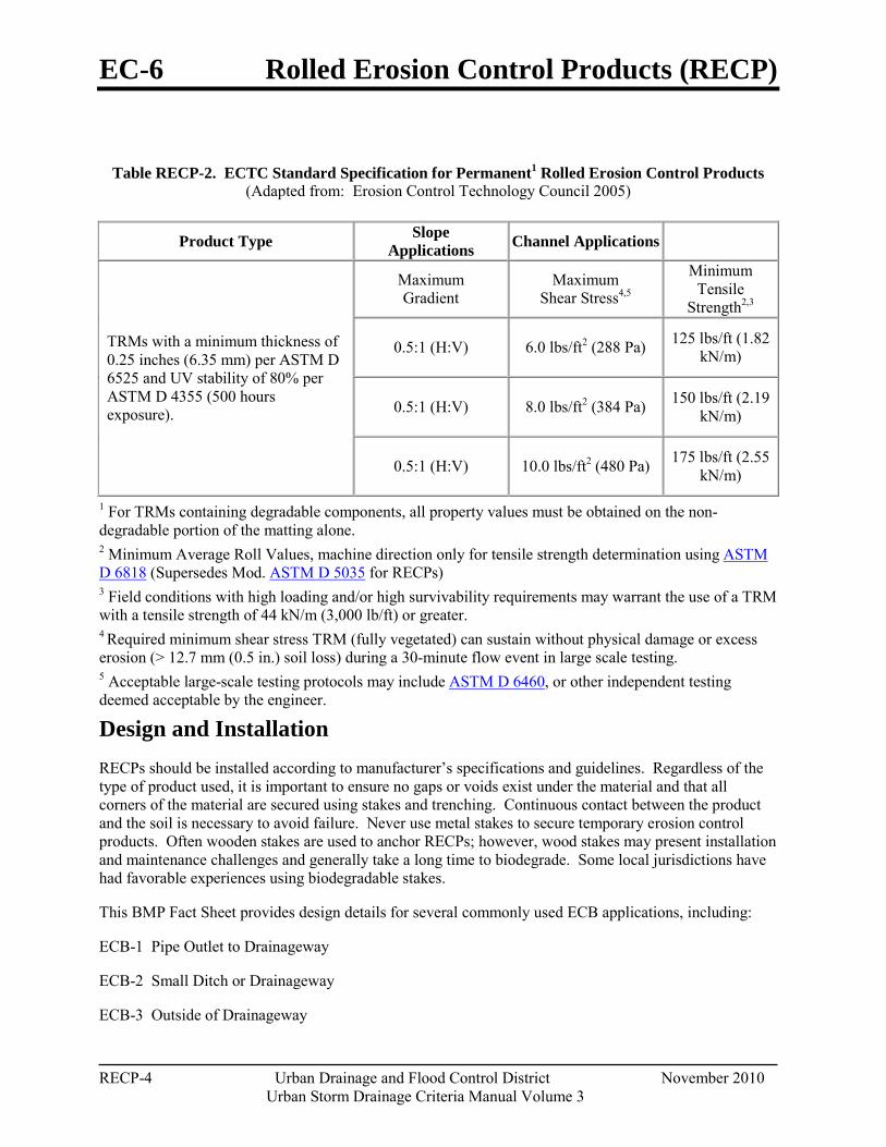
EC-6 Rolled Erosion Control Products (RECP)
RECP-4 Urban Drainage and Flood Control District November 2010
Urban Storm Drainage Criteria Manual Volume 3
Table RECP-2. ECTC Standard Specification for Permanent1 Rolled Erosion Control Products (Adapted from: Erosion Control Technology Council 2005)
Product Type Slope Applications Channel Applications
TRMs with a minimum thickness of 0.25 inches (6.35 mm) per ASTM D 6525 and UV stability of 80% per ASTM D 4355 (500 hours exposure).
Maximum Gradient
Maximum Shear Stress4,5
Minimum Tensile
Strength2,3
0.5:1 (H:V) 6.0 lbs/ft2 (288 Pa) 125 lbs/ft (1.82 kN/m)
0.5:1 (H:V) 8.0 lbs/ft2 (384 Pa) 150 lbs/ft (2.19 kN/m)
0.5:1 (H:V) 10.0 lbs/ft2 (480 Pa) 175 lbs/ft (2.55 kN/m)
1 For TRMs containing degradable components, all property values must be obtained on the non-degradable portion of the matting alone. 2 Minimum Average Roll Values, machine direction only for tensile strength determination using ASTM D 6818 (Supersedes Mod. ASTM D 5035 for RECPs) 3 Field conditions with high loading and/or high survivability requirements may warrant the use of a TRM with a tensile strength of 44 kN/m (3,000 lb/ft) or greater. 4 Required minimum shear stress TRM (fully vegetated) can sustain without physical damage or excess erosion (> 12.7 mm (0.5 in.) soil loss) during a 30-minute flow event in large scale testing. 5 Acceptable large-scale testing protocols may include ASTM D 6460, or other independent testing deemed acceptable by the engineer.
Design and Installation RECPs should be installed according to manufacturer’s specifications and guidelines. Regardless of the type of product used, it is important to ensure no gaps or voids exist under the material and that all corners of the material are secured using stakes and trenching. Continuous contact between the product and the soil is necessary to avoid failure. Never use metal stakes to secure temporary erosion control products. Often wooden stakes are used to anchor RECPs; however, wood stakes may present installation and maintenance challenges and generally take a long time to biodegrade. Some local jurisdictions have had favorable experiences using biodegradable stakes.
This BMP Fact Sheet provides design details for several commonly used ECB applications, including:
ECB-1 Pipe Outlet to Drainageway
ECB-2 Small Ditch or Drainageway
ECB-3 Outside of Drainageway
Rolled Erosion Control Products (RECP) EC-6
November 2010 Urban Drainage and Flood Control District RECP-5 Urban Storm Drainage Criteria Manual Volume 3
Staking patterns are also provided in the design details according to these factors:
ECB type
Slope or channel type
For other types of RECPs including TRMs, these design details are intended to serve as general guidelines for design and installation; however, engineers should adhere to manufacturer’s installation recommendations.
Maintenance and Removal Inspection of erosion control blankets and other RECPs includes:
Check for general signs of erosion, including voids beneath the mat. If voids are apparent, fill the void with suitable soil and replace the erosion control blanket, following the appropriate staking pattern.
Check for damaged or loose stakes and secure loose portions of the blanket.
Erosion control blankets and other RECPs that are biodegradable typically do not need to be removed after construction. If they must be removed, then an alternate soil stabilization method should be installed promptly following removal.
Turf reinforcement mats, although generally resistant to biodegradation, are typically left in place as a dense vegetated cover grows in through the mat matrix. The turf reinforcement mat provides long-term stability and helps the established vegetation resist erosive forces.
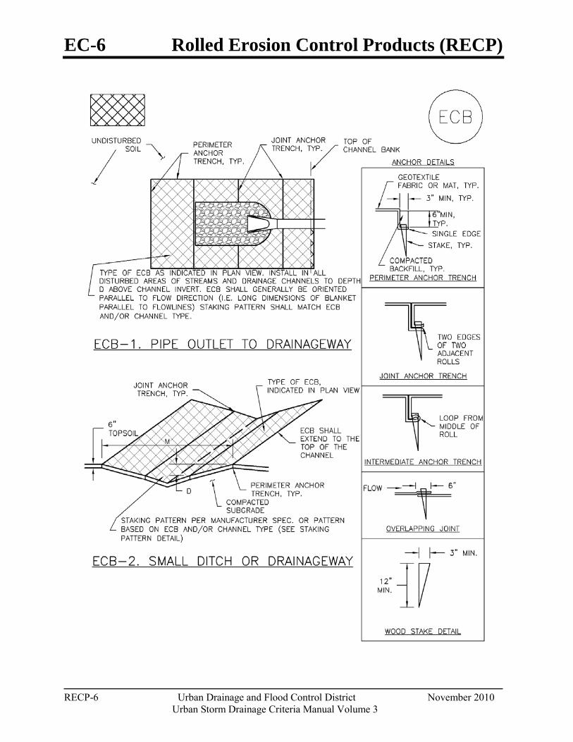
EC-6 Rolled Erosion Control Products (RECP)
RECP-6 Urban Drainage and Flood Control District November 2010
Urban Storm Drainage Criteria Manual Volume 3
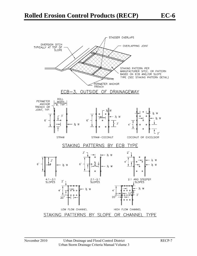
Rolled Erosion Control Products (RECP) EC-6
November 2010 Urban Drainage and Flood Control District RECP-7 Urban Storm Drainage Criteria Manual Volume 3

EC-6 Rolled Erosion Control Products (RECP)
RECP-8 Urban Drainage and Flood Control District November 2010
Urban Storm Drainage Criteria Manual Volume 3
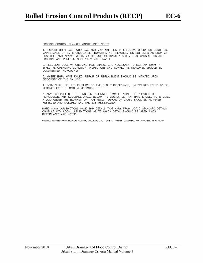
Rolled Erosion Control Products (RECP) EC-6
November 2010 Urban Drainage and Flood Control District RECP-9 Urban Storm Drainage Criteria Manual Volume 3

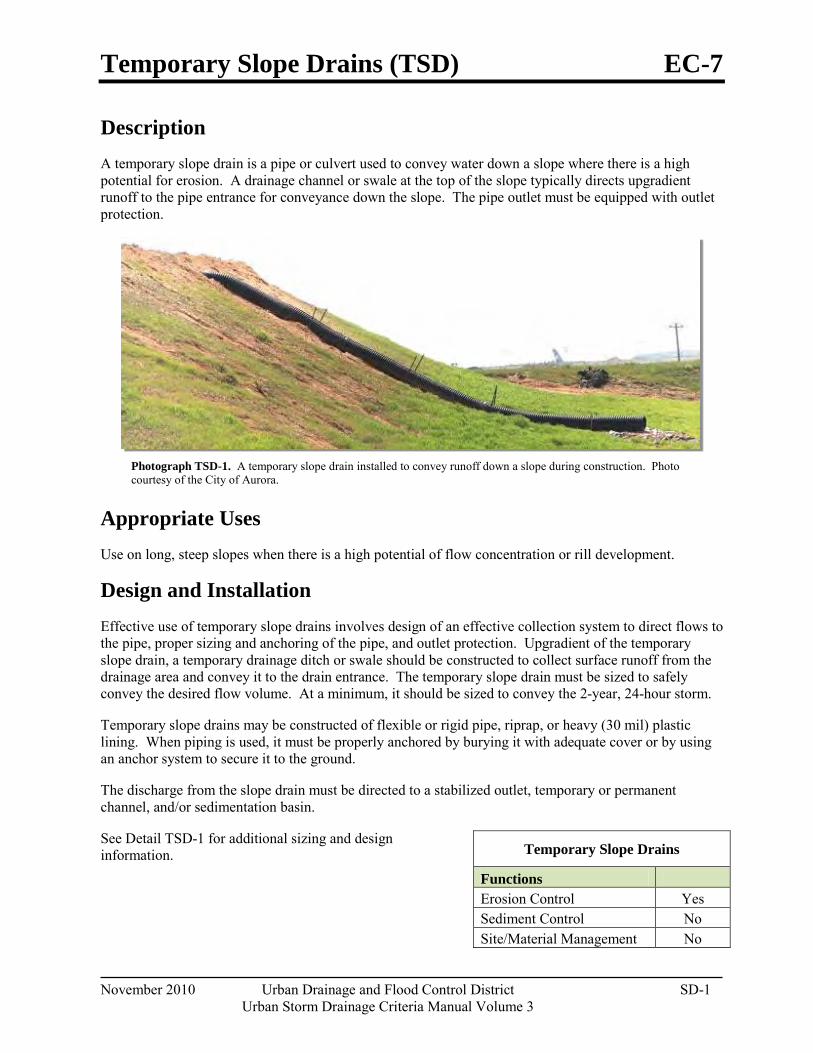
Temporary Slope Drains (TSD) EC-7
November 2010 Urban Drainage and Flood Control District SD-1 Urban Storm Drainage Criteria Manual Volume 3
Photograph TSD-1. A temporary slope drain installed to convey runoff down a slope during construction. Photo courtesy of the City of Aurora.
Description A temporary slope drain is a pipe or culvert used to convey water down a slope where there is a high potential for erosion. A drainage channel or swale at the top of the slope typically directs upgradient runoff to the pipe entrance for conveyance down the slope. The pipe outlet must be equipped with outlet protection.
Appropriate Uses Use on long, steep slopes when there is a high potential of flow concentration or rill development.
Design and Installation Effective use of temporary slope drains involves design of an effective collection system to direct flows to the pipe, proper sizing and anchoring of the pipe, and outlet protection. Upgradient of the temporary slope drain, a temporary drainage ditch or swale should be constructed to collect surface runoff from the drainage area and convey it to the drain entrance. The temporary slope drain must be sized to safely convey the desired flow volume. At a minimum, it should be sized to convey the 2-year, 24-hour storm.
Temporary slope drains may be constructed of flexible or rigid pipe, riprap, or heavy (30 mil) plastic lining. When piping is used, it must be properly anchored by burying it with adequate cover or by using an anchor system to secure it to the ground.
The discharge from the slope drain must be directed to a stabilized outlet, temporary or permanent channel, and/or sedimentation basin.
See Detail TSD-1 for additional sizing and design information.
Temporary Slope Drains
Functions Erosion Control Yes Sediment Control No Site/Material Management No
EC-7 Temporary Slope Drains (TSD)
SD-2 Urban Drainage and Flood Control District November 2010
Urban Storm Drainage Criteria Manual Volume 3
Maintenance and Removal Inspect the entrance for sediment accumulation and remove, as needed. Clogging as a result of sediment deposition at the entrance can lead to ponding upstream causing flooding or overtopping of the slope drain. Inspect the downstream outlet for signs of erosion and stabilize, as needed. It may also be necessary to remove accumulated sediment at the outfall. Inspect pipe anchors to ensure that they are secure. If the pipe is secured by ground cover, ensure erosion has not compromised the depth of cover.
Slope drains should be removed when no longer needed or just prior to installation of permanent slope stabilization measures that cannot be installed with the slope drain in place. When slope drains are removed, the disturbed areas should be covered with topsoil, seeded, mulched or otherwise stabilized as required by the local jurisdiction.
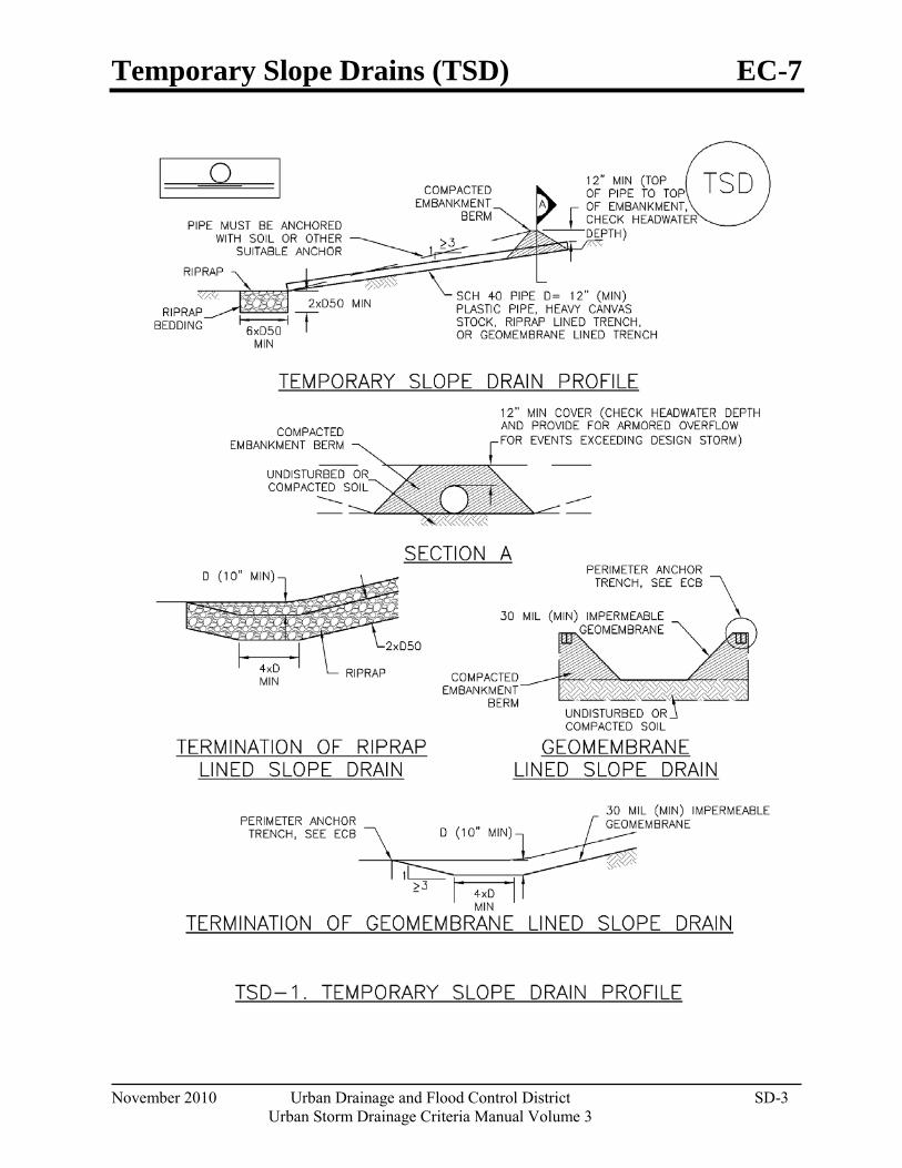
Temporary Slope Drains (TSD) EC-7
November 2010 Urban Drainage and Flood Control District SD-3 Urban Storm Drainage Criteria Manual Volume 3
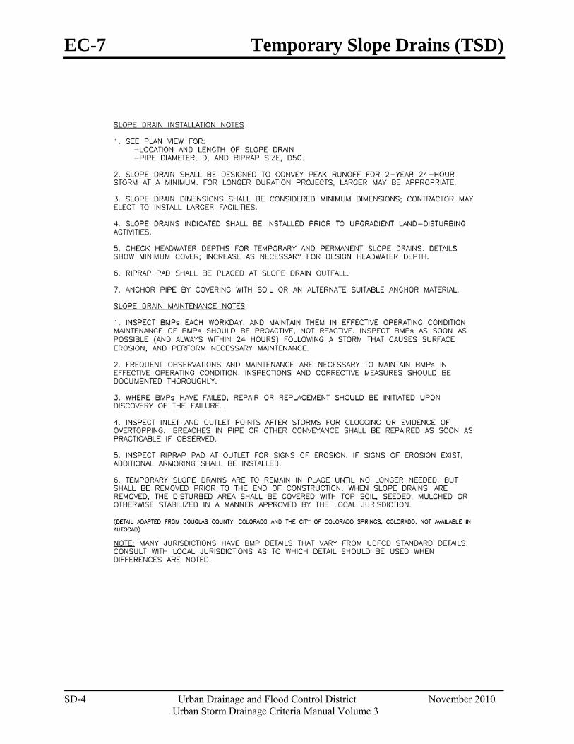
EC-7 Temporary Slope Drains (TSD)
SD-4 Urban Drainage and Flood Control District November 2010
Urban Storm Drainage Criteria Manual Volume 3
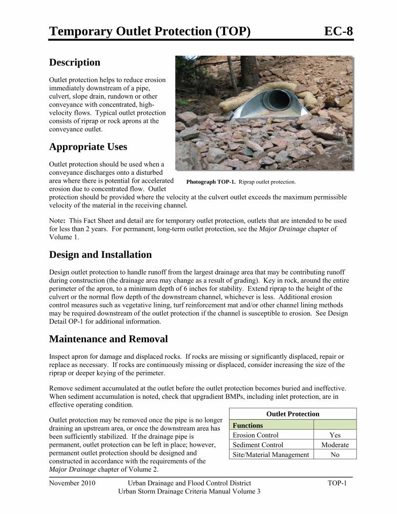
Temporary Outlet Protection (TOP) EC-8
November 2010 Urban Drainage and Flood Control District TOP-1 Urban Storm Drainage Criteria Manual Volume 3
Photograph TOP-1. Riprap outlet protection.
Description Outlet protection helps to reduce erosion immediately downstream of a pipe, culvert, slope drain, rundown or other conveyance with concentrated, high-velocity flows. Typical outlet protection consists of riprap or rock aprons at the conveyance outlet.
Appropriate Uses Outlet protection should be used when a conveyance discharges onto a disturbed area where there is potential for accelerated erosion due to concentrated flow. Outlet protection should be provided where the velocity at the culvert outlet exceeds the maximum permissible velocity of the material in the receiving channel.
Note: This Fact Sheet and detail are for temporary outlet protection, outlets that are intended to be used for less than 2 years. For permanent, long-term outlet protection, see the Major Drainage chapter of Volume 1.
Design and Installation Design outlet protection to handle runoff from the largest drainage area that may be contributing runoff during construction (the drainage area may change as a result of grading). Key in rock, around the entire perimeter of the apron, to a minimum depth of 6 inches for stability. Extend riprap to the height of the culvert or the normal flow depth of the downstream channel, whichever is less. Additional erosion control measures such as vegetative lining, turf reinforcement mat and/or other channel lining methods may be required downstream of the outlet protection if the channel is susceptible to erosion. See Design Detail OP-1 for additional information.
Maintenance and Removal Inspect apron for damage and displaced rocks. If rocks are missing or significantly displaced, repair or replace as necessary. If rocks are continuously missing or displaced, consider increasing the size of the riprap or deeper keying of the perimeter.
Remove sediment accumulated at the outlet before the outlet protection becomes buried and ineffective. When sediment accumulation is noted, check that upgradient BMPs, including inlet protection, are in effective operating condition.
Outlet protection may be removed once the pipe is no longer draining an upstream area, or once the downstream area has been sufficiently stabilized. If the drainage pipe is permanent, outlet protection can be left in place; however, permanent outlet protection should be designed and constructed in accordance with the requirements of the Major Drainage chapter of Volume 2.
Outlet Protection Functions Erosion Control Yes Sediment Control Moderate Site/Material Management No
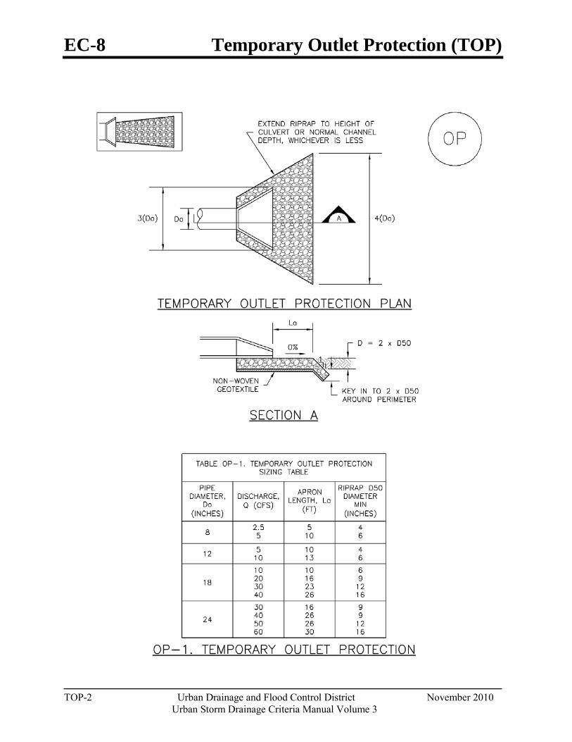
EC-8 Temporary Outlet Protection (TOP)
TOP-2 Urban Drainage and Flood Control District November 2010
Urban Storm Drainage Criteria Manual Volume 3
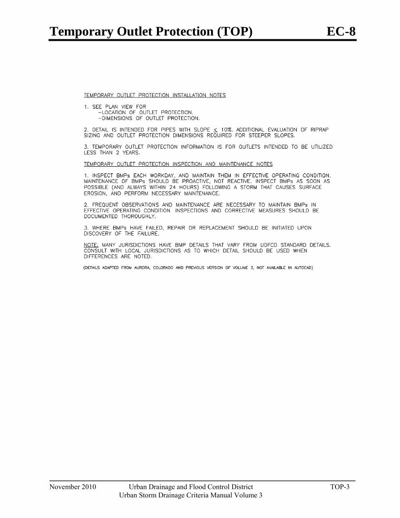
Temporary Outlet Protection (TOP) EC-8
November 2010 Urban Drainage and Flood Control District TOP-3 Urban Storm Drainage Criteria Manual Volume 3

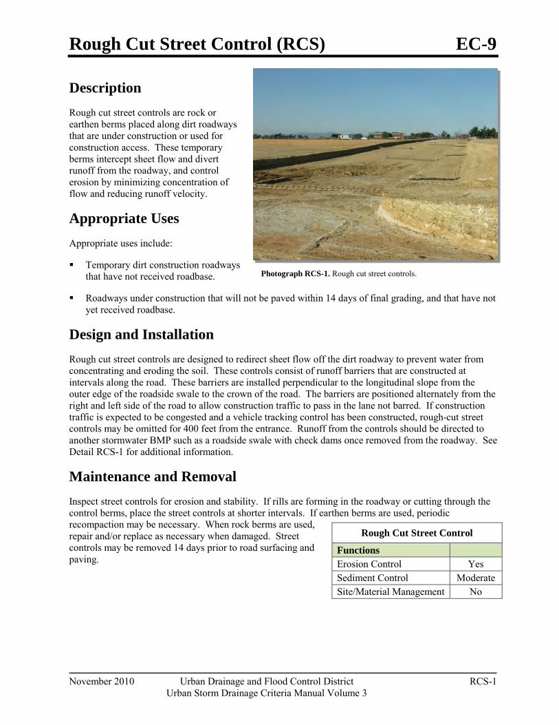
Rough Cut Street Control (RCS) EC-9
November 2010 Urban Drainage and Flood Control District RCS-1 Urban Storm Drainage Criteria Manual Volume 3
Photograph RCS-1. Rough cut street controls.
Description Rough cut street controls are rock or earthen berms placed along dirt roadways that are under construction or used for construction access. These temporary berms intercept sheet flow and divert runoff from the roadway, and control erosion by minimizing concentration of flow and reducing runoff velocity.
Appropriate Uses Appropriate uses include:
Temporary dirt construction roadways that have not received roadbase.
Roadways under construction that will not be paved within 14 days of final grading, and that have not yet received roadbase.
Design and Installation Rough cut street controls are designed to redirect sheet flow off the dirt roadway to prevent water from concentrating and eroding the soil. These controls consist of runoff barriers that are constructed at intervals along the road. These barriers are installed perpendicular to the longitudinal slope from the outer edge of the roadside swale to the crown of the road. The barriers are positioned alternately from the right and left side of the road to allow construction traffic to pass in the lane not barred. If construction traffic is expected to be congested and a vehicle tracking control has been constructed, rough-cut street controls may be omitted for 400 feet from the entrance. Runoff from the controls should be directed to another stormwater BMP such as a roadside swale with check dams once removed from the roadway. See Detail RCS-1 for additional information.
Maintenance and Removal Inspect street controls for erosion and stability. If rills are forming in the roadway or cutting through the control berms, place the street controls at shorter intervals. If earthen berms are used, periodic recompaction may be necessary. When rock berms are used, repair and/or replace as necessary when damaged. Street controls may be removed 14 days prior to road surfacing and paving.
Rough Cut Street Control
Functions Erosion Control Yes Sediment Control Moderate Site/Material Management No
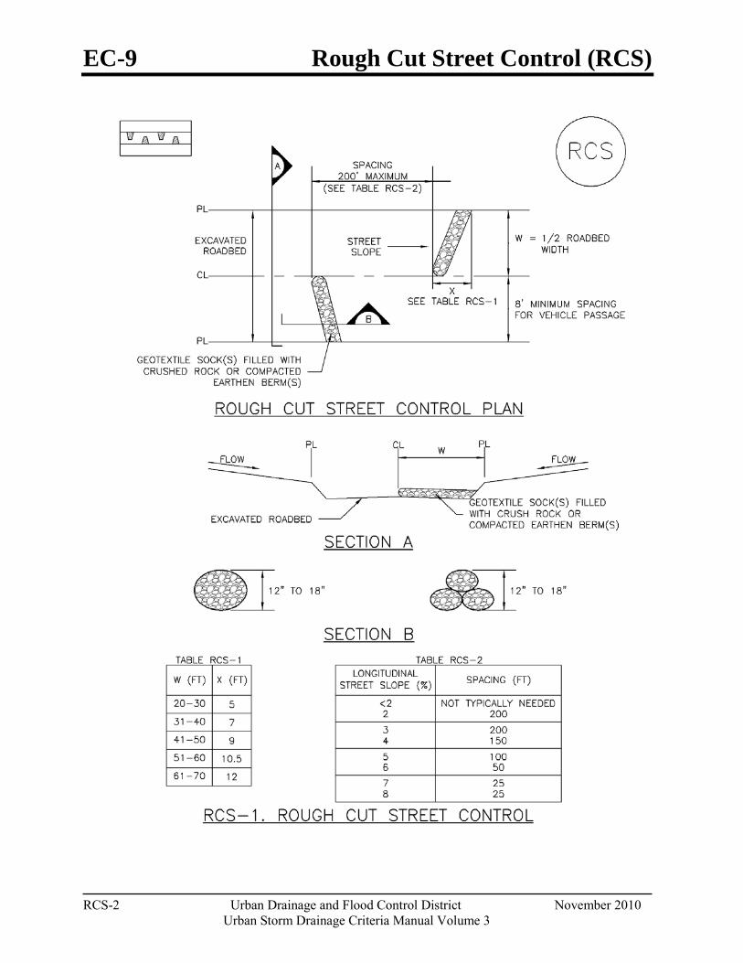
EC-9 Rough Cut Street Control (RCS)
RCS-2 Urban Drainage and Flood Control District November 2010
Urban Storm Drainage Criteria Manual Volume 3
Rough Cut Street Control (RCS) EC-9
November 2010 Urban Drainage and Flood Control District RCS-3 Urban Storm Drainage Criteria Manual Volume 3

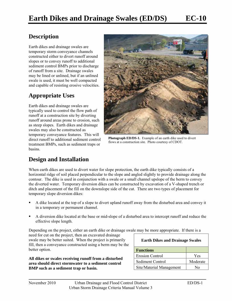
Earth Dikes and Drainage Swales (ED/DS) EC-10
November 2010 Urban Drainage and Flood Control District ED/DS-1 Urban Storm Drainage Criteria Manual Volume 3
Photograph ED/DS-1. Example of an earth dike used to divert flows at a construction site. Photo courtesy of CDOT.
Description Earth dikes and drainage swales are temporary storm conveyance channels constructed either to divert runoff around slopes or to convey runoff to additional sediment control BMPs prior to discharge of runoff from a site. Drainage swales may be lined or unlined, but if an unlined swale is used, it must be well compacted and capable of resisting erosive velocities.
Appropriate Uses Earth dikes and drainage swales are typically used to control the flow path of runoff at a construction site by diverting runoff around areas prone to erosion, such as steep slopes. Earth dikes and drainage swales may also be constructed as temporary conveyance features. This will direct runoff to additional sediment control treatment BMPs, such as sediment traps or basins.
Design and Installation When earth dikes are used to divert water for slope protection, the earth dike typically consists of a horizontal ridge of soil placed perpendicular to the slope and angled slightly to provide drainage along the contour. The dike is used in conjunction with a swale or a small channel upslope of the berm to convey the diverted water. Temporary diversion dikes can be constructed by excavation of a V-shaped trench or ditch and placement of the fill on the downslope side of the cut. There are two types of placement for temporary slope diversion dikes:
A dike located at the top of a slope to divert upland runoff away from the disturbed area and convey it in a temporary or permanent channel.
A diversion dike located at the base or mid-slope of a disturbed area to intercept runoff and reduce the effective slope length.
Depending on the project, either an earth dike or drainage swale may be more appropriate. If there is a need for cut on the project, then an excavated drainage swale may be better suited. When the project is primarily fill, then a conveyance constructed using a berm may be the better option.
All dikes or swales receiving runoff from a disturbed area should direct stormwater to a sediment control BMP such as a sediment trap or basin.
Earth Dikes and Drainage Swales
Functions Erosion Control Yes Sediment Control Moderate Site/Material Management No
EC-10 Earth Dikes and Drainage Swales (ED/DS)
ED/DS-2 Urban Drainage and Flood Control District November 2010
Urban Storm Drainage Criteria Manual Volume 3
Unlined dikes or swales should only be used for intercepting sheet flow runoff and are not intended for diversion of concentrated flows.
Details with notes are provided for several design variations, including:
ED-1. Unlined Earth Dike formed by Berm
DS-1. Unlined Excavated Swale
DS-2. Unlined Swale Formed by Cut and Fill
DS-3. ECB-lined Swale
DS-4. Synthetic-lined Swale
DS-5. Riprap-lined Swale
The details also include guidance on permissible velocities for cohesive channels if unlined approaches will be used.
Maintenance and Removal Inspect earth dikes for stability, compaction, and signs of erosion and repair. Inspect side slopes for erosion and damage to erosion control fabric. Stabilize slopes and repair fabric as necessary. If there is reoccurring extensive damage, consider installing rock check dams or lining the channel with riprap.
If drainage swales are not permanent, remove dikes and fill channels when the upstream area is stabilized. Stabilize the fill or disturbed area immediately following removal by revegetation or other permanent stabilization method approved by the local jurisdiction.
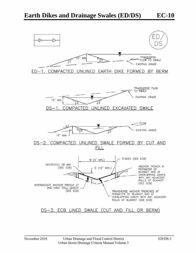
Earth Dikes and Drainage Swales (ED/DS) EC-10
November 2010 Urban Drainage and Flood Control District ED/DS-3 Urban Storm Drainage Criteria Manual Volume 3
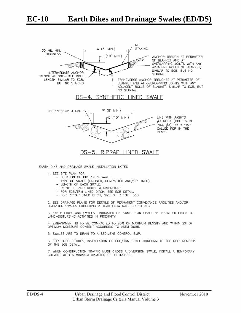
EC-10 Earth Dikes and Drainage Swales (ED/DS)
ED/DS-4 Urban Drainage and Flood Control District November 2010
Urban Storm Drainage Criteria Manual Volume 3
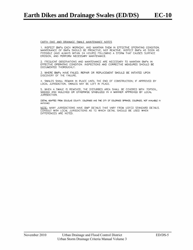
Earth Dikes and Drainage Swales (ED/DS) EC-10
November 2010 Urban Drainage and Flood Control District ED/DS-5 Urban Storm Drainage Criteria Manual Volume 3

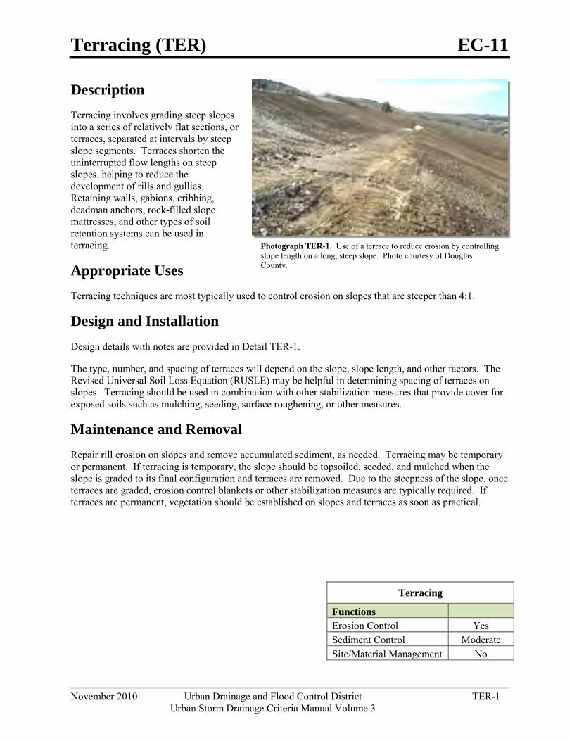
Terracing (TER) EC-11
November 2010 Urban Drainage and Flood Control District TER-1 Urban Storm Drainage Criteria Manual Volume 3
Photograph TER-1. Use of a terrace to reduce erosion by controlling slope length on a long, steep slope. Photo courtesy of Douglas County.
Description Terracing involves grading steep slopes into a series of relatively flat sections, or terraces, separated at intervals by steep slope segments. Terraces shorten the uninterrupted flow lengths on steep slopes, helping to reduce the development of rills and gullies. Retaining walls, gabions, cribbing, deadman anchors, rock-filled slope mattresses, and other types of soil retention systems can be used in terracing.
Appropriate Uses Terracing techniques are most typically used to control erosion on slopes that are steeper than 4:1.
Design and Installation Design details with notes are provided in Detail TER-1.
The type, number, and spacing of terraces will depend on the slope, slope length, and other factors. The Revised Universal Soil Loss Equation (RUSLE) may be helpful in determining spacing of terraces on slopes. Terracing should be used in combination with other stabilization measures that provide cover for exposed soils such as mulching, seeding, surface roughening, or other measures.
Maintenance and Removal Repair rill erosion on slopes and remove accumulated sediment, as needed. Terracing may be temporary or permanent. If terracing is temporary, the slope should be topsoiled, seeded, and mulched when the slope is graded to its final configuration and terraces are removed. Due to the steepness of the slope, once terraces are graded, erosion control blankets or other stabilization measures are typically required. If terraces are permanent, vegetation should be established on slopes and terraces as soon as practical.
Terracing
Functions Erosion Control Yes Sediment Control Moderate Site/Material Management No
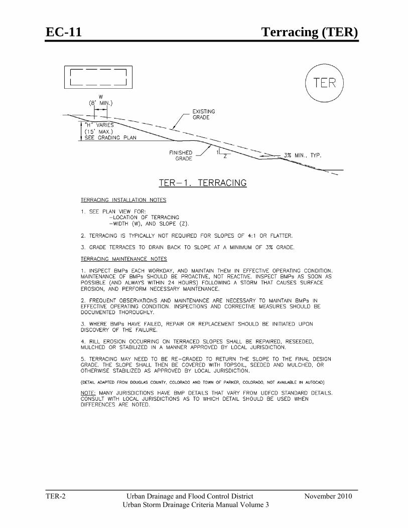
EC-11 Terracing (TER)
TER-2 Urban Drainage and Flood Control District November 2010
Urban Storm Drainage Criteria Manual Volume 3
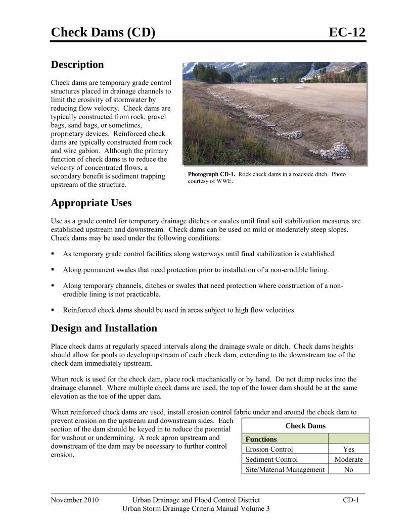
Check Dams (CD) EC-12
November 2010 Urban Drainage and Flood Control District CD-1 Urban Storm Drainage Criteria Manual Volume 3
Photograph CD-1. Rock check dams in a roadside ditch. Photo courtesy of WWE.
Description Check dams are temporary grade control structures placed in drainage channels to limit the erosivity of stormwater by reducing flow velocity. Check dams are typically constructed from rock, gravel bags, sand bags, or sometimes, proprietary devices. Reinforced check dams are typically constructed from rock and wire gabion. Although the primary function of check dams is to reduce the velocity of concentrated flows, a secondary benefit is sediment trapping upstream of the structure.
Appropriate Uses Use as a grade control for temporary drainage ditches or swales until final soil stabilization measures are established upstream and downstream. Check dams can be used on mild or moderately steep slopes. Check dams may be used under the following conditions:
As temporary grade control facilities along waterways until final stabilization is established.
Along permanent swales that need protection prior to installation of a non-erodible lining.
Along temporary channels, ditches or swales that need protection where construction of a non-erodible lining is not practicable.
Reinforced check dams should be used in areas subject to high flow velocities.
Design and Installation Place check dams at regularly spaced intervals along the drainage swale or ditch. Check dams heights should allow for pools to develop upstream of each check dam, extending to the downstream toe of the check dam immediately upstream.
When rock is used for the check dam, place rock mechanically or by hand. Do not dump rocks into the drainage channel. Where multiple check dams are used, the top of the lower dam should be at the same elevation as the toe of the upper dam.
When reinforced check dams are used, install erosion control fabric under and around the check dam to prevent erosion on the upstream and downstream sides. Each section of the dam should be keyed in to reduce the potential for washout or undermining. A rock apron upstream and downstream of the dam may be necessary to further control erosion.
Check Dams
Functions Erosion Control Yes Sediment Control Moderate Site/Material Management No
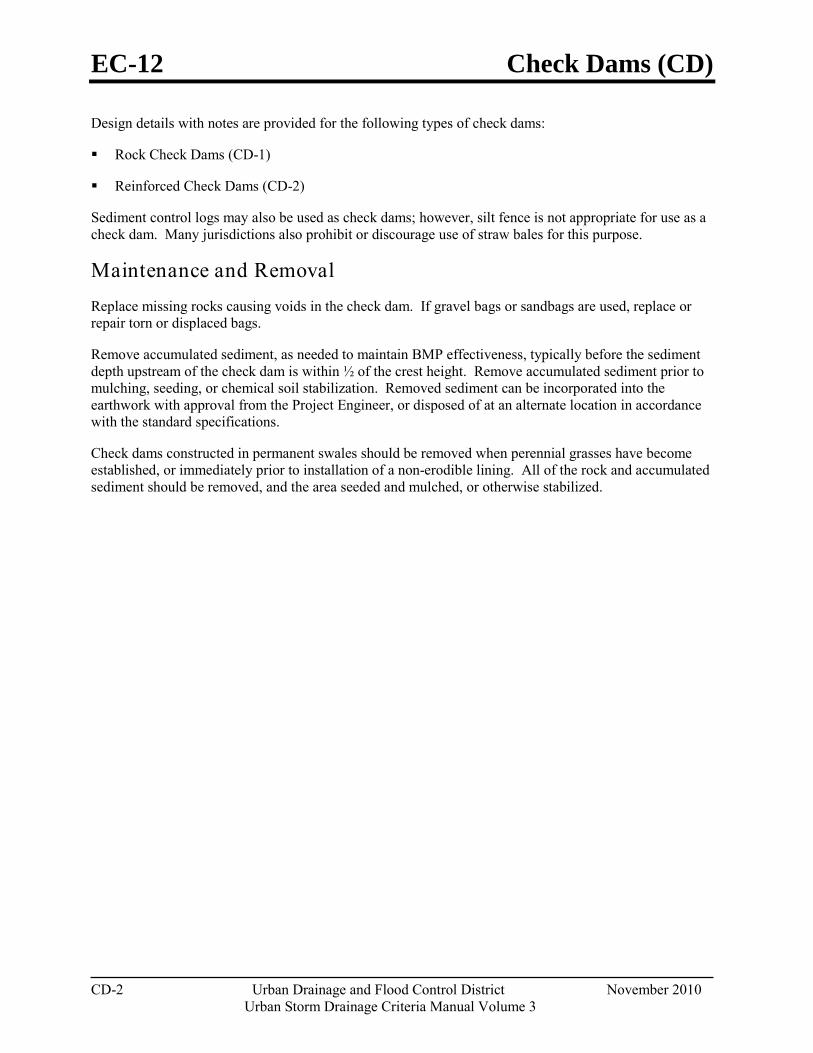
EC-12 Check Dams (CD)
CD-2 Urban Drainage and Flood Control District November 2010
Urban Storm Drainage Criteria Manual Volume 3
Design details with notes are provided for the following types of check dams:
Rock Check Dams (CD-1)
Reinforced Check Dams (CD-2)
Sediment control logs may also be used as check dams; however, silt fence is not appropriate for use as a check dam. Many jurisdictions also prohibit or discourage use of straw bales for this purpose.
Maintenance and Removal Replace missing rocks causing voids in the check dam. If gravel bags or sandbags are used, replace or repair torn or displaced bags.
Remove accumulated sediment, as needed to maintain BMP effectiveness, typically before the sediment depth upstream of the check dam is within ½ of the crest height. Remove accumulated sediment prior to mulching, seeding, or chemical soil stabilization. Removed sediment can be incorporated into the earthwork with approval from the Project Engineer, or disposed of at an alternate location in accordance with the standard specifications.
Check dams constructed in permanent swales should be removed when perennial grasses have become established, or immediately prior to installation of a non-erodible lining. All of the rock and accumulated sediment should be removed, and the area seeded and mulched, or otherwise stabilized.
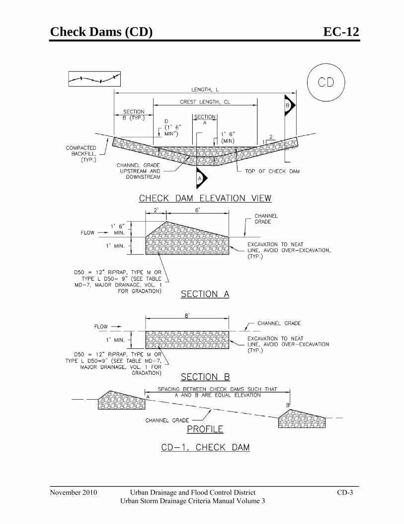
Check Dams (CD) EC-12
November 2010 Urban Drainage and Flood Control District CD-3 Urban Storm Drainage Criteria Manual Volume 3
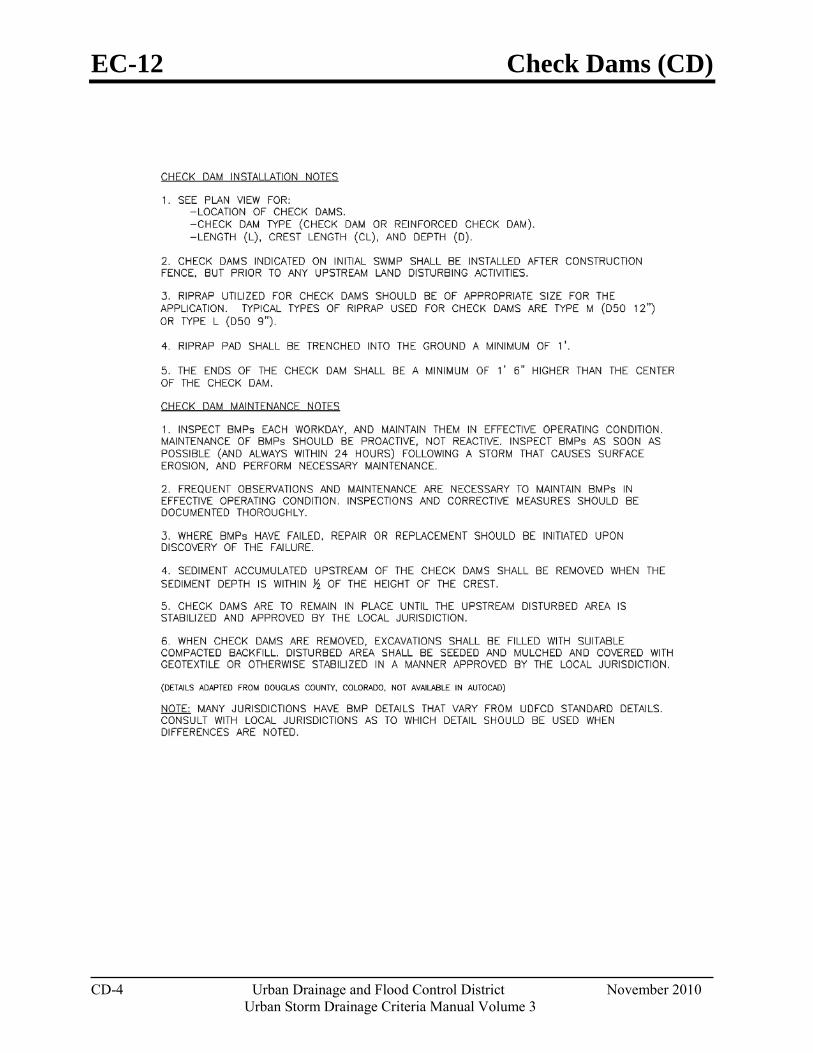
EC-12 Check Dams (CD)
CD-4 Urban Drainage and Flood Control District November 2010
Urban Storm Drainage Criteria Manual Volume 3
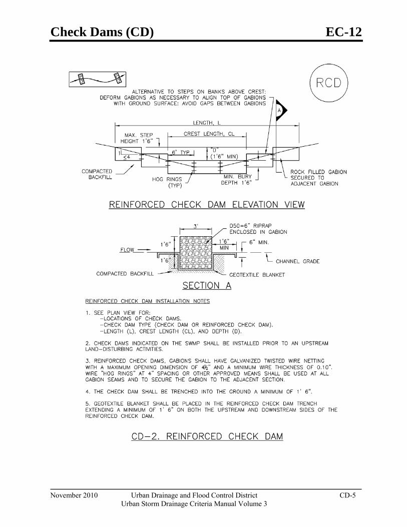
Check Dams (CD) EC-12
November 2010 Urban Drainage and Flood Control District CD-5 Urban Storm Drainage Criteria Manual Volume 3
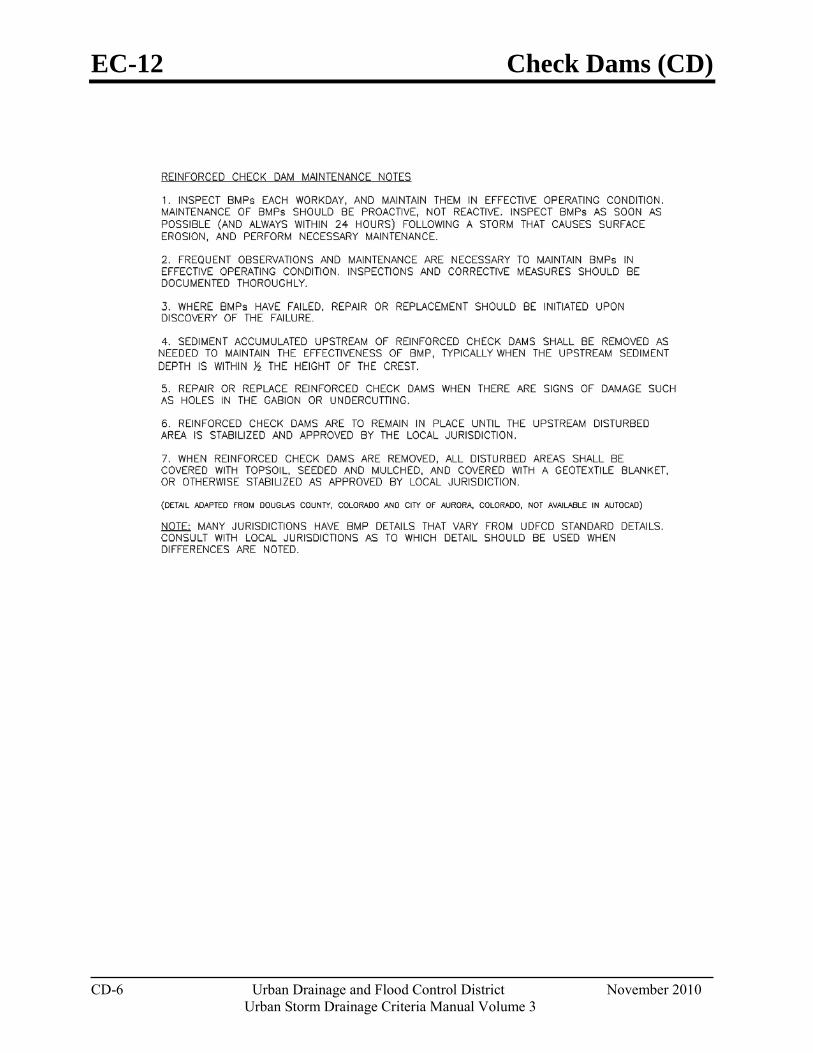
EC-12 Check Dams (CD)
CD-6 Urban Drainage and Flood Control District November 2010
Urban Storm Drainage Criteria Manual Volume 3
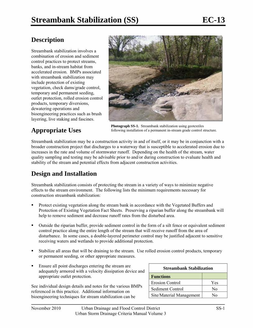
Streambank Stabilization (SS) EC-13
November 2010 Urban Drainage and Flood Control District SS-1 Urban Storm Drainage Criteria Manual Volume 3
Photograph SS-1. Streambank stabilization using geotextiles following installation of a permanent in-stream grade control structure.
Description Streambank stabilization involves a combination of erosion and sediment control practices to protect streams, banks, and in-stream habitat from accelerated erosion. BMPs associated with streambank stabilization may include protection of existing vegetation, check dams/grade control, temporary and permanent seeding, outlet protection, rolled erosion control products, temporary diversions, dewatering operations and bioengineering practices such as brush layering, live staking and fascines.
Appropriate Uses Streambank stabilization may be a construction activity in and of itself, or it may be in conjunction with a broader construction project that discharges to a waterway that is susceptible to accelerated erosion due to increases in the rate and volume of stormwater runoff. Depending on the health of the stream, water quality sampling and testing may be advisable prior to and/or during construction to evaluate health and stability of the stream and potential effects from adjacent construction activities.
Design and Installation Streambank stabilization consists of protecting the stream in a variety of ways to minimize negative effects to the stream environment. The following lists the minimum requirements necessary for construction streambank stabilization:
Protect existing vegetation along the stream bank in accordance with the Vegetated Buffers and Protection of Existing Vegetation Fact Sheets. Preserving a riparian buffer along the streambank will help to remove sediment and decrease runoff rates from the disturbed area.
Outside the riparian buffer, provide sediment control in the form of a silt fence or equivalent sediment control practice along the entire length of the stream that will receive runoff from the area of disturbance. In some cases, a double-layered perimeter control may be justified adjacent to sensitive receiving waters and wetlands to provide additional protection.
Stabilize all areas that will be draining to the stream. Use rolled erosion control products, temporary or permanent seeding, or other appropriate measures.
Ensure all point discharges entering the stream are adequately armored with a velocity dissipation device and appropriate outlet protection.
See individual design details and notes for the various BMPs referenced in this practice. Additional information on bioengineering techniques for stream stabilization can be
Streambank Stabilization
Functions Erosion Control Yes Sediment Control No Site/Material Management No
EC-13 Streambank Stabilization (SS)
SS-2 Urban Drainage and Flood Control District November 2010
Urban Storm Drainage Criteria Manual Volume 3
found in the Major Drainage chapter of Volume 1 and additional guidance on BMPs for working in waterways can be found in UDFCD’s Best Management Practices for Construction in Waterways Training Manual.
Maintenance and Removal Inspect BMPs protecting the stream for damage on a daily basis. Maintain, repair, or replace damaged BMPs following the guidance provided in individual BMP Fact Sheets for practices that are implemented. Some streambank stabilization BMPs are intended to remain in place as vegetation matures (e.g. erosion control blankets protecting seeded stream banks and turf reinforcement mats).
For BMPs that are not to remain in place as a part of final stabilization such as silt fence and other temporary measures, BMPs should be removed when all land disturbing activities have ceased and areas have been permanently stabilized.
Wind Erosion/Dust Control (DC) EC-14
November 2010 Urban Drainage and Flood Control District DC-1 Urban Storm Drainage Criteria Manual Volume 3
Photograph DC-1. Water truck used for dust suppression. Photo courtesy of Douglas County.
Description Wind erosion and dust control BMPs help to keep soil particles from entering the air as a result of land disturbing construction activities. These BMPs include a variety of practices generally focused on either graded disturbed areas or construction roadways. For graded areas, practices such as seeding and mulching, use of soil binders, site watering, or other practices that provide prompt surface cover should be used. For construction roadways, road watering and stabilized surfaces should be considered.
Appropriate Uses Dust control measures should be used on any site where dust poses a problem to air quality. Dust control is important to control for the health of construction workers and surrounding waterbodies.
Design and Installation The following construction BMPs can be used for dust control:
An irrigation/sprinkler system can be used to wet the top layer of disturbed soil to help keep dry soil particles from becoming airborne.
Seeding and mulching can be used to stabilize disturbed surfaces and reduce dust emissions.
Protecting existing vegetation can help to slow wind velocities across the ground surface, thereby limiting the likelihood of soil particles to become airborne.
Spray-on soil binders form a bond between soil particles keeping them grounded. Chemical treatments may require additional permitting requirements. Potential impacts to surrounding waterways and habitat must be considered prior to use.
Placing rock on construction roadways and entrances will help keep dust to a minimum across the construction site.
Wind fences can be installed on site to reduce wind speeds. Install fences perpendicular to the prevailing wind direction for maximum effectiveness.
Maintenance and Removal When using an irrigation/sprinkler control system to aid in dust control, be careful not to overwater. Overwatering will cause construction vehicles to track mud off-site.
Wind Erosion Control/ Dust Control
Functions Erosion Control Yes Sediment Control No Site/Material Management Moderate

Concrete Washout Area (CWA) MM-1
November 2010 Urban Drainage and Flood Control District CWA-1 Urban Storm Drainage Criteria Manual Volume 3
Photograph CWA-1. Example of concrete washout area. Note gravel tracking pad for access and sign.
Description Concrete waste management involves designating and properly managing a specific area of the construction site as a concrete washout area. A concrete washout area can be created using one of several approaches designed to receive wash water from washing of tools and concrete mixer chutes, liquid concrete waste from dump trucks, mobile batch mixers, or pump trucks. Three basic approaches are available: excavation of a pit in the ground, use of an above ground storage area, or use of prefabricated haul-away concrete washout containers. Surface discharges of concrete washout water from construction sites are prohibited.
Appropriate Uses Concrete washout areas must be designated on all sites that will generate concrete wash water or liquid concrete waste from onsite concrete mixing or concrete delivery.
Because pH is a pollutant of concern for washout activities, when unlined pits are used for concrete washout, the soil must have adequate buffering capacity to result in protection of state groundwater standards; otherwise, a liner/containment must be used. The following management practices are recommended to prevent an impact from unlined pits to groundwater:
The use of the washout site should be temporary (less than 1 year), and
The washout site should be not be located in an area where shallow groundwater may be present, such as near natural drainages, springs, or wetlands.
Design and Installation Concrete washout activities must be conducted in a manner that does not contribute pollutants to surface waters or stormwater runoff. Concrete washout areas may be lined or unlined excavated pits in the ground, commercially manufactured prefabricated washout containers, or aboveground holding areas constructed of berms, sandbags or straw bales with a plastic liner.
Although unlined washout areas may be used, lined pits may be required to protect groundwater under certain conditions.
Do not locate an unlined washout area within 400 feet of any natural drainage pathway or waterbody or within 1,000 feet of any wells or drinking water sources. Even for lined concrete washouts, it is advisable to locate the facility away from waterbodies and drainage paths. If site constraints make these
Concrete Washout Area Functions Erosion Control No Sediment Control No Site/Material Management Yes
MM-1 Concrete Washout Area (CWA)
CWA-2 Urban Drainage and Flood Control District November 2010
Urban Storm Drainage Criteria Manual Volume 3
setbacks infeasible or if highly permeable soils exist in the area, then the pit must be installed with an impermeable liner (16 mil minimum thickness) or surface storage alternatives using prefabricated concrete washout devices or a lined aboveground storage area should be used.
Design details with notes are provided in Detail CWA-1 for pits and CWA-2 for aboveground storage areas. Pre-fabricated concrete washout container information can be obtained from vendors.
Maintenance and Removal A key consideration for concrete washout areas is to ensure that adequate signage is in place identifying the location of the washout area. Part of inspecting and maintaining washout areas is ensuring that adequate signage is provided and in good repair and that the washout area is being used, as opposed to washout in non-designated areas of the site.
Remove concrete waste in the washout area, as needed to maintain BMP function (typically when filled to about two-thirds of its capacity). Collect concrete waste and deliver offsite to a designated disposal location.
Upon termination of use of the washout site, accumulated solid waste, including concrete waste and any contaminated soils, must be removed from the site to prevent on-site disposal of solid waste. If the wash water is allowed to evaporate and the concrete hardens, it may be recycled.
Photograph CWA-3. Earthen concrete washout. Photo courtesy of CDOT.
Photograph CWA-2. Prefabricated concrete washout. Photo courtesy of CDOT.
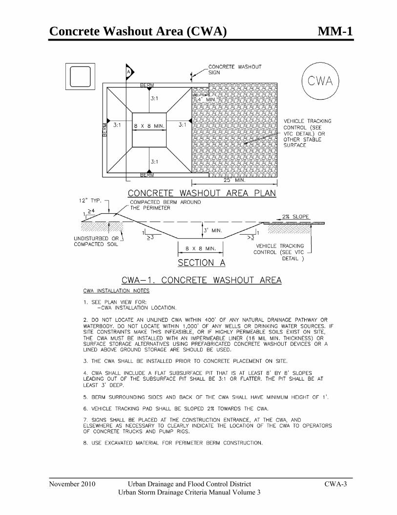
Concrete Washout Area (CWA) MM-1
November 2010 Urban Drainage and Flood Control District CWA-3 Urban Storm Drainage Criteria Manual Volume 3
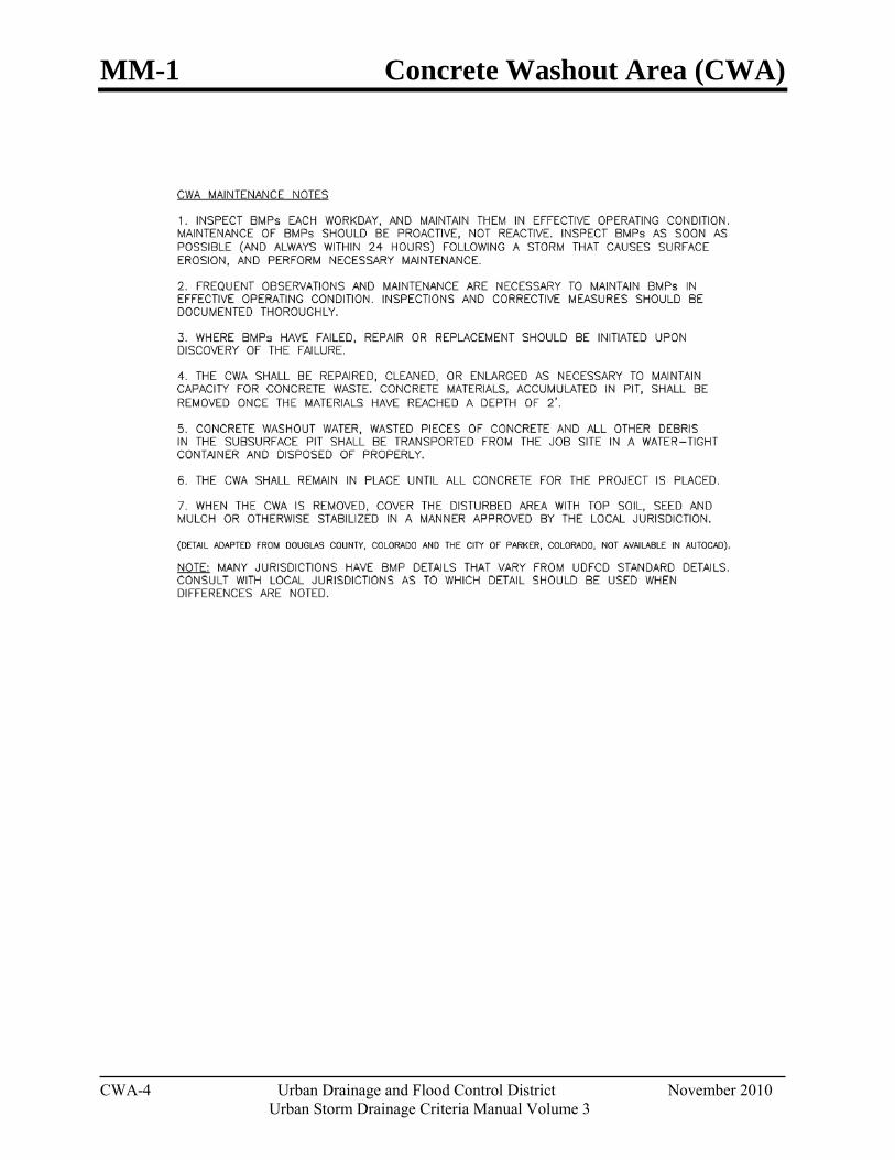
MM-1 Concrete Washout Area (CWA)
CWA-4 Urban Drainage and Flood Control District November 2010
Urban Storm Drainage Criteria Manual Volume 3
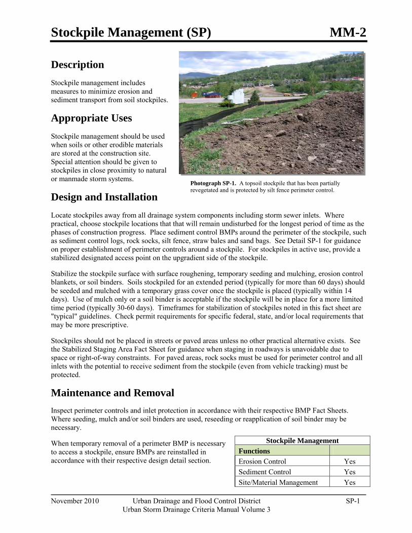
Stockpile Management (SP) MM-2
November 2010 Urban Drainage and Flood Control District SP-1 Urban Storm Drainage Criteria Manual Volume 3
Photograph SP-1. A topsoil stockpile that has been partially revegetated and is protected by silt fence perimeter control.
Description Stockpile management includes measures to minimize erosion and sediment transport from soil stockpiles.
Appropriate Uses Stockpile management should be used when soils or other erodible materials are stored at the construction site. Special attention should be given to stockpiles in close proximity to natural or manmade storm systems.
Design and Installation Locate stockpiles away from all drainage system components including storm sewer inlets. Where practical, choose stockpile locations that that will remain undisturbed for the longest period of time as the phases of construction progress. Place sediment control BMPs around the perimeter of the stockpile, such as sediment control logs, rock socks, silt fence, straw bales and sand bags. See Detail SP-1 for guidance on proper establishment of perimeter controls around a stockpile. For stockpiles in active use, provide a stabilized designated access point on the upgradient side of the stockpile.
Stabilize the stockpile surface with surface roughening, temporary seeding and mulching, erosion control blankets, or soil binders. Soils stockpiled for an extended period (typically for more than 60 days) should be seeded and mulched with a temporary grass cover once the stockpile is placed (typically within 14 days). Use of mulch only or a soil binder is acceptable if the stockpile will be in place for a more limited time period (typically 30-60 days). Timeframes for stabilization of stockpiles noted in this fact sheet are "typical" guidelines. Check permit requirements for specific federal, state, and/or local requirements that may be more prescriptive.
Stockpiles should not be placed in streets or paved areas unless no other practical alternative exists. See the Stabilized Staging Area Fact Sheet for guidance when staging in roadways is unavoidable due to space or right-of-way constraints. For paved areas, rock socks must be used for perimeter control and all inlets with the potential to receive sediment from the stockpile (even from vehicle tracking) must be protected.
Maintenance and Removal Inspect perimeter controls and inlet protection in accordance with their respective BMP Fact Sheets. Where seeding, mulch and/or soil binders are used, reseeding or reapplication of soil binder may be necessary.
When temporary removal of a perimeter BMP is necessary to access a stockpile, ensure BMPs are reinstalled in accordance with their respective design detail section.
Stockpile Management Functions Erosion Control Yes Sediment Control Yes Site/Material Management Yes

MM-2 Stockpile Management (SM)
SP-2 Urban Drainage and Flood Control District November 2010
Urban Storm Drainage Criteria Manual Volume 3
When the stockpile is no longer needed, properly dispose of excess materials and revegetate or otherwise stabilize the ground surface where the stockpile was located.
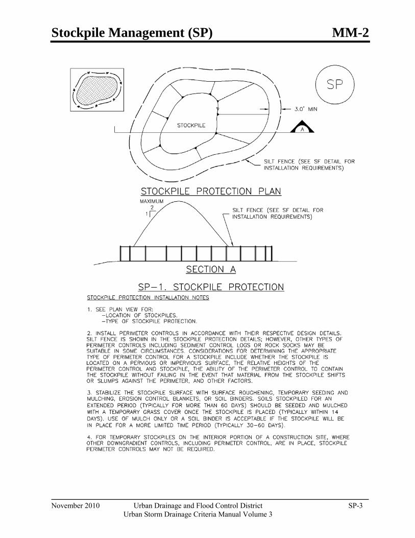
Stockpile Management (SP) MM-2
November 2010 Urban Drainage and Flood Control District SP-3 Urban Storm Drainage Criteria Manual Volume 3
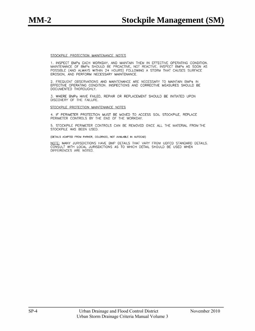
MM-2 Stockpile Management (SM)
SP-4 Urban Drainage and Flood Control District November 2010
Urban Storm Drainage Criteria Manual Volume 3
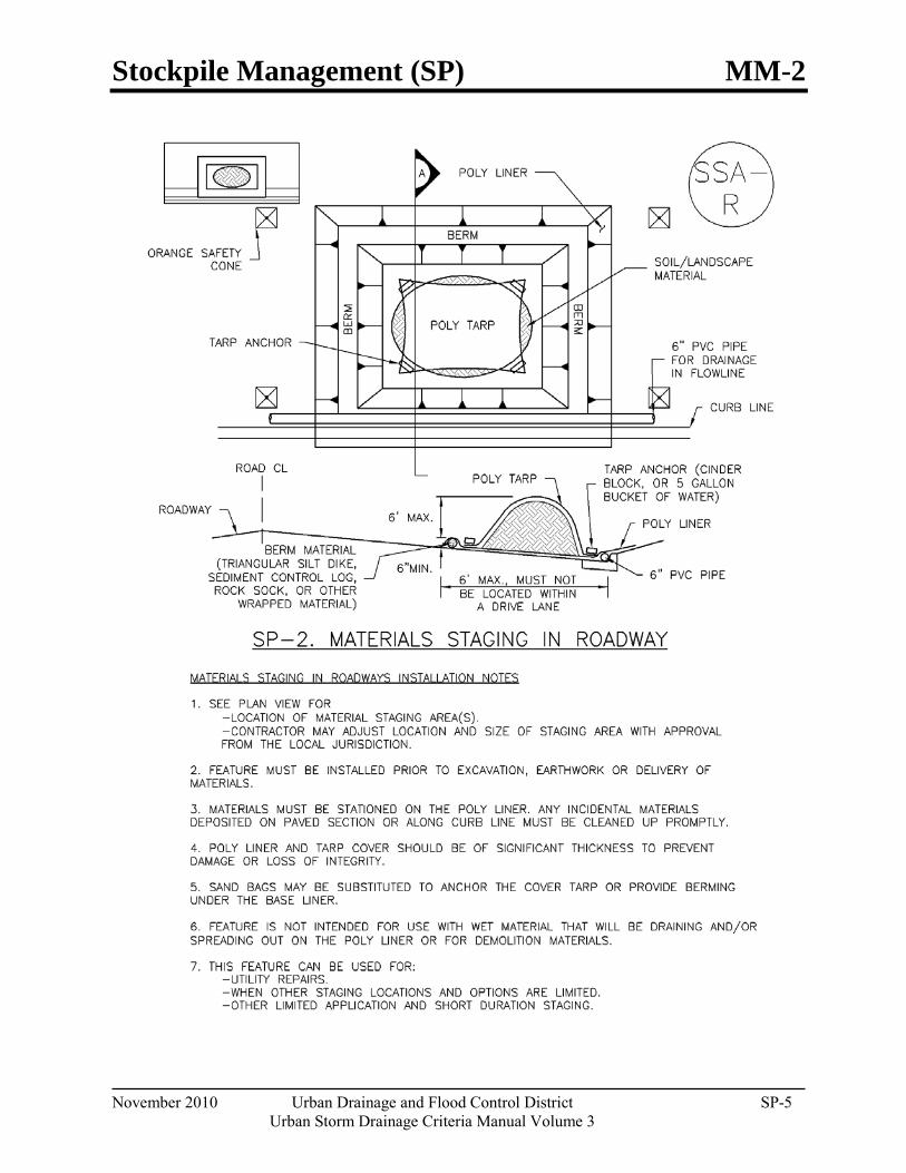
Stockpile Management (SP) MM-2
November 2010 Urban Drainage and Flood Control District SP-5 Urban Storm Drainage Criteria Manual Volume 3
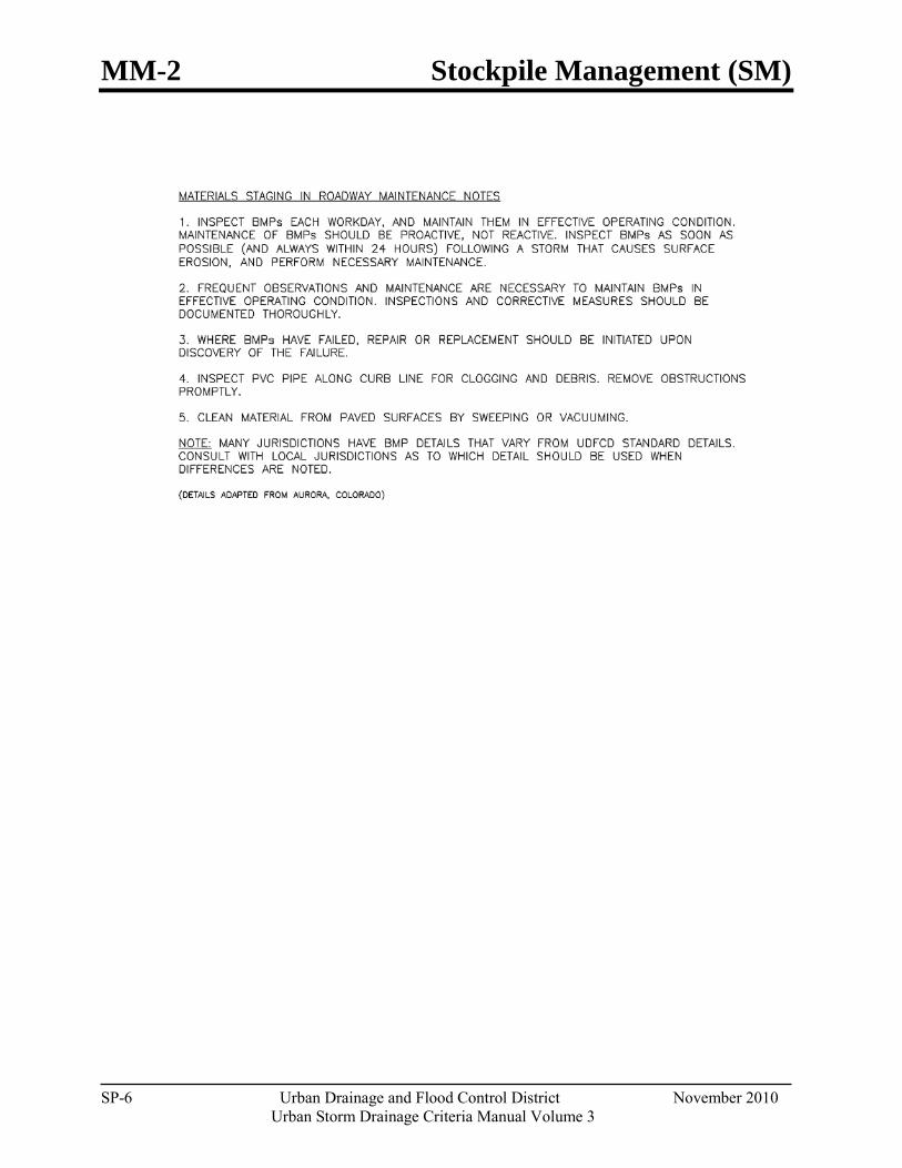
MM-2 Stockpile Management (SM)
SP-6 Urban Drainage and Flood Control District November 2010
Urban Storm Drainage Criteria Manual Volume 3

Good Housekeeping Practices (GH) MM-3
November 2010 Urban Drainage and Flood Control District GH-1 Urban Storm Drainage Criteria Manual Volume 3
Photographs GH-1 and GH-2. Proper materials storage and secondary containment for fuel tanks are important good housekeeping practices. Photos courtesy of CDOT and City of Aurora.
Description Implement construction site good housekeeping practices to prevent pollution associated with solid, liquid and hazardous construction-related materials and wastes. Stormwater Management Plans (SWMPs) should clearly specify BMPs including these good housekeeping practices:
Provide for waste management.
Establish proper building material staging areas.
Designate paint and concrete washout areas.
Establish proper equipment/vehicle fueling and maintenance practices.
Control equipment/vehicle washing and allowable non-stormwater discharges.
Develop a spill prevention and response plan.
Acknowledgement: This Fact Sheet is based directly on EPA guidance provided in Developing Your Stormwater Pollution Prevent Plan (EPA 2007).
Appropriate Uses Good housekeeping practices are necessary at all construction sites.
Design and Installation The following principles and actions should be addressed in SWMPs:
Provide for Waste Management. Implement management procedures and practices to prevent or reduce the exposure and transport of pollutants in stormwater from solid, liquid and sanitary wastes that will be generated at the site. Practices such as trash disposal, recycling, proper material handling, and cleanup measures can reduce the potential for stormwater runoff to pick up construction site wastes and discharge them to surface waters. Implement a comprehensive set of waste-management practices for hazardous or toxic materials, such as paints, solvents, petroleum products, pesticides, wood preservatives, acids, roofing tar, and other materials. Practices should include storage, handling, inventory, and cleanup procedures, in case of spills. Specific practices that should be considered include:
Solid or Construction Waste
o Designate trash and bulk waste-collection areas on-site.
Good Housekeeping
Functions Erosion Control No Sediment Control No Site/Material Management Yes
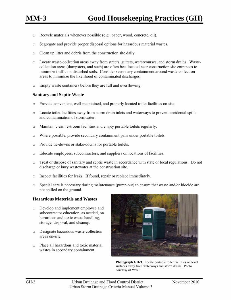
MM-3 Good Housekeeping Practices (GH)
GH-2 Urban Drainage and Flood Control District November 2010
Urban Storm Drainage Criteria Manual Volume 3
Photograph GH-3. Locate portable toilet facilities on level surfaces away from waterways and storm drains. Photo courtesy of WWE.
o Recycle materials whenever possible (e.g., paper, wood, concrete, oil).
o Segregate and provide proper disposal options for hazardous material wastes.
o Clean up litter and debris from the construction site daily.
o Locate waste-collection areas away from streets, gutters, watercourses, and storm drains. Waste-collection areas (dumpsters, and such) are often best located near construction site entrances to minimize traffic on disturbed soils. Consider secondary containment around waste collection areas to minimize the likelihood of contaminated discharges.
o Empty waste containers before they are full and overflowing.
Sanitary and Septic Waste
o Provide convenient, well-maintained, and properly located toilet facilities on-site.
o Locate toilet facilities away from storm drain inlets and waterways to prevent accidental spills and contamination of stormwater.
o Maintain clean restroom facilities and empty portable toilets regularly.
o Where possible, provide secondary containment pans under portable toilets.
o Provide tie-downs or stake-downs for portable toilets.
o Educate employees, subcontractors, and suppliers on locations of facilities.
o Treat or dispose of sanitary and septic waste in accordance with state or local regulations. Do not discharge or bury wastewater at the construction site.
o Inspect facilities for leaks. If found, repair or replace immediately.
o Special care is necessary during maintenance (pump out) to ensure that waste and/or biocide are not spilled on the ground.
Hazardous Materials and Wastes
o Develop and implement employee and subcontractor education, as needed, on hazardous and toxic waste handling, storage, disposal, and cleanup.
o Designate hazardous waste-collection areas on-site.
o Place all hazardous and toxic material wastes in secondary containment.

Good Housekeeping Practices (GH) MM-3
November 2010 Urban Drainage and Flood Control District GH-3 Urban Storm Drainage Criteria Manual Volume 3
o Hazardous waste containers should be inspected to ensure that all containers are labeled properly and that no leaks are present.
Establish Proper Building Material Handling and Staging Areas. The SWMP should include comprehensive handling and management procedures for building materials, especially those that are hazardous or toxic. Paints, solvents, pesticides, fuels and oils, other hazardous materials or building materials that have the potential to contaminate stormwater should be stored indoors or under cover whenever possible or in areas with secondary containment. Secondary containment measures prevent a spill from spreading across the site and may include dikes, berms, curbing, or other containment methods. Secondary containment techniques should also ensure the protection of groundwater. Designate staging areas for activities such as fueling vehicles, mixing paints, plaster, mortar, and other potential pollutants. Designated staging areas enable easier monitoring of the use of materials and clean up of spills. Training employees and subcontractors is essential to the success of this pollution prevention principle. Consider the following specific materials handling and staging practices:
o Train employees and subcontractors in proper handling and storage practices.
o Clearly designate site areas for staging and storage with signs and on construction drawings. Staging areas should be located in areas central to the construction site. Segment the staging area into sub-areas designated for vehicles, equipment, or stockpiles. Construction entrances and exits should be clearly marked so that delivery vehicles enter/exit through stabilized areas with vehicle tracking controls (See Vehicle Tracking Control Fact Sheet).
o Provide storage in accordance with Spill Protection, Control and Countermeasures (SPCC) requirements and plans and provide cover and impermeable perimeter control, as necessary, for hazardous materials and contaminated soils that must be stored on site.
o Ensure that storage containers are regularly inspected for leaks, corrosion, support or foundation failure, or other signs of deterioration and tested for soundness.
o Reuse and recycle construction materials when possible.
Designate Concrete Washout Areas. Concrete contractors should be encouraged to use the washout facilities at their own plants or dispatch facilities when feasible; however, concrete washout commonly occurs on construction sites. If it is necessary to provide for concrete washout areas on-site, designate specific washout areas and design facilities to handle anticipated washout water. Washout areas should also be provided for paint and stucco operations. Because washout areas can be a source of pollutants from leaks or spills, care must be taken with regard to their placement and proper use. See the Concrete Washout Area Fact Sheet for detailed guidance.
Both self-constructed and prefabricated washout containers can fill up quickly when concrete, paint, and stucco work are occurring on large portions of the site. Be sure to check for evidence that contractors are using the washout areas and not dumping materials onto the ground or into drainage facilities. If the washout areas are not being used regularly, consider posting additional signage, relocating the facilities to more convenient locations, or providing training to workers and contractors.
When concrete, paint, or stucco is part of the construction process, consider these practices which will help prevent contamination of stormwater. Include the locations of these areas and the maintenance and inspection procedures in the SWMP.
MM-3 Good Housekeeping Practices (GH)
GH-4 Urban Drainage and Flood Control District November 2010
Urban Storm Drainage Criteria Manual Volume 3
o Do not washout concrete trucks or equipment into storm drains, streets, gutters, uncontained areas, or streams. Only use designated washout areas.
o Establish washout areas and advertise their locations with signs. Ensure that signage remains in good repair.
o Provide adequate containment for the amount of wash water that will be used.
o Inspect washout structures daily to detect leaks or tears and to identify when materials need to be removed.
o Dispose of materials properly. The preferred method is to allow the water to evaporate and to recycle the hardened concrete. Full service companies may provide dewatering services and should dispose of wastewater properly. Concrete wash water can be highly polluted. It should not be discharged to any surface water, storm sewer system, or allowed to infiltrate into the ground in the vicinity of waterbodies. Washwater should not be discharged to a sanitary sewer system without first receiving written permission from the system operator.
Establish Proper Equipment/Vehicle Fueling and Maintenance Practices. Create a clearly designated on-site fueling and maintenance area that is clean and dry. The on-site fueling area should have a spill kit, and staff should know how to use it. If possible, conduct vehicle fueling and maintenance activities in a covered area. Consider the following practices to help prevent the discharge of pollutants to stormwater from equipment/vehicle fueling and maintenance. Include the locations of designated fueling and maintenance areas and inspection and maintenance procedures in the SWMP.
o Train employees and subcontractors in proper fueling procedures (stay with vehicles during fueling, proper use of pumps, emergency shutoff valves, etc.).
o Inspect on-site vehicles and equipment regularly for leaks, equipment damage, and other service problems.
o Clearly designate vehicle/equipment service areas away from drainage facilities and watercourses to prevent stormwater run-on and runoff.
o Use drip pans, drip cloths, or absorbent pads when replacing spent fluids.
o Collect all spent fluids, store in appropriate labeled containers in the proper storage areas, and recycle fluids whenever possible.
Control Equipment/Vehicle Washing and Allowable Non-Stormwater Discharges. Implement practices to prevent contamination of surface and groundwater from equipment and vehicle wash water. Representative practices include:
o Educate employees and subcontractors on proper washing procedures.
o Use off-site washing facilities, when available.
o Clearly mark the washing areas and inform workers that all washing must occur in this area.
o Contain wash water and treat it using BMPs. Infiltrate washwater when possible, but maintain separation from drainage paths and waterbodies.
Good Housekeeping Practices (GH) MM-3
November 2010 Urban Drainage and Flood Control District GH-5 Urban Storm Drainage Criteria Manual Volume 3
o Use high-pressure water spray at vehicle washing facilities without detergents. Water alone can remove most dirt adequately.
o Do not conduct other activities, such as vehicle repairs, in the wash area.
o Include the location of the washing facilities and the inspection and maintenance procedures in the SWMP.
Develop a Spill Prevention and Response Plan. Spill prevention and response procedures must be identified in the SWMP. Representative procedures include identifying ways to reduce the chance of spills, stop the source of spills, contain and clean up spills, dispose of materials contaminated by spills, and train personnel responsible for spill prevention and response. The plan should also specify material handling procedures and storage requirements and ensure that clear and concise spill cleanup procedures are provided and posted for areas in which spills may potentially occur. When developing a spill prevention plan, include the following:
o Note the locations of chemical storage areas, storm drains, tributary drainage areas, surface waterbodies on or near the site, and measures to stop spills from leaving the site.
o Provide proper handling and safety procedures for each type of waste. Keep Material Safety Data Sheets (MSDSs) for chemical used on site with the SWMP.
o Establish an education program for employees and subcontractors on the potential hazards to humans and the environment from spills and leaks.
o Specify how to notify appropriate authorities, such as police and fire departments, hospitals, or municipal sewage treatment facilities to request assistance. Emergency procedures and contact numbers should be provided in the SWMP and posted at storage locations.
o Describe the procedures, equipment and materials for immediate cleanup of spills and proper disposal.
o Identify personnel responsible for implementing the plan in the event of a spill. Update the spill prevention plan and clean up materials as changes occur to the types of chemicals stored and used at the facility.

MM-3 Good Housekeeping Practices (GH)
GH-6 Urban Drainage and Flood Control District November 2010
Urban Storm Drainage Criteria Manual Volume 3
Spill Prevention, Control, and Countermeasure (SPCC) Plan
Construction sites may be subject to 40 CFR Part 112 regulations that require the preparation and implementation of a SPCC Plan to prevent oil spills from aboveground and underground storage tanks. The facility is subject to this rule if it is a non-transportation-related facility that:
Has a total storage capacity greater than 1,320 gallons or a completely buried storage capacity greater than 42,000 gallons.
Could reasonably be expected to discharge oil in quantities that may be harmful to navigable waters of the United States and adjoining shorelines.
Furthermore, if the facility is subject to 40 CFR Part 112, the SWMP should reference the SPCC Plan. To find out more about SPCC Plans, see EPA's website on SPPC at www.epa.gov/oilspill/spcc.htm.
Reporting Oil Spills
In the event of an oil spill, contact the National Response Center toll free at 1-800-424- 8802 for assistance, or for more details, visit their website: www.nrc.uscg.mil.
Maintenance and Removal Effective implementation of good housekeeping practices is dependent on clear designation of personnel responsible for supervising and implementing good housekeeping programs, such as site cleanup and disposal of trash and debris, hazardous material management and disposal, vehicle and equipment maintenance, and other practices. Emergency response "drills" may aid in emergency preparedness.
Checklists may be helpful in good housekeeping efforts.
Staging and storage areas require permanent stabilization when the areas are no longer being used for construction-related activities.
Construction-related materials, debris and waste must be removed from the construction site once construction is complete.
Design Details See the following Fact Sheets for related Design Details:
MM-1 Concrete Washout Area
MM-2 Stockpile Management
SM-4 Vehicle Tracking Control
Design details are not necessary for other good housekeeping practices; however, be sure to designate where specific practices will occur on the appropriate construction drawings.
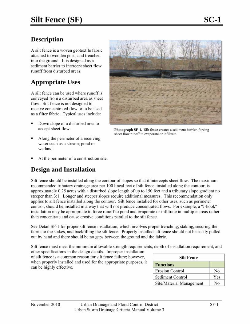
Silt Fence (SF) SC-1
November 2010 Urban Drainage and Flood Control District SF-1 Urban Storm Drainage Criteria Manual Volume 3
Photograph SF-1. Silt fence creates a sediment barrier, forcing sheet flow runoff to evaporate or infiltrate.
Description A silt fence is a woven geotextile fabric attached to wooden posts and trenched into the ground. It is designed as a sediment barrier to intercept sheet flow runoff from disturbed areas.
Appropriate Uses A silt fence can be used where runoff is conveyed from a disturbed area as sheet flow. Silt fence is not designed to receive concentrated flow or to be used as a filter fabric. Typical uses include:
Down slope of a disturbed area to accept sheet flow.
Along the perimeter of a receiving water such as a stream, pond or wetland.
At the perimeter of a construction site.
Design and Installation Silt fence should be installed along the contour of slopes so that it intercepts sheet flow. The maximum recommended tributary drainage area per 100 lineal feet of silt fence, installed along the contour, is approximately 0.25 acres with a disturbed slope length of up to 150 feet and a tributary slope gradient no steeper than 3:1. Longer and steeper slopes require additional measures. This recommendation only applies to silt fence installed along the contour. Silt fence installed for other uses, such as perimeter control, should be installed in a way that will not produce concentrated flows. For example, a "J-hook" installation may be appropriate to force runoff to pond and evaporate or infiltrate in multiple areas rather than concentrate and cause erosive conditions parallel to the silt fence.
See Detail SF-1 for proper silt fence installation, which involves proper trenching, staking, securing the fabric to the stakes, and backfilling the silt fence. Properly installed silt fence should not be easily pulled out by hand and there should be no gaps between the ground and the fabric.
Silt fence must meet the minimum allowable strength requirements, depth of installation requirement, and other specifications in the design details. Improper installation of silt fence is a common reason for silt fence failure; however, when properly installed and used for the appropriate purposes, it can be highly effective.
Silt Fence Functions Erosion Control No Sediment Control Yes Site/Material Management No
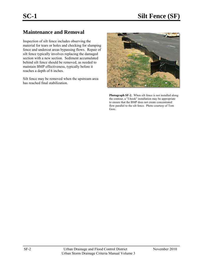
SC-1 Silt Fence (SF)
SF-2 Urban Drainage and Flood Control District November 2010
Urban Storm Drainage Criteria Manual Volume 3
Photograph SF-2. When silt fence is not installed along the contour, a "J-hook" installation may be appropriate to ensure that the BMP does not create concentrated flow parallel to the silt fence. Photo courtesy of Tom Gore.
Maintenance and Removal Inspection of silt fence includes observing the material for tears or holes and checking for slumping fence and undercut areas bypassing flows. Repair of silt fence typically involves replacing the damaged section with a new section. Sediment accumulated behind silt fence should be removed, as needed to maintain BMP effectiveness, typically before it reaches a depth of 6 inches.
Silt fence may be removed when the upstream area has reached final stabilization.
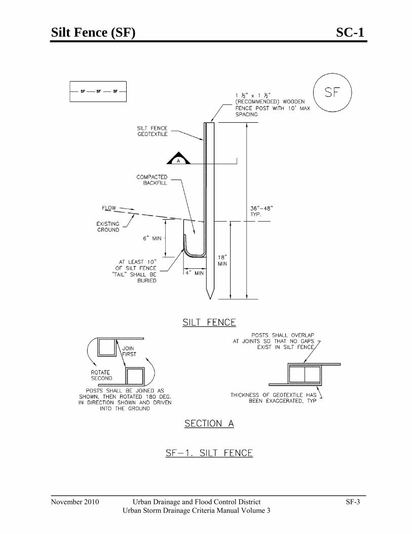
Silt Fence (SF) SC-1
November 2010 Urban Drainage and Flood Control District SF-3 Urban Storm Drainage Criteria Manual Volume 3
SC-1 Silt Fence (SF)
SF-4 Urban Drainage and Flood Control District November 2010
Urban Storm Drainage Criteria Manual Volume 3
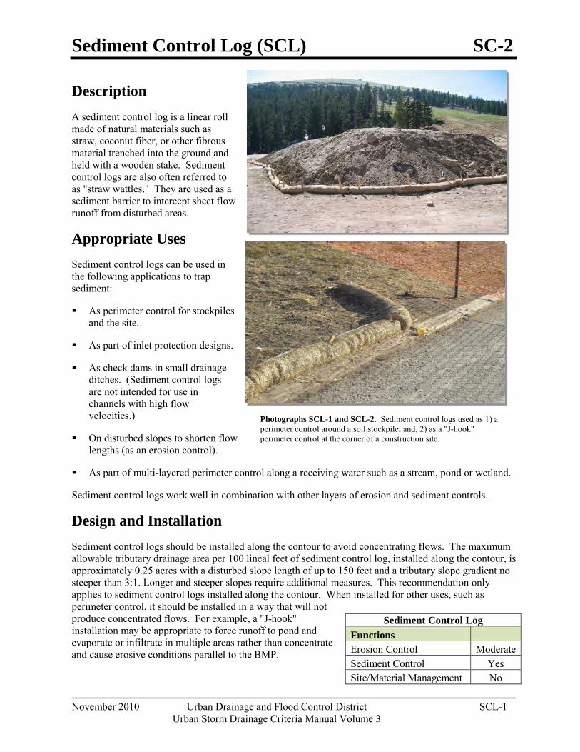
Sediment Control Log (SCL) SC-2
November 2010 Urban Drainage and Flood Control District SCL-1 Urban Storm Drainage Criteria Manual Volume 3
Photographs SCL-1 and SCL-2. Sediment control logs used as 1) a perimeter control around a soil stockpile; and, 2) as a "J-hook" perimeter control at the corner of a construction site.
Description A sediment control log is a linear roll made of natural materials such as straw, coconut fiber, or other fibrous material trenched into the ground and held with a wooden stake. Sediment control logs are also often referred to as "straw wattles." They are used as a sediment barrier to intercept sheet flow runoff from disturbed areas.
Appropriate Uses Sediment control logs can be used in the following applications to trap sediment:
As perimeter control for stockpiles and the site.
As part of inlet protection designs.
As check dams in small drainage ditches. (Sediment control logs are not intended for use in channels with high flow velocities.)
On disturbed slopes to shorten flow lengths (as an erosion control).
As part of multi-layered perimeter control along a receiving water such as a stream, pond or wetland.
Sediment control logs work well in combination with other layers of erosion and sediment controls.
Design and Installation Sediment control logs should be installed along the contour to avoid concentrating flows. The maximum allowable tributary drainage area per 100 lineal feet of sediment control log, installed along the contour, is approximately 0.25 acres with a disturbed slope length of up to 150 feet and a tributary slope gradient no steeper than 3:1. Longer and steeper slopes require additional measures. This recommendation only applies to sediment control logs installed along the contour. When installed for other uses, such as perimeter control, it should be installed in a way that will not produce concentrated flows. For example, a "J-hook" installation may be appropriate to force runoff to pond and evaporate or infiltrate in multiple areas rather than concentrate and cause erosive conditions parallel to the BMP.
Sediment Control Log Functions Erosion Control Moderate Sediment Control Yes Site/Material Management No
SC-2 Sediment Control Log (SCL)
SCL-2 Urban Drainage and Flood Control District November 2010
Urban Storm Drainage Criteria Manual Volume 3
Although sediment control logs initially allow runoff to flow through the BMP, they can quickly become a barrier and should be installed is if they are impermeable.
Design details and notes for sediment control logs are provided in Detail SCL-1. Sediment logs must be properly trenched and staked into the ground to prevent undercutting, bypassing and displacement. When installed on slopes, sediment control logs should be installed along the contours (i.e., perpendicular to flow).
Improper installation can lead to poor performance. Be sure that sediment control logs are properly trenched, anchored and tightly jointed.
Maintenance and Removal Be aware that sediment control logs will eventually degrade. Remove accumulated sediment before the depth is one-half the height of the sediment log and repair damage to the sediment log, typically by replacing the damaged section.
Once the upstream area is stabilized, remove and properly dispose of the logs. Areas disturbed beneath the logs may need to be seeded and mulched. Sediment control logs that are biodegradable may occasionally be left in place (e.g., when logs are used in conjunction with erosion control blankets as permanent slope breaks). However, removal of sediment control logs after final stabilization is typically recommended when used in perimeter control, inlet protection and check dam applications.
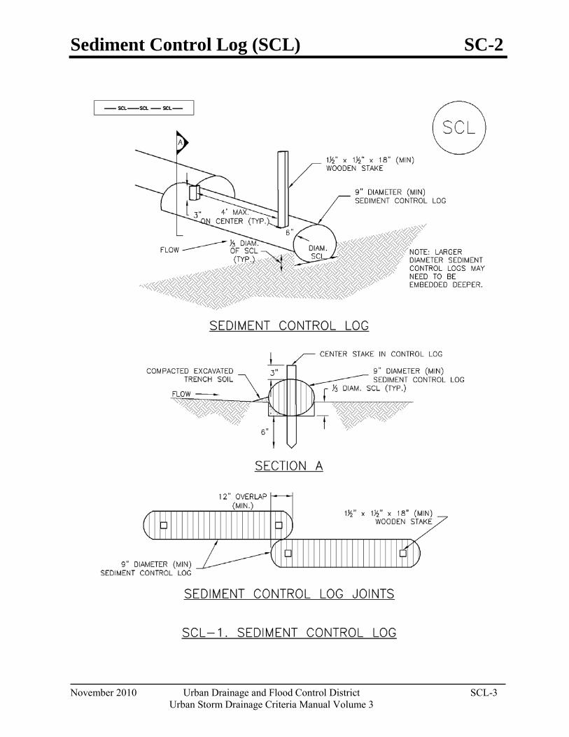
Sediment Control Log (SCL) SC-2
November 2010 Urban Drainage and Flood Control District SCL-3 Urban Storm Drainage Criteria Manual Volume 3
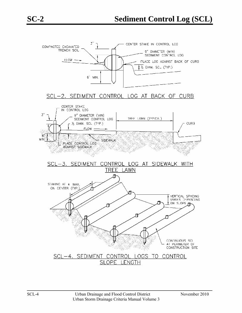
SC-2 Sediment Control Log (SCL)
SCL-4 Urban Drainage and Flood Control District November 2010
Urban Storm Drainage Criteria Manual Volume 3
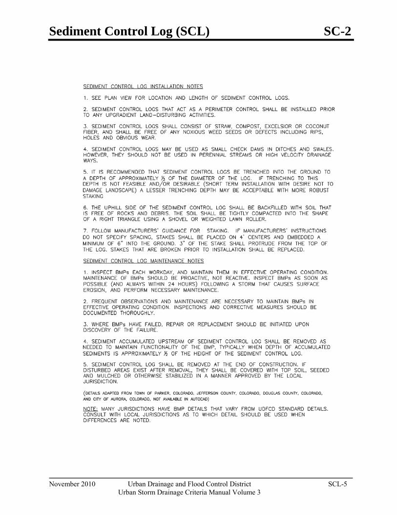
Sediment Control Log (SCL) SC-2
November 2010 Urban Drainage and Flood Control District SCL-5 Urban Storm Drainage Criteria Manual Volume 3

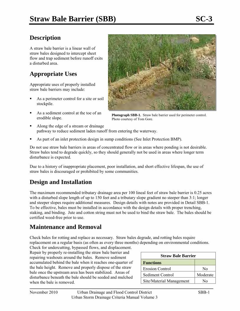
Straw Bale Barrier (SBB) SC-3
November 2010 Urban Drainage and Flood Control District SBB-1 Urban Storm Drainage Criteria Manual Volume 3
Photograph SBB-1. Straw bale barrier used for perimeter control. Photo courtesy of Tom Gore.
Description A straw bale barrier is a linear wall of straw bales designed to intercept sheet flow and trap sediment before runoff exits a disturbed area.
Appropriate Uses Appropriate uses of properly installed straw bale barriers may include:
As a perimeter control for a site or soil stockpile.
As a sediment control at the toe of an erodible slope.
Along the edge of a stream or drainage pathway to reduce sediment laden runoff from entering the waterway.
As part of an inlet protection design in sump conditions (See Inlet Protection BMP).
Do not use straw bale barriers in areas of concentrated flow or in areas where ponding is not desirable. Straw bales tend to degrade quickly, so they should generally not be used in areas where longer term disturbance is expected.
Due to a history of inappropriate placement, poor installation, and short effective lifespan, the use of straw bales is discouraged or prohibited by some communities.
Design and Installation The maximum recommended tributary drainage area per 100 lineal feet of straw bale barrier is 0.25 acres with a disturbed slope length of up to 150 feet and a tributary slope gradient no steeper than 3:1; longer and steeper slopes require additional measures. Design details with notes are provided in Detail SBB-1. To be effective, bales must be installed in accordance with the design details with proper trenching, staking, and binding. Jute and cotton string must not be used to bind the straw bale. The bales should be certified weed-free prior to use.
Maintenance and Removal Check bales for rotting and replace as necessary. Straw bales degrade, and rotting bales require replacement on a regular basis (as often as every three months) depending on environmental conditions. Check for undercutting, bypassed flows, and displacement. Repair by properly re-installing the straw bale barrier and repairing washouts around the bales. Remove sediment accumulated behind the bale when it reaches one-quarter of the bale height. Remove and properly dispose of the straw bale once the upstream area has been stabilized. Areas of disturbance beneath the bale should be seeded and mulched when the bale is removed.
Straw Bale Barrier Functions Erosion Control No Sediment Control Moderate Site/Material Management No
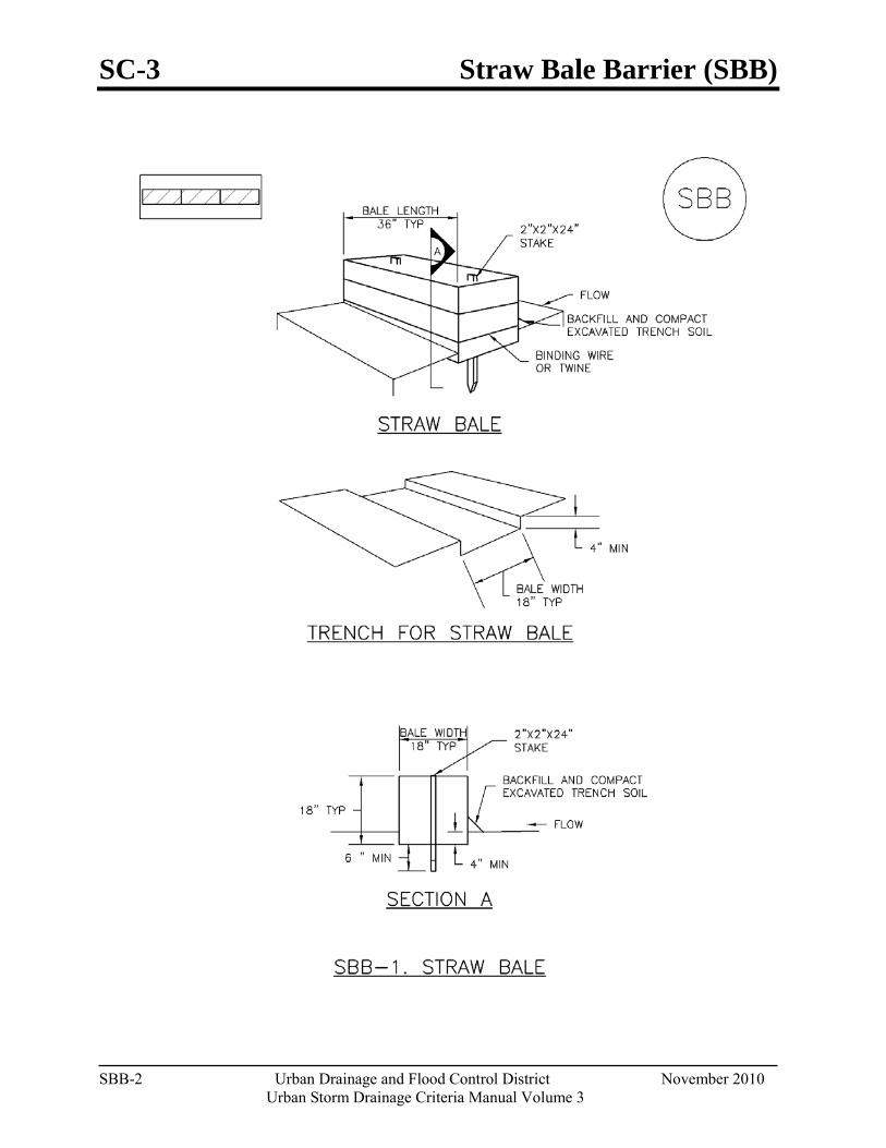
SC-3 Straw Bale Barrier (SBB)
SBB-2 Urban Drainage and Flood Control District November 2010
Urban Storm Drainage Criteria Manual Volume 3
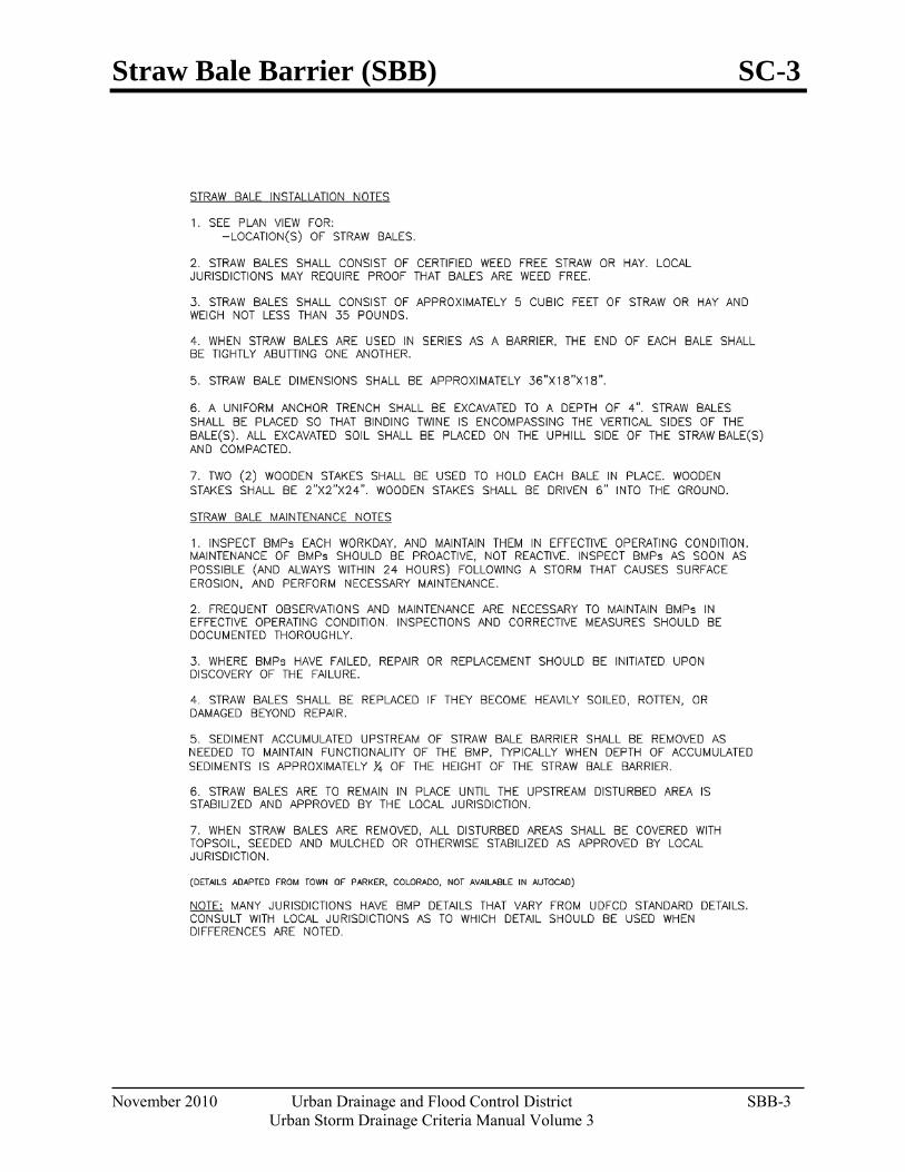
Straw Bale Barrier (SBB) SC-3
November 2010 Urban Drainage and Flood Control District SBB-3 Urban Storm Drainage Criteria Manual Volume 3

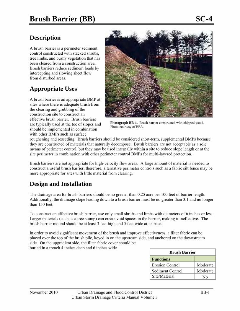
Brush Barrier (BB) SC-4
November 2010 Urban Drainage and Flood Control District BB-1 Urban Storm Drainage Criteria Manual Volume 3
Description A brush barrier is a perimeter sediment control constructed with stacked shrubs, tree limbs, and bushy vegetation that has been cleared from a construction area. Brush barriers reduce sediment loads by intercepting and slowing sheet flow from disturbed areas.
Appropriate Uses A brush barrier is an appropriate BMP at sites where there is adequate brush from the clearing and grubbing of the construction site to construct an effective brush barrier. Brush barriers are typically used at the toe of slopes and should be implemented in combination with other BMPs such as surface roughening and reseeding. Brush barriers should be considered short-term, supplemental BMPs because they are constructed of materials that naturally decompose. Brush barriers are not acceptable as a sole means of perimeter control, but they may be used internally within a site to reduce slope length or at the site perimeter in combination with other perimeter control BMPs for multi-layered protection.
Brush barriers are not appropriate for high-velocity flow areas. A large amount of material is needed to construct a useful brush barrier; therefore, alternative perimeter controls such as a fabric silt fence may be more appropriate for sites with little material from clearing.
Design and Installation The drainage area for brush barriers should be no greater than 0.25 acre per 100 feet of barrier length. Additionally, the drainage slope leading down to a brush barrier must be no greater than 3:1 and no longer than 150 feet.
To construct an effective brush barrier, use only small shrubs and limbs with diameters of 6 inches or less. Larger materials (such as a tree stump) can create void spaces in the barrier, making it ineffective. The brush barrier mound should be at least 3 feet high and 5 feet wide at its base.
In order to avoid significant movement of the brush and improve effectiveness, a filter fabric can be placed over the top of the brush pile, keyed in on the upstream side, and anchored on the downstream side. On the upgradient side, the filter fabric cover should be buried in a trench 4 inches deep and 6 inches wide.
Brush Barrier
Functions Erosion Control Moderate Sediment Control Moderate Site/Material
No
Photograph BB-1. Brush barrier constructed with chipped wood. Photo courtesy of EPA.
SC-4 Brush Barrier (BB)
BB-2 Urban Drainage and Flood Control District November 2010
Urban Storm Drainage Criteria Manual Volume 3
Maintenance and Removal Inspect the brush barrier for voids where concentrated flow or erosion is occurring. Voids in the brush barrier should be filled with additional brush. Accumulated sediment should be removed from the uphill side of the barrier when sediment height reaches one-third of the height of the barrier.
If filter fabric is used, inspect the filter fabric for damage; replace and properly secure it, as needed.
Once the upstream area has been vegetated or stabilized, the brush barrier should be removed and the underlying area revegetated.
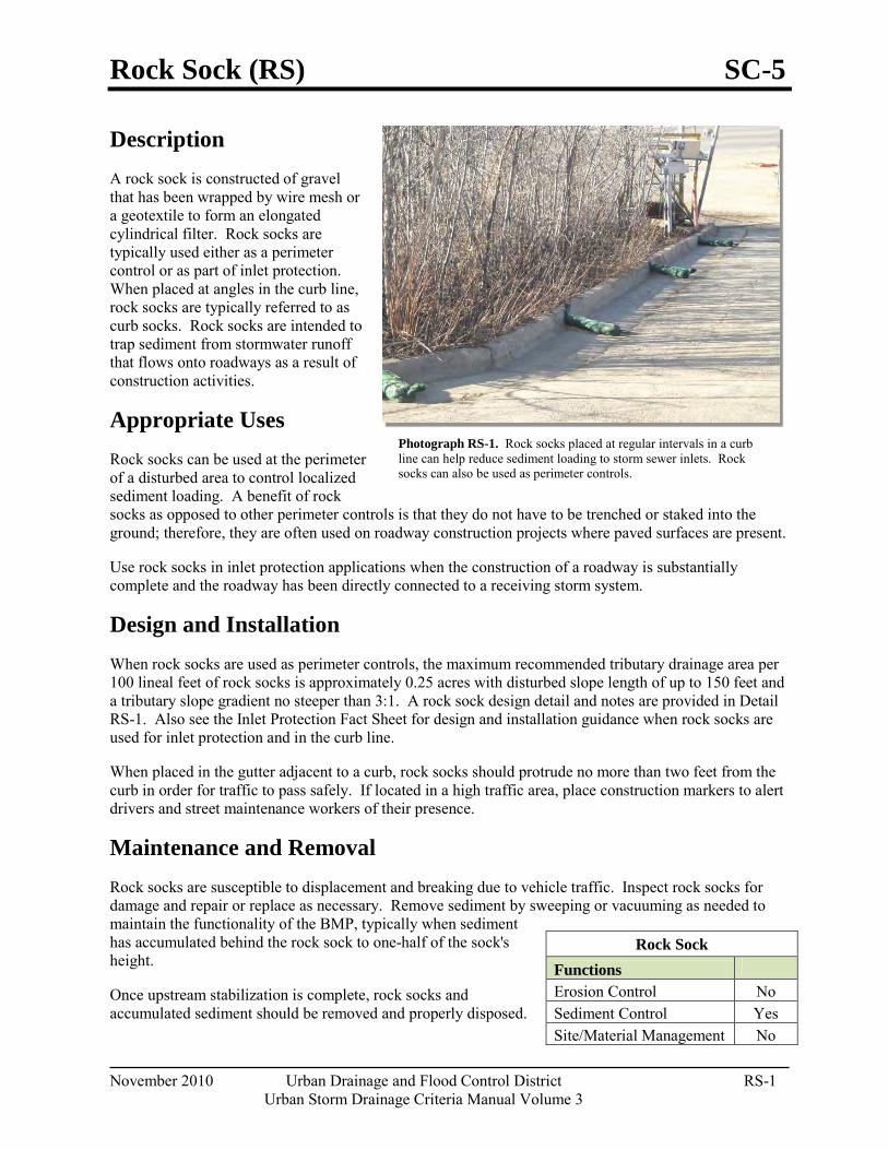
Rock Sock (RS) SC-5
November 2010 Urban Drainage and Flood Control District RS-1 Urban Storm Drainage Criteria Manual Volume 3
Photograph RS-1. Rock socks placed at regular intervals in a curb line can help reduce sediment loading to storm sewer inlets. Rock socks can also be used as perimeter controls.
Description A rock sock is constructed of gravel that has been wrapped by wire mesh or a geotextile to form an elongated cylindrical filter. Rock socks are typically used either as a perimeter control or as part of inlet protection. When placed at angles in the curb line, rock socks are typically referred to as curb socks. Rock socks are intended to trap sediment from stormwater runoff that flows onto roadways as a result of construction activities.
Appropriate Uses Rock socks can be used at the perimeter of a disturbed area to control localized sediment loading. A benefit of rock socks as opposed to other perimeter controls is that they do not have to be trenched or staked into the ground; therefore, they are often used on roadway construction projects where paved surfaces are present.
Use rock socks in inlet protection applications when the construction of a roadway is substantially complete and the roadway has been directly connected to a receiving storm system.
Design and Installation When rock socks are used as perimeter controls, the maximum recommended tributary drainage area per 100 lineal feet of rock socks is approximately 0.25 acres with disturbed slope length of up to 150 feet and a tributary slope gradient no steeper than 3:1. A rock sock design detail and notes are provided in Detail RS-1. Also see the Inlet Protection Fact Sheet for design and installation guidance when rock socks are used for inlet protection and in the curb line.
When placed in the gutter adjacent to a curb, rock socks should protrude no more than two feet from the curb in order for traffic to pass safely. If located in a high traffic area, place construction markers to alert drivers and street maintenance workers of their presence.
Maintenance and Removal Rock socks are susceptible to displacement and breaking due to vehicle traffic. Inspect rock socks for damage and repair or replace as necessary. Remove sediment by sweeping or vacuuming as needed to maintain the functionality of the BMP, typically when sediment has accumulated behind the rock sock to one-half of the sock's height.
Once upstream stabilization is complete, rock socks and accumulated sediment should be removed and properly disposed.
Rock Sock Functions Erosion Control No Sediment Control Yes Site/Material Management No
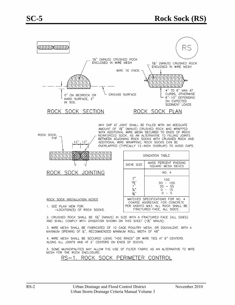
SC-5 Rock Sock (RS)
RS-2 Urban Drainage and Flood Control District November 2010
Urban Storm Drainage Criteria Manual Volume 3
Rock Sock (RS) SC-5
November 2010 Urban Drainage and Flood Control District RS-3 Urban Storm Drainage Criteria Manual Volume 3

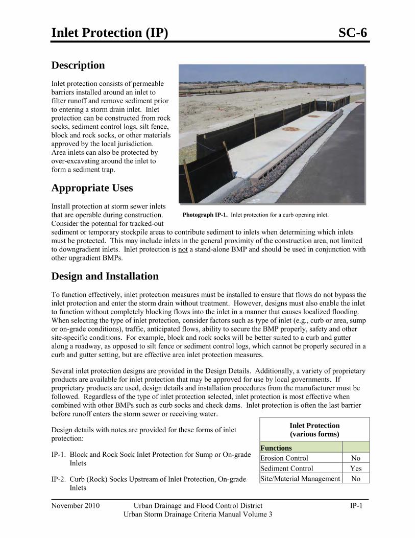
Inlet Protection (IP) SC-6
November 2010 Urban Drainage and Flood Control District IP-1 Urban Storm Drainage Criteria Manual Volume 3
Photograph IP-1. Inlet protection for a curb opening inlet.
Description Inlet protection consists of permeable barriers installed around an inlet to filter runoff and remove sediment prior to entering a storm drain inlet. Inlet protection can be constructed from rock socks, sediment control logs, silt fence, block and rock socks, or other materials approved by the local jurisdiction. Area inlets can also be protected by over-excavating around the inlet to form a sediment trap.
Appropriate Uses Install protection at storm sewer inlets that are operable during construction. Consider the potential for tracked-out sediment or temporary stockpile areas to contribute sediment to inlets when determining which inlets must be protected. This may include inlets in the general proximity of the construction area, not limited to downgradient inlets. Inlet protection is not
Design and Installation
a stand-alone BMP and should be used in conjunction with other upgradient BMPs.
To function effectively, inlet protection measures must be installed to ensure that flows do not bypass the inlet protection and enter the storm drain without treatment. However, designs must also enable the inlet to function without completely blocking flows into the inlet in a manner that causes localized flooding. When selecting the type of inlet protection, consider factors such as type of inlet (e.g., curb or area, sump or on-grade conditions), traffic, anticipated flows, ability to secure the BMP properly, safety and other site-specific conditions. For example, block and rock socks will be better suited to a curb and gutter along a roadway, as opposed to silt fence or sediment control logs, which cannot be properly secured in a curb and gutter setting, but are effective area inlet protection measures.
Several inlet protection designs are provided in the Design Details. Additionally, a variety of proprietary products are available for inlet protection that may be approved for use by local governments. If proprietary products are used, design details and installation procedures from the manufacturer must be followed. Regardless of the type of inlet protection selected, inlet protection is most effective when combined with other BMPs such as curb socks and check dams. Inlet protection is often the last barrier before runoff enters the storm sewer or receiving water.
Design details with notes are provided for these forms of inlet protection:
IP-1. Block and Rock Sock Inlet Protection for Sump or On-grade Inlets
IP-2. Curb (Rock) Socks Upstream of Inlet Protection, On-grade Inlets
Inlet Protection (various forms)
Functions Erosion Control No Sediment Control Yes Site/Material Management No
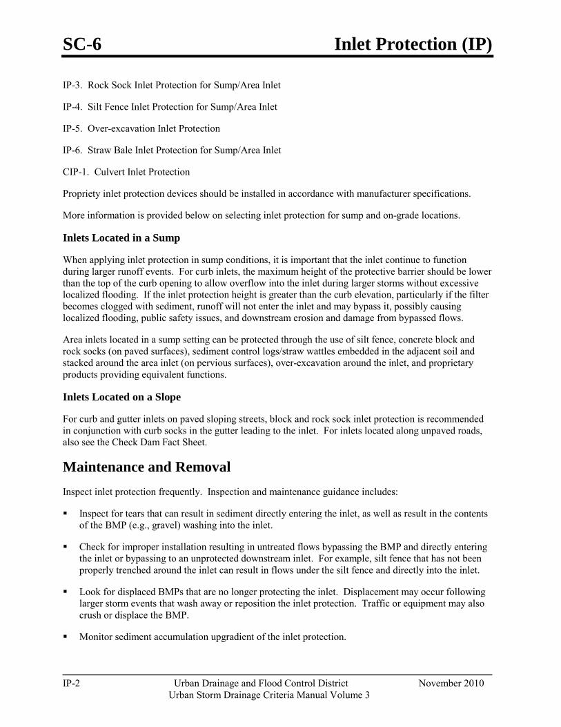
SC-6 Inlet Protection (IP)
IP-2 Urban Drainage and Flood Control District November 2010 Urban Storm Drainage Criteria Manual Volume 3
IP-3. Rock Sock Inlet Protection for Sump/Area Inlet
IP-4. Silt Fence Inlet Protection for Sump/Area Inlet
IP-5. Over-excavation Inlet Protection
IP-6. Straw Bale Inlet Protection for Sump/Area Inlet
CIP-1. Culvert Inlet Protection
Propriety inlet protection devices should be installed in accordance with manufacturer specifications.
More information is provided below on selecting inlet protection for sump and on-grade locations.
Inlets Located in a Sump
When applying inlet protection in sump conditions, it is important that the inlet continue to function during larger runoff events. For curb inlets, the maximum height of the protective barrier should be lower than the top of the curb opening to allow overflow into the inlet during larger storms without excessive localized flooding. If the inlet protection height is greater than the curb elevation, particularly if the filter becomes clogged with sediment, runoff will not enter the inlet and may bypass it, possibly causing localized flooding, public safety issues, and downstream erosion and damage from bypassed flows.
Area inlets located in a sump setting can be protected through the use of silt fence, concrete block and rock socks (on paved surfaces), sediment control logs/straw wattles embedded in the adjacent soil and stacked around the area inlet (on pervious surfaces), over-excavation around the inlet, and proprietary products providing equivalent functions.
Inlets Located on a Slope
For curb and gutter inlets on paved sloping streets, block and rock sock inlet protection is recommended in conjunction with curb socks in the gutter leading to the inlet. For inlets located along unpaved roads, also see the Check Dam Fact Sheet.
Maintenance and Removal Inspect inlet protection frequently. Inspection and maintenance guidance includes:
Inspect for tears that can result in sediment directly entering the inlet, as well as result in the contents of the BMP (e.g., gravel) washing into the inlet.
Check for improper installation resulting in untreated flows bypassing the BMP and directly entering the inlet or bypassing to an unprotected downstream inlet. For example, silt fence that has not been properly trenched around the inlet can result in flows under the silt fence and directly into the inlet.
Look for displaced BMPs that are no longer protecting the inlet. Displacement may occur following larger storm events that wash away or reposition the inlet protection. Traffic or equipment may also crush or displace the BMP.
Monitor sediment accumulation upgradient of the inlet protection.

Inlet Protection (IP) SC-6
November 2010 Urban Drainage and Flood Control District IP-3 Urban Storm Drainage Criteria Manual Volume 3
Remove sediment accumulation from the area upstream of the inlet protection, as needed to maintain BMP effectiveness, typically when it reaches no more than half the storage capacity of the inlet protection. For silt fence, remove sediment when it accumulates to a depth of no more than 6 inches. Remove sediment accumulation from the area upstream of the inlet protection as needed to maintain the functionality of the BMP.
Propriety inlet protection devices should be inspected and maintained in accordance with manufacturer specifications. If proprietary inlet insert devices are used, sediment should be removed in a timely manner to prevent devices from breaking and spilling sediment into the storm drain.
Inlet protection must be removed and properly disposed of when the drainage area for the inlet has reached final stabilization.
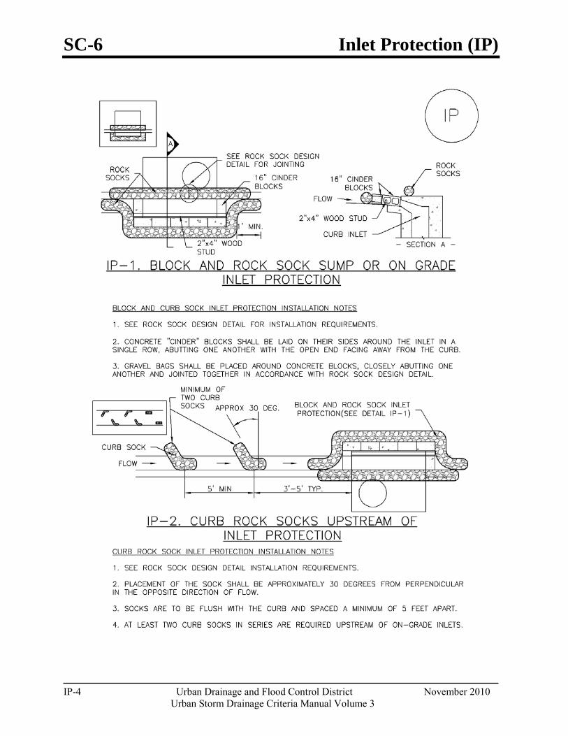
SC-6 Inlet Protection (IP)
IP-4 Urban Drainage and Flood Control District November 2010 Urban Storm Drainage Criteria Manual Volume 3
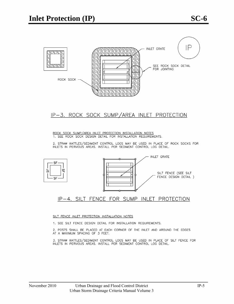
Inlet Protection (IP) SC-6
November 2010 Urban Drainage and Flood Control District IP-5 Urban Storm Drainage Criteria Manual Volume 3
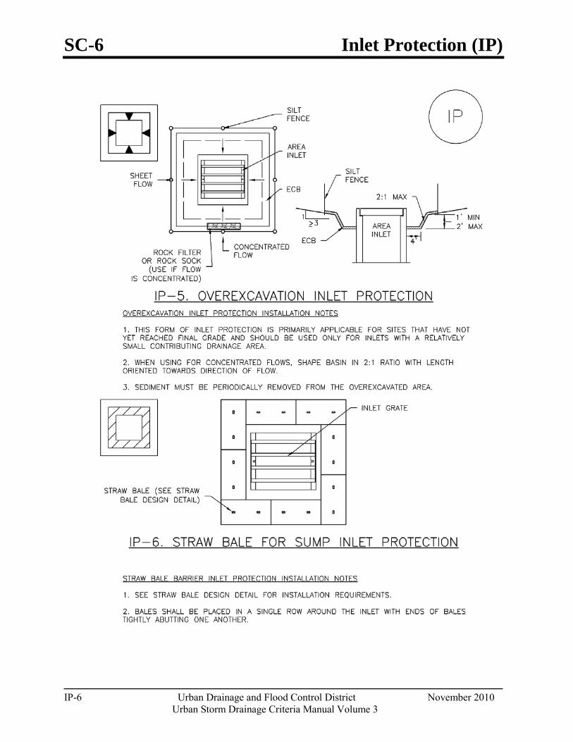
SC-6 Inlet Protection (IP)
IP-6 Urban Drainage and Flood Control District November 2010 Urban Storm Drainage Criteria Manual Volume 3
Inlet Protection (IP) SC-6
November 2010 Urban Drainage and Flood Control District IP-7 Urban Storm Drainage Criteria Manual Volume 3

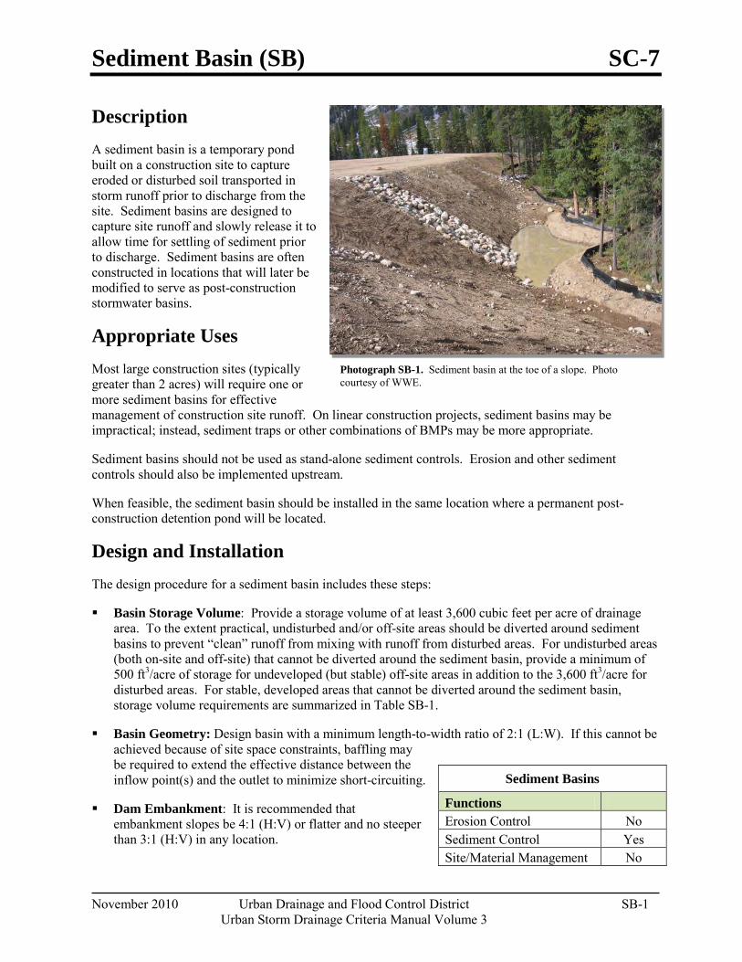
Sediment Basin (SB) SC-7
November 2010 Urban Drainage and Flood Control District SB-1 Urban Storm Drainage Criteria Manual Volume 3
Photograph SB-1. Sediment basin at the toe of a slope. Photo courtesy of WWE.
Description A sediment basin is a temporary pond built on a construction site to capture eroded or disturbed soil transported in storm runoff prior to discharge from the site. Sediment basins are designed to capture site runoff and slowly release it to allow time for settling of sediment prior to discharge. Sediment basins are often constructed in locations that will later be modified to serve as post-construction stormwater basins.
Appropriate Uses Most large construction sites (typically greater than 2 acres) will require one or more sediment basins for effective management of construction site runoff. On linear construction projects, sediment basins may be impractical; instead, sediment traps or other combinations of BMPs may be more appropriate.
Sediment basins should not be used as stand-alone sediment controls. Erosion and other sediment controls should also be implemented upstream.
When feasible, the sediment basin should be installed in the same location where a permanent post-construction detention pond will be located.
Design and Installation The design procedure for a sediment basin includes these steps:
Basin Storage Volume: Provide a storage volume of at least 3,600 cubic feet per acre of drainage area. To the extent practical, undisturbed and/or off-site areas should be diverted around sediment basins to prevent “clean” runoff from mixing with runoff from disturbed areas. For undisturbed areas (both on-site and off-site) that cannot be diverted around the sediment basin, provide a minimum of 500 ft3/acre of storage for undeveloped (but stable) off-site areas in addition to the 3,600 ft3/acre for disturbed areas. For stable, developed areas that cannot be diverted around the sediment basin, storage volume requirements are summarized in Table SB-1.
Basin Geometry: Design basin with a minimum length-to-width ratio of 2:1 (L:W). If this cannot be achieved because of site space constraints, baffling may be required to extend the effective distance between the inflow point(s) and the outlet to minimize short-circuiting.
Dam Embankment: It is recommended that embankment slopes be 4:1 (H:V) or flatter and no steeper than 3:1 (H:V) in any location.
Sediment Basins
Functions Erosion Control No Sediment Control Yes Site/Material Management No
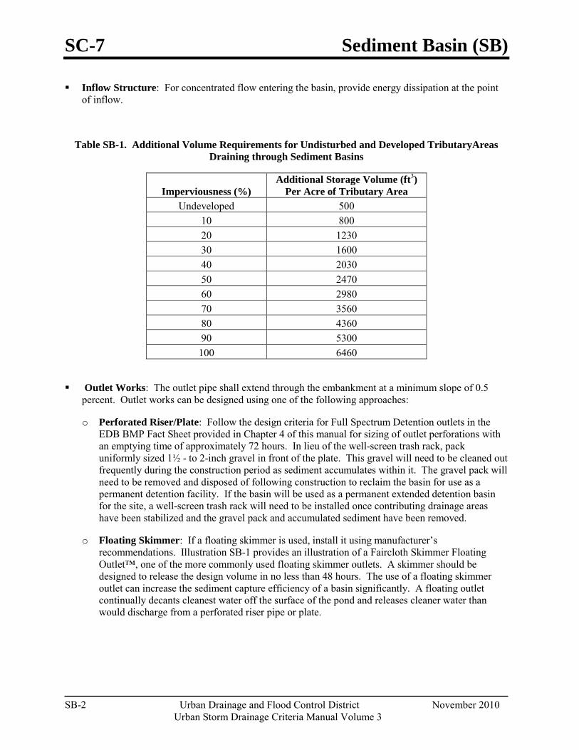
SC-7 Sediment Basin (SB)
SB-2 Urban Drainage and Flood Control District November 2010
Urban Storm Drainage Criteria Manual Volume 3
Inflow Structure: For concentrated flow entering the basin, provide energy dissipation at the point of inflow.
Table SB-1. Additional Volume Requirements for Undisturbed and Developed TributaryAreas Draining through Sediment Basins
Imperviousness (%) Additional Storage Volume (ft3)
Per Acre of Tributary Area Undeveloped 500
10 800 20 1230 30 1600 40 2030 50 2470 60 2980 70 3560 80 4360 90 5300 100 6460
Outlet Works: The outlet pipe shall extend through the embankment at a minimum slope of 0.5 percent. Outlet works can be designed using one of the following approaches:
o Perforated Riser/Plate: Follow the design criteria for Full Spectrum Detention outlets in the EDB BMP Fact Sheet provided in Chapter 4 of this manual for sizing of outlet perforations with an emptying time of approximately 72 hours. In lieu of the well-screen trash rack, pack uniformly sized 1½ - to 2-inch gravel in front of the plate. This gravel will need to be cleaned out frequently during the construction period as sediment accumulates within it. The gravel pack will need to be removed and disposed of following construction to reclaim the basin for use as a permanent detention facility. If the basin will be used as a permanent extended detention basin for the site, a well-screen trash rack will need to be installed once contributing drainage areas have been stabilized and the gravel pack and accumulated sediment have been removed.
o Floating Skimmer: If a floating skimmer is used, install it using manufacturer’s recommendations. Illustration SB-1 provides an illustration of a Faircloth Skimmer Floating Outlet™, one of the more commonly used floating skimmer outlets. A skimmer should be designed to release the design volume in no less than 48 hours. The use of a floating skimmer outlet can increase the sediment capture efficiency of a basin significantly. A floating outlet continually decants cleanest water off the surface of the pond and releases cleaner water than would discharge from a perforated riser pipe or plate.
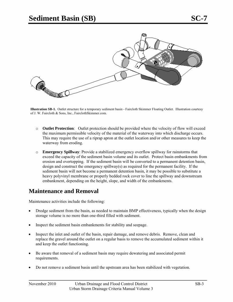
Sediment Basin (SB) SC-7
November 2010 Urban Drainage and Flood Control District SB-3 Urban Storm Drainage Criteria Manual Volume 3
Illustration SB-1. Outlet structure for a temporary sediment basin - Faircloth Skimmer Floating Outlet. Illustration courtesy of J. W. Faircloth & Sons, Inc., FairclothSkimmer.com.
o Outlet Protection: Outlet protection should be provided where the velocity of flow will exceed the maximum permissible velocity of the material of the waterway into which discharge occurs. This may require the use of a riprap apron at the outlet location and/or other measures to keep the waterway from eroding.
o Emergency Spillway: Provide a stabilized emergency overflow spillway for rainstorms that exceed the capacity of the sediment basin volume and its outlet. Protect basin embankments from erosion and overtopping. If the sediment basin will be converted to a permanent detention basin, design and construct the emergency spillway(s) as required for the permanent facility. If the sediment basin will not become a permanent detention basin, it may be possible to substitute a heavy polyvinyl membrane or properly bedded rock cover to line the spillway and downstream embankment, depending on the height, slope, and width of the embankments.
Maintenance and Removal Maintenance activities include the following:
• Dredge sediment from the basin, as needed to maintain BMP effectiveness, typically when the design storage volume is no more than one-third filled with sediment.
• Inspect the sediment basin embankments for stability and seepage.
• Inspect the inlet and outlet of the basin, repair damage, and remove debris. Remove, clean and replace the gravel around the outlet on a regular basis to remove the accumulated sediment within it and keep the outlet functioning.
• Be aware that removal of a sediment basin may require dewatering and associated permit requirements.
• Do not remove a sediment basin until the upstream area has been stabilized with vegetation.
SC-7 Sediment Basin (SB)
SB-4 Urban Drainage and Flood Control District November 2010
Urban Storm Drainage Criteria Manual Volume 3
Final disposition of the sediment basin depends on whether the basin will be converted to a permanent post-construction stormwater basin or whether the basin area will be returned to grade. For basins being converted to permanent detention basins, remove accumulated sediment and reconfigure the basin and outlet to meet the requirements of the final design for the detention facility. If the sediment basin is not to be used as a permanent detention facility, fill the excavated area with soil and stabilize with vegetation.
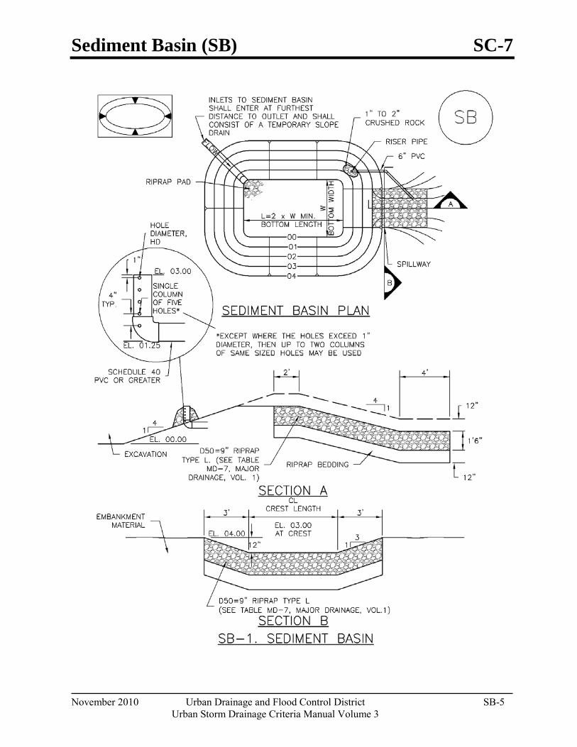
Sediment Basin (SB) SC-7
November 2010 Urban Drainage and Flood Control District SB-5 Urban Storm Drainage Criteria Manual Volume 3
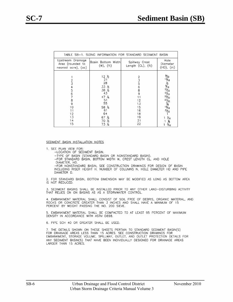
SC-7 Sediment Basin (SB)
SB-6 Urban Drainage and Flood Control District November 2010
Urban Storm Drainage Criteria Manual Volume 3
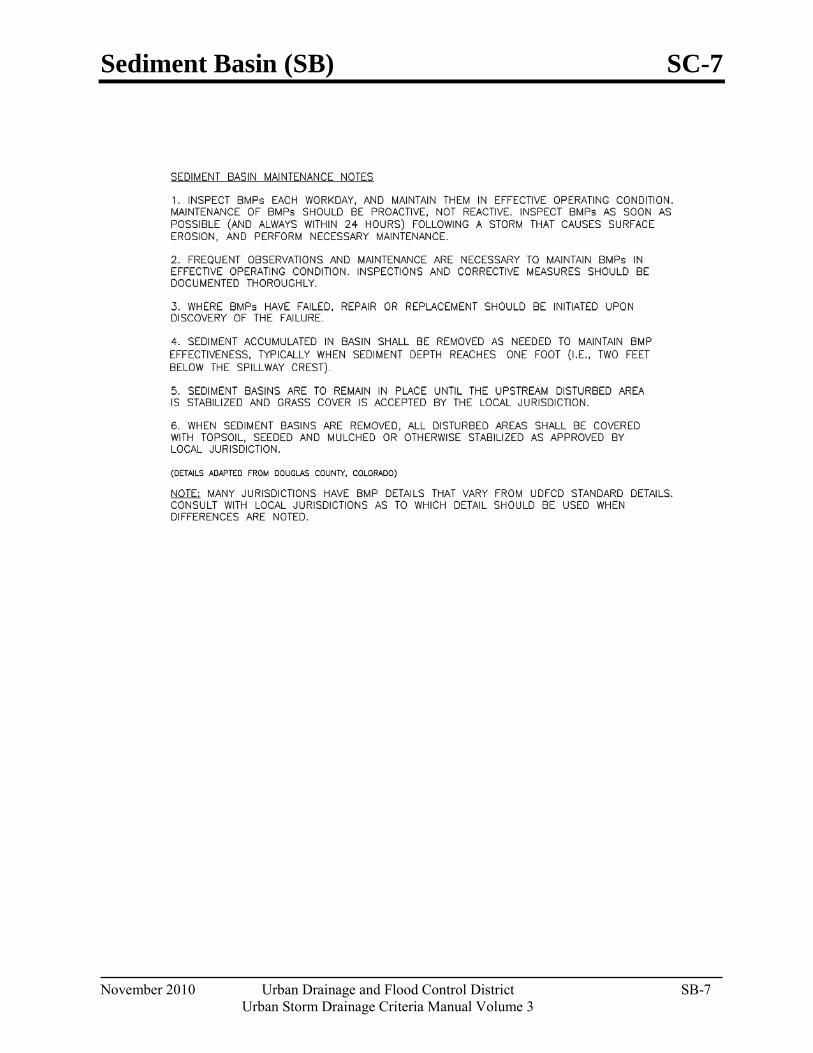
Sediment Basin (SB) SC-7
November 2010 Urban Drainage and Flood Control District SB-7 Urban Storm Drainage Criteria Manual Volume 3

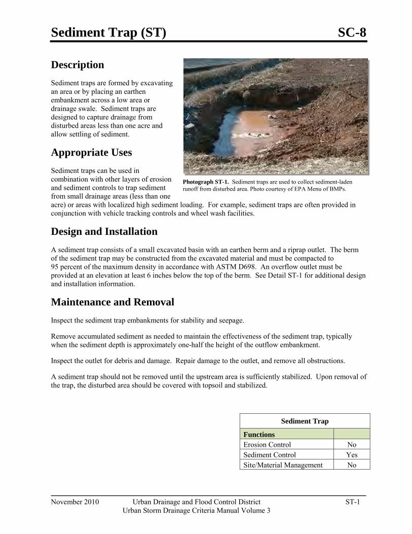
Sediment Trap (ST) SC-8
November 2010 Urban Drainage and Flood Control District ST-1 Urban Storm Drainage Criteria Manual Volume 3
Photograph ST-1. Sediment traps are used to collect sediment-laden runoff from disturbed area. Photo courtesy of EPA Menu of BMPs.
Description Sediment traps are formed by excavating an area or by placing an earthen embankment across a low area or drainage swale. Sediment traps are designed to capture drainage from disturbed areas less than one acre and allow settling of sediment.
Appropriate Uses Sediment traps can be used in combination with other layers of erosion and sediment controls to trap sediment from small drainage areas (less than one acre) or areas with localized high sediment loading. For example, sediment traps are often provided in conjunction with vehicle tracking controls and wheel wash facilities.
Design and Installation A sediment trap consists of a small excavated basin with an earthen berm and a riprap outlet. The berm of the sediment trap may be constructed from the excavated material and must be compacted to 95 percent of the maximum density in accordance with ASTM D698. An overflow outlet must be provided at an elevation at least 6 inches below the top of the berm. See Detail ST-1 for additional design and installation information.
Maintenance and Removal Inspect the sediment trap embankments for stability and seepage.
Remove accumulated sediment as needed to maintain the effectiveness of the sediment trap, typically when the sediment depth is approximately one-half the height of the outflow embankment.
Inspect the outlet for debris and damage. Repair damage to the outlet, and remove all obstructions.
A sediment trap should not be removed until the upstream area is sufficiently stabilized. Upon removal of the trap, the disturbed area should be covered with topsoil and stabilized.
Sediment Trap
Functions Erosion Control No Sediment Control Yes Site/Material Management No
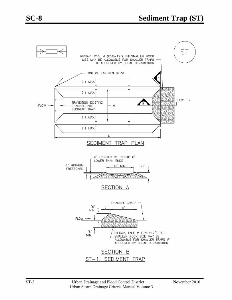
SC-8 Sediment Trap (ST)
ST-2 Urban Drainage and Flood Control District November 2010
Urban Storm Drainage Criteria Manual Volume 3
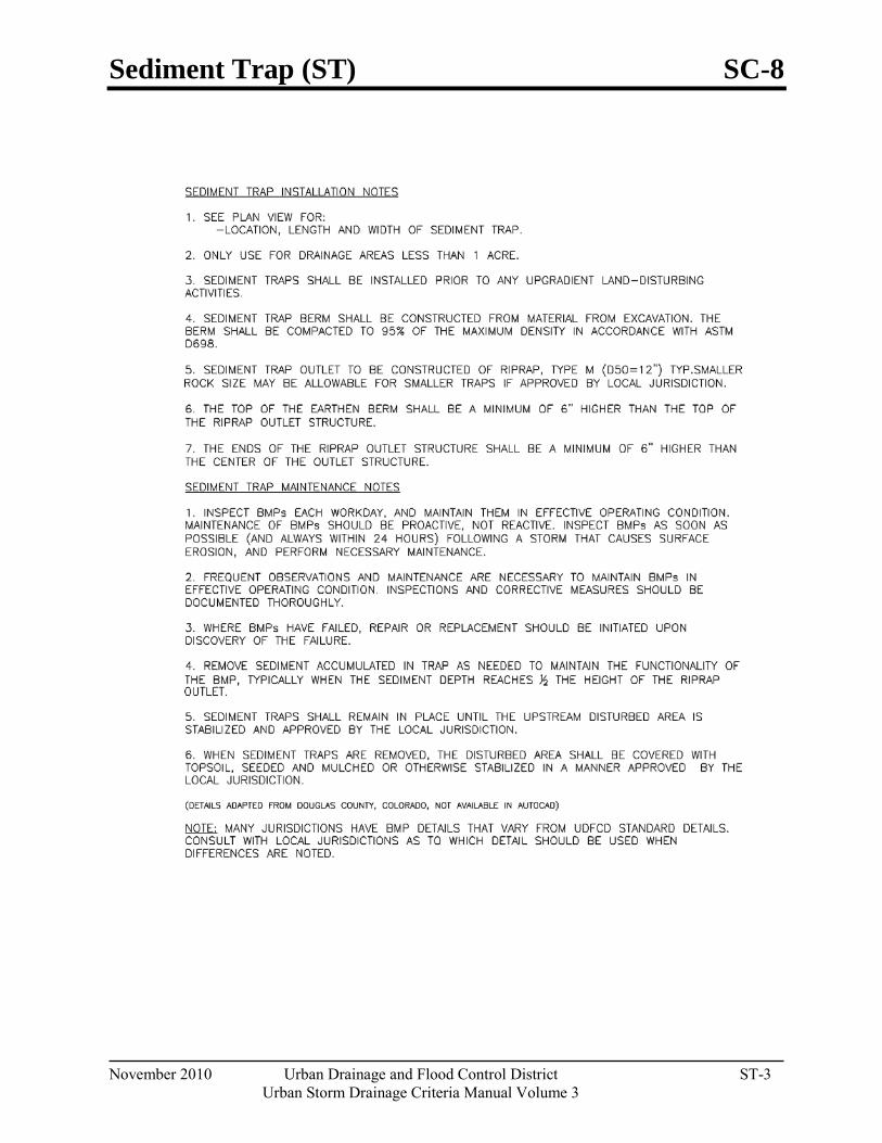
Sediment Trap (ST) SC-8
November 2010 Urban Drainage and Flood Control District ST-3 Urban Storm Drainage Criteria Manual Volume 3

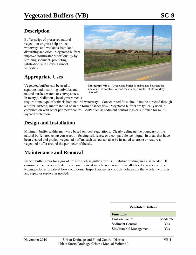
Vegetated Buffers (VB) SC-9
November 2010 Urban Drainage and Flood Control District VB-1 Urban Storm Drainage Criteria Manual Volume 3
Photograph VB-1. A vegetated buffer is maintained between the area of active construction and the drainage swale. Photo courtesy of WWE.
Description Buffer strips of preserved natural vegetation or grass help protect waterways and wetlands from land disturbing activities. Vegetated buffers improve stormwater runoff quality by straining sediment, promoting infiltration, and slowing runoff velocities.
Appropriate Uses Vegetated buffers can be used to separate land disturbing activities and natural surface waters or conveyances. In many jurisdictions, local governments require some type of setback from natural waterways. Concentrated flow should not be directed through a buffer; instead, runoff should be in the form of sheet flow. Vegetated buffers are typically used in combination with other perimeter control BMPs such as sediment control logs or silt fence for multi-layered protection.
Design and Installation Minimum buffer widths may vary based on local regulations. Clearly delineate the boundary of the natural buffer area using construction fencing, silt fence, or a comparable technique. In areas that have been cleared and graded, vegetated buffers such as sod can also be installed to create or restore a vegetated buffer around the perimeter of the site.
Maintenance and Removal Inspect buffer areas for signs of erosion such as gullies or rills. Stabilize eroding areas, as needed. If erosion is due to concentrated flow conditions, it may be necessary to install a level spreader or other technique to restore sheet flow conditions. Inspect perimeter controls delineating the vegetative buffer and repair or replace as needed.
Vegetated Buffers
Functions Erosion Control Moderate Sediment Control Yes Site/Material Management Yes

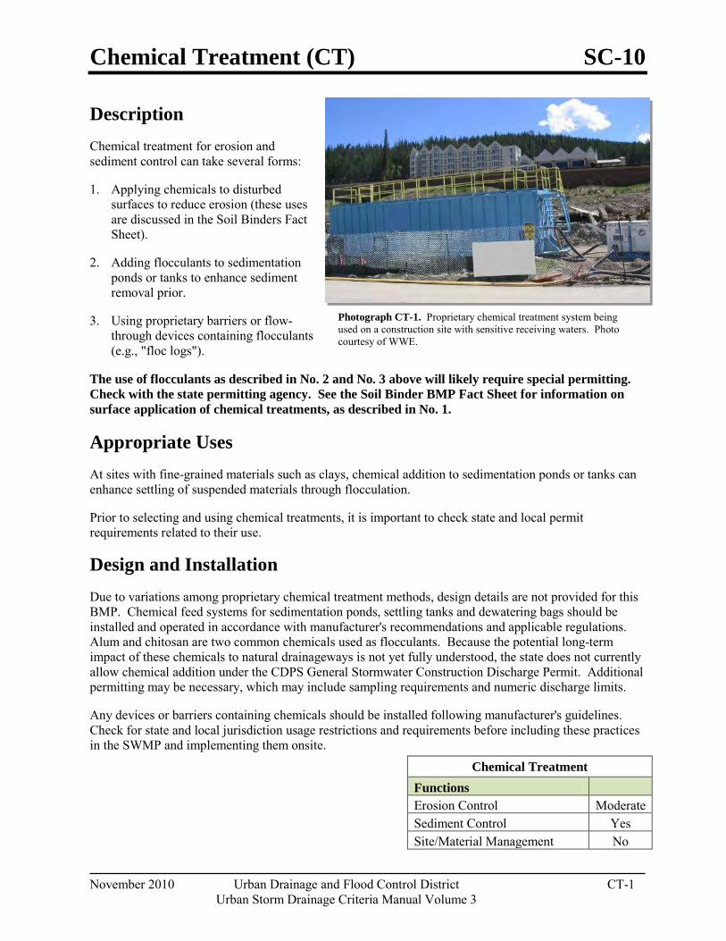
Chemical Treatment (CT) SC-10
November 2010 Urban Drainage and Flood Control District CT-1 Urban Storm Drainage Criteria Manual Volume 3
Photograph CT-1. Proprietary chemical treatment system being used on a construction site with sensitive receiving waters. Photo courtesy of WWE.
Description Chemical treatment for erosion and sediment control can take several forms:
1. Applying chemicals to disturbed surfaces to reduce erosion (these uses are discussed in the Soil Binders Fact Sheet).
2. Adding flocculants to sedimentation ponds or tanks to enhance sediment removal prior.
3. Using proprietary barriers or flow-through devices containing flocculants (e.g., "floc logs").
The use of flocculants as described in No. 2 and No. 3 above will likely require special permitting. Check with the state permitting agency. See the Soil Binder BMP Fact Sheet for information on surface application of chemical treatments, as described in No. 1.
Appropriate Uses At sites with fine-grained materials such as clays, chemical addition to sedimentation ponds or tanks can enhance settling of suspended materials through flocculation.
Prior to selecting and using chemical treatments, it is important to check state and local permit requirements related to their use.
Design and Installation Due to variations among proprietary chemical treatment methods, design details are not provided for this BMP. Chemical feed systems for sedimentation ponds, settling tanks and dewatering bags should be installed and operated in accordance with manufacturer's recommendations and applicable regulations. Alum and chitosan are two common chemicals used as flocculants. Because the potential long-term impact of these chemicals to natural drainageways is not yet fully understood, the state does not currently allow chemical addition under the CDPS General Stormwater Construction Discharge Permit. Additional permitting may be necessary, which may include sampling requirements and numeric discharge limits.
Any devices or barriers containing chemicals should be installed following manufacturer's guidelines. Check for state and local jurisdiction usage restrictions and requirements before including these practices in the SWMP and implementing them onsite.
Chemical Treatment Functions Erosion Control Moderate Sediment Control Yes Site/Material Management No
SC-10 Chemical Treatment (CT)
CT-2 Urban Drainage and Flood Control District November 2010
Urban Storm Drainage Criteria Manual Volume 3
Maintenance and Removal Chemical feed systems for sedimentation ponds or tanks should be maintained in accordance with manufacturer's recommendations and removed when the systems are no longer being used. Accumulated sediment should be dried and disposed of either at a landfill or in accordance with applicable regulations.
Barriers and devices containing chemicals should be removed and replaced when tears or other damage to the devices are observed. These barriers should be removed and properly disposed of when the site has been stabilized.
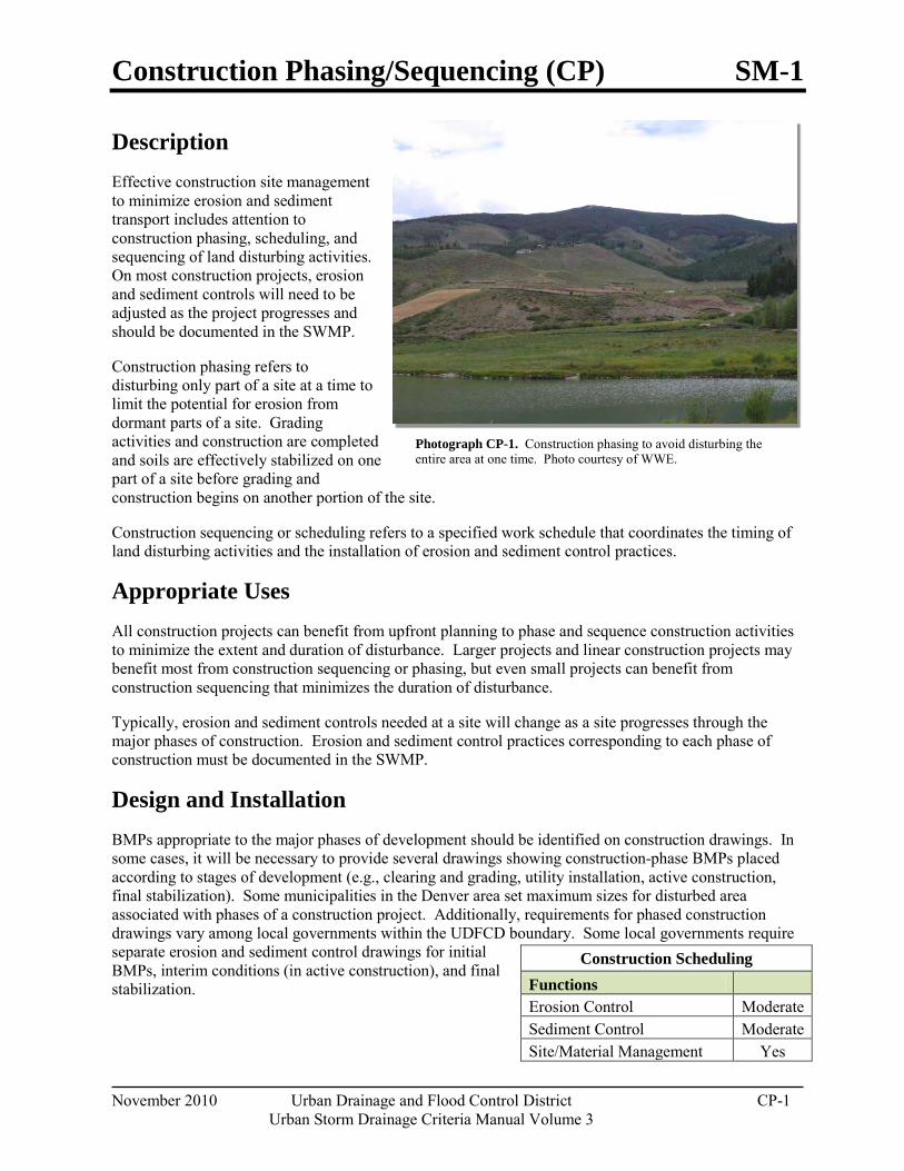
Construction Phasing/Sequencing (CP) SM-1
November 2010 Urban Drainage and Flood Control District CP-1 Urban Storm Drainage Criteria Manual Volume 3
Photograph CP-1. Construction phasing to avoid disturbing the entire area at one time. Photo courtesy of WWE.
Description Effective construction site management to minimize erosion and sediment transport includes attention to construction phasing, scheduling, and sequencing of land disturbing activities. On most construction projects, erosion and sediment controls will need to be adjusted as the project progresses and should be documented in the SWMP.
Construction phasing refers to disturbing only part of a site at a time to limit the potential for erosion from dormant parts of a site. Grading activities and construction are completed and soils are effectively stabilized on one part of a site before grading and construction begins on another portion of the site.
Construction sequencing or scheduling refers to a specified work schedule that coordinates the timing of land disturbing activities and the installation of erosion and sediment control practices.
Appropriate Uses All construction projects can benefit from upfront planning to phase and sequence construction activities to minimize the extent and duration of disturbance. Larger projects and linear construction projects may benefit most from construction sequencing or phasing, but even small projects can benefit from construction sequencing that minimizes the duration of disturbance.
Typically, erosion and sediment controls needed at a site will change as a site progresses through the major phases of construction. Erosion and sediment control practices corresponding to each phase of construction must be documented in the SWMP.
Design and Installation BMPs appropriate to the major phases of development should be identified on construction drawings. In some cases, it will be necessary to provide several drawings showing construction-phase BMPs placed according to stages of development (e.g., clearing and grading, utility installation, active construction, final stabilization). Some municipalities in the Denver area set maximum sizes for disturbed area associated with phases of a construction project. Additionally, requirements for phased construction drawings vary among local governments within the UDFCD boundary. Some local governments require separate erosion and sediment control drawings for initial BMPs, interim conditions (in active construction), and final stabilization.
Construction Scheduling Functions Erosion Control Moderate Sediment Control Moderate Site/Material Management Yes
SM-1 Construction Phasing/Sequencing (CP)
CP-2 Urban Drainage and Flood Control District November 2010
Urban Storm Drainage Criteria Manual Volume 3
Typical construction phasing BMPs include:
Limit the amount of disturbed area at any given time on a site to the extent practical. For example, a 100-acre subdivision might be constructed in five phases of 20 acres each.
If there is carryover of stockpiled material from one phase to the next, position carryover material in a location easily accessible for the pending phase that will not require disturbance of stabilized areas to access the stockpile. Particularly with regard to efforts to balance cut and fill at a site, careful planning for location of stockpiles is important.
Typical construction sequencing BMPs include:
Sequence construction activities to minimize duration of soil disturbance and exposure. For example, when multiple utilities will occupy the same trench, schedule installation so that the trench does not have to be closed and opened multiple times.
Schedule site stabilization activities (e.g., landscaping, seeding and mulching, installation of erosion control blankets) as soon as feasible following grading.
Install initial erosion and sediment control practices before construction begins. Promptly install additional BMPs for inlet protection, stabilization, etc., as construction activities are completed.
Table CP-1 provides typical sequencing of construction activities and associated BMPs.
Maintenance and Removal When the construction schedule is altered, erosion and sediment control measures in the SWMP and construction drawings should be appropriately adjusted to reflect actual "on the ground" conditions at the construction site. Be aware that changes in construction schedules can have significant implications for site stabilization, particularly with regard to establishment of vegetative cover.
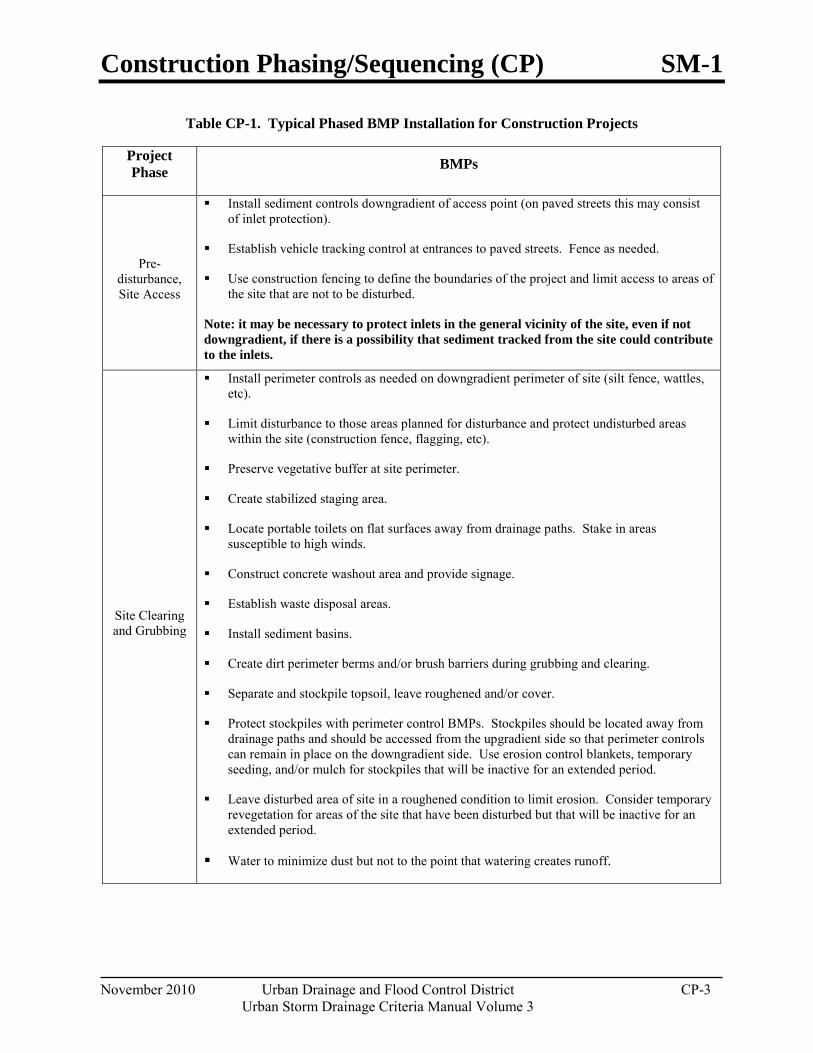
Construction Phasing/Sequencing (CP) SM-1
November 2010 Urban Drainage and Flood Control District CP-3 Urban Storm Drainage Criteria Manual Volume 3
Table CP-1. Typical Phased BMP Installation for Construction Projects
Project Phase BMPs
Pre-disturbance, Site Access
Install sediment controls downgradient of access point (on paved streets this may consist of inlet protection).
Establish vehicle tracking control at entrances to paved streets. Fence as needed.
Use construction fencing to define the boundaries of the project and limit access to areas of the site that are not to be disturbed.
Note: it may be necessary to protect inlets in the general vicinity of the site, even if not downgradient, if there is a possibility that sediment tracked from the site could contribute to the inlets.
Site Clearing and Grubbing
Install perimeter controls as needed on downgradient perimeter of site (silt fence, wattles, etc).
Limit disturbance to those areas planned for disturbance and protect undisturbed areas within the site (construction fence, flagging, etc).
Preserve vegetative buffer at site perimeter.
Create stabilized staging area.
Locate portable toilets on flat surfaces away from drainage paths. Stake in areas susceptible to high winds.
Construct concrete washout area and provide signage.
Establish waste disposal areas.
Install sediment basins.
Create dirt perimeter berms and/or brush barriers during grubbing and clearing.
Separate and stockpile topsoil, leave roughened and/or cover.
Protect stockpiles with perimeter control BMPs. Stockpiles should be located away from drainage paths and should be accessed from the upgradient side so that perimeter controls can remain in place on the downgradient side. Use erosion control blankets, temporary seeding, and/or mulch for stockpiles that will be inactive for an extended period.
Leave disturbed area of site in a roughened condition to limit erosion. Consider temporary revegetation for areas of the site that have been disturbed but that will be inactive for an extended period.
Water to minimize dust but not to the point that watering creates runoff.
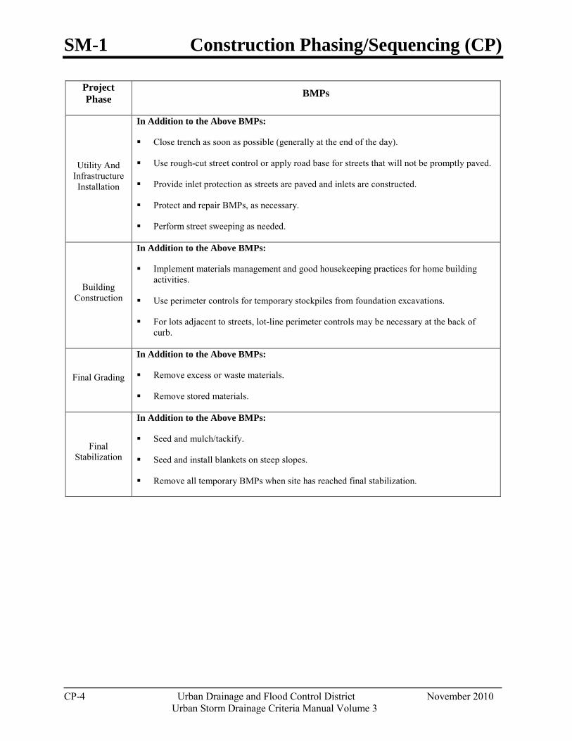
SM-1 Construction Phasing/Sequencing (CP)
CP-4 Urban Drainage and Flood Control District November 2010
Urban Storm Drainage Criteria Manual Volume 3
Project Phase BMPs
Utility And Infrastructure Installation
In Addition to the Above BMPs:
Close trench as soon as possible (generally at the end of the day).
Use rough-cut street control or apply road base for streets that will not be promptly paved.
Provide inlet protection as streets are paved and inlets are constructed.
Protect and repair BMPs, as necessary.
Perform street sweeping as needed.
Building Construction
In Addition to the Above BMPs:
Implement materials management and good housekeeping practices for home building activities.
Use perimeter controls for temporary stockpiles from foundation excavations.
For lots adjacent to streets, lot-line perimeter controls may be necessary at the back of curb.
Final Grading
In Addition to the Above BMPs:
Remove excess or waste materials.
Remove stored materials.
Final Stabilization
In Addition to the Above BMPs:
Seed and mulch/tackify.
Seed and install blankets on steep slopes.
Remove all temporary BMPs when site has reached final stabilization.
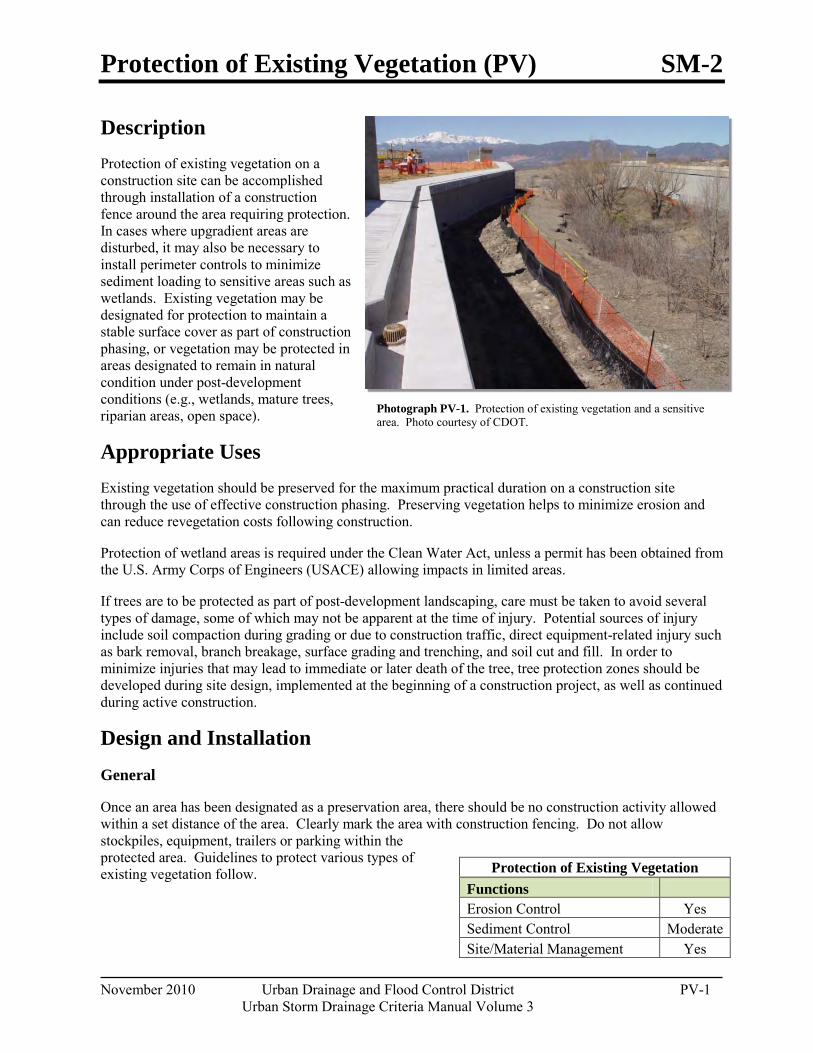
Protection of Existing Vegetation (PV) SM-2
November 2010 Urban Drainage and Flood Control District PV-1 Urban Storm Drainage Criteria Manual Volume 3
Photograph PV-1. Protection of existing vegetation and a sensitive area. Photo courtesy of CDOT.
Description Protection of existing vegetation on a construction site can be accomplished through installation of a construction fence around the area requiring protection. In cases where upgradient areas are disturbed, it may also be necessary to install perimeter controls to minimize sediment loading to sensitive areas such as wetlands. Existing vegetation may be designated for protection to maintain a stable surface cover as part of construction phasing, or vegetation may be protected in areas designated to remain in natural condition under post-development conditions (e.g., wetlands, mature trees, riparian areas, open space).
Appropriate Uses Existing vegetation should be preserved for the maximum practical duration on a construction site through the use of effective construction phasing. Preserving vegetation helps to minimize erosion and can reduce revegetation costs following construction.
Protection of wetland areas is required under the Clean Water Act, unless a permit has been obtained from the U.S. Army Corps of Engineers (USACE) allowing impacts in limited areas.
If trees are to be protected as part of post-development landscaping, care must be taken to avoid several types of damage, some of which may not be apparent at the time of injury. Potential sources of injury include soil compaction during grading or due to construction traffic, direct equipment-related injury such as bark removal, branch breakage, surface grading and trenching, and soil cut and fill. In order to minimize injuries that may lead to immediate or later death of the tree, tree protection zones should be developed during site design, implemented at the beginning of a construction project, as well as continued during active construction.
Design and Installation
General
Once an area has been designated as a preservation area, there should be no construction activity allowed within a set distance of the area. Clearly mark the area with construction fencing. Do not allow stockpiles, equipment, trailers or parking within the protected area. Guidelines to protect various types of existing vegetation follow.
Protection of Existing Vegetation Functions Erosion Control Yes Sediment Control Moderate Site/Material Management Yes
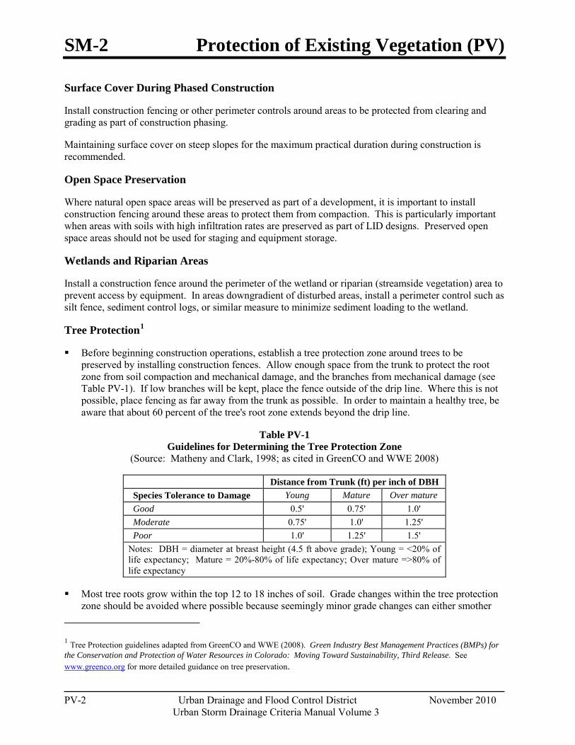
SM-2 Protection of Existing Vegetation (PV)
PV-2 Urban Drainage and Flood Control District November 2010
Urban Storm Drainage Criteria Manual Volume 3
Surface Cover During Phased Construction
Install construction fencing or other perimeter controls around areas to be protected from clearing and grading as part of construction phasing.
Maintaining surface cover on steep slopes for the maximum practical duration during construction is recommended.
Open Space Preservation
Where natural open space areas will be preserved as part of a development, it is important to install construction fencing around these areas to protect them from compaction. This is particularly important when areas with soils with high infiltration rates are preserved as part of LID designs. Preserved open space areas should not be used for staging and equipment storage.
Wetlands and Riparian Areas
Install a construction fence around the perimeter of the wetland or riparian (streamside vegetation) area to prevent access by equipment. In areas downgradient of disturbed areas, install a perimeter control such as silt fence, sediment control logs, or similar measure to minimize sediment loading to the wetland.
Tree Protection1
Before beginning construction operations, establish a tree protection zone around trees to be preserved by installing construction fences. Allow enough space from the trunk to protect the root zone from soil compaction and mechanical damage, and the branches from mechanical damage (see Table PV-1). If low branches will be kept, place the fence outside of the drip line. Where this is not possible, place fencing as far away from the trunk as possible. In order to maintain a healthy tree, be aware that about 60 percent of the tree's root zone extends beyond the drip line.
Table PV-1 Guidelines for Determining the Tree Protection Zone
(Source: Matheny and Clark, 1998; as cited in GreenCO and WWE 2008)
Distance from Trunk (ft) per inch of DBH Species Tolerance to Damage Young Mature Over mature Good 0.5' 0.75' 1.0' Moderate 0.75' 1.0' 1.25' Poor 1.0' 1.25' 1.5' Notes: DBH = diameter at breast height (4.5 ft above grade); Young = <20% of life expectancy; Mature = 20%-80% of life expectancy; Over mature =>80% of life expectancy
Most tree roots grow within the top 12 to 18 inches of soil. Grade changes within the tree protection zone should be avoided where possible because seemingly minor grade changes can either smother
1 Tree Protection guidelines adapted from GreenCO and WWE (2008). Green Industry Best Management Practices (BMPs) for the Conservation and Protection of Water Resources in Colorado: Moving Toward Sustainability, Third Release. See www.greenco.org for more detailed guidance on tree preservation.
Protection of Existing Vegetation (PV) SM-2
November 2010 Urban Drainage and Flood Control District PV-3 Urban Storm Drainage Criteria Manual Volume 3
roots (in fill situations) or damage roots (in cut situations). Consider small walls where needed to avoid grade changes in the tree protection zone.
Place and maintain a layer of mulch 4 to 6-inch thick from the tree trunk to the fencing, keeping a 6-inch space between the mulch and the trunk. Mulch helps to preserve moisture and decrease soil compaction if construction traffic is unavoidable. When planting operations are completed, the mulch may be reused throughout planting areas.
Limit access, if needed at all, and appoint one route as the main entrance and exit to the tree protection zone. Within the tree protection zone, do not allow any equipment to be stored, chemicals to be dumped, or construction activities to take place except fine grading, irrigation system installation, and planting operations. These activities should be conducted in consultation with a landscaping professional, following Green Industry BMPs.
Be aware that soil compaction can cause extreme damage to tree health that may appear gradually over a period of years. Soil compaction is easier to prevent than repair.
Maintenance and Removal Repair or replace damaged or displaced fencing or other protective barriers around the vegetated area.
If damage occurs to a tree, consult an arborist for guidance on how to care for the tree. If a tree in a designated preservation area is damaged beyond repair, remove and replace with a 2-inch diameter tree of the same or similar species.
Construction equipment must not enter a wetland area, except as permitted by the U.S. Army Corps of Engineers (USACE). Inadvertent placement of fill in a wetland is a 404 permit violation and will require notification of the USACE.
If damage to vegetation occurs in a protected area, reseed the area with the same or similar species, following the recommendations in the USDCM Revegetation chapter.

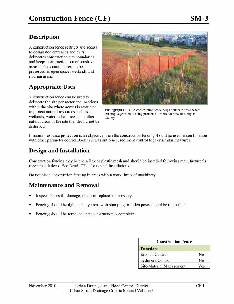
Construction Fence (CF) SM-3
November 2010 Urban Drainage and Flood Control District CF-1 Urban Storm Drainage Criteria Manual Volume 3
Photograph CF-1. A construction fence helps delineate areas where existing vegetation is being protected. Photo courtesy of Douglas County.
Description A construction fence restricts site access to designated entrances and exits, delineates construction site boundaries, and keeps construction out of sensitive areas such as natural areas to be preserved as open space, wetlands and riparian areas.
Appropriate Uses A construction fence can be used to delineate the site perimeter and locations within the site where access is restricted to protect natural resources such as wetlands, waterbodies, trees, and other natural areas of the site that should not be disturbed.
If natural resource protection is an objective, then the construction fencing should be used in combination with other perimeter control BMPs such as silt fence, sediment control logs or similar measures.
Design and Installation Construction fencing may be chain link or plastic mesh and should be installed following manufacturer’s recommendations. See Detail CF-1 for typical installations.
Do not place construction fencing in areas within work limits of machinery.
Maintenance and Removal Inspect fences for damage; repair or replace as necessary.
Fencing should be tight and any areas with slumping or fallen posts should be reinstalled.
Fencing should be removed once construction is complete.
Construction Fence
Functions Erosion Control No Sediment Control No Site/Material Management Yes
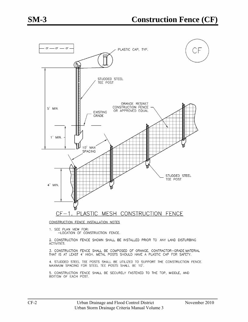
SM-3 Construction Fence (CF)
CF-2 Urban Drainage and Flood Control District November 2010
Urban Storm Drainage Criteria Manual Volume 3
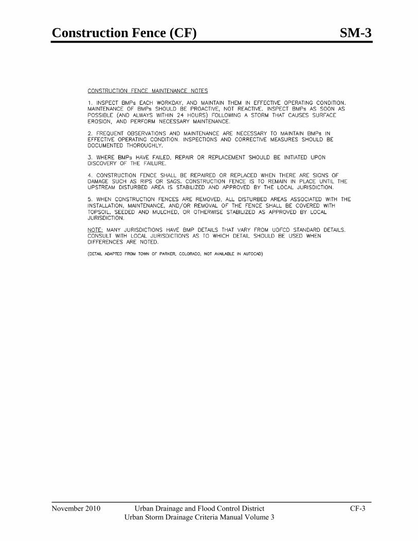
Construction Fence (CF) SM-3
November 2010 Urban Drainage and Flood Control District CF-3 Urban Storm Drainage Criteria Manual Volume 3

Vehicle Tracking Control (VTC) SM-4
November 2010 Urban Drainage and Flood Control District VTC-1 Urban Storm Drainage Criteria Manual Volume 3
Photograph VTC-1. A vehicle tracking control pad constructed with properly sized rock reduces off-site sediment tracking.
Descr iption Vehicle tracking controls provide stabilized construction site access where vehicles exit the site onto paved public roads. An effective vehicle tracking control helps remove sediment (mud or dirt) from vehicles, reducing tracking onto the paved surface.
Appropr iate Uses Implement a stabilized construction entrance or vehicle tracking control where frequent heavy vehicle traffic exits the construction site onto a paved roadway. An effective vehicle tracking control is particularly important during the following conditions:
Wet weather periods when mud is easily tracked off site.
During dry weather periods where dust is a concern.
When poorly drained, clayey soils are present on site.
Although wheel washes are not required in designs of vehicle tracking controls, they may be needed at particularly muddy sites.
Design and Installation Construct the vehicle tracking control on a level surface. Where feasible, grade the tracking control towards the construction site to reduce off-site runoff. Place signage, as needed, to direct construction vehicles to the designated exit through the vehicle tracking control. There are several different types of stabilized construction entrances including:
VTC-1. Aggregate Vehicle Tracking Control. This is a coarse-aggregate surfaced pad underlain by a geotextile. This is the most common vehicle tracking control, and when properly maintained can be effective at removing sediment from vehicle tires.
VTC-2. Vehicle Tracking Control with Construction Mat or Turf Reinforcement Mat. This type of control may be appropriate for site access at very small construction sites with low traffic volume over vegetated areas. Although this application does not typically remove sediment from vehicles, it helps protect existing vegetation and provides a stabilized entrance.
Vehicle Tracking Control Functions Erosion Control Moderate Sediment Control Yes Site/Material Management Yes
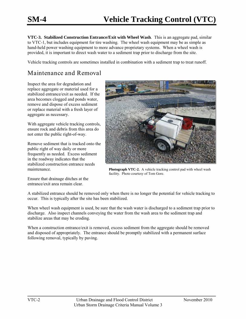
SM-4 Vehicle Tracking Control (VTC)
VTC-2 Urban Drainage and Flood Control District November 2010
Urban Storm Drainage Criteria Manual Volume 3
Photograph VTC-2. A vehicle tracking control pad with wheel wash facility. Photo courtesy of Tom Gore.
VTC-3. Stabilized Construction Entrance/Exit with Wheel Wash. This is an aggregate pad, similar to VTC-1, but includes equipment for tire washing. The wheel wash equipment may be as simple as hand-held power washing equipment to more advance proprietary systems. When a wheel wash is provided, it is important to direct wash water to a sediment trap prior to discharge from the site.
Vehicle tracking controls are sometimes installed in combination with a sediment trap to treat runoff.
Maintenance and Removal Inspect the area for degradation and replace aggregate or material used for a stabilized entrance/exit as needed. If the area becomes clogged and ponds water, remove and dispose of excess sediment or replace material with a fresh layer of aggregate as necessary.
With aggregate vehicle tracking controls, ensure rock and debris from this area do not enter the public right-of-way.
Remove sediment that is tracked onto the public right of way daily or more frequently as needed. Excess sediment in the roadway indicates that the stabilized construction entrance needs maintenance.
Ensure that drainage ditches at the entrance/exit area remain clear.
A stabilized entrance should be removed only when there is no longer the potential for vehicle tracking to occur. This is typically after the site has been stabilized.
When wheel wash equipment is used, be sure that the wash water is discharged to a sediment trap prior to discharge. Also inspect channels conveying the water from the wash area to the sediment trap and stabilize areas that may be eroding.
When a construction entrance/exit is removed, excess sediment from the aggregate should be removed and disposed of appropriately. The entrance should be promptly stabilized with a permanent surface following removal, typically by paving.
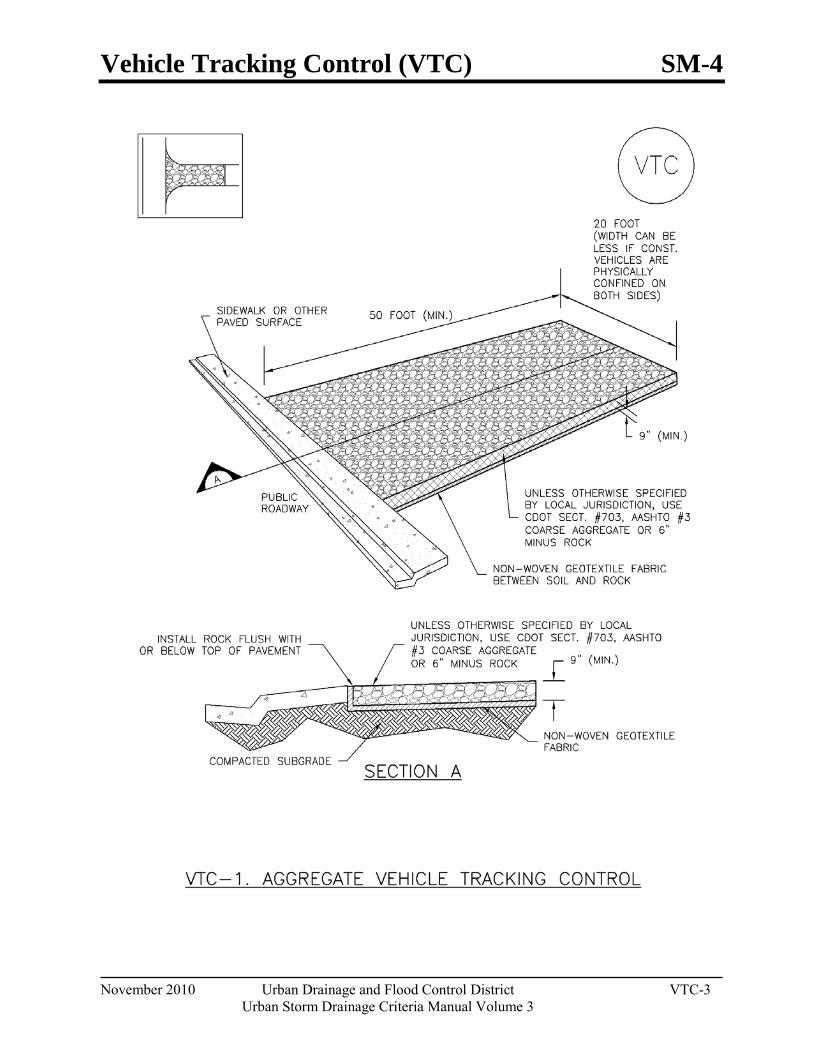
Vehicle Tracking Control (VTC) SM-4
November 2010 Urban Drainage and Flood Control District VTC-3 Urban Storm Drainage Criteria Manual Volume 3
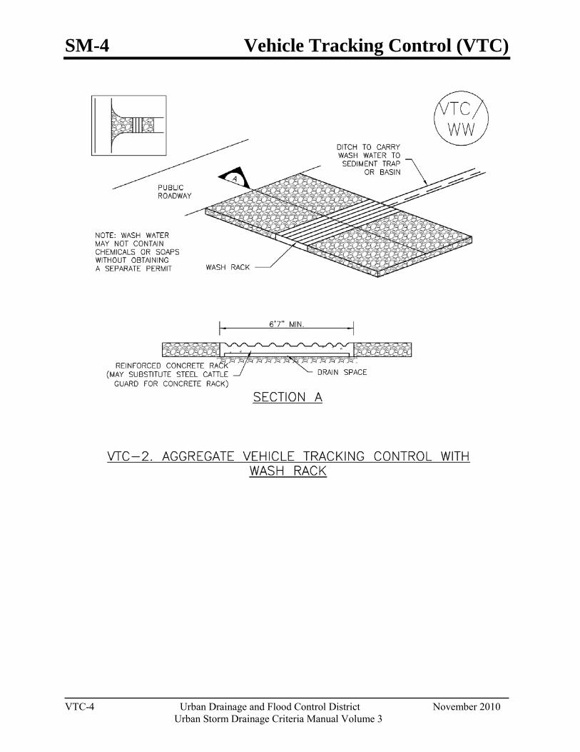
SM-4 Vehicle Tracking Control (VTC)
VTC-4 Urban Drainage and Flood Control District November 2010
Urban Storm Drainage Criteria Manual Volume 3
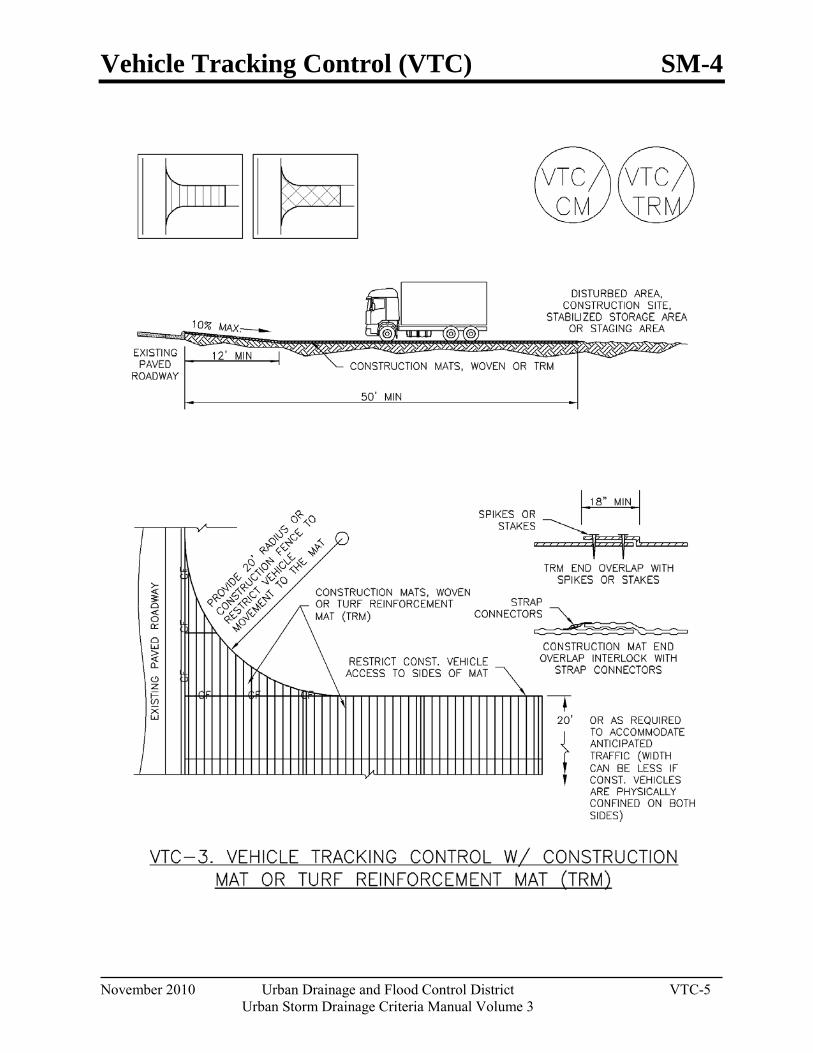
Vehicle Tracking Control (VTC) SM-4
November 2010 Urban Drainage and Flood Control District VTC-5 Urban Storm Drainage Criteria Manual Volume 3
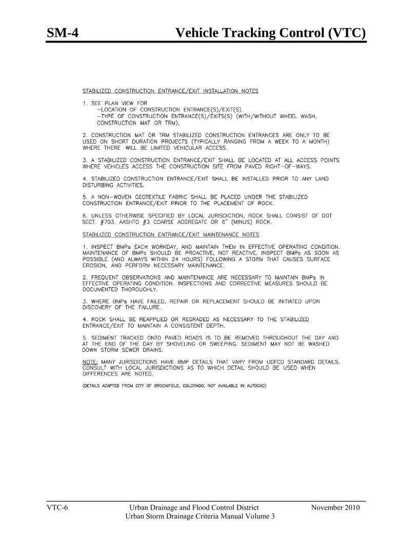
SM-4 Vehicle Tracking Control (VTC)
VTC-6 Urban Drainage and Flood Control District November 2010
Urban Storm Drainage Criteria Manual Volume 3
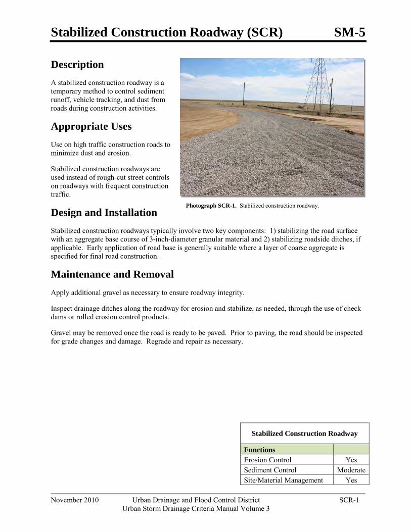
Stabilized Construction Roadway (SCR) SM-5
November 2010 Urban Drainage and Flood Control District SCR-1 Urban Storm Drainage Criteria Manual Volume 3
Photograph SCR-1. Stabilized construction roadway.
Description A stabilized construction roadway is a temporary method to control sediment runoff, vehicle tracking, and dust from roads during construction activities.
Appropriate Uses Use on high traffic construction roads to minimize dust and erosion.
Stabilized construction roadways are used instead of rough-cut street controls on roadways with frequent construction traffic.
Design and Installation Stabilized construction roadways typically involve two key components: 1) stabilizing the road surface with an aggregate base course of 3-inch-diameter granular material and 2) stabilizing roadside ditches, if applicable. Early application of road base is generally suitable where a layer of coarse aggregate is specified for final road construction.
Maintenance and Removal Apply additional gravel as necessary to ensure roadway integrity.
Inspect drainage ditches along the roadway for erosion and stabilize, as needed, through the use of check dams or rolled erosion control products.
Gravel may be removed once the road is ready to be paved. Prior to paving, the road should be inspected for grade changes and damage. Regrade and repair as necessary.
Stabilized Construction Roadway
Functions Erosion Control Yes Sediment Control Moderate Site/Material Management Yes

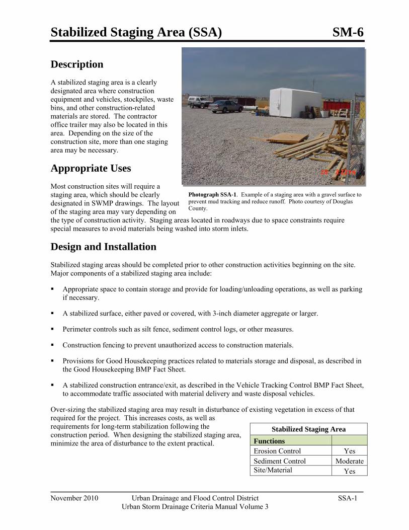
Stabilized Staging Area (SSA) SM-6
November 2010 Urban Drainage and Flood Control District SSA-1 Urban Storm Drainage Criteria Manual Volume 3
Photograph SSA-1. Example of a staging area with a gravel surface to prevent mud tracking and reduce runoff. Photo courtesy of Douglas County.
Description A stabilized staging area is a clearly designated area where construction equipment and vehicles, stockpiles, waste bins, and other construction-related materials are stored. The contractor office trailer may also be located in this area. Depending on the size of the construction site, more than one staging area may be necessary.
Appropriate Uses Most construction sites will require a staging area, which should be clearly designated in SWMP drawings. The layout of the staging area may vary depending on the type of construction activity. Staging areas located in roadways due to space constraints require special measures to avoid materials being washed into storm inlets.
Design and Installation Stabilized staging areas should be completed prior to other construction activities beginning on the site. Major components of a stabilized staging area include:
Appropriate space to contain storage and provide for loading/unloading operations, as well as parking if necessary.
A stabilized surface, either paved or covered, with 3-inch diameter aggregate or larger.
Perimeter controls such as silt fence, sediment control logs, or other measures.
Construction fencing to prevent unauthorized access to construction materials.
Provisions for Good Housekeeping practices related to materials storage and disposal, as described in the Good Housekeeping BMP Fact Sheet.
A stabilized construction entrance/exit, as described in the Vehicle Tracking Control BMP Fact Sheet, to accommodate traffic associated with material delivery and waste disposal vehicles.
Over-sizing the stabilized staging area may result in disturbance of existing vegetation in excess of that required for the project. This increases costs, as well as requirements for long-term stabilization following the construction period. When designing the stabilized staging area, minimize the area of disturbance to the extent practical.
Stabilized Staging Area Functions Erosion Control Yes Sediment Control Moderate Site/Material
Yes
SM-6 Stabilized Staging Area (SSA)
SSA-2 Urban Drainage and Flood Control District November 2010
Urban Storm Drainage Criteria Manual Volume 3
See Detail SSA-1 for a typical stabilized staging area and SSA-2 for a stabilized staging area when materials staging in roadways is required.
Maintenance and Removal Maintenance of stabilized staging areas includes maintaining a stable surface cover of gravel, repairing perimeter controls, and following good housekeeping practices.
When construction is complete, debris, unused stockpiles and materials should be recycled or properly disposed. In some cases, this will require disposal of contaminated soil from equipment leaks in an appropriate landfill. Staging areas should then be permanently stabilized with vegetation or other surface cover planned for the development.
Minimizing Long-Term Stabilization Requirements
Utilize off-site parking and restrict vehicle access to the site.
Use construction mats in lieu of rock when staging is provided in an area that will not be disturbed otherwise.
Consider use of a bermed contained area for materials and equipment that do not require a stabilized surface.
Consider phasing of staging areas to avoid disturbance in an area that will not be otherwise disturbed.
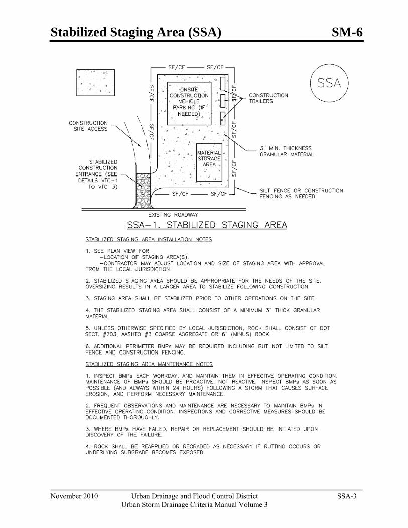
Stabilized Staging Area (SSA) SM-6
November 2010 Urban Drainage and Flood Control District SSA-3 Urban Storm Drainage Criteria Manual Volume 3
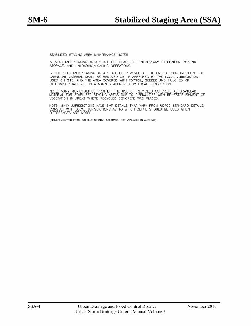
SM-6 Stabilized Staging Area (SSA)
SSA-4 Urban Drainage and Flood Control District November 2010
Urban Storm Drainage Criteria Manual Volume 3

Street Sweeping and Vacuuming (SS) SM-7
November 2010 Urban Drainage and Flood Control District SS-1 Urban Storm Drainage Criteria Manual Volume 3
Photograph SS-1. A street sweeper removes sediment and potential pollutants along the curb line at a construction site. Photo courtesy of Tom Gore.
Description Street sweeping and vacuuming remove sediment that has been tracked onto roadways to reduce sediment transport into storm drain systems or a surface waterway.
Appropriate Uses Use this practice at construction sites where vehicles may track sediment offsite onto paved roadways.
Design and Installation Street sweeping or vacuuming should be conducted when there is noticeable sediment accumulation on roadways adjacent to the construction site. Typically, this will be concentrated at the entrance/exit to the construction site. Well-maintained stabilized construction entrances, vehicle tracking controls and tire wash facilities can help reduce the necessary frequency of street sweeping and vacuuming.
On smaller construction sites, street sweeping can be conducted manually using a shovel and broom. Never wash accumulated sediment on roadways into storm drains.
Maintenance and Removal Inspect paved roads around the perimeter of the construction site on a daily basis and more
frequently, as needed. Remove accumulated sediment, as needed.
Following street sweeping, check inlet protection that may have been displaced during street sweeping.
Inspect area to be swept for materials that may be hazardous prior to beginning sweeping operations.
Street Sweeping/ Vacuuming
Functions Erosion Control No Sediment Control Yes Site/Material Management Yes

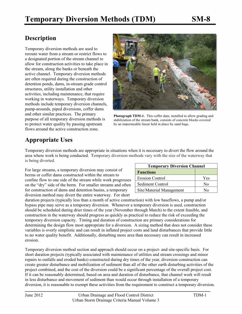
Temporary Diversion Methods (TDM) SM-8
June 2012 Urban Drainage and Flood Control District TDM-1 Urban Storm Drainage Criteria Manual Volume 3
Photograph TDM-1. This coffer dam, installed to allow grading and stabilization of the stream bank, consists of concrete blocks covered by an impermeable linear held in place by sand bags.
Description Temporary diversion methods are used to reroute water from a stream or restrict flows to a designated portion of the stream channel to allow for construction activities to take place in the stream, along the banks or beneath the active channel. Temporary diversion methods are often required during the construction of detention ponds, dams, in-stream grade control structures, utility installation and other activities, including maintenance, that require working in waterways. Temporary diversion methods include temporary diversion channels, pump-arounds, piped diversions, coffer dams and other similar practices. The primary purpose of all temporary diversion methods is to protect water quality by passing upstream flows around the active construction zone.
Appropriate Uses Temporary diversion methods are appropriate in situations when it is necessary to divert the flow around the area where work is being conducted. Temporary diversion methods vary with the size of the waterway that is being diverted.
For large streams, a temporary diversion may consist of berms or coffer dams constructed within the stream to confine flow to one side of the stream while work progresses on the “dry” side of the berm. For smaller streams and often for construction of dams and detention basins, a temporary diversion method may divert the entire waterway. For short duration projects (typically less than a month of active construction) with low baseflows, a pump and/or bypass pipe may serve as a temporary diversion. Whenever a temporary diversion is used, construction should be scheduled during drier times of the year (November through March) to the extent feasible, and construction in the waterway should progress as quickly as practical to reduce the risk of exceeding the temporary diversion capacity. Timing and duration of construction are primary considerations for determining the design flow most appropriate for a diversion. A sizing method that does not consider these variables is overly simplistic and can result in inflated project costs and land disturbances that provide little to no water quality benefit. Additionally, disturbing more area than necessary can result in increased erosion.
Temporary diversion method section and approach should occur on a project- and site-specific basis. For short duration projects (typically associated with maintenance of utilities and stream crossings and minor repairs to outfalls and eroded banks) constructed during dry times of the year, diversion construction can create greater disturbance and mobilization of sediment than all of the other earth disturbing activities of the project combined, and the cost of the diversion could be a significant percentage of the overall project cost. If it can be reasonably determined, based on area and duration of disturbance, that channel work will result in less disturbance and movement of sediment than would occur through installation of a temporary diversion, it is reasonable to exempt these activities from the requirement to construct a temporary diversion.
Temporary Diversion Channel Functions Erosion Control Yes Sediment Control No Site/Material Management No
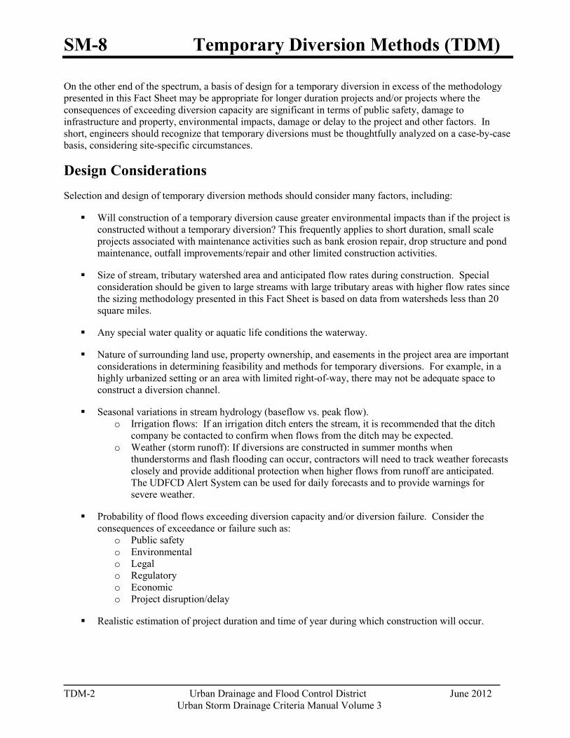
SM-8 Temporary Diversion Methods (TDM)
TDM-2 Urban Drainage and Flood Control District June 2012
Urban Storm Drainage Criteria Manual Volume 3
On the other end of the spectrum, a basis of design for a temporary diversion in excess of the methodology presented in this Fact Sheet may be appropriate for longer duration projects and/or projects where the consequences of exceeding diversion capacity are significant in terms of public safety, damage to infrastructure and property, environmental impacts, damage or delay to the project and other factors. In short, engineers should recognize that temporary diversions must be thoughtfully analyzed on a case-by-case basis, considering site-specific circumstances.
Design Considerations Selection and design of temporary diversion methods should consider many factors, including:
Will construction of a temporary diversion cause greater environmental impacts than if the project is constructed without a temporary diversion? This frequently applies to short duration, small scale projects associated with maintenance activities such as bank erosion repair, drop structure and pond maintenance, outfall improvements/repair and other limited construction activities.
Size of stream, tributary watershed area and anticipated flow rates during construction. Special consideration should be given to large streams with large tributary areas with higher flow rates since the sizing methodology presented in this Fact Sheet is based on data from watersheds less than 20 square miles.
Any special water quality or aquatic life conditions the waterway.
Nature of surrounding land use, property ownership, and easements in the project area are important considerations in determining feasibility and methods for temporary diversions. For example, in a highly urbanized setting or an area with limited right-of-way, there may not be adequate space to construct a diversion channel.
Seasonal variations in stream hydrology (baseflow vs. peak flow). o Irrigation flows: If an irrigation ditch enters the stream, it is recommended that the ditch
company be contacted to confirm when flows from the ditch may be expected. o Weather (storm runoff): If diversions are constructed in summer months when
thunderstorms and flash flooding can occur, contractors will need to track weather forecasts closely and provide additional protection when higher flows from runoff are anticipated. The UDFCD Alert System can be used for daily forecasts and to provide warnings for severe weather.
Probability of flood flows exceeding diversion capacity and/or diversion failure. Consider the consequences of exceedance or failure such as:
o Public safety o Environmental o Legal o Regulatory o Economic o Project disruption/delay
Realistic estimation of project duration and time of year during which construction will occur.

Temporary Diversion Methods (TDM) SM-8
June 2012 Urban Drainage and Flood Control District TDM-3 Urban Storm Drainage Criteria Manual Volume 3
Comparison of the overall project costs to the temporary diversion costs (design and construction) and determining the costs and benefits of different diversion strategies relative to the protection that they provide.
Permitting requirements for overall project and for diversion methods (United States Army Corps of Engineers, United States Fish and Wildlife Service, Colorado Department of Public Health and Environment, Federal Emergency Management Agency, Division of Water Resources, local governments, and others). Permit requirements and existing vegetative cover may limit the allowable area disturbance.
Public safety aspects. For example, if a pipeline is being used, consideration should be given to public access and inlet protection.
Legal considerations, which are a function of many different factors such as property ownership, history of localized flooding, or parties that will have interest in project.
Design and Installation 1. Determine if a diversion is appropriate based on appropriate uses and design considerations stated
earlier. As noted, in some cases, constructing a project under wet conditions is preferable to constructing a temporary diversion to create dry conditions, especially if construction of the temporary diversion will require a significant amount of disturbance relative to the overall project.
2. Determine project duration.
“Long duration” projects are projects that last longer than three months and in many cases are Capital Improvement Projects or traditional land development projects.
“Short duration” projects are projects that are completed within one month or less and generally are associated with maintenance and repair activities.
“Interim duration” projects are projects that will last longer than one month but up to three months.
3. Determine the time of year in which construction will occur.
4. Gather necessary temporary diversion sizing parameters that may include tributary area, imperviousness, project duration safety factor, and seasonal sizing coefficient.
5. Apply applicable sizing methodology and perform necessary calculations (provided following this section). Use engineering judgment to determine if the temporary diversion design flow is adequate for the specific project.
6. Determine appropriate method of diversion. Follow the design steps for the selected method discussed below.
Channel Diversion – For smaller streams, construction of dams and detention basins, or as the site allows, a channel diversion may divert the entire waterway as illustrated in Figure TDM-1.
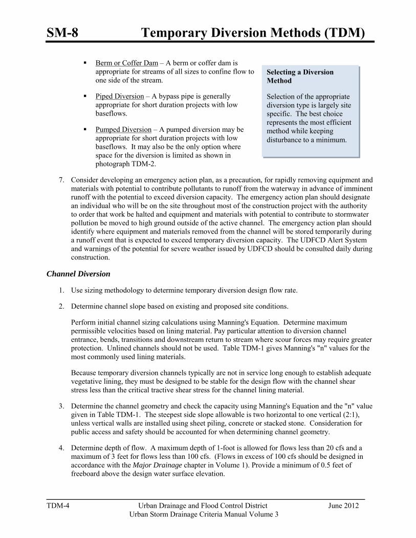
SM-8 Temporary Diversion Methods (TDM)
TDM-4 Urban Drainage and Flood Control District June 2012
Urban Storm Drainage Criteria Manual Volume 3
Selecting a Diversion Method
Selection of the appropriate diversion type is largely site specific. The best choice represents the most efficient method while keeping disturbance to a minimum.
Berm or Coffer Dam – A berm or coffer dam is appropriate for streams of all sizes to confine flow to one side of the stream.
Piped Diversion – A bypass pipe is generally appropriate for short duration projects with low baseflows.
Pumped Diversion – A pumped diversion may be appropriate for short duration projects with low baseflows. It may also be the only option where space for the diversion is limited as shown in photograph TDM-2.
7. Consider developing an emergency action plan, as a precaution, for rapidly removing equipment and materials with potential to contribute pollutants to runoff from the waterway in advance of imminent runoff with the potential to exceed diversion capacity. The emergency action plan should designate an individual who will be on the site throughout most of the construction project with the authority to order that work be halted and equipment and materials with potential to contribute to stormwater pollution be moved to high ground outside of the active channel. The emergency action plan should identify where equipment and materials removed from the channel will be stored temporarily during a runoff event that is expected to exceed temporary diversion capacity. The UDFCD Alert System and warnings of the potential for severe weather issued by UDFCD should be consulted daily during construction.
Channel Diversion
1. Use sizing methodology to determine temporary diversion design flow rate.
2. Determine channel slope based on existing and proposed site conditions.
Perform initial channel sizing calculations using Manning's Equation. Determine maximum permissible velocities based on lining material. Pay particular attention to diversion channel entrance, bends, transitions and downstream return to stream where scour forces may require greater protection. Unlined channels should not be used. Table TDM-1 gives Manning's "n" values for the most commonly used lining materials.
Because temporary diversion channels typically are not in service long enough to establish adequate vegetative lining, they must be designed to be stable for the design flow with the channel shear stress less than the critical tractive shear stress for the channel lining material.
3. Determine the channel geometry and check the capacity using Manning's Equation and the "n" value given in Table TDM-1. The steepest side slope allowable is two horizontal to one vertical (2:1), unless vertical walls are installed using sheet piling, concrete or stacked stone. Consideration for public access and safety should be accounted for when determining channel geometry.
4. Determine depth of flow. A maximum depth of 1-foot is allowed for flows less than 20 cfs and a maximum of 3 feet for flows less than 100 cfs. (Flows in excess of 100 cfs should be designed in accordance with the Major Drainage chapter in Volume 1). Provide a minimum of 0.5 feet of freeboard above the design water surface elevation.
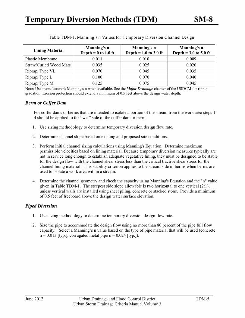
Temporary Diversion Methods (TDM) SM-8
June 2012 Urban Drainage and Flood Control District TDM-5 Urban Storm Drainage Criteria Manual Volume 3
Table TDM-1. Manning’s n Values for Temporary Diversion Channel Design
Lining Material Manning's n Depth = 0 to 1.0 ft
Manning's n Depth = 1.0 to 3.0 ft
Manning's n Depth = 3.0 to 5.0 ft
Plastic Membrane 0.011 0.010 0.009 Straw/Curled Wood Mats 0.035 0.025 0.020 Riprap, Type VL 0.070 0.045 0.035 Riprap, Type L 0.100 0.070 0.040 Riprap, Type M 0.125 0.075 0.045 Note: Use manufacturer's Manning's n when available. See the Major Drainage chapter of the USDCM for riprap gradation. Erosion protection should extend a minimum of 0.5 feet above the design water depth.
Berm or Coffer Dam
For coffer dams or berms that are intended to isolate a portion of the stream from the work area steps 1-4 should be applied to the “wet” side of the coffer dam or berm.
1. Use sizing methodology to determine temporary diversion design flow rate.
2. Determine channel slope based on existing and proposed site conditions.
3. Perform initial channel sizing calculations using Manning's Equation. Determine maximum permissible velocities based on lining material. Because temporary diversion measures typically are not in service long enough to establish adequate vegetative lining, they must be designed to be stable for the design flow with the channel shear stress less than the critical tractive shear stress for the channel lining material. This stability criterion applies to the stream-side of berms when berms are used to isolate a work area within a stream.
4. Determine the channel geometry and check the capacity using Manning's Equation and the "n" value given in Table TDM-1. The steepest side slope allowable is two horizontal to one vertical (2:1), unless vertical walls are installed using sheet piling, concrete or stacked stone. Provide a minimum of 0.5 feet of freeboard above the design water surface elevation.
Piped Diversion
1. Use sizing methodology to determine temporary diversion design flow rate.
2. Size the pipe to accommodate the design flow using no more than 80 percent of the pipe full flow capacity. Select a Manning’s n value based on the type of pipe material that will be used (concrete n = 0.013 [typ.], corrugated metal pipe n = 0.024 [typ.]).

SM-8 Temporary Diversion Methods (TDM)
TDM-6 Urban Drainage and Flood Control District June 2012
Urban Storm Drainage Criteria Manual Volume 3
“Long duration” projects last longer than three months.
“Short duration” projects are
completed within one month or less.
“Interim duration” projects last longer than one month and up
to three months.
Photograph TDM-2. Despite a relatively significant baseflow, a pumped diversion was selected for this Lakewood Gulch project due to a lack of space crossing Federal Boulevard. Photo courtesy of City and County of Denver.
Pumped Diversion
1. Use sizing methodology to determine temporary diversion design flow rate.
2. A backup pump (or pumps) with capacity equal to or greater than the diversion design flow rate should be on site and in good working order at all times.
Sizing Methodology The methodology for sizing of temporary diversion methods was developed using baseflow observations and Crest Stage Indicator (CSI) peak flow data collected from 21 watersheds within the UDFCD boundary. These data were collected over extended periods of time (up to 31 years) and, as a result, provide a sound statistical basis for the sizing methodology.
Determine sizing procedure to use based on the project duration.
• “Long duration” projects last longer than three months and in many cases are Capital Improvement Projects or traditional land development projects.
• “Short duration” projects are completed within one
month or less and generally are associated with maintenance and repair activities. For these projects, it is recommended that the temporary diversion be sized based on the statistics identified for baseflows (i.e., vs. peak flows) and be of sufficient size to convey a flow that has a less than 50% chance of being exceeded between November – March, including a project duration safety factor.
• “Interim duration” projects will last longer than one month but up to three months. In these projects,
engineering judgment must be applied, drawing on sizing methods for “short duration” and “long duration” project criteria and the time of year of construction to develop a basis of design for the temporary diversion method that is appropriate for the project.
It is highly recommended that projects involving temporary diversions be constructed between November and March. If a short duration project requiring a temporary diversion must be conducted between April and October, the extended weather forecast should be evaluated to avoid periods of anticipated precipitation and a conservative safety factor should be applied. Additional protection may need to be provided for the site if higher flows from runoff are anticipated.
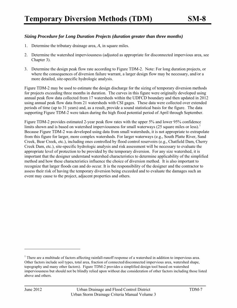
Temporary Diversion Methods (TDM) SM-8
June 2012 Urban Drainage and Flood Control District TDM-7 Urban Storm Drainage Criteria Manual Volume 3
Sizing Procedure for Long Duration Projects (duration greater than three months)
1. Determine the tributary drainage area, A, in square miles.
2. Determine the watershed imperviousness (adjusted as appropriate for disconnected impervious area, see Chapter 3).
3. Determine the design peak flow rate according to Figure TDM-2. Note: For long duration projects, or where the consequences of diversion failure warrant, a larger design flow may be necessary, and/or a more detailed, site-specific hydrologic analysis.
Figure TDM-2 may be used to estimate the design discharge for the sizing of temporary diversion methods for projects exceeding three months in duration. The curves in this figure were originally developed using annual peak flow data collected from 17 watersheds within the UDFCD boundary and then updated in 2012 using annual peak flow data from 21 watersheds with CSI gages. These data were collected over extended periods of time (up to 31 years) and, as a result, provide a sound statistical basis for the figure. The data supporting Figure TDM-2 were taken during the high flood potential period of April through September.
Figure TDM-2 provides estimated 2-year peak flow rates with the upper 5% and lower 95% confidence limits shown and is based on watershed imperviousness for small waterways (25 square miles or less).1
Because Figure TDM-2 was developed using data from small watersheds, it is not appropriate to extrapolate from this figure for larger, more complex watersheds. For larger waterways (e.g., South Platte River, Sand Creek, Bear Creek, etc.), including ones controlled by flood control reservoirs (e.g., Chatfield Dam, Cherry Creek Dam, etc.), site-specific hydrologic analysis and risk assessment will be necessary to evaluate the appropriate level of protection to be provided by the temporary diversion. For any size watershed, it is important that the designer understand watershed characteristics to determine applicability of the simplified method and how these characteristics influence the choice of diversion method. It is also important to recognize that larger floods can and do occur. It is the responsibility of the designer and the contractor to assess their risk of having the temporary diversion being exceeded and to evaluate the damages such an event may cause to the project, adjacent properties and others.
1 There are a multitude of factors affecting rainfall-runoff response of a watershed in addition to impervious area. Other factors include soil types, total area, fraction of connected/disconnected impervious area, watershed shape, topography and many other factors). Figure TDM-2 provides a simplified design tool based on watershed imperviousness but should not be blindly relied upon without due consideration of other factors including those listed above and others.
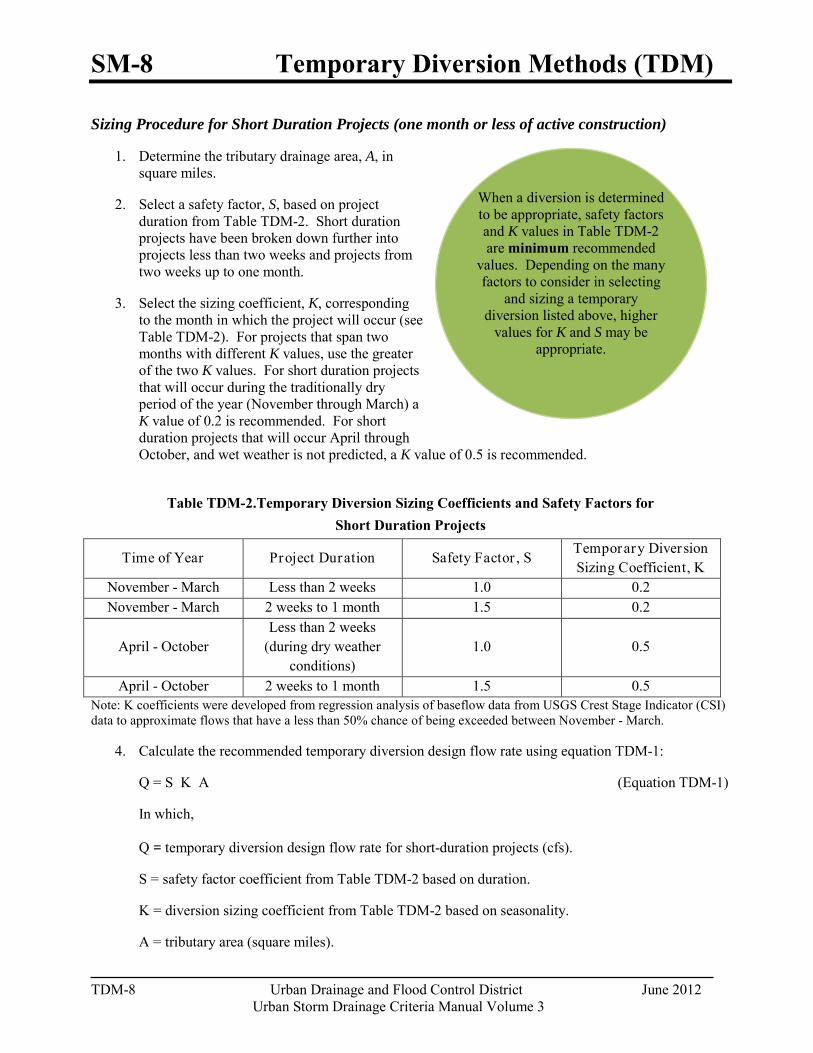
SM-8 Temporary Diversion Methods (TDM)
TDM-8 Urban Drainage and Flood Control District June 2012
Urban Storm Drainage Criteria Manual Volume 3
When a diversion is determined to be appropriate, safety factors and K values in Table TDM-2 are minimum recommended
values. Depending on the many factors to consider in selecting
and sizing a temporary diversion listed above, higher
values for K and S may be appropriate.
Sizing Procedure for Short Duration Projects (one month or less of active construction)
1. Determine the tributary drainage area, A, in square miles.
2. Select a safety factor, S, based on project duration from Table TDM-2. Short duration projects have been broken down further into projects less than two weeks and projects from two weeks up to one month.
3. Select the sizing coefficient, K, corresponding to the month in which the project will occur (see Table TDM-2). For projects that span two months with different K values, use the greater of the two K values. For short duration projects that will occur during the traditionally dry period of the year (November through March) a K value of 0.2 is recommended. For short duration projects that will occur April through October, and wet weather is not predicted, a K value of 0.5 is recommended.
Table TDM-2.Temporary Diversion Sizing Coefficients and Safety Factors for
Short Duration Projects
Time of Year Project Duration Safety Factor , S Temporary Diversion Sizing Coefficient, K
November - March Less than 2 weeks 1.0 0.2 November - March 2 weeks to 1 month 1.5 0.2
April - October Less than 2 weeks
(during dry weather conditions)
1.0 0.5
April - October 2 weeks to 1 month 1.5 0.5 Note: K coefficients were developed from regression analysis of baseflow data from USGS Crest Stage Indicator (CSI) data to approximate flows that have a less than 50% chance of being exceeded between November - March.
4. Calculate the recommended temporary diversion design flow rate using equation TDM-1:
Q = S K A (Equation TDM-1)
In which, Q = temporary diversion design flow rate for short-duration projects (cfs).
S = safety factor coefficient from Table TDM-2 based on duration.
K = diversion sizing coefficient from Table TDM-2 based on seasonality.
A = tributary area (square miles).
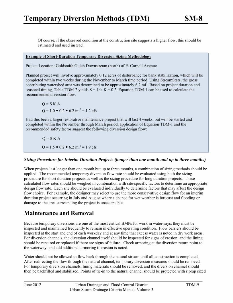
Temporary Diversion Methods (TDM) SM-8
June 2012 Urban Drainage and Flood Control District TDM-9 Urban Storm Drainage Criteria Manual Volume 3
Example of Short-Duration Temporary Diversion Sizing Methodology
Project Location: Goldsmith Gulch Downstream (north) of E. Cornell Avenue
Planned project will involve approximately 0.12 acres of disturbance for bank stabilization, which will be completed within two weeks during the November to March time period. Using StreamStats, the gross contributing watershed area was determined to be approximately 6.2 mi2. Based on project duration and seasonal timing, Table TDM-2 yields S = 1.0, K = 0.2. Equation TDM-1 can be used to calculate the recommended diversion flow:
Q = S K A Q = 1.0 0.2 6.2 mi2 = 1.2 cfs
Had this been a larger restorative maintenance project that will last 4 weeks, but will be started and completed within the November through March period, application of Equation TDM-1 and the recommended safety factor suggest the following diversion design flow:
Q = S K A
Q = 1.5 0.2 6.2 mi2 = 1.9 cfs
Of course, if the observed condition at the construction site suggests a higher flow, this should be estimated and used instead.
Sizing Procedure for Interim Duration Projects (longer than one month and up to three months)
When projects last longer than one month but up to three months, a combination of sizing methods should be applied. The recommended temporary diversion flow rate should be evaluated using both the sizing procedure for short duration projects as well as the sizing procedure for long duration projects. These calculated flow rates should be weighed in combination with site-specific factors to determine an appropriate design flow rate. Each site should be evaluated individually to determine factors that may affect the design flow choice. For example, the designer may select to use the more conservative design flow for an interim duration project occurring in July and August where a chance for wet weather is forecast and flooding or damage to the area surrounding the project is unacceptable.
Maintenance and Removal Because temporary diversions are one of the most critical BMPs for work in waterways, they must be inspected and maintained frequently to remain in effective operating condition. Flow barriers should be inspected at the start and end of each workday and at any time that excess water is noted in dry work areas. For diversion channels, the diversion channel itself should be inspected for signs of erosion, and the lining should be repaired or replaced if there are signs of failure. Check armoring at the diversion return point to the waterway, and add additional armoring if erosion is noted.
Water should not be allowed to flow back through the natural stream until all construction is completed. After redirecting the flow through the natural channel, temporary diversion measures should be removed. For temporary diversion channels, lining materials should be removed, and the diversion channel should then be backfilled and stabilized. Points of tie-in to the natural channel should be protected with riprap sized
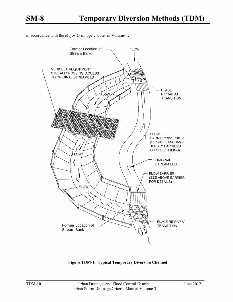
SM-8 Temporary Diversion Methods (TDM)
TDM-10 Urban Drainage and Flood Control District June 2012
Urban Storm Drainage Criteria Manual Volume 3
in accordance with the Major Drainage chapter in Volume 1.
Figure TDM-1. Typical Temporary Diversion Channel
Former Location of Stream Bank
Former Location of Stream Bank
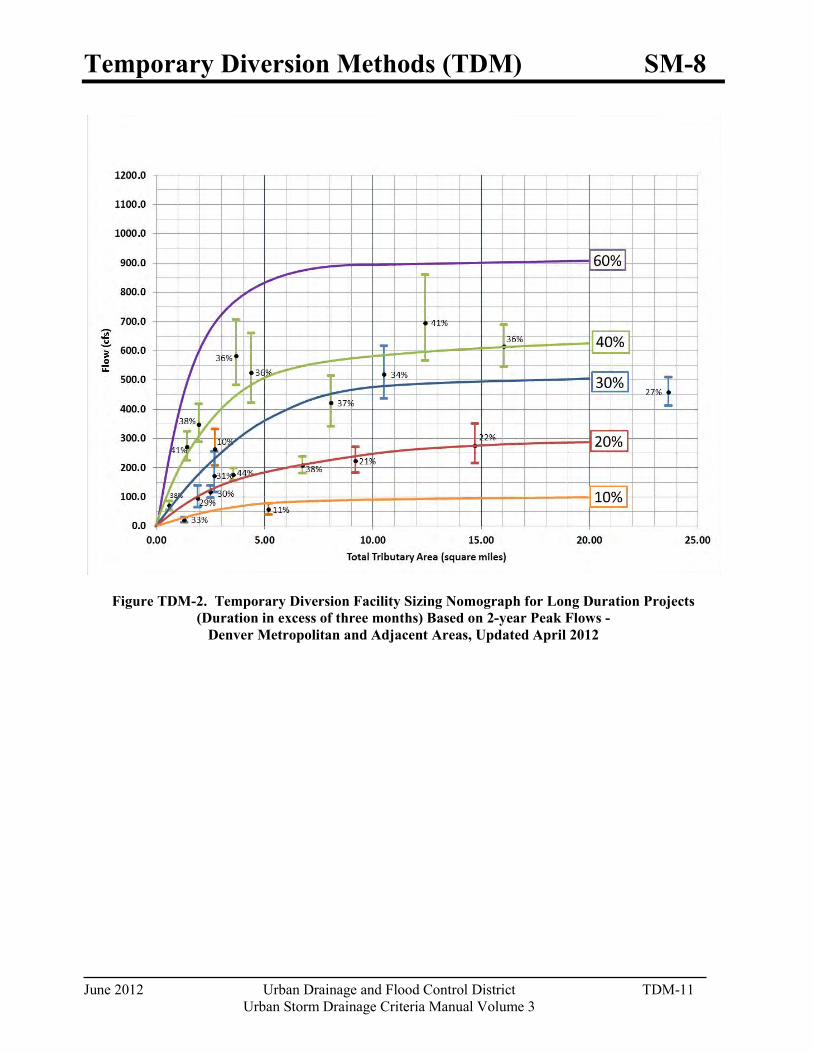
Temporary Diversion Methods (TDM) SM-8
June 2012 Urban Drainage and Flood Control District TDM-11 Urban Storm Drainage Criteria Manual Volume 3
Figure TDM-2. Temporary Diversion Facility Sizing Nomograph for Long Duration Projects
(Duration in excess of three months) Based on 2-year Peak Flows - Denver Metropolitan and Adjacent Areas, Updated April 2012
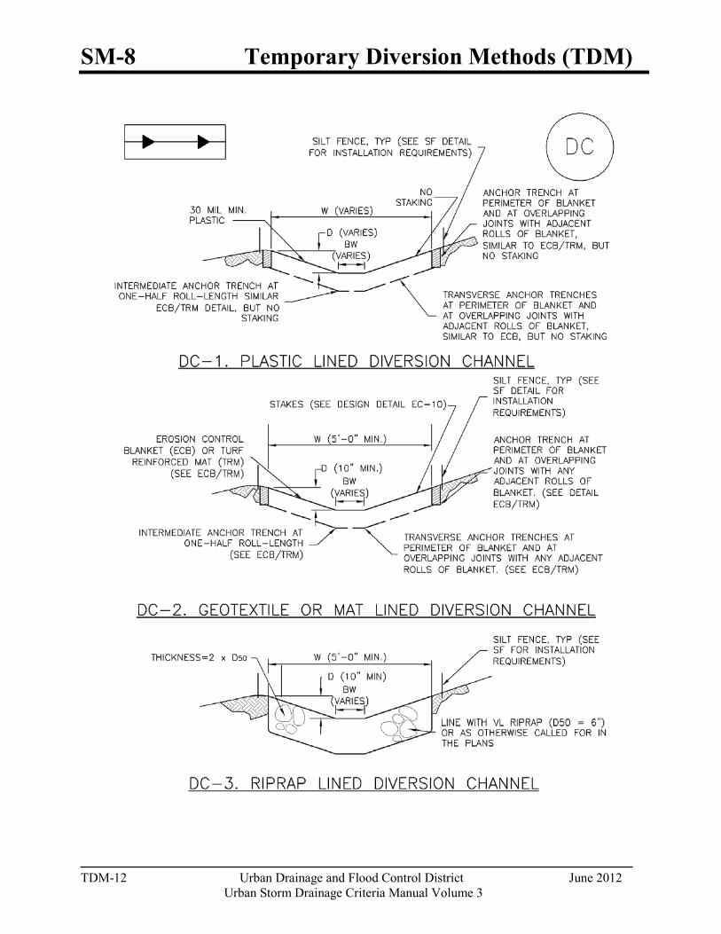
SM-8 Temporary Diversion Methods (TDM)
TDM-12 Urban Drainage and Flood Control District June 2012
Urban Storm Drainage Criteria Manual Volume 3
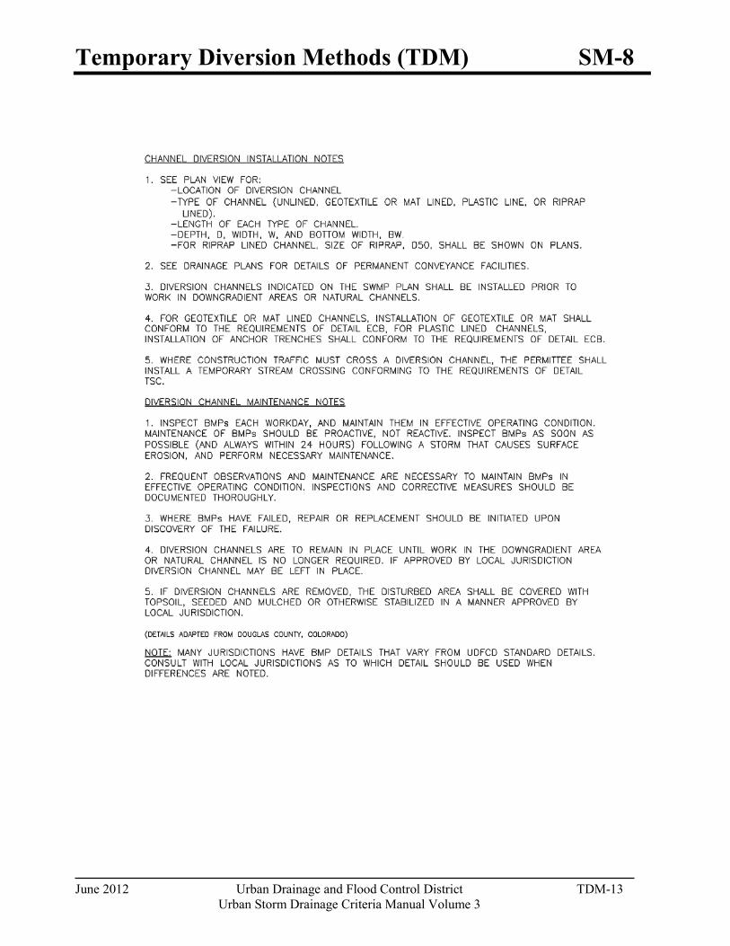
Temporary Diversion Methods (TDM) SM-8
June 2012 Urban Drainage and Flood Control District TDM-13 Urban Storm Drainage Criteria Manual Volume 3

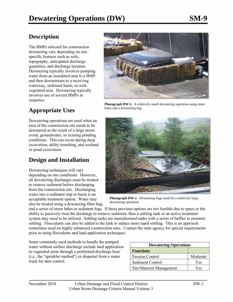
Dewatering Operations (DW) SM-9
November 2010 Urban Drainage and Flood Control District DW-1 Urban Storm Drainage Criteria Manual Volume 3
Photograph DW-1. A relatively small dewatering operation using straw bales and a dewatering bag.
Photograph DW-2. Dewatering bags used for a relatively large dewatering operation.
Description The BMPs selected for construction dewatering vary depending on site-specific features such as soils, topography, anticipated discharge quantities, and discharge location. Dewatering typically involves pumping water from an inundated area to a BMP, and then downstream to a receiving waterway, sediment basin, or well-vegetated area. Dewatering typically involves use of several BMPs in sequence.
Appropriate Uses Dewatering operations are used when an area of the construction site needs to be dewatered as the result of a large storm event, groundwater, or existing ponding conditions. This can occur during deep excavation, utility trenching, and wetland or pond excavation.
Design and Installation Dewatering techniques will vary depending on site conditions. However, all dewatering discharges must be treated to remove sediment before discharging from the construction site. Discharging water into a sediment trap or basin is an acceptable treatment option. Water may also be treated using a dewatering filter bag, and a series of straw bales or sediment logs. If these previous options are not feasible due to space or the ability to passively treat the discharge to remove sediment, then a settling tank or an active treatment system may need to be utilized. Settling tanks are manufactured tanks with a series of baffles to promote settling. Flocculants can also be added to the tank to induce more rapid settling. This is an approach sometimes used on highly urbanized construction sites. Contact the state agency for special requirements prior to using flocculents and land application techniques.
Some commonly used methods to handle the pumped water without surface discharge include land application to vegetated areas through a perforated discharge hose (i.e., the "sprinkler method") or dispersal from a water truck for dust control.
Dewatering Operations Functions Erosion Control Moderate Sediment Control Yes Site/Material Management Yes
SM-9 Dewatering Operations (DW)
DW-2 Urban Drainage and Flood Control District November 2010
Urban Storm Drainage Criteria Manual Volume 3
Dewatering discharges to non-paved areas must minimize the potential for scour at the discharge point either using a velocity dissipation device or dewatering filter bag.
Design Details are provided for these types of dewatering situations:
DW-1. Dewatering for Pond Already Filled with Water
DW-2 Dewatering Sump for Submersed Pump
DW-3 Sump Discharge Settling Basin
DW-4 Dewatering Filter Bag
Maintenance and Removal When a sediment basin or trap is used to enable settling of sediment from construction dewatering discharges, inspect the basin for sediment accumulation. Remove sediment prior to the basin or trap reaching half full. Inspect treatment facilities prior to any dewatering activity. If using a sediment control practice such as a sediment trap or basin, complete all maintenance requirements as described in the fact sheets prior to dewatering.
Properly dispose of used dewatering bags, as well as sediment removed from the dewatering BMPs. Depending on the size of the dewatering operation, it may also be necessary to revegetate or otherwise stabilize the area where the dewatering operation was occurring.
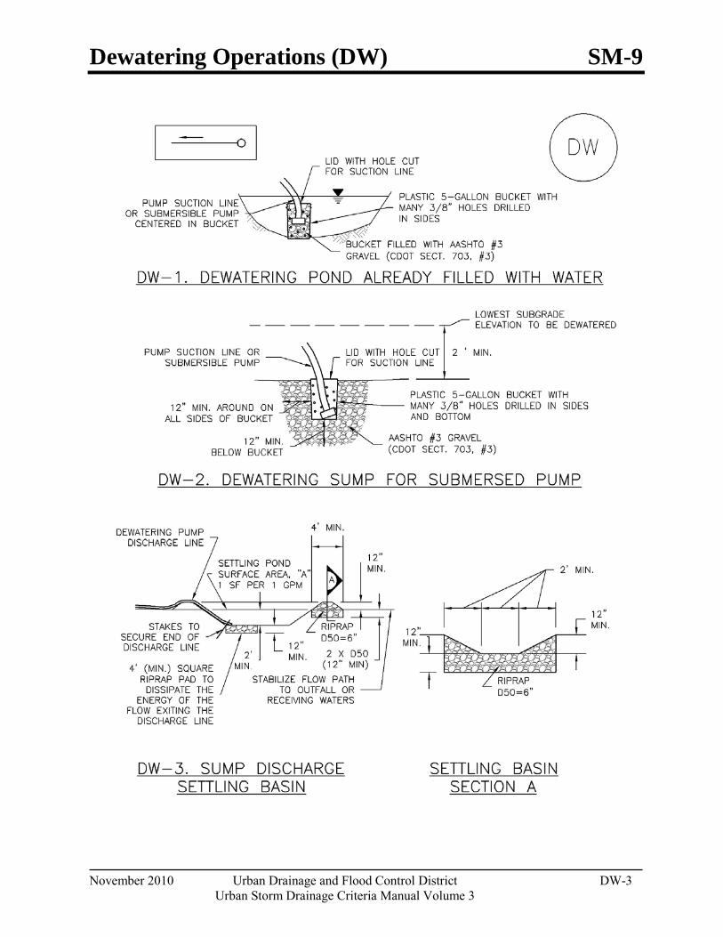
Dewatering Operations (DW) SM-9
November 2010 Urban Drainage and Flood Control District DW-3 Urban Storm Drainage Criteria Manual Volume 3
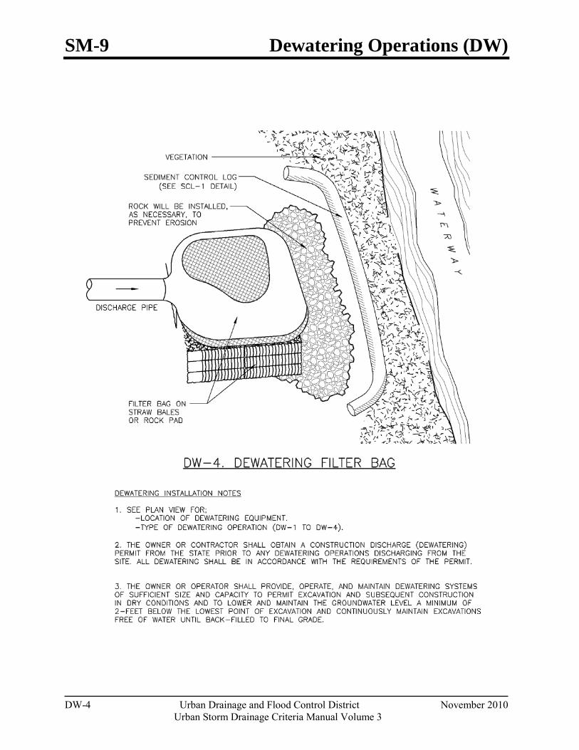
SM-9 Dewatering Operations (DW)
DW-4 Urban Drainage and Flood Control District November 2010
Urban Storm Drainage Criteria Manual Volume 3
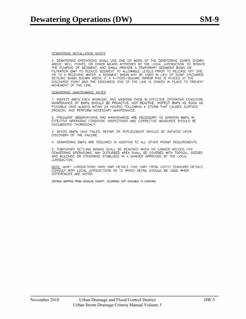
Dewatering Operations (DW) SM-9
November 2010 Urban Drainage and Flood Control District DW-5 Urban Storm Drainage Criteria Manual Volume 3

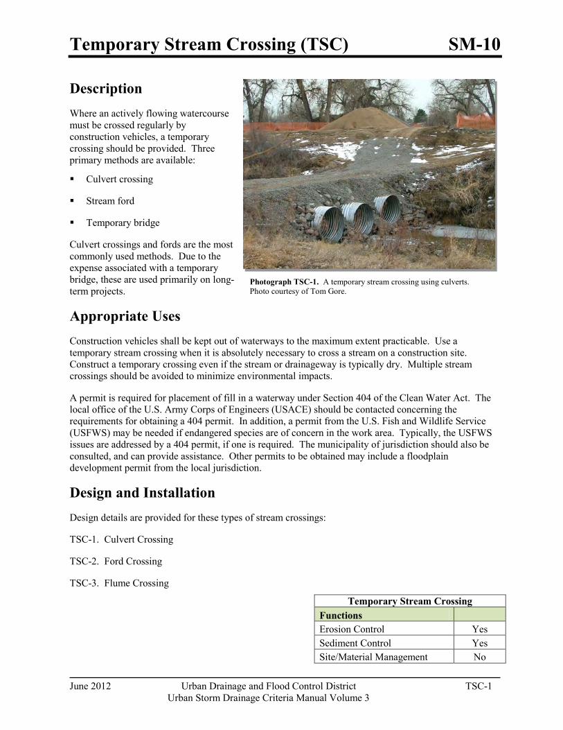
Temporary Stream Crossing (TSC) SM-10
June 2012 Urban Drainage and Flood Control District TSC-1 Urban Storm Drainage Criteria Manual Volume 3
Description Where an actively flowing watercourse must be crossed regularly by construction vehicles, a temporary crossing should be provided. Three primary methods are available:
Culvert crossing
Stream ford
Temporary bridge
Culvert crossings and fords are the most commonly used methods. Due to the expense associated with a temporary bridge, these are used primarily on long-term projects.
Appropriate Uses Construction vehicles shall be kept out of waterways to the maximum extent practicable. Use a temporary stream crossing when it is absolutely necessary to cross a stream on a construction site. Construct a temporary crossing even if the stream or drainageway is typically dry. Multiple stream crossings should be avoided to minimize environmental impacts.
A permit is required for placement of fill in a waterway under Section 404 of the Clean Water Act. The local office of the U.S. Army Corps of Engineers (USACE) should be contacted concerning the requirements for obtaining a 404 permit. In addition, a permit from the U.S. Fish and Wildlife Service (USFWS) may be needed if endangered species are of concern in the work area. Typically, the USFWS issues are addressed by a 404 permit, if one is required. The municipality of jurisdiction should also be consulted, and can provide assistance. Other permits to be obtained may include a floodplain development permit from the local jurisdiction.
Design and Installation Design details are provided for these types of stream crossings:
TSC-1. Culvert Crossing
TSC-2. Ford Crossing
TSC-3. Flume Crossing
Temporary Stream Crossing Functions Erosion Control Yes Sediment Control Yes Site/Material Management No
Photograph TSC-1. A temporary stream crossing using culverts. Photo courtesy of Tom Gore.
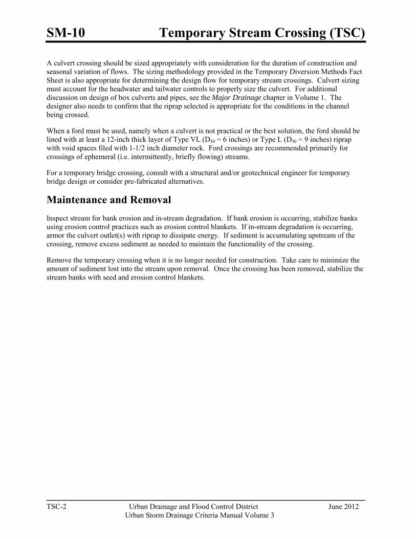
SM-10 Temporary Stream Crossing (TSC)
TSC-2 Urban Drainage and Flood Control District June 2012
Urban Storm Drainage Criteria Manual Volume 3
A culvert crossing should be sized appropriately with consideration for the duration of construction and seasonal variation of flows. The sizing methodology provided in the Temporary Diversion Methods Fact Sheet is also appropriate for determining the design flow for temporary stream crossings. Culvert sizing must account for the headwater and tailwater controls to properly size the culvert. For additional discussion on design of box culverts and pipes, see the Major Drainage chapter in Volume 1. The designer also needs to confirm that the riprap selected is appropriate for the conditions in the channel being crossed.
When a ford must be used, namely when a culvert is not practical or the best solution, the ford should be lined with at least a 12-inch thick layer of Type VL (D50 = 6 inches) or Type L (D50 = 9 inches) riprap with void spaces filed with 1-1/2 inch diameter rock. Ford crossings are recommended primarily for crossings of ephemeral (i.e. intermittently, briefly flowing) streams.
For a temporary bridge crossing, consult with a structural and/or geotechnical engineer for temporary bridge design or consider pre-fabricated alternatives.
Maintenance and Removal Inspect stream for bank erosion and in-stream degradation. If bank erosion is occurring, stabilize banks using erosion control practices such as erosion control blankets. If in-stream degradation is occurring, armor the culvert outlet(s) with riprap to dissipate energy. If sediment is accumulating upstream of the crossing, remove excess sediment as needed to maintain the functionality of the crossing.
Remove the temporary crossing when it is no longer needed for construction. Take care to minimize the amount of sediment lost into the stream upon removal. Once the crossing has been removed, stabilize the stream banks with seed and erosion control blankets.
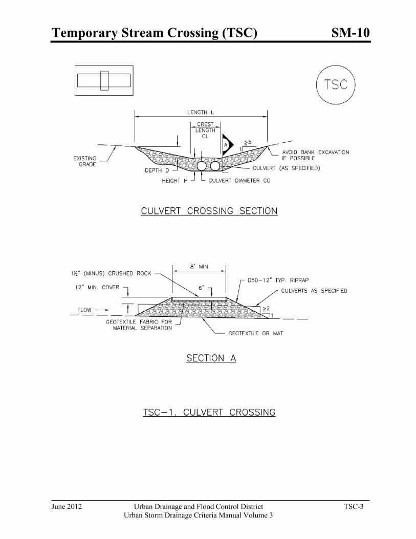
Temporary Stream Crossing (TSC) SM-10
June 2012 Urban Drainage and Flood Control District TSC-3 Urban Storm Drainage Criteria Manual Volume 3
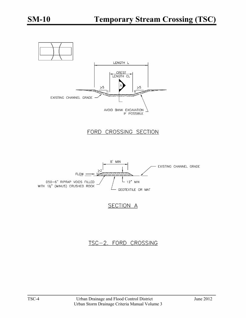
SM-10 Temporary Stream Crossing (TSC)
TSC-4 Urban Drainage and Flood Control District June 2012
Urban Storm Drainage Criteria Manual Volume 3
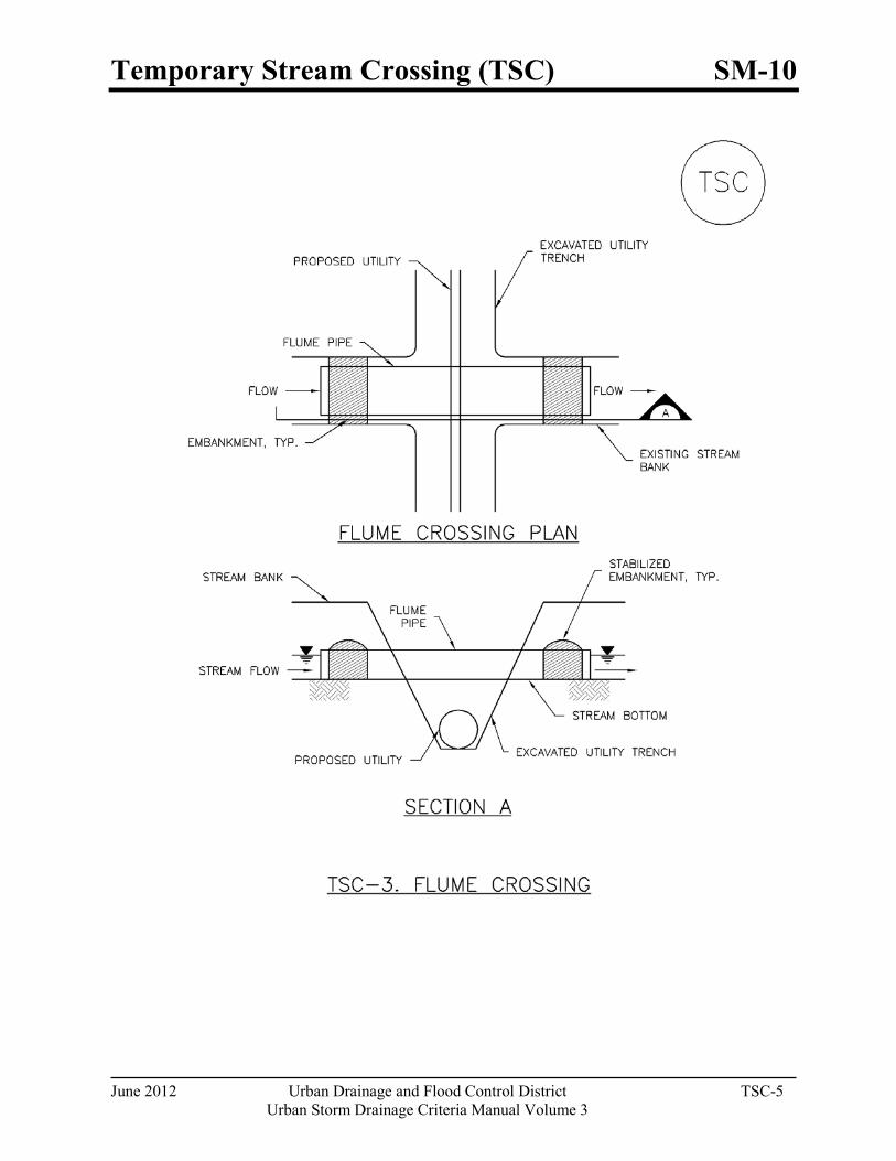
Temporary Stream Crossing (TSC) SM-10
June 2012 Urban Drainage and Flood Control District TSC-5 Urban Storm Drainage Criteria Manual Volume 3
SM-10 Temporary Stream Crossing (TSC)
TSC-6 Urban Drainage and Flood Control District June 2012
Urban Storm Drainage Criteria Manual Volume 3
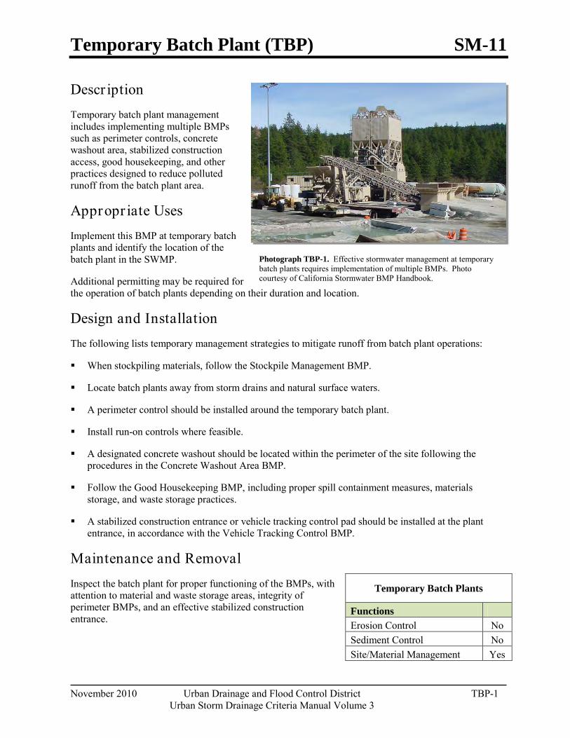
Temporary Batch Plant (TBP) SM-11
November 2010 Urban Drainage and Flood Control District TBP-1 Urban Storm Drainage Criteria Manual Volume 3
Photograph TBP-1. Effective stormwater management at temporary batch plants requires implementation of multiple BMPs. Photo courtesy of California Stormwater BMP Handbook.
Descr iption Temporary batch plant management includes implementing multiple BMPs such as perimeter controls, concrete washout area, stabilized construction access, good housekeeping, and other practices designed to reduce polluted runoff from the batch plant area.
Appropr iate Uses Implement this BMP at temporary batch plants and identify the location of the batch plant in the SWMP.
Additional permitting may be required for the operation of batch plants depending on their duration and location.
Design and Installation The following lists temporary management strategies to mitigate runoff from batch plant operations:
When stockpiling materials, follow the Stockpile Management BMP.
Locate batch plants away from storm drains and natural surface waters.
A perimeter control should be installed around the temporary batch plant.
Install run-on controls where feasible.
A designated concrete washout should be located within the perimeter of the site following the procedures in the Concrete Washout Area BMP.
Follow the Good Housekeeping BMP, including proper spill containment measures, materials storage, and waste storage practices.
A stabilized construction entrance or vehicle tracking control pad should be installed at the plant entrance, in accordance with the Vehicle Tracking Control BMP.
Maintenance and Removal Inspect the batch plant for proper functioning of the BMPs, with attention to material and waste storage areas, integrity of perimeter BMPs, and an effective stabilized construction entrance.
Temporary Batch Plants
Functions Erosion Control No Sediment Control No Site/Material Management Yes
SM-11 Temporary Batch Plant (TBP)
TBP-2 Urban Drainage and Flood Control District November 2010
Urban Storm Drainage Criteria Manual Volume 3
After the temporary batch plant is no longer needed, remove stockpiled materials and equipment, regrade the site as needed, and revegetate or otherwise stabilize the area.

Paving and Grinding Operations (PGO) SM-12
November 2010 Urban Drainage and Flood Control District PGO-1 Urban Storm Drainage Criteria Manual Volume 3
Photograph PGO-1. Paving operations on a Colorado highway. Photo courtesy of CDOT.
Description Manage runoff from paving and grinding operations to reduce pollutants entering storm drainage systems and natural drainageways.
Appropriate Uses Use runoff management practices during all paving and grinding operations such as surfacing, resurfacing, and saw cutting.
Design and Installation There are a variety of management strategies that can be used to manage runoff from paving and grinding operations:
Establish inlet protection for all inlets that could potentially receive runoff.
Schedule paving operations when dry weather is forecasted.
Keep spill kits onsite for equipment spills and keep drip pans onsite for stored equipment.
Install perimeter controls when asphalt material is used on embankments or shoulders near waterways, drainages, or inlets.
Do not wash any paved surface into receiving storm drain inlets or natural drainageways. Instead, loose material should be swept or vacuumed following paving and grinding operations.
Store materials away from drainages or waterways.
Recycle asphalt and pavement material when feasible. Material that cannot be recycled must be disposed of in accordance with applicable regulations.
See BMP Fact Sheets for Inlet Protection, Silt Fence and other perimeter controls selected for use during paving and grinding operations.
Maintenance and Removal Perform maintenance and removal of inlet protection and perimeter controls in accordance with their respective fact sheets.
Promptly respond to spills in accordance with the spill prevention and control plan.
Paving and Grinding Operations
Functions Erosion Control No Sediment Control No Site/Material Management Yes

November 2010 Urban Drainage and Flood Control District Glossary-1
Urban Storm Drainage Criteria Manual Volume 3
Glossary1
Best Management Practice (BMP): A technique, process, activity, or structure used to reduce pollutant discharges in stormwater. BMPs include source control practices (non-structural BMPs) and engineered structures designed to treat runoff. BMPs are most effective when used in combination and selected and designed based on site-specific characteristics.
Biofilter: Dense vegetation designed to filter pollutants from stormwater runoff. (Also see definition of Grass Buffer and Grass Swale.)
Note: This glossary is not intended to provide regulatory or legal definitions of terms. Instead, it is intended to provide users of Volume 3 with a basic understanding of terms used in this manual.
303(d) List: Section 303(d) of federal Clean Water Act requires states to list those waterbodies that are not attaining water quality standards, including designated uses, and identify relative priorities among the impaired waterbodies. Once a stream is listed on the state 303(d) list, a Total Maximum Daily Load (TMDL) is typically required to assign allowable pollutant loads to various sources to enable the waterbody to attain designated uses in the future.
404 Permit: A federal discharge permit authorized under Section 404 of the Clean Water Act, which regulates the discharge of dredged, excavated, or fill material into wetlands, streams, rivers, and other Waters of the U.S. The U.S. Army Corps of Engineers is the federal agency authorized to issue Section 404 Permits for certain activities conducted in wetlands or other U.S. waters. When working in or around waterways or wetlands, 404 Permits are often required.
Bioretention: A method of stormwater quality treatment that relies on soils and vegetation for reduction of the quantity (volume) of stormwater runoff and removal/retention of stormwater pollutants. Bioretention facilities reduce runoff volume discharged downstream by infiltration and evapotranspiration. Bioretention facilities may be designed for infiltration to subsoils or with underdrains, depending on site-specific conditions. Pollutant removal processes include filtration, biological uptake, sorption and sedimentation (in the temporary surface pool during an event). Bioretention facilities are also known as rain gardens and porous landscape detention.
Buffer Zone: A designated transitional area around a stream, lake, or wetland left in a natural, usually vegetated state so as to protect the waterbody from runoff pollution. Development is often restricted or prohibited in a buffer zone.
Catch Basin: A depressed entryway to the storm drain system, usually located at a street corner.
1 Definitions in this glossary have been compiled from several key references and websites including: Denver Water Quality Management Plan Glossary, Denver Wastewater Management Division Rules and Regulations http://www.denvergov.org/admin/template3/forms/Sewer%20charges.PDF, CWQCD http://www.cdphe.state.co.us/wq/, Utah APWA http://www.ulct.org/apwa/Glossary.htm, EPA website glossaries http://www.epa.gov/ednnrmrl/main/gloss.htm and http://cfpub.epa.gov/npdes/glossary.cfm?program_id=0, the Low Impact Development website: http://www.lowimpactdevelopment.org/school/glossary.html, the Maryland website http://www.mde.state.md.us/assets/document/sedimentstormwater/Glossary.pdf, and the NRDC website http://www.nrdc.org/water/pollution/storm/gloss.asp.
Glossary
Glossary-2 Urban Drainage and Flood Control District November 2010
Urban Storm Drainage Criteria Manual Volume 3
Clean Water Act: Federal legislation that provides statutory authority for the National Pollutant Discharge Elimination System (NPDES) program and other water quality protection requirements; Public law 92-500; 33 U.S.C. 1251 et seq. Also known as the Federal Water Pollution Control Act. Under the Clean Water Act stormwater requirements, most urban areas must meet requirements of Municipal Separate Storm Sewer System (MS4) permits, and many industries and institutions such as state departments of transportation must also meet NPDES stormwater permit requirements. Operators of regulated MS4s are required to develop a Stormwater Management Plan (SWMP) that includes measurable goals and to implement needed stormwater management controls (BMPs). MS4s are also required to assess controls and the effectiveness of their stormwater programs and reduce the discharge of pollutants to the "maximum extent practicable."
Colorado Discharge Permit System (CDPS): The State of Colorado's system of permitting discharges (e.g., stormwater, wastewater) to Waters of the State that corresponds to the federal NPDES permits under the federal Clean Water Act.
Constructed Wetland Basin: An engineered stormwater BMP designed with a permanent shallow water surface and hydrophytic vegetation such as rushes, willows, cattails, and reeds. Constructed wetland basins included outlet structures to control peak flows and treat the WQCV through settling of pollutants and biological uptake. A perennial supply of water is necessary for constructed wetland basins.
Design Storm: A rainfall event of specific duration, intensity, and return frequency (e.g., the 1-year, 24-hour storm) that is used to calculate runoff volume and peak discharge rate for the purpose of designing stormwater facilities.
Detention: The storage and slow release of stormwater from an excavated pond, enclosed depression, or tank. Detention is used for pollutant removal, stormwater storage, and peak flow reduction. Both wet and dry detention methods can be applied.
Directly Connected Impervious Area (DCIA): The impervious portion of a site that drains directly to the storm sewer system. DCIA is a key component of the conceptual model used in the volume reduction calculations in Chapter 3 of this manual.
Distributed Controls: Use of multiple BMPs distributed throughout a development site to control and treat stormwater close to it source, as opposed to routing flows to a larger, centralized stormwater facility. Use of distributed stormwater controls is key component of Low Impact Development.
Dry Pond: See definition of Extended Detention Basin (EDB).
Dry Weather Flows: Flows from municipal storm sewer systems that are not due to rain or snow-generated urban runoff.
Effective Imperviousness: Impervious areas that contribute surface runoff to the drainage system. For the purposes of this manual, Effective Imperviousness includes Directly Connected Impervious Area and portions of the Unconnected Impervious Area that also contribute to runoff from a site. For small, frequently occurring events, the Effective Imperviousness may be equivalent to Directly Connected Impervious Area since runoff from Unconnected Impervious Areas may infiltrate into Receiving Pervious Areas; however, for larger events, the Effective Imperviousness is increased to account for runoff from Unconnected Impervious Areas that exceeds the infiltration capacity of the Receiving Pervious Area. Note: Users should be aware that some national engineering literature defines the Effective Impervious Area more narrowly to include only Directly Connected Impervious Area.
November 2010 Urban Drainage and Flood Control District Glossary-3
Urban Storm Drainage Criteria Manual Volume 3
Effluent Limitation Guidelines (ELGs): EPA-published guidelines in the Federal Register (Volume 74, Number 229, pages 62997-63057) establishing technology-based effluent limitation guidelines and new source performance standards for the construction and development industry. This rule requires construction site owners and operators to implement a range of erosion and sediment control measures and pollution prevention practices to control pollutants in discharges from construction sites. Additionally, the rule will eventually require monitoring and sampling of stormwater discharges and compliance with a numeric standard for turbidity in these discharges for larger construction sites (i.e., 10 acres or more).
Endangered Species Act: The Endangered Species Act of 1973 protects animal and plant species currently in danger of extinction (endangered) and those that may become endangered in the foreseeable future (threatened). It provides for the conservation of ecosystems upon which threatened and endangered species of fish, wildlife, and plants depend, both through federal action and by encouraging the establishment of state programs.
Erosion Control Measures: Source controls used to limit erosion of soil at construction sites and other erosion-prone areas. Representative measures include surface treatments that stabilize soil that has been exposed due to excavation or grading and flow controls that redirect flows or reduce velocities of concentrated flow.
Erosion: Process by which soil particles are detached and transported by wind, water, and gravity to a downslope or downstream location
Eutrophication: An increase in the concentration of chemical nutrients (e.g., phosphorus, nitrogen) in an ecosystem to an extent that increases the primary productivity (e.g., algal growth) of the ecosystem, resulting in decreased oxygen levels and deteriorated water quality.
Event Mean Concentration (EMC): Pollutant concentration based on a composite of multiple samples (aliquots) collected during the course of a storm. Because EMCs represent conditions at multiple points on a storm hydrograph, they are most representative of average pollutant concentrations over an entire runoff event. EMCs are contrasted with single "grab" samples, which reflect storm conditions at a particular point in time.
Excess Urban Runoff Volume (EURV): The difference between urban and pre-development runoff volumes. The EURV is the basis of design for Full Spectrum Detention facilities.
Extended Detention Basin (EDB): An engineered basin with an outlet structure designed to slowly release urban runoff over an extended time period to provide water quality benefits and control peak flows for frequently occurring storm events. The basins are sometimes called "dry ponds" because they are designed not to have a significant permanent pool of water remaining between storm runoff events. Outlet structures for extended detention basins are sized to control more frequently occurring storm events, whereas flood control detention facilities are designed to control less frequent, larger storm events. Outlet structures can be designed to integrate water quality and flood control into a single detention facility. Also see Full Spectrum Detention.
Extensive Green Roof: A shallow green roof, typically 6 inches or shallower, that is designed to satisfy specific engineering and performance goals such as water quality treatment. An extensive green roof has low lying plants designed to provide maximum groundcover, water retention, erosion resistance, and respirative transpiration of moisture. Extensive green roofs usually use plants with foliage from 2 to 6 inches and provide 2 to 4 inches of soil/growing media.
Glossary
Glossary-4 Urban Drainage and Flood Control District November 2010
Urban Storm Drainage Criteria Manual Volume 3
Forebay: Storage space located near a stormwater BMP inlet designed to trap incoming coarse sediments and other gross solids before they accumulate in the main treatment area of the BMP.
Full Spectrum Detention: A stormwater detention facility design to provide water quality and flood control benefits and reduced impacts on downstream channels by detaining the Excess Urban Runoff Volume (EURV) and releasing it over a 72 hour period. The EURV is approximately
Geographic Information System (GIS): A database of digital information and data on land-use, land cover, ecological characteristics, and other geographic attributes that can be overlaid, statistically analyzed, mathematically manipulated, and graphically displayed using maps, charts, and graphs.
Grass Buffer: Uniformly graded and densely vegetated area, typically turfgrass. This BMP requires sheet flow to promote filtration, infiltration, and settling to reduce runoff pollutants.
Grass Swale: Densely vegetated drainageway with low-pitched side slopes that collects and slowly conveys runoff. The design of the longitudinal slope and cross-section size forces the flow to be slow and shallow, thereby facilitating sedimentation while limiting erosion.
Green Roof: An engineered vegetated roof that can be used to detain and treat precipitation. Green roofs require an engineered structure that can support soils, vegetation and loads associated with rainfall, snow, people and equipment. Key components include a waterproof membrane, root barrier, drainage layer, soil/growing medium, irrigation system and plants.
Hot Spot: Area where land use or activities have the potential to generate highly contaminated runoff with concentrations of pollutants in excess of those typically found in stormwater.
Household Hazardous Waste: Common everyday products such as paint, paint thinner and pesticides that can be hazardous if not properly disposed.
Illicit Connection: A sanitary plumbing fixture connected to a storm sewer, resulting in illicit discharges to the storm sewer system.
Illicit Discharge: A discharge to a municipal separate storm sewer that is not composed entirely of stormwater and is not authorized by an NPDES permit, with some exceptions (e.g., discharges due to fire-fighting activities).
Impervious Area: A hard surface area (e.g., parking lot or rooftop) that prevents or retards the infiltration of water into the soil, thus causing water to run off the surface in greater quantities and at an increased rate of flow relative to pervious areas.
Infiltration: The percolation of water from the land surface into the ground.
Inlet: An entrance into a ditch, storm sewer, or other waterway.
Integrated Pest Management (IPM): The practice of using biological, chemical, cultural, and physical measures to manage pests while minimizing or eliminating the use of chemical pesticides.
Intensive Green Roof: Landscaped roofs with several feet of soil and a variety of plant types, often including trees.
Level Spreader: An engineered structure designed to convert concentrated runoff to sheet flow and disperse it uniformly across a slope, thereby preventing/minimizing erosion.
November 2010 Urban Drainage and Flood Control District Glossary-5
Urban Storm Drainage Criteria Manual Volume 3
Low Impact Development (LID): LID is an overall land planning and engineering design approach to managing stormwater runoff. LID emphasizes conservation and use of on-site natural features to protect water quality. This approach implements engineered small-scale hydrologic controls to mimic the pre-development hydrologic regime of watersheds through infiltrating, filtering, storing, evaporating, and detaining runoff close to its source. The term Green Infrastructure (GI) may also be used, particularly in areas with combined sewer overflow (CSO) issues.
Low Impact Development Practice: Individual practices used as part of overall LID developments or integrated into traditional developments include practices such as bioretention facilities, rain gardens, vegetated rooftops, rain barrels, permeable pavements and other infiltration-oriented practices.
Materials Management Practices: Source control practices at construction sites intended to limit contact of runoff with pollutants such as construction materials and equipment-related fluids. By intentionally controlling and managing areas where chemicals are handled, the likelihood of these materials being transported to waterways is reduced.
Media Filter: A stormwater BMP designed to filter runoff as it passes through media such as sand, compost, sand-peat, perlite-zeolite, or similar materials. (See Sand Filter Extended Detention Basin.)
Micropool: A smaller permanent pool incorporated into the design of larger stormwater ponds to reduce potential of clogging of the outlet and minimize resuspension of sediment.
Minimizing Directly Connected Impervious Areas (MDCIA): A variety of runoff reduction strategies that route runoff from impervious surfaces over pervious areas to decrease runoff velocities and promote infiltration.
Minimum Measures: Stormwater management activities required under Phase II MS4 permits. The six minimum measures include 1) public education and outreach, 2) public participation/involvement, 3) illicit discharge detection and elimination, 4) construction site stormwater runoff control, 5) post-construction stormwater management, and 6) pollution prevention/good housekeeping for municipal operations.
Municipal Separate Storm Sewer System (MS4): A publicly owned conveyance or system of conveyances that discharges to waters of the U.S. and is designed or used for collecting or conveying stormwater, is not a combined sewer, and is not part of a publicly owned treatment works (POTW).
MS4 Permit: A state or federal stormwater discharge permit to regulate discharges from municipal separate storm sewers (MS4s) for compliance with Clean Water Act regulations.
National Pollutant Discharge Elimination System (NPDES): The national program under Section 402 of the Clean Water Act for regulation of discharges of pollutants from point sources to waters of the U.S.
Non-Point Source (NPS) Pollution: Pollution that occurs when rainwater, snowmelt, or irrigation transports pollutants from diffuse sources across land surfaces into waterbodies. Nonpoint source pollution is contrasted with point source pollution in that it is not discharged from single discharge points such as storm sewers and wastewater treatment plants.
Non-Structural BMPs: Stormwater BMPs that focus on management of pollutants at their source by minimizing exposure to runoff, rather than treating runoff in constructed facilities. Non-structural BMPs are referred to as source controls in this manual.
NPDES: National Pollutant Discharge Elimination System, as described above.
Glossary
Glossary-6 Urban Drainage and Flood Control District November 2010
Urban Storm Drainage Criteria Manual Volume 3
Peak Runoff Rate: The highest actual or predicted flow rate (typically measured in cubic feet per second) for runoff from a site for a specific event.
Permeability: The ability of a material to allow the passage of a liquid, such as water through rocks or soil. Permeable materials, such as gravel and sand, allow water to move quickly through them, whereas impermeable material, such as clay, does not allow water to flow freely.
Permeable Pavement Systems (PPS): A general term to describe pavements designed to allow infiltration of water from the paved surface into subsurface layers. Depending on the design, permeable pavements can be used to promote volume reduction, provide treatment and slow release of the WQCV, and/or reduce effective imperviousness. Permeable pavement systems include permeable interlocking concrete pavement, concrete grid, pervious concrete, reinforced grass, and porous gravel.
Point Source Pollution: Pollutants from a single, identifiable source such as a factory, refinery, or place of business. In the context of TMDLs, point sources typically include NPDES-permitted sanitary wastewater treatment facilities, municipal separate storm sewer systems (MS4s), and confined animal feeding operations (CAFOs).
Pollutant (as defined by CDPS Regulation 6.3.0 [51]): Dredged spoil, dirt, slurry, solid waste, incinerator residue, sewage, sewage sludge, garbage, trash, chemical waste, biological nutrient, biological material, radioactive material, heat, wrecked or discarded equipment, rock, sand, or any industrial, municipal or agriculture waste.
Pollutant Load: The mass of pollutants carried in runoff, calculated based on flow volume multiplied by pollutant concentration. Pollutant loading has units of mass and is calculated over specific timescales such as day, month or year.
Porous Landscape Detention (PLD): Also known as a rain garden or bioretention facility, this stormwater quality BMP consists of a low lying vegetated area underlain by a permeable media with an underdrain. A shallow surcharge zone exists above the porous landscape detention for temporary storage of the WQCV.
Rain Garden: See definitions of Bioretention and Porous Landscape Detention (PLD).
Receiving Pervious Area (RPA): The pervious portion of a site that receives runoff from an upgradient impervious area prior to draining to the storm sewer system. RPA is a key component of the conceptual model used in the volume reduction calculations in Chapter 3 of this manual.
Redevelopment: Improvements to an existing developed area, typically involving removal of existing structures and construction of new buildings and associated infrastructure. Depending on the scale of the redevelopment activity, post-development stormwater permit requirements may be triggered.
Retention Pond: A BMP consisting of a permanent pool of water designed to treat runoff by detaining water long enough for settling, filtering, and biological uptake. Also known as wet ponds, these ponds may also be designed to have an aesthetic and/or recreational value. These BMPs have a permanent pool of water that is replaced with stormwater, in part or in total, during storm runoff events. In addition, a temporary extended detention volume is provided above this permanent pool to capture storm runoff and enhance sedimentation. Retention ponds require a perennial supply of water to maintain the pool and are typically used on larger sites.
Retrofit: The creation or modification of a stormwater management practice, usually in a developed area, that improves or combines treatment with existing stormwater infrastructure.
November 2010 Urban Drainage and Flood Control District Glossary-7
Urban Storm Drainage Criteria Manual Volume 3
Revised Universal Soil Loss Equation (RUSLE): An erosion prediction method originally developed for agricultural land use that can also be used for estimating erosion potential on construction sites and adjusting BMPs to reduce the estimated erosion. Factors included in this equation include rainfall-runoff erosivity, soil erodibility, slope length and steepness, surface cover management, and erosion control practice implementation.
Runoff: Water from rain, melted snow, or irrigation that flows over the land surface.
Sand Filter Extended Detention Basin: A stormwater quality BMP consisting of a sand bed and underdrain system. Above the vegetated sand bed is an extended detention basin sized to capture the WQCV. A sand filter extended detention basin provides pollutant removal through settling and filtering and is generally suited to off-line, on-site configurations where there is no base flow and the sediment load is relatively low.
Sediment Control Measures: Practices that reduce transport of sediment off-site to downstream properties and receiving waters. Sediment controls generally either provide filtration through a permeable media or slow or detain runoff to allow settling of suspended particles.
Separate Pervious Area (SPA): The pervious portion of a site that drains to the storm sewer system, but does not receive runoff from upgradient impervious areas. SPA is a key component of the conceptual model used in the volume reduction calculations in Chapter 3 of this manual.
Sheet Flow: The portion of precipitation that flows overland in very shallow depths before eventually reaching a stream channel or other conveyance.
Site Management Practices: A combination of construction site management practices that help reduce pollutants leaving a construction site. These include practices such as construction sequencing and scheduling, vehicle tracking controls and street sweeping, and good management of practices associated with site construction such as stream crossing, temporary batch plants, dewatering operations and other measures.
Slotted Curbs: Curbs with slots or cut-out areas that allow stormwater to flow away from the curbed pavement into an adjacent landscape or turf area, as opposed to transporting runoff directly to a storm sewer system.
Source Controls: A variety of practices implemented to minimize pollutant transport in runoff by controlling pollutants where they originate and/or accumulate. Representative source controls include good housekeeping measures, landscape management practices, pet waste controls, public education regarding household hazardous waste, covering outdoor storage areas, etc.
Spill Prevention Control and Countermeasure (SPCC) Plan: A written plan prepared for an industrial, commercial or construction operation identifying measure to minimize the likelihood of a spill and to expedite control and cleanup activities should a spill occur. SPCC plans are legally required for certain types of operations.
Stormwater Management Plan (SWMP): A written plan required under state and federal stormwater discharge permits identifying measures that will be implemented to minimize the discharge of pollutants in stormwater. Requirements for SWMPs are legally specified in state and federal discharge permits. Requirements vary depending on whether the discharge permit is associated with municipal, industrial, or construction activities.
Structural BMPs: Engineered structures constructed to provide temporary storage and treatment of stormwater runoff.
Glossary
Glossary-8 Urban Drainage and Flood Control District November 2010
Urban Storm Drainage Criteria Manual Volume 3
Surface Water: Water that remains on the surface of the ground, including rivers, lakes, reservoirs, streams, wetlands, impoundments, seas, estuaries, etc.
Total Maximum Daily Load (TMDL): The maximum allowable loading of a pollutant that a designated waterbody can assimilate and still meet numeric and narrative water quality standards. Section 303(d) of the federal Clean Water Act requires states to identify waterbodies that do not meet federal water quality standards and establish TMDLs that result in attainment of stream standards.
Trash Rack: Grill, grate or other device installed at the intake of a channel, pipe, drain, or spillway for the purpose of preventing oversized debris from entering the structure. Trash racks may also serve a safety function.
Treatment Train: BMPs that work together in series to provide stormwater quality treatment.
Unconnected Impervious Area (UIA): The impervious portion of a site that drains over a receiving pervious area before discharging to the storm sewer system. UIA is a key component of the conceptual model used in the volume reduction calculations in Chapter 3 of this manual.
Underdrain: A perforated pipe, typically 4- to 6-inches in diameter, placed longitudinally at the invert of a stormwater facility for the purposes of achieving a desired discharge rate and controlling nuisance ponding.
Water Quality Capture Volume (WQCV): The quantity of stormwater runoff that must be treated in stormwater quality BMPs in Denver. This volume is equivalent to the runoff from an 80th percentile storm, meaning that 80 percent of the most frequently occurring storms are fully captured and treated and larger events are partially treated.
Waters of the United States: All waters that are currently used, were used in the past, or may be susceptible to use in interstate or foreign commerce, including all waters subject to the ebb and flow of the tide. Waters of the U.S. include all interstate waters and intrastate lakes, rivers, streams (including intermittent streams), mudflats, sand flats, wetlands, sloughs, prairie potholes, wet meadows, playa lakes, or natural ponds. [See 40 CFR 122.2 for the complete definition.]
Watershed: A geographical area that drains to a specified point on a water course, usually a confluence of streams or rivers (also known as drainage area, catchment, or river basin).
Wet Pond: See definition of Retention Pond.
Wet Weather Flows: Water entering storm sewer systems as a result of precipitation events.
Wetlands: Areas that are inundated or saturated by surface or groundwater at a frequency and duration sufficient to support, and that under normal circumstances do support, a prevalence of vegetation typically adapted for life in saturated soil conditions. Wetlands generally include swamps, marshes, bogs, and similar areas.
November 2010 Urban Drainage and Flood Control District Bibliography-1
Urban Storm Drainage Criteria Manual Volume 3
Bibliography Altitude Training Associates. 2008. Stormwater Management During Construction: Best Management
Practices for Construction in Waterways Training Program Student Manual. www.udfcd.org.
American Society of Civil Engineers (ASCE) and Water Environment Federation (WEF). 1992. Design and Construction of Urban Stormwater Management Systems. ASCE Manual and Reports of Engineering Practice No. 77 and WEF Manual of Practice FD-20. Alexandria, VA: WEF.
Barrett, M., Lantin, A. and S. Austrheim-Smith. 2004. Stormwater Pollutant Removal in Roadside Vegetated Buffer Strips. Prepared for the Transportation Research Board: Washington, DC.
Bedient, Philip B. and Wayne C. Huber. 1992. Hydrology and Floodplain Analysis (Second Edition). Addison-Wesley Publishing Company.
Burton, A. and R. Pitt. 2001. Stormwater Effects Handbook: A Toolbox for Watershed Managers, Scientists, and Engineers. Lewis Publishers. http://www.epa.gov/ednnrmrl/publications/books/handbook/index.htm
California Stormwater Quality Association (CASQA). 2003. California Stormwater BMP Handbook, Practice SC-70 Road and Street Maintenance.
California Stormwater Quality Association (CASQA) 2003. California Stormwater BMP Handbook, Vegetated Buffer Strip.
Center for Watershed Protection Website: http://www.cwp.org
Center for Watershed Protection, 2008. Urban Stormwater Restoration Manual Series 8: Municipal Practices and Programs.
Center for Watershed Protection. 2005. Urban Stormwater Restoration Manual Series 8: Pollution Source Control Practices. Version 2.0. February.
Center for Watershed Protection and Robert Pitt. 2004. Illicit Discharge Detection and Elimination: A Guidance Manual for Program Development and Technical Assessment. (http://cwp.org.master.com/texis/master/search/+/form/New_IDDE.html).
Center for Watershed Protection. 2002. Article 121 New Developments in Street Sweeper Technology. The Practice of Watershed Protection.
Chow, Ven Te. 1959. Open Channel Flow. McGraw Hill: New York, NY.
City of Aurora Utilities Department, City of Denver Department of Public Works, City of Lakewood Department of Planning, Permits and Public Works in cooperation with Urban Drainage and Flood Control District. 1992. Stormwater NPDES Part 3 Permit Application Joint Appendix.
Colorado Department of Public Health and Environment Water Quality Control Division. 2007. CDPS General Permit, Stormwater Discharges Associated with Construction Activity.
Colorado Ready Mixed Concrete Association (CRMCA). Specifier's Guide for Pervious Concrete Pavement Design Version 1.2. www.crmca.org
Bibliography
Bibliography-2 Urban Drainage and Flood Control District November 2010
Urban Storm Drainage Criteria Manual Volume 3
Colorado State University Turfgrass website: http://csuturf.colostate.edu/.Colorado Water Quality Control Division (WQCD) Website: http://www.cdphe.state.co.us/wq
Colorado Water Quality Control Commission (WQCC). 2009. Regulation No. 61 Colorado Discharge Permit System (CDPS) Regulations
Colorado Water Quality Control Division (WQCD). 2009. Authorization to Discharge under the Colorado Discharge Permit System, Permit No. COS-000001. City and County of Denver MS4 Permit.
Colorado Water Quality Control Division (WQCD). 2008. MS4 General Permit. Permit No. COR-090000. CDPS General Permit, Stormwater Discharges Associated with Municipal Separate Storm Sewer Systems (MS4s). Authorization to Discharge under the Colorado Discharge Permit System.
CONTECH Stormwater Solutions. 2007. StormFilter Inspection and Maintenance Procedures. www.contech-cpi.org.
Davies, P.E. 1986. Toxicology and Chemistry in Urban Runoff. Urban Runoff Quality-Impacts and Quality Enhancement Technology Proceedings. American Society of Civil Engineers (ASCE). New York, NY.
Debo, T. and A. Reese. 2002. Municipal Stormwater Management. Second Edition. Lewis Publishers: Boca Raton, FL.
Denver Regional Council of Governments (DRCOG). 1983. Urban Runoff Quality in the Denver Region. Denver, CO.
Driscoll, E., G. Palhegyi, E. Strecker, and P. Shelley. 1990. Analysis of Storm Event Characteristics for Selected Rainfall Gauges Throughout the United States. Prepared for the U.S. Environmental Protection Agency (EPA). Woodward-Clyde Consultants: Oakland, CA.
Driscoll, E. 1983. Performance of Detention Basins for Control of Urban Runoff. International Symposium on Urban Hydrology, Hydraulics and Sediment Control Proceedings. University of Kentucky: Lexington, KY.
Dunnett, N. 2004. Planting Green Roofs and Living Walls. Timber Press, Inc: Portland, Oregon.
U.S. Environmental Protection Agency (EPA) "Menu of BMPs" website: http://cfpub.epa.gov/npdes/stormwater/menuofbmps/. Accessed April 2010.
U.S. Environmental Protection Agency (EPA) Stormwater Program Website: http://cfpub.epa.gov/npdes/home.cfm?program_id=6
U.S. Environmental Protection Agency (EPA). 2009. Effluent Limitations Guidelines and Standards for the Construction and Development Point Source Category, Final Rule. December 1, 2009. Federal Register, Part III Environmental Protection Agency, 40 CFR Part 450. 74 (229): 62997-63057.
U.S. Environmental Protection Agency (EPA). 2009. Federal Register Notice Regarding Stakeholder Input; Stormwater Management Including Discharges from New Development and Redevelopment. Federal Register, Vol. 74, No. 247, 68617-68622.
Bibliography
November 2010 Urban Drainage and Flood Control District Bibliography-3
Urban Storm Drainage Criteria Manual Volume 3
U.S. Environmental Protection Agency (EPA). 2009. Municipal Solid Waste Generation, Recycling, and Disposal in the United States: Facts and Figures for 2008. http://www.epa.gov/epawaste/nonhaz/municipal/pubs/msw2008rpt.pdf
U.S. Environmental Protection Agency (EPA). 2005. Stormwater Phase II Final Rule: Small Construction Program Overview. Fact Sheet 3.0. Office of Water. http://www.epa.gov/region8/water/stormwater/pdf/fact3-0.pdf
U.S. Environmental Protection Agency (EPA) and American Society of Civil Engineers (ASCE). 2002. Urban Stormwater BMP Performance Monitoring: A Guidance Manual for Meeting the National Stormwater BMP Database Requirements. Prepared by GeoSyntec Consultants and the Urban Drainage and Flood Control District. Washington DC.
United States Environmental Protection Agency (EPA). 1999. Storm Water Technology Fact Sheet: Wet Detention Ponds.
U.S. Environmental Protection Agency (EPA). 1992. Storm Water Management for Industrial Activities: Developing Pollution Prevention Plans and Best Management Practices. Office of Water. http://yosemite.epa.gov/water/owrccatalog.nsf/065ca07e299b464685256ce50075c11a/8f0a041d18e75f4885256d83004fd9b0!OpenDocument
U.S. Environmental Protection Agency (EPA). 1990. Urban Runoff and Stormwater Management Handbook. Chicago, IL.
U.S. Environmental Protection Agency (EPA). 1983. Results of the Nationwide Urban Runoff Program, Volume 1 – Final Report. U.S. Environmental Protection Agency, Water Planning Division, Washington D.C.
Erickson, Andy. 2009. Field Applications of Enhanced Sand Filtration. University of Minnesota Stormwater Management Practice Assessment Project Update. http://wrc.umn.edu.
Fairfax County Virginia. 2005. LID BMP Fact Sheet, Street Sweeping.
Geosyntec and Wright Water Engineers. 2010. International Stormwater Best Management Practices (BMP) Database Technical Summary: Volume Reduction. Prepared for the Water Environment Research Foundation, Federal Highway Administration, and the Environment and Water Resources Institute of the American Society of Civil Engineers.
GreenCO and Wright Water Engineers. 2008. GreenCO Best Management Practices for the Conservation and Protection of Water Quality in Colorado: Moving Toward Sustainability (www.greenco.org).
Green Roofs for Healthy Cities website. http://www.greenroofs.org/index.php/about-green-roofs accessed 17 March 2010.
Grizzard, T.J., C.W. Randall, B.L. Weand, and K.L. Ellis. 1986. Effectiveness of Extended Detention Ponds. Urban Runoff Quality-Impact and Quality Enhancement Technology Proceedings . Engineering Coundation Conference. American Society of Civil Engineering (ASCE). New York, NY
Bibliography
Bibliography-4 Urban Drainage and Flood Control District November 2010
Urban Storm Drainage Criteria Manual Volume 3
Guo, James C.Y., E. G. Blackler, A. Earles, and Ken Mackenzie. Accepted 2010. Effective Imperviousness as Incentive Index for Stormwater LID Designs. Pending publication in ASCE J. of Environmental Engineering.
Guo, James C.Y. 2006. Urban Hydrology and Hydraulic Design. Water Resources Publications: LLC.: Highlands Ranch, CO. Guo, James C.Y., PhD, Anu Ramaswami, PhD, and Shauna M. Kocman, PhD Candidate. 2010. Sustainable Design of Urban Porous Landscape Detention Basin. University of Colorado Denver
Guo, James C.Y. and Ben Urbonas. 1996. Maximized Detention Volume Determined by Runoff Capture Rate. ASCE Journal of Water Resources Planning and Management, Vol. 122, No 1, January.
Hartigan, J.P. 1989. Basis for Design of Wet Detention Basin BMPs. Design of Urban Runoff Quality Controls. Proceedings Engineering Foundation Conference. American Society of Civil Engineers (ASCE): New York, NY.
Horner, R.R., J.J. Skupien, E.H. Livingston and H.E. Shaver. 1994. Fundamental of Urban Runoff Management: Technical and Institutional Issues. Terrene Institute and EPA: Washington D.C.
Interlocking Concrete Pavement Institute (ICPI), Contractor Focus PICP Construction Tips. Interlocking Concrete Pavement Magazine vol. 17, no. 2, pp. 16-22, May 2010.
Interlocking Concrete Pavement Institute (ICPI). 2008. Permeable Interlocking Concrete Pavement: A Comparison Guide to Porous Asphalt and Pervious Concrete. www.icpi.org
Interlocking Concrete Pavement Institute (ICPI). 2007. Permeable Interlocking Concrete Pavements: Selection, Design, Construction, Maintenance. www.icpi.org
Interlocking Concrete Pavement Institute (ICPI). 2004. ICPI Tech Spec No. 10. www.icpi.org
International Stormwater Best Management Practices Database. www.bmpdatabase.org. Cosponsored by the Water Environmental Research Foundation, American Society of Civil Engineers, Environmental and Water Resources Institute, Federal Highway Administration and U.S. Environmental Protection Agency. Accessed in 2010.
Jarrett, A.R. 1997. Effectiveness of Undersized Sedimentation Basins: An Evaluation and Demonstration. Final Completion Report for Research Project funded by Great Lakes Commission. Great Lakes Basin Program for Soil Erosion and Sediment Control.
Koski, T. and Skinner, V. 2003. Colorado State University Extension. Fact Sheet no.7.202, Lawn Care. http://www.ext.colostate.edu/pubs/garden/07202.html
Law, N.L., K. DiBlasi, and U. Ghosh. 2008. Deriving Reliable Pollutant Removal Rates for Municipal Street Sweeping and Storm Drain Cleanout Programs in the Chesapeake Bay Basin. Center for Watershed Protection. Prepared for U.S. EPA Chesapeake Bay Program Grant CB-973222-01: Ellicott City, MD. www.cpw.org.
Low Impact Development (LID) Center Website: http://www.lid-stormwater.net/
Mazzerolle, Marc J. 2002. Detrimental Effects of Peat Mining on Amphibian Abundance and Species Richness in Bogs. Elsevier Science Limited.
Bibliography
November 2010 Urban Drainage and Flood Control District Bibliography-5
Urban Storm Drainage Criteria Manual Volume 3
Metcalf and Eddy, Inc. 2003. Wastewater Engineering, Treatment, Disposal and Reuse. Fourth Edition. Revised by G. Tchobanoglous and F.L. Burton. McGraw-Hill: New York, NY.
Mineart, P. and S. Singh. 1994. Storm Inlet Pilot Study. Prepared for Alameda County Urban Runoff Clean Water Program. Woodward-Clyde Consultants: Oakland, CA.
National Research Council. 2008. Urban Stormwater Management in the United States. National Academies Press. http://www.epa.gov/npdes/pubs/nrc_stormwaterreport.pdf
Newnan, Donald G. 1996. Engineering Economic Analysis. Sixth Edition. Engineering Press: San Jose, CA.
Northeastern Illinois Planning Commission (NPIC). 1997. Reducing the Impacts of Urban Runoff: The Advantages of Alternative Site Design Approaches. Chicago, IL.
Oregon State University et al. 2006. Evaluation of Best Management Practices for Highway Runoff Control. Tramsportation Research Board. NCHRP-565. Corvallis, OR. http://www.trb.org/news/blurb_detail.asp?id=7184
Pitt, R., A. Maestre, H. Hyche, and N. Togawa. 2008. The Updated National Stormwater Quality Database, Version 3, Proceedings of the 2008 Water Environment Federation Technical Exposition and Conference. Chicago, IL.
Pitt, R., A. Maestre, and R. Morquecho. 2004. The National Stormwater Quality Database (NQSD), Version 1.1. University of Alabama: Tuscaloosa, AL.
Pitt, R., R. Bannerman, and R Sutherland. 2004. The Role of Street Cleaning in Stormwater Management, Proceedings of World Water and Environmental Resources Conference. Environmental and Water Resources Institute of the American Society of Civil Engineers: Salt Lake City, UT.
Pitt, R. and P. Bissonette. 1984. Characterizing and Controlling Urban Runoff Through Street and Sewerage Cleaning. Bellevue Urban Runoff Program. Summary Report. U.S. Environmental Protection Agency. EPA-600/S2-85/038: Washington, DC.
Prince George's County, Maryland. 1997. Low Impact Development: Design Manual. Department of Environmental Resources.
Randall, C.W., K. Ellis, T.J. Grizzard, and W.R. Knocke. 1982. Urban Runoff Pollutant Removal by Sedimentation. Stormwater Detention Facilities. Proceedings of the Engineering Foundation Conference. ASCE: New York, NY.
Renard, K.G., G.R. Foster, G.A. Weesies, D.K. McCool, and D.C. Yoder, coordinators. 1997. Predicting Soil Erosion by Water: A Guide to Conservation Planning with the Revised Universal Soil Loss Equation. U.S. Department of Agriculture, Agriculture Handbook 703. 384pp. http://ddr.nal.usda.gov/dspace/bitstream/10113/11126/1/CAT10827029.pdf
Roesner, L.A. and C. Olson. 2009. BMP-REALCOST.xls Spreadsheet Tool. Prepared for Urban Drainage and Flood Control District: Denver, CO.
Bibliography
Bibliography-6 Urban Drainage and Flood Control District November 2010
Urban Storm Drainage Criteria Manual Volume 3
Roesner, L.A. and B.P. Bledsoe. 2003. Physical Effects of Wet Weather Flows on Aquatic Habitats. Water Environment Research Foundation: Alexandria, VA. Co-published by IA Publishing: United Kingdom.
The SeaCrest Group. 2001. Evaluation of Selected Deicers Based on a Review of the Literature, Report No. CDOT-DTD-2001-15. Prepared for Colorado Department of Transportation Research Branch.
Shaver, E. R. Horner, J. Skupien, C. May, and G. Ridley. 2007. Fundamental of Urban Runoff Management: Technical and Institutional Issues, Second Edition. U.S. Environmental Protection and North American Lake Management Society.
Snodgrass, E. 2006. Green Roof Plants: A Resource and Planting Guide. Timber Press, Inc.: Portland, Oregon.
Stahre, P. and B. Urbonas. 1990. Stormwater Detention for Drainage, Water Quality, and CSO Management. Prentice Hall.
Strecker, E.W., G.E. Palhegyi, and E.D. Driscoll. 1990. The Use of Wetlands for Control of Urban Runoff Pollution in the U.S.A.. Proceedings of the Fiftieth International Conference on Storm Drainage: Osaka, Japan.
Tennis, Paul D, Michael L. Leming and David J. Akers. 2004. Pervious Concrete Pavements. Portland Cement Association (PCA). www.cement.org
Urban Drainage and Flood Control District (UDFCD). 2001. Urban Storm Drainage Criteria Manual Volumes 1 and 2. Updated and maintained by UDFCD. Denver, CO.
Urbonas, B. and J. Doerfer. 2003. Some Observations on Atmospheric Dust Fallout in the Denver, Colorado Area of the United States. Flood Hazard News. Urban Drainage and Flood Control District. Denver, CO.
Urbonas, B., L. A. Roesner, and C. Y. Guo. 1996. Hydrology for Optimal Sizing of Urban Runoff Treatment Control Systems. Water Quality International. International Association for Water Quality: London, England.
Urbonas, B., C.Y. Guo, and L.S. Tucker. 1990. Optimization of Stormwater Quality Capture Volume. Urban Stormwater Quality Enhancement. Proceedings of the Engineering Foundation Conference. American Society of Civil Engineering (ASCE). New York, NY.
Urbonas, B., J. Guo, and L.S. Tucker. 1989 updated 1990. Sizing Capture Volume for Storm Water Quality Enhancement. Flood Hazard News. Urban Drainage and Flood Control District: Denver, CO.
Urbonas, B.R., and W. Ruzzo. 1986. Standardization of Detention Pond Design for Phosphorous Removal: Urban Runoff Pollution. NATO ASI Series. Volume G10. Springer-Verlag, Berlin Heidelberg, Germany.
United States Geological Survey (USGS). 1986. Constituent-Load Changes in Urban Stormwater Runoff Routed Through a Detention Pond-Wetland System in Central Florida. Water Resources Investigations 85-4310. USGS: Tallahassee, FL.
Bibliography
November 2010 Urban Drainage and Flood Control District Bibliography-7
Urban Storm Drainage Criteria Manual Volume 3
Water Environment Federation (WERF). 2005. Critical Assessment of Stormwater Treatment Controls and Control Selection Issues. 02-SW-01. WERF: Alexandria, VA: IWA Publishing: London.
Water Environment Federation and American Society of Civil Engineers. 1998. Urban Runoff Quality Management, WEF Manual of Practice No. 23 and ASCE Manual and Report on Engineering Practice NO. 87. Water Environment Federation (WEF): Alexandria, VA.
Watershed Management Institute. 1997. Operation, Maintenance and Management of Stormwater Management Systems. Watershed Management Institute: Ingleside, MD.
Werthmann, C. 2007 Green Roof: A Case Study: Michael Van Valkenburgh Associates' Design for the Headquarters of the American Society of Landscape Architects. Princeton Architectural Press: New York, New York.
Wischmeier, W.H. and D.D. Smith. 1978. Predicting rainfall erosion losses: A guide to conservation planning. Agriculture Handbook No. 537, US Dept. of Agriculture. Washington, DC.
Wischmeier, W.H. and D.D. Smith. 1965. Predicting rainfall-erosion losses from cropland east of the Rocky Mountains. Agriculture Handbook No. 282, US Dept. of Agriculture. Washington, DC.
Wright Water Engineers and Geosyntec Consultants. 2010. International Stormwater Best Management Practices Database Pollutant Category Summary: Fecal Indicator Bacteria. Prepared for WERF, FHWA and EWRI-ASCE.
Wright Water Engineers, Inc., Wenk Associates, Muller Engineering Company, Inc., Matrix Design Group, and Smith Environmental. 2004. City and County of Denver Water Quality Management Plan. Denver, CO
Wulliman, J.T., M. Maxwell, W.E. Wenk, and B. Urbonas. 1988. Multiple Treatment Systems for Phosphorous Removal. Design of Urban Runoff Quality Controls. Proceedings of the Engineering Foundation Conference: Potosi, MO.