Unvented Hot Water Storage Cylinders - St Annes Beach Huts
34
ti) ARISTON Instructions for Installation, Servicing and Use Unvented Hot Water Storage Cylinders kiwa kiwa Country of destination: GB/IE ce benchmark i
-
Upload
khangminh22 -
Category
Documents
-
view
5 -
download
0
Transcript of Unvented Hot Water Storage Cylinders - St Annes Beach Huts

ti) ARISTON
Instructions for Installation,
Servicing and Use
Unvented Hot Water Storage
Cylinders
kiwa kiwa
Country of destination: GB/IE cebenchmarki

TABLE OF CONTENTS
1. THE BENCHMARK SCHEME Page 2
2. GENERAL INFORMATION Page 32.1 Guarantee Page 32,2. How the Appliance Works Page 32.3 Delivery Page 4
3. INSTALLATION Page 53.1 Water Regulations Page 53.2 Building Regulations Page 53.3 General Guidance Page 53.4 Cold Water Supply Page 53.6 Siting and Fixing Page 63.7 Overall Dimensions Page 73.8 Connection of Mains Supply Page 83.9 Cold Water Combination Valve Page 113.10 Connection to Services Page 143.11 Secondary Return Page 143.12 Discharge Pipework Page 143.13 Electrical Connection Page 173.14 Electrical Diagrams Page 19
4. COMMISSIONING Page 24
5. MAINTENANCE Page 265.1 ProTech Anti-corrosion System Page 265.2 Thermal Cut-out(s) Page 265.3 Immersion Heater(s) Page 265.4 Unvented Controls Page 265.5 Thermostats Page 275.6 Maintenance Page 27
6. FAULT FINDING Page 29
7. TECHNICAL INFORMATION Page 30
8. BENCHMARK COMMISSIONING CHECKLIST Page 34
9. BENCHMARK SERVICE RECORD Page 35
1- The Benchmark
Scheme
Benchmark places responsibilities on both manufacturers and installers.The purpose is to ensure that customers are provided with the correctequipment for their needs, that is installed, commissioned and serviced inaccordance with the manufacturer's instructions by competent persons andthat it meets the requirements of the appropriate Building Regulations. TheBenchmark Checklist can be used to demonstrate compliance with BuildingRegulations and should be provided to the customer for future reference.
Installers are required to carry out installation, commissioning and servicingwork in accordance with the Benchmark Code of Practice which is availablefrom the Heatinmg and Hotwater Industry Council who manage and promotethe Scheme. Visit vvww.centralheating.co.uk or more information.

2. GENERAL
INFORMATION
2.1 Guarantee
This manual is an integral and essential part of the product. It should be keptwith the appliance so that it can be consulted by the user and/or authorisedpersonnel.
Please read carefully the instructions and notices about the appliancecontained in this manual, as they provide important information regarding thesafe installation, use and maintenance of the cylinder.Failure to do so may invalidate the guarantee.
When installing and servicing the cylinder, Ariston ThermoUK Ltdrecommend the use of protective clothing i.e. gloves.
The Ariston range of unvented cylinders come with Varying guaranteesdepending on the model of cylinder. The guarantee periods offered witheach model of cylinder are as follows:
ST Range
Classico HE Range
Primo HE Range
10 Years tank
2 Years electrical components
5 Years tank
2 Years electrical components
25 Years tank
2 Years electrical components
Note: The guarantee is subject to the cylinder being installed and servicedannually by a competent person as per the servicing instructions in Section5.6 of this manual. For units with the ProTech anti-corrosion device it must
be ensured that this is connected and operating correctly (green LED only).
2.2 How THE Appliance
Works
The immersion heater(s) are controlled through a thermostat which sensesthe water temperature. The operating temperature can be pre-set byadjusting the spindle in the head of the thermostat. In addition to thethermostat there is a thermal cut-out incorporated if the thermostat fails andthe water temperature rises too high. Once the cut-out operates it can onlybe re-set manually after the fault has been rectified.Indirect models have dual thermal controls. In addition to the above there is
a separate cylinder thermostat and thermal cut-out for controlling eachindirect circuit. Again the thermal cut-out operates if the cylinder thermostatfails, by disconnecting the live feed (call for hot water) from the programmer.
ITI/ITD/ITSI models have a stainless steel tank and therefore need no
protection against corrosion.
STD/STI models have an enamelled steel tank and therefore are suppliedwith magnesium anodes to prevent corrosion of the cylinder tank. It isimperative that the top anode is checked during the annual service and iffound to be corroded both anodes should be replaced. Failure to do socould invalidate the warranty of the tank.
i-. ^
The Wall-hung (ST) units utilise the ProTech anti-corrosion system(electronic anode). This prevents an electrolytic reaction between the tankand dissimilar metals. The ProTech system shows if it is operating correctly(green LED) or incorrectly (red LED). In the event that the red LED lights(even with the green light still showing), it is imperative that a service agentis contacted immediately as continued use with the ProTech system in thisstate could invalidate the warranty on the tiank.
The factory fitted temperature & pressure relief valve at the top of thecylinder is a safety device to back-up the thermostat(s) and thermal cut-out(s). It works by sensing an excess in water temperature or pressure and

releasing the hot water Into a discharge tundish and drain.The cylinder will only work in the vertical position. The inlet pipe needs todeliver cold water to the bottom of the tank. When water is heated it
expands. To accommodate this increase in volume an expansion vessel isprovided. A cold water combination valve is also provided in two pieces,loose jointed for ease of installation. These comprise a combined linestrainer/pressure reducing valve and core non-return valve/expansion reliefvalve.
2.3 Delivery Arlston range of Unvented Cylinders are available in the followingoptions:
The Wall-hung ProTech cylinder (100 litre model), which is supplied asfollows;
One box containing;1) The cylinder with factory fitted temperature & pressure relief valve,
immersion heater and thermostat with thermal cut-out.
One box containing;1) Unvented control pack (expansion vessel, 2 piece cold water combination
valve and tundish), instructions for installation, servicing and useincluding the Benchrnark Log Book).
The STD and ST/floor standing range (125, 150, 200, 300 and 500 litremodels) and the ITD and ITI floor standing range (100*, 125, 150, 200, 250*and 300 litre models which are supplied as follows;
One box containing;.1) The cylinder with factory fitted temperature & pressure relief valve,
immersion heater(s) and thermostat(s) with thermal cut-out(s), cylinderthermostat with thermal cut-out (indirect only).
2) Unvented control pack (expansion vessel, 2 piece cold water combinationvalve and tundish), motorised valve (indirect only, non-high temperature),expansion vessel mounting bracket, instructions for installation, servicingand use including the Benchmark Log Book.
The /TS/twin coil floor standing range (200, 250 and 300 litre models) aresupplied with the following;
One box containing;1) The Cylinder with factory fitted temperature & pressure relief valve,
immersion heaters and thermostats with thermal cut-outs, cylinderthermostats with thermal cut-outs.
2) Unvented control pack (expansion vessel, 2 piece cold water combinationvalve and tundish), 2 x motorised valves (non-high temperature),1 X elongated thermostat pocket (for solar applications), expansion vesselmounting bracket, instructions for installation, servicing and use includingthe Benchmark Log Book.
ITI only

3. INSTALLATION
3.1 Water Regulations
3.2 Building Regulations
3.3 General Guidance
The appliance should be installed in accordance with the Domestic HeatingCompliance Guide.
These regulations (byelaws in Scotland) ensure a good supply ofwholesome water, ahd that only approved materials, pipes and fittings areused to convey water.
These are a statutory document and take priority over all other regulationsand recommendations. The installation of an unvented hot water storagecylinder is classified as a "Controlled Service" and Regulation G3 applies. Tomeet the requirements of the Regulation, installation of an unvented systemshould be undertaken by a "competent installer".All installations of unvented hot water storage systems having a capacity ofmore than 15 litres should be notified to the relevant Local Authority byrrieans of building notice or by the submission of full plans. It is important tonote that it is a criminal offense to install an unvented hot water storagesystem without notifying the Local Authority. The installation of the unventedcylinder and hot water system must comply with BS 6700 and the HSELegionella Code of Practice.
Current guidance notes do not cover the connection of a solar thermalcircuit to an unvented storage vessel (cylinder). However, if guidance issought for compliance with current regulations the fundamental principle isto provide a failsafe means of shutting off the solar input to the heatexchanger if the cylinder temperature should rise above the set temperatureof the cylinder's energy cut out. (See Note 1).As with all unvented hot water systems, notification of intention to installshould be given to your local building control.
Option A. A non self resetting mechanical shut-off should be installed onthe solar primary flow to the cylinder. The mechanical shut-off should besuitable for use with a solar primary circuit (i.e. high temperature and glycolresistant). The mechanical shut-off should be integrated electrically with thecylinder energy cut out/s and if necessary the solar circuit temperaturecontrol, please refer to the solar controller manufacturer for furtherinformation.
Option B. Where the solar controller and hydraulic system demonstrate thatby no lesser means the requirement in Option A is satisfied by other means;certification by an approvals body is required to demonstrate that in theevent of the stored water going over temperature, the heat input to thecylinder is isolated by physical means and Is non self resetting.These systems should be clearly identified with reference to the approvalsbody. (See Note 2)Note 1 :Whilst most solar cylinders use a coil type heat exchanger otheroptions such as external plate to plate devices , external annulars or 'tank Intank' systems may be used but the same control options always apply.
Note 2 :Current approved bodies include the British Board of Agrement(BBA), WRc-NSF Limited, or KIWA
3.4 Cold Water Supply The strainer prevents any debris entering the other controls. The pressurereducer ensures the correct operation of the expansion vessel, and preventsany damage to the control valves through too great a pressure.The non-return valve ensures the water expansion is forced into theexpansion vessel and prevents contamination of the mains cold watersupply. The expansion relief valve will discharge expanded water to thedischarge tundish if the expansion vessel fails.
It is important to ensure that the cold water main is capable of supplying theincreased demand which will be imposed on it. Hot and cold water are bothdrawn off the same source of supply. Remember, there will not be a storagetank to help compensate for variations in the demand on thasystem.

3.6 Siting and Fixing A minimum dynamic pressure of 1.5 bar or 20 litres per minute is requiredfor satisfactory operation. 85% of UK dwellings have a mains pressureabove 2.0 bar.
Note: THE MAINS WATER SUPPLY MUST NOT EXCEED 16 BAR.
The cylinder should be left packed until it is time to install. When unpackingthe appliance follow the guidelines within the packaging and take care not todamage the temperature and pressure relief valve.
The cylinder may be installed in any convenient position. As it is connectedto the mains cold water supply. Consideration must be given to allow easeof access for maintenance purposes.
Additionally, do not install the unit in premises which may be subject tofreezing.
Ensure that the floor load bearing strength is adequate to take the weight ofthe cylinder when full of water (see Table 1). e.g. Do not install the cylinderon floors made of chipboard or other flooring where the mechanical strengthis compromised when damp.
The ST50, ST80 and ST100 ProTech models are wall mounted. All other
models are free standing. These are supplied with feet which are attachedto the heater via self-tapping screws which are also supplied.
All units must be installed in the VERTICAL POSITION.
For maintenance purposes leave at least 500 mm free space in front of theunit, for access.
Important: In the event that the installation of this cylinder wll require a thirdsensor to be fitted (i.e. Solar) the following actions will be necessary:
Replace one of the thermostat pockets supplied with the indirectthermostats in the Unvented Kit with the elongated thermostat pocket alsosupplied.
This thermostat and pocket must now be fitted to the top thermostatconnection.
Please also refer to Section 2.3 General Guidance Options A and 8 (page5) of this manual.
For further technical advice, please contact the Ariston Technical AdviceLine on 0870 241 8180.

DIRECT RANGE
Wall'hung
ST 100 ProTech
Storage
Capacity
Units Pipe Size
Inlet Outlet
CoilSurface
rrP
Floor Standing
ClassicoHESTDIZS
ClassicoHESTDISO
CtoHESTD 210
ClassicoHESTD300
ClassicoHESTDSOO
3/4" Male
3/4" Male
3/4" Male
3/4" Male
1" Male
ClassicoHESTI125
CtoHESTIISO
ClassicoHESTI210
QassicoHESTISOO
ClassicoHESTlSOO
3/4" Male
3/4" Male
3/4" Male
3/4" Male
1" Male

storage
Capacity
DIRECT RANGE
PRIMOHEfTD125
PRIMOHEITD150
PRIMOHEITD210
PRIMOHEITD300
lIMJiiSiiiaJM:
PRIM0HEIT11M
PRIMO HE 171125
PRIMOHEITI 150
PRIMOHEITI210
PRiMO HE 171250
PRiM0HEI7l 300
TWIN COIL RANGE
PRtMOHEI7S!210(topA)OltOfii)PRIMO HE 1751250 (topAotlOffl)PRiMOHEI7SI300(topMo!n)
Units Pipe Size
Inlet Outlet
3/4" Male
3/4" Male
3/4" Male
3/4" Male
3/4" Male
3/4' Male
3/4" Male
3/4" Male
3/4" Male
3/4" Male
CoilSurface

3.8 Connection of Mains
Water Supply
For floor standing models:On the front of the unit there is a label to identify the connection ports.Please check this before making any connection to the unit.
For units up to 300 litres it is recommended that all mains cold water supplypipe work is a minimum of 22mm, with the exception of model ST 50ProTech where 15mm can be used. For 500 litre models the supply shouldbe 28mm. An isolating valve should be installed between the cold watersupply and the cylinder for servicing. ALL PIPEWORK MUST BE FLUSHEDTO AVOID DAMAGE TOTHE CONTROL VALVES.
Please refer to Figs. 3.1 - 3.7 for a suggested installation layout.
Draining taps must be located in acessible postions to permit the draining ofthe whole cylinder. The taps must be a minimal size of at least 15mmnominal size (preferably 22mm), and manufactured in accordance with BS2879:1980.
When installing the expansion vessel it can either be connected directly tothe combination valve (see Figs 3.8 - 3.10), or it can be installed remotelyusing the flexible hose supplied.
Important Note:-
When installing the expansion vessel, do not install the expansion vesselvertically as air can become trapped in the expansion vessel resulting inpotential vibrations through the cylinder and pipework. When using theflexible hose to remotely install the expansion vessel away from the controlvalve, again, ensure that the vessel is not installed in a vertical positionwhere it can trap air.
See below for acceptable installation practices.
A □□

ST ProTech 100STD 125-150-210-300 Direct
ITD 125-150-210-300 Direct
PRESSURE » TEMPERATURE
RELIEF VALVE
COMBINATIOM
VALVE
EXPANSION
VESSEL V
EXPANSION
RELIEF
HOT SUPPLY
22inm
''■WW. ■o:\0i?d
Tl 125-150-210-300 Indirect10-125-150-210-250-300 Indirect
SECONDARYRETURN ■
MAX. tOOmmI
Note: Flow and Return pipes may be connecteiTO THAT SHOWN IN THE DIAGRAMS FOR INDIRECT CYL

EXMNSlON RELIEF ZONEPIPE VALVE
SECONDARY
RETURN ^

Cold Water
Combination Valve
The cold water combination valve may be fitted in close proximity to thecylinder, or alternatively, it may be separated to allow the pressure reducingvalve where the mains supply enters the property allowing for balanced coldwater throughout the whole property whilst the 6 bar safety valve is fitted inclose proximity to the cylinder.
A balancing port is supplied on the 22mm and 28mm valves allowingbalanced cold water supply to the rest of the building giving constant resultsfor mixer and shower valves. If the facility is not needed a plug is supplied.Refer to Fig. 3.8 and Fig. 3.9
Note!
There should be no other valves fitted between the cylinder and the
EXPANSION valve.

3/4" B.S.P. CONNECTION
FOR EXPANSION VESSEL
22mm COLD
MAINS IN
SERVICEABLE 3/4" PRESSURE REDUCING
CARTRIDGE AND LINE STRAINER
(SET AT 3.5 BAR)
22mm TO WATER HEATER
22mm COLD
MAINS IN '
15mm EXPANSION RELIEF
OUTLET TO TUNDISH
EXPANSION RELIEF VALVE
(SET AT 6 BAR)
Important Note!
The connecting nut used onthis water group Is of aneccentric design. The offsethole is not a manufacturingdefect.
22mm TO CYLINDER
NON-RETURN VALVE
(WITHIN HOUSING)
22mm BALANCED COLD WATER TAKE OFF
. WITH NON-RETURN VALVEFor ST 100, Prime HE ITD, III, ITSI,
Classico HE SID and STI models up to 3001
SERVICEABLE 1" PRESSURE REDUCING
CARTRIDGE AND LINE STRAINER
(SET AT 3.5 BAR)EXPANSION RELIEF VALVE
(SET AT 6 BAR)
28mm TO
CYLINDER
3/4" B.S.P CONNECTION
FOR EXPANSION VESSEL
r BALANCED COLD WATER TAKE OFF
WITH NON-RETURN VALVEFor Classico HE STD and
STI 500 models

3.10 Connection TO Services It is recommended that a 22mm pipe run should supply the outletsthroughout the building, especially to baths and showers. Short runs of15mm pipe may be used to connect basins and sinks.
3.11 Secondary Return On floor-standing models a secondary return may be fitted (consult the labelon the face of the unit for the correct location). A non-return valve (notsupplied) must be fitted to prevent back flow and a bronze pump will beneeded in conjunction with a pipe thermostat and timer to circulate the hotwater (both not supplied).Note: an extra expansion vessel may be required where the additionalvolume of the secondary return exceeds the capacity of the expansionvessel supplied.
3.12 Discharge Pipework Note!
The safety relief valves must not be used for any other purpose
1) Discharge pipes from the temperature & pressure relief and expansionrelief valve may be joined together.
2) The tundish must be vertical and fitted within 500mm of the temperature& pressure relief valve and must be located with the cylinder but awayfrom any electrical devices. The tundish must also be In a position visibleto the occupants, and positioned away from any electrical devices. Thedischarge pipe from the tundish should of metal and terminate in a safeplace where there Is no risk to persons in the vicinity of the discharge.
3) The pipe diameter must be at least one pipe size larger than the nominaloutlet size of the safety device unless it's total equivalent hydraulicresistance exceeds that of a straight pipe 9m long.i.e. Discharge pipes between 9m and 18m equivalent resistance lengthshould be at least 2 sizes larger than the nominal outlet size of the safetydevice. Between 18m and 27m at least 3 larger, and so on.Bends must be taken into account in calculating the flow resistance.See Fig. 3.10 and Table 2.
4) The discharge pipe must have a vertical section of pipe at least 300mmin length below the tundish, before any elbows or bends in the pipework.
5) The discharge pipe must be installed with a continuous fall and should beat least one pipe diameter clear of the wall where It terminates.
6) The discharge should be visible at both the tundish and the final point ofdischarge, but Where this is not possible or practically difficult; thereshould be clear visibility at one or other of these locations. Examples ofacceptance are: .
i) Ideally below a fixed grating and above the water seal in atrapped gully.
ii) Downward discharges at a low level; i.e. up to 100mm aboveexternal surfaces such as car parks, hard standings, grassedareas etc. These are acceptable providing that where childrenmay play or otherwise come into contact with discharges, a wirecage or similar guard is positioned to prevent contact, whilstmaintaining visibility.
iii) Discharges at high level; Onto a roof capable of withstanding hightemperature discharges of water 3m from any plastic gutteringsystems that would collect such a discharge (tundisb visible).
iv) Where a single pipe serves a number of discharges, such as inblocks of flats, i.e. into a metal hopper and metal down pipe withthe end of the discharge pipe clearly visible (tundish visible ornot), the number served should be limited to not more than 6systems so that any installation can be traced reasonably easily.
14^

The single common discharge pipe should be at least one pipesize large than the largest individual discharge pipe to beconnected. If unvented hot water storage systems are installedwhere discharges from safety devices may not be apparent i.e. indwellings occupied by the blind, infirm or disabled people,consideration should be given to the installation of anelectronically operated device to warn when discharge takesplace.Note: The discharge will consist of scalding water and steam.Asphalt, roofing felt and non-metallic rainwater goods may bedamaged by such discharges.
Temperature & pressurerelief valve
Metal discharge pipe (D1) fromtemperature & pressure relief valve,to tundlsh.
Tundish
500mm Max
300mm
MIn
Metal discharge pipe (D2) from tundlshwith continuous fall. See Table 2 and worked
example.
Discharge belowfixed grating,(see page 10 foralternative pointsof discharge).
Fixed grating
Fig. 3.10Trapped gulley
Table 2. Sizing of copper discharge pipe "D2" for common temperature valve outlet sizes.
Valve outlet size Minimum size of
discharge pipe D1*Minimum size of
discharge pipe D2*.from tundlsh
Maximum
resistance allowed,expressed as a
length of pipe (i.e.no elbow or bends)
Resistance createdby each elbow or
bend
G 1/2 15mm 22mm
28mm
35mm
Up to 9mUp to 18mUp to 27m
0.8m
1.0m
1.4m
G3/4 22mm 28mm
35mm
42mm
Up to 9mUp to 18mUp to 27m
1.0m
1.4m
V 1.7m
G 1 28mm 35mm
42mm
54mm
Up to 9mUp to 18mUp to 27m
1.4m
1.7m
2.3m
15

WORKED EXAMPLE
The example below Is for a G1/2 temperature & pressure relief valve with adischarge pipe (D2) having 4 no. elbows and length of 7m from the tundishto the point of discharge.
From Table 2;
Maximum resistance allowed for a straight length of 22mm copper dischargepipe (D2) from G1/2 temperature & pressure valve is 9m. Subtract theresistance for 4 no. 22mm elbows at 0.8m each = 3.2m. Therefore themaximum permitted length equates to: 5.8m. As 5.8m is less than the actuallength of 7m therefore calculate the next largest size.Maximum resistance allowed for a straight length of 28mm pipe (D2) fromG1/2 temperature & pressure valve equates to: 18m. Subtract the resistancefor 4 no. 28mm elbow at 1 .Cm each = 4m. Therefore the maximum permittedlength equates to: 14mAs the actual length is 7m, a 28mm (D2) copper pipe will be satisfactory.
WARNINGS
The outlet from the temperature & pressure relief valve must not be used forany other purpose. This also applies to the expansion relief valve. No othervalve is to be fitted between the cold water combination valve and the
cylinder.
The temperature & pressure relief valve must not be removed in anycircumstances. Any of the above will totally invalidate the guarantee.

3.13 Electrical
Connection
The electrical installation must be In accordance with the current I.E.E.wiring regulations.
PROTECH ELECTRONIC ANTI-CORROSION SYSTEM (ST 100 modelsonly)Important: The ProTech anti-corrosion system MUST be permanentlyconnected to a fused non-switched 240V electricity supply see Fig 3.11.
Anode circuit
! O O1
Electronic anode
Fig. 3.11
The ProTech. system, an exclusive solution, is an electronic anti-corrosionprotection system which ensures maximum longevity of the appliance,regardless of water quality. The electronic circuit creates a difference inpotential between the hot water tank and the titanium electrode, therebyguaranteeing optimum protection of the tank and preventing corrosion.To ensure the proper operation of the protection system, IT MUST BEPERMANENTLY CONNECTED TO A FUSED NON-SWITCHED 240V, 3AELECTRICITY SUPPLY even in the event of shut-down of the system. Toprevent risk to the appliance's lifespan when disconnecting the protectionsystem for an extended period of time, it is necessary to drain the appliancebeforehand.
In addition to the 240V network, the electronic circuit is also connected to
the tank, which is to be protected, and to the titanium protection electrode,INFORMATION FOR THE END USER
Proper operation of the protection system is shown by a continuous greenL.E.D, indicating that the circuits terminals are being supplied with electricity.
In the event of failure, a red L.E.D. indicates that there is a short-circuit
between the electrode and the cylinder tank, that one of the leads (tank orelectrode) is disconnected or that there is no water in the cylinder.Your appliance Is thus properly protected when the green L.E.D. isilluminated and the red L.E.D. Is off. Should this not be the case, pleasecontact your installer.

DIRECT SYSTEMS
A mains supply of 240V, 3kW (13 amps) Is required. Heat resistant cable,round 3 or 4 core 2.5mm^ {to BS6141 table 8) must be used to connect theelectrical supply through the Economy 7 time control switch using eithersystem 'A' or 'B' as illustrated in Fig. 3.12.
ECONOIY 7CONTROLLER
SYSTEM A
PtG. 3.12
irPER a£»CHTJDAYTIME TOP UPl
LOtCR ELOCNTtHIGHT STQR£>
M.L HOURSSUPPLY
tlal
SYSTEM B
LOCR ELOCMTST9E)
i

3.14 Electrical Diagrams Should the Economy 7 system not to be used, a separate 13 amp supply toeach element will be required through a double pole fused isolating switchhaving a contact gap of at least 3mm on each pole.The immersion heatershall be installed with 85°C rubber insulated HOFR-sheathed flexible cable
complying with Table 8 of BS 6141: 1991. Make the connection{s) to theimmersion heater(s) as per Fig. 3.13 and Fig. 3.14. For High Capacity 500litre models see Fig. 3.15 (page 20).
Single ElementTHERMAL
CUT-GLrr
THERMOSTAT
ELEMENT
Fig. 3.13
LI 0
N 0
THERMAL
CUT-OUTTHERMOSTAT
DAY ELEMENT
3kW 240V~
THERMAL
CUT-OUTTHERMOSTAT
N 0
NIGHT ELEMENT
3kW 240V~
ECONOMY?
Fig. 3.14

p CO
<n
;y.-i
g..-;
O) O) <
s g <
s j
! S
3 § z
O t-
^
35 rn
5
W i 2
fo m 2
>50
S H
3 m S
CO "I
^ g
i ?
> z
3
■=>0
m
O
D>
«
CD
=
g i
m
m
m o
m
o
wm
g
< 2
m H
CO ^
5 >
m o
SIN
GLE
PH
AS
E W
IRIN
G IN
ST
RU
CT
ION
S F
OR
6K
W IM
ME
RS
ION
HE
AT
ER
Ne
utr
al
Live
Sup
ply
from
com
mo
n fu
sed
sisp
ur
\f
6 4
2
Te
rmin
als
5 3
1
Neu
tral
s to
be
co
nn
ect
ed
usin
g am
p ta
g co
nnec
tors
A
Sw
itch
ed
Liv
e
) <
Live
wire
s su
pplie
d in
kit
Earth
s om
itted
for c
larit
y

INTEGRAL ICLOCK '
INTEGRAL BOILER CONNECTIONS1
2 ZONE ,CLIP-IN I
Valve Valve I
1 2 I
REMOVE
^ LINK
Note: Enable Parameter 223
and change from 0 to 1
GENUS Range program timezones 1 & 2 on digital display
CLAS HE both zones timed
from integral timer
240 V
E N L 3 4 5 6 7 8 9 10 11 12 13TERMINAL
BLOCK
/ 4 CALLING
' ROOMTHERMOSTAT
2« SATISFIED
CALLING
E GR OR BR BL E GR OR BR BL
WN MOTORISED C/H MOTORISED
VALVE (ZONE 1) VALVE (ZONE 2)
Note: Orange & Grey wires not used
HIGH LIMIT
STAT
CYLINDER
THERMOSTAT*
* Terminals shown are for the Ariston
Unvented Hot Water Cylinder Thermostats
IVJ
.fts.Et'!■ -■ Vj
■J;4.
' ."fA
ss IH ni S5 o ao
3 Sz
5r
o
^ 2m qa 0)
o £ H.!S 1 o^ 1 3 o S
o i i13 =«S| iS
2g?
m 200 ^ S00 oO O 11■ 3 o§ a
q
■n
P001a■>1
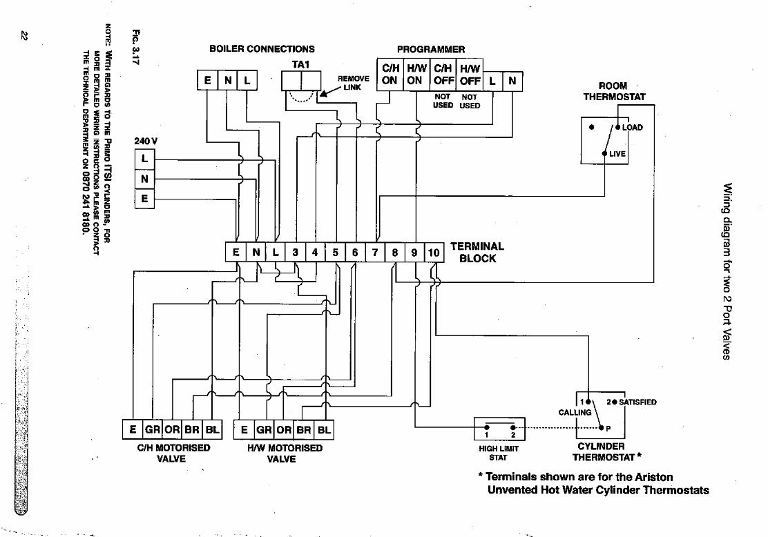
BOILER CONNECTIONS
TA1
PROGRAMMER
E N L
240 V
REMOVELINK
C/H H/W C/H H/WON ON OFF OFF
N
y\.
NOT NOTUSED USED
N ROOMTHERMOSTAT
I
LOAD
LIVE
E N L 3 4 5 6 7 8 9 10TERMINAL
BLOCK
2 •SATISFIED
CALLING
13(Q
0}(Q
P3
oN>
-PO;:5.
(0
E GR OR BR BL E GR OR BR BL
C/H MOTORISEDVALVE
H/W MOTORISEDVALVE
HIGH LIMITSTAT
CYLINDERTHERMOSTAT*
* Terminals shown are for the AristonUnvented Hot Water Cylinder Thermostats

m
Wi
<0-
' - i''
•no
BOILER CONNECTIONS
TA1
PROGRAMMER
E N L REMOVE
LINK
C/H
ON
H/W
ON
C/H
OFF
H/W
OFF L N
RELAY
240 V
L 3 4 5 6 7 8 9 10TERMINAL
BLOCK
WH BL GR OR E E GR OR BR BL
MID POSITIONDIVERTER VALVE
2 PORT VALVE HIGH LIMIT
STAT
LOAD
ROOM
THERMOSTAT
V
CALLING
1
24 SATISFIED
CYLINDER
THERMOSTAT*
Co
* Terminals shown are for the Ariston
Unvented Hot Water Cylinder Thermostats
3(Q
0)CQ
V
3
0)
CO
TPO
spo
ro
TJ0a.
1n

4. COMMISSIONING The thermostat{s) on the immersion heater(s) should be adjusted to trip ateo-es^C. This is the ideal temperature to prolong element life in hard waterareas. Scale on the sheath builds up more rapidly at temperatures abovethis causing the element to overheat and premature failure can occur.Higher temperatures without additional controls would result in scalding. Inknown hard water areas the use of a scale inhibitor is also recommended.
In addition to the thermostat the thermal cut-out will switch power off to theelement should the thermostat malfunction, causing an excessive rise inwater temperature. The thermal cut-out can be reset manually after the faulthas been corrected.
INDIRECT SYSTEMS
For models up to 300 litres a mains supply of 240V, 3kW (13 amps) will berequired for the direct immersion heater, heat resistant cable, round 3 core2.5mm2 (to BS6141) must be used. For High Capacity 500 litre modelsconsult the wiring diagram on the reverse of the inspection panel.
For indirect controls a 240V, 3 amp supply Is required.
The cables must be clamped in position (as previously stated) and thecontrol thermostat should be set at 60°C for the reasons above. In addition
to the thermostat there is a thermal cut-out should the thermostat fail. Refer
to Fig. 3.14.
WARNING : THE APPLIANCE MUST BE EARTHED.
The earth continuity conductor of the electrical installation must beeffectively connected to all exposed parts of other appliances and servicesin the room in which the water heater is to be installed and conform to the
I.E.E. wiring regulations.
Note: Do not switch on the immersion heater or fire the boiler until the
cylinder is full of water.
Check for obvious signs of damage to the cylinder and controls, and alsothat the controls fitted correspond with the references quoted in theseinstructions.
Ensure that the drain cock at the base of the appliance is closed beforecommencing.
1) ProTech Models Only. Ensure that the ProTech anti-corrosion system isconnected to the electrical supply;
2) Ensure that the line strainer (situated in the pressure reducing valve) isclear of installation debris and clean If necessary;
3) Check that the pressure in the expansion vessel is the same as theincoming water pressure;
4) Open all outlet taps;
5) Turn on mains water supply and allovy the water heater to fill;
6) Ensure that the hot water system is flushed in accordance with BS 6700;
7) Close taps in turn after having purged the system of air;
8) Check for leaks around the controls and immersion heaters and againafter the unit has heated up;
9) Check that no water is passing to waste through the relief valves;

10) Test the operation of the temperature & pressure relief and expansionvalves by lifting/turning the manually operated test lever/cap andobserving that water flows through freely and safely to waste;
11) Check that the discharge pipe is plumbed so that it falls continuouslyand that no taps, valves or other shut off devices are installed in thepipe;
12) Check that all thermostats are set at approximately 60-65°C:
13) DIRECT UNITS. Switch on immersion heater(s) and allow unit to heatup. Check operation of thermostat(s);
14) INDIRECT UNITS. Fill the indirect (primary) circuit following the boilerinstructions. Switch on the boiler, ensure that the programmer is in thedomestic hot water position. Allow unit to heat up and check operation ofindirect thermostat on motorised valve(s);
15) Check the temperature of the hot water at the nearest outlet and recordin the Benchmark Log Book;
16) Demonstrate operation to user, including operation of temperature &pressure relief valve and what to do if it operates;
17) Give this manual along with the completed Benchmark Log Book to theuser to retain for future reference and make the customer aware that
periodic checks of the equipment are essential for safety.
. r.i:.

5. MAINTENANCE To ensure efficient and safe operation, and to maintain the warranty, it isnecessary to ensure the appliance is serviced annually by a competentperson.
Before servicing, preliminary electrical system checks must be carried out toensure electrical safety (i.e. polarity, earth continuity, resistance to earth andshort circuit).
5.1 ProTech
Anti-corrosion System
WARNING: SWITCH OFF THE POWER SUPPLY BEFORE WORKING ON
THE APPLIANCE.
Trouble-shooting:1) The green L.E.D. is NOT on:
- Check to see that the circuits electric plug is connected (if not,connect);
- Check to see that the P.C.B, is supplied with electricity (if not, replacethe supply cable);
- Check to see that 230 V electricity is supplied (if not, ensure that 230 Vis supplied);
- If all these checks fail to locate the problem, replace the electroniccircuit (installer).
2) The red L.E.D. is on:- Check to see that the tank is filled with water (if not, fill it beforecarrying out the following checks);
- Check to see that the clip-on circuit connector is in the proper position(if not, position correctly);
- Check to see that the electrodes connection lead is property connected(to check this, gently pull on it) (if not, replace the electrode);
- Check to see that the connection lead to the tank is properly connectedto the tank (if not, connect properly);.
- Check to see thait the two leads from the clip-on circuit connector arenot damaged, stripped, etc. (if so, replace the electrode);
- If all these checks fail to locate the problem, replace the electroniccircuit.
Note: To replace the RC.B, there is no need to drain the cylinder;1) Disconnect the two supply cables from the P.C.B. to the supply terminal;2) Disconnect the clip-on circuit connector and polarising slot which
connects the circuit to the tank and the electrode;
3) Disconnect the P.C.B. from its supporting plate (plastic clips in the 4corners) and;
4) Replace the defective circuit with a new one, then re-install in reverseorder to the above.
5.2 Thermal Cut-out(s) If the thermal cut-out has operated the cause must be found before resetting(see section 6).
5.3 Immersion Heater(s) Should the immersion heater(s) become scaled, we would recommend thatthe immersion heaters be replaced, a scale reducer be fitted on the coldwater supply to the cylinder and that the thermostat is set below 60°C toprevent further scale formation.
5.4 Unvented Controls
26
Check controls as per the following:1) Line strainer - with the water supply turned off remove screen from
strainer and clean off any debris;2) Expansion vessel - with the water supply turned off and taps open, check
expansion vessel pressure and top up as necessary;3) Temperature & pressure relief valve - with the water supply turned on,
check manually by lifting the test lever/turning the test knob (ensure valve

closes after testing):4) Expansion relief valve - check manually by turning the test knob (ensure
valve closes after testing);5) Discharge pipes (D1) - from both temperature & pressure relief and
expansion relief valve for obstructions;6) Tundish & discharge pipe (D2) - open either valve gradually to produce a
full bore discharge Into tundish and D2 without any back pressure;7) Pressure reducing valve - check that the correct outlet pressure Is being
maintained by recording the pressure at an In-line terminal fitting e.g. tap.
5.5 Thermostats Ensure that all thermostats are adjusted for the correct temperature setting,this should be between 60 and 65°C.
5.6 Maintenance Procedure To ensure efficient and safe operation, and to maintain the warranty, It Isnecesary to ensure the appliance Is serviced annually by a competentperson.
After servicing, preliminary electrical system checks must be carried out toensure electrical safety (I.e. polarity, earth continuity, resistance to earth andshort circuit).
To drain the cylinder It Is necessary to proceed as follows:
1) Close the mains supply service valve;2) Open hot water taps;3) Attach a hose and open the drain cock and allow the cylinder to empty.
Magnesium Anodes (STD and STI models only)
No longer than every 12 months, the installer should check the magnesiumanti-corrosion anodes (consult the label on the face of the unit for the correctlocation). Assessment of the condition of the bottom anode (where fitted)can be made by judging the condition of the top anode.
Removal of anodes;
1) Close the mains supply service valve;2) Open hot water taps;3) Attach a hose and open the drain cock and allow the cylinder to empty;4) The anodes are removed by unscrewing;
EXAMINE THE ANODES AND IF THE DIAMETER IS LESS THAN 10mm
replace both anodes.
The use of an approved P.T.F.E. sealing tape Is required to ensurewatertight connection for anodes.
Thermal Cut-out(s)
If the thermal cut-out has operated the cause must be found beforeresetting.
Immersion Heater(s)
Should the Immersion heater be scaled, we would recommend It be
replaced.
Mim

Unvented Controls(s)
Check controis as per the following:1) Line strainer - with the water supply turned off remove screen from
strainer and clean of any detritus;
2) Expansion vessel - with the water supply turned off and taps open, checkexpansion vessel pressure and top up as necessary;
3) Temperature & pressure relief valve - with the water supply turned on,check manually by lifting the test lever/turning the test knob (ensure valvecloses after testing);
4) Expansion relief valve - check manually by turning the test knob (ensurevalve closes after testing);
5) Discharge pipes (D1) - from both temperature & pressure relief andexpansion relief valve for obstructions;
6) Tundish & discharge pipe (D2) - open either valve gradually to produce afull bore discharge into tundish and D2 without any back pressure;
7) Pressure reducing valve - check that the correct outlet pressure Is beingmaintained by recording the pressure at an in-line terminal fitting i.e. tap.
Thermostats
Ensure that all thermostats adjusted for the correct temperature setting, thisshould be between 60 and 65°C.
After servicing, complete all relevant sections of the Benchmark Checklistlocated on page 35 of this manual.
Note!
Where there is a possibility of scale forming, it is recommended the
THERMOSTAT BE SET TO BELOW 60°C AND A SCALE REDUCER BE FITTED ON THE
INCOMING MAINS SUPPLY

FAULTFINDING
FAULT POSSIBLE CAUSES REMEDY
NO HOT WATERFLOW
REDUCED FLOW
RATE
WATER FROM
HOT TAPS
IS COLD
DISCHARGE FROMPRESSURE/
TEMPERATURERELIEF VALVE
DISCHARGE FROMEXPANSION
VALVE
1) Mains cold watersupply shut off
2) Line strainerblocked
3) Cold WaterCombination valve
fitted incorrectly
1) Low mains waterpressure
2) Line strainerpartially blocked
3) Size of servicepipe too small
1) Direct immersionheater is not
switched on
2) Direct thermalcut-out has
operated
3) Boiler programmerset to central
heating only(Indirect models)
4) Boiler is notfunctioning(Indirect models)
5) Indirect thermalcut-out has
operated
6) Motorised valvejammed or notwired correctly(Indirect models)
1) Pressure above 7bar, failure ofpressure reducingvalve. Temperatureabove 90®C failure
of thermal control
1) Continually.Pressure reducingvalve faulty
2) When heater is heating.Faulty expansionvessel or lost charge
3) Back feed of high mainspressure via mixer.
Check and open Isolatingand/or stop valve. Checkwater, Local Water Authority
Turn off mains water supply,remove line strainer andclean
Check direction of flow
arrows on valve, refit in .correct position if necessary
Check pressure, consultLocal VVater Authority Ifnecessary
Turn off mains water supply,remove line strainer andclean
Increase to size stated onpage 9
Check immersion heater,switch on if necessary
Test thermostat operationand wiring, if faulty,correct/replace. Reset cut-out
Check switch on domestic
hot water if necessary
Check boiler operation, iffault suspected consultmanufacturer's instructions
Test thermostat operationand wiring, if faul^,correct/replace. Resetcut-out
Check wiring and operation ofmotorised valve correct/replace as necessary
Shut down boiler or immersionheater. Check pressurereducing valve and thermalcontrols. Replace Ifnecessary
Check pressure from valve.Replace if over 3.5 bar
Check charge of vessel. Recharge vessel to 3.5 bar or matchIncoming mains pressurereplace If necessary
Service / replace mixer
WATER HAMMER 1) Expansion Vessel fittedvertically.
2) Pipework not secure
Ensure vessel is fitted horizontally orconnection at top.
Clip pipework
3) Jumpers on taps loose Replace tap jumpers

TECHNICAL DATA
Majdmum-Water Supply Pressure*Operating PressureExpansion Vessel Charge PressureExpansion Relief Valve SettingPressure & Temperature Relief Valve SettingPressure Reducing Valve Set PressureElectrical SupplyImmersfon Heater RatingImmersion Heater TypeImmersion Heater Reference Numlaer
Maximum Primary PressureHeat Excharrger PerformanceCoil Surface Area
Heat Loss (kWh in 24h) @ 60®CNett WeightOzone Depletion Potential (ODP)Global Wanning Potential (GWP)
Q af-
CM CO
Q Q1- I-
o o1- oCO CO
H I-OJ CO CO CO CO CO W CO
LLi lil LU LLI LLJ lil LLl liJX I XXX X X X
OlOlOlOlOlOlQ O O
12 1
6 6
7/90 7/90
3.5 3.5
240 240
3+3 3+3
(1) (1)(3) (3)
1.73 1.97
49 54
0 0
<5 <5
To pressure reducing valve Single Phase Single Phase/Three Phase BS EN 60335-2-73
Model
ST ProTech 100 SYR 22mm)
ITySTI125-300 SYR 22mm)
TD/STD 125 - 300 SYR 22mm)
ITS! 210 • 300 SYR (22mm)
STD/STI 500 RWC (28mm)
Make of 6 bar
Safety Valve
SYR (22mm)
SYR (22mm)
SYR (22mm)
SYR (22mm)
RWC (28mm)
CASHH
CASHH
CASHH
CASHH
CASHH
Model Hme taken to raise
temperature from 15 to 60*C i
Time taken to raise
70% of stored volume to SO^C
ST Protech 100 1 hr56 mins 72 mins
ClassicoST1125 HE* 19 mins 18 mins
Classico STI150 HE* 19 mins 18 mins
Classico STI 210 HE* 27 mins 23 mins
Classico STI 300 HE * 44 mins 37 mins
Classico STI 500 HE * 58 mins 48 mins
Classico STD125HE** 2 hrs 28 mins 1 hr46 mins
Classico STD150HE**
Classico STD 210 HE** 3 hrs 46 mins 3 hrs 54 mIns
Classico STD 300 HE ** 5 hrs 14 mins 4 hrs 37 mins
Classico STD 500 HE*** 4 hrs 37 mins 3 hrs 18 mins
Indirectly heated3kW Immersion heater
6kW Immersion heater

Maximum Water Supply Pressure*Operating Pressure
Expansion Vessel Cha/ge PressureExpansion Relief Valve SettingPressure & Temperature Relief Vah/e SettingPressure Reducing Valve Set PressureElectrical SupplyImmersion Heater RatingImmersion Heater TypeImmersion Heater Reference Number
Maximum Primary PressureHeat Exchanger PerformarK«Coil Surface Area
Heat Loss (kWh in 24h) @ SS'CNett WeightOzone Depletion Potential (ODP)Gtobal Warming Potential (GWP)
m o o<M m T-T- ■«- CM
Q Q Qt b bLU LU UJX X I
12 12 123.5 3.5 3.53.5 3.5 3.56 6 6
7/90 7/90 7/903.5 3.5 3.5240 240 240
3+3 3+3 3+3
(1) (1) (1)(3) (3) (3)3.5 3.5 3.5
1.60 1.73 1.97
30 32 430 0 0
<5 <5 <5
o o m o o o oCO o CM m ■«- m oQ 1- t- CM CM COb E E E E E ELLI Hi LU UJ LU ill LLIX X X X X X XO O O O O O OE E E E E E E
7/90 I 7/903.5
123.53.56
7/903.52403+3
(1)(3)3.5
16.6/16.60.67/0.67
0.80530
<5
123.53.56
7/903.52403+3
(1)(3)3.5
16.6/16.60.67/0.67
0.87600
<5
12
3.53.56
7/903.52403+3
(1)(3)3.5
22.8/16.60.89/0.67
1.0660
<5
To pressure reducing valve Single Phase ® Single Phase/Three Phase BS EN 60335-2-73
Model Time taken to raise temperaturefrom 15*0 to 65'C
Time taken to raise 70% of thestored volume to 65*C
m100*" 17 mlns 16 mins
III 150"* 19 mins 18 mins
m210*" 27 mins 23 mins
m 250"* TBC TBCm 300*** 44 mins 37 mins
ITS! 210**** 27 mins 23 mins
ITS! 250**** TBC TBC
ITS! 300**** 44 mins 37 mins
ITD125 148 mins 106 minsITD 150 168 mins 130 minsITD 210 226 mins 174 minsITD 300 314 mins 220 mins
Model Make of PressureReducinq Valve
Make of 6 barSafety Valve
Make ofT&P Valve
ITI100-300 1 SYR (22mm) SYR (22mm) CASHH
ITD 125-300 SYR (22mm) SYR (22mm) CASHH
ITS! 210-300 SYR (22mm) SYR (22mm) CASHH
Indirectly heated.As above utilising bottom coll only.

5. BENCHMARK COMMISSIONING CHECKLISTI MAINS PRESSURE HOT WATER STORAGE SYSTEM COMMISSIONING CHECKLISTThis Commissioning Checklist is to be completed in full by the competent person who commissioned the boiler as a means of demonstratingcompliance with the appropriate Building Regulations and then handed to the customer to keep for future reference. ^
Failure to install and commission this equipment to the manufacturer's instructions may invalidate the warranty but does not affect statutory rights.
Customer Name Telephone Number
Boiler Make ar^d Model
Boiler Serial Number I I I 1 I 1 I I 1 1 I I I I I I 1 I I I ! I I 1 1 I I I I I I I I I I 1 I I I ICommissioned by print rtame) CORGI ID Number ^
Company Name ^ Telephone Number
Company Address
: Commissioning Date
To be completed by the customer on receipt of a Building Regulations Compliance Certificate*:
Building Regulations Notification Number (if applicable) .
ALL SYSTEMS PRIMARY SETTINGS (indirect heating only)
is the primary circuit a sealed or open vented system?
What Is the maximum primary flow temperature?
ALL SYSTEMS
What is the incoming static cold water pressure at the inlet to the system?
Has a strainer been cleaned of Installation debris (if fitted)? YesJIs the installation in a hard water area (above 200ppm)? Yes
If yes, has a water scale reducer been fitted? Yes□What type of scale reducer has been fitted?
Time and temperature controls have been fitted in compliance with Part L of the Building Regulations?
Type of control system (if applicable)
Is the cylinder solar (or other renewable) compatible?
What is the hot water temperature at the nearest outlet?
^ What is the pressure reducing valve setting?
Has a combined temperature and pressure relief valve and expansion valve been fitted and discharge tested?
The tundish and discharge pipework have been connected and terminated to Part G of the Building Regulations
Are all energy sources fitted with a cut out device?
^ Has the expansion vessel or internal air space been checked?
THERMAL STORES ONLY
What store temperature is achievable?
What is the maximum hot water temperature?
ALL INSTALLATIONS
>3 The hot water system complies with the appropriate Building RegulationsThe system has been installed and commissioned in accordance with the manufacturer's instructions
The system controls have t>een demonstrated to and understood by the customer
The manufacturer's literature, including Benchmark Checklist and Service Record, has been explained and left with the customer
Commissioning Engineer's Signature
Customer's Signature(To contirm salisractory demonstration and racaipt o! manufacturer^ literature)
*AI1 InstailaUons In Ensland and V^tes must be notified to Local Authority Building Control (LABC) ^her directly or through a Competent Persons Scheme.A BuiKfing Bssulatlona Compliance Certincate will then be issued to the customer. .
benchmark
GHeating and Hotwater Industry Council (HHIC) vwvw.centridheatlng.co.uk

BENCHMARK SERVICE RECORD
SERVICE RECORDIt IS recammended that your hot water system is serviced regularly and that the appropriate Service Record is completed.Service Provider
hstructionT'^''"^ appropriate Service Record below, please ensure you have carried out the service as described in the manufacturer
SERVICE 1 Date
Engineer Name
Company Name
Telephone Number
Comments
SERVICES Date
Engineer Name
Company Name
Telephone Number
Comments
Signature
SERVICES Date
Engineer Name
Company Name
Telephone Number
Comments
Signature
SERVICES Date
Engineer Name
Company Name
Telephone Number
Comments
Signature
SERVICE? Date
Engineer Name
Company Name
Telephone Number
Comments
Signature
SERVICE 4 Date
Engineer Name
Company Name
Telephone Number
Comments
Signature
SERVICE 6 Date
Engineer Name
Company Name
Telephone Number
Comments
Signature
SERVICES Date
Engineer Name
Company Name
Telephone Number
Comments
Signature
SERVICES Date
Engineer Name
Company Name
Telephone Number
Signature
*V
SERVICE 10 Date
Engineer Name
Company Name
Telephone Number
Comments
Signature >- Sianature

Manufacturer: Ariston Thermo Group, Luce - France o
o
Commercial subsidiary: Ariston Thermo UK Ltd dAriston Building ^Hughenden Avenue °High Wycombe §Bucks. HP13 5FT E
Telephone: (01494) 755600 |Fax:(01494)459775 ?Internet: www.ariston.co.uk 1
>.
E-mail: [email protected] ^
Technical Service Hot Line: (0870) 241 8180
Customer Service Help Desk: (0870) 600 9888