
Untitled - National Sea Grant Library - The University of Rhode Island
508
-
Upload
khangminh22 -
Category
Documents
-
view
4 -
download
0
Transcript of Untitled - National Sea Grant Library - The University of Rhode Island


Copies avellshie from:
See Grant Extension Program6022 MoCarty HallUniversity of FloridaGslnssvlila, F I. 3281 1
PletW.Sse Orant Cogsge le supported hy awed of the Office of See Orant, National Oceania aad Atrnoepherie Admlnletradon, U4. Depert-raent ef Cetmmrm, grant nwahw NAESAA-~, under provisions of the Natkmef 8ee Grant Cogege and Programs Aot of 1888. Thishdenaatlaa ls pehlldted hy the See Orant Eatenekm Proipam wideh funatlons as ~ component of the Florida Cooperative Eatenslon Ssrvtse.Jehu T. ggaeste, dom, In mmduetlng Coeperadve Extension work in Agriculture. Home Eoonomies, and ggerine Seieneee. State of Fkrride. U.S.gttpartnrsnt ef Agrharlture, UA Qspartment of Commerse, and Soerde of County Commiesloasm, cooperating. printed end dlstrlhuted Inferdsemnse of the Acts of CengrWs of Stay 8 aad June 1 1, 1814. The Florida See Orant College h an Equal Employment Opportunity-Affirme-~ ee Aetkm employer aatharlmd m 'yrow4h ~h, edaoatloaal krformadon and other earvtaee only to individuals and InstNutlom that~ aoetten without Nacrd ta ress, eaktr, eea, or national origin.

I NTERNATI QNAL CONFERENCE
DN
DESIGN, CONSTRUCTION, AND OPERATION OF
COMMERCIAL F I SHING VESSELS
Sponsored By:
Florida Sea Grant College ProgramSociety of Naval Architects and Marine Engineers,
Southeast SectionFlorida Institute of Technology
College of Science and Engineering: Ocean Engineering Program
Held At:
Florida Institute of Technology
Edi ted By:John C. Sainsbury
Thomas M. Leahy
Sea Grant Project No. IR/84-6Grant No. NA 80AA-D-00038
Report Number 67Florida Sea Grant College
May 1985
Price: $10.00

ACKNOWLEDGEMENTS
SPONSORS: Florida Sea Grant CollegeSociety of Naval Architects and Marine
Engineers, Southeast SectionFlorida Institute of Technology, College
of Engineering: Ocean Engineering Program
CONFERENCE GENERAL CHAIRMAN: Dr. John C. Sainsbury, Professor Chairman,Ocean Engineering Program, Florida Institute ofTechnology, Melbourne, Florida 32901, USA
CDGRD I NAT I NG COMMITTEE: Tom Col 't ins, Desco. Marine Inc.St. Augustine, FloridaNorman, DeJong, DeJong 4 Lebet Inc.Jacksonvi 1 le, FloridaPeter Hjul, Editor, Fishing News International,LondonLeigh Taylor Johnson, Florida Sea GrantAndrew Lebet, DeJong 4 Lebet Inc .,Jacksonville, FloridaGordon MacAlister, MacAli ster, El li ott hPartners . Lymington, UKJames Penni ngton, St . Augustine Seafood Co .,St. Augustine, FloridaCommander William Remley, U.S . Coast Guard,Jacksonville, FloridaJohn W. Shor tall ! II, University of SouthFlorida, Tampa, Florida: Chairman, SNAMESoutheast SectionDonald Sweat, Florida Sea Grant
STAFF: Reception: Ann Sai nsbury . Carole Shortal 1Assistants: Douglas Garbini, Michael TorchiaSecretary: Oeborah Kearse

FOREWORD
This publication is a collection of papers accepted for presenta-t1on at the International Conference on Design, Construct1on and Operationof Conanercial Fishing Vessels. Forty papers are included; One of these"Development of a Sail Assisted FRP Fishing Canoe for the Comoros" by TokuzoFukamachi did not arrive in time for presentation at the Conference, but isconsidered to be of sufficient importance to be included in this collection.
There were 112 registrants from eighteen countries at the Conference.That and the generally high quality of the papers given confirmed that thetime was right for a techn1cal meeting of naval architects. shipbuilders,fishermen, economists and other social sc1ent1sts, government and inter-national officials, in order to update developments in the field.
This had not occurred in such a generalized manner since the third andlast World Fishing Boat Conference organized by the U.N. Food and AgricultureOrganization in 1967. That series of conferences led to steady and markeddevelopment in the technology of fishing vessel design, construction andoperation, and 1t was fitt1ng that Jan-Olof Traung, organizer of thoseConferences presented a paper here whi ch traces fishing vessel improvementssince 1950 and looks to the year 2000.
During the past ten years, rapid changes have occurred worldwide in theeconomic climate surrounding fisheries and fi shi ng operati ons due to factorssuch as Extended Jurisdiction and the energy crisis . As a result fishingvessels are presently in a phase of rapi d development and change, especiallyi n terms of energy consumption and fi shing systems to meet the changingsituation. This collection of papers is illustrative of the changesoccurring, e.g., the return to sails as a means of reducing fuel consumption,the increasing extension of oil product1on into fishing areas, and the effecton f1shing industry operations of changing demands for waterfront use.
Conference parti c1pants were asked to vote for the best paper each day,and for the best student paper. The three best papers in the overall categorywere: "Fishermen and Oil Men Working together in the North Sea" by AlanWilson, "A Rev1ew of Some Recent Stab1lity Casualties Involving PacificNorthwest Fishing Vessels" and "Model Tests of Dynamic Response of a FishingVessel" both by Bruce Adee, and "Particular Needs of Fishing Vessels for Usein The Developing World" by Alejandro Acosta, Theophi lus Brainerd, BambangPr1yono, Norbert Simmons, and Rajapaksa Don Warnadasa . Best Student Paperaward went to Douglas McGuffey who presented the paper "Effect of Loading onF1shing Vessel Stability - A Case Study" .
In order to bring within bounds the invnense amount of materialcontained in the original papers, it has been necessary to undertake someedit1ng. In undertaking this task, 1 attempted to ma1ntain the authors' textand remove only supporting mater1al and illustrations which did not appear ta beessential. However, I am sure that some authors will be disappointed; to them
apologize, and accept full responsibility, emphasizing only the necessityof reducing the material to a publishable amount.
111

The Conference itself would not have been possible without thesupport of the sponsoring organizations, and the dedication and hard work ofthe coordinating committee and conference staff. all of whom are listed else-where. We owe them a special thank you.
The authors, session chai rmen, and the partici pants were the flesh andbackbone of the whole affai r, and were the ingred1ents of the success whichthey achieved so well. My thanks to them all.
I would especially like to acknowledge the work of Tom Leahy,Director of Coneunications and Publ1cations for the Florida Sea Grant CollegeProgram. It 1s mainly through his efforts that publication of these papershas materialized.
John C. SainsburyConference General Cha1rmanFlorida !nstitute of TechnologyMelbourne, FloridaMay 1985

TABLE OF CONTENTS"
Foreword.
PART I -- FISHING VESSEL DEVELOPMENT
50 Years of Improvements in Fishing Vessels -- from 1950 to2000. Jan-Olof Traung.
Written Contribution, Bruce Culver 20
PART II -- FISHING VESSEL OPERATIONS
Water front Use Conflicts and Their Effect on CorrrnercialFishing Operations in Florida. Leigh Taylor Johnson .
A Simple Method to Determine Optimum Vessel Speed.George A. Lundgren. 33
The Development of an Off-Bottom Shrimp Trawl.Clifford A. Goudey. 43
Evaluation of Koyama's Equation for Estimating Trawl NetResistance. M. Orianto, T. Tongprasom, R. Latorre. 53
Fishermen and Oilman Working Together in the North Sea.Alan Wilson. 63
Computer Applications in Midwater and Bottom Trawling.J. Douglas Dixon . 79
Written Contributions. S.M. Calisal, Christopher Tupper,Cliff Goudey.
PART III -- FISHING VESSEL DESIGN AND CONSTRUCTION
Fishing Vessel Design Curves. W. Brett Wilson. 94
Weight and Kg Estimates for Ferro Cement Fishing Vessel.Hulls. B. Pickett, R. Latorre. 112
Hydrodynamic Design of Tuna Clippers. R, Adm. PascualO'Dogherty, Miguel Moreno, Manuel Carlier, Manuel O'Dogherty.. 121
Added Resistance of Fishing Vessels in Head Seas.Stephen R. Judson. 14D
The Effect of Variations in Major Hull Parameters of FishingVessels Upon Oi rectional Stability. W. Brett Wilson. . . . . . 152
Changes fn the World Fisheries Situation and Vessel Need -- ThePast Twenty Years. Peter Hjul..............,, . 2

Fishing and Ship Motions -- Design Considerations Based onObservations of Operations. Christopher N. Tupper. 169
A New Approach to the Problem of Sheathing Wooden Hulls.Bill Seemann. 177
Potential for Advanced Brayton-Cycle Engines for CoIimnercialFishing Vessels. David Gordon Wilson. 185
Transportation Efficiency Data Development Using a HighSensitivity Loran "C" Receiver Outputted to a CPU Based EnergyConversion Instrumentation and Information Reduction System.Hendrick W. Haynes. 199
Written Contributions. N.T. Riley, Cliff Goudey. . 204
PART IV -- FISHING VESSEL SAFETY
Analysis of U,S. Comercial Fishing Vessel Losses -- 1970-1982LCDR Tony E. Hart, Frank Perrini. 206
A Review of Some Recent Stability Casualties Involving PacificNorthwest Fishing Vessels. Bruce H. Adee. 217
legal Aspects of Fishing Vessel Safety. Robert R. Hyde. , 238
Fishing Vessel Intact Stability Criteria and Compliance due toVariation in Vessel Dimensions. Philip M, Read, R. Latorre . 261
Model Tests of the Dynamic Response of a Fishing Vessel.8ruce H. Adee, Feng-I Chen . 273
The Effect of Loading on Fishing Vessel Stability: A CaseStudy. D.B. McGuffey and J.C. Sainsbury . 289
Written Contributions. Bruce Culver, Cliff Goudey, N.T. Riley,Robert Hyde. 311
PART V -- SAIL-ASSISTEO FISHING VESSELS
Designs for Wind-Assisted Conmercial Fishing Vessels.John W. Shortall III. NA. . 316
Design Overview and Econoaic Analysis of the Aquaria 38Sail-Assisted Fishing Vessel, David A. Olsen, Frank Crane,Rob Ladd. . . . . 323
Performance Measurements of a 25-Foot Sail-Assisted FishingVessel. Richard D. Sewell, John C. Sainsbury. 336
Rotor Propulsion for the Fishing Fleet. Kenneth C. Morisseau. 344
Fishing Vessel Safety in the U.S.A. What are we Doing?Robert J. Shephard. . 256

Further Development of the Tunny Rio. E.w.H. Gifford, C. Palmer, 360
A Microcomputer-Based Instrumentation Package for On-Board Wind-Assist Measurements. Jeffrey Zenoniani, John W. Shortali III 378
Design and Testing of a Fishing Vessel With Combined Motor/SailDrive f' or the Artisanal Small Scale Fishery of Sierra Leone.K. Lange.
388
A Progress Report With Special Reference to a 30.5 M FishinqCatamaran. John G. Walker.
391
Easi ly Handled Rigs for Fishing Vessel Sail Assist, Frank MacLear. . 401
'Written Contribution. Gunnar C.F. Asker.
PART VI -- INTERNATIDNAL AND SMALL-SCALE FISHERIES
Comparison of Operational Economics for Vessels Working From ThreeWest African Ports. John C. Sainsbury. 41Z
Appropriate Designs for Fishing Craft in Bangladesh.R. R. MacAlister, C. Eng. Mrina. 4Z3
Particular Needs of Fishing Vessels for use in the DevelopingWorld, Alejandro Acosta et al 433
Development of a 4B-Foot Multi-Purpose Fishing Vessel: AlZ-Year Retrospect by the Builder. H. Lee Brooks. 445
Energy Saving and Rig Development for Artisanal Fishing Boats.E. W. H. Gifford, C. Palmer. 45e
Change on the Chesapeake. Donald W. Webster. aya
Development of a Sail-Assisted FRP Fishing Canoe for the Comoros.Fukamachi Tokuzo, NA.
APPENDIX
Conference Participants493
*Statetatements contained herein are the private opinions and assertions ofthe writers and should therefore not be construed as reflecting the viewof the sponsors, nor of any other organization with which the writersare affiliated.

The following resolution was approved unanimously by delegates to theConference:
"THIS CONFERENCE WISHES TO GO ON RECORD AS RECOGNIZING THE URGENTNEED TO REDUCE FISHING VESSEL CASUALTIES RESULTING FROM PROBLEMS DURINGOP ERAT ION.
THERE IS AN URGENT NEED FOR BETT'ER UNDERSTANDING OF VESSELBEHAVIOR UNDER REALISTIC SEA CONDITIONS, AND APPLICATION OF KNOW-LEDGE TO THE OPERATING PROFILES OF INDIVIDUAL FISHERIES AND VESSELS.
IT IS RECOMNENDED THAT PRIVATE, PUBLIC, AND COMMERCIAL SECTOR GROUPS,TOGETHER WITH THE UNIVERSITIES, RESEARCH AND EXTENSION AGENCIES INCREASEMARKEDLY THE LEVELS OF EFFORT AND INTERACTION IN THIS AREA. IN PARTIC-ULAR THIS WILL REQUIRE INCREASED LEVELS OF FUNDING THROUGH INDUSTRY ANDSUCH AGENCIES AS SEA GRANT, COAST GUARD, AND N.N,F.S."

PART I
FISHING VESSEL DEVELOPMENT

CHANGES IN THE MORLO FISHERIES SITUATION AND VESSEL NEEOS
THE PAST T'WENT Y YEARS
Peter HjulEditor
Fish1ng News InternationalLandon
Abstract
Awareness 'of new and previously underused resources, together withseveral technical innovations caused a "revolution" 1n f1sher1es during theyears 1950 to 1970 . Catches rose by five to six percent a year and estimatesof end-of-century product1on suggested a harvest of over 120 mill 1on metr1ctons . However, ri si ng catches put pressure on many stocks, and this, togetherwith the widespread claims to 200-mi le limits and soaring fuel and othercosts. halted the rapid growth i n production. There remains a need to f1ndaround 100 million tons of food fish a year by 2000, double the presentsupply . This will require further efforts to f1sh under-ut111zed spec1es, toassist Thi rd World countries make the best use of thei r resources, and to getmore from fish and shellfish already being caught.
The fishing revolution
The original i ntent of th1s paper had been to review the momentousdevelopments in the world's commercial sea fisheries aver a period roughlyspann1ng the Third FAO Fishing Boat Congress in Gothenburg in 1965 and th1sconference here today. For the author, 1t was a convenient period as he wentto Gothenburg soon after taking up an appointment in 'London as editor ofFishin N ws I t ationl. Qn reflection, however that conference, i mportant
g rk a beginning nor an end in fishing boat designconstruction, or use. It did, in fact, take place when some of the mast vitalchanges in the way we seek and catch fish were still in progress, or were justbeginning.
Jan-Olof Traung, the organizer of the Seri es of Mater Fishing VesselConferences, sensed th1s when he planned a Fourth Boats Congress for 1971; butby that time the Food and Agriculture Organization 1tself was changing andthose in charge of f1sheries were looking ta other types af conferences. Themajor one to assess the state of the world's f1sh resources and the pressureson them took place in Vancouver in 1973, and a repetition appears plannedthrough a monster FAO Meeting on Fisheries Management and Oevelapment to beheld in Rome at the end of June, 1984. However, there 1s unl1kely to be muchpractical talk there of vessels . rm thods . processes or products . For anopportunity ta examine essential aspects of the f1shing industry and 1tsfuture, we have to thank people and those who they persuade to come and sharetheir technical knowledge.

In h1ndsight, the world-wide fishing industry appears to have expe-rienced a revolution, which, like that of France in the 18th Century or ifIran today, was no sudden turnaround but rather a protracted sequence ofdrastic and tr aumat1c changes.
An example of these to come was to be found in 1948 in a village calledLaaiplek on the West Coast of the Cape Province 1n South Africa. Fishing inthe Cape had been transformed by the discovery that a small pelagic f1shcalled the pilchard could be caught in great quantities for cann1ng or forreduct1on into readily saleable fish meal and oil.
The industry there was at the beginning of a boom that would for awh1le put South Af'rica among the top fishing nations. Laaiplek, once a bleakconlaunfty of fmpoverished fishermen, was the site of one of the new factories.!t was a time when people still believed the sea to be "inexhaustible": with1ts fish and shellfish just waiting for the enterpri s1ng exploiter. To help1t do th1s, the company at Laaiplek had called in expert help from the sardineindustry of Californ1a. Three Neptune mechanical packi ng lines for Al tellsand a new Enter pri se fi sh meal plant revealed the American experience in thiskind of fishing.
It also revealed two other thi ngs that presaged the coming revolution infisheries.
Fi rst, the American involvement reflected the concern in Californiaover a decline in the sardi ne pilchard! catches - the f1 rst of many dramati ccollapses that would be blamed perhaps not entirely correctly! on over-fishing. Californ1a was to be one of the early post-war s1gns that the seawas not inexhaustible and that care had to be exerci sed in management ofprecious resources.
Second. w1th all the evi dence of abundant stocks of pilchardsand jack mackerel wait1ng to be exploited, South Africans were eager to tryanthing that would get them the biggest catches in the shortest poss1ble time .
The top boat then feed1ng the factory was a wooden hull lampara seiner,newly bui lt for about $11,000. Her net was worked by hand, with the help of acrude mechanical winch and pulley . The net was made of natural ffbre, and ahaul in ft of 37 tons was talked about up and down the coast . There was noradio nor any other instrument in the wheelhouse other than a magneticcompass. Nav1gation was usual'ly by si ght of landmarks on the shore. Rut: theboat dfd boast a new Caterpillar 80 hp engf ne, one of the first of many to be1mported to power the growi ng fleet of Southern Afri ca.
From Laaiplek and nearby Vel ddrif, the pf lchard boom was reaching600 miles north to Walv1s Bay in South West Africa now Nam1bia !. Boats grewquickly to 50, to 60 and 70 ft.

All the time 1n those and many other emerging fisheries, the status ofthe fishermen was changing and so was the industry's attitude to its equipment'and its boats.
Britain, France, Japan and other f1shing nations whose fleets had beendevastated by war or forced to starid still for years were do1ng more than justreplacing vessels. They were also experimenting with new types. new gear andnew ideas.
In addition- to some remarkable recoveries, and a few steep decl1nes,the 1950's saw another aspect of the revolution - the emergence of fisheri esand fish1ng countries starti ng almost from nothing.
Peru was a boom 1ndustry more on the Southern African pattern. Therewas very little there on which to base any k1nd of fishi ng acti vity . The Perucatch fn 1938 was 23,000 tons. At the begi nn1ng of the anchoveta sur ge i n1958 it was 235,000 tons. By 1970, it had soared past ten milli on tons a yearand was to peak soon after at 12.5 mi'lli on tons. There were then some 1500purse sei ners supplying more than 100 meal plants. Aboard the boats werefishermen and even skippers who, until the boom, had never even seen the sea,let alone move out onto it. Peru was the world's largest catcher 'by the endof the 1960's, followed by Japan, and then by another newcomer to the f1shingtop league.
Like Poland and other Eastern European neighbors, Russia does nothave a large coastal sea f1 shery resour ce . Her development resulted from adeliberate decision in the mid-1950s to obta1n protei n from fish by sendingships out to work distant stocks that were then still readi ly avaiable.
Russia, Peru and the expanding industries of Iceland, Nor~ay, Canadaand Japan, were leading the fishing revolution because they were maki ng useof resource opportunities partly by goi ng out and f1nding them, but alsobecause significant advances in the techniques of fish finding, nav1gati on,vessel desi gn and construct1on including use of materials such as GRP! . ingear materials and handling, and in processi ng and preservation enormouslyincreased their hunting capacity.
Further, the revolution was a response to an increasing demand for fish,and to an effort to assist developing countr ies make use of it as a nourishingfood and an export earner. But it was the advances in technology that made itall possible.
It is possible to mention only the most obvious of these profoundlysignificant technical developments of the 1950s and 1960s:
1. The British experiment with the stern tra~ler and with freezing atsea. From the Fai rfree tr1als of the late 1940s, the Salvesen Companyin Scotland planned~and built its three Fairtry factory trawlers.

Not only did these ships demonstrate the advantages of trawling fromthe stern- they also pointed the way to hull arrangements that wouldaccommodate processing machines and freezers in a factory deck.
Since the 1920s, Rudolf Baader of Luebeck had been devisingmachines, compact and proved by tests in shore factori es, that werebecoming available just:at the time of the stern trawler experiments� .Together with the horizontal and later the vertical plate freezers,they made it possible to take a factory and a freezing plant and coldstore out to sea.
Although the Fair trys enjoyed only a brief period of profitability,the idea quic~ycaug t on in countries seeking ways of getting theirfishermen to distant resources. Russia was one of the first, with anorder placed in Mest Germany for 24 ships very similar to theFairtr s. By the time of the Gothenburg conference, Britain and Russiaa een joi ned by Japan, Poland, East Germany, Nor~ay and Spain as
operators of stern trawlers.
The heydays of the ocean-roaming fish factori es have been comparedto the age of the dinosaurs in the sense that they marked the upperextreme in size and capacity in the industry . If the high-performanceprocessor trawler or big purse seiner was the Tyrannosaurus rex of thisbrief era, the meal factory ship was the gluttonous Brontosaurus.
Two such ships were allowed by South Africa to work for about threeyears at the end of the 1960s off the coast of Namibia . They had dailycapacities of 2000 and 2500 tons exceeded later by the 3000 tons of aNorwegian ship, the Norglobalj . In 1968, the factory shi p Sui der krui s
and worked by eight crew. The top boats were catching 30,000 tons ofpi lchards a year and their crews were said to be among the world 'srichest fishermen. In 1968 and again in 1969, the owners of theSuiderkruis reported profits of more than 1 millions pounds .
By the early 1970s protests f'rom the shore forced the factories out.They went north to Mest Africa where they were joined by the Norglobaland the Astra, also from Norway. But the fishery of Namibia carriesthe scars oHheir pillage and the yearly haul of pelagic schoal fishis still less than a tenth of what it was in the years just before thefactory ships arrived.
Z. Floating factories such as these meal ships were able to get consis-tent large supplies of fish partly due to invention of the Po~er Blockand because of the introduction of synthetic fibres to netting.
Nario Puretic's power block for purse seines in 1953 and its applica-tionn to fishing by the tglarco company of Seattle ranks among the mostsignificant of all technical innovations in fisheries. Mhen PeterSchmidt of Marco visited Southern Africa in the 1950s not long afterhis company had introduced Puretic's block to salmon seiners working

out of puget Sound, even b1gger applications were being made inIceland. Soon the power block in conjunction with the lighter andstronger synthetic fibre nets was to turn the ailing pole and linetuna clipper of California into the h1ghly prosperous purse seiner.
The excesses in fishing that ruined the stocks off Nanribia, that stillthreaten the'tunas. and which have made the purse seine the most fearedof all man-made predators of fish should not detract from the inventivegenius of puret1c and the development flair of Schmidt and Marco.Their combi nat1on provides a classic study of RkD in the fi sh1ngindustry.
Along with the power block and the nylon nets, should also belinked the work of applying hydraulic power to hauling machinery� . Inparticular, this development extended high-capacity fish1ng to even thesmaller boat and is today an important feature of the compact, multi-purpose vessels extensively used by i ndustries operati ng withi n thei r200-mile lim1ts.
3. The novel 1dea that the electrically generated sound pulses and echoesof the ear'ly depth meters mi ght be used to locate fish was be1ng testedin the 1930s. In Britain herring dr1fer skipper Ronnie Balls begangetting 1 nteresting results from a set in his boat the Violet 5 Rose .
the later 1940s . By the 1950s the fish finding echo sounder wasquickly becoming an essential aid to catchi ng.
A logical offshoot from th1s development was the appli cati on of si deand forward probing asdic to fishing in the form of sonar. A number ofcountries parti ci pated in this but the early commercial drive was bySimrad of Norway.
kith sonar even more than up-and-down echo sounding, interpretationof the echoes was for years dependent on the skills of the skipper inreading the signals. Now, with microprocessor technology, the modernfish finding sonars and sounders "think" their way through all thattheir high-performance transducers pick up from the sea. Fish spottinghas become a prec1se operat1on with the boat able to use its instru-ments to garget ri ght onto its quarry.
Other instruments have been part of the fish1ng revolution-posit1on fixing Decca Navigator, Loran. Omega and now satnav; radar;weather facsimile recorders; gyro compasses and autopilots; and all theadvances in radio corrlrrunications. The wheelhouse of a modern fishingboat is as instrument packed as that of a warship, and more than thatof the average merchant ship. The fishing skipper has become a skil ledand enterprising user of electronic aids.
4. The fishing echo sounder and sonar were to play an important rolein the 1960s in the trials leading to the one-boat mid-water or pelagic

trawl. This work was undertaken from West Germany by a team led by Dr.Joachim Scharfe. Between June 1959 and October 1968, 43 trial trips incormrrercial and research ships showed that big nets tawed by ships withsuffic1ent power between the sea bottom and the surface could take hugehauls of shoaling species such as the herring. One early success wasan increase in the West. German herring catch from 18,000 tons in 1964to 93,000 tons, 93 percent caught in pelagic trawls.
One of the most recent applications of mid-water trawling is to f1shthe concentrated shoals of small blue whiting as they migrate in thewinter and early spr1ng to the west of the Brit1sh Isles. Norwegiantrawler/purse seiners now take around 1804000 tons of blue whiting ayear fishing down to 600-800 fathoms.
Another application has been by German, Polish and other trawlers testfishing for the small crustacean krill in the Southern Ocean.
With the stern trawler design, synthetic fibre nets and improvedgear handling machinery, the attractions of distant waters encouragedthe building of larger and larger ships.
Biggest of all was probably the Russian prototype class Gori zont,364 ft. 'long and 7000 hp. In regular service a11 over t7eewor arethe East German built Super-Atlantiks, 335 ft. long with a claimedprocessi ng capacity of 125 tons .
From italy came a 352 ft. super-trawler of 4000 hp with four Baader11nes for filleting her catch. She was bought last year by a Faroeisland company and is now being employed fishing for blue whitingwhich is processed aboard into minced product for use in fish sticks.
5 . Improvements and 1nnovati ons 1 n handling the catches and in processingand preserving them contributed to the f1shing revolution . Apart fr omthe processi ng machines and the plate freezers, they included plasticboxes which have encouraged the trend to box1ng catches at sea; compactand economic ice-making machines; advances in ref'rigeration to increaseopportun1ties for deep freezing and chilling-smoking plant such as theTarry kiln; shipborne meal plants; shore meal plants with stickwaterevaporator s and other devices to extract the maximum yield fromindustr1al fish; and pelleted and powdered bulk meal transport andstorage.
Ra id increase in catches
One very noticeable effect of this revolution was the rise year byyear 1n catches, reported to FAO and compiled in its Yearbooks of FisheryStatistics. From the early 1950s and on to the beginning of the 1970s, thegrowth 1n the har vest of fish and shellfish was a remarkable five to sixpercent a year.

By the late 1940s the recovering fishing industries had restored thepre-war total of around 20 million tons a year. Some 15 years later, at thetime of the Gothenburg conference, the total had reached 53 million tons wi ththe marine sector contributing over 45 mi 11 ion tons.
A few years later the total was 60.5 mi llion tons and by 1971 it was 70mi 1 1 i on tons.
At that stage the industry had accepted what appeared to be inexorableexpansion accepted confident forecasts for the future were accepted withoutlooking too closely at some ominous clouds looming just over the horizon.
Over some 20 years, agencies such as FAO working in the Third World hadbeen striving to introduce the benefits of modern fishing technology to boostfish supplies. There were the inevitable failure. Workers in the fieldlearned by hard experience that not all machines or improved techniques aresuitable for improving traditional small-scale fisheries.
But many developing countries were participating in the general rise offisheries, not only Chile or Peru.
At about the end of the 1960s FA0 attempted to relate its experiences infisheries to what it estimated to be the fish protein need of the world at theend of the 20th century. It calculated that this would probably rise to over120 million tons and suggested it could be met by an increase in the marinecatch of known species by known methods to around 100 million tons. To thismight be added another 20 mi llion tons or more from inland fisheries with themain contribution coming from aquaculture.
The plat,eau of the 1970s
During the early 1970s the yearly catch settled onto a plateau at around68 to 70 million tons. This was caused partly by a slump in the Peru fisherydue to the effects of an El Nino; however, several other countries werereporting severe declines, and pressures began to build for more coastal stateprotection of stocks heavily fished by distant water fleets.
When the United Nations Law of the Sea Conference assembled inVenezuela for what was to be the first of many meetings. high on the agendawas the question of fishing limits.
Iceland could not wait. First she claimed 50 miles and, after con-testing this with British and other ships, got it accepted. Iceland's trawlerfleet was expanded to take the i ncreased share of the resource. Soon she wasclaiming the full 200-mi les. Eventual]y this was accepted and by ]977Britain's huge distant water trawler fleet had been forced out of its mostvaluable grounds. As the Icelandic deepsea fleet grew, the British fleetfaded away. In 1975, it totalled 168 distant water ships, with 45 of themfreezer stern trawlers. This has now all but disappeared.

Afthfn the EEC, Britain has negotiated a 36 percent share of the mostpopular specfes. But the fleet taking it consists mainly of compact coastal-type trawlers and seine netters, and smaller boats.
For a wh11e Iceland revelled in her hard-won new limits as the cod catchrose past 400,000 tons a year, all of it for her boats and factories. But thestern trawler fleet has now grown to 104 ships and poor year-classes havemeant less cod. This year her industry has had to go onto vessel quotas toeke out a permftted cod haul of only 220,000 tons.
This is just one example of how wider limits have failed to produce thefish1ng bonanzas expected by their protagonists. In North America there arethe problems of the Pacific Northwest and Alaska fisheries, and the troubledfishery of the Canadian East Coast.
These cases bear out the learning g1 ven by several authorities when theag1tation for w1der 11m1ts was at its he1ght. One of them, Or, John Gullandof FAO, showed that fn 1970 non-local fleets took 7 .1 mill 1on tons in a worldmarfne total of 54.6 mf111on tons. Other figures indicated an even hfgherproportion - up to 16.4 mi llion 1n 58 mi lli on tons in the mid-1970s. No lessthan 11 mi lli on tons of this was from waters that would be enclosed by thewi der 1 imi ts.
One early effect. therefore, of the exclusive economic zones was aswitch in catchfng effort from the high-performance distant water fleets tooften smaller and usually less efficient coastal craft from the littoralstate. In some cases this led to an improvement in fishing and 1n managementof the stocks. In others catches fell or, as in the case of Iceland, over-capac1ty soon bu1lt up fn the natfonal fleet.
Soaring costs
Mfth the spread of limits, the fear' for stocks and the fishing collapses,the 1970s also brought. the oil cr1sis.
In Br1ta1n it was noted that from 8 million pounds in 1972, the fuelbill of the fishing industry increased to 27.5 million pounds in 1974 and wasexpected to rise to over 33 mf llion pounds in 1976. In France fuel pr1ceswent up 350 percent between 1970 and 1976, while fish pri ces rose 65 percent .
If limit extensi ons had not impeded the progress of distant ~aterf1shing, it might well have been stopped for many countries by the soari ngprice of fuel linked to the much slower rise in the pr1ce of fish.
As it is, some countries and fisher1es could be reaching the unhappyposition where it may no longer be economic to go out for species that do notconlnand attr acti ve pri ces.

Nore and more, as species and area controls put ceilings on howmuch can be fished, industries will need to consider allocating the catchespermitted among skippers, owners or vessels. Such individual quotas areanathema to fishermen steeped in the idea of their craft as one involvinggreat risks alleviated by great opportunities. But in this age of theExclusive Economic Zone EEZ!, quotas and high costs, the fisherman is nolonger gambling with a fair chance.
Canada is already applying a form of vessel quotas on her East Coast.Iceland is introducing quotas this year, and they are sure to spread to otherfisheries .
The future
Given these and other curbs on free fishing of a common resource, what isthe future of the industry and its boats'
First, the idea of replacing the millions of tons of hunted fish with theincreasing crops of farms must be rejected.
Aquaculture appears sure of a strong future. Already it is contr ib-uting an estimated seven to ei ght million tons to the world supply of fish andshellfish. But much of this still comes from non-intensive, small-scale pondfarming long established in countries such as China, the philippines,Indonesia and India.
Intensive farming while holding out rich promise is still mainly in adevelopment stage, despite the successes round the world in trout farmi ng, i nthe USA in freshwater catfish and in Norway and Scotland in farmi ng Atlanticsalmon. There is great promise in the non-i ntensi ve pond growing of penaei dshrimp. The mussel crops of Spain, France and Holland total hundreds ofthousands of tons . However, it is likely to be necessary to wait well pastthe year 2OQG before aquaculture produces the 20 million tons a year forecastfor it 15 years ago.
[n 1983, the world total harvest by hunting and farming was probablyabout the same as the 75 million tons of 1982. Of this, about 25 mi lli on tonswent to fish meal leaving 50 million tons for direct food use.
In Rome during 1983, FAO Director-Gener al Edouar d Saouma saidthe food fish supply would have to be more than doubled by the year 2000 ifthe industry was to meet world consumption needs. But world production ispresently rising by only about one percent a year and the total at this ratewould barely reach 90 million tons.
Ineediate challenges therefore are to get the best possible use fromfish already being caught or farmed. This means reducing waste for example,it is estimated that five to si x million tons of so-called "trash" fi sh isbeing discarded each year by shrimp boats!; developing new products such ascrab sticks from Alaska pollack or minced fi sh from blue whiting; working on
10

the restoration of once-great fish runs in Norway, for example, there isstrong evidence that the Atlanto-Scandian herring stock is recovering!; and-developing stock enhancement and ranching.
FAO, quite rightly, stresses the important role to be played by thedeveloping countries in getting the maximum possible use of resources withinthe new economic zone. Work in the 7hird World fisher1es will be discussed ina later session of this conference; for the present it may be noted that theneeds and the possibilities of these f1sheries are vital to any considerationof the future of the 1ndustry.
Established large industries that have fallen on hard times could well berevived, given the right injections of investment, the markets and the will torecover,
As an example, Peru has seen her industry plunge from the top ofthe world to a catch in 1983 of 1.42 million tons. Even that may seem a goodenough haul . But 1t has to support a fleet that still exceeds 300 vessels andtoo many meal plants and factories ashore. One urgent need is to cut down thenumber of meal plants to eight or ten from over 100 in 1971!. Another is tomodernize an ageing and inadequate fleet so that Peru's fishermen can go afterfood species in the deeper waters, such as the mackerel and horse mackerel.
Looking to underutil1zed species, there does not appear to be untr1edoptions left .
The small ocean mesopelagic fish are mentioned in the more optimisticforecasts whi ch estimate the resource at anything from a few million up to 100million tons . But these fi sh, 1 1ke so many others, are underused because theyare small and difficult to process, are 1n remote fishing areas and even withthe help of modern electronics may be hard to find.
The cephalopod resource offers a better prospect withestimates ranging from 10 mi llion to 50 mi llion tons and more. As withthe mesopelagics, exploitation will requi re ma1n'ly long-range fleets andthe cost of ships and fuel may curb enthusiasm.
The much-publicized kri 11 resource in the Southern Ocean is estimatedto be capable of yielding catches from a few million to hundr'eds of millionsof tons a year. Kri 11 has now been investigated, caught and test processedfor well over ten years . The catch in 1980 was 480,000 tons with Russia,Japan and Poland among the main catchers . In 1981 1t dropped to 450,000tons . It seems that kr111 fishing using a big pelagic trawl wi 1'1 have to bedone by large processing shi ps, which are costly to build and run .
Just how expensive is indicated by the latest freezer stern trawlersbuilt tn Holland in 1983 and this year. The bi ggest so far is the 312 ft .long Di rk 01 rk, a ship of 3019 gross tons and capable of freez1ng 180 tons offish a day. he ss powered by a 4300 hp hat engine and ss reported to havecost about $8.S million. Oozens of ships of this type and size might beneeded even to take the most modest estimate of the possible krill catch.
Perhaps 1t might be better to follow the advice of some American PacificCoast researchers and try to seed the Southern Ocean with salmon. Ehey wouldat least convert the abundant krill into a read11y acceptable fish protein!
11

50 YEARS QF IMPROVEMENTS IN FISHING VESSELS � FROM 1950 TO 2000
Jan-Olof TraungCEng. NINA, FAG ret.!
Traung 4 Associates - Marine Consultants HBLilla Cedergatan 9
S-421 74 V Frolunda Goteborg!
Abstract
Acoustic fish detection instruments and fishing gear made up of man-madestrong fibres increased the fishing power considerabQ, The mainmachinery went from heavy-duty types like diesels and steam engines tolight-weight automotive type diesels and sterling engines coupled throughreduction gears with large ratios to ensure high propeller efficiency.Propellers were fitted with controllable blades and installed in nozzles .Hydraulics wer e introduced for the flexible drive of fishing winches,Special powered rollers and blocks were introduced as well as drums forthe haul of purse seines and trawls. Full scale measurement and resultsfrom model tests gave designers the possibi lity of designing hulls wi thminimum power requirements and at the same time having sufficientstability and good seakindliness. Toward the end of the period a newoptimism went through the fishing industry which then again invested con-siderably in medium-sized fishing vessels. A number of major Inter-national organizations like FAG, Unesco's IOC, EEC and 0ECD joined forcesand built a most unorthodox prototype fishing vessel to celebrate the21st century.
The 50s
In 1950 the world had started to recover after Morld Mar 2, In greatsecrecy during the occupation, France had planned a new fishing fleet forwhich, after the peace, they at once had placed orders also in the UK andthe USA. That fleet had now begun to fish and those vessels influencedthe design of similar vessels particularly in Germany, the Netherlands andthe UK, The Scandinavian countries had got together fn 1947 to comparenotes of their fishing vessels and they found great differences betweenvessels fishing on the same waters. The learned naval architecturesocieties like RINA and SNAME published a few papers describing fishingvessel development. Hardy �947! had described fishing vessel developmentsin many places in the world and thus also emphasized how little, if' any, co-op~ration there had been between nations to develop efficient and economicfishing vessels.
Small vessels were built of wood and, when longer than about 80 ft, of steel.Host engines were heavy-duty, if not semi-diesels and steam. Some echosounders had come into use for depth indication - but not for fish detection.Ninches were powered from the main engines by belt or chain not hydraulicallyor electrically. Trawls were handled from the side. Purse seines werehandled either from two smaller boats or by the derrick of the main mast anda turntable. Netting materials were natural fibres which were very muchsubject to deterioration by rot or sun. Fish was preserved by ice. Crewsaccoamodations were ascetic.
1.2

The Pacific coast fishing vessels of USA fished from the stern, and theyhad the wheel house forward. They created much interest in Europe.Also whale factory ships which hauled up the whales on a slip aft stimul-ated designers to consider stern fishing, The first fish factorytrawler, Fairfree, working from the stern appeared in 1949 and she wassoon fo11~owe y the ~fairtr o'lass built for the UK and USSR.
The United Nations Food and Agriculture Organization FAO! organized in'1953 a World Fishing Boat Congress with sessions in Paris and Miami.The papers again referred to the many different fishing vessel types beingused around the world . They discussed the important aspects of powering,whether high-speed or low-speed engines, whether fixed blade or controll-able pitch propellers. They took up the problems of hull shape withregard to resistance in calm water and increased resi stance in waves andin one important study measurements of the behaviour in a high sea ofactual fishing vessels were given and discussed.
The second half of the 50s was then characterized by intense developmentwork on all aspects of fishing vessel design and construction such asmodel testing to develop more economic and seakindlier hull shapes,computer techniques to optimize results from such tests, rational form-ulation of construction rules for wooden ships, multiple reduction gearsfOr main engines, nOZzleS and diesel-electriC driveS R
In 1957 FAO organized a Congress on Fishing Gear which again presentedbasic information on all the different fishing methods used and also f' orthe first time revi ewed the progress on fish finding, gear testing andnew materials like man-made fibres. Those fibres permitted completelynew designs of more efficient fi shing gears which then also could be kepton board much easier than before, not being subject to rot or deterior-ation by the sun. These stronger nets could a'1so be handled mechanic-ally, thus a powered b]ock for the hauling of large purse seines wasdeveloped by the American fisherman Puretic. A number of reports weregiven to the Congress on the use of echo sounders for fish detecti on,also the use of horizontal echo ranging asdic = sonar.Similarly the use of light and electricity to attract fish was coveredin papers.
The FAO Second Fishing Boat Congress in Rome in 1959 demonstrated nowthe large steps taken in fishing vessel 4evelopment during the 50s.One paper on the use of glass reinforced plastics was presented. Againengineering was dealt with at large. There was a long list of papersdealing with resistance, seakindliness, and the use of computer tech-niques to develop optimum hu11 shapes. The use of bu'1bs and the choiceof the optimum pr ismatic coefficient was suggested. The importance ofsufficient stability was dealt with by several authors. Very smallcraft were covered in detail.
The time had come to predict the future, 15 years hence or 1975, andamong the many ideas presented, this author stated:
13

" There are many technical developments which have beensuccessfully applied on a laboratory or pHot scale, butwhich are not in coalaon use by the industry. Here are a few.
Echo-ranging asdic!Fish attraction light, electrici ty, vibration!Fish collection pumps!Net design using synthetic fibres and engineering principles!Underwater television for record of gear behaviour and offish entering the gear!Mechanized handling of Crawl gear by stern trawling orwinding the gear directly on the winch!Extension of storage Ciam chi lied seawater, anti-biotics andr'adiation!Transfer of crews and cargoes by airplaneFishing under ice submarine!Artificial upwellings by nuclear heating!New materials plastic, aluminium, rubber!New power plants gas turbi nes, nuclear, Wankel principle!
The fishing boat designer must keep such possibilities in mind,and he must also follow the development of his own profession,and in this he cannot avoid seeing how new boat types are beingdeveloped and how knowledge of theor etical naval architecture isbeing acquired at an accelerated pace."
The 60s
This decade also was one full of developments. The Second FAO Fishing GearCongress in 1963 was the venue for a number of important papers describingfurther developments of man-made fibres and their applications in moreeffective fishing gear. Similarly progress in the use of acoustics forfish detection was reviewed. Several papers covered the powering ofwinches, particularly the use of hydraulic power to ensure a high degreeof flexibility. The powered block had come to stay.
The fishing vessel desig~ers and builders were quick to uti li ze the develop-ment in the fishing methods field. Much of this was reported to the ThirdFAO Fishing Boat Congress in 1965. Now one also started to considertechno-socio-economic problems and the very small fishing boats.
As before, FAG gave high priority to questions of hull shape in connectionwith eco~ of powering and seakindliness because they felt that thl wasa comaon field where one country could learn from the other even if thefishing methods were different and boat types and boat sizes were not thesame. A first report was given on FAG computer statistical analyses of agreat nlaber of results fryer model tests of fishing vessels which FAO hadsucceeded in collecting from various model testing establishments aroundthe world - and from individual owners of such tests. With the aid of thestudy four vessels were designed, 4G, 55, 70 and 85 ft. models were testedin two different establishments and, as Figure 7 shows, they proved to bebetter than anything else earlier tested, e.g., bette than any of themodels which had been used to make up the regression analyses. The finalanalys~s, together with the obtained coefficients, was published in aseparate document by FAG Hayes and Engvall 'l969!.
14

FAG had organized a meeting on stability utilizing the Rahola suggestionfor minimum dynamic stability in Gdansk in The InternationalMaritime Organization IMO! organized, together with FAG. a fishing vesselstability working group which after many deliberations came up withessentially the same reconmiendations which were presented to a meeting inTorremolinos in
Plastics and aluminium as boat building materials were covered i n severalpapers. The Ita'lian architect and engineer, Nervi, had, during World War 2,developed a concrete-mix with which to build boats, and his paper describingthis had been rediscovered by boat bui lders in the UK and New Zealand, whohad started to use this material for fishing boats as well. FAO startedcollaboration with Nervi.
Actually at the end of the 60s it had become quite popular to arrange Inter-national meetings to discuss advances in fishing vessel design. There weremeetings in Triesto, Italy; Montreal, Canada; Copenhagen, Oenmark, and theGold Coast, Australia, to mention a tew. Also, some text books on fishingvessel design were published.
The 70s
FAO's planned Fourth Fishing Boat Congress in 1971 was not organized becauseFAO's governing body in the field of fisheries, the so-called Coamittee ofFisheries COFI! felt that so many other organizations would gladly organizeone. The Canadians continued with a number of important meetings onseveral aspects such as materials and winches. FAO organized smallermeetings on subjects like beach fishing.
The 70s was characterized by the implementation of National fishing zones .the so-called EEZ's. Also great increases in fuel prices scared people otffrom investing in fishing craft. The result was that many long distancefishing fleets disappeared. In some countries a few vessels were built formedium distance fishing.
The 80s
This decade was characterized by the energy problems and a general lack ofinitiative and imaginaCion for fishing vessel improveaents. Fishing vesselyards were closed down.
There was some positive thinking about the possibilities of using wind powerto economize on liquid fuels . An important outcome of this was the re-activation of Flettner's proposal to utilize the Magnus effect for propulsionby wind . Also a suggestion to use the Magnus effect for rudders andpropeller blades.
Aluminium caught on, ferro cement fell into oblivion. Working decks werecovered in, so that the crews could work more independently of the weather.Cranes and mechanized rollers came more and more into use.
With advanced catch technology and sophisticated electronic fish detect~onapparatus, great quantities of fish were now caught so that many speciessuffered from overfishing.
16

Echo sounders and sonars had gone through extensive improvements inperformance. A whole range of fish finders had ridden in on the waves ofmicro-processor technology. Electronic circuitry and signal processinghad undergone great changes . The information was processed and presentedin an easily understandable way for the operators, the fishermen .
With an understanding of the acousti c principles and the physical limi tat-ions such as beam-width, frequencies, source level, noise level, target,strength, etc., a new generation of fish detection apparatus had developed:echo sounders, sonars and trawl mounted equipment.
The echo sounder now had functions such as scale expanders, dual frequency .trawl watch and operational memory. It became passible to determinewhether the size of the fish was large enough to be worth fishing or not.
The use of color became coNeon and it permitted a wider range than thepaper recorder.- The colors made it easier to interpret echo strength.Fish of a certain size could be recorded by the same color at all depths bythe use of receivers with accurate time varied gain TVG!.
With the trawl instruments it was possible to monitor the sinking or raisingof the trawl relative to bottom and surface due to the speed of the trawler,to observe the gap of the trawl and whether fish were entering or not.With a special catch i ndicator one obtained quantitative information of thecatch.
To the original searchlight sonars were added omni-sonars and multi-beamsonars. They covered a wider sector in shorter time and had a very highsource level and long detection range . Some such sonars were equippedwith automatic target treeing, even several fish schools could be registeredat the same time. The sonar's computer calculated the course and the speedof the schools whi ch was displayed in true motion relative to the vesseli tself.
At mid-80s a review was made of the 1959-predictions, e.g., what hadhappened after 25 rather than 15 years. The following developments hadthen taken place:
Asdic - or sonar as it had then been +namedUse of light in fish attractionPumps to transfer heavy catches into the holdAdvanced net designUnderwater televisionWinding the gear directly on the winchesStorage by chilled sea waterNew materials such as- plastic and aluminium
But many things had not yet materialized. and were perhaps not to come:-
Use of electricity and vibrations for attractionUse of anti-biotics and radiation for storateUse of rubber for constructionTransfer of crews and cargoes by air craftFishing under the ice by submarinesArtificial upwelling by nuclear heatingNew power plants such as gas turbines, nuclear,Wankel principle!
16

As far as the general recommendation that fishing boat designers should followdevelopments in their field. there is a great improvement here thanks toorganizations like FAO and the technical journals which do much to disseminateinformation. Also, makers of engines, acoustic instruments and net makers domuch to help the designers improve their technical knowledge. A major FAObook entitled; Fishin Boat Desi n made it possible for trained engineers with-out specialize now ge o is ing vessel design to design ef'ficient ones forthe future.
The predicted use of hydrofoils, hovercraft' and catamarans had not come about,The power requirements of hydrofoils and hovercraft seemed to have appeared tooexcessive for such a low priced careodity as fish.
The possibility of' using aircraft, especially hel icopters, was not utilized inspite of their popularity in connection with oil exploration. Aircraft couldalso have been used for acoustic detection - and perhaps carrying a light netfor imprisoning catches until catcher craft could come.
The idea of locating fish under the ice cap had not,as far as known, been tested.
The ideas of using containers and other recent cargo handling equipment such asfork lift trucks came slowly into use by some progressive fishermen who also hadstarted to use pallets .
Anti-rolling tanks were coming into use. However little of the researchpublished on how to design less resistant and more seakindly fishing vessels hadbeen uti lized by practising fishing vessel designers; they had apparently hopedfor some prototype to confirm the validity of the suggested possibilities.3n 1959 one talked about nuclear propulsion of aircraft - so something similarwas suggested for fishing vesse'ls. This was 'out' because of the widespreadresistance against nuclear power production - and also because no such plantswere sufficiently light. There were several suggestions for the revival of'steam. And the advocates of the sterling principle of external combustionengines worked hard to get this principle adopted by the automobile industry.The ideas of using inflatable rubber catcher vessels might still materialize.There was no awareness in 1959 that the price of fuel would increase so much.Other factors that influenced the situation in the mid-80s were:-
Cost of labor requi ring further automation and mechanization!Shorter trips to improve quali ty of catchesDemand by the crews for more comfort. both while fishing and while notfishing! and shorter trips
At the end of the 80s owners and fishermen were still very reluctant to obtaintechnical advice from institutions and consultants. They did not trust the com-petence of those offering to improve their operations. ?n some cases, theywere actually buying considerable amounts of advice indirectly; when they boughtacoustic i nstruments and other electronic equipment for navigation, they did notquite realize that the main part of the cost was for soft ware and developmentand that only a small part was for the .hardware itself.
17

The 90s
After the 'quiet 80s' a wave of optimism gave the fishing industry a stronglift at the beginning of the 90s. population pressure, scarcity of meat and ageneral understanding that fish was a health food had increased fish prices somuch that investments into equipment like vessels was not such a marginal in-vestment as in the 70s and 80s. Also, Governments were now assisting thefishing industry as much as they did agriculture. 1n order to protect loansand subsidies, they required fishermen to pay openly for soft ware, for thedesign of vessels and equipment. The Governments also had their own shipresearch institutes devoting considerable time to fishing vessel developments.
Computer programs were developed with which one could determine the best shapeof a vessel both with regard to minimln resistance at the required workingspeeds and at the same time having sufficient stability and the most agreeableworking motions.
Mith the help of such programs it was now possible to consider new materials,like aluminium and lightmeight high tensile fibre reinforced plastics withouthaving as in the 70s and 80s! to compensate for the lighter construction withballast, which in many cases introduced impossible ship's movements.
All components became lighter: Sterling-engines did reduce the engine-weightsby 4 without the propel'ler efficiency suffering because new light-weightreduction gears perm~ tted high reduction ratios, thus low propeller r . p.m.
Remote sensing had become a reality: daily reports were now issued about thecatchable fish concentrations, like weather maps. The acoustic instrumentscarried on board had increased in range and cover at the same time as priceshad become comparatively less, so that even a small boat could use the mostsophisticated equipment. A single instrument with a small transducer couldact as both a high-speed sonar and an echo sounder with the whole range ofpractical frequencies. Actually, the sounder decided in relation to the targetwhat would be .the most effective frequency and it would then report to theoperator in easily readable form, such as by print-out, what catches to expectat the fishing power of his specific vessel.
The whole unit would becane much more compact than today. Similarly, otherelectronic devices like the r adio would be miniaturized and able to cover allwave lengths, eliminating the need to carry a whole range of receiver/trans-mitters.
Also sane special highly efficient fish attraction devices had come into usewhich worked with both acoustic signals, light of various colors and frequencies,electricity and vibrations. At the beginning of their use, serious problemsarose when competing vessels were 'fighting' for the same schools. However, atthe end of the decade, with the scientific management of the resources as awhole, solutions were also found to have vessels share the available schools ina just matter.
The work onboard was made easi'er with the aids of cranes and,more particularly,with the help of pumps to extract the fish from the nets and place them in thehold and then after landing to move them from the holds to the shore plants.
18

Individual boxing of fish with ice and the heavy and difficult internal movesof those boxes which had been found to be the best indication of good fishhandling in the 80s, became outmoded by these more rational handling methodswhich also resulted in higher standards of hygiene. The fishing industry didrealize that other industries had solved their handling problems more efficient-ly, such as the potato - and fruit - handling systems, and they took theirexperiences into account.
Crew accomaodation, their feeding and entertainment when off work, became verymuch improved so that the crews were as well off as those on oi'I rigs. Severalcrews to one vessel became standard, no owner could afford keeping vessels idlewhen a crew was off duty.
Yessels were again built wi th better proportions between length and beam toensure best possib'1e behaviour in seaways, especially in head seas.
The Year 2000
To celebrate the new century, a number of the major International organizationswith fisheries and oceanographic departments, decided to join forces and tobui ld an unorthodox prototype fishing vessel. These were organizations likeFAO's Comafttee on Fisheries COFI!, Unesco's IOC, EEC, OECD, etc. i&en readythe prototype will visit all major fishing grounds and fishing ports. High-liner fishermen from those ports wil'1 be invited to take coalaand of the vesselto carry out trials to satisfy their curiosity. A'1l operations will be care-fully monitored by instruments and visual observations, and progress reportsissued at frequent intervals. The trials will be recorded by TV-crews so thatthe interest of all fishermen can be kept high.
The outline specification of the prototype will roughly be:-tength 80 feetBeam 21 feetHull weight, light shipContinuous powerCruising speedTrawling speedFuel consumption at 10 knots cruisingAverage fuel consumption
24 meter7 meter
130 tons500 horse power
10 knots3-3f knots
The hull wi ll have optfnem prismatic coefficient, transom stern, bow bulb toreduce the bow wave and thus the resistance, stern bulb to equalize the wake andthus to improve the propeller efficiency, large propeller aperture to permitsloe running propeller. The hull will have two stabilizing systems: fins forsailing to and from the fishing grounds and flume tanks to be used primarilywhen operating at low speed such as when fishing.
Fish attraction system:
Fish detection system uti'Jizing remote sensing from satellites and sensors fr omthe vessels placed in radio-directed unmanned helicopters, long range combinedecho sounder and sonar with multiple frequencies and print-out faci lities,
19
Hain- machinery will be by Sterling engines working through a reduction gear withmultiple gear ratios to permit the use of most economic propeller r.p.m.,propeller with controllable pitch blades or Flettner rotors,Flettner rotor rudder.

All-wave length radio transmitter/receiver
Multi-frequency radar, 3 - 10 cm
Navigation system uti lizing radio-beacons, Loran, Oecca and the globalpositioning system NAYSTAR.
WRITTEN CONTRIBUTION
Future Oevelopment in Fishing Vessels
Bru ce Cul ve r
Fishery utilization will tend to increase over the rest of the century.Nations with large stocks of fish within their own contiguous zones will seetheir industry enhanced, others will decline.
Specific types of vessels to be built in the future will continue tobe heavily dependent on local conditions, and will vary substantially from onepart of the world to another.
Plastic will see increased use in small vessels. Aluminum fsuseful for small boats, but its disproportionate increase in price is alreadydiscouraging its use in larger vessels, even as a deckhouse material. Boatsof more than 30 meters length or so will continue to be built of steel.
The diesel engine will remain the prime power source, tending'o light weight geared designs. Use of low grade fuels will increasedramatically. Fuel cost optimization will be important.
Methods of processing on board and preservation of catch will beimportant areas of development and will probably produce the most radicalchanges.
Marketing will be important, particularly to American producers, Newproducts such as imitation shellfish produced from traditional Japanese surimiwill open new and potentially lucrative markets .
Electronics conti nue to improve communication. controls, and navigationas well as fish finding.
20

PART II
EISHING VESSEL OPERATIONS

WATERFRONT USE CONFLICTS AND THEIR EFFECTS ONCOMMERCIAL FISHING OPERATIONS ZN FLORIDA
Leigh Taylor JohnsonPlorida Sea Grant Extension Program
Comsercial fishing vessel operators increasingly face challen-ges to their use of the waterfront. These problems can become acutevhen changes aze planned for waterfront traditionally used by com-mercial fishermen and seafood dealers . Pive major trends contributingto competition for limited waterfront access points are populationgrowth, waterfzont residential development, pleasure boat prolifera-tion, environmental constraints on development of vaterfront facilitiesand grovth of deep draft shipping in some areas. Efforts are underwayand have succeeded in some places to find feasible alternatives wherecossserciaL fishing vessels have lost traditional vaterfront' facilities.Coawsercial fishermen and seafood dealers who buy from them should be-come aware of local trends which msy affect future watezfront access,establish good coasmnication with governsmnt agencies, and begin workwhere necessary to ensure that adequate facilities will be availablefor future docking and off-loading operations-
Cosssercisl fishing vessel operators in Florida increasingly facechallenges to their use of the waterfront. Although problems of water-front access seem remote from daily opezations, they can become acutewhen changes are pLanned for waterfzont traditionally used by commer-cial fishermen and seafood dealers. This report vill review sourcesand examples of vaterfront, use conflicts affecting cosmLercial fishingoperations in Plorida and describe ways in which some of them arebeing resolved. It should help to alert the seafood industry totxends which may affect their operations and to means of seekingsolutions to problems which may arise.
E Is of Va r tC t ionS ur
Five major trends are causing increased competition fox limitedvaterfront access points in Florida. They are population growth,residential development in coastal areas, pleasure boat proliferat,ion,environmental constraints on development of waterfront facilities,and growth in deep draft shipping in some areas . Population growthis the driving factor for nmch of this change and is predicted tocontinue wall into the next century.
Florida's population has doubled during the past twenty years,rising from 4,951,560 in 1960 to 9,746,324 in 1980, according to theUnited States Bureau of the Censui U. Fla., 1982! and is projectedto reach 14 to 25 million by 2020 Terhune, 1982!. The Universi.tyof Florida's Buzeau of Economic and Business Research estimates an
22

additional 1000 people per day vere added to Florida's population inthe year from april I, 1980 to April I, 1981. The 35 coastal countiescontain 7,664,458 people, or 79% of the state's population. U. Fla.1982! Thus, the majority of the people are squeesed into the coastalxone Figure I!.
Dv n Ma A
The rate of growth in waterfront areas of a coastal county mayexceed its overal.l growth rate. For example. the number of electricalmeters connected in the barrier island cities of Brevard County ineast central Florida increased from 11,058 in 1970 to 17,383 i.n 1979.However, the total number of meters in the county grew from 69,020 ta98,889 in the same period. Wentworth, 1982! Thus, barrier islanddevelopment occurred at a rate of 5Th compared to only 43K for thecounty as a vhola.
Florida Department of Coemerce statistics for 1970-1979 shov thatnet migration accounted far 91'X of the state's population growth FDOC, 1980!. Tn fact, for the recant year 1980 - 1981, net migrationvas responsible for 93K of Florida's grovth Terhune, 1982!, Thistrend suggests that many nev residents may not be familiar vith tra-ditional commercial fishing industries. Also, the atmosphere ofurban and suburban neighborhoods is very different from that of ruralcosssunities, which are directly dependent on land or sea for prosperity.These factors may account for some of the conflicts vhich have occurredbetween commercial fishing operations and coastal residents.
The hpril, 1984 i.ssue of ~Na ~Q Fish~ra~ magazine discussesthe effect of special dock and commercial fishing license ordinancesin Pinellas County, an urban, peninsular county which lies betweennorthvest Tampa Biy and the Gulf of Nexico. The dock ordinanceprohibi.ts the netting of fish, except by cast net, vithin 100 feet ofa public or private dock. The article explains that docks of residen-tial homes line 100 miles of the Pinellas County bayshore, so that80K of it is closed to cosmarciaI gill net fishermen. This restrictsthe mullet gill net fishery, because mullet prefer shallow vatersclose to shore. The 1983 Florida legislative session established a$300 cosssercial fishing license for Pinellas County, whereas thestate's saltvater product license is only $25 for state residents, orBIGO for non-residents.
The Florida Keys are a 100 mile long tradi.tional fishing coassunitywhich is changing in character as land is developed for retirementhomes, veekend retreats, and resorts. Commercial fishermen in manyareas of the Keys have found it convenient to live along a canal, moorat home, and work on gear in the backyard. Hovever, they nov facecoapetition for waterfronr. property, as vali as pressure from otherlandowners vho prefer a suburban or resort atmosphere .
%aroe County includes the Florida Keys, has 3768 regi.steredcoessercial boats, and leads the state in fishery landings RFS, 1982!->n 1980. the county enacted an ordinance regulating vork on fish netsand fish, lobster, and crab traps in some residential and business
23

COCO I
'a
0
0
ekJC 0V
O
Ch
lgl
r
Cl Fl hl w Q
POPUIkT ION Mi I krone o f peop ke!
e e e0VC
'a e
e 0
0 C 3 0 Ol0JJ4
CL0
4l
b0

zoning districts. New fishermen and those unable to prove they qualifyfor exception under a grandfather clause may not conduct some or allfishing gear related activities at home ~ Because land is scarce,expensive, and in demand for residential snd tourist development,finding reasonable alternatives can be difficult.
P s Bo t prolif rat n
The number of pleasure boats registered in Florida grew from128,723 in 1965 to 466,775 in 1980, whereas the number of coasnerciallyregistered boats grew from 27,608 to 31, 116 in the same period FDNR,1965 - 1980!. Figure 2 illustrates this difference in growth ratessnd Table 1 lists actual numbers of boats registered from 1965 to1980. The anomaly between 1974 and 1975 pleasure boat registrationstatistics occurred because boats with an engine of less than 10horsepower were not required to be registered before 1975 Cato andKathis, 1979!.
Extrapolating population statistics for 1960 and 1970 producesestimated 1965 populations of 5,871,489 for Florida and 4,607,203for the coastal counties Figure 1!. Comparing boat registrationand population data for the fifteen year period 1965 to 1980, it iaevident that the state's population increased by 66/, the number ofcoazsercially registered boats increased by 13'K, but the number ofregistered pleasure boats increased by 263'X'.
The increase in pleasure boats has created a demand for slips andlaunching sites. For example, in southern Brevard County a marinalocated on the shore of the prime hard shell clam harvest area hasbeen converted recently from a quiet facility serving both commercialsnd pleasure boats to a plush anchorage specializing in fishingtournaments . The loss of some mooring facilities and the boom in thehar'd shell clam fishery in south Brsvard County have combined toforce many commercial clammers to launch directly from the banks ofthe Indian River. Thi.s practice has drawn complaints from coaaaunitieswhich fear it will erode the shoreline.
The 12 square mile area designated Body "F" by the Florida DNRsupports an estimated 300 to 400 hard clam fishermen, so the competi-tion for waterfront access is intense. A fishing camp which hasallowed coamercial clam fishermen to launch has found their unloadingactivities sometimes tie up facilities needed for sport fishermen.The county has built a new launching and docking facility in thearea with funds from the Florida Notorboat Revolving Trust Fund. How-ever, parking spaces are limited, so coaaaercial and pleasure boatsmust compete for them.
Another result of pleasure boat proliferation has been conversionof marinas to private facili.ties associated vith condominium develop-ments. Of 12 marines in the Melbourne-Palm Bay area of south BrevardConnty three .have been recently converted to "dockaeininea". ~Boatin%1ggzirLg reported a shortfall of 2000 to 3000 slips in Dade County %ami area! in a l983 article, which suggested that buying a condo-minium might be the only reliable way to get a good spot for a new

C0
I
COCO
el
0
C0
Cl
aCi
0 3U
4l
dCI
Qc8 g g II o o o o oPv R
TEER Thoua~a or toaCe!
C7I
O a>
4l4l
444l
JJ4l
0 4l4l
CL
0 4f
4I
5CI
0
4l6C4

Table l. Number of pleasure snd cosssercial boats registered inFlorida, 1965 - 1980
Numb r of BoatsYear
1965
1966
1967
1968
1969
1970
1971
1972
1973
19 74
1975
1976
1977
1978
1979
1980
27
128. 723
1.36, 706
149, 663
164,875
177,212
192,554
208,096
229,426
249,219
276, 112
360,390
409,564
422,398
434,818
456,038
466.775
27,608
32,927
31,858
30,490
28,183
29,065
27,197
24,962
23,813
21, 782
22,566
26,784
24,636
24,805
24,918
31,116

boat .
Construction of mazinas is expensive, requires a lengthy andcomplex permitting process, and is dependent. on location of suitableland which is increasingly scarce. Because the return on total assetsto the average marina in Florida in 198L ranged from 7.4X to a negative7.5X with the median less than L.OX Ni,lon, et.al., 1983!, there isnot a strong incentive to develop waterfront for affordable, publicmarines .
Mban pleasure boat marines are adjacent to commercial fishingvessel facilities snd seafood processing pLants, conflicts can arise.At Port Canaveral, pleasure boat marines mingle along the watezfrontwith scallop, shrimp, and fish processing plants, where fishingvessels unload along the bulkhead. These activities generate noise,odors, and a hectic appearance which are at odds with the resortambience preferred by marina clientele.
Increased attention to protection of the FLorida marine environ-ment is another factor constraining development of marines whichmight replace lost coemexcial fishing vessel anchorages. The FloridaDepartment of EnvironmentaL Regulation and the U.S. Army Corps ofEngineers have strict policies regulating dredge and fill operations,which ars necessary to construct and maintain basins of sufficientdepth. Finding appropriate sites for disposal of wet, silty, saltyspoil material is difficult, because coastal land is expensive andintensively used.
Bulkheading eliminates shallow water habitats which support many .marine species and has a negative impact on fishery productivity.Approved shellfish harvesting areas are few, and marina developersproposing to build in or near these waters face opposition fromshellfishermen and review by the Florida DNR's Shellfish EnvironmentalAs sess mant Section. Would be marina deve Lopezs must. also cons iderwhether the proposed basin would be in a state Aquatic Preserve, aNanatee Sanctuazy, or an Outstanding Florida Rater. Appropriatestozmwater drainage or retention facilities must be constructed, endhazardous waste disposal guidelines and local soning ordinances mustbe observed.
Much of the Indian River in south Brevazd County is in the Body "F"shellfish harvesting area. A preliminary economic survey by the Flori-da DNR recently reported to the Florida curine Fisheries Coamission Berrigan, l984!, estimated the ex-vessel value of Body "F"'s boominghard clam fishery to be between five and fifteen million dollars ayear. Although docking, off-loading, and maintenance facilities areneeded by the 300 to 400 fishermen participating in this fishezy,their construction and operation could degrade the water quality inBody "F" to the point where i.t would lose its "Conditionally Approved"status.
In centraL Brevard County, a developer has received approval from

the Canaveral Port Authority to lease watezfront access to the BargeCanal crossing Nerritt Island and providing access for boats fromPort Canaveral to the Intra-Coastal Waterway in the Indian River.The developer faces a lengthy permit application process before hecan build a commercial boat repair yard serving vessels with a draftless than 12 feet. Other shaLlow draft facilities may be neededalong the Barge Canal. in the near future as the Pozt Authority imple-ments its plan to increase the percentage of waterfront committed todeep draft shipping.
D D S
It is hard for ports to justify retaining deep draft docking areasfor the relatively shallow draft vessels used in commerciaL fishingoperations. When a deep draft vessel must use a shallow water port,it cannot carry a full load, whi.ch considerably increases cargo trans-portation costs. Maintaining bulkheads and other facilities isexpensive, so ports must maximize revenues in order to keep up withthe trend toward deeper draft cargo ships. Revenue from commercialfishing vessels and coasaercial seafood companies is generally Lowerthan that from industrial shippers.
At Port Canaveral, much watezfront is owned by the military, whichlimits space for civilian use. The Port is a deep draft �5 feet!facility and the Port Authori.ty plans to make more waterfront availa-ble to deep draft shipping, such as cargo ships and cruise liners.Thi.s wiIL eventually displace a seafood company, a recreational marina,and some charter and party boats. It wi.LL also utilize much of themooring area used by the coamLerciaL scallop, shrimp, and finfish fleetsbetween tripe and during storms . Seafood dealers estimate 100 to 150boats may be in port during stormy weather at peak fishing periods,
Like Port Canavezal, Port Tampa is a deep draft facility. Itschannel is being dredged from 34 feet to 43 feet deep, in order toaccommodate larger, modern vessels. Phosphate ships curzently mustcarry light loads, but should be able to ship full when the dredgingis complete. Tampa has been home port for a coasaerciaL shrimpingfleet of 70 to 80 vessels for 30 to 35 years . Pour major companiespurchase shrimp from these boats and processors handle both domestichand imported products. However, in 1977 the shrimp fleet was dis-placed when a shipyard needed space for expansion. The story of thenew Tampa Shrimp Dock is an example of a successful effort to findan alternative facility for commercial fishing vessel operations.
R s f C i olu n
~PT~gm
When the Tampa shrimp fleet faced displacement from their dockingarea in l977, the Administzative Services Director of the Port,W. Thomas O' Connor, undeztook a relocation project. The U.S. EconomicDevelopment Administration granted three million dollazs and Hills-borough County matched those funds with another two million dollarsfor construction of a new shrimp facility.
29

The new Tampa Shrimp Dock was begun ia 1979 and opened in 1981.It features four finger piers, four seafood companies, two marinesuppliers, a boat lift, repair yards, aad some open bulkhead formaintenance activities requiring the boat to be tied alongside abyroad buLkhead area. The four seafood companies are responsible formanaging the piers and the open bulkhead, saving the Port Authoritythe expense of supervi.sion.
Successful planning and implementation of this new facility re-quired two years of planning, two years for constructi,on, and carefulcoordination among funding agenci.es, the Port Authority, end theseafood companies who were the prospective tenaats. The effort haspreserved access to the Port of Tampa for cessercial fishing vessel.s,and thus will maintain the possibility for fishery expansion to har-vest the many underutilized species found in the Gulf of Mexico.
The portion of the cosmercial fishing fleet which will Lose dock-ing space with the expansion of deep draft facilities at Port CanaveraLwi.ll have access to a cosssercial fi.shing dock aad boat repair yard atDaytona Beach. The Ponce de Leon Inlet Port Authority is developing ashallow draft feei.lity and would welcome additioaal vessels. Poncede Leon Inlet is a reasonable distaaca from the calico scallop bedslocated off Cape Caaaveral, and could present scallop trawlers analternative to Port Canaveral without too much extra fuel cost.
Cossserciai seafoed companies at Port Canaveral are working to im-prove the appearance of their facilities in order to establish anatmosphere sore in harmony wi.th neighboring marinas, restaurants, andcruise ships. Modern pleats and offices have beea built and workareas have been enclosed by attractiv» feaces. The fi,rst annual PortCanaveral Seafood Festival successfully served 50,000 people inkpriI, 1984 with the assi.stance of food, supplies, and labor donatedby the seafood companies Shealy, 1984!. Such attention to goodpublic relations will help the seafood industry face future challengesto use of the waterfront.
Fishermea's Points is a Limited cooperative established in Mara-thon in the Florida Keys to provide coemerciaL fisherman with an alter-native to the use of residential lots for coastruction, storage andmaintenance of cosmerciaI fishing gear . The 0rganised Fisherman ofFlorida, the FIorida Department of Comamnity Affairs, the FloridaDepartment of Environmental Regulatioa, aad Monroe County staff workedwith local fishermen and attorneys to develop sui.table permitting, re-view standards, and ordinances for this developmeat. One of the fish-ermen who played a key role ia planniag Fisherman's Points reportedthat aLI lots were quickly taken. Clearly, the pro]ect has met a needfor oashore facilities for commercial fishing operations .
30

Trends affecting waterfront use for commercial fishing operationscontinue to pose problems for couasercial fishermen and seafood dealersin Florida. Successful conflict resolution requires adequate planningtime, funding sources, and good coordination among the seafood indus-try, government agencies, and developers of marine facilities. Newfacilities are expensive, appropriate Land on which to build them maybe hard to find, and permitting procedures are complex and time con-suming.
Cosmercial fishing vessel operators and the seafood dealers whobuy from them should evaluate local trends which may affect theiroperations. They should also establish good communication with govern-ment agencies and begin work whexe necessary to ensure adequate facili-ties will be available for future docking, maintenance, and off-loadingoperations.
Berxigan, Maxk. 1984. preliminary economic survey of Brevard Countyhard shell clam fishery. Reported to Florida Marine Fisheries Com-mission Meeting, April 26 - 27, L984. Tallahassee, Florida.
Cato, James and Kary Mathis. 1979. The Florida fleet: for businessand pleasure. Qy~d ~F ~d Rgso~ur ~Repel s No. ~2. IFSS,University of Florida. Gainesville, Florida. 4 p.
Donaldson, Grant. 1984. When the charge begins, Florida-'s mullet menare there. ln' .The inehore fisheriee. N~~I ~Fheri~ ~Ma~azi2~.April, 1984: 30 - 33, 67 ~
Bureau of Economic Development. Tallahassee, Florida. 168 p.Florida Department of Natural Resources. 1965 - 1980. Boats regis-tered in L964 - 1965....l979 - l980. Bureau of License snd MotorboatRegistration. Tallahassee, Florida. 30 p.
Milon, Walter, Gary Wiikowske, and George Brinkman. l983. Financialstructure and performance of Florida's recreational marines and boat-yarde. ~Pi~ ~S ~r Rsn~t~ ~N. ~. Univereity of Florida.Gainesvi lie, Florida. 70 p.
Monroe County. L980 ~ Ordinance No. 20-1980. Amendment to SectionL9-154, Article VI, Chapter l9 ~ ~C ~o ~Od gLe ~f ~ ~Coun g ofNgggo, ~plot da. Rey Neet, Florida ~ 3 p ~
National Nariae Fisheries Service. 1980. ~F1 >~r'ija ~Fh ~haodin s Re-~ortin ~guten. Southeast F1sheriss Center..Nisei, Florida. C3 p.O'Boyle, Bonnie. 1983. Waterfront living. 8~patio N~aasine.January, l983: 68 - 69.
31

Shesly, Jane. 1984. Festival rides high on success of seafood. TODAY~Ni~gr. Nondey, April 2, 1984: 1B - 2B.
Terhune, Frances, ed. 1982, P r 8 i 1 Ab ra t. Bureau ofEconomic and Business Research, University of Florida. The UniversityPresses of Florida. Gainesvi lie, Flor ida. 712 p.
University of Florida. 1982. P d E Po ulation. Pop-ulation Program, Bureau of Economic and Business Research. 43 p-Wsntteorth, Michael. 1982. Br v C De e A a t. PlanningDepartment, Brevard County. Titusville, F1orida. 70 p
32

A SIMPLE METHOD TO DETERMINE OPTIMUM VESSEL SPEED
GEORGE A . LUNDGR EN, P-. E .MARINE EFFICIENCY ENGINEERING � SEATTLE, WA
Abstract
Slower speeds save fuel. Do they save money? That dependsupon the cost of fuel compared to the value of time, Thepaper describes a simple method of analyzing individualvessel fuel consumption characteristics from which arational optimum operating speed may be chosen.
For any incremental reductio~ in speed, a correspondingincrement of extra time required is the price which must bepaid to save that incremental amount of fuel.
By measuring or estimating fuel consumption vs. vesselspeed, the monetary value of each increment can becalculated and plotted. Optimum speed is then givendirectly for any value of the operator's time.
Examples are: A 100 ft SNAME trawler, 8$ ft and 40 ftoptimized fishing vesseLs from Traung, Doust, and Hayes FBW3!, and measured data from a 58 ft Alaska seiner, and a 33ft deep-vee planing hull.
Introduction
Every boat has fuel consumption characteristics which areunique and distinct from all other vessels, Even sisterships will exhibit slightly different characteristicsbecause of differences in displacement, trim, enginecondition, etc.
Higher speeds save time but require more fuel. What is thebest trade-off between time and fuel costa? The answer canbe found using a sCmple analysis of a boat's individual fuelconsumption "fingerprint."
FueL consumption must be either measured or predicted over arange of hull speeds. Measured values automatically includecomplex effects of variations in hull, engine, and propeller.efficiencies. Fuel consumption can also be predictedindirectly from horsepower, using either traditional EHP
33
The method is asconceptual designwhat RPM to run.hour consumed vs.and �! the value
appLicable to a navalas it is to a fishermanIt requires knowing only r
speed, �! the cost ofof one's time.
architect doingtrying to decide
�! gallons perfuel per gallon,

prediction methods or measured RPN values and propeller lawassumptions. By assuming values of pr'opulsive efficiencyand engine specific fuel consumption, fuel rate isdetermined.
Optimum speed is inversely related to the price of fuel.The higher the price of fuel, the more it pays to slowdown.
Although it's difficult for some fishermen to come up withmonetary values for their time, the term "optimum speed" ismeaningless othervise. A good approach is to ask: would Ibe willing to get where I'm going one hour later if somebodypaid me five thousand dollars? Hov about fifty cent,s. Thenjust zero in between those values until it feels right.
Since the value of a person's time or vessel's time! isdifferent under different conditions, optimum speed is alsodifferent under different conditions.
The Method
The key to the analysis is to look at the difference in fuelneeded to travel a fixed distance at two different speedsand compare that difference to the difference in traveltime. To illustrate, consider the folloving example for anarbitrary 100 mile trip.
18409 ~ 94
10 ~ 06
19.0191
Reducing engine speed 32 RPM adds a little over four minutesto a 100 mile trip, but saves nine gallons of fuel. That isequivalent to saving 128 gallons of fuel for every extrahour takin. The results are the same no matter whatdistance is chosen, The VALUE of traveling at the lowerspeed is 128 gallons per hour. Assuming fuel at$1.00/gallon, the vessel 's time would have to be worth atleast $128/hour to justify traveling at the higher speed.
Zf VALUES are calculated for increments at successivelylover speeds, eventually the point will be reached vhere itis no longer ~orth one's time to go any slower. That speedis the "optimum" or most cost effective speed, Going fasteruses too much fuel, and going slover takes too much time.
Xn this paper, effects of incremental reductions in speedare analyzed. Marginal speed. increases can just as well be
RPM:Xnots:Hours for 100 mile trip:Extra hours needed:Gallons per hour:Gallons used:Gallons saved.:
18089.87
10.13.07 hours
18 ' 01829.0 gallons

used.
A T ical Exam le
The previous illustration used measured data from a 335 HP,58 ft Alaska seiner, displacing 130 tons, towing a seineskiff. VALUES for increments at other speeds are shown
/and miles/gal vs. speed. Looking at the value curve givessome intere4ting insight into the economical operation ofthis boat:
If the fisherman 's time is worth about $20/hour, theoptimimum speed to run would be 1500 RPM 8.7 knots!. Notethat nothing in the shape of either the GPH or MPG curvescould produce the same conclusion. One might have suspectedthat 9.2 knots �600 RPM! was the "best" speed, since fuelconsumption rises sharply at higher speeds. In reality, itwould only be the best optimum! speed if time is worth$65/hr assuming $1.00/gaL!.
Note that it doesn't make sense to run anywhere between 7and 8 1/2 knots. When time is worth more than about l6gal/hour, speed should be above 8.5 knots. When time isworth less than about 16 gal/hour, speed should be less than7 knots.
As previously shown, time must be very valuable to justifyoperating at the higher speeds. As much as 128 gallons offuel can be saved for each extra hour running, simply byslowing sli.ghtly from full throttle. That may seemextraordinary since the engine's maximum fuel consumption is19.0 GPH, but is typical of vessels analyzed.A Towed Model Exam le
In addition to being able to determine optimum operatingspeeds for existing vessels, the technique is useful duringdesign and evaluation stages. Model tests of SNAME TrawlerModel W-8 sheet f 169! are used to demonstrate anotherexample. WaterLine length is 103 feet, beam is 22 feet, anddisplacement is 300 tons.
Some assumptions are first necessary to convert predictedEHP to expected fuel consumption. It ia expedient andreasonably accurate to assume constant values of ,5 foroverall propulsive efficiency, and 18 hp per gph forthermodynamic e'fficiency of a typical four-cycle dieselengine BSFC~,39 lb/hp-hr!. In other words, fordisplacement boats, dividing EHP by 9.0 gives reasonableestimates of fuel consumption in gal/hr, The increase inpartial load specific fuel consumption at part throttle issomewhat offset by an increase in propeller efficiency.
35

In ~Fi ure 2 are plotted the original EHF data along withVALUE and MPG vs. speed curves. Again, several conclusionsmay be drawn which would not be obvious f rom ei ther the EHPor miles/gal curves: Time would have to be worth 900 gal/hrto !ustify running free at 14 knots. A big change ineff iciency occurs gust belov 12 knots. Oytimum speed is 9. 2knots when time is vorth 50 gal/hr and 11.7 knots at 100gal/hr. Obviously, many other statements could be maderegarding economical povering or operational decisions.
Two FAO 0 timized Hulls
As a result of a regression analysis of resistancecharacteristics of many fishing vessels, Traung, Doust, andHayes developed four optimized low-resistance hulls. Theresults were published in "Fishing Boats of the World: 3"and presented at the Third FAO Fishing Boat Congress in1965, To further demonstrate thi.s method of analysis, thelargest 85 ft! and smallest �0 ft! vere chosen.
As before, fuel consumption in gal/hr was assumed to beequal to EHP divided by 9. 0. The results for the 85 footer
10.3 knots, the relationship between EHP and speed is nearlylinear, If time is worth 20 gal/hr, it pays to run at 9.8knots instead of any slower. Time value haa to double to 40gal/hr to /ustify the .4 knot increase from 9.8 to 10.2knots. If time is only vorth 10 gal/hr, 8 knots is optimumrather than 9.2 knots since VALUE is greater than 10 gal/hrbetveen 8 and 9.2 knots!.
The results for the 40 footer are similarly plotted in~FI ure 4. Several comments regarding the 40 footer are:resistance is virtually constant from 5.7 to 7.3 knotsgiving constant miles/gal ovex the same range. The effectmakes the VALUE zero over the range, meaning no matter howlittle time is worth, it never pays to run between 5.7 and6.8 knots.
Since the boat is so easily povered, it is seen that speedsup to about 7 knots are extremely economical. Even at atime VALUE of 1 gal/hr, it doesn't pay to slow below 7knots'
A Planin Boat
The previous exampLes utilized computer predictedresistance, model test resistance, and measured fuelconsumption for several displacement vessels. The analysisis general in nature and is equally applicable to any modeof transportation such as automobile or aircraft.
The final example uses measured fuel consumption on a 33 ftdeep-vee sport fisherman with twin turbocharged 270 hp, V-8
36

diesels, capable of 28 knots. Beam is 12. 7 f t, deadrise is17 l/2 degrees, and displacement is 19,900 pounds.
In this case, a propulsive efficiency of .55 and an engineefficiency of 18 hp/gph were assumed so ZHP and resistancecould be estimated. This was done only for discussion'ssake since only GPH vs. speed is required to calculateVALUE. The resistance, GPH, MPG, and VALUE curves are shownin Fi r 5.
The slope of the resistance curve is seen to be moderatefrom hump speed at about 10 knots to about 25 knots. Thiscorresponds to moderate VALUES over that range, meaning itdoesn't save much fuel to slow down in that range.
Above 25 knots resistance increases sharply, making VALUEincrease to 50 gal/hr. This means that it is veryworthwhile to run at 25 rather than 27 knots. Good placesto run this boat would be 8, 17, or 25 knots. Poor placeswould be 10, 20 and 27 knots.
If this operator 's time were worth 10 gal/hr, 23 knots wouldbe the best trade-off of fuel for his time even thoughmiles per gallon are better at l7 knots!.
Pro aller Law Estimates
For existing vessels, if a fuel flow meter is not available,reasonably accurate estimates of fuel consumption can bemade using tachometer readings.
Maximum fuel rate can be obtained either from manufacturer'sdata or estimated from maximum horsepower, using one GPH foreach 18 hp. A more accurate value can often be derived fromengine sales literature.
For displacement vessels, fuel consumption at lover RPM canbe estimated .by assuming a 3.0 cubic! propeller law:
3GPH I RPM ] x max GPH
Lmax RPMJ
For planing hulls, a 1,9 power relationship can be used:1.9
GPH P RPM g r max GPHLmax RPMJ
~Fi ure 6 compares measured to estimated fuel consumption forthe 58 ft seiner and the 33 ft planing boat examples.Differences in the two methods are seen to be small.
37

a�alysis of the relationship between speed and fuelption is essential to both responsible new design and
intelligent operation of exis ting vessels.
proposed method is simple and uses either: l!theoretically or empirically predicted EHP or resistance
�! measured fuel consumption, or �! estimated fuelconsumption usi.ng measured tachometer data.
VALUE is an indicator of the slope of a vessel's resistancecurve in terms of the value of time. A negative VALUE meansresistance is increasing as speed decreases, so a lowerspeed is pointless. A VALUE near zero means resistance andNPG are approximately constant,
If VALUE keeps rising as speed decreases, it pays to look ateven lower speeds. Peaks in the VALUE curve are good spotsto run or design to! when speed is important.
The current value of one's time or vessel's time! inequivalent gallons per hour determines the associatedoptimum speed direct.ly from the VALUE curve. Other speedssimply do not economically balance time against money.
38
If there is more thanuse the lower speedtwo possible speeds.a minimum between the
one possible speed for a given VALUE,if the curve has a maximum between theUse the higher speed if the curve hastwo speeds.

58 Ft Alaska Seinar
Knots
39

2.0
1.8
1.6
1.4
l.. I
,6
7 8 9 10 11 12 13 lla 'l5
~ll i~me85 gt 18000~ 8wll 140
100 I

12
10
gamete
~Fi sro 533 tt Plsotag
Doey fee
35
0 RO
10
3 0
+10
I25o
20 ~a
15 $
10 12 lh 16 18 20 22 Zh 26 26Kookie

20
42
0 1000
0 1000
1200

THE DEVELOP!fENT OF 4N OFF-80TTO!f SHRI!fP TRAM
PRELIMINARY REPORT
Clff'ford A. Goudey, N.A.
Hassachusetts Institute of Technology Sea Grant Program
AeSTRACT:
This paper oresents the prelinfnary results oi' an effort to develoo anoff-bottom trawl for Gulf of' !4afne shrfmo, Pandalus borealis. This fishery is
near-water activity For nearly 200 inshore vessels from Maine toHassachusetts. Present techniques of botton trawling are plagued by damage tothe groundffsh resources and ineffectfveness at night.
These shrinp move up at night, beyond the reach of even the highestopening trawls. An off-bottom trawl has been constructed ~hich couldpotentially solve both the hy-catch problen and have far greater effectivenesswith nore hours of potential operation than bottom tr awls.
A 26' by 13' rigid franc was used to supnort a four seam net of 2"- f1 Snylon webbing. The frame is towed by twelve wire-rope bridles confng togetheri' or attachment to one nr two towing warps.
Preliminary tests have shown the rig is easy to handle and has a drag farless than conventional gear. Results of those engfneering trials areoresented along with the details of the travel desfqn.
The concept has shown potential and ff shinq trials are planned for the1984-85 season.
INTZOn! jCTION:
Gulf of Hafne shrimp, >endalus borealis, are an fnportant seasonalffShery far COastal Nafne, New HarmShfre, and the nOrth ShOreS ofMassachusetts. Annual landings vary fran a high of 5,300 netrfc tons mt! inlq75 to 1,000 mt in 1911 to a present level of over 3,000 mt.
This catch is landed hy approxfnately 200 vessel s durfng the wintershrimpfnq season, usually Oecember through April. The rest of the year mostof these vessels return to qroundfishing. The gear currently being used bythese small dragger s fs small mesh bottom trawls with mesh sizes of 1 3/4"to 2", stretched. Thfs gear is plagued by two serious problems. The first fsthat the small mesh catches !uvenfle groundfish, typically first and secondyear cod, haddock, and flounder, in amounts that concern both the fishermenand resource biologists.
43

Estimates of this by-catch vary from one third of the haul to well overhalf. Since most of these fish don't survive, the effect on the groundfi shstock f s siqnificant. The task of on-deck sorting is also a burden. Often, abrine settling tank is used to float the finfish. Thfs reportedly has ade'leterious effect on shrfmo quality.
The second problem with the trawls is the fact that the shriap can becaught only during daylight nine hours per day during December! since onlythen are they found nn the seabed. Ouring the night and even on heavilyovercast days they remain off-bottom, well beyond the reach of the trawl s nowused.
There is some conjecture about whether this specfes di sperses when up inthe ~ater column or whether it remains in schools suitable for mfdwatertrawlfnq. 4s rjore skippers use color sounders, many are finding the stripesof color they seek durinq bottom trawling tend to rise 5 to 15 fathons at duskand remain in discrete bands. Ho serious sanplfng has been done to deternfnethe composftion of these bands; however, many ffshereen think ft must beshrfmo.
The sfze of vessel wnich enters winter shr fnp fishing fs typicallybetween 35 and 55 feet lonq with under 200 horsepower. This small size,conbfned with the irregular coastal ~ater and strong tidal currents, or~ventsthe use of conventional single or pair mfdwater rigs. In addition, mostnfdwater gear is designed for schooling fish whfch can K effectively herdedby large nesh nettinq. Since shrimp est essentially 5e filtered from thewater, snail meshes est be used throughout.
V~'-linTT% SH'RI'% TRA'IL 9KSIQN:
In cooperation with Portsnouth, Hew Hampshire fisherman |.yle Chamberlain,an fnnovatfve rfg was designed which would be easy to handle whfle offering areliable nouth openinq necessary to evaluate the feasibflfty of an off-bottomfishery. Through the use of a rigid rectangular frame, the variabilfties ofhorizontal spread «nd vertfca'1 height would be eliminated. 41 so, theresfstance associated with traw'1 doors and headrope floats would not exist.
7' he size of the frame was based on what seemed reasonable to handle fromCapt. Chamberlain's vessel, the availabilfty of salvaged saflboat' nastextrusions, and funding linits. A horizontal width of 26 feet and a verticalheight of 13 feet was selected and the frame sections were cut from ~ 39'extrusfons nf crossection shown in Figure 1.
'Ends »ere cut at 45 degrees and pre-drilled flanqes were welded forassembly. The sfde and lower frames were provided wfth P." diameter vent holeswhile the upper frame was welded water tiqht. The buoyancy nf the uppersection was just sufficient to balance the %0 pound might of the frame whflekeepfnq the frame upright when deployed. 4 smaller vertfcal centerl fne bracewas used to add rigidity.

Ffqure 1. Mast extrusion used for the trawl frame.
The net was design d to be vade fast along the trailinq edge of theframe. Sail track slugs were placed at one foot intervals alonq the perimeterrooe. 0 hanqfng ratfo of 0.5 was used with a taper rate of 181'' in the four-seam oorti on and 281P f n the two-seam portion. This produced a net ofapproximately 50' fn length. The net olan is shown in Figure 2 with the paneldrawn to shape. The gradual taper of this desiqn may seem unusual cortpared toconventional shrimp trawls.
It has been reported that the sharp tapers of comon shrimp trawls causethe substantfa'l hufldup of shrimp and debris against the netting, causinqincreased r esfstance.i This material often becomes dislodqed durfnq a turnand usually qets washed back into the codend durfnq haulhack. Since theplanned design would not allow such washing back, the long taper was selected.
All qores were made up bunching four meshes from each oanel. 4 120 meshcodend was used to ~fnish the net construction.
To pull the frame, a bridle arrangement of twelve 3/16' diameter 7x7galvanfted wire rope was used. The number of bridles was based on an attenatto mfnfmfze the bendfng stesses fn the frame through close spaced supports.ln addition, since one of the obgectfves of the rig is to eliminate by-catch,the soacing of the wires could effectively herd finfish from the net's path,allowinq cleaner catches.
<or reasons now unclear, ft was decfded to tow the gear using bothwarps. Sfx brid'le wires would be lead to form two aoexes. The problem ofslack bridles should warps be paid out unequally was remedfed by having onlyfour brid'les of fixed lenqth with the other eight arranqed through sheaves atthe apex to allow self adjustment and uniform tension. Coriouter modeling ofthe desi qn was used to achfeve the confiquration prese~ted in <igure 3. Thebrief program used is included in Appendix I.
45

0 t lao for off-bottom trawl.F]gee Z. "e 0
SEA TRIALS
leted rig was assembled aboard t he ~/Vrtsmouth Harbor demonstrated the relat|veelfm!hary tOws Off
rt 5 bse t d lo t f of t towe«e the rig
used to pull the codend aboar d while ma n a

front view
26' 0"
Figure 3. The bridle arrangement to provide uniform loading in spite of anywarp length misad!ustment.
0ue to funding constraints of this prospect, fishing tine could not be~ supported, therefore a request was submitted to use the gear and sell the
shrimo to defray boat expenses. Pernission fros both Hew Hampshire andmassachusetts was denied. Cormercial trials were therefor e postponed untilthe spring, dur inq the later part of the season when the weather forexperimentation would again be acceptable. 3n early 'larch the F/V Jayma-Ellenwas destroyed by fire along with the plans for a cornercia1 demonstration.
To determine the resistance of the trawl, it was transported to Bostonfor use aboard tiIT' s research vessel | dgerton. 4, single warp rigqfnq was usedand cable tension was monitored usinq a dial-indicating dynamometer. Speedthrough the water was determined with a strut-mounted kno~ter with ayacht-type digital display.
Cahle tension r3easurenents were taken with 300 ' of 5/8" wire paid out.The results are tabulated in Table 1 and presented graphically in Figure 4.The effects of cable resistance have been neglected.
~Seed Tension 'desi stance
Table l. Measured data from sea trials.
47
1.01.92.83 4
20 degrees854
400 pounds1.2002,2002,700
372 pounds1,1882,1912,691

3000
'0 c ZODO
~ 1000 1.0 R.OSpeed knots!
Ffgure 4. Resf stance versus speed of off-bottom shrfnp trawl.
As wfth nearly all data taken during sea trials, these aeasuren»nts aresubject to nur»rous sources of error. Sea conditions during the test runscaused wide variation fn the fnstantaneous displays of tension and speed.Averages of visual observations were recorded. The proximity of the knotmeterstrut to the vessel hull may have affected those readings. The propell or slipstream nay have had an effect on the water flow at the trawl. tlnlfkeresistance experiments where these pararjeters have been within the control ofthe researcheR, the above results shou'1d be consfdered appraxfaate.
ANALYSIS:
~rom the above cable tension data, a relationship for speed, towingdepth, and required weight can be establfshed. Again, cable characteri sticshave been ignored and a str aight line configuration assumed.
T' he weight required to oafntafn the desired warp angle can be expressed
M R tan 8

where H weight, R resistance, and 8 is the vertical warp angle.
Sinilarly, the relationship of trawl depth to the warp length is
d~L sin8
~here d depth and L ~ warp length.
Conbining these two equations we can determine the fishing depth based onwarp length, weight, and resistance. Guidelines for the ooeration of thetrawl can then be developed for use in intercepting shrimp indicated on thesounder. Tables 2 and 3 have been so developed for weights of 200 and 500
oounds. Table 2. Fishing depth with 200 pounds of weigh..Table 3. <fshing depth with 600 pounds of weight.
These tables reveal a trawl which, because of its fixed geometryand predictable resistance, can be directed to a wide range of depths usinqaQustnents of warp lenqtn and vessel speed. Incr enental changes inresistance due to codend loading could be careensated for based on experience.
49

CIPHER!AL POTENTIAL:
Ry elimfnatfng the hydrodynamic resistance associated with conventionaltrawl doors and the seabed friction of a bottom trawl, thfs gear could beappropriate for the harvestfng of off-bottom shrimp stocks, partfculary in the~jul f oi' Haf ne, Further development of the concept 1 s needed. The presentdesign is susoected of being overbuilt. Fewer bridles or snal 1er crossectionextrusfons could be used.
Since contact with the bottom can be prevented by using the conf'igurationdfagrareed fn Ffgure 5, nuch of the damage that occurs with conventionaltrawls is orevented. For the sane reason, the twine dfaneter of the nettingcould be significantly finer, resulting in reduced resistance or larger frappedimensions.
Mokght oc plll44tlc ~
~fqure 5. 4 recomended arrangment to prevent damage from bottom contact.
The naterfal costs nf the gear as constructed were as follows.
Almf nun extrust1on2" xfl5 tarred nylon netting",1 gging and hardware
Total
I360.00327.GG244. GO
~I7N
This conpares favorably with a complete bottom trawl of equivalentoroportf ohs~
<IIN'% PLAHS;
Corrercfal trials of this rig are being planned for the 1984-85 shrimp
fishin
season for the deternfnatfon of the gears effectiveness. The predictions ofng deoth verses speed and warp length will be verified and the results
will be reoorted to the industry.
50

ACKHOHLEDGEMEMTS:
The work described in this paper was supported in part by ihe NlT SeaGrant College Program, National Oceanic and Atmospheric Administration, U.S.Department of Cormerce, through grant number NA29AA-000101. Funds for the rigmaterials were provided by the New England Fisheries Development Foundation.
The author wishes to thank Capt. Lyle Chamberlain and hfs crew for theiroarticipation in this development ei'fort. The assistance of Hinninghoff 8oatsof Rowley, >0 is gratefully acknowledged for its donation of the excellentwelding services in fabricating the frame. The assistance of Paul Shuman inthe design and assembly of the net is also appreciated.
REFERENCES:
l. watson, John Il.. OFS Pascagoula. Per sonal conssunication.
?. Goudey, C.A.. 1983. Full Scale Resistance Tests of Yankee TrawTs of bothNylon and Polyethylene Construction. Center for Fisheries EngineeringResearch Report Mo. 1. HlT, Cambridge, massachusetts.
51

AppENQ~g l: Bridle Optimization Program
~ 'r
IS14 ~ p 4 Irst4 ~ ~ 1 1 4 lan al t 406 41 1 1 1 I ~ 44I0 ~ 4 44 4 4 4444 4 a aI trtttrrrtrrtrZZZZt t ter ~ 44 ~ n Ia 0
Z 0 O Sl4 4 traIXQAL OIrr A ~ONlrlr tA14Pn1 1 1 L r lr ll 4 Ia 0aaow 44AP oar 0lr la II ff IX IX III III Ia III Ia
Anr 411 OOOON Ir ~ ' Tr II' 4 0 ~ aa r aa
~ ~ II 44PIIX Qa ~ 0NIXIXIXNPNIXSA Ir
~ I4
442 g~ 2~ ~~ 2 ~
P 44
V ~ ~
I PP2 22
ZZR
Sa4
'r II 4 Ir II r 1 tIa ~ A rstnoraaAAzAAooana IXAlra r nnaaOvlntraOOaaIX la Ir Ia Sa Ir Ir lr A aa l
talDNal r4 ra r
QDAaanr ~ Anna ~Sa IX 4 lr Ia lr 4 aa 4 4 Sl
Ia4 L ai4 L 4g laa
38
42
4
r4I 4 42P gf JVP'
4 ~ '
IS4 4 Ia~ I
4 n Sa non noo0 lat anon'4040404 0 n 0 4 0 4 Ir A i 4 4~ a ~0
X 4
0
0 4
V L 0 I
~ a
N Ir~ ~A ISI I~ I aaL L
~ I
I IL L
AI ~
~ r I'Ir p
asV LLIX I
l ~~ ~
LIrlrI X
~, XX LIS L0
P 4Ir
«t
4 4~ aa4 A
44
g 4
Z 4
Q ~
0 g
oz
I044a I
0 a ~Dh 4 lr4
AV Vl4 V 4XVV 0~ ~
24E IL lr0 ~
OZ~ 0f«'R0~ 42 ~IS
OJN0 4
f.2 4g 00 0
0 00 00 0~ SI ~
V 4~ 4 4 2C C
4 z0»~ a 4
V IrI47 4I
2 2
441 ~~ 4 ~X 40 ~ 2~ 4
SlP 00 IJXA~ ~ 0 ~ 2 Z0 EOf POV~ +4 ~
~ 4 f2 ~
X 0~ 0I QX L ~
X 4 2Ia~ ~
Xo 2 2T ~ L LV 4~ Z 2
1 ~
Ia2 4L XIS 40VS XJ 4~ ISIa ~
0 2 ~" IS4 4
92Z 4
0 ~~ 4nonA4 ~AIS POOf ~0 4 01 4
2 1L LX 2
OV 0E4vC-ZVZXaay
L tz 4on so'r t r Sl
V ~r 1 ~~ ~ ~2 1 ~ 1~ ~ ~~ 1~ ZZZs a
~ ~~ L
V~ 40~ I I
ZXSJ 'SALL
ZZZ~ X XLLL I s 40 ~ ~4 J 4~ ~ ~
OO ~ ra ~ a ~pplrla
Pa ~44
4 ~ o 0 0 o 0 0 o 0 o o 0 o o 0 0 4aao aaA ~ 4 ~ Ia ~ ~ O llnrrA A A rial aln A 1 ~ 1 1 1 t0QQ0lr I1 aa0 4 ~4QDQO~ Ia 4D 0lr AISE J lr
52
n 4R
EIS 4
"atZ L
zIZ
~ a S V
TN
5 $ 'I
zih
4 2
Z f Kal
43-a~ 2 KRo-gno j!g 48
-chC I 1 92 4TDRa='-QR
X 47C-ZP4 IS
Z 2 ~ 7 ~ 2 Zf ~ ~ 12 2 ~ !AC xI D 4 4 44 4DLLZ4 a 4 ~ 7 0 ~ ~X 'S ~ 1 444~ J ~ ~ ~ ~ ~ ~ ~ ~ ~nf Ant ~ PSO ~Z ~ 5S222211X V ~ D~ 50P 4 ~ EEXVSXLVLOOLLLLO
004000 ISOQQQISA ~ 4 ~ 5 h A ~ 0ll IX
5
I
E Z4
h 1 P
2' aO 44
4ynlfr-VE4 lr ~
n
RzIJ
0 ~A XI
V ~ I4n4 aa$ I ~V
4Z'IV 44
2 4 4~ R!
4 7zn pco "0

EVALUATION OF KOYAMA'S E UATION FOR ESTIMATING
TRAWL NET RESISTANCE
by
M. Orianto, Univ. of Michigan, Present Address: 33 Sumbawa StreetWurabaya, Indonesia
S . Tonprasom, Univ. of Michigan, Present Address . The Naval DockyardRoyal Thai Navy, Arun Amarin Road, Bangkok, Thailand
R. Latorre, Associate Professor, School of NavalArchitecture and Marine Engineering, University of New Orleans,
P. 0. Box 1098, New Orleans, La. 70148 U.S.A.
ABSTRACT
This paper presents a comparison of the trawl net resistancecalculated by Koyama's Method /I/ and the full scale trawl net measure-ments made by Taber /2/,/3/. The comparison indicates the KoyamaMethod underestimates the measured trawl resistance. A modified KoyamaMethod is introduced to improve the resistance estimates.
I. Introduction
With the expansion of U.S. fishing fleets /4/ and the concern withenergy consumption, i t is necessary to have accurate estimates of thefishing vessel power requirements. This includes estimating the powerused during trawling. Several studies have been made by Miyamoto /5/,Hamuro and Ishii /6/, Taber /7/, and Amos /8/,/9/ which serve asvaluable references.
In the present study a comparison of the trawl net resistancecalculated by Koyama' s Method /1/ and the full scale trawl net dragmeasurements made by Taber /2/,/3/ are compared. The limited scope ofthe paper was necessary in order f' or it to be completed as a classproject /10/ in NA 402 Small Comnercial Vessel Design taught by thethird author at the University of Michigan.
2. Nomenclature
53
a ...b ~ ~ ~
Cd...Ct
D ...d ...
di...HP...
1 1,....
Maximum circumference of net, mMaximum length of net, mOtter board drag coefficient = 0.3
Warp drag coefficient, Fig. 3Depth from towing point to trawl, ftNet twine diameter, mWarp diameter, m
Trawlihg horsepowerLength of net mesh bar, mLength of warp, m

Length of tow warp, ftTotal resistance of trawlResistance of trawl net, kgf
Resistance of an otter board, kgf
Resistance of warp, kgf
Total resistance of2trawlOtter board area, mAverage warp tension, lbsTowing velocity, m/sTowing velocity, knots
Towing velocity, m/sSea water density, kg s /m
LR ...R ...
nR ...
R ...S ...
T V ...Vks ~ ~v ~ ~ ~
F 4 '
3.
3.1 Trawl Resi stance Components /1/
Following Koyama, the total trawl net resistance R is given by:
R R�+R +R� �!and the corresponding horsepower is:
R Vk �!
3.2.1 Koyama Trawl Resistance Estimate /1/
Koyama fitted the line denoted by 1" to the data in Fig. 1. Thisis given by:
R� > a b d/1! V �!where:
d/1 ... average value for net panels 1 throuoh 7 taken at:
Slide Panel for 4-6 seam net
Upper net for 2 seam net
This is illustrated in Fig. 2. Fig. 2 also defines the values of a andb used in the calculation.
54
Koyama developed an empirical equation for estimating the trawlnet resistance /I/. Trawl net resistance measurements were made onten different trawl nets. These nets were tawed by seven differenttrawlers covering a range of 100 GT-300 HP to 3500 GT-4000 HP. The netmeasurements were made under typical operational conditions at speedsbetween 3.0 and 4.7 knots. The results are plotted in Fig. 1.

3,2.2 Otter Soard Resistance Estimate /1/
The trawl nets tested were fitted with upright curved otterboards. Scharfe /ll/ has found that an angle of attack of 15 degreesis optimum from the standpoint of resistance. At 15 the correspond-ing drag coefficient Cd 0.3. In Koyama's approach, the otterboards are assumed to be adjusted so the angle is 15 . The otterboard resi stance is then estimated by:
R ~1/2 CdSV «!
3.2.3 Warp Resistance Estimate /1/
The submerged weight of the trawl warp towing wire! is muchsmaller than the tension. Consequently, it is possible to considerthe submerged warp as an equivalent straight line element. Under thisassumption the warp resistance R is given by:
w
R ~ 1/2 Gd S V �!
The warp drag coefficient Cd' varies with the anole of attack oc aswell as the Reynolds Number. The C ~ values of Diel /12/ are used inKoyama's method. Diel's Cd values are plotted in Fig. 3.3.3 Taber's Analysis of Trawl Resistance /3/
In a brochure prepared for the University of Rhode Island MarineAdvisory Service /3/ Taber derived the following equation for trawlhorsepower:
HP = >~~~~� g 1- cos 90- y ! - < !2Tv / 2 D 2�!
For typical operations p'/2 is small, and eq . �! can be written as:
It is necessary to convert calculated HP to resistance R' in kgf. Thisis done by:
R' 33000 � � 2.205 kgf 8!
This is used in the following analysis of Taber's trawl resistancemeasurements /2/.
55

4. Com arison of Taber's Measurements and Ko ama's Resistancest>mates
In a project sponsored by the- University of Rhode Island's MarineAdvisory Service, trawl nets were tawed in the "torpedo range"approximately 8 miles east of Point Judith, Rhode Island. The runswere made in opposite d1rections to minimize the effect of wind andtide. Results for 17 condftions for the two br1dle trawl and 13conditions for the three bridle trawl were reported /2/'. Taber gavethe results in calculated HP whfch are shown in Ffg. 4.
The test measurements were used to calculate the trawl net resist-ance R us1ng the method of Koyama. The calculated HP was converted tothe resistance R' using eq. 8. These values are compared in Table l.The error in percent is given by:
R R'Error x 100%
The comparisons are plotted in Fig s 5 and 6. From Table 1 andFigs. 5 and 6 it is clear that the Koyama Method underestimates themeasured trawl resistance. This lead to the development of the modi-fied Koyama Method described fn the next section.
5. Oevelo nt of Modified Ko ama Method
The error fn Table 1 was analyzed using the MIDAS computerprogram /13/,/14/. A correlation between the error and the trawltowing speed was determined. This fs shown by the line "2" in Fig. 7.
Using the results from F1g. 7, it was possible to introduce acorrection factor k in eq. 3:
R - k a b d/l! V
where K ~ 1.0 - Vk ~ 3.0 knots1.1- 2.7 ~ Vk ~ 3.0 knots1.2 - 2.5 ~ Vk ~ 2.7 knots1.4 - 2.0 ~ Vk ~ 2.5 knots
This allows the trawl net resistance to be est1mated by the KoyamaMethod for 2.0 ~ V W 3.0 knots.
IO!

Comparison of Measured and Calculated TrawlNet Resistance
Table 1
eq. 8Set Cal HP V
/2/ /SR lbseq. 1
Erroreq. 9
Two Bridle Ming TrawlThree Bridle Trawl
Notes: Set ISet LI
57
I-1I-2I-3I-41-5I-61-7I-8I-9I-10I-11I-12I-13I-14I-151-16I-17
II-1II-2II-3II-4II-5II-6IT-7!I-BII-911-10II-11I!-12II-13
33. 821.212.120.721.620.222.119.719.822.513.522.134.621.321.3Z1.626.1
32.6Z1.618.512.825.424.425.519.823.832.222.229.827.7
3.332.572.182.742.932.662.792. 672.702.722.112.673.382.732.692.663.00
3.172.6b2.491.842.762.832.662.442.713.032.642.842.84
33102678180724572400246925772399238526902082269133292537257525183833
33412700Z4232771299428063117264528563461273434153174
33431990143822752596214623572162221022421348216234632258219421462720
35662398218511902697283425082099260232422471285328S3
1.0+-25.7X-20.4%- 7.4%
8.2%-13.1X- 8.5X� 9.9'X- 7.3%-16.6%-35.2X-19.7%
4. O'X
-10.9%-14.8%-14.8%- 4.0f
6,8%-11.2%- 9.8%-57.0X- 9 . 9'X
1 . O'X
- I 9 . 5X- 20 . 6X- 8 . 9%- 6.3'X- 9.6X-16.4X- 10. 1'X

Conclusions
The Koyama Method underestimates the traw'1 net resistancemeasured in Taber's tests.
The error is larger as the velocity is reduced below 3 knots.2.
A correction factor k was introduced to improve the KoyamaMethod estimates. It is recoamnended that the original KoyamaMethod should not be used for speeds below 2.5 knots.
3,
8. References
Koyama, T. "A Calculation Method for Matching Trawl Gear toTowing Power of Trawls," MODERN FISHING GEAR, Vol. 3, 1971.
Taber, R., "The Dynamics of European Hing Trawls," University ofRhode Island, Narine Advisory Service, 1969.
Taber, R., "Computing Horsepower in Trawling," University ofRhode Island, Narine Advisory Service.
3.
Pike, 0., "Expansion of U.S. Fishing Fleets," Naval ArchitectRINA, No. 1, 1982.
4.
Miyamoto, H., "On the Relation between Otter Trawl Gear andTowing Power," MODERN FISHING GEAR OF THE MORLD, Yol, 1,1959, pp. 248-250.
5.
Hamuro, C,, 1shii, K., "Studies on Two-8oat Trawls and OtterTrawls by Neans of Measuring Instruments," MODERN FISHINGGEAR OF THE LCRLD, Vol. 1, 1959, pp. 234-240.
6.
Taber, R., "Scottish Seining Applied to Inshore Vessels inSouthern New England," Univ. Rhode Island Sea Grant PublicationMarine Adv. Service No. P725, 1978.
7.
Amos, D., "Single Vessel Midwater Trawling," Univ. Rhode IslandSea Grant Publication Mar. Adv. Service No. P872, 1980.
8.
Amos, D., Sohon, C., Russo, M., "URI Narine Advisory ServiceTrawl Data Sheet 0 1: Tow Tank Tests on the Yankee 41 Seriesand URI 340 Series, "Univ Rhode Island Sea Grant Publication,Mar. Adv. Service No. P918, 1981.
9.
Tongprasom, S., Orianto., N., "Development of Koyama Method forEstimating Trawl Gear Resistance," Univ. of Michi., Dept. Nav.Arch. and Marine Eng. 402 Report April, 1983.
58
The authors appreciate the excellent typing of Mrs, MercedesLatapie.

ll. Scharfe, J., "Experiments to Decrease the Towing Resistance ofTrawl Gear," MODERN FISHING GEAR OF THE WORLD, Vol. 1, 1959-
12. Diel, R., ENGINEERING AERODYNAMICS, New York, 1928-
13. "Elementary Statistics Using MIDAS," Statistical ResearchLaboratory, The University of Michigan, December, 1976.
14. Feingold, M., "Preparing Data for MIDAS," Statistical ResearchLaboratory, The University of Michigan, March, 1981.
Rfy2 Retationship Between NetR 't +2 d
SOOOxg s2~m4000
3000
2000
]000 0 l00 200 300 400 500abd m2
59

0
4I
VC4
CI
Q F
E EXii! lgX E
~ CP~ C
V!Q
IbCJ
C f5
vl
K
0

0.3
0.1
104
FiG. 3
20
10'160 200 240 280 320 360 400 440
Velocity ft/m;n
FiG.4
61
0.4
Cd'
Cal.HP
30
Wire Rope Drag Coefficient C<'Versus Angle o From Diel /1 /
20' 30 40'
oc Deg
Results For Trawl Net Tests/2/

R,R' Comparison of Trawl Resistancelbs
3500
2000
1500
1000150 180 240 300 360
Corrjparisan of Trawl ResistanceThree Bridle Christensen
R,R'lbs
3500
2000
10
F l G.7
-20
-30
-40 150 1SO 240 300 360
3000
FIG.S2500
3000FIG. 6
2500
1000150 NO
Error %
240 300 360

FISHERMEN AND OILMENWORKIN RTH SEA
ALAN WILSON
TOTAL OIL MARINE picLONDON Wl ENGLAND
Introduction
Today, in many parts of the world the development of offshoremineral rfghts such as oil is increasing. The impact on the fishingindustry of this type of development is constantly under discussion butis ft rea'I'Iy a serious problem? The matter has been discussed at 'world'level by governments trying to reach agreement under the heading 'Law ofthe Sea'. It has also been discussed within government between thevarious minfstrfes or departments who have the responsibility for theircountry's activities in the fie'Ids of economfcs, energy, fishi ng,mining, transport and treasury. Finally of course there is the dfrectcontact between the parties and between the people concerned.
The overall question is very vexed but basically it must beaccepted that the industries involved are a11 necessary for peoplesurvival. Means must theretore be found to accommodate the needs ofeach industry. Thus the fisherman can have his gasoline or dfesel oilfor his boat, car and truck and the oi lman can have his protefn needs atmeal times supplied in the form of crab, oyster, shrimp, or white ffsh.
Thfs paper wi 11 show that in the sea area between Europe and theUnited Kingdom know as the 'North Sea' co-exfstence has been achieved.This has been brought about by regular on-going discussions and, in theevent that a problem area has been determined, ft has been properlyaddressed and resolved.
By exami ni ng the construction of an offshore pipeline some of theproblem areas wfll be revealed. Their resolution can then be discussed.
In the North Sea a typical pipeline to carry oil or gas is likelyto be from twelve inches 12"! to thirty sfx inches �6"! in diameterand from twenty 20! kflometers to four hundred �00! kilometers long.It may go between two platforms or between platform and shore. Atpresent almost all North Sea field developments are by use of steel orconcrete platforms, The drilling of the development well fs carried outfrom deck of the platform and the product produced from the well mayreceive treatment on the platform before being transported to shore.
Ideally, the pipeline should follow a straight line but havingdrawn that theoretical line on a map, the route must be examinedcertainly kilometer by kilometer, and in some areas perhaps even moreprecfsely than that. Ffrst, consideration must be given to whether it
63

crosses allocated areas or blocks belonging to other oil companies andin which exploration or development is intended. Next a sea bed surveymust be carried out to determine the precise nature of the soilformation down to at least one meter below the bed surface. This mayinclude actual soil sampling to confirm existing data. This survey mustalso quantify changes fn level since abrupt changes. especially ifassociated with rock outcrops, may be unacceptable for eventualpipelaying.
kohen the basic route has been determined, it is then discussed withother operators and with the fishermen through their industryorganization. If that basic route is acceptable the pipeline can beplanned and complex questions such as the effect of sea bed currentsalong the proposed route studied .
The existence or not of currents will effect whether the pipelinecan be safely left on the sea bed or whether it must be trenched. Atone time North Sea pipelines were almost always trenched but thisproduced problems for both fishermen and oilmen. For the former theproblem was that trenching seriously disturbs the sea bed along the'pipeline route. If the sea bed is sand then the natural movements onthe sea floor will soon smooth it over. But, if it is hard sand,boulder clay or rocky outcropping then it may be many years, if ever,before the sea bed returns to its original state. For the latter theproblem fs that some trenching techniques risk to damage the pipeline orits concrete coating. But regardless of technique it is a high costitem and could impact on the overall economics of a field development.Some authorities quote figures of over $1,000 per meter.
To investigate the question of leaving pipelfnes on the sea bed,studies were carried out by some of the oil companies operating in theNorth Sea in conjunction with government departments and universities.These tests showed that, if due precautions are taken. then in more thantwenty �0! meters of water, it is better to leave pipelines oversixteen { 16! inches in diameter resting on the sea bed and untr enched . Ref. 1 4 2!. Below that figure discussions are still continuing and anew research project to cover pipelines with diameters between six �!and sixteen 16! inches is presently being developed.
Trenching pipelines in shallow water or shore approach areas isnormally needed to avoid the effect of inshore currents and to provideadditional protection against, for example, inadvertent anchoring bysmall vessels.
The diameter of the line will be determined by the quantity andnature of the product to be transported. These parameters wi'll in turnalso determine the steel thickness and steel grade to be used. Forpipelines of thirty �0! inches diameter the wall thickness may well bebetween three quarters of an inch �.75"! and one inch 1.0"!. Thegrades are likely to be in accordance with the specification API 5 L-grades X.52 to X.65.
64

The pipe when laid must stay in place on the sea bed and since thesteel weight on its own will normally be fnadequate ft must be givenextra wefght to ensure that the necessary negative buoyancy or submergedweight fs attained. This is normally achieved by the addition ofconcrete reinforced with steel cages. The concrete is applied over acoating providing corrosion protection and which may well be of coal taror bitumen reinforced wfth ffbre glass. Epoxy and polyethylene havealso been used for this purpose but the former has technical drawbackswhi 1st the latter may be rather costly if a good thfckness of materialfs used, Corrosfon protection is further guaranteed by the addition ofself sacrifici ng anodes made of zfnc or complex alumfnium alloys.Simp'le alumi nfum alloys are not normally suitable for sub-sea pfpelfnes.
Good corrosfon protection fs essential for the pfpeline but it isa'iso essential for the fisherman as it reduces to a mfnimum thepossibf lity of corr osion resulting in pfpeline failure.
The concrete weight coating is also important to the fishermansince it ensures that the pipe stays in the place where it has beenlaid. It also protects the line agafnst impact from types of ffshinggear which are pulled along the sea bed ~
Pf e Protection with Concrete Coati n
Concrete fs added to the steel pipe either by forming orimpingement techniques. Its basic purpose is to keep the pipestationary on the sea bed but the mechanical protection function isequally iraportant for safe operation.
Trawlfng in the North Sea is done by vessels of from 500 to 2500H.P. Table I! and the net is held open by trawl doors weighing from one IT! to �T! tonnes. {Figure 1!. These doors are metal and reinforcedon their edges and hence they have a damaging effect on anything theyhit. Figure 2!. Should this be a pipeline then the concrete mustprotect the lfne from denting or, fn the ultimate, rupture.
NaJor development programmes have been completed between pipecoating contractors and of 1 companies to ensure that the concrete asapplfed fs adequate for its protection role. At one tfme it was appliedusing wire mesh or 'chicken' wire. Thfs mesh was only really intendedto hold the concrete in place during the coating process unti 1 theconcrete had 'cured'. It did not have a true refnforcing effect. Todaysuch wire has been replaced by either very heavy woven wire or moreusually by cages made of 'rebar steel five �! to eight 8! millfmetersin diameter.
The important aspect regarding this use of a greater quantity ofsteel per meter length of pipe fs that f s provides a true reinforcementof the concrete, both during the laying and once the pipeline is on thesea bed. In fact, the percentage of steel within the concrete is aboutthe same as that of reinforced concrete for buildings. It thereforeprovides good resistance to fmpact from heavy objects such as trawlboards or- small boat anchors.

Some oil companies wished to check both the suitability of pipescoated with reinforced concrete for laying and just how resistant it wasto impact. Three tests were therefore devised. They were:
- a shear test- a bending test and- an impact test.
The shear test is carried out by fixing say a one meter length cutfrom a coated pipe on a holding block. Hydraulic rams are then used toapply a horizontal force to the steel pipe until such time as slippageoccurs between the concrete and the corrosion coating on the steel ofthe pipe. This force is then re lated to the shear forces that the pi pewill experience during laying and a check made that the pipe will notslip through the concrete.
For the bending test some eight 8! joints of pipe, each of thenominal joint length of twelve 12! meters, are welded together on aflat test site. Using a suitable crane, one end of the pipe is lifteduntil some six �! joints are clear of the ground. The concrete is theninspected to see that no major spalling has occurred and that nos~gnificant movement of the concrete coating has taken p'Iace. This testis repeated, first with the pipe rotated through one hundred and eighty 180! degrees about its longitudinal axis. Next, these tests arerepeated lifting from the opposite end of the pipe.
This complete test simulates the pipelaying 'S' bend technique.Thus, it further confirms the suitability of the chosen concrete coatingsystem for actual offhsore laying.
For the impact test a hammer weighing from on 1! to two �!tonnes is fixed in a jig by wire supports Figure 3!. The exact wei9htdepends upon the trawl board to be simulated. The hammer has an edge onthe head of say thirty �0! by two�! cent~meters. A test pipe isplaced in front of the hammer head so that the coating may be struck ablow at ninety 90'! or sixty �0'! degrees to the horizontal axis. Byallowing the hammer to swing through a distance of from on 1! to two�! meters, an equivalent speed to from three �! to five �! knots canbe achieved.
Thus the pipe is struck with a force equal to that of a trawl boardbeing pulled along the sea bed and hitting a pipeline.
Various programs may be devised for this type of test. Forexample, a coated pipe may be required to withsta~d at least twenty �0!blows at any one spot without the steel surface of the pipe becomingvisible. Alternatively, single blows may be struck at random, at twenty�0! centimeter intervals along the pipe without causing the concreteover the reinforcement to fall away.
Ideally such a test, unlike the two others, should be performed onselected pipes throughout the coating production to check that thequality of the reinforced concrete is being maintained.
66
Pi el ine Fi el d Jof nts
The pipe when coated is ready for laying and this will be done froma lay barge. On board the barge the pipe fs welded together by manualor semf-automatic welding technfques.
After welding and after the weld has been proved by non destructivetesting includfng radiography, a fie'Id joint has to be applied. Thfsfflls up the space between the two layer of concrete on either side ofthe weld.
The final exterior shape of the field joint must be such as toprovide a contiguous surface and also, as with the concrete. provide asound mechanical protection barrier. It often consists of an adhesivetape overlaid with mastic material formed from bitumen and aggregate,The tape fs applied directly to the steel to complete the arrti-corrosionwrapping appl fed in the coating yard. The mastic replaces the concreteand provides both the weight and the protection against mechanicalimpact.
The joint itself if properly applied represents no problem tofishermen but the method of application must be controlled. In the pastthe field jofnt was formed by using a thin sheet steel cover or formerheld in place by steel bands. This form was left in place after pipelaying and in some cases the steel holding bands corroded away allowingthe thin sheet steel cover to become loose, Cases have been reported offishing nets being cut when the net has been passed over such loosesteel forms.
Following dfscussion between all the parties involved in assessingsuch a problem, care is now taken to ensure that the sheet steel form iskept free of sharp edges and the banding is done with efther very stronghigh grade plastic or stainless steel. In either case the bands do notcorrode and hence the form stays in place.
This solution may well only be in the short term since three othersolutions are now in the last stages of practical proving.
The fir st i s the use of a form made of a magnesium alloy . Figure4!. The form is made of extruded sections and hence is smooth. 8eingof magnesium ft corrodes away in sea water and thus leaves the fieldjoint in a smooth and acceptable condition. Sy adjustment of thechemical composition of the alloy the rate of corrosion can be adjusted,Hence adequate life during storage in a marine envirorvxent f s achievedwhi 1st maintaining the eventual desirability that it corrodes away onthe sea bed. Ref. 3!.
The second is a quick curing concrete which will harden within six�! minutes to a value acceptable for passing over the barge stinger orlaying ramp. This is moulded using a machfne on the barge and themoulding surface or form does not pass into the sea.

The third is similar to the second but instead of concr ete consistsof a quick curing plastic containing aggregate or iron ore to providedensity. The use of a plastic material for the field jo1nt has beencons1dered for many years but the problems of use have been to achieveadequate weight and good mechanical impact resistance properties. Ref.4!. Materials possessing these properties are now ava1lable and curi ngin four �! minutes is possible. Again the form is removable and stayson board the barge, The chemicals involved in producing such plasticmust be carefully evaluated for, whilst the final joint is chemicallyinert and safe, this may not be the case for the curing solution,particularly if subject to heat or fire.
The pipelay1ng operation is one of passing the pipe over the sternof the lay barge. This is achieved by moving the barge forward us1ngwinches pull1ng on anchored cables. Figure 5!. Naturally the anchorshave to be moved as the pipelaying progresses. $n certain soils thismovement of anchors can leave a disturbed sea bed similar to but on amuch smaller scale than that caused by trenching.
Here again a sandy sea bed particularly in areas of known sea floorcurrents will be self correcting. In areas of boulder clay thi s may notbe the case since if the boulders are pulled to the surface and if theclay is hard they may not be reabsorbed within the sea bed. Anchormounds can then represent a problem for f1shing act1vities involvingtrawling or seine netting.
Recently. ploughs have been developed capable of smooth1ng out suchanchor mounds and if pipes do have to be trenched then such ploughs canbe used both for the trenching and the grading of the trench sides.Very large ploughs may even be capable of breaking up all except thelargest of boulders but can in any case be used to grade the soi 1 aroundvery large boulders to prevent them remai ning as a problem to fishermen.Pi elines in 0 eration
When a pipeline has been laid and put into operation it must beassumed that fishing activities will take place along and across thepipeline.
As discussed earlier, the direct impact of such items as trawlboards can be guarded against in the design phase. Ref. 1 8 2!. Twoother aspects are however important.
The first is the development of free spans dur1ng the life of thepipeline and the, second is the use of fishing techniques where. nets Naybe dragged across the line.
When a pipe is laid on the sea bed it may be supported between tworock outcrops, Alternatively, during operation sea bed currents maywash friable material away fran under sections of the pipe leaving alength of say fifty �6! to one hundred and fifty 150! metersunsupported.!n e1ther case the span so formed will need technical appraisal.
68
The basic questions to be addressed are, can it be:
- left as it fs?
- restabilfsed?
A combination of theoretical and practical studies has shown thatcertain spans can be left quite safely if their length is correctlyrelated to free linear weight and correctly related to free linearweight and current velocity plus current and tide direction. Ref. 5!,
If the evaluation shows that a span cannot be left safely thenmeans must be used to re-stabi lish ft. This may mean removing hardzones at either end of the span to let the lfne again rest on the seabed, or fillfng up the space below the span. The latter can be done inthe simplest cases by diver positioning of sand bags or grout bags. Inmore complex areas, use of special vessels to dump heavy aggregate orsmall sized rocks below six �! inches! may be needed to ensure thatthe problem does not ari se a second time. Figure 6.!
It is worth nothing that on thirty �0! inch diameter pipelinesspans of over fifty �0! meters in length have been shown to beperfectly safe under their related sea bed conditions. Ref. 6!.
This is one fishing technique which may result in net being slowlypulled across a pipeline. To assure both oil companies and ffshermenthat this was not a problem practical trials wer e carried out in theNorth Sea. Ref. 7!.
The gear used for these trials consisted of two towing warps twothousand six hundred �,600! meters in length connected to a sweepholding open the mouth of the trawl which was approximately thi rty five�5! meters across.
The gear was run out in a conventional fashion and then towed.Durfng the tow the net was slowly hauled into the vessel and the actionof hauling caused the mouth of the net to be closed trapping the ffshinside the nets. Deployment handhaul took about two �! hours and wascarried out so that the net passed over two typical pfpelfnes positionedsome thirty �0! meters apart.
A total of seven tows were completed on four different pfpelinelocations. The vessels used was typical fishing vessel having a grosstonnage of fourty eight �8 ! tonnes and an overall length of twenty �0!meters.
The trials showed that in the areas tested the pipelines did notcause any damage to the gear. %hi 1st it cannot be said to be conclusivefor all conditions it represents nevertheless an example of co-operationto fmprove the understanding between fisherman and oflmen.
69

Offshore construction is no better but no worse than onshoreconstruction, It produces waste, and what easier place to dump it thanin the the sea. This must be guarded against as a matter of ecologicalgood behavior. but additionally some materials if dumped at sea can behazard for fishing equipment.
Examples of this are, the steel shavings produced when preparingpipe ends for welding, old wires and chains, steel offcuts and any metaldetritus which can snag, cut or tear nets. Careful housekeeping, ifnecessary controlled by legislation as it is in the North Sea canprevent this happening. Ref. 8!. Not that all the blame can beallocated to the oil industry. A study in Norwegian water supported bythe Government of Norway showed that when a know sea bed area wastrawled for waste some 60% of the material recovered was shown toemanate from the fishing industry, mainly wires and ropes.
Mithin North Sea areas consultative groups have been set up toprovide a forum for discussions. An example of this is the Fishing andOffshore Ofl Consultative Group FOOCG! in the United Kingdon, Member-ship is a mixture of representatives from government departments, oilcompanies through their association known as the UK Offshore Operators'Association UKOOA! and fishing industry groups. This consultativegroup meets on average at least twice per year and has a sub-group whichstudies in particular pipeline related problems.
Another direct relationship between fishermen and oil men is onewhich arises when fishermen experience some prob'lem due to fishing gearbecoming damaged and where it is suspected that the damage has beencaused by some type of oil installation or debris associated with theoil industry. In such a case the location where the damage occurred isrecorded using Oecca coordinates. On returning to port, the problem isreported to the Government appointed official fisheries officer whoshould have full details of the position of pipelines and platforms .That officer can therefore advise the fishermen as to which offshoreoperator owns the installation with which the damage is said to beassociated. It is to that operator that the fisherman then addresseshis claim for compensation.
Where the incident is close to an oil industry pipeline, well heador platform, it is obviously quite simple for the "offending" oilcompany to be identified in this way, but on occasions the inc~dentturns out to be nowhere near any identifiable company' s installation .In such a case the claim may be directed to a fund which has been set upby the United Kingdon Offshore Operators' Association UKOOA! in orderto pay compensation for an eventuality when an oil industry origin seemsto be indicated but cannot be assigned to a particular operator.Naturally, when an oil company has been clearly identified, the claim
70

is addressed to that company. Iiost operators have found it useful tohave an experienced fishing expert available as a consultant to commentupon the merits of the claim and the validity of the amount of moneybeing claimed to cover the repair of whatever fishing gear has beendamaged. A reconmendation may them be made for either the claim to besettled or rejected. In the case of rejection, the fishermen mayaddress his claim to the UKOOA fund for payment. This fund isadministered by a specialist coamnittee consisting solely ofrepresentatives from the fishing industry. In the event that thatcommnittee recommends payment from the fund then naturally this is madeand fn effect the claim is distributed between all of the operators whoare members of the offshore association.
Oespite requests the UKOOA have decided that ther e should not be anoil man on that comnittee and payments from the fund are never made inother than wel'1 documented and well justified cases. The overallpercentage payments are. in fact, lower than those made directly by theoperators.
It can be seen that either by di rect payment from an oil company orby indirect payment from the fund, fishermen are recompensed for anydamage that may be considered to be oi 1 industry related and henceunnecessary tensions between the two industries are reduced to aminimum.
In all North Sea zones a pipeline cannot be laid without priorpermission having be obtained from the relevant government department. Ref. 9!. Normally this is the one responsible for' Oil and Energy.Whilst the application for permission to lay naturally covers manytechnical aspects, it also covers sea bed conditions but also isrequired to include documents showing that the prepared route has beendiscussed with and accepted by the relevant fishing industryorganisations.
Fishermen and Oilmen both have their jobs to do but it is desirablethat they work together when comon problems arise. Thus an amicablerelationship can be generated and they can work together in harmony.
REFERENCES
Ref. 1 Protection of Pipelines from Trawl GearEvaluation and Recomendation for the North SeaA joint oil industry report prepared by Shell U.K. Explorationand Production, February 1980.
Ref. 2 Influence of Bottom Trawl Gear on Submarine PipelinesA joint oil industry study report by Yassdrags - OgHavnelaboratoriat VHL!, Trondheim, Norway.
Ref. 3 Hagnesium Noulds on FIeld Joints on Submersible PipelinesReport available from Norsk Hydro, Oslo, Norway.
Ref. 4 The Development and Production of a Nulti Component Material forSubmarine Pipelines.A. J . Strange - U, K. Corrosion Conference 1983.
71

Ref. 5 The Influence of Boundary Layer Velocity Gradiants and BedProximity on Vortex Shedding from Free Pipelines SpansGrass - Raven - Stuart - Bray. OTC 4455 - Presented to OTC,Houston, May 1983.
Ref. 6 Rules for Submarine Pipelines Systems1981 - issued by Det Norske Veritas DNV!, Oslo, Norway.
Ref, 8 The U.K. Dumping at Sea Act 1974.Her Majesty's Stationary Office HMSO!, London.
Ref. 9 The U. K. Petro'leum and Submarines Pipelines Act 1975HMSO London.
OVERALL HEIGHTMeters
OVERALL LENGTHMeter s
HEIGHT IN AIRKg
TRAVEL DOORTYPE
1.523.201100RECTANGULAR
1.843.40BIG V-SHAPED 1550
2.35500 1.24SMALL V-SHAPED
3.12 1.841200OVAL
TABLE ! TRAML DOOR DATA
72
Ref. 7 Report of Seine Net Fishing Trial on Frigg PipelinesOctober 1983 - A Total Oil Marine internal report availab'le onwritten request!.


Fig. Z: Trawl board crossing a pipeline
Tow warp contact
With pipe
Board topples
Board paralteI to hei
Board rolls aver pipeline

CONCRETE TESTING DEVICE
- Nass : 1 t
Fig. 3
75

76

M~ ~
3 aK
71
a Q-
I
4',e
5t
,.01
I
CO~ ~
CC
CS
CIlm
CO
CC
O 05C,D.

78

COMPUTER APPL I CAT IONS IN
M I DWATER A'ND BOTTOM TRAWL I NG
J. Douglas DixonMarco Seattle
2300 West Comnodore WaySeattle, Washington 98199
Abstract
This paper examines the development oF automatic controlsfor trawl winches spurred by recent microprocessor-basedtechnology. Shoot ing, tow i ng, and haul ing of the t raw I ne tare Functions that now can be accompl i shed wi th minimaluser input from a central command station. Maintainingthe trawl net in proper conf iguration and protecting itfrom inadvertently encountered obstructions using computercontrol led constant tension and deci sion logic is reviewed.Future interface of the automated trawl winch controlswi th the vertical depth sounding electronics that willmaximize Fish harvesting capabi1 i ties is proposed. Addi-tional link-up of fish-finding sonar and communicationselectronics that wii I combine the locating and harvestingof f i sh into one computer-a i ded process with shore-basedmoni toring i s outlined.

1.0 INTRODUCTION
Automated trawl winch controls had their start in the early 1960'swhen large European factory trawl ers installed automatic brake re leaseand tension controls to prevent breaking wire on their electricallydriven trawl winches. For hydraulic trawl winches, the beginning stepwas taken in Norway by Hydraulik Brattvaag in the late 1960's. Theyenabled trawl winches to haul-in and pay-out automatically by balancingand adjusting hydrau'lic pressure between the split trawl winches. Inthe 1970's, Norwegian manufacturers Rapp-Hydema, Arctic Heating,Norwinch, Karmoy, and F. K. Smith Electronics all contributed to thedevelopment of similar automated controls and the application of micro-processors. The following is a description of IntelliTrawltm, thefirst microprocessor-based automated controls for hydraulic trawlwinches developed domestically in the U,S.A. by Marco Seattle.
2.0 AUTOMATED SHOOTING, TOMING, AND HAUIING
The basis for automated winch control is generally characterizedby position or tension control. Automated trawling employs bothcharacteristics. Position control can be looked at as a set-up andlimitation system; tension control as a balancing or optimizing system.These characteristics are variable from operation to. operation, vesselto vessel, and set to set. Operational limits must be established alsoto protect the machinery and system from self-destruction. These arecharacteristics of a specific winch system and can be built into acontrol or programmed into a system capable of operating a variety ofwinch systems'
2.1 Data Entry
At installation and start-up of an automated system, the controlcomputer must be progranIned with the specific parameters of the winchsystem it will control. This part of data entry is a one-time operationunless, of course, one of the parameters changes. Parameters to beentered are:
l. Drum size: core diameter, distance between flanges, andflange diameter, in combination with wire diameter and length,will allow the system to define the operation point on thedrum and calculate the length of wire paid out.
2. Mire diameter and total length: used with drum size in estab-lishing wire position and length paid out.
3, Maximum a I lowable drum RPM: prevents internal damage tomachine.
4. System pressure: prevents system damage or overload,

Each set, or tow, presents a potential ly di fferent set of operatingrequi rements. Some of the requirements wi i l change i i tt le or not at ai 1from tow to tow, but should be addressed at the start of each tow seeFigure 'l!.
l. Set length-' the amount of cable to pay out in order to placethe net in the proper trawling position.
2. Window of operation: maximum permissible pius-or-minus devia-tion from the set 'length prior to sounding of an alarm.
3. Guard length: the length from the stern of the vessel withinwhich automatic functions are locked out; manual controls onlycan be used inside this position to ensure proper setting ofthe trawl gear and safe handling of the trawl doors.
Figure l
2.2 Video Display
During fishing operations, information such as set length, portand starboard warp length, differential length, guard length, window,port and starboard warp tension, trawl winch hydraul ic pressure, netsounder winch hydraul ic pressure, drum RPH, warp speed, and time aredisplayed digi tally on the video monitor. Port and starboard trawlwarp tension have a bar graph presentation, along with warp length,during shooting and hauling. Port and starboard warp length withinthe window is deliniated by a cursor which moves as the winches haulin and pay out during towing.
2.3 Manual Controls
During init'ia'i pay-out and final haul-in of the trawl gear, it isnecessary to handle heavy trawl doors and equipment. Manual controlsare provided that are always active, th roug» nterlocks, within theguard length. The ability always exists « interrupt the automatedcontrol and revert to manual by the push of a button in the event thetrawl gear requi res a change in pos i t ~on.
S1

Once the trawl gear is properly set past the guard length, auto-matic shooting can commence. The computer controls the flow of hydraulicoil to the winches to pay out at maximum equal speed, port and starboard.As the trawl gear approaches the set length, an automatic decelerationensures a smooth stop. An alarm and message warn the operator to slowthe vesse I to towing speed.
2.5
During automated towing, pressure is equalized between the twowinches, equalizing warp tensions for optimum spread of the doors.Pressure is automatically adjusted to maintain warp length at the setlength by incrementing pressure slightly if the actual length isgreater than the set length, and decrementing pressure if the actuallength ls I ess than the set length. The microprocessor monitorspressure and position, and gradually i ncreases tens ion as the net fi I Iswith fish, thus maintaining the set length within the window of operation.
the event of a hang-up, the constant tension allows cable topay out without damage to the trawl gear. When the cable passes the farend of the window, an alarm sounds and a warning message is displayed.The cable then continues to pay out until the vessel can be stopped andmaneuvered to clear the hang-up.
In the case of a broken cable, one winch would haul in due toreduced tension. After hauling half the length of the window, the winchis then stopped automatically. Again, an alarm sounds and the warningmessage is displayed.
During automated towing, relative tensions are displayed alongwith the differential length between the port and starboard trawl warps.As the vessel moves through its six degrees of freedom, the continuouspay-out and haul-in tends to maintain the trawl net at constant veiocityand height with respect to the ocean bottom. This helps to maintain thetrawl net in proper configuration regardless of the motion of the vesselin a seaway.
82

Pay-outFixedLengt
EQUALIZED TENS ION UNEQUALIZED TENSION
Figure 2
2.6 Automated Haul in
Once the tow period is compl ete, automatic haul ing commences atthe push of a button. The comPuter controls the winches to haul in atmaximum equal speecf, port and starboard. %tarp tension is monitoredwhile haul ing, and tension capacl ty of the winches i s maintained onlyslightly greater than that required for hau'ling. Thus, in roughweather, the winches may stoP. « even pay out, to cushion the shockof violent motions of the vessel. As the trawl gear approaches theguard length, automatic de«Ie«t ion ensures a smooth stop. Finalretrieval and stowage of the tra» gear is accompi ished with the manualcontrols.
83
During turning maneuvers wi thout automated controls, tensionincreases in the outboard warp and decreases in the inboard warp. Wi thautomated towing, the outboard warp wi I I pay out while the inboard warphauls In, thus ensuring equali7ed tension and maintaining the mouth ofthe net in the maximum open position . This also helps prevent crossingof the trawl warps and subsequent roll up of the trawl gear seeFigure 2!.

3.0 FUTURE AUTOMATED VERTICAL NET POSITIONING
3.1 Net Sounder Interface
The first step in maintaining trawl gear at either a constantheight above the bottom or depth from the surface is to determine wherethe net is. This may be accomplished with a transducer, mounted on theheadrope of the net, that sends s i gnal s up or down to determine di s-tance to the surface or bottom. These signals can be compared to apre-set height or depth and used to generate pay-out or haul-in com-mands to adjust and maintain the net at a pre-set vertical location.One problem that may occur is the net sounder encountering a school offish so dense that it believes they are the bottom, with resultantpositioning of the net over the school.
3.2 Vertical Sounder Interface
In trying to adjust the vertical position of the net to avoid pin-nacles and obstructions, it is necessary to elevate the net prior to thesignal being received at the net sounder. This would require a tie-inwith the vertical sounder transducer on the vessel and a speed monitor,along with a determination of speed and distance to the gear. With thispreliminary indication of an obstruction, the signal to haul in could begenerated in time to elevate the net after inputting the vessel 's speedand distance to the trawl gear. The microprocessor would be programmedto coordinate the haul-in with the signa'is from the hull and net trans-ducers for the time required to clear the obstruction. Then, theoriginal vertica1 position would be re-established through automaticpay-out. Using this same method, the microprocessor could be programmedto adjust the net vertically for the various species of fish that have atendency to ei ther di ve or rise as the net approaches see Figure 3!.
Figure 3

For a given depth and conf igurati on of bottom trawl gear, thereis an ootimum warp length. insufficient length tends to lift the gearoff the bottom while excessive length allows the warp to drag on thebottom. Automated controls could be prograrrmed to calcu'late theproper catenary and maintain the opt imum length at any depth througha tie-ln to the vertical depth sounder see Figure 4!.
Trawl warps proper length - cables horizontal at trawl door
Trawl warps too tong - cable drags on bottom
Trawl warps too short - net lifts off bottom
Figure 4
85

3.4 Hain En ine Throttle and Pro eller Pitch Control
The case may exist where vertical posi t toning of the net must beaccomplished by vessel speed control in addition to haul-in and pay-out.In this event, computer-generated conInands for variation in main enginespeed or prope'lier pitch would be requi red. A routine could also bedeveloped to maximize the vertical opening of the net through bothlength and speed adjustments, Developing the orogram for this controlwill take experimentation to determine the varied effects of vesselspeed and trawl warp length on trawl net vertical position and responset ime.
4.0 FUTURE AUTOHAT'ED THREE-DIHENSIONAL NET POSITIONING
Locating fish with a sonar and linking their depth and bearinginformation with the trawl winch microprocessor may be the next stepin automated fish harvesting. In conjunction with the sonar bearingreadings of the fish mass, the magnetic or gyroscopic autopilot couldbe interconnected to automatically navigate the vesse'I on an interceptcourse. Sonars coupled with current indicators at various depthscould be used to calculate drift of the trawl gear and adjust thevessel's heading to compensate. The trawl-gear-locating capabilitiesof the sonar would facilitate positioning the net with respect todrift due to cross currents.
Problems with sonar recognition that must be dealt with includereflection and refraction through various thermoc'lines, pressure gra-dients, and salinity gradients. These tendencies to produce falsereadings may dictate use of the so~ar only as a preliminary net posi-tioning device, with final position adjustments made utilizing thehull and net sounders.
The result of three-dimensional control of the trawl net,, coupledwith the fish-locating capabilities of sonar, is a reduction of thefisherman's decision-making requirements. This concept may be slow indeveloping, since experienced fishermen are capable of performing thesame tasks with nearly the same reliability and precision as the corn-puter. Perhaps the first stage of this development wiii not be fullyautomated control, but rather a display of the options available to thecaptain to achieve specific results. Secoming totally dependent upon amachine does have its drawbacks, especially when the decision-makingprocess involves input from the unpredictable forces of nature. Thefailure of any one element in the link of control for automated fishingwould require immediate input from the fisherman to avoid either lostca tch or damaged gea r.
86

5.0 ANC ILLARY INTERFACES TO AUX IL IARY MECHANICAL AND ELECTRONICDEVICES
5.1 Catch indicators
Normal ly pos it ioned along the length of the cod end of a trawl netare sensors that indicate the extent of filling of the net. Safeguardsto protect against over-filling could be incorporated to automaticallyacsivate elevation of the net above the fish mass and conmence haul-in.
5.2 Trawl En ine Governor
With vessels that utilize an auxiliary generator to power thetrawl hydraulics, either electrirally or directly, there is sometimesthe possibility of overloading and stalling the engine, depending uponauxiliary electrical loads. Engine loading could be monitored and aninterface between the engine governor and trawl winch controls could beset up to limit the delivered hydrauiic horsepower.
5.3 Navi ation Aids and Catch Histories
Expandable microprocessor memory wi 1 'I al low the input of ei therOmega, Loran-C, or Satnav coordinates at the beginning and end of eachtow. The National Marine Electronics Association NMEA! has beendeveloping standards NMEA 0183! for -the transmission of data usingformats acceptable to manufacturers of all marine electronics. Thisinformation, when coupled with an internal clock, will aid in developingcatch histories. These catch histories have proven to be a decidedadvantage to foreign fleets that have enjoyed unrestricted fishing overthe past years,
5- i User in uts and Shore-8ased Communication
A user interface with the microprocessor memory would al low inputof comrents by the fisherman relative to estimated quantity of variousspecies caught. Satel 1 ite conmnunicat ion connections to al low trans-mission of this data would permi t shore-based processors to moni torharvesting and determine the proper timing for return to port foroptimum plant operations.
5.5 Miscellaneous
Eng i ne speed, exhaus t temperatures, fuel consumpt i on, sea tempera-tures, vessel speed, trawl warp tensions, and hydraulic pressures areal I examples of data that could be recorded during trawl lng operationsfor later study and advancement of the developing body of knowledge.
S7

Vertical Positioning
Vert 1 ca 1Sounder
HetSounder
VesselSpeed
AutoPi lot
Mi see I 1 aneous
User Loran-C
Input Sa tnavOmega
SatcornCatchInd i cator
TrawlOataRecorder
E exhaust
TempSca
Temp EngineGovernor
Fi qure 5
Three Dinicnsiona1
Sonar
Positioning
CurrentIndicator
MainEngine
Throttlea Pitch
Fue1Mc'as u f c
nice t
6.0 CONCLUSIONS
The capta in, who is in full command of the trawl ing operations,must assemble information from a variety of mechanical, hydraul ic, andelectronic devices in order to adjust the trawl winch contro'is, enginespeed, and vessel direction to maximize the amount of fish caught.Experienced fishermen, familiar with their vessels and gear, makedecisions based on logic gained through previous trial and error.Inexperienced f i sherman, however, make decisions based on trial anderror only.
The goal of computerization and interface of input devices is toassist fishermen in making command decisions based on c'lear logic,regardless of their experience or knowledge of gear/vessel interaction.This is accompl ished by taking the trial-and-error decision-makingprocess and applying pre-programmed logic from the microprocessor tothe input data. Action is then taken by the output devices in theform of trawl winch and vessel control to properly set, position, andhaul the net. This automation relieves the captain of the need toworry about details, thus freeing him to concentrate on the businessof catching fish.
The current value of automated controls I ies in their ability toproperly posit'ion the net and protect valuable gear. Crew fat igue canbe reduced as the computer takes on more of the repetitive tasks ofconvent ional fishing. Computers cannot think, but they are preciseand unti ring at contro'I tasks, being as eff icient at the end of awatch as at the beginning. The end resul t is the del i very of fresherfish with lower operational costs. Development of interfaces withelectronic equipment is the next logical step. However, automatedcontrols can be a valuable too l only when used by technically qualifiedpersonnel and combined with good fishing and seamanship skills.
S9

WRITTEN CONTRIBUTION
S. N. Calisal
I would like to consent on the concept "value" presented by Nr.Lundgren. If seems that this parameter could be used by the sh1p operator tocalculate an acceptable speed for e fishing scenario. The determination ofvessel speed for departure and return legs seems to be critical in theprofitability calculations. To this end Canadian Department of Fisher1es andOceans and the University of British Columb1a are developing a computerprogram to be used by or for the fishermen. This program treats the fish1ngvessel as a complete system. The objective is not to tell the fi sherman whatspeed they should sail at. but to give them a measure of dollars saved by achange of speed or propulsion hardware. Information on possible savings bythe installation of controllable propellers, nozzles, and new propellers on anexisting boat are given to the fisherman.
The application of this computer program showed us that the opera-tional profile on the f1shi ng scenario is very important in the calculation ofthe fuel consumption and in the optimi zation of the boat parameters . It isalso clear that the classical naval architectural concepts based on theseparate optimization of the hu'll, machinery and the propeller is not theproper way to optimize a boat . Finally there 1s no single optimum" boatunless an exact operat1onal profi le 1s established. It seems that if theoperational prof1 le is not included in the calculation of the parameters foran optimum boat the problem 1s not a well posed one.
To faci litate the input of the fishing scenario a map of thePacific Canadian Coast is plotted on the v1sual display of the computer.The fisherman then inputs the possible fishing route. All the technicalcalculations are transparent to the user.
It seems that the usage of the concept value" defined in thi sconference could very eas1ly establish the proper ship sheep for the operator .
lN ITTEN CONTRIBUTION
Chr1stopher Tupper
Regarding the Koyama's equation calculation: The net resistanceplots given in the paper seem to be quite a bit flatter in shape than thesquared relationship between resistance and velocity as is assumed inKoyama 's equation . I have seen this in other recent tank test data fortrawl resistance. Is there a reason for this? Should we be quest1oning ourassumpt1ons that net resistance follows this simple quadratic relat1onship DRAG V2!
90

WRITTEN CONTRIBUTION
Clii'f Goudey
Koyama 's equations can be useful for predicting the drag of trawls if thedesign under consideration is similar t'o those studied by Koyama and is riggedand operated in a similar way.
Extension of his work to other configurations can prove unreli-able particularly when important information on the trawl is neglected orunavailable. A major difference between the Japanese trawls of Koyama andthose of Taber is the type of trawl doors used.
The upright curved trawl doors used by Koyama are of aspect ratio1.0 to 1.5 and are considerably more efficient than those used by the U .S .trawling fleet. While the drag coefficient of these doors is not as low asthe midwater door data from Sharfe, it is far lower than flat door performanceof CD 0.8 to 1.0.
Since trawl door resi stance can account for 30 to 40 percent oftotal trawl system drag, the approximately 3 fold discrepancy in CD used byDr. Latorre would more than account for the errors revealed by his analysis.
It is tempting to look for a second power relationship between trawlresistance and speed. Test results seldom cooperate.
The explanation for this is several fold. First; gross trawl dimen-sions change with increased speed reduced headrope hei ght, for example, causeschanges in angle of attack of netting panels.
Second; increased speed results in hi gher twine stresses and elongati onseffecting not only mesh size but also reducing twine diameters.
Thi rd; netting twine drag coefficients tend to decrease with i ncreasedreynolds number, at least in the range of practical importance.
The fourth and possibly most important explanation is the fact thatbottom trawl resistance has a component of bottom friction which is somewhati ndependent of speed. This causes plots of drag versus speed to have a y-intercepts well above the origin.
91


PART III
FISHING VESSEL DESIGN AND CONSTRUCTION
93

FISHING VESSEL DESIGN CURVES
N. Brett NilsonNOAA Data Buoy Center
NSTL, Mi ssi ss i ppi 39529
Abstract
Preliminary design curves are presented based on data from MaritimeAdministration United States Fishing Fleet Improvement Act fi lesfor fishing boats built between 1960 and 1970. The curves aredeveloped in both metric and English measurement systems and arearranged in a logical and easily utilized format. Trends shown onthe curves are b~iefly analyzed and a sample design is presented todemonstrate the use of the curves in early stage design. The paperprovides the naval architect with the means to quickly determinesizes and weights of technically feasible fishing boats for fallow-on use in developing construction cost estimates.
Introduction
During the 196Ds, a considerable number of fishing vessels wereconstructed under the United States Fishing Fleet Improvement Act.To support the Act, technical files for these vessels were createdand maintained in the Maritime Administration's Division of SmallShips. Sosmtime after 1970, these files were sent to MaritimeAdministration archives for permanent storage.
In the past 15 years, the Maritime Administration continued toparticipate in occasional fishing vessel designs, in particularserving as the design agent for the National Oceanic and Atmos-pheric Administration NOAA!. Examples of NOAA designs done by theMaritime Administration are the Sl&-MA124a 120-ft Crabber/TrawlerResearch Vessel and the PD-226 90-ft Shrimper Research Vessel.Since the old fishing boat files were available as a result ofbeing called out of archives for the NOAA desig~s, an opportunityexisted to collect and reduce the data contained therein. Thedesign curves in this paper are the result of such an effort under-taken during the spring of 1980.
The curves themselves are based on data from 39 fishing boats builtin the United States between 1961 and 1972. Of course, this meansthat the curves are 10 to 20 years out of date, which is a signifi-cant deficiency. The major technical shortcoming associated withthe outdated curves is the complete absence of glass-r einforcedplastic vessels and the inclusion of only one all-aluminum boat.However, the wide variety of vessel types that constitute the database tends to offset the age of the information and its lack ofbreadth as far as hull structural materials are concerned. Also,the evolutionary nature of shipbuilding technology development asis evident in the general consistency of the data over the 1960 to1970 time frame described in the design graphs! should enable theuse of the curves as a good baseline, especially for early design

purposes. The format of the design curves is amenable to easyupdating by individual designers, consultant organizations, orshipyards.
Nomenc 1 a ture
- maximum beam, molded- block coefficient corresponding to the ready-for-sea
di spla cement 7/ L x 8 x T!- transverse waterplane inertia coefficient =
/ L x B3!transverse
" longitudinal waterplane inertia coefficient =/{L3 x B!longitudinal
- longitudinal prismatic coefficient = CB/Cx- waterplane coefficient A te 1 / ? x B!
waterplane� midship section coefficient A�id hi / B x T!
midships- structure/machinery/outfit/ballast - weight coefficients
weight/cubic number" molded depth, from baseline at amidships to main deck- metacentric height- height of center of gravity above baseline- length, on design waterline- longitudinal center of gravity relative to the forward
perpendi cul ar- design draft, molded, at amidships
B
CB
Ci
CiL
CpCw
CxC
DGMKGLLCG
Standards of Measurement
For the most part, the design curves are presented in the metric,or International System S1! of units, although secondary axes inEnglish units have been maintained. The standard {S1! units usedherein are given below:
Length - Meters
Volume - Cubic Meters
Displacement and Weight - Metric Tons, Equal to 1000 Kilo-grams. � metric ton = 1 m~fresh water 0.976 m~ seawa ter!
Power - Kilowatts
- Speed - Knots
All ship characteristics are based on the "ready-for-sea"condition, consisting of lightship, crew and effects, stores, fuel,lube oil, fresh water, and ice if carried!.

The characteristic hull length measurement is length on the designwaterline in the ready-for-sea condition. Most of the design dataavailable had 10 stations in length on waterline.! Draft, depth,and hul'1 coefficients are molded values based on the baseline atamidships at the intersection of hull and keel.
The Maritime Admini stration's weight classification system isemployed with the steel category modified to "str~cture" to accountfor wooden vessels. The following breakdown is typical:
STRUCTURE
HullHouse
Fastenings for wooden vessels!fielding
OUTFlT Auxiliary machineryPiping with liquidsElectricalJoiner workFurnitureHull outfitFishing outfitSpars and riggingPaint, cement, and caulking
MACHINERY
Propulsion machineryMachinery outfit
BALLAST AND SOAKAGETaken together for waaden vessels
Cubic number equals LxBxD!/100 in English units, and has beensoft-converted to metric units as LxBxD!/2.834. To obtain thelightship category weight in long tons, the product of the cubicnumber and the weight coefficient is calculated. Far metric tonsthis product must be multiplied by 1.0163, although for thepurposes of early design the 1.0163 factor could be ignored.
The design figures have been arranged to allow an orderlyprogression from initial vessel requirements to a first-cut set ofdesign characteristics. Mhen using the curves, judgement should beemployed to account for particular ship requirements. Theindividual data points have been plotted with indicators of vesseltype to facilitate this process. The symbols given below arereproduced on the first figure, hold volume versus length:
0 - wood side trawler, or sca1loperU - steel side trawler, or scalloper
96

~ - steei stern trawler+ - steel shrimper> - steel seiner0 - aluminum multipurposex - steel menhaden
Where several points have the same location, a numeralcorresponding to the total number of coincident points has beenplaced adjacent to a single, exactly positioned symbol.
The initial step in using the curves is to enter with a hold volumerequirement and select a length and then beam and depth fromFigures 1 and 2. With length, beam, and depth, the cubic numbercan be calculated, and Figures 3 through 7 consulted to estimatethe weights and centers of the lightship components. The designeris left to his own judgment to add reasonable weight and KG marginsto the sum of the component weights and KGs determined from thesecurves. It should be noted, however, that the curve of lightshipKG/0 versus cubic number in Figure 7 includes a KG rise.
Figure 8, propulsion power plotted against ship speed anddisplacement, should be used for gross estimation only. It assumesa propulsion coefficient on the order of 0.50 to 0.60. Figure 9,machinery weight versus power, is provided as another means,besides cubic number, of estimating machinery. weight.
Other hull coefficients and stability parameters are given inFigures 10 through 16 in order to allow trim and stabilityconditions to be evaluated without hydrostatic curves. Designtrends are also presented for bow height, drag of keel. andfreeboard in Figures 17, 18, and 19, respectively.
The following equations mathematically represent the design curvesgiven in the figures. They are linear least-square fits of theplotted data, although logarithmic or quadratic transformations maybe involved. In the case of the latter, to avoid the second-orderleast-squares computations, a location for the curve minima ormaxima was selected "by eye'.
~ Hold Volume versus Length Figure I!:Vol ~ 0.0139 L! ', m
~ L/8 versus Length Figure 2!:L/8 a L/21.7 + 2.48
~ 8/0 versus Length Figure 2!:8/0 ~ L/60.2 + 1.40
~ C Structure, Steel, versus Cubic Number Figure 3!:C Struct Cubic No./50,000. + 0.326
~ C Structure, Wood, versus Cubic Number Figure 3!:C Struct Cubic No./2,500. + 0.30
~ KG/D Structure versus Cubic Number Figure 3!:KG/D = Cubic No./14,630. + 0.771
97

C Outfit versus Cubic Number Figure 4!:C Outfft ~ Cubic No./17,140. + 0.196
KG/0 Outfit versus Cubic Number Ffgure 4!:KG/D ~ Cubic No./8,820. + 1.04
C Machinery versus Cubfc Number Figure 5!:C Mach ~ Cubic No./27,300. + 0.0537
KG/D Machinery versus Cugfc Number Figure 5!:KG/0 ~ Cubic No.-400!i/1,309,000. + 0.494
C 8allast and Soakage ver sus Cubic Number Figure 6!:Wood - C Ball ~ -Cubfc No./10,980. + 0.163Mtee - C Ball -Cubic No./10.670. + 0.104
KG~allast and Soakage versus Cubfc Number Ffgure 6!:Mood - KG/D ~ -Cubic No,/3,250. + 0.350steel - KG/D ~ Cubfc No./7,270. + 0.212
Lf~g s fp KG/D and LCG/L versus Cubic Number Figure 7!:House Forward
.I .. ~LCG/L -Cubfc No./25,000. + 0.510
House Aft
lX>ZI Cubic No./12,000. + 0.723LCG/L -Cubfc No./30,000 + 0.552
Nachfnery Wefght versus Power Figure 9!:Mefght ~ propulsion power, kw! ' /308.8, metric tons1.332
B/T versus L Figure 10!:,8/T > </103.4 + 2.85
Cp versus L Ff gure 11! 'Cp < -L/1175. + 0.662
CB versus L Figure 11!:Cp ~ L/400. + 0.440
GN/5 versus L Ffgure 12!:GM/8 -L/400. + 0.185
KB/T versus CB Figure 13!:KB/T ~ %.467 CB + 0.857
Cw versus Cp - Figure 14!:Cw 0.65Cp + 0.395
Bow Height versus L Ffgure 17!;
Height 1.54 L! ' , metersDrag of Keel versus L Ffgure 18!:
Drag - L - 32.5/360.9 + 1 ~ 176, metersFreeboard versus L Ffgure 19!:
~ ~ ~ ~ ~Seiners with ion u er decks
to ma n . ~ . 5 - 1.625, metersF'b'd to upper dk. -L/55.6 + 3.66, meters
Other~b 'd to main dk . ~ L/35 .2 + 0.270, meters
of Desi n TrendsAnal sis
98
The majority of the trends displayed fn the figures are reasonableat first glance; however, the following are considered to warrantspecial attention:

Ff gure 1: Hold volume is assumed to be the principal designrequirement. Arguments can be made fn favor ofhaving al ternati ve prf ncf pal requf rements, such asinstalled horsepower or working-deck length andarea; however, hold volume appears to result in ahigh correlation of basic hull characteristics forthe entire spectrum of fishing boat types.
Ffgure 3: Woad fs measurably heavier than steel as a struc-tural material, and the difference in weightincreases fn proportion to the length. On theother hand, the KGs for wooden boats are the sameor less than those of equivalent steel hulls. Thesfngle all-aluminum hull some of the steel hullshave alumfnia or wooden hauses! fs substantiallylighter than steel with a slightly higher KG.
Figure 7: The KG line for house-forward boats fs 0.08 D to0.10 D higher than house-aft vessels across thecubic number range. The corresponding LCG curvefor house-forward hulls fs about 0.05 L fartherforward than that for house-aft boats.
ll: The trend for prismatic coefficient, C, fsnearly constant versus length, while b!ock coeffi-cient, CB. increases wf th length. Therefore, ftappears that larger vessels tend to have highermidship section coefficients.
Ff gure
12: The ratfo of metacentrfc hefght to beam GM/B!,decreases with fncreasfng length. This trendrepresents a slight decrease in GN as ship lengthincreases.
Figure
18: The quadratic curve fft for this figure is aresult of most hulls fn the 20- to 40-m rangehaving a 1.0- to 1.4~ drag. Shorter boats haveless absolute drag of keel, but a similarproportion relatfve to their length. As the hullsapproach the size of ships greater than 40 m!,the drag of kee'1 decreases, and for some vesselsfs zero.
Ff gure
Conclusions
99
A Set Of fishing veSSel design curveS fs preSented based On datafrom Naritfme Admfnfstratfon technical files generated under theVnfted States Fishing Fleet Improvement Act between 1960 and 1970.The curves are arranged fn a logical format that fs suitable forearly design use . An example concept design using the curves fsshown fn the Appendfx.

10,000
15012575
Long tlf
Figure 1. Hald Volume vs. Length
5.0
4.0
3.0
2.0
1.0
15075
Figure Z. Molded L/B and B/0 vs . Length

0.9
0.0
0.7
0. 6
0.5
G,i
I 0,30.2
0.1 i00 600 600 700CubiC uuubbr
Figure 3. Structure Weight Coefficient and KG/D vs. Cubic Number
0.9
O,i
a 0.3
0.2
0,1 200 300Cubic uuubrr
Figure 4. Outfit Weight Coefficient and KG/D vs. Cubic Number
IQ1

0. OB
0. 06
g u O.D6
0. 02 300 600 500600 700 BDO
Cubic uuubuu
Figure 5. Machinery Weight Coefficient and KG/D vs. Cubic Number
0.3
0.2
a 0.5
0. 55
8 0. LDO.DS
BDD 9006 IXI 500 600 100300IOO 2DD
Cubic uuubcu
Figure 6. Ballast and Soakage Weioht Coefficient and KG/D vs. Cubic Number
luZ

p. 1
p.6
p,5
0.6
7pp apo gppcubic auaber
I15 ~ w
� 1500 kw-2000 hp
+9+-i j-+ � I-W. ~
1250 kb15
1000 kw1250 hp
750 kr1000 h. T
500 kwS00 hp ~
L250 kw
.i ~
0
Ready-fpr-Sea DfgplaCemeot Metr!O 7png!
Figure 8. TnStal led Maximum COntinuOuS Rated pOb6er vS. iSpiaCement
ivy
III
14hC
Vl0
12
C%7I I
ll
I
10
Figure 7. Lightship KG/0 and LCG/L vs. Cubic Number
200 400 600 800 1200

120
110
100
90
80
20
10
500
70
60
X tJ50
40
30K
1000 1500 2000 2500 hp
1nstalled Propulsion Power
Figure 9. Machinery Weight vs. Power

4J
ChC Cl
K
CV
Al
CV
s/m
rill
CPICl
I�
CX5
C3
4J
Pl4
l/8
0 0lA
0 O O
Vlo
4.
clO
CO

IAC!0 3
'IO0
V'0
0C CO0 0 0
CP IA40 0 0
Ih + P!0 0 040 0 0
'Cl Ill0 O
0 0 0
I44CO
4
0
0 3
0 C!
0
0 4CO 4fI0
cJ

{ s~~ «a! i q6 ~ay mg

APPENDIX - EXAJ4IPLE DESIGN USING CURVES
Procedure
Step 1: Estimate L from Figure l.For hold volume = 100 m, obtafn L 24.0 m
Estimate initial 6 and D from Figure 2. With L 24.0 m,L/B 3.60 and B/D 1.80, yielding 8 24.0/3.606.67 m and D 6.67/1.80 3.70 m.
Step 2:
Step 3: Calculate cubic number and lfghtship component weightsand centers.Cubic no. - L x B x D/2.834 i 209.0Structure Ffgure 3!~s. 33 KG/D 0. 785
Wefght 0.33 x 209.0 x 1.0163 70.1 metric tonsKG 0.785 x 3s70 2,90 m
Outfit Figure 4!~a 0.21 KG/D 1.07
Weight 44.6 metric tonsKG i 3.96 m
Hachfner Figure 5!m ~ .062 KG/D ~ 0.52
'Weight 13.2 metric tonsKG ~ 1.92 m
Ballast Figure 6!~ 0.085 KG/D 0.18
Attempt to avoid use of bal'last if possible.
Calculate Lightship wefght and centers usfng a 5C wefghtmargfn and a O.lm KG rise. From Figure 7, forhouse-forward, LCG/LWL 0. 50.
Step 4:
Item Wef ht, m. t. KG m LCG, m
2.90
3.961.92
StructureOutfi tMachiner
70. 144. 613. 2
3.17+0.1
12. 0127.96.4
134.3 3.27Total 12,0
Note that KG/D Lightship 0.88.
l08
Develop characteristics to support a construction cost estimate fora steel stern trawler. The required hold volume f s 100 cubicmeters.

Make an initial estimate of ready-for-sea displacementbased on the foll owing addi tf onal requirements:
Desi gn speed = 12 knCrew ~ 10
Endurance = 7 days, 5 9 full power, 2 8 half powerCrew and Stores - Estimate 10.0 metric tons
I I«tons
Fuel - As a first guess, assume 500 kw installed power ata fuel rate of 0.3 kg/kw-hr = 21.6 metric tons
Assume lube oi 1 is negligible and no fce.Ready-for-sea displacement, d = 177.6 metrfc tons
Step 5
Step 6:
Obtain CB and Cp from Figure 11.With L 24.0 m, select CB 0.48 below curve! and Cp= 0.63.
Then T 4/ L x 8 x CB x specific gravity of sea water!177.6/�4.0 x 6.67 x 0.48 x 1.025!
~ 2.25 m
So that 8/T 2.96. This fs within the spread of datashown on Figure 10,
Step 7:
Estimate GM from Figure 12. Assume that this is arequired GM value for L = 24.0 m, N/8 = 0.12,GM ~ 0.80 m.
Step 8:
Step 9: Obtain hydrostatic stabflity parameters.Figure 13: Wf th C8 = 0.48. KB/T = 0.63, so that KB
1.42 mFigure 14: With Cp = 0.63, Cw 0.80Figure 15: Wfth Cw 0.80, Ci 0.056Then I =Ci xLx8 398.8m
transverse
BM It ! V 398.8/�77.6/1.G25! = 2.30 m
17, obtain bow hefght = 6.0 m below curve!.18. select drag of keel 1.0 mD - T = 3.70 - 2.25 > 1.45 m, which is highFigure 19, but acceptable.
From FigureFrom FigureFreeboard =compared to
Step 10:
109
Remstfmate machinery wefght using Figure 8. For 12 knand 180 m- tons, obtain approximately 450 kw fnstalledpower. Keep the previous value of 500 kw and from Figure9 obtain a machinery weight of 13 m. tons, so use the 13.2value estimated earlier,

Step 11: Draw a small sketch to locate centers.
Step 12: Trim and Stability
KG m LCG, mItem Mei ht, mt
12.09.1
13.24.3
Lightship 134.3Crew and Stores 10.0Fuel Oil 21,6Fresh Mater 11. 7
3.275.402.01.75
177.6 3. 13 11. 5Ready for sea
GN KB + BH - KG - free surface1.42 + 2.30 - 3.13 � 0.01 estimated!
- 0.58 m
This is below the 0.80 value from Step 8, so add ballast See Step 3!
Ballast weight = 0.085 x 209 x 1.0163 17.8 metrictons
KG 0.18 x 3.70 0.66 mlocate at LCG - 14.0
Ba1 last 17.8 0. 66 14. 0ea y or sea
110
Assume propulsion power is still sufficient for the newdisplacement.Recalculate GM with revised hydrostatics and weights.
Displacement = 195.4 metric tonsAssume CB = 0.48 as previously obtainedThen
T ~ 195.4/�4.0 x 6.67 x 0.48 x 1.025! = 2.48 mKB ~ 0.63 x 2.48 ~ I. 56 mBN I /new V = 398.8/�94.5/1.025! = 2.10 m
transverse

GM 1.56 + 2.10 - 2.90 � 0.03. = 0.75 mConsider this adequate until intact stability studies can beconducted later in the design.
LCG ~ 11.70 m ~ 0.49 x L
Princi al Characteristics
L 24.0 m on waterline8 ~ 6.67 m0 3.70 m
Ready for sea 5- l95,4 metric tonsT ~ 2.48 m CB 0.48 Cp = 0.63 Cw 0.80Installed power 500 kw
111


WEIGHT AND K ESTIMATES FPR FERRO CEMENT FISHING VESSEL HULLS
by
B. Pickett, University of MichiganPresent Address: 154 Cri tchlow Avenue
South Riumveld Gardens, Georgetown GUYANA
R. Latorre, Associate ProfessorSchool of Naval Architecture and Marine Engineering
University of New OrleansP. 0. Box 1098
New Orleans, La. 70148
Abstract
This paper presents formulas for estimating weight and Kg/0 forferro cement fishing vessel hulls of 30 Loa 60 ft. These formulaswere derived by extending published data and adopting simplifyingassumptions. A check on the weight estimate indicates agreementwithin 10%.
1. Introduction
Ferro cement has attracted much attention as an alternatematerial to steel for constructing fishing boat hulls. In additionto the lower material costs which represent savings of 4 to 7X, awell built ferro cement hull has additional advantages including:
1.2.3.
4.
Ferro cement as a boat building materi al is like wood and fi ber-glass, It requires some skill and previous experience to obtain thedesired results. The continued publicat.ion of books and reports /I/-/6/ has overcome this lack of information and promoted the use offerro cement in fishing vessel construction .
113
Ruggedness:StrengthCorrosion
Resistance:Capacity:
Able to wi thstand service abrasion.Increased strength as cement cures.
No rust or corrosion protection required.In smaller vessels, a laraer fish hold
is possible due to less space taken upby scantlings and thermal insulationrequired. This advantage is lost asvessel size increases.

In the present study an attempt was made to correlate publishedinformation to obtain formulas for estimating weight and Ko/D valuesfor ferro cement fishing vessel hulls of 30 Loa < 60 ft. Thisrepresents an attempt to reduce the data to the format used in theMaritime Administration's "Fishing Vessel Design Data" report /7/. Thefinal stage of using existing vessel data to confirm these formulas wasnot attempted. This was an unfortunate necessity in order to finishthe study as a class project /8/ in NA 402, Small Commercial VesselDesign, taught by the second author at the University of Michigan.
2. Nomenclature
Hull surface area ft2
Beam ft
Hull weight coefficient
Hull cubic index - Loa x B x T!/100
Hull cubic number Loa x B x D!/100
Hull structure coefficient
Hull depth ft,
Vertical center of gravity of hull ft.
Vertical center of gravity of hull and structure ft.
Hull length overal 1 ft
Hull length on waterline ft
Ferro cement hull surface density lbs/ft
Hull draft ft
Weight of decks and brackets tons
Weight of hull Table 1! tons
Weight of steel hull Table 1! tons
Weight of hull and structure tons
Weight of hull and upperworks tons
Weight of component tons
Verti cal center of gravity of component ft.
As
8
c C G DKg
Kg
Loa :
Lwl
Sd
VVd
W*:h
Ws
W
w
114
During the 1960's a number of fishing vessels were constructed bythe U. S. Fishing Fleet Improvement Act. The Maritime Administration'sdivision of small ships created technical files for these vesselswhich were subsequently stored. In preparing fishing vessel designsfor the National Oceanographic and Atmospheric Administration NOAA!these files were brought out of storage and published as a series ofgraphs and design equations for preliminary vessel design /7/.

The present study stems from an effort to develop guidelinessimilar to those in /7/ for estimating the weight and Kg /D offerro cement fishing vessels of length 30 Loa 60 ft. Theformat follows Fig. I from /7/ where
W = C C tonss n I!
Kg = Kg /0 D �!Here the subscript "s" refers to structure which includes the fishingboat hull, house, welding, and fastenings for wooden vessels!.
With the possible combinations of a ferro cement hull, and upper-works constructed using wood, steel or ferro cement, it is difficultto obtain a reasonable estimate for weight and Ko/D for all thedifferent cases.
Therefore the present study developed equations for estimatingweight and Yg/0 for ferro cement, steel and aluminum hulls of30 c Loa C' 60 ft.
Wh ChCn
KGh = KGh/D 0 �!
4. Fishin Vessel Hull Wei ht and K /0 Estimates
4.1 Components Included in Hull Weight, Kg/0 Estimates.
The components included in the hull weight and Kg/D estimatesare summarized in Table I. The individual component weight is presentedin terms of the hull weight Wh for ferro cement, steel and aluminumfishing vessel hulls based on a 100 ft fishing vessel designs /3/.The structural weight W is then assumed to be:
s
W = Wh+W +Ws h d uw
where
0.10 W�+ Wd! �!
giving
s 1.10 Wh + Wd!
115
w
WdW
In /6/assumed:
Hull weight, broken down in Table I.
Main deck, forecastle deck and bracket weight.House and upper works weight.
W i s not included. For the present compari son, it 1 s

Further analysis resulted in a ratio of W /W for ferro cement, steel,and aluminum hulls given in Table 1.
4.2 Kg/D Estimates.
The governing equation for obtaining the Kg/0 of eachhull is:
w/WW! x z/D!Kg/D
w/Wh!.
Equation 8! is used to obtain Kg/D for the ferro cement, steel.and aluminum hulls in Table 1. The results are sunmarized in Table 2.
Development of Fishing Vessel Hull Weight Wh Estimates.Equation �! was used to develop the vessel hull weight
W estimates. For the range of 30 to 60 ft hull length, it wasa!sumed that the structure weight N of a ferro cement would be equalto the equivalent weight of a wooden' hull. A hypothetical hull ofLoa 52.5 ft., LWL 47.6 ft., 8 = 14.5 ft..D=7.4 ft,,T 5.7 ft. wasused as a basis. This hull has a cubic number C ~ 56.33 and acubic index C = 43.39. Assuming the C equatio for wooden hulls/7/, is valid for ferro cement hulls with C 56.70, then from Fig. 1
C ~ ns ~g � + 0.30 9!
giving
C ~ 0.322s
From equation �!:
W = C C ~ 18.14 tonss s n
Using the results in Table 1 Wh/W ~ 0.54 for ferro cement hullsresults in:
s
Wh ~ 0.54 �8.14! = 9.8 tons.
In this manner it was possible to obtain the coefficients forequation �! which are summarized in Table 2.
5. Check of- Ferro Cement Wei ht Estimates
l 16
It is possible to check the weight estimated using eq. 1! andthe C> coefficient f' or ferro cement hulls in Table 2. The hypotheticalhull has C = 43.39 which corresponds to a surface area A = 1015 ft 2
I

Table 1. Hull Weight W and Kg/D Breakdown Based on /6/h
Notes: Wh* 55,26 tons for Steel Hul 1K 0 Italue
Steel AluminumFerro Cement
w/Wh* Z/D! w/Wh Z/D!O.01,8 �.01! 0.023 G.01!
w/Wh �/0!
0.013 .03!
0.037 �.35! 0.040 �.35!
O. 555 �.50! 0.586 �.50!
O. P35 �.20! 0.033 �.22!
G. 014 �.19! 0,011 �.19!
0.254 �.60! 0.216 �.60!
0.087 �.15 ! 0.091 �.15!
1.00 �.465D! 1.00 �.46D!w/Wh Kg/D!
h h
Wh/W
1.20 0.4481.0
O. 4/0.54 0.27
Table 2. Coefficients for Ch and Kg/D in Equations �! and �!
Steel
0.15
0.465
Ferro Cement
0.174
Hull Material Aluminum
Kg/D
0.044
0.373 0.460
117
Hull Material
Component
Keel 8 sternbar
Rudder 5 sternframe
Shell plating
Shaft tunnel
Bottom shellstiffness
Bulkheads
Engine seats
0.030 �.35!
0.5B �.30!
0.027 �.2O!
0.015 �.19!
0.25 �.67!
O.085 �.15!
1.00 �.373D!

using curve "1" in Fig. 2 for normal hulls. Assuming a ferro cementhull will have a surface density sd = 19.45 lbs/ft, then
sd! A lbsh �0!
�9.45! �015! ]g741 75 lbs = 8.81 tonsn
Diff ~ x 100%
Which gives a difference of - 105.
6. Discussion and Recomnendations
This paper has presented the results of a limited study onweight and Kg/D equations for ferro cement hulls in the range of30 Loa 60 ft. The calculation and assumptions introducedin obtaining the coefficients in Table 2 for equations �! and �!are sunlnarized. The results of an independent check on the wei ght ofthe ferro cement indicates the hull weight estimates are ~ithin 10%of each other.
The preliminary Kg/0 estimates indicate the hull Kg/D for ferrocement is lower than steel and aluminum hulls. This calculationshould be refined and a more detailed analysis made to establish theactual Kg/0 position for several fishing vesse'1 designs.
As an extension of this study it is recommended the final stageof using existing vessel data to confirm the coefficients in Table 2be made.
Refer ences
1. Jackson, G. W. and Sutherland, W. N., CONCRETE BOATBUILDING,Allen 5 Unwin, London, 1969.
2. Bingham, B., FERRO CLIENT DESIGN, TECHNIqUES AND APPLICATIONS,Cornell Maritime Press, Centerville, Maryland, 1974.
118
If these initial Kg/D estimates are confirmed, then there is anadditional advantage of larger GN to be claimed for ferro cement versusconventional hulls.

3. Samson J. & Wellens, THE FERRD CEMENT BOAT, Samson MarineDesign Enterprise, Ltd., Vancouver, Canada, 1972.
4. The Use of Ferro Cement in Boatbuilding, Articles from NationalFisherman, ]6 pp No. U75] in Int. Marine Pub. Co.,Ca~~en, $arine Catalogue.
5. Canby, C. 0., "Ferro Cement with Particular Reference to MarineApplications," University of Michigan, Department ofNaval Architecture and Narine Engineering, Report No.014, March, 1969. 64 pp.
6, Scott, W. G., editor, "Ferro Cement for Canadian Fishing Vessels,Vol. 1, Industrial Development Branch Fisheries Service,Department of the Environment, Ottawa, Project ReportNo, 42, August, 1971,
7. Anon., "Fishing Vessel Design Data," U. S. Department of CommerceNaritime Administration, Office of Ship Construction,Washington, D. C., Nay, 1980.
8. Pickett, B., "Ferro Cement kull Weight Estimates and a Comparisonwith Steel and Aluminum Vessels," University of Michigan,Department of Naval Architecture and Narine Engineering,Report No. 402, April, 1983.
119

FIGI STRUCTURE VVKIGHT COEFF'ICIET CSAHO ttG~ FOR tt5,FISHING VESSELS 1960-1970 >1/Q m l ter I Vessel M ter<at Vess I
~ Aluntanwn MWty purpose e 51 eel M enha deno Sl eel Side Trawl o 5 teel 5hr> mper~ Steel Slern Trawl e wood 54e lrawl.O
d9
00
ON
125
0A
03
02 400 SOO 800 700 800 900Cottle Nvattter, Cn e !JQ ~ Cn
100 . 2,03sA FIG,2
1 'IOlt2
100
200 10 20 30 <0 50Cuttrc Inder CI a lQP~
IOO
120

HYDRODYNAMIC DESIGN OP TUNA CLIPPERS
R. Adm . Pascual O'L'ogher ty!iigue' MorenoManuel Carli.er
Manuel O'Dogher tyC.E.H. de El Par do
Abstract
.he great incr ease experienced in the cost of mar'ine. ue s has a lar'ge influence on the service speed of manyvessels, which tends to decrease. Nevertheless, in the caseof Tuna Clippers, the high value of the catch brings aboutthe need of maintaining a rather high service speed for abetter economy of' exploitation, Due to this designrequirement, the hydrodynamic studies, contributing to amaximum fuel economy become of prior importance-
In this paper, the hydrodynamic aspects of' the designof Tuna Clippers are analized, including:
Computer aided choice of main Design parameters.Hull Lines Optimization .Appropriate choice of propelling system.
Two empirical Power/Speed Estimation methods are alsopresented. Both of Chem can be applied, with satisfa.ctoryresults, to the tuna clippers. The first one is an earlydesign method, being Che second one a more accuraCe method,based on regr'essional analysis of the tests results ofsimilar vessels, stored in the Data Bank of El Pardo 11odelBasin.
Introduction
The attention to be paid Co the hydrodynamic aspects ofthe design of tuna clippers is of' utmost importance takingInto account the following consider atior.s:
� These ships have to stay at sea duri,ng long periods o.time, so that it becomes essential to assure that the shiphas good seakeeping conditions, being able to sustainrelatively high speeds in adverse weather conditions.
.he pr'esence of holds with live bait and large freesurfaces renders the stability of these vessels a point ofutmost importance, that must be studied in great detail, inorder to avoid service conditions that may endanger shipsafety.
121

The study of ship lines and the appr opriate choice of thepropulsion equipment and/or the reduction gear in order todect.de favour'able screw oper at'onal r pm's have a la.r geIncidence on fuel consumption and so on the economy o.exploi t;ation.
� The screw design may have a gr eat bear ing on the fuelconsumption, so that It becomes essential to avoidundesir able cavitation phenomena wht.ch may develop t.ntov'brations problems, leading to a loss In propel'eref f i.ciency and the produc tion of vIbr ation noise,unfavourable for the fishing activities.
For the design of' ship linea, having tuna clippersr clat t.vely small dimensions as compared with those ofmer chant ships, prefer ence must be paid to seakeeping incompar ison wit;h the behaviour in calm water, so that it isnecessary to consider the preva.iling weather conditions onthe areas of sht,p operati.on.
Bearing this in mind the fallowing gener'al guidelinesare of application;
- lIoder ate length/breadt;h ratios, gener ally in the range 4.5to 5, are advisable due to stability requirements andseawor'thiness.
� r'xtr erne V sections should be avoided f'rom the stabilitypoint of view, since they tend to incr ease the loss ofstability In following seas. Besides very pronounced V sternframes may lead to shipping water on the stern deck, with areduction on the ship safety.
good sheer for war d, the adoption of satisf actor yi reeboard values and the existence of deck superst. uctur es,for ecas le, etc. impr ove the seawor thir.ess, specially w'respect to shipping wate~ on deck.
� The counterstern profile should have a slight rising slopein the aft direction, what Is favourable for damping t' hepitching motions of the ship, contributing also to diminishthe propeller' suctt.on.
� The shape of the sternpost is also Important f' or obtainingsuff'icIent hull-propeller clearances, in order to avoidexcessive excitation to the hull and/or the propeller shaft,
- 'Jsing nabla-type bulbous bows is advisable for these sh'pssince they allow an incr ease in ser vi.ce speed in fair anorough weather due to the reduction of' pitcning motions t'natthey produce.
The use of sterr. bulbs may be advt. sable, soecially :orthose ships provided of high propelling power, in order to
122

o'otain a more uniform flow entrance to the screw and a lowervibration level transmitted by the propeller .
Tuna Cli er Shi Lines Desi n
As for any other ship type, the choice of ship lines isclosely related to the most essential design char'aeter isticssuch as
ShIp main par ticular sDeadweigh.Requlr ed power for the design soeedStability and seaworthinessJfanoeuvrabilityShip cost
It can be stated that almost all of the character isticsof a. tuna clipper are mutually depender.t, in such a wsy thata modification of any design parameter w111 affect someother shIp qualities requiring the reconsideratior, of otherparameters. Therefore, the process to get an optimum desigr.corresponds to an iterative scheme that leads the designerto a satisfactory compromise between 0he different des'gncharacterist,ics.
A flow-chart of the process for ship forms design ir,this type of vessel may be seen in figure l. Theinvestigation of all the possible alternatives ir, thatdiagram would require a forbidding work, if there is lack ofsufficient information on ships similar to the design. Onthe other hand, that information may greatly simplify thedesign pr ocess as it may permit; to restrict the scope of tnestudy, under the following assumptions:
Ship main d.imensions choice, having in mind the aesigntrends suggested by the service results of similar ships.
- D'ffer ent aspects of the ship performance may be foreseen,having Into account the knowledge of model and full scaleresults of those ships taken a.s the basis for the design.
Prom that. point of view, a I'todel Elasin will be in anoptimum position to study the ship l'nes for a new desig..@ecting satisfactorily all the design requirements.
Stability and Seakeeping
Ship Stability is a factor of primary importarce, as's Intimately related to ship seaworth'ness ard safety.In Ref. l, Paulling studied the stability condItions o;American tuna clippers, including some capsizing problems,he Stability study of these vessels should take into
consideration. the following problems
123
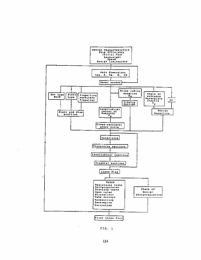
0 ES f CB Cll ARAC TEA I ST! C SShip Efftct fancy
lnitt ~ L CostDe ~ dvetght
SpeedD ~ sign llutter.Lone
ll ~ in Diam ~ LansLpp, 4, Ta. D, Cb
4LLge radius0 ' a4ris ~
Ca
Cn
0 ~ signQaterttne
ro55-seCtian ~ 1~ r ~ ~ 5 curve
W ~ t ~ riin ~ 5
'Tran5ver5e sections
l.ongitudinal ~ ~ ttians
DiagOnal sect ianr
t.ines PLY n
TESTSAssistance testaSe L f propul5 ionTravLing testsOpen vaterStreaai ines'Make surveyshanoeuvringSeak ~ ~ ptngC ~ vttatton
Final t.ines PLan
Paver needed
L.ong i t u4 in a LCent ~ r Ofbuoyancy
Cp
Check ofDesign
Charactert5tl.C5

.una clippers sail very often with large trims hatpr oduce r ighting arms that ar e dif fer ent f r on thoseca'cu ated fran the cross curves ceduced for the design
l Jml
«'hen tne ship is oper ating at low speeds in followingseas, the r ighting arms ar e lar gely modif ied by the wavesaction. That modification brings about a severe r'eductionwnen the ship is in the hogging condition, with a crestamidships and hollows forward and aft fig 2!. On this. igure, thr ee sections l, 2 and 3, r epresent typica'sections, forward, midships and aft. 'AoLo represents thewaterline for the ship inclined to a lar'ge angle, in stilwate., while 'vJ,L, is the local wa.ter level amidships ar.d ~i,�,represents the water level at the forward and aft sections.En compar ison wi.th the still water line of flotation, theship has an additional buoyancy, E,, amidships, whileexper iences losses of buoyancy, E,, E,, for war d and af t ..hecombined effect is a heeling moment which r educes ther ighting ar ms of the vessel.
FIG ~ 2
Gr eat losses of stability due to lar'ge f ree sur faces nayoccur in some cases, as a. consequence of the necessary ho'=swith live bait.
125

:n Ref. 2, a Stability Criterion for fishing coats w"sestab' Isned. It has been checked by app y'ng it to a. Largenumber of fishing boats, including bo h, vessels o:satisfactory stabil' ty and sea behaviour ana ships tnat have'oeen lost at sea, through capsizing pr'oduced by defectivestability. The Criterion has shown a good correlatior., inorder to establish a safe standard of stability.
In order to evaluate the seakeeping behaviour offishing vessels, it is essential to investigate tne rol' ingmotions of' the ship, The rolling period of any vessel may beexpressed as:
Tb = f B//Gff
where f is a constant for any ship and loading condition,that takes values from about 0.73 to 0.83, if B and GH areexpressed in meters. The values of f depend on the loadingcondition, the fullness of the ship and its we'ghtdistr ibution. In general, it may be assumed that f incr easeswhen the ship has empty spaces, permanent ballast, and/orlarge superstructures and top hamper. On the contr ary,tends to diminish when the ship is loaded, or' if the sniplines are very fine, or the weights are concentrated aroundthe rolling axis, or the ship has no super structures or verylittle top weight.
Kempf established the rolling nondimensional constant,Ck Tb~g, that r elates the r oil.ing per iod and the beam.Ck gives a measur e of the accelerations produced by therolling motions, so that small values of Ck, say less than7, imply that the ship is very stiff, being submitted toviolent rolling motions. On the other hand, large values o.Ck, say more than 12, are associated to large rollingper'iods, with low initial stab'lity of the ship, that maybecome tender and unsafe at sea, unless it is provided w'ample freeboard and/or a large amount of water tishsuperstructures.
In order to avoid unsatisfactory rolling motions, whatmay occur either with slow motions, due to Insufficient'niti.al stabili.ty, dangerous for the ship safety, or withviolent rolling motions, if GN is excessive, making verydifficult the work on board, the values of Ck, in alloperating conditions of the ship, should comply with thefollowing criterion:
5.4 + 0.05 LBP < Ck < 9 ' 2 + 0.06 LBP
Tuna Clipper Dimensions and Proportions
Table 1 shows main par ticulars of several tuna clipper stested at EL Par do Model Basin. A multiple linear r egr ession

analysis of those data furnishes linear r elationships amongthe differ ent var iables to be used in the design.
Table l.
LBP m! B~m! T m! CC ~SenvE EHP cv! Pnn
The following empirical formulae have been obtained, byregr essional analysis of the data that corresponds to themost satisfactory designs of Tuna clippers:
B = 0 ~ 1 LBP + 6.4
LBP/B = 0.044 LBP + 0.9 Fnd + 1.6
Cb B/LBP = -0,00152 LBP � 0.16 Fnd + 0.324
crn = 0.53 cb + 0.607
For the half-angle of entrance, at the design waterline, though not included in the above tabulation, thefollowing relation has been obtained in the same way:
Y ~ -0. 25 LBP + 165 Cb B/LBP + 14
Considerations on the Ship lines of Tuna clippers
No easy and safe rules can be established for ensuringa satisfactory and near optimum design of ship lines forthese fishing boats. Nevertheless, some notes may be givenas a general guidance for preliminary design:
.he experience of Fl Pardo Nodel Basin, tnrough theanalysis of information stored in our Data Bank, shows aclear trend for an improved performance of vessels of th'stype provided with bulbous bows. Great care should beexercised in designing the bulb, making sure that tne bulb
127
66.oo47.0052.0041.0063.60?2 2563.0056.1056.1o60.0054.0066.0o61.0061.. 5063.0064.00
13.0011.7012 F 1010.7013.0011. 6012. 9511.8011.9012.7013.1013.5012.5012.9013.0012 ~ 85
6 ~ 3005 ~ 4005.65o5.0005.80o5.5005 ' 7505.4504.7505.6505.2106.ooo5.4005.7005.7005.6oo
.6656
.655o
.6338,63o3.61T8.6490.5642.5918~ 5773.6071.6o23.5380.5895. 5801. 5818. 5810
14.5012. 3613. T612. 2514.7813. 6.
3C14. 44
16. 1915. 2615 5315-9615.2815. 0815.2215-37
2o42.1120.
1453849.
2128.4
19'7.1459 ~1978.2151.2344.2558.1841.1912.1915.1923.
. 608
. 574
. 624
.6o3
.6! I
.62
.6�
.661
.T60
.675
.686
.695
.684
.667
.669
.678

is designed to be effective at the design draughts ofoper at'on, as a poor know' edge of design dr aughts and
".. e vessel may have a ' arge 'n luence or. Cheper forr;,ance, render' ng the bulb effect to become negligor even negative .
sh'pr'ms
4
The analysis of the results obtained with the ships ofthis type for which we have information in our Data Basesuggests the following design consider ations:
For the bulb protuberance:
0.020 < Xb/LBP <0.022
� For the bulb height:
0.40 < Hb/Tpr < 0,44
- For the bulb sectional area at the forward perpendi,euler:
As20/As10 ~ 0.354 - 0.088 LBP/B + 0.222 Cb
The value of the parameter Cb B/LHP has a marked influenceon ship resistance, so that satisfactory results areobtained with moderate values of this parameter . From thestudied ships, Chose with better hydrodynamic behaviour forthe design speed range, showed values in the range 0.1150 ' 125.
� The longitudinal position of the center of buoyancy is ofsome impor'tance from the points of view of resistance andseakeep1ng. In general its posItion must be aft, but with agood choice of lines 1ts situation is not critical admitinga va.r'iation of 0.5 f of LBP with respect to the estimatedoptimum position. From the point of view of' seakeeping, itshould be slightly for ward of the optimum position forpropulsion in calm water. With these considerations in mind,3 - 3.5 5 of LBP aft are the suggested values .or th'sparameter.
Zn or der to obtain a favo~r able pr opeller inmer sion withlarge screw diameter's, corresponding to low r pm, associateto larger pr opulsive coefficient, a design trim is advisable
128
- Prismatic coefficient optimum values are in accordancewith the high service speed of these ships, for which aminimum wavemaking resistance in calm and rough seas must oeseeked. Values in the r ange 0. 62 � 0. 64 ar e advt. sable, ForCp' s gr eater than the higher limit, the long' ud'na'distribution of volume 's 1mpalr ed and the r esistanceincreases. For values below the lower limit, ac equal blockcoefficients, the midship section coefficie~t Cm mustincrease what damages the hydrodynamic behaviour of thehull.

t;-.ese vessels. hat trim may r ange f r or.. l � 3 of LBP...ust be realized that, in any case, a moderate af ter tri;,.
' s advantageous f r orn a. r esistance point or" view.
:he shape of the m'dship secCior. is related to thefullness and form of the hull. The use of deadrise isadvisable for achieving forns of' low r esistance. Its amountmust be combined with the choice of bilge radius to attain asatisfactory curvature at the bilge, in order to diminishthe gener ation pf bilge vortices.
'ne r atio LBP/B has a gr eat ef fect on res' stance. Tn somecases, the design values of Cb and/or Cp ar e obtainec byadopting an excessive value of t,he bean, in combination w' t';.relatively fine entr ance and r un, wnat originates str ong'ocal changes of curvatur e that may produce many undesirableeffects like eddy-making, wave-breaking, separation ancshoulder waves.
� The longitudinal position of the maximum sectional areamust be somehow abaft of' midships, its position being afunction of the weight distribution and the angle ofentrance.
� The use of transom stems is very convenient since itallows f' or more ample space aft for fIshing operations,favours ship stab111ty and diminishes the exit angles of' thewater lines near the surface, reducing the r isk ofundesirable flow phenomena.
Closed sternfrarnes are generally used, what is convenientto protect the net in the fishing operations.
As an example figure 3 represents the body plar,,sectional area curve and design waterline of a. modern .uraclipper of satisfactory design .
Power/S eed Estimates
The prediction of power for a fishing vessel isparticularly difficult having In mind the following:
- The small size of these vessels makes very difficult toobtain reliable Inf'ormation, referring Co systematic Tanktests, carried out for f'Ishing vessels.
- These ships a,re designed to operate at. r'ather h'gh valuesof Fn, as they have usually small length/beam ra-ios, whatIn time, gives rise to very high values of' wavemakingresistance, that may be accompanied by unpredictableIncreases in viscous pressure resistance, due to edoymaking, breaking waves and/or shoulder waves.
129

FIG. 3
1tttl Ot Lll ttttlt1tt
I t t ~ t I lt It I ~ I ~ I' It tt
Due to the small size of many of these vessels, the'rservice cond' Cions are very influenced by envir onmentaiconditions, sea and wind, so that the seakeeping conditionsof these vessels have also a lar'ge influence on theirsustained sea speed, and their fishing ability,
There are great differences in the technological designconditions of fishing boaCs of different countries, whichdepend not only on their variable technological levels, butalso on the different fishing techniques and correspondingenvironmental conditions and economical criteria.
The information published abou power estimates fortrawlers is not applicable to tuna clippers due to the largedifferences in characteristics and d'mensions. Similarcomments may be stated when referring Co methods forestimating the power of merchant ships, like those of :ap,Holtr op, Series 60, etc . As an example able 2 includesnormal values of CbB/LB?, Pnl and 2nd for the types of sn'psmentioned above.
130

Table 2.
una Clipprawlers."'.eL chan
0,11 � 0.' 4
0. 30 � 0. 380.55 � 0.70
0.10 � 0.140.15 � 0.250.35 - 0.65
0. 11 � 0. 170. 22 � 0. 340. 45 � 0. 70
Cb B/LBPFnlEnd
Therefore, the best method to obtain accurat,epredicCions and an optimum hydrodynamic design wil be tocarry out a Tank test program including, resistance, streamlines, wake survey, open water, selfpropu'sion anccavitat,ion tests.
Nevertheless, at, the preliminary design stage, it isnecessary to have an approximate prediction method availablein order to obtain power predictions of reasonable accuracy.
Power/Speed Prediction By Means of a Data Base
.his 'method, obviously, takes advantage o. neknowledge of model tests and full scale results for a num"e;of existing ships. In Ref. 4 a complete description of tneprocedur e and Data Base can be found .
Fig. 4 represents the flow-chart that corresponds tothis Power Prediction Method . In the course of thisPrediction method, it becomes convenient to use empiricalexpressions corrected by means of the results obtained byits appiica.tion to the basic-hull sample. What is actua.l' ydone is to accept the general trend of the forrnu' a butcorrecting iCs "independent terms" in such a way that a goofit to the absolute values appearing .'n the analyzed has'c-hulls is achieved.
Empirical Method of Power/Speed Prediction
Prom an analysis of the information on tuna clippersstored at the Data Base of El Pardo, the follow'r gappr'oximate power prediction method has been derived.
The basis of the method is the knowledge of the ratioCrs/Cfs between the resistance coefficients def1ned asfollows:
Cf s ITTC-57 ! 0. 075/ logRn-2 !
Crs = Cr'm = Ctn � Cfm
131
This method is considered the most accurate one tnatmay be used at the design stage, its typical error for tunaclippers being about 5$

SAHPLK SELECTION OF SIHII AR SHIPS
EHP ~ f V! KSTIHATIQNHultiple Linear Regression Analysis
of Scaled Resistance Tests
BHP f V! FIRST APPRQXINATIQNc.Ad Estimate by Empirical Formula
BHP ~ f V! FINER APPROXIHATIONETAd Obtained from Empirical Formulae Corrected by
Analysis of trends in Scaled Propulsion Tests
RPH ~ f V! KSTIHATIQNFrom BHP ~ f RPN! Sample's Trend
SCREW DIAHKTKR KSTIHATKBurtner's Formula
Wqm and Wtm ESTIHATIQNHar vald's Formula Cor r ected by Sample
DESIGN OF TROOST PROPELLER
NEW KTAd CALCULATIONFrom its Calculated Components
IF NORE THAN li DIFERKNCK WITH PREVIOUS QNECorr ect EHP Estimate
FINAL BHP ESTINATE
FIG. 4
The above r atio may be approximated by using ar egr essional f o regula given by:
Cr s/Cf s = a Cb B/LBP + b B/Tm + c LBP + d
obtained f rom a linear mu' t' pie regr esion analysis of theavailable data. The coefficients a, b, c and d have beendetermined for a standard Tuna clipper of 2,500 m3
132

displacement and for different values o Fnd . hese va' esar e shown on ab' e 3.
Table 3.
b c dFnd
In order to obtain the power prediction , one ;,.ustproceed as follows
Compute the value of Fnd for the design.
Obtain from table 3 the values of the coefficients a, b, cand d corresponding to that Fnd .
Calculate the ficticious length LBPf necessary to get adisplacement of 2500 m3 with the proportions of the design.
Compute Cfsf corresponding to the values Fnd snd BPfdetermined above .
Compute Crs for the design by applying:
Crs = Cfsf a Cb B/LBP + b B/Tm + c LBPf + d!
where all tne values not otherwise stated cor.espond to thedesign.
Comput.e Cfs for the design.
Compute Cts = Cfs + Crs + Ca
Compute Rts as:
Rts = G.5 o Scap V Cts
Finally: EHP cv! ~ Rts kp! V m/s! / 75.
By using the appropriate va.lues of ETAm and ETAd theBHP value may be estimated.
Screw Des'.gn. General Considerations
In order to obtain a good propeller design, severa'considerations should be taken 'nto account.
133
0.5500-5750.6GG0.6250.6500.675
3.6068.438
19 ' 52334.35852.16370.272
-0.4505-0. 44»
-0 3331-0.3626-0-.4695-O.7487
-0.0188-G.G160� 0.0047
0.01320.04000.0757
2.7192.002
-0.191-2.868-6.265-9,865

As for any other ship type, the modification of the«or kir.g cond' tions of the propelling system produced oy theaeterior ation of hull, pr'opelle. and pr opu sion plant,should be accounted for 'oy designing the scr ew to absorbfract1on of the nomina power of about S5$ to 90,. at .henominal r pm' s, in trial cond' tions.
.he 'ar ger price of hi-her str ergth propeller ."..at r'als ' st j pa' d back by the savings pr oduced ' n . ue
consumption and maintenance.
Knowing the wake distribution when design'ng the propre e-is of par amount impor tance for' avoiding cavitat ion ar.dvibration problems, obtain1ng a wake-adapted p. opeller o"high efficiency. This requires to per form the cor r espondingwake sur vey tests.
Apa r t f r' om the f orm of the dis t r'ibution, it isnecessary to know the absolute mean value of the effectivewake Ws . As a fir st approximation, the following formulamay be used.
Ws - 0.3 Cb + 0.9 B/LBP - 0.15
The limitations imposed by the stern frame contour on thepropeller design should be taken 1nto account when designingthe aft end of the ship, apart from the usual considerationson provision of spaces for fuel and ballast tanks ormachinery elements.
Propeller Clear ances
As it is known, providir.g scar ce clearances bet«eenpropeller and hull may produce ser ious vibr ation ar,=cavitation problems.
Analyzing the minimum c' earances required by theClassification Societies it can be seen that thoserequirements are lower the larger the number of blades, whatis logical since torque and thr'ust fluctuations per bladedecrease for 1ncreasi.ng number of blades. On the other' handthe optimum diameter for larger number of blades is lower,allowing t'ne use of lower rpm at the pr'opeller, what, meansan increase in efficiency. On tne debit side, it must betaken into account that, general' y, for larger number ofblades efficiencies tend to decrease. Therefore an optimummust be found considering all @he possible alternatives,Usually this optirnurn corresponds to 5 bladed propeller s.
The Wake and its Influence on the Screw Working Conditions
The flow entrance conditions to the screw are dec'ss'vefor the propeller-hull interaction, conditioning, on oneside, the propeller efficiency, and on the other side, the
134

possibility of cavitation phenomena, usually accompaniedv'brations and noises that may scare away he catch.
An estimat' on of the probability of appear ance of th. sk'nd of phenomena may be obtained by the B.S.R.A. Cr' terion Ref. 3! . This Criterion makes clear the convenience oflowering the propeller rpm.
Propeller RPM Choice
From the considerations made above it may oe statedtnat it should be chosen the minimum rpm value compati= ew' .h the following condi .Ions:
� Possibility of using the optimum diameter, for' which themaximum efficiency of the propeller can be attained.
Provision of the necessary propeller-hull clearances, forwhich the requirements of Clasificaton Societies are usua'lya good guidance.
Availability of the necessary reduction gear .
tl ~
PP 1 ~ ~ FIG. 513S

� The pr opeller inmersion for all operating conditions mustbe satisfactory.
As an example of the above considerations, in Table 4the characteristics of the propellers for a tuna clipperwith 3700 BHP as a function of the chosen rpm are outlined.Figures 5 and 6 show isowake and circumferential variationof the wake for this ship.
Table 4.
Zt can be seen that increasing the propeller' rpmdiminishes the service speed, the propeller efficiency andthe B. S.R.A. Criterion safety margin . This last situation isrepresented on figure 7 where the cavitation number 'sgiven as a function of the parameter W> , that gives an ideaof the amplitude of variation of the wake values. For valuesin excess of 240 rpm, a high risk of cavitation andvibration problems can be foreseen.
Conclusion
The consider at'ons outlined in this paper on thehydrodynamic design of tuna clippers reflect the presentstate of the art of the design technique for this type of
136
:-lade numberRPII
D m!Ae/AoV knots!ETAoIIargin
1803 ' 35o.6o0.92215 ~ 4539$
52003 ' 220.62o.87315.423K
52203. 10o.65o.82615 3311$
52402.98o.68o.78615. 25
0$
528o2.650 ' 770 ~ 80LL
15.1-7$

sh'ps in Spain, as it can be concluded from the informat'oncontained In El Pardo Data Base about ships tested in thelast decade.
hough this Information may be useful .or the design ofnew tuna clippers, predictions made on the behaviour ofships of similar characteristics should be confirmed by thecorresponding test programme that may allow, besides, theoptimization of the design.
0.20
O,l S
o.loW ma a - W min
W 4 W Illeih
f37
Ae/AoAs 10'As 20
BBHPCa.CbCfmCfsCkCm
Blade Area RatioMaximum Cross Sectional AreaCross Sectional Area. at, Fore PerpendicularMoulded breadthPropulsion Plant PowerResistance Allowance CoefficientBlock CoefficientITTC-57 Model Frictional CoefficientZTTC-57 Ship Frictional Coe ficientKempf's Nondimensional CoefficientMaximum Cross Sectional Area Coefficient

References
2 ~
FZTZSZMMONS, P. A ~: "Propeller Excited VibratIons:Cavitation Criterion for the Assesment of Scaled ModelWakes". The Naval Architect. November, 1977.-
3�
138
C rr,"
CrsCtmCts
DEHPETAdETAmETArETAoFnFndf
gGMHbLBPRrRnRPMRts
ScapTTbTmTfV
WqmWs
Wtm
WgXb
PrIsmatic Coeffic'entModel ResIduary Resistance Coe"ficientShip Residuary Resistance Coef icientModel Total Resistance CoefficientShip Total Resistance CoefficientScrew DiameterEffective PowerQuasi-Propulsive EfficiencyLIne-Shaft Mechanical EfficiencyRotative-Rels,tive EfficiencyPropeller EfficiencyLength Froude NumberDisplacement Froude Number ~ V/Constant for Rolling Period CalculationAcceler ation of GravityMetacentr ic HeightBulb HeightLength Between PerpendicularsScrew RadIusRadius for a Section of the ScrewReynolds NumberSpeed of Rotation In rev/minShip Towing ResistanceWetted Sur'face with AppendagesDraughtRolling PeriodMean DraughtDraught at Fore PerpendIcularShip SpeedModel Wake Fraction at Equal TorqueShi,p Effective Wake FractionModel Wake Fraction at Equal ThrustB,S.R.A. Criterion ParameterBulb ProtuberanceDesign waterline Half-Angle of entranceFluid DensityCavitation Number
PAULLZNG, J.: "Transverse Stability of Tuna Clippers".Fishing Boats of the Wor ld, No . 2. F-A.O., 1960.
O'DOGHERTY, P.; MORENO, M. and PEREZ-ROJAS,"Fishing Boats Stability Criterion, ObtaIned fromStatistical Analysis of Ship Losses". Proceedings of theSecond 1nter national Conference on Stability of Shipsand Ocean Vehicles. The Society of Naval Architects o.Japan . okyo . October, 1982.

".ARLIER, M. and O'DOGHERTY, I1.: "The Use of a Data Bankin the Optimization Process of a New Design".Proceedings of the International Symposium on ShipHydrodynamics and Energy Saving ISSHES-83!. Canal deExperiencias Hidrodinamicas, El Pardo, Spain. September,1983.
5. � O'DOGHERTY, P.; CARLZER, N. and O'DOGHERTY, M,:"Proyecto Hidrodinkaico de Buques Atuneros". Cana' deExper iencias Hidr odinamicas, El Pardo, Spain . Repor t IIo .73. January, 1983.
6.- O'DOGHERTY, P.: "Comportamiento en la Mar de BuquesPesqueros", Canal de Experiencias Hidrodinamicas, ElPardo, Spain. Report. no. 49. February, 1975.
139

ADD=I' EES;ST:,'.,:= 0F; IS.'i:I.' V:-.. =L,
i!' HEAD S-".'.S
STEPI'EI' R. ~UDSC,;, P,E.»
A3STR ACT
Yedels of three typical hew En land fishing vessels wer e towe5 in elm waterand in three different fully developed head seaways. Total dr ag was measuredin each case which allow d the calculation of added resistance due to motionin w-ves. The sane three designs were used in the H.J.T. Five-De,.ree-of-Freedon Sni~Motions Pro ran that predicts added resistance. All of thspeeds and seaways used in the model tank tests were duplicated in th ship-motions pr o ram, and so the accur acy of the added resistance prediction of thprogran was checked for this type of vessel.
The data from the towing tank test show that motion in waves may increase th=drag of these vessels by more than 300�. In one case, the data indicat.e that'h e added resistance reaches a limiting value with in reasin= s away seve. ity.Comparison added-resistance calculation shows that the shi~otions programdid not predict that quantity with any degree of accuracy or reliability fortypical New En> land fishing vessels. The results are presented in a fashionthought to be most useful to designers who can use th results to estimatepowering for this type of vessel.
"Lieutenant, U.S. Coast Guard, Ship Superintendent, U.S. Coast Guard 7ARD,Curtis Bay, MD
Opinions in this paper reflect those of the author and not necessarilythose of the U.S. Coast Guard.
140

INTRODUCTION
Orate of t,he great unknowns 1n estlm.tlnf, pow r Lng 1.s the added r sos anceof' the vessel in waves. Tnis added resistance can become a ver y si=nificantpart, of the total resistance. Indeed, if the waves becom large enou. h or ifthe vessel is snail enough, the vessel is slowed greatly or even stopped.Ooviousl y, an attempt to gather data for added resi stance in waves for alltypes of vessels and wave conditions would be a project of' incrediblep. oportions. Tnis pap r desct ibes an ef f'ort undertaken to quan ify addedresistance for a group of mall vessels. The vessels considered were NewEnr land fishing trawlers. This group was selected for two reasons; there isvery lit,tie resistance data of any kind availabl.e on these vessels and becauseof the author's proximity to these vessels.
Three models of these vessels were used in the M.I.T. To~ing Tank toobtain resistance data in both calm water and ~aves. They were also used inthe M.I.T. 5-Degree-of-Freedon Ship-Motions Program to check the accuracy of'the computer predictions for added resistance for this type of vessel. Theresults of their effort showed that added resistance in waves may increase thetotal drag of these vessels by more than 300~ over calm water resistance, Italso showed that the M.I.T. Ship-Motions Program does not, predict addedresistance for New England fishing trawlers with any degree of accu. acy orr el i ab ility.
SELECTION OF VESSELS
The author contacted John W. Gilbert Associates, Inc. in Boston forassistance in selecting appropriate vessels. The Gilbert design firm waschosen since it has had a great deal of experience in designing fishing,vessels. Mr. Jerry Gilligan of Gilbert reconfirmed the concept of greatsimilarity between -typical New England trawlers and he provided representativevessel.s for this work.
The specific requirements for vessel selection were to include a range ofsize fram largest to tallest vessel and to be as representative as possibleof the vessels actually in use. These requirements were met by five vessels;four fishing trawlers and a research vessel. The research vessel was includedfor two reasons; first, it was basically a fishing vessel with its outfitchanged for a different purpose and secondly, a towing tank model was air eadyavailable for use. The lines, proportions, center of gravity and gyradii ofthe research vessel all were in the same range as the type of vessel beinginvestigated.
At this point, it becane necessary to decide which of the five vesselswere to be towed in the model testing tank. There was neither time nor fundsto do all five, so the largest, smallest and rnid-sized vessels were chosen.The largest was a 139' research vessel which also had a model ready to use.The others were a 119' tra~ler and a 76' tra~ler. The author also decided touse the M.I.T. Five-Degree-of-Freedom Ships-Motions Program SUP! to canparethe results of it to the towing tank results. This had added potentialbenefit since if the program predicted the tank results accurately, then thetwo vessels not towed might also be used in the program to obtain data ofinterest. Particulars and body plans of the vessel.s used in the tank areincluded in Appendix I.
EXPERIMENTAL SET-UP
Models of the anallest and mid-sized vessel were constructed offiberglass by Applied Yodel Technology in Needhan, Massachusetts. The modelswere built as lightly as possible ccrTnensurate with maintaining rigidity.This ensur ed that du. ing the ballasting procedure, the mass dis'ribution ofthe mooel auld accurately reflect the actual vessel ~ Tnis was importan'since the mass distribution affects vessel motion, which in turn affects theresistance in waves,
141

TABLE ITOWING TANK TEST CONDITIONS
Hodel 1 � 76' TrawlerCalm Water DragSea~ay SignificantSpeeds in Seaways:
2-12 Kts Full ScaleWave Heigts: 1.92', 5.0', 8.15'
3.00 Kts, 5.03 Kts, 7.05 Kts
Model 3 - 119' Tra~lerCalm Water DragSea~ay SignificantSpeeds in Seaways:
2-14 Kts Full ScaleWave Heights: 3.0', 7.0', 10,85'
3.14 Kts, 5.05 Kts, 6.95 Kt,s
Vessel2-12 Kts Full ScaleWave Heights; 2.9', 6.31', 10,2'
2.99 Kts, 4.95 Kts, 7.21 Kts
Model 5 � 139' ResearchCalm Water DragSeaway SignificantSpeeds in Seaway:
142
The towing tank and wavemaking apparatus at the 1;.I.T. Ship Widel Towin-Tank were used without modif ication. Durin testing, the models wer fre tomove in heave and pitch, but were restrained in roll, yaw, su. ge anc sway.Model resistance was measured on a force block which incorporates a lineardifferent.ial tr ansformer. Th force block was mounted on he models at theLCG and as close to the p, opeller-shaft line as possible. This locationresults in the best estimate of what shaft hor sepower SHP! will b reauire'.
Waves were generated by a flat-plate wavenaker at one en" o. the tankwhich was hinged at the tank bottom and driven by a hydraulic ra . Du to thegeometry of the tank, this allows only the case of head and following seas tobe tested; how ver, the author feels that head seas is the most. severe case.The waves in which the models were towed were synthesized Pierson-11oskowitzfully developed sea spectra. The spectra were created at Yi.!.T. using randomnoise as a source. Each spectrm is on magnetic tape with a real time sznpleof approximately n7 minutes. The model were run in each seaway long enough toexposes them to roughly 20 of the running time. This provided a significantsmp3.e for each wave condition.
The models were all ballasted to correspond to the maximan load conditionand level trim. They were towed in calm water to obtain standard resist, ancein waves. Then each model was towed at three different speeds in each ofthree different sea states. Xn every case, the highest sea state was themaximm that th tank wavenaker could generate. The numerical value of thefull scale significant wave height in each of these cases varied with themodel, since the models were all built to different scales. The speeds wereselected to provide a range that the fishing vessels would encounter inservice.
Table I s~marizes the test conditions. In addition to using models inthe towing tank, the N.I,T. Five-Degree-of-Freedom Ship-%tions Progrm wasalso used to generate added resistance data. The SNP has many outputs, one ofthem being the calculation of added resistance due to motion in head seas.The progran was utilized to predict values of added resistance for a widerrange of seaways and speeds than were tested in the tank. The specificconditions were included and the author felt that if those results correlatedwell with the tank results, the wider range of seaways and speeds auldprovide more dat,a for more complete estimat,es of added resistance.

DATA Al<ALYSIS
RESULTS
The results of the model tests are presnted in graphical form in Figures1-6. These plots show drag versus speed and EHP versus ~need f' or all threevessels f' or calm-water and wave tests.
As can be seen by the figures, there is a significant increase in dragand EHP in waves. This canes as no surprise to anyone who has ever been tosea. What is of particular interest is the mount of the increase. The testsindicate that for a given speed, the drag in waves may double or even triplecompared to drag in calm water. The sme is of course true for powering.Conversely, for a given power level, the speed may be reduced by so much asseveral knots. Again, this is no surprise, but it has not been quantifiedbefore for this type of vessel, to the author's knowledge.
Figures 7-9 show the values of added resistanceobtained by model test and by SHP plotted against speed. This illustratesraphically that the SHP does not predict added resistance for these type
vessels accurately or with any predictable error. It was fogra was for this reason tha
the SMP was not used to predict added resistance for the 2 vessels for whichno model tests were done.
CONCLUS IOllS
the substantial added~aves. It may be ofpropulsion. lt snoulda designer needs to
i s of tank tests dramatically quantifiesis ser es n o rating inre sistance fishing vessels encounter when operorse wer for
use ot designers in estimating required hor pore in EHP, sob ted again that the powering curves aree no ' nt.apply a specific propulsive coefficien
143
The drag raw data were recorded as a digitized frequency and convertedpound via the force-block calibr ation constant. These dra" forces wereexpanded up to fu'll-scale vessel drag and effective horsepow r EH. ! usin-standar d mo 'el-test data-analysis p. ocedures. Tne In' ernational Towin� TankConference ITTC! formulation for calculation of frictional resistancecoefficient C~! an" a co. relation allo~ance C ! of .000< w re used incalcula in full-scale drag f' or the vessel in 59 F seawater. A shortprogrm was written for a TI-59 progrznmable calculator to perform thecalculations. Sufficient runs in calm water were made to make a moothrunnin plot of R /V versus V.
For the data in waves, enough runs were made at each speed to ensu. ethat approximately 20�of the duration of each sea state tape was encounteredby the model. Du. ing the higher speeds, this sometimes resulted in as many as14 runs for one data point. For this portion of the analysis, in one seastate at one speeds, the drag forces form all runs were averaged to obtain thodrag at that point. These drag forces were expanded in the sane manner ascalm water drag to obtain full scale drag and EHP. No corrections were usedto account for changing wetted surface since there is no way of estimating thewetted surface at any given time. Added resistance was simply calculated bysubtracting the value of calm ~ater resistance off of the faired drag curvefrom the value of' drag in waves at the sme speed.
The output of the ÃP is directly in added resistance for the full scalevessel at each sea state/speed point. This allows direct comparison of' themodel results and SIP results.

The range of differences between tank test values of added resistance andS!1P values of added resistance clearly indicates that th S'hP does not predictth se values for thes tvpe of vessels well at all, The author feels thatthis is attributable to two main reasons. Tn first is that the vessels w rewell beyond the range of linear ship motion theory. There was large rigidbody motion taking place, with green wate. bein" shipp d over th bow veryfrequently. The second reason is that, the SYRUP is more suited to much largerconventional hull vessels such as freighters and tankers wnich have muchlarger length-bern ratios which better satisfies strip-slender body theory.
It is interesting to note the. results of the tests on tho 76' hull. Tnadded resistance values for the significant wave height of 8.16' are less thenthose for the significant height of 5'. The au.hor feels this is due to thefact that as waveheights get larger, so do wavelengths, and the vessel isriding easier, It is analogous to a lifeboat riding relatively comfortably inwaves that batter large ships. This auld indicate that there may be some peakvalue of added resistance for any vessel at a particular speed. Addedreistance may increase with increasing waveheight up to this maximum pointafter which the added reistance may fall off. This seems reasonable since asthe waves get larger and larger, the vessel only experiences smaller andsmaller waves in its immediate vicinity even though it may be climbing theback of a mountainous wave.
It should be pointed out that there are several factors that have notbeen included in this analysis. The first is the added drag of a propellerwhen the vessel is being towed but the propeller is not tur ning or if it isfreewheeling. The first case is worse than the second since the blades of anon-turning propeller will act as flat plates being dragged through the water.A reasonable estimate of this drag is 10-20o of the calm ~ater resistance. Inthe higher sea states, it can be seen that value becomes insignificantcompared with the total drag.
The second factor not considered was wind resistance. Accuratedetermination of wind resistance was beyond the scope of this work and wouldadd yet another vari. able in the total resistance formulation.
In summary, the work done here was quantified what seamen and navalarchitects have known; that there is added resistance in waves. It hasindicated that the values of added resistance are quite significant; as muchas 300, or more of the calm wat.er resistance. It provides designers offishings vessels usable data for input to various decisions.
144

Ia
a
I
!
O
4
pa
m 4
Eal h1
FV 4'e 0
n
I I I
S
'a
145

CkJhC
1JPJ
OC!Vl
lalrh 441
L Vlk e
4
CI
K 4id ial
laj g Vl
g
0 04
I I
C C
Q A V
5 ~ c5 ' ~ aI I i I
0 e a
IC7 0
Jl146

O OVl
147
O O rv O O
~ IIC

O
* hlCI
OO OO 0O O OO O
Ill
148
CI
kl
O lila
Ii 3

lsl
U CClM <PI

4 IO0ID
i C
Ifd
I
CII A Cl!
MOe
I 6 n
Ln
C 0 WP
150

O 0 ChM
Oo &
4 R
15[

THE EFFECT OF VARIATIONS IN MAJOR HULL PARAMETERSOF FISHING YESSELS UPON DIRECTIONAL STABILITY
W. Brett Wf lsonNOAA Data Buoy Center
NSTL, Mfssfssippf 39529
Abstract
Directional stability fs a term associated with the course-keepingabflfty and maneuverability of marine vehicles. In the design oflarge ships, directional stability and other maneuverability param-eters are often evaluated using model tests or rather complex ana-lytical methods. Unfortunately, the cost of such tests and analy-ses cannot normally be justfffed in the design of fishing boats orworking vessels. Nevertheless, the need exfsts for the capabilityto make some assessment of the maneuverfng characteristics of afishing boat early in fts design. The naval archftect may be facedwith requfrements for high maneuverabflfty for fishing operationsor, conversely, for a large degree of dfrectional stability tocounteract sftuations where broaching might occur. This paperdescribes the development of a simple technique for determiningwhether a given ffshfng boat hull will be directfonally stable, andfor evaluating the effects of changes in ma/or hull form parameterson dfrectfonal stabilfty.
Based on standard analytical methods for estfmatfng hydrodynamiccoefffcfents, a numerical model was wrf tten to compute thecontrols-fixed directional stability index specffically for workingvessel hull forms. The numerical model was then run for variatfonsfn length-to-beam and beam-to-draft ratios, block coefffcfent,longitudinal center of gravfty, and drag of keel. The results areplotted as "stability threshold" curves that can be easily used bythe naval architect in the early stages of design to determine if avessel configuration fs directfonally stable.
Introduction
Fishing boats and other working vessels frequently operate fn ser-vices requfring greatly varying amounts of maneuverability and/orcourse-keeping ability. High maneuverabilf ty may be desired forfish-ffnding as well as fishing seining, long-lining, trawling,etc.!, while the abilf ty to maintain course may be necessary forsteaming to and from the fishing ground. The latter requirement isbeneficial from the standpoint of minimizing strain on the helmsmanand may be crucial for other reasons fn severe sea conditfons. Inparticular, course-keeping ability may substantially affect theresistance of a boat to broaching. Broachfng may be defined as theloss of course-keeping ability and control when a vessel fstravelling in a following sea at or near to the wave velocity.Since broaching is often accompanied by or can lead to a severereduction in hydrostatic transverse stability, catastrophicconsequences can resul t.
152

Course-keeping ability is dependent upon a number of factors L'I]that include the magnitude and nature of the forces acting to dis-turb the vessel from its intended path; the speed and accuracy withwhich such disturbances can be detected and corrected through thehelmsman, steering gear, and rudder; and the responses of the ves-sel to the distur'bances independent of helmsman and rudder. Thelatter are normally assessed through a determination of controls-fixed directional stability characteristics. To the extent a ves-sel exhibits controls-fixed stability, its course-keeping abilitywill be enhanced. Instability is not inherently disastrous, butbecause more than one yaw angle or ship's heading! can arise froma given rudder angle, the control problem is made more difficult.
In ship design, direction~1 stability is frequently evaluated usingmodel tests in sophisticated tank facilities or with complex ana-lytical methods. Unfortunately, the time and expense associatedwith these tests and analyses cannot normally be justified duringthe design of a fishing boat. A need, therefore, exists for ameans to quickly and inexpensively estimate the directional stabil-ity proper ties of fishing boats and other working vessels.
Nomenc 1 a ture
6 - ship beam, m or ftC - controls-fixed stability criterionCa - correlation allowanceC6 - block coefficient, on waterline lengthCp - drag coefficient for Jacobs formulaCf - frictional resistance coefficientCp - prismatic coefficientCr - residuary resistance coefficientCs - 2-dimensional added mass coefficientCtot - total resistance coefficienth - local draft, m or fthf - height of deadwood at trailing edge of deadwood, m or ftK - rotational added moment of inertia for a spheroidK~ - longitudinal added mass for a spheroidK2 - lateral added mass for a spheroidL � length, on waterline, m or ftLCS - longitudinal center of buoyancy from amidships, m or ftm - mass of ship. kg or slugsm2 � added mass of hull in swaymz - rotational added mass of hullNr - derivative of yaw moment w/respect to rotational velocityN� - derivative of yaw moment w/respect to sway velocityRtot � total resistance. N or lb!5 - wetted surface of hull, m or ftT - draft amidships, m or ftt - time, sY - ship speed, knotsv - ship speed, m/s or ft/s7 - centroid of added mass in sway from amidships, m or ft
- centroid of skeg lateral area from amidships, m or ft
153

XgXo
Xp
Su erscri ts and Subscrf ts
6 uations of Motfon and the Stabf lit Criterion
The nondimensional equations of motion for a ship fn the horizontalplane and neglecting surge are [lj:
-Y'v' + m' - Y'!v' � Y' - m' !r'v v r
Y', � m'X'!r' 0r'' g Sway!
- N-' - m'X'!v' - N' - m'X'!r'v 9 r g
-N'v'v
+ I' - N.'!r'' = 0z r' Yaw!
In accordance with the presentation in [1], the solutions to theabove simultaneous differential equations can be assumed to takethe following f orm:
v ve +v3e2
o t o2tr' =re +r3e
2
For controls-fixed stabflity, the sway velocf ty v'! and yaw angu-lar velocfty r'! must decrease with time, which necessitates thatboth oI and a2 be negative. If the solutions for v' and r' areinserted back into the equations of motion. a quadratic equatfon fnterms of o results:
154
YrYva9V
- center of gravfty from amidships, m or ft� Cp/L- center of lateral effort of hull profile from amfdshfps,
mor ft- derivative of sway force w/respect to rotational velocity- derivative of sway force w/respect to sway velocity- stability index- density of water, kg/m, or sl/ft- volume of dfsplacement of hull, m3 or ft~
- prime indicates nondimensfonalization- as fn Nv!f indicates the skeg hydrodynamic coefficient- as in N�!h indicates the bare hull hydrodynamic
coef fici ent- indicates dffferentfal with respect to time as fn v
and H�'!

Ao +Bo+C = 02
Solving,
-B/A +o
For ships, A and B are always large and positive, so that C must bepositive in order to obtain negative values for cr1 and a2.Thus, the criterion for controls-fixed stability can be shown to
be C ~ Y' N' - m'X'! � N' Y' - m'! > 0v r g v r
Oetermination of H drod namic Coefficients
The approach outlined in Llj was employed to predict the hydro-dynamic coefficients or derivatives! for use in the above stabil-ity criterion equation. Essentially, this approach assumes thebare hull of a ship to be a low aspect ratio foil, where the aspectratio is defined as draft/length, operating at a Froude number of0.25 or less. The Froude number restriction is imposed in orderthat the influence of wave making can be neglected. Therefore, thehull can be considered to be the lo~er half of a double body mir-rored about the free surface horizontal plane. The velocity-dependent bare hull hydrodynamic coefficients can then be estimatedwi th the following equations:
BARE HULL VELOCITY-DEPENDENT SWAY FORCE
Y�!� Y'! � + C !
LTv
The fir st term, mT/L, is the slope of the lift coefficient versusangle of attack curve based on Jones' formula for low aspect ratiofoils, and is generally applicable only where the hull's effectiveaspect ratio. 2T/L, is less than 1/5. Nost working vessels satisfythis criterion, although not by a significant amount. The range ofeffective aspect ratio investigated in this report is 1/3 to1/10.8. Jones' formula is used for the higher aspect ratios any-way. since from Figure 41 on page 501 of [1j, it does not appear tobe greatly in error until the effective aspect ratio exceeds 1/2.
The second term. CO!h. is the drag of the vessel at zero angleof attack. or the total calm water resistance. Using the Webb
155

Standard Trawler Series resistance data L2j, CD!h was deter-mined using ITTC friction and a correlation allowance, Ca of0.0004. The residuary resistance coefficient was approximated forV/QL 1.2 by the following exponent{a! 1 {near fit:
Cr 0.0427 Cp '
Having obtained Ctot = Cr + Cf + Ca, it is necessary to convert itto Cp!h. which is nondimensionalized by different parameters.Note that:
but C !D h p LTv
Ctot = prRtot
~Sv
For the Webb Series, Nevitt used the Taylor wetted surface coeffi-cient, C S/JUL, where C is a constant varying from 2.65 to 2.75.Using C 2.70 as a mean, the conversion can be made as follows:
Cp!h Ctot x 2.70 BC /T
As a final point, the high speed-length ratio of 1.2 was selectedas being typical of a trawler or other fishing vessel in the free-running condition. This violates the earlier restriction on wavemaking since it corresponds to a Froude number of approximately0.36. However, the high speed-length ratio affects only the Cp! p term, whi c h i s very sma 11, There f ore, the hydrodynami ccoefficients for the free-running condition or for lower speedsthat do satisfy the wave-making requirement will not be substan-tially in error.
BARE HULL VELOCITY-DEPENDENT YAW MOMENT
�v'h,', X ll'! = = - {m' - tlm'! + p y'�vh ALT 2 1 v h
v
The first term is the velocity-dependent moment of the hull in anideal fluid in which
156
This relationship was derived from Figure 1 which is taken from[2j. A displacement-length ratio of 467 was assumed in order todevelop the equation for Cr. Note that the effect of displacement-length ratio upon Cr is small compared to the effect of Cp. Sincethe total term Cpjh is not large, neglecting the effect of thedisplacement-length ratio will not introduce significant error intothe final results.

~ ~C h! dx2 P 2
0
m'2
k2 lateral added mass coefficient for a spheroid ininfinite flow
local hull draft
Cs = the 2-dfmensional sectional added masscoefficient, equal to 1.00 for an ellipse
and
k m' added mass of the shfp in surge nondimensional!1
m
kl longitudinal added mass coefficient for a spheroidin infinite flow.
In order to sfmplify and generalize the expressfon for m', thehull form is assumed to consist only of elliptical sectifns. Thisallows a constant value of Cs to be used and also enables majorhull form variations to be made wfthout requiring a specfal meansto generate sectional hal f-breadths for each variatfon. The ellfp-tical section yfelds a midship section coefficient of 0.785, whichfs typical for workfng vessel types. Given a reasonable sectionalarea curve and underwater hull profile, an equally reasonabledesign waterline results.
It should be noted that the inclusion of L/T in the integrand ofthe last formula on page 521 of Llj is apparently in error.
The second term fn the yaw-moment equation is due to the formatfonof vortices on the downstream sides of both bow and stern as aresult of viscous flow. These vortices can be associated with areduction in the pressure distribution over the hull from that ofthe ideal flow case. Xp fs taken as the distance from amidships tothe center of lateral effort of the hull.
BARE HULL ROTATIONAL VELOCITY-DEPENDENT SWAY FORCE
Y'! = � + = -K m' + p Y'!rh ALT 1 vhv
157

Here, the first term is the outward force exerted by an ideal fluidon the hull undergoing a constant rotational velocity, and thesecond term again accounts for viscous effects.
BARE HULL ROTATIONAL VELOCITY-DEPENDENT YAH MOMENT
h ~g z vh
Here mz = the rotational added mass coefficient= X'/X2!m!
where k' the rotational added moment of inertia for aspheroid in infinite flow
the centroid of added mass in sway from amidships
~ ~ Cp/2.Xo
SKEG HYDRODYNAMIC COEFFICIENTS
Using Jones' formula and the method of Ll]:
m hf!2
where hf height of skeg at trailing edge of skeg
N�'!, - X, Y�'!,
where Xf = distance from center of lateral effort of skeg toami dshi ps
Y'!f = N'!f
Finally, the total hydrodynamic coefficients are hull plus skeg!:
]58

v vh vf
v v h v
r rh rf
N' ~ {N'! + {N'! fr r h r f
Oevelo ment of Directional Stabilit Threshold Curves
A numerical model was written to compute the hydrodynamic coeffi-cients and the controls-fixed stability index. The model was usedto run a large number of hull form variations as a means to developa simple graphical method for determining directional stability.
A typical working vessel will have a length/beam ratio of around4.0, a beam/draft ratio of 2.5, drag of keel equal to 0,03 timesthe length, and a block coefficient of 0.50. In order to investi-gate the effect of changes in these parameters and also LCB anddrag of keel. a matrix of hull form variations was generated.Based on the Webb Trawler Series hull W-18 from I,2], three separatehull and skeg profiles were constructed corresponding to zero dragof keel. drag equal to 0.03L, and drag equal to 0.06L. Sketches ofthese profiles and tabulated values of the local hull and skegdraft nondimensionalized by draft amidships are sho~n in Figure 2.
For each drag of keel, nine different sectional area curves weredrawn. as shown in Figure 3. For these curves, CB was variedfrom 0.40 to 0.60 by 0. 10 increments. Then, for each CB, threeLCBs {0.05L aft of amidships, amidships, and 0.05L forward of amid-ships! were developed. Trial and error were used to obtain sec-tional area curves with the proper CB and LCB.
The numerical model includes an option to produce automatic varia-tions in L/B and B/T from 3 to 6 by increments of 1, and from 2.0to 3.6 by increments of 0.40, respectively. With the three hullprofile variations, nine LCB-CB variations, and 20 L/8-8/T varia-tions, a total of 540 different hull forms were investigated.These 540 hulls were divided into 27 ship sets for cataloguing pur-poses, with each ship set having only one drag of keel, LCB, andCB. but 20 different L/B and 8/T ratios.
Throughout, a standard hull length of 100 feet was chosen as beingtypical of a mid-sized fishing boat. The initial run of each shipset was arbitrarily selected at L = 100, 8 = 40, and T = 20. Thisis a particularly fat hull of unusual dimensions used only to i ni-tialize each ship set, and the resulting stability output wasignored.
159

Plots of stability criterion, C, versus 8/T for the four L/8 ratioswere developed from the numerical model output for each ship set.An example of these plots fs given in Figure 4 for zero drag ofkeel, LCB at amidships, and CB 0.50. The general trend inthese graphs is for the low L/B hull to be stable at higher B/Tvalues. This fs primarily due to the fact that 8/T and L/8 are notindependent, and therefore, what actually is occurring is a strongdependence of the stability criterion upon T/L. From these graphs,the values of 8/T at C 0 were read and then replotted in Figures5, 6, and 7,
Figures 5, 6, and 7 are plots of C = 0 lines, or "stabf lity thres-holds" against L/8 and B/T. Each figure fs for a sfngle blockcoefficient, but includes the three drag of keel and three LCB var-iations. The concept of the "stability threshold" graphs is toallow the design naval architect to enter with major hull formparameters and qufckly determine if the vessel fn question will bedirectionally stable. Any point lying to the left of a thresholdline fndfcates stabflfty, any point to the right, instability.Stabflfty characterfstfcs for intermediate values of CB. drag ofkeel, or LCB can be approximated by interpolation.
The behavior of the threshold lines is reasonable. Low blockcoefficient, additional drag of keel, and LCB forward all increasethe "stable region." The biggest improvement in stability occursfor increases fn drag of keel � the effects of LCB changes and CBchanges are about equal. In fact, a drag of keel of 0.06L appearsto guarantee directional stability for normal fishing boat hulls,where 8/T seldom exceeds 3.0.
Conclusions and Recommendations
An easy-to-use graphical method for determining the effects ofvarfatfons fn major hull parameters of fishing boats on controls-ffxed dfrectional stabflity is presented. The method is based onthe results of a numerical model that computes hydrodynamic coeffi-cients followfng a published theoretical approach with adjustmentsto suit fishing boat hull forms. With the graphs. the fishing boatdesigner can quickly and inexpensively estimate whether a givenhull will be directfonally stable and also determine the changesthat can be made to alter stabflity characteristics i'f required.
The graphs represent a ffrst step in providing the fishing boatdesign communi ty general information relative to directional sta-bilityy and course-keepfng. As a recommendation, data from modeltests or full-scale maneuvering trials, if available, should becollected in order to validate the curves shown on the graphs.
References
I. Comstock, John P., ed.,Society of Naval Archfte1967, pp. 518-529.
Therk,
2. Ridgely-Nevitt, Cedric, "The Resistance of a High Ofsplace-ment-Length Ratio Trawler Series," 1967 SNAME Transactfons,New York, 1967.
160

V/M= 1.2 500
450
350
300
250
200
.56 .58 .60 .62 .64 .66 .68 .70Cp
Figure 1, Ilebb Trawler Series Residuary Resistance Contours for Y~ = 1.2
Ordinates of Hull and Skeg Profiles Sk D ft � 0 ft St 5~H 11 Draft �: Draft Sta. Sl
Figure Z. Drag of Keel Variations
161

1.0SectionalArea
8 0.6Station 5
0.2
10 9 8 7 5 5 4 3 2 1 0
Stations
Curves tor LCB ~ 0.50L
1.0SectionalArea
0.6Station 5
0.2
10 9 8 7 6 5 4 3 2 1 0
Stations
Curves for LCB ~ 0.55L
Reverse tor LCB ~ 0.45L!
Figure 3. Sectfonal Area Curve Varfatfons
0. 02
0.01
L~ I
p p
W. 01
%.02
3.02.0
Figure 4, Example Plot of Stability Criterion vs. Beam to Draft Patio

aft
3.0R.O 4.0
Figure 5. Directional Stability Thresholds f' or Cz 0.40
Pr OS 0. 03L
LCS O. 05L 0. OSL. ~y'Bs 0 O6LQ
4.02.0
B/T
Figure 6. Directi onal Stability Thresholds for C> G.SQ
163
~ Oreg i 0.03L gLCB ~0.05L O.OSL
Key:ThreehalO, C < 0

p Drag ~ 0.03LqLCB t � Drag ~ 0.05L~t Drag ~ Monaco.05L 0.05L LCB
1,02.0 3.0
BIT
FigUre 7. Oirectional Stability Thresholds for C> - 0.60

V/vl = 1.2 5/.KL500
450
400
350
300
250
200
.56 .58 .60 .62 .64 .66 .68 ~ 70Cp
Figure l. I ebb Trawler Series Residuary Resistance Contours for V~ = 1.2
Ordinates of Hull and Skeg Profiles ISk D ft � 0 ft St 5!Hull Draft �: Draft Sta. 5I
Figure Z. Drag of l eel Variations
I 6~

1.0Sectfona1Area
0.6Station 5
0,2
9 8 7 5 5 4 3 2 1 0
Stat fons
Curves for LCB ~ 0.50L
1.0SectionafArea
0.6Statfon 5
0.2
10 9 8 7 6 5 4 3 2 1 0
Statfons
Curves f' or LCB ~ 0.55L
Reverse for LCB ~ 0.45L!
Figure 3. Sectional Area Curve VariatlOns
0. 02
0. 01
0.0
v+
-0. 01
-0. 02
3.02.08/T
Figure 4. Example Plot of Stability Criterion VS, Beam tO Oraft Patia

t � 0ra g ~ 0.03L ~
LCB ~0. 05L 0.054
~af t 0.0 fieKey:
Threshold, C * 0
aft
2.0 3.0 4.0B/T
Figure 5, Directional Stability Thresholds for C< = 0.40
~Drag 0. 03L ~
LCB - O,0SL O.OSL ~rag - 0.05'0 fCCd
4.03.02.0
8/T
Figure 6. Directional Stability Thresholds for C = 0.50B

porag ~ 0.03LqLCB ~ t � Dra g 0. 06L~
~ Drag ~ Nana1 0,05L 0.05LLCB
2.0 3.0B/T
Figure 7, Directiona1 Stability Thresholds for C 0.60

Christopher N. TupperOcean Research Corporation
Kennebunk, Maine, USA
Ship motions obviously impacton the ability to fish ~ Not only isproduction time lost when weatherprecludes fishing, the weatherdependent fluctuations of the landingsacross the industry cause chaos andi.nefficiency all down the line inprocessing, distribution, marketing andconsumption. The resultant loss issignificant.
This paper presents notes basedon a study of Seakeeping and HumanEngineering. Practical designconsiderations are reviewed.
Fishermen enjoy a well deserved prestige becausethey work in small ships subject constant motion from thesea. Designers of fishing vessels share in this prestigebecause, more often then not, fishing vessels do returnsafely to port. But just how good a job have designersbeen able to do, and is there room for improvement?
The New England Goundfish industry presents a goodexample. When weather precludes fishing production time ilost. Lost time increases the capital costs of fishing,Since this industry deals with a fresh product having ashelf life of only 8 to 14 days, fish prices vary inverselyas the amount of good weather. Bad weather yields goodprices. Because of the weather dependent fluctuations oflandings, the entire system of processing, distributing,and marketing fish is very flexible and quite inefficient.Dockside prices in the summer are less than half the pricesfor the same fish in the winter. This is not because thefish have changed, but because the industry can not handleboth situations with equal effectiveness. Essentially iffish were dependably available year round, the system couldbe set up to yield the same high added value in the summeras it does in the winter. All of this can not be laid atthe door 5f ship motions, but Figure l shows the remarkable
169

100
90
80
70
SO
40r-- -. i I Tine Mind I.aaa Than L4 Knoca
�Tcipa pea IIonah llocsalixed To
June teak, portland II ' . 197820
GCausdf iah Landinga ',Iocselicadco July tank, toccland, 1979
FIGURE I
COTRCIOERCE Or IIEATIIERtTSIITIK TRlt'5 AIIO LlÃDTIICS
E100
90
90
50
40
Typical Oock trice toe «round ash'Hoasaliaed ca January prices
i Tine Oiad ieaa Than 16 Kao sLO
caa san ann ~v ~c ~v qua aapr ocr mv
tTCURE 2
SFASoIIA1. 915'8 PRICE RID 'uEiTIIEII TARE,TIOII
170
Jan Pa% INN Ann Mcv inc aA,V AVO an't Ocr nOv ORC

coincidence of good weather, number of fishing trips andfish landings ~ Note the close correlation of monthlylandings to number of trips. This indicates a relativelyconstant catch per unit effort.
What is this weather that sa hampers the industry?Statistics from shipboard observations large merchantsships! give the fo3.lowing for the Gulf of Maine:
Figure 3Weather Conditions in Gulf of Maine
Occurance Wind Speed Wave Height Wave Period
4 [1.2m!6 [1.8m!9 [2.8111]
6
7 9162233
668195
The 16 knot conditions correspond very well withthe fishing activity as shown in Figure l. It appears that
weatherproofing" the operations so that they could beconducted in the 33 knot wind conditions would essentiallye3.iminate the effects of weather upon the system.
These weather conditions seem surprisingly mildwhen one considers that the industry statistics cited arebased on vessels 40 to 130 feet in length [12 to 40 mjfishing from 3 to 200 miles from part [5 to 320 km] . Xtshould a3.so be stated that the fishermen's perception ofthe situation is not as severe as imp3.ied by thesestatistics. A recent spot sampling indicated thatfishermen felt that lack of weather restrictions would addonly 20 to 60 extra trips to seasons that alreadyencompassed 150 to 200 trips.
The following descriptions of reasons that motionsinterfere with fishing are based on observation trips withfishermen, interviews with fishermen and the start of a
171
Figure 2 shows the inverse relationship of priceand weather. Taking number of trips in the most activemanth as an indication of fleet capacity, the figuresindicate that fleet operates at about 60 percent of itsannual capacity. Taking the winter time price as anindication of the obtainable y~ for the fish, thefisherman recieves an average of 60% of this value. It isprobably not overstating the case to say that weather shipmotion! restrictions cost the New England fishing system atleast 50% of its potential economic efficiency.

survey of fishermen on the subject. These al.l refer tostudies of New England fishermen, The importance of oneinfluence or another refers to the frequency with which itseems to interfere with fishing on an industry wide basis.
The first category of motion interference withfishing is: This includes swamping,capsize in waves, loss of directional control while runningwith following waves, and structural damage from slamming.Fishing vessel designers have been concentrating onpreventing these events and in a survey of fishermen onlythe last of these was given as a reason that fishing wasstopped because of weather. Designers should perhaps becomforted; danger to the vessel is an importantconsideration but is not the usual. reason that fishingceases when it does.
The second category of motion interference withfishing is: ' Observations indicate thatthis is a very important aspect of the problem. Zt isparticularly a problem for trawlers as the ship motions heave and pitch! are translated to pulsing motions of thedoors and net. Experience indicates that the catch ratedrops off as the motion level of the vessel increases.This is an important factor in causing vessels to ceasefishing.
The third category of motion interference withf ishing is: This, too, is avery important aspect. Fixed gear fishing methods such asgillnetting and longlining require that the vessel excel atstation keeping so that the gear can be worked over slowly speed less than one knot! . As ship motions increase,especially surface drift and loss of control of heading,l.arge strains are placed upon the fishing gear. Also thespeed at which the vessel can work its way down the gear isdecreased. This, too, is an irrrportant factor in causingvessels to stop fishing.
The fourth category of motion interference withfishing is: This threatcan be to the vessel, to the gear itself or to the crew.Arrangements are easily made to secure most gear. There isobviously some danger to the crew while in the process ofsecuring the gear, but the time periods for this danger arequite short and are accepted as a normal part of the thejob. While this is an important consideration it was notobserved to be a major reason that fishing was halted.
The fifth category of motion interference withfishing is: This threat is togear on deck, to the fish being processed on deck, and tothe crew. Again this is an important consideration,especially for vessels with very low freeboard, but does
172

not appear to be a major reason that fishing ceases.
The sixth category or motion interference withfishing is: Thisincludes the traditional seasickness category, which doesnot appear to be very important in stopping fishing.Slipping and sliding on the tilting deck appears to be a"medium" level problem in causing fishing to cease. A moreimportant reason appears to be the jerking around" thatcauses difficulty for the crew in maintaining their bodyposition relative to the ship. Another important aspect isthe exhaustion from fighting motion. These last two wouldhave to be classes as major reeasons that fishingactivities ceased.
Figure 4 presents a summary of the motioninfluences that interfere with fishing and ranks them inorder of decreasing frequency and importance.
Figure 4Motion Influences Interfering N'ith Fishing
Ranked by Frequency of Occurance
MOST FREQUENT REASONSGear Doesn't FishVessel Can't Stay on GearCrews Gets Jerked AroundExhaustion from Fighting Motion
MODERATELY FREQUENT REASONSCrew Slips and Slides on Inclined DecksWater On Deck Poses Threat
LEAST FREQUENT REASONSLoose Gear On Deck Poses ThreatDanger to Vessel
A study of Seakeeping and Human Engineering wasrecently completed for SNAME panel H � 7, SeakeepingCharacteristics. The study illustrated the complexity ofthe influence of motion of man's ability to work at sea.It also showed that very little is really understood aboutthis interaction.
The study illustrated two important extensions tothe commonly used "model" of man interacting with motions.Previous studies had not considered either thepredictability of motions nor the amount that the crew wasjerked around. During observation trips with fishermenboth of these were observed to be important. The amount.
173

that the crew is jerked around has a physical measurement,jerk, which is the time derivative of acceleration.Previous studies have made much of acceleration levels,which are related to the frequency squared for sinusoidalmotion. Jerk, however, may be more important and isre3.ated to the frequency cubed.
The quasi-static picture in Figure 5 shows a gooddeal about man working on the deck of a moving vessel.Within broad boundaries the force leve3.s themselves are notprob3.ems, the man can provide a wide variety of opposingforces to maintain his position relative to the shipiHowever, unlike a rigid body, say a statue at thisposition, the man must actively use his brain and musclesto maintain this position. This interferes with the workhe is doing, such as securing loose gear on deck, whichalso requires active use of the brain and muscle system.Thus it, is the time variation of the forces andaccelerations that is the problem rather than the forcesthemselves.
The jerk problem can be immediate, in that thecrewmen may not be able to simultaneously hold theirposition and perform their tasks, or the problem may becumulative, showing up as fatigue and exhuastion. Bothimmediate jerk and fatigue were observed to be importantreasons that fishing ceased. Fishermen who have installedparavanes flopper stoppers! have reported that, of all ofthe effects from the 30 to 50% reouctions in rollamplitude, the biggest improvement is in the endurance ofthe crew.

It is-not likely that any set of simple designconsiderations are going to extend the fleet operati.ons to33 knots wind conditions. However, some boats are reputedlygood sea boats, while others are not. There are reporteddifferences even amoung sister ships. Fishermen offer manytheories as to why this vessel is better than that, but nodefinative work seems to have been done on this subject.
Too little is understood to be able to offernumerical guidelines or methods of analysis for designing"good" boats as far as motions are concerned. The bestthat can be offered as design considerations are reallyonly common sense items. It should be noted, however, thatmany fishing vessels fall outside the guidelines of thesecommon sense considerations. The results are alwayspredictably bad. Many vessels have pilothouses way forwardwhere pitching motions are extreme. Perhaps this isacceptable in the waters for which these vessels wereoriginally designed, but vessels today are mass producedand marketed and moved around the world.
Design considerations fall into three categories,designing the vessel to reduce motions, arranging whichtasks take place in which motion environments on thevessel, and arranging details of body supports, etc., atthe work stations.
In the category of reducing ship motions roll andpitch can be reduced somewhat by increasing the dampinginfluence of fins, bilge keels, chines and paravanes.There is ample fishermen testimony to the effectiveness ofthese measures. Interestingly, although fishermen likechine boats, there are complaints about vessels with toosharp a chine possessing too "jerky" a motion as the sharpchine suddenly comes into play during a roll. GM metacentric height! also comes into play, although in acomplicated way. Increased GM is needed for stabilitysafety, and it also tends to reduce the roll amplitude.The reduced roll amplitude is helpful in reducingaccelerations and jerk levels, but seems to be more thanoffset by the fact that increased GM leads to higher rollfrequency and thus higher acceleration and jerk. Ingeneral increased CF is associated with a more "jerky"motion. GF in excess of whatever is really needed forsafety is probably detrimental to the vessel's performance.This of course opens a whole debate about the appropriatetrade off between ultirrrate vessel stability and operatingconcerns.
Closely related to the motion design considerationsare those of station keeping in rough weather. Windageshould be kept down and the vessel's heading relative to
175

the wind should be easily maintained. Boats with high bowsand low stems are difficult to keep on course when workingover fishing gear at low speeds in high winds unless theunderwater profile is designed to match the windageprofile. Extra maneuvability is desirable for vesselsfishing fixed gear and side thrusters would probably behelpful.
The location of various tasks should be arrangedwith consideration of the motion environment. Theplacement of pilot houses way forward or very high arecommon examples of arrangements that could be improved froma motion design standpoint. Everything is a compromise,however. For maneuverability the hauling of fixed gearover the side should be located as far forward of thevessel's turning pivot point as possible. From a purelymotion standpoint the hauling station should be located asclose to amidship as possible in order to minimize themotion levels and also the relative motion between thestation and the sea surface.
Probably the area with the most immediate potentialis in the detailed design of workstations and tasks forcrewmembers. Nore attention could be given to providingconvenient handholds and body supports. Tasks could bedesigned to eliminate the handling of heavy objects and tocut down on the amount of "travel" requited on a pitchingdeck. Modifications like these do not need to be expensiveand will address one of the most important motioninfluences that interferes with fishing.
There certainly is room for improvement i.n thedesign of fishing vessels so that ship motions will be lessof a restriction to operations. There is also a great dealyet to be learned.
The fishing industry has perhaps more to gain thananyone else from the study of how ship motions interferewith operations at sea. Who else goes down to work the seain such small small ships and expects to do so in all kindsof weather. Perhaps this is why the fishing industryalready has a leadership role in the study of these things,Some of the most practical published work on this subjectis that of Capt. Walter Mockel in the "Fishing Boats of the
, World," Volumes I and II. Unfortunatley very little seemsto have been done since then.
One has to hope that discussions today and futurework on this subject will yield better understanding ofthis issue. Perhaps we can look forward to more quantativeguidelines at future conferences.
176

4 5QTT hPZBQA!N XQ THE ZKBhLZH QK S18MXZRG KNJMI MALS
Bill Seemann, Seemann Fiber glass, Inc.
hbM~i&
In the past< attempts to sheath large waaden vessels withreinfor ced plastics.have largely been unsuccessf ul due todelamination af the sheathing f rom the woad in a relativelyshort time. This paper describes a new technique of using anelastomeric adhesive ta band the sheathing to the wood. Theflexibility of the bond allows some movement between thesheathing and the planking, reducing stress concentrations andgreatly reducing the likelihoad of delaminatian. Thetheoretical reasons far using this approach are descr ibed aswell as field experience with the system. Case histories arecited alang v ith pictures of the appl ication process and ofthe finished baats.
Z~urv. af ~ Zasta~
For many years builders have tried to cover pl ankedvoo den h ul 1 s wi th a m embr ane in ar der to el iminate l ea king,atacks from marine organisms ar to retard marine growth.Capper, canvas, and reinfarced plastics have all been usedwith varying degrees of success. When reinfarced plastics wasintroducedi it seemed the ideal material for this purpose.While the covering did not by itself retard marine growth, itdid off er a continuous water proof membrane whi ch strengthenedthe hull, stapped 1 caking, and protected the voad f rom marinebor er s.
The process was relatively easy to do, parti cul arly ifthe hull was turned upside down. The materials were notexpensive rel ative to the benef its which vere derived. Thefirst boats vhich were covered vere naturally small baatsalthaugh it vas clear that large vessels such as large fishingvessels would benefit if a workable process were available.There vere attempts made to cover large vessels using thestandar d techniques but, unf or tuna tely, al though the pro cessvorked well on smaller baats, probl ems began to develop viththe jobs dane an the larger vessels. Some rules an successfulsheathing practice began to emerge:
l. Small boats, particularly plyvood boats andparticul arly fir plywoad boats were relatively easy to cov erand vere usually very successf ully done vith the standardpolyester resin and glass cloth technique.
2. A better bond caul d be devel aped between the wood andthe gl ass reinf or ced pl asti cs GRP! cev ering irf a ch oppedstrand mat CSM! vere used first an the wood.
3. Oily woods and har dw oods were dif f i cul t to band tovith polyester resin and epoxy resin should be substituted for
177

a better bond.
4. Glued construction hulls, either doubl e planked, coldmolded, or strip planked were much better candidates forsheathing vith GRP than were caul ked carvel planked hulls.
5. Lar ge carvel planked hulls over 40' or so! werediff icul t to successf ul ly sheath with GRP. Delamination ofthe GRP from the wood was likely to occur in a short time.
6. Any large vessel was difficult to sheath because ofthe probl ems of doing the overhead GRP vork on the bottom ofthe hul l. If the hul 1 could be tipped to the side thisproblem was greatly al eviated, but this was difficult to do onlarger boats.
The major probl em with sheathing 1 arge caul ked hul lsremained that the sheathing vas likely to delaminate fr om thewood. It is recoqnized that differential movement between thewood and the GRP is the cause of the stresses vhich developand attempts to reduce these stresses have included using amore flexible r einf or cement in the sheathing Dynel andpolypropylene fabr ics! with epoxy resins. In the U.K., theCascover process was developed. This process involves gluinga nylon fabric to the wood with Casco+en Glue.
Another technique to deal with the tendency of the GRP todel aminate f rom the wood has been dev el ope d by Mt. AlainVaistes of Mat tapoisett, Massachusetts, U. S. Mr. Vaistes doesnot attempt to develop a bond between the sheathing and thewood, but rather mechanically fastens the sheathing to thehul 1 with nails or stapl es. These vessels are usual ly tippedto the side to facilitate the work. The author understandsthat Mr. Vaistes has done many successf ul jobs up to 60'vessels.
In late 1978 the author began to develop a process forsheathing carvel planked hulls which would address theproblems of the delamination of the sheathing and the probl emof vor king the wet GRP process overhead on the bottom of lar gewooden hul ls vithout having to turn or tip the hul l. It vasrecognized that the process, if successf ul, vould be mostusef ul. in pl aces where the kind of equipment necessary to tipa lar ge hull vas not availabl e.
A f ul 1 seal e hal f section of a trawler hul l vasconstructed and the first vor k was on the techniques toel iminate the necessi ty for tipping the hul l. It vas foundthat C'-Flex Fiberglass Planking could easily be applied to theoverhead if it was appl ied dry into an adhesive paste. CF1 exis a 12 vide unidirectionally reinf or ced material vhi ch hashigh str ength �7000 psi tensi.l e, 46000 psi compressive! inthe long direction of the roll. The Cl-Flex was appliedperpendicul ar to the run of the planking, that is from gunwaleto keel. Applied in this manner, the hi gh strength of the
178

material is orientated in the proper direction to vithstandthe high loading of expansion of the planking. Also, it vasfound that the material was very easy to apply in thisdirection. Once the upper end of the strip was secured inplace, it proved very easy to bend the rest of the plank intoposition, even wor king on the overhead. C -Flex has precuredpultruded rods as part of its construction and it provednecessary to staple battens every l2" for so to hold thematerial in place properly bedded into the adhesive. Theadhesive used in this first series of tests was a filledpolyester pa ste.
Once the bedding adhesive had cured, the battens could bepulled off. The C-Flex vas then saturated with resin andsev eral layers of chopped strand vere appl ied to f inish thejob. The chopped strand mat layers proved to be relativelyeasy to apply if the upper end was done first, then the restcaref ully rolled down and under the hull.
This application technique seemed to solve the problem ofbeing able to sheath a hull easily without tipping or turningthe hul l. Most of the material was applied dry, and thematerial which was applied wet was manageable.
The next step vas testing of the f ul l seal e model bycycling it through wet-dry cycles. Vnf ortunately> thesheathing separated f rom the planking af ter the f irst cycl eand close examination revealed that the bond betveen the voodand the GRP had not broken but that the wood f ibe rs beneaththe bond had failed.
What was observed was that there was considerabl emovement of the planking in a direction normal to the planksurf ace and this mov ement caused high peel forces which torethe sheathing from the wood. It vas theorized that thesheathing, vhich was L/4" thick in this case, had reached adegree of stiffness where it would resist bending beyond thecapacity of the wood f iber tear-out strength normal to theplank surface. This explained why sheathing systems vouldwork on smaller boats, where the sheathing vas thin and not ofsufficient stiffness to resist the tear out strength of thewood f i.hers. The author had sheathed a 36' sail boat in thelabe l950's vhere he had faired the hull to the point where noplank seams shoved before launch, and he had observed, to hishorror, every seam become obvious vi thin two weeks of launchas the pl anking regained its moisture content and warped to anew shape.
It vas obv ious that there vere two major kinds ofmovement of the planking that exerted high peel stresses onthe bond between the sheathing and the wood.
1. Warpage fo the plank.
2. Slippage of the planks.
179

It vas clear that na improvement in bond strength couldovercome these problems, but that an entirely differentapproach was needed. After testing many types of adhesives, apolyurethane elastomeric adhesiv e was sele cted. Thi sparticular a%esive bonded tenaciously to every type af waodtested, including oak, teak, cypress, mahogany, and fir. Itis a maisture cure product, and has the capacity fo bondingwell to damp vood. Furthermore, and mast important, it hashigh elasticity up to 300% tensil e elongation bef ar e break!and thus allows some movement between the sheathing and thewaad without developing the high stress concentrations of arigid adhesive. Wet strength retention was excellent and inmast cases tested the adhesive system strength exceeded thestrength of the substrate. In all cases the peel strength ofthe system was dramatically improved aver a rigid adhesive.
The decision was made to ga ahead with a f ull scale testof the system. The 55' ACF motor cruiser 'Sally Forth ownedby Alton NcIver of New Orleans was the first boat ta be done.The boat had been built in 1929 and showed the effects af itsalmost 50 years: thinned planks from many sandings, loosefastenings, broken frames, a tendency to sag when beinghauled, etc. The jab was finished in spring 1979 and the boatis stiff, does nat leak, has showed na signs af delaminationor signs of rot caused by the sheathing system. Since thattime many vessel s hav e been sheathed, including manycommercial fishing boats and, the largest to date, a 138' ex-minesvee per .
There have been no reparts of delamination, ev en thoughsome of the vessels have been in heavy commer cial fishingservice. Furthermore, many of the jobs have been dane outsidewith no caver and, even under these bad conditions,satisf actory jobs have been passible.
The vessels af ter sheathing are stronger, do not leak andare abl e to perf orm to like new standa r ds in commer ci alservi ce.
Two examples af commercial fishing boats dane to date are:
The 65' shrimp travler "North Star ovned and sheathed byBel 1 Buoy Seaf aod, Kdi sto Beach, South Caral ina. Bef or esheathing when she had been hauled vith vater in her bilgesthe weight of the water had pushed sev eral planks of f her.These planks were refastened, but no other refastening vasdane. She vas sheathed anly to the vaterl inc. Last vinter shevent on a shoal near Framptan Inlet and pounded in breakingsurf for several days. The rigging w as bent from the farce afthe pounding, the rudder shaft was bent' so that the shaf t layright up along side the hul l. Yet when she was pul led of fthere was no hull structural damage except that the samson-post and stem were pulled out of her in the ref loating
180

operation. The hull only leaked slightly along the garboardwhere the sheathing had not been carried under the keel buthad been stopped on each side of the keel. Delamination hadoccured in areas where bilge oil leaking from the hull hadprevented a proper bond during the appl ication of thesheathing. No other areas fo delamination have been found.
The 70' snapper and longl ine vessel Fx iendship II"-Bef ore sheathing this vessel had been given up for scrap andwas destined for the artif icial reef. Old ref rigerator s, etchad already been loaded aboard. Raf field Shipbuilding took onthe job to sheath and to re-equip her and she has recentlybeen appraised at $300 000.00
This process has proven itsel f well in short termtesting. Only really long term testing will finally prove ordisprove the worth of this system.
In order to obtain a proper bond to the planking, allpaint and foreign matter must be removed from the wood. Thebeet technique to use to xemove the bottom paint is tosandblast. Sandblasting is fast, will give the wood anexcellent texture for the adhesive to gr ip to as wel 1 as tor emov e rotten woo* Unf or tunately, sandblasting wi1 1 not wor kvery well on the topsides as the topsides enamel is usuallyharder than the wood and the sandblasting will eat the woodaround patches of paint. The best way to remove topsidespaint is to use a large disc grinder with coarse paper �6 ox24 grit!. Grinder swirls are no pxoblem but, of cour se, careshoul d be taken to keep, or make, the surface as f air aspossi bl e.
Rotten planks should be repl aced. Fits are not reallyimpor tant, al though a wor kman1 i ke j ob shoul d be done. Badspots in the pl anki.ng may be spot patched with pieces of woodgl ued in place with the same adhesive used to bond thesheathing in place. Again, fit is not really important asthis adhesive is gap-filling. Seams need not be reefed but,any loose material should be scraped away.
Thru-hull fittings should be removed, if feasible. Samefor rudder fittings, struts, etc. In some cases where thesefittings are extremely dif ficul t to remove it has provenpossibl e to work over them and to bond and mechanical ly fastenthe sheathing to the outside of the fitting. The C-Bondadhesive will bond wel 1 to bronxe and, parti cul arly if thebond is backed up by mechanical fastenings, will adequatelyseal the j oi nt.
181

Some re-fastening of the planking may be necessary butnot as much as would be needed if the boat were not to besheathed. One of the main purposes for planking fastening isto keep the planks from popping off the frames. The sheathingvill perform this function once it is in place, so extensivere-fastening may not be necessary. Several boats have beendone vith no re-fastening at all, even though the fasteningswere known to be bad, and no probl ems have developed.
Bad frames will have to be replaced or sistered on a caseby case basis. The sheathing, vith its 1/4 + thickness andextremely high strength, will replace some of the function ofthe framing and make some of the framing redundant. This mustbe judged on a case by case basis. Some of the boats thathave been sheathed still have cracked or bad frames in themand are holding up in heavy service vith no probl ems to date.More experience will be needed before a recommendation can bemade on this point.
The one-part polyurethane adhesive which has been usedf or this process is a viscous mastic. It can be made veryvorkabl e by heating to 100 deg. F or so. It is applied with a12 wide deep notched trowel at a rate of approx. 25 sq. ft.to the gal ion. The pot lif e fo the mastic is at least 4 hour sand one person applying the adhesive can easily keep ahaed oftvo peopl~e applying the C-Flex.
The first plank should be appl ied amidship and the workshou3.d proceed forward and aft from there. The planks arefirst staplied across the top, then held in pl ace with woodenbattens every foot or so. A pneumatic stapler is necessaryfor this part of the job. It is essential that the C-Fl ex bepressed compl etely into the adhesive. Af ter a shortinstr uction period the appl ica tor wil 1 be abl e to visual lydetermine if enough battens have been used by observingvhether th e adhesi v e has ooz ed thr ough the C-FL EX to asufficent extent. A good three man crew can applyapproximately 75 sq. ft. of adhesive and planking per hour.The adhesive will take approximately 24 hours to cure and thenthe battens may be stripped off.
After the battens hav e been stripped of f the next step isto saturate the C-FLEX with resin. Some care must beexercised at this point to ensure that the resin is catalyzedto cure slowly enough to al3.ow time to fully saturate the C-F3 ex. The heav ier ge ade of CFl ex contains 65 ounces offiberglass reinfor cement per sq. yd. so it takes a fair amountof resin to fully saturate. The proper procedure to follow toensure complete saturation is to work three strips at once.Roll the resin onto the first strip, then the second, then thethird. Then repeat the proce'ss twice before moving to the

fourth strip. Each strip will thus be coated three times withsome time between applications to allow for saturation. Whenthe C-Flwex is f ul ly satur ated the dark brown color of theadhesive vill be clearly visible.
While the .resin is still vet additional stapl es aredriven through the C-Flex to mechanically fasten the sheathingto the hull. This is usually done at a rate of approximatelyl2 staples per square f oot. As we gain experience vith thissystem we ar e questioning v-heth er or not th ese stapl es arenecessary. At least one boat has been done without thesestapl es. The airer af t industry cal ls these chickenfasteners". They don't really seem necessary, but we are toochicken to not use them.
Once the C~liex is cured, the surface is sanded to knockoff high spots and then the rest of teh laminate is applied.Vessels up to 70' LOA vill need approximately 3 ounces of CSMover the C!-Flex, with additional layers of CSM and WovenRoving WR! u~sed to reinf orce specific areas such as thegarboard, stem and transom joints, etc. Typically these areaswill be additionally reinforced with three plies of l.5 oz. SN + 24 oz. WR!. This laminate is doubled under the keel andacross the stem, giving a 1aminate thickness in these areas,including the C-Flex, of approximately 5/8 .
Service exper ience seems to bear out that this isadequate f or vessels up to 70' or so. A case in point is the65' vessel 'North Star". This vessel vas sheathed v ith thelaminate as suggested with the exception that the sheathingvas stopped sl ightly abov e the waterline and it was notcarried across under the keel as suggested, but stopped oneach side of the keel. As mentioned pr ev iously, this vesselwas grounded on an exposed bar last winter and pounded inheavy surf for four tides. She was washed l/4 mile across thebar. The concensus of experienced fishermen who witnessed theevent vas that even a nev vooden vessel voul d not havesurvived but vould have broken up. The only place vhere sheleaked when she vas ref loated vas along the garboard where,according to the owner, the sheathing had not bonded veil insome areas due to oil leaking through the garboard seam dur ingthe sheathing process. The vessel had not been refastenedprior to sheathing and no other structural wor k had been donesuch as rebol ting floors, etc.
This can be the most time consuming step in the processif a yacht type finish is required. The processes of fillingand sanding, priming and topcoating. are veil known and are thesame as are used to finish a custom GRP vessel. Commer cialfishing boats do not require this type of finish and theauthor has recently developed a technique of reducing the time
l83

required to achieve an acceptable commercial finish.
This technique consists of 1 aying a layer of air craf tpeel-ply material over the last CSM as it is being appl ied.Peel-ply is a fine nylon cloth which, when wet vith resin anda fine spray of styrene monomer, can be trowel ed with a widesteel trowel to a surprisingly smooth and fair finish. Whatreally happens is that the nylon cloth acts as somewhat of ascreed to allow the resin in the CSM to be redistributed tofill in the low spots and thin dovn the high spots. Once theresin has cured, the peel ply is pulled off, and the surfaceis ready for paint. The surface that results after peeling thepeel ply away is a finely textured surface which will acceptpaint without any further work whatsoever. The peel ply isnot expensive hpprox. $.25 per sq. f t.! and the process seemsto be easy to do, although no full scale vessels have beendone with this procedure as yet.
The C-Pl ex Sheathing System has been in use forapproximately five years. The original objectives of thesystem, to develop a system vhich would resi st delaminationand which would be easy to apply, seem to have been met. Todate there have been no major pL obl ems with the system. Anadded plus seems to be that the sheathing adds a substantialamount of strength and stiffness to a hull. This has allowedolder commercial fishing hulls to be put back into service ona like new basis. Only more time and experience vill provevhether this system has solved all the problems of sheathinglarge carvel pl anked hul ls. Et is the author's hope thatboatowners, shipyard operators and surveyors will appraisethis system critically and report on problems and advantagesas they see them.
Adhesive . $1.91ClFLEX CF45! . 1.58Resin .30z. Chopped Strand Mat ............30Catatyst . .03Acetone . .08Staples 20Miscellaneous............08
TOTAL COST PER SOUARE FOOT..... $4 89
This translates into a total material cost to cover a 55' fishing boat of approximately 1700 square feet tobe about $8,313.00. Coat and material requirement will vary, depending upon size of vessel.

PuTEh TILL FOR AuYA>iCEu il~AYTu,'~-CYCLE E~iuihE&Ui II l K
*uavid i ordon >~il son
Theoaosios P. Korakianitis*Via s sac hu se t ts In s t i tu te o f Technology
Cambrioge, Ilassacnuset ts
AD~TRACT
A Strong pOtential exiStS fOr the deVelOpment Of an engine that ~Oui'be more efficient than the advanced Diesel engine both at full and partpower, and that would also be lower in First cost, have a lower mass anovolume, and require less maintenance.
Al though this engine could be produceo with conventional technologyand material s, to real ize its fullest potential it depenos, as ooes theadvanced Diesel, on the development of improved ceramics. There are atpreSent Several reSearCh and develOpment prOgramS, funded priVately ana bythe U.S. and other governments, that are showing very promising rusul tsfor the application of ceramics to both types of engines.
CeramiCS Or Certain Other nOnmetal S wOuld enable high turbine-inlettemperatures to be used in small, gas-turbine engines. Large oas-turbineengines such as aircraft jet engines employ air-cooled metal turbine blauesto allow high temperatures to be used. Small engines below j,ii~'! cannotuse air-cooled blades with economy. Yet high inlet temperatures must beuSed if the efFiCienCy Of Small gaS-turbine engineS iS tO be imprOVed. Theuse of ceramics would bring other advantages: tne cost woulo be Far lower;designers could use more turbine stages with lighter loading and increaseoefficiency; we would not be dependent on strategically scarce ma terialslike CObal t and ChrOmium; and waSteful uSe Of CompreSSed air farturbine-blade cooling would no longer be needed.
The engines we are proposing appear to have some advantages overcurrent experimental gas- turbine engines using ceramics. w'e show in thispaper that the use of highly effective ceramic heat exchangers enables thepressure ratio to be reoucea from the frequently used range of 5-l& toabout 3. The result is an eng ine in which stresses and speeds can be soreduced as to allow the compressor to be made From a commercial reinforcedplastic, while giving outstanding efficiency and range of operation. Theturbine-bl aae . stresses would al so be greatly reduced. The resulting engineis predicted to give lu to 30 percent improvement in fuel consumption overthe advanced Diesel engine at full and part power, while retaining itsadvantages of small size, high reliability, and potentially lower cost.
MIT room 3-447, CA%RIDGE, MA 02139
185

advanced engines
Background
Although the events that set off the "energy crisis" of a decade agoor OduCed an unpreCedented incr'eaSe in the price of petroleu~ fuel S, theinflation induced in most countries has si nce reduced the relative effectconsiderably. Nevertheless, there is still suffic ient remainingdifferential to Cause fuel COstS tO be a Very Si gni i'iCant compon nt of thetotal costs of coianercial fishing. The long- term, and perhaps theshort- term, trends are for further increases in the costs of fuel relativeto other costs. The cur'rent study was undertaken, therefore, to examinewhether or not the principal engine used by fi shermen today, the dieselengine, could be surpassed, at least in fuel efficiency, by turbineengines.
The diesel engine is already the most eFficient of prime movers,exceeding in certai n cases the efficiency of the largest steam- turbineplant. Moreover, the peak thermal efficiency of the most advanced dieselengines is being continually increased, reaching over bu percent in somelarge marine units. Ln contrast, the efficiency of steam-turbine plant isdecreasing because of the effects of legal requi rements to reduce sulfuremissions.
The diesel engine has other virtues. 1ts idling fuel consumption isthe lowest of any of the principal engines, and its part-'load efficiency isalsO very goOO. ttS OperatiOn iS little ai'feCted by water, a ver' yfavorable attribute in comparison with the spark-ignition engine, andalthough a salt-laden atmosphere is not beneficial, it is also notcrippling, The engine is extremely reliable so long as some~hat demandingmaintenance schedules are observed.
The diesel engine would appear to be a paragon, difficult to improveupon. That we should have the temerity to suggest that a better engine forsuch a specialized duty as that demanded by US fishermen could be producedrequires a thorough and convincing explanation. 4'e do our best belo~.Full documentation of our arguments will have to await the publication ofour final project report for Sea Grant, due in July, 1984. 0 large measureof the justification for our approach i s given in a just-published text byone of the authors l !.
The emer gence of the hi h-efficiency gas-turbine en ine
Although the first gas-turbine engines were designed for industrialpurposes, research and development were soon dominated by the particularrequirements of mil itar'y anu commercial aircraft engines, All heat enginesare endowed witn improvements in both thermal efliciency and specific power a measure of the power-to-weight ratio! if the maximum temperature of thewor King f1ui 4" - air in thi s case - is increased. The diesel engine
achieves its high efficiency principally because the short duration of itscombustion processes allo«s very high gas temperatures to be useo. Itsspecific power is low mainly because the combustion occupies so short a
186

Advanced eng ines
proportion of each cycle.!
Under the intense stimulus of the rewards bestowed on aircraft turbineeng ineS by higher gaS air! temperatureS at turbine inlet, extraOrdinarydevelopments fi rst in metallurgy and then in methods of cooling turbineolaoeS have led to temperatureS Only a li ttle below i0VU F lobU C ! tu bein current uSe iigure I!. The tliermodynamiCS Of tne CyCle requi re that,for the full aovantages of the higher temperatures to be obtained, thecompressor pressure ratio must also be substantially increased ref. I!.'lddern jet engineS have compreSSor preSSur e ratiOS between ZG: 1 and vu: I.
These high pressure ratios have in turn led to extraordinarydevelopments. Compressors of high pressure ratio are extremelytemperamenta'l, and it has taken Herculean efforts to provide them withnarrow but adequate working ranges of acceptable efficiency by eithersplitting them into several low-pressure-ratio compressors driven byseparate turbines through complex concentric shaft arrangements, or byeoually complex systems whereby about half the stationary blades of anengine CenpreSSOr are pivOted and mOved thrOugh preCiSe angles at differentpoints in the operating envelope. A very large proportion of tne hugeexpense necessary to develop new ai rcraft engines goes to the cost ofproducing an aCceptable high-presSure-ratiO CompreSSor.
To a large extent, aircraft-engine developments have doriinated much ofthe COmmerCial gaS-turbine field. ilany induStrial gaS-turbine engineS are,in fact, simply jet engines in which the exhausts pass through largeShaft-pOwer turbineS in plaCe Of the nOrmal prOpell ing nOZZleS. HOwever,low-power gas-turbine engines have had to take a different approacn. Th irsmall physical size has made it impossible, for rattier abstruse butdefinite fluid-mechanical reasons, to design compressors of high pressureratiO, and it iS alSO impraCtiCable tO prOduce Small turbine blades h~vingtortuous cooling passages.
Designers of small turbine engines for, principally, automotive useswere forced to take a different approach: the heat-exchanger or"regenerative" cycle. Tn thi s a low-pressure-ratio compressor passes itsFlOw thrOugh one "Side" Of a heat eXChanger, thrdugh the Other Side Ofwhich flow the hot gases from the turbi ne exhaust figure 2 ! . The fuelflow requi red in the combustion chamber to produce the desiqn turoi ne-inlettemperature can then be reduced, and an acceptable thermal efficiency canbe obtained.
Me are proposing a rather riinor extrapolation of tne heat-exchangercycle that simply makes a virtue of the necessity of using botn the h ateXChanger and the lOw preSSure ratiO. InStead Of aiming far somewhere n arthe maximum pressure ratio easily obtainable in small engines, an approachOfte~ uSed in the paSt, we are ChOOSing to deSign fdr tlie maximum feaSibleheat-exchanger eFfectiveness coupled with a pressure ratio that will givethe optimum set of characteristics for the engine outy specified. It hasturned out that this approach has serendipitously brought-several
187

Advanced engines
unsuspected advantages� .
THE LOP-PRESSURE-RATIO CYCLE
The SpeCifiCation Of tire maximum feaSible heat-exChanger effeCtiveneSsrequires engineering and economic judgement, In the first place, the onlyfeasible ireat exchanger for a high-temperature low-pressure-ratio cycle isa Ceramic rotary regenerator SOmetimeS called a "heat wheel" inarr-conditioning applications! figure 3!. The reason is that the maximumpoSSible inlet temperature for a WetalliC heat exChanger iS currently oelow7bU C I4OO F!. Turbine-inlet terrrperatures are currently over 93uillou F! for uncooled turbines and up to lb4u C �uuo F! for cooledturbineS figure I!. The temperature drOp thrOurh a lOw-preSSure-ratiOturbine expander may be aS lOw aS 250 degreeS C �bu degreeS F!, SO trratmetallic hea t exchangers could be used only ei ther f' or low-temperature urlCOOled! gaS turbineS Or fOr irigh-temperature turbineS haVing a highpressure ra tio. The size of engine that we have chosen as typical forfisfring vessel S in our Study iS Ilgwu k'll 15UU ho!, 1 ar'ge enouali to havecooled blades and thus to be categorized as potentially a high-temperatureengine. If »e opt, therefore, for a lo»-pressure-ratio cycle, the use ofmetallic heat excnangers must be ruled out.
In any case, ceramic heat exchangers have certain distinct advantagesfor this appliCation, and thiS iS where eCOnomiC judgement must be uSed.The size of heat exchangers for a given duty is roughly proportional to thesquare of the passage hydraulic! diameter, The passages in a rotaryregenerator can be made far smaller than tnose in a metallic recuperatorfor two siqnificant reasons. In a rotary regenerator figure 3! the flowreverses every few seconds through every passage, tending to clear a»ayaCCumulated par tiCles. It haS al sO become practicable to extruderegeneratOr COreS having oaSSageS Of extreme'ly Small hydraulrC diameter» thout a large increase in cost per unit surf'ace area possibly, in fact,a decrease in unit cost!. These are advantages over metal recuperators inwhich the flow is unidir ectional, and small passages tend to becomeclogged, and in which the unit cost increases as passages are made small .The overall size of rotary regenerators of given effectiveness can be asn all fraction of the size of a metallic recuperator in consequence of thisability to form and to use small passages.
A disadvantage of rotary regenerators over recuoerators is leakage,which inevitably flows past the wiping seals around tne four ducts thatlead the two flO»S tO and frOm the faCeS Of the oiSk, and whiCh al SO OCCurSthrOugh the Carrying Of the trapped gaS in tire matrix OaSSageS intO theopposing stream. The effect of both of these leakages is reduced byreduced pressure ratio. A 1 imi ti ng pressure ratio of 6: I is generallyapplied to rotary regenerators ref. 2!; the cycles we are reconmendrngare well below this limit.
188

Advanced engines
TherefOr e a Strbng CaSe Can be made fpr the SpeC i fiCatiOn Of CeramiCrotary regener ators. Judgement is required in the specification of tneeffectiveness - a characteristic that can be roughly translated to"heat-tranSfer effiCienCy". Haximum effeC tiveneSSeS far gaS-turbine heatexchangers has risen rapidly since the early problems with rotaryregenerators have been solved, as shown in figure 4'. The highesteffectiveness heat exchanger we know of in a gas turbine is in theAllison i T 4U4, at just over O.gb. This engine, designed in the earlylg7bs ref. 3!, uses the common arrangement of twin ceramic disks takingthe compressor and turbine flows split evenly between them, disposed onopposite sides of the shaft . ith their convnon axis of rotation intersectingthe main turbine axiS at right angleS figure 5!. They are Of mOderateSiZe. TO inCrease the effeCtiveneSS tO U.975 - halving the thermal loSSeS- could be done by doubling the thickness of the ceramic disks, «nich woulukeep the si ze within reasonable bounds and would improve the flowdist~ibution to give further gains. We have therefore specifi eu this valueOf heat-eXChanger effeCtiveneSS in the engineS we are prOpOSing. It COuldwell be economically juStified tO prOpOSe even nigher levels ofeffectiveness - which would entai 1 even lo~er optimum pressure ratios forthe gas-turbine cycle - but our judgement is that we should proceed withsome caution.
AdVantageS Of lOw preSSure ratiOS in gaS-turbine en lineS
The combination of low compressor pressure ratio with highheat-exchanger effectiveness has some particular advantages for the type ofhigh-efficiency engines needed for marine propulsion. The design-point.thermal efficiency will be higher. The maximum possible thermal efficiencyof a heat engine is set by the thermodynamic Carnot limit, which is I - I/T'!, where T' iS the ratiO Of the abSOlute! turbine-inlettemperature to the. compressor-inlet temperature. For marine engines ir thelate lgdOS, T' will be between i tS preSent value Of about 5 to a futurevalue whiCh ShOuld be reaChed wi th CeramiC turbine blades of at least O.The Carnot efficiency limit is therefore between U.UU and U.t'i. TheCl OSeneSS with whiCh aCtual gaS turbineS apprOaCh the thermOdynamiC limitwill depend on the sum of the component losses. Compressor losses roughlytaken as 1 - polytropic efficiency! decrease with decreasing pressureratio figure 6 !, but seem to reach a limiting low value of U.06.. Heatexchangers, on the other hand, seem to have no theoretical lo~er limit oflosses. In practice, the sum of the thermal and pressure-drop losses canbe considerably less than V.06, and far less than compressor losses wouldbe for a high-pressure-ratio no-heat-exchanger cycle.
Heat exchangers also have efficiency advantages over compressors,especially those ot high pressure ratio, at part load. Heat exchangersactually improve thei r performance at part load, while compressor sdeteriorate markedly figure 7 ! . We are worki ng to substantiate theseeStimated vari atiOnS wi th analytiCally derived CharaCteri StiCS, but thereiS nO daubt aS tO the trend. We have SHOwn One CalCulated Curve Ofpart-load efficiency ref. 3! for a converteo, ano therefore compromised,heliCopter engine, and have eStimated a performanCe Curve far a"clean-sheet" engine oesign in figure 8.
189

advanced eng ines
A majOr unCertainty with regard tn future h>gh-elfiCienCy gaS turbin'Sat present is rhe possioility uf using nonmetallic materials. The cniefCandidateS are variOuS fbrriS Of CeramiCS, all being extremely brittle, andtending to fail after a time of successful use in ways as yet imperfec tlyunderStOOd; and graphi te fiberS in a graphite matriX Called"carbon-carbon" ! which is a tough composite material actually increasing i nstrength up to at least 3bu0 F �2VU K!, but requiring the absoluteexclusion of oxygen by means of coatings. The ceramic materials seemcloser to reelization, but have experienced failures when incorporated intoengines hav ing very highly 1 oaded turbines with hi gh peripheral speeds anoCOnSequent high Centrifugal StreSSeS. The LVk CyCle we are prOpOSing hereuSeS lightly 1Oaded turbineS Of low peripheral speeoS and low CentrifugalstresseS, and aCCordingly might be an ideal Candidate far the intr OduC tionof ceramic blades, possibly strengthened with graphi te fibers.
Being able to use ceramic or other nonmetallic blades in a gas- turb ineengine COuld increase the effiCiency at, full- and part-1Oad fOr thr eereasons.
1. There »Ould be neeo fOr Only a Smali amOunt Of COOling air bled frOmthe compressor discharge figure 9!. Tne compressor work reouireo toprovide this cooling air has a damaging effeCt On engine thermaleffiCienCy, and therefOre the Smaller the quantity required the better theperformance.
2. Turbine blade shapes would not need to be compromised to provide forinternal coolirlg passages, and the discharge of cooling air woulo beeliminated, thus decreasing the fluid-mechanic losses in two ways.
3 . 8 CauSe CeramiC Or Otner nOnmetal 1 io ! bladeS are expeCted eventuallyto be relatively inexpensive ro produce, there would no longer be a costreason to keep tne number of turbine stages to a minimum. The need tominimize the number of blades to be cooled by expensive compressed airwould also disappear. Accordingly, in most nonai rcra ft si tuati ons it wouldbe fOund tO be eConomically Optimum to chOose to have the number Of turbinestages above the minimum, and thus to gain the benefits of higher turbineefficiency that come wi th lower loading figure LU !.
The higher turbine efficiency that would result would have a snowballeffeCt, beCauSe it wOul d reSul t in an Optimum preSSur e r atiO that ~ould belower than before, other things being equal. This lower pressure ratio~ould in turn require a compressor and turbine of lower loading andtherefore hi gher effic iency, further lowering the optimum pressure r ati o.
USing nOnmetal liC material S fn pl aCe Of al layS hi gh in Chromium andCObal t would have signi fiCant StrategiC advantageS. There may, i naddition, be reduced material attack from fuel consti tuents and fromaerosols in the airflow in marine atmospheres.
190

Aovanced engines
The "Lpi<" approach increases the size of tiie turbomaciiinery, making itunsuitable for high-speed aircraft. For inarine ano other uses, theturbomachinery is still small in comnarison with the size of al ternativeeng i neS, aS will be Seen b 1Ow. The Shaft Speed i S COnS iderably reduCedCOiipared witii higii-preSSure-ratiO qaS turoineS, whiCh iS an adVantage.
PiiELI ilNAPY OESIbta OF" A* CA5EL1NE ERC Il>E
Our preliminary "clean-sheet" design is not yet conipleted, but ~e cangive some details wi th fair confi aence . We chose as our "baseline" fi sh i ngvessel a 36-meter 119- ft! stern trawler with a propul sion engine rated atl..l2 YiW l&UO hp! on the recommendation of Jack i ilbert ref. 5!.
'de chose 1555 K �330 F! for the turbine-inlet temperature. This istypical of current naval gas turbines using metal blades ref. b! and woulotherefore allow the design to be produced with either metall ic ornonetallic blading, The teiiperature ratio T' is, with an ambient compressor-inlet! temperature of 288 K �U F!, 5.4. Using a rotaryregenerator of effectiveness 0.975 the thermal efficiency- was found to be aslowly varying function of pressure ratio figure ll!, and we chose a valueof 3;1.
With two al ternative values of cooling-air requirements, a higher oiiefor conventional metallic blades based on LHASA wor k ref. 7!, and a lowerproportion assumed for nonmetallic blades, we found that themetallic-bladed engine should have a gross thermal efficiency of57 percent, and an engine wi th nonmetallic blades should have an efficiencytwo points higher. The net efficiency, by which we mean the brake thermaleffic,iency at the shaft when all the deductions for beari ng friction,~indage, fuel and Oil pumpS and COntrO1 driVeS haVe been made, ShOuld be nOmore than two poi nts lower, These translate to speci fic-fuel-consumptionvalues of G .243 - 0.252 ibm per bhp-hr .
The preliminary design of an engine to give 15UU hp �.12 HW! showsthat an axial compressor attaining a pressure ratio of 3:1 with a mass flowof 5.5 kg/s would have six stages with a rotor-blade-tip diameter of 3UU immi ll.b in! and an overall length for the compressor of under 500 imn �U in!including the diffuser. With this design the blade speeds would be lowenough for the compressor blading, and perhaps the disks and casings, to bemade in fairly commionplace reinforced molding resins. Three such riaterialswith outstanding high-temperature fatigue and creep resistance arepolyphenylene sul fide VPS!, polyetheretherketone PEEK! andpolyethersul fone PES!, which could be reinforced with glass or carbonfibers ref. 8!. These would also convey excellent moisture and salt-sprayresistance.
The axial-flow turbine required for this engine would have threestages six rows of blades! with an outside diameter of about 45U mm
The shaft speed would be about 16,70U rev/min, giving very lo»turbine-blade StreSSeS compared with COnventional desig~, and therefore
lgl

Advanced engines
prOviding favorable COndi tions far the appliCation of nOnmetallic blades.A two-stage epicycl ic reduction »ould probably be used if the engine isdirectly coupled to a controllable-reversible-pitch propeller.
The turbine exhauSt would paSS intO a Ceramic regeneratOr. The uSualarrangement for the small engines so far equipped with this type of heatexChanger iS to uSe two CerainiC diSkS, one on eaCh Side of the turbi ne figure 5}. If this scheme were used for the ISUU-hp engine, the diskswould be I.75 m b9 in! diameter and 13b mm b .e in! thick . Hoth thediameter and th~ thickness are apparently beyond the range of currentPrOduCtibn teChnOl ogy, at leaSt in the US, but COuld PoSSibly bemanufaCtured overSeas by extruSiOn Or by building up a large disk fromSmaller SeCtiOnS. If the PreSent US limitS were tO be adhered tO, 12double-thickness disks U.71 mm �d in! diameter and 7b rr<n � in} thick~ould be uSed. ThiS arrangement ~Ould COmpliCate the duCting but lower theproduCtion cost because a standard regenerator could be used. Each diskpair would be independently driven by a fractional-horsepower electricmOtOr thrOugh a Standard gear reduCtian and stainleSS-Steel-belt drive.The cool exhaust gases would leave the opposi te faces of the disks and beducted up the stack, perhaps giving up further heat to a waste-heat boilerand/or an absorption chiller/freezer on the way.
The compressed air leaving the compressor would be ducted to sectorson the disks, pass through the matrix and be combined in the casing of asingle combustor supplying the turbine. The combination of ducting, heatexchanger and combustor would probably be located above the turbomachineryline to allow easy access for servicing.
While all new maChinery is CuStOmarily introduced with promises ofvery low maintenance requirements, promises not always borne out inpractice, the gas turbine in several duties, incluoing marine service withthe US and Royal Navies ref. 9! with highly rated aircaft-derivativeunits, has indeed required exceptionally low maintenance. In naval duty itis general'ly the practice to exchange ~hole engines when anything grea terthan minor maintenance is needed. The small size and low weight of turbineuni ts make them fairly easy to remove and replace, for instance thr ough thestack.
GONCLUSIOlwiS
We have made a case that the low-pressure-ratio highly regenerated gasturbine has particular advantages for marine use. The low blade speedsrequired would enable nonmetallic materials to be used wi th advantage,although the vir tues of the cycle are not dependent on the use ofnonmetals. The design-point fuel consumption should be exceptionally good,and part-load consumption down to at least 2S-percent po~er should bebetter than that of any competitor. Engines of this type could be producedtoday - indeed, it could be said that the industry is mov ing cautiouslytoward this type of design - but developments in nonmetallic materials,particularly in ceramics and ceramic-shielded graphite fibers, would, if
192

Advanced rn~jineS
ini tial booed repor tS of the resiStanCe oi' ceramiC cuatingS to Sulfidationattack are further confirmed, n«ake the engine even riore attractive iormdr lne use .
A university group cannot do much more than point out advantages anddisauvantages of different technologies. We are fundeu by public noney toStimulate Change. Qe hOpe that SOme engine manufaCturerS will Study thiSapparently attractive engine and produce some version of it for US andover seas fishing fleets.
ACKNOWLEUGEHEUTS
This project was funded in part by the US Ueparbi«ent of Coimuerce,Office of Sea Grant. We have been given a great deal of help by anadvisory committe with members from the fishing, marine-construe tion, andengine-manufacturing industries, and from academia. Uur Sea-Grant contractmoni tors have given particular assistance. Our grateful thanks are due toall. Their names will be listed in the project final report, which shouldbe available in AuguSt 19u4 frOm the OffiCe Of Sea Grant, HIT room EBB-SVZ,CAl-iBRIUGE, NN UZ139, or from the Department of Commerce in Washington, UC;
REFERENCES
1. Wilson, David Gordon. THE DESIGN OF HIGH-EFFICIENCY TURBOHACHI,'<ERY ANDGAS TURBINES. The MIT Press, Cambridge« IlA, 19B4.
Z. NcDonala, C.f.. THE RULE UF THE RECUPERATUR IN HIGH-PERFURHANCEGAS-TURBINE APPLICATIOMS. ASJIE paper 7B-GT-46, HY, NY, 197B.
3 ~ Nigro, U ~ N., R. G, Stewart, and S. A. Apple. SUPPORT ANDPOWER-PLANT UOCU~ENTAT!ON FOR THE GAS-TURBINE-POWEREU BUS DEMONSTRATIU:«PROGRAH. Final report DOE/NASA/OIt57-BZ-I; NASA CR-165227; DUA EUR IUU55;Uept. of Energy, Washington, UC ZU545, llarch 19BZ .
4- King, Joseph Adam. PRELIMINARY REUESIGN OF EXISTING GAS-TURBINEE>ENGINES TO INCORPORATE A HIGH-EFFICIENCY LOM-PRESSURE-RATIOHIGHLY-REGENERATED CYCLE FOR MARINE USE. t15 Aero/Astro thesis, NIT,Cambridge, NA, June 1982.
5, Koraki ani tis, Theodosios P- - CHANGE TU SPECIFICATIONS AND GENERAL DATAOf BA5ELINE FI5HING VESSEL. Sea Grant internal memo on discussions withJack W. Gilbert; HIT, Cambridge, NA, January 9, 1984.
b. Bowen, T. L. and J. C. Mess. REGENERATEU lQRINE GAS TURBINES, PARTI- CYCLE SELECTIOM ANU PERFOR/lANCE ESTIilATION. ASilE paper HZ-GT-3Ob, NY,NY, 1982.
7- Livingood, J. N. B., Herman H. El lerbrock, ano Albert Kaufman. NASATURBINE-COOLING RESEARCH: STATUS REPORT. NASA Til X-2384, Washington, UC,1971.
193

tiavanCed engineS
t'eriby, 4iegory 0., and Jo»n E. Theberge. Luh~-TERit UEHAYI !K UFHEI',FuaCEu ThEkt]LPLABTIC>. llactiine Uesign, Cleveland, 0,'-<, ttarch i, 190~.
~id>ey, P. W. W.. RUYAL tIAVY ttAttlt E GAS TURI'>ItiLS It> ThE: SuUTttATLAttTIC 1>l 1982. ASViE paper 03-4T-19, t<Y, ttY, l963.
zc 00
TOiv '0
60
14 >0 Sp FIGURE 1 INCREASE OFTURBINE- INLET TEN'E RAT UREWITH TI %
from ref. 1
~P ~ro ~ 1660
YEAR
FIGURE 2 BLOCK OIAGRAMOF GAS-TURBINE ENGINEMITH HEAT EXCHANGER
from ref. 1
194

Advanced engines MATRIX <0'k ~ AIVING 4x>4L mSsacES
EELS FIGURE 3 DISK-TYPE ROTARYREGENERATOR
from ref. 1
~ nVlId
2 4I
U ul
6 2Q>
Z I$0
uf
X iSSOY&~
c&ueee c~ Tw oF pcAK E,FMc&vE.AE.Ss v~<~ GAS- TuRSlke HUT El CHIHSERS
{%ST>tlkTKD!
195

Advanced engines
GAS-TURBINE ENGINEREGENKRATI Yg HEAT
OOA GT 404!
fram ref. 3
2O5 IO <S
~gpg~~~ p ~55,URE R'ETIOcagtlahk Pc>I4T!
FIGURER Pb 1K. COflPRG.%SOD GWiClE SIC IES WT!I1EVRO!
196

Advanced engines
ZS sQ 14 i OoQNg<ug i Q0,Q, f%tc.RklThce
FlSveav TYPicAL vleiaTio~ or c~ai4r
err i CI &NClQS Hi TH QACiHE ~O
~ ~oxg g
$p
5oo ~1$IXl ~ ~h g5DQ s,WVC fbi ~k- i ~I.C, Y l ~s%MTggg
C~Ce. 5 VVRBiee Caai.ii4C-RZ CEaui~n~
197

Advanced engines
!!o4 r! iOLCAOIVL CCKFCiC if.HT
a~a to %ac ruesit4'. &pc'icic~cs vg4KCOOVV4lllC ~AOIHO
QCSNyH- POINT PC/'g'gggQ R ~ TIO
Ftavee it TNeRnaa i-spicif~v vs mSii v pefS5uW etio~c, <gbgEi.iud" C~i'ivy
398

TRANSPORTATION EFFICIENCY DATA DEVELOPMENT USING A HIGHSENSITIVITY LORAN "C" RECEIVER OUTPUTTED TO A CPU BASED ENERGYCONVERSION INSTRUMENTATION AND INFORMATION REDUCTION SYSTEM
Hendrick W. HaynesM.S.E. CorporationP.O. Box 66152Seattle, WA 98166
Editors' Note: We regret that due to the length of thispaper �5 pages! it is not possible to present it in itsentirety in these proceedings. Anyone wishing to reviewthe 29 additional pages of the report along with the 37pages of illustrations and data which had to be omittedmay contact Dr. John Sainsbury, Department of Oceanographyand Ocean Engineering, Florida Institute of Techno'logy,Melbourne, FL 32901.!
48STRACT
Cargo transportation and bottom f ishing are two basic typesof operati ons where EFFICIENCY anal ysi s based on speed overland is important. This inf ormation is usual 1 y integratedwith data concerning energy utilizati on, such as gal lans perhour of fossil f uel consumed, produc t dat a, vari ah I e cost sconcerning crew ~ages, vessel supPort, depreci ational 1owances and cost of 1 ost opportuni ty. Manual methods ofoperating on "sampled" data is slow and inadequate for usein pseudocycl ical markets wherein the market cycle is muchgreater than the cargo revenue peri od, company li qui di ty i slow and the cost of money high. The method, theref are, must.deal with the single cargo revenue period and multi-scenarioprojections. An iterative appraach to speed made good towarddestination and projections pertaining thereto fitted to ahi starical economic model, frequents y updated, could be ofprime importance, parti cul arly since management goals andoperator behavior MUST be tightly interlocked forservivability in a highly competitive market place withnarrow prof it margins. This paper e>:pl ores some of the toolsneeded in reachi ng toward that i deal resul t.
The nature of the requi si te sensor technol ogy, data path andinitial data reduction as developed in work with 5,000 to12,000 hp. Inland tUaterways tow boats is discussed. EarlyFuel Management System equipment applicati ons on f i sheri esresearch vessels are discussed, along with opportunities forfurther.' research utilizing the technology developed as asubject of this paper.
I NTRODUCT I ON.
Fuel and Power Management. Instr umen tat i on or PROPULSIONMANAGEMf NT SYSTEMS of var yi ng cl asses dependi ng on the degreeof sensor complexity and vertical integration of information !,as priority equipment on board commerci al vessels, has grownsignificantly since 1978. Design life af the various measuringelements has been improving! as wel 1 as the scope af the
199

measurement systems in their applicati on to myri ad types ofvessels Increases in fishing catches and reductions inoperating costs with constant or improving revenue dollars hasresulted in "wordmf ~uth" pub 1 i city enlarging the sales ofthi s type of equi pment amongst f i shermen. Fuel and powerinstrumentation i s becomming increasingly important in the
economic survival of marine commerce, as it gives a greaterdegree of precision by which the vessel operator maydiscriminate the relationship between what the vessel is doingvs. the f inancial goals that he is af ter.
The PROPULSION MANAGEMENT INSTRUMENT, known by product c 1 assesas "Fuel Management System", "Power Management System","Performance Monitoring System" and other titles, is aclustering of instruments, read-out systems and data gatheringsystems. This process, to be a true management tool, mustinclude a data reduction and aids in report writing, e.g.,software.
PROPULSION MANAGEMENT SYSTEM instrumentation generallycomprises several classes of sensors that input intocalculating electronics. The inputing instrumentation dealswith energy conversion, and hence deals with such simpleelements as time, motion, volume, pressure and location.Propulsion management systems deal with the systematicgathering of various types of power conversion instrumentatio~,the presentation of that data and varying degrees of datareduction supplier dependent !.
The PONER MAN46EMENT SYSTEM used in starting this study wascomprised of a three �.' step approach. This involved i!instrumentation for use by the pilot and engineer, �! datagathering, storage and its preliminary decoding and storageonto a magnetic "floppy" disc, and �! the reduction of datafor interpretation using a scull desk top computer and softwareand staged" software to facilitate modeling and projectionsdevel opment A. D. R. E. S. tm! .
4pproximately 15 tow boat vessels see photos i, 2 and <! havebeen equipped with instrumentation using a specially modifiedTrimble Navigation model 100 Loran "C", proximity type digitaltachometers and M. S.E. recirculation type fuel f low measurementsystems. The bulk of the vessels were equipped by.
4merican Performance Monitoring SystemsOne Todd PlazaPass Christian, Mississippi 59571
�01> 452-7621
The equipment is rebranded MSE equipment, and A. P.M.S. leasesthese units to companies interested in fuel consumptionresearch.
200

Tbe qompani es could have 4. P. M. S. and/or M. S .E. develo reportsp
and software, or could option, as some did, purchase theequi pment and do their anal ysi s in-house these compani es had"main frame" and staff time available>. The vast majority ofthe customer vessels are 6,000 to 12,000 horsepower .tow boatsoperating on the Mississippi, Missouri, Ohio and Tennesserivers, the Gul f of Mexico and the Caribbean.
The Fuel Management System computer NAVSCANtm!, Tachometer andFuel sensors, Magnetic Tape data storage device, aranDiscrimination Card and A.D.R.E. S. tm �utomated Data Retrievaland Evaluation System! are products of Marshall ScottElectronics.
Two important drawbacks had to be addressed at the start of thepFogram:
1! Since the introduction of Loran "C"receivers with a land speed measuringcapability, many tow boat operators haveexperimented with Loran units f or speedover bottom measurements. Due to I of tyclaims by poorly inf armed sales people,the receivers were misapplied with di-s-asterous results on the inland waterways.By word of mouth, everyone "knew" thatLaran "C" couldn t be used for landl ocat i on and speed inf ormati on on theinland waterways. This was due to thedif ference in radio wave propogationspeed over land and over water. "None"coul d. produce accurate coordinates andspeed data with over land measurements,It was up to us to develop a systemati capproach and prove otherwi se.
2! Instrumentation reli ability was a must.Common ship board instrumentation, suchas D.C. or "turns caunter" digital tach-ometers were nat reliable or accurateenough for baiel ine and ongoing measure-ments. Gn many work boats> M. T. B. F. MeanTime Before Failure! for tachometerdrives was less than 6 months, and hadinterpretation as well as absoluteaccuracy problems. "4later Meter" P.D.and turbine fuel flow sensors could gi veuseable short term resul ts when proper I ycal ibrated, but were uncertain over timedue to measurement dr i f t and sticking.
Althaugh the above seem simple to overcome at first gl ance,much time and experimentation was required to put together aworking system and shake-out the result suf f iciently to begin aprogram and demonstrate the results. The vessel operators mustbe convinced, then the port engineer, and final.ly, management
201

Of particular importance, in dealing with work boats, is thatthey are almost always moving cargo over long distances, andsigni f icant ef f ort must be expended in developing, i nstal 1 inservicing and gathering the data from the equipment. The boatis rarely where it is suppose to be at the time intended, andservice must be accordingl y planned. Usual 1 y, the work must beconducted while the vessel is moving, with great risk invol ved
n getting on and af f the boat with the powerf'ul engines
driving against the current. Getting off the boat would be atthe convenience of the Captain, with his cargo and crewconsiderations, and finding a location at were some form ofsurface transportatian is waiting is diff icul t usually atfleeting and fueling locations near major river cities>.Recent advances in Loran "C" technology employing "overlandcorrection" Mi 1 1 ington' s method! has produced automati celectronically corrected Latitude/ Longitude and Land Speedinf ormation adequate for both use over devel oped countries'coastal waters and Inl and Water ways in the Uni ted States Ithas advanced the Loran "C", in our research, as the mostpromising candidate for low cost iterative speed measurement approx. 1/6 to 1/10th the cost af Doppler Shift speed logwith greater position information! for incorporation into acomputer system. This computer system, still underevolution, is capable of automated data descrimination,interpolation and integratian with other power variablesBecause of river water channel width and depth effects,knowing where the vessel was when the data was gathered hasbecome as important to vessel managers as knowing how fastthe vessel is going is to the vessel pilot. The data must belater statistically separated and reduced.
By having an understanding of the vessels' fuel consumptionrelative to engine r.p.m., knowing the vessels land speed,its location, time and the make up of the tave, a generalizedmathematical relationship can be developed which, throughoperations research, can predict cost savings with differentvessel operating scenarios.' Unfartunately, the accuracy ofthe underlying equation is dependent on the amount of datato be explained, with conf idence growing wi th the size andordering of the data base.
N.S.E is currently building an iterative approach toeconamic model, development. Near term results of this effortwill be the subject of later papers as authorized by theresearching companies.
202

REFERENCES:
LORAN � C USER HANDBOOK, May 1980 United States CoastGuard COMDTINST MI6562.3 old CG-462! !
"Loran Calibration by Prediction", L.B. Bunch, R.H.Doherty and J.R. Johler Navigation, Vol. 23, No. 3, Fall1 976!
2!
"Phase of the Low Radio Frequency Ground Wave", J.R.Johler, W.J. Keller and L.C. 4leltus U.S. National Bureauof Standards Circular 73, 1956!
3!
"Ground Wave Propogat i on Over an Inhomagenous SmoothEarth", G. Mi1 1ington, J.R. Johler, J. Ralph and R.H.Doherty Proc. Inst. Elect. Engrs., Pt. 3. 96, Part 3, Vol96, p. S3, Jan. 1949!
"Ground Wave Propogati on Over an Inhomagenous SmoothEarth" Part 2, Experimental Evidence and PracticalImplementations. G. Mill ington Proc. I.E.E., >art II,Vol. 97, p.209, July 1950!
"Optimization of Underway Efficiency Through Marine PowerCo~version Instrumentation Placed at Critical EnergyTransformation Points", H.W. Haynes et al Collectionpublished papers, Marshall Scott Electronics Corp.,Seattle, Wa., August 1982!
6!
"Low Cost Microprocessor Based Power Con rersionInstrumentation Applicable to Sail Assisted CommercialFishing Vessels"~ H.W. Haynes et al InternationalSymposium on Sail Assisted Fishing Vessels, TarponSprings, Fl a., 18 May, 1983, proceedings pp. 311- 61!
7!
"TRIMBLE NAV1'SATION on the I ssues of Accuracy and Range",Brochure Trimbl e Navigation, Mount ai n Vi ew, Ca. 9404 ~,�1 S! 962 9893s 800! TRIMBLEe 1984!
"The World's Most Accurate and Comprehensive LORANComputer", Brochure on Model 200 Ibi d, Triable Nav. !
9!
10!
203
"Qomprehensi ve Navi gati on and Perf ormance Featur es of theModel 200 Computer", Brochure on Model 200 Ibid, Trimbl ekav. !

WRITTEN CONTRIBUTION
N. T. Riley
The following may be of interest in establishing a lower end point toNr, Wilson's data:
We were required to design a trawler for the Gulf of Carpenteria prawnfishery in Northern Australia, but because of crewing regulations and govern-ment subsidery constraints the L.O.A. and hence design L.W.L. was restructedto 60.6 ft.
The relevant details of the vessel were as follows:
The vessel was of double chine constructi on. When designing the lines webecome concerned about the directional stability characteristics principally be-cause of the high displaceaent length ratio, the low L/B ratio and also we hadno comparative data for a vessel of, these extreme proportions.
To ensure that we had no problems in this area we paid special attention tothe design of the shape in the aft end and in particular the shape of the buttocksin the run.
In particular we made sure that the angle of the mean buttock did not exceed15 degrees to the horizontal, the irmrsion of the transom was moderate and theskeg was carried well aft.
When trials were carried out the directional stability was found to bewi thout problems.
WRITTEN CONTRIBUTION
Cliff Goudey
Nr. Tupper identifies the deterioration of trawl gear performance asthe most frequent negative effect of vessel moti ons . While some improvementsin vessel sea-keeping can be achieved through the use of bilge keels, steadingsails, or paravanes, conventional hulls will always be hampered by adversesea-states.
One method of maintaining trawl performance would be to isolate theeffects of heave, pitch and surge from the trawl. Through the use of someform of constant tension system or a passive cable accumulator the traw'I doorsand net would experience a far more uniform pull.
204
L.W. L.Noul ded beamNean draftDi sp 1 a cementL/BB/d/�-OXL!
60.623 ft.
81 SO tons
2. 633.20
674

PART IV
FISKING VESSEL SAFETY
205

ANALYSIS OF UN- COMMERCIAL
9 - 2
MR. PRANK PERRINIU.S. COAST GUARD
LCDR TONY E. HARTU.S. COAST GUARD
From the viewpoint of the UA ~ Coast Guard commercial vessel safety program, the Ua.1'iahing fleet iS eSSentially unregulated. Tne one notable eXCeptiOn iS the requirementSimilar tO requirementS iinposed On all VeSSeh tO Carry Certain lifeaaVing and f irefigntingequipment onbmrd.
Tne safety record of the commercial fishing fleet leaves muon to be desired. Analysisindicates that the fatality rate of commercial fishermen, considering deaths associatedwith a casualty and accidentai aeaths, is approximately 7 times that of the overall U.s.industry average, and although the loss rate of vessels showed some improvement duringthe l970's, the rate began to increase again in 1981 and 1982.
This analysis examined casualties suffered by the UW commercial fishing fleet from 1970through 1982. The analysis concentrated on casualties which involved the total loss of afishing vessel docuinented by the Coast Guard, and all loss of life on documented L'ishingvessels. As additional information on tne magnitude and nature of casualties beingincurred by the fishing fleet, the number of vessels reporting damages are shown inAppendix A to this analysis.
~ualty data for this analysis was obtained from the Coast Guard vessel casualty file atCOaSt Guard Headquartera. ThiS file haS been COmpiled from repOrts of casualties andpersonnel accioents subinitted to the Coast Guard by vessel owners and operators. Thesereports are required by 46 Code of Federal Regulations Part * Fishing vessel populationdata were obtained frcm COaat Guard VeSSel dOCumentatiOn fileS. Other Sources Ot'information regaraing fishing activities included National Marine Pisheries Service IMPS!annual publications, "Fisheries of the United States" and "Fisheries Statistics of the UnitedStates'
206
Caamlties involving state-numbered boats used in commercial fishing are not consideredin the analySis. It iS diff iCult to diStinguish from CaSualty data thOSe State-numbered boatsused in commercial fishing from those used for recreational purposes. Further, there is nogOOd meaSure of the tctal state-numbered baats used in ccmmereiai fishing. Also, acasualty incurred oy one of these boats, which is often nothing more than a small,outboard~wered open craft, is difficult to compare with the foundering, capsizing orgrcunding of a Iarger, dceumented VeSSeL

Anal sis - Vessel Losses
It is generally acknowledged that commerciaL fishermen are engaged in one oi' the morehazardous occupations. This perception is reinforced by this examination of casualtieswhich have been reported to tne Coast Guard and which are inaintainea in thecomputerized vessel casualty t'ile at Coast Guard Headquarters. This examination ofCasuaitieS for the period, l970-1982 haS disclOSed that the U.S. commerciaL I'iShing fleetincurred vessel Loss rates on tne order of 5 times that of US- oceangoing cargo ships ana3 times that of U.S. ocean~ing tanKships.
Fiahing veSSei lOSSeS for the periad 1970-l982 are Siiown in Table 1, brazen down by tnenature of the casualty incurrea. One can see that the single greatest contriouter to iossesis tne category: founaering, flooding and capsizing. Fires and explosions are the nextleading Category, and Within tne paSt tnree yearS the tOtai iiumber Of veSSeLS iast tOfire/eXpiaaian haS inereaaed. Throughout moat Of the perioa examined, tne totat numberOf VeSSeLS lOSt generally fall Oetween 150-200. However, during 1981 and 1982, tnenumber of vessels Lost increased substantially.
TABLE 1: US. DOCUsIENTED FISHING VESSELS TOTALLY LOSTA A AL
1970 l971 1972 1973 1974 1975 1976 1977 1978 1979 1980- 1981 l982
GOLIJSION 41 42 20 24 23 16 17 20 7 17 13 20 23
FIRES dL'EXP LOSION 43 41 25 31 34 25 35 26 14 35 52 57 74
GROUNDING 52 44 27 47 36 23 27 26 18 37 32 27 .31
FOUNDERFLOODING l9 8 13 18 79 103 92 72 51 112 95 125 1 l9CAPSIZE
HEAVY WX 6 0 2 3 0 2 L 0 0 0 0 0 3
ivl ATE RIALFAILURE 49 42 54 47 12 0 5 7 0 7 4 21 20
OTHER 5 4 5 1 4 0 1 0 1 1 1 0 0
NOTE: Between 1970 and 1973 many of founderings, floodings and capsizings werecoded as material failures.
Looking anly at a change in the number Of Caaualtiea WithOut COnaideration Of any Changesin the number of vessels at risk may not present a complete picture of the fleet's safetyrecord. While the number of annual fistung vessel losses remained relatively constantbetween L970 ana 1980, the fianing fleet itSelf experiencea substantial growth. AcCOraingto the Coast Guara Vessel Documentation File at Coast Guard Headquarters, the U.S.fleet numberea abOut 19,500 dOcumentea fishing VesaelS in 1970. By i.982, tniS had grOwn
207

to approximately 33,000 vessels. Using vess=< population as a ousia tor expressing ve~eiloss rates, the casualty rate iur tissu.uiiL vesseis ueciineo from Ll vessels lost per i000vessels in l970 to 5.0 vesseis <~st per L000 vessels in L980. Tnis improvement aia notcontinue in L98L ano Ls82, ~~ toe casualty rate increaseo to 7.7 vessels per l000 in LsSi«nu up to 8.2 vessels in iv82. Table 2 snows tne annual casualty rates for tne periooexam inca.
TABi E 2: U.S. DOCUisiKNTED FLSHLNG VESSEL LOSSES - L870-ts82
Year Nuinuer of Vessels Lost Vessel PopuLation uolte Rate
FISURE 1: Loca Rate for Oocumented F/V1970 � 18821 A T E
P E R1
0 D
I 7l 2 l3 li 16 I ll I ll I I I
YEAR
t970L97lL 972L973l974L975l976l977L978L979l980.L 98Ll982
215LSLl46LVlL88L69L78L51
89209L97250
270
L 9588202632062322L402344224L50249652537428434305673265832800 est.j33000 est.!
L l.08.97 i7.78.0'7.0
V.l5.73. iO.so.07.V
8.2

The analysis also examined Losses in relation to certain vessel cnaracteristics to determinewhat effeCt, if any, they could be having relative tO the number of losses Suffered.CharaCteriStiCs ChOSen for the Study included null material, veasel lengtn ana VeSSel age.
In 19VG, the initiaL point of the study, 86.8% af the fleet were wooden vessels with steeland fibergLass accounting for an additional 11.0% and 1.9% respectively. During the nexttwelve years, this composition changed considerably as the numoer of fiberglass vesselsincreased from 1.9% to approximately 22% by 1982. At the same trme, wooden hulledvessels declined to approximately 60% of the total while steel hulled vessels increaseoslightly to about 16%. Wood, steel and fiberglass hulled vessels now make upapproximateiy 98% of the commercial fisning fleet.
Loss rates for wood, steel and fiberglass huiieo vessels are shown in Table 3. With theexception oi the Last two years, wocxl and steel vessels experienced approximately thesame loss rates. Througnout the entire period examinee} the Loss rate for fiberglass vesselshas been substantially lower than those vessels constructeo of wood or steel. However,this loss rate may be somewhat influenced because fibergiass vessels generally tend to beconcentrated cnore toward the smaller segment of the fleet and therefore may not ventureas far out tO Sea Or Carry aS muCh tcpaide equipment aS wOOden Or Steel Veaaela.
TABLE 3: U.S. DOCUiV!ENTED FISHING VESSELS TOTALLY LOSTCASUALTY RATES PER 1000 VESSELS BY HULL TYPE
Woooen Hull Vessels Steel Hull Vessels
Age of the vessel also appears to have an effect on the loss rate. As shown in Table 4, asage increases so does the loss rate, at least until some point at which the loss rate beginsto decline. It is interesting to note that a similar tread; ie., an increase in loss rate aadthen a decrease, has been observed for other types of merchant vessels. It is unclear whythe rate begins to decrease at some point but one possibility includes a decrease in use ofthe "older" v~ which would decrease its exposure to risk. It is encouraging to notethat, as a whole, the overall age of tne fleet nas decreaseo between 1970 ann 1982. In1970, 54% of the fleet was 20 years old or older. By 1982, the percentage of the fleet intnis age group had decreased to 41%.
209
1970197!197219731974197519761977197819791980l9811982
11.69.1V.lV.58.47.57.36.03.27~95.8V.V8.4
6.56.87.49.26.87.57.05.84.07.56.1
10.610.5
0.00.00.04.33.61.94.03.71.62.02.95.05.8

TABLE 4: U.S. DOCUMENTED FISHING VESSELS TOTALLY LOSTCASUALTY RATES PER 1000 VESSELS
Vessel less Vessel 5 to Vessel 10 to Vessel 15 to Vessel 20 ano
than 5 years less than less than less than greater
10.01970 5 5 8.1 17.5 20.$
1$VS 5.1 3.6 6.6 $.2
1$8G 5.1 5.0 5.2 9.2
1982 6-0 7.2 8.0 V.8
8.2
6.2
6.8
Table 5 presents loss rates based on vessel length broken down into 3 separate ranges ofvessel size. These ranges were aictated by constraints present in the casualty file. Unt tL1981, vessel Lengtg and certain other vessel characteristics were entered into variouscodang grOupS in the Caaualty file. It iS now pOSSinle Starting with L$8L CaSualty data tOextract the exact length of vessels involved in casualties.
Vessels less than 65 feet in length experienced the lowest loss rate during the entire ttmeframe examined. One particularly distressing note is the tremendous increase in the lossrate during 1982 of vessels greater than 100 feet iong. Between 1970 and 1981 an averageof 6.75 vesIsels greater than 100 feet were lost. In 198+ 13 vessels in this size range werelost. This increase in the number of larger vessels lost also is depicted by casualty oatspublished by LLoyd's Register of Shipping. LLoyd's compiles and publishes losses ofself-propelled vessels of 100 grOSS tcnS and above. According to Lloyd' s, 24 VeSselsgreater than 100 gross tons were lost in 1982 compared to 14 vessels of that size during1981, a 71% increase.
U.S. DOCUMENTED FISHING VESSELS TOTALLY LOSTCASUALTY RATES PER 000 V E
TABLE 5:
Vessels 55 feet vessels greater than vesseLs greater thanand under 65 feet ana Less than LGO feet
LOO feet
210
1970
19711972
197319741975197619771978L$7$L$80L$81l$82
9.7
7.35.86-17.06-36.15.22.66.25.06.4SeZ
1$.617.812.918.813-311.813.6
8.15.L
10.410.615.716.0
14.0
14.319.7
5.616.2
$.012.5
8.110.2
$.614.5
7.7LL8

InCluded in the analysiS waS an effert tO determine hOw the U.S. fishing fleet'S safetyrecord compares with foreign fleets. Exact comparisons are not possible. Each country' sfleet iS different in vessel charaCteriStiCS, the t'ianerieS engaged in, geographical ai'eaS andenvironmental conditions in which the fleet operates, etc. Additionally, in some countries,the fishing fleet is more nigh!y regulated than in others. Because there are nostandardized, internationally used casualty reporting requirements or casualty puolicationformats, each country's casualty data is different in content and format whicn furthercompounds the problem of comparisons. Comparisons made to date are still preliminary,but indieatiOns pOint toward commOn prcblerns wOrldWide with fishing veSSel safety.
Table 6A presents loss rates for United Kingdom fishing vessels between 1975 and l982alongside the U.S. rates for the same period. Notice that tne rates correspond veryclosely.
TABLE 6A:
COMPARISON OF UNITED KINGDOM 0 UNITED STATES FISHING VESSEL I OSSES
United States
NOte: POpulatiOn data and lOSSeS fOr United Kingdcm veSsels Obtained from the annualCasualties to Yeaaela and ACCidentS tO iVIen, publiahed by tne Department Of Trade,London, England.
One source for obtaining worldwide casualty information is Lloyd's Register of shipping.FOr eXamining fishing Veaael IOSSes, the primary COnatraint With uSing data publiahed in theLloyd's ~uaity Returns is that the minimum size of vessel incluaed is 100 gross tons.This excludes the majority of fishing wuusels in our fleet as well as most other countries.However, using casualty data from the quarterly LLoyd's Register of Shipping CasualtyReturns, Table 6B has been prepared to depict the average loss rates for t'ishing vessels ofselectea countries during the period 1979-l 982.
19751976197719781979198019811982
66916740695370677242689573516797
4735373842405250
7.05.25.65.15.85.87.17.4
Z.G7.l5.73.l6.86.07.68.2

TABLE 6B: LOSS RATES FOR FISHING VESSELS OF 100 GROSS TONS AND ABOVE
~Count
Note-' Total Losses taken from Lloyd's Casualty Returns. Vessel population taken fromTable i3 of the annual Lloyd's Statistical Tables.
Cause Of Casualties
I the analysis of vessel Losses it is often difi'icult to identify and isolate the specific causeof the casualty. However, an analysis of the causes of the casualties suggests that manycouM have been prevented or the severity of the incident diminisnea had a few precautionsbeen taken. The installation of fire alarms in the engine spaces would have in many casesalerted the crew to a fire in its early stages. Simiiarily, a bilge aLarm would have alertedthe crew to the early ingress of water into the vessaL Generally, causes can fall intothree broaa categories: human failure, vessel related, or environmental, but very seldomis the cause the result of a single failure. Instead, the cause is usually the result of achain of events which culminate in an accident.
Among the various causes noted in reviewing casualties, human failure Stands out. Thesef &ilures lncludet
a. Poor watchkeeping practices.b. Navigational errors and rules of the road violations.c. Lack of understanding of the various forces acting on the vessel, especially as
concerns the stability; i.e., failure to Ioaa and operate the vessel according to its stabilitychart, modification of tne vessel without consideration of possiole change in stabilitycharacteristics, operation of the vessel in weather conditions which overwhelm the vesseL,etc.
Furthermore, the human factor often plays a role in those casualties where the directcause was the failure of some vessel component. Required or prudent maintenance mayimmit have done or possibly the cleanliness of the vessel was not maintaineu which led to fire.
Faced with increasing fisheries conservations efforts ana by greater competition forlimited resources, operators are embarking on voyages in weather conditions which wouldOtherwiae diCtate Staying in pOrt. With Veaaela rOutinely enCOuntering conditions whiChseverely tax their capabilities, Losses are inevitaoie. It should be Kept in mind that oniy2% of the fishing fleet are larger tLMn l00 feet. Therefore, seas which pose only aminimal threat to the larger segments of the merchant fleet can be life-threatening to therelatively smaIL fishing vesseL
212
Ca had&TaiwanJapanSouth Korea
NorwaySpainUnitea KingaomUnited States
1979- 982
Aver e Loss Rate durin 1979-1982 r 1000 vessels!
6.430.3
3.018.7
5.15.13.17.8

One particular causal area which is of increasing concern, and more so in certain fishenesthan in others, is that of stability. Casualty data for the period l970-l982 Indicate thatapproximately 44% of ail losses can be categorized as foundering, flooding or capsizing.Of these, about I3% can be attributed to capsizing. Some losses due to capsizing can betraCeu direotly tO an unStabie veSSel deSign. In one CaSe a vesael CapaiZec, WaS plaCedb&cK into service, and capsizeo again resulting in a fatality, However, not ail capsizingsare due tO unatable design. A VeaaeVS intaCt Stability COnditiOn is influenoea by threebasic faCtOrs:
a. Inherent stability.b. Operaiions.c. Forces of nature.
The naval architect and/or builder has the greatest control over tne original design andconsequently, the initial Stability Of the vesaeL If the purChaSer makeS mOdificationa, aSoften happens, the original stability can be adversely affected. A vessei can «iso becomean unstable platform if operated beyond its capabilities. There appears to be littleappreciation on the part of many vessel operators of the number of hazards confronted atsea which can seriously reduce a vessel's stability. Among these are: .
a Excess deck weights crab pots, catch, nets, etc.!,b. Free surface water on deck or within the hulg.c. Operations in following seas reduction in waterplane as a vesseL momentarily sits
on a wave!.d. Beam seas/winds.e. Towing.f. Off center loading or unsecured catch on deck.
Again, the human element is present. A number of casualty reports have been reviewed inwhich the vessel was built to International Maritime Organization recommended stabilitycriteria and had stability loading charts but the operator neglected to load or operate theveasel according to these charts.
Anal sis - Personnel Deaths
In addition to vessels, commercial fishing also exacts a heavy toil in human lives. Betweenl970 and 1980, an average of L03 fishermen died from accidents onboard vessels, fromnatural causes, or as the result of a vessel being lost or damaged. In l981 and 1982, tneaverage declined to 69 deaths per year but much of this decline was due to a change inreporting requirements. Starting with l 981, deaths resulting from natural causes,including suicide, were no longer required to oe investigated. The average for these twoyears does altar to be somewhat below the average for eariier years, if one excludesthose deaths resulting from natural causes. The expected average shouLd be between80-85 per year. The total number of deaths onboard documented fishing vessels from ailcauses between l970-L982 are shown in Figure 2. These deaths are then broken down inTable 7 as to whether the death resulted from the total loss of a vessel, a vessel sufferingdamages, or from accidental causes.

FZGURE 2: Fateltt2ee oo Documented F/Vs%970 � iS82
ee
ll l4 lI 5 ll I ll I IYEAR
TABT.E 7: DEATHS ONL3OARD DOcUIvLENTED F1SHlHG VESSELs 1970 -Laiiz
Total Loss of Vessel Vessel Damageo ACciuent Onboara VeSsciYear
Tne gre"teSt LOSS ot' Lit'e OCCurS wnen a VeSSel iS tOtalry loSt tnrOugn fOuuuerin- orcapsizing. An average of 30.2 fisnermen uiea ouring tnese occurrences eacn year, alniusttwO-tniros ot tne aeatns aSsoCiateu witn tne total LOSS of a veSSei Similarly, an aVerageOf 6 deatnS, Or abOut One~if Ot' tne oeatnS reSultrng frOm a Oamagea VeSSeL, OCCurreuwnen floooing or capsizniif of a veSsel too< place. By far tne greatest Cause Of acc>ue»carueatiis waS frOm failuig overboaru. An average oi 20.7 persOns uieO caen year frOui tiiesefalls.
2'14
F
4
T
A
L I rE S
1970L971197219731974L97519751977197819791980L9811982
59405930445337
38525rl462531
6 911211423Lo
621L8
223
4o
45
49SL
38345l60292532

In order to develop fatality rateg statistics on tne number ot' persons engaged incommercial fishing are needed. Unfortunately these statistics are lacking in sufficientdetaiL ln tiiis analysis, fataLity rates for 1981 and 1982 were developea by estiniating tnetotal number of fishermen using casualty reports received by the Coast Guard. Thenumner of perSOns onbOarn the VeSSel at the time Of the Caaualty was nOted alOng with theSiZe Of the VeSSel inVOIVe. USing thiS methOd, the number of fiShermen OnOOarudOCumenteu vesSeLS was eStimated to be approXimately 83,000 fOr 1981 and 1982. Frointhis, it is estimated that the fatality rate for fishermen was approximately 85 per 100,000persons in 1981 and 83 per l00,000 in 1982. This is about 7 times greater tnan that of tnenational average for all types of workplace safety as shown in Table 8 below.
TABLE 8: U.S. WORKPLACE FATAL ITY RATES 1981 dc 1982: Rates r 100 000 Workers
1981 1982
All Industries
Mining, QuarryingConstrue t ionGovernment
COMMERCIAL FISHING
1255
4010
85
Ll55401083
Note: Fatality data for workpLace safety except commercial fishing! extracted fromACCIDENT FAC'IS, 1982 and 1983 editions, published by the National Safety CounciL
Tneae rateS dO not appear tO be out of line With fOreign eXperienCe. A Study by HansPecer Pederson entitled, "Fatal Accidents Qn Norwegian Fishing Vessels During The Years1961-1975" states:
"Comparing work onboard the fisning vessels against shoreindustries in Norway the Level of risk for loss of life,f LShing iS 10-20 timeS higher than in the induatrieS ashOre.The risk level in the fisheries is about L3 fatalities/10,000man year."
215
This analysis presents a general overview of the safety recoro of the fishing fleet oct ween1970-1982. The analysis does not cover all aspects of fishing vessel safety which should beexamined, nor does it address in detail the question of whht certain things are takingplace. Instead, it provides a foundation for measuring the fieet's safety record in futureyears and a starting place for additional analysiL Work in other areas needs to be donesuoh as the identification of Losses based on geographic areas and specific fisheries. Amore accurate means of determining the number of fishermen that work on documentedfishing vessels needs to be developed in order to generate more accurate fatality rates.Also, a more accurate means of developing vessel Loss rates would be useful since ratesbased on vessel population does not take into account the Varying degrees of vesselutilization. There should also be an analysis done to determine why the vessel Loss ratehas started to increase again. Finally, a prograin, or programs, aimed at reducing tnelcaSeS ShOuld be developed and implemented.

APPENDIX A:
BREAKDOWN SY NATURE OF C UALTY
!970 !971 1972 1973 1&74 1975 1976 1977 LQ78 !979 1980 L98L l982
COLLISION 165 109 1 21 178 182 149 168 !94 326 226 257 92 103
FIRES'.EXP LOSIONS 20
GROUNDING 130 85 114 119 197 180 174 231 283 262 233 140 l08
FOUNDERING,F LOODING, 10CAPSIZING
HEAVY WX 21 0 2 7 9 0 5 2 0 0 2 4 4
63 23 196 194 174 53 90 146 356 456 455 519 357
6 I 10 27 33 11 17 18 24 46 56 0 5
TOTAL - 415 251 486 596 701 604 572 733 1201 1167 1161 88L 725
Note: Effective January 1981, one of the reporting criteria 1'or defining a reportao!emarine casualty waS reVLSed. WhereaS the repOrting Criteria 1'Or being a repOrtaolecasualty was property clamege in excess of $ 00., the revised criteria for propertydamageu wai raised to $25,000.
216
M ATERIAL
FAILURE
OTHER
U.S. DOCUIvLENTED FISHING VESSELS DAMAGED
24 19 32 36 33 37 33 60 38 49 45 3'7
9 24 39 70 88 81 109 152 139 109 91 ill

A REVIEW QF SCME RECENT STABILITY CASUALTIESINVOLVMi PACIFIC NORTHWEST FISHING VESSELS
Bruce H. Adee
Ocean Eng1neerfng ProgramUn1versfty of Washfngton
Ff sh fng vessel s engaged fn the Al aska kf ng-crab f fshery aresubject to large varfatfons fn loading resultfng from variable fuelloading. the need to carry the catch fn large cf rculatfng seawatertanks and the number of heavy crab pots carried on deck. In the pastyear. losses of vessels and 1 fves have been particularly heavy due tocaps1z f ng. Ff ve caps 1 z f ng cases are rev f ewed. fncl udf ng theconstructfon of probable loading condftfons at the tfme of capsfz1ngand an examf natf on of other possf bl e contr 1but1ng f actors.Recommendatfons ar e provided whfch may assist operators and navalarchftects fn reducfng the tragfc toll of losses.
Over the years'.the Alaska kfng-crab ffshery has proven to be veryhazardous~ with large losses of vessels and lives. The 1982-N seasonseeaed extraordfnary fn this respect. Moor losses were suffered as aresult of capsfzfngs. Ffve of these capsizing casualt1es are described1n this paper.
Most of the vessels engaged tn the king-crab f1shery have verysimilar characterfstfcs. They are hard chine vessels with a long opendeck and low freeboard aft. Forward. the vessels generally haveconsiderable flare> and a hfgh focsle deck and deckhouse. Crab tanksare located below the mafn deck aft. When fn use they are ffl led r1thcfrculatfng seawater and lfve crab. The engine roam fs located forwardof the crab tanks. Above the engfne roan are the galley and ere>'squarters. Because of the s1gnfffcant prfce d1fferentfal for fuelbetween Alaska and the Northwest states, the vessels are often capableof carrying re'}at1vely large msounts of fuel. Body plans for thevessels dfscussed fn thfs paper are shown fn Figure l.
The crab are captured fn large pots wefghfng about 700 pounds eachwhfch must be stacked on the deck of the vessel as ft travels to andfram the f1shfng grounds. When the ffshfng begfns> the pots are baitedand set fn the water. After sane tfmei the pots are recovered and thecrab loaded fnto the tanks. Once one of the cfrculat1ng seawater tanksfs filled> there fs little change fn the wefght of the vessel no matterhow many crab are caught. Moj or changes fn loading take place as thepot load on deck changes.
217

Figure 1. Body plans of four Alaska king crab vessels.
AMERI CUS/ALTAIR
GOLDEN VIKING
218
OCEAN GRACE
ARCTIC DREAMER

In the past few years. rapfdly decl1nfng stocks of crab have ledto changes whfch tend to reduce the stab111ty margfn for many of thesevessels. Many. of the crabb1ng areas near the major ports have beendep] eted and f1shfng amphasf s has sh1 fted to more d1stant and morehostf le 1 ocatfons. Because of the short openfngs of the seasons. asmuch as gear as possfble must be employed and moved fnto posit1on. Thetendency fs to make a mfn1mum number of tr1 ps to move pots.Conseqaentlyi .the vessels often are heavf 1y loaded.
The declfne fn the crab ffshery has also led many owners to addtrawlfng gear enabl fng vessels to be used for a greater portfon of theyear. These convers1ons add sfgnfffcant wefght above the mafn deck andreduce the stabfl fty of the converted vessel.
When assessfng the statfcal stabflfty of larger ffshfng vessels..the Internat1onal Marftfme Organfzatfon IMO! stabflfty gufdel fnes 513are almost un1versal ly applfed fn the Un1ted States. Sectfon 5. 1 ofthese gufdel fnes establ1shes the followfng stabflfty crfterfa:
a! The area under the rfghtfng lever curve should not be lessthan:
I! 0.055 meter-radfans �0.339 feet-degrees! up to30 degrees
�! 0.09 meter radf ans �6.918 feet-degrees! up to40 degrees
�! 0.03 meter radfans �.639 feet-degrees! between 30and 40 degrees.
b! The rfghtfng lever shoul d be at least 0.20 meters �.631feet! at an angle of heel eqsal to or greater than30 degrees.
c! The maxfmum rfghtfng lever should occur at an angle of heelpreferably exceed1ng 30 degrees but not less than 25 degrees.
d! The 1nf tf al metacentrf c hef ght shoul d not be less than0.35 meters �.148 feet! ~
Th fs assmaes that the angle of down f1 ood1ng 1 s greater th an40 degrees.
Stab1l 1 ty curves are calcu'l ated for the sub] ect vessel s undervarf ous possfbl e 1oadfng condf tf ons usfng the constant trfm manentmethod of calcul atfon. In most of these condftfonsi the free surfaceeffect fs small and fs fncluded 1n the analysfs by usfng an apparentposftfon of the vertfcal center of gravfty whfch fncludes a "max1mum"free surface correctfon rather than the formula contafned fn the IMOstabfl 1 ty guf del fnes.
Icfng does not appear to have played a major role fn the casesconsfderedr and 1t has not been fncluded fn the calculat1ons.
219

The reader fs also asked to vfew the results presented with sanecautfon. Wh1le every effort has been made to accur ately reconstructthe loadfng condftfon of the vessels many assumptions were necessary fneach case. In the cases of the Amerfcus and Altafr there were nosurvfvors, so there were no stateaents fram the crew which could beused fn determfnfng the exact loadfng.
The purpose of thfs paper fs not to publfcfze specific casualtfesor embarr ass any fndfv1dual s> . but to hei p the f fsh1ng communfty.fncludfng naval architects and operators< learn from the tragedfeswhich others have suffered.
The F.V. Amerfcus and the F.V. Altafr were two of seven sfsterships buf1 t for king crabbfng. These vessel s were 123.5 feet fnoverall length with a beam of 32.0 feet at the main deck. TheAmerfcus was de11vered fn 1978 and the Altafr fn 19%. Over the periodfraa December 1981 until January 19N> the vessels were substantf al lymodfffed for use fn trawling as well as crabb1ng. The mod1ffcat1onsadded an estimated 35.2 tees to the orfg1nal lfght shfp dfsplacement of289.3 tees.
A stabflfty booklet had been prepared for each of these vessels atthe tfme they were del 1vered. No modf f fcations of the stabf1 ftybooklets had been made to 1nclude the subseqaent additions to thevessels. All of the the stabf1 fty calculatfons were based on anfncl1nfng of the F.V. Antares..the first of the class. There fs noindication that a deadwefght survey had been performed on the latervessels in the class to compare wfth the Antares.
Following work fn a sh1pyard fn Januaryi the vessels leftAnacortes. Washfngton for Dutch Harbor. Alaska fn early february 1983.Before their departure the vessels took on fuel to bring thefr total toabout 73>000 gallants each. When they arrfved fn Dutch Harbor thevessels discharged about 28i000 gallons of fuel each> loaded crab potsand prepared to enter the Prfbflof Islands crab ffshery.
The Altafr left Dutch Harbor about 2 a.m. ~ followed by theAmerfcus at about 8:30 a.m. on 14 February 1983. Both vessels werealmost 1 dentf cal ly loaded. Another f 1 ah 1 ng vessel head f ng forDutch Harbor passed the Altafr about 4 a.m. around 20 m1les northwestof Dutch Harbor. Ho messages were ever received fram efther boat. Thenext contact wfth the vessels was made by a passing fref ghter at3:20 p.m. on 14 February «hen the Amer 1 cus was reported f1oatf ngups1de down about 30 miles northwest of Dutch Harbor. The hull dfd notappear to have been damaged and cont1nued to float until 11:30 a.m. on16 February. Thfrty-two days after . the casualty an fnflatable raftfdentf f fed as coafng from the Altair was found about 5 m1les from wherethe Amerfcus was first s1ghted floating ups1de down. All 14 hands arepresNaed lost with the vessels.
At the time of the casualty the weather conditions were relat1vely
220

calm for the area. W1nds reported by vessels fn the vfctn1ty werebetween 10 and 20 knots from the east. There was a swell of about1 meter in height and seas of about 0.5 to 1 meter. Both vesselsshould have been in bean seas on the course fram Dutch Harbor to thePrfbilof Islands.
In attmnpting to determfne the reasons for the caps1zfng of theAmer1cus., the 1nvestfgatfon 1nft1al ly fol lowed two paths. The firstwas to examine the exf stf ng cal cul atf ons found 1 n the stab111tybooklet. F1gure 2i Curve 1 fs the stabf1 fty curve for the Americus forloading condftfon 5 heavfly loaded! described fn the stabilitybooklet. The vessel easily meets the IMO stability crfterfa fn thiscondft1on. Curve 1 fs based on the orfgfnal light ship weight estimatewhich must be modified to account for the addft1on of the trawlinggear. If the lfght shfp weight fs modfffedi.then stab111ty Curve 2 fnFfgure 2 fs the result. Th1s load1ng is detailed fn Table 1 forreference. The vessel fn thfs loading condftfan would not meet all theIMO stabflfty cr iterfa.
The second path which was fallawed was to reconstruct the actualload1ng condft1on as the vessels departed Dutch Harbor. Based on theevfdencei two possible loading conditions were developed. The onlydffference between these was fn the dfstributfon of the estfmated fuelon board. Figures 3 and 4. Curve 1 represent the stabflfty curves forthe two possfble loading condftfans> with an assumed light ship weight1ncludfng the madfffcatfons. Wfth the double bottom- fuel tanks full Ffgure 3i Curve 1! all IMO stabflity crfterfa are satfsffed except c!because the peak of the curve occurs at about 21 degrees. With thedouble bottam fuel tanks esptyi.stabf1 fty crfterfa b! and c! are notsatf sf fed.
Although the calculatfons show the vessels «auld not meet IMOstability crfterfa under these possible loading conditions..they do natindicate grossly unstable vessels fn a cond1tian where both ~ould belfkely to capsize.
The next step was to verify the appl1cab111ty of the results ofthe tnclfnfng experfment performed on the Antares to the Amer fcus andAltafr at the time of thefr loss. An opportunity arose fn duly 1983 toperform an fncl1nfng test on the F. Y. Morning Stari .another sister shipwhfch had also been converted to a cambfnatfon crabber/trawler. Thefncl fn1ng experfment revealed a startling df fference. After theconversion we1ght was accounted for..the Morning Star was about 56 tonsheavier than an estimate based on the Antares inclfnfng fndfcated.
Usfng the data for the Morn1ng Star. a new estimate was made forthe Amerfcus/Altafr lfght ship candft1on. Tables 2 and 3 are estimatesof two possible loadfng condftfons as the vessels left Dutch Harborbased on the Morning Star fnclfnfng. The stabil 1ty curves for theseconditions are plotted 1n Figures 3 and 4r Curve 2. The laad condftfonfran the stabil 1ty booklet was alsa recalculated and fs plotted fnFigure 2> Curve 3.
Particularly with the double bottam fuel tanks aapty~ these
221

vessels as they were loaded would be vulnerable to capsfz1ng.
Because of the magnftude of the d1fference fn the 1 fght shfpwef ght.. add1tf onal corroboratf ng ev 1 dence was sought. A deadwef ghtsurvey on the F. V. Vfkfng Expl orer. another sfster vessel ~ Vfkfng Explorer had not been converted to a canbfnatfon vessel at thet1me of the deadwe1ght survey! revealed a dffference fn lfght shfpwefght of almost the same 60-ton magnftude. Another vessels theF.V. Aleyeska> .has subseqaently been refnclfned. Although thfs fs nota sfster vessels ft fs almost the same except for a shallower depth.In thfs case there also was an 1ncrease of about 60 tons fn 11ght shfpwefght over and above the changes whfch resulted from conversfon whenthe fnftfal and recent fncl1nfng results were compared.
At the Coast Guard fnqufry fnto the loss of these two vessels, .testfmony was fntroduced free whfch an approxfmate waterl1ne at thetfme they left Dutch Harbor may be calculated. The dfsplacement forthfs water11ne fs about 20 tons above the dfsplacement estfmated basedon the Mornfng Star fnc] fn1ng as the possfble loadfng condftfon at thetfme the vessels ware lost.
The F.V. Ocean Grace was del1vered fn 1980 for use fn the Alaskakfng-crab ffshery. It had an overall length of 107 feet and a beam atthe mafn deck of 27.17 feet.
In August 1983 the vessel was preparfng to leave Dutch Harbor toenter the St. Matthew crab f1shery. Some problmns were dfscovered wfththe steerfng systmn and at least tmnporary repaf rs were made whfchwould not delay the vessel's departure. The vessel loaded fuel ~ water.and pots fn the Dutch Harbor area and departed at about 2 p. m. on14 August 1983. About an hour after leav1ng,,the captafn dfd not lfkethe way the vessel was handlfng and decfded to ffll the aft crab tankwfth seawater. The tank was fflled successfully but the engfneer wasconcerned wfth the very heavy load the vessel was carry1ng. Hereported that the guard on the port sfde was underwater from a lfttleahead of mfdsh1p all the way to the stern except for the last 10 feetat the stern. Soon after
she layed over a lfttle bft>,...i on a normal swell~ but shegust stopped there. She df dn't come back. On the next oneshe went a lot farther. Itell. that got everybody startled> .and everybody came pflfng out of thefr stateroons> ... Idfdn 't say anythfng, .I was J ust tryfng to feel the boat,thfnkfng, . well> . okayi,she should start comfng back> and shenever dfd. �3
At the tfme the vessel capsfzed~ . condft1ons were moderate andgettfng worse. The wfnd was about 30-35 knots..and the vessel wastravellfng fn 6- to 7-foot fol low1ng seas. There was one survfvor outof a crew of S.
222

HEEL ~LES PEGI+FKS >
Figure 2. Stability curves for F.Y. Americus for loading conditionNo. 5 see Table 1! in stability booklet.
I 0
80 3O <0~t4 ~LES < OE GREEKS >
Figure 3. Stability curves for F.V. Americus for estimated loadingas vessel left Dutch Harbor double bottom fuel tanks ful'I,see lable 2!.
F o. ~
~EL flan LL5 < DEG+tCS>
Figure 4. Stability curves for F.V. Americus for estimated loading asvessel left Dutch Harbor double bottom fuel tanks empty,see Table 3!.
223

Table 1. Loading of F.Y. &ericus as described in stability hooklet see Figure 2, curve 2!.
VESSEL: AMERICUS/ALTAIRCONDITION: LOADING CONDITION NO. 5 FROM STABILITY BOOKLET
LIGHT SHIP BASED ON ANTAR'ES INCLINING MITH ADDITIONOF CONVERSION MEIGHTLCG EXPRKSSED IN FEET AFT OF FORMARD PERPENDICULARVCG EXPRESSED IN FEET ABOVE THE BASELINEMKIGHT IN LONG TONSCRAB POTS ARE 7 X 7 X 2.67 FT 9 700 LB EACH
LCG4 F.S, MEIGHT VCG V MOM L '%MDESCRIPTION
30376.3361.35TOTALS 76.7 495.10 12.61 6241.18
324.46 15.80 5126 .47LIGHT SHIP16803.7851.79
57.57 47180.12LOADED DISPLACEMENT 76.7 819.56 13.87 11367.65
TRANSVERSE METACENTER ABOVE BASELINETRANSVERSE METACENTRIC HEIGHTFREE SURFACE CORRECTIONAPPARENT TRANSVERSE METACENTRIC HEIGHTAPPARENT VERTICAL CENTER OF GRAVITY
18.044.170.094.08
13.96
224
CREM, PROVISIONS 8 STORESREFERI GERATED STORESSHIP'S STORKS FR 33-36NO. 1 CARGO TANK P/SNO. 2 CARGO TANK P/SF. N. NO. 1 NING TANK P/SF. 0. DAY TANK FR 4-6F. 0. NO. 1 DBTM TANK P/SF . 0. NO. 2 DBTM TANK P/SF. 0. NO. 2 MING TANK P/SF. 0. NO. 3 NING TANK P/SF. 0. NO. 4 MING TANK P/SF. 0. DEEP TANK C. L.HYDRAULIC OIL FR 6-8 SLUBE OIL TANKSKMAGE TANKCONT. OIL TANK FR 6-10CRAB POTS 1ST TIER 94!CRAB POTS 2ND TIER �0!CRAB POTS 3RD TIER �0!CRAB POTS 4TH TIER �0!
0. 0,00 ~ 0.00. 0-0
100. 0.0100. 0.0
50. 2.7100. 66.5
O. 0.00. 0;0
100. 3.2100. 0.0
0. 0.0100. 0.0
95. 1.795. 1.710. 0.9O. 0.00. 0.00. 0.00. 0.00. 0,0
2.005.002.M
137.50133.60
18.7018.10
0.000.00
33.0031.50
O.M47.20
4.304.30
0.300.00
29.409.409.40
9.40
22.50 45.0020,50 102.5012.50 25.0010 .75 1478.1311.00 1469.606.50 121.55
13.16 238.200.00 0.'000.00 0.00
10.53 347.49�.58 333.270.00 0.00
11.97 564.9814.10 60.6314.10 60.636.35 1.910.00 0.00
20.50 602.7025.33 238.1028.00 263.2030.67 288.30
15.0034. 2088.2050.0070,0030.1210.60
O.OO
0.00
50.2769.66
0.0093.6615.1315.1315.86
0.0080.0080. 0080.00
80.00
30.00171.QO
176.406875.009352.00
563.24191,86
O.OO
0.00
1658.912194.29
O.OO4420.75
65.0665. t�
4. 760.00
2352.00752.00752.00752.00

Table 2. Possible loading of F.y. ~ericus as vessel left Dutch Harbor see Figure 3, curve 2!.
VESSEL: AMERICUS/ALTAIRCONDITION: POSSIBLE LOADING WITH DOUBLE BOTTOM TANKS FILLED
LIGHT SHIP BASED ON MORNIHG STAR INCLININGLCG EXPRESSED IN FEET AFT OF FORWARD PERP'ENOICULARVCG EXPRESSED IN FEET ABOVE THE BASELINEMEIGHT IN LONG TONSCRAB POTS ARE 7 X 7 X 2.67 FT 8 700 LS EACH
LCG L MOMV MOM% F.S. MEIGHT VCGDESCR IPT ION
TOTALS 82.2 350.16 13.63 4771.80 62.49 21881.53
380.00 16.57 6296 .60LIGHT SHIP 54. 26 20618. 80
82.2 730.16 1S.16LOADED DISPLACEMENT,- 58 .21 42500 .3311068.40
TRANSVERSE METACENTER ABOVE BASELINETRANSVERSE METACENTRIC HEIGHTFREE SURFACE CORRECTIONAPPARENT TRANSVERSE METACENTRIC HEIGHTAPPARENT VERTICAL CENTER OF GRAVITY
18.273.110.113.00
15.27
225
CREM, PROVISIONS 4 STORESREFERIGERATED STORESSHIP'S STORES FR 33-36No. 1 CARGO TANK PNo. 2 CARGO TAHK SF. M. No. 1 MING TAHK P/SF. O. DAY TANK FR 4-6F. O. No. 1 DBTM TANK P/SF. O. HO. 2 DBTM TANK P/SF. 0. No. 2 MING TANK P/SF. 0. No. 3 MING TANK P/SF. 0. No. 4 WING TAHK P/5F. O. DEEP TANK C. L.HYDRAULIC OIL FR 6-8 SLUBE OIL TANKSEWAGE TANKCONT. OIL TANK FR 6-10CRAB POTS 1ST TIER 88!CRAB POTS 2ND TI'ER �8!CRAB POTS 3RD TIER �8!CRAB POTS 4TH TIER �8!CRAB POTS 5TH TIER �8!CRAB POTS 6TH TIER �8!
0. 0.0 5.00O. 0.0 5.000. 0.0 5.00
100. 0.0 65.84100. 0.0 63. 29
35. 15.7 13.0785. 66.5 15.37
].OO . O.O 26 .02100. 0.0 23.82
.0. 0.0 O.OO0. 0.0 0 .00O. 0.0 0.00
100. 0.0 47.20100 . 0.0 4.65100. 0.0 4.65
O. O.O 0.00O. O.O 0.00O. 0.0 27.50O. 00 8750. 0.0 8.75O. 0.0 8.75O. 0.0 8.750. 0.0 8.75
22 ~ 5020 ~ 5012. 5010.7511.00
5. 7912.30
4.314.700.000 .Oo0.00
11 .9714.1014. 10
0.000 .00
20.5025.3328.003D.6733.3336.00
112.50102.50
62.50707.78696.19
75.68189.05112.15111 .95
0.00O.OOO.OO
564,9865.5765.57
O.OOO.OO
563 .75221.64245.00268.36291.64315.00
15.0034.2088.2050.0070.0030.1210.60
. 50,3469.00
0.00O. 00O.OO
93.6615.1315.13
O.OO0.00
75.8075.8075.8075.8075. 8075.80
75.00171.00441,00
3292.OO4430. 30
393.67162.92
1309.851643.58
0.000.00O.OO
4420.7570.3570. 35.0.000. OO
2084. 50663.25663.25663.25663.25663.25

Table 3. Possible loading of F.V. Americus as vessel left Dutch Harbor see Figure 4, curve 2!.
VESSEL: ANERICUS/ALTAIRCONDITION: POSSIBLE LOADING WITH DOUBLE BOTTOM TANKS EMPTY
LIGHT SHIP BASED ON MORNING STAR IMCLIHINGLCG EXPRESSED IN FEET AFT OF FORWARD PERPENDICULARVCG EXPRESSED IN FEET ABOVE THE BASELIMEWEIGHT IH LOMG TONSCRAB POTS ARE 7 X 7 X 2.67 FT 9 700 Le EACH
% F-S- WEIGHT VCG V MOM9 ESCR IPT I OM LCG L MOM
64. 20TOTALS 83. 6 352. 66 14.51 5116. 33 22641.48
54.26 20618.80380.00 16.57 6296.60LIGHT SHIP
LOADED DISPt ACEMENT 59.05 43260.7983.6 732.66 15.58 11412. 93
18. 262.68O.ll2.57
15.69
TRAHSVERSE METACENTER ABOVE BASELINETRANSVERSE METACEMTRIC HEIGHTFREE SURFACE CORRECTIONAPPARENT TRANSVKRSE NETACENTRIC HEIGHTAPPARENT VKRTICAL CENTER OF GRAVITY
226
CRKM PROVISIONS & STORESREFERIGERATED STORKSSH!P'S STORES FR 33-36MO. 1 CARGO TANK PNO- 2 CARGO TANK SF. M. MO. 1 MING TANK P/SF. 0. DAY TANK FR 4-6F. 0. NO. 1 DBTM TANK P/SF. 0. NO. 2 DBTM TANK P/SF. 0. NO. 2 MING TAHK P/SF. 0. HO. 3 W!NG TANK P/SF. O. NO. 4 WING TANK P/SF. O. DEEP TANK C. L.HYDRAULIC 0IL FR 6-8 SLUBK DIL TANKSEWAGE TANKCOHT. OIL TANK FR 6-10CRAB POTS 1ST TIER 88!CRAB POTS 2ND TIER �8!CRAB POTS 3RD TIER �8!CRAB POTS 4TH TIER �8!CRAB POTS STH TIER �8!CRAB POTS 6TH TIER �8!
0. 0.00. 0.00. 0.0
100. 0.0100. 0.0
35. 15.785. 66.5
0. 0.00. 0.0
25. 1.41M. 0.0100. 0.0
0. 0.0100. 0.0100. 0.0
0. O.O0. 0.00. 0.00. 0.00. 0.00. 0.00. 0.00. 0.0
5.005.005.00
65.8463.2913.0715.37
0.000.008.24
31.5059.80
O.OO4.654.650.000.00
27.508.758.758.'758.758.75
22. 5020.5012.5010.7511.00
5.7912.300.000.005.76
10.5812.59
0.0014.1014.10
0.00O.OO
20. 50
25.3328.0030.6733.3336.00
112.50102.50
62.50707.78696.19
75.68189.05
0.000.00
47.46333.27752 .88
0.0065.5765,57
0.000.00
563.75221.64245.00268.36291.64315.00
15.0034.2088. 2050.0070.0030.1210.600.000.00
50. 2769.6692.41
0.0015.1315-13
0.000.00
75.80
75.8075 .8075.8075.8075 .80
75.00171.00441.00
3292.004430. 30
393,67162.92
0.000.00
414.222194.295526.12
O.OO70. 3570. 35
0. 000.00
2084.50
663.25663.25663.25663.25663.25

Table 4. Maximum pot loading of F.V. Ocean Grace fom stabs 1]ty booklet see Figure 5!.
VESSEL: OCEAN GRACECONDITION: LOADING CONDITION FROM STABILITY BOOK FOR MAXIMUM POTS
LCG EXPRESSED IN FEET AFT OF FORWARD PERPENDICULARVCG EXPRESSED IN FEET ABOVE THE BASELINEWEIGHT IN LONG TONSCRAB POTS ARE 7 X 7 FT 8 700 LB EACH
0 E SCRIP TI ON % F.S. WEIGHT VCG V MOM LCG L MOM
TOTALS 105.0 208.90 9.80 2047.13 58.91 12306.27
184.00 14.92 2745.28 42.06 7739.04LIGHT SHIP
105.0 392.90 12.20 4792.41 51.02 20045 .31LOADED DISPLACEMENT
TRANSVERSE METACENTER ABOVE BASKLINE 15.12TRANSVERSE METACENTR IC HEIGHT 2.92FREE SURFACE CORRECTION 0.27APPARKNT TRANSVERSE METACENTRIC HEIGHT 2.66APPARENT VERTICAL CENTER OF GRAVITY 12.46
227
CREW 4 EFFECTSBOSUN'S STORESENGINEER'S STORESCONSUMABLE STORESNO. 1 CARGO TANK FWD!NO. 2 CARGO TANK AFT!FRESH MATERFUEL OILLUBE OIL TANKHYDRAULIC OILSEWAGE TANKCONT. OIL TANKCRAB POTS ON DECK �8!
O. 0.00. O.O0. 0.00. 0.0
100. 0.0100. 0.0
50. 4.050. 99.064. 1.064. 1.0
0. O.O0. 0.00. 0.0
0.700.500.500.50
88.6050.90
9.0034.10
1.401.400.000.00
21.30
18.5710.00
8.0016.00
9.3010,10
6.78.7.103.573.570.000.00
17.18
13.00 19. 625. 00 87.624.00 17.628.00 31.62
823. 98 56.80514.09 85 .95
61.02 43.07242.11 24.90
5.00 25.345.00 25.340.00 O.OO0.00 O.OO
365.93 70 .85
13.7343.81
8.8115.81
5032.484374.85
387.63849.09
35.4835.48
0.00O.OO
1509.10

E0 30 40'HEEL RH LES I OEGIIEESI
Figu~e 5. Stability curve for F.Y, Ocean Grace for maximumpot loading from stability booklet.
I < 0.S
0. ~
20 30 ~ 0~EL ++LES 10EaeeeSI
Figure 6. Stability curve for F.V. Ocean Grace for assumed loadingas the vessel left Dutch Harbor.
< 0.S
0 ~
0 0 0e010
Is@EL ANGLES IS:GIIEESI
Figure 7. Stability curves for F.V. Ocean Grace for assumed loadingwith aft tank flooded.
228

Table 5. Possible loading of F.V. Ocean Grace as it see Figure 6!.
left Dutch Harbor
VESSEL: OCEAN GRACECONDITION: LOADING CONDITION DESCRIBED BY ENGINEER/REL IEF SKIPPER
LCG EXPRESSED IN FEET AFT OF FORWARD PERPENDICULARVCG EXPRESSED IN FEET ABOVE THE BASELINEWEIGHT IN LONG TONSCRAB POTS ARE 7 X 7 X 2.83 FT 9 700 LB EACH
L MOMDESCRIPTION % F . S . ME I GHT VCG V MOM LCG
TOTALS 2.0 215.15 11,25 11185.412419.56 51. 99
7739.04LIGHT SHIP 184.00 14. 92 2745.28 42.06
18924,45LOADED DISPLACEMENT 2.0 399.15 12.94 5164.84 47.41
TRANSVERSE METACENTER ABOVE BASELINE 15.26TRANSVERSE METACENTRIC HEIGHT 2.32FREE SURFACE CORRECTION 0.01APPARENT TRANSVERSE METACENTRIC HEIGHT 2.32APPARENT VERTICAL CENTER OF GRAVITY 12.94
229
O.O.0.
I.OO.O.
100.100.100.100.
/S O.100.
64.64.
0.0 ~O.O.O.O.0,
CREM 4 EFFECTSREFER!GERATED STORESSHIP'S STORESNO. 1 CARGO TANK FMD!NO. 2 CARGO TANK AFT!F. W. TANK P/SF. 0. DBTM. TANKF. O. NO. 1 MING TANK P
F. O. NO. 1 WING TANK SF. O. NO. 2 MING TANK PF. O. NO. 2 C. L. TANKLUBE OIL TANKHYDRAULIC OILSEMAGE TANKCONT. OIL TANKCRAB POTS AFT TANK �1!CRAB POTS 1ST TIER �4!CRAB POTS 2ND TIER �1!CRAB POTS 3RD TIER �1!CRAB POTS 4TH TIER �6!
O.O0.00.00.00.00.0O.OO.O
0.0O.O0.01.01.00.00.0O.OO.OO.O0.00.0
1.504.001.00
88.600.00
28. 9816. 5013.1710. 78
0.0010.12
1.031.030.000.003.44
16.886.566.565.00
19.0018.M20.00
9.300.008.905.56
10.109.800.00
10. 982.822.820.000.008.25
17.3022.2225.0427.88
28.5072.0020,00
823.980.00
257 .9291.74
133.02105.64
0.00111.12
2.902.900.000.00
28.38292.02145.76164.26139.40
18.0030.00
4.OOS6.80
0.0041.2018.7830.68
29. 900.00
95.0025.1225.12
0.000.00
56.0071.5075 .0075.0075.00
27.00120.00
4.005032.48
0.001193.98
309.87404.06
322,320.00
961.4025.8725.87
O.OO0.00
192.641206 .92
492.00492.00375.00

tank floodedTable 6 . Possible loading of F .V. Ocean Grace with aft crab see Figure 7, curve 1!.
VESSEL: OCEAN GRACECONDITION: LOADING CONDITION DESCRIBKD BY ENGINEER/RELIEF SKIPPER
AFT CRAB TANK FLOODEDLCG EXPRESSED IN FEET AFT OF FORWARD PERPENDICULARVCG EXPRESSED IN FEET ABOVE THE BASELIHKWEIGHT IN LONG TONSCRAB POTS ARE 7 X 7 X 2.83 FT 8 700 LB EACH
0 ESCR I PTI ON L MOMLCG% F.S. WEIGHT VCG V NOM
TOTALS 2.0 266.01 11.03 2933.25 14999.9156.39
184.00 14.92 2745 .28 7739.0442.06LIGHT SHIP
2.0 450.01 12-62 5678-53 22738.9550.53LOADED DISPLACEMENT
TRANSVERSE NETACENTER ABOVE BASELINE 14.89TRANSVERSE METACENTRIC HEIGHT 2.27FREE SURFACE CORRECTIOH 0.00APPARENT TRANSVERSE METACENTRIC HEIGHT 2.27APPARENT VERTICAL CENTER OF GRAVITY 12.62
230
CREW a EFFECTSREFER I GERATED STORESSHIP'S STORESHO. 1 CARO TANK FMD!NO. 2 CARGO TAHK AFT!F. M. TANK P/SF ~ 0- DBTN. TAHKF. 0- NO ~ 1 MING TANK PF. 0. NO. 1 MING TANK SF. 0. NO. 2 'MING TANK P/SF . 0. HO. 2 C. L. TAHKLUBK OIL TANKHYDRAULIC OILSEWAGE TANKCONT. OIL TANKCRAB POTS AFT TANK ll!CRAB POTS 1ST TIER �4!CRAB POTS 2ND TIER �1!CRAB POTS 3RD TIER �1!CRAB POTS 4TH TIER �6!
0. 0.0O. 0.0O. 0.0
100. 0.0
100. 0.0100. 0.0100. 0.0100. 0.0100. 0.0
O. 0.0100. 0.064. 1.064. 1.0
0. 0.00. 0.0O. 0.0O. 0.00. 0.00. O.OO. 0.0
1.504.001.00
88.6050.8628.9816.5013.1710.78
0.0010.12
1.031.030.000.003.44
16.886.566.56
5.00
19.00 28. 5018.00 72.0020.00 20, tm
9. 30 823. 9810.10 513.69
8.90 2S7.925.56 91.74
10.10 133.029.80 105.640-00 0.00
10,98 111.122.82 2.902.82 2 .900.00 0.000.00 0.008. 25 28. 38
17.30 292.0222.22 145.7625.04 164.2627.88 139.40
18.0030.00
4.QO56.8075.0041,2018.7830.6829. 90
0.0095.0025.1225,12
0.000.00
56.0071.5075.0075.0075.00
27.00120.00
4.005032.48
3814.501193.98
309.87
404.06322 .32
0.00961.40
25,8725.87
0.000.00
192.64
1206.92492.OO492.00
375.00

Accordfng to the stabf11ty booklet, the maximum nmber of potsrecommended for the Ocean Grace was 68. A complete 1 fstfng of theloading for these condftions is given fn Table 4 and the stabilitycurve fs plotted in F1gure 5. Under the cal cul ation schese used 1nthfs paper to compute the stabf1 fty curve,.the vessel does not meet thestability cr iterfa fn this loadfng condftfon. There fs not suff1c1entarea under the curve between 30 and 40 degrees. The maximum rfghtfnglever occurs at about 20 degrees and the r1ghtfng lever fs fnsufffcientat 30 degrees or greater.
An est1mate of the loading condition for the Ocean Grace as ftleft Dutch Harbor was reconstructed on the basfs of the survivor'sstatement. Th1s fs descrfbed fn Table 5 and the stabflity curve forthis loadfng condft1on fs plotted in F1gure 6. Under this load1ngcondition the vessel fails to meet all of the stabfl 1ty criteria except d!~ the initial metacentrfc height reqafrmnent.
Before the vessel capsized~, the aft tank was fil led. Thisapparently was completed whfle the vessel was still fn protected water.The loading fn this condftfon 1s given fn Table 6 and the stab11 ftycurve fs platted fn F1gure 7 as Curve 1. Looking at this f1gure leaveslfttle doubt that the vessel had very 11ttle stat1c stabfltty. Curve 2
Ff gure 7 1 s for the same loading condf tf on with a maxf mumfree surface moment for the aft crab tank also fncluded.
dna ~M
The F.V. Golden Vfkfng was constructed fn 1975 for king crabbing.The vessel had an overall length of 84.15 feet and a beam at the maindeck of 24.5 feet. In early 1983 the vessel was "stretched" by adding13 feet to the stern>.brfngfng the overall length to 97.33 feet afterthe modfffcat1on. At the time a new inclining exper1ment was per formedand a new stab111ty booklet prepared.
Fol 1 ow 1 ng the 1 engthenf ng .. the vessel returned to f 1 shsuccessfully fn the rmaafnfng seasons early fn 1983. The capsizingoccurred on 1 September 19N near St. Matthew Island. The vessel hadloaded crab pots from its storage area and was proceedf ng towardSt. katthew Island to begfn ffshfng. The vessel semned to develop aport list which had caused concern for the captain and engfneer.Checks were tnft1ated for slack flufd fn the tanks..but none was found>so sane fuel was transferred to starboard. As fuel was beingtransferredi,the vessel took a starboard 11st more suddenly than thecaptafn expected and he ordered scme fuel transfer red back to the porttanks. The vessel then proceeded tb the ffshfng grounds 1n aquarterfng yea on the starboard bow, When they reached the f1shingarear' the captafn began-a turn to port and the vessel was hft by a wavewhfch crested over the starboard- ra11. The water on deck caused asevere starboard lfst,,breakfng loose the fresh ba1t on deck. whichcontrfbuted to the starboard list The vessel semaed to hold astarboard list. To correct this~ the cap«fn steered hard to starboardand applied full power fn an attespt to right the boat. The attesptwas unsuccessful and the vessel and two of the crew of s1x were lost.
231

The weather reported at the t1me the vessel capsfzed was wfnds of25-30 knots. an 8 to 10-foot swell and about a 4-foot chop.
There are several phenaaena whfch occurred fn th'fs case thatshould be careful ly noted by operators. The ffrst fs the descrfptfonof the rapfd shfft fn 11st fram port to starboard as fuel wastransferred. Thfs fs a sfgn of low stab1lfty. The second 1s the largeangle of heel assumed by the vessel when the water swept on deck. Thfsappears to be related to the descrfptfon of a vessel reachfng a"pseudo-statfc" angle of heel. Thfs fs a wel 1-documented phencmenonfor vessels wfth low metacentrfc hefght. When water fs trapped on deckthese vessels «f11 take an fmedf ate 1 1st of 20-30 degrees fnto thewaves and wfll appear to have reached eqef1 fbrfum at thfs angle of heeluntf1 the water fs sufffcfently cleared fry the deck or the vesselcapsfzes. Ffnallyi there fs the qaest1on of what can be done to save avessel fn grave danger of capsfzfng. Tests of a radfo-controlled modelfndfcate that no sudden actfons should be taken. Power should bereduced to zero and the rudder should be held close to the centerposftfoni whfch allows the boat to slowly rfght ftself thfs presumesno dowgfloodfng fs occurrfng!.
The appl fcatfon of maxfauIn power and hard over rudder may do twothfngs to decrease the chances of savfng the vessel. Sfnce thepropeller shaft fs usually below the center of gravfty..the fncrease fnpower results fn trte by the stern. Increased water ve'focfty fn theregfon of the propeller also results fn lower pressure on the sternfurther fncreasfng trfm by the stern. In thfs type of vessel thfs fsdetrfmental to stabflfty.
If a vessel fs heeled to starboard and a hard starboard turn fsfnftfatedi, the fssnedfate effect 1s to cause further heel to starboard,It fs not untfl the turn fs underway that centrffugal force wfl 1 causethe vessel to heel to port.
The maxfmum pot loadfng recommended for the Golden Vfkfng fn ftsstabf1 fty booklet allows 61 pots on deck. The load1ng fs gfven fnTable 7 and the stabf1 fty curve 1s plotted 1n F1gure 8. In thfsloadfng condftfon the vessel meets all the stabf1 fty crfterfa.
There fs arne dfscrepancy between the captafn's and the engfneer~sdescr1 ptf on of the loadf ng at the tf me the vessel capsf zed. Thecaptafn clafms the vessel was carryfng 95 crab pots and the engfneer103. The captafn's descrfptfon 1s gfven fn Table 8 and the assocfatedstabf1 fty curve ts plotted fn Ffgure 9i Curve 1. The stabf1 fty curvebased on the engfneer~s statement of loadfng fs g1ven fn Ffgure 9>Curve 2. In both cases the vessel woul d have had fnsuf ffcfentstpbf1 fty.
In thfs case 1t fs fnterestfng to exmnfne how the crab pot load1ngwould have to be reduced fn order for the vessel to meet the stabf1 ftycrfterfa. Ffgure 10 fllustrates a varfety of pot reductfons. Curve 11s based on the captafn's statesent but wfth a reductfon of 1 tfer ofpotsi leav1ng 2 t1ers wfth a total of 84 pots. Curve 2 fs for 1 tferof 60 pots and Curve 3 fs wfth no pots on deck. To meet the stabf1 fty
232

from stability bookletTable 7. Maximum pot loading of F. V. Golden Viking see Figure 8!.
VESSEL: GOLDEN VIKINGCONDITION: LOADING CONDITION X FROM STABILITY BOOKLET
LCG EXPRESSED IH FEET AFT OF FORWARD PERPENDICULARVCG EXPRESSED IH FEET ABOVE THE BASELINEWEIGHT IN LONG TONSCRAB POTS ARE 6.5 X 6.5 X 2.83 FT 8 700 LB EACH
V MOM LCG L MOMVCGD ESCRIPTIOH I F.S. WEIGHT
TOTALS 9.5 159.66 11.72 1871.82 42.67 6812.46
LIGHT SH1P 190.33 14.83 2822. 59 36. 92 7026. 98
LOADED DISPLACEMENT 9. 5 349. 99 4694.42 39.54 13839.4413.41
TRAHSVERSE METACEHTER ABOVE BASELINETRANSVERSE METACEHTRIC HEIGHTFREE SURFACE CORRECTIONAPPARENT TRANSVERSE METACENTRIC HEIGHTAPPARENT VERTICAL CEHTER OF GRAVITY
16.453.040.03
3.0113.44
233
CREW 4 EFFECTSBAIT FREEZERMO. 1 CARGO TANKMO. 2 CARGO TANKF ~ W. DBTM. TAMKF. W. PEAK TAHKF. 0. OAY TANK P/SF. 0. NO. 1 TANK P/SF ~ O. NO. 2 TANK P/SF. 0. NO. 3 TANK P/SF. 0. NO. 4 TANK P/SF. 0. NO. 5 TANK P/SF ~ 0. DBTM. TAMK P/SL UB E 0 I L TANK-SEWAGE TANKCONT. OIL TANKCRAB POTS 1ST TIER �8!CRAB POTS 2HD TIER �3!
O. 0.00. 0.0
98. 0.0O. 0.0
98. 0.0O. 0.0
98. 1.398. 2.998. 2.910. 2.4
O. 0.00. 0.0
98. 0.0O. 0.00. 0.00. 0.00. 0.0O. 0.0
1 .502.50
86.710.002.980.005.44
13.8812.94
1.100.000.00
10.420.000.000.00
18.134.06
18.2512.5010.600.006.65O. 00
10.8510.9011.00
8. 200.000.005,350.000.000.00
19.7024.55
27.3831.25
919.130.00
19.820.00
59.02151.29142. 34
9.020.000.00
55.750.00O.OO0 .OO
357.16
99. 67
23 .12
63.8840.12
0.009.180.00
30.5837. 5246,8854. 98
0.000,00
37.080.000.00O.OO
60.92
65. 72
34.68
159.703478.81
0.0027.36
O.OO166.36520.78606.63
60.48
0.000.00
386.370.000. 000.00
1104.48266.82

Table 8. Possible loading Captain's description! oi' F,V. Golden Vikingat the time the vessel capsited see Figure 9, curve 1!.
VESSEL: GOLDEN VIKINGCONDITION: LOADING CONDITION DESCRIBED BY CAPTAIN
LCG EXPRESSED IN FEET AFT OF FORWARD PERPENDICULARVCG EXPRESSKD IN FEET ABOVE THE BASELINEHEIGHT IN LONG TONSCRAB POTS ARE 6.5 X 6.5 X 2.83 FT 9 700 LB EACH
0 ESCR IP TI ON % F.S. HEIGHT YCG V NOH LCG
23.1230.00
0.0065.0032.5040.1240.12
60.9257.00
TOTALS 4.4 177-49 13 46 2388.22 47.27 8389.7O
7026.98LIGHT SHIP 190. 33 14.83 2822.59 36.92
4.4 367.82 14.17 5210.81 41.91 15416.68LOADED DI SPLACEHENT
16.472.300.012.29
14.18
TRANSVERSE METACENTER ABOVE BASELINETRANSVERSE METACENTRIC HEIGHTFRKE SURFACE CORRECTIONAPPARENT TRANSVERSE METACENTRIC HEIGHTAPPARENT VERTICAL CENTER OF GRAVITY
234
CREM 6 EFFECTSREFERIGERATED STORESSHIP'S STORESBAIT LOCKER AFT!BAIT BOXES DECKHOUSE!NO. 1 CARGO TANKNO. 2 CARGO TANKF. M. OBTN. TANKF. N. PEAK TANKF. O. DAY TANK P/SF. O. NO. 1 TANK PF. 0. NO. 1 TANK SF. 0. NO. 2 TANK PF. 0. NO. 2 TANK SF. 0. NO. 3 TANK PF. 0. NO. 3 TANK SF. O. NO. 4 TANK P/SF. 0, NO. 5 TANK P/SF. 0. DBTM. TANK P/SLUBE OIL TANKSEWAGE TANKCONT. OIL TANKCRAB POTS 1ST TIER �0!CRAB POTS 2ND T'IER �4!CRAB POTS 3RD TIER �1!
0. 0.00. 0.00. 0.00. 0.00. 0.0
98. 0.00 ~ 0.0
98. 0.098. 0.098. 0.0
5. 1.533 ' 1.5
O. 0.025. 1.498. 0.0
0. O.O98. 0.098. O.O
0. 0.00. 0.00. 0.00. 0.00. 0.00. 0.00. 0.0
1.503.001.002.682.68
86.71O.OO2.984.435.440.322.270.001.625.37O.OO9.68
18.120.000.00O. 000. 00
18. 757.503.44
18.2520.50
18.0011.0024.0010.6011.15
6.6512,8010.85
6.557.850.007.81
11.850.00
13.3514.450.00
11.70O.OOO.OO
19.7024.3627.I.9
27.3861.5018.0029.4864.32
919,130.00
19.8256.7059.02
2.1017.82
0.0012.6563.63
0.00129.23261.83
0.000.000,000.00
369.38182.70
93.53
9.183.02
30.5837.5237.52
0.0046.4856.38
0.0066.0277.72
0.0029.22
0.000.00
60.92
34.6890.00
0.00174.20
87.103478.81
O,OO27.3613.38
166.3612.0185.17
0.0075.30
302.76O.OO
639.071408.29
0.000.00O.OO0.00
1142.25456.90196.08

0
0 5
Ig
0.2
0 . OI0 50 30 AO
~EL IIIHGLES DEGREES!10
Figure 8. Stability curve for F.V. Go'tden Viking for maximum potloading from stability booklet.
I 0
0.5
0.4
0.0~ 0
REEL I5IGI ES IDEGREESI
Figure 9. Stability curves for F,V. Golden Viking for possibleloading at the time of capsiting.
0. ~
L 0.
g
0. ~
0. 0SO 40 SD 50
MEL RRGLES IDEGREESI
Figure 10, Stability curves for F.V. Golden Viking for possibleloading with reduced numbers of crab pots.
235

criteria..the vessel would be able to carry only a few pots.
The Arct1c Dreamer was built fn 198! and was a 11ttle over 98 feetfn overall length with a 24-foot beam at the main deck. This design 1sbased on an earl fer 86-foot vessel to which an add1tfonal 12 feet wereadded. The 12 feet were added aft of the rudder. extending the sternand provfd1ng more deck area aft.
At the tfme of the casualty the vessel was proceedfng from Akutanto Dutch Harbor. The forward crab tank was loaded. The vessel wasfull of fresh water and had between 6 and 7 thousand gallons of fuel inaddi tf on to ful 1 wf ng tanks which were not used. Between 68 and70 pots were carried on deck.
The skipper was outside the brfdge on the port wing. He lookedaft and notfced that the stern had started to settle under the waterand that there was water on deck. He ran to the steering stat1on andswftched free auto pflot to jog and appl1ed full throttle fn an attmaptto rafse the stern. The vessel dipped the starboard bulwark and watercame onto the ma1n deck. He then turned the rudder hard to starboardbut the vessel dfd not recover. All the crew mmabers were rescued.
The loss of the Arctfc Dremser fs a very fnterestfng case becauseseveral similar vessels have also been 'lost as a result of capstzfng.Unfortunatelyi the available 1nformatf on fs insufficient to per formaccurate stabf 1 1 ty cal cul at1ons. There sees to be consf derabl ed1fferences 1n the tankage described by the capta1n and similar shfpsand the 1 fght ship data fry the 1ncl fn1ng experfment performed on asister sh1p are not contafned fn the stabf1 fty booklet. However. ftshoul d be noted that the stab11fty booklet recommends a maxfmum of50 pots when one of the crab tanks fs flooded.
/hen prepar fng a stabf1 fty booklet for a vessel ~ consf derat1onshould be given to performfng an fncl fnfng test for every vessel.including sister ships. At a mfnfmen. a careful deadweight survey fsneeded to fnsure the applfcabf1fty of a prevfous inclining.
These casualties also raise qsestfons about the changes fn lightshfp weight experienced by larger f tshfng vessels over ttee. Thisneeds to be monftored on a regular basis «fth a refnclfnfng reqafredshould sfgnfftcant changes occur.
The conversion to combtnatf on ct abber/trawler vessel s shoul d alsobe followed by a refncl fnfng. In preparation for a converston> .adeadwef ght survey shoul d certa1nly be per formed to insure that aprevfous fnclfnfng fs still appl fcable. If this fs not done..we maywind up «1th converted vessels wbfch are not well sufted to ef therf 1shery.
236

In conductfng the incl fning experfment on the Hornfng Star. ft wasnecessary to refgh most of the ftams on board. Thfs revealed that theestimates «fdely used for crew effects. stores and spare parts are low.Because of the price differential these vessels wf1 1 ffll wfth fuel andstores fn Washington or Oregon before they travel north to Al aska.Consequently. at the begfnnfng of the season the vessels may be heavily1 oaded w f th these f tmns.
Meetfng the IN! stabilty guidelines appears to be a good way toreduce the possibility of capsfzfng. In designing a vessel whfch maybe converted fn the future> a margin of safety above the guidelinesalso appears to be fn order. The light ship weight fncrease whfchvessels seen to experfence also fndfcates the need for a factor ofsafety.
On the operational side there are many recommendations. To beginwith> the dangers of stern quartering and followfng seas must beunderstood. It fs much more difficult to capsize a vessel fn head orbow,quartering seas.
Double bottom fuel tanks should be consfdered ballast tanks andonly used when there fs na mare fuel left.
Everyone should be aware of the effect of modfffcatfons andadditions on vessel stability. If the captain kept track of the draftsfor a vessel under specfffc loading conditions. changes fn these draftsover time would fndfcate changes fn the vessel's stabflity and a newstability booklet could be requested.
ln attempting to save a vessel that fs on the verge of capsiz1ng,the application of full power and hard over rudder are not recommended.It fs better to reduce power, close any openfngs which can be closed toprevent downfloodfng. and very slowly turn into the waves. Whileheading at low speed fnto the wavesi any possfble correctfve action pumpfng out a flooded hold. dumping pots. etc. ! should be taken.
The most fmportant stabflfty problem in the king-crab fishery lsoverloading. We must recognize that freeboard fs critical tomafntafnfng vessel stabflfty.
The support of the Washfngton Sea Grant Program under a grant fromthe National Oceanic and Atraospherfc Admfnfstratfon fs gratefullyacknowledged. Thef r support of the Fishing Vessel Safety Center at theUnfversfty of Washington has made this paper possible. The cooperatfonof both the 13th and 17th Caast Guard Dfstrfcts has been fnvaluable.In' addftfoni.several naval architects made significant contrfbutfons tothis effort.
Baf~nf:es
1. U. S. Coast Guard. Nav fgatfon and Vessel Inspectfon CircularHo. 3-76.
2- U- S. Coast Guard. Seventeenth Coast Guard Df strfct, Case No.C-OOea-ANC-63. The One Nan Forrnal Board of Investigation fnto theCapsfzfng and Sinking of the F/Y Ocean Grace. Vol. 1. pp. 29-30.
237

LEGAL ASPIC TS OFFISHING VESSEL SAFETY
Robert R. Hyde, Esquiresattioni, Nattioni a sattioni, Ltd.
Philadelphia, Pennsylvania
This paper presents a brief overview of certainlegal aspects of fishing vessel safety. The legalstandards of liability as they effect the builder,designer, seller and repairmen are examined.Special emphasis is placed on the legal treatmentof a vessel and its components as products. Onecritical aspect is whethe~ the absence of stabil-ity would render a vessel defective as a pro-duct. Using certain technical considerations by atypical stability casualty as a starting point,the legal ramifications of imposing greater sta-bility standards are then reviewed. It is pointedout that the demands of the legal and engineeringdisciplines sometimes conflict. The concludingsection offers certain guidelines for promotingfishing vessel safety within this context.
Introduction
The commercial fishing industry has one of the worstsafety records of any domestic industry.[l] Studies haveshown that stability related casualties,[2! although amongthe least frequent form of loss, are associated with thegreatest loss of life and vessel.�] Yet the operationalfact of life is that few fishermen are formally trainedmariners and most have only an intuitive notion of whethertheir craft is stable. As a consequence, as we examine thequestion of how to promote fishing vessel safety and speci-fically how to reduce stability casualties, it is natural tofocus on the inherent stability characteristics of thevessel, rather than on operational considerations.
Many of us are familiar with the hallmarks of a typicalstability casualty. A loaded vessel is returning at nightto port after several days at sea. The vessel may be over-loaded with the extra catch stored outside of the holds,often in a manner that affects the center of gravity. Thecrew, except for ,the member at the helm, are asleep orotherwise occupied. The weather and sea, while not calm, donot, appear to be hazardous, and so no special precautionsare taken. The door to the lazarette may be open. Runningwith trailing oz quarter seas, the aft portion of the deckbecomes partially immersed, creating an entrapped waterproblem. Sea water begins to fill the fish holds or enter
* The views expressed herein are solely those of theauthor.
Z36

the lazarette space. Perhaps at that point, the crew isalerted to the impending problem. Emergency actions oftencompound the loss of stability, and within minutes thevessel has capsized.
Setting aside the operational decisions of the crew,this scenario suggests the enormity of the technical prob-lems invol,ved: how to assess the effects of reduced free-board, overloading, changes in center of gravity, loss ofri.ghting arm due to wave crests, entrapped water, etc., on avessel's stability. Indeed, one author has noted that thereare over thirty parameters that may have to be consid-ered.[4] It is thus encouraging to note that the technicalaspects of fishing vessel safety, especially as they relateto stability casualties, are receiving increasing attentionin the technical literature.[5] One must remember, however,that the era of sophisticated stability analysis was usheredin some 45 years ago with Rahola's seminal analysis of fish-ing vessel stability.[6] As is evident from the continuingnumber of stability casualties, we remain far away fromreaching a comprehensive solution to the problem of ensuringgreater fishing vessel safety through improved design.
Similarly, on the legal front, the recent attempts byattorneys and others to articulate the legal standards ap-plicable to the marine industry at large are also encourag-ing.[7] This is an equally difficult 'and important task,for-it defines the framework in which the technical improve-ments often will be evaluated. It is my intention in pre-senting this paper to make the first step toward bridgingthe technical and legal gap in the context of promotinggreater fishing vessel safety.
A. A lication of Admiralt Law
In understanding how the law effects the liability ofbuilders, designers, sellers and others involved in theconstruction and outfitting of fishing vessels, two impor-tant considerations must be kept in mind. The first ofthese is derived from our federal constitutional mandatewhich dictates that the power of the federal courts shallextend to cases of admiralty and maritime jurisdiction.[8]Congress, since the beginning of this nation, has seen fitto endow the federal courts with jurisdiction over admiraltymatters, although always reserving to litigants their rightsto bring common law claims in state court.[9! The resulthas been the development of a distinct body of substantivelaw referred to as the general maritime or admiralty law.
Nith rare exception, Congress has avoided legislatingsubstantive maritime law.[10] This has meant that the fed-eral courts traditionally have been the primary source for
239

the development of admiralty law. While these courts havelabored to formulate a uniform law in this area, this evolu-tion has not been without its problems, and numerous issuesremain unresolved.[ll]
The second consideration is more specific and is reallyan example of the practical implications of the first prin-ciple. En looking at the nature of substantive maritimelaw, one obvious and fundamental question is whether a con-tract to construct a ship is maritime in nature and thuswithin the court's maritime jurisdiction. Federal courtshave consistently held that a contract to construct a vesselis not a maritime contract and, therefore, not subject tofederal admiralty law.'[12I This exception has been des-cribed as the curious anomaly" of admiralty law. This doesnot mean that a contract to build a vessel or supply compo-nent parts would not wind up in federal court as an admir-alty matter. Rather, it simply means that the various con-t.ractual relationships will be governed by the appropriatestate law, rather than the general maritime law. ln compar-ison< contracts to repair vessels have been deemed to bemaritime contracts and thus cognizable in admiralty.[13] Asa result, even though the nature of repair work is similarto new construction, the legal consequences may vary.
It is this second consideration that in recent yearshas had to bear the brunt of the infusion of products lia-bility law into admiralty. At one time, problems relatingto the construction of a vessel essentially were limited tocontract disputes. With the evolution of products liabilitylaw in this century and its gradual incorporation i.nto ad-miralty law, that statement is no longer true. %hat hashappened is that federal courts have recognized that tor-tious conduct arising out of construction contracts is pro-perly an admiralty matter. The gradual result has been tomake such tortious conduct the focus of the litigation withthe contract questions assuming a secondary role.
The introduction of products liability law into admir-alty is generally acknowledged to have been initiated by theCourt of Appeals for the Third Circuit's 1945 decision inSieracki v. Seas Shi in Co.[14] Sieracki was a longshore-man in ured by a falling oom and tackle while loading cargoafter the shackle supporting the boom had failed. The trialcourt determined that the shackle had broken as a result ofa forging defect. The appellate court, although concludingthat the shipyard and its subcontractor had not been negli-gent, i.ndicated that a maritime tort would be evaluatedaccording to the standards of land based products liabilitylaw. The United States Supreme court affirmed the appellatecourt's decision although the language of that decision didnot deal directly with the products liability issue. Sier-acki's precedential significance to products liability lawhas been to legitimize the perception that such action could
240

be maintained in admiralty. This notion subsequently hasbeen reinforced by numerous appellate court decisions.
The second seminal decision affecting products liabil-ity law in the maritime context was the United StatesSupreme Court's 1972 decision in Executive Jet AviationInc. v. Cit of Cleveland.�5] This case arose out of anairplane eras , an the ssue was whether the claim could be
- brought as an admiralty case in federal court. The tradi-tional rule in the case of a maritime tort looked only tothe locality of the injury. In Executive Jet, the Court
that �! the injury occur on navigable waters the localityrequirement!, and �! the wrong bear some relationship totraditional maritime activities the nexus requirement!.While this decision ostensibly sought to reduce maritimetort case loads by eliminating certain tort actions such asairplane crashes, it also affirmed the rule that, for pur-poses of determining admiralty jurisdiction, the presence ofa maritime tort was determined by the point of its occur-rence, rather than by the conduct causing the tort. It thusmattered not that the underlying tortious conduct occurredon land and had little or no connection to maritime activi-ties.
When viewed in conjunction with the gradual incorpora-tion of products liability law into admiralty, the effect ofthe Executive Jet rule has been to bring nearly all phases
within the federal courts admiralty jurisdiction. It is,for example, settled law that an action in negligent designor construction can be brought by an owner against a ship-yard concurrently with a contract action. [16] But the rulehas been extended far beyond this. Thus, for instance, ithas been held that the manufacturer of a defective steeringsystem has a product liability claim against its sellers inadmiralty for manufacturing allegedly defective componentparts. �7] Significantly, the court there determined it wasimmaterial whether the subcontractor had manufactured thecomponents specifically for use in marine systems; it wassufficient merely that the product had found its way into amaritime application.[18] Such a holding clearly exposes asupplier or component parts manufacturer to suit in admir-alty by an owner/operator or by other users, even thoughthere is no contractual privity.
B. What is a Products Liabilit Action?
I have already alluded to the term "products liability"in discussing the Executive Jet decision. While I do not
introduction into the nature of a products liability actionis necessary because it is the focus of this paper. Oneauthority has defined it in the following terms:
Z41

the liability of a manufacturer, processor,or nonmanufacturing seller for injury to theperson or property of a buyer or third partycaused by a product which has been sold.�9]
Generally, recovery under a products liability theory doesnot include what the law refers to as intentional torts,such as fraud or deceit. The traditional assessment of aproducts liability action focuses on three components: �!contract warranties, �! negligence, and �! strict liabil-ity. There is, in addition, a fourth theory which is takingon increasing importance: misrepresentation.
This is not to say that every claim arising from afishing vessel casualty is properly a "products liability"claim. For example, the traditional rule applicable to adesigner or naval architect is that his professional ser-vices are not to be regarded as products.[20] This is trueeven though he may furnish plans or drawings as part of hisservice.f21} Similarly, a repairyard may be subject to lia-bility for breaching its warranty of workmanlike servicewhere it has selected unsafe or defective er uipment.[22]Yet, vith certain exceptions, the legal theories encompassedwithin a products liability claim are generally applicableacross the board to the activities of builders, designers,etc., and will form the basis of the fol1owing remarks.
ehe contract claim looks to the nature of the agreementbetween the parties. This breaks dovn into roughly tvoconcerns. The first is whether the parties have performedthe contract in accordance with the terms of the agree-ment. Zn effect, this concern largely ends when the productis delivered. The second, in contrast to the first, iswhether the warranties contained in the contract have beenbreached. The emphasis here is on the use of the product.
It should be noted that such varranties could be eitherexpress or implied. Express warranties are identifiablefrom the terms of the contract. As an example, a buildermay expressly warrant that his vessel conforms to certainregulatory standards. Implied warranties arise from therelationship of the parties. Thus, as to an owner/pur-chaser, the builder would be under an implied warranty thathis product is suitable for its intended use. In an analo-gous fashion, a repairer would be under an implied duty toperform its services in a workmanlike manner. The hallmarkof the warranty action is that plaintiff's burden of proofis simplified. As explained by one court, the plaintiffneed only shov that the warranty existed, that the productdid not conform to the warranty and that the deviation prox-imately caused the injury or damage.�3! This contrastssignificantly with the tort theories of recovery which willnov be revieved.
242

An action in negligence may coexist with an action incontract or exist in the absence of a contractual claim. Itis important to understand that the presence of a contrac-tual relationship between the parties does not automaticallydisplace a negligence claim. The negligence claim is gener-ally said to have four elements: L! the existence of aduty or obligation recognized, by law ~ �! a failure to con-
. form to that standard; �! a causal connection between thebreach of the duty and the resulting harm; and �! someactual loss or damage.[24I It is evident from this defini-tion that the focus is on the conduct of a Liable party, asopposed to the terms of the agreement in the contract con-text.
The negligence action depends on the standard of careimposed by the court on the parties. This evaluation issubject to an assessment, of the relative skill,s of the par-ties, the nature and extent of the work and the kind ofiudgment exercised by the parties. For example, the tradi-tional rule is that a marine designer must exercise reason-able care in developinq its design, but this duty is notlimited to the party with whom the designer is in contrac-tual privity. Thus, in one of the f irst post-Sierackicases, the representatives of deceased crew members of atrawler lost after a fishing vessel capsized were allowed tobring their claims sounding in negligent design against boththe shipbuilder and naval architect.[25j The vessel wasfound to lack sufficient stability because of faultydesign. The implication of this decisinn is that the de-signer's duty to use due diligence in his design extends tothe ultimate users of the vessel.
It is also a requirement of the negligence action that,the act or omission be, in legal jargon, the proximate causeof the injury. An example of this latter limitation inpractice is found in a recent case a designer was exoneratedfrom liability because his alleged failure to perform cer-tain calculations was found not to have been the cause ofthe casualty.�6] An important variation of the negligenceaction is the concept of negligence ~er ae which is presentin the case of a failure to meet statutory requirements.This rule traditionally has had the legaL effect. of shiftingthe burden of proof as to the negLigence onto theoffender. In fact, admiralty has an especially stringentversion of this standard applicable in collision cases,called the Pennsylvania Rule, which reQuires that the partywhich violated the statute establish t»t it could not havebeen at fault for the casualty-�7l The converse proposi-tion, that compliance with a stat«««Ld exonerate a partyfrom negligence, is not axiomatically true . Nor should itbe the case, for that. would fail 'to Promate a higher stan-dard of care.
243

The third element of the typical products liabilityaction is strict liability in tort. Here, the admiraltycourts have uniformly, although not unanimously, adopted thedefinition given in the Restatement Second! of TortsS402A. t7nder this theory of recovery, liability depends onwhether the product was in a defective condition unreason-ably dangerous to the user or consumer or to his property.As the term implies, showing fault is not required. Thus,
- it is not the nature of the conduct, but rather the natureof the item that is at issue. In theory, this claim doesavay with any requirement for plaintiff to establish negli-gent conduct and thus eases that burden of proof. Implicitin this formulation is that, a "product" is involved and that,the liable party is a seller" as defined by that stan-dard. One reason for the seller requirement as a basi.s ofimposing liability is to ensure that the risk of increasedcosts can be distributed along the commercial chain. Arelated reason is that the costs of the improved product, canbe absorbed because of its mass production.
As courts have refined the concept of strict productsliability under 5402A, it has taken on several aspects. Ithas been recognised that a product can be defective becauseof defects in its manufacture, design or marketing.[28} Thedifferences in those three types of defects can be illus-trated by considering the typical winch used on a fishingvessel. If the winch vere equipped vith a shield which hadbroken, a manufacturing defect could be involved. If thewinch did not have a guard such that it could become danger-ous during operation, this would be design defect. If therewere no warning about reaching under the shield, there maybe a marketing defect. Any of these examples would renderthe product "defective" within the meaning of 5402A.
As previously noted, an action based on strict liabil-ity vould be cognisable in admiralty against sellers andcomponent subcontractors, even in the absence of their spe-cific knowledge of the product's ultimate use in a roarineenvironment. As to the builder, inasmuch as his vessel mayincorporate such defective components, he too would be lia-ble as a seller u~der this theory. Typically, such a suitwould name as def'endants the builder of the vessel, itsdealer and the manufacturer of the defective component pro-duct, as each of these would qualify as a seller within themeaning of %402A.
The threshold question, and, I believe this remainsunresolved, is whether a vessel as a ~hole can be deemed tobe a "product" within the meaning of S402A. There is atleast one reported decision that appears to espouse thatapproach. f29] In that case, the owner of a fishing vesselbrought an action against the shipyard which had designed,manufactured and sold the vessel. The vessel sank approxi-mately tvo years after the date of sale. Although the deci-

sion does not state the cause of the sinking, the tenor ofthe court's decision is that the vessel itself, as opposedto a particular component, was treated as a "product" withinthe scope of $402A. In any event, unlike most other deci-sions dealing with this issue, this case did not specifi-cally point to a defective component. The significance ofthis legal perception is that it in effect creates a newcause of action against a builder related to the inherent
- characteristics of the vessel, even though those character-istics are "design" related and no specific components wereinvolved. In other words, the builder may be liable withouta showing that he was negligent in the design or construc-tion of the vessel.
While this decision has had limited precedentialeffect, it suggests that admiralty courts may eventuallyrecognize that a strict liability action based on defectivedesign will encompass questions of vessel stability. Statedin another way, the builder may be subject to liabilityunder 9402A because his vessel lacks stability. On the onehand, such a conclusion would seem inconsistent with therecognized principle that the liability of a designer ornaval architect is limited to his negligent conduct. Yet itis the logical extension of the products liabilityanalysis. We are all, for example, familiar with a vessel'sthe shoreside counterpart, the automob'ile, which repeatedlyhas been found to be defective because of its design. How-ever, it must be conceded that a fishing vessel is not a"product" in the same sense as a car may be. The element ofmass production is clearly absent. Moreover, vessels areunique in their construction and often built in accordancewith the owner's guidelines.
Because of its implication in terms of the liability ofa vessel builder, this is an especially critical aspect ofthe introduction of products liability law into maritimelaw. At least one appellate court has persuasively acknow-ledged that there are inherent limitations in the applica-tion of the strict liability doctrine to admiralty ques-tions.'[30J Resolution of these conflicting perceptions wi.llbe one of the major themes in admiralty law over the nextdecade. The outcome could have a significant impact on theliability of the builder of fishing vessels although thiswould not extend to manufacturers of component parts orsystems.
There is one additional standard of liability whosesignificance seems destined to grow in this decade. I thinkthis emerging theory may be especially important to themanufacturers of component equipment for use on fishingvessels. This is the standard of misrepresentation of aproduct as articulated in Restatement Second! of Torts%402B:
245

5402B. Misrepresentation by Seller ofChattels to Consumer
One engaged in the business of sellingchattels who, by advertising, labels, orotherwise, makes to the public a misrepresen-tation of a material fact concerning thecharacter or quality of a chattel sold by himis subject to liability for physical harm toa consumer of the chattel caused by justi-fiable reliance upon the misrepresentation,even though
a! it is not made fraudulently or negli-gently, and
b! the consumer has not bought the chattelfrom or entered into any contractualrelation with the seller.
The thrust of this tort is that the seller of the product isliable for physical harm to the consumer where a misrepre-sentation of a material fact is made to the public. Xt mustbe emphasized that the misrepresentation need not be fraudu-lent or require evidence of negligence; it can be made "in-nocently". This tort has some of the flavor of the warrantytheory of contract law but is more properly regarded as aspecies of strict liability.
While the case law in this area is relatively sparse,this theory of liability fills a particular gap left by<402A by addressing misrepresentations relating to the char-acter or quality of certain products. A frequently citedexample is an advertisement representing that certain auto-mobile glass is "shatterproof". A driver/owner injured bythe shattering of such glass from an accident would have anaction under 9402B against a manufacturer, even though theglass is not defective. I suggest that |manufacturers ofcomponent equipment for fishing vessels would do well toconsider the implication of this theory and attempt. to becircumscribed or precise about their product representa-'tions~
The questions presented by these theories of law raisecomplicated and difficult legal questions in the context ofpromoting fishing vessel safety. Who is entitled to claimthe benefit of a contractual warranty? What is the appro-priate standard of care in a particular set of circum-stances' Es absence of stability a defect or a fishingvessel a product within the meaning of $402A? When does anadvertisement become a misrepresentationP Such questionsdefy answering in the abstract. While addressing such ques-tions in detail is beyond the scope of this paper, youshould understand that there is extensive case law illus-
246

trating how courts apply these standards of liability tobuilders, designers, sellers and repairmen of f ishing ves-sels.
Rn ineerin Model
In the preceding section of this paper, Icussed the legal framework confronting those engaged in the
. design, construction and repair of fishing vessels and theircomponents. I now would like to focus on a secondconcern: how would our effort to promote greater fishingvessel safety through improved technology effect legal lia-bility. Seemingly, we should want our legal system to pro-mote greater safety by encouraging higher standards and byreducing exposure to liability for those who develop andmaintain higher standards. Yet the realization of thisobjective is not so certain,
One point I think we can agree upon is that we do notwant to permit the legal mechanism alone to impose morestringent standards. Pi'rst, the uncertainty of this ap-proach makes it undesirable. This reflects my earlier pointthat the law in this area is largely judicially fashioned,but it also follows from the inherent difficulty of thetask. Second, this approach would be largely evolutionary,so it would have no immediate impact. There is, however, athird consideration which makes this inquiry germane to thisconference. That is the question of how technical improve-ments dovetail with the demands of a society whi.ch believesin resolving disputes through litigation; In discussingthis question, I will focus primarily on the problem ofrealizing greater vessel stability as a means of promotingsafety by returning to some of the problems suggested in myearlier casualty scenario.
On one level, it would seem that law and engineeringcan function in a compatible fashion. Por example, in con-sidering a fishing vessel, it is readily apparent that atruly watertight bulkhead dividing the engine room from thefish hold will enhance a vessel's damage stability charac-teristics. The term watertight, however, may have severalmeanings, depending upon the perspective of the listener.To a lawyer, this means that the bulkhead would prevent thetransfer of liquids or sea water. An engineer intuitivelywould agree, but his assessment implicitlY contains certainengineering assumptions, as for example the appropriatedesign hydrostatic pressure. Thus, beYond that preciselydefined standard, the bulkhead would not be watertight to anengineer. In most instances, the legal inquiry into whethera vessel is seaworthy[3l] because of its watertight bulkheadarrangement translates into a fairly manageable engineeringquestion. The tension between the two disciplines ariseswhere the respective standards come into conflict.
247

Turning our attention toward the area of stability, wecan see this problem more clearly. The question of vesselstability, whether or not raised in the context of a pro-ducts liability action, has received limited judicial con-sideration. In a case involving a trawler casualty in whichall lives were lost, the court found that the captain wasnegligent in attempting to return to port during astorm.f32' It also held that the vessel was unseaworthy.The vessel had been constructed from a basic plan but thenmodified during construction at the request of theowner/captain. The modifications consisted of lengtheningthe stem and raising the freeboard, A second modificationwas completed at another yard, also under the direction ofthe captain, and this resulted in the addition of a plywoodenclosure extending from the deck house to the stern.
In discussing the unseaworthiness issue, the courtnoted that no naval architect or marine expert had beenconsulted regarding either of these changes. The court thenproceeded to give perhaps the most thorough analysis of theappropriate standard for vessel stability appeari,ng in thereported decisions:
On the basis of expert testimony of navalarchitects at the trial,...I find that it ispossible prior to construction of a vessel,once her plans and specifications have beencompleted, to make a computation of the meta-centric height and metacentric radius of thevessel and to plot this information on agraph with other data and thus to determineher essential stability and consequently herseaworthiness. This can be done by makingcalculations based on weight estimates of theengine, hull, machinery, gear, cargo andstores. After the construction of a vesselit is possible to determine actual, as dis-tinguished from theoretical, metacentricheight, and hence actual as distinguishedfrom theoretical stability of the vessel, byperforming inclining tests with reference tothe vessel. This was not done after con-struction of the MIDNIGHT SUN, and at no timeprior to her last, voyage were hydrostaticcurves of the vessel computed, nor was anydetermination of her metacentric height evermade.
Expert witnesses called by both sides to thiscontroversy testified that they calculatedthe metacentric height of the MIDNIGHT SUNfrom her basic plans to be about l.8 ft.,which I find to be "moderate absent any
degrading factors," i.e., special conditionstending to decrease metacentric height.t33]
248

The court then found that several such degrading factorswere present: l! seawater entrapped by the plywoodshelter, �! seawater entrapped by closed scuppers, �! anabsence of effective longitudinal partitioning in the fishhold and �! presence of two uncovered dories on top of thepilot house. Therefore, reasoned the court, "these 'de-grading factors' eradicated the moderate L.8 ft. metacentricheight of the MIDNIGHT SUN and Produced a negative metacen-tric height during the storm, thereby rendering the vesselunstable and unseaworthy."[34!
The decision is noteworthy in that the court's determi-nation that the vessel was unseaworthy is akin to a findingthat it was defective in a strict liability sense: it doesaway with a requirement to prove negligent conduct orfault. The court concluded that the vessel was unseaworthybecause it had insufficient metacentric height "GM"!. This
because it amounts to a finding that the vessel was ren-dered defective because of the lack of GN.
As this analysis illustrates, reference to an initialGM has been the established legal standard for evaluatingstability. In fact, that same standard has been recognizedfor years as the primary stability index by the indus-try.�5! Moreover, reliance on initial GM standard is un-derstandable because it is a mathematically concise stan-dard. Plus, it is intuitivel.y appealing, for the absence ofpositive GM shows up immediately in terms of a ship' sresponse to external forces, a permanent list being oneexample. Thus, the GM standard has an appeal both as alegal and engineering standard.
Yet, in another respect, this standard doesn't makessense, for at least in the case of fishing vessels, theinadequacy of GM alone as an indicator of stability has beenknown since Rahola's historic study in l939. It seemssettled law that a builder would be held negligent forbuilding a fishing vessel with inadequate or negative ini-tial %. Suppose, however, that the typical fishing vesselhas adequate inj,tial GM, but lacks sufficient positiverighting arm at higher angles of heel or simply fails tocomply with the more elaborate stability cri.teria containedin the IMO Resolution A.L68. Under the present state of thelaw, 'it is not clear that such an absence of stability couldestablish negligence on the part of the owner. Arguably,however, it could render the vessel a defectively designedproduct under a strict liability standard. Thus, a shipyardcould be held liable for constructing a defective vessel,even in the absence of any showing of negligence.
The problem becomes more acute as we attempt to assimi-late more complicated technical matters into the present
249

legal framework. In an engineering sense, saying that afishing vessel meets this IKO standard resolves only part ofthe underlying question, for implicit in that conclusion isthe fact that compliance is based on certain engineeringassumptions. For example, it is now clear that the methodof calculating cross-curves is critical to evaluating corn-pliance with that stability standard. Vse of the constanttrim method, probably feasible on a hand-held calculator,
. may produce seriously incorrect results in the case of afishing vessel.f36] Computation by means of the constanttrim moment method, however, may require use of a sophisti-cated computer prograra. Performing such calculations thusmay place a serious economic burden on the typical smallyard building fishing vessels. It may, however, be a costjustified calculation because of its significant impact onassessing stability and, therefore, on creating a safer"product." A similar analysis could be applied to the sel-ection of downflooding points for use in a stability calcu-lation. The point is that the technical conclusion only hasmeaning in light of the underlying assumptions.
Recently, several technical papers have focused on morecomplex and mathematically elaborate questions as loss ofstability due to wave crests or the effects of entrappedwater. As the MIDNIGHT SUN decision indicates, thesefactors may well be appropriate for consideration by a courtin determining liability. Yet, it is clear that the costsrelated to developing engineering solutions for such prob-lems may render their treatment inaccessible in an economicsense to the typical shipyard building fishing vessels.Purthermore, such solutio~s only have utility in a legalsense insofar as they reasonably represent or reconstructthe situation under scrutiny.
The tension between the engineering and legal modelsarises because of the relative demands of the two disci-plines. To an engineer, a stability criterion is essen-tially a hypothesis which states that compliance with thoserequirements will reduce the probability of a vessel cap-size. It has been suggested, and I think correctly� sug-gested that a single all-purpose mathematical formula simplywill not assure satisfactory vessel behavior under all anti-cipated named circumstances.[37] Even when couched in termsof probability, a legal inquiry can go astray unless theassumptions underlying the engineering answer are completelyrevealed. In effect, the legal question of whether a vesselis unseaworthy or defective becomes more elusive when encom-passed within the framework of more technically refinedengineering models,
tifhat we ultimately have then is an inherent tensionbetween the perspectives of engineers and attorneys, as theyrelate to assessing responsibility for a casualty. Advancedtechnical. concepts do not find direct legal counterparts.
250
Courts have noted this problem in the context of expertwitnesses testifying at trial, but the problem is reallymore acute as ve attempt to formulate ways of designing asafer fishing vessel. Ny real concern is to ensure, as weintroduce more sophisticated notions into our attempt toengineer sound and stable fishing vessels, that the legalsystem vill not act in a contrary manner by exposing thosepeople so engaged to greater liability. If I have a singleresponse to this question, it is that all technical improve-ments be undertaken with the greatest degree of care.
One area that particularly troubles me is the prospectof greater computer utilizations. This will be a difficulttransition for the typical small yard engaged largely inbuilding fishing vessels. It may be necessary either tohire a naval architect of your ovn or run the risk of in-creasing costs by retaining a consultant. In a depressedmarket, these costs will be difficult to recover. Addition-ally, shipyards will have to exercise some degree of revie~responsibility over those independent contractors. Thisseems especially true when confronted vith the prospect of adefectively designed vessel constituting a product withinthe meaning of products liability law, thus exposing you asa builder to liability even though the designer may only bemeasured by a negligence standard. While legal nicetiessuch as indemnification may afford some relief and loss re-allocation, your exposure may be significant. The fact ofthe matter is that whether builder or designer, it vill benecessary to proceed on this course of action only by exer-cising the greatest possible care.
Conclusion
I would like to conclude by expressing several thoughtsregarding the treatment of the problems which have beendescribed.
Pirst, the adoption of uniform regulatory or classifi-cation requirements would seem the preferrable vay ofsetting minimum standards applicable across the board. Itis not necessary, however, for these to be as stringent asis set forth i.n INO Resolution A.168.[381 As an alterna-tive, insurers could take a more active role by insistingthat certain stability requirements be met as a pre-condi-tion for issuing insuraqce or reducing premiums for vesselsmeeting such requirements.
Second, it is recommended that, designers and buildersshould on their own initiative undertake a more sophisti-cated analysis of vessel stability as part of the design andmanufacturing of a commercial fishing vessel. At themoment, this would seem to entail a computer modeling ofyour vessel from the point of view of stability; performanceof an inclining test; and ensuring that certain bulkheads
251

are watertight. Because of the sensitive nature of thesevessels to stability at higher angles of heel, shipyardswill be obligated to proceed with such an analysis before-hand to have a reasonable assessment of whether their pro-duct will meet those requirements. Shipyards and repair-yards must appreciate that the law imposes certain impliedobligations and that they, in undertaking to provide theseservices, also assume an obligation to fulfill those ser-vices at a certain standard.
Third, component suppliers and subcontractors mustrealize that they are liable for defective products and, inaddition, for those products which fail to perform as speci-fied Product manufacturers and suppliers should be espe-cially careful regarding their representations for theirproducts.
Fourth, marine designers and naval architects shouldconvey to the purchasers of their services the precisenature of their review and the underlying assumptions. Thisduty would extend to advising of the failure to meet theselected criteria.
Fifth, researchers should be encouraged to developformulae that offer reasonable solutions to difficult tech-nical problems which can be communicated or translated intocost effective methods for shipyards.
Sixth, and perhaps most importantly, the law itselfmust remain flexible enough to respond to evolving techno-logy.
Admittedly, in the context of the harsh economic sur-rounding the construction industry, some of these commentsmay be unwelcome. Unlike consumer oriented industries, thefishing vessel industry is not in the position to absorbadditional costs by virtue of its product line. Here themotivation is more direct: producing a safer product, espe-cially in terms of a more stable vessel, may ultimatelyreduce your direct exposure to litigation. While economicdemands are a definite factor, they should be balancedagainst these competing ob!ectives. If the ultimate goal isto promote fishing vessel safety, we must be prepared toabsorb the costs, in the hope of ultimately fostering asafer product.
252

A 1980 study concluded that the death rate for fisher-men was t~ice that of miners and ]0 times the rate ofall other workers.
A "stability related casualty" may represent a capsiz-ing loss of transverse stability! foundering over-whelming by natural forces!, or flooding ingress ofwater from below waterline!, although the focus will beon losses resulting from capsizing.
W.J. Ecker, Re ort on Fishin Vessel Accidents for 66thNSCE October 197 ! in icating t at t ere is betterthan a 25% chance of a death occurring in the case of astability related casuaLty.
W.A. Cleary, Subdivision Stabilit Liabilit, 19Marine Technology 28, 234 July 1982! .
Recent examples are: I. Caglayan and R.L. Storch,Stabilit of Fishin Vessels with water on Deck: ARev ew, Journal o S p Researc 1 June 1 !;Dillingham, Motion Studies of a Vessel with Water onDeck, 18 Marine Tec nology 8 January 19 1!; R.L.Storch, Alaskan Kin Crab Boat Casualties, 15 MarineTechnology 5 January 197
J. Rahola, Jud in of Stabilit of Ships �939! . Thesignificance of RahoLa's octoral thesis is that, itestablished that initial GM i.s an inadequate indicatorof stability for certain types of vessels such asfishing vessels. His work has been incorporated intonumerous stability standards, including the IMCO nowIMO! Recommendation on Intact Stability of FishingVessels Resolution A.168!. This standard appears inthe U.S. Coast Guard NVIC 3-76, entitled Stability ofFishing Vessels."
W.N. France, The Professional Liabilit of MarineDesi ners and Constructors, 1 Mar ne Tec nology 14 APril 1981! g G.P. Chandler, III, P«fessional Liabil-it as it Relates to the Naval Arc detect ar ne En l-neer an Ot er Mar t me profess onals, 1 Marine Tech-nology Octo er 19 9!.
U.S. Const., Art. III, %9.
The Judiciary Act of 1789, $9 ~
One notable example is the T imitation of Liability Act,46 UPS,CD $18]-189 which in certain instances mightpermit an owner of a fishing vessel to reduce his lia-bility arising from a casualty.
253

12.
13.
14.
15.
16.
17.
18.
19.
20 '
21.
22 '
23 '
24.
For instance, the federal appellate courts have reacheddiffering conclusions on the question of whetherasbestos litigation relating to ship construction is anadmiralty matter. ~Cpm are, Owens-Illinois Inc. v.United States District Court, 69 P. 9 7 9th Cir.1983!, with White v. Johns-Manville Cor ., 662 P.2d 234�th cir. 19 1!, cert. danie, 454 U.s. 1163 �982! .
Kossick v. United Fruit Co., 365 U.S. 731 �961!; ThePRANCIS MC DONALD, U.S. 242 �920!; Peo le's FerrCo. v. Beers, 1 U.S. �0 How.! 129 �860!.
New Bedford Dr Dock Co. v. Purd , 258 U.S. 96 �922!;Point A ams Pack n Co. v. Astor a Marine ConstructionCo., 594 F.2 th Cir. 1979! .
Sieracki v. Seas Shi in Co., 149 F.2d 98 �d Cir.194 !, aff'd, 328 U.S. 85 �9 ! "Sieracki"!.
Executive Jet Aviation Inc. v. Cit of Cleveland, 409U.S. 24 � ! " Executive Jet"!.
Ji the Third Cor . v. Puritan Marine Insurance Under-writers Cor ., 19 92 d171 �t Cir. 1975!, cert
en e, 4 U.S. 954 �976! .
rr Rand Cor . v. Radio Cor . of America, 618 F.2d'8l �t Cir. 19 !.
618 F.2d at 321. See Austin v. Unarco IndustriesInc., 705 F.2d 1, 10 �st C r. 1983!.
R.D. Hursch and H.J. Bailey, American Law of Productsn:
LaRosa v. Scientific Desi n Co., 402 F.2d 937, 942-43� Cir. 196 ! non-a miralty ~ Avondale Shi ardsInc. v. Vessel THOMAS E. CUPPE, 4 F.SuPP. E.D. La. 19
This rule has its limits. See S 1Co., 707 F.2d 671 �d Cir. 1%8 !, 9produced navigational charts constitute "products"within the scope of products liability law.
Little Beaver Enter rises v. Hum hre s Railwa s. 719F. , t C r. 19 3!.
Pischbach a Moore International Cor . v. Crane Bar e R-14, 632 P.2d 1123, 1125 �th Cir. 19 0!.
W.L. Prosser, Law of Torts, S30 �th ed. 1971!.
254

Dunn v. Wheeler Shi buiMin Cor ., 86 P.Supp. 659 E AD.N.Y. 1949!.
25.
26. Dillin ham Tu $ Bar e Cor . v. Collier Carbon k Chem-
27. The PENNSYLVANIA, 86 U.S. �9 Wall.! 125 �873!.
Pavlides v. Galveston Yacht Basin Inc., 727 F. 2d 339�th Cir. 1984!.
28.
29. Kell Inc. v. Bruno k Stillman Yacht. Co. Inc.,1981A.le.C. 104 D.N.H. 1980!.
%etta v. RockwelL International Cor ., 704 F.2d 444,44 9th Cir. 1983!, cert. denied, U.S. , 104S.ct. 7ll ~
30.
"Seaworthiness" in a legal sense means that the vesselwas sufficiently strong, staunch, and appropriatelyequipped to undertake its intended voyage or use.Nitchell v. Tra~ler Racer Inc., 362 U.S. 539 �960!;N aari v. Peter Pan Seafoo s Inc., 508 F.Supp. 151
W.D. Was . 19 1!.
31.
SUN , P.Supp. 9 D. Mass. 196 ! .
33. 248 P.Supp. at 931.
248 F.Supp. at 932.34.
Cleary makes reference to this problem in his citedpaper. See Reference 4, ~su ra at ,233.
35.
Storch gives a lucid analysis of the difference inthose two methods in one of his cited papers. SeeReference 5, ~su ra, 15 Marine Technology at 13.
36.
See Reference 4, ~su ra at 2,34.37.
38. An example of such a reduced standard appears in INOResolution A.207, also available as part of U.S. CoastGuard NVIC 3-76.
255
32 ' Petition of Risdal and -Anderson Inc. the MIDNIGHT

FISHY% VESSEL SAFETY 1N THE U 0A.
l8AT ARE lK QOIICT
ROBERT J. SHEPHARD,- ASSOCIATE OIRECTORNATIONAL SEA GRA~T COLLEGE PROGRAM
The National Sea Grant College Program Office hosted a national
conference on Fishing Vessel Safety in November 19S3. Its primary purpose was
to bring together people who were working on Fishing Vessel Safety; and from
this group, determine what needs could be addressed .
In attendance were Sea Grant College participants in Fishi~g Vessel
Safety, primarily tJniver sity of Rhode Island, University of Washington and
University of Florida; U 8 . Coast Guard; National Council of Fishing Vessel
Safety; National Transportation Safety Board's Accident Division; Stafi'
Members of the House Nerchant Marine and Fisheries Subcommittee on Coast Guard
and others.
Tasks that need to be addressed are:
A! Review of current research, including that of the Coast Guard, the
Society of Naval Architects and Marine Engineers, the Institute of
Naval Architects, the Narine Index Bureau, NOAA through Sea Grant,
other federal agency and foreign sources, where appropriate to
determine what fs being done and what remains to be done .
B! Broadening the distribution of casualty reports, getting these to
fishermen in a form that will be informative and useful .
C! Investigating the possibility oi' equipping principal areas
throughout the country with comnon visual aids, stability models and
other devices that can make the fisherman a~are of the potential
safety problems and how to deal with them .
256

Active work by the National Council of Fishing Vessel Safetyand Insurance, HFI fs enlargfng the knowledge base of fishing vesselsafety.
Addftionally, Coast Guard efforts to put fts large deposftory of FishingVessel Casualty data to work is a heartening sign that productive effort tor ealfze the need for educatfon and knowledge of the need is forthcomfng .
This conference is further addressi ng thfs very important issue .
The Natfonal Sea Grant Program has for over 10 years been involved in
Ffshfng Vessel Safety via its Research and Extension arm. Research has beenaccomplished fn several areas:
Under operatfng conditions and - - - - - - - - Vessel Stability
extreme sea conditions!
Study of severi ty of ship motions - - - - - - Vessel Seakf ndlinees
fn a specfff ed sea spectrum!
Vessel Fuel Efficiency
Addftfonally, educatfon of the user in vessel safety fs being
accomplfshed by Marine Extension Agent s in several parts of the country .
Sea Grant support in this very important area has led to establishment of
what are called Ffshfng Vessel Safety Centers . Two ar e fn existance and a
thf rd is being formed; one is at the University of Rhode Island . Leader;
Professor Tad Kowalski .
257

A feasibility study has been completed to establish a Fishing Vessel
Safety Center at the University of Rhode Island for the New England area
fsihermen. Ground rules, techniques for obtaining stability criteria, and an
operating ph1losophy have been established. The Center has investigatod four
prob'lem areas: vessel stability; vessel seakindlinees; vessel fuel
efficiency: and. education in vessel safety. Through activ1ties that provfde
much needed help to local fishermen, it is hoped the Center will achieve
increased safety for f1shing operations.
The second F1shing Vessel Safety Center is located 1n the Sea Grant
Office at the Un1versity of Mashington. Under Dr. Bruce Adee's capable
management since I978, a program of Research and Marine Extension activity has
existed. This center has a traveling stability show and has traversed as far
north as Alaska. Research in the Sea Grant program as the Un1versity has been
in stability and hull data. It is a very active enterprise on a very small
budget .
The third center of interest lies here at FIT in Florida. Or. Sa1nsbury
has been funded some research 1n stability from Sea Grant and has started up
an Advisory Coeeittee to help determine ~here the needs of the Safety Center
can best be applied.
The word center can be somewhat misleading. One could concur up the
image of a building with a sign outside saying Fishing Vessel Safety Center;
walk1ng in the door, a pretty reception1st would d1rect you to a manager who
would answer all your questions about safety issues, show you demonstrations
of stability, seak1ndliness, etc. with a "hot" line number.
258

This 1s not the case; rather three Sea Grant Regions are banding together
their resources and knowledge to further the base of information on hand and
needed to better educate the fishermen in this important area. One direct
offshoot of this center concept fs visibil1ty of the need at Ieast regionally.
The University of Flor1da has research in this area, also, and 1s
developing the same concept in the Southeast.
Several other states are 1nvolved, from a marine extension viewpoint, in
Fishing Vessel Safety 1 m., Alaska, South Car olina, Mafne, Texas, and Oregon.
The Nat1onal Office pos1tfon at thfs stage is to endorse the need,
contfnue to endorse research that is competitive with other local and regional
Sea Grant needs; motivate marine extension personnel to help their
constituency to be sensitive to and aware of safety requf r ements, and join
nationally with those leaders who view this problem as very important to
further explore ways to educate and reduce the tragic accidents.
A vehicle presently env1sioned fs a committee of interested parties
fncludfng Sea Grant. Coast Guard, Nat1onal Council of Fish1ng Vessel Safety
and insurance and other interested parties.
Me have cal led ourselves the Fishing Vessel Safety Activfties
Organization . There is no formal organizational set-up, but if the i.nterest
is great enough, I would certainly appreciate your i nputs .
259

1 don't think that we can pass this opport~nity by. Lives are at stake
and there are enough interested professionals around to band together and help
reduce unnecessary hazards at sea.
Thank you for this opportunity to disucss my thoughts and count me in as
one of your active players .
260

FISHING VESSEL INTACT STABILITY CRITERIA AND COMPLIANCE DUE TO
VARIATION IN VESSEL DIMENSIONS
By
P»lip M. Read, University of Michigan1106 Baits E., Ann Arbor, Michigan 48109
R. Latorre, Associate Professor,School of Naval Architecture 8 MarineEngineering. University of New OrleansP.O. Box 1098New Orleans. La. 70148
Abstract
Fishing vessel safety is a problem of international concern. Theintact transverse stability of fishing vessels has been an area ofresearch. The present study examines the influence of small changes ina 90 ft. crab boat dimensions on the the lightship stability index. Theindex being taken as the GMT and GZ-Q curve of the intact vessel. Fourvariants are developed from the parent hull for the study. The stabilitycalculations are sumrarized for these five hulls. Comparisons are madeusing three sets of GMT cr iter ia and three sets of GZ-G criteria.
l. Introduction to Problem
The safety of ships at sea is based on three factors:
I. The vessel design and compliance. with safety standards.
!I. The enviromnental conditions of sea waves, wind, icing, etc.
III.The !udgment of the officers and crew operating the vessel.
The seasonal and regional nature of fishing has established numerousdesigns capable of operating in varied environments. The expansion ofthe fishing vessel fleet has caused a renewed interest on improvement offishing vessel safety standards and their possible improvement /I/-/6/.
ln the beginning of the 1983 tanner-crab fishing season. five crabboats capsized and 16 deaths were recorded /7/-/12/. These occurredto vessels operating in the Bering Sea out of Dutch Harbor, Alaska Fig. I!. The problem of crab boat capsizing is a complex one due to theinfluence of the large number of crab pots carried on the deck, icing,as well as the free surface in the boat's tanks. In many cases theseinfluences are controlled by factors II and III. Nevertheless, it isappropriate to examine factor ! by studying a crab boat hull stabilityand compliance with available stability criteria.
261

Originally the study was to examine both a 60 ft. and 90 ft.vessel. However, it was necessary to limit the study to a 90 ft.vessel and four variants to finish the study as a class project /14/ inNA 402, Small Corrlnercial Vessel Design, taught by the second author atthe University of Hi chlgan.
2. Nomenclature
Fishing vessel hull designs are evolved from general requirementsof vessel capacity, crew size, operating time and speed. Thesetranslate into a total weight h of equivalent vessel displacement 0Using the block coefficient CB vessel size and dimensions are relatedby
f CB LBT �!The influence of small changes in the vessel size can be estimated
by rewriting equation �!:
logh logl + log C + log L + lob B + log T �!B
and under the assumption g ~ constant, CB constant, we obtain afterdifferentiating:
dh dL dB dT+ ~ + �!
For the case of constant displacernent d 6 0, equation �! can be usedto estimate the required changes in L, B and T /15/.
This type of redesign is easily done using a specially developedcomputer aided design system such as SPIRAL /16/. This or similar
262
B, B'BMCBDEFBDGMTGZKBKGL, LBPL FOCSLML
Mal ded beamDistance from center of buoyancy to metercenterBlock coefficient, CB V/LBTNolded depth to main deckRestoring energy area under GZ-Q curveFreeboardTransverse metacentric heightRighting arm lengthDistance from keel to center of buoyancyDistance from keel to center of gravityLength between perpendicularsLength of' Foes ' leLength of design waterlineDraftDisplacementVolume displacementSpecific GravityHeel angle

computer aided design systems, makes it relatively straight forward toexamine the effect that small changes in a vessel's principa'I dimen-sions have on its stability. The stability being expressed in termsof static transverse stability GMT:
�!GMT = BM + KB - KG
and the righting arm GZ versus heel angle 0 curves.
It becomes possible to illustrate qualitatively and quantitativelythe impact on a fishing vessel's stability of small changes in itsprincipal dimensions. This is done by using several sets of publishedstability criteria and examinig the degree of compliance of the parentand variant hull forms.
4. Stabi 1 i t Cal cul ati on
4.1 Development of Four Variant Crab Boat Designs
The procedure used in this study is basically as follows: offsetsfor the parent crab boat hull were entered into the computer database.The preliminary design was then modified as follows;
I! Mod. A. Draft and depth were increased 10% while length wasdecreased 10'5, for approximately constant displacement. This conditionis called I.IT in all figures and tables.
2! Mod. B. Draft and depth were decreased IOX while length wasincreased IOX. This condition is called 0.9T in all figures and tables.
3! Mod. C. Beam was increased 10'X while length was decreased IOX.This condition is referred to as I.IS in all figures and tables.
4! Mod. D. Seam was decreased 10% while length was increased 10$.This condition is called 0.9S in all figures and tables.
The parent crab boat hull offsets were modified using the ALTERModule of the SPIRAL computer system /16/. This input required for theALTER Module included the parent hull offsets, dimensions, L, B, T, D!,and the desired dimensions of the variant. This resulted in five filescontaining the parent hull and four variant hull offsets. These five
263
The vessel examined was a 90 foot crabbing vessel. The firstauthor was very fortunate in being able to obtain lines and offsetsfor an existing vessel from a boatbuilder experienced in the design andconstruction of all sorts of fishing vessels. The parent hull wasdesigned and built for operation in the harsh environment of the NorthPacific Ocean. The stability of crab boats became the focus of atten-tion when in early 1983, five similar vessels built by other boatbuilders were lost in the Bering Sea. In two of these accidents, therewere no survivors. Fortunately, the full crew of the third boat escapedalive /7/-/12/. These tragedies remind us that the subject of ship' sstability remains a problem.

files were then processed into input data for the stability calcula-tions using the VERIFY module of the SPIRAL system,
In all the calculations, the vessel displacement was assumedto be constant. This was found to be a reasonable assumption followingequation �! and the results of the displacement calculations made bythe computer using the modified hull offsets. These computer calcula-tions gave displacements within 5% of the parent hull displacement.The particulars of the parent and modified crab boat hulls aresunInarized in Table l.
TABLE 1. VESSEL PARTICULARS
Mod 8 Nod G0. 9xT l.lxB
Parent Nod Al.lxT
Grab BoatStud
13.147 14.462 11.832 13.147Draft T ft
333.79
12.2812.2811.0512.28 13.51KG KG ft
4.2 Calculation of GMT
The value of the parent and each variant GMT was estimated by thefollowing formula developed from fishing vessel design data by theU. S. Maritime Administration /7/:
GMT B ~ + 0.185!
where GMT , B and LML are in meters. In this and subsequent calcula-tions LML and T are taken at the design lightship conditions for theparent hull and corresponding var iant conditions.
The GZ-Q curves for the parent and the four variant hulls weremade using the SPIRAL computer system. These calculations were madeusing the STABLE module of the SPIRAL system. The input for the STABLEincluded the hull offsets, the data calculated from the VERIFY module,the desired waterline s! and the angles of heel Q. Also the vessel'sVGG obtained from boatbui lder. Here, the design waterline for the lightship condition was used.
264
Length LBP ft 87.875 79.088 96.663 79.088
Beam B ft 27.093 27 .093 27.093 29.802
Depth 0 f t 18.417 20.259 16. 575 18.417
Oispl. tons 333.79 333.79 333.79 333.79
4.3 Righting Arm GZ - Angle of Heel 9 Calculations
Mod DG. 9xB
96.663
24.384
13.147
18.417

5. Stabilit Criteria
In order to get an idea of the suffi ciency of the calculatedstability the GNT and GZ-Q curves for the parent and four variants werecompared to three sets of GNT cri teria and three sets of GZ-Q criteria.More than one set of cri teria was used to illustrate comoarativedifferences. These differences mean that a vessel which has sufficientstability according to one set of criteria, could be defic~ent accordingto another criteria.
5.1 GNT Criteria-The following is a summary of the three static transverse stability
GNT criteria:
1! Simplified IMCO Criterion. GNT must be greater than:
GNT 1.7388 + �8 GM1 + GN2!! �!
where: GMl = 0,75 - + �.82! ~ ! ! and
GM2 0 - 0,014 B/0! - 0.032 LFOCS/LWL!
2! Japanese Criteria. GNT must be greater than the larger of:
GMT a + 0.4 ! �.2808! ft. �!and
+ 0.4! �.2808! ft.
3! Simplified Polish Criterion: GNT must be greater than:
+ �.083! 5 !, ft. 9!GMT ~ D�.105�
265
Figure 2 shows the GZ righting arm curves for the parent and thefour offspring hulls. As expected, when the beam is increased, orwhen draft is decreased, the righting arm, GZ, is larger than the parenthull GZ, This observation is valid up to angles of heel less than 40 .As the angle of heel approaches 90o the GZ values drop off sharply forthe case of increased beam or decreased length Mod. C!!. Anotherexpected result was the loss in stability when draft is increased, andwhen beam is decreased. An unexpected result concerns the shape of thecurves. In the conditions where the general dynamic stability isdecreased, namely, when the beam is decreased Mod D! and draft isincreased Nod A! the ang'le Q where the righting arm GZ is maximum islarger than the other curves. These GZ-Q curves appear to be moresynlnetrical than the other curves.

5. 2 GZ-Q Criteria
The following is a summary of the three sets of stability criteriaapplied to the vessel 6Z-Q curve.
1. Rahola's Criteria.
I. The maximum right1ng ass must be greater than 0.656 ft.
II. The area under the righting arm curve to maximum GZ mustbe larger than 15.04 feet-degrees.
III. The angle where the righting am is maximum must be largerthan 30o.
2. U. S. Criteria.
I. The minimum area under the righting arm curve to 40 is16.9 feet-degrees.
II. The minimum area under the righting arm curve from 30 too
40 is 5.6 feet-degrees.
III. The angle where the righting are is maximum must be largerthan 25o.
IY. The righting arm must be positive at a heel of 30 .
3. INCO Criteria.
I. The minimum area under the right1ng arm curve to 30 is10.3 feet-degrees.
II. The m1nimum area under the righting arm curve to 40 1s16.9 feet-degrees.
III. The minimum area under the righting arm curve between 300
and 40 is 5.6 feet-degrees.
IV. The angle where the righting arm is maximum must be largerthan 25 .
V. The minimum righting arm at any angle over 30 is 0.656 ft.
6. Discussion of Calculated Stabilit Parameters and Stabilit Criteria
The comparisons of the calculated stability parameters and thevarious stability criteria described in Sections 5.1 and 5.2 aresunlnarized in Tables 2, 3, 4 and 5.
6.1 GNT Comparisons
Table 2 sho~s the results of the calculations of actual meta-centric height GNT and the GNT required by each criter1a. The resultsfor the parent design and the four variants are sumnarized in thisTable. The changes in GNT for the different modifications are
266

TABLE 2. COMPARISON OF RE, UIRED AND CALCULATED
Crab Boat
Stud
Static StabilityGMT Calculated
1.53Yes
1. 52Yes
1.79Yes
1.32Yes
1.68Yes
1.37Yes
1.59Yes
1.48Yes
1.48Yes
1. 48Yes
2. 57Yes
2.68Yes
2.78Yes
2.92Yes
3.24Yes
TABLE 3. COMPARISO~ OF GZ-Q CALCULATlON QITH RAHOLA'S
Mod C Mod D1. 1xB O. 9xB
Parent Mod Al.lxT
Mod B0.9xT
Crab BoatStud
I! GZ Calc. Ft. 2.11
GZ 0.656 ft.max
Satisfied?
2.18 2.15 1.571.68
Yes Yes YesYes
63.73 59.37 43.9153.53 46.83
E 15.04f t-deg? Yes Yes YesYesYes
46 40' 40'49 480
Yes YesYes YesYes
267
GMT Requi red byIMCO, ftSatisfied?
GMT Required byJapaneseRegulations, ft.Satisfied?
GHT Required byPolish Regula-tions, ft.Satisfied?
II! E ft.-deg. toQ at GZ
III! Q at GZ
deg
Q 30?
Parent Mod A Mod B Mod C Mod Dl.lxT 0.9xT l.lxB 2.6 ft
316 ft 335 ft 298 ft 3 68 ft 268 ft

TABLE 4, COMPARISON OF GZ-Q CALCULATION WITHU.S. Si BIL TY RI ERI
Parent Mod A Mod 8I. lxT P. 9xT
Crab BoatStud
Mod C Mod D1 lxB 0 9xB
I! E to Q=40 ,ft. - deg. 53.5 59.4 39.463.7042.57
E 16.9 ft deg? Yes Yes YesYesYes
II! Q at GZIMx
deg 46 40 40
Q> 25 deg? Yes YesYesYesYes
III! E between30<1 ~ 40,ft - deg 18.3
E4po-E300»
5.6?
13.933.621.214.6
YesYesYesYes
IV} GZ at Q=60 ft 1.88
GZ 0 ft Yes
1.54 1.481.671.89
YesYesYes Yes
Mod C Mod 0l.lxB P.gxB
Mod A1xlxT
Crab BoatStudy
Mod B0. 9xT
Parent
I! E to Q 30 ft deg 35.2
E ~ 10.3 ft deg? Yes
II! E to Q~40 ftdeg 53.53
E r 16.9 ft deg? Yes
25.525.842.527.9
YesYesYesYes
59.463.7 39.442.57
YesYesYesYes
III!E between
30 ~ Q %40 ftdegl8. 3
E4po E3po ~ 5.6'? Yes
IV!Q at GZ deg 46HQX
Qr25 ? Yes
33.621. 2 13. 914.6
YesYesYesYes
48
Yes
40
Yes
40
Yes
49
Yes
V} For QZ30
GZ r 0.657 ft? Yes Yes YesYesYes
268
TABLE 5. COMPARISON OF GZ-Q CALCULATION MITH

interesting. As intuitively expected, GNT varies with beam changes. Itranges from 2.6S feet for the smallest beam lfod p! tp 3,68 feet fo rthe largest beam Nod C!. Thus a 20% variation in beam is responsiblefor a 1 foot increase in GMT. As for the differences in the requiredGNT, in every case, the Japanese and the INCO Simplified Criteria yieldsimilar results. The Simplified Polish Criteria is consistentlystricter with required GNT values almost twice those of other criteria.With the parent vessel at lightship condition, all GNT requirementsare met. However, in two of the offspring cases, the polish GNT Criterionis met by less than a 0.25 ft. margin.
6.2 GZ-Q Comparisons
Tables 3, 4 and 5 present the comparisons for the GZ-Q calcula-tions and GZ-Q criteria described in Section 5.2. In the criteria theenergy E represented by the area under the GZ-Q curve free from G tosome 8 is given by:
8
E = GZdQ ft. - deg. �O!
0
The integral was evaluated numerically using either Simpson's firstor second rule using the GZ-Q results from Fig. 2.
Table 3, indicates the parent and the four variant hu1 ls meet theRahola's stabilfty criteria. Table 4 shows an equally large marginbetween the U.S. criteria and calculated GZ-Q values. The IHCO criteriahas five separate requirements which is the largest number to be satis-fied. As Table 5 illustrates, the calculated GZ-Q curves for theparent and four variants adequately meet these ISO criteria.
It should be noted that, even in the most severe conditions, allcriteria requirements are met. However, these calculations assume alightship condition. The operatfng vessel will have a considerablyhigher center of gravity due to the large weight of the cr ab pots andother deck equipment. In addition slack fuel, water, and crab tankswill result in a free surface effect which could cause a substantialloss of stability index given either by GNT or GZ. It remains as afuture task to quantify these influences.
The main benefits of this study are of illustrative value. First,it has presented the comparative severity of sever al sets of stabili tycriteria. Secondly. it has illustrated the effects that small designchanges have on a vessel's stability. While the present study involveda number of factors, it is in no way complete. The authors recpnmendcontinued work on this topic. One possible study wouldperform similar calculations on a series of fishing vessel s and develppappropriate regression equations to predict changes in a vessel'sstability i.e., area under the GZ curve! caused by dimensional changesduring the preliminary vessel design. Such information could be aninvaluable tool for fishing boat designers, and would contribute topreventing future loss of life at sea.
269

8.0 References
Cleary, W. A,, "Subdivision, Stability, Liability," MarineTechnology, Vol. 19, No. 3, July, 1982, pp. 228-244.
Aerssen, G., Ferdinande, V., "The Stability of Trawlers," NavalArchitect, January, 1982, p. E29-E30.
Starch, R., Small Boat Safety, The Alaskan King Crab BoatExperience," Marine Technology, Vol. 17, No. 3, July, 1980,pp. 231-242.
3.
Fraser, D., Jones, D., van Der Net, G. !., "Cost of Stabilityfor Fishing Vessels,"Marine Technology, Vol. 10, No. 1, January,1973. pp, 64-73.
O'Archangelo, A. N., NA 402, Handout on Intact Stability ofFi shing Vessels, 1975, University of Michigan, Department ofNaval Architecture and Marine Engineering, Ann Arbor, Michi gan.
Amy, J,, Johnson, R., Miller, E., "Development of IntactStability Criteria for Towing and Fishing Vessels," TRANSACTIONSSNAME, Vol. 1976, pp. 1.
6.
7.
Gilmore, S., "Probe of missing boats Americus - 7 dead andAltair - 7 dead! continues to ficus on balancing technique"
. Filling crab tanks to enable more crab pots on deck!.Article. The Seattle Times, March 9, 1983.
Gi lmore, S.-, "Gale kept divers away from capsized fish boat Americus!" Article, The Seattle Times, March 10, 1983.
Gilmore S., "6 Rescused as Seattle boat Arctic Dreamer! si nksin Bering," Article, The Seattle Times, March 12, 1983.
10.
Anon., "Unused life raft of Altair found," Article, The SeattleTimes, Narch 18, 1983.
Gilmore, S., "Fishermen face cold, drudgery, perhaps death;Many come to barren, desolate Dutch Harbor Alaska! only for themoney, but even that is less than it used to be," Article,The Seattle Times, March 20, 1983. Reports of capsizing of 5 crab boats: Americus, 2/14; Altair,2/14; Arctic Dreamer, 3/ll; Sea Hawk, 3/12; Fly Boy, 3/12,and 16 deaths!.
12.
270
Anon,, "Fishing Vessel Design Data," IJ. S. Department of Commerce,-Maritime Administration, Office of Ship Construction, Washington,D, C., 20230, May. 1980.

13. Macdonald, S., "Crab-boat Model used at University of Washingtonto seek Capsizing Alarm," Article, The Seattle Times, March IQ,1983.
14. Read, P., "Examination of the Stability of the Preliminary Designfor a 90 ft. Crabbing Vessel and Several 'Offspring Hulls',"University of Michigan, Department of Naval Architecture andMarine Engineering 402 Report, April, 1983.
15. Latorre, R., "Form Calculation and Stabi lity," University ofMichigan, Department of Naval Architecture and Marine Engineering,NA 201 Informal Notes, Fall, 1980, pp- 59.
16. Woodward, John B. III, "A Desi gn Analysis Exercise Usinq theSPIRAL Computer System," University of Michigan, Department ofNaval Architecture and Marine Engineering, Report No. 209,November, 1978.
I> ~ Anon., "Fishing Vessel Design Data," U. S. Department of Comnerce,Maritime Administration, Office of Ship Construction, Washington,D. C., May, 1980.
271

FIG.l LOCATION OF CRAB BOAT CAPSIZ t NGS /12/
170' 168' 166' 164'
50 miles 100
KEY VESSEL DEATHS38 Dead: 1/80-3/83Altair 7
2 AmericUs 73 Sea Hawk 1
Artie Dreamer 0
1983 Feb-March 16
FIG. 2 COMPARISON OF CALCULATEDR I G H TING ARM CURV E S GZ- e
GZ FEET
2.0
1.0
0.5
272
10 ' 20' 30' 40' 50' 60 ' 7Q' SQ' 90
ANGLE OF HEEL eDEGREES

MODEL TESTS OF THE DYNAMIC
RESPONSE OF A F!SN1NG VESSEL
Bruce H. Adee and Fang-I Chen
Ocean Engfneerfng ProgramUniversity of Mashfngton
Abstract
Testfng of a scale model of an Alaska king-crab ffshfng vessel fnthe natural envfronment of a fresh water lake fs descrfbed. The waveenvironment was determfned using an array of capacitance wave staffsmounted on a mobile wave measuring platform. During the tests, thedymanfc response of the model was measured for various vertical centerof gravf ty locatfons and model headings relatfve to the predomfnant wavedirection. The tfme serfes were analyzed and response and wave spectracomputed. The model testing program has a'fso provided an opportunfty toobserve the capsize phenomena at first hand and learn how an operatorshould respond to a potentfal capsizing sf tuation.
Introductf on
The ffshfng vessel model testfng program under way at theUnfversfty of Mashfngton has many facets. It provfdes an opportunfty tostudy the dynamfc response of a fishing vessel model fn a wind drfvensea. The model response fs highly complex and difffcult to predictusfng current shfp-motfon theorfes. The model testing program provfdesvoluminous quantftatfve data and a growf ng 'intuitive data base ofqualftative fnformatfon based on observatfons. In the long run thisshould lead to better pr edfctfon of vessel dynamfcs and to correlatfonbetween the data measured in the natural envfr onment and model basin.
The phenomena assocfated with capsizing may be observed andrecorded. By testfng a series of models the applicability of theInternatfonal Maritime Organfzatfon standards may be evaluated anddevfces such as stabflfty alarms tested.
Test Sfte
Lake MaShfngtan fS Situated CloSe to the OnfverSfty Of MashfngtOncampus fn Seattle. The lake fs over 15 nautical miles long fn thenorth/south dfrectfon and 1 to 2 nautical mf les wfde fn the testfngarea. Ffgure 1 shows the portion of the lake used for testfng. It fsbounded on the south by the Evergreen Point Floating Brfdge which lfmftsthe fetch to about 2.3 miles for the predominant southerly wfnds duringthe testfng season. Appropriate wind speeds for testing are fn therange of 8-17 knots. Minds above this range cause model motfons whichare too severe for the sensors to measure properly .
273

Figure l. Model testing location.
274

Have Measurement
The waves encountered fn the test area are typfcal of fetch limitedregions. The waves are measured using an array of sfx capacitance wavestaffs mounted on the Ocean Engineering Mobfle Nave MeasurementPlatform. The platform shown fn Figure 2, fs of a semi-submersibledesign and is held on statfon with anchor lines extending from each ofthe four corners. For the winds and waves encountered at the testfngsfte the platform fs extremely stable wf th very little motion inresponse to the waves.
On the pl atform data acquf sf tfon f s control 1 ed by a POP 11/2microcomputer which samples the data from the sfx wave staffs as well aswind speed and direction data from an anemometer. The digital data isstored on cassette tapes at a sampl ing rate of 5 Hertz for 1 ateranalysis. During testfng. a record of 1024 points for each channel fstaken at ten mfnute intervals.
Figure 3 shows the averaged wave spectrum measure ed on 23 March1984.
The major reason model testing fs performed fn the open ~ater onLake Nashfngton fs to exmafne the dyamfc response of the fishing vesselmodel s to wind generated waves. In order to properly interpret themeasured motion response ft fs necessary to compute the dfrectfonal wavespectrum. For thf s purpose, the modf ff ed maximum 1 fkel fhood methoddeveloped by Regfer 1j was used, This method offers sfgnfffcantlyfmproved- resolution over the Fourier series method [23. The directionalwave spectrum for 23 March 1983 fs plotted fn Figures 4, 5 and 6.
The Model
The experfments were conducted usfng a self-propelled, radio-controlledmodel of a king-crab fishing vessel. The model was constructed of woodwfth plexfglass decks which are completely sealed. Particulars of themodel are given fn Table 1 and the lfnes are shown fn Ffgur e 7.
Table 1. Ff shfng vessel and model dfmensions
Moveable weight position 3
275
PROPERTIESScale RatioLength OverallLength MaterlfneBeam at Main DeckDesign DraftDfsplacementMoveable wefght position 2
FULL SCALE FT!11.1691 .0085.0025.7512.00
374.30 tons
MODEL FT!1.008.157.622.311.08
603.0 lb2.0 fn above
datum
4.0 fn abovedatum

Figure 2. Mobile wave measuring platform.
276

83~, r~
MPH5 deg.
0.0 0,1 0, ~ L.0.$0.8
fr equencv Ha!
Figure 3. Averaged wave spectrum measured 23 March 1984.
83 Mar. >964
0. CLS 145 deg.
0-0 0.4 1.0
Ppegyvency <Ha!
figure 4. Directional wave spectrum measured 23 March lg84
277

,II O,0I
I OO
Figure 5. Directional wave spectrum measured 23 March 1984.
I9 ~, lSHI
QpreoL i on Degree!
Figure 6. Directional wave spectrum measured 23 March 1984.
278

279

The weight and center of gravfty of the model are controlled by theplacement af internal equipment and lead ballast. In the deckhouse areaa 78.7 pound moveable lead weight fs mounted. This weight may be movedup or down usfng a swftch mounted on the outs1de of the deckhouse. Oncethe proper fore and aft tr1m 1s established by placing the ff xedballast the ver tfcal center of gravity 1 s al tered by changing theposition of the moveable wefght,
Power for the model is provided by rechargeable gell cellbatterfes. Separate cfrcufts are provided for the mafn engfne and forthe fnstrumentatfon.
Oata acquisition fs under the control of a POP ll/2 microcomputer.Currently ten of the sfxteen available analog to digital channels areused during the experiments. Oigftfzed data fs recorded on cassettetapes for later analysis fn the laboratory. The data channels include:
1. roll angle2. pitch angle3, heave acceleration4, sway acceleration5. surge acceleration6. head1ng angle � channels!7. rudder angle8. vertical posftfon of moveabale wefght9. motor RON.
Model ~Test1n Procedure
On a day when testing fs to be performed the first step fs to set upthe fnstrments on the wave measur fng pl atform and start the dataacqufsftfon system. The model fs launched at a public boat launchingramp and then towed to the test sfte fn the vicinity of the platformwhere the model' s electronics are turned on.
For a given vertfcal center of grav1ty posf tion, tests at fivedifferent headings relative to the predomfonant waves are run . Theyare:
1. head seas
2. bow quartering seas3. bern seas4. stern quarterfng seas5. followfng seas.
These dfrectfons are all selected by the person at the helm of the radiocontrol. Ouring each test 1024 data points are recorded at a samplfngrate of 5 Hertz. Ken a set of 5 tests are completed the verticalcenter of gravfty posf tfon fs changed and another set of 5 tests arerun.
If the model capsfzes during a test, the vertical gyro fs caged andthe computer allowed to complete data acquisition for the run. The gyro
280

i s then uncaged and the r emaf ning runs compl etd. ! f possfbl e sufficient battery power and space on the data tape!, the test duringwhich the model capsfzed is r epeated.
Observations
Figures 8 and 9 show the tfme histories of two model tests fn sternquartering seas on the same day. For the test shown in Figure 8 themoveable wefght fs located 2 fnches above the datum posf tfon and forFigure 9 the weight was 4 fnches above the datum posf tfon. Both of thecapsfzfngs were very sudden. Hefther was preceeded by a slowlyincreasing amplitude of roll. From the rudder movement throughout thetests it fs quf te easy to conclude that attemptf ng to maintain a steadyheading under these condf tions is very dffffcult. !f the controls areffxed and not used, the model wfll quickly broach fn either following orstern quartering seas.
The observed sequence of events fn these capsfzfngs appears to be:
1. The wave overtakes the model from astern and comes upunder the stern.
2. Thfs lifts the stern causing trim by the bow and anincrease in speed.
3. Because the wave energy is not perpendfcular to thecenterlfne of the model, the wave strfkfng efther the portor starboard sfde of the stern causes the model to yaw.
4. As the wave crest moves amidship the model momentarilyloses stabflfty and rolls to a large angle whilecontfnufng to yaw.
5. Men the crest approaches the forward end. of the model,the wave force tends to restore the model back toward itsorfgf nal heading . N th the crest moving forward themodel' s stability also fncreases and the model then beginsto roll in the other direction. By thfs tfme a ruddercorrection has also been made fn an attempt to return tothe orgfnal headfng.
6. The next wave then hf ts the model . but thfs time the modelhas an fnftfal yaw and roll velocfty and it will roll tothe opposite side when compared with the fnftfal largeroll! and will capsize .
Even when operatfng fn a low stabflf ty condition, capsizfng was notextremely frequent. In most cases, the model fs excfted as describedabove by a group of steep waves, but the wave group passes before thesequence leadfng to capsize fs completed. There ar ~ far more "nearmfsses .than actual capsfzfngs.
For the tests when the model was operatfng with low stabflfty,capsizing also occurred durfng maneuvering . This was particularly trueas the model completed a test fn beam seas and was turnfng to preparefor a following seas or stern quartering seas test.
It fs interesting to note that at no tfme during the testing hasthe model capsized in beam . head or bow quar ter fng seas . This may be
281

a! Roll Angle
b! Rudder Angle
c! Pitch Angle
ra~ e
Figure 8. Roll, pitch and rudder angle time series 23 March 1984 at weightposition %2, stern quartering sea.
282

a! Roll Angle
�! Rusher Ampleia
c! Pitch Angle
Figure 9. Roll, rudder and pitch angle time series 23 Mrch l9B4 at weightposition A3, stern quarterias sea.
283

due so the fact that no bulwarks are installed. Others have observedthat capsfzfng fn those seas fs closely tied to the addftfonal problemof operating wfth water on deck.
The computed spectra for roll, pitch and heave response are shownfn Figure 10 ll and 12 respectfvely.
It was surprising that the rollfng response in following and sternquarterfng seas was considerably greater than fn beam seas. The peak atabout 0,4 Hertz f s assocfated with the natural frequency in rol 1 sl fghtly lower i' or the less stable weight postfon 3!. In Figures 10,11and 12 the frequency scale fs actually frequency of encounter whichexplains why thfs peak fs at a lower frequency for following seas whencaapared with beam seas.
The second peak fn the roll spectra between 0.1 and 0.2 Hertz wasnot expected. A possfble explanatfon fs that thfs is related to thepresence of water on deck. The total load for the model fn these testswas very heavy leaving a minimum freeboard. As a result, water wouldfrequently cene onto the deck. In two-dfmensfonal model tests conductedfn a wave tank ft was clearly establfshed that the effect of water ondeck was much more pronounced fn lower stabflfty condftfons. Thedifference between the the roll response spectra fs also clearly evidentfn the time series for these tests.
The pitch and heave response spectra shown fn Ffgures ll and 12 areabout as expected. The shift fn the frequency of the maxfmum responsefs a result of plottfng frequency of encounter.
Conclusfon
Sfmflar type model tests performed on a model of a fast cargo linerfn San Francisco Sayt.3j lead to similar conclusfons r egardfng thedangers of operatfng fn stern quartering and following seas.
We are begfnnfng to learn a great deal more about the dynamfcr esponse of ff shfng vessels from the model testing program. Asadditional models are constructed and tested the program should provevaluable for the data produced and the study of relatively rarephenomena which can be frequently reproduced.
~ I ~ ~
The support of the Mashfngton Sea Grant Program under a grant fromthe Natfonal Oceanic and Atmospheric Admfnfstratfon is gratefullyacknowledged. Their support of the Ff shfng Vessel Safety Center at theUnfver sfty of Washington has made this paper possible. The model usedfn these tests fs on loan from the U. S. Coast Guard. OuwamishShfpyard fn Seattle has provided the use of a support vessel during thetests. The assistance of several naval archf tects has also been veryvaluable.
284

e! e3 Hat. i%84 2145 deg.
ad sea!m sea!w quarter!llowing sea!rn quarter!
0.4 o.e >.0
PP'OQUOhCy HR !
fb! 83 Ikey, f3: 145 deg.
ead sea!ow quarter!am!ollowing sea!
}.o
Figure 10. Roll spectra 23 March 1984.
285

e! e3 Her, 96'
f45 deg.
ia
f reqvenav Hz !
<b> e3 ~, ~see
14' deg.
ia
286
0
O. QO O. Q5 O. 50 O.
P'r~aaaney HC !
Figure ll. Pitch spectra 23 March 1984.
d sea!sea!quarter!
lowing sea!n quarter!
d sea!quarter!
Ilowing sea !

a! P3 Mar. tSSW 145 deg.d sea!
sea!quarter!
lowing sea!n quarter!
0.0I
0.00 0 00 0.55 0 50 0 75 t 00 t e5 t 50trraauoncy ~!
<bt 53 Mar. 1954 d sea!quarter!sea!
lowing sea!
D. 55 0.50 0.75 t .00 t .
Trcuency ~ !
Figure 12. Heave spectra 23 March 1984.
287

References
1. Regfer, L., "Observations of the Power and 0frectfonal Spectrum ofOceanic Surface Haves " Ph.D. Oi ssertation, Unf versi ty ofCal ffornfa, San Ofego, 1915.
2. Panfcker, N. Ne e Borgman, L. Ee e "Oirectional Spectra From Mave-Gage Array," Universf ty of Calffornfa, Berkeley, Report HEL 1-16,1970.
3. Maddara, M. R., et.al., "Capsfzfng Experiments with a Model of aFast Cargo Liner in San Francisco Bay," U. S. Coast Guard ContractOOT-CG-84 549A, January 1972.

D.B. ~ IcGuffev and J.C, 5ainsbur>Fl or i da Inst i tote cf Tecnrol ogy
~i~»t r uat
Scallop vessels oper at ing out of port Canaveral,are suscept ibl e to stabi 1 i tv problems due to the adver~mposed on them, The probl em i s that the boat» are 1 oup to 30 ton» of seal ' op» on the ma i n dec v ~ i n» tead ofthe catch in the ho 1 d. Th i s paper w i 11» ddre»s the pr.anal yz ing one tvp i cal vesse 1 throughout an ent i re f i shDi f fer ent 'I oadir gs wi 11 be tested and the cr i t i cal conwi 1 1 be i dent i -, i ed. Pecommendat ions f-r impr ov ina -.heto some ex ter t wi 11 be gi ven.
Fl or-, -'a
se loadinasaded w;th
carr>'i n =ob'em b-
ino trip.di ti ons
stabi'
The goal of thi s paper is to display the stabi I i tycondi t i ons of a typ i cal boat dur ing al l stages of a tr i p. Thesecondi t i ons may then be compared, and the cr i t i cal I oadi ngs whenthe. vessel i s in a danger ous state can be de termined. Suggesteda'i ternat i ve l oadings woul d then be eva1 uated as possibl esolut iona to the stabi li ty problem.
The test vessel p i cKed f or anal ysi s I s shown on Fi gure II t i s a 75 f t. steel, hard-ch ined tr awl er. I t i s Known that
289
Scallop vesse'Is operating out of Port Canaveral, Flcridaare susceptible to stabi'iity problems due to the adverse loadingimposed on them. There were five capsizings in the year s 1982and f983. Host of the casualties occurred in the , or t ju» t priorto the unloading of the vessels.
The number of cap»izings has prompted the nsuranceindustr y to prov i de onl y one underwr i ter to insur e vessel s forsca'I 1 oping. The premium for seal lop vessel s is about 6 l/2percent of hul 1 value, as compared to 3 � '5 per cent for shr imp
-boats. Actual 1 y the seal 1 op f lect consi sts mainl y of conver tecishr imp trawl ers. The problem i s that curr ent operat ingprocedures in the scallop fishery dictate that the catch becarried on the decV., instead of in the hold. This is in order tofacilitate the metnod of unloading employed. which is to usemechanical clam-shell shovel and scoop the scallops off the deck .T e heavy dec V. 1 oad as much as 30 tons> r a i ses the vesse I scer ter of gr a i ty ano imposes a 1 arge tr im bv the stern,r esul ting in decreasea stab i 'I i ty for the boat. 'n ado i: i or .shor t du~at i on of tr i ps about 24 hours! prec1udes the need fcrthe operators to car r y much fue'I ~ The vessel s center of grav i tvcoul d be 1 owered substant i al 1 y wi th increased fuel .

FIGURE I
TEST VESSELS75' steel, hard-chined shr imp trawler.Tank 4.. ~ . ~ Fue1 Wing Tanks 8200 gals.~Tank 6... ~ .4Jater TanK �000 oals.!
290

miler ve»sel» at thea ' aroe percent .ge
i e 1 i st» some cf ti;e
the e are .',= sister ships andso the eel ect i on of th! s
cf the fleet abo~ t ';'. Thepr inc i; I e:ar.arne?er =- of the te
a numbe r c .'
boat repref ol I owl no
51%ent a
» t v»»»
WC~ s
f t.5 tons00 oa'; s.
tanks!
gal s .
length8P,....,
h ~ ~ ~ ~
Over al
LengthBr eadt
Pep th .C!s
Fuel'. 8200
Potabl�000
..20~ 10.'5
108...I4.0
stern
..2000
p I acemen taoacity..
!h wino
e water..in forwa
tanks, 5800 i r
r d tank!
c. An .ly»js
4 sequence of computer programs was wr i t ten and used inorder to anal y=e rumerous 1 oadings of the test ~essel andpr'ov! de the abi 1 i ty to analyze several di ffer ~ nt;essel s. Thesequence begin» wi th a hu'1 model ing p~ogr am using 8-»pl ir e» tccreate a table of offsets to be used in the subsequer t routines.
a tabl e of of f se ts of suf f i c i en t ac cur acy i s ava i 'I abl e, th i sr out ine need not be used. In the case of the test vessel, a setof I ir es plans was available so a table of offsets taken off thep'I ans was used for the anal ysi s. 4 compari son of a computgenerated hul I of the test vesse I to the hul I taken frorr, thep'I ans i s prov i ded by f i gure 2. The pr ogram gi ves very cl oseresul ts in general but tends to make the vessel sl i ghtl y nar rowat the boy The program is especially useful in creating a hullfr om a minimum of points, such as when a vessel is dryciocked andpoints ar e taken off the hul I .
Once a table of offsets is generated, i t i» entered into ar outine which develops cross-curves of stability at eiohtdisplacements for eight angles cf heel up to 80 degrees!. Thisroutine automatically balances and trims the boat at every heelangle, The c"oss-curves are calculated fcr a center f oravit'entered by the user . * typical set of these curves is shown byFigure 3 ~
291
Static-stabi I! ty curves are then plotted by a separ aterout! ne for anv displacement which has been included ! n the setof cr oss-cur ves. The rout ine ca.l cul ates the righting-arms GZ!for the given displacement by interpolating between points on thecross-cur ves and pl ots a second-order curve between the, nine count ing zer o! GZ points. The ar eas under the curve betweeneacn angl e are calcul ated and summed for r ~ ference to stab i 1 i tycr i ter i a. Nex t, the program super imposes e i ther a wind- orturning-heel ing arm on the static-stabi 1 i ty curve and appl i es theUni ted States Naval stabi I i ty cr i ter i a as a refer ence. If thevessel f ai 1 s the cr i ter i a a message i s pr in ted indi cat ing the

292

i. i lure, he test r esul ts ar e evalua ted usirg these cur ves arr:he:" compr i se t..e rema inder o~ ti;-e f i gures ~r thi s paper.
An 1 «i f tne Test Vess 1
The rema i nder of the paper wi 11 di sp 1 ay the resu ' .== der! ve-ft orn anal ysi s of the test vessel using stat ic-stabi 1 i ty curvescai cui ated for the var i ous 1 oadings encounter ed dur ingsca. l 1 op ino. F: r st. some inf ormat i on about the stanciardocerat ing condi -'. iona and the v ~ sse1 i tse1 f w 11 be prov i de
4 typ i cal tr ip 1 asts about 24 hours and inc 1udes. four- hoursof travel time to the grounds, 16 hour s of trawl ing and a returnt ime 'of four hours ~ *s soon as the boat c'l ears the port. theout r i gger's are 1 owered s imu i taneosl y ~ They ar e kep t 1 oweredunt i 1 the boat r eturns to por t. The l ength of a s ingl e trawl1 asts anywher e fr om ten minutes to *bout 45 minutes. The doorsare general 1 y not kept on deck, but remain hung off theoutr i gyers, al ong wi th the nets. If we assume a fuel consumpt i onof 18 gal s/hr, then the amount of fuel used dur ing the tr' i p i sless than 450 gals. The af t furl tanks are generally Kept empty>while the forward water tank is Kept ful 1 .
-Now some spec i f i c charac ter i st i cs of the test vessel wi i 1be given. The outriggers have been shorteneo from the standardlength for shrimping of 40 f t., to about 20 f t. Their ~eight habeen est imated to be 700 1bs. each. The door s are a,pprox i ma!el y350 1 bs. each, and each ne t about 645 1 bs. 4fhen cal cul at i ng t,eeffect of the gear wei ght, the weight of tach piece of equipmentwas increased to accoun t for ~ater absorp t i on. The center ofgravi ty for the 1 ightship condi ti on wi th the doors and nets onthe deck was determined by per forming an incl ir ino exper irrent.This location was found to be 11.45 ft. from a basel ine 2.16 ft ~bel ow the hul 1 at amidshr'ps. Thi s corresponds to about one f t.below the deck at amidships. The hor i zontal 1 ocat i on was 34.3f t. fr om the bow.
The fol i owing 1 oading condi tions wer e evaluated in order todi sp i ay the change in stabi 1 i ty of the test vesse'1 through atyp i cal tr i p. The effect of decreased fuel 1 oading i sdemonstrated by compar ing the r esul ts from set [147 and set L IB:whi ch represent fuel amounts of 2000 gal s. and 8200 oal s ~
293
; r e i n i t i al me t acenter ~ =i.'- cancor di t i =n for wh i ch cree=--curves t ave-out inc de ter mi nes the waterp 1 ane momecenter of buoyancy and calculates thesugoested minirrum GH as determined byfor ccmparisor . The GM value determincompared to the GH pici.ed off the statextending the tangent of the curve atr adi an~ .
be determired for ary tr im
beer gerer ate d. Anothernt of irer tia and verticalGN. ?n addi t i on. aIHO standar ds . s di sp'i ayeoed from thi s rout ne car. beic-stability curveszero to 57.3 deg.�

FIGURE 3
CROSS-CURVES OF STABLED? TY
l 00. 0 l20. 0 t a no 'I
294
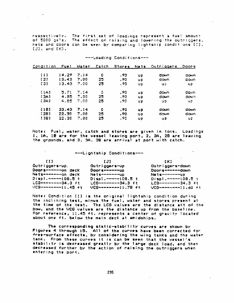
r espect i eel y, The f irst set af 1 oadinqs represent a fuel amountaf 000 aa' s. The ef feet of rai sino and 1 ower ino the outr i aaers,nets and doors can be seer by compar ing 1 iohtship condi i ons [11.L' 13. and LK! .
---~ nadi na Candi t i ans.��
Ccn i t i on Fue 1 4later Catch Stares Ne ts Gutr i a er s Doors
[11 14.29 ?,14 0121 13. 43 7. 06 25�] 13.43 7.00 25
downdown
.90~ 90~ !?0
gowndown
up
upupup Uc
1'1*j 5 71 r.14 0
l 241 4. 85; . 00 251343 4.85 .'.00 25
~ 90.90~ 90
d QLa3 ndo@in
p
downdown
uD
Upupup
1 iBi 23 43 7.14 0! 2B3 22.30 7. 00 25l 3Bi 22. 30 7,00 25
downdoNrn
Up
downdmin
p
~ 90.90,90
upupup
Note: Fuel, water, catch and stores are given in tons. Loadings14, iB are for the vessel 1 caving port, 2, 24, 28 are 1eav ing
the grounds, and 3. 34, 38 ar e arrive.l at por t wi th catch.
-Li ghtshi p Condi t i ons ��
Nate: Condi t i on [ 1 3 i s the or i gi nal 1 i ghtshi p condi t i an dur i ngthe incl ining test, minus the fuel, water and stores present atthe t ime of the test. The l CS values ar e the di stance af t of thebow, and the VCG values are the di stance up fram the base 1 inc.For r eference, 11.45 f t. represents a center of grav i ty 1 ocatedabout one f t. be l ow the main deck at ami dships.
The corresponding stat ic-stabi 1 i t! cur ves are shown byFigures 4 thr ough 15. 411 of the curves have been corrected forfree-sur'face effects, by consi der ing the sing tanks and the watertank. Fr om these curves i t i s can be seen that the vessel ',sstabi1 i ty is decreased greatly by the 1 arge deck load, and thendeer eased further by the action af raising th» outr i gger s whene~ter ing the por t.
295
[flOuir i ggers-up.Door s- on de ckNe ts � � � -an deckDi sp1,� - � 108.5 tLCG- � � 34 ~ 3 f tVCG � � - � -11.45 f t
J3Ou tr i gger s-upDoor s- upNe ts � � � -upDi sp'l . � � --108.5 tLCG � - � � -34 ~ 3 f tVCG � � � --11 . 78
K3Gu tr i ggers-downDoor s � � -downNe ts--- � � upPi spl .--- � 108.5 tLCS-- � � � -34 3 f t
VCG 11.bQ f t

Anal ~ i s of th Re l t~
I t has a'l ready been ment i oned that many cf the caps i z ir gsoccurred in the por t. To investigate th~ cause of theseacc i dents i t was necessary to model the condi t i ons surr our dir gthe return of a boat to port wi th i ts load. Af ter studyir g thereccr ds of sever al of the casual ties, a 1 ist of adverse forcesand 'l oadi ngs was prepared. Th i s 1 i st included such heel ingmoments as a hearn wind, unsymmetric fuel loading. turning momentsand running aground. The first three moments are relativelysimp:-e to app'!y. Figures 6, 9'. and 12 show static-stabilitycurves for the thr ee loading condi ti ons -, W, 3S whi ch re r ese-:fuel l oadings of 5GGG, 20GG, and 8200 gals. respect ivel y ~ 4 windand heel ing are curve has been super imposed on the stabi 1 i tyr-ur ves. The heel ing curve is a composi te of the effects of a 3Ck- ot beam wind and a sl ow turn. I t i s fel t that the values use=-for tne calculation of this curve were conservative, Forexamples the turning speed used was two knots and the turningradius was 100 ft. If a boat was insteaci tr ~ing to turn at : veknots. the heeling curve due to turning would be s:x times asgreat as for two Knots.
*nother way to decrease the stabi 1 i ty qui ckl y i s by loadingthe vessel unsymnetr i cal ly about the centerl ine. Ther e is adocumented casual ty in whi ch i t was di scovered that one of ther easons +or the capsizing was that one tank was comp'letely fui lwhile the other was empty. This was obviously an unusualoccurr ence, but we can simulate the problem by consi der inp thefol lowing more 1 ikely scenario. If a boat drew fuel out of onlyone wing tank for at least one tr ip and then hal foray throughanother, the total imbal ance would be about 60D gal s. Thi s waul dcause a moment of 12.57 ft-tons creating a heel ing arm of between~ 076 and .086 f t. depending on the displ acement. 4dding thi supsetting for ce to the wind ancf turning arms we see that thestabi 1 i ty of the vessel is very nearly depleted. Figures 12through 15 show the composite wind, turning and weioht shiftheel ing are curve. * large weight shift also occurs if theoutrigger s are not raised simu'l taneousely, but rather one beatsthe other to the top. For example, consi der one outr i gger at 60deg. and the other at 30 deg. The moment due to this diff erencei s about 4 ~ 71 f t-tons. The he ~ l ing arm created i s then .031 f t.
Final l y we wi l l consider the consequences of bump ing thebot tom wh i le in por t. 4ccordi ng to Coast Guard repor ts, th i s wasa factor in a severa'l of the casualties. Unfortunatel y,calcul at ing the exact ~ ffect that gr ounding woul d have on avessel is not straightforward. The effect of str iking thebottom, or any submer ged f ixed object wi l 1 tend to raise thevessel 's center of gravi ty since same of' the we ight i s. taken bythe f ixed object. To appr oximat ~ the effect of grounding weassumed the simp 1 if i ed case that the boat hi ts ciir ectly on the
296

Keel at ami dsh i ps such that no tr im occur s. Now assuming thatthe boat r i ses .iust one i nch due to gr ounding, the force on thebottom wi 11 be abou t,2.4 tons, The resul '. ing r i se i n the cen te;of gr av i tv i s then 0.155 f-;., or 1.86 inches, Fr om Fi gur e 14 i tcan be seer that ther e i s onl y about 0 ~ 1 f t. of max imum GZ afterthe vesrel is subjected to the wind, turning and ~eight shif theel ing arms. Thi s ri se could easily capsize the vessel wnerapplied with the other upsetting forces'
Ther e are pr ocedur es whi ch i f' f ol 1 owed can reduce thechance of capsizing when the vessel is in the cond ticns wher ecaps i z ing i s most pr eval ent. However, these procedures ar e notconst dered adeciuate to prov; de sat i sf actory stabi 1 i ty for the-. esse I uncie these 1 oad i nqs. The vesse 1 w i 11 st i 11 not meet tr estandard !NQ criteria, for minimum areas under the GZ-curve. !tcan be seen that the vessel's stability improves with increasecifuel loading. Ther efore, i t would benef i t the operators toto top of f the tuel tanks bef ore mak i ng another tr i p. Hostimper tan tl y. the operators should avoi d unsymme tr i c fuel 1 oadingsby swi tching tanKs r egul ar 1 y and keep i ng track of the ac tual1 oadings present on the vessel at al 1 t imes. Of course thepolicy of always keeping the forward water tank full should becontinued. By Keep ing the door s stowed in the racks instead ofraising them when arriv ing at port, the CG can be reduced about1.05 inches. It is understood that this is difficult because ofthe deck load, so perhaps they could be dropped to the deckforward of the load this is where they were during the inc'1 iningtest!. Figure 16 displays a curve for the condition of fullfuel, synmetr i ca'l ly loaded and wi th the doors on deck. Thesi tuat i on i s improved but st i 1 1 consi der ed dangerous according tothe IMO cr i ter i a. The outr i ggers shoul cf be r ai sed onl y whennecessary and of course gr eat car e shoul d be taKen to rai se themtoge ther. They should only be handled when the vessel i s no!turning. Lastl y, the oper ator s shoul d be awar e of shal 1 ow areasnear the docks and know the drafts of the ir boat at al '1 times ~
297

30 20 30 40 50HEAL ANGLE deN>
298

2.0
1.0
D.S
-l. 0
1.S
2 ~ 0
299
ZO 40 5'0-O'EEL AHGt E, tdee>
80 SO ioo

C
=.C-
qrVc 4
~ ~ ~ ~
!.0
0.$
-l. 0
-l. 5
-2.000
30O
io za Xa 40 50}tFEL RHGLE koQ>

2.0
].5
-J.O
-1. 5
50 40 50 60 70 80 90 100HE,E.L AN C LE f d e 0 !
301

C
yeargwC
4 II I
10 2O ZO 40 SOHEEL ANQt K Easel >
302

2.0
! ~ D
O.S
-l. 0
-i. 5
70 8D 80 1 00HE,EL AHGLE fled~
303

C ~ ~
0 C'
10 20 XQ 40 50HKEI RHGLK dna>
304

HEAL RHGLE fdeli
305

2.0
1.$
$.0
0.5
-l. 0
-1. 5 10 HEEL ANGLE de I ~
306

10 20 30 40 5'p gg 70 80 80 100HKKL AN G LE d ~ 0 >
307

2.0
0.5
-l. 0
-}.5
30 40 50 60 70 80 90 �0HEEL ANGLE fdic>
308

C'
hI I I
I - ~ Pf +mr
I I C'
2.0
1.5
1 ~ 0
0.5
-1 ~ 0
-1. 5
-2. 0
309
I 92 0 ~I I
~ t ~ ~ ~ ~
i o 2a ro 40 sottEEL 4HGLE �ea!
pf 8% =:gf 4- clw.ll hw +P'~ . h
'Jhhl; h.=
0 80 BO 100

FiGURE 16
ST4 1C-VIABILITY CURVE FUR LOADiN=. [SB"3
2.0
1.S
-1. 5
-2. 0
0 80 SQ 100HEEL ANGLE del3
310
Fuel ....,...23 ' 65Water...... ~ 7.00Catch.......25.00Stores..... ~ 0.5'0
Ver tica'I Center of gravity � ! 11.26
Free Surface. ~ ~ ~ 0 ~ 0 5?Winci bee ing....Turning Hee i ~... C . =138We i ght Shi t t....Q.OGD

WRITTEN CONTRIBUTION
Bruce Culver
1. Regulations similar to those used for tugs and supply boats might beapplied. Basic criteria should include at least a minimum initial GM anda minimum freeboard, calculated from some simple criteria.
2. I agree that conservation regulations have an adverse effect on vesseloperations, but I'm afraid very little can be done about it.
3. Boats of normal form designed to meet IMO criteria are generallysafe from capsizing. The IMO criteria are too severe for boats of lessthan perhaps 25 meters in length .
4. No damage stability criteria are practical for boats of this size . Ifyou poke a hole in it too big for the bilge pumps all bets are off.
5. Some form of simplified licensing should be applied to captain's only .Forget 200 gross ton limit.
6. No ABS classification should be required-not economic.
7. Legislate size and design of freeing ports.
B. Survival suits and emergency locator beacons should be mandatory .9. Small crews and inadequate rest contribute to accidents, but rules on
this would be uneconomic, hard to enforce, and strongly resisted by theindustry. Laissez-faire policy is best.
'WRITTEN CONTRIBUTION
Cliff Goudey
It is interesting to note, and I'm sure represents a source offrustration to Or. Adee, that draft marks are not used on these vessels .
Reductions freeboard are of course observable but difficult to quantifywithout some reference points . These draft marks would seem to be of day today value to an operator in maintaining efficient trim.
I wonder if West Coast naval architects include draft marks onthei r designs or are they simply pai nted-out during thei r first dry docking?
311

'NITTEN CONTR IBUT ION
Cliff Goudey
As a representative of the MIT Sea Grant Program, I also partici pated inthe Fishing Vessel Safety Conference described by Mr. Shephard. At that timeM!T's role in fishing vessel safety, both past and present, was outlined.
Ne have conducted a variety of research and advisory projectsaddressing saftey issues brought to our attention by our local fishingindustry. Innovations in deck hardware have resulted from two of these pro-jects allowing reduced risk of injury during fishing activities. A morerecent project has developed a thermographic technique for the detection offlaws in GRP hulls. Losses from fai lure due to imcomplete resin saturation ormissing laminates could be reduced by this technique.
Other projects have had an indirect relation to safety. The implica-tions on safety and vessel survivability was an important phase of our sail-assist project reported at last year's conference in Tarpon Springs .
A considerable amount of effort went into the safety aspects of theshrimp trawl development which I reported on yesterday morning paper 2.4! .HIT's research on the addeg resistance of fishing vessels in head seas,reported yesterday afternoon, was in response to the Coast Guard 's need torespond effectively to calls-for-help from distressed fishing vessels.
I believe ft is important for all of us to be aware of the safetyimplications of our efforts, particularly if they relate to the modificationof vessels, the introduction of new gear, or the development of an alternativefishery. As Mr. Adee so clearly demonstrated, the operator cannot be reliedupon to be a proper judge of vessel safety. Driven by the pressures ofeconomic survi vabi lity. situations can evolve with disasterous results.Progress towards efficiency and fishing effectiveness should not be at theexpense of fishermen's lives.
The National Sea Grant College Program can help by insuring that inthe projects they support that relate to fishing, the implications of safetyare properly considered. In addition, the effective linking of Sea Grantadvisory activities and research projects should be stressed. In this way,safety developments from other marine fields can be identified and adapted ifappropri ate.
The MIT Sea Grant Program, for its part will continue to respondto the needs of our local fishing industry. Participation on the safetycommittee will also allow our response to national problems if appropriate.
MIT's capabilities in naval architecture, dynamic analysis, mechan-ical design, and structures represents a formidable resource to confront theengineering aspects of this problem. A national c'onvnitment to reduce fishingvessel accidents nest be accompanied by a coeaitment to support the cost ofthe needed research. Otherwise we are destined to simply continue the headcount and go on wishing something could be done.
3IZ

WRITTEN CONTRIBUTION
N. T. Riley
In Australia tuna vessels must have stability data. Most states requirestability data to be provided for other fishing vessels also.
The stab111ty criteria used 1s that promulgated by INO but we must usefree trimming cross curves.
The structure, machinery. outfit, life saving appliances as well as thestability requirements are regulated by the Uniform Shipping Laws Code. Me donot see these regulations as being onerous but as a guide to reasonable designand also the one set of rules, with minor variations, covers the whole ofAustralia.
The rules provide for one set of stability data coveri ng sister shipsprovided the light ship weights agree.
Ny one preference is to incline sister ships, then there is noquestion of errors creeping into the stability data whi ch is used for these"similar" ships.
It is a requirement 1n New South 'Males it is mandatory that forwooden vessels to have the lines lifted of the vessel when preparing thestabi lity data. The reason for this requirement is that frequently thevariations between the lines as designed show marked variations with thevessels as built.
I would like to make a few remarks on Professor Latorre's paper.
In a paper ~ ~ we delivered in 1979 we looked at the effects onstability of an 80,000 ton D.M. tanker, a 3,000 ton U.M. cargo vessel and anumber of fish1ng boats when free trinIning and balanced on a standard wave.
From the results obtained we concluded the current methods adoptedfor assessing the stabi lity of vessels have little resemblance to what reallyexisted when free triaIaing and wave effects were considered and as suchseriously overestimated the stat1cal stability and dynamical stabilityavailable.
Me further concluded that increasing beam was the most effective way ofobtain1ng increased stab11ity, at large angles of heel.
Ref . I! "Some Aspects of Fishing Boat Stability", Riley and HelmoreSymposium on Ship Technology, University of N.S.M. 1979.
313

MR [TTEN CONTR I BUT!ON
Robert Hyde
Ultimately, the uniform recognition of an intact stability criteria asopposed to requiring only a certain positive initial metacentric height! whichaddresses the complex nature of vessel stability is more important than deter-mining which of the available standards is more suitable. Based on theavailable research. the INO stability criteria Resolution A.168! appears tobe satisfactory. Ny concern, however, is that most of the analyses applyingor evaluating that criteria fail to reflect proper consideration of down-flooding as incorporated into that criteria. Downflooding on a fishing vesselcan occur at extremely low angles of heel. The typical result is that the0.03 meter-radians area requirement between 30 and 40 degrees of heel wouldnot be Nmt. The failure to take downflooding points into account would castsodom doubt on the conclusion that the lMO stability criteria is the appro-priate standard for assessing the intact stability of a fishing vessel.suggest that researchers approach this problem more carefully.
314

PART V
SAIL-ASSISTED FISHING VESSELS
315

DESIGNS FOR WIND-ASSISTED CONMERCIAL FISHING VESSELS
John W. Shorta'tl III, NAUniversity of South Florida
College of EngineeringTampa, Florida 33620, U.S.A.
Editors' Note: We regret that due to the length. ofthis paper it is .pessib'le to include only the narrativeportion. Forty-six pages showing hull designs and otherdata are omitted. Anyone wishing to review these pagesmay contact Dr. John Sainsbury, Department of Oceanographyand Ocean Engineering, Florida Institute of Technology,melbourne, FL 32901.!
Hull 1 ines drawings, offsets and particulars ar e givenfor two catamaran and f i ve single hul 1 conf igurat i onssui table for use as cmmaerc ial f i shing vessels. Recommendedsail areas are given using the cr iterion of ten degrees ofheel in 20 knots of apparent wind ve loc i ty. Camsents areincluded on the operational decisions necessary to choosebetween twin and sing'le hul 1 vessels as canmerc i al f i shboats. Stabil i ty data on the single hu'll craft are shcxon wi thr ighting arm curves fiom zero to 180 degrees. One hull is aclassic 45 foot workboat from a book of Chapel le's. Two 32foot and one 38 foot versions have been derived. 4lhi le mostsui ted for imp 1 ementat i on by other naval arch i tects, ther e i ssuf f i c i en t information for exper i enced boa tbu i 1 der s toconstrict these hulls. All are of the hard chine type forease and economy of bui 1 ding.
This article was developed under the auspices of theFlor ida Sea Grant College Program wi th support fran theNational Oceanic and Atmospheric Adninistr ation, Office ofthe Sea Gt ant, U.S. Department of Camerce, Grant No.NR80AA-D-00038.
INTRODUCTI 04
The investigation by the author of the oper ational and engineeringpracticality and the econaaics of wind-assisted cereercia'l f ishing vesselsccxaes to a close with this r eport, the 27th du~ing the past three andone-quarter years. A few of the more pertinent ones are. listed unde~references. Up to now, the research and design has been concerned largelywith the retrofit case and to answer the question: is it economically andoperationa'1'ly sound to equip existing fishing boats with sail rigs? The
316

answer was found to be usual 1 y yes but is hi ghiy dependent on suchconsiderations as the pr oximity of low bridges! range to the fishing groundsand clean superstructures among other s.�!�!�!. Originally, it was plannedta retrofit a snapper-grouper boat or a shrimp trawler and take actuaimeasurements of fuel useage and performance at sea in a full-scaleexperiment. 4 computer -based instrumentation package was deve'loped for thispurpose and is reported on separately.�! This was found to be unneeded withthe successful full-scale demonstr at ions in: Federal Republ ic of Germany,fr ance, England, Nor~ay, Sweden and the U ~ S.A. and the general agr cement ofthose resul ts wi th the computer models developed here. I!�!�! In sunxaary,depending on the f ishery, the use of saf t sails on caneeercial f i shingvessels can be expected to shaw savings of between 15 and 40/ in fueluseage, and sail rig pay back time ranges fr om one to two and one-half yearsfor simple, inexpensive arr angements.
This paper presents 1 ines dr awings for seven possible hui ls which couldbe used for cowener cial wind-assisted f ishboats. Not <ncluded. See Ed!tars' Note.!
HULL DESIGNS - GENERAL CIKSIDERATIRIS
These hul'is were designed on an Apple I I ' microcmnputer equipped withthe Letcher Offshore Design software for hull design, hydrostatics andstability caeputations. 8! Ail hu'ils are of the hard chine variety witheither one or two chines each side of the center line. Two builders inFlor ida were interested in constructing wind-assisted fishboats. Both wantedhard chine hulls. One is to build a single hull craft and the other acatamaran. These builders: Hazard Branch and Garland Mebster, gave theimpetus far these designs. Har d chine hulls have several advantages overr ound-bilged. They are inexpensive and relatively easy for one man to build.Materials can be either marine p'iywood or sheets of fiberglass cast onlevelled formica tab'les and bent around frames ar maulds. The chines wi11give some resistance to leeway though certainly not to the extent of keelsor boards. Their major disadvantage is perhaps a ten percent reduction inhull volume for a single chine versus a round hull.
BUILDING CQ4SIDERATINIS
Sheet materials wer e mentioned above. Aluminum could be added to thislist as could cored fiberglass using such materials as' balsa, foam,honeycomb and the like. The disadvantage of these two materia'Is is cost andadded skills needed. These vessels are too smail to consider steelconstruction, except perhaps in the case of the 45 footer. Marine plywoodcovered with fiber glass and all edges sealed wi th epoxy can produce a veryrobust structure and is wel 1-sui ted for workboats. 4 simpl if i ed method ofbuilding .the chine lag has been descr ibed by Jim Brawn.<9! The builder
317

simply butts the piywood shetts at tht chines. On the insidt, he buildsshallow sbex$tn troughs about thret or four inches «idt along each chine,ln to thtstf wet f ibtrgl ass matt is laid in several 1 ayers ~ The chi nes artthen sanded off on the outside. This is much simpler and less timt-consumingthan spiling and bevelling solid wooden chine logs.
Scantl ings art not given but may tasi 1 y bt devel optd by any of a numberof standard ttchniques. Note that for each craft, areas at each station aregivtn. from which materials tstimatts of bulkheads can tasf ly be eaCh ~ Alsogivtn ar ~ total hull artas and surface areas under tht waterline only whichwi 'l l ass f st mak ing mater i al s est imates, dtve 1 oping cost f i gures anddetermining f inal center of gravi ty. The bui f der should remember thatweights must be grouped evenly fore and aft about tht longf tudinal center ofbuoyancy if the hull is to float 'on her lines.'
SALL AREA
in each case, a sai I area i s receanended suf table for use insubtropical waters such as exi st ntar the southeastern Uni ted States. Theamount of sail area is based on a maximum of ten dtgrets heel in 20 knots ofapparent wind. Rfgs may bt of the simple, fretstanding mast type with onemain sai I or bt onewasted sloop, cutter or cat~ i gged. 4 conveni entarrangtmtnt of ttn is to step the mast on a thwar tships bulkhead Just af t orforward of the fish hold.
LATERAL PLANE AND RUMERS
No lateral plane devices or areas art suggtsted htr ~ . Due to extr emelyshoal' «attr s in this regfon, the only practicaf kttl «i I 1 bt a long, io«aspect r atio skeg which also wf'l l protect the hull and pr opel fer «hengrounding. Sons may wish tb use 'letboards to help prevent drift to leeward.However, sfnce these are motor sai fers, use of the engine tends to limitleeway angl ~ to a ftw degrees. Rudders can be as simple as outboard,barn-door types to r etain shoal draft or of the posted types through thehul 1 near tht stern, The builder should r emember that at 1 o«speecfs, therudder area required is consider ably more than at high speed and take intoaccount his planned service speed.
ENSJNES AND EN81NE USE STIIATEGlES
Wind assi st means Just that - when of a f avorabl e strength anddir ectfon the «ind is used to assist the engine to propel the boat. Exceptin the cast of tngine failurt, it is never assumed that the fisherman willust sai'Is alont, although an tnttrpr ising f isherman concerned wi th maximumfuel savings could at times do that. Each operator will have his own engineuse strategy f and th i s dtpends al so on the aver agt strength and direct i on of.the winds in the par ticular ar ta sailed - hence no horsepower estimates havebetn gi.ven. Tht f ish boat owner must decide on a long term avtrage whatptrcentage of power he wishes to use fran the wind and how much fron thetngint ~ In any cast, max fmum rated tngine horstpowtr can be r educed toapproximately half that requirtd for pur e poker boats. A maJor factor in thedecision on r ated horsepower is for tht owner to set a miniee service speedunder engine alone and a maximum «ind velocity against which the engine mustbt able to pr opel the boat, tvtn at lo«speed. ln any cast, speeds on the'ordtr of tht square r oot of the water l ine length wi I ! pr obably be nearmax I mum'
318

lo Table 1 are- seaaat'Ized a nuiaber of paraaeters of five single huiicraf t designed for wind assist. The Nui tichine 41 appears bargel ice at theaft endings due to the client specification that all minor weights be aft ofaidhships. The longitudinal center of buoyancy is a rather extreee 5% aft!The Chapel le 45 is taken frcxa Reference �0!. Each of- the following thr ee isa derivative of the 45 with constant biocK and priaeatic coefficients. ln~ ach case the righting arel SZ in feet is a erasure of stability at tendegrees heel and thus is a erasure of' sail carrying power. Drawings of eachof these hulls are shown in the annexes. Not included. See Ed<tora.' Note.!
TABLE 1
PARTI CULARS � 81NSLE HULL VESSELSNJLTl CHINE 41 CHAPELLE 45 CHAPELLE 32A CHAPELLE328 CHAPELLE38
f TEN
NOTES
l. Lengths, beaas, drafts, etc. are in feet ~ Areas areDi sp 1 aceeen t i s i n pounds.2. LOA - length overal 1 fr ac bow to ster" ~3 ~ QJL length on waterl lne of waterplane along center'1 ine.4. 8OA - beaa overal'1. aaxiraga width of top of hull.!5 Bg be jg waterl ine iaax iaxxe width on the waterl ine of the waterpl ane ~ !d. Draft - distance frae waterl ine to bottle of fairbody not including kee
in square feet
319
LOA >LML >BOAiS'IL iDRAFT iD1SPL.:4/Bi8/7 IAREA WSiAREA HULLgRISHT ARE>PRlS ~ COEF:8LK ~ CDEF:DLR>LCF>LC8:N T! 'N L!:VC8:AREA WP PPlrHT-lt
HULL CS XiHULL CS Z:SAlL *REAt
413611.3410.422.64329933.453.953666850.60 ' 630.5231625. 5525.972.0544 ' 4-0,99294.41570339123.23+.09638
454413.712.72.33298143.55.454417921 ~ 120.520.3615624.5023.737.7482.11-0.733932096463723.23+.111033
31.7319.289.021.66107053.45.432223920.740.530.3616017. 3816 ~ 854.5057 ' 13-0 e521981056164416.f7+.06314
31.73113. 712.72. 33211722 ' 45.453145571.12Q.530.3631717. 3816.856.7340.0-0. 7327914882277fP6.12
940
37.83711.6611.402.33226003.24.89
3416230.870.530 ' 3619920. 6$
20.015.1257 ~ 13-0 ~ 732981589290819.15+.15760

7. Displacement is the weight of the entire vessel and its contents.8. L/8'- length to beais ratio on waterline.9. 8/T - beam to draft ratio of fairbody not including keel! on water line.10. Area QS is arta of hu'll wetted surface below waterl ine!.II, Arta Hull is entire hull surface arta.I2. Righting arm is the 82 at ten degrets heel «i th trim change.I3 ~ DLR - displacement length ratio in tons per cubic foot.Iq LCF - longitudinal center of flotation measured froa bow af t - notforward water 1 int ending.I5. LCB - longi tudinal centtr of buoyancy - seat. Al 1 weights must begrouptd tqually fore and aft about this point for vessel to float evtnly ondesign waterline.Id. Sf T! - transver st metactntric htight.17. tS L! � longitudinal metacentr ic height.I8. VCB - vertical centtr of buoyancy measured fram waterline,19. Area MP - waterplane ar ta.20. PPI - pounds ptr inch ieaersion.2I ~ NT-I - monent to tr im ont inch in foot-pounds ptr inch'
Hull CS X is distanct aft fran bow ending of hull surface center ofgravity. Z value is height fraa water lint.23. Sail Area - allowable square footage for ten degrees httl in 20 knots ofapparent wind in subtropical climts except for Chapels 32S.
CATi'INARANS AS CQtKRCIAL FI SH MATS
Twin&ulled vessels have been used in caaaercial serv ice for thousandsof years. blhtn the hulls are of equal ltngth and shape and are aligned, thevessel is cal ltd a catamaran. The name apparently derives fran the indian«ordr kattumaram, At this time, there ar ~ approximately 50,000 ccmntrcialf 1 sh ing kat tumarams on the tast coast of Indi a, most. of wh i ch use sai '1 s asthe chief method of propulsion.
The concept of shoal dr af t, tconomi cal, beachabl ~ 'l oad-carryingcatamarans as fishing vtsstls apptars eminently suited to many areas of the«or 1 d «htther proptl 'led by engines or sai 1 s or both. Long narra« hul 1 srequire much less horsepower to attain a given spttd than short fat ones.Bftctivt horsepceer is proportional to speed timts resistanct. It has longbeen knee that resistance decreases with displacement-length ratio: DLR ~/ .OIL! ~ Simply put, the major caust of dr ag for long narr o«hulls isfr ict ional resistance, «hi 1 ~ that for shot t fat ones i s «avemak ingres i stance. Thus, catamarans can e i thtr . tr ave 1 f aster for the samehorsepmver/sail area or can have reductd horsepcnver/sail area for the sajaespeeds'
Others havt wri t ten that 50X of the cargo in catamarans can beconsidered as acting as ballast. hihen beachtd, tht catamaran gains stabii i tywith both bows groundtd. The catamaran is safer and more practical in largersites designed to carry heavy cargo «i th per haps water bal last. They alsoprovidt a stable non+eel ing platform and large work space. Their shallydraft al lac acctss to nmrous bay and close-in fishtries. Their ease ofbeaching makes for mort fr tquent and economical bot tat c 1 eaning andpainting.
The most usual reason for not corisidtring catamarans is the fear ofcapsize. LJhile it is true that most catamarans are mor e stable upside dernthan rightsidt up, so are most motorixed fishing boats «hich have a much
320

greater, tendency to caps i xe than do cataaarans. The other reason i sdiff icul ty and expense in finding dock space due to the large bern.�! Table2 il lustrates the particulars of two cataearans designed as work boats. Thescalier 27.5 footer is a derivative of the fir st except that its hul'ls areear ~ widely flared.
TABLE 2
PiARTICULARS - CATARRH FISH BQATS
CAT 4I CAT 27.5
ITSY
l47TES
All of above figures are for one of the two hul'ls used in cataaar ans.Thus total dispiaceeent of the 27.5 is 5508 pounds. Total PPI w 740 'lbs. perinch for the 27.5, etc.
2. Over all beae of two hu'lls connected by beaas and a bridge deck is usuallytaken at about one-half the LQA � perhaps a bit nore for work boats.
3 ~ Recmsended sail area is for light air conditions such as usually obtainin Sulf of Nexico and near -Atlantic and near-Caribbean waters.
321
LOA iLWL >SQA >$4LtDRAFT rl/B i8/T iAREA WS;4REA HUI.LtPRIS.COEF>BLK.COEF!DLR >LCF >LCS >Sf L! >VCS rAREA WPiPPI >HT-I:
HUlL CG X:HULL CG 23REC.SAIi. AREA>OVERALL BEAPi:
365.545.05I.657.I3. 06I 924620.650.488724. 6023.7790 I I-0.54
l53SI 6I 90522.26+0.8I50022
27.5244 ~ 063.45I . IO7.03.1Bd.72I 50 ' 650.4889I 6.44I 5 ~ 936I .4W ~ 3669.3370587I4.97+0.50400IS

RKF EREBUS
I ~ John W. Shor ta 1 1 I I I, 'Cornett c i al Sa i 1 ing Fi sh ing Vease 1 aCarnputtr&idtd Design,' SNYE Fishing Induatr y Energy Conservat ionConftrencer Stattl ~ f Oct r 1981 ~
2- JMSIII, 'Corentr c ial Sail ing F-i shing Vtase la,' Nat i onaiConference/workshop Appl ications of SaiiWssisttd Pcnrer Technology> Norfolk iNayr I982.
3. JMSIII, 'Catartaran Constr cial Fishing Vessels,' ibid.
JWSIII f Sail&ssiated Fishing Vtsstla for Sulf of Mexico, Caribbtan andNtar&tlantic Waters,' Procttdings, Inttrnational Conference onSail&ssisted Coneatrcial Fishing Vessels, Vol.I, Florida Sea &rant Report:SSR-58, Tarpon Syringa, Florida, May, l983.
5. JWSIII, Wor ld Trends in Sail&ssisttd Caeeercia'l Fishing Vessels,' ibidVolurae II, Florida Sta Srant Reports 89R-60, Oct., 1983.
6. JWSIII> arne tit'lt and subJect. Ancient Inter face XIII Symposium onSai ling, AIAA/SHN%, San Diego, Oct., 1983.
7. Jtffrey L. Zenoniani ih John W. Shor tal 1 II I, '4 kicrocaaputer-SaaedInstrurntntat ion Package for On&oard Win~ssi st Measurements,' Proceedi n95,Intl. Conf. Design, Construction 4 Optration of Ceeeercia'l Fishing Veaaeis,-kelbourne, Flor ida, kay, 1984 '
8. John S. Letchtr, Jr ., 'Fairline Methods for CareputerWided Hull Design,'SNAHK Southeast, I4 January, I984 ~
9. James Srown, 'Searunner Construction kanualr no date .
I0 ~ Hrneard I e Chapel 1 t r 'Soatbul 1 dingy ' Nor toll y I94l r p.339.
322

DESIGN OVERVIEM AND ECONOMIC ANALYSIS OFTHE AQUARIA ~ SAIL ASSISTED FISHING VESSEL
BY
Davi d 4. Ol sen, Ph. D.Theapson Nanageeent Inc./Beeline SeafoodsPort Canaveral, - Florida 32920
Frank Cr aneAquarian ResearchFort Lauderdal e, Fl or i da Hei
Rob LaddLadd liar i neFort Lauder dal e, Fl or i da 3350l
323
The modern era of fi sheries development has been marked by anincreasing awareness af energy efficiency. As fuel prices havecontinued ta rise, energy efficiency has became nearly a developmentalequivalent for economic eff iciency. At the same time, worldpopulation pressures have increased the demand for marine protein sothat harvest af under utilized resources has become an increasingpriority. In developing nations, the quandry between need for protsicand deficit balance of payments created by petrochemical imports hasplagued al I concerned.
One solution ta these problems involves the appropriatereintroduction of sail as an auxiliary power source. We say auxiliaryhere because sail alone tends to limit access ta the resource, bothtemporally and geagraphically. As an auxiliary, however, sail simplyenhances prof itabi lity of existing f i shing aperatians. Al though therehas been much discussion af the sail assist concept, it has centeredon the reuse of histarical hul I forms and sail plan. Otherapplicati ons of sail assist have concentrated an larger vessel si-esor specialized fisheries. The results of these efforts are notgeneral ly available ta the fishing industry as a whole.
The present discussian centers an one sail-assist project appliedwithin a working fleet in Florida. The vessel was designed with aCaribbean «pplication in mind. To date four of these vessels havebeen built and fished in the southeastern United States as part of' theThompson Management longline f ishing f lect.
The developeent of the Aquaria cancept was an attempt ta combineproven sail and fishing technologies in a form that would addre~~ ourawn internal needs for greater control of f ish production costs andyet produce a vessel which would find a earket both domestically andin developing cauntries. Ta this end, proven simplified sai Itechnalogy was employed in conjunction with a modern hul I f orm toprovide an excellent fishing platfor m.
As mentianed previously, the real impetus f or thi s proj ect wasthe experience gained in the Thompson Management/Beeline Seafoodsfleet of Thompson 60 and 90 footers. A drastic rise in productioncosts in the longline fishery between 1982 and L983, coupled with aweakening resources was f ore ing us to relocate our long l i ners ta otherfisheries. The develapment af the Aquarias was intended to provide avessel which cauld continue to exploit longline resource~castmffectively. Subsequently, since the operations af these boatsoccurred within the same di verse, prof i t oriented f.lect, we were al soable to evaluate the relative merits of the fisheries involved aswell as the vessel types.
Some background an the history of the proj ect may be of interestin arder to bring aut the degree of collaboration between state of tiesart sail and fishi.ng technologies that has been employed. The genesisof the project came from the U. S. Virgin Islands Saltonstal I-Kennedyfunded f'ishery praject. Information and exper ces gained there andthroughout the Caribbean indicated that, althaugh many of the more
324

devel oped areas were conver ting f rom sai 1 and sai 1 assi st to pureengine powered f i shi ng boats, thi s conversi on was not beingsuccessful The reasons for this lack of success were various andincluded:
Small outboard powered boats~ which extend the rangeof fishing activities have proven unreliable andexpensive to operatelLarger inboard powered vessels were expensive topurchase and operate and maintenance was generallyunavailable to keep them running.Expansion of fishing activities resulted in resourceoverexploitation which made the vessel~ becomeuneconomical.Increased fuel utilization and import of boatscreated economic problems within the country in termsof hard currency necessary for import of fuel andboats.
3.
4.
The Aquaria project attempted to address some of these prablems.The boat itself was largely the result of the stimulus and initiativeof Tom Worrel 1, who assembled a design/application team whichconsisted of the authors and the respective staffs of ThompsonTrawl mrs~ Aquarian Research, Thompson Management, and BeelineSeafoods The boat developed by this team, then was the product of anaval architect with a history of successf ul yacht designs, a bui 1 derof commercial fishing boats, a fleet operator/seafood company and af ishery biologist with experience in developmental requirements ofsmall scale «nd underdeveloped fisheries.
Speed and Power Reduction. Our other f lect operationsindicated that we needed to have a 200 mile radiusof operations in order to consistently f ind f ish.An 8 knot hull speed allowed us to have this range.Analysis of resistance curves f igure I! indicatedthat greater speeds would increase power requirementssignificantly. In order to provide the sail assistwith enough carrying capacity over the range, a 650 !lb. fish weight! fish hold was included in thedesi gn requirement.Improved Propulsion and Auxiliary Power. The boatwas designed to minimize power requirements throughhull form and sail assist. Although the vessle isdesigned for motor sailing, it is fully capabile ofreaching hull speed under either power source.Improved Fish Targeting. We wanted the Aquaria boatsto be competitive in catching power with our largerboats. Consequently, we incorporated many of the
2.
325
The design team considered that increased efficiency could beobtained in a variety of areas, and the end product should be a vesselthat cauld be easily operated in lesser developed areas but wouldstil 1 have sufficient catching power and trip capacity to beprofitably operated within our own fleet operations The areas thatwe concenntrated an f or improvement were.

The design parameters selected to address these problems were asf ol low
In response, preliminary drawings and specifications wereproduced for a vessel close to the upper end of the specifiedvariables in terms of overal 1 length. This was deemed necessary tomeet the demand for speed and hold capacity. Me also felt that a hullform utilizing a modern airfoil secti.on keel and skeg hung rudderwould best satisfy the requirements of speed under sail and windwardper f ormance.
}n addition, the hull form should have to be rather round insection to keep wetted surface to a minimum. This approach shouldallo~ the vessel to perform well in light wind conditions with nosacrifice to performance in stronger winds.
Stability was recognized as a key dimension of this design.Regard for the commercial fisherman, who may be unfamiliar eeith the'subtleties of a sailing vessel, combined with concern over thepossibility of shifting cargo, urged us to create a most stableplatform figure 2! .
The final design figure 3! incorporates a relatively shallowcanoe body with a moderately hi gh center of buoyancy. This, combined
a low center of gravity and greater than average beaa insuresgood stability. Sections are typically round throughout whilewaterlines are fine forward and full aft These design elements areintended to alloee for good performance while maintaining the volumenecessary f or the f i sh hold.
The principal dimensions of the final design are as follow.
XT' 6"33' 4"13' Oi
5 0"
25000 1 bs.
L. G.A.L. L4. L.BeamDraf tDi spl acement
326
1.24
4.5.6.7.S-9.
10.11.12.
f ish f lading aptions that had proven valuable onaur 60 and 90 ft. boats wherever possible. Theseincluded: radar, col orscopes, loran,pl otters, temperaturesensors, single side band and UHF radios.
An overall length between 34 and 38 f t.A desired speed af 7.5 to 10 knots under power.Similiar performance to �! under sail alone.Fuel consumption in the 1 gph range.Fuel capacity to be 200 gallons.Fresh water capacity to be 100 gallons.Accomodations for 3 to 4 men for 5 days.Crew requirements of 2 or less.Fish hold of 5000 lbs. or better.Half load draft not to exceed 5 ft.True multipurpose fishing capability.Bollard pull of 3500 lbs

7000 I bs.6500 I bs.
734 sq. ft.
BallastMold Capaci tySai I Area
Fuel capacity worked out to be 240 gal., while fresh watercapacity is i00 qal. The accomodation plan f iqure 4! allows for fourbirths, an enclosed head and a galley forward. A small dinette andsteering station are located in the pi lot house.
Computer predictions for sail performance f igure 6! indicate anexpected speed at 7 ~ 25 knots to windward at 29 deqrees apparent windangle in a wind strength of 20 knots true. Off wind performance forthe same wind strength is 8.80 knots at 96 deqrees apparent winddi recti on.
The construction of the Aquaria 38 sail assist is of hand layupF.R.P. A spl it mold is used for the hull and seperate molds are usedfor the main deck and the pilot house. Hull reinforcement is gainedthrough the use of strategically placed F.R.P. hat section stringersand floors. Construction scantlings and materials are to AmericanBureau of Shipping rules f or building and classing reinforced plasticvessels. The engine beds are canted L.5 degrees of f center tostarboard to provi de f or removal of the propel I er shaf t past therudder skeg. The of f center angled shaf t counteracts, to a greatextent, any "torque steering" tendencies due to propeller rotation.The propeller is exposed between the keel and the rudder skeg and issupport by a "V shaped strut near its hub.
Ballast is Lead and V.C.B is 4.5 in. below L.N.L. in a half loadstate Nhen fully loaded, the cargo's C.B. Lies over the designedC B. Trim is maintained throughout the vessel's load range.
The main po~er plant may vary in size from approximately 40 h-p-to 175 h p. The larger engine delivers the expected bollard pullvalues while a 60 h.p. engine will power the boat at 8.25 knts. whi leburning less than 7/8 qallons per hour.
Observed speed under sail has been in accordance with ourComputer predictions. Her performance rivals sailing. Yachts ofsimilar length and displacement on all points of sail Performanceunder power yields a top speed in excess of 9 knots with a Perkins4-i54! 60 h.p. main engine. Her motion is quite normal and steeringis excellent with her large rudder and balanced sail plan. StabilitY
327
Zn an effort to provide a substantial amount of sail area interms of economy and ease of handling, a self furling sloop riq waschosen figure 5! . Other rig types such as free standing cat rigswere examined and eventual ly disregarded as less f avorable. 4gallows frame aft supports the backstay and provides a base for themain sheet. The standing rigging consists of upper shrouds, singlelower shrouds, headstay and backstay. The jib is raIler furling andthe mainsail furls into the mast The 734 sq. ft. sail area providesadequate performance for light air conditions Conf igured asrelatively short, yet broad on the base, the saai I plan combines powerand stability.

is what one would expect: the Dellenbaugh angle is 9.07 degrees.
With no cargo on board, the very buoyant hull form gives asl ight]y corky ride, which is to be expected, but as load increases,stab i. I I ty, whi ch i s already very good, improves and the vessel becomesmore seakindly. The hull stiffness also provides a very stablefishing platform.
The captains af the four 4quarias all lacked sailing exper ienceprior to taking over the boats. They have al 1 learned qui ckly and cansingle hand the baat in all wind and sea conditions. so that steeringi,s easy an all points of sail.. Light weather performance has beenmost encouraging since a large portion of the warlds underdevelopedfisheries occur in areas of light to moderate winds.
The Thompson Nanagement fleet consisted of i7 vessels at itspeak, inluding four 38 f t- sail assists, eleven 60 f t. ThompsanTrawlers, and two 90 ft. Thompson Trawlers which aperated as a scallopcatcher/factory and a squid catcher/processor. We built all of theboats in Titusvil le, Florida. The fleet was invalved in longl iningfor surface and bottom f ish, graundfish trawling, squid trawling,shrimp trawl ing, and seal lap trawling. The f lect management f aci I i tywas operated in Port Canaveral, Florida. Fleet operations .occurprimarily in the Sulf af Mexico and Hid 4tlantic with the exception ofthe shrimping which is in euyana. Two of the 60 ft. Iangliners madeone explaritoryy trip to Jamaica in conjunction with Anti,llean Pride,a Jamaican canning company.
Fishing performance of the *quarias has been the most encouragingaspect af the prospect. Initial trials with Aquaria I included:
Bottom longlining with 6 mile sets of up to 3500hooks per day.Trolling 'under sail and mator sailing with 6lines. We have begun to explore using Norh Pacifictrolling methods with up to 15 or more lines.Shrimp trawling. We have successfull.y pulled a 56ft. net and doors. At 20 plus knots of wind, thecan be pulled at 2.5 knots under sail alone.Surface longline, trap hauling, v» tical set lines,and gill netting have also been tried successfully.
2
4.
TheProf itabi1ity is the real measure of commercial f ishinq success.
e sail assists produced 75X aperating profit while the 60s onlyduced 52X despite the fact that their capital costs were nearly 5
-ti me greater. In other words, we have f ound the Aquarias to be328
The mast convincing result comes from a comparison of the sailassists to aur conventional 60 foot trawler in the bottom lang linef ishery Table I!. In terms of daily revenue, the sail assistproduces nearly 70X as much as the larger boat despite the fact that
60 faoters set twice as many hoaks. The reason for this is thefac that the 4quarias can set lighter gear which is mare effective.
also shows in in the bait expenses~ as the sail assist bait costsonly amaunt to 8 2X of the revenue> compared to 14 6X of the sixties'.

nearly as powerful at fishing as the much more expensive larger boat.Additionally, because it requires fewer crew and has lower expenses, agreater operating prof it is generated.
As mentioned earlier, fuel eff iciency was an aspect emphasized inthe design project. The Aquarias' fuel costs were only 5X of totalrevenue compared with 12X of the sixtys'. When conversion of fuel tof jsh is ronsi dered Table 7 1! I the sai 1 assists were over 2. 5 timesas ef f icient as our f lect of sixtys. When the Aquarias were compared
other f isheries, both with our oven boats and other f igures from theliterature, the Aquarias provided one of the most fuel efficient.options available.
Thi s tab l e al so shows vehat every fisherman knows and that i s thatenergy efficiency does not necessarily equal economic efficiency atevery turn. Otherveise there would be li ttle production of highpriced, energy intensive, products like shrimp, scallops and sword fishwhich can provide revenue greatly in excess of the increased fuelinvolved in their production Despi te this f act, our experience inthe application of sail assist from the drawing board to the very real~ eorld of operation of commercial fishing boats has been extremelyencouraging Savings from energy efficiency have been obtained, butthe boats have proven to be flexible, powerful f ishing machines thatCan hold their Oven when COmpared saith Larger mare eXpenSive vesSelSinvolved in the same fisheries. Zt is our opinion. that considerablepromise and profit are available through the appropriate use of sail
assi s't r Fteurv l. HIIn raSIStanca, Speed and pacer mquiramntSfar tha Aquaria sail assist,
R E LATIONSHIP EEIIeE EH v EsSE LBLEEP AalO RESISTANCE
5
a
K vs sat I Srrf D IIEIKlrsl329

PiEure 2. RlgbtinE arm ve. heel aegle relationship forfor the Aquaria sail assist.
'AQUARIA' - OUTPUT
FOR AQUARIAN R ERE ARCHIae~ lM4
RRIHTIHQ ARII vL HEEL ANGLE
MEKL asQLE l4r4
330

yigure g, Final design and layout of the Aquaria sailSeeiet Shoeing the ShSllOe CanOe bOdy, Skeghung rudder and anple after deck.
331

Figure 4, Deck layout aud «ccomodatioss pl«n for the
Aquaria sail assist.
332

Sail plan for the Aquaria carries 734 sq,
ft, of sail on a sloop rig with roller furling
gib and main sails for ease of handling,
333

Figure 6.
'AQUARIA' - OUTPUTFOR AQUARIAN RESEARCH
2% F~ tN4
334
MAT~ Fees
eVIII
KNOTII
polar plot of predicted sailingperformance of the Aquaria suggestedan easily driven, relatively close-winded performance.

Table I, «mParison of 38 ft. sail assist to 60 ft,trawler/longliner,, Results are shown aspercent of total revenue consumed by variousexpense categories, Total daily revenue is shownin the right hand column,
DAILYREVENUEFUELBAIT
TOTALEXPENSES
$0 Ft. Long Liner
38 Ft. SA Long Liner12.1
8.1
81348
8 942
478
23.8
14.8
8.2
Comparison of energy conversion Kcal of fuel/Kcal of product! for various fisheries that theThOmpSon II anagement fleet was inVolVed in,
Table IX.
COMPARISON OF ENERGY CONSUMPTION{KCAL OF FUEL/KCAL OF PRODUCT
FOR SELECTED FISHERIES
Keel Input/Koan OutputF ISHER Y
Northeast Ground Fish Trawler
Florida Spanish h aakerel Gillnet
Tgg Sail Aaisted Bottom Longlina �8 ft.!
Thg Srpsid Trawler/Proaoswrr 90 fLI
Virgin ldenda Trap Fishery �2 ft.!Tgg Bottom Leeylk $0 fL!
Tfd Seslop OraOgsr/I'rorlwor SO fL!
Tgg Sworslfiah Longlirer OO ft.!
Thg Shrimp Trasdar Guyana $0 ft.i
F le./Gulf Shrimp Trswier
4.1
7.8
7.9
18.8
204
39.5
191.7
198.0
10ieael fuel ~ 34,860 ksal/goi.Fish ~ OA28 kal/gm.Shrimp ~ 0.804 keel/gm.Scallop ~ O.072 koal/gm.
335
COMPARISON OF EXPENSES GIVEN AS % OF TOTAL REVENUE!+EILEEN Bo FT T BOTTOM LONG LINER AND 38 FT. SA L ASSISTED LONG LINER
PERFORMANCE MEASUREMENTSOF A 25 FOOT SAIL-ASSISTED FISHING VESSEL
Richard 0, Sewell and John C. SainsburyFl ori da Ins t i tute of Technology
ABSTRACT
A condensed version of the original assessamnt of the performance andfuel savings potential while on passage for a typical small European safl-assisted fishing vessel is presented. Varfous tacks and engine output levelswere compared on the basis of reduction available in the most efficientpropulsive mode. The test vessel shen rigged in the sail-assist arrangementconsistently proved more fuel efffcfent then when power alone was employed,as long as a i'avorable tack was maintained. The evaluation of the sea trials,while admiCtably conducted in ideal conditions, showed that fuel savings ofmore Chan 90 percent while on passage could be realized. The extent of thebenefits was dependent on many variables, fncluding wind condftions, thevessel course, proper sail trim, and requfred engine output to maintfam apartfcular shfp speed. Based on the findings of this study and the obvfousneed of comaercfal fishermen to cut operating costs, the use of sall-assistedfishfng vessels seems warranted and demonstrates at. least one techniqueavaflable for reducing the major expense, fuel cost.
INTRODUCTION
Sharp increases fn oil prices, parCicularly in the early seventiesprompted the consideration and adoption of energy conservation measuresby the UnfCed States fishfng fndust~. These included more efficientgear and less energy conseefng ffshfng methods. One imporCant developmentwas the use of sail-assistance to provide additional power I!.
It has been shown that the use of sail-assistance in conjunctionwith fossfl fuel power can be an economically favorable method of vesselpropulsion. Early trfals in the U.S. on various vessel types have shown thepossibf Ifty of reducing power output by thirty percent or more, fuel useby over twenty percent, and transit time by more than ten percent throughsafl-assfstance�!. Simply stated, the safl-assist vessels are showinga better return on capftal than Che mechanfzed vesse'Is. a development fromwhich Che ffshfng industry could benefit famedfately. The price of fuelofl has becaae Che largest single expense of shfpowners . Mhfle presentlythere is a slight decrease in the price of- crude of'I, it can be shown thatfuelofl during the last ten years has continuously risen in price overalland is estimated to cost as much as Cwo hundred dollars per barrel in thenot distant future l!. The rise in fuel prices has caused the economics theffshfng operatfon to becoae out of lfne with the economics of the marketplace. This has resulted in the need to reduce fuel consumption and hencecosts�!. The use of sails aboard fishing vessels is advocated to increasethe financial viability of these vessels�!.
Sail power not only offers a means of reducing the power needed, andhence fuel consumption on passage . or the time required for passage making.but also provides an emergency means of propulsion should the principal
336

power system fafl�j.
TEST VESSEL
The vessel selected for the project, to act as a representativecommercial ffshfng vessel, was a Fisher design Fairways PoCter 25. Thistype of vessel fs caeenly used in crab and lobster pot ffshing withinEurope. The hull design fs of North Sea Trawler type, with distinctf'o'csle and a wheelhouse abaft amfdshfps. The dimensions are as follows:
Length averall..............25feet 3inchSeam.. . . .... .... ..9feet 4inchLength, waterline...........2lfeetDraft................. ....3feet ginchDisplacement.... . .. .. 4.5tons
The existing power source fs a 36 horsepawer, maxfaaaa continuous bhp,Yolvo-Penta model &38, three cylinder, four stroke diesel. The reductiongear ratio fs of MS type with a ratio of I.9l:l.
The standard package, shown in figure 1, is strictly a power vesselequipped with a 41 square foot steading sai1 far damping rolling motion andstatfon keeping while working gear.
The sall-assist arrangeamnt, shown in figure 2, fs a ketch rfg andcomprises 245 square feeC of sail.
TEST PROCEDURE
The actual test methodology was developed through prelfmfnary trials andChe masC satisfactory method to obtain the needed data adapted. The testprocedure involved steaming between known points at various engine revolutionswith engine power alone, amasurfng ship velocity. The runs were then repeatedwith engine power plus sail-assistance at engine revolutions corresponding tothose in the power alone runs fn a variety of wind conditfons.
Engine revolutions ranged fran eight-hundred, just above idle speed,to nfneteen-hundred and ten rpm's but because of previaus research showing adecreasing advantage to safl-assist with high engine power, emphasis was placedan readings of eight-hundred, to thirteen-hundred .5!.
Only a few safl-only trials were conducted as. ft is unifkely that "pure"sailfng shfps wfthout any installed power wfll prove advantageous in the nearfuture�!. It daws however provide an indication of power available to thesails.
PRESENTATION AND ANALYSIS OF RESULTS
Nethod of analysis-The data collected during sea trails was analyzed fn a series of steps
leading to Che final canparfson of engine power alone, and sail-assisted,propulsion in terms of fuel consumption. All data was grouped according towind speed, engine speed, and the tack of the vessel.
The sailed courses fr+a which data was recorded represented four tacks{true wind direction to the vessels course! that cauld be used to generalize
337

vessel performance on almost all tacks. The tacks tested included thevessel traveling on a broad reach, a reach, close hauled, and running withthe wind. Mind conditions varied fran about five to twelve mph, closelyrepresenting the minimum speed of the wind requfred for effective sailusage and the maxfnnnn wind speed for setting all sails for certain tacks!without reefing.
Engfne power-alone data was obtained by running the trials usuallyearly in the morning while waftfng for the wind to fncrease for the safl-assisted runs and represents generally a no-wind condition.
Results-
The results obtained fran data analysis involved plotting and comparingvessel perfornmnce for power-alone and sail-assisted propulsion. Mhileperformfng the sea trfals the advantage of usfng sail-assistance was firstrealized as a reduction in engine revolutions while maintaining a previouslyattained power-alone vessel speed.
Vessel Speed and Associated Engine Revolutions- figure 3!
The results deoonstrate the ability to maintain a predetermined desiredvessel speed at much reduced engfne revolution levels with sall-assistancethan could be otgained in the engine power-alone mode. This reduction ofrevolutions was shown to vary fran about efght to forty-three percent. Theextent of these reductions is dependent on the course sailed, the wind speedand direction to the course, and also the experfence of the crew.
The largest of engine revolutfon reductions occurred at the lower valuesof engine revolutions and vessel speed. TMs fs to be expected since thevessel is capable of making two to three knots while under sail-power alonefn moderate winds. At the lower engine revolutions, which produce onlyslightly greater vessel speeds, the sail-assistance represents a greatercontribution to the powerfng than at the higher revolutions where the enginehas a much greater effect.
Vessel Speed and Assocfated Fuel Consenption- figure 4!
The final evalvatfon of the test vessels performance deals with theamount of fuel requfred fn the engine power-alone mde and reduction fnthe amoant of fuel consumed when using sail-assistance.
To accaeplfsh the comparfson of propulsfon modes the brake horsepower wascalcu1ated frln the propeller dfmnsfons and a standard Bp-g chart. The actualfuel consumption was calculated using an engine dfagram provided by theengine manufacturer,
The results demonstrate considerable reduction of fuel consumption canbe accomplished by utilizing sail-assistance fn a motor-sailing propulsionnode. The actual extent of fuel savfngs fs also dependent on many variablesincluding vessel geometry, course sailed, crew experience efficient sailtrim}, desired vessel speed, sea state, and most importantly, wind conditions.The test vessel showed the greatest fue'I saving potential when in the sail-assist mode at a low engine speed in winds of high true velocity. Fuelsavings varied from about, thirty-seven to greater than ninety-two percent
338

depending on the values of the proviously described parameters.
COHCL US I OH
The data collected and anlayzed in this study produced results thatshow with favorable wind conditions and by assisting the vessel's main powerplant with sails it is possible to reduce the engine revolutions over fortypercent while maintaining desired ship speed. From known propellercharacteristics and the appropriate Bp~ chart it was possible to convertthe RPH reductions into power reductions and then to determine range of fuelsavings. Power required by the propeller at particular vessel speedsand the associated fuel consumption showed potential reductions for bothat over ninety percent for a vessel shile on passage. These advantagesdecreased rapidly as the normal vessel cruising speed. determined as velocitiesin the4/~ range of I.l to 1.2, was surpassed.
Minds that produced desirable sail efficiency varied from fifty to threehundred and ten degrees to the vessel heading. Setting of the full complimentof sails was limited to wind speeds of three to fifteen mph on all tackswith exception of the vessel on a run. Beyond these wind speeds reducingthe sail area reefing! is required and further study is needed to examinebenefits available in this case. Minds on the beam of the vessel, especiallya broad reach tack j,OO 129 degrees!, consistently demonstrated the mostefficient results, obviously producing optirmxa lift and drag relationshipsbetween the sails and the hull. This tack also allowed a potential sail-assisted vessel speed increase of over one-hundred percent that obtained withengine power-alone in the lower engine revolution range .
A tabulated surrmirary of the results acquir ed is presented in tables land 2. These agian show the considerable fuel savings available in the fullrange of typical vessel speeds through sai 1-assistance. A further analysisdetermined the extent of fuel savings that could be expected depending onthe percentage of trip time the sai ls were employed. Mind polars areillustrated in figure 5 displaying the increased vessel speed on varioustacks that were measured aboard the test vessel.
REFERENCES
1. Shortall III, J. M.: 'Sail-Assisted Fishing Vessels for Gulf of Mexico,Carribean and Hear-Atlantic Waters'. International Conference on Sail-Assisted Carmrercial Fishing Vessels in Tarpon Springs, Florida, May 1983.
2. HE Staff Report, Mechanical Engineering, February 1983.3. Sainsbury, J.C.: 'Review of Potential Sail-Assist. Appl ications to
Fisheries and Influence of Fishery Operations on Design' Inter-national Conference on Sail-Assisted Comrrercial Fishing Ves'sels inTarpon Springs, Florida, Hay 1983.
4. SCOtt, H.F.N.: 'A IEIOdern PraCtiCal Seaman'S View On COrrIrrerCial S '1'In ternational Confernece on Sail-Assisted Comrercial Fishing Vessel sa al
in Tarpon Springs, Florida, May 1983.
Lange, K , Schenzle, P.: 'Some Aspects of Sail Power Applications inthe German Sea Fishery '. International Council for the Exploration ofthe Sea, 1981.
6. Letcher, J.S.: 'Optimal Performance of Ships Under Combined Power andSail '. Journal of Ship Research, September 1982,
339

F1sher Oes1gn Fairways Potter 25, North Sea Trawler hall,LOA-25'3, Beaa 9'4", Draft 3'9", D1splacement 4.5; Standard packageequ1pped with 41 sq. ft; steady1ng sa11. Power source 1s a Volvo Penta,36 hp, model H03B, 3 cylinder, 4 -stroke diesel.
Sa11-Ass[st Arrangement, Ketch rjgged, with 245 sq. ft.
349

Lsss
Ia <<esse<
+ Iail&sht. st ~ IA-55»~ ~I»
sa <teshjIsslaa SIS ~sa Wast< Isaac I lssae leNS!
Isil&sistgt ~ I I 5»Ia'light. tl Is �»
9 ~l»
341
I I 5 Seh<
<sties SSI maw smsal <esse <Clmsaeslsal
Ss <SealINlae ISS sestet Ssassl lease Sees sa ~ 11 Ist
elias SS verlm Saaasl ISasa S Saaiel+ Issl&sht, II ' 1-5,5»g 5ail-assist, II ~ 44»0 Is<1~isa, st ~ 15 I »~ ~1»
'Is taeaslISIIW ~ sss» Ihssl lass< S Seal
5aiimsht. Sg I-t »4 IailWhc sl ~ S-II sS<5 trees alms

4,4~ .4
4.4~ .4
4.4~ .4
41
4ve teell»I Cere»Ver» rerev ra»i Iar» l eaaraj
4A
554
~ .I
a»I C»ev»ev» vrVV Veeel Cease � aarl
~ .I
e Caee5avl 4sarar» raveea eeaal lleea ~ 4 asses 44 CII area
342
~,l4ella
la arse Veaeel level Cle»aerlae
ee e»el~ ael case»vev revel Cv» � Crass esvarl
4.4Calla
~ alla ~
~ 4
4ve aaevel

1.taeeetlee Ie 5441ae ere'7 aae S'il Ceaemelw,e Samey
474' ~ 7eal Caaesmtl ee Ca I/07reaer Sall Sell ~tl a tl 7 l 5 real 044.
taaeeelea Ie feel Ceaevyeeea~ Oaeaeeta0 ee 5all 7Ie, hr SarelaeSeaal ee ~ S,O 5.0 trace/
5 teaaeelae ewyeeeea
Le%a Clmaaeelee tata Crete CaeNIN 40 ML4
VA ifA 0.450.0 SC.C 1LO40 CS.WSA SL! LC 75.4 CS 0N ~ 75 0 774 S.m,e
~ alar Oeee err M Ne eleieer7Ia0 ela4 Seaeee �.0 IO AS 'eler~ re INSET
<< earelee elec Seaaee0 ae'+ eer77sg elec Seaaee
343
4.0 $5Ll 770. 04 0 5470.0 450.~.40.0 1CCS.S 700.0LC 1450 4 047.5 lcN.S~ .0 �77.7 7750.0 U77 0Ll . AN,5 ltN.C 5540.4
I0405.7 N.C50.0LC-SC.O
50 7 75.770.0-77.0
~ .070 O.DC 0.4004.1N ~ .007 0.000O. 507 C.N70.570 0.0$ a 0.7N~ .404 C.NCO,NC O,NC. 0.505
704 74.5N.7 - 7LON.CSC.C N.O7CZ - 07.0
R %4 ~7.7<7.050.4 74 4 .DSCLC
I 1 I I I
ROTOR PROPULS ION FOR TH E F I SH I iNG F L EET
KENNETH C . NOR I SS EAUSUPERVISORY MECHANICAL ENGINEER
UNDERWAY REPLENISHMENT BRANCHDECK AND REPLENISHMENT DIVISION
NAVAt SEA SYSTEMS COMMANDMAY 1984
ABSTRACT
1924 Anton Flettner sail~.d the first rotor ship,-
Baden-Baden, from Germany to New York during which she
encountered hurricane force wind ' with no adverse effects.
Since that time, little practical application has been made
of rotor sails, However, in rece.nt years, U.S., as well as
French, Swedish, German and Russ i an investigators, have
revisiti!d the rotor including extensive model testing and full
scale testing on vessels of less than 100 feet. The
relative! y low cost, s impl ic ity if operat ion and low
maintenance cost make t he rotor in ideal ~ail assist choice
fnr the <.ommercial fishing fleet as well as large and small
cargo vessels.
The paper reviews the history of the rotor and its
s client characteristic'. In addition the fallowing are
provided: A rotor system design for a typical shrimper,
a methodology for rotor sizing, ~nd guidance on how to build
a rotor system using r i!adiiy available materials and tools,
344
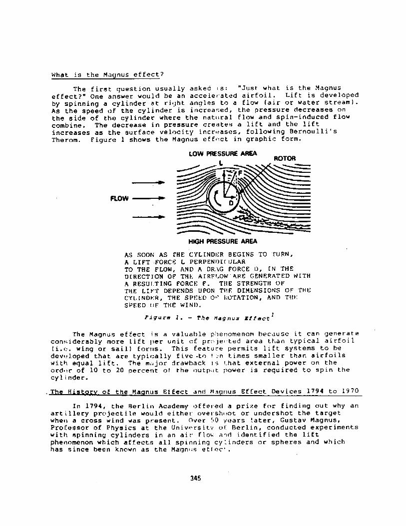
What is the Ma nus effect?
The f irst question usuaLLy asked i s: "Just. what is the MagnuseffeCt?" One anSwer wOuld be an aCceleF ated airfOiL. Lif t iS develOpedby spinning a cylinder at right angles to a flow air or water stream!.As the speed of the cylinder is increased, the pressure decreases onthe side of the cylinder where the nat«raL flow and spin-induced flowcombine. The decrease in pressure creates a lif t and the lif tincreaSes aS the Surface velocity incrF.aSes, follOwing Her»Oulli'sTherom. Figure l shows the Magnus eEE«ct in graphic Eorm.
LOW PRESSURE AREAROTOR
FLOW ~
HIGH PRESSURE AREA
As SOON As IHE CYLINDI.R BEGINS TO IURN,A LIFT -FORCE L PERPENI!I 'ULARTO THE FLOW, AND A DR,iG FORCE DF IN THEDIRECTION OF THE A IRF~'.OW ARE GENERATED WITHA RESUI,TING FORCI; F. TIIE STRENGTH OFTHE LI FT DEPENDS UPON Tf'IF, DIMENSIONS OF 'I'HECYLINDI;R, THE SPf;ED 0 ' I,'O'I'ATION, AND THI-:SPEED OF TXE WINI!.
Ei gure 1. � The Ffag~Lia EtfeCC I
The Magnus ef Eeet I s a valuaI>Le pI~enomenom because i t can generateconsiderably more Lift I>er unit of pri jei ted area tl an typical airfoil i.». wing or sail! forms. This I:eatu-.e permits li ft systems to hedeVL.LOped that are typically f ive -tn t n t imeS Smal ler than air fOilSwith equal lift, The m;ijOr drawbaok is that external pOwer on theord r of 10 to 20 percent of the outp«t power is required to spin thecyl i. nder.
Of the Ma nuS Ef EeCt and Mao»uS Effect. DeviCeS I?94 to L970T H'
34S
In 1794 the Berlin Academy of fe~ ed a prise for Eindi»g out why anart illery projectile should either ovei shi.ot or undershot the targetwhe» a cross wi nd was p resent. Over '.~0 years Later, Gustav Magnus,PrOteSSOr Of PhySiCS at the UniverSity oI' Berlin, COnduCted experimentswith spinning cylinders in an air f LoL and identified the lif tphenomenon which af fects all spinning cylinders or spheres and whichhas since been known as the Magn«s ef I ec'' .

I rr I H 1 l < r<rr <I I ay I< iqls <rut<I i she<I < I .<I>r r t t le<! " !rr I'Iri I < r»<li< I r r'Fli<lht >I 'I'annie P~ lls. " '1'h s treat i .. < <plained why a "sl i«r <I" I <'nrr isbal I wi 1,1 drop sharply because of the -Iagnus ef feet.
L,F.NG'f NI V.AMI!E PTI I
KV�1, 'I'<'t I'r! ! I ' L!<: 'li ! .'AI ic! 'AI'A ' I'I'4MA IN PROP< I .S< I !N
300 ' -�"43'-�"
< 7 ~ I A<000 'I' rN.'i
I! IESI I HNGIN1, S IN 'l.lSCREW, 1060 HP
�'-2"56'-1"
150 RPM!- � HI' El ECTRIC MOTORS
on» per r<rtor!
RO'I'ORSA I L i0IAMFTl; I>HE IG1 T
ROTOR S Pf;I:I!I O'fAR OR I'Jf.'S
Figure 2. - Barbara with three Rotors
346
Until l922, a lthaugh a number of !Cient iSt S harl expnr imente ! wi I hthe Magnus ef f< ct, lit.tie, if any, practical application of thephe< omenon was considered. In 1922 a lerman enterpreneur, AntonElettner, set <!ut to design an auxiliary sai 1 pt'opuls ion system forships, His initial ef forts focused on basic airfoil technology. Helater diSCarde<] the ai r foil in favOr O I' MagnuS ef f eCt rOtor propu 1S ion.In the early 1920s, two vessels, were .quipped with Magnus effect, windrotor, aux i 1 i ary propu ls ion. The f ir sr: vessel, "Baden-Baden,"previOualy a 164 f<!Ot three-maSted bar :errtine, waS equipped with tworotrirs. "Baden-Baden's conversion was urrderwritten by Krupp. Thesecond vessel, "Barbara", shown !n f iq< re 2, was equipped with threerotors. Both >f these vessels were reasonably successful; however,fuel saving ideas in tho 1920s were more technical curiosities thanpra< t i«: 1 nece'sities.

From 1933 until the 197<!s lit tie work was done on M«gnus <;f fe<:tdevices. How<>ver, the fuel price eris is in the 1970s ge><crate<icons iderable r<.newed interest in the H,>gnus ef feet For ai>pL icai ionswhere traditio>ial airfni 1 shapes are n >rmally used. For morehistorical dat.i, see reference 2.
Marine Maqnus Effect Applications
Since L97G, a number of initiatives have been made concern ing theuse of the Magnus effect. for marine applications. Three of them are ofinterest to f. ishing fleet operators: Wind propulsion, rudders andpropel 1 ers.
Wind Prop«lsion> Investigators in France, Germany, Russia, andSwe<'.en, as well as the United States, l>ave been vigorously pursuingrot< rs and other Magnus effect-like de«ices for the auxiliarypropulsion of ships. The Swedish, Ger ~an and U.S. invest igations Iiavebee>i with pure Magnus e feet rOtOrS, e,iCh hav ing bu i 1 t arid teS ted yaCht.s iz<. rotors. The results of these tes. 's have been L i f t. curves thatindi cate that Flet< ner 's res<>its did n<>t fully expl<iit the pot< n't i,i 1 ofthe rotor. Th<. recent t est >f a rot<» h~ Wind Sh ip of N<>rwe 1 1, Mass
has demonstrated si jni f icantly better performan.»thar> that attained by Flettner.
The rotor has distinct advantages over oth< r wind propulsiondevices. Som< of these advantages are sh<>wn in Table 1. The mostsign i f icant f,rr tor is the cost per uni< ol li f t. H<>wever, othercons ideiat i<>n" s«c'I< as simpl icity <>f <i> er it ion, the rotor ',; ri n<ii <icy i:<i >e st<>r«r-p> <>ol, a<i<i t l>e r<alat ive ease <' i t'i whic/> a < ot<>r <,«< ><telcscoi>cd C<i <-ope wi tl> hrid<ie clear an es, further e>ihanced i ts ut i I i t y,Although ther<> remain a few characteri ties, which have yet. t<> he i.ul lyexplore<i, the > ot or is currently a via< le wind-assist dev i ce f <ir tiief ishino Fleet .
p,vTabLe 1> Rr',g C<>mpari<riorr TabLe.
DFL4G FACTOR7RRClST FACTOR l% OF US&LBLE CL/$If P&F FT'! WIND A IIGLESJ
9.9SQUARE
STAYED FORf 5 AFTr'
SHIN AITOKU MARU
8318.5
89- 22.5
83UNSTAYED FORE 5 AFT CAT! 23.2
AIRFOIL I/SIMPLE FLAP
ROTOR
9234.5
89109.9
347
In 1933, .Julius Madarasz, of Royal Oak, Michigan, developed a designfor a massive Land hased, e Lect r i ca 1 ienerator sys Cern which env is i onedlarge Magnus >i feet rotors o<i ra i Lroad cars running on a circu Lartrack. One cy Linder was bui lt and tested with favorable results;however, the .spital required to compl:te the pro3ect. was notf o i > hen><> i ng .

The Cousti!au Organi zat ion, wi th f inaniral supp<>rt f rom the Frenchgov< rnment, has recently bui It and tested a device called the Aspiratedellipse, which is similar in principle to Magnus uf tect rotors. Thisdevice features an elliptical mast with two slots on its after. end,port and starb<!ard, whir h are alternati!Iy covered or uncovered,dope nding on whether the wind is comin<i from port or starboard i. e.,
port or starboard tack!. A fan at the top of the ellipse is usedto . uck air through the open slot> accelerating air on one side of theellipse and thereby creating lift. The developersclaim less power is required per pound of. lift as compared to theroti r; however, the ellipse needs to have about twice the projectedarea as a rotor for equal lift. Unfortunately, the Aspirated Ellipseon ousteau's test vessel> "Woulin a V .nt," broke off in November l983dur:ng an attempt to cross the Atlanti<:. Although the CousteauOrg~nization is satisfied with the performance of the AspiratedKIL pse> it is too soon to say whether the device has a serious future.
- PrOpellerS: Patenta have been in ef feCt fOr MagnuS effeCt prnpellerSsince 1912. More recent worl'. by John Borg of Atascadero, CA, indicatesthat a Magnus effect propeller in conj unction with a Kort nozzle, asshown in Figure 3, couLd increase prop <ls ive ef f iciencg and have lowerd ivemanufacturing cost than c<!nv<>nt io<ial s rew propel lers Rotor s pinrive can be accomplished by usinq a r'ck in the shroud nozzle! t
kta e power fr<>m the shaf t or thro<!gh a concentric shaf t by a separate0
driv.. Thrust reversal coul<i be Eairl, easily accomplished with eitherdrive approach. The ef f iciency a<avant. ge of the Maanus propeller overoth< r types i ~ shown in f iqui.e 4.
.348

SHROUO
BORGMAGNUS
RUDDER Figure 3 � Bourg Rudder and Propeller3
I- TANKERS
TWIN SCREW SINGLE SCREW CQASTERS TRAWLERS TUGSCARGO SHIPSSHIPS
0.70
080
W 0 0.40
0~ 10 20 50 100
TAVLOR POwHV cOEPPCIENT ls NP+-~lva>-Sl
Ff.Rure 4 � Propeller Efficiency Curves 3
''iI hilt'I ".' .X I Igtlu." Vt tv t I udd&t' lui iue waS Patented in l 929 by W.: ' I deuCO i.= ave i labl e the ' wOII ld indi Cate that a !4OOS Paten t.
~ udder r was a.'ver built. H however, Boi g has equipped' a tow boat wi th a"agnus ef f ..t rudder simi <ar to the Ro~s patent design See Figure '>!.he device was very SucceIIsful in t.hat steering performance was
In i f iCan' ly irIIproved ariel reS iSI.an .e in lIaril tIIrnS waS S ign i I i Cant! y~ ei!uued. l P!agnuS ef feCt rudder re luiroe mOI-e pOwe.r than a~ onvent ion I ' rut!der. llowuver, f<>r veeselS that fr'equently use largeI udder ang iuS, suCh as tu ls, t ~wbOai S an<i f ishing veSSelS, the lowPsistanCe of the COtOr,:ombined witl. its ability tO apply thrust at
' hp right .Inglee tO the h il 1 c ~ nteI. ir, makes it a mOSt deS irable..-t =m. 7
349

Oesigni<><! a Rotor for,> Shrimp h at
To desi !» a rotor wind pr<>pu ! s i < .'.yst «m or i shr imp ti<> it ,et us first look at the rules.
Ru les of Thumb for Rotors:
�! The height of the rotor abov . the waterline is limited bythe lowest f ixed bridge expected tc be encountered Unless therotor i s a telescoping des i rjn ! .
�! To <!ain maximum 1 ift, the .i"p< ct rat io A/R! of a r<>torshould I>< in the range of 6 to 1.'.. Above 12, gain» in 1 i f tare small. and below 6 1 if t drops of f rapidly. Asliect ratiof<>r a rotor = height/diameter. ! See Figure 5, CurvesA,B,C,E, F.
�! Surface velocity >f a rotor is a maj<>r factor inestablishing lift. For rotors with A/R valises above 6,s<irface velocity of f ive times e <pected average wind vel icit, isreCOmmended. HOweVer, fOr an A/R«of Say 2, increas ing S irfa--evelocity ratio above 2 will not <irnvide siqnisicantlyincreased lift See Figure 5!.
a�! Surface roughness of/rotor has some iinpact on 1 if t. Atleast one experiment has indicat<.d that rough cylindersprovide at least 305 m<>re 1 if t than smooth cy linders at lowReynolds numbers on the ordez of 4xl0"!. Use of a lightlysanded surface is reco<nmended until more data, especially athigher Reynolds numbers, is avai lable See Figure 5, curves E
E'!,
�! End caps improve rotor lif t especial ly for low A/RrOtOrs. End CapS Or plates wit h d iameters of l. 5 tO 2.0 t.imesrotor diameter ar~ recommended ee F igur~ 5, curves A, A I, 0a D'!.
�! if nore than one rotor is u ed, rot< rs should be spaced aminimum of six diameters apart.
�! Because upwind performance is best at a velocity ratio of2 ~ rotor drive should be variabl ' speed. See Figure 6! .
350

REYNOLDSROTOR FINISHA/R END FLATES
~ TESTEO IN WATER � OTHSRs TESTED IH
C
0
CL
NOtE
' ~ ~ 0 ~ ~ ~ ~ ~ 11 ~ ~ ~ ~NarE e [
4 I
VSR r VW
RANGE QF LIFT FQR RIGID AIRFDILSRAIIGE QF L I FT FOR SQYT $A [LSL URVE. A, A, E g E, AND F ARE FRQM gWANSQH8I$ FRV3 IIINDSHI P, I IS FRQIM 3!pRG2AND p AND p1 AREYRQM FLI TT'IER 3" .
3.
351
A 424 4 24A1 18.44 ~,2
~ C E.OO 4.7D'E 4.7'E 8.7f 4.0
8.0 XNO INIE1.44 x
2 X1.7 xNOHENONENONEWALL
UNK HOW NUNK HOW HSMOO'THSMOOTHUNKNOWNUNKNOwHSANDEDSMOOTH
UNKNOWN
8-8 - 4.4 x 10⁴S.S -11a x 1047 {FULL 8CALE!
74.2 X 1042 X 10
4-4 X 10 48- ~ X10i
SX 10'

Cdco 2 3 4 5 8 7VsRNw~
Pigure 6
352

1«st<!r L< < t R«]ui rmunt s
Rot«r ! i f t rc qui cement s <-.an he estab! i eh< d in one <~'I tw<'ways:
I! Replace total power capabil<ty � In a case such asreplacin<! the sail system on a yacht 'with a rotor of equallift, th<. area of the exist inq system mul t ipl ied by the rat ioof sail system lift to rotor L i f t A sai 1 x CL sa iL/C L rotor!will provide the requisite proje .ted rotor area. For example,if a catamaran, wi th 2LO sq. f t. of high ef f iciency ful1ybattened sail with a lift coeffi<:ient CL! of 1.5. were to bereplaced with a rotor with an aspect ratio A/R! of 8, endcaps of 2 times rotor diameter,,-~nd an estimated CL of l3 at asurface velocity to apparent win ! velocity rat.io of 5, theresult in<! projected rotor area w<iu! r! he 26. 25 sq. ft�LOxl.5/L3!.
�! Augment existing propulsion plant � In the case of alarge ship, the maximum practica I lift is usually the goal.Optimization of cost, is required which makes the problem moc..difficult.
Rotor S is i nq 6 Arrangements
Data Required:
I! All>wable rotor height with a«d or without telescoping Bridge clearance - weather deck height above the DWL! .
�! Selection of the number of rotors avd the rotorar'rangement � Typica 1 ly, small v.ssels �00 f t long or less !,need only one rotor. '<Iowever, l~r<ge vessels usual ly need 2 ormore rotors to gain a reasonably significant effect.
353

Kxamp! e
Ship selected: Florida Shrimper
Reasons: High fuel consume>tiorr pr r ~>ound r>f catch andrelativ< !y large open»eath<!r de< k >rea fr>rwar d.
P<>wcr r< oui raiment r 75 hp t<> per>«it 8 knot speed un<ier <> <t im«mr<>tor per formance and i2 kn<>ts o< ar>parent wind �2 knot:: isthe average wind in the Florida area.
One rotor has been selected as or>e can provided enough power.
A rotor with a height <>f 42 feet and a diameter of 6 feet foran A/R > 7 r o comply with Rule <2! is planned.
T!>e rot<>r is planned t«be teles«>p inq to permit pass in@ ur<r!<>rbr idges with 40 foot clearance t comply with Rule �!.
Rotor end caps, 10 feet �x1.67! in diameter have beenprovided to comply with Rule �!.
A variable speed drive has been, rovided to c<>mply with Rulc�!.
CAE.CULAI'IONS
.if t Ca i,r:ulat iona
G L </><n:
Rotor height L!: 42 fe t
Rotor diameter d!: 6 r<eet
Optimum apparent wind sr>end wo!: 12 kts or 20.0v
f t/sec
Velocity of rotor surface s R!: 20.0 x 5 ~ 100v
ft/sec Complies with R<>le �!.!
Projecter! area Ap!: L x d 42 x 6 ~ 252 sq f t
iMass density in slugs/cu t t ~ 0.0023 air! or 1.9875in salt »ater! !.
354

Wind S eed Vw ! Ratio Lift L! Pounds!
Knots f t/sec Vsr/Vw!
10 L6.9 �4.0! � 149!5,9 57
758l2 20,0 Vwo! 5.0 L, 500L3,0
15 25. 3 11. 5 2,1164.0 106
20 33. 8 9.03,0 2, 956 148
25 42. 2 6.8 3, 48l2.4 l74
5.0 3,69530 50.7 2.0 L85
67.640 3.0 3,941 l97
'n l L <x~se Ro to r
1.3 2,81850 1.284,5
0.3100 L68.9 0.6 L,299 65
4Mumbers in brackets are ext rapolations of existing test <grata inFigure 5 and may not be ace«rate. Other numbers areinterpolated f rom Figure 5.
75 HP wi1 l <drive a medium sized shrimper at eight knots. 11
355
C A PVw /2!2HP
if t x.05

Horse ower }} Pin ! <'a l c«la t ions
Given:
ion axis in feet L! - 42
in feet d! - 6
Length along cotat
Diameter of rotor
tes in feet d } � 10
ind speed in feet/s,.c V ! � 20 pWo
locity to VW ral j ! � 5Wo a}r! or O.pl water! !
Diameter of endpla
Optimum apparent
Optimum surface ve
"-r i.ct ion factor f
Then:
projected area Ap! Ld 42 x 6 .�. 2 i2 square f t
ty VsR! ': VW x 5 ~ 20.0 x S = 100 f t/secWo
As ! ~ Ap > = 252'<YR100/6 II ~ 5. } I
Rotor surface veloci
Rotor surface area,
Rotor RPS ~ VsR/ n dRotor RPM = 60 RPS 318
c end AsPPR! -.: !/2! h = 9 squarer en' cap outs<de surface AsgpO! d,./2!
Surface area of ento
Surfac» area of roto
25'~T s�uac<- F t2 Vs ! = RPS x II. x /ld
*AAuthors iM<ite: The input horsepow r is very conservative. Actualinp<>t ho<-sepower m;iy be as li t t le as 50}} of the
ca lou lat d va lue.
356
iur face v<:.loci ty oF r<>to< end pie >
66. 7 } t/sec
Surface vv!ocity of r»to< end cap ~ut".ide surf a<>e Vs !Eco
RPB x II x 2/3dE = I lI ft/sec8<it >r T»r<}ue }'! = I' f As, x d/2 x, '- s ' ! +I, }}25
!q R AS,, X } >'3 x Vn., ! > 1 hs, r d. '3 x V~,, ' !I. BZS I.H '
I'P< > I ' ' }:, '<1 EPO I ' ' '>
x d, 3 x Vs,p ' !I I0 ~ 000}}! 21 I �52 II x ~/2 x 100 ' ! + �5 Ii x lp/3 x I I I !
+ 2 [2S I+ x 10/3 x ill ! - '9}1 x 6/3 x 66.7 ' !I IT 177 f t pounds}}pin ~ T x Rpg/5252 = 177 x 381/S2 2 = 10.7

The rotor is shown installed on a typical shrimp boat infigure 7, and is designed to be constructed f rom readilyavaiIabl» materials. The rotor itself should be made off iberglass, the mast of standard aluminum tubing and pipe andthe hydraulics system should use stock hydraulic componentsavailable from a number of hydraulics manufacturers. Based oncosts the author is current1y Incurring for a smaller rotor, acost f igure of SIOO per. square E ot of rotor projected area,half for materials and half for I abor, is consideredreasonable. Therefore, the cost of the rotor system shown inf igure 10., should be about $25,000 Ap x Cost/sq f t 252 x100 = S25,200!.
In 1970, the fuel bill for ~ typical shrimper was on theorder of S10,000 to S12,000 a year, however by 19SO, fuel costrose to between S80,000 to SIOO,GOO a year. The expected fuelsavings with the proposed rotor are on the order of 25%.Therefore the cost of rotor system can be written off in aboutone year and when the cost of system .installation which wil1vary from vessel to vessel! is a fded, a writeoff p»riod of oneto two years is anticipated.
357

l~> i rure ~ . - Na<yn~s 8f t cot tot or For a S>>ri ep So~ t
Conclusions and Recommendat ions
The Naqnus effect is a significant phenomenon which hasbeen overlooked tn a great extent by the marine community.Kith fossil Fuel energy in short supply and at a high cost, weshould be considering those changes that either eliminate or~educe fuel requirements. The Magnus effect is clearly aphenomenon that should be used. Therefore, the fishing fleet
and operators should seriously consider the following:
Fitting fish boats with hlagnus effect rotors,
Fitting fish boats with %agnus effect rudders,
Fitting f ash boats with 'magnus effect propellers
358

Re f e ri. nce s
l. Anon, "Aspirated Cylinders: The;lhape of Things to Come, CalypsoLoci Special Dispatch, Vol. i0, No. 3, Summer 1983.
2. "A study Report on the Nagnus Effect prepared by Borg/LutherGroup, Atascadero, California, under Navy oontract numberNOU024-83-5350, unpublished!.
3. Morisseau, K.C. Advanced Wind Propulsion Devices-Current Statusanal Potential, Intern'ational Conference on Sail-Assisted CommercialFi:hing Vessels: Proceedings V.I, Florida Sea Grant College, Nay 1983.
4. Bergeson, et al, "Wind Propulsion for Ships of the AmericanNerchant Marine", Wind Ship Company for the Naritime Administration,March, 198 l,
5. Borg Propeller Data Sheet, Borg/Luther Group, October 1982.
6. Borg, John L.. "Magnus Ef feet Ste.ring, Marine Engineering Log,March l.980.
7. "Magnus Effect Borg Rudders", Borg/Luther Group, Carpenteria, CA,Oct ober l982.
8. SwanSOn, W.M., 'The Nagnue EffeCt: A Summary Of InveetigatiOnS tODale', Journal of Basic Engineering, ASNE, September 1961.
9. Berqensen, L., Greonwald, C.K., and Hansen, T.F., Magnus RotorTe..t and Evaluation for Auxiliary Propulsion . Proceedings of the 13thAI.-'A Symposium on the Aero/Hydronauli:s of Sailing. Volume 29, October1983.
10. Flettner, Anton, The Stor of the Rotor, F.O. Willhoftt< New York,197.6.
l l. Trang, Jan-Olaf, "The Prismatic C'oef f icient," Fishing Boats of theWorld, 2, Fishing News Books Iimited, Farmham, Eng., 1960.
12. Shortall, J.W., "World Trends in Sail-Assisted Commercial FishingVe.-.sels International Conference on Sail-Assisted Commercial FishingVe 'eels, Proceeding V. II. Florida Sea Grant College. Oct. 1983.
l3. Ringhaven. I..C.. 'Design and Nass Production of Shrimp Trawlers,Fishing Boats of the World, 2, ibid.
359

FURTHER DEVELS'NENT OF THE TUNNY RIG
E M H GIFFORD ANO C PALNER
Gi f ford and P a rt nersCarlton HouseRlngwood RoadHoodl andsSouthamPton S04 2HTUK
360

1, lNTRODUCTION
The idea of using a wing sail is not new, indeed the ancient junk rig isessentially a flat plate wing sail. The two essential characteristicsare that the sail is stiffened so that ft does not flap in the wind andattached to the mast in an aerodynamically balanced way.
These two features give several important advantages over so called'soft sails' and have resulted in the junk rig being very successful ontraditional craft. and modern short handed -cruising yachts.
Unfortunately the standard junk rig is not every efficient in anaer odynamic sense, due to the presence of the mast beside the sai 1 andthe flat shape which results from the numerous stiffening battens.
The first of these problems can be overcome by usi ng a double ski nnedsail; effectively two junk sails, one on either side of the mast. Thisshields the mast from the airflow and improves efficiency, but it stillleaves the problem of a flat sail.
To obtain the maximum drive from a sail it must be curved or cambered!,an effect which can produce over 5� more force than from a flat shape.Whilst the per'formance advantages of a camber ed shape are obvious, thepractical way of achieving it are far more elusive.
One line of approach is to build the sail from ri gid components witharticulated joints that allow the camber to be varied Ref 1!. Thisapproach is claimed to give a very good performance, but suffers fromthe practi cal di sadvantage that the sai 1 area cannot be reduced byreefing.
On large vessels, where the rig provides sail assistance contributingonly a fraction of total power. this may not.be a limitation, but forsmall vessels designed to exploit sail power to the full, some form ofarea reduction appears to be vital!.
The alternative of a sail which has both camber control and provisionfor reefing has proved to be a very difficult specification to meet witha practical seagoing solution.
Many extremely complicated systems have been proposed, which whilst theymay have worked for thei r enthusiastic inventors, have not beensufficiently practical to attract wider attention.
The first practical solution to this problem has come fr om an unexpectedquarter. The Combewrights had a simple objective, to build the cheapestboat that would take them safely across the Atlantic. They started withno preconcepti ons and little knowledge of boats or the sea. They talkedto people, listened and learnt. Their solution was a 32' catamaran witha wing sail - a wing sail with camber control which they called theTunny Rig. They realised their ambition, crossing the Atlantic lastyear without problem. Since then they have proceeded via the Westindies to the Panama canal and so to the West Coast of America.
Thei r voyage has proved the pr acticality and seaworthi ness of the ri g inits prototype form, and their basic concepts are embodied in newversions of the rig being developed by Gifford Technology. Thisdevelopment has taken place over the past 18 months and has now reacheda stage where a production prototype is being tested and corrmrerci alapplications are under serious consideration.
361

2. PR!NCIPLES OF THE TUNNY RIG
The Tunny Rig is an aerofoil wing sail made from a set of shaped battensconnected by panels of sail cloth Fig I!. The battens wrap around themast, thus forming the aerofoil section, and can be collapsed one on topof the other either for reefing or clearing away the sail.
For almost two thirds of thefr length the battens are rigid frames, madefram thfn section timber. The final third of the length comprisesdetachable, flexible extensions to the main frame, interconnected onlyby a single tensioned line.
The camber control comes from two lines, one from the end of eachflexible section, which are fastened to a cross member in the front partof the batten. By differential ly tensioning these lines the batten iswarped one way or another, the degree of waro being limited by thetension line joining the flexible extensions.
ln the full rfg these control lines are tensfoned by a conwnon linerunnfng down through the sail to over centre levers on the lower batten or boom!.
3. TUNNY RIG OEVELOPMENT
Building on the Combewrf ghts ' ori ginal concept the ri g has beendeveloped in two phases, comprising the manufacture pf a 28m2 sail forinitial pract i cal apprai sal fol 1 owed by an 18. 2m< sail for di rectcomparative evaluation against other rigs.
Much of the first stage was reported in Ref 2, notably the selectfon ofthe aerofoil section for the sail and the simplification of the internalmechani sm.
The section chosen was the NASA GA M, a recent product of researchinto aerofofls suftable for light aircraft. It proved fdeally suited tothe Tunny Rig for several reasons:
Relative insensitivity to surface roughness
Thick section with thickness carried well forward
Camber la'rgely concentrated in small proportion of the trailing edgeGood lift to drag ratio coupled with high maximum lift coefficient
Good aerodynamic properties retained in low wfnd speeds, i.e. lowReynolds numbers
Figure 4 from Ref3! shows the basic lift characteristics of the sectionat typical sailing boat Reynol ds numbers. Ff gure Q shows itssuperiority in terms of maximum lift over other typical sections, in thepractical condition of aerodynamically rough surfaces.
The first development rig of 28m2 area was built using this section andfitted to a catamaran trial s boat Fig 4!. Extensi ve tri als werecarried out last suniaer in a wide range of wfnd strengths and a greatdeal was 1 earnt about the general handl f ng characteri st i cs andpractfcality of the rig.
The positive features demonstrated are:
362

Low sheet loads. A direct result of the sail area beingy lanced on the mast as in the junk rig.
Evenl distributed loadin . Since the sail does not rely for itsshape on being set between attachment points where loads are highlyconcentrated, the sheet and'aerodynamic loads are evenly distributedso reducing the weight and quality of sail cloth required as well asthe complexity of manufacture.
Insensitivit to sheet osition. Because the sail is selfsupporting it does not rely upon the di rection of the sheet lead forits shape. Consequently the sheet can be taken to poi nts which donot obstruct operation of the boat and which fit best with theoverall deck layout, rather than dictating the layout as with manysoft sail rigs.
The sail cloth is supported by the Tunnyog when being rai sed or as the sail is tacked.
Practi cali t of Reefi n . Again in comnon with the junk rig reefingis a quick and effective process.
Ease of handlin . The light sheet loads mean that the 28m2 sail canbe tended single handed without the need for a winch. Its docilebehaviour when hoi sting or lowering also makes life much easi er forsmall crews.
retained dri ve even when very close to the wind, tacking was a muchmore reliable pr ocess than is normally the case on a catamaran.Provided the sheet was freed off contrary to normal practice! asthe boat was put i nto the wi nd the sai 1 would drive the boat roundand through the wi nd.
Close winded. The lower drag of the rig coupled with i ts stable
Camber effective. Trials conducted with and without camber in thesail demonstrated an improvement i n dri ve resul t i ng from thea pp1 i cat i on of camber .
By pushing the sail out into a reverse mode the craftastern quite simply.
Li fe is not al 1 gain however and there are of course some negat ivepoints about the rig. Compared to, say, a Bermudian rig, the Tunny Rigwill always be heavier, though further development and the incorporationof more refined st ructural details could well reduce the margincons i de rab1y.
The other prob 1 ems whi ch were found on the fi rst ri g were 1 argel yspecific to that particular rig and were rectified for the next 18.6m2vers i on.
Excessi ve structural wei ht. In the absence of rel i able 1 oadingdata the Tunnies and the sail cloth were made greatly over strengthand thus the rig was much heavier than necessary.
363

If<see et gecvian $4spe an Mastrrerm utr ~nrenr
1 eynal4 Mrnae r
TUNNEY kjc OH SAHGSYtPPER
NASA GA W! -1 Section
~ f Srrr'inca Oovynness ana ~ nolae Hvmbar
~ et Attmh laearaeal
Figure 1
Figure 3364
Figure 2

Creasin of sail cloth. Oue to deflection in the top batten gaff!t e top pane set bad y towards the trailing edge. Also it provedimpossible to complete'ly eliminate creases around the leading edge,even when extreme halliard tensions were applied.
The sail was laced to the Tunnies far morenecessary, making removal and adjustment very
time consuming.
Hi h camber control forces. This problem was linked to theoverstr ong structure which resulted in the Tunnies bei ng stiff anddifficult to deflect.
Dama e to control mechanism. The camber lines were tensioned bymeans of levers on each Tunny. These worked well but suffereddamage when the sai 1 was lowered .
Li it d ri rotati on Due to the halliard arrangement and the downhau on t e oom the rig could not swi ng out freely to largeangles. Since it was finely balanced about the mast the aerodynamicforces were insufficient to force the sail out and thus it wasdifficult to reduce the dri ve by simply freei ng the sheet.
Lack of visual clues to sai I setti n . Since the sail did not flapw en not set correct y it was di icult to determine visually thebest sheeting angle.
No reliable measure of erformance. Whilst the sail appearedsubjectively to perform well it was not possible to obtai n any vali dcomparison with other rigs by which its true performance could bejudged-
4. THE 18.5m2 RIG
Choice of Area
As part of a contract with the Commissioners of the European Communities CEC! Gifford Technology had carried out a series of comparative sailingtrials using four di fferent rigs, each of 18.5m~ area Ref4!.Accordingly it was decided to build a Tunny Rig of this same area whichcould be evaluated in the same way, thus gi vi ng a measure of i tsperformance relative to other well known ri gs.
Having fixed the area it was also decided to i ncrease the aspect rati oby a moderate amount to a value of 2.0. This is still far from the mostefficient shape for the very best performance to windward, but areasonable compromise for all round performance when heeling moment andstructural consideration were taken into account-
Pl anform
Theory indicates that the elliptical planform is the best from the pointof view of minimising the induced drag of the rig. Practically it isfar from ideal since each Tunny must be a different length, thus greatlyCOmpliCating manufaCture. Similar COnSiderationS apply tO a triangularshape, which is also a bad shape aerodynamically.
365

These 1 i nes of reasoning 1 ed to a rect angul a r pl an form, whi c'hparticularly when associated wi th a squarely cut off ti p, gi vesvirtual 1 y the same performance as the el 1 i pt i ca 1 shape ~ The f i na 1refinement was the cutting back of the top batten to gi ve a small amountof taper and to eliminate the creasing in the top panel.
Using i nformati on i n Ref s 5 and 6 predict i ons were made of the i nduceddrag for di fferent planforms and it was found that the penaltyassoci ated with adopting the practical rectangul ar pl anform wasneg'iigible, as compared to the "ideal" ellipse.
In addition to these basic design considerations a number of detailchanges were made, mainly as a result of the negative features found onthe 28m2 rig-
Lightweight Structure. The size of the timber used for the Tunnieswas reduced from 90mm x i8mm to 40mn x 12mm. For reasons of economysolid redwood tfmber was used and further weight savings could bemade by using laminated timber construction.
Lightweight sail cloth. Cloth weight was reduced to 4~ oz.
Lacing arrangement Figure 4,'. The number of lacf ngs on theintermedi ary Tunnf es was greatly reduced and a revi sed systemadopted for the top and bottom whfch makes adjustment of the sailmuch easier.
Detachable battens. The flexible sections of the Tunnfes were madedetachable so that they could be readily replaced if damaged. Theywere sleeved into the sai 1 in the same manner as conventional sailbattens, so further reduci ng the need f' or lacing.
Harp String Warping Fig 5!. Instead of using levers on each Tunnyfor tensioning the warping lines a harp string approach wasadopted. This does not give qufte such a good mechanical advantage,but offers significant gains in simplicity and a reduction inweight.
Floating Ribs. To give a smooth shape around the leadi ng edgeintermediary 'floating ribs' were fitted to the sail.
Mast Crane and Collar Ffgure 6 !. To ensure that the safl was freeto rotate the halliard was lead from the mast head via a rotatingcrane and the boom restrained by small wheels bearing against acollar on the boom.
5. THE TWIN TUNHY RIG
In parallel with the development of the Tunny rig a 28' double hulled«shing boat was being developed for a beach fishing project in SriLanka Ref 7!-
a good sailing performance in tropical condi tions a sai 1 area of3~m was considered necessary and a design exercise was undertaken toexamine the possible rig alternatives.
366

Lacing Details
4e has
se aces Figure 4 Sail Swivelling ArrangementsM ~ ~ rll IAk ~ M 1 ~ SWarping System Development Arthur ~
V eeS 0 eel
+see i eelleam
Figure 5
Figure 6367

368

The traditional rig that could be used was the lateen, which though apractical and culturally acceptable option, was not expected to give avery good performance. Also the size of the spar required would becomedifficult to stow on the boat and vulnerable in surf. Slmilarily therewere likely to be problems with spar size if other rigs such as thesprit or bermudian were carried on'a single mast. Within the length ofthe boat the idea of splitting the rig to give a ketch or schoonerlayout proved impractical - the rigs would be so close together as tointerfere a great deal and nuch of the double hulled advantage of deckarea would be lost. Finally a centr e line position for a mastintroduced addi ti onal structural loads on the cross beams andpractically precluded the possibility of using unstayed masts.
The solution adopted was to place the masts side by side, one in eachhul l. It was ienedi ately apparent that thi s gave many worthwhilestructur al and 1 ayout advantages and potential ly good aerodynami cperformance.
Figure 10 shows that 8.5m boat fitted with two 18.5m~ Tunny rigs thoughthe layout is not rig specific and coul d be made to work well with othersingle rigs suitable for unstayed masts!.
The advantage of this layout over a single central rig are considerable:
Lower centre of effort height.
Less weight aloft giving lower centre of gravity and lower pitchinerti a.
No obstruction to bridge deck for handling nets.
Absence of rigging and the associated point loadings.
Cross beams do not have to be reinforced to take mast compression.
In Figure 8 the two rigs are overlaid and the differences are visuallyvery apparent. The other appealing features of thi s layout whencompared to a fore and after disposed twin rig are:
Masts can be buried into the hulls and thus unstayed if required.
Close hauled performance is likely to be much better though notquite as good for a single rig!.
Reaching performance is potentially very good due to the slot effectthat can be created by working the two sails together.
Dern wind additional sail area can be set between the two masts.
The boat remains balanced with only one rig set, so reefing can bereadi ly achieved by dropping one complete sail. Also the singlesai 1 rig is useful where only low thrust and fine control arerequired.
Most of these points are illustrated by the various insets in Figure 7and 8.
369

Performance Predictions
Using a computer program specfally developed for evaluating the effectsof different ri9 and hull characteristics a series of polar performancepredictions were made. Figure 9a shows three of the results obtained.Fi gure 9a i 1 lustrates the correl at i on between the theory andexperimental results obtained for the bermudi an ri 9 tested on aSandhopper trials craft during the CKC trials. It can be seen that theprediction is within the scatter of the full scale results and can thusbe considered an adquately reliable tool, particularly where emphasis isplaced upon relative performance compari sons.
For Fig ga the hull data was obtained directly from trial results andrig data from wind tunnel tests at Southampton University Ref 8!.
For the predi ctf ons of the SK28 performance no direct test data wasavailable for the hull. However, tank test data for the 20' craft ofvery simf lar proportions was availab'le, as was full scale thrust datafor the SK24, a craft even closer to the proposed SK28. Figure l 0 showsthese two results plotted non-dimensi onally and Figure 1 1 is theprediction made from them for the SK28. Fi nally a check was made usi nothe excellent predfction method of Gerri tsma Ref9!. Also on Figure llis the thrust curve measured during the CEC .trials for the 13.5 HP Deut'diesel, the engine proposed for the SKZB.
Rig data could not be established quite so reliably and varf ousassumptions had to be made so that conventional aerodynamic theory couldbe applied.
The first stage was to construct a polar curve for an AR*2 Tunny ri9.For operation up to the point of stall standard aerodynamic theory wasused to correct the wfnd tunnel data of Ref 3 to finite aspect ratio andthe planform and tip shape of the proposed rig. Then using other rigdata and information from Ref 6 a drag coefficient of I.2 was deducedfor the foil set normal to the flow and a smooth curve fitted betweenthat point and the stall point. This approach may not gi ve a veryreli ab'le estimate of the foil performance just beyond st al 1, but theprediction program indicated that the optimum angle for the rig seldomexceeded the stall point except on direct down wind courses. Thus theerrors resulting from the inprecision are likely to be very small. Theresulting rig polar is shown in Figure12.
For the twin tunny rig a biplane correction factor was applfed to theresults up to the stall pofnt this was appl fed as a virtual reductionin aspect ratio and hence increase in induced drag!. Beyond the stallpoint it was assumed that the sails were set to give beneficial mutualinteraction which at large angles of attack could give a peak lift««ffcfent similar to that of a flapped aerofoil, i.e. around 2.4. In
down wind conditi on the drag coef fici ent was corrected toincorporate the effect of adding extra area and the vague intermedfarypart of the data faired in. This result fs also shown on Ffgure12-Finally using simi lar methods a rig polar for a Tunny sail fitted wfth anotional flap was also constructed.
Ff gur e 16 shows var ious rig polars from other sources with the twinTunny predi ct i on overlaid for comparison.
370

sPEED<KTS7 vs TRUE
OQAT,SAI<DHDPt nnnc 5
RZG r YPE i SLOOPSAZL AREA LG en 2
/dd»G fktHy nd Svcc
4 ~ ' 4 vr:ekteHsnd rrcvd»S.
e Esperimentel pe+Iswittd speed ~ 8 0kts
ZFFGRD TECHHQLQGY
Figure 9 a
D<KTS> tts TRUE HZHD
OOAT:SK2ODZSP i 2. 1O tonnrs
RIG TYPE! SLOQPSAZL AREAr3T.On 2
l4ind errrd d 6. Oktrl4 nd errrd»4 eg 4-S. .Oktr
TECHHOLOGV
Figure 9 b
ED <KTS! VS TRUE HIHD
OOAT~SK2GDZSPaZ.S.O tonnre
AzG TYPE: TUHHvx2SAZL AREA:37 en 2
~ Iind errrd»6 Oktrk<tnd srrrd»Z .Oktekttnd errrd I .Okte
TECHHOLOGV
Figure 9 c
371

Figaro
Figure 1 0
~oem aa~~ R 4 I-SI 44 has Ssssl
% M sss
Fige'I 1 2 Fiqute 13
ACIS AaSIS I IACtS ISssSISAI OSaSss SAC CIA AS AS~ ~CIAAS IIssss llsssr M
4 I 4 j 4 92 ~ 7 4 ~ 'IS'll lj111c'I%14111 ~ ICCI 4%II CeHe~ CS
372

Using thi s data and Southampton Uni ver/i ty daQ for Bermudi an sai 1 s Aefs 8 and 10! a range of per formance predicti6ns were made. Two ofthe polar curves are shown in Figure gb and gc and the results of thefull set of runs sunvnarised 1n Figures'l4 and 15.
Figure 14 compares the performance of the four different rigs inknots of wind a typical tropical breeze!- For each rig three differentspeeds are shown:
Speed made good to windward.
Maximum reaching speed {generally with true w1nd angles of 90 toIOO'!.
Down wind speed true wind angle of 180'!.
To windward the Bermudian sloop has a slight advantage over the others,showing a Vmg of 4 .5 knots agai nst 4.2 for the t..in urn' ano 4 .3 forthe single tunny,
When reaching the twi n tunny and the tunny with flap gave the bestperformance and downwind the twin tunny i s fastest of all, due to theadditional area assumed to be set between the masts.
On all pOints of Sai'ling the Speed thrOugh the water exceeds 5 knots,and when reaching it 1s greater than 7.5 knots. This comparesfavourably with the maximum speed under po~er of 7.8 knots and suggeststhat lack of speed will not be a large disincentive to the use of sail.
The results in Figure 14 are for a wind strength where even for the tallsingle rigs an adequate stability margin remains.
With increasing wind speed the sail area must be progressively reduced-the lim1ting stability point of flying a hull occurring in 19 knots ofwind with the single sail rigs and 21 knots with the. twin tunny.
Figure 18 compares the performance of reefed rigs. First; in 18 knotsof wind a single small Tunny i.e. twin rig with one sail dropped! iscompared to the sl oop ri g wi th a deep reefed ma i nsa i 1. The stepfunct i on change in tunny r 1 g a rea resul t s in a sl 1 ght ly i nf er 1 orperformance, but the d1 ff'erence is not more than 10%.
In stronger winds �5 knots! a comparison is nmde of the single Tunnywith a mainsail only Bermudian rig. Under these cond1tions the Tunnyri 9 i s superi or on al 1 poi nts, but aga i n the margi n i: lorna 1 i .
The single Tunny can theoretically be carried in winds of 30 knots, butthe option of reefing that sail remains if continued operation undersail is required in still stronger ~inds.
From these comparisons it can be seen that twin Tunny rig has a goodperformance potential, which coupled with its convenient layout and easeof handling makes it a very attractive rig for small commercial boats.
6. ECONOMIC ANALYSIS OF SAIL ASSI STANCE
Particularly at an early stage fn a project it is very difficult to makevalid economic forecasts of sail assistance projects. There are twodi stinct but -in some senses connected! sides to the equation; on oneside the capital investment and running costs for the rig, on the other
373

Figure 14
RIG PERFORNAHCE CONPARISOHS K 28 MULL TR U E MZ X D = 1 2 K n o t s
5 Speed made good5 R e a c h i ng~g Running
18 Tl4XH BERN. TVHX Y TUHHVTVHXV SLOOP +FLRP
Figure 15
RIG PERFORNAHCE -REEFEOSK28 HULL TRUE NXHD 18Kts 8: 25Kte
I Speed made goad5 Reaching<g Running
N I aX 5
8 TUHHV SLOOP TQHXY SLOQP2+i.8.5m 25.8m 18.5m L8.5m2 . 2 2
+Mainsai I only374

the fuel saving that will result from the use of the rig. The capitalside is relatively straightforward, though maintenance costs will tendto be very dependent on actual operational conditions. The problemscome when the other side is tackled. Difficult questions immediatelyarise:
How many hours per year wil I be rig be used
What is the minimum speed acceptable
Will motor and sail be used together
Will the use of sail influence the fishing strategy
Does sail allow more fishing tri ps to be made i.e. say cases ~herefuel was previously unavailable!
The combination of all these unknowns must make very unreliable anyattempt at a si ngle answer for the amount of fuel savi ng that wil Iresult from the use of the rig.
Fortuntely i f computers are ava i I ab1 e to do the donkey work it i s asimple matter to examine a range of different cases and so get a feelfor the sensitivity of the economics to the different variables. Fromthis it is possible to make reasonable judgements and answer "what if"questions.
To demonstrate this approach the ITIS/Gi ffords Sandski pper project inSri Lanka is taken as a basis. Two 7.3m double hull -Sandskipper fishingboats are currently wo~king in Sri Lanka, soon to be joined by a larger 8.5m! boat. Using data from the present operation a prediction of theeconomic performance of the new boat was made. The method used is afull discounted cash flow over a ten year period a conservative lifefor the boat!. Figure 16 sho~s the result for a datum condition. Aninternal rate of return IRR! of 96% is indicated. For more details ofthi s predi ction and the assumpti on with it, see Ref 7. The techniquesused for the analysis are weII described in Ref 11.
To investigate the potential for sail assi stance the analysis was rerunfor three different conditions to gi ve a range of rates of return. Ineach condition the capital cost of the ri g was adjusted to maintain aconstant IRR.
Figure I 7 shows that at IRR of 108% an expendi ture of roughly RS 500 isjustified for each percentage poi nt of fuel savi ng. Since theoperational experience reported for other sai I assi st project i ndicatesthat fuel savings in the range of 10% to 30% are practical, the capitaloutlay on a rig can be Rs 8000 to Rs 20000. Rs 2000 being alreadyallowed in the datum condition!. For projects where' a lesser rate ofreturn is acceptable greater capital expenditure can be justified.
No cost for the Tunny rig in Sri Lanka is currently available, but it isknown that a Iateen rig of similar area would cost only Rs 2000. Evenassuming a fourfold price differential the Tunny rig ~ould only have toprovide a 10% fuel saving to earn its keep. Experience suggests thatthis will be an easy target to meet, thus giving great confidence thatthe twin Tunny ri g could provide economic sail assi stance in thi sproject.
376

Figure 1 6
B4NDS 1 . I F'F'EFe ~ B i n St=A I 1 4' t .4PRK D 1 C T CD ECCSNQP1 l C F'KRFQRY4lvCK
Cali ate�.IA' OEI� I E Es
Ilt Stsa. ~ La CEA
«TSe 20 Is� ,120 a Ss ÃKf
OEsfssE IEI eEI Fa at ts2t Illa
«I as ea OE Fao i Ns $
I SCO e EI EISe FLOe aatLTS� I Fetal w eal «05 tie
�00. Iil
,N .H.N SRNIAt.H HIN.N.00
TSN. H 1 IH. N.at 20H.H
,N
RN.H
24ISIO N lAl.at 55N.4I 1500.4t �20N.H TSH.N 25H.I4 1RTI.HTOT«
TITIL 1055a.50 'ti075AI ti015. N lffh 'N TH75.04 tilh. N tffh. H ttsl5, 00 7� I. 70S92StNII ~ INSt 92AIIllgl&SketRNU A ~ SA OI4$RBJRISlIR&tOVVkItSRIttSNSI 8IOt ~ ~ sNI L t$4I 92 ~ ~ ~ 1tC ITIS CIOII 222054, 00 ISSh. II thh. N 055h. II 2otth. N 055 15. Ol '07515. N t55 15, I4 NS i. 10%«W a�5I.H 2 AII H 2150H. N 2�N0.44 2150N.40 2150Ni.lN 2lSIM,H 2�444.44 Stilt,ll«TT CISI hN 't AOI.H lttt25.H Ittt25.N �'li,'S,H 0025.N t tth.H tll ,5.04 lttt'.5.00 5422 ,SIITIC Oe KI Cata FLOI -SIHI. al 5THF. ll 155T5.20015CINa TEI late CElatfasat 4 E IF I TWO N.aa
Nlt h lol-55 2�a.SI �5s. h STI. 25 10 42-2 I. 71
Figure 17
Capital Value of Fuel SavingIT Conetent fnteene Rote of Retetrn
IRR
~ rJ
ILCI
tI IRR
Facet Savin� ~!
376
Cas�«COST!asst neatEsltasacti tsetssk4kl kkaSi� Fff Sleses S
RIOI lel N SFk lfest eatsFwl tas Cet testa iaLtasseCs stsssstsOtka tss
ISOIO.N554N.NieNO. NRAN. NISN.N
.H
ill .NI.SI
�542,501lh N, HSaNI, H
AI
.N15 N. H
2504. HO. 20
20ht. III e004 INtNH. NtaaH.Htfh.H
h40. HI. 20
20hl. NliNO. 4ItNH.40tN40.HN5 N
25N.HI. 50
20h0. H 4044.H
�4H. INTSAR.OI
hlO,N
24754. H1 taff,tltIHI. II�404. 00
2500. HLll
20750, tt iHI. IasIN4, NTNH. N1225,H
.HA4.44.H
�N,N2NI. N
h04.HI.ft
20F50. H1 tIN.II
NN. H�25.00
25 a. H0,50
20TSI, al1 e taa. Htttaa. N tait, tal B,H
t i,Ni. 50
S I IT. 50SSH. 40
12aaa. 00«Aa. N25 . 25

REFERENCES
1. Aerodynamics of High Performance Wing Sails. J Otto Scherer. Nar incTechnology 1974.
2 . The Tunny Rig, A Variable Camber Flexible Wing Sail. E W H Gi fford.Int Conf on Sail Assisted Conrnercial Fishing Vessels, 1983.
3. Low Speed Aerodynamic Characteristics of a 17% Thick Airfoil SectionDesigned for General Aviation Applicat1ons. R J HcGhee and W DBeasley. NASA TN 0-7428, 1973.
4. Feasibility Study for Energy Sav1ng in the Arti sanal Fi sh1ngIndustry. Gifford Technology, 1983 unpublished!.
5. Aero-hydrodynamics of Sailing. C A Narchaj. Granada Publishing,1979.
6. Flu1d-dynamic Drag. S F Hoerner, 1965.
7. Energy Saving and Rig Development for Arti sanal Fishing Boats. E W HGi ffor d and C Palmer. Int Conf on the Design, Construction andOperation of Comercial Fishing Vessels, Florida, 1984.
B. ACYR Reports on YOD, DRAGON and 10R Sl oop Rigs, SouthamptonUniversity.
9- Geometry, Resistance and Stability of the Delft Systematic Yacht HullSeries. J'Gerritsma, R Onnink, A Verslu1s. HISWA 1981.
10 The Aerodynamic Characteristics of a 2/5 Scale Finn Sail and itsEfficiency When Sailing to Windward. C A Narchaj, SUYR Report No 13,1964.
ll Fishery Investment Projects - Their Identification and Preparation.Gordon Campleman, FAO Fisheries Tech Paper No 149, 1976.
377

4 NI CROCP1PUTER BASED INSTRUNENi AT 1 QN nACKA0E P CiPCt'-BOARD W lhlg ASSI ST NEASURENENTS
Jeffrey lenoni ani and John 4f. Shor tal I l 1 IUn i vers i ty of South Fl cir i da
College of Engineer ingTarepa, P'cr i da 33620
ABSTRACT
Oescr ibed is an inexpensive instrurrientat i or and dataI ogg ing package ap pl i cab l e .c per f orrnance measur emen t s ofwind-assisted coirxeerc i ai vessel s as wel I as sai I inc yachts.Power i s suppl i ed by smaI I dry ce'I l hatter i es to a CNOStechnology lap corrrpu ter' The Epson HX-20. Oata are 'logged onthe self-Contained microcasset te tape. Sensors are used tomeasure and iog data on: apparent wind speed, apparent winddirect ion, vesse'I speed through the ~ater, hull leeway ar yawangle ancl angle of hee'. Eyper irnental runs are piet ted ander.ors discussed.
INTROOUCT I QN
This work was preceded by the earlier, development o+ amicr ocomputer data acquisition package usi ng an Applemicr ocomputer, 12 volt mar ine storage battery, inver ter and a 44000Cyborg Isaac plus sensors for a total instrumentation expanse of about510000. The work was concluded successfu'lly and has been reported indetail. I>�> Earlier worK in thi s field is described in Referencesand �>.
4lith litt'le time or monies avai'lab'le, it was decided to attemptdevelop an inexpensive set of instruments to accomplish the samefunctions.. The ebject was to measure the foll ming par amete, s a"cardsai'.ing vessels and yachts: boat speed through the water, apparer t ' -""speed, apparent wind angle, yaw or leeway angle and heel angle.addition, earlier work used a roll monitor from Ocean Notions Corr.panyto record metacentri« height - changes in vertical cen ter of gr avi ty. *diesel fuel flow sensor was also obtained from that company.
This series of experiments was conducted to measure the fi~st f:vepar'Nneters listed above and do so inexpensively with low battery drainequipment. The CPOS technology Epson HX-, 20 notebooK computer withrechargeable, low current drain batteries proved ideal. !t is thanks ',oChet Swenson, Marine Engineer, whose idea this was ancf the generosityof Epson Araerica Corporation, that we were provided with this beautifu'small computer. Total cost including computerr analog to digitalCOnuer ter box and SenSOrS WaS abOut S 1600. ThiS COu'ld be reduCed to S
by successful junkyard scrounging to |neasure the firstparameters listed.
Ther e was only t ime for one day of data acquisition with ;his newpackage. 4s in almost all exper imental projects, one problem occurrec',which was not evident until after the experimental day: boat speed wasmeasured but not recorded! There was no time for a r epeat series ofmeasurements, and the data presented here are thus incomplete.
378

EXPERf RENTAL EOU I WENT
he ser ies of four photographs in F iu .- ~ I show the .'y footmooing ied Cougar catamar an useC as a test bed for these a-c es-'caper i~ents, The sensor - =are mcun tee onan aluminum pi pe «e' ', fcr va" r
p' an in clean a:r and water on all points o< sai ' ~n:running. See Reference �! for a thorough discuss on of tnar r angement. The wind sensor s shown here are from Kenyon Corner at i cn.The «ind was heavy that day - hence the double reef in the mainsailthe generally poor sai I set. Figures 2 and 3 show the instruments ~
The computer and analog to digita' c«we~e housed in an attache case, The coffee can contains the j oyst,«ith a plumb bob mounted an the stick. The aluminum pipe p ercee thewater and holds a hydrofoil-shaped foam ancl fiber glass irstrumentat;=;,housing for the ~ater speed paddlewheel sensor. A t«o-cimena.=nahydr ofoi1 blade of t ive square inches senses I eeway angl e by tur nine . na set of bear ings and shaf ts taken from an old bicycle steer ing cc'umn.The instrumentation p'late is a stee'I bookshelf with holes for mountingal I equi pmen t including the r ol! moni tor not shown here.
Figure 4 presents a bl ocK di agr am of the instrurnentat ion packageshowing the gener a'I ar rangement of computer, anal og to di gi tal box ar.cthe sensors, Note that two heel angle i~puts wer e taken. There were twcpotentiometers on each of the two axes of the Joystickr and signa',=«ere taken fr om two of these for compari son.
EXPERIMENTAL PROCEDURES
Data was acquired at 48DG baud, and it was tentatively foundimpossible to incr ease the rate. Three hours of data fit on one side oa 30 minute micr osette tape, and 2400 se ts of data were ! ogged in tha'.time ~ Thus, each set of data tooK approximately 4,5 second~. Of thattime, the one digital input; boat speecl, took 3 seconds. Yaw ang',e,«ind speed, wind direction aneI the two heel angle measurement- eachtook about 0.3 seconds. Cour ses were sailed fr om zero to 18 l eg-ca=-,on port and starboard tacKs, blind was gusting to I8 knots or so.
Unfortunately, ther e was not time to back-calibrate the wind epeesensor, so that raw data has not yet been analyzed. As noted abcve,5oat speed was not logged due either to corr oded or loose elec',-ica'contacts or to salt water enter ing the potted knotmeter sen~or case.CracKs were noted in the potting compound after the test. In theReference I! and �! tests, a strobe light was used to pre-calibratethe paddle wheel sensor.
CAPARISON 4llTM ANALYTICAL I4ETMODS OF PERFORMANCE PREDICTIC4
Ther e have been various successful attempts to measure or predictsailboat performance. See references �! through I'5! for examples.Data were taken from the ear lier experiments 1!�!, ancf are p1ottecFigur es 5 and 6. A towing test of the catamaran test bed gave gcod cragfigures for the fouled hu11 used dur ing those experiments. A quadrat.cequation was fit to the data and provided resistance informationer,ter ing the performance predicti on computer program.�! Results 'r orr.the computer pr ogr'am are shown as crosses and crosses in c,r c',es
379

F i gures $ and 6. The exper cmental data c 1 ear 1 y show the C i f f erencessa i 1; ng th i s par t i cu 1 ar craf t on por t and starboard tacks .. lost sa i ' ngveeee! S u,i ''1 Sai 1 bet ter on One taCk thar the other . Ol though veasurec,', e sway angl e was not i nc luded her e. That woul d sh i f t the ear '.: p ar tthe expe~ >en ta' cur ve to the 1ef t. Leeway ang'le d~ -set' 'apparent wind angl e and thus true wind angle i s al so recuced:y ~ leusual tr i gonometr i c re 1 at i onsh i p, < IG! ; I! Another sh i f t to tne ' e~'.would occur from a cleaner hul 1 bottom and more exper i encedhelmspersonship. Pinching is clearly evident when close-haul eC. Thus,the anal yt i cal and exper imental curves wou 1 d then tend to ag~ee evenmore than is shown in the f igures.
The experimental pcints in Figur e $ are the resul t of inten=ivestat i st ical anal ysi s as di scussed in detai 1 in Reference -'2! . Eac'point repr esents many individua'1 measurements. The ver '.ical bar s are95/ confidence limits which give a measure of consistency ir. the cata.In Figure 6, a sixth order polynomial was fitted to the mean Cata af lersome exper imentation.<2! A spline fit might have been better. Th semphasizes even more clearly the differences in the close-ha.vied«ondition as discussed above .
EXPERIMENTAL PROBLEMS AND REC~ENGATIONS
The computer and analog-to-digital box required protection f-c"�salt wate~ while in an open boa'. on a windy day. The attache case usedwas helpful, but a permanent case with transparent window and ansocket in the case would be preferable. Perhaps a seaied,.rr<ernbr aneKeyboard would be an improvement. htuch salt water corrosion of themechanical Parts was noted a few days after the test run ~ Sa't waterresistant materials should be used. Voltage dr opping resistors on theinstrumentation p'latform were also cor roded and need to be in wa'ertight enclosures. There was considerable noise in the signa', s lead'ngto variations in Cata obtained when such should have been constan..r easor, for this is as yet unKnown to the authors. Speed of r eac.n = '.. edigital data inputs was limited by the use of BASIC and couio have -ee.;'«uch improved had ther'e been time to ~rite that routinelanguage. * much preferable solution would be to ensure that all 'nputeare analog. Simple, rugged and accurate boat speed sensors have beenconstr uc ted with Simerl generators and paddle wheels. I5!
There were ser'ious prob'lerns with battery drain, although o..e 6vOlt 'lantern battery Wae uSed. The analOg-tO-digital bOx ueeS only $0ma ~ and the port will handle 6 to 24 volts. The sensors were r elative' yheavy current user s, especially the boat speed pacfdle wheel, andbatter y vol tage dropped from 6.7 to $ ~ 35 vol ts af ter f ive to six hour suse, The voltage dropping resistors used with the analog sensors a soconsumed power, The vol.tage drop led to er roneous readings. A separatebatter y pacK wi 1 1 be necessary per haps wi th a zener-regulated supply.
CGNCLUSI QNS
hi s br ief pr eJect was successful in terms of proving thePract ical i ty of nexpensi ve computer-aided data aequi si t ion forPerformance measurements of sail ing craf t. I t is unfortunate that Catawas not recor ded from the key sensor: that for boat speecf. I; was ver yeasy to progr am and use both the Epson HX-20 and the ABC-I. Technical

ao ~: ce f rom both compan i es was excel 1 en t as was the i r w 1' agr es toi ecuss probl ems and suggest sol ut i ons.. The package r an at eea ~or overue hou. s with no prob!eris,
REFERENCES
I ~ Jeffrey L. Zenoni ani, 'InStrumentatiOn far COnSnerC i al Sai ',,' theAmerican Society of Mechanical Engineers, Southeast Region S'.udentPapers Compet i t ion, Birmingham, Alabama, March, 1984.
2. Jeffrey L. 2enoni ani h Manue] Apar i c io IV, 'Devel opnient snc*ppl 'Cati On Of a MiCrOCOmputer-Baeed InStrumentation, Data ACquand Anal ysis System for Conener c ial Sail ing Vessels anC Yacr ts.' theSociety of Naval Architects and Marine Engineers, Southeast Sect o;.,Tampa, Fl or ida, Apri 1 13, I984 ~
3. *1 ex X. Bares, 'Per f ormance Predict i on of Sa i 1 craf t, ' 5NA~ESoutheast, Tampa, Florida, Feb., 1981.
4. Deborah 4l. Berinan, 'A Desi gn Guide for Est imat ing Speed "ade Gocdf or a Sa i 1 i ng Yacht,' SNAME Chesapeake Sai 1 ing Yach; SyrripcsAnnapol i s, Maryl and, January, 198l .
5. David R. Pedrick 4 Richard S. McCurdy, "Yacht Performance Ana,',ys swith Computers,' ibid,
6. Mi 1 ton Li.Clauser, '* Microcomputer Beats to MindwarC,' ibid, 179 ~
7. Al ar. J. Adl er, 'The Influence of Yacl. t Di mens i ons or Per' -.-ance,"Proc. 8th *IAA Symposium on the AER/Hydronau ties of Sai '.=;nMarch, 1977.
8. Alan J. Adler, 'A Siinp'lified Method for Calculating the HydrodynamicResistance of Displacement Vessels,' ibid.
9 ~ M.S,BraCf i el d 5 L.M, Br iswold, 'An Evaluation of Sai 'l ing Veh 'c le R'.,Polars fr om Two-Dimensional Mind Tunnel Data,' ibid.
10, C.A. Marchaj, 'Sailing Theor y and Pr'actice,' DoCd Mead, '>64.
I I. ~ * . 'larchaj, "Aer o-Hydrodynamics of Sailing,' Dodd eaC, 19, r.
12. Richard D.Sewell, 'Performance l".easurements of a 2 ootSa'l consisted Fishing Vessel,' M.S. Thesis, Florida Institute
381

',4. John C. Sainsbury h Pichard D. Seweil, 'Performance MeasurementsAboard a 25-Foot Sail assisted Fishing Vessel,'fntl Conf.Sai!-Assisted ConInercial Fishing Vessels, Vol. iI.Sea Gr ant College SGR-60, Oct., 1983.
15. Edmond Bruce h Harr y 'Morss, 'Design for Fast Sai l ing,' Page=-1 20 130 i 'Per f ormance Heasur i ng Instruments f or Sai I i ng Graf t, ' AmateurYach t Re se ar c h Soc i e t y, AYRS 82, 1 976.
16. 'ADC-1 Instruction Manual,' Remote Measuring Systems, 1983.
17, 'Program Development Ki t PDKI I!k for the HX-20 NotebooK Computer-Prel imi nary Vers i on,' Epson Amer i ca, Inc., Par t No. 830714. No date .
]3. R.Sewell i J.C.Assistance Tria'Is,'Operation of ConvnercialPub.; Florida Sea Grant
Sainsbury, 'Fi na'I Report on F i sh i ng VesselPr cc. In t'f . Conf . Des i gn, Construct: ori andFishing Vessels, i",elbourne, Fl or ~da,,"ay, 1984.College.
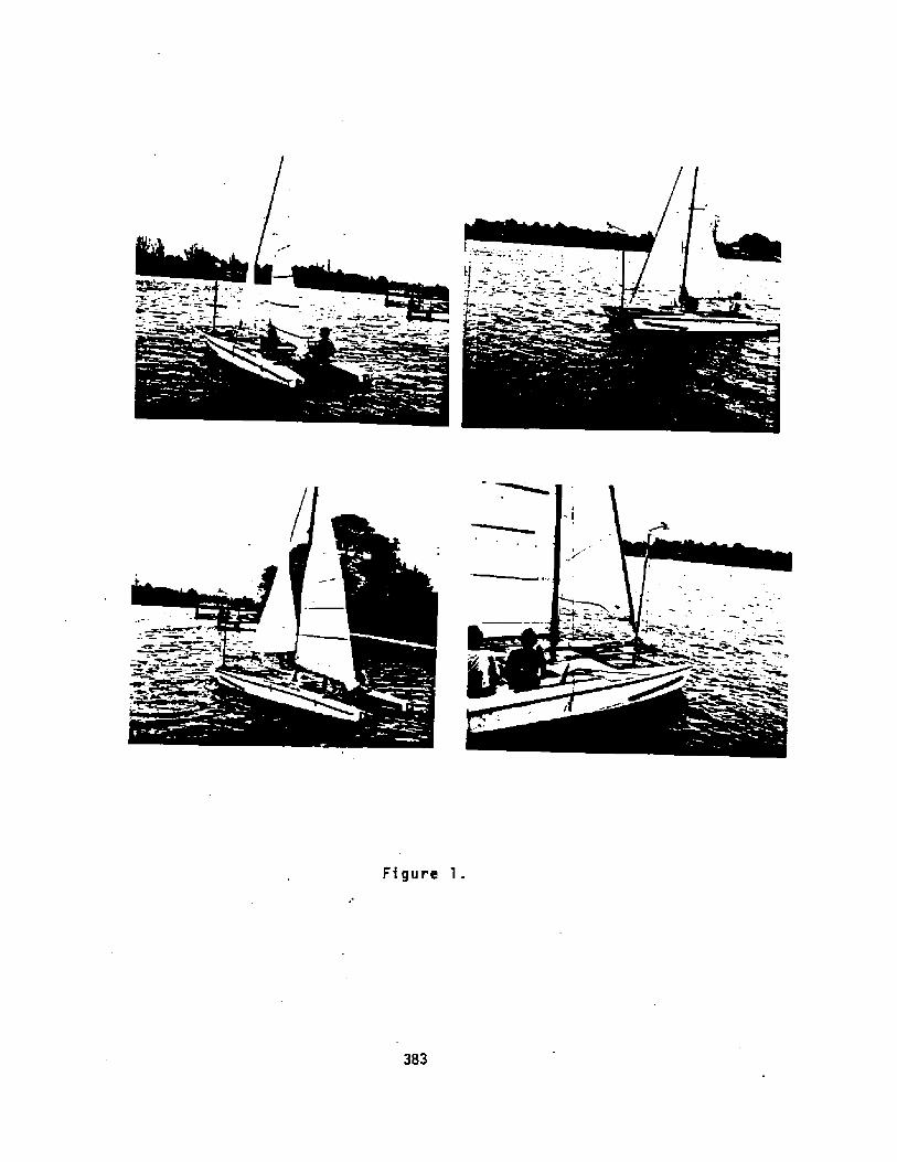
Figure l.
383

Figure 2.
Figure 3

lg
~l
jZ
X.
O
XC
'L0
la
taJ
J 4.ue C
+jm< z
2O
4'
e ZM td
0 D
K 4
4 +
Y
I


A387

DESIGN AND TESTING OF A FISHING VESSEL WITH COMBINEDMOTOR SAIL DRIVE FOR THE ARTISANAL SHALL SCALE FISHERY
OF SIERRA LEONE
K. LangeBundesforschungsanstalt fur Fischerei
Institut fur FangtechnikPalmaille 9
2000 Hamburg 50Federal Republic of Germany
Abstract:
Rising fuel prices during the l.ast tvelve years made it necessaryto reduce the fuel consumption of fishing vessels especiallyin developing countries. To replace gasoline outboard enginesused in the artisanal fishing fleet of Sierra Leone, by dieselinboard engines of considerably lover fuel consumption, majorchanges in design and construction of the traditional fishingcraf ts vere needed.An ll m V-bottom boat driven by a 30 HP diesel engine and astanding lug rig of 49 m' vas designed and tested. From theresults it can be seen that the nev type of fishing boat canbe used successfully in the small scale fishery of Sierra Leone.
Since 1980, the Fisheries Pilot Project Tombo FPPI'!, a Germandevelopment aid project of "Deutsche Gesellschaft fur Techni-sche Zusammenarbeit" GTZ!, is engaged in developing the artisanalsmall scale fishery i,n Tombo, Sierra Leone.
There are tvo main fields of activity in this project:
l. Improvment of the fishing technology of local fishermen.
2- Introduction of improved types of fishing boats.
Local traditional fishing crafts cover a vide range from small6m-dugouts driven by paddies to I8 m Ghana-type planked canoesdriven by gasoline outboard engines vith a pover up to40 HP�9 8 kv!.High fuel consumption, frequent repairs, and short life timemake these outboard engines one of the most expensive partsof the fishing equipment. All these problems could be solvedby introducing inboard diesel engines, but this cannot be donevithout major alterations in hull shape and constructional de-tails of the traditional canoes;
For these reasons, the FPPT started r.he design of a U-bottomboat..based on a t'ype vhich vas developed by the FAO in l974./1/

10.90 mLo.a.
D.
The body plan is given in Fig. l.
The boat ist driven by a Yanmar Diesel Engine 3 gH 30 of 30 HP�2,4kv!at 2600 rpm with a reduction gear of 2..21 : l. The 3 bladepropeller has a diameter of 460 mm and a pitch of 330 mm.
For the rig a standing Iug sail of 34 m' was chosen with anadditional jib of 15 m Fig. 2!.
A sail areadisplacement
7i
ve find Ts 3.73. This corresponds to values of Ts publishedby Timmermann !2/.Hast, boom, and yard were made out of bamboo giving highsr.rength at lov veight.
Speed tests vere performed in '~november 83 at the Yawri Bay,south of rhe Freetown peninsula. The boat's speed vas measuredby means of a Dutchman's log and a stop watch. To measure thevind speed, a cup anemometer vas available.
At full engine pover, a mean speed of 8 kts vas obtained at adisplacement of 5.1 rn'. With less displacement �.0 m'! thespeed increased to 8.6 kts. Speed measurements when sailingwere more difficult because of the low vinds prevailing duringthis time October - December! at the coast of Sierra Leone.Only few data could be obtained vhich should be completed attimes of better wind conditions. Sailing on a course broad reachto dovn wind,a boat's speed of v ~ 2.4 m/s �.6 kts! vas measur-ed at a vind speed of u ~ 5 m/s.
Rollingof theheightformula
tests were performed to check the initial stabilityboat. arith a rolling period of T~ 2.5 s, a metacentricof G'1 0. 56 � 0.65 m was calculated according to the
// .Q ~ C~ !7q P 389 /3/
The main dimensions of this new design are..
Length over all
Len g th bet ween pe r p en di cu 1 ar s
Beam moulded
Depth
Draught
Displacement
Calculating the sail area/displacement ratio
9.85 m
2,80 m
l. 10 m
0.60 m
6.60 m'

C, . 0.79 � 0.85B 2.34 m beam at waterline!
The last rest of this series was a one day fishing trip withlocal crew of 15. The crew experienced in using an 18 m out-
board powered canoe, had no problems to handle the gear, a tradi-tional ring net, aboard this new type of boat. Shooting andhauling the net was done in about the same time needed on atraditional Ghana-canoe for these operations.
Literature:
/1/ Gulbrandsen, 8. Fishing Boat Designs: 2V-Bottom Boats
FAG Fisheries Technical Paper No. 134Rome 1974
Vom Pfahlewer sum HotorkutterSc hr i f ten de r 1 un des f o r ac hungsan st a 1 tfgr Fischerei, Hamburg, Bd. 3Vestl iche Berliner Ver lagsgesel lschaf tHeenemann KC,Berlin 1957
/2/ Timaermann, G.:
Schif fbautechnisches Handbuch Bd.VEB Ve r la g Tec hn ikBerlin 1956
/3/ Henschke, M.:
Cfysra l. 'I-lotto@ Iong, gog1pyan
figwort Z, V IottOa 4Oet, Sail ~ rranqlsent
390

A PROGRESS REPORTWITH SPECIAL REFERENCE TO
A 30.5 M FISHING CATAMARAN
JOHN G. WALKERWALKER WINGSAIL SYSTEMS L IMITED
Hamble Lane, Hamble, Mants, S03 5JRSOUTHAMPTON �703! 454855
1. 1'ntr aduction and background
4n earlier paper presented to last gear ' s InternationalConference on Sai &bssisted Cosser Cf al Fishing Vessels inFlorida, USA in Nag 1988 gave the overall backgr ound to ourpro Ject, saic hist, or ical inf orsat,ion, and a braad over view ofwhat. we are trging to achieve wi th r espect, to coaaer cial cr af t ofall tgpes . Since then we have consolidated r at her effectivelg,abtained aaJor ventur.e capit,al funding and filled in sang af thegreg areas in our technological k nowledge. We have cospleted thedesign af a noeinal 100 sq. a. triplane thrust unit, whichcall the Nodule 2, and we ar e in t,he exciting earlg stages ofaanufacture of the fir st prototgpe.
2. Aerodgnaaics
'We decided that, even thaugh we had a verg great deal o<aeradgnasic inforaat.ion about bath single and triple aerafoilcoebi nati ans, we needed to build a 1/Lo scaLe wind tunnel testaadel of t.he act,ual Nodule 2 coaplete in everg detail. Thisquite large device was too big to fit inta the Nar khas tunnel atCaab ridge Univer s i tg Engineer ing Oepar taent, which we had used saef feet ivelg for aost of the ear lier runs ~ and we ther ef are sadearrangeaent.s to test, it, in the lar ge 2 Negawatt t4o. 0 wind tunnelat British Aer ospace at Fil ton neat Br istol. Bg an oddcoincide~ce this was where I had star ted sy aero-engineer ingcareer saic LS gears before.
The sadel is suspended in the convent,ional wag, Fig. 1,hari ton taLlg in the tunnel and li f ting downwards, with anupstreaa pra jecting sting linked to a ver tical wi r e controllingt,he aadel in angle as well as seasur ing the turning aoaentsabou t the aain suspension points. We have now - done threeseparate ser ies af tests at Filtan on this sodel with both zeroflap and full flap conditions, tail on and tail off and over awide range of Aegnolds nuabers, and feel that, we are getting tagr i ps ex t reae1 g weL 1 wi th the coop lex aerodg nasics o f hi ghperforsance triplanes.
The last tiae that ang wor k was done on t.r iplane aerodgnaaics inang ser ious wag was of course before the 1st Morld War, and wehave f ound t,hat to be an! g of sar ginal r elevance in 1984.
39l

have conf ir a»d that ae can control the tr iplan» verysatisfactorily in the CL ~ 8.3 ta 8.5 r ange, ace'opting of course
the tr iplane CL aax. vill inevitably b» laser than the CLobtainable an a single aeraf ail. This is because of
in ter f er ence between the three planes ~ vhich i n sac» mays i sbeneficial, delaying stall and ther efor'e isproving th» triatolerance of the device; in o ther r»spects being d»tr is»ntal, inthat the act ua1. overall thrust per sq. ~ . is sar ginally d»gr ad»d .Qg have al so s i eu 1 ated the s tora surv i val case cher e the vi ngsai 1
aaaathercack in ~inds up to 75 e p»r sec, sosething of theor der of iSO knats, neither daeaging itself nor putting thevessel into any kind af danger ardiscoefart. The results ar ea]] quite favourable, and na aodifications to the design as itprogr esses have been forced by aerodynasic constraints
FIG. 1.
392

3, Structures
The design of the triplane has waved ahead ver y str ongly in thewon ths since we were wri t,ing last Hay, and we now have a ver yclear idea of the best wag to build the type of str uctur eenvisaged. LJe have settled upon a standard 400 w» square r oiledhollow section steel central wast up the aiddle of the centrewing, carr ging the entir e bending aowent of the sailset, andaounting the entire triplane down onto a standar d off-the-shelfslewing ring type rotating bear ing, ver y siwilar to the oneswhich give extreselg reliable service underneath saall andwediue-sized earth waver s and diggers. This central spar is cladwi th streawlined reinforced plastic aerodynawic sur faces, andsupports a pair of cross-ar s structures which carr g the outerwings r Fig. 2.
The outer wings are of identical pr ofile to the centr al wing, but,have a wuch lighter spar structur e, since they only have tasupp'art their own bending aowents and cowaunicate their thrustonto the centr al spar thr ough the cross-ares. Hinged onto thesethree wings, the outer ones of which ar e set slightlg forward in
sywwetl ical staggel ed conf igur ation, so as to tt'ia the nettcentre of pr essur e to a suitable position, are three flaps.These are all very nearlg identical, although the centr e one hasslight 1 g st ronger hinge structures which r eact the hydraulicloads f roe the hydr aulic actuating cglinders and also dr ivepushrods which cause t,he outer flaps to wove in unison with t,hecentre flap. Qe have two hgdraulic cylinder s operating thecent,r e flap working in har ness, arranged so that in t,he event ofone failing due to a burst hose or a leaky seal t,he other willstill be able to carry the load.
Supported downstreas of this high thrust triplane is the tail'vane, which is full height and is slightly longer in chord thanei ther the wain wing or the f lap. Zt is again supported at twopoints by t.riangulated br acing struts and is again operated bytwo hgdr aulic r aws for safety and reliability, even though theyare considerably swaller in sixe and thrust rating than the oneswhich operate the wain flaps
The general structur e of the triplane, apar t frow the steelcen tral spar which we have air eadg aen tie ned, consists of arein far@ed plastics 0-box leading edge with woulded ribs leadingbach fr oa the 0-box to a trailing edge in a fairlg conventionalai rcraf t st yle of const ruct i on, wi th all the 1 ight lg loadedpanels covered . in a specialist Awerican airer af t coveringwaterial called Cecqnite. This is a heat shrinking self priaedwatel ial and we expect i't to give ex'treacly 94od pef f oreance atwoderate cost, with the ease of r epair of winor r ips and defectsusing readily available on the spot eethads.
393

394

Ahead af the triplane on a short stub painting upstr eaa f roe thecentral steel sain spar is a balance weight which provides staticand dy nas ic balance f or the rig as i t p ivats and weather coc k son its f ree bearing, using a balancing pr inciple pioneered byUtne in Horway in the late i980's. Earlier in the pr eject webelieved that we would need an "ups tr eas stalling vane" which wasshown an our earlier illustrations and photogr aphs. This isbecause when you fully stall this type of triplane with adawnstreas tailvane the vane finds itself in a low energy eddyingwake f roe the central sai 1 . In the wind tunnel we had f aund thata very slight and sirror isageable asyssetry was perfect.lycapable of giving us reliable in-stall drag soaents as soan asthe peak of the li f t cur ve was passed, and we have theref areelisinated, at least fras this particular design, the upstreass tal 1 i ng van».
Coaputer Systrs
The coaputer systes is necessary far any econoey device such asour own because for a vessel to work, whether she be a tanker ar'a fishing boat, she aust have her cr ew available to do the workfor which they ar e tr ained and needed. lf we instal onto suchvessels an econaay device which incr eases the crew laading,either in teras of over tiae paysents or actual extra crewaesber s, then we are taking away at one sweep such o f thebenef i t, which we ar e able to br ing to the owner and operatar o fthe craf t by f itting the econoey device in the f ir st place.
Me therefore equip the wingsail with a 8 position switch far "On,4head"; "Of f, locked and isolated" and "On, *stern" and 8 lights,one being green for "all systess an and operating"; one beingasbar for "a fault has occurred but redundancy is caping and theunit is still in oper ation"; and a r ed light indicating thatthere is a fault present which the redundancy systes has not beenable t.o correct snd that there f ore the sys tee been shu t down,all vanes brought ta central, and is weather cocking with ssalldrag and no cross wind force.
The coapu ter is based upan the well known Zilog Z80 chip, sadeeast faaous perhaps by Sir Clive Sinclair with his ubiquitousr ange of casputers far the everyaan. fig. 3. The unit takesinf or sation fr oa several trs nsducers. It receives infor sationfroa a vane aounted on an instrusent strut, extending upstreae ofthe unit, as to the angle af the wind to the centre axis of thewingsai 1, and it takes inf or sat ion f ros a potentioseter whichr eads the angle o f the sailset to the centre line of the ship .Fr oa those taro inputs the cosputer can know at all tines bathwhat the angle of the appar ent wind t o the sailset is and whatthe angle of the apparent wind to the vessel centreline is. Prosthe angle of the apparent wind ta the vessel centreline thecosputer decides whether ta set the unit inta ane of four sades:�
395

Zf the wind is coaing fros within RO deg. either sidet,he vessel ' s cent, reline f roe ahead, the cospu ter kno~s
that there can be no benefit, obtained bg switching t,he sailset,on and it therefore either saintains the weather cockedstate, or it brings it. te the weather cocked state if thiscircuast,ance has just arisen.
Zf the appar ent wind direction is between 8 and 60 deg. tothe vessel's cent reline, the ceaputer knows autosaticallgupon which t.ack th» vessel is and it sets the sailset .upcorrectly for that tack and for optisus lift/dr ag ratio.
gf the wind is between 40 and 185 deg. to the vessel ' scentr elaine the coepu ter sets sax i sue thrust.
FIG. 3.
I f the wind is between 185 and 180 deg . the co op u terstalls the r ig to produce the saxiaus dr ag and the worst lif tdrag ratio that it can achieve.
coaputer also receives inforaation fr oa an anesoseter whichi t whether the wind is too low to provide sign i f i can t,
energy, at 5 s/sec. or appr oxiaatelg 9 knots; whet,her i t is inwor king range of 5 to 20 e/sec.; and whether it. is in the
ever RO a/sec. range, where ther s is statisticallg very littleene r gg available on a gear round basis f roe these higher ~inds .It, therefore, far a fur ther 5 S/sec., platforsS the Outputthr urust, and af ter 25 a/sec. it reduces the out,put thrust down to
bg going to aode l
396

Sa we have sade i which is the wind ahead case, soda 2 far closehauled an either tack, sade 8 for reaching and
broad reaching an either tack and sade 4 stalled, the spinnakermade, for running downwind.
The next set of activities which the caaputer perforas is theaanitaring of the relative health af the various iteas in thesystea, so as to check whether the electrics, hydraulics,st,ructur e or coaputer are functianing as they should. Zn soaecases there is available redundancy and t,he unit aay stillcontinue in the presence o f a fa,u]t either at full ar reducedef f iciency. Xn the event of a fault which cannat be caped withby redundancy the coaputer wil,l r stum all vance and flaps tocentral, close everything down electrically, spring laaded pinslacking all in-line for safe lang-tera weathercocking,
Lfe at f ir'st thought that al 1 t,his was going t a 'be Qu 5 t e adifficult set af probleas for a coaputer to solve. However ~ dueto the advanced state of knowledge in the aodern aicra coaputerfield, we have discovered that a s iaple low cast unit can be sadeup»«h «11 perfor a all of these funct,ions, and which wouldprabably have spare tiae to play Space Xnvaders in betweenwhiles, if it felt so inclined.
5. Hydr aulic Systea
The vanes and flaps are, all eaved fros the centr al pasitions tatheir oper ating positions and back again, as we have already~ entioned, by aodestlg sized hydraulic cylinders, soae singleacting with spr ing extension for lacking purpases, and saaedouble acting . These are al 1 control led by a set o f solenoidoperated spool valves arranged in a fairly coapl icat.ed cir'cuitdesigned ta provide fail safety.
The logic of the circuit has been sketched aut brief Ly above inthe section on the coapu ter sye tea . The sgs tee receives a set ofiapulses and coaaands f roe the coaputer sgstea: � for exaaple whenstar ting up wi th the wind between PO and 60 deg . on the star boardbaw the hydr aulic aotor provides a pressure of BOO bar,appr oxiaately 3000 p- s i .. char ging up 2 saall hydr aulicaccuaulator s The sgstaa will then hydraulically withdraw allthe lacking pins froa the flap and vane sgsteas and push bathflap and vane over to their full angles of actian. Then it willall ow re-entry of the f lap locking pins to hold the flaps at ful 1extension, and respond t,o the coeaands af the coaputer incontr oiling the vane so ss to aaintain the aptiaua lif tidragratio of the sain tr iplane, with CL about 1.8.
1' f the wind direction r elative to the centre line of the shiqchanges inta the 60 � 1@ deg - sector, the caapu ter causes thetail vane to look for a differ ent ope4 ating position ~ seeking nawfor aaxiaua thrust.
397

6. Znstailation an 80.5s Cata«ar an fishing craft
We ar e very interested indeed in fitting an ear ly standar dNodule R' unit to an appraxisately 80.5 «catasar an fishing craf t .Fig.
Such a vessel wauld have about, 14 setr es af boas, and provide anexcellent stable wor king platfar s with large deck ar ea forhandling nets and catches, a high spr int speed for getting to andfr o« fishing grounds with «iniaus loss af tiae, while capable ofco«pletely silent and vibr ationless tr awling and line hauling,We are convinced that a quiet fishing boat aust be likelycatch sor e fish than a noisy and vibr «ting fishing baat beatingthe wat«r with propeXlors, although we should of course be ver yhappy to receive the opinions of the experts on this sub ject.The installation should present na particular prabless: � we havetaken a standard "Fjellstrand" design as used extensively aroundthe Scandinavian caast and as ail r ig ser vice bast, ~ in the NorthSea, and si«ply widened it by the addition of a par aII«X sect,ionto take the beas aut fra«appr ox. g « to approx. i4 ~ .We believe that this would nat in any way degr ade the seakeepingand other char «cter i sties of the vessel as a power craf t, befitted with twin diesel engines and fully feather ing contr ollablepi tch pr op«i lor's Ca systes which is aire«dy well pr oven in thisclass of vessel i,n any case! . hh believe that she aef llrepr «sent ~ either in ste«I or in welded light alloy a practicaIand cost effecti.ve vessel for sedius offshor ~ fishing purposes.We shall be ver y happy indeed to take this proposal, which at the«asent is only at the schese design stage, through to a stage offuXI analysis with any ser iously interest«d par'ties.Zf the wind goes r ound to aster n, then the vane wiXI extend tafull angle to .stall the «ain sail«et.
At any t ise if there is a fault, or if the wind drops too low ~ ori f i t r ises too high, then the elect,r ical power to t he hydraulicsyste« is cut, «ain syste«pressur e dr ops and hydr aulic reser vairpr essur e is used to pull oot the flap lock pins, r eturn flaps andvane to centre, finally allowing the r ~ntry of flap and vanepins.
Ail this «est be co«pl et ely auto«atic since irr star «conditionsthe last thing needed would be a husan input to the systes,especially on a ssall cr af t.
Secause of the way that, the syste«has been optisised, all thevalves and cosponents ar e s«all, at inter naticrnal CETOP 3 size,wi th I/8 inch bore piping in «est cases. The r «pair andr epLacesent of el««ents which «ay have failed is therefore a«odes t and econ a«ical tas k,
398

399

7. Suswarg
a e at the wowent building, as ae have said, the firstpro to t g pe Ho du le 8, and bg the t i we that thi s paper i s prese n ted
wain tr iplane sing elewents v5.11 be cowplete and the firstging r ibs ~ill be cowing through frow the sub contractors readyfor installation and fabr ic cover ing. Figs 5 and 6.
Qowpletion and f irst tris ls are scheduled for Hid-Septewber 1984,and e hope that bg that t iwe we shall have wade not one bu t wangcontacts awong people who either attend The InternatianalC;onference or who read the pr oceedings, so that i f our pr oductscould wake a cost ef fective contribution to their activities,then ue shall not siss any oppor tunitg to put forward pr oposals,have discussions, and eventually negotiate contracts.
FIG. 6.FIG. S.
400

E AS I L Y HANDLED R I GS FOR
FISHING VESSEL SAIL ASSIST
MacLear & Harris, Inc.28 Hest 44 Street
New York, N,Y. 10036
ABSTRACT
Once one has successfully mechanized sai 1 handling it is relatively easy toautomate it electronically.
Luff roller-furling of soft sails is the best way to set, reef and fur 1sails. A crane-boom whose rotation is cantilever controlled that is not freepivoting as all booms have been! is the best way to sheet sails. Crane-boomsfree the rails and deck and are safe and very easy to handle.
INTRODUCTION
If the average fisherman is asked: do you want sails on your fi shi ng boatmost will answer "No! " . Their negative answer is because they have never seena truly well equipped modern sail assisted fishing boat . They do not- realizehow extremely little sail handling would be required. The truth is that noneyet exist although ri ght now such a vessel could be built� . This paper triesto explain some important rig, sai lplan, and deck machinery features of such asuper-modern fishing vessel.
ADVANTAGES
A fi shi ng vessel with sails would roll much less and thus could catchmore fish in higher sea states. It could stay out in worse weather and bemore comfortable and less tiring for the crew. In addition to these multipleadvantages, it would save fuel and often travel faster and thus be a con-siderably better money earner.
MECHANIZED OR AUTOMATED
Mechanized sai-1 handling is the first step towards automated sailhandling. Once sails are mechanized it is relatively easy to automate themif one wishes. Mhether or not to automate is primarily a consideration ofequipment costs and maintenance versus a small amount of labor saving andmedi um amount of judgement obviati ng.

RIG AND SAIL CONFIGURATION
The basic sail system that I favor is a luff roller-furling sail whoseclew is controlled by a crane-boom which may also be called a cant1levered-boom, davit-boom, or controlled-boom. As the name implies, this device 1s along armed crane whose rotation is controlled at 1ts foot or forward end sothat it can never flog or get out of control. The clew of the sail is con-trOlled by a "Sheet-Outhaul" which Can be a Single part Or a multiple parttackle that goes from the clew to the tip of the boom davit. There are thusno sheets to pay out and no sheets to gather in when one tacks or jibes, forone simple rotates the crane by push botton or turning a dial to the newsetting. Such a device obviates overlapping sai ls such as genoas wh1ch reallyhave very little place on a working sailboat because they are, fi rst: labor1ntensive, second: dangerous, and third: cause a clutter.
MAINSAILS AND MIllENS
Th1s writer believes that it is very important that roller mainsails andm1zzens roll up 1n the open rather than rolling into a cavity in the mast.The absence of lips and cavities in the mast assures reduced friction and wearand obviates the possibility of jamming in the mast slot or cavity since theydo not exist in my systems. The rolled up sail is a few inches abaft themast. and never out of sight or out of reach.
%ST AND RIGGING
The mast may e1ther be cantilevered or stayed. Cantilevering permitslowering the mast 1n tabernacles if it is important to have this capabilitybecause of 11mited air-draft.
CARGO AND 80AT HANDLING
It should be noted that a really good and powerful crane can servemultiple purposes in addition to trimming the sails. Mhile under power orwhile in harbor, such a crane can make substantial lifts from the water orfrom the shore. It can thus on and off-load gear or cargo of all kinds, andboats of any size that might. be desir ed.
SAILS
Sails would be soft and made of the best sailcloth material availableand they could be single ply or mult1ple ply in order to achieve the desiredstr4.ngth.
Sails are tr1angular and can. be of jib, staysai 1, mainsail, or mizzenconfiguration.
Ideally all Sai lS on a given vessel m1ght be the same SiZe SO that thecraft can carry a spare on board or shore based one for quick replacement whennecessary.

ASPECT RATIO
Since the sails that are trimmed by a crane-boom cannot overlap a mast. themost convenient way of having suffic1ent sail area is to design and spec1fy atall mast or masts from the outset.
ROLLER STAY
It is our practice to use stainless steel tubing with a stainlesssteel groove to support and roll up sails. Aluminum is considered much lesssuitable because of its softness, which cannot resi st scratches, or deepscoring which create stress raisers . Because of aluminum 's low Young 'sModulus of ten million compared to sta1nless steel's thi rty million, analuminum tube will either stretch or twist more per given tens1on or torquethan stainless steel. Such a sta1nless steel tube stay is ideally confi guredto take torque, as well as tension. It can be shipped in 30 foot lengths andjoined together by pinned spigots as is the practice of the British Rotomarinewhen they are supply1ng roller furling gear to larger vessels. We haveemployed more than si xteen such units and we have found them to be sound anddurable on ocean going vessels.
We do not consider a comb1nation of one by nineteen wire with sections ofaluminum extrusion outside separated by plastic sleeves durable enough or ofsufficient ly long life. Two of these materials aluminum and plastic! are toosoft and 1n combination steel and aluminum inv1te corrosion, particularly inthe tropics. The above admittedly has a price advantage for pleasure craftbut lacks the durability requ1red by workboats, that have along season, harduse and require mi nimum overhaul time.
THE CRANE BOOM
The crane boom can be actuated at its base by cogged gears, wormgear s, hydraulic rack and pinion and various other systems. It could alsobe controlled by timing belt, roller chain, or cable and quadrant. Since itis a question of controlled rotation any device simi lar to steeri ng gear canbe applied to control the rotation of the vertical post on which the craneboom rotates. Actually, most crane technology and best practice is applicableto this fai rly standard crane application.
ADVANTAGES OF CRANE BOOM
In addition to the already ment1oned advantages of the crane boom, this typeof sheet control greatly reduces the need for sheet winches, since a multiplepart tackle of say four parts can be used, this means that a winch of onequarter of the power will do the job. Usually a headsai 1 requires two sheetsand two winches whereas the crane-boom can have one light winch of one eighththe cost of the two bigger winches.
403
This is of particular advantage to a coenercial fishing boat for 1t frees thedecks of headsail sheet w1nches and the lines at the rail that cross the deckas in older sai 1 trimming systems .
SAFETY FEATURE
Loose-footed luff roller-furl1ng ji bs usually have a hi gh clew to minimizere-leading the sheet as the clew moves forward during reef1ng. This hi gh clewcreates a dangerous flogging sheet problem. On the davit-boom the sheet isvery short and does not flog since it is never loose. As r eefing commencesthe lead slides forward automatically thus keeping the sheet lead relativelyshort and free from flogging and be1ng a danger to the crew. The long leadfrom a high clew to the rail of a normal completely loose footed sail createsa true hazard and people's heads and other parts have been flogged by theseh1gh clewed jib sheets. I have seen a man with glasses get a bad cut acrossthe face as his glasses were r1pped off h1m by a flogging sheet and it couldhave been considerably worse. I am sure that this hazard repeats itself agreat many times per year as h1gh clewed jibs are becom1ng more and morepopular for the above named reasons.
Thus the benef1ts accrued by crane-boom 1nclude: lower costs, because ofsubstantially reduced number and power of winches, much less cluttered decks,safety from flogging sheets, substantial labor saving, and mechanization whichis easily automated.
COSTS
In fairness it should be admitted and stated that the crane boom is itselfexpensive, requires deck re1nforcing and takes up some space on deck a fewfeet aft of the mast or stay that it serves.
It is hard to say whether the initial cost of a crane boom cancels out thecost of the multiple sheet winches needed for a loose-footed headsail but Iwould estimate that they fairly well cancel each other out. On the otherhand, there can be no doubt that a cantilevered boom would quickly amortizeits initial costs and maintenance because of the substant1al labor saving.
aREmTHROUGH I~ SAIL HA~pi.lNG
The crane boom is surely the one single greatest contributions to conwnercialsail since luff roller-furling and reef1ng which has been progressing for over~O years. Crane-booms are still extremely rare but 1n this writer's estima-tion they are very promis1ng and they have an excellent future. Me should beseeing a great many more crane-booms on larger vessels. They are so con-venient and safe that they will probably also be used on moderate si zed, andlarge yachts to minimize crew requirements. The idea of fixing a point 1nspace by the tip of a crane is certainly not new, but up to this point it wasconsidered too expensive and too much weight compared to restricting swing bya sheet at the after end of booms.

The main reason that this author recommends cranes now is that labor isexpensive and a swinging boom free pivoting at this forward end is dangerousand labor intensive to contro] by conventional sheet, not to mention foreguys,boom vang, and topping ]ifts.
CONCLUSION
A sail assisted f1shing boat that is equipped with external luff rpller-furling sails and crane booms wou]d be so easy tp handle that fishermen wouldaccept them. They would soon see the great anti rolling feature of sail andthe 1ncrease profit from fue] saving.
Ne propose to offer commercial fishermen air foils that appear and disappearby push-button and that are oriented by turn1ng a dial-
Hand]1ng sai] of th1s kind would be so simple that one would not need to gofurther, but making the ent1re system automatic has already been done by theJapanese and is relatively easily accomplished if one desi res to automateelectronically.
Such a mechanized sail handling vessel, be she automated or not, wouldeventually be popular with the fisermen and would more importantly be a moreprofitab]e craft. She could catch more f1sh in worse sea conditions and havefuel as well.
It is this writers opinion that if one good one were bui lt, that many morewould follow.!

WRITTEN C'ONTRI BUT ION
Gurina r C. F. As ker
It is evident from the number of papers on this subject thatthe interest is considerable, but the acceptance for commer-c'al operations with wind-assist systems has been slow.
Tnis is partly due to the fact that the econo. 'c benefits tomost operators are marginal today.
he must hovever be ready with fully developed systems, which arepractical and easy to operate, vhen the oil prices again villrise. The increased costs of drilling and ext.action vill soonneccessitate higher oil prices.
2Cth century technology is available to apply new practicalte "hnioues to utiliae the oldest method of ship propulsion, whichvas oars and «<nd power. Human oar power plus «4nd power vasthe first motor sailer.
A Cnd-assist system saves fuel, but equally important it pro-vides the fishermen with a stabler platform from which to work.The reduced rolling and pitching means less energy lost in pro-ceeding through the seas and this results 'n more fuel savings.
After development and design of several different approaches,vh' ch included rotor thrusters as well as wing-sails I have be-co;.e convinced that for smaller vessels the combination of a rollerfurled Genoa side sail combined «4th a small permanently installed«Cng-sail provides a practical means of wind-assist system.
Fo. Larger co~ercial vessels, such as general cargo ships andt~-.k ships my patented "Twin-Rotor" wind-assist system would bepreferable, because of reduced overall siLe. Tais system is de-scribed in US Patent '4.398,895, «hich issued Aug~st 16. 198$.
Tre "Flexi-Sail" «<ng-sail was first tried in a small lake vitha radio controlled 3 foot long model sho«~ in figure 1.
Then my 24 foot Ulrichsen Sea skiff vas eouipped «4th a 36 ft 2
«<.-.g-sail after two parallel plate keels and a sailboat type rudderhad been added. The metacentric height «as unchanged and also thedi placement, because a 660 LB 100HP gas engine was exchanged fora ' olvo-Penta 2! Hp diesel of approximately half the weight. TheVo vo engine vas kindly furnished by Volvo-Ferta.

..".e exper'ence «qth the 36' f~~y rota a'ole «<ng-sail systemis that the hinged gib-mil to the ~n ~ng-sail enables theboat to pcint higher than «hat is possible «<th a soft sa 1 ofequal area. The «gng-sail is easy to control and can, because of'..e modest sail area, remain mounted in all kinds of «cather,
T«same boat «4th a flying bridge installed mou3.d have lesss.ability and considerably higher drag.
iolling and pitching «as reduced and the boat goes through savesmor'e smoothly-, in fact higher speed can be maintained in choppyseas «4thout aiscomfort compared to a boat «ithout «'ind-assistsystem. This «as evidenced by observing the inclinometer onboard.
/it 5 to 6 knots boat speed in a 20 to 25 knot «Cnd speed the fuelsaving approx1mated 50$ ~th the engine delivering about 0.5 to 5>2 and the propeller shaft running yt 40503pY. Zt is impossible to ob-tain such fuel sa~gs ~~ a g fH ~g s&l frma And proyulsicneffort alone Therefore the energy saving frosL smoother travel throughthe seas accounts for the difference. This has also been observedby the Japanese in comparing identical vessels, @here one «' as eouipped«4th <rind-assist sytem and the other ship «as identical, but «<thoutsails,
Figure l.
3 foot Long «mg-sail equipped test model

Figure 2
24 foot Sea S kiff equi.pped with "Fl xi-e -Sail" wing-sail.
After testa a with the wing-sail andthe baat shown in fi 2
also "Twin-Rotor" systems angure 2, I have developed the a r
g vessels and other llof fu s and a permanent wing--sail system.
For transport to and fram fram fishing graunds both the
as fast with the Genoa and the win -aaie standard main sail and !ib ojf ababout 10$ larger sail area.
Figure 3 showss a 35 foot test boat with which
the wind-assist s
s a which I will conduct testo determine the inter
te th id ail inbout engine power.
various combinatians with
In figure 0iI show the relative position between ther pressure decreases in thr
he wing- sail and the ai ~dward side afee ste s.
g-
h g l an lowestan l on the lee side of theer
408

for ppassaga.«'ing-sail aloneroe fisni g ~steadying,
li-'pltilr ~ Laai L~a ~
Lr. tali La a'apiaaaalaa '.
r Laa tLtg lail La . trial La La, l ~ 'L ~ attar rlr It«a alali araaaaaia 1a, 1 ' ll 1 ~ a at«a par tali laiLLA Al.aa
1 al aaa L 1 ~ '1, 'fa 192 1 ~ Ll ~ 1r ICCt
a ~ ca

Th<nL 117
Sin le RotorR otor
LI' i i 11 + h
100 104Vm4
i frCCI%909
~Fi r~e11 4
9991$
IIC'I 9 'IQ I. t 19 ~ 19 ICCl ICtt4
TrZs testboat is equipped with a sw4ng keel and can be operatedas a rotor sailer with the keel up and as a full rigged sailings."'p with the keel down.
One should also keep in mind that for commercial use motor sglingis safe and makes sense. 3 Hp of engine power added to 210 ft ofsail is eq+ to a sail area of some 330 ft for this test boat.Kith $3Q ft. of sails this boat is unsafe in winds over 8 m/s, butwou2.d be safe and fast with 3 HP or more plus the wing-sail andthe Genoa, which will furl as determined by wind strength. The sidedrift is also reduced by the addition of engine power.
L Fisheries Znspection Vessel of 150 feet length shown in figure 5is large enough to take advantage of the reduced overall size oft?'.e "Twin-Rotor" system, which Z have also tested an the Sea Skiffshown in figure 2.
Zn canclusian tray Z want to mention that- we have seen many differentaporaaches to wind-assist systems. Zt is apparent that quite a fewresearchers vork independently without much knowledge of each other.
The upcoming 4w,D-TiCZ meeting in ~985 in Southamptan, england, isa step in the right direction.
410
Zf ve all work together- Researchers, Designers, Operators, Financpersar." Fishermen in at least exchange information, we will be able toreduce net cost of the catches.

PART VI
INTERNATIONAL AND SMALL-SCALE FISHERIES

I PQIIi~irfpAp [ pN QF 0 PE. 'T f C fAI =O'Ql'I Gt 1 ~SI;JEST AFFI.!".i PGPT8
John r. Sa: nsbur y
Fl or i da Inst! tute of Technology
A+~tr~ct
f!'ma
u
I OC
I n f~ri~l t I !!In
and of ten the cr i -., = a I 'ing veSSel 'S Oper a-. I On ~and earnings fr om cat
concfi t i on», ye'. te»»e ' wh i Ch haS pr =-.I ed
par t I cu 1 ar cour,r I w;; bE
Qperat i onal economi cs i s always impar tan t.factor determining prof i tabi1 i ty of a f i»hCevel oping Countries both operating costssal es can vary wi del y as a resu! t of 1 ocaluncommon f or developer s to assume that a vpr of! tabl e i n a f i sherv when work i ng fr om~qual 1 y»ucces»ful when based e'I sewhere.
eoI'>hi i i e cons! derat! ons other than pure pr of i tabi 1 i ty may be i nve ~ g ~ the need to prov i de for f i sh prote in needs of a popu at iobi i ous1 y necessary that any vesse 1 se 1 ectect be appropr i atefac! I! t i es and serv ices avai ', able 1oca'. 1y, and have theI and f ish at an acceptabl e cost wi th,n the particular si tuat:some countries the need i s cri t ical that thi s be acnie.ed atposs! b I e cost w! th the 1 east poss i bl e dr.ai n on f are i on e::cNanor ! n orcler to boost fore i gn cur rency resource
or t
on.I owe'
n»~o»
d! f f erences whi ch can ar i se, ven among ne i ohbour ' ngwi th ' n the same area and work' i ng on essent i al 1 y the same
cfemonstrated by cons! er ing the f.'est Afr i can coursenegal . The Gamb i a and 8uinea Bi ssau, see Fi g, 1 xF i g..'.Pef erence 1! and the case of a» mi 1 ar .Iesse1 work i ng9r ' nc i pa'I f! ning por ts of Qakar, Banvul and Bi ssau.
c urI,I lef ' cn IVII
z» rfpI ~of trie i r
pun tr v Fi slier i es 8 i tuat i or s
in Fi g.1, the threeg. Nor tl.. and 1640 deg, to
f !sheries of the blestoffshore.
t haports are»i tuated between 11 deg.18-30 4Jest and have direct acces» toAfr i can cont incr tal shel f and:he -e I Rg I c
not been uncommon among some -eve 1 oper s to as»umeI » prof i tab'I e i n a f i shery, when work ing from a par . c
country an port, wi 1 1 orove equal ly successfu' when operate=di f f er en t country or por t. There can however be a cons i der ab' edi f fer ence in operat ing costs for the same vesse'I when wor', r ~such a si tuat i on, and thi s di f f er ence can have a markeci effectuni t cost of 'I anding a par t icul-ar spec i e=. Pr edi cted cost . fosim~ 1 ar ve»sel wor K ing from three Rest Afr i can ports are use:prOv i de an exampl e Of how di fferenCeS in Operat irg, Crew,:.-!dir >estment expenses i ead to considerable change in 1 anded un! ..
directed fishery ~

Bene a, i = a net f i sh expor ting nat-'on, ~,'matnt -~ high '> iue sineci asEur ope.-, Ref . 1. wi th the i ndustr i al, zed sec tor c=n i .t; ng of o. =-.-trawl ers, shr impers, purse se iners., g i 1'inc t ter and hancll ner Ref .2> ~ A majOr new .and expandabl e? f i Sh ~ ng pOr t at Dakar, i S wesi tuated, and i = a cen ter for al 1 ser v i ces needed by a s == h, s t . c a?f i shi no f 1 ee t, w i th da i 1 y air serv i ce to European, US., Af-.. can,South Amer i can and Easter n dest i nat i ons. and wor 1 dwi de con .a i r,=--serv i ces by sea. Both Seneoal ese and Fore i gn vessel s uncer1 and i n Dakar, and there i s an energe t i c pr i vate sec tor nvo': .'erne-the industry, with a free market situation prevailing. Fi=-' noAgreements are in force wnich allow Senega:ese vesse == to fish "a!of The Gambi.a and Guinea Bissau.
The Gamb i a Ref . I ! i s Si tuated arOund a, 1 arge r i Ver, w i th =enega',the North, South and East. The country has v irtual 1 y nc inciust, i alf i shing sector: several forei gn purse s.e iners land f sh for exportGhana, and a local pr ivate company i s commenc ing the use of vessell arger than the tradi t i onal canoes to further devel oe a success fu'.expor t trade to Eur ope. The por t of Banjul i s conven i ent 1 y = i tuateofor direct access to the offshore f i shing grounds, wi th -ac i 1 i t i eslanding fish available; ice and processing plant capacity i n=t f: lutilized, vessel maintenance and repaiir facilities are s tuatedPort. with other services and supplies available locally or from iiak ar<30 mins. by ai r, and some 2~3 hours by r oad! . Pr i iate Sec tori nvol vement in the i ndustry i s deve I op i ng, and publ i c sec torelec 1 i hing, w i th a f ree market s i tuat i on prevai 1 ing. 4 Rec i proc .1Fi shing agreement i s in force al 1 owing access to =eneqal ese wate. =.
Bi ssau, the pr inc i pal por t of Guinea Bi ssau Ref .1! is si '. atedshort distance up the mouth of a 1 arge river, and an offshore orou.i s'I ands must be c 1 eared i n or der to reach tr aw1 i ng grounds.f i Sh 1 andi ngs, frOm the InduStr i al i Zed Sec tOr ar i Se from a mien terpr i se company w i th USSR> "Estre! 1 o do Mar" wh i cW oper a . ==sever~i vessel s under the coun tr y s fl ag. Othe~ mi xe corrpan i e ar =.1 cnqer oper at ing at sea, al though a sma I 1 pr i vate sector comp an.-pr epar ing to expand to offshore f i shi ng. Fi sh ur. 1 oadino f a- i 1 i t i esare avai 1 abl e and an extensive new freez i ngr'col d store f ac i 1 I tycompl etc�. Vessel maintenance and serv i ce f ac i i i t i es are avai 1 abl eboth the publ i c rmi 1 i tary! and pr i vate sec tor restr i c ted' al thou=hspec i al i zed serv i ces and supp l i es must be imported. Ther e are da.i 1 yfl i ght connect i ons by propel l er airer af t to Dakar and sever a'- '.:mesweek by set to Portugal and USSR. Fi sh pr i ces are establ i «heo by '- ieGovernment as are the pr i ces of fuel rat i oned'> and. other supp!:i es al 1 impor ted! wh i ch are of ten di ft i cul t to obta i n or unava i 1 abl e.; '-epr esence of offshor e oil resources is expected to ease ooth fuelimpor t problems in due cour se. *n extensi ve ser i es of f i sh' ngagreements are in ef feet wi th some 15 countr i es including Senega' ~EEC, USSR, Al ger i a and Portugal: pr i vate sector act «~i t i es arebecoming important i n many areas of the e conomy.
C m nent of the Tot 1 CostyT n of Landin P rticul ar S e- i es
In order to make a real i st i c cost compar i son i t i s necessary to ha redata avai lab'1 e for the oper at i on of the same vessel type fr om thethree por ts of DaVar, Baneful and B i ssau. Reference I pr ov i des
413

L- a 'Ti > c
x ~
atesee n
fo-
Pr te 1 andin s:The anal ysi s ai so assumed a;otal capac: ty o+tons f or th'e v esse 1, and that f i sh i ng con t i nued un t i 1 tu 1 I . The num e'
days f i shing oer year and Per trip ther efore varied wi thwi th the total days at sea Fishing and on passage etc.:
225 per year for vessel s work ing fram Bi ssau and Ban,ul, anoper year from Dakar; th i s di ff erence was to al 1 aw for increasedt ime and more di ff icul t working condi t i ons ant i c i pated from thosepor ts. A summary of the projec ted 1 andings i s ~ho~n in Tabl e! extr acted from Tabl e 1,8.1 of' Ref .1?, whi ch ref 1 ec t the d, f far.n=ein steaming t ime and hence tr i p length necessary to '1 and 60 tons.'tr . =
Data fram Refer ence 5 indi cated that when under tak ing a directedf i shery for Bal i stes, hi gh value food f i sh aprax imated 8'i o+catch, and this was included in the analysis.
V 1 r at in r ts: In cal cul at in' vessel operat ino Costs. oat=.f i ved and vari abl e casts were added to give the total annus! ever a' ' - �.cost. The fol'1owing were included;
Fuel: consumption estimated fram Fig.2, compiled tram Aver ageconsumption figures given in Reference 3?; Prices: Bissa : +I.>0."='<gal; Banj ul i 41 .22''USgal; Dakar i sQ .77''USgal .
Oi I s; B~ of fuel cost <ref .3.:
Gear repair 5 Rep1 acement: Reference4JeSt Af r i Can trawl erS aS 457. 000 f Orper year. This figure was adjusted forto g i ve Assumed Cast ~ s57,000 x No ~operat ions are present 1 y tak ing pl acerel i able data was avai 1 able, and costparts was assumed to follow the above
ngo I
+ o
":m tho =e
< If used? based on a 1:1 Fi sh: i ce ra', i o plus 20:-; al i a@i:nc~Ref . 3?, Pr i ces. Bi ssau s50r'mt; Ban ju1 S21. 20 -'mt; Da~: ar:
Ins»»ce: Taken as 3.51 of investment cost Pef.3? .
i sh ing Li cense:Pegistry. Banjulthan 400 hp . Dak
Var i es wi th «ountr ~ l Bi ssau: not re'quired%24 ar t veSSel S av'e, 400 hp, S}2r'Or'. veese'. =
ar ' s25r'gr t .
Taxes: Var i es wi th Port; Bi ssau: SI + S12.75''mt 1 anded;pr i vate moar ina %5@'month, freshwater 45,20~thousand gal s. i.250assumed!; Dakar: 1/ val ue of 1 anc}ed ca -.Ch.
al =-
~a' n tenance and Repa i r: For new vesse 1: 5.5?'. o'f i nves tmen t co r ar
est imwtea f i gures tari ~r i gger Fi Sh.' whi Ch
gest Afr ica. and whpar ts
Norweoi an Research Ves1; these, toqe ther witthe economic analyes c1.25 tons per fishing
78 faot vesse', ta work the s! acts otdevel oped wi th i n the
ich appear ta be avai 1 able almastFi g.1? . Typi cal catch rates abta -.:dse 1 P..yV Fr i dt's of Nansen ar e al sc si.ownh data from Peference 5 1 ed ta cat =hontained in Reference 1 being sethour .
3 indi cates an averagean average of 1B0 + - 'shi
number af f i sh i no daysof F i sh . davs/1 SQ. A»from Banjul and Si ssau
fot vessels workingf ormu 1 at i on .

e ar .Ref .3', Fcr used blesse 1 8. 2 of i nve--tmerit cos t per iear .on dat. of Ref .3'i .
for I -c+', crew usual 1 v i nc', uaeBi seau: S! yday at Sea p! .=- 24 K, '. OS
1: total of s12000~vr a! 1 owed f or 1 ca a ifor I acat crew. *I so i ncaa uded here =- the
sportation of evpatri ate skipper, baseach por t.
Crew Expenses: Evctr ar spar t at; on al 1r i c e,'mc n t h.yp e r s c n,cos ts: Daksr: 412,=os t of hous i ng ans i tuat on preva i 1 i
ense =-, Il.aJ an i
Ban!uOGnyyrd tran
ng
Admi n i str at i on Cost: The average admi n i str at i on costs for i Je:-tAfr i can vessel s i s approx imatel y 4!'. of total operating ari= cre co Ref ~ 3! .
Vessel s and Investment Cost: The vessel s used n theassumed to be of US or i gi n and representat i ve of thosethe f i shing operat ions Invol ved. A number of simi arsol d to Nest Afr; can Interests dur ing the past f i ve ~eRef erence 4 pr av i des typ < cal f' i r st cost for ~esse 1 =-shr imp trawl i ng and stern tr awl i ng on the Af r i can !i.'es tcost ' .investmen-t cost! for such vessel s i s summar i sed
the year 1982! . As a basi s for the cost cal cu i at i onspar t i cul ars of the vessel s were assumed as: Length 78fappr. 84. In arder to i 1 1 ustrate the effect of using Istorage, and the difference be tween new and u .ed vessevessel in.estmen t co ts were used:
1 ys i =-: tabl e
an au
e sse'an a
Dao
Fio.3the4
ce, s
prir,HP
.ier =
a r arige
stor age: New vesse 1Used vesselllew vesselLlsed vessel
. 5,000s474,0004600,0i3044OO.OOG
Ice storage
eac case, f inane ina arrangements typ ical ly avai 1 abl e-tates wer e assumed: one thi rd down payment wi th f i f teenamor t i zat i cnat 15M i nterest on the annua.l decl i n i ng balcosts for the f i rst year of operat i on were then ca1c'ul at
in the i n, teeye
ance. Capac ~
In res tmen t cos t: 675,000600 . 0130475,000400.000
First year int. t amor t i zat i on OO4322f286
s 1
415
Cr ewi COSte: Crew r equ i r ementS var y aCCOr d' ng tO r coul «! i Cin«:-nd t- -:nrac t i ces comma~ i n each or t. An expatr i ate sk, over '; as as "me=al I cases, wi th an a nu 1 pay o+ S3 400 oer month pl us1 anded. Pav o+ 1 ccal crew was basecl on a seal e arid bonus comm.=n:rr ecommended by the i ndustr y i n each por t. B i ssau; Enoi neer< expatr i ate! 420000/vr + bonus. mate %1850:vr + bonu=-, As»: s t:.n.Eng i neer s1860r'yr t bonus, Cook $1650<yr + bonus, eckh andsS1500yyr + banuSl BOnuS Shared by 1OCal cr ew: 1!' .Of catch . a ue10 tonsr'day. Baneful: Engineer %3360/'yr t bonus., late s264O.; r-bOnus, Ass i stan t Eng i neer 41680!'yr + banuS, COOK S1200.~vr + banua.Deckhands �! 43840/yr + bonus; bonus shared by local crew:Dakar: Eng i neer %3600/'yr + bonus, Hate 43200y'yr + bonus, Ass i s t an .Eng i neer $2400 + bonus, Cook %2200.r'yr + bonus, Deckhar;ds ~ 4! %800 ..+ bonus; Bonus: 410 per ton.

fr om Hi h i.'al e Food Fi sl; By-catch: As men t i onedpf ev j ous1 Y q approv i mate] y .'i.' of the tot al catch f or tr awl ers Pu,
di re» ted Ba1 i stes f i sh cry cons. i st s of h i qh v a'l ue f ood f i shused for expor t earnings or fai. ir ternal consurrp t i on in ',e
Caun try, !he earn inqS fram Sal e Of theSe f i Sh waS cOnS der ed o 'L»credit, hence r educing the actual cost of I anding the Bal; =t
Appl [ cabl e f i sh pr i ces for the var i ous ports were found to be:
Bissau official maximum Prices!; Class i +ish: %0.75ykg exr'kg.~ retail; Class 2 fish: 40.56''kg ex-boat, st/'ko. ret
3 fish; 40.38~kg ex-boat, SOD 75/'kg retail: Class 4 fish: %0.ex-boat, %0.56''kg retail. For the analysis an average figure4B9ir'tonne was assumed as potential retail earnings to becredit against cost of landinq Balistes.
of
Baneful and Dakar: ASSumed Auerage pr i Ce r eCei ved far evpor te: foodf i sh was $720''mtonne, Ref s. 2 5 3!
total cost of f i sh i ng f or aryand por t was therefore give~ oy:
n i 1 i stes: The
particular combination of vesse
Total Cost ~ Vessel operating cost + crew cost + Administr ation+ capital east'
The actual cost of landing Bali stes was then calcu', ated as:
Total cost of Balistes = Total Cost � va',ue of Gther Fi=i;
«om this the unit cost of landing Balistes is calculated assumed equivalent to long ton!, and in cents''Ib..
peference 1 prov i des tabl es showing est imated l anded cost of =alfor the range of catch rates se1 ecte»l -and for the var i ous i e sel
i nvestment costs ou tl i ned pr ev i ou 1 y. Tabl e 2 shows. a come ar1 anded costFmtonne for a used vessel ut i 1 izing RSM ho', ding.
wo«ing fI cm the three ports, and demon trates the devel oomentf ' 4«es f or 1 anded co tr'mtonne. Tabl e 2 i s extracted from dataoresented in Tables II.A.5 ~ 2, I I.B.4.2, and II.C.4.2 af p=ference
e-
2 ~ there is a spread of more th»,en Bi ssau, the most expens i ve, and ~akar,
the value of 1 ocal hi gh value catchto some 24<, and in te~ms. of Cost i n s.- tonneff erence r i ses fur ther to 32.': al though the9akar are almost identical. It ishe differ ence in oper sting expenses -'.others! i s 541
be seen f rom Tabl etotal oper at ing cast betwethe 1 east - expensi ve. 4lhenincluded the spread rises
Balistes landed, the dicosts for both Banjul andinteresting to note thatthan crew and cap i tal co
416
Note that f irst year caoi tal cost= only were ir»luded, so tnatyear s waul d reduce cons~ derabl .. No a t tempt ~ia m:-,=
to carry the analysis over years beyond the first.

=eer, fr=mReference
r >1 -':-= the
The Ef+ec'vlf' ch isa=
an beTab e
incr ea-e
rate dearr easesference bet~ieen -or ..=-
cast per un t we. i»nit ' ardecreasestends taw
The effect of applying new or used vessels, together «, th t .: meof hol d storage can be seen fr om Fig,8 which shows tne ", esult= fcpor t cf Baneful <Fi g. II .8,4.5 of Peference }! . In general,for both methods af storage approx imate cne anather-, v! i th RS Jan advantage above a catch r..te «f about 0.5 tans,'hcuabout } 0%' at a catch r ate af 1.25 tons.-'hr, As m! gh? be ex;e: te=.operation of a br and new resect resul ts in increasedr!r act i ce, of course, ! t may we 1 I be possi bl o ta cl ose the c =. =e 'the new and used vessel s through audi c i ous use af f i nanc
manipulation.
i cia
The effect af vessel investment cost for the Par t af Ban..:u'in Fi g,6 Fi g. I I .B.4.7 of Refers ence I'.i for a catch rate aftons.'hr. Under the cap i tal cos t s i tuat i ari used in Re f er eric =be seen that an RSM vesse'1 of approx imate1 y sl $0, 000 gr! sterinvestment i s. predi c ted to pr oduce Bal i s tee at the samean I .ce storage vessel .
Re+erences
t Study iri Lv'+i s.iU ~ ~ Ace n=
I . Amer i ca's Deve 1 apmen t Foundat i on: "A Pre-InvestmenAfrica For the Processing and Marketing o Tr! ggerThe Gamb i a and Guinea Bi ssau"; Repor t presnted toInternational Deve'Iopment US AID> May !<83. <.'AmerDevelopment Fcundation, 500 South ' ee Street, Ale...
I casandrI a,
2, Everett G.V., Ansa Emmim M., Robinscn M A. and PoeTi ends in CECAF Fisheries"; CEC*F TECH. 82''42, FAG Dai. ar . Ju 1 -.
3. Jarrol d P..M. and Ever et t G.V.; "Same Observat i on=- or:Al ternat i ve 8trategi es for Devel opmen t of Mar i ne F; shCECAL'TECH''8}r'38, FAG C ak ar, De c ember I 98} .
co/ rru a 'r
4. Gr i f f in i!i.L. arid Grant 4J.E.; "A 8 i aecanorni c Anal ~s i s a+Shr imp Fi shery"; CECAF,'TE Hy'82 4}, Apri ' }982,
5 ~ Str omme, Sae terdal T.G. and GJ osaeter H.: "Pre! miSurveys wi th PyV Fr i dt.jof Nansen in @lest Afr i canPresented to the CECAF Nor ii, '> ng Par ty on ResourcesSi x th Sess i on, Dakar . 20 February ';'782.
na: ': Repcatep -,
~va uat I 'r i
417
af catch ratcamailed u=in
i n 1 anded coste ases. al thoug
As the catchards a const»n
e on the 1 an dedg data fr cm the
per uni t i:ei ghth the per centage di f
r ate i ncreases theval ue .

l7
Figure l
418

300 400 500 600 700 BOO 900horse paver
~ 4200
oD
2621 22 23 24Length in Meters
Assumed First Cost for Vessels E d For ShrimTrawl and Stern Trawl African West Coast 1 2
Caeyiled Prom data Included in "Biceconomic Analjreisof a CZCAF Shrz~ Plane~ Ref 4!
419
F.Q~ 2: Ave Fuel Conaum ticn Fcr West African TrawlersCoaed.led From, Data Included In "Scma Observations onPorsnQation of Alternative Strategies for Developnentof Narine Fisheries" Ref.3!

25
20
~ IV
~e 10
Oe5 . 0 75 >.0Catch Rate tonsor
P~~i~: Effect of Catch Rate cn Landed Coet
Caapiled fram Data inclnded in Ref,f
1 25
an n E r nomi c Anal s! sT~~~lr 1: Pr t e
Por t F!shino claus Tl I psCatch Rate Catch toner' Land! no=-
12hr . da>.Ton sr'hr perper rear
8! ss au 180187. 5195 ~ 6204.5
453?.529.420. 5
2, 002r2 0'! -60
122:
1.251.00G.75G . '5
1512
9
Bangtail 200204.5209.3214, 3
5040.931,421.4
300024541883.71285,8
I '5
1296
1.251.GG0.750.5
Dakar 1922GG208. 7218.2
484G31. 321.8
15
12 9 6288024001878. 31309. 2
1,251.000.75G . '5
420

Tab I e 2: Com ar i on f anded Cos ty'mt onne f Bal i s te s for Use h RBi!vessel wort i n fr om 8 i sa Ban ' l nd Dakar at catch
rate Of tanne/f i Shin hr . VeSSel Co t: S4. 5 000
Ban ' DakarBis auPor t
1.040.9
5.5225204. 5
1.040
5240200
1 ~ 037,5
5225187.5
Catch rate; tonnesr'hrTr i ps/yeardays''tr i pdays a t se ar'ye arda s fi hin r' ear
2400192
2592
2454196.3
2650
catch; Bal i stes: tons''yr 2250Other: tons''yr 8/.'! 180
f:tons/' 243G
Ice:
Fue l:
Crew Cos t sy r 85 979 80 023
316 219
86 120
Total: 0 er. + crew 411 801 29.. 803
Admi n. cost Sr' 11 91216 472 12 649
Ca ital c st: 1 t. r. 226 944 225 944
~55 812
226 '?44
Total CO t Sy' r 655 217 536 658
value of b -catch sr'~r 160 380 138 280141 336
Total st: Bal i stes 494 837 4f 4 476 398 379
cost:Bal i stes %r'mtonne 219.9Cents/lb. 9.8
f 66.0i 7
168.97 ' 5
421
t on sf'yrcost:4/yr
Gal� .~hrGal lyrCost %r'yr
cos t satyrc os t sr'yranc e 'kz'yr
ng L i cense syyrtaxes sr'yr
h Re pa i r sr'yrEx pe n se s %r'yr
er. Cost kr' r
Qi l sSearfnsurFi shiPor tNa in tCr ewTatal
1581,000
153,900f 2,63659. 37'5
16,625
30, 91140,37512,000
325 82
1581,00098,820
?, 90558,28315,625
2,015171
40, 3?512,000
236 196
8665.
5,53r16,
5,40 ~12,
211
15400c' 2 o
322333525100400375
0 1 I li8 ~

25
20
10
1.25
Source: Reference 0 ~
Mlis tescost
cen ts/lb4
600 7CO
Samce: Reference 1 ~
422
Balls tee Cos
Cents/lb
TPZ CAft3TACost of candler Balistes
0e5 0,75 1.0
Catch Hate: Tons/hr+ga~e : Effect af S ancL Nev sed Vessel
m LamkecL Ucxlt Cast: Part of Ban
400 500
Vessel cost: thousands of dollars
Ffjgg~ 6: Effect af Vessel Znvestment Cost ceLanded Unft Cost: Part af Ban

APPROPRIATE DESIGNS
FISHING CRAFT IN BANGLADESH
b R.G. NacA11ster C. En . Nrina
NacA11ster Elliott and Partners Ltd56 High Street Lymington Hampshire
S04 9AH England
1. SVNOPSIS
In 1982, NacAlister El liott and Partners were asked by the BangladeshKrishi Bank BKB! to desi gn and organise the construction of a number of smallfishing boats for the Asian Development Sank ADB! Bangladesh Fisheries CreditProject BAN 420!. This paper describes the desi gn thinking for a series ofgi llnetters and trawlers to be bu11t in local yards with local mater1als andfaci lities but optimising vessel efficiency and safety.
2, BACKGROUND
Bangladesh is a deltaic country with a population of some 100 millionpeople. The marine fisheries have been largely confined to coastal acti vitiesbut in recent years, efforts have been made to exploit the deeper Bay ofBengal waters withi n thei r Exclusive Economi~ Zone. The traditional fisheriesfor Hi isa, jewfish, pomfr et and Bombay Duck . as well as sharks, skates andrays, are facing 1ncreasing compet1tion from high value catches of shrimp forexport. Although the value of annual catches has ri sen by as hach as 26% perannum since independence, in 1972, land1ngs of f1sh for local consumption havedropped over the years . Various projects are in hand to try and increasedomestic landings, including the A.D.8. project with which we are involved.
The A.D.B. Bangladesh Fisheries Credit project aims to provide 200 mech-anised wooden gi llnetters and 100 small wooden trawlers plus associated backup and distribut1on infrastructure such as landing places, workshops, iceplants, cold stores and refri gerated trucks . The pr oject is being coordinatedby the counterpart agency, the Bangladesh Yrishi Bank.
In 1982, 'NacAlister Elliott and Partners were asked by the A.D.B. tor'ev1ew some fishing boat designs which had been prepared in Bangladesh for theproject. As is so often the case when drawings are required for an acti vitywhi ch has been carried on for generations by skill and experience withoutdrawings, the results»ere sadly lacking and did not define realist1c or safevessel s.
MacAlister Elliott and Partners were consequently retained by the BangladeshKr1shi Bank to research and prepare- suitable designs, to identify appropriateyards and to provide the necessary master boatbuilder to guide construction.
423

In December 1982, the writer visited Bangladesh to glean information for thedesign process. This involved understanding the fishermen's preferences, thefishing methods and condit1ons, the faci lit1es and materials avai lable and theski 11 and techniques of traditional boatbuilders.
3. TRADITIONAL BOATBU ILG I NG
lith the myr1ad of estuaries, rivers, canals and waterways in Bangladesh,the number and var1ety of vessels is enormous. Most of the inshore fishinghowever, is carried out by Balams or similar craft. Gill netting and driftnetting has been practiced in the Bay of Bengal for generations, and theBalams were traditionally sailed, drifted or rowed. Their fine lines and lowprofile are well suited to gill nett1ng and their shallow forefoot and keelesssection allows beach1ng and settling in the mud which is prevalent along thecoast.
The build1ng method is simple and requi res few structures or premi ses . TheBalam is a well developed traditional boat.
Figure 1. Gi llnetter in Cox's Bazaar.
For operational and logistical reasons, the project concentrated in S.E,Bangladesh and time was spent in that area studying building methods .
A number of yards in Chittagong and Cox's Bazaar were visited, both toassess competence and faci lit1es and to select the yards which would be askedto tender. There are perhaps IDO more or less established yards 1n the areaand 50 or so had expressed interest in participating.
Yards vary from the Bangladesh F1sherfes Development Corporation BFDC! ex Danida! yard in Ch1ttagong with extensive space, plant and equipment andmater1al stores, to informal organisations seemingly without staff or premiseswhich mobilise to bu1ld boats if asked. Generally . yards consist of a smallarea of land with access to water with one or more boats being bui lt orrepa1red with hand tools. Some have electric1ty but few have any wood workingequipment. Many have nevertheless been building durable boats for genera-tions. Many boats are also built by fishermen employing itinerant carpenters1n their own v1llages.
The design and building of fishing boats has remained virtually unchangedover generations except for the introduction of mechanisation. The Balam typeboats vary in length from about 10 metres to 20 metres overall.
Construction methods vary little up and down the coast but represent a~egional boatbui ld1ng method not found elsewhere. The hull is started bylaying down a 'keel' or 'hog' which is a wide, flat board running from stemto transom. This is propped at the ends and fastened down 1n the middle toform a pronounced rocker. A substantial stem is attached to the 'hog' with asingle knee, and a flat planked transom is supported at the aft end. Rudimen-tary sawn floors which extend to the turn of the bilge are attached to the'hog',
424

Figure 2. Gillnetter under construction show1ng floors and transom.
The garboards and bottom are planked with boards about 150 mm to 175 mmwide, the garboards being butted di rectly to the 'hog' but rabbetted into t' hestem, Fastening is usually by wire nails and some long bolts.
Thus the bottom structure of the boat is completed w1th few supports, theshape being defined by the curve of the 'hog' and the floors faired by eye andexperience. No structures or building or machines have been necessary, thoughthe planks nowadays are generally machined in a saw mi 11.
Frames for the topsides are next attached to the floors and nailed orbolted in place. rather haphazardly. Planking continues, the boards beingwedged together without caulking bevels and nai led to the frames . Planks arekept plane w1th each other by edge nailing into specially chiselled slots.Thus the canoe body of the hull is complete.
At th1s stage, there is no deadwood/keel. This is cut from solid orfabricated and attached to the canoe body with long 'bolts or 'U' bolts . Thisunusual procedure may have been adequate before mechanisation but is a sourceof weakness today.
The hulls are decked with a small camber and a simple accoxInodation deck-house built over the engine room. Finally, the hull and decks are payed andcaulked, using cotton and pitch.
Below the waterline, the hulls are burned and tarred to restrict activityof marine borers. In service, weH maintained boats are hauled, burned andtarred, about every three months.
Balam type gi llnetters are generally reported to last about 5 or 6 years,during which time there will have been some replacement of planking and steelfastenings.
4, MATERIALS
Timber.
Most of the timber available for boatbuilding in the region comes from thehi ll country behind Chittagong and Cox's Bazaar. Generally, trees are felledand floated down to saw mills in the towns. In Chittagong, higher usage oftimber for various trades has exploited most of the larger trees and boardsseldom exceed 10 metres in length. In Cox's Bazaar, large trees can still befelled and due to their s1ze, are pit sawn where they fall. At the yards inthis region, boats are built using some planks over 20 metres long.
The most common boatbui ld1ng timber in the region is Gurjun Dipterocarpus!, also known as Keruing and Yang. This teak-like wood ismoderately coarse grained, has some resistance to rot and marine borers,and has sat1sfactory cutting and working properties . It is an acceptable,though not ideal, boatbuilding timber. Other timbers such as Jarul areavailable in smaller quantities,
Toredo worm is a major hazard 1n these waters and can reduce a hull to scrapif not protected.

Figure 3 ~ Toredo damage to a sect1on of stem.
Gurjun 1s moderately responsive to CCA Copper Chrome Arsentate! treatmentto reduce attack by parasites . Ideal ly, thi s process needs to be carr f ed outunder pressure to obtain opt1mum penetration and protection. Only one plant,at the BFDC Danida! yard, has pressure equ1pment but it 1s of insuff1c1entcapacity to treat timber for outside yards.
Other yards have various iamersion tanks but the efficacy of the treat-ment 1s lower. Nevertheless, all ineersed timber keel, sternpost, underwaterplanking, etc.! should be treated as efficiently as possible, after shaping.
Fastenings.
All the yards with the exception of the BFDC yards, construct boats withsteel w1 re nails and a few bolts . Only one yard was us1 ng cut boat nails andthese were secondhand. The BFDC yard galvanises its own fastenings . Thereappears to be insufficient galvanising capacity in Bangladesh to allow anadequate supply of fastenings and the Project will have to rely on tr aditionalmethods for treating planking fastenings. It is however, considered essent1althat the main structural bolts are galvanised.
Fabr1cating and Nach1ning.
There are numerous small workshops with fabricating and machiningcapabi lit1es. Raw mater ial 1s 1n short supply but most 1tems can be madew1th ingenuity and the re-use of materials .
Paints and Caulking Naterials.
Boats are caulked with a satisfactory pitch compound in adequate supply . Allboats are tarred below the waterl1ne and many above as well. A few boats havepainted topsides and general purpose alkyd paint is available.
Fitting out Nater1als
There is no organised supply of chandlery or engineer1ng supplies inCh1ttagong or Cox's Bazaar. Items can be obtained on an occasional basis butthe suppliers of the main machinery and equipment must provide all necessaryparts for complete installat1on.
CONCEPT OF THE NEN DESIGNS
T»s then was the background for the design and building of 200 gi llnettersand IOO small wooden multf purpose trawlers; a reg1on which since t1me beganhas built numerous boats on a casual basis and wh1ch has developed aneff1cient inshore 'Balam' type craft.
426

Since mechanisation, however, there have been few developments and the hullis no longer ideal. Nechanised boats go further offshore and encounter worseweather. The round sections and lack of keel on the Balams make the vesseltender and unstable. Consequently, much fishing time is lost in evenmoderately bad weather. The stresses and vibrations from the engine causeproblems with the structure of the boat which is weak due to the keel and non-rabbetted garboard configuration. Even with the low horse power mechanisedgi llnetters, bailing and pumping is often a full time occupation .
There is little tradition of inshore trawling in Bangladesh and few smalltrawlers exist along the South East Coast.
These vessels wi 11 be bottom trawling in areas with strong currents andpredominantly silt and mud bottom. This can be difficult and requires aversatile, powerful boat. Great strai ns can be put on the hull and gear ifthe trawl doors drop into the mud. The sea is calm much of the time, butdangerously rough during the monsoons, so safety and good sea keeping areessential.
The fishing grounds are about a days steaming from most of the basesand there were long discussions with potential owners about preferred vesseldimensions. There is a natural tendency to associ ate safety with length andthere were many requests for craft out of all proportion to the task andpotential catch, though due to the long rake of the stem and narrow water-lines, the volume visualised for a given length is much less than might beexpected.
Eventually the following basic dimensions were selected as suitingboth practical and personal requirements clients requested imperial units!:
Gillnetter:
427
L.O.A.Length on deckLength at datum W.L.BeamBeam at datum W.L,Draft to datum M.L.Moulded depthFish hold capacityFuel oil tank capacityFresh water tank capacityDisplacement at half loadDisplacement at 4'0" draft level trim!Nain Engine
42 I 7 II37'6"34 I gll] 1l Oil
91 9II3 I 5ll5I 1si
160 cu. feet
60 gallons60 gallons
8 tons approx.12 tons approx.
approx. 35 hp.

Trawler:
Gillnetter
The new gi llnetter s are designed to be built in the traditional yards, usingavailable materials and to be operated by local crews. The design, therefore,shows a vessel of traditional appearance but designed to be a good, robust seaboat. The shallow forefoot has been retained for beaching, but a substantialkeel forms the basis for the structure. This wi ll, incidentally, improve thesailing ability of the hull and outlines of suitable ri gs are included in thedesign.
The lines have been designed to minimi se the curvature of the planking tothe deadwood as this wi ll be unfamiliar to the builders. It is neverthelessconsidered essential that the keel/deadwood is integrated into the structure.
Layout of holds, low windage accomnodatfon, cooking and toi let faci liti es istraditional, although the hold insulation has been upgraded. The constructionof the canti levered heads has been left strictly to the builders. We are notsure what goes where.
The gillnetter has been designed for a crew of up to 8 people with fuel, waterand ice for up to 7-day tri ps. The vessel will cruise at about 7 knots .
Tra~ler
Tr awlers are marine tractors and although the installed horsepower in theproject vessels is relatively modest, a substantial and adequately deep hullis required to carry the machinery and stern gear.
The design shows a fine vessel with similarities in appearance tofishing boats in the region and Bay of Bengal. The hull is deep enough for anefficient propeller, and will be dry and stable. The layout is as a sterntrawler with a forward wheelhouse and mechani cally driven winch. The 16 ton«sh hold is sufficient for the maximum likely catch of fi sh and ice.Trawling in these waters can impose severe strains on trawl gallows so astrong gantry system has been included.
428
L.O.A.Length on deckLength at datum W.l..BeamBeam at datum M.L.Draft to datum M.L.Moulded depthFish holdFuel oil tank capacityFresh water tank capacityDisplacement at half loadDisplacement at 6'6" draftNain Engine
51'0248 I 9H45'6"14 I 0Q12'6"6'0"6 I 9ll
565 cu. feet720 gallons90 gallons23 tons approx.27 tons approx.
approx. 160 hp .

For some of the year, trawling is not economic and layout and topside heightshave been maintained for gill netting. During this period, the gantry can beremoved and a steadying sail may help the boat to 11e to the nets.
Accoranodation and tankage are sufficient for 9 people for up to 7-day trips.The tra~ler will crui se at about 8.5 knots.
6. CONSTRUCTION.
It would be simple to speci fy construction methods and materials of thehighest standard. In practice, it is i llog1cal to specify anything whichcannot or wi 11 not be used. The designer must accept the fact that the hullsand much of the structure wi 11 be made of keruing, that the timber treatmentwi ll be rudimentary, the fastenings mostly wi re nails and the cotton caulkingdriven into unbevelled seams. However much lofting, mould making and super-vision the Master Boatbui 1 der does, the boats w1 1 1 tend to look the way thebuilder thinks they should.
The desi gns, drawn in our design office by Robert Brasted, take theserealities into account. A proper keel structure is essential to provideadequate strength for a mechanised boat but a simple parallel keel isacceptable. Although they may not prov1de an ideal depth of rebate, theycan be sawn, if necessary . in a pit without too much skill and with closeframes and floors the garboard strake can be more than adequately fastened.Galvanised boat nails are not indigenous and the facilities for making themare very var1 able. It has been assumed that ordinary round wire nails willbe used much of the time and in order to prov1de well fastened structures,clenched fastenings have been used in some areas, and threaded throughfastenings only in major items of structure. The wire nails wi ll be dippedin hot tar and driven wild 1n pi loted holes.
Mechanical installat1ons are basic with minimum electrics and mechan1caldrive to the trawler w1nch. Engine starting is manual on the gilnetters, andwould be on the trawlers too 1f more manufacturers offered the option. 11thplenty of room and several crew at each end, it is amazi~g what s1ze of enginecan be started by hand.
These two designs define, we hope, strong safe vessels which will performthe functions well, can be built in the existing yards and with machinerywhich can be mainta1ned in the somewhat rudimentary facilities ava1lable.
7. CONCLUSIO~.
The aim of this project has been to provide f1nance and technical assi stance .to enable the Bangladesh fish1ng and boatbuilding industries to expand thei rsmall mechan1sed fleet us1ng local boatbui lders and local crews . Mithin thiscontext, the technical assistance 1s endeavouring to ensure the best possibleboats. Progress is not fast but procurement of machinery is under way andconstruction of the first batch of gillnetters should cogence soon.
Copyright NacAlister Elliott and Partners Ltd. 19S4.
429

430
Figure l, Gillnetter in Cox's Bazar
Figure 2. Gillnetter under constructionshying floors and transom
Figure 3. Toredo damage toa section of stem.

jj fl JJ l J
iaJ
I J 4 IJ
e.
S
t
l
431

432

PARTICULAR NEEDS OF FISHING VESSELS
FOR USE IN THE DEVELOPING NORLD
Alejandro AcostaTheophilus Brainerd
Bambang PriyonoNorbert Simmons
Rajapaksa Don MarnadasaStephen Drew, Editor
International Fisheries AssociationUniversity of Rhode Island
433

pARTICULAR NEEDS OF FISHING VESSELS FOR USE IN THE DEVELOpING WORLD
Al ej andro -Acosta, Theophi 1 us Br ai nerd. Norbert S i mmons,Bambang Priyono, Rajapaksa Don Warnadasa. and Stephen Drew, editor[nternational Fisheries Association. University of Rhode Island
Abstract
The fisheries of developing nations sometimes require vessels whosecharacteristics are quite different from those used in theindustrialized countries. The panel assembled here is composed ofrepresentatives from East Asia, Latin America. West Africa, SoutheastAsia, and the Caribbean. Each of these regions encompasses a tremendousvar iety of fi sheries and physical conditions. For example. to discussthe requirements for fishing vessels for Southeast Asia may be likediscussing the needs of fishing vessels for North America. Constraintsin space and time permit only general overviews. and detai leddescription of any one fishery is impossible here. In some cases thefocus will be on a particular country within the region, and in othercases the discussion may center on considerations which are generallycommon to an entire region.
Also present in many of these areas are foreign flag, distant waterfishing vessels. often with on-board freezing or processing capacity.The following discussion will not include such operations, but willfocus on the fishing operations of the nations within each region.
Na ny deve 1 op i ng nations hav e recent 1 y es tab 1 i shed 200 mi 1 eExclusive Economic 2ones, and they are anxious to increase theirbenefits from the fisheries resources of these zones. Where industrialfleets have increased, small scale fisheries have sometimes beenneglected. Nevertheless, small scale fisheries are often extremelyimportant local sources of protein, employment. and income. Theparticular problems and considerations involved in vessel operations indeveloping areas often have a greater impact on small craft than onlarge vessels. For the above reasons, this discussion will focusprimarily on the small scale fishing sector. There is endless debate onthe definition of small scale fishing. and any definition will find many~~ceptions. For discussion purposes here, the terms small scale fisheryand artisanal fishery are used interchangeably, and defined as thosefisheries involving vessels of less than 15 meters in length, generallyoperating within 20 miles off the coast.
The versatility offered by multi-purpose, combination fishing' ~es~els is a great advantage in many developing areas, if the cost of
conversion to a different fishery is not prohibitive. Many deve'lopingnations have hi gh unemployment, and in these areas. innovations whichtend to decrease crew size might do more harm than good.
Many developing countries have a shortage of foreign exchange withwhich to buy imports. Where this causes high fuel prices or shortages.«el efficiency and alternative energy sources such as sail should beimportant considerations. In the fisheries of developing areas, inboardmotors are sometimes far more economica'l to operate and maintain thanoutboards.
434

Motors, spare parts, and repair facilities are sometimes lacking.and new technology should be as easy as possible to maintain and repair.Provision for long-term supply of spare parts is a must. Vesselconstruction maximizing the use of local materials and labor cansometimes ease problems with foreign exchange.
In many areas. adequate harbor facilities are lacking. and smallcraft must be launched directly from the beach. In most areas, there ismuch room for improvement of fish handling and preservation an board.
The traditions and desires of local fishermen are extremelyimportant considerations in the planning of new technology. Wheneverunfamiliar equipment or methods are introduced. it is most importantthat they be accompanied by thorough training programs in theirefficient operation and maintenance.
Southeast Asia
Bambang Priyono, Resource Economist, Indonesia
This region covers an area much greater than that of the UnitedStates. with many island and coastal nations which harbor a tremendousrange of mar itime conditions and fisheries. Commercially valuablestacks include pe 1agi c schoal ing species such as tuna. ski p jack.sardines. and mackerel; as well as demersal fish species and crustaceans
'such as prawns. crabs, and lobsters.
The region's traditional fishing vessels are made of woo* Some are-dugout canoe-style, but most are planked. Most small craft have one ortwo outriggers. This style of construction is common in vessels from-six to eleven meters in length overall. and larger outrigger canoes arealso seen in some areas. Most of these vessels are equipped with sails,and many also use outboard motors or inboar ds. a typical installationbeing a 5-20HP direct drive inboard gasoline engine. The most commonfishing methods employed by these craft are handlines, pole and line,gillnets, bagnets. and various seines. Many use light to attractschooling fish at night. A very substantial part af the region'sproduction comes from small craft in this category.
In the early 1960's bottom trawling was introduced to manycountries of the area. It praved highly effective in many areas, andled to substantial i ncreases in production. Many cauntries in theregion now have a number of trawlers, 'longliners, and purse seiners of
- 50-200 Gross Tons.
Several countries are also involved in large scale offshore fishingoperations. with vessels ranging up to 300 GT, either o~ned nationallyor operated in joint ventures with cauntries such as Japan.
Nhi le some areas of the region are overfished. in many places thereis room for expansion or improvement of the fleets. Many nations arevery anxious to exploit the offshore waters of their recently
435

established 200 mile Exclusive Economic Zones. It is felt that vesselsin the range of 30-60 GT might be most appropriate for this purpose.Fishing vessels are quite expensive in the area at this time. Forexampl~, in 1980. the price of a new wooden tuna pole and line vessel of30GT in Indonesia was approximately US$72.000, including motor andfishing gear. High quality wood for boatbuilding is very expensive, andin these tropical waters worms and borers contribute to short vessellife and high maintenance costs. Alternative building materials such asfiberglass. ferrocement. or steel would be superior in many ways. Inaddition. the following criteria should be considered in vessel design.
Many fisheries are aimed at fast-swimming pelagic species. Forchasing these fish and manoeuvering with fishing gear, high speed andmoderate speed vessels are most effective. Distances traveled to thefishing grounds are often greater than thase seen in the fisheries ofother regions. For example. some tuna boats of 20-30 GT make trips of'one to four days, traveling to grounds 10 to 80 miles from their ports.Travel time to and from the grounds is often a high proportion of totalvessel time. and faster boats facilitate landing fresher catch forhigher prices.
Several nations of the region are oil producers, and although fuelis sometimes unavailable on outlying islands, fuel prices in many areasare lower than in the U.S.A. Sailing fishing boats have been used inthis region for thousands of years. and their use is still common inmany areas. Although the transitions between the monsoon seasonsfrequently bring strong winds which interrupt fishing, during most ofthe year steady, moderate trade winds provide favorable conditions forsailing. However, local fishermen are well aware of the advantages ofmotors, and many consider that the combination of sail and motor is mostappropriate. Japanese motor manufacturers have very aggressive and~ ffective practices for marketing. distribution. and service in theregion, and most fishing vessels use Yanmar, Kubota, or Yamaha motors.These are also considered the most reliable and easiest to maintain andservice.
Although a few fisheries of the region concentrate on low valuespecies such as sardines, most fisheries produce moderate to high pricedspecies, so most vessels do not need the capacity to hold very largequantities of low priced fish.
Some areas are characteri zed by strong currents and choppy seas.However. in most areas, seas are general 1 y moderate. and permitoperation in the medium speed range most of the time.
Most craft which make trips of more than one day's duration use iceon board to preser ve the catch, so insulated holds or fish boxes are~~cessary. The pole and line fishery for tuna is widespread. andvessels for this fishery must have live bait wells.
The more developed areas have good harbor facilities with supportservices. although dr ydocking facilities are few, and generally veryexpensive. Outlying islands may be 'less well equipped, supporting onlyvery small boats which fish strictly one day trips
436

Mith regard to the above criteria, any new small craft must offercharacteristics at least as favorable as the traditional banca fishingcraft. or they are not likely to find acceptance by the fishermen.
In introducing prototypes, care must be taken to provide instructionin fishing methods which can take advantage of improved fishingcapabi lity of the prototype boat,s.
Due to the importance of small scale fisheries in the region, theFAO has done a great deal of work in the design of vessels appropr iatefor use in this sector, concentrating on the Philippines. A few oftheir sketches of tradional and alternative craft are included in theAppendix of this paper. as well as a design by the World Bank of a 30 GTtuna pole and line vessel. Since many other fisheries of the region aresimilar. this work may be considered a good base for working in manyother nations.
Southern Asia - Focus on Sri Lanka
Rajapaksa Don Marnadasa. Marine Engineering Assistant. Sri Lanka
Sri Lanka is a large island in the Indian Ocean off the southeastcoast of India. Its large fishing sector exploits several pelagicspecies such as tuna, skipjack. mackerel, swordfish. and shark, as wellas a variety of semi-pelagic and demersal species. Shrimp. lobsters,and crabs are also fished commercially.
Hind and sea conditions in the area are generally moderate.el 1 lowing a relatively high number of fishing days per year.Occaisionally, during the monsoon seasons, winds blow up to 30 or 40knots. causing several consecutive days of down time for fishermen.
The island has a few trawlers of about 100 GT. but the majority ofthe fishing activity is done with an estimated 25.000 fishing craft. ofless than 15 meters LOA. Almost half these small craft are wooden. non-motorized sailing outrigger canoes less than 12 meters in length.Another 5.000 similar boats are powered by outboard motors which run onkerosine in 1983 kerosine and diesel sold for around US$2 per gallon,while gasoline cost about US$3 per ga'lion due to excise tax!. In the10 to 12 meter range there are also many fishing vessels with inboarddiesel engines which fish offshore waters.
Dominant fishing methods are hook and line. trolling. gillnetting,beach seining, longlining, and shrimp trawling. Boats of less than 10meters gener ally make 1-day trips. ~hile the 10-12 meter vessels stay atsea for periods up to 1 week. On these trips ice is used for preservingthe catch on board. The larger boats fish out to 80 miles offshore.
Most of the harbors in the country are overcrowded, and almost allthe small craft are forced to land and offload catch directly on thebeach. sometimes through moderate sur f. Support facilities for haulingout vessels, maintenance and repair are also insufficient. Rising costsof materials, equipment, and operations have seriously hurt the fishingsector.
437

The Sri Lankan government is currently engaged in an ambi tiouscampaign to improve its fishing fleet and increase production. Sincethe native woods which were used for boatbuilding are becoming veryrare and expens i ve, a 1 ternati ve mater i a'l s. are bei ng used. pri mari 1 yfiberglass with some construction in steel as well. High fuel costshave prompted a great deal of experimentation with alternative energysources. concentrating on saf ls for wind power as well as on solarpower, Fuel efficiency is a top priority in boat design for the area.
The experience of recent fisheries development programs in SriLanka should provide valuable lessons for similar programs in otherregions. The following guidelines for the introduction of new vesselsand gear to the artisanal sector have been developed.
Combination vessels, which can switch to different methods andconcentrate on different species according to the seasons and fishinggrounds, would be most valuable.
Any new technology must be well suited to operation under localconditions, as outlined above. Vessel stability and safety for openwater fishing is the top priority. Cost effectiveness is, of course amost important factor.
Since few vessels concentrate on very high volumes of low pricedspecies. car rying capaci ty rel ative to vessel si ze need not beexcessive. However, vessels over l0 meters need a capacity sufficientfor trips of several days' duration.
Artisanal fishermen are most likely to accept new technology whichis not too dissimilar from that which they are familiar with. New typesof vessels. motors, and saliing rigs should be as simple and easy to useand maintain as possible. It is essential to introduce new technologycarefully, with demonstrations and training programs in which thefishermen are taught proper operation and care of new equipment.
The Caribbean ReeIion
Norbert SisInons. Fisheries Technologist, Bermuda
The Caribbean region includes an area from 10 to 32 degrees NorthLatitude. stretching from the Grenadines to 8ermuda It contains dozensof self-governing, inter-trading islands. The quality of the differentfishing grounds of the region are strongly affected by the twocategories of islands:
1! Islands that rise immediately from the seabed with ver y deep wateralmost inInediately offshore.
~! Islands surrounded by an extensive shallow coral covered! reef withgradual dropoffs.
438

The resources of the latter include pelagic as wel 1 as reefdwelling species, grouper, snapper, and lobsters. Waters surroundingthe former type of island. with a sharper drop-off, generally have fewerreef-dwelling stocks. and fishermen there must concentrate more on deep-water or pelagic species. The major comnrercial stocks include the reefspecies mentioned earlier as well as tunas. kingfish, mackerel, shark,and wahoo.
Fisheries play a very prominent role in the regional economy, in.most places ranking third or fourth in terms of GNP behind suchactivities as tourism, agriculture. home industry, and offshore company tax exempt! business.
Fishing vessels range from the traditional long and narrow WestIndian dugout canoe to large modern diesel work vessels and shrimptrawlers of a few areas. The four to six aeter open craft usually use1.5-25HP outboard motors. and operate with one or two man crews. Moodis the most common construction material. but in some areas fiberglassboats are increasing fn number, Making one-day trips. these boats usehook and line, fish traps. trolling gear, beach seines, and in someareas, gi llnets.
In the southern part of the region, .the most common larger vessels,of 9-12 meters in length, are the traditional decked wooden fishingsloops, most of which have small inboard diesels. These may have a crewof up to five member s, and fish over 100 traps in deeper water. Somealso use deep water reels for snapper and grouper. In the northernislands, reeving closer to the LISA, it is more common to see fiberglassvessels of 9-14 meters fn length, often with relatively large inboarddi ese1 s, equi pped to f i sh traps or deep water snapper reel s.
Hydraulic and electric line haulers and reels have contributedsignificantly to offshore vessel development. The larger vessels of thiscategory make trips of up to one week's duration. Host of thesepreserve the catch with ice. However, during some seasons shortages offresh water lead to unavability of ice. For many years live wells havebeen used to keep reef fish and lobsters on board. As the reef dwellingstocks have become less abundant, many fishermen are concentr'ating mor eon the faster swimming pelagics, which do not survive in live ~elis:consequently. the use of ice is on the increase.
The use of sail is not uncommon in most fisheries. of the region. Itwas very common 20 years ago, and is still used in inter-island freightdelivery. The steady northeast trade winds provide very good conditionsfor sailing throughout the region. Fuel is very expensive in most areas fuel i n Bermuda cost U5$150 per gal 1 on i n 1 982!, and the re-introduction of sail to local fisheries could lead to substantialsavings in operating costs. 'Hany fishermen are becoming increasinglyinterested in this fuel-saving alternative.
The main cities of most islands provide limited landing facilitiesfor commercial vessels, transport and fishing craft together. There is aneed for more dock areas and facilities for commercial fishing vessels.In some areas. smaller fishing boats use beaches for landing andoff'loading catch.
439

Host fisheries concentrate on species of moder ate to highindividual value. Whf Te these vessels are not required to carry verylarge loads of low prfced fish, the range and duration of fishing trips
generally increasing, and longer trips require increased holdcapacity for the catch.
Although there fs some evidence of overffshing in some inshorewaters, there may be room for expansion of the fisheries for pelagfcspecfes, and there is definitely room for modernization of currentlyused vessels and equipment. The planning of new vessels must take fntoaccount the local conditions outlined above. One ma!or design criterionwould be a vessel's abilfty to particfpate in a variety of fisheries. Acombfnation. multi-purpose vessel would be able to explore newfisherfes, and take advantage of the region's diverse resources as wellas stocks which migrate seasonally.
The 200 mile Exclusive Economic Zones of many Car fbbean nations arepresently ff shed by foreign nations under permits, wfth vesselsgenerally of the 30 meter. 200GT classes. Most of these vessels arelonglining tuna. This is a possible area for future fisheries expansionfor many island nations.
Latin America - Focus on Venezuela
Xlegandro Acosta. Fisheries Technologfst, Venezuela
Venezuela has a coastline approximately 1700 miles. long. on thenorth coast of South America. In some ways it is atypical of LatinAmerican nations - for example, its oil production eases foreignexchange problems, and provides fuel for the fishing fleet at relativelylow prices. However, the country provides a good fllustration of thecontrasts between large and small scale fishing operations working fnthe same area
Species most commonly fished commercially include sardines, tuna,skipjack. snapper, grouper. shrimp. squid, and octopus. The continentalshelf along this coast is relatively narrow, and it is intensivelyfished by over 200 Venezuelan shrimp trawlers of the double net typetypi-cal in the Southern USA and other areas. Since the resources andgrounds of waters off the edge of the shelf are not well known by local«»ermen both small scale and industrial scale vessels compete for theresources of the narrow shelf. The country also runs a small fleet ofoffshore tuna vessels. pole and liners, longliners and purse sefners,which have the capability of freezing on board. and makfng longer tripsto more distant grounds.
Steady northeaster ly trade winds dominate the area. and provideconditions generally favorable for operation of a wide range of vessels.
The small scale fishery fn Venezuela supplies much of the freshfish and the domestically consumed protein. It also provides employmentand income for a large percentage of the population in some areas of thecountry. However, it fs generally considered a low priorfty, and many

obstacles hinder its development. The small scale fleet consists ofaround 6.000 vessels. ranging from 3 to 12 meters in length. Wood isthe traditional building material. and the most popular. There are somesmall fiberglass fishing craft including boats recently manufactured inthe country under a joint venture with Yamaha of Japan. However, thefishermen have little experience operating, maintaining, and repairingfiberglass craft. and despite its advantages, they are sometimesreluctant to accept thi s new mater i al. More energeti c promoti on of thi sfiberglass for fishing craft might overcome this problem.
Most of the small vessels use outboard engines running on gasoline,and Yamaha is the most, common brand seen. Vessels over 8 meters inlength often have inboard diesel motors. Fishing gear most commonlyused by the artisanal fleet includes handlines. longlines, traps. beachseines, trolling, and gillnets. Most cr aft have neither electronics fornavigation and fishfinding, nor mechanical equipment for hauling gear,and fishing operatians require a great deal of manual labor. Most ofthese vessels make one-day trips. but some stay at sea for up to oneweek. using ice for preservation of the catch. Crews an small vesselsgenerally have one to six members.
While harbor facilities for the industrial fishing fleet areadequate. dock and off loading facilities for sraall craft are lacking,and many small craft land their boats and catch directly on the beach.
In Venezuela, fishery products have a high demand. and seafoodprices are relatively high. It is felt that improved management andmodernization of the fleet can lead to increased production in the longrun. The mollusks such as squid and octopus are underexploited. Moreresearch is needed to estimate resources farther offshore, outside therange of the traditional fisheries. Vessels of ll to 15 meters inlength might be within the reach of some artisanal fishermen, and suchcraft could .work on the resources near the edge of the continentalshel f.
5ince local stocks are very diverse and knowledge of potential newfisheries is incomplete. any new vessels must be designed for multi-purpose fishing. Conversion from one fishery to another should be asfast and simple as possible, allowing the fisherman to experiment withnew stocks and grounds, as well as to enter seasonal fisheries.
In order to increase the efficiency of vessels in the 8 - 12 meterrange. some electronic and navigational equipment. such as compasses anddepth recorders would be very helpful. Mechanical or hydraulicequipment for hauling fishing gear would also be a significantimprovement. Ho~ever, since the coastal region depends heavily onfishing for employment, innovations which lead to reduced crew size~auld probably bring more problems than benefits. Planners should becareful not. to displace fishermen from their current occupations.
Unfortunately. in contrast to cheap fuel, imported equipment andmachinery is quite expensive, and sometimes unavailable. For successfuloperation in the long run, any new vessels or equipment must beaccompanied by a commitment to provide spare parts and service in thecountry.
441

Sea and wind conditions would be favorable for sail-assi stedfishing craft. but in Yanezua]a ~here fuel is inexpensive. they mightnot be able to compete with faster ~otorized craft.
Artisanal fishermen have very little exposure to vessels and gearfound fn their area of operation. The introduction of new
technology must be accompanied by education and training of fisherman.They should be made aware of the advantages and di sadvantages ofun fami 1 iar systems, and when new vessel s are actua'l 1y delivered. it i sessent1al to provide thorough training in the operation, maintenance,and servicing of the new equipment.
Rest African ~Re ian ~Eastern Central ~Atlantic
Theophilus Srainerd, Resource Economist, Sierra Leone
Along the coast under consideration, from Morocco to Kaire, fishingis an important activity for the product1on of food and income. Thearea contains large concentrations of pelag1c stocks, such as sardinesand anchovies. as well as moderate to sparse distr ibutions of demersalspecies. Some countr1es have reasonably high stocks of shrimps andother shelfish. The fishing grounds in the northern part of the regionare generally the richest.
For discuss1on purposes, the region can be said to contain fourfishing sectors - a fore1gn flag distant ~ater fleet, an African-ownedindustrial fleet in which some nations enjoy the right to fish in thewaters of other African nations, local industrial scale fleets fishingin the waters of their flag states, and small scale. artisanal fleets.The distant ~ater fleet is composed principally of fore1gn-owned freezeror processor fishing vessels, sometimes operating under agreements orjoint ventures with local governments.
In the industrial sector of the African owned vessels, boats over15 meters LOA include shrimp trawlers, purse seiners. side trawlers,longliners> and vessels which empoloy fish and lobster traps. The mostcommon construction material is steel. but there are also wooden and«berglass vessels. These vessels fish the grounds from 5 milesoffshore to out past the adga of the continental shelf. Our ation ofvoyages ranges from 3 days to one month. depending on the country andthe f1shery. Most of these boats use ice for preserving the catch< but,some have freezing capabi lity.
In this region there are approximately 40,000 artisanal fishing~~~~e~s. fishing on~ay trips within 10 miles off the coast, using hookand 11ne, cast nets. set nets, drift nets, surrounding gillnets, purseseines. and longlines. These craft fall into 3 main categories. Thefirst category consists of vessels ranging in length from 5 to 6 meterswith beams less than one meter. They are usually dugout from tree
operated by one man with paddle as the means of propulsion. In"ecent years, the number of these vessels has declined considerably asfishermen mo've to the larger vessel~
442

The second category consists of vessels with lengths ranging from 6to 9 meters, with beams greater than one meter. These vessels areusually operated with outboard engines in the 6HP to 15HP range. Insome countries the use of sails is becoming popular due to high fuelcosts and economic conditions. These vessels are built with woodenplanks, and carry up to 10 fishermen.
In the third category. ~hich has received a great deal of attentionbecause of its suitability for use with larger fishing gear, vesselsrange in length from 9 to 15 meters with beams less than 5 meters. Theyare operated with outboard engines in the 25HP to 40HP range.Construction is of wooden planks. and the boats carry up to 15fishermen. The fishing gear used by these boats consists of surroundingnets. purse seines, gillnets, and some longlines. Since winches andhauling machinery are not generally used in the area, a great deal ofmanual labor is needed to haul and set the relatively large nets.
In the past, storage facilities such as insulated ice boxes havebeen lacking on the vessels. and this limits the duration of fi shingtrips. Recently, insulated fish boxes are becoming popular in somecountries. but their use is also dependent on the sporadic localavailability of ice. Cabins or ather crew shelter are lacking onvirtually all sma'll craft
In sraall fishing craft, wood has been the traditional buildingmaterial because of fts availability, and also because localboatbuilders have experience only in wood construction. Fiberglassvessels have been introduced in some countries. but have not found muchsuccess.
In many areas, there is room for expansion of both the industrialand the artisanal fleets. New vessels could fish the same stockscurr ently exploited, as well as some underexploited species such assquid and sharks.
In planning effective vessels, certain deficiencies in thesupporting coastal facilities must be kept in min* Adequate harbor andport facilities are sometimes few and far between, and in many areas thesmall craft land and unload product directly on the beach. Problems inobtaining foreign exchange often cause difficulties in importing motorsand spare parts. and it is best t,o find out in advance whichmanufacturers have effective local networks for parts and service. !tis all too comman to see fishermen unable to fish because their motorsneed repairs ar parts which are simply not available in the country.
Fuel is generally quite expensive in the region; for example, in1983, in Sierra Leone, gasoline and diesel cost approximately U5$2.00per gallon. Any new vessels should be as fuel efficient as possible.The northeast trade winds and southwest monsoons are prevalent. oftenproviding conditions favorable for sailing, and the use of sai'ls asauxiliary power is increasing. Yessels which concentrate on pelagicspecies should be capable of relatively high speeds.
5ince many large and small vessels fish law priced, high volumespecies. carrying capacity for any vessel should be as large as possiblerelative to thecost of the boat. In these tropical temperatures, there
443

is much room for improvement in on-board equipment for fish handling andpreservation.
The versatility offered by multi-purposa vessels could be a veryvaluable quality for new fishing craft her'e, especially small craft.However, even with a multi purpose vessel ~ conversion from one fisheryto another is sometimes very expensive, especially with larger vessels.A careful feasibility study should precede any added constructionexpense involved fn making a vessel suited for various fisheries.
labor is relat.ively cheap in the region, and unemployment issometimes a pr'oblem. Consequently, crew numbers tend to be quite highrelative to vessel size. Mhile modernization of equipment could bringsome benefits. changes which would reduce crew size might cause serioussocial and economic problems.
Mares and borers are a serious pr oblem for wooden vessels in thearea. and fiberglass. steel, or blEST wood-epoxy saturation techniquewith an outer coat of fiberglass!. would offer significant advantages inincreased durability and low maintenance. However. the infrastructureand expertise for service and repair of these materials fs presentlyincomplete, and support facilities must accompany such new developments.
Artisanal fishermen may be reluctant to try technologies whichdiffer significantly from traditional methods. Planning of new vesselsand gear should include input directly from the fishermen. Actualintroduction of new technology must be done car'efully and tactfully. andthorough training programs to familiarize fishermen with new equipmentare a must

DEVEi OPMENT OF 4 4Q FOOT MULTI-PURPOSE FISHING VESSELA I 2 YEAR RETROSPECT BY THE BUILDER
H. Le e BrooksBr ook s Boa t Corpora t i on
P. O. Box 50 I 0Evergl acies Ci ty, Fl or i da 33929
Abstrac t:
Thi s paper explores the concept of semi-custom boatbui 1 ding for a var i e ty of commerc i al purposes, usi ng astandard produc t i on hul 1 f orm. The v i ewpo in t i s thebui 1 der's, from the incep t i on of the i dea, through theproduc t i on and sal e of the boats, to a point some 12 yearslater, when cer tain conc 1usi ons are dragon as to the successof the product based on usage. The author's company forsemi-custom construe t i on, for seven year s of operat i on, wasMar ine Management Company, of Miami, Florida.
Design Development and Basic Construction
Prior to 1969, ther e were almost no f'iberglass boats inthe 40'-50' size range designed for commercial fishermen,using state of the art technology, being built on the U. S.east coast. Most of the boats in this size range werere-interpretations of hulls designed for pleasure ormilitary use. Based on my past experience in boat operationand repair and on many conversations wtih commercialfishermen, I decided to commission a. design for a commercialhull to be built in fiberglass. The underlying philosophywas that the needs of fishermen and other commercial users indiverse areas could best be met by taking a well designed,versatile, production hull and customizing it to fit, anindividual's needs. Construction would be rugged, easy tomaintain and bui'lding techniques would be flexible enough topermit semi-custom constr uction at a price that the usercould afford while the builder could make a prof i t. To thisend the basic hull design had to be suitable for multipurposeuses.
To meet these requirements, the boat had to be seaworthyand fast in the i ightl y loaded condi ti on, given adequatehorse power, and at the same t ime, be seawor thy and eif i c i er tat pure di spl acement speecfs in a heavi 1 y loaded condi t i on. Adraf t of four feet or less was consi dered pract i cal topr ovide access to shoal harbours. Adequate protection wasrequired for the pr opel 1 er in case of accidental grounding.Lastly, the vessel had to provide a r el at ively stable andcomfortable work p 1 at f orm.
445

hul 1 of about 50' in length seemed to offer the mostversat i 1 i ty as a boat smal 1 enough to be operated by two men
day trip basi s and yet 1 arge ~ nough to accommodate 4 top 1 us i ce and gear f or 1 anger tr i ps of f shore.
Because of the varied load and speed capaci ties whichwer ~ ant icipated, trim was a very impor tant consi derat ~on in
design. Regardless of load si tuations, trave l ing for anydf stance e i ther down by the bow or stern was not accep tab 1 e ~Bal 1 ast ing ands'or trim tabs were not opt i ons for prac t ical
by worK i ng owners ~
Given these basic cri teria, Wynne marine Inc, designed ahul 1 to be bui 1 t in f ibergl ass wi th the fol 1 owing
spec i f i cat i ons: l oa 46'7" or 48'beam 14'7'dl af t 3'6"
hol d capac i ty 600 cu. f t.fuel 1200 gallons for single engine
500 gal l ons for twin engineswater 300 gal,1ons
Basic Hul I Pr awing
446

design i s hard chine wi th a shar p vee forward toreduce pounding and amp I e f 1 are for dryness. Af t, the hul Ifl at tens out for load car rying abi I i ty. The mol ded-in keelhelPs prov i de good propel I er protect i on and, in comb inat i onwi th a spec i al 1 y desi gned tunnel, al 1 o s shoal draf t and alow shan't angle of 6 1/2 degrees in the single engineconfiguration Twin engine installations also make use ofshal I ow tunne I s, so that shaf t angl es are 1 aw and theProPel 1 er ti ps are above the bottom o f the Keel .
the single engine installation, the engine with thefuel tanKs outboard on either side is located near the center
buoyancy. Trim does not change adversely with a change intuel 1 oad. Thi s also per mi ts the use of a shor t propel I ershaf t of appr ox imatel y 80 inches. Space i s ava i I able for abe 1 ow deck f i sh or storage hol d forward of the engine, thusel irninat ing the of ten noted probl ems of 1 ong shaf ts andinaccessibl e i ntermedi ate bear ings.
The tops i dewi th some curveside. The worK32' I ong i n thtwin tunnel optinserts. There
provide 4 bunKs
s are almost ver t i cal, not s I ab si ded bu tto make i t easy and safe to worK over the
ing deck is 30' long in the 46 7" model ande 48' boat. The length apt ions and single andiona are made possible by the use of mold
i s suf f i c i en t room under the f orwar d deck tohead and gal 1 ey.
One of the most obv i ous var i at i ans f rom boat to boat i sin the conf i gurati on and layout of the superstructure/P i 1 othouse. Espec i al I y in corrmerc i al f i shing, the 1ocat ion ofsteer ing and control s are signi f i cant to the indi v i dual user.elhi 1 e one style of mol ded deck house and fore deck, of coreconstrue t i on, was offered, most customers requ i red a spec i a!design and fabrication in this area.
Construct i on is on the heavy si de. The hu1 I i s sol i dgl ass I arni nate < i .e.,no core mater i al ! and i s 1 ai d up in aone piece female mold, as described in the Appendix.
Constr uct i on di ffered from industr y standardsways. 4s prev i ousl y ment i oned wood frames were i nstal I edf r om stat i on 3 to the transom on 34" centers. Theseextended from Just above the' chine to the 'shearserved several purposes - to stiffen the hull sides and to
447
*f ter str i ngers, bulKheads, deck c I amp and f rames wer einstal led, the hul 1 was removed from the mol d, by cr ane,set on a wheeled, steel shop cradl e. The fue I tanks, aff iber glass or metal, were then set in place. I f a standardmol ded fore decK and/or house were to be used the crane wouldposi t i on the p i eces. The crad'I e was then moved to aconstruction station, the hul 1 leveled, the shear cut taowner's spec i f i cat i ons, and f in i sh work commenced.

el iminate stress concentrations at the hul 1 to decK Joint,the rub r ai 1 lands against a dock or loading platform.
frames al so prov i de an easy point for secur ing thecockp i t ce i 1 i ng, wi th space between the frames for ai r ventsto ~ ngine spaces. 41 1 i nter i or cabinet work was const cleredstructural and glassed to the hull accordingly.
indication of the rigidity of this construction, allengine alignment was completed in the shop to .003" at theshaft coupling faces. Each boat was then tr ucKed about 6miles to the water and launched. 4fter launching alignment
checked with a dial indicator, ln the thr ee years afteradopt i ng thi s pr ocedur e, i t was not necessary to real i gn an~ ngine af ter launching.
4 method was developed whereby decK houses weregeneral 1 y bui 1 t of f ibergl ass and bal sa core panel s 1 ami natedin conveniently sized sheets, then cut and Joined asnecessary. While this technique was not new in customconstruction, it offered much flexibility for the semi-custombui'lder faced with a variety of cabin arrangements.
Since our basic const uction techniques were the same onal'1 boats and as the worK force was experienced and stable,it was not necessary to have formal drawings for eachcareer cial boat even though each was di fferent from al 1 theothel 5 In some ways ~
Pleasure boats were usual ly custom designed by WynneMar ine inc., wi th a compl ete and detai 1 ed se t of pl ans. Wi thfew except i ons al 1 of our commerc i al customers were~ xper i enced and knew what they wanted, how i t shoul d work andwhat i t should look l iKe. The only probl ems werecommunications. Experience proved that the over al'1aPPearance of a boat, in plan and prof i le, could be workedout wi th the owner quick 1 y by using preprinted basi c hul Idrawings, a penc i 1 and a Big eraser ~
We would di scuss wi th the buyer in detai 1 how he pl armedto work the boat. These conversations made clear theProbl ems of we i ght di str ibut i on, gear 1 ocat i on, worKstat i ons, ~ tc. that had to be sol ved. Compromi ses wereusual 1 y worKed out by going aboard boats under construe ti on.
four or f ive boats in the shop at varying levels ofcomP1 et i on, the eventual solut i on to a probl em coul d bei 1 lustrated in actual construction detail�. We had very few
of mi sunderstandi ng .and subsequen t r cwork us i ng th i ssystem.
Wi th the details worKed out, a fixed price contr act wasPr ~ Par ed ~ Pr i c ing was somewhat 1 abor i ous even though many
and costs were the same from boat to boat.
4 detailed contract form> describing constr uct ion
. 448

techn i ques and mater i al s, was ut i 1 i zed, and a very spec i f i cpaymen t schedu 1 e was par t of the con trac t. A 10r! depos i tupon signing of the contract was fol lowed by an addi ti anal20/ upon the date that the hul 1 was begun. Other paymentswer e tied to specific events in the progress of construction
such as the date of engine del ivery or the date that thecabin exteri or was in pl ace. A bal ance of about I5r.' to 20/ ~was reserved for the elate of de 1 i very and acceptance by thebuyer. Wi th this ver y clear cut approach to f inances. weexper i enced 1 i t tl e di f f i cul ty wi th cash f 1 ow and had a goodre 1 at i onshi p wi th the customers in tecum~ of our mu tualresponsibi 1 i ty. For the pr otec t i on of both par t i es to thecontract, i t was understood that the cost of bui lder'sinsurance was tied to boat value and bui 1 t into the contract
price.
Review of Boats In Use
Eval uat i on of the semi -custom approach to wor k boatconstruction is obviously tied to financial results.Assuming that the builder can make a prof it, the winner orloser is then the boat owner. The building-in of specificutility for the individual and the building-out ofmaintenance and breaKdown war r i es can go a 1 ong way towar dsenhancement Of the bat tarn 1 ine. After 7 yearS Of praduC ti Onand appr oximately 65 boats built, we determined that most ofthe boats were still being operated by their original owners.Their uses wer ~ extremely varied and included such
appl icatians as a fast r esearch support baat for theUni ver si ty of Ni ami, mackeral and king f i sh g i 11 netter s wi throller rigs for south Florida, tub trawlers and offshorelobster boats for New England, tour baats for Bermuda and atuna boat for Hawai i . One boat was in serv i ce as atreasurer'sal vage vessel and several had been U.S. Coast Guardcertified to carry diving parties of up to 35 persons. Wi thsui table variations in superstructure, inter i or layout andpower, the hul 1 was being used f or char ter spor ts f i sh i ng andpl easure crui sing.
Wi th thi s var i ety of empl oyment, same hul 'is were beingoper atecl wi th 1 ight loads at r e 1 at ive'I y high speeds, somewer e vi ewed as strictly displacement hul 1 s and others wereused i n both modes. To demonstr ate the success of the desi gnconcep t as implemented by semi-custom constr uct ion me thods, adescr ipt ion of several boats is offered here.
The attached plan and prof i le drawings demonstrate thef '1 ex i bi 1 i ty that can be developed wi th thi s singl e good hul 1desi gn.
One South Flor ida f ishery r equir ing speed and 1 oadcarrying capabi1 i ty i s the gi 1 1 netting of K ingf i sh andmackerel . In this f isher y, spotter planes are frequently
449

used. L4ork ing wi th several boats, the pl ane' s p i 1 ot searche~f or f i sh, and when a school i s s i gh ted, he r adi os thelocation to his boats. The race starts for the f ish w~ th thef irst there control 1 ing the school and maKing the f erst set.If there are large numbers of f ish, another boat may have anoppor tun i ty to set i ts net and shar e the catch. I t i s notunusual to catch 20,600 to 35,600 pounds. in a se t.Consequentl y, when the net is haul ed back and cleared, theboat i s back to the sl ow speed range ~ Power for most ofthese boats i s usual 1 y a l2V7ITI, whi ch prov i des speeds ofappr ox imate 1 y 26 to 28 knots, r unn i ng 1 i gh t .
A particular New England offshore lobster boat is a goodexamp1 e of the hul 1 used at semi-di sp1 acement speeds. In thi scase the crui sing speed is. I I to l2 knots. The average tr i pis 3 days with I2 hours spent travel ing each way and 48 hoursf i shing ~ Cruising speed i s about the same in each direct i onas the vessel loading does not change much. The weight oflobsters in an aereated, sea water tanK on the return trip isoffset by the use of 4500 lbs of bait, fuel and waterconsumed prior to returning. Fuel consumption is 506 to 600gal 1 ons of diesel, wi th a Cater p i 1 1 ar 343 for power. The1 ive tanks wi 1 '1 ho'ld up to 6706 pounds of lobster.
This boat tended 800 traps set in trawl s of 25 to a 1 ine' in 660 of water. Sea Keeping was important. Even though
the boat did not begin a tr ip in adverse weather condi tions,she was caught of f shore in a bl ow many t imes ~ Her or i gi nalowner operated her so successful 1 y for 7 Ir'2 years that hehas Just taKen del ivery of a replacement for her � a 65'aluminum vessel whose cost is approximate]y a half mi 1 1 iondol 1 ar s.
The day f i shery for stone crabs in southwest p'1 or i dar equires a fast, maneuverable boat when pul 1 ing traps and aseak indi y 1 oad carr i er when mov ing traps. In thi s usage, theboats leave the dock before dayl ight at a time that wil 1permi t them to be at their trap 1 ines at f irst 1 ight. Thedai 1 y run out may be as short as f i f teen mi 1 es or as 1 ong assi xty mi les. Power for boats in this f i shery i s usual 1 yprovided by e i ther a GHI2V7IN or GMI2V71TI, giv ing cr ui singspeeds of about 20 knots 1 i ght and l0 to I2 knots loaded.
Most boats of the 46 to 56 foot size are equi pped wi thtwo hydraul ic haul ers mounted at the stern. These ar eoperated by the two cr ew members on an al ternate basi s, sothat one. man is hauling a trap while the other is engaged inclearing and rebai ting a trap Just hauled. Traps areindi v i dual 1 y buoyed and set in water depths ranging from l6to 60 feet wi th 500 to 650 traps per '1 ine. Traps are spacedapprox imatel y 260' to 360' apar t and are hauled, cleared,bai ted and reset, at the rate of one per minute per hauler in25 to 30 feet of water and one ever y I ~ 5 minutes in deeperwater. Speed of the boat and spac ing of the traps are such
450

that there r s Just enough t <me f or each puhi s job before his next buoy is alongrequires team work and a very maneuver abl ewhen work ing in cr oss winds and tides. I t isengines and steer ing systems. In a typ i calengine RPM can var y from i die to 1800 RPMqui ck1 y change to idl e and up to 1800 RPMbuoy i s reached. Thi s procedur e represents agear changes a day and of ten t irnes somedown .
I 1 er to comp 1 e tesi de. Thi s paceboat, espec i al I yalso a strain on
hauling cycle,in forward, thenn reverse when a
minimum of 1200powerful backing
Builder's Conclusions
The precedi ng examp1 es prove that a we 1 I desi gnedproduction hul I can be an effective mul ti-purpose boat whenf i n i shed on a semi -custom bas i s.
The top f i shermen of today using boats in the 40' to 50'range have si gni f i cant cap i tal investments. 4 stone crabberwi th a new 48' boat mi ght have 5150,000 in boat andelectronics costs and 585,000 in trap~. *dditional fundswil'I be committed to off season fishing gear, such as longlines and fish traps. This crabber will employ two full timecr ew members to help him wor K the boat, and two addi t i onalpersons may be needed dur ing the off season to bui ld andrepair traps. Thi s man i s not ready for a smal 1 er, fuelcor servat i ve boat that mi gh t put him bacK i nto the mom andpop" category of f i shing, al though he i s def ini tel y recepti veto means of reducing costs and improving profit. Forexample, a savings in fuel costs is not beneficial if suchf ac tor s as trave I t ime, produc t i v i ty or crew ~ages. areadversely affected.
Qi th speci f ic regard to constr uct ion method~ andmater i al s, my exper i ence supports the concept of overbui 1 ding for strength and 'I ongevi ty ~ Most oi the f i shingboats that I have known wel I in the past I5 years have noregul ar preven tat i ve maintenance programs Repairs are madewhen a fai lure stops the f i shing ~ The gr adual deter i orat i onof s true tur al components i s ap t to be i gnored as ] ong as theboat can be f i shed successful I y. Thi s means that hul 1,underwater gear, steer ing systems and engine foundations
451
In this daily routine, boats usual ly return to the dockbetween 8 and 7 P.M ~ ~ The product is I i gh t in ~eight and iscarried to the dock unrefrigerated, so speed is important.By contrast, the seasonal setting out or bringing in of trapsi 5 sl ow worK requir i ng unusual I oad carry i ng abi I i ty ~
Moreover, I ines of trap~ are of ten moved i n the course of theseason. During these operati ons a ful 1 I ine of 600 traps,we i ghing 42,000 pounds dry or 48,000 pounds wet, i s stackedon deck.

shoul d be over bui 1 t to compensate for rough usage. Use oflight weight, modern materials and sophisticated buildingtechniques must be balanced by regard for the abuse which theend product wi'I'I receive.
The semi-custom concept has particular value for thebuilder who prefers a relatively @eall oper ation whileappealing to a broad rnarKet ~ 4lith the aid of the smailpersonal computers now available, pricing and contractpreparation could be accomplished in minutes instead ofseveral hours. The computer could also be used to generateshop drawings and regul ate inventor y and bi 1 1 ing, Thi s wouldgi ve the innovat i ve bui I der r n a anal I shop more t ime tosolve customers' problems.
In each of the f i sh ing si tuati ons descr i bed prev i ousl y,the boat i s the central tool in an economic uni t whi chprovides employment for several persons whi le pr oducing asi gni f i cant food produc t for di str ibut i on to a I arge numberof people. My observat i on of moti vated f i shing boat ownerssuggests that they have in common a traditional approach totheir worK and that they are interested in innovations intheir tools only if those innovations improve their financialbasis. In this regard, the boat builder can emerge as aforce for conservation by employing good structuraltechniques and reliable' , easy to maintain materials. Thesemi-custom building situation offers a unique framework inwhich to keep costs under control and quality high� .
452

APPENDIX
General Specifications for construction of hulls by MarineManagement Company
DIMENSIONS: 46' or 48' long x 14'6" beam x 3'6" draf t
HULL: hand lay up, 1 aminat ion of sol id f ibergl ass, wI thapprox imate thi cKness in sides of I/2" to 3y'4" at chines to1/8" or 1 I/4" at kee'I, Mul I 1 aminate schedul e: ge I coats'onelayer ot 3r'4 oz. mat r' 5 I ayer~ of 1 ly'2 oz. mat and 24 oz.woven roving in pairs to develop the hul I thi ckness ofnominal I:2" . Addi t i anal hul 1 thicKness i s deve'I oped whens tr i ngers are gl assed in p I ace as fol I ows.
STRINGERS: Four ful 1 length of I I/2" x 8" mahogany, total I yencapsul ated wi th one layer of I 1/2 oz. mat and two layersof 24 oz. rov i ncl. In way of eng i ne s!, str i ngers are doubl edto 3" thi cKness and covered wi th two I ayer s of I Ir'2 oz ~ matand four layers of 24 oz. roving. Voids betwee~ wood andhul 1 are f i I 1 ecf wi th f iberg'I ass put ty and a radius i s formedin the putty between stringer and hull.
BULKHEADS: Four standard bulkheads of 3r'4" pl ywood gl assed inplace on. each side wi th bonding angles of ane 1 ayer of 1 ir'2oz. mat and two 1 ayers of 24 oz. roving. Al 1 four buIKheadsare watertight. Voids between bulKheads and hull are f i liedwi th f ibergl ass putty and radiuses formed.
DECKS' Main deck of 3r'4" plywood nai'led with threaded bronzenails «nd glued ta 2" x 4" decK beams on 12" centers.. Deckbeams bolted to clamp with 5r'16 stainless steel machinescrews� . Main decK is fiberglass cover ed wi th two layers ofir'2 oz. mat and gel coated.
Forward deck i s af same constr uc t i on as ma i n deck, or i s ofmolded gl ass, hand I aminated wi th I 1/16' bal sa core,dependi ng on buyer ' s r equ i remen ts.
RUB RAILS at shear of mahogany, I I/2" x 3" x 2', wi th metalguard at buyer s option.
GU44ALES and CQAMINGS of 3/4" pl mood secur ed wi th st a i nl esssteel screws and glassed wi th one. layer of mat.
4CC~GDATIONS to buyer's spec if ications ~
453
FRAMES: Fr1 ayer of mcenters stextendingfr aming anaccommodatwith one mstructural
ames trom 1' x 6" mahogny glassed in pl ace wi th oneat and two of r ov ing. Frames instal I ed on 34"ar t ing at stat ion N3 and going to transom, andfr om shear to chine. Forward of stat i on N3,d support are prov i ded by cabin tl oars and inter d'ori ons, such as bunKs, wh i ch are gl assed i n p I aceat and two ravings and which are considered

FINISHES and MATERIALS: Al 1 rnol ded surfaces to have gl oss ge1coat finish. Other fiberglassed surfaces which requirefinish to be painted with mat gel coat. Painteci woodensurfaces to have one coat of primer and one coat of gfossenamel of epoxy type. Interior mahogany trim to be varnfshed.All woven roving to be 24 oz., and all mat, except surfacenext to hu 11 ge 1 coat, to be I IJ'2 oz . Bottom painted withan 't I -f ou l i r-rg.
FUEL TANKS: Wi th single engine instal 1 at i on, e i ther mof decif iberg!ass as standard two tanks wi th capaci ty of S50 each!,or custom tanks of aluminum or epoxy coated black iron.
Wi th twin engines, custom tanks of aluminum or epoxy coatedbl ack iron.
WATER TANKS> Fiberglass or aluminum to meet buyer' srequirements.
UNDERWATER GEAR: Extra heavy duty construction. Sturts,rudders and skegs of stainless steel; shafts of Armco Aquametstainless steel, 2" or 2 I/2", depending on engine; r udderpor'ts, shaf t logs, and pr opel 1ers of bronze, wi th propel 1 ersto be four blade sized to engines.
Single engine boats to have "Y" strut and skeg; twin engineboats to have "V' struts and no skeg.
ENGINE S! of buyer's choice.
ENGINE BEDSt If'2" x 6' x 6' steel, epoxy coated, full lengthof engine, and through bolted with ten Ir'2' carriage bolts oneach engine str inger.
RUDDER PORT BRACKETS 6' steel channel, epoxy coated, withbronze bearing.
STEERING: Mechanical or hydraulic to buyer's requirements.
ExHAUSTSl Dry or wet as required.
ELECTRICAL SYSTEM: l2-24-32 volt systems available. Affcircuits proper ly fused and wire correctly sized for load and1 ength of run. Al 1 under water me tal par ts bonded.
THRU HULL FITTINGS: Bronze wi th bronze gate val ves if be 1 owwater 1 ine and ace tal r csin U.L. approved i f above waterfinch
LIGHTS: Navigation lights in accor dance wi th InternationalRules; cabin and deck 1 ights to bu>er 's requir ements.
454

455

466

457

ENERGY SAVING AND RIG DEVELOPMENT
FOR ARTISANAL FISHING BOATS
E.W.H. Gifford and C. Palmer
Gi fford and PartnersCarlton House, Ringvood Road
Woodlands, Southampton S04 2 HT
1. INTRODUCTION
Over the last 20 years cons i derabl e progress has been made inmechani s i ng arti sana 1 fi shi ng boats by f i t t i ng di esel engi nes oroutboard mtors. Thi s has increased their fi shing capacity, reducedlabour and improved safety.
Unfortunately the va1 ue of many of these improvement s has now beenovertaken by the increased price of oil, which may sometimes representhalf of the total cost of the fishing operation, Already in many areasfishing boats cannot afford to go to sea unless they can be assured ofan unusual ly good catch. Thi s prabl em wi 1 1 increase in severi ty,particularly in those countries without their own oil resources.
Art i sanal fi shermen contribute approximately one hal f of the worl d' scatch, with larger proportions being common in tropical areas, and theyare potentially highly economic. It is therefore vitally important thatthe energy efficiency of artisanal boats should be increased.
Nearly al 1 arti sana 1 boats were at one t ime sai 1 propel 1 ed and manystill are. Generally, however, the rigs used gave a performance greatlyinferior to that achieved with mechani sation, so until fuel oil pricesincreased, they declined in use. At best, however, most tradi tionalrigs are usually laborious and relatively inefficient though they are,in the main, capable of improvement.
In response to these changes Giffords have been involved for many yearsin the development of low cost, fuel efficient boats for beachfisheries. During this time many different rig and propulsion engineconfigurations have been evaluated, culminating in a year long studyundertaken for the Comaission for the European ConInunitfes CEC!entitled "Feasibi lity Study for Energy Saving in Arti sanal Fisheries".This work involved an experimental investigation of the performance ofthe hull appendages needed for good sai ling performance, carefulmeasurements of the thrust and fuel consumption of a range of propul sionsystems and a direct comparison of the performance of four differentsailing rigs. The first stage was completed by August 1983.
In parallel with this CEC work two practical projects were undertaken onartisanal fishing boats in South India and Sri Lanka.
2' ~ EARLY RIG EXPERIENCE
In a seri es of di f ferent art i sana 1 boat devel opment projects Gi f fordshave fitted or specified a wide variety of different rigs on both singledouble hul led craft. The particular choice of rig was general ly
458

made taking into account the existing focal rigs and availability ofmaterials. In no case was it possible to obtain much of a measure ofthe absol ut e performance of the ri gs, nor even the i r per forma ncerelative to other rigs.
Since performance is very far from being the only parameter by which thesuitability of a rig should be judged, this limit&ion has not been tooimportant though there was a growing feeling that some direct measure ofrig performance would be a valuable aid to the selection process.'
The various rig configurations tried included the Lug Fig 1!, Oru Fig2!, Sprit Fig 3!, Lateen Fig 4! and a form of Lateen/Gunter hybridbased on the traditional South Indian Kattumaran rig Fig 5!. Each ofthese rios had its own particular practical advantages and disadvantagesand with experience it has proved increasingly possible to specify therig most appropriate for a particular boat. However the lack of knowledgeof the actual performance of each rig remained a problem, so when theopportunity arose to make true comparati ve trials for the CEC study, it wasa major step in rig development.
3. EXPERIMENTAL RESULTS FROM THE CEC STUDY
The overall aim of the CEC funded work was to work towar ds a standardmethodology by which the fue'i use of a particular operation could be predictedand the potential for savings assessed. The results discussed in this paperare the experimental studi'es of propulsion systems and sailing rigs, whichwere carried out to provide basic input data for the method.
These results are the foundations of a data base which can be used toperform the following tasks related to the analysis of fuel effici ency .
guantify the effects of changes in hull form and weight
guantify the effects of changes in operating speed
quantify the effects of using different types of propulsion system
Selection of the most appropriate rig for sail power or sailassistance
* Selection of the most appropriate appendage to give the r equiredsailing performance
The combination of these results allows predictions to be made about thepotential for fuel saving in existing craft and the potential forimprovements through design changes to hulls and propulsion systems.
As they stand the methods are suitable for use by experienced peopletrained in boat design or naval architecture. However, with furtherrefinement they will be presented in a form accessible and useful tonon- specialists.
459


SUMHARY OF ENGINE PROPELLER COMBINATIONS
ANALYSIS OF ENGINE EFFICIENCY
* This propeller did not absorb fu11 power at maximum engine speed undethe condition tested. Hith more load from greater hul1 resistance!woul d ha ve maint ai ned the same speed, resulting in better tran s porefficiency and a higher transmission effici ency.
+ This figure i s calculated as the rati o of measured thrust horse poweto the manufacturers quoted engine power.
461

Figure 7
Speed IVII Sec
ure 8

At maximum speed the fuel ef fi ci ency vari es considerably. the bestdiesel conf1guratfon being over four times more fuel eff1cient than the25 hp outboard. The small outboards fall between the two.
Note also how the overall efficiency of the outboards is significantly1 ess than the di esel, and how the rat1o of overal 1 to propel 'lerefficiency 1s rich better for the diesel. This ratfo is an indicatfonof the reliability of the manufacturer's rated power figures and also ofthe transmi ssion efficiency. For the outboards the mean figure isapproximately 75% and for the diesel in excess of 9�. This differencemost likely reflects the greater reliability of the power rating of thed1esel engine, rather than great differences fn transmfssion losses.
The variation of speed between the different engfnes somewhat confusesthe compari son of fuel efficiency. At constant speed the relat1veranking becomes more apparent:
The marked superiority of the diesel is obvious from these figures, as1s the very poor performance of the 25 hp outboard.
The 5 hp outboard gives good fuel efficfency at low power settings, butdeteriorates rapidly as full power is approached.
Figure S shows how the idling tick over! fuel flow varies between theengines. In thi s case the diesel i s not the best, but ranks secondafter the small outboard; On a specific basfs, i.e. fuel flow per horsepower, the diesel comes out best by a considerable margin.
Figure 9 shows the thrust and fuel consumption for full power settingsin the bollard pull conditi ons. The diesel and the 25 hp outboardproduce comparable levels of thrust, with the 3:I reduction ratio givingthe diesel overall superiority. The fuel consumption picture is ratherdifferent. The 25 hp outboard uses almost three times as much fuel asthe diesel. Thus for a given amount of fuel the outboard will onlyproduce one third of the thrust produced by the di esel . Thi s i sillustrated in Figure 10, where the vertical axis is thrust/fuel flow,i.e. the thrust produced per unit of fuel consumed. This shows how thelarge outboard is out performed by both the smaller outboards and thedi esel .
A way of approaching this result is to combine 1t with the top chart inFigure 9. Thi s shows that the total thrust. produced by the 25 hpoutboard is three times greater than the smaller outboard.
However, the thrust fuel efficiency as shown in Figure 10 is much poorerfor the 25 hp motor, hence for the same thrust it would be more fuelefficient to use three 5 hp motors than one 25 hp motor.
463

SOLLARO PULL COHD ITlbhl
Figure lO
2 5HP 0/B
8HP 0/B
5HP 0/B
464
l2.5HP DIESEL
104
E
j
Figure ll
BOLLARO PULL

Also of relevance is the specific thrust, or thrust per unit of ratedpower. This is equivalent to propulsive effic1ency in the free runningcase.
Figure 11 shows the result for the four eng1nes. The diesel at leastwith 2;1 and 3:1 reduction! comes out best, followed by the 5hpoutboard. The 25 hp outboard agai n turns fn the poorest performance.
3-2 Trials Under Sail
Two distinctly different types of sailing trials were conducted, one toestabl i sh the absolute sai 1 ing performance of a parti cular boat/ri gcombination and the other the relative performance of two di fferentI lgs ~
For the tri al s two i denti cal boats were provi ded. Both were 6mSandhopper double hull boats, ballasted to the same displacement of 0.76tonnes. The boats were kept ashore between trials to minimise variationdue to water uptake and marine growth. The double-hul led form waschosen partly because of the convenience of deck space and stability butalso to eliminate the heeling component for simplicity of comparison ofresul t s.
One boat was permanently fi tted with a Bermudian ri g. The geometrychosen was r epresentat1ve of the type that mi ght be most suited toworking sailing boats. Its aspect ratio was moderate and a minimum ofcontrol lines were provided.
The other boat was fitted with three different rigs, all of the sametotal area as the Bernedian �8.6m2! ~ The four rigs are illustrated inFigure 12. They were representative of types that are used on artisanalboats in different parts of the world, namely:-
Lateen RigSpritsail RigGaff Rig
The absolute sailing performance of the boat with the Bermudian rig wasdeterm1ned first. This proved to be a very t1me consuming exercise,which even so only produced rather scattered results- This difficultyof obtaining good absolute performance resul ts accords wel 1 wi th thereports of other workers. F1gure 13 shows the polar performance curveplotted as a ratio of boat speed to wind speed. The curve drawn isbased on a knowledge of the points thought to be most reliable, but hasa considerable subjective element in it.
ln practice the absolute performance is not necessarily of greatimportance since it is only valid for one particular combination of hulland rig.
@hat is really of . interest is the relative performance of differentrigs. This information is suffici ent to assi st in decision making aboutsuitable rigs, and is much more eas1ly and reli ably obtained .
For comparative sai ling trials it is not necessary to make such preci semeasurements of the envi ronmental conditions as for absolute tr 1als.However it is necessary to have two identical boats, whereas absolutetrials can be conducted with just one boat.
465

Figure 12
SPRITL ATE EN
GAFF BERMUDIAN466
RIGS USED IN COMPARATIVE SAILING TRIALSTOTAL SAIL AREA OF EACH RIG 18 6
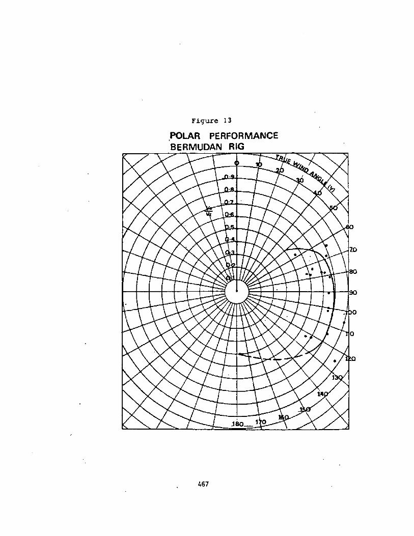
Figure l3
POLAR PERFORMANCE
BERMUDAN RlG
467

Provided two identica'1 boats are available comparative trials can becarr i e6 out qui ck ly and economi cally. They are 1 ess sensi ti ve tovariations in wind speed and direction and can be carried out over longdistances to give good time averaged results. The effects of tidalstreams are also much less significant than for absolute trials.
The main requirement is that a variety of courses of known distance canbe sailed at different angles to the wind. A series of courses setaround fixed mar ks will quickly build up a representati ve range ofheadings. For running the trials the following procedure was adopted.
A sequence of courses was predetermi ned once the boats wer elaunched.
Both boats grouped close to the first mark.
The one expected to be faster set off along the course, followed bythe other boat.
The time was noted as each boat passed the first mark, then theboats were sai led as well as possible along the course noting thetim as each passed the end marker.
Care was taken to ensure that the boats did not i nterfere with eachother, and when tacking was required, the boats made long tacks andagreed a cormrron moment to go about, so mi nimising the effects of«ind shifts.
Using this technique the performance of the three artisanal rigs wasestablished relative to the Bererdian rig.
The results are shown in Figure 14, and were at first si ght veryunexpected. Both the sprit rig and the gaff rig are superior on allpoints of sai 1 ing to the Bermudi an, wi th the su peri ori ty beingarticularly marked when sailing to windward. In very light winds theateen rig is comparable to the Bermudian, but as wind speed increased
it became inferior due to excessive flexing of the yard.
The normalised presentation of .Figure 14 may be difficult to interpret.To illustrate its implications the absolute polar performance curve forthe Bermudian rig has been used as a basis for the true comparativepresentation of Figure 15.
The shapes of the curves are considered reliable for true wi nd anglesfrom 70 around to 180 . Fran 70 to 0' the absolute data is sparse, sothe curve is drawn with a considerable element of judgement. However itstill serves the present purpose, since the relative performances of therigs were reliably established between 0 and 70 as well as 70 to180 !.
One of the overriding impressions from the trials, subsequentlysubstantiated by analysis, was the marked superiority of the spritsailrig when sailing to ~indward. The sprit boat pointed higher to the windthan the Berrmrdian and was faster through the water.
This result is totally at odds with conventional wisdom, so might beconsidered suspect. However sone reflection shows that it is not, asunlikely as it appears since:- 468

IV lg
V Z 0 ZOu.II Q brvK~mEIkl I ICICO4I aCO
CO~QaZ4bII-CO<0
COez+gI ~4
u. i'd%OCg~ZINCazCO g 4III4Cj
ZOO4 DZ+g24zgO~C~~ md@
', jI0 sj
m ~LgCO
UJ pi
453

The sprit rig was fitted with vangs, so could be sailed free oftwi st.
The spri t ri g ma in sa i 1 was more ful 1 than the Bermudi an abeneficial feature in the light to moderate winds of the trials!.
The rectangul ar pl an form of the spri t rig i s aerodynamf ca 1 lysuperior to the triangular shape of the Bermudian.
The performance of the lateen rig deserves some comnent. It was themost difficult rig to control and in wind strengths a@eh above 5 knotsit tended to distort and become inefficient- In light winds it provideda performance comparable to the Bermudian, but as wind speed increasedtowards 8 to 10 knots it became considerably worse.
Thi s deteri orati on i s only consi dered to be parti al ly an inherentfeature of that rig. With suitable development, and perhaps improvedsailing skills it fs anticipated that it could turn in a much betterperformance. Already since the trials, improvements have been notedfollowing the fitting of a stiffer yard.
However being a single sail rig it may well never be quite as good asjib/mainsail rigs which can exploit the extra drive which arises fromthe slot effect of two close coupled sails.
It should however compare favourably with Genoa and cat type Bermudianrigs which are coneenly proposed for working sailing boats. In such acomparison its greater versati 1 ity and fami 1 i arity wi th tropicalfishermen may give it a practical advantage.
4. PRACTICAL EXANPLES
Sandskipper in Sri Lanka
For the past year, two Sandskfpper 24 double hulled boats have beenfishing from Nadduwa, a sma1 1 vi 1 1 age South of Col ombo on the Westcoast of Sri Lanka!. This is an ITIS funded project, introducing theboats to a fishery currently exploited by small, ro~ed orus and 28'harbour based mchanised boats. The orus, which operate from the beachare restricted in the surf size they can manage and the 28' boats canonly be operated from harbours. They are heavy monohull boats designedbefore fuel efficiency became a major consideration.
The Sandskippers operate from the beach and are capable of negotiatinglarger sur f than the orus, though there are still a few days per yearwhen they have to stay ashore. So far they have been very succussful,providing an excellent economic return which is enabling the localskippers to buy the boats.
The boats are fitted with 34m2 lateen sai ls, which are used voluntarilyby the fishermen as a fuel saving measure. The double hullconfi guration gives a good sai 1 carrying power, so on reaching coursesthe sails give as nech, or mre, speed than the small Petter Oi eselsfitted to the boats.
One year's operational experience has shown that the 24' boats are alittle too small to carry as many nets as the fishermen would like andto negotiate the worst of the monsoon surf- Accordingly a 28' versionhas been designed and is currently under- construction. It will be builtin GRP a favoured material in Srf Lanka! and fitted with a 12 .5hp Deutzdiesel with 3:I reduction ratio for good propulsive efficiency.
470


A sailfng rig will be fitted, initially a 38m2 lateen, but this may wellbe eventually changed to the twfn tunny rig or some other twin rig toimprove ease of handling and increase the area which can be carrf ed.
8ased on the catch data recorded for the Sandskf pper 24 operati on,predictions have been made of the economic performance of theSandskipper 28. Catch figures are avai lable for the two Sandski ppersfor most of the past year and are shown in Figure 16. These resultswere obtained with an average of 17.5 sets of nets, whereas the SK28wf 11 carry 30. Experience has shown that drift netting is essentially astatistical based technique, and on average more nets equais more fi sh,on a pro rata basis. Hence these fi gures are factored i n the ratio of30 : 17.5 to predict the revenue that wi 11 be earned by the SK28.0sing these ff gures in associ atf on wf th estimates of local buf 1 dingcosts, crew costs, fuel etc. a full discounted cash flow analysis wascarrfed out. It indfcates an internal rate of return of 96'5. Table 1shows this result. To put this isolated ffgure into perspective varioussensitivities of this result were fnvestigated.The main areas of interest were
Capital CostsRevenueFuel Cost/Fuel Saving
The results are shown in the following fi gures:
Figure 17 fffect of Capital Cost and Revenue on Internal Rate of Return
The lower solid! line shows how increasing the capital cost of theproject reduces t' he rate of return in a non-linear fashion. Initiallythe effect is very marked, but as the rate of return reduces, so itbecomes fess sensitive to capital costs i.e. the first 2M fncrease incapital cost reduces the IRR by more than 1/3 whereas the increase from75% to 10� reduces ft less than 1/4!. The upper dotted line shows theeffect of increased revenue - the line being moved bodily upwards butretaining the same characteristics as for the standard revenue.
Related to the influence of capital cost on internal rate of return isthe effect of revenue changes.
Figure 18 Variation of IRR with Revenue and Fuel Use
The datum value for this analysis was not the standard conditfon, but asituation which gave a 56% [RR. It shows that the IRR is very sensitiveto revenue changes - in the datum case a drop in revenue of 25% takesthe operation fron being very profitable to quite marginal IRR from 56%down to 3f ! . Al so shown on thf s f f gure is the ef feet of fuelconsumption, as a percentage i ncrease over the datum case.
The -25% case represents a reasonable target for the effect of sailassf st'.ance, whilst the +300% case approximates to the position of theexisting heavy dfsplacement 28' boats. To generate the same rate ofreturn as the SK28 they would need to catch around 5� more fish withthe ~ crew and nets and capftal costs.
472

Figure 18
Verietian et Itgt with Revenue etet euet UeeFigttrs E7
F igttrp E 9
Figure 20
Cepitet Vetue ot Fuel Savinge ~ ~ tw s ea
Fiqur '. E
Ceptel Vetue ef tnqneeeet in tlevenueuI ~~swee~
Conversely the effect- of 25'4 fuel saving on the SK28 operation is notlarge, SinCe Edith the Sma
5$ chan e ina sma raction of t al
11, efficient diesel engine fuel costs are onlyot 1 costs. Such a fuel saving is equivalent to a
$ change in catch or revenue! or 11 percentage point chan in ERR.As the pri ce of fuel rimarked.
ue r ses the ef feet of fuel saving becomes moreange > n
473

Consider the line for the heavy displacement boat t300% fuel!. This isequivalent to a fourfold price rise at constant fuel consumption. The+200% line thus represents a 25% fuel saving at this high fuel price.In this case the effect of the 25% fuel saving is equivalent to an 18%change in revenue.
The other way of looking at this effect is that it corresponds to 22percentage points increase in !RR - which is a big improvement by anystandards.
The influence of fuel price on rate of return is shown more directly inthe next figure.
Figure 19 Variation of IRR with Fuel Cost.
This again uses the 56% IRR case as the datum, with a fuel price of Rs5-0/1 itre. The variation in fuel cost is interchangeable with variationin fuel consumption, i.e. a fuel price of Rs 10/'li tre has the sameeconomic effect as twice the consumption of fuel at the datum rate of Rs5/litre.
In addition to the basic relationship between fuel price and return, theother two lines shown illustrate the effect of fuel prices subject toinflation. The cases sho~n assume fuel pri ce inflation rates of IPl and20% per annum. It is interesting to note that starti ng wi th a fuelprice of Rs 5/litre, if the fuel price inflation rate goes up to 2� perannum the internal rate of return approaches zero, compared to 56% wi thno inflation!.
Nevi ng to the left of the pi cture towards lower fuel price or lowerconsumption! it is seen that the results are far less sensitive toinflation. Since sail assi stance is an effective method of fuelreduction its adoption provides a worthwhile defence agai nst the effectsof fuel price inflation. On todays prices the value of sai 1 assi stancemay not seem to be great, but against the prospect of- long term fuelprice inflation it makes sound economic sense. If it i s adopted now i twill be second nature by the ti me that large gains can be made-Kconomic projects of thi s nature contain a balance between initialcapital investment and recur ring costs. An oft quoted example is thechoice between outboard motors and diesel engi nes. The outboard ischeap to buy, but expensi ve to run; the diesel expensi ve t:o buy butcheaper to run. Oependi ng upon the price of money one or other can beshown to be the better opti on.
Simi larly for a particular project it is possible to determine therelationship between a recurri ng cost feature and capital investmentestablishing what is in effect the capital value of the change in therecurring cost,.
Figure 20 Capital Value of Fuel Saving
This picture shows the capital va1ue of varying degrees of fuel savi ngat three different rates of return. The lower the rate of return orthe longer the period required to recoup the initial investment! thegreater the capital value of fuel savi no.
474

Practically, one use of this picture is to look at the economic worth ofdifferent sail assist schemes. For example on a scheme with 56% IRR aninvestment of Rs 30,000 in a rig is justified if it leads to a fuelsaving of 35$. On a longer term project up to Rs 50,000 can bejustif1ed against a 35% fuel savi ng.
Consider1ng that the 38m2 lateen - rig is expected to cost Rs 2,000, itcan be seen that it only has to produce a fuel savi ng of about 4% toearn its keep even on a project where an IRR of around 100% is expected.
Usi ng this picture it is possible to bu1ld up a good feel for theeconomic potential of fuel saving measures, which is invaluable whenmaking judgements in the design stage. practically it is very difficultto make any hard and fast prediciti ons about the actual fuel saving thatwill result from sail assistance. In the end it relies a great deal onjudgement and the experience of others, so any additional informationsuch as this provides very useful extra 1nput for evaluating differentschemes.
In the same way that investment in fuel saving measures can be evaluatedit is possible to look at the effect of investing 1n improving therevenue earning potent1al.
Figure 21 Capital Value of Increases in Revenue
The results show a similar pattern to those for fuel saving: incr easinginvestment 1s justified as economic rate of return decreases.
Even for the hi ghest rate of return shown, quite large investments wouldappear to be justified for relatively small increases in catch,- e.g. at98% IRR it is worth investing Rs 50,000 for a revenue i ncrease of 15%.To put this i nto perspective the price of a complete set, of 30 nets isRs 4,000 and a new boat Rs 95,000.
One note of caution in i nterpreti ng these capital value results. Theli nes drawn apply to a once only investment and take no account of thelife cycle costs of the equipment bought with the capital egmaintenance costs and additional manning requi rements!. For the highrates of return the effect of thi s wi ll be small, but for longer terminvestments it could become significant. The general result will be areduct1on 1n the gradient of lines which becomes more significant as IRRreduces - so the spread of the lines will be compressed.
5- ECONOMIC CONCLUSIONS
arith these results it 1s possible to get a good overall pi cture of theeconomics of the operation which can poi nt the way to futuredevel opments.
It would be tempting to conclude that the primary need is additionalcapital investment in larger boats and more gear to ensure largercatches. Theoreti cal ly, thi s 1 s undoubtedly the correct v1ew, butpractically it is unlikely to live up to expectations.
The fishermen for whom this project is run naturally form 1nto certainsized groups, of three to five men. This imnediately sets an upperlimit on the net size that can be handled and 1nfluences the capitalthat can be raised for boat purchase. The boats operate from the beach,which sets limits on boat size and weight.
475

Consequently there are practica'1 restraints on the capital investment,at least fnsofar as it might be thought best to put it into bigger boatsor longer nets.
Instead, a better approach is to optimf se the selected fi shing uni t s .Examine ways of making a ffxed boat/crew/net combfnation moreeffecti ve. Nfthin this context the use of net haulers, fi sh finders anddifferent patterns of operation might be considered.
With present fuel prices and the fuel efficient design of the boatconsidered, the value of fuel savi ng is not perhaps as attractive asmeasures to improve catch. For example Figure 18 fndicates that a 50%increase in fuel use is justified by a I� increase in revenue. Thus itmay make sense to travel further to more lucrative fi shfng grounds.lith these curves ft is at 'least possible to get an idea of thetrade-off that f s appropr i at e.
One final observatfon on the capital value. The boat studied is a beachboat and hence limited in size. Larger catches may well be made bybigger more powerful harbour based boats - but do they justify theoverhead cost of the harbour'
Assuming the relationships remain linear out side the range presented, a50'% increase in revenue is worth'some Rs 250,000. A harbour for say 200boats could well cost upwards of Rs 300 million; an investment of Rs 1.5million per boat - i e. stretchi ng the results still further it isimplied that a 300% increase in catch will be needed to justify theharbour How that will be physically achieved and whether the fishstocks are there to be caught for the lifetime of the harbour will beleft for the planner of large scale schemes to contemplate!.6 ~ THE FUTURE FOR SAIL ASSISTANCE
The preceding sectfons have provided some insights into the performanceof different sailing rigs and the economic value of sail power and fuelefficient fishing boat design. There fs no doubt that sail assistancecan be economically justified, particularly fn a world where fuel pricesshow every indication of being subject to price fnflation.
What then are the factors which inhibit the adopt~on of sail assistanceon artisanal fishing boats?
The following are perhaps the most significant
FashionLack of Sailing SkillsDesire for SpeedAddi ti ona1 Labour Requirements.
Fashion - engines are modern; a sign of progress whilst sail is a signof the past. Fi shermen can be suspicfous of suggestions that theyreturn to the use of sai 1, seeing it as a retrograde step. Consequentlythey tend to be unsympathetic to the use of sail and thus unlikely tomake the best of sail assist ideas.
Lack of Sailing Skills - In many places sail may never have been used orhas long lapsed into disuse. The skf 1'ls needed to handle sail are thennot avai'lable.
476

Desire for Speed - Fishermen the world over like to go fast. ln mostcases saf 1 power will not gi ve as much speed as even a quite smal 1motor, which greatly detracts from fts appeal.
Addi t i onal Labour Requirements - Sai 1 s require addi ti ona1 time andeffort to set and trfm compared to the ease of usfng an engine when itis working !.
These are four important areas which must be tackl ed in sai 1 po~erprojects. The rel ati ve importance of each wi 1 1 vary f rom place toplace, but always one of the major hurdles will be the great appeal of ashiny new engine compared to even the most modern lookfng sailfng rig.
The appeal of the engine is not restricted to the fishermen who use it,but extends to those who can benefit from its supply. ln a developingcountry engines tend to represent a gr eat concentrati on of value andthus offer potential for manufacturers, importers and suppliers to makesubstantial profits. This increases the pressures for, adoptingmechani sation as ft is ecch more difficult to make equi valent profitsfrom the supply of sai ling rigs. lt means that the motives for theprovi sion of engines are often quite unrelated to the real needs of thefishermen who will pay for them and try to make a living from them.
However the economic realities of fuel prices, engine maintenance andfrequently limited unreliable engi ne life, can temper the immediateappeal of mechanisation, leaving the fishermen to view sail power with amore sympathetic eye. Then is the time to initiate sail assistanceprojects, with the aim of either total engine replacement or, morecorrmonly, a combfned use of sai 1 and power to gf ve the optimum economi cmix of the flexibility of mechani sed operation and the low cost ofoperation under saf 1.
6-1 Sail power on Small Boats
A very large proporti on of arti sanal boats are small in size, of lengthup to no more than 10m. As boats become smaller they represent anincreasingly difficult problem for effecti ve sail assi stance.
The sea is no respecter of size, so big and small boats experience thesame wind and waves. Thus, for simi lar performance the smal 1er boatrequires proportionately more power to over come the effects of wind andwa ve.
Bfg or small, boats are still handled by the same human beings. Speedis subject to inherent psychological influences which tend to result insmall boats being driven much harder than larger ones.
Psychologically a speed of 10 knots is qufte 'fast' for a fi shi ng boatand 6. knots is 'slow'. For a 30m boat, l0 knots fs hydrodynamically amoderate speed whilst 6 knots is a proportionately much higher speed foran 8m boat. An equivalent speed would be just over 5 knots, definitely'slow'. -Consequent.ly there is a tendency for small boats to beoverdriven; to carry proportionately more power than their largersisters.
477

Thus there are two influences pushing up power levels in smaller boats,which means that proportionately more sai 1 is required for effectivesail assistance. Speed under sail depends primarily upon stability, orpower to carry sail. This has the perverse characteristic of increasingwith increasing vessel size. Small boats thus lose out both ways - theyrequire prOpOrtiOnately mOre prgpul Si Ve pOWer yet haVe prOpartiOnatelyless power to carry sail.
Thus for effective sail assistance the smaller the boat the more thatstability becomes the critical consideration. On light slender boats,dugout types and thei r derivatives, crew weight can have a power fulinfluence. To augment this, balance boards have, for example, long beena feature of the artisanal boats of India, allowing the crew weight tobe exerted further from the centre 'line and hence increase the rightingme»nt- In many pl aces various forms of out ri g ger have evol ved,allowing extra stability to be gained by both buoyant forces and thedistribution of crew weight-
For high speeds under sail, out> iggers or multi hulled configurationshave 1 ong been establ i shed as the only pr acti ca 1 solut i on. Thesuperiority of this form is confirmed by the modern trends in the designof yachts for long distance 'open' races. In these circules the debateis about the relative merits of two hulls or three; the possibility ofusing a monohul 1 conf i gurati on i s not even thought to be worthconsidering .
Thus for smaller vessels in parti,cular the multi-hulled or outriggerconfiguration has a great deal in its favour if sai 1 assi stance i srequired. Indeed in the long term it is difficult to see small monohullboats making successful use of sai 1 power where multi -bulled craft couldbe used instead.
478

CHANGE Ok THE CHESAPEAKE
The influence of Economic ~ Pol i tical, Legaland Management Factors on Small Scale FishingOperations in maryland's Chesapeake Bay
Donald V. MobsterUniversity of Haryland
ABSTRACT:
Since colon'Ia'I tines maryland waterman have evolved distinctive craftcapable of carrying out their tasks in particular geographicallocations. For narc than 15O years legis'lation has frequently beenutil ized, at the urging of local waterman, to preserve traditionalfishing conmmltles by an apportionnmnt of ava'liable resources andrestrictions on fishing methods and gear. Court decisions haveprofoundly affected management of the resources and these. as wall asworldwide shifts In economic and energy matters, have caused the smallscale waterman to adapt to these changes. llhile existing In a highlyregu'lated environment, waterman have macle many changes in the design,size, and powering of their vessels. An overview of the evolution ofChesapeake Say area vessels is described. Changes in fishing craft,equipment, and operations are related to economic, legal, political,and management factors.
479

The Bay
The Chesapeake Bay is the largest estuary in the Uni tcd Statesand one of the largest in the world. It includes about 4,000 mi 'iesof shoreline in the states of Maryland and Virginia and has a lengthof approximately 200 miles encl a width that varies from 4 to 30 mi'les.I t is, to be precise, the drowned river valley of the Susquehanna,which provides thc Say with about hal f of its freshwater inflow. Itis an excel lent place for speciea such as oysters, crabs, and fish tospawn and live and is one of the earliest settled areas in the country.it was only natural, then, for thc colonists to begin to utilize theseafood found there and to evolve craft suitable to havcst them in thecondi tions prevalent.
Many of the early sett'lers in the Chesapeake Say region came fromEngland. Today, a'I though most do not realize it, many of the itemsfound in this area in terms of harvesting equi pnent and other features,can be traced back to those found on the southern coast of England.Thc waterman's crab shanty is similar to the "croglofft". The nippersand hand Conga are simi'lar to those fomd there. The cyl lndrical celpot used today is a variation on early pots woven of strips of splitoak. Many of the dialecCs found in the Bay area- are of Cornish origin.
Vessel Evolution
Thc earliest vessc'ls found in the Bay were thc log canoes builtby the Indians. These werc made by burning and scraping logs to pro-duce a scrviccablc boat enabling the Ind'lans to reach oysters. crabs,and fi sh with which Co feed their tribes. The car/y colonists used'es sel s of thi s type and gradually improved on the design by Increasingthe size with the addi tion of logs to form largcar craft ca=able ofcarrying Increased loads. Canoes of two, three, a;d five logs becamecoreonplacc. These vessels were not only used for harvesting but fortransportation since there existed no road network connecting nest ofthe Bay coaInunitias. Although most of Cha remaining log canoes todayare owned by sportsmen who use them to race during the sunIncr months,there are soma which have remained, fitted with engines and small cabins,in Chc work fleet.
The most rapid development of the Bay fisheries began after theldar of '1812 when New England schooners, having decimated many of thei rlocal oyster beds, began to come to the region to harvest from theabundar,t Chesapeake beds. They brought with them the oyster dredgeand carried 'large numbers of oysters with them as they sailed back totheir northern states. First they harvested large, mature oysters andlater tne smal I seed stock with which to replant the areas which theyhad depleted. Chesapeake waterman began to agitate for exclusion ofthe outsiders, even as many enlarged Chair boats and added dredges tocompete with them in a. race to sec who would harvest the last oyster.IIIth the competition. came new designs in the Chesapeake craft, many
480

of which were adapted from the Mcw Engianders' schooners. Theschooner, sloop, and pungy named, in all I ikcl ikhood after theboatbui'Iding town of Pungoteaguc in Virginia! al I had disadvan-tages fn being able to dredge for oysters however, ci ther thebulwarks were too high to efficiently pul'I the dredges or thedraft too deep for the areas 'In which oysters were most prevalent.The log canoe became the double masted brogan which in turn evolvedinto the bugeye. Log boats were less expensive to build than theframed vessels of that period.
Mith the decline of many of thc 'larger trees came the devel-opment of the deadrise bateau or skipjack which is still in usetoday. Built as a cheap workboat, it is amazing Chat many of thesevessels have survived into this century. Most of thc remainingfleet was built around the turn of the century.
By 1880 aver 2,000 larger dredging vessels and 6,856 sailingcanoes and other small craft were plying their trade on the Bay.Many of the local ports were thriving and had built up by the migra-tion of many of thc New England dealers moving to the region becauseof changes in the Maryland laws which forbade non-residents fromharvesting local products. The conflicts between the tongers workingfrom their sma'lier vesseis and the dredgers working from their largercraft escalated, many tines Into pitched batt'les with death anddestruction occurring. It was during this period that- the MarylandOyster Navy was farmed which survives to this day as the Marine01vislon of the Natural Resources Po'I icc. There alsq exists thestories of the 'butlaw drudgcrs" and "arster pirates" which have beenpassed down throughout the years.
Many Bay craft ware designed to meet specific differences infisheries or geographic location. Since the bay Is shallow, shoaldraft boats were necessary.
The sa I I ing vessel 5 whi ch evo I ved to bacon' nest ef f i ci cn t werebuilt with centerboards and low sides. They were used during thesLmmmr months to haul farm products to market and to transport lumberto the c,1 ties.
Power crafC used for tonging and crabbing had no fish hold and araised engine box. A small cabin was usually located forward with justsufficient space to afford minimal protection from the cold winterweather while oystering.
Today, about 6,000 Individuals make their 1 iving as watcrmen inMaryland- The fisheries have remained much the same over the yearsdue to prcssure from watcrnmn's groups to restrict efficiency in theharvesting of seafood. The Maryland fisheries are soma of the nesthighly regulated in the Ilni ted States in terms of harvesting equipment,quotas, md seasons. While relying upon these traditional harvestingmethods, waterman have become influenced by outside factors. An extensiveroad network now connects all ports and towns. The construction of a
481

bridge across the Say at Annapol is has made easier access betwccr,shores and, consequently, markets, Hew construction materials suchas fiberolass are replacing the traditional wood vessels. Electronicand hydraulic equipment have made some fisheries easier to participatetn ~
Interestingly, in spite of restrictions placed upon how one mightharvest, little was done to actually regulate how much was harvested.The resul t was that ovcrharvesting did occur despi te legislated ineffi-ciency, and, at the present time ~ Maryland ls ln the rather incongruousposition of marking thc 350th Anniversary of the founding of the statewith the worst oyster harvest in recorded history.
Other influences such as legal and economic ones have 1'fkcwiseinfluenced Bay fishing operations.
Until 1971, waterman were legally allowed only to harvest in thewaters in which they were residents. In 1971, however, in a casebrought' by a waterman from Smith Island, the State Court ruled inBruce vs. Director, Dc rtment of Chase cake ~Ba Affairs, that thesestatutes bio ate the hery an snh lln ta States C~onst tutlons andwere therefore i'ilegal. This allowed waterman to travel from countyto county harvcstlcg oysters and crabs wheWver they were most plceti-ful. While the Bruce Decision tended to equa'lite the prices paid forthe products artsmd thc state, it caused a great dea'f of trouble forthe management agency. Qatennen vould congregate in large numberswhereve~ catch rates were highest causing rapid depletion of thestocks and a great deal of animosity between residents and non-residentsof the counties which had the greatest resources. ' Coupled wl th thisnew found rmbil ity was a tendency for waterman to invest in largervessels since they were in many cases traveling long distances by waterand needed vessei s which were capable of withstanding heavier weatherand which had larger cabins for extended accosodations. Boats wh'ichwould enter the patent tong fishery for oysters were frequently morethan ii0 feet in length.
Of recent development have been court decisions which havedeclared invalid residency requi rements between states. At the presenttime there are some problems occurring with large numbers of Marylandwatermen working in thc VIrginia portion of the Bay harvesting crabsas a direct rcsul t of a case brought by the Smith I sland watermcn whichresulted in a decision last year.
Economic Factors
The energy crises of the l970' s changed the way many watermen thoughtabout vessels from the standpoint of motive power. The search for speedunder sail had adapted itself very nicely to the usc of engines duringthe 20th Century. This was apparent by the engines which watcrmen wereusing in their vessels. Host of the boats were powered with largegasoline engines converted from autormbile use to marine by ~ans ofadapter kits. These large displacement engines used great a~unts of
482

cnea; fuel . As long as the fuel was cheap i t was economical to usethese conversions. The first "fue'I panic" which occurred in 1973caused prices to rise fmm around 35 to about 7D cents a gal ion.There was a sl ightly noticeab'ie shi ft in engines. Some watermen,especially those with larger boats or who traveled a great deal, beganto invest in diesel engines and to adequately size them to their boats.Previously, many of the large gasoline engines suppl ied more power tothe shaft than the boat was capable of using. There seemed to be asmuch a status to having a large eng'ine in one's boat as in one' sautomobile.
The second fuel crisis in 1979 boosted the price once again andbrought I t in i ine wi th the real cost of energy in the world. Pricesabout doubled again from the 65 cent range to around SI.25 a gallon.The shift in engines at that point was fairly dramatic. Many of thosewho were sti 11 using gasol ine conversions changed from large disp'lace-ment e'Ight cylinder engines to smaller six cylinder models. Largerboats were changing much more readily to diesel and there began atrend to smaller f'iberglass boats which were trailerable.
This shift to sma'll trailerable boats marked an interestingchange In the Chesapeake Bay away from locally designed and built craftto those from other areas.
In the 1970's a few companies, located primarily in the areas ofNorth Carolina and New England, began to produce small fiberglass boatsdesigned specifically for the conmerciai fisherman. This was a distinctdeparture from earlier companies which had concentrated primarily on therecreational boating market. These boats were very attractive to theBay waterman because they offered low maintenance with a weil designedfiberglass hull with no extraneous frills and the added advantage ofbeing able to trailer the vessel to the piace nearest his point ofwork. With an excel'lent road network built up over the years and manypublic and private launching facilities around the Bay area, he couldessive eas'ily from place to place in search of the oysters, crabs, andfish which had formed the livelihood of h' im and so many before him.These small coaIaercial workboats have become very popular in the Bayarea and many waterman have either totally converted to these smallboats or have one in addi tion to thei r large vessels.
The Maryland waterman has come qui te a distance from the use ofthe Iog canoe with which to get around in a place which had no inter-connection by roads to the use of small fiberglass vessels which makegood use of the current excellent road network in order to carry onhis work.
483

DEV LOP"ANT OP A SAIL-ASSISTED PRP FISHING CANOE FOR ' HE CO.',OLIOS
PUlMÃACHI Tokuzo, N.A.
Overseas Projects Dept., Marine OperationsYm~ Motor Co., Ltd.
3380-67 Mukohjima, Arai-choHamana-~, Shizuoka-ken, JAPAN
ABSTRACT
The development of a PRP fishing canoe with sail and outriggeris described.. The light weight, beachable hu11 with a smallmarine diesel has gained. more energy-saving performance byfitting with a simple alminum mast � Genoa sail combination.
Mental acceptability to the local fishermen was also considered
to facilitate the smooth introduction of totally new conceptto the artisanal fishery.
3ACKGROUND AND HISTORY
Yamaha Motor Co.,Ltd. well known as cne of the leading motor-cycle manufacturers in the world � he.s been also contributingin the world fisheries scene by supplying its PRP fishing boatsand. outboard motors to the fishermen for more than two decades.
Particularly for these years the growing demand from variouscountries has led the company up to design and manufacture PRPfishing boats which are really suitable for their specific uses,and the company has answered one by one to those demand.s.
Sri I,anka, Senegal, Nigeria and Mauritania are some of the
countries in which ite design projects have been conducted.
Incidentally and opportunely, one of the Japanese Government
Overseas.Aid Schemes had materialized in $981 as the developmentof local fisheries in the Federal and Islamic Republic of theComoros. Yamaha was awarded a tender to supply fifty �0! PRPfishing boats as a part of the aid and thence started a designof the new type of fishing craft for the country.
484

TH-' CONORO ISLANDS
The Pederal and, Islamic Republic of the Comoros chiefly consistsof three islands which lie in the north of the Mozambique Channel
off the east African coast. Its land area totals about 1,600 ZH2
and on the coastlines of those three islands, most of its 400,000population settle. Among them some 5,000 are fishermen usingvery small dugout canoes called. "Pirogues" in French � theirformer ruler's language. The craft falles into a category ofso-called "Double Outri.�-,er Canoe" which has a float on each sideof the hull. This type of canoe is widely distributed from thePacific Islands to Madagascar, and is reported to have certaincorrelation with each other. The Comoro canoe is said to be a
good example which indicates the westernmost trace of the out-rigger canoe culture.
a mechanized. PRP replacement of the traditional wooden dugouts
and. to improve the local fishermen's lives through this process.The word. "replacement" did not necessarily mean the same shapeand size of the boat. It should supersede the old one. A drastic
change should, however, be avoided because fishermen have a corn-..ontendency being reluctant to the new ideas � particularly when they
are brought from outside. Therefore, the appearance and. general
arrangement were designed as similar as possible to the existinecanoes, yet all basic design features be observed. Pig.f}
Hull: The size of existing canoes mostly 3 - 5M! must have longbeen decided by the fishermen who took various factors into ac-
count, such as local availability of wood, building cost, weight
restriction in case of beaching {they carry the canoe by hands-
not pull on the ground.! etc.. Prom the safety point of viewas well as economical standpoint they are too small. To be able
to yield the sufficient amount of catch to step up from the sub-
sistence level, the size should be at least doubled.
On the other hand, the lack of harbor facilities and inevitable
beach landing operation requires as small and lightweight aspossible craft even though it is a modern mechanized type.
485

t
ii~~ I
l 1I t
CX
i- aZ
'll
I
460

The company's previous experiences showed theat the launchingweight of one tonne �,000 KG} would be maximal for the hand-hauled beach landing craft. Taking this figure into consid.eration,the principal dimensions were decided as shown in the SP=CI."ICATICNS.This 9.21M canoe may be depicted as one of the minimum offshorefishing craft with marine diesel.
The hull shape is rather classic; long slender double-ender withmcderate Chine. Wide shallOw keel runS thrau,h Centerline like
a spine, and on its aft end allocated the propeller.
~n ine: The mechanization of existinq canoes had been partlydone by fitting with small � � 8PS! outboard. motors and hasso far proven successful. It was desirable, however, to installa small marine diesel in the mentioned. boat. There have been
many controversies between diesel inboards and gasoline outboards,and it is not practical to lean always to one side. However, as
in this case, once its higher initial cost � the most essential
disadvantage of diesel - is met by government grant, there is no
hesitation to dieselize. The lower running cost and simpler
maintenance would certainly profit the local fishermen.
~Sail Ri : The sea around the Comoros is predominated by thetropical monsoon almost all-year round.. The local fishermen
have been making full use of the wind for their trips to and
from the fishing grounds. Mechanization is indeed a very important
step towards the modernization of artisanal fisheries, but there
has also arisen a new problem inherent in this step; ever-increasing
fuel cost makes big hol,es in the fishermen's pockets and. forces
their fishing efforts almost profitless.
Reconsideration of Sail-Assistance to the mechanized craft is
therefore of prime importance, particularly for such a small scale
fishery as of the Comoros. The first option of the sailing rig
was the conventional lateen rig which is still used on the existing
canoes' That idea was eliminated however, on. the way of desi~
consideration because of its long heavy yard. which would. without
doubt spoil the workability onboard. Secondly, the mod.em andefficient 3ermuda sloop rig was studiede 3ut it was also unadaptedto the purpose for the reasons of complex sheeting arrangement andexistance of the cumbersome boom.
487

pinally adopted was a low aspect ratio Genoa sail as shown inZts advantages are:
No boom, no yard, then no hindrance to the deckwork
Easy furling by a roller furling device
Easy single-sheet handling of the sail
Higher sailing efficiency owing to the sharp leading edge
of the sail not spoiled by mast or yard
~ile there are some disadvantages such as the deeper sail draft
in the free-running leg due to its long unsupported foot of the sail,
por all those points, it was obviously better than other sail
errangements f' or the FRP canoe. The sail area was decided according
to the maxianm allowable heeling angle under certain wind force
assumed as most predominant in the area. Hem of the sail wa=
patched with blue-colored strips to protect from the strong ultra-
violet rays while furled around the forestay.
f
stability under sail, double outrigger was added as an optional
equipment mainly because of the local fishermen's
preferences; so-called "Security Blanket" effect was expected as
to the stability of the hull. Broader working space between out-rigger booms was also considered useful' The outrigzer assemblyitself would be utilized, anipeay the practical usage was left tothe fishermen.
The floats were made of FRP, and outrigger beams of anodizedalminum pipes Both were jointed with stainless steel bands.«nventional rope-tying method. was employed. to secure the outrigger
the hull so as that the fishermen could easily deal with it,~11 jointed. and rope-tied portions of the pipes were sheathed withabber collars to prevent electrolysis and abrasion. To avoid un-
«»ary frictional resistance, the floats were set at the heightm above the designed water line. The float generats its maximum
u yance of about 140 KG at the heeling angle of' 15 degrees toeither side.
488

SP'CIFICATIONS
L.O.A.
Beam
Depth
Gross Tonnage
Displacement
Cr evr
Construction
B! Propulsion
Main Ehgine
Output
Reduction Ratio
Propeller
F.O.T.
Autonomy
Sail
Mast
Wood one pair!Oars
C! Fishing Gear
3 sets
2
o.6 x3
Outrigger Float
=Outrigger Beam
489
A! Principal Particulars
Multi-purpose Winches
Trolling Rod. Holders
Insulated Pish Hold.
D! Other Features
921M
1.76 M
0+90 M
2. 1 Tons
950 KG
6 Pens.
PRP Single Skin Construction
YaLmaha RE60H
4 cycle diesel; sea vrater cooled
11.5 PS/ 2,600 rpm1 03
Alminum Die-cast
D 9+~" x P H" 3 Mades
48 Liters diesel!100 Nautical Miles
Duclon 4. 5 oz 12 ' 0 M2
A6063 Mast Section L. 5.4 M
FRP 31 XG ea.
A6063 O.D. 100 mm t 3.0 mm

SEA TRIALS
Af'ter completion of the first production canoe, the sea trialswere conducted under the supervision of the Japanese GovernmentAuthority.
As for the speed of the boat, Maximum of 7.95 kt was obtainedunder light condition without outrigger. It was quite acceptablefor the size of the boat and engine. After necessary engine break-in, it is expected to well exceed the design speeC of' 8 kt.
The sailing syeed was also measured on several different legs, andthe maximum speed of 4,23 kt was observed in abeam run at the wind.
speed of 6 M/sec. approx. The heading angle was nearly 50 degreesto the wind Cirection and tacking was possible when sailed without
outrigger. It was observed that considerable amount of wind powerwas exhausted by turning the propeller underway. It would bedesirable to lock the propeller shaft while under sail.
Beach landing test was conducted on the sand beach of a small
island near the boatyard. Necessary towing force was measured.for the future data accumulation. Using plastic sleepers it waseasily pulled up by hands of ten 10! men. It is recommended touse the launching trolleys which were also included in the aid
materials wherever their use is possible.
Fifty �0! units of the PHP canoes were shipped. to the Comoros inPebruary 1983, and to date all major design objectives have beenmet «ith regard to the local fishing conCitions. The fishermenwho used the canoes are reported to be satisfied with the greaterloading capacity anC better stability as well aa the quite similarhandling response to the existing pirogues.
Although the practical Cata proving the improved. profit by theintroduction of FRP canoes are not yet available, from the sea
trials result it is evident, that their superb speed performance
and fuel economy can result in the significant saving of bothcruising time anC running cost for the Comoro fishermen.
490

491

APPENDIX
CONFERENCE PARTICIPANTS
Alejandro AcostaUniversity of' Rhode IslandP.O. Box 309Kingston, RI 02881 VENEZUELA!
Bruce AdeeDirector, Ocean Eng. Program326 Mechanical Engineering 8Ldg FU-10Universi ty of WashingtonSea t tie, WA 98195
Luis Colino 4lvarezUniversidad Central De VenezuelaFacul tad De Ingenieria-Caracas-
Ven e zuela619811 >30 ext 2354!
Gunnar C. F. Asker4sker EnterprisesThe Lincoln BuildingRoom 411, 60 fast 42New York City, HY 10165
Richard P. BlommaertP.O. Box 7581St. Petersburg, FL 33734 813! 823-2119
Lee BrooksBox 5010Everglades Ci ty. FL 33920
Jean E Buhler4821 Campo Sano CtCoral Gables, Ft 33146271-5721
492
Scott 4ndreeP. 0. Box 820Perry. FL 32347 904! 5849350
Conrad BirkhoffLaufgrabenD-2000 Hamburg 13Germany49-40-449-127
Theophilus R. BrainerdP. O. Box 227K ings ton, R I 02881�01! 729-2471 SIERRA LEONE!
T. Peter BurgessBurgess Management Associates1133 Avenue of the AmericasNew York, NY 10036�12! 92l-2626
Willard A. Burpee10650 NW South Raver DrzveMiami, FL 33179�05! 558-1131
Philip Cahil lBox 714, Rt 3Gloucester, VA 804! 642-2111 ext 198
S.M. CalisalMech. Eng. Dept.University of British Columbia
VancouverBC UGNIW5Canada
James C. CatoBldg 803Florida Sea GrantUniversity of FloridaGainesvil le, FL 32611 904! 392-5970
Howard A Chatter ton3801 Idle CourtBowie, MD 20715 301 ! 267-3361
Paul Christian511 Marsh CircleSt. Simons Island, GA 31522 912! 264-7268
Gary L. Collar420 Van Reed Manor DriveB-r andon, FL 33511 813! 689-7145
Thomas J Collins JrDESCO MARINE, INCP.O. Box 1480, 1 DIeseL RoadSt. Augustine, FL 32085-1480 904! 824-4461

493
C. G. CooperFisheries Development Branch1e49 Hol 1 i s St r ee tHalifax, Nova ScotiaCanada 83J 2S7 902! 426-7239
Frank Crane2300 E. I as Olas 2EFort Lauderdale, FL�05! 522-2166
Bruce Culver177 S. Hormanoy RoadSeattle, Washington 98149�06!- 593-8800
William Czvekus3404 Vista Oaks WestPalm Bay, FL 32905�05! 465-2400 ext 274
A. W. DialP. 0. Box 2879Fort Myers Beach, FL 33931 813! 463-4451
Jose M. Diaz7170 S. W 12th St.Miami, FL 33144�05! 823-4899
Nancy V. DinwiddieP O. Box 1194Melbourne, FL 32901�05! 724-0946
Doug Dixon3259 NW 56th StreetSeattle, WA 98107�06! 285-3200
Br adf i eld 4. Dobbs297 Ohio AvenueFt. Myers Beach. FL 33931 813! 463-6087
Capt. E. Thoeas DrennanP O. Box 14915H. Palm Beach, FL 33508 305! 848-4570
Masood F r ou tanS tuden tF.I T, 0 8 OE Dept.Melbourne, FL 32901
Douglas GarbanzoFlorida Institute of Technology0 8 OE Department150 West University BoulevardMelbourne, FL 32901
Tim GasparriniB37 S. Hickory s2Melbourne, FL 32901
Karen GlatzelP.O; Box 2534Melbourne, FL 32901�05! 725-3265
Cl i f f GoudevCenter For Fisheries
Engineer ing ResearchRooe E38-376292 Hain StreetCambridge, MA 02139MI T �17! 253-7079
Bill HallRt. 1-Box 281.-LHams tead. NC 2B443 919! 270-2131
Joe HaluskyRt. 1 Box 12148 t. Augustine, FL 32086 904! 471-0092
Tony E Hart3113 Catrina Lane4nnapol is, MD 21403�02! 416-6251
George Reynolds/Al Hawver8738 N. Meadowview CircleTampa, FL 33615 813! 920-6273
Kathy HillS4ILA1553 Bayville StreetNor f o 1k, WA 23503 804! 588-6022
Peter HjulFishing Hews International87 Blackfriars RoadLondon SEl BHB�1! 928-8641

Robert R. Hyde330 Market St EastSuite 200Philadelphia, PA 19106�15! 629-1600
Leigh T. JohnsonMarine Extension 4gent1948 Pineapple AvenueMelbourne, f L 32935�05! 727-9721
Lt. Stephen R. Judson1810 Woodrail DriveMillersvi lie. MD 21108�01! 789 1600 ext 316,317,318
R. P. LairdEngineering DivisionCaterpillar Tractor CoPeor i a, IL 61629
Peter LappColuebian Bronze Corp.216 No. Main StreetFreepor t, NY 11520�16! 378-0470
R. LatorreUniversity of New OrleansP. 0. Box 1098New Orleans, LA 70185�04! 286-7183
Brian Kagy311 Ocean Avenue s3Melbourne, FL 32951�05! 729-0147
Kiyohisa Kasui333 Clay St., Suite 1500Houston, TX 77002�13! 658~11
De@arab D. Kearse107 Hest Lake CircleCocoa, FL 32926�05! 632-24&2
Donald J. Ker3in. PECOMDT G-MTH-4!U.S. Coast Guardwashington. DC 20593�02! 426 2197
Jerry KilpatricP.O. Box 3143St. Augustine, FL 32804 904 ! 824-3308
T. KowalskiDepartsent of Ocean Eng.205 Lippitt HallUniversity of Rhode IslandK ingston, RI 02881�01 ! 729-2550/2273
Rob LaddP.O. Box 598Gr ason vi I le, MD 21638�01! 827-8150
Toe LeahyBldg 803University of FloridaGainesville, FL 32611392-2801
Lebet1734 Eeerson StreetJacksceville, FL 32207 904! 396-5571 or 399-3673
Scott LewitDept of Oceanography I Ocean EngFlorida Institute of TechnologyHe!bourne. FL 32901
Geor ge 4. LundgrenMarine Efficiency EngineeringFishereen 's TersinalC � 10 BldgSeattle� , 4J4 98119�06! 281-7388
R. Gowan MacAlisterMacAlister, Elliott a Partners56 High St. LyeingtonHants S04 968 U.K.U.K. �90! 75973
Edward Maciejko.625 S PalawayLake Worth, Ff .33460�05! 585-2861
Frank HacLearMacLear 4 Harris Inc.28 Liest 44th St
York, NY 10036�12! 869-3443

34286
49'
Richard F. Managmn13950 NW 27 AvenueMiami, FL 33054�05! 688-8102
Donald McCreight126 Woodward Hal liICMRD
of Rhode IslandKingston, R.I. 02BBl�01! 729-2479
Juliusz Mekwinski420 Waterway Dr. HSatellite Beach, FL�05! 777-0026
Laurence T Moor e206 Flamingo LaneMelbourne Beach, FL 32951�05! 727-0111
LCDR William J. Morani Jr.Commandant G-MVI-2!2100 Second St. S44Washington, DC 20593�02! 426-4431
Miguel MorenoPo De La Alameda De Ojuna, 74Madrid - 22 SPAIN7-36-02-00
Kenneth C. Morr iseau1610 4pricot Ct.Reston, VA�03! 435-3330
Ben OstlundP. 0 Box 875Tarpon Springs, FL 813! 938-4495
Colin PalmerGif f ord 4 PartnersCarlton HouseRingwood RoadWoodlands, Sou th amp ton,
J D. PennxngtonP.O. Box 1567St Augustine, FL 904! 824-4394
Jorge Pimentel5 E. U iversity
Melbourne. FL GUNNEA B4SSAG!
Mark Pittslo 4 I t t te o f TechnologyMelbourne, FL 32901
Ayel ino Pon tes325 E. University Blvd ¹92Melbourne, FL 32901 Gunnea Bassau!
Bambang Edi PriyonoICMRD. U R. I.University of Rhode IslandKingston, R. I. 02B81783-6093 INDONESIA!
Kenneth Proudfootll School StreetWakef ield. RI 02879�01! 785-5994
Wayland PurmontWest Main RoadLittle Compton, R. I 02837�01! 635-2236
Ronnal P ReichardOceanography a Ocean Eng DeptFlorida Institute of TechnologyMelbourne, FL 3290 I�05! 723-3701 ext 7273
Bill Remley, USCG8211 Cutter PlaceJac ksonvi lie, FL 32216 904! 791-2648
Noel T Riley24/24 Thomas StreetChatswood NSW 2067Australia�2! 412-4894
Max D. Rodgers4404 Vista Oaks i@estPalm Bay, FL 32905
Ann P. Sainsbury9970 So Tropical TrailMerritt Island, FL 32951
John W. Sainsbury9970 So. Tropical Tr ailMer r i t t Island. FL 32951�05! 723-3701 ex t 7452

496
Simon SainsburyR.R. 1, Sox 196Ft. Pierce, Fl 33450�05! 465-2400
Carl SalafrioBox 6328Helbourne, FL 32901�05! 723-9984
Jose SalasUniversidad Catolica ValparaisoCasilla 1020Valparaiso, CHILE
Sill SeeeannP. O. Box 13704New Or leans, LA 70185�04! 482-1179
Robert Jases ShephardAssoc Director Seagrant Prog.6010 Executive Blvd.Rockville. HD 20852�01 ! 443W8$5
Patti Shipyard, Xnc.P.O. Box 271Pensacola. FL 32592 904! 434-2972
Carol ShortallCaribbean HarineP.O. Sox 1205Tarpon Springs, FL
John W. Shortall ZIIUniversity of South FloridaCollege of Engineer ingTaapa, FL 33620 813! 934-6789 or 974-2581
Joe SieeondsP. O. Box 148K ings ton, R. Z . 02881 St. Kitts, west Indies!
NOrbert SieeOnSP =0 Sox 113Soraerset Sridge P.O.Bermuda
Bob SteeberColuabian Bronze Corp.216 No. Hain StreetFreeport, NY 11520�16! 378-0470
Russel R. SteinerPost Office Box 742Bayou La Batre, Alabama 36509�05! 824-4143
Rick StoufferFish Boat HagazineP. O. Box 2400Covington, EA 70434�041 893-2930
Geoffrey SwainOCeanOgraphy 4 Ocean Eng DePtFlorida Znstitute of TechnologyHelbourne, FL 32901�05! 723-3701 ex t 741 1
Capt A. E. Tanos, U.S.C.G.51 S.W. First Ave. CCGD 7 m!Hiaei, FL 33130�05! 350-5651
Hlchael TorchlaFlorida Institute of Technology0 I OE Departeent150 Nest University BoulevardHelbourne, FL 32901
Jan~lof Traung9 Lilla CedergatanS-42174 V. Frolunda Go tebor g ! SWEDENTel. 031-29 65 73, 29 65 74
Chrietopher N TupperR.R. 2, Box 116Kennebunkport, Haine 04046�07! 985-4520
Thomas TuPperp g, OE DeparteentFlorida Institute of TechnologyHelbourne, FL 32901
Gerard van SuurtSan Fumgeweg 5Cur acaoNetherlands, Antilles78500 or 70288 hoee 79834
Rajapaksa Don WarnadasaZCHRDUniversity of Rhode XslandK ingston, RZ 02B81 SRI EANKA!
Don WebsterUniversity of Har y landHorn Point LabP. O. Box 775Casbridge, HD 21613�01! 228-B200 ext 276

Garland WebsterR. 2 Box 541Summer land Key, FL 33402�05! 745-1600
Thomas C. Williams2705 S. Atlantic AvenueNew Smyrna Beach, Fl 32069 904! 427-3786
Alan WilsonTotal Oil MarineBerkeley Square HouseBerkeley SquareLondon W. I. EnglandLondon 499-6080
David Gordon WilsonRoom 3-447. M.Z.T.
Cambr idge, MA 02139�17! 253-5121
Brett Wilson221 McGuire DriveLong Beach, MS�01! e68-e237
Andrew Zborowski, ProfessorOceanography 8, Ocean EngineeringFlorida Institute of TechnologyMelbourne, FL 32901�05! 723-3701 ext 7453
497