Rhode Island Weatherization Field Guide - RI Department of ...
552
-
Upload
khangminh22 -
Category
Documents
-
view
1 -
download
0
Transcript of Rhode Island Weatherization Field Guide - RI Department of ...


Rhode Island Weatherization Field Guide 3
Rhode Island WAPWeatherization
Field GuideSWS-Aligned Edition
The author recognizes the knowledge, ingenuity, and creativity of the
weatherization network throughout the United States for pioneering,
changing, and perfecting the standards, specifications and
procedures documented in this field guide.
Primary author: John KriggerIllustrators: John Krigger, Bob Starkey,
Steve Hogan, Wayne Harney, Darrel TenterTechnical publisher: Darrel Tenter
Editors: Darrel Tenter, Timmie Smart, and Mary Coster
The Rhode Island Weatherization Field Guidepresents procedures to analyze and retrofit existing buildings for
energy efficiency, health, and safety under the Department of Energy’s Weatherization Assistance Program. This field guide is
hyperlinked to DOE’s Standard Work Specifications for Single-family, Multifamily, and Manufactured Homes as of January 2018.
Copyright 2019 by
Saturn Resource Management, Inc.
Version 041619
Rhode Island Weatherization Technical Committee Field Guide Review Team:
Julie Capobianco, John Costello, Sal Estacio, Ed Fisk, Bill Larocque,
Dennis Lopes, David MacLellan, Rui Pires, Merredith Plante, Steve Santos

4
AcknowledgmentsWe are Saturn Resource Management of Helena Montana. Our content expertise is energy conservation for buildings. We pub-lish documents, create curricula, implement training, and con-sult.
We thank the Department of Energy’s Weatherization Assis-tance Program (WAP) for promoting residential energy effi-ciency for more than 35 years. Without the DOE, our industry wouldn’t exist as a building-science-based endeavor.
Weatherization agencies, State WAP grantees, private contrac-tors, national laboratories, utility companies, and non-profit corporations have also contributed much to the content in this guide.
For many years, we’ve tried to list the specific people who have influenced Saturn’s work in a substantial way. Now there are just too many contributors to list. You know who you are: thank you.
WAP energy specialists and energy experts associated with WAP are our most important contributors. Saturn’s present and past staff have done a fine job of compiling the information in this field guide. Thanks to everyone who has reviewed this field guide and labored to improve it. Thank you, past-and-present customers, for allowing Saturn the privilege of serving you. We appreciate your business.

Rhode Island Weatherization Field Guide 5
PrefaceThis Weatherization Field Guide outlines a set of best practices for the Weatherization Assistance Program (WAP). Weatheriza-tion experts collaborating with the National Renewable Energy Lab (NREL) developed the Standard Work Specifications (SWS) beginning in 2009. These new SWS standards reside online in NREL’s SWS Tool.
The SWS presents details and outcomes for weatherization mea-sures that are required when a weatherization agency selects a weatherization measure, based on its cost effectiveness. The technical content of this guide aligns with the SWS require-ments.
A major purpose of this guide is to show how its contents are aligned with the SWS. Therefore, we’ve inserted hypertext refer-ences to the specific SWS details that our content aligns to. When you click on one of these references, the relevant detail appears in your browser.
This guide also incorporates information from the following standards and specifications.
• DOE Weatherization Job Task Analysis (2018)
• Building Performance Institute’s (BPI) relevant standards
• WAP Policy Directives from 2005 to 2018
• International Residential Code 2012
• International Energy Conservation Code 2012
• Standards for combustion systems by The National Fire Protection Association (NFPA) 2009 editions, including NFPA 54, 31, and 211
We begin this guide with health and safety, an important topic for both workers and clients. The first part of the chapter dis-cusses client health and safety. The last part of the chapter covers worker health and safety.
6
Next, the guide presents a chapter on energy auditing, inspect-ing, customer relations, and work flow development. The fol-lowing chapter discusses insulation and air sealing materials and their characteristics. We follow that with four chapters on the four distinct parts of the building shell: attics and roofs; walls; floors and foundations; and windows and doors.
The guide’s largest chapter is heating and cooling. We created a separate chapter on ventilation, which includes whole-house ventilation, local ventilation, attic and crawl-space ventilation, and ventilation for cooling.
We’ve included a dedicated chapter on mobile homes where we discuss the ECMs particular to mobile homes. In this chapter we often refer to other sections of the guide that contain informa-tion that’s relevant to both mobile homes and site-built homes.
The last chapter’s topic, Air Leakage Diagnosis, is an effective tool for weatherization agencies to guide cost-effective air seal-ing. This chapter doesn’t align to the SWS because the SWS doesn’t detail testing procedures.
Like the SWS, this field guide is a living document and a work-in-progress. The field guide will change as the SWS changes. We hope you find this guide authoritative, easy to use, and well aligned to the SWS. We welcome all comments, suggestions and criticism. Thanks for your hard work and dedication in imple-menting the Weatherization Assistance Program.
John [email protected]

Rhode Island Weatherization Field Guide 7
TABLE OF CONTENTS
1: Health and Safety
Educate Occupants and Building Operators . . . . . . . . . . . . . 22
Fire Safety . . . . . . . . . . . . . . . . . . . . . . . . . . . . . . . . . . . . . . . . . . . . . . 23
Carbon Monoxide (CO) . . . . . . . . . . . . . . . . . . . . . . . . . . . . . . . . . 24Causes of Carbon Monoxide (CO) . . . . . . . . . . . . . . . . . . . . . 25
Smoke and Carbon Monoxide (CO) Alarms . . . . . . . . . . . . . . 26Smoke Alarms . . . . . . . . . . . . . . . . . . . . . . . . . . . . . . . . . . . . . . . . 26CO Alarms. . . . . . . . . . . . . . . . . . . . . . . . . . . . . . . . . . . . . . . . . . . . 27
Gas Range and Oven Safety . . . . . . . . . . . . . . . . . . . . . . . . . . . . . 28
Reducing Moisture Problems . . . . . . . . . . . . . . . . . . . . . . . . . . . 29Symptoms of Moisture Problems. . . . . . . . . . . . . . . . . . . . . . 31Solutions for Moisture Problems . . . . . . . . . . . . . . . . . . . . . . 32Crawl Space Moisture and Safety Issues . . . . . . . . . . . . . . . 36Ground Moisture Source-Reduction. . . . . . . . . . . . . . . . . . . 37
Pollutants Source Control . . . . . . . . . . . . . . . . . . . . . . . . . . . . . . . 38Radon. . . . . . . . . . . . . . . . . . . . . . . . . . . . . . . . . . . . . . . . . . . . . . . . 38Asbestos Containing Materials (ACM) . . . . . . . . . . . . . . . . . 39Lead-Safe Procedures . . . . . . . . . . . . . . . . . . . . . . . . . . . . . . . . 40
Electrical Safety. . . . . . . . . . . . . . . . . . . . . . . . . . . . . . . . . . . . . . . . . 43Knob-and-Tube Wiring . . . . . . . . . . . . . . . . . . . . . . . . . . . . . . . 45Constructing Shielding for Knob-and-Tube Wiring. . . . . 46
Worker Health and Safety . . . . . . . . . . . . . . . . . . . . . . . . . . . . . . . 46Commitment to Safety . . . . . . . . . . . . . . . . . . . . . . . . . . . . . . . 47New Employees . . . . . . . . . . . . . . . . . . . . . . . . . . . . . . . . . . . . . . 48Driving. . . . . . . . . . . . . . . . . . . . . . . . . . . . . . . . . . . . . . . . . . . . . . . 49Lifting and Back Injuries . . . . . . . . . . . . . . . . . . . . . . . . . . . . . . 50Respiratory Health. . . . . . . . . . . . . . . . . . . . . . . . . . . . . . . . . . . . 51Hazardous Materials . . . . . . . . . . . . . . . . . . . . . . . . . . . . . . . . . . 53Equipment for Personal and Crew Safety . . . . . . . . . . . . . . 54Falls. . . . . . . . . . . . . . . . . . . . . . . . . . . . . . . . . . . . . . . . . . . . . . . . . . 54

Table of Contents8
Tool Safety . . . . . . . . . . . . . . . . . . . . . . . . . . . . . . . . . . . . . . . . . . . 56Repetitive Stress Injuries . . . . . . . . . . . . . . . . . . . . . . . . . . . . . . 57Safety for Crawl Spaces and Other Confined Areas . . . . . 58Safety for Extreme Weather . . . . . . . . . . . . . . . . . . . . . . . . . . . 59
SWS Alignment. . . . . . . . . . . . . . . . . . . . . . . . . . . . . . . . . . . . . . . . . 60
2: Energy Audits and Quality Control Inspections
Purposes of an Energy Audit . . . . . . . . . . . . . . . . . . . . . . . . . . . . 65Energy-Auditing Judgment and Ethics . . . . . . . . . . . . . . . . 66Health and Safety Considerations . . . . . . . . . . . . . . . . . . . . . 67Energy-Auditing Record-keeping . . . . . . . . . . . . . . . . . . . . . 68
Customer Relations . . . . . . . . . . . . . . . . . . . . . . . . . . . . . . . . . . . . . 68Communication Best Practices . . . . . . . . . . . . . . . . . . . . . . . . 68Customer Interview . . . . . . . . . . . . . . . . . . . . . . . . . . . . . . . . . . 69Deferral of Weatherization Services . . . . . . . . . . . . . . . . . . . 70
Parts of an Energy Audit . . . . . . . . . . . . . . . . . . . . . . . . . . . . . . . . 71Visual Inspection . . . . . . . . . . . . . . . . . . . . . . . . . . . . . . . . . . . . . 72Diagnostic Testing . . . . . . . . . . . . . . . . . . . . . . . . . . . . . . . . . . . 72SIR Calculations . . . . . . . . . . . . . . . . . . . . . . . . . . . . . . . . . . . . . . 73
The Work Order . . . . . . . . . . . . . . . . . . . . . . . . . . . . . . . . . . . . . . . . 74Questions about the Audit and Work Order . . . . . . . . . . . 75
Work Inspections . . . . . . . . . . . . . . . . . . . . . . . . . . . . . . . . . . . . . . . 75In-Progress Inspections . . . . . . . . . . . . . . . . . . . . . . . . . . . . . . . 75Final Inspections . . . . . . . . . . . . . . . . . . . . . . . . . . . . . . . . . . . . . 76Quality Control Versus Quality Assurance . . . . . . . . . . . . . 77
Field Monitoring. . . . . . . . . . . . . . . . . . . . . . . . . . . . . . . . . . . . . . . . 78
Understanding Energy Usage . . . . . . . . . . . . . . . . . . . . . . . . . . . 79Energy Indexes . . . . . . . . . . . . . . . . . . . . . . . . . . . . . . . . . . . . . . . 79

Rhode Island Weatherization Field Guide 9
Customer Education . . . . . . . . . . . . . . . . . . . . . . . . . . . . . . . . . . . . 80
SWS Alignment. . . . . . . . . . . . . . . . . . . . . . . . . . . . . . . . . . . . . . . . . 80
3: Weatherization Materials
Air-Sealing Goals . . . . . . . . . . . . . . . . . . . . . . . . . . . . . . . . . . . . . . . 83
Air Sealing Safety . . . . . . . . . . . . . . . . . . . . . . . . . . . . . . . . . . . . . . . 84Air Sealing and Fire Containment . . . . . . . . . . . . . . . . . . . . . 85
Air Sealing Materials . . . . . . . . . . . . . . . . . . . . . . . . . . . . . . . . . . . . 86Air Barrier Materials. . . . . . . . . . . . . . . . . . . . . . . . . . . . . . . . . . . 86Stuffing Materials. . . . . . . . . . . . . . . . . . . . . . . . . . . . . . . . . . . . . 87Caulking and Adhesives . . . . . . . . . . . . . . . . . . . . . . . . . . . . . . 88Liquid Foam Air Sealant . . . . . . . . . . . . . . . . . . . . . . . . . . . . . . 90
Insulation Building Science . . . . . . . . . . . . . . . . . . . . . . . . . . . . . 92Insulation Receipt or Certificate . . . . . . . . . . . . . . . . . . . . . . . 93
Insulation Material Characteristics. . . . . . . . . . . . . . . . . . . . . . . 94Fibrous Insulation Materials. . . . . . . . . . . . . . . . . . . . . . . . . . . 94Operating the Insulation Blowing Machines . . . . . . . . . . . 98Spray Foam Insulation Materials . . . . . . . . . . . . . . . . . . . . . . 99Special Safety Precautions for Spray Foam. . . . . . . . . . . . 101Fire Protection for Foam Insulation. . . . . . . . . . . . . . . . . . . 102Foam Board Insulation. . . . . . . . . . . . . . . . . . . . . . . . . . . . . . . 103
Insulation Safety and Durability . . . . . . . . . . . . . . . . . . . . . . . . 105Insulation Durability . . . . . . . . . . . . . . . . . . . . . . . . . . . . . . . . . 106
Shading Materials and Methods. . . . . . . . . . . . . . . . . . . . . . . . 108
SWS Alignment. . . . . . . . . . . . . . . . . . . . . . . . . . . . . . . . . . . . . . . . 108
4: Attics and Roofs
Air-Sealing Attics and Roofs . . . . . . . . . . . . . . . . . . . . . . . . . . . . 111Sealing around Manufactured Chimneys . . . . . . . . . . . . . 111Sealing around Fireplaces and Chimneys . . . . . . . . . . . . . 112Air Sealing Recessed Lights . . . . . . . . . . . . . . . . . . . . . . . . . . 113Sealing Stairways to Unconditioned Attics . . . . . . . . . . . 117

Table of Contents10
Sealing Porch Roof Structures. . . . . . . . . . . . . . . . . . . . . . . . 118Removing Insulation for Attic Air Sealing . . . . . . . . . . . . . 119Sealing Joist Cavities Under Kneewalls . . . . . . . . . . . . . . . 120Sealing Kitchen or Bathroom Interior Soffits . . . . . . . . . . 121Sealing Two-Level Attics . . . . . . . . . . . . . . . . . . . . . . . . . . . . . 122Sealing Suspended Ceilings. . . . . . . . . . . . . . . . . . . . . . . . . . 123
Insulating Attics and Roofs . . . . . . . . . . . . . . . . . . . . . . . . . . . . . 125Preparing for Attic Insulation . . . . . . . . . . . . . . . . . . . . . . . . 126Safety Preparations for Attic Insulation . . . . . . . . . . . . . . . 127Blowing Attic Insulation . . . . . . . . . . . . . . . . . . . . . . . . . . . . . 131Closed-Cavity Attic Floors. . . . . . . . . . . . . . . . . . . . . . . . . . . . 133Insulating Closed Roof Cavities . . . . . . . . . . . . . . . . . . . . . . 134Installing Fiberglass Batts in Attics . . . . . . . . . . . . . . . . . . . 137Cathedralized Attics (Open Cavity) . . . . . . . . . . . . . . . . . . . 137Vaulted Attics . . . . . . . . . . . . . . . . . . . . . . . . . . . . . . . . . . . . . . . 139Finished Kneewall Attics . . . . . . . . . . . . . . . . . . . . . . . . . . . . . 140Kneewall Insulation. . . . . . . . . . . . . . . . . . . . . . . . . . . . . . . . . . 143Access Doors in Vertical Walls . . . . . . . . . . . . . . . . . . . . . . . . 145Walk-Up Stairways and Doors . . . . . . . . . . . . . . . . . . . . . . . . 146Insulating & Sealing Pull-Down Attic Stairways . . . . . . . 147Parapet Walls. . . . . . . . . . . . . . . . . . . . . . . . . . . . . . . . . . . . . . . . 148Skylights . . . . . . . . . . . . . . . . . . . . . . . . . . . . . . . . . . . . . . . . . . . . 149Whole-House Fans . . . . . . . . . . . . . . . . . . . . . . . . . . . . . . . . . . 149
Cool Roofs . . . . . . . . . . . . . . . . . . . . . . . . . . . . . . . . . . . . . . . . . . . . 150
Landscaping . . . . . . . . . . . . . . . . . . . . . . . . . . . . . . . . . . . . . . . . . . 152
SWS Alignment. . . . . . . . . . . . . . . . . . . . . . . . . . . . . . . . . . . . . . . . 153
5: Walls
Air Sealing Walls . . . . . . . . . . . . . . . . . . . . . . . . . . . . . . . . . . . . . . . 159Multifamily Firewalls. . . . . . . . . . . . . . . . . . . . . . . . . . . . . . . . . 159Built-In Cabinets/Shelves . . . . . . . . . . . . . . . . . . . . . . . . . . . . 160Wall Framing Around Fireplaces and Chimneys. . . . . . . 161Pocket Door Cavities . . . . . . . . . . . . . . . . . . . . . . . . . . . . . . . . 162Cooling Appliances Installed through Walls or Windows . .

Rhode Island Weatherization Field Guide 11
162Balloon Framed Walls. . . . . . . . . . . . . . . . . . . . . . . . . . . . . . . . 163
Minor Air Sealing . . . . . . . . . . . . . . . . . . . . . . . . . . . . . . . . . . . . . . 165Window and Door Frames . . . . . . . . . . . . . . . . . . . . . . . . . . . 165Rim Joist Area . . . . . . . . . . . . . . . . . . . . . . . . . . . . . . . . . . . . . . . 166Masonry Surfaces. . . . . . . . . . . . . . . . . . . . . . . . . . . . . . . . . . . . 166Interior Wall Top Plates . . . . . . . . . . . . . . . . . . . . . . . . . . . . . . 166
Wall Insulation . . . . . . . . . . . . . . . . . . . . . . . . . . . . . . . . . . . . . . . . 167Wall Insulation: Preparation and Follow-up. . . . . . . . . . . 167Retrofit Closed-Cavity Wall Insulation . . . . . . . . . . . . . . . . 172Open-Cavity Wall Insulation . . . . . . . . . . . . . . . . . . . . . . . . . 175Insulated Wall Sheathing . . . . . . . . . . . . . . . . . . . . . . . . . . . . 178Wall Insulation in a Retrofitted Frame Wall . . . . . . . . . . . 180Insulating Unreinforced Brick Walls . . . . . . . . . . . . . . . . . . 180
SWS Alignment. . . . . . . . . . . . . . . . . . . . . . . . . . . . . . . . . . . . . . . . 182
6: Floors and Foundations
Thermal-Boundary Decisions: Floor or Foundation. . . . . . 185
Air Sealing Foundations and Floors. . . . . . . . . . . . . . . . . . . . . 187Garages Underneath Living Areas . . . . . . . . . . . . . . . . . . . . 187Plumbing Penetrations . . . . . . . . . . . . . . . . . . . . . . . . . . . . . . 188Stairways to Unconditioned Areas . . . . . . . . . . . . . . . . . . . 189Incomplete Finished Basements . . . . . . . . . . . . . . . . . . . . . 192Cantilevered Floors . . . . . . . . . . . . . . . . . . . . . . . . . . . . . . . . . . 192
Preparing for Floor Insulation . . . . . . . . . . . . . . . . . . . . . . . . . . 193Rim-Joist Insulation and Air-Sealing . . . . . . . . . . . . . . . . . . 194Installing Floor Insulation . . . . . . . . . . . . . . . . . . . . . . . . . . . . 195Installing Fiberglass Batt and Blown Cellulose Floor Insulation . . . . . . . . . . . . . . . . . . . . . . . . . . . . . . . . . . . . . . . . . . . 197Crawl-Space Wall Insulation . . . . . . . . . . . . . . . . . . . . . . . . . 199Basement Insulation. . . . . . . . . . . . . . . . . . . . . . . . . . . . . . . . . 202

Table of Contents12
SWS Alignment. . . . . . . . . . . . . . . . . . . . . . . . . . . . . . . . . . . . . . . . 202
7: Windows and Doors
Storm Windows . . . . . . . . . . . . . . . . . . . . . . . . . . . . . . . . . . . . . . . 205Exterior Aluminum Storm Windows . . . . . . . . . . . . . . . . . . 205Interior Storm Windows . . . . . . . . . . . . . . . . . . . . . . . . . . . . . 207
Window Repair and Air Leakage Reduction . . . . . . . . . . . . . 208Double-Hung Window Weatherization . . . . . . . . . . . . . . . 208Weatherstripping Double-Hung Windows. . . . . . . . . . . . 209
Window Replacement Specifications . . . . . . . . . . . . . . . . . . . 211Window Energy Specifications . . . . . . . . . . . . . . . . . . . . . . . 212Removing Old Windows . . . . . . . . . . . . . . . . . . . . . . . . . . . . . 213Installing Replacement Windows . . . . . . . . . . . . . . . . . . . . 213Replacing Nailing-Fin Windows . . . . . . . . . . . . . . . . . . . . . . 214Block-Frame or Finless Windows . . . . . . . . . . . . . . . . . . . . . 216Flush-Fin Window Replacement . . . . . . . . . . . . . . . . . . . . . 219
Window Safety Specifications . . . . . . . . . . . . . . . . . . . . . . . . . . 220Windows Requiring Safety Glass . . . . . . . . . . . . . . . . . . . . . 220Fire Egress Windows. . . . . . . . . . . . . . . . . . . . . . . . . . . . . . . . . 222
Window Shading Treatments . . . . . . . . . . . . . . . . . . . . . . . . . . 223
Door Replacement and Improvement . . . . . . . . . . . . . . . . . . 224Door Replacement . . . . . . . . . . . . . . . . . . . . . . . . . . . . . . . . . . 224Door Adjustment and Repair. . . . . . . . . . . . . . . . . . . . . . . . . 224
SWS Alignment. . . . . . . . . . . . . . . . . . . . . . . . . . . . . . . . . . . . . . . . 229
8: Heating and Cooling Systems
HVAC-System Commissioning & Education . . . . . . . . . . . . . 233HVAC-System Commissioning . . . . . . . . . . . . . . . . . . . . . . . 233HVAC-System Education. . . . . . . . . . . . . . . . . . . . . . . . . . . . . 234
Combustion-Safety Evaluation . . . . . . . . . . . . . . . . . . . . . . . . . 235Combustion-Safety Observations . . . . . . . . . . . . . . . . . . . . 235Leak-Testing Gas Piping . . . . . . . . . . . . . . . . . . . . . . . . . . . . . 236
Rhode Island Weatherization Field Guide 13
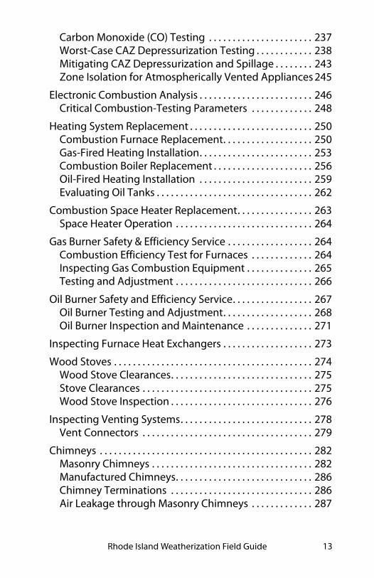
Carbon Monoxide (CO) Testing . . . . . . . . . . . . . . . . . . . . . . 237Worst-Case CAZ Depressurization Testing . . . . . . . . . . . . 238Mitigating CAZ Depressurization and Spillage . . . . . . . . 243Zone Isolation for Atmospherically Vented Appliances 245
Electronic Combustion Analysis . . . . . . . . . . . . . . . . . . . . . . . . 246Critical Combustion-Testing Parameters . . . . . . . . . . . . . 248
Heating System Replacement . . . . . . . . . . . . . . . . . . . . . . . . . . 250Combustion Furnace Replacement. . . . . . . . . . . . . . . . . . . 250Gas-Fired Heating Installation. . . . . . . . . . . . . . . . . . . . . . . . 253Combustion Boiler Replacement . . . . . . . . . . . . . . . . . . . . . 256Oil-Fired Heating Installation . . . . . . . . . . . . . . . . . . . . . . . . 259Evaluating Oil Tanks . . . . . . . . . . . . . . . . . . . . . . . . . . . . . . . . . 262
Combustion Space Heater Replacement. . . . . . . . . . . . . . . . 263Space Heater Operation . . . . . . . . . . . . . . . . . . . . . . . . . . . . . 264
Gas Burner Safety & Efficiency Service . . . . . . . . . . . . . . . . . . 264Combustion Efficiency Test for Furnaces . . . . . . . . . . . . . 264Inspecting Gas Combustion Equipment . . . . . . . . . . . . . . 265Testing and Adjustment . . . . . . . . . . . . . . . . . . . . . . . . . . . . . 266
Oil Burner Safety and Efficiency Service. . . . . . . . . . . . . . . . . 267Oil Burner Testing and Adjustment. . . . . . . . . . . . . . . . . . . 268Oil Burner Inspection and Maintenance . . . . . . . . . . . . . . 271
Inspecting Furnace Heat Exchangers . . . . . . . . . . . . . . . . . . . 273
Wood Stoves . . . . . . . . . . . . . . . . . . . . . . . . . . . . . . . . . . . . . . . . . . 274Wood Stove Clearances. . . . . . . . . . . . . . . . . . . . . . . . . . . . . . 275Stove Clearances . . . . . . . . . . . . . . . . . . . . . . . . . . . . . . . . . . . . 275Wood Stove Inspection . . . . . . . . . . . . . . . . . . . . . . . . . . . . . . 276
Inspecting Venting Systems. . . . . . . . . . . . . . . . . . . . . . . . . . . . 278Vent Connectors . . . . . . . . . . . . . . . . . . . . . . . . . . . . . . . . . . . . 279
Chimneys . . . . . . . . . . . . . . . . . . . . . . . . . . . . . . . . . . . . . . . . . . . . . 282Masonry Chimneys . . . . . . . . . . . . . . . . . . . . . . . . . . . . . . . . . . 282Manufactured Chimneys. . . . . . . . . . . . . . . . . . . . . . . . . . . . . 286Chimney Terminations . . . . . . . . . . . . . . . . . . . . . . . . . . . . . . 286Air Leakage through Masonry Chimneys . . . . . . . . . . . . . 287

Table of Contents14
Special Venting Considerations for Gas . . . . . . . . . . . . . . . . . 288Venting Fan-Assisted Furnaces and Boilers . . . . . . . . . . . 289
Combustion Air. . . . . . . . . . . . . . . . . . . . . . . . . . . . . . . . . . . . . . . . 291Un-Confined-Space Combustion Air . . . . . . . . . . . . . . . . . 292Confined-Space Combustion Air . . . . . . . . . . . . . . . . . . . . . 293
Ducted Air Distribution . . . . . . . . . . . . . . . . . . . . . . . . . . . . . . . . 295Sequence of Operations . . . . . . . . . . . . . . . . . . . . . . . . . . . . . 295Solving Airflow Problems . . . . . . . . . . . . . . . . . . . . . . . . . . . . 296Unbalanced Supply-Return Airflow Test . . . . . . . . . . . . . . 300Evaluating Furnace Performance. . . . . . . . . . . . . . . . . . . . . 303Rooftop Units (Air Handlers) . . . . . . . . . . . . . . . . . . . . . . . . . 305Improving Forced-Air System Airflow . . . . . . . . . . . . . . . . 308Air Filtration for Air Handlers. . . . . . . . . . . . . . . . . . . . . . . . . 310
Evaluating Duct Air Leakage . . . . . . . . . . . . . . . . . . . . . . . . . . . 312Troubleshooting Duct Leakage . . . . . . . . . . . . . . . . . . . . . . 312Measuring Duct Air Leakage with a Duct Blower . . . . . . 316Measuring House Pressure Caused by Duct Leakage . . 319
Sealing Duct Leaks . . . . . . . . . . . . . . . . . . . . . . . . . . . . . . . . . . . . 320General Duct-Sealing Methods. . . . . . . . . . . . . . . . . . . . . . . 320Sealing Return Ducts . . . . . . . . . . . . . . . . . . . . . . . . . . . . . . . . 321Sealing Supply Ducts . . . . . . . . . . . . . . . . . . . . . . . . . . . . . . . . 322Materials for Duct Sealing. . . . . . . . . . . . . . . . . . . . . . . . . . . . 325
Duct Insulation . . . . . . . . . . . . . . . . . . . . . . . . . . . . . . . . . . . . . . . . 325Spray Foam Duct Insulation. . . . . . . . . . . . . . . . . . . . . . . . . . 327
Hot-Water Space-Heating Distribution . . . . . . . . . . . . . . . . . 327Boiler Efficiency and Maintenance . . . . . . . . . . . . . . . . . . . 328Distribution System Improvements . . . . . . . . . . . . . . . . . . 329
Steam Heating and Distribution. . . . . . . . . . . . . . . . . . . . . . . . 332Steam System Maintenance . . . . . . . . . . . . . . . . . . . . . . . . . 333Steam System Energy Conservation . . . . . . . . . . . . . . . . . . 334
Programmable Thermostats . . . . . . . . . . . . . . . . . . . . . . . . . . . 337
Electric Heat. . . . . . . . . . . . . . . . . . . . . . . . . . . . . . . . . . . . . . . . . . . 338Electric Baseboard Heat. . . . . . . . . . . . . . . . . . . . . . . . . . . . . . 338Electric Furnaces . . . . . . . . . . . . . . . . . . . . . . . . . . . . . . . . . . . . 339

Rhode Island Weatherization Field Guide 15
Central Heat-Pump Energy Efficiency . . . . . . . . . . . . . . . . 339Room Heat Pumps . . . . . . . . . . . . . . . . . . . . . . . . . . . . . . . . . . 343Ductless Minisplit Pumps . . . . . . . . . . . . . . . . . . . . . . . . . . . . 345Duct Leakage and System Airflow. . . . . . . . . . . . . . . . . . . . 346Evaluating Heat-Pump Charge . . . . . . . . . . . . . . . . . . . . . . . 346
SWS Alignment. . . . . . . . . . . . . . . . . . . . . . . . . . . . . . . . . . . . . . . . 347
9: Ventilation
Pollutant Control . . . . . . . . . . . . . . . . . . . . . . . . . . . . . . . . . . . . . . 353Pollution-Control Checklist . . . . . . . . . . . . . . . . . . . . . . . . . . 354
ASHRAE Standard 62.2–2016 Ventilation . . . . . . . . . . . . . . . 354ASHRAE 62.2–2016 Components. . . . . . . . . . . . . . . . . . . . . 355Whole-Dwelling Ventilation Requirement . . . . . . . . . . . . 355Local Exhaust Ventilation Requirement. . . . . . . . . . . . . . . 356Infiltration Credit . . . . . . . . . . . . . . . . . . . . . . . . . . . . . . . . . . . . 358
Fan and Duct Specifications. . . . . . . . . . . . . . . . . . . . . . . . . . . . 358Fan Specifications . . . . . . . . . . . . . . . . . . . . . . . . . . . . . . . . . . . 358Termination Fittings . . . . . . . . . . . . . . . . . . . . . . . . . . . . . . . . . 360Duct Sizing. . . . . . . . . . . . . . . . . . . . . . . . . . . . . . . . . . . . . . . . . . 362Duct Materials and Installation . . . . . . . . . . . . . . . . . . . . . . . 363
Commissioning Ventilation Systems. . . . . . . . . . . . . . . . . . . . 365
Whole-Dwelling Ventilation Systems . . . . . . . . . . . . . . . . . . . 365Exhaust Ventilation . . . . . . . . . . . . . . . . . . . . . . . . . . . . . . . . . . 365Exhaust Ventilation . . . . . . . . . . . . . . . . . . . . . . . . . . . . . . . . . . 367Supply Ventilation. . . . . . . . . . . . . . . . . . . . . . . . . . . . . . . . . . . 368Balanced Ventilation . . . . . . . . . . . . . . . . . . . . . . . . . . . . . . . . 370Adaptive Ventilation. . . . . . . . . . . . . . . . . . . . . . . . . . . . . . . . . 371Rooftop-Unit (RTUs) Economizer Ventilation . . . . . . . . . 372
Garage Exhaust Ventilation . . . . . . . . . . . . . . . . . . . . . . . . . . . . 372
Air Filtration for Indoor Air Quality . . . . . . . . . . . . . . . . . . . . . 374Installing Filters for Outdoor Air . . . . . . . . . . . . . . . . . . . . . . 374
Attic Ventilation . . . . . . . . . . . . . . . . . . . . . . . . . . . . . . . . . . . . . . . 375Attic Ventilation as a Solution for Moisture Problems . 375

Table of Contents16
When to Install Attic Ventilation. . . . . . . . . . . . . . . . . . . . . . 375Attic Ventilation Requirements . . . . . . . . . . . . . . . . . . . . . . 376Unventilated Attics . . . . . . . . . . . . . . . . . . . . . . . . . . . . . . . . . . 378
Crawl Space Ventilation. . . . . . . . . . . . . . . . . . . . . . . . . . . . . . . . 378Naturally Ventilated Crawl Spaces. . . . . . . . . . . . . . . . . . . . 379Power-Ventilated Crawl Spaces . . . . . . . . . . . . . . . . . . . . . . 379Whole-House Fans . . . . . . . . . . . . . . . . . . . . . . . . . . . . . . . . . . 380Window Fans. . . . . . . . . . . . . . . . . . . . . . . . . . . . . . . . . . . . . . . . 382Air Circulation . . . . . . . . . . . . . . . . . . . . . . . . . . . . . . . . . . . . . . . 383
SWS Alignment. . . . . . . . . . . . . . . . . . . . . . . . . . . . . . . . . . . . . . . . 383
10: Baseload Measures
Baseload Versus Seasonal Use. . . . . . . . . . . . . . . . . . . . . . . . . . 388
Refrigerator Replacement and Maintenance . . . . . . . . . . . . 391Refrigerator Replacement . . . . . . . . . . . . . . . . . . . . . . . . . . . 392Refrigerator Cleaning and Tuning . . . . . . . . . . . . . . . . . . . . 392
Lighting-Efficiency Improvements . . . . . . . . . . . . . . . . . . . . . 393LEDs versus CFLs . . . . . . . . . . . . . . . . . . . . . . . . . . . . . . . . . . . . 393Light Color . . . . . . . . . . . . . . . . . . . . . . . . . . . . . . . . . . . . . . . . . . 394Lighting Retrofit Equipment . . . . . . . . . . . . . . . . . . . . . . . . . 394
Clothes Washer Selection/Replacement . . . . . . . . . . . . . . . . 397Clothes Washer Selection . . . . . . . . . . . . . . . . . . . . . . . . . . . . 397Clothes Washer Installation . . . . . . . . . . . . . . . . . . . . . . . . . . 397
Clothes Dryer Selection/Replacement . . . . . . . . . . . . . . . . . . 398Clothes Dryer Selection . . . . . . . . . . . . . . . . . . . . . . . . . . . . . . 398Clothes Dryer Installation . . . . . . . . . . . . . . . . . . . . . . . . . . . . 398Clothes Dryers Service and Venting . . . . . . . . . . . . . . . . . . 399
Water-Heating Energy Savings . . . . . . . . . . . . . . . . . . . . . . . . . 401Water-Saving Shower Heads and Faucet Aerators . . . . 402Water-Heater Pipe Insulation . . . . . . . . . . . . . . . . . . . . . . . . 404
Storage Water Heaters . . . . . . . . . . . . . . . . . . . . . . . . . . . . . . . . . 405Determining a Storage Water Heater’s Insulation Level . . .405

Rhode Island Weatherization Field Guide 17
Storage Water-Heater Selection. . . . . . . . . . . . . . . . . . . . . . 406
Alternative Water-Heaters . . . . . . . . . . . . . . . . . . . . . . . . . . . . . 407Sidewall-Vented Gas Storage Water Heaters . . . . . . . . . . 407On-Demand Gas Water Heaters . . . . . . . . . . . . . . . . . . . . . . 408Heat Pump Water Heaters . . . . . . . . . . . . . . . . . . . . . . . . . . . 408
Water Heater Installation . . . . . . . . . . . . . . . . . . . . . . . . . . . . . . 409
Comparing Water Heaters . . . . . . . . . . . . . . . . . . . . . . . . . . . . . 410Safety Comparison . . . . . . . . . . . . . . . . . . . . . . . . . . . . . . . . . . 410Reliability Comparison. . . . . . . . . . . . . . . . . . . . . . . . . . . . . . . 411Efficiency and Energy Cost Comparison . . . . . . . . . . . . . . 412
SWS Alignment. . . . . . . . . . . . . . . . . . . . . . . . . . . . . . . . . . . . . . . . 413
11: Mobile Homes
Mobile Home Heating . . . . . . . . . . . . . . . . . . . . . . . . . . . . . . . . . 418Furnace Maintenance and Energy Efficiency. . . . . . . . . . 420Furnace Replacement . . . . . . . . . . . . . . . . . . . . . . . . . . . . . . . 420
Mobile Home Cooling and Ventilation Systems . . . . . . . . . 421Mobile Home Ventilation Systems . . . . . . . . . . . . . . . . . . . 421
Mobile Home Air Sealing. . . . . . . . . . . . . . . . . . . . . . . . . . . . . . . 422Shell Air Leakage Locations . . . . . . . . . . . . . . . . . . . . . . . . . . 423Duct Leak Locations . . . . . . . . . . . . . . . . . . . . . . . . . . . . . . . . . 424Belly Pressure Test. . . . . . . . . . . . . . . . . . . . . . . . . . . . . . . . . . . 425
Mobile Home Insulation . . . . . . . . . . . . . . . . . . . . . . . . . . . . . . . 428Insulating Mobile Home Roof Cavities . . . . . . . . . . . . . . . . 428Mobile Home Sidewall Insulation . . . . . . . . . . . . . . . . . . . . 434Mobile Home Floor Insulation. . . . . . . . . . . . . . . . . . . . . . . . 436
Mobile Home Windows and Doors . . . . . . . . . . . . . . . . . . . . . 439Mobile Home Storm Windows . . . . . . . . . . . . . . . . . . . . . . . 440Replacing Mobile Home Windows . . . . . . . . . . . . . . . . . . . 441Mobile Home Doors . . . . . . . . . . . . . . . . . . . . . . . . . . . . . . . . . 442
Cool Roofs for Mobile Homes . . . . . . . . . . . . . . . . . . . . . . . . . . 442Applying the Coating. . . . . . . . . . . . . . . . . . . . . . . . . . . . . . . . 443

Table of Contents18
Mobile Home Skirting. . . . . . . . . . . . . . . . . . . . . . . . . . . . . . . . . . 444
SWS Alignment. . . . . . . . . . . . . . . . . . . . . . . . . . . . . . . . . . . . . . . . 444
12: Air Leakage Diagnostics
Shell Air-Leakage Fundamentals . . . . . . . . . . . . . . . . . . . . . . . 447Goals of Air-Leakage Testing . . . . . . . . . . . . . . . . . . . . . . . . . 448
Single-Family Airtightness Testing . . . . . . . . . . . . . . . . . . . . . 450Blower-Door Principles . . . . . . . . . . . . . . . . . . . . . . . . . . . . . . 450Preparing for a Blower Door Test . . . . . . . . . . . . . . . . . . . . . 453Blower-Door Test Procedures . . . . . . . . . . . . . . . . . . . . . . . . 454Approximate Leakage Area (ALA) . . . . . . . . . . . . . . . . . . . . 456Testing Equipment . . . . . . . . . . . . . . . . . . . . . . . . . . . . . . . . . . 457
Testing Air Barriers . . . . . . . . . . . . . . . . . . . . . . . . . . . . . . . . . . . . 457Primary Versus Secondary Air Barriers . . . . . . . . . . . . . . . . 460Simple Pressure Tests. . . . . . . . . . . . . . . . . . . . . . . . . . . . . . . . 461Simple Zone Pressure Testing. . . . . . . . . . . . . . . . . . . . . . . . 463Locating the Thermal Boundary. . . . . . . . . . . . . . . . . . . . . . 467
SWS Alignment. . . . . . . . . . . . . . . . . . . . . . . . . . . . . . . . . . . . . . . . 470
Appendices 471
R-values for Common Materials
ASHRAE 62.2 Duct Sizing
Fire Testing and Rating
Maximum CAZ Depressurization
Gas Furnace Output Table
BPI Combustion-Testing Diagrams
DOE Health and Safety Guidance
Glossary 479

Rhode Island Weatherization Field Guide 19
Index 543

Table of Contents20

Rhode Island Weatherization Field Guide 21
CHAPTER 1: HEALTH AND SAFETY
This chapter discusses some of the most important hazards that you find both in residential buildings and on weatherization jobs. The SWS contains many health-and-safety requirements that relate to various cost-effective energy-conservation mea-sures (ECMs). These SWS requirements are referenced in this chapter.
The chapter begins with health, safety, and durability of the building. If health-and-safety problems affect the cost-effective ECMs you select, solve the problems before or during the weatherization work.
Workers are the most important asset of WAP. We discuss their health and safety at the end of this chapter.
Customer Health and Safety
House fires, moisture problems, carbon-monoxide poisoning, and lead-paint poisoning are the most common and serious health and safety problems found in homes.
Alert residents to any health and safety hazards that you find. Discuss known or suspected health concerns with occupants; take extra precautions based on occupant sensitivity to environ-mental hazards, such as chemicals and allergens.
✓ Inspect the home for fire hazards such as improperly installed electrical equipment, flammable materials stored near combustion appliances, or malfunctioning heating appliances. Discuss these hazards with occupants, and remove these hazards if possible, as allowed under WPN 17-7.
✓ Understand and comply with the fire-containment code requirements of the IRC and the state of Rhode Island.
SWS Detail: 2.0100.1 Global Worker Safety

Health and Safety22
✓ Test combustion appliances for carbon monoxide and related hazards. Also measure carbon monoxide (CO) in the ambient air. Investigate and eliminate CO.
✓ Find moisture problems, and discuss them with the occu-pant. Solve moisture problems before or during weather-ization work. See page 29.
✓ Obey the EPA Repair, Renovation, and Painting rules when working on homes built before 1978. Prevent dust during all weatherization projects. Explain the lead paint hazard and tell residents what you’re doing to protect them. See page 40.
Worker Health and Safety
In the worker-safety section at the end of this chapter, we dis-cuss the most dangerous hazards present during weatherization and how to avoid these hazards. Hazards include: driving, falls, back injuries, cuts, chemical exposure, repetitive stress, and electrical shocks.
1.1 EDUCATE OCCUPANTS AND BUILDING OPERATORS
Homes are complex systems of building envelopes and mechan-ical systems that harbor a variety of hazards. Educate occupants, landlords, and building operators about the health and safety hazards and the improvements that you make to mitigate these hazards.
✓ Explain any health or safety hazard you see with fellow workers, occupants, and building operators, and discuss how to mitigate the hazard.
SWS Details: 2.0203.4 Occupant Education, 2.0702.3 Building Operations Staff Education

Rhode Island Weatherization Field Guide 23
✓ Suggest contacting specialists to mitigate particular haz-ards if appropriate.
✓ Explain equipment operation and maintenance (O&M).
✓ Provide an O&M procedures manuals and manufacturers’ equipment specifications. Encourage occupants or staff to store important documents in a safe and obvious location.
✓ Instruct occupants or staff to remove combustible materi-als from near ignition sources.
✓ Inform occupants and staff about smoke alarms, carbon monoxide (CO) alarms, and combination alarms, and explain their functioning.
✓ Suggest that occupants or staff remove or isolate indoor air quality hazards such as pesticides, petroleum products, and solvents.
✓ For complex mechanical systems in multifamily buildings.
1.2 FIRE SAFETY
The building codes focus on preventing the spread of fire within and between buildings. A fire barrier is a wall assembly that has been tested and certified to withstand and contain a fire for a particular time duration.
A fire partition is a fire barrier that prevents the spread of fire between the sections of a building. A firewall is a structural fire barrier between buildings that is designed to remain standing during and after a fire.
Flame spread is a tested value of how fast a material burns com-pared to red oak planks.
A thermal barrier is a sheeting material that protects the materi-als behind it from reaching a temperature of 250°F or breeching during a fire. One-half-inch drywall is the most commonly used thermal barrier and is rated for 15 minutes of protection. Fire

Health and Safety24
partitions in multifamily buildings usually require a wall assem-bly with a 2-hour rating.
An ignition barrier is a material used with foam insulation to prevent the foam from igniting. The code specifies a number of materials that can serve as ignition barriers including drywall, plywood, fibrous insulation, galvanized steel, and intumescent paint.
See also "Fire Testing and Rating" on page 473.
1.3 CARBON MONOXIDE (CO)
Carbon monoxide is a colorless, odorless, poisonous gas. The EPA’s suggested maximum 8-hour CO exposure is 9 ppm as measured in room air. CO at or above 9 ppm is often caused by malfunctioning combustion appliances in the home, although cigarette smoking or auto exhaust are also common CO sources. The EPA’s one-hour CO limit is 35 ppm as measured.
SWS Details: 2.0105.1 Combustion Worker Safety, 2.0201.2 Combustion Safety, 2.0201.1 Combustion Appliance Zone (CAZ) Testing
10
20
30
40
50
60
70
80
90
1 2 3 4
Collapse
Headache Dizziness
Impaired judgement
Fatal
Hour s of Exposure
CO
per
cen
t blo
od
sat
ura
tion
100
200
400
800
1600 3200 Effects of CO: This graph’s
6 curves represent different CO exposure levels in PPM (parts per million).
Rhode Island Weatherization Field Guide 25
1.3.1 Causes of Carbon Monoxide (CO)
CO is released by unvented gas space heaters, kerosene space heaters, backdrafting vented space heaters, gas ranges, leaky wood stoves, and motor vehicles idling near the home. Central furnaces and boilers that backdraft may also lead to high levels of CO.
CO is usually caused by these conditions.
• A combustion appliance is overfired compared to its rated input.
• Backdrafting combustion gases are smothering the flame.
• An object interferes with the flame (a pan over a gas burner on a range top, for example).
• Too-little combustion air.
• Rapidly moving air interferes with the flame.
• Burner misalignment causes a distorted flame.
• Flue or heat exchanger blockage interferes with the flow of flue gases.
Measure CO at the exhaust port of the heat exchanger. Identify and correct CO problems.
Testing for Carbon Monoxide (CO)
The most common CO-test instruments use electronic sensors with a digital displays showing parts per million (ppm). Read the manufacturer’s instructions on zeroing the meter — usually by adjusting the meter in outdoor air. CO test equipment must usually be re-calibrated every 6 months, using factory-specified procedures.
Air-free CO measurement includes both CO and O2 sensing with a calculation to find the CO concentration in undiluted flue gases that contain no oxygen. Air-free CO measurement avoids the perception that moving the testing probe or diluting

Health and Safety26
CO are solutions to elevated levels of CO. See "Carbon Monoxide (CO) Testing" on page 237.
Technicians must test for CO both before and after weatheriza-tion.
1.4 SMOKE AND CARBON MONOXIDE (CO) ALARMS
All Weatherization Auditors and Monitors are required to wear a personal CO detector at all times when in the home.
Every home should have at least one smoke alarm. Homes with combustion appliances must also have a carbon monoxide (CO) alarm. Install these alarms on each level, near the bedrooms. New buildings require alarms in hallways and inside bedrooms.
Install combination CO/smoke alarms in homes with combus-tion appliances that lack both smoke alarms and CO alarms.
Don’t install alarms within 15 feet of gas ranges or combustion devices because small amounts of smoke or CO can cause nui-sance false alarms.
Single-function alarms or combination alarms can interconnect electrically for whole-building protection. If one alarm sounds the other alarms sound too.
Educate occupants about the alarms and what to do if the alarm sounds. Discuss the low-battery chirping sound and how to replace the battery. Tell residents that alarms last less than 10 years and that a different sound will alert them when the alarm fails.
1.4.1 Smoke Alarms
Install smoke alarms labeled UL 217 in buildings where they don’t exist or don’t work.
SWS Detail: 2.0301.1 Smoke Alarm

Rhode Island Weatherization Field Guide 27
✓ Install at least one smoke alarm in each home on each floor.
✓ If mounted on a wall, mount the alarm from 4 to 12 inches from the ceiling.
✓ If mounted on a ceiling, mount the alarm at least 6 inches from the nearest wall.
✓ If battery powered, prefer long-life lithium batteries.
✓ If hard wired, connect the alarm to a circuit that is ener-gized at all times.
Don’t install smoke alarms in these situations.
• Within 12 inches of exterior doors and windows
• In a garage or attic, unless the garage or attic has an installed heating system.
• With an electrical connection to a switched circuit
• With a connection to a ground-fault interrupter circuit (GFCI)
1.4.2 CO Alarms
Install at least one CO alarm on each habitable floor of all weatherized dwellings or weatherized apartments. CO alarms must comply with these specifications.
✓ Have a label with a UL 2034 listing.
✓ If hard wired, connect to a circuit that is energized at all times by plugging in to an electrical receptacle.
✓ If battery powered, prefer long-life lithium batteries.
✓ Have a sensor-life alarm.
Don’t install CO alarms in these situations.
SWS Detail: 2.0301.2 Carbon Monoxide Alarm or Monitor, 2.0201.2 Combustion Safety

Health and Safety28
• In a room that may get too hot or cold for alarm to function properly
• Within 5 feet of a combustion appliance, vent, or chimney
• Within 5 feet of a storage area for vapor-producing chemi-cals
• Within 12 inches of exterior doors and windows
• With an electrical connection to a switched circuit
• With a connection to a ground-fault circuit interrupter (GFCI)
1.5 GAS RANGE AND OVEN SAFETY
Gas ovens can release CO, natural gas, or propane into a kitchen. Test the burners for safe combustion with these steps and do the recommended improvements.
1. Test for gas leaks in the gas piping in and around the range and oven and seal leaks.
2. Check oven for stored items. Turn the oven burner and then range burners to high one-by-one. Inspect the flames and test them for CO. For the oven burner test at its outlet. For range burners, hold the test probe at least 8 inches above the flame.
3. If the CO reading is over 225 ppm, advise customer of the issue and require clean & tune or defer.
4. If the CO reading remains over 225 ppm as measured, consider further measures. These include: scheduling a service call by a gas specialist; installing a kitchen fan if none currently exists; or installing an additional CO
SWS Details: 2.0100.1 Global Worker Safety, 2.0201.2 Combus-tion Safety - Make-up Air, 6.6005.2 Kitchen Range, 6.6005.4 Kitchen Range Hood within Dwelling Unit (All Building Types)

Rhode Island Weatherization Field Guide 29
alarm near the kitchen but at least 20 feet away from the range.
Caution: To protect yourself and the occupants, measure CO in the ambient air in the kitchen during these tests. If the ambient CO reading is 35 ppm or more, discontinue the testing.
Client Education about Ranges
Educate clients about the following safety practices in using their gas range.
✓ Never use a range burner or gas oven as a space heater.
✓ Open a window, and turn on the kitchen exhaust fan when using the range or oven.
✓ Never install aluminum foil around a range burner or oven burner because the foil could interfere with the flame.
✓ Keep range burners and ovens clean to prevent dirt from interfering with combustion.
✓ Burners should display hard blue flames. Advise the cus-tomer if you notice yellow flames, white flames, wavering flames, or noisy flames.
1.6 REDUCING MOISTURE PROBLEMS
SWS Detail: 2.0401.1 Air Sealing Moisture Precautions
35
225
outlet
CO from range and oven: Measure CO at oven in undiluted flue gases.
Measure ambient CO in the area of the range, but not directly above the burners or oven vent.

Health and Safety30
Moisture causes billions of dollars worth of property damage, sickness, and high energy bills each year in American homes. Water damages building materials by dissolving glues and mor-tar, corroding metal, and nurturing pests like mold, dust mites, and insects. These pests, in turn, cause respiratory illness.
Water reduces the thermal resistance of insulation and other building materials. High humidity also increases air-condition-ing and dehumidifier costs because the air conditioner removes moisture from the air to provide comfort.
The most common sources of moisture are leaky roofs and damp foundations. Other critical moisture sources include dry-ers venting indoors, showers, cooking appliances, and unvented gas appliances like ranges or decorative fireplaces. Clients con-trol many of these moisture sources, so educate them about how to reduce the moisture sources discussed here.
Climate is also a major contributor to moisture problems. The more rain, extreme temperatures, and humid weather a region experiences, the more of its homes are vulnerable to moisture problems.
soil moisture
oven & range
perspiration
showeringwasher & dryer
aquariumhumidifier
Moisture sources: Household moisture can often be controlled at the source by informed and motivated occupants, who work to control moisture sources like these.

Rhode Island Weatherization Field Guide 31
Reducing moisture sources is the first priority for solving mois-ture problems. Next most important are air and vapor barriers to prevent water vapor from migrating through building cavi-ties. Relatively tight homes need mechanical ventilation to remove accumulating water vapor.
1.6.1 Symptoms of Moisture Problems
Condensation on windows, walls, and other cool surfaces sig-nals high relative humidity and the need to reduce moisture sources.
During very cold weather or summer air conditioning, conden-sation may occur on cold surfaces. Occasional condensation isn’t a major problem. However, if condensation happens fre-quently, take action to reduce moisture sources. Adding insula-tion helps eliminate cold walls, ceilings, and air-conditioning ducts where water vapor condenses.
Moisture problems arise when parts of the building become wet often and remain wet. Moisture in organic or porous building materials reaches a threshold that allows pests like mold, dust mites, and insects to thrive. These pests can cause or trigger
Table 1-1: Moisture Sources and Their Potential Contributions
Moisture SourcePotential Amount
Pints
Ground moisture 0–105 per day
Unvented combustion space heater 0.5–20 per hour
Seasonal evaporation from materials 6–19 per day
Dryers venting indoors 4–6 per load
Dish washing 1–2 per day
Cooking (meals for four persons) 2–4 per day
Showering 0.5 per shower
SWS Detail: 2.0401.1 Air Sealing Moisture Precautions
Health and Safety32
asthma, bronchitis, and other respiratory ailments because they produce potent biological allergens.
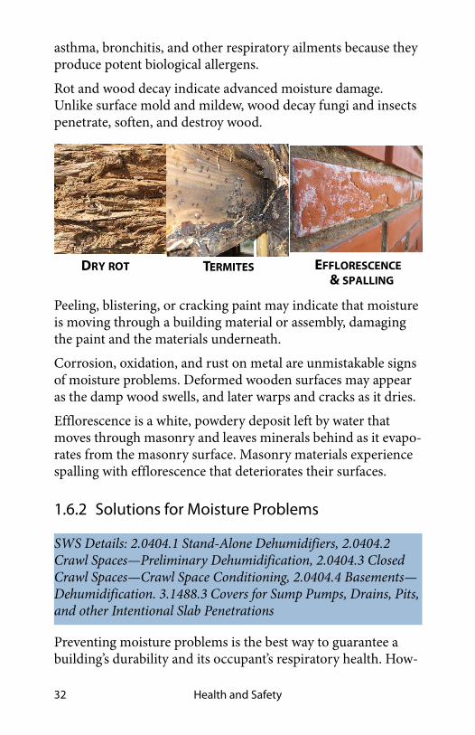
Rot and wood decay indicate advanced moisture damage. Unlike surface mold and mildew, wood decay fungi and insects penetrate, soften, and destroy wood.
Peeling, blistering, or cracking paint may indicate that moisture is moving through a building material or assembly, damaging the paint and the materials underneath.
Corrosion, oxidation, and rust on metal are unmistakable signs of moisture problems. Deformed wooden surfaces may appear as the damp wood swells, and later warps and cracks as it dries.
Efflorescence is a white, powdery deposit left by water that moves through masonry and leaves minerals behind as it evapo-rates from the masonry surface. Masonry materials experience spalling with efflorescence that deteriorates their surfaces.
1.6.2 Solutions for Moisture Problems
Preventing moisture problems is the best way to guarantee a building’s durability and its occupant’s respiratory health. How-
SWS Details: 2.0404.1 Stand-Alone Dehumidifiers, 2.0404.2 Crawl Spaces—Preliminary Dehumidification, 2.0404.3 Closed Crawl Spaces—Crawl Space Conditioning, 2.0404.4 Basements—Dehumidification. 3.1488.3 Covers for Sump Pumps, Drains, Pits, and other Intentional Slab Penetrations
DRY ROT TERMITES EFFLORESCENCE& SPALLING

Rhode Island Weatherization Field Guide 33
ever, the solutions get progressively more expensive if simple solutions don’t solve the problems.
Inexpensive Moisture Solutions
If moisture source reduction isn’t adequate to prevent moisture problems, try these solutions after preventive measures are in place.
✓ Install a ground moisture barrier. See “Crawl Space Mois-ture and Safety Issues” on page 36.
✓ Verify that clothes dryers and exhaust fans vent to the out-doors and not into crawl spaces or attics.
✓ Seal water leaks in the foundation.
✓ Seal water leaks in the roof.
✓ Remove unvented space heaters, a major source of mois-ture, from the dwelling.
✓ Educate clients about ways to reduce moisture that they control.
✓ Educate customers to avoid excessive watering around the building’s perimeter. Watering lawns and plants close to the building can dampen its foundation. In moist climates, cut shrubbery back away from the foundation, allowing air to circulate near the foundation.
UNVENTED WATER POOLING DUCT CONDENSATIONSPACE HEATER

Health and Safety34
✓ Insulate air-conditioning ducts to prevent summer con-densation.
More Costly Moisture Solutions
Follow these preventive measures before trying any of the solu-tions in the next section.
✓ Install or improve air barriers and vapor barriers to pre-vent air leakage and vapor diffusion from transporting moisture into building cavities. See page 447.
✓ Add insulation to the walls, floor, and ceiling of a building to keep the indoor surfaces warmer and less prone to win-ter condensation. During cold weather, well-insulated homes can tolerate higher humidity without condensation than can poorly insulated homes.
✓ A sump pump is the most effective remedy when ground water continually seeps into a basement or crawl space and collects there as standing water. Persistent ground-water seepage may only be solved by connecting an interior perimeter drain to the sump. The sump cover must not interfere with drainage and must be accessible and rigid. See "Sump pump" on page 37.
Stopping water intrusion: Take all necessary steps to protect homes from water intrusion.
rain gutter
sloped groundperforated drain pipe
downspout directs water away
gravel drainage
sump pump

Rhode Island Weatherization Field Guide 35
✓ Ventilate the dwelling with drier outdoor air to dilute the more humid indoor air. Ventilation is only effective when the outdoor air is drier than the inside air, such as in win-ter. In summer, outdoor air may be more or less humid than indoor air depending on climate, time of day, and whether the dwelling is air conditioned. See "Ventilation" on page 353.
Dehumidifiers and Air-Conditioners for Drying
As a last resort, remove moisture from indoor air by cooling the air to below its dew point with dehumidifiers in winter and air-conditioners in summer. Using air conditioners and dehumidifi-ers for drying a building is the most expensive solution. Try all the moisture solutions discussed previously before resorting to a dehumidifier.
The dehumidifier should meet these specifications.
✓ Must be ENERGY STAR or more efficient.
✓ Must have a fan-off option.
✓ Must retain automatic settings after power interruption.
✓ Must be rated for low temperature operation if located in a basement or crawl space.
When you install a dehumidifier, observe these requirements.
✓ Install the dehumidifier in a location that allows free air-flow around it.
✓ The dehumidifier should have automatic controls to limit energy and power.
LOW TEMP
HIGH HUMIDITY
HIGH TEMP
LOW HUMIDITY
Dehumidifiers: In damp climates, dehumidifiers protect homes from excessive moisture.

Health and Safety36
✓ Make sure that the dehumidifier works and measure the relative humidity in the space before completing the installation.
✓ Drain the dehumidifier’s collected water to a plumbing drain in a code-approved way.
✓ Give the homeowner the user guide and warranty infor-mation, and explain how to use the dehumidifier. Show the occupant how to clean or change the filter and how to clean the condensate drain.
1.6.3 Crawl Space Moisture and Safety Issues
Air, water vapor, liquid water, and pollutants move through soil and into crawl spaces and dirt-floor basements. Even if soil’s surface seems dry and airtight, the soil may allow a lot of water vapor and soil gases to enter a home.
Cover the ground with an airtight moisture barrier to prevent the movement of moisture and soil gases from the ground into the crawl space using these procedures.
✓ The crawl space should have an access hatch or door that is sized adequately for a worker or a resident to enter and exit.
✓ Remove biodegradable matter, such as wood and card-board, from the crawl space.
✓ Cover the ground completely with a ground moisture bar-rier such as 6-mil polyethylene.
✓ The edges of the barrier should run at least 12” up the foundation walls and internal supporting structures. Fas-ten the barrier with wood strips, masonry fasteners, and
SWS Detail: 2.0111.2 Crawl Spaces—Pre-Work Qualifications, 2.0111.3 Crawl Spaces—Debris Removal, 2.0403.2 Closed Crawl Spaces—Ground Moisture Barriers, 2.0403.1 Vented Crawl Spaces—Ground Moisture Barrier

Rhode Island Weatherization Field Guide 37
sealant. Installers may also adhere the barrier with poly-urethane adhesive or acoustical sealant to a clean and flat masonry surface.
✓ Seams must overlap 12 inches. Seal the edges and seams with urethane, acoustical sealant, butyl caulking, or con-struction tape to create an airtight seal between the crawl space and the ground underneath.
✓ To avoid trapping of moisture against wood surfaces, ground moisture barriers must not touch wood structural members, such as posts, mud sills, or floor joists.
1.6.4 Ground Moisture Source-Reduction
Observe the following specifications to avoid building deterio-ration from ground moisture. Finish the following tasks before air sealing the floor or installing underfloor insulation, with non-DOE funds or as allowed under DOE guidelines.
✓ Repair plumbing or sewer leaks.
✓ Solve all drainage problems, ground-water problems, wood-deterioration, and structural problems.
motor
impeller
ground water
Sump pump: Pumps water out of a sump or basin where water collects in a basement or crawl space.

Health and Safety38
✓ Verify that the ground outside the home slopes away from the foundation or that water doesn’t puddle near the foun-dation.
✓ Install or repair rain gutters as necessary, and verify that downspouts discharge rainwater at least 3 feet away from the home.
✓ Verify that all combustion vents (chimneys), clothes-dryer vents, and exhaust fan vents are vented to outdoors and not into crawl spaces.
✓ Suggest a sump pump for crawl spaces or basements with a history of flooding. The sump pump should be located in an area where it collects water from the entire below-grade area and pumps it away from the foundation to daylight.
✓ Provide crawl-space ventilation which follows the require-ments of the IRC and SWS. See “Crawl Space Ventilation” on page 378.
1.7 POLLUTANTS SOURCE CONTROL
Radon and asbestos are also important hazards to both occu-pants and workers.
1.7.1 Radon
Radon is a dangerous indoor air pollutant that comes from the ground through rocky soil. Studies predict about 20,000 lung cancer deaths per year are caused by radon exposure. Weather-ization workers should be aware of: the radon hazard, radon testing procedures, and radon mitigation strategies.
The EPA believes that any home with a radon concentration above 4 pico-Curies per liter (pC/l) of air should be modified to reduce the radon concentration. There are several common and
SWS Details: 2.0501.1 Radon—Air Sealing Considerations, 2.0501.2 Radon—Basements and Crawl spaces

Rhode Island Weatherization Field Guide 39
reliable tests for radon, which are performed by health depart-ments and private consultants throughout the U.S.
Energy conservation work usually has little effect on radon con-centrations. However, ground-moisture barriers and foundation air sealing may reduce radon concentrations in addition to reducing air leakage.
Radon Mitigation
DOE funds can’t pay for fans or other measures specifically designed for radon mitigation. Radon mitigation must use non-DOE funds. Since radon comes through the soil, mitigation strategies include the following.
1. Installing a plastic ground barrier and carefully sealing the seams and edges.
2. Sealing the walls and floor of the basement or crawl space.
3. Ventilating the crawl space or basement with an exhaust fan to dilute radon.
1.7.2 Asbestos Containing Materials (ACM)
Asbestos is classified as a “known carcinogen.” Asbestos is found in the following materials: boiler and steam-pipe insulation, duct insulation, floor tile, siding, roofing, some types of vermic-ulite, and some adhesives. Weatherization workers must be trained to recognize asbestos and to avoid disturbing it. Weath-erization workers should not perform either pressurization or depressurization blower door tests when there is a friable asbes-tos in the home. Penalties for mishandling asbestos-containing materials can amount to $25,000 per day.
DOE weatherization policy requires weatherization agencies to observe the following safety precautions regarding asbestos.
SWS Detail: 2.0104.1 Insulation Worker Safety

Health and Safety40
• Asbestos siding comes in sheets approximately 16 inches by 24 inches. It is very weatherproof but very brittle. Remove asbestos siding only if you can remove the siding without damaging it.
• Assume that asbestos is present in old gray-colored pipe insulation and duct insulation. Don’t disturb asbestos-con-taining pipe or duct insulation; also caution occupants to avoid disturbing asbestos.
• Don’t cut, drill, scrape, sand or brush ACM.
• Weatherization work on homes with vermiculite should be deferred. Provide homeowner with educational materials to have the vermiculite mitigated before weatherization work can start.
1.7.3 Lead-Safe Procedures
In 2010, The EPA’s Lead-Safe Renovation, Repair, and Painting (RRP) rule became a legal mandate for weatherization work.
Lead dust is dangerous because it damages the neurological sys-tems of people who ingest it. Lead often poisons children in pre-1978 homes because of paint disturbance during building improvement and because children’s hand-to-mouth behavior is common. Lead poisons workers when they inhale lead dust.
Lead paint was commonly used in homes built before 1978. Contractors working on these older homes should either assume the presence of lead paint or perform tests to rule out its presence.
EPA RRP Requirements
The RRP rule requires lead-safe containment procedures when-ever workers disturb painted surfaces of more than 6 square feet of interior surface per room or more than 20 square feet of exte-
SWS Detail: 2.0100.1 Global Worker Safety

Rhode Island Weatherization Field Guide 41
rior surface per side. Cutting, scraping, drilling, or other dust-creating activities disturb lead in pre-1978 homes. Disturbing paint on windows and doors always requires containment.
The RRP requires certifications, warnings, dust-prevention, dust collection, and housecleaning as summarized here.
✓ With pre-1978 homes, either test for lead-based paint or assume that lead-based paint is present.
✓ Every pre-1978 weatherization or renovation job must be supervised by a certified renovator with 8 hours of EPA-approved training when workers disturb more than the minimum paint area or when they disturb paint on win-dows or doors.
✓ Renovation firms must be registered with the EPA and employ one or more certified renovators.
✓ Signs and barriers must warn occupants and passersby not to enter the work area.
✓ Floor-to-ceiling dust-tight barriers must prevent the spread of dust from the work area.
✓ Plastic sheeting must protect surfaces and fixtures within the work area.
✓ Workers must clean work surfaces sufficiently to pass an EPA-approved dust-wipe test, conducted by the certified renovator.
✓ Workers must not track dust from the work area into the dwelling.

Health and Safety42
Additional Lead-Safe Work Practices
When engaging in the paint-disturbing weatherization activi-ties, follow these lead-safe work practices that were established by weatherization experts.
✓ Wear a tight-fitting respirator to protect yourself from breathing dust or other pollutants.
✓ Confine your work within the dwelling to the smallest possible floor area. Seal this area off carefully with floor-to-ceiling barriers made of disposable plastic sheeting, sealed at floor and ceiling with tape.
✓ Don’t use heat guns or power sanders in LSW work.
✓ Spray water on the painted surfaces to keep dust out of the air during drilling, cutting, or scraping painted surfaces.
Protective sheeting: Dust-tight floor-to-ceiling barriers must separate work areas from living areas, according to EPA’s RRP rule.

Rhode Island Weatherization Field Guide 43
✓ Erect an effective dust-containment system outdoors to prevent dust contamination to the soil around the dwell-ing.
✓ Use a dust-containment system with a HEPA vacuum when drilling holes indoors.
✓ Avoid taking lead dust home on clothing, shoes, or tools. Wear boot covers while in the work area, and remove them to avoid tracking dirt from the work area to other parts of the building. Wear disposable coveralls, or vacuum cloth coveralls with a HEPA vacuum before leaving the work area.
Wash thoroughly before eating, drinking, or quitting for the day.
1.8 ELECTRICAL SAFETY
Electrical fires and shocks are common and serious safety prob-lems. Electrical safety is a basic housing need, requiring atten-tion during home weatherization and repair.
SWS Detail: 2.0100.1 Global Worker Safety
Drill shroud connected to HEPA vacuum: Collect dust where you’re generating it.

Health and Safety44
Observe the following specifications for electrical safety in weatherizing existing homes.
✓ Whenever working around wiring, use a non-contact volt-age tester to determine whether circuits are live. Turn cir-cuits off at circuit breakers as appropriate.
✓ Inspect wiring, fuses, and circuit breakers to verify that wiring isn’t overloaded. If the auditor suspects that there are electrical issues that need attention, a licensed electri-cian should be contacted for further evaluation. Maximum capacity for 14-gauge wire is 15 amps and for 12-gauge wire is 20 amps.
✓ Confirm that all wire splices are enclosed in electrical junction boxes. If you plan to cover a junction box with insulation, attach a flag to mark its location.
✓ Don’t allow metal insulation shields to contact wiring.
✓ Verify that the electrical system is grounded to a ground rod with an uninterrupted electrical connection to the ground.
✓ If the house is not grounded, it should be grounded by a licensed electrician.
✓ Whenever you doubt the integrity of a home’s electrical system, use a generator to power insulation blowers and other large power tools.
S-type fuse: An S-type fuse prohibits residents from oversizing the fuse and overloading an electrical circuit.
Non contact voltage tester: Test voltage wires near your work area and take action to turn off the circuit if appropriate.

Rhode Island Weatherization Field Guide 45
1.8.1 Knob-and-Tube Wiring
When Knob and Tube (K&T) wiring is present in the home, it should be determined if the walls and attic have active K&T present. Testing for active K&T wiring must be done by a licensed RI electrician. Walls that have live K&T present any-where in the scoped wall cannot be insulated.
RI WAP does not allow insulating over knob and tube wiring in attics. If the cost to remove sections of attic K&T and replacing the circuit is less than $1,000, removal is preferred. Ask an elec-trician and/or an electrical inspector to determine whether the attic wiring can be decommissioned and replaced with non-metallic sheathed electrical cable. Depending on the situation, the electrician may choose one of these two options.
1. Terminate the existing attic knob-and-tube wiring, and connect the new NM circuit directly to the main ser-vice box.
2. Install a flagged junction box in the attic to connect the knob-and-tube riser to new NM cable in the attic.
RI WAP does not allow electrical upgrades or repairs as part of weatherization services. If there is an electrical issue present in the home, the problem is brought to the attention of the client, education is provided, and the project is deferred.
SWS Detail: 4.1001.2 Knob and Tube Wiring
Knob and tube wiring: Obsolete and worn wiring should be replaced during energy retrofit work so that building cavities can be sufficiently insulated.

Health and Safety46
1.8.2 Constructing Shielding for Knob-and-Tube Wiring
Attics with active K&T where removal and replacement exceeds $1,000, insulation may be installed just below the wire but must be dammed to the sides. Never cover knob-and-tube wiring with insulation that covers the wires.
✓ Construct structural dam to maintain a 3-inch clearance between attic insulation and knob-and-tube wiring. Do not cover the knob-and-tube wiring.
✓ Flag the shielding structure before insulating up to it to mark it for future access or removal.
1.9 WORKER HEALTH AND SAFETY
The personal health and safety of each employee is vitally important to every weatherization agency. Injuries are the fourth leading cause of death in the United States, while long-term exposure to toxic materials contributes to sickness, absen-teeism, and death of workers. Both injury hazards and toxic sub-stances are present during weatherization work.
SWS Detail: 2.0601.1 Knob and Tube Wiring
SWS Detail: 2.0100.1 Global Worker Safety, 2.0106.1 Ventilation Worker Safety
Shielding knob and tube: If you can’t decommission knob-and-tube wiring, you may construct a dam to shield it from being covered by insulation.

Rhode Island Weatherization Field Guide 47
The Occupational Safety and Health Administration (OSHA) establishes workplace safety standards. Weatherization staff and contractors must attend training on OSHA standards and observe these standards on the job. Safety always has priority over other factors affecting weatherization operations.
Some hazards deserve attention because of their statistical dan-ger. Become aware of these most common workplace hazards.
✓ Vehicle accidents
✓ Falls
✓ Back injuries
✓ Exposure to hazardous materials
✓ Electrical hazards
✓ Repetitive stress injuries
1.9.1 Commitment to Safety
Workers may not remember safe work practices unless safety is periodically reinforced.
✓ Arrange regular health and safety training.
✓ Conduct monthly safety meetings at headquarters and weekly safety meetings on the current jobsite.
Safety education: Safety meetings are an essential part of a successful safety program.

Health and Safety48
✓ Provide well-equipped first-aid kits in the work vehicles and in the warehouse.
✓ Provide or require personal protective equipment for workers appropriate for their job duties.
✓ Provide a fire extinguisher in the warehouse and each work vehicle.
✓ Keep equipment in good condition.
✓ Observe all state and federal standards relating to worker health and safety.
✓ Keep lists of emergency-contact phone numbers for both employees and emergency services in the warehouse and in the work vehicles.
✓ Keep Material Safety Data Sheets (MSDSs) in the ware-house and in the work vehicles.
Safety requires communication and action. To protect yourself from injury and illness, learn to recognize hazards, communi-cate with co-workers and supervisors, and take action to reduce or eliminate hazards.
1.9.2 New Employees
New employees are several times more likely to injure them-selves on the job compared to experienced workers. Before their first day on the job, new employees should learn about safety basics such as proper lifting, safe ladder usage, and safe opera-tion of the power tools they will use on the job.

Rhode Island Weatherization Field Guide 49
Be sure to inform new employees about hazardous materials they may encounter on the job. Show new hires the Material Safety Data Sheets (MSDS) required by OSHA for each material.
New employees should be required to use this common safety equipment.
✓ Proper clothing.
✓ Leather gloves with cuffs.
✓ Respirators.
✓ Safety glasses.
✓ Hearing protectors.
Ban alcohol, drugs, and smoking from the job.
1.9.3 Driving
According to the Bureau of Labor Statistics, one-third of all occupational fatalities in the United States occur in motor-vehi-cle accidents. Staff members should organize commuting to the job site to minimize vehicle travel.
New hire: New hires are several times more likely to be injured than are experienced workers.

Health and Safety50
Vehicles should be regularly inspected and repaired if necessary. Verify that these safety features are present and functioning.
✓ Brake system
✓ Steering system
✓ Horn
✓ Headlights
✓ Rear-view and side-view mirrors
✓ Directional signals
✓ Backup lights
✓ A fire extinguisher
Always wear seat belts. Before traveling to the job, secure tools and materials in the vehicle’s cargo area to prevent shifting.
1.9.4 Lifting and Back Injuries
Back injuries account for one out of every five workplace inju-ries. Most of these injuries are to the lower back and result from improper lifting, crawling in tight spaces, and using heavy tools.
Workers often injure their backs by lifting heavy or awkward loads improperly or without help. Use proper lifting techniques such as lifting with the legs and keeping a straight back when-ever possible. To avoid back injury, get help before trying to lift heavy or awkward loads, stay in good physical condition, and control your weight through diet and exercise.
Safe vehicles: Maintain vehicles in good repair. Drivers and passengers should always wear seat belts.

Rhode Island Weatherization Field Guide 51
Workers with limited lifting abilities because of weakness or prior injury should avoid heavy lifting.
These policies help prevent jobsite injuries.
✓ Redesign work activities: adapt equipment to minimize awkward movements on the job site.
✓ Perform strength-testing of workers, set lifting limits, and provide training for all workers on the causes and preven-tion of back injuries.
✓ Encourage breaks to prevent workers from being in strain-ing positions for long time periods.
✓ Share the most difficult work among all capable crew members.
1.9.5 Respiratory Health
Wear your respirator when working in a polluted environment. Common construction dust can contain toxins including lead, asbestos, and chemicals released by drilling, cutting, scraping.
SWS Detail: 2.0100.1 Global Worker Safety, 4.9901.1 General Information on Spray Polyurethane Foam (SPF), 2.0106.1 Ventilation Worker Safety
Awkward loads: Ask for help when moving heavy or awkward loads.

Health and Safety52
Liquid foam, caulking, and solvents release toxic organic vapors that require either organic vapor cartridges or a fresh-air supply.
A medical evaluation of employees is required to use respirators.
Test your respirators to be sure they have a good fit.
✓ Check the straps and face piece to be sure they are soft and free of cracks.
✓ Strap on the respirator and adjust the straps to be snug but comfortable.
✓ Close the exhalation valve with a hand.
✓ Exhale gently and check for leaks around the edges.
✓ If there are leaks, adjust or repair the respirator.
When applying low pressure 2-component spray polyurethane foam, wear an air purifying mask with an organic vapor car-tridge and a P-100 particulate filter.
Workers with beards, facial scars, and thick temple bars on eye-glasses must use full-face respirators to achieve a good seal. OSHA requires a completed form documenting employees’ fit tests each year.
When spraying low-pressure polyurethane foam, use a respira-tor cartridge designed to filter organic vapors, and ventilate the area where you’re spraying the foam.
Learn how to recognize asbestos insulation that may be installed around older furnaces and boilers.
Control dust in your client’s homes by erecting temporary barri-ers when you are doing work that may release dust. Wear cover-alls when entering attics or crawl spaces. Coveralls should be disposable or laundered professionally.

Rhode Island Weatherization Field Guide 53
1.9.6 Hazardous Materials
Your health and safety can be threatened by hazardous materials used on the job. Workers often fail to protect themselves from hazardous materials because they don’t recognize the hazards. Breathing hazardous materials, absorbing them through the skin, and coming into eye contact with hazardous materials are common ways workers are injured by chemicals.
OSHA regulations require employers to notify and train employees about hazardous materials used on the job. A Mate-rial Safety Data Sheet (MSDS) for every workplace hazardous material should be readily available to employees. Obtain copies of MSDSs from manufacturers or their distributors. OSHA requires that the MSDSs be available at headquarters and at the jobsite for worker reference.
Learn how to handle hazardous materials used on the job. Use the personal protective equipment (PPE) that is recommended by the MSDS.
SWS Detail: 2.0110.1 Material Selection, Labeling, and Material Safety Data Sheets (MSDSs), 2.0100.1 Global Worker Safety
Personal protective equipment: Employees should own and maintain protective equipment to protect themselves from hazardous materials.

Health and Safety54
1.9.7 Equipment for Personal and Crew Safety
Worker should have their own personal protective equipment.
• Respirators with dust and organic-vapor cannisters
• Clean cloth coveralls or disposable coveralls
• Gloves
• Safety glasses
• Hearing protection
• Hard hat for head-injury hazards
Crews should equip themselves with the safety equipment listed here.
• Ladder levelers and stabilizers
• Portable lights for work in dark areas
• A water jug
• Insect spray
• Safe, heavy electrical cords with GFCI receptacles
1.9.8 Falls
Falls off ladders and stairs cause 13% of workplace injuries according to the National Safety Council. Other falls from the heights account for approximately 7% of workplace injuries.
SWS Detail: 2.0100.1 Global Worker Safety
SWS Detail: 2.0100.1 Global Worker Safety

Rhode Island Weatherization Field Guide 55
Broken ladders and unstable ladders are both major causes of on-the-job falls. Step ladders, for instance, are often used for work that is too far off the ground, forcing workers to stand on the top step or to reach too far.
OSHA regulations include these important guidelines for ladder use.
✓ Maintain all ladders in good repair, and replace ladders if they have missing or damaged steps, cracked side-rails, or damaged feet.
✓ Extend extension ladders at least three feet above the area they access.
✓ Ladders shouldn’t have a pitch steeper than four feet of rise for each foot that the ladder’s feet are away from the build-ing.
✓ Block or tie ladders firmly in place at the top and bottom if you install the ladder at a steeper angle than suggested above or on windy days.
✓ Don’t use metal ladders where they may accidentally touch electrical conductors.
Ladders: Ladders are the most dangerous tools workers use.
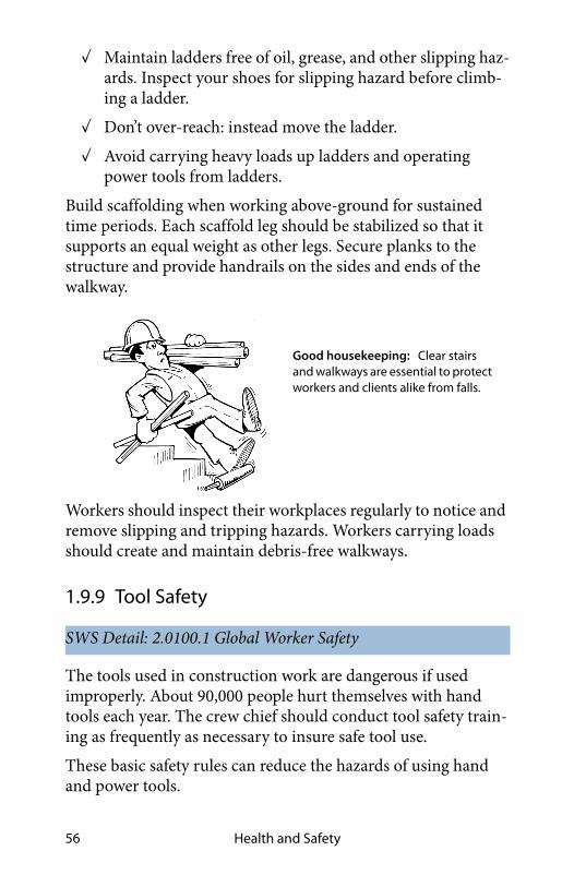
Health and Safety56
✓ Maintain ladders free of oil, grease, and other slipping haz-ards. Inspect your shoes for slipping hazard before climb-ing a ladder.
✓ Don’t over-reach: instead move the ladder.
✓ Avoid carrying heavy loads up ladders and operating power tools from ladders.
Build scaffolding when working above-ground for sustained time periods. Each scaffold leg should be stabilized so that it supports an equal weight as other legs. Secure planks to the structure and provide handrails on the sides and ends of the walkway.
Workers should inspect their workplaces regularly to notice and remove slipping and tripping hazards. Workers carrying loads should create and maintain debris-free walkways.
1.9.9 Tool Safety
The tools used in construction work are dangerous if used improperly. About 90,000 people hurt themselves with hand tools each year. The crew chief should conduct tool safety train-ing as frequently as necessary to insure safe tool use.
These basic safety rules can reduce the hazards of using hand and power tools.
SWS Detail: 2.0100.1 Global Worker Safety
Good housekeeping: Clear stairs and walkways are essential to protect workers and clients alike from falls.

Rhode Island Weatherization Field Guide 57
✓ Use the right tool for the job.
✓ Keep all tools in good condition with regular maintenance.
✓ Inspect tools for damage before using them.
✓ Operate tools according to the manufacturer’s instruc-tions.
✓ Use appropriate personal protective equipment.
✓ Use double insulated power tools of ground-fault-circuit-interrupter (GFCI) outlets or extension cords to prevent electric shock.
✓ Use generators for electrical service on the jobsite and ground them.
✓ Verify that generator exhaust is directed away from the home, the vehicle, and the crew.
1.9.10 Repetitive Stress Injuries
Repetitive stress injuries are caused by over-working certain parts of your body. Poor body posture, such as reaching above your head when operating a power drill, can encourage these injuries. Good work habits prevent this type of injury.
✓ Use a comfortable arm and hand posture when operating tools for a long period of time.
Electrical safety: Maintain cords in good condition. Use ground-fault-circuit interrupter (GFCI) cords for outlets in wet conditions.

Health and Safety58
✓ Change the angle and location of your work surface fre-quently.
✓ Mix your difficult tasks with easier ones.
✓ Carry smaller loads.
✓ Take short rest breaks periodically, and stretch any tight muscles during this time.
When you purchase hand and power tools, look for models with ergonomic designs that place less stress on your body.
1.9.11 Safety for Crawl Spaces and Other Confined Areas
The Occupational Safety and Health Administration (OSHA) defines a confined space as a space that contains a hazard like confinement, limited access, or restricted airflow because of its small size.
Access to Confined Spaces
Employers must be aware of the hazards of confined spaces and have policies for protecting workers. Consider these require-ments when appropriate.
✓ The crawl space should have an access hatch or door that is sized adequately for a worker or a resident to enter and exit.
✓ Workers should identify access and egress points before entering a confined space.
✓ If a heating and cooling system is located in the crawl space, the crawl space must have an access hatch or door measuring 22 inches by 30 inches or big enough to remove the heating and cooling system, whichever is greater.
SWS Detail: 2.0701.1 Crawl Spaces—Providing Access, 2.0701.2 Crawl Space Information Sign

Rhode Island Weatherization Field Guide 59
Chemicals in Confined Space
Observe these requirements when using chemicals in confined spaces.
✓ At minimum, workers using any type of chemical in a con-fined space must employ continuous powered ventilation using adequately sized openings to facilitate airflow into and out of the confined space.
✓ If workers use chemicals in significant quantities, such as spraying of two-part polyurethane foam, the workers should wear respirators that supply fresh air.
✓ If a confined space contains a hazard like chemical vapors or the potential to collapse or trap a worker, the space is called a permit-required confined space (PRCS). A worker must have an OSHA permit to enter the space and workers without permits must not enter. The permitted workers must have special training and equipment to enter the confined space.
1.9.12 Safety for Extreme Weather
Extreme weather is a common cause of job-related sickness and injury. You can avoid sickness and injury by awareness and pre-ventive measures.
Hot Weather Safety
Know the signs of heat ailments and take action if you or a co-worker experiences the beginning of symptoms. Observe these hot-weather suggestions for staying cool and preventing heat ailments.
✓ Drink plenty of water and take salt tablets.
✓ Ventilate attics with fans.
SWS Detail: 2.0100.1 Global Worker Safety

Health and Safety60
✓ Rotate workers in attics to prevent heat exhaustion.
✓ Use water or ice to cool your skin.
✓ Rest when you feel fatigued.
Cold Weather Safety
Workers and supervisors should know the temperature, wind speed, and precipitation forecast. Dress for extreme cold and plan work around storms and other extreme weather events.
✓ Dress in layers for comfort and changing temperatures.
✓ Wear insulated boots or heavy socks.
✓ Wear insulated gloves.
✓ Seek warm shelter if you experience numbness or uncom-fortable chilling.
Windy Weather Safety
Be aware of the forecast for windy weather and take precautions before beginning work and before the wind blows.
✓ Tie ladders off high and anchor them low.
✓ Avoid carrying sheet goods that could act as a sail allowing the wind to blow you over.
✓ Store materials and tools where the wind can’t move them.
1.10 SWS ALIGNMENT
Field Guide Topic SWS Detail
Fire Safety Pg. 23
Carbon Monoxide (CO) Pg. 24
2.0105.1 Combustion Worker Safety,2.0201.2 Combustion Safety,2.0201.1 Combustion Appliance Zone (CAZ) Testing

Rhode Island Weatherization Field Guide 61
Causes of Carbon Monoxide (CO) Pg. 25
Smoke and Carbon Monoxide (CO) Alarms Pg. 26
Smoke Alarms Pg. 26 2.0301.1 Smoke Alarm
CO Alarms Pg. 272.0301.2 Carbon Monoxide Alarm or Monitor2.0201.2 Combustion Safety
Gas Range and Oven Safety Pg. 28
2.0100.1 Global Worker Safety, 2.0201.2 Combustion Safety
Reducing Moisture Problems Pg. 29
2.0401.1 Air Sealing Moisture Precautions
Symptoms of Moisture Problems Pg. 31
2.0401.1 Air Sealing Moisture Precautions
Solutions for Moisture Problems Pg. 32
2.0404.1 Stand-Alone Dehumidifiers,2.0404.4 Basements—Dehumidification3.1488.3 Covers for Sump Pumps, Drains, Pits, and other Intentional Slab Penetrations
Crawl Space Moisture and Safety Issues Pg. 36
2.0111.2 Crawl Spaces—Pre-Work Qualifications,2.0111.3 Crawl Spaces—Debris Removal,2.0403.2 Closed Crawl Spaces—Ground Moisture Barriers,2.0403.1 Vented Crawl Spaces—Ground Moisture Barrier
Ground Moisture Source-Reduction Pg. 37
Pollutants Source Control Pg. 38
Field Guide Topic SWS Detail

Health and Safety62
Radon Pg. 38
2.0501.1 Radon—Air Sealing Considerations,2.0501.2 Radon—Basements and Crawl spaces
Asbestos Containing Materials (ACM) Pg. 39
2.0104.1 Insulation Worker Safety
Lead-Safe Procedures Pg. 40 2.0100.1 Global Worker Safety
Electrical Safety Pg. 43 2.0100.1 Global Worker Safety
Knob-and-Tube Wiring Pg. 45 4.1001.2 Knob and Tube Wiring
Constructing Shielding for Knob-and-Tube Wiring Pg. 46
2.0601.1 Knob and Tube Wiring
Worker Health and Safety Pg. 462.0100.1 Global Worker Safety,2.0106.1 Ventilation Worker Safety
Commitment to Safety Pg. 47
New Employees Pg. 48
Driving Pg. 49
Lifting and Back Injuries Pg. 50
Respiratory Health Pg. 51
2.0100.1 Global Worker Safety,4.9901.1 General Information on Spray Polyurethane Foam (SPF),2.0106.1 Ventilation Worker Safety
Hazardous Materials Pg. 53
2.0110.1 Material Selection, Labeling, and Material Safety Data Sheets (MSDSs),2.0100.1 Global Worker Safety
Equipment for Personal and Crew Safety Pg. 54
2.0100.1 Global Worker Safety
Falls Pg. 54 2.0100.1 Global Worker Safety
Tool Safety Pg. 56 2.0100.1 Global Worker Safety
Field Guide Topic SWS Detail

Rhode Island Weatherization Field Guide 63
Repetitive Stress Injuries Pg. 57
Safety for Crawl Spaces and Other Confined Areas Pg. 58
2.0701.1 Crawl Spaces—Providing Access,2.0701.2 Crawl Space Information Sign
Safety for Extreme Weather Pg. 59
2.0100.1 Global Worker Safety
Field Guide Topic SWS Detail

Health and Safety64

Rhode Island Weatherization Field Guide 65
CHAPTER 2: ENERGY AUDITS AND QUALITY CONTROL INSPECTIONS
This chapter outlines the operational process of energy audits, work orders, and final inspections as practiced by non-profit agencies and contractors working in the Department of Energy’s (DOE) Weatherization Assistance Program (WAP).
WAP’s Mission
The mission of DOE WAP is “To reduce energy costs for low-income families, particularly for the elderly, people with dis-abilities, and children, by improving the energy efficiency of their homes while ensuring their health and safety.”
This chapter also discusses ethics, customer relations, and cus-tomer education.
Why We Care about Health and Safety
The health and safety of customers must never be compromised by weatherization. Harm caused by our work would hurt our cli-ents, ourselves, and our profession. Weatherization work can change the operation of heating and cooling systems, alter the moisture balance within the home, and reduce a home’s natural ventilation rate. Weatherization workers must take all necessary precautions to avoid harm from these changes.
2.1 PURPOSES OF AN ENERGY AUDIT
An energy audit evaluates a home’s existing condition and out-lines improvements to the energy efficiency, health, safety, and durability of the home.
Depending on the level of the audit, an energy audit may include some or all of the following tasks.

Energy Audits and Quality Control Inspections66
• Inspect the building and its mechanical systems to gather the information necessary for decision-making.
• Evaluate the current energy consumption along with the existing condition of the building.
• Diagnose areas of energy waste, health and safety, and durability problems related to energy conservation.
• Recommend energy conservation measures (ECMs).
• Diagnose health and safety problems and how they may be affected by the proposed ECMs.
• Predict savings expected from ECMs.
• Estimate labor and material costs for ECMs.
• Encourage behavioral changes that reduce energy waste.
• Educate residents about their energy usage and your pro-posed energy retrofits.
• Provide written documentation of the energy audit and the recommendations offered.
2.1.1 Energy-Auditing Judgment and Ethics
The auditor’s good decisions are essential to the success of a weatherization program. Good decisions depend on judgment and ethics.
✓ Understand the requirements of the WAP program.
✓ Treat every client with the same high level of respect.
✓ Communicate honestly with clients, coworkers, contrac-tors, and supervisors.
✓ Know the limits of your authority, and ask for guidance when you need it.
✓ Develop and maintain the inspection, diagnosis, and soft-ware skills necessary for WAP energy auditing.

Rhode Island Weatherization Field Guide 67
✓ Choose ECMs according to their cost-effectiveness along with DOE and State policy, and not according to personal preference or customer preference.
✓ Don’t manipulate Weatherization Assistant or a priority list to select or avoid particular ECMs.
✓ Avoid personal bias in your influence on purchasing, hir-ing, and contracting.
2.1.2 Health and Safety Considerations
Energy auditors and inspectors must know and understand the health and safety (H&S) policies of the State weatherization pro-gram. H&S measures impact the budget and the economic via-bility of most weatherization jobs. An auditor may justify a H&S measures as any of the following types according to WPN 17-7.
1. An required H&S measure funded by the State’s H&S budget, which protects occupants or workers but isn’t justified by the energy audit and isn’t included in the average cost per unit (ACPU).
2. An incidental repair measure (IRM), with H&S bene-fits, funded to protect an ECM or to mitigate a rela-tively inexpensive hazard such as a roof leak, chimney repair, or electrical repair.
3. An H&S measure that serves as a precaution or a benefit of an cost-effective ECM, and in this case, the H&S measure adds costs to the SIR calculation.
4. A H&S benefit of an ECM that isn’t itself cost-effective but justifiable by the H&S benefits combined with the ECM’s energy savings.
When you consider whether a measure is an ECM or a H&S, evaluate its SIR, and if cost-effective, treat it as a ECM.

Energy Audits and Quality Control Inspections68
2.1.3 Energy-Auditing Record-keeping
The client file is the record of a weatherization progress and completion. The client file will contain all of the following items, based on State WAP policy.
1. Customer intake document
2. Income verification
3. Owner/Rental agreement form
4. Work plan
5. Client health-notification documents
6. Insulation identification and R-value
7. Energy-education documentation
8. Moisture and mold findings
9. Hold harmless statement
10. Progress notes
11. Deferral letter
12. Photo documentation
13. Post-inspection report
14. EPA LSRRP Rule, final-inspection report (if applica-ble)
2.2 CUSTOMER RELATIONS
Customer satisfaction depends on the energy auditor’s reputa-tion, professional courtesy, and ability to communicate.
2.2.1 Communication Best Practices
Making a good first impression is important for customer rela-tions. Friendly, honest, and straightforward communication cre-

Rhode Island Weatherization Field Guide 69
ates an atmosphere where the auditor and clients can discuss problems and solutions openly.
Setting priorities for customer communication is important for the efficient use of your time. Auditors must communicate clearly and directly. Limit your communication with the cus-tomer to the most important energy, health, safety, and durabil-ity issues.
✓ Introduce yourself, identify your agency and provide photo id that links you to your agency. Explain the pur-pose of your visit.
✓ Make sure that the customer understands the goals of the WAP program.
✓ Listen carefully to your client’s reports, complaints, ques-tions, and ideas about their home’s energy efficiency.
✓ Ask questions to clarify your understanding of your cli-ent’s concerns and document.
✓ Before you leave, give the client a quick summary of what you found.
✓ Never make promises until you have time to finish the audit, produce a work order, and schedule the work.
✓ Make arrangements for additional visits by crews and con-tractors as appropriate.
2.2.2 Customer Interview
The customer interview is an important part of the energy audit. Even if customers have little understanding of energy and build-ings, they can provide useful observations that can save you time and help you choose the right ECMs.
✓ Ask the customer about comfort problems, including zones that are too cold or hot.
✓ Ask the customer to see their energy bills if you haven’t already evaluated them.

Energy Audits and Quality Control Inspections70
✓ Ask the customer if there is anything relevant they notice about the performance of their mechanical equipment.
✓ Ask about family health, especially respiratory problems afflicting one or more family members.
✓ Discuss space heaters, fireplaces, attached garages, and other combustion hazards.
✓ Discuss drainage issues, wet basements or crawl spaces, leaky plumbing, and mold infestations.
✓ Discuss the home’s existing condition and how the home may change after the proposed retrofits.
✓ Identify existing damage to finishes to insure that weather-ization workers aren’t blamed for existing damage. Docu-ment damage with digital photos.
✓ Ask the client to sign the necessary permissions.
2.2.3 Deferral of Weatherization Services
When you find health, safety, or durability problems in a home, sometimes it’s necessary to postpone weatherization services until those problems are solved. The problems that are cause for deferral of services include but are not limited to the following.
• Roof leakage.
• Foundation damage.
• Moisture problem including mold infestation.
• Plumbing problems.
• Human or animal waste in the home.
• Electrical problems or fire hazards.
• The home is vacant or the client is moving.
• The home is for sale or in foreclosure.
Behavioral problems may also be a reason to defer services to a customer, including but not limited to the following.

Rhode Island Weatherization Field Guide 71
• Illegal activity on the premises.
• Occupant’s hoarding makes difficult or impossible to per-form a complete audit.
• Lack of cooperation by the customer.
Matching Funds to Avoid Deferrals
Auditors should assist customers in obtaining repair funds from the following sources whenever possible:
• Department of Housing and Urban Development (HUD) Emergency Repair Funds
• HUD Green and Healthy Homes Initiative Funds
• Department of Agriculture (USDA) Rural Development Funds
• State and local repair funds
• Church, charity, and foundation funds
• Rhode Island Housing - Lead Safe program Community Development Block Grant.
2.3 PARTS OF AN ENERGY AUDIT
Visual inspection, diagnostic testing, and numerical analysis are three types of energy auditing procedures we discuss in this sec-tion. These procedures should aid you in evaluating all the pos-sible ECMs that are cost-effective according to DOE-approved software: Hancock & Hancock Manual.
The energy audit must also propose solutions to health and safety problems related to the energy conservation measures.

Energy Audits and Quality Control Inspections72
2.3.1 Visual Inspection
Visual inspection orients the energy auditor to the physical real-ities of the home and home site. Among the areas of inspection are these.
• Health and safety issues
• Building air leakage
• Building insulation and thermal resistance
• Heating and cooling systems
• Ventilation fans and operable windows
• Baseload energy uses
• The home’s physical dimensions: area and volume
2.3.2 Diagnostic Testing
Measurement instruments provide important information about a building’s unknowns, such as air leakage and combus-tion efficiency. Use these diagnostic tests as appropriate during the energy audit.
• Blower door testing: A variety of procedures using a blower door to evaluate the airtightness of a home and parts of its air barrier.
• Duct leakage testing: A variety of tests using a blower door, pressure pan and duct blaster to locate duct leaks.
Diagnostic
Testing
Quantitative
Analysis
Visual
Inspection
The Energy Audit: Categories of Services

Rhode Island Weatherization Field Guide 73
• Ventilation testing: Measure airflow through existing exhaust fans with an exhaust fan flow meter.
• Combustion safety and efficiency testing: Sample combus-tion by-products and measure depressurization to evaluate safety and efficiency. Test the gas lines within the home for existing gas leaks. Test the home’s ambient air for CO.
• Infrared scanning: Viewing building components through an infrared scanner shows differences in the temperature of building components inside building cavities.
2.3.3 SIR Calculations
Energy auditors currently use DOE-approved software to deter-mine which ECMs have the highest Savings-to-Investment Ratio (SIR). The ECMs with the highest SIRs are at the top of the WA priority list for a particular home.
SIR = INITIAL INVESTMENT ÷ LIFETIME SAVINGS
DOE WAP and the State WAP program require that ECMs have an SIR of 1 or greater. ECMs with higher SIRs should be installed before or instead of ECMs with lower SIRs.
Whether a weatherization provider uses software or a priority list, the auditor must collect information to inform decisions about which ECMs to choose.
✓ Measure the home’s exterior horizontal dimensions, wall height, floor area, volume, and area of windows and doors.
✓ Measure the current insulation levels.
✓ Do a blower door test to evaluate air leakage. Do not per-form blower door or zonal pressure test if friable asbestos and/or vermiculite are present.
✓ Do a combustion efficiency test to evaluate the central heating system.

Energy Audits and Quality Control Inspections74
✓ Do a worst case depressurization test and spillage test to evaluate whether or not the combustion appliance zone fails or passes.
✓ Evaluate energy bills and adjust the job’s budget within limits to reflect the potential energy savings.
2.4 THE WORK ORDER
The work order is a list of materials and tasks that are recom-mended as a result of an energy audit. Consider these steps in developing the work order.
✓ Evaluate which ECMs have an acceptable savings-to-investment ratio (SIR) using software or a priority list.
✓ Select the most important health and safety problems to correct, as these problems are directly related to the cost-effective ECMs.
✓ Provide detailed specifications so that crews or contractors clearly understand the materials and procedures necessary to complete the job.
✓ Estimate the cost of the materials and labor.
✓ Verify that the materials needed are in stock at the agency or a vendor.
✓ Inform crews or contractors of any hazards, pending repairs, and important procedures related to their part of the work order.
✓ Obtain required permits from the local building jurisdic-tion, if necessary.
✓ Specify interim testing during air-sealing and heating-sys-tem maintenance to provide feedback for workers.
✓ Consider in-progress inspections and schedule the final inspection for the job’s final day if possible.
Rhode Island Weatherization Field Guide 75
2.4.1 Questions about the Audit and Work Order
The monitor/auditor/inspector asks these questions during the inspections.
• Did the auditor find all the opportunities and identify all the hazards?
• Do the audit’s ECMs comply with the Weatherization Assistant computer analysis, and the SWS?
• Did the work order specify the labor and materials required by the energy audit adequately?
• Did the crew follow the work order?
• What changes did the crew leader make to the work order?
• Did these changes benefit the client and the WAP program?
• Is the completed weatherization job, the energy audit, and the work order aligned with State policy and the SWS?
2.5 WORK INSPECTIONS
The monitor is responsible for the quality control of the weath-erization process. Good inspections ensure that the energy sav-ings measures are effective and installed properly. There are two common opportunities for inspections: in-progress inspections and final inspections.
2.5.1 In-Progress Inspections
Many ECMs are best inspected while the job is in progress. Vis-iting while the job is in progress demonstrates your commit-ment to getting the job done correctly. Either the energy auditor or the monitor may conduct an in-progress inspection.
These measures are good candidates for in-progress inspections because of the difficulty of evaluating them after completion.
• Dense-pack wall insulation

Energy Audits and Quality Control Inspections76
• Insulating closed roof cavities
• Furnace installation or tune-up
• Air-conditioning service
• Duct testing and sealing
• Attic air sealing
In-progress inspections are also an excellent way to provide training and technical assistance. If an in-progress inspection is not possible, contractors may be required to take digital pictures of the work in progress of the areas that can not be seen during the final inspection.
2.5.2 Final Inspections
A certified inspector completes a final inspection before the weatherization job is reported to DOE as a completion. The inspector is ideally a different person than the auditor.
Final inspections ensure that weatherization services were pro-vided as specified in the work order, and that the home is left in a safe condition. The weatherization agency does the final inspection for quality control, which is a term for in-house self evaluation of jobs.
Completing the final inspection with the crew or contractor on site allows the inspector and workers to review the work scope and correct deficiencies without requiring a return to the home. Verify the following during the final inspection.
✓ Confirm that the crew installed the approved materials in a safe, effective, and neat way.
✓ Confirm that the crew matched existing finish materials for measure installation and necessary repairs.
✓ Confirm that the contractor put a certificate of insulation at the circuit breaker box. During the final inspection, the inspector should take pictures of the work, especially the

Rhode Island Weatherization Field Guide 77
work with special instructions and the posted certificate of insulation.
✓ Review all completed work with the client. Confirm that the client is satisfied.
✓ Verify that combustion appliances operate safely. Do worst-case depressurization tests and CO tests as appro-priate.
✓ Do a final blower door test with simple pressure diagnos-tics if appropriate.
✓ Use an infrared scanner to inspect insulation and air-seal-ing quality.
✓ Use simple pressure-diagnostic techniques to verify the effectiveness of air sealing.
✓ Specify corrective actions whenever the work doesn’t meet standards.
✓ Verify with in-process pictures that the crew used the cor-rect lead-safe procedures if these procedures were neces-sary in installing ECMs.
✓ Verify that all required paperwork, with required signa-tures is in the client file. See “Energy-Auditing Record-keep-ing” on page 68.
2.5.3 Quality Control Versus Quality Assurance
Quality control is an internal process of a weatherization agency focusing on the final inspection. Quality assurance is a third-party inspection performed by an inspector employed by either the State or the DOE. This requirement only applies to DOE funded jobs.
Certified quality-control inspectors (QCI) may perform both quality-control inspections and quality-assurance inspections. The following are important elements of these inspections.

Energy Audits and Quality Control Inspections78
• Verify compliance with specifications, job order, and energy audit.
• Provide feedback on material quality and worker perfor-mance, both good and bad.
• Issue instructions for correcting errors and omissions.
• Survey clients for level of satisfaction.
• Perform energy-conservation monitoring and evaluation, if appropriate.
• Report to the weatherization agency, the State, or the DOE about the quality of the weatherization work.
At the local level, the energy auditor and the inspector are some-times the same person. This situation requires more quality assurance inspections from the State WAP.
The State WAP must justify to the DOE and utility inspectors the percentage of homes that State inspectors inspect for quality assurance. The required percentage depends on the indepen-dence of the local agency’s quality control inspectors from the agency’s energy auditors.
2.6 FIELD MONITORING
Field monitoring is the quality assurance visits conducted by the State weatherization program. The utility inspector inspects 10% of completed jobs. The State monitor’s job is similar to the utility’s and agency’s inspector. However, the State monitor is independent of the local weatherization agency and reports his or her inspection results to the State. The monitor describes these inspection results in these ways.
1. Strengths or areas where the agency performs well.
2. Concerns are minor problems with paperwork or job quality that the agency can easily correct.
3. Major findings, including contract violations, safety violations, or omissions of required procedures.
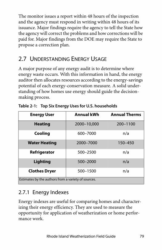
Rhode Island Weatherization Field Guide 79
The monitor issues a report within 48 hours of the inspection and the agency must respond in writing within 48 hours of its issuance. Major findings require the agency to tell the State how the agency will correct the problems and how corrections will be paid for. Major findings from the DOE may require the State to propose a correction plan.
2.7 UNDERSTANDING ENERGY USAGE
A major purpose of any energy audit is to determine where energy waste occurs. With this information in hand, the energy auditor then allocates resources according to the energy-savings potential of each energy-conservation measure. A solid under-standing of how homes use energy should guide the decision-making process.
2.7.1 Energy Indexes
Energy indexes are useful for comparing homes and character-izing their energy efficiency. They are used to measure the opportunity for application of weatherization or home perfor-mance work.
Table 2-1: Top Six Energy Uses for U.S. households
Energy User Annual kWh Annual Therms
Heating 2000–10,000 200–1100
Cooling 600–7000 n/a
Water Heating 2000–7000 150–450
Refrigerator 500–2500 n/a
Lighting 500–2000 n/a
Clothes Dryer 500–1500 n/a
Estimates by the authors from a variety of sources.

Energy Audits and Quality Control Inspections80
Most indexes are based on the square footage of conditioned floor space. The simplest indexes divide a home’s energy use in either kilowatt-hours or British thermal units (BTUs) by the square footage of floor space.
A more complex index compares heating energy use with the climate’s severity. BTUs of heating energy are divided by both square feet and heating degree days to calculate this index.
2.8 CUSTOMER EDUCATION
Customer education is a potent energy conservation measure. A well-designed education program engages customers in house-hold energy management and assures the success of installed energy conservation measures (ECMs).
2.9 SWS ALIGNMENT
Field Guide Topic SWS Detail
2.1: Purposes of an Energy Audit - Pg. 65
2.1.1: Energy-Auditing Judg-ment and Ethics - Pg. 66
2.1.3: Energy-Auditing Record-keeping - Pg. 68
2.2: Customer Relations - Pg. 68
2.2.1: Communication Best Practices - Pg. 68
2.2.2: Customer Interview - Pg. 69
2.2.3: Deferral of Weatherization Services - Pg. 70
2.3: Parts of an Energy Audit -Pg. 71

Rhode Island Weatherization Field Guide 81
2.3.1: Visual Inspection - Pg. 72
2.3.2: Diagnostic Testing - Pg. 72
2.4: The Work Order - Pg. 74
2.4.1: Questions about the Audit and Work Order - Pg. 75
2.5: Work Inspections - Pg. 75
2.5.1: In-Progress Inspections -Pg. 75
2.5.2: Final Inspections - Pg. 76
2.5.3: Quality Control Versus Quality Assurance - Pg. 77
2.6: Field Monitoring - Pg. 78
2.7: Understanding Energy Usage - Pg. 79
2.7.1: Energy Indexes - Pg. 79
2.8: Customer Education - Pg. 80
Field Guide Topic SWS Detail

Energy Audits and Quality Control Inspections82

Rhode Island Weatherization Field Guide 83
CHAPTER 3: WEATHERIZATION MATERIALS
This chapter focuses on materials for insulation and air sealing. It begins by discussing the introductory information on air seal-ing and then air sealing materials, insulation building science, and insulation materials. This information supports the next four chapters on the major parts of the building shell.
3.1 AIR-SEALING GOALS
Perform air leakage testing and evaluation before beginning air-sealing or duct-sealing work. Always evaluate ventilation and perform combustion-safety testing as a part of air sealing a home. See "ASHRAE Standard 62.2–2016 Ventilation" on page 354.
Reducing air leakage accomplishes several goals.
• Saves energy by reducing unintentional air exchange with outdoors
• Reduces air leakage and convection around insulation, pro-tecting its thermal resistance
• Increases comfort by reducing drafts and moderating the radiant temperature of interior surfaces
Note about fire testing: The IRC requires certain fire tests for weatherization materials. The numbered fire tests, used in this chapter refer to a building material’s certification by virtue of passing that particular fire test. We present these references, such as ASTM E-184, for you to identify a certified building product. The product should display the number of the test on its label or in its specifications. You can buy the fire-test proto-cols on the internet, but we don’t suggest doing that. For more information on the tests referenced in this chapter, see “Fire Testing and Rating” on page 473.

Weatherization Materials84
• Reduces moisture migration into building cavities
• Reduces the pathways by which fire spreads through a building
3.2 AIR SEALING SAFETY
Air sealing reduces the exchange of fresh air in the home, and can alter the pressures within the home. Before air sealing, sur-vey the home to identify both air pollutants that may be concen-trated by air sealing efforts and open combustion appliances that may be affected by changes in house pressure.
Don’t do air sealing when there are obvious threats to the occu-pants’ health, the installers’ health, or the building’s durability that are related to air sealing. If any of the following circum-stances are present, either postpone air sealing until they’re cor-rected or correct the problems as part of the air-sealing work.
SWS Detail: 2.0103.1 Air Sealing Worker Safety
Air leaks at the thermal boundary: The air barrier and insulation, which should be adjacent to one other, are located at the thermal boundary. The insulation and the air barrier are often discontinuous at corners and transitions.
rim joist area
joint between collar beam and rafter
cantilevered floor
corner at garage ceiling
insulation
air barrier
thermal boundary
joint between porch and house
joint between finished-attic floor and knee wall

Rhode Island Weatherization Field Guide 85
• Measured carbon monoxide levels exceed the suggested action level. See "Carbon Monoxide (CO) Testing" on page 237.
• Combustion zone depressurization exceeds the limits shown in “Maximum CAZ Depressurization” on page 474 during a worst-case test. See "Worst-Case CAZ Depressur-ization Test" on page 239.
• The air-leakage area has moisture damage, indicated by staining, mold or rot.
3.2.1 Air Sealing and Fire Containment
Fire, flame and smoke spread through the paths of least resis-tance. Many building assemblies harbor concealed voids or cavi-ties within walls, ceilings and attics. During a fire, these pathways spread fire and make fire-fighting difficult.
In new buildings, the IRC requires builders to seal all shafts and hidden air leaks between living spaces and intermediate zones with fire-blocking materials.
The building codes define a fire-block as a material installed to “resist the free passage of flame through concealed spaces.” Fire-blocking materials don’t need to be non-combustible.
We recommend that you use rigid fire-blocking materials such as the following ones suggested in the IRC.
• Plywood, OSB or other wood sheeting (3/4 inch thick)
• Drywall (two layers of 5/8”)
SWS Detail: 4.1001.5 Dense Pack Preparation, 3.1001.2 Chase Capping, 3.1001.3 Walls open to Attic—Balloon Framing and Double Walls

Weatherization Materials86
3.3 AIR SEALING MATERIALS
Air barriers must resist severe wind pressures. Use strong air barrier materials like structural wood paneling, drywall, or sheet metal to seal large air leaks, especially if your region has powerful winds. Attach these strong materials with mechanical fasteners and seal them with caulk or adhesive. If a technician needs to access a shaft or penetration in the future use a caulk that isn’t a strong adhesive, such as acrylic latex.
Use caulk by itself for sealing small cracks. Use liquid foam for cracks larger than 1/4 inch.
3.3.1 Air Barrier Materials
Air barrier materials should themselves be air barriers and also rated as fire blocks. See Table 12-1 on page 460.
Plywood, OSB, etc.
Three-quarter-inch plywood, OSB, and particle board are IRC-approved fire-blocking materials, and they’re strong enough to resist windstorms. Attach these structural sheets with screws or nails along with any sealant or adhesive that effectively air seals the joint.
Drywall
Half-inch drywall constitutes a 15 minute thermal barrier, and is also an ignition barrier. When air sealing a fire-rated assembly in a commercial or multi-family building, choose two layers of five-eighths -inch drywall and a fire-rated caulking. Fasten dry-wall with screws and construction adhesive. Don’t use drywall in damp locations where it may get wet.
Steel and Aluminum Sheet Metal
Being non-combustible, sheet metal is used to seal around chimneys and other heat producing components. To seal around chimneys, cut the galvanized steel accurately, with less than a

Rhode Island Weatherization Field Guide 87
1/8“inch gap, so that you can seal the gap with high tempera-ture, non combustible caulk labeled ASTM E136.
NOTE: Do not use tin.
Foam Board
Foam board may be a desirable product for air sealing; however it has less structural strength and fire resistance than the other materials discussed previously.
Cross-Linked Polyethylene House Wrap
House wrap and polyethylene sheeting are air barriers. These flexible materials aren’t rated as fire-blocks, and they are struc-turally weak.
3.3.2 Stuffing Materials
Stuffing materials are used to insulate a cavity, to give the cavity a bottom, or to serve as supporting part of an air seal.
Backer Rod
Backer rod and caulking are the most reliable and long-lasting air seals. Backer rod is closed-cell polyethylene foam that creates a bottom barrier in a gap before caulking. Backer rod doesn’t bond to the caulking, and so prevents three-sided adhesion that could tear the caulking bead apart with the materials’ expansion and contraction of temperature extremes.
Fiberglass Batts
Fiberglass batts reduce air convection in cavities where they’re installed. However, fiberglass batts are air permeable, even if compressed. Batts can support two-part foam sprayed over the opening of a cavity. Fiberglass batting is a good stuffing material for use with non-combustible caulk for penetrations through fire-rated assemblies because of its low combustibility.

Weatherization Materials88
Blown Cellulose or Fiberglass
Blown cellulose and fiberglass reduce air convection and air leakage through closed cavities. However neither material is an air barrier even when blown at high densities. Both are consid-ered fire-blocks when installed in closed cavities because they block the passage of flames.
3.3.3 Caulking and Adhesives
The adhesion and durability of caulking and adhesives depends on their formulation and on the surfaces to which they’re applied. Some caulks and adhesives are sensitive to dirt and only work well on particular surfaces, while others are versatile and dirt-tolerant. Remove debris and clean the joint to create a long lasting seal.
Water-Based Caulks
A wide variety of paintable caulks are sold under the description of acrylic latex and vinyl. These are the most commonly used caulks and the easiest to apply and clean up. Siliconized latex caulks are among the most adhesive and durable sealants in this group. Don’t apply water-based caulks to building exteriors when rain is forecast since they aren’t waterproof until cured, and they stain nearby materials if they are rained upon while curing. Don’t apply water-based caulks during freezing weather.
Silicone Caulk
Silicone has great flexibility, but its adhesion varies among dif-ferent surfaces. Silicone is easy to gun even in cold weather. Sili-cone isn’t as easy to clean up as water based caulks, though it’s easier than polyurethane or butyl. Silicone isn’t paintable, so choose an appropriate color. High-temperature silicone may be used with galvanized steel to air seal around chimneys if labeled ASTM E136, meaning that the caulk is non-combustible.

Rhode Island Weatherization Field Guide 89
Polyurethane Caulk
Polyurethane has the best adhesion and elasticity of any com-mon caulk. It works very well for cracks between different mate-rials like brick and wood. Polyurethane resists abrasion and is used to seal critical joints in concrete slabs and walls. It is also good for sealing the fastening fins of windows to walls. Polyure-thane is almost as sticky and adhesive as a construction adhe-sive. Cleaning it up is difficult so neat workmanship is essential. Polyurethane caulk doesn’t gun easily, and should be room tem-perature or higher. Polyurethane caulk doesn’t hold paint.
Acoustical Sealant
This solvent-based or water-based adhesive is used to seal laps in polyethylene film and house wrap. Acoustical sealant is very sticky, adheres well to most construction materials, and remains flexible. Acoustical sealant is used to seal building assembles for sound deadening. Acoustical sealant is also used to seal the seams of polyethylene vapor barriers and ground moisture bar-riers.
Water Soluble Duct Mastic
Duct mastic is the best material for sealing ducts, including cav-ities used for return ducts. A messy but highly effective sealant, duct mastic can be applied with a thickness of 1/8-inch with a brush or rubber glove. Have a bucket of warm water handy to clean your gloved hands and a rag to dry the gloves. Spread the mastic and use fiberglass fabric web tape to reinforce cracks more than 1/8-inch in diameter. Thorough cleaning of dust and loose material isn’t necessary. Mastic bonds tenaciously to everything, including skin and clothing.
Stove Cement
Stove cement is a material that can withstand temperatures up to 2000° F. It is used to seal wood stove chimneys and to cement wood stove door gaskets in place. Do not use on ducts.

Weatherization Materials90
Non-Combustible Caulk
Some elastomeric caulks are designed specifically for use in fire-rated assemblies. They are labeled ASTM E136, meaning that the caulk is non-combustible. Use this type of sealant when seal-ing penetrations through fire-rated assemblies in multifamily buildings.
Fire-Rated Mortar
Used with other air-sealing materials to seal various sized holes and gaps in multifamily buildings with fire-rated masonry building assemblies. This mortar often covers a foam air sealant to create a non-combustible surface for an combustible air seal.
Construction Adhesives
Construction adhesives are designed primarily to bond materi-als together. But they also create an air seal if applied continu-ously around the perimeter of a rigid material. They are often used with fasteners like screws or nails but can also be used by themselves. Some construction adhesives act like contact adhe-sives to bond lightweight materials without mechanical fasten-ers.
Use specially designed construction adhesives for polystyrene foam insulation because many general-purpose adhesives decompose the foam’s surface.
3.3.4 Liquid Foam Air Sealant
Liquid closed-cell polyurethane foam is a versatile air sealing material. Closed-cell foam is packaged in a one-part injectable variety and a two-part sprayable variety. It has a high R-value per inch and is ideal for insulating and air sealing small, poorly insulated, and leaky areas in a single application.
Installation is easy compared to other materials to accomplish the same air sealing tasks. However, cleanup is difficult enough that you probably don’t want to clean up multiple times on the

Rhode Island Weatherization Field Guide 91
same job. Instead identify all the spots needing foam applica-tion, make a list, and foam them one after another.
One-Part Foam
This gap filler has tenacious adhesion. One-part foam is best applied with a foam gun rather than the disposable cans. Cleanup is difficult if you’re careless. When squirted skillfully into gaps, one-part foam reduces air leakage, thermal bridging, and air convection. One-part foam isn’t effective or easy to apply to gaps over about one inch or to bottomless gaps. This product can leave small air leaks because it cracks when the materials around it move or shift.
Two-Part Foam
Good for bridging gaps larger than one inch. Two-part foam is popular for use with rigid patching materials to seal large open-ings. Cut foam board to close-enough tolerances around obsta-cles and fill the edges with the two-part foam. Two-part foam should be sprayed to at least an inch of thickness when it serves as an adhesive for foamboard patches over large holes for strength.
Foam Construction Adhesive
Polyurethane foam dispensed from foam guns is an excellent adhesive for joining many kinds of building materials. It works well for joining foam sheets together into thick slabs for vertical access doors and attic hatches.

Weatherization Materials92
3.4 INSULATION BUILDING SCIENCE
Insulation reduces heat transmission by resisting the conduc-tion, convection, and radiation of heat through the building shell. Insulation combined with an air barrier creates the ther-mal envelope between the conditioned indoors and outdoors.
SWS Details: 4.1001.6 Unvented Roof Deck—Preparation for Spray Polyurethane Foam, 4.1001.7 Vented Roof Deck—Prepara-tion for SPF
One-part foam: A contractor uses an applicator gun to seal spaces between framing members and around windows.
Two-part foam: A contractor air seals and insulates around an attic hatch dam with two-part spray foam.

Rhode Island Weatherization Field Guide 93
Installing insulation is one of the most effective energy-saving measures. You can ensure insulation’s safety and effectiveness by following these guidelines.
✓ Install insulation in a way that enhances fire safety and doesn’t degrade it. See "Safety Preparations for Attic Insula-tion" on page 127.
✓ Comply with lead-safe practices when disturbing paint in pre-1978 homes. See "Additional Lead-Safe Work Practices" on page 42.
✓ Prevent air movement through and around the insulation with an effective air barrier. Make sure that the air barrier and insulation are aligned (next to one another) using pro-cedures outlined starting on page 111.
✓ Protect insulation from moisture by repairing roof and siding leaks, providing site drainage, and by controlling vapor sources within the home. See "Solutions for Moisture Problems" on page 32.
✓ Install insulation to meet or exceed the guidelines of the International Energy Conservation Code (IECC) 2012 and the DOE’s Standardized Work Specifications.
3.4.1 Insulation Receipt or Certificate
Provide each client, receiving insulation products and services, a printed and signed receipt or certificate that includes the follow-ing information.
• Insulation type
• Number of bags installed
• Coverage area
• R-value
• Installed thickness and settled thickness

Weatherization Materials94
• Amount of insulation installed according to manufacturer’s specifications
3.5 INSULATION MATERIAL CHARACTERISTICS
The purpose of insulation is to provide thermal resistance that reduces the rate of heat transmission through building assem-blies. Characteristics such as R-value per inch, density, fire safety, vapor permeability, and airflow resistance help weather-ization specialists choose the right insulation for the job.
3.5.1 Fibrous Insulation Materials
Fibrous insulation materials are the most economical insula-tions for buildings. If blown at a high density, fibrous insulations aren’t air barriers themselves, but they may contribute to the air-flow resistance of a building assembly that functions as an air barrier. The term mineral wool describes both fiberglass and rock wool. Rock wool is both a generic term and a trade name. We use rock wool in the generic sense as an insulating wool spun from rocks or slag. Fiberglass is wool spun from molten glass.
Cellulose was once made from virgin wood fiber under trade names like Balsam Wool. Now cellulose is manufactured pri-marily from recycled paper, treated with a fire retardant.
A vapor permeable air barrier should cover fibrous insulation installed vertically or horizontally in human-contact areas to limit exposure to fibers, which may cause respiratory distress.
Fiberglass Batts and Blankets
Most fiberglass batts are either 15 inches wide or 23 inches wide to fit 16-inch or 24-inch spacing for wood studs or joists. How-
SWS Detail: 4.1003.7 Ignition and Thermal Barriers—Spray Poly-urethane Foam

Rhode Island Weatherization Field Guide 95
ever, manufacturers also provide 16-inch or 24-inch widths for metal stud construction.
The advertised R-values of batts vary from 3.1 per inch to 4.2 per inch depending on density. Installed fiberglass R-values may be 5% to 30% less than advertised depending on installation quality and the effectiveness of the assembly’s air barrier.
Installers must cut and fit batts very carefully. Batts achieve their advertised R-value only when they are touching all six sides of the cavity it inhabits.
See “Open-Cavity Wall Insulation” on page 175.
Fiberglass blankets are typically three to six feet wide. Blankets come in a variety of thicknesses from 1 to 6 inches. Fiberglass blankets are used to insulate metal buildings, to insulate crawl spaces from the inside.
Although fiberglass doesn’t absorb much moisture, the facings on blankets and batts can trap water in the batts, which can dampen building materials and provide a water source for pests.
Facings for Fiberglass Batts
Insulation manufacturers make batts and blankets with a num-ber of facings, including the following.
• Unfaced: Vapor permeable and Class-A fire rating of ≤25 flame spread.
High-performance: good installation: no voids
Standard: good installation: no voids
Standard: fair installation: 2.5% voids
Standard: poor installation: 5% voids
3.5
3.0
2.5
2.0R-v
alu
e p
er in
ch o
f th
ick
nes
s
Batt type and quality of installation
Evaluating batt performance: The thermal performance of batts depends on density and installation.

Weatherization Materials96
• Kraft paper: A Class II vapor retarder that is flammable (Class-C or Class 3) with a flame spread ≥150.
• Foil-kraft: foil bonded to kraft paper. A vapor barrier with a flame spread of >75 (Class-C or Class 3).
• Foil-skrim-kraft (FSK): Aluminum foil bonded to kraft paper with skrim netting in-between as reinforcement. A vapor barrier available as a Class-A material with a flame spread of ≤25.
• White poly-skrim-kraft (PSK): White polyvinylchloride bonded to kraft paper with skrim netting in-between as reinforcement. A vapor barrier available as a Class A fire-rated material with a flame spread of ≤25. The white sur-face maximizes light reflection.
Blown Fiberglass
Loose fiberglass is blown in attics from 0.4 to 0.6 pcf and at that density the R-value is around 3.2 per inch. Blown fiberglass is non-combustible as a virgin product. However, some blown fiberglass is made from chopped batt waste that contains a small amount of combustible binder.
Loose fiberglass is blown in attics from 0.3 to 0.8 pcf and at that density range, the R-value is around 2.9 per inch. Expect around 5% settling within five years after installation.
Fiberglass manufacturers now provide two blowing products, one for standard densities of up to about 1.4 pcf, and another for dense-packing to more than 2.0 pcf.
In closed cavities, installers blow fiberglass from 1.2 to 2.2 pcf, with the R-value per inch varying from 3.6 to 4.2. Higher den-sity achieves a higher R-value. The high-density fiberglass is typically reserved for walls where the superior resistance to set-tling, airflow, and convection has extra value over lesser density.

Rhode Island Weatherization Field Guide 97
Blown Cellulose
Cellulose is the most inexpensive insulation and among the eas-iest insulations to install. Loose cellulose is blown in attics from 0.6 to 1.2 pcf and at that density range, the R-value is around 3.7 per inch. Expect around 15% settling within five years after installation.
In wall cavities, cellulose is blown at a higher density of between 3.5 to 4.0 pcf, to prevent settling and to maximize its airflow resistance. At that high density, cellulose’s R-value per inch is around 3.4. Evaluate the strength of wall cladding before blow-ing a wall with cellulose to prevent damage during installation.
Cellulose absorbs up to 130% of its own weight in water. Before anyone discovers a moisture problem, the cellulose could be soaked, shrunken, double its dry weight, and far less thermally resistant. Avoid using cellulose in regions with an annual aver-age precipitation of more than 50 inches or an annual average relative humidity of more than 70%. We believe that cellulose shouldn’t be installed in the following places regardless of cli-mate.
• Horizontal or sloped closed roof cavities
• Floor cavities above crawl spaces or unconditioned base-ments
• Crawl space walls or basement walls
Rock Wool
Rock wool is a type of mineral wool like fiberglass. Rock wool has a small market share in North America. Rock wool batts
Insulation hoses, fittings, and the fill tube: Smooth, gradual transitions are important to the free flow of insulation.

Weatherization Materials98
have similar R-values per inch as fiberglass batts and contain flammable binders. Rock wool itself is non-combustible so blown rock wool doesn’t burn.
Rock wool is also the most moisture-resistant insulation dis-cussed here. In rainy and humid climates, rock wool is the least likely insulation to harbor moisture or support pests.
Damp Spray Fibrous Insulation
Installers mix fibrous insulation with sprayed water and a small amount of adhesive in damp-spray applications either in open cavities or directly adhered to building surfaces. Sprayed cellu-lose contains a non-corrosive fire retardant to prevent metal corrosion when used in contact with metal building compo-nents.
3.5.2 Operating the Insulation Blowing Machines
Perform these important steps before and during insulation-blowing.
✓ Verify that the electrical source can provide the ampere draw of the insulation machine.
✓ Measure the pressure created by a blowing machine by connecting the hose to a fitting attached to a manometer. Close the feed gate and turn the air to the highest setting. For cellulose, the blowing machine should develop 2.9 pounds per square inch (psi) or 80 inches of water (IWC) For other types of fibrous insulation, check manufacturer specifications for blowing machine set up.
✓ Verify that you’re blowing the correct density of fibrous insulation by using the bag’s weight or the manufacturer’s coverage tables.
SWS Detail: 4.1001.5 Dense Pack Preparation, 4.1088.7 Insulat-ing Inaccessible Attics

Rhode Island Weatherization Field Guide 99
Important Note: Dense-packed fibrous insulation can reduce air leakage and convection in closed building cavities. However, don’t use dense-packed fibrous as a substitute for the air-sealing techniques described throughout this guide.
3.5.3 Spray Foam Insulation Materials
Spray Polyurethane Foam (SPF) is combustible and creates toxic smoke. Foam insulation usually requires covering with a ther-mal barrier or an ignition barrier, discussed in“Fire Protection for Foam Insulation” on page 102. SPF comes in two formula-tions: closed-cell and open-cell. Both are described below.
Spray foam is an insect-friendly material that can aid termites and carpenter ants in establishing a colony in wood structures. Mitigate all sources of ground water before installing foam near a foundation. When foam is installed on the outside of founda-tions, the surrounding soil should be treated with a termiticide if necessary. Inside a crawl space, foam must never provide a direct link from the ground to wood materials. The Interna-tional Residential Code (IRC) forbids foam below grade in “very heavy” termite-colonized areas.
Caution: SPF is hazardous to installers. Installers must wear special personal protective equipment and ventilate spaces
SWS Details: 4.1001.6 Unvented Roof Deck—Preparation for Spray Polyurethane Foam, 4.1001.7 Vented Roof Deck—Preparation for SPF, 2.0100.3 Global Worker Safety
Blower pressure gauge: For blowing closed cavities, blower pressure should be at least 80 IWC or 2.9 psi. Measure the pressure with maximum air, feed gate closed, and agitator on.

Weatherization Materials100
during installation. SPF can also harm occupants who breathe the toxic vapors during installation. SPF requires precise mixing of the two components at specific temperature ranges. Improp-erly mixed or installed spray foam can emit vapors for months or years resulting in long-term respiratory hazards. Installers must follow strict guidelines when installing this material.
Closed-Cell Spray Polyurethane Foam
Closed-cell polyurethane spray foam (SPF) is an air barrier and a vapor barrier and is the most expensive insulation discussed here. Closed-cell SPF is a good value when space is limited, where an air or vapor barrier is needed, or where its structural strength and durability are needed.
Spray foam professionals install closed-cell SPF from two 55-gallon containers through hoses and a nozzle that mix the mate-rial. The closed-cell foam installs at approximately 2 pcf density and achieves an R-value of 6 or more per inch. However, roofing applications call for a density near 3 pcf.
Closed-cell polyurethane foam is also packaged in smaller con-tainers in the following products.
• One-part high-expanding foam for air sealing.
• One-part low-expanding foam for air sealing.
• Two-part high-expanding foam for air sealing and insula-tion of surfaces.
Open-Cell Polyurethane Spray Foam and Injectable Foam
Polyurethane open-cell foam is installed at between 0.5 pcf to 1.0 pcf and achieves an R-value of around 3.7 per inch to 4.7 per inch depending on density.
These open-cell formulations are injected into a hole, one inch or smaller, through an injection nozzle and not a fill tube. (The plastic fill tube would clog and isn’t cleanable.) The open-cell foam can subject a wall cavity to some pressure, so evaluate wall-cladding strength before injecting it.

Rhode Island Weatherization Field Guide 101
Open-cell foam can absorb both water vapor and liquid water. Open-cell foam can hold moisture and become a medium for mold growth. We recommend that contractors don’t install low-density spray foam in the following locations.
• Underside of roof decking
• Underside of floor decking above crawl spaces
• Crawl space walls
3.5.4 Special Safety Precautions for Spray Foam
Two-part foam is hazardous to installers and building occu-pants. SPF can harm occupants who breathe the toxic vapors during installation. SPF requires precise mixing of the two com-ponents at specific temperature ranges. Improperly mixed or installed spray foam can emit vapors for months or years result-ing in long-term respiratory hazards.
Installers must wear special personal protective equipment and ventilate spaces during installation to avoid lung, skin, and eye damage.
Consider these precautions for spraying foam safely.
1. Ask the occupants to leave while you spray foam for as long as a day. Power ventilate the area during installa-tion and for at least 24 hours afterwards.
2. When spraying low-pressure polyurethane foam — either 1-part or 2-part — use a respirator cartridge designed to filter organic vapors, and ventilate the area where you’re spraying the foam.
3. You must complete training, including safety training, before spraying high-pressure 2-part foam.
SWS Detail: 4.1003.7 Ignition and Thermal Barriers—Spray Poly-urethane Foam

Weatherization Materials102
4. When spraying high-pressure polyurethane foam from a truck-mounted machine, use a supplied-air, positive-pressure respirator, and ventilate the area.
3.5.5 Fire Protection for Foam Insulation
Plastic foam is the generic term used by the IRC for both rigid and spray foams. Plastic foams are combustible, and create toxic smoke when they burn.
The following fire-safety and durability issues are particularly important to installing foam insulation.
• Foam insulation requires a thermal barrier covering of at least half-inch drywall when installed in a living space.
• Foam may require an ignition barrier when installed in attics or crawl spaces or it may not.
• A thermal barrier is a material, usually drywall, that pro-tects combustible materials behind it from heat and flame creating a fire.
• An ignition barrier is designed to delay the ignition of the material it protects. Ignition barriers include plywood, gal-vanized steel, damp-spray fiberglass, and intumescent paint. Intumescent paint is a proprietary latex coating designed to delay the ignition of foam insulation in a fire.
The IRC requires a thermal barrier (half-inch drywall) for spray foam in all living areas and storage areas. Instead of a thermal barrier, installers may use an ignition barrier (1.5 inches of fibrous insulation or intumescent paint) to cover foam in attics and crawl spaces that aren’t used for storage.
Fire protection requirements vary among foam formulations, according to the amount and type of fire retardant. Foam insula-tions generally fit into one of two classifications.
SWS Detail: 4.1003.7 Ignition and Thermal Barriers—Spray Poly-urethane Foam

Rhode Island Weatherization Field Guide 103
• Class I or Class A; ≤25 flame spread
• Class II or Class B; flame spread 26-75
If a foam product has a flame spread of 25 or less (Class I), it may require no thermal barrier or ignition barrier. If a foam product has a flame spread of more than 25, further testing may qualify it for exemption from the thermal barrier or ignition barrier requirements of the IRC.
Code jurisdictions and individual building officials vary in their interpretation of the IRC depending on these three factors.
1. Foam manufacturer’s fire-testing reports.
2. The possibility that residents might use an attic or unoccupied basement for storage or even living space.
3. The possibility that no one may ever enter the space again except for maintenance.
3.5.6 Foam Board Insulation
Foam board is combustible and creates toxic smoke if it burns. Foam insulation usually requires covering with a thermal bar-rier or an ignition barrier, discussed in“Fire Protection for Foam Insulation” on page 102.
Foam board, although not an insect food, is an insect-friendly material that can aid termites in establishing colonies in wood structures. Mitigate all sources of ground water before installing foam near a foundation. When foam is installed on the outside of foundations, the surrounding soil should be treated with a termiticide. Inside a crawl space, foam must never provide a direct link from the ground to wood materials where termites or carpenter ants are common. The IRC forbids foam below grade in “very heavy” termite-colonized regions; the foam must be kept 6 inches above grade.

Weatherization Materials104
Expanded Polystyrene (EPS) Foam Board
EPS foam board, sometimes called beadboard, is the most inex-pensive of the foam insulations. EPS varies in density from 1 to 2 pcf with R-values per inch of 3.9 to 4.7, increasing with increasing density. EPS is packaged in a wide variety of products by local manufacturers. Products include structural insulated panels (SIPS), tapered flat-roof insulation, EPS bonded to dry-wall, and EPS embedded with fastening strips.
EPS is flammable and produces toxic smoke when burned. It has a low maximum operating temperature (160 degrees F) that is a concern for using EPS under dark-colored roofing or siding. EPS has shrunken in some installations.
EPS is very moisture resistant and its vapor permeability is simi-lar to masonry materials, which makes EPS a good insulation for masonry walls.
Dense EPS (2 pcf) is appropriate for use on flat roofs and below grade. Dense EPS is also more dimensionally stable and less likely to shrink. Use weatherproof coverings to prevent degrada-tion by ultraviolet light and freezing and thawing at ground level.
Extruded Polystyrene (XPS) Foam Board
XPS is produced by only a few manufacturers and is popular for below-grade applications. XPS is more expensive than EPS and has an R-value of 5.0 per inch. XPS may be the most moisture-resistant of the foam boards.
XPS is flammable and produces toxic smoke when burned. XPS must be covered by a thermal barrier when installed in living spaces. XPS has a low maximum operating temperature (160 degrees F) that is a concern for using XPS under shingles or dark-colored siding. XPS has shrunken in some installations. Use weatherproof coverings to prevent degradation by ultravio-let light and freezing and thawing at ground level.

Rhode Island Weatherization Field Guide 105
Polyisocyanurate (PIC) Foam Board
PIC board has the highest R-value per inch (R-6 or a little more) of any common foam board. PIC is packaged with a vapor per-meable facing or an aluminum-foil (vapor barrier) facing. PIC is expensive but worth the cost when the thickness of insulation is limited.
PIC is combustible and produces toxic smoke during a fire. However some products have fire retardants that allow installa-tion in attics and crawl spaces without a thermal barrier or igni-tion barrier.
PIC has a low maximum operating temperature (<200 degrees F) that may be a concern for using PIC under dark-colored roof-ing or siding. Use the high-density (3 pcf) PIC board for low-sloping roof insulation.
Polystyrene Beads
Polystyrene (EPS) beads can be poured or blown into cavities. The cavities must be airtight or the beads will escape, making an annoying mess. EPS beads have an R-value between 2.2 and 2.5 per inch. Beads work well for filling hollow masonry walls.
Vermiculite and Perlite
These expanded minerals are pour-able and used when a non-combustible insulation or high temperature insulation is needed. R-value per inch is between 2.0 and 2.7 per inch. These products are good for insulation around single-wall chimney liners to prevent condensation in the liner. Existing vermiculite may contain asbestos, and it must not be disturbed by anyone except a licensed asbestos abatement specialist.
3.6 INSULATION SAFETY AND DURABILITY
Insulation activities require awareness about safety. Reference the following safety-related sections of this guide if necessary.

Weatherization Materials106
✓ See “Asbestos Containing Materials (ACM)” on page 39.
✓ See “Knob-and-Tube Wiring” on page 45.
✓ See “Respiratory Health” on page 51.
3.6.1 Insulation Durability
Moisture is the most common and severe durability problem in insulated building assemblies. Moisture fosters rot by insects and microbes. Entrained moisture reduces the thermal resis-tance of many insulation materials. Moisture affects the chemis-try of some building materials: metals for example.
Moisture prevention includes denying moisture access to build-ing cavities, allowing condensed water to drain out, and allow-ing moisture to dry to the indoors, outdoors, or both.
Retrofitting insulation can affect the preventive measures listed here. Consider the function and relevance of these building components whenever you install insulation.
• Air barrier: Air can carry moisture into building cavities from indoors or outdoors where the moisture can condense and dampen insulation and other building materials. Air leakage is an energy problem too. The air barrier is any continuous material or building assembly that provides acceptable resistance to air leakage.
• Vapor retarder: Vapor diffusion can carry large amounts of water vapor into building cavities where it can condense and dampen insulation and other building materials. Vapor retarders resist water vapor diffusion from indoors into cavities where condensation can dampen insulation and other building materials.
• Ground-moisture barrier: The ground under a building is the most potent source of moisture in many buildings, especially those built on crawl spaces. Most crawl spaces require ground-moisture barriers to prevent the ground from being a major cause of moisture problems.

Rhode Island Weatherization Field Guide 107
• Water resistive barrier (WRB): Asphalt paper or house wrap, under siding and roofing, serves as the home’s last defense to wind-driven rain, which can dampen sheathing and other building materials. This water resistive barrier must be protected during insulation and incorporated into window openings during window replacement.
• Vapor permeable materials: Most common building materials are permeable to water vapor, which allows the water vapor to follow a gradient from wet to dry. This pro-cess allows building assembles to dry out to both indoors and outdoors. Vapor permeable materials are essential for fail-safe building assemblies in most climates.
• Flashings: Seams and penetrations in building assemblies are protected by flashings, which prevent water from enter-ing these vulnerable areas.
• Drainage features: Intentional or unintentional drainage features of buildings allow water to drain out of cavities. Examples: Masonry veneers have intentional drainage planes and weep openings near their bottoms. Cathedral ceilings drain water out through their soffit vents uninten-tionally.
• Water storage: Masonry veneers and structural masonry walls have the ability to store rainwater and dry out during dry weather.
• Ventilation: Roofs, attics, crawl spaces and even some walls have ventilation features that dry out wet building assemblies.
• Termiticide: When foam insulation is installed below grade in regions with termites, educate homeowner to apply a termiticide to the soil in amounts determined by the labeling of the termiticide.
Consult with experts when necessary to preserve, protect, or install these moisture-prevention features, according to local cli-mate and established best practices.

Weatherization Materials108
3.7 SHADING MATERIALS AND METHODS
Shading is the final envelope-material consideration of this chapter. A significant percent of buildings overheat during the summer and most of that excess heat comes from solar radia-tion.
Most solar radiation falling on a building affects the roof and the windows. Three shading approaches are appropriate for weath-erization.
1. Cool roofs: roofs that reflect 60% or more of the solar radiation that impinges on them.
2. Landscaping: the most cost-effective shading approach when applied skillfully, but needs time to mature.
3. Window treatments: awnings, solar screens, and blinds can reduce the solar radiation reaching the indoors.
See the following sections for more information on shading.
• “Cool Roofs” on page 150
• “Landscaping” on page 152
• “Cool Roofs for Mobile Homes” on page 442
3.8 SWS ALIGNMENT
Field Guide Topic SWS Detail
3.2: Air Sealing Safety - Pg. 842.0103.1 Air Sealing Worker Safety
3.2.1: Air Sealing and Fire Containment - Pg. 85
4.1001.5 Dense Pack Preparation
3.4: Insulation Building Science -Pg. 92
4.1001.6 Unvented Roof Deck—Preparation for Spray Polyurethane Foam,4.1001.7 Vented Roof Deck—Preparation for SPF

Rhode Island Weatherization Field Guide 109
3.4.1: Insulation Receipt or Certificate - Pg. 93
3.5: Insulation Material Characteristics - Pg. 94
4.1003.7 Ignition and Thermal Barriers—Spray Polyurethane Foam
3.5.1: Fibrous Insulation Materials - Pg. 94
3.5.2: Operating the Insulation Blowing Machines - Pg. 98
4.1001.5 Dense Pack Preparation
3.5.3: Spray Foam Insulation Materials - Pg. 99
4.1001.6 Unvented Roof Deck—Preparation for Spray Polyurethane Foam, 4.1001.7 Vented Roof Deck—Preparation for SPF2.0100.3 Global Worker Safety
3.5.5: Fire Protection for Foam Insulation - Pg. 102
4.1003.7 Ignition and Thermal Barriers—Spray Polyurethane Foam
3.5.6: Foam Board Insulation -Pg. 103
3.6: Insulation Safety and Durability - Pg. 105
3.6.1: Insulation Durability - Pg. 106
3.3: Air Sealing Materials - Pg. 86
3.3.1: Air Barrier Materials - Pg. 86
3.3.2: Stuffing Materials - Pg. 87
3.3.3: Caulking and Adhesives -Pg. 88
3.3.4: Liquid Foam Air Sealant -Pg. 90
Field Guide Topic SWS Detail

Weatherization Materials110

Rhode Island Weatherization Field Guide 111
CHAPTER 4: ATTICS AND ROOFS
This chapter discusses air sealing and insulating attics and roofs. Whether the thermal boundary is at the attic floor or the roof, the air barrier and the insulation should be adjacent to one another and continuous at that location.
4.1 AIR-SEALING ATTICS AND ROOFS
Air sealing attics and roofs may be the most important and cost effective weatherization measure and one of the most challeng-ing. The attic or roof is a prominent location for air-leakage and moisture damage. Building fires tend to spread through large air leaks in the attic. Air-sealing can prevent these problems.
4.1.1 Sealing around Manufactured Chimneys
Several types of manufactured chimneys are common in resi-dential buildings. We explain these in “Manufactured Chimneys” on page 286. Observe the required clearances listed in “Clear-ances to Combustibles for Common Chimneys” on page 285. Install the chimney’s air seal with an insulation shield if you’ll retrofit insulation after air sealing.
✓ Remove existing insulation from around the manufac-tured chimney.
✓ Cut light gauge aluminum or galvanized steel in two pieces with half-circle holes for the chimney that create small caulk-able cracks.
✓ Bed the metal in sealant and staple, nail, or screw the metal in place.
✓ Caulk around the junction of the chimney and the metal air seal with non-combustible caulk labeled ASTM E136.
SWS Detail: 3.1001.1 Penetrations and Chases

Attics and Roofs112
✓ Cut and assemble a metal insulation shield that creates a 3-inch space between the shield and chimney and extends above the planned level of the retrofit insulation.
✓ Move the existing insulation that you removed back into place around the insulation shield before installing the ret-rofit insulation.
4.1.2 Sealing around Fireplaces and Chimneys
Leaks around fireplace chimneys are often severe air leaks. Use this procedure to seal air leaks through the chimney chase.
✓ Cut sheet metal to fit the gap that borders the chimney with overlaps connecting to nearby attic framing lumber.
SWS Detail: 3.1001.1 Penetrations and Chases
Sealing manufactured chimneys: When installing retrofit insulation in addition to air sealing, install a shield on top of the air seal that extends above the level of the new insulation.
shield
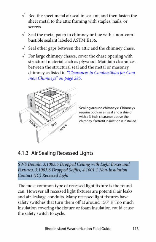
Rhode Island Weatherization Field Guide 113
✓ Bed the sheet metal air seal in sealant, and then fasten the sheet metal to the attic framing with staples, nails, or screws.
✓ Seal the metal patch to chimney or flue with a non-com-bustible sealant labeled ASTM E136.
✓ Seal other gaps between the attic and the chimney chase.
✓ For large chimney chases, cover the chase opening with structural material such as plywood. Maintain clearances between the structural seal and the metal or masonry chimney as listed in “Clearances to Combustibles for Com-mon Chimneys” on page 285.
4.1.3 Air Sealing Recessed Lights
The most common type of recessed light fixture is the round can. However all recessed light fixtures are potential air leaks and air-leakage conduits. Many recessed light fixtures have safety switches that turn them off at around 150° F. Too much insulation covering the fixture or foam insulation could cause the safety switch to cycle.
SWS Details: 3.1003.5 Dropped Ceiling with Light Boxes and Fixtures, 3.1003.6 Dropped Soffits, 4.1001.1 Non-Insulation Contact (IC) Recessed Light
Sealing around chimneys: Chimneys require both an air seal and a shield with a 3-inch clearance above the chimney if retrofit insulation is installed
joist
sheet metal
shie
ld
sealant
sealant
shie
ld

Attics and Roofs114
Types of Recessed Can Lights
There are three kinds of recessed can lights found in buildings with regard to their need for insulation shielding. (IC means insulation contact. AT means airtight.)
1. Older cans that aren’t rated for contact with insulation, known as non-IC-rated cans.
2. IC-rated cans that may be covered with fibrous insula-tion but not foam insulation.
3. ICAT-rated cans that are airtight in addition to being rated for insulation contact.
Options for Sealing Non-IC-Rated Fixtures
Consider these three options for air sealing recessed can lights. You can enclose the existing fixture, replace it with an ICAT recessed fixture, or retrofit it with an LED retrofit kit.
1. Build a Class I fire-resistant enclosure over the non-IC-rated fixture leaving at least 3 inches clearance from insulation on all sides and to the lid of the enclosure. Seal this enclosure to surrounding materials with foam to create an airtight assembly. The top of this fire-resis-tant enclosure must have an R-value of 0.5 or less. Don’t cover the top of the enclosure with insulation.
2. Replace the recessed fixture with a new ICAT fixture, and carefully seal around this airtight fixture.
3. Install an airtight LED-retrofit assembly in the existing can. This option assures that the light is energy-effi-cient and low heat because you replace the existing incandescent lamp holder with a cooler LED retrofit assembly.
If the non-IC rated fixture remains, replace the incandescent lamp with a compact fluorescent lamp (CFLs) or LED lamp,

Rhode Island Weatherization Field Guide 115
which operates cool and minimizes the fire hazard associated with these fixtures.
Recessed light fixtures should contain 60-watt bulbs or less. Compact fluorescent lamps (CFLs) or LED lamps should be installed during a utility Appliance Management Program (AMP) audit.
Caution: Don’t cover IC-rated or airtight IC-rated fixtures with spray foam insulation. The foam’s high R-value and continuous contact could overheat the fixture.
See also "Safety Preparations for Attic Insulation" on page 127.

Attics and Roofs116
Low-air-leakage trim retrofit: These kits employ a standard Edison base. Install a CFL or an LED in the base for maximum energy savings.
Air seal and shield for non-IC can: This drywall box is an insulation shield and air seal, but allows the fixture some air circulation for cooling.
drywall box air seal
recessed light fixture
Airtight LED retrofit for can lights: These retrofit fixtures provide a low-wattage LED with a low-air-leakage enclosure that inserts into the existing can light.

Rhode Island Weatherization Field Guide 117
4.1.4 Sealing Stairways to Unconditioned Attics
There are a variety of stairways and hatchways that provide access from the building to an unconditioned attic.
The following components of these stairways may need air seal-ing and insulation depending on whether they are at the thermal boundary.
• The risers and treads of the stairways
• The surrounding triangular walls
• Vertical or horizontal doors or hatches
• The framing and sheeting surrounding the doors or hatches
• Sloping ceilings above the stairways
Consider the following air-sealing measures.
✓ Study the geometry of the stairway and decide where to establish the air barrier and install the insulation.
✓ Weatherstrip around doors and hatches if the door or hatch is at the thermal boundary. The hatch should be a minimum of 3/4 inch plywood.
✓ Air-seal and densepack the walls and stair-stringer space if they are at the thermal boundary.
✓ Seal gaps between the door frame and the framing with one-part foam, two-part foam, or caulking.
✓ If attic insulation is or will be above the level of the attic-access hole, build a dam that extends above the top of the floor joists with a small landing around attic access hatch. Make the dam strong enough to support the weight of any-
SWS Details: 3.1002.1 Interior with Sloped Ceiling, 3.1002.2 Stairwell to Attic—Door at Bottom with No Ceiling Above, 3.1002.3 Stairwell to Attic—Door at Top with Finished Ceiling Above

Attics and Roofs118
one entering the attic. The landing allows technicians and workers to easily bring equipment into the attic space. Air seal this dam to the surrounding structure of the attic access hatch.
✓ With existing insulation dams, clear existing fibrous insu-lation from around dam around the hatch framing. Spray two-part foam around the perimeter to reduce heat loss through the hatch framing.
See also "Walk-Up Stairways and Doors" on page 146.
4.1.5 Sealing Porch Roof Structures
Porch roofs on older homes were often built at the framing stage or before the water resistive barrier (WRB) and siding were installed. The porch’s roof sheathing, roofing, and tongue-and-groove ceiling aren’t air barriers. The loosely fitting wall sheath-ing or unsheathed wall allows air into the wall cavities where it migrates into the conditioned space or convects heat into or out of the building.
Check with the state monitor before proceeding with any of these options for air sealing leakage through a porch roof.
Option 2: A
ir-se
al an
d insu
late
stai
rway
, 3 w
alls,
and d
oor.
Option 1: Weatherstripped and insulated hatch.
insu
late
/w
eath
erst
rip
door
Unconditioned attic
Conditioned
livin
g spac
e
Stairways at the thermal boundary: The stairway may be within the thermal boundary or outside it. Only walls, ceilings, doors, and hatches at the thermal boundary require thorough air sealing. The door as shown is open.
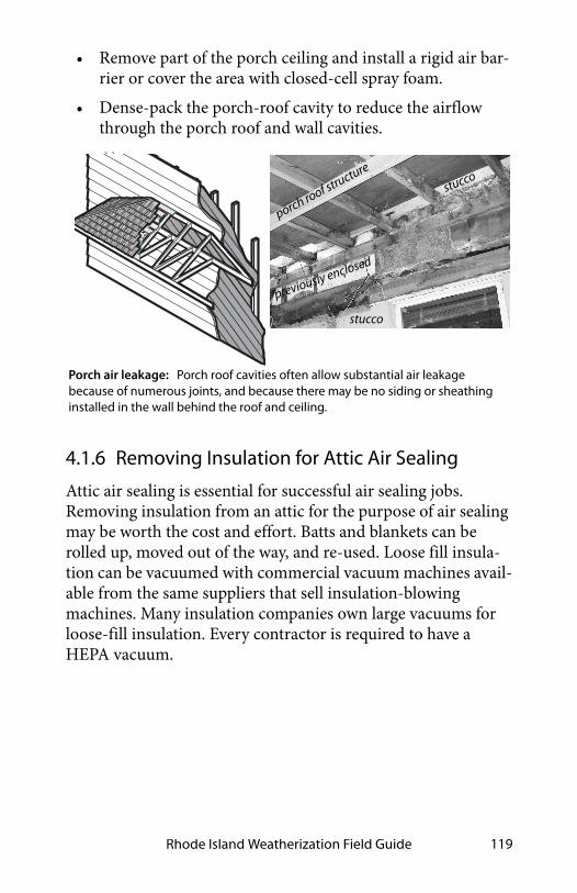
Rhode Island Weatherization Field Guide 119
• Remove part of the porch ceiling and install a rigid air bar-rier or cover the area with closed-cell spray foam.
• Dense-pack the porch-roof cavity to reduce the airflow through the porch roof and wall cavities.
4.1.6 Removing Insulation for Attic Air Sealing
Attic air sealing is essential for successful air sealing jobs. Removing insulation from an attic for the purpose of air sealing may be worth the cost and effort. Batts and blankets can be rolled up, moved out of the way, and re-used. Loose fill insula-tion can be vacuumed with commercial vacuum machines avail-able from the same suppliers that sell insulation-blowing machines. Many insulation companies own large vacuums for loose-fill insulation. Every contractor is required to have a HEPA vacuum.
Porch air leakage: Porch roof cavities often allow substantial air leakage because of numerous joints, and because there may be no siding or sheathing installed in the wall behind the roof and ceiling.
porch roof structure
stucco
stucco
previously enclosed

Attics and Roofs120
4.1.7 Sealing Joist Cavities Under Kneewalls
Floor joist cavities beneath knee walls (also known as transition walls) allow air from a ventilated attic space to enter the floor cavity between stories. This is a problem of homes with a fin-ished attic, also known as story-and-a-half homes.
Create an air seal between the knee wall and the ceiling of the space below using one of these methods.
• From the attic, install a combination of rigid foam with one-part or two-part foam sealing the perimeter.
• From the attic, stuff a fiberglass batt into the joist space and seal it with spray two-part foam from the attic.
• From the attic, install foam board on the attic side of the knee wall and continue it down to cover the joist space by cutting slots in the foam board for the joists. Seal around the joists and at the ceiling of the space below with spray foam.
SWS Detail: 4.1004.1 Preparation for Dense Packing, 4.1004.2 Preparation for Batt Insulation
Removing attic insulation: Technicians vacuum and collect existing attic insulation for re-use or disposal because of moisture damage or to allow effective air sealing.

Rhode Island Weatherization Field Guide 121
• From indoors, cut the flooring back from the wall at the indoors and install the air seal and insulation under the knee wall.
4.1.8 Sealing Kitchen or Bathroom Interior Soffits
Many modern homes have soffits above kitchen cabinets and in bathrooms. Large rectangular passages link the attic with the soffit cavity. At best, the air convects heat into or out of the con-ditioned space. At worst, attic air infiltrates the conditioned space through openings in the soffit or associated framing.
✓ Seal the soffit with plywood or drywall, bedded in sealant and fastened to ceiling joists and soffit framing with screws, nails or staples.
✓ Seal the patch’s perimeter thoroughly with two-part foam or caulking. Take pictures of before and after the air seal-ing work is performed.
SWS Detail: 3.1001.1 Penetrations and Chases, 3.1001.2 Chase Capping, 3.1003.6 Dropped Soffits

Attics and Roofs122
4.1.9 Sealing Two-Level Attics
Split-level and tri-level homes have a particular air leakage problem related to the walls and stairways dividing the homes’ levels.
✓ Seal wall cavities below the ceiling joists from the attic with a rigid material fastened to studs and wall material.
✓ Or insert folded fiberglass batt into the wall cavity and spray with at least one inch of two-part foam to create a rigid air seal.
✓ Dense-pack the transitional wall or insulate it with fiber-glass batts. Either way install an air barrier on the attic side of the wall.
✓ Seal all penetrations between both attics and conditioned areas.
SWS Detail: 3.1001.3 Walls Open to Attic—Balloon Framing and Double Walls
Kitchen soffits: The ventilated attic is connected to the soffit and the wall cavity through framing flaws. Any hole in the soffit creates a direct connection between the kitchen and attic. Block off the soffit from the attic with drywall or plywood sealed with two-part spray foam as shown in the photo.
recessed light
eave vents
air leakage

Rhode Island Weatherization Field Guide 123
4.1.10 Sealing Suspended Ceilings
Work on suspended ceilings should be discussed with the state monitor before proceeding. Suspended ceilings are seldom air-tight, especially the T-bar variety. T-bar ceilings and other non-structural suspended ceilings may not be a practical location to establish an air barrier.
• The ceiling was installed room by room.
• The amount of spray foam necessary to seal the joints may be too heavy for the non-structural suspended ceiling to support.
• Technicians may need access to the crawl space above the suspended ceiling in multiple locations to work on utilities installed above the ceiling.
Take down some panels of a suspended ceiling to inspect the suspended ceiling or gain access from above. Observe these options for air-sealing non-structural suspended ceilings.
SWS Detail: 3.1003.1 New Ceiling Below Original—Old Ceiling Intact or Repairable, 3.1003.2 Ceiling Leaks Not Repairable—No Air Barrier Above, 3.1003.4 3-D Walls, 3.1003.3 Above Closets and Tubs, 3.1003.5 Dropped Ceiling with Light Boxes and Fixtures
recessed light
soil stack
chimney
seal wall cavities
duct
wireTwo-level attic: Split-level homes create wall cavities connected to the ventilated attic. Other air leaks shown are duct, recessed light, attic hatch and chimney.
Tri-level home
problem wallinsulate here

Attics and Roofs124
• A plaster ceiling above a non-structural suspended ceiling is weak and failing. You plan to install insulation on top of existing insulation above the failing ceiling. Reinforce the existing plaster with screws and plaster washers. Screw dry-wall over areas of missing plaster. Seal the joints and perim-eter with spray foam.
• An insulated roof deck above a non-structural suspended ceiling may be the only practical place to establish an air barrier. The perimeter walls and the wall-roof junction may be leaky and uninsulated. Insulate and air seal the perime-ter walls above the suspended ceiling if necessary to com-plete the insulation and air barrier at the thermal boundary.
Ceilings suspended using lumber or steel studs, on the other hand, may be structural enough to walk on.
• The suspended ceiling is strong enough to walk on its structure. Seal the ceiling joints, penetrations, and perime-ter with spray foam. Insulate the walls between the sus-pended ceiling and upper ceiling. Either insulate above the suspended ceiling or above the upper ceiling.

Rhode Island Weatherization Field Guide 125
4.2 INSULATING ATTICS AND ROOFS
Attic and roof insulation are two of the most cost-effective energy conservation measures.
Sealing existing upper ceilings: With a non-structural suspended ceiling and a damaged plaster ceiling above, seal the plaster ceiling above if it’s impractical to air seal the suspended ceiling.
inte
rior w
all t
op p
late
wall cavity
suspended
ceiling
suspendedceiling
leaky
old ceiling
Sealing the roof deck: Seal the roof wall junction with spray foam. Insulate the walls above the suspended ceiling. Insulate the roof deck if there’s no insulation on top of the roof deck.
uninsulated beam
uninsulated wall
insulated roof d
eck
Sealing structural suspended ceilings: Two-part foam air seals and insulates an interior wall top plate and the wall cavity between the ceiling and roof deck.
wall cavity
hatch

Attics and Roofs126
Buildings with flat ceilings are usually insulated at the ceiling and this is attic insulation. An attic is a space under a roof where a person can walk or crawl.
Buildings with sloping ceilings or flat roofs are usually insulated in the roof cavity. Roof cavities are spaces that aren’t usually accessible for walking or crawling.
A majority of buildings have fibrous insulation in their attics or roof cavities. Fibrous insulation is the most economical insula-tion for attics and roof cavities. Attics and roof cavities need ventilation for drying, cooling, and to prevent ice dams. See “Fibrous Insulation Materials” on page 94.
4.2.1 Preparing for Attic Insulation
These preparatory steps before insulating the attic.
✓ Before insulating the attic, seal air leaks and bypasses as described previously. See “Air-Sealing Attics and Roofs” on page 111. Verify attic air-tightness as described in “Simple Zone Pressure Testing” on page 463.
✓ Repair small roof leaks, remove other moisture sources, and repair other attic-related moisture problems before insulating attic. Don’t do any retrofit work in the attic until all attic moisture problems have been repaired.
✓ Vent all kitchen and bath fans outdoors through appropri-ate roof fittings, side wall fittings, or soffit fittings. See “Fan and Duct Specifications” on page 358.
✓ Install an attic access hatch if one is not present in an area determined by the auditor.
✓ An interior attic hatch should be at least 22 inches square if possible. Insulate the hatch to the maximum practical R-value. The roof ’s height above the hatch may limit rigid
SWS Detail: 4.1001.4 Vented Eave or Soffit Baffles, 4.1001.1 Non-Insulation Contact (IC) Recessed Lights

Rhode Island Weatherization Field Guide 127
board foam you can attach to the back of the hatch door. Apply white primer to any plywood surfaces that are exposed to the home’s interior.
✓ Prepare documentation of the insulation type, installed thickness, coverage area, and insulation R-value to post at the electric box after installation.
✓ Build an insulation dam with a small landing around the attic access hatch two inches above the height of the insu-lation. Build the dam with rigid materials like 3/4” ply-wood or oriented-strand board so that the dam supports the weight of a person entering or leaving the attic.
✓ If head space is limited at the hatch, use fiberglass batts to dam loose fill insulation.
4.2.2 Safety Preparations for Attic Insulation
Before insulating the attic, protect the heat-producing fixtures, such as recessed light fixtures, bathroom exhaust fans, and chimneys, by installing shields. Without shields, the light fix-tures, bathroom fans, or chimney might ignite the insulation.
SWS Detail: 4.1001.1 Non-Insulation Contact (IC) Recessed Light, 4.1006.3 Whole-House Fan, 4.1005.2 Accessible Floors—Loose Fill Installation, 4.1005.3 Accessible Floors—Batt Insulation Over Existing Insulation, 4.1005.4 Accessible Floors—Loose Fill Over Existing Insulation, 4.1001.2 Knob and Tube Wiring
Insulated attic hatch: Building a dam prevents loose-fill insulation from falling down the hatchway. Foam insulation prevents the access hatch from being a thermal weakness. Install foam to achieve attic-insulation R-value of R-49. Foam can be glued together in layers.
2-inch foam
plywood dam ceiling joists
2-inch foam
2-inch foam
weatherstrip

Attics and Roofs128
Or, the insulation might cause a light fixture, bathroom fan, or chimney to become hot enough to ignite something else.
The shielding enclosure must often serve as the air-seal for the light fixture, bathroom fan, or chimney.
Protecting Recessed Light Fixtures
There are three different types of recessed light fixtures and light-fan fixtures. (IC = insulation contact)
1. Non-IC-rated fixtures that must not touch insulation.
2. Type IC-rated fixtures that may be covered with fibrous insulation.
3. Type IC-AT, which are reasonably airtight (AT) and safe for contact by fibrous insulation.
Consider these options when preparing recessed light fixtures or bathroom fans for attic insulation.
• Remove the recessed light fixture and replace it with a sur-face-mount fixture.
• Replace non-IC-rated fixtures with airtight IC-rated fix-tures (IC-AT). You can cover these IC-AT fixtures with fibrous insulation after sealing the gap between the fixture and the surrounding materials.
• If the existing fixture is rated IC, you can seal the fixture’s enclosure to the ceiling with caulk and cover the fixture with fibrous insulation. Or you can shield the fixture with an enclosure, seal the enclosure to the ceiling with foam, and then cover the enclosure with insulation.
• Shield all existing non-IC-rated fixtures with airtight enclo-sures that extend above the level of the retrofitted insula-tion. Seal the enclosure to the ceiling with foam, and then surround the enclosure with insulation, but don’t insulate over its top.

Rhode Island Weatherization Field Guide 129
• In cavities that are sheeted on both sides, either shield non-IC recessed lights or replace them before dense-pacing the cavities.
Caution: Spray foam insulation must not cover or surround recessed light fixtures or any other heat-producing devices.
Enclosing the Non-IC Fixture Remains
If an existing older recessed fixture, which isn’t labeled IC must remain in place, do these steps.
✓ Build a Class I fire-resistant enclosure over the non-IC-rated fixture leaving at least 3 inches clearance from insu-lation on all sides and to the lid of the enclosure. The top of this fire-resistant enclosure must have an R-value of 0.5 or less and extend 4 inches above the level of the new insu-lation.
✓ Notch the shields around wires.
✓ Seal the enclosure to the ceiling with foam or caulk.
✓ Don’t cover the top of the enclosure with insulation.
Protecting Chimneys
The requirements for protecting chimneys from contact with insulation vary widely from one building department to another. We know of three common approaches to insulating
Recessed light fixtures: Cover recessed light fixtures with fire-resistant drywall or sheet-metal enclosures to reduce air leakage to allow installers to safely insulate around the box.
newinsulation
3” minimum clearance
3” 3”
no insulation on topair seal
air seal

Attics and Roofs130
around chimneys, which are listed here beginning with the most restrictive.
1. Air-seal around the chimney using non-combustible material like 26 gauge galvanized steel. Seal the steel to the chimney with a high-temperature sealant.
2. After air sealing gaps, install non-combustible insula-tion shields around masonry chimneys and manufac-tured metal chimneys to keep insulation at least 3 inches away from these chimneys.
3. A clearance smaller than 3 inches may be allowed if the attic insulation is non-combustible or if the specifica-tions of the vent material allow a clearance less than 3 inches. For example: type B gas vent has a typical mini-mum clearance of 1 inch and all-fuel chimneys have a typical minimum clearance of 2 inches.
4. If the insulation is non-combustible, such as blown fiberglass or rock wool, no clearance between insula-tion and manufactured or masonry chimneys is neces-sary if this option is permitted by local building officials.
maintain 3-inch clearance
Air-sealed chimney with metal shield: Metal flashing bridges the gap between the chimney and the framing. A metal shield keeps the insulation 3 inches away from the chimney.

Rhode Island Weatherization Field Guide 131
Electrical Junction Boxes
Observe these specifications during attic-insulation prepara-tion.
1. Install covers on all electrical junction boxes that lack covers.
2. Use caulk or two-part foam to air seal electrical boxes that penetrate the ceiling (for light fixtures and fans), before blowing fibrous insulation over the boxes.
3. Flag the electrical boxes so that an electrician can find the boxes for future electrical work. If the box can’t be flagged from the floor of the attic, the flag should be stapled to the roof rafter directly above the box.
Knob-and-Tube Wiring
If knob-and-tube wiring is present in the attic, consider decom-missioning it prior to installing insulation. See “Knob-and-Tube Wiring” on page 45.
4.2.3 Blowing Attic Insulation
Install attic insulation to a cost-effective R-value, depending upon existing insulation level and climatic region. Air seal attics before installing attic insulation. Air sealing may require remov-ing existing insulation and debris that obstruct air sealing. See “Removing Insulation for Attic Air Sealing” on page 119.
Blown insulation is usually better than batt insulation because blown insulation forms a seamless blanket. Blown fibrous attic insulation settles: cellulose settles 10% to 20% and fiberglass set-tles 3% to 10%. Blowing attic insulation at the highest achievable
SWS Detail: 4.1005.2 Accessible Floors—Loose Fill Installation, 4.1005.4 Accessible Floors—Loose Fill Over Existing Insulation, 4.1005.8 Loose Fill Over Existing Insulation on Accessible Attic Floors

Attics and Roofs132
density helps minimize both settling and air circulation within the blown insulation.
Observe these specifications when blowing loose-fill attic insu-lation.
✓ Calculate how many bags of insulation are needed to achieve the R-value specified on the work order from the table on the bag’s label.
✓ Install insulation depth rulers: one for every 300 square feet, and all facing toward the attic access.
✓ Maintain a high density by moving as much insulation as possible through the hose with the available air pressure. The more the insulation is packed together in the blowing hose, the greater is the insulation’s installed density.
✓ Fill the edges of the attic first, near the eaves or gable end, then fill the center.
✓ When filling a tight eaves space, push the hose out to the edge of the ceiling. Allow the insulation to fill and pack against the baffle.
✓ Install insulation to a consistent depth. Level the insula-tion with a stick if necessary.
✓ Post an insulation certificate, with insulation type and number of bags installed, installed thickness, coverage area, and insulation R-value at the home’s main electrical panel. See “Insulation Receipt or Certificate” on page 93.
Blown-in attic insulation: Blown insulation is more continuous than batts and produces better coverage. Insulation should be blown at a high density to minimize settling and air convection.

Rhode Island Weatherization Field Guide 133
4.2.4 Closed-Cavity Attic Floors
The ceiling joists in the attic are often covered by a wood floor for storage. You may have to remove some floor boards or drill the floor sheathing to install dense-packed insulation.
✓ Inspect and thoroughly seal the floor cavity’s air leaks before blowing insulation.
✓ Protect recessed light fixtures and other heat-producing devices in the floor cavity.
✓ Then dense-pack fiberglass or cellulose insulation into the spaces between the ceiling joists.
✓ Post an insulation certificate, with insulation type and number of bags installed, installed thickness, coverage area, and insulation R-value at the home’s main electrical panel. See “Insulation Receipt or Certificate” on page 93.
SWS Detail: 4.1003.4 Cape Cod Side Attic Roof—Dense Pack Installation, 4.1005.6 Enclosed Attic Storage Platform Floor —Dense Pack Installation
Finished attic floor: Find the large air leaks underneath the flooring and seal them before insulating the space between the joists.

Attics and Roofs134
4.2.5 Insulating Closed Roof Cavities
Many existing homes have cathedral ceilings or flat roofs that are partially filled with fibrous insulation. These roofs are often unventilated or ineffectively ventilated. The insulation job may include repair of the roof deck and installation of foam insula-tion over the roof deck. If there is no roof ventilation, then install foam roof insulation in addition to filling the cavity with insulation. Foam R-value of between R-5 and R-35 depending on climate as specified by the IRC.
Ventilated Closed Roof Cavities
To prepare for roof-cavity insulation, without existing baffles and with a ventilated space above the insulation, use this proce-dure.
✓ Remove either the roofing and sheathing or the interior ceiling to gain full access to the cavity.
✓ Remove recessed light fixtures and replace them with sur-face-mounted light fixtures. Carefully patch and air seal the openings.
✓ Install fiberglass or foam insulation to meet the IECC regional minimum roof-assembly R-value requirements.
✓ Install openings into the ventilation channel above the insulation totaling 1/150 of the roof area. If the ceiling has a Class I or II vapor retarder, the requirement is reduced to 1/300 of the roof area.
SWS Detail: 4.1002.1 Above Deck Roof Insulation—Preparation, 4.1002.2 Above Deck Roof Insulation—Installation, 4.1001.5 Dense Pack Preparation, 4.1003.1 Pitched/Vaulted/Cathedralized Ceilings—Loose Fill Over, 4.1003.2 Pitched/Vaulted/Cathedralized Ceilings—Dense Pack Over, 4.1003.3 Unvented Flat Roof with Existing InsulationSWS Detail: 4.1003.5 Unvented Roof Deck—Spray Polyurethane Foam Installation

Rhode Island Weatherization Field Guide 135
✓ In cold climates, install a Class I or II vapor retarder at the ceiling. One option is to paint an oil-based primer over the interior drywall or plaster.
✓ Repair small roof leaks or install a new water-tight roof.
✓ Install an air-barrier ceiling (drywall) if the existing ceiling isn’t an adequate air barrier, for example tongue-and-groove paneling.
✓ Seal other air leaks with great care, especially at the perim-eter and around ridge beams.
Un-Ventilated Closed Roof Cavities: Decisions
Many homes have cathedral ceilings, vaulted ceilings, or flat roofs that are partially or completely filled with insulation and would require major building surgery to install code-compliant roof ventilation or rooftop foam board during retrofit cavity insulation.
Dense-packing the cavities prevent most convection and moist-air infiltration, which are leading causes of moisture problems in roof cavities.
Important Note: Dense-packing roof cavities with fiberglass insulation and without ventilation is controversial. The colder the climate, the higher the risk of problems, such as ice dam-ming. However, dense-packing the cavities prevents most con-vection and moist-air infiltration, which are leading causes of moisture problems in roof cavities.
Closed Roof Cavities: Preparation
To prepare for dense-packing the roof-cavity, consider the fol-lowing steps at the auditor’s discretion.
✓ Identify the sources of moisture in the home. See "Solu-tions for Moisture Problems" on page 32.

Attics and Roofs136
✓ Verify that the ceiling has a Class I or II vapor retarder and air barrier on the interior. If not, install a vapor retarder and air barrier.
✓ Seal other ceiling air leaks, large and small, with great care.
Important Note: Whether roof cavities can be safely dense-packed with fiberglass or blown cellulose insulation and without ventilation is controversial and depends on climate. The colder the climate, the higher the risk of problems. Dense-packing the cavities prevents most convection and moist-air infiltration, which are leading causes of moisture problems in roof cavities.
Blowing Insulation into the Closed Roof Cavity
Always use a fill tube when blowing closed roof cavities. Insert the tube into the cavity to within a foot of the end of the cavity. Access the cavity through the eaves, the roof ridge, the roof deck, or the ceiling. Consider one of these procedures.
• Remove the soffit and blow insulation from the eaves.
• Drill and blow through a drywall ceiling.
• Carefully remove a tongue-and-groove ceiling plank and blow insulation into cavities through this slot.
Blowing from the eaves: Some vaulted ceilings can be blown from the eaves and/or the ridge.

Rhode Island Weatherization Field Guide 137
4.2.6 Installing Fiberglass Batts in Attics
Follow these specifications when installing fiberglass batts in an attic. Fiberglass batts aren’t the best insulation for attics because of all their seams.
✓ When layering batts, install new layers at right angles to underlying layers if the top of the existing batts are level with or above the ceiling joist or truss bottom chord.
✓ Install un-faced fiberglass insulation whenever possible.
✓ If you must install faced batts, install them with the facing toward the heated space. Never install faced insulation over existing insulation.
✓ Cut batts carefully to ensure a tight fit against the ceiling joists and other framing.
4.2.7 Cathedralized Attics (Open Cavity)
A cathedralized attic has insulation attached to the bottom of the roof deck and is also called a hot roof. Choose to insulate the bottom of the roof deck instead of insulating the ceiling when the building owner wants to use the attic or to enclose an attic air handler and leaky ducts within the home’s thermal bound-ary.
Important: Insulating the underside of the roof deck presents a risk of moisture problems in the structural sheathing from roof leaks or condensation. To avoid moisture condensation within
SWS Detail: 4.1005.3 Accessible Floors—Batt Insulation Over Existing Insulation
SWS Details: 4.1003.2 Pitched/Vaulted/Cathedralized Ceilings—Dense Pack Over, 4.1003.5 Unvented Roof Deck—Spray Polyurethane Foam Installation, 4.1001.7 Vented Roof Deck—Preparation for SPF, 4.1003.7 Ignition and Thermal Barriers—Spray Polyurethane Foam

Attics and Roofs138
the insulation or within the structural sheathing during cold weather, install air-impermeable insulation such as closed-cell foam or install a perfect air barrier and a vapor retarder to the rafters beneath the insulation. (If the job requires a permit, see the IRC for guidance on its recommendations on rooftop insu-lation, required to prevent condensation and increase the assembly’s thermal resistance.)
Provide the client an insulation certificate, with insulation type and number of bags installed, installed thickness, coverage area, and insulation R-value. See “Insulation Receipt or Certificate” on page 93.
Spray Foam Roof-Deck Insulation
Use these procedures for spraying high-density, closed-cell foam on the underside of the roof deck.
✓ Remove any vapor retarder in the ceiling insulation at the floor of the attic.
✓ Create an airtight insulation dam at the eaves to form an air barrier at the roof-wall junction and to prevent spray foam from escaping into the soffit.
✓ Spray the foam to cover the entire surface of the cavity.
✓ Comply with fire safety provisions of the IRC as discussed in “Closed-Cell Spray Polyurethane Foam” on page 100.
Use only high-density closed-cell spray foam and not low-den-sity open-cell spray foam for application to the bottom of a roof deck.
Fiberglass Roof-Deck Insulation
Insulating the rafter space with an air-permeable insulation requires an air barrier, vapor retarder, and Class I (or A) fire-rated material at the roof cavity’s lower boundary. Consider these two alternatives.

Rhode Island Weatherization Field Guide 139
1. Install the rafter’s depth of fiberglass batts and then a material or combination of materials that constitutes an air barrier, vapor retarder, and Class I fire barrier.
2. Blow dense-packed insulation between the roof deck using a rigid sheeting or flexible insulation restraint.
4.2.8 Vaulted Attics
A vaulted attic is framed with a special truss that creates a slop-ing roof and a sloping ceiling. Access to the cavity varies from difficult to impossible.
Install insulation from either the top of the roof deck or through the ceiling. Insulation, installed at the ceiling, must have some stability to prevent gravity from pulling it downhill or wind from piling it, leaving some areas under-insulated. Damp spray fibrous insulation may serve this purpose.
Consider the following options to insulating uninsulated or par-tially insulated vaulted attics.
1. Insulate the ceiling with fiberglass batts. Install the batts parallel to the framing if the top of existing insulation is below the framing. Install the batts perpendicular to the framing if the top of the existing insulation is above the framing.
2. Insulate the bottom of the roof deck, as described previ-ously for a cathedralized attic, if you remove the ceiling.
3. Insulate the ceiling with sprayed foam or with batts from the roof.
4. Fill the cavity with insulation from indoors or through the roof. Maintain the existing vents and hope that set-tling or under-filling provides room for ventilation.
SWS Detail: 4.1003.1 Pitched/Vaulted/Cathedralized Ceilings—Loose Fill Over

Attics and Roofs140
5. Preserve or install openings into the ventilation space above the insulation totaling 1/150 of the roof area. If the ceiling has a vapor retarder the requirement is 1/300 of the roof area.
Whatever option you choose, provide the client with an insula-tion receipt or certificate, with insulation type, installed thick-ness, coverage area, and insulation R-value. See “Insulation Receipt or Certificate” on page 93.
4.2.9 Finished Kneewall Attics
Finished attics require special care when installing insulation. They often include five separate sections that require different air-sealing and insulating methods. Seal air leaks in all these assemblies before insulating them. If necessary, remove the planking and insulation from the side-attic floor to expose the air leaks
Use these specifications when insulating finished attics.
✓ Seal large air leaks between conditioned and non-condi-tioned (transition wall) spaces.
✓ Inspect the structure to confirm that it has the strength to support the weight of the insulation.
✓ Insulate access hatches to the approximate R-value of the assembly through which it is located.
✓ Post an insulation certificate, with insulation type, installed thickness, coverage area, and insulation R-value at the attic entrance. See “Insulation Receipt or Certificate” on page 93.
SWS Detail: 4.1004.1 Preparation for Dense Packing, 4.1005.1 Accessible Floors—Batt Installation

Rhode Island Weatherization Field Guide 141
Attic Floor
There are a number of options for insulating the attic floor of a finished attic with knee walls. By attic floor, we mean the ceiling of the living space below with its ceiling joists and any floor sheeting installed over the joists for a storage platform.
• Install blown fibrous insulation over the ceiling, which should be an air barrier.
• Install blown fibrous insulation over existing insulation.
• Install fiberglass batts over the ceiling, which should be an air barrier.
• Install fiberglass batts over the existing insulation.
Whichever of these options that you choose, do the necessary air sealing to the attic floor before installing insulation. Also observe the preparations and safety precautions discussed in “Preparing for Attic Insulation” on page 126 and “Safety Prepara-tions for Attic Insulation” on page 127.
Attic floor and knee wall: Establish an air barrier at the attic floor and knee wall if you insulate these assemblies.
finish
ed a
ttic
air b
arrie
r
foam plug under knee wall
foam or house wrap
blown floor
air barrier at ceiling or above
insulation

Attics and Roofs142
Exterior Walls of Finished Attic
Insulate these walls as described in “Retrofit Closed-Cavity Wall Insulation” on page 172 or “Open-Cavity Wall Insulation” on page 175.
Collar-Beam Attic
Insulate this type of half-story attic as described in “Blowing Attic Insulation” on page 131.
Sloped Roof
Insulate sloped roof with dense-packed cellulose insulation and seal with Hi-R board and foam.
Finished attic: This illustration depicts two approaches to insulating a finished attic. Either A) insulate the knee wall and side attic floor, or B) insulate the roof deck.
roof insulation
side attic
knee wall
collar beam
ceiling joist
insulated ceiling joist, knee wall, and slope
Method A
Method B
(cathedralized attic)

Rhode Island Weatherization Field Guide 143
4.2.10 Kneewall Insulation
Insulate knee walls using any of these methods.
• Install un-faced fiberglass batts and cover the insulation with drywall on the attic side. Prefer R-13 or R-15, 3.5-inch fiberglass batts.
• Install drywall and then blow dense-packed fibrous insula-tion into the cavity. (Cellulose: 3.5 pcf; fiberglass 2.2 pcf)
SWS Details: 4.1004.1 Preparation for Dense Packing, 4.1004.3 Strapping for Existing Insulation, 4.1004.4 Knee Wall Without Framing, 4.1004.5 Knee Walls and Gable End Walls—Preparation for and Installation of Spray Polyurethane Foam (SPF)
flexible fill-tube
lath and plaster
celluloseinsulation
fiberglassinsulation
joist
rafter
fiberglass batt or
2-part spray foam seal
air-barrier paper
Finished attic best practices: Air sealing and insulation combine to dramatically reduce heat transmission and air leakage in homes with finished attics.
densepack plug
Air-seal and insulatebetween joists
Attics and Roofs144
• Spray the cavities with open-cell or closed-cell polyure-thane foam after gaining access to the cavities and remov-ing surface dirt to ensure good adhesion.
• For knee walls without framing, mechanically fasten rigid insulation to the wall’s surface and seal the seams.
Post an insulation certificate, with insulation type and number of bags installed, installed thickness, coverage area, and insula-tion R-value at the home’s main electrical panel. See “Insulation Receipt or Certificate” on page 93.
Preparation for Kneewall Insulation
Make whatever repairs and seal air leaks before installing the knee wall insulation.
✓ Seal all large air leaks with structural materials.
✓ Seal all joints, penetrations, and other potential air leaks in the cavities with caulk or foam.
✓ Before installing caulk or spray foam insulation, clean dust and any other material that might interfere with the spray foam’s adhesion.
Air Sealing and Insulating under the Kneewall Transition Wall
To seal and insulate under the knee wall, create an airtight and structurally strong seal in the joist spaces under the knee wall. Consider these options.
• Install sealed wood blocking between the floor joists cov-ered with spray foam.
• Insert 2-inch-thick foam sheets and foam their perimeters with one-part or two-part foam.
• Insert a fiberglass batt into the cavity and foam its face with an inch of two-part closed-cell spray foam.

Rhode Island Weatherization Field Guide 145
4.2.11 Access Doors in Vertical Walls
For knee wall access doors, observe the following.
✓ Insulate knee wall access hatches and collar-beam access hatch with an R-value equivalent to the wall cavity.
✓ All knee wall access doors must include 3/4 inch plywood, Hi-R equivalent to knee wall insulation, weatherstripped on all 4 sides, hinged with 2 slide bolts and a handle.
✓ Weatherstrip the hatch and install a latch or other method to hold the access door closed against the weatherstrip.
✓ Close off and seal the opening whenever possible. Con-tractor must include pictures.
SWS Detail: 4.1006.2 Access Doors and Hatches
2-inch foam panels
Insulated access door in knee wall: Achieve an R-value as close to the wall as practical. Weatherstrip the door and install some type of latch.

Attics and Roofs146
4.2.12 Walk-Up Stairways and Doors
SWS Detail: 4.1006.2 Access Doors and Hatches, 3.1002.1 Interior with Sloped Ceiling, 3.1002.3 Stairwell to Attic—Door at Top with Finished Ceiling Above, 3.1002.2 Stairwell to Attic—Door at Bot-tom with No Ceiling Above
Insulating and sealing attic stair walls, doors, and stairs: Insulating and air sealing these is one way of establishing the thermal boundary.
Insulating and weatherstripping the attic hatch: Air sealing around the hatch and insulating the hatch is an alternative method.

Rhode Island Weatherization Field Guide 147
Think carefully about how to install a continuous insulation blanket and air barrier around or over the top of an attic stair-way. If you enter the attic by a stairwell and standard vertical door, use these instructions.
✓ Blow dense-pack fibrous insulation into walls of the stair-well.
✓ Install a threshold or door sweep, and weatherstrip the door.
✓ Insulate or replace the door with an insulated door if cost effective.
✓ Blow dense-packed insulation into the sloping cavity beneath the stair treads and risers.
✓ If there is no sloping cavity, install 2" foam board for insu-lation and air sealing beneath the stair treads.
You can also establish the thermal boundary at the ceiling level, but this requires a horizontal hatch at the top of the stairs.
When planning to insulate stairwells, investigate barriers such as fire blocking that might prevent insulation from filling cavi-ties you want to fill. Also consider what passageways may lead to areas you don’t want to fill such as closets.
4.2.13 Insulating & Sealing Pull-Down Attic Stairways
Pull-down attic stairways are sometimes installed above the access hatch. Building a foam-insulated box, or thermodome, or buying a manufactured stair-and-hatchway cover are good solu-tions to insulating and sealing this weak point in the ceiling insulation. Install weatherstripping around the insulated box.
SWS Detail: 4.1006.1 Pull-Down Stairs

Attics and Roofs148
Educate the client on the purpose and operation of stair-and-hatchway cover, and ask them to carefully replace it when they access the attic.
4.2.14 Parapet Walls
Parapet walls are a continuation of exterior walls that rise above the roof. Parapet walls are often an air-leakage and thermal bridging problem because the insulation and air barrier aren’t continuous between the exterior wall and roof.
Inspect the parapet area from both indoors and outdoors and decide how to connect the wall insulation and air barrier with the roof insulation and air barrier. Consider these two alterna-tives.
1. Install an air barrier and dense-pack the wall cavity of the parapet.
2. Spray foam the parapet to connect the insulation and air barrier of the exterior wall with attic or roof insulation and air barrier.
SWS Details: 4.1088.4 Parapet Walls—Dense Pack, 4.1088.5 Par-apet Walls—Spray Polyurethane Foam (SPF)
foam insulation cover
magnetic tape
Manufactured pull-down-stair covers: Manufacturers provide insulated stair covers for use with walkable attic floors or with dams to be surrounded by fibrous insulation.

Rhode Island Weatherization Field Guide 149
4.2.15 Skylights
Skylights are places where the insulation and air barrier may not be continuous. Inspect the insulation and air barrier of the sky-light shaft. Install insulation and air seals as necessary to make a continuous insulated and air-sealed assembly as shown in the illustration.
4.2.16 Whole-House Fans
Whole-house fans can create significant thermal bridging if they aren’t dammed and insulated thoroughly around their perime-ter. Whole-house fans can leak a lot of air if they lack an airtight seasonal cover.
SWS Details: 4.1088.3 Skylights
SWS Detail: 4.1006.3 Whole-House Fan
Insulated and air sealed skylight: The skylight shaft must be insulated and air sealed from the ceiling to the roof.

Attics and Roofs150
✓ Build a foam panel as thick as practical and install it inside the whole-house fan’s frame from indoors.
✓ Use clips or other restrainers to hold the panel in place.
✓ Install weatherstrip around the perimeter to limit air leak-age.
4.3 COOL ROOFS
Homes with reflective roof coatings, along with at least R-19 insulation and good attic ventilation, may show two-thirds less solar heat gain than those buildings with darker roofs, little insulation, and poor ventilation.
The best cool roofs must both reflect solar heat and also effec-tively emit or release solar heat that accumulates in the roof assembly. The concept of emittance informs us that some mate-rials reflect heat well but don’t release heat effectively. Their emittance prevents shiny metal materials from being efficient cool-roof materials.
Scientists at Lawrence Berkeley Laboratory created an index for comparing the coolness of roofing materials that combines both
SWS Detail:5.3202.2 Reflective Roof Coatings, 5.3202.1 Reflective Coatings on Metal Roofs
Whole house fans: The whole-house fan has a dam to allow the sides of its opening to be thoroughly insulated. The movable insulation is installed at the grille indoors.

Rhode Island Weatherization Field Guide 151
reflectance and emittance into a rating more predictive of air-conditioning energy savings. The solar reflectance index (SRI) ranges from a little less than 0 to a little more than100. High SRI numbers are better than low numbers.
Standard white asphalt shingles have an SRI of only 20 to 25 when new, and that degrades over time due to loss of white granules and dirt deposits. Darker asphalt roofs have SRIs as low as 1.0 (they absorb almost all the solar heat that strikes them). White metal roofs have good SRIs from 70 to 82.
Bare galvanized steel and aluminum aren’t nearly as cool as white roofing. Those shiny metals reflect solar heat well, but they don’t emit heat effectively so they tend to heat up, resulting in SRIs in the 40s for bare galvanized steel and in the 70s for bare aluminum.
Compared to poorly ventilated roofs, good roof ventilation helps to keep attic temperatures lower. But expect less savings from improving attic ventilation compared to cool roofs and other sun-blocking measures, because radiant heat transfer —not air convection — dominates attic heat gain.
Roof and window shading: Tall trees near the south facing walls and broad trees near the east- and west-facing walls are a good shading strategy.
Reflective roof coatings: Coatings must be compatible with the existing roof surface and this may require a primer.
Attics and Roofs152
4.4 LANDSCAPING
Well-planned landscaping can reduce an unshaded building’s summer air-conditioning costs by 15% to 50%. However, poor tree siting or careless tree selection is common, so consult with landscaping experts during planning and planting.
Studies by the Lawrence Berkeley Laboratory found summer daytime air temperatures 3°F to 6°F lower in neighborhoods with mature tree canopies compared to newly developed areas with no trees.
A tree can produce daily cooling effects similar to five average-sized air conditioners running 20 hours per day. Shading and evapotranspiration — the process by which a tree releases water vapor — can reduce air temperatures as much as 9°F compared to unshaded areas.
SWS Detail: 5.3201.1 Indigenous Shading

Rhode Island Weatherization Field Guide 153
4.5 SWS ALIGNMENT
Table 4-1: Effectiveness of Cool Roofing Materials
������� ���� ����������� ��� �����
White elastomeric coating (low slope)
.70 to .85 87 to 107
White EPDM rubber membrane (low slope)
.70 to .80 80 to 105
White clay tile .70 90
White rubber membrane .70 84
White metal .60 to .70 82
New aluminum metal .60 71
New galvanized steel .60 46
Colored clay tile .20 to .50 20 to 60
White asphalt shingles .20 to .30 21 to 40
Colored asphalt shingles Š0.20 –2 to 22
Black EPDM rubber membrane (low slope)
.06 –1
Higher numbers are better: a high reflectance or high SRI yields low cooling costs. An ENERGY STAR rating (in 2008) requires an SRI of 25 or higher for steep-sloped roofs, and an SRI of 65 or higher for low-slope roofs.
Field Guide Topic SWS Detail
4.1: Air-Sealing Attics and Roofs - Pg. 111
4.1.1: Sealing around Manufac-tured Chimneys - Pg. 111
3.1001.1 Penetrations and Chases
4.1.2: Sealing around Fireplaces and Chimneys - Pg. 112
3.1001.1 Penetrations and Chases

Attics and Roofs154
4.1.3: Air Sealing Recessed Lights - Pg. 113
3.1003.5 Dropped Ceiling with Light Boxes and Fixtures, 3.1003.6 Dropped Soffits, 4.1001.1 Non-Insulation Contact (IC) Recessed Light
4.1.4: Sealing Stairways to Unconditioned Attics - Pg. 117
3.1002.1 Interior with Sloped Ceiling, 3.1002.2 Stairwell to Attic—Door at Bottom with No Ceiling Above, 3.1002.3 Stairwell to Attic—Door at Top with Finished Ceiling Above
4.1.5: Sealing Porch Roof Structures - Pg. 118
4.1.6: Removing Insulation for Attic Air Sealing - Pg. 119
4.1.7: Sealing Joist Cavities Under Kneewalls - Pg. 120
4.1004.1 Preparation for Dense Packing, 4.1004.2 Preparation for Batt Insulation
4.1.8: Sealing Kitchen or Bath-room Interior Soffits - Pg. 121
3.1001.1 Penetrations and Chases, 3.1001.2 Chase Capping
4.1.9: Sealing Two-Level Attics -Pg. 122
3.1001.3 Walls Open to Attic—Balloon Framing and Double Walls
Field Guide Topic SWS Detail

Rhode Island Weatherization Field Guide 155
4.1.10: Sealing Suspended Ceilings - Pg. 123
3.1003.1 New Ceiling Below Original—Old Ceiling Intact or Repairable, 3.1003.2 Ceiling Leaks Not Repairable—No Air Barrier Above, 3.1003.4 3-D Walls, 3.1003.3 Above Closets and Tubs, 3.1003.5 Dropped Ceiling with Light Boxes and Fixtures
4.2: Insulating Attics and Roofs -Pg. 125
4.2.1: Preparing for Attic Insulation - Pg. 126
Subtopic 4.1001 General Prepa-ration4.1001.1 Non-Insulation Contact (IC) Recessed Lights
4.2.2: Safety Preparations for Attic Insulation - Pg. 127
4.1001.1 Non-Insulation Contact (IC) Recessed Light, 4.1006.3 Whole-House Fan4.1005.2 Accessible Floors—Loose Fill Installation, 4.1005.3 Accessible Floors—Batt Insulation Over Existing Insulation, 4.1005.4 Accessible Floors—Loose Fill Over Existing Insulation4.1001.2 Knob and Tube Wiring
Field Guide Topic SWS Detail

Attics and Roofs156
4.2.3: Blowing Attic Insulation -Pg. 131
4.1005.2 Accessible Floors—Loose Fill Installation, 4.1005.4 Accessible Floors—Loose Fill Over Existing Insula-tion, 4.1005.8 Loose Fill Over Existing Insulation on Accessible Attic Floors
4.2.4: Closed-Cavity Attic Floors -Pg. 133
4.1003.4 Cape Cod Side Attic Roof—Dense Pack Installation4.1005.6 Enclosed Attic Storage Platform Floor —Dense Pack Installation
4.2.5: Insulating Closed Roof Cavities - Pg. 134
4.1002.1 Above Deck Roof Insulation—Preparation, 4.1002.2 Above Deck Roof Insulation—Installation, 4.1003.3 Unvented Flat Roof with Existing Insulation, 4.1001.5 Dense Pack Preparation
4.2.6: Installing Fiberglass Batts in Attics - Pg. 137
4.2.6: Installing Fiberglass Batts in Attics - Pg. 137
4.1005.3 Accessible Floors—Batt Insulation Over Existing Insulation
Field Guide Topic SWS Detail

Rhode Island Weatherization Field Guide 157
4.2.7: Cathedralized Attics (Open Cavity) - Pg. 137
4.1003.2 Pitched/Vaulted/Cathedralized Ceilings—Dense Pack Over, 4.1003.5 Unvented Roof Deck—Spray Polyurethane Foam Installation, 4.1001.7 Vented Roof Deck—Preparation for SPF, 4.1003.7 Ignition and Thermal Barriers—Spray Polyurethane Foam
4.2.8: Vaulted Attics - Pg. 1394.1003.1 Pitched/Vaulted/Cathedralized Ceilings—Loose Fill Over
4.2.9: Finished Kneewall Attics -Pg. 140
4.1004.1 Preparation for Dense Packing, 4.1005.1 Accessible Floors—Batt Installation
4.2.11: Access Doors in Vertical Walls - Pg. 145
4.2.12: Walk-Up Stairways and Doors - Pg. 146
4.1006.2 Access Doors and Hatches, 3.1002.1 Interior with Sloped Ceiling, 3.1002.3 Stairwell to Attic—Door at Top with Finished Ceiling Above, 3.1002.2 Stairwell to Attic—Door at Bottom with No Ceiling Above
4.2.13: Insulating & Sealing Pull-Down Attic Stairways - Pg. 147
4.1006.1 Pull-Down Stairs
Field Guide Topic SWS Detail

Attics and Roofs158
4.2.14: Parapet Walls - Pg. 148
4.1088.4 Parapet Walls—Dense Pack,4.1088.5 Parapet Walls—Spray Polyurethane Foam (SPF)
4.2.15: Skylights - Pg. 149 4.1088.3 Skylights
4.2.16: Whole-House Fans - Pg. 149
4.1006.3 Whole-House Fan
Field Guide Topic SWS Detail

Rhode Island Weatherization Field Guide 159
CHAPTER 5: WALLS
This chapter discusses air sealing and insulation for walls in existing buildings. Air sealing begins by inspecting the disconti-nuities in walls, such as the following.
• Inside and outside corners of walls.
• Openings for windows and doors.
• Protrusions and indentations in walls.
Insulation begins by evaluating the existing wall insulation and deciding on the cost-effectiveness of installing additional wall insulation. Other wall-insulation issues may include the follow-ing.
• Whether to insulate from interior or exterior of the home.
• How to open a wall cavity and restore it after insulating the wall cavity.
• How to install insulation to the wall’s surface.
5.1 AIR SEALING WALLS
Most wall air leakage involves the wall’s discontinuities, joints, and irregularities.
5.1.1 Multifamily Firewalls
Firewalls are structural walls between buildings or dwelling units that prevent the spread of fire from one unit to another. Air-sealing between building materials on the two sides of the fire wall and the fire wall itself is an important safety and energy-conservation task.
✓ When air-sealing, preserve existing fire ratings of materi-als and assemblies along with existing-material compati-bility and comparable durability.
Walls160
✓ Verify that non-monolithic fire walls, such as balloon-framed walls, are airtight assemblies both to air flowing horizontally and vertically. Improve airtightness as neces-sary through air sealing and dense-packing with fibrous insulation.
✓ Seal air channels, created by furring strips or wall framing, against a monolithic firewall. At a minimum seal the top and bottom of each channel, and/or densepack the chan-nels with fibrous insulation.
✓ Seal gaps and cracks with air-sealing materials and back-ing materials that are compatible with and similar to exist-ing materials with fire-containment functionality.
See “Air Sealing and Fire Containment” on page 85. See “Balloon Framed Walls” on page 163. See “Fire Testing and Rating” on page 473. See “Fire Safety” on page 23.
5.1.2 Built-In Cabinets/Shelves
Built-in cabinets and shelves are a feature of older homes and present challenges for air sealing. Sealing these areas from inside the cabinet requires care and attention to appearances.
✓ If possible, establish both an air barrier and insulation behind the cabinet, out of sight of the occupants.
✓ Install drywall or wood wherever the cabinet is open to a wall cavity after insulating the cavity.
✓ Use caulking that is compatible with the colors of the sur-rounding wood if you seal its interior-facing side.

Rhode Island Weatherization Field Guide 161
5.1.3 Wall Framing Around Fireplaces and Chimneys
Leaks around fireplace chimneys are often severe air leaks. Use this procedure to seal air leaks through the chimney chase.
✓ Cut sheet metal to fit the gap that borders the chimney with overlaps connecting to nearby framing lumber.
✓ Bed the sheet metal air seal in sealant (ASTM E136), and then fasten the sheet metal to the framing with staples, nails, or screws.
✓ Seal the metal patch to chimney or flue with a non-com-bustible sealant. Don’t use chimney cement.
✓ For large chimney chases, cover the chase opening with structural material such as plywood. Maintain clearances between the structural seal and the metal or masonry chimney as listed in “Clearances to Combustibles for Com-mon Chimneys” on page 285.
SWS Detail: 3.1001.1 Penetrations and Chases
Built-ins and other connected air leaks: Built-in cabinets, a chimney chase, and recessed lights create a major air leakage problem in this living room.
built-in cabinets
chimney chase
can lights

Walls162
5.1.4 Pocket Door Cavities
When located on the second floor, cap the top of the entire wall cavity in the attic with rigid board. Airseal the cap using caulk or foam the cap and fasten it to the home’s framing with mechani-cal fasteners.
5.1.5 Cooling Appliances Installed through Walls or Windows
Room air conditioners, room heat pumps, and evaporative cool-ers are sometimes installed through walls or in windows. The units installed in windows are often very leaky because of the temporary nature of the air seals.
SWS Detail: 3.1201.4 Pocket Door
Chimney chase: Chimney chases can be multistory air-leak conduits if they’re not sealed at floors and ceilings.
chim
ney c
hase
fireplace framing
seal chase here

Rhode Island Weatherization Field Guide 163
• Remove window units in the fall and re-install in the spring.
• If the client doesn’t remove the unit seasonally, cover the unit with a room-air-conditioner cover as shown here.
• Units installed through walls should have a sheet-metal sleeve that seals well to the surrounding framing and finish. This metal sleeve provides a smooth surface to seal to the room air conditioner or heat pump.
• Seal the unit’s perimeter with one-part foam or caulking, depending on the width of the joint.
5.1.6 Balloon Framed Walls
Balloon framed two-story walls are common in older homes. Some modern homes have balloon framed gable walls, where the studs rise above the level of the ceiling joists and are cut at an angle to frame the gable. Even when these balloon framed gable walls are full of insulation, air can convect through the insula-tion. On occasion, windstorms have blown the insulation out of the wall cavity into the attic.
SWS Detail: 3.1001.3 Walls Open to Attic—Balloon Framing and Double Walls
Room-air-conditioner cover: If you can’t take the unit out for the winter, cover it with a room-air-conditioner cover.

Walls164
✓ Dense-pack insulation into the wall cavities to reduce air leakage and convection, adding drywall if necessary to restrain the insulation.
✓ At the auditor’s discretion, dense-pack insulation into an air-permeable bag inserted with the fill tube into the bal-loon-wall floor cavity.
✓ Seal stud cavities from the attic, basement, or crawl space with a insulation plug, covered with a 2-part foam air seal.
✓ Or seal the tops and bottoms of cavities with a rigid bar-rier, such as drywall or plywood, sealed and bonded to surrounding materials 2-part foam.
See also "Wall Insulation" on page 167.
Balloon framed walls: Wall cavities, shown from outdoors at right and from the attic at left, are open to the floor cavity, the attic, and the crawl space.
ballo
on st
ud
ceiling joist
ledger
lathplaster
2ndfloor

Rhode Island Weatherization Field Guide 165
5.2 MINOR AIR SEALING
Minor air sealing includes sealing small openings with such materials as caulk or weather stripping.
5.2.1 Window and Door Frames
Sealing from the exterior serves to keep bulk water out and pro-tect the building. If the crack is deeper than 5/16-inch, it should be backed with a material such as backer rod and then sealed with caulk. Any existing loose or brittle material should be
Sealing wall-floor junction: Blown insulation reduces convection through walls and floors. A bag helps contain and pack the blown insulation that extends into the floor cavity.
fiberglassbatt
interior wall
ceiling joist
wall stud
Balloon framed interior walls: Fiberglass insulation covered by a 1-inch layer of two-part foam seals wall cavities.
Balloon framed gable: Studs extend above the ceiling allowing convection from the attic.
blown cellulose
open wall cavities
bag
spray foam
floor cavity

Walls166
removed before the crack is re-caulked. See also "Windows and Doors" on page 205.
5.2.2 Rim Joist Area
The rim joist area is composed of several joints. They can be sealed from the basement or crawl space with caulk or foam. Remove dust before applying sealant. See also "Rim-Joist Insula-tion and Air-Sealing" on page 194.
5.2.3 Masonry Surfaces
Masonry surfaces are best sealed with a cement-patching com-pound, mortar mix, or high quality caulking, such as polyure-thane. For cement-based patches, buy a mix designed for patching and prime the damaged areas with a concrete adhesive.
5.2.4 Interior Wall Top Plates
Drywall is installed after interior walls are constructed. The top plates of interior walls are open to the attic. Top plate shrinkage opens up cracks that run the entire length of the interior wall. Move insulation and seal the cracks with foam or two-part foam.
Leaky top plates: The cracks along top plates are from lumber shrinkage. They are small cracks but there are long lengths of them.

Rhode Island Weatherization Field Guide 167
5.3 WALL INSULATION
Install wall-cavity insulation with a uniform coverage and den-sity. Wall cavities encourage airflow like chimneys. Convection currents or air leakage can significantly reduce wall insulation’s thermal performance if channels remain for air to migrate or convect.
Important: Provide the client with an insulation receipt or cer-tificate, with insulation type, installed thickness, coverage area, and insulation R-value. See “Insulation Receipt or Certificate” on page 93.
Blown Wall-Insulation Types
Cellulose, fiberglass, and open-cell polyurethane foam are the leading insulation products for retrofit-installation into walls.
5.3.1 Wall Insulation: Preparation and Follow-up
Inspect and repair walls thoroughly to avoid damaging the walls, blowing insulation into unwanted areas, or causing a dust hazard.
Table 5-1: Wall Insulation Density and R-Value per Inch
Insulation Material Density R-Value/in.
Fiberglass (virgin fiber) 2.2 pcf 4.1
Cellulose 3.5 pcf 3.4
Open-cell urethane foam 0.5 pcf 3.8
pcf = pounds per cubic foot
SWS Detail: 4.1101.1 Exterior Wall Dense Packing, 4.1101.2 Exterior Wall Insulating Sheathing, 4.1101.3 Exterior Wall Spray Polyurethane Foam (SPF)—Masking and Surface Preparation, 4.1101.4 Exterior Wall Spray Polyurethane Foam (SPF)—Electrical System Considerations

Walls168
Preparing for Wall Insulation
Before starting to blow insulation into walls, take the following preparatory steps.
✓ When preparing for exterior wall insulation, the contrac-tor must put down tarps or equivalent material 6-8 feet away from the perimeter of the house and follow LSW practices at all times.
✓ Calculate how many bags of insulation are needed to achieve the R-value specified on the bag’s label.
✓ Inspect walls for evidence of moisture damage. If an inspection of the siding, sheathing, or interior wall finish shows a moisture problem, don’t install sidewall insulation until the moisture problem is identified and solved.
✓ Inspect above dropped ceilings to check for any open walls and ceilings. Use drywall or foam board to cover any holes.
✓ Inspect indoor surfaces of exterior walls to assure that they are strong enough to withstand the force of insulation blowing. Reinforce interior sheeting as necessary.
✓ Inspect for interior openings or cavities through which insulation may escape. Examples include balloon-framing openings in the attic or crawl space, pocket doors, un-backed cabinets, interior soffits, and openings around pipes under sinks, and closets. Seal these openings to pre-vent insulation from escaping the wall cavity.
✓ Verify that exterior wall cavities aren’t used as return or supply ducts. Either avoid insulating these cavities, or re-move the ducts and reinstall them somewhere else.
✓ Auditor should check if there are recessed heating ele-ments in the wall with use of infrared camera.
✓ Verify that electrical circuits inside the walls aren’t over-loaded. Maximum ampacity for 14-gauge copper wire is 15 amps and for 12-gauge copper wire is 20 amps. DON’T

Rhode Island Weatherization Field Guide 169
INSULATE CAVITIES CONTAINING KNOB-AND-TUBE WIRING. See “Electrical Safety” on page 43.
Patching and Finish after Insulating
The insulators, the home owner, and others should agree about the patching method and the final appearance of the wall finish. The insulators are usually responsible for patching holes and returning the interior or exterior finish to its previous condition or some pre-agreed and documented level of finish.
✓ Patch the exterior wall sheathing with wood plugs, plastic plugs, or foam plugs.
✓ Use caulk or putty and primer to dress exposed exterior plugs.
✓ Seal gaps in external window trim and other areas that may admit rain water into the wall.
✓ Patch interior finish with standard plastering methods or a chair rail trim board.
✓ Install drywall with joint compound to open cavities to comply with IRC fire codes.
Balloon-framed gable wall insulation: Spray foam plug or other rigid dam prevents insulation from escaping the wall cavity. The dam also prevents air circulation or wind washing through wall insulation.

Walls170
Wall Insulation Quality Control
Retrofit wall insulation has more risk of incomplete application than insulation that you can visually inspect. Implement at least two of the quality control options below to verify the proper coverage and density of retrofit wall insulation.
• Viewing the wall through an infrared camera.
• Looking through an electrical outlet or other access hole for insulation.
• Calculation of installed weight of installed insulation com-pared to wall-cavity volume and required density.
• Using chemical smoke to show that insulation prevents vis-ible air movement at 50 pascals of pressure difference between house and outdoors.
Drilling Exterior Sheathing: Insulation Retrofit
Avoid drilling through siding. Where possible, carefully remove siding and drill through sheathing. This procedure avoids the potential lead-paint hazard of drilling the siding. Drilling
Problems with low density insulation: Blowing insulation through one or two small holes usually creates voids inside the wall cavity. This is because insulation won’t reliably blow at an adequate density more than about one foot from the nozzle. Use tube-filling methods whenever possible, using a 1.5-inch hose inserted through a 2-inch or larger hole.
interior drywall
voids from settlinginsulation that bridged and never filled the bottom of cavity

Rhode Island Weatherization Field Guide 171
through only the sheathing also makes it easier to insert flexible fill tubes since the holes pass through only one layer of material.
If you can’t remove the siding, consider drilling the walls from inside the home. OBTAIN THE OWNER’S WRITTEN PERMISSION BEFORE DRILLING INDOORS, AND PRAC-TICE LEAD-SAFE WEATHERIZATION PROCEDURES. See page 40.
Consider these possible methods of removing siding.
• Cut completely through the paint on wood-siding joints with a sharp utility knife before carefully prying the siding off.
• Use a zip tool to carefully remove metal or vinyl siding. When reinstalling, hammer nail from the bottom lip, NOT through the face of the siding.
• Insulate homes from the indoors if they have brick veneer asbestos siding.
• Use a primed decorative chair rail to cover holes drilled indoors.
Restore holes drilled for insulation to an appearance as close to original as possible, or in a manner that is satisfactory to the customer.

Walls172
5.3.2 Retrofit Closed-Cavity Wall Insulation
This section describes four ways of installing wall insulation.
1. Blowing walls with fibrous insulation using a fill tube from indoors or outdoors.
2. Installing batts or 2” air-sealed foam board in an open wall cavity.
3. Spray open-cell or closed-cell foam into an open wall cavity.
4. Blowing fibrous insulation behind non-flammable material.
Blowing Walls with a Fill-Tube
Install dense-pack wall insulation using a blower equipped with separate controls for air and material feed. Mark the fill tube in
SWS Detail: 4.1103.1 Dense Pack Exterior Walls, 4.1103.2 Additional Exterior Wall Cavities
Removing asbestos shingles: End-cutting nippers are used to pull the two face nails out of each shingle. Holes are then drilled in the sheathing for tube filling.
asbestos shingle sheathing
nails
end-cutting nippers
zip tool
metal siding
board
zip tool
metal siding
Removing metal siding: A zip tool separates joints in metal siding.
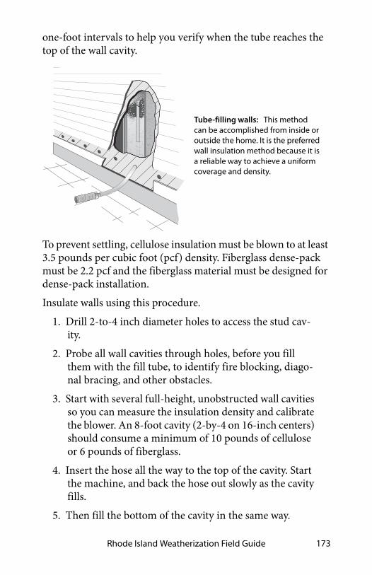
Rhode Island Weatherization Field Guide 173
one-foot intervals to help you verify when the tube reaches the top of the wall cavity.
To prevent settling, cellulose insulation must be blown to at least 3.5 pounds per cubic foot (pcf) density. Fiberglass dense-pack must be 2.2 pcf and the fiberglass material must be designed for dense-pack installation.
Insulate walls using this procedure.
1. Drill 2-to-4 inch diameter holes to access the stud cav-ity.
2. Probe all wall cavities through holes, before you fill them with the fill tube, to identify fire blocking, diago-nal bracing, and other obstacles.
3. Start with several full-height, unobstructed wall cavities so you can measure the insulation density and calibrate the blower. An 8-foot cavity (2-by-4 on 16-inch centers) should consume a minimum of 10 pounds of cellulose or 6 pounds of fiberglass.
4. Insert the hose all the way to the top of the cavity. Start the machine, and back the hose out slowly as the cavity fills.
5. Then fill the bottom of the cavity in the same way.
Tube-filling walls: This method can be accomplished from inside or outside the home. It is the preferred wall insulation method because it is a reliable way to achieve a uniform coverage and density.
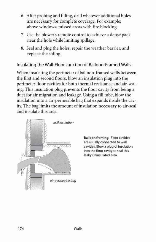
Walls174
6. After probing and filling, drill whatever additional holes are necessary for complete coverage. For example: above windows, missed areas with fire blocking.
7. Use the blower’s remote control to achieve a dense pack near the hole while limiting spillage.
8. Seal and plug the holes, repair the weather barrier, and replace the siding.
Insulating the Wall-Floor Junction of Balloon-Framed Walls
When insulating the perimeter of balloon-framed walls between the first and second floors, blow an insulation plug into the perimeter floor cavities for both thermal resistance and air-seal-ing. This insulation plug prevents the floor cavity from being a duct for air migration and leakage. Using a fill tube, blow the insulation into a air-permeable bag that expands inside the cav-ity. The bag limits the amount of insulation necessary to air-seal and insulate this area.
Balloon framing: Floor cavities are usually connected to wall cavities. Blow a plug of insulation into the floor cavity to seal this leaky uninsulated area.
wall insulation
air-permeable bag

Rhode Island Weatherization Field Guide 175
5.3.3 Open-Cavity Wall Insulation
Fiberglass batts are the most common open-cavity wall insula-tion. Batts achieve their rated R-value only when installed care-fully. If there are gaps between the cavity and batt at the top and bottom, the R-value can be reduced by as much as 30 percent. The batt should fill the entire cavity without spaces in corners or edges. The following steps are to be done at the auditors discre-tion.
✓ Use unfaced friction-fit batt insulation where possible. Fluff the batts during installation to fill the depth of the wall cavity.
✓ Choose medium- or high-density batts: R-13 or R-15 rather than R-11, and R-21 rather than R-19.
SWS Details: 4.1102.1 Open Wall Insulation—General, 4.1102.2 Open Wall—Spray Polyurethane Foam (SPF) Installation
R-15 fiberglass batts: Install R-15 batts in open walls and attach them to the face of the stud as shown above. Or install unfaced batts as shown below. Either way, cut the batts accurately and install them carefully.

Walls176
✓ Seal all significant cracks and gaps in the wall structure before or after you install the insulation.
✓ Insulate behind and around obstacles with scrap pieces of batt before installing batts.
✓ Staple faced insulation to outside face of studs on the warm side of the cavity. Don’t staple the facing to the side of the studs, even though drywallers may prefer that method, because this method leaves an air space that encourages convection currents.
✓ Cut batt insulation to the exact length of the cavity. A too-short batt creates air spaces above and beneath the batt, allowing convection. A too-long batt bunches and folds, creating air pockets.
✓ Split batt around wiring, rather than letting the wiring compress the batt to one side of the cavity.
✓ Fiberglass insulation, exposed to the interior living space, must be covered with minimum half-inch drywall or other material that has an ASTM flame spread rating of 25 or less.
✓ Fiberglass batts exposed to unoccupied spaces like attics must be covered with an air barrier such as house wrap or foam sheeting to prevent R-value degradation by convec-tion and human exposure to fibers.
See “Fiberglass Batts and Blankets” on page 94.

Rhode Island Weatherization Field Guide 177
Sprayed Open-Cavity Wall Insulation
Both fibrous and foam insulation can be sprayed into open wall cavities. Varieties include the following.
• Fiberglass or cellulose mixed with water and glue at a spe-cial nozzle sprayed into the open wall cavity with the excess shaved off (fibrous damp-spray insulation).
Fiberglass batts, compressed by a cable: This reduces the wall’s R-value by creating a void between the insulation and interior wallboard.
Batt, split around a cable: The batt attains its rated R-value.
Spraying open-cell foam: The sprayed open-cell foam is left short of filling the cavity or else shaved off.

Walls178
• Open-cell or closed-cell polyurethane foam sprayed into an open wall cavity and either held short of filling the whole cavity or with the excess foam shaved off after it cures.
Blowing Open Wall Cavities behind Substrate
Blowing dry fibrous insulation behind non-flammable material is a common way of insulating open walls before drywall appli-cation, especially with cellulose. However, you must install the insulation to a sufficient density to resist settling.
✓ Verify density of at least 3.5 pcf for cellulose or 1.6 pcf for fiberglass.
✓ Select a restrainer that will allow the above densities with-out bulging excessively.
✓ Fasten the non-flammable material with power-driven sta-ples, 1.5 inches apart.
✓ Roll bulging insulation with a roller to facilitate drywall installation.
5.3.4 Insulated Wall Sheathing
Insulated wall sheathing covers the wall surface with insulation, reducing thermal bridging through structural framing. Insu-lated sheathing is an excellent retrofit, when you replace the sid-ing and windows.
Insulating wall sheathing is usually foam board, such as polysty-rene or polyisocyanurate. Always fill the wall cavity with insula-tion before installing insulated sheathing.
SWS Detail: 4.1103.3 Insulated Sheathing and Insulated Siding Installation

Rhode Island Weatherization Field Guide 179
Fastening Insulating Sheathing
Fastening the insulating sheathing requires one of the following to secure the insulation to the wood sheathing or masonry under it.
• A batten board
• An embedded strip
• A broad staple
• A long screw with a large washer
• A special adhesive (masonry)
Use appropriate fasteners for wood or masonry materials. Wood battens or embedded strips allow attachment of a variety of sid-ing materials. The embedded strips work best with steel, alumi-num, or vinyl siding, which are lightweight and drain water through weep holes in every unit of siding.
Foam sheathing with battens: One-by-four battens are applied to 4 inches of foam board on the exterior provide a fastening strip for siding and trim.
Foam with embedded strips: Strips of plywood or OSB are spaced on 16 or 24 inch centers at the factory. Wide corner pieces can be added on the job with foam cutting and grooving tools.
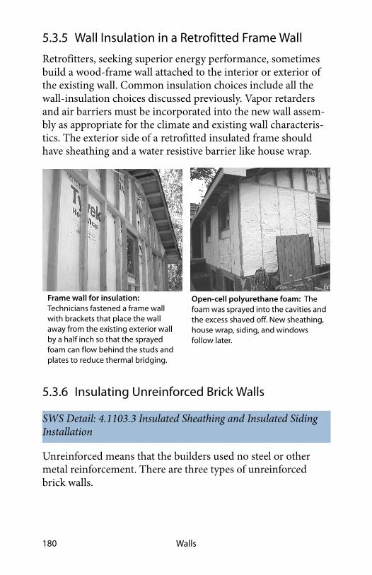
Walls180
5.3.5 Wall Insulation in a Retrofitted Frame Wall
Retrofitters, seeking superior energy performance, sometimes build a wood-frame wall attached to the interior or exterior of the existing wall. Common insulation choices include all the wall-insulation choices discussed previously. Vapor retarders and air barriers must be incorporated into the new wall assem-bly as appropriate for the climate and existing wall characteris-tics. The exterior side of a retrofitted insulated frame should have sheathing and a water resistive barrier like house wrap.
5.3.6 Insulating Unreinforced Brick Walls
Unreinforced means that the builders used no steel or other metal reinforcement. There are three types of unreinforced brick walls.
SWS Detail: 4.1103.3 Insulated Sheathing and Insulated Siding Installation
Frame wall for insulation: Technicians fastened a frame wall with brackets that place the wall away from the existing exterior wall by a half inch so that the sprayed foam can flow behind the studs and plates to reduce thermal bridging.
Open-cell polyurethane foam: The foam was sprayed into the cavities and the excess shaved off. New sheathing, house wrap, siding, and windows follow later.

Rhode Island Weatherization Field Guide 181
1. Traditional brick walls with header bricks that hold two layers of stretcher bricks together. Larger buildings may have three or more brick layers instead of two.
2. Various types of hollow brick walls with usually one layer of brick on either side of an air space.
3. Wood-frame brick veneer walls with a single layer of brick veneer that is attached to a typical wood frame wall.
All three of these brick assemblies may have structural problems depending on the condition of the bricks and mortar joints. Mortar can turn to dust over the decades; hollow brick walls can be frighteningly fragile; and small movements can topple 100-year-old brick veneer. Consult a structural engineer before making any modification to an unreinforced brick building.
Insulation Receipt or Certificate
Provide the client with an insulation receipt or certificate, with insulation type, installed thickness, coverage area, and insula-tion R-value. See “Insulation Receipt or Certificate” on page 93.
Hollow brick wall: Two separate single brick walls are held together by wood lath embedded in the mortar joint.

Walls182
5.4 SWS ALIGNMENT
Field Guide Topic SWS Detail
5.1: Air Sealing Walls - Pg. 159
5.1.2: Built-In Cabinets/Shelves -Pg. 160
5.1.3: Wall Framing Around Fire-places and Chimneys - Pg. 161
3.1001.1 Penetrations and Chases
5.1.4: Pocket Door Cavities - Pg. 162
3.1201.4 Pocket Door
5.1.5: Cooling Appliances Installed through Walls or Windows - Pg. 162
5.1.6: Balloon Framed Walls - Pg. 163
3.1001.3 Walls Open to Attic—Balloon Framing and Double Walls
5.2: Minor Air Sealing - Pg. 165
5.2.1: Window and Door Frames - Pg. 165
5.2.2: Rim Joist Area - Pg. 166
5.2.3: Masonry Surfaces - Pg. 166
5.2.4: Interior Wall Top Plates -Pg. 166
5.3: Wall Insulation - Pg. 167

Rhode Island Weatherization Field Guide 183
5.3.1: Wall Insulation: Prepara-tion and Follow-up - Pg. 167
4.1101.1 Exterior Wall Dense Packing,4.1101.2 Exterior Wall Insulating Sheathing,4.1101.3 Exterior Wall Spray Polyurethane Foam (SPF)—Masking and Surface Preparation,4.1101.4 Exterior Wall Spray Polyurethane Foam (SPF)—Electrical System Considerations
5.3.2: Retrofit Closed-Cavity Wall Insulation - Pg. 172
4.1103.1 Dense Pack Exterior Walls,4.1103.2 Additional Exterior Wall Cavities
5.3.3: Open-Cavity Wall Insulation - Pg. 175
4.1102.1 Open Wall Insulation—General, 4.1102.2 Open Wall—Spray Polyurethane Foam (SPF) Installation
5.3.4: Insulated Wall Sheathing -Pg. 178
4.1103.3 Insulated Sheathing and Insulated Siding Installation
5.3.5: Wall Insulation in a Retro-fitted Frame Wall - Pg. 180
5.3.6: Insulating Unreinforced Brick Walls - Pg. 180
4.1103.3 Insulated Sheathing and Insulated Siding Installation
Field Guide Topic SWS Detail

Walls184

Rhode Island Weatherization Field Guide 185
CHAPTER 6: FLOORS AND FOUNDATIONS
The importance of defining the thermal boundary at the build-ing’s lower reaches depends on how much of the building’s heat loss is moving through the foundation or floor. The building’s thermal boundary may not be obvious because of the lack of insulation at both the floor and the foundation. The energy auditor must choose where to insulate and air seal if these ECMs are cost-effective.
Either the first floor or the foundation wall is the thermal boundary. After choosing, air seal and insulate the chosen ther-mal boundary.
6.1 THERMAL-BOUNDARY DECISIONS: FLOOR OR FOUNDATION
The results of air-barrier tests can help in selecting the thermal boundary’s location. See “Air Leakage Diagnostics” on page 447.
Moisture problems, the location of heating and cooling equip-ment, and the necessity of crawl-space venting are other import-ant considerations.
The tables presented next summarize the decision factors for choosing between the floor and the foundation wall as the air barrier. You may also encounter situations that aren’t addressed here.
50pa Reference
Input
-25Digital Manometer
house WRT zone (crawl space)
House-to-crawl-space pressure: Many homes with crawl spaces have an ambiguous thermal boundary at the foundation. Is the air barrier at the floor or foundation wall? Answer: in this case, each forms an equal part of the home’s air barrier.

Floors and Foundations186
When a home has a basement and crawl space connected, both Table 6-1 on page 186 and Table 6-2 on page 187 are relevant to the decision-making process of selecting the air barrier and site for insulation, if insulation is cost-effective. A basement may even be divided from its adjoining crawl space to enclose the basement within the thermal boundary and to place the crawl space outside the thermal boundary.
Table 6-1: Crawl Space: Where Is the Thermal boundary?
Factors favoring foundation wall
Factors favoring floor
Ground moisture barrier and good perimeter drainage pres-ent
Dry crawl space with ground moisture barrier installed during weatherization
Foundation walls test tighter than floor
Floor air-sealing and insulation are reasonable options, consider-ing access and obstacles
Vents can be closed offFloor tests tighter than founda-tion walls
Furnace, ducts, and water pipes located in crawl space
No furnace or ducts present
Concrete or concrete block walls are easily insulated
Building code or code official for-bids closing vents
Floor air-sealing and insulation would be more difficult than sealing and insulating the foun-dation
Rubble masonry foundation wall
Foundation wall is insulated Floor is already insulated
Warm, damp homesite + climate Cooler, drier homesite + climate

Rhode Island Weatherization Field Guide 187
6.2 AIR SEALING FOUNDATIONS AND FLOORS
The floor and foundation are complex structures that can be dif-ficult to air seal. This section describes the most problematic air leakage location in the floor and foundation, and how to seal them.
6.2.1 Garages Underneath Living Areas
Whenever a garage is in a subspace below living areas, the effec-tiveness of air sealing is essential for three objectives.
1. Block air pollutants,
Table 6-2: Unoccupied Basement: Where Is the Thermal Boundary?
Favors foundation wall Favors floor
Ground drainage and no existing moisture problems
Damp basement with no solu-tion during weatherization
Interior stairway between house and basement
Floor air-sealing and insulation is a reasonable option, consider-ing access and obstacles
Ducts and furnace in basement No furnace or ducts present
Foundation walls test tighter than the floor
Floor tests tighter than founda-tion walls
Basement may be occupied some day
Exterior entrance and stairway only
Laundry in basementRubble masonry foundation walls
Floor air-sealing and insulation would be very difficult
Dirt floor or deteriorating con-crete floor
Concrete floor Cracked foundation walls
SWS Detail: 3.1501.1 Penetrations, Cracks, and Doors Between Garage and House

Floors and Foundations188
2. Create a fire barrier,
3. Save energy by separating the unconditioned garage from the building’s conditioned zones.
Air-sealing a garage area is straightforward although this task can consume a lot of materials.
• For wood-frame structures, use fire-taped drywall throughout the surface area of the garage after sealing leaks in the floor above and the in the top plate of the walls.
• For concrete and masonry structures, carefully seal cracks and penetrations with compatible materials such as mortar and caulk designed for masonry joints.
6.2.2 Plumbing Penetrations
Seal gaps with expanding foam or caulk. If the gap is too large, seal with foam board or equivalent and spray foam over the top to seal the surface of the plug.
✓ Fit large openings with foam board or drywall bedded in a sealant like latex caulk or foam tape, which isn’t an adhe-sive.
✓ Screw the patch in place, so that a plumber can remove the screws if necessary for access.
✓ Seal holes and gaps around pipes with expanding foam or caulk.
SWS Detail: 3.1001.1 Penetrations and Chases, 3.1001.2 Chase Capping

Rhode Island Weatherization Field Guide 189
6.2.3 Stairways to Unconditioned Areas
A variety of stairways and hatchways provide access from the building to an unconditioned basement.
The following components of these stairways may need air seal-ing and insulation depending on whether they are at the thermal boundary.
• The risers and treads of the stairways
• The surrounding triangular walls
• Vertical or horizontal doors or hatches
• The framing and sheeting surrounding the doors or hatches
• Sloping ceilings above the stairways
Consider the following air-sealing measures.
SWS Detail: 3.1002.1 Interior with Sloped Ceiling, 3.1002.2 Stairwell to Attic—Door at Bottom with No Ceiling Above, 3.1002.3 Stairwell to Attic—Door at Top with Finished Ceiling Above
Sealing large plumbing penetrations: Bed drywall or wood sheathing in sealant and fasten with nails or screws. Fill gaps around the penetrations with one-part foam to complete this airtight seal.

Floors and Foundations190
✓ Study the geometry of the stairway and decide where to establish the air barrier and install the insulation.
✓ Weatherstrip around doors and hatches if the door or hatch is at the thermal boundary.
✓ Seal the walls, stair-stringer space, and ceiling if they are at the thermal boundary.
✓ Seal gaps around door frame or hatch frame perimeters with one-part foam, two-part foam, or caulking.

Rhode Island Weatherization Field Guide 191
Unfinished stairways: Unfinished spaces underneath stairs create major air leakage pathways between floors and between the attic and crawl space or basement.
insu
late
/w
eath
erst
rip
do
or Air-seal and insulate 3 w
alls,
door, and sloped ceiling.
Stairway not insulated
Unconditioned basement
Insulated floor
Conditioned living space
Stairways at the thermal boundary: The stairway may be within the thermal boundary or outside it. Only walls, ceilings, doors, and hatches at the thermal boundary require thorough air sealing. The door as shown is open.
Stairway wall within the thermal boundary: Double wall forming the stairwell connects an unfinished area under the basement stairs with the living spaces, attic, and the space behind the finished basement walls.
partitio
n wall
supply boot
stairwell wall bottom
space open to attic
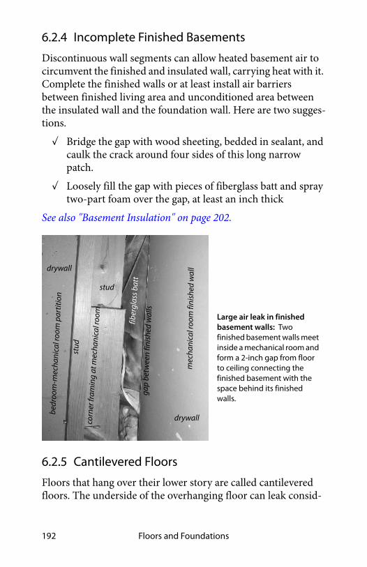
Floors and Foundations192
6.2.4 Incomplete Finished Basements
Discontinuous wall segments can allow heated basement air to circumvent the finished and insulated wall, carrying heat with it. Complete the finished walls or at least install air barriers between finished living area and unconditioned area between the insulated wall and the foundation wall. Here are two sugges-tions.
✓ Bridge the gap with wood sheeting, bedded in sealant, and caulk the crack around four sides of this long narrow patch.
✓ Loosely fill the gap with pieces of fiberglass batt and spray two-part foam over the gap, at least an inch thick
See also "Basement Insulation" on page 202.
6.2.5 Cantilevered Floors
Floors that hang over their lower story are called cantilevered floors. The underside of the overhanging floor can leak consid-
corn
er fr
amin
g at
mec
hani
cal r
oom
drywall
stud
fiber
glas
s bat
t
drywall
stud
Large air leak in finished basement walls: Two finished basement walls meet inside a mechanical room and form a 2-inch gap from floor to ceiling connecting the finished basement with the space behind its finished walls.
gap
betw
een
finis
hed
wal
ls
mec
hani
c al r
oom
f in i
shed
wa l
l
bedr
oom
-mec
han i
cal r
oom
par
titio
n

Rhode Island Weatherization Field Guide 193
erably. Many balconies and bay windows have cantilevered floors that leak air into a building’s floor cavity.
✓ Remove a piece of soffit under the overhanging floor to determine the condition of insulation and air barrier.
✓ Stuff the overhanging floor with blown fibrous insulation.
✓ Install the sheeting underneath the overhanging floor in sealant where possible. Caulk joints and seams where the sheeting isn’t embedded.
✓ Seal any ducts you find in the cantilevered floor sections.
See also "Installing Floor Insulation" on page 195.
6.3 PREPARING FOR FLOOR INSULATION
Floor insulation can increase the likelihood of moisture prob-lems. Installers should take all necessary steps to prevent mois-ture problems from ground moisture before installing insulation.
SWS Detail: 4.1402.2 Basement Wall Insulation—No Groundwater Leakage, 4.1402.3 Basement Wall Insulation—Groundwater Leakage
Cantilevered floors under construction: Cantilevered floors allow air leakage into floor cavities because of the lack of sealant and dense-packed insulation.
cantilevered floor
cantilevered balcony
cantilevered bay window

Floors and Foundations194
6.3.1 Rim-Joist Insulation and Air-Sealing
The rim-joist spaces at the perimeter of the floor are a major weak point in the air barrier and insulation. Insulating and air sealing both the rim joist and longitudinal box joist are appro-priate either as individual procedures or as part of floor or foun-dation insulation.
Air seal stud cavities in balloon-framed homes as a part of insu-lating the rim joist. Air seal other penetrations through the rim before insulating. Two-part spray foam is the most versatile air sealing and insulation system for the rim joist because spray foam air seals and insulates in one step.
Polystyrene or polyurethane rigid board insulation are also good for insulating and air sealing the rim joist area. When the rim joist runs parallel to the foundation wall, the cavity may be air sealed and insulated with methods similar to those as shown here.
If you leave the spray foam exposed, it should have a flame spread of 25 or less and be no more than 3.25 inches thick according to the IRC. In habitable spaces, cover all foam with a thermal barrier such as drywall or use an insulation product that doesn’t require a thermal barrier like foil-faced foam board.
SWS Detal: 4.1401.1 Band/Rim Joists—Spray Polyurethane Foam (SPF) Installation
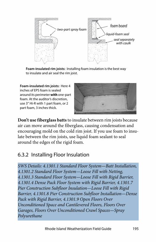
Rhode Island Weatherization Field Guide 195
Don’t use fiberglass batts to insulate between rim joists because air can move around the fiberglass, causing condensation and encouraging mold on the cold rim joist. If you use foam to insu-late between the rim joists, use liquid foam sealant to seal around the edges of the rigid foam.
6.3.2 Installing Floor Insulation
SWS Details: 4.1301.1 Standard Floor System—Batt Installation, 4.1301.2 Standard Floor System—Loose Fill with Netting, 4.1301.3 Standard Floor System—Loose Fill with Rigid Barrier, 4.1301.4 Dense Pack Floor System with Rigid Barrier, 4.1301.7 Pier Construction Subfloor Insulation—Loose Fill with Rigid Barrier, 4.1301.8 Pier Construction Subfloor Installation—Dense Pack with Rigid Barrier, 4.1301.9 Open Floors Over Unconditioned Space and Cantilevered Floors, Floors Over Garages, Floors Over Unconditioned Crawl Spaces—Spray Polyurethane
Foam-insulated rim joists: Installing foam insulation is the best way to insulate and air seal the rim joist.
foam boardtwo-part spray foam
liquid-foam seal
seal separately with caulk
Foam-insulated rim joists: Here 4 inches of EPS foam is sealed around its perimeter with one-part foam. At the auditor’s discretion, use 3” Hi-R with 1 part foam, or 2 part foam, 3 inches thick.

Floors and Foundations196
Before installing floor insulation, make the following prepara-tions.
✓ Seal air leaks in the floor from the living space or the crawl space or basement, as opportunity allows.
✓ Seal and insulate ducts remaining in the crawl space or unconditioned basement.
✓ Identify electrical junction boxes, plumbing valves and drains before insulating and provide access to them.
✓ Insulate water lines in cold climates if they protrude below the insulation.
Blowing Floor Insulation
The best way to insulate a floor cavity is to completely fill each joist cavity with insulation. Blowing insulation is the easiest way to achieve complete coverage because the blown insulation is able to surround obstructions and penetrations.
✓ Cover the entire under-floor surface with a vapor perme-able supporting material such as: dust-free fabric insula-tion restraint or equivalent vapor-permeable and drain-able material.
✓ Use wood strips to support the flexible or semi-flexible support material unless that material with its fasteners can support the floor insulation without sagging.
✓ Install rock wool or fiberglass blowing wool through V-shaped holes in the air barrier.
netting or vapor-permeable air barrier
blown
floor truss
insulation
Blown floor insulation: This method works particularly well with floor trusses.

Rhode Island Weatherization Field Guide 197
✓ Use a fill tube for installing the blown insulation. Insula-tion must travel no more than 12 inches from the end of the fill tube.
✓ Seal all penetrations in the air barrier with a tape, approved for sealing seams in the air-barrier material.
6.3.3 Installing Fiberglass Batt and Blown Cellulose Floor Insulation
Observe these material and preparation specifications for insu-lating under floors.
✓ Seal all significant air leaks through the floor before insu-lating the floor, using strong airtight materials.
✓ Insulation thickness must fill the complete depth of each cavity.
✓ Batts must be neatly installed, fitting tightly together at joints, fitting closely around obstructions, and filling all the space within the floor cavity.
✓ Crawl-space access doors, adjacent to a conditioned space, must be insulated to at least R-21 for horizontal openings and to at least R-15 for vertical openings.
SWS Detail: 4.1301.1 Standard Floor System—Batt Installation, 4.1301.5 Cantilevered Floor—Batt Installation, 4.1301.6 Pier Construction Subfloor Insulation—Batt Installation with Rigid Barrier
Blowing floor cavity: Uninsulated floor cavities can be blown with fiberglass or cellulose insulation, using a fill tube.
rigid air barrier
First Floor

Floors and Foundations198
✓ Crawl-space access doors, adjacent to a conditioned space, must be effectively weatherstripped.
Installation Specifications for Batts in Floor Cavities
Batt insulation, installed in floors, must be supported by twine, wire, wood lath or other suitable material that keeps the insula-tion touching the floor. Friction-fit fiberglass batts supported by self-supporting wire insulation supports aren’t good practice. Fasteners for floor insulation must resist gravity, the weight of insulation, and moisture condensation.
✓ Install batts in continuous contact with the subfloor.
✓ Cut the batts accurately and squarely.
Use one of the following 4 restrainer materials to keep the fiber-glass batts in the floor cavity.
1. Install standard wood lath (1/4 inch by 1 inch) or nomi-nal one-inch lumber. Install the lath or lumber perpen-dicular to joists 12 inches apart for joists on 24-inch centers and 18 inches apart for joists on 16-inch cen-ters.
2. Install metal or stainless steel wire with a minimum diameter of 0.04 inches or size 18 AWG.
3. Install a rigid vapor-permeable air barrier, such as ply-wood.
Observe these requirements about installation and fasteners for the restrainers.
• Fasten lath or a rigid barrier with screws, nails, or power-driven staples. The fastener should penetrate the joist 3/4 inch or more.
• Install power-driven staples over the twine or wire 12 inches apart for joists on 24-inch centers and 18 inches apart for joists on 16-inch centers. The staples must pene-trate the wood joists by at least 5/8 inch. Don’t hand staple the restrainer.

Rhode Island Weatherization Field Guide 199
.
6.3.4 Crawl-Space Wall Insulation
Crawl-space foundation insulation is only worthwhile if you can seal the existing foundation vents. See "Power-Ventilated Crawl Spaces" on page 379.
Materials for Crawl-Space Insulation
Retrofit foundation insulation is usually installed on the inside of the foundation walls. Contractors undertake this retrofit for both energy savings and moisture control. Observe these insula-tion specifications for insulating foundation walls.
• Any foam foundation-wall insulation should be labeled ASTM E84 or UL 723 with a flame spread of less than 25 and smoke developed value of less than 450.
SWS Detail: 4.1402.2 Basement Wall Insulation—No Groundwater Leakage, 4.1402.3 Basement Wall Insulation—Groundwater Leakage, 4.1402.1 Closed Crawl Spaces —Wall Insulation, 3.1402.2 Closed Crawl Spaces —Air Sealing Foundation Vents
lath or 1x2
synthetic twine or wire
Floor insulating with batts: Use unfaced fiberglass batts, installed flush to the floor bottom, to insulate floors. The batt should fill the whole cavity if it is supported by lath or plastic twine underneath.

Floors and Foundations200
• Foam insulation must be protected by intumescent paint or another ignition barrier if not labeled ASTM E84 or UL 723.
• Local building officials may approve other foam materials based on product labels such as NFPA 286, FM 4880, UL 1040, or UL 1715.
• Metal fasteners should carry a label of ASTM B 695 Class 55.
These insulation products might meet some of the above speci-fications.
• Foil-faced polyisocyanurate
• Expanded polystyrene foam board.
• Two-part high-density spray polyurethane foam with fire-retardant specifications as listed above. See "Fire Protection for Foam Insulation" on page 102.
• Unfaced rock wool board or fiberglass board..
Consider these issues with the use of fibrous insulation in crawl spaces.
one-part foam
termite shield
ground-moisture barrier
footing
foundationwall
subfloor
rim jo
ist
sheet foam
Foam-insulated foundation wall: A A 10 mil ground moisture barrier protects the wood floor against termites and other pests.
fastener
termite inspectionzone

Rhode Island Weatherization Field Guide 201
• Fiberglass batts or blankets are poor choices for foundation insulation because their facing is a vapor retarder. The fac-ing can trap moisture in the fiberglass between the founda-tion wall and the facing.
• Sprayed fiberglass and cellulose are easily damaged by moisture, mechanical abrasion, and adhesive failure.
Safety and Durability
Consider the following issues when insulating foundation walls.
✓ Secure outdoor access hatches to foundation walls. If the foundation walls are insulated, also insulate any crawl-space access hatch with foam to the same R-value of the foundation wall.
✓ Remove obstacles and debris from crawl space before ret-rofit.
✓ If an open-combustion appliance is located in a crawl space, verify that outdoor combustion air is available to the appliance.
✓ When insulating crawl-space walls, consult the local build-ing inspector about acceptable ventilation options if in doubt. See "Crawl Space Ventilation" on page 378.
In regions affected by termites, carpenter ants, and similar insects consider these suggestions.
✓ Leave a termite-inspection zone between the foundation and the rim-joist insulation, or defer the project if the area shows signs of infestation.
✓ Consult with experts to ensure that the insulation, air seal-ing materials, and moisture barrier don’t provide a conduit for insects to infest the wood floor.

Floors and Foundations202
6.3.5 Basement Insulation
Before installing basement wall insulation, inspect for moisture problems and take appropriate action to solve moisture prob-lems.
✓ Check for bulk-water problems like puddling around the foundation or malfunctioning gutters and downspouts.
✓ At the auditors discretion, remove obstacles and debris from the basement.
✓ On a case by case basis, and with state monitor approval, install a drainage system with a sump and outdoor drain-age as appropriate to solve major moisture problems.
6.4 SWS ALIGNMENT
SWS Detail: 4.1402.2 Basement Wall Insulation—No Groundwater Leakage, 4.1402.3 Basement Wall Insulation—Groundwater Leakage
Field Guide Topic SWS Detail
6.1: Thermal-Boundary Deci-sions: Floor or Foundation - Pg. 185
6.2: Air Sealing Foundations and Floors - Pg. 187
6.2.2: Plumbing Penetrations -Pg. 188
3.1001.1 Penetrations and Chases, 3.1001.2 Chase Capping

Rhode Island Weatherization Field Guide 203
6.2.3: Stairways to Uncondi-tioned Areas - Pg. 189
3.1002.1 Interior with Sloped Ceiling, 3.1002.2 Stairwell to Attic—Door at Bottom with No Ceiling Above, 3.1002.3 Stairwell to Attic—Door at Top with Finished Ceiling Above
6.2.4: Incomplete Finished Basements - Pg. 192
6.2.5: Cantilevered Floors - Pg. 192
6.3: Preparing for Floor Insulation - Pg. 193
4.1402.2 Basement Wall Insulation—No Groundwater Leakage, 4.1402.3 Basement Wall Insulation—Groundwater Leakage
6.3.4: Crawl-Space Wall Insulation - Pg. 199
4.1402.1 Closed Crawl Spaces —Wall Insulation,3.1402.2 Closed Crawl Spaces —Air Sealing Foundation Vents
6.3.1: Rim-Joist Insulation and Air-Sealing - Pg. 194
4.1401.1 Band/Rim Joists—Spray Polyurethane Foam (SPF) Installation
Field Guide Topic SWS Detail

Floors and Foundations204
6.3.2: Installing Floor Insulation -Pg. 195
4.1301.1 Standard Floor System—Batt Installation,4.1301.2 Standard Floor System—Loose Fill with Netting, 4.1301.3 Standard Floor System—Loose Fill with Rigid Barrier, 4.1301.4 Dense Pack Floor System with Rigid Barrier,4.1301.7 Pier Construction Subfloor Insulation—Loose Fill with Rigid Barrier, 4.1301.8 Pier Construction Subfloor Installation—Dense Pack with Rigid Barrier,4.1301.9 Open Floors Over Unconditioned Space and Cantilevered Floors, Floors Over Garages, Floors Over Unconditioned Crawl Spaces—Spray Polyurethane
6.3.3: Installing Fiberglass Batt and Blown Cellulose Floor Insulation - Pg. 197
4.1301.1 Standard Floor System—Batt Installation, 4.1301.5 Cantilevered Floor—Batt Installation, 4.1301.6 Pier Construction Subfloor Insulation—Batt Installation with Rigid Barrier
Field Guide Topic SWS Detail

Rhode Island Weatherization Field Guide 205
CHAPTER 7: WINDOWS AND DOORS
This chapter presents specifications and procedures for improv-ing the airtightness and thermal resistance of windows and doors.
Use lead-safe weatherization methods for all tasks relating to window and door weatherization, repair, and replacement. See "EPA RRP Requirements" on page 40.
7.1 STORM WINDOWS
A storm window is an additional window installed outside or inside the primary window.
7.1.1 Exterior Aluminum Storm Windows
Exterior storm windows can save energy and preserve old worn primary windows from destructive weathering. You can attach exterior operable storm windows to the blind stop or exterior window casing of a double-hung window. Or, attach a fixed storm to any flat surface of a window frame or sash if the win-dow is fixed or if a movable sash can support the extra weight.
Metal exterior storm windows are the best choice if they are well designed and installed properly.
• Choose operable storm windows to install on operable windows. Choose fixed storm windows to install on fixed windows or on sashes that open along with the movable primary window.
• If operable, make sure that the storm window opens and closes to allow the maximum amount of ventilation and egress area.
• Storm-window frames should have sturdy corners so they don’t rack out-of-square during transport and installation.
• Sashes must fit tightly in their frames.

Windows and Doors206
• The gasket sealing the glass should surround the glass’s edge.
• Storm windows should be hard-coat, low-e glass for the storm window, which should face the primary window to protect the low-e coating.
• The storm window should be sized accurately and should fit tightly in the opening.
• The storm window’s sashes should be removable from indoors for cleaning.
Installation of Exterior Storm Windows
Contractors must follow these guidelines when installing storm windows.
✓ If installing a new double pane window, the storm window must be removed prior to installation.
✓ Seal storm windows around the frame at time of installa-tion with sealant tape or caulk.
bullet catch
meeting rail
frame
lower sash
upper sash
Aluminum exterior storm windows: They protect the primary window and add about an R-1 to the window assembly.
View of interior surface
weep holes

Rhode Island Weatherization Field Guide 207
✓ Don’t allow the tape or caulk to interfere with the weep holes at the bottom of the frame. If weep holes aren’t man-ufactured into new storm window, drill weep holes or leave at least 2 two-inch spaces in sealant to allow water on the sill to escape.
✓ Don’t allow storm windows to restrict emergency egress or ventilation through movable windows.
✓ Never install a storm window over a double pane thermal window. Educate client on benefits of removing storm windows that have been in place over a year.
See also "Mobile home double window" on page 441.
7.1.2 Interior Storm Windows
Interior storm windows are usually more airtight than exterior storm windows because they must be airtight to avoid conden-sation and icing on the primary window during winter. Interior storm windows are usually a metal or plastic frame enclosing some type of plastic glazing.
Consider these specifications when selecting interior storm windows.
• Don’t install fixed interior storm windows on egress win-dows.
• Interior storm windows should have an airtight edge seal to prevent warm moist air from passing by the interior storm window and condensing or icing the interior of the glass on the primary window.
• Interior storm windows should be easily removable for storage.
• The home should have a safe place to store the storm win-dows seasonally.
SWS Details: 3.1201.6 Interior Storm Windows

Windows and Doors208
• Consider using low-e glass or plastic for glazing to increase thermal resistance.
7.2 WINDOW REPAIR AND AIR LEAKAGE REDUCTION
With the exception of broken glass or missing window panes, windows aren’t often the major source of air leakage in an exist-ing home.
Window weatherstripping may solve comfort problems around windows, even though it may not be cost-effective. Avoid expensive or time-consuming window repair measures that are implemented to solve minor comfort complaints if the weather-ization budget is limited.
7.2.1 Double-Hung Window Weatherization
Re-glazing window sashes in a quality manner is time consum-ing. This task is best accomplished as part of a comprehensive window rehabilitation project. Re-glazing wood windows may not be a durable repair without thorough scraping, priming, and painting. Use lead-safe work practices when working on win-dows. See page 54.
Repair measures may include the following.
✓ Replace missing or broken glass. Use glazing compound and glazier points when replacing glass in old windows.
✓ Caulk the window frame where appropriate to prevent air leakage, condensation, and rain leakage. Use sealants with adhesion and joint-movement characteristics appropriate for both the window frame and the building materials sur-rounding the window.
SWS Details: 3.1202.1 Fixed Frame with Wood Sash—Older House, 3.1201.2 Single-Unit Window and Fixed Frame with Wood Sash, 3.1201.1 Double-Hung Wood Windows

Rhode Island Weatherization Field Guide 209
✓ Replace missing or severely deteriorated window frame components.
✓ Replace damaged wood with pressure treated wood, Azek, or equivalent.
✓ Adjust window stops if gaps exist between the stop and jamb. Ensure that the window operates smoothly follow-ing adjustment.
✓ Weatherstrip large gaps between the sash and the sill or stops. Weatherstrip the meeting rails if needed.
✓ Replace or repair missing or non-functional top and side sash locks, hinges, or other hardware if this significantly reduces air leakage.
7.2.2 Weatherstripping Double-Hung Windows
Window weatherstripping is mainly a comfort retrofit and not a high weatherization priority.
Paint is the primary obstacle when weatherstripping double-hung windows. Often the upper sash has slipped down, and is
SWS Detail: 3.1201.1 Double-Hung Wood Windows
Low
er-s
ash
stor
m p
anel
Upp
er-s
ash
stor
m p
anel
Dou
ble-
trac
k st
orm
win
dow
Out
door
s
Indo
ors
Window-weight pocket
Optimized double-hung window: An exterior aluminum storm window plus storm window panels on the window sashes create triple glazing in this double-hung window.

Windows and Doors210
locked in place by layers of paint, producing a leaking gap between the meeting rails of the upper and lower sashes.
✓ To make the meeting rails meet again, either break the paint seal and push the upper sash up, or cut the bottom of the lower sash off to bring it down.
✓ To lift the upper sash, cut the paint around its inside and outside perimeter. Use leverage or a small hydraulic jack to lift the sash. Jack only at the corners of the sash. Lifting in the middle can break the glass.
✓ Block, screw, or nail the repositioned upper sash into place.
Weatherstripping double-hung windows: Can solve comfort problems and reduce air leakage around loosely fitting sashes.
parting bead
sill
plastic v-strip
bronze or plastic v-strip
meeting rail
upper sash
Weatherstripping double-hung windows: Can solve comfort problems and reduce air leakage around loosely fitting sashes.

Rhode Island Weatherization Field Guide 211
✓ To weatherstrip the window, remove the lower sash. Cut the paint where the window stop meets the jamb so the paint doesn’t pop off in large flakes as you pry the stop off. Removing one stop is sufficient to remove the bottom sash.
✓ Scrape excess paint from the sashes and the window sill.
✓ Apply vinyl V-strip to the side jambs, and bronze V-strip to the meeting rail on the top sash. The point of the bronze V goes skyward. The weatherstrip is caulked on its back side and stapled in place, as shown in the illustration.
7.3 WINDOW REPLACEMENT SPECIFICATIONS
The purpose of these specifications is to guide the selection and installation of replacement windows. Improper window installa-tion can cause water leakage, air leakage, and noise leakage.
Existing window openings may have moisture damage and air leakage. Repair these conditions before or during window replacement.
Included here are specifications for two special window safety considerations.
Lifting an upper window sash: First cut paint away from around the sash inside and outside. Then lift with leverage or a jack.

Windows and Doors212
1. Windows in high risk areas, such as around doors and walkways, must have safety glass.
2. Some bedroom windows function as a fire escape (egress). Recognize and accommodate this egress func-tion.
7.3.1 Window Energy Specifications
Installing new windows incurs a large labor expense so they should be as energy-efficient as budget allows.
1. Replacement windows must have a U-factor less than or equal to what is required by State standards. Lower is better, especially in cold climates.
2. Replacement windows facing east or west in air condi-tioned homes should have a solar heat-gain coefficient (SHGC) that is equal to or less than what is required by State standards. Lower is better in hot climates.
Certified
NFRC
ACME Window CompanyEnerSaver 2010
Vinyl FrameDouble Glazing - Argon Fill - Low E
Horizontal Sliding Window
U-Factor (US/I-P)
Air Leakage (US/I-P)
Solar Heat Gain Coefficient
Visible Transmittance
0.32 0.40
0.54Condensation
0.51
0.3
Manufacturer stipulates that these ratings conform to applicable NFRC procedures for determining whole product energy performance. NFRC ratings are determined for a fixed set of environmental conditions and specific product sizes. NFRC does not recommend any product and does not warrant the suitability of any product size. Contact the manufacturer for other performance information.
www.nfrc.org
National Fenestration Rating Council
Energy Performance Ratings
Additional Performance Ratings
Example NFRC label: The key selection criteria for window shopping is displayed on the NFRC label.

Rhode Island Weatherization Field Guide 213
7.3.2 Removing Old Windows
Remove existing windows without damaging the home’s interior finish, siding, exterior trim, or the water-resistive barrier (WRB) if possible.
1. Protect the interior of the home from construction debris. See "EPA RRP Requirements" on page 40.
2. Remove window sashes, jambs, or siding, depending on the window-replacement method chosen.
3. Repair moisture damage to the rough opening before installing the new window.
7.3.3 Installing Replacement Windows
The most important considerations for installing new windows is that the window installation is watertight and airtight.
Water leakage deteriorates building components around the window. To prevent water leakage in frame buildings, the win-dow must be integrated, if possible into the home’s water resis-tive barrier (WRB).
SWS Details: 3.1203.2 Single-Unit Window, Mounted on Rough Opening—Newer House, 3.1203.1 Fixed Frame with Wood Sash—Older House, 3.1203.1 Replacement Window in Existing Window Frame
Window-frame types: It’s important to order the right window-frame type for the method of window installation you plan to use.
Windows and Doors214
7.3.4 Replacing Nailing-Fin Windows
Install replacement windows with nailing fins in the rough opening after removing the existing window frame and exterior trim. Fasten the nailing fins directly to the house’s sheathing or framing, but support the window’s weight on the sill with or without shims before fastening the window to the building.
Water-Resistive Barrier (WRB): Designers and builders assume that some rain water penetrates through the siding. The WRB is the building’s last defense against water. House wrap and asphalt felt are the most common WRBs. Window replace-ments that expose the home’s WRB must incorporate the WRB in the window installation. Install a sill pan below the window and flashing on the side fins. Use flashing to connect the win-dow opening to the WRB so water that penetrates the siding, trim, or window exits the building by way of the WRB.
Windows are exposed to wind and rain. Install replacement windows so water that penetrates the siding or trim drains to the outdoors. If water leaks underneath the existing WRB or the new flashing, the water eventually damages the building. With proper flashing, the fins and flashing create a drainage system that drains water to the outdoors rather than relying on caulked siding and trim to prevent rain water from penetrating the building’s surface.
SWS Detail: 3.1203.2 Single-Unit Window, Mounted on Rough Opening—Newer House, 3.1203.1 Fixed Frame with Wood Sash—Older House

Rhode Island Weatherization Field Guide 215
Follow these steps to install a nailing-fin window in the rough opening.
1. At the sill, insert the flashing underneath the existing siding, over top of existing building paper, and under the bottom nailing fin of the window.
2. Use flat shims to provide a level surface and support under the vertical structural members of the new win-dow frame. Don’t allow the fins to support the window’s weight.
3. Use fasteners with heads wide enough in diameter to span the holes or slots in the window fin.
4. Avoid over-driving the fasteners or otherwise deform-ing the window fin.
5. Flash the window around its perimeter with 15-pound felt, house wrap, or a peel-and-stick membrane.
a. Flashing procedures may vary. However, always install flashing materials to overlap like shingles.
b. Insert the new building paper or flashing underneath the existing siding and underneath existing building paper on the sides and top of the window opening.
cap flashing
water-resistive barrier
with dam
Cap flashing: Cap flashing at the window’s head protects the window from rain water penetration.

Windows and Doors216
6. Windows that are exposed to wind-driven rain or with-out overhangs above them or without WRB integration should have a rigid cap flashing (also called head flash-ing) to prevent rainwater from draining onto the win-dow. The cap flashing should divert water away from vertical joints bordering the window with an overhang or dam.
7. Tuck the cap flashing up behind the WRB or exterior siding. Metal cap flashing must have downward bend-ing lip of at least 1/4 inch on the front and ends.
8. Thoroughly caulk all filler and trim pieces surrounding the replacement window.
7.3.5 Block-Frame or Finless Windows
Contractors install windows using a block-frame or finless installation when they can’t remove the existing window frame
SWS Detail: 3.1203.1 Fixed Frame with Wood Sash—Older House
Flashing nail-fin windows: Installers place the window on and over the sill flashing. The side and top flashing cover the fastening fin. The two methods shown here are: using a flexible membrane (right) and using a bowtie-shaped flashing to underlay the corners when using a standard membrane

Rhode Island Weatherization Field Guide 217
or in a masonry window opening. Block-frame windows rely on caulk or rigid flashing to create a weatherproof seal around the window perimeter. Take care when installing caulk so that it is durable and effective for as long as possible.
Comply with the following requirements when installing block-frame or finless windows.
1. Block-frame or finless windows may require a suffi-ciently wide gap between the new window and the existing window frame or masonry opening to allow for the following.
a. Allowing for a slightly out-of-square opening.
b. Leveling the window.
c. Insulating the gap with foam.
2. Access the window-weight cavities, remove the weights, and fill the cavities with insulation, and seal the cavi-ties.
3. Protect the existing sill with a metal or plastic sill pan or rigid sill flashing if necessary for drainage and to pro-tect the existing sill that protrudes from the exterior wall. Or, install a new sill as part of the window replace-ment.
4. Support block-frame or finless windows under their main vertical supports with shims that level the win-dow.
a. Use flat shims for support if the sill surface is flat.
b. Use tapered shims or a sill angle for support if the sill surface is sloping.
5. Windows without fins must be secured to the rough opening within 4 inches of each side corner and a mini-mum 12 inches on center along the remainder of the frame with one of these fastening methods.

Windows and Doors218
a. Screws fastened through the window frame. Use screws that are designed for fastening block-frame windows if available.
b. Jamb clips or plates that are fastened first to the window and then to the opening in separate steps.
6. Fill any gaps over 3/8 inch that are between the exterior siding and the block-frame window. Install backer rod in all exterior or interior voids over 3/8 inch in depth or width before caulking.
7. If possible, flash block-frame windows between the opening and the replacement-window frame and extend the flashing out far enough to slip under or into the siding.
a. Tuck the flashing up behind the exterior siding at least 1 inch.
b. Sill and cap flashing should have a downward bending lip of at least 1/4 inch on the front that sheds water away from the building.
Block frame window installation: Block-frame windows don’t have a fin. Installers use plates or screws to fasten the window to its opening.
Rhode Island Weatherization Field Guide 219
7.3.6 Flush-Fin Window Replacement
Flush-frame windows are replacement windows that fasten to the window opening and mount directly over the flat siding sur-rounding the window opening. Replace windows in stucco walls using windows with flush fins, also called stucco fins, that have no nail holes. Flush-fin windows work well for any window opening with a flat water-resistant finished surface surrounding the window opening.
This flush-fin window-replacement technique is similar to block-frame window installation.
1. Support the replacement window on the existing sill with one of the following materials.
a. A flat or tapered continuous wood support.
b. Flat shims under the window’s main vertical supports.
c. Tapered shims under the window’s main vertical sup-ports if the sill is sloping.
2. Apply a sealant that remains flexible to the back of the flush fin of the replacement window in order to seal it to the surface of the exterior wall. Interrupt the caulk-ing at the bottom fin for one inch on each side of the window’s weep holes.
3. Fasten the flush-fin window to the window opening by driving screws through the replacement window’s frame.

Windows and Doors220
7.4 WINDOW SAFETY SPECIFICATIONS
Windows have special requirements for breakage-resistance in areas that are prone to glass breakage, and for fire escape in bed-rooms.
7.4.1 Windows Requiring Safety Glass
Safety glass is required in locations that the IRC 2012 considers hazardous to the building’s occupants. Safety glass must be either laminated glass, tempered glass, organic coated glass, or annealed glass bearing a permanent label identifying it as safety glass, manufactured in compliance with CPSC 16 CFR 1201 or ANSI Z97.1.
Instead of safety glazing, glazed panels may have a protective bar installed on the accessible sides of the glazing 34 to 38 inches above the floor. The bar must be capable of withstanding a hori-zontal load of 50 pounds per linear foot without contacting the glass and be a minimum of 11/2 inches in diameter.
Flush frame window: Flush frame windows have the fin at the exterior surface of the window and seal to a flat exterior surface like stucco.

Rhode Island Weatherization Field Guide 221
Safety glass or a protective bar is required in the following haz-ardous locations.
✓ Glazing wider than 3 inches in entrance doors.
✓ Glazing in fixed and sliding panels of sliding doors and panels in swinging doors.
✓ Glazing in fixed or operable panels adjacent to a door where the nearest exposed edge of the glazing is within a 24-inch arc of the vertical edge of the door in a closed position and where the bottom edge of the glazing is less than 60-inches above the floor or walking surface. Excep-tion: If there is an intervening wall or permanent barrier between the door and the glazing, safety glass isn’t required.
✓ Glazing adjacent to the landing of the bottom of a stairway where the glazing is less than 36 inches above the landing and within 60 inches horizontally of the bottom tread.
✓ Glazing with a bottom exposed edge that is less than 36 inches above the walkway surface of stairways, landings, and ramps.
✓ Glazing in any portion of a building wall enclosing show-ers, hot tubs, whirlpools, saunas, steam rooms, and bath-tubs where the bottom exposed edge is less than 5 feet above a standing surface or drain inlet.
Glazing in an individual fixed or operable panel that meets all of the following conditions must also have safety glass:
door
24-inch arc
window
safety glass safe
ty gla
ss
Top View
window
required not require
d
opening
Door arc intercepted by intervening wall.
Safety glass around doors: A window near a door must be glazed with safety glass when the window is less then 24 inches from the door and less than 60 inches from the floor.

Windows and Doors222
1. An exposed area of an individual pane greater than 9 square feet, and
2. An exposed bottom edge less than 18 inches above the floor.
3. An exposed top edge greater than 36 inches above the floor.
4. One or more walkways within 36 inches horizontally of the glazing.
7.4.2 Fire Egress Windows
Windows are the designated fire escape for bedrooms and should offer a minimum opening for a person’s escape. If the window installation requires a code-approved egress window, observe these specifications.
1. Each bedroom must have one egress window.
2. Egress windows must provide an opening that is at least 20 inches wide and at least 24 inches high.
3. Egress windows must provide an opening with a clear area of at least 5.7 square feet except for below-grade windows, which must have at least 5.0 square feet of opening.
4. The finished sill of the egress window must be no higher off the floor than 44 inches.
5. You may install security bars, screens, or covers over egress windows as long as these security devices are easily removable from indoors.

Rhode Island Weatherization Field Guide 223
7.5 WINDOW SHADING TREATMENTS
Single-pane, unshaded windows transmit about 85% of the solar heat striking them. This high transmittance accounts for up to 40% of the heat a building accumulates.
Consider these factors when deciding which windows to shade.
• Direction the windows face. South windows transmit the most solar heat. West windows contribute solar heat in the afternoon, just when summer comfort is most difficult to provide. East windows begin heating the home early in the morning, causing more hours of potential discomfort.
• Location of natural shade from trees, overhangs, and other objects. If windows are already shaded by trees, nearby buildings, or large overhangs, additional shading is unnecessary.
• Total surface area of windows. Shading devices for larger windows are generally more cost-effective than for smaller windows.
Egress windows: Windows for fire escape must be large enough and a convenient distance from the floor.24
-inch
min
imum
op
enin
g he
ight
20-inch minimum width
44-inch maximum sill
5.7 sq.ft. minimum
area

Windows and Doors224
7.6 DOOR REPLACEMENT AND IMPROVEMENT
Exterior doors suffer a lot of wear because they function as entrances to buildings. Doors need adjustment or repair when they’re malfunctioning or damaged.
Install flashing around doorways according to the specifications in“Installing Replacement Windows” on page 213.
7.6.1 Door Replacement
Door replacement may be completed as an efficiency measure if the cost is justified. Use RRP & LSW methods to ensure occu-pants and workers are not placed at risk during door repair mea-sures. See "EPA RRP Requirements" on page 40.
Observe the following standards when replacing exterior doors.
✓ Replace the door using an exterior-grade insulated door-blank or a pre-hung steel insulated door, unless the door opening isn’t standard width or height.
✓ Don’t replace an exterior panel door with another panel door.
✓ All exterior replacement doors must have three hinges, weatherstripping and sweep, and a keyed lock set.
7.6.2 Door Adjustment and Repair
Door operation affects building energy-efficiency, security and durability, so doors are sometimes an important weatherization priority. A leaky door may be an important comfort problem, and weatherstripping it can be a high-value energy conservation measure. Perform all door adjustment and repair in a lead-safe manner. See "EPA RRP Requirements" on page 40.
SWS Detail: 3.1201.3 Exterior Doors

Rhode Island Weatherization Field Guide 225
Evaluating Exterior Doors
Before weatherstripping a door, evaluate the door’s operation.
• Does the door bind or scrape against its jambs, indicating a need for hinge adjustment?
• Does the door close tightly and evenly against its stops or is there an uneven space between the door and stop when the door is latched?
• Can you move the latched door back and forth against its stops, indicating a need for latch adjustment?
• Can you move the open door up and down, indicating loose hinges?
Fixing Binding Doors
You can adjust binding doors by moving the door within its opening. Moving the top and middle hinges in, or moving the bottom and middle hinges out moves the door’s top latch-side corner upward and back toward the top hinge. Moving the top and middle hinges out drops the door down and moves the door away from the top hinge.
• If the hinges are loose, tighten the hinges and add longer screws if necessary. Longer screws can even move the door
Door adjustment: Tightening and adjusting locksets, strike plates, and hinges helps doors work better and seal tighter.
strike platelockset
latch bolt
face plate

Windows and Doors226
jamb a little, when necessary, if the screws penetrate the stud next to the door.
• If the gaps at the top latch-side corner are uneven, rotate the door in its opening by adjusting the hinges. Chisel the hinge mortises a little deeper or install cardboard shims between the hinges and door or jamb to move the door to create an even space around the door.
• If the house has settled and the opening is out-of-square, plane or power-sand the door so it closes without rubbing or binding against its jambs.
• If paint has built up and reduced the door’s operating gap, plane or sand off the excess paint. Planing and sanding are a last resort, so try the previous suggestions first.
Adjusting Latches and Stops
If a door won’t latch, inspect the door stops and weatherstrip-ping to see if they’re binding. If there’s no obvious problem with the weatherstrip or stops, move the strike plate out slightly or use a file to remove a little metal from the strike plate to allow the latch to seat itself. The strike plate is mortised into the door frame that receives the latch.
✓ Tighten loose door knobs, face plates, and strike plates.
✓ If the door is warped and doesn’t fit well against its stops, adjust the stops by moving them against the door or plan-ing them so door closes snugly against its stops.
✓ Move the strike plate to hold the door evenly against its stops if necessary. Use toothpicks to fill widened screw holes. Use longer screws if you have to move the strike plate.
Weatherstripping Doors
Consider these suggestions when weatherstripping doors.

Rhode Island Weatherization Field Guide 227
✓ Use a durable stop-mounted or jamb-mounted weather-strip (Q-Lon or equivalent) to seal the door’s side jambs and head jamb.
✓ When installing the weatherstripping, seal the back with caulk to prevent air from leaking behind the weatherstrip.
✓ Install thresholds and door sweeps if needed to prevent air leakage at the door bottom. These air seals should not bind the door. Thresholds should be caulked underneath and on both sides of the door sill.
✓ If there is no threshold, put in an autosweep.
✓ Install corner seals to close the gaps at the bottom corners of the door jambs.

Windows and Doors228
✓ Seal gaps between the stop and jamb with caulk.
✓ Install a door sweep if you don’t install a door bottom.
✓ The door must operate smoothly after you weatherstrip it.
Weatherstripping doors: The three weatherstrips shown should be flexible enough to move with the door seasonally and maintain their seal as the door moves seasonally.
Bronze v-strip mounts on the door jamb and is very durable.
Silicone bulb weatherstrip is much more flexible than vinyl bulb and therefore seals better.
Vinyl flap weatherstrip is particularly flexible, allowing the door to remain sealed with seasonal movements of the door
jamb
stophinge
stop-mounted weatherstrip

Rhode Island Weatherization Field Guide 229
7.7 SWS ALIGNMENT
Field Guide Topic SWS Detail
7.1: Storm Windows - Pg. 205
7.1.1: Exterior Aluminum Storm Windows - Pg. 205
7.1.2: Interior Storm Windows -Pg. 207
3.1201.6 Interior Storm Win-dows
7.2: Window Repair and Air Leakage Reduction - Pg. 208
sweep
door
threshold
doorbottom
Weatherstripping at the door bottom: A threshold and door bottom are the ideal bottom seal for a door. The threshold and door bottom must be adjusted to seal but not bind. Corner seals in the bottom complete a quality door-weatherstripping job.

Windows and Doors230
7.2.1: Double-Hung Window Weatherization - Pg. 208
3.1202.1 Fixed Frame with Wood Sash—Older House, 3.1201.2 Single-Unit Window and Fixed Frame with Wood Sash, 3.1201.1 Double-Hung Wood Windows
7.2.2: Weatherstripping Double-Hung Windows - Pg. 209
3.1201.1 Double-Hung Wood Windows
7.3: Window Replacement Specifications - Pg. 211
7.3.1: Window Energy Specifications - Pg. 212
7.3.2: Removing Old Windows -Pg. 213
7.3.3: Installing Replacement Windows - Pg. 213
3.1203.2 Single-Unit Window, Mounted on Rough Opening—Newer House, 3.1203.1 Fixed Frame with Wood Sash—Older House3.1203.1 Replacement Window in Existing Window Frame
7.3.4: Replacing Nailing-Fin Windows - Pg. 214
3.1203.2 Single-Unit Window, Mounted on Rough Opening—Newer House, 3.1203.1 Fixed Frame with Wood Sash—Older House
7.3.5: Block-Frame or Finless Windows - Pg. 216
3.1203.1 Fixed Frame with Wood Sash—Older House
7.3.6: Flush-Fin Window Replacement - Pg. 219
7.4: Window Safety Specifications - Pg. 220
Field Guide Topic SWS Detail

Rhode Island Weatherization Field Guide 231
7.4.1: Windows Requiring Safety Glass - Pg. 220
7.4.2: Fire Egress Windows - Pg. 222
7.6: Door Replacement and Improvement - Pg. 224
7.6.1: Door Replacement - Pg. 224
7.6.2: Door Adjustment and Repair - Pg. 224
SWS Detail: 3.1201.3 Exterior Doors
Field Guide Topic SWS Detail

Windows and Doors232

Rhode Island Weatherization Field Guide 233
CHAPTER 8: HEATING AND COOLING SYSTEMS
This chapter discusses safety and energy-efficiency improve-ments to heating and cooling systems. It is divided into these main sections.
1. Essential combustion-safety testing
2. Heating-system replacement:
3. Servicing gas and oil heating systems
4. Combustion venting
5. Heating distribution systems
The SWS requires that weatherization agencies perform a com-bustion-safety evaluation as part of each weatherization work scope. This evaluation is the chapter’s first topic. The chapters other topics are procedures and requirements related to cost-effective ECMs, such as tune-ups and equipment replacement.
8.1 HVAC-SYSTEM COMMISSIONING & EDUCATION
HVAC commissioning is the process of inspecting, testing, a system and educating occupants, landlords, and building opera-tors to achieve the following goals.
8.1.1 HVAC-System Commissioning
✓ Verify that the HVAC system works as the manufacturer, designer, and installer understand that it should work, based on plans, specifications, and manufacturers’ litera-ture.
SWS Details: 5.3102.38 Full Commissioning,5.3003.6 Evaluating Sequence of Operation, 5.3002.12 Cooling Equipment—Installa-tion, Maintenance, and Commissioning— Mid and High Rise

Heating and Cooling Systems234
✓ Take appropriate measurements to verify that the HVAC system works safely and efficiently.
✓ Verify that the building owner or building operator under-stands the HVAC system’s operation and has the necessary system documentation.
✓ Verify that the building owner or building operator under-stand the procedures and schedule for routine mainte-nance.
There are three (3) types of commissioning.
1. Retro-commissioning, is commissioning implemented on existing HVAC equipment in an existing building.
2. Initial commissioning occurs during installation of a new HVAC system.
3. Re-commissioning is commissioning HVAC systems, that were already commissioned during original HVAC-system installation.
This chapter strives to provide the essential information for commissioning HVAC systems. However, this information isn’t a substitute for plans, specifications, and manufacturers’ litera-ture that should guide all HVAC installations. Searching for the HVAC system’s documentation is an essential first step in retro-commissioning or recommissioning.
8.1.2 HVAC-System Education
Homes and multifamily buildings are complex systems of build-ing envelopes and mechanical systems that harbor a variety of hazards. Educate occupants about the health and safety hazards and the improvements that you make to mitigate these hazards.
✓ Explain equipment operation and maintenance (O&M).
SWS Details:2.0702.3 Building Operations Staff Education, 5.3003.7 Occupant Education

Rhode Island Weatherization Field Guide 235
✓ Provide a O&M procedures manuals and manufacturers’ equipment specifications. Encourage occupants to store important documents in a safe and obvious location.
✓ Instruct occupants to remove combustible materials from near ignition sources.
✓ Inform occupants about smoke alarms, carbon monoxide (CO) alarms, and combination alarms, and explain their functioning.
8.2 COMBUSTION-SAFETY EVALUATION
At a minimum, evaluate the combustion safety at the weather-ization job’s completion.
8.2.1 Combustion-Safety Observations
Make the following observations before testing to help you determine the likelihood of carbon monoxide (CO) and spillage problems.
✓ Recognize soot near the draft diverter, barometric damper, or burner of a combustion appliance as a sign that the appliance has produced CO and spilled combustion gases.
✓ Recognize that rust in a chimney or vent connector may also indicate spillage.
✓ Look for irregularities and flaws in the venting system.
✓ Specify that workers seal all accessible return-duct leaks attached to combustion furnaces.
✓ Verify that the home has a working CO alarm. If the home has no working smoke alarm in addition to no CO alarm,
SWS Detail: 2.0105.1 Combustion Worker Safety, 5.3003.14 Com-bustion Analysis of Gas-Fired Appliances (LP and Natural Gas), 5.3003.2 Combustion Analysis of Oil-Fired Appliances

Heating and Cooling Systems236
install a combination CO-smoke alarm, or separate CO and smoke alarms.
8.2.2 Leak-Testing Gas Piping
Natural gas and propane piping systems may leak at their joints and fittings. Find gas leaks with an electronic combustible-gas detector, also called a gas sniffer. A gas sniffer finds significant gas leaks if used correctly. Remember that natural gas rises from a leak and propane falls, so position the sensor accordingly.
✓ Sniff all valves and joints with the gas sniffer. Start with the meter, which may be outside the home. If high readings call technician for immediate repair.
✓ Accurately locate leaks using a noncorrosive bubbling liq-uid, designed for finding gas leaks.
✓ Repair all gas leaks.
Draft-diverter spillage: Look for soot or corrosion near the draft diverter and also near the burner caused by spillage.
exiting gases
chim
ney
dow
ndra
ft
chim
ney
dow
ndra
ft
spillage spillage
gase
s
Draft Diverters

Rhode Island Weatherization Field Guide 237
8.2.3 Carbon Monoxide (CO) Testing
CO testing is essential for evaluating the safety of combustion and venting. Measure CO in the vent of every combustion appli-ance you inspect and service. Measure CO in ambient air in both the home and Combustion Appliance Zone (CAZ) as part of inspection and testing of combustion appliances.
Vent Testing for CO
Testing for CO in the appliance vent is a part of combustion test-ing that happens under worst-case conditions. The DOE and Building Performance Institute have two separate CO limits depending on the type of appliance. If the following CO limits are exceeded in the undiluted combustion byproducts, the appliance fails the CO test under current DOE and BPI stan-dards.
• Space heaters and water heaters: 100 ppm as measured or 200 ppm air-free
• Furnaces or boilers: 100 ppm as measured or 200 ppm air-free
SWS Detail: 2.0105.1 Combustion Worker Safety, 2.0301.2 Carbon Monoxide Alarm or Monitor
of f on
Gas sniffer: Use this device to detect the presence of combustible gases around fittings.

Heating and Cooling Systems238
Ambient Air Monitoring for CO
The DOE SWS require contractors, monitors, auditors and inspectors to monitor CO during combustion testing to ensure that CO in the combustion appliance zone (CAZ) doesn’t exceed 35 ppm as measured. If ambient CO levels in the combustion zone exceed 35 ppm, stop testing for your own safety. Ventilate the CAZ thoroughly before resuming combustion testing. Inves-tigate indoor CO levels of greater than 9 ppm to find their cause. See "Causes of Carbon Monoxide (CO)" on page 25.
8.2.4 Worst-Case CAZ Depressurization Testing
CAZ depressurization is the leading cause of backdrafting and flame roll-out in furnaces and water heaters that vent into natu-rally drafting chimneys.
Worst-case vent testing uses the home’s exhaust fans, air han-dler, and chimneys to create worst-case depressurization in the combustion-appliance zone (CAZ). The CAZ is an area contain-ing one or more combustion appliances. During this worst-case testing, you can measure the CAZ pressure difference with ref-erence (WRT) to outdoors and test for spillage.
Worst-case conditions do occur, and venting systems must exhaust combustion byproducts even under these extreme con-ditions. Worst-case vent testing exposes whether or not the venting system exhausts the combustion gases when the com-bustion-zone pressure is as negative as you can make it. A digital manometer is the best tool for accurate and reliable readings of both combustion-zone depressurization and chimney draft.
SWS Detail: 2.0103.1 Combustion Worker Safety, 2.0201.1 Combustion Appliance Zone (CAZ) Testing, 2.0201.2 Combustion Safety - Make-up Air, 2.0201.3 Vented Combustion Appliance Safety Testing

Rhode Island Weatherization Field Guide 239
Take all necessary steps to reduce CAZ depressurization and minimize combustion spillage, based on your tests and add make-up air if necessary.
Worst-Case CAZ Depressurization Test
Follow the steps below to find the worst-case depressurization level in the combustion appliance zone (CAZ).
1. Close all exterior doors, windows, and fireplace damper(s). Open all interior doors, including closet doors.
2. Remove furnace filter, or replace with a new filter. Be sure the filter slot is covered.
3. Record the base pressure of the CAZ with reference to outdoors.
4. Turn on all clothes dryers and exhaust fans. (Clean clothes dryer filter trap)
5. Open or close interior doors including the CAZ door, to maximize the negative pressure. Record this pressure.
6. Turn on the furnace air handler.
7. Open or close interior doors including the CAZ door, to maximize the negative pressure. Record this pressure.
Combustion air down chimney
Flame roll-out: A serious fire hazard can occur when the chimney is blocked, when the combustion zone is depressurized, or during extremely cold weather.

Heating and Cooling Systems240
8. Calculate the net difference between the worst depres-surization found from #5 or #7 and the baseline pres-sure. This is the worst-case depressurization.
9. Refer to “Maximum CAZ Depressurization” on page 474.
10. Specify improvement if the measured worst-case depressurization limit is exceeded. See "Mitigating CAZ Depressurization and Spillage" on page 243.
Troubleshooting depressurization sources: When depressur-ization resists simple diagnosis or persists after mitigation attempts, you can test depressurization caused by exhaust appli-ances and the air handler separately to determine which is the larger depressurizer. Observe the effect of opening and closing interior doors and the CAZ door to determine which house zones are causing depressurization in the CAZ.
combustion zone WRT outdoors
Reference
Input
-5Digital Manometer
Worst-case depressurization: Worst-case depressurization tests identify problems that weaken draft and restrict combustion air. The testing described here is intended to reveal the cause of the CAZ depressurization and spillage.

Rhode Island Weatherization Field Guide 241
Analyzing CAZ Depressurization
Analyze the negative and positive pressures you measure in the CAZ to find workable solutions, using the troubleshooting table here.
Neg
ativ
e C
AZ
Pre
ssu
reC
ause
s•
Stac
k ef
fect
•Su
pply
duc
t lea
kage
to o
utdo
ors
•In
teri
or d
oor c
losu
reSo
luti
on
s•
Seal
supp
ly d
ucts
•Pr
essu
re re
lieve
inte
rior
room
sP
osi
tive
CA
Z P
ress
ure
Cau
ses
•Re
turn
duc
t lea
kage
to o
utdo
ors
•In
teri
or d
oor c
losu
reSo
luti
on
s•
Seal
retu
rn d
ucts
•Pr
essu
re re
lieve
inte
rior
room
s
Neg
ativ
e C
AZ
Pre
ssu
reC
ause
s•
Stac
k ef
fect
•Ex
haus
t app
lianc
esSo
luti
on
s•
Elim
inat
e or
redu
ce C
FM o
f exh
aust
•Is
olat
e co
mbu
stio
n ap
plia
nces
•Re
plac
e th
e co
mbu
stio
n ap
plia
nces
•Pr
ovid
e m
ake-
up a
ir
Neg
ativ
e C
AZ
Pre
ssu
reC
ause
s•
Stac
k ef
fect
•Ex
haus
t app
lianc
es in
the
CA
Z or
affe
ctin
g th
e C
AZ
Solu
tio
ns
•El
imin
ate
or re
duce
CFM
of e
xhau
st•
Isol
ate
CA
Z fr
om th
e ex
haus
t ins
ide
the
build
ing
•Is
olat
e C
AZ
from
the
exha
ust o
utsi
de th
e bu
ild-
ing
•In
stal
l sea
led-
com
bust
ion
furn
aces
and
/or e
lec-
tric
or p
ower
-ven
ted
wat
er h
eate
rs•
Prov
ide
mak
e-up
air
Neg
ativ
e C
AZ
Pre
ssu
reC
ause
s:•
Stac
k ef
fect
•Re
turn
duc
t lea
kage
in th
e C
AZ
Solu
tio
ns
•Se
al re
turn
duc
ts in
the
CA
ZP
osi
tive
CA
Z P
ress
ure
Cau
ses
•Su
pply
duc
t lea
kage
in th
e C
AZ
Solu
tio
ns
•Se
al su
pply
duc
ts in
the
CA
Z
CA
Z D
oo
r O
pen
Furnace Blower OnFurnace Blower Off
Furnace Blower Off Furnace Blower On
CA
Z D
oo
r C
lose
d
By: Tom Andrews
INCAA Training Center,

Heating and Cooling Systems242
Spillage and CO Testing
Next, verify that the appliance venting systems don’t spill or pro-duce excessive CO at worst-case depressurization. Test each appliance in turn for spillage and CO as described below.
1. Detect spillage at the draft diverter of each combustion appliance, starting with smallest appliance, moving to larger, than both together.
a. Smoke from a smoke pencil being repelled by spillage at the draft diverter.
b. A mirror fogging at the draft diverter
2. If spillage in one or more appliances continues at worst-case depressurization for 2 minutes or more, retest under normal conditions.
3. Measure CO in the undiluted flue gases of each space heater or water heater at steady state. If CO in undiluted flue gases is more than 100 ppm as measured or 200 ppm air-free measurement for the water heater, shut it down and educate client. For space heaters, shut down the system and clean and tune.
4. Measure CO in the undiluted flue gases of each furnace or boiler at steady state. If CO in undiluted flue gases is more than 100 ppm as measured or 200 ppm air-free measurement, take action to reduce CO level.
Spillage and draft: Spillage and draft are two indications of whether the combustion gases are exiting the building as they should. In this guide, we focus on spillage because it’s spillage we’re trying to avoid, and we can detect it easily.
Draft, if you measure it, should be between 0 pascals (0.000 IWC) and –10 pascals (–0.040 IWC) for atmospheric burners. Positive draft indicates spillage, but not reliably. Draft is compli-cated and requires training to understand what it is. Look for spillage, unless you understand draft and know how to measure it.

Rhode Island Weatherization Field Guide 243
8.2.5 Mitigating CAZ Depressurization and Spillage
If you find problems with CAZ depressurization or spillage, consider the improvements discussed next to solve the prob-lems.
If the appliance spills or shows inadequate draft, open a window, exterior door, or interior door to observe whether the additional combustion airflow through that opening stops the spillage.
1. If this additional air improves draft, the problem is usu-ally depressurization.
2. If this additional air doesn’t stops the spillage, inspect the chimney. The chimney may be obstructed, under-sized, oversized, or leaky.
Improvements to Mitigate CAZ Depressurization
This list of duct improvements may solve spillage problems detected during the previous tests on a forced air heating sys-tem. Duct work is done on a limited basis.
• Seal all return-duct leaks near the furnace.
• Isolate the CAZ from return registers and exhaust fans by air-sealing the CAZ from the depressurizing zones and providing combustion air to the sealed CAZ.
• Reduce depressurization from the exhaust appliances.
Spill switch: If you don’t trust an appliance to be spill-proof, install a spill switch that extinguishes the burner if the chimney spills.

Heating and Cooling Systems244
These two suggestions may reduce depressurization caused by the home’s exhaust appliances.
1. Isolate combustion appliances from exhaust fans and clothes dryers by air sealing between the CAZ and zones containing these exhaust devices as described on page 245.
2. Provide make-up air for dryers and exhaust fans and/or provide combustion air inlet(s) to the CAZ. See page 291.
Chimney Improvements to Mitigate Spillage Problems
Suggest the following chimney improvements to mitigate spill-age problems detected during the previous testing.
• Remove chimney obstructions.
• Repair disconnections or leaks at joints and where the vent connector joins a masonry chimney.
• Measure the size of the vent connector and chimney and compare to vent-sizing information listed in Chapter 13 of the National Fuel Gas Code (NFPA 54). A vent connector or chimney liner that is either too large or too small can reduce draft.
Table 8-1: Spillage and Draft Problems and Solutions
Problem Possible Solutions
Spills immediately and continuously
Remove chimney blockage, seal chimney air leaks, or provide additional combus-tion air as necessary.
Exhaust fans cause spillage
Provide make-up or combustion air if opening a door or window to outdoors improves draft during testing.
Blower activation causes spillage
Seal leaks in the furnace and in nearby return ducts. Isolate the furnace from nearby return registers.

Rhode Island Weatherization Field Guide 245
• If the masonry chimney is corroded, install a new chimney liner on a case by case basis. State approval and pictures required.
• Increase the pitch of horizontal sections of stack.
8.2.6 Zone Isolation for Atmospherically Vented Appliances
An isolated CAZ improves the safety of atmospherically vented appliances. The CAZ is isolated if it receives combustion air only from outdoors. An isolated CAZ doesn’t require worst-case depressurization and spillage tests. However you should inspect the CAZ for connections with the home’s main zone and make sure it is isolated.
1. Look for connections between the isolated CAZ and the home. Examples include joist spaces, transfer grills, leaky doors, and holes for ducts or pipes.
2. Measure a base pressure from the CAZ to outdoors.
Table 8-2: Combustion Problems and Possible Solutions
Problem Possible causes and solutions
Spillage with CAZ depressurization
Return duct leaks, clothes dryer, exhaust fans, other combustion stacks. Seal return leaks. Isolate CAZ. Provide make-up air.
Spillage with no CAZ depressurization
Chimney or stack connector is blocked, leaky, incorrectly sized, or has inadequate slope. Or else CAZ is too airtight.
Excessive COMixture too rich or too lean. Adjust gas pres-sure. Check chimney and combustion air for code compliance.
Stack temperature or temperature rise too high or low
Adjust fan speed or gas pressure. Improve ducts to increase airflow.
Oxygen too high or low
Adjust gas pressure, but don’t increase CO level.

Heating and Cooling Systems246
3. Perform 50-pascal blower door depressurization test with the combustion appliances disabled. The CAZ-to-outdoors pressure should not change more than 5 pas-cals during the blower door test.
4. If the CAZ-to-outdoors pressure changed more than 5 pascals, air-seal the zone, and retest as described in steps 2 and 3.
5. If you can’t air-seal the CAZ adequately to isolate the zone, solve worst-case depressurization and spillage problems as described in “Mitigating CAZ Depressur-ization and Spillage” on page 243.
8.3 ELECTRONIC COMBUSTION ANALYSIS
SWS Detail: 5.3003.2 Combustion Analysis of Oil-Fired Appliances, 2.0201.2 Combustion Safety, 5.3003.14 Combustion Analysis of Gas-Fired Appliances (LP and Natural Gas)
read draft
sample combustion gases
detect spillage
Draft Diverters
Testing locations: This illustration shows two draft diverters and the locations (circles) for draft testing, spillage detection, and sampling of combustion gases.

Rhode Island Weatherization Field Guide 247
The goal of a combustion analysis is to quickly analyze combus-tion safety and efficiency. When the combustion heater reaches steady-state efficiency (SSE), you can measure its most critical combustion parameters. This information saves time and informs both service and installation adjustments.
Modern flue-gas analyzers measure O2, CO, and flue-gas tem-perature. Some models also measure draft. Flue-gas analyzers also calculate combustion efficiency or steady-state efficiency (SSE), which are synonymous.
CH4 + O2 CO2 + H2O + CO + O2 Some oxygen goes through combustion without reacting. This percent of excess oxygen informs us about the fuel-air mixture.
Carbon dioxide and water are the products of complete combustion.
Carbon monoxide is the product of incomplete combustion
Methane, the principle component of natural gas.
Oxygen from the air
primary air
secondary air
dilution air
draft diverter
fluid in
fluid out
spud and orifice
Atmospheric, open combustion gas burners: Combustion air comes from the indoors in open combustion appliances. These burners use the heat of the flame to pull combustion air into the burner. Dilution air, entering at the draft diverter, prevents overfire draft from becoming excessive.

Heating and Cooling Systems248
8.3.1 Critical Combustion-Testing Parameters
These furnace-testing parameters tell you how efficient and safe the furnace currently is and how much you might be able to improve efficiency. Use these measurements to analyze the com-bustion process.
Carbon monoxide (CO) (ppm): Poisonous gas indicates incom-plete combustion. Modern combustion analyzers let you choose between a normal flue gas and air measurement (as measured) or a corrected measurement that calculates the concentration in theoretical air-free flue gases. Adjusting combustion to produce less than 100 ppm as measured or 200 ppm air-free is almost always possible with fuel-pressure adjustments, air adjustments, or burner maintenance.
Oxygen (percent): Indicates the percent of excess air and whether fuel-air mixture is within a safe and efficient range. Efficiency increases as oxygen decreases because excess air, indi-cated by the O2 carries heat up the chimney. Percent O2 may
70+ Furnace: Sample flue gases within the draft diverter inside each exhaust port.
80+ Furnace: Measure draft and sample flue gases in the vent connector above the furnace.

Rhode Island Weatherization Field Guide 249
also indicate the cause of CO as either too little or too much combustion air. Technicians used to measure CO2, but O2 is eas-ier to measure, and you only need to measure one of these two gases.
Flue-gas temperature: Flue-gas temperature is directly related to furnace efficiency. Temperature range should be 250-450 degrees. Too high flue-gas temperature wastes energy and too-low flue-gas temperature causes corrosive condensation in the venting system.
Smoke number: For oil only, this measurement compares the stain made by flue gases with a numbered stain-darkness rating called smoke number. Smoke number should be 1 or lighter on a 1-to-10 smoke scale.
Draft: The pressure in the chimney or vent connector (chimney draft or breech draft). Also the pressure in the combustion chamber (over-fire draft), used primarily with oil power burn-ers.
Table 8-3: Combustion Standards for Gas Furnaces and Boilers
Performance Indicator SSE 70+ SSE 80+ SSE 90+
Carbon monoxide (CO) (ppm as measured/air-free)
<100 ppm/200 ppm
<100 ppm/200 ppm
<100 ppm/200 ppm
Stack temperature (°F) 350°–450° 325°–450° <120°
Oxygen (%O2) 5–10% 4–9% 4–9%
Natural gas pressure inches water column (IWC)
3.2–4.2 IWC*
3.2–4.2 IWC*
3.2–4.2 IWC*
LP gas pressure 10–12 IWC 10–12 IWC 10–12 IWC
Steady-state efficiency (SSE) (%) 72–78% 78–82% 92–97%
Chimney draft (IWC, Pa)–0.020 IWC
–5 Pa–0.020 IWC
–5 Pa
0.100–0.250 IWC+25–60 Pa
* pmi = per manufacturer’s instructionsUse these standards also for boilers except for temperature rise.See “Minimum Oil Burner Combustion Standards” on page 270.

Heating and Cooling Systems250
8.4 HEATING SYSTEM REPLACEMENT
This section discusses replacing combustion furnaces and boil-ers. We’ll also discuss gas heating-replacement and oil-heating-replacement specifications.
8.4.1 Combustion Furnace Replacement
This section discusses air handlers of combustion furnaces and also heat pumps. Successful air-handler replacement requires selecting the right heat (and cooling) input, blower model, and blower speed. The installation must include making repairs to ducts and other remaining components, and testing to verify that the new air handler operates correctly.
Table 8-4: Carbon Monoxide Causes and SolutionsAll adjustments must be done by a qualified technician.
Cause Analysis & Solution
Flame smothered by com-bustion gases.
Chimney backdrafting from CAZ depressurization or chimney blockage.
Burner or pilot flame impinges.
Align burner or pilot burner. Reduce gas pressure if excessive.
Inadequate combustion air with too rich fuel-air mixture.
O2 is <6%. Gas input is excessive or combustion air is lacking. Reduce gas or add combustion air.
Blower interferes with flame.
Inspect heat exchanger. Replace fur-nace or heat exchanger.
Primary air shutter closed. Open primary air shutter.
Dirt and debris on burner. Clean burners.
Excessive combustion air cooling flame.
O2 is >11%. Increase gas pressure.
SWS Detail: 5.3001.1 Load Calculation and Equipment Selection, 5.3001.2 Ductwork and Termination Design, 5.3002.1 Preparation for New Equipment, 5.3003.1 Data Plate Verification
Rhode Island Weatherization Field Guide 251
Preparation
✓ Recover refrigeration in the existing heating-cooling unit according to EPA regulations.
✓ Disconnect and remove the furnace or heat pump, attached air-conditioning equipment, and other materials that won’t be reused.
✓ Transport these materials off the customer’s property to a recycling facility.
✓ Verify that all accessible ducts were sealed as part of the furnace’s installation, including the air handler, the ple-nums, and the branch ducts.
Equipment Selection
✓ Evaluate the building to determine the correct size of the furnace, using ACCA Manual J or equivalent method.
✓ Select the air handler using ACCA Manual S or equivalent method along with manufacturers’ air-handler specifica-tions.
✓ Select the supply and return registers using ACCA Manual T or equivalent method.
Air-Handler Installation
✓ Install MERV 6 or higher filter in the new furnace.
✓ The filter retainer must hold the filter firmly in place.
✓ The filter must be easy to replace.
✓ The filter must provide complete coverage of blower intake or return register. Filter compartment must not permit air to bypass the filter.
✓ If flue-gas temperature or supply air temperature are unusually high, check static pressure and fuel input. See “Ducted Air Distribution” on page 295.

Heating and Cooling Systems252
✓ Attach the manufacturer’s literature including, operating manual and service manual, to the furnace.
Sealed combustion heaters: Sealed-combustion furnaces prevent the air pollution and house depressurization caused by some open-combustion furnaces.
Reference
Input
0.32Digital Manometer
Static pressure and temperature rise: Measure static pressure and temperature rise across the new furnace to verify that the duct system isn’t restricted. The correct airflow, specified by the manufacturer, is necessary for high efficiency.

Rhode Island Weatherization Field Guide 253
Supporting Air Handlers
Support the new air handlers using these specifications.
• Support horizontal air handlers from below with a non-combustible, water-proof, and non-wicking material. Or support the horizontal air handler with angle iron and threaded rod from above.
• Support upflow air handlers with a non-combustible mate-rial from below when necessary to hold it above a damp basement floor.
• Support downflow air handlers with a strong, airtight sup-ply plenum. Insulate this supply plenum on the exterior of the plenum.
8.4.2 Gas-Fired Heating Installation
SWS Detail: 2.0201.2 Combustion Safety, 5.3003.14 Combustion Analysis of Gas-Fired Appliances (LP and Natural Gas)
90+ Gas furnace: A 90+ furnace has a condensing heat exchanger and a stronger draft fan for pulling combustion gases through its more restrictive heat exchanger and establishing a strong positive draft.
80+ Gas furnace: An 80+ furnace has a restrictive heat exchanger and draft fan, but has no draft diverter and no standing pilot light.
condensing heat exchanger
burner
draft fan
combustion air

Heating and Cooling Systems254
The goals of gas-appliance replacement are to save energy and improve heating safety. The heating replacement project should produce a gas-fired heating system in virtually new condition, even though existing components like the gas lines, chimney, pipes, or wiring may remain.
Include maintenance or repair of existing components as part of the installation. Analyze design defects in the original system, and correct the defects during the heating system’s replacement. Consider installing condensing boilers on a case by case basis.
• If possible, install a condensing sealed-combustion (direct vent) furnace or boiler with a 90+ AFUE.
• Install non-condensing furnaces and boilers with a mini-mum AFUE of 80% if the 90% replacement unit isn’t cost-effective or practical.
• Install new gas-fired unit with adequate clearances to allow maintenance.
• Follow manufacturer’s venting instructions along with the National Fuel Gas Code (NFPA 54) to install a proper vent-ing system. See “Inspecting Venting Systems” on page 278.
• Check clearances of the heating unit and its vent connector to nearby combustibles, according to NFPA 54. See page 279.
• Measure the new unit’s gas input and adjust the gas input if necessary.

Rhode Island Weatherization Field Guide 255
Testing New Gas-Fired Heating Systems
✓ Do a combustion test, and adjust fuel-air mixture to mini-mize O2. However don’t allow CO beyond 100 ppm as measured or 200 ppm air-free with this adjustment. See pages 237 and 264.
✓ Verify that the gas water heater vents properly after instal-lation of a sealed-combustion or horizontally vented fur-nace or boiler. Install a chimney liner if necessary to provide right-sized venting for the water heater.
draft diverter
pressurized plastic vent
vent connector to metal venting system
draft inducer fan
70+ AFUE 80+ AFUE
90+ AFUEvent collar
Gas furnace evolution: Energy auditors should be able to identify the 3 types of gas and propane furnaces. Only the 90+ AFUE furnace has a pressurized vent. The two earlier models vent into traditional atmospheric chimneys.

Heating and Cooling Systems256
8.4.3 Combustion Boiler Replacement
Technicians replace boilers as an energy-conservation measure or for health and safety reasons.
Boiler piping and controls present many options for zoning, boiler staging, and energy-saving features. Dividing homes into zones, with separate thermostats, can significantly improve energy efficiency compared to operating a single zone.
Follow these specifications when recommending a replacement boiler.
Design
A boiler’s seasonal efficiency is more sensitive to correct sizing than is a furnace’s efficiency.
✓ Determine the correct size of the boiler, using ACCA Manual J and considering the installed radiation surface connected to the boiler.
✓ Consider weatherization work that reduced the heating load serviced by the previous boiler when sizing the new boiler.
✓ Size new radiators according to room heat loss and design water temperature.
✓ Specify radiator temperature controls (RTCs) for areas with a history of overheating.
✓ A functioning pressure-relief valve, expansion tank, air-excluding device, back-flow preventer, and an automatic fill valve must be part of the new hydronic system.
SWS Details: 2.0105.1 Combustion Worker Safety, 5.3001.1 Load Calculation and Equipment Selection, 5.3101.2 Space Load Calculation—Heat Emitter Sizing

Rhode Island Weatherization Field Guide 257
Pump and Piping
✓ Verify that all supply piping is insulated with foam or fiberglass pipe insulation.
✓ Suggest that the pump be installed near the downstream side of the expansion tank to prevent the suction side of the pump from depressurizing the piping, which can pull air into the piping system.
✓ Replace the expansion tank, unless it’s the proper size for the new system. Adjust the expansion tank for the correct pressure during boiler installation. See page 329.
✓ Extend new piping and radiators to conditioned areas, like additions and finished basements, which are currently heated by space heaters.
Controls
✓ Maintaining a low-limit boiler-water temperature is waste-ful. Boilers should be controlled for a cold start, unless the boiler is used for domestic water heating.
✓ For large boilers, install reset controllers that adjust supply water temperature according to outdoor temperature and prevent the boiler from firing when the outdoor tempera-ture is above a setpoint where heat isn’t needed.
Radiator temperature control: RTCs work well for controlling room temperature, especially in overheated rooms.

Heating and Cooling Systems258
✓ Verify that return-water temperature is above 130° F for gas and above 150° F for oil, to prevent acidic condensa-tion within the boiler, unless the boiler is designed for condensation. Install piping bypasses, mixing valves, pri-mary-secondary piping, or other strategies, as necessary, to prevent condensation within a non-condensing boiler.
Combustion Testing
✓ Inspect the chimney and upgrade it if necessary.
✓ Verify that flue-gas oxygen and temperature are within the ranges specified in these two tables.
a. “Combustion Standards for Gas Furnaces and Boilers” on page 249
b. “Minimum Oil Burner Combustion Standards” on page 270
Reset controller: This control adjusts circulating-water temperature depending on the outdoor temperature.
outdoor sensorreset controller
aquastat boiler-water sensor

Rhode Island Weatherization Field Guide 259
Steam Boilers
Steam-boiler performance is heavily dependent on the perfor-mance of the existing steam distribution system. The boiler installer should know how the distribution system performed when it was connected to the old boiler.
The new boiler’s water line should be at the same height as the old boiler’s water line, or the installers should know how to compensate for the difference in water-line levels. See "Steam Heating and Distribution" on page 332.
8.4.4 Oil-Fired Heating Installation
SWS Detail: 2.0201.2 Combustion Safety, 2.0203.3 Draft Regulation—Category I Appliance, 5.3003.9 Heating and Cooling Controls, 5.3003.4 Evaluating Electrical Service, 5.3003.2 Com-bustion Analysis of Oil-Fired Appliances
baseboard
expansion tank
pumpair excluder
boiler
pressure-relief valve
return
insulated supply
Simple reverse-return hot-water system: The reverse-return method of piping is the simplest way of balancing flow among the heat emitters.
convectors

Heating and Cooling Systems260
Oil-heating replacement should provide an oil-fired heating sys-tem in virtually new condition, even though components like the oil tank, chimney, piping, and wiring may remain in place.
Any maintenance or repair for these remaining components should be part of the replacement job. Analyze design defects of the original system, and correct them during the heating-system replacement.
✓ New oil-fired furnaces and boilers should have an AFUE of 83%.
✓ Install new oil-fired furnaces and boilers with adequate clearances to facilitate maintenance.
✓ Inspect the existing chimney and the vent connector. Re-place the vent connector with Type L double-wall vent pipe.
✓ Install a stainless steel chimney liner if necessary. See "Spe-cial Venting Considerations for Gas" on page 288.
✓ Verify that the clearances between the vent connector and nearby combustibles are adequate. See “Clearances to Combustibles for Vent Connectors” on page 281.
✓ Install a new fuel filter, and purge the fuel lines as part of the new installation.
Oil heating system: Components of an oil heating system may need replacement, repair, or cleaning during replacement of the furnace or boiler.
oil storage tank
barometric draft control
fill pipe
vent
filter
service switch
chimney with liner
oil burner

Rhode Island Weatherization Field Guide 261
Controls
✓ Verify that a working emergency shut-off is installed in the living space.
✓ Look for a control that interrupts power to the burner in the event of a fire.
✓ Measure the transformer voltage to verify that it complies with the manufacturer’s specifications.
✓ Measure the control circuit amperage, and adjust the ther-mostat’s heat anticipator to match the amperage. Or, follow the thermostat manufacturer’s instructions for adjusting cycle length.
Testing New Oil-Fired Heating Systems
✓ Measure the oil pressure.
✓ Look for the oil nozzle’s gallon-per-minute (gpm) rating.
✓ Adjust oil pressure or replace nozzle as necessary to pro-duce the correct input and to limit the flue-gas tempera-ture.
✓ Verify that the spray angle and spray pattern fit the size and shape of the combustion chamber.
Oil-fired downflow furnaces: Their design hasn’t changed much in recent years except for the flame-retention burner.
burner
heat exchanger
blower
primary control

Heating and Cooling Systems262
✓ Adjust oxygen, flue-gas temperature, and smoke number to match manufacturer’s specifications or specifications given here. Smoke number should be zero on all modern oil-fired equipment.
8.4.5 Evaluating Oil Tanks
Inspect the oil tank. Verify that the oil tank and oil lines comply with NFPA 31.
Oil tanks are now almost always installed above ground. But many old oil tanks are still buried. Inspect above-ground tanks to find leaks.
Below-ground tanks and above-ground tanks can both be evalu-ated by tests for water in the fuel system. Inspect the oil filter for corrosion. Corrosion in the oil filter indicates a high probability of water and corrosion in the tank.
See also NFPA 31 Chapter 7 Fuel Oil Tanks.
Inspecting Above-Ground Oil Tanks
Indoor oil leaks are usually accompanied by petroleum smells. Inspect the oil tank as well as all the oil piping between the oil tank and the oil-fired furnace.
✓ Look for different colors on the tank from condensation, corrosion, or fuel leaks.
✓ Look at the bottom of the oil tank and see if oil is dripping from a leak.
✓ Look for patches from previous leaks.
✓ If the oil tank is new, don’t mistake previous oil-tank leaks for leaks in the new tank.
Advice for Below-Ground Oil Tanks
Leaky below-ground oil tanks are a financial problem and a major environmental problem. Local, state, or federal authori-

Rhode Island Weatherization Field Guide 263
ties may require homeowners to remove the tank, abandon it in place, or have it leak-tested.
8.5 COMBUSTION SPACE HEATER REPLACEMENT
Space heaters are inherently more efficient than central heaters, because they have no ducts or distribution pipes.
Weatherization agencies replace space heaters as an energy-con-servation measure or for health and safety reasons. Choose a sealed-combustion space heater. Inspect existing space heaters for health and safety problems.
✓ If power outages are common, select a space heater that will work without electricity.
✓ Follow manufacturer’s venting instructions carefully. Don’t vent sealed-combustion or induced-draft space heaters into naturally drafting chimneys.
✓ Verify that flue-gas oxygen and temperature are within the ranges specified in Table 8-3 on page 249.
SWS Detail: 2.0201.2 Combustion Safety
combustion
combustion
Sealed-combustion space heater: Sealed-combustion space heaters draw combustion air in, using a draft fan.
Space heater controls: Many modern energy-efficient space heaters have programmable thermostats as a standard feature.
air
by-products

Heating and Cooling Systems264
✓ If the space heater sits on a carpeted floor, install a fire-rated floor protector.
✓ Install the space heater away from traffic, draperies, and furniture.
✓ Provide the space heater with a correctly grounded duplex receptacle for its electrical service.
8.5.1 Space Heater Operation
Inform the customer of the following operating instructions.
✓ Don’t store any objects near the space heater that would restrict airflow around it.
✓ Don’t use the space heater to dry clothes or for any pur-pose other than heating the home.
✓ Don’t allow anyone to lean or sit on the space heater.
✓ Don’t spray aerosols near the space heater. Many aerosols are flammable or can cause corrosion to the space heater’s heat exchanger.
8.6 GAS BURNER SAFETY & EFFICIENCY SERVICE
Gas burners should be inspected and maintained during a ser-vice call. These following specifications apply to gas furnaces, boilers, and space heaters. Water heaters are serviced on a case by case basis.
8.6.1 Combustion Efficiency Test for Furnaces
Perform the following procedures at steady-state efficiency (SSE) to verify a furnace’s correct operation.
• Perform a combustion test using a electronic flue-gas ana-lyzer. Recommended flue-gas temperature depends on the type of furnace and is listed in the table titled, “Combustion Standards for Gas Furnaces and Boilers” on page 249.

Rhode Island Weatherization Field Guide 265
• Measure temperature rise (supply minus return tempera-tures). Temperature rise should be within the manufac-turer’s specifications for a furnace or boiler: between 30° and 70°.
• If O2 is high, or the estimated output from the table is low, increase gas pressure to 6% O2 if possible as long as you don’t create CO.
• Increase gas pressure if needed to increase temperature rise and flue-gas temperature.
If you know the airflow through the furnace from measure-ments described in “Ducted Air Distribution” on page 295, you can use the table, “Gas Furnace Output Table” on page 475, to check whether output is approximately what the manufacturer intended. Dividing this output by measured input as described above gives you another check on the steady-state efficiency.
8.6.2 Inspecting Gas Combustion Equipment
Perform the following inspection procedures on all gas-fired furnaces, boilers, water heaters, and space heaters, as necessary.
✓ Look for soot, melted wire insulation, and rust in the burner and manifold inside and outside the burner com-partment. These signs indicate flame roll-out, combustion gas spillage, CO, and incomplete combustion.
✓ Inspect the burners for dust, debris, misalignment, flame-impingement, and other flame-interference problems. Clean, vacuum, and adjust as needed.
✓ Inspect the heat exchanger for cracks, holes, or leaks.
✓ Verify that furnaces and boilers have dedicated circuits with fused safety shutoffs near the appliance. Verify that all 120-volt wiring connections are enclosed in covered elec-trical boxes.
✓ Verify that pilot is burning (if equipped) and that main burner ignition is satisfactory.

Heating and Cooling Systems266
✓ Check venting system for proper diameter and pitch. See page 278.
✓ Check venting system for obstructions, blockages, or leaks.
✓ Observe flame characteristics. Flames should be blue and well shaped. If flames are white or yellow, the burner may suffer from faulty combustion.
8.6.3 Testing and Adjustment
The goal of these measures is to reduce carbon monoxide (CO), stabilize flame, and verify the operation of safety controls.
✓ Do an electronic combustion analysis and note the oxygen, CO, and flue-gas temperature.
✓ Test for spillage or measure draft. Take action to improve the draft if it is inadequate because of improper venting, obstructed chimney, leaky chimney, or depressurization. See page 243.
✓ If you measure CO and the measured oxygen level is low, open a window while observing CO level on the meter to see if CO is reduced by increasing the available combus-tion air through the open window. See page 291.
✓ Adjust gas input if combustion testing indicates over-firing or under-firing.
–0.008 IWC
–0.02 IWC
pascals
Reference
Input
-2.0Digital Manometer
Reference
Input
-5.0Digital Manometer
Measuring draft: Measure chimney draft downstream of the draft diverter.
inches of water column (IWC)
Rhode Island Weatherization Field Guide 267
✓ For programmable thermostats, read the manufacturer’s instructions about how to control cycle length. These instructions may be printed inside the thermostat.
Burner Cleaning
Clean and adjust the burner if any of these conditions exists.
• CO is greater than 100 ppm as measured or 200 ppm air-free measurement for space heaters and water heaters and 100 ppm as measured or 200 air-free for furnaces or boil-ers.
• Visual indicators of soot or flame roll-out exist.
• Burners are visibly dirty.
• Measured draft is inadequate. See page 278.
• The appliance has not been serviced for two years or more.
Maintenance and Cleaning
Gas-burner and gas-venting maintenance should include the following measures.
✓ Remove causes of CO and soot, such as over-firing, closed primary air intake, flame impingement, and lack of com-bustion air.
✓ Remove dirt, rust, and other debris that may be interfering with the burners. Clean the heat exchanger if there are signs of soot around the burner compartment.
✓ Seal leaks in vent connectors and chimneys.
8.7 OIL BURNER SAFETY AND EFFICIENCY SERVICE
Oil burners require annual maintenance to maintain acceptable safety and combustion efficiency. Use combustion analysis to evaluate the oil burner and to guide adjustment and mainte-nance. These procedures apply to oil-fired furnaces, boilers, and water heaters. Use other test equipment as discussed to measure

Heating and Cooling Systems268
other essential operating parameters and to make adjustments as necessary.
8.7.1 Oil Burner Testing and Adjustment
Unless the oil-fired heating unit is very dirty or disabled, techni-cians should do combustion testing and adjust the burner for safe and efficient operation.
Combustion Testing and Adjustment
Combustion testing is essential to understanding the current oil burner performance and potential for improvement.
✓ Sample the undiluted flue gases with a smoke tester, after reading the smoke tester instructions. Compare the smoke smudge left by the gases on the filter paper with the manu-facturer’s smoke-spot scale to find the smoke number.
✓ If the smoke number is higher than 2, take steps to reduce smoke before sampling the gases with a combustion ana-lyzer to prevent the smoke from fouling the analyzer.
✓ Sample undiluted flue gases between the barometric draft control and the appliance. Analyze the flue gas for O2,
SWS Detail: 5.3003.2 Combustion Analysis of Oil-Fired Appliances
blast tube
pump
motor fan housing
transformerOil Burners: Oil burners are power burners that atomize the oil by pumping it through a nozzle. A blower forces combustion air into the oil mist. Electrodes powered by a transformer light the mixture.

Rhode Island Weatherization Field Guide 269
flue-gas temperature, CO, and steady-state efficiency (SSE).
✓ Measure the overfire draft over the fire inside the firebox through a plug in the heating unit.
✓ A flue gas temperature more than 450° F is a sign that a clean heating unit is oversized. Exceptions: steam boilers and boilers with tankless coils. If the nozzle is oversized, replace the burner nozzle after selecting the correct nozzle size, spray angle, and spray pattern.
✓ Adjust the barometric damper for a negative overfire draft of–0.020 IWC or –5 pascals at a test plug in the heating unit.
✓ Adjust the air shutter to achieve the oxygen and smoke values, specified in Table 8-5 on page 270.
✓ Adjust oxygen, flue-gas temperature, CO, and smoke number to match manufacturer’s specifications or specifi-cations given here. Smoke number should be near zero on all modern oil-fired equipment.
Barometric draft control: This control provides a stable overfire draft and controlled flow of combustion gases through the heat exchanger.

Heating and Cooling Systems270
Other Efficiency Testing and Adjustment
✓ Adjust the gap between electrodes and their angle for proper alignment.
✓ Measure the control-circuit amperage. Adjust the thermo-stat’s heat anticipator to match the amperage, or read the thermostat manufacturer’s instructions for adjusting cycle length.
Table 8-5: Minimum Oil Burner Combustion Standards
Oil Combustion Performance Indicator
Non Flame Retention
Flame Retention
Oxygen (% O2) 4–9% 4–7%
Stack temperature (°F) 350°–600° 325°–500°
Carbon monoxide (CO) parts per million (ppm as measured)
≤100 ppm ≤ 100 ppm
Steady-state efficiency (SSE) (%) ≥ 75% ≥ 80%
Smoke number (1–9) ≤ 2 ≤ 1
Excess air (%) ≤ 100% ≤ 25%
Oil pressure pounds per square inch (psi)
≥ 100 psi ≥ 100–150 psi
(pmi)*
Atmospheric venting:Overfire draft (negative)
–.020 IWC or –5 Pa.
> –.020 IWC or > –5 Pa.
Positive-pressure burner with atmospheric chimney and baro-metric control: Over-fire draft (positive)
n/a
or 0.020 to0.120 IWC5 to 30 Pa.
(pmi)*
Positive-pressure burner with horizontal vent and without a barometric control: Over-fire draft (positive)
n/a
or 0.20 to0.60 IWC
50 to 150 Pa.(pmi)*
* pmi = per manufacturer’s specifications

Rhode Island Weatherization Field Guide 271
✓ Measure the oil-pump pressure, and adjust it to manufac-turer’s specifications if necessary.
✓ Measure the transformer voltage, and adjust it to manufac-turer’s specifications if necessary.
✓ Adjust the airflow or the water flow to reduce high flue-gas temperature if possible, but don’t reduce flue-gas tempera-ture below 350°F.
8.7.2 Oil Burner Inspection and Maintenance
Use visual inspection and combustion testing to evaluate oil burner operation. An oil burner that passes visual inspection and complies with the specifications on page 270 may need no maintenance. Persistent unsatisfactory test results may indicate the need to replace the burner or the entire oil-fired heating unit.
Safety Inspection, Testing, and Adjustment
✓ Verify that each oil furnace or boiler has a dedicated elec-trical circuit. Assure that all 120-volt wiring connections are enclosed in covered electrical boxes.
✓ Inspect burner and appliance for signs of soot, overheat-ing, fire hazards, corrosion, or wiring problems.
✓ Inspect heat exchanger and combustion chamber for cracks, corrosion, or soot buildup.
✓ If the unit smells excessively of oil, test for oil leaks and repair the leaks.
✓ Time the flame sensor control or stack control to verify that the burner shuts off, within either 45 seconds or a time specified by the manufacturer, when the cad cell is blocked from seeing the flame.
SWS Detail: 5.3003.4 Evaluating Electrical Service

Heating and Cooling Systems272
✓ Measure the high limit shut-off temperature and adjust or replace the high limit control if the shut-off temperature is more than 200° F for furnaces, or 220° F for hot-water boilers.
Oil Burner Maintenance
After evaluating the oil burner’s operation, specify some or all of these maintenance tasks as necessary, to optimize safety and efficiency.
✓ Clean the burner’s blower wheel.
✓ Clean dust, dirt, and grease from the burner assembly.
✓ Replace oil filter(s) and nozzle.
✓ Clean or replace air filter.
✓ Remove soot from combustion chamber.
✓ Remove soot from heat exchange surfaces.
✓ Adjust gap between electrodes to manufacturer’s specs.
✓ Check if the nozzle and the fire ring of the flame-retention burner is appropriate for the size of the combustion cham-ber.
✓ Repair the ceramic combustion chamber, or replace it if necessary.
✓ Verify correct flame sensor operation.
After these maintenance procedures, the technician carries out the diagnostic tests described previously to evaluate improve-ment made by the maintenance procedures and to determine whether more adjustment or maintenance is required.

Rhode Island Weatherization Field Guide 273
8.8 INSPECTING FURNACE HEAT EXCHANGERS
Leaks in heat exchangers are a common problem, causing the flue gases to mix with house air. Ask customers about respira-tory problems, flue-like symptoms, and smells in the house when the heat is on. Also, check around supply registers for signs of soot, especially with oil heating. All furnace heat exchangers should be inspected as part of weatherization. Con-sider using one or more of these six options for evaluating heat exchangers.
1. Look for rust at exhaust ports and vent connectors.
2. Look for flame-impingement on the heat exchanger during firing and flame-damaged areas near the burner flame.
<1 Smoke
100
PSI 78%
Reference
Input
-5 Pa
IWC
Reference
Input
-10 Pa –0.04
–0.02
IWC
Measuring oil-burner performance: Measuring oil-burning performance requires, a manometer, flue-gas analyzer, smoke tester, and pressure gauge.
overfire draft
flue draft
SSE, CO, O2
oil pump pressure
smoke test
Note: IWC = inches of water column pressure
oil burner
barometric draft control
Temperature

Heating and Cooling Systems274
3. Observe flame movement, change in chimney draft, or change in CO measurement when blower is activated and deactivated.
4. Measure the flue-gas oxygen concentration before the blower starts and then again just after the blower starts. There should be no more than a 1% change in the oxy-gen concentration.
5. Examine the heat exchanger by shining a bright light on one side and looking for light on the other side using a mirror to look into tight locations.
6. Employ chemical detection techniques, according to the manufacturer’s instructions.
8.9 WOOD STOVES
Wood heating is a popular and effective auxiliary heating source for homes. However, wood stoves and fireplaces can cause indoor air pollution and fire hazards. Inspect wood stoves to evaluate potential hazards.
Furnace heat exchangers: Although no heat exchanger is completely airtight, it should not leak enough to display the warning signs described here.

Rhode Island Weatherization Field Guide 275
8.9.1 Wood Stove Clearances
Stoves that are listed by a testing agency like Underwriters Labo-ratory have installation instructions stating their clearance from combustibles. Unlisted stoves must adhere to clearances speci-fied in NFPA 211.
8.9.2 Stove Clearances
Look for metal tags on the wood stove that list minimum clear-ances. Listed wood stoves may be installed to as little as 6 inches away from combustibles, if they incorporate heat shields and combustion design that directs heat away from the stove’s back and sides.
Unlisted stoves must be at least 36 inches away from combusti-bles. Ventilated or insulated wall protectors may decrease unlisted clearance from one-third to two thirds, according to NFPA 211. Always follow the stove manufacturer’s or heat-shield manufacturer’s installation instructions.
Floor Construction and Clearances
The floor of a listed wood stove must comply with the specifica-tions on the listing (metal tag). Modern listed stoves usually sit on a 1-inch thick non-combustible floor protector that extends 18 inches beyond the stove in front.
The floor requirements for underneath a unlisted wood stove depends on the clearance between the stove and the floor, which depends on the length of its legs. Unlisted wood stoves must have floor protection underneath them unless they rest on a floor of non-combustible construction. An example of a non-combustible floor is one composed of only masonry material sitting on sand or gravel.
An approved floor protector is either one or two courses of hol-low masonry material (4 inches thick) with a non-combustible quarter-inch surface of steel or other non-combustible material on top of the masonry. This floor for a non-listed wood stove

Heating and Cooling Systems276
must extend no less than 18 inches beyond the stove in all direc-tions.
Vent-Connector and Chimney Clearance
Interior masonry chimneys require a 2-inch clearance from combustibles and exterior masonry chimneys require a 1-inch clearance from combustibles. All-fuel metal chimneys (insu-lated double-wall or triple wall) usually require a 2- inch clear-ance from combustibles.
Double-wall stove-pipe vent connectors require a 9-inch clear-ance from combustibles or a clearance listed on the product. Single wall vent connectors must be at least 18 inches from com-bustibles. Wall protectors may reduce this clearance up to two-thirds.
See also “Wood Stove Clearances” on page 275 and “Stove Clear-ances” on page 275.
8.9.3 Wood Stove Inspection
All components of wood stove venting systems should be approved for use with wood stoves. Chimney sections penetrat-ing floor, ceiling, or roof should have approved thimbles, sup-port packages, and ventilated shields to protect nearby combustible materials from high temperatures. Perform or specify the following inspection tasks.
✓ Inspect stove, vent connector, and chimney for correct clearances from combustible materials as listed on stoves and vent assemblies or as specified in NFPA 211.
✓ Each wood stove must have its own dedicated flue pipe. Two wood stoves may not share a single flue.
✓ If the home is tight (<0.35 ACH), the wood stove should be equipped with a dedicated outdoor combustion-air duct.

Rhode Island Weatherization Field Guide 277
✓ Inspect vent connector and chimney for leaks. Leaks should be sealed with a high temperature sealant designed for sealing wood stove vents.
✓ Galvanized-steel pipe must not be used to vent wood stoves.
✓ Inspect chimney and vent connector for creosote build-up, and suggest chimney cleaning if creosote build-up exists.
✓ Inspect the house for soot on seldom-cleaned horizontal surfaces. If soot is present, inspect the wood stove door gasket. Seal stove air leaks or chimney air leaks with stove cement.
✓ Inspect stack damper and/or combustion air intake damper.
✓ Check catalytic converter for repair or replacement if the wood stove has one.
✓ Assure that heat exchange surfaces and flue passages within the wood stove are free of accumulations of soot or debris.
✓ Wood stoves installed in manufactured homes must be approved for use in manufactured homes.

Heating and Cooling Systems278
8.10 INSPECTING VENTING SYSTEMS
Combustion gases are vented through vertical chimneys or other types of approved horizontal or vertical vent piping. Iden-tifying the type of existing venting material, verifying the cor-rect size of vent piping, and making sure the venting conforms
18˝
36˝
18˝
18˝
double wall
single wall
PMI
Per manufacturer’s instructions: usually 6 or 9 inches
support package
ventilated wall protector
2 inches clearance to combustibles
Wood-stove installation: Wood-stove venting and clearances are vitally important for wood-burning safety. Read manufacturer’s instructions for the stove and its venting components.
insulation shield
vent connector
noncombustible floor or floor protector
stove
combustible wall

Rhode Island Weatherization Field Guide 279
to the applicable codes are important tasks in inspecting and repairing venting systems. Too large a vent often leads to con-densation and corrosion. Too small a vent can result in spillage. The wrong vent materials can corrode or deteriorate from heat.
NFPA Codes
The National Fire Protection Association (NFPA) publishes authoritative information on material-choice, sizing, and clear-ances for chimneys and vent connectors, as well as for combus-tion air. The information in this venting section is based on the following NFPA documents.
• NFPA 54: The National Fuel Gas Code 2009
• NFPA 31: Standard for the Installation of Oil-Burning Equipment 2006
• NFPA 211: Standard for Chimneys, Fireplaces, Vents, and Solid-Fuel-Burning Appliances 2006
8.10.1 Vent Connectors
A vent connector connects the appliance’s venting outlet collar with the chimney. Approved vent connectors for gas-fired units are made from the following materials.
• Type-B vent, consisting of a galvanized steel outer pipe and aluminum inner pipe for gas-fired units.
• Type-L vent connector with a stainless-steel inner pipe and a galvanized-steel outer pipe for oil-fired units.
• Double-wall stove-pipe vent connector with a stainless-steel inner pipe and a black-steel outer pipe for solid-fuel units.
• Galvanized steel pipe for gas or oil-fired units only: See table.

Heating and Cooling Systems280
Double-wall vent connectors are the best option, especially for appliances with some non-vertical vent piping. A double-wall vent connector maintains flue gas temperature and prevents condensation. Gas appliances with draft hoods, installed in attics or crawl spaces must use a Type-B vent connector. Use Type-L double-wall vent pipe for oil vent connectors in attics and crawl spaces.
Vent-Connector Requirements
Verify that vent connectors comply with these specifications.
• Vent connectors must be as large as the vent collar on the appliances they vent.
• Single wall vent-pipe sections must be fastened together with 3 screws or rivets.
• Vent connectors must be sealed tightly where they enter masonry chimneys.
• Vent connectors must be free of rust, corrosion, and holes.
• Maintain minimum clearances between vent connectors and combustibles.
Table 8-6: Single-Wall Galvanized Vent Connector Thickness
Diameter of Vent Connector (inches) Inches (gauge)
5 and smaller 0.022 (26 gauge)
6 to 10 0.028 (24 gauge)
11 to 16 0.034 (22 gauge)
Larger than 16 0.064 (16 gauge)
From International Mechanical Code 2009

Rhode Island Weatherization Field Guide 281
• The chimney combining two vent connectors must have a cross-sectional area equal to the area of the larger vent con-nector plus half the area of the smaller vent connector. This common vent must be no larger than 7 times the area of the smallest vent. For specific vent sizes, see the NFPA codes listed on page 279.
• The horizontal length of vent connectors shouldn’t be more than 75% of the chimney’s vertical height or have more than 18 inches horizontal run per inch of vent diameter.
• Vent connectors must have upward slope to their connec-tion with the chimney. NFPA 54 requires a slope of at least 1/4-inch of rise per foot of horizontal run so that combus-tion gases rise through the vent. The slope also prevents condensation from collecting in the vent and corroding it.
Table 8-7: Clearances to Combustibles for Vent Connectors
Vent Connector Type Clearance
Single wall galvanized steel vent pipe 6" (gas), 18" (oil)
Type-B double wall vent pipe (gas) 1" (gas)
Type L double wall vent pipe 3" or as listed (oil)
Single-wall stove pipe 18" (wood)
Double-wall stove pipe 9" or as listed (wood)
Table 8-8: Areas of Round Vents
Vent diameter 4" 5" 6" 7" 8"
Vent area (square inches) 12.6 19.6 28.3 38.5 50.2
Table 8-9: Connector Diameter vs. Maximum Horizontal Length
Diam (in) 3" 4" 5" 6" 7" 8" 9" 10" 12" 14"
Length (ft) 4.5' 6' 7.5' 9' 10.5' 12' 13.5' 15' 18' 21'
From International Fuel Gas Code 2000

Heating and Cooling Systems282
• When two vent connectors connect to a single chimney, the vent connector servicing the smaller appliance should enter the chimney above the vent for the larger appliance.
8.11 CHIMNEYS
There are two common types of vertical chimneys for venting combustion fuels that satisfy NFPA and ICC codes. First there are masonry chimneys lined with fire-clay tile, and second there are manufactured metal chimneys, including all-fuel metal chimneys, Type-B vent chimneys for gas appliances, and Type L chimneys for oil appliances.
8.11.1 Masonry Chimneys
Verify the following general specifications for building, inspect-ing, and repairing masonry chimneys.
• A masonry foundation should support every masonry chimney.
• Existing masonry chimneys should be lined with a fireclay flue liner. There should be a 1/2-inch to 1-inch air gap between the clay liner and the chimney’s masonry to insu-
SWS Detail: 2.0203.2 Combustion Flue Gas—Orphaned Water Heaters
Two vent connectors joining chimney: The water heater’s vent connector enters the chimney above the furnace because the water heater has a smaller input.
vent connectors

Rhode Island Weatherization Field Guide 283
late the liner. The liner shouldn’t be bonded structurally to the outer masonry because the liner needs to expand and contract independently of the chimney’s masonry struc-ture. The clay liner can be sealed to the chimney cap with a flexible high-temperature sealant.
• Masonry chimneys should have a cleanout 12 inches or more below the lowest inlet. Clean mortar and brick dust out of the bottom of the chimney through the clean-out door, so that this debris won’t eventually interfere with venting.
• Seal the chimney’s penetrations through floors and ceilings with sheet metal and high-temperature sealant as a fire-stop and air barrier.
• Re-build deteriorated or unlined masonry chimneys as specified above or reline them as part of a heating-system replacement or a venting-safety upgrade. Or, install a new metal chimney instead of repairing the existing masonry chimney.
concrete cap
clay liner
foundation
inlet
Masonry chimneys: Remain a very common vent for all fuels.
Inspect the cleanout and empty out the ashes as part of heating service

Heating and Cooling Systems284
Metal Liners for Masonry Chimneys
Install or replace liners in unlined masonry chimneys or chim-neys with deteriorated liners as part of heating system replace-ment. Orphaned water heaters may also need a chimney liner because the existing chimney may be too large. Use a correctly sized Type-B vent, a flexible or rigid stainless-steel liner, or a flexible aluminum liner.
Flexible liners require careful installation to avoid a low spot at the bottom, where the liner turns a right angle to pass through the wall of the chimney. Comply with the manufacturer’s instructions, which usually require stretching the liner and fas-tening it securely at both ends, to prevent the liner from sagging and creating a low spot.
Flexible liners are easily damaged by falling masonry debris inside a deteriorating chimney. Use B-vent, L-vent, or single-wall stainless steel pipe instead of a flexible liner when the chim-ney is significantly deteriorated.
To minimize condensation, insulate the flexible liner — espe-cially when installed in exterior chimneys. Consider fiberglass-insulation jackets or perlite, if the manufacturer’s instructions allow. Wood-stove chimney liners must be stainless steel and insulated.
Flexible metal chimney liners: The most important installation issues are sizing the liner correctly along with fastening and supporting the ends to prevent sagging.
cap
flexible liner
mortar sleeve
single wall collar
termination fitting

Rhode Island Weatherization Field Guide 285
Sizing flexible chimney liners correctly is very important. Over-sizing is common and can lead to condensation and corrosion. The manufacturers of the liners include vent-sizing tables in their specifications. Liners should display a label from a testing lab like Underwriters Laboratories (UL).
Masonry chimneys as structural hazards: A building owner may want to consider reinforcing a deteriorated chimney by re-pointing masonry joints or parging the surface with reinforced plaster. Other options include demolishing the chimney or fill-ing it with concrete to prevent it from collapsing during an earthquake and damaging the building.
Solutions for Failed Chimneys
Sometimes a chimney is too deteriorated to be re-lined or repaired. In this case, abandon the old chimney and install one of the following.
• A double-wall horizontal sidewall vent, equipped with a barometric draft control and a power venter mounted on the exterior wall. Maintain a 4-foot clearance between the ground and the vent’s termination if you live where it snows.
• A new heating unit, equipped with a power burner or draft inducer, that is designed for horizontal or vertical venting.
Table 8-10: Clearances to Combustibles for Common Chimneys
Chimney Type Clearance
Interior chimney masonry w/ fireclay liner 2"
Exterior masonry chimney w/ fireclay liner 1"
All-fuel metal vent: insulated double-wall or triple-wall pipe
2"
Type B double-wall vent (gas only) 1"
Type L double-wall vent (oil) 3"
Manufactured chimneys and vents list their clearances.

Heating and Cooling Systems286
8.11.2 Manufactured Chimneys
Manufactured metal chimneys have engineered parts that fit together in a prescribed way. Parts include: metal pipe, weight-supporting hardware, insulation shields, roof jacks, and chim-ney caps. One manufacturer’s chimney may not be compatible with another’s connecting fittings.
All-fuel chimneys (also called Class A chimneys) are used pri-marily for the solid fuels: wood and coal. All-fuel metal chim-neys come in two types: insulated double-wall metal pipe and triple-wall metal pipe. Comply with the manufacturer’s specifi-cations when you install these chimneys.
Type-B vent double-wall pipe is permitted as a chimney for gas appliances. Type BW pipe is manufactured for gas space heaters in an oval shape to fit inside wall cavities.
Type L double-wall pipe is used for oil chimneys.
8.11.3 Chimney Terminations
Masonry chimneys and all-fuel metal chimneys should termi-nate at least three feet above the roof penetration and two feet above any obstacle within ten feet of the chimney outlet.
All-fuel metal chimney: These chimney systems include transition fittings, support brackets, roof jacks, and chimney caps. The pipe is double-wall insulated or triple-wall construction.

Rhode Island Weatherization Field Guide 287
B-vent chimneys can terminate as close as one foot above flat roofs and above pitched roofs up to a 6/12 roof pitch. As the pitch rises, the minimum required termination height, as mea-sured from the high part of the roof slope, rises as shown in this table.
8.11.4 Air Leakage through Masonry Chimneys
The existing fireplace damper or “airtight” doors seldom pro-vide a good air seal. Help the customer decide whether the fire-place will be used in the future or whether it can be taken out of
Table 8-11: Roof Slope and B-Vent Chimney Height (ft)
flat-6/12
6/12-7/12
7/12-8/12
8/12-9/12
9/12-10/12
10/12-11/12
11/12-12/12
12/12-14/12
14/12-16/12
16/12-18/12
1' 1' 3" 1' 6" 2' 2' 6" 3' 3" 4' 5’ 6' 7'
From National Fuel Gas Code 2009
SWS Detail: 4.1001.3 Fireplace Chimney and Combustion Flue Vents
Chimney must extend at least 3 feet above its highest roof-exit point
Chimney must extend at least 2 feet above any obstacle within 10 feet of the chimney horizontally
Chimneys must extend to a height that satisfies both of these NFPA requirements
2’
10’
3’
Chimney terminations: Should have vent caps and be given adequate clearance height from nearby building parts. These requirements are for both masonry chimneys and manufactured all-fuel chimneys.

Heating and Cooling Systems288
service. Consider these solutions for chimneys with ineffective or missing dampers.
• Install an inflatable chimney seal along with a notice of its installation to alert anyone wanting to start a fire to remove the seal first.
• Install an operable chimney-top damper and leave instruc-tions on how to open and close it. Also notify users of which position is open and which is closed.
• Air seal the chimney top from the roof with a watertight, airtight seal. Also seal the chimney from the living space with foam board and drywall. If you install a permanent chimney seal such as this, post a notice at the fireplace say-ing that it is permanently disabled.
8.12 SPECIAL VENTING CONSIDERATIONS FOR GAS
The American Gas Association (AGA) publishes a classification system for venting systems attached to natural-gas and propane appliances. This classification system assigns Roman numerals
Reducing air leakage through masonry chimneys: You can seal a chimney off permanently, install an inflatable seal inside, or install a chimney-top damper from the outside to reduce air leakage through the chimney.
clay liner
inflatable sealclay liner
damper
operable damper

Rhode Island Weatherization Field Guide 289
to four categories of venting based on whether there is positive or negative pressure in the vent and whether condensation is likely to occur in the vent.
A majority of gas appliances found in homes and multifamily buildings are Category I, which have negative pressure in their vertical chimneys. We expect no condensation in the vent con-nector or chimney.
Condensing furnaces are usually Category IV, have positive pressure in their vent, and condensation occurring in both the appliance and vent. Category III vents are rare, however a few fan-assisted furnaces and boilers vent their flue gases through airtight non-condensing vents. Category II vents are very rare and beyond the scope of this discussion.
8.12.1 Venting Fan-Assisted Furnaces and Boilers
Newer gas-fired fan-assisted central furnaces and boilers elimi-nate dilution air and may have slightly cooler flue gases com-pared to their predecessors. The chimney may experience more condensation than in the past. Inspect the existing chimney to
Negative- pressure Venting
Positive- pressure
American Gas Association Vent Categories
Co
nd
en
sin
g
N
on
-co
nd
en
sin
g
I
II
III
IV
Combustion Efficiency Combustion Efficiency
83% or less 83% or less
over 83% over 87%
Use standard venting: masonry
or Type B vent
Use only pressurizable vent
as specified bymanufacturer
Use only pressurizable
condensing-service vent as specified by
manufacturer
Use only special condensing-service vent as specified by
manufacturer
Combustion Efficiency Combustion Efficiency
AGA venting categories: The AGA classifies venting by whether there is positive or negative pressure in the vent and whether condensation is likely.

Heating and Cooling Systems290
verify that it’s in good condition when considering replacing an old atmospheric unit. Reline the chimney when you see any of these conditions.
• When the existing masonry chimney is unlined.
• When the old clay or metal chimney liner is deteriorated.
• When the new furnace has a smaller input (BTUH) than the old one, the liner should be sized to the new furnace and the existing water heater.
Liner Materials for 80+ Furnaces
For gas-fired 80+ AFUE furnaces, a chimney liner should con-sist of one of these four materials.
1. A type-B vent
2. A rigid or flexible stainless steel liner (preferably insu-lated)
3. A poured masonry liner
4. An insulated flexible aluminum liner
Chimney relining is expensive. Therefore consider a power-vented sealed-combustion unit when an existing chimney is inadequate for a new fan-assisted appliance.
B-vent chimney liner: Double wall Type-B vent is the most commonly available chimney liner and is recommended over flexible liners. Rigid stainless-steel single wall liners are also a permanent solution to deteriorated chimneys.

Rhode Island Weatherization Field Guide 291
8.13 COMBUSTION AIR
A combustion appliance zone (CAZ) is classified as either an un-confined space or confined space. An un-confined space is a CAZ having the NFPA-required amount of room volume that is assumed to provide enough combustion air. A confined space is a CAZ with less than the NFPA-required amount of volume.
A confined space is defined by NFPA 54 as a room containing one or more combustion appliances that has less than 50 cubic feet of volume for every 1000 BTUH of appliance input.
For confined spaces, the NFPA 54 requires additional combus-tion air from outside the CAZ. Combustion air is supplied to the combustion appliance in four ways.
Table 8-12: Characteristics of Gas Furnaces and Boilers
Annual Fuel Utilization Efficiency
(AFUE)
Operating characteristics
70+Category I, draft diverter, no draft fan, standing pilot, non-condensing, indoor combustion and dilution air.
80+Category I, no draft diverter, fan-assisted draft, electronic ignition, indoor combustion air, no dilu-tion air.
80+Category III, horizontal fan-pressurized non-con-densing vent, indoor combustion air, no dilution air.
90+
Category IV, no draft diverter, fan-assisted draft, low-temperature plastic venting, positive draft, electronic ignition, condensing heat exchanger, outdoor combustion air is strongly recommended.
SWS Detail: 2.0203.1 Combustion Air for Natural Draft Appliances

Heating and Cooling Systems292
1. To an un-confined space through leaks in the building.
2. To a confined space through an intentional opening or openings between the CAZ and other indoor areas where air leaks replenish combustion air.
3. To a confined space through an intentional opening or openings between the CAZ and outdoors or ventilated intermediate zones like attics and crawl spaces.
4. Directly from the outdoors to the appliance. Appliances with direct combustion air supply are called sealed-combustion or direct vent appliances.
Important Note: The National Fuel Gas Code (NFPA 54 – 2009) presents two methods for calculating combustion air. The simplest of the two methods is discussed in this section. We dis-cuss this method because mechanical inspectors often refer to it. However, neither method really predicts the amount of available combustion air.
The best way to evaluate the combustion air in an existing build-ing with an existing combustion heating system is with an elec-tronic combustion analysis. If the oxygen reading from the combustion analyzer is more than 5%, this oxygen (O2) mea-surement verifies that an adequate amount of combustion air is available. At 5% or more of flue-gas oxygen, additional com-bustion air is usually unnecessary.
8.13.1 Un-Confined-Space Combustion Air
Combustion appliances located in most basements, attics, and crawl spaces get adequate combustion air from leaks in the building shell. Even when a combustion appliance is located within the home’s living space, it gets adequate combustion air from air leaks, unless the house is airtight or the combustion zone is depressurized.

Rhode Island Weatherization Field Guide 293
8.13.2 Confined-Space Combustion Air
A confined space is defined by NFPA 54 as a room containing one or more combustion appliances that has less than 50 cubic feet of volume for every 1000 BTUH of appliance input.
However, if a small mechanical room is connected to adjacent spaces through large air passages like floor-joist spaces, the CAZ may not need additional combustion air despite sheeted walls and a door separating the CAZ from other indoor spaces. You can measure the connection between the CAZ and other spaces by worst-case draft testing or blower door pressure testing.
When the home is relatively airtight (<0.40 ACHn), the CAZ may not have adequate combustion air, even when the combus-tion zone is larger than the minimum confined-space room vol-ume.
Combustion Air from Outdoors
In confined spaces or airtight homes where combustion appli-ances need outdoor combustion air, NFPA 54 prefers a single vent opening installed as low in the CAZ as practical. A com-bustion air vent into an attic may depressurize the CAZ and
combustion air from adjacent spaces or outdoors through a door or over the door
combustion air from outdoors or a ventilated crawl space
Passive combustion air options: Combustion air can be supplied from adjacent indoor spaces or from outdoors. Beware of passive combustion air vents into the attic that could depressurize the combustion zone or allow moist indoor air to travel into the attic. Also beware of taking combustion air from wet crawl spaces.

Heating and Cooling Systems294
deliver warm moist air from the CAZ into a cold attic. Instead, connect the combustion zone to a ventilated crawl space (if it’s dry) or directly to the outdoors through a single low vent if pos-sible.
For the intake, choose an outdoor location that is sheltered from prevailing winds, but not in an inside corner. Don’t choose an exterior wall that is parallel to prevailing winds. Wind blowing parallel to the exterior wall or at a right angle to the vent open-ing de-pressurizes both the vent and the CAZ connected to it.
Net free area is smaller than actual vent area and takes the blocking effect of louvers and grilles into account. Metal grilles and louvers provide 60% to 80% of their area as net-free area while wood louvers provide only 20% to 25%. Combustion-air vents should be no less than 3 inches in their smallest dimen-sion.
Example Combustion Air Calculation
Here is an example of one indoor space providing combustion air to another indoor space. The furnace and water heater are located in a confined space. The furnace has an input rating of
Table 8-13: Combustion Air Openings: Location and Size
Location Dimensions
Two direct openings to adjacent indoor space
Minimum area each: 100 in2
1 in2 per 1000 BTUH eachCombined room volumes must be ≥ 50 ft3/1000 BTUH
Two direct openings or vertical ducts to outdoors
Each vent should have 1 in2 for each 4000 BTUH
Two horizontal ducts to outdoors
Each vent should have 1 in2 for each 2000 BTUH
Single direct or ducted vent to outdoors
Single vent should have 1 in2 for each 3000 BTUH
From the National Fuel Gas Code 2009 (NFPA 54)

Rhode Island Weatherization Field Guide 295
100,000 BTUH. The water heater has an input rating of 40,000 BTUH. Therefore, there should be 140 in2 of net free area of vent between the mechanical room and other rooms in the home.
([100,000 + 40,000] ÷ 1,000) = 140 X 1 IN2 = 140 IN2
Each vent should therefore have a minimum of 140 in2 net free area. If a metal grill covers 60% of the opening’s area, divide the 140 in2 by 0.60.
140 IN2 / 0.6 = 233 IN2
8.14 DUCTED AIR DISTRIBUTION
The forced-air system consists of an air handler (furnace, heat pump, air conditioner) with its heat exchanger along with attached ducts. The annual system efficiency of forced-air heat-ing and air-conditioning systems depends on the following issues.
• Duct leakage
• System airflow
• Blower operation
• Balance between supply and return air
• Duct insulation levels
8.14.1 Sequence of Operations
The evaluation and improvement of ducts has a logical sequence of steps.
✓ Solve the airflow problems because a contractor might have to replace ducts or install additional ducts.
✓ Determine whether the ducts are located inside the ther-mal boundary or outside it.

Heating and Cooling Systems296
✓ Evaluate the ducts’ air leakage and decide whether duct-sealing is important and if so, find and seal the duct leaks.
✓ If supply ducts are outside the thermal boundary or if con-densation is an air-conditioning problem, insulate the ducts.
8.14.2 Solving Airflow Problems
You don’t need test instruments to discover dirty blowers or dis-connected branch ducts. Find these problems before measuring duct airflow, troubleshooting the ducts, or sealing the ducts. These steps precede airflow measurements.
1. Ask the customer about comfort problems and tem-perature differences in different rooms of the home.
2. Based on the customers comments, look for discon-nected ducts, restricted ducts, and other obvious prob-lems.
3. Inspect the filter(s), blower, and indoor coil for dirt. Clean them if necessary. If the indoor coil isn’t easily visible, a dirty blower means that the coil is probably also dirty.
4. Look for dirty or damaged supply and return grilles that restrict airflow. Clean and repair them.
5. Look for closed registers or closed balancing dampers that could be restricting airflow to uncomfortable rooms.
6. Notice moisture problems like mold and mildew. Mois-ture sources, like a wet crawl space, can overpower air conditioners by introducing more moisture into the air than the air conditioner can remove.
SWS Detail: 5.3003.3 Evaluating Air Flow
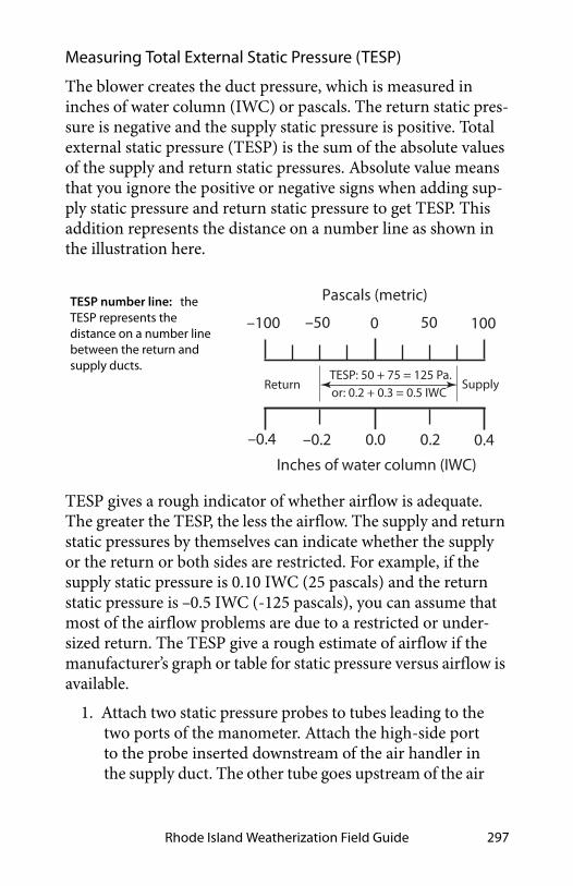
Rhode Island Weatherization Field Guide 297
Measuring Total External Static Pressure (TESP)
The blower creates the duct pressure, which is measured in inches of water column (IWC) or pascals. The return static pres-sure is negative and the supply static pressure is positive. Total external static pressure (TESP) is the sum of the absolute values of the supply and return static pressures. Absolute value means that you ignore the positive or negative signs when adding sup-ply static pressure and return static pressure to get TESP. This addition represents the distance on a number line as shown in the illustration here.
TESP gives a rough indicator of whether airflow is adequate. The greater the TESP, the less the airflow. The supply and return static pressures by themselves can indicate whether the supply or the return or both sides are restricted. For example, if the supply static pressure is 0.10 IWC (25 pascals) and the return static pressure is –0.5 IWC (-125 pascals), you can assume that most of the airflow problems are due to a restricted or under-sized return. The TESP give a rough estimate of airflow if the manufacturer’s graph or table for static pressure versus airflow is available.
1. Attach two static pressure probes to tubes leading to the two ports of the manometer. Attach the high-side port to the probe inserted downstream of the air handler in the supply duct. The other tube goes upstream of the air
1000–100
0.40.20.0–0.2–0.4
Pascals (metric)
Inches of water column (IWC)
50–50
TESP: 50 + 75 = 125 Pa.
or: 0.2 + 0.3 = 0.5 IWCReturn Supply
TESP number line: the TESP represents the distance on a number line between the return and supply ducts.

Heating and Cooling Systems298
handler in the return duct. The manometer adds the supply and return static pressures to measure TESP.
2. Consult manufacturer’s literature for a table of TESP versus airflow for the blower or the air handler. Find airflow for the TESP measured in Step 1.
3. Measure pressure on each side of the air handler to obtain both supply and return static pressures sepa-rately. This test helps to locate the main problems as related to either the supply or the return.
Static Pressure Guidelines
Air handlers deliver their airflow at TESPs ranging from 0.30 IWC (75 Pascals) to 1.0 IWC (250 Pascals) as found in the field. Manufacturers maximum recommended static pressure is usu-ally a maximum 0.50 IWC (125 pascals) for standard air han-
0
+0.1
+0.2
+0.3
+0.4
–0.1
–0.2
0
25
50
75
100
Pasc
als
Inch
es o
f Wat
er C
olum
n (IW
C)
Tota
l Ext
erna
l Sta
tic P
ress
ure
(TES
P)
Supply
Return
Heat Exchanger
Cool
ing
Coil
Filte
r
BlowerIWC Pa.
Return grille 0.03 7
Return duct 0.08 17
Filter 0.07 20
Cooling coil 0.20 50
Supply duct 0.14 35
Registers 0.03 7
Total 0.55 136
Adapted from Heating, Ventilating, and Air Conditioning:Analysis and Design, by McQuiston and
Parker, John Wiley and Sons Publishers.
d
www .srmi.biz
Visualizing TESP: The blower creates a suction at its inlet and a positive pressure at its outlet. As the distance between the measurement and blower increase, pressure decreases because of the system’s lower resistance.

Rhode Island Weatherization Field Guide 299
dlers. TESPs greater than 0.50 IWC indicate inadequate airflow in standard residential forced-air systems.
The popularity of pleated filters, electrostatic filters, and high-static high-efficiency evaporator coils, prompted manufacturers to introduce premium air handlers that can deliver adequate air-flow at a TESPs of greater than 0.50 IWC (125 pascals). Pre-mium residential air handlers can provide adequate airflow with TESPs of up to 0.90 IWC (225 pascals) because of their more powerful blowers and variable-speed blowers. TESPs greater than 0.90 IWC indicate the possibility of inadequate airflow in these premium residential forced-air systems.
Ducts
Filters
Coil
40% = 0.2 IWC40% = 0.2 IWC
20% = 0.1 IWC
Static pressure budget: Typical static pressures in IWC and % for a marginally effective duct system.

Heating and Cooling Systems300
8.14.3 Unbalanced Supply-Return Airflow Test
Closing interior doors often separates supply registers from return registers in homes with central returns. A bedroom door with no return register and a closed door restricts the bedroom air from returning to the air handler. This restriction pressurizes bedrooms and depressurizes the central areas near return regis-ters. These pressures can drive air leakage through the building shell, create moisture problems, and bring pollutants in from the crawl space, garage, or CAZ.
The following test uses only the air handler and a digital manometer to evaluate whether the supply air can flow back to the return registers relatively unobstructed. Activate the air han-dler and close interior doors.
1. Measure the pressure difference between the home’s central living area and the outdoors with a digital manometer.
Reference
Input
0.32Digital Manometer
Total external static pressure (TESP): The positive and negative pressures created by the resistance of the supply and return ducts produces TESP. The measurement shown here simply adds the two static pressures without regard for their signs. As TESP increases, airflow decreases. Numbers shown below are for example only.
Table 8-14: Total External Static Pressure Versus System Airflow for a Particular System
TESP (IWC) 0.30 0.40 0.50 0.60 0.70 0.80
CFM 995 945 895 840 760 670
Example only

Rhode Island Weatherization Field Guide 301
2. Measure the bedrooms’ pressure difference with refer-ence to outdoors.
If the sum of these two measurements is more than 3.0 pascals with the air handler operating, pressure relief is desirable. Like TESP, disregard the positive or negative signs, and add the abso-lute values.
• Or, you can measure the pressure difference between the central zone and the bedroom as shown in the next illustra-tion.
To estimate the amount of pressure relief needed, slowly open the bedroom door until the pressure difference drops below 1 pascal.
Estimate the surface area of that door opening. This is the area of the permanent opening required to provide pressure relief. Pressure relief may include undercutting the door or installing transfer grilles or jumper ducts.

Heating and Cooling Systems302
Reference
Input
10.0Digital Manometer
bedroom WRT
central zone
Pressure difference bedroom to central zone: The air handler depressurizes the central zone and pressurizes the bedroom, when the bedroom doors are closed. This test measures the pressure difference.
Pressurized bedrooms: Bedrooms with supply registers but no return register are pressurized when the air handler is on and the doors are closed. Pressures this high can double or triple air leakage through the building shell.
Measuring unbalanced airflow: The distance on a number line represents the difference in pressure between the central zone and the bedroom.
80–8Pascals (Pa.)
42 6–4–6 –2
4 + 6 = 10 Pa.
Central WRT Outdoors
BR WRT Outdoors
Difference
Reference
Input
6.0Digital Manometer
bedroom WRT
outdoors

Rhode Island Weatherization Field Guide 303
8.14.4 Evaluating Furnace Performance
The effectiveness of a furnace depends on its temperature rise, fan-control temperatures, and flue-gas temperature. For effi-ciency, you want a low temperature rise. However, you must maintain a minimum flue-gas temperature to prevent corrosion in the venting of 70+ and 80+ AFUE furnaces. Apply the follow-ing furnace-operation standards to maximize the heating sys-tem’s seasonal efficiency and safety.
✓ Perform a combustion analysis as described in “Gas Burner Safety & Efficiency Service” on page 264.
✓ Check temperature rise after 5 minutes of operation. Refer to manufacturer’s nameplate for acceptable temperature rise (supply temperature minus return temperature). The temperature rise should be between 40°F and 70°F with the lower end of this scale being preferable for energy effi-ciency.
✓ Verify that the fan-off temperature is between 95° and 105° F. The lower end of this scale is preferable for maximum efficiency.
✓ Verify that the fan-on temperature is 120–140° F. The lower the better.

Heating and Cooling Systems304
✓ With time-activated fan controls, verify that the fan is switched on within two minutes of burner ignition and is switched off within 2.5 minutes of the end of the combus-tion cycle.
✓ Verify that the high limit controller shuts the burner off before the furnace temperature reaches 200°F.
✓ Verify that there is a strong noticeable airflow from all supply registers.
✓ Adjust fan control to conform to these standards, or replace the fan control if adjustment fails. Some fan con-trols aren’t adjustable.
✓ Adjust the high limit control to conform to the above stan-dards, or replace the high limit control.
✓ All forced-air heating systems must deliver supply air and collect return air only from inside the intentionally heated
Inadequatetemperature rise:condensation andcorrosion possible.
Temperature rise OK forboth efficiency andavoidance ofcondensation.
Temperature isexcessive: Check fanspeed, heat exchangerand ducts.
Excellent fan-offtemperature ifcomfort is acceptable.
Bor derline acceptable:Consider replacing fancontrol.
Unacceptable range:Significant savingspossible by adjustingor replacing fancontrol.
Ex cellent fan-ontemperature range:No change needed.
Fair: Consider fan-controlreplacement if fan-offtemperature is alsoborderline.
Poor: Adjust or replacefan control.
20° 45° 70° 95°
85° 100° 115° 130°
100° 120° 140° 160°
Temperature Rise = Supply Temperature – Return Temperature
Fan-off Temperature
Fan-on Temperature
Table 8-14: Furnace Operating Parameters

Rhode Island Weatherization Field Guide 305
portion of the house. Taking return air from an un-heated area of the house such as an unconditioned basement or a crawl space isn’t acceptable.
8.14.5 Rooftop Units (Air Handlers)
SWS Detail: 5.3003.4 Evaluating Electrical Service, 5.3003.26 Electrical Service—Mid and High Rise, 5.3003.11 Heating and Cooling Controls
Too Low
To
o H
igh
Still Too High
OK
Temperature Rise Test
Remove Blower compartment door and re-measure
temperature rise.
7. Install turning vanes in 90°main return.
6. Install new return air duct or jumper duct.
5. Clean or remove AC coil. 4. Test gas input and reduce if too high. 3. Clean blower. Increase blower speed. 2. Clean or replace filter.
and registers. 1. Look for restrictions in the return ducts Return airflow is inadequate
4. Increase size of supply ducts and registers to hard-to-heat areas.
3. Add additional supply branches to hard-to-heat areas.
supply ducts and registers. 2. Find and remove restrictions in the 1. Clean blower. Increase blower speed.
Supply airflow is inadequate
4. Reduce fan speed.
3. Check for return air leakage from outdoors.
2. Test gas input and increase if too low.
1. Look for signs of corrosion in the vent and heat exchanger.
Temperature rise is too low
Troubleshooting Temperature Rise

Heating and Cooling Systems306
Rooftop units (RTUs) are air handlers located on roofs or on slabs or platforms outdoors. RTUs may contain one or more of the following.
• A combustion furnace
• All the components of an air conditioner (packaged or uni-tary air conditioner)
• All the components of an heat pump (packaged or unitary heat pump)
• Outdoor-air damper with another damper, called an econ-omizer for ventilation and free cooling.
Economizers
A controller in the economizer measures the temperature (and humidity in humid climates) of the outdoor air. When the out-door conditions are favorable, the control switches the air condi-tioning compressor off and cools the building with outdoor air instead. The economizer uses far less cooling energy compared to air conditioning.
Economizers typically operate at night when the outdoor air is cooler than the indoor air in a process known as “free cooling”. Economizers mix enough outdoor air into the indoor air in order to meet the thermostat setpoint (which may be lower than the AC setpoint), without using the compressor.
Fresh air that economizers exchange with indoor air while they save cooling energy at night can also count as ventilation. Therefore the ventilation system can run for fewer hours and avoid operating during the day’s peak electrical load.
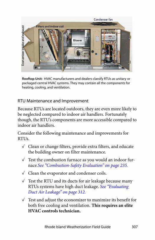
Rhode Island Weatherization Field Guide 307
RTU Maintenance and Improvement
Because RTUs are located outdoors, they are even more likely to be neglected compared to indoor air handlers. Fortunately though, the RTU’s components are more accessible compared to indoor air handlers.
Consider the following maintenance and improvements for RTUs.
✓ Clean or change filters, provide extra filters, and educate the building owner on filter maintenance.
✓ Test the combustion furnace as you would an indoor fur-nace.See “Combustion-Safety Evaluation” on page 235.
✓ Clean the evaporator and condenser coils.
✓ Test the RTU and its ducts for air leakage because many RTUs systems have high duct leakage. See “Evaluating Duct Air Leakage” on page 312.
✓ Test and adjust the economizer to maximize its benefit for both free cooling and ventilation. This requires an elite HVAC controls technician.
Rooftop Unit: HVAC manufacturers and dealers classify RTUs as unitary or packaged central HVAC systems. They may contain all the components for heating, cooling, and ventilation.

Heating and Cooling Systems308
✓ Educate the building owner or operator on economizer function and control. Replace the thermostat, if necessary to accommodate optimal economizer functioning. Note: Economizers functioning isn’t intuitive and therefore many, if not most, economizers function poorly.
8.14.6 Improving Forced-Air System Airflow
Inadequate airflow is a common cause of comfort complaints. When the air handler is on there should be a strong flow of air out of each supply register. Low register airflow may mean that a branch duct is blocked or separated, or that return air from the room to the air handler isn’t sufficient. When low airflow is a problem, consider specifying the following improvements as appropriate from your inspection.
✓ Clean or change filter. Select a less restrictive filter if you need to reduce static pressure substantially.
✓ Clean air handler’s blower.
✓ Clean air-conditioning or heat pump coil.
✓ Clean the air-conditioning coil. If the blower is dirty, the coil is probably also dirty.
✓ Increase blower speed.
✓ Make sure that balancing dampers to rooms that need more airflow are wide open.
✓ Lubricate blower motor, and check tension on drive belt.
terminals
bimetal element
adjustable dial
Fan/limit control: Turns the furnace blower on and off, according to temperature. Also turns the burner off if the heat exchanger gets too hot.

Rhode Island Weatherization Field Guide 309
Duct Improvements to Increase Airflow
Consider specifying the following duct changes to increase sys-tem airflow and reduce the imbalance between supply and return.
✓ Modify the filter installation to allow easier filter chang-ing, if filter changing is currently difficult.
✓ Install a slanted filter bracket assembly or a enlarged filter fitting to accommodate a larger filter with more surface area and less static-pressure drop than the existing filter.
✓ Remove obstructions to registers and ducts such as rugs, furniture, and objects placed inside ducts, such as chil-dren’s toys and water pans for humidification.
✓ Remove kinks from flex duct, and replace collapsed flex duct and fiberglass duct board.
✓ Remove excessive lengths of slacking flex duct, and stretch the duct to enhance airflow.
✓ Perform a Manual D sizing evaluation to evaluate whether to replace branch ducts that are too small.
Washable filter installed on a rack inside the blower compartment.
Panel filter installed in return register
Panel filter installed in filter slot in return plenum
Air-handler filter location: Filters are installed on the return-air side of forced air systems. Look for them in one or more of the above locations.

Heating and Cooling Systems310
✓ Install additional supply ducts and return ducts as needed to provide heated air throughout the building, especially in additions to the building.
✓ Undercut bedroom doors, especially in homes without return registers in bedrooms.
✓ Repair or replace bent, damaged, or restricted registers. Install low-resistance registers and grilles.
8.14.7 Air Filtration for Air Handlers
Manufacturers equip air handlers with air filters at the factory or recommend that installers install air filters in return ductwork. The purpose of these filters is to protect the blower and heat exchangers from fouling by dust.
Another possible function for air filters is to remove particles from indoor air. This function is useful when the outdoor envi-ronment contains a lot of particles, such in large cities, rural areas where wind and agriculture create particulates, or during forest fires.
Air Filter Effectiveness
The most common filter-rating method is the Minimum Effi-ciency Rating Value (MERV). A higher MERV rating means that the filter removes more particles and a larger fraction of smaller particles.
The MERV rating system divides particles into three size catego-ries: 0.3–1, 1–3, and 3–10 microns. The two smallest categories are the most important for human health, as small respirable particles (PM2.5) can more easily deposit in the lungs compared to larger particles.
The need for high MERV filters depends on the severity of the particle problem in a building. Particles less than 2.5 microns are the most dangerous because they can lodge themselves deep in the lungs. Filtering air with a long-running central air handler

Rhode Island Weatherization Field Guide 311
or a portable air cleaner can be energy intensive and it may or may not be effective.
The MERV ratings of available HVAC filters range from MERV 3 to MERV 16, with higher ratings removing more particles at smaller sizes. A MERV 3 filter captures large particles — cloth-ing fibers, pollen, and dust mites, but few smaller respirable par-ticles. A MERV16 filter captures more than 95% of all three particle sizes, including bacteria and tobacco smoke. The mini-mum MERV rating to remove 50% of the respirable 1–3 microns particle-size range is MERV 10. See also "Air Filtration for Indoor Air Quality" on page 374.
Air Filter Pressure and Airflow Effects
Air filters affect the airflow and energy consumption of forced air HVAC systems and balanced ventilation systems. Before choosing the type of air filter, consider its MERV rating and a home’s need for particle removal.
HVAC designers designed air handlers for use with low-MERV filters with a small pressure drop. Changing to higher-MERV fil-ters can cause the filter pressure drop to increase and the system airflow to decrease.
Insufficient airflow may cause blowers to fail prematurely as they struggle to overcome system pressures beyond their design specification. For heating systems, the furnaces may overheat and cycle on their high limit switches. Airflow reductions in cooling systems risk coil icing and premature compressor fail-ure. See also "Air Filtration for Indoor Air Quality" on page 374.
To reduce the resistance of an high-MERV air filter, consider installing steps to accommodate a larger filter with more surface area and less static-pressure drop compared to the existing filter.
• A slanted filter bracket assembly
• An enlarged filter fitting to allow a filter with more surface area

Heating and Cooling Systems312
• Filters in each return register instead of only one at the air handler.
8.15 EVALUATING DUCT AIR LEAKAGE
Duct leakage is a major energy-waster in homes where the ducts are located outside the home’s thermal boundary in a crawl space, attic, attached garage, or leaky unconditioned basement. When these intermediate zones remain outside the thermal boundary, duct sealing is usually cost-effective.
Duct leakage within the thermal boundary isn’t usually a signifi-cant energy problem.
8.15.1 Troubleshooting Duct Leakage
There are several simple procedures for finding the locations of the duct leaks and evaluating their severity.
Finding Duct Leaks Using Touch and Sight
One of the simplest ways of finding duct leaks is feeling with your hand for air leaking out of supply ducts, while the ducts are pressurized by the air handler’s blower. Duct leaks can also be located using light. Use one of these 4 tests to locate air leaks.
looking for light
examining
Finding duct air leaks: Finding the exact location of duct leaks precedes duct air sealing.
duct interiors
feeling for air

Rhode Island Weatherization Field Guide 313
1. Use the air handler blower to pressurize supply ducts. Closing the dampers on supply registers temporarily or partially blocking the register with pieces of carpet, magazines, or any object that won’t be blown off by the register’s airflow increases the duct pressure and make duct leaks easier to find. Dampening your hand makes your hand more sensitive to airflow, helping you to find duct air leaks.
2. Place a trouble light, with a 100-watt bulb, inside the duct through a register. Look for light emanating from the exterior of duct joints and seams.
3. Determine which duct joints were difficult to fasten and seal during installation. These joints are likely duct-leakage locations.
4. Use a trouble light, flashlight, and mirror or a digital camera to help you to visually examine duct interiors.
Feeling air leaks establishes their exact location. Ducts must be pressurized in order to feel leaks. You can feel air leaking out of pressurized ducts, but you can’t feel air leaking into depressur-ized return ducts. Pressurizing the home with a blower door forces air through duct leaks, located in intermediate zones, where you can feel the leakage coming out of both supply and return ducts.
Pressure Pan Testing
Pressure pan tests can identify leaky or disconnected ducts located in intermediate zones. With the house depressurized by the blower door to either –25 pascals or –50 pascals, make pres-sure pan readings at each supply and return register.

Heating and Cooling Systems314
If the ducts are in a basement and the basement is conditioned, pressure pan testing isn’t necessary, although air sealing the return ducts for safety is still important.
If instead, the basement is unconditioned, open a window or door between the basement and outdoors. Close any door or hatch between conditioned spaces and basement during pres-sure pan testing.
1. Install blower door and set-up house for winter condi-tions. Open all interior doors.
2. If the basement is conditioned living space, open the door between the basement and upstairs living spaces. If the basement isn’t conditioned living space, close the door between basement and upstairs, and open a base-ment window.
3. Turn furnace off at the thermostat or main switch. Remove furnace filter, and tape filter slot if one exists. Be sure that all grilles, registers, and dampers are fully open.
4. Temporarily seal any outside fresh-air intakes to the duct system.
5. Seal supply registers in unoccupied zones that aren’t intended to be heated — an unconditioned basement or crawl space, for example.
Reference
Input
4Digital Manometer
A pressure pan: Blocks a single register and measures the air pressure behind it, during a blower door test. The magnitude of that pressure is an indicator of duct leakage.

Rhode Island Weatherization Field Guide 315
6. Open attics, crawl spaces, and garages as much as possi-ble to the outdoors so they don’t create a secondary air barrier.
7. Connect hose between pressure pan and the input tap on the digital manometer. Leave the reference tap open.
8. With the blower door’s manometer reading –25 or –50 pascals, place the pressure pan completely over each grille or register one by one to form a tight seal. Leave all other grilles and registers open when making a test. Record each reading, which should give a positive pres-sure.
9. If a grille is too large or a supply register is difficult to cover with the pressure pan (under a kitchen cabinet, for example), seal the grille or register with masking tape. Insert a pressure probe through the masking tape and record the reading. Remove the tape after the test.
10. Use either the pressure pan or tape to test each register and grille in a systematic way.
Pressure Pan Duct Standards
If the ducts are perfectly sealed with no leakage to the outdoors, you won’t measure any pressure difference (0.0 pascals) during a pressure-pan test. The higher the measured pressure reading, the more connected the duct is to the outdoors.
• If the median pressure pan reading is 4 pascals or more and/or if one reading is more than 8 pascals, duct-sealing is usually cost-effective.
• Following duct-sealing work, no more than three registers should have pressure-pan readings greater than 2 pascals. No single reading should be greater than 4 pascals.
• The reduction you achieve depends on your ability to find the leaks and whether you can access the leaky ducts. The best weatherization agencies use 1 pascal or less as a gen-eral goal for all registers.

Heating and Cooling Systems316
Examine the registers connected to ducts that are located in areas outside the conditioned living space. Unconditioned spaces containing ducts include attics, crawl spaces, garages, and unoccupied basements. Also evaluate registers attached to stud cavities or panned joists used as return ducts. Leaky ducts, located outside the conditioned living space, may lead to pres-sure-pan measurements more than 30 pascals if the ducts have large holes.
8.15.2 Measuring Duct Air Leakage with a Duct Blower
Pressurizing the ducts with a duct blower measures total duct leakage. The duct blower is the most accurate common measur-ing device for duct air leakage. It consists of a fan, a digital manometer or set of analog manometers, and a set of reducer plates for measuring different leakage levels. Using a blower door with a duct blower measures leakage to outdoors.
Measuring Total Duct Leakage
The total duct leakage test measures leakage to both indoors and outdoors. The house and intermediate zones should be open to
Pressure pan test: A pressure pan reading of 2 indicates moderate duct air leakage in the supply ducts.
Problem return register: A pressure reading of 7 pascals indicates major air leakage near the tested register.
50pa
Reference
Input
2.0Digital Manometer
Unconditionedbasement
50pa
Reference
Input
7.0Digital Manometer
Unconditionedbasement

Rhode Island Weatherization Field Guide 317
the outdoors by way of windows, doors, or vents. Opening the intermediate zones to outdoors insures that the duct blower is measuring only the ducts’ airtightness — not the airtightness of ducts combined with other air barriers like roofs, foundation walls, or garages.
Supply and return ducts can be tested separately, either before the air handler is installed in a new home or when an air handler is removed during replacement.
Follow these steps when performing a duct airtightness test.
1. Install the duct blower in the air handler or to a large return register, either using its connector duct or simply attaching the duct blower itself to the air handler or return register with cardboard and tape.
2. Remove the air filter(s) from the duct system.
3. Seal all supply and return registers with masking tape or other non-destructive sealant.
4. Open the house, basement or crawl space, containing ducts, to outdoors.
5. Drill a 1/4 or 5/16-inch hole into a supply duct a short distance away from the air handler and insert a manometer hose. Connect a manometer to this hose to measure duct with reference to (WRT) outdoors. (Indoors, outdoors, and intermediate zones should ide-ally be opened to each other in this test).
6. Connect an airflow manometer to measure fan WRT the area near the fan.
Check manometer(s) for proper settings. Digital manometers require your choosing the correct mode, range, and fan-type settings.
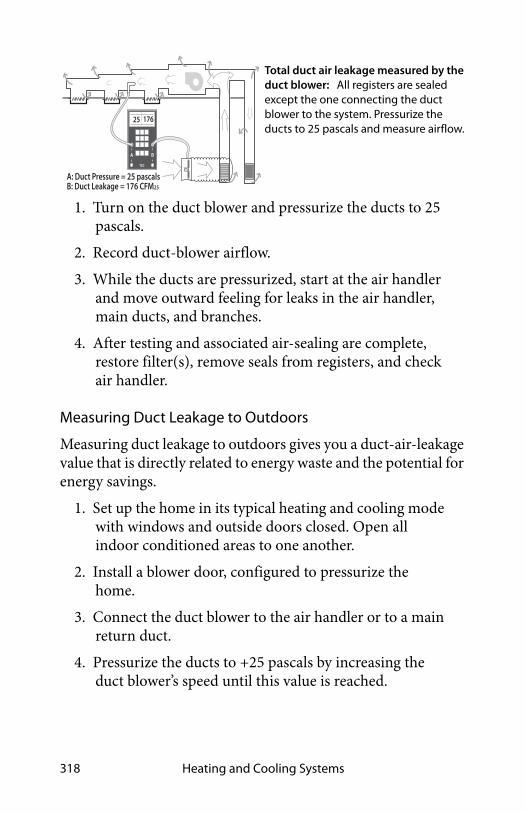
Heating and Cooling Systems318
1. Turn on the duct blower and pressurize the ducts to 25 pascals.
2. Record duct-blower airflow.
3. While the ducts are pressurized, start at the air handler and move outward feeling for leaks in the air handler, main ducts, and branches.
4. After testing and associated air-sealing are complete, restore filter(s), remove seals from registers, and check air handler.
Measuring Duct Leakage to Outdoors
Measuring duct leakage to outdoors gives you a duct-air-leakage value that is directly related to energy waste and the potential for energy savings.
1. Set up the home in its typical heating and cooling mode with windows and outside doors closed. Open all indoor conditioned areas to one another.
2. Install a blower door, configured to pressurize the home.
3. Connect the duct blower to the air handler or to a main return duct.
4. Pressurize the ducts to +25 pascals by increasing the duct blower’s speed until this value is reached.
Total duct air leakage measured by the duct blower: All registers are sealed except the one connecting the duct blower to the system. Pressurize the ducts to 25 pascals and measure airflow.
A B
25
TEC
176
A: Duct Pressure = 25 pascalsB: Duct Leakage = 176 CFM25

Rhode Island Weatherization Field Guide 319
5. Pressurize the house until the pressure difference between the house and duct is 0 pascals (house WRT ducts). See "Blower-Door Test Procedures" on page 454.
6. Read the airflow through the duct blower. This value is duct leakage to outdoors.
8.15.3 Measuring House Pressure Caused by Duct Leakage
The following test measures pressure differences between the house and outdoors, caused by duct leakage. Try to correct pres-sure differences greater than +2.0 pascals or more negative than –2.0 pascals because of the shell air leakage that the pressure dif-ferences create.
1. Close all windows and exterior doors. Turn-off all exhaust fans.
2. Open all interior doors, including door to basement.
3. Measure the baseline house-to-outdoors pressure dif-ference and zero it out using the baseline procedures described in “Blower-Door Test Procedures” on page 454.
4. Turn on air handler.
5. Measure the house-to-outdoors pressure difference. This test indicates dominant duct leakage as shown here.
BA
A B
250
25 pa.
25 pa.
Measuring duct leakage to outdoors: Using a blower door to pressurize the house with a duct blower to pressurize the ducts measures leakage to the outdoors — a smaller number and a better predictor of energy savings. This test is preferred for evaluating duct leakage for specialists in both shell air leakage and duct air leakage whenever a blower door is available.

Heating and Cooling Systems320
A positive pressure indicates that the return ducts (which pull air from leaky intermediate zones) are leakier than the supply ducts. A negative pressure indicates that the supply ducts (which push air into intermediate zones through their leaks) are leakier than return ducts. A pressure at or near zero indicates equal supply and return leakage or else little duct leakage.
8.16 SEALING DUCT LEAKS
Ducts located outside the thermal boundary or in an intermedi-ate zone like a ventilated attic or crawl space should be sealed. The following is a list of duct leak locations in order of their rel-ative importance. Leaks nearer to the air handler are exposed to higher pressure and are more important than leaks further away.
8.16.1 General Duct-Sealing Methods
Duct sealers install duct mastic and fiberglass mesh to seal duct leaks. When they need reinforcement or temporary closure, the duct sealers use tape or sheet metal. Observe these three stan-dards.
Reference
Input
2Digital Manometer
leak
leak leaks
house WRT outdoors
Reference
Input
-3Digital Manometer
leak
leakleak leak
house WRT outdoors
Dominant return leaks: When return leaks are larger than supply leaks, the house shows a positive pressure with reference to the outdoors.
Dominant supply leaks: When supply leaks are larger than return leaks, the house shows a negative pressure with reference to the outdoors.

Rhode Island Weatherization Field Guide 321
1. Seal seams, cracks, joints, and holes, less than ¼ inch using mastic and fiberglass mesh.
2. Bridge seams, cracks, joints, holes, and penetrations, between ¼ and ¾ inch, with sheet metal or tape and then cover the metal or tape completely with mastic reinforced by mesh at seams in the sheet metal or tape.
3. Overlap the mastic and mesh at least 0ne inch beyond the seams, repairs, and reinforced areas of the ducts.
8.16.2 Sealing Return Ducts
Return leaks are important for combustion safety and for effi-ciency. Use the following techniques to seal return ducts.
✓ First, seal all return leaks within the combustion zone to prevent this leakage from depressurizing the combustion zone and causing backdrafting.
✓ Seal panned return ducts using mastic to seal all cracks and gaps within the return duct and register.
✓ Seal leaky joints between building materials composing cavity return ducts, like panned floor cavities and furnace return platforms. Remove the panning to seal cavities con-taining joints in building materials.
✓ Carefully examine and seal leaks at transitions between panned floor joists and metal trunks that change the direc-tion of the return ducts. You may need a mirror to find some of the biggest return duct leaks in these areas.
✓ Seal filter slots with duct tape to allow removal for easy changing of filters.
SWS Detail: 3.1602.1 Air Sealing Duct System, 3.1602.5 Return—Framed Platform, 3.1602.4 Air Sealing System Components, 3.1602.7 Return and Supply Plenums in Basements and Crawl Spaces

Heating and Cooling Systems322
✓ Seal the joint between the furnace and return plenum with silicone caulking or foil tape.
8.16.3 Sealing Supply Ducts
Inspect these places in the duct system and seal them as needed.
SWS Detail: 3.1602.1 Air Sealing Duct System, 3.1602.5 Return—Framed Platform, 3.1602.4 Air Sealing System Components, 3.1602.7 Return and Supply Plenums in Basements and Crawl Spaces, 3.1601.3 Support
Panned floor joists: These return ducts are often very leaky and may require removing the panning to seal the cavity.
return register
return duct
leakage
leakage
metal panning
Lining a panned cavity: Foil-faced foam board, designed for lining cavities is sealed with duct mastic to provide an airtight return.
Panned floor joists: These return ducts are often very leaky and may require removing the panning to seal the cavity.

Rhode Island Weatherization Field Guide 323
✓ Plenum joint at air handler: Technicians might have had problems sealing these joints because of a lack of space. Seal these plenum connections thoroughly even if you must cut an access hole in the plenum. Use silicone caulk-ing or foil tape instead of mastic and fabric mesh here for future access — furnace replacement, for example.
✓ Joints at branch takeoffs: Seal these important joints with a thick layer of mastic. Fabric mesh tape should cover gaps and reinforce the seal at gaps.
✓ Joints in sectioned elbows: Known as gores, these are usu-ally leaky and require sealing with duct mastic.
✓ Tabbed sleeves: Attach the sleeve to the main duct with 3-to-5 screws and apply mastic plentifully. Or better, remove the tabbed sleeve and replace it with a manufactured take-off.
✓ Flexduct-to-metal joints: Apply a 2-inch band of mastic to the end of the metal connector. Attach the flexduct’s inner liner with a plastic strap, tightening it with a strap ten-sioner. Attach the insulation and outer liner with another strap.
✓ Damaged flex duct: Replace flex duct when it is punctured, deteriorated, or otherwise damaged.
Plenums, poorly sealed to air handler: When air handlers are installed in tight spaces, plenums may be poorly fastened and sealed. Cutting a hole in the duct may be the only way to seal this important joint.
Sectioned elbows: Joints in sectioned elbows, known as gores, are usually leaky and require sealing with duct mastic.
access panel

Heating and Cooling Systems324
✓ Deteriorating ductboard facing: Replace ductboard, prefer-ably with metal ducting, when the facing deteriorates because this deterioration leads to a lot of air leakage.
✓ Consider closing supply and return registers in unoccu-pied basements or crawl spaces.
✓ Seal penetrations made by wires or pipes traveling through ducts.
✓ Seal the joint between the boot and the ceiling, wall, or floor between conditioned and unconditioned areas.
Duct Support
✓ Support rigid duct joints with duct hangers at least every 5 feet or as necessary to prevent sagging of more than one-half inch.
✓ Support flexible ducts and duct board every 4 feet using a minimum of 1 ½” wide support material.
Flexduct joints: Flexduct itself is usually fairly airtight, but joints, sealed improperly with tape, can be very leaky. Use methods shown here to make flexduct joints airtight.
strap tightener
sheet-metal screw
metal sleeve
inner linerinsulationtightened straps
takeoff
mastic

Rhode Island Weatherization Field Guide 325
8.16.4 Materials for Duct Sealing
Duct mastic is the best duct-sealing material because of its supe-rior durability and adhesion. Apply mastic at least 1/16-inch thick, and use reinforcing mesh for all joints wider than 1/8-inch or joints that may move. Install screws to prevent joint move-ment or separation.
Aluminum foil or cloth duct tape aren’t good materials for duct sealing because their adhesive often fails. Consider covering tape with mastic to prevent tape’s adhesive from drying out and failing.
8.17 DUCT INSULATION
Insulate supply ducts that are installed in unconditioned areas outside the thermal boundary such as crawl spaces, attics, and attached garages with vinyl- or foil-faced duct insulation. Don’t insulate ducts that run through conditioned areas unless they cause overheating in winter or condensation in summer. Use these best practices for installing insulation.
✓ Always perform necessary duct sealing before insulating ducts.
✓ Duct-insulation R-value must be ≥R-8.
SWS Detail: 4.1601.1 Insulating Flex Ducts, 4.1601.2 Insulating Metal Ducts
Sealing register boots: Seal between the boot and floor. Seal joints inside the boot.
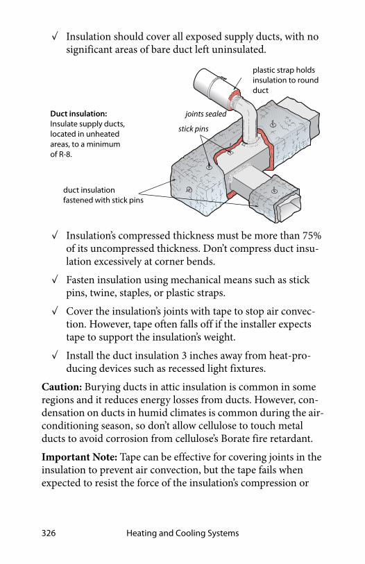
Heating and Cooling Systems326
✓ Insulation should cover all exposed supply ducts, with no significant areas of bare duct left uninsulated.
✓ Insulation’s compressed thickness must be more than 75% of its uncompressed thickness. Don’t compress duct insu-lation excessively at corner bends.
✓ Fasten insulation using mechanical means such as stick pins, twine, staples, or plastic straps.
✓ Cover the insulation’s joints with tape to stop air convec-tion. However, tape often falls off if the installer expects tape to support the insulation’s weight.
✓ Install the duct insulation 3 inches away from heat-pro-ducing devices such as recessed light fixtures.
Caution: Burying ducts in attic insulation is common in some regions and it reduces energy losses from ducts. However, con-densation on ducts in humid climates is common during the air-conditioning season, so don’t allow cellulose to touch metal ducts to avoid corrosion from cellulose’s Borate fire retardant.
Important Note: Tape can be effective for covering joints in the insulation to prevent air convection, but the tape fails when expected to resist the force of the insulation’s compression or
joints sealed
plastic strap holds insulation to round duct
duct insulation fastened with stick pins
stick pins
Duct insulation: Insulate supply ducts, located in unheated areas, to a minimum of R-8.

Rhode Island Weatherization Field Guide 327
weight. Outward-clinch staples or plastic straps can help hold the insulation facing and tape together.
8.17.1 Spray Foam Duct Insulation
High-density spray foam insulation is also a good duct-insula-tion option, assuming it is listed as ASTM E-84 or UL 723. Spray foam is particularly helpful in areas where the foam can seal seams and insulate in one application. However, the spray foam application is limited by space around the duct to a greater amount than wrapping with fiberglass blankets.
8.18 HOT-WATER SPACE-HEATING DISTRIBUTION
The most significant energy wasters in hot-water systems are poor steady-state efficiency, off-cycle flue losses stealing heat from the stored water, and boilers operating at a too-high water temperature. For information about boiler installation, see page 256.
SWS Details: 3.1602.2 Duct Spray Polyurethane Foam (SPF) Installation

Heating and Cooling Systems328
8.18.1 Boiler Efficiency and Maintenance
Monitor boiler performance and efficiency in the following ways.
• Corrosion, scaling, and dirt on the water side of the heat exchanger.
• Corrosion, dust, and dirt on the fire side of the heat exchanger.
• Excess air during combustion from air leaks and incorrect fuel-air mixture.
• Off-cycle air circulation through the firebox and heat exchanger, removing heat from stored water.
Cast-iron sectional boilers: The most common boiler type for residential applications.
cast-iron section
burner
Tankless coil water heater found on some boilers
controls

Rhode Island Weatherization Field Guide 329
Boiler Efficiency Improvements
Consider the following maintenance and efficiency improve-ments for both hot-water and steam boilers based on boiler inspection.
✓ Check for leaks on the boiler, around its fittings, or on any of the distribution piping connected to the boiler.
✓ Clean fire side of heat exchanger of noticeable dirt.
✓ Drain water from the boiler drain until the water flows clean.
8.18.2 Distribution System Improvements
Hydronic distribution systems consist of the supply and return piping, the circulator, expansion tank, air separator, air vents, and heat emitters. A properly designed and installed hydronic distribution system can operate for decades without service. However, many systems have installation flaws or need service.
Note: You can recognize a hot-water boiler by its expansion tank, located somewhere above the boiler. The expansion tank provides an air cushion to allow the system’s water to expand and contract as it is heated and cooled. Without a functioning expansion tank excessive pressure in the boiler discharges water through the pressure-relief valve.
Safety Checks and Improvements
Work with contractors and technicians to specify and verify the following safety and efficiency tests and inspections.
• Verify the existence of a 30-psi-rated pressure-temperature (P&T) relief valve. The P&T relief valve should have a drain pipe that terminates 6 inches from the floor. Replace a mal-functioning valve or add a P&T relief valve if none exists.
SWS Details: 5.3104.2 Maintenance: Gas Boiler Service Inspection

Heating and Cooling Systems330
Look for signs of leakage or discharges. Find out why the relief valve is discharging.
• Verify that the expansion tank isn’t waterlogged or too small for the system. A non-operational expansion tank can cause the pressure-relief valve to discharge. Measure the expansion tank’s air pressure. The pressure should be one (1) psi per 2.3 feet of the distribution system’s height.
• If you observe rust in venting, verify that the return water temperature is warmer than 130° F for gas and warmer than 140° F for oil. These minimum water temperatures prevent acidic condensation.
• Verify that high-limit control disengages the burner at a water temperature of 200°F or less.
• Lubricate circulator pump(s) if necessary.
Simple Efficiency Improvements
Do the following energy-efficiency improvements.
✓ Repair water leaks in the system.
Expansion tank, air separator, and Vent: Preventing excessive pressure and eliminating air from the systems are important for hydronic distribution systems. Zone valves: Separate thermostats
control each zone valve. Zone valves have switches that activate the burner.
air separator vent

Rhode Island Weatherization Field Guide 331
✓ Remove corrosion, dust, and dirt on the fire side of the heat exchanger.
✓ Check for excess air during combustion from air leaks and incorrect fuel-air mixture.
✓ Bleed air from radiators and piping through air vents on piping or radiators. Most systems fill automatically through a shutoff and pressure-reducing valve (PRV) con-nected to the building’s water supply. If there is a shutoff and no PRV, open the shutoff during air-purging and close it afterwards. Then check the system pressure at the expansion tank and adjust the pressure as necessary.
✓ Vacuum and clean fins of fin-tube convectors if you notice dust and dirt there.
✓ Insulate all supply and return piping, passing through unheated areas, with foam pipe insulation, at least one-inch thick, rated for temperatures up to 200° F.
Improvements to Boiler Controls
Consider these improvements to control systems for hot-water boilers.
✓ Install outdoor reset controllers to regulate water tempera-ture, depending on outdoor temperature.
✓ If possible, operate the boiler without a low-limit control for maintaining a minimum boiler-water temperature. If the boiler heats domestic water in addition to space heat-ing, the low-limit control may be necessary.
Purging air: Trapped air collects at the hot-water system’s highest parts. Bleeding air from radiators fills the radiator and gives it more heating surface area.
trapped air
air bleed valve

Heating and Cooling Systems332
✓ After control improvements like two-stage thermostats or reset controllers, verify that return water temperature is high enough to prevent condensation and corrosion in the chimney as noted previously.
✓ Install electric vent dampers on atmospheric gas- and oil-fired high-mass boilers.
8.19 STEAM HEATING AND DISTRIBUTION
Steam heating is less efficient than hot-water heating because steam requires higher temperatures than hot water. Multifamily buildings, especially multi-story buildings, may have little choice but to continue with steam because of the high cost of switching systems.
Note: You can recognize a steam boiler by its sight glass, which indicates the boiler’s water level. Notice that the water doesn’t completely fill the boiler, but instead allows a space for the steam to form above the boiler’s water level.
If the steam-heating system remains, operate it at the lowest steam pressure that heats the building adequately. Two psi on the boiler-pressure gauge is a practical limit for many systems although some systems can operate at pressures down to a few ounces per square inch of pressure. Traps and air vents are cru-cial to operating at a low steam pressure. Electric vent dampers reduce off-cycle losses for both gas- and oil-fired systems.

Rhode Island Weatherization Field Guide 333
8.19.1 Steam System Maintenance
Do these safety and maintenance tasks on steam systems.
✓ Verify that steam boilers have functioning high-pressure limits and low-water cut-off controls.
✓ Verify that unit has a 12psi relief valve.
✓ Verify the function of the low-water cutoff by flushing the low-water cutoff with the burner operating. Combustion should stop when the water level in the boiler drops below the level of the float. If combustion continues, repair or replace the low-water cutoff.
✓ Verify that flush valves on low-water cutoffs are operable and don’t leak water.
SWS Details: 5.3104.3 Maintenance: Checklist
Sight glass & low-water control: The sight glass shows the boiler water level. The low water control adds water to the boiler and extinguishes the burner if the water level is too low.

Heating and Cooling Systems334
✓ Ask owner about instituting a schedule of blow-down and chemical-level checks.
✓ Specify that technicians drain mud legs on return piping.
8.19.2 Steam System Energy Conservation
Specify the following efficiency checks and improvements for steam systems.
One-Pipe Steam
✓ Verify that high-pressure limit control is set at or below 1 (one) psi or as low as acceptable in providing heat to the far ends of the building.
✓ Verify that steam reaches all radiators during every steam cycle. Steam need not fill radiators on every cycle. In mild weather, steam partly fills radiators before the boiler cycles off.
✓ Radiator air vents should be open to release air while the system is filling with steam, then closed when steam reaches the vents. Replace malfunctioning radiator air vents as necessary. However, don’t over-vent radiators because this can cause water hammer.
✓ Verify air vents function and that all steam radiators receive steam during every cycle. Unplug air vents or replace malfunctioning vents as necessary. Add vents to steam lines and radiators as needed to get steam to all the registers.
Two-Pipe Steam
✓ When you can gain access to all the system’s steam traps, repair leaking steam traps or replace them. All failed traps should be replaced at the same time to prevent new traps failing because of water hammer from steam leakage through neighboring failed traps. The only 100% reliable way to test a steam trap is to connect it to a test apparatus

Rhode Island Weatherization Field Guide 335
and see if it allows steam to pass. However if you have an accurate thermometer, the temperature on the radiator side of a functioning trap should be more than 215°F and the temperature on the return side of that trap should be less than 205°F when steam is in the radiator.
✓ When you can’t gain access to all the system’s steam traps at the same time, consider abandoning failed steam traps and installing radiator-inlet orifices in two-pipe steam radiators. The orifices limit steam flow to an amount that can condense within the radiator. Orifices can also reduce steam delivery to oversized radiators by 20% or a little more.
✓ Consider controlling radiators with thermostatic radiator valves (TRVs) except for radiators in the coolest rooms. TRVs can be used with systems equipped with either traps or orifices. For effective temperature control, the thermo-static element of the TRVs must be located in the path of air moving toward the radiator or convector. TRVs are
One-pipe and two-pipe steam systems: Still common in multifamily buildings, one-pipe steam works best when very low pressure steam can drive air out of the piping and radiators quickly through plentiful vents. Vents are located on each radiator and also on main steam lines.
condensate tank
vents
traps
Two-pipe steam systems: Radiator traps keep steam inside radiators until it condenses. No steam should be present at the condensate tank.

Heating and Cooling Systems336
available with sensors located remotely from the valve, which solves the problem of a valve located where the radiator heats a valve-mounted sensor, fooling it into clos-ing.
✓ Inspect return lines and condensate receiver for steam coming back to the boiler. Check radiator and main line traps.
✓ Check steam traps with a digital thermometer or listening device to detect any steam escaping from radiators through the condensate return. Replace leaking steam traps or their thermostatic elements.
✓ Consider installing remote sensing thermostats that vary cycle length according to outdoor temperature and include night-setback capability.
✓ Repair leaks on the steam supply piping or on condensate return piping.
✓ Consider a flame-retention burner and electric vent damper as retrofits for steam boilers.
Steam traps: Steam enters the steam trap heating its element and expanding the fluid inside. The expanded element plugs the steam’s escape with a valve.
steam first entering
expanding fluid
condensed water escaping
condensing steam
valve seated
valve un-seated
is trapped

Rhode Island Weatherization Field Guide 337
✓ Clean fire side of heat exchanger of noticeable dirt.
✓ All steam piping that passes through unconditioned areas should be insulated to at least R-3 with fiberglass or spe-cially designed foam pipe insulation rated for steam pip-ing.
8.20 PROGRAMMABLE THERMOSTATS
A programmable thermostat may be a big energy saver if the building’s occupants understand how to program it. However, a programmable thermostat won’t save any energy if occupants already control day and night temperatures effectively.
If you replace the existing thermostat, as a part of weatheriza-tion work, discuss programmable thermostats with occupants. If they can use a programmable thermostat effectively, then install one. Educate occupants on the use of the thermostat and leave a copy of manufacturer’s directions with them.
Many models of programmable thermostats have settings that you select from inside the thermostat. These settings include the heat-anticipator setting, which adjusts the cycle length of the heating or cooling system.
SWS Details: 5.3104.1 Controls — Thermostat Replacement
Inside a programmable thermostat: In addition to the instructions on the exterior of this thermostat are instructions inside for setting the heat anticipator.

Heating and Cooling Systems338
8.21 ELECTRIC HEAT
Electric heaters are usually 100% efficient at converting the elec-tricity to heat in the room where they are located.
8.21.1 Electric Baseboard Heat
Electric baseboard heaters are zonal heaters controlled by ther-mostats within the zone they heat. Electric baseboard heat can help to minimize energy costs, if residents take advantage of the ability to heat by zones.
Baseboard heaters contain electric resistance heating elements encased in metal pipes. These are surrounded by aluminum fins to aid heat transfer. As air within the heater is heated, it rises into the room. This draws cooler air into the bottom of the heater.
• Make sure that the baseboard heater sits at least an inch above the floor to facilitate good air convection.
• Clean fins and remove dust and debris from around and under the baseboard heaters as often as necessary.
• Avoid putting furniture directly against the heaters. To heat properly, there must be space for air convection.
The line-voltage thermostats used with baseboard heaters some-times don’t provide good comfort. This is because these thermo-stats allow the temperature in the room to vary by 2°F or more. Newer, more accurate thermostats are available. Programmable thermostats for electric baseboard heat use timers or a resident-activated button that raises the temperature for a time and then automatically returns to the setback temperature. Some base-board heaters use low-voltage thermostats connected to relays that control baseboard heaters in rooms.

Rhode Island Weatherization Field Guide 339
8.21.2 Electric Furnaces
Electric furnaces heat air moved by its fan over several electric-resistance heating elements. Electric furnaces have two to six elements — 3.5 to 7 kW each — that work like the elements in a toaster. The 24-volt thermostat circuit energizes devices called sequencers that bring the 240 volt heating elements on in stages when the thermostat calls for heat. The variable speed fan switches to a higher speed as more elements engage to keep the air temperature stable.
8.21.3 Central Heat-Pump Energy Efficiency
An air-source heat pump is almost identical to an air condi-tioner, except for a reversing valve that allows refrigerant to fol-low two different paths, one for heating and one for cooling.
Electric baseboard: Electric baseboard is more efficient than an electric furnace and sometimes even outperforms a central heat pump because it is easily zone-able. The energy bill is determined by the habits of the occupants and the energy efficiency of the building.
Electric furnace: A squirrel-cage blower blows air over 2 to 6 electric resistance coils and down into the plenum below the floor.
sequencers
elements
air outlet
filters
air inlet

Heating and Cooling Systems340
Heat pumps move heat with refrigeration rather than converting it from the chemical energy of a fuel.
Like air conditioners, air-source heat pumps are available as centralized units with ducts or as room units. Heat pumps are 1.5 to 3 times more efficient than electric furnaces. Heat pumps can provide competitive comfort and value with combustion furnaces, but they must be installed with great care and plan-ning.
Heat pumps are also equipped with auxiliary electric resistance heat, called strip heat. The energy efficiency of a heat pump depends on how much of the heating load the compressor pro-vides without using the strip heat.
Evaluating Heat Pumps During the Heating Season
Heat pumps should have two-stage thermostats designed for use with heat pumps. The first stage is compressor heating and the second stage is the inefficient strip heat. Evaluating heat pumps in the winter is more difficult than a summer evaluation. Con-sider these steps to evaluate heat pumps during the winter.
22
Reference
Input
.45Digital Manometer
Heat pump: The air handler contains a blower, indoor coil, strip heat, and often a filter. Static pressure and temperature rise are two indicators of performance.
strip heat
indoor coilfilter
temperature
total externalstatic pressure
blower
main return
main supply
ammeter detects strip heat
rise

Rhode Island Weatherization Field Guide 341
• Look for a temperature rise of around half the outdoor temperature in degrees Fahrenheit.
• Check for operation of strip heat by measuring amperage. Then use the chart shown here to find out if strip heat is operating.
• External static pressure should be 0.5 IWC (125 pascals) or less for older, fixed-speed blowers and less than 0.8 IWC (200 pascals) for variable-speed and two-speed blowers. Lower external static pressure promotes higher airflow.
• Seal supply and return ducts and insulate them after you’ve verified the airflow as adequate. Return ducts should be sealed too.
Most residential central heat pumps are split systems with the indoor coil and air handler indoors and outdoor coil and com-pressor outdoors. Individual room heat pumps are more effi-cient since they don’t have ducts, and are factory-charged with refrigerant. The illustrations show features of an energy-efficient heat pump installation.
In the summer, use the same procedures to evaluate central heat pumps as to evaluate central air conditioners, described on page 345.
10 2 8 4 6 12
Stage One: Compressor
Stage Two: Compressor and Strip Heat
Strip heat adds at least 4–7 kW Compressor 1kW/ton
Indoor and outdoor fans 1 kW
kW
Is strip heat activated? Using an ammeter and the nameplate data on the heat pump, a technician can know when and if the strip heat is activated.

Heating and Cooling Systems342
Heat pump: This upflow indoor air handler contains a blower, indoor coil, strip heat, and filter bracket.
blower
strip heat
indoor coil
Reversing valve: The outdoor unit contains a reversing valve installed near the compressor.
Heat pump thermostat: These should have two indicator lights, one for auxiliary heat and one for emergency heat.
auxiliary heatindicator light
emergency heat
switch
indicator light
emergency heat
filter bracket

Rhode Island Weatherization Field Guide 343
The illustration shows features of an energy-efficient heat pump installation.
8.21.4 Room Heat Pumps
Room heat pumps can provide all or part of the heating and cooling needs for small homes. These one-piece room systems (also known as terminal systems) look like a room air condi-tioner, but provide heating as well as cooling. They can also pro-vide ventilation air when neither heating nor cooling are required. They mount in a window or through a framed open-ing in a wall.
Room (or unitary) heat pumps can be a good choice for replac-ing existing unvented gas space heaters. Their fuel costs may be somewhat higher than gas furnaces, though they are safer and require less maintenance than combustion appliances. Room
Multiple returns ensure good airflow to all parts of the home.
Coil is cleaned every year. Weeds, grass and shrubs shouldn’t grow within 3 feet. Verify that no airflow restrictions exist above the outdoor unit.
Supply ducts are airtight and sized to provide the needed airflow. Supply ducts are insulated in unconditioned areas.
Refrigerant charge and airflow are verified.
Two-stage thermostat activates the compressor first and the strip heat only if the compressor can’t satisfy the load.
Outdoor thermostat prevents strip heat from operating until outdoor temperature is less than 40°F. Thermostat stages elements as needed.

Heating and Cooling Systems344
heat pumps also gain some overall efficiency because they heat a single zone and don’t have the delivery losses associated with central furnaces or central boilers. If they replace electric resis-tance heat, they consume only one-half to one-third the electric-ity to produce the same amount of heat.
Room heat pumps draw a substantial electrical load, and may require 240-volt wiring. Provide a dedicated circuit that can supply the equipment’s rated electrical input. Insufficient wiring capacity can result in dangerous overheating, tripped circuit breakers, blown fuses, or motor-damaging voltage drops. In most cases a licensed electrician should confirm that the house wiring is sufficient. Don’t run portable heat pumps or any other appliance with extension cords or plug adapters.
1.PRESS RESET BUTTON.
2.PLUG INTO POWER
RECEPTACLE.3.PRESS TEST BUTTON UNIT
SHOULD LIGHT.
4. PRESS RESET BUTTON AGAIN
FOR USE.
TESTING
DO NOT USE IS TEST ABOVE FAILS
Unitary heat pumps: These unitary ductless heat pumps sit inside an exterior wall. They are a very efficient kind of electric heating and cooling.
wall enclosure
compressor
indoor coiloutdoor coil
cont
rol b
ox
return
supply

Rhode Island Weatherization Field Guide 345
8.21.5 Ductless Minisplit Pumps
Ductless minisplit heat pumps contain an outdoor condenser and one or more indoor fan-coil units that heat or cool the rooms. Mini-split heat pumps are among the most efficient heating and cooling systems available, providing 2-to-4 watt hours of heating or cooling for each watt hour of electricity they use. Specify minisplits heat pumps as replacement HVAC solu-tions when they are appropriate, for example.
• Homes currently having no ducts.
• Homes with poorly designed or deteriorating ducts outside the thermal boundary or located in inaccessible areas, such as floor cavities.
• Isolated part of a building such as an addition or a bonus room.
• Very well-insulated, airtight, and shaded homes.
• Bedrooms needing cooling in homes with no central air conditioning.
• Masonry buildings being retrofitted to replace obsolete central space-conditioning systems (often steam).
Ductless mini-split heat pumps: These systems have very high efficiency: 200% to 400%.
indoor fan-coil
outdoor condenser

Heating and Cooling Systems346
8.21.6 Duct Leakage and System Airflow
Unfortunately, duct leakage and poor airflow afflict most air-conditioning systems. The testing and mitigation of these prob-lems was covered earlier in this chapter.
1. See “Evaluating Duct Air Leakage” on page 312.
2. See “Ducted Air Distribution” on page 295.
8.21.7 Evaluating Heat-Pump Charge
Air-conditioning replacement or service includes refrigerant charge-checking. HVAC technicians evaluate refrigerant charge by two methods depending on what type of expansion valve the air conditioner has.
1. If the expansion valve has a fixed orifice, the technician performs a superheat test.
2. If the valve is a thermostatic expansion valve (TXV), the technician performs a subcooling test.
These two tests indicate whether the amount of refrigerant in the system is correct, or whether there is too much or too little
Ad d Refrigerant
Remo ve Refrigerant
AddRefrigerant
RemoveRefrigerant
Char ge OK Charge OK
within 5 F of tar ge t
>5 F more than tar ge t
Superheat Method Fixed-Orifice XV
Subcooling MethodThermostatic XV
within 3 Fof target
>3 F lessthan target
>3 F morethan target
>5 F less than tar ge t
Charge-checking: Two methods help technicians judge whether the charge is correct. The remedy for incorrect charge is to either add or remove refrigerant.

Rhode Island Weatherization Field Guide 347
refrigerant. The amount of refrigerant is directly related to the efficiency of the air-conditioning system.
Perform charge-checking after the airflow tests, airflow adjust-ments, and duct-sealing are complete. Do charge-checking during the cooling season while the air conditioner is operating.
8.22 SWS ALIGNMENT
Field Guide Topic SWS Detail
8.2: Combustion-Safety Evaluation - Pg. 235
2.0105.1 Combustion Worker Safety
8.2.1: Combustion-Safety Observations - Pg. 235
8.2.2: Leak-Testing Gas Piping -Pg. 236
8.2.3: Carbon Monoxide (CO) Testing - Pg. 237
2.0105.1 Combustion Worker Safety, 2.0301.2 Carbon Monoxide Alarm or Monitor
8.2.4: Worst-Case CAZ Depres-surization Testing - Pg. 238
2.0105.1 Combustion Worker Safety,2.0201.1 Combustion Appliance Zone (CAZ) Testing, 2.0201.2 Combustion Safety
8.2.5: Mitigating CAZ Depressur-ization and Spillage - Pg. 243
8.2.6: Zone Isolation for Atmo-spherically Vented Appliances -Pg. 245
8.3: Electronic Combustion Analysis - Pg. 246
5.3003.2 Combustion Analysis of Oil-Fired Appliances
8.3.1: Critical Combustion-Test-ing Parameters - Pg. 248

Heating and Cooling Systems348
8.4: Heating System Replacement - Pg. 250
8.4.1: Combustion Furnace Replacement - Pg. 250
5.3001.1 Load Calculation and Equipment Selection, 5.3001.2 Ductwork and Termination Design, 5.3002.1 Preparation for New Equipment, 5.3003.1 Data Plate Verification
8.4.2: Gas-Fired Heating Installation - Pg. 253
2.0201.2 Combustion Safety
8.4.3: Combustion Boiler Replacement - Pg. 256
2.0105.1 Combustion Worker Safety, 5.3001.1 Load Calculation and Equipment Selection, 5.3101.2 Space Load Calculation—Heat Emitter Sizing
8.4.4: Oil-Fired Heating Installation - Pg. 259
2.0201.2 Combustion Safety, 2.0203.3 Draft Regulation—Category I Appliance, 5.3003.9 Heating and Cooling Controls, 5.3003.4 Evaluating Electrical Service
8.4.5: Evaluating Oil Tanks - Pg. 262
8.5: Combustion Space Heater Replacement - Pg. 263
2.0201.2 Combustion Safety
8.5.1: Space Heater Operation -Pg. 264
8.6: Gas Burner Safety & Effi-ciency Service - Pg. 264
Field Guide Topic SWS Detail

Rhode Island Weatherization Field Guide 349
8.6.1: Combustion Efficiency Test for Furnaces - Pg. 264
8.6.2: Inspecting Gas Combus-tion Equipment - Pg. 265
8.6.3: Testing and Adjustment -Pg. 266
8.7: Oil Burner Safety and Effi-ciency Service - Pg. 267
8.7.1: Oil Burner Testing and Adjustment - Pg. 268
5.3003.2 Combustion Analysis of Oil-Fired Appliances
8.7.2: Oil Burner Inspection and Maintenance - Pg. 271
5.3003.4 Evaluating Electrical Service
8.8: Inspecting Furnace Heat Exchangers - Pg. 273
8.9: Wood Stoves - Pg. 274
8.9.1: Wood Stove Clearances -Pg. 275
8.9.2: Stove Clearances - Pg. 275
8.9.3: Wood Stove Inspection -Pg. 276
8.10: Inspecting Venting Systems - Pg. 278
8.10.1: Vent Connectors - Pg. 279
8.11.1: Masonry Chimneys - Pg. 282
2.0203.2 Combustion Flue Gas—Orphaned Water Heaters
8.11.2: Manufactured Chimneys - Pg. 286
8.11.3: Chimney Terminations -Pg. 286
Field Guide Topic SWS Detail

Heating and Cooling Systems350
8.11.4: Air Leakage through Masonry Chimneys - Pg. 287
4.1001.3 Fireplace Chimney and Combustion Flue Vents
8.12: Special Venting Consider-ations for Gas - Pg. 288
8.12.1: Venting Fan-Assisted Fur-naces and Boilers - Pg. 289
8.13: Combustion Air - Pg. 2912.0203.1 Combustion Air for Natural Draft Appliances
8.13.1: Un-Confined-Space Com-bustion Air - Pg. 292
8.13.2: Confined-Space Combus-tion Air - Pg. 293
8.14: Ducted Air Distribution -Pg. 295
8.14.1: Sequence of Operations -Pg. 295
8.14.2: Solving Airflow Problems - Pg. 296
5.3003.3 Evaluating Air Flow
8.14.3: Unbalanced Supply-Return Airflow Test - Pg. 300
8.14.4: Evaluating Furnace Performance - Pg. 303
8.14.6: Improving Forced-Air System Airflow - Pg. 308
8.15: Evaluating Duct Air Leakage - Pg. 312
8.15.1: Troubleshooting Duct Leakage - Pg. 312
8.15.2: Measuring Duct Air Leak-age with a Duct Blower - Pg. 316
Field Guide Topic SWS Detail
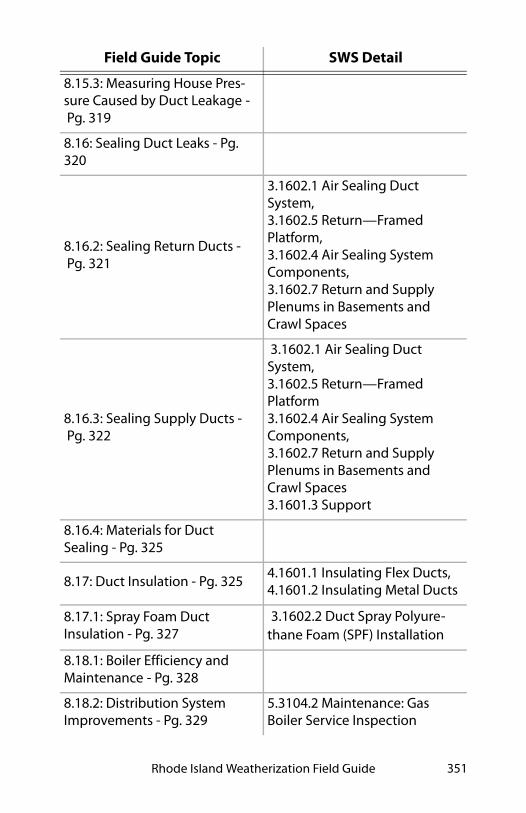
Rhode Island Weatherization Field Guide 351
8.15.3: Measuring House Pres-sure Caused by Duct Leakage -Pg. 319
8.16: Sealing Duct Leaks - Pg. 320
8.16.2: Sealing Return Ducts -Pg. 321
3.1602.1 Air Sealing Duct System, 3.1602.5 Return—Framed Platform, 3.1602.4 Air Sealing System Components, 3.1602.7 Return and Supply Plenums in Basements and Crawl Spaces
8.16.3: Sealing Supply Ducts -Pg. 322
3.1602.1 Air Sealing Duct System, 3.1602.5 Return—Framed Platform3.1602.4 Air Sealing System Components, 3.1602.7 Return and Supply Plenums in Basements and Crawl Spaces3.1601.3 Support
8.16.4: Materials for Duct Sealing - Pg. 325
8.17: Duct Insulation - Pg. 3254.1601.1 Insulating Flex Ducts, 4.1601.2 Insulating Metal Ducts
8.17.1: Spray Foam Duct Insulation - Pg. 327
3.1602.2 Duct Spray Polyure-thane Foam (SPF) Installation
8.18.1: Boiler Efficiency and Maintenance - Pg. 328
8.18.2: Distribution System Improvements - Pg. 329
5.3104.2 Maintenance: Gas Boiler Service Inspection
Field Guide Topic SWS Detail

Heating and Cooling Systems352
8.19: Steam Heating and Distribution - Pg. 332
8.19.1: Steam System Maintenance - Pg. 333
5.3104.3 Maintenance: Checklist
8.19.2: Steam System Energy Conservation - Pg. 334
8.20: Programmable Thermostats - Pg. 337
5.3104.1 Controls — Thermostat Replacement
8.21: Electric Heat - Pg. 338
8.21.1: Electric Baseboard Heat -Pg. 338
8.21.2: Electric Furnaces - Pg. 339
8.21.3: Central Heat-Pump Energy Efficiency - Pg. 339
8.21.4: Room Heat Pumps - Pg. 343
8.21.5: Ductless Minisplit Pumps - Pg. 345
8.21.6: Duct Leakage and Sys-tem Airflow - Pg. 346
8.21.7: Evaluating Heat-Pump Charge - Pg. 346
Field Guide Topic SWS Detail

Rhode Island Weatherization Field Guide 353
CHAPTER 9: VENTILATION
This chapter discusses ventilation, fans, termination fittings, and ducts. Before installing a ventilation system, read “Health and Safety” on page 21 for more information on controlling the sources of moisture and indoor air pollutants.
This chapter covers these types of ventilation.
• Local or spot ventilation
• Whole-house ventilation
• Attic and crawl space ventilation
• Ventilation for cooling
9.1 POLLUTANT CONTROL
Controlling pollutants at the source is the highest priority for good indoor air quality. Mechanical ventilation can dilute pol-lutants. However, ventilation is ineffective against prolific sources of moisture and pollutants. Ask these questions to eval-uate pollution sources.
• Do the occupants have symptoms of building-related ill-nesses? See also "Health and Safety" on page 21.
• Do sources of moisture like ground water, humidifiers, water leaks, or unvented space heaters cause indoor damp-ness, high relative humidity, or moisture damage? See “Gas Range and Oven Safety” on page 28.
• Are there combustion appliances, especially unvented ones, in the living space?
• Do the occupants smoke?
• Are there paints, cleaners, pesticides, gas or other chemi-cals stored in the home?

Ventilation354
9.1.1 Pollution-Control Checklist
Survey the home for pollutants before air-sealing the home. Per-form the following pollutant control measures if needed.
✓ Repair roof and plumbing leaks, with monitor approval.
✓ Install a ground moisture barrier over any bare soil in crawl spaces or dirt-floor basements.
✓ Verify that all dryer ducts and exhaust fans move their air to the outdoors.
✓ Verify that combustion-appliance vent systems operate properly.
✓ Verify that kitchen range hoods vent to the outdoors.
✓ Move paints, cleaning solvents, and other chemicals out of the conditioned space if possible.
The home’s occupants are often the source of many home pol-lutants, like candles and deodorizers. Educate the residents about minimizing pollutants in the homes.
9.2 ASHRAE STANDARD 62.2–2016 VENTILATION
Most dwellings in North America currently rely on air leakage for ventilation. The American Society of Heating, Refrigerating, and Air Conditioning Engineers (ASHRAE) publishes ventila-tion standards for dwellings.
Their current standard, ASHRAE 62.2–2016, defines the roles and minimum requirements for mechanical and natural ventila-tion systems and the building envelope. The roles and require-
SWS Details: 6.6005.1 Clothes Dryer, 6.6005.2 Kitchen Range
SWS Details: 6.6201.2 Primary Ventilation Air Flow between Rooms,

Rhode Island Weatherization Field Guide 355
ments intend to provide acceptable indoor air quality in residential buildings.
9.2.1 ASHRAE 62.2–2016 Components
If you air-seal dwellings during weatherization, you may need to install whole-dwelling mechanical ventilation systems under ASHRAE 62.2–2016, which has 3 components.
1. Whole-dwelling ventilation.
2. Local ventilation.
3. Natural infiltration credit.
This ventilation standard allows for natural infiltration (air leak-age) to contribute toward the required whole-dwelling ventila-tion rate for single-family homes.
9.2.2 Whole-Dwelling Ventilation Requirement
To comply with ASHRAE 62.2–2016, use either the formula or the table shown here to determine the whole-dwelling ventila-tion airflow requirement.
You can provide this mechanical airflow in 4 ways.
1. A dedicated exhaust or supply fan running continuously or cycling by automatic control.
2. A bathroom or kitchen exhaust fan running continu-ously or cycling by automatic control.
3. A central air handler drawing filtered outdoor air into its return.
SWS Details: 6.9901.1 Supplemental Ventilation Information—ASHRAE 62.2, 6.6204.1 Commissioning Ventilation Systems, 6.6201.2 Primary Ventilation Air Flow between Rooms, 6.6202.1 Controls, 6.6288.1 Sound-Rating Limits

Ventilation356
4. A balanced ventilation system such as a heat-recovery ventilator (HRV) or energy-recovery-ventilator (ERV).
Room Pressure Imbalances
If any room in the building exceeds ±3 pascals pressure with ref-erence to the common area when all interior doors are closed and while the ventilation system is operating, take action to reduce the pressure. Install transfer grilles or jumper ducts as needed to reduce the room to common area pressure difference to less than ±3 pascals. SWS Detail: 6.6201.2 Primary Ventilation Air Flow between Rooms
Ventilation Guidance
If the ventilation airflow requirement is less than 15 CFM, ASHRAE 62.2–2016 exempts the mechanical-ventilation requirement.
Residential Energy Dynamics provides a free online tool to help calculate ASHRAE 62.2–2016 ventilation rates.
Refer to the ASHRAE standard for more details, guidance, and exceptions that are beyond the scope of this field guide.
9.2.3 Local Exhaust Ventilation Requirement
There are two options for complying with the local ventilation requirements for kitchens and bathroom: demand-controlled exhaust or continuous exhaust.
1. For demand-controlled exhaust specify a minimum of 100 CFM for the kitchen, and 50 CFM for each bath-room. An operable window reduces a bathroom’s venti-lation requirement to 30 CFM.
SWS Detail: 6.6002.3 Exhaust-Only Ventilation—Fan Intake Grille Location, 6.6003.3 Through the Wall, 6.6005.2 Kitchen Range

Rhode Island Weatherization Field Guide 357
2. For continuous exhaust specify a minimum of 20 CFM for each bathroom, and 5 ACH for the kitchen (based on volume).
Local Exhaust Deficit
If the existing kitchen or bathroom ventilation doesn’t meet the requirements stated here, you may adjust the whole-dwelling ventilation rate to compensate for the local airflow deficits. Fol-low these steps to calculate the local-ventilation deficit in CFM that must be added to the whole-dwelling ventilation rate.
1. Determine the total local exhaust ventilation require-ment for all kitchens and bathrooms.
2. Measure the delivered airflow of existing kitchen or bathroom exhaust fans using flow hood, flow grid, or other airflow measuring device. Subtract this amount from the total local exhaust ventilation requirement.
3. If the local jurisdiction allows for operable windows to provide for local ventilation, subtract 20 CFM for each kitchen or bathroom that has an operable window.
The result of these steps is the local exhaust ventilation deficit in CFM. Add 1/4 of this deficit to the required whole-dwelling ven-tilation rate.
Measuring fan airflow: Use an exhaust-fan flow meter or a flow hood to verify the airflows through local exhaust fans and whole-building ventilation fans.

Ventilation358
9.2.4 Infiltration Credit
ASHRAE 62.2–2016 allows for infiltration to contribute to the dwelling’s ventilation airflow. Infiltration can supply the entire whole-dwelling ventilation requirement for very leaky build-ings. For moderately leaky buildings, infiltration may supply some of the building’s ventilation.
Single-family buildings are eligible for the infiltration credit.
You can determine the amount of the infiltration credit with a blower door test and weather data based on the building’s loca-tion. Calculating the infiltration credit without software is com-plicated. To simplify the calculations, use the RED Calc Free online tool and select “yes” for the “Use the infiltration credit” option.
9.3 FAN AND DUCT SPECIFICATIONS
This section covers fan and duct specifications for both local ventilation and whole-building ventilation. Duct sizing, materi-als, and installation determine whether airflow meets the design amount (CFM). Most existing exhaust fans and ventilation sys-tems don’t achieve their design airflow because of installation flaws.
9.3.1 Fan Specifications
Continuous ventilation is highly recommended because it sim-plifies design and control. Continuous ventilation also mini-mizes depressurization by allowing selection of the minimum-sized fan. Exhaust fans, installed as part of weatherization work, must vent to outdoors and should include the following features.
SWS Detail: 6.6003.1 Surface-Mounted Ducted, 6.6003.2 Inline, 6.6003.3 Through the Wall, 6.6003.4 Multi-Port System, 6.6003.5 Garage Exhaust Fan, 6.6288.1 Sound-Rating Limits
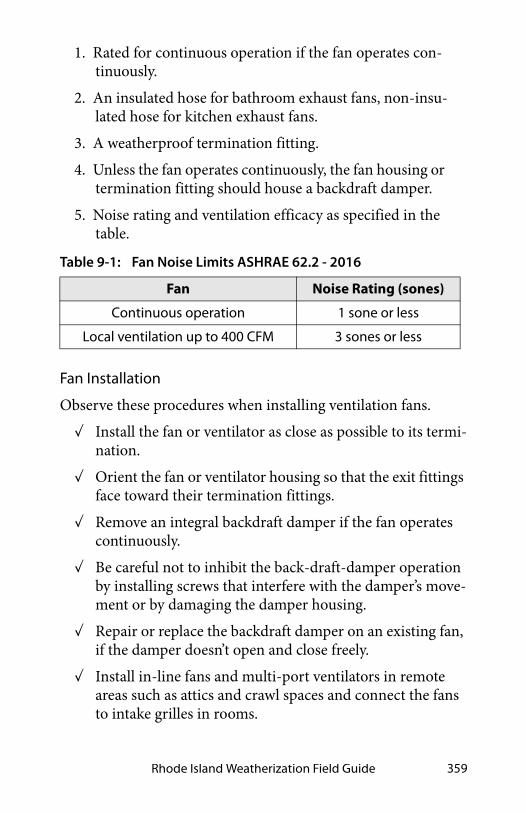
Rhode Island Weatherization Field Guide 359
1. Rated for continuous operation if the fan operates con-tinuously.
2. An insulated hose for bathroom exhaust fans, non-insu-lated hose for kitchen exhaust fans.
3. A weatherproof termination fitting.
4. Unless the fan operates continuously, the fan housing or termination fitting should house a backdraft damper.
5. Noise rating and ventilation efficacy as specified in the table.
Fan Installation
Observe these procedures when installing ventilation fans.
✓ Install the fan or ventilator as close as possible to its termi-nation.
✓ Orient the fan or ventilator housing so that the exit fittings face toward their termination fittings.
✓ Remove an integral backdraft damper if the fan operates continuously.
✓ Be careful not to inhibit the back-draft-damper operation by installing screws that interfere with the damper’s move-ment or by damaging the damper housing.
✓ Repair or replace the backdraft damper on an existing fan, if the damper doesn’t open and close freely.
✓ Install in-line fans and multi-port ventilators in remote areas such as attics and crawl spaces and connect the fans to intake grilles in rooms.
Table 9-1: Fan Noise Limits ASHRAE 62.2 - 2016
Fan Noise Rating (sones)
Continuous operation 1 sone or less
Local ventilation up to 400 CFM 3 sones or less

Ventilation360
✓ Isolate in-line fans and multi-port ventilators from fram-ing to minimize noise.
✓ Measure the fan airflow to verify compliance with Stan-dard 62.2 - 2016.
9.3.2 Termination Fittings
SWS Detail: 6.6002.2 Terminations, 6.6102.2 Intakes
Advanced 4-speed range fan: Lower speeds for continuous ventilation and higher ones for spot ventilation.
Two- or variable-speed fan: An occupancy sensor toggles between speeds. A 6-inch outlet provides airflow for whole-building ventilation.
In-line fan in attic: A Y guides exhaust airflow from two bathrooms for both local exhaust and whole-building ventilation.

Rhode Island Weatherization Field Guide 361
Termination fittings for intake and exhaust ducts must exclude pests and water. Termination fittings must comply with these specifications.
✓ Termination fitting must direct water away from its open-ing.
✓ Flash or weather-seal termination fittings.
✓ Termination fittings must have insect screens over the openings.
✓ The termination-fitting collar must be the same diameter as the exhaust or intake fitting on the fan.
✓ If the fan has no backdraft damper and the fan operates intermittently, install a termination fitting with a backdraft damper, to operate in the direction of airflow.
✓ Fasteners must not interfere with backdraft-damper oper-ation.
PVC elbow: This screened PVC elbow is an intake fitting for an HRV.
Termination fitting: If the fan operates intermittently, the termination fitting or the fan must have a backdraft damper.

Ventilation362
Locating Termination Fittings
Locate termination fittings using these specifications.
✓ At least 6 inches above grade
✓ At least 10 feet from another fan termination
✓ Above local snow or flood line
✓ At least18 inches above a sloped asphalt based roof
✓ Never on a flat roof
✓ As required by local building authority
✓ Exhaust terminations must be at least 4feet away from an operable window, an exterior door, or the property line.
9.3.3 Duct Sizing
Fans often fail to deliver their rated airflow capacity. Bends, un-straight flex duct, dirty grills, and backdraft dampers can reduce design airflow by 50% or more.
If you follow the sizing in this table, you may achieve the fan’s rated airflow for short duct runs with a maximum of two elbows.
For more detailed duct-sizing recommendations, see“ASHRAE 62.2 Duct Sizing” on page 472.
Table 9-2: Round Duct Diameters (inches) for Desired Airflows
DesiredCFM
25 50 75 100 150 200
Rigid 4 5 6 7 8 9
Flex duct 5 6 7 8 9 10
Friction rate = 0.05; maximum equivalent length =100 feet

Rhode Island Weatherization Field Guide 363
9.3.4 Duct Materials and Installation
This sections covers SWS requirements and best practices for installing ventilation ducts connected to exhaust fans, ventila-tors, and air handlers.
See also "Sealing Duct Leaks" on page 320.
Rigid Duct Installation
Observe these best practices for installing rigid ventilation ducts.
✓ Prefer rigid smooth metal pipe (30 gauge or thicker) or plastic pipe (Schedule 30 or thicker) for ventilation duct.
✓ Limit elbows to a maximum of two per duct run.
✓ Use three equally spaced sheet-metal screws to fasten sec-tions of round metal duct together.
✓ Join rigid duct sections so the edge of male end of a duct section isn’t opposing airflow.
✓ Follow manufacturer’s instructions to join other types of rigid ducts together.
✓ Seal all rigid-duct joints and seams with mastic, mastic and webbing, labeled UL181B or UL181B-M. See “Sealing Duct Leaks” on page 320.
✓ Support metal ducts with at least 1/2-inch, 18 gage strap-ping or at least 12-gage galvanized wire, not less than 10 feet apart.
SWS Detail: 6.6002.1 Ducts, 6.6002.2 Terminations, 6.6003.2 Inline, 6.6003.1 Surface-Mounted Ducted, 6.6003.4 Multi-Port System, 6.6005.2 Kitchen Range, 6.6102.1 Outside Air Ventilation Supply Ducts, 6.6102.2 Intakes, 6.6103.1 Inline or Multi-Port, 6.6202.2 Heat Recovery Ventilator (HRV) and Energy Recovery Ventilator (ERV) Installation

Ventilation364
✓ Insulate metal ducts to R-8 to prevent condensation if they travel through unconditioned spaces. See “Duct Insula-tion” on page 325.
✓ Fasten PVC exhaust ducts together with approved PVC cement.
Flexible Duct Installation
Observe these best practices for installing flexible ducts.
✓ Stretch flex duct and support it every 4 feet with a 1.5-inch duct support, at maximum length of 10 feet.
✓ Use tool-tensioned plastic tie bands to join both the inner liner and the outer liner of the flex duct to the rigid duct or a fitting on the fan or termination fitting.
✓ Install a screw to secure the flex duct and tie band to the metal duct between the tie band and the end of the metal duct.
✓ Flexible air duct material must meet UL 181, NFPA 90A/90B, International Mechanical Code, or the Uniform Mechanical Code.
Flex duct joint to metal: Seal the metal takeoff to the main duct. Seal the inner liner of the flex duct to the takeoff with a tool-tensioned tie band.
tie band
takeoff
flex duct
main ductmastic

Rhode Island Weatherization Field Guide 365
9.4 COMMISSIONING VENTILATION SYSTEMS
Commission new, retrofitted and serviced whole-dwelling ven-tilation systems to verify that the systems function according to design and the ASHRAE 62.2 standard.
✓ Verify that all the required ventilation-system components are present and connected correctly.
✓ Use airflow and pressure manometers that are appropriate for the operating range and that render accuracy of ± 10%.
✓ Measure total airflow, room airflows, and total static pres-sure to verify that these measurements are within design specifications.
✓ Adjust fan speed, dampers, and registers as necessary to bring airflow into conformance with design specifications.
✓ Verify that all sensors and controls function correctly.
9.5 WHOLE-DWELLING VENTILATION SYSTEMS
This section discusses three options for design of whole-dwell-ing ventilation systems.
✓ Exhaust ventilation
✓ Supply ventilation
✓ Balanced ventilation
See “Fan and Duct Specifications” on page 358.
We begin by discussing ducts for all types of ventilation systems.
9.5.1 Exhaust Ventilation
SWS Detail: 6.6204.1 Commissioning Ventilation Systems, 6.6201.4 Balancing—Makeup/Outside Air (All Building Types)
SWS Detail: 6.6201.1 Installed System Air Flow

Ventilation366
Exhaust ventilation systems employ an exhaust fan to remove indoor air, which is replaced by infiltrating outdoor air.
Installing a two-speed bathroom fan is a common ventilation strategy. The new fan runs continuously on low speed for whole-building ventilation.
A remote fan that exhausts air from several rooms through ducts (4-to-6 inch diameter) may provide better ventilation for larger more complex homes, compared to a single-point exhaust fan.
✓ Fans must conform to “Fan Specifications” on page 358
✓ Ducts must conform to “Duct Materials and Installation” on page 363.
✓ Termination fittings must conform to“Termination Fit-tings” on page 360.
Exhaust ventilation systems create a negative house pressure, drawing outdoor air in through leaks in the shell. This keeps moist indoor air from traveling through building cavities, which would occur with a positive house pressure. The negative house pressure reduces the likelihood of moisture accumulation in building cavities during the winter months in cold climates.
LIVING ROOM
KITCHEN
BA THROOM BEDROOM
–
– –
–
Multi-port exhaust ventilation: A multi-port ventilator creates better fresh-air distribution than a single central exhaust fan.

Rhode Island Weatherization Field Guide 367
9.5.2 Exhaust Ventilation
Exhaust ventilation systems employ an exhaust fan to remove indoor air, which infiltrating outdoor air then replaces.
Installing a two-speed bathroom fan is a common ventilation strategy. The new fan runs continuously on low speed for whole-building ventilation. A built-in occupancy sensor switches the fan automatically to a high speed to remove mois-ture and odors from the bathroom quickly.
A remote fan that exhausts air from several rooms through ducts (4-to-6 inch diameter) may provide better ventilation for larger more complex dwellings, compared to a single-point exhaust fan.
Exhaust ventilation systems create a negative house pressure, drawing outdoor air in through leaks in the shell. This keeps moist indoor air from traveling through building cavities, which would occur with a positive building pressure. The negative building pressure reduces the likelihood of moisture accumula-
SWS Detail: 6.6003.2 Inline, 6.6004 Exhaust Ventilation Systems, 6.6202.1 Controls, 6.6004.2 Individual Exhaust Fan Serving Mul-tiple Rooms Within Single Dwelling Unit (All Building Types), 6.6004.1 Central/Common Exhaust Fan Serving Multiple Dwell-ing Units via Common Duct(s) and Dwelling Unit Branches
LIVING ROOM
KITCHEN
BA THROOM BEDROOM
–
– –
–
Multi-port exhaust ventilation: A multi-port ventilator creates better fresh-air distribution than a single central exhaust fan.

Ventilation368
tion in building cavities during the winter months in cold cli-mates.
In hot and humid climates, however, this depressurization can draw moist outdoor air into the home through building cavities. Therefore we recommend supply ventilation for warm humid climates rather than exhaust ventilation.
Single-Family Exhaust-Ventilation-System Specifications
✓ Fans must conform to “Fan Specifications” on page 358.
✓ Ducts must conform to “Duct Materials and Installation” on page 363.
✓ Termination fittings must conform to“Termination Fit-tings” on page 360.
Multi-room Exhaust-Ventilation-System Specifications
✓ Evaluate the seal between the roof-mounted ventilator and the its ducts and the roof.
✓ Evaluate ventilation-duct chases for air leakage.
✓ Install backdraft dampers on intermittently operating sys-tems.
✓ Measure airflow through registers to ensure a correct air-flow rate. Adjust register size if necessary to decrease or increase ventilation airflow.
✓ Adjust ventilator airflow if building ventilation airflow is either excessive or insufficient.
✓ Insulate ducts outside the thermal boundary to R-8.
✓ Educate occupants on maintenance procedures.
9.5.3 Supply Ventilation
SWS Detail: 6.6102.3 Intake for Ventilation Air to Forced Air System Used for Heating or Cooling

Rhode Island Weatherization Field Guide 369
Supply ventilation, using the home’s air handler, is never oper-ated continuously as with exhaust ventilation because the fur-nace or heat-pump blower is too large and would over-ventilate the home and waste electrical energy. Supply ventilation may not be appropriate for tight homes in very cold climates because supply ventilation can push moist indoor air through exterior walls, where moisture can condense on cold surfaces.
Motorized Outdoor-Air Damper
A motorized damper that opens when the air-handler blower operates must control outdoor-air supply. The furnace/air con-ditioner heats or cools the outdoor air as necessary before deliv-ering it to the living spaces.
The damper control estimates how much ventilation air is needed. The damper closes after the required amount of ventila-tion air has entered during heating or cooling. The control also activates the damper and the blower for additional ventilation air as needed without heating or cooling the air, during mild weather.
Supply-Ventilation System Requirements
Supply ventilation typically uses the furnace or heat pump as a ventilator. A 5-to-10 inch diameter duct connects the furnace’s main return duct to a termination outdoors.
✓ The existing duct system must leak less than 10% of the air handler flow when measured at 25 Pa. WRT outside.
+
+ +
+ +
Supply ventilation: A furnace or heat pump with an outside air duct intake is used for ventilation with a control that ensures sufficient ventilation.

Ventilation370
✓ The outdoor air must flow through a MERV 6 or better air filter before flowing through heating and cooling equip-ment.
✓ Ducts must conform to “Duct Materials and Installation” on page 363.
✓ Termination fittings must comply with“Termination Fit-tings” on page 360.
9.5.4 Balanced Ventilation
This information is not applicable to Rhode Island, but provided for educational purposes. Balanced ventilation systems exhaust stale air and provide fresh air through a ducted distribution sys-tem. Of the three ventilation systems discussed here, balanced systems do the best job of controlling pollutants in the home.
Balanced systems move equal amounts of air into and out of the home. Most balanced systems incorporate heat-recovery venti-lators or energy-recovery ventilators that reclaim heat and mois-ture from the exhaust air stream.
Balanced ventilation systems can improve the air quality and comfort of a home, but they require a high standard of care. Testing and commissioning is vital during both the initial instal-lation and periodic service calls.
SWS Detail: 6.6202.2 Heat Recovery Ventilator (HRV) and Energy Recovery Ventilator (ERV) Installation
Centralized balanced ventilation: Air is exhausted from areas most likely to contain pollutants and fresh air is supplied to living areas.

Rhode Island Weatherization Field Guide 371
Heat-Recovery and Energy-Recovery Ventilators
The difference between heat-recovery ventilators (HRVs) and energy-recovery ventilators (ERVs) is that HRVs transfer heat only, while ERVs transfer both sensible heat and latent heat (moisture) between air streams.
HRVs are often installed as balanced whole-building ventilation systems. The HRV core is an air-to-air heat exchanger in which the supply and exhaust air streams pass one another and exchange heat without mixing.
9.5.5 Adaptive Ventilation
The home’s residents can maintain good indoor air quality by using spot ventilation together with opening windows and doors. Depending on climate and season, residents can control natural ventilation to provide clean air, comfort, and energy effi-ciency.
✓ Choose windows and screen doors in strategic locations to ventilate using prevailing winds.
✓ Make sure that windows and screen doors, chosen for ven-tilation, open and close and have effective insect screens.
Heat-recovery ventilator: Heat from the exhaust air heats a plastic or aluminum heat exchanger, which in turn heats the fresh intake air. Two matched fans provide balanced ventilation.

Ventilation372
✓ Open windows to provide make-up air when an exhaust fan or the clothes dryer is operating.
✓ Understand that dust and pollen may enter through win-dows or screen doors and consider the consequences.
9.5.6 Rooftop-Unit (RTUs) Economizer Ventilation
Many buildings, particularly those with RTUs use economizers as their ventilation system. Economizers don’t normally have heat recovery or energy recovery function, so ventilating with an economizer can have an energy penalty compared to a heat recovery ventilators.
Mild climates are ideal for ventilating with an economizer. When buildings use an economizer for ventilation, its dampers are open a small amount while the HVAC system is heating, cooling, or operating on the fan-only option. The fan-only option is for when you need ventilation but not heating or cool-ing.
To run optimally, the economizer requires a programmable thermostat that tracks the amount of ventilation air delivered during the free cooling mode and during the ventilation mode.
9.6 GARAGE EXHAUST VENTILATION
SWS Detail: 6.6104.1 Outdoor Supply Air Handling Unit Serving Multiple Dwelling Units or Corridors (All Building Types), 6.6104.2 Outdoor Intake to Forced Air System—One System per Dwelling (All Building Types), 6.6102.3 Intake for Ventilation Air to Forced Air System Used for Heating or Cooling, 6.6202.9 Filtra-tion for Fan-Powered (Active) Systems
SWS Detail: 6.6004.3 Garage Exhaust Fan (All Building Types), 6.6003.5 Garage Exhaust Fan, 6.6003.1 Surface-Mounted Ducted

Rhode Island Weatherization Field Guide 373
Attached garages, particularly garages beneath living areas, may require exhaust ventilation to prevent indoor CO contamina-tion. Only consider garage exhaust ventilation when all attempts to air-seal the garage from the house have been insufficient.
• Use pressure diagnostics to assist in determining the level of connection from the garage to the house and in making the determination for the need to add garage ventilation.
• For single family homes, install 100-CFM-capacity exhaust fans on the exterior wall or surface mounted inside the garage.
• Make sure the fan doesn’t cause an unacceptable depressur-ization in a nearby CAZ. Provide pressure-relief if neces-sary.
• Operate the fan using an occupancy sensor with a 15-min-ute runtime or continuous for larger garages as necessary.
See also "Garages Underneath Living Areas" on page 187.
Multifamily exhaust ventilation system: Many multifamily buildings have vertically ducted exhaust ventilation systems with registers opening to kitchens and bathrooms on each floor.
Roof-mounted ventilator

Ventilation374
9.7 AIR FILTRATION FOR INDOOR AIR QUALITY
Efficient air filters can reduce particle pollution in homes where particles are a air-quality problem. Ventilation isn’t effective at removing small particles. Suggest that customers run their air handlers during heavy air pollution in cities, proximity to dirt roads, seasonal forest fires, and other particle-generating events.
You can run an air-handler fan using the “fan only” setting on a thermostat. You can even program the fan to run for a period each day using a programmable thermostat.
The best places for filters are in forced-air HVAC systems or in balanced ventilation systems. Room air cleaners can also be effective particle removers if there is natural circulation among rooms.
Air filters affect the airflow and energy consumption of forced air HVAC systems and balanced ventilation systems. Before choosing the type of air filter and deciding to use the filter to remove particles, consider the filter’s MERV rating and a home’s need for particle removal. For more information on MERV rat-ings, see “Air Filter Effectiveness” on page 310.
9.7.1 Installing Filters for Outdoor Air
Provide filters for outdoor air supplied through ducted ventila-tion systems and observe these specifications.
✓ Select a filter with a MERV rating of 6 or greater.
✓ The filter’s pressure drop must not result in insufficient ventilation airflow.
✓ Install the filter on the inlet side of the fan.
✓ Make the filter accessible for changing or cleaning.
✓ Instruct the occupants or building manager on how and when to service the filter.
SWS Detail: 6.6202.9 Filtration for Fan-Powered (Active) Systems
Rhode Island Weatherization Field Guide 375
9.8 ATTIC VENTILATION
Attic ventilation has the following functions.
• To keep the attic insulation and the attic’s other building materials dry by circulating dry outdoor air through the attic.
• To prevent ice dams in cold weather by preventing snow melt by keeping the roof deck cold during the winter.
• To remove solar heat from the attic during the summer.
9.8.1 Attic Ventilation as a Solution for Moisture Problems
The best way to keep attic insulation dry is to air-seal the attic floor to block moist air from entering the attic. Adding attic vents may help to solve certain attic moisture problems.
• Seasonal moisture deposition removed by vents.
• Ice damming in areas that currently lack high and low vents.
Adding attic vents won’t solve these attic moisture problems.
• Moisture deposited by air leaks between the living space and the attic.
• Rain driven through attic vents.
• Roof leaks that dampen building materials beyond the capacity of the vents to dry.
9.8.2 When to Install Attic Ventilation
Install more attic ventilation only if you believe that the home needs one of the attic-ventilation functions listed above. Con-sider the following discussion points.
SWS Detail: 4.1088.1 Attic Ventilation
Ventilation376
• Don’t increase attic ventilation without first sealing attic air leaks and testing the attic air barrier for adequate airtight-ness.
• Avoid cutting new vents through the roof to avoid the pos-sibility of roof leaks.
• Attic ventilation may not provide a useful function in some climates, such as persistently damp climates or windy, rainy climates.
Important note: An outright exception to ventilating attics is offered by the IRC if a code official determines that “atmo-spheric or climatic conditions” aren’t favorable to attic ventila-tion.
9.8.3 Attic Ventilation Requirements
Always vent exhaust fans directly to outdoors (through a soffit, gable, or wall) and never into a ventilated attic.
Net free area is the area of the vent minus the vent’s solid obstructions such as screens and louvers. The net free area is typically 50% to 70% of the gross vent area.
The IRC and SWS state these requirements for attic ventilation.
✓ Provide a maximum ratio of one square foot of net free vent area to 150 square feet of attic area.
✓ The IRC requires only one square foot of net free area per 300 square feet of attic area for cool-climate ceilings, that have an interior vapor barrier, or well distributed ventila-tion (high and low), or with thorough air-sealing of the ceiling.
✓ Vents must have screens, with 1/4-to-1/16 inch or less open-ing, to prevent the entry of pests and to reduce the entry of snow and rain.
✓ Vertical vents must have louvers to deflect rain.

Rhode Island Weatherization Field Guide 377
✓ Install vent chutes or baffles to prevent blown insulation from entering the space between soffit vents and the attic. The baffles should allow the maximum amount of insula-tion to be installed over top plates without restricting ven-tilation paths. Vent chutes or baffles also help prevent the wind-washing of insulation caused by cold or hot air entering soffit vents. They should extend upwardly along the rafter to at least 4 inches above the finished insulation level.
✓ Don’t use powered ventilators to increase attic ventilation because of their energy consumption and doubtful effec-tiveness.
High and Low Vents
A combination of high and low vents is the best way to move ventilating air through the attic. Soffit vents and ridge vents are an ideal combination for high-low attic ventilation. However, gable vents and roof vents, located high or low, also create acceptable ventilation.
Soffit chute or baffle: Install a maximum amount of insulation that the baffle allows. The chute prevents wind-washing and conveys the ventilation air over the insulation. The distributed vents ventilate the whole surface of the insulation and cool the whole roof in winter, preventing ice damming.
distributed ventila
tion

Ventilation378
9.8.4 Unventilated Attics
According to the IRC, new attics may be unventilated if the two conditions listed here are both met.
1. There is no vapor barrier installed in the ceiling.
2. The roof assembly is insulated with an air-impermeable insulation, such as high-density sprayed polyurethane, to the bottom of the roof sheathing or foam board on the top side of the roof sheathing.
9.9 CRAWL SPACE VENTILATION
Before taking steps to improve crawl-space ventilation, comply with these requirements.
✓ The crawl space should have an access hatch or door that is adequate for a worker or resident to enter or exit.
✓ Correct drainage and gutter-and-downspout problems related to crawl-space moisture problems.
✓ Install a ground moisture barrier as specified in “Crawl Space Moisture and Safety Issues” on page 36.
SWS Detail: 2.0401.2 Vented Crawl Space—Venting, 2.0111.2 Crawl Spaces—Pre-Work Qualifications, 2.0111.3 Crawl Spaces—Debris Removal, 2.0404.3 Closed Crawl Spaces—Crawl Space Conditioning, 2.0701.1 Crawl Spaces—Providing Access
Low and high attic ventilation: Distributed ventilation — high and low — is more effective than vents that aren’t distributed.

Rhode Island Weatherization Field Guide 379
9.9.1 Naturally Ventilated Crawl Spaces
9.9.2 Power-Ventilated Crawl Spaces
The IRC allows you to seal the crawl-space vents completely when you insulate the foundation walls and power-ventilate the crawl space. These three specifications apply to power-venti-lated or conditioned crawl spaces.
1. Remove moisture sources like standing water and install a seam-sealed and edge-sealed ground-moisture bar-rier, before sealing the foundation vents.
2. The IRC requires 1 CFM per 50 square feet of crawl space floor area in continuous powered exhaust ventila-tion. The IRC requires openings from the crawl space into the home so that make-up air comes from the liv-ing space. Some installers depend on floor air leakage to provide make-up air instead of intentional openings between the home and crawl space.
3. An acceptable alternative to option 2is controlling the exhaust fan with a dehumidistat (moisture sensitive control). Such an exhaust fan typically operates contin-uously until the crawl space is dry and then intermit-tently after that. This option isn’t IRC-approved.
SWS Detail: 2.0401.1 Air Sealing Moisture Precautions, 2.0403.3 Closed Crawl Spaces—Vapor Retarders on Walls
SWS Detail: 2.0401.1 Air Sealing Moisture Precautions

Ventilation380
9.9.3 Whole-House Fans
Whole-house fans range in diameter from 24 inches to 42 inches, with capacities ranging from 3,000 to 10,000 cubic feet per minute (cfm). The capacity of the fan in cfm is rated for two different conditions: 1) free air; and 2) air constricted by 1 inch of static pressure. The second condition is closer to the actual operating conditions of the fan in a home, and the cfm rating at 1 inch of static pressure may still be 10 to 30 percent higher than the actual volume of air moved by the installed whole-house fan. This means you should probably install a fan with a greater capacity than the sizing recommendations that follow.
Whole-house fans require 2 to 4 times the normal area of attic vent openings. Install a minimum of 1 square foot of net free area for every 750 cfm of fan capacity. However, more vent area is better for optimal whole-house-fan performance because the extra vent area increases airflow.
Modern whole-house fans: Modern models feature multiple speeds, tight-sealing insulated enclosures, and quiet operation

Rhode Island Weatherization Field Guide 381
To estimate the suitable size of a whole-house fan in cubic feet per minute, first determine the volume of your home in cubic feet. To calculate volume, multiply the square footage of the floor area in your home that you want to cool by the height from floor to ceiling. Take that volume and multiply by 15 to 40 air changes per hour, depending on how much ventilation you want. Then, divide by 60 minutes to get cubic feet per minute of capacity for the whole-house fan.
Some fans come with a tight-sealing winter cover. If the fan doesn’t have such a cover, or if the attic access doesn’t allow you to cover the fan easily, then you can fabricate a cover for the grille on the ceiling. A seasonal cover, held in place with rotating clips or spring clips and sealed with foam tape, works well. If the clients switch between air conditioning and cooling with a whole-house fan as the summer weather changes, build a tightly-sealed, hinged door for the fan opening that is easy to open and close when they switch cooling methods.
Whole-house fan circulation: the whole-house fan sucks air out of the house and exhausts it into the attic or through a gable wall. Cooler air enters the windows as make-up air for the fan.
Fan Airflow(CFM) = House volume X 15-40 ACH60

Ventilation382
9.9.4 Window Fans
Educate clients on changing fan direction for seasonal use. Win-dow fans are best used in windows facing the prevailing wind or away from it to provide cross ventilation. Window fans can aug-ment any breeze or create a breeze when the air is still. If the wind direction changes in your area, use reversible type window fans so you can either pull air into the home or push air out, depending on which way the wind is blowing. Experiment with positioning the fans in different windows to see which arrange-ment works best.
Air-sealed and dammed whole-house fan: The whole-house fan must be dammed like an attic access hatch with air sealing and insulation to prevent excessive heat loss or gain.
Ceiling fans: Ceiling fans cool people by convecting air next to their skin and helping evaporate sweat.
Window fans: Window fans circulate outdoor air when it is cooler than indoor air. The air circulation removes heat from the house.

Rhode Island Weatherization Field Guide 383
9.9.5 Air Circulation
Air circulating fans are very effective cooling energy savers. Air circulating fans may allow a 4 degree rise in the thermostat set-ting with no decrease in comfort.
Use circulating fans with air conditioners, evaporative coolers, whole-house fans, or by themselves. Circulating fans save cool-ing energy by increasing air movement over the skin to help occupants feel cooler.
Ceiling fans and various types of portable fans provide more comfort at less cost than any other electrically powered cooling strategy. Options include: small personal fans that sit on table-tops, or heavier units that sit on the floor or on metal stands with wheels.
Ceiling fans produce high air speeds with less noise than oscil-lating fans or box fans. High quality ceiling fans are generally more effective and quieter than cheaper ones. Ceiling fans are a key element to providing low-cost comfort to a home.
9.10 SWS ALIGNMENT
Field Guide Topic SWS Detail
9.1: Pollutant Control - Pg. 353
9.1.1: Pollution-Control Checklist - Pg. 354
6.6005.1 Clothes Dryer,6.6005.2 Kitchen Range
9.2: ASHRAE Standard 62.2–2016 Ventilation - Pg. 354
6.6201.1 Installed System Air Flow

Ventilation384
: This ventilation standard allows for natural infiltration (air leak-age) to contribute toward the required whole-dwelling venti-lation rate for single-family homes. - Pg. 355
6.6201.1 Installed System Air Flow,6.9901.1 Supplemental Ventilation Information—ASHRAE 62.2,6.6204.1 Commissioning Existing Exhaust or Supply Ventilation Systems,6.6201.2 Primary Ventilation Air Flow between Rooms
9.2.3: Local Exhaust Ventilation Requirement - Pg. 356
6.6201.1 Installed System Air Flow6.6005.2 Kitchen Range
9.3: Fan and Duct Specifications - Pg. 358
9.3.1: Fan Specifications - Pg. 358
6.6003.1 Surface-Mounted Ducted, 6.6003.2 Inline, 6.6003.3 Through the Wall, 6.6003.4 Multi-Port System, 6.6003.5 Garage Exhaust Fan6.6288.1 Sound-Rating Limits
9.3.2: Termination Fittings - Pg. 360
6.6002.2 Terminations6.6102.2 Intakes
9.3.3: Duct Sizing - Pg. 362
Field Guide Topic SWS Detail

Rhode Island Weatherization Field Guide 385
9.3.4: Duct Materials and Installation - Pg. 363
6.6002.1 Ducts, 6.6002.2 Terminations, 6.6003.2 Inline, 6.6003.1 Surface-Mounted Ducted, 6.6003.4 Multi-Port System, 6.6005.2 Kitchen Range, 6.6102.1 Outside Air Ventilation Supply Ducts, 6.6102.2 Intakes, 6.6103.1 Inline or Multi-Port, 6.6202.2 Heat Recovery Ventilator (HRV) and Energy Recovery Ventilator (ERV) Installation
9.5: Whole-Dwelling Ventilation Systems - Pg. 365
9.5.1: Exhaust Ventilation - Pg. 365
6.6201.1 Installed System Air Flow
9.5.3: Supply Ventilation - Pg. 368
6.6102.3 Intake for Ventilation Air to Forced Air System Used for Heating or Cooling
9.5.4: Balanced Ventilation - Pg. 370
6.6202.2 Heat Recovery Ventilator (HRV) and Energy Recovery Ventilator (ERV) Installation
9.5.5: Adaptive Ventilation - Pg. 371
9.8: Attic Ventilation - Pg. 375 4.1088.1 Attic Ventilation
9.8.1: Attic Ventilation as a Solu-tion for Moisture Problems - Pg. 375
9.8.2: When to Install Attic Ventilation - Pg. 375
Field Guide Topic SWS Detail

Ventilation386
9.8.3: Attic Ventilation Requirements - Pg. 376
9.8.4: Unventilated Attics - Pg. 378
9.9: Crawl Space Ventilation - Pg. 378
2.0401.2 Vented Crawl Space—Venting, 2.0111.2 Crawl Spaces—Pre-Work Qualifications, 2.0111.3 Crawl Spaces—Debris Removal, 2.0404.3 Closed Crawl Spaces—Crawl Space Conditioning, 2.0701.1 Crawl Spaces—Providing Access
9.9.1: Naturally Ventilated Crawl Spaces - Pg. 379
2.0401.1 Air Sealing Moisture Precautions, 2.0403.3 Closed Crawl Spaces—Vapor Retarders on Walls
9.9.2: Power-Ventilated Crawl Spaces - Pg. 379
2.0401.1 Air Sealing Moisture Precautions
9.9.3: Whole-House Fans - Pg. 380
9.9.4: Window Fans - Pg. 382
9.9.5: Air Circulation - Pg. 383
Field Guide Topic SWS Detail

Rhode Island Weatherization Field Guide 387
CHAPTER 10: BASELOAD MEASURES
In Rhode Island, baseload measures are installed through the National Grid AMP program. Customers inquiring about base-load measures will be referred to their local CAP agency.
Baseload energy consumption accounts for a large part of home energy use. This should be understood by energy professionals. This chapter is provided for your information and reference. It discusses energy savings for refrigeration, entertainment, light-ing, laundry, and water heating.
Table 10-1: Levels of Household Electric Baseload Consumption
Indicator Low Medium High
kWh per Year <4500 4500–8500 >8500
kWh per Month <375 375–700 >700
kWh per Day <12 12–23 >23
kWh per Person (Annual) <1900 1900–3500 >3500
Doesn’t include heating, cooling, or water heating. Assumes 2.4 per-sons per household and average annual consumption of 6500 kWh per household.
Baseload Energy Consumption: These baseload usage percents are, of course, different for every dwelling unit. However this chart gives an ides of a typical distribution. Miscellaneous electrical loads or MELs can be up to half of total baseload consumption.
Laundry
Kitch
en
Dryer Wa
she
r
Lig
hti
ng
Miscellaneous
electrical loads
(MELs)
Dishwasher
Kitch
en R
ang
e
Refrigerator/Freezer50%
2%
23
%
24%
4%
4%
8%
12%
19%

Baseload Measures388
10.1 BASELOAD VERSUS SEASONAL USE
We divide home energy usage into two categories: baseload and seasonal. Baseload includes water heating, lighting, refrigerator, and other appliances used year round. Seasonal energy use includes heating and cooling. You should understand which of the two is dominant as well as which types of baseloads and sea-sonal loads are the highest energy consumers.
Many homes are supplied with both electricity and at least one source of combustion fuel. Electricity can provide all seasonal and baseload energy, however most often there is a combination of electricity and natural gas, oil, or propane. The auditor must understand whether loads like the heating system, clothes dryer, water heater, and kitchen range are serviced by electricity or by fossil fuel.
Table 10-2: Electrical Consumption of Typical Appliances
ApplianceAnnual usage
(kWh) Annual cost
Ten-year-old refrigera-tor or freezer
1250 $188
New ENERGY STAR refrigerator or freezer
500 $75
Television 100–1000 $15–$150
Clothes dryer 1200 $180
Well pump 500 $75
Furnace fan 500 $75
Computer 50–400 $8–$60
Hot tub, spa 2300 $345
Water bed 1000 $150
Data from Lawrence Berkeley Laboratory and others. Based on 15¢ per kilowatt-hour for electricity.

Rhode Island Weatherization Field Guide 389
Total energy use relates directly to potential energy savings. The greatest savings are possible in homes with highest initial con-sumption. Avoid getting too focused on a single energy-waste category. Consider all the individual energy users that offer measurable energy savings.
Separating Baseload and Seasonal Energy Uses
To separate baseload from seasonal energy consumption for a home with monthly gas and electric billing, do these steps.
1. Get the energy billing for one full year. If the customer can’t produce these bills, they can usually request a summary from their utility company.
2. Add the 3 lowest bills together.
3. Divide that total by 3.
4. Multiply this three-month low-bill average by 12. This is the approximate annual baseload energy cost.
5. Total all 12 monthly billings.
0
800
1200
1600
2000
2400
Kilowatt-hours
per month
400
Baseload Dominated
Seasonal Energy Use
ww
w.s
rmi.
biz
Fe
b
Seasonal
Seasonal Dominated
Energy Use
Summer Winter
Summer Winter
Jan
De
c
No
v
Oc
t
Se
p
Au
g
Jul
Jun
Ma
y
Ap
r
Ma
r
Fe
b
Jan
De
c
No
v
Oc
t
Se
p
Au
g
Jul
Jun
Ma
y
Ap
r
Ma
r
Baseload
Water heating, refrigeration, clothes dryer,
lighting, and other
Baseload
Water heating, refrigeration, clothes dryer,
lighting, and other
Seasonal vs. Baseload Domination of Energy Use: Homes with inefficient shells or in severe climates have large seasonal energy use and smaller baseload. More efficient homes and homes in mild climates are dominated by baseload energy uses.

Baseload Measures390
6. Subtract the annual baseload cost from the total bill-ings. This remainder is the space heating and cooling cost.
7. Heating is separated from cooling by looking at the months where the energy is used — summer for cool-ing, winter for heating.
8. For cold climates, add 5 to 15 percent to the baseload energy before subtracting it from the total to account for more hot water and lighting being used during the winter months.

Rhode Island Weatherization Field Guide 391
10.2 REFRIGERATOR REPLACEMENT AND MAINTENANCE
Refrigerators built after 1993 use less electricity than refrigera-tors built before that year. Another efficiency increase occurred in 1999 in the refrigerator industry.
Table 10-3: Separating Baseload from Seasonal Energy Use
Factor and Calculation Result
Annual total gas usage from utility bills 1087 therms
Monthly average gas usage for water heatingAverage of 3 low months gas usage(21 + 21 + 22) ÷ 3 = 21.3 therms per month
21.3 thermsper month
Annual gas usage for water heatingMonthly average usage multiplied by 1212 x 21.3 = 256 therms per year
256 thermsper year
Annual heating gas usageAnnual total minus annual water-heating usage1087 – 256 = 831 therms per year
831 thermsper year
Annual total electric use from utility bills 6944 kWh
Monthly average usage for electric baseloadAverage of 3 low months electricity usage(375 + 372 + 345) ÷ 3 = 364 kWh per month
364 kWhper month
Annual electric usage for baseloadMonthly average usage multiplied by 1212 x 364 = 4368 kWh per year
4368 kWhper year
Annual heating and cooling electrical usageAnnual total minus annual baseload usage6944 – 4368 = 2576 kWh per year
2576 kWhper year

Baseload Measures392
10.2.1 Refrigerator Replacement
Comply with the following requirements when replacing refrig-erators.
✓ The new refrigerator must fit the existing space.
✓ The new refrigerator must be more efficient than the min-imum federal standards or be labeled ENERGY STAR.
✓ Refrigerators that are replaced are sent to a facility that is licensed to reclaim their refrigerant and recycle the refrig-erator’s parts.
✓ No refrigerator, taken out of service, may be returned to service by sale, barter, or for free.
Some clients use two or more refrigerators in their homes, and this practice results in high electricity usage. Suggest to these cli-ents to consolidate food storage into a large single refrigerator.
10.2.2 Refrigerator Cleaning and Tuning
SWS Detail: 7.8001.1 Refrigerator and Freezer Replacement
SWS Detail: 7.8001.2 Cleaning and Tuning Existing Refrigerators and Freezers
0–5°F
35–40°F
Refrigerator clean and tune: Clean coils and check temperatures. Adjust temperatures that are out of range.

Rhode Island Weatherization Field Guide 393
Cleaning and tuning an existing refrigerator can increase its effi-ciency. Follow these procedures. This is not a Rhode Island WAP/IES measure. It is included here for customer education purposes.
✓ Clean dirt off clogged coils.
✓ Move objects that block airflow around the refrigerator, and ask the client to store the objects elsewhere.
✓ Measure refrigerator temperature and verify that it is between 35° and 40° F. Otherwise re-set the thermostat to this temperature range.
✓ Measure the freezer temperature, and verify that it is more than or equal to 0° F. If it is colder that 0°, re-set the freezer’s thermostat to 0° F.
✓ Check the condensation-control switch. If the condensa-tion control is on, the refrigerator door or door frame is being heated. Try turning the switch to “energy saver” which turns the heating elements off. If frost forms on the door, turn the control back on.
10.3 LIGHTING-EFFICIENCY IMPROVEMENTS
Lighting-efficiency improvements include bulb (lamp) replace-ment, daylighting, fixture replacement, and energy-efficient lighting controls.
10.3.1 LEDs versus CFLs
CFLs were the dominant energy-saving alternative to incandes-cent for at least 20 years. Now, LEDs have largely captured the lighting-retrofit market because of their superior energy effi-ciency, long life and low cost.

Baseload Measures394
10.3.2 Light Color
Some clients are sensitive to light color. Manufacturers design and label commercial lamps with a color temperature (°K), depending on their “coolness” or “warmness.” People perceive colors at the blue-green end of the color spectrum as cool and those at the color spectrum’s red end as warm. Morning sunlight from the north is a cool blue-green and from southwest evening sunlight is a warm red-yellow.
Office workers perform better under cool light sources for visual tasks, since cool light produces better illumination and contrast at the printed page, workbench, or other task. People often prefer warm light sources for living spaces, because warm light seems to many to illuminate people’s skin and clothing in a flattering way.
Light color is a complex topic of color measurement by degrees Kelvin (°K) through a range of 3000°K (very warm) to 5000°K (very cool). The full discussion of this range of options is more relevant for commercial and industrial buildings than residen-tial buildings. That discussion goes beyond the scope of this field guide.
10.3.3 Lighting Retrofit Equipment
Consider The following requirements when retrofitting lighting equipment.
✓ Ask the customer about their lighting usage, and explain the electrical savings potential for switching to light-emit-ting diodes (LEDs).
✓ Demonstrate a LED bulb to the customer if they’re hesi-tant about replacing their incandescent light bulbs.
✓ Select the type of LED and its wattage, according to its use and the customer’s accustomed light level.
SWS Detail: 7.8003.1 Lighting Upgrade

Rhode Island Weatherization Field Guide 395
✓ Turn on each LED after installation to ensure that it oper-ates. Make sure that the customer is satisfied with the light level.
✓ All bulbs, fixtures, and controls must be appropriate for the intended application (for example: enclosed, dimma-ble, indoor, outdoor).
✓ Select bulbs, fixtures, and controls to provide the bright-ness and light quality required in that application (for example: task lighting, walkway lighting, night lights).
✓ Selected equipment should have the highest level of effi-ciency within a technology, such as bulbs, fixtures, or con-trols.
✓ All bulbs, fixtures, and controls must be ENERGY STAR® rated where applicable.
✓ When possible, select bulbs, fixtures, and controls that employ the latest energy-efficient lighting technology.
✓ Bulb wattage must not exceed rated wattage of the light fixture.
LED lamps and fixtures: LEDs are rapidly gaining market share because of their superior energy efficiency and long life.
LED bulb
LED can replacement

Baseload Measures396
✓ Select bulb replacements based on expected life span, light quality, and lifetime energy use.
✓ All bulbs, fixtures, and controls will be UL-approved and installed according to local code(s) and NFPA 70 National Electric Code
✓ Inform customers about proper recycling of fluorescent bulbs by stores, municipal waste departments, or other recycling organizations.
Table 10-4: Recommended Horizontal Light Levels (FC)
Building AreaRecommended
Footcandles (FC)
Corridors and stairways 5-10
Kitchens and work areas 25-50
Dining rooms and bedrooms 10-20
Common bathrooms 5-10
Parking garages 1-2
Lobbies 5-10
Outdoor walkways 1-2
Outdoor building entrance 2-5
LEDtorchiere
LED candle
LED lamps: These advanced lamps use about one-third of the electricity of the incandescent lamps they usually replace, and they last about ten times as long.

Rhode Island Weatherization Field Guide 397
10.4 CLOTHES WASHER SELECTION/REPLACEMENT
Observe the following standards to minimize the energy con-sumption of clothes washers.
10.4.1 Clothes Washer Selection
Comply with these requirements when selecting a new clothes washer.
✓ Select clothes washers that meet or exceed ENERGY STAR® specifications.
✓ Maintain adequate clearance around appliance when fit into the available space, so access to cabinets and light switches aren’t blocked.
✓ Appliances are covered by a minimum one-year warranty.
✓ Standby losses for clothes washers must be one watt or less.
10.4.2 Clothes Washer Installation
Comply with these requirements when installing a new clothes washer.
✓ Install clothes washers in accordance with manufacturer specifications, (including leveling, plumbing connections, electrical connections) and meet all applicable codes.
✓ Air seal any penetrations to the exterior of the home cre-ated by the washer’s installation.
✓ Provide specific information about proper maintenance of the washer to the occupant.
SWS Detail: 7.8004.1 Washing Machine
SWS Detail: 7.8004.1 Washing Machine

Baseload Measures398
✓ Provide warranty information, operation manuals, and installer to the owner.
10.5 CLOTHES DRYER SELECTION/REPLACEMENT
The following standards minimize the energy consumption of clothes dryers.
10.5.1 Clothes Dryer Selection
Comply with these requirements when selecting a new clothes dryer.
✓ Adequate clearance will be maintained around appliance when fit into available space so access to cabinets and light switches are not blocked
✓ Appliance will be covered by a minimum one-year war-ranty
✓ Equipment will be selected with features that reduce peak electric demand and absolute energy use.
✓ Standby losses for equipment will be one watt or less
10.5.2 Clothes Dryer Installation
Install the appliance in accordance with manufacturer specifica-tions and all applicable codes. If existing venting doesn’t meet manufacturer specifications, code, or the following criteria, install new venting using the following specifications.
✓ Vent all dryers, other than condensing dryers to the out-doors.
SWS Detail: 7.8004.2 Clothes Dryer Replacement
SWS Detail: 7.8004.2 Clothes Dryer Replacement

Rhode Island Weatherization Field Guide 399
✓ Vent appliance to the outdoors using metal-to-metal or UL listed foil-faced dryer vent.
✓ Use only metal clamps on semi-rigid metal and UL listed foil-type vent pipes.
✓ Install a pest screen at the termination.
✓ Insulate at least 3 feet of the vent closest to the home’s exte-rior to a minimum of R-6.
✓ If a combustion appliance is used, perform combustion-safety testing as described in “Combustion-Safety Evalua-tion” on page 235.
✓ Seal penetrations to the outdoors created by the appliance installation to an airtight condition.
✓ Demonstrated energy-related dryer controls to the occu-pant.
✓ Provide specific information of the proper maintenance of the equipment to the occupant.
✓ Provide warranty information, operation manuals, and installer contact information to the occupant.
✓ Recycle or remove and dispose of replaced appliances in accordance with local regulations, including older equip-ment switches containing mercury
10.5.3 Clothes Dryers Service and Venting
Clogged clothes-dryer vents are a leading cause of house fires. The drying time of a load of laundry is determined by the dryer installation and the amount of lint in the dryer, vent piping, and vent termination. Lint builds up over time and slows drying time, increasing energy use and cost. The original installation can also cause excessive drying time when flexible vents are excessively long, kinked, or restricted in some other way.
SWS Detail: 6.6005.1 Clothes Dryer

Baseload Measures400
Vinyl flexible dryer vent isn’t an approved dryer vent material and should be replaced with metal flexible dryer vent if found as part of an ECM or incidental repair.
Service Procedures
Observe the following suggestions when servicing clothes dry-ers to prevent fires, reduce drying time, improve energy effi-ciency, and reduce lint build-up.
✓ Unplug the clothes dryer before making any improve-ments.
✓ Remove the vent pipe and vent termination and clean all lint out of them.
✓ Clean lint out of the electric heating elements and the air-way around them.
✓ Inspect the airway at the dryer’s vent connection, and clean the lint out of it.
Dryer Exhaust Venting Requirements
Follow these venting requirements for clothes dryers when ser-vicing dryers.
✓ Dryer vents should be piped in 4-inch-diameter rigid alu-minum or galvanized pipe whenever and wherever possi-ble.
ü Don’t use screws or rivets to join rigid pipe sections because they collect lint. Join and seal the sections with mechanical fasteners (clamps) or UL 181B tape.
✓ Exhaust venting duct must be supported at maximum 4-foot intervals.
✓ Use short, stretched pieces of flexible metal dryer vent, labeled UL 2158A, to connect the dryer to the rigid vent through difficult framing or to allow dryer to be moved in and out. Make connections using rigid fittings installed

Rhode Island Weatherization Field Guide 401
male-to-female in the direction of exhaust flow to prevent lint build-up.
✓ Fasten UL listed foil-type vent or semi-rigid sheet metal to rigid metal with a clamp.
✓ Other specialized duct fittings will be fastened in accor-dance with manufacturer specifications.
✓ Seal duct connection with foil tape labeled UL 181B or 181B-M.
✓ Install a booster fan for dryer ducts exceeding 35 feet in duct equivalent length. When calculating duct length, add 5 feet for each 90º bend and 2.5 feet for each 45º bend.
✓ Provide make-up air if you measure excessive depressur-ization or if the dryer moves 200 CFM or more.
10.6 WATER-HEATING ENERGY SAVINGS
For safety information on combustion water heaters, see “Spill-age and CO Testing” on page 242.
The most important tasks in evaluating hot water energy savings are determining the water heater’s insulation level, measuring the shower’s flow rate, and measuring the water temperature.
Dryer vent types: Clothes dryer energy-efficiency depends on the type of vent material and the equivalent length of the vent.

Baseload Measures402
10.6.1 Water-Saving Shower Heads and Faucet Aerators
Most families use more hot water in the shower than for any other use. A low-flow shower head reduces this consumption.
✓ Water-saving shower heads must be rated for a flow of ≥2.5 gallons per minute.
✓ Water-saving aerators must be rated for a flow of ≥2.2 gal-lons per minute.
✓ Use caution in removing the existing shower head or aera-tor from old, fragile plumbing fixtures.
✓ Water quality will be evaluated for debris that may clog the equipment.
Table 10-5: Water Heating Consumption According to Family Size
Number of Residents
Annual kWhAnnual Therms
GallonsPer Day
1 2700 180 25
2 3500 230 40
3 4900 320 50
4 5400 350 65
5 6300 410 75
6 7000 750 85
Author’s interpretation of data from single-family homes with exist-ing water heaters from Energy Information Administration, Law-rence Berkeley Laboratory, Home Energy Magazine, and others.
SWS Detail: 7.8101.1 Shower Head and Faucet Aerator

Rhode Island Weatherization Field Guide 403
✓ Once installed, high-efficiency shower heads or faucet aer-ators will be tested to determine if equipment is tightened adequately to prevent leakage at the point of connection.
✓ The shower or faucet flow rate must be satisfactory to the occupants and be documented. Features will be selected that meet any special needs of the occupant (shut off, swivel, handheld showers).
✓ Recycle replaced shower heads and aerators.
Measuring Shower or Faucet Flow Rate
You can determine flow rate by measuring the time needed to fill a one-gallon plastic container. If the one-gallon container fills in less than 20 seconds, your flow rate is more than 3 gallons per minute.
1. Start the shower and set it to the maximum showering rate.
2. Start a stopwatch at the same time you move the con-tainer underneath the shower, capturing its entire flow.
3. Record the number of seconds and divide 60 by that number to find gallons per minute.
Water-saving shower heads: Two styles of water-saving shower heads give consumers a choice between steamy showers and less steamy ones.

Baseload Measures404
10.6.2 Water-Heater Pipe Insulation
Install pipe insulation to slow convection of hot water into the water lines near the tank.
✓ Interior diameter of pipe sleeve must match exterior diam-eter of pipe
✓ Use pipe wrap with a minimum thickness of 1 inch and a minimum R-value of 2. Cover elbows, unions and other fittings with the same insulation thickness as the pipe.
✓ Corners must be mitered, tight fitting, sealed and secured with appropriate material to prevent failure.
✓ Keep pipe insulation 6 inches away from single-wall vent pipe and 1 inch away from Type B vent.
✓ Fasten pipe insulation with zip ties, tape, or other approved method.
SWS Detail: 7.8103.1 Storage-Type Appliance, 7.8103.2 On-Demand Appliance
1 gal15 sec
60 sec1 min =X 4
galmin
Measuring shower flow rate: If you divide 60 by the number of seconds needed to fill a gallon container, you will calculate flow in gallons per minute.
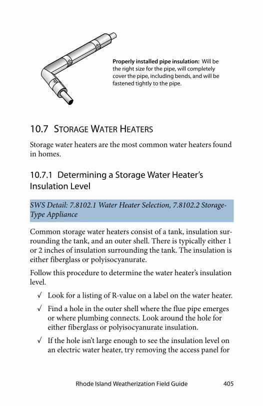
Rhode Island Weatherization Field Guide 405
10.7 STORAGE WATER HEATERS
Storage water heaters are the most common water heaters found in homes.
10.7.1 Determining a Storage Water Heater’s Insulation Level
Common storage water heaters consist of a tank, insulation sur-rounding the tank, and an outer shell. There is typically either 1 or 2 inches of insulation surrounding the tank. The insulation is either fiberglass or polyisocyanurate.
Follow this procedure to determine the water heater’s insulation level.
✓ Look for a listing of R-value on a label on the water heater.
✓ Find a hole in the outer shell where the flue pipe emerges or where plumbing connects. Look around the hole for either fiberglass or polyisocyanurate insulation.
✓ If the hole isn’t large enough to see the insulation level on an electric water heater, try removing the access panel for
SWS Detail: 7.8102.1 Water Heater Selection, 7.8102.2 Storage-Type Appliance
Properly installed pipe insulation: Will be the right size for the pipe, will completely cover the pipe, including bends, and will be fastened tightly to the pipe.

Baseload Measures406
the heating element after disconnecting power from the unit.
✓ You may just be able to see the gap between the tank and outer shell. If you can’t see this gap, use a ruler or probe to push through the insulation along side of a pipe connect-ing to the tank until the probe hits the steel tank to deter-mine thickness. Make sure that the probe is against the tank and not against a nut welded to the tank.
✓ Do not install insulation.
10.7.2 Storage Water-Heater Selection
Existing gas water heaters, including propane, typically use 200 to 400 therms per year. New gas water heaters use as little as 175 therms per year, resulting in a savings of between 25 and 225 therms per year. Similar savings are possible by replacing elec-
SWS Detail: 7.8102.1 Water Heater Selection, 7.8102.2 Storage-Type Appliance
Table 10-6: Insulation R-Values
Insulation/thickness R
Fiberglass 1 inch 3
Fiberglass 2 inches 6
PIC1 inch 6.5
PIC 2 inches 13
PIC 3 inches 19.5
Look here: gap around
Look here: gap around flue
Identifying Tank Insulation
hot and cold lines
Rhode Island Weatherization Field Guide 407
tric water heaters. Consider the following recommendations for specifying water heaters.
• A replacement gas or oil storage water heater should have an energy factor of at least 0.67 and be insulated with at least 2 inches of foam insulation.
• A replacement electric water heater should have an energy factor of at least 0.93 and be insulated with at least 2.5 inches of foam insulation.
10.8 ALTERNATIVE WATER-HEATERS
Weatherization programs sometimes choose alternative water-heating products to improve efficiency and safety.
10.8.1 Sidewall-Vented Gas Storage Water Heaters
When gas storage water heaters cause persistent venting prob-lems, specify a sidewall-venting water heater. Two common types of these water heaters are shown here.
✓ Choose a sealed-combustion sidewall-vented gas water heater, if possible. Next best is a fan-assisted unit.
✓ The replacement water heater must be installed in accor-dance with manufacturer specifications, 2012 IRC G2427.8, and additional applicable codes.
SWS Detail: 2.0201.2 Combustion Safety, 7.8102.1 Water Heater Selection, 7.8102.2 Storage-Type Appliance

Baseload Measures408
10.8.2 On-Demand Gas Water Heaters
On-demand gas water heaters are more efficient and cost less to operate compared to conventional gas storage water heaters. However, on-demand gas water waters are more expensive to install and may have shorter lifespans compared to storage water heaters.
✓ Choose a sealed-combustion on-demand gas water heater, if possible. Next best is a fan-assisted unit.
10.8.3 Heat Pump Water Heaters
Heat pump water heaters can heat water at up to 2.3 times more efficient than electric-resistance storage water heaters. Heat pump water heaters use heat from surrounding air to heat water. They cost much more than conventional electric water heaters but are far less costly to operate.
SWS Detail: 7.8102.1 Water Heater Selection, 7.8102.3 On-Demand Appliance
Fan-assisted water heater: The fan allows horizontal venting. The water heater may be open combustion or sealed combustion.
Direct-vent water heater: Moves combustion air and flue gases through a concentric pipe system without a draft fan.

Rhode Island Weatherization Field Guide 409
10.9 WATER HEATER INSTALLATION
Follow these procedures when installing a storage water heater or an alternative water heater.
✓ Replacement water heater must have a pressure-and-tem-perature relief valve with a discharge line that terminates less than 6 inches from the floor into a floor drain or drain pan.
✓ The discharge pipe should be made of rigid metal pipe or approved high-temperature plastic pipe.
SWS Detail: 7.8102.3 On-Demand Appliance, 7.8102.2 Storage-Type Appliance
Sealed-Combustion Tankless Water Heater: These expensive water heaters have a tiny market share and save around one-third of energy used by the best storage water heaters.
draft fan
combustion air
heat exchanger
Heat pump water heater: This heat pump water heater has the heating coil (condenser) surrounded by the domestic water.

Baseload Measures410
✓ Install dielectric unions and a backflow preventer as part of a water heater replacement if any of these components are missing from the existing installation.
✓ Install an expansion tank for all storage water-heater replacements.
✓ Install an emergency drain pan with sides that extend a minimum of 4" above floor under each replacement water heater that is installed in an area that would be damaged by a leak.
✓ Install a 3/4-inch drain line to the tapping on drain pan. Terminate the drain line in a floor drain or outdoors, at least 6 inches above grade.
✓ Install heat traps on the water heater’s inlet and outlet pip-ing if the manufacturer hasn’t provided traps.
✓ Adjust water temperature to 120° F or to the lowest setting acceptable to occupants.
For a complete list of DOE installation requirements for water heaters, see SWS Detail 7.8102.2 Storage-Type Appliance.
10.10 COMPARING WATER HEATERS
The choice of fuel and model for a storage water heater isn’t easy and it involves many factors including safety, reliability, effi-ciency, and installed cost.
10.10.1 Safety Comparison
Conventional direct-fired gas water heaters vent their combus-tion by-products to a gravity vented chimney. They can spill products of combustion into the living space, especially if the chimney isn’t tall enough, warm enough, or sized properly. Sharing of a main chimney with another combustion appliance can cause venting problems. If the furnace or boiler is replaced with a sealed-combustion or horizontal-vented model, the

Rhode Island Weatherization Field Guide 411
chimney may then be too big for the remaining combustion water heater.
Electric water heaters have no chimney and need no combus-tion air, which makes them safer for buildings with low natural air leakage, compared to conventional gas storage water heaters.
Electric water heaters have no products of combustion to worry about. However, because their recovery capacity is generally much less than gas water heaters of the same size, there is a greater chance of someone trying to compensate for a cold shower by setting the electric water heater to an unsafe tempera-ture where occupants could get scalded.
10.10.2 Reliability Comparison
Storage water heaters are popular because they are inexpensive and reliable. Both gas and electric storage water heaters are sim-pler and more reliable than more expensive and complex water heaters. The lifespan of storage water heaters depends on local water quality and the quality of the water heater’s tank.
Standard gas water heater: These open combustion appliances are often troubled by spillage and backdrafting.
draft diverter
burner
P/T valve
sacrificial anode
cold waterdip tube
gas supply valve
thermostat
Baseload Measures412
Most heaters have glass-lined steel tanks which are typically warranted for five years. All types of heaters are available with larger or additional sacrificial anodes, which are pieces of metal that corrode before the tank does, thereby extending the tank life and maybe the warranty. If you buy a ten-year guarantee heater instead of a five-year guarantee heater, this choice might reduce the future cost of replacement and possible water dam-age from tank leaks.
10.10.3 Efficiency and Energy Cost Comparison
Conventional gas storage water heaters are rated at about 80% steady-state efficiency. However, whenever a storage water heater isn’t firing, it’s losing heat up the chimney. This happens when cold air, flowing through the heater, is warmed by the heater and escapes up the flue. This off-cycle heat loss reduces annual efficiency drastically and may result in the water heater’s energy factor (EF) being less than 0.60.
The exact EF for a particular storage water heater is difficult to estimate because of many factors including: chimney height, chimney diameter, wind, the home’s air-tightness, outdoor tem-perature, and water heater temperature setpoint. With these variables the actual EF can vary from 0.60 to 0.40 or even lower. Nevertheless, gas storage water heaters cost less to operate than electric water heaters with the same insulation level.

Rhode Island Weatherization Field Guide 413
Electricity is approximately 2.5 times as expensive as natural gas. However, electric water heaters have no chimney and therefore no chimney losses. They do lose heat through the insulation jacket, which brings their EF down to around 0.90. Heat-pump water heaters have an operating efficiency of 200% because they heat water with heat from the surrounding air. But because the electricity production and transmission system in the U.S. is about 31% efficient, the overall energy use and cost for heating water with electricity is still higher than with gas.
10.11 SWS ALIGNMENT
Field Guide Topic SWS Detail
10.1: Baseload Versus Seasonal Use - Pg. 388
10.2: Refrigerator Replacement and Maintenance - Pg. 391
10.2.1: Refrigerator Replacement - Pg. 392
7.8001.1 Refrigerator and Freezer Replacement
Standard electric storage water heater: Electric water heating is more expensive than gas or oil but safer. Electric water heaters should have at least 2 inches of foam insulation.
resistance
thermostat
anode
fill tube
elements

Baseload Measures414
10.2.2: Refrigerator Cleaning and Tuning - Pg. 392
7.8001.2 Cleaning and Tuning Existing Refrigerators and Freezers
10.3: Lighting-Efficiency Improvements - Pg. 393
10.3.3: Lighting Retrofit Equipment - Pg. 394
7.8003.1 Lighting Upgrade
10.4: Clothes Washer Selection/Replacement - Pg. 397
10.4.1: Clothes Washer Selection - Pg. 397
7.8004.1 Washing Machine
10.4.2: Clothes Washer Installation - Pg. 397
7.8004.1 Washing Machine
10.5.1: Clothes Dryer Selection -Pg. 398
10.5.1: Clothes Dryer Selection -Pg. 398
7.8004.2 Clothes Dryer Replacement
10.5.2: Clothes Dryer Installation - Pg. 398
7.8004.2 Clothes Dryer Replacement
10.5.3: Clothes Dryers Service and Venting - Pg. 399
6.6005.1 Clothes Dryer
10.6: Water-Heating Energy Savings - Pg. 401
10.6.1: Water-Saving Shower Heads and Faucet Aerators - Pg. 402
7.8101.1 Shower Head and Faucet Aerator
10.6.2: Water-Heater Pipe Insulation - Pg. 404
7.8103.1 Storage-Type Appliance, 7.8103.2 On-Demand Appliance
10.7: Storage Water Heaters - Pg. 405
Field Guide Topic SWS Detail

Rhode Island Weatherization Field Guide 415
10.7.1: Determining a Storage Water Heater’s Insulation Level -Pg. 405
7.8102.1 Water Heater Selection, 7.8102.2 Storage-Type Appliance
10.7.2: Storage Water-Heater Selection - Pg. 406
7.8102.1 Water Heater Selection, 7.8102.2 Storage-Type Appliance
10.8: Alternative Water-Heaters -Pg. 407
10.8.1: Sidewall-Vented Gas Storage Water Heaters - Pg. 407
2.0201.2 Combustion Safety, 7.8102.1 Water Heater Selection, 7.8102.2 Storage-Type Appliance
10.8.2: On-Demand Gas Water Heaters - Pg. 408
7.8102.1 Water Heater Selection, 7.8102.3 On-Demand Appliance
10.8.3: Heat Pump Water Heaters - Pg. 408
10.9: Water Heater Installation -Pg. 409
7.8102.3 On-Demand Appliance, 7.8102.2 Storage-Type Appliance
10.10: Comparing Water Heaters - Pg. 410
10.10.1: Safety Comparison - Pg. 410
10.10.2: Reliability Comparison -Pg. 411
10.10.3: Efficiency and Energy Cost Comparison - Pg. 412
Field Guide Topic SWS Detail

Baseload Measures416

Rhode Island Weatherization Field Guide 417
CHAPTER 11: MOBILE HOMES
Mobile homes are covered by their own details and outcomes in the SWS, which refers to mobile homes as manufactured homes. These two names refer to the same type of housing. We prefer the term “mobile home.” In this chapter, we cover mobile-home air sealing, insulation, windows, doors, and heating systems.
Typical components of a mobile home: 1–Steel chassis. 2–Steel outriggers and cross members. 3–Underbelly. 4–Fiberglass insulation. 5–Floor joists. 6–Heating/air conditioning duct. 7–Decking. 8–Floor covering. 9–Top plate. 10–Interior paneling. 11–Bottom plate. 12–Fiberglass insulation. 13–Metal siding. 14–Ceiling board. 15–BOWSTRING trusses. 16–Fiberglass insulation. 17–Vapor barrier. 18–Galvanized steel one-piece roof. 19–Metal windows.

Mobile Homes418
11.1 MOBILE HOME HEATING
Mobile home furnaces are similar to furnaces for site-built homes in some ways and different in other ways. Mobile home combustion furnaces have been sealed-combustion since the early 1970s. Gas furnaces are either the old atmospheric sealed-combustion type or the newer fan-assisted mid-efficiency type. Some older less-efficient sealed-combustion furnaces had draft fans too. For information on electric furnaces, see “Electric Fur-naces” on page 339.
Mobile-home oil furnaces are a close relative to oil furnaces in site-built homes. However, they should have a housing that fits around the burner’s air shutter and provides outdoor air directly to the burner. See “Oil Burner Safety and Efficiency Service” on page 267.
Mobile-home furnaces are different from conventional furnaces in the following ways.
• A great majority of mobile homes are equipped with down-flow furnaces, designed specifically for mobile homes.
• Mobile home combustion furnaces are sealed-combustion units that use outdoor combustion air, unlike most fur-naces in site-built homes. They don’t have draft diverters or barometric draft controls.
• Gas-fired furnaces have kits attached, containing alterna-tive orifices, to burn either propane or gas.
• Return air enters the furnace through a large opening in the furnace rather than through return ducts.
SWS Detail: 5.3003.11 Heating and Cooling Controls. 5.3003.14 Combustion Analysis of Gas-Fired Appliances (LP and Natural Gas), 5.3003.15 Combustion Analysis of Oil-Fired Appliances, 5.3001.1 Load Calculation and Equipment Selection, 5.3003.3 Evaluating Air Flow

Rhode Island Weatherization Field Guide 419
Important Note: Install only furnaces—designed for mobile homes—in mobile homes.
Combustion air
Combustion gases
Ventilation air
Heated air
Blower
Com
busti
on ga
ses
Return air
Filte
r
Mobile home furnace airflow: Return air flows from the hallway through the furnace grill. The air is heated and distributed through the ducts.
Mobile home furnace combustion: Combustion air enters through the flue assembly on the roof and feeds the flame through a sealed passageway.

Mobile Homes420
11.1.1 Furnace Maintenance and Energy Efficiency
Mobile home furnaces should comply with this guidebook’s combustion safety and efficiency standards. See “Gas Burner Safety & Efficiency Service” on page 264 and “Oil Burner Safety and Efficiency Service” on page 267.
11.1.2 Furnace Replacement
Mobile home furnaces must be replaced by furnaces designed and listed for use in mobile homes.
Consider replacing the existing furnace with a sealed-combus-tion, downflow, condensing furnace. One manufacturer makes condensing furnaces, approved for mobile homes.
Consider replacing a mobile home furnace when you observe any of the following.
• The furnace has a cracked heat exchanger.
• Repair and retrofit exceed half of the replacement cost.
• The furnace is not operating and not repairable.
Mobile home furnaces require an outdoor source of combustion air. Mobile home furnaces have either a manufactured chimney that includes a passageway for combustion air or a combustion-air chute connecting the burner with the crawl space.
✓ Install a new furnace base unless you are sure that the existing base exactly matches the new furnace.
✓ Attach the furnace base firmly to the duct, and seal all seams between the base and duct with mastic and fabric tape before installing the furnace.
✓ Support the main duct underneath the furnace with addi-tional strapping if necessary.
✓ When replacing mobile home furnaces, note the differ-ences between old furnace and new, in the way each sup-plies itself with combustion air.

Rhode Island Weatherization Field Guide 421
✓ Install a new chimney that is manufactured specifically for the new furnace.
✓ Often the old chimney opening doesn’t exactly line up with the new furnace’s flue. In these cases either use an off-set pipe, provided by the manufacturer, or else cut the opening larger so that the new chimney can be installed absolutely vertical. Also make sure the chimney cap is installed absolutely straight.
Mobile home furnaces have short chimneys, and their combus-tion process depends on a delicate balance between combustion air entering and combustion gases leaving. The furnace demands a vertical, leak-free chimney, and a properly installed chimney cap. Follow manufacturer’s installation instructions exactly.
11.2 MOBILE HOME COOLING AND VENTILATION SYSTEMS
Mobile home cooling systems are, in most ways, identical to sin-gle-family cooling systems.
11.2.1 Mobile Home Ventilation Systems
Consult the SWS links above and the links listed below for infor-mation on mobile home ventilation systems.
• “Whole-Dwelling Ventilation Requirement” on page 355
SWS Detail: 5.3003.11 Heating and Cooling Controls, 5.3003.12 Package Units—Repair and Service, 5.3003.13 Refrigerant Charge Evaluation, 5.3003.8 Evaporative Cooler Maintenance and Repairs, 5.3003.3 Evaluating Air Flow
SWS Detail: 6.6204.1 Commissioning Ventilation Systems 6.6205.1 Manufactured Housing Exhaust-Only Strategies,

Mobile Homes422
• “Exhaust Ventilation” on page 365
• “Adaptive Ventilation” on page 371
11.3 MOBILE HOME AIR SEALING
The location and relative importance of mobile home air leaks was a mystery before blower doors. Some mobile homes are fairly airtight, and others are very leaky. Air leakage serves as ventilation in most mobile homes. Comply with the whole-building ventilation standards outlined in “ASHRAE Standard 62.2–2016 Ventilation” on page 354.
A duct airtightness tester, which pressurizes the ducts and mea-sures their air leakage, is the best way to measure and evaluate duct air sealing. See “Evaluating Duct Air Leakage” on page 312. For simply locating duct leaks, the blower door used in conjunc-tion with a pressure pan does a good job. See "Pressure Pan Test-ing" on page 313.
Most mobile home duct sealing is performed through the belly. This work is more difficult once the belly has been re-insulated. Inspect the ductwork and seal any major leaks, such as discon-nected trunk lines, before insulating the belly.
SWS Detail: 3.1101 Manufactured Housing Walls

Rhode Island Weatherization Field Guide 423
Mobile home shell air leakage is often substantially reduced when insulation is installed in roofs, walls, and belly cavities. Prioritize your efforts by performing these tasks in this order.
1. Evaluate the insulation levels. If adding insulation is cost-effective, perform the usual pre-insulation air seal-ing measures that also prevent spillage of insulation out of the cavity.
2. Install cavity insulation. Perform duct sealing first if the belly is to be insulated.
3. Re-check the air leakage rate.
4. Perform additional air sealing as needed.
11.3.1 Shell Air Leakage Locations
Blower doors have pointed out the following shell locations as the most serious air leakage sites.
✓ Plumbing penetrations in floors, walls, and ceilings. Water-heater closets with exterior doors are particularly
Table 11-1: Air Leakage Locations & Typical CFM50 Reduction
Air Sealing Procedure Typical CFM50 Reduction
Patching large air leaks in the floor, walls and ceiling 200–900
Sealing floor cavity used as return-air plenum (See “Floor return air” on page 426.)
300–900
Sealing leaky water-heater closet 200–600
Sealing leaky supply ducts 100–500
Installing tight interior storm windows 100–250
Caulking and weatherstripping 50–150
SWS Detail: 3.1001.4 General Penetrations (Electrical, HVAC, Plumbing, Vent Termination, Recessed Lighting)

Mobile Homes424
serious Air Leakage problems, having large openings into the bathroom and other areas
✓ Torn or missing underbelly, exposing flaws in the floor to the ventilated crawl space
✓ Large gaps around furnace and water heater chimneys
✓ Severely deteriorated floors in water heater compartments
✓ Gaps around the electrical service panel box, light fixtures, and fans
✓ Joints between the halves of double-wide mobile homes and between the main dwelling and additions
Note: Window and door air leakage is more of a comfort prob-lem than a serious energy problem.
11.3.2 Duct Leak Locations
Blower doors and duct testers have pointed out the following duct locations as the most serious energy problems.
✓ Floor and ceiling cavities used as return-air plenums — These floor return systems should be eliminated and replaced with return-air through the hall or a large grille in the furnace-closet door.
✓ Joints between the furnace and the main duct — The main duct may need to be cut open from underneath to access and seal these leaks between the furnace, duct connector, and main duct. With electric furnaces you can access the duct connector by removing the resistance elements. For furnaces with empty A-coil compartments, you can simply remove the access panel to seal the duct connector.
✓ Joints between the main duct and the short duct sections joining the main duct to a floor register
✓ Joints between register boots and floor
SWS Detail: 3.1602.11 Air Sealing System

Rhode Island Weatherization Field Guide 425
✓ The poorly sealed ends of the duct trunk, which often extend beyond the last supply register
✓ Disconnected, damaged or poorly joined crossover ducts
✓ Supply and return ducts for outdoor air conditioner units
✓ Holes cut in floors by tradesmen.
✓ New ductwork added to supply heat to room additions
Be sure to seal floor penetrations and ductwork before perform-ing any belly repair. Pollutants in the crawl space such as mold and dust will be disturbed by repair work and can be drawn into the home by duct depressurization.
See “Pressure Pan Testing” on page 313. See “Sealing Supply Ducts” on page 322.
11.3.3 Belly Pressure Test
Mobile home supply duct leaks pressurize the belly cavity. Fol-low these steps to perform this rough test to determine if duct leaks are present and their general location.
✓ Repair the rodent barrier.
✓ Turn on the air handler.
✓ Insert a manometer hose into the belly through the rodent barrier and test the pressure with-reference-to the out-doors.
✓ Start near the furnace, and work your way toward the ends alongside the trunk line. A pressure rise gives you a rough idea of the location of leaks, size of leaks, and tightness of the nearby rodent barrier.
✓ Repair the ducts and re-test.
SWS Detail: 5.3001.3 Replace Return Air Systems that Incorporate Floor Cavity (Belly) and/or Attic as the Return Air Pathway

Mobile Homes426
furnace
duct
return grille
floor cavity
duct connector
furnace closet door
main return
return grilles
furnace
supply registers main return
Floor return air: Return-air registers at the floor’s perimeter bring air back to the furnace. The floor cavity serves as one big leaky return duct. When leakage is serious, the floor return system should be eliminated.

Rhode Island Weatherization Field Guide 427
Mobile home ducts: Mobile home ducts leak at their ends and joints — especially at the joints beneath the furnace. The furnace base attaches the furnace to the duct connector. Leaks occur where the duct connector meets the main duct and where it meets the furnace. Branch ducts are rare, but easy to find, because their supply register isn’t in line with the others. Crossover ducts are found only in double-wide and triple-wide homes.
furnace
register boot
branch duct
crossover ductduct end
duct connector
furnace base
Sealing the end of the main duct: The main duct is usually capped or crimped loosely at each end, creating a major air leakage point. Seal this area and improve airflow by installing a sheet metal ramp, accessed through the last register, inside the duct. Seal the ramp to the ductwork with metal tape and silicone or mastic.
register
crimped end
main duct
ramp

Mobile Homes428
11.4 MOBILE HOME INSULATION
Address all significant moisture problems before insulating. The most important single moisture-control measure is installing a ground-moisture barrier. See also "Preparing for Floor Insula-tion" on page 193.
11.4.1 Insulating Mobile Home Roof Cavities
Blowing a closed mobile home roof cavity is similar to blowing a closed wall cavity, only the insulation doesn’t have to be as dense. Use fiberglass blowing wool because cellulose is too heavy and absorbs water too readily for use around a mobile home’s lightweight sheeting materials.
If existing insulation is attached to the underside of the roof, blow the insulation below it. If existing insulation lays on the ceiling, blow the insulation above it. If you find insulation at both the ceiling and roof, blow the new insulation in between the two existing layers of insulation.
SWS Detail: 2.0104.1 Insulation Worker Safety
SWS Details: 4.1003.10 Installing Fiberglass Blown Insulation for Flat, Bowed, or Vaulted Ceilings (via Interior Access Through the Ceiling), 4.1003.8 Installing Fiberglass Blown Insulation for Flat, Bowed, or Vaulted Ceilings (via Roof Side Lift), 4.1003.9 Installing Fiberglass Blown Insulation for Flat, Bowed, or Vaulted Ceilings (via Exterior Access from Top of Roof), 4.1003.11 Installing Fiberglass Blown Insulation in Roof-Over Constructions

Rhode Island Weatherization Field Guide 429
There are three common and effective methods for blowing mobile home roof cavities.
1. Cutting a square hole in the metal roof and blowing fiberglass through a flexible fill-tube.
2. Disconnecting the metal roof at its edge and blowing fiberglass through a rigid fill-tube.
3. Blowing fiberglass through holes drilled in the ceiling.
Preparing to Blow a Mobile Home Roof
Perform these steps before insulating mobile home roofs.
✓ Reinforce weak areas in the ceiling.
✓ Inspect the ceiling and seal all penetrations.
✓ Replace all broken mushroom vents or remove and seal them.
✓ Take steps to maintain safe clearances between insulation and recessed light fixtures and ceiling fans.
✓ Verify that gas, water, and electrical lines are secured at least every 4 feet to a floor joist or framing member.
Blowing Through the Top
Blowing through the roof top does a good job of filling the criti-cal edge area with insulation, and the patches are easy to install
Bowstring roof details: Hundreds of thousands of older mobile homes were constructed with these general construction details.
stud
galvanized-steel roof
J-rail
metal trim
insulation
truss
3/4-inch top plate
fiberboard ceiling

Mobile Homes430
if you have the right materials. It is important to complete the work during good weather, however, since the roof will be vul-nerable to rain or snow during the job.
If the roof contains a strongback running the length of the roof, the holes should be centered over the strongback, which is usu-ally near the center of the roof ’s width. A strongback is a 1-by-4 or a 1-by-6, installed at a right angle to the trusses near their center point, that adds strength to the roof structure.
1. Cut 10-inch square holes at the roof ’s apex on top of every second truss. Each square hole permits access to two truss cavities.
2. Use a 2-inch or 2-1/2-inch diameter fill-tube. Insert the fill-tube and push it forcefully out to within 6 inches of the edge of the cavity.
3. Blow fiberglass insulation into each cavity.
4. Stuff the area under each square hole with a piece of unfaced fiberglass batt so that the finished roof patch will stand a little higher than the surrounding roof.
5. Patch the hole with a 14-inch-square piece of stiff galva-nized steel, sealed with roof cement and screwed into the existing metal roof.
6. Cover the first patch with a second patch, consisting of an 18-inch-square piece of foil-faced butyl rubber.
Roof-top insulation: Blowing fiberglass insulation through the roof top is effective at achieving good coverage and density on almost any metal roof.

Rhode Island Weatherization Field Guide 431
Blowing Through a Round Hole on the Roof
Consider this alternative to cutting a square hole as suggested above.
1. Drill a 3-inch or larger hole between each truss.
2. Use a 2-inch or 2-1/2-inch diameter fill-tube. Insert the fill-tube, and push it forcefully out to within 6 inches of the edge of the cavity.
3. Blow fiberglass insulation into each cavity to fill the entire cavity.
4. Patch the holes with galvanized steel, plastic caps, and roofing material that is compatible with the existing roof.
Blowing a Mobile Home Roof from the Edge
Erect scaffold to do this procedure safely and efficiently. Mobile home metal roofs are usually fastened only at the edge, where the roof joins the wall.
Square roof patch: An 18-inch square of foil-faced butyl rubber covers a base patch of galvanized steel, which is cemented with roof cement and screwed with self-drilling screws.
foil-faced butyl rubber patch
galvanized steel patch
trap door cut in roof steel
mobile home truss

Mobile Homes432
1. Remove the screws from the metal j-rail at the roof edge. Also remove staples or other fasteners, and scrape off putty tape.
2. Pry the metal roof up far enough to insert a 2-inch-diameter, 10- to 14-foot-long rigid fill-tube. Two com-mon choices are steel muffler pipe and aluminum irri-gation pipe. Inspect the cavity with a bright light to identify any wires or piping that could be damaged by the fill tube.
3. Insert the fill-tube, and push it forcefully out to within 6 inches of the edge of the cavity.
4. Blow insulation through the fill-tube into the cavity. Turn off the insulation-material feed and blower on the blowing machine when the tube is a couple feet from the roof edge, in order to avoid blowing insulation out through the opening in the roof edge. Stuff the last foot or two with unfaced fiberglass batts.
5. Fasten the roof edge back to the wall using galvanized roofing nails, a new metal j-rail, new putty tape, and larger screws. The ideal way to re-fasten the metal roof edge is with air-driven galvanized staples, which is the way most roof edges were attached originally.
The re-installation of the roof edge is the most important part of this procedure. Putty tape must be replaced and installed as it was originally. This usually involves installing a layer of putty tape or a bead of high quality caulk under the metal roof and another between the metal roof edge and the j-rail.
Roof-edge blowing: Use a rigid fill tube to blow insulation through the roof edge. This avoids making holes in the roof itself, though this process requires much care in refastening the roof edge.

Rhode Island Weatherization Field Guide 433
The advantages of blowing through the edge is that if you have the right tools, including a powered stapler, this method can be very fast and doesn’t require cutting into the roof. The disadvan-tages of this procedure are that you need scaffolding to work at the edges, and it won’t work on roof systems with a central strongback that stops the fill tube from reaching all the way across the roof.
Blowing a Mobile Home Roof from Indoors
The advantage to this method is that you are indoors, out of the weather. The disadvantages include being indoors where you can make a mess — or worse, damage something.
Blowing the roof cavity from indoors requires the drilling of straight rows of 3-inch or 4-inch holes and blowing insulation into the roof cavity through a fill tube.
Follow this procedure.
1. Drill a 3-inch or 4-inch hole in an unseen location to discover whether the roof structure contains a strong-back that would prevent blowing the roof cavity from a single row of holes.
2. Devise a way to drill a straight row of holes down the center of the ceiling. If a strongback exists, drill two rows of holes at the quarter points of the width of the ceiling.
3. Insert a flexible plastic fill tube and push it forcefully out to within 6 inches of the edge of the cavity.
4. Fill the cavity with tightly packed fiberglass insulation.
5. Cap the holes with manufactured plastic caps. Care must be taken not to damage the holes so that the plas-tic hole covers fit properly. You can also install a piece of painted wood trim over the line of holes.

Mobile Homes434
11.4.2 Mobile Home Sidewall Insulation
The sidewalls of many mobile homes are not completely filled with insulation. This reduces the nominal R-value of the exist-ing wall insulation because of convection currents and air leak-age. Consider the following steps for adding insulation to partially filled mobile home walls.
1. Check the interior paneling and trim to make sure they are securely fastened to the wall. Repair holes in inte-rior paneling and caulk cracks at seams to prevent indoor air from entering the wall. Note the location of electrical boxes and wire to avoid hitting them when you push the fill tube up the wall.
2. Remove the bottom horizontal row of screws from the exterior siding. If the vertical joints in the siding inter-
SWS Details: 4.1101.5 Exterior Wall Dense Packing, 4.1104.2 Fiberglass Blown Insulation Installation (Lifting Siding), 4.1104.3 Fiberglass Blown Insulation Installation (via Penetrations Through or Behind the Siding)
Blowing through the ceiling: The contractor pushes the fill-tube into the cavity and out near the edge of the roof. The holes are drilled in a straight line for appearance sake.
Rhode Island Weatherization Field Guide 435
lock, fasten the bottom of the joints together with1/2-inch sheet metal screws to prevent the joints from com-ing apart. Pull the siding and existing insulation away from the studs, and insert the fill tube into the cavity with the point of its tip against the interior paneling.
3. Push the fill tube up into the wall cavity until it hits the top plate of the wall. The tube should go in to the wall cavity 7-to-8 feet. It is important to insert the tube so that its natural curvature presses its tip against the inte-rior paneling. When the tip of the fill tube, cut at an angle, is pressed against the smooth paneling, it is least likely to snag the existing insulation on its way up the wall. If the fill tube hits a belt rail or other obstruction, twisting the tube will help its tip get past the obstruc-tion.
4. Stuff a piece of fiberglass batt into the bottom of the wall cavity around the tube to prevent insulation from blow-ing out of the wall cavity. Leave the batt in-place at the bottom of the wall, when you pull the fill tube out of the cavity. This piece of batt acts as temporary gasket for the hose and insulates the very bottom of the cavity after the hose is removed. This batt also eliminates the need to blow fiberglass insulation all the way to the bot-tom, preventing possible spillage and overfilling. If you happen to overfill the bottom of the cavity, reach up inside the wall to pack or remove some fiberglass insu-lation, particularly any that lies between the loose sid-ing and studs.
5. Draw the tube down and out of the cavity about 6 inches at a time. Listen for the blower fan to indicate strain from back-pressure in the wall. Watch for the fiberglass insulation to slow its flow rate through the blower hose at the same time. Also watch for slight bulging of the exterior siding. These signs tell the installer when to pull the tube down.

Mobile Homes436
6. Carefully refasten the siding using the same holes. Use screws that are slightly longer and thicker than the orig-inal screws.
11.4.3 Mobile Home Floor Insulation
Mobile home floor insulation is a good energy-saving measure in cool climates. The original insulation is usually fastened to the bottom of the floor joists, leaving much of the cavity uninsu-lated and subject to convection currents. This greatly reduces the insulation’s R-value. Blown-in belly insulation also tends to control duct leakage.
SWS Details: 4.1302.1 Prepare Belly Floor Cavity for Insulation, 4.1303.1 Insulation of Floor Cavity with Blown Material
Standard mobile home construction: 2-by-4 walls and 2-by-6 floor joists are the most common construction details.
Adding insulation to mobile home walls: A contractor uses a fill tube to install more insulation in a partially filled mobile home wall.

Rhode Island Weatherization Field Guide 437
Preparing for Mobile Home Floor Insulation
Prior to installing floor insulation, always perform these repairs.
✓ Repair plumbing leaks.
✓ Secure gas, water, and electrical lines at least every 4' to a floor joist or framing member
✓ Tightly seal all holes in the floor.
✓ Inspect and seal ducts.
✓ Repair the rodent barrier.
✓ Install a ground-moisture barrier in the crawl space if the site is wet.
Patching the Belly
Mobile homes have two common types of belly covering: rigid fiber board and flexible paper or fabric. The fiberboard is nor-mally stapled to the bottom of the floor joists. To patch a rigid belly, simply screw or staple plywood or another rigid material over the hole.
Flexible belly material may have no solid backing behind the hole or tear because the material forms a bag around the main duct, which is installed below the floor joists. In this case, use both adhesive and stitch staples to bind the flexible patch to the flexible belly material.
Blowing bellies: A flexible fill-tube, which is significantly stiffer than the blower hose, blows fiberglass insulation through a hole in the belly from underneath the home.
existing insulation
new insulation

Mobile Homes438
Insulating the Floor
The preferred method is to spray foam the belly, using high den-sity spray polyurethane foam (SPF). It is applied at a 3-inch thickness and is a continuous application.
Two additional methods of insulating mobile home floors are common. Blown fiberglass is recommended over cellulose for either method.
1. Drilling through the 2-by-6 rim joist and blowing fiber-glass through a rigid fill tube into the belly.
2. Blowing fiberglass insulation through a flexible fill tube or a rigid fill tube into the underbelly.
First repair all holes in the belly. Use mobile home belly-paper or Tyvek, silicone sealant, and stitch staples. Use these same patches over the holes cut for fill-tubes. Screw wood lath over weak areas if needed.
When blowing through holes from underneath the home, con-sider blowing through damaged areas before patching them.
Identify any plumbing lines, and avoid installing insulation between them and the living space if freezing could be an issue.
Blowing a floor through the belly: The contractor inserts a rigid fill tube through the belly to blow insulation into the floor cavity and underbelly.
Patching a flexible belly: The technicians uses both adhesive and stitch staples to fasten a patch.

Rhode Island Weatherization Field Guide 439
This may require running a piece of belly-paper or Tyvek under the pipes, and insulating the resulting cavity, to include the pipes in the heated envelope of the home.
Unfaced fiberglass batts may also be used to insulate floor sec-tions where the insulation and belly are missing. The insulation should be supported by lath, twine, or insulation supports. This is a good approach when it isn’t cost-effective to insulate the entire belly.
11.5 MOBILE HOME WINDOWS AND DOORS
Repairing or replacing mobile home windows and doors is often part of a mobile home weatherization job. Installing storm win-dows or replacing existing windows is expensive per square foot and isn’t as cost-effective as insulation. However, storm win-
SWS Detail: 3.1201.5 Manufactured Housing Windows and Doors
Blowing crosswise cavities: Blowing insulation into belly is easy if the floor joists run crosswise. However, the dropped belly requires more insulation than a home with lengthwise joists.
Blowing lengthwise cavities: Floors with lengthwise joists can rarely be filled completely from the ends because of the long tubing needed. The middle can be filled from underneath.

Mobile Homes440
dows and replacement windows are all energy conservation measures for mobile homes that are worth considering.
11.5.1 Mobile Home Storm Windows
Interior storm windows are common in mobile homes. These stationary interior storms serve awning and jalousie windows. Sliding interior storm windows pair with exterior sliding prime windows.
✓ Interior storm windows double the R-value of a single-pane window. They also reduce infiltration, especially in the case of leaky jalousie prime windows. If jalousie win-dows are present, they should be replaced.
✓ Interior storm windows must be operable and egress-rated in egress locations.
✓ Consider repairing existing storm windows rather than replacing them unless the existing storm windows can’t be re-glazed or repaired.
SWS Detail: 3.1201.6 Interior Storm Windows
Glass interior storms: Traditional mobile home storm windows have aluminum frames glazed with glass.
clip
gasket spline
plastic film
aluminum frame
Plastic storms: Some newer Storm window designs use a lightweight aluminum frame and flexible or rigid plastic glazing.
foam tape

Rhode Island Weatherization Field Guide 441
✓ When sliding primary windows are installed, use a sliding storm window that slides from the same side as the pri-mary window. Sliding storm windows stay in place and aren’t removed seasonally, and are therefore less likely to be lost or broken.
11.5.2 Replacing Mobile Home Windows
Replacement windows should have lower U-factors than the windows they are replacing. Inspect condition of rough opening members before replacing windows. Replace deteriorated, weak, or waterlogged framing members.
Prepare the replacement window by lining the perimeter of the inner lip with 1/8-inch thick putty tape. Caulk exterior window frame perimeter to wall after installing the window.
SWS Details: 3.1202.3 Replacing Damaged Window Glass in Manufactured Housing, 3.1203.3 Replacement of Manufactured Housing Windows and Doors
Mobile home double window: In mobile homes, the prime window is installed over the siding outdoors, and the storm window is installed indoors.
interior storm window
prime window

Mobile Homes442
11.5.3 Mobile Home Doors
Mobile home doors come in two basic types: the mobile home door and the house-type door. Mobile home doors swing out-wardly, and house-type doors swing inwardly.
Existing or replacement mobile home doors should be air-tight, water-tight, and operable. Replace missing or damaged weather-stripping, drip cap, or flashing to ensure that water or air can’t penetrate the opening. Properly adjust the door so that it closes securely, but does not crush or deform the weatherstripping.
11.6 COOL ROOFS FOR MOBILE HOMES
Cool roof coatings reduce summer cooling costs and improve comfort by reflecting solar energy away from the home's roof and slowing the flow of heat into the home. They are shown to reduce overall cooling costs by 10-20%, and are a good choice for mobile homes or site-built homes with low slope or flat roofs. Cool roof coatings are usually bright white, and must have a reflectivity of at least 60% to meet the ENERGY STAR or equiva-lent requirement for cool roof coatings.
SWS Detail: 3.1201.5 Manufactured Housing Windows and Doors
SWS Details: 5.3202.1 Reflective Coatings on Metal Roofs, 5.3202.2 Reflective Roof Coatings
Mobile home door: Mobile home doors swing outwardly and have integral weatherstrip.

Rhode Island Weatherization Field Guide 443
Cool roof coatings are usually water-based acrylic elastomers, and are applied with a roller. They can be applied over most low-sloped roofing such as metal, built-up asphalt, bitumen, or sin-gle ply membranes. Some underlying materials require a primer to get proper adhesion-check the manufacturer's recommenda-tions for asphalt-shingle roofs. See also "Cool Roofs" on page 150.
11.6.1 Applying the Coating
Surface preparation is critical when applying any coating. The underlying roofing materials must be clean so the coating will stick. Repairs should be performed if the existing roofing is cracked or blistered. Roof coating Won’t stick to dirty or greasy surfaces, and they can’t be used to repair roofs in poor condi-tions. Observe the following specifications when installing cool roof coatings.
✓ Install the coating when dry weather is predicted. Rain heavy dew, or freezing weather, if it happens within 24 hours of installation, will weaken the coating’s bond to the underlying roofing.
✓ Protect any nearby windows, siding, or automobiles from splatters. For roller application, use a large brush for the edges, and a shaggy 1 to 1 1/2-inch roller on a 5- or 6- foot pole for the field. Run the coating up the roof jacks and other penetrations to help seal these areas. Install at least two coats, with second coat applied in the opposite direc-tion to the first to get more complete coverage. Allow a day for drying between coats.
✓ Clean the roof of loose roofing material and other debris.
✓ Wash the roof with a water/tri-sodium phosphate (tsp) solution, or comparable mildew-cide, and scrub brush. Better yet, use a pressure washer.
✓ For metal roofs, sand any rusted areas down to sound metal. Install metal patches over any areas that are rusted through, followed by polyester patches as described above.

Mobile Homes444
✓ Buy the highest quality coatings, and look for those that are specifically formulated as mobile home roof coatings.
✓ Reinforce any open joints around skylights, pipe flashing, roof drains, wall transitions, or HVAC equipment. For build-up asphalt or bitumen roofs, repair any cracks, blisters, or de-laminations. Use polyester fabric and roof coating for these reinforcements and repairs by dipping fabric patches in the roof coating and spreading them over the existing roofing, or by laying dry fabric into a layer of wet coating. Smooth the patches down with a broad-knife or squeegee to remove bubbles or wrinkles. Allow any repairs to cure for 1 to 2 days before applying the topcoat.
11.7 MOBILE HOME SKIRTING
The primary purpose of skirting is to keep animals out of the crawl space. Skirting must be vented to reduce moisture accu-mulation in many climates, so there isn’t much value in insulat-ing it.
Installation and repair of mobile home skirting is seldom cost-effective and is not allowed in weatherization work. Locate the thermal boundary at the floor of mobile homes.
11.8 SWS ALIGNMENT
SWS Detail: 3.1488.2 Skirting Manufactured Homes
Field Guide Topic SWS Detail
11.3: Mobile Home Air Sealing -Pg. 422
3.1101 Manufactured Housing Walls
11.3.1: Shell Air Leakage Locations - Pg. 423
11.3.2: Duct Leak Locations - Pg. 424
3.1602.11 Air Sealing System

Rhode Island Weatherization Field Guide 445
11.3.3: Belly Pressure Test - Pg. 425
5.3001.3 Replace Return Air Systems that Incorporate Floor Cavity (Belly) and/or Attic as the Return Air Pathway
11.4: Mobile Home Insulation -Pg. 428
2.0104.1 Insulation Worker Safety
11.4.1: Insulating Mobile Home Roof Cavities - Pg. 428
4.1003.10 Installing Fiberglass Blown Insulation for Flat, Bowed, or Vaulted Ceilings (via Interior Access Through the Ceiling), 4.1003.8 Installing Fiberglass Blown Insulation for Flat, Bowed, or Vaulted Ceilings (via Roof Side Lift), 4.1003.9 Installing Fiberglass Blown Insulation for Flat, Bowed, or Vaulted Ceilings (via Exterior Access from Top of Roof ), 4.1003.11 Installing Fiberglass Blown Insulation in Roof-Over Constructions
11.4.2: Mobile Home Sidewall Insulation - Pg. 434
4.1101.5 Exterior Wall Dense Packing, 4.1104.2 Fiberglass Blown Insulation Installation (Lifting Siding), 4.1104.3 Fiberglass Blown Insulation Installation (via Penetrations Through or Behind the Siding)
11.4.3: Mobile Home Floor Insulation - Pg. 436
4.1302.1 Prepare Belly Floor Cavity for Insulation, 4.1303.1 Insulation of Floor Cavity with Blown Material
11.5: Mobile Home Windows and Doors - Pg. 439
3.1201.5 Manufactured Housing Windows and Doors
Field Guide Topic SWS Detail

Mobile Homes446
11.5.1: Mobile Home Storm Windows - Pg. 440
3.1201.6 Interior Storm Windows
11.5.2: Replacing Mobile Home Windows - Pg. 441
3.1202.3 Replacing Damaged Window Glass in Manufactured Housing, 3.1203.3 Replacement of Manufactured Housing Windows and Doors
11.5.3: Mobile Home Doors - Pg. 442
3.1201.5 Manufactured Housing Windows and Doors
11.7: Mobile Home Skirting - Pg. 444
3.1488.2 Skirting Manufactured Homes
Field Guide Topic SWS Detail

Rhode Island Weatherization Field Guide 447
CHAPTER 12: AIR LEAKAGE DIAGNOSTICS
This chapter focuses on pressure-testing homes, to determine their airtightness and to guide air-sealing during weatheriza-tion. Ideally the air barrier and insulation are installed together at the building’s thermal boundary. The airtightness of the air barrier has a substantial effect on the performance of the insula-tion. The testing described here helps to analyze the existing air barriers and decide whether and where air-sealing is needed.
12.1 SHELL AIR-LEAKAGE FUNDAMENTALS
Controlling shell air leakage is a key concern for successful weatherization. The decisions you make about sealing air leaks affect a building throughout its lifespan. Air leakage has these impacts.
• Air leakage accounts for a significant percentage of a build-ing’s heat loss.
• Air leakage through insulated assemblies reduces the R-value of insulation.
• Air leakage moves moisture in and out of the house, wet-ting and/or drying the building.
• Air leakage causes house pressures that can interfere with the venting of combustion appliances.
Air Leakage and Ventilation
Most homes depend on air leakage to provide outdoor air for diluting pollutants and admitting fresh air. However, air leaks can also bring pollutants into the home. Mechanical ventilation is a more reliable and efficient way to provide fresh air. See “ASHRAE Standard 62.2–2016 Ventilation” on page 354.

Air Leakage Diagnostics448
12.1.1 Goals of Air-Leakage Testing
Air-leakage testing accomplishes a variety of purposes.
• Air-leakage and pressure testing measures the home’s air-tightness level.
• It evaluates the home’s ventilation requirements.
• It helps you to decide how much time and effort is required to achieve cost-effective air-leakage and duct-leakage reductions.
• It helps to compare the air-tightness of the air barriers on either side of an intermediate zone, such as an attic or crawl space. For example, comparing the airtightness of the plas-ter ceiling with that of the ventilated sloped roof gives the auditor an idea of how leaky the ceiling is.
• It helps decide the best place to establish the air barrier in an area that has no obvious thermal boundary such as an uninsulated crawl space.
The reason for the complexity of air-leakage testing is that there is so much uncertainty about air leakage. Testing is needed because there simply is no accurate prescriptive method for determining the severity and location of leaks, especially in complex homes. Depending on the complexity of a home, you may need to perform varying levels of testing to evaluate shell air leakage. In particular, the number of major components like stories, additions, corners, and gables indicates a home’s poten-tial for large air-leakage reductions.

Rhode Island Weatherization Field Guide 449
Air-Sealing with Air-Leakage Testing
Dedicate most of your effort to seal the large air leaks that pass directly through the thermal boundary first. Chasing small leaks or leaks that connect to the outdoors through interior walls or floors isn’t worth as much effort if the budget is limited.
✓ Perform blower door testing.
✓ Analyze the test results to determine if air sealing is cost-effective.
✓ Locate and seal the air leaks.
✓ During air-sealing, monitor your progress with blower door testing.
✓ Stop air sealing when air-sealing goals have been achieved or the budget limit has been reached.
Do ducts supply heated air to the addition?
Are the crawl space ducts inside or outside the air barrier?
Where is the primary air barrier: at the rafter or ceiling joist?
Is the half-basement inside or outside the air barrier? Is this space heated?
Are the floor cavities connected to outdoors?
Are the intermediate zones connected?
Questions to ask during an air-leakage evaluation: Your answers help determine the most efficient and cost-effective location for the air barrier.

Air Leakage Diagnostics450
12.2 SINGLE-FAMILY AIRTIGHTNESS TESTING
House airtightness testing was made possible by the develop-ment of the blower door. The blower door measures a home’s leakage rate at a standard pressure of 50 pascals. This leakage measurement can be used to compare homes with one another and to established air-leakage standards.
The blower door also allows the auditor to test parts of the home’s air barrier to locate air leaks. Sometimes air leaks are obvious. More often, the leaks are hidden, and you need to find their location. This section outlines the basics of blower door measurement along with some techniques for gathering clues about the location of air leaks.
12.2.1 Blower-Door Principles
The blower door creates a 50-pascal pressure difference across the building shell and measures airflow in cubic feet per minute (CFM50), in order to measure the leakiness of homes. The blower door also creates pressure differences between rooms in
Digital Manometer
RefInput
A: -50B:2800
fan
digital manometerframe
panel
Ch A Reference
Ch B Input goes to fan
Blower Door Components
pressure sensor
goes to outdoors

Rhode Island Weatherization Field Guide 451
the house and intermediate zones like attics and crawl spaces. These pressure differences can give clues about the location and combined size of a home’s hidden air leaks.
Blower-Door Terminology
Connecting the digital manometer’s hoses correctly is essential for accurate testing.
This method uses the phrase with-reference-to (WRT), to distin-guish between the input zone and reference zone for a particular measurement. The outdoors is the most commonly used refer-ence zone for blower door testing. The reference zone is consid-ered to be the zero point on the pressure scale.
For example, house WRT outdoors = –50 pascals means that the house (input) is 50 pascals negative compared to the outdoors (reference or zero-point). This pressure reading is called the house pressure.
50pa
Digital Manometer
RefInput
A: -50B:2800
Blower door test: Air barriers are tested during a blower-door test, with the house at a pressure of 50 pascals negative with reference to outdoors. This house has 2800 CFM50 of air leakage. Further diagnostic tests can help determine where that leakage is coming from.
–50 –25 0 +25House WRT Outdoors Pressure in Pascals
Out
door
s
Hou
se

Air Leakage Diagnostics452
Low-Flow Rings
During the blower door test, the manometer measures airflow through the fan. This airflow (CFM50) is the primary measure-ment of a home’s airtightness and is directly proportional to the surface area of the home’s air leaks. For the blower door to mea-sure airflow accurately, the air must be flowing at an adequate speed. Tighter buildings and smaller buildings don’t have enough air leakage to create an adequate airspeed to create the minimum fan pressure. This low-flow condition requires using one or two low-flow rings, to reduce the blower-door fan’s open-ing and to increase air speed, fan pressure, and measurement accuracy.
When the air speed is too low, the DG-700 or DG-1000 displays “LO” in the Channel B display. After installing one of the low-flow rings, follow the manufacturer’s instructions for selecting the proper range or configuration on the digital manometer. If the DG 1000 displays a very high outcome in Channel B an auditor can link their smart phone or tablet to the manometer using the application from The Energy Conservatory. This will allow the auditor to move freely around the home to see if there are any missed open windows. The auditor can also turn the blower door off and on at any time during testing.
A B
Input pressure ports: connect to area to be tested
reference ports: connect to reference area
display
Digital manometers: Used to diagnose house and duct pressures quickly and accurately.
A B

Rhode Island Weatherization Field Guide 453
12.2.2 Preparing for a Blower Door Test
Preparing the house for a blower door test involves putting the house in its normal heating-season operation with all condi-tioned zones open to the blower door. Try to anticipate safety problems that the blower door test could cause, particularly with combustion appliances.
• Identify the location of the thermal boundary and deter-mine which house zones are conditioned.
• Identify large air leaks that could prevent the blower door from achieving adequate pressure, such as a pet-door.
• Put the house into its heating-season operation with win-dows, doors, and vents closed and air registers open.
• Turn off combustion appliances temporarily, or set them to “pilot”. Leave your vehicle keys on one of these appliances as a reminder to turn everything back on. You can’t leave without your keys!
• Open interior doors so that all indoor areas inside the ther-mal boundary are connected to the blower door. This should include the basement, conditioned knee wall areas, and closets.
• Turn off all exhaust fans and dryers that will work against the depressurization of the blower door fan.
Avoiding Risky Situations
Don’t perform a blower door test in risky situations like the fol-lowing until you remove the risk or have the client perform an acceptable building repair.
• A wood stove is burning.
• Holes in the ceiling that could lead to dust pollution during a blower door test.
• Extremely weak building components, like a poorly installed suspended ceiling or loose wood wall paneling.

Air Leakage Diagnostics454
• Lead, vermiculite, or asbestos dust is present.
12.2.3 Blower-Door Test Procedures
Follow this general procedure when performing a blower-door test.
✓ Set up the house for winter conditions with exterior doors, primary windows and storm windows closed. The door to the basement should be either open or closed, according to whether or not the basement is considered to be within the thermal boundary.
✓ Install blower door frame, panel, and fan in an exterior doorway with a clear path to outdoors. On windy days, install the blower door on the home’s leeward side if possi-ble. Pay attention to the blower door’s location and any other conditions that may affect test results.
✓ Follow manufacturer’s instructions for fan orientation and digital-manometer setup for either pressurization or depressurization. Depressurization is the most common orientation.
✓ Connect Channel A of the digital manometer to measure house WRT outdoors. Place the outside hose at least 5 feet away from the fan and to the side of fan, not in front.
✓ Connect Channel B to measure fan WRT zone near fan inlet. Do not place the hose directly in front of the fan intake.
✓ Ensure that children, pets, and other potential interfer-ences are at a safe distance from the fan.

Rhode Island Weatherization Field Guide 455
Conducting the Blower Door Test
Follow these easy steps to accurately set up the blower door using a DG-700 or DG-1000 digital manometer.
1. Turn on the manometer by pushing the ON/OFF button
2. Select the MODE: PR/FL@50 using the DG 700. If you are using the DG 1000 follow the on-screen guide for setting up the hoses set for the blower door at the start-up.
3. Select the correct DEVICE that matches the blower door you’re using.
4. With the fan covered, conduct the BASELINE proce-dure to cancel out the background wind and stack pres-sures. Let the manometer average the baseline pressure for at least 30 seconds.
5. Remove the cover from the blower door fan. Complete the next two steps for tighter buildings.
6. Install the flow ring in the blower door fan which matches the expected flow rate. The fan pressure should be at least 25 Pa while measuring CFM@50.
7. Push CONFIG or Range button on the DG-700 until you match the flow ring being used. For the DG-1000 follow the on screen instructions to change the flow ring.
–50 pascals0 +50 pascals0

Air Leakage Diagnostics456
8. Turn on the blower door fan slowly with the controller. Increase fan speed until the building depressurization on the Channel A screen is between –45 and –55 pas-cals. It doesn’t need to be exactly –50 pascals
9. The Channel B screen will display the single-point CFM50 air leakage of the building. If this number is fluctuating a lot, push the TIME AVG button to increase the averaging time period.
10. You can also use the cruise-control function to auto-matically control the fan speed to create and hold –50 pascals of pressure using either the DG-700 or the DG-1000 digital manometer.
Blower-Door Test Follow-Up
Be sure to return the house to its original condition.
✓ Inspect combustion appliance pilot lights to ensure that blower door testing didn’t extinguish them.
✓ Reset thermostats of heaters and water heaters that were turned down for testing.
✓ Remove any temporary plugs that were installed to increase house pressure.
✓ Document the location where the blower door was installed.
✓ Document any unusual conditions affecting the blower door test. Pictures of pre and post blower-door work are required.
12.2.4 Approximate Leakage Area (ALA)
There are several ways to convert blower-door CFM50 measure-ments into square inches of total leakage area. A simple and rough way to convert CFM50 into an approximate leakage area (ALA) is to divide CFM50 by 10. The ALA can help you visual-
Rhode Island Weatherization Field Guide 457
ize the size of openings you’re looking for in a home or section of a home.
Example: Blower door results: 3500 @ 50cfm
Approximate Leakage Area: 350 square inches
One square foot is 144 square inches. If you divide 350 in2 by 144 in2 you get a total of 2.43 square feet. Explain to your client that this is quite a large opening. It is like having a window open all the time and never closing it.
As an energy auditor you can explain how the leakage in their home affects their energy bill. Educate your client in terms they understand. This will certainly decreasing their energy con-sumption and bills and may even make them excited about the weatherization process.
12.2.5 Testing Equipment
The quality and quantity of test equipment and the experience of the testing technicians determines the effectiveness of the testing. The larger the building, the more air-moving horse-power and technology the testing equipment requires.
Several software packages can automate the process of monitor-ing multiple blower doors and tracking pressures throughout a large building. Wireless sensors and wireless gauges make the process of remote measurement more practical.
Detailed instructions about operating a large-building air-leak-age testing system are beyond the scope of this field guide.
12.3 TESTING AIR BARRIERS
Leaks in air barriers cause energy and moisture problems in many homes. Air-barrier leak-testing avoids unnecessary visual inspection and unnecessary air sealing in hard-to-reach areas.
ALA (SQUARE INCHES) = CFM50 ÷ 10

Air Leakage Diagnostics458
Advanced pressure tests measure pressure differences between zones in order to estimate air leakage between zones. Use these tests to make decisions about where to direct your air-sealing efforts, for example.
• Evaluate the airtightness of portions of a building’s air bar-rier, especially floors and ceilings.
• Decide which of two possible air barriers to air seal — for example, the floor versus foundation walls.
• Determine whether building cavities like porch roofs, floor cavities, and overhangs are conduits for air leakage.
• Determine whether building cavities, intermediate zones, and ducts are connected together through air leaks.
• Estimate the air leakage in CFM50 through a particular air barrier, for the purpose of estimating the effort and cost necessary to seal the leaks.
• Blower door guided Air Sealing is cost effective when CFM50 reduction of 100 CFM is achieved on an hourly basis (See the Rhode Island Weatherization Operations Manual - Section 3.11.8)
50Pa
Digital Manometer
RefInput
A: -50B:1800
Blower door test: Air barriers are tested during a blower-door test, with the house at a pressure of 50 pascals negative with reference to outdoors. This house has 1800 CFM50 of air leakage. Further diagnostic tests can help determine where that leakage is coming from.
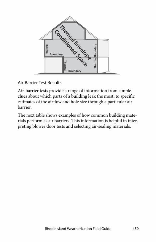
Rhode Island Weatherization Field Guide 459
Air-Barrier Test Results
Air-barrier tests provide a range of information from simple clues about which parts of a building leak the most, to specific estimates of the airflow and hole size through a particular air barrier.
The next table shows examples of how common building mate-rials perform as air barriers. This information is helpful in inter-preting blower door tests and selecting air-sealing materials.
Thermal Envelope
Conditioned Space
Thermal
Boundary
Thermal
Boundary
Ther
mal
Bou
ndar
y

Air Leakage Diagnostics460
12.3.1 Primary Versus Secondary Air Barriers
A home’s air barrier should be a material that is continuous, sealed at the seams, and impermeable to airflow. Where there are two possible air barriers, in an attic for example, the most airtight barrier is the primary air barrier and the least airtight is the secondary air barrier.
The primary air barrier should be adjacent to the insulation to ensure the insulation’s effectiveness. We use pressure-diagnostic testing to verify that the insulation and the primary air barrier are together. Sometimes we’re surprised during testing to find that our assumed primary air barrier is actually secondary, and the secondary air barrier is primary.
Table 12-1: Building Components and Their Air Permeance
Good air barriers:<2 CFM50 per
100 sq. ft.
Poor air barriers:10–1000 CFM50 per
100 sq. ft.
5/8” oriented strand board5/8” tongue-and-groove wood
sheeting
1/2” drywall 6" fiberglass batt
4-mil air barrier paper 1.5" wet-spray cellulose
Asphalt shingles and perforated felt over 1/2” plywood
wood siding over plank sheath-ing
1/8” tempered hardboardwood shingles over plank
sheathing
painted un-cracked lath and plaster
blown fibrous insulation
Measurements taken at 50 pascals pressure.Based on information from: “Air Permeance of Building Materials” by
Canada Mortgage Housing Corporation, and estimates of comparable assemblies by the author.
Although cellulose reduces air leakage when blown into walls, it isn’t considered an air-barrier material.

Rhode Island Weatherization Field Guide 461
Intermediate zones are unconditioned spaces that are sheltered within the exterior shell of the house. Intermediate zones can be located inside or outside the home’s primary air barrier. Inter-mediate zones include: unheated basements, crawl spaces, attics, enclosed porches, and attached garages.
Intermediate zones have two potential air barriers: one between the zone and house and one between the zone and outdoors. For example, an attic or roof space has two air barriers: the ceiling and roof. You should know which air barrier is the tightest.
12.3.2 Simple Pressure Tests
Blower door tests give us valuable information about the relative leakiness of rooms or sections of the home. Listed below are five simple methods
1. Feeling zone air leakage: Close an interior door partially so that there is a one-inch gap between the door and door jamb. Feel the airflow along the length of that crack, and compare that airflow intensity with airflow from other rooms, using this same technique.
2. Observing the ceiling/attic floor: Pressurize the home and observe the top-floor ceiling from the attic with a good flashlight. Air leaks will show in movement of loose-fill insulation, blowing dust, moving cobwebs, etc. You can also use a small piece of tissue paper to dis-close air movement.
3. Observing smoke movement: Pressurize the home and observe the movement of smoke through the house and out of its air leaks.
4. Room pressure difference: Check the pressure difference between a closed room or zone and the main body of a home. Larger pressure differences indicate larger potential air leakage within the closed room or else a tight air barrier between the room and main body. A small pressure difference means little leakage to the

Air Leakage Diagnostics462
outdoors through the room or a leaky air barrier between the house and room.
5. Room airflow difference: Measure the house CFM50 with all interior doors open. Close the door to a single room, and note the difference in the CFM50 reading. The dif-ference is the approximate leakage through that room’s air barrier.
Tests 1, 2, and 3 present good customer education opportunities. Feeling airflow or observing smoke are simple observations, but have helped identify many air leaks that could otherwise have remained hidden.
When airflow within the home is restricted by closing a door, as in tests 4 and 5, it may take alternative indoor paths that render these tests somewhat misleading. Only practice and experience can guide your decisions about the applicability and usefulness of these general indicators.
50 pa.
Interior door test: Feeling airflow with your hand at the crack of an interior door gives a rough indication of the air leakage coming from the outdoors through that room.

Rhode Island Weatherization Field Guide 463
12.3.3 Simple Zone Pressure Testing
Manometers aren’t limited to finding indoor WRT outdoor dif-ferences. They can also measure pressure differences between the house and its intermediate zones during blower-door tests. The purpose of these tests is to evaluate the air-tightness of the home’s interior air barriers.
The blower door, when used to create a house-to-outdoors pres-sure of –50 pascals, also creates house-to-zone pressures of between 0 and –50 pascals in the home’s intermediate zones. The amount of depressurization depends on the relative leaki-ness of the zone’s two air barriers.
50pa
House WRT room
Reference
Input
-20Digital Manometer
Bedroom test: This bedroom pressure difference may be caused by its leaky exterior walls or tight interior walls, separating it from the main body of the home. This test can determine whether or not a confined combustion zone is connected to other rooms.

Air Leakage Diagnostics464
For example, in an attic with a fairly airtight ceiling and a well-ventilated roof, the attic will indicate that it is mostly outdoors by having a house-to-zone pressure of –45 to –50 pascals. The leakier the ceiling and the tighter the roof, the smaller that the negative house-to-zone pressure will be. This holds true for other intermediate zones like crawl spaces, attached garages, and unheated basements.
Zone Leak-Testing Methodology
Depressurize house to –50 pascals with a blower door.
1. Find an existing hole, or drill a hole through the floor, wall, or ceiling between the conditioned space and the intermediate zone.
2. Connect the reference port of a digital manometer to a hose reaching into the zone.
3. Leave the input port of the digital manometer open to the indoors.
Manometer measures house wrt zone
Insulated walls are dark colored
zone
zone
zone
zone
50 pa.
Reference
Input
-47Digital Manometer
Reference
Input
-27Digital Manometer
Reference
Input
-34Digital Manometer
Reference
Input
-38Digital Manometer
Pressure-testing building zones: Measuring the pressure difference across the assumed thermal boundary (house wrt zone) tells you whether the air barrier and insulation are aligned. If the manometer reads close to –50 pascals, the air barrier and insulation are aligned and the tested zones are well-connected to outdoors.
air barrier
air barrier

Rhode Island Weatherization Field Guide 465
4. Read the negative pressure given by the manometer. This is the house-to-zone pressure, which will be –50 pascals if the air barrier between house and zone is air-tight and the zone itself is well-connected to outdoors.
5. If the reading is significantly less negative than –45 pas-cals, find the air barrier’s largest leaks and seal them.
6. Repeat steps 1 through 5, performing more air-sealing as necessary, until the pressure is as close to –50 pascals as possible.
Leak-Testing Building Cavities
Building cavities such as wall cavities, floor cavities between sto-ries, and dropped soffits in kitchens and bathrooms can also be
0–50 –40 –30 –20 –10House WRT Zone Pressure in Pascals
Out
door
s
Hal
fway
Hou
seZone is more connected to house
than to outdoors
Zone is more connected to outdoors
than to house
Interpreting house-to-zone pressure: The greater the negative number the better the air barrier is performing.
50pa Reference
Input
-13Digital Manometer
attic WRT outdoors
50pa
house WRT attic
Reference
Input
-37Digital Manometer
House-to-attic pressure: This commonly used measurement is convenient because it requires only one hose.
Attic-to-outdoors pressure: This measurement confirms the first because the two add up to –50 pascals.

Air Leakage Diagnostics466
tested as described above to determine their connection to the outdoors as shown here.
Testing Zone Connectedness
Sometimes it’s useful to determine whether two zones are con-nected by a large air leak. Measuring the house-to-zone pressure during a blower door test, before and then after opening the other zone to the outdoors, can establish whether the two zones are connected by a large air leak. You can also open an interior door to one of the zones and check for pressure changes in the other zone.
50pa Reference
Input
-20Digital Manometer
Porch roof WRT outdoors = -20 pa
50pa Reference
Input
-30Digital Manometer
Cantilevered floor WRToutdoors = -30pa
Cantilevered floor test: We hope to find the cantilevered floor to be indoors. A reading of –50 pascals would indicate that it is completely indoors. A reading less negative than –50 pascals is measured here, indicating that the floor cavity is partially connected to outdoors.
Porch roof test: If the porch roof were outdoors, the manometer would read near 0 pascals. We hope that the porch roof is outdoors because it is outside the insulation. We find, however, that it is partially indoors, indicating that it may harbor significant air leaks through the thermal boundary.
These examples assume that the manometer is outdoors with the reference port open to outdoors

Rhode Island Weatherization Field Guide 467
Leak-Testing Building Cavities
You can also test building cavities such as wall cavities, floor cavities between stories, and dropped soffits in kitchens and bathrooms with a digital manometer to evaluate their possible connection to the outdoors by way of air leaks.
12.3.4 Locating the Thermal Boundary
When retrofitting, you need to decide where to air-seal and where to insulate. Zone pressures are one of several factors used to determine where the thermal boundary should be.
For zone leak-testing, the house-to-zone pressure is often used to determine which of two air barriers is tighter.
• Readings of -25 to -50 pascals house-to-attic pressure mean that the ceiling is tighter than the roof. If the roof is almost completely airtight, achieving a 50-pascal house-to-attic pressure difference may be difficult. However if the roof is well-ventilated, achieving a near 50 pascal difference should be possible.
• Readings of 0 to -25 pascals house-to-attic pressure mean that the roof is tighter than the ceiling. If the roof is well-
50pa
Reference
Input
-41Digital Manometer
50pa
Reference
Input
-47Digital Manometer
Zone connectedness: The attic measures closer to outdoors after the basement window is opened, indicating that the attic and basement are connected by a large bypass.

Air Leakage Diagnostics468
ventilated, the ceiling has even more leakage area than the roof ’s vent area.
• Readings around –25 pascals house-to-attic pressure indi-cate that the roof and ceiling are equally airtight or leaky.
Pressure readings more negative than –45 pascals indicate that the ceiling (typical primary air barrier) is adequately airtight. Less negative pressure readings indicate that ceiling air leaks should be located and sealed.
Floor Versus Crawl Space
The floor shown here is tighter than the crawl-space foundation walls. If the crawl-space foundation walls are insulated, holes and vents in the foundation wall should be sealed until the pres-sure difference between the crawl space and outside is as nega-tive you can make it — ideally more negative than –45 pascals. A leaky foundation wall renders its insulation nearly worthless.
If the floor above the crawl space were insulated instead of the foundation walls then the air barrier and the insulation would be aligned.
If a floor is already insulated, it makes sense to establish the air barrier there. If the foundation wall is more airtight than the floor, that would be one reason to insulate the foundation wall.
0–50 –40 –30 –20 –10House WRT Attic Pressure in Pascals (Pa)
Ou
tdo
ors
Hal
fway
Ho
use The roof is tighter
than the ceilingThe ceiling is tighter
than the roof
50Pa
house WRT attic
Reference
Input
-25Digital Manometer

Rhode Island Weatherization Field Guide 469
Attic Boundary
Generally, the thermal boundary (air barrier and insulation) should be between the conditioned space and attic. An excep-tion would be insulating the roof to enclose an attic air handler and its ducts within the thermal boundary.
Garage Boundary
The air barrier should always be between the conditioned space and a tuck-under or attached garage, to separate the living spaces from this unconditioned and often polluted zone.
Duct Location
The location of ducts either within or outside the thermal boundary is an important factor in determining the cost-effec-tiveness of duct-sealing and insulation. Including the heating ducts within the thermal boundary is preferred because it reduces energy waste from both duct leakage and duct heat transmission.
–5 pa.
–45 pa.
–40 pa.
–10 pa.
50 pa.
Pressure measurements and air-barrier location: The air barrier and insulation are aligned at the ceiling. The crawl-space pressure measurements show that the floor is the air barrier and the insulation is misaligned — installed at the foundation wall. We could decide to close the crawl space vents and air-seal the crawl space. Then the insulation would be aligned with the air barrier.

Air Leakage Diagnostics470
12.4 SWS ALIGNMENT
Field Guide Topic SWS Detail
12.1: Shell Air-Leakage Fundamentals - Pg. 447
12.1.1: Goals of Air-Leakage Testing - Pg. 448
12.2: Single-Family Airtightness Testing - Pg. 450
12.2.1: Blower-Door Principles -Pg. 450
12.2.2: Preparing for a Blower Door Test - Pg. 453
12.2.3: Blower-Door Test Procedures - Pg. 454
12.2.4: Approximate Leakage Area (ALA) - Pg. 456
12.3: Testing Air Barriers - Pg. 457
12.3.1: Primary Versus Second-ary Air Barriers - Pg. 460
12.3.2: Simple Pressure Tests -Pg. 461
12.3.3: Simple Zone Pressure Testing - Pg. 463
12.3.4: Locating the Thermal Boundary - Pg. 467

Rhode Island Weatherization Field Guide 471
APPENDICES
A–1 R-VALUES FOR COMMON MATERIALS
Material R-value
Fiberglass or rock wool batts and blown 1” 2.8–4.0
Blown cellulose 1” 3.0–4.0
Vermiculite loose fill 1” 2.7
Perlite 1” 2.4
White expanded polystyrene foam (beadboard) 1” 3.9–4.3
Polyurethane/polyisocyanurate foam 1” 6.2–7.0
Extruded polystyrene 1” 5.0
High-density 2-part polyurethane foam 1” 5.8–6.6
Low-density 2-part polyurethane foam 1” 3.6
Oriented strand board (OSB) or plywood 1/2” 1.6
Concrete or stucco 1” 0.1
Wood 1” 1.0
Carpet/pad 1/2” 2.0
Wood siding 3/8–3/4” 0.6–1.0
Concrete block 8” 1.1
Asphalt shingles 0.44
Fired clay bricks 1” 0.1–0.4
Gypsum or plasterboard 1/2” 0.4
Single pane glass 1/8” 0.9
Low-e insulated glass (Varies according to Solar Heat Gain Coefficient (SHGC) rating.)
3.3–4.2

Appendices472
A–2 ASHRAE 62.2 DUCT SIZING
Rated Fan CFM
50 80 100 125 150 200 250 300
Duct Dia. Smooth Hard Duct - Maximum Duct Length in Feet
3” 5 X X X X X X X
4” 114 31 10 X X X X X
5” NL 152 91 51 28 4 X X
6” NL NL NL 168 112 53 25 9
7” NL NL NL NL NL 148 88 54
8” NL NL NL NL NL NL 198 133
Duct Dia. HVAC Flex Duct - Maximum Duct Length in Feet
3” X X X X X X X X
4” 56 4 X X X X X X
5” NL 81 42 16 2 X X X
6” NL NL 158 91 55 18 1 X
7” NL NL NL NL 161 78 40 19
8” NL NL NL NL NL 189 111 69
NL: No limit; X: not allowedTable assumes no elbows. Deduct 15 ft from allowable duct length for each elbow.

Rhode Island Weatherization Field Guide 473
A–3 FIRE TESTING AND RATING
Test/Rating Description
ASTM E-136 If a material passes this test, it is non-combustible.
ASTM E-119Hourly rating of a wall when exposed to fire. Deter-mines how long that the wall holds back heat and flames and maintains its structural integrity.
ASTM E-184Hourly rating for a sealant system for a penetration through a fire-rated (ASTM E119) assembly.
ASTM E-84
Test measures how fast flames spread in a fire tun-nel lined with the tested material, compared to red oak, which is given a flame spread of 100. This test classifies materials as Class I, II, or III (or A, B, & C) See flame spread in the three rows below.
Class I or A Flame spread less than or equal to 25
Class II or B Flame spread 26 to 75
Class III or C Flame spread 76 to 200
FM 4880 or UL-1040
Like ASTM E-84 except the fire burns in a 90-degree corner of a wall assembly containing the tested material. These tests are designed to closer approximate actual performance of a material installed in a typical building assembly. The flame spread and smoke developed ratings also relative to Class I, II, and III assemblies.
UL 1715
Like the tunnel test and corner test except the fire burns in a room with its wall and ceiling assembly containing the tested material. The flame spread and smoke developed ratings also relative to Class I, II, and III assemblies.
UL181Duct materials, duct-closure systems, and duct sealants so labeled pass UL fire-resistance tests.

Appendices474
A–4 MAXIMUM CAZ DEPRESSURIZATION
Appliance Type Max. Depress.
Atmospheric water heater only (Category I, natural draft), open-combustion appliances, and orphaned water heaters
–2 pa
Atmospheric water heater (Category I, natural draft) and atmospheric furnace (Category I, natural draft), common-vented, open-combustion appliances
–3 pa
Gas furnace or boiler, Category I or Category I fan-assisted, open-combustion appliances, and stand-alone gas water heaters
–5 pa
Oil or gas unit with power burner, low- or high-static pressure burner, open combustion appliances
–5 pa
Wood-burning appliances –7 pa
Open-combustion furnaces or boilers with fan-pow-ered horizontal venting
–15 pa
Pellet stove with draft fan and sealed vent –15 pa
Direct-vent, sealed combustion appliances with forced draft.
–25 pa
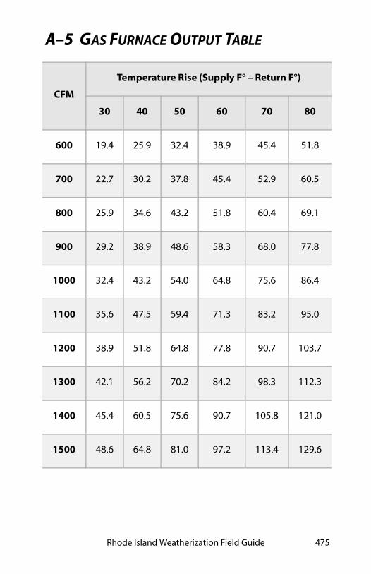
Rhode Island Weatherization Field Guide 475
A–5 GAS FURNACE OUTPUT TABLE
CFM
Temperature Rise (Supply F° – Return F°)
30 40 50 60 70 80
600 19.4 25.9 32.4 38.9 45.4 51.8
700 22.7 30.2 37.8 45.4 52.9 60.5
800 25.9 34.6 43.2 51.8 60.4 69.1
900 29.2 38.9 48.6 58.3 68.0 77.8
1000 32.4 43.2 54.0 64.8 75.6 86.4
1100 35.6 47.5 59.4 71.3 83.2 95.0
1200 38.9 51.8 64.8 77.8 90.7 103.7
1300 42.1 56.2 70.2 84.2 98.3 112.3
1400 45.4 60.5 75.6 90.7 105.8 121.0
1500 48.6 64.8 81.0 97.2 113.4 129.6

Appendices476
A–6 BPI COMBUSTION-TESTING DIAGRAMS

Rhode Island Weatherization Field Guide 477
A–7 DOE HEALTH AND SAFETY GUIDANCE
Weatherization Program Notice 17-7 is Effective August 9, 2017. WPN 17-7 clarifies, updates, and provides additional informa-tion related to the implementation and installation of health and safety (H&S) measures as part of the DOE WAP. This guidance also provides required components for Grantees to include in their Health and Safety Plans.
You can find the WPN 17-7 documents at:http://www.energy.gov
Resource Links
• WPN 17-7: Weatherization H&S Guidance
• Attachment A- Additional H&S Guidance Related to Heat-ing Systems
• Table of Issues

Appendices478

Rhode Island Weatherization Field Guide 479
GLOSSARY
Abatement : A measure or set of measures designed to perma-nently eliminate a hazard
Absolute humidity: Air’s moisture content expressed in weight of water vapor per standard weight (pounds, grams) of dry air.
Absorptance: The ratio of a solar energy absorbed to incident solar. Also called absorbtivity.
Absorption: A solid material’s ability to draw in and hold liquid, gas, or radiant energy.
Accent lighting: Illumination of walls or other surfaces, to spread light and reduce contrast in an indoor or outdoor area.
Acoustical Sealant: Sealing agent used to minimize sound trans-mission through a joint.
ACH50: The number of times in one hour that all of the air in a home is replaced by outside air during a 50-pascal blower door test.
Adsorption: Adhesion of a thin layer of molecules to a surface they contact.
Air barrier: Any part of the building shell that offers resistance to air leakage. The air barrier is effective if it stops most air leak-age. The primary air barrier is the most effective of a series of potential air barriers.
ACH50: Air changes per hour at 50 pascals. The number of times the volume of air in a structure will change in one hour at the induced blower door house pressure of 50 pascals.
ACHnat: Air changes per hour natural. The number of times the indoor air is exchanged with the outdoor air in one hour under natural driving forces.
Air conditioning: Cooling buildings with a refrigeration system. More generally means both heating and cooling.

Appendices480
Air Conditioning Contractors of America (ACCA): Industry group that promotes best practices and lobbies for the industry.
Air exchange: The process whereby indoor air is replaced with the outdoor air through air leakage and ventilation.
Air-free carbon monoxide (ppm): A measurement of CO in an air sample or flue gas that accounts for the amount of excess air (oxygen, O2) in the sample. It adjusts the as-measured CO ppm value, thus simulating air-free (oxygen-free) conditions in the sample. Measured in parts per million (ppm).
Air handler: A steel cabinet containing a blower with cooling and/or heating equipment, connected to ducts that transport indoor air to and from.
Air-handling unit (AHU): See air handler.
Air leakage: Uncontrolled ventilation through gaps in the air barrier. Typical sites of air leakage include around windows, pipes, wires and other penetrations.
Air-impermeable insulation: An insulation having an air perma-nence equal to or less than 0.02 L/s-m2 at 75 Pa pressure differ-ential tested according to ASTM E 2178 or E 283.
Air sealing: The systematic approach to reducing air leakage in a building.
Albedo: The ratio of reflected light to incident light.
Altitude adjustment: The input modification for a gas appliance installed at a high altitude. When a gas appliance is installed more than 2000 feet above sea level, The installer may reduce its input rating according to manufacturers’ specifications.
Ambient: Of the surrounding area or environment.
Ambient air: Air in the habitable space. Also the air around a human observer.
Ambient lighting: Lighting spread throughout the lighted space for safety, security, and aesthetics.

Rhode Island Weatherization Field Guide 481
American Gas Association (AGA): A trade association represent-ing American natural gas supply companies. AGA collaborates with ASC and NFPA on the National Fuel Gas Code.
American National Standards Institute, Inc. (ANSI): A private non-profit organization that oversees the development of volun-tary consensus standards for products, services, processes, sys-tems, and personnel in the United States.
American Recovery and Reinvestment Act (ARRA): Bill signed by President Obama in February 2009 as an economic stimulus package.
American Society of Heating, Refrigeration, and Air Conditioning Engineers (ASHRAE): A technical society for individuals and organizations interested in heating, ventilation, air-condition-ing, and refrigeration. ASHRAE publishes standards and guide-lines relating to HVAC systems and issues.
American Society for Testing and Materials (ASTM) : A stan-dards organization that develops and publishes voluntary con-sensus technical standards for a wide range of materials, products, systems, and services.
Amperage: The rate that electrical current flows through an appliance at any given time; also called current.
Ampere: A unit that measures the rate that electrons move through a conductor.
Anemometer: A device that measures air speed, used in HVAC work to determine flow rates at registers.
Annual Fuel Utilization Efficiency (AFUE): A laboratory-derived efficiency for heating appliances that accounts for chimney losses, jacket losses, and cycling losses, but not distribution losses, fan energy, or pump energy.
Annual return: The annual savings divided by the initial cost of an ECM, expressed as a percent.
Appliance: Any device powered by electricity or combustible fuel.

Appendices482
Approach temperature: The temperature difference between the fluid inside a heat exchanger and the fluid outside of it.
Aquastat: A heating control device that controls the burner or the circulator in a hydronic heating system.
Arc-fault circuit interrupter (AFCI): A circuit breaker that dis-connects a circuit when it detects an electrical arc.
Area: Length x width = area.
As-measured carbon monoxide (CO): A calculation of CO in parts per million (ppm) of a combustion-gas sample with the excess air (oxygen, O2), diluting the CO concentration removed by the calculator in the fuel-gas analyzer.
ASHRAE: American Society of Heating, Refrigerating, and Air-Conditioning Engineers. International technical society which develops standards for those concerned with refrigeration pro-cesses and the design and maintenance of indoor environments.
ASHRAE 62.2-20xx: Indoor air quality standard developed for low-rise residential buildings. Defines the roles of an minimum requirements for mechanical and natural ventilation systems and the building envelope.
Asbestos: A fibrous mineral with fireproofing and insulating characteristics manufactured into a variety of building materi-als. Small, sharp, asbestos fibers are a known carcinogen when inhaled.
Association of Energy Engineers (AEE): A professional organiza-tion for energy engineers. AEE offers many certification pro-grams, including energy auditors and other energy experts.
Association of Home Appliance Manufacturers (AHAM): Trade association representing the appliance manufacturing industry
Asthma: An acquired respiratory illness with strong correlation to buildings, moisture problems, and pets.
Atmospheric appliance: A combustion appliance that burns and exhausts its combustion gases at atmospheric pressure.

Rhode Island Weatherization Field Guide 483
Atmospheric pressure: The weight of air and its contained water vapor on the surface of the earth. At sea level this pressure is 101,325 pascals or 14.7 pounds per square inch.
Attic: The unfinished space between the ceiling assembly of the top story and the roof assembly.
Attic, habitable: A finished or unfinished area, not considered a story. See the IRC for specific requirements.
Audit: The process of identifying energy conservation opportu-nities in buildings.
Auxiliary heat: Electric resistance heat in a heat pump that heats the building when the compressor isn’t able to provide the entire heat capacity needed for cold weather.
Awning window: Awning windows are essentially casement win-dows that swing vertically.
B-vent: A double-wall pipe for gas- or propane-fired combus-tion appliances.
Backdrafting: Continuous spillage of combustion gases from a vented combustion appliance into the conditioned space.
Backdraft damper: A damper, installed near a fan, that allows air to flow in only one direction.
Backer rod: Polyethylene foam rope used as a backer for caulk-ing.
Baffle: 1. A lightweight plate that directs air from a soffit over attic insulation and along the bottom of the roof deck to venti-late the attic and cool the roof deck. 2. A plate or strip designed to retard or redirect the flow of flue gases.
Balance point: The outdoor temperature at which no heating is needed to maintain indoor comfort.
Ballast: A coil of wire or electronic device that provides a high starting voltage for a lamp and also limits the current flowing through it

Appendices484
Balloon framing: A method of construction in which the vertical framing members (studs) are continuous pieces running the entire height of the wall.
Band joist: See - Rim joist
Barometric vent damper: A device installed in the heating unit vent system to control draft. Usually used on oil-fueled heaters or gas heaters with power burners
Barrier: Material used to block passage or movement.
Basement: The portion of a building that is partly or completely below grade.
Batt: A blanket of preformed fibrous insulation designed to fill cavities.
Beam: A strong horizontal building support used to carry the weight of a floor or roof.
Belly blow: A process for re-insulating floor cavities with blown-in insulation.
Belly return: A configuration found in some mobile homes that uses the belly cavity as the return side of the heating/cooling dis-tribution system.
Bimetal element: A metal spring, lever, or disc made of two dis-similar metals that expand and contract at different rates as the temperature around them changes. This movement operates a switch in the control circuit of a heating or cooling device.
Blocking: A construction element or material used to strengthen or to prevent the movement of air or insulation into or out of building cavities.
Block frame: A non-finned window frame for new or retrofit installation in a rough opening.
Blower door: A blower door is a diagnostic tool used to locate air leaks in the building envelope and help prioritize the air sealing protocols.

Rhode Island Weatherization Field Guide 485
Blow-down: The act of removing water from a boiler to remove sediment and suspended particles from the boiler water.
Blower: The squirrel-cage fan in a furnace or air handler.
Blown insulation : A loose-fill insulation that is blown into attics and building cavities using an insulation blowing machine.
Board feet: An American measurement of lumber volume. A board foot equals 144 cubic inches of wood.
Boiler: A fossil fuel appliance used for producing hot water or steam as the medium to distribute heat to the dwelling unit.
Boot: A duct section that connects between a duct and a register or between round and square ducts
Bonus room: A room that is substandard in some way and not listed in a home’s salable features.
Borescope: A flexible tube with a light and camera or viewer at one end. Inspectors use borescopes to look into wall cavities and other tight spaces, otherwise impossible to inspect.
Boundary: Defines where one area ends and another begins.
Branch circuit: An electrical circuit used to power outlets and lights within a home.
Branch duct: An air duct which branches from a main duct.
Brightness: The intensity of the sensation derived from viewing a lit surface. Measured in footlamberts or candelas per square meters. It is also called luminance or luminous intensity.
British thermal unit (Btu): The quantity of heat required to raise the temperature of one pound of water one degree Fahrenheit.
BTUh : British Thermal Units per hour.
Building cavities: The spaces inside walls, floors, and ceilings between the interior and exterior sheeting
Building envelope: The area of the building that encloses its con-ditioned and unconditioned spaces.

Appendices486
Building Management System (BMS): Computer-based control system installed in buildings that controls and monitors the building's mechanical and electrical equipment such as air han-dling and cooling.
Building Performance Institute (BPI): Organization supporting the development of a highly professional building performance industry through individual and organizational credentialing and a quality assurance program.
Building science: A complex perspective on buildings, using con-temporary technology to analyze and solve problems of design, construction, maintenance, safety, and energy efficiency.
Building shell: Separates a building’s indoors from the outdoors.
Building Tightness Limit (BTL): Calculation procedure, expressed in units of CFM50, based on the American Society of Heating, Refrigerating and Air-Conditioning Engineers Stan-dard 62-2001, Ventilation for Acceptable Indoor Air.
Bulk moisture: Large amounts of water intrusion, for example from wind-driven rain or sub-surface water.
Burner: A device that facilitates the burning of a fossil fuel, like gas or oil.
Butyl-backed tape: Heavy-duty, pressure-sensitive sealant or gas-ket.
Bypass: An air leakage site that allows air to leak into or out of a building flowing around the air barrier and insulation.
Cad cell: A flame sensor composed of the chemical compound cadmium sulfide. Its purpose is to sense whether a flame is pres-ent during a burner cycle. If the cad cell doesn’t detect a flame, it shuts the burner off.
Calibration: Comparison of the test results of an instrument to a known reference point.
Call-back: Having a weatherization team return to a job site to perform work not done or to redo work done unsatisfactorily.

Rhode Island Weatherization Field Guide 487
Can light: A light fixture (or can) that is set into the ceiling. Also called a recessed light fixture.
Cantilever: A projecting structure, such as a beam, that is sup-ported at one end and carries a load at the other end or along its length.
Cantilevered floor: A floor that extends beyond the foundation of the framed structure below it.
Cape Cod: A house design featuring a finished attic space, also called a one-and-a-half story.
Capillary action: The ability of water to move through materials, even upward against gravity, through small tubes or spaces.
Capillary barrier: A material or air space designed to stop capil-lary action from carrying water into a building.
Carbon dioxide (CO2): A heavy, colorless, nonflammable gas formed by the oxidation of carbon, by combustion, and by the respiration of plants and animals. One of two main products of complete combustion of a hydrocarbon (the other is water vapor).
Carbon monoxide (CO): Carbon monoxide is a tasteless, odor-less, colorless and poisonous gas that is a by-product of incom-plete combustion of fossil fuels. It is usually caused by a lack of air to support combustion or impingement of the flame.
Carcinogen: A material known to cause cancer.
Casement window: Casement windows have a single operable sash that swings outward on a horizontal plane. Casement win-dow frames that have gone out of square due to settling can stick and quite possible render these types of windows inoperable.
Casing: Decorative molding or trim around a window or door.
Cathedral ceiling: A sloped ceiling insulated between the roof deck and the finish ceiling material.
Cathedralized attic: An attic that is insulated at the underside of the roof deck rather than at the ceiling.

Appendices488
Caulking: Mastic compound for filling joints and cracks.
Celsius (°C): The metric temperature scale where water freezes at 0°C and boils at 100°C.
Cellulose insulation: Insulation, packaged in bags for blowing, made from newspaper or wood waste and treated with a fire retardant.
Centigrade: See Celsius (°C)
Central heating system: The primary heating system of the dwelling unit including the heat producing appliance along with the return and supply system for heat distribution.
Certification: Recognition by an independent person or group that someone can competently complete a job or task, frequently demonstrated by passing an exam.
Certified renovator: A person authorized by the EPA to perform repair and renovation projects that disturb lead-based paint.
CFM50: The amount of cubic feet per minute of air moving through a structure and measured at 50-pascals pressure during a blower door test.
CFMn: The cubic feet of air flowing through a house from indoors to outdoors during typical, natural conditions.
CFM - Cubic feet per minute: An American measurement of air-flow equal to 0.472 liters per second.
Chaseway: Cavity within a building with a purpose of conveying pipes, ducts, etc. through the building. Chaseways, such as plumbing walls, are common sites for air leakage.
Chimney: A building component designed for the sole purpose of assuring combustion by-products are exhausted to the exte-rior of the building.
Chimney connector: A pipe that connects a fuel-burning appli-ance to a chimney. Also see vent connector.

Rhode Island Weatherization Field Guide 489
Chimney flue: A passageway in a chimney for conveying com-bustion gases to the outdoors.
Chimney chase: The framing and other building materials that surround the chimney.
Circuit breaker: A device found in a Circuit Panel Box that com-pletes an electric circuit. This breaker disconnects the circuit from electricity when it senses an overload of current.
Cladding: The exterior covering or coating on a structure, such as wood siding, stucco, or brick veneer.
Clean and tune (C&T): A procedure performed on a heating or cooling system by a qualified technician to optimize its effi-ciency.
Cleanout: An opening in a chimney (usually at its base) to allow inspection and the removal of ash or debris.
Clearances: Allowable distances between heat-producing appli-ances, chimneys, or vent systems and combustible surfaces.
Climate zone: An area with a prevailing climate that distin-guishes it from other areas by parameters such as temperature, rainfall, and humidity.
Codes: Any set of standards set forth and enforced for the pro-tection of public health and humidity.
Co-efficient of performance (COP): A dimensionless number representing the ratio of a heat pump or air conditioner’s output in watt-hours of heat moved divided by watt-hours of electrical input.
Coil: A snake-like piece of copper tubing surrounded by rows of aluminum fins that clamp tightly to the tubing and aid in heat transfer.
Coil stock: Sheet metal packaged as a coil in various widths.
Cold-air return: Ductwork that draws house air into the air han-dler for reheating by a furnace.

Appendices490
Cold roof: A roof design where the roof temperature is equalized from top to bottom by roof ventilation and/or roof insulation to prevent ice damming.
Collar beam: A horizontal piece in roof framing that provides structural strength by connecting opposite rafters.
Color rendering index (CRI): A measurement of a light source's ability to render colors the same as sunlight. CRI has a scale of 0 to 100.
Color temperature: A measurement of the warmness (redness or yellowness) or coolness (blueness or whiteness) of a light source in the Kelvin temperature scale.
Column: A vertical building support usually made of wood or steel.
Combustible: Means something will burn, although not neces-sarily readily.
Combustible gas leak detector: A device for determining the presence and general location of combustible gases in the air.
Combustion: The act or process of burning. Oxygen, fuel, and a spark must be present for combustion to occur.
Combustion air: Air that chemically combines with a fuel during the combustion process to produce heat and combustion gases, mainly carbon dioxide and water vapor.
Combustion analyzer: A device used to measure and analyze combustion gases for efficiency and safety.
Combustion appliance: Any appliance in which combustion occurs.
Combustion appliance zone (CAZ) : The closed space or area that holds one or more combustion appliances.
Combustion appliance zone (CAZ) testing: Diagnostics per-formed to ensure that combustion appliances work properly and that house pressures allow combustion gases to vent.
Rhode Island Weatherization Field Guide 491
Combustion byproducts: Gases, vapors, and particulates pro-duced whenever carbon-based fuels are burned.
Combustion chamber: The area inside the heat exchanger where the flame burns.
Combustion efficiency: Synonymous with steady-state efficiency.
Combustion gases: Combustion byproducts.
Commissioning: The process of testing and adjusting building mechanical systems.
Common vent : The portion of the vent or chimney through which passes products of combustion from more than one appliance.
Compact fluorescent lamp (CFL): A small fluorescent light engi-neered to fit in an Edison base of an incandescent fixture.
Compartmentalization: Air-sealing that prevents air from migrating from one dwelling or zone of a multifamily building to another.
Competency: Demonstrated ability to perform a job or task.
Compressor: A motorized pump that compresses the gaseous refrigerant and sends it to the condenser where heat is released.
Concentrically constructed direct-vent: A direct-vent appliance that has an exhaust-gas vent and a combustion-supply-air vent arranged in a concentric fashion: one pipe is inside the other with a space between the walls of each.
Condensate: Vapor condensed back to a liquid. For example: water or refrigerant.
Condensate receiver: A tank for catching returning condensate water from a steam heating system or condensed refrigerant from a condenser.
Condense: When a gas turns into a liquid as it cools, it con-denses. When a gas condenses into a liquid it releases heat.

Appendices492
Condenser: The coil in a refrigeration system where the refriger-ant condenses and releases heat.
Condensing furnace: A high-efficiency furnace that removes latent heat from combustion gases by condensing water vapor out of the combustion gases.
Conditioned: Intentionally heated or cooled areas of a building.
Conditioned air: Air that has been heated, cooled, humidified, or dehumidified to provide comfort.
Conditioned space: For energy purposes, space within a building that is provided with heating and/or cooling equipment or sys-tems, or that communicates directly with a conditioned space. For mechanical purposes, an area, room or space being heated or cooled by any equipment or appliance.
Conductance: The quantity of heat, in BTUs, that flows through one square foot of material in one hour, when there is a one degree Fahrenheit temperature difference between both sur-faces. Conductance values are given for a specific thickness of material.
Conduction: Conduction is the transfer of heat through a mate-rial by molecular vibration.
Conductivity: The quantity of heat that flows through one square foot of homogeneous material, one inch thick, in one hour, when there is a temperature difference of one degree Fahr-enheit between its surfaces.
Confined space: A space, defined for the purpose of evaluating combustion air, with a volume of less than 50 cubic feet per 1,000 BTU per hour of the total input rating of all combustion appliances installed in that space.
Contractor: Any person or entity that provides services under contract, and not as employees of the purchasing agency.
Contrast: Difference in brightness measured by the relationship between an object’s brightness and the brightness of its back-ground.

Rhode Island Weatherization Field Guide 493
Control circuit: An electrical circuit that activates or deactivates a power circuit or opens and shuts a valve.
Convection: The transfer of heat caused by the movement of a fluid like water or air. When a fluid becomes warmer it becomes lighter and rises.
Convective loop: Heat flow resulting from fluid flow between surfaces of different temperatures.
Cooling load: The maximum rate of heat removal required of an air conditioner when the outdoor temperature and humidity are at a standard worst-case outdoor condition.
Core competencies: Essential skills for weatherization workers, defined by the Weatherization Trainers Consortium.
Cost effective: Having an acceptable payback, return-on-invest-ment, or savings-to-investment ratio.
Crawl space: The low space beneath the ground floor of a build-ing that gives workers access to wiring and plumbing.
Crew leader: A crew leader is a residential energy professional who supervises weatherization tasks specified in the scope of work.
Critical framing juncture: An intersection of framing members and envelope components that require special attention during air-sealing and insulation.
Cross section: A view of a building component drawn or imag-ined by cutting through the component.
Crosswise floor-joists: Mobile home joist configuration where the main duct is located beneath the floor joists and connected by boots to the sub-floor.
Cubic foot per minute (CFM): A measurement of volumetric air-flow rate. See also CFM50 and CFMn.
Curtain wall: A wall between columns and beams that supports no weight but its own.

Appendices494
Dado: A rectangular groove cut into wood to create a structural joint.
Decatherm: One million BTUs or 10 therms.
Decking: The wood material structural sheathing installed over the rafters to support the roofing.
Decommissioning: Removing or retiring equipment from active service including disposing of hazardous material in an approved way.
Deferral of services: Postponement or denial of weatherization services to the client.
Dehumidification: The removal of water from the air. Excess humidity can cause mold.
Degree days (DD): A cumulative measurement of outdoor tem-perature calculated by adding the temperature differences between an indoor temperature of 65°F and the daily average outdoor temperature for a one-year period.
Delta-T: Temperature difference.
Demand: The peak need for electrical energy. Some utilities levy a monthly charge for demand.
Demand-side management (DSM): The planning and imple-mentation of utility-sponsored conservation of electricity or gas.
Dense packing: Blowing insulation with sufficient force to create a high density to reduce settling and minimize air leakage and air convection.
Density: The weight of a material divided by its volume, usually measured in pounds per cubic foot.
Depressurization tightness limit (DTL): A calculation procedure, expressed in units of CFM50, performed to estimate the building tightness level at which combustion appliances might backdraft when the house is under conditions of worst-case depressuriza-tion. The DTL sets a low limit for air sealing that may or may not be lower than the BTL for the same house.

Rhode Island Weatherization Field Guide 495
Depressurize: Cause to have a lower pressure or higher vacuum with respect to a pressure reference point such as the outdoors.
Desiccant: A liquid or solid material used to absorb water or water vapor.
Design temperature: A high or low temperature, based on cli-mate history, used for designing heating and cooling systems when calculating heating and cooling loads.
Desk monitoring: Weatherization monitoring activities per-formed through review of paperwork.
De-superheater: A heat exchanger that removes the superheat from a compressed refrigerant and transfers that heat to another fluid, usually water.
Dew point: The warmest temperature of an object in an environ-ment where water condensation from the surrounding air would form on that object.
Diffusion: Movement of water vapor through a material as a function of the vapor pressure across a material and the vapor permeability of that material. See also: vapor permeable
Dilution air: Air that enters through the dilution device—an opening where the chimney joins to an atmospheric-draft com-bustion appliance
Dilution Device: A draft diverter, draft hood, or barometric draft control between an atmospheric-draft combustion appliance and its chimney.
Direct current: An electric current flowing in only one direction.
Direct leakage: Air enters and exits at same location; occurs at direct openings to outdoors.
Direct-vent appliance: A combustion appliance for which all combustion gases are vented to the outdoors through an exhaust vent pipe and all combustion supply air is supplied to the com-bustion chamber from the outdoors through a separate, dedi-cated supply-air pipe. See also sealed-combustion

Appendices496
Discount rate: The interest rate at which expected future cash savings can be discounted for the time value of money.
Distribution system: A system of wires, pipes, or ducts that dis-tributes energy.
DOE: The United States Department of Energy.
Domestic hot water (DHW): Refers to a separate, closed system to heat potable (drinkable) water and supply it to the dwelling unit for washing, bathing, etc.
Dominant duct leakage: To identify either dominant supply or return leaks in a forced-air distribution system by measuring house pressure.
Door casing: A wooden trim around doors that covers the seam between the jamb and the wall.
Door stop: The wood trim fastened to the inside of the door jamb that stops the door’s swing.
Dose: The amount of pollutant that enters a human body, exposed to the pollutant.
Dormer: A framed structure projecting above a sloping roof sur-face, and normally containing a vertical window.
Double-hung window: Double-hung windows have operable upper and lower sashes that slide vertically in a channel.
Downflow: Airflow configuration in a furnace where air flows from above the air handler and discharges from the bottom.
Downflow furnace: Furnace type where the blower is located at the top of the furnace cabinet and air is forced downwards across the heat exchanger and into the ducts located in below the furnace.
Downstream: Away from the source of the flow.
Draft: A pressure difference that causes combustion gases or air to move through a vent connector, flue, chimney, or combustion chamber.

Rhode Island Weatherization Field Guide 497
Draft diverter: A device located in gas appliance flue pipe. Used to moderate or divert draft that could extinguish the pilot or interfere with combustion.
Draft fan: A mechanical fan used in a venting system to aug-ment the natural draft in gas- and oil-fired appliances. These electrically operated, paddle-fan devices are installed in fur-naces.
Draft gauge: Device for testing chimney draft.
Draft hood: See draft diverter.
Draft inducer: A fan that depressurizes the combustion chamber or venting system to move combustion products toward the out-doors.
Draft regulator: A self-regulating damper attached to a chimney or vent connector for the purpose of controlling draft.
Drainage plane: A space that allows water storage and drainage in a wall cavity, adjacent to or part of the water-resistive barrier.
Dropped down belly: Mobile home configuration where a hump is formed in the floor by the rodent barrier and insulation going around the main duct attached to the floor’s bottom.
Dropped soffit: A lowered part of the ceiling in a home.
Drywall: Gypsum interior wallboard used to produce a smooth and level interior wall surface and to resist fire. Also called gyp-sum wall board or sheetrock.
Dry-bulb temperature: Normal ambient air temperature mea-sured by a thermometer.
Duct blower: A blower-door-like device used for testing duct leakiness and airflow.
Duct board: Rigid board composed of insulation material with one or both sides faced with a finishing material, usually alumi-num foil.

Appendices498
Duct boot: Transition piece that connects the main duct to the floor and is often vulnerable to failure.
Duct-induced pressure differences: Pressure differences between rooms in a building caused by the ducted air delivery system, can be due to supply ducts, return ducts, or both.
Duplex: Any structure which consists of two separate dwelling units in one building.
Dwelling unit: A house, including a stationary mobile home, an apartment, a group of rooms, or a single room occupied as sepa-rate living quarters.
Eave: The part of a roof that projects beyond its supporting walls (See - Soffit).
Eave chute: Device that maintains air space between the insula-tion blanket and the roof sheathing and prevents insulation from clogging eave vents.
Eave vent: Vent opening located in the soffit under the eaves of a house to allow the passage of air through the attic and out the roof vents.
Economizer: A subsystem in an HVAC system that caves energy by using favorable outdoor temperature and humidity to condi-tion building air.
Efficiency: The ratio of output divided by input.
Efficacy: The number of lumens produced by a watt used for lighting a lamp. Used to describe lighting efficiency. Synonym: Effectiveness.
Egress window: A window with a defined opening size for the purpose of fire escape.
Elastomeric: A characteristic of a material that is flexible and permits joint movement.
Elastomeric coating: Polymeric material, such as acrylic, that is used to coat roof leaks and to reduce solar heat gain.

Rhode Island Weatherization Field Guide 499
Electrical load: Term for the wattage drawn by a electrical device or the device itself.
Electric service: The electric meter and main switch, usually located outside the building.
Electro-mechanical: Describes controls where an automatic mechanical device like a bimetal or bulb-and-bellows does the switching.
Emergency heat: 1. A heating device that doesn’t require electric-ity used during an emergency. 2. Or electric-resistance heating elements used for heating in case a heat pump’s compressor fails.
Emittance: The rate that a material emits radiant energy from its surface. Also called emissivity.
Encapsulation: Any covering or coating that acts as a barrier between the hazard, such as lead-based paint, and the indoor environment.
Enclosure: The building shell or building envelope. The exterior walls, floor, and roof assembly of a building.
Energy: A quantity of heat or work
Energy audit: The process of identifying energy conservation opportunities in buildings.
Energy auditor: One who inspects and surveys the energy use of buildings in order to promote energy conservation.
Energy conservation measures (ECM): Building components or products installed to reduce the building's energy consumption.
Energy consumption: The conversion or transformation of potential energy into kinetic energy for heat, light, electricity, etc.
Energy education: Communication used by weatherization staff to inform customers of ways to reduce energy consumption by altering their behavior.

Appendices500
Energy efficiency: Term used to describe how efficiently a build-ing component uses energy.
Energy efficiency ratio (EER): A measurement of energy effi-ciency for room air conditioners. The EER is computed by dividing cooling capacity, measured in British Thermal Units per hour (Btuh), by the watts of electrical power. (See - Seasonal Energy Efficiency Rating or SEER)
Energy factor: The fraction of water heater input remaining in 64 gallons per day of hot water flowing from a water heater.
Energy Information Administration (EIA): Section of the U.S. Department of Energy providing statistics, data, and analysis on resources, supply, production, and consumption for all energy sources.
Energy rater: A person who evaluates the energy efficiency of a home and assigns a performance score, a certification received from HERS (Home Energy Rating System).
Energy-recovery ventilator (ERV): A ventilator that recovers latent and sensible energy from the exhaust airstream and imparts it to the incoming airstream.
Enthalpy: The internal heat of a material measured in Btus per pound.
Entropy: Heat unavailable to a closed thermodynamic system during a heat transfer process.
Envelope: The building shell. The exterior walls, floor, and roof assembly of a building. Also referred to as the enclosure.
Environmentally sensitive: Highly susceptible to adverse effects of pollutants.
EPA, U.S. Environmental Protection Agency: EPA protects human health and safeguards the natural environment.
Equivalent Leakage Area (ELA): Calculation, in square inches, of the total area of all holes and cracks in a structure. The leakage area is then accumulated to represent one total leakage point.

Rhode Island Weatherization Field Guide 501
Equivalent length: The length of straight pipe or duct that has equivalent resistance to a pipe fitting or duct fitting. Used for piping and duct design.
Equivalent duct length (EDL): A measure of how much static pressure a fan has to overcome.
Equivalent leakage area (ELA): Calculation, in square inches, of the total area of all holes and cracks in a structure. The leakage area is then combined to represent one total leakage area.
Evaporation: The change of a liquid to a gas. Evaporation is the key process in the operation of air conditioners and evaporative coolers. Evaporation absorbs heat.
Evaporative cooler: A device for cooling homes in dry climates by reducing the temperature of incoming air by the evaporation of water.
Evaporator: The heat transfer coil of an air conditioner or heat pump that cools the passing air as the refrigerant inside the coil evaporates and absorbs the air’s heat.
Excess air: Air in excess of what is needed for combustion.
Exfiltration: The movement of air out of a building.
Expanded polystyrene: White polystyrene insulation.
Expanding foam: An insulation product designed to expand and harden upon contact with the air. Available in canisters with spray nozzles that make it easy to apply foam in a wide variety of situations.
Expansion valve: A valve that meters refrigerant into the evapo-rator.
Exposure: A specific assessment of pollutant amount and dura-tion that a human is exposed to.
Fahrenheit: A temperature scale used in the United States and a few other countries. On the Fahrenheit scale, water boils at 212 degrees and freezes at 32 degrees.

Appendices502
Fan-assisted combustion: A combustion appliance with an inte-gral fan to draw combustion supply air through the combustion chamber.
Fan control: A bimetal thermostat that turns the furnace blower on and off as it senses the presence of heat.
Fan-off temperature: In a furnace, the supply-air temperature at which the fan control shuts down the blower fan.
Fan-on temperature: In a furnace, the supply air temperature at which the fan control activates the blower fan.
Federal Energy Management Program (FEMP): A program of DOE that implements energy legislation and presidential direc-tives. FEMP provides project financing, technical guidance and assistance, coordination and reporting, and new initiatives for the federal government.
Feeder wires: The wires connecting the electric meter and main switch with the main panel box indoors.
Fenestration: Window and door openings in a building's wall.
Fiberglass: A fibrous material made by spinning molten glass used as an insulator and heat loss retardant.
Field testing: Evaluation of a trainee’s abilities conducted on-site, rather than in a classroom.
Fill tube: A plastic or metal tube used to blow insulation inside a building cavity.
Fin comb: A comb-like tool used to straighten bent fins in air conditioning and heat-pump coils.
Final inspection: An evaluation of a weatherization job at or after its completion.
Finished attic: An attic that was converted to living space by the construction of dormers and knee walls.
Finned tube: A length or coil of pipe with heat transfer fins attached for heat transfer.

Rhode Island Weatherization Field Guide 503
Fire barrier: A fire-resistance-rated building assembly, designed to contain a fire for a particular time period.
Fireblocking: Building materials installed to resist the free pas-sage of flames and smoke, to adjacent areas of the building.
Fire resistance: The property of building materials or assemblies that prevents or retards the passage of heat, hot gases, or flames during a fire.
Fire resistance rating: The period of time a building element, component or assembly maintains the ability to confine a fire, continues to perform a given structural function, or both.
Fire stop: Framing member designed to stop the spread of fire within a wall cavity.
Fire tape: Tape and drywall-finishing compound applied to cre-ate a fire-resistant assembly.
Firewall: A fire-resistance-rated smoke-tight wall with protected openings that restricts the spread of fire. A firewall extends con-tinuously from the foundation to or through the roof. The fire-wall is designed to remain standing even if the assemblies on either side collapse during a fire.
Flame impingement: The contact of flame against an object, such as a metal heat exchanger.
Flame rectification: A modern method of flame sensing that uses the flame itself as a conductor in the flame-safety circuit.
Flame-retention head burner: A high efficiency oil burner that produces a hotter flame and operates with a lower airflow, com-pared to older oil burners.
Flame roll-out: Fuel gas combustion process occurring outside the normal combustion area of a combustion appliance.
Flame safety control: A control device used to stop the flow of fuel to the burner if the fuel doesn’t ignite.

Appendices504
Flame spread: A fire rating for materials in a fire test that com-pares the spread of flame to red oak, which has a flame spread of 100.
Flammability: The rating for building materials that will burn readily when exposed to a flame.
Flammable: Combustible; readily set on fire.
Flashing: Waterproof material used to prevent leakage at inter-sections between building assemblies or penetrations through the building envelope.
Floor joists: The framing members that support the floor.
Flue: The channel or pipe that conveys combustion gases.
Flue gas: Combustion gases, mainly carbon dioxide, water vapor, nitrogen, and oxygen.
Flush flange: A window frame designed to provide a finished exterior appearance over a flat exterior surface like stucco.
Foam board: Plastic foam insulation manufactured most com-monly in sheets.
Foam compatible adhesive: Adhesive that is manufactured to safely adhere foam to itself and other materials.
Foot candle: A measure of light striking a surface.
Footing: The part of a foundation system that actually transfers the weight of the building to the ground.
Forced draft: A vent system for which a fan installed at the com-bustion appliance moves combustion gases to the outdoors with positive static pressure in the vent pipe. Because of this positive pressure, the vent connector must be air-tight.
Fouling: The deposit of particles and fluids on a heat exchanger or other HVAC component.
Friable: Easily broken into small fragments or reduced to pow-der, as with asbestos.

Rhode Island Weatherization Field Guide 505
Frost line: The maximum depth of the soil where water will freeze during the coldest weather.
Fuel escalation rate: Annual escalation rate of fuel prices based on the annual energy price forecasts of DOE's Energy Informa-tion Administration.
Furnace: An appliance that produces and distributes warm air throughout the dwelling unit.
Furring: Thin wood strips fastened to a wall or ceiling surface as a nailing base for finish materials.
Fuse: A current carrying element that melts if too much current flows in an electric circuit.
Gable: The triangular section of an end wall formed by the pitch of the roof.
Gable roof : A roof shape that has a ridge at the center and slopes in two directions.
Gable vent: A screened vent installed at or near the peak of a roof gable that allows air exchange between the attic and out-doors.
Gallons per minute (GPM): The unit for measuring water flow in a supply pipe or heat-distribution pipe or oil flow in a burner.
Gasket: Elastic strip that seals a joint between two materials.
General heat waste: Pertaining to general weatherization materi-als that DOE believes are cost-effective.
Glare: Any bright light or light reflection that annoys, distracts, or reduces visibility.
Glass load factor: A number combining glass’s solar heat trans-mission and its heat conduction. Used for cooling load calcula-tions.
Glazing: Pertaining to glass assemblies, installation or windows.
Glazing compound: A flexible, putty-like material used to seal glass in its sash or frame.

Appendices506
Grade: The level of the ground around a building.
Grantee: The individual or organization that receives a grant.
Gravity furnace: A central heating system that uses natural grav-ity to distribute heated air or water throughout the dwelling unit as opposed to forced circulation, using pumps or blowers.
Ground fault circuit interrupter (GFI or GFCI): An electrical connection device that breaks a circuit if current flows in a grounding wire.
Ground-moisture barrier: A plastic material covering the ground that is both a vapor barrier and a water barrier, which protects building materials from excessive relative humidity.
Gusset: A metal or wood plate added to the surface of a joint to strengthen the connection.
Gypsum board: A common interior sheeting material for walls and ceilings made of gypsum rock powder packaged between two sheets of heavy building paper. Also called drywall, sheet-rock, gyprock, or gypboard.
Habitable space: A building space intended for continual human occupancy. Examples include areas used for sleeping, dining, and cooking, but not bathrooms, toilets, hallways, storage areas, closets, or utility rooms. See occupiable space and conditioned space.
Hallway return or hallway return system: A type of mobile home air distribution system. The mobile home heating or cooling system receives return air through a central trunk line beneath the hallway.
Hatch: A rectangular hole in a horizontal building assembly like a floor or ceiling that allows access
Hazardous Material: A particular substance that is considered a danger to the client or crew.
Head: Foot pounds of mechanical energy per pound of fluid cre-ated by a pump to overcome gravity or friction.

Rhode Island Weatherization Field Guide 507
Head jamb: Groove at the top of the window that allows the window sashes to slide into place and sit inside the window frame.
Health and safety (H&S): Provision included in a 1976 law change for the Weatherization Assistance Program. WAP now considers the health and safety of low-income families, as well as reducing their energy costs.
Heat: Molecular movement
Heat anticipator: A device in a thermostat that causes the ther-mostat to turn off before room temperature reaches the thermo-stat setting, so that the house doesn’t overheat from heat remaining in the heater and distribution system after the burner shuts off.
Heat capacity: The quantity of heat required to raise the tem-perature of 1 cubic foot of a material 1 degree F.
Heat exchanger: The device in a heating unit that separates the combustion chamber from the distribution medium and trans-fers heat from the combustion process to the distribution medium.
Heat gains: Term used to mean unwanted heat that accumulates in homes, making mechanical cooling desirable or necessary.
Heat loss: The amount of heat escaping through the building shell as measured for a specific period of time (month, year, etc.)
Heat pump: A type of heating/cooling unit, usually electric, that uses a refrigeration system to heat and cool a dwelling.
Heat-recovery ventilator: A central ventilator that transfers heat from exhaust to intake air.
Heat transmission: Heat flow through the walls, floor, and ceil-ing of a building, not including air leakage.
Heat transfer coefficient: See U-factor.
Heating degree day(s) (HDD): See: Degree days

Appendices508
Heating load: The maximum rate of heat conversion needed by a building during the coldest weather.
Heating seasonal performance factor (HSPF): Rating for heat pumps describing how many Btus of heat they transfer per watt-hour of electricity they consume.
High-efficiency particulate air (HEPA) vacuum: A vacuum cleaner that uses a high-efficiency particulate air (HEPA) filter.
High limit: A thermostat that turns the heating element of a fur-nace or boiler off if it senses a dangerously high temperature.
Hinges: The metal objects that attach a door to a door jamb, nor-mally with screws.
Hip roof: A roof with two or more adjacent roof surfaces, joined along a sloping “hip.”
Home energy index: The number of BTUs or kWh of energy used by a home, divided by its area of conditioned square feet.
Home energy rating systems (HERS): A nationally recognized energy rating program that give builders, mortgage lenders, sec-ondary lending markets, homeowners, sellers, and buyers a pre-cise evaluation of energy losing deficiencies in homes.
Home heating index: The number of Btus of energy used by a home divided by its area in square feet, then divided by the number of heating degree days during the time period.
HOME Program: A program created under Title II (the Home Investment Partnership Act) of the National Affordable Hous-ing Act of 1990. Provides funds for states to expand the supply of decent and affordable housing for low-income people.
Home Ventilating Institute (HVI): A non-profit association of manufacturers of residential ventilating products offering a vari-ety of services including testing, certification, verification, and marketing programs.
Hot roof: An unventilated roof with insufficient insulation to prevent snow melting on the roof and the creation of ice dams.

Rhode Island Weatherization Field Guide 509
House as a system: The concept that many components of a house interact, affecting the home’s comfort and performance.
House depressurization limit: A selected indoor negative pres-sure; expressed in Pascals, immediately around vented combus-tion appliances that use indoor air for combustion supply air.
House pressure: The difference in pressure between the indoors and outdoors measured by a manometer.
House wrap: A generic term for the modern version of the building’s water-resistive barrier.
HUD: U.S. Department of Urban Housing and Development
Humidistat: An automatic control that switches a fan, humidi-fier, or dehumidifier on and off to control relative humidity.
Humidity ratio: Same as “absolute humidity.” The absolute amount of air’s humidity measured in pounds or grains of water vapor per pound of dry air.
HVAC: Heating, ventilation, and air-conditioning system. All components of the appliances used to condition a building’s indoor air.
Hydronic system: A heating system that uses hot water or steam as the heat-transfer fluid. Commonly called a hot-water heating system.
Hygrometer: A tool for measuring relative humidity. A psy-chrometer, which uses two thermometers, one with a dry bulb and one with a wet bulb, is a simple hygrometer.
IAQ: Indoor Air Quality. The quality of indoor air relative to its acceptability for healthful human habitation.
I-beam: A rolled or extruded metal beam having a cross section resembling a capital I.
IC rated: Insulation Contact rating for light fixtures. IC housings may be in direct contact with fibrous insulation.

Appendices510
Ice dam: Ice that forms at the roof eaves during differential tem-peratures of a roof deck causing freezing and thawing.
IECC: International Energy Conservation Code
Ignition barrier: A material installed to prevent another mate-rial, often plastic foam, from catching fire.
Illumination: The light level measured on a horizontal plane in Foot Candles.
Inaccessible cavity: An area that is too confined to enter and/or maneuver in by an average worker.
Incandescent light: The common light bulb found in residential lamps and light fixtures and known for its inefficiency.
Inches of Water Column (IWC): A non-metric unit of pressure difference. One IWC equals about 250 Pascals.
Incidental repairs: Under DOE rules, this term refers to the repairs on a dwelling unit to protect the performance and dura-bility of energy conservation measures.
Indirect leakage: Describes how air leaks into the home at one point and out at a different point. Indirect leakage is more diffi-cult to discover compared to direct leakage. Indirect leakage occurs through a dwelling’s bypasses or chaseways.
Indoor air quality (IAQ): The quality of indoor air relative to its acceptability for healthful human habitation.
Induced draft: A vent system or combustion appliance for which a fan, installed at or very near the termination point of the appli-ance or the vent pipe, moves the combustion gases.
Infiltration: Infiltration refers to the movement of air into a building through cracks and penetrations in the building enve-lope.
Infrared: Pertaining to heat rays emitted by the sun or warm objects on earth.

Rhode Island Weatherization Field Guide 511
Infrared camera: A special camera that “sees” temperature dif-ferences on surfaces, allowing the user to determine if a building assembly is insulated properly. This instrument is also useful for detecting air leakage if used with a blower door.
Infrared thermography: The science of using infrared imagers to detect radiant energy on building surfaces, which visualizes a building’s heat loss.
Input rating: The measured or assumed rat at which an energy-using device consumes electricity or fossil fuel.
Insolation: The amount of solar radiation striking a surface.
Inspector: A weatherization worker responsible for quality con-trol or quality assurance by making final inspections and in-progress inspections.
Inspection gap: A gap in foundation insulation left for the pur-pose of inspecting for insect infestation.
Instantaneous water heater: A water heater with no storage tank that heats water instantaneously as the water flows through it.
Insulated flex duct: A round duct composed of two flexible plas-tic tubes with tubular insulation and air barrier between the two.
Insulated glass: Two or more glass panes spaced apart and sealed in a factory.
Insulation: A material used to resist heat transmission.
Insulation dam: A material that prevents fibrous insulation from flowing into an area where it isn’t necessary or wanted.
Insulation restrainer: A flexible material, such as netting or fab-ric, use to hold blown fibrous insulation in place.
Insulation shield: A fire-barrier erected around a heat producing device to prevent insulation from covering or contacting hot surfaces.
Insulated glass unit (IGU): Two or more glass panes spaced apart and sealed in a factory,.

Appendices512
Intentionally conditioned: Conditioned by design and fitted with radiators, registers, or other devices to maintain a comfortable temperature.
Intermediate zone: A zone located between the building’s condi-tioned space and the outdoors, like a crawl space or attic.
Intermittent ignition device (IID): A device that lights the burner on a gas appliance when the control system calls for heat, thus saving the energy wasted by a pilot light.
Internal gains: The heat generated by bathing, cooking, and operating appliances, that must be removed during the summer to promote comfort.
International Association of Plumbing and Mechanical Officials (IAPMO): The industry trade group that develops the Uniform Mechanical Code and the Uniform Plumbing Code.
International Codes Council (ICC): An international non-gov-ernmental organization for developing building safety, fire pre-vention, and energy efficiency codes (I-codes).
International Fuel Gas Code (IFGC): Code that addresses the design and installation of fuel gas systems and gas-fired appli-ances through requirements that emphasize performance.
International Residential Code (IRC): The most prominent building code in the US managed by the International Codes Council.
Interstitial Space: Building cavity. Space between framing and other building components.
Intrusion: Air moving into and out of insulation without going through the wall or ceiling assembly.
Jalousie windows: A type of window usually associated with mobile homes with two or more panes of glass that pivot on a horizontal axis.
Jamb: The side or top piece of a window or door frame.

Rhode Island Weatherization Field Guide 513
Jamb clips or plates: Structural devices used to fasten a block-frame window to its opening.
Job task analysis: A prioritized list of knowledge, skills, and abil-ities derived from analysis of a job.
Joist: A horizontal wood framing member that supports a floor or ceiling.
Joule: A unit of energy. One thousand joules equals 1 BTU.
Kerf: A slit made by cutting, often with a saw.
Kilowatt: A unit of electric power equal to 1000 joules per sec-ond or 3412 Btus per hour.
Kilowatt-hour: The most commonly used unit for measuring the amount of electricity consumed over time; one kilowatt of elec-tricity supplied for one hour. A unit of electric energy equal to 3600 kilojoules.
Kneewall: A short wall, often less than three feet in height. Knee-walls are common in old houses with finished attic spaces.
Knee-wall attic: An triangular attic with short walls, usually under three feet in height.
Knob-and-tube wiring: Early standardized electrical wiring in homes consisting of insulated copper conductors supported by porcelain knobs and tubes.
Lamp: A light bulb.
Latent heat: The amount of heat energy required to change the state of a substance between a solid and a liquid, or from a liquid to a gas.
Lath: A support for plaster, consisting of thin strips of wood, metal mesh, or gypsum board.
Lawrence Berkeley National Laboratory (LBNL): Member of the national laboratory system supported by DOE though its Office of Science. LBNL conducts research on building energy effi-ciency.

Appendices514
Lead RRP Program (RRP): Firms that work on projects that dis-turb lead-based paint in homes, child care facilities and pre-schools built before 1978 must have their firm certified by EPA (or an EPA authorized state), use certified renovators who are trained by EPA-approved training providers and follow lead-safe work practices.
Leadership in Energy and Environmental Design (LEED): A building certification system developed by the U.S. Green Build-ing Council.
Leakage ratio: Measurement of total square inches of air leakage area per 100 feet of building envelope surface area.
Light quality: The relative presence or absence of glare and brightness contrast. Good light quality has no glare and low brightness contrast.
Local ventilation: Ventilation at the source of building pollut-ants, also called spot ventilation. For example: kitchen and bath-room exhaust fans.
Loose-fill insulation: Fibrous insulation in small fibers that installers blow into a building assembly using a blowing machine.
Low-flow rings: Part of a blower door that forces air past the sen-sors fast enough to obtain a reliable reading.
Low-E: Short for “low emissivity”, which means the characteris-tic of a metallic glass coating to resist the flow of radiant heat.
Low expanding foam: Liquid-applied form that expands 20-30 times its liquid size.
Low water cutoff: A float-operated control to turn the burner off if a steam boiler is low on water.
Lumen: A unit of light output from a lamp.
Luminaire: A light fixture.
Main panel box: The electric service box containing a main switch, and the fuses or circuit breakers located inside the home.

Rhode Island Weatherization Field Guide 515
Make-up air: Air supplied to a space to replace exhausted air.
Manifold : A tube with one inlet and multiple outlets, or multi-ple inlets and one outlet.
Manometer: A differential gauge used for measuring pressure.
Manufactured homes: Transportable homes that are faster and less expensive to build compared to site-built homes.
Mastic: A thick creamy substance used to seal seams and cracks in building materials, especially ducts.
Masonry: Stone, brick, or concrete block construction.
Mean radiant temperature (MRT): The area-weighted mean temperature of all the objects in an environment.
Mechanical draft: A combustion appliance with induced draft of forced draft.
Meeting rails: The rail of each sash that meets a rail of the other when the window is closed.
Membrane: A barrier that separates two environments. Mem-branes may be permeable to the flow of air, water, and other flu-ids or particles.
Microclimate: A very localized climatic area, usually a small site or habitat.
Micron: A micrometer or 1/100,000 of a meter.
Mildew: Fungi that colonize organic building materials.
Minimum Efficiency Rating Value (MERV): The dominant industry rating of the ability of HVAC air filters to remove parti-cles.
Mitigate: To make better or reduce some negative effect.
Mobile home belly: Part of a home that contains the insulation, duct system, and plumbing. It is enclosed by the sub- and fin-ished floor, with a rodent barrier underneath.

Appendices516
Mobile Home Energy Audit (MHEA): A software tool that pre-dicts manufactured home energy consumption and recom-mends weatherization retrofit measures.
Moisture meter: An instrument for measuring the percentage of water in a substance.
Mold: A growth of minute fungi forming on vegetable or animal matter and associated with decay or dampness.
Monitor: The process through which a person, frequently a rep-resentative of a State or Federal agency, visits completed units to ensure that weatherization funding is spent appropriately.
Mortar: A mixture of sand, water, and cement used to bond bricks, stones, or blocks together.
Mortise: A recessed area cut into the wood framing member where a hinge or wood tongue fits.
Mud sill: A wood component attached to the foundation of a building that creates a means of attaching various components of the framing to the foundation.
Mullion: Vertical framing members that don't run the full length of the door.
Multifamily (MF) housing: A building with five or more residen-tial units.
Mushroom vent: A vent that has at the top of a vertical shaft a broad rounded cap that can be screwed down to close it.
Nail fin or flange: Semi-flexible strips of metal or plastic used to attach a window frame to the outside of a rough opening.
National Association for State Community Services Programs (NASCSP): Assists States in responding to poverty issues. NASCSP members are state administrators of the Community Services Block Grant (CSBG) and U.S. Department of Energy's Weatherization Assistance Program (DOE/WAP).

Rhode Island Weatherization Field Guide 517
National Electric Code (NEC): A safety code regulating the elec-tricity use. The NEC is a product of the National Fire Protection Association.
National Energy Audit Tool (NEAT): Created by Oak Ridge National Laboratories as a DOE approved audit qualifying for the 40% materials waiver. It is a computerized auditing tool for prioritizing energy conservation measures for houses.
National Fenestration Rating Council (NFRC): NFRC is a non-profit organization that administers the only uniform, indepen-dent rating and labeling system for the energy performance of windows, doors, skylights, and attachment products.
National Fire Protection Association (NFPA): Creates and main-tains minimum standards and requirements for fire prevention, training, and equipment, developing and publishing codes and standards such as the NFPA 70, the National Electric Code, and NFPA 54, the National Fuel Gas Code.
National Institute for Occupational Safety and Health (NIOSH): A federal agency responsible for conducting research and mak-ing recommendations for the prevention of work-related injury and illness to help ensure safe and healthful working conditions.
Natural draft: Draft that relies on the buoyancy of heated gases (not a fan) to move combustion gases up a chimney.
Natural gas: A hydrocarbon gas that is usually obtained from underground sources, often in association with petroleum and coal deposits.
Natural ventilation: Ventilation using only natural air movement without fans.
Net-free vent area (NFVA): The area of a vent after that area has been adjusted for insect screen, louvers, and weather covering. The free area is always less than the actual area.
Netting: An open weave fabric or plastic mesh that supports fibrous insulation. See insulation restrainer
NFPA: National Fire Protection Association.

Appendices518
NFPA 211: National Fire Protection Association's Standard for Chimneys, Fireplaces, Vents, and Solid-Fuel-Burning Appli-ances includes installation procedures for vents and chimneys that serve wood-burning stoves and fireplaces.
NFPA 31: National Fire Protection Association's Standard for the Implementation of Oil-Burning Equipment, dictating that chimneys must be at least 2 feet higher than any portion of the building within 10 feet.
NFPA 54: National Fire Protection Association's National Fuel Gas Code.
Noncombustible material: Materials that pass the test procedure for defining noncombustibility of elementary materials set forth in ASTM E 136.
Nonconditioned space: A space that isn’t heated or cooled.
Non-expanding foam: Spray foam that doesn’t expand. Used in window and door jambs, and other constricted spaces where expanding foam may distort building window or door frames.
Nozzle: An orifice for spraying a liquid like fuel oil.
O2: Oxygen
Oak Ridge National Laboratory (ORNL): Laboratory where the Mobile Home Energy Audit (MHEA) software was developed.
Occupants: People of any age living in a dwelling. Animals are not defined as occupants.
Occupational Safety and Health Administration (OSHA): An agency of the United States Department of Labor, with a mission to prevent work-related injuries, illnesses, and occupational fatalities by issuing and enforcing standards for workplace safety and health.
Off-gas: Off-gassing is the evaporation of volatile chemicals in non-metallic materials at normal atmospheric pressure. This means that building materials can release chemicals into the air through evaporation.

Rhode Island Weatherization Field Guide 519
Ohm: A unit of measure of electrical resistance. One volt can produce a current of one ampere through a resistance of one ohm.
One-part foam: One-part foam comes in spray cans (e.g., Great Stuff) and spray guns with screw-on cans. One-part foam is best suited for filling gaps and holes less than ¾-inch.
Open-combustion appliance: An appliance that does not have a sealed combustion chamber and draws its combustion air from the surrounding room.
Orifice: A hole in a gas pipe or nozzle fitting where gas or fuel oil exits to be mixed with air before combustion occurs in the heat-ing chamber. The diameter of the orifice determines the flow rate.
Orphaned water heater: A gas water that formerly shared a chimney with a gas furnace or boiler but now is the only appli-ance venting into the naturally drafting chimney.
Oscillating fan: A fan, usually portable, that moves back and forth as it operates, changing the direction of the air movement.
OSHA : Occupational Safety and Health Administration
Output capacity: The useful heat in BTUH that a heating unit produces after accounting for waste.
Over-fired: When a burner burns too much fuel caused by over-sized fuel nozzles or excessive fuel pressure.
Oxidation: The chemical reaction of a substance with oxygen.
Oxygen content: A measure of the amount of oxygen in the air or combustion gases as a percent.
Oxygen-depletion sensor: A safety device on a heating unit that shuts off the fuel supply when oxygen content of the combustion air is inadequate.
Packaged air conditioner: An air conditioner that contains the compressor, evaporator, condenser, and air handler in a single cabinet.

Appendices520
Packaged terminal (PT): A self-contained space heating and/or cooling system, usually powered with electricity, .
Packaged terminal air conditioner or heat pump (PTAC or PTHP): A self-contained space heating and/or cooling system, frequently installed in a sleeve through the exterior wall of a building, using heat pump technology. Common in hotels and apartment buildings.
Panel: Parts of a door between rails and stiles or mullions.
Parapet walls: A low wall at the edge of a low-sloping roof.
Parts per million (ppm)]: The unit commonly used to represent the degree of pollutant concentration, where the concentrations are small.
Pascal (Pa): A unit of measurement of air pressure. One inch of water column equals 247 pascals. Atmospheric pressure (29.92 inches of mercury) is equivalent to 102,000 Pa.
Passive attic venting: Takes advantage of the natural buoyancy of air by providing inlets and outlets low and high on the roof.
Payback period: The number of years that an investment in energy conservation requires to repay its cost through energy savings.
Performance standard: Specification of the conditions that exist when a someone performs a job in an approved manner.
Perimeter basement drain: An indoor drain cut into the floor and around the perimeter of a basement or crawl space to inter-cept and remove water from the basement.
Perlite: A heat-expanded non-combustible mineral used for insulation.
Perm: A measurement of how much water vapor a material transmits per hour. Specifically: diffusion of 1 grain of water vapor per hour, per square foot, per inch of mercury pressure.
Permeance rating: Number that quantifies the rate of vapor dif-fusion through a material.

Rhode Island Weatherization Field Guide 521
Personal fall arrest system: A system used to arrest an employee in a fall from a working level. It consists of an anchor point, con-nectors, a body belt or body harness and may include a lanyard, deceleration device, lifeline, or combinations of these.
Personal protective equipment (PPE): Accessories such as safety glasses, ear plugs, and respirators worn to protect individuals from workplace hazards.
Phase change: The act of changing from one state of matter to another, for example: solid to liquid or liquid to gas.
Photoresistor: Electronic sensing device used to sense flame, sunlight, artificial light.
Photovoltaic (PV): A solid-state electronic device that converts light into direct current electricity.
PIC: Polyisocyanurate foam insulation.
Picture window: Picture windows have no operable sashes and are used primarily for outdoor viewing and daylighting.
Pier and beam foundation: Housing base that uses a concrete footing and a pier to support the floor, walls, and roof.
Pitch: The slope of a roof expressed as the rise over the run or by an angle in degrees.
Plaster: A plastic mixture of sand, lime, and Portland cement spread over wood or metal lath to form the interior surfaces of walls and ceilings.
Plastic tie band: A ratcheting plastic band used to clamp wires or flexible ducts to metal ducts or to attach insulation to round metal ducts.
Plate: A framing member installed horizontally to which the vertical studs in a wall frame are attached.
Platform framing: A system of framing a building in which floor joists of each story rest on the top plates of the story below or on the foundation sill for the first story, and the bearing walls and partitions rest on the subfloor of each story.

Appendices522
Plenum: The large duct that connects the air handler to the main ducts.
Plumb: Absolutely vertical at a right angle to the earth’s surface.
Plywood: Laminated wood sheeting with layers cross-grained to each other.
PM: Particulate matter or particle pollution. PM2.5 particles are less than 2.5 microns in diameter. PM10-2.5 are between 2.5 and 10 microns in diameter.
Pocket doors: Doors that slide into a wall cavity and typically leak a lot of air.
Polyethylene: A plastic made by the polymerization of ethylene, used in making, lightweight, and tough plastics, films, insula-tions, and vapor barriers.
Polyisocyanurate (PIC): A plastic foam insulation sold in sheets, similar in composition to polyurethane.
Polystyrene insulation: A rigid plastic foam insulation, usually white, pink, green, or blue in color.
Polyurethane: A versatile plastic spray-foam insulation, usually yellow in color.
Porosity: Measure of the void spaces in a material, expressed as either a fraction or a percentage of the total volume of material.
Positive-pressure, supplied-air respirator: Has its own air com-pressor to supply fresh air to the worker through a sealed mask or hood.
Potential energy: Energy in a stored form, like fuel oil, coal, wood, or water stored in a reservoir.
Potentiometer: A variable resistor used as a controller or sensor.
Pounds per square inch (psi): Units of measure for the pressure a gas or liquid exerts on the walls of its container.

Rhode Island Weatherization Field Guide 523
Power burner: A burner that moves combustion air at a pressure greater than atmospheric pressure. Most oil-fired burners and many larger gas burners are power burners.
Power venter: A blower located on the inside or outside of an exterior wall that pulls the combustion gases out of the appli-ance and exhausts these gases outdoors.
Prescriptive standard: Specifies in detail the requirements and procedures to be followed rather than specifying a performance outcome.
Present value (PV): The amount that a future sum of money is worth today considering a specific discount rate.
Pressure: A force encouraging movement of a fluid by virtue of a difference in density, elevation, or some other condition between two places.
Pressure-and-temperature relief valve: A safety component required on boilers and water heaters, designed to relieve excess pressure or temperature in the tank by discharging water.
Pressure balancing: To equalize house or duct pressure by adjust-ing supply and return airflow in ducted forced-air distribution systems.
Pressure boundary: The surface that separates indoor air from outdoor air. Also called the air barrier.
Pressure diagnostics: The evaluation of building pressures and airflows in order to control air leakage and to ensure sufficient airflow for heating, cooling, and ventilation.
Pressure-equalized rain screen: A space between the water-resis-tive barrier and the exterior cladding in a wall that connects to the outdoors so that no pressure difference exists between the space and the outdoors. This assembly gives superior resistance to wind and wind-driven rain.
Pressure-pan testing: One method for determining duct leakage. Uses a pressure pan, manometer, and a blower door to quantify pressure differences and verify improvements after duct sealing.

Appendices524
Pressuretrol: A control that turns a steam boiler’s burner on and off as steam pressure changes.
Pressure-reducing valve: An adjustable valve that reduces the building’s water pressure to provide water to hydronic and steam heating systems and potable-water systems.
Primary air: Air mixed with fuel before combustion.
Prime window: The main window installed in the rough open-ing consisting of fixed or moveable sashes (not to be confused with a storm window).
Priority list: The list or ranking of energy-conservation mea-sures developed by a program to produce the most cost-effective energy savings results based on a savings to investment ratio cal-culation.
Propane (liquefied petroleum gas, or LPG): A colorless, flamma-ble gas occurring in petroleum and natural gas.
Psychrometer: An instrument for determining atmospheric humidity by the reading of two thermometers, the bulb of one being kept moist and ventilated.
Psychrometric chart: A chart presenting the physical and ther-mal properties of moist air in graphical form. Used in conjunc-tion with a psychrometer to determine relative humidity, dew point, enthalpy, and other characteristics of humid air.
Psychrometrics: The study of the relationship between air, water vapor, and heat.
Pull-down stairs: Staircase that folds up into the attic until pulled down for use.
Pulley seals: A component of a double-hung window sash that minimizes air leakage through the pulley hole.
Purlins: Framing members that sit on top of rafters, perpendicu-lar to them, designed to spread support to roofing materials.
Quality assurance (QA): The systematic evaluation of a product or service to ensure quality standards are being met.

Rhode Island Weatherization Field Guide 525
Quality control (QC): Review of the final work product to ensure that it was correctly done.
QCI or Quality control inspection: Detailed inspection of the final work product and its relationship to the energy audit and work order.
R-Value: A measurement of thermal resistance of materials, especially layered materials.
Radiant barrier: A metalized sheet or coating designed to reflect radiant heat or to resist the emission of radiant heat.
Radiant temperature: The surface temperature of objects in a home, like walls, ceiling, floor, and furniture.
Radiation: Heat energy that is transferred by electromagnetic energy or infrared light, from one object to another. Radiant heat can travel through a vacuum, through air, or through other transparent and translucent materials.
Radon: A carcinogenic radioactive gas that decomposes into radioactive particles.
Rafter: A roof support that supports the roof deck and follows the roof ’s slope.
Rain screen: The combination of a water-resistive barrier and a space, used to keep wall assemblies dry in climates with substan-tial rainfall.
Rater: A person who performs energy ratings. Same as energy rater.
Recovery efficiency: A water heater’s efficiency at actually heat-ing water to the water heater’s rated capacity without consider-ing standby or distribution losses.
Reflectance: The ratio of lamination or radiant heat reflected from a given surface to the total radiation falling on the surface. Also called reflectivity.

Appendices526
Reflective glass: Glass that has a mirror-like coating on its exte-rior surface to reflect solar heat. The solar heat gain coefficient of reflective glass ranges from 0.10 to 0.30.
Refrigerant: Any of various liquids that vaporize at a low tem-perature, used in refrigeration systems.
Refrigerant: A fluid used in air conditioners and heat pumps that heats air when it condenses from a gas to a liquid and cools air when it evaporates from a liquid to a gas.
Register: The grille cover over a duct outlet for forced-air distri-bution systems and may control the airflow.
Relamping: The replacement of an existing, standard light bulbs with lower wattage energy-efficient bulbs.
Relative humidity: The percent of water vapor that air contains, compared to the maximum amount of water vapor the air can hold. Air that is completely saturated has 100% relative humid-ity.
Relay: An automatic, electrically-operated switch.
Reset controller: Adjusts fluid temperature or pressure in a HVAC system according to the outdoor air temperature.
Residential Load Calculation: Manual J: Allows the user to prop-erly size building HVAC systems.
Resistance: The property of a material resisting the flow of elec-trical energy or heat energy.
Respirable: Able to be breathed deeply into human lungs.
Retrofit: An energy conservation measure applied to an existing building.
Return air: Air circulating back to an air handler from the build-ing, to be heated or cooled and supplied back to the building’s conditioned areas.
Return plenum: A large main duct that brings return air back to the air handler.

Rhode Island Weatherization Field Guide 527
Revolutions per minute: Number of times the crankshaft of an combustion engine, or the shaft of an electric motor, rotates in one minute.
Reweatherized unit: Any unit that received weatherization ser-vices prior to September 30, 1994 and has received additional services under subsequent grants or allowed by current DOE regulations.
Ridge venting: Ridge venting is a continuous vent (or two strips of vents) along the roof ridge. Usually combined with continu-ous soffit or eave vents as part of an overall attic-ventilation sys-tem.
Rim joist: The outermost joist around the perimeter of the floor framing. Also known as band joist.
Riser: Transition piece that connects the main duct to the floor and is often vulnerable to failure. Also the vertical part of a stair step. See also duct boot.
Rodent barrier: Guard used to keep rodents from entering a mobile home through its belly.
Roof jack: Chimney assembly that penetrates the roof and includes the flashing and chimney cap assemblies.
Roof vent: A screened and louvered opening to allow air exchange between the attic and outdoors.
Room air conditioner: An small air conditioning unit installed through a wall or window, which cools a room by removing heat and releasing it outdoors.
Room heater: A heater located within a room and used to heat that room.
Rough opening: The framed opening in a wall into which a door or window is installed.
SDS: Safety Data Sheet.
Safety Data Sheet (SDS): A sheet containing data regarding the properties of a particular substance, intended to provide work-
Appendices528
ers with procedures for handling or working with that substance in a safe manner, including information such as physical data, toxicity, health effects, first aid, storage, disposal, and protective equipment.
Safety glass: Glass that is toughened or laminated so that it is less likely to splinter when broken.
Sash: A movable or stationary part of a window that frames the glass.
Saturation: Describing a mixture of vapor and liquid at the phase-change point. The condition in which the air can’t hold any more moisture, as a function of temperature and vapor pres-sure.
Savings-to-investment ratio (SIR): SIR is the cash savings divided by the initial investment over the lifespan of energy-conserva-tion measures. SIRs of greater than one are considered cost effective according to DOE WAP.
Scale: Dissolved minerals that precipitate inside boilers and stor-age tanks.
Sealed-combustion heater: A heater that draws air for combus-tion from outdoors and has a sealed exhaust system. Also called a direct-vent appliance.
Seasonal efficiency: Refers to the overall efficiency of the central heating system including AFUE and distribution losses.
Seasonal energy efficiency ratio (SEER): A measurement of energy efficiency for central air conditioners. The SEER is com-puted by dividing cooling capacity, measured in BTUh, by the Watts (see also Energy Efficiency Rating).
Seasonal heating performance factor (SHPF): Ratio of useful heat output of a heat pump to the electricity input, averaged over a heating season.
Secondary air: Combustion air surrounding a flame.

Rhode Island Weatherization Field Guide 529
Sensible heat: The heat required to change the temperature of a material.
Sequencer: A bimetal switch that turns on the elements of an electric furnace in sequence.
Service equipment: The electric meter and main switch, usually located outside the building.
Service wires: The wires coming from the utility transformer to the service equipment of the building.
Set-point: The temperature setting of a thermostat or other tem-perature-based control.
Shading coefficient (SC): A decimal describing how much solar energy is transmitted through a window opening compared to clear single glass having an SC of 1.0. For example, reflective glass has an SC of 0.20 to 0.40.
Sheathing: Structural sheeting, attached on top of the framing, underneath the siding and roofing of a building. Any structural building material used for covering a building surface.
Sheet Metal and Air Conditioning Contractors' National Associa-tion (SMACNA): An international association of contractors who specialize in heating, ventilation and air conditioning.
Sheeting: Common term for any building material used for cov-ering a building surface.
Sheetrock: See drywall.
Shell: The building’s exterior envelope including walls, floor, and roof.
Shingle: A modular waterproof roofing material, that installs in overlapping rows to cover the roof surface.
Short circuit: A dangerous malfunction in an electrical circuit where electricity flows through conductors and into the ground without going through an electrical load.
Sill: The bottom of a window or door frame.

Appendices530
Sill box: The outer area of the floor bound by the rim joist, floor joist, sill plate, and floor.
Sill pan: A flashing device that sits on a rough-framed window sill to prevent water penetration if water infiltrates the cladding and sealant around the finished window.
Single-family (SF) home: A free-standing residential building, occupied by one family unit.
SIR: See savings-to-investment ratio.
Skirting: A non-structural screening built around the exterior of an open crawl space to exclude animals, wind, and sunlight. Also has aesthetic value.
Slab-on-grade foundation: Building foundation using a concrete slab usually poured at one time.
Slider window: A slider window is essentially a double-hung window turned on its side so the sashes move horizontally.
Sling psychrometer: A device holding two thermometers that is slung through the air to measure wet-bulb temperature and dry-bulb temperature for calculating relative humidity, enthalpy, and other psychrometric factors.
Slope: The roof section of an attic with the roof and ceiling sur-faces attached to the rafters. See also: pitch.
Smoke-developed index: The level of smoke that a material pro-duces when burning in a fire test compared to red oak, which has an index of 100.
Smoke tester: Device to test the amount of smoke being pro-duced by an oil-burning furnace or boiler. High smoke means the fuel-to-air ratio is incorrect, and combustion is inefficient.
Soffit: The underside of a roof overhang or a small lowered ceil-ing, as above cabinets or a bathtub.
Solar absorption: The ratio of absorbed solar radiation to inci-dent solar radiation.

Rhode Island Weatherization Field Guide 531
Solar control film: Plastic films, coated with a metallic reflective surface, that are adhered to window glass to reflect solar heat gain. See also window film.
Solar gain: Heat from the sun that is absorbed by a building's materials and contributes to the heating and cooling require-ments of the dwelling.
Solar heat: Radiant energy from the sun with wavelengths between 0.7 and 1 micrometers.
Solar heat gain coefficient (SHGC): The ratio of solar heat gain through a window to incident solar heat, including both trans-mitted heat and absorbed/radiated heat.
Solar reflectance: The ratio of reflected solar radiation to inci-dent solar radiation. See also albedo.
Solar screen: A framed screen, installed on the window’s exte-rior, designed to absorb solar heat before it strikes window glass.
Solar transmittance: The percent of total solar energy transmit-ted by a transparent or translucent material.
Solar water heater: Water-heating system where solar radiation heats the water.
Solenoid: An electromagnetic device that moves a switch or valve stem.
Sone level: An international unit used to measure sound levels. One sone is equivalent to the sound of a quiet refrigerator in a quiet kitchen.
Space conditioning: Heating, cooling, or ventilation of an indoor space.
Space heating: Heating of the building’s living spaces with a room heater or central heating system.
Spalling: Surface degradation of masonry materials because of moisture movement.
Span: Horizontal distance between supports.

Appendices532
Specific heat: The ratio of the heat storage capacity of a particu-lar material to the heat storage capacity of water.
Spillage: Temporary flow of combustion gases from a dilution device.
Spline: A strip of vinyl, rubber, or plastic that, when inserted into a groove, holds a screen or plastic film in place on a frame.
Split-system air conditioner: An air conditioner having the con-denser and compressor outdoors and the evaporator indoors.
Spray foam: Liquid-applied foam that expands forming a rigid foam material with millions of insulating cells.
Spot ventilation: Spot ventilation includes kitchen exhaust fans and bathroom exhaust fans. See also local ventilation.
Stack effect: The draft established in a building from outdoor air infiltrating low and exfiltrating high.
Standard Work Specifications: Voluntary guidelines for quality work for residential energy upgrades. These specifications define the minimum requirements for high-quality installation of energy-conservation measures.
Standing loss: Heat loss from a hot water storage tank through its shell.
State point: Air at a particular temperature and humidity occu-pies a single point on the psychrometric chart called a state point.
Static pressure: Measurement of pressure in a fluid filled cham-ber at a specific location, and at a right angle to the fluid flow.
Steady-state efficiency (SSE): The heating-efficiency percentage calculated by a combustion analyzer by measurements of oxy-gen and flue-gas temperature.
Steel chassis: Supporting under-frame for the mobile home.
Steam trap: An automatic valve that closes to trap steam in a radiator until it condenses.

Rhode Island Weatherization Field Guide 533
Steam vent: A bimetal-operated air vent that allows air to leave steam piping and radiators, but closes when steam arrives at the vent.
Stiles: Full-length vertical framing members of a door.
Stop: A thin, trim board for windows and doors to close against or slide against.
Strapping: Similar to furring. A nailer applied to a building sur-face.
Strike plate: The metal plate attached to the door jamb that the latch inserts into upon closing.
Strip heat: An electric-resistance heating cable or element as in a heat pump for electric resistance heater.
Stucco: Plaster applied to the building’s exterior walls.
Stud: A vertical wood or metal framing member used to build a wall.
Subfloor: The sheathing over the floor joists and under the floor covering.
Subspace: A space or zone located partially or completely below grade, such as a basement or crawl space.
Subcooling: The number of degrees Fahrenheit that a condenser and nearby piping cools the liquid refrigerant below its satura-tion temperature.
Subgrantee: An agency—usually a community action agency—that is awarded a sub-grant and is accountable to the grantee (State government) for managing weatherization at a local level.
Substrate: A layer of material to which another layer is applied.
Sulfur dioxide (SO2): A colorless, nonflammable, water-soluble gas air pollutant.
Sump pump: A pump that removes water from underneath a building.
Appendices534
Superheat: The number of degrees Fahrenheit that an evapora-tor and nearby piping heats gaseous refrigerant above its satura-tion temperature.
Supply air: Heated or cooled air that moves out of an air handler through the ducts and to the supply registers of a building.
Suspended ceiling: Modular ceiling panels supported by a hang-ing frame.
Tankless water heater: A water heater with no storage tank that heats water instantaneously as the water flows through it. Also called: instantaneous water heater.
Task lighting: Lighting provided at the area where a visual task is performed.
Temperature: A measure of the heat present.
Temperature and pressure relief valve: A safety component required on boilers and water heaters, designed to relieve excess pressure or temperature in the tank by discharging water.
Temperature rise: The number of degrees of temperature that the heating fluid increases as it moves through the heat exchanger.
Therm: A unit of energy equal to 100,000 Btus or 29.3 kilowatt-hours.
Thermal barrier: A material that protects materials behind it from flame impingement or from reaching 250° F during a fire. Drywall is a 15-minute thermal barrier.
Thermal boundary: A line or plane where insulation and air bar-rier(s) exist in order to resist thermal transmission and air leak-age through or within a building shell.
Thermal break: A relatively poor heat-conducting material sepa-rating two highly conductive materials, installed to reduce heat flow through the assembly.

Rhode Island Weatherization Field Guide 535
Thermal bridging: Rapid heat conduction resulting from direct contact between very thermally conductive materials like metal and glass.
Thermal bypass: A large air leak that allows air to flow around insulation.
Thermal conductance: A homogeneous material’s ability to con-duct heat, denoted by the letter k.
Thermal emittance: Thermal emittance or thermal emissivity is the ratio of the radiant emittance of heat of a specific object or surface to that of a standard object called a black body.
Thermal enclosure/envelope: The insulated and air-sealed boundaries of a dwelling that surround the conditioned space.
Thermal mass: A solid or liquid material that absorbs and stores heating or cooling energy until it is needed.
Thermal resistance: R-value; a measurement expressing the abil-ity to resist heat flow.
Thermal transmittance: Expressed as U-factor, thermal trans-mittance is heat flow by conduction, convection, and radiation through a layered building component like a wall.
Thermistor: An electronic resistor used to sense temperature.
Thermocouple: A bimetal-junction electric generator used to keep the safety valve of an automatic gas valve open.
Thermodynamics: The science of heat.
Thermostat: A device used to control a heating or cooling sys-tem to maintain a setpoint temperature.
Threshold: The raised part of a floor underneath a door that acts as an air and dust seal.
Ton of refrigeration: The capacity to remove 12,000 BTUs per hour of heat from a building.

Appendices536
Total solar energy rejected: The percent of incident solar energy rejected by a glazing system equals solar reflectance plus the part of solar absorption that is reradiated outward.
Tracer gas: A harmless gas used to measure air leakage in a building.
Training and technical assistance (T&TA): Formal technical communication that ensures that all work in the field meets State standards.
Transformer: A double coil of wire that increases or decreases voltage from a primary circuit to a secondary circuit.
Trim: Decorative wood that covers cracks around window and door openings and at the corners where walls meet floors and ceilings. Sometimes called molding.
Truss: A braced framework usually in the shape of a triangle to form and support a roof.
Tuck-under garage: Architectural style in which the garage is sit-uated underneath a room of the house.
Turbine vent: Vent usually mounted on the roof of a building. The vent has at its head a globular, vaned rotor that is rotated by wind, conveying air through a duct to and from a chamber below.
Two-part foam: A triple-expanding foam that insulates and seals air leaks. Two-part foam comes in portable low-pressure two-tank kits and high-pressure truck-mounted spray systems.
Type IC recessed electrical fixture: An recessed light fixture that is rated to be in direct contact with fibrous insulation.
Type-S fuses: Fuse type with a rejection base that prevents tam-pering as well as mismatching.
U-factor: The total heat transmission of a building assembly in BTUs per square feet per hour per degree Fahrenheit between the indoor and the outdoors.

Rhode Island Weatherization Field Guide 537
U.S. Department of Agriculture (USDA): United States govern-ment agency responsible for agricultural programs, USDA also administers some housing programs.
U.S. Department of Energy (DOE): United States government agency whose mission is to advance energy technology and pro-mote related innovation in the United States.
U.S. Department of Housing and Urban Development (HUD):
United States government agency charged with rule-making and enforcement of the HUD Code for manufactured homes.
U.S. Environmental Protection Agency (EPA): The mission of the U.S. Environmental Protection Agency is to protect human health and the environment.
U-value: See U-factor. An older term for U-factor.
Ultraviolet Radiation: Light radiation having wavelengths beyond the violet end of the visible spectrum; high frequency light waves.
Unconditioned crawl space: A crawl space without a supply of heat from a forced-air register or other heat emitter.
Unconditioned space: An area within the building envelope not intentionally heated.
Underlayment : Sheeting installed to provide a smooth, sound base for a finish material.
Under-fired: Describes a burner that isn’t receiving a sufficient flow rate of fuel.
Underwriter’s Laboratory (UL): A private laboratory that tests materials and lists their fire-resistance characteristics.
Uniform Mechanical Code (UMC): A model code developed by the International Association of Plumbing and Mechanical Offi-cials to govern the installation and inspection of mechanical sys-tems.

Appendices538
Uniform Plumbing Code (UPC): A model code developed by the International Association of Plumbing and Mechanical Officials to govern the installation and inspection of plumbing systems.
Unintentionally conditioned: A space that is heated or cooled by energy that escapes the heating or cooling system. For example: a cooled attic or heated crawl space, which have no intentional space conditioning or comfort needs.
Unitary: Refers to an HVAC system that has all its components in one cabinet. See also: Packaged
Unvented attic: An attic space without intentional vents to venti-late it.
Upduct: An automatic vent, between the conditioned space and the attic, that operates by the pressure created by an evaporative cooler. Upducts exhaust room air into the attic. Used when open windows are a security problem.
Upflow furnace: A furnace in which the heated air flows upward as it leaves the furnace.
Upstream: Toward the source of the flow.
Vapor barrier: A material that controls water-vapor diffusion to less than 0.1 perms.
Vapor diffusion: The flow of water vapor through a solid mate-rial.
Vapor permeable: A material with a water vapor permeance of more than 10 perms.
Vapor pressure: The pressure exerted by a vapor, which increases with temperature.
Vapor retarder: A material that limits water-vapor diffusion to less than 10 perms.
Vaporize: To change from a liquid to a gas.

Rhode Island Weatherization Field Guide 539
Vaulted attic/ceiling: An attic bounded by a sloped ceiling and sloped roof, which is created by a roof truss and typically has more than 16 inches of space between the ceiling and roof.
Veiling reflection: Light reflection from an object or task that obscures visibility.
Veneer: The outer layer of a building component that protects or beautifies the component.
Vent connector: The vent pipe carrying combustion gases from the appliance to a vent or chimney.
Vent chute: A lightweight plate that directs air from a soffit over attic insulation and along the bottom of the roof deck to venti-late the attic and cool the roof deck. A baffle.
Vent damper: An automatic damper powered by heat or electric-ity that closes the chimney while a heating device is off.
Vent pipe: The pipe carrying combustion gases from the appli-ance to the chimney.
Vent terminations: A fitting that prevents moisture intrusion, detritus, or pests into the building, and allows safe exhaust of vented gases.
Vented crawl space: Crawlspace with grilles or vents installed to allow for passive ventilation beneath the home.
Venting: The removal of combustion gases by a chimney or hor-izontal vent.
Venting system: A continuous passageway from a combustion appliance to the outdoors through which combustion gases can safety pass.
Ventilation: Refers to the controlled air exchange within a struc-ture such as local ventilation, whole-house ventilation, attic ven-tilation, and crawl space ventilation.
Vermiculite: A heat-expanded fire-resistant mineral used for insulation.

Appendices540
Visible transmittance: The percent of visible light transmitted by a glass assembly.
Visqueen: Polyethylene film vapor barrier.
Volt: The amount of electromotive force required to push a cur-rent of one ampere through a resistance of one ohm.
Voltage drop: The reduction of voltage in a circuit caused by resistance.
Volume: The amount of space occupied by a three-dimensional object or region of space, expressed in cubic units.
Water-resistive barrier: A water-resistant material used to pre-vent water from wetting a building’s structural sheathing and other vulnerable components.
Watt (W): A unit of measure of electric power at a point in time, as capacity or demand. One Watt of power is equal to one joule per second.
Watt-hour: One Watt of power used continuously for one hour. One thousandth of a kilowatt-hour.
Watt meter: An instrument for measuring watts of electric power in a circuit.
Weatherization: The process of reducing energy consumption and increasing comfort in buildings by improving the energy efficiency of the building while maintaining health and safety.
Weatherization Assistance Program (WAP): DOE’s Weatheriza-tion program.
Weatherization program notices (WPN): Guidance documents issued by the U.S. Department of Energy for the weatherization program.
Weather-resistant barrier: See water-resistive barrier.
Weatherstripping: Flexible gaskets, often mounted in rigid metal strips, for limiting air leakage at openings in the building enve-lope such as doors and windows.

Rhode Island Weatherization Field Guide 541
Webbing: A reinforcing fabric used with mastics and coatings to prevent the coating from cracking.
Weep holes: Holes drilled for the purpose of allowing water to drain out of an area in a building where it accumulates.
Wet-bulb temperature: The temperature of a dampened ther-mometer of a sling psychrometer used to determine relative humidity, dew point, and enthalpy.
Wet spray: Fibrous insulation mixed with water and sometimes also a binder during installation.
Whole-house fan: A fan that draws fresh outside air into the liv-ing space, flushes hot air up the attic and exhausts it to the out-side.
Whole-building ventilation: Controlled air exchange using one or more fans and ducts to maintain good indoor air quality and to keep the building sufficiently dry.
Wind effect: Building pressure and airflow between indoor and outdoors caused by the wind.
Wind washing: Wind-driven air passing over and through build-ing materials, particularly insulation.
Window films: Plastic films coated with a metallic reflective sur-face that adhere to window glass in order to reflect solar radia-tion.
Window frame: The sides, top, and sill of the window forming a box around window sashes and other components.
With reference to (WRT): Compared to another measurement. In weatherization, a way to assess pressure differences between ducts and the rest of the home.
Work order: An order authorizing workers to complete specified tasks. Sometimes called the work scope.
Workforce Guidelines: DOE guidance on specific energy conser-vation measures; also called Standardized Work Specifications.

Appendices542
Work scope: The summary of energy conservation measures, materials lists and labor estimates that is prepared by an energy auditor as part of an energy audit. Same as: work order.
Worst-case depressurization test: A safety test, performed by spe-cific procedures, designed to evaluate the probability of chim-ney back-drafting.
Zone: A room or portion of a building separated from other rooms by an air barrier.
Zone pressure diagnostics (ZPD): Using a blower door to deter-mine the interconnectivity of various building components, which helps the practitioner locate the air barrier and know if the insulation and air barrier are aligned. Also called zonal pres-sure diagnostics.

Rhode Island Weatherization Field Guide 543
INDEX
A
Acoustical sealant 89Adhesives
caulking as 88-90construction 90for polystyrene foam 90
Air barriersair permeance of 460definition 460primary vs. secondary 461testing for leaks 457-467
Air conditionersrefrigerant charge 346
Air filtersassembly improvements 311MERV ratings 310oil burner 272selection 310ventilation 355
Air handlersSee also Blowerssee also Furnacesrooftop 306sealing holes in 251
Air leakageof materials, rates 460when to test 450
Air leaksceilings 121-122chimneys 287floor cavities 120plumbing 188porches 118size, type 84soffits 121stairways 118, 191
Air permeanceof building materials 460
Air quality 21See also Indoor air quality
Air sealingdoor/window frames 165-166duct boots 320-324masonry surfaces 166materials for 86-87mobile homes 422-424return ducts 321-322supply ducts 322-324
Air separator 330Air shutters, oil 269Airflow
improving low 308testing for unbalanced 300-301troubleshooting 296-301ventilation standards 355-358
Air-free CO measurement 25Air-to-air heat exchangers 370-371Alarms
carbon monoxide 26smoke 26
American Gas Associationventing categories 288
Appliancesenergy measures 387-404
Asbestos 39-40, 51-52Attic
ventilation 150Attic ventilation 151Attics
air sealing 122finished 120, 140-145hatches 117insulation 126-147ventilation 127-140

Index544
Average cost per unit (ACPU) 67
B
Backdrafting 238-239Backer rod 87Balloon framing 174Band joists
air sealing 166insulation 194-195
Baseloadanalysis example 391measures 387-404
Basementsair sealing 192testing for air leakage 467thermal boundary 185-187
Bathtubair sealing 189
Battsfloor cavities 197-199open wall cavities 175-176
Blower doorscomponents/description 450-452preparing for tests 453pressure diagnostics 457-467simple zone testing 461-462test procedures 454testing 450-456
Blowerscontrols 303
Boilerscorrosion 328efficiency 330-331low-limit control 331maintenance/efficiency 328-329sizing 256
Burnersgas, servicing 235-236nozzle for oil 269oil 267-272
C
Cad cell 271Cans. See Lights, recessedCantilevered floor
testing 466Cantilevered floors
air sealing 192Carbon monoxide 24-28, 249
air-free measurement 25alarms 26causes of 25causes/solutions 250exposure limits 25standard for oil 270testing 25, 238
Caulking 423fire-rated 90types of 88-90uses of 120-131
CAZ 294Ceilings
air leakage 121-122insulation 126-147
Cellulose insulationcharacteristics 97stuffing material 88
CFL 394See also Compact fluorescent lamps
CFM50defined 450
Chargerefrigerant 346-347
Chimney effect. See Stack effectChimney liners
sizing 285Chimneys
air leakage 287air sealing around 112all-fuel 286and insulation safety 130clearances 285

Rhode Island Weatherization Field Guide 545
masonry specifications 282measures to improve draft 244mobile homes 421retrofit liners 284, 290termination 286types 282when to reline 290
Clothes dryers 388, 398-399CO 21
See also Carbon monoxideCombustion
oil standards 270problems/solutions 245testing/analysis 247-250the chemical process 247
Combustion aircfm requirements 238, 291confined spaces 293-294methods of providing 291mobile home furnaces 420unconfined spaces 292-293
Combustion lossesexcess air 331
Combustion zonedefinition 238, 291depressurization 85
Compact fluorescent lamps 115, 393-396Computers, energy consumption388Construction adhesives 90Consumption
of energy 79Controls
economizers 306, 308enthalpy 306
Convectorsfin-tube 331
Corrosion 328Costs
seasonal/baseload 389Crawl space
thermal boundary 468
Crawl spacesair sealing 166thermal boundary 185-187ventilation 205
D
Dampersbalancing 296
Dense-packed insulation 172-174Diagnostics
airflow 296-301building shell 457-467house pressure 319-320pressure-pan testing 313-316unbalanced airflow 300-301
Doors 224mobile home 442replacement 224sealing frames 165-166weatherstrip 228, 229
Draftand duct improvements 243measuring, illus. 266over-fire 269strength & types of 238-239
Draft proofingsee also Air sealing
Drainage 107, 205Drywall 86, 114, 129, 166Duct blower
leak-testing 316-319Duct mastic 89Ductboard
deteriorating facing 324Duct-induced house pressure319-320Ducts
air sealing boots 320-324duct-airtightness testing 316-319evaluating leakage 312-315finding leaks 312-315improvements to solve draft prob-lems 243

Index546
in crawl spaces 196Insulation 325-326mastic 89mobile home leakage 424-426pressure-pan testing 313-316sealing leaks 320-324sealing return 321-322sealing supply 322-324static pressure 297-299thermal boundary and 469troubleshooting leakage 312-325
Dustand respirators 42protecting clients from 52worker hazard 51-52
E-F
Economizers 306Efficiency
storage water heaters and412-413Efflorescence 32Egress windows 222Electric furnaces. See Furnaces, elec-tricElectric heat 338-344
baseboard 338furnaces 339
Electrical safety 43-44Energy
baseload measures 387-404consumption 79
Energy auditorresponsibilities 65-74
Energy auditsethics, bias 66
Energy consumption 388Energy factor 412
water heating 407Energy recovery ventilators370-371Energy use
analysis 79-391analysis, example 391
EPA lead rules 40-41Ethics 66Excess air
oil burners 270Exhaust fans 368, 373Expansion tanks 330Fiberglass insulation
characteristics 94-96floor batts 197-199floor blowing 196-197for stuffing 87mobile homes 428-439R-value 167wall batts 175-176
Fill tubesuse for wall insulation 435
Filtersair, installation 251
Fire partitions 23Fire safety
closed-cell foam 101-103insulation 127-131light fixtures 115, 128-129
Fireplacesair leakage 112
Fire-rated assemblies 90Firewalls 23Flame characteristics 266, 274Flashings 107Flexduct
joints 323Floors
cantilevered 192, 466insulation 195-197mobile homes 436-439sealing cavities 120thermal boundary 468
Flue dampers. See vent dampersFlue-gas analysis 268Fluorescent lamps
compact 115Foam
characteristics of materials

Rhode Island Weatherization Field Guide 547
103-105closed-cell polyurethane 100-103injectable 100-103liquid sealant 90-91one-part 91open-cell polyurethane 100-101spray 100-103two-part 91
Foam board 87EPS 104polyisocyanurate 105wall sheathing 178-179XPS 104
Free cooling 306, 372Furnace fans, energy consumption388Furnaces
installation 250-255mobile homes 418-421operating parameters 304replacement 250-255sealing holes in 251temperature rise 303
G
Galvanized steel 86Garages
air sealing 187thermal boundary 469
Gas burnersoperation of 247
Gores 323Ground moisture barrier36, 106, 186
H
Hazardous materials 53-54protective equipment 42, 53
Hazardsavoiding 21-57
Health and safety 21-57communication 47-48, 53customer 24-44
MSDS 53worker 46-57
Heat exchangersmobile-home furnaces 420
Heat pumpsefficiency 339-343room 343-344testing 340-341
Heat recovery ventilators 370-371Heating systems
electric 338-344electric baseboard 338electric furnaces 339forced-air 295-327heat pumps 339-343hot-water 327hydronic 256-257, 329-332mobile homes 418-421oil-fired 267-272replacement 257room heat pumps 343-344steam 332-337
High limithot-water heating 330steam 334
Hot tubs, energy consumption 388House depressurization limit
for determining BTL 354House pressures
limits 300measuring 451reducing 243unbalanced airflow 300-301
HRVs.See Heat recovery ventilators
Hydronic heating systems 329-332
I
IAQ 21See also indoor air quality
Index548
IC-rated fixtures 115, 129Ignition barriers 24, 102Incidental repair measure (IRM) 67Indoor air pollution
controlling 24-40Indoor air quality 24-40
see also Ventilationworker 51-52
Infiltration 84See also
Air sealing, Air leakageInjuries
preventing 46-57Inspections
final 76in-progress 75
Insulationattic 126-147cellulose 97cellulose stuffing 88characteristics 94-105dense-packed cellulose 172-174durability 106-107fiberglass batts 175-176, 197-199fiberglass, blown 196-197fire safety 127-131foam sheathing 178-179hydronic pipe 257hydronic piping 331, 337injectable foam 100-103mobile home 428-439non-combustible 98, 105polystyrene beads 105pourable 105rock wool 97safety 105-106spray foam 100-101steam piping 331, 337to reduce condensation 34wall 167-181wall, mobile home 434
Intermediate zonesdefined 451
Intumescent paint 24, 102
J-M
Kneewalls 120, 143-145Ladders
safety 55-56Lawrence Berkeley Laboratory (LBL)388Lead safety 40-43
EPA RRP rule 40-41Lead-safe weatherization 42-43Leakage area 456Light fixtures
fire safety 115, 128-129Lighting 393-396Line-voltage thermostats 338Low-flow shower head 402Low-limit 257Lungs
protecting 51-52Manometers
digital 238, 452Masonry
sealing 166Mastic
duct 89Material Safety Data Sheets 49, 53Mesh tape 323Mildew 84
See also MoldMinimum Efficiency Rating Value (MERV) 310Mobile homes 417-444
air sealing 422-424air-leakage locations 423-424construction/components 417doors 442duct leaks 424-426duct pressure testing 428floor insulation 436-439furnaces 418-421insulation 428-439roof insulation 428-433

Rhode Island Weatherization Field Guide 549
skirting 444wall insulation 434windows 440-441
Moistureand health 31-32barriers, ground 33, 36, 186, 205problems 29-35source reduction 34-35sources 30-31water leaks 32-33
Mold 32MSDS. See Material Safety Data SheetMultifamily
air sealing 187economizers 306rooftop units 306
N-O
National Fire Protection Associationstandards 279
National Safety Council 54NFPA. See National Fire Protection AssociationOccupational Safety and Health Administration 47Oil burners 267-272
air filter 272excess air 270maintenance/adjustment267-272nozzles 269performance indicators 249, 270
Oil filters 272Oil pressure 249, 270Orifices
steam 335Outdoor thermostat 343Over-fire draft 269
P-Q
Paintfailure 32
Perlite 105Pipe insulation 331, 337Plaster 120Plumbing penetrations
sealing around 188Plywood
air barrier 86Pollution
controlling sources 24-40Polyethylene
cross-linked 87Polyisocyanurate foam board 105Polystyrene (EPS) beads 105Polystyrene foam
adhesive for 90expanded 104extruded 104
Polyurethanecaulking 89closed-cell foam 100-103foam sealant 90-91open cell foam 100-101
Porch rooftesting air leakage through 466
Porchesair leakage 118
PressureSee also House pressuresmeasuring differences in 451pan testing 313-316WRT notation 451zone leak-testing 461-462
Pressure boundary. See Air barrierPressure diagnostics. See House pres-sures, See DiagnosticsPressure pan testing 313-316Pressure tank 257
and pump 257Pressure-relief valve 256, 329Programmable thermostats 338Propane 288
finding leaks 236

Index550
Pumpshydronic, installation 257
Quality assurance 77Quality control 76, 77
R-S
Radiator valvesthermostatic 335
Radiators 331Radon 38-39Recessed lights
air sealing 116, 161Refrigerant
charge 346-347Refrigerators
evaluation and replacement 391Registers
sealing around 320-324unoccupied spaces 324
Renovation, repair and painting rule40-41Reset controllers 332Respirable particles 310Respirators 42, 49, 51-52Rim joists
air sealing 166insulation 194-195
Rock wool 97Roof coatings
reflective 150Roofs
mobile homes 428-433Rooftop units (RTUs) 306R-values
see also Thermal resistanceof blown insulation 167
Safetycommitment to 47-48communication 22, 47-48electrical 43-44fire 127-131insulation 105-106ladders 55-56
new employees 48of residents 39preventing falls 54-56storage water heaters 410-411tools 56-57vehicles 49-50windows 220-222worker 46-57
Safety and health 21-57Scaffolding
safety 56Sealants
caulking 88-90foam 90-91one-part foam 91two-part foam 91
Shadingwindows 223
Sidingremoval 170
Siliconecaulking 88
Siliconized latex caulk 88Skirting
mobile home 444Smoke alarms 26Smoke number 270Soffits
kitchen 121Solar transmittance
and cooling 223Split-level homes 122Stairways
air leakage 118, 191Static pressure 297-299Steady-state efficiency 249, 270
testing for 268Steam
orifices 335Steam heating 332-337Steam orifices
replacing steam traps 335

Rhode Island Weatherization Field Guide 551
Steam traps 332, 336switching to orifices 335
Steelgalvanized 86
Stick pins 326Storage water heaters 405-413
efficiency 412-413safety 410-411
Storm windowsexterior 205-207mobile home 440-441
Stove cement 89Stuffing materials 87-88Subcooling 346-347Superheat 346-347Supply ventilation 368-369
T-V
Tapeholding power 325
Televisions 388Temperature rise
furnace 303Termites 99, 103, 107Termiticides 99, 103, 107Thermal barriers 23, 102Thermal boundary
see also Insulationbasements and crawl spaces185-187flaws in 84ideal location 469
Thermal resistancesee also R-valuesimproving 159-174, 185-207, 428-441of insulation materials 471
Thermostatic radiator valves 335Thermostats
and economizers 306, 308line voltage 338outdoor 343programmable 338
two-stage 343Tools
safety 56-57Torchiere 393-396Trees 152
benefits 152Tri-level homes 122Utility bills
analysis, example 391Valves
thermostatic radiator 335Vapor barriers 106Vehicle safety 49-50Vent connectors 279-282
clearances 280, 281materials 279specifications 280
Vent dampers 332Ventilation
airflow, determining 355-358attic 127-140, 150, 151balanced 370crawl spaces 205determining need for 353exhaust 365-366, 367-368roof and cooling 151supply 368-369systems 365-371through windows and doors371-372whole house 365-371with economizers 306see also Indoor air quality
VentingAGA categories 288atmospheric 279-285fan-assisted 289
Vermiculite 105
W-Z
Wallsdense-packing 172-174inspection 170

Index552
insulated sheathing 178-179insulation 167-181
Waterleakage 32-33
Water heatersstorage 405-413
Water-resistive barriers 107, 213Weatherstrip
attic hatches 117, 189doors 228, 229windows 208-209
Well pumpsenergy consumption of 388
Windowsdouble-hung, weatherizing 209-211egress 222exterior storm 205-207mobile home 440-441repair and weatherstrip 208-209replacement 211-218safety 220-222sealing frames 165-166shading 223
Wood decay 32Wood heating 274-277
clearances 275inspection checklist 276
Wood stovesUL-listed 275
Work orders 74Worst-case draft test 85, 238-239Zones
combustion-appliance 238input vs. reference 451intermediate 312, 451pressure testing 461-462simple pressure test 461