Untitled - National Green Tribunal
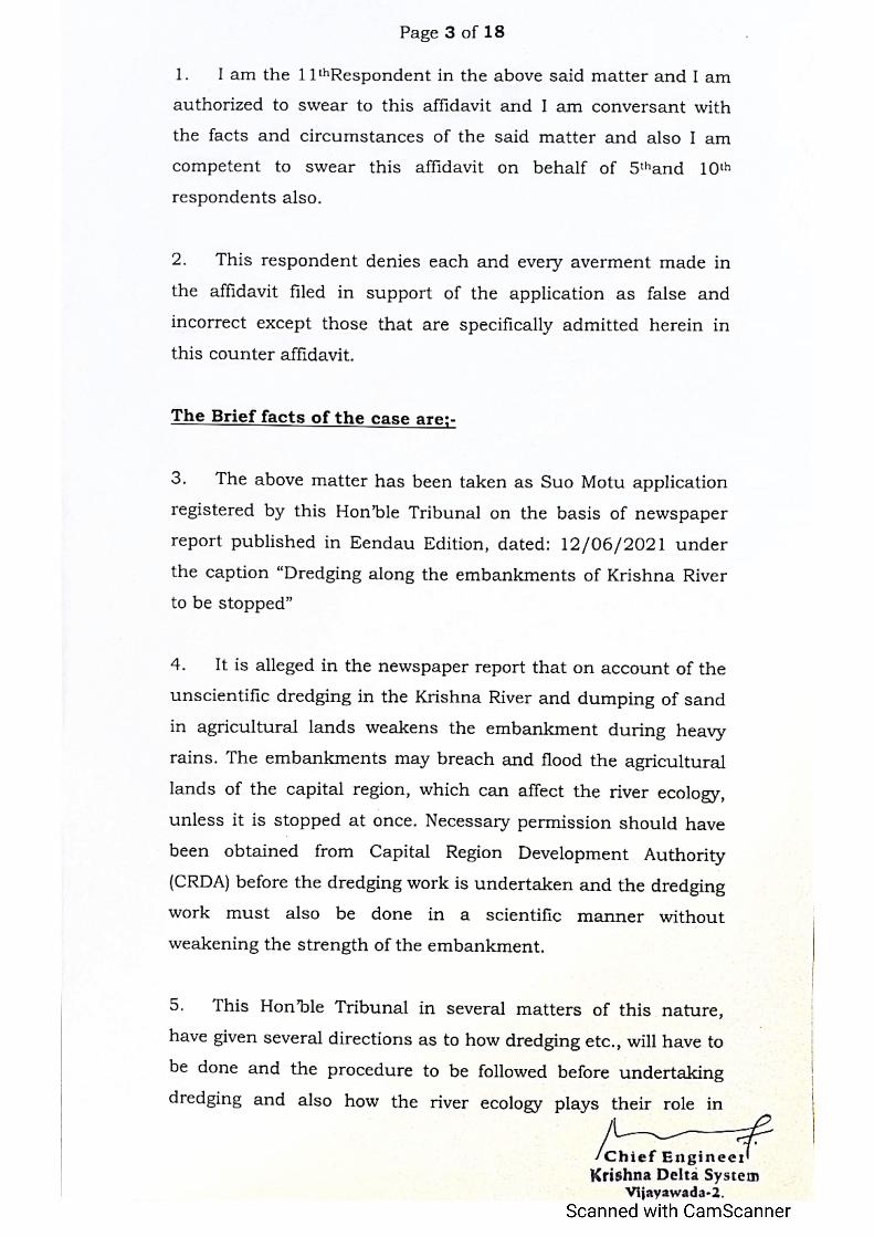
125
-
Upload
khangminh22 -
Category
Documents
-
view
2 -
download
0
Transcript of Untitled - National Green Tribunal


Disclosure to Promote the Right To Information
Whereas the Parliament of India has set out to provide a practical regime of right to information for citizens to secure access to information under the control of public authorities, in order to promote transparency and accountability in the working of every public authority, and whereas the attached publication of the Bureau of Indian Standards is of particular interest to the public, particularly disadvantaged communities and those engaged in the pursuit of education and knowledge, the attached public safety standard is made available to promote the timely dissemination of this information in an accurate manner to the public.
इंटरनेट मानक
“!ान $ एक न' भारत का +नम-ण”Satyanarayan Gangaram Pitroda
“Invent a New India Using Knowledge”
“प0रा1 को छोड न' 5 तरफ”Jawaharlal Nehru
“Step Out From the Old to the New”
“जान1 का अ+धकार, जी1 का अ+धकार”Mazdoor Kisan Shakti Sangathan
“The Right to Information, The Right to Live”
“!ान एक ऐसा खजाना > जो कभी च0राया नहB जा सकता है”Bhartṛhari—Nītiśatakam
“Knowledge is such a treasure which cannot be stolen”
IS 7349 (2012): Barrages and weirs - Operation and
maintenance - Guidelines [WRD 22: River Training and
Diversion Works]
19

20
21
IS 7349 : 2012
© BIS 2012
September 2012 Price Group 6
B U R E A U O F I N D I A N S T A N D A R D SMANAK BHAVAN, 9 BAHADUR SHAH ZAFAR MARG
NEW DELHI 110002
Hkkjrh; ekud
cSjt vkSj fo;j — çpkyu vkSj j[k-j[kko — ekxZn'khZ( nwljk iqujh{k.k )
Indian Standard
BARRAGES AND WEIRS — OPERATION AND
MAINTENANCE — GUIDELINES
( Second Revision )
ICS 93.160
22
River Training and Diversion Works Sectional Committee, WRD 22
FOREWORD
This Indian Standard (Second Revision) was adopted by the Bureau of Indian Standards, after the draft
finalized by the River Training and Diversion Works Sectional Committee had been approved by the Water
Resources Division Council.
Proper maintenance and operation of barrages and weirs are the prime factors to govern the life and efficacy
of the structure. Experience shows that improper operation and maintenance have considerably diminished
the life as much as the efficacy of the structure. It is necessary for the engineer in-charge, to be well conversant
with the final drawings (both civil and manufacturer’s drawings of hydro-mechanical equipments) and manual,
etc. His prime duty should include the documentation of the data, design computations, modifications in the
designs and final drawings, etcs, as well as inspection of the structure from time-to-time.
This standard was first published in 1974 and revised in 1989. The first revision was made in view of the
experience gained during the use of this standard. In the first revision requirements of operation and regulation
had been fully revised, providing detailed clarifications/guidelines on many of the issues faced by the site
engineers. The history of headworks had also been revised with the addition of data on gate/shutter operation
adopted from time-to-time.
With the experience gained from the prototype behaviour of many barrages and weirs and the corresponding
remedial measures suggested/adopted for addressing the difficulties, faced in actual operation and maintenance,
it is considered necessary to revise the standard to incorporate many of the measures currently in vogue
based on the latest technical advancements.
The composition of the Committee responsible for the formulation of this standard is given at Annex B.
23
IS 7349 : 2012
1
Indian Standard
BARRAGES AND WEIRS — OPERATION AND
MAINTENANCE — GUIDELINES
( Second Revision )
1 SCOPE
This standard lays down guidelines for the operation
and maintenance of hydro-mechanical installations
and civil structures connected with the barrages and
weirs.
2 REFERENCES
The standards listed in Annex A contain provisions,
which through references in this text constitute
provisions of this standard. At the time of
publication, the editions indicated were valid. All
standards are subject to revision and parties to
agreements based on this standard are encouraged
to investigate the possibilities of applying the most
recent edition of the standards indicated in Annex
A.
3 GENERAL
Generally, the river discharges are widely fluctuating
and operations/regulation of the gates have to be
modified from time-to-time on the basis of river
behaviour, morphological changes, etc. Barrages are
not storage structures and the waterway is designed
according to design flood without any moderation.
As such, during the life of barrage, it is seldom that
all the gates are required to be opened fully. Gate
operations, particularly during low floods is a key
factor for flushing of sediments and prevention or
alteration of shoal formation on the upstream and
downstream of the barrage.
4 OPERATION AND MAINTENANCE OF
HYDRO-MECHANICAL INSTALLATIONS
4.1 It should be ensured that a thorough inspection
of hydro-mechanical installations/equipment is done
atleast once in a year to check corrosion, loss of
metal and other defects. All machinery at the works
should be kept clean, tidy and in proper working order
and care should be taken to ensure that it is properly
handled in conformity with the manufacturer’s
instructions. The main hydro-mechanical items are
generally the gates, hoist equipment, control system,
etc. IS 7718 may also be referred for inspection,
testing and maintenance of gates.
In case of remote controlled operation of gates, it
has to be ensured that the operating system
(hardware and software) are fully functional in
addition to mechanical controls.
4.2 Operation of Gates and Falling Shutters
4.2.1 All lift gates should be operated at suitable
intervals, preferably once in fortnight to clear the
gate grooves/slots, flood passage and ensure free
movement of moving parts of gate. In low supplies
when openings are not desirable, raising of gates by
150 mm for a few minutes should suffice. If the gates
have not been moved for a sufficiently long time,
they should not be forcibly raised all at once but
should be lifted by about 30 mm or so and left at that
position for about 10 to 15 min till the silt deposited
against the gates gets softened and water begins to
ooze out. This is essential to avoid heavy strain on
the machinery.
4.2.2 The speed of operation of the gates should be
limited to the maximum speed indicated by the
manufacturer.
4.2.3 The head regulator gates should be opened
equally unless otherwise indicated in the model
studies report.
4.2.4 The operation of under sluice gates should be
based on approved gate operation schedule besides
model studies, if conducted, for optimum silt
exclusion, hydraulic efficiency and structural safety.
4.2.5 Sequence of operation of barrages gates/weir
shutters should be decided by the engineer-in-
charge depending on the prevailing factors, such as
river behaviour, shoal formation, scour, etc, both on
the upstream and the downstream. However, while
deciding the same, recommendations/ observations
of the model studies, if any, should also be kept in
view.
4.2.6 Where the considerations given in 4.2.5 are
not governing, it should generally be desirable to
subject barrage gates to wedge operation
commencing to open from the centre and moving on
either side till all the gates have been opened equally.
The gates should be opened in installments not
exceeding 300 mm at a time. However, suitable
passage may be provided to flush out the boulders/
debris, as required.
24

IS 7349 : 2012
2
4.2.7 The operation should be carried out in such a
manner that the safety of the structure is not
jeopardized at any time. It should be ensured that
the permissible difference in static head on either
side of the divide walls is not exceeded beyond the
safe limit, which should be clearly specified.
4.2.8 The gates provided for silt/shingle excluding
devices should be closed very slowly to avoid water
hammer action, and other detrimental effects.
4.2.9 Stop-logs are multiple elements placed one
above the other upstream of main gate for facilitating
inspection and maintenance of main gates. They are
generally operated by a gantry crane or a monorail
hoist under balanced head condition. Stoplogs shall
not be operated under flowing water or unbalanced
condition unless these and the operating machinery
is designed for such conditions.
4.3 Maintenance of Gates
4.3.1 All cavities and angles in the gates/shutters
should be kept clear of debris, driftwood, moss and
silt accumulations. All drainage holes in the webs of
horizontal structural members should be kept clear
to drain off any accumulated water. Green stains
should not be allowed to form on the steel members
at the back of the gates/shutters. The gates and
counter balanced boxes should hang perfectly in
level and plumb. This should be checked
occasionally and adjustment made as needed. In case
of shutters, the chains/anchors holding them should
be kept free from rust. IS 10096 (Part 1/Sec 1) and
IS 7718 may also be referred for the inspection/
maintenance of the gates considering the type of
gates provided on the barrages/weirs.
4.3.2 No painting is required for machined surfaces
and surfaces of stainless steel, brass or bronze.
These surfaces should be protected by a coating of
gasoline-soluble rust preventive non-corrosive
compound.
4.3.3 Painting shall be restored by the same type/
quality of paint as originally provided if it has proved
satisfactory. Otherwise a suitable painting system
can be evolved considering local conditions. The
method of application for the paint and surface
preparation shall be as per IS 14177 or any standard
practices being followed by project owner with the
approval of concerned competent authority.
4.4 Gate Grooves and Seals
Grooves and particularly their machined faces should
be kept clean and lubricated well and all sticky
deposits should be scraped off before application of
lubricant.
4.4.1 Seals
Efficiency of rubber seals should be tested initially
after construction and at the time of closures or
isolation of different portions for repairs. The
horizontality and verticality of the seal seat and wall
plates should be checked with spirit level and seal
faces of the rubber seal should be tested to press
uniformly both by light test and by use of paper strip
inserts. Seals of the gate should be checked for wear
and tear as well as deterioration. These should be
adjusted/replaced, as necessary. Few sets of spare
seals should be kept in stock and stored for
emergency in such a way that these seals do not get
damaged during storage with the passage of time.
4.4.2 Staunching Pipes
Staunching pipes, where provided, should be
checked for their sealing efficiency. Repairs/
replacements should be carried out, if necessary.
4.5 Steel Wire Ropes
All steel wire ropes must be cleaned to remove all
dust accumulation and lubricated with suitable grease
at least once a year.
4.5.1 The clamping devices should be de-clamped
and re-clamped at least once in three years. The
inspection and maintenance of wire ropes, wire
clamps and other clamping devices should be in
accordance with the provisions contained in IS 3973
and IS 10096 (Part 3).
4.6 Roller Trains and Fixed Rollers
The roller trains should be examined at least once a
year. Partially jammed rollers should be cleaned, freed
and greased but totally jammed rollers should be
replaced. The bolts of roller guard should be checked
and tightened. The sliding/fixed rollers should be
extracted at the time of closure (unless necessitated
otherwise due to some defects which may need
immediate repairs), and cleaned and greased
properly. Spare rollers should be kept in stores for
ready replacement. IS 7718 may also be referred for
inspection, testing and maintenance of gates.
4.7 Winches/Hoist
4.7.1 All winches and lifting drums should be
examined at least once a year to see, if all the gears
and axles are clean and properly lubricated. All
grease-fed bearings should be cleaned, old grease
removed with kerosene oil and fresh grease applied.
The alignment of shafts should be checked and
coupling bolts tightened.
4.7.2 All grease cups must be kept full of lubricants
and covers tightened periodically to ensure lubricant
25

IS 7349 : 2012
3
moving and causing an effective seal against dust
getting into the bearings. For winches with ratios of
60 : 1 to 100 : 1, four men should be able to operate
the hoist easily. If the working of any winch becomes
hard and it requires more men to operate, it should
be examined and the defect removed before it is used.
Winch gear covers should have felt or rubber washers
to check the entry of dust. The winches should be
operated in correct direction and to ensure this,
direction or operation should be correctly marked
and the limits of operation indicated.
4.7.3 In case of electrically-operated hoists, all
precautions necessary to ensure safety and fault free
operation of electric motors and switching devices
such as checking up of insulation of all electrical
wirings, motor armature windings, etc, should be
taken. Mechanical upkeep of motor bearings and
reducing gears should be ensured through proper
inspection and lubrication. The arrangement for
operation of hoists manually in addition to the
operation of hoists by electric means should also be
provided besides provision for isolating the one from
the other. The latest technique of automatic gate
lifting may also be provided, if the project is
equipped for such operation.
4.8 Wooden planking wherever provided in the
decking of hoist bridge, should be checked to tighten
up the loose holding down nuts and bolts and worn
out planks shall be replaced. The wooden planking
should receive at least two coats of creosote oil
application once in two years.
4.9 The engineer-in-charge should test all lift gates,
chain and clips of falling shutters and submit a
certificate to the competent authority before the
advent of the monsoon to the effect that all gates/
falling shutters are in good operational condition.
4.10 All flood lighting and barrage illumination
should be checked daily during flood season and
once in a week during slack season.
4.11 The road bridge bearings should be inspected,
cleaned and attended for any defects once a year
after the monsoon.
4.12 Any part of the gate leaves, grooves, lifting
mechanisms, etc, that may get deteriorated or
damaged due to negligence or accident, should be
thoroughly repaired or replaced as soon as the
damages are noticed.
4.13 The cleaning and painting of superstructures
should be done once in two years.
4.14 IS 10096 (Part 3) may also be referred for
inspection/maintenance of hoists considering the
type of hoist provided on the barrages/weirs before
the onset of monsoon and after the flood season.
5 INSPECTION, MAINTENANCE AND
INSTRUMENTATION OF CIVIL WORKS
5.1 Inspection of barrages and weirs is necessary
to repair all damages and to obviate the possibility
of extension of damage. Such inspection should
usually be carried out annually for all underwater
works after monsoon by means of under water lamps
and sounding rods. In addition, detailed inspection
in stages should be carried out using underwater
videography at suitable intervals depending upon
extent of damage. Repairs can be undertaken by
either depleting the pond or by isolating the damaged
portion by construction of ring bunds. The requisite
suitable measures for upstream floor and other floors
shall be suitably planned and designed.
5.2 The repairs as necessary as a result of
inspection should be carried out well before the onset
of the next monsoon. Serious defects noticed should
be reported to appropriate authorities for taking
remedial measures in time.
5.3 The inspection and maintenance for the
following works may be carried out:
a) Aprons:
1) Upstream apron and area immediately
upstream of it; and
2) Downstream apron and area
immediately downstream of it;
b) Impervious floors:
1) Upstream of the gates/falling shutters;
and
2) Downstream of the gates/fall ing
shutters;
c) Piers/Abutments;
d) Road/Rail bridges;
e) Sediment excluding devices;
f) Canal head regulator;
g) Instrumentation and performance; and
h) River training works.
5.3.1 Aprons
The sounding and probing in the area should be
undertaken every year immediately after the monsoon
in order to assess the scours and launching of aprons
in the vicinity of structures. The non-launching
portion should be carefully examined, particularly on
downstream, to ensure the effectiveness of inverted
filter.
5.3.2 Impervious Floors
A thorough inspection of upstream and downstream
floors should be undertaken after the monsoon. The
upstream floor should be inspected every year early
in the fair weather season by probing and the use of
26
IS 7349 : 2012
4
underwater lamps. A careful inspection of joints of
the stone-sets should be done where such structures
exists. Minor repairs can be done underwater whereas
major repairs may be undertaken by isolating the area.
5.3.2.1 The downstream basin should also be
carefully inspected and the repairs carried out well
in time before the onset of monsoon. In case of deep
cisterns requiring expensive cleaning and dewatering,
inspection of sandy reaches can be carried out by
probing but in boulder reaches where this may not
be possible, dewatering, cleaning and repairs may
be carried out by rotation once in three years. The
condition of boulder-set or granite block in the case
of boulder stage river should be carefully examined,
and repairs and replacements made, as found
necessary. While dewatering deep downstream
basins, care should be taken to ensure that the design
uplift for such condition is not exceeded. This should
be clearly specified in the regulation order.
5.3.3 Sediment Excluding Devices
A thorough inspection of roofs, ducts and mouth of
the sediment excluders should be carried out every
year in the fair weather with the help of divers and
underwater lamps. Minor repairs may be carried out
underwater and major repairs by local isolation.
5.3.4 Canal Head Regulator
The works should be carefully examined every year
in the fair weather. The upstream floor should be
examined by probing and downstream floor under
dry conditions during closure or isolating the area
where closure may not be possible. Visual inspection
of upstream floor should also be carried out once in
three to five years by isolating the area. All necessary
repairs should be carried out in time.
5.3.5 Instrumentation and Performance
It is essential that every year a performance report
be prepared on the basis of instrument observations.
The observations can be broadly classified under
the following sub-heads:
a) Uplift pressure;
b) Suspended sediment;
c) Settlement;
d) Retrogression;
e) Aggradation upstream; and
f) Discharge distribution and cross flow.
5.3.5.1 Uplift pressure
The uplift pressure observation pipes (see IS 6532)
are embedded in the weir or barrage structure,
generally in piers and flank walls in such a manner as
to give representative uplift, pressure along and
immediately beneath the horizontal floor and at
different points along the vertical cut-off. Additional
pressure pipes may be installed, if required, to
determine uplift pressure at critical points in case of
stratified foundations. The pipes should be
numbered and a permanent record of observations
should be maintained. The observed uplift pressure
should be compared with the design uplift pressures
with the help of a graphical plot and any needed
remedial measures taken. Frequency of observation
will depend upon local conditions. It may generally
be enough to take observations once a month during
monsoon period and more frequently during the non-
monsoon period. It should be ensured that,
a) the mouths of all pipes are kept closed by
caps to obviate the chances of foreign matter
findings its way into the pipes and clogging
them;
b) each pressure observation point is given a
distinct number; and
c) each pipe is frequently tested to ensure that
its strainer is not choked. This can be best
done with the help of an ordinary hand
pump, by working it till water comes out
freely.
5.3.5.2 Pressure release (drainage) pipes
The effluent/discharge coming out of pressure
release/drainage pipes, where provided in the
downstream floor, should be observed for its quantity
as well as quality of sediment contents. Such
observations may be possible only during dry season
when all the gates of the compartments are closed.
This is necessary to check the efficient working of
the drainage system. A correlation between head of
water and discharge should be established and any
large variations immediately taken notice of and
suitable action taken. As presence of sediment in
the effluent could lead to undermining of the
foundations, immediate remedial measures should be
undertaken. In extreme case, it may become necessary
even to completely block the sediment discharging
pipe.
5.3.5.3 Hydraulic jump profile
Strip gauges should be painted every 10 m on the
wing walls and the long divide walls to observe the
hydraulic jump profile in the prototype under
different hydraulic conditions. The following
observations should be taken:
a) Upstream water level;
b) Downstream water level;
c) Shade temperature — maximum and
minimum;
d) Temperature of the river water at a depth
from the surface below which it remains
approximately constant;
27

IS 7349 : 2012
5
e) Temperature of the sub-soil water in a few
selected observation pipes;
f) Water level in all pipes may be observed by
using a bell sounder or by other suitable
means;
g) Discharge from drainage pipes; and
h) Depth of sediment on upstream and
downstream floors.
5.3.5.4 Suspended sediment
During the monsoon season, water sample should
be taken in accordance with IS 4890 simultaneously
upstream and downstream of the under-sluices and
in the canal below the head regulator to assess the
suspended sediment therein. Such observations
should be taken at least once a week (closer intervals
in case of high sediment concentration) to asses the
efficiency of sediment exclusion device and to decide
if any change in the mode of regulation and/or other
remedial measures are required.
5.3.5.5 Settlement
Where appreciable foundation settlements are
anticipated, particularly when the structure is
founded partially or wholly on clay or other soft soil,
surface settlement of relatively heavily loaded parts
of the structure should be observed early in the fair
weather every year and remedial measures
undertaken, if necessary. This can be done by
establishing permanent observation points of steel
on the structure and doing precise levelling from
permanent bench marks established sufficiently away
from the influence of any structure.
5.3.5.6 Retrogression
Retrogression of the river bed can be expected
downstream of the weir/barrage. In order that the
lowering of water level at any discharge condition
does not exceed that provided for in the design, it is
necessary to establish gauges on both banks, one
immediately downstream of the work and two more,
1 000 m and 2 000 m downstream of the first and to
observe them simultaneously at least once a day.
Remedial measures should be undertaken as and
when required to ensure the safety of the structure.
5.3.5.7 Aggradation upstream
The river bed upstream of the barrage or weir is likely
to aggradate resulting in increased afflux and
reduction in freeboard provided in design. To
determine the increase in the afflux, if any, gauges
should be established on the upstream, one
immediately upstream of the work and one each at
1 000 m and 2 000 m upstream of the first, and
observed regularly. The afflux bunds may have to be
raised, if found necessary, to restore the designed
freeboard.
5.3.5.8 Discharge distribution and cross-flow
Observations should be taken to find the discharge
distribution through different bays of the barrage. If
there is significant cross-flow and/or difference in
discharge intensities through different bays,
remedial measures should be taken to check this
tendency by adopting modified gate regulations,
removal of shoals, etc.
5.3.5.9 Pond capacity
Where balancing storage is also provided in the
barrage, soundings in the entire pond area may be
made at suitable intervals for periodic review of
storage capacity.
5.3.6 River Training Works
5.3.6.1 A detailed river survey covering the barrage/
weir and river training works upstream and
downstream should be carried out every year. The
survey should preferably extend about one metre
above the design flood level on both the banks on
upstream side. Similarly, the survey on downstream
side should extend to a length up to which river bed
changes occur. Sufficient number of permanent
reference marks should be established on both banks
to facilitate superimposition of old and new survey.
The changes in the river course should be examined
and remedial measures taken.
5.3.6.2 The afflux bunds, guide bunds and spurs
should be examined in the fair weather and necessary
repairs to the bunds, pitching and aprons carried
out and completed well before the onset of monsoon.
An adequate stock of boulder/stones should be
maintained close to the protection works for use in
emergency.
6 OPERATION AND REGULATION
6.1 Adequate regulation staff should be provided
and their duties should be clearly specified.
Adequate stock of stores, tools and plants required
to meet emergencies should be maintained on all
barrages and weirs. These should be listed in detail
in the regulation orders and their availability checked
periodically by the engineer-in-charge. The gauge
sites (see 6.3.2.1) should be linked with the
headworks by a reliable communication arrangement
such as telephone, wireless, telegraph, etc. As a
precautionary measure, the engineer-in-charge will
maintain a dossier of personnel who could be
deployed at project site in emergency. These
personnel should be available at very short notice
and capable of performing assigned tasks.
28

IS 7349 : 2012
6
6.2 In general, operation of the barrage gates should
ensure the following features:
a) Required pond level is maintained both
during the non-monsoon flows and the
falling flood periods.
b) Non-monsoon flows remain near the under-
sluice bays so that feeding of the canal(s)
through the head regulator(s) is not
affected.
c) A fair uniform distribution of discharge
along the width of the barrage is obtained,
as far as practicable.
d) Flow parallel to barrage axis both on the
upstream and the downstream of the barrage
is avoided at all times, as far as practicable.
e) Risk of deep scour and shoal formations in
the vicinity of the barrage both on the
upstream and the downstream is minimized,
as far as possible.
f) If shoal formation has taken place, the gates
in front of the shoal should be opened more
to accentuate flushing of sediment with the
forward flow wherever sufficient discharge
is available. Alternatively, method of
sudden and simultaneous opening of
required number of gates in front of the
shoal could be tried.
g) To evolve the operation of gates to exclude
maximum silt /debris deposits on the
upstream side and also to minimize the entry
of same in canals/channels.
h) Hydraulic jump should not be allowed to
form beyond the toe of the downstream
glacis in any case.
j) A relatively high intensity of flow is avoided
in the deep scour zones, if formed.
k) If a shoal has formed on either upstream, or
downstream, or both sides of the barrage, it
is washed out and kept away from the
barrage, as far as practicable.
m) Gate operation schedule should also
consider constraints regarding rates of
lowering/raising of ponds. It should also
consider the safe rate of filling of the canals.
n) Constant and regular supply in canals/
channels even during fluctuations in
discharges from power houses located on
the upstream side.
p) Approach channel should be trained so that
the tendency of the river to meander near
the barrage or outflanking the barrage can
be arrested.
6.3 The operation and regulation can be divided into
three distinct periods as given below:
a) Pre-monsoon;
b) During monsoon; and
c) Post-monsoon.
6.3.1 Pre-monsoon Operation
It is a low flow period and normally no wastage of
water should be permitted during this period. The
barrage gates/falling shutters should be regulated
in such a way that all the available supplies are
conserved and pond level is maintained. Any excess
flow over and above the requirements through the
head regulator(s) should be released through under-
sluice bays and silt excluder tunnels, wherever
provided. The release through the head regulator of
the canal should be based on the discharge tables.
The discharge tables should be occasionally checked
for accuracy by actual measurements in the canal.
For any flashy flood, the canal may have to be closed
temporarily, if the concentration of suspended silt is
in excess of the safe limit prescribed.
6.3.2 Monsoon Operation
6.3.2.1 Gauges to indicate flood stage should be
installed sufficiently (not less than 1 000 m) upstream
of the barrage at suitable locations so as to ensure
adequate margin of time for operation of gates at the
weir/barrage site.
6.3.2.2 During low floods, the gauges should be
signalled and recorded every 3 h while in medium
and high floods, these should be recorded every
hour. The signaller at the headworks, on receiving
the flood warning should communicate the same to
the official/officer-in-charge of the headwork and
other regulation points downstream and to the
district officers of the neighbouring districts.
6.3.2.3 The advisability of installation of wireless
transmitting stations on headworks located on major
rivers for speedy transmission of flood warning
should be considered.
6.3.2.4 In order to create most favourable conditions
for sediment exclusion from the canal, still-pond
regulation should be resorted to, as far as possible.
However, in locations where canals cannot be closed
for flushing, semi-still pond/regulation may be
adopted (as in the case of power channels) as given
below:
a) Still pond operation — In stil l pond
operation, all the gates of the under-sluice
bays are to be kept closed so as to limit the
discharge flowing into the under-sluice
pocket to be equal to the canal supply. The
specified or required discharge only should
be drawn in the canal and the surplus river
discharge should be passed through the
29

IS 7349 : 2012
7
spillway bays or river sluice bays, if
provided. As the under-sluice bays are kept
closed, the flow velocity in the pocket cause
the sediment to settle down and relatively
clear water enters the canal. However, the
pocket gets silted up in this process after
some time.
At that time, the canal head regulator gates
should be closed and deposited silt should
be flushed out by opening the gates of the
under-sluice bays. The canal supply may be
stopped during this scouring operation
which may take about 24 h. After the silt
deposits are flushed out sufficiently, the
head regulator gates should be opened and
under-sluice closed. This operation is
desirable where the crest of the head
regulator is at a sufficiently higher level than
that of the upstream floor of the under-sluice
bays. This still pond operation should be
continued till the river stage reaches the
pond level after which the under-sluice gates
should be opened to avoid overtopping.
b) Semi-still pond operation — In the semi-
still pond operation, the gates of the canal
head regulator are not closed for flushing
of silt deposit in the pocket. The gates of
the under-sluice bays should be kept
partially open to the minimum necessary so
that the bed material in the pocket could be
passed downstream. The discharge in
excess of the canal requirement should be
passed through the under-sluice bays and
silt excluder tunnels also, wherever
provided.
6.3.2.5 Excluders, where provided, should be kept
open and while doing so, the limitations imposed by
the safety of the structure should be kept in view.
The required intensity of discharge q, which may be
sufficient to flush the deposited silt in the pocket
can be calculated from the Lacey/Blench’s scour
equation:
0.332
1.35q
Rf
=
where
R = scour depth that is, between the water level
and the level of the pocket floor in this case,
in m;
q = intensity of discharge, in m3/s/ m width; and
f = silt factor corresponding to the deposited
material in the pocket.
The required intensity of discharge thus calculated
may be generated by suitable gate openings when
sufficient head is available in the pond. Under no
circumstances should the under-sluice gates be
allowed to be overtopped. Silt ejectors in the canal
should be operated as much as possible so that the
chances of heavy siltation in the canal posing a
problem of flushing due to its compaction are
minimized.
6.3.2.6 During monsoon month, it is important to
keep a constant watch over the sediment entering
the headworks, the portion thereof ejected by the
extractor if any, and the sediment deposition taking
place in the canal and to ensure that sediment
deposition only to the extent that can be washed out
early in the fair weather before the full demand
develops, is allowed. For this, the following actions
should be taken:
a) Sediment charge observations (both
suspended sediment and bed load) should
be made at least once a day in low floods
immediately below the head regulator, below
the silt ejector, if any, and at any other
sensitive point lower down the canal. The
frequency of observations may be increased
in medium and high floods as required;
b) Cross-section of the canal should be taken
daily at a few sensitive points to watch the
extent of sediment deposition in the canal;
c) Water surface slopes in the sensitive head
reach of the canal should be kept under
observation daily with the help of gauges;
d) The ponding upstream of power stations, if
any, in the canal should be restricted to the
requisite extent so as to avoid harmful
sediment deposition; and
e) The canal should be closed from the
headworks,
1) beyond a specified sediment charge
during medium/high flood and re-
opened when the sediment charge drops
below the specified limit. Since the silt
carrying capacity of the canal would
govern this specified limit, it would vary
from project to project and should be
estimated based on actual data/
experience. In so far as the power
channels are concerned, this would
depend on the size of the particle carried
down.
2) when sediment deposition at the
sensitive points has reached the
maximum permissible bed level. This
limit along with the sediment charge in
excess of which the canal is to be kept
closed, may have to be fixed for
different months during the monsoon
period in order to be able to meet the
irrigation and power demand.
30

IS 7349 : 2012
8
6.3.2.7 Since cross flows and vortex formations
dangerously cause deep scours both on the upstream
and downstream of the barrage leading to washing
away or sinking of cement concrete blocks and loose
stone aprons, and damages to the nose and shanks
of guide bunds, visual observations of the direction
of current and vortex formation during low and
medium floods should be made. After critically
observing the effects of different patterns of gate
operation on the same, the engineer-in-charge
should judiciously select the correct pattern which
would cause only minimum scour or minimum
shoaling.
6.3.2.8 The engineer-in-charge should be
conversant with the shoal formations, changing
network of spill channels, etc, which cause unequal
distribution of flows through different bays, cross
flow near the barrage floor ends, vortex formations,
etc. Gate operation of barrage structure should be
attempted in such a manner that the shoal formation
in the vicinity of barrage structure both upstream
and downstream is avoided.
6.3.2.9 The pond level should be kept minimum
required to feed the canal with the required discharge
by suitably opening the gates. It should be ensured
that in a high flood, all falling shutters of weirs are
lowered and all gates raised clear of the water level
with adequate freeboard to clear floating debris.
6.3.2.10 The operation of barrage gates/weirs
shutters should preferably be based on model studies
at various flood intensities, that is, low, medium and
high, as modified by observed river behaviour at site.
In this connection, for major barrages it would be
desirable to constitute a gate regulation committee
for each barrage comprising senior engineers of the
project design office and research station and
engineer-in-charge of the headworks division. The
Committee should hold meetings at least once during
pre-monsoon, monsoon (preferably twice) and after
monsoon and should review the gate operation
pattern and modify, wherever necessary on the basis
of the observed river cross-section on the upstream
and downstream of the structure. After some years
when satisfactory flow conditions are established,
all the recommendations of the Committee from time-
to-time should be compiled in the form of a manual
so that guidance could be obtained by the gate
operating personnel for future use in the project.
Generally with the rise in the flood discharge, step-
by step gate operation with gradual increase of
opening from ends towards the centre is sometimes
recommended.
6.3.2.11 In order to keep a close watch on the river
behaviour and bed configuration both upstream and
downstream of the barrage, river surveys should be
conducted regularly, once before the floods and
another after the floods. For major structures,
powerful launches fitted with echo-sounders or any
other state of art instrument is desirable to take cross-
sections even during medium flood stage. The survey
should be conducted over a stretch of the river close
to the barrage at least up to the end of guide bank
both on upstream and downstream. The bed levels
should be determined at close intervals of at least
10 m. Depending upon the bed configuration, the
pattern of gate regulation should be modified suitably
to ensure safety and better hydraulic performance
of the barrage. Canals having hydro-electric power
stations should be provided with trashracks at the
head regulator to check entry of floating debris. The
trashracks should be kept clean, preferably by a
mechanical or electrical operation device. Instances
of collapse of trash racks due to lack of cleaning and
excessive pressure built up have been on record.
Where floating debris try to enter the irrigation canal
head regulators, trash booms may be erected just
upstream of the head regulators.
6.3.2.12 The cranes for lifting weir shutters should
be housed safely in the crane house when not in
use.
6.3.3 Post-monsoon Operation
6.3.3.1 Sediment charge observations and cross-
section at sensitive points on the canal should be
continued at less frequent intervals till satisfactory
conditions have been established.
6.3.3.2 Still/semi-still pond operation, with sediment
excluders operating, depending on the surplus water
availability should be continued till water becomes
reasonably clear.
6.4 When a canal is first opened, a low supply should
be run for a few hours at least and the depth should
gradually be increased according to the
requirements. The rate of falling and lowering of the
canal should be prescribed and these should not be
transgressed. Silt ejector hoppers and outlet pipes
may be cleaned by pressure flow or back-jetting
before the canal is started for operation.
6.5 If a study of the survey data indicates that shoal
formation has occurred on the upstream and/or
downstream of the barrage inspite of judicious
operation of the gates, during normal and flushing
operation of reservoir, the shoal should be removed
by dredging by the use of suitable dredgers to the
extent possible so that satisfactory flow conditions
are established and also desired capacity is restored.
6.6 Satellite imageries obtainable from the National
Remote Sensing Agency may be helpful in the
identifying the variations of the bank lines, flow
31

IS 7349 : 2012
9
patterns, formation of submerged shoals, etc, in the
upstream pond from year to year. Studies with
satellite imageries may be made and remedial
measures for improving the river behaviour and flow
pattern may be taken up.
6.7 In addition, physical/morphological model study
will be useful for understanding,
a) morphological behaviour of the river;
b) its aggradation, degradation and
meandering tendency; and
c) sediment transport with varying level, etc.
Attempt should be made to prove/improve these
models on the basis of prototype observations of
barrages.
7 HISTORY OF HEADWORKS
A continuous history of river behaviour and the
overall performance of the barrage/weir, head
regulators and river training works should be
maintained on all major headworks. The history
should also contain the details of maintenance,
damage and repair carried out from time-to-time,
prescribed schedule of gate operation and in case of
deviation of prescribed schedule, the actual gate
operation with reasons thereof, etc. Necessary
drawings should be appended in the record. Pre-
monsoon and post-monsoon river bed contours may
be plotted, reduced in size and properly filed in serial
order for comparison to understand the pattern of
shoals, scours, oblique flow, etc.
ANNEX A
(Clause 2)
LIST OF REFERRED INDIAN STANDARDS
IS No. Title
3973 : 1984 Code of practice for the selection,
installation and maintenance of wire
ropes (first revision)
4890 : 1968 Methods for measurement of
suspended sediment in open
channels
6532 : 1972 Code of practice for design,
installation, observation and
maintenance of uplift pressure pipes
for hydraulic structures on permeable
foundations
7718 : 1991 Recommendations for inspection,
testing and maintenance of fixed
wheel and slide gates (first revision)
10096 Recommendations for inspection,
testing and maintenance of radial
gates and rope drum hoists:
(Part 1/Sec 1) : Inspection, testing and assembly at
1983 the manufacturing stage, Section 1
Gates
(Part 3) : 2002 After erection (first revision)
14177 : 1994 Guidelines for painting system for
hydraulic gates and hoists
IS No. Title
32

IS 7349 : 2012
10
ANNEX B
(Foreword)
COMMITTEE COMPOSITION
River Training and Diversion Works Sectional Committee, WRD 22
Organization Representative(s)
Central Water Commission, New Delhi SHRI G. S. PURBA (Chairman)
Bhakra Beas Management Board, Nangal Township SUPERINTENDING ENGINEER
SENIOR DESIGN ENGINEER (B&B) (Alternate)
Border Roads Organization, New Delhi SHRI A. K. DIKSHIT
SHRI D. K. PURWAR (Alternate)
Brahamputra Board, Guwahati GENERAL MANAGER
CHIEF ENGINEER (P&D) (Alternate)
Central Water & Power Research Station, Pune SHRI D. N. DESHMUKH
SHRI M. N. SINGH (Alternate)
Central Water Commission, New Delhi DIRECTOR (FM I)
DIRECTOR (BCD) E&NE (Alternate)
Consulting Engineering Services, New Delhi SHRI P. K. CHATTERJEE
DR OM PRAKASH (Alternate)
Delhi College of Engineering, New Delhi HEAD (CIVIL ENGINERRING DEPARTMENT)
Flood Control Department, Government of Assam, Guwahati CHIEF ENGINEER (QUALITY CONTROL)
ADDITIONAL CHIEF ENGINEER (Alternate)
Gammon India Limited, Mumbai SHRI M. S. BISARIA
SHRI V. N. HEGGADE (Alternate)
Ganga Flood Control Commission, Patna DIRECTOR (MASTER PLANNING 2)
DIRECTOR (PLANNING) (Alternate)
ICT Pvt Ltd, New Delhi SHRI P. L. DIWAN
PROF S. K. MAZUMDER (Alternate)
IIT, Roorkee DR NAYAN SHARMA
Indian Institute of Technology, New Delhi HEAD (CIVIL ENGINEERING DEPARTMENT)
Irrigation & Waterways Directorate, Govt of West Bengal, Kolkata DIRECTOR (CDO)
DR ABHIJIT SAHA (Alternate)
Irrigation Department, Government of Andhra Pradesh, Hyderabad SUPERINTENDING ENGINEER (B&C)
SUPERINTENDING ENGINEER (DAMS) (Alternate)
Irrigation Department, Government of Haryana, Chandigarh CHIEF ENGINEER (DRAINAGE)
DIRECTOR (CENTRAL DESIGN) (Alternate)
Irrigation Department, Government of Jammu, Jammu SHRI BODH RAJ DOGRA
SHRI NATHA RAM (Alternate)
Irrigation Department, Government of Punjab, Chandigarh CHIEF ENGINEER (DRAINAGE)
JOINT DIRECTOR (CENTRAL DESIGNS) (Alternate)
Irrigation Department, Government of Uttarakhand, Roorkee DIRECTOR (IRI)
RESEARCH OFFICER (IRI) (Alternate)
Irrigation Department, Government of Maharashtra, Nasik SUPERINTENDING ENGINEER (GATES)
SHRI R. V. JALTARE (Alternate)
Kolkata Port Trust, Calcutta SHRI BIKAS CHAUDHURI
SHRI M.N RAY (Alternate)
33

IS 7349 : 2012
11
Ministry of Railways (RDSO), Lucknow DIRECTOR (B&F)/INP.
ASSISTANT DESIGN ENGINEER (B&F) (Alternate)
NHPC Ltd, Faridabad SHRI A. K. JAIN
SHRI MAHESH KUMAR (Alternate)
Public Works Department, Chennai EIC, WRO & CE (GI)
SUPERTENDING ENGINEER (DC) (Alternate)
RITES, New Delhi SHRI G. SETHURAMAN
SHRI MUKESH KUMAR (Alternate)
Sardar Sarovar Narmada Nigam Limited, Gandhi Nagar SHRI VIVEK P. KAPADIA
SHRI MUKESH B. JOSHI (Alternate)
Tehri Hydro Development Corporation Limited, Rishikesh SHRI G. M. PRASAD
Water Resources Department, Patna SHRI S. JANKI RAMAN PRASAD SINHA
Water Resources Development Organization (WRDO), Bangalore SHRI C. V. PATIL
SHRI BASAVARAJA KOTI (Alternate)
BIS Directorate General SHRI J. C. ARORA, Scientist ‘F’ and Head (WRD)
[Representing Director General (Ex-officio)]
Member Secretary
SHRI R. R. DASH
Scientist ‘B’ (WRD), BIS
Organization Representative(s)
34

35

Bureau of Indian Standards
BIS is a statutory institution established under the Bureau of Indian Standards Act, 1986 to promote harmonious
development of the activities of standardization, marking and quality certification of goods and attending to
connected matters in the country.
Copyright
BIS has the copyright of all its publications. No part of these publications may be reproduced in any form without
the prior permission in writing of BIS. This does not preclude the free use, in course of implementing the standard,
of necessary details, such as symbols and sizes, type or grade designations. Enquiries relating to copyright be
addressed to the Director (Publications), BIS.
Review of Indian Standards
Amendments are issued to standards as the need arises on the basis of comments. Standards are also reviewed
periodically; a standard along with amendments is reaffirmed when such review indicates that no changes are
needed; if the review indicates that changes are needed, it is taken up for revision. Users of Indian Standards
should ascertain that they are in possession of the latest amendments or edition by referring to the latest issue of
‘BIS Catalogue’ and ‘Standards: Monthly Additions’.
This Indian Standard has been developed from Doc No. : WRD 22 (341).
Amendments Issued Since Publication
______________________________________________________________________________________
Amendment No. Date of Issue Text Affected______________________________________________________________________________________
______________________________________________________________________________________
______________________________________________________________________________________
______________________________________________________________________________________
______________________________________________________________________________________
BUREAU OF INDIAN STANDARDS
Headquarters:
Manak Bhavan, 9 Bahadur Shah Zafar Marg, New Delhi 110002
Telephones: 2323 0131, 2323 3375, 2323 9402 Website: www.bis.org.in
Regional Offices: Telephones
Central : Manak Bhavan, 9 Bahadur Shah Zafar Marg 2323 7617
NEW DELHI 110002 2323 3841
Eastern : 1/14, C.I.T. Scheme VII M, V.I.P. Road, Kankurgachi 2337 8499, 2337 8561
KOLKATA 700054 2337 8626, 2337 9120
Northern : SCO 335-336, Sector 34-A, CHANDIGARH 160022 260 3843
260 9285
Southern : C.I.T. Campus, IV Cross Road, CHENNAI 600113 2254 1216, 2254 1442
2254 2519, 2254 2315
Western : Manakalaya, E9 MIDC, Marol, Andheri (East) 2832 9295, 2832 7858
MUMBAI 400093 2832 7891, 2832 7892
Branches : AHMEDABAD. BANGALORE. BHOPAL. BHUBANESHWAR. COIMBATORE. DEHRADUN.
FARIDABAD. GHAZIABAD. GUWAHATI. HYDERABAD. JAIPUR. KANPUR. LUCKNOW.
NAGPUR. PARWANOO. PATNA. PUNE. RAJKOT. THIRUVANATHAPURAM. VISAKHAPATNAM.
Published by BIS, New Delhi
{
{{
{
{
36
37
38

39
40
41
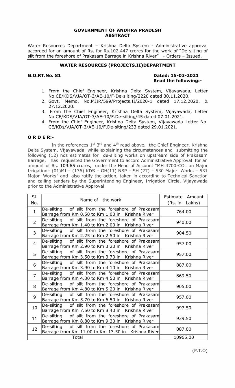
GOVERNMENT OF ANDHRA PRADESH ABSTRACT
Water Resources Department – Krishna Delta System - Administrative approval
accorded for an amount of Rs. for Rs.102.447 crores for the work of “De-silting of
silt from the foreshore of Prakasam Barrage in Krishna River” - Orders – Issued.
WATER RESOURCES (PROJECTS.II)DEPARTMENT
G.O.RT.No. 81 Dated: 15-03-2021 Read the following:-
1. From the Chief Engineer, Krishna Delta System, Vijayawada, Letter
No.CE/KDS/VJA/OT-3/AE-10/F-De-silting/2220 dated 30.11.2020. 2. Govt. Memo. No.MJIR/599/Projects.II/2020-1 dated 17.12.2020. &
27.12.2020. 3. From the Chief Engineer, Krishna Delta System, Vijayawada, Letter
No.CE/KDS/VJA/OT-3/AE-10/F.De-silting/45 dated 07.01.2021.
4. From the Chief Engineer, Krishna Delta System, Vijayawada Letter No. CE/KDs/VJA/OT-3/AE-10/F.De-slting/233 dated 29.01.2021.
O R D E R:-
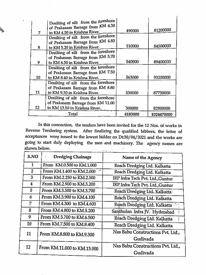
In the references 1st 3rd and 4th read above, the Chief Engineer, Krishna Delta System, Vijayawada while explaining the circumstances and submitting the
following (12) nos estimates for de-silting works on upstream side of Prakasam Barrage, has requested the Government to accord Administrative Approval for an
amount of Rs. 109.65 crores, under the Head of Account “MH 4700-COL on Major Irrigation– (01)MI – (136) KDS – GH(11) NSP – SH (27) – 530 Major Works – 531 Major Works” and also ratify the action, taken in according to Technical Sanction
and calling tenders by the Superintending Engineer, Irrigation Circle, Vijayawada prior to the Administrative Approval.
Sl.
No. Name of the work
Estimate Amount
(Rs. in Lakhs)
1 De-silting of silt from the foreshore of Prakasam Barrage from Km 0.50 to Km 1.00 in Krishna River
764.00
2 De-silting of silt from the foreshore of Prakasam
Barrage from Km 1.40 to Km 2.00 in Krishna River 940.00
3 De-silting of silt from the foreshore of Prakasam
Barrage from Km 2.25 to Km 2.50 in Krishna River 904.50
4 De-silting of silt from the foreshore of Prakasam
Barrage from Km 2.90 to Km 3.20 in Krishna River 957.00
5 De-silting of silt from the foreshore of Prakasam Barrage from Km 3.50 to Km 3.70 in Krishna River
957.00
6 De-silting of silt from the foreshore of Prakasam Barrage from Km 3.90 to Km 4.10 in Krishna River
887.00
7 De-silting of silt from the foreshore of Prakasam Barrage from Km 4.30 to Km 4.50 in Krishna River
869.50
8 De-silting of silt from the foreshore of Prakasam Barrage from Km 4.80 to Km 5.20 in Krishna River
905.00
9 De-silting of silt from the foreshore of Prakasam
Barrage from Km 5.70 to Km 6.50 in Krishna River 957.00
10 De-silting of silt from the foreshore of Prakasam
Barrage from Km 7.50 to Km 8.40 in Krishna River 997.50
11 De-silting of silt from the foreshore of Prakasam
Barrage from Km 8.80 to Km 9.30 in Krishna River 939.50
12 De-silting of silt from the foreshore of Prakasam Barrage from Km 11.00 to Km 13.50 in Krishna River
887.00
Total 10965.00
(P.T.O)
42
::2::
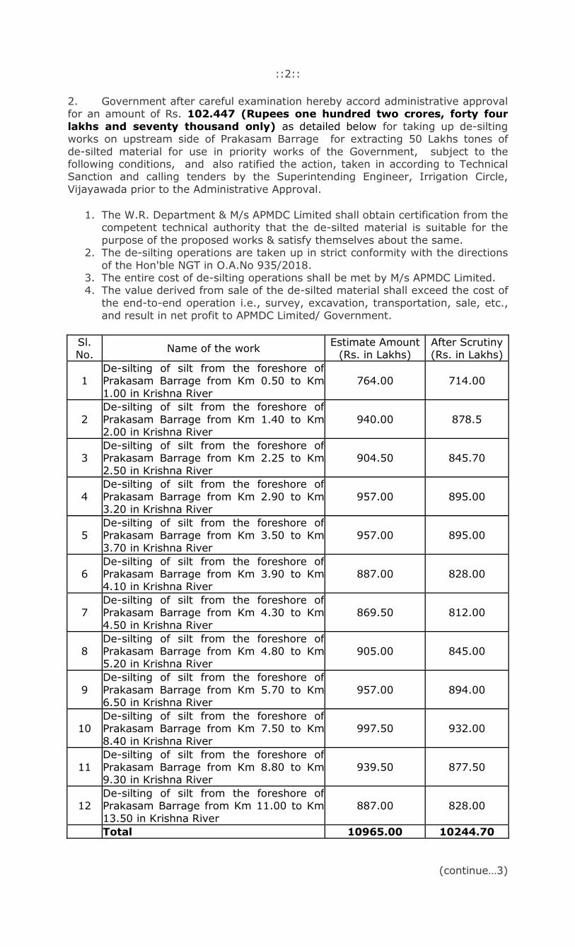
2. Government after careful examination hereby accord administrative approval for an amount of Rs. 102.447 (Rupees one hundred two crores, forty four
lakhs and seventy thousand only) as detailed below for taking up de-silting works on upstream side of Prakasam Barrage for extracting 50 Lakhs tones of
de-silted material for use in priority works of the Government, subject to the following conditions, and also ratified the action, taken in according to Technical Sanction and calling tenders by the Superintending Engineer, Irrigation Circle,
Vijayawada prior to the Administrative Approval.
1. The W.R. Department & M/s APMDC Limited shall obtain certification from the competent technical authority that the de-silted material is suitable for the
purpose of the proposed works & satisfy themselves about the same. 2. The de-silting operations are taken up in strict conformity with the directions
of the Hon'ble NGT in O.A.No 935/2018. 3. The entire cost of de-silting operations shall be met by M/s APMDC Limited. 4. The value derived from sale of the de-silted material shall exceed the cost of
the end-to-end operation i.e., survey, excavation, transportation, sale, etc., and result in net profit to APMDC Limited/ Government.
Sl. No.
Name of the work Estimate Amount
(Rs. in Lakhs) After Scrutiny (Rs. in Lakhs)
1 De-silting of silt from the foreshore of Prakasam Barrage from Km 0.50 to Km
1.00 in Krishna River
764.00 714.00
2
De-silting of silt from the foreshore of
Prakasam Barrage from Km 1.40 to Km 2.00 in Krishna River
940.00 878.5
3 De-silting of silt from the foreshore of Prakasam Barrage from Km 2.25 to Km
2.50 in Krishna River
904.50 845.70
4
De-silting of silt from the foreshore of
Prakasam Barrage from Km 2.90 to Km 3.20 in Krishna River
957.00 895.00
5 De-silting of silt from the foreshore of Prakasam Barrage from Km 3.50 to Km
3.70 in Krishna River
957.00 895.00
6 De-silting of silt from the foreshore of Prakasam Barrage from Km 3.90 to Km 4.10 in Krishna River
887.00 828.00
7 De-silting of silt from the foreshore of Prakasam Barrage from Km 4.30 to Km
4.50 in Krishna River
869.50 812.00
8 De-silting of silt from the foreshore of Prakasam Barrage from Km 4.80 to Km 5.20 in Krishna River
905.00 845.00
9
De-silting of silt from the foreshore of
Prakasam Barrage from Km 5.70 to Km 6.50 in Krishna River
957.00 894.00
10 De-silting of silt from the foreshore of Prakasam Barrage from Km 7.50 to Km
8.40 in Krishna River
997.50 932.00
11
De-silting of silt from the foreshore of
Prakasam Barrage from Km 8.80 to Km 9.30 in Krishna River
939.50 877.50
12 De-silting of silt from the foreshore of Prakasam Barrage from Km 11.00 to Km
13.50 in Krishna River
887.00 828.00
Total 10965.00 10244.70
(continue…3)
43
::3::
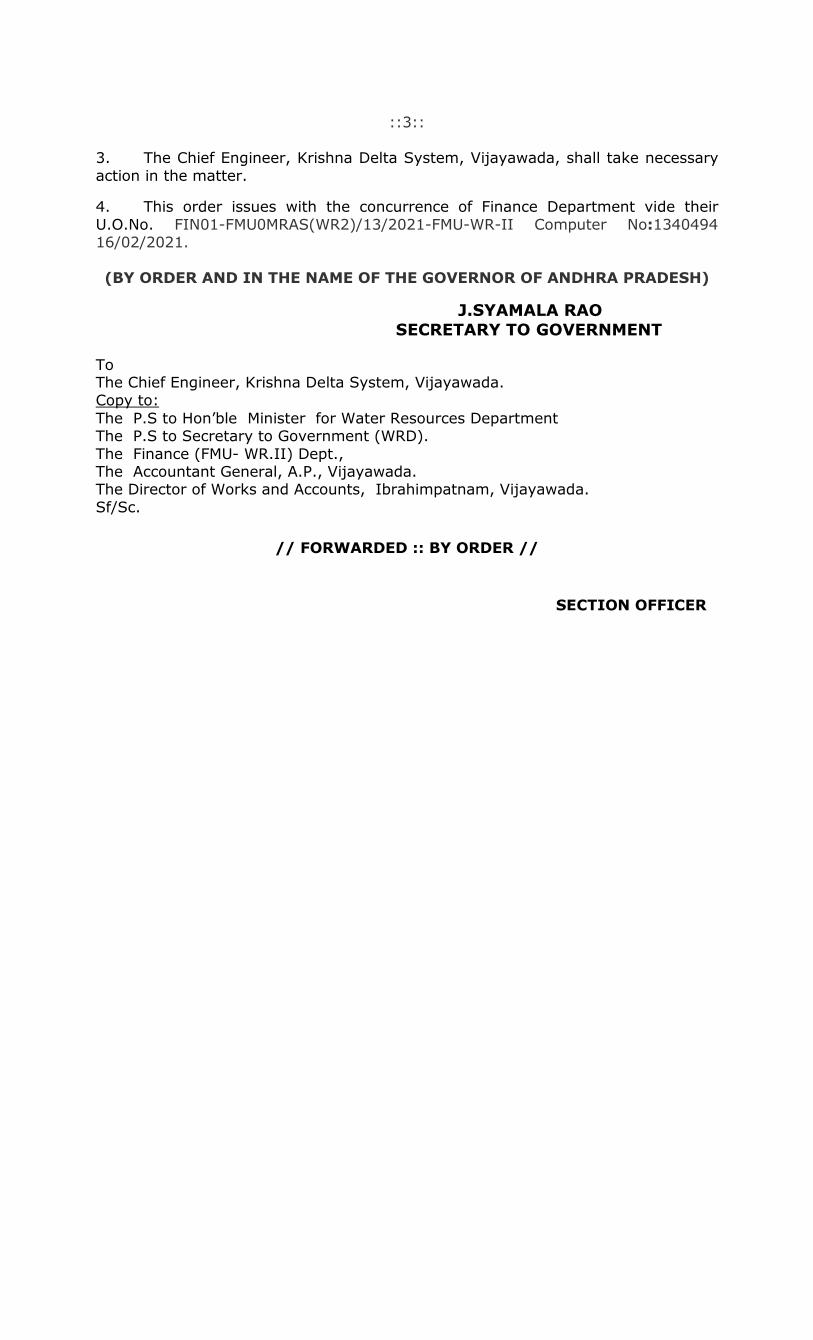
3. The Chief Engineer, Krishna Delta System, Vijayawada, shall take necessary
action in the matter.
4. This order issues with the concurrence of Finance Department vide their
U.O.No. FIN01-FMU0MRAS(WR2)/13/2021-FMU-WR-II Computer No:1340494 16/02/2021.
(BY ORDER AND IN THE NAME OF THE GOVERNOR OF ANDHRA PRADESH)
J.SYAMALA RAO
SECRETARY TO GOVERNMENT To The Chief Engineer, Krishna Delta System, Vijayawada.
Copy to:
The P.S to Hon’ble Minister for Water Resources Department The P.S to Secretary to Government (WRD).
The Finance (FMU- WR.II) Dept., The Accountant General, A.P., Vijayawada. The Director of Works and Accounts, Ibrahimpatnam, Vijayawada.
Sf/Sc.
// FORWARDED :: BY ORDER //
SECTION OFFICER
44
45

46
47

48

49
50
51

52

53

54
55
56

57
58

59
60
61
62
63

64
65
66

67
68

69

70
71
72

73
74
75

76

77
78

79

80
81

82
83

84
85

86

87
88

89
90

91
92

93

94

95

96

97

98
99
100

101

102

103
104

105
106

107

108
109
110

111
112

113

114

115
116

117
118

1
Item No.05 Court No. 1
BEFORE THE NATIONAL GREEN TRIBUNAL
PRINCIPAL BENCH, NEW DELHI
(By Video Conferencing)
Original Application No. 935/2018
(With report dated 20.07.2020)
Anumolu Gandhi Applicant(s)
Versus
State of Andhra Pradesh Respondent(s) Date of hearing: 24.08.2020
CORAM: HON’BLE MR. JUSTICE ADARSH KUMAR GOEL, CHAIRPERSON
HON’BLE MR. JUSTICE S. P. WANGDI, JUDICIAL MEMBER
HON’BLE DR. SATYAWAN SINGH GARBYAL, EXPERT MEMBER
HON’BLE DR. NAGIN NANDA, EXPERT MEMBER
Applicant(s): Mr. Sravan Kumar, Advocate Respondent(s): Mr. R. Venkataramani, Senior Advocate with Mr. G.N.
Reddy for State of Andhra Pradesh Mr. TVS Raghvendra Sreyas, Advocate for State PCB Mr. Aman Bhalla, Advocate for CPCB
ORDER
1. Whether the activity termed as ‘de-silting’ by the State authorities
is in fact ‘illegal mining’ in Krishna river in Andhra Pradesh, as alleged by
the applicant, is the question for consideration.
2. Vide order dated 14.02.2020, the Tribunal referred to earlier
proceedings and finding conflicting versions in the report, sought a
report from an Expert Committee.
3. Accordingly, a report dated 20.07.2020 has been filed. Overall
concluding remarks in the report are:-
119

2
“Overall concluding remarks of the Committee Members
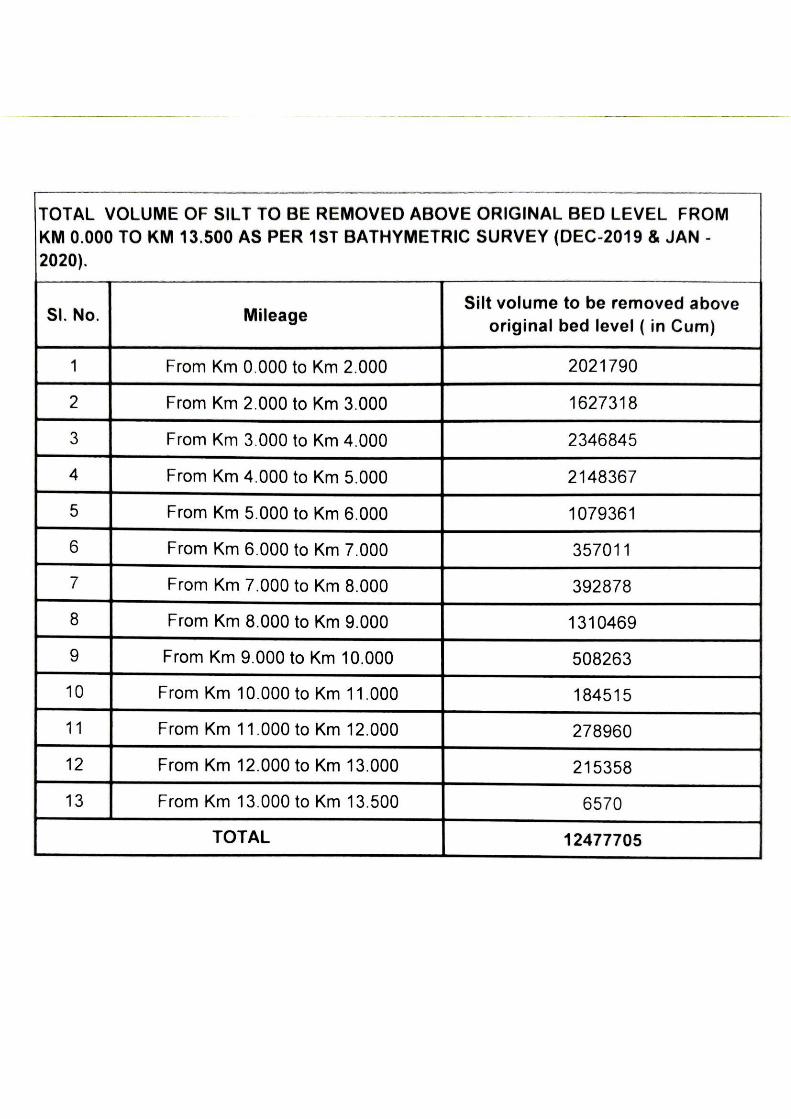
i. Water Resource Department, Government of Andhra Pradesh has carried out bathymetric survey in conformity with the established and recommended practices. As per the Bathymetric survey carried out during December, 2019 to January, 2020 present storage capacity of Prakasam barrage is 2.982 TMC. There is loss in storage capacity of 0.089 TMC as compared to the design capacity of 3.071 TMC.
ii. The report submitted by Water Resource Department, Govt. of Andhra Pradesh to Hon'ble NGT is satisfactory.
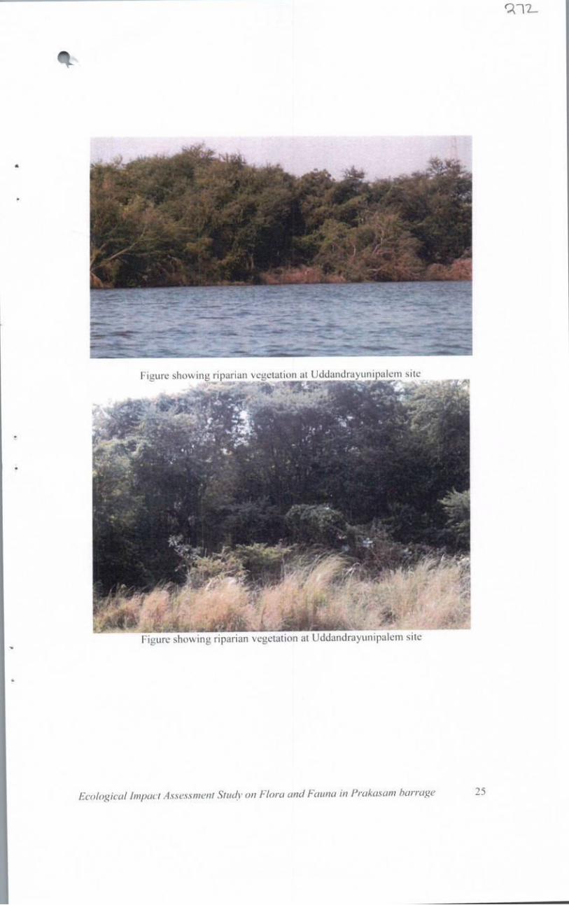
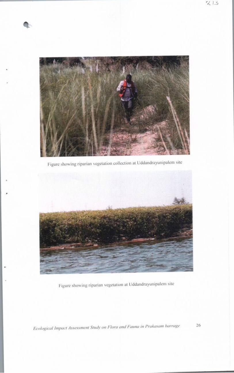
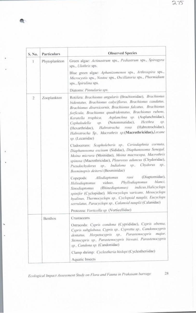
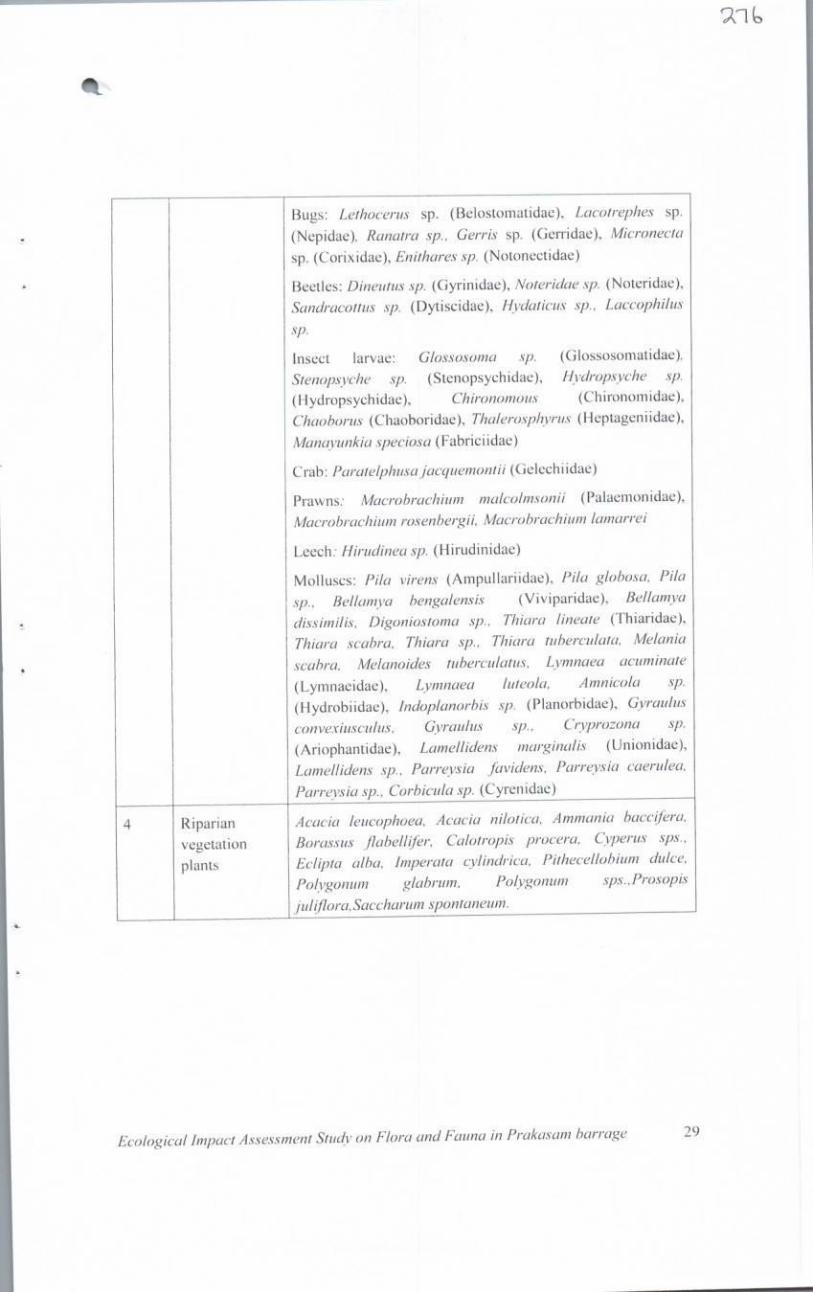
iii. From the Ecological assessment report it can be inferred that
the cautious use of dredgers & mechanised boats and
judicious desilting activity may not have serious impacts on flora and fauna in Prakasam barrage.
iv. Overall the Ecological assessment report is satisfactory
excepting the section on Water quality.”
4. In view of above, no further order is necessary except that the
operations be overseen by the same Expert Committee to ensure that no
damage is caused to the environment.
A copy of this order be forwarded to the members of the Expert
Committee by e-mail.
All pending applications do not survive and are disposed of.
Adarsh Kumar Goel, CP
S. P. Wangdi, JM
Dr. Satyawan Singh Garbyal, EM
Dr. Nagin Nanda, EM August 24, 2020 Original Application No. 935/2018 A
120

121

122
123
124