Page 518 of 1031 - National Green Tribunal
173
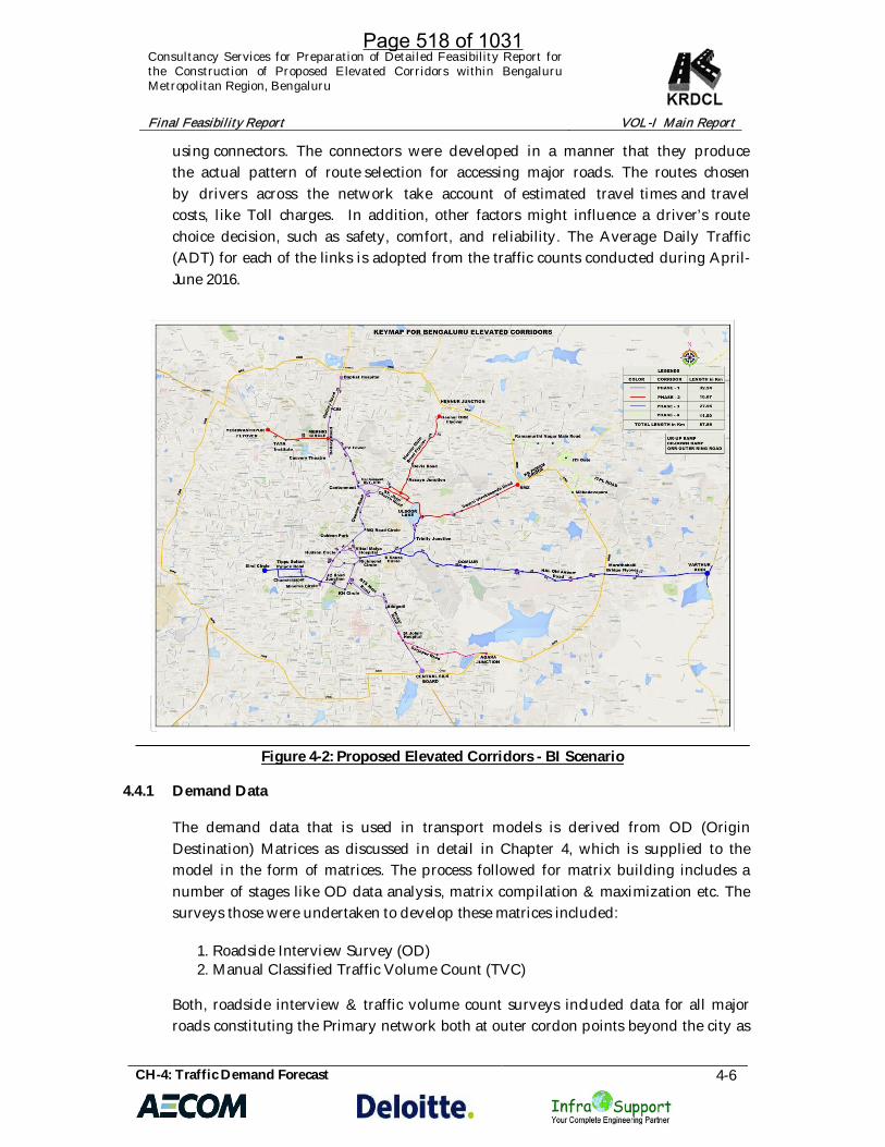
Consultancy Services for Preparation of Detailed Feasibility Report for the Construction of Proposed Elevated Corridors within Bengaluru Metropolitan Region, Bengaluru Final Feasibility Report VOL-I Main Report CH-4: Traffic Demand Forecast 4-6 using connectors. The connectors were developed in a manner that they produce the actual pattern of route selection for accessing major roads. The routes chosen by drivers across the network take account of estimated travel times and travel costs, like Toll charges. In addition, other factors might influence a driver’s route choice decision, such as safety, comfort, and reliability. The Average Daily Traffic (ADT) for each of the links is adopted from the traffic counts conducted during April- June 2016. Figure 4-2: Proposed Elevated Corridors - BI Scenario 4.4.1 Demand Data The demand data that is used in transport models is derived from OD (Origin Destination) Matrices as discussed in detail in Chapter 4, which is supplied to the model in the form of matrices. The process followed for matrix building includes a number of stages like OD data analysis, matrix compilation & maximization etc. The surveys those were undertaken to develop these matrices included: 1. Roadside Interview Survey (OD) 2. Manual Classified Traffic Volume Count (TVC) Both, roadside interview & traffic volume count surveys included data for all major roads constituting the Primary network both at outer cordon points beyond the city as Page 518 of 1031
-
Upload
khangminh22 -
Category
Documents
-
view
3 -
download
0
Transcript of Page 518 of 1031 - National Green Tribunal
Consultancy Services for Preparation of Detailed Feasibility Report forthe Construction of Proposed Elevated Corridors within BengaluruMetropolitan Region, Bengaluru
Final Feasibility Report VOL-I Main Report
CH-4: Traffic Demand Forecast 4-6
using connectors. The connectors were developed in a manner that they producethe actual pattern of route selection for accessing major roads. The routes chosenby drivers across the network take account of estimated travel times and travelcosts, like Toll charges. In addition, other factors might influence a driver’s routechoice decision, such as safety, comfort, and reliability. The Average Daily Traffic(ADT) for each of the links is adopted from the traffic counts conducted during April-June 2016.
Figure 4-2: Proposed Elevated Corridors - BI Scenario
4.4.1 Demand Data
The demand data that is used in transport models is derived from OD (OriginDestination) Matrices as discussed in detail in Chapter 4, which is supplied to themodel in the form of matrices. The process followed for matrix building includes anumber of stages like OD data analysis, matrix compilation & maximization etc. Thesurveys those were undertaken to develop these matrices included:
1. Roadside Interview Survey (OD)2. Manual Classified Traffic Volume Count (TVC)
Both, roadside interview & traffic volume count surveys included data for all majorroads constituting the Primary network both at outer cordon points beyond the city as
Page 518 of 1031

Consultancy Services for Preparation of Detailed Feasibility Report forthe Construction of Proposed Elevated Corridors within BengaluruMetropolitan Region, Bengaluru
Final Feasibility Report VOL-I Main Report
CH-4: Traffic Demand Forecast 4-7
well as in the city core area. Main vehicle types considered for modelling purposeincludes:
· Two wheelers· Auto rickshaws· Cars (including taxis)· Buses· Light Commercial Vehicles (Mini LCVs, 4-Tyre & 6-Tyre)· 2-Axle Trucks· 3-Axle Trucks· Multi Axle Vehicles (MAVs)· Tractor-trailers
4.4.2 Development of O-D matrices
Location wise OD matrices were obtained for all the survey locations, followingthe above mentioned vehicular classification. The location wise matrices were thenclubbed to obtain one combined OD matrix. In the estimation of the combined O-Dmatrix, the following procedure has been considered:
· If an O-D element (or O-D pair) can be observed at only one location, thenthe value of the O-D element from that location matrix is considered inthe combined estimate.
· If an O-D matrix element can be observed at more than one location andare on the same path, then the maximum of that element in the locationmatrices has been considered for combined matrix.
· If an OD matrix element observed at more than one location, the OD pairof which has a parallel route than the sum of that element has beenconsidered for the combined matrix.
Based on the expanded OD data, mode-wise share of different vehicle type is given inTable 4-4.
Table 4-4: Matrix Total by Mode (ADT, PCUs)
Modes Expanded OD Matrix TotalTW 6,93,897Auto Rickshaws 4,11,448Cars 8,63,284Buses 1,70,431Goods (LCV + Trucks) 8,01,512TOTAL 29,40,572
4.5 TRAFFIC ASSIGNMENT
Traffic assignment technique models the route choice behavior between a pair of origin& destination. If the decision is to be made based on a number of alternatives, then the
Page 519 of 1031

Consultancy Services for Preparation of Detailed Feasibility Report forthe Construction of Proposed Elevated Corridors within BengaluruMetropolitan Region, Bengaluru
Final Feasibility Report VOL-I Main Report
CH-4: Traffic Demand Forecast 4-8
choice is determined on the basis of travel time & travel cost on each route. These arefunction of the road condition & also traffic congestion along a particular route.
4.5.1 Assignment Approach
The assignment procedure adopted for the highway model is based on an TimeEquilibrium Assignment model with multiple demand segments (cars, TW, buses &freight vehicles). The assignment is controlled to continue for as much iteration as arerequired to achieve a satisfactory level of convergence. In the case of VISUM model theprocess was continued until full convergence was achieved.
The methodology used for assignment of Private trips in this study is known asEquilibrium assignment. The Equilibrium assignment distributes the demandaccording to Wardrop’s first principle – Equilibrium procedure only terminates whenall routes of any OD pair are in the balanced state in terms of travel time, theprocedure provides realistic results. The computation time required by the equilibriumassignment depends on the volume/capacity ratio in the network. Because new routesare found in every iteration step for a strongly saturated network, more computationtime is required in this case.
In this method the impedance of the links is determined from the current travel time.The current travel time is in links calculated using the capacity restraint function BPRwith a, b and c values.
Where
- Sat - Volume/capacity ratio sat =q/qmax *C
- tcur - Current travel time on a network object in loaded network
- t0 - Travel time on a network object with free flow time
- q - Current volume
- qmax - Capacity
4.5.2 Generalized Cost Estimation
Generalized Cost (GC) goes as input into the traffic assignment model discussedabove. The GC then becomes a critical parameter for defining the route choice betweenrespective OD pairs.
Generalized cost consists of the monetary and non-monetary costs of a Journey.Monetary or “out-of-pocket” costs might include a fare on a public transport journey,or the costs of fuel, wear and tear and any parking charge, toll or congestion charge ona personal mode journey. Non-monetary costs refer to the time spent undertaking the
Page 520 of 1031

Consultancy Services for Preparation of Detailed Feasibility Report forthe Construction of Proposed Elevated Corridors within BengaluruMetropolitan Region, Bengaluru
Final Feasibility Report VOL-I Main Report
CH-4: Traffic Demand Forecast 4-9
journey. Time is converted to a money value using a value of time figure, whichusually varies according to the traveler’s income and the purpose of the trip.
The Generalized Cost is equivalent to the price of the good in supply anddemand theory. Demand for journeys can be related to the generalized cost ofthose journeys using the price elasticity of demand. Supply is equivalent tocapacity (and for roads, road quality) on the network. The cost of travel (C-generalized cost) between the zones has been estimated based on existing toll chargeson highways and bridges.
For the purpose of present study, travel time and toll cost (wherever applicable) havebeen considered for estimating GC for each road link.
Skims of travel time are taken from the assignments. Generalised cost matrix isestimated for all modes and purposes. The expanded OD matrices were assigned tothe network in VISUM on the basis of optimization of Travel Time & Toll cost,wherein the function for generalized cost can be described as below:
GC = TT +TC
Where,
TT = Travel Time
TC = Toll Cost
For the purpose of present study, travel time and toll cost (wherever applicable) havebeen considered for estimating GC for each road link. Adopted toll rates for theproposed elevated corridors are mentioned in Table 4-5 below:
Table 4-5: Adopted Toll Rates for Elevated Corridors
Mode Toll Rate/ Km(INR)
Car 4.80
Bus 12.97
TW 1.62
4.5.3 Model Calibration & Validation
Matrix calibration for the base year model has been done on the basis of screen linecross-traffic flow on the links using the ‘T-flow Fuzzy’ method. ‘T-flow Fuzzy’ updatesa given O-D matrix in such a way that the modelled result of the assignment flowsaims to closely match the observed traffic volume values on the given links.
Page 521 of 1031

Consultancy Services for Preparation of Detailed Feasibility Report forthe Construction of Proposed Elevated Corridors within BengaluruMetropolitan Region, Bengaluru
Final Feasibility Report VOL-I Main Report
CH-4: Traffic Demand Forecast 4-10
The base traffic flow demand data obtained from the OD surveys data wassegregated into the following basic matrix categories: Two Wheeler, AutoRickshaw, Car, Bus, LCV, 2-Axle Truck, 3 Axle truck and MAV’s. The ODmatrices were then expanded with reference to the traffic volume count observed atthe survey locations. These expanded OD matrices were given as an input to VISUMfor running the calibration procedure. Mode-wise calibration procedure has beenadopted in this study.
The matrices were calibrated to the observed link flows. Figure 4-3 shows the overviewof the procedure which has been followed to produce the origin-destination matrix.The demand estimation in VISUM was checked by comparing the assignedflows against the observed flows for screen line cross traffic flow on the links. Thiswas done by calculating the quality of fit using the GEH statistic. The GEH statistic is acommon comparative measure in the context of transport modelling. The formula ofthe GEH statistic is as follows:
The GEH is a measure that includes both the absolute and the relative differencebetween the traffic flow measured (i.e. Observed) and the flow simulated by themodel. The quality of fit is considered acceptable if the GEH statistic is less than 5 in85% of cases.
Figure 4-3: Estimation flow for Matrix Calibration
4.5.4 Base Year Traffic model Validation
Validation of the traffic model becomes essential to determine whether the modelreplicates the ground count or not. In order to validate the model, the 2016 vehiculartrip matrices of all the modes were assigned on to the base year highway network.
Page 522 of 1031

Consultancy Services for Preparation of Detailed Feasibility Report forthe Construction of Proposed Elevated Corridors within BengaluruMetropolitan Region, Bengaluru
Final Feasibility Report VOL-I Main Report
CH-4: Traffic Demand Forecast 4-11
Base year assignment for all the modes is presented in Figure 4-4.
Model validation was undertaken by comparing observed data collected from thesurveys for the project with their equivalent synthesized results as produced by thetransport model. Comparisons were made of traffic volumes. The assignment has beenvalidated at all the identified screen-line locations with cross-traffic volume. Thecomparison of observed average daily traffic volumes in terms of PCUs on the linksfrom survey to the synthesized modelled average daily traffic volumes in PCU aresummarized in Table 4-6 for all Traffic Volume count locations chosen for field survey.The results show a reasonably good match between observed and synthesized trafficvolumes. Based on the results of validation, traffic model was considered sufficientlyrobust for application for the study. Figure 4-4 presents the traffic assignment on theStudy Area network for the base year.
Table 4-6: Observed and synthesized traffic volume
S.No. Corridor Observed
ADTModelled
ADTDifference in
Volume%
Change GEH
1 Hebbal 198,588 198,312 276 0.1% 0.6
2 Kasturba road 89,576 89,500 76 0.1% 0.3
3 Silk board flyover 187,951 186,819 1132 0.6% 2.6
4 ITC colony – KRPuram 127,246 126,681 565 0.4% 1.6
5 Jayamahal Road 81,918 80,453 1465 1.8% 5.1
6 CPRI Road 94,869 93,458 1411 1.5% 4.6
7 Rangudanhalli 66,905 65,238 1667 2.5% 6.5
8 Hal Stop 108,999 108,500 499 0.5% 1.5
9 Sirsi 164,250 162,347 1903 1.2% 4.7
10 Jakkasandra 127,858 126,547 1311 1.0% 3.7
Page 523 of 1031

Consultancy Services for Preparation of Detailed Feasibility Report forthe Construction of Proposed Elevated Corridors within BengaluruMetropolitan Region, Bengaluru
Final Feasibility Report VOL-I Main Report
CH-4: Traffic Demand Forecast 4-12
Figure 4-4: Traffic Assignment BAU Scenario - 2016
4.5.5 Divertible Traffic Estimation
As discussed above, Traffic Assignment Model was used to model traffic flows on thestudy area network. Same model will now be used to estimate potential divertibletraffic likely to use the proposed elevated corridors due to reduction in travel time,increase speed along with payment of toll charge. Considering the proposed alignmentof elevated corridors and enhanced parameters such as increased speed, capacity andentry-exit locations, the model was first run for estimation of divertible traffic for thebase year. Since the network of proposed elevated corridors was coded for restrictionof use by commercial vehicles, no trucks have been assigned on the proposedcorridors.
The estimated traffic diversion in the base year as per the results of traffic assignmentmodel is presented in Table 4-7.
Page 524 of 1031

Consultancy Services for Preparation of Detailed Feasibility Report forthe Construction of Proposed Elevated Corridors within BengaluruMetropolitan Region, Bengaluru
Final Feasibility Report VOL-I Main Report
CH-4: Traffic Demand Forecast 4-13
Table 4-7: Divertible Traffic (PCUs) on Proposed Elevated Corridors for the Base Year (2016)
Sl.No Corridor SectionBAU Scenario (Traffic, PCUs)
Divertible Traffic BI ScenarioWith Elevated Corridors
(PCUs)Residual Traffic (PCUs) Traffic
Reduction(%)TW Autos Bus Cars Total TW Bus Car Total TW Autos Bus Car Total
North-South CorridorI JAYAMAHAL ROAD 27982 13598 6050 37225 84855 56296 7217 63855 127368 15303 5430 5419 22644 48796 42%II QUEENS ROAD 18645 9712 2809 25005 56171 31408 5971 40812 78191 8642 6530 2294 9415 26881 52%III KASTURBA ROAD 30051 15641 12447 52001 110140 37300 6282 43460 87042 3010 8628 1568 5632 18838 83%
IV RICHMOND ROAD-ST. JOSEPH JN. 17752 7033 4214 19943 48942 42230 4436 46250 92916 2825 7157 366 3427 13775 72%
V ST. JOSEPH JN. -SIDDAIAH ROAD 16430 7748 6998 20260 51436 47749 7844 48255 103848 7299 6474 2437 9475 25685 50%
VI SIDDAIAH ROAD -WILSON GARDEN 9894 3334 2743 12152 28123 47413 1018
4 48593 106190 3434 2511 452 4047 10444 63%
VIIHOSUR ROAD -SARJAPURJUNCTION
25503 12248 9933 24891 72575 47907 8910 51706 108523 11072 6074 5223 10331 32700 55%
VIII SARJAPUR JN. - ORR 11991 6297 1969 14437 34694 38333 7977 41454 87764 2122 6849 423 3118 12512 64%East West- I Corridor
I YASHWANTHPUR -IISC 33421 13130 9010 36837 92398 28884 4428 24824 58136 10561 10666 4560 14428 40215 56%
II TUMKUR ROAD: IISC- MEKHRI CIRCLE 41543 17783 16469 45686 121481 41585 6526 47216 95327 7240 5132 2157 8875 23404 81%
III MILLERS ROAD - ST.JOHNS CHURCH 17303 9240 5332 32199 64074 39709 8986 56609 105304 2463 7937 954 7618 18972 70%
Page 525 of 1031

Consultancy Services for Preparation of Detailed Feasibility Report forthe Construction of Proposed Elevated Corridors within BengaluruMetropolitan Region, Bengaluru
Final Feasibility Report VOL-I Main Report
CH-4: Traffic Demand Forecast 4-14
Sl.No Corridor SectionBAU Scenario (Traffic, PCUs)
Divertible Traffic BI ScenarioWith Elevated Corridors
(PCUs)Residual Traffic (PCUs) Traffic
Reduction(%)TW Autos Bus Cars Total TW Bus Car Total TW Autos Bus Car Total
ROAD
IV KENSINGTON ROAD- MURPHY ROAD 24414 13570 8397 37635 84016 41164 6489 47495 95148 2030 5587 989 6026 14632 83%
VOLD MADRAS ROAD- KR PURAMJUNCTION
63503 21550 14485 83626 183164 37569 8000 38751 84320 6918 6865 975 10066 24824 86%
VIKR PURAMJUNCTION -BHATTARAHALLI
55293 19437 10394 40530 125654 31247 6593 23389 61229 2734 8280 838 2176 14028 89%
East West- II Corridor
I DEEPANJALI NAGAR- SULTAN ROAD 32884 13871 14489 45633 106877 25483 5757 20550 51790 8522 10343 2794 9238 30897 71%
II KR MARKET -RICHMOND CIRCLE 17752 7033 4214 19943 48942 15223 5463 13280 33966 4206 4018 3681 5905 17810 64%
III CHAMRAJAPETE -KH CIRCLE 8673 2852 1783 11861 25169 15002 3005 16122 34129 1788 4678 150 1427 8043 68%
IV RICHMOND ROAD -HAL AIRPORT ROAD 26185 12335 3448 35361 77329 51332 6229 48537 106098 5941 3376 3043 5318 17678 77%
V HAL AIRPORT ROAD- DOMLUR FLYOVER 26185 12335 3448 35361 77329 48117 6742 48893 103752 11624 8220 1224 8856 29924 61%
VIOLD AIRPORT ROAD- MARATHAHALLI(ORR)
34367 12470 6984 41752 95573 34936 5607 32457 73000 5729 9627 770 7121 23247 76%
Page 526 of 1031

Consultancy Services for Preparation of Detailed Feasibility Report forthe Construction of Proposed Elevated Corridors within BengaluruMetropolitan Region, Bengaluru
Final Feasibility Report VOL-I Main Report
CH-4: Traffic Demand Forecast 4-15
Sl.No Corridor SectionBAU Scenario (Traffic, PCUs)
Divertible Traffic BI ScenarioWith Elevated Corridors
(PCUs)Residual Traffic (PCUs) Traffic
Reduction(%)TW Autos Bus Cars Total TW Bus Car Total TW Autos Bus Car Total
VII VARTHUR ROAD 19210 7157 3546 18988 48901 28430 3133 19423 50986 1382 3341 92 977 5792 88%Connecting Corridor - I
SARJAPUR ROAD 13676 8806 1428 17695 41605 21667 2278 22802 46747 1810 3893 170 2327 8200 80%Connecting Corridor - II
D'SOUZA CIRCLE -BHASKARAN ROAD 48739 18138 9428 54675 130980 41729 8075 37415 87219 1881 3137 234 2539 7791 94%
Page 527 of 1031

Consultancy Services for Preparation of Detailed Feasibility Report for theConstruction of Proposed Elevated Corridors within BengaluruMetropolitan Region, Bengaluru
Final Feasibility Report VOL-I Main Report
CH-4: Traffic Demand Forecast 4-16
Figure 4-5: Traffic Assignment Business Induced (BI) Scenario – 2016
4.5.6 Conclusions
As evident from table above, traffic diversion will happen not only from the networkwhere the elevated corridors have been proposed but also from surrounding networkdue to reduction distance, travel time and enhanced speed.
As per the model outputs, following conclusions can be drawn out:
· Maximum traffic i.e. 1,27,368 on the North South elevated corridor will bein the section on Jayamahal Road.
· On the East West-I corridor the maximum traffic will around 1,05,304PCUs in the section between Millers Road - St. Johns Church Road.
· In the East West II corridor, maximum traffic will be in the range of1,06,098 PCUs in the Richmond Road - Hal Airport Road.
· Out of all Connecting Corridors, CC-II will attract maximum traffic in therange of 87,219PCUs.
· A total of 46,747 PCUs of traffic will be diverted to CC-I corridor and22,457 PCUs to CC-III Corridor in the base year.
Page 528 of 1031

Consultancy Services for Preparation of Detailed Feasibility Report for theConstruction of Proposed Elevated Corridors within BengaluruMetropolitan Region, Bengaluru
Final Feasibility Report VOL-I Main Report
CH-4: Traffic Demand Forecast 4-17
4.6 TRAFFIC FORECAST
Traffic growth rates have been estimated for the traffic flowing on the primarynetwork within the city of Bangalore. The overall traffic growth rates have beenestimated considering the growth rate used for passenger trip forecast as per therecommendations of Comprehensive Traffic and Transportation Plan (CTTP) forBangalore, 2025 and the DPR for Bangalore Metro Phase I and II. The growth alsoconsiders the impact of Metro expansion in the city of Bangalore.
4.6.1 Growth of Registered Vehicles
In order to analyze the vehicle growth in the city of Bangalore, the vehicle registrationdata of the city has been collected. The annual growth rates and Compound AverageGrowth Rate (%) of different vehicle types is presented in Table 4-8.
Table 4-8: Growth of Registered vehicles in Bangalore (In Lakhs)
Year TW Cars Autos Buses TrucksTaxiCab
Tractors/ Trailers
OthersTotal
Vehicles
1980 1.12 0.36 0.10 0.05 0.08 0.00 0.04 0.01 1.75
1985 2.16 0.60 0.10 0.05 0.12 0.00 0.01 0.02 3.07
1990 4.59 0.91 0.17 0.05 0.19 0.00 0.04 0.04 5.98
1995 6.49 1.26 0.37 0.11 0.29 0.02 0.06 0.10 8.71
2000 10.67 2.14 0.61 0.21 0.42 0.04 0.12 0.17 14.38
2001 11.62 2.36 0.64 0.23 0.48 0.05 0.13 0.16 15.66
2002 12.92 2.61 0.68 0.25 0.53 0.05 0.15 0.20 17.39
2003 14.19 2.87 0.72 0.28 0.59 0.07 0.16 0.24 19.12
2004 15.86 3.36 0.74 0.34 0.68 0.10 0.20 0.28 21.57
2005 18.11 3.87 0.80 0.37 0.85 0.13 0.23 0.31 24.67
2006 20.74 4.54 0.91 0.39 0.92 0.16 0.29 0.46 28.41
2007 22.32 5.27 0.95 0.48 1.10 0.18 0.31 0.45 31.07
2008 22.64 5.53 0.96 0.49 1.19 0.19 0.32 0.54 31.85
2009 26.08 6.46 1.06 0.42 1.29 0.21 0.32 0.69 36.53
2010 25.47 7.24 0.93 0.73 1.38 0.20 0.13 0.78 36.86
2015 41.11 11.59 1.59 0.88 0.96 0.99 0.16 0.43 59.49
CAGR 10.75% 10.32% 8.10% 8.33% 7.27% 14.06% 5.10% 11.29% 10.51% Source: Comprehensive Traffic and Transportation Plan for Bangalore, 2025; RTA Karnataka.
Page 529 of 1031

Consultancy Services for Preparation of Detailed Feasibility Report for theConstruction of Proposed Elevated Corridors within BengaluruMetropolitan Region, Bengaluru
Final Feasibility Report VOL-I Main Report
CH-4: Traffic Demand Forecast 4-18
4.6.2 Traffic Growth Rates
For the purpose of forecasting traffic growth rates, growth rate of population andpassenger trips in the city of Bangalore has been considered. For this purpose theCTTP for Bangalore, 2025 along with the DPR for upcoming Phase II of BangaloreMetro have been studied and referred.
As per the CTTP the population of the city has grown at a Compound Annual GrowthRate (CAGR) of 3%. The employment growth estimates a CAGR of 4% till 2025.Considering this as the base for calculation, the DPR of Bangalore Metro Phase II isconsidered for the trip estimates for the future year as per projected metro ridership.The vehicle registration data for the city of Bangalore further reflects an overall CAGRof 6% till 2025.
Table 4-9 presents the CAGR for population, employment and registered vehicles forcity of Bangalore.
Table 4-9: Growth trends in the city of Bangalore
Year Population Employment Registeredvehicles
2001 5,676,058 1,851,000 1,566,0002011 7,000,749 2,426,000 3,686,0002021 8,500,481 3,125,000 5,539,0002025 12,300,000 5,050,000 6,357,000
CAGR 3% 4% 6%Source: CTTP for Bangalore, 2025; DPR for Bangalore Metro.
The DPR of Bangalore Metro Phase II suggests a modal share of 16% for the metro andan average annual growth rate of 3% for entire passenger trips. Considering this thebase year passenger trips as obtained from the overall O-D analysis have beenprojected at an annual rate of 3% for the horizon year 2035 and also for cardinal yearswith 5 year interval.
Of the total projected passenger trips, 16 % share of metro has been excluded for theyear 2020, while beyond 2030, a shift of 20% of total passenger trips are assumed to bediverted to metro. Remaining non-metro trips have been further distributed by modeusing the modal composition as observed in the base year for the purpose of obtainingmode wise horizon and cardinal year vehicular matrices. Substantial shift of buspassengers to metro trips is considered as per the DPR.
The modal share composition adopted for the project for the city of Bangalore isdescribed in Table 4.10.
Page 530 of 1031

Consultancy Services for Preparation of Detailed Feasibility Report for theConstruction of Proposed Elevated Corridors within BengaluruMetropolitan Region, Bengaluru
Final Feasibility Report VOL-I Main Report
CH-4: Traffic Demand Forecast 4-19
Table 4-10: Modal Share Composition for Horizon Year 2035
Modes % ShareTW 25Car 32Auto 15Bus 8Metro 20
The mode wise passenger trips as projected for Bangalore city are presented in Table4.11.
Table 4-11: Projected Passenger Trips by Mode
Year TW Car Auto Bus Total Metro trips Non-Metro Trips
2016 701076 1274684 807300 5098738 7881,799
2020 789068 1434669 908623 5738674 8871,034 1419,365 7451,668
2025 914746 1663174 1053344 6652696 10283,959 1645,434 8638,526
2030 1060441 1928075 1221114 7712298 11921927 2384,385 9537,542
2035 1229342 2235167 1415606 8940667 13820781 3455,195 10365,586
The growth rate for passenger trips was further applied on mode wise trip matrices forobtaining horizon and cardinal year passenger trip matrices by mode. Cardinal yearsinclude matrices for year 2020, 2025 and 2030 at 5-year intervals.
The mode wise passenger trip matrices were then converted back into vehicularmatrices using the base year occupancy and further into PCUs matrices for the purposeof traffic assignment. The horizon year matrices are then assigned in the highwaynetwork using the base year assignment model considering the planned transportinfrastructure upgradation.
The model will then result in project link volumes on the proposed elevated corridorsconsidering the growth, future congested speeds and toll rates. Following sectiondescribes the traffic forecast under various highway network and demand scenarios.
4.6.3 Horizon year Network
The future traffic assignment procedure considers subsequent development phaseswhich are expected to be incorporated to the existing primary network in the city ofBangalore. Proposed links and highways are thus incorporated into the future networkscenarios to bring out the real picture of expected traffic flows in the upcoming days.The proposed new links that are incorporated into the base year network include:
Page 531 of 1031

Consultancy Services for Preparation of Detailed Feasibility Report for theConstruction of Proposed Elevated Corridors within BengaluruMetropolitan Region, Bengaluru
Final Feasibility Report VOL-I Main Report
CH-4: Traffic Demand Forecast 4-20
1. Proposed Airport Expressway – expected to be functional by 2020.2. Proposed extension of the NICE Ring Road – expected to be completed by
2020.
Figure 4-6 presents the horizon year network from 2020 and beyond.
Figure 4-6: Horizon Year Road Network
Existing Links
Page 532 of 1031

Consultancy Services for Preparation of Detailed Feasibility Report for theConstruction of Proposed Elevated Corridors within BengaluruMetropolitan Region, Bengaluru
Final Feasibility Report VOL-I Main Report
CH-4: Traffic Demand Forecast 4-21
4.6.4 Project Phasing
The proposed elevated corridors will be constructed in phases and not altogether. Asand when each phase is constructed it will be made open to traffic and toll willcharged only for the length that is operational. It is proposed that North South (NS)Corridor along with Connecting Corridor 1 (CC-I) will be taken up for construction inthe first phase followed by East West- 1 along with Connecting Corridors 2 & 3 (CC 2& 3) and East West-2 corridors in subsequent phases 2 & 3. For the purpose of analysisthe construction period of 3 years for each corridor has been considered.
The project phasing will further be used to estimate traffic diversion with respect tocompletion of each elevated corridor during the horizon period subject to theirrespective time of opening for operations, which will then be used to estimate toll-abletraffic forecast both for horizon and cardinal years. Error! Reference source not found.Presents the Project Phasing and completion schedule.
Table 4-12: Project Phasing, Completion & Operation Schedule
PhaseYears
2019 2020 2021 2022 2023 2024Corridors
INS + CC-1
(% Completion)30 40 30
IIEW-1 + CC-2+
CC-3(% Completion)
30 40 30
IIIEW-2
(% Completion)30 40 30
As evident from above table, the NS & CC 1 Corridors will be operational in the year2021, EW-1, CC-2 & CC-3 will be open in year 2023 and EW-2 will be open forcommercial operations in the year 2025.
Phasing of proposed elevated corridors is presented in Volume IX- Drawings.
4.6.5 Toll-able Traffic Forecast
The projected vehicular matrices have been assigned on the horizon year network asdiscussed above to estimate link wise vehicular volume for estimating toll-able trafficfor each phase till the horizon year study.
For the purpose of present study vehicular modes such as Cars, TW and Buses havebeen considered to be tolled and same will only be allowed to ply on the proposed
Page 533 of 1031

Consultancy Services for Preparation of Detailed Feasibility Report for theConstruction of Proposed Elevated Corridors within BengaluruMetropolitan Region, Bengaluru
Final Feasibility Report VOL-I Main Report
CH-4: Traffic Demand Forecast 4-22
elevated corridor. Remaining traffic will use the existing network at grade formovement.
Toll-able traffic estimates have been made till the year 2037.
Projected tollable traffic for the proposed elevated corridors is presented in Table 4-13.
Page 534 of 1031

Consultancy Services for Preparation of Detailed Feasibility Report forthe Construction of Proposed Elevated Corridors within BengaluruMetropolitan Region, Bengaluru
Final Feasibility Report VOL-I Main Report
CH-4: Traffic Demand Forecast 4-23
Table 4-13: Projected Toll able Traffic – Business Induced (BI) Scenario (Vehicles)
Corridors Sections
SectionLength
(inKM)
Without Corridors : BAU Scenario Phase I Completed Phase I Tolling Begins Phase II Tolling Begins Phase III TollingBegins
Projected Traffic Volume - Phase III
(All Corridors Operational)
2016 2020 2021 2022 2023 2030 2035 2037
Base Year Assigned Traffic (Vehicles) Vehicles Vehicles Vehicles Vehicles Vehicles Vehicles Vehicles
TW Autos Buses Cars TW Buses Cars TW Bus
es Cars TW Buses Cars TW Buses Cars TW Buses Cars TW Buses Cars TW Buses Cars
NS
I JAYAMAHAL ROAD 2.6 37,309 9,066 2,750 37,225 78473 129 43,225 80043 132 44,090 105481 117 49,276 102067 131 52,961 101593 233 56,650 102845 135 49,780 107000 141 51,791
II QUEENS ROAD 3.13 24,860 6,475 1,277 25,005 1,00,945 215 62,803 1,02,964 219 64,059 59,067 141 39,583 59,347 140 35,896 58,503 195 38,452 56,084 142 38,619 58,350 148 40,179
III KASTURBA ROAD 2 40,068 10,428 5,658 52,001 105661 207 61,119 107775 211 62,341 62,732 131 38,042 65,525 160 37,505 62,955 219 38,688 62,572 158 38,664 65,100 164 40,226
IV RICHMOND ROAD-ST. JOSEPH JN. 1.8 23,669 4,689 1,915 19,943 65,447 165 37,819 66,756 168 38,575 79,865 120 39,836 86,640 122 34,750 85,213 121 35,823 77,949 120 41,273 81,098 125 42,940
V ST. JOSEPH JN. -SIDDAIAH ROAD 1.8 21,907 5,166 3,181 20,260 60409 165 36,188 61618 168 36,912 92,855 153 46,330 84,401 210 40,252 81,965 292 42,197 79,997 224 42,998 83,229 233 44,735
VI SIDDAIAH ROAD -WILSON GARDEN 1.6 13,192 2,223 1,247 12,152 103236 262 58,187 105301 268 59,351 93,225 153 46,330 85,777 245 43,389 85,109 347 43,685 85,587 243 42,307 89,044 253 44,016
VIIHOSUR ROAD -SARJAPURJUNCTION
2.3 34,004 8,166 4,515 24,891 127725 275 69,999 130280 281 71,399 113571 229 53,948 1,00,419 221 49,621 99,701 295 50,863 95,988 245 50,061 99,866 254 52,083
VIII SARJAPUR JN. - ORR 1.2 15,988 4,198 895 14,437 90,105 215 41,247 91,907 219 42,072 82,257 174 31,764 73,111 172 32,380 74,095 232 33,657 75,944 193 31,270 79,012 201 32,533
EW -1
I YASHWANTHPUR -IISC 1.5 44,561 8,754 4,095 36,837 0 0 0 0 0 0 62,635 91 27,371 59,049 94 25,074 59,256 144 24,630 61,600 111 23,889 64,089 115 24,854
II TUMKUR ROAD: IISC- MEKHRI CIRCLE 2.5 55,391 11,855 7,486 45,686 0 0 0 0 0 0 82857 103 42,504 83,477 150 46,357 85,272 253 47,418 85,523 154 41,336 88,978 160 43,006
IIIMILLERS ROAD - ST.JOHNS CHURCHROAD
1.6 23,071 6,160 2,424 32,199 0 0 0 0 0 0 70,636 155 39,700 72,153 120 41,049 71,680 209 43,263 74,105 133 40,740 77,099 139 42,386
IV KENSINGTON ROAD- MURPHY ROAD 2 32,552 9,047 3,817 37,635 0 0 0 0 0 0 77,577 90 41,411 86,232 173 42,713 82,940 156 40,764 80,325 112 37,857 83,570 117 39,386
VOLD MADRAS ROAD- KR PURAMJUNCTION
3.64 84,671 14,367 6,584 83,626 0 0 0 0 0 0 100435 187 44,746 90,416 189 42,671 76,563 247 36,746 85,743 210 38,969 89,207 219 40,543
VIKR PURAMJUNCTION -BHATTARAHALLI
13.6 73,724 12,958 4,725 40,530 0 0 0 0 0 0 80,352 170 29,336 70,895 138 24,659 67,876 187 24,403 69,427 170 23,402 72,232 177 24,347
EW-II
I DEEPANJALI NAGAR- SULTAN ROAD 3 43,845 9,247 6,586 45,633 0 0 0 0 0 0 0 0 0 46,068 25 20,758 47,989 35 24,173 47,657 32 25,099 49,583 33 26,113
II KR MARKET -RICHMOND CIRCLE 6.27
23,669 4,689 1,915 19,943 0 0 0 0 0 0 0 0 0 32,287 116 12,320 33,220 156 11,982 33,717 128 12,418 35,080 133 12,920
III CHAMRAJAPETE -KH CIRCLE 11,564 1,902 810 11,861 0 0 0 0 0 0 0 0 0 34,728 52 16,189 34,277 75 17,100 31,224 33 16,784 32,485 35 17,462
IV RICHMOND ROAD -HAL AIRPORT ROAD 2.5 34,913 8,224 1,567 35,361 0 0 0 0 0 0 0 0 0 1,01,0
01 185 38,430 97,253 253 40,469 92,160 217 43,696 95,883 226 45,461
V HAL AIRPORT ROAD- DOMLUR FLYOVER 3.5 34,913 8,224 1,567 35,361 0 0 0 0 0 0 0 0 0 88,223 143 39,596 87,084 198 40,451 78,708 156 42,709 81,888 162 44,434
VI OLD AIRPORT ROAD- MARATHAHALLI 6.5 45,823 8,313 3,175 41,752 0 0 0 0 0 0 0 0 0 78,069 117 38,000 76,864 171 36,561 71,241 138 38,160 74,119 144 39,702
Page 535 of 1031

Consultancy Services for Preparation of Detailed Feasibility Report forthe Construction of Proposed Elevated Corridors within BengaluruMetropolitan Region, Bengaluru
Final Feasibility Report VOL-I Main Report
CH-4: Traffic Demand Forecast 4-24
Corridors Sections
SectionLength
(inKM)
Without Corridors : BAU Scenario Phase I Completed Phase I Tolling Begins Phase II Tolling Begins Phase III TollingBegins
Projected Traffic Volume - Phase III
(All Corridors Operational)
2016 2020 2021 2022 2023 2030 2035 2037
Base Year Assigned Traffic (Vehicles) Vehicles Vehicles Vehicles Vehicles Vehicles Vehicles Vehicles
TW Autos Buses Cars TW Buses Cars TW Bus
es Cars TW Buses Cars TW Buses Cars TW Buses Cars TW Buses Cars TW Buses Cars
(ORR)
VII VARTHUR ROAD 5.2 25,613 4,771 1,612 18,988 0 0 0 0 0 0 0 0 0 61,668 47 20,661 60,819 63 21,782 55,661 48 20,862 57,910 50 21,705
CC-I SARJAPUR ROAD 4.48 18,235 5,871 649 17,695 89,048 72 34,849 90,829 73 35,546 64,459 63 24,923 55,887 60 21,770 54,731 76 22,855 54,897 55 20,464 57,115 57 21,291
CC-II D'SOUZA CIRCLE -BHASKARAN ROAD 2.8 64,985 12,092 4,285 54,675 0 0 0 0 0 0 72,357 135 33,199 81,507 133 33,629 77,007 183 33,472 78,845 154 33,121 82,031 160 34,459
Page 536 of 1031

Consultancy Services for Preparation of Detailed Feasibility Report for theConstruction of Proposed Elevated Corridors within BengaluruMetropolitan Region, Bengaluru
Final Feasibility Report VOL-I Main Report
CH-4: Traffic Demand Forecast 4-25
Figure 4-7: Projected Traffic Assignment, Phase I - 2021
Figure 4-8: Projected Traffic Assignment, Phase II – 2023
Page 537 of 1031
Consultancy Services for Preparation of Detailed Feasibility Report for theConstruction of Proposed Elevated Corridors within BengaluruMetropolitan Region, Bengaluru
Final Feasibility Report VOL-I Main Report
CH-4: Traffic Demand Forecast 4-26
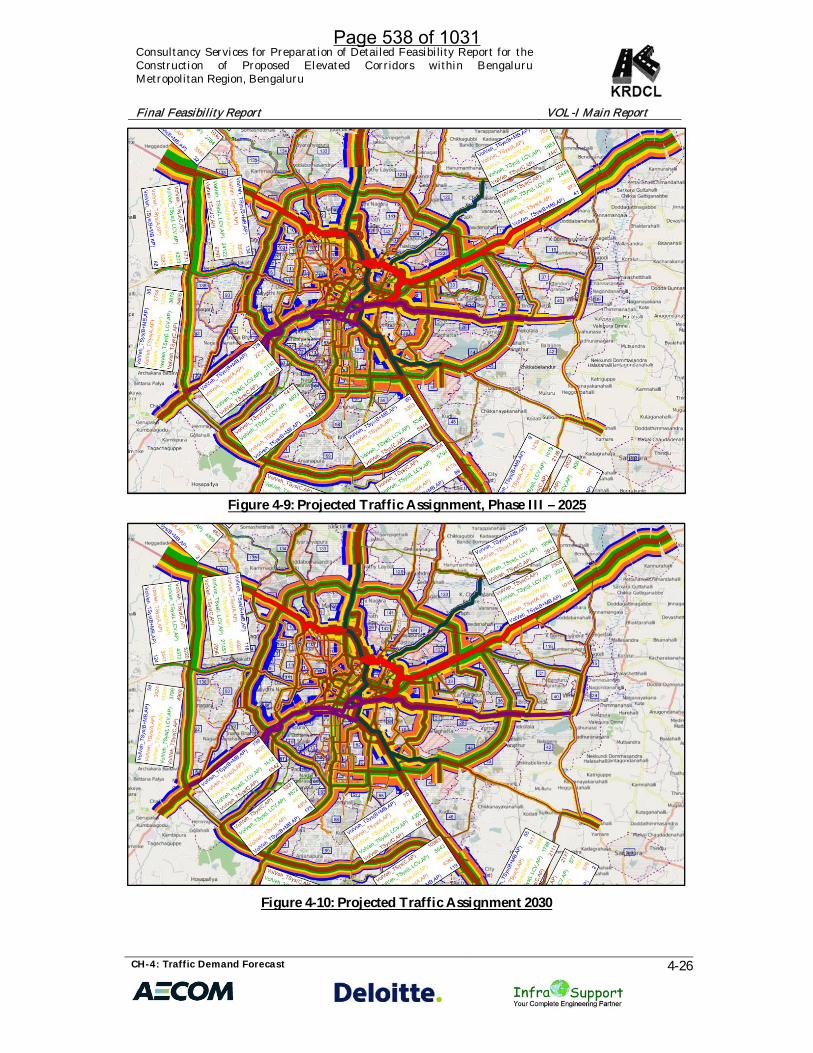
Figure 4-9: Projected Traffic Assignment, Phase III – 2025
Figure 4-10: Projected Traffic Assignment 2030
Page 538 of 1031

Consultancy Services for Preparation of Detailed Feasibility Report for theConstruction of Proposed Elevated Corridors within BengaluruMetropolitan Region, Bengaluru
Final Feasibility Report VOL-I Main Report
CH-4: Traffic Demand Forecast 4-27
Figure 4-11: Projected Traffic Assignment 2037
4.7 RECOMMENDATIONS
Once the toll-able traffic forecast is made, it is prudent to understand the capacitylimitations of proposed transport infrastructure. The estimated traffic is analysed withrespect to capacity of the proposed corridors and analysis is made to understand thetimeline by which the proposed corridors will no longer be in a position to offerdesired Level of Service and the traffic volume exceeds the capacity. The section brieflydescribes the capacity augmentation requirements of the proposed corridors.
4.7.1 Capacity Augmentation Requirements
In order to plan for future network it is important to understand that when the presentinfrastructure will reach the design capacity. Therefore it is important to understandwhen these facilities require capacity augmentation and what impact it will have onother facilities, if not upgraded. The ground scenario of Bangalore in the base year 2016shows clearly that capacity augmentation is a must for almost all major corridors in thecity area. Especially in the core areas of central and southern Bangalore, capacity of theurban network has already been eaten up with roads having a V/C ratio of greaterthan 1.5.
With the growing trends of city population, and vehicular growth rates, capacityaugmentation of the primary road network is a must for the city of Bangalore. Theproposal of elevated corridors in the city of Bangalore having a stretch of 88 Km in a
Page 539 of 1031

Consultancy Services for Preparation of Detailed Feasibility Report for theConstruction of Proposed Elevated Corridors within BengaluruMetropolitan Region, Bengaluru
Final Feasibility Report VOL-I Main Report
CH-4: Traffic Demand Forecast 4-28
whole may immediately address the capacity issue of the urban network in Bangalorewhich results in congestion, lesser journey speeds and higher vehicle operating costs inthe city. The proposed corridors will provide higher capacities, greater travel speeds tothe citizen of Bangalore, in turn addressing the ground problem to reduce congestionon the roads.
On the contrary, it is to be noted that the improved capacities and infrastructurefacilities will attract more traffic to traverse on the elevated corridors. Not only thesecorridors will have diverted traffic from the ground, which used to traverse at grade inthe existing scenario, these corridors will attract induced traffic from other zones to eatup the capacity.
With growing urbanization trends of Bangalore in terms of growth in population andtraffic numbers in the city, the enhanced capacity of these proposed elevated corridorswill soon be utilized fully within the horizon year 2023, when capacity of most of theelevated sections (around 70%) will be exhausted. Traffic assignments on the proposedcorridors in all three suggested scenarios for the horizon years clearly indicate thesame. Some of the proposed elevated sections are found to be exhausted in the baseyear situation only if the corridors are assumed to function from the base year only.
In Phases I, II and III section loads along the proposed elevated corridors show asteady increase in traffic volume from 2016 to 2023 where most part of the corridorshave exceeded their maximum design capacity and shall be bound to congestion,decreased journey speeds and longer travel times.
The situation needs to be addressed with a holistic approach. The growing trends ofurbanization are bound to have drastic impact on the traffic numbers on roads. Themain goal is to reduce the number of private vehicles like two wheelers and cars on theroad and provide the urban population better means to commute via public transit.With growing population trends and travel demand in the city of Bangalore, it isdefinitely advisable to bring forth a comprehensive mass transit system planning toshift more people to public transport than using private vehicles.
Table 4-14 presents the capacity augmentation requirements of proposed elevatedcorridors.
Page 540 of 1031

Consultancy Services for Preparation of Detailed Feasibility Report for theConstruction of Proposed Elevated Corridors within BengaluruMetropolitan Region, Bengaluru
Final Feasibility Report VOL-I Main Report
CH-4: Traffic Demand Forecast 4-29
Table 4-14: Capacity Augmentation Requirements for Proposed Elevated Corridors
Corridor Section
Capacityas perIRC inPCU
Capacity analysis2023 2030 2037Total
traffic inPCU
Totaltraffic in
PCU
Totaltraffic in
PCUNORTH-SOUTH
I JAYAMAHAL ROAD 120000 129800 133358 132351II QUEENS ROAD 120000 80715 82758 84266III KASTURBA ROAD 120000 87002 86385 89412
IV RICHMOND ROAD- ST. JOSEPHJN. 120000 99999 101250 104039
V ST. JOSEPH JN. - SIDDAIAHROAD 120000 104015 104313 107670
VI SIDDAIAH ROAD - WILSONGARDEN 120000 108262 108281 111356
VII HOSUR ROAD - SARJAPURJUNCTION 120000 125422 126287 127543
X SARJAPUR JN. - ORR 120000 87591 89739 92235EAST-WEST I
I YASHWANTHPUR - IISC 120000 69567 69388 73174
II TUMKUR ROAD: IISC - MEKHRICIRCLE 120000 109294 111929 110092
III MILLERS ROAD - ST. JOHNSCHURCH ROAD 120000 95427 97483 100515
IV KENSINGTON ROAD - MURPHYROAD 120000 107768 103313 102321
V OLD MADRAS ROAD - KRPURAM JUNCTION 120000 110899 94711 107930
VI KR PURAM JUNCTION -BHATTARAHALLI 120000 78134 75721 78911
EAST-WEST II
I DEEPANJALI NAGAR - SULTANROAD 60000 55365 60242 63373
II KR MARKET - RICHMONDCIRCLE 30000 36790 37241 39523
III CHAMRAJAPETE - KH CIRCLE 30000 42349 42973 41902
IV RICHMOND ROAD - HALAIRPORT ROAD 60000 114588 113966 117871
V HAL AIRPORT ROAD - DOMLURFLYOVER 60000 106077 106200 106207
VI OLD AIRPORT ROAD -MARATHAHALLI (ORR) 60000 96810 94585 95608
VII VARTHUR ROAD 60000 67016 67534 65247CONNECTORI SARJAPUR ROAD 60000 63816 64070 64252
CONNECTORII
D'SOUZA CIRCLE -BHASKARAN ROAD 60000 95051 91630 96335
Page 541 of 1031

Consultancy Services for Preparation of Detailed Feasibility Report for theConstruction of Proposed Elevated Corridors within BengaluruMetropolitan Region, Bengaluru
Final Feasibility Report VOL-I Main Report
CH-4: Traffic Demand Forecast 4-30
4.8 CONCLUSIONS
From the tabulated section loads for proposed elevated corridors for horizon year,certain inferences can be drawn forward:
· Maximum traffic volume was observed on the Section I – Jayamahal Roadalong the NS corridor accounting for 1,33,358 PCUs of traffic followed bySection - VII Hosur Road - Sarjapur Junction accounting 1,25,422 PCUs of trafficthereby exceeding the capacity in 2023.
· For EW II corridor, Section IV – Richmond Road - Hal Airport Road sectionaccounts for 1,14,588 PCUs of traffic followed by Section-V Hal Airport Road -Domlur Flyover accounts for 1,06,077 thereby exceeding the capacity in thebase year, i.e. 2023.
· CC-II D'souza Circle - Bhaskaran Road section accounts for 95,051 PCUs oftraffic thereby exceeding the capacity in the base year, i.e. 2023.
· Section II and Section VII (Hosur Road – Sarjapur Junction section) of NScorridor is expected to exceed the 6-lane capacity by 2023.
· The capacity of the EW II corridor sections being 60,000 PCUs, Section IV and Vof EW II corridor is expected to exceed the capacity by 2023.
· Major share traffic being diverted to elevated corridors are two wheelers,followed by private cars and commercial cabs.
· The CC-I i.e. Sarjapur road section is expected to have a maximum volume of64,252 PCUs in the year 2037.
· CC-II i.e. Bhaskaran Road-Dsouza circle section is expected to have a maximumvolume of 96,335 PCUs in 2037.
4.9 RECOMMENDATIONS
From the tabulated section loads for proposed elevated corridors for horizon year,certain inferences can be drawn forward:
The above table clearly reflects that after completion of Phase III of the project, theproposed infrastructure will be able to sustain uncongested traffic flow beyond 2023,with a few critical elevated sections where the capacity will be utilized completely.Some of the capacity augmentation requirements to be included in design of proposedelevated corridors include the following:
· It is recommended Section III of the NS corridor being the common section ofNS and EW-I corridors should be developed for 8 lane carriagewayconfiguration.
· Considerations can be undertaken in the design to provide for additional lanesin the future in the affected sections of the corridors.
· Section IV and V of the EW-II corridor is expected a traffic volume whichdefinitely requires 6-Lane divided carriageway configuration for uncongestedtraffic flow.
· CC-II is recommended to be developed for 6 lane carriageway configuration.
Page 542 of 1031

Consultancy Services for Preparation of Detailed Feasibility Report for theConstruction of Proposed Elevated Corridors within BengaluruMetropolitan Region, Bengaluru
Final Feasibility Report VOL-I Main Report
CH-4: Traffic Demand Forecast 4-31
· A comprehensive mass transit network well integrated along the corridors canbe a way out to decrease the volume of traffic on the roads.
4.10 NEED FOR INTEGRATED MASS TRANSIT NETWORK
The very Objective of the elevated corridors in Bangalore will only be achieved if theproposal is integrated with development of Peripheral Ring Road (PRR) to avoid thethrough traffic from entering the City Core central area, development of Mass transitsystem including new Metro and Mono rail feeder corridors. The existing MRT Systemof Bangalore city can be strategically expanded using Metro rail and Mono railcombinations to connect all the arterial and sub arterial roads with the potentialProduction and Attraction zones to meet the growing travel demand of the city. Policylevel interventions are required to integrate the upcoming metro corridors / Mono railcorridors with the proposed elevated corridors so as to provide last mile connectivityand generate substantial shift of passengers from private to public modes. Access toMRTS is needed to be optimized in both central as well as peripheral areas of the cityof Bangalore to maximize its utility. Promoting public transit and strengthening masstransit network in the city can be a holistic way forward to solve the growingcongestion impacts on the streets of Bangalore and improve the degrading quality ofurban life as a whole.
Page 543 of 1031

CHAPTER – 5
DESIGN PROPOSALS
Page 544 of 1031

Consultancy Services for Preparation of Detailed Feasibility Report for theConstruction of Proposed Elevated Corridors within Bengaluru MetropolitanRegion, Bengaluru
Final Feasibility Report VOL- I Main Report
CH-5: Design Proposals 5-1
TABLE OF CONTENTS
CHAPTER 5 : DESIGN PROPOSALS ..................................................................................... 55.1 INTRODUCTION .......................................................................................................................... 55.2 DESIGN STANDARDS ................................................................................................................. 55.2.1 Highway Design Standards: ......................................................................................................... 55.3 STRUCTURE DESIGN STANDARD: ........................................................................................ 125.3.1 Durability Requirement .............................................................................................................. 125.3.2 Standards and Code of Practices ................................................................................................ 135.3.3 Structural Analysis and Design .................................................................................................. 145.3.4 The structural behaviour in the ULS shall be analysed with regard to: .................................. 145.3.5 The structural behaviour in the SLS shall be analysed with regard to: ................................... 155.3.6 Assumptions for Structural Analysis ......................................................................................... 155.3.7 Design Loadings .......................................................................................................................... 155.3.7.1 Dead Load (DL) ................................................................................................................... 155.3.7.2 Super Imposed Dead Load (SIDL):..................................................................................... 155.3.7.3 Design Vehicular Loading (IRC Class Loading) ................................................................ 155.3.7.4 For Local Live Load Analysis (LL) ..................................................................................... 165.3.7.5 Longitudinal force of Live Load due to Braking (BR): ...................................................... 175.3.7.6 Centrifugal forces (CF) ........................................................................................................ 185.3.7.7 Vehicular Collision Load:.................................................................................................... 185.3.7.8 Accidental load on Crash Barriers ...................................................................................... 185.3.7.9 Wind loads ........................................................................................................................... 185.3.7.10 Seismic Loading ................................................................................................................... 185.3.7.10.1 Design response spectra ...................................................................................................... 195.3.8 Bearing Replacement ................................................................................................................... 205.3.9 Settlement (SE) ............................................................................................................................. 205.3.10 Earth Pressure ...................................................................................................................... 205.3.11 Creep and shrinkage effects (CR & SH) ............................................................................. 205.3.12 Thermal Effect (Cl.215 of IRC: 6-2014) ............................................................................... 215.3.12.1 Uniform temperature (TU).................................................................................................. 215.3.12.2 Temperature Gradient (TG) ................................................................................................ 215.3.13 Combination of Loads for Design ...................................................................................... 225.3.13.1 Combination of Loads for under Ultimate Limit State ..................................................... 225.3.13.2 Combination of Loads for under Serviceability Limit State ............................................. 235.3.14 Material Specifications ........................................................................................................ 245.3.14.1 Concrete ............................................................................................................................... 245.3.14.2 Steel reinforcement .............................................................................................................. 255.3.14.3 Structural Steel ..................................................................................................................... 255.3.15 Minimum Clear Concrete Cover ........................................................................................ 255.3.16 Vertical and Lateral Clearances .......................................................................................... 255.3.17 Miscellaneous....................................................................................................................... 265.3.17.1 Crash Barriers ...................................................................................................................... 265.3.17.2 Expansion Joints .................................................................................................................. 265.3.17.3 Wearing Coat ....................................................................................................................... 265.3.17.4 Approach Slab ..................................................................................................................... 265.4 GEOMETRIC DESIGN: ............................................................................................................... 275.4.1 INTRODUCTION ........................................................................................................................ 275.4.2 NORTH-SOUTH CORRIDOR-1 (NS-1): .................................................................................... 275.4.3 Typical cross sections and their schedule proposed along North South Corridor ................. 295.4.4 Horizontal alignment .................................................................................................................. 325.4.5 Vertical alignment ....................................................................................................................... 405.4.6 Major junctions along project corridor and improvement proposals ...................................... 42
Page 545 of 1031

Consultancy Services for Preparation of Detailed Feasibility Report for theConstruction of Proposed Elevated Corridors within Bengaluru MetropolitanRegion, Bengaluru
Final Feasibility Report VOL- I Main Report
CH-5: Design Proposals 5-2
5.4.7 Ramps 435.4.8 At grade improvement proposals .............................................................................................. 445.5 EAST – WEST CORRIDOR-1(EW-1): CONNECTING NH48 (NH-4) AT RMZ ON OLDMADRAS ROAD AND YESHWANTHPURA FLYOVER ON TUMKUR ROAD ........................... 445.5.1 Typical cross sections and their schedule proposed along the project corridor ...................... 465.5.2 Horizontal alignment .................................................................................................................. 505.5.3 Vertical alignment ....................................................................................................................... 565.5.4 Major junctions along project corridor and improvement proposals ...................................... 575.5.5 Ramps 595.6 EAST – WEST CORRIDOR-2 (EW-2): CONNECTING SH-35 AT VARTHUR KODI ANDSIRSI CIRCLE ON MYSORE ROAD ................................................................................................... 605.6.1 Typical cross sections and their schedule proposed along East West-2 corridor .................... 615.6.2 Horizontal alignment .................................................................................................................. 645.6.3 Vertical alignment ....................................................................................................................... 695.6.4 Major junctions along project corridor and improvement proposals ...................................... 705.6.5 Ramps 715.7 Connecting Corriodr-1 (CC-1): ................................................................................................... 715.7.1 Typical cross sections and their schedule proposed along the project corridor ...................... 725.7.2 Horizontal alignment .................................................................................................................. 725.7.3 Vertical alignment ....................................................................................................................... 735.7.4 Ramps 735.8 Connecting Corridor-2 (CC-2): ................................................................................................... 745.8.1 Typical cross sections and their schedule proposed along the project corridor ...................... 745.8.2 Horizontal alignment .................................................................................................................. 755.8.3 Vertical alignment ....................................................................................................................... 755.8.4 Ramps 765.9 Bus Stops 765.9 PAVEMENT DESIGN ................................................................................................................. 775.9.1 Pavement Evaluation Summary ................................................................................................. 775.9.2 Pavement Proposals .................................................................................................................... 775.9.3 White Topping ............................................................................................................................. 785.9.3.1 Design of White-topping as per IRC SP: 76 – 2015. ........................................................... 805.9.3.2 Recommendations for White-topping ................................................................................ 845.10 STRUCTURAL DESIGN ............................................................................................................. 885.10.1 Choice of Structural Material: ............................................................................................. 885.10.2 Comparison: Concrete & Steel ............................................................................................ 885.10.3 Structural Arrangement ...................................................................................................... 915.10.3.1 Superstructure: .................................................................................................................... 925.10.3.2 Substructure & Foundation: ................................................................................................ 925.10.4 Elevated Structural Configuration ..................................................................................... 935.10.4.1 North South Corridor: ......................................................................................................... 935.10.4.1.1 Main Corridor: ..................................................................................................................... 935.10.4.1.2 Loops: ................................................................................................................................... 985.10.4.2 East West Corridor 1: .......................................................................................................... 995.10.4.2.1 Main Corridor: ..................................................................................................................... 995.10.4.2.2 Loops: ................................................................................................................................. 1015.10.4.3 East West Corridor 2: ........................................................................................................ 1035.10.4.3.1 Main Corridor: ................................................................................................................... 1035.10.4.3.2 Loops: ................................................................................................................................. 1045.10.4.4 Connecting Corridor 1: ...................................................................................................... 1055.10.4.5 Connecting Corridor 2: ...................................................................................................... 1055.10.5 Structural Analysis/ Design Methodology...................................................................... 106
Page 546 of 1031

Consultancy Services for Preparation of Detailed Feasibility Report for theConstruction of Proposed Elevated Corridors within Bengaluru MetropolitanRegion, Bengaluru
Final Feasibility Report VOL- I Main Report
CH-5: Design Proposals 5-3
LIST OF TABLESTable 5-1: Dimensions of Shoulder ............................................................................................... 6Table 5-2: Desirable distance of Sight Distance (in-m) ................................................................ 7Table 5-3: Speed, Horizontal Curvature and Sight Distance for Ramp Design ......................... 7Table 5-4: Geometric Design Standards for Project Corridors .................................................. 10Table 5-5: Code of Practices for Structures ................................................................................. 13Table 5-6: Typical Cross Section schedules along North South Corridor ................................ 30Table 5-7: Details of the Corridor Horizontal Alignment .......................................................... 33Table 5-8: Details of the Corridor Vertical Alignment ............................................................... 40Table 5-9: Details of entry/exit ramps along North South Corridor ........................................ 43Table 5-10: Typical Cross Section schedules along East West Corridor-1 ................................ 47Table 5-11: Typical Cross Section schedules along East West-2 Corridor (RammurthynagarLoop) ............................................................................................................................................. 50Table 5-12: Details of the Corridor Horizontal Alignment ........................................................ 50Table 5-13: Details of the Corridor Horizontal Alignment ........................................................ 54Table 5-14: Details of the Corridor Vertical Alignment ............................................................. 56Table 5-15: Details of entry/exit ramps along East West Corridor-1 ....................................... 60Table 5-16: Typical Cross Section schedules along East West-2 Corridor ................................ 62Table 5-17: Details of the Corridor Horizontal Alignment ........................................................ 64Table 5-18: Details of the Corridor Vertical Alignment ............................................................. 69Table 5-19: Details of entry/exit ramps along East West Corridor-2 ....................................... 71Table 5-20: Typical Cross Section schedules along Connecting Corridor-1 ............................. 72Table 5-21: Details of the Corridor Horizontal Alignment ........................................................ 73Table 5-22: Details of the Corridor Vertical Alignment ............................................................. 73Table 5-23: Typical Cross Section schedules along Connecting Corridor-2 ............................. 75Table 5-24: Details of the Corridor Horizontal Alignment ........................................................ 75Table 5-25: Details of the Corridor Vertical Alignment ............................................................. 76Table 5-26: Table shows details of entry/exit ramps ................................................................. 76Table 5-31: Design Parameters..................................................................................................... 80Table 5-32: Percentages for Axle Loads for the Design of TWT ................................................ 81Table 5-33: Expected Repetitions for Axle Loads ....................................................................... 82Table 5-34: Design Data................................................................................................................ 82Table 5-35: Fatigue Life Consumed for Single Axle Load ......................................................... 82Table 5-36: Fatigue Life Consumed for Tandem Axle Load ...................................................... 82Table 5-37: Road wise Summary of White Topping Design Thickness for Elevated Corridor(at grade Improvements) ............................................................................................................. 84Table 5-38: Details of Design Thickness ...................................................................................... 85Table 5-39: Comparative Statement Steel & Concrete Structure ............................................... 90Table 5-40: Deck Slab Configuration ........................................................................................... 93Table 5-41: North South Structural Typical Cross Section ........................................................ 93Table 5-42: North South Structural Typical Cross Section of Loops ......................................... 98Table 5-43: East West-1 Structural Typical Cross Section .......................................................... 99
Page 547 of 1031

Consultancy Services for Preparation of Detailed Feasibility Report for theConstruction of Proposed Elevated Corridors within Bengaluru MetropolitanRegion, Bengaluru
Final Feasibility Report VOL- I Main Report
CH-5: Design Proposals 5-4
Table 5-44: East West-1 Structural Typical Cross Section of Loops ........................................ 101Table 5-45: East West-2 Structural Typical Cross Section ........................................................ 103Table 5-46: East West-2 Structural Typical Cross Section of Loops ........................................ 104Table 5-47: Connecting Corridor-1 Structural Typical Cross Section ..................................... 105Table 5-48: Connecting Corridor-2 Structural Typical Cross Section ..................................... 105
LIST OF FIGURES
Figure 5-1: Class A Train of Vehicles .......................................................................................... 16Figure 5-2: Class 70R Train of Vehicles ....................................................................................... 16Figure 5-3: Traverse Spacing of the Wheels ................................................................................ 17Figure 5-4: Vehicle Impact percentage for IRC Class A ............................................................. 17Figure 5-5: Response Spectra ....................................................................................................... 19Figure 5-6: Temperature Difference across Steel and Composite Section ................................ 22Figure 5-7: Indicative Typical Cross-sections along North South Corridor ............................. 29Figure 5-8: Indicative Typical Cross-sections 4-lane with Paved Shoulder North SouthCorridor ......................................................................................................................................... 30Figure 5-9: Loops at Mekhri Circle .............................................................................................. 42Figure 5-10: Indicative Typical Cross-section along East West Corridor ................................. 47Figure 5-11: Indicative Typical Cross-section along East West Corridor ................................. 47Figure 5-12: Interchange at ITI ..................................................................................................... 57Figure 5-13: Interchange at Ulsoor Lake ..................................................................................... 59Figure 5-14: Indicative Typical Cross-sections along East West-2 Corridor ............................ 61Figure 5-15: Indicative Typical Cross-sections 4-Lane with Paved Shoulder along East West-2Corridor ......................................................................................................................................... 62Figure 5-16: Interchange at Varthur Kodi ................................................................................... 70Figure 5-17: Indicative Typical Cross-sections along Connecting Corridor-1 ......................... 72Figure 5-18: Indicative Typical Cross-sections along Connecting Corridor-2 ......................... 74Figure 5-20: Graph showing relationship between BBD & Modulus of Subgrade reaction ... 79Figure 5-21: Typical Cross-section for At Grade Six Lane with Service Road ......................... 86Figure 5-22: Typical Cross-section of At Grade Four-lane Carriageway.................................. 86Figure 5-23: Typical Panel Details for White-topping ............................................................... 87
Page 548 of 1031
Consultancy Services for Preparation of Detailed Feasibility Report for theConstruction of Proposed Elevated Corridors within Bengaluru MetropolitanRegion, Bengaluru
Final Feasibility Report VOL- I Main Report
CH-5: Design Proposals 5-5
CHAPTER 5 : DESIGN PROPOSALS
5.1 INTRODUCTION
This chapter deals with various Design aspects of the project which includes followingmain sections:
· Design standards· Geometric design· Pavement Design· Structural design
5.2 DESIGN STANDARDS
5.2.1 Highway Design Standards:
Geometric design of the elevated road and existing road at ground level shall be as perIRC: 86, IRC: 92 and IRC: SP: 90 as well as other related codes taking into account theurban conditions. Uniformity of design standards will be maintained for the projectcorridor. Deficiencies in the existing geometry will be rectified to meet the minimumstandards.
5.2.1.1 Design Speed
As far as possible the design speed shall be 80/65 kmph and minimum speed shall be50/ 40 kmph for elevated corridor. However, ramps and loop ramps shall be for 30kmph. Unless otherwise there is site constrain from social and environmental point ofview, generally the design speeds shall be maintained.
5.2.1.2 Road Land Width
As per the IRC 86, a minimum Right of Way of 50m for Arterial roads and 30m forsub-Arterial roads should be available. However most of the Bengaluru urban roadsdo not have recommended right of way. On the other side, the traffic is growingexponential on these roads. Hence to have smooth flow of traffic, within availableRoW or with minimum land acquisition elevated corridors are proposed. As far aspossible consultant will try to accommodate the elevated corridor within the availableland corresponds to each corridor. At few locations like short length narrow sections,curves, ramp/interchange locations, considering social/environmental aspectsadditional land requirement would be proposed. The client would acquire theadditional land wherever required. The land to be acquired shall be indicatedseparately for each corridor after the finalization of alignment report, cross section andjunction design.
Page 549 of 1031

Consultancy Services for Preparation of Detailed Feasibility Report for theConstruction of Proposed Elevated Corridors within Bengaluru MetropolitanRegion, Bengaluru
Final Feasibility Report VOL- I Main Report
CH-5: Design Proposals 5-6
5.2.1.3 Roadway Width
The standard lane width of the Project corridors shall be 3.5 m, the shyness shall be500/250 mm for elevated corridor. For at grade road, due to construction of piers forelevated structure width of existing road will get reduced. Since land is a constraintand in urban conditions speeds will be less, hence lane width of 3.0 m and shyness of250 mm is followed. This is in reference to the newly improved roads by BBMP under“Tender Sure” and other schemes, where the lane width is been standardized to 3.0 m.Overall roadway width for different cross sections are worked out separately andpresented at the end of this chapter.
5.2.1.4 Shoulder Width
Width of shoulders on the outer side (left side of respective carriageway) shall be asgiven in Table.
Table 5-1: Dimensions of Shoulder
Type of SectionWidth of Shoulder (m)
Paved Earthen Total
Built Up Area 2.0 - 2.0
Approaches to grade separated structures 2.0 - 2.0
Approaches of Bridges 1.5 2.0 3.5
The elevated corridors are provided with paved shoulders of 1.5 m, which willsubstantially increase the capacity and also provide emergency space for breakdownvehicles.
For at grade roads, the shoulders are provided depending upon the available roadwaywidths after accommodating footpaths.
5.2.1.5 Median:
As per IRC SP 84:2014, width of shoulder in urban areas is 1.5m excluding shyness.However due to constraints it is proposed to have 0.61m median (New Jersey Crashbarrier) on proposed elevated corridors. At grade road median width will be guidedby the width of pier of elevated structure. Mostly the width of pier including safetyjacketing is 2m. At portal frame proposed locations as far as possible existing medianwidth will be maintained.
Page 550 of 1031

Consultancy Services for Preparation of Detailed Feasibility Report for theConstruction of Proposed Elevated Corridors within Bengaluru MetropolitanRegion, Bengaluru
Final Feasibility Report VOL- I Main Report
CH-5: Design Proposals 5-7
5.2.1.6 Sight Distance and Radius
The minimum radii of horizontal curves for 4% super elevation are given below
Table 5-2: Desirable distance of Sight Distance (in-m)Desirable Minimum
265 m 150 m
Table 5-3: Speed, Horizontal Curvature and Sight Distance for Ramp Design
Particulars
Design Values for Major Highway DesignSpeed of For Loop Ramps
80 km/hr 100 km/hrMinimum Desirable
Minimum Desirable Minimum Desirable
Ramp DesignSpeed (km/hr) 40 50 50 65 30 40
Radius ofCurvature (m) 60 90 90 155 30 60
Stopping signdistance (m) 45 60 60 90 25 45
Note: 1. The major highway design speeds of 80 km/hr. is appropriate for highways in Urban areas.2. The radius of curvature values have been worked out for a maximum superelevation of 7
per cent
The radius of horizontal curves shall not be less than the desirable minimum valuesgiven in above table except for sections where site constraints are available. At thoselocations lesser radius will be provided.
5.2.1.7 Gradients
The ruling and limiting gradients are given in below table. Ruling gradients shall beadopted as far as possible. Limiting Gradient shall be adopted in difficult situationsand for short lengths.
Nature of Terrain Ruling Gradient Limiting Gradient
Plain and Rolling 2.5% 3.5%*
At sections where there is acute land problem in case of providing the entry & exitramps from the elevated structure then the limiting gradient have to be increased.
IRC 92 mentions gradients in the range of 4 - 6%, depending upon the site constraintsthe gradients in the range of 4 – 6% are used. Due to land constraints at few locationsramps length have to be reduced, hence steeper gradients provided but in no case aremore than 6%.
5.2.1.8 Intersections
As part of consultancy agreement consultant need to improve at grade existingfacilities. At grade intersections adversely influence the quality of roads in terms of
Page 551 of 1031

Consultancy Services for Preparation of Detailed Feasibility Report for theConstruction of Proposed Elevated Corridors within Bengaluru MetropolitanRegion, Bengaluru
Final Feasibility Report VOL- I Main Report
CH-5: Design Proposals 5-8
speed, capacity and safety because of interruptions to the flow of traffic. Thus the basicrequirements for the design of intersections are not only to cater for safe movementsfor the drivers, but also to provide them full traffic information by way of signs,pavement markings and traffic signals. Intersections will be designed in line with IRCSP 41 but limiting improvements within available RoW.
5.2.1.9 Utility Corridor
As a part of at-grade road improvement proposal, utility corridors will be proposed atground level on either side along the proposed elevated corridors route. As far aspossible 2 m wide strip of land at the extreme edge of ROW shall be kept foraccommodating utilities, both over as well as underground. However no land will beproposed for acquisition. Provisions contained in IRC: 98 shall be followed as theproject corridors fall in built up area. Utility Ducts in the form of 600mm diameter NP-4 Pipe across the Project corridor at a spacing of 500m shall be provided for crossing ofUnderground utilities. The provision of Utility corridor will be subjected to Landavailability.
5.2.1.10 Traffic Control Devices and Safety Measures
Traffic Control Devices, Road safety devices and Road side furniture shall comprise ofroad signs, road markings, object markers, hazard markers, studs, delineators,attenuators, safety barriers, pedestrian guard rails, boundary stones, km stones etc.Guidelines given in IRC: 25, IRC: 26, IRC: 35, IRC: 67, IRC: 79, IRC: 103 and section 800of MORTH Specifications shall be used for providing these items unless otherwisespecified.
5.2.1.11 Bus-Stops
The Bus stops (at ground level) will be redesigned, wherever the bus stops aredisturbed due to construction of elevated corridor or if the existing roads are beingwidened. The bus stop structure shall be structurally safe, aesthetically pleasing andfunctional so as to protect the waiting passengers from sun, rain and wind. Adequatedrainage arrangement shall be provided at bus stops and bus bays.
Further, the roads leading to entry/exit of the elevated corridors are to be improvedby providing proper bus bays/stops to ensure undue congestion due to entry/exitramps.
Standard bus shelter plans that are being developed by BBMP is recommended.
5.2.1.12 Toll Plaza
The project is envisaged as a toll free road and hence no toll plazas are designed. Incase, the Govt. proposes for toll collection as part of revenue mobilization or to have
Page 552 of 1031

Consultancy Services for Preparation of Detailed Feasibility Report for theConstruction of Proposed Elevated Corridors within Bengaluru MetropolitanRegion, Bengaluru
Final Feasibility Report VOL- I Main Report
CH-5: Design Proposals 5-9
kind of restriction of personal vehicles, tolling by way of ERP “Electronic road pricingcan be adopted”, necessary infrastructure for ERP can be provided as its needed.
5.2.1.13 Lighting System
Since the project corridors are traversing though the urban area Lighting shall beprovided on elevated structure and lighting shall also be provided in soffit of the deckof elevated structure so that required illumination is available for existing groundlevel traffic. IS: 1944 (Part I and II) 1970 shall be followed in regard to lightinginstallations and also IRC:SP:90 shall be followed.
5.2.1.14 Pedestrian Facilities
The proposed elevated corridors are meant for only motorized vehicles. Hencepedestrian facilities shall be retained/provided at ground level. Pedestrians arevulnerable to being involved in accidents. Therefore, adequate consideration shall begiven to their safety through provision of facilities.
5.2.1.15 Footpaths (sidewalks)
The width of sidewalks depends upon the expected pedestrian flow and shall be fixedsubject to land availability, but shall not be less than 1.8m.
5.2.1.16 Pedestrian crossings
Facility for crossing the carriageway by the pedestrians shall be provided throughpedestrian underpass. At-grade pedestrian crossings shall be controlled. Controlledform of crossing shall be achieved through provision of Zebra Crossings, whether atsignalized intersection or pedestrian actuated signal.
5.2.1.17 Pavement Design
Designs for new pavement and overlays shall be produced in accordance with IRCcodes. Generally, the recommendation for rehabilitating the existing pavementdepends upon the functional condition, structural condition of the pavement,Subgrade type, Subgrade strength and characteristics. Once the improvementproposals are finalised the flexible pavement composition shall be designed as perIRC: 37 and concrete pavement shall be designed as per IRC 58 and white topping asper IRC SP 76.
5.2.1.18 Summary of Proposed Cross-section
Lane width, shyness, median width and overall width of each cross section proposedare derived from IRC:SP:90 and IRC: 86. They are presented below for ready referenceand approval.
Page 553 of 1031

Consultancy Services for Preparation of Detailed Feasibility Report for theConstruction of Proposed Elevated Corridors within Bengaluru MetropolitanRegion, Bengaluru
Final Feasibility Report VOL- I Main Report
CH-5: Design Proposals 5-10
Elevated Road:· The lane width shall be 3.5 m· The shyness shall be 0.5 m· The median width shall be 0.610m in case of New Jersey Crash barrier.· The total width of 6 lane flyover will be 24.61m· The total width of 4 lane flyover will be 17.61m· The total width of 4 lane with PS flyover will be 19.61m· The total width of 3 lane flyover will be 12.5 m· The total width of 2 lane flyover/Loop will be 9.0 m· The width of Ramp will be 5.5 m
At Grade Road:
· The lane width shall be 3.0 m· The shyness shall be 0.25 m
Combination of 2/3/4/5/6 lanes are to be planned depending upon the traffic flow,exit/entry points, accordingly the space standards will be adopted in the planning.
While finalizing the above cross section widths, provision of shoulder is dispensed,this is the deviation from the IRC codes.
Table 5-4: Geometric Design Standards for Project Corridors
S No. Design Specification Unit Proposed Design Standards Remarks
1 Design Speed km/hr 50-80 IRC-86 &IRC:SP:90
Design Speed for Rampsmin. km/hr 30-40 IRC-92
Design Speed for loop min. km/hr 30-40 IRC-92
2 PROW mProposed elevated structure
width plus a minimum of 1mon either for working space
3 Carriageway Width m
Lane width is 3.5 – ElevatedRoad
Lane width is 3.0 – At gradeRoad
IRC-86
4 Width of Service road(min) m 5.5/7.0 IRC:SP:84
5Median Width in UrbanAreas / with New Jerseybarrier
m 1.5 / 0.610 IRC:SP:84
Page 554 of 1031

Consultancy Services for Preparation of Detailed Feasibility Report for theConstruction of Proposed Elevated Corridors within Bengaluru MetropolitanRegion, Bengaluru
Final Feasibility Report VOL- I Main Report
CH-5: Design Proposals 5-11
S No. Design Specification Unit Proposed Design Standards Remarks
6 Kerb Shyness m 0.5/0.25 IRC:SP:84
7 Width of Parapet / CrashBarrier m 0.5 IRC:SP:84
8 Width of Footpath-cum-drain m Minimum 1.8 IRC-103
9
Longitudinal Gradient
a) Max. % 3.5%-4.0% for elevated road4.0% - 6.0% for ramps IRC:SP:90
b) Min. % 0.30.3 IRC:SP:90
10 Cross Fall % 2.0/2.51.7/2.0 IRC:SP:90
11 Super-elevation(Maximum) % 4.0
4.0 IRC:SP:90
12 Minimum Radius ofCurvature m 100-265 IRC-86
13 Safe Stopping SightDistance m 80-120 IRC:SP:90
14 Minimum VC Length m 40-50 IRC-86
15. Speed change lanes m
Acceleration lane m 250 (desirable)/180 (min.)* IRC-92
Deceleration lane m 120 (desirable)/90 (min.)* IRC-92
16. Weaving length m 300 (desirable)/200 (min.)* IRC-92
17. Lateral clearance m Min. 1.0 IRC:SP:90
18. Vertical clearance m 5.5/6.525/8.1 IRC:SP:90
* Depending upon the availability of the land.
Page 555 of 1031

Consultancy Services for Preparation of Detailed Feasibility Report for theConstruction of Proposed Elevated Corridors within Bengaluru MetropolitanRegion, Bengaluru
Final Feasibility Report VOL- I Main Report
CH-5: Design Proposals 5-12
5.3 STRUCTURE DESIGN STANDARD:
Design standards will be clearly identified and enumerated for evolving acomprehensive design philosophy, which will cover all aspects of design for variousparts of the elevated corridor viz. superstructure, substructure, foundations,protection works and repair and rehabilitation works of existing structures (if anybeing amalgamated with proposed corridor). The design philosophy will be primarilybased on relevant IRC codes of practice (prescribed for design, execution, maintenanceand safety during construction and service), IRC specifications, latest guidelines andcirculars of NHAI/MORTH/KRDCL and relevant stipulations from Bureau of IndianStandards (BIS) Codes. For aspects not covered by IRC and BIS Standards, relevantrecommendations of the International Standards (viz. EUROCODES, AASHTO-LRFD)and judicious Sound Engineering Practices will be followed. For the elevated structurepassing across the Railway/Metro Lines, relevant Standards/instructions laid downby Ministry of Railways/BMRCL will be been kept into consideration before finalizingthe structure arrangement and its type.
The requirement of shape, size, type and configuration of the elevated corridor at anylocation will be decided by collecting sufficient relevant data and information andanalyzing it with respect to volume, intensity and type of traffic, loadings, climaticconditions and geotechnical investigations, space restraints limitations because ofunderground and overhead utilities services and available geometries, trafficregulation during construction etc. All this data will be collected and then studies andinvestigations will be properly and adequately done for deciding the variousparameters for planning, layout, design and construction and maintenance etc.
In the process of developing the design and structural drawings, Consultant shallmake use of the data gathered and collected from the existing sources and theinformation obtained directly at the site. On the basis of the detailed siteinvestigations, topographic surveys, core drilling and subsurface investigation,hydrological study (in any) and geometric alignment design, Consultant shall preparethe final design and drawings of various structure modules conforming to the siterequirements.
5.3.1 Durability Requirement
· Required bridge design life will be 100 years· Structures will be designed for normal exposure conditions with adequate
concrete cover to exposed surfaces.· However for certain replaceable components the life time will be less. The design
life of the temporary structures and support systems will be defined such that thestructural stability is not compromised until all permanent works are completed.
Page 556 of 1031

Consultancy Services for Preparation of Detailed Feasibility Report for theConstruction of Proposed Elevated Corridors within Bengaluru MetropolitanRegion, Bengaluru
Final Feasibility Report VOL- I Main Report
CH-5: Design Proposals 5-13
5.3.2 Standards and Code of Practices
For planning and design the structures of elevated following codes of practices andspecifications will be followed: -
Table 5-5: Code of Practices for Structures
IRC:5-2015Standard Specifications and Code of Practice for Road BridgesSection: I - General Features of Design (5th Revision)
IRC:6 – 2014Standard Specifications and Code of Practice for Road BridgesSection: II - Load and Stresses (Revised Edition)
IRC:22-2015Standard Specifications and Code of Practice for Road BridgesSection - VI Composite Construction (Limit State Design) - (3rdRevision)
IRC:24 – 2010Standard Specifications and Code of Practice for Road BridgesSection - V Steel Road Bridges (Limit State Design) - (3rd Revision)
IRC:78 -2014Standard Specifications and Code of Practice for Road BridgesSection: VII – Foundations and Substructures (Revised Edition)
IRC:83 - 2015 (Part I)Standard Specifications and Code of Practice for Road BridgesSection: IX – Bearings (Rocker & Roller Bearings) – (2nd Revision)
IRC:83 - 2011 (PartII)
Standard Specifications and Code of Practice for Road BridgesSection: IX – Bearings (Elastomeric Bearings)
IRC:83 - 2002 (PartIII)
Standard Specifications and Code of Practice for Road BridgesSection: IX – Bearings (Spherical and Cylindrical Bearings)
IRC:83 - 2014 (PartIV)
Standard Specifications and Code of Practice for Road BridgesSection: IX – Bearings (POT, POT-cum-PTFE, Pin and MetallicGuide Bearings)
IRC:87 - 2011 Design and Erection of Formwork, False-work and TemporaryStructures (Ist Revision)
IRC:89 – 1997 Guidelines for design and construction of river training and controlworks for road bridges
IRC: SP:13 - 2004 Guidelines for the Design of Small Bridges and Culverts
IRC: SP:50 - 2013 Guidelines for Urban Drainage (Ist Revision)
IRC: SP:56 - 2000 Guidelines for Steel Pedestrian Bridges
IRC: SP:64 – 2005 Guidelines for Analysis and Design of Cast in Place Voided SlabSuperstructure
IRC: SP:66 – 2005 Guidelines for Design of Continuous Bridges
IRC: SP:69 - 2005 Guidelines and Specifications for Expansion Joints
IRC:SP:84-2014 Manual of Specifications & Standards for four Laning of Highways
Page 557 of 1031

Consultancy Services for Preparation of Detailed Feasibility Report for theConstruction of Proposed Elevated Corridors within Bengaluru MetropolitanRegion, Bengaluru
Final Feasibility Report VOL- I Main Report
CH-5: Design Proposals 5-14
through Public Private Partnership
IRC:SP:90-2010 Manual for Grade Separators and Elevated Structures
IRG:SP:99-2013 Manual of Specifications and Standards for Expressways
IRC:SP:102-2014 Guidelines for Design and Construction of Reinforced Soil Walls
IRC:SP:104-2015 Guidelines for Fabrication and Erection of Steel Bridges
Other Design Codes and Standards to be followed as and when required:
· ASHTO-LRFD Bridge Design Specifications 6rd Edition 2012.· AASHTO - Guide Specifications for Design and Construction of Segmental
Concrete Bridges (1999)· MORTH - Specifications for Road & Bridge Works (5th Revision)· EUROCODE - European Standards (EC0 to EC8)· Recommendations for Stay Cable Design, Testing and Installation, (PTI), Phoenix,
Arizona, 2001· FIB Bulletin 30, “Acceptance of Stay Cable Systems using Prestressing Steels”,
Lausanne, 2005.· Any Specific Requirement of the Project as per TOR from KRDCL
Reference shall also be made to other Standard Engineering Practices as and whenrequired. All calculations and drawings shall be made in metric (SI) system.
Each design discipline report will contain a comprehensive list of design codes andstandards which should be used in the design calculations.
5.3.3 Structural Analysis and Design
Structures shall be designed according to requirements of IRC code of practice formodeling, loadings, load combinations and stress limits and shall be analyzed usinggrillage or FE models. Analysis will be carried out using internationally recognizedstructural software viz. STAAD-Pro, ADAPT-ABI, MIDAS-CIVIL etc. For substructureand foundation design, spread sheet calculations will be carried out.
Ultimate Limit State (ULS) and Serviceability Limit State (SLS) load combinationsshould be analyzed for shear, axial force and bending moments based on the expectedfoundation conditions and the requirements of latest IRC codes.
5.3.4 The structural behaviour in the ULS shall be analysed with regard to:
· Safety against structural failure;· Deformation and rotation capacity against local mechanisms;· Static equilibrium of the whole structure;
Page 558 of 1031

Consultancy Services for Preparation of Detailed Feasibility Report for theConstruction of Proposed Elevated Corridors within Bengaluru MetropolitanRegion, Bengaluru
Final Feasibility Report VOL- I Main Report
CH-5: Design Proposals 5-15
5.3.5 The structural behaviour in the SLS shall be analysed with regard to:
· Stress limitations;· Crack widths;· Water resistance;· Deflections;
The global design analyses performed to determine the global force effects for theelevated structures will be based on linear elastic models, using the appropriatematerial properties. Local analysis in the Serviceability Limit State shall be based onelastic behavior.
5.3.6 Assumptions for Structural Analysis
· Plane sections remain plane, material is orthotropic and shear deformations arenegligible.
· Stress and strain compatibility will be satisfied throughout the analysis and check· Un-cracked sectional properties will be used for analysis.
5.3.7 Design Loadings
5.3.7.1 Dead Load (DL)
Dead Load is defined as the self-weight of the structure. For design purpose, self-weight of reinforced concrete and pre-stressed concrete will be taken as 25kN/m3.Similarly weight of the structural steel will be taken as 78.5 kN/m3.
5.3.7.2 Super Imposed Dead Load (SIDL):
SIDL is defined as self-weight of non-structural component such as surfacing and otherutilities carried by the bridge / structure.
Following permanent elements loads will be considered in the category of SIDL:
· For design purposes weight of the asphaltic wearing course shall be consideredas 2.2 kN/m2 (with future overlay)
· Concrete crash barrier with a weight of 8.0kN/m will be considered for bothunsupported longitudinal edges of the deck
· The weight of known utilities carried on the elevated structure shall be taken intoconsideration. As future utilities are unknown then an allowance of 1 kN/m percarriageway shall be considered for this purpose
5.3.7.3 Design Vehicular Loading (IRC Class Loading)
Page 559 of 1031

Consultancy Services for Preparation of Detailed Feasibility Report for theConstruction of Proposed Elevated Corridors within Bengaluru MetropolitanRegion, Bengaluru
Final Feasibility Report VOL- I Main Report
CH-5: Design Proposals 5-16
All proposed elevated structures with single or dividing carriageway will be designedfor governing effect of IRC loadings (Class 70R and Class A) with appropriate lanereduction factor as specified in IRC: 6-2014. The above loads will be increased byappropriate impact factors as per provision of Cl: 208 of IRC: 6-2014.
Figure 5-1: Class A Train of Vehicles
Class-A trains are spaced every 20m whereas 70R are spaced every 30m between axlesfor wheeled vehicles, and every 30 m from tail to nose for tracked vehicles.
5.3.7.4 For Local Live Load Analysis (LL)
Load cases of single axle of 20t and a bogie of 40 t (two axles spaced at 1220 mm) are tobe considered for the local analysis of the deck. Transverse spacing of the wheels ofthe axle or the bogie, and wheel impact shall be as per the following sketch:
Figure 5-2: Class 70R Train of Vehicles
Page 560 of 1031

Consultancy Services for Preparation of Detailed Feasibility Report for theConstruction of Proposed Elevated Corridors within Bengaluru MetropolitanRegion, Bengaluru
Final Feasibility Report VOL- I Main Report
CH-5: Design Proposals 5-17
Figure 5-3: Traverse Spacing of the Wheels
Effect of Vehicle Impact for longitudinal and transverse analysis (IM)
Vertical impact for Class A loading shall be as per figure given below:
Figure 5-4: Vehicle Impact percentage for IRC Class A
Class 70 R – wheeled vehicles, impact shall be taken equal to 25 % for spans less than12m, and in accordance with above figure for spans in excess of 12 m.
For Class 70 R – tracked vehicles, impact shall be taken equal to 25 % for spans upto 5m, linearly reducing to 10% for spans of 9m. 10% for spans up to 40 m and inaccordance with above figure for spans in excess of 40 m.
As per Cl. 4.(II) of IRC: SP: 66-2005, impact factor for the continuous bridge of unequalspans, the least effective span will be considered for determining the Impact Factor.
5.3.7.5 Longitudinal force of Live Load due to Braking (BR):
For the first two loaded lanes, braking force will be considered 20% of the vertical loadof the first train load without reduction plus 10% for the succeeding trains. From thethird loaded lane and succeeding lanes, only 5% of the vertical load of each lane shallbe considered for all additional lanes.
Total braking force will be computed based on the number of design lanes in the samedirection. Braking forces will not be increased for impact allowance and assumed toact horizontally at a height of 1.2m above the roadway surface and distributed equallyon all bearings
Page 561 of 1031

Consultancy Services for Preparation of Detailed Feasibility Report for theConstruction of Proposed Elevated Corridors within Bengaluru MetropolitanRegion, Bengaluru
Final Feasibility Report VOL- I Main Report
CH-5: Design Proposals 5-18
5.3.7.6 Centrifugal forces (CF)
Bridges on a horizontal curve will be designed for centrifugal forces based on thefollowing equation-
C =
Where C = centrifugal force acting normal to the traffic
W = live load
V = the design speed of the vehicles using the bridge in km per hour
R = the radius of curvature in meters
The centrifugal force will be considered to act at 1.20m above the formation levelof the elevated structure in the transverse direction. No impact value oncarriageway live load has been considered for calculating the centrifugal force.
5.3.7.7 Vehicular Collision Load:
Effect of Vehicular collision load shall be in accordance with clause 222 of IRC: 6-2014.
Structures which are within 4.5 m away from carriageway shall be considered forcollision loads. Collision load shall be taken as an accidental load. These loads shall beas per table 11 of IRC: 6-2014.
5.3.7.8 Accidental load on Crash Barriers
Loads coming from crash barriers of P-1 category (Refer IRC: 6-2014), will beconsidered for the transverse analysis of the superstructure. The transverse bendingmoment transmitted by the base of the barrier is equal to 15kN/m.
5.3.7.9 Wind loads
Wind load on structure shall be considered as per clause 209 of IRC: 6-2014.
A lateral wind force against moving live loads shall be considered as acting at 1.5mabove the roadway and shall be assumed equal to 300 kg/m.
5.3.7.10 Seismic Loading
As per the seismic map given in IRC: 6-2014, the project corridors lie in Zone-II.Therefore all structures will be designed for basic seismic condition of Zone-II. Seismicforce shall be calculated in accordance with the IRC: 6-2014.
Page 562 of 1031

Consultancy Services for Preparation of Detailed Feasibility Report for theConstruction of Proposed Elevated Corridors within Bengaluru MetropolitanRegion, Bengaluru
Final Feasibility Report VOL- I Main Report
CH-5: Design Proposals 5-19
F = A (Dead Load + Appropriate Live Load)
Where,Ah = horizontal seismic coefficient = X(I)X
Z = Zone factor shall be taken from IRC: 6 – 2014I = Importance factor shall be taken from IRC: 6 – 2014.R = Response reduction factor shall be taken from IRC: 6 – 2014T = Fundamental period of the bridge in seconds in horizontal vibrations
= Average response acceleration coefficient depending upon fundamentalperiod of vibration
Figure 5-5: Response Spectra
5.3.7.10.1 Design response spectra
In accordance with provision of Cl. 219.4 of IRC:6-2014, the following seismiccombinations will be considered for the seismic design loading on the structure:
EQ = EQx + 0.3 EQy
EQ = EQy + 0.3 EQx
Vertical seismic forces shall not be considered as the bridge is located in zone-II ofSeismic Map of India.
The seismic force (modal mass) due to live load shall not be considered when acting inthe direction of traffic, but shall be considered in the direction perpendicular to traffic.Parts of the structure embedded in soil shall not be considered to produce any seismicforces. Only 20% of Live Load on the deck will be considered in transverse seismiccase.
Seismic effect on the structure will be determined by multi modal-dynamic analysis ofthe structure. Dynamic analysis is performed under three stages. The first being modalanalysis, which includes determinations of natural frequencies, mode shapes andhence the participation factors and the spatial distribution of the masses for eachmode. The second stage is the calculation of the spatial distribution of the effective
Page 563 of 1031

Consultancy Services for Preparation of Detailed Feasibility Report for theConstruction of Proposed Elevated Corridors within Bengaluru MetropolitanRegion, Bengaluru
Final Feasibility Report VOL- I Main Report
CH-5: Design Proposals 5-20
earth quake forces based on the concept of Response Spectrum. And in the third step,the evaluation of earthquake forces in different components of the structure.
5.3.8 Bearing Replacement
The superstructure deck, substructure and bearings shall be designed and detailed topermit future bearing replacement of each and every bearing and jacking points shallbe clearly shown on the drawings.
· No reduction in traffic loading shall be considered during bearing replacement.· A maximum jacking movement of 10mm shall be assumed for bearing
replacement.
5.3.9 Settlement (SE)
If required, differential settlement shall be considered as a long term effect developinggradually and its effect shall be considered as being modified by concrete creep,however the maximum reduction due to creep shall be limited to 40%.
5.3.10 Earth Pressure
· Abutments, wing walls and retaining walls shall be designed for active pressuresKa.
· Walls that do not deflect will be designed for at rest pressure with ko = 0.5· Where live load is present behind retaining structures a live load surcharge
equivalent to a minimum of 1.2 meter of soil shall be considered.· An appropriate drainage system shall be provided behind all retaining
structures.· In case of structures with integral abutments, two different patterns for lateral
earth pressure acting on abutments will be considered. One will be active earthpressure case for longitudinal temperature fall condition and other will be earthpressure at rest case for longitudinal temperature rise condition.
· Density of cohesion less backfill material shall be taken as 20kN/m3· Backfill parameters proposed to be taken for the backfill material behind
abutments and other earth retaining wall are:
f> 300, d = 20.0, gd = 20kN/m3, gsub= 10kN/m3
5.3.11 Creep and shrinkage effects (CR & SH)
Following engineering calculations of time dependent effects on concrete shall beconsidered as given below
· For shrinkage calculations purposes, the average humidity ratio shall be taken at75%;
Page 564 of 1031

Consultancy Services for Preparation of Detailed Feasibility Report for theConstruction of Proposed Elevated Corridors within Bengaluru MetropolitanRegion, Bengaluru
Final Feasibility Report VOL- I Main Report
CH-5: Design Proposals 5-21
· Creep calculations will be done for 100 years horizon;
Time dependent effects of creep and shrinkage for precast and in-situ portion of thestructure shall be computed using ACI-209 model.
A range of ± 20% shall be considered on the creep factor for both pre-cast and in-situdesign
5.3.12 Thermal Effect (Cl.215 of IRC: 6-2014)
There are two temperature effects that cause forces in a continuous bridge viz.temperature gradient in the girder and a uniform temperature range applied to theentire structure
5.3.12.1 Uniform temperature (TU)
Minimum and maximum air shade temperatures in the project corridor are equal to+0°C & 45.0°C respectively. Therefore the mean of maximum and minimum air shadetemperature is equal to 22.5°C.
As the bridge location has a difference between maximum and minimum shadetemperature greater than 20 °C; the bridge temperature to be assumed when thestructure is effectively restrained as per the table shown in IRC-6 § 215.2, is equal tomean of maximum and minimum air shade temperature +10°C whichever is critical,which corresponds in this case to 22.5 °C or 32.5 °C.
Then, lowering of temperature will be in the range of 32.5 - 0 = 32.5°C andtemperature increase equal to 45.0 – 22.5 = 22.5 °C. Uniform temperature variation isconsidered as a long term loading. The elastic modulus for uniform temperatureeffects will be taken as 0.5 times the instantaneous elastic modulus.
5.3.12.2 Temperature Gradient (TG)
Positive and reverse temperature differences have to be considered as a short termeffect for the superstructures of main bridge only. The non-linear thermic diagramdefined in IRC 6-2015 §215.3 will be used
Construction loads and construction load combinations shall be considered as perprovision of AASHRO LRFD Section 5.14.2.3.2
Construction agency will be responsible for ensuring that his proposed handling,erection methods and sequences of construction do not overstress the permanentworks.
Stability during Erection: § 5.14.2.4.4 of AASHTO-LRFD Specifications
Page 565 of 1031

Consultancy Services for Preparation of Detailed Feasibility Report for theConstruction of Proposed Elevated Corridors within Bengaluru MetropolitanRegion, Bengaluru
Final Feasibility Report VOL- I Main Report
CH-5: Design Proposals 5-22
During all stages of erection longitudinal and transverse stability of the incompletestructure shall be ensured and a minimum stability factor of 1.5 under the worstcombinations of dead loads, construction loads, loads from erection equipment andwind load shall be required.
· A construction live load (CLL) of 50 kg/m² shall be considered during cantilevererection.
· Weight of the lifting frame (CE) will be taken as per manufacturer’s data fordifferent segment sizes
· An impact (IE) of 10 % shall be considered for the moving construction loads
Figure 5-6: Temperature Difference across Steel and Composite Section
5.3.13 Combination of Loads for Design
Annexure-B to Cl.202.3 of IRC:6-2014
For Limit State Design Approach, load combination as shown in Annex B shall beadopted.
5.3.13.1 Combination of Loads for under Ultimate Limit State
· For checking the equilibrium of the structure, under ULS Basic Combination, thepartial safety factor for loads shown in Column No. 2 or 3 under Table 3.1 shallbe adopted.
· For checking the structural strength of the structure, under ULS BasicCombination, the partial safety factor for loads shown in Column No. 2 underTable 3.2 shall be adopted.
Page 566 of 1031
Consultancy Services for Preparation of Detailed Feasibility Report for theConstruction of Proposed Elevated Corridors within Bengaluru MetropolitanRegion, Bengaluru
Final Feasibility Report VOL- I Main Report
CH-5: Design Proposals 5-23
· Under ULS Accidental Combination, for checking the equilibrium of thestructure, the partial safety factor for loads shown in Column No. 4 or 5 underTable 3.1 and for checking the structural strength, the partial safety factor forloads shown in Column No. 3 under Table 3.2 shall be adopted.
· Under ULS Seismic Combination, for checking the equilibrium of the structure,the partial safety factor for loads shown in Column No. 6 or 7 under Table 3.1and for checking the structural strength, the partial safety factor for loads shownin Column No. 4 under Table 3.2 shall be adopted.
5.3.13.2 Combination of Loads for under Serviceability Limit State
The serviceability limit state check shall be carried out in order to have control onstress, deflection, vibration, crack width, settlement and to estimate shrinkage andcreep effects. It shall be ensured that the design value obtained by using theappropriate combination shall be less than the limiting value of serviceability criterionas per the relevant code. The rare combination of loads shall be used for checking thestress limit. The frequent combination of loads shall be used for checking thedeflection, vibration and crack width. The quasi-permanent combination of loads shallbe used for checking the settlement, shrinkage creep effects and the permanent stressin concrete.
· Under SLS Rare Combination, for checking the stress limits, the partial safetyfactor for loads shown in Column No. 2 under Table 3.3 shall be adopted.
· Under SLS Frequent Combination, for checking the deflection, vibration andcrack width in pre-stressed concrete structures, partial safety factor for loadsshown in column no. 3 under Table 3.3 shall be adopted.
· Under SLS Quasi-Permanent Combination, for checking the crack width in RCCstructures, settlement, creep effects and to estimate the permanent stress in thestructure, partial safety factor for loads shown in Column No. 4 under Table 3.3shall be adopted.
The permissible stresses for pre-stressing and reinforcement shall be considered asper Chapter 12 of IRC:112-2011.
· Allowable compressive stresses in concrete under rare combination of loadsshall be limited to 0.48fck.
· Allowable compressive stresses in concrete under quasi permanentcombination of loads shall be limited to 0.36fck.
· Allowable stresses in reinforcement for reinforced concrete structures underrare and quasi permanent combination of loads shall be limited to 300MPawithout fatigue check
· Crack width calculations shall be done as per Cl. 12.3.4 of IRC:112-2011. Thecrack width shall be limited to 0.3 mm for RC members & pre-stressed withunbounded tendons under quasi-permanent load combination and 0.2 mm for
Page 567 of 1031

Consultancy Services for Preparation of Detailed Feasibility Report for theConstruction of Proposed Elevated Corridors within Bengaluru MetropolitanRegion, Bengaluru
Final Feasibility Report VOL- I Main Report
CH-5: Design Proposals 5-24
pre-stressed members with bonded tendons under frequent load combinationas per Table 12.1 of IRC: 112-2011.
5.3.14 Material Specifications
5.3.14.1 Concrete
The specified compressive strength (fck) of concrete at 28 days (based on tests of cubeof size 150x150x150 mm made and tested in accordance with provision of IS:516).Equivalent cylindrical strength of the concrete will be considered as 80% of its cubestrength.
Minimum concrete strength requirements for various components of structure are:
RCC Superstructure - M35Substructure M30Pile Foundations - M30Open Foundations - M30RCC Crash Barriers - M40RCC Approach Slab - M40PCC for Leveling Course - M15
Instantaneous Young modulus for normal weight concrete is calculated using thefollowing equation:
=5000
Long time elasticity modulus shall be taken equal to half the instantaneous modulus.
· Poisson’s ratio is taken as n = 0.2 for un-cracked components;· Poisson’s ratio is neglected for components expected to be subject to cracking.
Shear modulus of concrete, G, is calculated using the following equation:
G =E
2(1 + ϑ)
Coefficient of thermal expansion and contraction for normal concrete is taken as1.08x10-5/°C.
Density of the pre-stressed concrete is taken equal to c = 25 kN/m3
Density of the reinforced concrete is taken equal to c = 25 kN/m3
Density of the plain concrete is taken equal to c = 22 kN/m3
Page 568 of 1031

Consultancy Services for Preparation of Detailed Feasibility Report for theConstruction of Proposed Elevated Corridors within Bengaluru MetropolitanRegion, Bengaluru
Final Feasibility Report VOL- I Main Report
CH-5: Design Proposals 5-25
5.3.14.2 Steel reinforcement
Deformed bars of Grade Designation Fe-500 conforming to IS: 1786 is proposed to beused. Yield strength of steel reinforcement is considered equal to 500 MPa and Youngmodulus of elasticity equal to 200000 MPa
The following diameters of reinforcement can be used [in mm]: 8, 10, 12, 16, 20, 25, 28,32, 36 & 40 with a maximum length for a single rebar of 12 m.
5.3.14.3 Structural Steel
Structural Steel in all structural steel work shall be conform to IS:2062-2011. Grade ofthe steel will be chosen from Table-1 &2 of IS:2062-2011.
Provision of surface protective coating as per coating system-4 under Table-D2 ofAnnex-D of IRC:24-2010 will be proposed against protection of the structural steel. Toensure the 100 year life of the steel, no part of the structural steel will be left uncoatedand proposed coating will be done at every 18 years.
5.3.15 Minimum Clear Concrete Cover
The following minimum concrete cover shall be provided:
Location Minimum Covermm
1 Cast-in-situ Concrete exposed to weather 402 Concrete of all substructure elements in contact with earth 753 Concrete of all substructure elements exposed to weather 504 Superstructure cast-in-place concrete exposed to weather 405 Concrete of foundation in contact with earth 75
5.3.16 Vertical and Lateral Clearances
Vertical clearance over road above finished road level of lower road 5.5mVertical clearance of underpass for pedestrians, 3.5mVertical clearance of underpass for cattle 4.5mVertical clearance for railway traction over rails 6.525mVertical clearance for railway freight corridor (to be confirmed) 8.1m*Vertical clearance for power telecommunication lines 6.0mElectric power lines up to 650v 6.5m
Lateral clearance at railway traction* For present situation, vertical clearance of 6.525 is adopted
As specifiedin RailwayCode
Page 569 of 1031

Consultancy Services for Preparation of Detailed Feasibility Report for theConstruction of Proposed Elevated Corridors within Bengaluru MetropolitanRegion, Bengaluru
Final Feasibility Report VOL- I Main Report
CH-5: Design Proposals 5-26
5.3.17 Miscellaneous
5.3.17.1 Crash Barriers
New Jersey type concrete barriers shall be used as vehicular parapets on thestructures.
Barriers with circular top rails will be preferred to full height solid barrier as this allowacross view for vehicle rider. On the outer face some fine ribbing or other carvedfinishing accepted to client will be done.
5.3.17.2 Expansion Joints
Expansion joints will be provided at the all EJ support locations. It is proposed toprovide modular strip or finger joints to cater large movements at the expansion joints.These joints will be designed according to Cl. 5.3 of IRC:SP:69-2005 and procured fromthe MORTH’s approved manufacturers.
5.3.17.3 Wearing Coat
Asphaltic concrete wearing coat, 50-65 mm thick as per MOORTH standards, will beprovided.
5.3.17.4 Approach Slab
Reinforced concrete approach slabs in M30 grade concrete at either end of the bridge,will be proposed, with one end supported on the reinforced concrete bracketprojecting out from the dirt wall and the other end resting over the soil, in accordancewith the guidelines issued by MOSRT & H. A leveling course, 150 mm thick, in M 15grade concrete will be provided under the approach slab.
Page 570 of 1031

Consultancy Services for Preparation of Detailed Feasibility Report for theConstruction of Proposed Elevated Corridors within Bengaluru MetropolitanRegion, Bengaluru
Final Feasibility Report VOL- I Main Report
CH-5: Design Proposals 5-27
5.4 GEOMETRIC DESIGN:
5.4.1 INTRODUCTION
Geometric design has been carried out based on the design standards presented inInception Report. However at few locations where due to site constraints design hasbeen carried out with reduced speeds. At these locations safety measures likeprovision of signs and markings have been proposed to alert drivers. Regardingroute/alignment of Project Corridors has been discussed in detail in Stage 2:Alignment report which was submitted in the month of September’2016. Further,geometric design has been fine-tuned based on updated topographic data, siteconstraints and to minimize the land acquisition. Corridor wise detail discussion hasbeen carried out in following sections.
5.4.2 NORTH-SOUTH CORRIDOR-1 (NS-1):
CONNECTING HEBBAL ON NH-44 (NH-7) TO SILK BOARD ON NH-44 (NH-7).
Initially, the elevated corridor was started from Mekhri circle as BDA had proposed aelevated road ‘six laning from Hebbal to Basaveshwara circle’, however, after thetender was cancelled, Govt. has asked to consider elevated corridor from Hebbal.Based on the traffic studies and delays at esteem mall, consultants have recommendedthe elevated corridor must be integrated with the existing airport expressway atesteem mall, accordingly the plans are prepared. However, BMRCL has revealed thattheir station from two corridors from Gorguntapalya and KR puram and airportconnectivity will interfere the elevated corridor alignment and also BDA has alreadyfast-tracked the construction of two additional loops to Hebbal flyover. ( 2 lane loopfrom Airport to City at 2nd level and another 2 lane loop from KR puam to Airpor at2nd level)
After several discussions and deliberations, it was agreed that Hebbal flyover is acomplex issue and need to have road as well as metro connectivity here and a detailedstudy to find out how to integrate metro, elevated corridor, BDA loops is required.The Govt. has authorized BMRCL to prepare the study and present it. Till such timethe KRDCL was asked to do the following
1. The elevated corridor shall start from Baptist Hospital
2. Airport to city: integrate the 2 lane airport to city loop of BDA and provide 1 laneup ramp at Baptist Hospital for the local traffic originating at Hebbal junction
3. City to Airport: Down 1 lane at Baptist Hospital for the local traffic leading toHebbal junction and provision of extending 2 lanes to to the airport side onceBMRCL study is done.
Page 571 of 1031

Consultancy Services for Preparation of Detailed Feasibility Report for theConstruction of Proposed Elevated Corridors within Bengaluru MetropolitanRegion, Bengaluru
Final Feasibility Report VOL- I Main Report
CH-5: Design Proposals 5-28
Hence, The revised corridor starts from Baptist Hospital and ends at Silk Board flyovervia. - Jayamahal main road – Cantonment RUB jn.- Millars road – Netaji road jn.-Cantonment rly. Station road - Queen’s Road - Indian Express Junction - Infantry RoadJunction - Minsk Square – MG road jn. –Kasturba Road - Tiffanys circle - HudsonCircle – Kaliga rao rd jn. – Subbaiah circle – Lang ford rd. jn. – Shantinagar bus stand –BTS road - Adugodi main road – St. John’s hospital jn. – Silk board jn.
Total Length of the Main Corridor: 24.32 km
Length of One way loops: 4.66 km
Number of lanes: 6 lanes
Number of ramps: 15 nos.
From Baptist hospital to Mekhri circle 3+3 lanes is the configuration, at Mekhri circle,2+2 lanes are taken left towards Jayamahal road and 2+2 lanes are extended straighttowards Kaveri Junction.
From Mekhri circle to Condonement its 3+3 lanes as additional traffic fromYeshwanthpura will also be connected.
A 3 lane one-way elevated loop is proposed around cantonment station to provide aseamless connectivity and movement for traffic coming from KR Puram, Mekhri circleand leading to city (via Queens road)
Further an interchange is provided at corner of Queens road for ingress/egress ofbuses and vehicles. This interchange will help to give access to Cantonment, proposedMetro station at bamboo Bazar.
From Queens road till Siddalingaiah circle (earlier known as tiffany’s junction) it’s a3+3 lane in a Double decker to save all the trees along and to not impact buildings
From Siddalingaiah circle, the elevated corridor forms a oneway loop moving towardsRichmond circle via vittal malya road, integrate with Richmond road, move on KHroad and take left at BTS road next to Shanthinagar TTMC.
From Shanthinagar TTMC to Silk Board is a 2+2 lane moving on BTS road, Boschcampus, NDRI land and on Hosur road.
A CBD elevated one-way loop is proposed from Richmond circle, KH road, Lalbaghroad, JC road, Hudson circle and back to Richmond circle. This elevated loop willfunction as hub and spoke wherein the loop will take traffic from Silk board, Mysoreroad, cantonment, Varthur kodi and disperse the traffic smoothly. The loop willprovide much relief to the traffic below as all the through traffic gets elevated the roadspace below will be used only by local traffic. Further, the traffic movement at gradewill become two way on these roads which will improve the access substantially.
The CBD loop is a 4 lane one way loop.
Page 572 of 1031

Consultancy Services for Preparation of Detailed Feasibility Report for theConstruction of Proposed Elevated Corridors within Bengaluru MetropolitanRegion, Bengaluru
Final Feasibility Report VOL- I Main Report
CH-5: Design Proposals 5-29
Further an interchange is provided at Shanthinagar TTMC for ingress/egress of busesto the bus stand.
Another interchange is provided at Augogodi on Hosur Road using NDRI/NIAMPland
5.4.3 Typical cross sections and their schedule proposed along North South Corridor
Figure 5-7: Indicative Typical Cross-sections along North South Corridor
Page 573 of 1031

Consultancy Services for Preparation of Detailed Feasibility Report for theConstruction of Proposed Elevated Corridors within Bengaluru MetropolitanRegion, Bengaluru
Final Feasibility Report VOL- I Main Report
CH-5: Design Proposals 5-30
Figure 5-8: Indicative Typical Cross-sections 4-lane with Paved Shoulder North SouthCorridor
Table 5-6: Typical Cross Section schedules along North South Corridor
ChainageTotal
Length
Proposed Lane ConfigurationRemarks
From To Elevated Corridor At-Grade Road
0+000 2+300 2300 2 lane
2+300 5+000 2700 6 lane
0+000 0+300 300 Makeri CircleRHS Loop Follow Existing
0+300 0+600 300 3+3 Lane6 Lane (3L + 3L)Service Road(2L+2L)
0+600 0+900 300 3+3 LaneLHS Ramp
6 Lane (3L + 3L)Service Road(2L+2L)
0+900 1+200 300 3+3 LaneRHS Ramp
6 Lane (3L + 3L)Service Road(2L+2L)
Page 574 of 1031

Consultancy Services for Preparation of Detailed Feasibility Report for theConstruction of Proposed Elevated Corridors within Bengaluru MetropolitanRegion, Bengaluru
Final Feasibility Report VOL- I Main Report
CH-5: Design Proposals 5-31
ChainageTotal
Length
Proposed Lane ConfigurationRemarks
From To Elevated Corridor At-Grade Road
1+200 2+180 980 3+3 Lane6 Lane (3L + 3L)Service Road(2L+2L)
2+180 2+400 220 4+4 LaneRHS Ramp
6 Lane (3L + 3L)Service Road(2L+2L)
2+400 2+650 250 3+3 LaneLHS Ramp
6 Lane (3L + 3L)Service Road(2L+2L)
2+650 3+100 450 3 LaneCarriageway Follow Existing
3+100 3+800 700 3 Lane 4 Lanes (2L + 2L)
3+800 4+500 700 3 Lane Follow Existing
4+500 4+780 280 3 Lane 2 Lane
4+780 5+000 220 3+3 lane VaryingLevel Diff 2 Lane
5+000 5+800 800 3+3 lane 2 Lane
5+800 6+340 540 3+3 lane 6 Lane (3L + 3L)
6+340 6+800 460 3+3 lane 4 Lanes (2L + 2L)
6+800 7+040 240 3+3 lane VaryingLevel Diff 4 Lanes (2L + 2L)
7+040 7+850 810 4 Lane 6 Lane (3L + 3L)
7+850 8+150 3002 Lane + 3 LaneVarying LevelDiff
6 Lane (3L + 3L)
8+150 8+600 450 2 Lane 2 Lane
8+600 9+100 500 3 Lane 4 Lanes (2L + 2L)
9+100 9+380 280 3 Lane 4 Lanes (2L + 2L)
9+380 9+750 370 3 LaneLHS Ramp
4 Lanes (2L + 2L)Service LHS (2L)
9+750 10+280 530 4 Lane with PS Follow Existing
Page 575 of 1031

Consultancy Services for Preparation of Detailed Feasibility Report for theConstruction of Proposed Elevated Corridors within Bengaluru MetropolitanRegion, Bengaluru
Final Feasibility Report VOL- I Main Report
CH-5: Design Proposals 5-32
ChainageTotal
Length
Proposed Lane ConfigurationRemarks
From To Elevated Corridor At-Grade Road
10+280 10+600 320 4 + 2 LaneRHS Ramp Follow Existing
10+600 11+480 880 4 Lane with PS Follow Existing
11+480 11+600 120 4 lane with PS + 2Lane 6 Lane (3L + 3L)
11+600 11+820 220 4 lane with PS + 2Lane 6 Lane (3L + 3L)
11+820 13+500 1680 4 Lane with PS 6 Lane (3L + 3L)
13+500 13+800 3004 Lane + 2 LaneVarying LevelDiff
6 Lane (3L + 3L)
13+800 14+020 220 2+2 Lane SplitCarriageway Follow Existing
14+020 14+400 3806 LaneMiddle UP/DownRamp
Service Road (2L +2L)
14+400 15+150 750 4 Lane 6 Lane (3L + 3L)
15+150 15+550 400 2+2 Lane SplitCarriageway Follow Existing
From South to North
18+150 19+900 1750 5 Lane 4 Lanes (2L + 2L)
0+000 0+400 400 3 lane 4 Lanes (2L + 2L)
0+400 0+850 450 3 lane 2 Lanes
0+850 1+400 550 5 lane 4 Lanes (2L + 2L)
*plus addition length of 4.66 km is planned as one ways and loops.
*Details of TCS are shown in Plan of Drawing Volume IX.
5.4.4 Horizontal alignment
Horizontal alignment design has been carried out using Mx road software ontopographic survey data (base plan). Generally design standards mentioned inprevious section have been followed, except at few locations where site constraints
Page 576 of 1031

Consultancy Services for Preparation of Detailed Feasibility Report for theConstruction of Proposed Elevated Corridors within Bengaluru MetropolitanRegion, Bengaluru
Final Feasibility Report VOL- I Main Report
CH-5: Design Proposals 5-33
compelled to deviate from standards. The minimum radius adopted is 40m at onelocation.
From the revised start point i.e before Hebbal flyover approach, the alignment istraversing along the existing road centerline.
Table 5-7: Details of the Corridor Horizontal Alignment
Section Fromkm
Tokm
Laneconfiguration Land usage Pier location Description
From beforeBaptist Hospitalto Mekri circle
0.0 5.0 3 lanedivided
Centre ofthe ex. road
The exact startpoint of thiscorridor isfrom BaptistHospital.
From Mekhricircle toCantonment(Jayamahalroad, Overlaplength withEW1)
0.0 2.5
6 lanedividedAlso partlengthdoubledecker(+1 level)and 3-lane(+2 level)
LHS – Airforce /Akashwani /Private /ReligiousRHS - Palace
On the RHSedge of ex.road
After theinterchange atstart point(Mekhricircle),proposedcenter line(PCL)alignmentshifted fromexistingcenterline andtraversestowards RHS.This shift isproposed toutilize alreadyacquiredPalace land.Shift ofalignmentalso necessarytoaccommodate6-lane MCWcross sectionand tworamps oneither side ofMCW. Byshiftingalignment,acquisition ofair force land
Page 577 of 1031

Consultancy Services for Preparation of Detailed Feasibility Report for theConstruction of Proposed Elevated Corridors within Bengaluru MetropolitanRegion, Bengaluru
Final Feasibility Report VOL- I Main Report
CH-5: Design Proposals 5-34
Section Fromkm
Tokm
Laneconfiguration Land usage Pier location Description
for the rampcoming fromHebbal isavoided.
CantonmentRUB junction toQueen’s road(Overlap lengthwith EW1)
2.5 4.8 3 – lane oneway
LHS –Private /PalaceRHS – Railways/ Religious /Private
Centre ofthe ex. road
This section ofthe corridor ishighlycomplicateddue to variousexisting roadsmeeting.MoreoverEW1 corridoris alsomerging /diverging inthis sectionitself.Consideringabove andlandavailabilityfor theconstructionof 6-lanecarriageway itis proposed toprovide oneway trafficmovement. AtCantonmentRUB junctiontraffic comingfrom Silkboard / KRPuram willget divertedin two waysone towardsMekhri circleand othertowards KRPuram bycrossingexistingrailway line.
Page 578 of 1031

Consultancy Services for Preparation of Detailed Feasibility Report for theConstruction of Proposed Elevated Corridors within Bengaluru MetropolitanRegion, Bengaluru
Final Feasibility Report VOL- I Main Report
CH-5: Design Proposals 5-35
Section Fromkm
Tokm
Laneconfiguration Land usage Pier location Description
At Queensroad tworamps(entry/exit)provided fortheconvenienceof railwaypassengers.EW1 corridoralignment ismerging km3.8. A minorelevatedjunction isproposed atthis locationfor smoothmerging/diverging oftraffictowards EW1corridor. Carehas beentaken whileproposing thealignmentalong theCantonmentroad to avoidconflict withrailway trackon RHS.
Queen’s roadjunction toTiffany’s circle
4.8 7.0
6-lanedoubledecker(+1 level)and 3-lane(+2 level)
LHS –Private /Govt. (stadiumetc.)RHS –Religious /Govt. (park etc.)/ Private
Centre ofthe ex. road
This section ofthe corridortraversesthroughnarrow RoW.Hence toreduce impacton adjacentproperties it isproposed tohave doubledeckerstructure. At
Page 579 of 1031

Consultancy Services for Preparation of Detailed Feasibility Report for theConstruction of Proposed Elevated Corridors within Bengaluru MetropolitanRegion, Bengaluru
Final Feasibility Report VOL- I Main Report
CH-5: Design Proposals 5-36
Section Fromkm
Tokm
Laneconfiguration Land usage Pier location Description
this junctionLHS carriageway will betraversing on+1 level andRHS carriageway will beon +2 level.Though thereis sufficientRoW inbetweenMinsk squareand MG roadjunction, butavailablelength is notsufficient tonegotiatefrom +2 levelat Minsksquare to +1level andagain toachieve +2level at MGroad junction.Just beforeTiffanys jn.RHS carriageway willdescend from+2 level to +1levelAt km 5.7, thiscorridoralignment iscrossingundergroundMetro
Tiffany’s circleto Kaligaraoroad junction
7.0 8.1 2/3-lanedivided
LHS – Stadium /BBMPRHS – Park /Religious/private
Centre ofthe ex. road
This section ofthe corridor istraversingthroughCubbon park,Hudson circle
Page 580 of 1031

Consultancy Services for Preparation of Detailed Feasibility Report for theConstruction of Proposed Elevated Corridors within Bengaluru MetropolitanRegion, Bengaluru
Final Feasibility Report VOL- I Main Report
CH-5: Design Proposals 5-37
Section Fromkm
Tokm
Laneconfiguration Land usage Pier location Description
and BBMPoffice. AtTiffanys jn.itself LHScarriagewaygot split intotwo way. Oneway leads toHudson circleand othertowardsRichmodcircle. AtTown hall jn.LHScarriagewayalignmenttakes left turntowardsKalinga raoroad. At km7.85 EW2corridor RHScarriage waywill cross at +level
Kalingarao roadjn. to Subbaiahcircle
8.1 8.6 2-lane oneway
LHS – Govt. /PrivateRHS –Private/Religious
Portalarrangement
In this sectionLHScarriagewayalignmenttraversesthroughKalingaraoroad andmeets EW2alignment atsubbaiahcircle.
Subbaiah circleto Langford jn. 8.6 9.1 3-lane one
wayLHS – PrivateRHS – Private
Centre ofthe ex. road
In this sectionLHScarriagewayalignmenttraversesthrough LalBagh mainroad and
Page 581 of 1031

Consultancy Services for Preparation of Detailed Feasibility Report for theConstruction of Proposed Elevated Corridors within Bengaluru MetropolitanRegion, Bengaluru
Final Feasibility Report VOL- I Main Report
CH-5: Design Proposals 5-38
Section Fromkm
Tokm
Laneconfiguration Land usage Pier location Description
meets EW2alignment atLangford jn..It is proposedto integrateexistingRichmodcircle flyoverwith projectalignment.For this it isproposeddismantleexistingRichmodcircle flyoverrampapproachesand mergeprojectalignment toit.
Lang ford jn. toShantinagar busstand (overlapwith EW2corridor)
9.1 9.8 3-lane oneway
LHS – PrivateRHS – Private
Centre ofthe ex. road
In this sectionLHScarriagewayalignmenttraversesthroughDouble (KH)road and EW2corridoroverlaps
Shantinagar busstand to KengalHanumanthaiahcircle toLalbagh maingate to LalbaghMinerva circle(overlap withEW2 corridor)
18.2 19.9, 3-lane oneway
LHS – Private /Religious / parkRHS – Private /Religious
Centre ofthe ex. road
In this sectionRHSalignmenttraversesthrough KHroad -Hosurmain road-Lalbagh fortrd.-Jayachamarajawodeyar rdand EW2corridoroverlaps
Page 582 of 1031

Consultancy Services for Preparation of Detailed Feasibility Report for theConstruction of Proposed Elevated Corridors within Bengaluru MetropolitanRegion, Bengaluru
Final Feasibility Report VOL- I Main Report
CH-5: Design Proposals 5-39
Section Fromkm
Tokm
Laneconfiguration Land usage Pier location Description
LalbaghMinerva circleto JC rd.junction
0.1 0.4 3-lane oneway
LHS – PrivateRHS – Private
Centre ofthe ex. road
In this sectionRHSalignmenttraversesthroughJayachamarajawodeyar rd
JC rd. junctionto Kalingaraoroad junction (overlap withEW2 corridor)
19.1 18.7,0.8 –1.3
3-lane oneway
LHS – PrivateRHS – Private /Archeological
Centre ofthe ex. road
In this sectionRHSalignmenttraversesthroughJayachamarajawodeyar rdand EW2corridoroverlaps. EW2corridor, RHSis gettingbifurcated atkm 18.7 intwo ways, oneway leads toHudson circleand othertowardsLangfordroad jn
Shanti nagarbus stand toAdugodi mainrd.
9.8 /18.2 11.5 6-lane
divided
LHS – Private /Govt. /encroachmentRHS – Private /Govt. / religious/ encroachment
Centre ofthe ex. road(upto km10.2) andPortalarrangementthere after
In this sectionalignment istraversingalong thedrain. Afterkm 10.2 portalframearrangementis proposedwith portalpiers on eitherside of serviceroads besidedrain
Adugodi mainrd. to Slik boardjn.
11.5 15.56 6-lanedivided
LHS – PrivateRHS – Private
Centre ofthe ex.Road, bt.km13.7-km 13.9
In this sectionalignmenttraversethrough
Page 583 of 1031

Consultancy Services for Preparation of Detailed Feasibility Report for theConstruction of Proposed Elevated Corridors within Bengaluru MetropolitanRegion, Bengaluru
Final Feasibility Report VOL- I Main Report
CH-5: Design Proposals 5-40
Section Fromkm
Tokm
Laneconfiguration Land usage Pier location Description
and km14.4-14.7Portalframe, bt.Km 13.9-km14.4 and km15.2-15.56splitcarriageway
congestedarea ofAdugodimain road. AtAdugodijunctionentry/exitrampsprovided. Atkm 13.9 CC1corridor’sLHS carriageway iscrossing at +2level andmerges withRHS of thiscorridor.Between 13.9 -14.4alignment getsplits toaccommodateentry/exitramps. At endagainalignment getsplits andmerges withexisting silkboard flyover.Since there isa proposalfrom BMRCLto integrateexistingflyover, nomajorimprovementproposed.
5.4.5 Vertical alignment
Vertical alignment design has been carried out using Mx road software on existingprofile generated from digital terrain model.
Table 5-8: Details of the Corridor Vertical Alignment
Page 584 of 1031

Consultancy Services for Preparation of Detailed Feasibility Report for theConstruction of Proposed Elevated Corridors within Bengaluru MetropolitanRegion, Bengaluru
Final Feasibility Report VOL- I Main Report
CH-5: Design Proposals 5-41
Section Fromkm To km Description
From Baptist Hospital toMekhri Circle
From Mekhri circle toCantonment (Jayamahalroad)
0.0 2.5
In this section, profile is designed at +1 level.(+1 level means, a minimum clearance of 5.5m below the pier cap. Adding, height of piercap and superstructure, the differencebetween at grade road and top of elevatedroad is 11.0m. this will enable minimumclearance of 5.5m +3.0 m from at grade roadbelow the soffit of the elevated corridor, sothat in the +3.0 m additional clearance can beutilized to accommodate existing and futureskywalk/FOB’s)
Cantonment RUB junctionto Queen’s road (Overlaplength with EW1)
2.5 4.8
In this section profile is designed at +1 level.At Cantonment RUB junction traffic comingfrom Silk board / KR Puram will get divertedin two ways one towards Mekhri circle at +1level and other towards KR Puram bycrossing existing railway line at +2 level. Carehas been taken while crossing Netaji roadunderpass and RUB at km 3.8. minimumclearance of 6.542m is maintained from railtop level. Further since carriageway deck isoverhanging minimum clearance from railtop level has been maintained.
Queen’s road junction toTiffanys circle 4.8 7.0
In this section due to limited EROW doubledecker structure is proposed. Hence LHScarriageway will be on +1 level and RHScarriage way will be on +2 level.
Tiffanys circle to Kaligaraoroad junction 7.0 8.1
In this section profile is designed at +1 levelKalingarao road jn. toSubbaiah circle 8.1 8.6
Subbaiah circle to Langfordjn. 8.6 9.1
Profile of previous section is continued andthen matched with the Richmond circleflyover viaduct portion. RE wall approachesare proposed to dismantle.
Lang ford jn. toShantinagar bus stand 9.1 9.8
Profile of Richmond circle flyover is followedupto viaduct portion of KH road ramp. REwall approaches of flyover are proposed todismantle
Shantinagar bus stand toKengal Hanumanthaiahcircle to Lalbagh main gateto Lalbagh Minerva circle
18.2 19.9, In this section profile is designed at +1 level
Lalbagh Minerva circle to 0.1 0.4 In this section profile is designed at +1 level
Page 585 of 1031
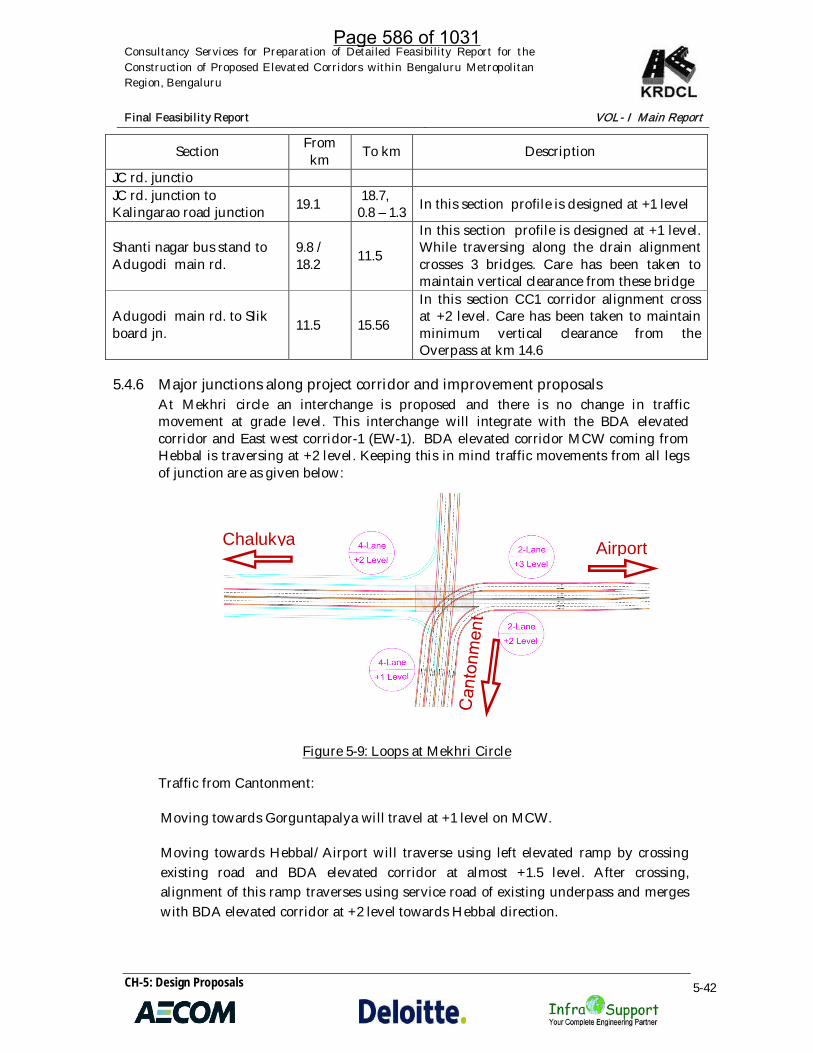
Consultancy Services for Preparation of Detailed Feasibility Report for theConstruction of Proposed Elevated Corridors within Bengaluru MetropolitanRegion, Bengaluru
Final Feasibility Report VOL- I Main Report
CH-5: Design Proposals 5-42
Section Fromkm To km Description
JC rd. junctioJC rd. junction toKalingarao road junction 19.1 18.7,
0.8 – 1.3 In this section profile is designed at +1 level
Shanti nagar bus stand toAdugodi main rd.
9.8 /18.2 11.5
In this section profile is designed at +1 level.While traversing along the drain alignmentcrosses 3 bridges. Care has been taken tomaintain vertical clearance from these bridge
Adugodi main rd. to Slikboard jn. 11.5 15.56
In this section CC1 corridor alignment crossat +2 level. Care has been taken to maintainminimum vertical clearance from theOverpass at km 14.6
5.4.6 Major junctions along project corridor and improvement proposalsAt Mekhri circle an interchange is proposed and there is no change in trafficmovement at grade level. This interchange will integrate with the BDA elevatedcorridor and East west corridor-1 (EW-1). BDA elevated corridor MCW coming fromHebbal is traversing at +2 level. Keeping this in mind traffic movements from all legsof junction are as given below:
Figure 5-9: Loops at Mekhri Circle
Traffic from Cantonment:
Moving towards Gorguntapalya will travel at +1 level on MCW.
Moving towards Hebbal/Airport will traverse using left elevated ramp by crossingexisting road and BDA elevated corridor at almost +1.5 level. After crossing,alignment of this ramp traverses using service road of existing underpass and mergeswith BDA elevated corridor at +2 level towards Hebbal direction.
Chalukya Airport
Page 586 of 1031

Consultancy Services for Preparation of Detailed Feasibility Report for theConstruction of Proposed Elevated Corridors within Bengaluru MetropolitanRegion, Bengaluru
Final Feasibility Report VOL- I Main Report
CH-5: Design Proposals 5-43
Moving towards Chalukya will have to get down from elevated corridor using thedown ramp at ch: 1.200.
Traffic from Gorguntapalya:
Moving towards Cantoment will travel at +1 level on MCW.
Moving towards Hebbal/Airport will traverse using left elevated ramp at +1 level.
Moving towards Chalukya will have to get down from elevated corridor using thedown ramp at ch: 22.500.
Traffic from Hebbal:
Moving towards Chalukya will travel on BDA elevated corridor at +2 level.
Moving towards Cantonment will travel on left ramp at +1 level.
Moving towards Yeshwantapur will travel on loop ramp from +2 level to GL.
Traffic coming from Chalukya:
Moving towards Hebbal/airport will travel on BDA elevated corridor at +2 level.
Moving towards Cantonment will have to use existing at grade slip road.
Moving towards Yeshwantapur will have to use existing at grade slip road.
5.4.7 Ramps
Ramps are crucial part of this project as they are the connection between elevatedcorridor and at grade road. Provision of as many as ramps will give the access to manycommuters who wish to travel on elevated corridor. More ramps more the traffic onelevated corridor. However, frequent provision of ramps will also cause someinconvenience to elevated corridor traffic, it requires acceleration and decelerationlanes and requires more land. Most of this corridor traverses through narrow roadswhere provision of ramps will need to acquire huge multi story buildings. Henceramps are provided at essential locations depending on land availability. Followingtable shows total number of ramps provided along this corridor.
Table 5-9: Details of entry/exit ramps along North South Corridor
Project CorridorLHS Ramps RHS Ramps Total Ramps
Up Down Up Down Up Down
Page 587 of 1031

Consultancy Services for Preparation of Detailed Feasibility Report for theConstruction of Proposed Elevated Corridors within Bengaluru MetropolitanRegion, Bengaluru
Final Feasibility Report VOL- I Main Report
CH-5: Design Proposals 5-44
NS (6-lane) 4 4 4 5 8 9
5.4.8 At grade improvement proposals
As per the terms of reference along with the proposal of elevated corridor at graderoad improvement has to be proposed. Moreover due (during) to construction ofelevated corridor and by shifting of any underground utilities which are obstructionfor construction of elevated corridor existing road would be damaged and restorationof same is unavoidable. Construction of piers is proposed by utilizing the medianspace. But a few locations existing median width is as low as 0.5m and generally 1.5m.Proposed pier width including jacketing requiring minimum of 2.5m. Hence due toless width of existing median, construction of piers for elevated corridor will encroachon to existing carriage way. Due to this after construction of elevated corridor at graderoad carriageway will get reduced. To retain traffic lanes of existing carriageway oneach side, widening of carriageway has been done by maintaining minimum width ofthe footpath cum drain (1.8m). Further since the speeds of city traffic is less compare torural roads, width of each lane is proposed to be 3m. Lane width of 3m has alreadybeen followed on few city roads.
Further it is tried to provide footpath cum drain of minimum width 1.8m throughout.Entry / Exit curves of all existing junctions are smoothened within available land.Signs and markings have been provided. Street lighting has been proposed throughoutthe corridors.
5.5 EAST – WEST CORRIDOR-1(EW-1): CONNECTING NH48 (NH-4) AT RMZON OLD MADRAS ROAD AND YESHWANTHPURA FLYOVER ONTUMKUR ROAD
Initially the elevated corridor was proposed to start from Bhattarahalli, however, fromBhattarahalli to KR puram, the road jurisdiction is with NHAI and they have informedthat a proposal to make this stretch signal free is in consideration and hence KRDCLcan drop improvement of this stretch. Further, KR Puram cable stayed bridge cant bewidened due to structural complexity, and additional lanes cant be provided throughnew bridge on either side due to presence of railway station on one side and metrocoming on other side.
Hence, the project corridor starts at RMZ on Old Madras Road (after BenniganahalliRUB), and ends at Yeshwanthpura Flyover via. - Suranjandas Road Junction - 80 FeetRoad junction - 100 feet Indiranagar road Junction - D Bhaskaran Road Junction -Kensington Road Junction (Philips buildings) – Ulsoor lake - St. John’s Road – Millarsroad - Jayamahal Main Road – Mekri circle - CV raman road
Further, since KR puram bridge is a bottle neck and needs a solution, a proposal ofconnecting ORR from Ramamurthynagar underpass to ORR at B narayanpura isproposed. This is a kind of making the ORR straight from Ramamurthynagar
Page 588 of 1031
Consultancy Services for Preparation of Detailed Feasibility Report for theConstruction of Proposed Elevated Corridors within Bengaluru MetropolitanRegion, Bengaluru
Final Feasibility Report VOL- I Main Report
CH-5: Design Proposals 5-45
underpass to ORR at B narayanpura. The idea behind this link is the traffic fromHebbal on ORR moving to Whitefield and Marathhalli will be diverted through thislink making substantial relief at tin factory junction and below the KR puram bridge.
Once this traffic is diverted the tin factory junction and below the KR puram bridgewill be left with only traffic from/to city which will save huge amount of travel time.
Further, a cloverleaf interchange is proposed at start of KR puram bridge (on Hosakoteside) where the new link crossed NH-4 for interchanging the traffic directions)
This is called as Additional corridor as it was not part of original corridors given tostudy.
Total Length along main corridor: 26.94 km
Length of One way loops: 2.36 km
Number of lanes: 4 / 6 lanes
Number of ramps: 21 nos.
This corridor will have a overlap with N-S corridor between cantonment station andMekhri circle. From Mekhri circle to Yeshwanthpura bus stand, the corridor will be a2+2 lanes ending with integrating with Yeshwanthpura flyover.
Page 589 of 1031

Consultancy Services for Preparation of Detailed Feasibility Report for theConstruction of Proposed Elevated Corridors within Bengaluru MetropolitanRegion, Bengaluru
Final Feasibility Report VOL- I Main Report
CH-5: Design Proposals 5-46
5.5.1 Typical cross sections and their schedule proposed along the project corridor
Page 590 of 1031

Consultancy Services for Preparation of Detailed Feasibility Report for theConstruction of Proposed Elevated Corridors within Bengaluru MetropolitanRegion, Bengaluru
Final Feasibility Report VOL- I Main Report
CH-5: Design Proposals 5-47
Figure 5-10: Indicative Typical Cross-section along East West Corridor
Figure 5-11: Indicative Typical Cross-section along East West Corridor
Table 5-10: Typical Cross Section schedules along East West Corridor-1
ChainageTotal
Length
Proposed Lane ConfigurationRemarks
From To Elevated Corridor At-Grade Road
0+000 0+400 400 4-Lane Ramp 6 Lanes (3L + 3L) +Service Road (2L + 2L)
0+400 1+350 950 4-Lane 6 Lanes (3L + 3L) +Service Road (2L + 2L)
1+350 2+460 1110 4-Lane 6 Lanes (3L + 3L)
2+460 2+750 290 4-Lane 4 Lanes (2L + 2L)
2+750 4+600 1850 EW1 & Additional Road Interchange and merging with ExistingFlyover
4+600 6+760 2160 No-Improvements
6+760 7+230 470 4-Lane with pavedshoulder with Ramp 4 Lanes (2L + 2L)
7+230 8+650 1420 4-Lane with PavedShoulder 6 Lanes (3L + 3L)
Page 591 of 1031
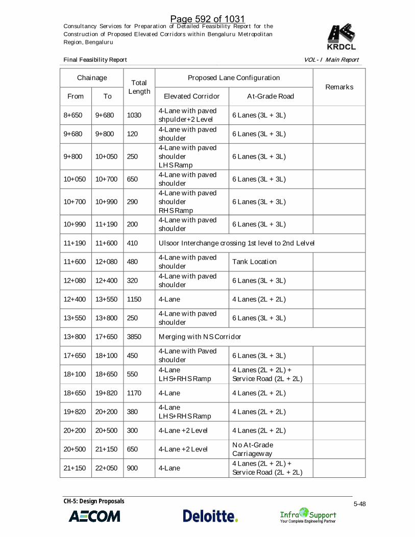
Consultancy Services for Preparation of Detailed Feasibility Report for theConstruction of Proposed Elevated Corridors within Bengaluru MetropolitanRegion, Bengaluru
Final Feasibility Report VOL- I Main Report
CH-5: Design Proposals 5-48
ChainageTotal
Length
Proposed Lane ConfigurationRemarks
From To Elevated Corridor At-Grade Road
8+650 9+680 1030 4-Lane with pavedshpulder+2 Level 6 Lanes (3L + 3L)
9+680 9+800 120 4-Lane with pavedshoulder 6 Lanes (3L + 3L)
9+800 10+050 2504-Lane with pavedshoulderLHS Ramp
6 Lanes (3L + 3L)
10+050 10+700 650 4-Lane with pavedshoulder 6 Lanes (3L + 3L)
10+700 10+990 2904-Lane with pavedshoulderRHS Ramp
6 Lanes (3L + 3L)
10+990 11+190 200 4-Lane with pavedshoulder 6 Lanes (3L + 3L)
11+190 11+600 410 Ulsoor Interchange crossing 1st level to 2nd Lelvel
11+600 12+080 480 4-Lane with pavedshoulder Tank Location
12+080 12+400 320 4-Lane with pavedshoulder 6 Lanes (3L + 3L)
12+400 13+550 1150 4-Lane 4 Lanes (2L + 2L)
13+550 13+800 250 4-Lane with pavedshoulder 6 Lanes (3L + 3L)
13+800 17+650 3850 Merging with NS Corridor
17+650 18+100 450 4-Lane with Pavedshoulder 6 Lanes (3L + 3L)
18+100 18+650 550 4-LaneLHS+RHS Ramp
4 Lanes (2L + 2L) +Service Road (2L + 2L)
18+650 19+820 1170 4-Lane 4 Lanes (2L + 2L)
19+820 20+200 380 4-LaneLHS+RHS Ramp 4 Lanes (2L + 2L)
20+200 20+500 300 4-Lane +2 Level 4 Lanes (2L + 2L)
20+500 21+150 650 4-Lane +2 Level No At-GradeCarriageway
21+150 22+050 900 4-Lane 4 Lanes (2L + 2L) +Service Road (2L + 2L)
Page 592 of 1031

Consultancy Services for Preparation of Detailed Feasibility Report for theConstruction of Proposed Elevated Corridors within Bengaluru MetropolitanRegion, Bengaluru
Final Feasibility Report VOL- I Main Report
CH-5: Design Proposals 5-49
ChainageTotal
Length
Proposed Lane ConfigurationRemarks
From To Elevated Corridor At-Grade Road
22+050 22+460 410 4-LaneLHS+RHS Ramp
4 Lanes (2L + 2L) +Service Road (2L + 2L)
22+460 22+650 190 4-Lane 4 Lanes (2L + 2L) +Service Road (2L + 2L)
22+650 22+920 270 4-Lane 4 Lanes (2L + 2L) +Service Road (2L + 2L)
22+920 23+100 180 4-Lane 4 Lanes (2L + 2L) +Service Road (2L + 2L)
23+100 23+700 600 4-Lane 4 Lanes (2L + 2L) +Service Road (2L + 2L)
*Details of TCS are shown in Plan of Drawing Volume IX
Page 593 of 1031

Consultancy Services for Preparation of Detailed Feasibility Report for theConstruction of Proposed Elevated Corridors within Bengaluru MetropolitanRegion, Bengaluru
Final Feasibility Report VOL- I Main Report
CH-5: Design Proposals 5-50
Table 5-11: Typical Cross Section schedules along East West-2 Corridor(Rammurthynagar Loop)
ChainageTotal
Length
Proposed Lane ConfigurationRemarks
From To Elevated Corridor At-Grade Road
0+000 0+400 400 3 LaneCarriageway 4 Lanes (2L + 2L)
0+400 1+600 1200 3 LaneCarriageway Follow Existing
1+600 2+130 530 3 LaneCarriageway Follow Existing
2+130 2+770 640 4 Lane No At-Grade
2+770 3+030 260 3 Lane + 2 Lane Follow Existing
3+030 5+600 2570 4 Lane 4 Lanes (2L + 2L)
5+600 6+550 950 2+2 LaneSplit Carriageway Follow Existing
*Details of TCS are shown in Plan of Drawing Volume IX
5.5.2 Horizontal alignment
Generally design standards mentioned in previous section have been followed, exceptat few locations where site constraints compelled to deviate from standards. Minimumradius of curve provided is 60m at one location.
This Corridor starts on NH4 at RMZ. At grade NH4 traffic will reach elevated corridorat +1 level through entry/exit ramps located at center of the existing NH. Thereaftercorridor alignment follows the existing road center line. Widening of existing NH isproposed due to reduction in width of carriageway due to construction of ramps.Widening of existing NH is proposed on either side of proposed ramps.
Table 5-12: Details of the Corridor Horizontal Alignment
Section Fromkm
Tokm
Laneconfiguration
Land usage Pier location Description
Gopalan mall /RMZ to Ulsoorlake
6.75 11.2
4-lanewithpavedshoulderdivided
LHS –Private /Govt. /graveyardRHS –
Centre of theex. road
Entry / exit ramps providedin front of RMZ for themovement of traffic GL to +1level. Ramps are provided inthe middle of the existing
Page 594 of 1031

Consultancy Services for Preparation of Detailed Feasibility Report for theConstruction of Proposed Elevated Corridors within Bengaluru MetropolitanRegion, Bengaluru
Final Feasibility Report VOL- I Main Report
CH-5: Design Proposals 5-51
Section Fromkm
Tokm
Laneconfiguration
Land usage Pier location Description
Private/Military
road and existing at graderoad is widened on eitherside of ramps for movementof at grade traffic and localtraffic. Thereafter alignmentis traversing along themiddle of the at gradeexisting road/median. At km8.95 alignment crossesexisting metro staircase andat km 9.375 it crosseselevated metro line.Thereafter alignmentnegotiates narrow sectionbetween Indiranagar doubleroad and SwamyVivekananda rd. on LHSgrave yard and on RHStemple / Eidga exists.
Ulsoor lake toSt. John’s roadjn.
11.2 12.4
4-lanewithpavedshoulderdivided
LHS –Private &LakeRHS –Private &Lake
Centre of theex. road
At Kensigton rd jn. CC2 ismeeting this corridor. Tohave uninterrupted trafficflow an Interchange isproposed. After theInterchange alignmenttraverses through along theUlsoor lake. There afteralignment continuous on toKensington rd up to St John’sroad jn.
St John’s roadto Coles parkjunction
12.4 13.53 / 4 -lane oneway
LHS –PrivateRHS –Private
Centre of theex. road
At km 12.4 alignment isproposed to split in twoways, LHS carriageway isproposed to continue alongSt John’s road and RHScarriageway will take rightturn and continue alongPromenade rd. and at the endit will take left turn andtraverse through Coles parkand merges back with LHScarriageway. On Prmenaderd. km 13.0 CC3 corridor ismeeting this corridor.
Coles park jn. 13.5 13.85 4-lane LHS – Centre of the This small section of the
Page 595 of 1031

Consultancy Services for Preparation of Detailed Feasibility Report for theConstruction of Proposed Elevated Corridors within Bengaluru MetropolitanRegion, Bengaluru
Final Feasibility Report VOL- I Main Report
CH-5: Design Proposals 5-52
Section Fromkm
Tokm
Laneconfiguration
Land usage Pier location Description
to Netaji roadjn.
withpavedshoulderdivided
PrivateRHS –Private
ex. road corridor is highly congestedand requires huge acquisitionof properties.
Netaji rd. jn. toCantonmentrly. stn. RUB jn.(overlap withNS)
13.85 14.9 3 – laneone way
LHS –Private/ Govt. /ReligiousRHS –Railways /Private
Centre of theex. road
At the start of this section NScorridor is meeting. A smalljn. at +1 level is proposed atthis point. Due to meeting oftwo corridors lane widthrequirement is more. Due tolake of right of way for theconstruction of 8-lanecarriageway it is proposed toprovide one way trafficmovement. At Queens roadtwo ramps (entry/exit)provided for the convenienceof railway passengers. AtCantonment RUB junctiontraffic coming from Silkboard / KR Puram will getdiverted in two ways onetowards Mekhri circle andother towards KR Puram bycrossing existing railway line.A minor elevated junction isproposed at this location forsmooth merging /divergingof traffic from both thecorridors. Care has beentaken while proposing thealignment along theCantonment road to avoidconflict with railway track onRHS.
Cantonmentrly. stn. RUB jn.to Mekhri circle(Jayamahalroad, Overlaplength withEW1)
14.9 17.65 6 – lanedivided
LHS – PalaceRHS –Airforce /Akashwani /Private /Religious
On the RHSedge of ex.road
After the Cantonment RUBjn. proposed center line(PCL) alignment shifted fromexisting centerline andtraverses towards RHS. Thisshift is proposed to utilizealready acquired Palace land.Shift of alignment alsonecessary to accommodate 8-lane MCW cross section and
Page 596 of 1031

Consultancy Services for Preparation of Detailed Feasibility Report for theConstruction of Proposed Elevated Corridors within Bengaluru MetropolitanRegion, Bengaluru
Final Feasibility Report VOL- I Main Report
CH-5: Design Proposals 5-53
Section Fromkm
Tokm
Laneconfiguration
Land usage Pier location Description
two ramps on either side ofMCW. By shifting alignment,acquisition of air force landfor the ramp coming fromHebbal is avoided.
Mekhri circle toNew BEL rd. 17.65 18.85 4 – lane
divided
LHS –Private /Govt.RHS –Airforce
Centre of theex. road
After the Mekhri circle jn.alignment traverses center ofthe existing road.
New BEL rd. toYeshwantapurFlyover
18.85 20.5 4-lanedivided
LHS – Govt./ PrivateRHS – CPRI/IISC
Centre of theex. road
In this section align traversesthrough center of the existingroad except at Sankeyunderpass. At Sankeyunderpass alignment ismarginally shifted towardsRHS to avoid impact onunderpass. Care has beentaken to maintain minimumclearance from the top ofunderpass.
Additional Loop from Ramamurthy Nagara Bridge on ORR to Mahadevapura Flyover onORR
This additional loop is provided for connectivity between Ramamurthy Nagara Bridge onORR to Mahadevapura Flyover on ORR, this is sort of straightening the ORR. At present, thetraffic at KR Puram bridge is in chaos, the volume of traffic at this junction is many foldshigher than the capacity it can handle. Added to it, merging and diverging of traffic beforethe bridge and the bottleneck below the bridge. Further, proposed metro corridorconnecting baiyappanahalli and white field passes through RHS of the bridge, this willfurther worsen the traffic movements, during and after construction. Since, anyimprovements at this location is not possible as bridge can’t be widened as it’s a cable stayedbridge, also, no new bridge can be added, as on RHS, metro is coming and on LHS, thereexists railway station.
The solution here is manifold, but important are 1) increase capacity by adding many lanes,2) reduce the conflicts by introducing multi level ramps and 3) reduce traffic. Since first andsecond is not feasible, after careful study of the area, it was proposed, why not reduce thetraffic itself?. So, it was proposed to connect the ORR from east to west bypassing the KRpuram bridge via Ramamurthynagar main road. This will reduce about 50% of the trafficentering KR puram bridge area and will give big relief to passengers.
Page 597 of 1031

Consultancy Services for Preparation of Detailed Feasibility Report for theConstruction of Proposed Elevated Corridors within Bengaluru MetropolitanRegion, Bengaluru
Final Feasibility Report VOL- I Main Report
CH-5: Design Proposals 5-54
The plan of connectivity is shown in drawings and a brief description is given below Table 5-13.
Table 5-13: Details of the Corridor Horizontal Alignment
ITPL toMahadevapura mainrd.
0.0 0.500 4-lanedivided
LHS –Private RHS– Private
Centre of theex. Road
This section of the corridor isproposed to divert trafficcoming from white field/ITPL/Kundanahalli gatetowards ORR at DoddaBanasawadi underpass. Asthe Metro line is proposed totraverse at center of theexisting road, entry /exitramps are provided outsideof the existing road. Furtherservice road is proposedoutside the ramps on eitherside.
Mahadevapura mainrd. to ORR
0.500 1.3002-laneoneway
LHS –Private RHS– Private
Centre of theex. Road
At start of this sectionalignment is bifurcated intwo ways. LHS alignmenttakes left turn on toMahadevapura main roadand at ORR crossingintegrated with flyover.
ORR toITPL roadcross
1.3 2.12-laneoneway
LHS –Private RHS– Private
Centre of theex. Road
At ORR, corridor LHSCarriageway traffic ismerged with ORR LHS CWat +1 level. Traffic comingfrom Marathhalli isproposed to cross RHS CWof ORR and merges withproject corridor.
ITPL roadcross toInterchange startpoint
2.1 2.6 4- lanedivided
LHS –Private RHS– Private
Realignment
At start point of this section,LHS CW is proposed tomerge with RHS corridor.Thereafter both carriageways of project corridor willtraverse together.
Interchange startpoint toInterchange endpoint
2.6 3.44/8-lanedivided
LHS –Private RHS– Private
Realignment/ center of theex. road
This section of the corridor isproposed as elevatedcloverleaf. This proposal isessential due to huge trafficcoming from ITPL/ORR andold Madras road trafficintersects at this point.
Interchang 3.4 6.5 4/8- LHS – Center of ex. This section of the corridor is
Page 598 of 1031

Consultancy Services for Preparation of Detailed Feasibility Report for theConstruction of Proposed Elevated Corridors within Bengaluru MetropolitanRegion, Bengaluru
Final Feasibility Report VOL- I Main Report
CH-5: Design Proposals 5-55
e endpoint toDoddaBanaswadiunderpass
lanedivided
Private RHS– Private
road /spltcarriageway
traversing though highlycongested area. Due toMetro proposal, properarrangement was notpossible without hugeacquisition and high risestructures to cross existingCable stayed bridge andflyovers connecting ORR atTin factory. Hence it isproposed to divert ITPL andMarathhalli side ORR trafficvia ITI and Ramamurthynagar. After ITI, existingRoW through Ramamurthynagar is about 12m. Henceacquisition of properties isrequired. Just before RoB atORR junction, alignment isproposed to split in twoways. Care has been taken tocross Dodda Banaswadiunderpass by maintainingminimum vertical clearanceof 5.5m. After crossingunderpass LHS down rampwill follow middle of theexisting underpass ramp andafter the existing rampproject corridor ramp willmerge with ORR. RHS rampis proposed to start adjacentto existing underpass RTwall.
Page 599 of 1031

Consultancy Services for Preparation of Detailed Feasibility Report for theConstruction of Proposed Elevated Corridors within Bengaluru MetropolitanRegion, Bengaluru
Final Feasibility Report VOL- I Main Report
CH-5: Design Proposals 5-56
5.5.3 Vertical alignment
Vertical alignment design has been carried out using Mx road software on existingprofile generated from digital terrain model in below Table 5-14.
Table 5-14: Details of the Corridor Vertical Alignment
Section Fromkm To km Description
Gopalan mall / RMZ toUlsoor lake 6.75 11.2
After traversing through existing RUB, it is againproposed to start the elevated section, hence profiledesigned from GL to reach +1 Level. At km 8.95profile is designed in such way that it crossesexisting metro station staircase at about +1.5 leveland thereafter profile continue to rise up +2 levelgradually to cross Metro line at km 9.375. Aftercrossing Metro line profile is designed fordecreasing gradient from +2 level to +1 level.
Ulsoor lake to St. John’sroad jn. 11.2 12.4
At Ulsoor lake jn. Interchange proposed. Aftercrossing the Interchange, alignment traversesthrough Ulsoor lake. To minimize the impact onUlsoor lake special structure like Cable stayedbridge with minimum supports proposed. Due tothis profile of the Cable stayed bridge will be higherthan +1 level and accordingly profile designed.
St John’s road to Coles parkjunction 12.4 13.5
In this section profile is designed at +1 level with5.5m minimum clearance from existing road. At theend of this section to reduce tree cutting profile isproposed rise from +1 level to 1.5 level.
Coles park jn. to Netajiroad jn. 13.5 13.85 After the coles park profile will continue to rise
upto +2 level till Netaji rd. underpass.Netaji rd. jn. toCantonment rly. stn. RUBjn. (overlap with NS)
13.85 14.9 After crossing underpass profile will be descend to+1 level and continue upto Cantonment RUB.
Cantonment rly. stn. RUBjn. to Mekhri circle(Jayamahal road, Overlaplength with EW1)
14.9 17.65
Profile will rise from +1 level to +2 level at thecrossing of RUB. After crossing the RUB profile isdesigned to be at +1 level and is continued uptoMekhri circle Interchange.
Mekhri circle to New BELrd. 17.65 18.85
Profile will rise from +1 level to +2 level at thecrossing of RUB. After crossing the RUB profile isdesigned to be at +1 level and is continued uptoMekhri circle Interchange. After the Interchangeprofile is continued at +1 level upto New BEL rd.
New BEL rd. toYeshwantapur Flyover 18.85 20.5
In this section profile is proposed to rise from +1level to +1.5 level to reduce the impact on treetunnel.
ITPL to Mahadevapura 0.0 0.500 Traffic coming from ITPL is proposed to enter on to
Page 600 of 1031
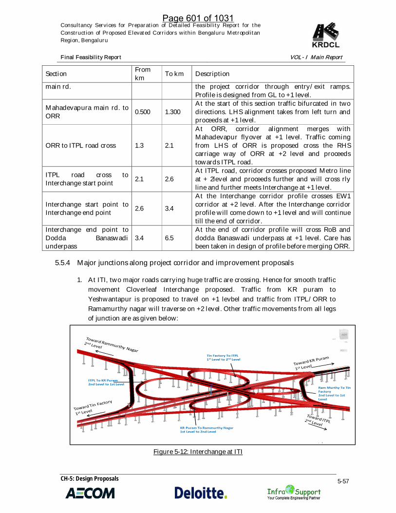
Consultancy Services for Preparation of Detailed Feasibility Report for theConstruction of Proposed Elevated Corridors within Bengaluru MetropolitanRegion, Bengaluru
Final Feasibility Report VOL- I Main Report
CH-5: Design Proposals 5-57
Section Fromkm To km Description
main rd. the project corridor through entry/exit ramps.Profile is designed from GL to +1 level.
Mahadevapura main rd. toORR 0.500 1.300
At the start of this section traffic bifurcated in twodirections. LHS alignment takes from left turn andproceeds at +1 level.
ORR to ITPL road cross 1.3 2.1
At ORR, corridor alignment merges withMahadevapur flyover at +1 level. Traffic comingfrom LHS of ORR is proposed cross the RHScarriage way of ORR at +2 level and proceedstowards ITPL road.
ITPL road cross toInterchange start point 2.1 2.6
At ITPL road, corridor crosses proposed Metro lineat + 2level and proceeds further and will cross rlyline and further meets Interchange at +1 level.
Interchange start point toInterchange end point 2.6 3.4
At the Interchange corridor profile crosses EW1corridor at +2 level. After the Interchange corridorprofile will come down to +1 level and will continuetill the end of corridor.
Interchange end point toDodda Banaswadiunderpass
3.4 6.5At the end of corridor profile will cross RoB anddodda Banaswadi underpass at +1 level. Care hasbeen taken in design of profile before merging ORR.
5.5.4 Major junctions along project corridor and improvement proposals
1. At ITI, two major roads carrying huge traffic are crossing. Hence for smooth trafficmovement Cloverleaf Interchange proposed. Traffic from KR puram toYeshwantapur is proposed to travel on +1 levbel and traffic from ITPL/ORR toRamamurthy nagar will traverse on +2 level. Other traffic movements from all legsof junction are as given below:
Figure 5-12: Interchange at ITI
Page 601 of 1031

Consultancy Services for Preparation of Detailed Feasibility Report for theConstruction of Proposed Elevated Corridors within Bengaluru MetropolitanRegion, Bengaluru
Final Feasibility Report VOL- I Main Report
CH-5: Design Proposals 5-58
Traffic coming from KP Puram:
Moving towards Ulsoor will travel on MCW at +1 level
Moving towards ITPL/ORR will use Southeast left slip ramp at +1 level
Moving towards Ramamurthy nagar will use Southwest loop and joins at +2 level
Traffic coming from Yeshwantapur:
Moving towards KP puram will travel on MCW at +1 level
Moving towards Ramamurthy nagar will use Northwest left slip ramp at +1 level
Moving towards ITPL/ORR will use Northeast loop and joins at +2 level
Traffic coming from ITPL/ORR:
Moving towards Ramamurthy nagar will travel on MCW at +2 level
Moving towards Yeshwantapur will travel use Southwest slip ramp at +1 level
Moving towards KR Puram will use Northwest loop and joins at +1 level
Traffic coming from Ramamurthynagar:
Moving towards ITPL/ORR will travel on MCW at +2 level
Moving towards Yeshwantapur will use Southwest loop ramp and joins at +1 level
Moving towards KR Puram will use Northeast slip ramp at +1 level
2. At Ulsoor, EW-1 and CC2 are meeting and forming major junction at +1 level.Hence an trumpet type Interchange is proposed. At +1 level traffic from KR Puramto MG road is proposed travel. Other traffic movements from all legs of junctionare as in Figure:5-13.
Page 602 of 1031

Consultancy Services for Preparation of Detailed Feasibility Report for theConstruction of Proposed Elevated Corridors within Bengaluru MetropolitanRegion, Bengaluru
Final Feasibility Report VOL- I Main Report
CH-5: Design Proposals 5-59
Figure 5-13: Interchange at Ulsoor Lake
Traffic coming from KP Puram:
Moving towards Yeshwantapur will travel on left ramp and will proceed at +2 level
Moving towards MG road will use MCW at +1 level
Traffic coming from Yeshwantapur:
Moving towards KP puram will travel on MCW at +1 level
Moving towards MG road will use loop ramp (+1 level will reach +2 level at thejunction and through loop will reach +1 level)
Traffic coming from MG road:
Moving towards KR Puram will travel on MCW at +1 level
Which wants to go towards Yeshwantapur will travel left ramp +1 level
5.5.5 Ramps
Ramps are crucial part of this project as they are the connection between elevatedcorridor and at grade road. Provision of as many as ramps will give the access to manycommuters who wish to travel on elevated corridor. More ramps more the traffic onelevated corridor. However frequent provision of ramps will also cause someinconvenience to elevated corridor traffic, it requires acceleration and decelerationlanes and requires more land. Most of this corridor traverses through narrow roads
Page 603 of 1031

Consultancy Services for Preparation of Detailed Feasibility Report for theConstruction of Proposed Elevated Corridors within Bengaluru MetropolitanRegion, Bengaluru
Final Feasibility Report VOL- I Main Report
CH-5: Design Proposals 5-60
where provision ramps will need to acquire huge multi story buildings. Hence rampsare provided at essential locations depending on land availability. Following tableshows total number of ramps provided along this corridor.
Table 5-15: Details of entry/exit ramps along East West Corridor-1
Project CorridorLHS Ramps RHS Ramps Total Ramps
Up Down Up Down Up Down
EW-1 (6-lane/4-lane) 2 5 5 2 7 7
5.6 EAST – WEST CORRIDOR-2 (EW-2): CONNECTING SH-35 AT VARTHURKODI AND SIRSI CIRCLE ON MYSORE ROAD
The corridor takes off at Varthur kodi junction on SH-35 – ends at Sirsi circle road via.Kundala halli gate junction – Marathahalli underpass (ORR) - Suranjandas RoadJunction - Old Airport road – Wind tunnel road junction - Domlur Junction - TrinityChurch Junction - D’Souza circle - General K S Thimayya Road - Vellara Junction -Richmond Circle - K.H.Road - Lalbagh Main Road – Minerva junction - Chamarajpet5th Main Road - 9th Cross Road - 1st Main Road Junction - Alur Venkata Rao Road
Page 604 of 1031

Consultancy Services for Preparation of Detailed Feasibility Report for theConstruction of Proposed Elevated Corridors within Bengaluru MetropolitanRegion, Bengaluru
Final Feasibility Report VOL- I Main Report
CH-5: Design Proposals 5-61
Total Length : 23.30 km
Length of One way loops: 5.36 km
Number of lanes: 4/6 lanes
Number of ramps: 30 nos.
This is a straight corridor all the way from Varthur Kodi to Richmond Road, based onthe traffic study it was found that this corridor is an ideal corridor to have anintegrated structure carrying mass transportation and road traffic. This matter wasdiscussed with BMRCL and after many deliberations, it was agreed consider having acommon structure carrying rail and road at multi levels. The matter is underdiscussions and BMRCL will have to get back on the modality. However, pending thedecision, the road corridor is proposed as of now.
5.6.1 Typical cross sections and their schedule proposed along East West-2 corridor
Figure 5-14: Indicative Typical Cross-sections along East West-2 Corridor
Page 605 of 1031

Consultancy Services for Preparation of Detailed Feasibility Report for theConstruction of Proposed Elevated Corridors within Bengaluru MetropolitanRegion, Bengaluru
Final Feasibility Report VOL- I Main Report
CH-5: Design Proposals 5-62
Figure 5-15: Indicative Typical Cross-sections 4-Lane with Paved Shoulder along East West-2Corridor
Table 5-16: Typical Cross Section schedules along East West-2 Corridor
CHAINAGE TotalLength
Proposed Lane ConfigurationRemarksFROM TO Elevated
Corridor At-Grade Road
0+000 0+350 350 4-Lane Ramp Service Road (2L+2L)
0+350 4+350 4000 4-Lane 4 Lanes (2L + 2L)
4+350 5+030 680 4-Lane withPaved shoulder Follow Existing RoB
5+030 5+300 270 4-Lane withPaved shoulder 4 Lanes (2L + 2L)
5+300 5+700 400 4-Lane withPaved shoulder 4 Lanes (2L + 2L)
5+700 5+900 2004-LaneLHS+RHSRamps
4 Lanes (2L + 2L)Service Road LHS (2L)
5+900 6+600 700 4-Lane 4 Lanes (2L + 2L)
Page 606 of 1031

Consultancy Services for Preparation of Detailed Feasibility Report for theConstruction of Proposed Elevated Corridors within Bengaluru MetropolitanRegion, Bengaluru
Final Feasibility Report VOL- I Main Report
CH-5: Design Proposals 5-63
CHAINAGE TotalLength
Proposed Lane ConfigurationRemarksFROM TO Elevated
Corridor At-Grade Road
6+600 7+000 4004-LaneLHS+RHSRamps
4 Lanes (2L + 2L)Service Road (2L+2L)
7+000 7+900 900 4-Lane 4 Lanes (2L + 2L)
7+900 8+150 250 4-LaneLHS Ramps
4 Lanes (2L + 2L)Service Road LHS (2L)
8+150 11+500 3350 4-Lane 4 Lanes (2L + 2L)
11+500 12+100 600 4-Lane +2 Level 4 Lanes (2L + 2L)
12+100 13+500 1400 4-Lane 4 Lanes (2L + 2L)
13+500 13+840 340 4-LaneLHS Ramps 4 Lanes (2L + 2L)
13+840 15+200 1360 4-Lane 4 Lanes (2L + 2L)
15+200 15+550 350 2-Lane 4 Lanes (2L + 2L)
15+550 17+050 1500 4-Lane 4 Lanes (2L + 2L)
17+050 17+500 450 2-Lane 4 Lanes (2L + 2L)17+500 19+900 2400 Merging with NS Corridor
19+900 22+580 2680 3-Lane 2 Lane (1L + 1L)2 Lane (Loop)
22+580 24+870 2290 4-Lane 4 Lanes (2L + 2L)
24+870 25+170 3004-LaneLHS+RHSRamps
4 Lanes (2L + 2L)Service Road (2L+2L)
25+170 25+400 230 4-Lane SplitCarriageway No At-Grade
25+400 25+550 150 4-Lane No At-Grade25+550 25+890 340 4-Lane Ramp No At-GradeTotal Length 25890*Details of TCS are shown in Plan of Drawing Volume IX
Page 607 of 1031

Consultancy Services for Preparation of Detailed Feasibility Report for theConstruction of Proposed Elevated Corridors within Bengaluru MetropolitanRegion, Bengaluru
Final Feasibility Report VOL- I Main Report
CH-5: Design Proposals 5-64
Cross Section Schedule for East West Corridor 02 Loop – 01
CHAINAGE TotalLength
Proposed Lane ConfigurationRemarksFROM TO Elevated
Corridor At-Grade Road
17+500 17+900 400 Merging with NS17+900 18+600 700 2 lane 3 Lanes18+600 19+100 500 2 lane 4 Lanes (2L + 2L)19+100 21+600 2500 2 lane 2 LanesTotal Length 4100*Details of TCS are shown in Plan of Drawing Volume IX
Cross Section Schedule for East West Corridor 02 Loop – 02
CHAINAGETotalLength
Proposed Lane ConfigurationRemarks
FROM TO ElevatedCorridor At-Grade Road
0+000 1+400 1400 Merging with NS Corridor
1+400 1+900 500 2 lane +2 Level Follow Existing
1+800 2+200 400 2 laneLHS Ramp 3 Lanes
2+200 2+400 200 2 lane 4 Lanes (2L + 2L)
Total Length 2500
*Details of TCS are shown in Plan of Drawing Volume IX
5.6.2 Horizontal alignment
Generally design standards mentioned in previous section have been followed, exceptat few locations where site constraints compelled to deviate from standards. Minimumradius provided at two locations is 30m.
Table 5-17: Details of the Corridor Horizontal AlignmentSection Fro
mkm
To km Laneconfiguration
Land usage Pier location Description
From Vathurkodi toMarthahalli jn.(ORR)
0.0 5.2 4 – lanedivided
LHS –PrivateRHS -Private
Centre ofthe ex. road
Alignment startswith entry/exitramps on Whitefield road.Ramps areprovided in the
Page 608 of 1031

Consultancy Services for Preparation of Detailed Feasibility Report for theConstruction of Proposed Elevated Corridors within Bengaluru MetropolitanRegion, Bengaluru
Final Feasibility Report VOL- I Main Report
CH-5: Design Proposals 5-65
Section Fromkm
To km Laneconfiguration
Land usage Pier location Description
middle of theexisting roadand existing atgrade road iswidened oneither side oframps formovement of atgrade traffic andlocal traffic.Thereafteralignment istraversing alongthe middle ofthe at gradeexistingroad/median.At km 4.4,alignment istraversingthrough medianof existing RoBapproach andobligatory spanof 60m providedto cross viaduct.
Marthahalli jn.(ORR) to km15.2 (Palmgrove rd. jn.)
5.2 15.2 4 – lanedivided
LHS –Private/ HALRHS –Private/ HAL
Centre ofthe ex. road
In this sectionalignmenttraverses at thecenter of theexistingroad/median. Itpasses throughHAL areacrossing majorjunctions likeDoddanakundird., KariyammaAgrahara rd.,Suranjandas rd.,Wind tunnel rd.,Lower Agaramrd. etc. At allthese junctionsobligatory spans
Page 609 of 1031
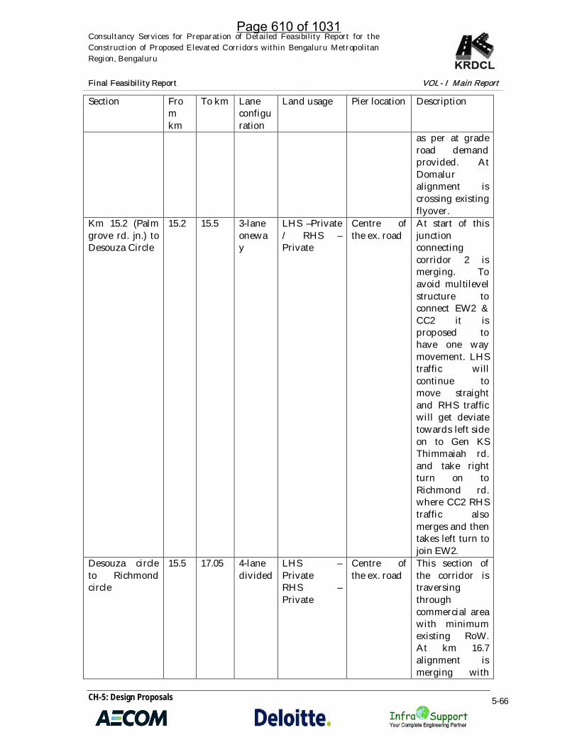
Consultancy Services for Preparation of Detailed Feasibility Report for theConstruction of Proposed Elevated Corridors within Bengaluru MetropolitanRegion, Bengaluru
Final Feasibility Report VOL- I Main Report
CH-5: Design Proposals 5-66
Section Fromkm
To km Laneconfiguration
Land usage Pier location Description
as per at graderoad demandprovided. AtDomaluralignment iscrossing existingflyover.
Km 15.2 (Palmgrove rd. jn.) toDesouza Circle
15.2 15.5 3-laneoneway
LHS –Private/ RHS –Private
Centre ofthe ex. road
At start of thisjunctionconnectingcorridor 2 ismerging. Toavoid multilevelstructure toconnect EW2 &CC2 it isproposed tohave one waymovement. LHStraffic willcontinue tomove straightand RHS trafficwill get deviatetowards left sideon to Gen KSThimmaiah rd.and take rightturn on toRichmond rd.where CC2 RHStraffic alsomerges and thentakes left turn tojoin EW2.
Desouza circleto Richmondcircle
15.5 17.05 4-lanedivided
LHS –PrivateRHS –Private
Centre ofthe ex. road
This section ofthe corridor istraversingthroughcommercial areawith minimumexisting RoW.At km 16.7alignment ismerging with
Page 610 of 1031

Consultancy Services for Preparation of Detailed Feasibility Report for theConstruction of Proposed Elevated Corridors within Bengaluru MetropolitanRegion, Bengaluru
Final Feasibility Report VOL- I Main Report
CH-5: Design Proposals 5-67
Section Fromkm
To km Laneconfiguration
Land usage Pier location Description
Richmond circleflyover. RE wallportion of theapproach isproposed to bedismantled andalignment ismerged withviaduct portionof flyover.
Richmond circleto Lang ford rd.jn.
17.05 17.5 3-laneoneway
LHS –PrivateRHS –Private
Centre ofthe ex. road
In this sectiontraffic from NScorridor ismerging withRHS trafficwhich is leadingto Varthur. It isalso proposed tomerge at gradetraffic fromMajestic/localthrough ramp toenable thistraffic to gotowardssouth/east/west direction.
Lang ford jn. toShantinagar busstand (overlapwith NScorridor)
17.5 18.2 3-laneoneway
LHS –PrivateRHS –Private
Centre ofthe ex. road
In this sectionLHScarriagewayalignmenttraversesthrough Double(KH) road
Shantinagar busstand to KengalHanumanthaiah circle toLalbagh maingate to LalbaghMinerva circle(overlap withNS corridor)
18.2 19.9 3-laneoneway
LHS –Private /Religious /parkRHS –Private /Religious
Centre ofthe ex. road
In this sectionRHS alignmenttraversesthrough KHroad -Hosurmain road-Lalbagh fort rd.-Jayachamarajawodeyar rd
LalbaghMinerva circle
19.9 22.55 3-laneone
LHS –Private
Centre ofthe ex. road
In this sectionLHS alignment
Page 611 of 1031

Consultancy Services for Preparation of Detailed Feasibility Report for theConstruction of Proposed Elevated Corridors within Bengaluru MetropolitanRegion, Bengaluru
Final Feasibility Report VOL- I Main Report
CH-5: Design Proposals 5-68
Section Fromkm
To km Laneconfiguration
Land usage Pier location Description
to jn. of 9th crossrd. ( Alurvenkata rao rd.)and 1st main rd.
way RHS –Private
traversesthrough LalBagh fort rd., 5th
Main rd. and 9th
cross rd ofChamarajpetrd.. One waywill end at jn. ofAlur venkatarao rd. and 9th
cross rd.Jn. of 9th crossrd. (Alurvenkata rao rd.)and 1st main rd.to JC rd.junction
19.1 21.6(22.55)
3-laneoneway
LHS –Private /ArcheologicalRHS –Private
Portalarrangement
At km 19.1, JCroad jn. RHSalignmentmerges with NSRHS alignment.This sectiontraverses verynarrowArumugamMudaliar road,Tippu sultanrd., Alurvenkata rao rd.
Jn. of 9th crossrd. (Alurvenkata rao rd.)
22.55 25.890 4-lanedivided
LHS –Private RHS– Private
Centre ofthe ex. road(upto km24.85) andsplitcarriageway
In this sectionalignment istraversing alongthe existingmedian. At km24.85 it isproposed tosplit theelevatedcarriageway toprovideentry/exitramps at themiddle of theexisting road.Due to thiswidening ofexisting road oneither side oframps has beenproposed for the
Page 612 of 1031

Consultancy Services for Preparation of Detailed Feasibility Report for theConstruction of Proposed Elevated Corridors within Bengaluru MetropolitanRegion, Bengaluru
Final Feasibility Report VOL- I Main Report
CH-5: Design Proposals 5-69
Section Fromkm
To km Laneconfiguration
Land usage Pier location Description
purpose of atgrade traffic/local traffic.
5.6.3 Vertical alignment
Vertical alignment design has been carried out using Mx road software on existingprofile generated from digital terrain model.
Table 5-18: Details of the Corridor Vertical AlignmentSection From
kmTo km Description
From Vathur kodi toMarthahalli jn. (ORR)
0.0 5.2 In this section profile is designed at +1level. However to maintain 5.5mclearance at existing RoB elevatedcorridor has to be raised to +2 level.
Marthahalli jn. (ORR) tokm 15.2 (Palm grove rd.jn.)
5.2 15.2 In this section profile is designed at +1level. At Marthahalli Underpass care hastaken to maintain minimum clearance.To cross Domalur Interchange, elevatedcorridor profile is designed at +2 level.
Km 15.2 (Palm grove rd.jn.) to Desouza Circle
15.2 15.5In this section profile is designed at +1levelDesouza circle to
Richmond circle15.5 17.05
Richmond circle to Langford rd. jn.
17.05 17.5 Profile of previous section is continuedand then matched with the Richmondcircle flyover viaduct portion. RE wallapproaches are proposed to dismantle.
Lang ford jn. toShantinagar bus stand(overlap with NS corridor)
17.5 18.2 Profile of Richmond circle flyover isfollowed upto viaduct portion of KHroad ramp. RE wall approaches offlyover are proposed to dismantle
Shantinagar bus stand toKengal Hanumanthaiahcircle to Lalbagh main gateto Lalbagh Minerva circle(overlap with NS corridor)
18.2 19.9
In this section profile is designed at +1level
Lalbagh Minerva circle tojn. of 9th cross rd. (Alurvenkata rao rd.) and 1st
main rd.
19.9 22.55
Jn. of 9th cross rd. (Alurvenkata rao rd.) and 1st
main rd. to JC rd. junction
19.1 21.6(22.55)
Page 613 of 1031

Consultancy Services for Preparation of Detailed Feasibility Report for theConstruction of Proposed Elevated Corridors within Bengaluru MetropolitanRegion, Bengaluru
Final Feasibility Report VOL- I Main Report
CH-5: Design Proposals 5-70
Section Fromkm
To km Description
Jn. of 9th cross rd. (Alurvenkata rao rd.).
22.55 25.890
5.6.4 Major junctions along project corridor and improvement proposals
At start point (Varthur kodi) multilevel flyover is proposed. At grade level a rotaryhas been provided for the convenience of traffic movement from three directions. Forthis purpose stream will have to be covered. Elevated corridor MCW starts on Whitefield road with up /down ramps and takes right turn towards Marthahalli at +1 level.Other traffic movements from all legs of junction are as given below:
Figure 5-16: Interchange at Varthur Kodi
Traffic coming from White field:
Moving towards Marthahalli will travel on MCW from GL to +1 level through up /down ramps
Moving towards Varthur will use at grade slip road
Traffic coming from Varthur:
Moving towards Marthahalli will travel from GL to +1 level through ramp
Moving towards White field will use at grade road
Traffic coming from Marthahalli:
Moving towards White Field will travel RHS carriageway of MCW
Page 614 of 1031
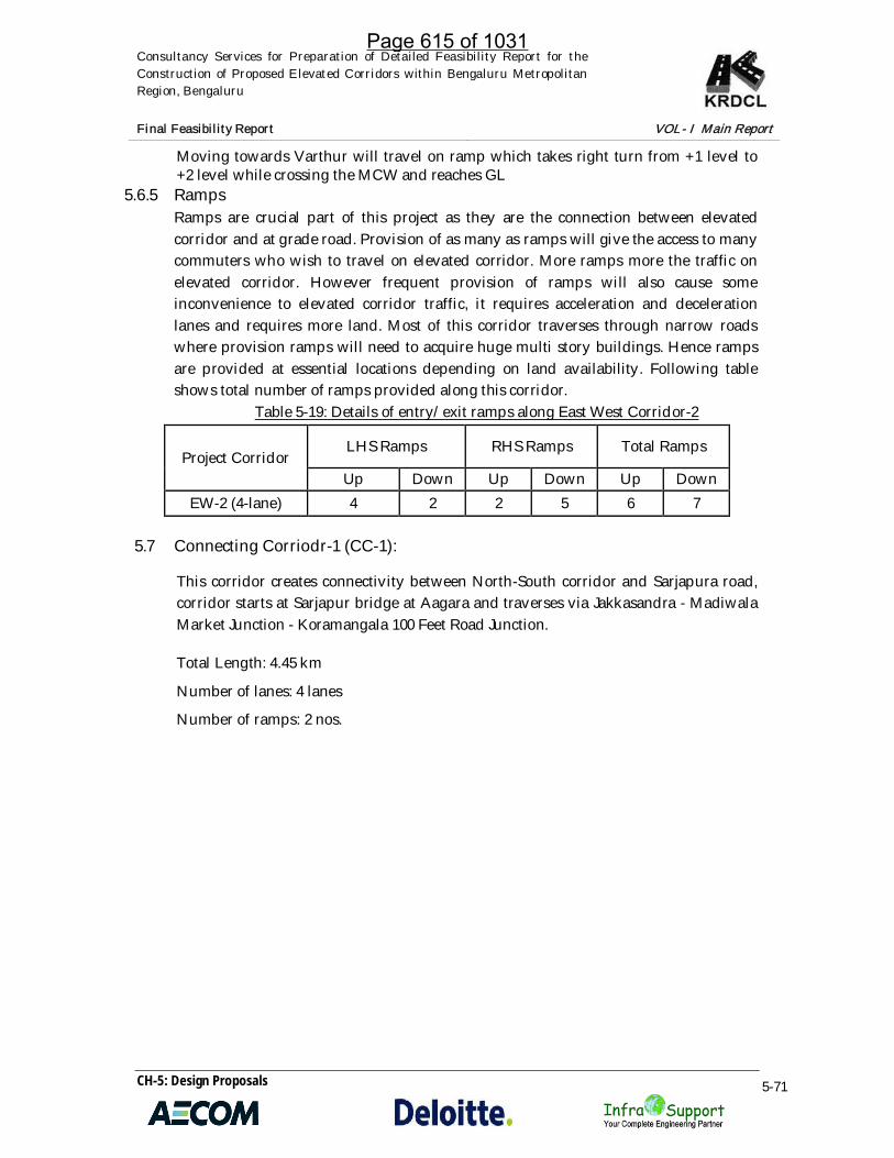
Consultancy Services for Preparation of Detailed Feasibility Report for theConstruction of Proposed Elevated Corridors within Bengaluru MetropolitanRegion, Bengaluru
Final Feasibility Report VOL- I Main Report
CH-5: Design Proposals 5-71
Moving towards Varthur will travel on ramp which takes right turn from +1 level to+2 level while crossing the MCW and reaches GL
5.6.5 RampsRamps are crucial part of this project as they are the connection between elevatedcorridor and at grade road. Provision of as many as ramps will give the access to manycommuters who wish to travel on elevated corridor. More ramps more the traffic onelevated corridor. However frequent provision of ramps will also cause someinconvenience to elevated corridor traffic, it requires acceleration and decelerationlanes and requires more land. Most of this corridor traverses through narrow roadswhere provision ramps will need to acquire huge multi story buildings. Hence rampsare provided at essential locations depending on land availability. Following tableshows total number of ramps provided along this corridor.
Table 5-19: Details of entry/exit ramps along East West Corridor-2
Project CorridorLHS Ramps RHS Ramps Total Ramps
Up Down Up Down Up DownEW-2 (4-lane) 4 2 2 5 6 7
5.7 Connecting Corriodr-1 (CC-1):
This corridor creates connectivity between North-South corridor and Sarjapura road,corridor starts at Sarjapur bridge at Aagara and traverses via Jakkasandra - MadiwalaMarket Junction - Koramangala 100 Feet Road Junction.
Total Length: 4.45 km
Number of lanes: 4 lanes
Number of ramps: 2 nos.
Page 615 of 1031
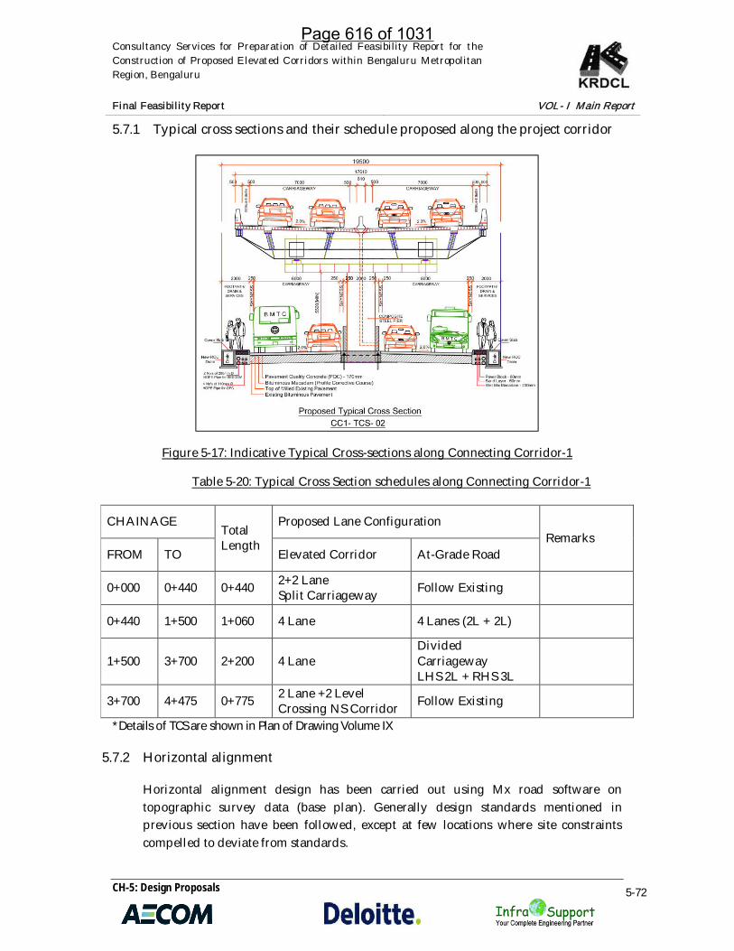
Consultancy Services for Preparation of Detailed Feasibility Report for theConstruction of Proposed Elevated Corridors within Bengaluru MetropolitanRegion, Bengaluru
Final Feasibility Report VOL- I Main Report
CH-5: Design Proposals 5-72
5.7.1 Typical cross sections and their schedule proposed along the project corridor
Figure 5-17: Indicative Typical Cross-sections along Connecting Corridor-1
Table 5-20: Typical Cross Section schedules along Connecting Corridor-1
CHAINAGETotalLength
Proposed Lane ConfigurationRemarks
FROM TO Elevated Corridor At-Grade Road
0+000 0+440 0+440 2+2 LaneSplit Carriageway Follow Existing
0+440 1+500 1+060 4 Lane 4 Lanes (2L + 2L)
1+500 3+700 2+200 4 LaneDividedCarriagewayLHS 2L + RHS 3L
3+700 4+475 0+775 2 Lane +2 LevelCrossing NS Corridor Follow Existing
*Details of TCS are shown in Plan of Drawing Volume IX
5.7.2 Horizontal alignment
Horizontal alignment design has been carried out using Mx road software ontopographic survey data (base plan). Generally design standards mentioned inprevious section have been followed, except at few locations where site constraintscompelled to deviate from standards.
Page 616 of 1031

Consultancy Services for Preparation of Detailed Feasibility Report for theConstruction of Proposed Elevated Corridors within Bengaluru MetropolitanRegion, Bengaluru
Final Feasibility Report
CH-5: Design Proposals
Table 5-21: Details of the Corridor Horizontal Alignment
Section Fromkm
Tokm
Laneconfiguration
Landusage
Pierlocation Description
Sarjapurflyoverto StJohn’sHospitalbus stop
0.0 4.475 4 – lanedivided
LHS –Private/ lakeRHS -Private
Centreof theex.road
This corridor is proposed to provideaccess to Sarjapur which is one of thevery fast growing areas inBengaluru. Take off point of thiscorridor is from the Sarjapur flyover.Left carriage way merges flyover atcentral span and RHS carriagewaytakes off from RHS side of flyover.RHS carriageway crosses the ORR tomerge with LHS carriageway. Aftermerging alignment traverses in thecenter of the existing road. At themeeting point with NS, LHScarriageway is proposed to cross theNS corridor and merges.Care has been taken to avoidacquisition of Temple on RHS offlyover and not to encroach intoAgara lake.
5.7.3 Vertical alignment
Vertical alignment design has been carried out using Mx road software on existingprofile generated from digital terrain model.
Table 5-22: Details of the Corridor Vertical Alignment
Section Fromkm
Tokm Description
Sarjapur flyover to StJohn’s Hospital Bus stop 0.0 4.475
At takeoff point alignment profile is at +1level. At end point LHS carriagewaycrosses NS corridor at +2 level and mergeswith NS at +1 level.
5.7.4 Ramps
There are no ramps proposed in this section.
Page 617 of 1031
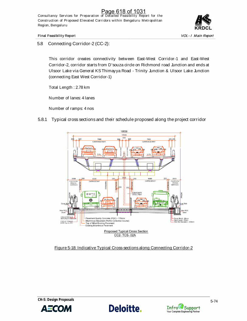
Consultancy Services for Preparation of Detailed Feasibility Report for theConstruction of Proposed Elevated Corridors within Bengaluru MetropolitanRegion, Bengaluru
Final Feasibility Report VOL- I Main Report
CH-5: Design Proposals 5-74
5.8 Connecting Corridor-2 (CC-2):
This corridor creates connectivity between East-West Corridor-1 and East-WestCorridor-2, corridor starts from D’souza circle on Richmond road Junction and ends atUlsoor Lake via General KS Thimayya Road - Trinity Junction & Ulsoor Lake Junction(connecting East West Corridor-1)
Total Length : 2.78 km
Number of lanes: 4 lanes
Number of ramps: 4 nos
5.8.1 Typical cross sections and their schedule proposed along the project corridor
Figure 5-18: Indicative Typical Cross-sections along Connecting Corridor-2
Page 618 of 1031

Consultancy Services for Preparation of Detailed Feasibility Report for theConstruction of Proposed Elevated Corridors within Bengaluru MetropolitanRegion, Bengaluru
Final Feasibility Report VOL- I Main Report
CH-5: Design Proposals 5-75
Table 5-23: Typical Cross Section schedules along Connecting Corridor-2Chainage Total
LengthProposed Lane Configuration RemarksFrom To Elevated Corridor At-Grade Road
0+000 0+500 0+500 3 Lane Carriageway Follow Existing
0+500 1+040 0+540 4 Lane 4 Lanes (2L + 2L)
1+040 1+450 0+410 4 Lane +2 Level 4 Lanes (2L + 2L)
1+450 1+700 0+250 4 Lane 4 Lanes (2L + 2L)
1+700 1+950 0+250 4 LaneLHS+RHS Ramps 4 Lanes (2L + 2L)
1+950 2+500 0+550 4 Lane 4 Lanes (2L + 2L)
*Details of TCS are shown in Plan of Drawing Volume IX
5.8.2 Horizontal alignment
Horizontal alignment design has been carried out using Mx road software ontopographic survey data (base plan). Generally design standards mentioned inprevious section have been followed, except at few locations where site constraintscompelled to deviate from standards. Minimum radius adopted is 30m at one location.
Table 5-24: Details of the Corridor Horizontal Alignment
Section Fromkm
Tokm
Laneconfiguration
Landusage
Pierlocation Description
Desouzacircle toUlsoorlake
0.0 2.78 4 – lanedivided
LHS –Private/LakeRHS -Private
Centreof theex.road
This corridor is proposed to provideconnection between EW1 and EW2.At start point one way loop providedto integrate with EW2 corridor.Alignment follows existing roadcenter line. At km 1.275 Trinity circlecorridor will cross Metro line. At endpoint Trumpet Interchange isproposed to integrate with EW1corridor.
5.8.3 Vertical alignment
Vertical alignment design has been carried out using Mx road software on existingprofile generated from digital terrain model.
Page 619 of 1031

Consultancy Services for Preparation of Detailed Feasibility Report for theConstruction of Proposed Elevated Corridors within Bengaluru MetropolitanRegion, Bengaluru
Final Feasibility Report VOL- I Main Report
CH-5: Design Proposals 5-76
Table 5-25: Details of the Corridor Vertical Alignment
Section From km To km Description
Desouza circle toUlsoor lake 0.0 2.78
At takeoff point alignment profile is at +1 level.At km 1.275 this corridor crosses Metro line at+2 level. At end point corridor profile is at +1level.
5.8.4 Ramps
Following table shows total number of ramps provided along this corridor.
Table 5-26: Table shows details of entry/exit ramps
Project CorridorLHS Ramps RHS Ramps Total Ramps
Up Down Up Down Up Down
CC-2 (4-lane) 1 1 1 1 2 2
5.9 Bus Stops
The corridor is proposed to have a dedicated bus lane on it. Several discussions havebeen made with bus transport departments to understand how the bus routes areoperated and bus occupancies, trips, etc., it was found that around 40 lakh trips aregenerated by BMTC buses on a daily basis. This is almost 40% of the total tripsgenerated in the city. There are over 6500 buses as of now operating, the speeds ofbuses have drastically comedown making less no. of trips per day and the speed isfalling year on year due to road congestions.
The dedicated lane on elevated corridor will provide much needed to space for bustravel. The BMTC will work on route optimization and what kind of buses to tun onelevated corridor as there will be a seemless connectivity through elevated corridors toHebbal, silkboard, Shanthinagar TTMC, Majestic, Yeshwanthapura TTMC. Buspassengers traveling from say, Hebbal to Koramangala/city center/silkboard need tochange many buses and spend huge time but take bus on elevated corridor to reachthe destinations within a fraction of time. At cantonment interchange andShanthinagar TTMC, provision of lifts/escalators/stairs are also provided for quickaccess by passengers.
Further, it was also agreed in the high-level meeting that roads leading to entry/exitramps are to be improved and bus stops/bays are to be provided to make sure noundue congestion happens on these roads. Otherwise these will become a potentialcongestion points. In this regard, the Govt. has authorized KRDCL to prepare plans
Page 620 of 1031

Consultancy Services for Preparation of Detailed Feasibility Report for theConstruction of Proposed Elevated Corridors within Bengaluru MetropolitanRegion, Bengaluru
Final Feasibility Report VOL- I Main Report
CH-5: Design Proposals 5-77
including land acquisitions and execution can be made either through BBMP orthrough additional grants as required.
5.9 PAVEMENT DESIGN
5.9.1 Pavement Evaluation Summary
The existing pavement surface condition survey reveals that around 13% of thepavement surface is affected by distress in all the project roads except for connectingcorridor 3 where 38 % of the pavement is affected by distresses. Around 87 %pavement surface of project roads is in fair condition. The characteristic deflectionvalues obtained from BBD survey varies from 0.90 to 1.19 and average deflection valuefor the corridor is 1.03 mm.
All the roads comprise flexible pavement at present, Existing bituminous layer variesin thickness ranging 185 mm to 260mm in North South Corridor, 190 mm to 280 mm inEast West 01 Corridor, 180 mm to 290 mm in East West 02 corridor, 190 mm to 270 mmin connecting corridor 01, 280 mm to 320 mm in connecting corridor 02, and 220 mm to260 mm in connecting corridor 03. The average bituminous layers’ thickness variesaround 240 mm. This clearly indicates the significant BT thickness occurred as a resultof repeated overlays.
5.9.2 Pavement Proposals
Pavements which bear the loads of commercial vehicles, are the costly component ofthe road. Pavement design, construction and maintenance call for a high degree ofskill and expertise. Good performance and economy are the key attributes of apavement. There are broadly two types of pavements viz, flexible pavement and therigid pavement.
The project corridors are arterial roads of Bangalore city, Pavement evaluation clearlyindicates functional and structural adequacy of existing pavement indicating and alltypes of pavement options can be proposed for the at grade improvements of thesearterial roads where elevated corridor is proposed to decongest and to achieve freeflow of traffic in the city.
Pavement deign can be made with different types of Pavement options viz,
1. Flexible Pavement / Flexible Overlay2. Rigid Pavement3. White Topping4. Inter locking Paver Blocks
Page 621 of 1031
Consultancy Services for Preparation of Detailed Feasibility Report for theConstruction of Proposed Elevated Corridors within Bengaluru MetropolitanRegion, Bengaluru
Final Feasibility Report VOL- I Main Report
CH-5: Design Proposals 5-78
Concrete overlay over the existing bitumen roads (known as White Toppingtechnology) can provide long lasting road network in India. It is a major rehabilitationtechnology for improving old pavements with a strong, long life, and lowmaintenance structure. This technology has been developed over the last two decades,especially in USA, to improve the highways, runways, light duty roads and streets. Itis very cost effective, fast and easy to construct. In India, Mumbai city has taken a biglead in this direction. Many other cities like Bengaluru, Pune, Nagpur, Indore,Chennai have also been adopting white topping technology for city roads.
As explained in the previous paragraphs White-topping on existing bituminouspavements provides many additional benefits as compared to conventionalbituminous overlay alternative. Some of the benefits are:
· Long life, low maintenance, low life-cycle cost, improved safety andenvironmental benefits.
· Bituminous overlays exhibit a more rapid loss of serviceability as compared toconcrete white-topping at some critical locations. The lives of successivebituminous overlays become progressively shorter after the first overlay.
· Deformation like rutting and cracking predominant in case of bituminouspavements is normally absent with concrete surfaces of white-topping. This isparticularly true in a hot climate like India.
· Conventional White-topping improves structural capacity of existingbituminous pavement, if built on a strong base course, and it impedesstructural distresses.
· White-topping requires much less maintenance and as such involves muchless frequent lane closures of road, as compared to bituminous surfaces.
· White-topping is quite cost-effective to tackle annual budget constraints andhigh traffic levels. It is, therefore, quite relevant to Indian conditions.
· White-topping can uniformly fill ruts in the wheel path of bituminouspavements more effectively because concrete is far more stiff and consistentat high temperature than bituminous mixes. Broadly, for similar reasons, theoccurrence of cracks is also relatively much less in case of white-topping.
· Concrete is relatively light in colour and hence concrete surface is morereflective to light, absorb less heat and reduce the urban heat island effect.Improved reflection of lights from vehicles enhances safety, lowers energyrequirement of external lighting, lower contribution to heat in environment.
· Fuel consumption on concrete roads has been found to be less than thebituminous roads.
· Thus proving the white topping is the most feasible and suitable pavementoption for the at grade improvement of project roads.
5.9.3 White Topping
Page 622 of 1031

Consultancy Services for Preparation of Detailed Feasibility Report for theConstruction of Proposed Elevated Corridors within Bengaluru MetropolitanRegion, Bengaluru
Final Feasibility Report VOL- I Main Report
CH-5: Design Proposals 5-79
White topping is defined as a Portland Cement Concrete (PCC) overlay constructed onthe top of an existing bituminous pavement. Whitetopping is thus PCC resurfacing(overlay) as a rehabilitation or structural strengthening alternative on bituminouspavement.
White Topping Thickness Design Criteria
The design principle adopted for Conventional Whitetopping is similar to those ofnormal concrete pavements as provided in IRC:58 “Guidelines for the Design of Plainjointed Rigid Pavements for Highways” and IRC:15 “Standard Specifications andCode of Practice for Construction of Concrete Roads”. design of TWT and UTWT is asper IRC: SP: 76-2015. Determination of modified / effective / support modulus ofSubgrade reaction (k). The correlation between CBR and ‘k’ value for the Subgrade asgiven in SP: 76-2015 be used for the design.
Modified “k” value on the top of Bituminous pavement can be determined using thecharts given in IRC: SP: 76-2015: “Tentative Guidelines for Conventional, Thin andUltra-Thin White topping”. Two charts are given for correlation based on the existingbituminous pavement is atop of granular base or cement treated base.
Alternative method is by using Benkelman Beam Deflection Test and is a Graphicalmethod. In this “k” value can be determined based on characteristic deflection of BBDtest as per IRC: 81.
Figure 5-19: Graph showing relationship between BBD & Modulus of Subgrade reaction
Surface Preparation
For Conventional White-topping, no special efforts are made to encourage bondingbetween the overlay and the underlying bituminous surface; however, some steps forsurface preparations may be required to address existing restorations in the existing
Page 623 of 1031

Consultancy Services for Preparation of Detailed Feasibility Report for theConstruction of Proposed Elevated Corridors within Bengaluru MetropolitanRegion, Bengaluru
Final Feasibility Report VOL- I Main Report
CH-5: Design Proposals 5-80
surface of the bituminous pavements or to correct surface profile. Three methods ofsurface preparation and overlying are normally used for White-topping.
Direct placement: The concrete overlay is placed directly on the existing hotbituminous surface after sweeping. Any ruts in the existing pavement are filled withconcrete, resulting in a thicker concrete pavement in the rutted areas.
Milling: The existing bituminous surface is milled to obtain a uniform surface. Millingcan be used to remove surface distortion like cracks in the top portion and adjust crossslopes. The removal of thickness should be between 25 to 50mm. Milling can also beselectively used with direct placement to treat the isolated stretch suffering fromdistortion in the project road. Milling is not mandatory.
Placemen of Leveling course: Sometimes a leveling course of bituminous mix is usedto produce a uniform surface for paving. A leveling course typically consists ofminimum 50mm if Bituminous Macadam (BM). Exact quantity will depend upon theundulations. When the distortion/rutting depth exceeds more than 50mm, the optionof milling as an economical alternative may be evaluated.
5.9.3.1 Design of White-topping as per IRC SP: 76 – 2015.
The White Topping is designed based on the “Guidelines for Thin and ConventionalWhite Topping, IRC: SP 76 - 2015” for the project road stretches considering the designlife of 20 years. Using the below inputs, the design thickness is worked out andsummarized. The sample white topping design and recommended white toppingdetails is given below.
Commercial traffic prevailing in the Project stretches are studied by conducting Trafficvolume count and Turning volume count at various location and AADT is arrived.Considering 2 years of construction period base year traffic is calculated andconsidered for pavement design. Traffic growth rate of 7.5 % is considered for a designperiod of 20years in accordance with the guidelines. The white topping thickness isdesigned with maximum length of the panel as1.2m. the sample design calculationsfor connecting corridor 02 of the project is tabulated below Table 5-31 to 5-36.
Table 5-27: Design Parameters
Design Parameters
i) Design Life, years 20
ii) Traffic Growth Rate. R 0.075
iii) Commercial Traffic, cvpd 2631
iv) Grade of Concrete, M40 40
Page 624 of 1031

Consultancy Services for Preparation of Detailed Feasibility Report for theConstruction of Proposed Elevated Corridors within Bengaluru MetropolitanRegion, Bengaluru
Final Feasibility Report VOL- I Main Report
CH-5: Design Proposals 5-81
Design Parameters
v) Cumulative Repetitions in 20 years 51586136
vi) Design traffic (25% of (v)), cvpd 10396534
Table 5-28: Percentages for Axle Loads for the Design of TWT
Axle load Class, Tons % of Axle Loads Axle load Class, Tons % of Axle Loads
15-17 0.00 0.000
13-15 2.24 26-30 0.000
11-13 4.27 22-26 0.095
9-11 5.97 18-22 0.171
7-9 16.90 14-18 0.152
less than 8 69.94 less than 14 0.266
99.32 0.68
Page 625 of 1031

Consultancy Services for Preparation of Detailed Feasibility Report for theConstruction of Proposed Elevated Corridors within Bengaluru MetropolitanRegion, Bengaluru
Final Feasibility Report VOL- I Main Report
CH-5: Design Proposals 5-82
Table 5-29: Expected Repetitions for Axle LoadsSingle Axle Load Tandem Axle loads
Axle load Class, Tons % of Axle Loads Axle load Class, Tons % of Axle Loads
16 0 28 0
14 232372 24 9871
12 444015 20 17768
10 621107 16 15794
8 1756513 less than 16 27640
less than 8 7271454
10325460 71074
Table 5-30: Design Data
Trial Thickness, cm 17
Subgrade Modulus, Kg/cm3, k 10.22Design Period, years 20Modulus of Rupture, Kg/cm3 45Load Safety Factor 1Length of Square Slab, cm 120Modulus of Elasticity of concrete 300000Poisson's ratio 0.15Radius of relative Stiffness, cm lc 59.21
Table 5-31: Fatigue Life Consumed for Single Axle LoadAxle
Loads,Tonnes
LoadStress,
Kg/cm2
StressRatio
ExpectedRepetition
FatigueLife, N
Fatigue LifeConsumed
Maximum loadstresses, kg/cm2
16 25.6 0.57 0 94100 0.00
25.59
14 22.4 0.50 232372 762000 0.305
12 19.2 0.43 444015 infinity -
10 16.0 0.36 621107 infinity -
8 12.8 0.29 1756513 infinity -
less than 8 7271454 infinity -
0.30
Table 5-32: Fatigue Life Consumed for Tandem Axle Load
Page 626 of 1031

Consultancy Services for Preparation of Detailed Feasibility Report for theConstruction of Proposed Elevated Corridors within Bengaluru MetropolitanRegion, Bengaluru
Final Feasibility Report VOL- I Main Report
CH-5: Design Proposals 5-83
Axle Loads,Tonnes
Load Stress,Kg/cm2
StressRatio
ExpectedRepetition
FatigueLife, N
Fatigue LifeConsumed
28 29.8 0.67 0 4410 0.00
24 25.5 0.57 9871 71200 0.139
20 21.3 0.47 17768 5200000 0.000
16 17.01 0.38 15794 infinity 0.000
less than 16 0.00 27640 infinity 0.000
0.14
The cumulative life consumed bothby single and tandem axle is 0.44
If the panel size is less than 1.30 m, then two axles of a tandem axle vehicle will not fall onthe same panel simultaneously, hence, stresses should only be considered for single axle.The possibility of wheels of two adjacent vehicles Simultaneously placed on one panel is alsoexcluded.
The cumulative life consumed bothby single and tandem axle is 0.30 Thickness provided is Safe Against
Fatigue Failure
σT = 1.933-241000(αdelT) + 1.267(L/le)
Δ T -0.15°C/cm x Thickness of whitetopping overlay
Δ T, oC -2.55
α 0.00001
Length of Square Slab, cm 120
Radius of relative Stiffness, cm lc 59.21
σT, Kg/Cm2 10.646
Maximum load stresses, kg/cm2 25.59
Total flexural stresses due to load andcurling=Maximum load stresses+ Curlingstresses, Kg/cm2
36.24
Slab is Safe against Stress, Hence Design is Safe
In the same lines the pavement design is made for the rest of the project roads.
Page 627 of 1031
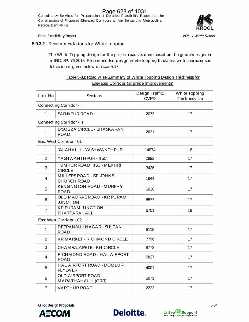
Consultancy Services for Preparation of Detailed Feasibility Report for theConstruction of Proposed Elevated Corridors within Bengaluru MetropolitanRegion, Bengaluru
Final Feasibility Report VOL- I Main Report
CH-5: Design Proposals 5-84
5.9.3.2 Recommendations for White-topping
The White Topping design for the project roads is done based on the guidelines givenin IRC: SP: 76-2015. Recommended design white topping thickness with characteristicdeflection is given below in Table 5.37.
Table 5-33: Road wise Summary of White Topping Design Thickness forElevated Corridor (at grade Improvements)
Link No Sections Design Traffic,CVPD
White ToppingThickness, cm
Connecting Corridor - I
1 SARJAPUR ROAD 2073 17
Connecting Corridor - II
1 D'SOUZA CIRCLE - BHASKARANROAD 2631 17
East West Corridor - 01
1 JALAHALLI - YASHWANTHPUR 14874 18
2 YASHWANTHPUR - IISC 2992 17
3 TUMKUR ROAD: IISC - MEKHRICIRCLE 3426 17
4 MILLERS ROAD - ST. JOHNSCHURCH ROAD 1944 17
5 KENSINGTON ROAD - MURPHYROAD 6036 17
6 OLD MADRAS ROAD - KR PURAMJUNCTION 6577 17
7 KR PURAM JUNCTION -BHATTARAHALLI 6701 18
East West Corridor - 02
1 DEEPANJALI NAGAR - SULTANROAD 6119 17
2 KR MARKET - RICHMOND CIRCLE 7796 17
3 CHAMRAJAPETE - KH CIRCLE 8773 17
4 RICHMOND ROAD - HAL AIRPORTROAD 5827 17
5 HAL AIRPORT ROAD - DOMLURFLYOVER 4001 17
6 OLD AIRPORT ROAD -MARATHAHALLI (ORR) 5071 17
7 VARTHUR ROAD 2223 17
Page 628 of 1031

Consultancy Services for Preparation of Detailed Feasibility Report for theConstruction of Proposed Elevated Corridors within Bengaluru MetropolitanRegion, Bengaluru
Final Feasibility Report VOL- I Main Report
CH-5: Design Proposals 5-85
Link No Sections Design Traffic,CVPD
White ToppingThickness, cm
North South Corridor
1 JAYAMAHAL ROAD 3168 17
2 QUEENS ROAD 3792 17
3 KASTURBA ROAD 1795 17
4 KASTURBA ROAD - KH ROAD 5275 17
5 KH ROAD to SHANTHINAGARTTMC 7470 17
6 HOSUR ROAD - SARJAPURJUNCTION 2838 17
7 SARJAPUR JN. - ORR 8477 17
Note: For locations where existing pavement is disturbed or having inadequate pavement structure,reconstruction is recommended. The recommended pavement composition for those locations is indicatedbelow.
Table 5-34: Details of Design Thickness
Details Thickness
White Topping (PQC), mm As per Table 3.47
Bituminous Macadam (BM), mm 75 mm
Wet Mix Macadam (WMM), mm 250 mm
Granular Sub Base (GSB), mm 200 mm
Page 629 of 1031

Consultancy Services for Preparation of Detailed Feasibility Report for theConstruction of Proposed Elevated Corridors within Bengaluru MetropolitanRegion, Bengaluru
Final Feasibility Report VOL- I Main Report
CH-5: Design Proposals 5-86
Figure 5-20: Typical Cross-section for At Grade Six Lane with Service Road
Figure 5-21: Typical Cross-section of At Grade Four-lane Carriageway
Page 630 of 1031

Consultancy Services for Preparation of Detailed Feasibility Report for theConstruction of Proposed Elevated Corridors within Bengaluru MetropolitanRegion, Bengaluru
Final Feasibility Report VOL- I Main Report
CH-5: Design Proposals 5-87
Figure 5-22: Typical Panel Details for White-topping
Page 631 of 1031

Consultancy Services for Preparation of Detailed Feasibility Report for theConstruction of Proposed Elevated Corridors within Bengaluru MetropolitanRegion, Bengaluru
Final Feasibility Report VOL- I Main Report
CH-5: Design Proposals 5-88
5.10 STRUCTURAL DESIGN
5.10.1 Choice of Structural Material:
The choice of bridging material; steel and concrete, is a major decision to be taken forlong elevated corridor for bridge engineers. Since the cost depends on thecircumstances prevailing at that time, the information is always imprecise. It is thechanges in this factors of this kind has been that involving box girder, plate girders etc.Selection of type of structural material and arrangement are governed by many factorssuch as availability of material, space for construction, Duration of project,construction technology, Cost of project, feasibility of construction and social andenvironmental impact etc.
However, only four factors pertinent to bridges need concern us:
I. Relative economy,II. Speed of erection,III. Aesthetic considerations, andIV. Corrosion / maintenance.
5.10.2 Comparison: Concrete & Steel
Some of the basic differences are listed below pertaining to use of steel and concretefor bridges;
CONCRETE;
· Material is easily Available in India for Mega Elevated Project· Post-tensioned box girders are efficient structures for medium to long span
bridges (30m to 150m).· Post-tensioned box girders can be constructed either in-situ or by the use of
match cast precast segments.· In-situ construction using ground supported false work has a relatively long
construction cycle time and requires good foundations for the false-work to avoidcracking of the immature concrete during the staged construction process.
· The elevation view of Close Box type superstructure is nice and deck is thinner asa proportion to its span
· Very high torsion rigidity of superstructure in curved alignment of elevatedcorridor
· Future widening of the deck is difficult.· Relatively economical from maintenance point of view.· All utilities can be passed through inside the box section of the deck.· Higher Cost for setting up the Pre-casting Yard.
Page 632 of 1031

Consultancy Services for Preparation of Detailed Feasibility Report for theConstruction of Proposed Elevated Corridors within Bengaluru MetropolitanRegion, Bengaluru
Final Feasibility Report VOL- I Main Report
CH-5: Design Proposals 5-89
· Less disturbance to the existing traffic during erection of the precastsuperstructure using launching gantries
· More experience in this type of precast construction in recent years· Production of the concrete segments in a protective environment where stringent
quality controls can be provided· High concrete strengths can be achieved in precast fabrication resulting in a
durable structure with minimizing life cycle maintenance costs,.· Accelerated construction schedule since pre-casting can occur in parallel with
construction of the Foundation.· Competitive price: the cost of special equipment will not be significant given the
size of the project.· Aesthetic value: visual continuity between substructure and superstructure, good
proportions (span length/height), smooth lines.
STEEL;
· Supply of the material will depend on the production of high quality steel in thenearby area
· Steel bridges usually offer a competitive alternative to concrete structures for therange of the pre-stressed beam and post - tensioned concrete structures.
· The main disadvantage of steel structures, particularly when they are exposed tosevere environmental conditions, is the need for a continual maintenanceprogram.
· If a steel structure is not well maintained corrosion can quickly become a seriousproblem.
· Another concern is the limited local experience with steel bridges compared toconcrete within the construction industry in India.
· Steel structures have a limited aesthetic appeal due to their lack of the morestreamlined appearance available with formed concrete.
· However with suitable architectural treatment the appearance of steel structurescan be enhanced.
· Steel structures are highly flexible with respect to future expansion.· They can be constructed in a speedy manner and require a minimal amount of
false work for superstructure construction.· Steel girders and boxes can be fabricated to match the roadway alignment and
curvature.· The initial cost of steel structures is comparable to the most economical concrete
structure types however the continual maintenance and inspection requirementsof a steel bridge over its useful life adds to the total long term cost of the bridge.
· Therefore, steel structures are best suited for curved structures where economy,speed of construction, future expansion and flexibility are of importance
Page 633 of 1031

Consultancy Services for Preparation of Detailed Feasibility Report for theConstruction of Proposed Elevated Corridors within Bengaluru MetropolitanRegion, Bengaluru
Final Feasibility Report VOL- I Main Report
CH-5: Design Proposals 5-90
· Weight of girders is much less, and needs lower capacity trailers fortransportation, and lighter cranes for handling and erection.
· Can be advantageous for construction on narrow roads, where large trailers andcranes cannot be deployed.
An exercise was performed for comparing the type of structure to be adopted and hasbeen tabulated. The arrangement was with a continuity of 4 spans for both type ofstructure. The total length has been considered for 1.0 km. the exercise was performedfor both 6 lane carriageway. It is observed that concrete structure is 20% cheaper thanthat of steel structure but the no. of foundations and the size makes it unfeasible in theurban area whereas steel structure due to its light weight, larger span length and lesserfootprint area on the ground makes feasible in the urban area.
A comparative statement has been presented in below table.
Table 5-35: Comparative Statement Steel & Concrete Structure
Parameters PC Box GirderBridge
Steel Box GirderBridge
CriteriaSpan Length 40 m 40 m
Bridge EffectiveWidth 24.61 m 24.61 m
Landscape Aesthetic view Good Good
EnvironmentalImpact
NaturalEnvironment No. of Pier 25 25
Regarding vibration problem Good Good
NoiseNo. of
ExpansionJoint
6 6
StructuralPerformance
Usage Record Many Moderate
Durability Durability ofBridge Deck PC Slab Composite Slab
Constructability
Impact on existing road More Impact Less Impact
No. of Pile Nos. More Less
Quality ControlDifficulty levelof QualityControl
Slightly difficult Easy
Maintenance
Painting No paint Paint
PeriodicMaintenance
Number ofExpansionJoint
6 6
Page 634 of 1031
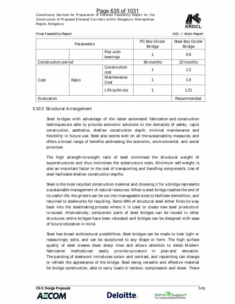
Consultancy Services for Preparation of Detailed Feasibility Report for theConstruction of Proposed Elevated Corridors within Bengaluru MetropolitanRegion, Bengaluru
Final Feasibility Report VOL- I Main Report
CH-5: Design Proposals 5-91
Parameters PC Box GirderBridge
Steel Box GirderBridge
Pier withbearings 1 0.6
Construction period 36 months 22 months
Cost Ratio
Constructioncost 1 1.2
MaintenanceCost 1 1.5
Life cycle cos 1 1.21
Evaluation Recommended
5.10.3 Structural Arrangement
Steel bridges with advantage of the latest automated fabrication and constructiontechniques are able to provide economic solutions to the demands of safety, rapidconstruction, aesthetics, shallow construction depth, minimal maintenance andflexibility in future use. Steel also scores well on all the sustainability measures, andoffers a broad range of benefits addressing the economic, environmental, and socialpriorities
The high strength-to-weight ratio of steel minimises the structural weight ofsuperstructures and thus minimises the substructure costs. Minimum self-weight isalso an important factor in the cost of transporting and handling components. Use ofsteel facilitates shallow construction depths.
Steel is the most recycled construction material and choosing it for a bridge representsa sustainable management of natural resources. When a steel bridge reaches the end ofits useful life, the girders can be cut into manageable sizes to facilitate demolition, andreturned to steelworks for recycling. Some 99% of structural steel either finds its wayback into the steelmaking process where it is used to create new steel products oris reused. Alternatively, component parts of steel bridges can be reused in otherstructures; entire bridges have been relocated and bridges can be designed with easeof future relocation in mind.
Steel has broad architectural possibilities. Steel bridges can be made to look light orreassuringly solid, and can be sculptured to any shape or form. The high surfacequality of steel creates clean sharp lines and allows attention to detail. Modernfabrication methods can easily provide curvature in plan and elevation.The painting of steelwork introduces colour and contrast, and repainting can changeor refresh the appearance of the bridge. Steel being versatile and effective materialfor bridge construction, able to carry loads in tension, compression and shear. There
Page 635 of 1031

Consultancy Services for Preparation of Detailed Feasibility Report for theConstruction of Proposed Elevated Corridors within Bengaluru MetropolitanRegion, Bengaluru
Final Feasibility Report VOL- I Main Report
CH-5: Design Proposals 5-92
are basically two types of superstructure configurations under consideration viz. Plategirder system and Box girder system.
5.10.3.1 Superstructure:
Box girder has been proposed for superstructure. Box girder configuration that is nowmore commonly used employs ‘open topped’ trapezoidal girders. These girders have asteel bottom flange, inclined steel webs and a narrow steel flange on top of each web.The closed cell is formed by the reinforced concrete deck slab. With this configuration,material access during construction can be minimised by the use of permanentformwork (or precast slabs) and for maintenance the cells are larger than those forrectangular steel boxes, thus reducing the difficulties of access.
The selection, or otherwise, of a steel box girder always needs a consideration of therelative advantages and disadvantages of box girder elements compared to the moretraditional 'I' girder elements.
Advantages, compared to 'I' girders:
· High torsional stiffness and strength, giving greater suitability forhorizontally curved bridges, greater aerodynamic stability and reducedsusceptibility to lateral buckling of flanges (in lateral-torsional or distortionalbuckling modes)
· Reduced need for support points· Improved durability and reduced maintenance of protective coatings (less
exposed surface, fewer edges, avoidance of exposed horizontal surfaces, noexposed bracing and stiffeners).
· The clean lines of a closed box girder are also often considered give anexcellent appearance, particularly for footbridges where the visual impact isconsidered to be important.
5.10.3.2 Substructure & Foundation:
Substructure comprises of steel pier cap and composite steel pier resting on pilefoundation. Inverted T Beam pier cap has been proposed to reduce the height of thestructure. Pier cap comprises of steel plate with internal diaphragms connected toresist buckling. Composite pier has been proposed with concrete filled steel pier. Thissystem reduces the size of pier considerably as it is a governing factor in urban area.Also the reduced time taken for erecting of pier and pier cap makes the proposalfeasible. The foundation has been proposed considering Geotech investigation results.Pile foundation has been recommended as per the investigation results. Also as theproposed elevated corridor traverse through urban road pile foundation is preferred
Page 636 of 1031

Consultancy Services for Preparation of Detailed Feasibility Report for theConstruction of Proposed Elevated Corridors within Bengaluru MetropolitanRegion, Bengaluru
Final Feasibility Report VOL- I Main Report
CH-5: Design Proposals 5-93
over open foundation to minimize the hindrances to existing traffic and road causedduring construction.
5.10.4 Elevated Structural Configuration
The project corridor comprises of various spans and width of structures. The proposedcorridors are for urban area with many cross roads of various widths and requiredifferent obligatory spans with faster mode of construction. The total deck width ofelevated road varies from 9.0m to 24.61m. The corridor involves interchanges, multi-level decks, crossing existing structures, ramps etc. The configuration of deck slab isdetailed as below,
Table 5-36: Deck Slab Configuration
SLNo.
No. ofLanes
CB(m)
SH(m)
CW(m)
SH(m)
CB(m)
Median(m)
SH(m)
CW(m)
SH(m)
CB(m)
TotalWidth
1. Two Lane 0.5 0.5 7.0 0.5 0.5 - - - - - 9.0
2. Three Lane 0.5 0.5 10.5 0.5 0.5 - - - - - 12.5
3. Four Lane 0.5 0.5 7.0 0.5 - 0.61 0.5 7.0 0.5 0.5 17.61
4. Four Lanewith
PavedShoulder
0.5 0.5 8.0 0.5 - 0.61 0.5 8.0 0.5 0.5 19.61
5. Six Lane 0.5 0.5 10.5 0.5 - 0.61 0.5 10.5 0.5 0.5 24.61
CB; Crash barrier, SH; Kerb Shyness, CW; Carriageway
The structural configuration comprises of various arrangements with single anddivided decks, Single and portal piers, pile foundations etc. The arrangement ofsubstructure depends on the availability of space at grade. As the corridor is in urbanarea care has been taken to provide best suitable configuration such that minimumhindrances to the at grade traffic. Each location is studied in detail with respect todetail topographic survey and site condition before providing the pier locations andstructural systems. Details Schedule of structural Proposal is presented in tables below.The Details of each cross section has been presented in Volume-III-Drawings
5.10.4.1 North South Corridor:
5.10.4.1.1 Main Corridor:
Table 5-37: North South Structural Typical Cross Section
Page 637 of 1031

Consultancy Services for Preparation of Detailed Feasibility Report for theConstruction of Proposed Elevated Corridors within Bengaluru MetropolitanRegion, Bengaluru
Final Feasibility Report VOL- I Main Report
CH-5: Design Proposals 5-94
Sl.No
CHINAGES Proposed LanesConfiguration
Proposed PierConfiguration Remark
FROM TO
1 0+000 2+300 2-Lane Single Pier (2 Nos)Level 2
2 2+300 5+000 6Lanes Single Pier
3 0+000 0+220 6Lanes (3L + 3L) Single Pier
4 0+220 0+495 6Lanes (3L + 3L) 3 Pier Portal Merging
5 0+495 0+615 8Lanes (6L + 2L) 3 Pier Portal Merging
6 0+615 0+815 8Lanes (6L + 2L) 3 Pier Portal +Ramp1 Side One Side Ramp
7 0+815 0+895 8Lanes (6L + 2L) 3 Pier Portal Merging
8 0+895 1+175 8Lanes (6L + 2L) 3 Pier Portal +Ramp1 Side One Side Ramp
9 1+175 1+600 6-Lanes 3 Pier Portal
10 1+600 2+000 8Lanes (4L + 4L ) DD 2 Pier Portal Double Decker
11 2+000 2+370 10Lanes (8L DD + 2L) 2 Pier Portal Double Decker withRamp
12 2+450 2+450 8Lanes (6L + 2L) 3 Pier Portal Merging
13 2+530 2+530 8Lanes (6L + 2L) 3 Pier Portal +Ramp1 Side One Side Ramp
14 2+530 2+650 8Lanes (6L + 2L) 2 Pier Portal +Ramp1 Side One Side Ramp
Page 638 of 1031

Consultancy Services for Preparation of Detailed Feasibility Report for theConstruction of Proposed Elevated Corridors within Bengaluru MetropolitanRegion, Bengaluru
Final Feasibility Report VOL- I Main Report
CH-5: Design Proposals 5-95
Sl.No
CHINAGES Proposed LanesConfiguration
Proposed PierConfiguration Remark
FROM TO
15 2+650 2+800 3 Lanes Single Pier Towards millersRoad(CenterlineEccentric)
16 2+800 2+840 5 Lanes ((3L + 2L)) 2 Pier Portal
17 2+840 3+405 3-Lanes Single Pier
18 3+405 3+725 3-Lanes Single Pier 6 Pile Group
19 3+725 3+875 6Lanes (3L + 3L ) 2 Pier Portal
20 3+875 4+035 3-Lanes Single Pier 6 Pile Group
21 4+035 4+235 3-Lanes Single Pier
22 4+235 4+315 5Lanes(3L+2L) 2 Pier Portal Merging
23 4+315 4+515 3Lanes Single Pier
24 4+515 4+540 3Lanes 2 Pier Portal
25 4+540 4+740 3-Lanes 2 Pier Portal
26 4+740 4+900 6Lanes (3L + 3L ) Single Pier (2 Nos)Level 2
One side Lvl 1 &Second side Lvl 2
27 4+900 5+050 6Lanes (3L + 3L ) 3 Pier Portal Double Decker
28 5+050 6+255 6Lanes (3L + 3L ) Single Pier Double Decker
Page 639 of 1031

Consultancy Services for Preparation of Detailed Feasibility Report for theConstruction of Proposed Elevated Corridors within Bengaluru MetropolitanRegion, Bengaluru
Final Feasibility Report VOL- I Main Report
CH-5: Design Proposals 5-96
Sl.No
CHINAGES Proposed LanesConfiguration
Proposed PierConfiguration Remark
FROM TO
29 6+255 6+375 6Lanes (3L + 3L ) 2 Pier Portal Double Decker
30 6+375 6+735 6Lanes (3L + 3L ) Single Pier Double Decker
31 6+735 6+855 6Lanes (3L + 3L ) 3 Pier Portal Double Decker
32 6+855 7+195 6Lanes (3L + 3L ) Single Pier (2 Nos)Level 2
One side Lvl 1 &Second side Lvl 2
33 7+195 8+075 4Lanes Single Pier
34 8+075 8+510 2Lanes 2 Pier Portal 2 Pile Group
35 8+510 8+590 2Lanes Single Pier
36 8+590 9+120 3Lanes Single Pier
37 9+120 9+280 3Lanes Single Pier
38 9+280 9+720 5Lanes (3L+ 2L) Single Pier + Ramp1 Side One Side Ramp
39 9+720 9+875 5Lanes (3L+ 2L) 3 Pier Portal
40 9+875 10+275 4Lanes PS Single Pier Nala
41 10+275
10+715 6Lanes (4L + 2L ) 2 Pier Portal +Ramp
1 SideNala(One sideramp)
42 10+715
11+495 4Lanes PS Portal Pier (2 Nos) Nala
Page 640 of 1031

Consultancy Services for Preparation of Detailed Feasibility Report for theConstruction of Proposed Elevated Corridors within Bengaluru MetropolitanRegion, Bengaluru
Final Feasibility Report VOL- I Main Report
CH-5: Design Proposals 5-97
Sl.No
CHINAGES Proposed LanesConfiguration
Proposed PierConfiguration Remark
FROM TO
43 11+495
11+815 6Lanes (4L PS+ 2L ) Single Pier +Ramp
Single Pier One Side Ramp
44 11+815
13+455 4Lanes PS Single Pier
45 13+455
13+705 6Lanes (4L PS+ 2L ) Single Pier +Ramp
Single Pier One Side Ramp
46 13+705
14+030
4Lanes (2L+2L)+2Lane
Cantilever Pier Bothside+Single pier
higher level
Split CW onIndividual Pier
47 14+030
14+070 8Lanes (4LPS +4L PS) 3 Pier Portal
48 14+070
14+385
8Lanes(2L+2L+2L+2L)
Cantilever Pier+Two Single PierRamps+Seperated
Single pier
Split CW onIndividual Pier +Ramp both side
49 14+385
14+745 4Lanes (2L +2L) 3 Pier Portal
50 14+745
15+145 4Lanes PS Single Pier
51 15+145
15+185 4Lanes (2L +2L) 3 Pier Portal
52 15+185
15+560 4Lanes (2L +2L) Cantilever Pier Both
sideSplit CW onIndividual Pier
From South to North
1 18+255
18+710 3 Lane Single Pier From Shantinagar
bus station toMinerva circle(Overlap with EW2)Chainages shownare for EW2
2 18+710
18+760 5 Lane (3L + 2L) 2 Pier Portal +
Ramp Single Pier
3 18+760
18+800 5 Lane (3L + 2L 2 Pier Portal
4 18+800
19+900 3 Lane Single Pier
Page 641 of 1031

Consultancy Services for Preparation of Detailed Feasibility Report for theConstruction of Proposed Elevated Corridors within Bengaluru MetropolitanRegion, Bengaluru
Final Feasibility Report VOL- I Main Report
CH-5: Design Proposals 5-98
Sl.No
CHINAGES Proposed LanesConfiguration
Proposed PierConfiguration Remark
FROM TO
From Minerva Circle to Hudson Circle (Overlap with EW2)
5 0+000 0+400 2 Lane Single Pier From MinervaCircle to HudsonCircle (Overlapwith EW2)
6 0+400 0+775 4 Lane Single Pier
7 0+775 0+855 6Lanes ((4L+ 2L)) 2 Pier Portal
8 0+855 1+415 4 Lane Single Pier
5.10.4.1.2 Loops:
Table 5-38: North South Structural Typical Cross Section of Loops
SlNo. Length Lane
ConfigurationProposed PierConfiguration Remark
1 80 2 Lane Single Pier U turn at Cantonment
2 550 5 Lane Single Pier Loop from Queens Road toJaymahal Rd
3 360 3 Lane Single Pier Loop from Queens Road toJaymahal Rd
4 220 3 Lane Single PierLoop from St Johns Road toJaymahal Rd (Opp toCantonment Rly Stn)
5 520 5 Lanes(3L+2L) Single Pier Loops
6 80 2 Lane Single Pier Ramps at CSI Hospital (OnCantonment Rly Stn Rd)
7 120 2 Lane Single Pier Ramps at CSI Hospital (OnCantonment Rly Stn Rd)
8 160 2 Lane Single Pier Ramp Towards Mejastic9 240 2 Lane Single Pier Ramps at Adugodi LHS
10 280 2 Lane Single Pier Ramps at Adugodi RHS
11 2 Lane Single Pier Ramps Towards Lal bagh Rd
Page 642 of 1031

Consultancy Services for Preparation of Detailed Feasibility Report for theConstruction of Proposed Elevated Corridors within Bengaluru MetropolitanRegion, Bengaluru
Final Feasibility Report VOL- I Main Report
CH-5: Design Proposals 5-99
5.10.4.2 East West Corridor 1:
5.10.4.2.1 Main Corridor:
Table 5-39: East West-1 Structural Typical Cross Section
Sl.No
CHINAGES Proposed LanesConfiguration
Proposed PierConfiguration Remark
FROM TO1 0+000 0+305 4 Lanes RE wall Approach2 0+305 2+825 4 Lanes Single pier3 2+825 3+035 4 Lanes 2 Pier Portal4 3+035 3+075 4 Lanes 3 Pier Portal5 3+075 3+180 4 Lanes Single pier
6 3+180 3+580 8Lanes (4L + 2L +2L)
Single pier + Ramp2 Side Both Side Ramp
7 3+580 3+725 8Lanes (4L + 2L +2L) 3 Pier Portal Merging
8 6+750 7+060 4 Lanes PS RE wall Approach9 7+060 8+680 4 Lanes PS Single Pier
10 8+680 9+790 4 Lanes PS Single Pier Crossing Metro
11 9+790 10+150 6 Lanes (4L PS+ 2L) Single pier + Ramp1 Side One Side Ramp
12 10+150 10+715 4 Lanes PS Single Pier
13 10+715 11+135 6 Lanes (4L PS+ 2L) Single pier + Ramp1 Side One Side Ramp
14 11+135 11+185 8 Lanes ((2L + 2L))+ ((2L + 2L)) 3 Pier Portal Merging
20 11+185 11+435 Interchange
21 11+435 11+715 8Lanes (4L + 2L +2L)
Single pier + Ramp2 Side
Both Side Ramp & Noapproach
22 11+715 11+795 4Lanes Single Pier23 11+795 12+300 4 Lanes PS 2 Pier Portal
24 12+300 12+500 4 Lanes PS Single Pier
25 12+370 12+400 4 Lanes PS 2 Pier Portal Merging
26 12+400 12+460 4 Lanes Single Pier
27 12+460 12+500 4 Lanes 2 Pier Portal Merging
28 12+500 13+415 4 Lanes Single Pier
Page 643 of 1031
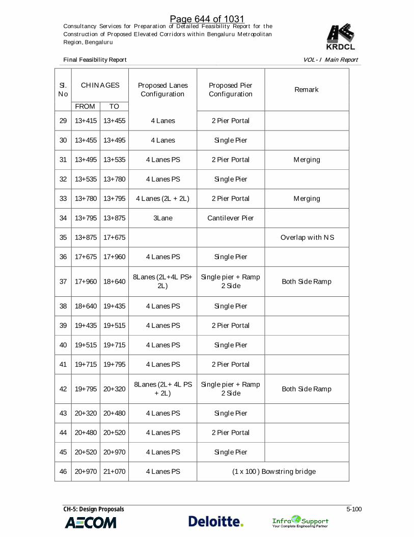
Consultancy Services for Preparation of Detailed Feasibility Report for theConstruction of Proposed Elevated Corridors within Bengaluru MetropolitanRegion, Bengaluru
Final Feasibility Report VOL- I Main Report
CH-5: Design Proposals 5-100
Sl.No
CHINAGES Proposed LanesConfiguration
Proposed PierConfiguration Remark
FROM TO
29 13+415 13+455 4 Lanes 2 Pier Portal
30 13+455 13+495 4 Lanes Single Pier
31 13+495 13+535 4 Lanes PS 2 Pier Portal Merging
32 13+535 13+780 4 Lanes PS Single Pier
33 13+780 13+795 4 Lanes (2L + 2L) 2 Pier Portal Merging
34 13+795 13+875 3Lane Cantilever Pier
35 13+875 17+675 Overlap with NS
36 17+675 17+960 4 Lanes PS Single Pier
37 17+960 18+640 8Lanes (2L+4L PS+2L)
Single pier + Ramp2 Side Both Side Ramp
38 18+640 19+435 4 Lanes PS Single Pier
39 19+435 19+515 4 Lanes PS 2 Pier Portal
40 19+515 19+715 4 Lanes PS Single Pier
41 19+715 19+795 4 Lanes PS 2 Pier Portal
42 19+795 20+320 8Lanes (2L+ 4L PS+ 2L)
Single pier + Ramp2 Side Both Side Ramp
43 20+320 20+480 4 Lanes PS Single Pier
44 20+480 20+520 4 Lanes PS 2 Pier Portal
45 20+520 20+970 4 Lanes PS Single Pier
46 20+970 21+070 4 Lanes PS (1 x 100 ) Bowstring bridge
Page 644 of 1031

Consultancy Services for Preparation of Detailed Feasibility Report for theConstruction of Proposed Elevated Corridors within Bengaluru MetropolitanRegion, Bengaluru
Final Feasibility Report VOL- I Main Report
CH-5: Design Proposals 5-101
Sl.No
CHINAGES Proposed LanesConfiguration
Proposed PierConfiguration Remark
FROM TO
47 21+070 21+915 4 Lanes PS Single Pier
48 21+915 22+475 8Lanes(2L+4LPS+2L)
Single pier + Ramp2 Side Both Side Ramp
49 22+475 23+195 4 Lanes PS Single Pier
50 23+195 23+945 4 Lanes PS Single Pier
51 23+945 27+945 4 Lanes (2L + 2L) Single Pier Both Side Ramp
5.10.4.2.2 Loops:
Table 5-40: East West-1 Structural Typical Cross Section of Loops
SlNo. From To Proposed Lane
ConfigurationProposed PierConfiguration Remark
Pomarade Road
1 12+370 12+450 3 Lanes 2 Pier Portal Merging
2 12+450 13+610 3 Lanes Single Pier
3 13+610 13+650 3 Lanes 2 Pier Portal Merging
4 13+650 13+720 3 Lanes Single Pier
5 13+720 13+760 3 Lanes 2 Pier Portal Merging
Whitefield to Rammurthy Nagar
1 0+000 0+140 3 Lane Approach
2 0+140 0+870 3 Lane Single Pier RHS
3 0+140 2+150 3 Lane Single Pier LHS
Page 645 of 1031

Consultancy Services for Preparation of Detailed Feasibility Report for theConstruction of Proposed Elevated Corridors within Bengaluru MetropolitanRegion, Bengaluru
Final Feasibility Report VOL- I Main Report
CH-5: Design Proposals 5-102
SlNo. From To Proposed Lane
ConfigurationProposed PierConfiguration Remark
4 2+150 2+470 4 Lane Single Pier
5 2+470 2+630 4 Lane 3 Pier Portal
6 2+630 2+780 4 Lane Single Pier
7 2+780 3+010 10 Lane ((2L + 3L)) +((3L + 2L)) 3 Pier Portal Merging
8 3+010 3+255 4 Lane Single Pier
9 3+255 3+295 10 Lane ((2L + 3L)) +((3L + 2L)) 3 Pier Portal Merging
10 3+295 5+575 4 Lane Single Pier
11 5+575 5+835 4 Lanes (2L + 2L) Single Pier onBoth Sides RHS Ramp
12 5+575 6+395 4 Lanes (2L + 2L) Single Pier onBoth Sides LHS Ramp
INTERCHANGES
KR Puram
1 3000 2 Lane Single Pier Loops
Ulsoor Lake
2 640 2 Lane Single Pier
Loops
3 280 4 Lane Single Pier
Page 646 of 1031

Consultancy Services for Preparation of Detailed Feasibility Report for theConstruction of Proposed Elevated Corridors within Bengaluru MetropolitanRegion, Bengaluru
Final Feasibility Report VOL- I Main Report
CH-5: Design Proposals 5-103
5.10.4.3 East West Corridor 2:
5.10.4.3.1 Main Corridor:
Table 5-41: East West-2 Structural Typical Cross Section
Sl.No
CHINAGES
Proposed LanesConfiguration
Proposed PierConfiguration Remark
FROM TO
1 0+000 0+340 4Lanes Approach bothsides Approach
2 0+340 3+780 4Lane PS Single Pier3 3+780 3+820 6Lanes(4L PS + 2L) 2 Pier Portal4 3+820 4+820 4Lane PS Single Pier5 4+820 4+880 4 Lane PS 2 Pier Portal6 4+880 5+730 4 Lane PS Single Pier
7 5+730 5+930 8Lanes (4L PS + 2L+2L)
Single Pier +Ramp both Side Merging
8 5+930 5+970 8Lanes (4L PS +4LPS) 2 Pier Portal
9 5+970 6+570 4 Lane PS Single Pier Split CW onCommon Pier
10 6+570 6+990 8Lanes (4L PS + 2L+2L)
Single Pier +Ramp both Side
Split CW onIndividual Pier
11 6+990 7+030 8Lanes (4L PS + 4LPS) 2 Pier Portal Split CW on
Individual Pier
12 7+030 7+920 4 Lane PS Single Pier Split CW onIndividual Pier
13 7+920 8+170 6L (4L PS + 2L) Single Pier +Ramp1 Side No Improvement
14 8+170 8+200 6L (4L PS + 2L) 2 Pier Portal Approach15 8+200 13+500 4 Lane PS Single Pier16 13+500 13+540 6L (4L PS + 2L) 2 Pier Portal Crossing Metro
17 13+540 13+820 6L (4L PS + 2L) Single Pier +Ramp1 Side One Side Ramp
18 13+820 14+780 4 Lane PS Single Pier 5m difference19 14+780 14+820 4 Lane PS 2 Pier Portal One Side Ramp20 14+820 15+180 4 Lane PS Single Pier Merging21 15+180 15+210 4 Lane PS 2 Pier Portal Interchange
22 15+210 15+240 2 Lane Single Pier Both Side Ramp &No approach
23 15+240 15+445 3 Lane 2 Pier Portal24 15+445 15+555 4 Lane (2 L + 2L) 2 Pier Portal
Page 647 of 1031

Consultancy Services for Preparation of Detailed Feasibility Report for theConstruction of Proposed Elevated Corridors within Bengaluru MetropolitanRegion, Bengaluru
Final Feasibility Report VOL- I Main Report
CH-5: Design Proposals 5-104
Sl.No
CHINAGES Proposed LanesConfiguration
Proposed PierConfiguration Remark
FROM TO
25 15+555 16+995 4 Lane PS Single Pier
26 16+995 17+040 4 Lane(2L +2L) 2 Pier PortalMerging
27 17+040 17+060 2 Lane Cantilever Pier28 17+060 17+550 Existing Flyover
29 17+550 19+900 Overlap with NSCorridor
36 19+900 19+960 4 Lane (2 L + 2L)2 Pier Portal +Ramp 1 Side
37 19+960 22+550 2 Lane Single Pier38 22+550 22+580 4 Lane (2L + 2L) 2 Pier Portal Merging39 22+580 24+865 4 Lane PS Single Pier
40 24+865 25+025 8 Lane ( 2L + 4L PS+2L)
Single Pier + 2Side RampCantilever Pier Merging
41 25+025 25+410 2 LaneSingle Pier BothSide
42 25+410 25+730 2 Lane Single Pier Overlap with NS
43 25+730 26+465 2 LaneApproach Bothsides
5.10.4.3.2 Loops:
Table 5-42: East West-2 Structural Typical Cross Section of Loops
SlNo. From To Proposed Lane
ConfigurationProposed PierConfiguration Remark
1 17+560 17+960
Overlap with NSCorridor
2 17+960 18+630 2 Lane 2 Pier Portal From Subbaiah Circle to
JC Road
3 18+630 19+110
Overlap with NSCorridor
4 19+110 21+680 2 Lane 2 Pier Portal From Sirsi Circle to JC
Road5 1+415 1+455 2 Lane 2 Pier Portal
From Hudson Circle toRichmond Circle viaRaja Rammohan Roy Rd
6 1+455 1+615 2 Lane 2 Pier Portal7 1+615 1+775 2 Lane 2 Pier Portal8 1+775 2+375 2 Lane Single Pier9 2+375 2+500 2 Lane 2 Pier Portal
10 2+500 2+720 2 Lane Single Pier
Page 648 of 1031

Consultancy Services for Preparation of Detailed Feasibility Report for theConstruction of Proposed Elevated Corridors within Bengaluru MetropolitanRegion, Bengaluru
Final Feasibility Report VOL- I Main Report
CH-5: Design Proposals 5-105
SlNo. From To Proposed Lane
ConfigurationProposed PierConfiguration Remark
11 2+720 2+770 2 Lane 2 Pier Portal
5.10.4.4 Connecting Corridor 1:
Table 5-43: Connecting Corridor-1 Structural Typical Cross Section
Sl.No
CHINAGESProposed LanesConfiguration
Proposed PierConfiguration Remark
FROM TO
1 0+000 0+400 4Lanes (2L + 2L) Cantilever Pier Bothside
Split CW onIndividual Pier
2 0+400 4+000 4Lanes Single Pier3 4+000 4+475 2 Lanes Single Pier 2nd Level
5.10.4.5 Connecting Corridor 2:
Table 5-44: Connecting Corridor-2 Structural Typical Cross Section
Sl.No
CHINAGESProposed LanesConfiguration
Proposed PierConfiguration Remark
FROM TO
1 0+000 0+555 3 Lane 2 Pier Portal Split CW LHS
2 0+000 0+290 3 Lane 2 Pier Portal Split CW RHS2 0+555 1+695 4Lanes Single Pier 2nd Level
3 1+695 2+075 8Lanes (4L + 2L +2L) Single Pier + Ramp2 Side
Two SideRamp
4 2+075 2+470 4Lanes Single Pier 1st Level
Page 649 of 1031

Consultancy Services for Preparation of Detailed Feasibility Report for theConstruction of Proposed Elevated Corridors within Bengaluru MetropolitanRegion, Bengaluru
Final Feasibility Report VOL- I Main Report
CH-5: Design Proposals 5-106
5.10.5 Structural Analysis/ Design Methodology
Structural Analysis shall be clearly identified and explained for evolving acomprehensive design methodology, which covers all aspects of design for variousparts of the bridges/ structures (viz. superstructure, substructure, foundations &bearings).
A design methodology has been presented in Vol II of Main report.
Page 650 of 1031

CHAPTER – 6
ENVIRONMENTAL ASPECTS
Page 651 of 1031

Consultancy Services for Preparation of Detailed Feasibility Report for theConstruction of Proposed Elevated Corridors within Bengaluru MetropolitanRegion, Bengaluru
Final Feasibility Report VOL- I Main Report
CH-6: Environmental Aspects i
TABLE OF CONTENTS
CHAPTER 6 : ENVIRONMENTAL ASPECTS .................................................................... 6-1
6.1 INTRODUCTION .............................................................................................. 6-16.2 Environmental Impact Assessment (EIA)............................................................ 6-26.3 Applicability of Environmental Impact Assessment Notification to the project ... 6-26.4 Clearances required for the project corridors ....................................................... 6-36.5 Baseline Environment ......................................................................................... 6-56.6 Potential Environmental Impacts ........................................................................ 6-56.7 Matrix Representation ......................................................................................... 6-96.8 Determining the sensitiveness of Project Corridor ............................................. 6-116.9 Environmental Management and Monitoring Plan ............................................ 6-116.10 Institutional Arrangements, Capacity Building and Training Programme .......... 6-116.11 Environmental Budgetary Provisions ................................................................ 6-126.12 Conclusion........................................................................................................ 6-12
LIST OF TABLES
Table 6-1: Details of the Proposed Elevated Corridors ................................................................................... 6-1Table-6-3: List of Clearances required for the Project ..................................................................................... 6-3Table-6-4: Environmental Impact Matrix for the Proposed Elevated Road Project .......................................... 6-8Table-6-5: Score to Quantity the Impacts ....................................................................................................... 6-9Table-6-6: Cumulative Impact Score for the proposed elevated corridor project ............................................ 6-10
Page 652 of 1031

Consultancy Services for Preparation of Detailed Feasibility Report for theConstruction of Proposed Elevated Corridors within Bengaluru MetropolitanRegion, Bengaluru
Final Feasibility Report VOL- I Main Report
CH-6: Environmental Aspects 6-1
CHAPTER 6 : ENVIRONMENTAL ASPECTS
6.1 INTRODUCTION
Bengaluru’s vehicle population has been growing day by day and there has been an uncontrolled andexponential growth in number of vehicles. This out growing numbers of vehicles are choking the cityroads with frequent traffic jams and have made traffic police helpless. This increase in number ofvehicles is adding to the problems of congestion, accidents, noise pollution and air pollution apartfrom spending more than 240 hours of time stuck in traffic every year ultimately resulting in loss ofproductivity, reduced quality of life, and increase in costs for services and goods.
As the widening of Bengaluru city roads is not possible due to narrow and highly developed roads, weare only left with the option of going vertical by going for elevated corridor which would counter thetraffic woes of the city in the form of traffic congestion and may provide solution for many of thetraffic related problems. The project envisages separating the cross-city traffic and the neighborhoodtraffic, with an aim to decongest the core city areas and provide easy access to different parts of thecity and the suburban towns near to Bangalore city.
The project is planned based on two traffic directions of the city i.e North-South and East-West, withinterconnecting and loop elevated corridors. In this context, Government of Karnataka has planned forelevated corridors to ensure safe, fast and congestion free connectivity to different parts of city bythree main corridors (North-South and East-west (1&2)) and three connecting corridors. Details ofelevated corridors is as shown in below Table 6-1.
Table 6-1: Details of the Proposed Elevated CorridorsSl No. Name of the Corridor Corridor
Length (Km)One wayloop(Km)
Total Length(Km)
Phase I
1NS-1: North-South Corridor-1 connecting Hebbalto Central Silk Board (i.e., NH-7 towards Bellaryto NH-7 towards Hosur)
15.22 12.57 27.79
2CC-1: Connecting Corridor-1 Connecting East-West Corridor-2 at St. John's Hospital Junction toAgara on Outer Ring Road
4 0.45 4.45
Phase II
3EW-1: East-West Corridor-1 connecting K.R.Puram to Gorguntepalya (i.e., NH-4 towards OldMadras and NH-4 towards Tumkur Road)
5.85 3.70 9.55
4CC-2: Connecting Corridor-2 Connecting East-West Corridor-1 at Ulsoor to East-West Corridor-2at D’souza circle.
2.80 - 2.80
5CC-3: Connecting Corridor-3 Connecting East-West Corridor-1 at Wheeler’s road jn.to HennurFlyover at Outer Ring Road
4.20 - 4.20
Phase III
6EW-2: East-West Corridor-2 connecting VarthurKodi to Jnanabharathi (Old Airport Road, SH-35to Mysore Road, SH-17)
23.30 5.360 28.660
Phase IV
7 EW-1 Additional Corridor from RammurthyNagar (Ring road) to ITPL Stretch 11 - 11
Total Length 87.86 21.82 87.86
Page 653 of 1031

Consultancy Services for Preparation of Detailed Feasibility Report for theConstruction of Proposed Elevated Corridors within Bengaluru MetropolitanRegion, Bengaluru
Final Feasibility Report VOL- I Main Report
CH-6: Environmental Aspects 6-2
The alignment of the proposed elevated corridors improvement proposal is for two/four/six/ten lanesdepending on the requirement and the availability of the space. The width of the elevated corridorsmay vary from 18 m to 62 m.
6.2 Environmental Impact Assessment (EIA)The main objective of the Environmental Impact Assessment is to identify the impact of the elevatedcorridor project on environment, and to ensure these environmental factors are considered in decisionmaking. The assessment helps to alleviate the impacts either by avoiding the development proposalsor by proposing mitigation and management measures.
The Environmental Impact Assessment Report is prepared in order to achieve the followingobjectives:
• Understanding the requirements of elevated corridor project.• Review information about the general environmental settings along the project corridor as
baseline data;• Review the applicability of National and State framework and relevant guidelines and policies
to the project implementation.• Identify significant potential impacts of the project and characteristic of the impacts,
magnitude, distribution, project affected group, and their duration to ensure thatenvironmental considerations are given adequate importance in the selection and design ofproposed improvements.
• Identifying Valued Environmental Components (VECs) and to formulate a screening criteriato help in the analysis of alternatives.
• Develop a broad frame work of mitigation measures and environmental management planaddressing identified impacts.
6.3 Applicability of Environmental Impact Assessment Notification to the project
As per the EIA Notification, prior Environmental Clearance (EC) is required for certain types ofprojects. All developmental projects can be categorized under Category ‘A’ and Category ‘B’, subjectto certain considerations listed in the Schedule.
Elevated corridors do not have a mention in the list of projects qualifying for environmental clearanceas per EIA Notification and its amendment. Though, certain stretches of alignment of elevatedcorridor forms a part National Highways (NH 4 & NH 7) and State Highways, elevated corridorscannot be classified as NH or SH looking at their functional and locational roles.
As the elevated corridors are proposed for decongesting Bengaluru city roads projects can beclassified under transportation sector, and considering these elevated corridors as a part of nationaland state highways which do have mention in the schedule of Notification, the total length of the mainelevated corridor is 102.04 km, but it involves additional right of way or land acquisition less than 40m along the existing alignments. The proposed six elevated corridors having a length of 102.04 km isto decongest the internal city roads and to give access controlled connectivity to the arterial roadswhich are connecting important neighbouring towns and cities. The elevated corridors are notcontinuous in nature to be considered as one project, but it constitutes of 6 different corridorsconnecting different parts of the city, hence the total length of all six corridors need not be consideredas length to be qualified for environmental clearance.
Page 654 of 1031

Consultancy Services for Preparation of Detailed Feasibility Report for theConstruction of Proposed Elevated Corridors within Bengaluru MetropolitanRegion, Bengaluru
Final Feasibility Report VOL- I Main Report
CH-6: Environmental Aspects 6-3
The elevated corridor will be supported by pier structures from the median and all possible efforts willbe made to limit width of the corridor within the available Right of Way (ROW). Hence, additionalright of way or total width of acquisition along the proposed alignments does not exceed 40 m. In fact,one of the main objectives is, to minimise the land acquisition except for junction improvements andat entry and exit points to link proposed elevated corridors with the existing roads beneath (at grade).Hence considering both length and width of the project corridor do not qualify for environmentalclearance.
However, an elevated corridors project is being considered under Townships and Area DevelopmentProjects (Item 8(b) of the Notification as per the NGT judgement in case of steel flyover project fromBasaveshwara Circle to Hebbal, Bangalore (Application Nos. 243 & 245 of 2016 (SZ) forenvironmental clearance under Area Development projects and Townships, Category 8 (b) of EIANotification, 2006 and subsequent amendments.
Proposed elevated corridor project has total built-up area of approximately 21,89,000 sqm and as itexceeds 3,00,000 sq. mtrs. qualifying under Schedule 8(b) of EIA Notification,.
The elevated corridor project is significantly different from building and construction projects interms of project requirements, construction activities, environmental impacts and mitigation measures.The excerpts from EIA Notification for Highways and Area Development projects and Townships aregiven in the following table for reference.
Project orActivity
Category with threshold limit Condition ifanyA B
8 Building / Construction projects / Area Development projects and Townships8(b) Townships
and AreaDevelopment projects
≥1,50,000 sq. mtrs and <3,00,000 sq. mtrs built uparea or covering an area ≥50 ha and < 150 ha
≥ 3,00,000 sq. mtrs ofbuilt up area or coveringan area ≥ 150 ha1
Note - GeneralCondition shallnot apply”.
6.4 Clearances required for the project corridorsAfter reviewing various applicable acts and statutes mentioned above, it is understood that followingclearances or permissions are required. A summary of clearances required for the project is shown inTable 6-3.
Table-6-2: List of Clearances required for the ProjectSl.No. Subject Relevant Act Authority Granting
Clearance/ In charge When required
1 EnvironmentalClearance
EIA Notification, 2006(including amendments)issued under EnvironmentProtectionAct, 1986
SEAC, MoEF, GoI BeforeConstruction
2 Consent / NOC forsub-projects
Air (Prevention andControl of Pollution) Act, KSPCB, Karnataka Before
Construction
1 Amendment made through Notifications dated 9th December 2016; 13th March 2018; & 3rd April 2018.
Page 655 of 1031

Consultancy Services for Preparation of Detailed Feasibility Report for theConstruction of Proposed Elevated Corridors within Bengaluru MetropolitanRegion, Bengaluru
Final Feasibility Report VOL- I Main Report
CH-6: Environmental Aspects 6-4
Sl.No. Subject Relevant Act Authority Granting
Clearance/ In charge When required
1974Water (Prevention andcontrol of Pollution) Act,1981
3Permission forcutting of trees andtransportation
Karnataka TreePreservation Act, 1976 &Forest Conservation Act,1980
State ForestDepartment, MoEF,Govt. of India
BeforeConstruction
4
Permission forconstruction ofelevated corridorwithin prohibitedarea of protectedMonuments andHeritage structuresof Bangalore.
The Ancient Monumentsand Archaeological Sitesand Remains Act 1958and subsequentamendments. listed inRevised Master Plan
National MonumentAuthority, G0I.
BeforeConstruction
5
No ObjectionCertificate (NOC)for Crushers,Batching Plants,Wet Mix Macadamplants, Hot mixplants
Air (Prevention andControl of Pollution) Act,1981 and Noise Pollution(Regulation and Control)Rules, 2000
KSPCB, Karnataka DuringConstruction
6
Storage, handlingandtransport ofhazardousmaterials
Hazardous Waste(Management andHandling) Rules, 1989and Manufacturing,Storage and Import ofHazardous ChemicalsRules, 1989
KSPCB, Karnataka DuringConstruction
7Traffic Managementand Regulationduring operation
Local Traffic Policeinstructions/Regulations
Traffic PoliceDepartment
DuringConstruction
8 Installation ofGenerators
Air (Prevention andControl of Pollution) Act,1974
KSPCB BeforeInstallation
9 License for storingDiesel/Fuel
Petroleum Rules, 2002(Amended in the year2011) of the PetroleumAct, 1934.
Commissioner ofExplosives
DuringConstruction
10
Location/ layout ofworkers camp,equipment andstorage yards
Environment ProtectionAct, 1986The Building and OtherConstructions Workers’(Regulation ofemployment &Conditions of Service)Act, 1996. InternationalLabour Organisation(ILO)
KSPCB, District HealthOfficer
DuringConstruction
Page 656 of 1031

Consultancy Services for Preparation of Detailed Feasibility Report for theConstruction of Proposed Elevated Corridors within Bengaluru MetropolitanRegion, Bengaluru
Final Feasibility Report VOL- I Main Report
CH-6: Environmental Aspects 6-5
Sl.No. Subject Relevant Act Authority Granting
Clearance/ In charge When required
11 Employing Labour/workers
The Building and OtherConstruction Workers(Regulation ofEmployment andConditions of Service)Act, 1996
District LaborCommissioner
BeforeConstruction
11
Permission forwithdrawal ofgroundwater forconstruction
Environment(Protection) Act,1986
Central Ground WaterBoard, Ahmedabad
DuringConstruction
12Rehabilitation &Resettlement ofDisplaced families
KIADB Act withcompensation at par withRFCTLARRA 2013.
GoI Before start ofconstruction
13
Construction withintheregulated area ofArchaeologicalMonuments
The Ancient Monumentsand ArchaeologicalSites and Remains(Amendment andValidation) Act 2010
National MonumentsAuthority, GoI
Before start ofconstruction
6.5 Baseline EnvironmentInformation on baseline environment was collected from secondary source of data for the macroenvironmental parameters like climate, physiography (topography and geomorphology), biologicaland socio-economic environment of the project influence area, The micro-environmental detailswithin the proposed Right of Way have been collected from primary sources of data duringreconnaissance survey, extrapolation of environmental features on the proposed design, treeenumeration, etc.Field visits have been carried out to identify environmentally sensitive locations such as air sensitive,noise sensitive, nearby water bodies and dense tree corridors along the proposed corridors,documenting them on base maps and google earth images to confirm locations of environmentalconflict. Environmental monitoring of air, noise, water, soil and meteorological parameters will beundertaken as per the State Environmental Impact Assessment Authority (SEIAA) recommendedTerms of References (TOR) through an approved laboratory.
6.6 Potential Environmental Impacts
The proposed elevated corridor project aims to ease the traffic nuisance being faced by Bengalurudwellers and contributes towards better infrastructure and improved connectivity. Improved access tojob locations, education, health facilities, market centers, tourist places and other essential services forthe public of the city and and dependent rural areas in the region; reduced sufferings during monsoonsand adverse climatic conditions; improved public safety and security; productive use of time whichinfluences and improves the income patterns; improves the quality of life and human dignity; opensup opportunities for social interaction; etc. All these factors improve economic and social welfare ofcommunities in the vicinity and the state as a whole.
For all the positive impacts, road improvement projects could also generate some adverse impacts onenvironment. The direct environmental impacts are usually due to activities that are directly related toconstruction and rehabilitation activities, while indirect environmental impacts are usually related to
Page 657 of 1031

Consultancy Services for Preparation of Detailed Feasibility Report for theConstruction of Proposed Elevated Corridors within Bengaluru MetropolitanRegion, Bengaluru
Final Feasibility Report VOL- I Main Report
CH-6: Environmental Aspects 6-6
the operation of improved roads. Such indirect environmental impacts include cumulative impacts dueto improved access to certain geographic areas.
Impacts of the elevated corridor project can be appropriately discussed under following heads.
I. Impacts during Pre-construction Phase.II. Impacts during Construction Phase.III. Impacts during Operation Phase.
The proposed elevated corridor project will cause following significant impacts during pre-construction and construction phases.
- It is estimated that approximately 98 acres of land to be acquired along the alignment of theproposed six corridors. Most of the land acquired is for ramps, junction improvements, gradeseparators which are integral parts of the proposed project.
- Approximately 4,34,500 cum of debris would be generated from the excavations for piles and pilecap out of which 75% of the debris suiting to the requirements of soil fillings shall be utilized forramp construction and 25 % of unserviceable materials shall have to be disposed in borrow pits orabandoned quarries in an environmentally sustainable manner.
- There are altogether 10 water bodies in the vicinity of project however, project alignment passesclose to only three lakes that is Ulsoor lake, Varthur Lake and Agara Lake. Stringent mitigationmeasures will be taken up to avoid and reduce the impact of construction activities.
- Waste water generated at construction camps and labour camps will be treated to the standardsprescribed by CPCB to water pollution in the vicinity of the project associated construction campsand labour camps.
- City traffic will get disrupted during the construction phase of the project due to traffic diversionswhich will be handled by effective traffic management and diversion plans.
- Generation of dust by the project activities like site preparatory earthworks; demolition of existingstructures; foundation excavation works; erection and use of heavy equipment & machinery;loading, transporting and unloading soil and construction materials and material handling; trafficdiversion; etc. is the main air quality issue associated with construction of the proposed elevatedcorridor. In addition to dust, it is also expected that project activities could release air pollutantslike SO2, NOx, CO, Lead, Benzene and Volatile Organic Compounds (VOC). Proper dust andemission mitigation measures are proposed in the EMP to handle the dust during various phasesof project implementation to prevent adverse impact on air sensitive receptors.
- The air pollutants emission is likely to come down to a greater extent by the operating vehicles onelevated corridor with extensive savings on consumption of fuel because of the signal freeuninterrupted traffic movements.
- Project corridor alignment has more than 60 air and noise sensitive receptors such as schools,colleges, hostels, hospitals, libraries including 30 km stretch of communities (built-up sections).Dust mitigation by regular sprinkling of water and noise mitigation measures such as provision ofbarricades during construction and noise barriers will be made at all the identified air and noisesensitive receptors to reduce the impact during construction and operation stages.
Page 658 of 1031

Consultancy Services for Preparation of Detailed Feasibility Report for theConstruction of Proposed Elevated Corridors within Bengaluru MetropolitanRegion, Bengaluru
Final Feasibility Report VOL- I Main Report
CH-6: Environmental Aspects 6-7
- 3716 trees may get impacted by the project which seems to be the most significant to Bangalorecity. The sincere efforts shall be made to save trees and avoid tree cutting at all the stages of theproject implementation by just pruning the branches wherever possible. Attempt shall also bemade to translocate at least 20 % of the trees being impacted to nearby identified locations. Inaddition at-grade median plantation will be taken up all along the proposed alignment and verticalgardens will be proposed on the piers of elevated corridor. In addition to above for every treeimpacted it shall be compensated at the rate of ten trees as per the direction of Forest Department.
- There are two notified archaeological structures along the North - South corridor. Tipu Sultan'sSummer Palace being a protected monument as per the Ancient Monuments and ArchaeologicalSites and Remains (Amendment & Validation) Act, 2010(prohibited area), is within a distance of100 metres from the proposed East West Corridor - 2. Another notified structure Old DungeonFort & Gates is at a distance of 330 m from the proposed North - South corridor, beyondregulated area (200 meters further beyond prohibited area as per the latest circular). Requiredpermission / NOC will be obtained from Archaeological Survey of India before construction ofelevated corridor.
- The project would impact on the livelihood, public services, health and safety of community andlabourers temporarily during construction of the project. Inconveniences caused by utilityshifting, excavations, unplanned stacking of excavated earth and traffic diversions in the vicinityof project corridors will be handled suitably as per the Statutory provisions.
The impacts of the project on the environment during operational phase are summarized as belowTable 6-3.
Apart from adverse impacts, construction of elevated corridor in a city like Bengaluru will also yieldtangible benefits such as better accessibility, less atmospheric air pollution, less travel time, comfortand improved quality of life. The impact on the economic growth of the city, improved quality of life,reduced air pollution and its impact on health and wellbeing of city dwellers which are difficult toquantify. The project is expected to generate employment in the secondary and tertiary sector duringconstruction and operation phases respectively. The proposed corridor will be safer, efficient andfaster compared to the present roads. Proposed elevated corridors are aimed to provide quick accessand reduce traffic congestion on the main roads in the city. Ease of traffic movement on the elevatedcorridors and reduction of vehicles on at grade roads will help in reduction of fuel consumption in thecity and corresponding reduction in gaseous emissions and improves the air quality in the city. Anyreduction in traffic and traffic congestion will also contribute for reduction in the noise levels.
Page 659 of 1031

Consultancy Services for Preparation of Detailed Feasibility Report for theConstruction of Proposed Elevated Corridors within Bengaluru MetropolitanRegion, Bengaluru
Final Feasibility Report VOL- I Main Report
CH-6: Environmental Aspects 6-8
Table-6-3: Environmental Impact Matrix for the Proposed Elevated Road ProjectEnvironmental Attributes
Different components of project implementation
PhysicalEnvironment
BiologicalEnvironment Social Environment Cultural
Environment
AirQualit
y
Surface &Ground
waterquality
Noise SoilHydrology &
NaturalDrainage
Topography
Destruction ofHabitat Public
Health &Safety
Landuse
Publicwell-being
Temples andArchaeological monumentsFlora Fauna
I. Pre-construction PhaseLand acquisition - - - - - - - - - .ve/p -ve/p -ve/pDemolition of physical properties -ve/t -ve/t -ve/t -ve/t -ve/t -ve/t - - -ve/t .ve/p -ve p -ve pCutting of Trees -ve/p -ve/p -ve/p -ve/p -ve/p - -ve/p -ve/p -ve/p -ve/p -ve/p -Utility shifting -ve/t - -ve/t -ve/t -ve/t -ve/t -ve/t - -ve/t -ve/p -ve/t -
II. Construction PhaseClearing, Grubbing -ve/t -ve/t -ve/t -ve/p -ve/t -ve/t -ve/p -ve/t -ve/t -ve/t -ve/t -Borrowing & Quarrying -ve/p -ve p -ve p -ve/p -ve/p -ve/p -ve/p -ve/p -ve/t -ve/p - -Pile Foundation -ve/t -ve/t -ve/t -ve/t -ve/p -ve/t - - -ve/t - -ve/t -Casting and casting yards -ve/t -ve/t -ve/t -ve/t -ve/t -ve/t -ve/t - -ve/t -ve/t -ve/t -Material Transport & Storage -ve/t -ve/t -ve/t -ve/t -ve/t -ve/t - - -ve/t -ve/t - -Traffic Diversion -ve/t - -ve/t -ve/t - - -ve/t -ve/t -ve/t -ve/t -ve/t -Labour/Construction CampActivities -ve/t -ve/t -ve/t -ve/t -ve/t -ve/t -ve/t -ve/t -ve/t -ve/t -ve/t -
Batching Plant & Hot Mix Plant -ve p -ve/t -ve/t -ve/t -ve/t -ve/t -ve/p - -ve/t -ve/p -ve/t -Use of Construction Equipment .ve/t - .ve/t -ve/t -ve/t - -ve/t - -ve/t - -ve/t -Pavement works -ve/t -ve/p -ve/t - -ve/p - -ve/t - .ve/t - - -
II. Operational PhaseTree Plantation .ve/p .ve/p .ve/p .ve/p .ve/p .ve/p .ve/p .ve/p .ve/p .ve/p .ve/p .ve/pVehicular Movement -ve/p - -ve/p - - - .ve/p .ve/p .ve/p - .ve/p .ve/p
Note: t – Temporary; p- Permanent; Impacts indicated in bold letters are significant impacts.The impacts indicated above are indicative and represent the impact without mitigation measures.
Page 660 of 1031

Consultancy Services for Preparation of Detailed Feasibility Report for theConstruction of Proposed Elevated Corridors within Bengaluru MetropolitanRegion, Bengaluru
Final Feasibility Report VOL- I Main Report
CH-6: Environmental Aspects 6-9
6.7 Matrix Representation
The potential impacts during construction and operation phases are presented in the form of amatrix in Table 6-5. The table of matrix indicates the significance of the impact of different projectactivities both during construction and operation phases of the project. The quantification of theseimpacts is done using numerical scores from 0 to 5 as per the following criteria.
Table-6-4: Score to Quantity the Impacts
Sl.No.
ImpactIndicators Severity criteria Impact
Score1 - No impact 02 -ve t Slight/ Short-term Impact 13 -ve t Occasional reversible Impact 24 -ve p Irreversible/ Long-term Impact 35 -ve p Permanent damage 4
Page 661 of 1031

Consultancy Services for Preparation of Detailed Feasibility Report for theConstruction of Proposed Elevated Corridors within Bengaluru MetropolitanRegion, Bengaluru
Final Feasibility Report VOL- I Main Report
CH-6: Environmental Aspects 6-10
Scores for various environmental parameters and project activities (Pre-construction and Construction phase) are presented in Table 6-6.
Table-6-5: Cumulative Impact Score for the proposed elevated corridor projectEnvironmental Attributes
Different activitiesof project implementation
PhysicalEnvironment
BiologicalEnvironment Social Environment
CulturalEnvironment
AirQuality
Surface &Ground
waterquality
Noise SoilHydrology& NaturalDrainage
Topography
Destruction ofHabitat Public
Health &Safety
Landuse
Public well-being
Temples andArchaeological
monumentsFlora Fauna
I. Pre-construction PhaseLand acquisition 0 0 0 0 0 0 0 0 0 4 4 3Demolition of physical properties 2 1 2 1 1 1 0 0 1 4 3 4Cutting of Trees 4 4 3 4 4 0 4 4 4 4 4 0Utility shifting 1 0 1 1 1 1 1 0 1 3 1 0
II. Construction PhaseClearing, Grubbing 1 1 1 3 2 2 4 2 1 1 1 0Borrowing & Quarrying 3 3 3 3 4 4 4 3 1 4 0 0Pile Foundation 2 1 2 2 3 1 0 0 1 0 1 0Casting and casting yards 2 1 2 1 1 1 1 0 1 1 1 0Material Transport & Storage 2 2 2 2 2 2 0 0 1 1 0 0Traffic Diversion 2 0 2 1 0 0 1 1 1 2 1 0Labour/Construction CampActivities 2 2 2 2 1 2 2 1 2 2 1 0
Batching Plant & Hot Mix Plant 3 2 2 2 1 2 3 0 2 3 2 0Use of Construction Equipment 2 0 2 1 1 0 1 0 1 0 1 0Pavement works 2 3 2 0 4 0 1 0 1 0 0 0Total Cumulative Score 28 20 26 23 25 16 22 11 18 29 20 7
Page 662 of 1031

Consultancy Services for Preparation of Detailed Feasibility Report for theConstruction of Proposed Elevated Corridors within BengaluruMetropolitan Region, Bengaluru
Final Feasibility Report VOL- I Main Report
CH-6: Environmental Aspects 6-11
6.8 Determining the sensitiveness of Project Corridor
For analysis of sensitiveness of the project corridor, twelve categories of commonly and frequentlyoccurring environmental attributes present in impact zone, such as inhabitants resided within 50 mfrom the corridor; trees being cut and pruned within the corridor of impact and buffer zonerespectively; impact of noise on noise sensitive receptors like schools, education institutions &hospitals; sensitive religious and community establishments; commercial establishments along thecorridor; water bodies adjacent to project corridor; narrow and congested locations which are prone toincreased air and noise pollution; impact on the common utilities like electrical lines, water pipelines,optical fibres, manholes; impact from project associated construction establishments such as borrowareas, quarries, batching plants, hot mix plants, construction camps, crushers, etc., are considered.
The total negative impact of various project activities (15 major activities) on an environmentalparameter is represented as a cumulative impact score and the cumulative scores of variousenvironmental parameters (12 Nos.) are given as total cumulative score. Any particular parameterhaving an individual score greater than 10 or more implies serious effects due to the project andcalls for suitable mitigation measures. Implementation of mitigation measures in the form ofEnvironmental Management plan will bring down the impact score of the project and reduces thesensitiveness of the project.
6.9 Environmental Management and Monitoring PlanEnvironmental Management Plan (EMP) deals with the implementation procedure of the guidelinesand mitigation measures recommended to avoid, minimize and mitigate foreseen environmentalimpacts of the project. It also includes management measures suggested for enhancement of theenvironmental quality along the proposed roads.
For each negative impact of the project, the mitigation measure, its timeframe for implementation andoverseeing / supervision responsibilities are discussed. To ensure that the EMP is implemented,Environmental monitoring plan is also prepared for some of the performance indicators indicatinglocations of monitoring, frequency of monitoring, responsibility of monitoring,
6.10 Institutional Arrangements, Capacity Building and Training Programme
Project Implementation Unit (PIU) is responsible for implementing the project to ensure and achievecertain level of quality in the project, and make sure that the statutory requirements are not violated.The Managing Director heads KRDCL will be responsible for the successful implementation of theProject. The Chief Engineer is the head of Project Implementation Unit (PIU) of KRDCL set up forthe implementation of the project. CE is assisted by Executive Engineers to look after all the technicalissues of the project implementation and Manager (Environment) to look after Environmental issuesof the project. It is proposed to constitute sub unit, Environmental Management Plan ImplementationUnit (EMPIU), which functions under PIU.
The Manager (Environment) and Social expert of KRDCL will look after the environmental andsocial issues during the project preparation, implementation and operation with the assistance of theEnvironmental Specialist of Project Design and Environmental Officer (EO) of the CSC in therespective phases of implementation.
Page 663 of 1031

Consultancy Services for Preparation of Detailed Feasibility Report for theConstruction of Proposed Elevated Corridors within BengaluruMetropolitan Region, Bengaluru
Final Feasibility Report VOL- I Main Report
CH-6: Environmental Aspects 6-12
During the operation phase monitoring will be carried out by PIU or the concessionaire depending onthe contract modalities with the help of environmental monitoring agencies approved by the State orCentral Pollution Control Board.
Relationship among Environmental Specialist of Construction Supervision Consultancy (CSC),Karnataka Road Development Corporation Limited (KRDCL) and Contractor/Concessionaire withrespect to supervision and monitoring of EMP is depicted in the following Figure 6-1.
Figure 6-1: Relationship among Environmental Specialist of CSC, KRDCL and
6.11 Environmental Budgetary ProvisionsThe budgetary provision for the implementing EMP of the elevated corridor project has been made.The cost for EMP implementation is estimated to be Rs. 120 Crores.
6.12 ConclusionThe proposed elevated corridor project will have both negative and positive impacts on theenvironment. Significant adverse impact will be on avenue trees along the proposed corridoralignment. It is estimated that approximately 3716 trees are to be cut and around 601 are to betrimmed. The other significant adverse impacts from the proposed project will be deterioration of airquality from construction activities and its impact on air sensitive receptors; increase in noise levelsand its impact on noise sensitive receptors like schools, colleges, hospitals due to constructionequipment and activities, disturbances to city traffic due to traffic diversions; land use changes byland acquisition to accommodate the traffic lanes along the corridor, at ramps and proposed gradeseparators; impact on nearby water during construction; transportation and disposal of unserviceabledebris generated from excavations and structure demolition and impact on the livelihood, public
Page 664 of 1031

Consultancy Services for Preparation of Detailed Feasibility Report for theConstruction of Proposed Elevated Corridors within BengaluruMetropolitan Region, Bengaluru
Final Feasibility Report VOL- I Main Report
CH-6: Environmental Aspects 6-13
services, health and safety of community in the vicinity and labourers during construction of theproject. Most of identified adverse impacts of the project are temporary in nature and can be mitigatedthrough specific engineering solutions incorporated into the project design; construction methodologyduring project implementation and the remedial measures as per EMP.
Proposed project will have advantages like the connectivity to major arterial roads like Bellary road,Hosur road, Hoskote road, Tumkur road, Mysore road, Sarjapura road; help segregating the fastmoving long distance traffic without interrupting the slow moving neighbourhood traffic; elevatedroads will decongest most of the major junctions and make way for traffic movement withouthindrance thus emitting less air pollutants and facilitate pedestrians to use at grade roads more safely.
Further, with the current phenomenal growing rate of vehicle population and the absence of adequatepublic transport system, which is ultimately leading to traffic chaos, Bengaluru city surely needs acomprehensive, integrated and sustainable transportation infrastructure which gives a boost toproductivity, improved quality of life.
Page 665 of 1031

CHAPTER – 7
SOCIAL IMPACT AND RAP
Page 666 of 1031

Consultancy Services for Preparation of Detailed Feasibility Report for theConstruction of Proposed Elevated Corridors within Bengaluru MetropolitanRegion, Bengaluru
Final Feasibility Report VOL- I Main Report
CH-7: Social Impact and RAP i
TABLE OF CONTENT
CHAPTER 7 : SOCIAL IMPACT AND RAP .................................................................................... 17.1 OBJECTIVES OF SOCIAL IMPACT ASSESSMENT ............................................................. 17.2 BASIC TENETS OF R&R PLANNING ................................................................................... 17.3 PROJECT DESCRIPTION ........................................................................................................ 1
7.3.1 Administrative Profile ......................................................................................... 17.3.2 Project Area Profile .............................................................................................. 27.3.3 Methodology ........................................................................................................ 67.3.4 Additional Land requirements ........................................................................... 67.3.5 Impact on Buildings ............................................................................................ 77.3.6 Impact on Government/ Community Properties ............................................. 87.3.7 Impact on Other Structures ................................................................................ 97.3.8 Impact on Tenants ............................................................................................... 9
7.4 LEGAL FRAMEWORK ........................................................................................................... 97.4.1 The Right to Fair Compensation and Transparency in Land Acquisition,Rehabilitation and Resettlement (Karnataka) Rules, 2015” ........................................... 11
7.5 CONCLUSION & WAY FORWARD.................................................................................... 13
LIST OF TABLESTable 7-1: Administrative Profile ....................................................................................................... 1Table 7-2: List of Project Affected Wards ........................................................................................... 3Table 7-3: Additional Land Requirement .......................................................................................... 7Table 7-4: Additional Land Requirement .......................................................................................... 7Table 7-5: Category wise Religious Properties ................................................................................. 8Table 7-6: Category wise Govt./Community Properties ................................................................. 8Table 7-7: Details of Tenants ............................................................................................................... 9
LIST OF FIGURESFigure 7-1:Snap shots of site activities ............................................................................................... 6
Page 667 of 1031
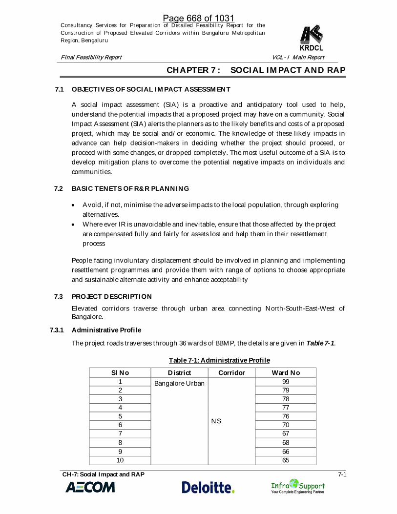
Consultancy Services for Preparation of Detailed Feasibility Report for theConstruction of Proposed Elevated Corridors within Bengaluru MetropolitanRegion, Bengaluru
Final Feasibility Report VOL- I Main Report
CH-7: Social Impact and RAP 7-1
CHAPTER 7 : SOCIAL IMPACT AND RAP
7.1 OBJECTIVES OF SOCIAL IMPACT ASSESSMENT
A social impact assessment (SIA) is a proactive and anticipatory tool used to help,understand the potential impacts that a proposed project may have on a community. SocialImpact Assessment (SIA) alerts the planners as to the likely benefits and costs of a proposedproject, which may be social and/or economic. The knowledge of these likely impacts inadvance can help decision-makers in deciding whether the project should proceed, orproceed with some changes, or dropped completely. The most useful outcome of a SIA is todevelop mitigation plans to overcome the potential negative impacts on individuals andcommunities.
7.2 BASIC TENETS OF R&R PLANNING
· Avoid, if not, minimise the adverse impacts to the local population, through exploringalternatives.
· Where ever IR is unavoidable and inevitable, ensure that those affected by the projectare compensated fully and fairly for assets lost and help them in their resettlementprocess
People facing involuntary displacement should be involved in planning and implementingresettlement programmes and provide them with range of options to choose appropriateand sustainable alternate activity and enhance acceptability
7.3 PROJECT DESCRIPTION
Elevated corridors traverse through urban area connecting North-South-East-West ofBangalore.
7.3.1 Administrative Profile
The project roads traverses through 36 wards of BBMP, the details are given in Table 7-1.
Table 7-1: Administrative Profile
Sl No District Corridor Ward No1 Bangalore Urban
NS
992 793 784 775 766 707 678 689 66
10 65
Page 668 of 1031

Consultancy Services for Preparation of Detailed Feasibility Report for theConstruction of Proposed Elevated Corridors within Bengaluru MetropolitanRegion, Bengaluru
Final Feasibility Report VOL- I Main Report
CH-7: Social Impact and RAP 7-2
Sl No District Corridor Ward No11 3912 9213 4114 7815 8216 6217 9118
EW1
8919 9720 6321 122 323 7824
EW2
4225 5326 9627 9828 5129 8230 6231 9132 CC1 3833 CC2 4134
CC374
35 7636 72
7.3.2 Project Area Profile
According to the 2011 census of India, the total population of Karnataka was 61,095,297 ofwhich 30,966,657 (50.7%) were male and 30,128,640 (49.3%) were female, or 1000 males forevery 973 females. This represents a 15.60% increase over the population in 2001. Thepopulation density was 319 per km and 38.67% of the people lived in urban areas. Theliteracy rate was 75.36% with 82.47% of males and 68.08% of females being literate.
Bangalore district with a total population of 96, 21,551 is the most populous district in theState. The total area of Bangalore district is 2196 sq. km. and it is the smallest district in thestate in terms of area. The district has the highest a density of 4,381 and it ranks 1st in theState. Bangalore district accounts for 15.8 percent of the total population of the State andstands at 1st place in the State. Bangalore has the highest decadal growth rate of 47.2percent in the State. Bangalore is the most urbanized district with 90.9 percent of itspopulation residing in urban areas. It has the highest institutional and houselesspopulation. The district has the lowest Sex ratio of 916 in the State. The district with a Sexratio of 944 among the child population in the age-group 0-6 holds the 24th rank in theState. The proportion of child population (0-6 age-group) is 10.9 percent in the district and
Page 669 of 1031

Consultancy Services for Preparation of Detailed Feasibility Report for theConstruction of Proposed Elevated Corridors within Bengaluru MetropolitanRegion, Bengaluru
Final Feasibility Report VOL- I Main Report
CH-7: Social Impact and RAP 7-3
holds the rank of 16th in the State. The district has a second highest literacy rate of 87.7 inthe State. The male literacy rate in the district is 91.0 percent and the female literacy rate is84.0 percent. Bangalore ranks at second place in terms of female literacy rate. TheScheduled Caste population contributes 12.5 percent and the Scheduled Tribe populationcontributes 2.0 percent to the total population of the district. The district has registered awork participation of 44.1 percent and stands at 21st place in the State. The workparticipation rates for Male and Female population in the district are 62.0 and 24.6respectively, the female work participation rate being lowest in the state. Among the totalworkers in the district 90.9 percent are Main workers and 9.1 percent are Marginal workers.Major work force of 92.9 percent is Other Workers. Only 4.6 percent are engaged inAgricultural sector i.e., Cultivators (2.3 percent) and Agricultural Labourers (2.3 percent)and 2.6 percent of the total workers are engaged in Household Industry. About 55.9percent of the total population in the district is non-workers. The list of project affectedwards are given below in Table 7-2.
Table 7-2: List of Project Affected Wards
Sl. No. WARD NUMBER WARD NAMENorth – South Corridor
1 35 Aramane Nagara2 34 Gangenahalli3 46 Jayachamarajendra Nagara4 63 Jayamahal5 78 Pulikeshinagar6 93 Vasanth Nagar7 111 Shantala nagar8 110 Sampangiram nagar9 117 Shanthi Nagar10 118 Sudham Nagara11 145 Hombegowda nagar12 146 Lakkasandra13 147 Adugodi14 151 Koramangala15 152 Suddagunte Palya16 172 Madivala17 173 Jakkasandra18 114 Agaram19 174 HSR Layout1 50 Benniganahalli2 57 C V Raman Nagar3 79 Sarvagna Nagar4 58 New Tippasandara5 80 Hoysala Nagar6 90 Halsoor7 78 Pulikeshinagar8 91 Bharathi Nagar
Page 670 of 1031

Consultancy Services for Preparation of Detailed Feasibility Report for theConstruction of Proposed Elevated Corridors within Bengaluru MetropolitanRegion, Bengaluru
Final Feasibility Report VOL- I Main Report
CH-7: Social Impact and RAP 7-4
Sl. No. WARD NUMBER WARD NAME
9 92 Shivaji Nagar
10 63 Jayamahal11 35 Aramane Nagara12 45 Malleswaram13 60 Sagayarapuram14 59 Maruthi Seva Nagar15 49 Lingarajapura16 24 HBR Layout17 29 Kacharkanahalli1 149 Varthuru2 84 Hagadur3 85 Dodda Nekkundi4 150 Bellanduru5 86 Marathahalli6 87 HAL Airport7 113 Konena Agrahara8 88 Jeevanbhima Nagar9 112 Domlur10 114 Agaram11 111 Shantala Nagar12 117 Shanthi Nagar13 118 Sudham Nagara14 143 Vishveshwara Puram15 119 Dharmaraya Swamy Temple16 140 Chamrajapet17 142 Sunkenahalli18 136 Jagajivanaramnagar19 141 Azad Nagar20 157 Gali Anjenaya Temple ward21 134 Bapuji Nagar22 133 Hampi Nagar23 158 Deepanjali Nagar24 111 Shantala Nagar25 114 Agaram26 90 Halsoor
East - West Corridor: 1
Sl. No. WARD NUMBER WARD NAME1 50 Benniganahalli2 57 C V Raman Nagar3 79 Sarvagna Nagar4 58 New Tippasandara
Page 671 of 1031

Consultancy Services for Preparation of Detailed Feasibility Report for theConstruction of Proposed Elevated Corridors within Bengaluru MetropolitanRegion, Bengaluru
Final Feasibility Report VOL- I Main Report
CH-7: Social Impact and RAP 7-5
Sl. No. WARD NUMBER WARD NAME5 80 Hoysala Nagar6 90 Halsoor7 78 Pulikeshinagar8 91 Bharathi Nagar9 92 Shivaji Nagar10 63 Jayamahal11 35 Aramane Nagara12 45 Malleswaram13 60 Sagayarapuram14 59 Maruthi Seva Nagar15 49 Lingarajapura16 24 HBR Layout17 29 Kacharkanahalli
East - West Corridor: 2
Sl. No. WARDNUMBER WARD NAME
1 149 Varthuru2 84 Hagadur3 85 Dodda Nekkundi4 150 Bellanduru5 86 Marathahalli6 87 HAL Airport7 113 Konena Agrahara8 88 Jeevanbhima Nagar9 112 Domlur
10 114 Agaram11 111 Shantala Nagar12 117 Shanthi Nagar13 118 Sudham Nagara14 143 Vishveshwara Puram15 119 Dharmaraya Swamy Temple16 140 Chamrajapet17 142 Sunkenahalli18 136 Jagajivanaramnagar19 141 Azad Nagar20 157 Gali Anjenaya Temple ward21 134 Bapuji Nagar22 133 Hampi Nagar23 158 Deepanjali Nagar24 111 Shantala Nagar25 114 Agaram26 90 Halsoor
Page 672 of 1031

Consultancy Services for Preparation of Detailed Feasibility Report for theConstruction of Proposed Elevated Corridors within Bengaluru MetropolitanRegion, Bengaluru
Final Feasibility Report VOL- I Main Report
CH-7: Social Impact and RAP 7-6
7.3.3 Methodology
The key tasks carried out for the preparation of Social screening report are summarizedbelow
· Collection of Secondary data: The ward maps are collected from BBMP and otherconcerned offices. Secondary data pertaining socio economic features of projectcorridors are gathered from various agencies including Census of India and otherpublished information.
· Land acquisition and R&R procedures: Land acquisition for the Project will becarried out according to the Karnataka Industrial Area Development Board Act withcompensation in par with the Right of Fair Compensation and Transparency inLand Acquisition and Resettlement and Rehabilitation Act 2013
· Social Screening Survey: In order to understand the impact of the project and identifythe social sensitive locations, screening surveys are conducted all along the projectstretches. Summary of findings are presented in this report and snap shots of the sitescreening survey is given in plate -1.
· Information Dissemination, Public Participation and Focus Group Discussions;Stakeholder consultations are an integral part of the Social Impact Assessment.Consultations will be carried out with a wide range of stakeholders including affectedcommunities, government agencies, local bodies, NGOs/CBOs etc in the next level ofthe study. At this stage opinion from public are gathered through FGDs.
Figure 7-1:Snap shots of site activities
7.3.4 Additional Land requirements
The project will entail private land acquisition from private individual, as the collection ofland records are being collected from the respective agencies the estimate at this stage is
Page 673 of 1031
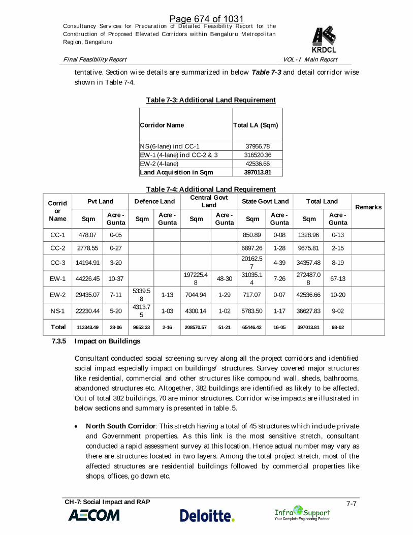
Consultancy Services for Preparation of Detailed Feasibility Report for theConstruction of Proposed Elevated Corridors within Bengaluru MetropolitanRegion, Bengaluru
Final Feasibility Report VOL- I Main Report
CH-7: Social Impact and RAP 7-7
tentative. Section wise details are summarized in below Table 7-3 and detail corridor wiseshown in Table 7-4.
Table 7-3: Additional Land Requirement
Corridor Name Total LA (Sqm)
NS (6-lane) incl CC-1 37956.78EW-1 (4-lane) incl CC-2 & 3 316520.36EW-2 (4-lane) 42536.66Land Acquisition in Sqm 397013.81
Table 7-4: Additional Land Requirement
Corridor
Name
Pvt Land Defence Land Central GovtLand State Govt Land Total Land
Remarks
Sqm Acre -Gunta Sqm Acre -
Gunta Sqm Acre -Gunta Sqm Acre -
Gunta Sqm Acre -Gunta
CC-1 478.07 0-05 850.89 0-08 1328.96 0-13
CC-2 2778.55 0-27 6897.26 1-28 9675.81 2-15
CC-3 14194.91 3-20 20162.57 4-39 34357.48 8-19
EW-1 44226.45 10-37 197225.48 48-30 31035.1
4 7-26 272487.08 67-13
EW-2 29435.07 7-11 5339.58 1-13 7044.94 1-29 717.07 0-07 42536.66 10-20
NS-1 22230.44 5-20 4313.75 1-03 4300.14 1-02 5783.50 1-17 36627.83 9-02
Total 113343.49 28-06 9653.33 2-16 208570.57 51-21 65446.42 16-05 397013.81 98-02
7.3.5 Impact on Buildings
Consultant conducted social screening survey along all the project corridors and identifiedsocial impact especially impact on buildings/ structures. Survey covered major structureslike residential, commercial and other structures like compound wall, sheds, bathrooms,abandoned structures etc. Altogether, 382 buildings are identified as likely to be affected.Out of total 382 buildings, 70 are minor structures. Corridor wise impacts are illustrated inbelow sections and summary is presented in table .5.
· North South Corridor: This stretch having a total of 45 structures which include privateand Government properties. As this link is the most sensitive stretch, consultantconducted a rapid assessment survey at this location. Hence actual number may vary asthere are structures located in two layers. Among the total project stretch, most of theaffected structures are residential buildings followed by commercial properties likeshops, offices, go down etc.
Page 674 of 1031

Consultancy Services for Preparation of Detailed Feasibility Report for theConstruction of Proposed Elevated Corridors within Bengaluru MetropolitanRegion, Bengaluru
Final Feasibility Report VOL- I Main Report
CH-7: Social Impact and RAP 7-8
· East West 1 Corridor: Out of 280 structures which includes commercial and otherstructure which includes compound wall, shed etc. and religious structures like smalltemples and shrine.
· East West 2 Corridor: A total of 57 structures are identified as affected, of which arecommercial. Here also of structures falling in the category of other structures likeImpact on Religious Properties
A total of 32 religious structures like small temples, mosque, shrines etc., were identified asaffected religious structures. Category wise religious structures under all the corridors aresummarized in the below Table 7-5.
Table 7-5: Category wise Religious Properties
Corridor Temple Church Mosque Total
North South incl CC1 5 5 3 13
EW1 incl CC2 & 3 20 1 0 21
EW2 11 0 0 11
Total 36 6 3 45
7.3.6 Impact on Government/ Community Properties
Among the total project affected buildings, 13 are identified as Government/ communityproperties. Category wise properties are given in the below Table 7-6.
Table 7-6: Category wise Govt./Community Properties
Corridor Govt. Offices Hospital Hall CompoundWall etc. Total
North South 5 1 0 2 8EW1 3 0 0 0 3EW2 1 0 1 0 2CC1 0 0 0 0 0CC2 0 0 0 0 0CC3 0 0 0 0 0
Total 9 1 1 2 13
Page 675 of 1031

Consultancy Services for Preparation of Detailed Feasibility Report for theConstruction of Proposed Elevated Corridors within Bengaluru MetropolitanRegion, Bengaluru
Final Feasibility Report VOL- I Main Report
CH-7: Social Impact and RAP 7-9
7.3.7 Impact on Other Structures
Structures like compound wall, shed, bathrooms, abandoned structures etc., were includedas other structures.
7.3.8 Impact on TenantsAs the project is in city limit, most of the buildings are having many numbers of tenants.Screening survey covers the same also and listed out a tentative figure which will furtherverify at the time of census survey. Category wise tenants under north south corridor, EW1and EW2 are given in below Table 7-7.
Table 7-7: Details of TenantsCorridor No of Tenants No of Employees
North South 64 96EW1 471 222EW2 708 1626Total 1243 1944
7.4 LEGAL FRAMEWORK
Acts and R&R policies relevant to the project State is summarized in below section,however the Resettlement Framework for this project shall be finalized by EA prior to thepreparation of Resettlement Plan.
Right of Fair Compensation and Transparency in Land Acquisition and Resettlementand Rehabilitation Act 2013
The Land Acquisition, Rehabilitation and Resettlement Bill, 2011 was introduced in LokSabha on 7 September 2011, passed by both the houses of parliament in 2013, and afterreceiving the assent of President of India, came into force as an act in January 1st , 2014.The Act has provisions to provide fair compensation to those whose land is taken away,brings transparency to the process of acquisition of land to set up factories or buildings,infrastructural projects and assures rehabilitation of those affected. This acts clearlystates that each affected family irrespective of title, are eligible for R&R assistance. As perthis Act, all the compensation and assistances should be disbursed to all the projectaffected families before taking possession of their land and assets.
The objectives of the Act are as follows:
· To ensure, in consultation with institutions of local self-government and GramSabhas established under the Constitution of India, a humane, participative,informed and transparent process for land acquisition for industrialization,development of essential infrastructural facilities and urbanisation with leastdisturbance to the owners of the land and other affected families.
Page 676 of 1031

Consultancy Services for Preparation of Detailed Feasibility Report for theConstruction of Proposed Elevated Corridors within Bengaluru MetropolitanRegion, Bengaluru
Final Feasibility Report VOL- I Main Report
CH-7: Social Impact and RAP 7-10
· Provide just and fair compensation to the affected families whose land has beenacquired or proposed to be acquired or are affected by such acquisition.
· Make adequate provisions for such affected persons for their rehabilitation andresettlement.
Salient features of RFCTLARR 2013
Bare minimum acquisition: Authority should try to avoid or minimise theacquisition by exploring all possible options.
Transparency in procedures: RFCTLARR 2013 assures 100% transparency in allprocedures related to land acquisition. Public hearing to be conducted after givingadequate publicity on venue and time is mandatory while conducting SIA study.Feedback of project affected community and public representatives to be collectedalong with SIA.
Appraisal of SIA by an expert group- Studied SIA will be reviewed by anindependent multi-disciplinary expert group which contains; (1) Two non-officialsocial scientists (2) Two representatives from Gram Sabha or any PRI institution (3)Two experts in rehabilitation (4) A technical expert in the subject relating to theproject.
Examination of proposals for land acquisition and SIA report by appropriateGovernment.
Publication of social impact assessment study- SIA report should be made availableto the public in local language.
Provision for higher compensation. Nothing in the Act shall prevent any State fromenacting any law to enhance or add to the entitlement enumerated under this Actwhich confers higher compensation than payable under this Act or make provisionsfor rehabilitation and resettlement which is more beneficial than provided under thisAct.(S.107)
Special provision to safeguard food security: - no irrigated multi cropped land to beacquired
Payment for damage: pay or tender payment for any damage caused, and, in case ofdispute as to the sufficiency of the amount so paid or tendered.
As per normal practice around 32 months’ would require to take possession of landfrom private entity for infrastructure development projects under RFCTLARR, Act2013. However, this may be reduced to 15 months through mobilization of moreofficers.
Relevance of RFCTLARR, Act 2013 in this project.
The Central Government has notified on January, 01, 2014 as the effective date ofAct, in accordance with Sec 1(3). The acts specified in fourth schedule of RFCTLARRwill have one year to adopt (i) compensation for land owners (First Schedule); (ii)rehabilitation and resettlement entitlements (second schedule); and (iii) provision of
Page 677 of 1031

Consultancy Services for Preparation of Detailed Feasibility Report for theConstruction of Proposed Elevated Corridors within Bengaluru MetropolitanRegion, Bengaluru
Final Feasibility Report VOL- I Main Report
CH-7: Social Impact and RAP 7-11
infrastructure amenities (Third schedule).
Since, the act (Karnataka Highways Act, 1964) which is being used for landacquisition in Karnataka, has not been included in this category, KarnatakaHighways Act, cannot be imposed for land acquisition. Moreover Govt of Karnatakahas recently streamlined the procedure through notification.
7.4.1 The Right to Fair Compensation and Transparency in Land Acquisition, Rehabilitationand Resettlement (Karnataka) Rules, 2015”
Government of Karnataka issued rules as provided in Section 109 of RFCTLARR Act 2013namely “The Right to Fair Compensation and Transparency in Land Acquisition,Rehabilitation and Resettlement (Karnataka) Rules, 2015”. Copy of gazette notification isenclosed as Appendix 7.1 of this report. These Rules, inter-alia, provide for the following.
a) Chapter II deals with the matters pertaining to Social Impact Assessment Study (SIA)and all matters concerning the same including its publication, (Rules.3 to 13).
b) Chapter III deals with the Process of Obtaining the Prior Consent (Rules 16-19)c) Chapter IV deals with the Preliminary Notification For Acquisition (Rule 20)d) Chapter V deals with the Rehabilitation and Resettlement Scheme and matters relating
thereto (Rules 21- 38)
Rule 40 empowers the government for removal of difficulties either in the interpretation ofthe provisions of the Rules and implementation of the provisions.
Karnataka Industrial Area Development Board Act
Salient Features of the Section 28 of KIADB Act
· If at any time, in the opinion of the State Government, any land is required fordevelopment by the Board, or for any other purpose in furtherance of theobjects of this Act, the State Government may by notification, give notice of itsintention to acquire such land.
· On publication of a notification under sub-section (1), the State Governmentshall serve notice upon the owner or where the owner is not the occupier, onthe occupier of the land and on all such persons known or believed to beinterested therein to show cause, within thirty days from the date of service ofthe notice, why the land should not be acquired. 12
· After considering the cause, if any, shown by the owner of the land and by anyother person interested therein, and after giving such owner and person anopportunity of being heard, the State Government may pass such orders as itdeems fit.
Page 678 of 1031

Consultancy Services for Preparation of Detailed Feasibility Report for theConstruction of Proposed Elevated Corridors within Bengaluru MetropolitanRegion, Bengaluru
Final Feasibility Report VOL- I Main Report
CH-7: Social Impact and RAP 7-12
· After orders are passed under sub-section (3), where the State Government issatisfied that any land should be acquired for the purpose specified in thenotification issued under sub-section (1), a declaration shall, by notification inthe official Gazette, be made to that effect.
· On the publication in the official Gazette of the declaration under sub-section(4), the land shall vest absolutely in the State Government free from allencumbrances.
· Where any land is vested in the State Government under sub-section (5), theState Government may, by notice in writing, order any person who may be inpossession of the land to surrender or deliver possession thereof to the StateGovernment or any person duly authorized by it in this behalf within thirtydays of the service of the notice.
· If any person refuses or fails to comply with an order made under sub-section(5), the State Government or any officer authorized by the State Government inthis behalf may take possession of the land and may for that purpose use suchforce as may be necessary.
· Where the land has been acquired for the Board, the State Government, after ithas taken possession of the land, may transfer the land to the Board for thepurpose for which the land has been acquired.
Section 29 of KIADB Act - 2007 compensation
· Where any land is acquired by the State Government under this Chapter, theState Government shall pay for such acquisition compensation in accordancewith the provisions of this Act.
· Where the amount of compensation has been determined by agreementbetween the State Government and the person to be compensated, it shall bepaid in accordance with such agreement.
· Where no such agreement can be reached, the State Government shall refer thecase to the Deputy Commissioner for determination of the amount ofcompensation to be paid for such acquisition as also the person or persons towhom such compensation shall be paid.
· On receipt of a reference under sub-section (3), the Deputy Commissioner shallserve notice on the owner or occupier of such land and on all persons knownor believed to be interested herein to appear before him and state theirrespective interests in the said land
Page 679 of 1031

Consultancy Services for Preparation of Detailed Feasibility Report for theConstruction of Proposed Elevated Corridors within Bengaluru MetropolitanRegion, Bengaluru
Final Feasibility Report VOL- I Main Report
CH-7: Social Impact and RAP 7-13
7.5 CONCLUSION & WAY FORWARD
Land acquisition plan and schedules shall be prepared for the locations where everadditional land is required especially for provision of loops, ramps etc. Census survey forthe project affected families also shall be conducted for the project affected families. Theresettlement frame works shall be prepared in consultation with the Executive Agency.Organized public consultation shall be done in discussion with the key stakeholders.
Page 680 of 1031

CHAPTER – 8
COST ESTIMATE
Page 681 of 1031

Consultancy Services for Preparation of Detailed Feasibility Report for the Construction ofProposed Elevated Corridors within Bengaluru Metropolitan Region, Bengaluru
Final Feasibility Report Cost Estimate
Ch:8 Cost Estimatei
Table of ContentsCHAPTER 8: COST ESTIMATE ............................................................................................................. 1
8.1 General ................................................................................................................................ 18.2 Estimation of Quantities and Cost .................................................................................. 18.3 Preamble ............................................................................................................................. 28.4 Rates ..................................................................................................................................... 2
8.4.1 Material ........................................................................................................................ 2
8.4.2 Labour ........................................................................................................................... 3
8.4.3 Machineries ................................................................................................................. 3
8.5 Total Project Cost ............................................................................................................... 4
Page 682 of 1031

Consultancy Services for Preparation of Detailed Feasibility Report for the Construction ofProposed Elevated Corridors within Bengaluru Metropolitan Region, Bengaluru
Final Feasibility Report Cost Estimate
Ch:8 Cost Estimate1
CHAPTER 8: COST ESTIMATE
8.1 General
The project cost estimates have been prepared based on various items of worksrequired for the construction of the Proposed Elevated Corridors within BengaluruMetropolitan Region, Bengaluru for different lane configuration.
The Major items rates for like Steel, Cement, Bitumen, M-Sand, Aggregates, labourand other items are from PWP IWTD SoR 2018-19, Bangalore Circle, Govt. of India.
8.2 Estimation of Quantities and Cost
In general, the work is to be executed as per Technical Specifications containedin “Specifications for Road and Bridge Works” (Fifth Revision- August 2015) issued.
The quantities of major items of road works have been worked out based oninventory; condition surveys pavement investigations data and geometric designoutput obtained from MX Software. The pavement quantities have been workedbased on the geometrics and cross sections, pavement design done based ontraffic and laboratory investigations. The following are the Bill wise of works, whichhave been estimated:
Site Clearance and Dismantling: The area considered for Site Clearance is thearea within the proposed Right of Way width.
Earth Works: This item provides for roadway excavation, earthwork inembankment, sub-grade and shoulders, islands including disposal of surplus earthand unsuitable material. The earthwork quantities are based on design softwareMX-Road. Sub-grade having a CBR > 8 % will be taken from borrows area.
Sub-base, Base Courses: This item provides for the items of GSB and WMM for themain carriage way.
Bituminous Works: For flexible pavement, the subhead for bituminous worksprovides for all items of bituminous courses and surfacing.
Culverts: The estimation of quantities for culverts i.e. Box type & Hume Pipe werebased on site inventory and condition survey.
Bridges and Elevated structures: The estimation of quantities for Major & MinorBridge and elevated structures were based on site inventory, detailed design anddrawings.
Page 683 of 1031

Consultancy Services for Preparation of Detailed Feasibility Report for the Construction ofProposed Elevated Corridors within Bengaluru Metropolitan Region, Bengaluru
Final Feasibility Report Cost Estimate
Ch:8 Cost Estimate2
Drainage and Protection works: Provision under this sub-head has been made forsurface, roadside drains, and Retaining wall / Reinforced Earth Wall respectively.
Traffic Signs and Road Appurtenances: Proper traffic signs were selected atrequired locations along the project corridor. It is reviewed considering the trafficand pedestrian safety and the number of traffic signs shall be minimum andmodified if required. Centre line and edge markings required from safety point ofview were considered in the quantity estimate.
Major/Minor Junctions Improvement: The junctions estimates are included in therelated items as per above includes which need improvement along thehighway.
8.3 Preamble
The project cost estimates have been prepared based on various items of worksrequired for the construction of the Proposed Elevated Corridors within BengaluruMetropolitan Region, Bengaluru for different lane configuration
The Major items rates for like Steel, Cement, Bitumen, M-Sand, Aggregates, labourand other items are from PWP IWTD SoR 2018-19, Bangalore Circle, Govt. of India.
8.4 Rates
The rates are as per the PWP IWTD SoR 2018-19, Bangalore Circle Analysis of ratesfor items not given in the SoR, analysis has been carried out based on procedure slaid down in the Standard Data Book.
8.4.1 Material
The Major items rates for like Steel, Cement, Bitumen, M-Sand, Aggregates, labourand other items are from PWP IWTD SoR 2018-19, Bangalore Circle, Govt. of India.The sources of material are as follows:
Bitumen : MRPL, Karnataka;Emulsion : MRPL, Karnataka;Steel : Tata/Jindal Steel, Bellary, Karnataka;Borrow Soil : Borrow areas along the project road;Aggregates : Bangalore Rural;Stone Boulder : Bangalore Rural;Course Sand : M Sand;Fine Sand : M Sand
Page 684 of 1031

Consultancy Services for Preparation of Detailed Feasibility Report for the Construction ofProposed Elevated Corridors within Bengaluru Metropolitan Region, Bengaluru
Final Feasibility Report Cost Estimate
Ch:8 Cost Estimate3
8.4.2 Labour
The labour rates are considered from PWP IWTD SoR 2018-19, Bangalore Circle,Govt. of India.
8.4.3 Machineries
Hire charge of machineries have been taken from PWP IWTD SoR 2018-19,Bangalore Circle, Govt. of India.
Page 685 of 1031

Consultancy Services for Preparation of Detailed Feasibility Report for the Construction of Proposed Elevated Corridors withinBengaluru Metropolitan Region, Bengaluru
Final Feasibility Report Cost Estimate
Ch:8 Cost Estimate
4
8.5 Total Project Cost
S. No. Description of Item
Phase-1 (NS) Phase-2 (EW1) Phase-3 (EW2) Phase-4 (ITPL)
TotalHebbal-Silk
Board & CC1
KR Puram (ROB)-Yeshwantpur
Flyover
Varthur Kodi toSirsi Circle
Rammurthynagar to ITPL
Road
(INR crore) (INR crore) (INR crore) (INR crore) (INR crore)
1 Civil Construction Cost (on whichproject would be bid out) 7,002 3,033 3,989 1,287 15,310
2 Land Acquisition and Resettlement 2,717 2,154 1,500 5,183 11,555
3 Other Cost (Supervision charges,Utility shifting, Escalation etc.,) 1,134 578 760 245 2,716
4 Total 10,852 5,765 6,249 6,715 29,582
Page 686 of 1031

Consultancy Services for Preparation of Detailed Feasibility Report(DFR) for the Construction of Proposed Elevated Corridors within
Bengaluru Metropolitan Region, Bengaluru
AECOM Asia Co. Ltd.in association with
Deloitte Touché Tohmatsu India LLP &Infra Support Engineering Consultants Pvt. Ltd
FINAL FEASIBILITY REPORTVOLUME-IV : ENVIRONMENTAL
IMPACT ASSESSMENT REPORT
FEBRUARY, 2019
KARNATAKA ROAD DEVELOPMENTCORPORATION LIMITED
ANNEXURE-R11Page 687 of 1031

Consultancy Services for Preparation of Detailed Feasibility Report for theConstruction of Proposed Elevated Corridors within Bengaluru MetropolitanRegion, Bengaluru
Detailed Feasibility Report VOL-IV Environmental Impact Assessment Report
i
TABLE OF CONTENTS
Adherence to Terms of Reference ............................................................................................ 1-1
1. INTRODUCTION ................................................................................................................ 1-5
1.1 Background .......................................................................................................... 1-51.2 Objective of Environmental Impact Assessment .............................................. 1-71.3 Methodology and Scoping .................................................................................. 1-71.4 Structure of the Report: ....................................................................................... 1-8
2. PROJECT DESCRIPTION .................................................................................................. 2-1
2.1 North - South Corridor Connecting Mekhri Circle and Silk Board Junction: 2-12.2 East - West Corridor - 1: Connecting NH48 (earlier NH-4) at Battarahalli and
Gorguntepalya on Tumkur Road ....................................................................... 2-12.3 East - West Corridor - 2: Connecting SH-35, Varthur Kodi to Deepanjanli
Nagar (West of Chord Road) NICE link road on Mysore road ....................... 2-22.4 Connecting Corridor-1: ....................................................................................... 2-22.5 Connecting Corridor-2: ....................................................................................... 2-22.6 Connecting Corridor-3: ....................................................................................... 2-22.7 Proposals for the elevated corridor .................................................................... 2-42.8 Traffic Forecast: .................................................................................................... 2-92.9 Typical Cross Sections proposed ...................................................................... 2-102.10 Corridor of Impact (COI) ............................................................................... 2-122.11 Materials of Construction and its availability: ............................................. 2-20
3. POLICIES AND THE REGULATORY FRAMEWORK AND ITS APPLICABILITY 3-22
3.1 Constitutional Provisions .................................................................................. 3-223.2 Environment Impact Assessment Notification and it’s applicability to the
project: ................................................................................................................ 3-223.3 The Environment (Protection) Act, 1986.......................................................... 3-243.4 Water (Prevention and Control of Pollution) Act, 1974 ................................. 3-243.5 Air (Prevention and Control of Pollution) Act, 1981 ...................................... 3-253.6 The Hazardous Wastes (Management and Handling) Rules, 2016 ............... 3-253.7 Wildlife Protection Act, 1972 ............................................................................ 3-253.8 The Indian Forest Act, 1927 .............................................................................. 3-253.9 Forest (Conservation) Act, 1980 (as Amended In 1988) ................................. 3-263.10 The Ancient Monuments and Archaeological Sites and Remains Act 2010 .. 3-
263.11 National Green Tribunal (NGT) Order dated 4th May 2016 in O.A. No. 222 of
2014 ..................................................................................................................... 3-273.12 The Right to Fair Compensation and Transparency in Land Acquisition and
Rehabilitation and Resettlement Act, 2013 (RFCTLARR Act 2013) ............... 3-273.13 Karnataka Industrial Area Development Board Act ................................... 3-283.14 Clearances required for the project corridors ............................................... 3-29
4. DESCRIPTION OF ENVIRONMENT............................................................................. 4-33
4.1 Location: ............................................................................................................. 4-334.2 Physiography ..................................................................................................... 4-36
Page 688 of 1031

Consultancy Services for Preparation of Detailed Feasibility Report for theConstruction of Proposed Elevated Corridors within Bengaluru MetropolitanRegion, Bengaluru
Detailed Feasibility Report VOL-IV Environmental Impact Assessment Report
ii
4.3 Topography ........................................................................................................ 4-364.4 Climate................................................................................................................ 4-364.5 Ambient Air Quality.......................................................................................... 4-42
4.5.1 Inferences on the Ambient Air Quality Analysis..................................... 4-704.5.2 Air Quality Modelling done for the project area: ........................................... 4-73
4.6 Noise Environment ............................................................................................ 4-834.6.1 Inference on the monitored Noise levels .................................................. 4-91
4.7 Water Environment ........................................................................................... 4-924.7.1 Water Environment .................................................................................... 4-964.7.2 Inference on the water quality analysis .................................................. 4-101
4.8 Land Environment ........................................................................................... 4-1024.9 Hydrogeology .................................................................................................. 4-1064.10 Land use pattern ........................................................................................... 4-1094.11 Environmental Pollution .............................................................................. 4-1134.12 Biological Environment ................................................................................ 4-1144.13 Social Economic Environment ..................................................................... 4-1164.14 Sites of Tourist and Archaeological Interest ............................................... 4-1194.15 Seismicity ....................................................................................................... 4-120
5. ENVIRONMENTAL IMPACTS AND MITIGATION MEASURES ......................... 5-121
5.1 IMPACTS DURING PRECONSTRUCTION PHASE ................................... 5-1215.1.1 Change of Land use: ................................................................................. 5-1215.1.2 Structures Affected ................................................................................... 5-122
5.2 IMPACTS DURING CONSTRUCTION PHASE .......................................... 5-1235.2.1 Impact on Topography ............................................................................ 5-1235.2.2 Impact on Soil ........................................................................................... 5-1235.2.3 Impact on Water Quality, Drainage and Hydrology ............................ 5-1255.2.4 Traffic Diversions ..................................................................................... 5-1285.2.5 Impact on Air Quality .............................................................................. 5-1285.2.6 Impact on Noise Quality .......................................................................... 5-1325.2.7 Impact on Biological Environment ......................................................... 5-1375.2.8 Impact on Water Bodies ........................................................................... 5-1385.2.9 Impact on Land Environment ................................................................. 5-1405.2.10Impact on Structures (Religious, Community structures and Historical
and Cultural Monuments ........................................................................ 5-1415.2.11Impact on Livelihood, Public services, Health and Safety of Community
and Labourers ........................................................................................... 5-1425.2.12Impact on Economy.................................................................................. 5-1435.2.13IMPACTS DURING OPERATION STAGE ............................................ 5-1435.2.14POSITIVE IMPACTS OF ELEVATED CORRIDOR PROJECT ............. 5-1445.2.15Environmental Impact Matrix ................................................................. 5-1445.2.16Matrix Representation .............................................................................. 5-1465.2.17Determining the sensitiveness of Project Corridor ................................ 5-148
6. ADDITIONAL STUDIES ................................................................................................ 6-149
6.1 Rain water Harvesting Potential and Proposal: ............................................ 6-149
Page 689 of 1031

Consultancy Services for Preparation of Detailed Feasibility Report for theConstruction of Proposed Elevated Corridors within Bengaluru MetropolitanRegion, Bengaluru
Detailed Feasibility Report VOL-IV Environmental Impact Assessment Report
iii
6.2 Tree Transplantation ....................................................................................... 6-1516.3 Compensatory Plantation Strategy: ............................................................... 6-1556.4 Vertical Gardens: ............................................................................................. 6-1566.5 Median Plantation: .......................................................................................... 6-1576.6 Quantification of solar energy harvesting potential: .................................... 6-1586.7 Carbon Foot print Study ................................................................................. 6-1616.8 Carbon Emission Studies ................................................................................ 6-1626.9 Energy Embodiment of materials and steps to reduce: ................................ 6-164
7. PROJECT BENEFITS ....................................................................................................... 7-165
8. ENVIRONMENTAL MANAGEMENT PLAN ............................................................. 8-166
8.1 Other Mitigation Plans .................................................................................... 8-1788.1.1 Resettlement Plan ..................................................................................... 8-1788.1.2 Construction Water Management Plan .................................................. 8-1788.1.3 Emergency Response Plan ....................................................................... 8-1788.1.4 Oil spill contingency plans (SCP) and clean up procedures ................. 8-178
8.2 Grievance Redressal Mechanism.................................................................... 8-1798.3 Environmental Monitoring programme ........................................................ 8-1808.4 Performance indicators ................................................................................... 8-1838.5 Reporting system ............................................................................................. 8-1858.6 Institutional Arrangements for implementation ........................................... 8-189
Environmental Cell, KRDCL ............................................................................. 8-1908.7 Institutional Capacity Building ...................................................................... 8-1928.8 Training Components:..................................................................................... 8-1928.9 Training Programme: ...................................................................................... 8-1928.10 Environmental Budgetary Provisions ......................................................... 8-194
9. CONCLUSION ................................................................................................................. 9-198
10. DISCLOSUREOF CONSULTANTS ENGAGED ....................................................... 10-200
LIST OF TABLES
Table 2-1: List of proposed elevated corridors ............................................................................................. 2-1Table 2-2: Phasing for Implementation of Elevated Corridor ........................................................................ 2-3Table 2-3: Present and Future Traffic along the proposed project stretches ................................................ 2-7Table 2-4: Growth of Registered vehicles in Bangalore (In Lakhs) ................................................................ 2-9Table 2-5: Corridor of Impact (CoI) for the Project Corridor ........................................................................ 2-13Table 2-6: Construction materials required per Kilometer .......................................................................... 2-20Table 2-7: Aggregate quarries and the distance .......................................................................................... 2-21Table 3-1: List of Clearances Required for the Project Road ........................................................................ 3-30Table 4-1: Month wise rainfall and Annual total rainfall data for Bangalore urban district ......................... 4-37Table 4-2: Month wise annual average temperature data for Bangalore urban district .............................. 4-38Table 4-3: Details of Ambient Air Monitoring Stations ................................................................................ 4-42Table 4-4: Details of Ambient Air Monitoring Stations ................................................................................ 4-42Table 4-5: Ambient Air Quality at Mekhri Circle .......................................................................................... 4-45NAAQS: National Ambient Air Quality Standards Table 4-6: Ambient Air Quality at Wheeler Road
Junction (Opp to HQ MEG Centre) ............................................................................................... 4-45
Page 690 of 1031