UNIT III - Vidyarthiplus
17
An arch is defined as a curved girder, having convexity upwards and supported at its ends. The supports must effectively arrest displacements in the vertical and horizontal directions. Only then there will be arch action. diagram and funicular polygon are plotted as shown; the funicular polygon is known as the linear arch or theoretical arch. The polar distance ‘ot’ represents the horizontal thrust. The links AC, CD, DE and EB will br under compression and there will be no bending moment. If an arch of this shape ACDEB is provided, there will be no bending moment. an arch is proportional to the vertical intercept between the linear arch (or theoretical arch) and the center line of the actual arch”. BM x = ordinate O 2 O 3 * scale factor UNIT III ARCHS 3.1.ARCH 3.2.Linear arch If an arch is to take loads, say W 1 , W 2 , and W 3 and a vector 3.3.Eddy’s theorem. Eddy’s theorem states that “The bending moment at any section of CE6501 Structural Analysis I SCE Dept of Civil www.Vidyarthiplus.com www.Vidyarthiplus.com
-
Upload
khangminh22 -
Category
Documents
-
view
7 -
download
0
Transcript of UNIT III - Vidyarthiplus

An arch is defined as a curved girder, having convexity upwards and supported at its ends.
The supports must effectively arrest displacements in the vertical
and horizontal directions. Only then there will be arch action.
diagram and funicular polygon are plotted as shown; the funicular polygon is known as the linear arch or theoretical arch.
The polar distance ‘ot’ represents the horizontal thrust.
The links AC, CD, DE and EB will br under compression and there
will be no bending moment. If an arch of this shape ACDEB is provided,
there will be no bending moment.
an arch is proportional to the vertical intercept between the linear arch (or
theoretical arch) and the center line of the actual arch”.
BMx = ordinate O2 O3 * scale factor
UNIT III ARCHS
3.1.ARCH
3.2.Linear arch If an arch is to take loads, say W1, W2, and W3 and a vector
3.3.Eddy’s theorem. Eddy’s theorem states that “The bending moment at any section of
CE6501 Structural Analysis I
SCE Dept of Civil
www.Vidyarthiplus.com
www.Vidyarthiplus.com

Degree of static indeterminacy of a three hinged parabolic arch For a three-hinged parabolic arch, the degree of static indeterminacy is
zero. It is statically determinate.
Let us take a section X of an arch. Let θ be the inclination of the tangent at X. if H
is the horizontal thrust and V the net vertical shear at X, from theb free body of the
RHS of the arch, it is clear that V and H will have normal and radial components
given by,
N = H cos θ + V sin θ
R = V cosθ – H sin θ
The normal thrust and radial shear in an arch rib.
Parabolic arches are preferable to carry distributed loads. Because, both,
the shape of the arch and the shape of the bending moment diagram are parabolic.
Hence the intercept between the theoretical arch and actual arch is zero everywhere.
Hence, the bending moment at every section of the arch will be zero. The arch will be
under pure compression that will be economical.
1.A three hinged parabolic arch hinged at the crown and springing has
a horizontal span of 12m and a central rise of 2.5m. it carries a udl of
30 kN/m run over the left hand half of the span. Calculate the resultant
at the end hinges.
CE6501 Structural Analysis I
SCE Dept of Civil
www.Vidyarthiplus.com
www.Vidyarthiplus.com

Difference between the basic action of an arch and a suspension cable An arch is essentially a compression member, which can also take
bending moments and shears. Bending moment and shears will be absent if the arch is
parabolic and the loading uniformly distributed.
A cable can take only tension. A suspension bridge will therefore
have a cable and a stiffening girder. The girder will take the bending moment and
shears in the bridge and the cable, only tension.
Because of the thrust in cables and arches, the bending moments
are considerably reduced.
If the load on the girder in uniform. The bridge will have only
cable tension and no bending moment on the girder.
Under what conditions will the bending moment in an arch be zero
throughout The bending moment in an arch throughout the span will be zero, if
(i) The arch is parabolic and
(ii) The arch carries udl throughout the span
VA = VB = 50 kN
2.A three-hinged semicircular arch carries a point load of 100 kN at the
crown. The radius of the arch is 4m. Find the horizontal reactions at the supports.
CE6501 Structural Analysis I
SCE Dept of Civil
www.Vidyarthiplus.com
www.Vidyarthiplus.com

Equating the moment about C to Zero, VA * 4 – H*4 = 0
H = VA
Horizontal reaction, H = 50 kN
Determine H, VA and VB in the semicircular arch shown in fig
3.A three-hinged semicircular arch of radius 10m carries a udl of 2 kN/m
over the span. Determine the horizontal and vertical reactions at
the supports.
CE6501 Structural Analysis I
SCE Dept of Civil
www.Vidyarthiplus.com
www.Vidyarthiplus.com
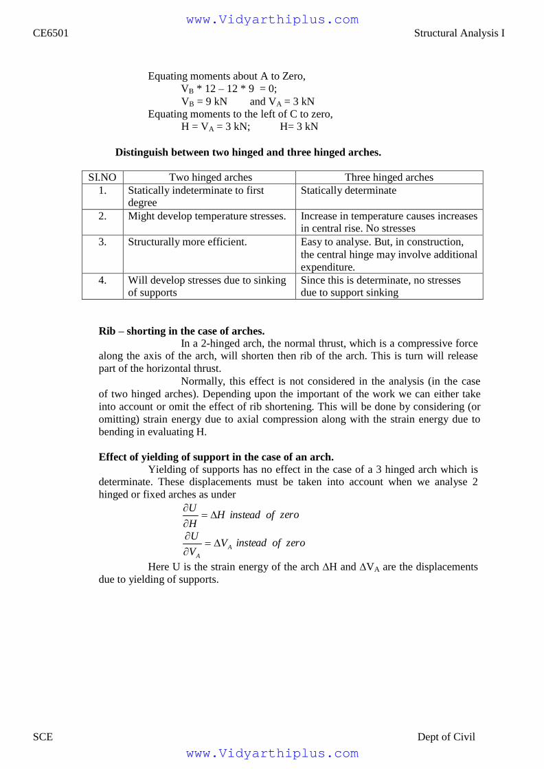
Equating moments about A to Zero,
VB * 12 – 12 * 9 = 0;
VB = 9 kN and VA = 3 kN Equating moments to the left of C to zero,
H = VA = 3 kN; H= 3 kN
Distinguish between two hinged and three hinged arches.
SI.NO Two hinged arches Three hinged arches
1. Statically indeterminate to first degree
Statically determinate
2. Might develop temperature stresses. Increase in temperature causes increases in central rise. No stresses
3. Structurally more efficient. Easy to analyse. But, in construction,
the central hinge may involve additional
expenditure.
4. Will develop stresses due to sinking of supports
Since this is determinate, no stresses due to support sinking
Rib – shorting in the case of arches. In a 2-hinged arch, the normal thrust, which is a compressive force
along the axis of the arch, will shorten then rib of the arch. This is turn will release
part of the horizontal thrust.
Normally, this effect is not considered in the analysis (in the case
of two hinged arches). Depending upon the important of the work we can either take
into account or omit the effect of rib shortening. This will be done by considering (or
omitting) strain energy due to axial compression along with the strain energy due to
bending in evaluating H.
Effect of yielding of support in the case of an arch.
Yielding of supports has no effect in the case of a 3 hinged arch which is determinate. These displacements must be taken into account when we analyse 2
hinged or fixed arches as under
U H instead of
H
zero
U
VA
VA
instead of
zero
Here U is the strain energy of the arch ∆H and ∆VA are the displacements
due to yielding of supports.
CE6501 Structural Analysis I
SCE Dept of Civil
www.Vidyarthiplus.com
www.Vidyarthiplus.com

5.A three-hinged parabolic arch has a horizontal span of 36m with a central rise
of 6m. A point load of 40 kN moves across the span from the left to
the right. What is the absolute maximum positive bending moment that
wills occur in the arch
CE6501 Structural Analysis I
SCE Dept of Civil
www.Vidyarthiplus.com
www.Vidyarthiplus.com

For a single concentrated load moving from one end to the
other, Absolute maximum positive bending moment
= 0.096wl = 0.096*40 * 36=138.24 kNm
This occurs at 0.211 l = 0.211 * 36 = 7.596 m from the ends.
Absolute maximum positive bending moment = 138.24 kNm at 7.596 m from
the ends.
Solution:
(a) Vertical reactions VA and VB :
Taking moments about A,
200(8) + 150(16) + 50 * 20 * (20 + 20/2) – VB (40)
= 0 1600 + 2400 + 30000 – 40 VB = 0
VB= = 850 kN VA = Total load – VB = 200 + 150 + 50 * 20 – 850 = 500 kN
(b) Horizontal thrust (H)
Taking moments about C,
-H x 8 + VA (20) – 200 (20 – 8) – 150 (20 – 16) = 0
-8H + 500 * 20 – 200 (12) – 150 (4) = 0 H =
875 kN
Solution:
6.A 3 hinged arch of span 40m and rise 8m carries concentrated loads of
200 kN and 150 kN at a distance of 8m and 16m from the left end and
an udl of 50 kN/m on the right half of the span. Find the horizontal
thrust.
7.A parabolic 3-hinged arch carries a udl of 30kN/m on the left half of
the span. It has a span of 16m and central rise of 3m. Determine
the resultant reaction at supports. Find the bending moment,
normal thrust and radial shear at xx, and 2m from left support.
CE6501 Structural Analysis I
SCE Dept of Civil
www.Vidyarthiplus.com
www.Vidyarthiplus.com

A = A
V 2 2
(1) Reaction at A nd B;
(i) Vertical components of reactions;
Taking moments about A,
-VB (16) + 30 x 82
/2 = 0 - VB (16) + 30 * 32 = 0
VB = 60 kN VA = Total load – VB = 30 * 8 – 60 kN VA = 180 kN
(ii) Horizontal components of reactions at A and
Taking moments about the crown point C,
VA * 8 – 30 * 8 * 8/2 – HA * yc = 0
180 * 8 -30 *32 = HA *3 HA = 160 kN
HB = HA = since H 0
HB = 160 kN
(iii) Resultants reactions at A and B;
RA = V 2 H
2
(180) 2 (160)
2
240.83 kN
RB = B H B = (60)
2 (160)
2 170.88 kN
(2) Bending moment at x = 2m from A:
Bending moment = VA (2) – 30 * 2 *1 – HA(y) -----------(1)
Where, y = Rise of the arch at x = 2m from ‘A’:
support
For parabolic arches, y 4r
* x(l x) at a distance of ‘x’ from thje l
2
Where, r = rise of the arch at Crown Point = 3m
y 4 * 3
* 2(16 2) (16)
2
CE6501 Structural Analysis I
SCE Dept of Civil
www.Vidyarthiplus.com
www.Vidyarthiplus.com

2
Substitute in (1)y = 1.3125 m at x = 2m from ‘A’.
Bending moment at x = 2m from A = 180 (2) – 30 * 2 * 1 – 160 * 1.3125
Bending moment at xx = 90 kNm
(3) Radial shear force at x = 2m from A
Shear force, RX = Vx cos θ – H sin θ
Where, V = Net vertical shear force at x = 2m from A
= VA - w (2) = 180 – 30 * 2
V = 120 kN
H = Horizontal shear force = 160 kN
tan 1 4r
(l 2x)
l 2
tan 1 4 * 3
(16)
θ = 29º21’
(16 2(2))
R = 120 cos 29º21’ – 160 sin 29º21’
R = 26.15 kN
(4) Normal thrust at x = 2m from A:
Normal thrust PN = Vx sinθ + H cos θ = 120 sin 29º21’ + 160 cos 29º21’ PN = 198.28 kN.
Solution:
(1)Reaction at supports: (RA and RB)
(i) Vertical components of RA and RB : (VA and VB)
Taking moments about A,
20 * 3 + 30 (7) + 25 * 10 * (10 +10/2) – VB *(20) = 0 VB = 201 kN VA = Total load – VB = 20 + 30 + 25 * 10 -201 VA = 99 kN
8.A parabolic 3-hinged arch carries loads as shown in fig. Determine the
resultant reactions at supports. Find the bending moment, normal thrust
and radial shear at D, 5m from A. What is the maximum bending moment
CE6501 Structural Analysis I
SCE Dept of Civil
www.Vidyarthiplus.com
www.Vidyarthiplus.com

side of ‘C’,
(ii) Horizontal thrust (H):
Taking moments about the crown point C, considering the right
-VB (20/2) + H (5) + 25 * 10 *5 = 0
-201 * (20/2) + 5 H + 1250 + 0 H = 125 kN
(iii) Resultant reactions RA and RB ;
tan 1 VA
A H
tan 1
99
152
324'30".6
RA = H 2 V
2 A (152)
2 (99)
2 181.39 kN
RB =
H 2 V
2 B
(152) 2 (201)
2
252 kN
tan 1 VB
B H
tan 1 201
5254'9".86 152
2. Bending moment, normal thrust and radial shear force (at D):
(i) y 4r
x(l x) D
l
2
4 * 5
(20) 2
* 5(20 5)
yD = 3.75 m
BMD = VA (5) – HyD – 20 (5-3) = 99(5) – 152yD – 20(2) = 495 – 152 (3.75) -40
BMD = -115 kNm
(ii) Slope of the arch at D,
dy
tan dx D
1 4r
tan l
2
(l 2x)
tan 1 4 * 5 (20 2 * 5)
(20) 2
θ = 26º33’55”.18
(iii) Normal thrust
P = V sin θ + H cos θ
V = Net beam shear force = VA – 20
V = 99 – 20 = 79 kN Substitute in (iii) P = 79 sin θ + 152 cos θ = 179.28 kN
(iv) Radial shear force
F = V cos θ – H sin θ
F = 79 cos θ – 152 sin θ = 2.683 kN
3. Maximum Bending Moment in CB:
Considering a section xx at a distance of ‘x’ m from ‘B’
BMxx = 254KNM
CE6501 Structural Analysis I
SCE Dept of Civil
www.Vidyarthiplus.com
www.Vidyarthiplus.com

Solution:
Vertical reactions VA and VB:
Taking moments about A, 10(7.5) – VB (25) = 0
VB = 3 kN VA = Total load – VB = 10 -3 = 7 kN
1. Horizontal thrust (H):
Taking moments about C
9.A 3-hinged arch is circular, 25 m in span with a central rise of 5m. It is
loaded with a concentrated load of 10 kN at 7.5m from the left hand
hinge. Find the
(a) Horizontal thrust
(b) Reaction at each end hinge
(c) Bending moment under the load
CE6501 Structural Analysis I
SCE Dept of Civil
www.Vidyarthiplus.com
www.Vidyarthiplus.com

Solution:
10.A three hinged circular arch of span 16m and rise 4m is subjected to two
point loads of 100 kN and 80 kN at the left and right quarter span
points respectively. Find the reactions at supports. Find also the
bending moment, radial shear and normal thrust at 6m from left support.
CE6501 Structural Analysis I
SCE Dept of Civil
www.Vidyarthiplus.com
www.Vidyarthiplus.com

V A
V B
(a) Reaction at A and B:
(i) Vertical components of reactions at A and B:
Taking moment about A,
100 (4) + 80(12) – VB(16) = 0 VB = 85 kN. VA = Total load - VB = (100+80)-85 VA = 95 kN.
b. Horizontal components of reactions at A and B; Taking moments about the crone points C
VA(8) -H(YC) - 100(4) = 0
95 (8) – H (yC ) – 100 (4) = 0 H = 90 kN
(iii) Resultant reactions at A and B:
RA = 2 H
2
952
902
130.86 kN
RB = 2 H
2 85
2 90
2 123.79 kN
(b) Bending moment at 6m from the left support:
In fig. ∆OEF is a right-angled triangle
To find the radius R,
l *
l
y (2R y )
2 2 c c
yc = 4 : L = 16 Therefore R = 10 m
To find y at x = 2m from center:
∆OEF is a right-angled triangle
R2
= (R – 4 + y )2
+ 22
Y2
+ 12 y – 60 =0
By solving this equ
= 95 (6 ) – 90y -100 (2) BM = 28 kNm
(c) Radial shear force ‘F’ :
From fig.
tan 1 2
OE
tan 1
2
6 y
tan 1
2
6 3.8
1132'
R = V cos θ - H sin θ
V = net shear force at x = 6m from A
= VA -100 = 95 – 100 = -5 kN
H = 90 kN
R = -5 cos (11º32’) – 90 sin (11º32’) = - 22.895 R = -22.89 kN
Y = 3.8m at x = 2m from center
Bending moment = VA (6) – HA (y) – 100 (2)
(D) Normal Thrust (at x = 6m from A) N = V sin θ + H cos θ N = -5 sin (11º32’) + 90 cos (11º32’) = -87.17 kN
CE6501 Structural Analysis I
SCE Dept of Civil
www.Vidyarthiplus.com
www.Vidyarthiplus.com

2
an udl of 30 kN/m over left of the span. The hinges are provided at these
supports and at the center of the arch. Calculate the reactions at the
supports. Also calculate the bending moment, radial shear, normal thrust
at distance of 10 m from the left support.
Solution:
(1) Reactions at the supports:
(i) Vertical components;
Taking moments about A, 2
30 * (20)
2
VB
* (40) 0
Vertical component of RB, VB = 150 kN VA = Total load – VB = 30 * 20 – 150 = 450 kN
(iii) Horizontal components
Taking moments about the crown, ‘C’,
l 20 VA H A ( yc ) 30 * 20 * 0
2
450(20) H
2
(8) 30 * (20)
0 A
2
H A 375
H 0
kN
; H A H B 0
(iii) Reaction RA and RB :
11.A symmetrical three hinged parabolic arch of span 40m and rise 8m
carries
CE6501 Structural Analysis I
SCE Dept of Civil
www.Vidyarthiplus.com
www.Vidyarthiplus.com

V 2 2
RA = A H A
2
(450) 2
2
(375) 2
2
585.77 kN
2
RB = VB H B (150) (375) 403.89 kN
(2) Bending moment at 10 m from A:
y 4r
x(l x) l
2
y 4 * 8
(40) 2
*10(40 10)
y 6m at 10m from A.
Bending moment = VA
(10) H ( y) 30 *10 * 10
A 2
= 450(10) – 375y – 30 (50)
BMxx = 3000 -375y
BMxx = 3000 – 375 (6) BM at 10m = 750 kNm
(3)Radial shear force at x = 10m:
R = Radial shear force = V cos θ – H sin θ Where, V = Net vertical shear force at x = 10m from A
H = Horizontal thrust.
tan 1 4r l
2
(l 2 x)
tan dy
d 4r x(l x)
dx
tan 4r
l 2
dx l 2
(l 2x)
tan 1
4 * 8 (40 2(10))
(40) 2
θ = 21º 48’
V = VA – wl/4 = 450 – 30* 10
Radial shear force, R = V cos θ – H sin θ
R = 150 cos 21º 48’ – 375 sin 21º48’
R = 0
CE6501 Structural Analysis I
SCE Dept of Civil
www.Vidyarthiplus.com
www.Vidyarthiplus.com

(4) Normal thrust at x = 10m from ‘A’: Normal thrust, N = V sin θ + H cos θ = 150 sin 21º48’ + 375 cos 21θ 48’
N = 403.89 kN
Solution:
(a) Reactions (Vertical) at the supports: As the loading is symmetrical, vertical reactions at A and B are equal
VA = VB = Total load/2 = wl/2
(b) Horizontal thrust: Taking moments about the crown point C,
2
w l
VA (
l
) 2
2
2
H yc 0
wl *
l
2 2
wl 2
4 * 2
H ( yc ) 0
wl 2
4
wl 2
8
H ( yc ) 0
2
H ( yc ) wl 8
2
H wl 8 yc
(c) Bending moment at xx;
M x VA ( x)
wx 2
2
Hyx
Since the arch is parabolic,
12.A parabolic 3-hinged arch of span ‘l’ is subjected to an u.d.l of w/m run
over the entire span. Find the horizontal thrust and bending moment
at any section XX.
CE6501 Structural Analysis I
SCE Dept of Civil
www.Vidyarthiplus.com
www.Vidyarthiplus.com

2
2 2
4 yc
y l
2
x(l x)
2 2
M wl
x w
x 2
wl . wl
. 4 yc .x(l x)
x
2 2 8 yc 8 yc l
wlx
wx
wxl
wx 0
2 2 2 2
CE6501 Structural Analysis I
SCE Dept of Civil
www.Vidyarthiplus.com
www.Vidyarthiplus.com