UNIT III SOLID STATE WELDING PROCESSES
18
2 UNIT III SOLID STATE WELDING PROCESSES A solid state welding process produces coalescence at temperatures essentially below the melting point of the base materials being joined, without the addition of a filler metal. Pressure is always applied. The following solid state welding processes will be discussed in this chapter: 1. Cold welding 2. Diffusion (bonding) welding 3. Ultrasonic welding 4. Explosive welding 5. Friction welding and Inertia welding 6. Forge welding. COLD WELDING Cold welding is a solid state welding process which uses pressure at room temperature to produce coalescence of metals with substantial deformation at the weld. Cold pressure is unique because it is carried out at ambient temperatures. Other forms of solid phase welding are conducted at elevated temperatures Working principle Cold state welding is a solid-state pressure welding process in which external pressure is applied at room temperature to cause substantial of two mating surfaces, deformation and welding gets completed. Cold-pressure welding has an absence of heat (additionally applied) and flux. At least one of the metals to be joined must be highly ductile, for satisfactory cold-welding. The surfaces to be weld must be cleaned with a wire brush to remove the oxide-film and must be carefully degreased before welding. Cold-Pressure Welding of Sheets. The two metal sheets are brought into overlapping contact and a special tool (punch) is used to produce localized plastic deformation, which results in coalescence between the two parts.The process in shown in Figure. This process is usually followed by annealing of the welded joint and is a replacement of riveting.
-
Upload
khangminh22 -
Category
Documents
-
view
5 -
download
0
Transcript of UNIT III SOLID STATE WELDING PROCESSES
2
UNIT III SOLID STATE WELDING PROCESSES
A solid state welding process produces coalescence at temperatures essentially below the melting point of the base materials being joined, without the addition of a filler metal. Pressure is always applied.
The following solid state welding processes will be discussed in this chapter:
1. Cold welding
2. Diffusion (bonding) welding
3. Ultrasonic welding
4. Explosive welding
5. Friction welding and Inertia welding
6. Forge welding.
COLD WELDING
Cold welding is a solid state welding process which uses pressure at room temperature to
produce coalescence of metals with substantial deformation at the weld. Cold pressure is unique
because it is carried out at ambient temperatures. Other forms of solid phase welding are conducted
at elevated temperatures
Working principle
Cold state welding is a solid-state pressure welding process in which external pressure is
applied at room temperature to cause substantial of two mating surfaces, deformation and welding
gets completed. Cold-pressure welding has an absence of heat (additionally applied) and flux. At least
one of the metals to be joined must be highly ductile, for satisfactory cold-welding. The surfaces to be
weld must be cleaned with a wire brush to remove the oxide-film and must be carefully degreased
before welding.
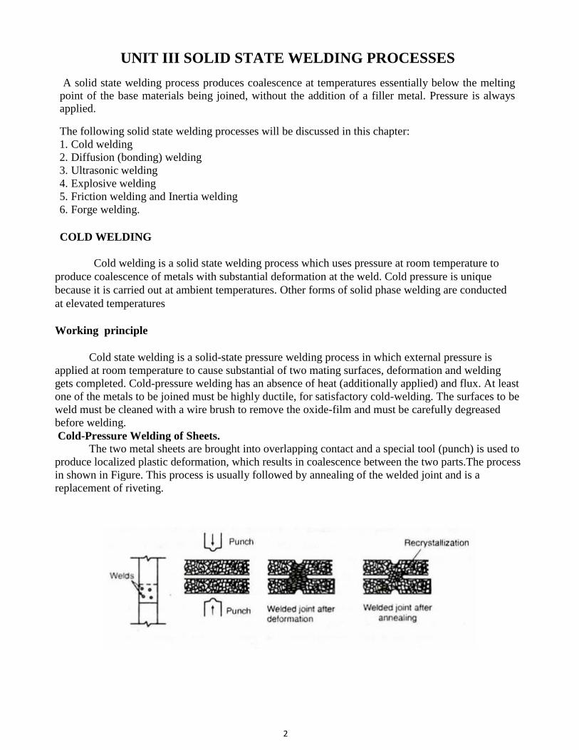
Cold-Pressure Welding of Sheets.
The two metal sheets are brought into overlapping contact and a special tool (punch) is used to
produce localized plastic deformation, which results in coalescence between the two parts.The process
in shown in Figure. This process is usually followed by annealing of the welded joint and is a
replacement of riveting.
3
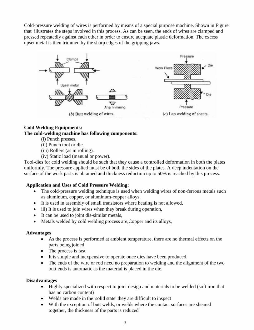
Cold-pressure welding of wires is performed by means of a special purpose machine. Shown in Figure
that illustrates the steps involved in this process. As can be seen, the ends of wires are clamped and
pressed repeatedly against each other in order to ensure adequate plastic deformation. The excess
upset metal is then trimmed by the sharp edges of the gripping jaws.
Cold Welding Equipments:
The cold-welding machine has following components: (i) Punch presses.
(ii) Punch tool or die.
(iii) Rollers (as in rolling).
(iv) Static load (manual or power).
Tool-dies for cold welding should be such that they cause a controlled deformation in both the plates
uniformly. The pressure applied must be of both the sides of the plates. A deep indentation on the
surface of the work parts is obtained and thickness reduction up to 50% is reached by this process.
Application and Uses of Cold Pressure Welding:
The cold-pressure welding technique is used when welding wires of non-ferrous metals such
as aluminum, copper, or aluminum-copper alloys,
It is used in assembly of small transistors where heating is not allowed,
iii) It is used to join wires when they break during operation,
It can be used to joint dis-similar metals,
Metals welded by cold welding process are,Copper and its alloys,
Advantages
As the process is performed at ambient temperature, there are no thermal effects on the
parts being joined
The process is fast
It is simple and inexpensive to operate once dies have been produced.
The ends of the wire or rod need no preparation to welding and the alignment of the two
butt ends is automatic as the material is placed in the die.
Disadvantages
Highly specialized with respect to joint design and materials to be welded (soft iron that
has no carbon content)
Welds are made in the 'solid state' they are difficult to inspect
With the exception of butt welds, or welds where the contact surfaces are sheared
together, the thickness of the parts is reduced
4
DIFFUSION WELDING
Diffusion welding is a solid state welding process which produces coalescence of the surfaces by the
application of pressure and elevated temperatures.The process does not involve microscopic
deformation melting or relative motion of the parts.
This process is used for joining refractory metals at temperatures that do not affect their
metallurgical properties. Heating is usually accomplished by induction, resistance, or
furnace.
Atmosphere and vacuum furnaces are used and for most refractory metals a protective inert
atmosphere is desirable.
Successful welds have been made on refractory metals at temperatures slightly over half the
normal melting temperature of the metal.
To accomplish this type of joining extremely close tolerance joint preparation is required
and a vacuum or inert atmosphere is used.
This process is used quite extensively for joining dissimilar metals.
This process is considered diffusion brazing when a layer of filler material is placed
between the faying surfaces of the parts being joined.
These processes are used primarily by the aircraft and aerospace industries.
Principle and Working:
This process works on basic principle of diffusion. Diffusion means movement of molecules
or atoms from high concentration region to low concentration region. This is fundamental principle
of diffusion welding. In this welding process both the welding plates are placed one over other in
high pressure and temperature for a long period of time. This high pressure force starts diffusion
between interface surfaces. This diffusion can be accelerated by the application of high temperature.
This temperature does not melt the welding plates. The temperature range is about 50-60% of
melting temperature. This whole process takes place in vacuum or in inert environment which
protects the welding plates form oxidation.
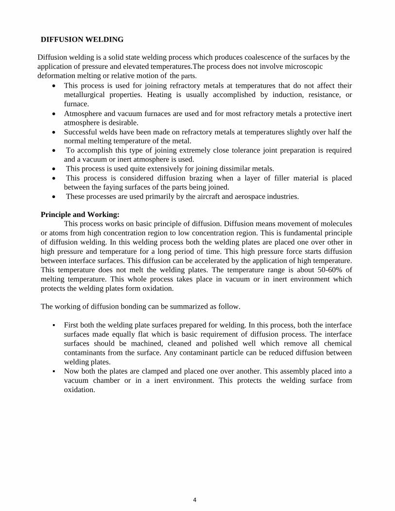
The working of diffusion bonding can be summarized as follow.
First both the welding plate surfaces prepared for welding. In this process, both the interface
surfaces made equally flat which is basic requirement of diffusion process. The interface
surfaces should be machined, cleaned and polished well which remove all chemical
contaminants from the surface. Any contaminant particle can be reduced diffusion between
welding plates.
Now both the plates are clamped and placed one over another. This assembly placed into a
vacuum chamber or in a inert environment. This protects the welding surface from
oxidation.
5
A high pressure and temperature applied on this assembly to start diffusion. The temperature
applied by the furnace heating or electric resistance heating. The high pressure is applied by
a hydraulic press, dead weight or by the differential gas pressure. This conditions are
maintained for a long duration of time for proper diffusion.
At the starting stage of this process, local deformation at the interface surface due to creep
and yield take place. Now the diffusion takes place which form a interface boundary.
After a long period of time, both the plates properly diffused into one another which makes
a strong joint. The interface boundary disappear which form a clean joint. This joint has
same properties or strength as the base material.
Advantages:
The joint have same mechanical and physical properties as parent material.
This process produces clean joint which is free from interface discontinuity and porosity.
Both similar and dissimilar material can be joint by diffusion bonding process.
It provides good dimension tolerance. So it is used to make precision components.
Low running cost.
It is simple in working.
It does not use filler material, flux etc. which are used in arc welding process.
It can weld complex shapes.
Disadvantages:
High initial or setup cost.
It is time consuming process. It takes more time compare to other welding process.
Surface preparations of welding plates are more critical and difficult.
Size of the weld is limited according to equipment available.
This process is not suitable for mass production.
Highly depend on welding parameters like surface finish, welding material, temperature,
pressure etc.
Application:
It is mostly used to weld refectory materials used in aerospace and nuclear industries.
Diffusion bonding is used to weld titanium, zirconium and beryllium metals and its alloy.
It can weld nickel alloy like Inconel, Wrought Udimet etc.
It is used to weld dissimilar metals like Cu to Ti, Cu to Al etc.
EXPLOSIVE WELDING
Explosion welding is a solid-state process that produces a high velocity interaction of
dissimilar metals by a controlled detonation
Oxides found on material surfaces must be removed by effacement or dispersion
Surface atoms of two joining metals must come into intimate contact to achieve metallic
bond
Component Terminology:
Base component
Joined to cladder
6
Remains stationary
Supported by anvil
Cladding metal
Thin plate in direct contact with explosives
Can be shielded by flyer plate
Flyer plate
Sacrificial plate placed between explosive material and cladder plate
Used to protect cladder metal
Interlayer
Thin metal layer
Enhances joining of cladder to base plate
Anvil
Surface of which the backer rests during explosion
Standoff
Distance between cladder and base plate before explosion
Bond Window
A range of variable in process such as velocity, dynamic bend, and standoff distance
that result in successful weld
Bonding Operation
Detonation of explosives that result in a weld
Principle of Explosion
Cladder metal can be placed parallel or inclined to the base plate
Explosive material is distributed over top of cladder metal
Upon detonation, cladder plate collides with base plate to form weld
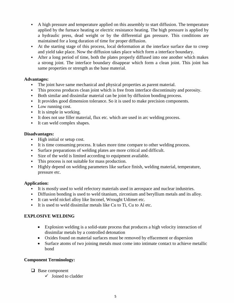
Placement of Cladder metal-parallel
Standoff distance predetermined and unique to material combination
Achieved by placing shims between plates
Shims designed to be consumed by explosion wave and do not affect weld
7
Explosive welding is mainly used for cladding processes. Nearly all kinds of metals
and alloys allowing more than 5% of strain may be joined by this
technique. Titanium explosive cladded tank bottoms have successfully withstood testing by
use in chemical apparatus.
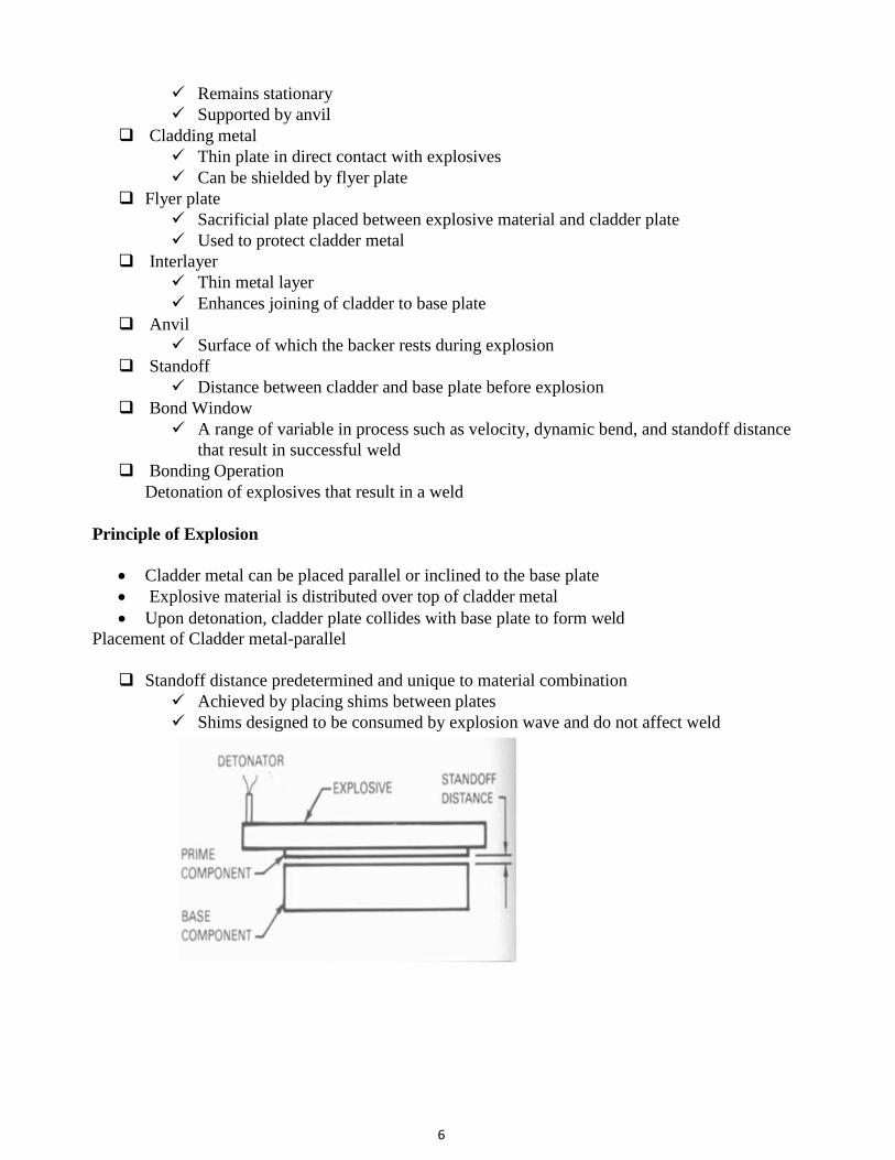
In explosive welding, a compression force created by detonation of explosives is
used to join overlapping metal sheets. The joining parts are arranged towards each other at
an angle of 1–15°, depending on the material and method, and are prepared with a layer of
explosive on the top. After ignition the joining areas are moved against each other at high
speed. Joining happens continuously by local plastic deformation of the contact area The
thickness of the cladding may vary between 0.1 and 30 mm and the detonation velocity is
between 1200 and 7000 ms−1. The top plate hits the bottom plate with a speed of 100–
1000 ms−1, and pressures are in the range of 10 to 100 kbar. Under certain conditions a
superheated layer of material forms in the contact area. The joint is then caused by
a deformation-induced melting bath. The melt layer is quite thin; for example, when
cladding an aluminum alloy it is about 0.5–4μm. The dilution of the molten zones results in
plane or corrugated interfaces.
In contrast to surface-layer welding, explosive welding causes no change
in microstructure, and corrosion resistance of the layers is not affected.
The following diagram shows the placement of Cladder metal-parallel – Angled
Applications
Any metal with sufficient strength and ductility can be joined
Can weld large areas of metal
Can weld inside and outside surfaces of pipes
Transition joints can be made
(see Fig. 1).
8
Advantages:
1. No heat-affected zone (HAZ) Only minor melting
2. Material melting temperatures and coefficients of thermal expansion differences do not
affect the final product
3. The shock front compresses and heats the explosive material which exceeds the sonic
velocity of undetonated explosives.
Disadvantages:
1. Brittle materials (low ductility and low impact toughness) cannot be processed;
2. Only simple shape parts may be bonded: plates, cylinders;
3. Thickness of flyer plate is limited - less than 2.5” (63 mm);
4. Safety and security aspects of storage and using explosives.
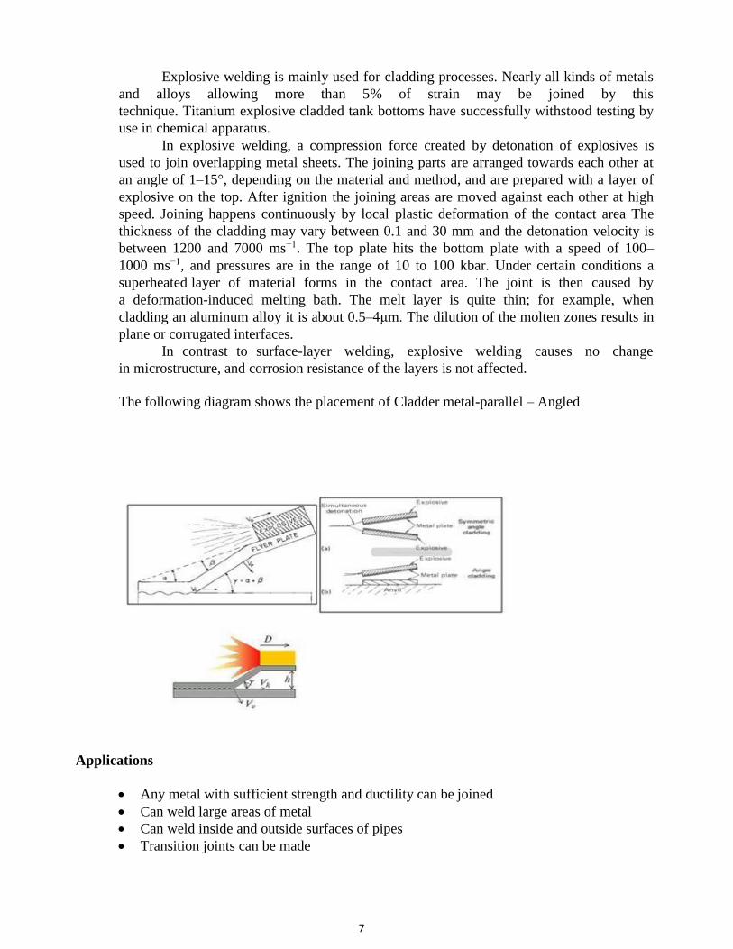
Following table shows typical metal combinations that can be explosion welded
Electrochemical
Oil & Gas
Power Generation
Cryogenic Processing
Pulp & Paper
Air conditioning & Chillers
Metal Production
Common industries that use explosion welding are as follows.
Chemical Processing
Petroleum Refining
Hydrometallurgy
Aluminum Smelting
Shipbuilding

9
ULTRASONIC WELDING
A solid state welding process in which coalescence is produced at the faying surfaces by the
application of high frequency vibratory energy while the work pieces are held together under
moderately low static pressure.
Ultrasonic welding is a welding technique whereby high-frequency ultrasonic acoustic
vibrations are locally applied to work pieces being held together under pressure to create a solid
state weld. The following figure shows the working of Ultrasonic welding
Principle:
It works on the basic principle of energy of ultrasonic wave. Ultrasonic vibration creates a
dynamic shear stress between the contacts of two work piece. Due to local plastic deformation and
heat generate due to friction between contact surfaces, joint formation will take place at the
interface.
Main Parts:
1. A Press: It is used to apply pressure on the two plastic pieces to be joined. It may be of
pneumatic or electric driven type.
2. Nest or anvil or fixture: It is a clamping device that is used to hold and clamp the two plastic
pieces together. It allows the high-frequency vibration directed to the interface of the two
pieces.
10
3. An Ultrasonic Stack: It consists of the three components, a converter or piezoelectric
transducer, a booster and a horn or sonotrode. These three elements are tuned to work on
resonate frequency of 15 kHz, 20 kHz, 30 kHz, 35 kHz or 40 kHz.
Converter: It converts the electrical signals into high-frequency mechanical vibration. And it
does so through the piezoelectric effect.
Booster: It modifies the amplitude of vibration mechanically. In some standard systems, it is
used to clamp the stack in the press.
Horn or Sonotrode: It vibrates at high frequency and transmits the mechanical vibration to
the two pieces to be welded. It also modifies the amplitude mechanically. It takes the shape
of the part. The horn is made of titanium or aluminum.
4. An Ultrasonic Generator: It generates and delivers high-frequency electrical signals
matching the resonance frequency of the stack.
5. Controller: It is used to control the movement of the press and delivery of the ultrasonic
energ
Working:
At the start, high frequency current passes through a piezoelectric transducer. This
transducer converts high frequency electrical signal into mechanical vibration.
A static clamping force is applied perpendicular to the interface between the work pieces.
The contacting sonotrode oscillates parallel to the interface.
Combined effect of static and oscillating force produces deformation which promotes
welding.
The amplified high frequency vibration passes through horn which is in contact with
welding plate.
This welding creates lap joint. One plant of the weld is fixed into fixture and other one is in
direct contact with horn. These plates are fixed under moderate pressure force.
The horn supply high frequency mechanical vibration to the welding plate.
Due to this vibration, oscillation shear force act at the interface between welding plates
which result elestoplastic deformation at interface.
It also create a localize temperature rise due to mechanical force and friction. This heat helps
in plastic deformation at interface and makes a strong joint without melting of work piece or
using filler metal.
Advantages
No heat is applied and no melting occurs.
Permits welding of thin to thick sections.
Welding can be made through some surface coatings.
Pressures used are lower, welding times are shorter, and the thickness of deformed
regions are thinner than for cold welding.
It is much faster than conventional adhesives or solvents.
Drying time is very quick
Site of weld is very clean and rarely requires any touch-up work
Limitations
The thickness of the component adjacent to the sonotrode tip must not exceed relatively thin
gages because of power limitations of the equipment.
Process is limited to lap joints.
11
Butt welds can not be made because there is no means of supporting the workpieces and
applying clamping force
This process is limited to small welds of thin, malleable metals
Eg: Aluminium, Copper, Nickel.
Ultrasonic would not be used in welding, pieces of a bicycle or automobile together, due to
the power levels required.
Applications
Assembling of electronic components such as diodes and semiconductors with substrates.
Electrical connections to current carrying devices including motors, field coils, and
capacitors.
Encapsulation and packaging.
Plastic parts
Microcircuit connections, sheet metal, foils, ribbons and meshes are often joined using
ultrasonic welding
This type of welding is often used to build assemblies that are too small, too complex, or too
delicate for more common welding techniques.
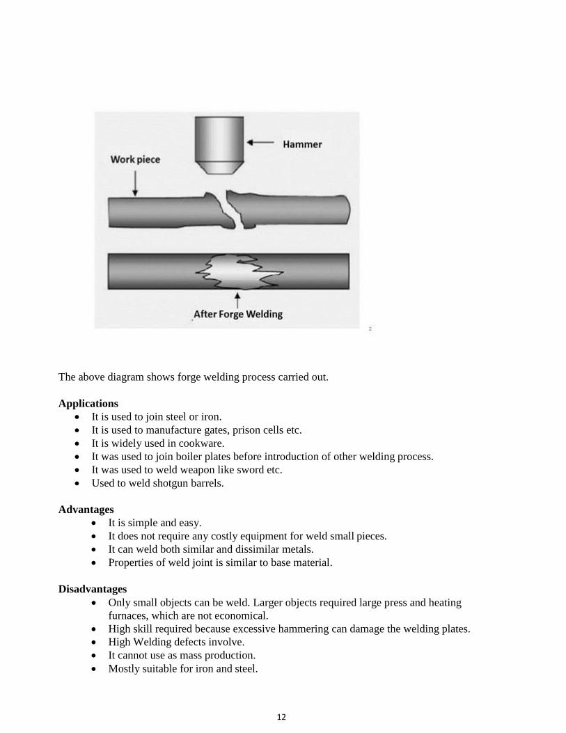
FORGE WELDING
Forge welding is a solid state welding process in which both the plates are heated quite
below its melting temperature. This heating deforms the work pieces plastically. Now a repeated
hammering or high pressurize load is applied on these plates together.
Due to this high pressure and temperature, inter-molecular diffusion takes place at the
interface surface of the plates which make a strong weld joint
One of the basic requirement of this type of welding, is clean interface surface which
should be free from oxide or other contaminant particles
To prevent the welding surface from oxidation, flux is used which mixes with the oxide
and lower down its melting temperature and viscosity. This allow to flow out the oxide
layer during heating and hammering process.
Working:
First both the work plates heated together. The heating temperature is about 50 to 90%
of its melting temperature. Both the plates are coated with flux.
Now manual hammering is done by a blacksmith hammer for making a joint. This
process is repeated until a proper joint is created.
For welding large work pieces, mechanical hammering is used which is either driven by
electric motor or by using hydraulic mean. Sometime dies are used which provides
finished surface.
No filler material required.
12
The above diagram shows forge welding process carried out.
Applications
It is used to join steel or iron.
It is used to manufacture gates, prison cells etc.
It is widely used in cookware.
It was used to join boiler plates before introduction of other welding process.
It was used to weld weapon like sword etc.
Used to weld shotgun barrels.
Advantages
It is simple and easy.
It does not require any costly equipment for weld small pieces.
It can weld both similar and dissimilar metals.
Properties of weld joint is similar to base material.
Disadvantages
Only small objects can be weld. Larger objects required large press and heating
furnaces, which are not economical.
High skill required because excessive hammering can damage the welding plates.
High Welding defects involve.
It cannot use as mass production.
Mostly suitable for iron and steel.
13
It is a slow welding process.
FRICTION WELDING
Friction welding (FW) is a class of solid-state welding processes that generates heat through mechanical friction between a moving workpiece and a stationary component, with the
addition of a lateral force called "upset" to plastically displace and fuse the materials. Technically,
because no melt occurs, friction welding is not actually a welding process in the traditional sense, but a forging technique. However, due to the similarities between these techniques and traditional
welding, the term has become common. Friction welding is used with metals and thermoplastics in a wide variety of aviation and automotive applications.
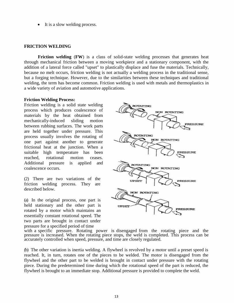
Friction Welding Process:
Friction welding is a solid state welding
process which produces coalescence of
materials by the heat obtained from
mechanically-induced sliding motion
between rubbing surfaces. The work parts
are held together under pressure. This
process usually involves the rotating of
one part against another to generate
frictional heat at the junction. When a
suitable high temperature has been
reached, rotational motion ceases.
Additional pressure is applied and
coalescence occurs.
(2) There are two variations of the friction welding process. They are described below.
(a) In the original process, one part is held stationary and the other part is
rotated by a motor which maintains an
essentially constant rotational speed. The two parts are brought in contact under
pressure for a specified period of time with a specific pressure. Rotating power is disengaged from the rotating piece and the pressure is increased. When the rotating piece stops, the weld is completed. This process can be accurately controlled when speed, pressure, and time are closely regulated.
(b) The other variation is inertia welding. A flywheel is revolved by a motor until a preset speed is
reached. It, in turn, rotates one of the pieces to be welded. The motor is disengaged from the
flywheel and the other part to be welded is brought in contact under pressure with the rotating piece. During the predetermined time during which the rotational speed of the part is reduced, the
flywheel is brought to an immediate stop. Additional pressure is provided to complete the weld.

14
(c) Both methods utilize frictional heat and produce welds of similar quality. Slightly better control is claimed with the original process. The two methods are similar, offer the same welding advantages, and are shown by figure.
The Friction Welding Process
1. Initial Situation:
Both workpieces are firmly clamped into the machine; one workpiece is rotated.
2. Heat Build-up:
The two workpieces are pressed together with a defined force; the rotation and contact force
generate friction which causes the weld surfaces to heat up.
3. Welding:
At a defined moment in time, the rotating workpiece is braked and the contact pressure is increased. This creates the friction-welded joint
Materials Welded by Friction and Inertia Welding - Materials that can be friction/inertia
welded are listed below:
(i) Aluminium and its alloys
(ii) Nickel alloys
(iii) Brass and bronze
(iv) Alloy steels
(v) Magnesium alloys
(vi) Carbon steels
(vii) Stainless steel
(viii) Tool steel
(ix) Tantalum
(x) Titanium alloys
(xi) Tungsten
(xii) Zirconium alloys
(xiii) Alloy steel to carbon steel
(xiv) Copper to carbon steels
(xv) Super alloys to carbon steels
(xvi) Stainless steel to carbon steels
(xvii) Sintered steels to carbon steels
(xviii) Aluminium to stainless steels
(xix) Copper to aluminium, etc.
In general, all forgeable materials which are not good dry bearing materials, can be easily welded. Cast iron in any form is not weldable because the free graphite acts as lubricant and limits frictional heating
15
Advantages :
Simplicity of operation. (i) Low power requirements.
(ii) Once the welding parameters for a job have been determined, the welding takes only a few seconds.
(iii) Surface impurities and oxide films are broken up and thrown off during the friction heating process.
(iv) As compared to conventional flash or resistance butt welding, friction/inertia welding produces improved welds at higher speed and lower cost, less electric current is required, and costly copper fixtures to hold components are eliminated.
(v) Heat is localized at the weld and is quickly dissipated so that there is only a slight effect on the parts joined. The heat affected zone adjacent to the weld is confined to a narrow band and
therefore does not affect the temper of the surrounding area.
The weld may not have to be heat treated.
(vi) With inertia/friction welding there is less shortening of the component, as compared to that in flash or butt welding.
(vii) Repeatability is reported as excellent, and several jobs have been fully automated.
(viii) There is no flux, gas, filler metal or slag present to cause imperfections in welds. Also no smoke, fumes or spatter are produced.
Disvantages of Friction / Inertia Weding
(i) The use of this process is restricted to flat and angular butt welds, where one part is normal to the other part.
(ii) So far the process has been applied only to the joining of small pieces in the form of bar stock.
(iii) Sometimes, quite a heavy flash is forced out in all inertia and friction welds.
(iv) If tubing is welded, flash may have to be removed from inside the joint.
(v) Flash from medium and high carbon steels being hard, must either be removed while it is hot or annealed before it is machined.
(vi) Thrust pressures in inertia welding will range from 700 to 2800 kg/cm2, which requires
a heavy rigid machine
Applications of Friction OR Inertia Welding
(i) Friction/inertia welding is finding varied applications for joining steels, super alloys, non ferrous metals and combinations of metals.
(ii) It frequently replaces brazing and (metallic) are, electron beam, pressure, flash or resistance butt welding.
(iii) Among its varied applications are:
Roll Welding (ROW)
Roll welding is a solid state welding process which produces coalescence of metals by heating and
by applying pressure with rolls sufficient to cause deformation at the faying surfaces. This process
is similar to forge welding except that pressure is applied by means of rolls rather than by means of
hammer blows. Coalescence occurs at the interface between the two parts by means of diffusion at
the faying surfaces.
16
Terminology:
The most common terminologies used in rolling process are given below. Ingot: It is casted structure with porosity and blowholes. Ignot is same as used in forging. This
ingot is rolled out at hot temperature of about 1200 degree centigrade into blooms. This ingot may
have any size according to the rolling requirement.
Blooms: It is first rolled product making by rolling ingot at high temperature. It has cross section
area more than or equal to 230 square centimeters. This bloom is further rolled to make I section,
billet, channel, railroad etc.
Slab: Slab is made by hot rolling of ingot. It has cross section area greater than or equal to 100
centimeters square and its width is greater than or equal to three times of its thickness. Slabs are
used to form plates, sheets, strips etc.
Billets: Billets are product of hot rolling of blooms. It has greater than or equal to 40 square
centimeters cross section area. Billets are used to roll into pipes, bars, wire etc.
Plate: Plate is product of further rolling of slab. It has greater than 6 mm thickness.
Sheet: Sheet has less than 6 mm thickness and width greater than 60 cm.
Strip: Strip is same as sheet but have width less than 60 cm.
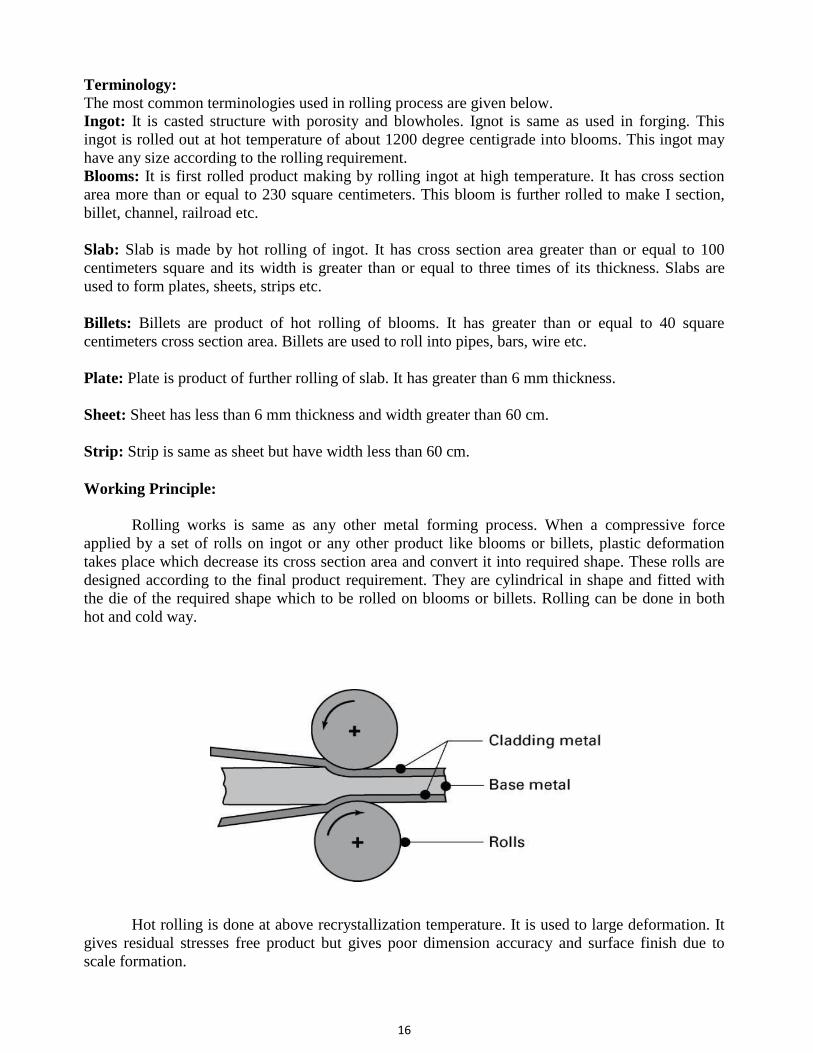
Working Principle:
Rolling works is same as any other metal forming process. When a compressive force
applied by a set of rolls on ingot or any other product like blooms or billets, plastic deformation
takes place which decrease its cross section area and convert it into required shape. These rolls are
designed according to the final product requirement. They are cylindrical in shape and fitted with
the die of the required shape which to be rolled on blooms or billets. Rolling can be done in both
hot and cold way.
Hot rolling is done at above recrystallization temperature. It is used to large deformation. It
gives residual stresses free product but gives poor dimension accuracy and surface finish due to
scale formation.

17
Cold rolling is another method witch is done at below recrystallization temperature. It is
done to get final product. This process gives high mechanical strength, dimension accuracy and
surface finish.
Application:
Rolling is used for making hollow seamless tubes, rods etc. Large length cross sections are produced by rolling process.
It is use for mass production of threaded parts like screw, bolts etc.
Gears can be cut on gear blank by rolling process.
Construction material, roofing panels, partition beams, railroads, etc. are rolling product.
It is used in automotive industries for manufacture various parts.
Rings of turbines, bearing and other machines are rolling product.
Steel sheets, plates are made by rolling process.
Advantages:
High rate of production.
Good finish and good dimensional accuracy.
Suitable for among others, the production of foils, plates and sheets.
Disadvantages:
Deformation limited to small reductions It is limited to only a few shapes and their variations such like square, round, and flat.
High cost of equipment
Hot pressure welding processes
Hot-pressure-welding is a solid state process that produces joints between the faying
surfaces of two bodies. It is done by application of heat and pressure. Fusion temperature is not
reached, filler metal is not needed, substantial plastic deformation is generated. Heat is generally
applied by flames of oxyfuel torches directed on the end surfaces of solid bars or hollow sections to
be joined.Alternatively, heat can be generated by eddy currents caused by electrical induction from
a suitable inductor coil.
Hot-pressure-welding: Heat and Squeeze
As soon as the two bodies facing ends reach the correct temperature, the torches are
suddenly removed, not to stand in the way. The bodies are brought to contact and upset
together under pressure, usually by hydraulic equipment. This variant is properly called the open
joint process. If the parts are making contact under pressure before heat application from the
outside, it is called the closed joint process. In either case flash material is expelled and a bulge is
formed at the joint. Hot-pressure-welding is similar in a way to both friction welding (see Friction
Welding Processes) and flash welding (see Flash Welding Process), although the source of heating
is different. For obtaining the best results the surfaces should be machined square and clean. Some
beveling can be used to control the amount of upset.
18
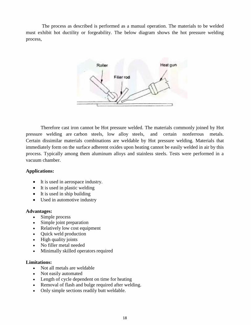
The process as described is performed as a manual operation. The materials to be welded
must exhibit hot ductility or forgeability. The below diagram shows the hot pressure welding
process,
Therefore cast iron cannot be Hot pressure welded. The materials commonly joined by Hot
pressure welding are carbon steels, low alloy steels, and certain nonferrous metals.
Certain dissimilar materials combinations are weldable by Hot pressure welding. Materials that
immediately form on the surface adherent oxides upon heating cannot be easily welded in air by this
process. Typically among them aluminum alloys and stainless steels. Tests were performed in a
vacuum chamber.
Applications:
It is used in aerospace industry.
It is used in plastic welding
It is used in ship building
Used in automotive industry
Advantages:
Simple process Simple joint preparation
Relatively low cost equipment
Quick weld production
High quality joints
No filler metal needed
Minimally skilled operators required
Limitations:
Not all metals are weldable Not easily automated
Length of cycle dependent on time for heating
Removal of flash and bulge required after welding.
Only simple sections readily butt weldable.
19
ADVANTAGES, LIMITATIONS AND APPLICATIONS OF SOLID STATE WELDING PROCESS
Advantages
Solid state welding can be easily automated.
This produces high strength joint without applying external heat.
They are used to weld both similar and dissimilar material.
Provide good surface finish.
They does not use any filler metal or flux as used in arc welding.
Mostly these processes do not affect properties of parent materials.
Limitations
High equipment cost or set up cost.
Welding preparation is more critical.
Complicated and special fixtures are required for different process.
Mostly, these process can't be used for mass production due to slow welding speed.
Applications
Solid state welding's are used in every where in mechanical industries.
It is widely used in aerospace and marine industries for structure work.
It is widely used in automobile industries for most of fabrication work.
Explosive welding used to join large welding plate which can’t be possible or
uneconomical by other methods like arc welding or gas welding.
Friction welding is used to join tubes, shaft etc.
These process are further used to join dissimilar material used in various industries.
Hydraulic piston, connecting rod, drive line, truck roller bushes, pump shaft, gear lever,
drill bit etc. are friction welded