valliammai engineering college - Vidyarthiplus
24
VALLIAMMAI ENGINEERING COLLEGE SRM Nagar, Kattankulathur – 603 203. DEPARTMENT OF ELECTRONICS & COMMUNICATION ENGINEERING QUESTION BANK SUBJECT : EC6405 – CONTROL SYSTEM ENGINEERING SEM / YEAR: IV / II year B.E. EC6405 CONTROL SYSTEM ENGINEERING UNIT I – CONTROL SYSTEM MODELLING Basic Elements of Control System – Open loop and Closed loop systems - Differential equation - Transfer function, Modeling of Electric systems, Translational and rotational mechanical systems - Block diagram reduction Techniques - Signal flow graph PART A Q.No Questions BT Level Domain 1. Compare the Open loop System with Closed loop System. BTL 4 Analyzing 2. Design the Electrical analogous network for the mechanical system shown in the fig. using Force-Voltage Analogy. BTL 6 Creating 3. Mention the transfer Function of the System. BTL 1 Remembering 4. List the advantages of Closed loop System? BTL 1 Remembering 5. What are the Properties of Signal flow graphs? BTL 1 Remembering www.Vidyarthiplus.com www.Vidyarthiplus.com
-
Upload
khangminh22 -
Category
Documents
-
view
1 -
download
0
Transcript of valliammai engineering college - Vidyarthiplus

VALLIAMMAI ENGINEERING COLLEGE SRM Nagar, Kattankulathur – 603 203.
DEPARTMENT OF ELECTRONICS & COMMUNICATION ENGINEERING
QUESTION BANK
SUBJECT : EC6405 – CONTROL SYSTEM ENGINEERING SEM / YEAR: IV / II year B.E.
EC6405 CONTROL SYSTEM ENGINEERING
UNIT I – CONTROL SYSTEM MODELLING
Basic Elements of Control System – Open loop and Closed loop systems - Differential equation - Transfer
function, Modeling of Electric systems, Translational and rotational mechanical systems - Block diagram
reduction Techniques - Signal flow graph PART A
Q.No Questions BT
Level
Domain
1. Compare the Open loop System with Closed loop System. BTL 4 Analyzing
2. Design the Electrical analogous network for the mechanical
system shown in the fig. using Force-Voltage Analogy.
BTL 6 Creating
3. Mention the transfer Function of the System. BTL 1 Remembering
4. List the advantages of Closed loop System? BTL 1 Remembering
5. What are the Properties of Signal flow graphs? BTL 1 Remembering
www.Vidyarthiplus.com
www.Vidyarthiplus.com

6. Give Mason’s gain formula of Signal flow graph. BTL 2 Understanding
7. Explain any two dynamic models to represent control system. BTL5 Evaluating
8. Discuss about the block diagram and its components of a
control system.
BTL 2 Understanding
9. Demonstrate the basic elements used for modelling a
mechanical rotational system.
BTL 3 Applying
10. Assess feedback and its types employed in Control system. BTL 4 Analyzing
11. Negative feedback is preferred in control system. Justify BTL 5 Evaluating
12. Write F-V Analogy for the elements of mechanical rotational
system?
BTL 1 Remembering
13. Illustrate any two rules to be followed in block diagram reduction
techniques.
BTL 3 Applying
14. Define Control System BTL 1 Remembering
15. Analyze non-touching loops. BTL 4 Analyzing
16. Interpret signal flow graph BTL 2 Understanding
17. Name the two types of electrical analogous for mechanical
system.
BTL 1 Remembering
18. Formulate force balance equation of ideal spring, ideal mass. BTL 6 Creating
19. Calculate transfer function of the network
BTL3 Applying
20. Describe mathematical model of a system. BTL 2 Understanding
PART –B
1. (i) How could you determine the Transfer Function of the
system Shown in the fig. (7)
www.Vidyarthiplus.com
www.Vidyarthiplus.com

(ii) Estimate the Transfer function of the electrical network
shown in the fig. (6)
BTL 5
Evaluating
2. (i) Design the Block diagram to its Canonical form and obtain
C(s)/R(s). (8)
(ii) Compile the differences between block diagram and Signal
flow graph methods. (5)
BTL 6
Creating
3. Solve C/R for the signal flow graph shown below. (13)
BTL 3
Applying
4. (i) Consider the Mechanical system shown below and write
the Differential equation. (7)
BTL1
Remembering
www.Vidyarthiplus.com
www.Vidyarthiplus.com

(ii) Draw the torque-voltage electrical analogous circuit for the
mechanical system shown below. (6)
5. (i) State any five block diagram reduction rules with example.
(8)
(ii) Mention in detail about any five terminologies used in
signal flow graph. (5)
BTL1
Remembering
6. (i) Can you discover the Equivalent signal flow graph and
obtain C/R using mason’s gain formula for the block diagram
show below. (6)
(ii) For the block diagram shown below, inspect the output
C/R. (7)
BTL4
Analyzing
www.Vidyarthiplus.com
www.Vidyarthiplus.com

7. Using SFG, Analyze the overall Transfer function for the
system shown in the fig. (13)
BTL4
Analyzing
8. How can you explain the differential equations governing the
mechanical rotational system shown in Fig. and estimate the T-
V and T-I electrical analogous circuits. (13)
BTL 1 Remembering
9. Demonstrate the differential Equations governing the
mechanical system shown in the fig. and determine the transfer
function. (13)
BTL2
Understanding
10. Estimate the overall transfer function of the system shown in
the fig.
BTL2
Understanding
www.Vidyarthiplus.com
www.Vidyarthiplus.com

Fig(i) (7)
(8)
(ii)Estimate the overall transfer function of the system shown
in the fig.
Fig(i) (6)
(5)
11. (i) Recall the functional blocks of closed loop feedback control
system. (6)
(ii) Give the step by step procedure of determining the transfer
function from the signal flow graph. (7)
BTL1
Remembering
12. (i)A certain system is described by the differential
equation𝑑2𝑦
𝑑𝑡2+
14𝑑𝑦
𝑑𝑡+ 40𝑦 = 5 . What is the relationship to
y(t), assuming initial conditions to be zero. (6)
(ii) Analyze the transfer function of the electric circuit shown
in figure (7)
BTL 4 Analyzing
www.Vidyarthiplus.com
www.Vidyarthiplus.com

13. Identify the transfer function of the system shown in figure
using block diagram reduction technique and signal flow
graph technique. (13)
BTL 3 Applying
14. (i) Explain with a neat block diagram explain the working of
Armature controlled DC motor as a control system. (5)
(ii) Translate to the signal flow graph for the following system
and obtain the transfer function using mason gain formula. (8)
4452255
4443342244
4432233
3322221122
xaxax
xaxaxax
xaxax
xaxaxax
BTL 2 Understanding
PART –C
1. Deduce the transfer function of system shown in figure (15)
BTL 6 Creating
www.Vidyarthiplus.com
www.Vidyarthiplus.com
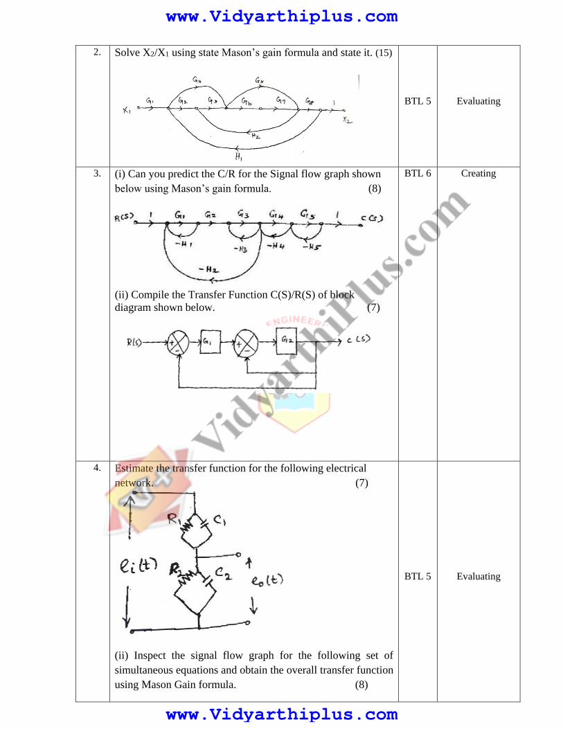
2. Solve X2/X1 using state Mason’s gain formula and state it. (15)
BTL 5 Evaluating
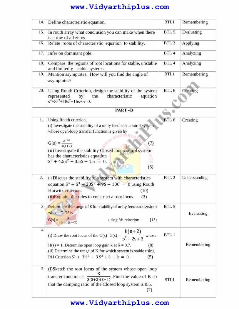
3. (i) Can you predict the C/R for the Signal flow graph shown
below using Mason’s gain formula. (8)
(ii) Compile the Transfer Function C(S)/R(S) of block
diagram shown below. (7)
BTL 6
Creating
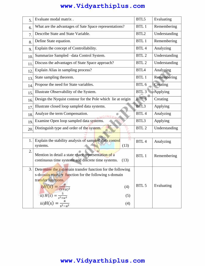
4. Estimate the transfer function for the following electrical
network. (7)
(ii) Inspect the signal flow graph for the following set of
simultaneous equations and obtain the overall transfer function
using Mason Gain formula. (8)
BTL 5 Evaluating
www.Vidyarthiplus.com
www.Vidyarthiplus.com

3432424
3332321313
3231212
XAXAX
XAXAXAX
XAXAX
UNIT II TIME RESPONSE ANALYSIS
Time response analysis - First Order Systems - Impulse and Step Response analysis of second order
systems - Steady state errors – P, PI, PD and PID Compensation, Analysis using MATLAB PART A
Q.No Questions BT
Level
Domain
1. Illustrate how a Control system is classified depending on
the value of damping ratio?
BTL 3 Applying
2. List the advantages of generalized error coefficients. BTL 1 Remembering
3. Generalize why derivative controller is not used in Control
systems.
BTL 6 Creating
4. Give steady state errors to a various standard inputs for type
2 systems.
BTL 2 Understanding
5. Determine the Damping ratio and natural frequency of
oscillation for the closed loop transfer function of a second
order system is given by 40022
400
SS
BTL 5 Evaluating
6. What is meant by peak overshoot? BTL 1 Remembering
7. Mention steady state error. BTL 1 Remembering
8. Define rise time. BTL 1 Remembering
9. The damping ratio and natural frequency of a second order
system are 0.5 and 8 rad/sec respectively. Calculate resonant
peak and resonant frequency.
BTL 3 Applying
10. With reference to time response, Examine peak time. BTL 4 Analyzing
www.Vidyarthiplus.com
www.Vidyarthiplus.com

11. Describe the transient and steady state response of control
system?
BTL 2 Understanding
12. Give the units of kp, kv, ka . BTL 2 Understanding
13. Outline the response of the second order under damped
system.
BTL 2 Understanding
14. Point out the time domain specifications. BTL 4 Analyzing
15. Summarize the generalized error and static error constants. BTL 5 Evaluating
16. Compare position, velocity error constants. BTL 4 Analyzing
17. Define damping ratio. BTL 1 Remembering
18. Demonstrate the test signals used in time response analysis. BTL 3 Applying
19. Label a step signal. BTL 1 Remembering
20. Formulate ramp, parabolic and impulse signal. BTL 6 Creating
PART –B
1. Explain how PI, PD and PID compensation will improve the
time response of a system with a neat block diagram and
derivation. (13)
BTL 1 Remembering
2. The Unity feedback system is characterized by the open loop
transfer function G(𝑆) =𝑘
𝑠(𝑠+10) . Estimate the gain K, so
that the system will have the damping ratio of 0.5. For this
value of K, Determine the settling times, peak overshoot, and
time to peak overshoot for a unit step input. (7)
ii) The open loop transfer function of a servo system with
unity feedback is G(s) =10
s(0.1s+1). Determine the static
error constants of the system. Obtain the steady state error of
the system, when subjected to an input given by
r(t) = 2 + 4t + (t2
6) (6)
BTL2
Understanding
3. How will you explain the meaning of for Rise time, fall
time, settling time, peak overshoot with expressions. (13) BTL 2 Understanding
4. The open loop transfer function of a unity feedback control
system is given by 𝐺(𝑆) = 𝑘
𝑠(𝑠𝑇+1) where K and T are
positive constants. Illustrate by what factor the amplifier
Applying
www.Vidyarthiplus.com
www.Vidyarthiplus.com

gain should be reduced so that the peak overshoot of unit
step response of the system is reduced from 75% to 25%.(7)
ii) A certain unity negative feedback control system has the
following forward path transfer function
G(s) =K(s+2)
s(s+5)(4s+1). The input applied is r(t) = 1 + 3t.
Find the minimum value of K so that the steady state error is
less than 1. (6)
BTL3
5.
Consider a Second order model 222
2
)(
)(
ns
ns
n
SR
SY
0 < 𝜀 < 1. Determine the response y (t) to a unit step input.
(13)
BTL 5
Evaluating
6. (i) A unit ramp input is applied to a unity feedback system
whose output response is𝐂(𝐬) =𝟏𝟎𝟎
𝐬𝟐+𝟓𝐬+𝟏𝟎𝟎. Analyze the
time response and steady state error. (6)
(ii) For a unity feedback control system the open loop transfer
function
𝐆(𝐬) =𝟏𝟎(𝐬+𝟐)
𝐬𝟐(𝐬+𝟏).Calculate Kp, KV, Ka and the steady state
error when the input is R(s) where𝐑(𝐬)2 3
3 2 1
3s s s . (7)
BTL 4
Analyzing
7. (i)Develop an Expression to find steady state error of closed
loop system. (6)
(ii) A unity feedback system has the forward transfer function
2)1(
.)(
S
SKSG
for the input r(t) = 1 + 5t, formulate the
minimum value of K so that the steady state error is < 0.1.
(Use final value theorem). (7)
BTL 6 Creating
8. Derive the time response analysis of a first order system for
step and ramp input. (13)
BTL1 Remembering
9. With a neat diagram explain the function of PID
compensation in detail. (13)
BTL1 Remembering
www.Vidyarthiplus.com
www.Vidyarthiplus.com

10. (i) What inference can you make about the unit step response
of the control system shown in the fig. (6)
(ii) The open loop transfer function of a unity feedback
system is given by )2(
20)(
SSSG .The input function
is r(t) = 2 + 3t + t2 . Examine the generalized error
coefficient and steady state error. (7)
BTL 4 analyzing
11. (i) A unity feedback system with unit step input for which
open loop transfer 𝐺(s) =16
s(s+8).Solve for the transfer
function, the natural Frequency, the damping ratio and the
damped frequency of oscillation. (7)
(ii) Calculate the delay time, rise time and peak overshoot
for the system whose natural frequency of oscillation is
10rad/s and damping factor 0.707. (6)
BTL 3 Applying
12. The unity feedback system is characterized by an open loop
transfer function 2)1)(15(
)12()(
sss
sKSG
with
r(t) = (1 + 6t). Estimate the minimum value of K if the
steady error is to be less than 0.1. (13)
BTL2 Understanding
13. Analyze the steady state errors for unit step, unit ramp and
unit acceleration input. For a unity feedback system
characterized by the open loop transfer function
G(s) =1
s(0.5s+1)(0.2s+1). Also determine the damping
ratio and natural frequency of dominant errors. (13)
BTL 4 Analyzing
14. 12
(i) What are the various standard test signals? Draw the
characteristics diagram and obtain the mathematical
representation of all. (7)
(ii). Write the response of undamped second order system for
unit step input. (6)
BTL 1 Remembering
www.Vidyarthiplus.com
www.Vidyarthiplus.com

PART –C
1. Determine the open loop transfer function for a unit feedback
control system with unit impulse response given by
c(t) = −te−t + 2e−t for (t>0). (15)
BTL 5 Evaluating
2. (i)A certain unity negative feedback control system has the
following open loop transfer function
G(s) =10(s+10)
s(s+2). Derive an expression for the output
variable as a function of time when the input applied is unit
step. What is the percentage overshoot, peak time and rise
time? (7)
(ii)For unity feedback system having
)10)(3(
)1(5)(
2
sss
ssG . Determine the type of system, error
coefficients and the steady state error, r (t) = 1 + 3t + (t2
2).
(8)
BTL 6 Creating
3. (i) Discuss the effect of derivative control on the
performance of a second order system. (8)
(ii) Figure shows PD controller used for a system
What would happen to the value of Td so when the system
will be critically damped. Calculate it’s settling time. (7)
BTL 6 Creating
4. An unity feedback control system is show in the fig. By using
derivative control the damping ration is to be made 0.8.
Evaluate the value of Td with and without derivative control
(15)
BTL 5 Evaluating
www.Vidyarthiplus.com
www.Vidyarthiplus.com

UNIT III FREQUENCY RESPONSE ANALYSIS
Frequency Response - Bode Plot, Polar Plot, Nyquist Plot - Frequency Domain specifications
from the plots - Constant M and N Circles - Nichol‟s Chart - Use of Nichol‟s Chart in Control
System Analysis. Series, Parallel, series-parallel Compensators - Lead, Lag, and Lead Lag
Compensators, Analysis using MATLAB. PART A
Q.No Questions BT
Level
Domain
1. Derive the transfer function of a lead compensator network. BTL 6 Creating
2. Define Phase margin & gain margin. BTL 1 Remembering
3. Illustrate the need for compensation. BTL3 Applying
4. What is Nyquist plot? BTL 1 Remembering
5. Describe Lag-Lead compensation. BTL2 Understanding
6. Sketch shape of polar plot for the open loop transfer function
G(s)H(s) = 1
𝑠(1+𝑇𝑠)
BTL 1 Remembering
7. Analyze the effects of addition of open loop poles. BTL 4 Analyzing
8. Summarize the advantages of Frequency Response
Analysis.
BTL2 Understanding
9. Mention gain crossover Frequency. BTL 1 Remembering
10. Express M and N circles in detail BTL2 Understanding
11. Demonstrate the MATLAB Command for Plotting Bode
Diagram.Y(S)
U(S)= 4S +
6
S3 + 3S2 + 8S + 6
BTL3 Applying
12. Explain compensators and list types of compensators. BTL 4 Analyzing
13. Formulate the transfer function of a lead compensator network. BTL 6 Creating
14. List the advantages of Nichol’s chart BTL 1 Remembering
15. Estimate the corner frequency in frequency response analysis? BTL2 Understanding
16. Draw the circuit of lead compensator and draw its pole zero
diagram.
BTL 1 Remembering
17. Frame the specifications required for frequency domain
analysis?
BTL3 Applying
18. Compare series compensator and feedback compensator BTL 4 Analyzing
www.Vidyarthiplus.com
www.Vidyarthiplus.com

19. Determine the Phase angle of the given transfer function
)1.01)(4.01(
10)(
SSSsG
BTL 5 Evaluating
20. Evaluate the frequency domain specification of a second order
system when closed loop transfer function is given by
C(S)/R(S) =164
𝑠2+10𝑠+64
BTL 5 Evaluating
PART –B
1. Given G(s) =
𝑘𝑒−0.2𝑠
𝑠(𝑠+2)(𝑠+8)
Draw the Bode plot and find K for the following two cases:
(i) Gain margin equal to 6db
(ii) Phase margin equal to 45°. (13)
BTL 1 Remembering
2. An UFB system has G(s)=
10
𝑠(𝑠+1). Design a Lead
Compensator for the following specification ess= 20sec,
Phase Margin = 50 deg. and Gain Margin ≥ 10dB
(13)
BTL6
Creating
3. The open loop transfer function of a unity feedback control
system is G(s) = 𝑘
𝑠(𝑠+1)(𝑠+2).Illustrate a suitable lag-
lead compensator so as to meet the following specifications
static energy velocity error constant Kv =10 sec-1, phase
margin =50 and gain margin ≥10db. (13)
BTL3 Applying
4. Consider a unity feedback system having an open loop
transfer function
Outline the polar plot and determine the value of K so that
(i) Gain margin is 20db
(ii) phase margin is 30°. (13)
BTL2 Understanding
5. A unity feedback control system has G(s) =
𝑘𝑠2
(1+0.2𝑠)(1+0.02𝑠) Draw the Bode plot.
Find K when GCOF = 5rad/sec. (13)
BTL 1
Remembering
6. Sketch the polar plot and find the gain and phase margin
of a control system has G(s) = 1
𝑠2(𝑠+1)(1+2𝑠) with unity
feedback. (13)
BTL 1
Remembering
( )(1 0.5 )(1 4 )
KG S
S S S
www.Vidyarthiplus.com
www.Vidyarthiplus.com

7. Discuss a suitable lead compensator for a system with
G(S) = 𝑘
𝑠(𝑠+2)to meet the specifications.
(i) Kv = 20 sec -1
(ii) Phase Margin = +50°
(iii) Gain margin ≥ +10db (13)
BTL2 Understanding
8. A Unity feedback system has an open loop transfer
function, G(s) = 𝑘
𝑠(1+2𝑠) . Select a suitable lag compensator
so that phase margin is 40° and the steady state error for
ramp input is less than or equal to 0.2. (13)
BTL4 Analyzing
9. Recommend a Lead Compensator for a Unity feedback
System with Open loop transfer function
G(S) =K
S(S+1)(S+3) to Satisfy the following
Specifications.
i) Velocity error Constant, Kv ≥50
ii) Phase Margin is ≥ 20 degrees. (13)
BTL 5 Evaluating
10. Analyse and explain in detail the procedure for Nichol’s
chart with M and N circles. (13)
BTL4 Analyzing
11. (i) Frequency domain specification. (3)
(ii) Derive any two frequency domain
specification parameters. (10)
BTL3 Applying
12. For the 𝐺(S) =
5(1+2S)
(1+4S)(1+0.25S), Estimate the value of
phase and gain margin using bode plot. (13)
BTL2 Understanding
13. Report the value of gain and phase cross over frequencies
for the following function using bode plot.
G(S) =10
S(1+0.4S)(1+0.1S) (13)
BTL4 Analyzing
14. (i) Write short notes on series compensation. (3)
(ii) Write down the procedure for designing lead
compensator using bode plot. (10) BTL 1
Remembering
PART-C
1. Consider a Unity feedback system has an open loop
transfer function, G(s) =K
s(1+0.2s)(1+0.05s).Apply the
polar plot and determine the value of k so that
(i)gain margin is 18db (7)
(ii)phase margin is 60 degrees. (8)
BTL5 Evaluating
www.Vidyarthiplus.com
www.Vidyarthiplus.com

2. Unity feedback control system having
G(S) =15
S(S+1). Design a lead compensator such that the
closed loop system will satisfy the following specification
(i)Phase margin of the system ≥45 degrees (7)
(ii) Steady state error of unit ramp input≤ 1/15
(iii)Gain cross over frequency of the system must be less
than 7.5 rad/sec . (8)
BTL6
Creating
3. (i)Apply the Bode magnitude plot for the transfer function
G(S) =100(1+0.1S)
(1+0.01S)(1+S)find phase and gain margin. (7)
(ii) Polar plot for G(S) =10(S+2)
S(S+1)(S+3) (8)
BTL6 Creating
4. Evaluate the stability of the unity feedback system
G(S) =100
S(1+0.1S)(1+0.2S) using bode plot. (15)
BTL 5 Evaluating
UNIT-4 STABILITY ANALYSIS
Stability, Routh-Hurwitz Criterion, Root Locus Technique, Construction of Root Locus, Stability,
Dominant Poles, Application of Root Locus Diagram - Nyquist Stability Criterion - Relative Stability,
Analysis using MATLAB
PART A
Q.No Questions BT Level Domain
1. Illustrate any two limitations of Routh-stability criterion. BTL 3 Applying
2. Report the advantages of Nyquist stability criterion over
that of Routh’s criterion.
BTL 3 Applying
3. Explain stability of a system. BTL 4 Analyzing
4. State Nyquist stability criterion. BTL2 Understanding
5. Assess Routh Hurwitz stability criterion. BTL 5 Evaluating
6. What is the advantage of using root locus for design? BTL 1 Remembering
7. Express the rules to obtain the breakaway point in root
locus.
BTL 2 Understanding
8. Describe BIBO stability Criterion. BTL 2 Understanding
9. What is Centroid? BTL1 Remembering
10. Quote Root locus BTL 1 Remembering
11. Associate the necessary and sufficient condition for
stability.
BTL2 Understanding
12. Name the effects of addition of open loop poles? BTL 1 Remembering
13. Elaborate the Parameters which constitute frequency
domain Specifications
BTL 6 Creating
www.Vidyarthiplus.com
www.Vidyarthiplus.com
14. Define characteristic equation. BTL1 Remembering
15. In routh array what conclusion you can make when there
is a row of all zeros
BTL 5 Evaluating
16. Relate roots of characteristic equation to stability. BTL 3 Applying
17. Infer on dominant pole. BTL 4 Analyzing
18. Compare the regions of root locations for stable, unstable
and limitedly stable systems.
BTL 4 Analyzing
19. Mention asymptotes. How will you find the angle of
asymptotes?
BTL1 Remembering
20. Using Routh Criterion, design the stability of the system
represented by the characteristic equation
s4+8s3+18s2+16s+5=0.
BTL 6 Creating
PART –B
1. Using Routh criterion,
(i) Investigate the stability of a unity feedback control system
whose open-loop transfer function is given by
G(s) = 𝑒−𝑠𝑡
𝑠(𝑠+2) (7)
(ii) Investigate the stability Closed loop control system
has the characteristics equation
S3 + 4.5S2 + 3.5S + 1.5 = 0.
(6)
BTL 6 Creating
2. (i) Discuss the stability of a system with characteristics
equation S4 + S3 + 20S2 + 9S + 100 = 0 using Routh
Hurwitz criterion. (10)
(ii)Explain the rules to construct a root locus . (3)
BTL 2
Understanding
3. Determine the range of K for stability of unity feedback system
whose OLTF is
G(s) = 𝑘
𝑠(𝑠+1)(𝑠+2) using RH criterion. (13)
BTL 5
Evaluating
4.
(i) Draw the root locus of the G(s)=G(s) =
2
k s 2
s 2s 3
whose
H(s) = 1. Determine open loop gain k at = 0.7. (8)
(ii) Determine the range of K for which system is stable using
RH Criterion S4 + 3 S3 + 3 S2 + S + k = 0. (5)
BTL 1
Remembering
5. (i)Sketch the root locus of the system whose open loop
transfer function is K
S(S+2)(S+4). Find the value of K so
that the damping ratio of the Closed loop system is 0.5.
(7)
BTL1 Remembering
www.Vidyarthiplus.com
www.Vidyarthiplus.com

(ii) Determine the range of values of K for which the unity
feedback system, whose G(S) =K
S(S2+S +1)(S+4)Is
stable and determine the frequency of sustained
oscillations.
(6)
6. (i) Express the mathematical preliminaries for nyquist
stability criterion. (5)
(ii) Explain the procedure for Nyquist Stability Criterion
(8)
BTL4
Analyzing
7. (i) Interpret Routh array and determine the stability of the
system whose characteristic equation is
S5 + S4 + 2S3 + 2S2 + 3S + 5 = 0. Comment on the
location of the roots of Characteristic equation. (7)
(ii) Summarize the rules used for construction of the Root
Locus of a feedback system. (6)
BTL2
Understanding
8. Label the Root Locus of the System whose open loop
transfer function is G(S) = K
S(S+1)(S+3) Determine the
Value of K for Damping Ratio equal to 0.5. (13)
BTL 1 Remembering
9. Demonstrate the Nyquist plot for a system, whose
O.L.T.F is given by G(S) H(S) = K(1+S)2
S3 Find the range
of K for stability. (13)
BTL3 Applying
10. Analyze the Nyquist plot for the System whose open loop
transfer function is G(s) H(s) = K
S(S+2)(S+10) Determine
the range of K for which the closed loop System is
Stable. (13)
BTL4
Analyzing
11. (i)Using RH criterion determine the stability of a system
representing the characteristic equation
S6 + 2S5 + 8S4 + 12S3 + 20S2 + 16S + 16 = 0.and
comment on location of the roots of the characteristic
equation. (8)
(ii)Describe about nyquist contour and its various
segments. (5)
BTL3
Applying
12. (i)Analyze the open loop gain for a specified damping of
the dominant roots. (9)
(ii)Point out the concepts BIBO stability. (4)
BTL 4 Analyzing
www.Vidyarthiplus.com
www.Vidyarthiplus.com

13. (i)Compare relative stability with absolute stability. (3)
(ii)Discuss the procedure for construction of root locus.
(10)
BTL2 Understanding
14. (i)Write detailed notes on relative stability with its roots
of S-plane. (8)
(ii)State and explain about different cases of RH
criterion. (5)
BTL 1 Remembering
PART-C
1. A unity feedback control system has an open loop
transfer function 𝐺(𝑆) =𝐾
𝑆(𝑆2+4𝑆+13) Determine the
location of poles using root locus. (15)
BTL 5 Evaluating
2. 𝑆7 + 5𝑆6 + 9𝑆5 + 9𝑆4 + 4𝑆3 + 20𝑠2 + 36𝑆 + 36 = 0.Find the
location of roots on S-plane and hence the stability of the
system. (15)
BTL 6 Creating
3. The open loop transfer function of a unity feedback
system is given by 𝐺(𝑆) =𝐾(𝑆+9)
𝑆(𝑆2+4𝑆+11) .Sketch the root
locus of the system and the evaluate the system stabilitity
with respect to their location of poles . (15)
BTL 5 Evaluating
4. Design the system using Nyquist plot
𝐺(𝑆)𝐻(𝑆) =𝐾(1+.5𝑆)(1+𝑆)
(1+10𝑆)(𝑆−1).Determine the range of
values of K for which the system is stable. (15)
BTL 6 Creating
UNIT V STATE VARIABLE ANALYSIS
State space representation of Continuous Time systems – State equations – Transfer function
from State Variable Representation – Solutions of the state equations - Concepts of
Controllability and Observability – State space representation for Discrete time systems.
Sampled Data control systems Sampling Theorem – Sampler & Hold – Open loop & Closed
loop sampled data systems. PART - A
Q.
No
Questions BT
Level
Competence
1. Name the methods of state space representation for phase
variables. BTL 1 Remembering
2. What is meant by quantization? BTL 1 Remembering
3. Write the properties of State transition matrix? BTL 1 Remembering
4. Determine the controllability of the system described by the
state equation. BTL 5 Evaluating
www.Vidyarthiplus.com
www.Vidyarthiplus.com
5. Evaluate modal matrix . BTL5 Evaluating
6. What are the advantages of Sate Space representations? BTL 1 Remembering
7. Describe State and State Variable. BTL2 Understanding
8. Define State equation. BTL 1 Remembering
9. Explain the concept of Controllability. BTL 4 Analyzing
10. Summarize Sampled –data Control System. BTL 2 Understanding
11. Discuss the advantages of State Space approach? BTL 2 Understanding
12. Explain Alias in sampling process? BTL4 Analyzing
13. State sampling theorem. BTL 1 Remembering
14. Propose the need for State variables. BTL 6 Creating
15. Illustrate Observability of the System. BTL 3 Applying
16. Design the Nyquist contour for the Pole which lie at origin BTL 6 Creating
17. Illustrate closed loop sampled data systems. BTL3 Applying
18. Analyze the term Compensation. BTL 4 Analyzing
19. Examine Open loop sampled data systems. BTL3 Applying
20. Distinguish type and order of the system. BTL 2 Understanding
1. Explain the stability analysis of sampled data control
systems. (13) BTL 4 Analyzing
2. Mention in detail a state space representation of a
continuous time systems and discrete time systems. (13) BTL 1 Remembering
3. Determine the z-domain transfer function for the following
s-domain transfer function for the following s-domain
transfer functions.
i)𝐻(𝑠) =𝑎
(𝑠+𝑎)2 (4)
ii) 𝐻(𝑠) =5
𝑠2+𝑤2 (5)
iii)H(s) =a
s2−a2 (4)
BTL 5 Evaluating
www.Vidyarthiplus.com
www.Vidyarthiplus.com

4.
Apply the necessary equations to obtain the Z-transform of
following discrete time sequences.
i) ak(k+1)(k+2)
2! (5)
ii)ak(k+1)(k+2)(k+3)
3! (4)
iii)ak
k! (4)
BTL 3
Applying
5. A system is represented by State equation �̇�= AX+BU;
Y=CX Where
A=[0 1 00 −1 10 −1 −10
], B=[00
10] and C= [1 0 0].Inspect the
Transfer function of the System. (13)
BTL 4
Analyzing
6. A System is characterized by the Transfer function
𝒀(𝑺)
𝑼(𝑺) =
𝟑
(𝒔𝟑+𝟓𝒔𝟐 +𝟏𝟏 𝒔+𝟔). Express whether or not the
system is completely controllable and observable and
Identify the first state as output . (13)
BTL 2
Understanding
7. i) The State model matrices of a system are given below
A=[0 1 00 0 10 −2 −3
] B=[001
] and C= [3 4 1]
Generalize the Observability of the System using Gilberts
test. (8)
ii) Find the Controllability of the System described by the
following equations. (5)
𝑋 ̇ =[−1 −1 2 −1
] [𝑋1
𝑋2] + [
01
]u(t)
BTL 3
Applying
8. i) Develop the Transfer function of the matrix from the data
given below
A= [−3 10 −1
] B= [11
] C=[1 1] D= 0
(5)
ii) The Transfer function of a Control System is given by 𝒀(𝑺)
𝑼(𝑺) =
(𝒔+𝟐)
(𝒔𝟑+𝟗𝒔𝟐 +𝟐𝟔 𝒔+𝟐𝟒) and plan the
controllability of the system. (8)
BTL6
Creating
www.Vidyarthiplus.com
www.Vidyarthiplus.com

9. Mention the Transfer Function of the system. The State
Space representation of a System is given below
(
�̇�1
�̇�2
�̇�3
) =(−2 1 00 −3 1
−3 −4 −5) (
𝑥1
𝑥2
𝑥3
) + (001
) u
Y= (0 0 1) (
𝑥1
𝑥2
𝑥3
) (13)
BTL1
Remembering
10. i) Interpret C(z)/R(z) for the following closed loop sampled
data control systems. Assume all the samplers to be of
impulse type. (8)
ii) Obtain the transfer function model for the following
state space system.
𝐴 = [0 1
−6 −5] 𝐵 = [
10
] 𝐶 = [1 0] 𝐷[0] (5)
BTL2
Understanding
11. Examine how controllability and observability for a system
can be tested, with an example. (13) BTL4 Analyzing
12. Write the explanatory notes on open loop and closed loop
sampled data systems. (13) BTL1 Remembering
13. i)State and explain sampling theorem (3)
ii)A discrete system is defined by the difference equation
𝑦(𝑘 + 2) + 5𝑦(𝑘 + 1) + 6𝑦(𝑘) = 𝑢(𝑘)
y(0)=y(1)=0;T=1 sec
Define the state mode in canonical form.Draw the block
diagram. (10)
BTL1 Remembering
www.Vidyarthiplus.com
www.Vidyarthiplus.com

14.
i)Obtain the state model of the system described by the
following transfer
𝑌(s)
U(s)=
5
s3+6s+7 (8)
ii)Express the state transition matrix for the state model
whose system matrix A is given by
A = 1 1
0 1 (5)
BTL2
Understanding
PART-C
1. i)Construct a state model for a system characterized by the
differential equation
(𝐝𝟑𝐲
𝐝𝐭𝟑) + 𝟔 (
𝐝𝟐𝐲
𝐝𝐭𝟐) + 𝟏𝟏 (
𝐝𝐲
𝐝𝐭) + 𝟔𝐲 + 𝐮 = 𝟎
(7)
ii)The input-output relation of a sampled data system is
described by the equation
𝒄(𝒌 + 𝟐) + 𝟑𝒄(𝒌 + 𝟏) + 𝟒𝒄(𝒌) = 𝒓(𝒌 + 𝟏) − 𝒓(𝒌).
Derive the z- transfer function. Also obtain the weighting
sequence of the system. (8)
BTL6 Creating
2. Determine the state model of field controlled dc
motor and armature controlled dc motor. (15) BTL5 Evaluating
3. Check for stability of the sampled data control systems
represented by the following characteristic equation.
(a) 5𝑍2 − 2𝑧 + 2 = 0 (5)
(b) 𝑍3 − 0.2𝑧2 − 0.25𝑧 + 0.05 = 0 (5)
(c) 𝑍4 − 1.7𝑧3 + 1.04𝑧2 − .268𝑧 + .024 = 0 (5)
BTL6 Creating
4. i) Evaluate the frequency response characteristics of zero
order holding device. (8)
ii) Estimate the analysis of systems with impulse
Sampling. (7)
BTL5 Evaluating
www.Vidyarthiplus.com
www.Vidyarthiplus.com