Unit-I Vehicle Performance Parameters - Government College ...
81
416495 Automotive Systems and Testing A J Bhosale Government College of Engineering and Research, Avsari (Kd) Unit-IV Vehicle Performance Parameters and Noise Vibration By, Mr. A J Bhosale Asst. Professor Dept. of Automobile Engineering Govt. College of Engineering and Research, Avsari (Kd)
-
Upload
khangminh22 -
Category
Documents
-
view
1 -
download
0
Transcript of Unit-I Vehicle Performance Parameters - Government College ...

416495 Automotive Systems and Testing A J Bhosale
Government College of Engineering and Research, Avsari (Kd)
Unit-IV
Vehicle Performance Parameters
and Noise Vibration
By,
Mr. A J Bhosale
Asst. Professor
Dept. of Automobile Engineering
Govt. College of Engineering and Research, Avsari (Kd)

416495 Automotive Systems and Testing A J Bhosale
Government College of Engineering and Research, Avsari (Kd)
Introduction:
Vehicle testing is a procedure mandated by national or
subnational governments in many countries, in which a
vehicle is inspected to ensure that it conforms to regulations
governing safety, emissions, or both.
Vehicle Performance Parameters:
1. Fuel Economy
2. Acceleration
3. Top Speed
4. Ride Comfort
5. Handling Characteristics etc.
416495 Automotive Systems and Testing A J Bhosale
Government College of Engineering and Research, Avsari (Kd)
1. Fuel Economy
The fuel economy of an automobile is the fuel efficiencyrelationship between the distance traveled and the amount offuel consumed by the vehicle.
• Consumption can be expressed in terms of volume of fuel totravel a distance, or the distance travelled per unit volume offuel consumed. (kmpl, mpg etc.)
• Since fuel consumption of vehicles is a significant factor inair pollution, and since importation of motor fuel can be alarge part of a nation's foreign trade, many countries imposerequirements for fuel economy.
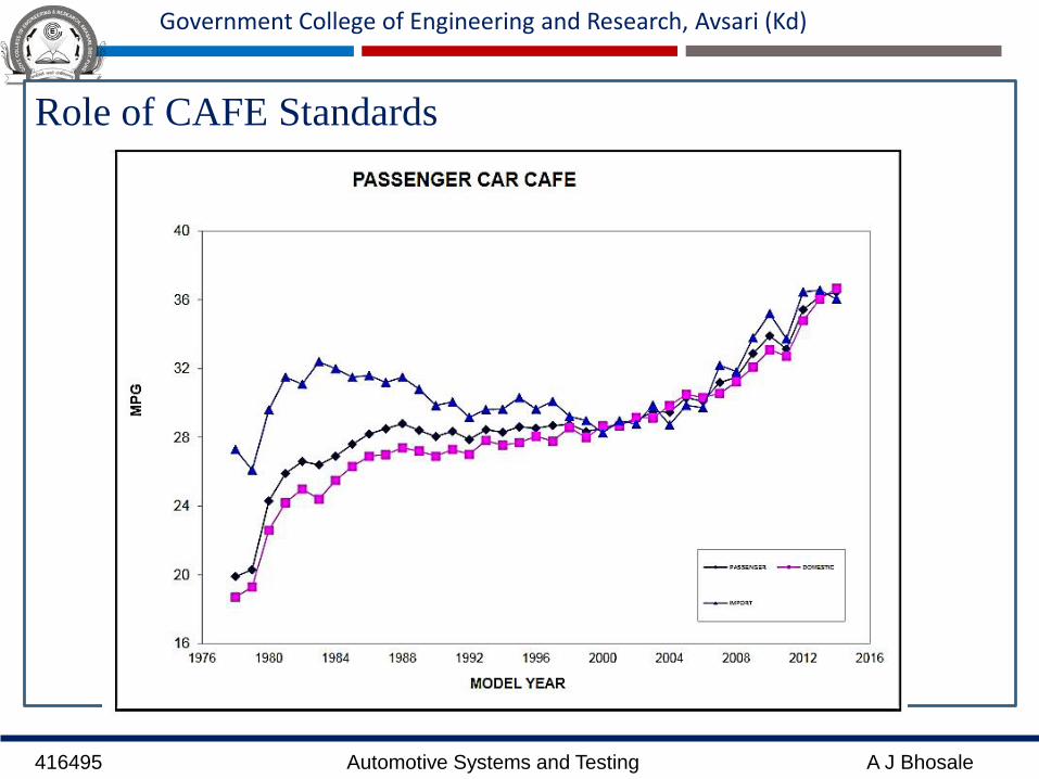
• Different measurement cycles are used to approximate theactual performance of the vehicle. (Corporate Average FuelEconomy (CAFE) )
416495 Automotive Systems and Testing A J Bhosale
Government College of Engineering and Research, Avsari (Kd)
• The energy in fuel is required to overcome various
losses (wind resistance, tire drag, and others) in
propelling the vehicle, and in providing power to
vehicle systems such as ignition or air conditioning.
• Various measures can be taken to reduce losses at each
of the conversions between chemical energy in fuel and
kinetic energy of the vehicle.
• Driver behavior can affect fuel economy; maneuvers
such as sudden acceleration and heavy braking waste
energy.
• CAFC( Corporate Average Fuel Consumption) norms
have been proposed in India in April 2017.

416495 Automotive Systems and Testing A J Bhosale
Government College of Engineering and Research, Avsari (Kd)

416495 Automotive Systems and Testing A J Bhosale
Government College of Engineering and Research, Avsari (Kd)
The fuel economy of an automotive vehicle depends
1.The fuel consumption characteristics of the engine,
2.Transmission characteristics,
3.Weight of the vehicle,
4.Aerodynamic resistance,
5.Rolling resistance of the tires,
6. Driving cycle (conditions), and
7. Driver behavior
416495 Automotive Systems and Testing A J Bhosale
Government College of Engineering and Research, Avsari (Kd)
Role of CAFE Standards

416495 Automotive Systems and Testing A J Bhosale
Government College of Engineering and Research, Avsari (Kd)
Indian Scenario:
• Though vehicle stock is expanding rapidly in India there is no
policy to mandate for fuel economy improvement for the vehicle
industry.

416495 Automotive Systems and Testing A J Bhosale
Government College of Engineering and Research, Avsari (Kd)
Indian Scenario:
416495 Automotive Systems and Testing A J Bhosale
Government College of Engineering and Research, Avsari (Kd)
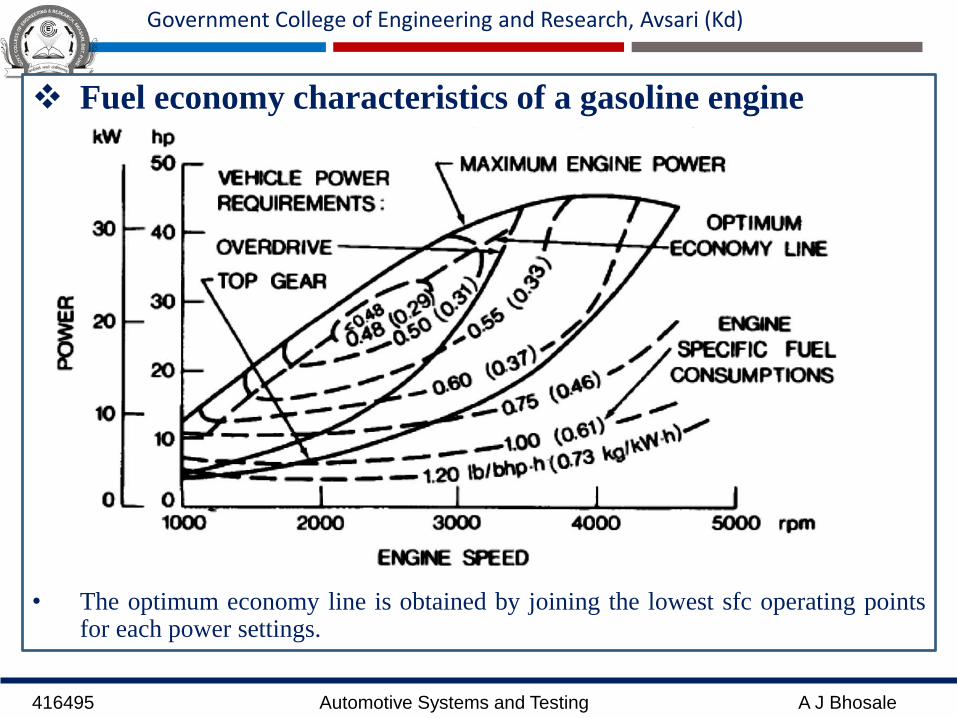
Fuel economy characteristics of a gasoline engine
• The optimum economy line is obtained by joining the lowest sfc operating pointsfor each power settings.
416495 Automotive Systems and Testing A J Bhosale
Government College of Engineering and Research, Avsari (Kd)
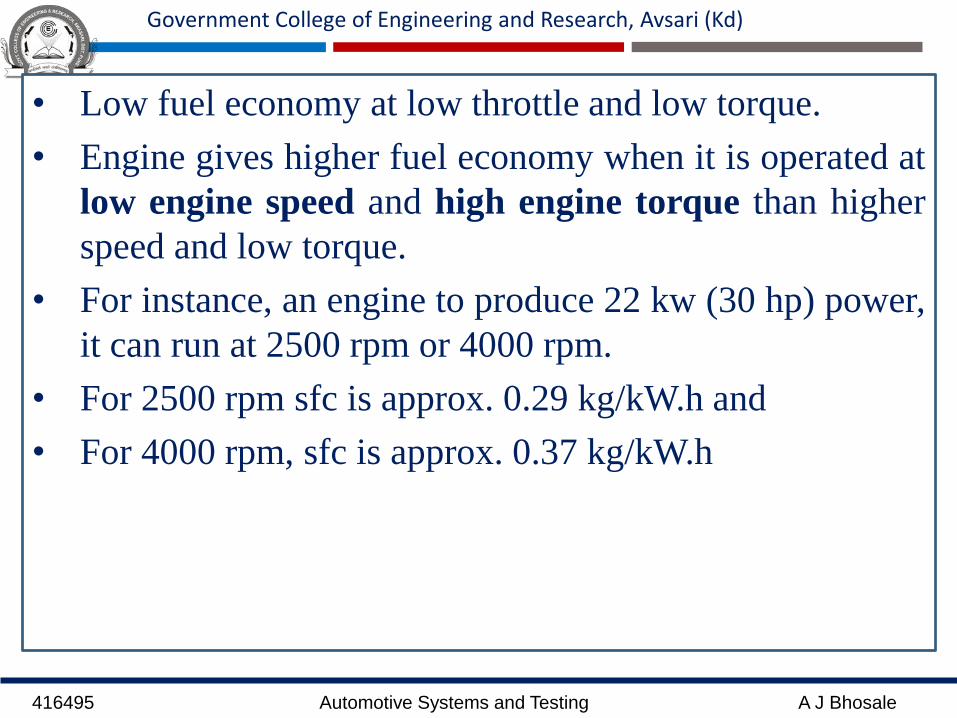
• Low fuel economy at low throttle and low torque.
• Engine gives higher fuel economy when it is operated at
low engine speed and high engine torque than higher
speed and low torque.
• For instance, an engine to produce 22 kw (30 hp) power,
it can run at 2500 rpm or 4000 rpm.
• For 2500 rpm sfc is approx. 0.29 kg/kW.h and
• For 4000 rpm, sfc is approx. 0.37 kg/kW.h
416495 Automotive Systems and Testing A J Bhosale
Government College of Engineering and Research, Avsari (Kd)
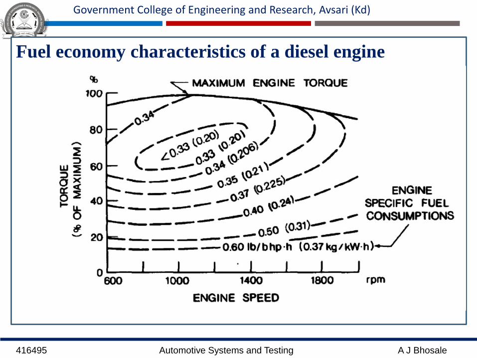
Fuel economy characteristics of a diesel engine

416495 Automotive Systems and Testing A J Bhosale
Government College of Engineering and Research, Avsari (Kd)
Effect of Gear shifts on fuel consumption:
416495 Automotive Systems and Testing A J Bhosale
Government College of Engineering and Research, Avsari (Kd)
• In each gear there is speed at which fuel consumption is
optimal.
• The driver can thus have a decisive effect on a fuel
economy by his gear selection and timing of gear shifts.
• Because air resistance increases as the square of speed,
the power requirement and thus fuel consumption
increases at higher speed.
• The transmission should be of continuous variable type
so that the engine can be operated under most
economical conditions.
416495 Automotive Systems and Testing A J Bhosale
Government College of Engineering and Research, Avsari (Kd)
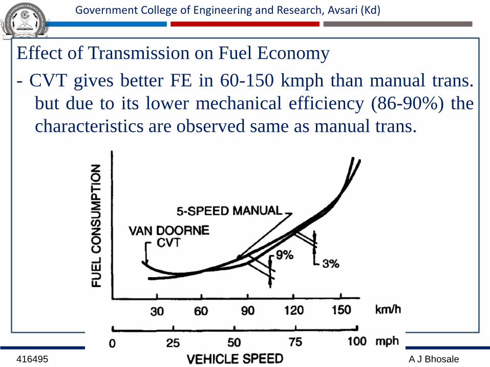
Effect of Transmission on Fuel Economy
- CVT gives better FE in 60-150 kmph than manual trans.
but due to its lower mechanical efficiency (86-90%) the
characteristics are observed same as manual trans.
416495 Automotive Systems and Testing A J Bhosale
Government College of Engineering and Research, Avsari (Kd)
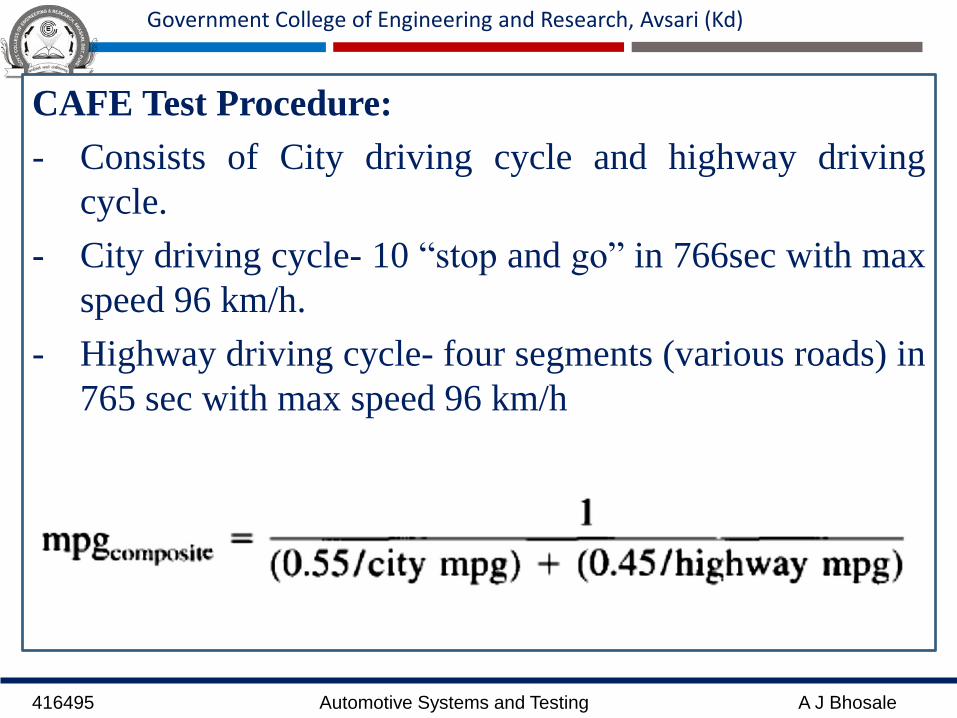
CAFE Test Procedure:
- Consists of City driving cycle and highway driving
cycle.
- City driving cycle- 10 “stop and go” in 766sec with max
speed 96 km/h.
- Highway driving cycle- four segments (various roads) in
765 sec with max speed 96 km/h
416495 Automotive Systems and Testing A J Bhosale
Government College of Engineering and Research, Avsari (Kd)
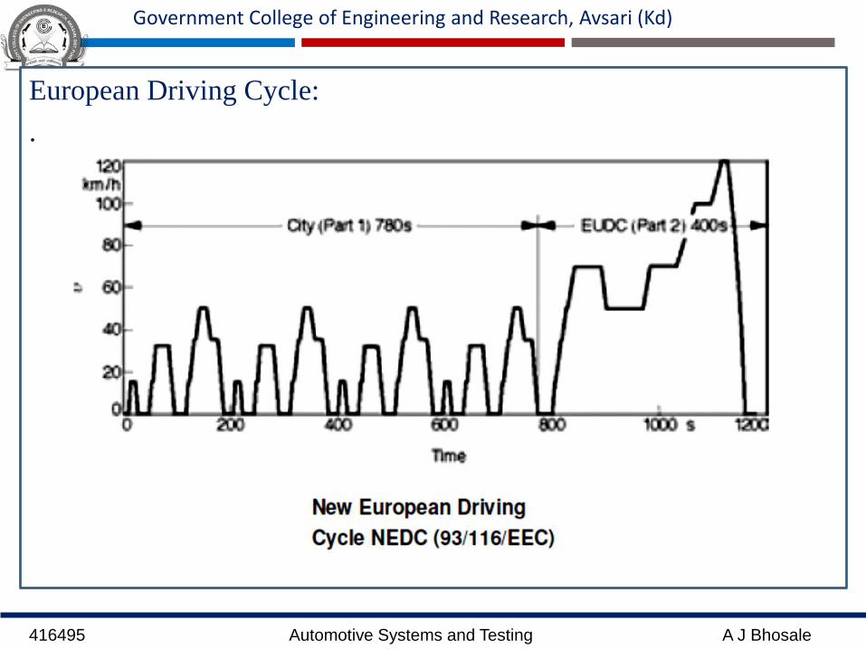
European Driving Cycle:
.
416495 Automotive Systems and Testing A J Bhosale
Government College of Engineering and Research, Avsari (Kd)
• The New European Driving Cycle (NEDC, 93/116/EEC) is a
cycle run on a dynamometer to ascertain fuel consumption.
• It consists of four similarly weighted urban cycles each
lasting 195 s and an extra-urban cycle lasting 400 s.
• The exhaust gas is collected in a sample bag and its
components subsequently analyzed. CO, HC and CO2 are
factored into the calculations in accordance with the carbon
analysis.
• The CO2 content of the exhaust gas is proportional to the
fuel consumption.
• It can therefore be used as an indicator to gauge the vehicle's
fuel consumption (diesel or gasoline, as appropriate).
416495 Automotive Systems and Testing A J Bhosale
Government College of Engineering and Research, Avsari (Kd)
Reducing Fuel Consumption:
1. Improving the efficiency of the IC Engine particularly
reducing the part load condition
2. Appropriate engine performance characteristics, i.e. vehicle
must be neither over-powered nor under-powered
3. Reducing driving resistance, for example- rolling resistance
and drag.
4. Improving the efficiency of the transmission (CVT)
5. Adaptive control of ratio selection by automatic selection
circuits and CVT
6. Traffic management systems to reduce stationary periods
7. Improved driving, intelligent control systems.
416495 Automotive Systems and Testing A J Bhosale
Government College of Engineering and Research, Avsari (Kd)
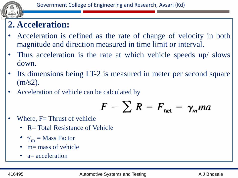
2. Acceleration:
• Acceleration is defined as the rate of change of velocity in bothmagnitude and direction measured in time limit or interval.
• Thus acceleration is the rate at which vehicle speeds up/ slowsdown.
• Its dimensions being LT-2 is measured in meter per second square(m/s2).
• Acceleration of vehicle can be calculated by
• Where, F= Thrust of vehicle
• R= Total Resistance of Vehicle
• γm = Mass Factor
• m= mass of vehicle
• a= acceleration
416495 Automotive Systems and Testing A J Bhosale
Government College of Engineering and Research, Avsari (Kd)
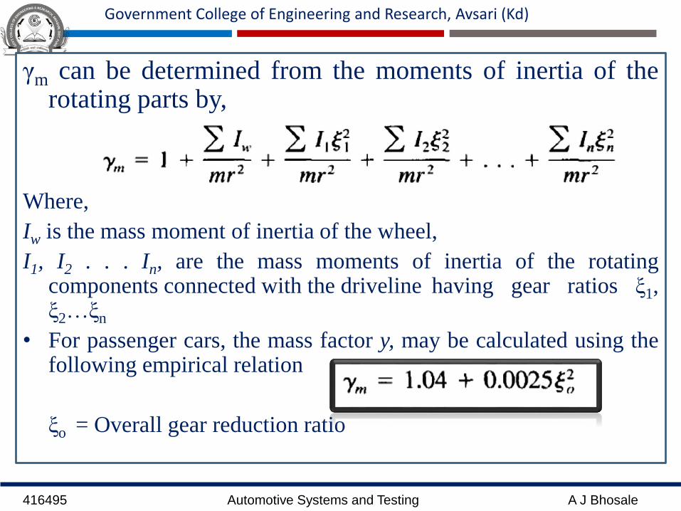
γm can be determined from the moments of inertia of therotating parts by,
Where,
Iw is the mass moment of inertia of the wheel,
I1, I2 . . . In, are the mass moments of inertia of the rotatingcomponents connected with the driveline having gear ratios ξ1,ξ2…ξn
• For passenger cars, the mass factor y, may be calculated using thefollowing empirical relation
ξo = Overall gear reduction ratio
416495 Automotive Systems and Testing A J Bhosale
Government College of Engineering and Research, Avsari (Kd)
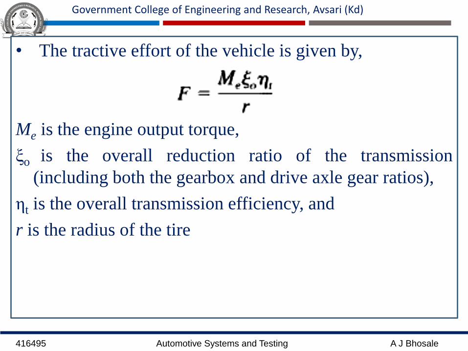
• The tractive effort of the vehicle is given by,
Me is the engine output torque,
ξo is the overall reduction ratio of the transmission
(including both the gearbox and drive axle gear ratios),
ηt is the overall transmission efficiency, and
r is the radius of the tire

416495 Automotive Systems and Testing A J Bhosale
Government College of Engineering and Research, Avsari (Kd)
• The relationship between vehicle speed and engine
speed is given by,
ne = engine speed
i = slip of the vehicle running gear.
• For a road vehicle, the slip is usually assumed to be 2-
5% under normal operating conditions

416495 Automotive Systems and Testing A J Bhosale
Government College of Engineering and Research, Avsari (Kd)
• Rolling Resistance:
Where, ρ is the mass density of the air,
CD is the coefficient of aerodynamic resistance
Af is a characteristic area of the vehicle, usually taken as the
frontal area and
Vr is the speed of the vehicle relative to the wind.
416495 Automotive Systems and Testing A J Bhosale
Government College of Engineering and Research, Avsari (Kd)
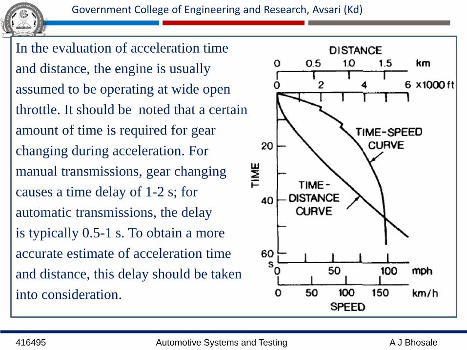
In the evaluation of acceleration time
and distance, the engine is usually
assumed to be operating at wide open
throttle. It should be noted that a certain
amount of time is required for gear
changing during acceleration. For
manual transmissions, gear changing
causes a time delay of 1-2 s; for
automatic transmissions, the delay
is typically 0.5-1 s. To obtain a more
accurate estimate of acceleration time
and distance, this delay should be taken
into consideration.
416495 Automotive Systems and Testing A J Bhosale
Government College of Engineering and Research, Avsari (Kd)
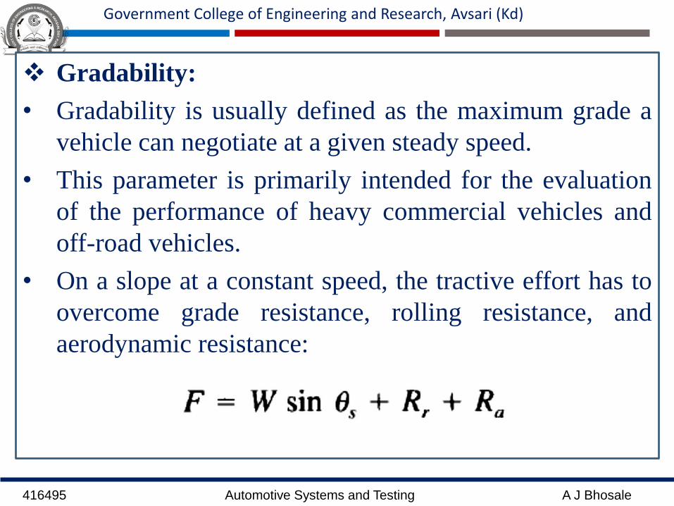
Gradability:
• Gradability is usually defined as the maximum grade a
vehicle can negotiate at a given steady speed.
• This parameter is primarily intended for the evaluation
of the performance of heavy commercial vehicles and
off-road vehicles.
• On a slope at a constant speed, the tractive effort has to
overcome grade resistance, rolling resistance, and
aerodynamic resistance:
416495 Automotive Systems and Testing A J Bhosale
Government College of Engineering and Research, Avsari (Kd)
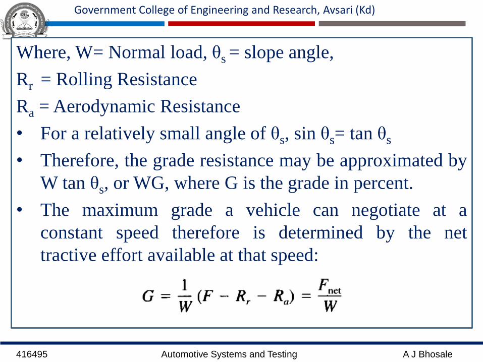
Where, W= Normal load, θs = slope angle,
Rr = Rolling Resistance
Ra = Aerodynamic Resistance
• For a relatively small angle of θs, sin θs= tan θs
• Therefore, the grade resistance may be approximated by
W tan θs, or WG, where G is the grade in percent.
• The maximum grade a vehicle can negotiate at a
constant speed therefore is determined by the net
tractive effort available at that speed:
416495 Automotive Systems and Testing A J Bhosale
Government College of Engineering and Research, Avsari (Kd)
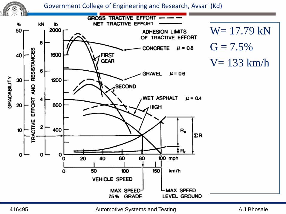
W= 17.79 kN
G = 7.5%
V= 133 km/h

416495 Automotive Systems and Testing A J Bhosale
Government College of Engineering and Research, Avsari (Kd)
For instance, the grade resistance of the passenger car with aweight of 17.79 kN (4000 lb) on a grade of 7.5% is 1.34 kN(300 lb).
A horizontal line representing this grade resistance can bedrawn on the diagram, which intersects that net tractiveeffort curve at a speed of 133 km/h (82 mph).
This indicates that for the passenger car under consideration,the maximum speed obtainable at a grade of 7.5% is 133kmlh (82 mph).
It should be noted that the limits of tractive effort set by thenature of tire-road adhesion usually determine the maximumgradability of the vehicle.
For instance, it can be seen from Fig. above that themaximum grade the vehicle can negotiate at low speeds on agravel surface with µ = 0.6 will be approximately 35%.

416495 Automotive Systems and Testing A J Bhosale
Government College of Engineering and Research, Avsari (Kd)
Top Speed:
The German Standard DIN 70020 defines top speed as
the greatest speed that a vehicle can maintain over
measured distance of 1 km.
The test conditions are:
1. Vehicle loaded with half load
2. Level, dry surface with good grip,
3. Max. wind speed ± 3m/s
4. The vehicle must travel along the test track in both
directions without interruption.

416495 Automotive Systems and Testing A J Bhosale
Government College of Engineering and Research, Avsari (Kd)

416495 Automotive Systems and Testing A J Bhosale
Government College of Engineering and Research, Avsari (Kd)
Braking Performance:
• Braking performance of motor vehicles is undoubtedlyone of the most important characteristics that affectvehicle safety.
• With increasing emphasis on traffic safety in recentyears, intensive efforts have been directed towardsimproving the braking performance.
• Safety standards that specify performance requirementsof various types of brake system have been introduced inmany countries.
• The braking force Fb originating from the brake systemand developed on the tire-road interface is the primaryretarding force.

416495 Automotive Systems and Testing A J Bhosale
Government College of Engineering and Research, Avsari (Kd)
h= height of CG
L= wheelbase
Fb = braking force
l1 = distance between front axle and center of gravity of the
vehicle
l2 = distance between Rear axle and center of gravity of the
vehicle

416495 Automotive Systems and Testing A J Bhosale
Government College of Engineering and Research, Avsari (Kd)
• When the braking force is below the limit of tire-road
adhesion, the braking force Fb is given by,
Where, Tb is the applied brake torque,
I is the rotating inertia connected with the wheel being
decelerated,
αan is the corresponding angular deceleration,
and r is the rolling radius of the tire.

416495 Automotive Systems and Testing A J Bhosale
Government College of Engineering and Research, Avsari (Kd)
• During braking, there is a load transfer from the rear
axle to the front axle.
• By considering the equilibrium of the moments about
the front and rear tire ground contact points, the normal
loads on the front and rear axles, Wf and Wr can be
expressed as
and
416495 Automotive Systems and Testing A J Bhosale
Government College of Engineering and Research, Avsari (Kd)
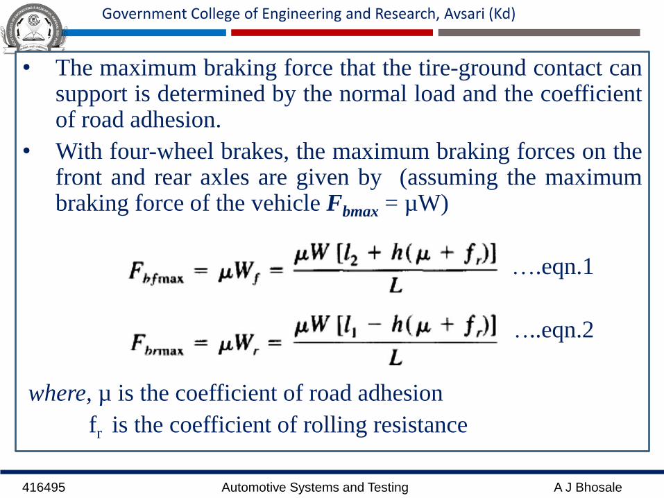
• The maximum braking force that the tire-ground contact cansupport is determined by the normal load and the coefficientof road adhesion.
• With four-wheel brakes, the maximum braking forces on thefront and rear axles are given by (assuming the maximumbraking force of the vehicle Fbmax = µW)
….eqn.1
…..eqn.2
where, µ is the coefficient of road adhesion
fr is the coefficient of rolling resistance
416495 Automotive Systems and Testing A J Bhosale
Government College of Engineering and Research, Avsari (Kd)
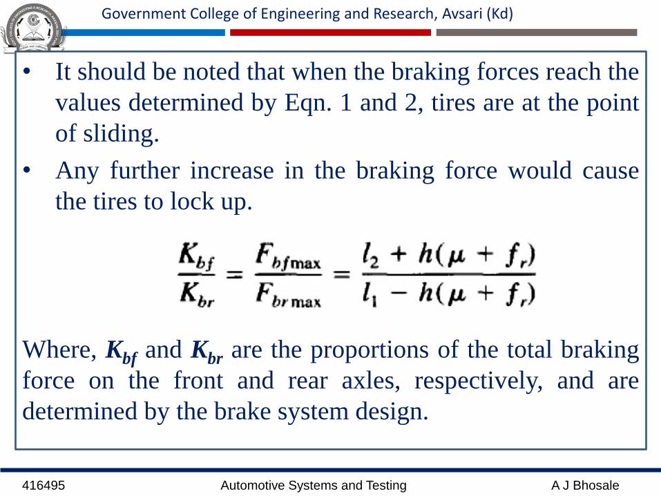
• It should be noted that when the braking forces reach the
values determined by Eqn. 1 and 2, tires are at the point
of sliding.
• Any further increase in the braking force would cause
the tires to lock up.
Where, Kbf and Kbr are the proportions of the total braking
force on the front and rear axles, respectively, and are
determined by the brake system design.

416495 Automotive Systems and Testing A J Bhosale
Government College of Engineering and Research, Avsari (Kd)
• For instance, for a light truck with 68% load on rear axle(l2/L = 0.32, l1/L = 0.68), h/L = 0.18, µ= 0.85, and fr= 0.01,the maximum braking forces of the front and rear tires thatthe tire-ground contact can support will be developed at thesame time only if the braking force distribution between thefront and rear brakes satisfies the following condition:
• In other words, 47% of the total braking force must beplaced on the front axle and 53% on the rear axle to achieveoptimum utilization of the potential braking capability of thevehicle.
416495 Automotive Systems and Testing A J Bhosale
Government College of Engineering and Research, Avsari (Kd)
• The braking force distribution that can ensure the
maximum braking forces of the front and rear tires
developed at the same time is referred to as the ideal
braking force distribution.
• If the braking force distribution is not ideal, then either
the front or the rear tires will lock up first.
• When the rear tires lock up first, the vehicle will lose
directional stability.
• When the rear tires lock, the capability of the rear tires
to resist lateral force is reduced to zero.
416495 Automotive Systems and Testing A J Bhosale
Government College of Engineering and Research, Avsari (Kd)
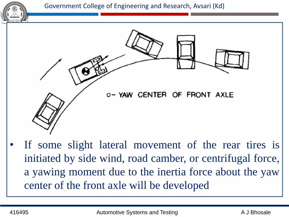
• If some slight lateral movement of the rear tires is
initiated by side wind, road camber, or centrifugal force,
a yawing moment due to the inertia force about the yaw
center of the front axle will be developed
416495 Automotive Systems and Testing A J Bhosale
Government College of Engineering and Research, Avsari (Kd)
• As the yaw motion progresses, the moment arm of theinertia force increases, resulting in an increase in yawacceleration.
• As the rear end of the vehicle swings around 90o, themoment arm gradually decreases, and eventually the vehiclerotates 180o, with the rear end leading the front end.
• The lock-up of front tires will cause a loss of directionalcontrol, and the driver will no longer be able to exerciseeffective steering.
• However, that front tire lock-up does not cause directionalinstability.
• Rear tire lock-up is a more critical situation, particularly on aroad surface with a low coefficient of adhesion.
416495 Automotive Systems and Testing A J Bhosale
Government College of Engineering and Research, Avsari (Kd)
Ride Comfort:
• Customer expectations of smooth running are high, especially in case ofcars, passenger bus etc.
• Ride quality is concerned with the sensation or feel of the passenger inthe environment of a moving vehicle.
• Ride quality refers to the degree of protection offered vehicle occupantsfrom uneven elements in the road surface, or the terrain if driving off-road. A car with very good ride quality is also a comfortable car to ridein.
• Ride comfort problems mainly arise from noise and vibrations of thevehicle body,
• Surface irregularities (potholes to random variations),
• Aerodynamic forces,
• Noise and vibrations of the engine and driveline, and
• Non uniformities (imbalances) of the tire/wheel assembly.
416495 Automotive Systems and Testing A J Bhosale
Government College of Engineering and Research, Avsari (Kd)
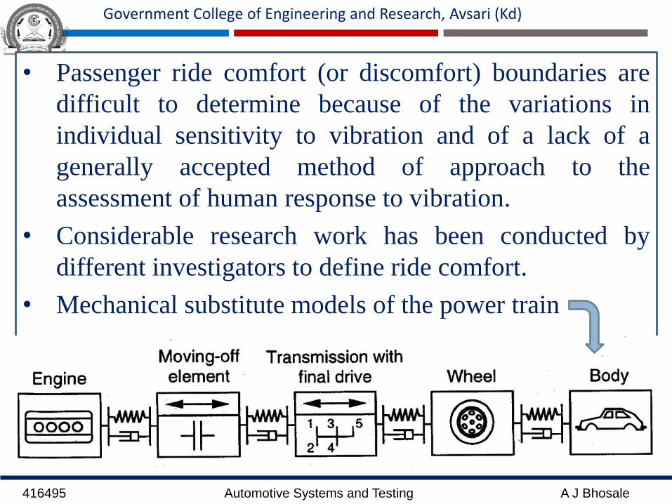
• Passenger ride comfort (or discomfort) boundaries are
difficult to determine because of the variations in
individual sensitivity to vibration and of a lack of a
generally accepted method of approach to the
assessment of human response to vibration.
• Considerable research work has been conducted by
different investigators to define ride comfort.
• Mechanical substitute models of the power train

416495 Automotive Systems and Testing A J Bhosale
Government College of Engineering and Research, Avsari (Kd)
• A variety of methods for assessing human tolerance to
vibration have been developed over the years:
• Subjective Ride Measurements.
• Shake Table Tests.
• Ride Simulator Tests.
• Ride Measurements in Vehicles.

416495 Automotive Systems and Testing A J Bhosale
Government College of Engineering and Research, Avsari (Kd)
1. Subjective Ride Measurements.
The traditional technique for comparing vehicle ridequality in the automotive industry in the past is to use atrained jury to rate the ride comfort, on a relative basis,of different vehicles driven over a range of roadsurfaces.
With a large enough jury and a well-designedevaluation scheme, this method could provide ameaningful comparison of the ride quality of differentvehicles.
The degree of difference in ride quality, however,cannot be quantitatively determined by this type ofsubjective evaluation.
416495 Automotive Systems and Testing A J Bhosale
Government College of Engineering and Research, Avsari (Kd)
2. Shake Table Tests.
In an attempt to quantitatively study human response to
vibration, a large number of shake table experiments
have been performed over the years.
Most of this research pertains to human response to
sinusoidal excitation.
It is intended to identify zones of comfort (or
discomfort) for humans in terms of vibration amplitude,
velocity, or acceleration in a given direction (such as
foot-to-head, side-to-side, or back-to-chest) over a
specific frequency range.
416495 Automotive Systems and Testing A J Bhosale
Government College of Engineering and Research, Avsari (Kd)
3. Ride Simulator Tests.
In these tests, ride simulators are used to replicate the
vibration of the vehicle traveling over different road
surfaces.
In some facilities, an actual vehicle body is mounted on
hydraulic actuators, which reproduce vehicle motions in
pitch, roll, and bounce (or heave). Road inputs are fed
into the actuators.
Using the simulator, it is possible to establish a human
tolerance limit in terms of vibration parameters.
416495 Automotive Systems and Testing A J Bhosale
Government College of Engineering and Research, Avsari (Kd)
4. Ride Measurements in Vehicles.
Shake table tests and ride simulator tests describedabove are conducted under laboratory conditions. Theydo not necessarily provide the same vibrationenvironments to which the passenger is subject whiledriving on the road.
Therefore, on-the road ride measurements, particularlyfor passenger cars, have been performed.
This test method attempts to correlate the response oftest subjects in qualitative terms, such as "unpleasant" or"intolerable,“ with vibration parameters measured at thelocation where the test subject is situated under actualdriving conditions.
416495 Automotive Systems and Testing A J Bhosale
Government College of Engineering and Research, Avsari (Kd)
Handling Characteristics:
• Vehicle handling is indicator that shows that the vehicle behavior
on the road.
• Handling characteristics of vehicles are closely related to driving
safety.
416495 Automotive Systems and Testing A J Bhosale
Government College of Engineering and Research, Avsari (Kd)
• Handling characteristics of road vehicles refer to its
response to steering commands and to environmental
inputs, such as wind gust and road disturbances that
affect its direction of motion.
• Many traffic accidents are caused by undesired and
unexpected handling behavior of vehicle.
• Hence it is necessary to understand the handling
characteristics of vehicle

416495 Automotive Systems and Testing A J Bhosale
Government College of Engineering and Research, Avsari (Kd)
• Handling issue comes into light at the time of cornering
and swerving (sharp turn).
• It is commonly judged by how a vehicle performs
particularly during cornering, acceleration, and
braking as well as on the vehicle's directional
stability when moving in steady state condition.

416495 Automotive Systems and Testing A J Bhosale
Government College of Engineering and Research, Avsari (Kd)
Factors that affect a Vehicle’s handling:
1. Weight distribution
2. Height of Center of Gravity
3. Center of Gravity
4. Suspension
5. Steering
6. Spring Rate
7. Suspension travel
8. Tire and wheels
416495 Automotive Systems and Testing A J Bhosale
Government College of Engineering and Research, Avsari (Kd)
Life Durability:
• Durability: System is durable when it performs or does not fail
beyond its expected life, examples of durability:
– A car does not need any repair during warranty period of 3 years
– A car is still on the road after 10 years
– A car is still on the road after 200,000 km
• The ability of a product to perform its required function over a
lengthy period under normal conditions of use without excessive
expenditure on maintenance or repair
• Ability to withstand to fatigue, corrosion, wear, creep, ...
• Customer expects a good lifespan and durable vehicle without
major defects and repair.

416495 Automotive Systems and Testing A J Bhosale
Government College of Engineering and Research, Avsari (Kd)
416495 Automotive Systems and Testing A J Bhosale
Government College of Engineering and Research, Avsari (Kd)
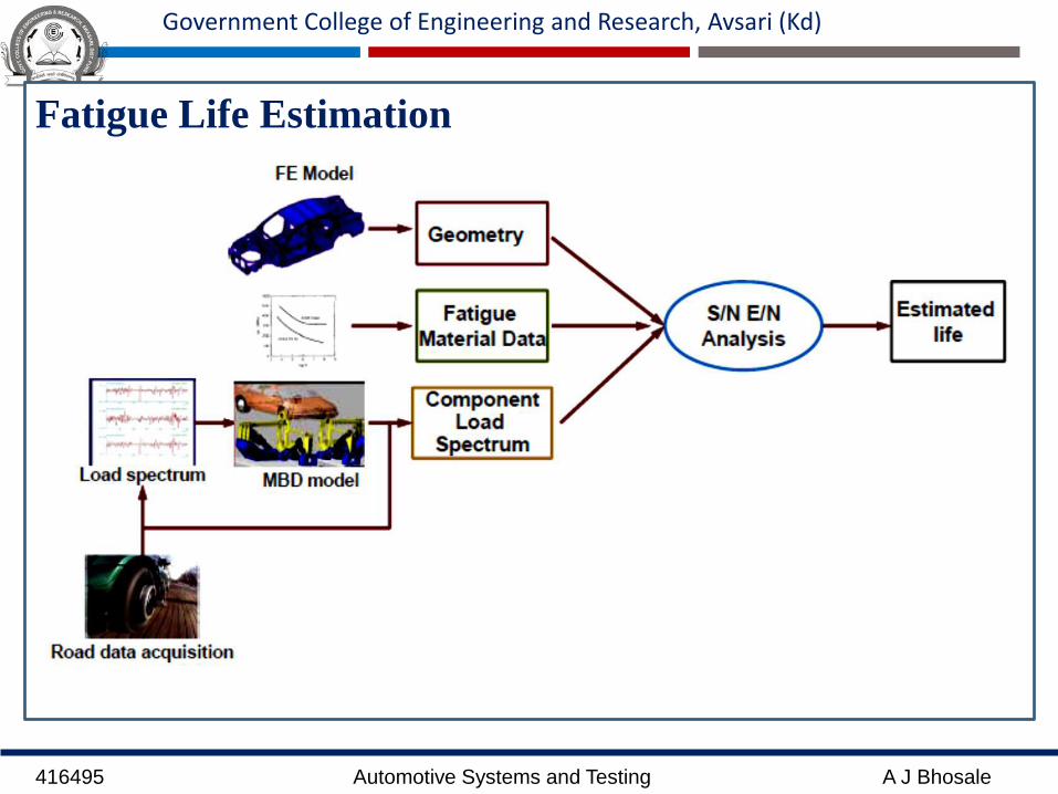
Fatigue Life Estimation

416495 Automotive Systems and Testing A J Bhosale
Government College of Engineering and Research, Avsari (Kd)
EGR Systems:
• Exhaust Gas Recirculation (EGR) systems effectively
reduce Nox emissions by recirculating a portion of the
exhaust gas and mixing it with the intake air to lower
the burning temperature. A computer automatically
controls the EGR amount in accordance with the engine
load or speed.

416495 Automotive Systems and Testing A J Bhosale
Government College of Engineering and Research, Avsari (Kd)
• Continuous Control EGR System (for Light Duty
Tucks)employ a continuous control system for the EGR
valve.
• This system contributes to Nox reduction by
electronically controlling the EGR volume and the
intake air amount through linkage with the EGR valve
and intake system.
416495 Automotive Systems and Testing A J Bhosale
Government College of Engineering and Research, Avsari (Kd)
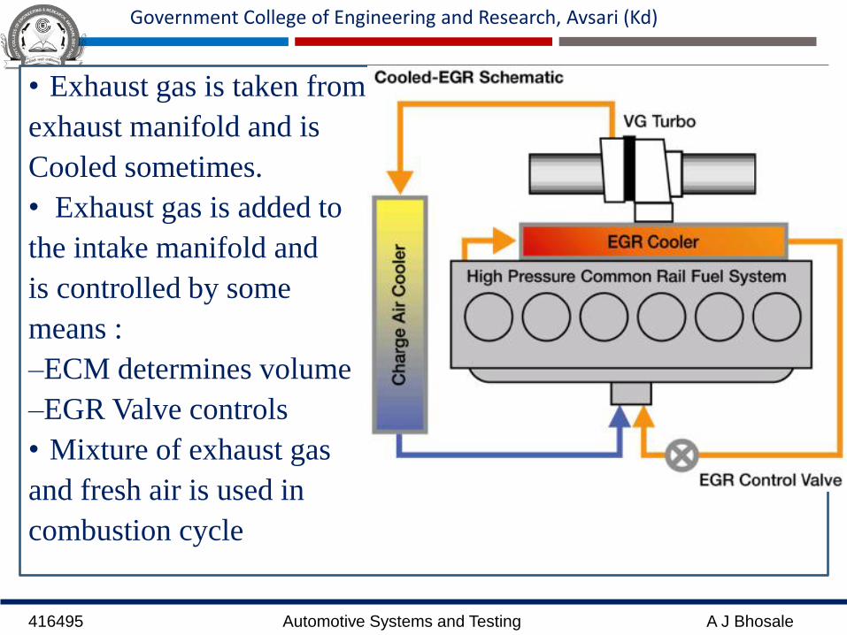
• Exhaust gas is taken from
exhaust manifold and is
Cooled sometimes.
• Exhaust gas is added to
the intake manifold and
is controlled by some
means :
–ECM determines volume
–EGR Valve controls
• Mixture of exhaust gas
and fresh air is used in
combustion cycle
416495 Automotive Systems and Testing A J Bhosale
Government College of Engineering and Research, Avsari (Kd)
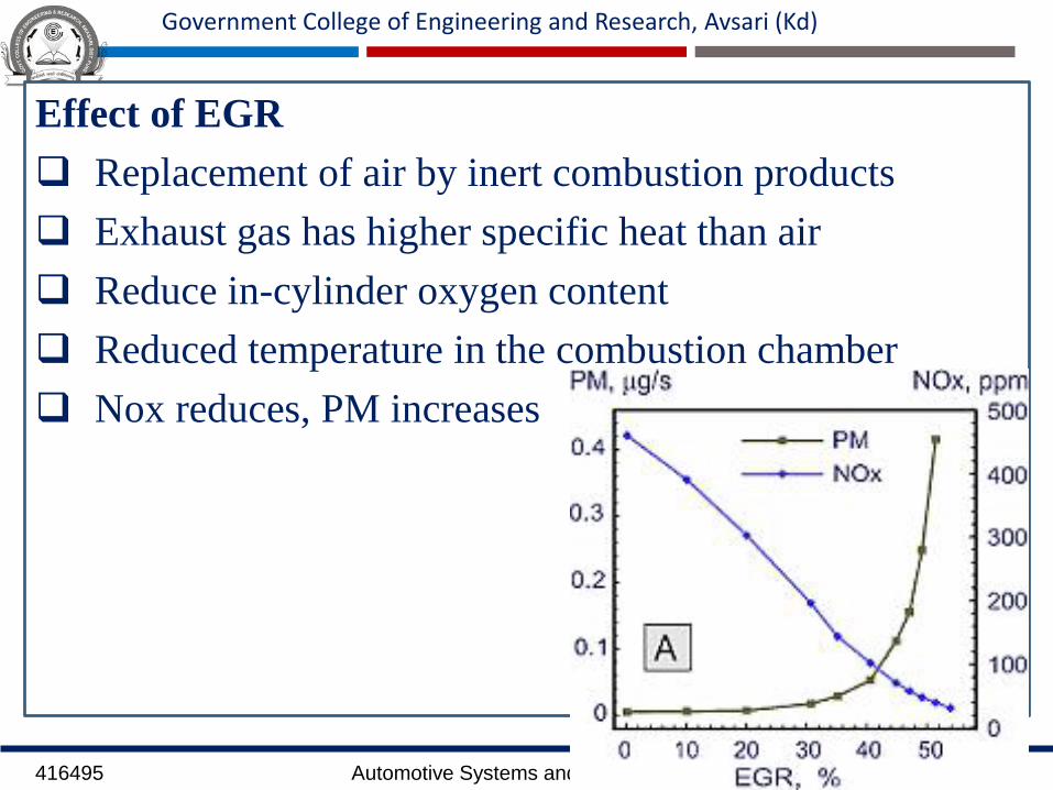
Effect of EGR
Replacement of air by inert combustion products
Exhaust gas has higher specific heat than air
Reduce in-cylinder oxygen content
Reduced temperature in the combustion chamber
Nox reduces, PM increases

416495 Automotive Systems and Testing A J Bhosale
Government College of Engineering and Research, Avsari (Kd)
Types of EGR
Internal EGR
External EGR
Hot EGR
Cooled EGR
Partially cooled EGR
High pressure EGR
Low pressure EGR
416495 Automotive Systems and Testing A J Bhosale
Government College of Engineering and Research, Avsari (Kd)
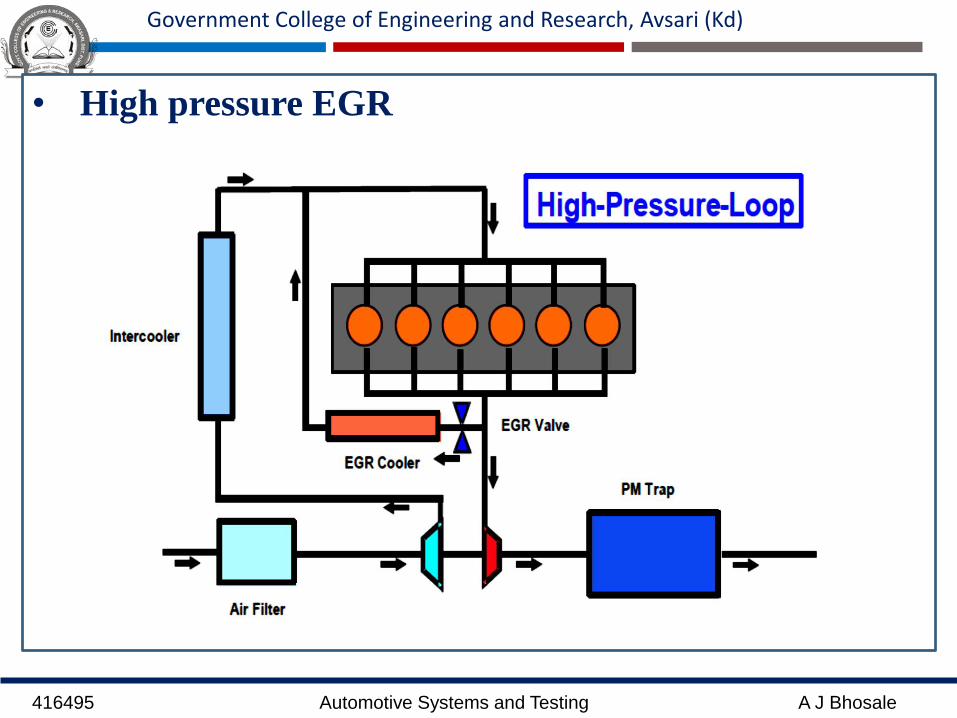
• High pressure EGR
416495 Automotive Systems and Testing A J Bhosale
Government College of Engineering and Research, Avsari (Kd)
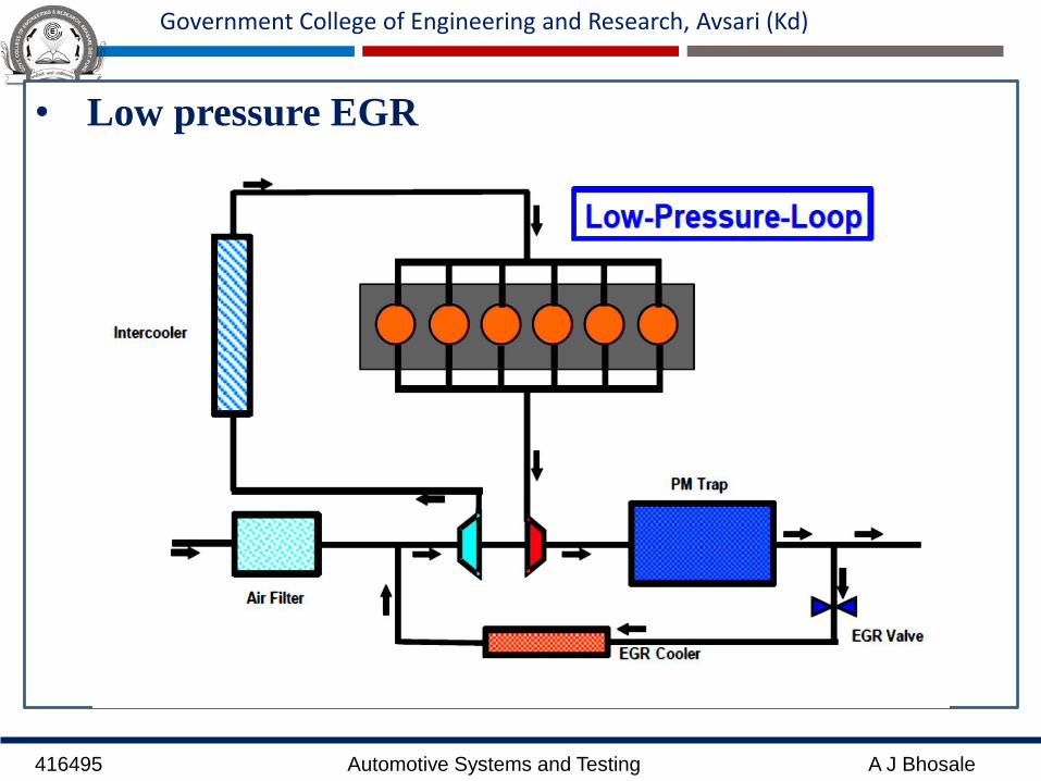
• Low pressure EGR
416495 Automotive Systems and Testing A J Bhosale
Government College of Engineering and Research, Avsari (Kd)
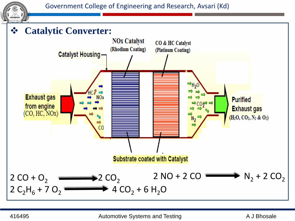
Catalytic Converter:
2 CO + O2 2 CO2
2 C2H6 + 7 O2 4 CO2 + 6 H2O
2 NO + 2 CO N2 + 2 CO2
416495 Automotive Systems and Testing A J Bhosale
Government College of Engineering and Research, Avsari (Kd)
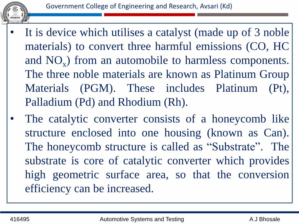
• It is device which utilises a catalyst (made up of 3 noble
materials) to convert three harmful emissions (CO, HC
and NOx) from an automobile to harmless components.
The three noble materials are known as Platinum Group
Materials (PGM). These includes Platinum (Pt),
Palladium (Pd) and Rhodium (Rh).
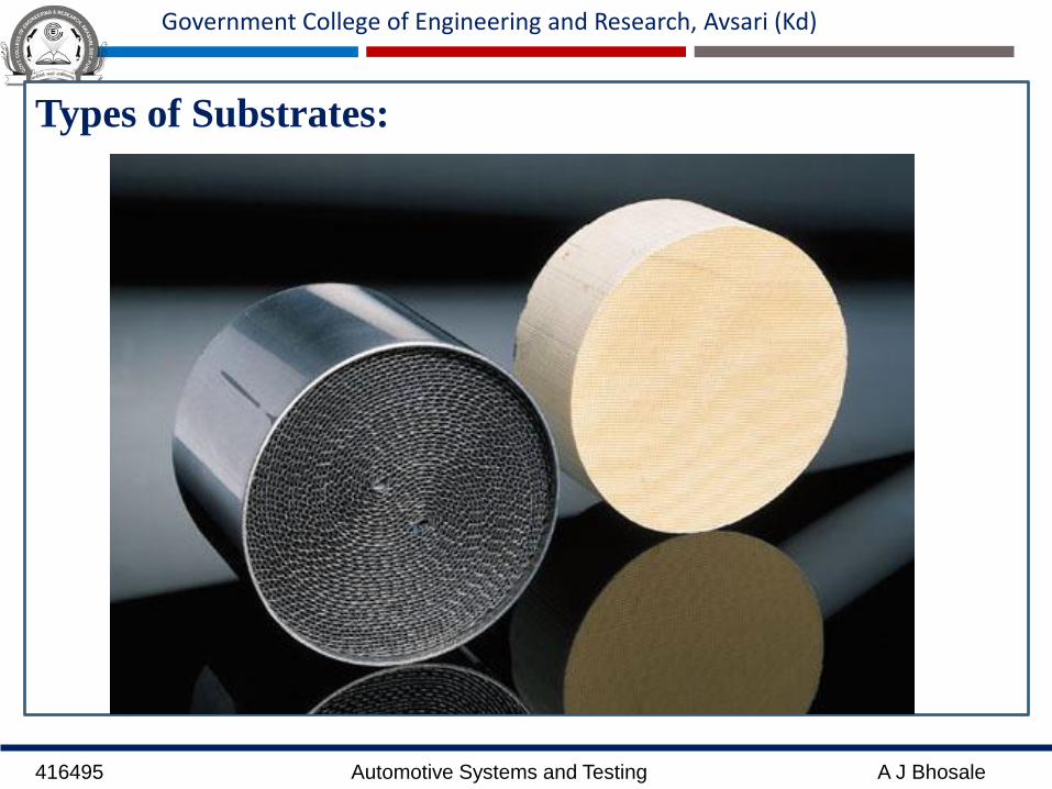
• The catalytic converter consists of a honeycomb like
structure enclosed into one housing (known as Can).
The honeycomb structure is called as “Substrate”. The
substrate is core of catalytic converter which provides
high geometric surface area, so that the conversion
efficiency can be increased.

416495 Automotive Systems and Testing A J Bhosale
Government College of Engineering and Research, Avsari (Kd)
• The substrate can be made up of Metal or Ceramic (e.g.
Silicon Carbide (SiC), Zirconia (ZrO2) etc.). The
substrate is coated with the platinum, palladium and
rhodium materials.
• The catalyst material transforms the harmful emissions
into harmless components by two chemical processes
viz., Oxidation and Reduction.
• In oxidation, it converts CO into CO2 by addition of O2,
also it converts HC into CO2 and water vapours by
addition of O2. So it is known as oxidation process. The
Platinum and Palladium catalysts are used for
oxidation process.
416495 Automotive Systems and Testing A J Bhosale
Government College of Engineering and Research, Avsari (Kd)
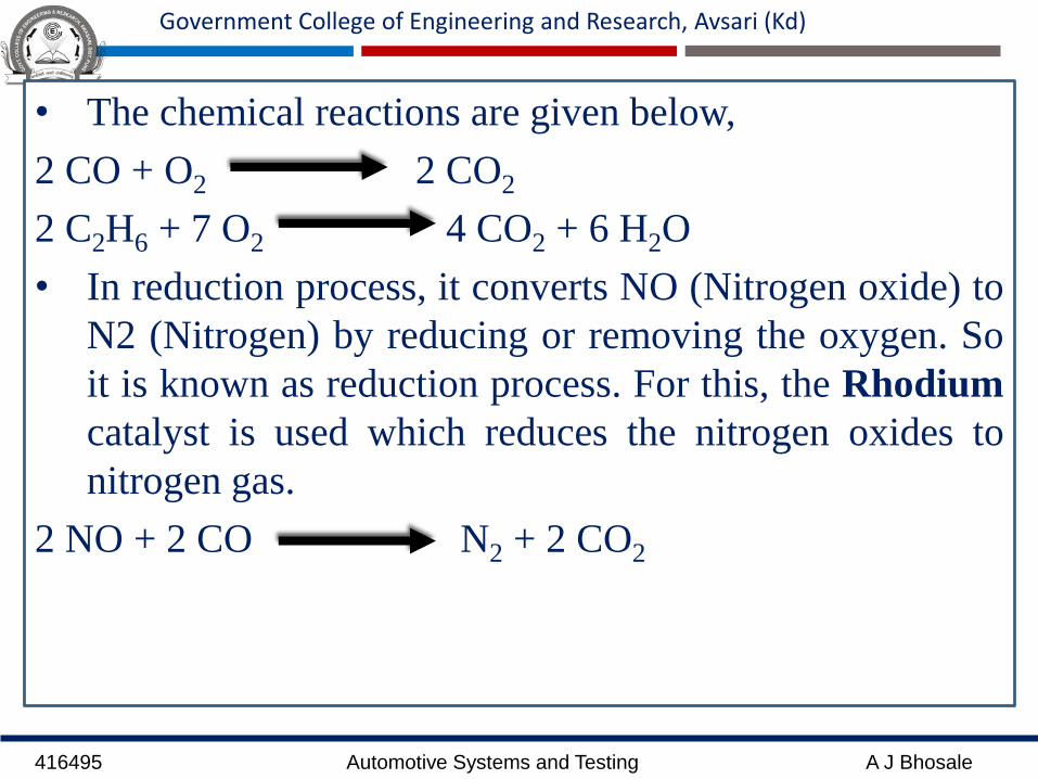
• The chemical reactions are given below,
2 CO + O2 2 CO2
2 C2H6 + 7 O2 4 CO2 + 6 H2O
• In reduction process, it converts NO (Nitrogen oxide) to
N2 (Nitrogen) by reducing or removing the oxygen. So
it is known as reduction process. For this, the Rhodium
catalyst is used which reduces the nitrogen oxides to
nitrogen gas.
2 NO + 2 CO N2 + 2 CO2
416495 Automotive Systems and Testing A J Bhosale
Government College of Engineering and Research, Avsari (Kd)
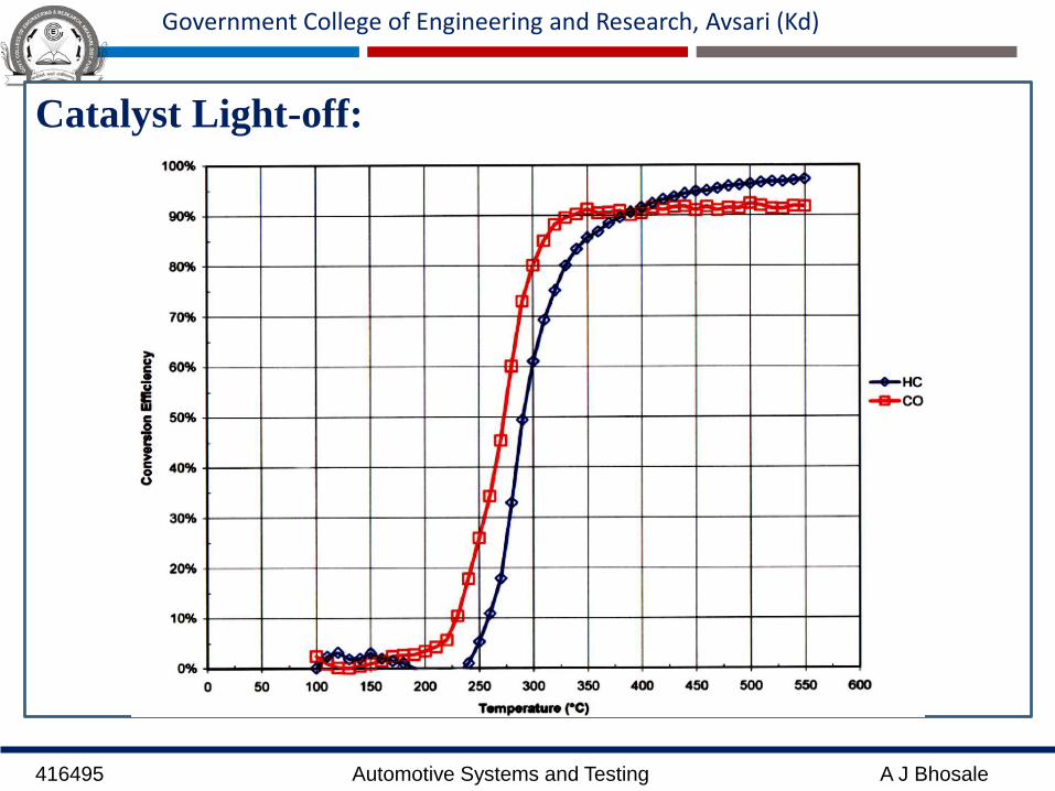
Catalyst Light-off:
416495 Automotive Systems and Testing A J Bhosale
Government College of Engineering and Research, Avsari (Kd)
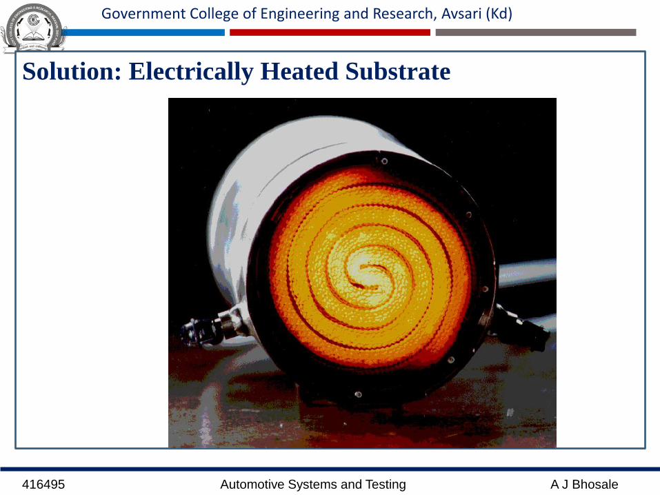
Solution: Electrically Heated Substrate
416495 Automotive Systems and Testing A J Bhosale
Government College of Engineering and Research, Avsari (Kd)
Types of Substrates:

416495 Automotive Systems and Testing A J Bhosale
Government College of Engineering and Research, Avsari (Kd)
Ceramic Substrate Metallic Substrate

416495 Automotive Systems and Testing A J Bhosale
Government College of Engineering and Research, Avsari (Kd)
Comparison:
416495 Automotive Systems and Testing A J Bhosale
Government College of Engineering and Research, Avsari (Kd)
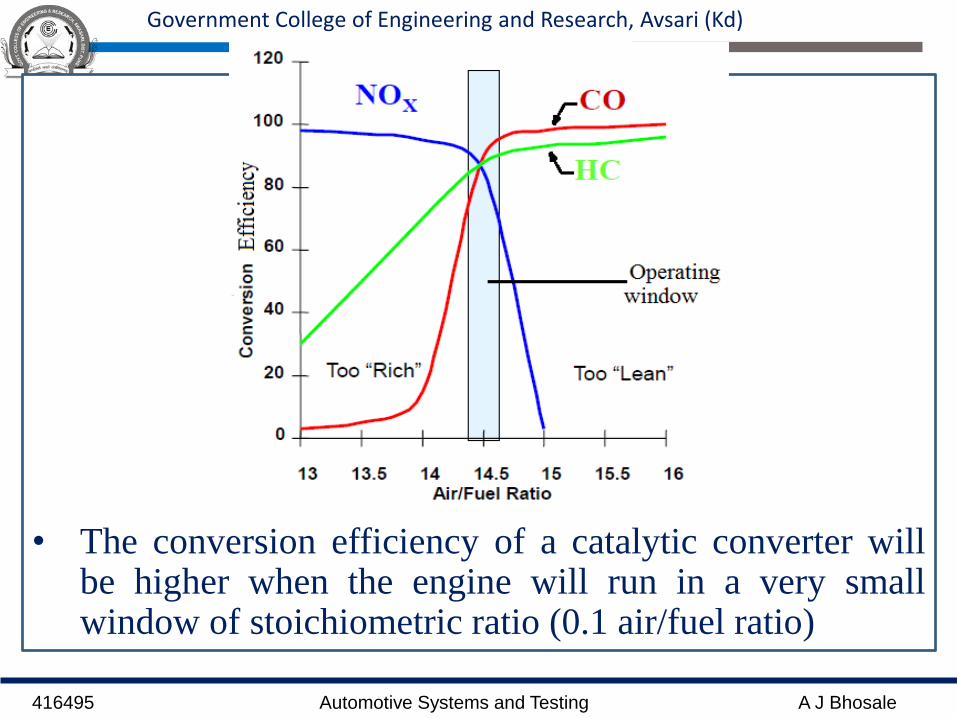
• The conversion efficiency of a catalytic converter willbe higher when the engine will run in a very smallwindow of stoichiometric ratio (0.1 air/fuel ratio)
416495 Automotive Systems and Testing A J Bhosale
Government College of Engineering and Research, Avsari (Kd)
• The conversion efficiency of a TWC depends mostly
air/fuel ratio (Window of ±0.05 air/fuel ratio)
• Controlling the average air/fuel ratio to the tolerances of
the TWC window requires accurate and precise
measurements of air flow rate and precise fuel delivery.
• This precise measurements can be obtained by
electronic engine control system.
416495 Automotive Systems and Testing A J Bhosale
Government College of Engineering and Research, Avsari (Kd)
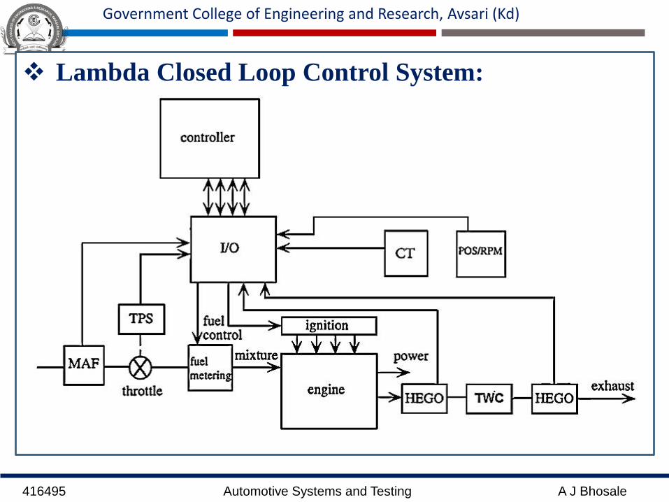
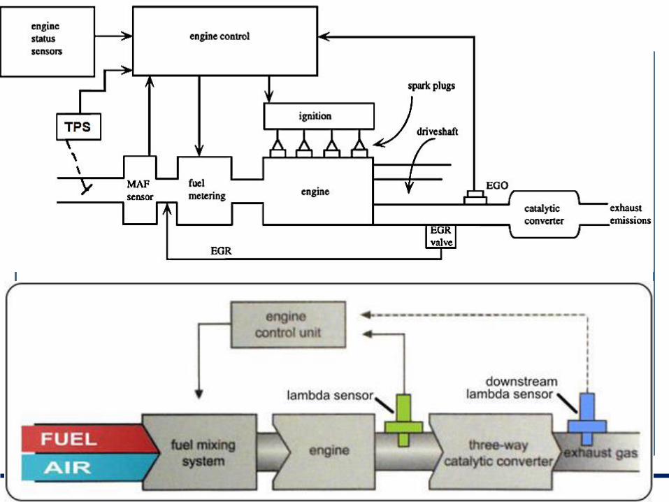
Lambda Closed Loop Control System:

416495 Automotive Systems and Testing A J Bhosale
Government College of Engineering and Research, Avsari (Kd)
MAF-Mass Air Flow Sensor
TPS- Throttle Position Sensor
HEGO-Heated Exhaust Gas Oxygen Sensor
CT- Coolant Temperature Sensor
TWC- 3 way Catalyst
POS/RPM- Position Sensor (Crankshaft RPM)
λ= 𝑎𝑖𝑟/𝑓𝑢𝑒𝑙
𝑎𝑖𝑟
𝑓𝑢𝑒𝑙𝑠𝑡𝑜𝑖𝑐ℎ𝑖𝑜𝑚𝑒𝑡𝑟𝑦
416495 Automotive Systems and Testing A J Bhosale
Government College of Engineering and Research, Avsari (Kd)
416495 Automotive Systems and Testing A J Bhosale
Government College of Engineering and Research, Avsari (Kd)
An average ECU using a narrowband sensor will
generally only use the lambda sensor's output during
two specific conditions:-
(a) during idle, i.e.. when the engine is under no load apart
from keeping itself running, and
(b) during part-load conditions (which we usually term
'cruising speed') where the engine is keeping the car at a
constant speed.
A car equipped with a wideband sensor is able to
usefully use the lambda signal over a wider range of
operating conditions but it is still mostly utilized around
stoichiometry or during lean-burn operation.

416495 Automotive Systems and Testing A J Bhosale
Government College of Engineering and Research, Avsari (Kd)
The ECU will generally ignore the (narrowband)
lambda sensor's output during three conditions:-
(c) when the car is accelerating - the ECU will spent much
of its time deliberately enriching the mixture to avoid
hesitation and to provide extra power, and
(d) when decelerating or 'engine braking', when most
ECU's will shut off the fuel completely to aid economy.
(e) In case of cold starting

416495 Automotive Systems and Testing A J Bhosale
Government College of Engineering and Research, Avsari (Kd)
Look-up Table:

416495 Automotive Systems and Testing A J Bhosale
Government College of Engineering and Research, Avsari (Kd)

416495 Automotive Systems and Testing A J Bhosale
Government College of Engineering and Research, Avsari (Kd)