Centre for Forensic Science - STAX - University of Strathclyde
Upload
khangminh22Category
view
0download
0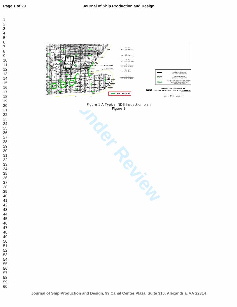
Under Review
Figure 1 A Typical NDE inspection plan
Figure 1
Page 1 of 29
Journal of Ship Production and Design, 99 Canal Center Plaza, Suite 310, Alexandria, VA 22314
Journal of Ship Production and Design
123456789101112131415161718192021222324252627282930313233343536373839404142434445464748495051525354555657585960

Under Review
Figure 2 Classification of weld flaws Figure 2
Page 2 of 29
Journal of Ship Production and Design, 99 Canal Center Plaza, Suite 310, Alexandria, VA 22314
Journal of Ship Production and Design
123456789101112131415161718192021222324252627282930313233343536373839404142434445464748495051525354555657585960

Under Review
Figure 3 Typical weld defects Figure 3
Page 3 of 29
Journal of Ship Production and Design, 99 Canal Center Plaza, Suite 310, Alexandria, VA 22314
Journal of Ship Production and Design
123456789101112131415161718192021222324252627282930313233343536373839404142434445464748495051525354555657585960

Under Review
Figure 4 Effect of Imperfections on the fatigue life of welded joints Figure 4
Page 4 of 29
Journal of Ship Production and Design, 99 Canal Center Plaza, Suite 310, Alexandria, VA 22314
Journal of Ship Production and Design
123456789101112131415161718192021222324252627282930313233343536373839404142434445464748495051525354555657585960

Under Review
Figure 5 Objectives of shipbuilding key stakeholders Figure 5
Page 5 of 29
Journal of Ship Production and Design, 99 Canal Center Plaza, Suite 310, Alexandria, VA 22314
Journal of Ship Production and Design
123456789101112131415161718192021222324252627282930313233343536373839404142434445464748495051525354555657585960

Under Review
Figure 6 Definition of midship length Figure 6
Page 6 of 29
Journal of Ship Production and Design, 99 Canal Center Plaza, Suite 310, Alexandria, VA 22314
Journal of Ship Production and Design
123456789101112131415161718192021222324252627282930313233343536373839404142434445464748495051525354555657585960

Under Review
Figure 7 Typical weld types application in shipbuilding
Figure 7
Page 7 of 29
Journal of Ship Production and Design, 99 Canal Center Plaza, Suite 310, Alexandria, VA 22314
Journal of Ship Production and Design
123456789101112131415161718192021222324252627282930313233343536373839404142434445464748495051525354555657585960

Under Review
Table 1 Summary of Class rules on specifying NDE checkpoints Tabel 1
Page 8 of 29
Journal of Ship Production and Design, 99 Canal Center Plaza, Suite 310, Alexandria, VA 22314
Journal of Ship Production and Design
123456789101112131415161718192021222324252627282930313233343536373839404142434445464748495051525354555657585960

Under Review
Table 2 Typical weld types and process in shipbuilding [18] & [19].
Table 2
Page 9 of 29
Journal of Ship Production and Design, 99 Canal Center Plaza, Suite 310, Alexandria, VA 22314
Journal of Ship Production and Design
123456789101112131415161718192021222324252627282930313233343536373839404142434445464748495051525354555657585960

Under Review
Table 3 Requirements of Classification Societies for Automatic welding and NDE method Table 3
Page 10 of 29
Journal of Ship Production and Design, 99 Canal Center Plaza, Suite 310, Alexandria, VA 22314
Journal of Ship Production and Design
123456789101112131415161718192021222324252627282930313233343536373839404142434445464748495051525354555657585960

Under Review
Table 4 Requirements of Classification Societies for additional inspections
Table 4
Page 11 of 29
Journal of Ship Production and Design, 99 Canal Center Plaza, Suite 310, Alexandria, VA 22314
Journal of Ship Production and Design
123456789101112131415161718192021222324252627282930313233343536373839404142434445464748495051525354555657585960

Under Review
A REVIEW OF NDE METHODS FOR NEW-BUILT SHIPS UNDERGOING CLASS INSPECTION Peyman Amirafshari1, 2, Nigel Barltrop2, Ujjwal Bharadwaj3, Martyn Wright4, Selda Oterkus3
National Structural Integrity Research Centre (NSIRC)1; University of Strathclyde2; TWI Ltd3;
Lloyd’s Register EMEA4
Abstract Classification societies require ship manufacturers to perform non-destructive examination of ship
weldments in order to ensure the welding quality of new-built ships. Ships can contain hundreds of
kilometres of weld lines and 100% inspection of all welded connections is not feasible. Hence, a
limited number of weldments are specified by rules of Classification Societies to be inspected for this
purpose. There is a variation between the rules and guidelines used by different Classification
Societies in terms of both philosophy and implementation which results in significant discrepancy in
the prescribed checkpoints numbers and their locations. In this paper, relevant sections of the rules
of mainstream IACS (International Association of Classification Societies) members are studied and
potential ways of improving them are discussed. The authors have endeavoured to make this study
as comprehensive as possible. However, given the challenges of covering every single aspect and
variable related to non-destructive examination (NDE) in the Classification Societies’ rules and
guidelines reviewed here, the authors can only attempt to cover the key features.
1 Introduction Ship structures are joined with hundreds of kilometres of weld lines. The presence of weld in a
structure potentially reduces the structure's fatigue life by means of introducing a discontinuity into
the completed weld/parent material joint, and introducing residual stress; this could be further
amplified by presences of defects inherent to the welding process. Rules, standards and guidelines
may require manufacturers to carry out certain procedures for enhancing weld's reliability, such as
weld toe grinding to enhance weld profile geometry (and hence fatigue improvement), heat
treatment to improve welded joint's toughness and non-destructive examination (NDE) to detect
weld defects. Performing NDE for finished welds is the best way to find possible defects, and,
relevant rules require manufacturers to do so. However, only a sample of welds is subject to
thorough NDE as it is unfeasible to carry out the same extent of detailed inspection on all ship
weldments.
Since welds are designed assuming a good execution, the rules set flaw size acceptance criteria up to
a point, which aims to verify the good workmanship/quality levels. Ship structures contain a large
number of welded joints and apart from visual inspection it is not feasible to perform 100% NDE.
Hence, Classification Societies tend to use a partial inspection regime by specifying a number of
checkpoints for examination of welds instead of 100% inspection. Figure 1 shows a part of a typical
NDE inspection scheme of a ship with checkpoints highlighted in green colour. This is with a view to
assessing the general quality of welding as well as ensuring that the critical structural elements are
defect-free. This is aimed to be achieved through recommending tables, formulas, and clauses
defining minimum number or length of inspection in various parts of the ship.
Page 12 of 29
Journal of Ship Production and Design, 99 Canal Center Plaza, Suite 310, Alexandria, VA 22314
Journal of Ship Production and Design
123456789101112131415161718192021222324252627282930313233343536373839404142434445464748495051525354555657585960

Under Review
Prescribed tables and equations have evolved over time based on engineering judgement and
historical experiences of cracks found during service, and do not necessarily incorporate structural
analysis of ships.
Each Classification society practices its own set of rules developed on the basis of its own experience
As a result, significant differences exist between final inspection plans from different Classification
Societies, both in terms of their locations and extent.
This paper starts with a summary of the types of defects that can be found by appropriate NDE
regimes and the perspectives of different stakeholders on the NDE inspection regime for new-built
ships. It is important to understand the viewpoint of key parties involved as it has a bearing on the
NDE regime and ultimately the quality of new- built ships. The next section describes key aspects of
NDE inspection as encapsulated in various Classification Societies’ standards or guidelines. Typically
used NDE techniques and how their optimal selection depends to a large extent on the welding
process being used are then described. This is followed by describing acceptance criteria used by
various classification societies and the action required should defects be found. The final section of
this paper identifies potential improvements over the current approaches and introduces risk-based
approaches that are increasingly being used in other industry sectors and are finding acceptance in
the shipping sector.
Figure 1 A Typical NDE inspection plan
1.1 Weld imperfections and structural integrity There is increasing evidence that weld imperfections reduce the fatigue life of welded joints
[1][2][3].Figure 2 lists various weld imperfections and Figure 3 illustrates planar and nonplanar
imperfections (flaws). As reported by Tobbe [4], even defect sizes as small as 0.5 mm wide and 6 mm
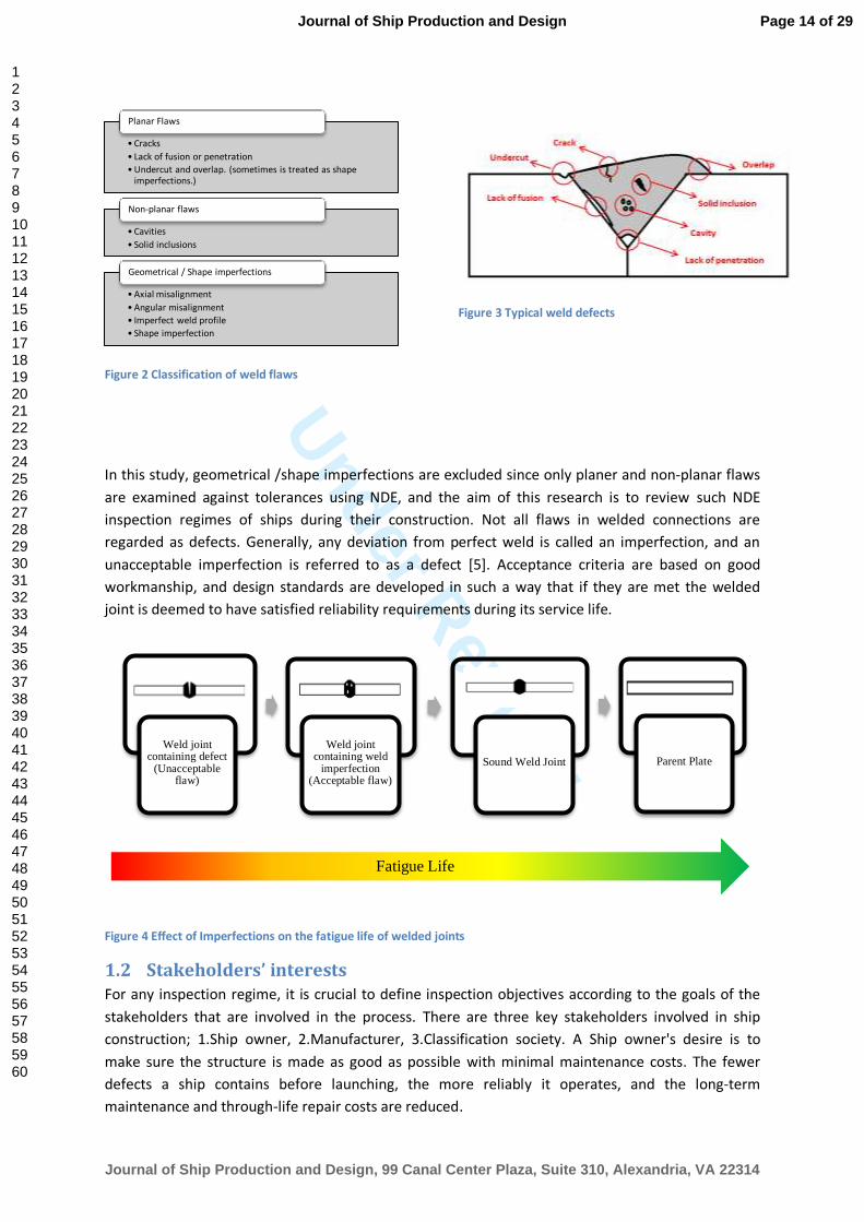
long decrease fatigue life below the average life of a sound weld. Figure 4 shows how weld
imperfection and weld defects reduce fatigue life of the joint compared with sound weld and parent
material. Standards such as ISO 6520 [5]and AWS D3.5 [6] provide a comprehensive guide to the
classification of weld imperfections and are widely adopted by marine industry. They can be
classified into three broad categories: 1.Planar flaws, 2.Non-planar flaws, and 3.Geometrical
imperfections see Figure 2. Non-planar flaws reduce the fatigue life of welded joints, but will be less
damaging if good workmanship levels is ensured[7], [8].
Page 13 of 29
Journal of Ship Production and Design, 99 Canal Center Plaza, Suite 310, Alexandria, VA 22314
Journal of Ship Production and Design
123456789101112131415161718192021222324252627282930313233343536373839404142434445464748495051525354555657585960
Under Review
Figure 2 Classification of weld flaws
Figure 3 Typical weld defects
In this study, geometrical /shape imperfections are excluded since only planer and non-planar flaws
are examined against tolerances using NDE, and the aim of this research is to review such NDE
inspection regimes of ships during their construction. Not all flaws in welded connections are
regarded as defects. Generally, any deviation from perfect weld is called an imperfection, and an
unacceptable imperfection is referred to as a defect [5]. Acceptance criteria are based on good
workmanship, and design standards are developed in such a way that if they are met the welded
joint is deemed to have satisfied reliability requirements during its service life.
Figure 4 Effect of Imperfections on the fatigue life of welded joints
1.2 Stakeholders’ interests For any inspection regime, it is crucial to define inspection objectives according to the goals of the
stakeholders that are involved in the process. There are three key stakeholders involved in ship
construction; 1.Ship owner, 2.Manufacturer, 3.Classification society. A Ship owner's desire is to
make sure the structure is made as good as possible with minimal maintenance costs. The fewer
defects a ship contains before launching, the more reliably it operates, and the long-term
maintenance and through-life repair costs are reduced.
• Cracks
• Lack of fusion or penetration
• Undercut and overlap. (sometimes is treated as shape imperfections.)
Planar Flaws
• Cavities
• Solid inclusions
Non-planar flaws
• Axial misalignment
• Angular misalignment
• Imperfect weld profile
• Shape imperfection
Geometrical / Shape imperfections
Weld joint containing defect
(Unacceptable flaw)
Weld joint containing weld
imperfection (Acceptable flaw)
Sound Weld Joint Parent Plate
Fatigue Life
Page 14 of 29
Journal of Ship Production and Design, 99 Canal Center Plaza, Suite 310, Alexandria, VA 22314
Journal of Ship Production and Design
123456789101112131415161718192021222324252627282930313233343536373839404142434445464748495051525354555657585960

Under Review
Ship manufacturers can reduce construction expenditure by reducing the amount of NDE that needs
to be performed, which in turn results in a reduction of remedial actions and faster shipbuilding.
Ship owners often have ships being built which are classed under different classification societies,
and one concern that may arise is that a classification society with less demand for inspection
checkpoints may have an inspection regime that may not be robust enough. Classification societies
that permit reduced inspection (other things being equal) argue that their rules are sufficient, and
hence there is no need for more extensive inspection.
Manufacturers, on the other hand, would claim that their general workmanship quality is good, and
thus, more inspection is considered 'redundant' (or no value added). They feel that some rules are
overly conservative and do not take into account the welding quality achieved. This means that they
are required to do the same extent of inspection as a manufacturer with a reputation for less
emphasis on welding quality. Classification Societies are keen to rationalise their rules and achieve a
more robust philosophy for their NDE checkpoint regimes. IACS members in particular strive to
establish, review, promote and develop minimum satisfactory technical requirements in relation to
design, construction and survey of ships, and other marine units as part of their commitments to
IACS directions.
Figure 5 Objectives of shipbuilding key stakeholders
2 Current approaches to NDE inspection Current approaches of classification societies are centred around two main concepts: one is to
assess the general quality of ship by defining the number of checkpoints with recommendation of
allocating these checkpoints to more critical members; and, the second is to focus on the relative
criticality of areas and specify the extent of inspection accordingly without specifying a set minimum
number for whole structure. Table 1 summarises rules of classification societies from these two
viewpoints. Most classification societies’ approaches have elements from both these concepts. Some
Optimised NDE
inspection
Ship Builder
•Reduce cost
• Increase the speed of construction
•Reduced inspection and remedial costs, with improved fabrication quality
Classification Society
•Ensure safety of the vessel
• Increase reliability
•Verify that the vessel is built to relevant Rules and Class notations
Ship Owner
•Achieve the best quality
•Reduce through-life maintenance cost
Page 15 of 29
Journal of Ship Production and Design, 99 Canal Center Plaza, Suite 310, Alexandria, VA 22314
Journal of Ship Production and Design
123456789101112131415161718192021222324252627282930313233343536373839404142434445464748495051525354555657585960

Under Review
approaches may lean more to the first concept and some to the other; some are more prescriptive
and some are more principle-based.
2.1 NDE from a Quality-Assurance perspective The extent of NDE in terms of the minimum number of checkpoints or percentage of welded lines is
specified by rules and guidelines. A number of Classification Societies define the number for whole
structure using an equation which is function of dimensions of ship or its members Some
classification societies employ tables defining the percentage or number of checkpoints for
structural members and the rest use a combination of the equation and tables.
ABS
American Bureau of Shipping (ABS) defines minimum number of checkpoints at 0.6L of amidship,
required using following equation:
𝑁 =𝐿∗(𝐵+𝐷)
46.5 ( 2.1-1 )
Where L= length of the vessel between perpendiculars, in metre (see Figure 6). B= greatest moulded
breadth, in metre. D= moulded depth at the side, in metre, measured at L/2. ABS explicitly specifies
that spot check of butt joints should be carried out in order to assess the workmanship quality [9].
RINA
Registro Italiano Navale (RINA) mandates equation (2.1 1) for 0.6L amidship areas and instructs
additional spot examination for areas outside 0.6L area and sensitive locations [10].
KR
Korean Classification society (KR), on the other hand, differentiates between shell plating joints and
internal joints of members and employs equation (2.1 1) to estimate the minimum number of
checkpoints of welded joints of deck and shell plating in 0.6L amidship areas. This number is reduced
to N/10 outside of 0.6L amidship. KR prescribes the required number of checkpoints in table 5 of
KR,[11] 2015. Part 2 materials and welding.[10] , 2015. Part 2 materials and welding. [12] depending
on whether they are inside or outside 0.6L amidship, and general location of members, in terms of
fractions of ship’s length L/40, L/8 and L/16 respectively. This results in higher number of
checkpoints compared to ABS and RINA as far as minimum number of checkpoints is concerned. KR
also recommends additional examinations for the sake of workmanship control for locations such as
parts of start, interrupted and end points of automatically welded joints, welded joints hatch corner
and other high critical areas [12].
NK
Nippon Kaiji Kyokai (NK) defines the number of checkpoints in terms of division of ship length,
individually for each structural member; however as opposed to KR which employs this method only
for internal members, NK applies this method to both internal members and shell platings.
Depending on the type, the location of the member and whether it is a butt joint or fillet weld, the
number of checkpoints differs. Strength deck, side shell plating, bottom shell plating, and hatch side
coaming will have 8 to 12 times more checkpoints than other members. Butt joints in 0.6L have
Page 16 of 29
Journal of Ship Production and Design, 99 Canal Center Plaza, Suite 310, Alexandria, VA 22314
Journal of Ship Production and Design
123456789101112131415161718192021222324252627282930313233343536373839404142434445464748495051525354555657585960

Under Review
three times more checkpoints than those are outside 0.6L area. The number of seam joint
checkpoints in plates remains constant across dimensions of the structure [13]. In ship construction,
it is very common to call butt welds in longitudinal direction along the length of the ship “seam
welds”, and refer to butt welds in transverse direction as “butt welds”.
DNV GL
DNV, on the other hand, doesn’t specify a minimum number of checkpoints and instead requires a
minimum percentage of weld seam needed to be examined. Critical areas receive the most attention
(20% of the weldment needs inspection) followed by deck/bottom plating within 0.4L amidship (5%
of the weldment needs inspection), the lowest amount of examination is prescribed for general
areas with (2% of weld seam length) [14].
LR
Similar to DNV, Lloyds Register doesn’t specify a minimum number checkpoints for the whole ship
and instead recommends the extent of inspection be defined based on type and location of
structural members. Structural members with higher susceptibility to crack initiation receive
significantly higher examination extent, either 50% or 100% examinations. More attention is paid to
the intersection of butt and seams of fabrication and section welds where 50% examination is
required and if these are located at highly stressed area 100% is required. Bilge keel butt welds
within 0.4L amidship are also required to be inspected 100% and 33% outside 0.4L amidship. Other
items, require less examination (1%-5%)[15].
2.2 NDE from a structural criticality perspective When a structure is not 100% examined, members that are considered to be more critical receive
more attention. Classification societies’ rules and standards more or less reflect this rule in their
specifications. As 0.4L to 0.6L amidship area of vessels goes under higher global bending moment,
classification societies require more inspection within this area. Additionally, locations that receive
higher stress levels are also required to receive more attention. These locations are normally
regarded as critical locations. The extent of NDE with regards to critical locations, from different
classification societies’ perspective, are reviewed below.
ABS
ABS recommends that when it comes to the selection of checkpoints, more attention should be paid
to welds in highly stressed areas, and members that are considered as important structural
members by ABS Engineering/Materials/Survey department, but doesn’t specify a quantified
measure or specify any particular members [9].
RINA
RINA, on the other hand, lists members and the area that should be examined. Some of these
require a specific number of checkpoints to be inspected and some are just indicated that they
should be a target for inspection [10].
KR
Page 17 of 29
Journal of Ship Production and Design, 99 Canal Center Plaza, Suite 310, Alexandria, VA 22314
Journal of Ship Production and Design
123456789101112131415161718192021222324252627282930313233343536373839404142434445464748495051525354555657585960

Under Review
KR require selection of checkpoints at 0.6L amidship that is 10 times more than outside of this
region. When it comes to an internal member, the difference between the number of checkpoints in
a member within 0.6L amidship and outside is 2.5 times and 5 times respectively, depending on
structural hierarchy and crack susceptibility. For internal members within 0.6L amidship area, weld
joints located at the strength deck needs to have twice as many checkpoints as other parts due to
their higher contribution to the load resistance [12].
NK
Similar to KR, NK prescribes more inspection checkpoints for butt welds within 0.6L amidship than
outside of this zone but the difference is 3 times [13].
DNV GL
DNV divides the ship into three areas: 1. Critical areas: defined as areas in the way of critical load
transfer points and large stress concentrations where a failure will endanger the safety of the vessel,
2. Deck/bottom plating within 0.4L amidship, 3. General areas Deck/bottom plating within 0.4 L
amidship to be inspected moderately more (5% of their weld seam length) than general areas (2% of
their weld seam length).There is a significant rise in percentage of inspection for critical areas to
20%. 20% of weld seam of fillet welds in critical areas are also required to be examined for surface
cracks using either MPI (Magnetic Particle Inspection) or DPI (Dye Penetrant Inspection).
Examination of fillet welds in general and deck/bottom plating within 0.4L amidship is not required.
DNV states that for vessels with no clearly defined strength deck e.g. cruise ships, the decks which
contribute most to hull strength should be regarded as strength deck [14].
LR
Lloyds Register, as opposed to DNV, requires 100% inspection of all critical areas as identified
through Lloyd’s Register’s ShipRight SDA (Structural Design Assessment) procedure and ShipRight
FDA (Fatigue Design Assessment) procedure [15]. Also, intersections of butts and seams of
fabrication and section welds at highly stressed areas, and hatchways coaming to deck at hatchway
ends within 0.4L amidships, and bilge keel butt welds within 0.4L amidship are required to be 100%
examined. Bilge keel butt welds outside 0.4L are required to be examined 1 in 3 (33%).% of length).
Figure 6 Definition of midship length
Page 18 of 29
Journal of Ship Production and Design, 99 Canal Center Plaza, Suite 310, Alexandria, VA 22314
Journal of Ship Production and Design
123456789101112131415161718192021222324252627282930313233343536373839404142434445464748495051525354555657585960

Under Review
Table 1 Summary of Class rules on specifying NDE checkpoints
Class Sample Type
Extent Equation Joint type
Structural members Area
ABS Number Hull 0.6L N Not Specified
RINA Number Hull 0.6L N Butt
KR Number External members
Within 0.6L N Butt
Outside 0.6L 𝑁/10 Butt
Length Internal members
Within 0.6L 1/8 𝐿, 1/16 𝐿 Butt
Outside 0.6L 1/40 𝐿 Butt
NK Length External members
Within 0.6L 6/10 𝐿, 2/10 𝐿 Butt
Outside 0.6L 2/10 𝐿 Butt
Internal members
Within 0.6L 3/40 𝐿, 1/40 𝐿 Butt
Outside 0.6L 1/40 𝐿 Butt
DNV Percentage Plates Within 0.4L 5% Butt/Tee
General areas Outside 0.4L 2% Butt/Tee
Critical areas Throughout 20% Butt/Tee/Fillet
LR Length Plates Throughout 1m in 25m Butt (Vertical)
1m in 100m Seam(Horizontal)
Structural Items when made with full penetration as follows: 1. Connection of stool and bulkhead to lower stool shelf plating, 2. Vertical corrugations to an inner bottom, 3. Hopper knuckles , and 4. Sheer strake to deck stringer.
Throughout
1m in 20m 1m in 20m
N/A
Hatchways coaming to deck depending on the location where hatchway ends:
within 0.4L All N/A
outside 0.4L 1 in 2 N/A
Remainder 1 in 40 m N/A
Joint
Longitudinal members Within 0.4L 1 in 10 welds Butt(Vertical)
Outside 0.4L 1 in 20 welds Butt(Vertical)
Critical locations Throughout All Not Specified
Bilge Keel Within 0.4L All Butt(Vertical)
Outside 0.4L 1 in 3 Butt(Vertical)
Intersection of butts and seams of fabrications with section welds
Highly stressed
All Butt/Seams
remainder 1 in 2 Butt
2.3 Weld type as a factor for the selection of NDE techniques Welded joints can be made from butt welds or fillet welds. Butt welds can be longitudinally loaded
(also known as seam welds in some standards) or transversely loaded, made fully or partially
penetrated. Figure 7 and Table 1 illustrate some typical applications of weld type in shipbuilding.
Butt weld connections have higher static strength compared to parent materials because the
ultimate strength of deposited metal is more than that of the base metal [16].
Page 19 of 29
Journal of Ship Production and Design, 99 Canal Center Plaza, Suite 310, Alexandria, VA 22314
Journal of Ship Production and Design
123456789101112131415161718192021222324252627282930313233343536373839404142434445464748495051525354555657585960

Under Review
Butt welds generally possess higher fatigue strength as opposed to connections made with fillet
welds. A study by TWI Ltd based on a questionnaire answered by professionals from companies
within TWI industrial membership suggests that joint type is the third most important contributing
factor in defect repair rate; it has 15% influence on defect repair rate. The same study also suggests
that 90% of weld defects are found in fillet welds and 10% in Butt welds [17] .
In this section, the way in which weld type is considered by different classes is reviewed. ABS doesn’t
specify any special requirement or limits the NDE to particular weld joints [9]. RINA, on the other
hand, specifically limits Radiography and Ultrasonic examination to Butt welds, leaving application of
MPI and DPI to surveyors’ decision to complement visual inspection [10]. KR allows application of VT,
MPI, DPI (Visual Testing), MPI, DPI and UT (Ultrasonic Testing) for butt welds, tee joints, corner joints
and cruciform joints with both full and partial penetration and RT only for butt welds with full
penetration, but specifies the distribution of checkpoints only for butt welds [12]. NK and LR specify
distribution of NDE checkpoints for butt welds [13]. DNV requires MPI/DPI of butt T-joints in all areas
and fillet welds in critical areas. DNV requires volumetric examination of butt welds and T-joints with
full penetration while limiting volumetric examination of T-joints to UT [14]. Lloyds Register
emphasises the use of MPI for ends of fillet welds, T-joints or crossings in main structural members
at stern frame connections [15].
Figure 7 Typical weld types application in shipbuilding [18] & [19].
Table 2 Typical weld types and process in shipbuilding [18] & [19].
No. Component Weld type Process Remarks
1 Panel plate to panel plate Horizontal Butt (Seam)
One-sided SAW Automatic
2 Longitudinal member to panel plate
Fillet FCAW Automatic
3 Double bottom inside Fillet FCAW Semi-automatic
4 Side shell(Section weld) Transverse Butt (Butt) FCAW Semi-automatic
EGW Automatic
5 Longitudinal member to Longitudinal member
Transverse Butt (Butt) One-sided FCAW Semi-automatic
6 Tank top plate to Hopper tank plate and bulkhead
Fillet FCAW Semi-automatic
7 Tank top plate to tank top plate
Horizontal Butt (Seam)
One-sided SAW Automatic
One-sided GMAW Automatic GMAW
5
6
7
4 2 1
3
Page 20 of 29
Journal of Ship Production and Design, 99 Canal Center Plaza, Suite 310, Alexandria, VA 22314
Journal of Ship Production and Design
123456789101112131415161718192021222324252627282930313233343536373839404142434445464748495051525354555657585960

Under Review
2.4 NDE techniques Non-destructive examination methods are employed to detect various weld defects. MPI and DPI
are used to detect surface flaws. Radiography and Ultrasonic methods are two volumetric
examination methods widely used to detect internal flaws. Other more advanced methods such as
Time of Flight Diffraction (TOFD) or Phased Array Ultrasonic Testing (PAUT) can also be used but
currently are not very common. All above methods are widely used during the construction of the
ship depending on the limitations of the test object. Generally, UT cannot be applied for plate
thicknesses below 8 mm, where Radiography must be chosen. Radiography requires access to both
sides of the test object and it is not applicable to connections with complex geometries such as T-
joints, cruciform joints and fillet welds.
Table 3, below, summarizes the Classification Societies’ rules and guidelines specifying application of
NDE techniques on finished welds.
2.5 Welding process as a factor in the choice of NDE undertaken Most commonly used welding processes in the shipbuilding industry are: flux-cored arc welding
(FCAWs), submerged arc welding (SAW), double-sided and one-sided, automatic, portable welder,
Line welder, semi-Automatic and robotic (see Table 2). FCAWs are most widely used because it
offers higher deposition rates over other types of filler metals, thus improving welding efficiency.
FCAW also offers high usability in all positions, which is suitable for ship hull construction as hulls
comprise large components with flat, vertical, overhead, and curved welding lines [19].
Since hull structures have many confined areas that are difficult to access, one-sided welding by
FCAW is common. SAW process is particularly used at for one-sided welding of butt joints of large
shell plates [19].
The welding process could also be automated, semi-automated or manual. Automated welding is
more reliable but if defective, it is more likely that defects have occurred more extensively. The
influence of the welder on the weld parameters is, in most cases, limited to pressing start and stop.
The most important variable in automated weld processes is the operator. Hence Classification
Societies rules implement special requirements for automated welded connection, particularly at
start/stop points (See
Table 3).
The welding process seems to be one of the factors affecting the weld quality. Rules related with the
welding requirement are summarised in Table 3.
Table 3 Requirements of Classification Societies for Automatic welding and NDE method
Class Automatic welding NDE method
ABS Can reduce frequency of inspection if Quality-Assurance techniques indicate
consistentsatisfactoryquality,butdoesn’tspecify the amount the reduction
MPI and DPI defined by manufacturer and approved by
surveyors
Volumetric examination check points defined as described
No preference between UT and RT ; left to surveyors decision based on shipyards capabilities
RINA NA MPI and DPI to complement VT
RT is preferred over UT
KC All start/stop points automatic welding MPI is preferred over DPI
Page 21 of 29
Journal of Ship Production and Design, 99 Canal Center Plaza, Suite 310, Alexandria, VA 22314
Journal of Ship Production and Design
123456789101112131415161718192021222324252627282930313233343536373839404142434445464748495051525354555657585960

Under Review
processes to be examined using RT or UT except for internal members
where the extent of testing should be agreed.
Allows reduction of checkpoints if
automatic welding has been carried out and the results of the survey verify
that the quality of welding procedure is consistent satisfactory quality
If a weld that needs to be repaired is
found in an automatically welded joint whose inspections have been
reduced, additional radiographs negating the reduction are required until an appropriate period has
elapsed and the quality is verified to be stable and satisfactory
Extent of MP is not defined
RT is preferred over UT
For thicknesses above 30 mm UT is to be used
NK 1. If defects are found in automatic
welding, additional NDE testing is to be extended to all lengths automatically welded joints
2. In 1. , the faulty welds to be repaired 3. Notwithstanding the requirements
specified in 2., all lengths or all
welded joints may be repaired 4. Faulty welds found in preceding 2, are
to be repaired.
5. Notwithstanding preceding 1 to 4, repair process and additional NDE in other welded joints are to be carried
out according to the surveyors’ direction
RT is preferred over UT
DNV NA 2% of MPI or DPI in general areas
5% of MPI or DPI for locations within 0.4L amidship
20% of MPI or DPI in critical locations
LR NA Radiography for plates below 8 mm
UT for the examination of full penetration tee, butt or cruciform welds or joints of similar configuration
Advanced ultrasonic techniques, such as PAUT, may be used as a volumetric testing in lieu of radiography or manual
ultrasonic testing
Particular attention needs to be given to defect rates of butt welds in longitudinals. If defects are found in more than 10%
of these welds additional inspection needs to be performed.
2.6 Additional inspections Since the inspection is performed partially, it is crucial to interpret the NDE results and to decide if
any additional inspection is needed. This is to: 1.Make sure the presence of defects is not systematic
and if so, such defects are found and rectified, 2. Ensure welding quality is to good workmanship
level. The requirements of Classification Societies for additional inspections are listed in Table 4.
Table 4 Requirements of Classification Societies for additional inspections
Register Additional NDE if one defect found
Additional NDE if defect rate exceeds a certain value
Remarks
ABS Additional UT to determine the extent of non-conformity
If high proportion of checkpoints for
example 90% 95% are defect free, inspection length can be reduced
from 1250mm to 750mm
Additional inspection is to be, if the pattern of non-conformity suggests the
non-conformity exists for an extended distance.
When non-conformity is at the end of a
checkpoint, additional Ultrasonic inspection is required to determine the
extent of the non-conforming area.
RINA NA NA NA
Page 22 of 29
Journal of Ship Production and Design, 99 Canal Center Plaza, Suite 310, Alexandria, VA 22314
Journal of Ship Production and Design
123456789101112131415161718192021222324252627282930313233343536373839404142434445464748495051525354555657585960

Under Review
KC NA If survey before repair exceeds 20% of total
number of checkpoints, it should be increased to a minimum of 40%.
NA
NK 1. Additional NDE for other two parts within welds lines if the defect is found
in plates members and girders
2. In1., non-destructive
testing is to be extended to all length of the welded joints
3. Notwithstanding the requirements specified in 2., all length or all
number of welded joints may be repaired
4. Faulty welds found in 2.,
are to be repaired. 5. Notwithstanding 1. to 4.,
repair process and
additional NDE in other welded joints are to be carried out
If faulty welds are more than 10% of number of inspected, requires
investigation of cause and improving quality
NA
DNV For each section of the weld to be repaired two more of the
same length shall be tested
N/A If systematically repeated defects are
revealed, the extent of the testing shall be increased under same conditions and where similar defects may be expected
If non-conforming discontinuities are found to occur regularly, the reason shall
be investigated. The Welding Procedure Specification (WPS) shall be reassessed before continuation of welding
LR If beyond Normal limits necessary corrective actions need to be taken
When warranted by previous results, the extent should be increased
When continuous or semi continuous defects are found additional length of
welds adjacent to and on both sides of the defective length are to be subject to further volumetric examination
2.7 Acceptance criteria For any weld imperfection there are two approaches for defining acceptance criteria: the first
approach is to define acceptance criteria based on good workmanship level and is generally
independent of the nature the structure, loading and in-service environment. The second approach
is based on Fitness for Service (FFS) which take into accounts stress which the imperfection may
experience during service and the environment in which the structure will operate. A review of
Classification societies’ rules and standards shows that acceptance criteria for weld inspection in
shipbuilding industry is based on good workmanship level and not FFS. This is because FFS requires
detailed fracture mechanics assessment requiring specific inputs that are not commonly available
given the current practice in ship industry. Apart from ABS and DNV, all other Classification Societies
apply the same acceptance criteria for all locations and weld types of a vessel. As per ABS, the areas
to be inspected are categorised in two classes: Class A and Class B. Inspection of full penetration
welds for all surface vessels 150 m (500 ft) and over in the midship 0.6L is to meet the requirements
of Class A. Class A may also be specified and applied to surface vessels less than 150 m (500 ft) when
special hull material or hull design justifies this severity level. Full penetration welds in way of
integral or independent tanks, except membrane tanks, of all vessels intended to carry liquefied
natural gas (LNG) or liquefied petroleum gas (LPG) cargo are to meet the requirements of Class A.
Page 23 of 29
Journal of Ship Production and Design, 99 Canal Center Plaza, Suite 310, Alexandria, VA 22314
Journal of Ship Production and Design
123456789101112131415161718192021222324252627282930313233343536373839404142434445464748495051525354555657585960

Under Review
Inspection of full penetration welds for surface vessels under 150 m (500 ft), and for welds located
outside amidship 0.6L, regardless of the size of the vessels, is to meet the requirements of Class B,
provided that Class A has not been specified in accordance with the special conditions noted in the
Class A criteria above. Areas that are classified as Class A generally have more stringent acceptance
criteria [9]. DNV adopts ISO standards acceptance criteria ISO 23278 [20]for Magnetic particle
testing, ISO 23277 [11] for penetrant testing, ISO 10675 for Radiographic testing [21], and ISO 11666
for Ultrasonic testing [22]. Depending on the location of the checkpoint level, 1-3 (in decreasing
order of rigour of inspection required), an acceptance criteria is assigned. Generally, areas within
0.4L amidships for container ships have a higher level of acceptance criteria for volumetric
inspection [14].
3 Scope for potential improvement
3.1 Limitations of current approaches 1. Current approaches are ‘one-size-fits-all’ in that they do not depend on the ship type nor allow
for a reduction in NDE effort even when there may be clear evidence of good workmanship. In
such cases, the question that arises is what rationale should be applied for determining a
reduced NDE regime.
2. Current inspection planning methods focus on critical structural members; however, such
approaches account only for stress distribution among structural members. An improved
method should take into account defect frequency and size distribution as well as member’s
stress.
3. Current methods do not strictly differentiate between structural members in terms of the
consequence of their failure. Hence, for example, failure of a welded connection in the shell
plate, which can result in water or cargo leakage, has the same severity as a crack failure in a
deck plate of a multi-deck passenger ship.
4. Formation and characteristics of weld defects are a function of welding variables such as welding
process, positions, consumables, etc. Apart from checking start-stop of automated welding,
prescribed by KR, NK and ABS, current approaches do not fully take into account these variables.
5. Although, the defect rate is recorded by shipyard and surveyors, there is no clear explanation
how to interpret this rate: some shipyards adopt a binary method by dividing the number of
failed checkpoints by the total number of checkpoints. Other shipyards use a length by length
method by dividing the total length of defects found by the total length of measured welds. This
results in significant amount of discrepancy between recorded defect rates. It is also not clear
how this number represents the welding quality or how it affects the structural integrity of the
ship. Should there be a benchmark average defect rate? How should this benchmark be defined?
And last but not least, how should this affect the remaining and additional inspections?
6. The number and extent of the inspection checkpoints should include an appropriate sample of
all weldments. The sample should correspond to the desired confidence level and take into
account weld-related variables, structural criticality, as well as the fabrication stage at which the
defect is found. Current rules do not seem to have robust and/ or consistent method to define
the number and the location of inspection checkpoints from the sampling perspective.
Page 24 of 29
Journal of Ship Production and Design, 99 Canal Center Plaza, Suite 310, Alexandria, VA 22314
Journal of Ship Production and Design
123456789101112131415161718192021222324252627282930313233343536373839404142434445464748495051525354555657585960

Under Review
3.2 Risk-based inspection
Risk-based inspection and maintenance has been used in a variety of industry sectors. There are
specific standards for adopting risk-based inspection methods for plant and process equipment [19],
[20], [21], and [23], [24], [25], and [26] and there are many software packages supporting operators
in implementing such approaches, for example RiskWISE® [27]. In the offshore sector, such
approaches have been used particularly for jacket structures, semisubmersibles, and FPSOs integrity
management [28], [29]. In the shipping sector, periodic inspections have traditionally being carried
out. However, recently there has been increasing interest in risk-based inspections [26], [27] ,[30],
[31], and Classification Societies are developing frameworks [23] to enable such approaches to be
used, often complementing the traditional time based approach, but sometimes justifying changes
to periodic inspections. Recent and ongoing developments in shipbuilding technologies and
competitive market demand have pushed shipbuilders to building bigger and more complex ships. It
is a challenge for the stakeholders to ensure the safety and reliability of vessels in a cost effective
way. Application of established risk-based approaches could allow shipbuilders to implement new
complexity and innovations which cannot be justified through current prescriptive rules due to their
limitations [32].
Risk-based methods are useful in the assessment of systems with significant uncertainty; particularly
in degrading structures. Degrading mechanisms are usually governed by variables which pose a great
deal of uncertainty, in these cases the assessors have two options: 1. Deal with the problem by
reasonably presuming the worst case scenario and design or inspect the structure accordingly, which
is not always feasible. 2. Collect as much information as possible to reduce the uncertainty in order
to predict the degradation of the system more accurately, and also to assess the consequence of the
degradation. These two steps allow assessors to make a better decision. Risk in this context is the
combination of the likelihood of an undesirable event and the consequence of such event. Once the
risk that is associated with components or system is estimated, one can take action towards the
improvement of that component or system. The improvement can be in design, or optimising
inspection maintenance interval or extent. Risk assessment can be Qualitative which normally
involves extensive use of engineering judgement, or Quantitative which requires a significant
amount of data and numerical estimation of failure probability of the structure. A third approach is
semi-quantitative where the attributes are those of both quantitative and qualitative approaches.
The choice of the assessment depends on the availability of the data and assessment tools.
3.3 Risk-based approach in conjunction with sampling theory for Quality-
Assurance Risk-based approaches support decision makers to optimise their inspection by making targeted
inspections such that the asset system remains within tolerable levels of risk. In certain cases, time
based regimes are informed by risk-based assessments to justify reduced or more inspection (both
in terms of inspection frequency and extent).
To address the ‘one-size-fits-all’ NDE inspection regime, in which regardless of evidence of good
workmanship in a particular shipyard, the same rigorous regime is advocated, experience from
quality-assurance as used in other industry sectors can be transferred. One could have two levels of
inspection with the first level aimed at assessing the quality of workmanship from an appropriate
sample (so that desired confidence is achieved) and depending on the result of the first level,
determine a more detailed level (with a bigger sample of inspection checkpoints) that is required.
Page 25 of 29
Journal of Ship Production and Design, 99 Canal Center Plaza, Suite 310, Alexandria, VA 22314
Journal of Ship Production and Design
123456789101112131415161718192021222324252627282930313233343536373839404142434445464748495051525354555657585960

Under Review
4 Concluding remarks Ship structures are made of steel members that are joined with welds. Welded connections may
contain various imperfection and flaws if welding procedure specification (WPS) parameters are not
strictly adhered to. These imperfections are inherent to this joining technology. Design rules and
standards are based on the assumption that welds are made to good workmanship level. Any
excessive imperfection beyond good workmanship level is considered to be unacceptable and
regarded as a defect. Hence, a ship is inspected during construction to make sure it is reasonably
defect free. However, since 100% inspection coverage is not feasible, only partial inspection has
been required by Classification Societies. Classification Societies have developed rules, standards
and guidelines specifying the extent to which inspection should be performed, which intends to:
1. Verify welding execution quality level,
2. Ensure that areas and members with higher susceptibility to defects receive sufficient attention,
3. Find and rectify any excessive variation in defect rates
A review of rules and standards from classification bodies that are members of IACS shows some
limitations in current practices. One key limitation is that the rules favour a ‘one-size-fits-all’
approach. In addition to that, significant discrepancy exists between rules of different classification
societies. Inspection regimes need to be adjusted taking cognisance of the perspectives of key
stakeholders involved in shipbuilding - specifically, ship owners, manufacturers, and Classification
societies. Factors that interest these stakeholders include: assurance of intended safety and
structural reliability of the vessel; saving time and the costs associated with NDE and subsequent
remedial action; and, incorporating manufacturing quality.
A promising way to achieve targeted and cost-effective inspections is to take a risk-based approach
to inspection. The risk-based inspection (RBI) process helps to identify the potential hazard and
failure scenarios, their likelihood and their corresponding consequence which in turn enables
decision makers to optimise inspection. Current rules, standards and guidelines, in essence, have
some level of qualitative risk assessment built into them. However this assessment has evolved over
time, and is substantially based on expert opinion and engineering judgement. The authors propose
a more systematic and quantitative (analyses – based) approach.
For the purpose of inspection during manufacturing (QC inspection), the risk-based approach needs
to be further complemented by statistical methods in order to allow incorporating data and
experiences from a manufacturer’s quality-assurance program so that the amount of inspection may
be adjusted based upon the expected level of quality.
5 Acknowledgment This publication was made possible by the sponsorship and support of Lloyd’s Register Foundation
(LRF). The work was enabled through, and undertaken at, the National Structural Integrity Research
Centre (NSIRC), a postgraduate engineering facility for industry-led research into structural integrity.
NSIRC was established and is managed by TWI through a network of both national and international
Universities, and industry. For the purpose of this research, the University of Strathclyde, LRF and
TWI Ltd collaborated under the auspices of NSIRC.
Page 26 of 29
Journal of Ship Production and Design, 99 Canal Center Plaza, Suite 310, Alexandria, VA 22314
Journal of Ship Production and Design
123456789101112131415161718192021222324252627282930313233343536373839404142434445464748495051525354555657585960

Under Review
6 References
[1] F. Mashiri, X.-L. Zhao, and P. Grundy, “Effects of weld profile and undercut on fatigue
crack propagation life of thin-walled cruciform joint,” Thin-walled structures, vol. 39,
no. 3, pp. 261–285, 2001.
[2] H. Remes and W. Fricke, “Influencing factors on fatigue strength of welded thin plates
based on structural stress assessment,” Welding in the World, vol. 58, no. 6, pp. 915–
923, 2014.
[3] A. Deshmukh, G. Venkatachalam, H. Divekar, and M. Saraf, “Effect of Weld
Penetration On Fatigue Life,” Procedia Engineering, vol. 97, pp. 783–789, 2014.
[4] Y. Tobe and F. Lawrence Jr, “Effect of inadequate joint penetration on fatigue
resistance of high-strength structural steel welds,” Weld. J.(Miami);(United States), vol.
56, 1977.
[5] B. ISO, “6520-1 (2007)‘Welding and allied processes: Classification of geometric
imperfections in metallic materials,’” Part 1: Fusion Welding, pp. 6520–1, 2007.
[6] A. C. on W. in M. Construction, D3.5:1993(R2000) GUIDE FOR STEEL HULL
WELDING. American Welding Society, 1992.
[7] P. Haagensen and S. Maddox, “Specifications for weld toe improvement by burr
grinding, tig dressing and hammer peening for transverse welds,” IIW Commission XⅢ-
Working Group, vol. 2, 1995.
[8] D. Béghin, O. F. Hughes, and J. K. Paik, Ship structural analysis and design. Society of
Naval Architects and Marine Engineers, 2010.
[9] A. B. of Shipping, Guide for non-destructive inspection of hull welds. 2014.
[10] RINA, Rules for carrying out non-destructive examinations of welding. RINA S.p.A.,
2007.
[11] BSI, Non-destructive testing of welds — Penetrant testing — Acceptance levels (ISO
23277:2015). BSI Standards Limited, 2015.
[12] KR, “Part 2 Materials and welding,” 2015, pp. 81–94.
[13] NK, “Rules for the survey and construction of steel ships,” 2015, pp. 24–31.
[14] DNV.GL, “Rules for classification Ships Part 2 Materials and welding Chapter 4
Fabrication and testing,” 2015, pp. 80–85.
[15] L. R. of S. (Firm: 1914-), “Rules and Regulations for the Classification of Ships,”
Lloyd’s Register of Shipping, 2015, pp. 352–354.
Page 27 of 29
Journal of Ship Production and Design, 99 Canal Center Plaza, Suite 310, Alexandria, VA 22314
Journal of Ship Production and Design
123456789101112131415161718192021222324252627282930313233343536373839404142434445464748495051525354555657585960

Under Review
[16] Y. Okumoto, Y. Takeda, M. Mano, and T. Okada, Design of ship hull structures: a
practical guide for engineers. Springer Science \& Business Media, 2009.
[17] C. F. W. Marcello Consonni, “Repair rates in welded construction - an analysis of
industry trends,” Welding & Cutting, no. 1, pp. 33–35, 2012.
[18] R. Boekholt, Welding Mechanisation and Automation in Shipbuilding Worldwide:
Production Methods and Trends Based on Yard Capacity. Abington Publishing, 1996.
[19] Kobelco, “State-of-the-art automatic arc welding processes meet the latest shipbuilding
requirements,” Kobelco welding today, vol. 14, 2011.
[20] BSI, Non-destructive testing of welds — Magnetic particle testing — Acceptance levels(
ISO 23278:2015). The British Standards Institution, 2015.
[21] BSI, Non-destructive testing of welds — Acceptance levels for radiographic testing Part
1: Steel, nickel, titanium and their alloys. The British Standards Institution, 2013.
[22] BSI, Non-destructive testing of welds — Ultrasonic testing — Acceptance levels (ISO
11666:2010). The British Standards Institution, 2011.
[23] Guidance Notes for Risk Based Inspection of Hull Structures.
http://www.lr.org/en/energy/compliance/rules-supporting-software-and-
guidance/guidelines/risk-based-inspection-for-hull-structures/: Lloyd’s Register Group
Limited, 2015.
[24] 206 Risk Based Inspection: A Guide To Effective Use Of The RBI Process. EEMUA,
2006.
[25] API Recommended Practice 580 Risk Based Inspection. USA: API Publications, 2009.
[26] API RP 581 Risk Based Inspection Technology. USA: API, 2008.
[27] “RISKWISE software for Risk Based Inspection (RBI) / Risk Based Maintenance
(RBM) software for Oil, Gas & Chemical Plant and Power Plant.” [Online]. Available:
http://www.twisoftware.com/riskwise. [Accessed: 25–05-2016]
[28] A. Lee, C. Serratella, G. Wang, R. Basu, R. Spong, and others, “Flexible approaches to
risk-based inspection of FPSOs,” in Offshore Technology Conference, 2006.
[29] DNV, Probabilistic methods for planning of inspection for fatigue cracks in offshore
structures. 2015.
[30] U. Bharadwaj and J. Wintle, “Risk-Based Optimization of Inspection Planning in
Ships,” Journal of Ship Production and Design, vol. 27, no. 3, pp. 111–117, 2011.
[31] N. Barltrop, “Final Report Summary - RISPECT (Risk-Based Expert System for
Through–Life Ship Structural Inspection and Maintenance and New-Build Ship
Structural Design),” 2014. [Online]. Available:
Page 28 of 29
Journal of Ship Production and Design, 99 Canal Center Plaza, Suite 310, Alexandria, VA 22314
Journal of Ship Production and Design
123456789101112131415161718192021222324252627282930313233343536373839404142434445464748495051525354555657585960

Under Review
http://cordis.europa.eu/result/rcn/143029_en.html. [Accessed: 23–05-2016]
[32] A. Papanikolaou, Risk-based ship design: Methods, tools and applications. Springer
Science \& Business Media, 2009.
Page 29 of 29
Journal of Ship Production and Design, 99 Canal Center Plaza, Suite 310, Alexandria, VA 22314
Journal of Ship Production and Design
123456789101112131415161718192021222324252627282930313233343536373839404142434445464748495051525354555657585960
Copyright © 2022 FDOKUMEN