under confirmation
165
TWO ROOM MULTI INVERTER SYSTEM Outdoor unit Indoor unit ASYG07LJCA ASYG09LJCA ASYG12LJCA ASYG07LUCA ASYG09LUCA ASYG12LUCA ASYG07LMCA ASYG09LMCA ASYG12LMCA ASYG07LJCA ASYG09LJCA ASYG12LJCA ASYG07LUCA ASYG09LUCA ASYG12LUCA ASYG14LUCA ASYG07LMCA ASYG09LMCA ASYG12LMCA ASYG14LMCA AUYG07LVLA AUYG09LVLA AUYG12LVLA AUYG12LVLB UTG-UFYD-W AGYG09LVCA AGYG12LVCA ARYG07LLTA ARYG09LLTA ARYG12LLTA ARYG12LLTB AOYG14LAC2 AOYG18LAC2 CONTENTS SPECIFICATIONS . . . . . . . . . . . . . . . . . . .1 DIMENSIONS. . . . . . . . . . . . . . . . . . . . . . .7 REFRIGERANT SYSTEM DIAGRAM under confirmation . . . 13 ERROR DETECTION. . . . . . . . . . . . . . . . 41 CIRCUIT DIAGRAM . . . . . . . . . . . . . . . . . 14 OUTNDOOR PCB CIRCUIT DIAGRAM. . . 20 INDOOR PCB CIRCUIT DIAGRAM . . . . . 24 PARTS (OUTDOOR UNIT) . . . . . . . . . . . . . 42 PARTS (INDOOR UNIT) . . . . . . . . . . . 45 ACCESSORIES . . . . . . . . . . . . . . . . . . . . 67
-
Upload
khangminh22 -
Category
Documents
-
view
0 -
download
0
Transcript of under confirmation

TWO ROOM MULTIINVERTER SYSTEM
Outdoor unit Indoor unit
ASYG07LJCAASYG09LJCAASYG12LJCAASYG07LUCAASYG09LUCAASYG12LUCAASYG07LMCAASYG09LMCAASYG12LMCA
ASYG07LJCAASYG09LJCAASYG12LJCAASYG07LUCAASYG09LUCAASYG12LUCAASYG14LUCAASYG07LMCAASYG09LMCAASYG12LMCAASYG14LMCAAUYG07LVLAAUYG09LVLAAUYG12LVLAAUYG12LVLBUTG-UFYD-WAGYG09LVCAAGYG12LVCAARYG07LLTAARYG09LLTAARYG12LLTAARYG12LLTB
AOYG14LAC2
AOYG18LAC2
CONTENTSSPECIFICATIONS . . . . . . . . . . . . . . . . . . .1
DIMENSIONS. . . . . . . . . . . . . . . . . . . . . . .7
REFRIGERANT SYSTEM DIAGRAM
under confirmation
. . .13
ERROR DETECTION. . . . . . . . . . . . . . . .41
CIRCUIT DIAGRAM . . . . . . . . . . . . . . . . .14
OUTNDOOR PCB CIRCUIT DIAGRAM. . .20
INDOOR PCB CIRCUIT DIAGRAM. . . . .24
PARTS (OUTDOOR UNIT)
. . . . . . . . . . . . .
42
PARTS (INDOOR UNIT)
. . . . . . . . . . .
45
ACCESSORIES. . . . . . . . . . . . . . . . . . . .67

Total Pipe Length
FULL CHARGE
MODEL NAME
COOLING CAPACITY
HEATING CAPACITYPOWER SUPPLY
FREQUENCY
RUNNING CURRENT
INPUT POWER
EER
AIR CIRCULATION HIGH
ELECTRICAL SPECIFICATIONS
230V
CoolingHeating
Cooling
Heating
CoolingHeating
Cooling
Heating
TYPE Two room multi
AOYG14LAC2
4.0 kW
4.4 kW
5.1 A
4.9 A
MAXIMUM CURRENT6.7 A
8.5 A
1.09 kW
1.03 kW
3.67 kW/kW
4.27 kW/kW
50 Hz
1,850 m3/hr
MAXIMUM PIPE LENGTH (each unit)
MAXIMUM PIPE LENGTH (total)
20 m
25 m30 m
ADDITIONAL CHARGE
1,250 g
1,300 g
1,350 g10 g/m
20 m
MINIMUM PIPE LENGTH (each unit) 3 m
MINIMUM PIPE LENGTH (total) 6 m
30 m
MAX ELEVATION (between indoor units) 10 m
MAX ELEVATION (between IU and OU) 15 m
OUTDOOR UNIT
SPECIFICATIONS
COMPRESSOR AND REFRIGERANT
FAN MOTOR
MEASUREMENT
COMPRESSOR TYPE
DISCRIMINATION DA108X1C-20FZA1
REFRIGERANT TYPE R410A
PRECHARGED REFRIGERANT 1,250 gWEIGHT (including oil) 10.4 kg
540 x 790 x 290 mm
41 kg / 37 kgWEIGHT
DIMENSIONS
MFE-40VVL
820 r.p.m.
H x W x D
Shipping / Net
HIGH SPEED (HEAT)
820 r.p.m.HIGH SPEED (COOL)
DISCRIMINATION
12011.02.23
NOISE LEVEL
HEAT
COOL 47 dB(A)
49 dB(A)
230V
AOYG18LAC2
5.0 kW
5.6 kW
6.9 A
6.3 A
8.7 A
9.2 A
1.56 kW
1.41 kW
3.21 kW/kW
3.97 kW/kW
50 Hz
2,050 m3/hr
1,300 g
1,400 g
1,500 g20 g/m
808-911-80B
R410A
1,300 g10.0 kg
42 kg / 38 kg
MFE-40VVL
900 r.p.m.
900 r.p.m.
50 dB(A)
51 dB(A)
Hermetic rotary,4 poles, DC inverter,
1-cylinder type
Hermetic rotary,4 poles, DC inverter,
2-cylinder type

High
DISCRIMINATION
Medium
Low
H x W x D 280 x 790 x 203 mm
FAN MOTOR
MEASUREMENTS
Net / Shipping 8.0 kg / 10.5 kg
MFD-12TYAN
1,050 r.p.m. 1,100 r.p.m. 1,200 r.p.m.
950 r.p.m. 980 r.p.m. 1,050 r.p.m.
850 r.p.m. 850 r.p.m. 880 r.p.m.
Quiet
Quiet
710 r.p.m. 710 r.p.m. 710 r.p.m.
1,050 r.p.m. 1,100 r.p.m. 1,200 r.p.m.
950 r.p.m. 980 r.p.m. 1,050 r.p.m.
850 r.p.m. 850 r.p.m. 910 r.p.m.
720 r.p.m. 720 r.p.m. 720 r.p.m.
INDOOR UNITCOMPACT WALL MOUNTED
ASYG12LJCAASYG09LJCAASYG07LJCAMODEL NAME
FAN SPEED
DIMENSIONS
WEIGHT
2.0 kW class 2.5 kW class 3.5 kW class
ELECTRICAL DATA
600 m3/h560 m3/h 660 m3/h
520 m3/h500 m3/h 560 m3/h
430 m3/h430 m3/h 450 m3/h
340 m3/h340 m3/h 340 m3/h
600 m3/h560 m3/h 660 m3/h
520 m3/h500 m3/h 560 m3/h
430 m3/h430 m3/h 470 m3/h
350 m3/h350 m3/h 350 m3/h
CAPACITY
AIR FLOW
Cooling
Heating
Cooling
Heating
High
Medium
36 dB(A)
Low
High
Medium
Low
Quiet
Quiet
High
Medium
Low
Cooling
Heating
High
Medium
Low
Quiet
Quiet
High
Medium
Low
29 dB(A)
37 dB(A)
29 dB(A)
40 dB(A)
30 dB(A)
25 dB(A) 25 dB(A) 25 dB(A)
32 dB(A) 33 dB(A) 36 dB(A)
36 dB(A)
29 dB(A)
37 dB(A)
29 dB(A)
40 dB(A)
31 dB(A)
25 dB(A) 25 dB(A) 25 dB(A)
32 dB(A) 33 dB(A) 36 dB(A)
NOISE LEVEL
22011.01.25
High
DISCRIMINATION
Medium
Low
H x W x D 282 x 870 x 185 mm
FAN MOTOR
MEASUREMENTS
Net / Shipping 9.5 kg / 12.0 kg
MFE-60TVT
1,030 r.p.m. 1,180 r.p.m.
950 r.p.m. 1,080 r.p.m.
850 r.p.m. 980 r.p.m.
Quiet
Quiet
650 r.p.m. 740 r.p.m.
1,030 r.p.m. 1,180 r.p.m.
950 r.p.m. 1,080 r.p.m.
850 r.p.m. 1,010 r.p.m.
650 r.p.m. 790 r.p.m.
INDOOR UNITCOMPACT WALL MOUNTED
MODEL NAME
FAN SPEED
DIMENSIONS
WEIGHT
2.5 kW class 4.0 kW class
ELECTRICAL DATA
600 m3/h 710 m3/h
550 m3/h 640 m3/h
470 m3/h 570 m3/h
330 m3/h 390 m3/h
600 m3/h 710 m3/h
550 m3/h 640 m3/h
470 m3/h 590 m3/h
330 m3/h 430 m3/h
CAPACITY
AIR FLOW
Cooling
Heating
Cooling
Heating
High
Medium
Low
High
Medium
Low
Quiet
Quiet
High
Medium
Low
Cooling
Heating
High
Medium
Low
Quiet
Quiet
High
Medium
Low
36 dB(A)
28 dB(A)
41 dB(A)
33 dB(A)
21 dB(A) 25 dB(A)
32 dB(A) 36 dB(A)
36 dB(A)
28 dB(A)
41 dB(A)
34 dB(A)
21 dB(A) 27 dB(A)
32 dB(A)
980 r.p.m.
910 r.p.m.
850 r.p.m.
650 r.p.m.
980 r.p.m.
910 r.p.m.
850 r.p.m.
650 r.p.m.
570 m3/h
520 m3/h
470 m3/h
330 m3/h
570 m3/h
520 m3/h
470 m3/h
330 m3/h
35 dB(A)
28 dB(A)
21 dB(A)
30 dB(A)
35 dB(A)
28 dB(A)
21 dB(A)
30 dB(A) 36 dB(A)
1,110 r.p.m.
1,030 r.p.m.
930 r.p.m.
650 r.p.m.
1,110 r.p.m.
1,030 r.p.m.
930 r.p.m.
650 r.p.m.
660 m3/h
600 m3/h
530 m3/h
330 m3/h
660 m3/h
600 m3/h
530 m3/h
330 m3/h
37 dB(A)
31 dB(A)
21 dB(A)
34 dB(A)
37 dB(A)
31 dB(A)
21 dB(A)
34 dB(A)
NOISE LEVEL
ASYG09LUCA
2.0 kW class
ASYG07LUCA
3.5 kW class
ASYG12LUCA ASYG14LUCA

under confirmation
High
DISCRIMINATION
Medium
Low
H x W x D 268 x 840 x 203 mm
FAN MOTOR
MEASUREMENTS
Net / Shipping 8.5 kg / 10.5 kg
MFD-12CYN
1,320 r.p.m.
1,160 r.p.m.
930 r.p.m.
Quiet
Quiet
680 r.p.m.
1,320 r.p.m.
1,160 r.p.m.
980 r.p.m.
710 r.p.m. 790 r.p.m.
1,040 r.p.m.
1,220 r.p.m.
1,360 r.p.m.
750 r.p.m.
990 r.p.m.
1,220 r.p.m.
1,360 r.p.m.
INDOOR UNITCOMPACT WALL MOUNTED
PANEL
ASYG12LMCA ASYG14LMCAASYG09LMCAASYG07LMCAMODEL NAME
FAN SPEED
DIMENSIONS
WEIGHT
H x W x D 49 x 700 x 700 mm
MEASUREMENTS
Net / Shipping 2.6 kg / 4.5 kg
DIMENSIONS
WEIGHT
UTG-UFYD-WMODEL NAME
2.0 kW class 2.5 kW class 3.5 kW class 4.0 kW class
ELECTRICAL DATA
600 m3/h 770 m3/h
640 m3/h
570 m3/h
390 m3/h
710 m3/h
640 m3/h
590 m3/h
430 m3/h
550 m3/h
470 m3/h
330 m3/h
600 m3/h
550 m3/h
470 m3/h
330 m3/h
CAPACITY
AIR FLOW
Cooling
Heating
Cooling
Heating
High
Medium
43 dB(A)
Low
High
Medium
Low
Quiet
Quiet
High
Medium
Low
Cooling
Heating
High
Medium
Low
Quiet
Quiet
High
Medium
Low
32 dB(A)
44 dB(A)
40 dB(A)
33 dB(A)
25 dB(A)
44 dB(A)
40 dB(A)
35 dB(A)
27 dB(A)
21 dB(A)
40 dB(A)
43 dB(A)
33 dB(A)
22 dB(A)
38 dB(A)
NOISE LEVEL
32013.04.25
High
DISCRIMINATION
Medium
Low
H x W x D 268 x 840 x 203 mm
FAN MOTOR
under confirmation
MEASUREMENTS
Net / Shipping 8.5 kg / 10.5 kg
MFD-12CYN
1,320 r.p.m. 1,360 r.p.m.
1,160 r.p.m. 1,220 r.p.m.
930 r.p.m. 990 r.p.m.
Quiet
Quiet
680 r.p.m. 750 r.p.m.
1,320 r.p.m. 1,360 r.p.m.
1,160 r.p.m. 1,220 r.p.m.
980 r.p.m. 1,040 r.p.m.
710 r.p.m. 790 r.p.m.
INDOOR UNITCOMPACT WALL MOUNTED
MODEL NAME
FAN SPEED
DIMENSIONS
WEIGHT
2.5 kW class 4.0 kW class
ELECTRICAL DATA
600 m3/h 770 m3/h
550 m3/h 640 m3/h
470 m3/h 570 m3/h
330 m3/h 390 m3/h
600 m3/h 710 m3/h
550 m3/h 640 m3/h
470 m3/h 590 m3/h
330 m3/h 430 m3/h
CAPACITY
AIR FLOW
Cooling
Heating
Cooling
Heating
High
Medium
Low
High
Medium
Low
Quiet
Quiet
High
Medium
Low
Cooling
Heating
High
Medium
Low
Quiet
Quiet
High
Medium
Low
43 dB(A)
32 dB(A)
44 dB(A)
33 dB(A)
21 dB(A) 25 dB(A)
40 dB(A) 40 dB(A)
43 dB(A)
33 dB(A)
44 dB(A)
35 dB(A)
22 dB(A) 27 dB(A)
38 dB(A) 40 dB(A)
NOISE LEVEL
32013.04.25
ASYG09LMCA
2.0 kW class
ASYG07LMCA
3.5 kW class
ASYG12LMCA ASYG14LMCA
High
DISCRIMINATION
Medium
Low
H x W x D 320 x 998 x 228 mm
FAN MOTOR
MEASUREMENTS
Net / Shipping 14 kg / 18 kg
MFD-50RON
1,250 r.p.m.
1,020 r.p.m.
900 r.p.m.
Quiet
Quiet
770 r.p.m.
1,250 r.p.m.
1,020 r.p.m.
900 r.p.m.
790 r.p.m.
INDOOR UNITWALL MOUNTED
ASYG18LFCAMODEL NAME
FAN SPEED
DIMENSIONS
WEIGHT
5.0 kW class
ELECTRICAL DATA
920 m3/h
740 m3/h
620 m3/h
550 m3/h
920 m3/h
740 m3/h
620 m3/h
550 m3/h
CAPACITY
AIR FLOW
Cooling
Heating
Cooling
Heating
High
Medium
43 dB(A)
Low
High
Medium
Low
Quiet
Quiet
High
Medium
Low
Cooling
Heating
High
Medium
Low
Quiet
Quiet
High
Medium
Low
33 dB(A)
31 dB(A)
37 dB(A)
44 dB(A)
33 dB(A)
31 dB(A)
37 dB(A)
NOISE LEVEL

High
DISCRIMINATION
Medium
Low
H x W x D 245 x 570 x 570 mm
FAN MOTOR
MEASUREMENTS
Net / Shipping 15 kg / 18 kg
MFF-24RVL
590 r.p.m. 660 r.p.m.
540 r.p.m. 580 r.p.m.
490 r.p.m. 520 r.p.m.
Quiet
Quiet
440 r.p.m. 460 r.p.m.
590 r.p.m. 650 r.p.m.
540 r.p.m. 580 r.p.m.
490 r.p.m. 520 r.p.m.
440 r.p.m.
590 r.p.m.
540 r.p.m.
490 r.p.m.
440 r.p.m.
590 r.p.m.
540 r.p.m.
490 r.p.m.
440 r.p.m. 460 r.p.m.
INDOOR UNITCOMPACT CASSETTE
PANEL
AUYG12LVLAAUYG12LVLBAUYG09LVLAAUYG07LVLAMODEL NAME
FAN SPEED
DIMENSIONS
WEIGHT
H x W x D 49 x 700 x 700 mm
MEASUREMENTS
Net / Shipping 2.6 kg / 4.5 kg
DIMENSIONS
WEIGHT
UTG-UFYD-WMODEL NAME
2.0 kW class 2.5 kW class 3.5 kW class
ELECTRICAL DATA
610 m3/h540 m3/h
530 m3/h490 m3/h
470 m3/h440 m3/h
410 m3/h390 m3/h
610 m3/h540 m3/h
530 m3/h490 m3/h
470 m3/h440 m3/h
410 m3/h390 m3/h
CAPACITY
AIR FLOW
Cooling
Heating
Cooling
Heating
High
Medium
33 dB(A)
Low
High
Medium
Low
Quiet
Quiet
High
Medium
Low
Cooling
Heating
High
Medium
Low
Quiet
Quiet
High
Medium
Low
29 dB(A)
37 dB(A)
31 dB(A)
27 dB(A) 28 dB(A)
31 dB(A) 33 dB(A)
34 dB(A)
29 dB(A)
37 dB(A)
31 dB(A)
27 dB(A) 28 dB(A)
32 dB(A)
540 m3/h
490 m3/h
440 m3/h
390 m3/h
540 m3/h
490 m3/h
440 m3/h
390 m3/h33 dB(A)
29 dB(A)
27 dB(A)
31 dB(A)
34 dB(A)
29 dB(A)
27 dB(A)
32 dB(A) 33 dB(A)
NOISE LEVEL
42011.01.25

2011.01.25 5
H x W x D 600 x 740 x 200 mmMEASUREMENT
DIMENSIONS
Net / Shipping 14 kg / 17 kgWEIGHT
MODEL NAMECAPACITY
INDOOR UNITFLOOR
AGYG12LVCAAGYG09LVCA
AIRCIRCULATIONHIGH
570 m3/hr
600 m3/hr
570 m3/hr
460 m3/hr 460 m3/hr
390 m3/hr 360 m3/hr
270 m3/hr 270 m3/hr
600 m3/hr
480 m3/hr 480 m3/hr
370 m3/hr 370 m3/hr
270 m3/hr 270 m3/hr
2.5 kW class 3.5 kW class
2 FAN RUNNING
ELECTRICAL DATA
Cooling
Heating
Cooling
Heating
Quiet
Low
Medium
High
Quiet
Low
Medium
High
Quiet
Low
Medium
High
Quiet
Low
Medium
High
22 dB(A)
28 dB(A)
34 dB(A)
39 dB(A)
22 dB(A)
30 dB(A)
36 dB(A)
42 dB(A)
22 dB(A)
30 dB(A)
35 dB(A)
39 dB(A)
22 dB(A)
32 dB(A)
38 dB(A)
42 dB(A)NOISE LEVEL
FAN MOTOR (upper fan)DISCRIMINATION MFD-14TXN
High
Medium
Low
Quiet
HighFAN SPEED
Medium
Low
Quiet
1,240 r.p.m.
1,050 r.p.m.
860 r.p.m.
660 r.p.m.
1,240 r.p.m.
1,080 r.p.m.
910 r.p.m.
660 r.p.m.
1,120 r.p.m.
960 r.p.m.
820 r.p.m.
660 r.p.m.
1,120 r.p.m.
1,000 r.p.m.
860 r.p.m.
660 r.p.m.
Cooling
Heating
FAN MOTOR (lower fan)DISCRIMINATION MFD-14SXN
High
Medium
Low
Quiet
HighFAN SPEED
Medium
Low
Quiet
1,050 r.p.m.
890 r.p.m.
730 r.p.m.
560 r.p.m.
1,050 r.p.m.
920 r.p.m.
770 r.p.m.
560 r.p.m.
950 r.p.m.
820 r.p.m.
700 r.p.m.
560 r.p.m.
950 r.p.m.
850 r.p.m.
730 r.p.m.
560 r.p.m.
Cooling
Heating

High
DISCRIMINATION
Medium
Low
H x W x D 198 x 700 x 620 mm
FAN MOTOR
MEASUREMENTS
Net / Shipping 19 kg / 25 kg
MFG-14WV
1,260 r.p.m.1,160 r.p.m.
1,000 r.p.m.
940 r.p.m.
880 r.p.m.
1,160 r.p.m.
1,000 r.p.m.
940 r.p.m.
880 r.p.m.
1,340 r.p.m.
1,160 r.p.m. 1,240 r.p.m.
1,060 r.p.m. 1,140 r.p.m.
Quiet
Quiet
960 r.p.m. 1,030 r.p.m.
1,260 r.p.m. 1,340 r.p.m.
1,160 r.p.m. 1,240 r.p.m.
1,060 r.p.m. 1,140 r.p.m.
960 r.p.m. 1,030 r.p.m.
INDOOR UNITSLIM DUCT
ARYG12LLTAARYG12LLTBARYG09LLTAARYG07LLTAMODEL NAME
FAN SPEED
DIMENSIONS
WEIGHT
2.0 kW class 2.5 kW class 3.5 kW class
ELECTRICAL DATA
650 m3/h600 m3/h550 m3/h
490 m3/h
470 m3/h
440 m3/h
550 m3/h
490 m3/h
470 m3/h
440 m3/h
600 m3/h550 m3/h
550 m3/h500 m3/h
480 m3/h450 m3/h
650 m3/h600 m3/h
600 m3/h550 m3/h
550 m3/h500 m3/h
480 m3/h450 m3/h
CAPACITY
AIR FLOW
Cooling
Heating
Cooling
Heating
High
Medium
28 dB(A)28 dB(A)
26 dB(A)
25 dB(A)
24 dB(A)
28 dB(A)
26 dB(A)
25 dB(A)
24 dB(A)
Low
High
Medium
Low
Quiet
Quiet
High
Medium
Low
Cooling
Heating
High
Medium
Low
Quiet
Quiet
High
Medium
Low
26 dB(A)
29 dB(A)
27 dB(A)
25 dB(A) 26 dB(A)
27 dB(A) 28 dB(A)
28 dB(A)
25 dB(A)
29 dB(A)
27 dB(A)
24 dB(A) 24 dB(A)
26 dB(A) 28 dB(A)
NOISE LEVEL
62011.01.25

OUTDOOR UNIT(unit : mm)
DIMENSIONS
290 mm 19
540 mm
Air flow
1072790 mm20
318
mm
540
mm
20
9
2011.02.07 7

2013.04.19 10
282
mm
185 mm870 mmINDOOR UNITCOMPACT WALL MOUNTEDASYG07LUCAASYG09LUCAASYG12LUCAASYG14LUCA
Drain hose length : 600 mm
INDOOR UNITCOMPACT WALL MOUNTEDASYG07LJCAASYG09LJCAASYG12LJCA
205 : Installed state
*1: Vertical flap is downward
203 mm
140 *1
10
*1
145 *1
790 mm
280
mm

2013.04.25
INDOOR UNITCOMPACT WALL MOUNTEDASYG07LMCAASYG09LMCAASYG12LMCAASYG14LMCA
268
mm
15.8
to 1
6.7
203 mm840 mm
Drain hoseDiameterOutside
Inside : 13.8 mm
600 mm

INDOOR UNITCOMPACT CASSETTEAUYG07LVLAAUYG09LVLAAUYG12LVLAAUYG12LVLB
2013.01.22 12
Unit : mm
530 : Hanging bolt position
102
135 250 700
700
75
30
30
262
540
: Han
ging
bol
t pos
ition
Cei
ling
open
ings
Decoration panel mounting state
Top view
150
to 2
00M
in. 4
50
Min. 450
Maintenance space
Side view
215
123
58
114
146 108
102
245
30
40 99Drain port
Ceiling
Drain port
Be sure to leavemaintenance spacefor future serviceat the designatedposition.
Bottom view
30 49Side view

INDOOR UNITFLOORAGYG09LVCAAGYG12LVCA
2010.09.17 13
740 mm
20060
0 m
m

INDOOR UNITSLIM DUCTARYG07LLTAARYG09LLTAARYG12LLTAARYG12LLTB(Serial number : T)
574 mm
174
100 x 6 = 600
650 mm
734 mm
30
377
mm
7855
10
620
mm
664 mm
700 mm
198
168
151
7855
2013.01.22 14
Unit : mm

INDOOR UNITSLIM DUCTARYG07LLTAARYG09LLTAARYG12LLTB(Serial number : R)
574 mm
174
100 x 6 = 600
650
734 mm
30
377
mm
7855
10
620
mm
664
700
198
168
151
7855
Unit : mm
2012.02.28 15

132011.02.25
If you use an arc or a fiery equipment,make sure the following cautions.
CAUTION(1) The room must be thoroughly ventilated. All windows and doors are open.(2) If you have any, use a mechanical ventilation.(3) An other person is necessary for observation or assistance.(4) Keep protective equipments and extinguishing apparatus within your reach.(5) Welding and brazing must be carried out by qualified specialists.
REFRIGERANTSYSTEM DIAGRAM
OUTDOOR UNIT
INDOOR UNIT A INDOOR UNIT B
Roomthermistor Pipe
thermistor
Outdoorthermistor
Pipe thermistor
Dischargethermistor
CompressorCompressor
thermistor(18 only)
Muffler
Muffler
Strainer3-wayvalve
3-wayvalve
2-wayvalve
2-wayvalve
Heat exchanger
Expansionvalve
Expansionvalve
4-way valve
HEAT COOL
Heat exchanger
Roomthermistor Pipe
thermistor
Strainer
LiquidpipeGas pipeLiquid
pipeGas pipe
Strainer
Distributor
PipeThermistor Pipe
ThermistorPipeThermistor
PipeThermistor
Heat exchanger
Refrigerant direction

RED
BLACKWHITEYELLOWBROWN
RED
BLUEORANGEYELLOWWHITE
REDBLUEORANGEYELLOWWHITE
BLACKBLACKBLACK
BLACK
BLACK
BLACK
BLACKBLACKBLACKBLACK
BLACKBLACKBLACKBLACKBLACKBLACKBLACKBLACK
REDWHITE
WHITE
BLACK
BLA
CK
BLA
CK
BLA
CK
WH
ITE
RE
D
YE
LLO
W
WH
ITE
GR
EE
N
1234567
1234567
123456
123456
12345
12345
12
12
1234567
1234567
8 8
1234
1234
123
123
12
12
W16W12 W20 W21 W1 W2 W3
CN70
CN23
CN71
CN39
W10W11
W7W8W9
CN800
CN40
CN401
CN30
R(R)
S(S)
C(T)
C M
F M
REDWHITEBLACK COMPRESSOR
FAN MOTOR
EXPANSIONVALVE A
EXPANSIONVALVE B
4-WAY VALVE
PMV
4WV
PMV
TERMINAL
THERMISTOR( HEATSINK )
THERMISTOR( OUTDOOR TEMP. )
( DISHARGE PIPE )( PIPE )THERMISTOR
REACTOR
THERMISTOR( VALVE )
2WV-A3WV-A2WV-B3WV-B
FUSEF101
250V 10A
TERMINALPOWERUNIT BUNIT A
1 2 3 1 2 3 L N
FUS
E 2
50V
20A
CONTROLLERPCB ASSY
2011.01.04 14
CIRCUIT DIAGRAM
OUTDOOR UNITAOYG14LAC2
RED
BLACKWHITE
1 RED
BLACKWHITEYELLOWBROWN
234567
1234567
W7W8W9
CN800
CN40
123456
123456
12345
12345
12
12CN30
CN401
RED
BLUEORANGEYELLOWWHITE
REDBLUEORANGEYELLOWWHITE
BLACKBLACK
BLA
CK
BLA
CK
GR
EE
N
WH
ITE
YE
LLO
W
BLA
CK
WH
ITE
RE
D
WHITE
BLACK
BLACKBLACK
BLACK
BLACK
BLACKBLACKBLACK
BLACK
BLACKBLACK
BLACKBLACKBLACKBLACKBLACK
BLACK
REDWHITE
BROWNBROWN
8 8
1234567
1234567
1234
1234
123
123
12
12
12
12
CN70
CN23
CN73
W16 W12 W20 W21 W1 W2 W3
CN71
CN39
W11W10
PMV
PMV
4WV
F M
C M COMPRESSOR
FAN MOTOR
EXPANSIONVALVE - A
EXPANSIONVALVE - B
4-WAY VALVE
THERMISTOR( COMPRESSOR )
THERMISTOR( HEATSINK )
THERMISTOR( OUTDOOR TEMP. )
( DISCHARGE TEMP. )
( PIPE )THERMISTOR
THERMISTOR( VALVE )
2WV - A3WV - A2WV - B3WV - B
REACTOR
F101
FUSE 250V - 10A
FUS
E 2
50V
- 20
A
R ( R )
S ( S )C ( T )
TERMINALTERMINALPOWERUNIT A UNIT B
L N1 2 3 1 2 3
CONTROLLERPCB ASSY
AOYG18LAC2

REDORANGEYELLOWPINKBLUE
BLACKBLACKBLACKBLACK
REDWHITE
WHITEWHITEWHITEWHITE
WHITE
BLUEYELLOW
WHITEBLACK
RED
BLA
CK
WH
ITE
RE
D
GR
EE
N
1 2 3 4 5 6 7 8
1 2 3 4 5 6 7 8
1 2 3 4 5 6 7 81 2 3
1 2
4 5 6 7
1 2 3
8
1234567
1 2 3 4 51 2 3 4 5
1234567
1234567
123456
123456
12345
12345
1234
1234
12345
CN1 W4
CN7
CN6
CN4
CN3CN5
CN8
THERMALFUSE 102
CN201
F MFAN MOTOR
INDICATOR PCBM LOUVER
THERMISTOR(PIPE TEMP. )
THERMISTOR(ROOM TEMP. )
TEST
1 2 3
EARTHTERMINAL
TERMINAL
To COMMUNICATION BOARD( OPTION )
MAIN PCB
INDOOR UNITCOMPACT WALL MOUNTEDASYG07LJCAASYG09LJCAASYG12LJCA
2013.01.23 21
WH
ITE
WH
ITE
WH
ITE
WH
ITE
WH
ITE
WH
ITE
54321
CN305
CN304 CN303
CN301
EX IN( OPTION )
EX OUT( OPTION )
REMOTECONTROL( OPTION )
To MAIN PCB
COMMUNICATION PCB
COMMUNICATION KITUTY-XCBXZ1
The limitation is option ofASYG07, 09 and 12LJCA
ORANGEYELLOWPINKBLUERED
ORANGEYELLOWPINKBLUE
RED
BLACK
BLACKBLACKBLACK
WHITEWHITE
BLUEYELLOW
WHITEBLACK
RED
WHITE
RED
WHITEWHITEWHITEWHITEWHITEWHITE
BLA
CK
GR
EE
N
RE
D
BLA
CK
12345678
12345678
12345678
123456
123456
123456789
12345
12345
123456
123456
1234
1234
12345
12
12
12
12
1 2 3 4 51 2 3 4 5
CN201
CN3
CN7
CN8
CN5
CN12
CN4
CN6
CN11
CN1W4
THERMALFUSE 102
LOUVER( UP / DOWN )M
M OPEN PANEL
THERMISTOR( PIPE TEMP. )
THERMISTOR( ROOM TEMP. )
TEST
PANEL LIMITSWITCH
EARTH TERMINAL
TERMINAL1 2 3
to COMMUNICATIONPCB ( OPTION )
FAN MOTOR FM
INDICATOR PCB
MAIN PCB
CND01
CNA01
CNB02
CNB01
CNC011
12
2
12
12
3
3
45
987654321
987654321
987654321
COMMUNICATION PCB
to MAINPCB
REMOTE CONTROL( OPTION )
EX IN ( OPTION )
EX OUT ( OPTION )OPERATION STATUS
EX OUT ( OPTION )ERROR STATUS
INDOOR UNITCOMPACT WALL MOUNTEDASYG07LUCAASYG09LUCAASYG12LUCAASYG14LUCA

2013.04.19 22
WHITE
WHITEWHITEWHITEWHITEWHITEWHITE
BLUEYELLOW
WHITEBLACK
RED
REDORANGEYELLOW
PINKBLUE
GREEN
BLA
CK
WH
ITE
RE
D
REDORANGEYELLOWPINKBLUE
BLACKBLACKBLACKBLACK
123456789
1234567
1234567
1234567
1234567
123456
123456
123456
123456
1234
1234
12345
12345
12345
1 2 3 4 51 2 3 4 5
CN1
CN201
CN3
CN7
CN5
W4
CN10
CN6
CN4
CN2
LOUVER( UP / DOWN )
M
TEST
THERMISTOR( PIPE TEMP. )
THERMISTOR( ROOM TEMP. )
TO COMMUNICATION KIT( OPTION )
TERMINAL
M
FM
DIFFUSER
FAN MOTOR
EARTHTERMINAL
INDICATORPCB
MAIN PCB
1 2 3
INDOOR UNITCOMPACT WALL MOUNTEDASYG07LMCAASYG09LMCAASYG12LMCAASYG14LMCA
CND01
CNA01
CNB02
CNB01
CNC01
1 2 3 4 5
987654321
987654321
987654321
21
21
321
UTY-XCBXZ2 (OPTION)COMMUNICATION PCB
TO MAIN PCB
REMOTE CONTROL( OPTION )
EX IN ( OPTION )
EX OUT ( OPTION )OPERATION STATUS
EX OUT ( OPTION )ERROR STATUS

2011.01.06 23
INDOOR UNITCOMPACT CASSETTEAUYG07LVLAAUYG09LVLAAUYG12LVLAAUYG12LVLB
GR
AY
GR
AYG
RAY
GR
AY
GR
AYG
RAY
GR
AYG
RAY
GR
AYG
RAY
GR
AY
BROWNREDORANGEYELLOWWHITEBLUEPURPLE
REDWHITEBLACK
REDWHITEBLACK
BLACK
GRAY
BLACK
GRAY
REDORANGEYELLOWPINKBLUE
REDORANGEYELLOWPINKBLUE
BLACK
BLACK
BROWNYELLOWWHITEBLACK
RED
GR
EE
N
GR
EE
N
YE
LLO
WY
ELL
OW
1 2 3 4 5 6 7 81 2 3 4 5 6 7 8
1 2 3 4 5 6 7 81 2 3 4 5 6 7 8
1 2 31 2 3
1 2 31 2 3
1 21 2
1 2 1 21 2
1 2 3 1 2 1 21 2
12345678
12345678
12345
12345
12345
12345
12345
12345
12345
12345
123
123
12
123456
123456
123456
1234567
1234567
1234567
1234567
1234567
123
12
123
CN5 CN7 CN8
CN4 CN1CN6
CN14
CN13
CN3CN12
CN11
CN9
CN10
CN104 CN101W105W102W101
CN105
CN103CN102 CN106E101 E102
THERMISTOR( PIPE TEMP. )
THERMISTOR( ROOM TEMP. )
TERMINAL
TERMINAL
WIRED REMOTE CONTROL( OPTION )
FRESH AIR( OPTION )
M DRAIN PUMP MOTOR
FAN MOTOR FM
INDICATOR PCB
FLOAT SWITCH
M
M
EX
IN (
OP
TIO
N )
EX
OU
T ( O
PTI
ON
)
1 2 3
1 2 3
POWER SUPPLYPCB
LOUVER( UP / DOWN )
LOUVER( RIGHT / LEFT )
MAIN PCB
YELLOW
YELLOW
RED
BLACKWHITE
BLUE
RED
BLACKWHITE
BLUE
ORANGE
BLUEPINKYELLOW
RED
BLUEPINK
YELLOWORANGERED
BLUEPINKYELLOWORANGE
RED
BLUE
PINKYELLOWORANGE
RED
WHITE
RED
WHITEWHITEWHITEWHITEWHITEWHITEWHITE
GRAYGRAY
BLACKBLACK
BLUEBLACK
BLUEBLACK
BLACK
WH
ITE
RE
D
CN203
CN202
TM5TM1 TM2
CN
21C
N22
CN
9C
N6
CN
18C
N13
CN
1C
N3
CN
11
CN
201
CN
10C
N17
CN
12C
N8
CN
5C
N2
CN
14C
N15
CN
16C
N20
987654321
123456789
7654321
7654321
654321
654321
54321
54321
654321
654321
654321
654321
54321
54321
321
321
321
21
21
21
21
54321
4321
4321
54321
7654321
21
21
123456789
1 2 3 4 5 6
6 5 4 3 2 1
THERMALFUSE 102
1 2 3
TERMINAL
EX OUTPUT( OPTION )
EX INPUT( OPTION )
DAMPERM
LOUVER( UP / DOWN )
M
DAMPER LOCK( RIGHT )
M
M
DC FAN MOTOR( LOWER )F M
F M DC FAN MOTOR( UPPER )
WIRED REMOTECONTROL ( OPTION )
THERMISTOR( ROOM TEMP. )
TEST
THERMISTOR( PIPE TEMP. )
INDICATORPCB
( SWITCH PCB )
MAIN PCB
DAMPER LIMITSWITCH ( OPEN )
DAMPER LIMITSWITCH ( CLOSE )
FLASH
DAMPER LOCK( LEFT )
INDOOR UNITFLOORAGYG09LVCAAGYG12LVCA

BLACKBLACK
GRAYGRAY
BLACK
BLACKREDWHITEBLACK
REDWHITEBLACK
BROWNYELLOW
WHITEBLACK
RED
GR
AY
GR
AYG
RAY
GR
AYG
RAY
GR
AYG
RAY
GR
AYG
RAY
GR
AY
GR
AY
GR
EE
N
GR
EE
N
GR
EE
N
YE
LLO
WY
ELL
OW
WH
ITE
WH
ITE
1 2 3 4 5 6 7 8 1 2 31 2 3 4 5 6 7 8 1 2 3
1 2 3 4 5 6 7 8 1 2 31 2 3 4 5 6 7 8 1 2 3
1 2 1 21 2 1 2
123456
1 2
1234567
123
12
123
12345
12345
123
123
12
123456
123456 1
2
1 2 3 1 21 2
1 2 31 2 3
E101 E102 E103
CN105
CN102 CN106 CN108
CN103
CN104 CN101W105W102W101
CN4 CN1CN10
CN9
CN11
CN12
CN5 CN7 CN8
CN3
CN13
CN14
CN6 FRESH AIR( OPTION )
TERMINAL
INDICATOR PCB( OPTION )
1 2 3
1 2 3
TERMINAL
REACTORDRAIN PUMP MOTOR
M
FM
FANMOTOR
HEATER( OPTION )
FLOAT SWITCH
LOUVER( OPTION )
THERMISTOR( PIPE TEMP. )
THERMISTOR( ROOM TEMP. )
TO REMOTE CONTROL
TO OUTDOOR UNIT
POWER SUPPLYPCB
MAIN PCB
2010.10.12 24
INDOOR UNITSLIM DUCTARYG07LLTAARYG09LLTAARYG12LLTAARYG12LLTB

W11B
W10B
REACTOR10A 15mH
UL3271AWG14WHITE
UL3271AWG14RED
UB W7
VB W8
WB W9
12
1
23
4
5
6
7
1
23
4
5
6
1
23
4
5
1
23
4
5
6
78
1
23
1
2
1
23
4
W1 B
W2 B
W3 B
W16 B
W12 B
W20 B
W21 B
RED
BLACK
WHITE
YELLOW
BROWN
RED
BLUE
ORANGE
YELLOW
WHITE
RED
BLUE
ORANGE
YELLOW
WHITE
BLACK
BLACK
UL3271 AWG16 x 3
BLACK
WHITE
RED
BLACK
BLACK
BROWN
BROWN
BLACK
BLACK
BLACK
BLACK
BLACK
BLACK
BLACK
BLACK
BLACK
BLACK
BLACK
BLACK
YELLOW
RED
WHITE
BLACK
UL1015AWG16GREEN
UL1015 AWG20
UL1015 AWG20
UL1015 AWG20
UL1015 AWG20
UL1015AWG14WHITE
UL1015AWG14BLACK
UL1015AWG14BLACK
W101
EARTH
F20120A
250V
CN711971032-4WHITE
CN701971032-3WHITE
CN231-1971032-2RED
CN391971032-8WHITE
CN301747052-1
WHITE
CN800B5 ( 7-2.3 ) B-XASK-1-A
WHITE
CN40B6B-XARK-1-A
RED
CN401B05B-PL I SK-1
WHITE
EMI FILTERTR-28-16-13
1TCOMPRESSOR
4-WAY VALVE
C. M.
F. M. DC FANMOTOR
ELECTRICEXPANSIONVALVE A
PMV
PMVELECTRICEXPANSIONVALVE B
THERMISTOR ( DISCHARGE TEMP. )
THERMISTOR ( PIPE TEMP. )
THERMISTOR ( OUTDOOR TEMP. )
THERMISTOR ( HEATSINK TEMP. )
THERMISTOR ( VALVE TEMP. )
TERMINAL
TERMINAL
EMI FILTERAFTC-25-15-12
2T
L
N
1
2
3
1
2
3
L
N
SERIAL
L
N
SERIAL
TO OUTDOOR UNIT A
TO OUTDOOR UNIT B
POWER SOURCEAC230V50Hz
2-WAY VALVE A
3-WAY VALVE A
2-WAY VALVE B
3-WAY VALVE B
CONTROLLER PCB ASSEMBLYK08CU-1201HUE-C1
INVERTER ASSEMBLYEZ-0121THUE
OUTDOOR PCB CIRCUIT DIAGRAM
2013.01.04 20
AOYG14LAC2

6
54
3
2
1
54
3
2
1
6
54
3
2
1
6
54
3
2
1
7
2
1
4
3
2
1
3
2
1
12V
I C80uLN2003
16151413121110
9
12345678
1C2C3C4C5C6C7CCOM
1B2B3B4B5B6B7B
E
PR / I C80-6SO1 / I C80-3SO2 / I C80-4
4WV_AC / I C80-5
12V
131254
16972
151081
141163
151081
141163
131254
16972 O1
O2O3O4GND1GND2GND3GND4
I 1I 2I 3I 4
COM1COM2
NC1NC2
O1O2O3O4GND1GND2GND3GND4
I 1I 2I 3I 4
COM1COM2
NC1NC2
12VI C40TD62064
I C41TD62064
12V
C400.1<F>
C420.1<F>
12V
R44 - R471.5k <1/10W>
x 4
R40 - R431.5k <1/10W>
x 4
C8010.01<F>
R8041.0k
D600DAN217U 5V
15V
3
2 1
3
1
2
2
1
3
2
1
3
2 1
3
2 1
2
3
1
2
3
1
3
1 2
3
21
-+3
21
-+
-+3
2 1
56
7
+67
1-
+
-+
1011
13
+54
2- -
+1489 3
2 1
3
21+-
32
1
+-13
1214
56
7+-
+- 8
910
32
1+-
-+
65
7
+ + +
15VL300
BL02Rn1
5V
15V
15V-2
+
L100BL02Rn1
C10410/25V
5V I C100TA8316
1573
R1244.7k
4
62GAT I N
S ID INC
VCCSO
GND
14131211109
7
141
2
3
4
5
6
1234567
13
12
11
10
9
8 8
I C101TC 74HC00AF
5V-2 5V-2
R16710k
5VD106DAN217U
R1106.8k
C1070.1<F>
+C1082.2/50V
I C102-3BA2901F
15V
C1060.1 <F>
R1134.7k1%
C1360.01<F>
R11415k1%
R11110k
+C1092.2/50V
C1120.1<F>
C1100.1<F>
C1411000p<B>
R1014.7k
R11210k1%
R11522k1%
I C102-1BA2901F
C1351000p<B>
R11722k1%
R11615k1%
R16422k
R16522k
C1114700P<B>
R11910k1%
R11810k1%
D107RB751V
D115DAN217U
D114DAN217U
5V-2
I C102-4BA2901FR1714.7k
C1420.1<F>
C1132700p<B>
5V
5V-2 L130BL02Rn1
5V
C1171.0<B>
I C105-2BA2903F
5V R16268k1%
I C105-1BA2903F
R16310k1%
5V
15V
12V
+
5V
C68100/25V
R6110k
C670.1<F>
+ C65470/25V
C69100/25V
+
-12V
D631SS355
D641SS355
I C60BA7805
1
2
3IG
O
+
C700.1<F>
+C66100/25V
C64330/25V
D61D1FL20U
D60D1FL20U
D62D1FL20U
R3118.66k1%
R3095.76k1%
R3101431%
R307, R308195k <RN-1/2W>
x 2
T60RPZ-1F
12345
109876
I C50TOP243PN
15V DCV-F
D53UF4005
R570R0
C522200p<E>
R56150k<2W>
+
1234 5
78M
SSC
SS
D
6321 8
475
CSSKD INC
VCCDONC
GND
I C570S-93C66BD0 I
5V
5V
5V+ C134
0.1<F>
D113DAN217U
3
1 2
3
2
1
+1
23
-
5V
+
-+
756
3
2 1
3
2 1
231
+-3
2 1
+756-
5V5V
5VR560100k
I C560S-80842
21
34
VCCOUT
NCGND
R5611.0k
C5610.01<F>
C5050.1
P0059585756555453525150494847464544434241393837363534333231302324251779212262
120612
3 1
P01P02P93P04P05P06P07P10P11P12P13P14P15P16P17P20P21P22P23P24P25P26P27P30P31P32P33P34MD0MD1MD2RSTAVRX0X1CAGNDGNDGND
VCC
AVCCVCC
40608029282726191816151413121110
98765432
78777675747372717069686766656463
P35P36P37P40P41P42P43P44P45P46P47P50P51P60P61P62P63P64P65P66P67P70P71P72P73P74P75P76P77P80P81P82P83P84P85P86P87
5V
X14.00MHz
<CSTCR>
5V R50410k
5VR50510k
C260.1<F>
I C1MB90F823
5V
C50110/25V
+
I C104-4BA2902F
I C104-1BA2902F 15V
C1150.1<F>
R16822k
C1160.1<F>
-12V
R17068k
C1310.1<F>
+
R16922k
C1322.2/50V
C1332.2/50V
C5800.1<F>
R58422k
R5831.0K
R58210k
R58110k
C50
4
C50
3
C50
2
R14110k1%
R13510k1%
D109RB751V
R14010k1%
I C104-2BA2902F
D108RB751V
I C104-3BA2902F
R13910k1%
R14639k1%
R14339k1%R144, R145
22k 1% x 2
C1242200p<B>
5V-3
R1524.7k1%
C1232200p<B>
C460.1<F>
R1494.7k1%
R2310k
<1/10W>
R1801.5k
<1/10W>1%
-12V
R1611.5k1%
C1291000p<B>
R1594.7k
D111DAN217U R160
68k1%
15V
15V
Q103DTC143EUA
D110DAN217U
5V
C1300.1<F>
Q800DTC143EUA
R17810k
<1/10W>
AN_3WV2 / 75P
C450.1<F>
AN_2WV2 / 76P
C440.1<F>
AN_3WV1 / 77P
C430.1<F>
AN_2WV1 / 78P
L203BL02Rn1
R17610k
<1/10W>
R17410k
<1/10W>
R17210k
<1/10W>
5V-3
R173 14k<1/10W>
1%
R175 14k<1/10W>
1%R177 14k<1/10W>
1%
R179 14k<1/10W>
1%
FAN_PWM / 11P
FAN_I N / 10P
EPV_A4 / 54PEPV_A3 / 55PEPV_A2 / 53PEPV_A1 / 52P
EPV_B4 / 43PEPV_B3 / 44PEPV_B2 / 42PEPV_B1 / 41P
PR / 35PSO1 / 36PSO2 / 34P4WV / 33PLED1 / 32PLED2 / 31P
JM2 / 29PJM1 / 28PJM0 / 27PPFC_PWM / 26PPFC_TRIP / 19PPFC_EN / 18P
TRXD / 15PTTXD / 14PNCNCFAN_PWM / 11PFAN_I N / 10P
AN_CT / 8PAN_I L / 7PAN_DCV / 6PAN_ACV / 5PAN_TA / 4PAN_TE / 3PAN_TD / 2PAN_2WV1 / 78PAN_3WV1 / 77PAN_2WV2 / 76PAN_3WV2 / 75PAN_HT / 74P
NCNCCP_POS / 70PNCUP / 68PUN / 67PVP / 66PVN / 65PWP / 64PWN / 63P
TRES / 17P
TMODE / 23PJM3 / 30P
LED2 / 31PLED1 / 32P4WV / 33PSO2 / 34P
PR / 35PSO1 / 36P
E2P_CS / 37PE2P_SK / 38P
E2P_DIO / 39PEPV_B1 / 41PEPV_B2 / 42PEPV_B4 / 43PEPV_B3 / 44P
NCNC
ZXL / 47PPFC_SW / 48P
ZXH / 49PRV_TRIP / 50P
TRIP / 51PEPV_A1 / 52PEPV_A2 / 53PEPV_A4 / 54PEPV_A3 / 55P
S I 2 / 56PS I 1 / 57P
AN_HT / 74P
E2P_CS / 37PE2P_SK / 38P
E2P_DIO / 39P
TTXD / 14P
TRXD / 15P
TMODE / 23P
TRES / 17P
TRES / 17P JM2 / 29PJM3 / 30P
JM1 / 28PJM0 / 27P
R57010k
C5700.1<F>
R5147
C5047/35V
C511.0<B>
D521SS355
L50, L51BLm21
<AG601>x 2
R92, R91, R90, R8910k x 4
5V
R53 - R55510k
<1/8W>x 3
R52470k
<1/8W>1%
D51UDZS8.2B
D501SS355
R8327k
<1/10W>
R811.0k
<1/10W>
C300100p<CH>
CP_POS / 70P
RV_TRIP / 50P
5VC1280.1<F> D112
DAN217U
R2201.0k
C2231000p<B> Q300
DTC114EUAC3390.01<F>
R337100k1%
I C302-1BA2903F
R33910k R334
10k1%
R3383.3k1%
15V
C3301000p<B>
I C302-2BA2903F
C8510/25V
5V 5V
C86470p<B>
C840.1<F>
C87330p<B>
D304, D303DAN217U x 2
-12V
W V U
R330, R3324.7k 1% x 2
R33147k1%
R32947k1%
I C300-1BA4560
15V
C3060.1<F>
C3050.1<F>
C2130.022<F>
C2142200p<B>
R2101.0k
I C200FSBS15CH60
2019181716151413121110
987654321 21
22
23
24
25
26
27
VCCCOMI NI NI NVFOCFODCSCI NVCCVBVSI NVCCVBVSI NVCCVBVS
P
W
V
U
NW
NV
NU
U V W
R3281.0k
D302RB751V
C3111000p<B>
R32722k
C3200.15
<ECQV>
5V
D301DAN217U
5V
R2184.7k
<1/10W>
R2191.0k
C2191000p<B>
R204 - R209390 <1/10W>
x 6
TRIP / 51P
WN / 63P
VN / 65P
UN / 67P
WP / 64P
VP / 66P
UP / 68P
PFC_SW / 48PPFC_EN / 18PPFC_TRIP / 19P
POW_GND
R1073.83k1%
DCV
R105, R106195k
<RN-1/2W>1%x 2
C1050.1<F>
R10922
<1/4W>
R10847
<1/4W>
DCV-F
DCV
F10015A
250V
F43.15A250V
FH2
FH1
R104220k<2W>
C100, C101660uF / 450V x 2
C1030.1
<HCP>R10247k
D102UF4007
R103100
<1/2W>
GT30J122Q100
12
3
R400 - R4070.2 <1W> 1%
x 8
15VR126100k1%
15V
I C103-1BA4560
-12V
2 1
3
756
+-
ZXH / 49P
D80SLR-332VR
<RED>
R802.2k
AN_TE / 3P
AN_TD / 2P
AN_TA / 4PC750.1<F>
C710.1<F>
C720.1<F>
C730.1<F>
R714.75k1%
R7213k1%
R7338.3k1%
5VL70
BL02Rn1
R7710k
R7610k
R7510k
L40BL02Rn1
+
POW_GND
R80310k
<1/10W>
5VR802560
<1/4W>
Q801DTA143EUA
R8011.0k
<1/4W>
C800100/25V
C8020.1<F>
L800BL02Rn1
DCV-F POW_GND
15V
6
54
3
2
1
7
8
4WV_AC / I C80-5
12V
5V
5V
R26, R2710k <1/10W>
x 2
S I 2 / 56P
C310.1<B>
R241.0k
<1/10W>
SO2 / I C80-4
5V
H Y I C 2 H U 2 0 0 1 R 3
H Y I C 1 H U 2 0 0 1 R 3
K30FTR-F3
CR30RE12010.1/120
188
14 10 5 4 3 2 167 5 4 3 2 1
18 14 10 5 4 3 2 18 67 5 4 3 2 1
4 3
1 2
3
2
4
1
C200.022<B>
D105DAN217U
PR / I C80-6
PFC_PWM / 26P
12V
PFC_EN / 18P
D100LL25XB60
D101LL25XB60
+
+
-
-
2
3 4
1
3
2
4
1
-12V
C1190.1<F>
C1200.1<F>
C1392.2/50V
C1400.1<F>
I C102-2BA2901F
R121100k1%
I C103-2BA4560
R122, R1234.7k 1%
x 2
R16
6 3
.9k
R15
8 3
.9k
I C3-2BA4560
R153 120k1%
R1421.2k1%
R13110
R1322.2k
Q102DTC143EUA
R154120k
R1302201%
I C3-1BA4560
R129100k1%
R127, R12810k 1%
x 2
C1382.2/50V
R1574.7k
+
C1370.1<F>
R155,R156100k1% x 2
R147, R150R148, R151
195k <RN-1/2W>1%x 4
K1DX12D1
5V
R2827k
<1/10W>
R2139k
<1/10W>
R20, R221.0k <1/10W>
x 2
C210.1<B>
SO1 / I C80-3
ZXL / 47P
S I 1 / 57P
3
1
4
2
C11.0
<LE>
L1SC-10-55JH
VA1470V
<TNR>
VA2470V
<TNR>
F10110A
AC250V
FH101 FH102
SA1RA-302M
W16B
AN_ACV / 5P
AN_CT / 8P
AN_DCV / 6PAN_I L / 7P
R305, R303, R301R306, R304. R302195k <RN-1/2W>
x 6
R335, R336, R33310k 1% x 3
I C300-2BA4560
POW_GND
R211
R212
R213
R214
R215
R216
0.15<1W>
1%x 7
IPM-G
IPM-G
C206 - C208, C215 - C2172200p <B> x 6
IPM-G
R20039
<1/2W>
D200 - D202US1J x 3
POW_GND
C1250.1<F>
C1262.2/50V
+ C1272.2/50V
+
R134, R13310k 1% x 2
R138 10k 1%
R137, R13610k 1% x 2
R12
0 4
.7k
1%
R12
5 4
.7k
R1ZPR0RCH400A
IPM-G
POW_GND
C20
4 4
7 / 3
5V
C20
2 4
7 / 3
5V
C20
0 4
7 / 3
5V
C20
5 0
.1 <
F>R
203
330
k
C20
3 0
.1 <
F>R
202
330
k
C20
1 0
.1 <
F>R
201
330
k C21
0 0
.1 <
F>
C20
9 0
.1 <
F>
C21
1 0
.1 <
F>
C21
2 0
.1 <
F>
C22
1 0
.1 <
F>
C22
2 1
.0 <
B>
D20
3 Z
P10
27-T
P
C22
0 1
00 /
35V
+
B B BW7 W8 W9U V W
TP00351-31 x 2
W1B
C40.022<YE>
C50.022<YE>
C63.3
<LE>
REACTOR
W10B
WHITE
W11B
RED
W5B
ORANGE
W6B
ORANGE
W20B
RED
W21B
NWHITE
LBLACK
POWER SOURCEAC230V50Hz
W2B
W3B
GREEN
W12B
EARTH
CN301747052-1
WHITE
4-WAY VALVE
CN800B5 ( 7-2.3 ) B-XASK-1-A
WHITE
DC FAN MOTOR
CN391971032-8
WHITETHERMISTOR( VALVE TEMP. )
2-WAY VALVE A
3-WAY VALVE A
2-WAY VALVE B
3-WAY VALVE B
CN40B06B-XARK-1-A
RED
EXPANSION VALVE A
CN401B05B-PL I SK-1
WHITE
EXPANSION VALVE B
C101.0k
<1/10W>CN711971032-4
WHITE
THERMISTOR ( PIPE TEMP. )
THERMISTOR ( DISCHARGE TEMP. )
CN701971032-3
WHITE
THERMISTOR ( OUTDOOR TEMP. )
0.1 <F> x 3
CN231-1971032-2
RED
THERMISTOR ( HEATSINK TEMP. )
JM100 - JM103
C5721.0k
<1/10W>
DCV
TP00351-31x 2
R5851.0k
CONTROL_GND
CONTROLLER PCB ASSEMBLY ( MAIN PCB )K08CU-1201HUE-C1
2013.01.04 21
OUTDOOR UNITAOYG14LAC2
+ +
R217
C111.0k
<1/10W>

W11B
W10B
REACTOR14A 17mH
UL3271AWG14WHITE
UL3271AWG14RED
UB W7
VB W8
WB W9
12
1
23
4
5
6
7
1
23
4
5
6
1
23
4
5
1
23
4
5
6
78
1
2
1
23
1
2
1
23
4
W1 B
W2 B
W3 B
W16 B
W12 B
W20 B
W21 B
RED
BLACK
WHITE
YELLOW
BROWN
RED
BLUE
ORANGE
YELLOW
WHITE
RED
BLUE
ORANGE
YELLOW
WHITE
BLACK
BLACK
UL3271 AWG16 x 3
BLACK
WHITE
RED
BLACK
BLACK
BROWN
BROWN
BLACK
BLACK
BLACK
BLACK
BROWN
BROWN
BLACK
BLACK
BLACK
BLACK
BLACK
BLACK
BLACK
BLACK
YELLOW
RED
WHITE
BLACK
UL1015AWG16GREEN
UL1015 AWG20
UL1015 AWG20
UL1015 AWG20
UL1015 AWG20
UL1015AWG14WHITE
UL1015AWG14BLACK
UL1015AWG14BLACK
W101
EARTH
F20120A
250V
CN711971032-4WHITE
CN701971032-3WHITE
CN231-1971032-2RED
CN732-1971032-3BLUE
CN391971032-8WHITE
CN301747052-1
WHITE
CN800B5 ( 7-2.3 ) B-XASK-1-A
WHITE
CN40B6B-XARK-1-A
RED
CN401B05B-PL I SK-1
WHITE
EMI FILTERTR-28-16-13
1T
COMPRESSOR
4-WAY VALVE
C. M.
F. M. DC FANMOTOR
ELECTRICEXPANSIONVALVE A
PMV
PMVELECTRICEXPANSIONVALVE B
THERMISTOR ( DISCHARGE TEMP. )
THERMISTOR ( PIPE TEMP. )
THERMISTOR ( OUTDOOR TEMP. )
THERMISTOR ( HEATSINK TEMP. )
THERMISTOR ( COMPRESSOR TEMP. )
THERMISTOR ( VALVE TEMP. )
TERMINAL
TERMINAL
EMI FILTERAFTC-25-15-12
2T
L
N
1
2
3
1
2
3
L
N
SERIAL
L
N
SERIAL
TO OUTDOOR UNIT A
TO OUTDOOR UNIT B
POWER SOURCEAC230V50Hz
2-WAY VALVE A
3-WAY VALVE A
2-WAY VALVE B
3-WAY VALVE B
CONTROLLER PCB ASSEMBLYK08CU-1202HUE-C1
INVERTER ASSEMBLYEZ-0121WHUE
2013.01.04 22
OUTDOOR UNITAOYG18LAC2

3
2
1
6
54
3
2
1
54
3
2
1
6
54
3
2
1
6
54
3
2
1
7
2
1
4
3
2
1
3
2
1
12V
I C80uLN2003
16151413121110
9
12345678
1C2C3C4C5C6C7CCOM
1B2B3B4B5B6B7B
E
PR / I C80-6SO1 / I C80-3SO2 / I C80-4
4WV_AC / I C80-5
12V
131254
16972
151081
141163
151081
141163
131254
16972 O1
O2O3O4GND1GND2GND3GND4
I 1I 2I 3I 4
COM1COM2
NC1NC2
O1O2O3O4GND1GND2GND3GND4
I 1I 2I 3I 4
COM1COM2
NC1NC2
12VI C40TD62064
I C41TD62064
12V
C400.1<F>
C420.1<F>
12V
R44 - R471.5k <1/10W>
x 4
R40 - R431.5k <1/10W>
x 4
C8010.01<F>
R8041.0k
D600DAN217U 5V
15V
3
2 1
3
1
2
2
1
3
2
1
3
2 1
3
2 1
2
3
1
2
3
1
3
1 2
3
21
-+3
21
-+
-+3
2 1
56
7
+67
1-
+
-+
1011
13
+54
2- -
+1489 3
2 1
3
21+-
32
1
+-13
1214
56
7+-
+- 8
910
32
1+-
-+
65
7
+ + +
15VL300
BL02Rn1
5V
15V
15V-2
+
L100BL02Rn1
C10410/25V
5V I C100TA8316
1573
R1244.7k
4
62GAT I N
S ID INC
VCCSO
GND
14131211109
7
141
2
3
4
5
6
1234567
13
12
11
10
9
8 8
I C101TC 74HC00AF
5V-2 5V-2
R16710k
5VD106DAN217U
R1106.8k
C1070.1<F>
+C1082.2/50V
I C102-3BA2901F
15V
C1060.1 <F>
R1134.7k1%
C1360.01<F>
R11415k1%
R11110k
+C1092.2/50V
C1120.1<F>
C1100.1<F>
C1411000p<B>
R1014.7k
R11210k1%
R11522k1%
I C102-1BA2901F
C1351000p<B>
R11722k1%
R11615k1%
R16422k
R16522k
C1114700P<B>
R11910k1%
R11810k1%
D107RB751V
D115DAN217U
D114DAN217U
5V-2
I C102-4BA2901FR1714.7k
C1420.1<F>
C1132700p<B>
5V
5V-2 L130BL02Rn1
5V
C1171.0<B>
I C105-2BA2903F
5V R16268k1%
I C105-1BA2903F
R16310k1%
5V
15V
12V
+
5V
C68100/25V
R6110k
C670.1<F>
+ C65470/25V
C69100/25V
+
-12V
D631SS355
D641SS355
I C60BA7805
1
2
3IG
O
+
C700.1<F>
+C66100/25V
C64330/25V
D61D1FL20U
D60D1FL20U
D62D1FL20U
R3118.66k1%
R3095.76k1%
R3101431%
R307, R308195k <RN-1/2W>
x 2
T60RPZ-1F
12345
109876
I C50TOP243PN
15V DCV-F
D53UF4005
R570R0
C522200p<E>
R56150k<2W>
+
1234 5
78M
SSC
SS
D
6321 8
475
CSSKD INC
VCCDONC
GND
I C570S-93C66BD0 I
5V
5V
5V+ C134
0.1<F>
D113DAN217U
3
1 2
3
2
1
+1
23
-
5V
+
-+
756
3
2 1
3
2 1
231
+-3
2 1
+756-
5V5V
5VR560100k
I C560S-80842
21
34
VCCOUT
NCGND
R5611.0k
C5610.01<F>
C5050.1
P0059585756555453525150494847464544434241393837363534333231302324251779212262
120612
3 1
P01P02P93P04P05P06P07P10P11P12P13P14P15P16P17P20P21P22P23P24P25P26P27P30P31P32P33P34MD0MD1MD2RSTAVRX0X1CAGNDGNDGND
VCC
AVCCVCC
40608029282726191816151413121110
98765432
78777675747372717069686766656463
P35P36P37P40P41P42P43P44P45P46P47P50P51P60P61P62P63P64P65P66P67P70P71P72P73P74P75P76P77P80P81P82P83P84P85P86P87
5V
X14.00MHz
<CSTCR>
5V R50410k
5VR50510k
C260.1<F>
I C1MB90F823
5V
C50110/25V
+
I C104-4BA2902F
I C104-1BA2902F 15V
C1150.1<F>
R16822k
C1160.1<F>
-12V
R17068k
C1310.1<F>
+
R16922k
C1322.2/50V
C1332.2/50V
C5800.1<F>
R58422k
R5831.0K
R58210k
R58110k
C50
4
C50
3
C50
2
R14110k1%
R13510k1%
D109RB751V
R14010k1%
I C104-2BA2902F
D108RB751V
I C104-3BA2902F
R13910k1%
R14639k1%
R14339k1%R144, R145
22k 1% x 2
C1242200p<B>
5V-3
R1524.7k1%
C1232200p<B>
C460.1<F>
R1494.7k1%
R2310k
<1/10W>
R1801.5k
<1/10W>1%
-12V
R1611.5k1%
C1291000p<B>
R1594.7k
D111DAN217U R160
68k1%
15V
15V
Q103DTC143EUA
D110DAN217U
5V
C1300.1<F>
Q800DTC143EUA
R17810k
<1/10W>
AN_3WV2 / 75P
C450.1<F>
AN_2WV2 / 76P
C440.1<F>
AN_3WV1 / 77P
C430.1<F>
AN_2WV1 / 78P
L203BL02Rn1
R17610k
<1/10W>
R17410k
<1/10W>
R17210k
<1/10W>
5V-3
R173 14k<1/10W>
1%
R175 14k<1/10W>
1%R177 14k<1/10W>
1%
R179 14k<1/10W>
1%
FAN_PWM / 11P
FAN_I N / 10P
EPV_A4 / 54PEPV_A3 / 55PEPV_A2 / 53PEPV_A1 / 52P
EPV_B4 / 43PEPV_B3 / 44PEPV_B2 / 42PEPV_B1 / 41P
PR / 35PSO1 / 36PSO2 / 34P4WV / 33PLED1 / 32PLED2 / 31P
JM2 / 29PJM1 / 28PJM0 / 27PPFC_PWM / 26PPFC_TRIP / 19PPFC_EN / 18P
TRXD / 15PTTXD / 14PNCNCFAN_PWM / 11PFAN_I N / 10PAN_CP / 9PAN_CT / 8PAN_I L / 7PAN_DCV / 6PAN_ACV / 5PAN_TA / 4PAN_TE / 3PAN_TD / 2PAN_2WV1 / 78PAN_3WV1 / 77PAN_2WV2 / 76PAN_3WV2 / 75PAN_HT / 74P
NCNCCP_POS / 70PNCUP / 68PUN / 67PVP / 66PVN / 65PWP / 64PWN / 63P
TRES / 17P
TMODE / 23PJM3 / 30P
LED2 / 31PLED1 / 32P4WV / 33PSO2 / 34P
PR / 35PSO1 / 36P
E2P_CS / 37PE2P_SK / 38P
E2P_DIO / 39PEPV_B1 / 41PEPV_B2 / 42PEPV_B4 / 43PEPV_B3 / 44P
NCNC
ZXL / 47PPFC_SW / 48P
ZXH / 49PRV_TRIP / 50P
TRIP / 51PEPV_A1 / 52PEPV_A2 / 53PEPV_A4 / 54PEPV_A3 / 55P
S I 2 / 56PS I 1 / 57P
AN_HT / 74P
E2P_CS / 37PE2P_SK / 38P
E2P_DIO / 39P
TTXD / 14P
TRXD / 15P
TMODE / 23P
TRES / 17P
TRES / 17P JM2 / 29PJM3 / 30P
JM1 / 28PJM0 / 27P
R57010k
C5700.1<F>
R5147
C5047/35V
C511.0<B>
D521SS355
L50, L51BLm21
<AG601>x 2
R92, R91, R90, R8910k x 4
5V
R53 - R55510k
<1/8W>x 3
R52470k
<1/8W>1%
D51UDZS8.2B
D501SS355
R8327k
<1/10W>
R811.0k
<1/10W>
C300100p<CH>
CP_POS / 70P
RV_TRIP / 50P
5VC1280.1<F> D112
DAN217U
R2201.0k
C2231000p<B> Q300
DTC114EUAC3390.01<F>
R337100k1%
I C302-1BA2903F
R33910k R334
10k1%
R3383.3k1%
15V
C3301000p<B>
I C302-2BA2903F
C8510/25V
5V 5V
C86470p<B>
C840.1<F>
C87330p<B>
D304, D303DAN217U x 2
-12V
W V U
R330, R3324.7k 1% x 2
R33147k1%
R32947k1%
I C300-1BA4560
15V
C3060.1<F>
C3050.1<F>
C2130.022<F>
C2142200p<B>
R2101.0k
I C200FSBB20CH60
2019181716151413121110
987654321 21
22
23
24
25
26
27
VCCCOMI NI NI NVFOCFODCSCI NVCCVBVSI NVCCVBVSI NVCCVBVS
P
W
V
U
NW
NV
NU
U V W
R3281.0k
D302RB751V
C3111000p<B>
R32722k
C3200.15
<ECQV>
5V
D301DAN217U
5V
R2184.7k
<1/10W>
R2191.0k
C2191000p<B>
R204 - R209390 <1/10W>
x 6
TRIP / 51P
WN / 63P
VN / 65P
UN / 67P
WP / 64P
VP / 66P
UP / 68P
PFC_SW / 48PPFC_EN / 18PPFC_TRIP / 19P
POW_GND
R1073.83k1%
DCV
R105, R106195k
<RN-1/2W>1%x 2
C1050.1<F>
R10922
<1/4W>
R10847
<1/4W>
DCV-F
DCV
F10015A250V
F43.15A250V
FH2
FH1
R104220k<2W>
+
C100 - C102660uF / 450V x 3
C1030.1
<HCP>R10247k
D102UF4007
R103100
<1/2W>
GT30J122Q100
12
3
R400 - R4070.2 <1W> 1%
x 8
15VR126100k1%
15V
I C103-1BA4560
-12V
2 1
3
756
+-
ZXH / 49P
D80SLR-332VR
<RED>
R802.2k
AN_CP / 9P
AN_TE / 3P
AN_TD / 2P
AN_TA / 4PC750.1<F>
C710.1<F>
C720.1<F>
C730.1<F>
R714.75k1%
R7213k1%
R7338.3k1%
R1213k1%
5VL70
BL02Rn1
R7710k
R7610k
R7510k
R1310k
L40BL02Rn1
+
POW_GND
R80310k
<1/10W>
5VR802560
<1/4W>
Q801DTA143EUA
R8011.0k
<1/4W>
C800100/25V
C8020.1<F>
L800BL02Rn1
DCV-F POW_GND
15V
6
54
3
2
1
7
8
4WV_AC / I C80-5
12V
5V
5V
R26, R2710k <1/10W>
x 2
S I 2 / 56P
C310.1<B>
R241.0k
<1/10W>
SO2 / I C80-4
5V
H Y I C 2 H U 2 0 0 1 R 3
H Y I C 1 H U 2 0 0 1 R 3
K30FTR-F3
CR30RE12010.1/120
188
14 10 5 4 3 2 167 5 4 3 2 1
18 14 10 5 4 3 2 18 67 5 4 3 2 1
4 3
1 2
3
2
4
1
C200.022<B>
D105DAN217U
PR / I C80-6
PFC_PWM / 26P
12V
PFC_EN / 18P
D100LL25XB60
D101LL25XB60
+
+
-
-
2
3 4
1
3
2
4
1
-12V
C1190.1<F>
C1200.1<F>
C1392.2/50V
C1400.1<F>
I C102-2BA2901F
R121100k1%
I C103-2BA4560
R122, R1234.7k 1%
x 2
R16
6 3
.9k
R15
8 3
.9k
I C3-2BA4560
R153 120k1%
R1421.2k1%
R13110
R1322.2k
Q102DTC143EUA
R154120k
R1302201%
I C3-1BA4560
R129100k1%
R127, R12810k 1%
x 2
C1382.2/50V
R1574.7k
+
C1370.1<F>
R155,R156100k1% x 2
R147, R150R148, R151
195k <RN-1/2W>1%x 4
K1DX12D1
5V
R2827k
<1/10W>
R2139k
<1/10W>
R20, R221.0k <1/10W>
x 2
C210.1<B>
SO1 / I C80-3
ZXL / 47P
S I 1 / 57P
3
1
4
2
C11.0
<LE>
L1RCH4716-070PF07
VA1470V
<TNR>
VA2470V
<TNR>
F10110A
AC250V
FH101 FH102
SA1RA-302M
W16B
AN_ACV / 5P
AN_CT / 8P
AN_DCV / 6PAN_I L / 7P
R305, R303, R301R306, R304. R302195k <RN-1/2W>
x 6
R335, R336, R33310k 1% x 3
I C300-2BA4560
POW_GND
R211
R212
R213
R214
R215
R216
0.1<1W>
1%x 6IPM-G
IPM-G
C206 - C208, C215 - C2172200p <B> x 6
IPM-G
R20039
<1/2W>
D200 - D202D1FK60 x 3
POW_GND
C1250.1<F>
C1262.2/50V
+ C1272.2/50V
+
R134, R13310k 1% x 2
R138 10k 1%
R137, R13610k 1% x 2
R12
0 4
.7k
1%
R12
5 4
.7k
R1ZPR0RCH400A
IPM-G
POW_GND
C20
4 4
7 / 3
5V
C20
2 4
7 / 3
5V
C20
0 4
7 / 3
5V
C20
5 0
.1 <
F>R
203
330
k
C20
3 0
.1 <
F>R
202
330
k
C20
1 0
.1 <
F>R
201
330
k C21
0 0
.1 <
F>
C20
9 0
.1 <
F>
C21
1 0
.1 <
F>
C21
2 0
.1 <
F>
C22
1 0
.1 <
F>
C22
2 1
.0 <
B>
D20
3 Z
P10
27-T
P
C22
0 1
00 /
35V
+
B B BW7 W8 W9U V W
TP00351-31 x 2
W1B
C40.022<YE>
C50.022<YE>
C63.3
<LE>
REACTOR
W10B
WHITE
W11B
RED
W5B
ORANGE
W6B
ORANGE
W20B
RED
W21B
NWHITE
LBLACK
POWER SOURCEAC230V50Hz
W2B
W3B
GREEN
W12B
EARTH
CN301747052-1
WHITE
4-WAY VALVE
CN800B5 ( 7-2.3 ) B-XASK-1-A
WHITE
DC FAN MOTOR
CN391971032-8
WHITETHERMISTOR( VALVE TEMP. )
2-WAY VALVE A
3-WAY VALVE A
2-WAY VALVE B
3-WAY VALVE B
CN40B06B-XARK-1-A
RED
EXPANSION VALVE A
CN401B05B-PL I SK-1
WHITE
EXPANSION VALVE B
CN732-1971032-3
BLUE
C110.1<F>
C101.0k
<1/10W>
THERMISTOR ( COMP. TEMP. )
CN711971032-4
WHITE
THERMISTOR ( PIPE TEMP. )
THERMISTOR ( DISCHARGE TEMP. )
CN701971032-3
WHITE
THERMISTOR ( OUTDOOR TEMP. )
0.1 <F> x 3
CN231-1971032-2
RED
THERMISTOR ( HEATSINK TEMP. )
JM100 - JM103
C5721.0k
<1/10W>
DCV
TP00351-31x 2
R5851.0k
CONTROL_GND
CONTROLLER PCB ASSEMBLYK08CU-1202HUE-C1
2013.01.04 23
OUTDOOR UNITAOYG18LAC2
+ +

W12B
W13B
W305B
W304B
W303B
W16B
W17B
W10B
W11B
W9B
W8B
W4B
W6B
W3B
W5B
W7B
W200B W201
BW202B W203
B
SERIAL B
SERIAL D
SERIAL A
SERIAL C
TM101
TM102
CN800B7B-XASK-1-AWHITE
CN27B6B-XARK-1-ARED
CN5006 XA / 1725201007WHITE
CN5106 XA / 1725201007WHITE
CN5206 XA / 1725201007WHITE
CN30179844-1WHITE
CN37B2B-XARK-1-ARED
CN36B2B-XASK-1-AWHITECN26B2B-XAMK-1-AGREENCN25B2B-XAKK-1-ABLACKCN21B2B-XH-AM YELCN22B2B-XH-AM REDCN23B2B-XAEK-1-ABLUE
CN3908 XA / 1725201007WHITE
CN4008 XA / 1725201007WHITE
CN34B2P3-VH-B-YYELLOW
CN103 XA / 1725201007 L=180WHITE
AC VOLT IN
CT
EARTH
CN1B3B-XASK-1-A
WHITE
CT OUT
03 VH / S I N1015 L=250
CN602B10B-PASK-1
WHITE
CN601B10B-PASK-1
WHITE
CN40706 PH / 1725201007 L=480WHITE
CHOKE COILL=0.3mH 30A
+
-
L1 L2 P
N1
N2
I OEMI FILTER
TFC25-15-12A2T
ACTPM CONTROL
EMI FILTERTFC25-15-12A
1TEMI FILTER
TFC25-15-12A2T
EMI FILTERZCAT1518-07301T
1234567
123456
12
4567
1
34567
12
8
567
1
3
12
12
12
12
12
1
12
1
9
345678
1
9
245678
1
2
3
4
5
6
7
8
9
10
1
2
3
4
5
6
7
8
9
10
1
2
3
4
5
6
1
2
3
1
3
4
5
1
2
3
1
3
4
UL1015AWG14BLACK
UL1015AWG14BLACK
UL1015AWG20BLACK
UL1015AWG14WHITE
UL1015AWG20BLACK
UL1015AWG20WHITE
UL1015AWG20RED
UL1015AWG20BLACK
UL1015AWG20WHITE
UL1015AWG16GREEN
UL1015AWG20BLACK
UL1015AWG20BLACK
UL1015AWG20WHITE
UL1015AWG20WHITE
UL1015AWG20YELLOW
UL1015AWG20PINK
UL1015AWG20BROWN
UL1015AWG20WHITEUL1015AWG20BLACK
UL1015AWG14WHITE
UL1015AWG14BLACK
UL1007 AWG24x 3
BLACK
BROWN
RED
UL1015AWG14RED
UL1015AWG14BLACK
UL1015AWG14WHITE
UL1015AWG14BROWN
UL1015AWG14BLUE
UL1015AWG14YELLOW
YELLOW
ORANGE
RED
BROWN
UL1007 AWG24x 4
UL1015 AWG14x 3
RED
WHITE
BLACK
COMPRESSOR
C M
F M
M
M
M
M
1
1
RED / WHITE
WHITE / WHITE
BLUE / WHITE
GREEN / WHITE
WHITE / WHITE
BLACKBLUEBLUEBLUEBLUEBLUE
BLACKGREENGREENGREENGREENGREEN
BLACKWHITEWHITEWHITEWHITEWHITE
ORANGEYELLOWWHITE
BLUEBROWNRED
RED
BLACKWHITEYELLOWBROWN
BLACK
BLACK
REDRED
WHITEWHITE
BROWNBROWN
BLACKBLACK
BROWNBROWN
BLACKBLACK
BLUEBLUE
BLACKREDREDREDREDREDREDRED
BLACKWHITEWHITEWHITEWHITEWHITEWHITEWHITE
3P TERMINALHP-T3061-3-3P
12P TERMINALHP-T3019A-23-12P
POWER SOURCEAC230V50Hz
INDOOR UNIT A
INDOOR UNIT B
INDOOR UNIT C
INDOOR UNIT D
DC FAN MOTOR
EXPANSION VALVE A
EXPANSION VALVE B
EXPANSION VALVE C
EXPANSION VALVE D
4-WAY VALVE
PRESSURESWITCH 1
PRESSURESWITCH 2
THERMISTOR(COMPRESSOR)
THERMISTOR(HEATSINK)THERMISTOR(DISCHARGE)THERMISTOR(PIPE)THERMISTOR(OUTDOOR)
THERMISTOR ( VALVE A, B TEMP. )
THERMISTOR ( VALVE C, D TEMP. )
2-WAY VALVE A3-WAY VALVE A2-WAY VALVE B3-WAY VALVE B
2-WAY VALVE C3-WAY VALVE C2-WAY VALVE D3-WAY VALVE D
BLACKBLACKBLACKBLACKBLACKBLACKBLACKBLACK
BLACKBLACKBLACKBLACKBLACKBLACKBLACKBLACK
ORANGEYELLOWWHITE
BLUEBROWNRED
ORANGEYELLOWWHITE
BLUEBROWNRED
ORANGEYELLOWWHITE
BLUEBROWNRED
L
N
1
2
3
1
2
3
1
2
3
1
2
3
SUB FLASH
MAIN FLASH
ACTPMI C404
SACT32010F1
POWER SUPPLYPCB ASSEMBLY
K04BA-0402HUE-P0
CONTROLLER PCB ASSEMBLY ( MAIN PCB )K11BY-1204HUE-C1
FUSE25A
AC250V
FUSE15A
AC250V
EMI FILTERZCAT1518-07301T
INVERTER ASSEMBLYEZ-01221HUE
OUTDOOR PCBCIRCUIT DIAGRAM
2013.01.09 27

C781.0k
<1/10W>RSTX-1
5V
I C6BD4742G
2
1
543
SUB
NC
VCCVOUT
GND
R73 100k<1/10W>
X18.00MHz<CSTLS>
C790.1<F>
R361.0k
<1/10W>
C170.1<F>
R721.0k
<1/10W>5V
R15810k
<1/10W>
SUB-FWDSUB-BKWDTMODE-1
P-SWPRS2P-SWPRS1TCK-1TRXD-1
R126 - R12810k <1/10W> x 3
5V
TAUX-1P-E2PCS1
FM1FDBP-E2PD I 1P-E2PSK1P-AFDCP-AFEP-UP-XP-VP-YP-WP-Z 5V5V
R2010k
<1/10W>
TAUX-1TTXD-1TRXD-1
TMODE-1TAUX3-1
TCK-1RSTX-1
TTXD-2TRXD-2
TAUX3-2TCK-2
RSTX-2
R60522k
<1/10W>
R61322k
<1/10W>
5V
5V
5VR11, R195
10k <1/10W>x 2
I C 1MB90F462
C19, C180.1 <F> x 2
5VC204.7/50V
<PS>
+
R608 10k<1/10W>
C40 01<F>
56
2511
26403637383912454650 U51 X52 V53 Y54 W55 Z14151820646362611
194813244923
22
31
2
465789
104443424157333231302928274734216058593
352
1617 P63
P62P46P12P50P37P36P40MD2P11P26P02P03P04P05P06P07P10CP20P21P22P23P57P56P55P54P52P53P51X0X1
VCCAVCC
P00P01P17P13P14P15P16AVRP24P25P30P31P32P33P34P35P60P61
MD0MD1P44P43P42P41P45
RSTXP27
AGNDGNDGND
789
10
1211
515049484746454443424140525354555657585960616263
117
16642019151439383736353433323130292827262524232218
3456
2113
2
P83
P24
P82P81P80P71P70P67P66P65P64P63P62P61P60P53P52P51P50P43P42P41P40P37P36P35P34P33P32P31P30
AVCCVCCAVR
MODRSTXPE0PE1PE2PE3PG0P00P01P02P03P04P05P06P07P10P11P12P13P14P20P21P22P23
X0X1X1AX0AAGNDGND
2
1 3
X1508.00MHz<CSTLS>
C1810.1<F>
R1961.0k
<1/10W>
SW150KSMC632B
SW1CFS-0302MC-5
321
654
3
1
2
2
3
1
3
21
A
1
2
3IG
O
IG
O1
2
3
3
2 1
3
2 1
3
2 1
3
2
1
2
1
543
SUB
NC
VCCVOUTGND
8475
1236
VCCDONCGND
CSSKD INC
P-CMPTHP-AN-HTP-AN-TDP-AN-TTP-AN-TA
P-SWPRS1P-SWPRS2
P-E2PCS1P-E2PSK1P-E2PD I 1
P-LED1P-LED2P-LED3P-LED4P-SO4P-SO3P-SO2
P-V2P-4WV-ACP-LEDP-PRP-SO1
P-EPV3-DP-EPV3-CP-EPV3-AP-EPV3-BP-EPV4-DP-EPV4-CP-EPVA-AP-EPV2-BP-EPV2-AP-EPV2-CP-EPV2-D
SUB-CLKSUB-FWDSUB-BKWD
PANT3WV2PANT2WV2PANT3WV1PANT2WV1PANT3WV4PANT2WV4PANT3WV3PANT2WV3
P-S I 4
P-S I 3
P-S I 2
P-POWER
P-S I 1
C1670.1<B>
C1680.1<B>
C1690.1<B>
C176, C1750.1 <F>
x 2 C1744.7/50V
<PS>
+
5V
5V
I C150MB95F108H
I C153BD4742G
R192100k
<1/10W>
R1931.0k
<1/10W>
C1790.1<F>
P-S I 1P-S I 2P-S I 3P-S I 4
P-AFS
R80, R811.0k <1/10W>x 2
5V
C810.1<F>
C800.1<F>
18V 18VC4150.01<F> A
Q403DTA143EUA
A
AA
R41122k
<1/10W>
Q401DTC124EUA
C4161000p<B>R82, R83
10k <1/10W> x 2
R612, R610, R60910k <1/10W>
x 3
C4130.01<F>
R437,R438
270 <1/10W>
1% x 2
5V
161514131211109 8
76543211C
2C3C4C5C6C7CCOM
1B2B3B4B5B6B7B
E
161514131211109 8
76543211C
2C3C4C5C6C7CCOM
1B2B3B4B5B6B7B
E
C561.0k
<1/10W>R20610k
<1/10W>
C910.1<F>
12V
5V
I C201S-93C66BD0 I
I C151uLN2003A
D150 - D153SLR-332VR <RED>
x 4
R182 - R1852.2k <1/4W>
x 4
12V
D15
3D
152
D15
1D
150
R18
5R
184
R18
3R
182
12V
I C3uLN2003A
18 14 10 5 4 3 2 16 5 4 3 2 178
18 14 10 5 4 3 2 16 5 4 3 2 178
18 14 10 5 4 3 2 16 5 4 3 2 178
18 14 10 5 4 3 2 16 5 4 3 2 178 5V
5V
5V
5V
H Y I C 1H U 2 0 0 1 R 3
H Y I C 2H U 2 0 0 1 R 3
H Y I C 3H U 2 0 0 1 R 3
H Y I C 4H U 2 0 0 1 R 3
D101D25XB60
C1150.1
<HCP>
+
-
2
3 4
14 3
21
K101DX12D1
12V
VA103470V
<TNR>
F45A
250V
R11610k
<1/10W>R11810k
<1/10W>
R12010k
<1/10W>R12210k
<1/10W>
R15010k
<1/10W>
R15210k
<1/10W>R15410k
<1/10W>
R15610k
<1/10W>
R10110k
<1/10W>
R9910k
<1/10W>R6210k
<1/10W>R6410k
<1/10W>
R6610k
<1/10W>
C1610.1<F>
C1600.1<F>
C1590.1<F>
C1580.1<F>
C460.1<F>
C450.1<F>
C440.1<F>
C430.1<F>
C390.1<F>
C380.1<F>
C370.1<F>
C610.1<F>
C600.1<F>
5V
5V
R153 14k<1/10W>
1%R155 14k<1/10W>
1%
R157 14k<1/10W>
1%
R151 14k<1/10W>
1%
R123 14k<1/10W>
1%
R121 14k<1/10W>
1%
R119 14k<1/10W>
1%
R117 14k<1/10W>
1%
R67 38.3k<1/10W>
1%
R65 4.75k<1/10W>
1%
R98 1.0k<1/10W>
1%
R1006.65k
<1/10W>
R636.65k
<1/10W>
5V
L203BL02Rn1
L204BL02Rn1
L201BL02Rn1
L202BL02Rn1
5V
CR5RE12020.2/120
12V
R93, R921.0k <1/10W>
x 2
R91, R902.2k <1/10W>x 2
C710.1<F>
C700.1<F>C73
0.01<F>
C720.01<F>
K17FTR-F3
3 2
41
PANT2WV1
PANT3WV1
PANT2WV2
PANT3WV2
PANT2WV3
PANT3WV3
PANT2WV4
PANT3WV4
1
2
3
4
5
6
7
8
9
1
2
3
4
5
6
7
8
9
1
2
1
2
1
2
1
2
1
2
1
2
1
2
1
2
3
1
Q1512SC2412K <BQ>
Q1502SC2412K <BQ>
R1651.0k
<1/10W>
R1611.0k
<1/10W>
R541.0k
<1/10W>
Q512SC2412K<BQ>
R53 4.7k<1/10W>
R160 4.7k<1/10W>
R164 4.7k<1/10W>
Q522SC2412K <BQ>
R561.0k
<1/10W>
R554.7k
<1/10W>
R5127k
<1/10W>
R167 27k<1/10W>
R166 47k<1/10W>
R163 27k<1/10W>
R162 47k<1/10W>
5V
5V
R58 27k<1/10W>
R57 47k<1/10W>
5VC510.01<B>
R521.0k
<1/10W>
R50 47k<1/10W>
5V
1
2
3
13
2
13
2
3
2
P-POWER
TAUX3-2RSTX-2P-LED1P-LED2P-LED3P-LED4
P-SO1TTXD-2TRXD-2
TCK-2
P-EPV1-CP-EPV1-D
P-SO2P-SO3P-SO4
P-EPV1-AP-EPV1-BP-EPV4-B
C1770.1<F>
R194 10k<1/10W>
P-AFE
P-AFDC
P-AN-DC
P-CP-POS
7
12365
8
4
+
+-
-
+-1
23
1615131210
9 876321
+
+
+
3
1
2
5V2
3
1
3
2
1
1
2
3
4
5
6
7
8
9
1
2
3
4
5
1
2
3
4
5
6
7
8
9
10
3
21
D61DAN217U5V
5V
5V
C35, C360.01 <F> x 2
R407, R40310k <1/10W> x 2
C95100p<CH>
T1JPZ-200
15V
+
+ + +
+
C8010.01<F>
I C310PS21267-AP
5V
15VC8020.1<F>
15VL800BL02Rn1R8011.0k
<1/2W>
Q801DTA143EUA
R802560
<1/4W>+
C800100/16V<PJ>
D803DAN217U
R8041.0k
<1/10W>
Q800DTC143EUA
R80310k
<1/10W>
5V
13121110987654321
26252423222120191817161514UP
VP IVUFBVUFSVPVP IVVFBVVFSWPVP IVPCVWFBVWFS
VN IVNCC I NCFO
FOUNVNWN
PUVWN
1510
81
141163 2
79
1645
1213
I 1I 2I 3I 4COM1COM2NC1NC2
O1O2O3O4
GND1GND2GND3GND4
I 1I 2I 3I 4COM1COM2NC1NC2
O1O2O3O4
GND1GND2GND3GND4
I 1I 2I 3I 4COM1COM2NC1NC2
O1O2O3O4
GND1GND2GND3GND4
I 1I 2I 3I 4COM1COM2NC1NC2
O1O2O3O4
GND1GND2GND3GND4
1510
81
141163
1510
81
141163
1510
81
141163
279
1645
1213
279
1645
1213
279
1645
1213
12V
12V
I C22TD62064
I C21TD62064
12V
12VI C20
TD62064
12V
12V
12V
C290.1<F>
R691.0M
<1/10W>
12VI C4
TD62064R97, R96, R95, R94
1.5k <1/10W> x 4
R173, R172, R171, R1701.5k <1/10W> x 4
R177, R176, R175, R1741.5k <1/10W> x 4
R181, R180, R179, R1781.5k <1/10W> x 4
P-AN-CT
R111, R86R112, R89R110, R88
195k <RN-1/2W>x 6
15V
R11427k
<1/10W>
5VR1131.0k
<1/10W>
SUB-CLK
P-POWERP-AN-CT
P-FM1POWTTXD-1
TAUX3-1P-AFS
P-CP-POS
P-PRP-LED
P-4WV-ACP-V2
P-TR I PP-EPV-AP-EPV-BP-EPV-CP-EPV-DP-AN-DC
P-AN-HTP-CMPTH
P-AN-TTP-ANTA
P-AN-TD
R186 - R18822k <1/10W>x 3
R189, R19010k <1/10W>x 2
5V 5V
R604, R21, R603, R602, R60110k <1/10W>
x 5
R6114.7k
<1/10W> 5V
P-UP-VP-WP-XP-YP-Z
P-TR I PP-FM1POW
FM1FDB
P-EPV1-AP-EPV1-BP-EPV1-CP-EPV1-D
P-EPV2-AP-EPV2-BP-EPV2-CP-EPV2-D
P-EPV3-AP-EPV3-BP-EPV3-CP-EPV3-D
P-EPV4-AP-EPV4-BP-EPV4-CP-EPV4-D
1
2
3
4
5
6
7
8
1
2
3
4
5
6
7
1
2
3
4
5
6
7
1
2
3
4
5
6
1
2
3
4
R3021.0k
<1/10W>
C3282200p<B>
C3270.022<F>
+ D307ZP1027
C33347/35V
C3320.1 <F>
L300BL02Rn1
0.1 <F> x 3C324
C325
C326
C311 - C3161000p <B>x 6 C33 0.01 <F>
C41810/35V
<PS>
18V
C6100/16V
<PS>
5VI C8
NJM7805
BA17818I C407
C406220/50V<PJ>
+D401
D1FL20U
D100D1FL20U
C7220/35V
C5220/16V<PJ>
C4470/25V<PJ>
R510k
<1/10W>
D8, D7D1FL20U
x 2
12V
C201 - C203600 / 450WV
x 3
+ + + C1160.1
<HCP>
R201220k<2W>
D450DAN217U
5V
R450, R451195k
<RN-1/2W>1%
F23.15A250V
L100R400, R440
180k<RN-1/2W>
x 2
R453 1.0k<1/10W>
C4500.1<F>
15V
R104, R106195k
<RN-1/2W>1%x 2
R4523.83k
<1/10W>
R4062.87k
<1/10W>1%
R4012.94k
<1/10W>1% D81, D82
DAN217U x 2
R4022.2k
<1/4W>
D402RD3.3ES
<B2>
+
C40910/25V
<PS>
I C400-1,I C400-2uPC393x 2
15V
C4120.1<F>
C414, C4110.01 <F> x 2
1.0k <1/10W>x 2
R435
R441
15V 15V
I C11-1uPC393
R1082.87k
<1/10W>1%
R10222k
<1/10W>
Q912SC2412K
<BQ>
R1034.7k
<1/10W>
C880.1<F>
C89470p<B>
C87330p<B>
R872.94k
<1/10W>1%
R107680
<1/10W>1%
R1052.49k
<1/10W>1%
R2 1.0k<RS-3W>
C1220p<B>
R6, R1100k <2W>
x 2Q1
2SC5354
D2D1FL20U
C2 0.047<ECQV>
R3 100<1W>
D10RD5.6ES
<B2>
R4330
<1/4W>
D1D1FL20U
R1401.2
<1/2W>
C3100/16V
<PJ>+
R36039
<1/2W>
C30
3C
304
C30
547
/35V
<PJ>
x 3
R36
2R
363
R36
133
0k<1
/10W
>x
3
C32
1C
322
C32
3
D30
3D
302
D30
1U
S1J
x 3
0.1<
F>x
3
R345R344R343R342R341R340
1.0k<1/10W>
x 6
W12B
YELLOW
CN103 XA / 1725201007 L180WHITE
CT
CN27B06B-XARK-1-ARED
EXPANSION VALVE - A
CN5006 XA / 1725201007 L250WHITE
EXPANSION VALVE - B
CN5106 XA / 1725201007 L250WHITE
EXPANSION VALVE - C
CN5206 XA / 1725201007 L250WHITE
EXPANSION VALVE - D
CN40706 PH / 172520
1007 L480WHITE
ACTPM CONTROL
CN602B10B-PASK-1WHITE
SUB FLASH
CN601B10B-PASK-1WHITE
MAIN FLASH
10
SERIAL - A
SERIAL - B
SERIAL - C
SERIAL - D
CN34B2P3-VH-B-Y
YELLOW
AC VOLT I N
CN30179844-1
WHITE4-WAY VALVE
CN37B02B-XARK-1-A
REDPRESSURE SWITCH - 1
CN36B02B-XASK-1-A
WHITEPRESSURE SWITCH - 2
CN26B02B-XAMK-1-A
GREENTHERMISTOR( COMP. TEMP. ) CN25
B02B-XAKK-1-ABLACKTHERMISTOR
( HEATSINK TEMP. ) CN21B2B-XH-AM-Y
YELLOWTHERMISTOR
( DISCHARGE TEMP. )CN22
B2B-XH-AM-RREDTHERMISTOR
( PIPE TEMP. ) CN23B02B-XAEK-1-A
BLACKTHERMISTOR
( OUTDOOR TEMP. ) CN3908 XA / 1725200
1007 L250WHITE2-WAY VALVE A
3-WAY VALVE A
2-WAY VALVE B
3-WAY VALVE B
2-WAY VALVE C
3-WAY VALVE C
2-WAY VALVE D
3-WAY VALVE D
CN4008 XA / 1725200
1007 L250WHITE
R370, R371, R373, R374R375, R376, R378, R379
0.033 <2W> x 8W13B
BLUE
C1800.1<B>
C5310k
<1/10W>
W16B
RED
W17B
BLACK
W10B
BLACK
W11B
WHITE
W200B
RED
W201B
YELLOW
W202B
PINK
W203B
BROWN
W305B
RED
W304B
WHITE
W303B
BLACK
C80410k
<1/10W>
OUTDOOR UNITCONTROLLER PCB ASSEMBLY ( MAIN PCB )K11BY-1204HUE-C1
2013.01.09 28
R200ZPR0RCH400
FH2 FH1
PFC5000-0702 x 2
PFC5000-0702 x 2
FH3
FH4
1
2
3
4
5
6
7
R40 1.0k<1/10W>
R3310k<1/10W>
CN800B07B-XASK-1-AWHITE
DC FAN MOTOR

TM10086028
L2N200500K1D7C
C1072.2
<LE>
L1RCH3818-022PF07
C1040.015<YE>C1050.015<YE>
C1011.0
<LE>
C1061.0
<LE>
VA101470V
<TNR>VA102470V
<TNR>
SA100RA-302M
L4RCH3818-022PF07
C1112.2
<LE>
5VD60
DAN217U
CT1CT-1B
R61 3.74k<1/10W>
1%
R60 680<1/10W>
1%
C60220/16V
VR1VG067TL1
B202
5V
R6822k
<1/10W>
C650.1<F>
C640.1<F>
+2
133
45
1
4 3
1 2
4 3
1 2
1
2
3
TM10186028
TM10286028
W4BLACK
B
CN1B03B-XASK-1-AWHITE
CT OUT
W5WHITE
B
W6BLACK
B
W7WHITE
B
W8BLACK
B
W9WHITE
B
W3GREEN
B
AC VOLT OUT
EARTH
TO I NDOOR UNIT
POWER SOURCEAC230V50Hz
2010.12.20 29
OUTDOOR UNITPOWER SUPPLY PCB ASSEMBLYK04BA-0402HUE-P0

UL1061 AWG28 x 7
UL1061 AWG28 x 5
BLACK
BLACK
BLACK
BLACK
RED
ORANGE
YELLOW
PINK
BLUE
RED
WHITE
WHITE
WHITE
WHITE
WHITE
WHITE
WHITE
WHITE
WHITE
WHITE
WHITE
WHITE
RED
BLACK
WHITE
YELLOW
BLUE
UL3226 AWG22 x 5
UL1007 AWG24 x 6
UL1061 AWG26 x 3
CN6-1 RED
CN6-2 WHITE
CN6-3 BLACK12
3
4
5
6
7
8
12
3
4
5
6
7
8
12
3
4
5
12
3
4
5
6
7
12
3
4
5
12
3
4
5
6
7
12
3
4
5
12
3
12
12
3
4
5
6
12
3
4
5
UL1015AWG22GREEN
UL1015 AWG24 BLACK
UL1015 AWG24 WHITE
UL1015 AWG24 RED
F1AC250V 3.15A
TERMINALHP-T3064A-A29-L1
L
N
SERIAL
E
1
2
3
EARTH
12
3
4
5
6
7
CN201JB20-07WHITE
THERMISTOR( PIPE TEMPERATURE. )
THERMISTOR( ROOM TEMPERATURE )
LOUVERM
F MDC FAN MOTOR
CN301SJH20-08WSF
WHITE
CN8SJH20-08WSFBWHITE
CN12013485-1WHITE
CN9B07B-PASK-1
WHITE
CN4B04B-PL I SK-1
WHITE
CN5B05B-PL I SK-1
WHITE
CN3B07B-PL I SK-1
WHITE
CN6B5B-PH-K-S
WHITE
CN7B5 ( 6-5 ) B-XARK-1-ARED
CN305B05B-XASK-1-AWHITE
CN303B3B-XH-AMWHITE
CN304B2B-XH-AMWHITE
EXTERNAL INPUT
EXTERNAL OUTPUT
TEST
FLASH
W4E
EARTH
INDICATOR PCBK07BJ-0900HSD-D0
BRANCH BOX UNITPOWER SOURCEAC230V50Hz
12
3
4
COMMUNICATION PCBK08DG-0801HSE-CA0
WIRED REMOTE CONTROL( OPTION )
OPTION
MAIN PCBASYG07LJCA : K09DS-1208HSE-C1ASYG09LJCA : K09DS-1209HSE-C1ASYG12LJCA : K09DS-120AHSE-C1
COMPACT WALL MOUNTEDCONTROL UNITASYG07LJCA : EZ-01235HSEASYG09LJCA : EZ-01236HSEASYG12LJCA : EZ-01237HSE
INDOOR PCBCIRCUIT DIAGRAM
2013.01.25 35

15V 15V-2
JM10R0
R570R0
15V-3
15V
I C13-8uLN2003ADR
A
9
8
VCC
G / V15V
5V
15V-2 340V
A
A
A A
1
2
3
4
5
6
7
1
2
3
4
5
5
4
3
2
1
8
5
4
3
2
1
A
340V
5V
A A
A
A
A A
A
A
A
A
+
5V 5V
C241.0<F>
C1810/25V
C191.0<F>
C360.1<F>
A
15V BZ1PS1240P02BT
R4310k
<1/10W>
I C13-7uLN2003ADR
10 7
5V
15V
L2BLm18
<BD102>
R910k
<1/10W>1%
A
C110.1<F>
R1010k
<1/10W>1%
I C6TL431 I Z
C1
A2
REF3
1
3
2
R71.0k
<1/10W>
R6150
<1/10W>
Q62SA1576A
<R>
+
C9330/25V
D4D1FL20U
D3D1FL20U
+C10220/25V
T1MY082N
A
D71SS355
R81.0k
<1/10W>
R1127k
<1/10W>
C120.1<F>
32
1
5678
4
21
SSSS
D
BP_MEN_UV
I C8TNY274PN
D2UF4007
R2100
<1/4W>2
3
4
5
10
9
8
7
6
Q52SC4081
<R>
340V
+C468/
420V
C50.01
<ECQE>
R356k
<1/4W>
R53, R5422k <1/4W>
x 2
D5S1NBC60
+
-
2
3
1
4
1
4
2
3
L118mH
<SS11V>
L520*20*18
0.6A - 10mH
C3, C20.01 <KH>
x 2
VA1470V
<TND07V>
F1250V3.15A
C10.1
<ECQU>
5V
JM20R0
R151.0k
<1/10W>
C210.01<B>A
A
I C13-5uLN2003ADR
12 5
23
1A A
5V
R1310k
<1/10W>
R141.0k
<1/10W>
C200.01<B>
Q1RT1N241M
R4410k
<1/10W>A
5V
I C12S-93C66BD0 I
R5510k
<1/10W>1325
8476
VCCDONC
TEST
CSD ISKGND
A
5V5V
C421000p<R>
C441000p<R>
A
R49, R5110k <1/10W>
x 2
5V
5V
R4710k
<1/10W>
C801000p<R>
R381.0k
<1/10W>
R401.0k
<1/10W>
R3910k
<1/10W>1%
R4149.9k
<1/10W>1%
C280.1<F>
C310.1<F>
A
A
A
A
L40R0
L60R0
L30R0
C171.0<F>
A
A
5V
C510.1<F>
C141000p<R>
C150.1<F>
R421.0k
<1/10W>R721.0k
<1/10W>
R7110k
<1/10W>
R52100k
<1/10W>
5V
R2210k
<1/10W>
R30100k
<1/10W>
R1910k
<1/10W>R231.0k
<1/10W>
R201.0k
<1/10W>
R2110k
<1/10W>
C231000p<R>
5V
+R268.2k
<1/10W>1%
C610/25V
15V-3
R2510k
<1/10W>1%
Q3DTA124EUA
Q2RT1N241M
23
1
2
3
1
5V
5V
C501000p<R>
R3610k
<1/10W>
C251000p<R>
R3747
<1/10W>
R4510k
<1/10W>
R461.0k
<1/10W>
C410.1<F>
R29, R28, R27270 <1/10W> x 3
R31 - R3447 <1/10W> x 4
5V
R8910k
<1/10W>
AA
R86 - R8810k <1/10W> x 3
R56, R58, R59100 <1/10W> x 3
1
2
34
5
6
7
4
32
1
1
2
34
5
1
3
5
I C1-32
I C1-31
I C1-42
I C1-42
I C1-21I C1-22I C1-23
I C1-36I C1-35
I C1-33I C1-32I C1-31I C1-30I C1-55
I C1-1
A
1
3
2
I C1-80I C1-79
I C1-77I C1-76
I C1-5
I C1-33
I C1-55
I C1-41
I C1-4I C1-35
X18.00MHz<FCR>R60, R61
10k <1/10W> x 2
I C 1uPD78F1154AGK
I C1-73
I C1-39I C1-70I C1-71I C1-72
I C1-54I C1-53I C1-52I C1-51
I C1-62I C1-61I C1-40
I C1-9I C1-8
I C1-5I C1-4
I C1-41I C1-10I C1-13
74737271703938545352515049484768676665646362614025
98765432
41101316176018
19205956424344454621222324262728293736353433323130555758
11514121169807978777675
VCCEVCC
AVREF0AVREF1
P51P52P53P54P55P60P61P62P63P64P65P66P67P70P71P72P73P74P75P76P77P90
P110P111P120P121P122P123P124P130P140P141P142P143P144P145
P00P01P02P03P04P05P06P10P11P12P13P14P15P16P17P20P21P22P23P24P25P26P27P30P31P40P41P42P43P44P45P46P47P50*RESETFLMD0REGCGNDAGNDEGND
I C13-6uLN2003ADR
11 6
I C1-79
I C1-76
I C1-77
I C1-10
I C1-8
I C1-9
I C1-13
I C1-61
I C1-62
I C1-73I C1-71I C1-72I C1-70
I C1-54
I C1-53
I C1-52
I C1-51
I C1-23
I C1-22
I C1-21
I C1-36
I C1-1
I C1-39
I C1-40
I C1-80
I C1-30
A
R12, R48470 <1/4W>
x 2
C291000p<E>
18 14 10 5 4 3 2 18 7 6 5 4 3 2 1
W4 GREEN
BE
CN12013485-1
WHITE
AC I N
TEST
CN6B5B-PH-K-S
WHITE
CN9B07B-PASK-1
WHITE
FLASH
CN4B04B-PL I SK-1
WHITE
CN8SJH20-08WSFWHITE
CN7B5 ( 6-5 ) B-XARK-1-ARED
CN3B07B-PL I SK-1WHITE
I NDICATOR PCB ASSY
CN5B05B-PL I SK-1WHITE
I C13-1 - I C13-4uLN2003ADR x 4
1 16
2 15
3 14
4 13
I C 2H I 2 0 0 3 R 3
BZ
THERMISTOR
DC FAN MOTOR
( COMMUNICATION PCB ASSY )
LOUVER
INDOOR UNITCOMPACT WALL MOUNTEDMAIN PCBASYG07LJCA : K09DS-1208HSE-C1ASYG09LJCA : K09DS-1209HSE-C1ASYG12LJCA : K09DS-120AHSE-C1
2010.09.08
FH1 FH2 TP0035-31 x 2
36

5V5V
5V
+
I C201GP1UM261
R20247
<1/4W>
C20247/10V
C2030.1<F>
SW201KSHC611BT
CN2017 - JB / PL IL=230 #26 / 1061
A
A
A
A
1
2
3
4
5
6
7
213
VCCOUTGND
D201 SLR-343MC GREEN
D203 SLR-343MC GREEN
D202 SLR-343DC ORANGE
INDICATOR PCBK07BJ-0900HSD-D0
INDOOR UNITCOMPACT WALL MOUNTEDASYG07LJCAASYG09LJCAASYG12LJCA
2010.09.08 37

13V-+ 3
21
+-
56
7
3
4
2
123
1
23
1
2 3
41
23
1
32
1
4
8
A
1
2
3
4
5
13V13V 13V
L3030R0
D307D1F60
R320390
<1/4W>1%
D306DAN217U
R31710k
<1/10W>1%
13V
C3040.1<F>
I C304
R31815.4k
<1/10W>1%
R31928k
<1/10W>1%
I C304-2BA10393F
C3101000p<R>
Q303DTC143EUA
C3090.01<B>
R3302.7k
<1/10W>
I C309PS2501L-1
Q302DTC143EUA
13V12V
R3161.2k
<1/4W>
12V
13VI C308PS2501L-1
R3152.7k
<1/10W>
I C304-1BA10393F
AA
R33122k
<1/10W>Q304DTC143EUA
R32210k
<1/10W>
CN305B05B-XASK-1-A
C3130.01<B>
13V
R3121.2k
<1/4W>
L3010R0
CN303B3B-XH-AM
1
2
3
A
I C306PS2501L-1
L3020R0
4
3 2
1
12V
12V
+C311100/25V
D302RF101L2S
A
12V
R30318k
<1/10W>
C3051.0<B>
R306 1.0k1%
R304 36k1%
R305 6.2k1%
I C301LNK603PG
R301390k
<1/4W>
R302270
<1/4W>D301
UF4007
C3021000p<E>
C3014.7/
450V
+
4
21
5678
SSSS
D
FBBP_M
390V
A
13V
JM3030R0
R30918k
<1/10W>
C306100/25V
+
D303RF101L2S
T301SW161-1
10
645321
23
1
A
Q301DTC123EUA
K301G5NB-1A1 3
4 2
1
2
CN304B2B-XH-AM
CN301SJH20-08WSF
8
5
43
21
POWER
GND
HA / EX I NHA / EX OUT
WIRED I N
WIRED OUT
EXTERNAL OUTPUT
EXTERNAL I NPUT
TO WIREDREMOTE CONTROL
POWER
E. X.
WIRED REMOTE CONTROL UNIT
2010.09.08 38
(Option)Communication kitUTY-XCBXZ1for ASYG07LJCA ASYG09LJCA ASYG12LJCA
COMMUNICATION PCBK08DG-0801HSE-CA0
TO MAIN PCB
The limitation optional of ASYG07, 09 and 12LJCA

BLACK
BLACK
BLACK
BLACK
RED
ORANGE
YELLOW
PINK
BLUE
WHITE
WHITE
RED
ORANGE
YELLOW
PINK
BLUE
RED
WHITE
WHITE
WHITE
WHITE
WHITE
WHITE
WHITE
RED
BLACK
WHITE
YELLOW
BLUE
WHITE
WHITE
WHITE
WHITE
WHITE
WHITE
WHITE
BLACK
WHITE
RED
GREEN
1
2
3
4
5
6
7
8
1
2
3
4
5
1
2
3
4
5
6
1
2
3
1
2
3
4
5
1
2
3
4
9
8
7
6
5
4
3
2
1
9
8
7
6
5
4
3
2
1
6
5
4
3
2
1
54321
CN12013485-1 CN4
B04B-PLIRK-1
W4
CN5B05B-PLISK-1
CN1B02B-PLIRK-1
CN12B06B-PLIRK-1
CN3B08B-PLIRK-1
CN6B5B-PH-K-S
CN201JB20-08
1
2
3
4
5
6
7
8
CN8SJH20-09WSFCND01
SJH20-09WSF
EARTH TERMINAL
TERMINAL
THERMALFUSE 102
3
2
1
OUTDOORUNIT
F MFAN MOTOR
TEST
OPEN PANEL
PANEL LIMIT SWITCH
LOUVER ( UP / DOWN )
THERMISTOR ( PIPE TEMP. )
THERMISTOR ( ROOM TEMP. )
M
M
EMI FILTERESD-R-19
orRTCB-19-10-10
3 T
CN7B5 ( 6-5 ) B-XNISK-A-1
COMMUNICATION PCB( OPTION )K10DC-1000HSE-CA0
INDICATOR PCBK10CX-1000HSE-D0
MAIN PCBASYG07LUCA : K10CH-1205HSE-C1ASYG09LUCA : K10CH-1206HSE-C1ASYG12LUCA : K10CH-1207HSE-C1ASYG14LUCA : K10CH-1208HSE-C1
INDOOR UNITCOMPACT WALL MOUNTEDCONTROL UNITASYG07LUCA : EZ-0121CHSEASYG09LUCA : EZ-0121DHSEASYG12LUCA : EZ-0121EHSEASYG14LUCA : EZ-0121FHSE
2012.10.31 39

13V
15V
+
+
D3D1FL20U
C10100/25V
C16330/25V
T1EE16
R24100k
<1/10W>
D11D1FL20U
R1127k
+
R82.7k
Q52SC4081
<R>
Q62SA1576A
<R>
5VJM30R0
5V-2
JM20R0
D13RD8.2FM
+
R1010k1%
R910k1%
C110.1<F>
R71.2kR6
150
I C6TL431 REF
3
C1
A2
3
12
VCC
G / V
9
8A
15V
VCC
G / V
9
8A
15V
I C14-8uLN2003
I C13-8uLN2003
A
AA
A
AA
340V
15V-2
15V-2
5V
A
A
13V
5V
13V
13V
5V
15V
5V 5V
2
31
10 7
Q7DTA124
15V-2
I C14-7uLN2003
+ C1810/25V
C241.0<F>
C191.0<F>A
A
I C178F1154AGK
R151.0k
C210.01<B>
C200.01<B>
A
A
A
AA
5V
5V
C360.1<F> R44
10k
R5510k I C15
S-93C66B0 I
C171.0<F>
A
R381.0k
C280.1<F>
R3910k1%
A A
R401.0k
C310.1<F>
R4149.9k1%
A A
5V-2
L30R0
L60R0
L40R0
C7470
<1/16W>
5V
A
A
5V
5V
R62 - R64100 <1/10W> x 3
R54470R49
10kR5110k
R52, R48, R47100 x 3
R89470
R87, R8810k x 2
340VD5S1NBC60
+C468/
420V
I C8TNY277
C2610/25V
32
1
5678
D
BP_MEN_UV
4
21
SSSS
D12ST03D-140
A
12345
910
876
L2BLm18
<BD102>D4
D1FL20U
C9470/25V
C400.1<F>
R701.0k
R691.0k
R750R0
Q15DTC143EUA
Q16DTC143EUA
Q13DTC143EUA R29 1.0k <1/4W>
R28 1.0k <1/4W>
R27 1.0k <1/4W>
R80
A
A
A
2
2
2
3
3
1
1
3
1
6 11
6 11 2
3
1
I C14-6uLN2003
Q3DTA124EUA
C501000p<B>
R3722
5V
R3610k
C251000p<B>
C410.1<F>
R461.0k
R4510k
5V
I C13-6uLN2003
R2510k1%
+R268.2k1%
C610/25V
R2110k
R201.0k
C231000p<B>
340V5V
15V
A A
C140.01<B>
C150.1<F>
I C13-7uLN2003
R4310k
7 10
BZ
A
2
3 1 X18.00MHz<FCR>R65
0R0
X332.768kHz<MC-146>
C3012pC3212p
BZ1KPT-1340P22
L50.6A - 10mH
L1<SS11V>
W4
C30.01<F>C2
0.01<F>
+
-
2
3 4
1
4 3
21
C10.1
<LE>
F13.15A250V
FH1 FH2
VA1470V
<ERZ10V>
JM40R0
5V
5V
R141.0k
Q1RT1N241M
R1310k
I C13-1uLN2003
A
A
23
1
16 1
8476
1325
VCCDONCTEST
CSD ISK
GND
C92470
<1/16W>
A
A
C291000p<E>
R121.0k
<1/2W>
18 14 10 5 4 3 2 1
R1910k
R30100k
R23 1.0k R60 100 R42 1.0k R61 100 R59 100
A
I C14-1 uLN2003
I C14-4 uLN2003I C14-3 uLN2003
I C14-2 uLN2003
I C13-2 uLN2003
I C13-5 uLN2003I C13-4 uLN2003
I C13-3 uLN2003
1 16
2 15
3 14
4 13
2 15
3 14
4 13
5 12
1
23
4
56
7
8
1
23
4
5
1
23
4
56
1
2
5
43
2
1
9
6
54
3
2
14
32
1
1
23
4
5
1
35
S-D I
WARIKOMI
15V CUT
P-SW
FB
WARIKOMI
S-DO
SSR
HA-I NHA-OUT
S-DOS-D I
W-OUT
5VCUT
LED-PWM
13VTR-CUT
PWM15V CUT
LED3LED2LED1P-SW
FB
ERRORLED-DEM
W-I N
HA-I NHA-OUT
W-I N
W-OUT
ERROR
19205956424344454621222324262728293736353433323130555758
11514121169807978777675
74737271703938545352515049484768676665646362614025
98765432
41101316176018
P00P01
VCCEVCC
AVREF0AVREF1
P51P52P53P54P55P60P61P62P63P64P65P66P67P70P71P72P73P74P75P76P77P90
P110P111P120P121P122P123P124P130P140P141P142P143P144P145
P02P03P04P05P06P10P11P12P13P14P15P16P17P20P21P22P23P24P25P26P27P30P31P40P41P42P43P44P45P46P47P50RESETFLMD0REGCGNDAGNDEGND
POWER SOURCEAC230V50Hz
CN12013485-1
TO TERMINAL
BLK
WHT
RED
TP00351-31 x 2
H I C 2G K - L V 3 0 1 1 E 5
LED1
LED2
LED3
R71100k
R2210k
AA A
R53100
I C14-5uLN2003
5 12
PWM
THERMISTOR ( PIPE TEMP. )
THERMISTOR ( ROOM TEMP. )
CN4B04B-PL I RK-1
CN6B5B-PH-K-S
TEST
COMMUNICATION PCB ( OPTION )
CN8SJH20-09WSF
CN11B02B-PL I RK-1
PANEL LIMIT SWITCH
CN12B06B-PL I RK-1
OPEN PANEL MOTOR
LOUVER ( UP / DOWN )
CN5B05B-PL I SK-1
CN3B08B-PL I RK-1
INDICATOR PCB
CN7B5 ( 6-5 ) B-XN I SK-A-1
FAN MOTOR
INDOOR UNITCOMPACT WALL MOUNTEDMAIN PCBASYG07LUCA : K10CH-1205HSE-C1ASYG09LUCA : K10CH-1206HSE-C1ASYG12LUCA : K10CH-1207HSE-C1ASYG14LUCA : K10CH-1208HSE-C1
2012.10.31 40

VCCOUTGND
213
A
A
AA
1
2
3
4
5
6
7
8
5V
13V5V
13V
+
I C201GP1UM271R
SW201KSHC611BT
C2030.1<F>
R20247
<1/4W>
R20122
<1/4W>
D204UDZS6.2B
D206UDZS6.2B
D205UDZS6.2B
D201SLR-343ECT
<GREEN>
D203SLR-343ECT
<GREEN>
D202SL I-343DCT
<ORANGE>
CN2018 - JB / PL I
L=250 #26 / 1061
C20447/10V
INDOOR UNITCOMPACT WALL MOUNTEDASYG07LUCAASYG09LUCAASYG12LUCAASYG14LUCAINDICATOR PCBK10CX-1000HSE-D0
2012.10.26 41

13V
12V
13V
13V12V
I C308PS2501L-1
I C309PS2501L-1
R3152.7k
<1/10W>
R3161.2k
<1/4W>
I C304-1BA10393F
13V
R31815.4k
<1/10W>1%
R31928k
<1/10W>1% 13V
R31710k
<1/10W>1%
13V
13V
C3040.1<F>
I C304
D307D1F60L303
0R0
D306DAN217U
32
1
56
7+-
I C304-2BA10393F
C3101000p<R>
R32210k
<1/10W>
R3302.7k
<1/10W>
C3090.01<B>
Q303DTC143EUA
23
1
R320390
<1/4W>1%
Q302DTC143EUA
A
AA
+-
32
1
32
1
4
3 2
1
23
1
2 3
41
Q304DTC143EUA
R33122k
<1/10W>8
4
CNC01B05B-XASK-1-A
WIRED REMOTECONTROL
1
2
3
4
5
1
2
1
2
1
2
3
9
6
5
4
3
2
1
390V
A A
13V
JM3030R0
12V
R30918k
<1/10W>
D303RF101L2S
+C306100/25V
T301SW1614-1
10
6
12354
5678
4
21
D
BP_MFB
SSSS
I C301LNK603
12V
R30318k
<1/10W>
13V
C3051.0<B>
R3061.0k1%
R30436k1%
R3056.2k1%
D302RF101L2S
C311100/25V
+
L3010R0
R3121.2k
<1/4W>
C3130.01<B>
CNA01B3B-XH-AM
I C306PS2501L-1
A
L3020R0
12VK301
FTR-F3
A
Q301DTC123EUA
32
1
2
13
4
CNB01B2B-XH-AM
CNB02B2B-XH-AM
12V
K304FTR-F3
2
13
423
1
A
Q305DTC123EUA
CN301SJH20-09WSF
+ C30147/
450V
R301390k
<1/4W>R302270
<1/4W>
D301UF4007
4
3 2
1
C3021000p<E>
EX ( I N )
EX ( OUT )
EX ( ERROR OUT )
TO MAIN PCB
(Option)Communication kitUTY-TWBXFfor ASYG07LUCA ASYG09LUCA ASYG12LUCA ASYG14LUCA
COMMUNICATION PCBK10DC-1000HSE-CA0
2012.10.31 42

BLACK
BLACK
BLACK
BLACK
RED
ORANGE
YELLOW
PINK
BLUE
WHITE
WHITE
WHITE
WHITE
WHITE
WHITE
WHITE
RED
BLACK
WHITE
YELLOW
BLUE
RED
ORANGE
YELLOW
PINK
BLUE
7
6
5
4
3
2
1
6
5
4
3
2
1
5
4
3
2
1
1
2
3
4
1
2
3
4
5
1
2
3
4
5
6
7
1
2
3
4
5
1
2
3
4
5
6
7
CN201S7B-PH-K-S
CN7B5 ( 6-5 ) B-XARKRED
CN5B6B-PH-K-SWHITE
CN2B7 ( 9-7.8 ) B-PL I SK9pin
CN3B7B-PH-K-S
WHITE
CN10B5B-PH-K-S
WHITE
CN4B4B-PH-K-S
WHITE
CN6B5B-PH-K-S
RED TEST
LOUVER( UP / DOWN )
M
THERMISTOR( PIPE TEMP. )
THERMISTOR( ROOM TEMP. )
DIFFUSER
FAN MOTOR
F M
M
OUTDOORUNIT
3
2
1
TERMINAL
EARTH TERMINAL
CN12013485-1
orSC25-05WSA
WHITE
GR
EE
N
RE
D
WH
ITE
BLA
CK
1 2 3 4 5
W4
MAIN PCBASYG07LMCA : K12JY-1202HSE-C1ASYG09LMCA : K12JY-1200HSE-C1ASYG12LMCA : K12JY-1201HSE-C1ASYG14LMCA : K12JY-1203HSE-C1 INDICATOR PCB
K12JZ-1200HSE-D0
INDOOR UNITCOMPACT WALL MOUNTEDCONTROL UNITASYG07LMCA : EZ-0124CHSEASYG09LMCA : EZ-0120MHSEASYG12LMCA : EZ-0120SHSEASYG14LMCA : EZ-0124DHSE
2013.01.17 43
COMMUNICATION KIT( OPTION )

A A
AA
A
AA
A A
A
A
A
A
A
A
A
A A
A
A
A
A A
A
A
A
A
AA
AA
A
A
1
2
3
4
5
6
7
5
4
3
2
1
1
2
3
4
5
6
7
5
4
3
2
11
2
3
1
2
3
4
5
6
1
2
3
4
4
3
2
1
1
2
3
4
5
1
3
5F1
3.15A250V
FH1 FH2
VA1470V
<TNR>
C291000p<E>
D10D1F60
R121.0k
<1/2W>
R590 - R59213k <1/3W> x 3
C551000p<X7R>
R69100
<1/10W>I C17
TLP165J
R65200
<1/8W>
I C15TLP181
D11D1F60
R593 - R59513k <1/3W> x 3
R67560
<1/10W>
W4UL1015AWG22GREENL=160
5V
R63220k<2W>
I C16TLP181
D12DAN202U
R6412k
<1/16W>
C540.022<R>
R6212k
<1/10W>
R151.0k
<1/16W>
C210.01<B>
R611.0k
<1/16W>
C530.047<R>
I C13-1uLN2003
Q1RT1N241M
R1310k
<1/16W>
C200.01<B>
R141.0k
<1/16W>
5V
I C8TNY274PN
C1622/
450V
+
C120.1<F> Q5
2SC4081<R>
R81.0k
<1/16W>
340V
D5S1NBC60
D20ST03D-200
15V
5V
T1LLC-1 D3
RF101L2S
+C10220/25V
C9330/25V
+
D4RF101L2S
L2BLm18
<BD102>
R1010k
<1/16W>1%
R910k
<1/16W>1%
C110.1<F>
I C6TL431
Q62SA1576A
<R>
R6150
<1/10W>
R71.0k
<1/16W>
15V 15V
A
15V 15V-2R57470
<1/8W>
D8UDZS12B
C260.1<F>
5V
5V
5V
R4510k
<1/16W>R461.0k
<1/16W>
15V-2
C410.1<F>
C251000p<B>
R3610k
<1/16W>
R3747
<1/16W>R251.8k
<1/16W>1%
C501000p<B>
Q3DTA124EUA
Q2RT1N241M
5V
R262.2k
<1/16W>1%
C647/35V
+
R2110k
<1/16W>
R201.0k
<1/16W>
C231000p<B>
340V
15V
340V
5V
5V
R811.0k
<1/16W>
R821.0k
<1/16W>
5V
5V 5V
5V
R5510k
<1/16W>
C360.1<F>
I C12M93C66
I C13-7uLN2003
15V
R4410k
<1/16W>
R4310k
<1/16W>
BZ1PS1240P02BT
R75 - R77330 <1/16W> x 3
R49 - R5110k <1/16W> x 3
5V 5VR781.0k
<1/16W>
R48100
<1/16W>
5V
5V
R791.0k
<1/16W>
R80100
<1/16W>
R381.0k
<1/16W>
R401.0k
<1/16W>
R3910k
<1/16W>1%
C280.1<F>
R4149.9k
<1/16W>1%
15V
C310.1<F>
R71 - R7447 <1/10W> 1% x 4
I C14-7 uLN2003A
I C14-1 uLN2003AI C14-3 uLN2003A
I C14-5 uLN2003A
L1SS21V-R060330
L50.6A - 10mH
20*20*18
R29 270 <1/10W>R28 1.0k <1/10W>R27 270 <1/10W>
I C13-2 uLN2003AI C13-3 uLN2003A
I C13-4 uLN2003AI C13-5 uLN2003A
R31 - R3447 <1/10W> 1% x 4
15V
R88 100 <1/16W>R87 100 <1/16W>R85 1.0k <1/16W>
R84 1.0k <1/16W>R86 100 <1/16W>
C630.01<B>
C640.1<F>
R8910k
<1/16W>
R91100k
<1/16W>
R9010k
<1/16W>
R92100k
<1/16W>
R1, R210k <1/16W>
x 2
C171.0<B>
C191.0<F>
5V
I C13uLN2003A
I C14uLN2003A
+
-
2
3 4
1
23
1
16 1
2
1
3
4
6
4
1
3
1237
8465
CSSKD INC
VCCDOTESTGND
2
1
3
43
2 1
4 3
21
5678
SSSS
4
21
D6
BP_MEN_UV
3
1
2
2
3
4
5
9
8
7
6
10
1
3
2
A2
C1 REF
3 9
8
9
8
23
1
2
3
1
10 7
2 15
3 14
4 13
5 12
10 7
12 5
14 3
16 1
I C 2R 5 F 1 0 0 G E A F B
P120 P41 P40 *RST P124 P123 P137 P122 P121 REGC VSS VDD
P60
P61
P62
P63
P31
P75
P74
P73
P72
P71
P70
P30
P147 P146 P10 P11 P12 P13 P14 P15 P16 P17 P51 P50
P27
P26
P25
P24
P23
P22
P21
P20
P130
P01
P00
P140
37 38 39 40 41 42 43 44 45 46 47 48
36
35
34
33
32
31
30
29
28
27
26
25
2423 22
21 20 19 18 17 16 15 14 16
12
11
10
9
8
7
6
5
4
3
2
1
CN1SC25-05WSA
TERMINALBLACK
WHITE
RED C10.1
<LE-MX>
FC51FL x 2
C34700p<E>C2
4700p<E>
CN4B4B-PH-K-S
WHITE
THERMISTOR ( ROOM TEMP. )
THERMISTOR ( PIPE TEMP. )
TEST
CN6B5B-PH-K-S
RED
CN5B6B-PH-K-FN
WHITE
CN10B5B-PH-K-SWHITE
LOUVER( UP / DOWN )
CN3B7B-PH-K-FNWHITE
INDICATORPCB
CN7B5 ( 6-5 ) B-XARK-1-ARED
FAN MOTOR
CN2B7 ( 9-7.8 ) B-PL I SKWHITE
DIFFUSER CONTROL
INDOOR UNITCOMPACT WALL MOUNTEDMAIN PCBASYG07LMCA : K12JY-1202HSE-C2ASYG09LMCA : K12JY-1200HSE-C1ASYG12LMCA : K12JY-1201HSE-C1ASYG14LMCA : K12JY-1203HSE-C1
2012.11.30 44
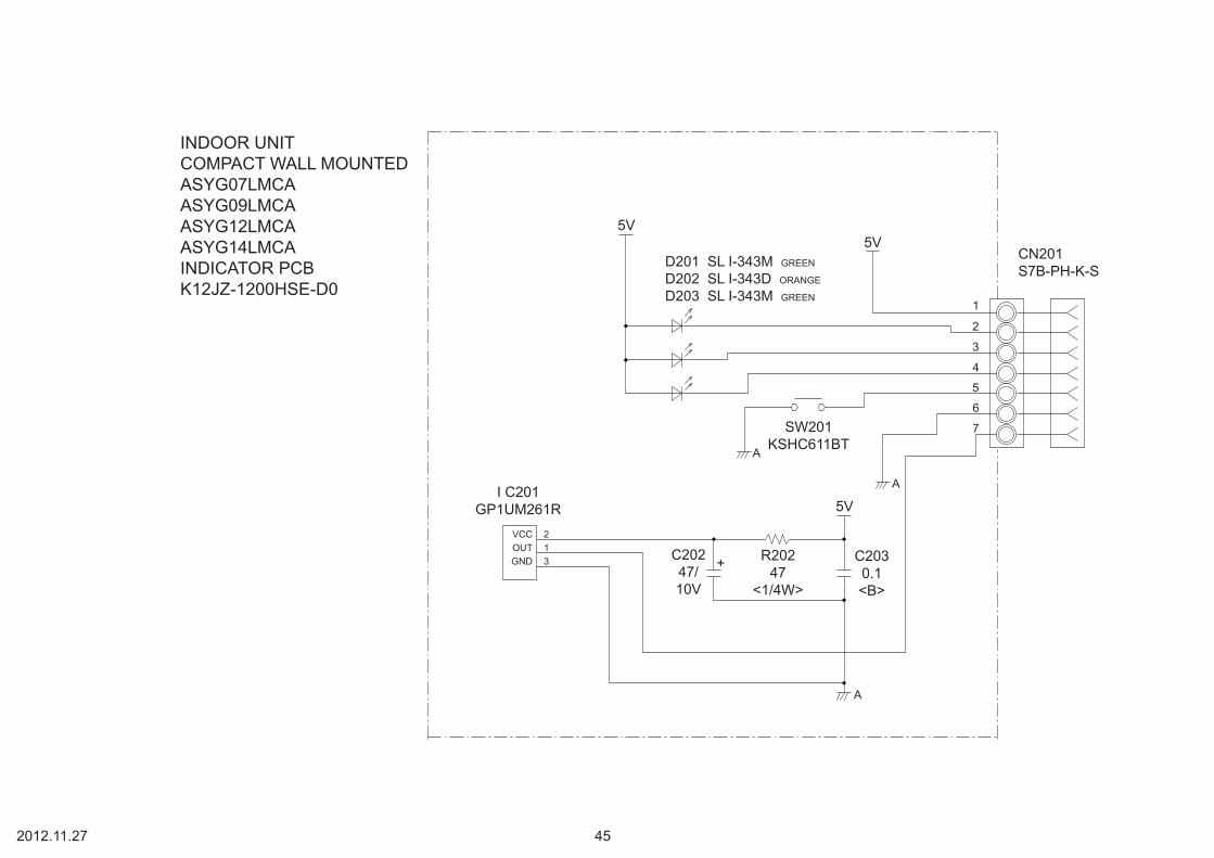
5V5V
5V
A
A
A
1
2
3
4
5
6
7SW201KSHC611BT
I C201GP1UM261R
+ R20247
<1/4W>
C2030.1<B>
C20247/10V
D201 SL I-343M GREEN
D202 SL I-343D ORANGE
D203 SL I-343M GREEN
213
VCCOUTGND
CN201S7B-PH-K-S
INDOOR UNITCOMPACT WALL MOUNTEDASYG07LMCAASYG09LMCAASYG12LMCAASYG14LMCAINDICATOR PCBK12JZ-1200HSE-D0
2012.11.27 45

13V
12V
13V
13V12V
I C308PS2501L-1
I C309PS2501L-1
R3152.7k
<1/10W>
R3161.2k
<1/4W>
I C304-1BA10393F
13V
R31815.4k
<1/10W>1%
R31928k
<1/10W>1% 13V
R31710k
<1/10W>1%
13V
13V
C3040.1<F>
I C304
D307D1F60L303
0R0
D306DAN217U
32
1
56
7+-
I C304-2BA10393F
C3101000p<R>
R32210k
<1/10W>
R3302.7k
<1/10W>
C3090.01<B>
Q303DTC143EUA
23
1
R320390
<1/4W>1%
Q302DTC143EUA
A
AA
+-
32
1
32
1
4
3 2
1
23
1
2 3
41
Q304DTC143EUA
R33122k
<1/10W>8
4
CNC01B05B-XASK-1-A
WIRED REMOTECONTROL1
2
3
4
5
1
2
1
2
1
2
3
9
6
5
4
3
2
1
390V
A A
13V
JM3030R0
12V
R30918k
<1/10W>
D303RF101L2S
+C306100/25V
T301SW1614-1
10
6
12354
5678
4
21
D
BP_MFB
SSSS
I C301LNK603
12V
R30318k
<1/10W>
13V
C3051.0<B>
R3061.0k1%
R30436k1%
R3056.2k1%
D302RF101L2S
C311100/25V
+
L3010R0
R3121.2k
<1/4W>
C3130.01<B>
CNA01B3B-XH-AM
I C306PS2501L-1
A
L3020R0
12VK301
FTR-F3
A
Q301DTC123EUA
32
1
2
13
4
CNB01B2B-XH-AM
CNB02B2B-XH-AM
12V
K304FTR-F3
2
13
423
1
A
Q305DTC123EUA
CN301SJH20-09WSF
+ C30147/
450V
R301390k
<1/4W>R302270
<1/4W>
D301UF4007
4
3 2
1
C3021000p<E>
EX ( I N )
EX ( OUT )
EX ( ERROR OUT )
TO MAIN PCB
(Option)Communication kitUTY-XCBXZ2for ASYG07LMCA ASYG09LMCA ASYG12LMCA ASYG14LMCA
Communication PCBK10DC-1000HSE-CA0
2013.03.13 46

FLOAT SWITCH
LOUVER ( RIGHT / LEFT )
LOUVER ( UP / DOWN )
WIRED REMOTE CONTROL
TERMINALHP-T3031-21
FRESH AIR( OPTION )
JUNCTIONCONNECTORXMR-07VWHITE
UL1430 AWG28x 7
UL1430 AWG28x 7
BROWNREDORANGEYELLOWGREENBLUEPURPLE
BROWNREDORANGEYELLOWGREENBLUEPURPLE
1234567
1234567
CN201-1CN201-2CN201-3CN201-4CN201-5CN201-6CN201-7
CN13-1CN13-2CN13-3CN13-4CN13-5CN13-6CN13-7
GRAYGRAY
BLACKBLACK
CN5-1CN5-2
CN7-1CN7-2
CN8-1CN8-2
CN14-1CN14-2CN14-3
CN6-1CN6-2
CN10-1CN10-2
CN11-1CN11-2CN11-3CN11-4CN11-5
CN12-1CN12-2CN12-3CN12-4CN12-5
CN9-1CN9-2CN9-3
CN2-1CN2-2CN2-3CN2-4CN2-5
CN15-1CN15-2CN15-3CN15-4CN15-5CN15-6
CN3-1CN3-2CN3-3
CN3-5CN3-6
CN3-4
CN4-1CN4-2CN4-3CN4-4CN4-5CN4-6CN4-7CN4-8
CN1-1CN1-2CN1-3
CN104-1CN104-2CN104-3CN104-4CN104-5CN104-6CN104-7CN104-8
CN101-1CN101-2CN101-3
CN105-6CN105-5CN105-4CN105-3CN105-2CN105-1
CN106-1CN106-2
CN103-1CN103-2
CN102-1CN102-2CN102-3
12345678
UL1015 AWG22 x 5
RED
BLACKWHITE
YELLOWBROWN
UL1015 AWG18 YELLOW
UL1015 AWG18 YELLOW
UL1015AWG16GREEN
UL1015AWG16GREEN
TERMINALHP-T3031-3-L1
UL1015AWG20BLACK
UL1015AWG20WHITE
UL1015AWG20RED
W105 W102 W101
F101AC250V3.15A
E101
E102
UL1430 AWG26 x 3
GRAY
UL1430 AWG26 x 8
GRAYGRAY
GRAYGRAYGRAYGRAYGRAYGRAYGRAYGRAY
UL1430 AWG26 x 5
UL1430 AWG26 x 5
REDORANGEYELLOWPINKBLUE
REDORANGEYELLOWPINKBLUE
REDORANGEYELLOWPINKBLUE
REDORANGEYELLOWPINKBLUE
UL1007 AWG24 BLACK
UL1007 AWG24 BLACK
UL1430 AWG22 WHITE
UL1430 AWG22 BLACK
UL1430 AWG22 RED
BLK WHT RED
THERMISTOR( ROOM TEMPERATURE )
THERMISTOR(PIPE - MID. TEMPERATURE )
CN201S07B-PASK-2WHITE
TESTCN2B5P-SHF-1AAWHITE
CN15B06B-XASK-1-AWHITE
CN3B06B-PASK-1WHITE
POWER DRIVE
DC SUPPLY
CN4B08B-PASK-1WHITE
CN1B03B-PASK-1WHITE
CN105B5P6-VH-BWHITE
CN106B2P3-VH-B-EBLUE
EXTERNAL OUT
EXTERNAL I N
CN103B2B-XH-AMWHITE
CN102B5P6-VH-BWHITE
CN101B03B-PASK-1
WHITE
CN104B08B-PASK-1
WHITE
CN8B02B-XASK-1-A
WHITE
CN7B02B-XAYK-1-A
YELLOW
CN5B02B-XAKK-1-A
BLACK
CN13B07B-PASK-1
WHITE
CN14B03B-XAKK-1-A
BLACK
CN6B02B-PAMK-1
GREEN
CN10B02B-PAOK-1
ORANGE
CN11B05B-XASK-1-A
WHITE
CN12B05B-XARK-1-A
RED
CN9B03B-XARK-1-A
RED
DC FAN MOTOR
DRAIN PUMP M
F M
M
M
L
N
SERIAL
E
1
2
3
BRANCH BOX UNITPOWER SOURCEAC230V50Hz
EMI FILTERZCAT2132-1130
1 T
EMI FILTERZCAT1518-0730
1 T
EMI FILTERZCAT1518-0730
2 T
INDICATOR PCBK06AG-1000HSE-D0
DECORATION PANEL ASSEMBLY
(LVLA)POWER SUPPLY PCBK06AL-1007HSE-P0
(LVLB)POWER SUPPLY PCBK06AL-1201HSE-P0
MAIN PCBAUYG07LVLA : K06AK-1007HSE-C1AUYG09LVLA : K06AK-1008HSE-C1AUYG12LVLA : K06AK-1009HSE-C1AUYG12LVLB : K06AK-1216HSE-C1
INDOOR UNITCOMPACT CASSETTECONTROL UNITAUYG07LVLA : EZ-01004HSEAUYG09LVLA : EZ-01005HSEAUYG12LVLA : EZ-01006HSEAUYG12LVLB : EZ-0122HHSE
2013.01.28 50

5V
C290.1<F>
R571.0k
<1/10W>
R5910k
<1/10W>
C300.1<F>
R581.0k
<1/10W>
R6049.9k
<1/10W>
C340.1<F>
R621.0k
<1/10W>
R6149.9k
<1/10W>
CN9B03B-XARK-1-A
( LF ) ( SN )
FLOAT SWITCH
5VR4510k
<1/10W>
R461.0k
<1/10W>
C310.01<F>
5V5V
R5010k
<1/10W>
THERMISTOR ( ROOM TEMP. )
CN8B02B-XASK-1-A
CN7B02B-XAYK-1-A
THERMISTOR ( PIPE - M I D. TEMP. )
CN5B02B-XAKK-1-A
CN15B06B-XASK-1-A
FLASH
CN13B07B-PASK-1
I NDICATOR PCB ASSY
CN14B03B-XAKK-1-A ( LF ) ( SN )
REMOTE CONTROL UNIT
5VR68, R52
10k <1/10W> x 2
5VR411.0k
<1/10W>
R43, R4410k <1/10W>
x 2
R4247
<1/10W>C241000p<R>
C230.01<F>
C2510/50V
+ C260.01<F>
12V5V
5V
13.5V
13.5V
R47390
<1/10W>
R351.0k
<1/10W>
R360R0
I C6-1BA10393F
I C6-1BA10393F
R5510k
<1/10W>
12V12V
D3D1FS4A
D2DAN217U
R5415.4k
<1/10W>
R5328k
<1/10W>
R4810k
<1/10W>
I C4uLN2003ADRBZ1
PKM13EPYH-4000-A0
CN11B05B-XASK-1-A
CN12 B05B-XARK-1-A
LOUVER ( UP / DOWN )
*LOUVER ( RIGHT / LEFT )
Q2DTC124EKA
5V I C7S-80842CNNB
R56100k
<1/10W>
C270.1<F>
C380.1<F>
R6910k
<1/10W>
R4010k
<1/10W>
C130.1<F>R37
10k<1/10W> I C5
S-93C66BD0 I
I C1uPD78F0536AGK
C360.47<F>
JM50R0
C8 - C100.1 <F> x 35V
5V
R4 - R61.0k <1/10W> x 3
R1 - R310k <1/10W> x 3
JM1
JM2
JM3
C32100/6.3V
+ C330.1<F>
C280.1<F>
R19 - R221.0k <1/10W> x 4
5V
12V13.5V
5V
C30.01<F>
+
D11SS355
I C2NJM7805
+C110/50V
C210/50V
I C8NJM7812
D41SS355
5V R15 - R1810k <1/10W> x 4
R7010k
<1/10W>
Q3DTC124EKA
5V
5V
5V
C19 - C220.1 <F> x 4
13.5V
R7 - R101.0k <1/10W> x 4
R11 - R1410k <1/10W> x 4SW1
CFS-0402MC
I C3uPA2003ADR
R29390
<1/10W>
R2810k
<1/10W>
C160.01<F>
Q1DTC124EKA
C150.01<F>
C141000p<R>
5V
C170.01<F>
C180.01<B>R27
330<1/10W>
R341.0k
<1/10W>
R3310k
<1/10W>
R3110k
<1/10W>
13.5V
13.5V
R251.0k
<1/10W>
R2610k
<1/10W>
C35, C12, C111000p <R> x 3
C370.1<F>
R671.0k
<1/10W>
5V
13.5V
R24, R23, R3210k <1/10W> x 3
R63 - R651.0k <1/10W> x 3
R6610k
<1/10W>
X18.00MHz<FCR>
CN4B08B-PASK-1
POWER DRIVE
CN3B06B-PASK-1
TEST
CN2B5P-SHF-1AA
CN1B03B-PASK-1
DC SUPPLY12
3
12
1
2
1
2
1
2
3
45
6
1
2
3
45
6
7
1
2
3
1
2
3
45
1
2
3
45
1
2
3
45
6
78
1
2
3
45
6
1
3
2
3
2
1
8765
4321
916151413121110
8
1234567
SKO1O2O3O4O5O6O7GND
I 1I 2I 3I 4I 5I 6I 7
SKO1O2O3O4O5O6O7
GND
I 1I 2I 3I 4I 5I 6I 7
9161514131211108
1234567
1
3
2
21
34
VDDOUT
NCGND
1
2
3
45
1
2
3
1
2
1
2
1
2
3IG
O
IG
O1
2
3
CN6B02B-PAMK-1
FRESH AIR
HEATER
CN10B02B-PAOK-1
1236
8475
CSSKD INC
VCCDONC
GND
NC
343936434445463332313029282726181920212223111213143837414025
942 52
515049484756555453
87654321
6463626160595857171615241035AVREF
I CRST*P00P01P02P03P10P11P12P13P14P15P16P17P20P21P22P23P24P25P30P31P32P33XT1XT2X1X2AGNDGND0GND1 P75
P74P73P72P71P70P67P66P65P64P57P56P55P54P53P52P51P50P47P46P45P44P43P42P41P40P36P35P34
VDD1VDD0AVDD
3
1
2
3
1 2
32
1
765+
-
+-
B. Z.
C40.01<F>
C51000p<R>
C71000p<R>
SP PCB
ARYG07LLTA : K06AK-120KHSE-C1ARYG09LLTA : K06AK-120LHSE-C1ARYG12LLTB : K06AK-120MHSE-C1(Serial number : R)
INDOOR UNITMAIN PCB
2013.01.25
*The ARYG type is not used
AUYG07LVLA : K06AK-1007HSE-C1AUYG09LVLA : K06AK-1008HSE-C1AUYG12LVLA : K06AK-1009HSE-C1AUYG12LVLB : K06AK-1216HSE-C1
ARYG07LLTA : K06AK-100CHSE-C1ARYG09LLTA : K06AK-100DHSE-C1ARYG12LLTA : K06AK-100EHSE-C1ARYG12LLTB : K06AK-1101HSE-C1(Serial number : T)
51

340V15V
15V
A
6
5
43
2
1
CN105B5P-VH-B
DC FAN MOTOR
I C103TLP621<GB> R114
4.7k<1/10W>
R1156.8k
<1/4W>
5V 15VR1161.0k
<1/4W>
I C104TLP621<GB>
R117820
<1/4W>
C117100/25V
+
A A
1
2
4
3
4
3
1
2
CN104B08B-PASK-1
1
23
4
5
6
7
8
1
23
3
2
1
2
1
5VL102
BLm18<AG601>
L103BLm18
<AG601>
I C101TLP621<GB>
R112330
<1/10W>
C1160.01<B>
4
3 2
1
13.5VCN103B2B-XH-AM
CN102B3B-XH-AM
5V 13.5V
C1210.1<F>
C1200.1<F>
CN101B03B-PASK-1
CN106B2P3-VH-B-E
5V
I C 1 0 5 H I 2 0 0 3 R 3
VA1030.01
<KH>
2
1
K102G5NB-1A 13.5V
RC101120/0.1
3 2
41
DRAIN PUMP
K101G5N-1A4
2
1
3
18 14 10 5 4 3 2 15 4 3 2 1678
W105RED
SERIAL
E102GREEN
C1180.01
<KH>
D101D3SB60
4
3
1
2
340V
R104330k<2W>
C109220p<BN>
R10575
<RS-2W>
Q1012SC5354
3
21
12
3
Q1022SC1815
R107100
<1/10W>
R1061.5
<RS-2W>
15V D106D1FL20U
A
C112330/25V
+
C111100/25V
D104MTZJ5.1B
D109MTZJ5.1B
R109330
<1/4W>+
R108100
<1/2W>D105
D1FL20U
D103D1FL20U
C110 0.047<ECQV>
D107RD16<B1>
R11010k
<1/10W>
C114, C1150.01 <KH>
x 2
13.5VD108D2FL20U
C1131000/25V
T101ZFT22B03-C
R11110k
<1/10W>
+12
10
235678
C1084700p<FNS>
R10362k
<RS-2W>
D1021SR139-600
C107100/450V
+
C1050.010<YE>
C1060.010<YE>
C1040.47
<R46>
LF101ELF17N015A
1 2
4 3
VA102470V
<TNR>SA101
RA-362M
VA101470V
<TNR>
FH101 FH102
F1013.15A250V
W101BLACK
W102WHITE
E101GREEN
DC SUPPLY
R113330
<1/10W>
EXTERNAL I N
EXTERNAL OUT
POWER DRIVEI C26-14 I C26-10
L N
I C26-14
I C26-10
L
N
I C26-14
I C26-10
L
N
AUYG07LVLAAUYG09LVLAAUYG12LVLAPOWER SUPPLY PCBK06AL-1007HSE-P0
AUYG12LVLBPOWER SUPPLY PCBK06AL-1201HSE-P0
2013.01.28
INDOOR UNITCOMAPCT CASSETTE
L101REP28-15
15mH, 1.1A
52

5V
R201 220 <1/4W>
R202 390 <1/4W>
R203 220 <1/4W> D203 SLR-325MC GREEN
D201 SLR-325MC GREEN
D202 SLR-325DC ORANGE
PHA201P I C-37143TH5
SW201EVQPAG04K
C20210/25V
+ C2010.1<F>
24 3
1
213
VCCOUTGND
CN201S07B-PASK-2 ( LF ) ( SN )
OPERATE
TIMER
MANUAL AUTO SWITCH
FILTER CLEN / FILTER SIGN5V
REMOTE CONTROL
GND
1
2
3
4
56
7
To MAIN PCB
INDICATOR PCB ( OPTION )K06AG-1000HSE-D0
INDOOR UNITCOMPACT CASSETTEAUYG07LVLAAUYG09LVLAAUYG12LVLAAUYG12LVLB
2010.09.02 53

9
8
7
6
5
43
2
1
7
6
5
43
2
1
6
5
43
2
1
1
2
3
4
5
1
2
3
4
5
6
1
2
3
4
5
6
1
2
3
4
5
1
2
3
4
5
1
2
3
4
5
1
2
3
4
1
2
3
1
2
3
1
2
3
1
2
1
2
1
2
1
2
3
4
5
67
1
2
1
2
CN6B05B-XASKWHITE
CN2SJH20-05WSWHITE
CN5SJH20-06WSWHITE
CN8B06B-PASKWHITE
CN12B05B-PASKWHITE
CN17B5 ( 7-5.6 ) B-XASK-1-AWHITE
CN10B5 ( 6-5 ) B-XARK-1-ARED
CN13B05B-PH-K-S
WHITETEST
CN11B09B-PASK
WHITE
CN18B04B-PASK
WHITE
CN14B3B-XH-AM
WHITE
CN15B3B-XH-AM-BK
BLACK
CN16B3B-XH-AM-RK
RED
CN20B2B-XH-AM
WHITE
CN21B2B-XH-AM-BK
BLACK
CN22B2B-XH-AM-RK
RED
CN9B07B-PASK
WHITEFLASH
CN3B02B-PASK
WHITE
CN12P-SAN
WHITE
1
2
3
4
5
67
8
9
CN201JB20-09HG
CN202JB20-06HG
654321
CN203JB20-06HG
123456
CN
201-
1
WH
ITE
CN
201-
2
WH
ITE
CN
201-
3
WH
ITE
CN
201-
4
WH
ITE
CN
201-
5
WH
ITE
CN
201-
6
WH
ITE
CN18-1 BLACK
CN18-2 BLUE
CN18-3 BLACK
CN18-4 BLUE
CN11-9 RED
CN11-8 WHITE
CN11-7 WHITE
CN11-6 WHITE
CN11-1 WHITE
CN11-2 WHITE
CN11-3 WHITE
CN11-4 WHITE
CN11-5 WHITE
CN3-1 GRAY
CN3-2 GRAY
CN2-1 BLACK
CN2-2 BLACK
CN13-1CN13-2
CN13-3CN13-4
CN13-5CN13-6
CN13-7
DAMPER LIMIT SWITCH( CLOSE )
DAMPER LIMIT SWITCH( OPEN )
EXTERNAL I NPUT 1( OPTION )
EXTERNAL I NPUT 2( OPTION )
EXTERNAL I NPUT 3( OPTION )
EXTERNAL OUTPUT 2( OPTION )
EXTERNAL OUTPUT 3( OPTION )
EXTERNAL OUTPUT 1( OPTION )
THERMISTOR( PIPE TEMPERATURE )
THERMISTOR( ROOM TEMPERATURE )
F M
M
M
M
M
F MCN10-2 YELLOW
CN10-1 BLUE
CN10-3 WHITE
CN10-4 BLACK
CN10-6 RED
CN17-2 YELLOW
CN17-1 BLUE
CN17-3 WHITE
CN17-4 BLACK
CN17-7 RED
CN12-3 YELLOW
CN12-2 ORANGE
CN12-1 RED
CN12-4 PINK
CN12-5 BLUE
CN8-3 YELLOW
CN8-2 ORANGE
CN8-1 RED
CN8-4 PINK
CN8-5 BLUE
CN5-3 YELLOW
CN5-2 ORANGE
CN5-1 RED
CN5-4 PINK
CN5-5 BLUE
CN2-3 YELLOW
CN2-2 ORANGE
CN2-1 RED
CN2-4 PINK
CN2-5 BLUE
CN8-1 RED
CN8-2 WHITE
CN8-3 BLACK
DAMPER LOCK( RIGHT )
DAMPER LOCK( LEFT )
LOUVER( UP / DOWN )
DAMPER
DC FAN MOTOR( UPPER )
DC FAN MOTOR( LOWER )
TERMINALHP-T3064A-A28-L1
THERMALFUSE 1023A 250V
BLACK
WHITE
RED
1
2
3
L
N
SERIAL
F1AC250V 3.15A
L I N
N I N
SERIAL I N
TM522007BLACK
TM122007WHITE
TM222007RED
MAIN PCBAGYG09LVCA : K09DD-0900HSE-C1AGYG12LVCA : K09DD-1000HSE-C1
INDICATOR PCB ASSEMBLY ( SWITCH + DISPLAY )K06DD-0801HSE-F0
SWITCH PCB
INDICATOR PCB
POWER SOURCEAC230V50Hz
WIRED REMOTE CONTROL( OPTION )
INDOOR UNITFLOORCONTROL UNITAGYG09LVCA : EZ-0090BHSEAGYG12LVCA : EZ-01002HSE
2010.09.06 54

D12RF201L2S
D10RF201L2S
C121000/25V
C13330/25V
+
+
12VT1
MY064
C280.01<F>
654321
89
10
JM60R0
C200.1<F>
7V
D151SS355
I C2BA05T
5V
C14330/25V
C210.1<F>
+
1 3
2
I OG
5V
I C15PS2561L-1-V
C1547/35V
+D9
RF101L2S
R7270
<1/10W>
C270.22<B>
C1147p1kV
I C8TOP244
C1847/35V
+ R515k
<1/10W>
Q72SA1037AK2
3
1
20V
C290.1<F>
JM90R0
5V
R181.0k
<RS-2W>
1
2
3IG
O
A
15VI C20
78M15
D141SS355
C300.1<F>
+C17330/25V
C25, C260.1 <F>
x 2
C230.1<F>
C2210/25V
+
5V
I C 1uPD78F1154AGK
C16100/50V
+
C190.1<F>
I C19TL431 I LP
R81.8k
<1/10W>
R9150
<1/10W>
R11 5.6k<1/10W> R12 200k
<1/10W>1%
R13 47k<1/10W>
1%
C3
A2
REF1
4
3 2
1
C591000p<R>
C520.1<F>
C510.1<F>
9
87
6
54
3
2
1
C411000p<R>
R53 - R56330 <1/10W>
x 4
R60 - R6210k <1/10W>
x 35V
C490.01<B>
+C50100/25V
C531000p<R>
5V
R57 47 <1/10W>R58 1.0k <1/10W>R59 1.0k <1/10W>
54
3
2
1
6
54
3
2
1
54
3
2
1
54
3
2
1
6
54
3
2
1
4
3
2
1
12
3
12
3
12
3
R69, R68, R6710k <1/10W>
x 3
5V
12V
R63 - R65330 <1/10W>
x 3
C61, C631000p <R>
x 2
5V
R105, R1064.7k <1/10W>
x 2
R103, R1041.0k <1/10W>
x 2
C76, C770.1 <F>
x 2
5V
R75330
<1/10W>L120R0
C750.01<B>
5V
5V
R2910k
<1/10W>
R7910k
<1/10W>
R761.0k
<1/10W>
C780.01<B>
I C23PS2561L-1-V
L130R0
5V L100R0
R73330
<1/10W>I C22
PS2561L-1-V
L110R0
C730.01<B>
5VL3
0R0R70 330<1/10W>
I C21PS2561L-1-V
C710.01<B>
L40R0
R7810k
<1/10W>
R741.0k
<1/10W>
R7710k
<1/10W>
R721.0k
<1/10W>
5V
C740.01<B>
C720.01<B>
I C6S-93C66B0 I
5V
8476
1325
VCCDONTTEST
CSD I
S KGND
3
12 VCC
G / V
8
9
VCC
G / V
8
9
VCC
G / V
8
9
VCC
G / V
8
9
1 16
1
2
4
33 14
4
3 2
1
4
3
1
2
VCC
G / V
4
8
15 2
14 3
413
12 5
2
4
3
1
1 16
1
2
4
3
C580.1<F>
R8510k
<1/10W>
5V
X18.00MHz<FCR>
R66, R8110k <1/10W>
x 2
12V
I C7-8uLN2003ADR
I C13-8uLN2003ADR
I C16-8uLN2003ADR
I C18-8uLN2003ADR
R8710k
<1/10W>
I C13-1uLN2003ADR
BZ1PS1240P02BT 12V
BZ
Q10RT1N241M
5V
R4510k
<1/10W>
R44390
<1/10W>
R47390
<1/10W>
C330.01<B>
C320.01<B>
5V
C370.1<F>
R2549.9k
<1/10W>1%
C380.1<F>
C4010k
<1/10W>
R261.0k
<1/10W>
5V
L6, L7BLm18
<BD102>x 2
C350.1<F>
C360.1<F>
R2310k
<1/10W>1%
R241.0k
<1/10W>
I C13-5uLN2003ADR
I C13-4uLN2003ADR
12V
I C13-3uLN2003ADR 5V
R510R0
R5210k
<1/10W>
12V
5V12V
12V
R9215.4k
<1/10W>1%R9328k
<1/10W>1%
I C5-2BA10393F
D3DAN217U R91
390<1/4W>
1%
I C13-2uLN2003ADR
I C5-1BA10393F
R951.0k
<1/10W>
C311000p<R>
R9410k
<1/10W>
C470.1<F>
I C5-3BA10393F
I C18-1uLN2003ADR
5V
R31330
<1/10W>
15V
I C10PS2561L-1-V
5V
R3310k
<1/10W>1%
+
R3910k
<1/10W>
R371.0k
<1/10W>
C451000p<R>
R358.2k
<1/10W>1%
C4310/50V
15VA A
I C14PS2561L-1-V
R414.7k
<1/10W>
R436.8k
<1/4W>
15V
340V
A
A A15V
5V
R3810k
<1/10W>
R361.0k
<1/10W>
C461000p<R>
I C9PS2561L-1-V
R404.7k
<1/10W>
R426.8k
<1/4W>
+R348.2k
<1/10W>1%
5V 15V
I C12PS2561L-1-V
R30330
<1/10W>
R3210k
<1/10W>1%
C4410/50V 340V
15V
A
I C18-3uLN2003ADR
C560.47<F>
12V
F20.2A30V
R2210k
D2D1F60
R9010k
<1/10W>
JP50R0
12V 21
3
2
4
3
1
5V R19 - R2110k x 3
R48 - R50100 x 3
K12G5NB-1A
K11G5NB-1A
3
32
2
4 1
4 1
K10G5NB-1A
R46470
<1/4W>R80470
<1/4W>
C481000p<E>
I C 2 6H I 2 0 0 3 R 3
18 14 10 5 4 3 2 1
34
1 2
L1SS21V-R060330FH1 FH2
VA1470V
<TNR>
L220*20*18
0.6A 10mH
340V
C100.01
<ECQE>
R2100k
<RS-2W>
D7UF4007
+ R82, R322 <1/4W>
x 2
C968/
420V
R65.6k
<1/10W>
D81SS355
D4RF101L2S
R412k <1/10W>
A
32
1
654
123
DFS
CLX
10 7
I C13-7uLN2003
1
2
3
4
5
6
7
1
2
3
4
5
1
2
2
1
2
1
2
1
1
2
5
4
3
2
1
5
4
3
2
1
3
4
2
1
3
4
2
1
3
4
2
1
I C7-2uLN2003ADR
I C7-1uLN2003ADR
I C7-3uLN2003ADRI C7-4
uLN2003ADRI C7-5
uLN2003ADRI C7-6uLN2003ADR
I C7-7uLN2003ADR
I C16-2uLN2003ADR
I C16-1uLN2003ADR
I C16-3uLN2003ADR
I C16-4uLN2003ADRI C16-5
uLN2003ADRI C16-7
uLN2003ADR
I C16-6uLN2003ADR
2 15
4 13
6 11
1 16
3 14
1 16
3 14
5 12
7 10
2 15
4
6
13
11
5
7
12
10
I C18-4uLN2003ADRI C18-5
uLN2003ADR
I C18-7uLN2003ADR
I C18-6uLN2003ADR
5
7
12
10
4
6
13
11
74737271703938545352515049484768676665646362614025
98765432
41101316176018
19205956424344454621222324262728293736353433323130555758
11514121169807978777675
P00P01P02P03P04P05P06P10P11P12P13P14P15P16P17P20P21P22P23P24P25P26P27P30P31P40P41P42P43P44P45P46P47P50*RESETFLMD0REGCGNDAGNDEGND
VCCEVCC
AVREF0AVREF1
P51P52P53P54P55P60P61P62P63P64P65P66P67P70P71P72P73P74P75P76P77P90
P110P111P120P121P122P123P124P130P140P141P142P143P144P145
I C1-61
I C1-62
I C1-4
I C1-5
I C1-10
I C1-8
I C1-9I C1-13
I C1-41
I C1-55
I C1-32
I C1-42
I C1-31I C1-42I C1-43I C1-44I C1-45I C1-46I C1-21I C1-22I C1-23I C1-24I C1-26I C1-27I C1-28I C1-29
I C1-36I C1-35I C1-34I C1-33I C1-32I C1-31
I C1-55I C1-57I C1-58I C1-1
I C1-80I C1-79
I C1-77I C1-76I C1-75
I C1-70I C1-73I C1-71I C1-72
I C1-73I C1-72I C1-71I C1-70I C1-39
I C1-54I C1-53I C1-52I C1-51I C1-50I C1-49I C1-48I C1-47
I C1-63
I C1-61I C1-40I C1-25I C1-9I C1-8
I C1-6I C1-5I C1-4
I C1-2I C1-41I C1-10I C1-13
I C1-75
I C1-25
I C1-39
I C1-40
I C1-80
I C1-24I C1-23
I C1-22
I C1-21
I C1-1I C1-36I C1-2
I C1-79
I C1-76
I C1-77
I C1-54
I C1-53
I C1-52
I C1-51
I C1-50
I C1-49
I C1-48
I C1-47
I C1-46
I C1-45I C1-44
I C1-43
I C1-29I C1-28
I C1-27
I C1-26
I C1-57
I C1-58
I C1-33
I C1-34
I C1-35
CN11B09B-PAEK-1WHITE
CN13B5B-PH-K-SWHITE
CN8B06B-PASK-1WHITE
CN12B05B-PASK-1WHITE
CN2SJH20-05WSWHITE
CN5SJH20-06WSWHITE
CN18B04B-PASK-1WHITE
CN16B3B-XH-AM-RRED
CN15B3B-XH-AM-BKBLACK
CN14B3B-XH-AMWHITE
CN17B5 ( 7-5.6 ) B-XASK-1-AWHITE
CN10B5 ( 6-5 ) B-XARK-1-ARED
CN6B05B-XASK-1-A
CN22B2B-XH-AM-R
RED
CN21B2B-XH-AM-BK
BLACK
CN20B2B-XH-AM
WHITE
CN3B02B-PASK-1
WHITE
CN1150-103-86172
TM2
TM1
TM5
-+
-+
65
7
23
1
D6D3SB60C2
0.22<ECQE>
C10.22
<ECQE>
F13.15A250V
TP00351-31x 2
I C1-6
EXTERNAL I NPUT 1
EXTERNAL I NPUT 2
EXTERNAL I NPUT 3
DAMPER LIMIT SWITCH
LOUVER ( UP / DOWN )
DAMPER
DAMPER LOCK ( LEFT )
DAMPER LOCK ( RIGHT )
TEST
INDICATOR PCB ASSEMBLY
THERMISTOR ( ROOM TEMP. )
THERMISTOR ( PIPE TEMP. )
EXTERNAL OUTPUT 1( OPTION )
EXTERNAL OUTPUT 2( OPTION )
EXTERNAL OUTPUT 3( OPTION )
FLASH
CN9B07BPASK-1
WIRED REMOTE CONTROL UNIT( OPTION )
DC FAN MOTOR( LOWER )
DC FAN MOTOR( UPPER )
POWER SOURCEAS230V50Hz
SERIAL
INDOOR UNITFLOORMAIN PCBAGYG09LVCA : K09DD-0900HSE-C1AGYG12LVCA : K09DD-1000HSE-C1
2010.09.07 55

5V
5V
5V
+ C20247/10V
R20147
<1/4W>I C201
GP1UM261
213
VCCOUTGND
C2010.1<F>
CN203 CN202
SW201KSHC611BT
SW202SSSS213000
5V 5VCN201
3 2 1
9
8
7
6
5
4
3
2
1
6
5
4
3
2
1
1
2
3
4
5
6
D201SLR-343DC
ORANGE
D202, D203SLR-343MC
GREEN
x 2
06 JB20 / JB201061 L60
09 PAP / JB201061 L550
INDICATOR PCBK06DD-0801HSE-F0
2010.09.06
INDOOR UNITFLOORAGYG09LVCAAGYG12LVCA
56

CN2-1CN2-2CN2-3CN2-4CB2-5
CN15-1CN15-2CN15-3CN15-4CN15-5CN15-6
CN3-1CN3-2CN3-3CN3-4CN3-5CN3-6
CN4-1CN4-2CN4-3CN4-4CN4-5CN4-6CN4-7CN4-8
CN1-1CN1-2CN1-3
CN101-1CN101-2CN101-3
CN104-1CN104-2CN104-3CN104-4CN104-5CN104-6CN104-7CN104-8
CN105-6CN105-5CN105-4CN105-3CN105-2CN105-1
CN106-1CN106-2
CN102-1CN102-2CN102-3
CN103-1CN103-2
CN108-1CN108-2CN108-3
CN10-1CN10-2
CN6-1CN6-2
CN14-1CN14-2CN14-3
CN5-1CN5-2
CN7-1CN7-2
CN8-1CN8-2
CN9-1CN9-2CN9-3
CN11-1CN11-2CN11-3CN11-4CN11-5
CN12-1CN12-2CN12-3CN12-4CN12-5
12345678
UL1015 AWG16GREEN
UL1015 AWG16GREEN
UL1015 AWG16GREEN
GRAY
BLACKBLACK
GRAY
THERMISTOR( ROOM TEMP. )
THERMISTOR ( PIPE - MID. TEMP. )
UL1430 AWG26 x 5
REDORANGEYELLOWPINKBLUE
REDORANGEYELLOWPINKBLUE
UL1007 AWG24 x 2
BLACK
BLACK
FLOAT SWITCH
LOUVER UP / DOWN( OPTION )
M
HEATER( OPTION )
FRESH AIR( OPTION )
UL1430 AWG22 WHITE
UL1430 AWG22 RED
UL1430 AWG22 BLACK
BLK WHT RED TERMINALHP-T3031-21
WIRED REMOTE CONTROL
UL1430 AWG26 x 3
UL1430 AWG26 x 8
GRAY
GRAYGRAYGRAYGRAYGRAYGRAYGRAY
GRAY
GRAYGRAY
RED
BLACKWHITE
YELLOWBROWN
BLACK
BLACK
UL1015 AWG18 x 2
WHITE
WHITE
MDRAIN PUMP
FM
DC FAN MOTOR
TERMINALHP-T3031-3-L1
E101
E102
E103
W105 W102 W101
F101AC250V
5A
CN105B5P6-VH-BWHITE
CN106B2P3-VH-B-EBLUE
EXTERNAL OUT
EXTERNAL IN
CN106B2B-XH-AMWHITE
CN102B3B-XH-AMWHITE
CN106B2P3-VH-BWHITE
REACTOR ASSY( RELAY41-22 )
CN101B03B-PASK-1
WHITE
DC SUPPLY
POWER DRIVE
CN104B08B-PASK-1
WHITE
CN1B03B-PASK-1WHITE
CN4B08B-PASK-1WHITE
CN3B06B-PASK-1WHITE
CN14B03B-XAKK-1-A
BLACK
CN6B02B-PAMK-1
GREEN
CN10B02B-PAOK-1
ORANGE
CN11B05B-XASK-1-A
WHITE
CN12B05B-XARK-1-A
RED
CN9B03B-XARK-1-A
RED
CN5B02B-XAKK-1-A
YELLOW
CN7B02B-XAYK-1-A
BLACK
CN8B02B-XASK-1-A
WHITE
CN15B06B-XASK-1-AWHITE
TESTCN2B5P-SHF-1AAWHITE
UL1015 AWG20 WHITE
UL1015 AWG20 RED
UL1015 AWG20 BLACKL
N
E
SERIAL
1
2
3
POWER SOURCEAC230V50Hz
EMI FILTERZCAT2132-1130
1 T
EMI FILTERZCAT1518-0730
2 T
POWER SUPPLY PCBK06AL-1008HSE-P0
MAIN PCBARYG07LLTA : K06AK-100CHSE-C1ARYG09LLTA : K06AK-100DHSE-C1ARYG12LLTA : K06AK-100EHSE-C1ARYG12LLTB : K06AK-1101HSE-C1(Serial number : T)
ARYG07LLTA : K06AK-120KHSE-C1ARYG09LLTA : K06AK-120LHSE-C1ARYG12LLTB : K06AK-120MHSE-C1(Serial number : R)
CN13-1CN13-2CN13-3CN13-4CN13-5CN13-6CN13-7
CN201-1CN201-2CN201-3CN201-4CN201-5CN201-6CN201-7
12345678
12345678
12345678
12345678
BROWNREDORANGEWHITEBLUE
GRAYPURPLE
UL1430 AWG28 x 7 UL1430 AWG28 x 7
BROWNRED
ORANGEWHITE
BLUE
GRAYPURPLE
JunctionConnectorXMR-08VWHITE
JunctionConnectorXMR-08VWHITE
CN201S07B-PASK-2WHITE
CN13B07B-PASK-1
WHITE
INDICATOR PCBK04EI-1000HSE-D0
RECEIVER UNIT( OPTION )
INDOOR UNITSLIM DUCTCONTROL UNITARYG07LLTA : EZ-01009HSEARYG09LLTA : EZ-0100AHSEARYG12LLTA : EZ-0100BHSEARYG12LLTB : EZ-01110HSE(Serial number : T)
ARYG07LLTA : EZ-01222HSEARYG09LLTA : EZ-01223HSEARYG12LLTB : EZ-01224HSE(Serial number : R)
2010.09.02 57

340V15V
15V
A
6
5
43
2
1
CN105B5P-VH-B
DC FAN MOTOR
I C103TLP621<GB> R114
4.7k<1/10W>
R1156.8k
<1/4W>
5V 15VR1161.0k
<1/4W>
I C104TLP621<GB>
R117820
<1/4W>
C117100/25V
+
A A
1
2
4
3
4
3
1
2
CN104B08B-PASK-1
1
23
4
5
6
7
8
1
23
3
2
1
2
1
5VL102
BLm18<AG601>
L103BLm18
<AG601>
I C101TLP621<GB>
R112330
<1/10W>
C1160.01<B>
4
3 2
1
13.5VCN103B2B-XH-AM
CN102B3B-XH-AM
5V 13.5V
C1210.1<F>
C1200.1<F>
CN101B03B-PASK-1
CN106B2P3-VH-B-E
5V
I C 1 0 5 H I 2 0 0 3 R 3
VA1030.01<F>
2
1
K102G5NB-1A 13.5V
RC101120/0.2
3 2
41
DRAIN PUMP
K101G5N-1A4
2
1
3
18 14 10 5 4 3 2 15 4 3 2 1678
W105RED
SERIAL
E102GREEN
C1180.01
<KH>
1 2
CN108B2P3-VH-B
NORMAL COIL
D101D3SB60
4
3
1
2
340V
R104330k<2W>
C109220p<BN>
R10575
<RS-2W>
Q1012SC5354
3
21
12
3
Q1022SC1815
R107100
<1/10W>
R1061.5
<RS-2W>
15V D106D1FL20U
A
C112330/25V
+
C111100/25V
D104MTZJ5.1B
D109MTZJ5.1B
R109330
<1/4W>+
R108100
<1/2W>D105
D1FL20U
D103D1FL20U
C110 0.047<ECQV>
D107RD16<B1>
R11010k
<1/10W>
C1140.01
<KH> E103GREEN
13.5VD108D2FL20U
C1131000/25V
T101ZFT22B03-C
R11110k
<1/10W>
+12
10
235678
C1084700p<FNS>
R10362k
<RS-2W>
D1021SR139-600
C107270/450V
+
C1050.010<YE>
C1060.010<YE>
C1040.22<F>
LF101ELF20N030A
1 2
4 3
C1010.22<LE>
VA102470V
<TNR>SA101
RA-362M
VA101470V
<TNR>
FH101 FH102
F1015A
250V
W101BLACK
W102WHITE
E101GREEN
DC SUPPLY
R113330
<1/10W>
EXTERNAL I N
EXTERNAL OUT
POWER DRIVEI C26-14 I C26-10
L N
I C26-14
I C26-10
L
N
I C26-14
I C26-10
L
N
POWER SUPPLY PCBK06AL-1008HSE-P0
2010.09.01
INDOOR UNITSLIM DUCTARYG07LLTAARYG09LLTAARYG12LLTAARYG12LLTB
58

5V
D205 EMPG3863X GREEN
D206 EMAA3863X ORANGE
D207 EMPG3863X GREEN
R201 330<1/4W>
R202 330<1/4W>
R203 330<1/4W>
PHA201PIC-37143TH5
JM201
VCCOUTGND
213
C2010.1<F>
C20210/16V
+
SW201EVQPAG04K
1 3
2 4
1
2
3
4
5
6
7
8
CN20108 / 08 JC25 / XMR
BROWN
RED
ORANGE
YELLOW
WHITE
BLUE
PURPLE
GRAY
( OPERATE )( TIMER )
( LOUVER )( LOUVER )
( 5V )
( REMOTE SIGNAL )( GND )
( MANUAL AUTO SWITCH )
INDICATOR PCB ( OPTION )K04EI-1000HSE-D0
INDOOR UNITSLIM DUCTARYG07LLTAARYG09LLTAARYG12LLTAARYG12LLTB
2013.01.22 59

If you use a wireless remote control, the lampon the photo detector unit will output error codesby way of blinking patterns.If you use a wired type remote control, errorcodes will appear on the remote control display.See the lamp blinking patterns and error codesin the table. An error display is displayed onlyduring running.
Indoor unitWiredremotecontrol
INDOOR UNITand WIRED REMOTE CONTROL
ERROR DETECTION
DescriptionOPERATIONlamp
(green)
TIMERlamp
(orange)
ECONOMYlamp
(green)
(1) (1)Serial communication error
(1) (2) Wired remote controlcommunication error
(1) (5) Check run unfinished
(2) (1)Unit number or Refrigerant circuit address setting error [Simultaneous Multi]
(2) (2) Indoor unit capacity error
(2) (3) Combination error
(2) (4)
Connection unit number • error (indoor slave unit) [Simultaneous Multi]Connection unit number error • (indoor unit or branch unit) [Flexible Multi]
(2) (7)Master unit, slave unit set-up error [Simultaneous Multi]
(3) (2)Indoor unit PCB model information error
(3) (5) Manual auto switch error
(4) (1) Inlet air temp. sensor error
(4) (2) Indoor unit Heat Ex. Middle temp. sensor error
(5) (1)Indoor unit fan motor error
(5) (3)Drain pump error
(5) (7) Damper error
(5) (15) Indoor unit error
(6) (2)Outdoor unit main PCB model information error or communication error
(6) (3) Inverter error
(6) (4)Active filter error, PFC circuit error
(6) (5) Trip terminal L error
(6) (10)Display PCB microcomputers communication error
(7) (1) Discharge temp. sensor error
(7) (2) Compressor temp. sensor error
(7) (3) Outdoor unit Heat Ex. liquid temp. sensor error
(7) (4) Outdoor temp. sensor error
(7) (5) Suction Gas temp. sensor error
(7) (6) 2-way valve temp. sensor error• 3-way valve temp. sensor error•
(7) (7) Heat sink temp. sensor error
(8) (2)
Sub-cool Heat Ex. gas inlet • temp. sensor errorSub-cool Heat Ex. gas outlet • temp. sensor error
(8) (3)Liquid pipe temp. sensor error
(8) (4)Current sensor error
(8) (6)
Discharge pressure sensor • errorSuction pressure sensor error• High pressure switch error•
(9) (4)Trip detection
(9) (5)Compressor rotor position detection error (permanent stop)
(9) (7) Outdoor unit fan motor error
(9) (9) 4-way valve error
(10) (1)Discharge temp. error
(10) (3)Compressor temp. error
(10) (4)High pressure error
(10) (5)Low pressure error
(13) (2)Branch boxes error [Flexible Multi]
: 0.5s on / 0.5s off
: 0.1s on / 0.1s off
( ) : Number of flashing
This is possible only on a wired remote control.
If an error occurs, the following display will be shown.(“Er” will appear in the set room temperature display.)
Error code
EX. Self-diagnosis
2011.02.25 41
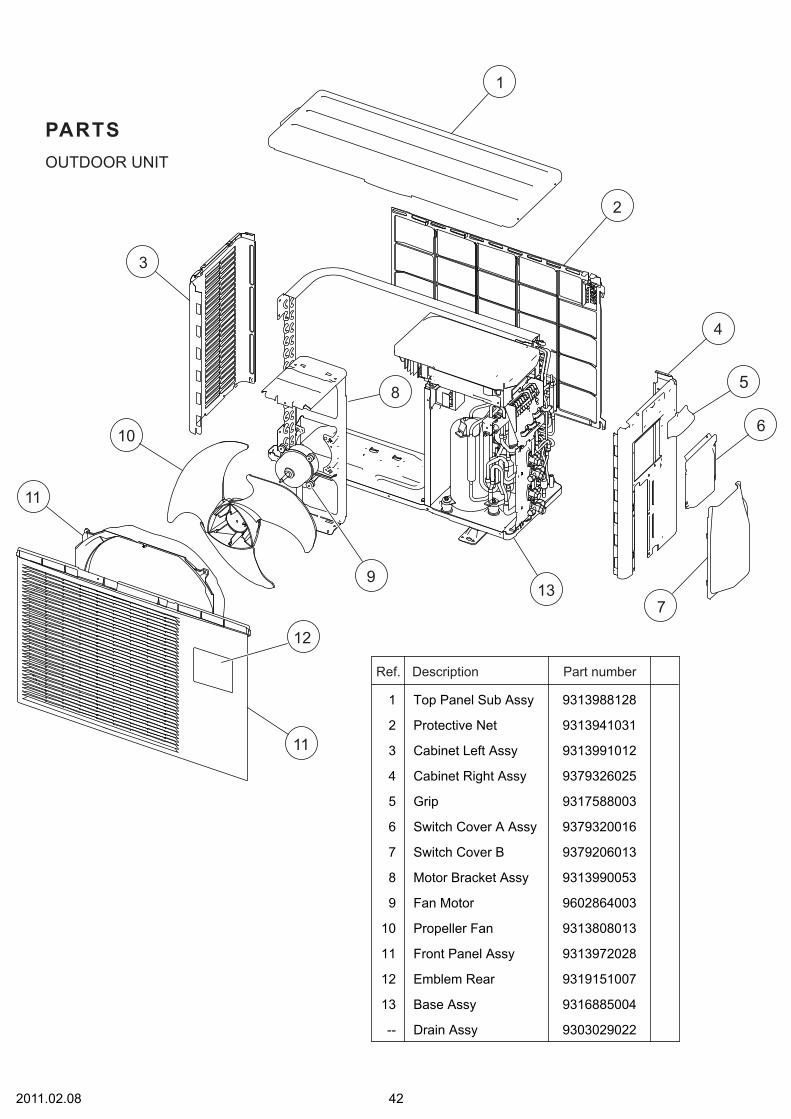
422011.02.08
OUTDOOR UNIT
PARTS
1 Top Panel Sub Assy
2
Front Panel Assy
5 Grip
6 Switch Cover A Assy
3 Cabinet Left Assy
8
Propeller Fan
9 Fan Motor
11
12
Protective Net
9313988128
9313941031
9317588003
9379320016
7 Switch Cover B 9379206013
9313991012
4 Cabinet Right Assy 9379326025
9313990053
9602864003
10
Motor Bracket Assy
9313808013
9313972028
9319151007Emblem Rear
Base Assy13
--
9316885004
9303029022Drain Assy
Ref. Description Part number
12
9
8
137
6
5
4
2
1
3
10
11
11

21 Condenser Total Assy
22 Separater Assy (14)
25 2-way Valve Assy
26 3-way Valve Assy
28 Expansion Valve Assy
23 Reactor Assy (14)
29 Expansion Valve Coil (L=650)
30 Expansion Valve Coil (L=850)
9314107061
9379344012
22 Separater Assy (18) 9317781015
9317171038
9317174053
9379334013
27 Valve Bracket 9379194013
9900611019
23 Reactor Assy (18) 9900354022
24 Compressor Assy (14) 9379315012
24 Compressor Assy (18) 9379679008
9970095016
9970096044
31 Solenoid 9970033032
32 4-way Valve 9970065019
Ref. Description Part number
43
OUTDOOR UNIT
26
25
25
29
30
28
32
31
24
27
22
21
23
26
2012.02.09

442013.01.04
OUTDOOR UNIT
41 Case Cover
42 Inverter PCB Assy (14)
45 Inverter Case Cover
46 Terminal Bracket Assy
48 Terminal 6P
43 PCB Holder
9309913011
9708080093
42 Inverter PCB Assy (18) 9708080109
9379252010
9379324021
9900016050
47 Terminal 3P 9306489175
9313074029
44 Inverter Case Assy 9379673013
-- Pipe Thermistor Assy
-- Outdoor Thermistor
-- Valve Thermistor Assy
9900536008
9900544003
9900535001
-- Compressor Thermistor (18)
-- Heatsink Thermistor
9900516017
9900518035
Ref. Description Part number
47
46
45
44
43
42
41
48
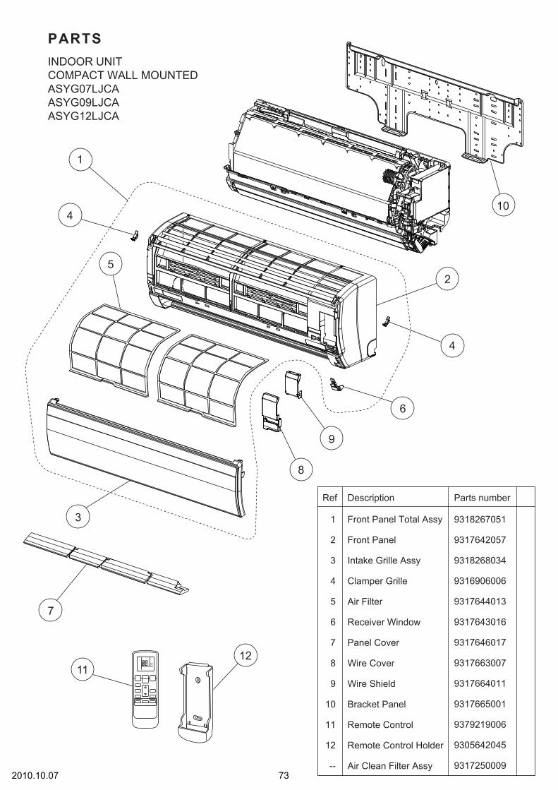
732010.10.07
PARTSINDOOR UNITCOMPACT WALL MOUNTEDASYG07LJCAASYG09LJCAASYG12LJCA
1
2 Front Panel
Front Panel Total Assy
3
Wire Cover
Wire Shield
4
5 Air Filter
6
Intake Grille Assy
Parts numberDescriptionRef
9318267051
9317642057
9318268034
9316906006
9317644013
9317643016
7
Clamper Grille
8
9
Receiver Window
Panel Cover
Air Clean Filter Assy
9317646017
9317663007
9317664011
9305642045
9317250009
10 Bracket Panel
Remote Control
9317665001
11
12
--
Remote Control Holder
9379219006
1
4
5
3
2
4
1112
10
6
7
9
8

742010.10.08
INDOOR UNITCOMPACT WALL MOUNTEDASYG07LJCAASYG09LJCAASYG12LJCA
21
22 Joint Pipe Assy
Evaporator Total Assy
23
Holder (Room Thermistor)
Thermistor Assy
24
25 Evaporator Holder R
26
Filter Guide
Parts numberDescriptionRef
9317820011
9317838009
9317652001
9317651004
9317650007
9317649001
Rear Bracket
27
28
Evaporator Holder L
9316895003
9900563004
21
2728
22
23
24
26
25

752010.06.29
INDOOR UNITCOMPACT WALL MOUNTEDASYG07LJCAASYG09LJCA ASYG12LJCA
31
32 Casing
Casing Assy
33
R AND L Louver B
Louver Gear Holder
34
35 Cable Guide
36
Motor Cover
Parts numberDescriptionRef
9318264050
9317647014
9316568006
9316601000
9316567009
9317653015
37
Motor Cover
38
39
Casing Cover B
Casing Cover F 9317654005
9316961012
9317669016
40 Louver Gear 9317648004
Parts numberDescriptionRef
9900384128
Gear A41
42 Motor Step
931690400243 Drain Hose Assy
931617701744 Drain Cap
933227700545 Fan Guard
960270400246 Fan Motor
931683000447 Crossflow Fan Assy
930662801748 Bearing C Assy
931765601649 Louver U
931765700650 Louver Z
9309994003
31
43
32 44
3845
39 41
42
40
37
4950
33
46
47
35
34
36
48
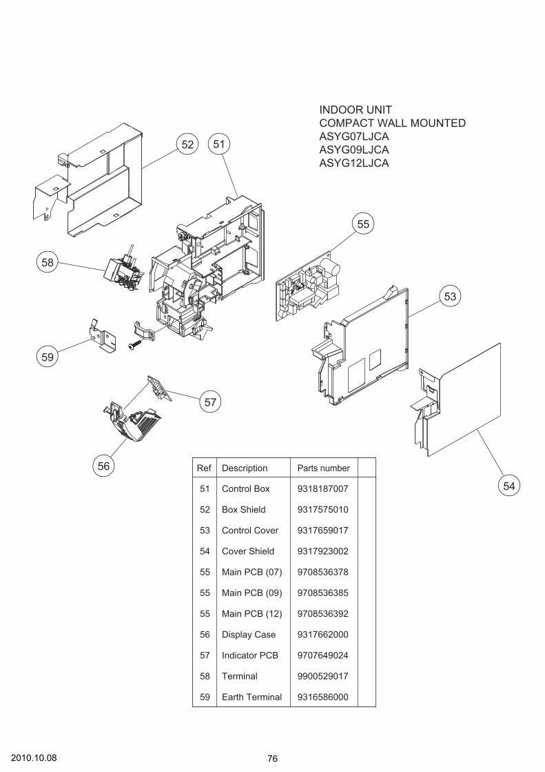
762010.10.08
INDOOR UNITCOMPACT WALL MOUNTEDASYG07LJCAASYG09LJCAASYG12LJCA
51
52 Box Shield
Control Box
53
Terminal
Earth Terminal
54
55 Main PCB (07)
55 Main PCB (09)
55 Main PCB (12)
56
Control Cover
Parts numberDescriptionRef
9318187007
9317575010
9317659017
9317923002
9708536378
9317662000
57
Cover Shield
58
59
Display Case
Indicator PCB 9707649024
9900529017
9316586000
9708536385
9708536392
51
53
54
55
56
57
58
59
52

2
1
3
6
7 8
4
5
INDOOR UNITCOMPACT WALL MOUNTEDASYG07LUCAASYG09LUCAASYG12LUCAASYG14LUCA
2011.03.08 77
5
2
6
4
3
Under Cover 9318879001
1 Bracket Panel 9318913002
7
Wire Cover 9318911008
8
Wire Shield 9318919004
-- Air Clean Filter Assy 9317250009
Remote Control 9319207018
Remote Control Holder 9318912005
Ref. Description Part number
Louver U 9318880007
Louver Z 9318881004

17
18
16
12
15
19
20
11
21
14
13
2011.03.08 78
15
Air Filter
9318910001
12
Front Panel 9318876000
16 Display Plate Holder L 9318894004
14
Front Panel Cover U
17 9318895001
18 Display Plate R 9318893007
Display Plate Holder R
19 9318900002
20 Grille Stay 9318899009
21 Grille Clamper B 9316951006
Arm Cover
9318883008
13 Intake Grille Assy 9319351001
11 Front Panel Total Assy 9319348001
Ref. Description Part number
INDOOR UNITCOMPACT WALL MOUNTEDASYG07LUCAASYG09LUCAASYG12LUCAASYG14LUCAFront panel

35
34
3637
32
33
79
31 Evaporator Total Assy (07,09,12) 9319327006
31 Evaporator Total Assy (14) 9319327013
32 Joint Pipe Assy (14) 9319322018
32 Joint Pipe Assy (07, 09, 12) 9319322001
33 Joint Pipe Holder 9318901009
35
34
Filter Guide 9318887006
36 Evaporator Holder L 9318875003
Base 9318874006
37 Air Seal 9319295008
Ref. Description Part number
2011.03.11
31
INDOOR UNITCOMPACT WALL MOUNTEDASYG07LUCAASYG09LUCAASYG12LUCAASYG14LUCAEvaporator

43
49
48
44
42
41
46
47
45
INDOOR UNITCOMPACT WALL MOUNTEDASYG07LUCAASYG09LUCAASYG12LUCAASYG14LUCAControl box
80
46
Terminal 9900638009
Main PCB (12) 9708713304
45
Earth Terminal 9318918007
41
Control Box
9318916003
42
Cover Shield A
9318882001
43 Box Shield Assy 9319344003
44
Main PCB (14) 970871331144
Main PCB (07) 970871328144
Main PCB (09) 970871329844
49 Step Motor 9900384166
47 Room Thermistor Holder 9319068008
48 Gear Cover 9318902006
Ref. Description Part number
56
Indicator PCB 970882401757
-- Thermistor Assy 9900627003
Display Assy 9708823010
54 Grille Key Top 9319334004
55 Micro Switch 9900625009
51 Panel Gear 9319293004
Switch Case 9319332000
52
53
Gear Case 9318903003
50 Gear B 9319294001
Ref. Description Part number
2013.01.28
52
53
50
51
54 55
56
57

80
68
6667
71
62
69
64
73
70
61
72
78
63
74
79
7765
76
75
81
76
Fan Guard 9318924008
77
Fan Motor 9602947003
78
Crossflow Fan Assy 9319361000
79
Bearing C Assy 9306628017
80
71
Gear A
9318904000
9309994003
72
Motor Step 9900384128
73
74
Drain Hose Assy 9316904002
75
Drain Cap 9316177017
Ref. Description Part number
64
65
Casing Cover B 9318920000
66
Casing Cover F 9318923001
67
R and L Louver 9318885002
61
Casing Assy 9319342009
62
Casing 9318873009
63
Motor Cover 9316601000
Motor Cover 9318888003
68
Pipe Bracket 9318889000
69
70
Panel Cover 9319296005
Louver Holder 9318886009
Louver Gear Holder
Louver Gear
9318905007
Ref. Description Part number
2011.03.09
INDOOR UNITCOMPACT WALL MOUNTEDASYG07LUCAASYG09LUCAASYG12LUCAASYG14LUCACasing assy

9
5
4
11
6
12
8
3
10
1
2
INDOOR UNITCOMPACT WALL MOUNTEDASYG07LMCAASYG09LMCAASYG12LMCAASYG14LMCA
2013.04.19 82
6
9
11
8
10
Intake Grille (FUJITSU) 9333052007
7 Front Panel Sub Assy (FUJITSU) 9332994001
3 Bracket Panel 9332882018
4
Wire Cover 9332894004
Wire Shield 9332906004
Electric Filter Holder 9332911008
5 Air Clean Filter Assy 9317250009
1 Remote Control 9319208008
2 Remote Control Holder 9318912005
Ref. Description Part number
Air Filter 9332875003
Louver 9332900002
12 Diffuser Assy 9332998009
7

24
22
21
28
INDOOR UNITCOMPACT WALL MOUNTEDASYG07LMCAASYG09LMCAASYG12LMCAASYG14LMCAControl box
83
26
Terminal 9900720001
Main PCB (09) 9709427019
25
Earth Terminal 9332880007
21
Control Box
9332915006
22
Cover Shield
9332892000
23 Box Shield Assy 9332877007
24
Main PCB (07) 970942703324
Main PCB (12) 970942702624
Main PCB (14) 970942704024
28 Room Thermistor Holder 9332868005
Ref. Description Part number
27
-- Thermistor Assy 9900714024
Display Assy 9709430019
2013.02.27
27
23
25
26

INDOOR UNITCOMPACT WALL MOUNTEDASYG07LMCAASYG09LMCAASYG12LMCAASYG14LMCAEvaporatorFan
Fan Motor 9603269005
Crossflow Fan Assy 9316830004
Bearing C Assy 9306628017
35
32
Evaporator Total Assy (07, 09, 12) 933298900731
Evaporator Total Assy (14) 933298901431
Casing Assy 9333009001
33
34
Ref. Description Part number
842013.02.27
35
34
33
31
32

51
49
47
43
42 42
45
50
41
44
48
46
INDOOR UNITCOMPACT WALL MOUNTEDASYG07LMCAASYG09LMCAASYG12LMCAASYG14LMCACasing assy
85
Fan Guard 9332905007
50
51
Step Motor 9900790004
46
Drain Hose Assy 9316904002
47
Step Motor 990079001148
Drain Cap 9316177017
41
Casing Cover B 9332908008
43
Casing Cover F 9332909005
42
R and L Louver A 9332891003
Casing 9332890006
Cable Guide 9332903003
Motor Holder L/R 9332859003
49
44
45
Ref. Description Part number
2013.04.19

1
11
902010.10.12
2
58 7
4
6
9
10
9
12
12 9
9
3
DECORATION PANELUTG-UFYD-W
Ref. Description
1 Decoration Panelwithout Insulations
9375525040
2 Display Panel 9375529123
3 Receiver Window 9375547011
5 Intake Grille 9375531027
6 Long Life Filter 9375533014
12 Flap Total Assy 9377760029
7 Hook Bracket 9375546014
9375532024
9375530013
8 Grille Hook
9 Panel Coverwithout Insulations
10 Indicator PCB Assy 9707371031
11 Connector Cover 9375549015
4 Intake Grille Assy 9375726027
Part number

Flap total assyMotor holder assy
912010.10.12
(connector : red)
(connector : white)
21
2223
24
Ref. Description
21 Gear A 9375536015
22 Motor Holder 9375535018
23 Step Motor(white connector)
9900139070
24 Step Motor(red connector)
9900139087
Part number
DECORATION PANELUTG-UFYD-W

922010.10.12
11
9
8
6
4
10
12
31
5
2
7
INDOOR UNITCOMPACT CASSETTEAUYG07LVLAAUYG09LVLAAUYG12LVLAAUYG12LVLB
2 Cabinet A Assy 9375492014
1 Top Plate Assy 9375490010
3 Cabinet B 9375494018
10 Wire Holder 9375478018
9 Bell Mouse 9375503017
11 Drain Pan Sub Assy 9377765024
7 Wire Cover 9375516017
8 Pipe Cover 9375515010
4 Hook R 9375504014
5 Hook L 9375505011
6 Insulation Box Assy 9377764027
12 Drain Cap 9375502010
Ref. Description Part number

INDOOR UNITCOMPACT CASSETTEAUYG07LVLAAUYG09LVLAAUYG12LVLAAUYG12LVLB
932010.10.12
23
21
22
22
25 24
28
2629
30
27
23 2 Stage Turbo Fan Assy 9375480011
21 Evaporator Total Assy (09, 12) 9375720032
21 Evaporator Total Assy (07) 9375720087
22 Evaporator Holder 9375508012
24 Fan Motor 9602436019
25 Fan Motor Holder 9375552015
28 Float Switch 9900361037
29 Drain Port Sub Assy 9375718015
30 Rubber (Pump) 9378426016
26 Pump Assy 9900472030
27 Drain Pump Holder B 9375518011
Ref. Description Part number

942013.01.28
INDOOR UNITCOMPACT CASSETTEAUYG07LVLAAUYG09LVLAAUYG12LVLAAUYG12LVLBControl unit
31
32
33
34
35
36
31 Control Box Cover 9375512019
32 Control Box A 9375511012
33
33
Main PCB (09) 9707393743
33 Main PCB (07) 9707393736
Main PCB (12LVLA) 9707393750
33 Main PCB (12LVLB) 9709245422
Ref. Description Part number
34 Power Supply PCB (LVLA) 9707398250
34 Power Supply PCB (LVLB) 9707398380
35 Terminal 9306489045
36 Terminal 9703345012
-- Pipe Thermistor 9703297014
-- Room Thermistor 9900502003
-- Remote Control 9379219006
-- Remote Control Holder 9305642045
Ref. Description Part number
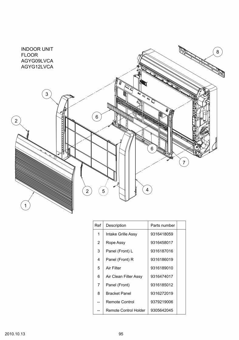
INDOOR UNITFLOORAGYG09LVCAAGYG12LVCA
952010.10.13
1
2
2
3
4
7
6
6
8
1 Intake Grille Assy
2 Rope Assy
3 Panel (Front) L
4 Panel (Front) R
6 Air Clean Filter Assy
Parts numberDescriptionRef
9316418059
9316458017
9316187016
9316186019
9316474017
Remote Control Holder-- 9305642045
-- Remote Control 9379219006
Bracket Panel8 9316272019
7 Panel (Front) 9316185012
5
5 Air Filter 9316189010

INDOOR UNITFLOORAGYG09LVCAAGYG12LVCA
962013.01.28
27
26
15
17
21
20
19
18
25
29
24
28
13
11
22
23
30
16
12
Fan Motor, MFD-34TXN27
Crossflow Fan Assy26
Bearing C Assy25
Terminal
Parts numberDescriptionRef
9602850006
9312004034
9306628017
9900385026
15
Cover (Terminal)16
Bracket (Pipe)17
Base30
Pipe Thermistor18
Display Case
9316307018
9316270015
9316193017
9900425012
931619401419
Display PCB Assy 970757104220
14
Bracket (Terminal) 9316269019
Parts numberDescriptionRef
Display Cover 931619101321
Thermistor Holder 931619201022
Room Thermistor 9700801108
12
Control Box 9316200012
11
Main PCB (09)
12 Main PCB (12)
9708532011
28
Control Cover 9316201019
29
Crossflow Fan B Assy 9316309012
24
Fan Motor, MFD-14SXN 9602851003
23
Motor Holder 9316195011
9708532028
13
25
14

INDOOR UNITFLOORAGYG09LVCAAGYG12LVCA
32 Evaporator Holder
Evaporator Total Assy31
Water Seal
Parts numberDescriptionRef
9316199019
9316091016
9316271012
972010.10.13
31
32
33
33

INDOOR UNITFLOORAGYG09LVCAAGYG12LVCACasing assy
41 Top Cover
R and L Louver U42
Parts numberDescriptionRef
9316207011
9316208018
Casing
43
9316204010
Fan Guard 9316211018
982010.10.13
50
41
43
47
48
49
4645
44
42
44
Motor Step (up / down)
46
9900384043
Gear A
45
9309994003
Gear Case 9316213012
REF (Casing)
49
50 9316378018
Louver Z
48
9316206014
Louver U
47
9316205017

INDOOR UNITFLOORAGYG09LVCAAGYG12LVCACasing aast
51 Motor Step (Damper)
Switch Micro (Limit switch)52
Motor Step (Damper Lock Left)53
Drain Cap
Parts numberDescriptionRef
9900384050
9900424015
9900384067
9316177017
Drain Hose Assy
55
9314147029
54
Drain Pan U 9316214019
992010.10.13
57
58
56
Motor Step (Damper Lock Right) 9900384074
Damper 9316216013
57
59 R and L Louver Z
58
9316334014
52
51
53
54
55
56
59
62
61
60
-- Fan Guard Z
60
9316918009
Cover (Lower)
61
62 9316374010
Stopper 9316219014
Drain Pan Z 9316215016

INDOOR UNITSLIM DUCTARYG07LLTAARYG09LLTAARYG12LLTAARYG12LLTB(Serial number : T)Refer to the servicebulletin RAC-0059
3 Pipe Panel Sub Assy
1 Side Panel R Sub Assy
2 Side Panel L Sub Assy
5 Outlet Frame Sub Assy
Parts numberDescriptionRef
Panel (Window) Sub Assy
3
12
11
13
14
16
7
2
9
10
4
1
1002013.01.22
12 Cabinet Panel (2 Fan)
9 Fan Guard (2 Fan)
11 Main Panel Sub Assy
13 Drain Cap
14 Drain Pan Sub Assy
9379906005
9379900003
9379907002
9379909006
9379915007
9379596008
9379637008
9379902007
9358746004
93799010004
Parts numberDescriptionRef
15 Evaporater Total Assy (07)
16 Pipe Thermistor
9364499666
15 Evaporater Total Assy (09, 12) 9364499581
9900498085
10 Air Filter 9379574006
7 Valve Cover Sub Assy 9379576000
6 Front Panel (2 Fan) 9379593007
8 Cover Pipe Sub Assy 9380033004 -- Hose Sub Assy 9378450103
5
6
8
15

Top Panel Sub Assy21
Separator Sub Assy22
Sirroco Fan Assy23
Motor Band Assy24
25 Motor Band
26 Rubber (Vibration Proof)
Casing B
21
22
23
28
32
29
33
35
3127
23
28
27
24 30
34
26
25
26
27
9379908009
9379898003
9379570015
9379613002
9379614009
9379644006
9379572002
Parts numberDescriptionRef
28
29
Casing U
30
Hook Metal
31
Fan Motor Assy (07)
32
Room Thermistor
33
Drain Pump Sub Assy
34
Pump Assy
35
Float Switch
9379571005
9379889001
9602966011
30 Fan Motor Assy(09,12) 9602967018
9703299247
9379914000
9900472047
9900465032
Drain Hose Assy 9379913003
Parts numberDescriptionRef
1012010.10.29
INDOOR UNITSLIM DUCTARYG07LLTAARYG09LLTAARYG12LLTAARYG12LLTB(Serial number : T)

42
41 Control Cover Sub Assy
Control Box Assy
43
45
44
47
--
Power Supply PCB
Main PCB (09)
45 Main PCB (12LLTA)
Parts numberDescriptionRef
Terminal 3P
Wired Remote Control
PCB Holder
9379806039
9380041023
9707398267
9707393798
45 Main PCB (07) 9707393781
9306489045
49 Terminal Bracket 9380132011
9318593013
46 Reactor Assy 9707457018
9379402002
9707393804
45 Main PCB (12LLTB) 9707393897
48 Terminal 3P (Wired Remote) 9703345012
1042013.01.25
INDOOR UNITSLIM DUCTARYG07LLTAARYG09LLTAARYG12LLTAARYG12LLTB(Serial number : T)
42
43
4746
49
41
48
44
45

INDOOR UNITSLIM DUCTARYG07LLTAARYG09LLTAARYG12LLTB(Serial number : R)Refer to the servicebulletin RAC-0059
3 Pipe Panel Sub Assy
1 Side Panel R Sub Assy
2 Side Panel L Sub Assy
5 Outlet Frame Assy
Parts numberDescriptionRef
Panel (Window) Sub Assy
3
11
10
12
7
2
8
9
4
1
1052012.02.28
11 Cabinet Panel (2 Fan)
10 Main Panel (2 Fan)
12 Drain Pan Sub Assy
9379906012
9379900003
9379907019
9380042006
9379915007
9380597001
8 Fan Guard (2 Fan) 9380589006
9380602002
93799010484
Parts numberDescriptionRef
13 Evaporater Total Assy (07) 9380682080
13 Evaporater Total Assy (09, 12) 9380682042
9 Air Filter 9379574006
7 Valve Cover Sub Assy 9379576017
6 Front Panel (2 Fan) 9380594000
5
6
13

27 Drain Pump Sub Assy
28
29
Float Switch Sub Assy
26 Fan Motor (09, 12) 9602967025
26 Fan Motor Assy (07) 9603139018
9379914024
9378593022
Drain Hose Assy 9379913003
30 Hose Sub Assy 9378450097
Parts numberDescriptionRef
Top Panel Sub Assy21
Sirroco Fan Assy22
23 Rubber (Vibration Proof)
Casing B24
9379908030
9379570015
9379644006
9379572002
25 Casing U 9379571005
Parts numberDescriptionRef
1062013.01.22
INDOOR UNITSLIM DUCTARYG07LLTAARYG09LLTAARYG12LLTB(Serial number : R) 21
27
30
29
22
25
24
26
28
23

1092013.01.25
44
46
43
45
41
42
42
41
44
--
Power Supply PCB
Main PCB (09)
42 Main PCB (12)
Parts numberDescriptionRef
Terminal 3P
Pipe Thermistor
9707398267
9709245286
42 Main PCB (07) 9709245279
9306489045
9900498108
43 Reactor Assy 9707457018
9709245293
-- Room Thermistor 9900653002
46 Wired Remote Control 9318593013
45 Terminal 3P (Wired Remote) 9703345012
INDOOR UNITSLIM DUCTARYG07LLTAARYG09LLTAARYG12LLTB(Serial number : R)

672011.02.28
OUTDOOR UNIT
ACCESSORIES
Use
For outdoor unit drain piping work
Q'ty
1
Name and Shape
Drain pipe assy
1
Adapter assy For use when connecting model 14to outdoor port A or B(AOYG18LAC2 only)
9.52mm 12.7mm

INDOOR UNITCOMPACT WALL MOUNTED ASYG07, 09, 12LJCA
1212013.01.28
Name and Shape Q’ty
Wall hook bracket
1
Remote control
1
Battery2
Remote controlholder
1
Cloth tape
1
Tapping screw(big)
8
Tapping screw (small)
2
Air cleaning filter
2
COMPACT WALL MOUNTED ASYG07, 09, 12, 14LUCA
Name and Shape Q’ty
Wall hook bracket
1
Remotecontrol
1
Battery
2
Remote controlholder
1
Cloth tape
1
Tapping screw(big)
8
Tapping screw (small)
2
Air cleaning filter
2

Name and Shape Part number
0600185541
9310519004
Battery (penlight)
Cloth tape
2013.04.16 122
INDOOR UNITCOMPACT WALL MOUNTEDASYG07, 09, 12, 14LMCA
Remote Control 9319208008
Remote Control Holder 9318912005
Bracket Panel
9332882018
Name and Shape Part number
9332911008
0700076046
9317250009
Filter holder
Air cleaning filter assy
Tapping screw(M4 x 25 mm)
Tapping screw(M3 x 12 mm)
0700019036
Name and Shape
Wired remote controlUTY-RNNYM
External connect kitUTY-XWZXZ5
Communication kitUTY-XCBXZ2
OPTIONAL PARTS
Simple remote ControlUTY-RSNYM
Wired remote controlUTY-RVNYM

INDOOR UNITCOMPACT CASSETTEAUYG07, 09, 12LVLAAUYG12LVLB
1232013.01.28
DECORATION PANELUTG-UFYD-WName and Shape Q’ty Application
Connector cover
1
For covering connector
Tapping Screw(M5 × 12 mm) 4
For mounting decora-tion panel
Tapping Screw(M4 × 12 mm) 1
For mounting connec-tor cover
L angle
2
For mounting the Hook Wire to the Decoration panel
Hook wire 2
For suspending the Decoration panel
Screw [pitch small] (M4 × 10 mm)
2
For mounting the Hook Wire (for metals)
Screw [pitch large] (M4 × 10 mm)
4
For mounting the L angle and Hook wire (for resins)
Name and Shape Q’ty Application
Special nut A (Large ß ange)
4For installing indoor unit
Special nut B (Small ß ange)
4For installing indoor unit
Template(Carton top)
1
For cealing openings cutting Also used as packing
Drain hose
1For installing drain pipe
Hose Band
1For installing drain hose
Drain hose insulation
1 For installing drain pipe
Remote controller
1For air conditioner operation
Battery
2For remote controller unit
Remote controller holder
1For installing the remotecontroller
Tapping screw(M3 × 12mm) 2 For mounting the remote
controller holder
Binder2
For electrical wiring
Wire clamper1 For electrical wiring
Coupler heatinsulation(Small)
1
For indoor side pipe joint (Liquid pipe)
Coupler heatinsulation(Large)
1
For indoor side pipe joint (Gas pipe)

1242011.01.07
INDOOR UNITFLOORAGYG09LVCAAGYG12LVCA
Remote control
1
1
Battery
2
Remote controlholder
1
Cloth tape
1
Tapping screw(M4 x 25 mm)
9
Tapping screw (M3 x 12 mm)
2
Air cleaning filter
Wall hook bracket
2
Name and Shape Q’ty

Name and Shape Q’ty Application
Installationtemplate
1
For positioning theindoor unit
Washer
8
For installing indoor unit
Couplerheat insulation(Large) 1
For indoor side pipe joint (Large pipe)
Couplerheat insulation(Small) 1
For indoor side pipe joint (Small pipe)
Binder Medium3
For power supply and remote control cable binding.
Large4
For fixing the coupler heat insulation.
Filter (Small)
2
(ARYG07LLTA ARYG09LLTA ARYG12LLTA, B)
Drain hose1
For installing drain pipe 3/4 in. (O.D. 1-1/16 in.)
Hose band
1
For installing drain hose
Drain hose insulation B1
Insulates the drain hose
Wired remotecontrol 1
Remote controlcable 1
For connecting theremote control
Tapping screw(M4 × 16 mm) 2
For installing the remotecontrol
1252013.01.28
INDOOR UNITSLIM DUCTARYG07LLTAARYG09LLTAARYG12LLTAARYG12LLTB

SPLIT TYPE ROOM AIR CONDITIONER
Models Indoor unit Outdoor unitAO*G18LAC2
INVERTER MULTI
SERVICE INSTRUCTION
R410A
Slim Duct / Compact CassetteCompact Wall Mounted /Floor type
AR*G07LL* AAR*G09LL* AAR*G12LL* *
AU*G07LVLAAU*G09LVLAAU*G12LVL*
AS*G07LJCAAS*G09LJCAAS*G12LJCA
AS*G07LUCAAS*G09LUCAAS*G12LUCAAS*G14LUCA
AG*G09LVCAAG*G12LVCA
AS*G07LMCAAS*G09LMCAAS*G12LMCAAS*G14LMCA

CONTENTS1. DESCRIPTION OF EACH CONTROL OPERATION
1. CAPACITY CONTROL................................................................................................
3. INDOOR FAN CONTROL...........................................................................................2. AUTO CHANGEOVER OPERATION..........................................................................
5. OUTDOOR FAN CONTROL.......................................................................................4. LOUVER CONTROL...................................................................................................
7. COMPRESSOR CONTROL.......................................................................................6. TIMER OPERATION CONTROL................................................................................
9. TEST OPERATION CONTROL..................................................................................8. ELECTRONIC EXPANSION VALVE CONTROL........................................................
11. 4-WAY VALVE EXTENSION SELECT.......................................................................10. PREVENT TO RESTART FOR 3 MINUTES ( 3 MINUTES ST )................................
13. MANUAL AUTO OPERATION...................................................................................12. AUTO RESTART........................................................................................................
15. POWERFUL OPERATION.......................................................................................... 14. COMPRESSOR PREHEATING..................................................................................
16. 10°C HEAT OPERATION...........................................................................................
01-0101-0101-0301-0901-1301-1401-1701-1801-1801-1801-19
01-1901-2001-20
18. DEFROST OPERATION CONTROL.......................................................................... 01-21
01-20
19. OFF DEFROST OPERATION CONTROL.................................................................. 01-23
17. ECONOMY OPERATION........................................................................................... 01-20
20. VARIOUS PROTECTIONS......................................................................................... 01-24
01-19
2-1-2 WIRED REMOTE CONTROLLER DISPLAY......................................................2-1-1 INDOOR UNIT DISPLAY....................................................................................
2-1 ERROR DISPLAY......................................................................................................
2. TROUBLE SHOOTING
2-2 TROUBLE SHOOTING WITH ERROR CODE..........................................................2-3 TROUBLE SHOOTING WITH NO ERROR CODE....................................................2-4 SERVICE PARTS INFORMATION............................................................................
02-0102-0102-02
02-3202-03
02-37
3. REPLACEMENT PARTS

1 . DESCRIPTION OF EACH CONTROL OPERATION
R410A
INVERTER (MULTI )
Slim Duct / Compact CassetteCompact Wall Mounted Floor type

2. AUTO CHANGEOVER OPERATION
01-01
1. CAPACITY CONTROL
1-1 COOLING, HEATING, DRY CAPACITY CONTROLCompressor frequency decides by capacity of an indoor unit, operation number of an indoor unit, set temperature, room temperature and outside temperature.
When the air conditioner is set to the Auto mode by remote controller, operation starts in the optimummode from among the Heating, Cooling, Dry and Monitoring mode. During operation, theoptimum mode is automatically switched in accordance with temperature changes. The temperaturecan be set between 18°C and 30°C in 1°C steps.
When operation starts, indoor fan and outdoor fan are operated for around 3 minutes. Room temperature and outdoor temperature are sensed, and the operation mode is selected in accordance with the table below. <Monitoring mode>
Cooling mode 25°C
Heating mode
( Table 1 : Operation mode selection table )
Room temperature (TR)
TR> Ts + 2°C
Ts + 2°C TR Ts - 2°C *Middle zone
TR < Ts - 2°C Heating
When Cooling or Dry mode was selected at and air flow mode is Auto, the air conditioner operates as follow.The same operation as COOLING OPERATION AND DRY OPERATION.When the room temperature has remained at set temperature -1.5°C, operation is automatically switched to Dry mode.If the room temperature reaches set temperature +2°C during Dry mode, operation returns to Cooling.
1
12
( Fig. 1 : Outdoor temperature zone selection )
Cooling(Autmatic dry)
Operation mode
*If it's Middle zone, operation mode of indoor unit is selected as below.
(1). Same operation mode is selected as outdoor unit. If outdoor unit is operating in Cooling, Dry, and Heating mode, indoor unit will be operated by the same operation mode.
(2). Selected by the outdoor temperature. If outdoor unit is operating in other than Cooling, Dry, and Heating mode, indoor unit will be operated according to the outdoor temperature as below.
Cooling
CoolingDry(X zone)
Dry(J zone)
Compressor stopWhen the roomtemperature drops
When the roomtemperature rises
Ts + 2°C
Ts - 0.5°C
Ts - 1.5°C
Ts + 1°C
Ts - 1.5°C
Ts - 2.5°C
( Fig.2 : Auto changeover : Cooling - Dry )
TR : Room temperatureTs : Setting temperature
TR : Room temperatureTs : Setting temperature
( Air flow mode : Auto )

01-02
START
Room temp.Ts + 2°C?
COOLING (AUTO:DRY) OPERATIONHEATING OPERATION
YES
YES
NO
NO
NO
AUTO CHANGEOVER operation flow chart
TS : Setting temperature
Room temp.Ts - 2°C?
Thermostat remainsin OFF state for 6 minutes or
longer?
System stopsor operation command other than
auto changeover operation?
NO
Thermostat remainsin OFF state for 6 minutes or
longer?
System stopsor operation command other than
auto changeover operation?
Middle zone
NO
Operation mode of outdoor unit : Cooling or Dry?
YES
NO
Operation mode of outdoor unit : Heating?
YES
NO
YESOutdoor temperature
25°C?
NO
YES
YES
NO
YESYES
When Heating was selected at , the same operation as HEATING OPERATION of page 01-02 is performed.
When the compressor was stopped for 6 consecutive minutes by the temperature control functionafter the Cooling(Auto:Dry) or Heating mode was selected at above, operation is switchedto Monitoring and the operation mode is selected again.
3 1
41

3. INDOOR FAN CONTROL
01-03
1. Fan speed(Table 2 : Indoor fan speed table)AS*G07LJCA AS*G09LJCA
AS*G12LJCA AU*G07LVLA
*Note, during Economy operation and operation mode is Fan, air flow is 1 step downs. (Hi > Me, Me > Lo, Quiet > Soft Quiet)
(rpm) (rpm)
(rpm) (rpm)
HiMe+MeLo
QuietCool Air Prevention
S-LoHiMeLo
Quiet*Soft Quiet
Auto
Operation mode
Heating
Cooling / Fan
Dry
Air flow mode Fan Speed
10501000950850710600480
1050950850680600
X, J zone:680
HiMe+MeLo
QuietCool Air Prevention
S-LoHiMeLo
Quiet*Soft Quiet
Auto
Operation mode
Heating
Cooling / Fan
Dry
Air flow mode Fan Speed
11001040980850710600480
1100980850680600
X, J zone:680
HiMe+MeLo
QuietCool Air Prevention
S-LoHiMeLo
Quiet*Soft Quiet
Auto
Operation mode
Heating
Cooling / Fan
Dry
Air flow mode Fan Speed
120011301050910710600480
12001050880680600
X, J zone:680
HiMe+MeLo
QuietCool Air Prevention
S-LoHiMeLo
Quiet*Soft Quiet
Auto
Operation mode
Heating
Cooling / Fan
Dry
Air flow mode Fan Speed
590570540490440400300590540490440400
X, J zone:440
AU*G12LVL*
HiMe+MeLo
QuietCool Air Prevention
S-LoHiMeLo
Quiet*Soft Quiet
Auto
Operation mode
Heating
Cooling / Fan
Dry
Air flow mode Fan Speed
650620580520460400300660580520460400
X, J zone:460
HiMe+MeLo
QuietCool Air Prevention
S-LoHiMeLo
Quiet*Soft Quiet
Auto
Operation mode
Heating
Cooling / Fan
Dry
Air flow mode Fan Speed
AU*G09LVLA
590570540490440400300590540490440400
X, J zone:440
(rpm) (rpm)

AR*G09LL*A (Static pressure:25Pa)
HiMeLo
QuietS-Lo
HiMeLo
Quiet*Soft Quiet
Auto
Operation mode
Heating
Cooling / Fan
Dry
Air flow mode Fan Speed
X, J zone:960
126011601060960500
126011601060960500
01-04
AR*G07LL*A (Static pressure:25Pa)
HiMeLo
QuietS-Lo
HiMeLo
Quiet*Soft Quiet
Auto
Operation mode
Heating
Cooling / Fan
Dry
Air flow mode Fan Speed
X, J zone:880
1160100094088050011601000940880500
(rpm)(rpm)
*Note, during Economy operation and operation mode is Fan, air flow is 1 step downs. (Hi > Me, Me > Lo, Quiet > Soft Quiet)
AR*G12LL** (Static pressure:25Pa)
HiMeLo
QuietS-Lo
HiMeLo
Quiet*Soft Quiet
Auto
Operation mode
Heating
Cooling / Fan
Dry
Air flow mode Fan Speed
X, J zone:1030
1340124011401030500
1340124011401030500
(rpm)
AS*G07LUCA AS*G09LUCA(rpm) (rpm)
PowerfulHi
Me+MeLo
QuietCool Air Prevention
S-LoPowerful
HiMeLo
Quiet*Soft Quiet
Auto
Operation mode
Heating
Cooling / Fan
Dry
Air flow mode Fan Speed
1030980980910850650610570
1030980910850650610
X, J zone:650
PowerfulHi
Me+MeLo
QuietCool Air Prevention
S-LoPowerful
HiMeLo
Quiet*Soft Quiet
Auto
Operation mode
Heating
Cooling / Fan
Dry
Air flow mode Fan Speed
108010301030950850650610570
10801030950850650610
X, J zone:650

01-05
AG*G09LVCA
HiMeLo
QuietCool Air Prevention
S-LoHiMeLo
QuietSoft Quiet
Auto
Operation mode
Heating
Cooling / Fan
Dry
Air flow mode Fan Speed
1120/9501000/850860/730660/560660/560660/560
1120/950960/820820/700660/560570/480
-
Upper / LowerUpper / LowerUpper / LowerUpper / LowerUpper / LowerUpper / LowerUpper / LowerUpper / LowerUpper / LowerUpper / LowerUpper / LowerUpper / Lower
12301090940750680680
12301070910750680
X, J zone:750
Upper & Lowerair flow mode
Upperair flow mode
AG*G12LVCA
HiMeLo
QuietCool Air Prevention
S-LoHiMeLo
QuietSoft Quiet
Auto
Operation mode
Heating
Cooling / Fan
Dry
Air flow mode Fan Speed
1240/10401080/920910/770660/560660/560660/560
1240/10401050/890860/730660/560570/480
-
Upper / LowerUpper / LowerUpper / LowerUpper / LowerUpper / LowerUpper / LowerUpper / LowerUpper / LowerUpper / LowerUpper / LowerUpper / LowerUpper / Lower
13001140980750680680
13001120930750680
X, J zone:750
Upper & Lowerair flow mode
Upperair flow mode
(rpm)
(rpm)
AS*G14LUCA (rpm)
PowerfulHi
Me+MeLo
QuietCool Air Prevention
S-LoPowerful
HiMeLo
Quiet*Soft Quiet
Auto
Operation mode
Heating
Cooling / Fan
Dry
Air flow mode Fan Speed
12301180118010801010790610570
123011801080980740710
X, J zone:740
AS*G12LUCA (rpm)
PowerfulHi
Me+MeLo
QuietCool Air Prevention
S-LoPowerful
HiMeLo
Quiet*Soft Quiet
Auto
Operation mode
Heating
Cooling / Fan
Dry
Air flow mode Fan Speed
1160111011101030930650610570
116011101030930650610
X, J zone:650

01-05+1
AS*G07LMCA AS*G09LMCA
AS*G12LMCA AS*G14LMCA
*Note, during Economy operation and operation mode is Fan, air flow is 1 step downs.(Hi > Me, Me > Lo, Quiet > Soft Quiet)
(rpm) (rpm)
(rpm) (rpm)
PowerfulHi
Me+MeLo
QuietCool Air Prevention
S-LoPowerful
HiMeLo
Quiet*Soft Quiet
Auto
Operation mode
Heating
Cooling / Fan
Dry
Air flow mode Fan Speed
109010501000950850710600480
10901050950850680600
X, J zone:680
PowerfulHi
Me+MeLo
QuietCool Air Prevention
S-LoPowerful
HiMeLo
Quiet*Soft Quiet
Auto
Operation mode
Heating
Cooling / Fan
Dry
Air flow mode Fan Speed
114010901040980850710600480
11401090980850680600
X, J zone:680
PowerfulHi
Me+MeLo
QuietCool Air Prevention
S-LoPowerful
HiMeLo
Quiet*Soft Quiet
Auto
Operation mode
Heating
Cooling / Fan
Dry
Air flow mode Fan Speed
1240119011201050910710600480
124011901050880680600
X, J zone:680
PowerfulHi
Me+MeLo
QuietCool Air Prevention
S-LoPowerful
HiMeLo
Quiet*Soft Quiet
Auto
Operation mode
Heating
Cooling / Fan
Dry
Air flow mode Fan Speed
1240119011201050910710600480
124011901050880680600
X, J zone:680

The airflow can be switched in 5 steps such as Auto, Quiet, Lo, Me, Hi, while the indoor fan only runs.When Fan mode is set at (Auto), it operates on (Me) Fan Speed.
2. FAN OPERATION
3. COOLING OPERATION (Auto : Cooling)Switch the airflow [Auto], and the indoor fan motor will run according to a room temperature, as shown in Fig 3.On the other hand, if switched in [Hi] [Quiet], the indoor motor will run at a constant airflow of [Cooling]operation modes Quiet, Lo, Me, Hi.
( Fig.3 : Airflow change - over (Cooling : Auto) )
When the room temperature rises
When the room temperature drops
TR : Room temperatureTs : Setting temperature
TR-Ts > +2°C=
+1°C > TR-Ts
+2°C > TR-Ts > +1°C=
TR-Ts > +2.5°C=
+1.5°C > TR-Ts
+2.5°C) > TR-Ts > +1.5°C=
Hi
Me
Lo=
=
==
4. DRY OPERATION (Auto : Dry)During the dry operation, the fan speed setting can not be changed,it operates automatically as shown in Fig. 4.Room temperature variation which the room temperature sensor of the indoor unit body has detected.
( Fig. 4 : Indoor fan control )
10 30 60 180 60 180 60 10 30 (sec)
Fan OFF
OFF
< Compressor > ON
Setting air flow
S-Lo
< Indoor fan air flow mode >
< All models >
< All models >
01-06
3-1 INDOOR UNIT FAN CONTROL FOR ENERGY SAVING (Cooling mode) Switch the airflow at cooling mode, and the indoor fan motor will run as shown in Fig.4. It depends on the Function setting "Indoor unit fan control for energy saving."

The maximum value of the indoor fan speed is set as shown in Fig 6, based on the detectedtemperature by the indoor heat exchanger sensor in heating mode.
< AS*G type >
01-07
5. HEATING OPERATION (Auto : Heating)Switch the airflow [Auto], and the indoor fan motor will run according to a room temperature,as shown in Fig 5. On the other hand, if switched in [Hi] [Quiet], the indoor motor will run at a constant airflow of [Heat] operation modes Quiet, Lo, Me, Hi, as shown in Table 2.
6. COOL AIR PREVENTION CONTROL (For Heating and Min. Heat operation)
( Fig.5 : Airflow change - over (Heating : Auto) )
TR-Ts > -1.5°C=
-2.5°C > TR-Ts
-1.5°C > TR-Ts > -2.5°C=
TR-Ts > -1°C=
-2°C > TR-Ts
-1°C > TR-Ts > -2°C=
When the room temperature rises When the room
temperature drops
TR : Room temperatureTs : Setting temperature
Lo
Me
Me+
42°C
30°C
34°C
When Indoor heat exchanger temperature rises When Indoor heat exchanger
temperature drops
Hi
*Me+ or setting FAN mode
Cool air prevention
39°C
37°C
37°C
32°C
28°CS-Lo
*Lo or setting FAN mode
29°C
When Indoor heat exchanger temperature rises When Indoor heat exchanger
temperature drops
*Lo or setting FAN mode
37°C32°C
24°C
*Hi or setting FAN mode
S-Lo
During NORMAL HEATING OPERATION< AR*G type >
*Lower speed is selected
Field setting is necessary at AR and AU type as "Cool air prevention : effective"
TR-Ts > -1.5°C=
-2.5°C > TR-Ts
-1.5°C> TR-Ts > -2.5°C=
TR-Ts > -1°C=
-2°C > TR-Ts
-1°C > TR-Ts > -2°C=
When the room temperature rises When the room
temperature dropsLo
Me
Hi
< AU*G / AR*G / AG*G type >
< AS*G type >
( Fig.6 : Airflow change - over for cool air prevention)
*Lower speed is selected

01-08
34°C
< AS*G / AU*G type > When Indoor heat exchanger temperature rises When Indoor heat exchanger
temperature drops
Lo
39°CAuto
When Indoor heat exchanger temperature rises
When Indoor heat exchanger temperature drops
Lo
Auto
32°C37°C
During MIN. HEAT OPERATION< AR*G type >
< AU*G type >
42°C
30°C
34°C
When Indoor heat exchanger temperature rises When Indoor heat exchanger
temperature drops
Hi
*Me+ or setting FAN mode
Cool air prevention
39°C
37°C
37°C
32°C
24°CS-Lo
*Lo or setting FAN mode
< AG*G type >
*Lower speed is selected
42°C
30°C
31°C
When Indoor heat exchanger temperature rises When Indoor heat exchanger
temperature drops
Hi
*Me or setting FAN mode
Cool air prevention
39°C
37°C
34°C
29°C
24°CS-Lo
*Lo or setting FAN mode
*Lower speed is selected
31°C
When Indoor heat exchanger temperature rises When Indoor heat exchanger
temperature drops
Lo
39°CAuto
< AG*G type >

4. LOUVER CONTROL
Each time the button is pressed, the air direction range will change as follow:(Function Range)
01-09
Use the air direction adjustments within the ranges shown above.
The vertical airflow direction is set automatically as shown, in accordance with the type of operation selected.Cooling / Dry mode : Horizontal flowHeating mode : Downward flow
When the temperature of the air being blown out is low at the start of heating operation or during defrosting, the airflow direction temporarily becomes to prevent cold air being blown onto the body.During use of the Cooling and Dry modes, do not set the Air Flow Direction Louver in the Heating range ( ) for long period of time, since water vapor many condense near the outlet louvers and drop of water may drip from the air conditioner. During the Cooling and Dry modes, if the Air Flow Direction Louvers are left in the heating range for around 30 minutes, they will automatically return to position .
(Fig.7 : Virtical Air Direction Range)Cooling / Heating / Dry mode / Fan mode
Cooling / Dry / Fan mode( ) :Heating / Fan mode( )
2. SWING OPERATION
When the swing signal is received from the remote controller, the vertical louver starts to swing.
(Swinging Range)1 3 1 4
4 6 6
Vertical Airflow Swing Operation
When the indoor fan is S-Lo or Stop mode, the swing operation is interrupted and it stops at either upper end or bottom end.
For AS*G07/ 09/ 12LJCA Type1. VERTICAL LOUVER CONTROL
Vertical Louver
<Compact Wall Mounted Type>
4

1. VERTICAL LOUVER CONTROL
3. SWING OPERATION
Each time the button is pressed, the air direction range will change as follow:(Function Range)
01-10
The vertical airflow direction is set automatically as shown, in accordance with the type of operation selected.Cooling / Dry mode Horizontal flowHeating mode Downward flow
When the swing signal is received from the remote controller, the vertical louver starts to swing.
(Fig.8 : Air Direction Range)
Cooling / Dry modeFan mode ( )
Types of Air flow Direction Setting: , , : During Cooling/Dry modes , , , : During Heating
The Remote Controller's display does not change.
Use the air direction adjustments within the ranges shown above.
During AUTO mode operation, for the first a few minutes after beginning operation, air-flow will be horizontal 1; the air direction cannot be adjusted during this period.The air flow direction setting will temporarily become 1 when the temperature of the air -flow is low at the start of the Heating mode.
Range
Heating modeFan mode ( )
The SWING operation may stop temporarily when the air conditioner’s fan is not operating, or when operating at very low speeds.
1
2
3
4
5
6
7
2. ADJUST THE RIGHT-LEFT LOUVERS
Move the Right-Left louvers to adjust air flow in the direction you prefer.
Knob (2 places)
Right-Left Louvers
Knob
To select Vertical Airflow Swing Operation
To select Horizontal Airflow Swing Operation
(No function)
For AS*G07/ 09/ 12/ 14LUCA Type
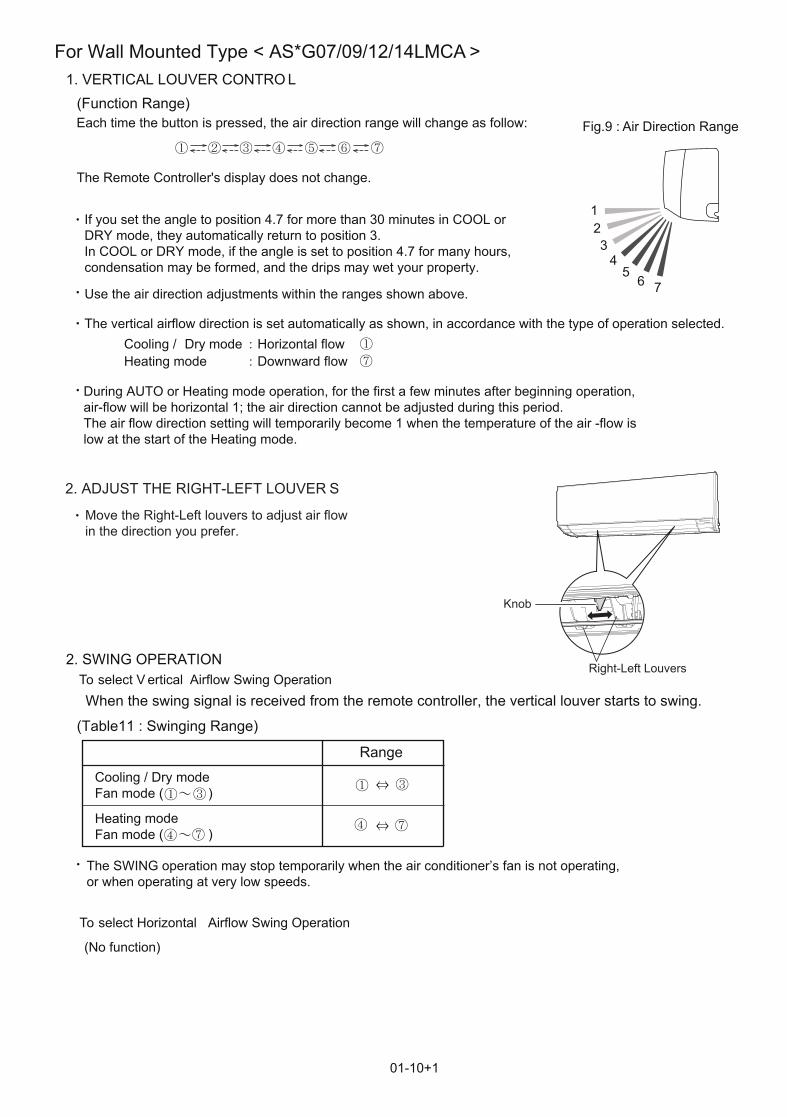
1. VERTICAL LOUVER CONTRO L
2. SWING OPERATION
Each time the button is pressed, the air direction range will change as follow:(Function Range)
01-10+1
The vertical airflow direction is set automatically as shown, in accordance with the type of operation selected.Cooling / Dry mode Horizontal flowHeating mode Downward flow
When the swing signal is received from the remote controller, the vertical louver starts to swing.
(Table11 : Swinging Range)
Air Direction RangeFig.9 :
Cooling / Dry modeFan mode ( )
The Remote Controller's display does not change.
Use the air direction adjustments within the ranges shown above.
If you set the angle to position 4.7 for more than 30 minutes in COOL or DRY mode, they automatically return to position 3.In COOL or DRY mode, if the angle is set to position 4.7 for many hours,condensation may be formed, and the drips may wet your property.
During AUTO or Heating mode operation, for the first a few minutes after beginning operation, air-flow will be horizontal 1; the air direction cannot be adjusted during this period.The air flow direction setting will temporarily become 1 when the temperature of the air -flow is low at the start of the Heating mode.
Range
Heating modeFan mode ( )
The SWING operation may stop temporarily when the air conditioner’s fan is not operating, or when operating at very low speeds.
2. ADJUST THE RIGHT-LEFT LOUVER S
Move the Right-Left louvers to adjust air flowin the direction you prefer.
To select V ertical Airflow Swing Operation
To select Horizontal Airflow Swing Operation
(No function)
Right-Left Louvers
123
45
6 7
Knob
For Wall Mounted Type < AS*G07/09/12/14LMCA >

01-11
1. VERTICAL LOUVER CONTROL
Each time the button is pressed, the air direction range will change as follows:
Use the air direction adjustments within the ranges shown above.
The vertical airflow direction is set automatically as shown, in accordance with the type of operation selected.
(Function Range)
(Fig.9 : Air Direction Range)
(Operation Range)Cooling / Heating / Dry / Fan mode :
Cooling / Dry / Fan mode Horizontal flowHeating mode Downward flow
2. SWING OPERATIONWhen the swing signal is received from the remote controller, the vertical louver starts to swing.The range of swing depends on the set airflow direction.
When the indoor fan is either at S-Lo or Stop mode, the swinging operation is interruptedand it stops at either upper end or bottom end.( Stop mode means Operation stop.)
During AUTO mode operation, for the first minute after start-up, air-flow will be horizontal ; the air direction cannot be adjusted during this period.
For AU*G07/ 09/ 12LVLA Type
1 2 3 4
1 2 3 4
1
1 4
4
12
3
4
(Swinging Range)
Cooling / Heating / Dry / Fan mode :

01-12
For AG*G09/ 12LVCA Type1. VERTICAL LOUVER CONTROL
2. SWING OPERATION
Each time the button is pressed, the air direction range will change as follows:
Use the air direction adjustments within the ranges shown above.
The vertical airflow direction is set automatically as shown, in accordance with the type of operation selected.
Cooling / Dry / Fan mode Horizontal flowHeating mode Downward flow
When the temperature of the air being blown out is low at the start of heating operation or duringdefrosting, the airflow direction temporarily becomes to prevent cold air being blown onto the body.
During Monitor operation in AUTO CHANGEOVER mode, the airflow direction automatically becomes , and it cannot be adjusted.
(Function and Operation Range)
When the swing signal is received from the remote controller, the vertical louver starts to swing .(Swinging Range)
When the indoor fan is either at S-Lo or Stop mode, the swinging operation is interrruptedand it stops at either upper end or bottom end.
( Fig.10 : Air Direction Range)
Cooling / Heating / Dry / Fan mode :

5. OUTDOOR FAN CONTROL
Following table 3 shows the fan speed of the outdoor unit.
01-13
1. Outdoor Fan Motor
* It runs at 500rpm for 20 seconds after starting up the outdoor fan.
( Table 3 : Fan speed of the outdoor unit )
900/ 820/ 700/ 410/ 320/ 250/ 200 rpm 900/ 820/ 700/ 410/ 320/ 250/ 200 rpm
Cooling Heating
AO*G18LAC2

6. TIMER OPEARTION CONTROL
1. ON / OFF TIMER
The table 4 shows the available timer setting based on the product model.
OFF timer : When the clock reaches the set time, the air conditioner will be turned off.
Operation mode
Stop mode
Set time of timer
ON timer : When the clock reaches the set time, the air conditioner will be turned on.
Operation modeStop mode
Set time of timer
The program timer allows the OFF timer and ON timer to be used in combination one time.
Operation mode
Operation will start from the timer setting (either OFF timer or ON timer) whichever is closestto the clock's current timer setting. The order of operations is indicated by the arrow in the remote control unit's display.
SLEEP timer operation cannot be combined with ON timer operation.
( Table 4 : Timer setting )
2. PROGRAM TIMER
Stop mode Stop mode Stop mode
Operation mode Operation mode
Set time Set time Set time Set time
01-14
6-1 WIRELESS REMOTE CONTROLLER
ON TIMER / OFF TIMER PROGRAM TIMER SLEEP TIMER *WEEKLY TIMER
* For AS*G07/ 09/ 12/ 14LUCA Type

3. SLEEP TIMER
Set temperature rises( Ts : Set temperature )
Stop of operation
Set temperature lowers( Ts : Set temperature )
Stop of operation
Ts+1°C+2°C
Set 60min
Set 30min 30min 30min
01-15
Ts-1°C-2°C-3°C-4°C
If the sleep is set, the room temperature is monitored and the operation is stopped automatically.If the operation mode or the set temperature is change after the sleep timer is set, the operation iscontinued according to the changed setting of the sleep timer from that time ON.
In the cooling operation modeWhen the sleep timer is set, the setting temperature is increased 1°C.It increases the setting temperature another 1°C after 1 hour.After that, the setting temperature is not changed and the operation is stopped at the timeof timer setting.
In the heating operation modeWhen the sleep timer is set, the setting temperature is decreased 1°C.It decreases the setting temperature another 1°C every 30 minutes.Upon lowering 4deg C, the setting temperature is not changed and the operation stops atthe time of timer setting.
4. WEEKLY TIMER (For AS*G07/ 09/ 12/ 14LUCA Type )This timer function can set operation times of the each day of the week.All days can be set together,the weekly timer can be used to repeat the timer setting for all of the days.
Setting day Setting day Setting day
ON OFF ON OFF ON OFF
Set time Set time

01-16
6-2 WIRED REMOTE CONTROLLER
The Table 5 shows the available timer setting based on the product model.
ON TIMER / OFF TIMER WEEKLY TIMER TEMPERATURE SET BACK TIMER
( Table 5 : Timer setting )
1. ON TIMER / OFF TIMERSame to 6-1 ON / OFF TIMER and shown in those.
2. WEEKLY TIMERThis timer function can set operation times of the each day of the week.All days can be set together,the weekly timer can be used to repeat the timer setting for all of the days.
3. TEMPERATURE SET BACK TIMERThis timer function can change setting temperature of setting operation times of the each day of the week.This can be together with other timer setting.
Normal tmp.
ON OFF
Setting day Setting day Setting day
ON OFF ON OFF ON OFF
Set time Set time
Set back tmp.
Set time Set time
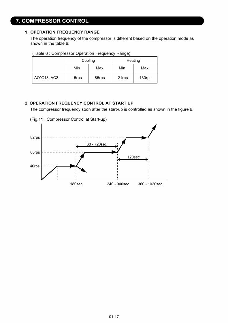
7. COMPRESSOR CONTROL
1. OPERATION FREQUENCY RANGE The operation frequency of the compressor is different based on the operation mode asshown in the table 6.
Cooling Heating
Min Max Min Max
AO*G18LAC2 15rps 85rps 21rps 130rps
(Table 6 : Compressor Operation Frequency Range)
2. OPERATION FREQUENCY CONTROL AT START UPThe compressor frequency soon after the start-up is controlled as shown in the figure 9.
1) Compressor operates for 180 seconds by 40 rotations.
2) In the case of lower than 40 rotations, it operates at these rotations.
3) Compressor operates for 60 to 780 seconds.
4) Compressor operates at target rotations after 120 second operation.When discharge temperature exceeds 30 degrees in the meantime, it shifts to 56 rotations.
(Fig.11 : Compressor Control at Start-up)
01-17
40rps
180sec
120sec
60 - 720sec
240 - 900sec 360 - 1020sec
60rps
82rps

8. ELECTRONIC EXPANSION VALVE CONTROL
01-18
The most proper opening of the electronic expansion valve is calculated and controlled under thepresent operating condition based on the Table7.The compressor frequency, the temperatures detected by the discharge temperature sensorand the outdoor temperature sensor.
At the time of supplying the power to the outdoor unit, the initialization of the electronicexpansion valve is operated (1000 pulses are input to the closing direction).
Cooling /Dry modeHeating mode
AO*G18LAC2
Operation mode Pulse range50 ~ 48030 ~ 480
(Table7 : The pulse range of the electronic expansion valve control)
9. TEST OPERATION CONTROL
The compressor won't enter operation status for 3 minutes after the compressor is stopped, even if any operation is given.
10. PREVENT TO RESTART FOR 3 MINUTES ( 3 MINUTES ST )
Under the condition where the air conditioner runs, press the TEST RUN button, and the test operation control mode will appear. During test running, the operation lamp and timer lamp of the air conditioner body twinkle simultaneously. Set the test operation mode, and the compressor will continue to run regardless of whether the room temperature sensor detects.
The outdoor unit, may not operate, depending on the room temperature. In this case, keep on pressing the MANUAL AUTO button of the indoor unit for more than 10 seconds. The Operation lamp and Timer lamp will begin to flash simultaneously during cooling test run. Then, heating test run will begin in about 3 minutes when HEAT is selected by the remote control operation. (When the air conditioner is running by pressing the test run button, the Operation lamp and Timer lamp will simultaneously flash slowly.)
Perform the test operation for 60 minutes.Pressing the MANUAL AUTO button of the indoor unit for more than 3 seconds.
If the Operation lamp is on, press the START/STOP button to turn it off.Press the MODE and the FAN buttons at the same time for more than two seconds to start the test operation.The operation lamp will light up and "o1" will be displayed on the set temperature display.
Perform the test operation for 60 minutes.Pressing the START/STOP button will stop the test operation.
[ Operation method ( For Wireless Remote Controller ( with TEST RUN button ) Type ) ]
The test operation mode is released if 60 minutes have passed after setting up the test operation.[ Release ]
[ Operation method ( For AS*G07/ 09/ 12/ 14LUCA Type ) ]
[ Release ]
[ Using the Wired remote control (Option) ]
[ Release ]
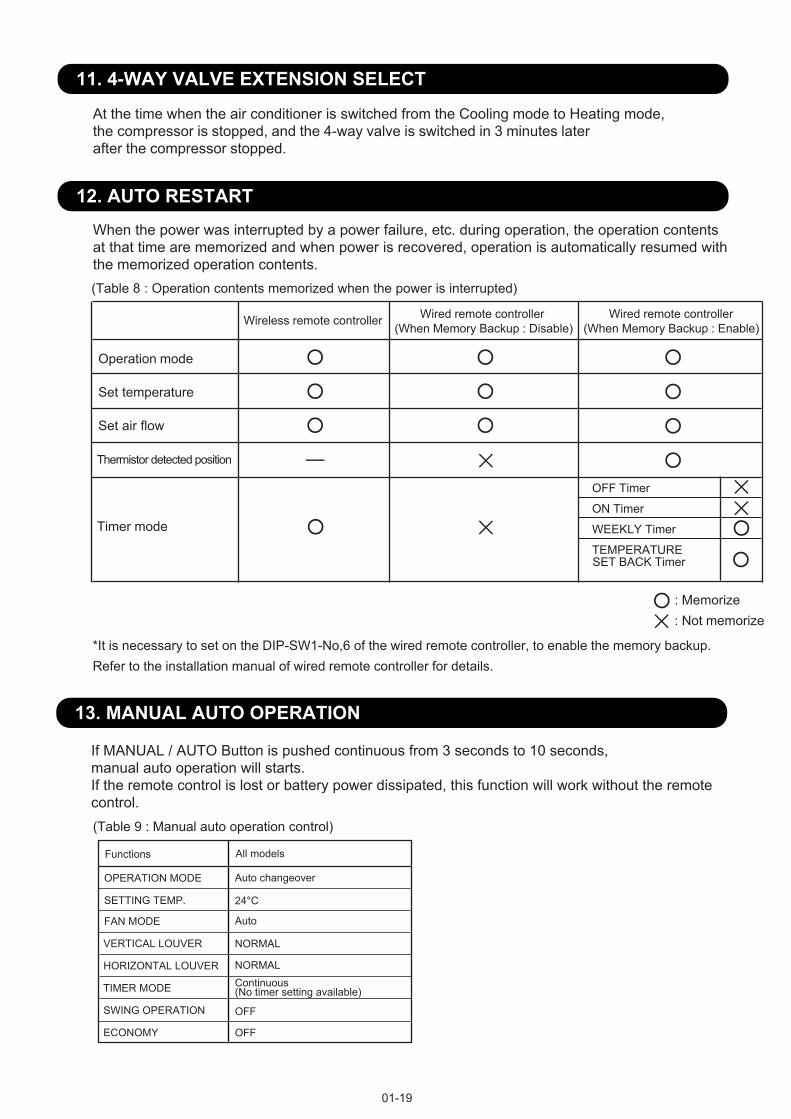
At the time when the air conditioner is switched from the Cooling mode to Heating mode, the compressor is stopped, and the 4-way valve is switched in 3 minutes later after the compressor stopped.
When the power was interrupted by a power failure, etc. during operation, the operation contentsat that time are memorized and when power is recovered, operation is automatically resumed withthe memorized operation contents.(Table 8 : Operation contents memorized when the power is interrupted)
11. 4-WAY VALVE EXTENSION SELECT
12. AUTO RESTART
01-19
13. MANUAL AUTO OPERATION
If MANUAL / AUTO Button is pushed continuous from 3 seconds to 10 seconds,manual auto operation will starts.If the remote control is lost or battery power dissipated, this function will work without the remotecontrol.
OPERATION MODE Auto changeover
Auto
Continuous (No timer setting available)
24°C
(Table 9 : Manual auto operation control)
SETTING TEMP.
FAN MODE
TIMER MODE
: Memorize: Not memorize
*It is necessary to set on the DIP-SW1-No,6 of the wired remote controller, to enable the memory backup. Refer to the installation manual of wired remote controller for details.
SWING OPERATION
ECONOMY
OFF
OFF
VERTICAL LOUVER NORMAL
NORMALHORIZONTAL LOUVER
All modelsFunctions
Operation mode
Set temperature
Set air flow
Thermistor detected position
Timer mode
Wireless remote controller Wired remote controller(When Memory Backup : Disable)
Wired remote controller(When Memory Backup : Enable)
OFF Timer
ON Timer
WEEKLY Timer
TEMPERATURESET BACK Timer

14. COMPRESSOR PREHEATING
01-20
When the outdoor heat exchanger temperature is lower than Operation temperature (Refer to Table 10)and the heating operation has been stopped for 3 hours, power is applied to the compressor and the compressor is heated.(By heating the compressor, warm air is quickly discharged when operation is started.)When operation was started, and when the outdoor temperature rises to Release temperature or greater, preheating is over.
(Table 10 : Preheating Operation / Release Temperature)Before 24 hour After 24 hour
Operationtemperature
Operationtemperature
Releasetemperature
Releasetemperature
3°C 7°C 0°C 4°C
15. POWERFUL OPERATION
The POWERFUL OPERATION functions by pressing POWERFUL button on the remote controller.The indoor unit & outdoor unit will operate at maximum power as shown in Table11.
Release Condition is as follows.[Cooling / Dry] - Room tenperature < Setting temperature - 1.5°C or Operation time has passed 20 minutes.
COMPRESSOR FREQUENCY Maximum
FAN CONT. MODE Powerful
SETTING LOUVER Cooling/ Dry : 3, Heating : 5
(Table11)
Powerful operation
=
=[Heating] - Room tenperature > Setting temperature +1.5°C or Operation time has passed 20 minutes.
16. 10°C HEAT OPERATION10°C HEAT operation performs as below when pressing 10°C HEAT button or Weekly timer setting on the remote controller.
Mode HeatingSetting temperature 10°CFan mode AutoLED display EconomyDefrost operation Operate as normal
(Table 12 : 10°C HEAT operation )
17. ECONOMY OPERATION
The ECONOMY operation functions by pressing ECONOMY button on the remote controller.At the maximum output, ECONOMY Operation is approximately 70% of normal air conditioner operation for cooling and heating.The ECONOMY operation is almost the same operation as below settings.
Mode Cooling/ Dry Heating
Target temperature Setting temp.+1°C Setting temp.-1°C
(Table 13 )

18. DEFROST OPERATION CONTROL
01-21
2. CONDITION OF THE DEFROST OPERATION COMPLETIONDefrost operation is released when the conditions become as shown in Table 15.
(Table 15 : Defrost release condition)Release Condition
Outdoor heat exchanger temperature sensor value is higher than 16°C orCompressor operation time has passed 15 minutes.
1. CONDITION OF STARTING THE DEFROST OPERATIONThe defrost operation starts when the outdoor heat exchanger temperature sensor detectsthe temperature lower than the values shown in Table 14-1, 14 -2.
(Table 14-1 : Condition of starting defrost operation)
Less than 6 min. *1 or 10min. *2 *2. Compressor stop time:
Below 20min. Select 6min. Above 20min. Select 10min.
After 6 min. *1 or 10min. *2
Compressor integrating operation :Less than 45min.
Compressor integrating operation :45min and over
-8°C *3-12°C *4-14°C *5-16°C *6-18°C *7
Does not operate
*1. It means contiguous operation time.
1-1 NORMAL DEFROST
*3. Outdoor temp. > 3°C*4. Outdoor temp. > -1°C*5. Outdoor temp. > -5°C*6. Outdoor temp. > -10°C*7. Outdoor temp. < -10°C
Normal defrost
Integrating defrost
If the compressor continuous operation time is less than 10 minutes, the OFF number of the compressor is counted.If any defrost operated, the compressor OFF count is cleared.
More than 210 minutes(For continuous operation)
Less than 10 minutes( For intermittent operation )
Compressor integrating operation time
When the compressor is stopped, If detected
outside air temp. at 2°C
OFF count of the compressor40 times
( at outside air temp. < 2°C )
1-2. INTEGRATING DEFROST(Table 14-2 : Condition of starting defrost operation)
=

01-22
3 sec later Compressor : OFF 3 sec later Outdoor fan motor : OFF28sec later 4WAY valve : OFF34sec later Compressor : ON
3. Defrost Flow ChartThe defrosting shall proceed by the integrating operation time, outdoor temperature and outdoor heat exchanger temperature as follows.
(Not defrosted for 6 or 10 minutes)
Heating operation start : Compressor ON
Outdoor HEX temp. : Over 16°Cor
Compressor ON time: Maximum 15 minutes
Defrost end
Outdoor HEX temp.Below -8°C
Integrating defrost
Defrost Indicator:[Operation lamp]7 sec ON / 2 sec OFF
Defrost start
Normal defrost
Outside air temp. > 3°C
Compressor integrating operation:Over 210 min.
Intermittent operation
Compressor OFF count :40 times(Less than 10min.)
Continuous operation
Outdoor HEX temp.Below -12°C
Outside air temp. > -1°C
Outdoor HEX temp.Below -14°C
Outside air temp. > -5°C
Outdoor HEX temp.Below -16°C
Outside air temp. > -10°C
When the compressor is
stopped, If detected outside
air temp. at 2°C
Outdoor HEX temp.Below -18°C
Outside air temp. < -10°C=

19. OFF DEFROST OPEARTION CONTROL
01-23
1. OFF DEFROST OPERATION CONDITION
When operation stops in the [Heating operation] mode, if frost is adhered to the outdoor unit heatexchanger, the defrost operation will proceed automatically. In this time, if indoor unit operationlamp flashes slowly (7 sec ON / 2 sec OFF), the outdoor unit will allow the heat exchanger to defrost,and then stop.
In heating operation, the outdoor heat exchanger temperature is less than -4°C,and compressor operation integrating time lasts for more than 30 minutes,and compressor operation contiguous time lasts for more than 10 minutes.
OFF Defrost Flow Chart
Heating operation stop
Defrost start
Defrost Indicater:[Operation lamp]7 sec ON / 2 sec OFF
Outdoor heat exchanger temperature:Over 16°C orCompressor ON time: Over 15 minutes
Defrost end
2. OFF DEFROST END CONDITION
Release Condition
Outdoor heat exchanger temperature sensor value is higher than 16°C orCompressor operation time has passed 15 minutes.
Outdoor heat exchanger temperature:Below -4°CandCompressor integrating operation:Over 30 minutesandCompressor contiguous operation:Over 10 minutes

17. VARIOUS PROTECTIONS
1. DISCHARGE GAS TEMPERATURE OVER RISE PREVENTION CONTROLThe discharge gas thermosensor (discharge thermistor : Outdoor side) will detect discharge gastemperature.When the discharge temperature becomes higher than Ⅰ ,the compressor frequencyis decreased 20rps, and it continues to decrease the frequency for 20rps every 120 seconds untilthe temperature becomes lower than Ⅱ.When the discharge temperature becomes lower than Ⅱ,the control of the compressor frequency is released.
When the discharge temperature becomes higher than Ⅲ ,the compressor stops.When the discharge temperature becomes lower than 80°C ,the compressor operates.
2. CURRENT RELEASE CONTROL
01-24
The compressor frequency is controlled so that the outdoor unit input current does not exceedsthe current limit velue that was set up with the outdoor temperature.The compressor frequency returns to the designated frequency of the indoor unit at the timewhen the frequency becomes lower than the release value.
3. ANTI-FREEZING CONTROL (Cooling mode)When the indoor unit heat exchanger and 2-way valve temperature becomes lower than Ⅰ ,the compressor frequencyis decreased 10rps, and it continues to decrease the frequency for 10rps every 120 seconds untilthe temperature becomes higher than Ⅱ.
This operation is not released until both the temperature of the indoor unit heat exchanger and 2-way valve temperature exceed the release temperature.
AO*G18LAC2 105°C 95°C 110°C
Temperature Temperature Temperature
(Table 16 : Discharge Temperature Over Rise Prevension Control / Release Temperature)
(Table 17 : Anti-freezing Protection Operation / Release Temperature)
>12°C 3°C 2°C 6°C
Temperature Temperature
3°C 2°C 13°C
Outside air Temperature Indoor Heat Ex.
Temperature2-way valve Temperature
Indoor Heat Ex. Temperature
2-way valve Temperature
<12°C
5°C
12°C
=

01-25
4. COOLING PRESSURE OVER RISE PROTECTION
When the outdoor unit heat exchange sensor temperature rises to 67.0°C or greater, the compressor is stopped and error display is indicated.
5. HIGH TEMPERATURE RELEASE CONTROL ( HEATING MODE )On heating mode, the compressor frequency is controlled as following based on thedetection value of the indoor heat exchanger temperature sensor.
(Fig 14 : Heating Overload Protection Control)
+
Indoor heat exchange temperature
63°CCompressor is OFF
The compressor frequency is decreased 5rps every 20 seconds.
54°C
53°C
A°C
B°C
Outdoor heat exchangetemperature
-9°C
Stable rangeRelease
=< Th
-11°C =< Th< -9°C
-13°C =< Th< -11°C
-15°C =< Th< -13°C
Th< -15°C
In one operation ofthe indoor unit: Qu air than
All indoor unit opeate,: Qu air
52°C
52°C
52°C
50°C
48°C
50°C
50°C
48°C
46°C
44°C
48°C
48°C
48°C
48°C
48°C
46°C
46°C
46°C
46°C
46°C
A°C A°CB°C B°C
The compressor frequency is decreased 6rps every 60 seconds.
The compressor frequency is decreased 2rps every 60 seconds.
Release

2 . TROUBLE SHOOTING
R410A
INVERTER (MULTI )
Slim Duct / Compact CassetteCompact Wall Mounted Floor type

02-01
2-1 ERROR DISPLAY
2-1-1 INDOOR UNIT AND WIRED REMOTE CONTROLLER DISPLAYPlease refer the flashing pattern as follows.The Operation, Timer, Economy lamps operate as follows according to the error contents.
Manual Auto Switch Error
Indoor Room Thermistor Error
Indoor Unit Model Information ErrorEEPROM Access Abnormal
Wired Remote Controller Communication Error
Error Contents
Continuous
Continuous
4 times
Continuous2 times
3 times
3 times
5 times
Continuous2 times1 times
Continuous1 times1 times
TroubleshootingEconomy
(Green) Timer (Orange)
Operation (Green)
1 times
Serial Communication Error
Indoor Unit Fan Motor Error
Indoor Heat Ex. Thermistor Error
Continuous4 times 2 times
Continuous1 times5 times
Intake grille Error Continuous8 times5 times
PFC circuit Error Continuous4 times6 times
Continuous7 times 1 times
Continuous
7 times 3 times Continuous
7 times 4 times Continuous
2 times7 times
Discharge Thermistor Error
Heat Ex. Thermistor Error
Outdoor Thermistor Error
Compressor Thermistor Error
1,2
3
4
5
6
7
8
9
10
11
12
13
14
15
16
17
18
19
20
21
22
23
24
25
26
27
28
29
Continuous7 times 7 timesHeat Sink Thermistor Error
Continuous10 times 3 timesCompressure Temp. Error
Continuous
Continuous5 times
9 times
9 times
7 times
Compressor Control Error
Outdoor Unit Fan Motor Error
Continuous4 times9 times
Continuous9 times 9 times4 Way Valve Error
Continuous1 times10 timesDischarge Temp. Error
Over Current Error
Continuous5 times6 timesIPM Error
Indoor Unit Display Wired Remote Controller Display
11
12
22
32
35
41
42
51
53
57
57
58
62
64
65
71
72
73
74
76
76
77
94
95
97
99
A1
A3
Indoor Unit Capacity Error Continuous2 times2 times
Continuous2 times6 timesOutdoor Unit Model Information Error
Continuous7 times 6 times2-way valve Thermistor Error
Continuous7 times 6 times3-way valve Thermistor Error
Continuous5 times 7 timesDamper(OPEN/CLOSE) Detection Limit Switch Error
Continuous3 times5 timesDrain pump Error
Continuous5 times 7 timesDamper(OPEN/CLOSE) Simultaneous Detection Limit Switch Error

02-02
When " Er " in Temperature Display is displayed, inspection of the air conditioning system is necessary. Please consult authorized service personnel.
2-1-2 WIRED REMOTE CONTROLLER DISPLAY
1. SELF - DIAGNOSIS
SU MOTU WETH FR SA
Unit number (usually 0)Error code
ex. Self-diagnosis check
2. ERROR CODE HISTORY DISPLAYUp to 16 memorized error codes may be displayed for the indoor unit connected to the remote controller.
1. Stop the air conditioner operation.
2. Press the SET TEMPERATURE buttons , simultaneously for 3 seconds or more to start the self-diagnosis.
4. Press the SET TEMPERATURE buttons , simultaneously for 3 seconds or more or there is no key input for 60 seconds to stop the display.
3. Press the SET TEMPERATURE button to select the error history number.
SU MOTU WETH FR SA
Error codeError history number
0 1 2 3 4 5 6 7F E d c b A 9 8
��
Lower Raise

Trouble shooting 1 OUTDOOR UNIT Error Method:
Detective Actuators: Detective details:
Forecast of Cause:
OK
Indicate or Display:
Refer to error code table.
YESYES
NO
Serial Communication Error (Serial Reverse Transfer Error)
Outdoor unit Main PCBOutdoor unit Fan motor
1. Connection failure 2. External cause 3. Main PCB failure 4. Outdoor unit Fan motor failure
Check Point 1-1 : Reset the power and operate
Does error indication reappear?
Check Point 1-2 : Check external cause such as noise
Check if the ground connection is proper.Check if there is any equipment that causes harmonic wave near the power cable (Neon light bulb or any electronic equipment which causes harmonic wave).
Check Point 2 : Check connection
Check any loose or removed connection line of between indoor unit and outdoor unit. >> If there is an abnormal condition, correct it by referring to Installation Manual or Data & Technical Manual. Check connection condition in control unit.(If there is loose connector, open cable or mis-wiring)
Check Point 3 : Check the voltage of power supply
Check the voltage of power supply >> Check if AC198V(AC220V-10%) - 264V(AC240V+10%) appears at outdoor unit terminal L - N.
When the indoor unit cannot receive the serial signal from Outdoor unit more than 2minutes after power ON, or the indoor unit cannot receivethe serial signal more than 15seconds during normal operation.
02-03
2-2 TROUBLE SHOOTING WITH ERROR CODE
OK
Check Point 4 : Check serial signal (Reverse transfer signal)
Check serial signal (Reverse transfer signal) >> Check if indicated value swings between AC70V and AC130V at outdoor unit terminal 1 - 3. >> If it is abnormal, Check the parts as follows. - Outdoor unit fan motor (PARTS INFORMATION 5)>> If Outdoor fan motor is abnormal, replace Outdoor unit fan motor and Main PCB.>> If the parts are normal, replace Main PCB.
12
3 RED
WHITE
BLACK
+-

Trouble shooting 2 INDOOR UNIT Error Method:
Detective Actuators: Detective details:
Forecast of Cause:
OK
Indicate or Display:
Refer to error code table.
YESYES
NO
OK
Serial Communication Error(Serial Forward Transfer Error)
Indoor unit Controller PCB
1. Connection failure 2. External cause 3. Controller PCB failure
Check Point 1-1 : Reset the power and operate
Does error indication reappear?
Check Point 1-2 : Check external cause such as noise
Check if the ground connection is proper.Check if there is any equipment that causes harmonic wave near the power cable (Neon light bulb or any electronic equipment which causes harmonic wave).
Check Point 2 : Check connection
Check any loose or removed connection line of between indoor unit and outdoor unit. >> If there is an abnormal condition, correct it by referring to Installation Manual or Data & Technical Manual. Check connection condition in control unit.(If there is loose connector, open cable or mis-wiring)
Check Point 3 : Check the voltage of power supply
Check the voltage of power supply >> Check if AC198V(AC220V-10%) - 264V(AC240V+10%) appears at outdoor unit terminal L - N.
Check Point 4 : Check serial signal (Forward transfer signal)
Check serial signal (Forward transfer signal) >> Check if indicated value swings between AC70V and AC130V at outdoor unit terminal 2 - 3. >> If it is abnormal, replace Controller PCB.
When the outdoor unit cannot properly receive the serial signal fromindoor unit for 10 seconds or more.
02-04
12
3 RED
WHITE
BLACK
+-

Trouble shooting 3INDOOR UNIT Error Method:
Detective Actuators: Detective details:
Forecast of Cause:
Check Point 2 : Check Wired Remote Controller and Controller PCB
Check Point 1 : Check the connection of terminal
OKOK
Indicate or Display:
Wired Remote Controller Communication Error
Indoor unit Controller PCBWired Remote Controller (Option)
1. Connection failure 2. Wired Remote Controller failure 3. Controller PCB failure
Check & correct the followings. Check the connection of terminal between Wired Remote Controller and indoor unit, and check if there is a disconnection of the cable.
When the indoor unit cannot properly receive the signal fromWired Remote Controller for 1 minute or more.
02-05
Refer to error code table.
>> If it is DC12V, Remote Control is failure. (Controller PCB is normal) >> Replace Remote Control>> If it is DC 0V, Controller PCB is failure. (Check Remote Control once again) >> Replace Controller PCB
Check Voltage at terminal 1-3 of Controller PCB or Communication PCB.(Power supply to Remote Control)Cassette, Duct Type : CN14Wall mount ,Floor Type : CN6Compact Wall mount Type : CN305(UTY-XCBXZ1)

Detective Actuators: Detective details:
Forecast of Cause :
OKOK
All indoor unit The total capacity of the indoor unit if it is install beyond.
1. The selection of indoor units is incorrect 2. Main PCB(Outdoor unit) failure
Check Point 1 : Check the total capacity of indoor unit
Check the total capacity of the connected indoor units. >> If abnormal condition is found, correct it by referring to Installation Manual or Design & Technical Manual.
02-06
Trouble shooting 4INDOOR UNIT Error Method:
Indicate or Display:
Indoor Unit Capacity ErrorRefer to error code table.
Check Point 2 : Replace Main PCB
If Check Point 1 do not improve the symptom, replace Main PCB of Outdoor unit.

02-07
Trouble shooting 5 INDOOR UNIT Error Method:
Indicate or Display:
Indoor Unit Model Information ErrorEEPROM Access Abnormal
Refer to error code table.
Detective Actuators: Detective details:
Forecast of Cause:
Check Point 3 : Replace Controller PCB
Check Point 2 : Check Indoor unit electric components
YESYES
NO
Indoor unit Controller PCB
1. External cause 2. Defective connection of electric components 3. Controller PCB failure
Check Point 1-1 : Reset Power Supply and operate
Does Error indication show again?
Check Point 1-2 : Check external cause such as noise
Check if the ground connection is proper.Check if there is any equipment that causes harmonic wavenear the power cable (Neon light bulb or any electronicequipment which causes harmonic wave).
Note : EEPROM
EEPROM(Electronically Erasable andProgrammable Read Only Memory) is a non-volatile memory which keeps memorizedinformation even if power is turned off. It canchange the contents electronically. To change the contents, it uses higher voltage than normal, and it can not change a partial contents. (Rewriting shall be done upon erasing the all contents.) There is a limit in a number of rewriting.
Change Controller PCB.
Check all connectors.(loose connector or incorrect wiring)Check any shortage or corrosion on PCB.
When power is on and there is some below case. When model information of EEPROM is incorrect. When the access to EEPROM failed.

Trouble shooting 6 INDOOR UNIT Error Method:
Indicate or Display:
Detective Actuators: Detective details:
Forecast of Cause :
OKOK
Manual Auto Switch Error
Indoor Unit Controller PCBIndicator PCBManual Auto Switch
When the Manual Auto Switch becomes ON for consecutive 60 ormore seconds.
1. Manual Auto Switch failure 2. Controller PCB and Indicator PCB failure
Check Point 1 : Check the Manual Auto Switch
Check if Manual Auto Switch is kept pressed.Check ON/OFF switching operation by using a meter. >> If Manual Auto Switch is disabled (on/off switching), replace it.
Check Point 2 : Replace Controller PCB and Indicator PCB
If Check Point 1 do not improve the symptom, replace Controller PCB and Indicator PCB.
02-08
Refer to error code table.

Detective Actuators:Indoor Unit Controller PCB CircuitRoom temperature Thermistor
Detective details:
Room temperature thermistor is open or short is detected always.
Forecast of Cause : 1. Connector failure connection 2. Thermistor failure 3. Controller PCB failure
Check Point 2 : Remove connector and check Thermistor resistance value
Check Point 1 : Check connection of Connector
Check if connector is loose or removedCheck erroneous connectionCheck if thermistor cable is open>>Reset Power when reinstalling due to removed connector or incorrect wiring.
OK
OK
Trouble shooting 7INDOOR UNIT Error Method:
Indicate or Display:
Indoor Room Thermistor Error Refer to error code table.
Check Point 3 : Check voltage of Controller PCB (DC5.0V)
Make sure circuit diagram of each indoor unit and check terminal voltage at Thermistor (DC5.0V)
Small size Wall mount circuit diagram(Connector connection)
If the voltage does not appear, replace Controller PCB.
H/E (MID) Thermistor
Room Temp. Thermistor
Room Temp. Thermistor
H/E Thermistor
Cassette circuit diagram (Connector connection) Wall mount Scircuit diagram (Direct soldering to PCB)
Duct circuit diagram (Connector connection)
BLACK
BLACK34
CN4
12
34
12
BLACK
BLACK
BLACK
BLACK
BLACK
BLACK
12
12
CN3
CN1
123
123
RED
WHITE
H/E Thermistor
Room Temp. Thermistor
BLACK
BLACK
12
12
1 12 2
CN5
CN8
GRAY
GRAY
12
CN7
BLACK
BLACK
12
12
1 12 2
CN5
CN8
GRAY
GRAY H/E (MID) Thermistor
Room Temp. Thermistor
02-09
Floor circuit diagram (Connector connection and Direct soldering to PCB)
BLACK
BLACK
12
12
12
CN3
CN1
GRAY
GRAY H/E (MID) Thermistor
Room Temp. Thermistor
Thermistor Characteristics (Rough value)
If Thermistor is either open or shorted, replace it and reset the power.
6.5
35
8.0
30
10.012.515.820.225.233.6Resistance Value ( )
2520151050
58.2
-10
44.0
-5Temperature (°C)
Resistance Value ( ) 4.35.3
4540Temperature (°C)
DC

Detective Actuators:Indoor Unit Controller PCBHeat Exchanger (MID) Thermistor
Detective details:Heat Exchanger (MID) thermistor is open or short is detected always.
Forecast of Cause : 1. Connector failure connection 2. Thermistor failure 3. Controller PCB failure
Check Point 1 : Check connection of Connector
Check if connector is loose or removedCheck erroneous connectionCheck if thermistor cable is open>>Reset Power when reinstalling due to removed connector or incorrect wiring.
OK
Check Point 2 : Remove connector and check Thermistor resistance value
02-10
Trouble shooting 8INDOOR UNIT Error Method:
Indicate or Display:
Indoor Heat Ex. Thermistor Error Refer to error code table.
OK
Check Point 3 : Check voltage of Controller PCB (DC5.0V)
Make sure circuit diagram of each indoor unit and check terminal voltage at Thermistor (DC5.0V)
If the voltage does not appear, replace Controller PCB.
H/E (MID) Thermistor
Room Temp. Thermistor
Cassette circuit diagram (Connector connection)
Duct circuit diagram (Connector connection)
BLACK
BLACK
12
12
1 12 2
CN5
CN8
GRAY
GRAY
12
CN7
BLACK
BLACK
12
12
1 12 2
CN5
CN8
GRAY
GRAY H/E (MID) Thermistor
Room Temp. Thermistor
Small size Wall mount circuit diagram(Connector connection)
Room Temp. Thermistor
H/E Thermistor
Wall mount Scircuit diagram (Direct soldering to PCB)
BLACK
BLACK34
CN4
12
34
12
BLACK
BLACK
BLACK
BLACK
BLACK
BLACK
12
12
CN3
CN1
123
123
RED
WHITE
H/E Thermistor
Room Temp. Thermistor
Floor circuit diagram (Connector connection and Direct soldering to PCB)
BLACK
BLACK
12
12
12
CN3
CN1
GRAY
GRAY H/E (MID) Thermistor
Room Temp. Thermistor
DC
Thermistor Characteristics (Rough value)
If Thermistor is either open or shorted, replace it and reset the power.
Resistance Value ( )
Temperature (°C)
Resistance Value ( )
Temperature (°C)
1131.9 579.6 312.3 233.2 176.0 134.2 103.3 80.3 62.9
49.7 39.6 31.7 25.6 20.8 17.1 14.1 11.6 10.4
-30 -20 -10 -5 0 5 10 15 20
25 30 35 40 45 50 55 60 63

02-11
Trouble shooting 9INDOOR UNIT Error Method:
Indicate or Display:
Indoor Unit Fan Motor Error Refer to error code table.
Detective Actuators: Detective details:
Forecast of Cause:
Check Point 1 : Check rotation of Fan
Check Point 2 : Check ambient temp. around motor
OK
OK
OK
Indoor unit Controller PCBIndoor unit fan motor
1. Fan rotation failure 2. Fan motor winding open 3. Motor protection by surrounding temperature rise4. Control PCB failure 5. Indoor unit fan motor failure
Rotate the fan by hand when operation is off.(Check if fan is caught, dropped off or locked motor)>>If Fan or Bearing is abnormal, replace it.
Check excessively high temperature around the motor.(If there is any surrounding equipment that causes heat)>>Upon the temperature coming down, restart operation.
When the condition that actual frequency of Indoor Fan is below 1/3 of target frequency is continued more than 56 seconds.
Check Point 4 : Replace Controller PCB
If Check Point 1- 3 do not improve the symptom, replace Controller PCB.
Check Point 3 : Check Indoor unit fan motor
Check Indoor unit fan motor. (PARTS INFORMATION 4)>>If Indoor unit fan motor is abnormal, replace Indoor unit fan motor.

Indicate or Display:
Refer to error code table.
Trouble shooting 10INDOOR UNIT Error Method:Drain pump Error
Detective Actuators:Indoor Unit Controller PCB CircuitFloat Switch
Detective details:
When Float switch is ON for more than 3 minutes.
Check Point 1 : Check Float Switch
Check operation of float switch. (any blocking by dust, etc.)Remove Float switch and check ON/OFF switching operationby using a meter.>>If Float switch is abnormal, replace it.
ON OFF
OK
Forecast of Cause : 1. Float switch failure 2. Shorted connector/wire 3. Controller PCB failure 4. Drain pump failure 5. Hose clogging
Check Point 2 : Check Connector (CN 9) / Wire
Check loose contact of CN9 /shorted wire (pinched wire).>>Replace Float switch if the wire is abnormal
Check Point 4 : Check Controller PCB
If Check Point 1 ~ 3 do not improve the symptom, change Controller PCB and execute the check operation again.
Attention!!Wall mount / Small size wall mount type does not have a float switch. In this case, replace Controller PCB and set up the original address. Please refer to.
OK
OK
Check Point 3 : Check Drain Hose
Check Drain Hose .>>If there is Hose clogging. Please clear the clog.
02-12

Indicate or Display:
Refer to error code table.
02-13
Detective Actuators: Detective details:
Forecast of Cause :
Indoor unit Controller PCB CircuitLimit switchDamper
When limit switch were not able to detect the close though the damper close.(Upper air flow)When limit switch were not able to detect the open though the damper open.(Upper & Lower air flow)
1. Limit switch failure 2. Shorted connector/ wire 3. Damper faulure 4. Controller PCB failure
Check Point 2 : Check Point 2 : Check Connector (CN18) / Wire
Check Point 1 : Check Limit switch
Check Point 4 : Replace Controller PCB
OKOK
OKOK
Check operation of limit switch. (any blocking by dust, etc.)Remove Limit switch and check ON/OFF switching operation by using a meter.
>>If Limit switch is detective, replace it.
Check loose contact of CN18 /shorted wire (pinched wire).>>Replace Limit switch if the wire is abnormal
Check Point 2 : Check Point 3 : Check Damper
OKOK
>>Replace Damper if the damper is abnormal
If Check Point 1 3 do not improve the symptom, change Controller PCB.
Check the obstruction of damper movement.Check the damper movement.
Trouble shooting 11 INDOOR UNIT Error Method:Damper(OPEN/CLOSE) Detection Limit Switch Error

Indicate or Display:
Refer to error code table.
02-14
Detective Actuators: Detective details:
Forecast of Cause :
Indoor unit Controller PCB CircuitLimit switch
When the limit switch detects open and close at the simultaneous.
1. Limit switch failure 2. Shorted connector/ wire 3. Controller PCB failure
Check Point 2 : Check Point 2 : Check Connector (CN18) / Wire
Check Point 1 : Check Limit switch
Check Point 3 : Replace Controller PCB
OKOK
Check operation of limit switch. (any blocking by dust, etc.)Remove Limit switch and check ON/OFF switching operation by using a meter.
>>If Limit switch is detective, replace it.
Check loose contact of CN18 /shorted wire (pinched wire).>>Replace Limit switch if the wire is abnormal
OKOK
If Check Point 1 & 2 do not improve the symptom, change Controller PCB.
Trouble shooting 12 INDOOR UNIT Error Method:Damper(OPEN/CLOSE) Simultaneous Detection Limit Switch Error

02-15
Trouble shooting 13
INDOOR UNITINDOOR UNIT Error Method:
Detective Actuators: Detective details:
Forecast of Cause :
Intake grille error
Indoor unit Controller PCBMicro switch
When the Micro switch is detected open while running the compressor.
1. Micro switch failure 2. Shorted connector/ wire 3.Controller PCB failure
Indicate or Display:
Refer to error code table.
Check Point 2 : Check Point 2 : Check Connector (CN11) / Wire
Check Point 1 : Check Limit switch
Check Point 3 : Replace Controller PCB
OKOK
Check operation of Micro switch. (any blocking by dust, etc.)Remove Micro switch and check ON/OFF switching operation by using a meter.
>>If Micro switch is detective, replace it.
Check loose contact of CN11 /shorted wire (pinched wire).>>Replace Micro switch if the wire is abnormal
OKOK
If Check Point 1 & 2 do not improve the symptom, change Controller PCB.
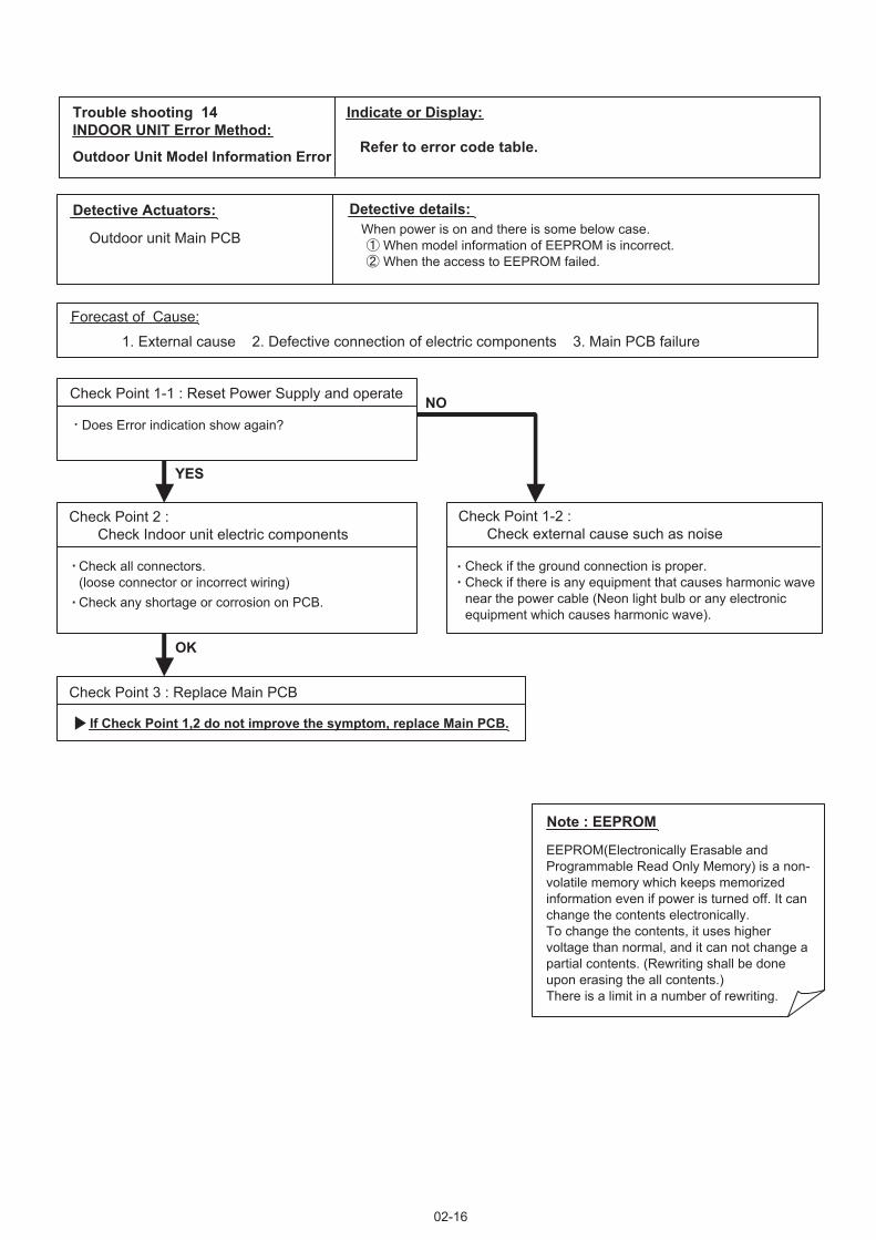
02-16
Trouble shooting 14INDOOR UNIT Error Method:
Indicate or Display:
Outdoor Unit Model Information Error Refer to error code table.
Detective Actuators: Detective details:
Forecast of Cause:
Check Point 3 : Replace Main PCB
Check Point 2 : Check Indoor unit electric components
YESYES
NO
Outdoor unit Main PCB
1. External cause 2. Defective connection of electric components 3. Main PCB failure
Check Point 1-1 : Reset Power Supply and operate
Does Error indication show again?
Check Point 1-2 : Check external cause such as noise
Check if the ground connection is proper.Check if there is any equipment that causes harmonic wavenear the power cable (Neon light bulb or any electronicequipment which causes harmonic wave).
Note : EEPROM
EEPROM(Electronically Erasable andProgrammable Read Only Memory) is a non-volatile memory which keeps memorizedinformation even if power is turned off. It canchange the contents electronically. To change the contents, it uses higher voltage than normal, and it can not change a partial contents. (Rewriting shall be done upon erasing the all contents.) There is a limit in a number of rewriting.
If Check Point 1,2 do not improve the symptom, replace Main PCB.
Check all connectors.(loose connector or incorrect wiring)Check any shortage or corrosion on PCB.
When power is on and there is some below case. When model information of EEPROM is incorrect. When the access to EEPROM failed.
OK

Trouble shooting 15INDOOR UNITOUTDOOR UNIT Error Method:
Detective Actuators: Detective details:
Forecast of Cause :
OKOK
OKOK
PFC circuit Error
Outdoor unit Main PCB
1. External cause 2. Connector connection failure 3. Main PCB failure
Check Point 2 : Check connection of Connector
Check if connector is removed.Check erroneous connection.Check if cable is open.>>Upon correcting the removed connector or mis-wiring, reset the power.
Check Point 3 : Replace Main PCB
If Check Point 1, 2 do not improve the symptom, change Main PCB.
Check Point 1 : Check external cause at Indoor and Outdoor (Voltage drop or Noise)
Instant drop : Check if there is a large load electric apparatus in the same circuit.Momentary power failure : Check if there is a defective contact or leak current in the power supply circuit.Noise : Check if there is any equipment causing harmonic wave near electric line. (Neon bulb or electric equipment that may cause harmonic wave) Check the complete insulation of grounding.
02-17
When inverter output DC voltage is higher than 415V for over 3 seconds, the compressor stops.If the same operation is repeated 5 times, the compressor stops permanently.
Indicate or Display:
Refer to error code table.

Detective Actuators: Detective details:
Forecast of Cause :
Check Point 1 : Replace Main PCB
Outdoor unit Main PCB
1. Main PCB failure
Change Main PCB.
02-18
Trouble shooting 16OUTDOOR UNIT Error Method:
IPM Error
Indicate or Display:
Refer to error code table.
When the signal from FO terminal of IPM in Main PCB is "L"(=0V)while the compressor stops.

Trouble shooting 17OUTDOOR UNIT Error Method:
Indicate or Display:
Detective Actuators: Detective details:
Forecast of Cause :
Check Point 2 :
Check Point 3 :
OKOK
OKOK
Outdoor Discharge Thermistor Error
Outdoor Unit Main PCB CircuitDischarge Pipe Temperature Thermistor
When Discharge Pipe Temperature Thermistor open or short-circuit is detected at power ON or while running the compressor.
1. Connector connection failure 2.Thermistor failure 3. Main PCB failure
Check Point 1 : Check connection of Connector
Check if connector is removed.Check erroneous connection.Check if thermistor cable is open.>>Upon correcting the removed connector or mis-wiring, reset the power.
Check Point 2 : Remove connector and check Thermistor resistance value
Thermistor Characteristics (Approx. value)
If Thermistor is either open or shorted, replace it and reset the power.
Check Point 3 : Check voltage of Main PCB (DC5.0V)
Make sure circuit diagram of outdoor unit and check terminal voltage at Thermistor (DC5.0V)
If the voltage does not appear, replace Main PCB.
02-19
Refer to error code table.
BLA
CK
BLA
CK
BLA
CK
BLA
CK
BLA
CK
BLA
CK
BLA
CK
BLA
CK
BLA
CK
BLA
CK
BLA
CK
BLA
CK
BLA
CK
BLA
CK
BLA
CK
BLA
CK
12345678
12345678
1234
1234
123
123
1212
CN
39
CN
71
CN
70
CN
23
THE
RM
ISTO
R(V
ALV
E)
THE
RM
ISTO
R(P
IPE
)
THER
MIS
TOR
(DIS
CH
AR
GE
PIPE
)
THE
RM
ISTO
R(O
UTD
OO
R T
EM
P.)
THE
RM
ISTO
R(H
EAT
SIN
K)
2WV-
A3W
V-A
2WV-
B3W
V-B
BR
OW
N
12C
N73
THE
RM
ISTO
R(C
OM
PR
ES
SO
R)
12B
RO
WN
Resistance Value (k )
Temperature(°C)
Resistance Value (k )
Temperature(°C)
-30 -20 -10 0 10 20 30 40 50
60 70 80 90 100 110 120
1013.1 531.6 292.9 168.6 100.9 62.5 40.0 26.3 17.8
12.3 8.7 6.3 4.6 3.4 2.6 2.0

Trouble shooting 18OUTDOOR UNIT Error Method:
Indicate or Display:
Detective Actuators: Detective details:
Forecast of Cause :
Check Point 2 :
Check Point 3 :
OKOK
OKOK
Compressor Thermistor Error
Outdoor Unit Main PCB CircuitCompressor Temperature Thermistor
When Compressor Temperature Thermistor open or short-circuit is detected at power ON or while running the compressor.
1. Connector connection failure 2. Thermistor failure 3. Main PCB failure
Check Point 1 : Check connection of Connector
Check if connector is removed.Check erroneous connection.Check if thermistor cable is open.>>Upon correcting the removed connector or mis-wiring, reset the power.
Check Point 2 : Remove connector and check Thermistor resistance value
Thermistor Characteristics (Rough value)
If Thermistor is either open or shorted, replace it and reset the power.
Check Point 3 : Check voltage of Main PCB (DC5.0V)
Make sure circuit diagram of outdoor unit and check terminal voltage at Thermistor (DC5.0V)
If the voltage does not appear, replace Main PCB.
02-20
Refer to error code table.
BLA
CK
BLA
CK
BLA
CK
BLA
CK
BLA
CK
BLA
CK
BLA
CK
BLA
CK
BLA
CK
BLA
CK
BLA
CK
BLA
CK
BLA
CK
BLA
CK
BLA
CK
BLA
CK
12345678
12345678
1234
1234
123
123
1212
CN
39
CN
71
CN
70
CN
23
THE
RM
ISTO
R(V
ALV
E)
THE
RM
ISTO
R(P
IPE
)
THE
RM
ISTO
R(D
ISC
HA
RG
E P
IPE
)
THE
RM
ISTO
R(O
UTD
OO
R T
EM
P.)
THE
RM
ISTO
R(H
EAT
SIN
K)
2WV-
A3W
V-A
2WV-
B3W
V-B
BR
OW
N12
CN
73
THER
MIS
TOR
(CO
MPR
ESSO
R)
12B
RO
WN
Resistance Value (k )
Temperature(°C)
Resistance Value (k )
Temperature(°C)
-30 -20 -10 0 10 20 30 40 50
60 70 80 90 100 110 120
1013.1 531.6 292.9 168.6 100.9 62.5 40.0 26.3 17.8
12.3 8.7 6.3 4.6 3.4 2.6 2.0

Trouble shooting 19OUTDOOR UNIT Error Method:
Indicate or Display:
Detective Actuators: Detective details:
Forecast of Cause :
Check Point 2 :
Check Point 3 :
OKOK
OKOK
DC
Heat Ex. Thermistor Error
Outdoor Unit Main PCB CircuitHeat Exchanger Temperature Thermistor
When Heat Exchanger Temperature Thermistor open or short-circuit is detected at power ON or while running the compressor.
1. Connector connection failure 2.Thermistor failure 3. Main PCB failure
Check Point 1 : Check connection of Connector
Check if connector is removed.Check erroneous connection.Check if thermistor cable is open.>>Upon correcting the removed connector or mis-wiring, reset the power.
Check Point 2 : Remove connector and check Thermistor resistance value
Check Point 3 : Check voltage of Main PCB (DC5.0V)
Make sure circuit diagram of outdoor unit and check terminal voltage at Thermistor (DC5.0V)
If the voltage does not appear, replace Main PCB.
02-21
Refer to error code table.
BLA
CK
BLA
CK
BLA
CK
BLA
CK
BLA
CK
BLA
CK
BLA
CK
BLA
CK
BLA
CK
BLA
CK
BLA
CK
BLA
CK
BLA
CK
BLA
CK
BLA
CK
BLA
CK
12345678
12345678
1234
1234
123
123
1212
CN
39
CN
71
CN
70
CN
23
THE
RM
ISTO
R(V
ALV
E)
THER
MIS
TOR
(PIP
E)
THE
RM
ISTO
R(D
ISC
HA
RG
E P
IPE
)
THE
RM
ISTO
R(O
UTD
OO
R T
EM
P.)
THE
RM
ISTO
R(H
EAT
SIN
K)
2WV-
A3W
V-A
2WV-
B3W
V-B
BR
OW
N
12C
N73
THE
RM
ISTO
R(C
OM
PR
ES
SO
R)
12B
RO
WN
Resistance Value (k )
Temperature(°C)
Resistance Value (k )
Temperature(°C)
Thermistor Characteristics (Approx. value)
If Thermistor is either open or shorted, replace it and reset the power.
-30 -20 -10 0 10 20 30 40 50
60 70 80
95.6 50.3 27.8 16.1 9.6 6.0 3.8 2.5 1.7
1.2 0.8 0.6

Trouble shooting 20OUTDOOR UNIT Error Method:
Indicate or Display:
Detective Actuators: Detective details:
Forecast of Cause :
Check Point 2 :
Check Point 3 :
OKOK
OKOK
Outdoor Thermistor Error
Outdoor Unit Main PCB CircuitOutdoor Temperature Thermistor
When Outdoor Temperature Thermistor open or short-circuit is detected at power ON or while running the compressor.
1. Connector connection failure 2.Thermistor failure 3. Main PCB failure
Check Point 1 : Check connection of Connector
Check if connector is removed.Check erroneous connection.Check if thermistor cable is open.>>Upon correcting the removed connector or mis-wiring, reset the power.
Check Point 2 : Remove connector and check Thermistor resistance value
Check Point 3 : Check voltage of Main PCB (DC5.0V)
Make sure circuit diagram of outdoor unit and check terminal voltage at Thermistor (DC5.0V)
If the voltage does not appear, replace Main PCB.
02-22
Refer to error code table.
BLA
CK
BLA
CK
BLA
CK
BLA
CK
BLA
CK
BLA
CK
BLA
CK
BLA
CK
BLA
CK
BLA
CK
BLA
CK
BLA
CK
BLA
CK
BLA
CK
BLA
CK
BLA
CK
12345678
12345678
1234
1234
123
123
1212
CN
39
CN
71
CN
70
CN
23
THE
RM
ISTO
R(V
ALV
E)
THE
RM
ISTO
R(P
IPE
)
THE
RM
ISTO
R(D
ISC
HA
RG
E P
IPE
)
THER
MIS
TOR
(OU
TDO
OR
TEM
P.)
THE
RM
ISTO
R(H
EAT
SIN
K)
2WV-
A3W
V-A
2WV-
B3W
V-B
BR
OW
N
12C
N73
THE
RM
ISTO
R(C
OM
PR
ES
SO
R)
12B
RO
WN
50
Resistance Value (k )
403020100-30 -20 -10Temperature(°C)
Resistance Value (k )
70 8060Temperature(°C)
Thermistor Characteristics (Approx. value)
If Thermistor is either open or shorted, replace it and reset the power.
224.3 115.2 62.3 35.2 20.7 12.6 8.0 5.2
3.5 2.4 1.6 1.2

Trouble shooting 21OUTDOOR UNIT Error Method:
Indicate or Display:
Detective Actuators: Detective details:
Forecast of Cause :
Check Point 2 :
Check Point 3 :
OKOK
OKOK
2-way valve Thermistor Error
Outdoor Unit Main PCB Circuit2-way valve Temperature Thermistor
When 2-way valve Temperature Thermistor open or short-circuit is detected at power ON or while running the compressor.
1. Connector connection failure 2.Thermistor failure 3. Main PCB failure
Check Point 1 : Check connection of Connector
Check if connector is removed.Check erroneous connection.Check if thermistor cable is open.>>Upon correcting the removed connector or mis-wiring, reset the power.
Check Point 2 : Remove connector and check Thermistor resistance value
Check Point 3 : Check voltage of Main PCB (DC5.0V)
Make sure circuit diagram of outdoor unit and check terminal voltage at Thermistor (DC5.0V)
If the voltage does not appear, replace Main PCB.
02-23
Refer to error code table.
BLA
CK
BLA
CK
BLA
CK
BLA
CK
BLA
CK
BLA
CK
BLA
CK
BLA
CK
BLA
CK
BLA
CK
BLA
CK
BLA
CK
BLA
CK
BLA
CK
BLA
CK
BLA
CK
12345678
12345678
1234
1234
123
123
1212
CN
39
CN
71
CN
70
CN
23
THE
RM
ISTO
R(P
IPE
)
THE
RM
ISTO
R(D
ISC
HA
RG
E P
IPE
)
THE
RM
ISTO
R(O
UTD
OO
R T
EM
P.)
THE
RM
ISTO
R(H
EAT
SIN
K)
2WV-
A3W
V-A
2WV-
B3W
V-B
THER
MIS
TOR
(VA
LVE)
BR
OW
N
12C
N73
THE
RM
ISTO
R(C
OM
PR
ES
SO
R)
12B
RO
WN
40
Resistance Value (k )
3020100-10-30 -20Temperature(°C)
Resistance Value (k )
60 70 8050Temperature(°C)
Thermistor Characteristics (Approx. value)
If Thermistor is either open or shorted, replace it and reset the power.
1131.9 579.6 312.3 176.0 103.3 62.9 39.6 25.6
17.1 11.6 8.1 5.8

Trouble shooting 22OUTDOOR UNIT Error Method:
Indicate or Display:
Detective Actuators: Detective details:
Forecast of Cause :
Check Point 2 :
Check Point 3 :
OKOK
OKOK
3-way valve Thermistor Error
Outdoor Unit Main PCB Circuit3-way valve Temperature Thermistor
When 3-way valve Temperature Thermistor open or short-circuit is detected at power ON or while running the compressor.
1. Connector connection failure 2.Thermistor failure 3. Main PCB failure
Check Point 1 : Check connection of Connector
Check if connector is removed.Check erroneous connection.Check if thermistor cable is open.>>Upon correcting the removed connector or mis-wiring, reset the power.
Check Point 2 : Remove connector and check Thermistor resistance value
Check Point 3 : Check voltage of Main PCB (DC5.0V)
Make sure circuit diagram of outdoor unit and check terminal voltage at Thermistor (DC5.0V)
If the voltage does not appear, replace Main PCB.
02-24
Refer to error code table.
BLA
CK
BLA
CK
BLA
CK
BLA
CK
BLA
CK
BLA
CK
BLA
CK
BLA
CK
BLA
CK
BLA
CK
BLA
CK
BLA
CK
BLA
CK
BLA
CK
BLA
CK
BLA
CK
12345678
12345678
1234
1234
123
123
1212
CN
39
CN
71
CN
70
CN
23
THER
MIS
TOR
(VA
LVE)
THE
RM
ISTO
R(P
IPE
)
THE
RM
ISTO
R(D
ISC
HA
RG
E P
IPE
)
THE
RM
ISTO
R(O
UTD
OO
R T
EM
P.)
THE
RM
ISTO
R(H
EAT
SIN
K)
2WV-
A3W
V-A
2WV-
B3W
V-B
BR
OW
N
12C
N73
THE
RM
ISTO
R(C
OM
PR
ES
SO
R)
12B
RO
WN
40
Resistance Value (k )
3020100-10-30 -20Temperature(°C)
Resistance Value (k )
60 70 8050Temperature(°C)
Thermistor Characteristics (Approx. value)
If Thermistor is either open or shorted, replace it and reset the power.
1131.9 579.6 312.3 176.0 103.3 62.9 39.6 25.6
17.1 11.6 8.1 5.8

Trouble shooting 23OUTDOOR UNIT Error Method:
Indicate or Display:
Detective Actuators: Detective details:
Forecast of Cause :
Check Point 2 :
Check Point 3 :
OKOK
OKOK
Heat Sink Thermistor Error
Outdoor Unit Main PCB CircuitHeat Sink Temperature Thermistor
When Heat Sink Temperature Thermistor open or short-circuit is detected at power ON or while running the compressor.
1. Connector connection failure 2.Thermistor failure 3. Main PCB failure
Check Point 1 : Check connection of Connector
Check if connector is removed.Check erroneous connection.Check if thermistor cable is open.>>Upon correcting the removed connector or mis-wiring, reset the power.
Check Point 2 : Remove connector and check Thermistor resistance value
Check Point 3 : Check voltage of Main PCB (DC5.0V)
Make sure circuit diagram of outdoor unit and check terminal voltage at Thermistor (DC5.0V)
If the voltage does not appear, replace Main PCB.
02-25
Refer to error code table.
BLA
CK
BLA
CK
BLA
CK
BLA
CK
BLA
CK
BLA
CK
BLA
CK
BLA
CK
BLA
CK
BLA
CK
BLA
CK
BLA
CK
BLA
CK
BLA
CK
BLA
CK
BLA
CK
12345678
12345678
1234
1234
123
123
1212
CN
39
CN
71
CN
70
CN
23
THE
RM
ISTO
R(V
ALV
E)
THE
RM
ISTO
R(P
IPE
)
THE
RM
ISTO
R(D
ISC
HA
RG
E P
IPE
)
THE
RM
ISTO
R(O
UTD
OO
R T
EM
P.)
THER
MIS
TOR
(HEA
TSIN
K)
2WV-
A3W
V-A
2WV-
B3W
V-B
BR
OW
N
12C
N73
THE
RM
ISTO
R(C
OM
PR
ES
SO
R)
12B
RO
WN
40
Resistance Value (k )
3020100-10-30 -20Temperature(°C)
Resistance Value (k )
60 70 80 90 10050Temperature(°C)
Thermistor Characteristics (Approx. value)
If Thermistor is either open or shorted, replace it and reset the power.
94.3 49.6 27.4 15.8 9.5 5.9 3.8 2.5
1.7 1.2 0.8 0.6 0.4 0.3

02-26
Trouble shooting 24OUTDOOR UNIT Error Method:
Indicate or Display:
Over Current Error Refer to error code table.
Detective Actuators: Detective details:
Outdoor unit Main PCBCompressor
When more than normal operating current to IPM in Main PCB flows,the compressor stops.After the compressor restarts, if the same operation is repeated within 40sec, the compressor stops again.If and repeats 5 times, the compressor stops permanently.
Forecast of Cause :
Check Point 3 : Check Outdoor fan
OK
OK
Check Point 5 : Replace Main PCB
OK
OK
Check Point 1 : Check connections of Outdoor unit electrical components
1. Defective connection of electric components 2. Outdoor fan operation failure 3. Outdoor heat exchanger clogged 4. Compressor failure 5. Main PCB failure
Check if connector is removed.Check if the terminal connection is loose.
Check erroneous connection.Check if cable is open.>>Upon correcting the removed connector or mis-wiring, reset the power.
Check Point 2 : Check Outdoor fan, Heat exchanger
Is there anything obstructing the air distribution circuit?Is there any clogging of Outdoor Heat Exchanger?Is the Fan rotating by hand when operation is off ?>> If the fan motor is locked, replace it.
Check Outdoor fan motor. (Refer to Trouble shooting 26) >> If the fan motor is failure, replace it.
Check Point 4 : Check Compressor
Check Compressor. (PARTS INFORMATION 2)
If Check Point 1 ~ 4 do not improve the symptom, change Main PCB.

Trouble shooting 25OUTDOOR UNIT Error Method:
Compressor Control Error
02-27
Detective Actuators: Detective details:
Forecast of Cause :
Check Point 1 : Check connection of around the Compressor components
Check Point 2: Replace Main PCB
Outdoor unit Main PCBCompressor
1. Defective connection of electric components 2. Main PCB failure 3. Compressor failure
If Check Point 1 do not improve the symptom, change Main PCB.
Check if connector is removed.Check erroneous connection.Check if cable is open.
>>Upon correcting the removed connector or mis-wiring, reset the power.
(Refer to PARTS INFORMATION 2)
For Compressor Terminal, Main PCB
While running the compressor, if the detected rotor location is out of phase with actual rotor location more than 105°,the compressor stops.After the compressor restarts, if the same operation is repeated within 40sec, the compressor stops again.If and repeats 5 times, the compressor stops permanently.
OKOK
Check Point 3: Replace Compressor
If Check Point 2 do not improve the symptom, change Compressor.
OKOK
Indicate or Display:
Refer to error code table.

02-28
Trouble shooting 26OUTDOOR UNIT Error Method:
Detective Actuators: Detective details:
Forecast of Cause:
Check Point 3 : Check Outdoor unit fan motor
OK
OK
Outdoor Unit Fan Motor Error
Outdoor unit Main PCBOutdoor unit fan motor
1. Fan rotation failure 2. Motor protection by surrounding temperature rise 3. Main PCB failure4. Outdoor unit fan motor failure
Check Point 1 : Check rotation of Fan
Rotate the fan by hand when operation is off.(Check if fan is caught, dropped off or locked motor)>>If Fan or Bearing is abnormal, replace it.
Check Outdoor unit fan motor. (PARTS INFORMATION 5)>>If Outdoor Fan Motor is abnormal, replace Outdoor fan motor and Main PCB.
Check Point 4 : Check Output Voltage of Main PCB
Check outdoor unit circuit diagram and the voltage. (Measure at Main PCB side connector)
If the voltage is not correct, replace Main PCB.
When outdoor fan rotation speed is less than 100rpm in 20 seconds after fan motor starts, fan motor stops.After fan motor restarts, if the same operation within 60sec is repeated 3 times in a row, compressor and fan motor stops.If and repeats 5 times in a row, compressor and fan motor stops permanently.
Read wire DC voltage
Red - Black 300 - 400V
White - Black 15 1.5V
CN800
1234567
BLACKWHITEYELLOWBROWN
RED
FM
FAN MOTOR
Check Point 2 : Check ambient temp. around motor
OK
Check excessively high temperature around the motor.(If there is any surrounding equipment that causes heat)>>Upon the temperature coming down, restart operation.
Indicate or Display:
Refer to error code table.

Detective Actuators: Detective details:
Forecast of Cause :
OKOK
1. Connector connection failure 2. Thermistor failure 3. Coil failure 4. 4-way valve failure5. Main PCB failure 6. Controller PCB failure
Check Point 1 : Check connection of Connector
Check if connector is removed. Check erroneous connection. Check if thermistor cable is open. >> Upon correcting the removed connector or mis-wiring, reset the power.
Check Point 3 : Check the solenoid coil and 4-way valve
02-29
[ Solenoid coil ] Remove CN30 from PCB and check the resistance value of coil. Resistance value is about 1.4k >> If it is Open or abnormal resistance value, replace Solenoid Coil.
[ 4-way valve ] Check each piping temperature, and the location of the valve by the temperature difference. >> If the value location is not proper, replace 4-way valve.
Check Point 5 : Replace Controller PCB
If Check Point 1- 4 do not improve the symptom, replace Controller PCB of Indoor unit .
Check Point 2 : Check thermistor of Indoor unit
Isn’t it fallen off the holder?Is there a cable pinched? >> Check characteristics of thermistor, (Refer to Trouble shooting 7,8), If defective, replace the thermistor.
Indoor unit Controller PCBHeat exchanger temperature thermistorRoom temperature thermistor4-way valve
When the indoor heat exchanger temperature is compared withthe room temperature, and either following condition is detected continuously two times, the compressor stops. Cooling or Dry operation [Indoor heat exchanger temp.] - [Room temp.] > 10°C Heating operation [indoor heat exchanger temp.] - [Room temp.] < -10°CIf the same operation is repeated 5 times, the compressor stops permanently.
Trouble shooting 27OUTDOOR UNIT Error Method:4-Way Valve Error
Indicate or Display:
Refer to error code table.
Check Point 4 : Check the voltage of 4-way valve
Check the CN 30 voltage of Main PCB Check if AC198V(AC220V-10%) - 264V(AC240V+10%) appears at CN 30 of Main PCB.[ Heating operation ] >> If it is not voltage, Replace Main PCB.[ Cooling operation ] >> If it is voltage, Replace Main PCB.
OKOK
OKOK
OKOK

<Cooling operation>
OK
OK
OK
OK
OK
<Heating operation>
Outdoor unit Main PCBDischarge temperature thermistor
"Protection stop by "discharge temperature 110°C during compressor operation"" generated 2 times within 24 hours.
Check Point 1 : Check if 3-way valve(gas side) is open.
Discharger thermistor characteristics check.(Check by disconnecting thermistor from PCB.)
* For the characteristics of the thermistor, refer to the "Trouble shooting 15".
Check Point 4 : Check the discharge thermistor
Check Point 3 : Check the outdoor unit fan,heat exchanger
Check for foreign object at heat exchangerCheck if fan can be rotated by hand.Motor check (PARTS INFORMATION 5)
Check Point 5 : Check the refrigerant amount
Leak check
If the 3-way valve(gas side) was closed, open the 3-way valve(gas side) and check operation.
02-30
Check Point 1 : Check if 3-way valve(liquid side) is open.
If the 3-way valve(liquid side) was closed, open the 3-way valve(liquid side) and check operation.
OK
Detective Actuators: Detective details:
Forecast of Cause :
Trouble shooting 28OUTDOOR UNIT Error Method:Discharge Temp. Error
Indicate or Display:
Refer to error code table.
1. 3-way valve not opened 2. EEV defective, strainer clogged3. Outdoor unit operation failure, foreign matter on heat exchanger4. Discharge temperature thermistor failure 5. Insufficient refrigerant6. Main PCB failure
EEV open?Strainer clogging check(Refer to PARTS INFORMATION 3)
Check Point 2 : Check the EEV, strainer
EEV open?Strainer clogging check(Refer to PARTS INFORMATION 3)
Check Point 2 : Check the EEV, strainer

<Cooling operation>
OK
OK
OK
OK
OK
<Heating operation>
Compressor temperature thermistor"Protection stop by "compressor temperature 110°C during compressor operation"" generated 2 times within 24 hours.
Check Point 1 : Check if 3-way valve(gas side) is open.
Discharger thermistor characteristics check(Check by disconnecting thermistor from PCB.)
* For the characteristics of the thermistor, refer to the "Trouble shooting 17".
Check Point 4 : Check the discharge thermistor
EEV open?Strainer clogging check(Refer to PARTS INFORMATION 3)
Check Point 3 : Check the outdoor unit fan,heat exchanger
Check for foreign object at heat exchangerCheck if fan can be rotated by hand.Motor check (PARTS INFORMATION 5)
Check Point 2 : Check the EEV, strainer
Check Point 5 : Check the refrigerant amount
Leak check
EEV open?Strainer clogging check(Refer to PARTS INFORMATION 3)
Check Point 2 : Check the EEV, strainer
If the 3-way valve(gas side) was closed, open the 3-way valve(gas side) and check operation.
02-31
Check Point 1 : Check if 3-way valve(liquid side) is open.
If the 3-way valve(liquid side) was closed, open the 3-way valve(liquid side) and check operation.
OK
Detective Actuators: Detective details:
Forecast of Cause :
Trouble shooting 29OUTDOOR UNIT Error Method:Compressor Temp. Error
Indicate or Display:
Refer to error code table.
1. 3-way valve not opened 2. EEV defective, strainer clogged3. Outdoor unit operation failure, foreign matter on heat exchanger4. Compressor temperature thermistor failure 5. Insufficient refrigerant6. Main PCB failure

Trouble shooting 30 Forecast of Cause:
YESYES
OKOK
OKOK
OKOK
Indoor Unit - No Power 1. Power Supply failure 2. External cause 3. Electrical Components defective
Check Point 1 : Check Installation Condition
Isn’t the breaker down?Check loose or removed connection cable.>>If abnormal condition is found, correct it by referring to Installation Manual or Data & Technical Manual.
Check Point 2 : Check external cause at Indoor and Outdoor (Voltage drop or Noise)
Instant drop ----- Check if there is a large load electric apparatus in the same circuit.Momentary power failure ----- Check if there is a defective contact or leak current in the power supply circuit.Noise ----- Check if there is any equipment causing harmonic wave near electric line. (Neon bulb or electric equipment that may cause harmonic wave) Check the complete insulation of grounding.
Check Point 3 : Check Electrical Components
Check Voltage of power supply.>> Check AC198 - 264V appears at Indoor Unit Terminal 1 - 2 (Power Supply).
Check Varistor (VA1) in Controller PCB.>> If Varistor is defective, there is a possibility of an abnormal power supply. Check the correct power supply and replace Varistor.
If Check Point 1 - 3 do not improve the symptom, replace Controller PCB and Indoor Unit Terminal.
02-32
2-3 TROUBLE SHOOTING WITH NO ERROR CODE

Trouble shooting 31 Forecast of Cause:
Check Point 3 : Check Electrical Components
OKOK
OKOK
YESYES
Check Point 1 : Check Installation Condition
Outdoor Unit - No Power 1. Power Supply failure 2. External cause 3. Electrical Components defective
Isn’t the breaker down?Check loose or removed connection cable.>>If abnormal condition is found, correct it by referring to Installation Manual or Data & Technical Manual.
Check Point 2 : Check external cause at Indoor and Outdoor (Voltage drop or Noise)
Instant drop ----- Check if there is a large load electric apparatus in the same circuit.Momentary power failure ----- Check if there is a defective contact or leak current in the power supply circuit.Noise ----- Check if there is any equipment causing harmonic wave near electric line. (Neon bulb or electric equipment that may cause harmonic wave) Check the complete insulation of grounding.
Check the voltage of power supply.>> Check if AC198 - 264V appears at Outdoor Unit Terminal L - N.
YESYES
Check Fuse (F201) in Main PCB.>> If Fuse is open, check loose terminal, and replace Fuse.
Check Varistor in Main PCB (VA1, VA2).>> If Varistor is defective, there is a possibility of an abnormal power supply. Check the correct power supply and replace Varistor. Upon checking the normal power supply, replace Varistor.
If Check Point 1- 3 do not improve the symptom, replace Main PCB.
02-33

Trouble shooting 32 Forecast of Cause:
Check Point 2 : Check external cause at Indoor and Outdoor (Voltage drop or Noise)
Check Point 1 : Check indoor and outdoor installation condition
OK
OK
No Operation (Power is ON)1. Setting/ Connection failure 2. External cause 3. Electrical Component defective
Indoor Unit - Check incorrect wiring between Indoor Unit - Remote Control.Or, check if there is an open cable connection.Are these Indoor unit, Outdoor unit, and Remote control suitable model numbers to connect?
>> If there is some abnormal condition, correct it by referring to Installation manual and Data & Technical Manual.
Turn off Power and check/ correct followings.
Is there loose or removed communication line of Indoor unit and Outdoor unit?
Instant drop ----- Check if there is a large load electric apparatus in the same circuit.Momentary power failure ----- Check if there is a defective contact or leak current in the power supply circuit.Noise ----- Check if there is any equipment causing harmonic wave near electric line. (Neon bulb or electric equipment that may cause harmonic wave) Check the complete insulation of grounding.
02-34
Check Point 3 : Check Wired Remote Controller and Controller PCB
OKOK
>> If it is DC12V, Remote Control is failure. (Controller PCB is normal) >> Replace Remote Control>> If it is DC 0V, Controller PCB is failure. (Check Remote Control once again) >> Check Indoor unit fan motor. (PARTS INFORMATION 4) If it is normal, replace Controller PCB. If it is abnormal, replace Indoor unit fan motor and Controller PCB.>> If the symptom does not change by above Check 1, 2, 3, replace Main PCB of Outdoor unit.
Check Voltage at terminal 1-3 of Controller PCB or Communication PCB.(Power supply to Remote Control)Cassette, Duct Type : CN14Wall mount, Floor Type : CN6Conpact Wall mount Type : CN305(UTY-XCBXZ1)

Attention
Trouble shooting 33 Forecast of Cause:
Check Point 2 : Check Outdoor Unit Operation
Check Point 1 : Check Indoor Unit
Check Point 3 : Check Site Condition
Check Point 5 : Check Refrigeration Cycle
Check Point 4 : Check Indoor/ Outdoor Installation Condition
Pipe (In) Pipe (Out)
Pipe (In) Pipe (Out)
OKOK
OKOK
OKOK
OKOK
MPa MPa
No Cooling / No Heating1. Indoor Unit error 2. Outdoor Unit error 3. Effect by Surrounding environment 4. Connection Pipe / Connection Wire failure 5. Refrigeration cycle failure
Does Indoor unit FAN run on HIGH FAN?Is Air filter dirty?Is Heat exchanger clogged?Check if Energy save function is operated.
Check if Outdoor unit is operating Check any objects that obstruct the air flow route.
Check clogged Heat exchanger.
Is the Valve open?
Is capacity of Indoor unit fitted to Room size?Any windows open? Or direct sunlight ?
Check connection pipe (specified pipe length & Pipe diameter?)Check any loose or removed communication line.>> If there is an abnormal condition, correct it by referring to Installation Manual or Data & Technical Manual.
Check if Strainer is clogged (Refer to the figure at right).Measure Gas Pressure and if there is a leakage, correct it.
>> When recharging the refrigerant, make sure to perform vacuuming, and recharge the specified amount.
Check EEV (PARTS INFORMATION 3)
Check Compressor (PARTS INFORMATION 1,2)
Strainer normally does not have temperature difference between inlet and outlet as shown in , but if there is a difference like shown in , there is a possibility of inside clogged. In this case, replace Strainer.
02-35

Trouble shooting 34 Forecast of Cause :
Trouble shooting 35 Forecast of Cause:
OKOK
OK
OK
OKOK
OKOK
OKOKMPa MPa
Abnormal Noise1. Abnormal installation (Indoor/ Outdoor) 2. Fan failure (Indoor/ Outdoor)3. Compressor failure (Outdoor)
Diagnosis method when Abnormal Noise is occurredAbnormal noise is coming from Indoor unit.(Check and correct followings)
Abnormal noise is coming from Outdoor unit.(Check and correct followings)
Is Fan broken or deformed?Is the screw of Fan loose?Is there any object which obstruct the Fan rotation?
Is Main Unit installed in stable condition?Is the installation of Air suction grille and front panel normal?
Is Fan broken or deformed?Is the screw of Fan loose?Is there any object which obstruct the Fan rotation?
Is Main Unit installed in stable condition?Is Fan Guard installed normally?
Check if vibration noise by loose bolt or contact noise of piping is happening.
Is Compressor locked?>> Check Compressor (PARTS INFORMATION 1,2)
Water Leaking 1. Erroneous installation 2. Drain hose failure
Diagnosis method when water is spitting out.
Is the filter clogged?
Check Gas pressure and correct it if there was a gas leak.
Diagnosis method when water leak occurs
Is Drain hose connection loose?Is there a trap in Drain hose?Is Drain Hose clogged?
Is Main unit installed in stable condition?Is Main unit broken or deformed at the time of transportation or maintenance?
Is Fan rotating?
02-36
>> Check Fan Motor

SERVICE PARTS INFORMATION 1
MPa
Compressor
Diagnosis method of Compressor ( If Outdoor Unit LED displays Error, refer to Trouble shooting )
Does not start up
Is there open or loose connection cable?
Check Main PCB, connection of Compressor,and winding resistance. (Refer to the next page).
Check Main PCB, connection of Compressor,and winding resistance. (Refer to the next page).
>> If there is no failure, the defect of Compressor is considered (Locked compressor due to clogged dirt or less oil)
Replace Compressor
Replace Compressor
Replace Compressor
Stops soon after starting up
Is there open or loose connection cable?
Is Gas Pipe Valve open?(Low Pressure is too low)
Check if Refrigerant is leaking.(Recharge Refrigerant)
Check if Strainer is clogged.(PARTS INFORMATION 3)
>> If there is no failure, the defect of Compressor can be considered. (Compression part broken or valve defective.)
Abnormal noise
Defective Compressor can be considered.(due to inside dirt clogging or broken component)
Check if vibration noise by loose bolt or contact noise of piping is happening.
02-37
2-4 SERVICE PARTS INFORMATION
MPa

SERVICE PARTS INFORMATION 2
Inverter Compressor
02-38
Check Point 2 : Check Winding Resistance
Check Point 3 : Replace Inverter PCB
C
SR
Check winding resistance of each terminalIf the resistance value is 0 or infinite, replace Compressor.
If the symptom does not change with above Check 1, 2, replace Main PCB.
Resistance Value : 0.668 ( at 25°C )
Check Point 1 : Check Connection
Check terminal connection of Compressor(loose or incorrect wiring)
R S (WHITE)
C(T)(BLACK)
Terminal cover opened
(RED)

02-39
SERVICE PARTS INFORMATION 3
Check Point 2 : Check Coil of EEV
Yellow - Red
Orange - Red
Blue - Red
White - Red
Read wire
46 4
Resistance value
Check Point 1 : Check Connections
Check Point 3 : Check Voltage from Inverter PCB. Check Point 4 : Check Noise at start up
at 20°C
Outdoor unit Electronic Expansion Valve( EEV )
Check connection of connector( Loose connector or open cable )
Remove connector, check each winding resistance of Coil.
If Resistance value is abnormal, replace EEV.
Remove Connector and check Voltage (DC12V)If it does not appear, replace Inverter PCB.
Turn on Power and check operation noise.If an abnormal noise does not show, replace Inverter PCB.
RED
BLUEORANGEYELLOWWHITE
REDBLUEORANGEYELLOWWHITE
123456
123456
12345
12345
CN40
CN401
EXPANSION VALVE A
EXPANSION VALVE B
PMV
PMV
Check Point 5 : Check Opening and Closing Operation of Valve
Pipe (In)
Pipe (Out)
Pipe (In)
CLOSEExample : Hot Gas
OPENExample : Hot Gas
Pipe (Out)
Pipe (In) Pipe (Out)Pipe (In) Pipe (Out)
Check Point 6 : Check Strainer
When Valve is closed, it has a temp. difference between Inlet and Outlet.
If it is open, it has no temp. difference between Inlet and Outlet.
Strainer normally does not have temperature difference between inlet and outlet as shown in , but if there is a difference as shown in , there is a possibility of inside clogged. In this case, replace Strainer.

SERVICE PARTS INFORMATION 5
Check Point 1 : Check rotation of Fan
Outdoor unit fan motor
Rotate the fan by hand when operation is off.(Check if fan is caught, dropped off or locked motor)>>If Fan or Bearing is abnormal, replace it.
Check Point 2 : Check resistance of Outdoor Fan Motor
Refer to below. Circuit-test "Vm" and "GND" terminal.(Vm: DC voltage, GND: Ground terminal)>>If they are short-circuited (below 300 k ), replace Outdoor fan motor and Main PCB.
Pin number (wire color)
Terminal function (symbol)
1 (Red)234 (Black)5 (White)6 (Yellow)7 (Brown)
DC voltage (Vm)No functionNo functionGround terminal (GND)Control voltage (Vcc)Speed command (Vsp)Feed back (FG)
SERVICE PARTS INFORMATION 4
Check Point 1 : Check rotation of Fan
Indoor unit fan motor
Rotate the fan by hand when operation is off.(Check if fan is caught, dropped off or locked motor)>>If Fan or Bearing is abnormal, replace it.
Check Point 2 : Check resistance of Indoor Fan Motor
Refer to below. Circuit-test "Vm" and "GND" terminal.(Vm: DC voltage, GND: Ground terminal)>>If they are short-circuited (below 300 k ), replace Indoor fan motor and Controller PCB.
02-40
Pin number (wire color)
Terminal function (symbol)
1 (Blue)2 (Yellow)3 (White)4 (Black)56 (Red)
Feed back (FG)Speed command (Vsp)Control voltage (Vcc)Ground terminal (GND)No functionDC voltage (Vm)
Pin number (wire color)
Terminal function (symbol)
1 (Brown)2 (Yellow)3 (White)4 (Black)56 (Red)
Feed back (FG)Speed command (Vsp)Control voltage (Vcc)Ground terminal (GND)No functionDC voltage (Vm)
For Cassette, Duct TypeFor Wall Mount, Conpact Wall Mount,Floor Type


3 . REPLACEMENT PARTS
R410A
INVERTER (MULTI )Wall Mounted type

03-01
Front Panel
Grip
Switch Cover A Assy
REM Plate
Cabinet Left Assy
Propeller Fan
Fan Motor
Fan Ring
Protective Net
Switch Cover B
Cabinet Right Assy
Motor Bracket
Emblem Rear
3. REPLACEMENT PARTS
Top Panel Sub Assy

Condenser Total Assy
Searater B Assy
2-Way Valve Assy
3-Way Valve Assy
Expansion Valve Assy
Reactor Assy
Expansion Valve Coil (L=650)
Expansion Valve Coil (L=850)
4-Way Valve Assy
Valve Bracket
Compressor Assy
Solenoid
03-02
2-Way Valve Assy
3-Way Valve Assy

03-03
Case Cover
Inverter PCB Assy
Inverter Case Cover
Terminal Bracket Assy
Terminal (6P)
PCB Holder
Cord clamp
Fuse holderTerminal (3P)
Inverter Case Assy
Fuse

1116,Suenaga,Takatsu-ku,Kawasaki 213-8502,Japan
Jan. 2012 Printed in Japan