Under Esteemed Instructor, Prof. Kenneth Goodwin By ...
467
Under Esteemed Instructor, Prof. Kenneth Goodwin By, SWETHA SAI SARADA PRATYUSHA ADIRAJU 1455328
-
Upload
khangminh22 -
Category
Documents
-
view
2 -
download
0
Transcript of Under Esteemed Instructor, Prof. Kenneth Goodwin By ...

Under Esteemed Instructor,Prof. Kenneth Goodwin
By,SWETHA SAI SARADA PRATYUSHA ADIRAJU
1455328

Introduction
What Is RFI
What cause RFI
How RFI Effect Fluorescent Lamps
Mitigate RFI
Conclusion

INTRODUCTION Wireless communication is one of the most promising
area for growth in the 21st century.
RFI involves the presences of unwanted interfering RF signals that disrupt the original data signals from wireless devices.
wireless devices because of RFI may introduce inevitable effects.

RFI? Hearing something or signals getting where not suppose to
Things like hearing the radio on your telephone or telephone calls on your TV
Example:

What cause RFI
Because the air is shared by all transmitters, transmissions by any device at the same frequency as an access point's radio can cause interference

RFI In Fluorescent Lamps Because of the arcing action at the lamp cathodes, all fluorescent
ballast and lamps RFI .
Modern electronic ballasts may cause interference.
The energy may interfere with sensitive equipment by one of three methods:
Direct radiation from the lamp,
Line feedback from the lamp through the power line, and
Direct radiation from the electric supply line.

Types of RFI :
Conducted RFI: Injected back into the power system
through the ballasts conductors.
Radiated RFI: Radiated into the air by the fluorescent lamp,
ballast, conductors, or ungrounded fixture.
RFI requirements for Electronic Ballasts:
Class A (non-consumer) : commercial installations.
Class B (consumer) : residential applications

Mitigate RFI in Fluorescent Systems :
Grounding
Wiring practices
RFI Filters and Shielding
Other Interactions

Conclusion:By this, we can say that, RFI degrades the systemperformance and causes noise. In order to mitigatethis RFI, we have to use filters which are cost effective.
Finally, a trade off between RFI and cost.

Wireless Charging Technologies: Fundamentals, Standards, and Network Applications
HARI MANJUSH AGARTHI
1454629
Sec-1

Wireless charging (also known as " Inductive charging ") uses an
electromagnetic field to transfer energy between two objects.
This is usually done with a charging station.
Energy is sent through an inductive coupling to an electrical device, which can then use that energy to charge batteries or run the device.
INTRODUCTION

WiTricity-Haire
WiTricity, a spin-off company
from MIT
Power transfer to Full HD TV in
CES 2010
Intel
12W power transfer to netbook
in 3feet
Receiver coils in the cover of
netbook
Independent standardization
activity on 100W wireless power
transfer
Sony
Power transfer to 22 LCD TV
60W
Efficiency: about 80% @ 50cm
Charging distance increases by
repeaters
Qualcomm
Announcement of eZone, a wireless
power transfer system, in CES2009
Maximum supportable devices: 2
Maximum charging distance: 0.2m
Qualcomm-WiPower
Takeover WiPower in 2010 for
developing a wireless power transfer
system
Developing power transfer system in
vehicles
Charging distance: 0.05m
Fujitsu
Simultaneous charging to two mobile
phones in Sep. 2010
Development of a simulator which is
used for analysis of magnetic fields
between multiple coils
Trends In Wireless Charging

When a power receiver is placed on a power transmitter, the system steps through a predefined sequence:
Analog ping from power transmitter detects the presence of an object. Digital ping (a longer version of the analog ping) gives the power receiver time to reply
with a signal-strength packet. Identification and configuration packets identify the power receiver and send
configuration and setup information to the power transmitter. In the power-transfer phase, the power receiver controls the power-transmitter
operating point.
To stop power transfer, the power receiver sends an end-power transfer packet
Sequence in Charging
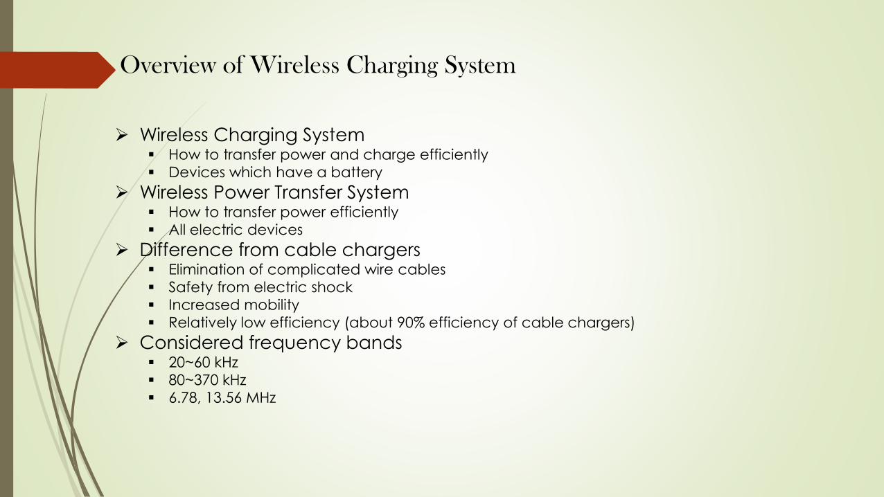
Wireless Charging System How to transfer power and charge efficiently
Devices which have a battery
Wireless Power Transfer System How to transfer power efficiently
All electric devices
Difference from cable chargers Elimination of complicated wire cables
Safety from electric shock
Increased mobility
Relatively low efficiency (about 90% efficiency of cable chargers)
Considered frequency bands 20~60 kHz
80~370 kHz
6.78, 13.56 MHz
Overview of Wireless Charging System
ADVANTAGES DISADVANTAGES
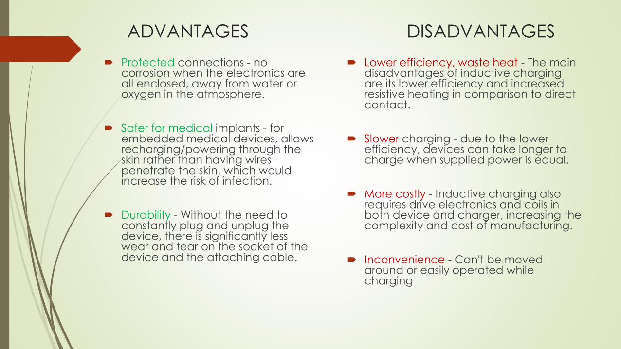
Protected connections - no corrosion when the electronics are all enclosed, away from water or oxygen in the atmosphere.
Safer for medical implants - for embedded medical devices, allows recharging/powering through the skin rather than having wires penetrate the skin, which would increase the risk of infection.
Durability - Without the need to constantly plug and unplug the device, there is significantly less wear and tear on the socket of the device and the attaching cable.
Lower efficiency, waste heat - The main disadvantages of inductive charging are its lower efficiency and increased resistive heating in comparison to direct contact.
Slower charging - due to the lower efficiency, devices can take longer to charge when supplied power is equal.
More costly - Inductive charging also requires drive electronics and coils in both device and charger, increasing the complexity and cost of manufacturing.
Inconvenience - Can't be moved around or easily operated while charging

Product Diversification• As market is increasing, each vendor makes the Wireless Charging
system which has different structure & protocol• Wireless Charging is possible only between systems having the same
structure & protocol
Frequency Issues• Each vendor considers different frequency bands for Wireless
Charging which disables interoperability between Wireless Charging systems
Regulation Issues• Each nation has different regulation for EMI/EMC, SAR, etc.
Challenges

Wireless power systems are constantly evolving as more and more practical
options for conveniently charging smartphones and other mobile devices. User
experience is the key factor that drives technology development, paving the way
for safer and more convenient devices accompanying us in everyday life.
Conclusion

Prepared by
TEJASWI ALAPARTHI

INTRODUCTION
MOBILE THREATS AND ATTACKS
HARDWARE SECURITY METHODS
PROTECTIVE MEASURES
CONCLUSION

As Cell Phone usage among people is increasing rapidly this project proposes a model to secure Cell Phones from theft as well as provides protection options.
Most cell phones use a password, PIN, or visual pattern to secure the phone.
Since theft of cell phones is becoming common day by day, there is a need for a security system that not only keeps the data safe, but also protects the phone using biometric security system
Further, a device dongle must be implemented in this setup to establish a stable security system that deters theft for the majority; biometrics is not sufficient.
Cell phones need power and must be charged daily. A biometric phone charger that behaves as a dongle with a solid state relay will be presented as a possible solution to theft in this research.
Actually, a mobile security system that combines biometrics with dongle technology is believed to be the flawless solution for limiting the stolen mobiles and without the biometric charger, the stolen cell phone would be concluded useless.

Mobile devices make attractive targets:◦ People store much personal info on them:
email, calendars, contacts, pictures, etc.◦ Sensitive organizational info too…◦ Can fit in pockets, easily lost/stolen◦ Built-in billing system: SMS/MMS (mobile
operator), in-app purchases (credit card), etc. Many new devices have near field communications
(NFC), used for contactless payments, etc. Your device becomes your credit card
–Location privacy issues NFC-based billing system vulnerabilities

Very easy for attacker to control a mobile device if he/she has physical access◦ Especially if there’s no way to authenticate user◦ Then device can join botnet, send SMS spam, etc.
Need access controls for mobile devices◦ Authentication, authorization, accountability◦ Authentication workflow:
Request access Supplication (user provides identity, e.g., John Smith) Authentication (system determines user is John) Authorization (system determines what John can/cannot
do)

Authentication generally based on:◦ Something supplicant knows Password/passphrase
Unlock pattern
◦ Something supplicant has Magnetic key card
Smart card
Token device
◦ Something supplicant is Fingerprint
Retina scan

More expensive/harder to implement
Prone to error:◦ False negatives: not authenticate authorized user
◦ False positives: authenticate unauthorized user
Strong authentication when it works
Does not work well in all applications◦ Fingerprint readers becoming more common on
mobile devices (Atrix 4G)

Passwords Smart Cards Biometrics Pattern Lock
Security Weak Strong Strong Weak
Ease of Use Easy Medium Hard Easy
Implementation Easy Hard Hard Easy
Works for phones Yes No Possible Yes
- Deeper problem: mobile devices are designed with single-user
Assumption.
- Fingerprint recognition may seem to be a bit more secure because
a fingerprint is extremely unique and difficult to mimic.

Types of mobile device information sources:
◦ Internal to device (e.g., GPS location, IMEI, etc.)
◦ External sources (e.g., CNN, Chase Bank, etc.)
Third-party mobile apps can leak info to external sources
◦ Send out device ID (IMEI/EID), contacts, location, etc.
◦ Apps ask permission to access such info; users can ignore!
◦ Apps can intercept info sent to a source, send to different destination!
Motives:
◦ Monitor employees’ activity using accelerometer
◦ Ads, market research (include user location, behavior, etc.)

To better establish a security system that is universal, reliable, and un-obtrusive, there needs to be two pieces of hardware that requires pairing to be operable; without one the other will not work.
Some software vendors utilize this type of security through the form of a USB device key, commonly known as a dongle.
A device dongle is piece of hardware that plugs into a computer to allow validate of certain programs to run.

Another reliable security method is a token-based validates system such as an RFID tag.
A Radio Frequency Identification-based Validate Middleware (RFID) system uses an RFID tag as a token to enable access via short wireless range such as Bluetooth technology.
Middleware, sometimes informally referred to as plumbing, is a layer of software above the operating system and below the application layer.
RFID technology is widely used in retail companies such as Walmart to manage supply chains.


The idea behind this research was that three seconds was coded into the mobile’s database using a VOCODER.
Once the voice is digitized, new input is compared to previous recordings for verification. A phoneme is the primary unit of sound to form distinctions between utterances.
A phoneme is also very exclusive and therefore only a small portion would have to be recorded for source.
This adds extra protection against breaching this method.

Next generation wireless Network
802.11ac
Presented by:
Vijay Kumar Annaldas
1471837

Introduction
802.11 ac is the next generation of the Wi-Fi standard,delivers high data rates which is 6.77 Gbps at 160 MHzbandwidth. It is called as Gigabit-WiFi.
In a multi-user environment , 802.11ac supports upto 4
streams that servs 4 different users simultaneously.
Lower latency, will make higher quality connections to
increase the quality of service for real time application
including VoIP and video.

AP is able to use its antenna resources to transmit multiple frames
to different clients, all at the same time and over the same frequency
spectrum.
AP
STA
STA
STA

Benefits
Mandatory 5GHz operation
Wider Bandwidth
Higher Order Modulation
Higher Order MIMO
Multi User MIMO (MU-MIMO)
RTS/CTS with Bandwidth Indication
All A-MPDU’s
Backwards Compatibility

• Cisco is the manufacturer of this device. Based on case study and
research Cisco has installed the 802.11ac standard devices in the
below segments.
Oil and mining
Education
Retail
Technology
Entertainment
Hospitality
Transpotation
Defence
Finance
Healthcare

Conclusion
802.11ac is the future of wireless LANs. 802.11ac can
provide full HD video at range to multiple users, higher
client density, greater QoS, and higher power savings
from getting on and off the network that much more
quickly.
IT administrators looking to invest in wireless LANs in
the near term should strongly consider 802.11n APs that
are field upgradable to 802.11ac.

CELL PHONE THEFT AND PROTECTION
HARISH KUMAR AVILALA
1463713

Different from computers:-Less likely to have up to date software and anti virus-Size-Functionality
COMMON USES
Reading personal email
Scheduling appointments & remainders
Accessing social websites
Listening to music and watching videos
Online shopping, banking and bill paying

Cellphone risks:
Increase mobility Increased exposure
Easily lost or stolen
- Device, Content, identity
Susceptibility to threats and attacks
-App bases, web based, SMS/Text message-based
Cell phones loss/theft:
Many mobile devices lost, stolen each year
113 mobile phones lost/stolen every minute in the U.S.
56% of us misplace our mobile phones or laptops each month

BEST SECURITY PRACTICES1. Password protect
Passcode protect
Passcode swipe protect?
2. Install software security
-Anti-virus and anti-malware available for mobile devices
3. Keep your apps up-to-date
4. Install a phone finder app
5. Enroll a backup program
6. Set a wipe contents after specified number of failed login attempts
7. When installing apps
- Take time to read the small print
What information does the app require to access?

Best security practices con’t….
8. Know where your device is at all times
9. Careful while using devices
Double check URLs for accuracy
Don’t open suspicious links
While giving any personal data to the website make sure that is secure or not.
10. Limit your activities when using public WiFi
- Use cellular network connection because this is more secure to compare
with other public devices
11. Check the URL’s before making a purchase whether it is secure or not.

SUMMARY
Mobile devices are increasingly popular.
There are many threats and attacks against mobile devices, e.g., loss/theft,
sensitive information leakage, and location privacy compromise.
Mobile access control, information leakage protection, and location privacy
protection, etc.
Passcode/password protection, lock your device, Use anti-virus software,
Backup your data, Install a phone finder app.

Near Field Communications
Pavan kumar Cheruvugattu
Section-1
1501554

Application of NFC

• Smart Posters
An object that has, affixed to or embedded init, one or more readable NFC tags with NDEFmessages stored in them.
Each tag is read when an NFC device is heldclose to it
“N-Mark” shows touch point
Not only a paper poster on the wall
Billboard, garment tag, magazine page, evena three-dimensional object
The Smart Posterrecord defines a URIplus some addedmetadata about it
Application of NFC

NFC and Mobile Payment
A customer makes his payment through mobile phone using NFC
NFC phone will open wallet applicationWallet will display product cost when user clicks “Buy”
At check out, wallet will display all credit/debit cards in wallet for paymentCustomer will select card for paymentWallet will show the confirmation page with the check out basketWallet will connect to retailer back end for authorization and display tracking information
Application of NFC

Peer-to-peer
Connection Handover : A handover use case is theexchange of configuration information via the NFC linkto easily establish a connection over (for e.g.Bluetooth or Wi-Fi ) and carry the information to beshared. Connection can be set between NFC devices
If the amount of information is relatively small (up toone kilobyte), it is possible to use NFC to transmitthe data itself (e.g. electronic business cards,contacts).
Speakers (touch to connect)
Smart Tags
Application of NFC
•Home computer components • In-car devices
•Home entertainment systems • Headsets and handsets
•Cameras and printers •Secure WLAN modem set-up

Additional Use Cases for NFC Smart Posters
• Asset Management - Use NFC phonesto read smart tags per product forinventory
• Access - Ensure secure building areaaccess for personnel with NFC deviceand contactless reader
• Parking – Use NFC to authenticateparking entry and keep record .
• Meal orders – Customers order theirmeals by touching NFC Smart Posters.
• Remote worker reporting – Remoteworkers confirm locations visited andtasks completed
• Maps – An interactive NFC SmartPoster map allows the user todownload the map, get additionalinformation on relevant services, andaccess coupons, etc.
• Events calendar – Users can downloadtickets or coupons or be linked toevent websites
NFC Parking >>
<< Security Gate
Application of NFC

Presented by,Mounika ChirraID:1447553Section- 1
Guided by ,Prof Goodwin kenneth
ZIGBEE AND ITS APPLICATION IN HOME AUTOMATION

• Home automation industry has drawn considerable attention of the researchers for more than a decade. The main idea is to automatically control and monitor electrical and electronic home appliances.
• Security systems have become the main stream of development activities.
• The WHAS has reduced the operation and maintenance cost. Additionally, it has provided comfort, security, safety, and remote monitoring capability. A typical WHAS consists of battery operated low power wireless sensors and actuators attached with the home appliances. These sensors and actuators are connected to a backbone wireless network.
INTRODUCTION:

THE ZIGBEE TECHNOLOGY:
• The ZigBee technology was introduced by the ZigBee Alliance. The ZigBee technology has evolved based on a standardized set of solutions called ‘layers'. These optimally designed layers have provided the ZigBee with unique features including low cost, easy implementation, reliable, low power, and high security.
• ZigBee Alliance has defined the upper layers in the ZigBee standard. Devices are the main components of the WPAN. The devices have been categorically defined as (a) physical type, and (b) logical type. The physical type devices have been further classified into two types namely Full Function Device (FFD) and Reduced Function Device (RFD). Any device may act as a sensor node, control node, and composite device irrespective of its type. Only the routing functions of a network are performed by the FFDs.

• APPLICATIONS:
ZIGBEE TECHNOLOGY:

FOR CO-ORDINATOR:

FOR ROUTER:
• In this work, a technical overview of the ZigBee technology has been presented and its application to a building temperature monitoring system has been demonstrated.
CONCLUSION:
UNIVERSITY OF HOUSTON CLEAR LAKECOMPUTER ENGINEERING
CELL PHONE VOICE QUALITY ISSUE
Submitted by
NAME: KAUSHIK DASARI
UHCL ID: 1505371
SECTION-1
Instructor: Kenneth Goodwin

TOPICS:
• 1. INTRODUCTION
• 2. REASONS FOR THE BAD VOICE QUALITY IN A PHONE
• 3. HOW TO IMPROVE THE VOICE QUALITY IN A PHONE
• 4. CONCLUSION

1.INTRODUCTION
• Cellular connectivity is primarily affected by interference of various kinds. Lets first talk about why this may happen.
• Cellular signals have many obstacles like environment, other signals, weather conditions, and many more.
• Due to these the cellular signals gets distracted and the voice quality also decreases.
• So to improve voice quality what we have to do
• Lets discuss about those things now!!!
2. REASONS FOR THE BAD VOICE QUALITY
• 2.1 They're space-challenged
• When it comes to sound quality, cordless phones have it easy. They have only one primary function—voice calls—and their larger size lets them place their large microphones and speakers as close to your mouth and ear as possible.
• Smart phones, on the other hand, are a technological sausage, densely packed with cameras, radios, microprocessors, sensors, and other hardware that enables them to do all those amazing things we expect them to do. Often, the tiny speaker is wedged between the bezel and the front-facing camera, while the microphone is sometimes relegated to the bottom of the phone—or the back. That almost guarantees a less-than-ideal connection with your mouth and ear.
• 2.2 The signals travel a long and winding road
• As I already mentioned that signals also get distorted because of the environment.
• As those signals jump from cell tower to cell tower, they run into trees, mountains buildings, the weather, and other obstacles that cause them to split. The split signals produce a phenomenon called multipath, when multiple copies of the same signal reach your smart phone at different times, like an echo.
• Deciphering multipath signals is quite difficult, and when the phone gets overwhelmed, the signal has to be retransmitted. Of course, few people notice because all of this happens within a fraction of a second. So that's why it's almost miraculous that voice calls sound as clear as they do.

• 2.3 Location of your hardware
• Interference is a poison for voice quality during voice communication. Often, VoIP equipment interfere with each other thus producing noise and other problems. For example, if your ATA is too close to your broadband router, you might experience voice quality problems. This is caused by electrical feedback. Try moving them away from each other to get rid of the garbled calls, echoes, dropped calls etc.
• 2.4 Compression: the codec used
• Transmits voice data packets in a compressed form, so that the load to be transmitted is lighter. The compression software used for this are called codec. Some codecs are good while others are less good. Put simply, each codec is designed for a specific use. If a codec is used for a communication need other than that for which it is meant, quality will suffer.

3. HOW TO IMPROVE VOICE QUALITY• 3.1: The place where you are situated while the call is on is a critical factor
for reception quality. If lots of trees, in a valley, or maybe inside a building surround you then there’s a whopping possibility of the networking reception being unusually low. You need to go to a better position, like on a flat surface, which is not crowded. Of course, this factor is valid if you are quite away from the network signal towers.
• 3.2 For the latest generation of cellular, LTE, a new voice codec is being developed. It is designated enhanced voice services[EVS]. It will cover variable [wider] bandwidths so it will be better for music and mixed voice and music content. It has many new codec rates, plus better VoIP [voice over Internet protocol] factors such as packet loss concealment[used to used to mask the disruptive effects of lost or discarded data packets] and jitter buffer management. [“Jitter” refers to variations in the length of time to deliver data packets.] But the standard will take awhile to get into deployments everywhere by service providers.

• 3.3 When fully deployed, LTE with EVS will be a big improvement—if video traffic does not take all of the bandwidth wherever you are, causing eNodeB to only allocate your voice call a low rate. In some ways the approach of service providers is understandable. No one wants a call dropped and no one wants their calls to be blocked [unable to get through]. Plus, video is something everyone appears to want on their mobile device.
•

4.CONCLUSION
• So now what I say is there are many reasons for the bad voice quality, in the same way there are many ways to get good voice quality.
• It is depends on the weather, cellular network company, base station and etc.
• Nowadays all those problems are taken care off and new and fast network has been launched which we call it as LTE. It is latest and present fastest signaling network.

CENG 5332 WIRELESS COMMUNICATIONS AND
NETWORKS
Cell Phone Theft and Protection
BYRohith Devarasetty
1500315Section 1

Organization
● Mobile Threats and Attacks● Location Disclosure● Mobile Access Control● Authentication● Countermeasures

Mobile Threats and Attacks
● Mobile devices make attractive targets:○ People store much personal info on them: email,
calendars, contacts, pictures, etc.○ Sensitive organizational info too…○ Can fit in pockets, easily lost/stolen○ Built-in billing system: SMS/MMS (mobile
operator), in-app purchases (credit card), etc.• Many new devices have near field communications (NFC),
used for contactless payments, etc.• Your device becomes your credit card
○ Location privacy issues● NFC-based billing system vulnerabilities

Location Disclosure
● MAC, Bluetooth Addresses, IMEI, IMSI etc. are globally unique
● Infrastructure based mobile communication● Peer-t-Peer ad hoc mobile communication

Mobile Access Control
● Very easy for attacker to control a mobile device if he/she has physical access○ Especially if there’s no way to authenticate user○ Then device can join botnet, send SMS spam, etc.
● Need access controls for mobile devices○ Authentication, authorization, accountability○ Authentication workflow:
• Request access• Supplication (user provides identity, e.g., John Smith)• Authentication (system determines user is John)• Authorization (system determines what John can/cannot
do)

Authentication: Categories
● Authentication generally based on:○ Hacker knows password or unlock pattern○ Hacker has magnetic key or smart card○ Hacker is fingerprint or eye scan

Authentication: Passwords
● Cheapest, easiest form of authentication● Works well with most applications● Also the weakest form of access control
○ Lazy users’ passwords: 1234, password, letmein, etc. ○ Can be defeated using dictionary, brute force attacks
● Requires administrative controls to be effective○ Minimum length/complexity○ Password aging○ Limit failed attempts

Authentication: Smart Cards/Security Tokens
● More expensive, harder to implement● Vulnerability: prone to loss or theft● Very strong when combined with another form of
authentication, e.g., a password● Does not work well in all applications
○ Try carrying a smart card in addition to a mobile device!

Authentication: Biometrics
● More expensive/harder to implement● Prone to error:
○ False negatives: not authenticate authorized user ○ False positives: authenticate unauthorized user
● Strong authentication when it works● Does not work well in all applications
○ Fingerprint readers becoming more common on mobile devices (Atrix 4G)

Authentication: Pattern Lock
● Swipe path of length 4–9 on 3 x 3 grid
● Easy to use, suitable for mobile devices
● Problems: [30]○ 389,112 possible patterns;
(456,976 possible patterns for 4-char case-insensitive alphabetic password!)
○ Attacker can see pattern from finger oils on screen

● Current smartphone access control focus: 1 user (admin)
● Hard to achieve fine-grained mobile device management:○ Control app
installation/gaming○ Parental controls○ Lend phone to friend
● We design differentiated user access control model○ Different users use
smartphone in different contexts
○ User classification: admin, “normal,” guest
Smartphone Privileges AdminNormal Guest
Personal Info
SMS ✔ ✔ ✘
Contacts ✔ ✔ ✘
Resource Access
WiFi ✔ ✔Limit‼
GPS ✔ ✔Limit‼
Bluetooth ✔ ✔
Limit‼
Apps
App Install ✔ Limit ✘
Sensitive Apps ✔ Limit ✘

DiffUser (2)
● Implement our system on Android using Java● Override Android’s “Home” Activity for multi-user
authentication, profile configuration
Source: [31], Figure 2. From left to right: “normal” user screen;user login and authentication; user profile configuration.

Mobile Device Information Leakage
● Types of mobile device information sources:○ Internal to device (e.g., GPS location, IMEI, etc.)○ External sources (e.g., CNN, Chase Bank, etc.)
● Third-party mobile apps can leak info to external sources○ Send out device ID (IMEI/EID), contacts, location, etc.○ Apps ask permission to access such info; users can ignore!○ Apps can intercept info sent to a source, send to different
destination!● Motives:
○ Monitor employees’ activity using accelerometers○ Ads, market research ○ Malice

Location Privacy Protection
● Strong regulation○ Corporate○ Individual
● Dynamic MAC and Bluetooth addresses○ Collision
● Proxy-based communications○ Dummy device as proxy○ Group communications

BIOMETRIC TECHNIQUES AND SYSTEMS
BIOMETRIC FACE RECOGNITION
●There are several different types of biometric authentication systems a) recognition of face, voice, and fingerprint. b) gait recognition and artificialIntelligence.

Summary
● Mobile devices are increasingly popular● There are many threats and attacks against mobile
devices, e.g., loss/theft, sensitive information leakage, and location privacy compromise
● Mobile access control, information leakage protection, and location privacy protection, etc.

By
Surya Vamsi Earneni
1461861
Section-01

Table of contents
Introduction
Related work
GPS
System design
Results
Conclusion

Introduction The main intension is to find the accident spot and
notify the ambulance by a shortest path.
There is loss of life as there is delay in ambulance reaching the accident spot.
So we notify the exact accident spot to ambulance and find shortest path to it.

Related work This system is based on GPS and GSM modem.
The intelligent traffic lights save both time and traffic loads.
The accident spot is detected by using algorithm built in the controller.

GPS.. Satellite based navigation uses Global Positioning
System (GPS) to send and receive the radio signals thatserves the user with the required information.
The GPS receiver in the ground station determines thelocation and distance accurately in all sough’s weatherwithout distortions are made easy with the satellite inorbit as a reference.

System design
Our system consists of five main units whichcoordinates with each other and makes sure thatambulance reaches the hospital without any delay.
Vehicle Unit
Main Server
Ambulance Unit
Traffic Unit
Hospital Unit


Results
When an accident is occurred the message is then immediately sent to near by ambulance and the ambulance is given an shortest path to reach the spot.

Conclusion By this new system the time lag is reduced by applying
the RF technologies that controls the traffic signals. The priority of service to the ambulance follows the queuing methodologies through server communication. This ensures the reduced time lag between the accident spot and hospital.

MOBILE PHONE LOCATION
DETERMINATION TECHNOLOGIES
BY VENKATESH GANGINENI (1405505)
ABSTRACT
Research and development on the technologies of locating the
mobile (wireless) phone caller have been rapidly gainingmomentum around the world. Once these technologies are mature
enough to be deployed, they will have significant impact on
automotive telematics and modern public transit systems. In this
paper, I discuss how to locate mobile phones using some
technologies among telecommunications.

LOCATION TECHNOLOGIES
THERE ARE THREE MOST COMMONLY TECHNOLOGIES USED FOR DETERMINATION MOBILE PHONE LOCATION
1.ANGLE OF ARRIVAL (AOA)
2.TIME OF ARRIVAL (TOA)
3.TIME DIFFERENCE OF ARRIVAL
*All these methods require radio transmitters, receivers, or transceivers. In other words, they depend on emitting and receiving radio signals to determine the location of an object on which a radio receiver, or a transceiver is attached.

ANGLE OF ARRIVAL
The angle-of-arrival (AOA) system determines the mobile phone position based on triangulation (Fig).
It is also called direction of arrival in some literature. The intersection of two directional lines of bearing defines a unique position, each formed by a radial from a base station to the mobile phone in a two-dimensional space.
This technique requires a minimum of two stations (or one pair) to determine a position.
If available, more than one pair can be used in practice. Because directional antennas or antenna arrays are required, it is difficult to realize AOA at the mobile phone

Time of Arrival
The time-of-arrival (TOA) system determines the mobile phone position based on the intersection of the distance (or range) circles (Fig).
Since the propagation time of the radio wave is directly proportional to its traversed range, multiplying the speed of light to the time obtains the range from the mobile phone to the communicating base station.
Two range measurements provide an ambiguous fix and three measurements determine a unique position.
The same principle is used by GPS, where the circle becomes the sphere in space and the fourth measurement is required to solve the receiver-clock bias for a three-dimensional solution.
The bias is caused by the unsynchronized clocks between the receiver and the satellite.
Similarly, for terrestrial-based systems, it also requires precisely synchronized clocks for all transmitters and receivers

Time-Difference-of-arrival (TDOA)
The time-difference-of-arrival (TDOA) system determines the mobile phone position based on trilateration.
This system uses time difference measurements rather than absolute time measurements as TOA does.
It is often referred to as the hyperbolic system because the time difference is converted to a constant distance difference to two base stations (as foci) to define a hyperbolic curve.
The intersection of two hyperbolas determines the position.
Therefore, it utilizes two pairs of base stations (at least three for the two-dimensional case as shown in Fig) for positioning.
The accuracy of the system is a function of the relative base station geometric locations.

REFERENCES
[1] IEEE TRANSACTIONS ON INTELLIGENT TRANSPORTATION SYSTEMS,
VOL. 1, NO. 1, MARCH 2000
[2] Y. Zhao, Vehicle Location and Navigation Systems. Norwood, MA:
Artech House, 1997.
[3] FCC, “Revision of the commission’s rules to ensure compatibility with
enhanced 911 emergency calling systems,” in Report and Order and
Further Notice of Proposed Rulemaking. Washington, DC: Fed.
Commun. Comm., June 1996.
[4] FCC, “FCC acts to promote competition and public safety in
enhanced wireless 911 services,” Washington, DC: WT Rep. 99-27, Sept.
15, 1999.

USE OF FREQUENCIES ABOVE MICROWAVE
VINODH GOGINENI
1413841
CENG 5332: WIRELESS COMMUNICATION
SECTION 1

Introduction
• Frequency spectrum:
From the frequency spectrum, the frequencies above microwave range are infrared rays, visible, UV- rays, x-rays and gamma rays.

Infrared waves
• Infrared waves lies between the range of microwave & visible light, these are thermal waves.
• Used in TV remote control, but the only defect is that they need free line of sight between them unlike microwave.
• Used in night mode cameras which use the property of IR waves which detects the shape of object depending on the emission of heat.
• Ultrasonic can be measured with the help of infrared communications.
• Wire-less infrared interlink connections used in satellite for communication purpose.

Visible light
• Visible light shares the range of frequencies above IR.
• The whole & sole benefit of visible light is that, it is the part of EM spectrum which our eyes can see, so that our world oriented around it.
• the light in this range is useful for plants in the process of photosynthesis.

UV-RAYS
• Sun is the main source of UV, which is invisible to human & harmful to human body, it is fortunate that most of the UV absorbed by ozone.
• UV-rays are used in the process of sterilization of medical equipment.
• Suitable doses of UV rays cause the body to produce vitamin D, and this Is used by doctors to treat vitamin D deficiency and some skin disorders
• These frequencies have the potential to be used in communication and researches are going on.
• Still, these are not the best form of waves that can be used for communication asare hazardous to human body

X-rays & gamma- rays:
• X-rays are to detect the bones for detection of fractures, not only for this but to predict some diseases like pneumonia, breast-cancer.
• NASA developed a x-ray communication system, having the advantage of high data rates at low power.
• Gamma rays are also mainly used in prevention of cancer cells and in radioactive tracers.

INNOVATIVE CONGESTION CONTROL SYSTEM FOR AMBULANCE USING RF
PRESENTED BY
ABHILASH REDDY GOLI
1447921
section-1

BLOCK DIAGRAM:

TRANSMITTER SECTION:
The transmitter section mainly consists of
a) Switch Pad b) HT12E Encoder c) RF Transmitter
module.
The Switch pad consists of 4 buttons representing the 4
directions at a traffic junction.
The switch button type used here is Push button
switch. For easy mechanism we can use Selector type
switch also

RECEIVER SECTION:
The RF signal transmitted reaches the receiver section
and controls the traffic lights.
The receiver section works on 5V DC output of the power
supply block.
The receiver section has got 4 main components.
They are :
a) RF Receiver Module.
b) HT12D Decoder.
c) AT89S52 uC .
d) LED Indicators.

The first block in receiver section is the RF Receiver
RWS-434.
It receives the serial data from RF Transmitter through
antenna.
Features:
Operating frequency: 433.92 MHz
Operating voltage: 3.3V- 9V
Low current consumption
Linear & Digital Outputs
Sensitivity: 3uV
RECEIVER SECTION:

POWER SUPPLY BLOCK
DIAGRAM

PICTORIAL REPRESENTATION

APPLICATIONS
Used in Ambulances
Used in fire engine services
Wireless alarm and security system
CONCLUSION
The Traffic signal is controlled in favor of ambulance and other emergency vehicles by using the trasmitter and receiver usind the zigbee technology.
By using this emergency vehicles can be moved from the accident spot to hospital without time lag

THANKYOU

CELL PHONES VOICE
QUALITY ISSUES
Presented by
Tejaswaroop Gudapudi
St Id:1462196
Section -1

INTRODUCTIONThe major problems faced by cells phones in the modern
technology are:
Low signal strength
Poor voice quality
Slow data rates
Jitter
Latency

OBSTACLE The main obstacle to a good-quality voice connection on
today’s mobile phones is their design.
It depends on load of the cell site, the time of day and
network usage projections.
As the distances between the calls increases, bandwidth
increases which is the other important problem.
Wideband technologies don’t work together from one
network o anoher.

SOLUTION Wireless carriers have been upgrading their
networks to support technologies oftenreferred to as HD voice or wideband audio.
Wideband audio includes a wider range offrequencies to make calls sound better,letting you hear more high and low tones.
The best solution to reduce jitter is to use jitterbuffers. A jitter buffer is basically to assign asmall buffer to receive the packets and give itto the receiver with a small delay.

CONCLUSIONCall quality with the G4, for the most part, is
unchanged from what we experienced last year
with the G3. In the greater scheme of things, it gets
the job done, as the earpiece and speakerphone
produce strong volumes to make them useable in
noisy environments. However, there’s a slight hint of
distortion to voices through the earpiece that make
them sound a little bit artificial, but it isn’t too terrible.On the other end of the line, things seem to flow
better, since voices have great audible command.

FUTURE WORKFor the latest generation of cellular, LTE, a newvoice codec is being developed. It isdesignated Enchaned voice services(EVS). Itwill cover variable bandwidths so it will bebetter for music and mixed voice and musiccontent. It has many new codec rates, plusbetter VoIP (voice over Internet protocol)factors such as packet loss concealment andjitter buffer management. But the standardwill take awhile to get into deploymentseverywhere by service providers.
Near field communication
based on visible light(NECAS)
Under Guidance of Dr. Goodwin Kenneth
Name: Sanobar Kadiwal
Section: 1(mon 1-3.50)
Student ID: 1415266
Near field communication system for
smartphones(NECAS)
Visible Light communication: short-range, secure and interference-free
wireless links
NFC : short range, high frequency communication
sender and receiver communicates via the visible light channel
NECAS applications :
o contactless payments, electronic ticket checking & device paring
Challenges
o Interference problem
o Reliability
o Combinations of color and intensity levels
o Increasing coding capacity, data rate & throughput

Introduction VLC as an alternative
Use of Non-imaging and imaging MIMO
o achieves high data rates
The LCD-camera pair
o builds wireless links
OFDM technology and complex computer vision algorithm
o achieves high throughput over a long distance
VMRA (Visual MIMO Rate Adaptation)
joint decoding algorithm
o solves interference problem
multiple intensity levels
o increases coding capacity

System Architecture
Encoder
multiple intensity level
Intensity division of each color sensor
Receiver
color sensor array
joint decoding algorithm
Cyclic redundancy code
rate adaption algorithm
mechanical “guard” structure

System Detail Sender side: Data encoded as different color(Android-Samsung Galaxy
Nexus)
NECAS encoder
• Encoding of adjacent data with different colors to detect the screen refreshing rate
• multiple intensity levels utilization to increase coding capacity
• interference of color channels and the refresh rate of smartphones
• Intensity color division and triplet merging
segmentation of phone screen to improve the data rate and throughput
Receiver side: color sensor array to sample light colors(Arduino platform )
NECAS decoder
• avoids interference
• Intensity matching independently

System details Design
Separation of different color sensors
Limits ambient light
Reducing the interfering light emitted from unintended screen sub-blocks.
Maximum data rate calculation
Fixed rate data stream transmission
Change measurement at sender screen
Color sampling at fixed rate to receive data
Dedicated color with dedicated intensity is used
Encoding of repetitive data chunks

Experimentation results
ExperimentationIntensity division(Red-5 level, green- 2 level, blue-4 level)
Four variants: NECAS-R, NECAS-B, NECAS-422 and NECAS-444
Result
Bit error rate : NECAS-R and NECAS-B perform worse
NECAS-422 & NECAS better than NECAS-444
Throughput measurement : NECAS-444 >NECAS >> NECAS-422 variant
Best performer : ‘NECAS’ in terms of throughput and bit error rate
Sender-receiver Distance variation
Bit error rate increases with the screen refresh rate
Throughput decreases with increase in sender-receiver distance
Joint decoding v/s independent decoding
Joint decoding - low bit error rate
With increase in distance independent decoding performs poorer

Conclusion
NECAS
preserves communication privacy and security
achieves 1 kbps bandwidth
error rate between 10-3 and 10−4 without any error-correction mechanisms
Future work
Improving NECAS reliability with CRC codes

Reference
NECAS: Near field communication system for smartphones based on visible light
J. Niu; W. Song; C. Liu; L. Shu; C. Chen
2014 IEEE Wireless Communications and Networking Conference (WCNC)
DOI: 10.1109/WCNC.2014.6952729

Voice Over IP(VOIP)
Kanigiri Radha Krishna Chaitanya
Section : 1
UHCL ID : 1469029

Voice over internet protocol (voip) is a technology that enables one to make and receive phone calls through the internet instead of using the traditional analogy PSTN(public switched telephone network) lines.
VoIP involves sending voice information in digital form in discrete packets rather than by using the traditional circuit-committed protocols of the public switched telephone network (PSTN). A major advantage of VoIP and Internet telephony is that it avoids the tolls charged by ordinary telephone service.
It allows 2-way voice transmission over broadband connection
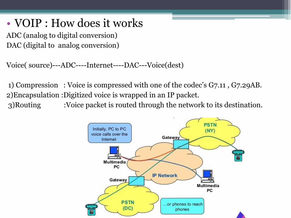
• VOIP : How does it worksADC (analog to digital conversion)
DAC (digital to analog conversion)
Voice( source)---ADC----Internet----DAC---Voice(dest)
1) Compression : Voice is compressed with one of the codec’s G7.11 , G7.29AB.
2)Encapsulation :Digitized voice is wrapped in an IP packet.
3)Routing :Voice packet is routed through the network to its destination.

Gateway:Gateway equipment performs the task of allowing non-IP equipment to talk to IP equipment .
• FXS
▫ Foreign Exchange Station
(Analog equipment ---FXS--- Internet)
Eg : ATA (Analog Telephone Adapter)
• FXO
▫ Foreign Exchange Office
▫ Interface between the PSTN and the local equipment that would also connect to the Internet

Main things that affect voice quality in VoIP and what can be done to maximize quality.
• Bandwidth: Internet connection always tops the list of factors affecting voice quality in VoIP conversations. For instance, if you have dial-up connection, don’texpect great quality. A broadband connection will work right, as long as it is not spotty.
• Equipment : The VoIP hardware equipment you use can greatly impact on your quality. It is therefore always good to have as much information as possible on an ATA, router or IP phone
• Phone frequencies : The frequency of your IP phone may cause interference with other VoIP equipment. There are many cases where people using 5.8 GHz phones have been getting voice quality problems.
• Weather Conditions : The effect of weather conditions on your connection is not something you can change. voice is terribly distorted by something called static, electricity generated on broadband. It is easy to get rid of static: unplug your hardware (ATA, router or phone) and plug it back again.

Location of your hardware
Interference plays major role in voice quality during voice communication. Often, VoIP equipment interfere with each other thus producing noise and other problems.
For example, if your ATA is too close to your broadband router, you might experience voice quality problems. This is caused by electrical feedback. Try moving them away from each other to get rid of the garbled calls, echoes, dropped calls etc.
Compression: the codec used
VoIP transmits voice data packets in a compressed form, so that the load to be transmitted is lighter. The compression software used for this are called codec’. Some codec s are good while others are less good. Put simply, each codec is designed for a specific use. If a codec is used for a communication need other than that for which it is meant, quality will suffer.
REFERENCE:
• IP Telephony Walter J. Goralski and Matthew C. Kolon McGraw-Hill
• Final Report for the European Commission—IP Voice and Associated Convergent Services

Part 2 1
Wireless Security
(both Cellular and
802.11 Hotspots)
Name: Nitish Kelagote
Student ID: 1473360
Part 2 2
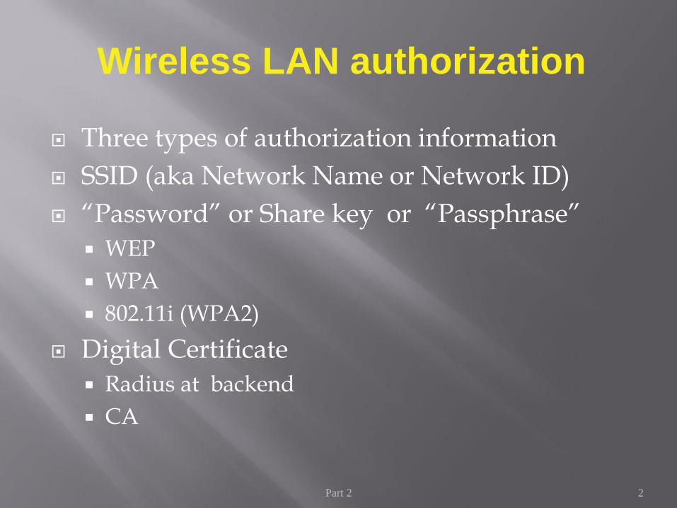
Three types of authorization information
SSID (aka Network Name or Network ID)
“Password” or Share key or “Passphrase”
WEP
WPA
802.11i (WPA2)
Digital Certificate
Radius at backend
CA
Wireless LAN authorization

3
Infrastructure mode
To ensure only authorized clients, valid Security Set ID(SSID) must match
An Access Point is required
Select INFRSTRUCTURE setting
SSID of the
Access
Point
Network Access Protection

4
WEP WPA
Encryption Flawed, cracked by scientists and
hackers
Fixes all WEP flaws
40-bit keys 128-bit keys
Static – same key used by
everyone on the network
Dynamic session keys. Per user,
per session, per packet keys
Manual distribution of keys -
hand typed into each device
Automatic distribution of keys
Authentication Flawed, used WEP key itself for
authentication
Strong user authentication,
utilizing 802.1X and EAP
WEP vs WPA

5
Internet
*****
Password
*****
Password
*****
Password
Step 1
Enter matching
passwords into AP and
Client
Step 2
AP checks client’s password. If
match client joins network. If not a
match client kept off network
Step 3
Keys derived &
installed. Client
and AP exchange
encrypted data
Access Point/Router
How Does it Work? (in SOHO)

6
802.11i is the official IEEE attempt to supply strong security for wireless links
802.11i will use Temporal Key Integrity Protocol (TKIP) similar to WPA.
Additionally added AES (Advance Encryption Standard) offering 128 bits, 192 bits and 256 bits block encryption.
Authentication using 802.1x for port access authentication (EAP-TLS, PEAP, LEAP)
RADIUS for Authentication, Authorisation and Accounting with default port 1812 for authorisation and port 1813 for accounting
IEEE 802.11i (WPA2)
7
Internet
*****
Password
*****
Password
*****
Password
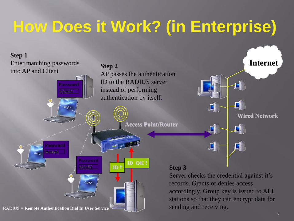
Step 1
Enter matching passwords
into AP and ClientStep 2
AP passes the authentication
ID to the RADIUS server
instead of performing
authentication by itself.
Step 3
Server checks the credential against it’s
records. Grants or denies access
accordingly. Group key is issued to ALL
stations so that they can encrypt data for
sending and receiving.
Access Point/Router
ID ?ID OK !
Wired Network
RADIUS = Remote Authentication Dial In User Service
How Does it Work? (in Enterprise)

8
VPN (Virtual Private Network)
Creating a virtual connection using IPsec or other VPN protocols to ensure the transmitted data is encrypted
Need VPN server
VLAN (Virtual LAN) with multiple SSID
Separate the users access to separate resources on the network
Need VLAN supporting switch and AP
Other Wireless Securities

LATEST DEVELOPMENTS INNFC
CENG 5332 Wireless Communication
Majeed, Waqas
4-18-2016

How does NFC work?
• The tech involved is deceptively simple. Evolved from radio frequency identification (RFID) tech, an NFC chip operates as one part of a wireless link. Once it's activated by another chip, small amounts of data between the two devices can be transferred when held a few centimeters from each other.

How does NFC work?
• No pairing code is necessary to link up and because it uses chips that run on very low amounts of power (or passively, using even less), it's much more power-efficient than other wireless communication types.

Design
• NFC is a set of short-range wireless technologies, typically requiring a separation of 10 cm or less. NFC always involves an initiator and a target; the initiator actively generates an RF field that can power a passive target. This enables NFC targets to take very simple form factors such as unpowered tags, stickers, key fobs, or cards. The tags can securely store personal data such as debit and credit card information.

Standards
• NFC standards cover communications protocols and data exchange formats, and are based on existing RFID standards including ISO/IEC 14443 and FeliCa.[4] The standards include ISO/IEC 18092[5] and those defined by the NFC Forum.
Usage
• In recent years, a lot of companies have adopted NFC as a payment method. Apple pay, google pay and a like method for contactless payments gave the industry much needed boost.

Future of NFC
• Looking toward the future, it's possible that NFC chips could be used to replace every card in your wallet. That means the unique info on your frequent shopper loyalty cards, library card, business cards, transit card, ID cards and the like could be contained and transmitted simply via NFC.

Future of NFC
• You can order food just by detecting the items (NFC tag) on the menu in a restaurant. Food places like Pizza hut, Subway or build a burger can use NFC tags to select the items from menu to build their pizza, burger or subway and just order. You can also get digital coupons and use them when you are paying simply via NFC.

Future of NFC
• Two friends can initiate multiplayer games just by getting close their smartphones, they can even share contacts, photos, videos and the possibilities are endless. Friends can also lend money to each other or pay them back just by using the NFC in their smartphones.
• NFC can also be used in gym equipment to fetch data like how many calories have you burned on your running machine etc. It can also be used by passengers at metro stations to scan their destination name (NFC tag) and find out the time in next shuttle or even whole schedule for the route. It can also be used for networking and file transfer.

WHAT COMES AFTER
802.11ac?
NEW WIRELESS PROTOCOLS
Submitted by:
Gayatri Kiran Mandapaka
ID : 1459302
Monday – 1:00PM-3:50PM

• Wireless standards tend to get proposed, drafted, and finally accepted at what
seems like a glacial pace.
• It’s been roughly 17 years since we began to see the first 802.11b wireless routers
and laptops.
• In the intervening time, we’ve only seen three more mainstream standards take
hold since then: 802.11g, 802.11n, and now 802.11ac

• If you thought that your new 802.11ac router’s maximum speed of
1,300Mbps was already fast, think again. With 802.11ac fully
certified and out the door, the Wi-Fi Alliance is looking at its
successor, 802.11ax.
• 802.11ax should deliver real-world speeds above 2Gbps.
• In a lab-based trial of technology similar to 802.11ax, Huawei hit a
max speed of 10.53Gbps, or around 1.4 gigabytes of data transfer
per second. Clearly, 802.11ax is going to be fast.
• Like its predecessor, 802.11ax operates in the 5GHz band, where
there’s a lot more space for wide (80MHz and 160MHz) channels.

• With 802.11ax, you get four MIMO (multiple-input-multiple-output) spatial
streams, with each stream multiplexed with OFDA (orthogonal frequency
division access). There is some confusion here as to whether the Wi-Fi Alliance
and Huawei (which leads the 802.11ax working group) mean OFDA, or OFDMA.
OFDMA (multiple access) is a well-known technique.
• Either way, OFDM, OFDA, and OFDMA refer to methods of frequency-division
multiplexing — each channel is separated into dozens, or even hundreds, of
smaller subchannels, each with a slightly different frequency. By then turning
these signals through right-angles (orthogonal), they can be stacked closer
together and still be easily demultiplexed.
• According to Huawei, the use of OFDA increases spectral efficiency by 10 times,
which essentially translates into 10 times the max theoretical bandwidth, but 4x is
seeming like more of a real-world possibility.

• Let’s say we take the more conservative 4x estimate, and assume a massive
160MHz channel. In that case, the maximum speed of a single 802.11ax stream
will be around 3.5Gbps (compared with 866Mbps for a single 802.11ac stream).
Multiply that out to a 4×4 MIMO network and you get a total capacity of
14Gbps. If you had a smartphone or laptop capable of two or three streams, you’d
get some blazing connection speeds of 1GB per second or more.
• In a more realistic setup with 80MHz channels, we’re probably looking at a
single-stream speed of around 1.6Gbps, which is still a reasonable 200MB/sec. If
your mobile device supports MIMO, you could be seeing 400 or 600MB/sec. And
in an even more realistic setup with 40MHz channels (such as what you’d
probably get in a crowded apartment block), a single 802.11ax stream would net
you 800Mbps (100MB/sec), or a total network capacity of 3.2Gbps.

• So far, neither the Wi-Fi Alliance nor Huawei has said much about 802.11ax’s
other important features. Huawei says “intelligent spectrum allocation” and
“interference coordination” will be employed, but most modern Wi-Fi hardware
already does that.
• It’s fairly safe to assume that working range will stay the same or increase
slightly. Reliability should improve a little with the inclusion of OFDA, and with
the aforementioned spectrum allocation and interference coordination features.
Congestion may also be reduced as a result, and because data will be transferred
between devices faster, that frees the airwaves for other connections.
• Otherwise, 802.11ax will work in roughly the same fashion as 802.11ac — just
with massively increased throughput. 802.11ac is already pretty great. 802.11ax
will just take things to the next level.
• The problem, as with all things Wi-Fi, isn’t necessarily the speed of the network
itself — it’s congestion, and more than that even, it’s what the devices themselves
are capable of.
• For example, even 802.11ax’s slowest speed of 100MB/sec is pushing it for a
hard drive — and it’s faster than what the eMMC NAND flash storage in most
smartphones can handle as well. Best-case scenario, a modern smartphone’s
storage tops out at around 90MB/sec sequential read, 20MB/sec sequential write
— worst case, with lots of little files, you’re looking at speeds in the single-
megabyte-per-second range. Obviously, for the wider 80MHz and 160MHz
channels, you’re going to need some desktop SSDs to take advantage of
802.11ax’s max speeds.
• Not every use-case requires you to read or write data to a slow storage medium.
But even so, alternate uses like streaming 4K video still fall short of these multi-
gigabit speeds. Even if Netflix begins streaming 8K in the next few years (and
you thought there wasn’t enough to watch in 4K!), 802.11ax has more than
enough bandwidth. And the bottleneck isn’t your Wi-Fi there; it’s your internet
connection. The current time frame for 802.11ax certification is 2018 — until
then, upgrading to 802.11ac (if you haven’t already) should be a nice stopgap.

IoT Gadget Control on Wireless AP
at Home
Bhanupriya Mandyam
1468586

Introduction
Now a days the number of IoT gadgets forthe personal or home intelligenceincreases.
We are trying to integrate the data frominternet-connected things and processthem efficiently on the cloud.
Providing connectivity and dataintegration for further analysis areimportant to build the infrastructure of theIoT environment.
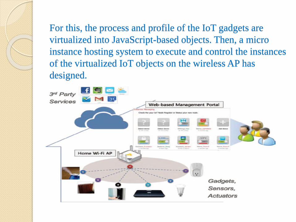
For this, the process and profile of the IoT gadgets are
virtualized into JavaScript-based objects. Then, a micro
instance hosting system to execute and control the instances
of the virtualized IoT objects on the wireless AP has
designed.

Things and instance interface
Relationship

Web-based User Interface for
Instance ManagerDemonstration set up

Conclusion
A way of providing the examples of the
IoT gadgets on the wireless AP is
introduced. This revealed that legacy
wireless AP can host instances of IoT
gadgets securely, efficiently, and
effectively for home IoT service.

THE MYTH OF NON-
OVERLAPPING CHANNELS
By,
Alekya Maramreddy
1465293

INTRODUCTION
Here we describe the interference measurement in IEEE
802.11.
In this IEEE 802.11. we see that in practice cross-channel
interference can be present also between non-overlapping
channels.
We adopt an incremental approach to overcome the problem
which occurs when multi-hop mesh network is tried to built
i.e., we first consider the case of unacknowledged broadcast
packets, then we extend to regular UDP streams, finally we
provide preliminary results for multi-hop TCP flows.

IEEE 802.11
SPECIFICATIONS
The IEEE 802.11 specifications include a detailed
description of PHY/MAC operational requirements.
The PHY layer embeds two components: The Physical
Medium Dependent (PMD) system and the Physical Layer
Convergence Protocol (PLCP).
In PMD we consider the two transmission techniques known
as High Rate/Direct Sequence Spread Spectrum(HR/DSSS)
and Orthogonal Frequency Division Multiplexing(OFDM).
The PLCP maps the IEEE 802.11 MAC frames into a format
suitable to the specific medium. It adds to each MAC-PDU a
preamble and a header.

EXPERIMENTAL RESULTS
The claim of perfect separation between non-overlapping channels implies that none of the two detrimental effects i.e., Spurious Carrier Sensing and Increased Interference Noise are observed in IEEE 802.11
In this we show experimental results where both effects are clearly visible, thus proving that the physical separation between so called “non-overlapping” channel does not hold in general.
Spurious carrier sensing:
A station operating in channel X with packets in its transmissionqueue defers channel access because of activity on channel Y.
The status of the carrier sensing mechanism which triggers the deferralof a transmission cannot be tracked directly, since there is noinformation available on how to read this data from the 2200BGfirmware registers. Consequently we had to resort to an indirect test.


CONCLUSION
We concluded that the empirical evidence that so called
“non-overlapping” channels in IEEE 802.11 are not
completely decoupled.
Our results suggest that current off-the-shelf IEEE 802.11
chipsets might not be ready to be integrated in a single box
with few centimeters of antenna separation.
The near-far problem can be mitigated to some extent by
refinements to the RF design, e.g. better filters.

A MODEL FOR REMOTE ACCESS
AND PROTECTION OF
SMARTPHONES USING SHORT
MESSAGE SERVICE
By
Rashmi Nallapareddy
1428584

INTRODUCTION TO TOPIC
The smartphone usage among people is increasing rapidly.
With the phenomenal growth of smartphone use,
smartphone theft is also increasing.
This model provides option to track and secure the mobile
by locking it. It also provides facilities to receive the
incoming call and sms information to the remotely
connected device and enables the remote user to control the
mobile through SMS.
The proposed model is validated by the prototype
implementation in Android platform. Various tests are
conducted in the implementation and the results are
discussed.

IMPLEMENTATION

CONCLUSION AND FUTURE
DIRECTIONS
The proposed model has been executed in android working framework. It was tried in Samsung system professional cell phone. This gives the empowering result.
The model can be actualized in other cell phone stages like windows, apple, and so forth. The conclusions drawn from the proposed framework are recorded underneath.
The proposed model encourages getting to of the gadget from a remote area utilizing any other portable terminal. The framework has been planned in a manner that the versatile terminal utilized for getting to the remote android gadget, need not be an android gadget.
The future bearings for this examination work are recorded beneath:
The remote association through SMS can be supplanted by GPRS.
The screen catching of remote gadget can be fused so that the definite showcase can be gotten to.

VOICE QUALITY CONTROL
By:
Krittika Sanjula Narmala
Student ID: 1444644

REFERENCES:
Sneha K. Kasera ,Ramachandran Ramjee, “ Congestion Control Policies for IP-based CDMA Radio Access
Networks.
“Voice – Quality Monitoring and Control for VoIP”, IEEE Computer Society, 1089-7801/05/$20.00,2005
IEEE,July-August 2005.
Haideh M. Karkhanechi , Michael A. Soderstrand , “ Voice Quality of Cellular Mobile Phones”.
Ken Burst, Laurie Joiner and Gary Grimes , “ Delay Based Congestion Detection and Admission Control for
Voice Quality in Enterprise or Carrier Controlled IP Networks”.
Lingfen Sun , Emmanuel C. Ifeachor , “ Voice Quality Prediction Models &Their Application in VoIP Networks “.
Byoungjin Kim,Hyewon Lee,Seongho Byeon,Kwang Bok Lee and Sunghyun Choi ,” Enhancing QoS of Voice
over WLANs “.
Matthijis A.Visser ,Magda El Zarki ,” Voice and Data transmission over an 802.11 Wireless Network”.
Samy El- Hennawey ,” Self-Healing Autonomic Networking for Voice Quality in VoIP and Wireless Networks”.

VOICE QUALITY OF MOBILE PHONES
•In speech coding , voice quality is determined by the Bit Error Rate Probability . It
provides an approximate waveform reproduction from transmitter to receiver.
•Voice quality depends on two factors : frequency sensitivity and energy of signal .
•By correlating the weighted signal-to-noise ratio (SNR) and mean square error
(MSE),in presence of White Gaussian Noise , we try to experimentally prove that not
all bands are non-reactive to noise .
•A basic block diagram of a communication system is given below .

VOICE OVER IP (VOIP)
If we can deliver phone service through good quality internet instead of regular landlines, we can have efficient
cellular network .
Factors that influence voice quality are delay, packet loss, jitter and limited bandwidth. General losses in VoIP
during packet transmission are link failures, bit error s and congestion.
Delays usually occur due to buffering in voice samples during encoding / decoding.
While the packets are still being transmitted in a queue , the observed delay during transmission is called jitter.
Jitter is eliminated using adaptive or static playout buffers.
Packet losses are calculated by the amount of calls arrived .
Congestion occurs when the data received exceeds the capacity of the cellular voice network . Hence , there are
a few control mechanisms developed to help overcome congestion .
They are : (i) Admission Control
(ii) Diversity Control
(iii) Router Control
Admission control considers all the air interface resources
Diversity Control considers soft hand off mechanism
Router Control follows queue management that can help overcome correlated losses .
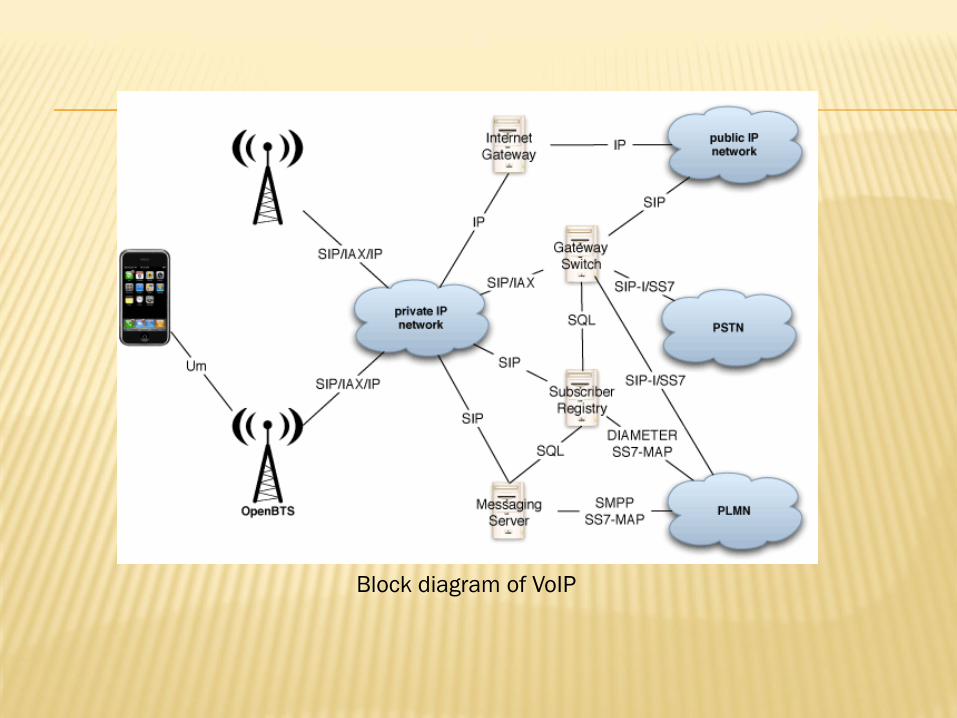
Block diagram of VoIP

CONGESTION
Congestion control algorithm

FUTURE SCOPE
VoIP has significantly earned its importance by making necessary modifications in packet transmission and
reception .
By focusing on diversity control and admission control , we are able to reduce delays .
VoIP is well used across the world, from popular apps like WeChat, helping connect rural communities in Africa,
and reducing costs for businesses making long distance calls. With this growth in the early years, VoIP traffic
rapidly expanded from 1–3% of all voice calls in 1998–2002 to 25% of voice calls in 2003. With providers such
as Skype and consumer VoIP, growth was rapid.
WeChat, Facebook, Kik and others are all using VoIP in their messaging apps, and now that millions of users are
using VoIP in their daily lives, this has acted as a driving force behind others adopting the technology.
With this in mind, it seems the future of VoIP is positive, with more opportunities for growth outside of the social
messaging market. Business collaboration tools, dating apps and customer service can start to use VoIP as a
technology that now has a much lower bar to entry than in previous years.

By
Parvathareddy Dheeraj Reddy(1470237)
section: 01
Wireless Sensor Networks

Now-a-days watching HD streaming videos and accessing cloud-based services are the main user activities consuming data capacity now, and in the near future.
In terms of network topology, heterogeneous networks (HetNets) will play an important role in integrating a diverse spectrum to provide high quality-of-service (QoS), especially in indoor environments where there is localized infrastructure supporting short-range directional wireless access.
a. The state of wireless and mobile communications: -
As the speed decrease through various reasons in Wi-Fi like multiple users, obstacles.
The WiFi evolution considers higher frequencies with new spectrum to reach multi-Gbps peak data rates (WiGig at 60 GHz) indoors and to serve multiple users in parallel. While the IEEE 802.11ad (WiGig) wireless local area network (WLAN) implementations are beginning to reach the consumer market in tri-band products (2.4 GHz, 5 GHz, and 60 GHz), optical wireless communications (OWC) systems, and specifically based on the visible light communications (VLC) technology, also called LiFi.
Multiuser transmission is used in WiFi as a next step, similar to the enabled multiuser multiple-input and multiple-output (MU-MIMO) in Long-Term Evolution (LTE)

b. Getting to high capacity and density: -
Operators say that 80% of the mobile traffic occurs indoors; therefore, the combination of LiFi and WiFi has great potential to be breakthrough technologies in future HetNets including the next generation (5G) mobile telecommunications systems.
In the Li+WiFi network, user devices (UDs) must be LiFi-enabled.
Evolving from 1G to 4G, the mobile technologies blaze the trail for marketing more advanced and more expensive user devices

In this section, we describe the proposed Li+WiFi network with a goal to provide seamless connectivity and to optimally distribute resources among users
a. Multiple Links and Aggregation: The SU-SVD-MIMO concept can be used to
avoid interference and maintain target illumination. The SVD is used to decompose the MIMO channel into parallel SISO sub-channels, enabling interference-free spatial multiplexing. At the receiver, and after estimating the channel, the information needed to pre- and post-process the signals at the transmitter and receiver, respectively, and the illumination set point (room brightness) is available on the feedback channel, to extract the parallel SISO channels.

b. Mobility and Medium Access: Resource allocation and scheduling are important aspects of QoS support in wireless networks.
The drawback of CSMA/CA in Wi-Fi is particularly notable in scenarios where low latency is required for multiple users in parallel.
Hybrid WLAN-VLC is always better than VLC- or WLAN when individually implemented for both single and multi-user cases.
Implemented a proof-of-concept Li+WiFi HetNet prototype system.
a. Capabilities of the LiFi Transceivers:

b. Performance of indoor and outdoor LiFi links:
c. Proof-of-concept experiment:

4. Future Research Opportunities 5. Conclusion
The coexistence between WiFi and LiFi is a new promising research area.
We have implemented several ways of channel aggregation for the suggested coexistence and demonstrated by proof-of-concept results, using state-of-the-art LiFi and WiFi frontends

LINK FAULT IDENTIFICATION USING DEPENDENT FAILURE IN WIRELESS
COMMUNICATION NETWORKS
Pillapakkamsridharan, Srivatsan
1417996

INTRODUCTION
Wireless communication networks are expected to play an important role in next generation internet. Wireless inks may congest, not only because of the unbalanced works or abnormal workloads for the nodes, but also for equipment faults or environmental impact. Numerous fault management methods have been developed for networks. Expert systems have gained wide acceptance as fault management tool. However the performance and flexibility of the expert system need further investigation.
This Letter focuses on a specific type of fault resulting link failure in wireless communication networks. The faulty link identification method also applies to satellite networks with connection oriented networks.

DFTG MODEL
Through building a dependent failure topology graph (DFTG) model, the management node can easily identify the most probable faulty links.
In DTFG modelling section, the fault identification model is outlined. Dependent failure method presents the dependent failure method for the identification of faulty links. The performance of the dependent failure method is discussed in performance analysis. This method is compared with the identification of faulty links. The performance of the dependent failure method is analyzed by performance.

MODELLING
Let G = ( N, L ) denote the communication network model, where N = { n1, n2, … , nN} is a finite non-empty set of nodes and L = { l1, l2, … , lk } denote a set of directed links ( lj, … , lm ) denotes the set of direct links. A fault in ni has a side effect on its direct links ( lj,…,lm) denotes the set of direct links of ni. Each link lj has the failure probability plj, plj is given as follows:
plj=plij x plkj,
where specifically, plij is the conditional probability plij = p (lj fails|ni fails) that lj fails as a result of failure of ni, and plkj is the conditional probability plkj = p (lj fails | nk fails) that lj fails as a result of the failure of nk, are the direct nodes of lj.

DEPENDENT FAILURE METHOD
The node importance evaluation is researched for the need of faulty management. The communication networks usually have multiple paths for data transmission from source node to destination node. While multiple paths can raise the probability of success for data transmission, they also cause flow differences between nodes in communication networks at the same time The higher the importance of a node, the more data packets through the node, and the higher the failure probability of the node in the network. The importance of a node can reflect its failure probability resulting from flow differences caused by network structure.

DEPENDENT FAILURE METHOD CONTD...
Studying on the dependence relationship of the importance of each node in the network, the importance of each node is determined by its location, and also limited by importance of other nodes in the network. The location of the node is determined by its betweenness, the betweenness is defined based on the shortest path, can be used to measure the ability to provide the shortest path in communication networks, and takes the impact of whole network into consideration. Closeness centrality considers the indirect influence obtain by the short path to all other nodes, and used to characterize the importance of dependence relationship among nodes.

PERFORMANCE ANALYSIS
The proposed method is compare with the independent failure method in the analysis of the example network topology. The betweenness, closeness centrality and dependent failure probability pi are shown in the table.
Node B(ni) C(ni) pi
n1 0.2 1 0.22
n2 0.05 0.8 0.21
n3 0 0.667 0.18
n4 0.05 0.8 0.21
n5 0 0.667 0.18

CONCLUSION
The DFTG model is created, into consideration the role of different nodes when finishing the communication tasks, effect on the direct links in the communication networks. The dependent failure method can not only overcome the defects of independent failure method, but also improve the accuracy of faulty links identification.
The proposed method considers the factor of hardware or software faults, the faults triggered by the flow difference of different nodes, and the environmental effects. The proposed method abandons the traditional idea of identifying faulty links by sending test packets, and only compute the probability of faulty links.

REFERENCES
• Tapolcai, J., Ho, P.-H., Ronyai, L., Babarczi, P., and Wu, B.: 'Failure localization for shared risk link groups in all-optical mesh networks using monitoring trails', IEEE/OSA J. Lightwave Technol., 2011.
• Tapolcai, J., Ronyai, L., and Ho, P.-H.: 'Link fault localization using bidirectional M-trails in all-optical mesh networks', IEEE Trans. Commun., 2013.
• Katzela, I., and Schwartz, M.: 'Schemes for fault identification in communication networks', IEEE/ACM Trans.Netw., 1995.

NEAR FIELD COMMUNICATIONS VERSUS BLUETOOTH
APARNA VALLABHANENI
1450280

INTRODUCTION
• Near field communication (NFC) is a set of communication protocols that enable two
electronic devices, one of which is usually a portable device such as a smartphone, to
establish communication by bringing them close to each other.
• Bluetooth Smart technology is a wireless communications system intended to replace
the cables connecting many types of devices, from mobile phones and headsets to hear
monitors and medical equipment over a range of 10meters to 100 meters

DIFFERENCES
• The main difference between NFC and Bluetooth is Bluetooth allows a very high speed,
reliable, and secure signal that isn’t possible with any other current technology where as
NFC is not secured much.
• The average communication range for a NFC product is less than 20 cm, but the
Bluetooth can communicate at around 10 meters.
• The connectivity of NFC is rather faster as it does not require manual pairing.

CONTD…
• NFC will allow people to use the wireless technology to make payments for products all
by simply holding a cell phone close to a reader which is not possible in Bluetooth.
• NFC has much lower power consumption when compared to Bluetooth, even the new
Bluetooth 4.0(Bluetooth low energy).
• Transmitting speed of data in NFC is just 424kbps where as for Bluetooth it is 2.1mbps.

APPLICATIONS
• Bluetooth technology is being used in such devices as fax machines, printers, cell phones
with Bluetooth headsets, home telephones, laptops and PCs, GPS systems, cameras(for
printers) and even video game consoles like play stations.
• NFC is used in posters and billboards. By simply scanning this with the smart phone, the
NFC can communicate and swap information. This can easily fill one's address book by
simply scanning. It is also used in health care, bus tickets checking,

REFERENCES:
• https://www.ipc.on.ca/images/Resources/mobile-nfc.pdf
• http://android-revolution-hd.blogspot.in/2013/09/nfc-vs-bt.html
• http://www.nearfieldcommunication.org/bluetooth.html

Analysis study of Seamless Integration
and Intelligent Solution in any situation
by the Future Advanced Mobile
Universal Systems 40 - (FAMOUS 40)
Sai Kiran Velpula
1503894

Introduction
• Communication is one of the important areas of electronics and always been a
focus for exchange of information among parties at locations physically apart.
• Rapid development of communication networks, fourth generation mobile
systems will be focused on seamlessly integrating the existing wireless
technologies including GSM, wireless LAN, and Bluetooth.
• 4G systems will support comprehensive and personalized services providing
stable system performance and quality service.

Evolution of Networks
• The radio telephone system contained one central antenna tower per region. The central antenna required radio phones to have a powerful transmitter, capable of transmitting up to 50 miles is OG.
• In 1G, Narrow band analogue wireless network is used, with this we can have the voice calls and can send text messages.
• In case of 2G Narrow Band Wireless Digital Network is used. Both the I G and2 G deals with voice calls and has to utilize the maximum bandwidth as well as a limited till sending messages i.e. SMS.
• 3G gives clarity of voice as well can talk with out any disturbance. Not only these but also have entertainments such as Fast Communication, Internet, Mobile T.V, Video Conferencing, Video Calls, Multi Media Messaging Service (MMS), 3D gaming, Multi-Gaming etc.
About 4G technology
• 4G Technology is basically the extension in the 3G technology with more
bandwidth and services offers in the 3G
• 4G technologies is likely to enable ubiquitous computing, that will
simultaneously connects to numerous high date speed networks offers
faultless handoffs all over the geographical regions.
• In 4G architecture, focus is on the aspect that multiple networks are able to
function in such a way that interfaces are transparent to users and services.

Key Features Of 4G Technologies & Terminal
Mobility
• 4G systems users can use multiple services from any service provider at the same time.
• 4G networks are: High usability: anytime, anywhere, and with any technology. Support for multimedia services at low transmission cost and integrated services.
• With the location management, the system tracks and locates a mobile terminal for possible connection.
• Location management involves handling all the information about the roaming terminals authentication information, and Quality of Service (QoS) capabilities.

TECHNOLOGY USED INSONOS EQUIPMENT
Presented by:
ABHISHEK VEMA
1429042

INTRODUCTION The SONOS company offers a wide range of products,
including the Sonos Wireless HiFi System creates a dedicated local Sonos network through wireless and/or Ethernet connections which allows for the streaming of digital audio to any Sonos device on the network.

SONOS, long known for its more expensive internet-connected speakers, released an entry-level model called the Play 1
The Sonos Play1 is about the size of a coffee can. Multiple Sonos speakers within the same network can easily
be synched. The key difference between a Sonos speaker is that Sonos
maintains its own connection to the internet You can use your phone to tell the speaker which digital music
stream to tune into, and then turn off your phone speaker is going to keep playing.

FEATURES Playing content stored locally on my mobile devices was a
snap, although accessing my Macbook’s iTunes library was a bit more challenging
Involved changing file sharing settings on the OSX system level even though I already shared my library through iTunes.
The speaker not only features a volume rocker, but also a play and pause button
ADVANTAGES
wireless device to control speakers through your Wi-Fi system. You can use more than one speaker. As long as the speaker and your device is in range of the Wi-Fi
network, you’ll be able to connect and expand your speaker system.
Takes input and gives the output simultaneously. Inbuilt memory/data.

CONCLUSION/FUTURE WORKS
When several players are linked together as a group – they continue to communicate directly with one another, keeping your music in perfect sync.
It uses digital audio to connect and not HDMI. I could control it with my iPhone or iPad.

INTERFERENCE AWARE ROUTING PROTOCOL IN
WIRELESS MESH NETWORKS
Submitted by
Rajani Yedla
ID:1450265
Section #1

INTRODUCTION
In the wireless mesh network, many wireless nodes can self organize into anetwork. There are also gateway node(s) which connects this mesh network to abackbone, or to the Internet.
The advantages of a wireless mesh network includes robustness, simpler andfaster deployment.
Here we look at a dynamic virtual carrier sensing and interference aware routingprotocol (DVCSIR) to select the optimum path because of which path experienceless interference, and thus suffer from less collisions and packet drops. We alsopresent simulation results using OPNET.

DSR AND DVCSIR
The Dynamic Source Routing protocol (DSR) is a simple and efficient routingprotocol designed specifically for use in multi-hop wireless mobile ad-hocnetworks.
The DSR protocol has two main functions, “Route Discovery" and "RouteMaintenance". They allow nodes to discover and maintain routes to arbitrarydestinations in the ad-hoc network.
The DVCSIR is a source routing algorithm that is modified from DynamicSource Routing protocol.
The DVCSIR protocol implements the complete set of route discoverymechanisms. It comprises of broadcasting route requests to find a route andreceiving route replies with a specific route to the destination.

SIMULATION RESULTS
Here the simulation was conducted using OPNET Modeler.
We compare the performance between DVCSIR and DSR since they are both source routing protocol.

CONCLUSION AND FUTURE WORK
The simulation results indicated that DVCSIR has superior performance due toits dynamic virtual carrier sensing mechanism, and interference aware pathrouting.
Here we can see that DVCSIR is able to provide a significant increase in termsof throughput at only a slight increase in delay.
In the future, we hope for implementing cognitive radio with dynamicadjustment of transmission power. This will help to get better performance forwireless mesh networks.
INTER-USER INTERFERENCE IN BODY SENSOR NETWORKS
SUBMITTED BY
VAISHNAVI YERNENI
ID: 1424171
SECTION #1

INTRODUCTION
• Body sensor networks (BSN) is a wireless network which provides remote monitoring of patients which is highly useful is emergency health conditions.
• Problem faced by BSNs: inter-user interference.
• Inter-user interference occurs when communication takes place between many networks of BSNs which are located closely.
• This inter-user interference adversely affects the efficiency of the networks by reducing the reception probabilities and throughput.
• A system is proposed which can reduce the effect of this inter-user interference using a fixed network (FN) infrastructure.
• The BSN nodes associate with this fixed network which is Wireless Sensor Network (WSN) which has various nodes across the area.
• When two BSNs associate with the same WSN node, they are likely to interfere with each other. The FN then recommends the interfering BSNs to change their protocols by assigning them to different operating frequency channels to reduce the interference.

IMPACT OF INTER-USER INTERFERENCE
• Each BSN is a cluster and each cluster consists of a gateway and one node.
• Packet Delivery Ratio (PDR) is defined as the ratio of number of packets received to the number of packets sent.
• From we can see that when a single network is operating, the PDR is almost 100%. The PDR keeps decreasing as the number of networks are increasing and when 8 networks are operating at a transmission rate of 100 packets/s, the PDR is reduced to almost 65%.
Fig 1. Change in PDR with rate of transmission Fig 2. Change in PDR with number of networks

SYSTEM TO MITIGATE INTER-USER INTERFERENCE
• The system overview is shown in the figure below.
• Interference Prediction Module:
It resides in FN node and predicts
which BSNs are likely to interfere
based on the given data (RSSI,
distance). This is information is
passed to resource arbitrator.
• Resource Arbitrator: It decides
how the protocol of the interfering BSNs need to change in order to reduce the
interference such as asking the BSNs to operate in different time slots or to
operate in different channels.
• Protocol Modifier: It resides on the BSN gateway and affects the changes suggested by the FN.
• Environment Monitor: It resides on BSN gateway and observes the environment to help FN predict whether the BSNs are interfering wit each other.
• Association Module: This module is present in both FN node and BSN gateway. It is used to assign a FN node to communicate with a BSN gateway

SYSTEM IMPLEMENTATION• In this system BSNs are allowed to operate in ZigBee channels, 11 to 25 and the
WSNs operate in channel 26 which is called control channel.
• Every 500ms, the BSN gateway switches to control channel and associates with one of the WSN nodes.
• The WSN offers a channel recommendation to the BSN gateway along with the RSSI information.
• The WSN keeps track of all the BSNs associated with it and the channels in which they are operating and the channel that is least occupied is recommended to the interfering BSN. In this way the inter-user interference is reduced.
• The BSN nodes associates with the one which has the highest RSSI value received from the WSN nodes. It accepts recommendation from that node regarding which channel the BSN should operate in and when the WSN node picked by the BSN receives the confirmation message, it stores the BSN’s ID as on the nodes it is associated with.
• All the nodes on BSN network are moved to recommended channel by implementing a polling MAC. When a BSN is asked to change its channel, it polls each node with a data packet asking it to change to new operating channel. The BSN node then responds with an acknowledgment and then changes its channel. If the node does not hear the poll packet, it will not respond and the gateway then continues to poll in the old channel with the request for node to change its operating channel.

RESULTS
• The figure below shows the results obtained with and without the proposed system.
• It can be seen that without the proposed system, the PDR is as low as 60% and with the use of the inter-user interference mitigating system, the PDR achieved is almost 100%. This the system has significant performance improvements and also reduces the inter-user interference effectively.
Fig 4. Impact of system on PDR achieved

Li Fi (Light Fidelity)
presentation by :
Rambabu Bagadi
1405503

Existing wireless technology - Why do we need
an alternate technology?
• CAPACITY
• EFFICIENCY
• AVAILABILITY
• SECURITY
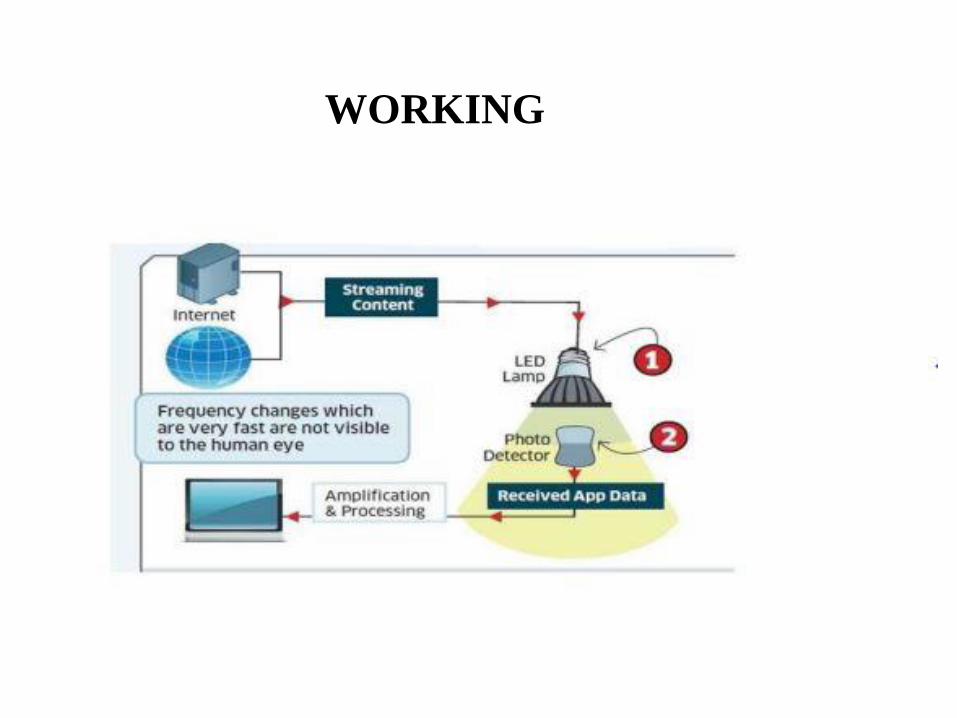
WORKING

WORKING

Real Time Usage of Li Fi

LIFI OVER WIFI

APPLICATIONS
• Underwater communications: Since radio waves cannot be used under water because these waves are strongly absorbed by sea water within feet of their transmission and this renders it unusable underwater but LIFI is suitable for underwater communication
• Health sector: Since WIFI is not safe to be used in hospitals and other various health care sectors because it penetrates human body. LIFI can be implemented and well suit in this sector.
• Internet anywhere: street lamps, light of vehicles can be used to access internet anywhere in footpaths, roads, malls, anywhere where light source is available.
• Safety and management: it can be used to update traffic information at almost every instant and it will be easy for traffic police to deal with traffic and catch the one who breaks the rule.

Recent Advances in Wireless Small cell Networks
Shashank Bhogoju
1502704
Section#2

Outline
• Introduction• Small cell network
• Backhaul Techniques
• Self Organizing Networks for Small cell Deployments
• Interference management• Inter cell Interference coordination
• MIMO Techniques
• Conclusion

Introduction
• Small cells are low-powered radio access nodes.
• Backhaul connects the small cells to the core network(Macro cell).
Types of Backhauls
Conventional point-to-point (PtP):
• high capacity
• coverage, spectrum OPEX, high costs
E-band (spectrum available at 71-76 and 81GHz)
• high capacity
• high CAPEX and OPEX
Non-Line of sight (NLOS) multipoint microwave
• good coverage, low cost of ownership
• low capacity, spectrum can be expensive

Implications which paved path to small cell networks
Administrators difficulty
–Meet the interest and keep up low expenses (i.e., incomes an issue)
•Need to diminish the consumption per bit of information (to stay away from bad options, for example, restricting utilization)
•Solutions that have been investigated in the previous couple of years
–Multiple antenna systems and MIMO
•Cannot give request of size increases
•Scalability and common sense issues
–Cognitive radio
•Availability of white spaces in real territories at crest hours is faulty
•MIMO and Cognitive radio will stay however should exist together alongside better, more versatile, and more intelligent options

Self Organizing Networks
Manual network deployment and maintenance is simply not scalable in a cost-effective manner for large femtocell deployments
• Trends toward Automatic configuration and network adaptation
• SON is key for Automatic resource allocation at all levels (frequency, space, time, etc.)
• Self organizing networks work on the game theory similar to the Nash equilibrium

Information Aspects
• Access Control in Small Cell Networks (Nash game)
• User Association in Small Cell Networks(matching game)
• Cooperative interference management(coalitional game)
• At every time t, every FBS jointly estimates its long-term utility function and updates its transmission probability over all carriers

Interference managementCarrier Aggregation
• Carrier aggregation is used in LTE-A via Component Carriers (CCs)
• Macro and Pico cells can use separate carriers to avoid strong interference
• Carrier aggregation (CA) allows additional flexibility to manage interference
In dense network deployments, femto-to-femto interference can be severe (co-tier interference)
• especially for cell edge users
• Assigning orthogonal resources among neighbouring femtocells protects cell edge UEs low spectral efficiency


MIMO Techniques
• In LTE-Advanced, CA increases system capacity by using more spectrum, and eICIC mitigates inter-cell interference by intelligent resource allocation
• FFR are used at macrocells through system-level MonteCarlo simulations, which account for not only fast fading (using the MIMO Spatial Channel Model Extended (SCME) but also path loss
• Proposed Technique
The macrocell layout comprising 7 sites with 3 sectors per site as illustrated in Fig shows FFR scenario in macrocell network

Performance Evaluation
• Consider four MIMO configurations: 1x1, 2x2, 4x2 and 4x4. Each UE has a velocity of 3 km/h.
• A Minimum Mean Square Error (MMSE) receiver is applied on each subcarrier.
• SINR per subcarrier is calculated over every spatial layer transmitted, and the effective SINR over multiple subcarriers is computed using the Mean Instantaneous Capacity (MIC) model
• Throughput is calculated from the effective SINR of each scheduled UE using a truncated Shannon bound

Conclusion
• Small cells are a necessary for future LTE networks.
• As existing 3G and 4G networks struggle to cope with the heavy data traffic, mobile operators are looking at solutions to offload traffic from their current base station networks. Small cells will be their solution of choice.
• Small cells will also be an enabler for the Internet of Things, paving the way for more connections than ever before.

References
• F. Pantisano, M. Bennis, W. Saad, and M. Debbah, \Spectrum leasing as an incentive towards uplink interference mitigation in two-tier femtocell networks," IEEE JSAC, April 2012.
• S. Samarakoon, M. Bennis, W. Saad, and M. Latva-aho, "Opportunistic Sleep Mode Strategies in Wireless Small Cell Networks," in Proc. of the IEEE International Conference on Communications (ICC), Mobile and Wireless Networks Symposium, Sydney, Australia, June 2014.

Wireless security, Hotspot security
Ramesh Babu Bojjani
Student ID 1498435
Section 2
Introduction
• Wireless local area networks (WLANs) have emerged as a promising networking platform to extend network connectivity to these public places, or hotspots.
• Contemporary “Wi-Fi” wireless LANs, based on IEEE 802.11b technology provide relatively high data connectivity at 11 Mb/s
• Recently, wireless Internet service providers (WISPs) have established Wi-Fi hotspots in increasing numbers at public venues, providing local coverage to traveling users and empowering them with the ability to access email, Web, and other Internet applications

Security and Privacy issues in Wireless Network.
• End users are not security experts, and may not be aware of the risks posed by wireless LANs.
• Nearly all of the access points running with default configurations have not activated WEP.
• Most of the users does not change access point’s default key used by all the vendor's products out of the box.
• The Wireless Access Points who are enabled with WEP can be cracked easily.

WPA (Wi-Fi Protected Access)
• It is also known as WEP+.
• WEP plus enhances WEP security by avoiding "weak IVs“.
• It is only completely effective when WEP plus is used at both ends of the wireless connection.
• It remains serious limitation.
• WPA use Temporal Key Integrity Protocol (TKIP) to addresses the encryption weaknesses of WEP.
• Key component of WPA is built-in authentication that WEP does not offer.
• WPA provides roughly comparable security to VPN tunneling with WEP, with the benefit of easier administration and use.

Protection Methods
• Changing Administrator Passwords and Usernames
• Upgrading your Wifi Encryption
• Changing the Default System ID
• MAC Address Filtering
• Stop Publicly Broadcasting your Network
• Auto-Connect to Open Wifi Networks?
• You've got a built-in firewall, so use it
• Positioning of the Router or Access Point
• When to Turn Off the Network

Security Challenges
• Mutual Trust: How can wireless-hop security be provided in a way to ensure mutual trust between the user and the hotspot provider
• Simplicity-Robustness Tradeoffs: Can hotspot networks employ WEP-based security by choosing from a set of guest access WEP keys as opposed to a single access key, thereby providing stronger security
• Hardware Approaches: Are there ways to provide the robustness of 802.1X through alternative hardware-based approaches
• Malicious Attacks: Hotspots are a comparatively open environment for malicious users to eavesdrop on communication traffic and threaten network security.

Conclusion
• The continuing rollout of hotspot deployment is being fueledby the growing requirement for high-speed connectivity in public areas such as airports, shopping malls, conference venues, hotels, and so on.
• However, a successful and viable hotspot business model will depend on the extent that it can provide value for all its stakeholders– the end user, the network service provider, and the building and premise owners.
• The challenges include authentication, security, coverage, network management, billing, and interoperability.

References
[1] B. Aboba. IEEE 802.1X Pre-Authentication. Presentation to
802.11 WGi, July 2002.
[2] A. Ahmad, R. Chandler, A. A. Dharmadhikari, and
U. Sengupta. SIM-Based WLAN Authentication for Open
Platforms. Technology at Intel Magazine, August 2003.
[3] J. Ala-Laurila, J. Mikkonen, and J. Rinnemaa. Wireless LAN
Access Network Architecture for Mobile Operators. IEEE
Communications Magazine, 39(11), Novemeber 2001.
[4] G. Appenzeller, M. Roussopoulos, and M. Baker.
User-Friendly Access Control for Public Network Ports. In
Proc. IEEE INFOCOM’99, March 1999.

Cognitive Networking
By:
GOPI SAINADH.CHALAMALASETTI
STUDENT I.D:1504150
SECTION:02
Presentation Outline:
• Introduction.
• Cognitive radio network architecture.
• Cognitive radio systems.
• Spectrum sharing.

Introduction:• Cognitive radio network is “A new paradigm that
provides the capability to share or use the spectrum in an opportunistic manner”.
Fixed Spectrum Assignment policy Spectrum White Spaces
(Inefficient spectrum utilization) (Efficient spectrum utilization)
• Cognitive radio is a wireless communication system which is aware of the environment and its changes and can adapt its transmission parameters accordingly.• Cognitive Capability: The ability to sense the unused spectrum at a
specific time and location (spectrum hole)
• Reconfigurability: The ability to receive and transmit at different frequency band enables the cognitive radio to reconfigure its parameters and select the best band.

Spectrum Hole:

Cognitive Radio Network Architecture:
• CR Network Access: CRs can access their own base station on both licensed
and unlicensed spectrum bands
• CR Ad Hoc Access: CRs can communicate with other CRs through an ad hoc
connection on both licensed and unlicensed spectrum bands.
• Primary Network Access : CRs can access primary base station through the
licensed bands.

Cognitive Radio Functionalities:
• Spectrum Sensing: Cognitive radio user has the ability to sense the unused spectrum at
any time and location.
• Spectrum Management: Based on the availability of the spectrum and other policies, CR
user allocates the best available spectrum band.
• Spectrum Mobility: CR user shall vacate the spectrum in the presence of any primary
user and move to next best available spectrum band
• Spectrum Sharing: CR network has to provide a fair and optimal spectrum allocation
method among multiple CR users.

Functions Of Network Layers:Physical Layer: • Spectrum sensing
• Data reconfigurable transmission based on Software Defined Radio (SDR).
Link Layer : • Spectrum analysis
• Spectrum selection(spectrum adjustment)
• Spectrum coordination.
MAC Layer:• Obtaining information on channel occupancy.• Performing negotiation among primary users and secondary users for
spectrum allocation and also among secondary users for channel sensing and access.
• Synchronizing transmission parameters (e.g. channel, time slot) between transmitter and receiver.
• Facilitating spectrum trading functions (e.g. spectrum bidding and pricing).

Cognitive radio systems:• Static Cognitive Radio System: Secondary user observes the
activity of the primary users in a fixed spectrum band and access the entire spectrum band if it senses the opportunity. Can be built on the following standards:
• 802.11
• 802.15
• 802.3
• Dynamic Cognitive Radio System: Secondary users can
transmit using different bandwidths by changing the transmission parameters in the physical layer (based on OFDM or MC-CDMA).

Spectrum Sharing:• Spectrum sensing: The secondary user can only allocate a
spectrum if it’s not used by an unlicensed user.
• Spectrum allocation: Allocation of a channel not only depends on spectrum availability but also depends on internal and external policies.
• Spectrum access: Since there are multiple secondary users trying to access the spectrum, their access should be coordinated to avoid colliding in overlapping portions of the spectrum.
• Transmitter-receiver handshake: After deciding a portion of the spectrum, the receiver of this communication should also be indicated.
• Spectrum mobility: If the specific portion of the spectrum is needed by a licensed user, the communication needs be continued in another vacant portion.

Classifications Of Spectrum Sharing:
Architecture:• Centralized : The spectrum allocation and process are controlled by a central
entity.
• Distributed : Spectrum allocation and access are based on local or global
policies that are performed by each node distributively.Distributed solutions closely follow the centralized solutions but they have the extra cost of message
passing between nodes.
Spectrum Allocation Behavior:• Cooperative Spectrum Sharing :The effect of the communication of one node
on other nodes in considered.
• Non-cooperative Spectrum Sharing :Only a single node is considered. As the
interference in other CRs are not considered this solution may result in reduced spectrum utilization.
Spectrum Access Technique:• Overlay Spectrum Sharing: Portion of the spectrum can be accessed that has
not been used by licensed users.• Underlay Spectrum Sharing: Transmission of a CR node is regarded as noise by
licensed users.

Inter And Intra-network Spectrum Sharing:
• Intra-network Spectrum Sharing: Spectrum allocation between the entities
of a CR network. The users of a CR network try to access the
available spectrum without causing interference to the primary users.
• Inter-network Spectrum Sharing: This setting enables multiple systems to
be deployed in overlapping locations and spectrum.

Security /Routing in Multi Hop Wireless Networks
Swati Gaekwad
Guide: Kenneth Goodwin
Section 2

Existing system
• It is very challenging to efficiently thwart traffic analysis/flow tracing attacks and provide privacy protection in multi-hop networks.
• Existing privacy-preserving solutions, such as proxy based schemes, Chaum's mix-based schemes, and onion-based schemes, may either require a series of trusted forwarding proxies or result in severe performance degradation in practice.
Proposed system
• In network coding unlinkability between incoming packets and outgoing packets, which is an important privacy property for preventing traffic analysis/flow tracing, can be achieved by mixing the incoming packets at intermediate nodes.
• It can work as removal codes to enhance the dependability of a distributed data storage system.
• Global Encoding Vectors (GEVs, also known as tags) prefixed to the encoded messages provide a back door for adversaries to compromise the privacy of users. A simple solution to address this vulnerability is to employ link-to-link encryption.
• Based on network coding and Homomorphic Encryption Functions (HEFs), objective is to achieve source anonymity by preventing traffic analysis and flow tracing in multi-hop networks.

Features• Enhanced Privacy against traffic analysis and flow tracing.
o The confidentiality of GEVs brings an implicative benefit, i.e., the confidentiality of message content, because message decoding only relies on GEVs. On the other hand, with random recoding on encrypted GEV s, the coding/mixing feature of network coding can be exploited in a natural manner to satisfy the mixing requirements of privacy preservation against traffic analysis
• EfficiencyoDue to the Homomorphism of REFs, message recoding at intermediate nodes
can be directly performed on encrypted GEV s and encoded messages, without knowing the decryption keys or performing expensive decryption operations on each incoming packet.
• High Invertible Probability
Modules:
• Attackers Modules.
• Homomorphic Encryption Functions.
• Threat models.
• Enhanced Privacy against traffic analysis and
• Flow tracing.
• Security Analysis.

High Invertible Probability
• Input design - The input design is the link between the information system and the user. It comprises the developing specification and procedures for data preparation and those steps are necessary to put transaction data in to a usable form for processing can be achieved by inspecting the computer to read data from a written or printed document or it can occur by having people keying the data directly into the system.
Objectives:o What data should be given as input?
o How the data should be arranged or coded?
o The dialog to guide the operating personnel in providing input.
o Methods for preparing input validations and steps to follow when error occur.

Output Design• Designing computer output should proceed in an organized, well thought out manner;
the right output must be developed while ensuring that each output element is designed so that people will find the system can use easily and effectively. When analysis design computer output, they should Identify the specific output that is needed to meet the requirements.
• Select methods for presenting information.
• Create document, report, or other formats that contain information produced by the system.
Objectives:o Convey information about past activities, current status or projections of theo Signal important events, opportunities, problems, or warnings .o Trigger an action.o Confirm an action.

Implementation of high invertible portability
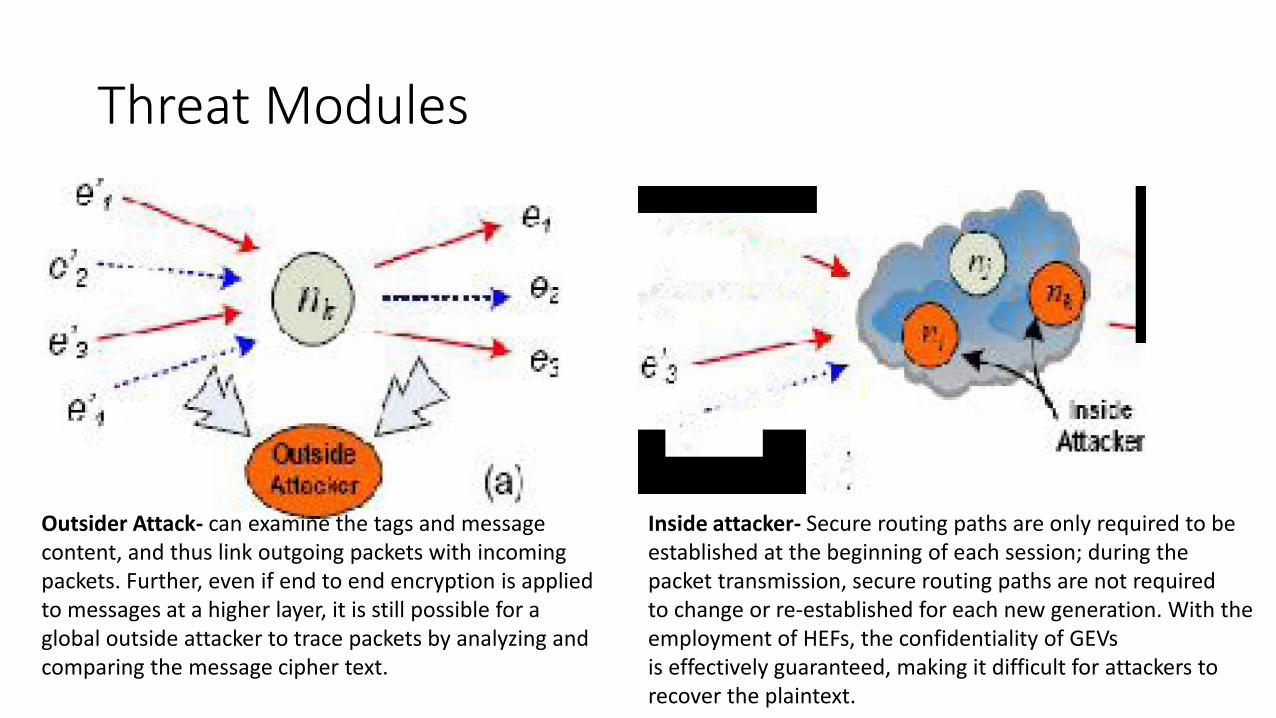
Threat Modules
Outsider Attack- can examine the tags and messagecontent, and thus link outgoing packets with incomingpackets. Further, even if end to end encryption is applied to messages at a higher layer, it is still possible for a global outside attacker to trace packets by analyzing andcomparing the message cipher text.
Inside attacker- Secure routing paths are only required to beestablished at the beginning of each session; during thepacket transmission, secure routing paths are not requiredto change or re-established for each new generation. With theemployment of HEFs, the confidentiality of GEVsis effectively guaranteed, making it difficult for attackers torecover the plaintext.

Conclusion
This method has enhanced the privacy and security in Multi hop Wireless Networks using traffic analysis in Network Codings with example of the appearance of an endangered animal in a monitored area, and then take subsequent actions to capture or kill the animals. With the lightweight homomorphic encryption on Global Encoding Vectors (GEVs), the proposed scheme offers two significant privacy preserving features, packet flow untraceability and message content confidentiality; this can efficiently thwart traffic analysis/flow tracing attacks.
Moreover, with homomorphic encryption, the proposed scheme keeps the essence of random linear network coding, and each sink can recover the source messages by inverting the GEVs with a very high probability.


INTRODUCTION
A compact sensor, is used to monitor the heartbeat in analog form .
To check the condition of the patient we required thermometer.
Temperature sensor and heart beat sensor is connected to monitor the patient’s condition.
Body sensor network systems can help people by providing healthcare services such as medical monitoring, memory enhancement, medical data access, and communication with the healthcare provider in emergency situations through the SMS or GPRS

PROPOSED METHOD
A GSM based “WIRELESS HUMAN HEALTH MONITOR” system is used.
Mainly three parts of the system, Heart beat and temperature sensor, transmitter and receiver.
• Heart beat sensor is used to measure heart beat rate.
• Temperature sensor is used to measure body temperature

Patient Monitoring Block Diagram - Transmitter

Patient Monitoring Block Diagram-Receiver

WORKING OF THE SYSTEM
There are mainly two parts of the system one is transmitter and the other one is the receiver.
In the transmitter, We have Heartbeat sensor, and the temperature sensor.
All the sensors are connected to the patient
The microcontroller monitors the all the system in the transmitter if any abnormality in the patient condition then it sends the signal so that the receiver will capture the signal and will work according to that.

CONCLUSION
Wireless BSN technology is emerging as a significant element of next generation healthcare services.
Portable and easy to use.
Prevention is better than cure.
Modern technologies have developed that promotes comfortable and better life which is disease free.

NEAR FIELD COMMUNICATION
GURRAM PRUDHVIDHAR REDDY
1452568

Contents
• Introduction
• Operation of NFC
• NFC phone architecture
• Comparison of NFC and Bluetooth
• Conclusion

Introduction
• It is a short range communication technology that enables devices to exchange information with other NFC enabled devices or certain NFC supporting cards.
• It can be done by touching the devices together or bringing them into close proximity, usually no more than a few minutes.

Operation of NFC
• Near field communication uses magnetic induction between two loop antenna located within each others near field, effectively forming a air-core transformer. It operates within the globally available and unlicensed radio frequency 1SM band 13.56MHZ with a bandwidth of 14KHZ.
• NFC always involves an initiator and a target.
• The initiator device generates a radio frequency field that transmits the data within a range of 10cm.
• The target device picks up the RF field and receives the data it contains.

Modes of communication
• Passive communication mode:
The initiator device provides a carrier fields and the target device answers by modulating the existing field. In this mode the target device may draw its operating power drom the initiator provided electromagnetic field, thus making the target device a transponder.
• Active communication mode:
Both indicatoe and target devices communicate alternately generating their own fields. A device deactivates its RF field while it is waiting for data. In this mode, both devices typically have power supplies.
• NFC role by protocol:
Initiator Target
Active possible Possible
Passive Not possible possible

Modes of operation
• Read/Write:The NFC device can read or write data to any of the supported tag types in a standard NFC data format.
• Peer-to-peer mode:The peer-to-peer mode makes it possible for two NFC enabled devices to exchange information. Such as virtual business cards or digital photos.
• Card emulation mode:The NFC device appears to an external reader much the same as traditional contractless smart card. This enables contactless payments and ticketing by NFC devices without changing the existing infrastructure.

NFC phone architecture

Algorithm
• User arrives at pos system of ther merchant and places his NFC enabled device on the terminal equipped with NFC reader for transaction.
• Upon initiating transaction, the users finger print and credit card details are sent wirelessly in an encrypted form to the NFC reader.
• The data is sent to the bank where it is decrypted and details are matched against their database.
• Upon a successful match, the name of the coustemer along with his photo 10 is sent to ther merchant.
• The merchant verifies the integrity of the coustemer with the received id.
• The transaction is processed upon valid authentication.
• The generated bill is printed or sent directly to the user’s phone.

Comparison Of NFC with Bluetooth
Aspect NFC Bluetooth
RFID compatible ISO 18000-3 active
Standardisaction body ISO/IEC Bluetooth SIG
Network ISO 13157 IEEE 802.151
Network type Point-to-point WPAN
Cryptography Not with RFID available
Range <0.2m ~10m
Frequency 13.56 MHZ 2.4-2.5GHZ
Bit rate 424 kbits/s 2.1 Mbits/s
Set up time <0.1s <6s
Power consumption <15mA Varies with class
Usability
Human centric Easy, intuitive, fast
Data centric medium
Use casespay, get access, share, initiate service, easy set up
Network For data exchange, headset
Consumer experience Touch, wave, simply connect Configuration needed

Conclusion
• Market research suggests that over the next few years, NFC technology will be in use all around.
• Shipments for NFC enabled phones are forecasted to reach 700 million units in 2016.
• For coustemers, the technology will become omnipresent in our lives and NFC enabled mobile phones will emerge as our primary consumer 10 credential

NFC enabled phones in the first 4 years of growth vs facebook users vs Internet users.

SOFTWARE DEFINED
NETWORK
SUBMITTED BY :
ANIL KUMAR.KAKARLA
1500006
SECTION 02

LIMITATIONS OF EXISTING
NETWORKS
Difficult to perform real world experiments on large scale
production networks.
i. Research stagnation-huge costly equipment to be
procured and networks to be setup by each team for
research.
ii. Networks have remained the same for many years.
iii. Rate of innovation in networks is slower as protocols are
defined in isolation-lack of high level abstraction.

Limitations of Current Networks
Million of
lines
of source
code
Billions of
gates
Many complex functions baked into infrastructure
OSPF, BGP, multicast, differentiated services,Traffic Engineering, NAT, firewalls, …
Specialized Packet Forwarding Hardware
Operating
System
Featu
reFeature
Cannot dynamically change according to network conditions

SDN Basic Concept• Separate Control plane and Data plane entities.
– Network intelligence and state are logically centralized.
– The underlying network infrastructure is abstracted from the applications.
• Execute or run Control plane software on general purpose hardware.
– Decouple from specific networking hardware.
– Use commodity servers and switches.
• Have programmable data planes.
– Maintain, control and program data plane state from a central entity.
• An architecture to control not just a networking device but an
entire network.

Global Network View
Protocols Protocols
Control via
open
forwarding
interface
Network Operating System
Control
Programs
Software-Defined Networking (SDN)
Control
Programs
Packet
forwarding

ARCHITECTURE OF SDN
In the SDN architecture, the control and data planes are decoupled,
network intelligence and state centralized, and the underlying network
infrastructure is abstracted from the applications.

NEED FOR SDN
• Facilitate innovation in network.
• Layered architecture with standard Open interfaces.
• Experiment and research using non-bulky, non-expensive equipment.
• More accessibility since software can be easily developed by more vendors.
• More flexibility with programmability.
• Ease of customization and integration with other software applications.
• Program a network vs. configure a network.
• The idea of Software Defined Network is originated from OpenFlowproject
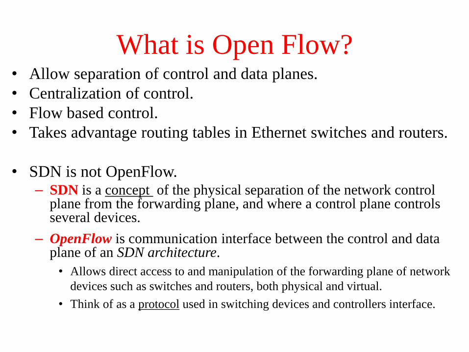
What is Open Flow?• Allow separation of control and data planes.
• Centralization of control.
• Flow based control.
• Takes advantage routing tables in Ethernet switches and routers.
• SDN is not OpenFlow.– SDN is a concept of the physical separation of the network control
plane from the forwarding plane, and where a control plane controls several devices.
– OpenFlow is communication interface between the control and data plane of an SDN architecture.
• Allows direct access to and manipulation of the forwarding plane of network
devices such as switches and routers, both physical and virtual.
• Think of as a protocol used in switching devices and controllers interface.

Basic OpenFlow: How Does it Work?
• Controller manages the traffic (network flows) by manipulating the flow table at switches.
• Instructions are stored in flow tables.
• When packet arrives at switch, match the header fields with flow entries in a flow table.
• If any entry matches, performs indicated actions and update the counters.
• If Does not match, Switch asks controller by sending a message with the packet header.
Data Plane
Control Plane :
Flow Table (has 3 sections)
Flow table
Communica
te via
secure
Channel
Match the
packet header

Centralized/Distributed Control
Centralized Control
OpenFlow Switch
OpenFlow Switch
OpenFlow Switch
Controller
Distributed Control
OpenFlow Switch
OpenFlow Switch
OpenFlow Switch
Controller
Controller
“Onix: A Distributed Control Platform for Large-scale Production Networks”

CURRENT STATUS of SDN
• Google built hardware and software based on the
OpenFlow protocol
• VMware purchased Nicira for $1.26 billion in 2012
• IBM, HP, NEC, Cisco and Juniper also are offering
SDNs that may incorporate OpenFlow, but also have
other elements that are specific to that vendor and their
gear.

Research Problems• Scalability:
– Control plane bottleneck.• Single controller is not sufficient to manage large scale network.
– How many controllers are needed to support large scale network?
– When to scale down?
• Multi Controllers.– Each controller is responsible to a subset of the network.
– Concern with synchronization and communication between controllers.
– How to slice the resources among controllers?
• Latency between controllers and switches.– Less accurate decision?

Research Problems
• Slicing Resources (CPU, bandwidth, etc). – How to allocate resources to different controllers and
users?
– Formulated to optimization and fairness problems.
• Using SDN to achieve more green DCN.– No substantial works in this area.
– As 2015, few publications on this subject are published in IEEE ICC and IEEEE Globe.com.
– Some software may provide measurement on power usage or capability to turn on/off switches.• NetFPGA, Mininet and OpenFlow?

Researc
h th
em
es
in S
DN
, as 2
01
5.

CONCLUSIONS and FUTURE SCOPE
• In future, networking will rely more on software to pick up the pace
the innovations in networks.
• SDN can transform today’s static networks into more flexible,
programmable platforms to provide scalability to support large data
centers. It will also provide virtualization that is needed to support
automated, dynamic and secure cloud environment.
• Mostly implementations of newly proposed systems, frameworks, or
applications

References:• Sources:
– “Software-Defined Networking: A Comprehensive Survey”, D. Kreutz, F. Ramos, et el. 2015.
– “Survey on Software-Defined Networking”, W. Xia, Y. Wen, et el. 2015.
• Supplement Documents:– “Software-Defined Networking: State of the Art and
Research Challenges”, M. Jammal, T. Singh, et el.
– “The Road to SDN: An Intellectual History of Programmable Networks”, N. Feamster, JennigerRexford, E. Zegura.
– “A Survey of Software-Defined Networking: Past, Present, and Future of Programmable Network”, B. Astuto, et el.

CELL PHONE VOICE QUALITY
ISSUES
Kantamneni, Dinesh
ID:1508290
Section 02

The Main Issues:
The first obstacle to a good-quality voice connection on today’s mobile phones is
their DESIGN.
For example, to create an elegant, palmable chassis for watching videos and
thumbing through music playlists, smartphone designers shrink and flatten
speakers and sometimes even cover them in plastic.
Secondly phone can filter out background noise, such as traffic. But when it
comes to sudden sounds, noise-canceling software may not be nimble enough to
silence the interruption.
Thirdly Distance from a cellular tower can degrade the quality of a voice call or
result in the conversation being dropped altogether.
Fourth point Cellular voice calls can be compressed multiple times and get
unpacked at their destination, garbling the speakers’ words.
Finally Compression can be worse on international calls, which carriers send via
submarine cables.
1. They're space-challenged
When it comes to sound quality, cordless phones have it easy. They have
only one primary function—voice calls—and their larger size lets them place
their large microphones and speakers as close to your mouth and ear as possible.
Smart phones, on the other hand, are a technological usage, densely
packed with cameras, radios, microprocessors, sensors, and other hardware that
enables them to do all those amazing things we expect them to do. Often, the
tiny speaker is wedged between the bezel and the front-facing camera, while the
microphone is sometimes relegated to the bottom of the phone—or the back.
That almost guarantees a less-than-ideal connection with your mouth and ear.

2. The signals travel a long and winding road
Every second of a cellular voice call is a scientific miracle. What you say and hear is
shredded into tiny pieces called packets that hitch a ride on microwave signals until
they're reassembled by the phone of the person to whom you are speaking.
As those signals jump from cell tower to cell tower, they run into trees, mountains
buildings, the weather, and other obstacles that cause them to split. The split signals
produce a phenomenon called multipath, when multiple copies of the same signal reach
your smart phone at different times, like an echo.
Deciphering multipath signals is quite difficult, and when the phone gets overwhelmed,
the signal has to be retransmitted.

Garbled voice: The voice of either or both people on the phone sound
distorted, muffled, or as thought the speaker is under water.
Static: There is constant static even when no one on the phone is speaking.
Static can sound like a hissing or buzzing sound, a low hum, or a series of
crackles or pops.
These issues are usually the result of electrical interference caused by a
problem in the phone wiring or interference from other electronic devices.
Echo: Either or both people on the phone hear their own voice echoed
back to them. An echo is usually the result of voice signals that are too
loud. It can also be caused by electrical feedback due to problems with the
phone wiring.

Conclusion
Part of a cell phone's appeal is that you can take them
everywhere. Unfortunately everywhere is often a noisy place,
filled with the din of traffic, rude conversations, and the sweet,
distracting sounds of Mother Nature. Some phone makers brag
about the noise-canceling technologies they've shoehorned
into their devices, but they rarely make a significant
difference.

NEAR FIELD COMMUNICATION SECURITY ISSEUES
PRESENTED BY
KOLISETTI SAI GANESH
#1500314
SECTION 2
WHAT IS NFC ???
NFC or Near Field Communication is a short range high frequency wireless communicationtechnology.
NFC is mainly aimed for mobile or handheld devices.
A radio communication is established by touching the two phones or keeping them in aproximity of a few centimeters (up to 10 cm) .
It allows for simplified transactions, data exchange, and wireless connections between twodevices.
Allows communication betweenTwo powered (active) devicesPowered and non self-powered (passive) devices

FEATURES OF NFC
NFC is an extension of Radio frequency identification (RFID) technology that combines theinterface of a smartcard and a reader into a single device. This allow two-way communicationbetween endpoints, where earlier systems were one-way only.
It operates within the globally available and unlicensed radio frequency band of 13.56 MHz, witha bandwidth of 14 kHz.
Working distance with compact standard antennas: up to 10 cm .
Supported data rates: 106, 212 and 424 Kbit/s
For two devices to communicate using NFC, one device must have an NFC reader/writer and onemust have an NFC tag

NFC READER
Usually a microcontroller-based (for example NFC enabledphones) with an integrated circuits that is capable of generatingradio frequency at 13.56 MHz with other components such asencoders, decoders, antenna, comparators, and firmwaredesigned to transmit energy to a tag and read information backfrom it by detecting the backscatter modulation. The readercontinuously emits RF carrier signals, and keeps observing thereceived RF signals for data.
An NFC Reader

OPERATION OF NFC
NFC devices communicate via magnetic field induction, where two loop antennas are located within each other's near field, effectively forming an air-core transformer.
The reader continuously generates an RF carrier sine wave (at 13.56 MHz), watching always for modulation to occur. Detected modulation of the field would indicate the presence of a tag.

MODES OF COMMUNICATION
Passive Communication Mode: TheInitiator device provides a carrierfield and the target device answersby modulating existing field. In thismode, the Target device may drawits operating power from theInitiator-provided electromagneticfield.
Active Communication Mode: BothInitiator and Target devicecommunicate by alternatelygenerating their own field. A devicedeactivates its RF field while it iswaiting for data. In this mode, bothdevices typically need to have apower supply.

COMPARISON WITH EXISTING TECHNOLOGIES
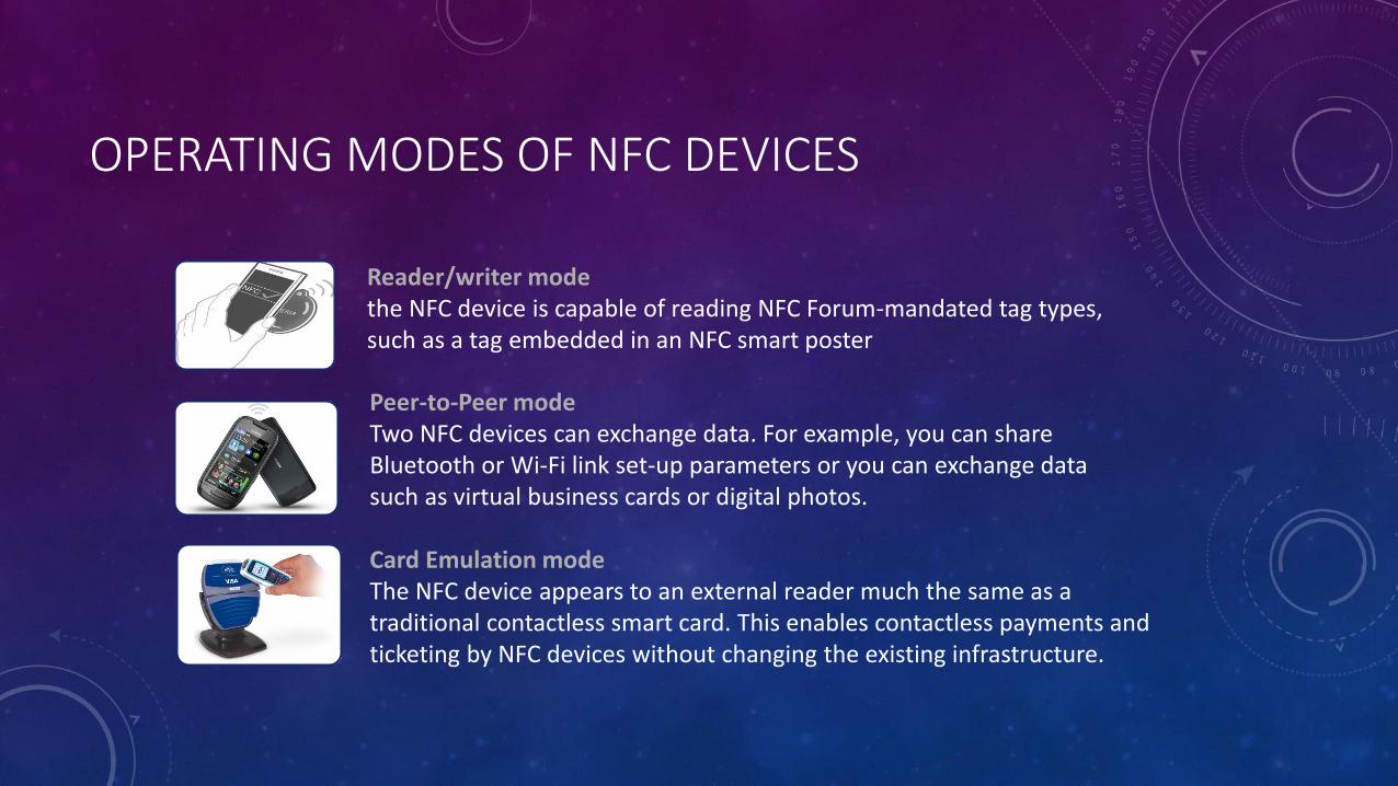
OPERATING MODES OF NFC DEVICES
Reader/writer modethe NFC device is capable of reading NFC Forum-mandated tag types, such as a tag embedded in an NFC smart poster
Peer-to-Peer modeTwo NFC devices can exchange data. For example, you can share Bluetooth or Wi-Fi link set-up parameters or you can exchange data such as virtual business cards or digital photos.
Card Emulation modeThe NFC device appears to an external reader much the same as a traditional contactless smart card. This enables contactless payments and ticketing by NFC devices without changing the existing infrastructure.

PRIVACY AND SECURITY WILL BE MAJOR ISSUES
• As with credit cards, the sensitive financial data stored on mobile phones will become targets for thieves and the unscrupulous.
• The upside, though, is that the security of NFC-enabled phones could be quite good, or at least no worse than a credit card. Since smartphones are miniature computers, strong cryptography and authentication protocol can be built into their systems – but it is up to device manufacturers and service providers to ensure these protections are in place for NFC transactions.
• NFC’s relatively short read range provides some protection against eavesdropping on transactions, but it may be possible to pick up data from NFC systems at a greater distance using an antenna.
• Of particular concern for data security are man-in-the-middle attacks in which a party to one transaction drops some form of spyware or malware onto the phone, subsequently infecting other phones that the original interacts with later. Anti-virus software and operating system architecture that controls flow of information between applications will be important safeguards to mitigate such attacks.
• Google, Sprint and possibly others have already made clear that they do not intend to generate revenue by taking a cut of mobile payment transactions. Instead, they hope to use NFC to provide highly personalized advertisements and coupons at the point of sale. Likewise, retailers, digital signage companies and others are considering ways to leverage NFC to deliver marketing tailored to location and preferences, enabling the “rich brand experience” so many companies believe consumers crave. Deep involvement by Google in mobile payments is uniquely consequential in that Google already gathers colossal quantities of data on consumers’ search habits, emails, calendars and locations. With NFC-equipped Android phones, Google will also have access to data on where individuals shop, when, and what they purchase.

SECURITY CONCERNS WITH NFC TECHNOLOGY
Eavesdropping
Eavesdropping is when a criminal “listens in” on an NFC transaction. The criminal does not need to pick up every single signal to gather private information. Two methods can prevent eavesdropping. First there is the range of NFC itself. Since the devices must be fairly close to send signals, the criminal has a limited range to work in for intercepting signals. Then there are secure channels. When a secure channel is established, the information is encrypted and only an authorized device can decode it. NFC users should ensure the companies they do business with use secure channels.
Data Corruption and Manipulation
Data corruption and manipulation occur when a criminal manipulates the data being sent to a reader or interferes with the data being sent so it is corrupted and useless when it arrives. To prevent this, secure channels should be used for communication. Some NFC devices “listen” for data corruption attacks and prevent them before they have a chance to get up and running.

CONT’D
Interception Attacks
Similar to data manipulation, interception attacks take this type of digital crime one step further. A person acts as a middleman between two NFC devices and receives and alters the information as it passes between them. This type of attack is difficult and less common. To prevent it, devices should be in an active-passive pairing. This means one device receives info and the other sends it instead of both devices receiving and passing information.
Theft
No amount of encryption can protect a consumer from a stolen phone. If a smartphone is stolen, the thief could theoretically wave the phone over a card reader at a store to make a purchase. To avoid this, smartphone owners should be diligent about keeping tight security on their phones. By installing a password or other type of lock that appears when the smartphone screen is turned on, a thief may not be able to figure out the password and thus cannot access sensitive information on the phone.
HOW TO AVOID RISKS OF BEING HACKED
1. Read the fine print for NFC-enabled applications
With a credit card transaction, most people understand that a handful of companies—the store, card processor, issuing bank and credit card company—will get some information on their buying habits. With NFC, however, the picture is less clear. The application developer and the service provider may also get information. Consumers should read up on any application’s data usage policy to protect their privacy.
2. Monitor NFC updates and patch your device promptly
The NFC vulnerabilities used to compromise devices in the Pwn2Own competition have been fixed, but manufacturers are typically slow to release patches for vulnerabilities in smartphones. They’re getting better, however, leaving consumers as the primary hurdle for locking down phones. “Consumers should be less concerned about whether or not another vulnerability will be discovered,” HP’s Gorenc says. “They should be concerned with how fast mobile device vendors can fix the issue and deploy the patch.”
3. If you’re not using NFC, turn it off
NFC is new, and many consumers have yet to adopt the technology. Unless you've started using Google Wallet or Apple Pay, turn NFC off. “The average mobile user has asked, ‘What does this do for me?’” TapTrack’s Shalabysays. “On the consumer-facing side, most people turn their NFC off.” Aside from saving some power, turning off unused networking features is a good rule of thumb to limit exposure to attackers.

APPLICATIONS OF NFC

BENEFITS OF NFC
Versatile: NFC is ideally suited to the broadest range of industries, environments, and uses
Open and standards-based: The underlying layers of NFC technology follow universally implemented ISO,ECMA, and ETSI standards
Technology-enabling: NFC facilitates fast and simple setup of wireless technologies, (such as Bluetooth, Wi-Fi,etc.)
Inherently secure: NFC transmissions are secure due to short range communication
Interoperable: NFC works with existing Contactless card technologies
Security-ready: NFC has built-in capabilities to support secure applications
NFC is as simple as a >> touch

CONCLUSION
Mobile handsets are the primary target for NFC and soon NFC will be implemented in most handheld devices. Even though NFC have the shortest range among radio frequency technologies but it is revolutionary due to it’s security, compatibility, user friendly interface, immense applications etc
The above mentioned scenarios are just a few examples of how NFC will change our lives for the better. With the high level of interest by corporations, as well as involvement of individual developers and users in this short range communication standard, the possibilities are endless.
REFERENCES
• https://cdt.org/blog/nfc-phones-raise-opportunities-privacy-and-security-issues/
• http://www.nearfieldcommunication.org/nfc-security.html
• http://www.pcworld.com/article/2938520/nfc-security-3-ways-to-avoid-being-hacked.html
• http://www.cso.com.au/article/440741/near_field_communication_security_risks_/
• "Information technology - Telecommunications and information exchange between systems — Near Field Communication — Interface and Protocol (NFCIP-1)", ISO/IEC 18092, First Edition, 2004-04-01.
• Klaus Finkenzeller, "RFID Handbuch", Hanser Verlag, 2002.
• Morris Dworkin, "Recommendation for Block Cipher Modes of Operation", NIST Special Publication 800-38A, 2001.
• W. Diffie and M.E. Hellman, "New directions in cryptography", IEEE Transactions on Information Theory 22 (1976), 644-654.

MIDTERM WIRELESS PROJECT
802.11 ac
-HENA PRIYA KONDA
St.Id: 1498853
Section-2

INTRODUCTION
O Wireless networking standard in the 802.11
family
O Faster and more scalable version of
802.11n
O Wider channels and more spatial streams
O Multi user mode-MIMO
O Optimized for high density and band width

O Encourages 5Gadoption
O More efficient modulation
O Breaks gigabit barrier
O Maximum speed of 6.9 Gps
O Supports 5GHz frequencies only

O 802.11 n n can only send and receive data
from one device at a time
O 802.1 ac can send and receive from each
device, which receives the full bandwidth on
offer continuously

802.11 ac key requirements
O Backwards compatibility
O Coexistence
O Single station throughput
O Multi station throughput
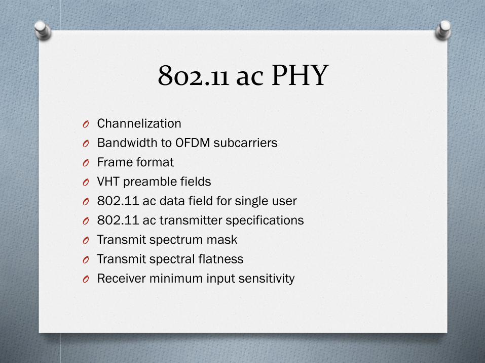
802.11 ac PHY
O Channelization
O Bandwidth to OFDM subcarriers
O Frame format
O VHT preamble fields
O 802.11 ac data field for single user
O 802.11 ac transmitter specifications
O Transmit spectrum mask
O Transmit spectral flatness
O Receiver minimum input sensitivity

PRESENTED BYCHATHURYA REDDY KOTHAPALLISECTION#2UHCL ID: 1452094
CELL PHONE VOICE QUALITY

• INTRODUCTION
• WHY IS CELL PHONE QUALITY SO BAD?
• WHAT IS THE BIG FOCUS FOR SERVICE PROVIDERS?
• PROMISING PROJECTS AIMED AT IMPROVING CALL QUALITY?
• CONCLUSION
• REFERENCES
CONTENTS:

INTRODUCTION:
• In the age of social media, texting, mobile e-commerce and video streaming it’s easy to overlook an experience hasn’t gotten better for smartphone users: talking on the phone.
• Despite sophisticated smartphones and networks, many mobile users are not satisfied with call clarity.
• In larger part that is because device makers often shrink, flatten and cover speakers in plastic to improve their phones’ overall functionality. Even on a high-end smartphone that uses several microphones and noise-cancellation algorithms, a caller is not guaranteed clear sound, especially in noisy environments.
• Change is happening slowly but there are promising new technologies are on the horizon. Start-up Cypher Corp. has built an artificial intelligence engine that analyzes the unique quality of the human voice that distinguishes it from other noises.

WHY IS CELL PHONE QUALITY SO BAD?
• It is primarily the service providers. A key point to note is that the base station/base station controller, now called eNodeB [for Evolved Node B] in LTE, is all-powerful. That is, eNodeB makes all of the decisions about how much bandwidth each handset gets no matter how good a channel connection a handset may have. Also, base station behaviors are not standardized—that is, no one really knows how they are making these decisions.
• They take into account how loaded the cell site is and how loaded adjacent cell sites are, plus other network data and other things when allocating bandwidth. This means that the base station allocates bandwidth conservatively, and thus the voice codec in the handset may operate at a lower than desirable rate.

• Video takes lots of bandwidth. For video, the service providers do not want you to have to wait for buffering, particularly after you have started to view a video. Second, cell sites/base stations cost money, so deployments of new cells are not done lightly. The latter leads to poor RF [radio frequency] connectivity in different areas for different providers.
• The service providers feel voice quality is not their main problem today. They want traffic, and video is big traffic compared to voice. Video is expected to dominate mobile data in the future so it is important to their business.
WHAT IS THE BIG FOCUS OF SERVICE PROVIDERS?

• For the latest generation of cellular, LTE, a new voice codec is being developed. It is designated enhanced voice services [EVS]. It will cover wider bandwidths so it will be better for music and mixed voice and music content. It has many new codec rates, plus better VoIP [voice over Internet protocol] factors such as packet loss concealment [used to used to mask the disruptive effects of lost or discarded data packets] and jitter buffer management. But the standard will take awhile to get into deployments everywhere by service providers.
PROMISING PROJECTS AIMED AT IMROVING CALL QUALITY:

• Since the arrival of the smartphone era, carriers have been strangely and frustratingly mum about sound quality. Even the largest U.S. carriers—AT&T, Sprint, and T-Mobile, which long shied away from discussing voice quality with the public.
• Verizon, the top U.S. carrier, which plans to start deploying the technology before year’s end, calls it “the next evolution in wireless calling.”If that’s really true, it’s reason for me and other voice customers to be optimistic.
CONCLUSION

[1] E. Malykhina, "Why Is Cell Phone Call Quality So Terrible?", Scientific American, 2016. [Online]. Available: http://www.scientificamerican.com/article/why-is-cell-phone-call-quality-so-terrible/
[2]"Why Mobile Voice Quality Still Stinks—and How to Fix It", Spectrum.ieee.org, 2016. [Online]. Available: http://spectrum.ieee.org/telecom/wireless/why-mobile-voice-quality-still-stinksand-how-to-fix-it.
REFERENCES

WIRELESS COMMUNICATION AND NETWORKS
BY
BINDUSPOORTHY MANNEPALLI
1500318
SECTION 2
NFC WITH BLUETOOTH AND WIFI

INTRODUCTION
NFC WITH BLUETOOTH AND WIFI
Near f ie ld communication (NFC ) :
NFC is a set of ideas and technology that enables smartphones
and other devices to establish radio communicat ion with each
other by touching them together or bringing them into
proximity, typical ly a dis tance of 10 cm (3.9 in) or less
Near field communicat ion, abbreviated NFC, is a
form of contact less communicat ion between devices l ike
smartphones or tablets . Contact less communicat ion al lows a
user to wave the smartphone over a NFC compatible device to
send information without needing to touch the devices
together or go through mult iple steps set t ing up a connect ion .
Fast and convenient .

NFC WITH BLUETOOTH AND WIFI
Bluetooth and Wi-Fi seem similar to near f ie ld
communicat ion on the surface . All three al low wireless
communicat ion and data exchange between digi tal devices
l ike smartphones . Yet near f ie ld communicat ion ut i l izes
electromagnet ic radio f ields while technologies such as
Bluetooth and Wi-Fi focus on radio transmissions instead.

NFC WITH BLUETOOTH
NFC WITH BLUETOOTH AND WIFI
• NFC is l imited to a dis tance of approximately four
centimeters while Bluetooth can reach over thir ty feet .
• NFC technology consumes li t t le power when compared
to standard Bluetooth technology.
• Bluetooth requires users to manually set up
connect ions between smartphones and takes several
seconds . NFC connects automatical ly in a fract ion of a
second, so fast i t seems instantaneous .
• Bluetooth low energy (BLE), is targeted at low power
consumption and uses even less power than NFC.

NFC WITH WIFI
NFC WITH BLUETOOTH AND WIFI
• WIFI had maximum coverage area over NFC
• The frequency of operat ion of NFC is13.56MHz and WIFI
is 2.4GHz,5GHz
• The data rate is more for WIFI than NFC and both are 2
way communicat ions
• WIFI is used only for wireless internet but NFC is used
for e- t icket booking,credi t card related payments
CONCLUSION
NFC WITH BLUETOOTH AND WIFI
The NFC (Near f ie ld communicat ion) is a data transfer
technique and is the type of the wireless communicat ion
with short range . The data is t ransferred in the form of
beam by touching the two things together . A single wave
or beam helps to transfer the data between two devices
within the range of 4 cent imeter . I t helps to transfer the
data at much faster rate and is bet ter than bluetooth and
wifi

NFC
(Near Field Communication)
CENG 5332 Wireless Communications & Networks
Sai Surya Teja Marouthu
Uhcl ID:1401304
Section-02

Principle of NFC:
•NFC is a short range wireless technology that
allows communications to take place between
devices that either touch or are momentarily held
close together.
•NFC is based on Radio Frequency Identification
(RFID) technology
•The technology works via magnetic field induction
technology and operates on an unlicensed radio
frequency band.

Advantages of NFC:
•Wide reach and Availability
•Can be used in various situations
•Very easy to use
•Value added services
•Compatible with existing RFID infrastructure.
Disadvantages of NFC:
•Security
•Costly
•Not enough Incentive

NFC Tags:
One way to take advantage of a
phone’s NFC capabilities is to
make your own NFC tags. These
tags, when read by your phone, can
perform a number of actions, like
open a map, launch a website,
change your phone’s settings and
configurations, plus dozens of
other tasks.
NFC tag operation
The NFC tag is a passive device with no power of its own. Accordingly when one is
used, the users touches an NFC enabled device onto the tag. A small amount of
power is taken by the NFC tag from the reader/writer to power the tag
electronics. The tag is then enabled to transfer a small amount of information to the
reader/writer.
The data stored in the tag memory is transferred to the NFC enabled device.
Although normally only a small amount of data, this may be used to direct the
device to a website URL, it may be a small amount of text, or other data.

Integration of NFC, WiFi and Bluetooth:
A newly published Apple patent
application uses a secure element in a
mobile phone to store cardholder
data, NFC to initiate a transaction and
Bluetooth or WiFi to complete the
processing of a transaction and return
coupons and other information to the
customer’s device.
Apple sets out a system that uses a secure element to store payment card data.
This data could then be sent directly from the secure element to the merchant’s
POS terminal via NFC in the usual way or, alternatively, NFC could be used only to
initiate a transaction.
In this case, once an initial link-up had been established via NFC, payment card data
would be sent from the secure element to the application processor and then on
to the POS terminal, via WiFi or Bluetooth, in an encrypted format — using an alias,
cryptographic data and a shared secret known only by the secure element and a
backend processor

Applications of NFC:
Touch and Go
• Transport Ticketing
• Movie Ticketing
Touch and Confirm
• Mobile Payment
• Smart Tags
Touch and Connect
• Asset Management
• Access
• Parking
• Meal orders
• Pemote worket reporting
• Maps
• Events Calender

Wireless Ad Hoc Network (WANET)
WCN CENG 5332 Shafiullakhan Mohammed
Dr. Kenneth GoodWin St Id# 1470130(Sec #2)
jk

WANet
Outline
Abstract
Different means to Access Networks
Challenges Faced
Error Occurred
Ad Hoc Network
Ad Hoc Routing
Issues
WCN Ceng-5332
1

WCN Ceng-5332
Abstract
•An ad hoc network, or MANET (Mobile Ad hoc NETwork), is a network composed only of nodes, with no Access Point.
•Messages are exchanged and relayed between nodes.
•Ad Hoc network has capability to establish communication with two different modes which are not in direct range, by using routing algorithm.
•This network can spread through a wide range for the means of communication.
2

Access of Networks
WCN Ceng-5332
Point to point wireless networksExample: Your laptop to CMU wirelessChallenges:
Poor and variable link quality (makes TCP unhappy)Many people can hear when you talk
Pretty well defined.Ad hoc networks (wireless++)
Rooftop networks (multi-hop, fixed position)Mobile ad hoc networksAdds challenges: routing, mobilitySome deployment + some research
Sensor networks (ad hoc++)Scatter 100s of nodes in a field / bridge / etc.Adds challenge: Serious resource constraintsCurrent, popular, research
3

Challenges faced
• Need to share airwaves rather than wire
– Don’t know what hosts are involved
– Host may not be using same link technology
– No fixed topology of interconnection
– Interference
• Other hosts: collisions, capture, interference
• The environment (e.g., microwaves + 802.11)
• Mobility -> Things change often
– Environmental changes do too
– How do microwaves work? Relate to 802.11 absorption.
• Other characteristics of wireless
– Noisy lots of losses
– Slow
– Multipath interference
WCN Ceng-5332
4

Error occurred
WCN Ceng-5332
Loss Congestion
Wireless
Computer 1 Computer 2
Router
2
0
1
Loss Congestion5

Ad Hoc Network
• All the challenges of wireless, plus some of:
– No fixed infrastructure
– Mobility (on short time scales)
– Chaotically decentralized (:-)
– Multi-hop!
• Nodes are both traffic sources/sinks and forwarders
• The big challenge: Routing
WCN Ceng-5332
6

Ad Hoc Routing
• Find multi-hop paths through network
– Adapt to new routes and movement / environment changes
– Deal with interference and power issues
– Scale well with # of nodes
– Localize effects of link changes
WCN Ceng-5332
7

Issues
Routing
Mobility
Bandwidth constraint
Self-Organization is required in ad hoc wireless networks:
Neighbor discovery
Topology organization
Topology reorganization
Security
Denial of service
Resource consumption
WCN Ceng-5332
8

PRESENTED BY
POOJA NALLA
1503897
SECTION-02

INTRODUCTION
802.11ac is the next evolution of the Wi-Fi standard which promises todeliver high data rates and sustain significantly higher throughput andlower latency than existing standards.
It is also named as “Gigabit Wi-Fi” as it can deliver maximum data rate of6.93 Gbps in 160MHz bandwidth mode.
Wireless speed is generally the product of three factors:
- channel bandwidth
- Modulation techniques
- number of spatial streams

Improved data rates and reduced latency is achieved by
Mandatory 5Ghz operations:
802.1relatively reduced interference and more number of non-
overlapping channels available compared to 2.4ghz band.
Wider bandwidth:
Wider bandwidth allows higher data rates to be achieved.
802.11ac introduces 80Mhz and 160Mhz channel bandwidths inaddition to 20Mhz and 40M1ac standard mandates operation only in 5Ghzband as it has Hz in 802.11n

Higher Order Modulation:
802.11ac increased the constellation configuration to 256-QAM
which increases data rate by 33% over 11n.
Each symbol represents 8 coded bits.
Higher Order MIMO:
The Speed is directly proportional to the number of spatial streams.
STA can receive up to eight spatial streams to effectively double thetotal network throughput.

Enabling multiple data streams via downlink MIMO
802.11ac is the first Wi-Fi standard that introduced multi-user MIMO. InMU-MIMO, the AP can serve multiple STAs simultaneously.
AP is able to use its antenna resources to transmit multiple frames todifferent clients, all at the same time and over the same frequencyspectrum.
AP
STA
STA
STA

MU-MIMO
In multi-user mode, the 802.11ac amendment supports up to four streamsserving four different users simultaneously.
Standard also specifies support for a different modulation and coding rate for each station being served in a downlink MU-MIMO transmission.
The AP has to know Channel state information of all the users in order todecrease the amount of inter-user interference generated by the multiplesimultaneous streams.
Through Pre-processing of data streams at the transmitter, the interferencefrom streams that are not intended for a particular station is eliminated atthe receiver of each STA. So, every STA receives data free from interference.
MU-MIMO Uses Combination of Beam forming and Null Steering to MultipleClients in Parallel.

CONCLUSION:
802.11ac is the future of wireless LANs, but Wi-Fi-certified 802.11ac APsare not yet available. 802.11ac can provide full HD video at range tomultiple users, higher client density, greater QoS, and higher power savings
from getting on and off the network that much more quickly. IT administrators looking to invest in wireless LANs in the near term should
strongly consider 802.11n APs that are field upgradable to 802.11ac.

THE FIFTH
GENERATION Wi-Fi IEEE
802.11ac
NIMMALAPUDI, MANIDHAR
Student id: 1502992
Section : 2

IEEE 802.11ac
Released in December 2013.
It is an amendment to IEEE 802.11
It provides a multi-station WLAN throughput of at least 1 Gbps
and a single link throughput of at least 500Mbps.
This is achieved by extending the air interface concepts which
are embraced by 802.11n like wider bandwidth (up to 160MHz),
more MIMO spatial streams ( up to 8), multi-user MIMO, and
high-density modulation.
Operates at 5GHz frequency band.

The following are the three different dimensions
that helped 802.11ac to achieve its speed
1. More channel bonding.
2. Denser modulation.
3. More multiple input, multiple output (MIMO).

5 GHz
11ac supports 5 GHz
frequencies only
Dual-band devices will support
11n in 2.4 GHz
Focuses on spectrum with more
bandwidth, less interference,
and better scalability and
capacity
Encourages client device
suppliers to adopt 5 GHz, to
benefit from 11ac marketing,
leaving 2.4 GHz as “best
effort” spectrum

80 and 160 MHz Channels
11ac devices must support 80 MHz channel width
Optional support for 160 MHz
Contiguous or non-contiguous (80+80)
Boosts maximum 802.11ac specs
Appeal is for consumers with 1 AP
PROS:
• Max data rate is more than doubled
• Boosts throughput in networks with few APs
• Improves backup, file transfer speeds

CONS:
• Sub-optimal spectral reuse in multi-AP deployments
• Max of 5 non-overlapping 80 MHz channels
• Increases neighbor interference and contention
• Likely decreases aggregate capacity in enterprise

Multi-User MIMO (MU-MIMO) Transmit simultaneous downlink frames to different receivers
Significant capacity enhancements in environments with many
single-stream devices (tablets, smartphones)
Requires 11ac client(s) with TxBF feedback/support
Creates new challenges related to signal steering and isolation

Name: SHIVANI PATHAK
Subject: WIRELESS NETWORK AND COMMUNICATION
SID: 1500436

INTRODUCTION
• The goal of communications technologies is to transmit information quickly, completely and accurately.
• Laser communication systems are wireless connection through the atmosphere
• Use Laser beams to transmit information between two location
• It is boon for space exploration as it is used for long distance communication
• Laser communication is a very specific application -- satellite-to-satellite, terrestrial-to-satellite, terrestrial-to-airplane -- are very high bandwidth applications that lasers can do.
• Lasers can be used for communication without any cables to communicate from huge distances, particularly in space.

Laser over RF
• Laser Communications uses the bandwidth that is around 100 times greater than for RF so there is a much wider range of frequencies to choose from without getting noise from other nearby stations
• Since Laser Communication is directed at a target, there is much less transmission power required. There is also less power loss than with Radio Frequency Communication.
• An LC antenna is much smaller than an RF Antenna which means less raw construction materials are needed.
• Due to low divergence of a laser beam, LC is much more secure than free-range radio frequencies.

FUTURE LASER TECHNOLOGY
• Laser technology has yet to advance and many enhancements are left to be made. Lasers technologies are improving at a rapid rate and new different techniques to improve lasers are still in the works.
• One such new technique is beam combining, which blends several laser streams into one high-power beam.
• Researchers are taking many approaches to combine laser beams which are: spectral beam combining, coherent beam combining and polarization beam combining.
• The goal of beam combining is to increase laser power and brightness to enable long-distance communications and laser weapons.
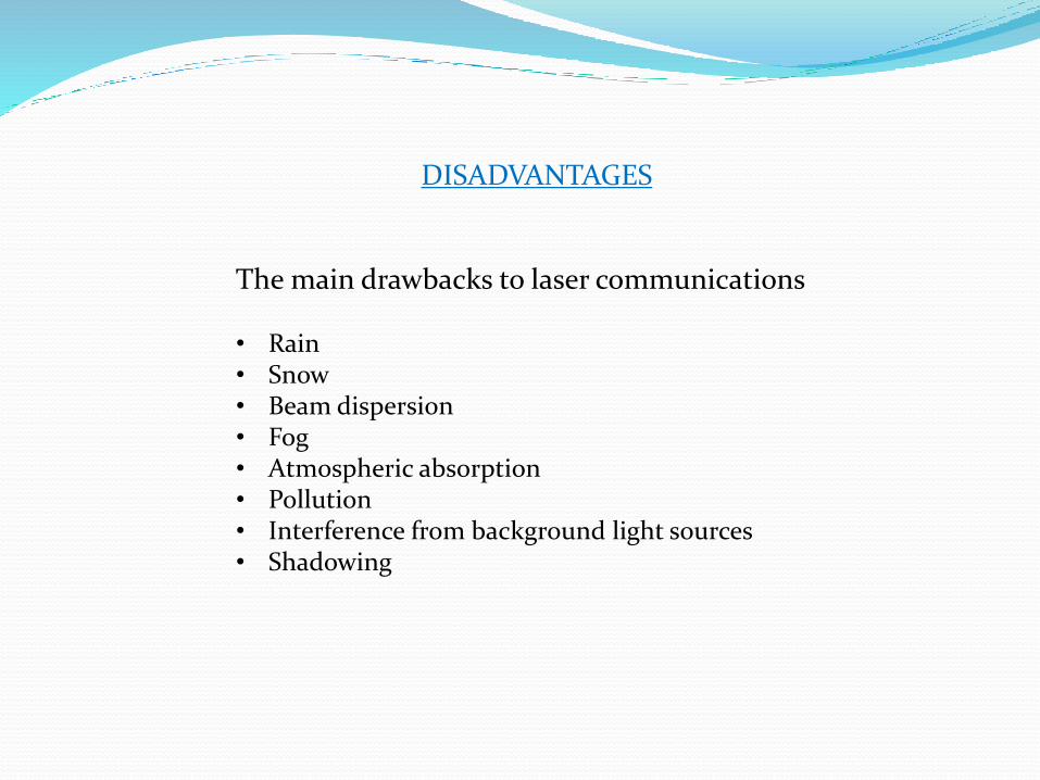
DISADVANTAGES
The main drawbacks to laser communications
• Rain• Snow• Beam dispersion• Fog• Atmospheric absorption• Pollution • Interference from background light sources• Shadowing

GENERATION OF M-SEQUENCES
BY
SAIRAM PONNAM
STUDENT ID:1414690

CONTENTS
INTRODUCTION
LINEAR FEEDBACK SHIFT REGISTER(LFSR)
PROCEDURE
ALGORITHMS USED
RESULTS OBTAINED
MATLAB CODE
CONCLUSION
REFERENCES

INTRODUCTION To write a MATLAB program to find the m-sequences and the number of m-
sequences for a given number of shift register stages N.
Maximal length sequences (m-sequence) are also known as
Pseudorandom Noise (PN) sequences. Maximal length sequences are of great importance in a variety of applications such as Direct Sequence
Spread Spectrum (DSSS), Built-in Self-Test (BIST), Decryption – Encryption
System (DES) and error detection.
The circuit is implemented as follows:
1. The LFSR contains n bits.
2. There are from 1 to (n - 1) XOR gates.
3. The presence or absence of a gate corresponds to the presence or absence of
a term in the generator polynomial (explained subsequently I, P(X), excluding the
Xn term.

LINEAR FEEDBACK SHIFT REGISTER(LFSR)
LFSR is made up of two parts. These parts are a shift register and a
feedback function.
The shift registers, which can store one bit, are D – type Flip-Flops (FFs) that
are connected as a chain. Moreover, each D-FF is also connected to a
clock.
Registers that are involved in the feedback operation are all connected to
the XOR operator.
The sequence of connections which are involved in the XOR operation logic is referred to a sequence of feedback taps.
An LFSR is a special type of Serial-In Serial Out (SISO) shift register that,
when clocked, propagates bits from the least significant to the most
significant bit position through its constituent neighboring registers, one bit every clock cycle.

CONTINUED…. Two equivalent ways of characterizing the PN LFSR are used. We can think
of the generator as implementing a sum of XOR terms:
Bn= A0B0 A1B1 ………………. An-1Bn-1 eqn 1
The above equation is implemented in the figure below:
The above figure is a Binary Linear Feedback Shift Register Sequence Generator.

PROCEDURE The period p of an n-bit LFSR may vary from p = 1 to 2n ‒1. The sequence
having length of 2n -1 is known as maximal length sequence (m-sequence).
Any binary sequence can be represented in a polynomial form. Feedback connection vector of an LFSR can be represented by a polynomial that is
technically referred to as a characteristic polynomial.
Equations (1) define a general form of a characteristic polynomial which
can be denoted as D(x).
D(x) = (c0* x0) + (c1* x1) +(c2* x2) +……………………(cn* xn) Eqn 2
Number of possible generators (NP) and number of possible m-sequence
generators in LFSR are shown in below table.
N NP NPP
31+X3
1+X2+X3
1+ X + X3
1+ X +X2+ X3
1+X2+X3
1+ X +X2+ X3

CONTINUED…. In an n-bit LFSR a sequence generator can be referred to as an m-
sequence generator only if its characteristic polynomial is primitive.
The parameters governing the sequence period of a generator are:
1. The order n,
2. The initial state, and
3. The used characteristic polynomial.
In general, the state equation of a sequence generator is defined by Equation (3).
q(t +1) = [A]* q (t) Eqn 3
The structure of matrix [A] for an n order can be defined in Equation (4).
q1(t+1) c1 c2 cn-1 cn q1(t)
q2(t+1) 1 0 0 0 q2(t)
= Eqn 4
qn-1(t+1) 0 0 0 0 qn-1(t)
qn(t+1) 0 0 0 0 qn(t)

CONTINUED Where,
cj = 0 or 1 for 1<= j<=n-1 Eqn 5
1 for j=n
In Equation (5), the values of cj show the existence or absence of a
feedback connection from the j-th stage of the LFSR. Equation (2) can be
written as:
q (t +1)= [A]q(t) Eqn 6
Let the matrix ‘period’ be the smallest integer p for which [A]p = I, where I is an identity matrix. Then [A]p [q(t)] = [q(t)] for any non-zero initial vector
[q(0)], indicating the ‘cycle length (or period)’ of the LFSR is p. The cycle
length for [q(0)] = 0 is always 1, independent of matrix [A]. Thus, on the
basis of this property of periodicity of LFSR and Equation (6), it follows that:
q(t)]= q (t + p)= [A ]p q(t) Eqn 7

CONTINUED…. Theorem 1: If m is a composite integer, then m has a prime factor not
exceeding the prime integer value of m1/2.
Theorem 2: Let m = p 1a1 p 2
a2 p 3a3………………. p k
ak be the prime (pi) of power (ai) factorization of the positive integer m. Then
Φ (m) = m (1-1/p1) (1-1/p2)…….. (1-1/pk) Eqn 8
Theorem 3: The total number of possible primitive polynomials (NPP) of
order n is given by
NPP = (m)/n Eqn 9

ALGORITHMS USED Algorithm 1: Computing prime factors of p:
Input: n
output: p, prime factors of p (pi), number of prime factors (k), and exponents of each prime factor (ei )
1) Read n and do the following
2) Compute p = 2n -1;
3) Check is p prime or not, if yes GOTO step 8;
4) Find pi;
5) Compute k;
6) Find ei ;
7) Return with p, pi, k and ei
8) Return with p, pi, = p, k = 1, and ei = 1
Algorithm 2: Computing NPP:
Input: n
output: NPP
1) Function: Algorithm1; generates p, k, and ei
2) Use the Equations (8) and (9) to compute NPP
3) Return with NPP

For the order 2 and 3
RESULTS
OBTAINED

For the order 4
CONTINUED…

CONCLUSION
A MATLAB program is written to find the m-sequences and the number
of m-sequences for a given number of shift register stages N. And also
for a given N, all the possible configurations are exhausted and the m-sequence and the number of m-sequences are found. The obtained
results are verified and observed that the results are correct.

REFERENCES Ahmad A, Al-Busaidi S S et al. (2013). Study on cyclic cross correlation
behavior of maximal length pseudo-random binary sequences, Indian Journal of Industrial and Applied Mathematics (Taylor & Francis), vol 4(1), 33–43.
Golomb S W (1982). Shift Register Sequences, Aegean Park Press, Revised Edition.
Chen H W, Aine C J E et al. (1996). Nonlinear analysis of biological systems using short m-sequences and sparse-simulation techniques, Annals of Biomedical Engineering, vol 24, 513–536.
Ahmad A, Al-Musharafi M J et al. (2001). Study and implementation of properties of m-sequences in MATLABSIMULINK – A pass / fail test tool for designs of random generators, Proceedings IEEE / IEE International Conference on Communication, Computer and Power (ICCCP’01), Oman, 191–196.
Ahmad A, and Ruelens D (2013). Development of digital logic design teaching tool using MATLAB & SIMULINK, IEEE Technology and Engineering Education (ITEE), vol 8, No. 1, 7–12.
MATLAB: Available from: http://www.mathworks.com

Energy-Harvesting RFID-Enabled Sensing
by Ayman Qaddumi
CENG 5332

Technology Description
• A miniature sensor module enhanced with processing and communication capabilities without the need for a direct power source.
• The module integrates communication, computation, sensing, actuation, and storage functionalities in passive ultrahigh-frequency (UHF) RFID tags.

ArchitectureRF Power harvesting & Mgmt Section
Digital Section
DC-DC Charge Pump
LDO Voltage regulator
RFID Gen2 Chip
MCU
Sensor 2
Sensor 3
Sensor 1
RF Section
10-bit ADC
Sensor power
Storage Cap.
Rectifier
50-ohm antenna
L
C
I2C Bus
UHF
RFID
DIPOLE
ANTENNA

Technology Components Sensors
• A sensor or a collection of sensors to detect and quantify any number of environmental parameters such as motion, proximity, temperature, pressure, pH, light, strain, vibration, and many others.

Technology Components Energy/Power
• An energy harvesting transducer that converts some form of ambient energy to electricity. Ideally, the system shall be compatible with piezoelectric, solar, RF field, and thermoelectric harvesters.
• An Energy Processor to collect, store and deliver electrical energy to the electronic or electro-mechanical devices resident at the sensor node. The module will produce rectified DC voltages from ambient sources with high enough power levels enabling RFID-based sensor data transmission up to 50 feet.

Technology Components Microprocessor
• A micro-controller and a serially-addressable RFID chip to receive the signal from the sensor, convert it into a useful form for analysis, and communicate with the radio link.

Technology Components COMM
• A RF link at the sensor node to transmit the information from the processor on a continuous, periodic, or event-driven basis to a RFID reader.

FREE VOLTAn implication of Radio Frequency energy harvesting

Introduction
• Radio Frequencies have energy, which can be captured.
• Eventually every thing will be wireless and be using RF frequencies.
• This energy, if captured, stored and amplified, can be used for powering up low energy devices.
• Free volt – a credit card sized device that can do this.
• First of its kind.
• Developed by Drayson Technologies.
• Free volt uses ambient power – the unused frequencies in the spectrum.

Design and Working
• Three parts:• Multi band Antenna – wide spectrum, wide angle and efficient.
• High Efficiency Rectifier – to convert AC to DC, efficiently
• Optimized Power Management Module – captures the energy, stores and amplifies it.
• Cleanspace ™ Tag:
• Developed by Drayson technologies uses Freevolt to measure the quality of the air we breathe.
• The tag measures the air and sends data to Smartphones via Bluetooth.
• The data can be uploaded to Internet and can be made useful to others.
-The Clean Space ™ tag and smartphone connected to it.

Advantages
• Most important application – Freevolt can power up Internet of Things (IoT), such as fitness bands, door locks, garage openers, digital pens, wearable gadgets, and a lot.
• Scalable, can be improved to power high energy devices in the future by placing an array of Freevolts – like a solar panel.
• Unlike solar panels, these can be placed inside buildings.
• Low space utilization.
• Environment friendly, clean and green.
• Economic.

Conclusion
• Freevolt powered sensors and monitors can be implemented in sensitive environments to gather real time data and can be made available to the common public ( air quality sensors, weather and natural calamity monitors.)
• In the future, Freevolts can provide clean energy for electronic advertisement boards, Wireless Sensor Networks, traffic lights, LED displays of smartphones and tabletsetc.
• They can reduce the amount of electric waste that is being generated.
• They can provide a boost to the growing market of Internet of Things and wearable computing.

By : Khaja Mohiddin Shaik
Section #2
(1496037)
Near field communication (NFC)

• Near Field Communication is a short range high frequency communication technology.
• A radio communication is established between devices by keeping them in a proximity of few centimeters.
• NFC is mainly aimed for mobile or handheld devices.
• Allows communication between.
▫ Two powered (active) devices.
▫ Powered and non self-powered (passive) devices.
What is NFC ?

• Near field communication (NFC) traces its roots back to radio-frequency identification (RFID).
• In 2004, Nokia, Sony, and Philips came together to form the NFC Forum.
• The first NFC-comptabile cell phone, the Nokia 6131 was released in 2006.
• The first android NFC phone, Samsung Nexus S was released in 2010.
History

• NFC is based on Radio Frequency Identification (RFID) technology.
• The technology works via magnetic field induction technology and operates on an radio frequency ISM band.
• NFC operates at 13.56 MHz.
• Working distance: up to 10 cm.
• Supported data rates : 106 kbits/s, 212 kbits/s & 424 kbit/s.
• NFC standard communication protocols and data exchange formats are based on existing RFID standards
including ISO/IEC 14443 and FeliCa.
How NFC works ?

• In Active mode, both devices with NFC chip generates
an electromagnetic field and exchange data.
• In Passive mode, there is only one active device and the
other uses that field to exchange information.
Modes of operation
Modes of operation
Active Mode Passive Mode

Wide reach and Availability
Can be used in various situations
Very easy to use
Value added services
Compatible with existing RFID infrastructure
Why NFC ?

Applications of NFC

Limitations :
• The system has a limitation that devices can communicate only under a short range i.e << 20 cm.
• The data transfer rate is very less about 106 kbit/s to 424 kbits/s.
Conclusion:
• In near future NFC will be commonplace in everyday life. The possibilities are endless for NFC.
NFC - Future of Wireless Communication
Limitations & Conclusion
Thank You

Terahertz Radiation
Use of frequencies above Microwave
Khushboo Sharma
1499156
Section #2

Terahertz means trillion cycles per second. Terahertz radiation is something
considered a subset of infrared radiation. i.e., terahertz waves lies between
long-wavelength of infrared and short wavelength of microwave radiation.
Terahertz Spectrum

Biomedical imaging and spectroscopy: Dermatology, Dentistry, Pharmacology
Homeland Security:
Concealed explosives, drugs, biological agents
Astronomy
Current and future instruments
Wireless Communication
Environmental monitoring
Trace gas sensing
Condensed matter physics
Semiconductors, Superconductors, Magnetic materials
Why might one study terahertz radiation ?

Terahertz waves can penetrate through materials opaque to other parts of
the EM spectrum.
Due to its comparatively low photon energy (4 meV at 1 THz), THz radiation
does not initiate any changes in chemical structure, as opposed to UV
radiation or X-rays.
In the same way that visible light can create a photograph, radio waves can
transmit sound and X-rays can view within the body, terahertz waves can
create images and transmit information.
Characteristics properties of THz radiation are high penetration depths and
low scattering combined with good spatial resolution. Resolution of THz wave
is 1 mm.
Properties
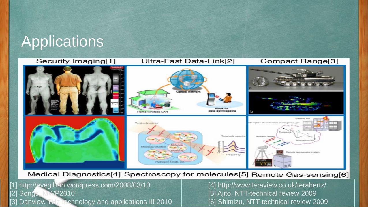
Applications
[1] http://eyegillian.wordpress.com/2008/03/10
[2] Songs, MWP2010
[3] Danvlov. THz technology and applications III 2010
[4] http://www.teraview.co.uk/terahertz/
[5] Ajito, NTT-technical review 2009
[6] Shimizu, NTT-technical review 2009

Radiation penetrates many common barrier material enabling concealed
objects to be seen.
Radiation at these frequencies is non-ionizing and, at modest intensities,
safe to use on people.
Wavelengths are short enough to give adequate spatial resolution for
imaging or localization of threat objects.
Applications

Current wireless systems utilizes carrier waves less than 5 GHz which
restricts their maximum data rate, 100 Mbits/s typically.
Higher frequency carriers enables high data rates and therefore 1000 Gbits/s
data rates are on offer with terahertz carrier waves.
In May 2012, a team of researchers from the Tokyo Institute of
Technology published in Electronics Letters that it had set a new record
for wireless data transmission by using T-rays. The researchers sent a signal
at 542 GHz, resulting in a data transfer rate of 3 Gigabits per second.
THz in Communication

Performance Analysis and Modeling of Soft Handoff Schemes in CDMA Cellular Systems
.
Presented By :DAKSHINYA SURANENI (ID: 1461366) Section 2

ABSTRACTThe main idea of this project is to investigate the features of a cellular geometry in code-division multiple-access (CDMA) systems with soft handoff and distinguishes controlling area of a cell from coverage area of a cell. Then to construct a continuous-time Markov chain (CTMC) model for CAC in CDMA with a soft handoff queue, and obtaining closed-form solutions, and thus develops loss formulas as performance indices such as the new blocking probability and the handoff dropping probability. As an application of the loss formulas, the modeling techniques are used to evaluate and compare the performance of conventional and proposed EPHC soft handoff schemes.

CELLULAR GEOMETRY AND PARAMETER ESTIMATION FOR SOFT HANDOFF
1. Soft Handoff in CDMA Cellular Systems
The soft handoff area is mainly controlled by the
handoff thresholds, such as TADD and TDROP,
broadcast by the serving BS. The ratio β of the
handoff area to the entire cell area is defined as

2. Relative Mobility Estimation of MSs in Handoff Area
Let ps(t, i) be the received pilot strength from the serving BS measured at time t by MS i and cr_ps(t, i) be the rate of change of ps(t, i) given by
where ∆t is the time period of information update in the cellular system.

The structure of the overall algorithm for relative mobility estimation that an MSC would execute in a CDMA system is as follows.
Step 1: Identify the position of handoff calls (with two or more channels in the Active Set)
Step 2: Evaluate the mobility of handoff calls
3. Eliminating Pseudo Handoff Calls (EPHC) Soft Handoff Scheme

ANALYTIC MODEL• Markov Chain Model for Soft Handoff With a Handoff Queue
• Performance Indices
1) Blocking Probability
2) Handoff Dropping Probability
• Fixed-Point Iteration

• Computational Aspects and Optimization Problems

EPHC handoff scheme is significant because the EPHC scheme distinguishes pseudo handoff calls from real handoff calls and serves more handoff calls.
As a numerical example of the optimization problem, we take N = 24, A = 20, A1 = 0.3, µl = 0.024, µ = 0.04, β = 0.3, and le = 4. We consider a system with parameters N = 24, g = 2, β = 0.3, λn = 0.01, µc = 0.01, µl = 0.024, µdc = (Tdc)−1 = 0.03, and le = 4 and the results are obtained as below.

CONCLUSION
• A new view of cellular geometry in the CDMA system and a relative mobility algorithm for soft handoff are proposed. Based on relative mobility estimation, a new soft handoff scheme (EPHC), which increases system channel utilization and decreases handoff dropping probability, is presented. Numerical results show that the developed loss formulas are effective, and the EPHC handoff scheme outperforms the conventional handoff scheme with respect to both the new call blocking probability and the handoff dropping probability.

Asynchronous Transfer Mode
(ATM)
Hemanth Reddy Suri
1490806
section- 02

ATM
ATM ( Asynchronous Transfer Mode) has beenadvocated as an important technology for thewide area interconnection of heterogeneousnetworks.
In ATM networks, the data is divided into small, fixed length units called cells. The cell is 53 bytes.
ATM switches support two kinds of interfaces: User Network Interface (UNI) and Network Node Interface (NNI).

ATM
ATM is intended as a universal networking technology that handles voice, video, and data transmission.
ATM uses a connection-oriented paradigm in which an application first creates a virtual channel (VC), uses the channel for communication, and then terminates it.
The communication is implemented by one or more ATM switches, each places an entry for the VC in its forwarding table.

Goal of ATM (extremely ambitious)
Universal Service
Support for all users
Single, unified infrastructure
Service guarantees
Support for low-cost Devices

Wireless ATM Protocol Architecture

Reasons for Wireless ATM
ATM is considered to reduce the complexity of thenetwork and improve the flexibility.
There are several factors that tend to favor the use ofATM cell transport for a personal communicationnetwork:
Flexible bandwidth allocation and service type selectionfor a range of applications.
Efficient multiplexing of traffic from burstydata/multimedia sources.
End-to-end provisioning of broadband services overwireless and wired networks.
Suitability of available ATM switching equipment forintercell switching.

Disadvantages of ATM
Expense: ATM technology provides a
comprehensive lists of services, even a moderate
ATM switch costs much more than inexpensive
LAN hardware..
Connection Setup Latency: ATM’s
connection-oriented paradigm introduces
significant delay for distant communication. The
time required to set up and tear down the ATM
VC for distant communication is significantly
larger than the time required to use it.

Disadvantages of ATM
Cell Tax: ATM cell headers impose a 10% tax
on all data transfer. In case of Ethernet, cell tax
is 1%.
Lack of Efficient Broadcast: Connection-
oriented networks like ATM are sometimes
called Non Broadcast Multiple Access (NBMA)
networks because the hardware does not support
broadcast or multicast. On an ATM network,
broadcast to a set of computers is ‘simulated’ by
arranging for an application program to pass a
copy of the data to each computer in the set.

Troubleshooting
Performing Basic Interface Checks.
Determining Network Connectivity.
Performing Loopback Tests.
Troubleshooting 155-Mbps and 622-Mbps
Interfaces.
Troubleshooting T1 and E1 Interfaces.
Troubleshooting DS3 and E3 Interfaces.
Troubleshooting CBR T1 and CBR E1
Interfaces.
Troubleshooting 25-Mbps Interfaces.

REFERENCES
D.Raychaudhuri and D. Wilson, "ATM-Based Transport
Architecture for Multiservices Wireless Personal
Communication Networks ", IEEE Journal On Selected
Areas In Communications, vol 12, No 8, Oct. 1994, pp
1401 - 1413.
U. Black, " ATM: Foundation for Broadband Networks
", Prentice Hall 1995.
www.compnetworking.about.com/od/networkprotocols/
g/bldef_atm.htm
P. Wong and D. Britland, " Mobile Data
Communication ", Artech House, 1993.

Orthogonal Frequency Division Multiplexing
(OFDM)
Adithya Teega
1495874
Section 2

Introduction
OFDM is a broadband multicarrier modulation method that offers superior
performance and benefits over older, more traditional single-carrier
modulation methods. It is a better fit with today’s high-speed data
requirements.
A large number of closely spaced orthogonal sub-carrier signals are used
to carry data on several parallel data streams or channels.
OFDM has been adopted in the Wi-Fi arena where the standards like
802.11a, 802.11n, 802.11ac and more. It has also been chosen for the
cellular telecommunications standard LTE / LTE-A, and has also been
adopted for a number of broadcast standards from DAB Digital Radio to
the Digital Video Broadcast standards, DVB.
It is a modulation format that is being used for many of the latest wireless
and telecommunications standards.

Main Feature
Spectrum Efficiency
Unlike FDM the carriers in OFDM overlap with each other and use the spectrum
efficiently.
There will not be any interference even though the carriers overlap as the
carriers are orthogonal to each other.

We can see from the figure that when a carrier is in its peak, the
overlapping carrier is at null so there will be no interference. This is
called orthogonality and is achieved if carrier spacing is equal to the
reciprocal of symbol duration.
f = k/T Hertz; where T seconds is the symbol duration, and k is a
positive integer, typically equal to 1.

OFDM variants
COFDM: Coded Orthogonal frequency division multiplexing.
Flash OFDM: Flash OFDM.
OFDMA: Orthogonal frequency division multiple access.
VOFDM: Vector OFDM.
WOFDM: Wideband OFDM.
Each of these forms of OFDM utilize the same basic concept of using closely
spaced orthogonal carriers.

Advantages
Makes efficient use of the spectrum by allowing overlap.
Can easily adapt to severe channel conditions without complex time-
domain equalization.
Robust against narrow-band co-channel interference
Eliminates ISI and IFI through use of a cyclic prefix
Efficient implementation using fast Fourier transform (FFT)
Low sensitivity to time synchronization errors
Tuned sub-channel receiver filters are not required (unlike
conventional FDM)

CONCLUSION
We can conclude that using OFDM we can efficiently use the transmission
spectrum and achieve high data transmission rates.

Adaptive Spectrum Selection for Cognitive Radio Network
CENG 5332section 2
Presented by: Thorrur, siva kumar

Increased user demand
• The ISM band is a host of many different wirelesstechnologies.
– WiFi
– Bluetooth
– Wimax
• The number of devices that function at the ISM band isconstantly growing.
– Interference between these devices is growing as well.
– This means degradation of performance.

Under utilization of licensed spectrum
• Licensed portions of the spectrum are underutilized.
– According to FCC, only 5% of the spectrum from 30 MHz to 30GHz is used in the US.
Cognitive radios
• Intelligent devices that can coexist with licensed userswithout affecting their quality of service.
– Licensed users have higher priority and are called primary users.
– Cognitive radios access the spectrum in an opportunistic wayand are called secondary users.
• Networks of cognitive radios could function at licensedportions of the spectrum.
– Demand to access the ISM bands could be reduced.

Performance optimization
• Proposed protocols in the literature define anoptimization problem.– The utility function depends on the performance metrics.
• Parameters of the problem are chosen from the followingset:– Channel allocation
– Adaptive modulation
– Interference cancellation
– Power control
– Beam forming

Definition of the problem

OFDM modulation
• The bit stream is divided into N parallel subflows.
• The symbols of each subflow are modulated using MPSK or MQAM.
• Resulting complex numbers are fed to a module that performs FFT-1.
• Finally the signal is converted from digital to analog, brought to the RF frequencies and then fed to the antenna of the transmitter.

OFDM Demodulation
• At the receiver the inverse procedure is followed.
• First the signal is brought down to baseband and isconverted from analog to digital. Then FFT is performedwhich produces the estimations of the transmittedsymbols.

NC OFDM
• NC OFDM (non contiguous OFDM) is exactly the same asOFDM with the following deference:
– Bins that are not allocated to a particular device aredeactivated.

NC OFDM receiver
• At the NC OFDM receiver the reverse process is followedin order to extract the transmitted symbols.

Adaptive modulation
• Consider that a pair of nodes communicate using achannel of width B and transmission power equal to P.
• According to Shannon the capacity of the channel is:
• Where γ denotes the value of SNR at the receiver.
)1log( BC

Hardware limitations
• If the transmitter was able to change it’s rate in acontinuous manner then throughput would be close tocapacity.
• Due to hardware limitations the transmitter has tochoose among a limited number of modulation schemes.
– The transmission rate could also take a finite number ofdifferent values.

References
• Interference cancellation:
– Popovski, P. and Yomo, H. and Nishimori, K. and Di Taranto,R. and Prasad, R., “Opportunistic Interference Cancellationin Cognitive Radio Systems,” IEEE International Symposiumon New Frontiers in DynamicSpectrum Access Networks,pp. 472–475, April 2007.
• Adaptive modulation:
– A. J. Goldsmith and S. Chua, “Variable-rate variable-powerMQAM for fading channels,” IEEE Trans. Commun., vol. 45,pp. 1218–1230, Oct. 1997.

Driverless Automobiles using Li-fi
Cooperative Control Systems
Submitted byV.L.Sri Venkatesh
1502368Section-2

❖ LiFi is transmission of data through illumination.
❖ Data is encoded in light by varying the rate at which the LEDs flicker on and off to give different strings of 1s and 0s.
❖ The LED intensity is modulated so rapidly that human eye cannot notice.
❖ Using mixtures of red, green and blue LEDs to alter the light’s frequency with promise a theoretical speed of 10 Gbps.
What is Li-Fi?

Driverless Automobiles
❖ Present driverless cars are equipped with GPS, Radar, Video camera,LASER and Ultrasonic sensors to map the environment around them.
❖ The computer onboard processes this data and steers and stops the automobile.
❖ Each automobile is autonomous and has much less time to react to a problem which can be solved by car to car communication.
❖ But Wireless communication using Radio waves cannot satisfy the need as its speed is much less than required.

Car to Car communication with Li-Fi
❖ LEDs used in the head and Tail lamps of vehicle can be replaced by special LEDs which can transmit and recieve Traffic Data.
❖ Traffic Lights can communicate directly to car.
❖ Street lamps can be replaced by sign boards to relay speed limit of that region and closed lanes for construction.
❖ No more unexpected maneuvers resulting in accidents.
❖ Vehicle blocking Line of Sight for another vehicle will no longer be a problem.

Conclusion:
Since the technology is in its primitive stage, further development is required in integration and developing algorithms once achieved will result in long awaited dream of Accident-Free Roads.
THANK YOU