UNCLASSIFIED AD NUMBER LIMITATION CHANGES TO
202
UNCLASSIFIED AD NUMBER LIMITATION CHANGES TO: FROM: AUTHORITY THIS PAGE IS UNCLASSIFIED ADB072071 Approved for public release; distribution is unlimited. Distribution authorized to U.S. Gov't. agencies only; Test and Evaluation; NOV 1982. Other requests shall be referred to Air Force Rocket Propulsion Laboratory, (STINFO/TSPR), Edwards AFB, CA 93523. Export Control. afrpl ltr, 24 oct 1984
-
Upload
khangminh22 -
Category
Documents
-
view
0 -
download
0
Transcript of UNCLASSIFIED AD NUMBER LIMITATION CHANGES TO

UNCLASSIFIED
AD NUMBER
LIMITATION CHANGESTO:
FROM:
AUTHORITY
THIS PAGE IS UNCLASSIFIED
ADB072071
Approved for public release; distribution isunlimited.
Distribution authorized to U.S. Gov't. agenciesonly; Test and Evaluation; NOV 1982. Otherrequests shall be referred to Air Force RocketPropulsion Laboratory, (STINFO/TSPR), EdwardsAFB, CA 93523. Export Control.
afrpl ltr, 24 oct 1984

i.". ■,"«.■'J,'. *.';■■ "■ .*<■+ ,i ■. '■■LH'I ■ i . ■ | ■ % ■■■■_■ ii, . ■ » »■-»■ -.*" »»- ^" *
AFRPL TR-82-072 AD:
Final Report Solid Propellent Reclamation Study
' Jovember 1982
>
D
J J
Authors: M. P. Coover L. W. Poulter
Thiokol Corporation Wasatch Division P. O. Box 524 Brigham City, Utah 84202
TWR-31084 V-\'.1
Subject to Export Control Laws
This document contains information tor manufacturing or using munitions of war Exporting this information or releasing it to foreign nationals living m tho United States without first obtaining an export license violates the International Traffic in Arms Regulations Under 22 USC 2778. sucn a violation is punishable by up to 2 years m prison and by a fine of $100 000 Distribution limited to US Government agencies only Test and Evaluation. November 1982 Other requests for this document must be relerrad to AFRPL TSPR (Stop 24). Edwards AKB. CA 93523
uric Prepaied for the: Air Force
Rocket Propulsion Laboratory
(v..-,« j \ y
An Force Spac.9 recnnology Center Space Division, An Force Systems Command Edwards Air force Base, California 93523
jlane
BS1

• «.' »."-«-■•.- --" r. -. •^.^■-■wwu;«-.-»..*-^---:.
3B FOREWORD
This report was submitted by Thiokol Corporation/Wasatch Division, Brigham City, Utah 84302 under Contract F04611-81-C-0051, Job Order No. G-2889 with the Air Force Rocket Propulsion Laboratory, Edwards AFB, CA 93523.
The Final Report is approved for release and distribution in accordance with the distribution statement on the cover and on the DD Form 2463.
ACKNOWLEDGEMENT
t--:
I.-'-.
The Authors are grateful for the contributions made by JOHN ASSOCIATES, INC, P.O. Box 145, Berkeley Heights, N.J. 07922, who
inical Consultant on this program.
BROWN served as
Beatrice Deak, 2d Project Manager
USAF Forrest S. Forbes Propel 1 ant Systems Section
»
FOR THE DI RECTO
ifcw«. A Eutfene G.Habehnan Ch|lef, Liquid Rocket Division
lv
NOTICE
When U.S. Government drawings, specifications, or other data are used for any purpose other than a definitely related Government procurement opera- tion, the fact that the Government may have formulated, furnished, or in any way supplied the said drawings, specifications, or other data, is not to be regarded by implication or otherwise, or in any manner licensing the holder or any other person or corporation, or conveying any rights or permis-.on to manufacture, use, or sell any patented invention that may be related thereto.
•
NOTICE
THIS REPORT HAS BEEN DELIMITED AND CLEARED FOR PUBLIC RELEASE
UNDER DOD DIRECTIVE 5200.20. NO RESTRICTIONS ARE IMPOSED
UPON USE AND DISCLOSURE.
DISTRIBUTION STATEMENT A
APPROVED FOR PUBLIC RELEASE,
DISTRIBUTION UNLIMITED

SECURITY CLASSIFICATION OF TNII RAOt (Whmt Dim
1
1 •
!
1
■i
i
REPORT DOCUMENTATION PAGE I. WP-ORT1 NUMHR """"
AFRPL-TR-82-072 1. OOVT ACCESSION NO 1. RECIPIENT'S CATALOO NUMBER
»• TITLE <mtt4 SuMllla)
Solid Propellant Reclamation Study
7. AUTMOftC*)
M. P. Coover L. W. Poulter
r RERFORMINO OROANIZ ATlON NAMI ANO ADDRESS
Thiokol/Wasatch Division P. 0. Box 524 Brigham City, Utah 84302
II. CONTROLLING OFFICE NAME ANO ADDRESS
Air Force Rocket Propulsion Laborafcery/LKCP Edwards AFB, California 93523
IX MOMiToNlNO AOCNCY NAME I ADDRESS/" 4lltmrm>l In
AFPRO, Thlokol Corp. Wasatch Division P. 0. Box 524 Brigham City, Utah 84302
I». DISTRIBUTION STATEMENT (ml Ihl, SESSSJ
I Cantrollln« Olllcm)
READ INSTRUCTIONS F EFORE COMPLETING FORM
I. TYRE OF REPORT A PERIOD COVERED
Final Technical Report 15 Sept 1981-31 July 1982
RERFORMINO ORO. R
TWR-31084 iT ORT NUMM'4
». CONTRACT OR ORAHT NUMEEMfa)
P04611-81-C-0051
"TC PROORAM ELEMENT. PROJECT TASK AREA A WORK UNIT NUMBERS
6-2829
U. REPORT OATB
November 1982 It. NUMBER «f RAOES
196 IS, SECURITY CLASS. (ml tfll« report)
Unclassified IS«. OECLAtflFICATION/OOWNORAOINa
SCNEOULE
Distribution limited to U.S. Government agencies only; test and evaluation, Nov 1982. Other requests for this document must be referred to AFRPL (STINFO/TSPR), Edwards AFB, CA 9J523
IT. DISTRIBUTION STATEMENT (ml in. «Batracl rntumn* In t>Uck It. II mllmrmnt |M Rmpot;)
Approved for public release; distribution unlimited.
10. SUPPLEMENTARY NOTES
IS. KEY WORDS (Cmntlnum an r*nm •!•% II n—mmmmn mn* l*mnillr by Mac* mllir)
oolid Propellant, Disposal, Ingredient Recovery, Reclamation, Incineration
* ABSTRACT (Cmntlnum mn ••»•*•• .1*. II McuMir mn* immnilty my »!•«« nvmmt)
Alternate methods for the disposal of solid propellants were identified and evaluated, including laboratory tests. The methods included (a) alternate use or application, (b) reclamation of major ingredients, and (c) incinera- tion. A pilot plant design was provided and an economic analysis of alternate disposal methods conducted.
DO,: r2Tn 1473 A A
EDITION OF I MOV SS IS OBSOLETE
SECURITY CLASSIFICATION OF TNlS »AOt fS»»R Cum SM««I|

CONTENTS
Page
SUMMARY 8
1.0 INTRODUCTION 10
L.l Background 10 1.2 Objective 11 1.3 Scope 11
2.0 TECHNICAL DISCUSSION 12
2.1 Review of Nonincineracion Disposal Methods 12 2.1.1 Descriptive Summary of Existing Disposal Methods 12 2.1.1.1 McBride, William R. and Thun, Wayne E.. . 12 2.1.1.2 Mclntosh, M. J. et al 20
1.3 Sinclair, J. E. et al 27 1.4 Tomna, A. S 28 1.5 Tompa, A. S., French, D. M 32 1.6 Williams, Carver, and Huskins 45 2 Unique and/or Original Concepts 46 2.1 Explosive Booster 48 2.2 Selective Solvent Extraction Process 50 3 Laboratory Experiments 57 4 Evaluation of Available Reclamation Technology 60
Bench Scale Demonstration of Selected Disposal Method«, . 49 Conversion of Class 1.1 Propellant to an Explosive Booster 68 Selective Solvent Extraction Process 81
1 Review of Conventional Extraction Technology 81 2 Nitrate Ester Extraction Process 85 3 Nitramine/Inorganic Oxidizer Extraction Process 96 4 Process Definition 103 5 Process Model 108
Pilot Plant Design 118 Explosive Booster 118 Selective Solvent Extraction Process 121 Incineration 125 APE-1236 Deactivation Furnace 127 Radford Rotary Furnace 129 Fluidized Bed Incinerator 132 Miscellaneous Incinerators 134 Environmental Impact 154 Economic Analysis 161 Introduction 161 Estimation of Costs for the Explosive Booster Process . . 163 Estimation of Costs for the Selective Solvent Extraction. 171 Estimation of Incineration Costs 182 Comparison of the Cost Estimations of Methods of High Energy Waste Disposal 186 Conclusions 186 Recommendations 190
.1
.1
.1
.1
.1
.1 ,1 .1.3
2.1.4 2.2 2.2.1 2.2.2 2.2.2 .2.2 ,2.2 .2.2 .2.2
2.3 2.3.1 2.3.2 2.4 2.4.1 2.4.2 2.4.3 2.4.4 2.4.5 2.5 2.5 2.5 2.5 2.5 2.5
2.6 2.7
.1
.2
.3
.4
.5
a
CONTENTS (CONT)
Page
BIBLIOGRAPHY 192
GLOSSARY 195
LIST OF ABBREVIATIONS, ACRONYMS, AND SYMBOLS . 196
S
3
Access!^ T>r
l-NTTS OK-.h\

ILLUSTRATIONS
Figure
1
2
3
4
5
6
8
9
10
11
12
13
14
15
16
17
18
19
20
21
22
23
24
25
26
Process Flow Chart
Waste Propellanc Disposal Methods
Separation Scheme for Crosslinked Double Base Propellant . . . .
Propellant Reclamation Process, 100 Ton/Yr Plant for Extraction of Nitroguanidine and Ammonium Perchlorate ■ . . . .
Solubility of AP and NQ in Water and in HC1
Page
. 18
. 22
30
Separation Schema for Tartar Booster and Standard Missile Booster
Separation Scheme for Sidewinder 1C, Using Toluene-Propanol and Ethanol Amine (EA)
NHC Recovery Process Flow Diagram
Explosive Booster Process Flow' Sheet
Sol-Gel Extraction from Solid Propellant Chemical Structural Aging Program
Selective Solvent Extraction Ingredient Recovery Process . .
Results of Solvolysis Test
Ternary Solubility Diagram ....
Effect of Temperature on Impact Sensitivity of Explosive Booster Formulations
Effect of Temperature on Friction Sensitivity of Explosive Booster Formulations
Effect of Temperature on Electrostatic Sensitivity of Explosive Booster Formulations
Effect of Temperature on the Safe Life of a Typical High Energy Propellant
Explosive Booster Initiated with Blasting Cap
Explosive Booster Initiated with Primacord
Witness Plate after Explosive Booster Test
Candidate Leaching Processes
Effect of Chip Size and Solute to Solvent Ratio on the Extraction Rate of 1IG from NEPE-HMX-AP-A1 Propellant .
Effect of Temperature on the Extraction Rate of NG from NEPE-
HMX-AP-A1 Propellant
Equilibrium Concentrations for Extract and Residue Phases . .
Equilibrium Diagram for Extraction of NG from NEPE-HMX-AP-A1 Propellant
Multistage Cocurrent Extraction of NG from NEPE-HMX-AP-A1 . .
3
35
36
41
44
47
49
51
53
58
63
71
72
73
74
77
78
79
82
89
90
91
94
9b

Figure
27
28
29
30
31
32
33
34
35
36
37
38
39
40
41
42
43
44
45
46
47
48
49
50
51
52
ILLUSTRATIONS (CONT)
Extraction Rate of AP and HMX from Residue at Different Stages of Total Solute Removal ....
Equilibrium Diagram for HMX-AP Extraction
Extraction of HMX-AP from NEPE-HMX-AP-A1 Propellant Residue with Acetone .....
Equilibrium Diagram Contact Stage Construction for HMX-AP Extraction
Selective Solvent Extraction Process
Multistage Cocurrent Extraction of NG from NEPE-HMX-AP-Al Propellant
Material Flow in Ingredient Recovery Process
Batch-Continuous Contact Extraction of HMX-AP from NEPE-HMX-AP- Al Propellant
Batch-Continuous Contact Extraction of HMX-AP from NEPE-HMX-AP- Al Propellant with Acetone
PröVessTlöv~C^älftTförnSpl.bsive Booster manufacture
Pilot Plant Design - Selective Solvent Extraction
APE 1236 Deactivation Furnace with Air Pollution Control System Kit E010
Rotary Kiln Incinerator System
Fluidlzed Bed Incinerator
Air Curtain Incinerator
Closed Pit, Batch-Type Incinerator Concept (Side View)
Batch Box Incinerator
Wet-air Oxidation (Zimpro) Process
Vortex Incinerator
Molten Salt Incinerator (Schematic)
Vertical Induced Draft Incinerator
Costs of Explosive Booster Manufacture Using Waste High Energy Propellant
Effect of Capital Cost on the Unit Cost of Explosive Booster Manufacture Using Waste High Energy Propellant
Effect of Reduced Booster Sale Value on the Cost of Booster Manufacture Using Waste High Energy Propellant
Pilot Plant Design - Selective Solvent Extraction
Estimate o;: Labor Requirements for Ingredient Recovery Pilot Plant
Page
100
102
104
105
107
110
111
113
114
120
123
128
131
133
136
141
144
147
151
152
155
168
169
170
173
179

ILLUSTRATIONS fCONT)
Figure Page
53 Cost of Baseline Ingredient Reclamation Plant as a Function of Plant Capacity 181
54 Effect of Capital Costs on the Unit Ost of Ingredient Reclamation from High Energy Prcpellant 183
55 Effect of Labor Costs on the Unit Cost of Ingredient Reclamation from High Energy Propellant 184
56 Effect of By-product Credit Reduction on the Unit Cost of Ingredient Reclamation from High Energy Propellant 185
57 Costs of Incinerating Explosive Materials in Fluldized Bed and Rotary Kiln Incinerators 188
58 Comparison of the Costs of High Energy Propellant Waste Treatment by Incineration, Explosive Booster Manufacture, and Ingredient Reclamation 189
—Si ■ I II » MSMH

Table
1
2
3
4
5
6
7
8
9
10
11
12
13
14
15
16
17
13
19
20
21
22
23
22
25
26
TABLES
Page
Bibliogr,- jhy of Disposal Methods 13
Summary of Disposal Methods 15
Materials Vuv.C for Laboratory Testing 27
Propeilants Investigated and Ingredient Recovery Techniques Proposed 33
Eff Lcitr.cy of Aqueous Extraction of AP and NQ 38
Solubilities of Selected Minimum Smoke Propellant Constituents as Determined with Sol-Gel Extraction Techniques 54
Solvent Evaluation 59
Ternary Solubility Data - HMX, AP, Acetone ..... 61
Ternary Solubility Data - HMX, AP, DMSO 62
Ignition Sensitivity of Intermediate Products - NEPE-HMX-AP-Al Propellant 64
Process Evaluation Criteria 66
Process Evaluation 67
Ignition Sensitivity Data for Candidate Explosive Booster Materials 70
Detonation Sensitivity of Explosive Booster Class 1.1 Propellant 75
Detonation Characterization of Explosive Booster Class 1.1 Propellant 76
Selective Solvent Evaluation for Nitrate Ester for Binder Sol Extraction 86
NG/Stabilizer Extraction Rate with Methylene Chloride .... 88
Equilibrium Data for Extraction of NG with Methylene Chloride 93
Selective Solvent Evaluation for Nitramlne/Oxidizer Extraction 97
HMX/AP Extraction Rate with Acetone 99
Equilibrium Data for Extraction of HMX-AP with Acetone NEPE-HMX AP-A1 Propellant 101
Selective Solvent Extraction Process Definition 106
Cocurrenl extraction of Nitrate Ester from NEPE-HMX-AP-Al Propellant 109
Bat;h-Continuous Contact Extraction of Nitramine and Inorganic Oxidizer from NEPE-HMX-AP-Al Propellant H2
Reclaimed Product Analysis 116
Ignition Sensitivity Summary 117
6

TABLES (CONT)
27
28
29
30
31
32
33
34
35
36
37
38
39
40
41
42
43
Explosiv« Booster Manufacture Equipment List 122
Equipment List for 20,000 lb Propellant/Yr Ingedient Recovery Pilot Plant 226
Typical Materials and Percentage Destruction by WAO 148
Federal Air Emission Standards for Incinerators 154
Stage and Regional Limitations on Thermal Disposal of Waste
Munitions , . . 156
Emission Design Goals 158
Pollution Control Summary . . . . 159
Demonstrated Incineration Performance 160
Preliminary Economic Analysis Activities 162
Estimation of Plant Investment Costs for Manufacture of Explosive Boosters . -
Estimation of Product Cost for Utilization of Waste Propellent To Manufacture Explosive Boosters
Material Balance Calculation Results for the Prcpellant Ingredient Recovery Process
Estimation of Major Equipment Cost
Summary of Major Equipment Costs
Estimation of Plant Investment Costs 177
Estimation of Product Cost 178
Baseline Incinerator Costs 187

SUMMARY
Three general methods for the disposal of waste Class 1.1 solid propel-
lanta were evaluated as economically and environmentally acceptable alterna-
tives to open pit burning:
a. Alternate use or application
b. Ingredient reclamation
c. Incineration
The alternate use evaluated was conversion of the waste propellant to an
explosive booster for use in mining, construction, and other industrial
applications. The ingredieic reclamation process evaluated recovers the
major propellant Ingredients, including the nitrate ester, nitramine. and
inorganic oxidizer by a selective solvent extraction process. Incineration
techniques evaluated Included the APE 1236 deactlvation furnace, the rotary
kiln, and the fluldlzed bed incinerator. Similar disposal methods for com-
posite Class 1.3 solid propellants were evaluated in a separate contract.*
These methods are identified but not evaluated in this report.
Bench scale tests were conducted to provide proof of principle and engi-
neering design and scale up data for the explosive booster and the selective
solvent extraction processes. A preliminary pilot plant design was provided.
The state of the art Incineration technology was assessed from published
reports and personal contacts and visits. A preliminary economic analysis of
each disposal method was conducted.
It was concluded that:
a. Alternate use of waste Class 1.1 propellant as an
explosive booster is technically feasible and
economical on an Intermediate production scale.
Distribution and marketing is restricted, however,
due to the security classification of many Class 1.1
propellant formulations.
♦Manufacturing Technology for Solid Propellant Ingredients/Preparation Recla- mation (F33615-81-C-5125), Air Force Wright Aeronautical Laboratories.

b. Reclamation of major ingredient« from Class 1.1
solid propellanc by a selective solvent extraction
process is technically feasible but economical only
on a comparatively large production scale. This
large scale is probably not compatible with the
projected waste propellant quantities of most manu-
facturers. Economical operation would therefore be
restricted to specialized applications such as obso-
lete motor demilitarisation programs.
c. Incineration of waste Class 1.1 solid propellants
has been demonstrated in full scale incinerators.
Economic incineration alro requires a comparatively
large production rate. Intermediate site incinera-
tors which address the full spectrum of propellant
and propellant contaminated wastes and their charac-
teristic emissions are not readily available.
In summary, open pit burning remains the most simple and cost effective
method for disposal of intermediate quantities of Class 1.1 solid propel-
lants. The alternative would Involve large capital investments for either an
Ingredient reclamation facility or an Incinerator and «v^ratlon of the facil-
ity on an inefficient and cost1* basis.

■n
SOLID PROPELLANT RECLAMATION 5TUDY
L. W. Poulter H. P. Coover
1.0 INTRODUCTION
1.1 BACKGROUND The solid propellant industry in the United States produces Million* of
pounds of propellant annually. Propellant types vary from simple composite
formulations containing a polymeric binder, aluminum powder, and ammonium
perch]orate oxidlzer to high performance crosslinked, double-base formula-
tions containing nitrate esters and nitramines. Inherent to the production
process is the generation of waste propellant from mixing, casting, and
machining operations and the accumulation of overaged, obsolete and out-of-
speclficaton propellant for disposal.
The majority of this surplus propellant is disposed of by open pit burn-
ing. This technique hai been widely accepted by the industry because of its
inherent simplicity and low cost. In recent years, however, the passage of
strict environmental protection laws has made open pit burning unacc#otable
in many localities.
Alternative controlled incineration processes have been developed and
evaluated on a limited scale for d^aposal of waste propellant. Army plants
at Radford, Virginia, and at Tooele, Utah, have developed rotary kiln Incin-
erators. The unit at Radford is a flrebrick/ceramic-llned rotary kiln while
the unit at Tooele Ordnance Depot Is a 3-ln. thick steel vailed rotary kiln,
sometimes referred to as a popping furnace. The Army depot at Dover, Ntj
Jersey (ARRADCOM) has experimented with fluidized bed Incinerators. A third
experimental method of propellant disposal Is a wet-air oxidation process
evaluated at the Naval Ordnance Station in Indian Head, Maryland, where high
pressure/high temperature steam was used to decompose the waste propellant. While
the controlled incineration processes generally meet air quality standards, large
capital investments for equipment are required and operating costs are high
compared to open pit burning.
10

■pyui.i;.v.1-.i"^, ■!-, -'•.<t'.'.'|.■'•■■.•■^"•■'.'•■•■•-■^•■••'v-'v-.'-.■••^•':- w^ :--^l-..-
Interest In recent years ha» shifted to the recovery and reuse of In-
gredients fron waste propellants. This approach has the potential for
* achieving acceptable air quality standards as wall as offsetting operational
costs through reuse and/or commercial markets for the reclaimed products.
Several propellent reclamation studies have been conducted on a laboratory
scale with promising results.
1.2 OBJECTIVE
The objective of this program was to identify economically and environ-
mentally acceptable disposal or reclamation methods other than incineration
for waste solid y -opelinnts.
1.3 SCOPE
The program was conducted in two phases over a ten month period. The
two phases were: (1) identification of"treatment methods, and (2) laboratory
N
J
demonstrations and economic design analysis.
During Phase I, a survey was conducted to identify existing noninciner.i-
tion methods for the disposal of waste solid propellants. The survey includ-
ed a literature aearch and personal contacts. Original and unqlue disposal
concepts were also considered. A descriptive summary of each disposal method
was provided. Supporting laboratory tests were conducted to verify the
feasibility of original and/or unique concepts and to supplement published
results, as required. The disposal methods were evaluated and those methods
which appeared to be economically and environmentally acceptable were selec-
ted for further evaluation in Phase II of the program.
During Phase II, bench scale demonstrations were performed for each
disposal method selected in Phase I to provide proof of principle and to
provide engineering design and scaleup data. An economic and design analysis
of each method was conducted and the cost of operation compared to the cost
of state-of-the-art Incineration. The economic and environmental impact
resulting from incineration of waste solid propellants was evaluated. A
pilot plant design for the disposal method was provided and recommendations
made for follow-on work.
11

' *-*■ "-*«"-■. " ■ ".*".'*.' -.,'" * * * ",~ '*,* "»" -»* •.* *»■'' • * "*"•*." ". * *." "O *»■ •■" ■•"* %"*."".**."■- *. '. ' -.
s ;."•<
tt
B
G
S3
2.0 TECHNICAL DISCUSSION
2.1 REVIEW OF NONINCINERATION DISPOSAL METHODS
2.1.1 Descriptive Summary of Existing Disposal Methods
A survey was conducted to identify existing noninclneration methods for
the disposal of waste, solid propellent. This survey inc uded a literature
search and industrial and government contracts. The literature searches were
made through the following agencies:
i •• 1. Chemical Propulsion Information Agency (CPIA)
2. Defense Technical Informs* ion Center (DTIC)
3. Lockheed Dialog
4. National Aeronautics and Space Administration (NASA)
The following industrial and government contacts vere made:
1. Aerojet General Corporation (AGO
2. Atlantic Research Corporation (ARC)
3. Hercules Incorporated (HI)
4. Naval Surface Weapons Center (NSWC)
5. Naval Weapons Certer (NWC)
6. Naval Ammunition Depot (NAD)
7. United Technology Corporation (UTC)
A bibliography of disposal methods identified from this survey is pre-
sented in Table 1. It includes disposal methods for flares and plastic bond-
ed explosives as well as solid propellants. A brief summary of each of the
solid propellent disposal methods is presented in the following paragraphs
and in Table 2:.
The summary Includes a process description, chemical reactions, efflu-
ents, intermediate and final products, and a list of major equipment.
1'J

3 i:
3 ^ PROPELLANTS ——
TABLE 1
BIBLIOGRAPHY OF DISPOSAL METHODS
• McBride, W. R. and Thun, W. E., Sensitivity and Characterisation of
Selected Ammonia System; Reclamation Methodogy for Ammonium
Perchlorate Propellents. Naval Weapons Center, China Lake, California,
April 1979.
• Meintosh, M. et al., Solid Rocket Propellent Waate Disposal/Ingredient
Recovery Study. Thiokol/Waeatuh. July 1975.
• Sinclair, J. E., et al., Investigation of Propellent and High Explosive
Disposal by Confined Space Shots -II. Naval Postgraduate School,
Monterey, California, July 1974.
• Tompa, A. S., A TC Study of the Solvolytic Breakdrra of a Crosslinked,
Double-Base Propellant. Naval Surface Weapons Center, Silver Spring,
Maryland, October 1980.
e Tompa, A. S., et al., utilization and Disposal of Solid Propellant and
Explosive Waates (U). Naval Surface Weapons Center, Sliver Spring,
Maryland, April 1977.
• William*, Carvar and Hugkins, recovery of NHC From Propellants. MICOM,
T-78-92, October 1978.
13

>. i, - ■
1 1
."■'
-1
TABLE 1 (Cone)
BIBLIOGRAPHY OP DISPOSAL METHODS
KLARES
• Dlnerman, C. E., GilUam, C. W., Ecological Disposal/Reclaim of Navy
Colored Smoke Compositions. Naval Weapons Support Center, Crane,
Indiana, June 1976.
• Gillian, C. W., Tanner, J. E., Flare, Igniter and Pyrotechnic Disposal.
Rad Phosphorus Smskaa. Naval Ammunition Depot, Crane, Indiana,
May 1975.
• Musselman, K. A., Isolation and Disposal of Chemical Ingredients
Utilized In Illuminating Flares. Naval Ammunition Depot, Crane,
Indiana, 1973.
PLASTIC BONDED EXPLOSIVES
• Dahlberg, L. F., et al., Procedures for Recycling and Reclaiming Plastic
J Bonded Explosives (U). Naval Weapons Center, China Lake, California,
1973-1975.
e Leake, E. E., Recovery of HMX From Scrap PEX-9404 High Explosive. Silas
Mason Company, Inc., Burlington, Iowa, October 1973.
14

:•
I
X
•«
t
U
■
3 s
Is &
z a a o
3d
äs
II
M N
JHa 2 ■8 X b b «4 • w » ■ O ti
M J 0 a a «»
!
aa
O b ■X • b -o <J 3 a 5
~* -b ~4
* -^ 3
na
5JI
I * z b
3
5!
o
w « u -b a e
il ■ t «J « 3 S
9
s ä o H
a« w «J M
a to •-4 O
1 a .3 ü
8» 3
C
M
I
b 0 • b
■O a -0 b b I I V b U M Ji«
<n X X
b b
i 1 3 J y o « 3 b b -o
»Jöio ■> Q m St &
eta ~ a
►
It El Is
b b 3 « iH b a s g
1 5
• b -b b • b a. 1 -o a 2 3 O b -• M ^ _t b a I a a. o o. a o 3 3 a
I
1
&
=2
i i
• b i — a
b 0 «I q | >< b a -i .2 0, B.O X u
<z
I 3
«4
I a a -
N I a o e I " a -. >» b «b
I 18 b b • b b a
as
5 «s a -• a a •* o ■o »«
s? a ■b K
to : 3
H
S" a a
5 'S 2 & K b ft U a- « a «
M «--4 O
iSan
§s ■H a b o
a
c 3 o o
ii o
«° s s
J2 b 0 3 VI b
<r. 9 a.
in
3 O »4 -1 (A a
£ 5
Ü ■o c
3 f>
% *■* b
■b b -I b .4 ! J« o a • M w *■* a a I
«I » -H b — U •a a a b a o M ■o x b « » o o a « u a 5 b Z b b J Krb rt b tfl J O J B U M
as
msi
n ii b •
1Z
i -
15

D B 3e
Z Q
ES
§
i
z o
I—I
g
>4 en
1 «I u <
■o o •a «■>
JS 3C"3 W oti U « I
5 c
33 33
S § 01 4J
•fj 5>S
S3 SS
I I
I ! I s
u a • 3 U u
s 13 s •
§ 35 «4 u 11 111 H 13 -1 -a c -4 «■ -< e M JO • ■ JU M »4 O 0 0
1 m
u « H X
> •I
3 1 10 J.H
*■" * • •aw u e c <t ■5 q ja • « «i 1 «I ja U 4J > T3 M U | ■ »4 -I I o
Ul 2 J E <A <3 in
n
I
5&
I*
M
11
XL
X
?9 tJ A4 •J B
■3 a.
• II
US
•I i * 3
u M 5 B *j *J -« 3 -* -H X —I SSO*«
a u a N < « •»« «i »« b * > *
3 fa ell — K O K 0
m SB o w o «
I I I
!
8
3 "J ■
o « a
■ « — a « ^•3 ft § "5
•a a <
ft* 8
duo
« 5
3
i
<
a.
w «
S3
i
3 O
9 tl -1 * • 3 a. u o
M M W 9 «4 M
• ►» -I 41 i • u a ■o JS « • i> «I U ■ <J >
W 1 H • 9 * *J M -H ■rt ^( K X X O
■ fa
I «V o ■ * tl fib » k, u w c •4«M«MO«U90 O. 3 S N C -j H N -c l* *0 « *• « II H T) « w O-l N1 > If HD 3
Bai— KO—K—KO a g o ai g low
I
3 «I N I
«i «i u > 3? fa o « -I
< •
I
I 00
5
I i
M » -I
la ? • • u b K • •* M-4 K a « M ■* •
a «
«J u u <•
16

2.1.1.1 McBride, William R. and Thun, Wayne E., Sensitivity and Characteri- zation of Selected Ammonia Systems: Reclamation Methodology for Ammonium Perchlorate Propellents. Naval Weapons Center, Chi \ Lake, California, April 1979
Nc A method for the recovery of ammonium perchlorate (AP) from CTPB and
HTPB composite propellant) using liquid ammonia was studied by McBrlde and
Thun. The liquid ammonia serves a dual function in this process. It is an
excellent solvent for extraction of AP and a solvolytlc reagent for the chem-
ical breakdown of the CTPB Binder. The HTPB Binder was not affected. AP
recoveries of up to 99Z were reported. The chemical purity of the recovered
AP was not determined. The rate of AP extraction was found to Increase with
larger AP particle sizes. Agitation during AP extraction produced mixed
results due to adhesion and flotation problems. Process conditions ranged
from -33*C (14.7 psia) to 100'C (1,000 psfa). A major disadvantage of the
process is the characteristic of AP-Ammonia solutions to propagate from de-
flagration to detonation.
Process Description - A process flow chart, constructed from the report
narrative,* is presented in Plgure 1. It includes unit operations for size
reduction, leaching, crystallization, and drying.
The propellant is first shredded into small pieces or chips to produce a
high surface-to-volume ratio. Since the rate of AP extraction appears to be
diffusion limited, this ratio together wich the AP particle size is a major
controlling factor affecting cycle time and efficiency of subsequent leaching
operations. Chip sizes evaluated In the study ranged from 6 to 25mm in
thickness.
The propellant chips are then charged into a leaching vessel containing
liquid ammonia for the extraction of AP. A contact period of 1 to 4 hours,
depending on process temperature and propellant chip size, is required to
obtain high recoveries of AP. Several conventional contact processes are
available for leaching operations. A batch contact method appears to be best
suited for the ammonia contact process becan»» of the high vapor pressure of
ammonia and the probable pressurlzatlon requirements.
*A process flow chart was not included in the report.
17

M
—J > _J «c «/) at - >
< z o
ro fc E CO 5
o t/1
>
O ^
UJ < -11-
Ü oe < _l a —I 111
a UJ
O. ec
S z
Q.
r O h- </1 1/1
|-s| z UJ CO
§£ z a i-i z
5 to -J < -t-
CC Z UJ UJ IQ IVI
oo z <<
( m >- o. _l I— z <_) o
i QL Ul ss Z =3 >—• —i 133 </1
J
'J
I tl)
V u 3 oo
18
■ - ,,..ii- ii i « i , «. ,« „■ j . i* j « i ii i ■ i « ■ « ii j i i t « i i » i i

The solid and liquid phases are Chen separated Co form en ammonia ex-
tract solution and an alumlnlzed binder sludge residue. The extract solution
is metered to a crystalllzer for precipitation of AP. Precipitation waB
Initiated In the study by solvent removal although solution cooling Is an
optional method. In either method the ammonia solvent is recovered and re*
used.
The alumlnlzed binder residue from CTPB propellants may be washed with
benzene to remove the degraded binder. Aluminum (Al) powder and other ln-
aoiubles would be left. The benzene would be recovered for reuse. Since
HTPB binders do not appear to be affected by ammonolysls, washing of the
residue is ineffective.
Chemical Reactions - The CtPB Binder is degraded by ammonolysls. A
postulated reaction mode is described below.
0 I
R-C-OCH3 + NH3
0 I
>* R-C-NH2 + CH3OH
No other chemical reactions were noted.
Effluents - The following materials, by-produccs of the extraction proc-
ess, are effluence from Che process:
1. Alumlnlzed binder residue (HTPB propellants)
2. Binder residue (CTPB propellants)
All solvents used are recovered for reuse.
Intermediate and Final Products - The following intermediate produces
are present in the process:
1. AP, ammonia solution
2. Binder, benzene solution (CTPB propellants only)
The following final products are formed:
1. AP
2. Al (CTPB propellants only)
Major Equipment - The following items of major equipment are required:
1. Shredder
2. Leaching tank, pressurized
3. Crystallizer
4. Dryer
5. Wash tank
6. Solvent still 19
mm

2.1.1.2 Meintoah, M. J., et al., Solid Rocket Propellant Waste Disposal Ingredient Recovery StudyT Thiokol/Waaatch, July 1975
I.i • study conducted under contract to the Jet Propulsion Laboratory
(JPL), four nonlncJneratlon methods of waste composite propellant disposal
were developed. These methods were (1) direct utilization of wast» propel-
lant as fire starters for the U.S. Forest Service, (2) direct use of waste
propellant as an ingredient In a slurrled explosive or blasting agent, (3)
recovery of ammonium perchlorate (AP) from the waste propellant, and (4)
recovery of aluminum (Al) powder from the waste propellant.
Fire starters are used by the U.S. Forest Service to Ignite and burn
wet, snow-covered piles of timber sla»-h during the fall and winter seasons.
Field tests conducted indicate that propellant fire starters would ignite
snow-covered wood slash piles that conventional kerosene and gasoline fire
starter? would not.
Slurrled explosives are used as blasting agents for mining, construc-
tion, and other industrial applications. Waste composite propellant and
aluminlzed binder residue, a by-product of the AP leaching process, were
successfully used as ingredients in slurrled explosive formulations. Other
Ingredients Included sansitlzers such as FETN and HMX, water soluble oxidi-
ze» such as ammonium and sodium nitrates and surfactants to reduce agglomer-
ations and gel agents. Formulations containing as much as 40 percent by
weight of waste composite propellant were successfully tested. Relative
energies as high es 1.32 TNT equivalents were obtained in demonstration
tests.
AP was extracted and recovered from waste composite propellsnts by an
aqueous leaching process. Test results indicate that extraction efficiencies
as high as 95 percent were obtained. Fresh water residue washing Increased
this efficiency to as high as 98 percent. Analytical tests Indicate that
reclaimed AP meets acceptance criteria for reuse in composite propellanc
manufacture.
Aluminum powder was recovered from aluminlzed binder residue, a by-prod-
uct of the AP leaching process, by two methods: pyrolysls and transesterifi-
catlon. In the first method, binder residue Is heated to 450° to 500°C.
When the AP content of the residue Is low, the binder pyrollzes and fumes
off. When the AP content approaches 15 percent, the fumes may ignite and 20
BHBB

burn part of the residue. The Al residue left from partial Ignition
often waa slightly caked, but readily formed a free flowing powder when moved
or stirred. Analysis of the active aluminum content present before and after
the ignition show« that it was decreased by approximately 2Z. In the second
method, PBAN binder is depolymerized, filtered, and washed from the aluminum
residue. This method uses a solvent with an alcoholic solution of sodium
methoxlde to transesterify the cro«slinked sites of the binder system. When
moisture is excluded from the system, the highly basic alkyl oxide radical
has little effect upon the Al present, but reacts very rapidly with tha
binder. Mixed solvents of either methanol and tetrahydrofuran or toluene
were effective in the transesterificatlon reactions. Reaction products were
readily soluble in toluene. Test results indicate aluminum recoveries of
98.7 to 99.7 percent.
Process Description - An Integrated process flow chart for the four
disposal methods is presented in Figure 2. A description of each process is
summarized in the following paragraphs.
1. Fire starters - uncured, waste, composite propelIant
is cast into 1/2- to 1-gallon ice cream cartons. A
fuse is then Inserted, the flaps taped shut, and the
cartons placed in an oven for propelIant cure. The
completed fire starters would be packaged and ship-
ped as a Class B explosive.
2. Slurried explosive- waste composite propellant is
shredded and then macerated in water to form a
finely divided slurry. A surfactant is added to
reduce adhesion and agglomeration of the propellent
particles. A water soluble oxldlzer, a sensitizer,
and a gel agent are added and the slurry blended.
The completed explosive is then packaged for
shipment.
3. Ammonium Perchlorate Recovery - the initial step in
this process is to shred the waste propellant into
small chips to Increase the surface area to mass
ratio. This ratio is a major controlling factor
effecting bo^i the rate and efficiency of subsequent
leaching operations. Surfactants may be added to
reduce adhesion and agglomeration of propellant
particles. 21

RECLAIMED AMONIUM PERCHLORATt
ttt LEACH TANK
LEAN AMMONIUM PERCHLORATE SOLUTION
1. 2. 3.
OXIDIZES AMMONIUM NITRAT* SODIUM NITRATE AMMONIUM PERCHLORATE
i
FIRE STARTERS SMALL MOTORS SELL FOR SLURRY EXPLOSIVE MANU- FACTURING
GEL AGENT
FILTER RESIDUE
SLURRY EXPLOSIVE FOR SALE OR DISTRIBUTION
CRYSTALLIZE*
T WET-PURE AMMONIUM PERCHLORATE CRYSTALS
i: DRYER
T
PYROLYSIS
T 1. USE IN SLURRY EXPLOSIVE 2. SELL FOR SLURRY EXPLOSIVE 3. LANOFILL DISPOSAL 4. OTHER USES
ALUMINUM POWOtR 1. SELL FOR SLURRY EXPLOSIVES I. USE IN SLUPRY EXPLOSIVES 3. OTHER US£S
LANOFILL PAVING ASPHALT OTHER USES
PURE-DRY AMMONIUM PERCHLORATE
1. USE IN-HOUSE IN SMALL MOTORS 2. SELL TO PERCHLORIC ACIO MANUFACTURER 3. SELL TO SLURRY EXPLOSIVE MANUFACTURING
1 USE IN SLURRY EXPLOSIVES SELL FOR SLURRY EXPLOSIVES SHIP TO P. E. FOP 9EPROCESSING SELL TO P. E. SELL TO PERCHLORATE ACID MANUFACTURER
Figure 2. Waste Propellant Disposal Methods
22
The ammonium perchlorate is Chen leached from the
propellent by intlaate contact of the propellent
with hot water. Leaching may be accomplished by any
one of several conventional contact methods includ-
ing multistage counter-current, multistage cocurrent,
batch continuous contact, and others. The propel-
lent slurry is agitated during the contact phase of
the leaching process to promote mass transfer.
The solid and liquid phases are then separated to
form a concentrated AP-water solution and an alumi-
nized binder sludge residue. Separation may be
accomplished by any conventional liquid-solids sepa-
ration process including screening, settling, and
filtration. The degree of difficulty in making the
separation is proportional to the degree of subdivi-
sion and adhesion of propellant particles.
The concentrated extract solution is metered to a
crystallizer where it is cooled to precipitate AP
crystal... The resulting di.ute solution exiting the
crystallizer is returned to ehe leaching vessel for
reuse. Recycle of the solvent constitutes a closed
loop process, thereby eliminating a potential
effluent waste stream. The recovered AP may be
dried or left fa wst cake form depending on the
planned utilization. The overall yield of the proc-
ess may be increased by washing the aluminized bind-
er sludge with fresh water.
4.a Aluminum powder recovery (pyrolysis) - aluminized
binder residue, a by-product of the AP leaching
process, is charged into a furnace or retort by a
slurry pump or other conventional sludge conveyor.
The residue Is heated in the retort to a temperature
of 450* to 500'C at which the binder pyrolyzes and
fumes off. The retort may be operated on a batch or
contln'p'ii basis. The fumes would exit the retort
2J

through a bag collector, water scrubber, or other
pollution control devices.
4.b Aluminum powder recovery (transesterlflcation) - the
first step in this process is to dewater and dry rhe
alumlnized binder residue from the AP leaching proc-
ess. Total water exclusion is necessary to preclude
side reactions in subsequent chemical treatments.
The dried residue is charged into a reactor. An
alcoholic solution of sodium methoxide is added and
the mixture heated to a temperature of 60*C for
approximately 1 hour. The mixture is then filtered
and washed with toluene. The degraded binder is
dissolved and removed in the toluena leaving aluminum
powder on the filter media. The aluminum powder wet
cake is placed in a dryer and the residual toluene
removed. The methanol, toluene, and residual sodium
methoxide may be recovered for reuse.
Chemical Reactions - The following chemical reactions occur in the four
disposal methods:
1. Fire starters - the propellant binder is polymerized
in this process. A typical polymerization reaction
for an hydroxy terminated polymer and an isocynnate
curing agent is shown below. 0 H 1 I
♦ -R-O-C-N-R- (Polyurathane)
HO-R-OH + O-OH-R-N-C-0 (Polymer) (Curing Agent)
The polymer formed in this reaction is referred to
as a polyurethane.
2. Slurried explosives - no chemical reactions occur In
this process.
3. AP recovery - no chemical reactions occur in this
process.
4. Aluminum powder tecovery
a. Pyrolysls - the residual binder Is decomposed
under heat according to the general equations:
24

^*. ■T.lü'l. I, I., m.< * n. ■. , ■ | ■ i i ■ i .■..'..; I !1 .•. •-■
b.
heat cnHn°nNn —♦ 'nH2n+2 + H2 * M2 + NH3 + CO, + N0X + H20
Other miscellaneous additives would likewise be
decomposed to their pyrolyals products.
Transesterlfication - tha ester groups In th«
binder are reacted with sodium methoxlde.
0 1 CH3OH 0
1 CH3OH "■O-0-CH2R~ + NaOCH3 ■ ■--•»■ -C-OCH3 + NaOCH2R~ -—♦
Crossllnked Copolymerlzed Polymer
NaOCH3 + HOCH2R
Note that the sodium methoxlde Is reformed In
the second phase of the reaction.
Intermediate and Final Products - The following Intermediate products
are formed In the disposal methods.
1. Fire Starters
• Unpolymerlzed propellent
2. Slurrled explosives
• Propellant-watar slurry
• Oxidizer-water solution
3. AP Recovery
• AP-water solution
4. Aluminum Recovery
a. Pyrolysls
• None
b. Transesterlfication
• RCO2CH3 (ester)
• NaOCH2R (alkoxlde)
The following final products are produced In the four disposal methods.
1. Fire Starters
• Cured propellent
2. Slurried Explosives
• Propellant-water-oxldlzers-seneltlzer slurry
3. AP Recovery
• Ammonium perchlorate
A. Al Powder Recovery
• Aluminum powder
25

.-^.•.I^.*_%I.N.".V*.%V»V.V- v-v, v-v-.:
3E
s
Waste Effluent Streams - The following waste effluent stream are formed
by the four disposal methods.
1. Fire Explosives
• None
2. Slurrled Explosives
• None
3. AP Recovei-y
• Aluminum-binder residue
4. Al Powder Recovery
a. Pyrolysis
• Pyrolysis products
b. Transesterification
• Degraded binder sludge
• Spent chemicals
Major Equipment - The following items of major equipment are required in
the four disposal methods.
1. Fire Starters
• Propellant curing oven
2. Slurrled Explosives
• Propellent shredder
,\j • Propellant macerator
• Slurry mixer-blender
• Solids feeder
• Metering pumps
B 3. AP Recovery
• Propellant shredder
• Leaching tank
• Crystalllzer
• Filter-centrifuge
• Dryer
4. Aluminum Powder Recovery
a. Pyrolysis
• Furnace or retort
• Water scrubber
2*

r
I
r.
i
b. Transesterlflcatlon • Dryer
• Reactor
• Solids separator
• Solvent stripping unit
2.1.1.3 Sinclair, J. E., et al., Investigation of Propellant and High Explo- sive Disposal by Confined Space Shots - II. Navel Postgraduate School, Monterey, California, July 1974A
A method for the disposal of both high energy explosives aad solid pro-
pellants via detonation or deflagration, respectively, In a subterranean
spherical chamber has >>een proposed by Sinclair and coworkers. The concept
was developed using supporting experimental evidence from laboratory scale
disposal of representative materials (see Table 3). It was found that the
combustion gas product distribution and the relative concentrations are rea-
sonably independent of the starting material. This suggested the possibili-
ties of processing the gases for material recovery, general pollution abate-
ment, or the generation of electricity via expansion through a turbine.
None of these Ideas were pursued in any detail. The authors concluded that
except for high explosives too sensitive to risk uncasing, this method of
disposal is at a disadvantage compared to wet-air oxidation and controlled
Incineration. Furthermore, it was stated that reclamation of the gaseous
combustion products did aot, at the time of the report, seem practical.
TABLE 3
MATERIALS USED FOR LABORATORY TESTING
Secondary High Explosives
1. PETN
2. MRX
3. RDX
A. TNT
5. C-4 (9IX RDX, 9Z Plasticizer)
Specific propellant compositions were not
detailed, but it was Implied that those
propellant« tested were of the high energy
type (that is, containing nitrocellulose
and/or nitroglycerine).
27

ffl
f- .'•
Process Description - A detailed description of how to prepare end
handle the waste materials for positioning in the chamber was not provided.
It would be necessary to attach an ignition or detonation de/lce on the waste
Tjft material bundle and than lower it into the chaaber. For detonabie wastes it
would be necessary to suspend the bundle at the center of the spherical cavi-
ty to minimize the shock wave energy reaching the cavity walls. It Is essen-
tial that the walls react elastically to the shock. The chamber would then
be sealed and the charge Initiated. Aa Indicated earlier, no ideas for deal-
ing with the combustion product ware explored in great detail. A look at gas
recovery for the production of useful aaterials was found to be lnfeas-
Ible.
Chemical Reactions - Numerous resctlons tska place In this process since
it is based on material combustion.
Effluents - Two effluent phases result from this process:
1. Ash which would be composed primarily of metal
oxides in the case of propellsnts.
2. All of the g3s phase combustion products consisting
primarily of H20, CO, C02, N0X and HC1.
Intermediate and Final Products - There are no producta generated in
>"r* this process unless components of the effluent stream are recovered.
Equipment - The investigators explored the possibility of using salt
domes as sites for disposal chambers. Mining costs were evaluated as were
the logistical problems that would be encountered. Transportation and site
storage equipment would need to be provided since the sites would more than
likely be located far from the waste producing facilities. Other equlment
Items can be envisioned which were not detailed in the report, such as a
winch device for lowering the waste bundles into the chambers and another for
lowering and raising the chamber plug.
2.1.1.4 Tompa, A. S., A TG Study of Solvolytlc Breakdown of a Crossllnked Double Base Propellent. Naval Surface Weapons Center, Silver Spring, Maryland, October 1980
A separation scheme whereby crossllnked double base propellent Ingredi-
ents may be recovered for reuse has been suggested by A. S. Tompa. The
scheue features the degradation of the propellant binder via chemical reac-
tion followed by separation of oxldlzer, fuel, and energetic filler by taking
28
*
s
3
•(
advantage of ta*£r differing solubility characteristics. Toapa found
Chat polyurethane binders could be cf.*<c««ntly degraded by reacting ethanol-
amlne (EA) with the urethane linkages In the binder MtwOrkt The propellent
he studied was a polyurethane crossllnlced double base nltroglycerln (NG)
composition which, In addition, contained ammonium perchlorate (AP), aluminum
(Al) and HMX.
Procees Description - The separation scheme that Tompa suggested Is
presented In Figure 3. The first step in any process based on this scheme
would be to reduce the size of the propelIant waste to much smaller dimen-
sions using a shredder or some similar size-reduction equipment. High sur-
face to mass ratios are essential to the efficient processing of solid mate-
rials in a reaction system.
The next operation is an extraction of NG from the propellent using a
suitable solvent. Tompa suggested using dichloromethane as the solvent. As
indicated In the scheme, the extraction solution contains NG, but '/ill in
addition contaip any stabilizers, plasticizers, and unreactad binders present
In the propellent that are soluble in the selected solvent. It would be
necessary to process this solution In some manner to recover most of the
solvent or dispose of it in an environmentally oound fashion.
The solids remaining after the NG extraction step are then reacted with
EA in toluene and isopropanol. This step, shown In Figure 3, Indicates
isopropanol alone as the solvent, but Tompa showed the two solvents combined
to be a more effective reaction median because the reaction rate was found to
be higher. The slurry is agitated and may be heated to accelerate the reac-
tion.
The reaction step is followed by a phase separation. The liquid phase
would contain solvents, unreacted EA, degraded binder, and any soluble mate-
rials not removed In the NG extraction operation. It would be necessary to
process this solution tc recover solvent and unreacted EA as a cost reduction
measure. Tompa suggested that the solids be washed prior to separation,
presumably to remove any residual soluble organic materials.
The next operation Involves dissolving both AP and the nltramlne In
dlmethylsulfoxlde (DMS ^. The insoluble aluminum metal is then separated
from the solution. Tompa suggested crystallizing the HMX by adding water to
i
29

*
c
a
a
CUB MWPEuAfr *H,C1,
EXTRACTION ^^«
I.IQUlD
(A)
DISCARD OXIDIZER ^—I LIQUID |
USD. WATER
AGITATION
NITRAMINE
I ETOH I WASH
(.i_dD "SOLI
CB)
RECOVERED NG OR DISCARD
EA IN ISOPROPANOL DIGEST, 70 C/7 HR UR 20°C/2 DAYS
SÖLfD 1 l LIQUID I
(C)
1. CH2C12
WASH
2. DMSO
DISCARD
▼
\ LIQUID 1 SOLID
METAL
ACETONE WASH
Figure 3. Separation Scheme for Croaalinkad Double Base Propellant
30

the solution and then simply discarding the solvent oxldlzer solution.
From an economy standpoint this would be rather expensive since it would be
desirable to recover the DMSO.
A number of modifications to this separation scheme could be made to
Improve its potential as a method for treating waste propellent. Solvent
cross-contamination is perhaps the most important drawback to the scheme as
presented. Thus, either Including drying steps between certain operations or
selection of solvents to reduce cross-contamination would be necessary. For
example, toluene could be used in the NG extraction step and since toluene-
isopropsnol is the solvent medium in the subsequent reaction no contaminaton
problems would result from carryover of solvent Into the reaction vessel.
Furthermore, toluene could be used in the post-reaction washing of the solids
and then combined with the liquid phase separated from the reaction mixture
for solvent recovery.
The AP and HMX recovery operations could be modified to avoid the expen-
sive recovery of solvent by distillation. For example, after the solids wash
step with, say, toluene, the material could be dried to remove all traces of
the solvent and then treated with water to remove AP. T'.a AP could be crys-
tallized and the water recycled. The wet Al-HMX mixture could be dried and
treated with acetone to remove HMX for subsequent recrystalllzatlon and re-
cycling of the acetone.
Chemical Reactions - The postulated reaction of ethanolamine and the
utethane linkage is is follows:
0 0 I !
HOCH2CH,NH2 + R'-N-C-O-R + R*-N-C-NHCH2CH2OH + ROH
This is the only chemical reaction in the process.
Effluents - Several effJuent streams would accompany a process based on
Tompa's separation scheme.
1. The solvent-NG solution which will Include other
soluble components would need to be treated to re-
cover the NG, or It could be discarded.
2. The liquid phase resulting from the reaction step
would contain bind« . residue, unreacted EA, anJ
perhaps plasticizer. A solvent recovery step would
51

be necessary to reduce solvent and reactant loss.
The eventual effluent could be a binder-residue-rich
liquid which could then be either burned c disposed
of by landfill.
Intermediate and Final Products - The following intermediate« are
present In the separation scheme (as described):
1. Propellent after NG extraction
2. Al, AP, HMX
3. AP, HMX, DMSO
The final products are as follows:
1. Al
| 2. AP
3. HMX
4. NG (possibly)
Equipment - Necessary equipment Includes:
1. Shredder
2. Leaching tanks
3. Crystallizers (2)
4. Driers
I 2.1.1.5 Tompa, A. S., French, D. M., Utilization and Disposal of Solid Pro- pellant and Explosive Wastes. Na^al Surface Weapons Cer.ter, Silver Spring, Maryland, April 1977
Separation schemes for the recovery of ingredients from several compos-
ite propellents have been proposed by Tompa and Prench. Each of the suggest-
ed schemes Involves either degrading the binder via chemical reaction with
subsequent recovery of the desired materials or leaching the desired ingredi-
ents out of the binder network leaving the polymer Intact. All of the pro-
► pellanta studied and for which separation schemes were suggested contained
ammonium perchlorate (AP) as the oxldant. The binder degradation method was
proposed for those formulations which in addition contained aluminum (Al),
since that method is the only reasonable means of recovering this material.
| Propellents which d1i not contain Al were subjected to a leaching process to
remove soluble Ingredients. The five propellants which were extensively
studied by the Investigators and for which processing schemes were suggested
are presented in Table 4. Three separation schemes were described as lndi-
I cated in the table and flow diagrams for each are depicted. The following
32

u i
e e a O 0 o & •* -H -H
c <a n) i« x: •O -B -O o ■ i eo 01 u u u H MM) bO
Er <5 Q SO Q BC a a
V U U -rt U i-l > « « ^ 1) * 0 -a 13 U T> O
C C nj C (0 u i
A CQ rJ PS J
2 et
cu O v at «
co 4) « .2 J3 Js
"0 T> ui ui u
g cr
B d u, u> u 4 -3 D 3 3
s 11 V ll
3 ui ui n
ui 16
3 a D be tfl as 1 c 41 V >■, * >>
•H C c O CJ O Ui «4 1 0 0 0
5 B Ul CO CO
M M M -J a 2 2
I H
I
CM 00
0 1 ■ -o
a «i
11 C ll
o
3 a «4 «4 ll •H •W ■o V u u
M ■ i CO CO <u ■ H u u a] £ 4 CO 3 i ^. ui UI iü X> u 11 cu
£ >•. >* 1) >^ :* H f-H .a r-4 —1
i-i o o ui O o
1 Cu Cu
M
Cu cu
cu 11 a. u C O q> «H M 4J »1 a.
c
CO o i
UI CO
3 to
aj a V u r* M —1 cu -H wt i-l it a
£ u CO CO 11 T< M* 31 CO UI (0
O H h 2 s CO
o UI CD
ru 11
a -o -a
E 3 JJ
t a Cfl u M T! T3 10 a
V s C ui ui T> 10 u U •H ui Ul CO 1 C/l tfi crt t- H
13

discussion of each of the processes details the operations involved,
equipment requirements, intermediates, products, and effluent streams.
Ammonium Purchlorate - Nltroguanidine Leaching Process
Process Description - The propellants studied which led to the develop-
ment of this process were the Tartar and Standard Missile Sustainer formula-
tions. The investigators designed a batch mode pilot plant for which the
equipment-flow diagram is shown in Figure 4. The process takes advantage of
the differing solubilities of AP and nltroguanidine (NQ) in water (see Figure
5).
Since ingredient separation in this process is accomplished by leaching
the materials from the propellant, it is important that the slurry Introduced
to the extraction vessel contain propellant chunks having a reasonably con-
sistent size distribution. Thus a shredder or some other suitable size re-
duction equipment must necessarily precede the slurry storage vessel.
The next operation Involves charging the extraction vessel with a bstch
of the propellant slurry. The investigators indicated that a long contact
time between propellant and water in the slurry storage tank at ambient tem-
perature would be sufficient to remove most of the AP from the propellant.
It was thus Implied that little if any time Is required at this point for
removal of AP from the solids. Since NQ is significantly less soluble in
water than AP at the temperature of the mixture, cross-contamination is mini-
mized.
The aqueous AP solution is separated from the solids and filtered to
remove suspended fines. An activated carbon absorption column Is then uti-
lized to remove the small amount of NQ present in the solution.
The final operation in the AP recovery segment of the process is the
evaporative crystallization of AP from the solution followed by an acetone
wash. The wash is presumably necessary to remove residual organics. The
spent acetone is then fed to a solvent recovery unit which also serves the NQ
recovery segment of the process. The aqueous solution resulting from the
crystallization could be recycled to the slurry tank.
After the aqueous AP solution has been separated from Che solids in the
extraction vessel, fresh water and filter cake from the filter described
34 \-.
3,000 AQUEOUS SLURRY STORAGE 22.5X
STEP 1 195 GAL. SLURRY -397 LB PROP
140 GAL WATER HEAT 3 HR AT 110 C
FILTER
20 GAL ACETONE WASH
Figure A. Propellant Reclamation Process, 100 Ton/Yr Plant for Extraction of Nitroguanidlne and Ammonium Perchlorate
S
S3

90
80
X 70 ce 9 cc 60 UJ 1—
5 50 <J5
§ 40
to
co
30
20
10
1 W4CL IN V WER
VTER AP IN W
-AP TN ?l 1 Mfl
.1.J NQ IN W \TER
J£ ^m IN i N HC
10 20 30 40 50 60 70 80 90 100
TEMPERATURE, °C
Figure 5. Solubility of AP and NQ in Water and in HCL
36

above are added Co the vessel and the mixture Is heated for several hours
at 110'C. At this temperature the solubility of NQ Is sufficiently high to
permit effective removal from the solids provided a high enough water-to-
solids ratio is used.
After this digestion operation is completed, the liquid is separated
from the solid residue. It is then filtered and cooled to crystallize the
NQ. The resulting filtrate will have a low concentration of AP and the ln-
vestlgatora suggested coupling the filtrate stream to the AP separation stream
Just above Che filter. In this way a potential pollution problem la
avoided.
The crystallized NQ is then washed with cold water and acetone to remove
residual contaminants. The acetone is recovered by distillation along with
acetone used in the AP segment of the process.
It was pointed out that the spent binder and bottoms from the solvent
still have some fuel value and thus can be sold or used to defray operating
costs.
Data showing the dependency of percent recovery on the temperature and
time of the extraction process were included In the report and are h*rj re-
produced in Table 5 In support of the discussion. Note that if the initial
slurry of propellent were to require no further processing in the extraction
vessel as was suggested earlier, it would have to be blended with water about
2 weeks prior to processing. The slurry would have to be kept at about 25"C
to preclude appreciable dissolution of NQ.
Chemical Reactions - There are no chemical reactions involved in this
process. Ingredient separation Is based solely on Che relative solubilities
of AP and NQ in water.
Effluents - The following describes process effluents.
1. The binder residue resulting from the NQ leaching
operation is one of the process effluents. If the
NQ solution was simply drained from the residue for
further processing, the waste would hold up a quan-
tity of the NQ-rlch liquid. Depending on the effi-
ciency of the AP leaching operation, there would
37

--*.*. • ._* ._- «.' ■.-. •_- •-■ ^-\ -V." V •-: •.' "w >*" •• -.•». •« .*. -%
TABLE 5
EFFICIENCY OF AQUEOUS EXTRACTION OF AP AND NQ (1/2-In. Cubes)
Aqueous Extraction of Standard Missile 9ustalrura
Extraction Exper No. I 2 3 4 5 6 7 8
Time, Days (25*C) Hours (110*C)
1 7 14 1 2 3 2« 3C
Z AP Recovered0 62 83 99 73 90 96 99 99
Z NQ Recovered1* 0 0 0.5 29 55 72 76 85
Aqueous Extraction of Tartar Suatainer
Extraction Exper No. 1 2 3 4 5 6 7 8
Time, Days (25°C) Hours (110°C)
Z AP Recovered15
Z NQ Recovered0
1
63
0
7
76
0
14
99
0.2
1
64
32
2
73
43
3
83
60
2C
84
63
3C
90
74
a33.3 t 0.20 g in 100 tal of water. "Percent based on recovered divided by theoretical. cSolvent decanted after each hour and fresh solvent added.
38

j
also be some AP in both the liquid holdup of the
binder residue and in Che waste as Che solid. Thus,
a number of factors will Influence Che composition
of this waste sCream.
2. Another process effluenC is Che bottoms produce of
Che acetone recovery still. If Che AP and NQ pre-
cipitates are not dried prior Co washing wich ace-
Cone, Che feed Co Che still will contain water.
Since water has Che lower vapor pressure, it will
wind up in Che bottoms produce. Furthermore, AP has
a significant solubility in acetone and thus will
[ appear in this effluent stream. If NQ is at all
soluble in acetone, it will also appear in the
bottoms.
3. Carbon in the absorption columns would need to be
replaced periodically and thus constitutes an
effluent.
Intermediate and Final Products - The following intermediates are
present in the separation scheme:
1. AP-water solution
2. NQ-water solution
The final products are aa follows:
1. AP
2. NQ
Equipment - The following equipment Is required.
1. Extraction vessel
2. Crystalllzers (2)
3. Solvent recovery still
4. Activated carbon absorption column
5. Filters (2)
6. Shredder
7. Slurry storage tank
Process Raw Materials - These materials are:
1. Wetar
2. Acetone
39

f. .-,
c
Ammonium Perchlorate and Aluainum Recovery From the Tartar and Standard Missile Booster Propellants
Process Description - The process scheme that Toapa and French developed
for the recovery of Al and AP.from the Tartar and Standard Missile Booster
propellants entailed chemically degrading the binder and then proceeding with
ingredient separation and purification. A flow diagram of the separation
scheme is presented in Figure 6.
As with any process for the recovery of propellant ingredients, a plant
designed around ehe scheme in Figure 6 must include suitable size reduction
equipment for the waste propellent. The propellant is then combined with an
ammonia-water solution and la heated to 110°C The binder is degraded during
this operation by the reaction of ammonia on * ,e urethane linkage of the
Tartar formulation or the amide linkage of the Standard Missile propellent.
After the reaction Is completed, the binder and aqueous phases are sepa-
rated, with the former containing the bulk of the Al and the latter contain-
'• lng the AP. The binder phase Is then washed twice with fresh water, presum-
ably to remove any residual AP. The wash wacer is combined with the aqueous
solution and AP is crystallized by evaporating the solvent. The precipitate
Is washed with acetone If additional purification is necessry. Although not rf* discussed by the investigators, the acetone wash would probably be combined
w<th the acetone wash in the Al purification segment of the process and re-
covered by distillation. Also, the aqueous AP and ammonia solution resulting
from the crystallization step could possibly be recycled to the reaction
step.
Aluminum is recovered by dissolving the degraded binder into a toluene-
lsopropanol solution. (According to the investigators, only toluene was
needed when processing the Tartar propellant.) Since the Al is insoluble, it
can be separated from the solution by simply allowing it to settle and de-
canting the liquid. The Standatd Missile propellant contains ferric oxide in
small quantities. To separate it from the Al, the Investigators found that a
small concentration of ethanolamlne In the solvent system aided dispersion of
the o.vide so thst it could be decanted with the liquid. There was no diffi-
culty In removing other insoluble ingredients, presumably because they were
much lighter than Al and easily suspended In the solution. It was reported
that several solvent washing are necessry for Isolation of Al, at least with
.0

s
«
n
8
«ä a 5 5 « >• uj </> ex y — a < o
s I
3 5
1111 S?
-/ > . >
«J
1 1 u to
s
z ■ o <St O —I 3 x a
S f - 9 g 5 </» _) o <
? T a </i S 3
UJ UJ
CD Q.
UJ </>
v*
fc z o _J X
UJ + E o <*> OC X a. z
■«■
>- 5 UJ Q
IB u
O
CO
Si
u g,
« I
41

Che Standard Missile propellent. The Isolated Al is then dried, washed
with acetone, and dried again. Most of the toluene-isopropanol solvent csn
be recovered by distillation and reused.
\P recoveries of 73 to 86 percent and Al recoveries of about 90 percent
were reported for these two propellents. Purities were reported to be within
federal specifications including particle size for the Al.
Effluents - The following describes process effluents.
| 1. The bottoms product from the toluene—isopropanol
solvent recovery would be one of the major efflu-
ents. It would contain the binder residue and
solids removed during the decanting procedure as
well as some solvent.
2. The bottoms from the acetone recovery would be an
effluent. It would contain a small amount of AP and
any soluble organlcs picked up In the Al wash ntep.
Intermediate and Final Products - The intermediate products In this
process are as follows:
1. Degraded propellent in aomonie-water system
2. AP-water solution
fj 3. Degraded binder, Al, and other solid ingredients
The final products are:
1. AP
2. Al
Equipment - Equipment required Is:
1. Shredder
2. Slurry tank
3. Reactor vessel
4. Crystallluer
5. Solvent recovery stills (2)
6. Tanks
7. Drier
Process Raw Material - These material
1. Water
2. Toluene
■4 2

a
g
>.-'■ 3. Aciton« j.v »\ 4. Isopropanol
'« 5. Ammonia
{V. Ammonium Perchlorate and Aluminum Recovery Proa Sidewinder 1C Propellant
Process Description - The binder degradation approach was si^ggested for
this propellant using EA rather than ammonia as the reactive ingredient in
3 Che solvent system. A toluene-propanol solution of SOt in each solvent vaa
F\ selected for use because toluene aided the swelling of the propellant chunks
thus improving the transport of ingredients out of the material, vA because
the solvent system dissolved, the ethanolamlne perchlorate art log of Ai-.
The separation scheme is presented in Figure 7. As before, size reduc-
tion equipment would need to be a part of the process. The propellant is
reacted with EA in the toluene-propanol solution at 110'C. After the reac-
tion is completed, the AP and Al are separated from the degraded binder-sol-
vent solution. The solvent can, in part, be recovered by distillation
leaving a binder-rich, solvent-poor solution as «astc.
Tetrahydrofuran (THF) was the solvent selected to wash the AP and Al
free of residual binder material. The investigators Indicated that several
washings were necessary to free the AL of residue. The solvent is recovered
by distillation while the solids are dried and then bleried with hot water to
dissolve the AP. After decanting the liquid, perhaps one washing of the Al
with water would be necessary If high purity of the Al was desired. The Al
Is then washed with THF to yield oetal high in purity.
Evaporative crystallization is performed on the aqueous solution to
precipitate the AP. The liquid filtrate would have a small concentration of
AP and could be recycled to the KP dissolution step nreviously described if a
high Al purity is not a requirement. If it is a requirement, then some of
the solution would have to be treated as waste since, otherwise, an Inventory
of this contaminated water would be continually built up. The investigators
suggested washing the AP with acetone to remove any soluble contamlnanca.
This solvent would, of course, need to be recovered or treated as waste.
It is possible that If the Initial washing of Al and AP with THF Is
thorough enough, the last washing of Al might be avoided. Otherwise the THF
43
<

J
8
5 i ■
M
«
f I 1 1 1M3 t t
* a i a
i Tu o
t- I- -m Ä >" *rt fc * o -j UJ ae g u. I 3 £ 3 1£ sissj
T t 8
J 1
1—, >
3
t |
t 10 a
i
±1
-I O O
Q. « a-
! I
I 1
§■
I c s s c •-( to 3
I to
u o
2 m a H
on
3
f.
2 2 5 —
U
- -....- > ii I t ■ *.-*.. «— i. ■* ^* ■—>■! « ■>. •■■^■i

froa both steps can be combined and purified In Che sane recovery step.
Introducing the additional solvent acetone in the AP wash step is soaething
that would be batter avoided in a scaled up process. Therefore, either re-
crystallizing the material or Insuring that the initial crystallisation is
sufficiently clean are two alternatives that deserve attention.
Effluents - The following describes process effluents:
1. The bottoa product froa the THF recovery unit would
be an effluent containing THF, binder residue, and
perhaps a little AP.
2. The bottoas product froa the toluene-propanol re-
covery unit would be an effluent rich in binder
residue and other organlcs present in the original
propellent. Of course it would also contain some
solvent.
3. A water solution weak in AP would constitute an
effluent if Al purity is a concern.
Intermediate and Final Products - The intermediate products encountered
In this process are as follows:
1. Al and AP
2. AP-water solution
The final products of the process are Al and AP.
Equipment - Equipment required is:
1. Shredder
2. Tanks (2)
3. Drier
4. Crystallizer
5. Solvent recovery units (2)
2.1.1.6 William», Carver, and Huskins, Recovery of NHC From Propellents. MICOM, T-78-92, October 1978
A process for the recovery of n-hexylcarborane (NHC) from Viper propel-
lent was developed by Wllllan«, Carver, and Huskins. The incentive for the
process is the high cost of NHC, estimated at $1,350/lb. The method, by Its
nature, is very specialized with limited application to other propellant
ingredient reclamation processes.
45

I
Proceas Description - A process flow chart for NHC recovery I* presented
in Figure 8. The propellent Is shredded to Increase the specific surface
area and contacted with pentane to extract the NHC. The extract is filtered,
evaporated and distilled to yield the final product. The pentane ts recycled
in the process.
Chemical Reactions - There are no chemical reactions in the process.
Effluents - The major effluents from the system would be the ex-
tracted propellant residue and the residue filter cake. Some pentane
and pentane vapor losses would also be expected.
Intermediate and Final Products - The following Intermediate products
are present In the process:
1. Shredded propellant-water slurry
2. Propellant-pentaae slurry
3. NHC-pentane solution
The final product is n-hexylcarborane.
Major Equipment - The following items of major equipment are required to
support the process:
1. Propellant shredder
2. Propellant screen basket
3. Extraction tank
4. Filter
5. Solvent recovery still 6. Condenser
7. Storage tanks (2)
2.1.2 Unique and/or Original Concepts
Two unique and/or original concepts were proposed for disposal of waste
Class 1.1 solid propellant. The first method, manufacture of explosive
boosters, provides an alternate use or application for the waste propellent.
The second method, selective solvent extraction process, provides a method
for the recovery of major propellant ingredients. These concepts am dis-
cussed in the following paragrapha.
46

I
2.1.2.1 Exploaive Booster
The detonation characteristics of Class 1.1 propellants make them
excellent candidates for use as explosive primers or boosters. These boosters
are used as an Initiation charge for blasting agents and are widely used In
mining, construction, and other industrial applications. A typical explosive
booster configuration would be approximately 3 In. in diameter and 2-1/2 in.
long with a 5/16-In. diameter center perforation for placement of a blasting
cap or primacord.
Description of Process - Uncured Class 1.1 propellant would be cast into
mold sets to produce the desired size and shape for the primer or booster.
The mold sets would be placed in an oven and the propellant cured. The cured
propellant grains would be removed from the mold sets and packaged for ship-
ment. A process flow sheet Is presented in Figure 9.
Chemical Reactions - The propellant binder is polymerized in this proc-
ess. A typical polymerization reaction for a hydroxy-terminated polymer and
an lsocyanate curing agent Is shown below.
0 H
HO-R-OH + O-C-H-R'-H-C-O
(Polymer) (Cuilng Agent)
■ I -R-O-C-N-R'-
(Polyurethane)
The polymer formed in this reaction is referred to as a polyurethane.
Intermediate and Final Products - The following intermediate product is
formed in the disposal method.
• Unpolymerlzed propellant
The following final product la produced in the disposal
• Cured (polymerized) propellant
sthod.
Major Equipment - The following items of major equipment are required
In the disposal method.
• Propellant casting equipment
• Propellant curing oven
Waste Effluent Streams - There are no waste effluent streams formed by
the disposal method.
V
A. '
N
h
i\,
. / v
4 »
.4
48
/

WASTE XLDB PROPELLANT (UNCURED)
I VACUUM CAST
INTO STD BOOSTER SIZE MOLDS
I CURE IN OVEN
I PACKAGE FOR
STORAGE OR SHIPMENT
I STORAGE
1 SHIPMENT TO USER
, Figure 9. Er.plosive Booster Process Flow Chart
ft

2.1.2.2 Selective Solvent Extraction Process
The selective solvent extraction process, for the recovery of Ingredi-
ents from waste propellent, is derived from analytical techniques developed
for the AFRPl-sponsored Minimum Smoke Chemical Structural Aging Program.
These analytical techniques, shown schematically in Figure 10, were designed to
isolate and separate the unpolymerlzed (binder sol) and the polymerized
(binder gel) fractions of the propellant binder. Other propellant ingredi- -
ents are also separated in the process. This separation technique is based
on the differential solubilities of major propellant ingredients.
This process is original in that it considers the unpolymerlzed fraction
of the binder (binder sol) as a separate ingredient. Binder sol causes the
ahredded propellant to adhere aivi agglomerate. Removal of the binder sol, aa
planned in this process, greatly imp-ivea propellant handling and increases
the efficiency of subsequent operations.
The selective solvent extraction process will, theoretically, accommo-
date composite, high energy and crossllnked, double-oase propellents. How-
ever, preliminary hazards analysis Indicates incompatibility between the
nitrate ester and many additives present In composite propellents.
Materials Incompatible With Nitrate Ester Ingredient
Periocene
Catocene
Ferric Oxide
REMAP
Tepanol
Liquid Imines
MAPO
Iron Unoleate
Function in Propellant
Burn rate catalyst
Burn rate catalyst
Burn rate catalyst
Bonding agent
Bonding agent
Bonding-curing agents
Curing agent
Cure catalyst
Incompatibility is determined by the Talianl test, in which the two
ingredients are combined in a confined vessel for 24 hours at a temperature
of 200°F. Incompatibility is defined as an explosion, burning, or a pressure
increase greater than 335mm mercury during the test. Incompatible combina-
tions of ingredients may be avoided with separate pretreatment facilities for
50

SHRED
INSOLUBLES
EXTRACTION WITH TOLUENE
SOLUBLES
BINDER GEL NITRAMINE
AP
A, EXTRACTION WwiTH ACETONE
INSOL
BINDER SOL NITRATE ESTER STABILIZERS
6 EXTRACTION WITH ACETONE/HEXANE
SOL
BINDER GEL NITRAMINE AP BINDER SOL
NSOL
A INSOL
EXTRACT WITH WATER
SOL
NITRAMINE AP
SOL
NITRATE ESTER STABILIZER
M
Figure 10. Sol-Gel Extraction from Solid Provellant Chemical Structural Aging Program
51
. C ft •« » * • %•'
composite and nitrate ester propellanta. The nitrate eater la removed
during pretreatment. Subsequent process facilities need not be separate.
Process isolation to avoid Incompatible combinations of ingredients is a
common precaution in plants processing a variety of p.-r-milaut. types.
Description of Process - The propotad selective solvent extraction pro-
cess is presented in flow chart form in Figure 11. It Includes unit oaera-
tions for size reduction, nitrate ester and binder sol extraction, nltramlne
and ammonium perchlorate leaching, and crystallization. All unit operations
In the proposed reclamation process are designed to be closed-loop processes
with solvent recovery. Raw material costs are thereby reduced and effluent
discharge streams eliminated. Common, readily available industrial solvents
have been selected for use In the process.
The propellant Is first shredded into small pieces or chips to obtain
high surface-to-mass ratios. This ratio is a major controlling factor In
determining the cycle time and efficiency of subsequent extraction and leach-
ing processes.
The next unit operaton is an extraction process to remove the nitrate
ester, stabilizers, and the unpolymerized fraction of the binder (binder sol)
from the propellant. Several selective solvents are Identified in Table 6
and have been used in the laboratory for this purpose. They Include chloro-
form and toluene. Methylene chloride has also been used in other applica-
tions for nitrate ester extraction. A cocurrent multistage, batch contact
method of extraction has tentatively been selected for this unit operation.
This method was selected because it offers a high recovery potential and is
adaptable to handling of high energy propellants. The shredded propellanta
would be placed In a closed vessel in contact with the solvents. The mixture
would be gently agitated, settled, and the dilute extract removed. Recovery
of the solute Is Increased as the number of stages and the quantity of sol-
vent is increased. The concentration of the extract becomes increasingly
dilute in succeeding stages.
The final unit operation is a leaching and crystallization process to
remove the nltramlne and ammonium perchlorate (AP) fron the shredded propel-
lant. A continuous contact, batch leaching process with crystallization and
solvent recovery has tentatively been selected for this unit operation.
Recycled solvent is continuously Introduced into the leeching vessel and
52

c
0
ex UJ
«rt cc -i M3zmvisxa3 UJ UJ o
M 00
1 o 3 a 4 UJ UJ
1 i °l to» <->l 1— Z </
C Z _l c 1 -•-i o ■) CO t/1
<_> t X UJ
\ X
\ < z «zmviSAa: \ UJ *x.
—1t—
/ il o
c u UJ a _i 2 UJ
x OU
<_> :* o. rv
<3 UJ <C _l 1—
—J i JJ < Q HZ
+ V CO c X
+ 1 C <_> _J o <-) «£ UJ
HOIO
_o
X i-i UJ UI(->
5 UJ tt 1 c —I I— «t h- 1 x _J z z <_>
t-^ UJ a. UJ —
I» U. s c (J
(TR
AC
- I0
N
ESSE
L o ce a. z N
SOL
N RA
F 1— X UJ
z UJ »— 5»
z o o £5 z o
m *—1 •—• i-4 *—• 1— t— V- t—
e s s su: c2uj M 1— »- »—o t—<J z
UJ Z Z < UJ UJ t-
z«c UJ h-
1 <_) <_> CJ on <_)(/> c U —1 o z z z Z o af uj
H- O </>
o o o o — o- t_>
c c z X —i UJ UJ UJ UJ UJ o UJ h- :» >— t— t— ce i-ce
3U »-4 -3 3 =9 UJ
A —i o —1 —1 >— O O u.
—J ►— OU.
a* To I/-) 1/1 l/>< 0O«£
UJ
UJ
X Z UJ >
1 UJ •^ .,_ M o a + ♦ »—• o o o c c 1/1 <_> X o X (_>
)-!
01 9) V u o ü
s U
g
I
>
cu
n 3 00
i
53

N
TAbLE 6
SOLUBILITIES OF SELECTED MINIMUM SMOKE PROPELLANT CONSTITUENTS AS DETERMINED WITH SOL-GEL
EXTRACTION TECHNIQUES
Solute Recovery (X)* Nitrani ne Binder Sol
PEG Desmodur Solvent RDX
2.0
HMX
1.3
2000
12.0
PGA
102.1
PCP-026
99.8
N-100
Toluene 100.6
Dlchloroethane 11.9 2.2 19.4 103.5 100.3 --
Glyme 90.8 39.2 22.5 — 53.3 ~
Acetone 100.1 93.8 9.8 100.0 6.7 100.2
Chloroform 2.2 1.4 91.7 102.3 102.9 102.6
Tetrahydrofuran 53.3 — — 102.9 101.9 —
Hexane 1.0 0.6 0.4 0.2 0.9 0.8
Ethyl Acetate 69.5 31.2 7.1 101.4 11.3 —
Acetonltrlle 94.4 96-8
*1 g Solute, 25 ml Solvent, 4 Washings
54
3
extract continuously withdrawn. Tha nltraalne and AP ara reaoved froa
the solvent by crystallization and tha solvent recovered for reuse. This
aet'aod was selected because It offers a high recovery potential and an
efficient use of the solvent. A two-stage leaching process Is required for
propellents containing both nltraalne and AP. A single stege Is required for
propellanta containing only AP. In the two-stage leaching process, the
nltraalne and AP are dlaaolved and reaoved in acetone or DHSO. Both
Ingredients are crystallized and the solvent recovered for reuse. The
recovered crystals are washed with water to dissolve and reaove the AP.
After crystallization, the water la recovered aa a dilute solution for reuse.
The nltraalne aay be left In a water wet cake for safe handling and atorage.
The AP aey be left aa a wet cake or dried depending upon planned disposition.
The process would not distinguish between nltrealnes such aa HMX and RDX or
between nitrate eatera auch aa HC and TMETN.
The aetal powder would be contained in the residual propellant binder
residue in this process.
Cheaical Reactions - There are no chealcal reactions Involved in the
selective solvent extraction process.
Intermediate and Final Products - The following Intermediate products
are present in the selective solvent extraction process.
1. Nltraalne, oxldizer, solv«..it solution
2. Nltraalne and oxldizer mixed crystals
3. Oxldizer end water solution
The following final product _.e produced.
1. Nitrate eater, stabiliser, solvent solution
2. Nltrsaine
3. Oxldizer
4. Metal powder, binder sludge residue
Material Balance - The selective solvent process is defined by the
following material balance equatlona.
1. Nitrate Eater
(Xp)(F) - (YE)(E) ♦ (YR)(R) + (XN)(N) ♦ (XA>(A)
2. Nltraalne
(Y_)(F) - (Y„)(B) + <Y)(R) + (Y )(N) ♦ (Y )(A) 'ERNA
55
SSt
3. Oxldizer
(Zp)(F) - (ZE)(E) + (ZR)(R) + (Z„)(N) + (ZA)(A)
4. Metal Powder
(UF)(F) - (ÜE)(E) + (ÜR)(R) + (U„)(N) + (CA)(A)
Where:
F - propellent feed stock (lb/hr)
E - extract (lb/hr)
R - residual sludge (lb/hr)
N - nitramine produce (lb/hr)
A - oxldizer product (lb/hr)
X - nitrate ester concentration (Z)
Y - nitramine concentration (Z)
Z - oxldizer coucentration (7.)
U - metal powder concentration (Z)
Special Equipment - The selective solvent extraction process uses the
following ttenm of major procesn equipment.
1. Shredder
2. Leaching Tanks
3. Crystalllzers
4. Filter
5. Solvent Still
All equipment must be corrosion resistant and compatible with surface ester
handling.
Unique Chemical Handling - Handling of nitroglycerln (NG) in its pure
state is prohibitive because of its extreme sensitivity. It is normally
9 diluted to a concentration of approximately 70 percent with an inert diluent
and stabilizers added for safe storage and handling. The selective solvents
used in the extrsctlon process would serve as an inert diluent for Interim
handling, transfer and storage of the extracted NG. Stabilizers sre extract-
ed with the NG. The storage containers would require vapor seals to prevent
loss of the diluent by evaporation, however. The NG would be transferred to
a less volatile diluent for any long-term storage.
56
a

%
X
I
■ i
Dry HMX and ROX are very sensitive to ignition by electrostatic dis-
charge. Although processed in a dry powder form, the material is generally
transported and stored as a wet cake.
2.1.3 Laboratory Experiments
Laboratory experiments Mere performed to further expand the data base
for the Tompa solvolysis process and the selective solvent extraction pro-
cess.
Solvolysis - Samples of three polyurethane propellents (PGA-NG-HMX-A1-
AP, PEG-NG-HHX-A1-AP, and HTP3-A1-AP) were treated with ethanolamlne to eval-
uate the solvolysis of the binder systems. The NG was removed from the pro-
pellants by solvent extraction prior to the solvolysis reaction. Conditions
for the solvolysis are summarized below
Toluene-Isopropanol 1:1
Ethanolamlne Concentration 2.0 molar
Propellant-Solvent 30g/100ml
Temperature 20°C
Reaction Time 16 hr
The results of this test are presented in Figure 12. The PGA binder was
completely dissolved by the process leaving the HMX, AP, and Al powder in a
free flowing slurry. The PEG and HTPB propellents were swollen but not de-
graded or dissolved by the solvents. Additional treatment for 7 hours at
80", 90*. and 120*C also failed to produce binder dissolution. It was there-
fore concluded that the ethanolamlne solvolysis process is binder-selective
and would therefore have limited application in a propellant Ingredient
t... nation process.
Selective Solvent Extraction - Four candidate solvents were evaluated
for the selective extraction of nitrate esters and several common binder sols
In the presence of nltramlnes, oxidlzers, and other ingredients found In most
solid propellant ingredients. The solvents evaluated were chloroform, methyl
chloroform, toluene, and methylene chloride. The solutes Include nitroglycer-
ine, HMX, RI»X, AP, and a variety of binder sols. One-gram samples of solute
were washed four time:« with 25 ml of solvent and the solute recovery deter-
mined. The results of the tests are summarized in Table 7. As noted in the

:■
S
■►■.■
r -
»" .
Ä
en
o > o to
o CO
3
(si
3
k ■ 58
rt
!!■« < ii i * ■■ * •■■»*-«

a
9
Solute
• Binder Sol
e HTPB
e CTPB
• PEC 2000
• PEG 4000
e PCP 026
e PGA
e N-100
e BITA
• Nitrate Ester
e NG
• Nltraaine
e HMX
e RDX
• Oxldlzer
• AP
TABLE 7
SOLVENT EVALUATION
Solute Recovery (X)* Methyl
Chloroform Chlorofom Toulene Methylene Chloride
100 — — ——
100 — _. __
100
100
100
1.3
92
100
100
100
100
1.4
2.2
12
100
100
100
100
1.3
2.0
100
100
100
100
1.4
0.5
*1 g Solute, 25 al Solvent, 4 Washings
59
cable, all four solvents will selectively dissolve nitroglycerine In the
presence of HMX, RDX, and AP, Sons variation was observed in the ability to
dissolve binder sols, especially the polyethylene glycols (PZG).
Two candidate solvents were evaluated for the extraction of HMX and AP.
Ternary solubility data were developed for the HMX-AP-acetone and HMX-AP-DMSO
systems. These data are presented in Tables 8 and 9 and in Figure 13. As
noted in the tables. HMX and AP are soluble in both solvents. The solubility
of HMX in DMSO is reduced ten-fold in the presence of AP. The solubility of
AP in either solvent was observed to be somewhat insensitive to tempera-
ture.
The ignition sensitivities of intermediate products of the selective
solvent extraction process were determined. Samples of NEPE-HMX-AP-A1 pro-
pellant were extracted with chloroform-acetone and chloroform-DMSO to provide
representative intermediate product samples. The Ignition nodes evaluated
were impact, friction, electrostatic discharge, and temperature. The
results of these tests are summarized in Table 10. Two observations are
apparent from these data.
1. Chloroform acts as a solvent and an Inert diluent
for safe handling of the extracted NG.
2. The dry HMX-AP crystals are sensitive to ignition by
impact and friction. The wet cake Is eletrostatlc
sensitive due to the flammabllity of the acetone.
Testing of the DMSO extract was discontinued. The high boiling point
and low solubility dependence on temperature exhibited by DMSO made HMX-AP
crystallization by evaporation and cooling very difficult. HMX crystalliza-
tion could be Induced by the addition of water, but recovery of AP from the
resulting DMSO-water solution becomes even more Involved.
2.1.4 Evaluation of Available Reclamation Technology
The potential reclamation methods Identified were evaluated based upon
the following technical and economic Indicators.
1. Technical Feasibility
2. Adaptability
3. Complexity
4. Raw Materials
60
n

TABLE 8
TERNART SOLUBILITY DATA HMX, AP, ACETONE
Temperatur« Concentration AP
(g/100 *i aol) HMX
Concentration (wt X)* CF) AP HMX Acatona
40 1.63 — 2.06 0.00 97.94
— 1.70 0.00 2.15 97.85
2.35 2.8/ 2.97 3.62 93.41
60 1.60 - 2.02 0.00 97.98
— 2.29 0.00 2.89 97.11
2.50 3.11 2.16 2.92 92.91
80 1.55 _ 1.96 0.00 98.04
— 2.20 0.00 2.78 97.22
2.35 3.54 2.97 4.47 92.56
100 1.68 — 2.12 0.00 97.88
— 2.54 0.00 3.21 96.79
2.38 4.11 3.01 5.19 91.80
120 1.68 — 2.12 0.00 97.88
— 2.94 0.00 3.71 96.29
2.37 4.64 2.99 5.86 91.15
♦Calculated Based on Solution Density of 79.2 g/100 ml.
61

TABLE 9
TERNARY SOLUBILITY DATA HMX, AP, DMSO
Temperature Concentration (g/100 al sol) C?) AP HMX
Concentratlop (wt Z)*
40
60
80
100
120
47.1
49.7
47.2
50.4
48.3
50.7
47.3
50.7
42.5
36.8
3.1
45.6
4.9
47.9
6.1
49.1
8.5
AP HMX DMSO
37.4 0.0 62.6
— M **
39.4 0.0 60.6
0.0 29.2 70.8
37.5 2.5 60.0
40.0 0.0 60.0
0.0 36.2 63.8
38.3 3.9 57.8
40.2 0.0 59.8
0.0 38.0 62.0
37.5 4.8 57.7
40.2 0.0 59.8
0.0 40.0 60.0
33.7 6.7 59.6
**"
♦Calculated Based on Solution Density of 1.26 **Phase Change at 40*F
Yi
)\
62

\',
I 9 8
4
g 3
63
ft

3« w -• ■ '— a a - x * I *• w a o ■—■ 1«
ii IP
3
w H H < Z
a J X w
u o H 05 Z Bu M
u. < O "^ >- <
M U CO Hu z w U Z cn
§
U
If! Ill
! :
1 1 V
I H
: :
S S
8 Si
2 i * ■*
t t
3
I
r < 9, i M
.3 B
5 • i t
N s
3
I 3
i si
ii
I
• ö a
si:
64

5. Scala-up Capability
6. Safety
7. Environmental Impact
A desirability rating fron 0.1 to 1.0 was assigned Co each indicator
according to the criteria defined in Table 11. Technical feasibility was
baaed on the amount of supporting data available. Adaptability was based on
the range of propellent types that the process would accommodate. Complexity
was established by the number of unit operations. Process raw material re-
quirements indicate the degree of solvent and chemical consumption. Scale-up
capability was baaed on the uniqueness of the unit operation. Safety con-
siders the degree of hazards associated with the process. Environmental
impact was based on the quantity and type of efflueut streams. Markets for
the reclaimed ingredients or conversion products were not considered in the
evaluation since they have not been developed in most instances.
Each process was assigned Individual ratings from each technical and
economic indicator. These ratings a» summarized in Table 12. A composite
rating or desirability factor* was then calculated for each process. Ratings
varied from 0.25 to 0.82 for the processes evaluated. In the composite pro-
pellent disposal processes, the McBrlde AP recovery process received a low
rating, primarily because of the nature of the ammonia solvent and the deton-
ablllty of ammonla-AP solutions. The Mein tosh aluminum povi.^r recovery pro-
cess was rated low because of economics—costly raw material consumption in
the esterIf leatIon process and high energy consumption in the pyrolysls pro-
cess. The Sinclair confined space shot process was not felt to be scaleable
and had potential safety problems. The Tompa NQ-AP recovery process and the
Williams NHC recovery process are restricted to specific propellent formula-
tions and therefore are limited in application.
All high energy propellent disposal processes received a low safety
rating since explosive materials (NC, HMX, etc.) are involved. In addition,
the Tompa solvol/?is process was rated low for adaptability and raw material
since It appeal- ".o be binder selective and consumes chemicals In the
process >
ny^
65
■o. limit lll'-l IIS

<-»*.-» V-/ *. • A W
TABLE 11
PROCESS EVALUATION CRITERIA
Technical Feasibility
• Pilot Plant and/or Production History
• Laboratory Data
• Theoretical
Adaptability
• High Energy and Composite Propellanta
• High Energy or Composite Propellants
• Specific Propellent Formulations
Complexity
• 1 to 6 Unit Operations
7 to 9 Unit Operations
• >10 Unit Operations
Process Raw Materials
• No Material Consumption
• Solvent Replacement and/or Make-up
• Reactive Materials Consumed
Scale-up Capability
• Standard Unit Operation
• Variation/New Application
• New Concept
Safety
• Nonhazardous
• High Pressure, High Temperature or Flammable
• Explosive or Toxic
Environmental Isroar.t
• No Effluents
• One or More Nonhazardous Effluent?
• One or More Hazardous Effluents
1.0
0.5
0.1
1.0
0.5
0.1
1.0
0.5
0.1
1.0
0.5
0.1
1.0
0.5
0.1
1.0
0.5
0.1
1.0
0.5
0.1
66

&
a
s - 1
M t/l 3
I 41
V)
2 1 3£
« a
oooooooooo
moommmmmmm o — -.ooooooo
""" © © © -* — m m i/i ui
o — — -.oooooo
•OOOOOMOOOO
i/iOOO-«©0-«-«m
o — «-<o — — ooo
©0©0©o«A«nu">in
mmmvtmo«-tf>w"i>* oooooooooo
in «« es m o o o
mom • • • o — o
o — o
-* o >n • • • o — o
«n © m • • • o — o
—i m o • • • o o —
£ a Si I i/>ioiomi/%miniAtnin • «••••••••
oooooooooo o o o
o J= ■
«4
</; •
8 2 § a l- «4
u. 0 « •a X a «1 U 01 —• tr sr a. ET B u w a u
• H <-i a to <8 01 c -i m u u u a w a o 1 > ■ U b
s «1 • > > 1 > o — a. u
a > w o 0 0 m u o ■-4 •rt 01 w ■ <-» o en >s o d c o U «1 a g «i *4 0 b 2 Si «4
Ü £ 1 at >
8 & 1 B u <M 0 ►»<*»-) 3 c u £ ~t 00 01
£ o Si
«4 5i 3 0 Sj 5 o o -J e» ** 1
H T)
la
.. a. -«
« i 1 1 ff « -H H to
1 V K O to W CO
«i .C t-
3 <U
•n V m •H 1 c 1 m ^8 0 4 tu 0 «4 <J <» •H 1 & It a o a. «4 J: f ■o H a g M oc 8 «5 £ i «4
en —1
X
„C
67

Based on tills preliminary «valuation, Che following nonlnclnaratlon
disposal methods were Identified as the most economical and environmentally
acceptable for further evaluation:
1. Coaposite (Clans 1.3) Propellent
a. Conversion to a fire starter
b. Conversion to a «lurried explosive
c. Recovery of ammonium perchlorate by aqueous leaching
2. High Energy (Class 1.1) Propellent
a. Conversion to an explosive booster
b. Recovery of major ingredients by a selective
solvent extraction process
ffl The coaposite propellant dispossl aethods identified are being eveluated
and scaled up in a Manufacturing Technology For Solid Propellant Ingredients-
Preparation Reclamation Program funded by the Air Force Wright Aeronautical
Laboratories (Contract F33615-81-C-5125). Therefore, only the high energy
propellant disposal methods will be evslusted and discussed in the balance of
this report.
2.2 BENCH SCALE DEMONSTRATION OF SELECTED DISPOSAL METHODS
2.2.1 Conversion of Class 1»! Propellant to an Explosive Booster
Ireco Chemicals, a local manufacturer and distributer of explosive
boosters, was consulted about qualification requirements for new booster
formulations. A variety of explosive geometries and configurations are used
by Ireco. The prime configuration considered for s Thlokol explosive booster
is 3 in. in diaaeter and 2-1/2 In. long with a 5/16 in. diameter center per-
foration for placement of a prlmacord or cap. The basic requirements for an
explosive booster are as follows:
• Safe handling and storsge over a temperature range
of -40* to +120*P.
• Consistent detonation when Initiated with s number 6
blsstlng cap or a 50-grain prlmacord over a tempera-
ture range of -40* to +120*P.
e Nondetonatlon when initiated with a 7.5-graln prlaa-
cord.
It was noted that aluminum foil lined cartridges would be required to prevent
nltroglycerln migration.
6fl

n
Handling - In order to evaluate handling characteristics of the Thlokol
explosive boosters, samples of a PGA-NG-HMX-AP-A1 Claaa 1.1 propellent were
tested to determine the Ignition sensitivity over the expected operating
temperature range of -40* to +120°F. Two counon booster materials, Pentollte
and Tt.T, were also tested to provide comparative data. The results of these
tests are presented In Table 1$. The data Include both a 50Z Ignition level
and a threshold Ignition level (TIL) based on a 0.01 probability. As noted
In Plgures 14, 15, and 16, the Ignition sensitivity of the Cliss 1.1 propel-
lant is reasonably stable over the temperature range tested and is generally
less sensitive to ignition, based on the TIL, than TNT, and Pentolite.
Storage - Sacrificial stabilizers are added to Class 1.1 propellents in
order to control the decomposition rate of the nitrate ester. The sale life
of the propellent Is determined by measuring the stabilizer depletion rate et
various temperatures and extrapolation of thia rate to zero stabilizer con-
centration at which time nitrate ester decomposition proceeds rapidly. The
effect of temperature on stabilizer depletion rate and therefore safe life of
a typical Class 1.1 propellent is illustrated in Figure 17. As noted, the
predicted safe life of the propellent at 100'F is 70 years. An Increase in
temperature of 20*F (to 120*F) reduces the safe life to approximately 10
years. Cyclic tempereture effects would be expected to be cumulative.
Detonation Sensitivity - Nine explosive boosters were tested to deter-
mine sensitivity to initiation by prlmacord. Test results sre summarized In
Table 14. Initial tests conducted with a 5/16-ln. diameter bore in the
booster grain were negative. The bore diameter was decreesed to 1/4-ln. and
the tests were repeated. Tests were positive with 50 and 70 grain prlmacord
and negative with 7.5 grain prlmacord.
Detonation Verification - Six explosive boosters were tested to verify
Initiation by blasting cap and prlmacord over the temperature range of -40*
to +120*F. A 5/16-ln. bore diameter was used with the blasting cap initiator
and two 1/4-ln. diameter holes used with the prlmacord. The results of these
tests are presented In Table 15. All teats were positive. A typical test
arrangement is Illustrated in Figures 18 and 19 using a bleating cap and
prlmacord for initiation, respectively. A post-test witness plate is shown
in Figure 20 indicating booater detonation.
h9
a
35 a
« M. O
« »4 *H
m in m IT) m m o CM CM CM CM CM r» <» • • • • • o o
o o m o i0 m r» in O CM O CM
3 O O O O O
ao A
ao ao A A
CO A
co A
00 CO A A
O GO O co o — OK CO -4 V0
o o o o o
Ö
<M I
m •JO
« « * ^> o o o o 2 o O g o o o O o ►J JO -* <» <r -» V* 00 u-l m C-l m m M .M CM CM C-l CM —4 CM —4 ■H -*
n c H w J 0
3 a. as u O (.1 •w u.
1 bu *•% | < K JO <t <* <» -T vT -T n-l <* VI- <r -* <t <t H O r-< MO vO vD vO vO -O vO -J3 VO vO -JO vO -40 -< OS in *—* A * * A A A A A A A A A Q g
—< c l-H >
en
l-C
H es « ."V
dg —4 ^ -O vO C-l -JO ** r-> en -JO vO —4
lO 1-4 CM CM CM CM CM e> CNI CM .-4 —H CM CM CM z tfi f-i w u o u r/J
a. i Z o a B 1—1 t-i >> H tu ^4, P>« o (1 cy. O O <r CKJ o o -JO NO -iO u >-i H »4 • r». ^t CM o —• r- —* —■ <r 'O <r -» -» ■H z s o o A A A rH
o Q m -H O o C^l a* •— cr. o ~- vC n» ■^
i-i M *W ™* 4—1 —4 *"* C-l CM CM
1 i D./-. —< a u. o Q Q o o O O o c o o O O O
«St, i
* « « u c
f*
V
CM
1 CM
+ ? ■J3
* CM
+ I ? CM vT
1 f CM •—4
+
■ 1— u
CO
• o
1)
> 3 c 0
■H -1 U < V) 1 uoo- c <
II a. u M 1 —1 O -o Q a hi ^ 5 n 0. ■o r-i X
31 u 0 1 C/l «■4 V u ^g • u 3
•-4
-4 CO «1 1
(9 o 1 H ft.
1 c I—i W « « iH 11 j: « « «J a. f-* «
70

I
i
■< &
o
o ro
o c\j >
I
a. O ai a. >• Q; UJ
O
»UZ 3: a. ►-
oa 4
o o
in 0
o en
> o >H CO
o c 1^»
c/1
o u SO Lb
o Q.
o *■■* ■ LT> UJ
at c =3
o 2 01
li 01
o UJ Q.
3 C u O
ro £ t— 01 ifl
o a^ CSJ
»26 O 0
o li
u 41 o U u
41 U) <w 0
o U-l 0 1—t UJ 00
o in 3 o
c\j
O CSJ
O ro
O
I
II
0£
(mo) in lovdwi
71

ft
z «s —1 _l LU (X o a: n.
>- C9 CC LU LU t— z <-• LU _l
o x »— C3 Z •— LU
oa
>■ "
z LU o o — o
<l
1 i o o
O U) CM
o a CM
o LD
o o o
LT>
CM 0 *-« -* o r-l i rl
<4J
8 o i-< u o -< > cr>
% a o r-
-1
O ^^ w U3 LU
o Li
O IN
LO LU OC =5
O F 41
o LU a.
u n 3 e u O
m LU 1—
u w
a-* o e a CM fi E
0 O .—1 O
M u «I U u
o u-i o >w o
r> bJ CO
i
o CM
u-l
1 01 o L|
1 00
o CJU
# i
O LT)
1
(33S/1J 8 IV 91) 111 NOUOIbd
n

'-',
I
I
t-
—i _J u
>- ce UJ z UJ
X <J
r
•
UJ
o
uj Z a. i—
UJ Q O
O a < ^
_i V
o
O
o o
o
§
o
O —. 10 u.
O o *"" LT) UJ
3
> ■H a o a 1 ui
o
<fl c M
2 o a.
o OJ
o I
o CM
I
I
o
t/> o u u a 0) iH UJ
c o
u u ■ 3 c i-i 0 ro T*
u u UJ ■ » —<
3
1- s O
IM u. 0
u 4-« 1) u u II ■
v*- o IM 0 UJ OQ
01 u 3
CO lO CM in
O '
(S3inOP) 111 39MVH3SIQ 3UVlSOcJl0313
73

3
B
I
.
1 1 1
0) o o. o o <o
o n >> •3" u
o o
c UJ
CM
£ •H
8 = M
O «4 «3 O.
O £ <T n
IM O
O CM <u
ex >- ►J
o —■ 0)
U3
UJ 1*4
01
« u c o 01
CVJ
U
u ■ ■"* Q. 1 in 0)
H c:
IH
f 0
o u o 01
CM «*- • 111 o
o o CM
o CO
c c O CM
O O
O o O o OJ
(J0) 3bniVH3dW3i
3 M
7*

'fasern DETONATION SENSITIVITY OF EXPLOSIVE BOOSTER
CLASS 1.1 PROPELLANT*
Test Prinacord Temp Bore Diameter No. (gr RDX/ft)
50
122 70
(m.) Results
1 5/16 Burned
2 70 70 5/16 Burned
3 70 70 1/4 Detonated
4 70 70 1/4 Detonated
5 50 70 1/4 Detonated
6 50 70 1/4 Detonated
7 7.5 70 1/4 No Reaction
8 7.5 70 1/4 No Reaction
9 7.5 70 1/4 No Reaction
*PGA-NG-HMX-AP-A1
75

TABLE 15
DETONATION CHARACTERIZATION OP EXPLOSIVE BOOSTER CLASS 1.1 PROPELLANT*
Test No. Initiation
Temperature (8F) Results
No. 6 Op -40 Detonated
No. 6 Cap +70 Detonated
No. 6 Cap +120 Detonated
50 gr Priaacord -40 Detonated
50 gr Pritaacord +70 Detonated
50 gr Priaacord +120 Detonated
* PGA-NG-HMX-AP-Al
lh

c M U oc c
-o 0)
en
§
en O H
8-
I
X
77
IHK ID» .■J.I—W.PilWlipiWMÜJJJUlUWUUI»^.. I I WU )MllllJl.llWWW(.flWlll.Hi|HiW»Wl

/ U
o o
cc
ID >
Q-
0)
3 0£
7^

u •u 09 o o
03
0) >
M <U
a V u a) f-t CM
to en
s
o
t -I [fa
«
7!)


2.2.2 Selective Solvent Extraction Process
The objective of the selective solvent extraction process Is to Isolate
and recover major Ingredients from high energy, Class 1.1 solid propellants,
Including the following:
a. Nitrate Eater (NG, TMETN, etc.)
b. Nltraalne (HMX, RJDX)
c. Inorganic Oxldlzer (AP, etc.)
Metal powders present In the formulation are retained in the depleted
binder residue.
A review of conventional extraction technology waa conducted and a basic
extraction process selected for nitrate ester, nltrsaine and Inorganic oxldl-
zer recovery. Bench scale tests were conducted with s representative NEPE/
HMX/AP/A1* Class 1.1 propellent to provide engineering dealgn and acale up
data for each major unit operation. Tests included:
a. Solvent Evaluation
b. Extraction Rate
C. Phase Equilibria
The process design was defined and a process flow chart constructed.
The process waa modeled on a bench scale to provide proof of principle,
determine yield, define product purity and to evaluate ignition sensitivities
of intermediate and final products.
2.2.2.1 Review of Conventional Extraction Technology
Pour basic extraction processes were considered for nitrate ester, nl-
tramine and oxldlzer extractions:
a. Batch - single contact
b. Batch - continuous contact
c. Multistage - cocurrent contact
d. Multistage - countercurrent contact
A schematic description of these processes Is presented in Figure 21.
The advsntages and dlsadvantagea of each process are summarized in the
following paragraphs.
•NEPE - nitrate eater/polyether (polyethylene glycol)
81

n
1/1
o
OLU o CCcC
LU
Qc2|
CO
CO
UJ <_> o
<: CO
s CL
C3
X O
CO UJ
a: X Ot- Q3H
Q O C o
2i -'S
co
UJ aiuj t_)t- X 111 »-^ •—«
O X H
Q O O O
5 5
CO
O Z3
a o
§3 -• o
5
u X <
«£ O CO o
I'JOJ« ■■
fc» t~ t- 5 3C E dlüu
LU in i
CO CL: — or »- 3 _j <_J
28
I UJ a:
UJ ct
»— ct CO UJ
=> o x. <~J
0) 01 U) U) 0) u o
Cu
c
u ra tj
■J
n -a —t
-a c u
0) u

N
Single Contact Batch - In ehe single contact batch
leaching process, the entire quantity of solvent and
propellant are charged into one container, agitated,
settled, and the extract withdrawn. The amount of
solute extracted is fixed solely by its solubility
and the total quantity of solvent used. A relative-
ly large amount of solvent, and hence large leach
vessels, are therefore required to attain high ex-
tractions. Sliv-.e the propellant residue is in equi-
librium with concentrated extract solution, rela-
tively large saouats of solute at high concentra-
tions are retained. Solute recovery is therefore
relatively poor without very efficient dewettlng and
extensive fresh solvent washings.
Continuous Contact Batch - In this process, the
propellant is charged into the leach vessel, solvent
continuously introduced and extract continuously
withdrawn. The solute 1« continuously removed from
the extract by crystallization and the solvent re-
covered for reuse. The amount of solute extracted
Is dependent on the total volume of solvent contact-
ed or, since the solvent is recycled, total contact
time. This process provides a more efficient use of
solvent than the single contact batch method.
Smaller volumes of solvent and smaller leaching
vessels are thurefore required. The final propel-
lent residue is in equilibrium with a leen extract
solution In this case so that solute retention is
relatively low. Solute recovery is therefore In-
creased over the single contact batching process.
Dewettlng and washing requirements sre less rigor-
ous. The extraction rnte Is not constant in this
process, however, and the concentration of solute In
the extract solution decreases with time as equilib-
rium conditions are approached.
Multistage, Cocurrent - In this process, fresh sol-
vent Is Introduced to the propellant in the leech
83

:c
vessel, the mixture agitated, settled, and the ex-
tract withdrawn. The cycle is repeated in succes-
sive stages using depleted propellant residue from
the previous stage as feed stock. Extraction rate
is not constant and the concentration of solute in
the extract solution becomes Increasingly dilute in
succeeding stages. The final propellant residue is
in equilibrium with very dilute extract so that
solute retention is very low. Total solute recovery
is normally very high with this process with minimal
dewettlng and washing requirements,
d. Multistage, Countercurrent - In this process, re-
cycled solvent and shredded propellant are Intro-
duced to opposite ends of a series of contact
stages. Liquid (extract) and solid (propellant
residue) phases progress countercurrently from st*ge
to stage thiough the system. The contacting mixture
In each stage la agitated for a designated time
period to attain equilibrium, settled and separated.
The stages may be operated on a batch basis or con-
tinuously. Extract removed from the last stage Is
In equilibrium wich the shredded propellent and
therefore concentrated with solute. The propellant
residue removed from the opposite end of the system
is in equilibrium with the lean, recycled solvent.
Solute retention Is therefore low and recovery high.
Recovery can be Increased by fresh solvent washing.
Extraction rste Is relatively constsnt In this pro-
cess and tho solute concentration in tiie extract
remains high.
The multistage, cocurrent process was selected for the nitrate ester
extraction process. While not as efficient as multistage, countercurrent
extraction, the cocurrent process does provide a high yield and minimizes
handling requirements for both the propellant and extract solution. Both are
essent'al for nitrate ester containing materials.
FU

s
«
Vi
The batch-continuous contact process was selected for the nltramine and
oxidlzer extraction process. This process also provides a high yield and
minimizes material handling requirements but also provides a more efficient
use of solvent than does the cocurrent process.
2.2.2.2 Nitrate Ester Extraction Process
Evaluation of Candidate Solvents
Four candidate solvents, methyl chloroform, chloroform, toluene, and
methylene chloride, were identified and evaluated in paragraph 2.1.3 for the
preferential dissolution of nitrate esters. The results of this evaluation
and other supplemental physical and chemical properties of each solvent are
summarized in Table 16".
The criteria for selection of a solvent is its ability to selectively
dissolve the nitrate ester, stabilisers, and binder sol in the presence of
other propellent ingredients. A low boiling point is also desired to facili-
tate its removal by distillation, sparging, etc., in subsequent transfer
processes. Low flammablllty and toxiclty are also desirable.
All four solvents evaluated were found to selectively dissolve the ni-
trate eater. Only two solvents, chloroform and methylene chloride, readily
dissolve the polyethylene glycol (PEG) binder sol, however. Boiling points
ranged from 39.8* to 110.4*C, flash joints from 4.4"C to none, toxiclty from
moderate to high. Methylene chloride also has a history of application as a
solvent and inert diluent for nitrate esters on a production scale.
Methylene chloride was selected as the solvent for nitrate ester extrac-
tion In the selective solvent extraction process. The logic used in this
selection is summarized below.
a. Methylene chloride Is an excellent solvent for ni-
trate jster and binder sol.
b. The solubility of nltramine* and Inorganic oxidlzer
In methylene chloride Is very low.
c. It has a relatively low boiling point to facilitate
removal from the nitrate ester during subsequent
transfer operstlons.
>S

JS
>. u u o o j=
•H U U O >-. tn -H z (U-H3
X
0 z
-o o £
o z
JS
o z
-o o X
T3 o B
II
-o o x:
0 5:
a
c o
—I IJ
C u C ^
•H u U iJ ro X 3 u «—• It —« > 0
UJ VI
u )- c U 41 1/ 0 TJ
UJ > U. C -3 ^-t •*■*
0 V)
CO
V 1) > u •-< !/) 4-1 U ■■j
11 ii —« u 01 fl
c/> u
i-H O O u- a. —'
01 "J 01 c c ~* c 0 0 • o z z <} z
BO C u
■H C ^ i-* -H O •H O o
01 01 C N
a •?
" ° z *0
-< o
o z
o z
o z
o z
i- 01 ^ u 0 7) l/i
UJ >-.
il SI 4-1 ■fl
<-- C k ■r^
*-t rö
2 -o
U C u: UJ <-.. PL.
w 4-1
a a. o. "j
•J </) u « X -J x 11 i > ti >- „ .
K W i> u >- >•
- E ^3 M .-.. O i-
u- '- 4-1 C —4
c k> XI u o u > tM 11 *— £ i- J o <-> 0 .: t/i '4-4 11 -J
4—< o c *-< >, 1- -J > £ 0 3 ..-: 4M . 4 • -i k J
- £. c .1
T. <_' •- r
ft*
•

3 d. It exhibits a low flammabllity.
e. It is of moderate toxicity.
f. It has a prior history of usage in nitrate ester
processing.
The solvent is also readily available on an Industrial scale at moderate
cost.
Extraction Rate
Bench scale tests were conducted to define the extraction rste of nltro-
glycerln, a nitrate ester, fro« an NEPE/HMX/AP/A1 Class 1.1 solid propellant.
Propellent chips were placed In contact with aethylene chloride and the NG/
stabiliser content of the extract solution monitored. The following process
variables were evaluated in the tests:
a. Specific surface aree
b. Solute/solvent ratio
c. Temperature
The results of these tests are summarized In Table 17 and in Figures 22
and 23. AH noted, the extraction rate increases with temperature and specif-
ic aurface aree but is relatively insensitive to the solute/solvent ratio
over the range of data evaluated. A contact time of approximately 10 minutes
wss required to reach equilibrium under optimum conditions of 70*-80*F and a
specific surface aree of 1,125 ln.2/lb.
Extract and Residue Phase Equilibria
The nomenclature used in phase equilibria defines the three components
of the extraction system as follows.
Component A Solvent (methylene chloride)
« Component B Insoluble Solid (binder, HHX, AP, aluminum)
Component C Solute (NG, stabilizer)
In order to define the system on rectangular coordinates, two concentra-
tion terms are used (Figure 24).
N - weight fraction of Insoluble solid 8 (A + C)
x.y* - weight fraction of aolute In the extract an* residue, repectlvely
TÄ-+-CT
S7

c u
o *t
4» ft
c o
U -H O U
M u o u u z x c
e o w
oo ■» oo «n IH -»
-» ^ OV N N H 00 vO m O O O 00 M ON <3\ Ov ITI N CO CO OA
m m CN o ""> 'O I— 00 00 00
oo r» e* o o o •* ^ r». r«. o> ^) IH OO vO r-4
irtf^CMtH *<<1HHN00iON COCOO>O>0000COO>
a 41 ^ s c H a
tr\ O >^i O © O mmcutO'i iO o* -» r^ u-i H <n •» * 51 tM H N 4 M OO HN 4 N H
oooooooo Nn'tl"*NCO-J
H rf N
to ac v
-o C -H O U
■H O
O X 10 u »4
X C tu <u
4i s: tj u
•H (II
ja jr (0 *-»
'J
c > o o (/] -H ^^ ta 41 (0 <J on 3
0
U. o Of w a. B 41 H
n] 41
0 u •H < -~.
•H 41 ■-( u u — 01 <0<"i a •*- c
3 s* U1
•T O
o in a
o o
o CN O
O oo
o
o o «
u c
tl a o u p-
4
1 c
HA
«■«

3 z N IA N o o o • • • o o o
UJ 0 o o
0 IO N
O CM
o CM CM
o o CM
S
a X X X •-* ^-* <•> • CM CM CM
z ^» ^> ^- a. «-» .—* ~* *—< »— I X X X o
CM CM CM *«» *«^ ****. ^H t—1 ^H
ä $ ♦ + o R
o
X o ~- CM
o o
c o
o
t-.
X
0)
o
ft 4J as C ■ C .-» 01 CD > a
>H O O I- en a.
23 i
41 flu W < 3 I
*~* r*£
in 2 l
T3 UJ C Du cd u
Z <u N B n O
U-i a. it o A Z u w* o 0
01
as
UJ
CN
It
3
NQIiVHiMONOO wniaPI"lin03 X iN3Da3d
d

§ CM
4 L* ä
ir> in o o o o
o CO
o
ul e
1—4 —^.
z a. •— •—« ~-- x o
o o CO r».
VO xo
X X
CM CM
X X «SI CM
o CM
S
o o
o
* as
c o
" s X -• Ul <u a at o
u 0-
si 8 5 s i
u X <U I a w E a.
(- z
o o u
o UJ O
u
NOUVM1N30N03 wnicj8ni.103 JO !N3DcJ3d
t>fi

& CO 3 g
3 s —1 o H ä </1 •-* u> 1 a «
UJ < CO o
1/1
-l__l_ -i i- I I I I t -1—1 l_lo
o
00
o
•
in
o
CM
o o
E
■ CO 1 E 01 3
TJ ■■H
CO 0) at
-a c I V «
= A o
CO c o
n h Id C aj U c Q
U>
S 3
3
T
3
C(3*V)/8] 3imOS 3ianiOSNI JO NOUDVaj 1H9I3A
-:

n UAI.U1C yam, IIM/ ut »uiraii, umuiuoje soiia ana soiute, it settled
and separated, forms two phases. The liquid phase or extract consists of a
solution of the solute In the solvent. The concentration of sojute In the
extract Is x and the concentration of Insoluble solid In the extract la N.
The propellant residue phase consists of Insoluble solid, undlssolved solute,
and residual extract solution. The concentration of solute In the residue Is
y* and the concentration of ii.ooluble solid In the residue Is N. The upper
curve In the equilibrium diagram defines the concentration of the resii'ue
phase (N versus y). The lower line defines the concentration of the extract
phase (N versus x). The connecting or tie lines Indicate equilibrium concen-
trations of the residue and extract phases.
Bench scale tests were conducted to determine the concentrations of the
methylene chloride extract and propollant residue phases In equilibrium with
each other. Propellant chips were submerged in solvent In sealed container»
and placed In a temperature controlled environment. When the samp]es reached
equilibrium, as determined by extraction rate tests, the extract and residue
phases were separated and the solute, solvent, and insoluble solids concen-
trations determined. Specific surface areas of 570 and 1,125 in.vlb and
solute to solvent ratios of 0.0025 to 0.06 were evaluated.
The <*esults obtained from these tests are presented In Table 18. An
equilibrium diagram, constructed from these data, is presented In Figure 25.
As previously discussed, the upper curve In the diagram defines the concen-
tration of the residua phase. The lower curve defines the concentration of
the extract phase. The connecting of the lines Indicate equilibrium concen-
trations of extract and residue phases. It is noted that:
a. The equilibrium concentrations of extract and resi-
due phases are predictable.
b. The equilibrium diagram Is insensitive to specific
surface a;ea over the range of data evaluated.
c. The equilibrium tie lines are not vertical indicat-
ing that all of the solute is not in solution.
The equilibrium diagram was used (Figure 26) to calculate the number of
theoretical, cocurrent contact stages required for the extraction process.
Four contact stages are required with a predicted yield of approximately 95X.
,'7''..

OOOOr*c*>eM\OCNCMr».Hc»io\Ococi ■»vOCMr^cOi-Hr».o'}r^o\or-»cor-aocoo>
©OOOoxu"iu"imrH»3,c*>o»./">CMr»mo
ooooooooooooooooo
£
«I -3* «T »» •» ^f I I I I I I o o o o o o
x y. y. K K x 4 O 4 O ^O N
O O «~« F* «H .H
I I I I I I I I I I oooooooooo
o o o o o o CM m oo i-i CT> ao vO \0 ID vO IÄ IÄ
odo'ooo
o o o o o 00 .-) O» ON CM CM rH CM CM CM CO •» o o o o o o
I I I I I I o o o o © o
XXXHKXXXXX XXX XXX
9><ecOHOHi-IHaOr-l CO f— so r~ CM o
HrtHN CM »-( ON GO r» »T
CM
U4
a x.
(NN'T^OvO\nOX60PirNrttnCON»00> o> *j GO 00 N ITI 00000©M^Hf-ICMeMC«-C«1C<">-»»y-» O r-t i-l i-t CM CM ooooooooooooooooo oooooo odododdddddddoodd
CMCMU"NU"NOO>'IOO'/IO"IO''IO>'"IO OPOOHrtriMMNrin^^lfliniO ooooooooooooooooo
d oddoddoo'cidoo
1 (U
u w- •^ < /-^ >4_ -O •r* OJ ~* u o ""s 4) CSCM a. <*-i c
co U ■-*
3 w
VI
HMHBBHBM

o
H CO z Z3 UJ UJ _l t" •*■ O :n _i t/i _J o z o (-0
-■•
U1
II ii II
< CO U
I i 1 l-l.i ij -i_k- -4 i_l_i.J 1 Lt-L.
1^. O
+
o </1
$
a. o
< i
i c-j a, UJ
e o v.
u
3
Uj
U-I ri
3
A' u J)
■Liu-i i i ) i i t I i i t i 1 i j-i iJ a o o o o o o -3
» *
o <r n o o o o CO
MMMEMltiPfc

■f — ■-» ■ ,«»T
■•* *." -v * v* * * ».' •- * v * '_* •- -." •-*«.' •." %" *.* *." iw" »V^ " » * - • i ■ * **• •". \ •". '\ •"• ■'* *". •*- »V»*. **. •'- *\*-".
u
C
I a.
P -2 IS>
UJ
u 4-1
X w
c 0) u u 3 u 0 u
00 i
NO rsi
1)
3
C(3+v)/fl] anos 3iamosNi JO Nouovaj IH9I3M 95
■".■*• ".••'-•

3
X!
1
2.2.2.3 Nitramin«/Inorganic Oxidizer Extraction Process
Evaluation of Candidate Solvents
Two candidate solvents for nitramine and oxldizer extraction, acetone
and DMSO, were iüsntlfied and evaluated In paragraph 2.1.3. The results of
thia evaluation together with supplemental physical and chemical properties
of each solvent are summarized in Table 19. Aa noted, DMSO has a much higher
solubility for HMX and AP than does acatone. The HMX solubility in DMSO
decreases ten fold in the presence of AP, however. The change in solubility
with respect to temperature (Ref. 2.1.3) is low for both solvents. DMSO has
a much higher boiling point and is leas flammable and less toxic than ace-
tone. Acetone, however, has an extensive history as a solvent used in the
manufactura of nltramlnes.
Acetone was selected as the solvent for nitramine and Inorganic oxldizer
extraction In the selective solvent process. The logic used In this selec-
tion is summarized below:
a. The mutual solubility of HMX and AP In acetone ex-
ceeds the individual solubilities.
b. Acetone has a low boiling point which facilitates
evaporative crystallization.
c. It has a moderate toxiclty level.
d. It has an extensive prior history of usage as a
solvent for nltramlnes.
The major dlaadvantage of the solvent is its flammablllty.
Subsequent to the evaluation and selection of a solvent for HMX and
AP, a personal contact with the Holaton Army Ammunition Plant (manufacturer
of HMX) revealed several additional solvents for HMX.
• Dimethyl formamlde (DMF), 34 g HMX/100 ml solution
r: • Cyclopentanone, 8.5 g HMX/100 ml solution
• Cyclohexanone, 5.2 g HMX/100 ol solution
• Dimethylacetamlde, 16 g HMX/100 ml solution
• Methylene carbonate, 12 g HMX/100 ml solution
"• • Dimethyl Cyanamide, 10 g HMX/100 ml solution
• T-butyrolactone, 21 g HMX/100 ml solution
96
T "."
i
I
X3
=-< i- 0 gSj ■
•H ! B M ■ ■ O 4) O 43*-» >* 55
hi *i •« 0 T4 a i"l » •? M £
fH ifl •n 3
o I o
=~ i-i •H a O o
•H •H X u o CD TS 1 H
1 M
2 1
J3 1 -1 a s -». a - 1 o r» m
■H 3 • i-t 0^ u. c u w 1
c c 0 o ■H
<H u 1-1 u ■ a] CO 3 M C i J H 4J •H 3 ^-. in C X tH i ■t W • > UJ •* 3 e tfl CTi U o e * >-' IA oo
h ta ^H u 01 C hl N 01 O -H > U, 73
1—1 •H 0 r.
CO o en
0) 11 -» ■
> C /-» 3
• oo •H •H .H CM <r 1-1 u g i
ON II n o j* • • H w o E PO vT <U i-( H
CO z oo
In o o CO
vD «t
n3 51 H O in
* u •H IH •H XI 3
pH O M rg ■*o to s rvi m
as > u. T3 < i-t I*
1J 11 c c 01 o > «J Q H o u £
CO < o
97

1
This Information was received too late Co be evaluated In the program,
however.
Extraction Rate
Bench scale tests were conducted to define the extraction rate of HMX, a
nltramlne, and ammonium perchlorate, an Inorganic oxldizer, from an "NG-free"
NEPE/HMX/AP/A1 propellant residue. The propellant residue chips were placed
in contact with acetone and the HMX/AP concentration of the extract solution
monitored. The following process variables were evaluated in the tests:
1. Process Temperature
2. Solute/Solvent Ratio
The latter variable was controlled by using partially depleted residues
for feedstock in consecutive tests.
The results of the tests are summarized in Table 20 and in Figure 27.
As noted, extraction rate increases slightly with temperature but Is rela-
tively insensitive to the solute-to-solvent ratio over the range of data
evaluated. Under the conditions evaluated a contact time of approximately 40
minutes is required to reach the knee of the curve beyond which the recovery
rate is much diminished.
Extract and Residue Phase Equilibria
The nomenclature used in phase equilibria was explained in paragraph
2.2.2.1. The definition of terms used in the HMX/AP system is as follows:
Component A Solvent (acetone)
Component B Insoluble Solid (binder, aluminum)
Component C Sclute (HKX, AP)
Bench scale tests were conducted to determine the concentrations of the
acetone extract and propellant residue phases in equilibrium with each other.
"NG-free" propellant residue chips were submerged in solvent in sealed con-
tainers and placed in a temperature controlled environment. When the samples
reached equilibrium, as determined by extraction rate tests, the extract and
residue phases were separated and the solute, solvent and insoluble solids
concentrations determined. The results of these tests are presented in Table
21. An equilibrium diagram constructed from these data is presented in Fig-
ure 28. The upper curve in the diagram represents the concentration of the
96

o a <n 5
u 4.1 a U (0 Tj U in
C 41
U 3 C r-1 o o
K 00
r» <N a\ r«. vo t-< r-i
OHrtHNNN
ao ■« «o mi» N is >t at N >o H sf « r>« -» co <~i m o -» r» I-I -or vo r- oo eo u-i r» © o i-t i-i <N so OJ \o o f> NO ri O iH r-4 i-l i-l i-t iH OOHHHHH O H H N N N (S
coooooo ooooooo ooooooo ooooooo
1
g o 8
4
41 a -*
•H t» H 41 u 4J 3 U C I« 1-1 u H C ^" o
o «.-> m m o © o N nmortnoo oooooooo H N in •* N -t >0 iH tN m f«. O © C4 H N n-»« H t-(
-HMO CM en sr to ■» o o © m o u-* o
o CM
M 3
S
■ M 3 <d &- M 0
a a 0 H
O §
J< «<"s u c o o u 4» •* C/l 3 *-"
■o o •a ■H (1 01 0} u 01 iv u u- as X
H £ U) 4-> oi co W iH
(fc ^
I ■H 01 01
S3 4-1 u u u « <0 U U 4J i-l X X
01 U 41 TJ U C
©^
£
2 *^ •o c 01 o 4J -i U 4J ro O
u -
£2
c o
01 -H 3 M
TJ u 1-1 n] (0 u 01 4->
otf x tJ
to u 01 V) U rH
99

CD
00
c
<u
a 3
-a
en U a:
—> O z -
a •o a) 8 « 1 ■
-2 £ *i — ^ H- rH u-i o
O O «5 U
IU --< u <a nj u
OC o I-
c o
X
(TW S/W9) N0IiVMiN33N03 iOVäiX3
100

* in
in
■H
I <u 3
•O •H tn 4) as
«n CM
.1 in CM
-a- CO CM
(SI co CM
oo co CM CM
CM CM CM
00 o CM
o rH CM
rH *■*
CM
rH o CM
rH
rH
O
rH
o o> rH
00 rH
co
rH
O o O o o O O o o o o O O o o o
N O 00 N (N O rH 00 r- rH ■* -T CO (V) fr,
o o o o o
CO 00 r» sr CM CM
> o o
CTv CM
rH m rH C7> CM rH
u-1 CM o to
ON CO
O O O O ©
KJ
3
OJ
3
8!u "v. C
v XH a o o
B c a. 5 11 2 51
u 0 U
<*H a.
a
-Q
3
UJ
+
%
«»«Mi/,lCr)0>S,CMOr~m-*-!rOCr)CMCM CNICMCMCNICNrHrHrHOOOOOOOO oooooooooooooooo oöooöööödooöööod
+ 4
o cr. •*> 1/1 in <f o r-» C* CTv 00 r— r~ ^o vD ^o -3- en n n co CO m CM CM CM CM CM CM CM CM CM o O o O o o O o O O O o o o O O o O o O o o O o o o o O o o o o
«»«*■*«» <r -j- <r
OOOOI OOOI I I I I I I I -HrHrHrHOrHrHrHOOOOOOOO
r co
X X X X X X X co 00 o CO r-l 00 vO CM rH CM CO <f CM CM CO <r CO CO CM CO CM
a >
r-l O O
t/J -rl •^ *J U CO u as 3
rH O
CO
ON .O r^ «a? <M «n rH o oo m *0 O *© t/1 »A O O O O O
Or»r^o"*oor».Or-» OOCMvOm-^CMrHO •»-»COCOCOfOCOCM oooooooo
ooooooooooooo
rH m r- 0> oo r» CM CM CM o o o odd
-if m CM CM CM CM
o o CO rH 00 f» vO ro
CM o
U1 CM rH rH O
•* 00 -» C^ 00 00 o o o
r-. o
1
2 5| at --
r-l w
C 3 OJ CD i-H U > 0 3
rH 01 rH o c o w H in
««II
O < M U u
101

o
o
o o o
I I I I I I
o
I* f
1—1 £ ^•^
s i si I
o o 1—1
M u f) P «4 ZD
ej 6 i^>
on to 9
•H O
2
o <M
O e 3
O g n Of •H u.
•H fc 9 — rr C3 U4 H*
X 00 CM
1) o u t—( 3 • M
[O+vj/a] anos aiamos« JO NOUOVHJ 1H9I3M
102

residue or leached solids phase. The lower curve represents the concen-
tration of the extract phase. Tie lines connect residue and extract solu-
tions In equilibrium with each other. It Is noted that:
a. Equilibrium concentrations of extract and residue
phases are predictable.
b. The equilibrium tie lines are not vertical indicat-
ing that all of the solute Is not in solution.
c. The equilibrium tie lines converge at two points on
the extract curve indicating a change In the rela-
tive solubilities of the two solutes.
The latter phenomenon is best described In Figure 29 mere the HMX to AP
ratio in the extract Is plotted as a function of solute to solvent ratio. At
high solute to solvent ratios there is enough of both solutes present to form
a mutually saturated solution (HMX/AP approximately 1.5). As the solute to
solvent ratio decreases, there Is Insufficient AP available to maintain mutu-
al saturation conditions and the extract remains saturated with respect to
HMX only. The HMX/AP ratio of the extract would therefore be expected to
increase with time during the extraction process.
These equilibrium data were used, in Figure 30, to determine the number
of theoretical contact stages required for the extraction process. Seven
theoretical stages are required with a predicted yield of approximately 95
percent.
2.2.2.4 Process Definition
A summary of the process conditions selected for each major unit opera-
tion in the selective solvent extraction process is presented In Table 22. A
process flow chart Is Illustrated in Figure 31.
The propellent la shredded to provide a specific surface area of approx-
imately 1,125 ln.vlb. The nitrate ester Is extracted from the propellant
with methylene chloride In a four stage, cocurrent extraction process. The
extract Is concentrated to a 70/30 nitrate ester/solvent mixture and the
solvent recovered for reuse. The nitramine and Inorganic oxldizer are ex-
tracted with acetone in a batch-continuous contact process. The solution is
concentrated to form a nitramine, oxldizer, solvent slurry, and the solvent
recovered for reuse. The concentrated slurry Is filtered and washed with
water to separate the two solutes.
103

2 s
I I I 1 I I I I I i J. III.]
\ o -
i I ) I I I I I I I I I I I I i i i I
S o
IT) CM
O CM
a:
1) c o
<
3
9 UJ o. o
o
O H-
O
* %
I UJ
w z
■ o
O —« c
o
o
u
u X
UJ
ON CJ
01 M g 10
o o
«o
ouva dV/xwH
104

o I«
§
Q o
3T =3 UJ ui j F »OS _J l/> _I o ■ o CO i— </»
HUM
< 0 o
§
o h w X W
o
+
I I 1 I 1 I I I 1 I I I I I I I I t I I I I I t
\
I I I L i i i i i i i i i"V ^sdS
*-< 3 u
liJ u
^ ° <•>
o
« c o u B
oo a)
3 cr W
3 M
O s
[p+v)/a] sanos aiamosNi JO NOUDVHJ IHJ>I3A
o
o o
105

J
c 0
-J Q T. 01 01 'J 0 u
c oj u CU M TJ 3 i-( CJ M 0 0 u H
* CJ Xl u —< ac oi -v a] c rj u a e 71 i«4 *4
•H >N
IJ jS <r u. u-i
H u o o CN
3 01 • o i-l X X. o rsi r-l
ao m H 71
C •H 6 o
u 01 u c o
CJ
•/I
3 0 3 3 -i 00 u H XI C • ^ o O ««^
CJ <N 01 a c t/1
A c u ■-< ^ £ o 3 u u u-l U- L/~l O w a —1 o r~l J= 01 u • O rH
CO < O 1^ rH P» CO
■
~ s Ul
9 >- 5 ^ M
3 01 > -< o
en
>
0) co
aj U <
B0 (0
a 3 4J
1*1 4-1 0 u c 01 CJ « o 4-1 u CO u 0)
•i-t c 01 U-l c E u cu BL u o •H CJ > e 3 u H 0) -H s CO u 0 H u* 01 4J en o 0 o X co u *— co ■H a
UJ Vj c OI y> tM M 01 0) 01 4-1 01 ■H 1) -3
u o > 3 o CJ XI ■H 0) o r^ iH 0 11 E Ul 1-1 u 0 0 u o. 3 01 CO PW CO CO a, CO % M Id «1
CO u 4-1 —1 7T.
gg a ID
01 01
0 0) 4-1 •H 01 u (O 4J h < 01 3 4J
« W 05
a u
u 01
u u 01 4J u c 0) IM c E 01 a M 0 •H
> b 3 CJ H ^ 01 CO 0 H ii_ 01
CO CJ o o to 4J
1—, 0) «4 c en c 01 en t4^ >-< 41 01 01 4-) 01 ■H 01 T) U > 3 CJ o X) •H 0 H H 0 01 ■a 'Jl u o O hi O. 3 01 a- CO CO a. CO z p£
106

I
1 5
»ja *■
1
5*
i 00
o ^>
♦ 2
UJ
CO Uw a:
I
I
T"
2
h a. c o
u
UJ
I V >
u 0>
V M
UJ
ä •H U.
I
J O
^1
I
107
_^.

'— ■'- ■.*«■ T^^T l-.'L ' K" '.' l ' ■r» J' -^—. • -
3
C
S
w
The final product* recovered are:
a. Nitrate ester in inert diluent
b. Nitramine, water wet
c. Oxldizer, water wet
The metal powder is retained in the depleted propellant residue.
2.2.2.5 Process Model
Nitrate Ester Extraction
The four stage, cocurrent extraction of nitrate ester from a Class 1.1
propellant was modeled on a bench scale. A 400 gram sample of an NEPE/HMX/
AP/A1 propellant was extracted with methylene chloride.
An initial solute to solvent ratio of 0.04 was used in the extraction.
Four cocurrent contac tages with residence times of approximately 1 1/2
hours were used in ehe process. Extract and residue phases were separated
after each contact phase by decantation and gravity drainage. Samples of the
extract from each contact stage were anclyzed for composition. The corre-
sponding residue compositions were calculated by material ba'ince. The re-
sults obtained from this extraction process are summarized In Table 23. A
comparison of the actual and predicted performance of each contact stage,
illustrated In Pigure 32, shows a reasonably close agreement. A total ni-
trate ester and stabilizer recovery of 96.7 perceut was calculated for the
process. A photograph of the recovered ingredients is presented in Figure
33.
Nitramine/Oxidlzer Extraction
A batch-continuous contact leaching process for the extraction of HMX
and AP from NEPE/HMX/A1/AP propellant was modeled on a bench scale. A 30
gram sample of "NG free" propellant residue, obtained from the nitrate ester
extraction process model, was used as feed stock. A continuous flow rate of
6.5 ml/min of acetone was used in order to provide an initial solute to sol-
vent ratio of 0.18. The concentration of HMX ana AP in the extract solution
was monitored and is summarized in Table 24 and in Figure 34 as a function of
time. A recovery of 99.4 percent HMX and 89.4 percent AP was obtained with a
contact time of three hours. Kote in Figure 35 that the ratio of HMX to
108
1

V -- -»• >1"-".VAV-"."-'.^".-V V-
u 01 4) > U
■H en
m 3 u B m 3 M U «
TI *-s <U 1-1 M c 01 01 > u o u o 01 01 a
OS w
m -3- ao CT\
\
UJ
9
os M H V) U H
u 3
H Cb M 9 z as
EL
§i
Sei w a. u £* w JE OS o OS OS p fc u o o
m m in
O O CD O o
vT O o
* ■ 1-1
>- PH
c <
«a- •* i i o o
U 0) cfl 0« w « C U O «1 u
oi u 3 u (9 ^v
01 o
■ 0)
CJ M ^-\ •-4 <:
—1 ■H 01 -^ a U<N <u * a O.M-1 n
CO u 3 to
>^
•5
'o
o o
o m
I o
o
CM O PI rH o o o
o o o
■K * m
M >H
U J3 C 3 41 II —i <-* > O 3
rH <fl rH 0 B O w i-i en
III 01 ■v 0 < 00 u o
a. J3
0) a. 0 u Q.
x: u c
x
*
109

u "_t«.C. w —* —•- -'. -x-.^.».^v^>-
S
c;
Q. 0 a.
I
? i < UJ — 55
CJ a l_l O
u
i ■ o
* c o 8 a •-* y I- « s a
(9 <V
£ u u Ü o 0) ao D
3 SB
1) U 3 3C
M [0+v)/8] anos 3iamosNi JO NOUOVHJ IH3I3M
110

3
3 ►
B
3
3
!
Ill
\

c
0) > c u v
en v w 3 /■>
r-t »« O w t/i
<u >
3 § 3 U
CNI -O N <* 00 t-4 o> r-. n o m <r el •O >£ <r sD O
N ON 00 00 00
in O oo 00
CM <3N
in o> c
\
ON i-l in 4
v0 m
vT oc oo 00 00
00 co
3 B 45 * a
-T vO 00 o (Nl ^O 43 CO o CM rt <r m vO r~ 00 o> r-t
-* vo oo O e-4 tn ■* m r~ oo
(V
3 u cd /—s M Eh V o
a 0) H
4) O M /-v
■H < £> <W rH i-4 V ■— O <J<N a» m c O.UJ 1-t
1/1 kl*-1
3 to
m (N|
112

i
B
I
§
o 00
o —< < .-I 1
5j i
1 o i
H a- g S u
«J
o 5
1
-s s
- §
o
_ o
o C\J
o o> § o g g
(%) AU3A033U 3iniOS
113
o CM
X H
3 0 3 c
C o U
i XI u
3

i
o o
-s
— o «4 5
1
u. o o C\4 41 »-* C C
O 0
u 01 U O
8 z z »
¥ c •-• 1- 0 *H
U 4) o CO
Ok 0) O
0 0- 3 C |-j •H < u 1
o li u S u 1
CO PU M ?! o
-J- rl
II M
■-<
u. o PU
0I1VM dY/XUH
114

AP extracted varies with tine as predicted by previous rate and solubili-
ty data. A photograpn of ehe recovered Ingredients Is presented In Figure
33.
Product Purity
Samples of the NC, HMX and AP reclaimed from the process model were
submitted for analysis. The results of this analysis are summarised In Table
25. Specification limits are presented for comparison, where applicable.
As noted, the NC extract contained a total of 96.39 percent NG and sta-
bilizers. The remaining 3.61 percent is attributed to binder sol. The HMX
was 96.9 percent pure with a mfrltiag point of 273*C, slightly below specifi-
cation acceptance limits. The recovered AP was 99.17 percent pure with no
major traces of impurities as indicated by the emission spectrograph.
All reported analytical values are within specification acceptance
limltB or sufficiently close to conclude that, with a more thorough washing,
reclaimed ingredients offer a source of raw materials of sufficient quality
for reuse In solid propellant manufacture and other related applications.
Ignition Sensitivities
Intermediate and "lial products from the process model were tested for
ignition sensitivity t,, impact, friction, electrostatic discharge, and auto-
Ignition temperature. The results of these tests are summarized In Table 26.
Two Ignition sensitive combinations were Identified in the process.
1. HMX/AP Wet Cake - The flammabllity of the acetone
used as a solvent in this step makes the wet cake
very susceptible to ignition by electrostatic dis-
charge.
2. HMX/AP Dry Cake - The dry mixture of HMX and AP
crystals were found to be impact and friction sensi-
tive.
Standard methods of flammable solvent handling, including electrical
grounding, explosion proof electrical equipment, vapor tight tanks, and inert
gas purge will be employed to minimize the Ignition hazard associated .-ich
acetone. The HMX and AP will be «ashed and separated In the wet stste to
•void handling the dry HMX/AP mixture.
115
L
\

-a ■ u M 0
*
«t f» 00 P^ ^o o> r» *H
• -» »H • en _i O • >.t • . »O r» •* • CfN * o o »NZ o c*
r- r» ui m r» ■ rtoon O n •■* • o o • ^o
5 C o •H
l l i l
o tri • in o
oo f»- • »NO AAV
• ao O er\ v \
i i l i
l t l I l i i l l i
a
u II
O o -i
JO 3 H 8 c
B-? *-* 0u
< Z
g| £§ tNI *l
o o u o 0} ST
<o <fl 0)
0)
U i 1)
a in
c o
■H
t/>
a tu
a^aaaaaaaaaaaao. 0.0.0.0.0.0.0.0.0.0.0.0.0.0..:-
00 rH as <
on n) c < Z N
■H JO u (S U (fl SC 0- WJ U O CO
116

0) H U M 3
«2
It, [n [fa [fa [fa [fa
o o O o en
o o cn
O O "1 m OONN Cl I<1 N N
O O O O en CO
i CO
<a> s> C3> <SJ <SJ C2i <SJ <S) <» <Sl
-3- CM CM CM N (M N <S CM CM
-3- CM
^■\ «) * 41 Q r-( C/l 3 M 0
■n w
1/-I l/l in m >n in .# m u~l CM CM CM CM CM CM O CM CM
M9 t-l -H fH O o
g o /-^
•H -H fal 0) u a
•H fa
[fa
CD
o 5
o 01 0)
<5J
O O
u 11 to
co
<2>
C o 00
u o 01 U 'J 01 0) 01 01 to
00 CO CO CO
CÄ» CÄ1 CE» <S/
O m © o p-( CM m r-t
01 u en 01 ^*^ (/) u *^^ <« 4-1 -
vC <r • <?j
o 9 u-l r-t CM
o
CO
o o cc
9 cn z u en
§
cj
<J ,-s ca B a. o 6 -'
vO CM
in ON IH • • en PH n >o f-t
o CD
0 fa a.
m o IH •-> m CM iH r» *■*». ^*» *^» ***- m o oo cn
c ^O 00 00 CJv *-s ^s. o /—\ *•* *•*■ *~r *•* *-* o o
TH o >. CM CM fai en J fa H N n^ *v» **^ dj *» ■o o o H 3 O •W • t • f 00 00 fa c** 5 O O O 0 N^ S-* u ^-< 0) z z z z H </] 5 ^ w u 01 01 r^ <; 01 u r-t X o nj U J <J ll .* M rfa Q ~-*. a 3E 4 •H o u o o co co fa X 01 • X M -o (0 cd co co o u • 01 u J4 5T u > o ■*^ u 01 fa fa fa fa o T3
^H o £ CJ H z fa X E u u u u *J >< z e a 0 ■>» ca O ■ w X X X u rfa 11 fa •H E u u u in 0) -o 01 UMUH CO 3 a 01 <a a in PL u —^ 3 c 5! w c 3
on M X ü T3 •<-! c ■H -a T3 z Pd z •H CO ** l-l [fa ■fa
0) cn X T, 01 U 01 y V
(«1 z cc s as
fa« H
a' > 01
c o
fa 0C
o J- «1 01 fa fi H
117

A third potential Ignition hazard is the loss of mcthyiene chloride I rom
the NG extract leaving an NG concentrated residue. Vapor tight seals and
storage temperature controls will be employed to preclude solvent loss.
Transfer of the NG to dltthylene glycol (DEC), a less volatile inert diluent,
is optional for long term storage and handling of the NG.
2.3 PILOT PLANT DESIGN
The nature of the processes Involved in direct conversion of waste Class
1.1 propellant to explosive boosters and in ingredient recovery are quite
different. The boosters are made by simply casting the uncured propellant
into small cylinders. This is a manufacturing process in which, except for
the exact container, every motor manufacturing facility has experience.
Ingredient recovery on the other ham! is effected by a chemical process in
which the desired propellant components are selectively recovered using sol-
vents.
With this in mind, the philosophy was adopted that routine small sample
casting of propellant as performed by all solid rocket motor manufacturers
may be considered sufficient pilot manufacturing experience. Thus, if It was
decided at some facility to incorporate a booster manufacturing unit Into
their operations, the full-scale equipment would be selected and Installed
without any intermediate production or pilot testing.
Nevertheless, the approaches taken in designing the booster manufactur-
ing unit and the Ingredient recovery pilot plant were similar. The nature of
the materials Involved were considered to determine what equipment types were
most suitable for the required handling. This Included both the physical
state of the macerlals and their hazards characteristics. Then incorporating
the bench scale results into the analysis equipment flow diagrams were devel-
oped. After finallzation of the diagrams, plant capacities and process oper-
ating parameters were selected and, in the case of ingredient recovery, a
material balance waa calculated.
2.3.1 Explosive Booster
Considerations made by any motor manufacturing facility concerning the
handling of Class 1.1 propellanrs are applicable to the manufacture of ex-
plosive boosters.
118

Uncured Class 1.1 propellents are typically high viscosity fluids (3-10
Kp) which are Induced to flow by application of a vacuum or by mechanical
means. It Is essential that the equipment be compatible with these mate-
rials. Items to be considered include weld porosity and the elimination of
metal to metal contact points.
The benefits of remote, as opposed to attendant, operation must be care-
fully assessed. Remote operation requires a greater degree of automation and
is possibly more expensive but has obvious safety advantages. The authors
feel that remote operation for this kind of process is essential fron the
safety standpoint.
Another major consideration is the propellent casting window or process
life. Uncured Class 1.1 propellents typically have process lives of from 30
to 50 hours after mixing has been completed. Process life is defined at
Thiokol as the length of time from curative addition to the time the propel-
lent viscosity reaches 40 kllopolse. Beyond that time, the propellent cannot
easily be cast by conventional meanr. Thus, the manufacturing facility must
be capable of processing expected quantities of waste propellant well within
the castl~(j window. The largest amount of propellant which could be avail-
able for casting into boosters at Thiokol is 6,000 lb which would constitute
a mix rejected for deficiencies which wouldn't affect booster performance.
To process this amount of propellant well within the process life, a casting
rate or capacity of 400 lb/hr was selected for the casting equipment.
Finally since this process is one which utilizes waste propellant gener-
ated at an established motoi manufacturing facility, equipment and facilities
already In existence may be suitable for booster manufacture.
With these considerations in mind, a process flow chart was developed
and is presented in Figure 36. Mold sets are preassembled. if assembly
is required, In anticipation of receiving waste propellant. When waste
propellant becomes available, It is transported to the casting building. The
transport vessel la presumably the bowl in which the propellant was mixed as
the bulk of waste uncured propellant is from either rejected mixes or motor
cast excess.
Tooling designed to receive propellant directly from the mix bowl is
then used to cast tho boosters. The boosters are cured In an oven typically
for a 5-day period at 120°F.
119

=3 CO
Q. « o •— CC </0 £ 5
UJ o 5» CL M CO
2
O-O—i
00
Q
i
oo <
o-J
en
8 CO
z UJ
o
<_J
o o CM
< uo >-
a. 3 I- 1/0
2
C3 Z
o 3 ca
i/o
z
o
g a. oo
oo
a
5 at
1/0 OS
UJ
UJ 3
5
1 oo
1/1 z 2
ce o
1) u J u o fl
IM 3 C
M OJ
in o o to
CD
>
a x
UJ
u o
i U
■ o u a.
v u 3 M
120

/. i.i ..H..'v'v'->.'■,.'•[.'• ..■-...-/..;•.-.-,;. ;-•.•■.•.'•.•■ VL.-.;'-.: :^vvv-vv-.. -.'. !-1 ' ' '••-!- FT.
3 Following cure Che boosters are transported to a finishing building
where they are separated fron the sold sets and any excess propellent is
trianed. After quality inspection, they are packaged and either shipped or
stored.
A detailed tooling and facility design was beyond the scop« of the proj-
ect. Table 27 is a list of the major items necessary for the manufacturing
process.
2.3.2 Selective Solvent Extraction Process
The most critical consideration in designing the Ingredient recovery
process was equipment and facilities comparability with NG and NG containing
materials. General requirements that were considered during the plant design
were that the plant be simple, have few moving parts, and be easily cleaned.
Other requirements included avoidance of the mating of metal parts, selection
of construction materials compatible with NG, and, where welds were neces-
sary, that they be of high integrity in accordance with ASME Unflred Pressure
Vessels, Section VIII, Appendix VIII. Location of the facility must be in
accordance with the quantity dlscance provisions of DOD 4145.26M. Compati-
bility of the facility construction materials with NG is again a requirement.
T Floors should be lead covered or sealed in a manner to prevent absorption or
Inclusion of high energy liquid plasticlzers such as NG. Special spill con-
tainment and clean-up provisions should be considered in the facilities de-
sign.
Minimization of inprocess material handling was a goal in designing the
plant. Operator contact with NG and the solvents In use is obviously unde-
sirable, and this consideration led to the selection of one leach tank for
removing both NG and the solids thus avoiding a transfer step. Consideration
should also be given to the special feedstock and product handling and stor-
age requirements in the ultimate plant design.
With the above considerations in mind and using the results of the bench
scale deao istration tests discussed earlier, an equipment flow diagram was
developed for th» pilot plant and Is presented in Figure 37.
The whole recovery process can be separated Into essentially four opera-
tions:
121

-* --. - . * 1 ■- . ■ ;. -> •fyj. ~T*;*'wTryjr*\+j* .*\ "V"*.^ '"• -"1,.-\%"*>'V -% •*" -'" -**
J
U
■<-
H S
i —
B w
- i Eh
C 0) B M
<H 3,
s1
<3 -H U •»»
a. a 3- § < 3
PL, 60 c a
3 3 O
>
aj CO
3
0/
00 c
30 60 TJ s s -o ■H •H iH -o -o •H H H 3 •H ■H pa 3 3 0Q CQ 00
C til! 0» ■H C 00 X •H nj W w c h •H 01 0) O C IT) > 4-i •H u o C/1 t*.
122

1 • I * ,-
s :.*•-■-•* .• s*^.v .*>^%.^^'.x\s^;\;^. fc **••■** i
i
3
4
n
MO»,. z 3* ~o2
! 3- -5
X Ui
s g
J X UJ
5 Si
177717
li 3s
*fe-
*3a
■ o
I«
>
4» >
J 1
ä I C (8
O
i- 123

"J>-«s»f-~.*-«'-
is
jv,-;- ed In the leaching tank. The tank la then charged with CH2CI2 and after
10 alnute8 the solution la drained into the NG/CH2CI2 surge tank. This
£-• sequence la repeated three tlmea for a total of four solvent contacts.
\, -; Aa aoon aa the firat contactaatage la completed, the distillation unit
la charged and distillation begun. Aa solvent la evaporated, condensed and
.V returned to the storage tank, the distillation unit la continuously fed.
When all of the solution has been distilled down to a concentration of 70X
\ • NG, distillation is ceased and the concentrate la discharged to a suitable
container. The total distillation should take between four and five
£•} hours. ►. -
The next atep In the proceaa la removal of HMX and AP from the propel-
lant residue. Since there la atill a considerable amount of CH2CI2 held
up by the propellent residue in the leach tank, it ia contacted briefly with
acetone and the resulting solution la diverted to a aolvent recovery holding
tank to be treated later.
The propellant residue, now only slightly contaminated with CH9CI2
is contacted continuously with acetone for a period of three hours as
follow». The acetone la fed from storage to the leach tank, with the bottom
outlet valve closed until solvent fills to the desired level. At that point,
the valve la opened and solution ia drained from, and fresh solvent fed to,
the leach tank continuously. When the solution surge tank reaches a prede-
termined level, the cryatalllzer ia charged and aolvent recovery commences.
The crystalllzer is fed continuously parallel to the leaching process.
Upon completion of the leaching process, the waste propellant residue Is
_ drained and can then be washed with water and disposed of in a laud fill.
: ~ The water dilution reduces the flammablllty hazard due to the solvent vapors,
k When the HMX/AP/acetone solution haa been reduced In the crystalllzer to a
[■ concentrated slurry It ia transferred to a filter. Here the solution portion
1. Propellant size reduction to increase the feedatock
aurface area and hence lncreaa« extraction ratea.
2. Extraction of NG with CHTC^.
3. Extraction of HMX and AP with acetone. .
4. Separation of HMX from AP. ^r
The propellant ia shredded into a mesh basket which in turn la position
: 17.4
I. 1 v r» r

• -'»-:■•*;.; .^
■~V- ••..''."*• > r * •"• of the slurry, which is contaminated wich NG, is filtered off and sent to
*"**..•..' tne solvent recovery surge tar._.
D
?
The next step is a wash of the crystals with a saall amount of fresh
acetone to reuove the last traces of NG. A saall amount of HMX and AP is
lost in the process. This solution is also sent to the solvent recovery
surge tank. The crystal« are then washed with hot water to dissolve the AP
which is transferred to a surge tank. The wet HMX is discharged from the
filter to a suitable storage container. Lastly, the AP is recovered by evap-
orating off the water to yield a wet cake product.
At some point in the process when the NC/CH2Cl2 distillation :•:■ It ■ becomes available, the solution in the solvent recovery tank Is treated to
reduce the solvent loss. The waate left over from this step contains AP/HMX/
NG and some solvent and should most likely be burned.
A list of the equipment, their estimated capacities or sizes and mater-
1 ials of construction are presented in Table 28 for a 20,000 lb/yr pilot
plant.
Some modifications to this design might become evident upon closer scru-
tiny of the details. Por example, the pump situated betveen the
S NG/C! CI2 tank and the distillation column might be too hazardous an
operation. In place of It, the surge tank could be pressurized to transfer
the liquid or the tank could be situated above the column to provide for
■U gravity flow. Also, it might be determined that shredding the propellent
could safely be done only If the operation Is flooded with water. As it
turnj out, the propellent Is quite hydrophoblc so that It is quite possible
that flooded shredding could be incorporated into the process. The
NG/CH2CI2 surge tc.' would have to be replaced by a phase splitting tank
i which would take the -.queous phase off the top and return It to the shredding
operation. However, the concept of flooded shredding and Its Impact on the
process were not evaluated In any detail.
V 2.4 INCINERATION
1 »- Three types of Incinerators are currently In use and/or under develop-
ment for the dlaposal of waate explosives, munitions, propellents, and pyro-
technics.
125
-H-
V. ^_

^
• "*7
As-
' t - -5 E
9
-'-"?.
3
XI
ui -I
2
< H -i Z ►J < U _1 a. a* o as I- '■3 3£ ° s O OS o w - > o o
OS OS o
H uj (/> i-i I-I Q HJ W
OS H O SS SJS
1
• 11 4J
01
CO CO 01
II 01 oj 01 0) 01 01 01 a 1 0> 01 01 01 01 01 01 01 •H 01
u M u u M M u M CO M M CO 01 CO co CO CO 01 CO u
01 01 01
01 CO CO CO CO CO CO 01 CO CO u en CO CO CO CO K 01 CO M 01 01
01 01 QJ 01 01 01 01 01 o 01 u r-t rH H r^ rH H H M H c ■^
C c a a C C c c 01 r o g •H •H •H •H •H ■H ■H T^ CO •H XI CO cd a CD co CO ■ t 01 CO CO u < u u 4J M u u u u u f-t u CO 01 CO co c-i CO CO 71 CO CO o CO u ■z. u
a co u 01 N
M u l-l x:
h £. x: M u ^ A ••» ■^ 4S a XI l-l *-»^ f-l H i-H H ^^ ~^ r-i x: XI 10 co H H CO CO -I XI ^* i r-4 M tfe -0 CO 00 00 cO .H S A 1
US 00 00 »4 O o o o o o o -n o J1 m ui o m i/i m ■ O -H CN ^H r~ r~ c^ -H CM CNI fH MD
c CO
3 o-
J*T
u u ■C x; 0) J u o
"3 X u u l-l
c "O C T* CO CO -—N 0 41 I-I c XI XI 01
■H hi =3 %— -—i c i ^
l-l x; 4-1 ■H X co- CO 01 c u u •—1 CJ in .* o 01 01 u - M CO —I N N c CO o C CO 4-1 •H ■-■4 ■H XI CO CO BO CO r-1 ^4 N.^ ^^ "J 4-t ~~- --I FH H a
01 3 H CO
u CO
4-1 l-l 01
u 01
a J! .* J4 M CL a o. l-l CO CO 4-1 4-1
o c s a c B a e 01 p«> >* ■H *-l I-I <0 CO CO CO 3 3 3 •H l-l u •»-. ■H
P» H H H H 0- O, o- Q CJ u U- u.
126

I
■*•!£:. \
1
1. APE 1236 Deactivatlon Furnace
2. Radford Rotary Furnace
3. Fluidized Bed Incinerator
The first two furnaces are variations of a rotary kiln Incinerator. The
latter Is a distinct and separate design approach. There are also a number
of one of a kind Incinerators which have been evaluated but not fully devel-
oped. In some instances they are forerunners which have evolved Into the
current state of the art incineration technology.
2.4.1 APE-1236 Deactivatlon Furnace
The APE-1236 deactivatlon furnace was originally developed by ehe army
for disposal of ordnance items which either burn, deflagrate, or detonate.
The furnace Is currently deployed in approximately 25 Army, Air Force, and
Navy installations in the United States and overseas.
Description
The APE-1236 Deactivatlon Furnace is illustrated in Figure 38. It con-
sists of an unlined, rotating steel cylinder equipped with internal flights
for advancement of the combustible material. The rate of advancement Is
proportional to the pitch of the flights and the rotational speed of the
kiln. The incinerator may be oil or gas fired. It normally contains a
single combustion stage although an after burner has been added to at least
one installation. A temperature gradient exists within the kiln from approx-
imately 1,200*F at the fired end to SOO'F at the feed end. The ordnance
items are fed to the incinerator by a conveyor belt and advanced In the com-
bustion chamber by the Internal flights. The advancement rate Is adjusted to
provide ignition of the material near the midpoint of the incinerator. Large
ordnance items are generally presheared tc preclude detonation in the combus-
tion chamber. The feed capacity of the incinerator ranges from 200 to 600
lb/hr depending on the type of material being consumed. Noncorobustlbles,
such as shell casings, are ejected from the fired end of the furnace by a
conveyor and are sometimes recycled to insure decontamination. Later models
contain, and earlier models are being retrofit with, a cyclone separator and
baghouse collector for partlculatc emission control. A water scrubber has
been added in at least one Installation.
■ \ i ■ \' — A ■■
12/
<t
s s M
3
■ to
O u
I
3
I-
<
I >
u 0) a
vO
5
0) t-. 3 no
128
.• \

Y7 —r-—- =
An alternate feed mechanism has recently been added to the Incinerator
for explosive wastes. It consists of a two stage, offset plunger arrangement
which precludes propagation fron the furnace to the control rooa. The Incin-
erator with this modification is termed an Explosive Waste Incinerator
(EWI).
Advantages:
1. This method is less expensive than complete ordnance
disassembly.
2. A skilled operator Is not required.
3. There is a potential for controlled pollution abate*
ment.
4. A regulated rate of feed provides safety.
5. Equipment is simple.
6. Reclamation of steel, brass, and copper is feasible.
7. The potential exists to handle a wide variety of
waste munitions, particularly with some equipment
modifications.
8. Technology is entirely or largely available.
9. Continuous or semicontinuous processing Is
possible.
Dlsadvsntages;
1. The section of the furnace where detonations occur
must be replaced due to erosion from high-velocity
fragments.
/ 2. Auxiliary fuel (gad or oil) Is required.
3. Detonation causes noise pollution.
4. There is poor control over temperature.
5. Thermal efficiency is low because of uninsulated ■I
'' > ■' walls and recycle of feed material. "\
6. There are no provisions for control of gaseous eraia-
i
— 7-
;•*./*-.
8ions such as N0X.
/ 2.4.2 Radford Rotary Furnace
The rotary kiln application for propellents, explosives, and pyrotech-
nics (PEP) disposal was investigated extensively on a pilot plaui scale (250
129

\ /
lb/hr) by the Radford Army Ammunition Plant (RAAP), Radford, Virginia.
Two full-alzed kiln« (550 lb/hr) were added in January 1977. These facili-
ties are being used for the disposal of bulk waste explosives and propel-
lants.
Description
The Radford Rotary Furnace is illustrated in Figure 39. It consists of
a 5-foot diameter by 8-ft long, alumina fire brick lined, rotating cylinder.
The units are oil fired and contain a primary and secondary combustion cham-
ber which operate at 1,600* and 1,700'F, respectively. The waste propellent
or explosives are metered into the furnace as a water slurry. The slurry
consists of approximately 257, ground solids (0.1 inch) and 757. water. The
feed rate varlej from 250 to 500 lb/hr (dry basis) depending on the explosive
waste. The furnace is equipped with a gas cooler and a marble bed water
scrubber for pollution control. Normally 8 to 16 hours are required for
start up ard shut down to avoid damage to the refractory lining.
Advantages:
1. The rate of feed is controlled.
2. This method of incineration is applicable to a wide
variety of materials.
3. Kiln rotation provides mixing action for the feed
and any ash which builds up; this helps to achieve
complete combustion.
4. Water slurry incineration has been shown to be rela-
tively safe.
5. The technology has been proven.
6. The equipment is amenable to modular construction.
Disadvantages:
1. Skilled operators are required.
2. Auxiliary fuel is required.
3. Long start up and shutdown periods are required.
4. There is considerable ash buildup for certain mate-
rials such as double-bise propellents containing
aluminum.
5. Equipment is fairly complex.
1J0

r- A-
I b o -• «i
g B
3
3
131

6. Energy is required Co convert 3 lb of «rater Co stem
for each pound of explosive waste.
7. Size reduction of the feed is required.
2.4.3 Fluidlzed Bed Incinerator
This approach for incineration of aqueous slurries of explosive aate-
rials has been under investigation by the Amy since- 1971. Initially,
Plcatlnny Arsenal contracted with Esso Research and Engineering Co., Linden,
New Jersey, to perform a lab-scale study using a 6-inch-diameter tube. This
demonstrated the potential for destruction of several common propellents and
explosives. Following the lab-scale work, Plcatlnny Arsenal decided to pur-
sue a pilot-plant program in-house at Plcatlnny Arsenal. The program uti-
lized an old vertical draft Incinerator which converted to a fluldlzed bed
operation by Process Plants Corporation of College Point, New York. A simi-
lar development program is currently underway at Aerojet General Corporation,
Sacramento, California, under contract to the Army.
Description
The fluldlzed bed incinerator is Illustrated In Figure 40. It consist«
of a vertical, 8-ft diameter by 30-ft high chamber, lined with fire brick.
The chamber supports an 8-ft (expanded) granular alumina bed. The granular
alumina is coated with a nickel oxide caralyst. The Incinerator Is oil fired
and contalne a primary and secondary combustion chamber. The primary combus-
tion chamber, containing nickel oxide catalyst, is operated in a reducing
atmosphere for conversion of N0X to elemental nitrogen. Propellent and
explosive waste are metered to the incinerator in a water slurry. The
Plcatlnny Incinerator had a capacity of 150 to 250 lb/hr (dry basis) explo-
sives. In addition to the two stage, catalyzed combustion for N0X reduc-
tion, the Incinerator was equipped with a cyclone collector for partlculate
emission control.
Advantages:
1. There is good temperature and air flow control.
2. This method has the potential of emitting very low
levels of oxides of nitrogen (NO^) with no follow-
on pollution abatement steps.
132

"*?r™- .
00,7nr\Qo
■ OCNOQ U« o
oQ.v. <3Q?ft. d c ■ciO n V A« *•
5,
9«$gtf. 3 '0,
1 \) * • v\*rv«f
h •*.(-&? a o'•
133

3. Minimization of N0X Is accomplished by the combi-
nation of of catalyst and initial combustion In a
reducing atmosphere.
4. The process is contained und controlled.
5. Pollution problems (N0X) are reduced because only
a slight excess of air is required (typically 202).
6. Retention time Is short.
Disadvantages;
1. Complex machinery Is used.
Construction and maintenance expenses are high.
Skilled operators and an engineer are required for
operation.
A period of time is required before this method
reaches operating temperature; likewise, consider-
able cool-down periods will be required.
A supplemental fuel Is required.
There Is a possibility of bed agglomeration.
Catalyst lifetimes are unknown.
Size reduction of the feed is required.
2.
3.
4.
5.
6.
7.
8.
2.4.4 Miscellaneous Incinerator
Other miscellaneous (nclr.oratlon approaches which IIHVI.« he«*n lnv«-nr i^nt -d
for disposal of explosive wastes are lifted below:
Air Curtain
Closed Pit
Batch Box
Molten Salt
Vortex
Vertical Induced Draft
Wet Air Oxidation
In the wet air approach, oxidation occurs within the liquid phase rather
than on the surface of the material being oxidized. Each of these Incinera-
tion approaches will be discussed briefly. Areas covered will be system
description and operation, advantages and disadvantages, and comparisons.
134

AIR CURTAIN INCINERATOR
rc
The air curtain incinerator (ACI) concept was initiated by E. S. Moore,
Jr., of I. E. Dupont de Nemours Co. in 1964. After developing ACI equipment
and using a number of ACI units, Dupont elected not to take a patent posi-
tion. A number of manufacturars offer ACI equipment for salt under a variety
of names including "trench burners," "trench incinerators," "open pit incin-
erators," "pit Incinerators," and "air curtain destructors" as well as "air
curtain Incinerators." The equipment appears to be employed ualnly for com-
bustion of trees and demolition of rubbish, pilings, railroad ties, municipal
refuse, rubber, plastics, combustible liquids, and certain PEP materials.
Wood wastes seem to be Its best application. There are conflicting reports
about the suitability of ACI equipment for the combustion of rubber materials
such as tires, certain plastics and other hydrocarbons, and painted wood.
Best results are apparently obtained when the materials are dry and are sized
and shaped so there is a considerable surface area exposed for combustion.
ACI has been utilized only to a limited extent for routine disposal of
hazardous or toxic liquids, and certain explosive materials.
System Description
An ACI system consists of a motor, a blower, sn air manifold ("header")
with a slit nozzle or group of nozzles, and a pit or trench. A typical ACI
system using an earthen pit Is shown In Figure 41. The motor powers the
blower; It may be either electric, dlesel, or alternately powered. Combus-
tion of the waste occurs In the pit. The pit may be either a temporary (un-
llned) or crudely lined earthen one or a permanent one constructed with suit-
able refractory materials and/or metals. A typical commercial ACI unit uses
a pit 8-ft wide and 12-fr deep with the length a function of the manifold
length; this is usually between 8-ft and 42-ft. The most critical pit'di-
mension parameter seems to be the depth/width ratio which should be about
1.5/2.5. Most designs have walls either vertical or as nearly vertical as is
feasible. The top of the pit may either be flush with or above the ground
level.
A high air flow from the blower is pumped through the manifold system at
a pressure typically equivalent to 0.4 psl. This air flow Is then distri-
buted through the manifold along the entire top edge of the longest pit di-
mension. The air flow Is directed against the opposite wall of the pit and
133
c> V > \\ v.:v 4

c
a
B
y.
< > ■v.
r« t
■V .\
A,
136
/'/-..
u o u a M 0) c U e
c ft u u 5 M
■H
M
'

• /
c
i
into Che lower portion of Che pic with usually some provision Co adjust
Che air flow angle. Some unite also provide for fan speed adjustment to
assist In proper startup. A nuaber of optional features Include underflre
ell with e liquid wesCe feed system, fly ash arrestor screens, adjustable fan
blades (to coapensate for altitude variations), lilgh-temperature control
shutdowns, solid waste feeding Systeme, eccees for ash removal, and trailers
and certain modifications to make the units portable.
Operational Principle
The air blower generates a very high flow of air which Is blown ouC of
Che sir manifold at a high velocity, about 100 mph, and directed as e "cur*
tain" of air diagonally across and down Into the pit. This air curtain pro-
vides a greetly lncressed amount of air which enhances combustion of the
materials in the pit. More Importantly, however, It »ets up e clrcjler flow
In the pit that results In the combustion gases being recirculated through
Che burning area Co burn combustible materials such as partlculates, carbon
monoxide (CO), and hydrocarbons that would otherwise be emitted. Figure 41
shows Che schematic cross section of an operating ACI system. For proper
operation, the flames and combustible material should be kept underneath the
air curtain. Temperatures in ACI burning pits have shown gradual lncreeses
for s number of hours following startup; temperetureo as high as 2,S00*F hsve
t>ien measured for ACI fires burning wood.
Advantages/Dissdvsntages
Advantages vs. Open Burning;
1. Convfcutlonal open burning Is eliminated.
2. Less land is required.
3. Visible emissions of psrticulatea are reduced.
4. Chancea for accidental fires sre reduced.
5. High air flows cause high burning races with result-
ing high capacities.
6. Public Relations of Che user organization are en-
hanced .
7. Carbon Monoxide (CO) and hydrocarbon emissions
should be reduced.
8. Odors from burning may be reduced or eliminated.
«
137
• /

!
B
Advantages V8 Other Incineration Techniques:
1. Initial costs are generally lower.
2. Maintenance and operation costs are lower.
3. Operation Is probably less critical as regards per-
formance; highly skilled operating personnel are
not required.
4. 'Accidental detonation of PEP should cause only rela-
tively Inexpensive damage if a temporary pit is
being used.
5. High air flows cause high burning rates with result-
ing high capacities.
6. Fuel consumption is reduced.
7. Thire is a potential for batch, semlcontinuous, or
continuous operation.
8. Equipment can be made portable if a temporary pit Is
being used.
9. A single motor and blower could provide air to mul-
tiple small. Incineration pits as compared to one
large pit, and thus possibly reduce safety
hazards.
Disadvantages vs Open Burning:
1. Costs are higher.
2. ACI may be much noisier depending on type of motor
used.
3. Energy consumption is higher.
4. ACI may be considered open burning by some regula-
tory agencies.
Disadvantages vs Other Incinerator Techniques:
1. The potential for pollution abatement of gaseous or
aerosol pollutants is small; it may be neither tech-
nically nor economically feasible.
2. Operation may be prohlbltod in certain areas by air
pollution regulatory agencies.
3. EPA has Indicated the Army's use of ACI for Inciner-
ation of PKP-contaminated dunnage will be sublect to
a considerable number of restrictions intended to
minimize adverse environmental impacts.
138

\
4. Unless ear« Is exercised, the refractory lining In a
permanent pit could be broken when feed Is dropped
Into the pit.
^ 5. A temporary pit will probably have a useful lifetime
of only a few days to a few months because of abra-
sion and caving in of the walls. A permanent pit
will eliminate the problem of earthen walls caving ■ * ■> in, but It will be expensive.
6. The combustion of materials with high ash buildup
may cause difficulty in cleaning the pit because of
safety problems, possible cooling, etc.
7. Continuous operation is the best mode for minimum
environmental effecta; consequently, ACI may not be
the best suited for disposal of small quantities of
PEP.
3 8. Higher combustion temperstuies may result In the
\' formation of more oxides of nitrogen (NOx).
9. Self-sustained combustion of PEP may require fairly
large amounts of PUP that may pose serious safety
problems.
10. Sustaining combustion for certain fast-burning PEP
items may be a problem.
11. There may be greater problems in feeding PEP
safely.
12. High air velocities may blow fine PEP out of the pit
prior to combustion.
13. High winds may interfere with normal operations.
14. There may be fly ash problems resulting from feed-
ing, operation, or waate removal.
15. A temporary pit may flooa if the water table is too
high. A raised pit would eliminate this problem.
16. If the ground Is very rocky, it may be difficult and
expensive to dig the pit. A raised pit would elimi-
nate this problem.
17. The potential for ground water contamination exists
if a temporary pit la used.
139
!

V \
CLOSED PIT INCINERATOR
.'-• Closed pit Incineration has been investigated for burning large quantl-
•'•' ties of bulk explosvies explosives on a batch process by Mason and Hanger-
H Silas Mason Company at the Pantex Energy Research and Development Administra-
tion (ERDA) plant located near Amarlllo, Texaa. This technique was lnvesti-
"".• gated as an alternative to open burning, which is prohibited in Texas. Con-
'.' cept feasibility was demonstrated and engineering design criteria completed
through tests conducted with a full-scale test facility. Explosives tested
include TNT and plastic-bonded explosive (PBX) manufacturing wastes.
System Description/Operational Principle
The closed pit incinerator is shown in Figure 42. It was constructed
™ from an eld ammunition storage magazine (igloo) measuring 26 ft wide by 26
ft long with a 10 ft Inside height. The bulk explosives, typically 1,000 lb,
are placed on the dirt floor of the magazine and Ignited with a squib.
Combustion air is provided by two 10,000 ftVain fans located on the front
-— of the igloo. These blow over the top of the explosives. The combustion
gases then rise and pass through the roof. The first roof is made up of
gravel and sand and is intended to act as a filter for partlculates. The
second roof is metal and Is used to protect the Incinerator and filter from
the weather.
Some laboratory work has been performed using a dirt rather than a sand
filter; It has shown that the dirt will reduce the concentration of oxides of
nitrogen (NOx). Dirt has been tried in the full-scale model; however, it
had a tendency to cause venting due to the internal pressure blowing holes in
the weak spots of the soil filter, allowing unfiltered combustion gases to
escape. This resulted from moisture causing soil agglomeration. Future
plans Include evaluation of various filter materials, measurement of pollu-
tants, and definition of design criteria and operational procedures.
Advantages/Disadvantages
Advantages vs Open Burning:
1. Open burning Is eliminated.
2. Less land is required.
3. Visible emissions of partlculates are reduced.
r.o
s
\
T X
4)
t/J
I« U
u c
I in
O
I
HI

'■ \
4. Chances for accidental fires are reduced.
5. Public relations of the user organization are en-
hanced .
Advanteges va Other Incineration Techniques;
1. Initial costs are lower.
2. Maintenance and operating costs are lower.
3. Design and construction are simpler.
4. Operation Is probably less critical as regards per-
formance; highly skilled operating personnel ars
not required.
5. No auxiliary fuel Is required.
6. It Is possible to burn up to 1,000 lb of PEP mate-
rial each burn.
7. Accidental detonation of explosives should cause
only relatively Inexpensive damage.
Disadvantage vs Open Burning:
1. Costs are higher.
Disadvantages vs Other Incineration Techniques:
1. Acceptance by air pollution regulatory agencies In
certain areas may be questionable.
2. Continuous operation does not appear feasible.
3. Disposal of filter material could be a potential
pollution problem.
4. A short cool-down period Is required between burns.
5. The formation of holes or channeling In the filter
will lead to emission of unabated effluents.
BATCH BOX INCINERATOR
Status
The batch box Incinerator Is unHor development by the Navy Ammunition
Production Engineering Center (NAPEC). The batch box incinerator was Intend-
ed for the disposal of a variety of waste munitions Including small arms
ammunition up to .50 caliber, pyrotechnics, and contaminated dunnage. The
items this furnace Is tentatively Intended to dispose of are listed below:
142

—
Small Arm« Ammunition up to .50 Caliber
Small Grenade«
Illuminating and Smoke Signal«
Cartridge-Actuated Device«
Flare«
Grenade, Rocket, and Projectile Puses
Primer«, Igniters, and Bleating Caps
Explosive Fittings
Tracers
An initial prototype furnace was constructed at NAD, McAlester, Oklaho
This furnace has been tested considerably to determine if it will work ac-
cording to design specifications. Partlculate emission problems are address-
ed by wet scrubbers or baghouae filters.
System Description/Operational Principle
This is an oil-fired Incinerator with overflre air. Figure 43 shows the
batch box incinerator's basic features. No. 2 fuel oil and wood dunnage
serve as the fuel for deflagrating or detonating the ordnance items fed into
the furnace. The contaminated dunnage is placed in the furnace box prior to
feeding in the PEP items. The materials to be disposed of are then fed la
betches to the furnace through an inclined feed chute. The chute has a pneu-
matic loading gate located behind a protective barricade; it also has a sec-
ond pneumatic gate farther down the chute. The chute is equipped with a
pneumatic vibrator to assist in moving the material down the chute and onto
the burning grate. The grate is power-operated for dumping ashes into a
cleanou. scrap pan. The exhaust gases resulting from the PEP combustion go
through an afterburner and a marble-bed wet scrubber prior to going out of
the exhaust stack. The residue or ash from the Items burned is manually
removed after sufficient accumulation.
Advantages/Disadvantages
Advantages;
1. Some pollution control is achieved by the after-
burner and marble-bed scrubber.
2. A skilled operstor is not required.
3. Cost is relatively low.
4. Ordnance lteca do not have to be disassembled.
5. The batch box incinerator will handle a variety of
items. U2

u o u nj u
c u C
X o
CO
A o u nj
DQ
in
<u u 3 M
14-

yr~r- .-J- = ~—V -
Disadvantage«:
1. Son* auxiliary fuel la required.
2. A cool-down period la required prior Co recharging
with dunnage.
3. Wall eroalon la a haxard If large-caliber (20mm)
rounds are detonated.
4* There may be a water pollution problea resulting
from the wet scrubber.
5. This incinerator type la not «enable to continuous
operation.
6. This method is unsuitable for large quantities of
bulk explosives.
7. The potential exlata for overloading the furnace.
8. The Incinerator must be fed manually.
WET AIR OXIDIZATION
Status
The Naval Ordnance Station (NOS), Indian Head, Maryland, has investi-
gated wet air oxidation (WAO) aa an alternative to open burning for the dis-
posal of waste PEP, principally propellanta. The original Intention was to
build a demonstration plant and determine the suitabili'y of WAO for thla
application rather than to eliminate the open burning f -oblem per ae.
System Description/Operational Principle
The wet air oxidation is based on an aqueous phase oxidation of PEP
materials using heat and air In a high-pressure reactor. The materl'.s most
commonly oxidized in WAC are those which contain a substantial PSUMBBC of
water and cannot easily be concentrated to sustain combuaticr- under conven-
tional burning conditions. Such materials are Industrie', wastes, waste or-
ganic sludges, and aewage sludges of all typea. There all oxidize very
easily. Fuels that are ateam-dlstiliable, and also water Insoluble, such as
naphthalene, are more difficult to oxidize sine practically no oxidation
occura in the gas phase. In any caae, the fuel concentration and oxidation
conditions must be arranged ao there la sufficient water present In the
liquid phase to permit the oxidation to proceed and to carry away any Insol-
uble ash r -alning after oxidation.
145
-*-'•-*" r«fft'

'S-
A WAO process may involve many variations, depending on the application.
A WAO flow diagram with principal components for a typical continuous liquid-
waste system Is shown in Figure 44. The process operates as follows: The
aqueous waste or sludge to bo oxidized (aqueous fuel) is ground under water
to 1/4 inch size before entering the storage tank where It is usually pre-
heated to 60s to 80°C. The small particle size is necessary to permit pas-
sage of the slurry through openings in the equipment. The waste material is
introduced into the system by a positive-displacement high-pressure pump
where it joins a metered amount of air supplied by a compressor. The
pressure of the system is maintained from 150 to 4,000 psl gage depending
upon the fuel concentration. The desired pressure is obtained by setting a
back-pressure valve In the gas line located after the gas separator.
The mixture of air and aqueous fuel passes through a series of heat
exchangers to increase its temperature to about 200°C, the point at which
oxidation will usually proceed spontaneously. During startup, the incoming
mixture is heated to the reaction temperature by steam Introduced into the
heat exchanger. After oxidation Is initiated, the heat generated by the oxi-
dation process is utilized to heat the incoming aqueous fuel and air.
The temperature of the reactor effluent can be controlled by regulating
the quantity of oxidation products passing through heat exchanger No. 2. To
achieve maximum reactor inlet temperatures, all the oxidation products sre
passed through heat exchanger No. 2 after which the steam goes to a g&s sepa-
rator. To control reactor inlet temperatures at a lower level, a portion of
the reactor effluent stream bypasses heat exchanger No. 2 and goes directly
to the gas separator. Here all gases, Including steam, nitrogen, and carbon
dioxide, are separated from the liquid stream. The liquid fraction carrying
any remaining suspended solids goes through heat exchanger No. 1 and a coll
In r.he storage tank, thereby heating the incoming aqueous fuel and air. Such
heat recovery may not necessarily be used in systems handling PEP materials
because of potential safety hazards. Gaseous streams may be expanded to
near-atmospheric pressure in « mixed-gas turbine to recover power if the unit
is sufficiently large.
Effluents from the NOS WAO reactor will consist of gaseous and liquid
oxidation products, nitrogen from the air feed, and a minor quantity of ash; »•»?•
14 ft
iJr\: I" rt ■ V
M' i\T/\V
~ r.-r _•• -
,-.<*''
■K 5 '* • ■ ;•-* ''
'■ -
, r
■ ■:!

in 01 m o a u a o u a. a
B O
-o
X o
0) I
oo
147

chey will be cooled by Che feed stream In a heat exchanger and then sepa-
rated Into gaseous and liquid streams. The gaseous stream will be treated by
an afterburner to destroy CO and residual hydrocarbons; a wet scrubber will
then be used to remove nitrogen oxides (NO*) before they are discharged
into the air. The liquid stream, which typically contains a few percent of
nitric acid, will be neutralized with ammonia to produce ammonia to produce
ammonium nitrate and to precipitate out metal salts as metal hydroxides. The
metal hydroxides will be sent to a recovery or disposal operation. The
liquid phase will be concentrated by reverse osmosis or some other met od to
recover an ammonium nitrate solution suitable for sale as a fertilizer.
Purified water will be recycled to the slurry preparation stage. The proc-
essing will be somewhat mnra complicated if propellents containing perchlo-
rates as well as nitrates are oxidized.
Some typical materials and their percentage destruction by WAO are list-
ed in Table 29.
TABLE 29
Item
Double base casting powder
OTTO Fuel II
Modified dou.)le-base casting powder
NOSET-A (Nitrate Ester)
Trinltrotclueae (TNT)
Photographic Him
Shipboard Wastes
Destruction (X)
97.6
79.5
94.8
92.5
94.8
43.7
60-90
Advantages/Disadvantages
Advantages
1. Following startup, a self-sustained reaction is
possible if the feed has a sufficiently high heat of
combustion.
2. Kpat recivt-ry aay be feasible on a large unit
(greater than 500 hp); power recovery mav be feasi-
ble on a very large unit (greater than 1,500 hp).
148
• I Ml

CT
r ,- \/.
/
[C
a
r\i v-«>
-v •
'■.
«
i—v—^~v~—(—~—~— \-^
3. This method is ■ controlled-temperature process.
4. Th'.s aethod works well with s variety of water mix-
tures or slurries which would be difficult to Incin-
erate by conventional Methods.
5. This metnod is claimed to eliminate air pollution
including nitrogen oxides; there is no fly ash eels-
si on.
6. PEP slurries containing urn low as 52 solids can be
fed Into this system.
7. Solids resulting from the process should be inert
and possibly disposable as landfill.
8. When the feed heat of combustion is increased rapid-
ly, this system displays au ability to safely absorb
large amounts of heat.
9. There is no open flame in this system.
Disadvantages;
1. Complex equipment requires high operator skill.
2. High-pressure equipment used In this system is ex-
pensive.
3. Certain propellent Ingredients result In very corro-
sive solutions such as mixtures including HNO3,
HC1, and HCIO4; this may necessitate use of expen-
sive and scarce metals such as titanium or tantalum
or various stainless s »els (i.e., Hastelloy C).
4. Effluent water may require treatment if all the
water cannot be recycled. The required technology
for this may not be entirely available.
5. Long retention times are necessary, typically 20-60
■in.
6. Some PEP materials sre not satisfactorily broken
down by wet air oxidation.
7. The degree of oxidation achieved Is dependent on the
temperature, pressure, solids content, retention
time, and chemical composition. It may be difficult
149

-«
i 30»
X
(•
— -■■■^.v . ■*—rr—«—'-—r— "V^ IS "*TÄ2
> J— 3 • j i
'//L4tr*6o£/wASAtCH OMStOH
to achieve steady-state operating conditions, espe-
cially with varying feed composition.
8. Size reduction of the feed may be required depending
on the waste munitions being handled.
VORTEX INCINERATOR
A vortex inclnertor, shown in Figure 45, was evaluated by RAAP as part
of their initial screening study for incineration using solid propellents and
explosives as feeds. The results were unsatisfactory due to settling of
solids in the combustion chamber prior to complete combustion of the solids.
This type of incineration is usually designed to burn wastes by atomizing the
feed and accomplishing combustion of the atomizeti feed while it is in suspen-
sion in the combustion air. Application of a vortex incinerator, therefore,
would appear to be limited primarily to liquid wastes.
MOLTEN SALT (FUSED SALT)
A bench-scale feasibility study was conducted on a molten salt incinera-
tion process by Atomics International in 1973 and 1974 under contract to
NAVORD. The process is shown schematically in Figure 46. The process was
successfully demonstrated for burning up to 1-lb samples of Composition B
without detonation. The process is also disclosed In a patent issued to
Rockwell International. Examples in the patent describe combustion of Compo-
sition B and an unspecified propellant using eutectlc mixtures of alkali
metal hydroxides and carbonates at temperatures between 230° and 525°C.
Although all work performed was in batches, a final proposal from Rockwell
International showed a semlbatch feeding operation using chain buckets.
Advantages/Disadvantages
Advantages
1. Temperature control is eesily accomplished, since a molten
salt bath acts as a heat sink to help sustain and stabilize
combustion.
2. Continuous operation is feasible.
3. A variety of PEP materials can be handled.
150
'< .?**
/,■
/ -•
A
,.: ■ /■■
*s._ A
-. %
■ ~>,
■v
A-
t; u
151
o
u
X 41 u u o >
M
ä

— cl" <_ •/
I"-'
# •••/
^-^i
_» * ■ ■
;*
i a H C
= 3
/
u en
k O u m
a «4 u C
I« (A
C
U
3 DC
./
152

//liOik&t'/ MXA tCH (WISH*
a
*• The molten salt bach physically retains coke, tar,
etc*, resulting from decomposition of energetic
Materials; introduction of an airstream should
cause complete burnup of such undesirable by-prod-
ucts.
5* If solid PEP can be fed with few or no diluents,
there is a potential for utilization of PEP heat of
combustion.
6. This systea has an extremely fast heat transfer.
7. A potential exists for molten salts to chemically
bind and thereby control the emissions of gaseous
pollutants such as sulfur oxides, HF and HC1.
S. The process any possibly be carried out in seversl
nodes including combustion in the molten salt with
excess air or partial combustion and pyrolysls in
the batch followed by complete combustion in an
afterburner.
9. Combustion temperatures are low.
Disadvantages
1. There is a considerable amount of equipment re-
quired.
2. There Is a complicated and long startup and shut-
x down.
3. This systea has a potential for an explosive reac-
tion in the event liquid water coaes in contact with
aolten salt. The latter constraint requires feeding
• dry PEP materials which coaplicstes the feed proc-
ess .
4. The PEP materials normally have a lower density chan
the salt and, therefore, have a tendency to combust
§ on the surface of the seit.
5. The initial and operating cost would be high.
Developmental work on the aolten salt spproach for PEP incineration was
discontinued by NAVSEA several yesrs ago.
153

/■I I "
/
--/.
/■ i
./■
-"<" 1
J V
i
"•■ >. ■-*.
f i
VERTICAL INDUCED DRAFT INCINERATOR
This unit, shown in Figura 47, was built In 1955 at Plcatlnny Arsenal
for disposal of explosives dissolved In organic solvents. The unit was later
modified to burn aqueous slurries of waste propellents and explosives; tests
of this type were run In 1972. The unit was run at a nominal rate of 250
lb/hr TNT using 30 ga.'/hr of No. 2 fuel oil. Tests were also run using Com-
position B, HMX and RDX. The unit consisted of a refractory-lined steel
furnace (8 ft in depth by 30 ft high), a cyclone dust collector located at
the base of the furnace, an induced-draft fan, and a 125 ft high exhaust
stack. Air flow was downward through the tower. Two burners were located on
opposite aides of the furnace about 8 ft below the top of the furnace.
Slurry feed was Injected through a steam atomizer about 10 ft below the top
of the furnace. The injection lance extended into the center of the furnace
and was water-cooled. This type of incinerator Is considered to be less
efficient than a rotary incinerator. It Is also considered outdated. This
unit has now been converted to a fluidlzed bed incinerator discussed in a
previous subsection.
2.4.5 Environmental Impact
There are currently no federal or state air regulations directed speci-
fically towards incineration of propellents, explosives, or pyrotechnics.
There are, however, a number of applicable air pollution regulations which
are primarily directed towards municipal-type Incinerators (Table 30).
TABLE 30
FEDERAL AIR EMISSION STANDARDS POR INCINERTORS
Pollutant
Partlculate
Visible
Standard
0.08 gr/DSCF
(180 mg/DSCM)
20X opacity
State and regional regulations concerning open burning and incineration
are presented in Table 31 for those areas where disposal requirements exist.
Partlculate standards vary from 0.03 to 0.30 GR/DSCF and visible emissions
from 20% (Ringelmann No. 1) to 40X (Ringelmann No. 2) opacity.
15<4
- \
r 4 .—< --vs.

___,. / ■. K' ■4 ! TT* . ...r
•*--■'-' \NA
>f ■
BLOWOUT DOORS
C!L BURNER
HOPPER
PEP SLURRY F?EO
r INDUCED DRAFT FAN
CYCLONE DUST COLLECTOR
V
/ r
Figure 47. Vertical Induced Draft Incinerator
155
_A—-

-r " \
</3 -> a
m
Oa) eg
on z Z O O M M H
u 5g 3 S
1
P5 -
r "y o M o M o
ii «i *S a* a*
-W — «• -4 'S to to
\i Si si si
.22
S3 2
t.
1
• to
52
1 ü * I 5
I
l'
l 1 1 **
J
I S • s j
8 S3
I 3
U H K » M H
* I
S S
I e
9 »
rl« III Hi 51i
J l
v u It
V)
JI T. 1 1 1.
j 2
5
i 6 2 j « !* S i s a i i
5 3 5 8 3 3 3
? 3 | -. « * • • w
H 3 S
S * B
.->* •
156
!

-^_ .
(I
Us sill
O M 0 *» ■- J »- « *» « •■ «-
Si»
«I
1 5
I I
V 5
! J
!
Is
12
s
» V V H
a
5 0
SI • •
—» • «
sisa to« J ÄS5
»1ft» I ** 4 H
it M
W
IIS«
1 J!
• •» a
* ? * - 1 11 1 • *» s
1 ä; • • *
« * 3
i l 1
? 1« • «-*■ - ■•
iff 5 » ** w
U-3
* 11" *
I 9 i 1
■
j
i &
l\ it ft 3 M
■• - is -• ü - s« o-< •< «» g
1 -t k. • 4 u • <• o « u -*
-**--r «' i
»a • • •
i »IDH
3 v Sa 2« rrnftä «58 8(49 O to «4 «# 4« D
• V >< •<* -"5"!* -=,-;?£-»sis-
I • 5 e« uj^ •"•> ?c 7S I • ■ ?•■&•& • * -4 to K 1 c • U £w "• -• A • « M
i J S S-2-2 -r 54 Ü-S-5-Ü g
157

As noted, no consideration is given to gaseous emissions in these stand-
ards. Investigators have had the foresight to establish design goals for
Incinerator emissions, however, which realistically address those gaseous
emissions characteristic of propellents, explosives, and pyrotechnics (Table
32).
TABLE 32
EMISSION DESIGN GOALS
Pollutant Standard
Partlculate 200 mg/DSCM
S02 200 ppa
H2S 10 ppa
HC1 SO pmn
N0X 200 ppa
The standard pollution control devices used on current Incinerator de-
signs and their effect on the three major pollutants generated froa solid
prupellants: (a) partlculates (octal oxides), (b) HC1 and (c) N0X are sua-
varlzed in Table 33.
As noted, the APE 1236 deact furnace is equipped with a cyclone separa-
tor and baghouse collector. These devices effectively remove partlculates
and visible emissions and generally meet current state regional and federal
standards. No consideration is given to HC1 or NO* emissions, however.
The Radford rotary kiln Is equipped with a water scrubber for removal of
partlculates and HC1 although the scrubber is ineffective for NOx control.
The fluid b*d Incinerator is equipped with a cyclone separator, two
stage combustion and reducing catalyst. This reduces partlculate emissions
and effectively controls N0X emissions. HC1 emission is not addressed In
this system.
Typical performance data for the three major incinerator types are pre-
sented in Table 34. The emissions vary, of course, depending upon the type
of material being c isumed. The data for the fluid bed incinerator were
158

y"" —:
o z
c o
<D 3 hi
JD CO a * O *H U c«
w 41 4 SOU 1 to o
M X. o •5 -H H 5B
,\
l^yj^-
/
M
I 2 o
hi
5
■'•" \'
-, ..—V
i'V C1 *J ci a UJ £ 5 o hi hi
o 3 o H /■N M M
z u) <a W hi O o oi «i 41 hi 41 41 l-l «J T3 ^ O A rl
Ö a <H i-l w JZ -< r-( X o u 3 0
-3 3 0 u «• hi u •J u H U o -H -H 41 •"* <s> 41 s *J (d e o c
u u o o u o n «t M <u r-t a. e u eo u o
S—' >> « fl >. u ea 3 CJ
41 u
§ 3 £
hi o • <TJ u hi i 01 41 c e a c
1-1 i-t l-l o ■w vD »• .-v TJ c u. <*> * ■« 01 H <N hl 00
fr- U v* ■o <fl W <d TJ •H
S3 u id 3 O aä -H
BS ^ OS ^ u.
159

•**■• "' ' '. " ' ,'!*■ -V..
//V
■a
CQ
3 to.
>
a O o CM o o <r m ^H m i i 00 oo « e*t 1 1
r- I-- O <N O lO •» i-t rH
3 3 g
tO c . CT> 00 r* OJ tn 0>
1 1 1 00
1 1 1 H o • o O O *£> rs|
U n) u o
en
o
U, u (/) a "-^ p!
w U c •—< re !-■ V 3
—v ^ ^ i-H *—N, S ^% ^—v E ■ —< 0 S Q. a ^^ I a. a. 3
0- O. c a M \ O. a U a. '— 0. »—■ t ^-> >— •H
s»*' *w ^0 u oj CN rj t/> u
o O o O u O r-i re 2". W u rJ X ■s> X a.
160

selected Co «how the effect of the catalyst undar optimum operating con-
ditions. There are, of course, considerable variation In emissions during
the test and demonstration program.
It is noted that no single incinerator meets all emission goals with
composite and high energy propellents:
a. Partlculatss (metal oxides)
b. Ha
c. »0,
The fluid bed Incinerator:
a. Meets partlculate limits
b. Meets NO* emission goals
The rotary kiln (Radford) incinerator:
a. Meets partlculate limits
b. Meets HC1 emission goals
e. NOx emissions are marginal
The rotary kiln (APE 1236) Incinerator:
a. Meets partlculate limits
All incinerators meet current state, regional, and federal emission
standards, however.
2.3 ECONOMIC ANALYSIS
/
2.5.1 Introduction
The economic analysis of the ingredient recovery process Is unusual In
that the goal is not to determine how much it costs to recover the ingred-
ients but how much it costs to dispose of the propellant. The components of
the analysis consist of estimation of major equipment costs, raw material
costs, labor requirements and overhead factors for various production rates
(see Table 35). Summation of these costs result in a calculation of the cost
per pound of production. In this estimation, comparison of the cost of final
products with other current methods of production is unimportant. The over-
161
■ ■ i ■ a*'-A
MF
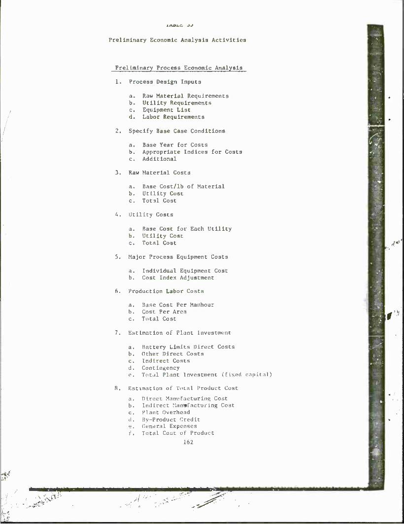
IAJJL.L _»->
Preliminary Economic Analysis Activities
Preliminary Process Economic Analysis
1. Process Design Inputs
a. Raw Material Requirements b. Utility Requirements c. Equipment List d. Labor Requirements
2. Specify Base Case Conditions
a. Base Year for Costs b. Appropriate Indices for Costs c. Additional
3. Raw Material Costs
a. Base Cost/lb of Material b. Utility Cost c. Total Cost
4. Utility Costs
a. Base Cost for Each Utility b. Utility Cost c. Total Cost
5. Major Process Equipment Costs
a. Individual Equipment Cost b. Cost Index Adjustment
6. Production Labor Costs
a. Base Cost Per Manhour b. Cost Per Area c. Total Cost
7. Estimation of Plant Investment
a. Battery Limits Direct Costs b. Other Direct Costs c. Indirect Costs d. Contingency e. Total Plant Investment (fixed capit.il)
8. Estimation of Total Product Cost
a. Direct Manufacturing Cost b. Indirect J'.anwfacturing Cost c. Plant Overhead cl. By-Product Credit e. General Expenses f. Total Cout of Product
162
'1/
«f* ^
Dfl
//"-•• «MM MMMM MaMMMW
*2
* ^
«
•11 objective of Che economic analysis le Co errlve eC comparison of Che
coses of propellant disposal by Che method» under consideration.
Laboratory tests conducted during Phase II indicated that recovery of
ingredients from Class 1.1 propellanCs vas technically feasible. A secondary
method of utilization of scrap uncured propellanc identified vas manufacture
of explosive boosters. Each of Chase methods of disposal appear at first
hand to be more attractive Chen disposal by incineration b»cause each
conserve materials and furnish an end-produce of monetary value. Whether Che
produce value Is sufficient Co defrey Che processing cost is a primary
question Co be answered by Che economic analysis and la dependent noC only on
optimization of Che processing method, but Che quality and marketability of
Che final product.
Three method» of disposal were selected for analysis: (1) explosive
boosCer manufacture, (2) ingredient recovery, and (3) incineration. Methods
of incineration evaluated were closed systems which appeared Co be capable of
meeting current federal emission standards.
An initial and necessary step of Che analysis was conslderaCion of the
amount of high energy wasCe Co be disposed. An examination of Thiokol'a
Class 1.1 propellanc production history Indicated a scrap race of 20,000 Co
100,000 lb/yr can be expected. With production of the First Stage Trident
motor, Thlokol probebly produces more Class 1.1 propellent and subsequently
more propellant waste than any other solid propellent rocket motor
manufacturer. This limited amount Is not much more thsn would be handled in
a pilot-size facility.
Larger quantitiea of propellent waste can be envisioned In e motor rec-
lamation or demilitarization program. Disposal of the propellant removed
from the motors could easily be one to severel million pounds.
Bssed on the above considerations, the selected range of sizes to be
"slutted were 20,000, 200,000, and 2,000,000 lb of propellant per year.
2.5.2 Estimation of Costs for the Explosive Booster Process
The base case selected for evaluation of utilization of waste propellanc
in explosive boosters assumed there would be 20,000 lb of castable propellant
163
\, N
VV

//
try
I
-^
■ V-.
V
r;
■*V
>'-
SV.
>
per year. The production rate for casting the boosters was selected to
be about 400 lb of propellent cast per hour. Production of explosive boost-
ers consists of casting a detonable propellant into a small cardboard or
plastic sleeve capable of holding about 1.2 lb of propellant. A cavity is
also formed during casting and curing for insertion of an initiator. This
operation is similar to typical sample and subscale casting operations per-
formed in rocket motor manufacturing to obtain and monitor propellant mechan-
ical and ballistic properties. Existing facilities would already be avail-
able and the design of what special tooling would be required would be
similar to already existing tooling and would not constitute a major design
problem.
Factors included in the estimation of the plant Investment costs are
tabulated in Table 36. The only major equipment would consist of the tooüng
specially adapted to the casting operation. Since no design was actually
made, the cost of similar tooling was used. Tooling for casting 1—lb charges
used in ballistic testing was selected as being most nearly similar to what
would be required.
Other direct plant Investment costs consists of installation costs,
piping and instrumentation which normally are Included as the battery limit
facilities. The factor of 80Z of the tooling cost is smaller than is usually
used since it was assumed that no new facilities or land development would be
required. Another basic item, which would not be available at most facili-
ties but would be needed, would be equipment associated with the packaging
and shipping of the product.
Item III, indirect plant investment costs, include such items as the
cost for design of tooling and of modification to the existing facilities to
accommodate the additional operation.
The total estimated plant Investment (fixed capital) of $186,000 would
be a constant for a range of production capacities. The amount of tooling
required depends on the working life of the propellant. For example, at a
casting rate of 400 lb/hr, a 6,000-lb batch of propellant would require 15
hours to cast. If one reject mix per week were processed (which is extremely
unlikely) a total of about 300,000 lb/yr could be cast Into boosters and
still leave most of the facility utilization time for proce«9lng the regular
samples and subscale units.
164
\
/:. -^-
♦■ -.
. \

>. \-
ft
K-'
«
e
« n >* (1) ID <J JD 01 ■H J>< u Ifl O I, ao a* «Oh o o o o o e u • o o o o o ©
O 4J o o o o o o c o c • ■ ■ m ■ O iH 4 o cc o* CO oo V0
•H 1 —l vD <r <£> \0 H ao u O >— iH —i 'J O 41 «y 3 O O.
TJ « 0 O O W W IN ft, a.
X UJ
s
I o Q.
>
5
u CD m a O
^s u « C/l ■o 00 u u « c u tf) Ul X
•H c o o ~" -H 01 CJ <J> ■*, o e o u u u u u (0 c V 0
V—' tl 01 II c > i V, kl 1/1 c u ~< c N
u i-c en -o ! Cfl en 01 c ^ V o U > 1-1 u u N <-> c c c m s
It ►-I ■o 01 II 01 1-1 -H c 00 > ^—v a. c PL, u CD c c rH X OJ c •*, 1-1 1 0) e ii It u «j i-i
a <J .-< o c fal •-< aO •H 01 cu 0) 0 c a c 3 u u o 4 a) ■-,
0" ■-> u •H r^ cj 1-1
UJ Q u a r-H a, CD 0) H TJ w u u 1- .-, I« —i 1) 01
o ii ■H nj M it X a ■—1 £ ■o 4-1 tl u ■-1 o n «j c 0 ? o '*-. T. o H H c H ^^ *
►1 > > 1-1
M 165
u

A.-. . - ,
E
&
Factors used In estimation of Che product cost are tabulated In Table
37 . The direct manufacturing costs normally consist of the cost of the fol-
lowing items: (1) raw materials, (2) direct operating labor, (3) utilities,
(4) supervision and clerical, (5) maintenance, (6) operating supplies, (7)
laboratory charges, and (8) patents and royalties. In this process Items (1)
and (7) are zero and all other items except Item (2), the direct labor, are
minimal.
The indirect manufacturing costs, which consists of the fixed charges of
depreciation, taxes, Insurance, and interest, constitute the major expense.
Since the same tooling and installation is capable of processing each of the
production levels considered (and more) the Indirect costs are a constant.
The plant overhead is a charge to cover the general plant costs not
Included above and la determined as a percentage of Che labor charges in-
cluded in the direct charges.
The disposal of the propellant was selected as the product or intent of
this operation; therefore, the explosive booster was considered as a by-product.
General expenses consist of administration, distribution and sales, and
research and development. They are based upon the cotal manufacturing
costs.
The estimated unit product costs determined by consideration of the
factors detailed above are shown in Figure 48 as a function of the plant
capacity or the pounds of castable propellant disposed of per year. It was
estimated that at about 40,000 lb of propellant per year thia process would
start showing a profit.
By examination of the Items In the co*t model tabulated In Table 36, it
Is evident that the product cost would be most affected by changes In the
capital or In the by-product credit. To demonstrate the effect of these
parameters, the estimated costs were recalculated using (1) a 50Z Increase In
capital and (2) a 252 decrease In by-product credit. The results, shown
graphically fn Figures 49 and r>n do not greatly affect tlie basic conclusion
that at higher waste levels the process could return a profit. The cost of
disposal at the 20,000 lb/yr level Is less thai, other disposal methods as
will be shown later.
If.h

• •A _ , _ . _ r.
I tfl yp
I n O CJ> oo oo r»
r> ■ u-\ CN r~i -*
oo o CN o\ o «» • ■ 00 OS
vO iH
o> CT> oo in r~ m
M • fM m ON rH
ON
I rH O OO 00
* « r-4 •*
-a- o -a- r»
CO CM
CT) r».
"'I
V
o -3- o p-
o oo
CN
o o c* o rH ON
■ (N pn
PO OO
-r o
CM
00
O*
Ul
I
M ID II
c rH ^ rH 01 . Q. 10 O U rl U) o. o
u UH O 00
c
02
c o
u 3 u 'J <TJ
IM 3 C <U
51
'J 3
"9 o u a- rH
U) o u 00 c
h 3 M o ra
U-i
3 C IT)
u u rf
-o c
-o 4 (J
-C u 0J > O
Q rH
*
01
o 3
-o o u
I
03
m o U
oo c
■rl U 3 u 'J M
IM 3 C
10 Ol (/) S m a x
a. o
a.
3 -
o H
(I u 0) B o> 'J
CO
en o u
u 3
"0 O u a,
O H
in O O
U 3
T3 O u IV
c
M 0) w U)
o o
XI -»» o o fM CO-
TS Ol u
■J 3
0 u a i
l-H rH ■> > rH rH > rH >
167
/

.•<v:- ■T ' ' --^
■?-■:>■ \,..-^:
«"*v?S, fc>
fy !
■
3
§ —<
s 00
§
c. *9-
J
1" _ § CSJ
s
1- </> O «_> tfl z
u. 13 J 3 f »-«
._ w / 8 /
bJ
2 / r-i
/ vo
/
/
f *»■
/ o <\J
o
a. O cc Q.
m -J
2 <
c
m a. o u
> 60
« c
UJ
X DC
01 u 0) <U 3
oc c •rf n D 0)
3 »-> u a)
lu 3 C m T.
u a>
o o
CO,
> n o r-l a x U
o
to
-J) o u
JO
u u 3 DC
O
00
O o o o i
o o o
o
(INVmdOHd 81/$) iSOO UNfl
If.«

S\ , A"
x- o o o
" " •—1
o oc
o 1
8
0
o
M »—• _J UJ
« OD $ s fe- ft f—»
il // o " o in
// 00
\ // o
V . J 7 KO
7 / o
//
r •
4 /
</> »— </» o o
Ul o
• / /
_j UJ (/I < CO
o
4) hi 3
I 3 i 2 !S 09
o c r-4 ni o. i-l
a It! o
^ »<
o. <
a <u o o u M tn >> O 00 U h
1 *J c ■rt W a
=3 JZ 00
-C S M
41 c 4-1 o U)
n) *-» n U) 0 00 <_> c
-« 0)
a
u 0J
Of
o o o o o o o o o o o c
00 l-~ *£> tn *c m <Ni •-• o "-•
(iNvn3dO»d 8i/$) ism ii*n
169
CM 1 1

o o 00 r>>
o o
<u u 3 u o 4
3 C 03
I
0 e
z J. t^
3 § o a:
D. 0 U a.
>. oc I- tl c
W — « >_ i/: x:
£ u " y 2
a
<u
o o
CG
-o 11 u 3
•a •v
U
M
01 u <n nj
00 C
3
(iNv-mdoad ai/$) is.: iiNn
170
Some basic probleaa are associated with the acceptability of this method
for disposal. Perhaps the greatest Is the utilization of propellents with
security classified formulations. Perheps additional Ingredients would have
to be edded to the reject mixes to remove the security classification. A
second problem Is that this method only processes the caatable propellent
waste. Some weste would still be creeted from this process. Other propel-
lent waste generated from machining operations, rejected cured motors, cured
samples, etc., would still require disposal; hence, another disposal method
would be required.
2.5.3 Estimation of Coets for the Selective Solvent Extraction Process
The calculation of the manufacturing cost for the recovered marketable
Ingredients was baaed upon accepted methods of estimation. This analysis
demonstrates the basic approach to establishing the plant costs for a proc-
ess. It presents e flow diagram, a material balance, and a tabulation of the
equipment, piping end instrumentation coet, including estimated installation
costs. This analysis follows standard preliminary estimating methods which
lists major equipment costs and uses fsctors es developed by Lang,1
Cuthrie,2 Haselbarth,3 and others4'5 to estimate piping, utility,
instrumentation and other costs. Actual data can be used if they ere avail-
able to make the coat estimates more accurate than can be achieved by using
factors above. Cost of site preparation and utilities are characteristic for
a given location and will vary from plentsite to plantslte; however, these
differences are usually Insignificant when compared to the coat of purchase
and installation jf the processing equipment. A very important element of
the estlmete is that sufficient detail Is given to assure that comparisons be
made on an equal basis. The first step in the analysis is the determination
of the process design Inputs. A prerequisite is the development of the flow
1Lang, H. J., Series of Articles, Journal of Chemical Engineering, September, October 1947, June-1948.
2Guthrie, K. M., Process Plant Estimating, Evaluation and Control, Craftsman Book Co. of America, Solana Peach, California (1974).
^Haselbarth, J. E., and Beck, J. M., Journel of Chemical Engineering, p. 158 (Hay-1960).
^Cran, J., Journal of Chemical Engineering, p. (Aprll-1981). 5Haselbarth, J. E., "Updated Investment Costs," Journal of Chemical
Engineering, p. , December 4, 1967.
171
sheet which Indicate« the types of equipment and the process flow neces-
sary to accomplish the task. A schematic for the planned pilot plant is
presented in Figure 51. A summary of the material balance is given in Table
38'. The material balance calculation, based upon the anticipated conversions
and separation efficiencies, was developed to determine the equipment sizes
and to determine the raw material and energy requirements for the processes.
These values should be adjusted a* evaluations better Identify the conver-
sions and separation efficiencies actually obtained in pilot plant opera-
tions.
After the equipment was sized, the cost of the major equipment was esti-
mated or obtained from vendor quotes. The current cost of equipment, listed
in Table 39, was obtained from vendor quotations and catalog prices of actual
or comparable equipment. CPI indices published in Chemical Engineering Maga-
zine were used to scale up costs to 1982 dollars where necessary. A power
factor was used to scale the costs for the various sized plants given lr.
Table 40.
From the major equipment costs, the plant Investment costs, shown In
Table 41, were estimated. The factors used in this calculation would be
adjusted by each company's historical records and are somewhat dependent upon
geographical location and other factors affecting construction costs. Based
upon the plant Investment costs, the manufacturing costs, listed In Table 42,
are calculated. The manufacturing cost is comprised of direct, indirect, and
fixed costs.
The direct costs include raw materials, operating labor, supervision,
maintenance, operating supplies, and utilities. The raw materials are ob-
tained from material balances of the process. For this calculation, the cost
of the raw material is low, as It consists only of makeup of solvent losses.
The original charge of solvent would be included in the original investment
and is insignificant compared to other capitalized cost!«.
Operating labor is also obtained from consideration of tb> preliminary
design and the pilot plant operation (Figure 52). Wlii!<- manpower require-
ments are significantly affected by the degree of automation designed into
the operation, average values based on production rates can be estimated
L7

A
^3» If»
c o
u n u
I 5
u OJ
in
41
c i a. u o •-*
ft.
0)
n
-3§ -is
173
- i - - -

o o oo o o n"> o\
in f\ vo ... m
O CM rH O CM 0">
o o o "1 r-l
Cl O O I O <T r-1 o CM m I
(*> m
3S
_1 _ w u c a. o o o£ oc o, a.
uj u.
*
at J c u. Q
o </3 — H
00 3 ui en c/j i—*
u c/i ui — --• «J _ c
9 S w
H '-' (/> H C/l < UJ
u 5 a u C£ -. a. < u >-
ti UJ UJ U -^ ^. O 2 u
UJ < £ 33
H .J «S < UJ —* — oc a UJ UJ H OS
2 z
o oo d I
O O O O f-l CN I
■* C* o O I 00
O O >-l CM I —I
<n o o • CM et i
9 O «4 •* I
n o --f r-t
O «» CM CM
1 1 1 1
1 1
1 1
1
1
p
o 2700
1 1
-t o
1
o
1
o
1
o -7
i i
1 i i i
H O
1 1 1 1
o
1
o
1 1 13
40
120
(0 u V N
c. •-4 0 -H
>H •-1 *~t J3 It m IJ 4J •n V)
«a
u 1 a. *T. <
-a u c C-
u c 0 V u < ro
3
o r-l
II
jQ r-U
O CM
+
n a. 4U
H oj ro u u 43
N ■ u ■ U JZ O •
•n 91 CO 11 4 CO > 3 r-l JJ o r-l CJ s a/ T-1 O a c U 1-. M o co a
0 01 JJ 00 u o J2 c
rrj U -H ex £ tu C B CJ u ■H •H Cd Id CU
TJ TJ r-4 £ JJ V
■n > M 01 % 0 01 B J fcj :> O
V O IJ *J U •j ii 0 CU u
IM 0
u co
su a 91 O CJ •H U 0 CM J= E *-» M t« tH -J u u r*j '»i CO rj X C CU
u 3 -C J-J E •—< JJ —1 ^
M U 3 O E O c —• O r i c^l r-l O
174

TABLE 39
ESTIMATION OF MAJOR EQUIPMENT COST
I. Size Reduction
1. Propellant Shredder
II. Ch2Cl2, NG leach
1. Leach tank w/hasket 2. Ch7Cl2 storage tank 3. Pumps a.
b. 4. Filter
III. ch2C17 recovery
1. Surge tank 2. Still «/conditioner
and reboiler 3. NG/CII.Cl, container
IV. HMX leach, acetone
1. Leach tank 2. Kilter 3. Pump.- (3) 4. Surge tank 5. Filtrate and
wash tank
Cost (K$) Size On Capacity Standard
NG fll Adapted ■
& ■■:■
. &* \ -,
100 lb/hr 50 50
75 gal. 2.5 3.8 150 gal. 2.1 3.2 300 gal/hr 1.0 1.5 25 gal/hr 0.5 0.8 — 0.5 0.8
150 gal. 250 lb/hr
50 gal.
2.1 30
1.5
3.2 30
2.3
2 2
Using CH Cl tank 6.5Z 0.8
150 gal/hr 2.4 3.5 75 gal. 1.7 2.6 150 gal. 2.1 3.2
wr \
i>
V. Crystallization of 1IMX/AP
1. Crystalllzer 2. Storage
VI. Filtration and wash
1000 lb/hr 200 gal.
30 2.5
30 3.8
1. Filter 2. Pump 3. Wash tank 4. AP crystallizer
15 ft IS 23 150 gal/hr 0.8 1.2 50 gal. 1.9 2.9
-- 10 IS
1.5 x Standard Equipment Costs, when required
175
0 ll

»*
<*
H
•z. O M
OJ a. o M a
o o o
O o o
o o o
o o o
o o o
O o o
o o o
a
ON l-l o
CM o H
-3- CD o
<.,-
o o o
o o o
O o o
o 5 o o 5 o
■ B ■ A A
c-> H
"1 4
o o o
o o O o o O O o o o o o O o 5 (—1 in (N oo r-> o
o e m O f> rv <M m H ro —i ««, <T 00
r-4
</> </V
"J N
to
0J N
00
c n
C «J <u o C (1 o (*. a. x u
o o u-i
O tfi
o
m 0 u
CU c a >* u o o kl c u •H II cu cu w > F
ri CJ <T! 0 a c r-* •c N u ■H 0 u «4 II 3
■H rsi 3 H a; O" l-J X —1 UJ n3 u > , be n 5= u B —.. V- c i_i hi 11 0 J J ■H u) 0 a •-1 > £ >^ <J) 'O a t-i oc 0 -J hi cd
o c CJ IB O C r 3 »4 u u 01 O
■a J= 00 ►J at ■H PH
V u LI 10 DC a ~1 a,
% a 1-1
cu iH < u, 0 0J J u "-^ w H N CM 1
's ~M
•H c X 3^ v4 </l 5E CJ Ec U*
•a II cu i-i N c •H 41 CO *4 M u 0 c
RI u .—I c a. 'J a IM
a 0 —I
j u cr en |i o
I J a V ii "1
CNI
n u II o N ij ■rl CJ en cc;
IM hi C
t- H r rH
■H UM hi C IM CJ 0 C 0 u a •X ;■: I
UJ U
I7fi

\\' "*<
^s: v x
B TABLE Al
ESTIMATION OF PLANT INVESTMENT COSTS (COSTS REPORTED IN K$)
X of Equipment Normal Plant Size, lb prop.
Cost Range 20K 200K 2000K
1 1
1 Direct Plant Investment Costs
100.0 100 182 741 1 Major Process Equipment 3074 I .2 Installation 45.0 43-50 82 333 1383 1 3 Process Piping 20.0 19-74 36 148 615 1 4 Instrumentation 11.0 10-19 20 82 338 1 5 Electrical 9.0 9-10 16 67 277 1 6 Process Buildings 10.0 6-10 18 74 307
(Battery Limits) - Subtotal 354 1145 5994
c
2. Other Direct Plant Inv«vv.t.n»nt Costs
2.1 Utilities 30.0 25-48 55 222 922 2.2 General Services, Site
Development, etc. 23.0 12-25 42 170 707
2.3 General Buildings 14.0 14-35 25 104 430 2.4 Receiving & Shipping Facilities 24.0 21-25 44 178 738
(Offsite Facilities) - Subtotal 166 674 2797
3. Indirect Plant Investment Costs 3.1 Engineering Overhead 45.0 3.2 Normal Contingencies 55.0
(Indirect) - Subtotal
38-55 44-71
82 100
182
333 408
741
1383 1691
3074
4. Total Direct and Indirect Costs
5. Overall Contingency, 307. of 4
6. Total Plant Investment (Fixed Capital) - excluding working capital.
701 2853 11835
210 856 3531
911 3709 15386
177
f
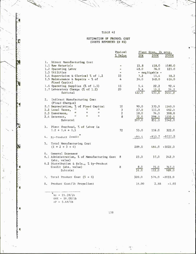
1 *
N
J
TABLE 42
ESTIMATION OF PRODUCl COST (COSTS REPORTED IN K$)
V
*
P
fe
1. Direct Manufacturing Cost 1.1 Raw Materials 1.2 Operating Labor 1.3 Utilities 1.4 Supervision & Clerical 7. of 1.2 1.5 Maintenance & Repairs - 7. of
Fixed Capital 1.6 Operating Supplies (7. of 1.5) 1.7 Laboratory Charge (% of 1.2)
Subtotal
2. Indirect Manufacturing Cost (Fixed Chargos)
2.1 Depreciation, 7. of Fixed Capital 2.2 Local Taxes, " " " 2.3 Insurance, " " " 2.4 Interest,
Subtotal
3. Plant Overhead, 7. of Labor in 1.2 + 1.4 + 1.5
Typical Plant Size, lb prop. 7. Value 20K 200K 2000K
— —
15 4
15.8 48.0 - neg 7.2
36.0
158.0 76.0
Ligable - 11.4
148.0
1580.0 121.0
18.2 616.0
15 20
5.4 9.6
22.2 15.2
92.4 24.2
10 3 2 8
72
4. By-Product Credit
5. Total Manufacturing Cost (1+2+3 + 4)
6. General Expenses 6.1 Administration, % of Manufacturing Cost 8
(abs. value) 6.2 Distribution & Soln., 7. By-Product
Credit (abs. value) 8 Subtotal
7. Total Product Cost (5 + 6)
8. Product Cost/lb Propellant
122.0 431.0 2451.0
90.0 370.0 1540.0 27.0 111.0 462.0 18.0 74.0 308.0 72.0 296.0 1232.0
207.0 851.0 3542.0
53.0 116.0 322.0
-93.4 -933.7 -9337.0
289.0
23.0
464.0 -3022.0
37.0 242.0
8.0 31.0
75.0 112.0
747.0 989.0
20.0 576.0 -2033.0
16.00 2.88 -1.02
NC - $5.28/lb HMX - $9.08/lb AP = $.68/lb
178
X

I.
p
I
i.
-
J: o» U hi u 0 <0 U -o I« -». hi M 41
JC O. o
I I
I ■ M 3 0
00 £
- !
Q. u 3 B
11 a. 3 >>
C > 01 % M CO H B a. c •1 CD 0 a 3 0 > a M '/I 1) «J s»-
0 4-1 u H c 11 y CJ
11 O m CJ a s 11 J> ^ tu IM -3
II —1
CO 3 £
u 4-1
u u 7) u ■ c en 01 3 c c ?N C CO CO It ■o nj CO u -0 o CU 3 0 o
i-t M tl •--1 —l u u rH 1-1 > a. u CJ ^0 0) a U o < CO u >- a -0 EJ >•. N w c CO 1) u -0 0 V b*f T4 0 u H u a u V .-1 >~ •w JS in > a a. & 2 -1 U 4-1 <o o 3 <U
<NI CO 0) CO CM3 'J 00 •n ■C ^H £ IJ > U rH 01 C 10 a u o o l/> o u CJ a u 10 1-. U IT! CNI CO ■«s 'J -1 (NIO cu 0
-C II X «1 M 01 -^ X kl a r-> 4-1 'VI -J o ~J CJ u u. u 14-1 CJ C/l
! -I a. u 0 H
3
r: eg
■H T3
UJ hi oc c
o
I •H 3
I I- o -3
CO -J
x_
O
1» 4-1
3
CM in
a >- 3 00
179

n
where no actual data exists.6 The labor costs estimated in Table 42
are based upon the residence times of the leaching steps and estimated cycle
times for the various operations.
Examination of the factors which comprise the manufacturing cost, tabu-
lated in Table 42, are worth considering. Labor costs are significant,
especially at lower production rates. Changes In the process may affect the
cost of raw materials, labor and utilities as well as the fixed capital in-
vestment and each of these factors affect other factors of the calculation.
While percentages may vary for preliminary estimates, experience has indi-
cated that, unless the operation is very unusual, the range of values for
each factor is quite small. Por example, maintenance costs usually range
between 2 to 10Z per year of the capital cost. A high value Is used for
processes In which corrosion is high. It has already been experienced''
that water solutions of AP are extremely corrosl"e; therefore, the higher
value was used in the example calculation. Other factors such <*s those list-
ed under indirect and fixed costs are variable from company to company and
with geographical location. The goal is to select values which are realistic
and form a solid basis for comparison.
The results of these calculations, shown in Figure 53, give the manu-
facturing cost of disposal of propellent as the plant size varies. This
representation accounts for the value of the recoverable Ingredients or by-
products which have e significant effect.
Since raw material costs are negligible (the waste propellant being
free), reduction of the direct operating labor charges would have the most
affect on the direct charges. Process Improvements which would reduce the
major equipment requirements and thus affect the Indirect manufacturing costs
«.,.„]-: would have a greater affect on the unit product cost. The most significant
• factor, however, is the effect of the by-product credit.
• This analysis assumes thst the ingredients recovered HMX, NG and AP, are
salable at the current market prices. Factors affecting this assumption will
','•: be discussed later.
"Weinberger, A. J., "Calculating Manufacturing Costs," Chemical Englneer- V- lng, December 23, 1963.
7Thlokol Report No. WCT-085, "Additional Study of Crack Initiation in Hitfh Pressure Pump Housings at the Motor Case Reclaim Facility," J. B.
a Ml Hard, 10 June 1963. • ..- 180
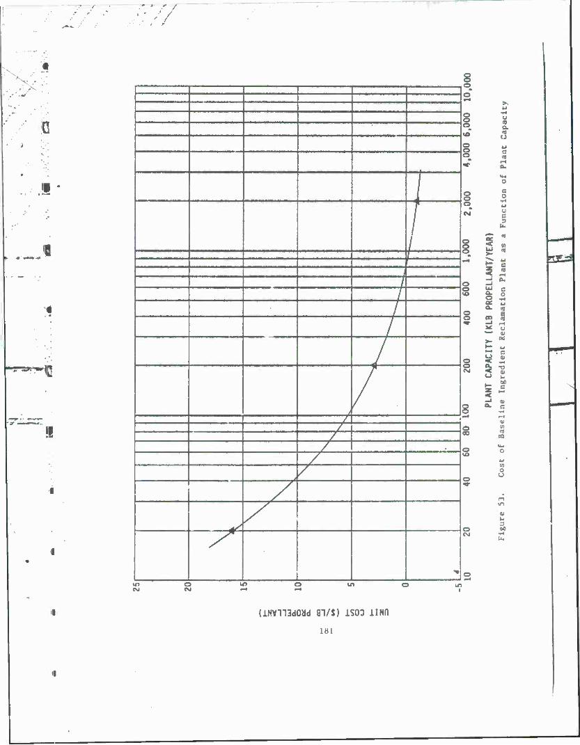
77
>>c--:
!!
-
o § lO
o o o
J „
1 «VI
1 Ri •■*
o o to
§
o
1
(Nl
s /
/ § /
o '£>
n -t
HI
"•
C\J
o
u n D. 0)
c CO
g o
i ! - 0.
Ä ° s ■**
3 3 2 1 <— tu
u n ro
CO
O
f-1 in
■ U 3 M
to o CM
I*» in i
(JLMVmdOM 81/$) 1S00 UNO
181

To demonstrate the affect of these post Important parameters on the unit
product cost, which is the cost of disposing of one pound of waste propel-
lant, a series of calculations were made to test the sensitivity of the unit v r* cost. Conditions investigated were: (1) decrease and Increase of the capital
'/. cost by 30Z, (2) decrease and increase of the labor cost by 502, and (3)
decrease of the market value of the by-product credit to 75, 50, and 25Z of
current market value. The results of these calculations are shown graphlcal-
'ji ly in Figures 54, 55 and 56.
The basic conclusion shown by these graphs are that the effect of plant
capacity Is the tiost Important parameter. For relatively small quantities of
propellant, less than 100K lb/yr, the cost of waste propellent disposal by
■ ingredient recovery is estimated to be considerably higher than by incinera-
tion methods. Thiokol, one of the leading producers of Class l.l propel-
lents, anticipates less than 100K lb waste per year during the next few
years. This Indicates that replacement of a major solid propellant weapon
g, system would probably be the only circumstance which would generate enough
waste to make this process economically feasible.
'•'. 2.5.4 Estimation of Incineration Costs
Considerable effort has been expended to develop closed Incineration
ül systems; such as fluid bed, rotary kiln, and APE 1236 deactivstlon furnace
systems for disposal of propellant and explosives. The successes of these
systems have been varied and high maintenance costs appear to be Inherent due
to the nature of the material burned. Most of these systems have been devel-
51 oped for specialized feed stocks and more development work may be needed to
develop feed systems and effluent clean-up systems to make them generally
useful.
The cost data use for this analysis were obtained from reports**»'
and from communication with personnel st the Ammunition Equipment Directo-
rate, Tooele Army Depot, Tooele, Utah. These data were used primarily to
develop current estimates of the major equipment costs and of labor require-
ments and capacities. Cost estimating methods previously described were then
°Tech Report AD-064124, Part 1 of 2, 1974, "Fluidized Bed Incineration for Disposal of Propellant and Explosives," R. Scola and J. Santos.
^Scola, R., Santos, J. S. , "Fluidized Bed Incinerator for Disposal of Pro- pel lants and Explosives," AARDCOM, Dover, N. J., October 1978, pp 129.
182
1

4 X
s
< B UJ «I >- •* *- S ^ ff —' P.
a. *" o o * « c
■Ji -*
CO o -> ZJ O «I Ü °- .3 u o
•H hi >- CO.
E 5>S «j ti on
Q. U 41 c
C UJ 5 o
■ u 0) o u
a 5
-T u-l
0)
(INVHidOMd 81/$) iSOO UNO
183

■s~"\
-! i
a. o Qf a.
CL
a u a1
c
T3 « U 00 c
U-l V) o «->
c ■U CO 0) .-H O »H u <u
a u o C a, a (U 0C
J= ^ u 1)
c C Ul o <£ 00 4-1 -H to x
o
U 01
■T-T
5f
(lNVn3dCMd 81/$) 1S00 lINn
I«;

c • ■**
-o IP u oc c
9
c
_ c Ä « <• 3 J= -< 13 *» —• >- « C c a ►-T o o z * 9 c ft. "3 -H ;*» £2 « eo
g <» w ■*• 0«
3 UK
u
E " 2 u 3 S
•O O 0 -H ki 4J n. n >. 3
U
0 PU
3
UJ
ä -H
(INV-mdOMd 8VS) 1S0D 1INH
ill 5

„..*•
used Co develop unit costs for disposal of HE propellant at various capa-
cities. The results of these calculations are listed in Table 43. The cost
calculated for comparison for the deactivation furnace at Tooele is believed
to be note accurate because the data are current and Mere received first
hand. The agreement between this cost and the cost developed from data in
the Scola and Santos report gives confidence to the analysis of the data and
the resulting estimation.
The Incinerator capable of handling 400,000 lb of propellant per year
(on a 200 operating days/year schedule) Is the smallest unit currently avail-
able. The capital Investment cost for lower capacities than 400,000 lb/yr is
therefore identical. At these lower capacities the opecation would be inter-
mittent with operating labor decreasing as capacity decreases. The results
of these calculations are shown in Figure 57.
2.5.5 Comparison of the Cost Estimations of Methods of High Energy Waste Disposal
Each of the cost estimates previously described used the same basis for
comparative purposes. Products produced in <.'ic manufacture of explosive
boosters and in ingredient reclamation were treated as by-products to keep
the final unit product cost defined as the cost for disposal of one pound of
propellant. A comparison of the results of the analysis are summarized in
Figure 58.
These results show that utilization of the propellant in explosive
boosters is the most economical method. Ingredient reclamation, although
technically feasible, is economically feasible only where very large quanti-
ties of propellant are available. Since the capital costs were depreciated
over a ten year period, this method is less attractive If the projected term
of operation were less than ten years. Incineration methods are shown to be
economically more feasible than ingredient recovery in the intermediate range
of capacity and extrapolation of the curve applicable for prediction of costs
at lower capacities.
2.6 CONCLUSIONS
The alternate use of waste Class 1.1 solid propellant as an explosive
booster is technically feasible and economical on an Intermediate production
-»

p
§ o o o o 00 o m rH m •
i-i o
o o o r-. vO
c/i H c/1 c u M O H
o o o C7> ■ o>
o • 00 o oo
§ o o o 00 r» o
o
UJ u Z
% M
I—<
-I UJ tn <
o o o o* 00 CD
vO
o o o
o o -.T
n 00 O ■ O0 c-i CO
c 3 u >-
—<
o C u
>-i r, •H IT) U, in
>> *o u r) m *-t I—t
o o csi u
o u u o
■J) 0
•J -4 c c — •_>
c c
—i *J -o > —< u V u o fl re Ü c
U 3
—>
u. 0 u
^—. CO
T3 0 u «-I
32 B re ■a ■r. -J N -"!
■-<
-3 -5 ■^< —. r '
i— _/ — '/•. ~
CO
0 U
co
a u
c 0
re •- u a o
c •J
E ha •J

a o
36 DEACT
FURNACE
KILN
ZED
BED
O
o o o ya
1 O t— < ne UJ
•
O
i o o
— C£ Q < >- UJ h- 3 o. o _j < or u.
OH<l
J3 z
3 -
r
CS)
o o o r-*
1
1 i o t o •t
o
d
i i
CM
o o V *-*
/ o ^ 00
o
ac . UJ
5 ^ CD
Is Ä UJ
•w
TENT
KLB/
Y
2|
2 °
C\J
o o
OJ
O
o O u1 o to :3
to CM a (M t
in i
TidücjV GT'$) ;S30 11 No
-o OJ
CO
0)
•a ■H
ae u)
uj ra >- -H
J S u _J 0 UJ V u o > a O •H it n: ■ J a. 0 c .-< •y—
m a, U J X C ^ U H
M C >- c H t— ■H •r-4
■—• ^J U.
y 03 >
Q- 1) l< «C c « U ■r- U
u 0 fc c 0ä z *—< «f -a
J IM £ Ou 0
1/1
c u
flj
OJ 1-
50

>. XI
G u o C n OJ u 1 ■ u R -o 1 <u —i u (J H
32 91 u u m c a OJ ^ 11
-T3 AJ i c u a) BC
r-1 C ^H HI *_ dl
er a -o «f o c uJ Ui m >- p. ■^ * H- >. 91
3 f" M
u 3
—1 OJ U i C u
Ui lu ■ n OJ
O X 3 nrr IC C n •rl 03
X 2. m j U-. 1*
x o V J->
1/1 II >- *J 0 i— u: 0 »—• 0 CO
i# U II
a. 1) > ■< £ <H o *-* IT
C i— u... .—•
C a «r X _i C
0 a
tu
- •n c M 0 ■o ■H c *-< H ra r. >- U 01
c
oo c 1/1
V u 3 00
(lNVmdOM 81/J) ISO"] UNO

scale of approximately 40,000 Co 50,000 lb/yr. The classification of
many Class l.l propellant formulations prohibits distribution to the indus-
trial sector however, and thereby restricts application of this disposal
concept.
Reclamation of major ingredients from Clans 1.1 solid propel lares by a
selective solvent extraction process is technically feasible, but economical
only on a comparatively large production scale in excess of 400,000 lb/yr.
The economics of this disposal method are very sensitive to th'j recovered
ingredient market. 1 production scale necessary for economical implementa-
tion of this disposal method exceeds projected wast-» Class 1.1 propellant
quantities for most manufacturers. Economical operation of an Ingredient
reclamation facility would therefore be restricted to specialized applica-
tions such as large aotor demilitarization programs.
Incineration of waste Class 1.1 solid propeliants has been demonstrated
on full seal« incinerators. Incineration appears to be economical only on a
large scale In excess of 400,000 lb/yr which, as previously r.oted, exceeds
projected waste Cliss 1.1 propellant quantities for most manufacturers.
Snail, intermediate size incinerators which address cured and uncured propel-
lant and propellant contaminated wastes (rags, plastics, disposable tools,
etc.) and their characteristic emissions are not available.
In summary, open pit burning remains the most simple and cost effective
method tor disposal of intermediate quantities of Class 1.1 solid propellants.
The alternative would involve large capital investments for either an ingre-
dient reclamation facility or an Incinerator and operation of the facility on
a low capacity, inefficient and costly basis.
2.7 RECOMMENDATIONS
It Is recommended that the selective solvent extraction process be
scaled up to the pilot plant level in order to:
a. Optimize the process
b. Develop markets for the reclaimed ingredients
c. Update the economic projections
d. Provide a design for a large 'oale plant

I- !»v
:i
j N—*
The large scale plant design may be modular In concept to facilitate
transfer to various motor demilitarization sites.
It is recommended that a low cost, intermediate size incinerator be
developed which would:
a. Be compatible with projected waste propellent quan-
tities.
b. Accommodate all types of hazardous wastes associated
with propellant manufacture including:
1. Cured propellant
2. Uncured propellant and premises
3. Propellant contaminated wastes
4. Scrap raw materials
c. Address total emissions characteristic of solid
propeHants, including:
ll ' 1. Participates (metal oxides)
2. N0X
3. HC1
This would provide a more economical and environmentally acceptable
means of disposal by incineration than the present state of the art
allows.
It Is recommended that alternate use and application concepts for dis-
posal of waste Claas l.l solid propellants be pursued due to the simplicity
and Inherent low costs associated with this approach. Two specific concepts
which surfaced late In the program but which appear promising are:
a. Conversion of waste Class 1.1 propellant to a war-
head explosive booster.
b. Utilization ct detonation energy of Class 1.1 pro-
pellant to synthesize industrial diamonds.
The first method avoids the security problems associated with dist-ibu-
tlon of explosive boosters containing classified formulations to the indus-
trial sector. The second method provides on-slte disposal and a readily
marketable by-product.
191

BIBLIOGRAPHY
Barber-Colman Company, DESTRUCTION BY WET OXIDATIOH OF. DOUBLE BASE SOLID PROPELLANTS TRINITROTOLUENE NITRATE ESTERS PHOTOGRAPHIC FILM AND SHIPBOARD WASTE, Santa Ana, CA, 1973.
Becker, K. P., Wall, C. J., FLUID BED INCINERATION OF WASTES, Dorr-Olwln Inc., October 1976
Brown, J. A., SUMMARY REVIEW OF INCINERATION OF NAVY ORDNANCE AND PEP, Con- tract N60921-77-M-E5A1, June 1978.
Brown, J. A., Shapira, N. I., et al., STATE OF THE ART STUDY: DEMILITARIZATION OF CONVENTIONAL MUNITIONS, EPA-600/2-78-012, Februar/ 1978
[M Brown, J. A., Shapira, N. I., ALTERNATIVES TO INCINERATION OF BULK EXPLOSIVES, PROPELLANTS AND PYROTECHNICS, U.S. Army Armament Research and Development Command (ARRADCOM), Dover, N.J., October 1979.
Brown, J. A., THE INCINERATION PROPERTIES OF SURPLUS MILITARY PEPS, Naval Surface Weapons Center, Dahlgren, Virginia, September 1977.
Clccone, V. J., et al., ECONOMICAL ANALYSIS OF THE ROTARY KILN AND FLUTDIZED BED P&E INCINERATORS, U.S. Army Armament Research and Development Command (ARRADCOM), Dover, N.J., September 1978.
Dahlberg, L. F., et al., PROCEDURES FOR RECYCLING AND RECLAIMING PLASTIC BONDED EXPLOSIVES (U), Naval Weapons Center, China Lake, CA., 1973-1975
Dlnerman, C. E., Cllliam, C. W., ECOLOGICAL DISPOSAL/PJ5CLAIM OF NAVY COLORED SMOKE COMPOSITIONS, Naval Weapons Support Center, Crane, Indiana, June 1976
Dunn, K. S., INCINERATION ROLE IN ULTIMATE DISPOSAL OF PROCESS WASTES, The Incinerator Co., October 1975.
Endicott, D. W., Denton, C. L., Levinthal, M. L., PROCESS FOR SEPARATION OF NITKOGLYCERIN FROM MIXTURES WITH DIETHYLENE GLYCOL, Thiokol Corporation, Brigham City, Utah, 1979.
Forsten, I., Santos, J. S., Scola, R., DEVELOPMENT TRENDS IN THE INCINERATION OF WASTE EXPLOSIVES AND PROPELLANTS, Picatinny Arsenal, Dover, N.J., May 1976.
Gaarder, D., et al., ENVIRONMENTAL IMPACT CONSIDERATIONS FOR DISPOSAL OF PROPELLANTS AND INGREDIENTS, Chemical Propulsion Information Agency, September 1975.
Gilliam, C. W., Tanner, J. E., FLARE, IGNITER AND PYROTECHNIC DISPOSAL: RED PHOSPHOROUS SHORES, Naval Ammunition Depot, Crane, IN, May 1975.
192
BIBLIOGRAPHY (Conf.)
Knight, J. A., Elston, L., LABORATORY STUDY OF PYROLYSIS OF EXPLOSIVE CONTAM- INATED WASTE, Georgia Inst. of Tech. Atlanta Engineering Experiment Station, July 1978.
Knight, J. A., et al., LABORATORY STUDY OF PYROLYSIS OF EXPLOSIVE CONTAMI- NATED WASTE, February 1979.
Leake, E. E., RECOVERY OF HMX FROM SCRAP PBX-9404 HIGH EXPLOSIVE, Sllaa Mason Company, Inc., Burlington, Iowa, October 1973.
Lewis, C. R., Edwards, R. E., Santos, M. A., INCINERATION OF INDUSTRIAL WASTES, October 1976.
Martens, W. S., Kink, W. R., Klaus, W. H., Mallls, J. N., THE ROLE OF INCIN- ERATION FOR NAVY ORDNANCE PROPELLANTS, EXPLOSIVES AND PYROTECHNICS DIS- POSAL, Naval Surface Weapons Center, Dahlgren, VA, August 1977.
McBrlde, W. R. and Thun, W. E., SENSITIVITY AND CHARACTERIZATION OF SELECTED AMMONIA SYSTEMS: RECLAMATION METHODOLOGY FOR AMMONIUM PERCHLORATE PRO- PELLANTS, Naval Weapons Center, China Lake, CA, April 1979.
Meintosh, M., at al., SOLID ROCKET PROPELLANT WASTE DISPOSAL/INGREDIENT RE- COVERY STUDY, Thiokol/Wasatch, Brlgham City, Utah, July 1975.
Musselman, K. A., ISOLATION AND DISPOSAL OF CHEMICAL INGREDIENTS UTILIZED IN ILLUMINATING FLARES, Naval Ammunition Depot, Crane, Indiana, 1973.
Raleigh, M. R. and Malone, H. E., A FACILITY TO DISPOSE OF LIQUID AND SOLID PROPELLANTS, 1974 JANNAF PROPELLANT MEETING, San Diego, CA.
Rollson, D. E., Dlckenson, R. L., THE PRODUCTION ENGINEERING OF AN AUTOMATED INCINERATOR FOR THE DISPOSAL OF PROPELLANT AND EXPLOSIVE WASTE AND EVAL- UATION OF A PROTOTYPE WASTE PROPELLANT INCINERATOR, Radford Army Ammuni- tion Plant, Radford, VA, February 1975.
Rollson, D. E., Dlckenson, R. L., Scola, R., EVALUATION OF AN INCINERATOR FOR WASTE PROPELLANTS AND EXPLOSIVES, Plcatlnny Arsenal, Dover, N.J., December 1976.
Santos, J. S., Canavan, J. J., INCINERATION PROCESSES FOR TROPELLANT AND EXPLOSIVE WASTE DISPOSAL, Plcatlnny Arsenal, Dover, N.J., December 1974.
Santos, J., Heidelberger, W., Antman, H., Bhula, N., DESIGN GUIDE FOR PROPEL- LANT AND EXPLOSIVE WASTE INCINERATION, Plcatlnny Arsenal, Dover, N.J., October 1973.
Scola, R., Santos, J. S., FLUIDIZED BED INCINERATOR FOR DISPOSAL OF PROPEL- LANTS AND EXPLOSIVES, Army Armament Research and Development Command, Dover, N.J., October 1973.
193
i

*»#.r.-*"
BIBLIOGRAPHY (Cont)
as Shaplra, N. I., Patterson, J., Brown, J., Noll, K., STATE OP THE ART STUDY:
DEMILITARIZATION OF CONVENTIONAL MUNITIONS, American Defense Prepared- ness Association, Washington, D.C., February 1978.
Shaw, U. C, RECOVERY OP ALUMINUM AND BINDER PROM COMPOSITE PROPELLANTS, Thlokol Corporation, Brighaa City, Utsh, September 1975.
Sinclair, J. E., et al., INVESTIGATION OF PROPELLANT AND HIGH EXPLOSIVE DIS- POSAL BY CONFINED SPACE SHOTS - II, Naval Postgraduate School, Monterey, CA, July 1974.
Tompa, A. S., A TG STUDY OF THE SOLVOLYTIC BREAKDOWN OF A CROSSLINKED, DOUBLE-BASE PROPELLANT, Naval Surface Weapons Center, Sliver Spring, Maryland, October 1980.
Tompa, A. S., French, D. M., White, B. R., DISPOSAL AND UTILIZATION OF SOLID PROPELLANT AND EXPLOSIVE WASTES, JANNAF Propulsion Meeting, Incline Village, Nevada, February 1978.
Tompa, A. S., French, D. M., PROPELLANT SOLVOLYTIC DEGRADATION OF CROSSLINKED POLYMER, U.S. Patent No. 4,098,627, issued 4 July 1978.
Tompa, A. S., French, D. M., PROPELLANT INGREDIENT RECLAMATION BY SOLVOLYSIS, 1974 JANNAF Environmental Protection Working Group Meeting, San Diego, CA, October 1974.
Tcmpa, A. S., French, D. M., UTILIZATION AND DISPOSAL OF SOLID PROPELLANT AND EXPLOSIVE WASTE, Naval Surface Weapons Center, Sliver Spring, Maryland, April 1977.
Williams, Carver, Husklns, RECOVERY OF NHC FROM PROPELLANTS, Micom, Report No. T-78-92, October 1978
194

- fr,
■T- .■ v- ■ .-. .■ .«. r t" -\ v -^ .- ■-• -_• \f '-.• •_> .•
GLOSSARY
fc-.
J AMMONOLYSIS
BINDER SOL
Degradation and dissolution of a propellant binder with ammonia
Soluble, unpolymerlzed fraction of propellent binder
BINDER GEL Insoluble, polymerized fraction of propellant binder
*
SOLVOLYSIS
TALIANI TEST
Cheaical degradation and dissolution pf a propellant binder
Test for compatibility of a material with a nitrate ester
195

—— w^^ *****
LIST OF ABBREVIATIONS, ACRONYMS, AND SYMBOLS
■ ;-- ■
ACI Al AP BITA C-4 CTPB Deaaodur N-lOO DMSO OSCF DSCM EA r.r HEMAP HMX HTPB MAPO
Kg MNA 2-NDPA NEPE Ng NHC
m PBAN PCP PEG PEP PETN PGA RDX THF TIL TMETN TNT WAO
Air curtain Incinerator Aluminum powder Ammonium perchlorate Bu«-yl lmlne adduct of trlmeslc acid 9IX RDX, 9Z Plastlclzer Carboxy Terminated Polybutadlene Polyiaocyanate Dlmethylaulfoxide Dry standard Cubic Foot Dry standard cubic meter Ethanol amlne Grain Hydroxyethyl-Methylazlrldlno-Proplonate Cyclo-tetraoethylene tetranitramlne Hydroxy terminated polybutadlene Methyl azlrldlnal phosgene oxide Milligram n-methyl-p-nltroanlllne 2-nltrodlphyenylamlne Nitrate ester polyether Nitroglycerine n-hexylcarborane Nltro guanldine Polybutadlene-acrylonltrlle Polycaptolactone Polyethylene glycol PropelLant8, Explosives and Pyrotechnics Pentaerythrltol Tetranitrate Polydiethylene Glycol Adlpate 1,3,5-tetranitraza-cyclohexane Tetrahydrofuran Threshold Ignition Level Trimethylolethane Triniträte Tri nltrotoluene Wet Air Oxidation
196

M1 ' ■ ■ »-*.