Ultra-low-cost 3D gaze estimation: an intuitive high information throughput compliment to direct...
12
Ultra-low-cost 3D gaze estimation: an intuitive high information throughput compliment to direct brain–machine interfaces This article has been downloaded from IOPscience. Please scroll down to see the full text article. 2012 J. Neural Eng. 9 046016 (http://iopscience.iop.org/1741-2552/9/4/046016) Download details: IP Address: 155.198.133.236 The article was downloaded on 31/07/2012 at 17:28 Please note that terms and conditions apply. View the table of contents for this issue, or go to the journal homepage for more Home Search Collections Journals About Contact us My IOPscience
Transcript of Ultra-low-cost 3D gaze estimation: an intuitive high information throughput compliment to direct...

Ultra-low-cost 3D gaze estimation: an intuitive high information throughput compliment to
direct brain–machine interfaces
This article has been downloaded from IOPscience. Please scroll down to see the full text article.
2012 J. Neural Eng. 9 046016
(http://iopscience.iop.org/1741-2552/9/4/046016)
Download details:
IP Address: 155.198.133.236
The article was downloaded on 31/07/2012 at 17:28
Please note that terms and conditions apply.
View the table of contents for this issue, or go to the journal homepage for more
Home Search Collections Journals About Contact us My IOPscience

IOP PUBLISHING JOURNAL OF NEURAL ENGINEERING
J. Neural Eng. 9 (2012) 046016 (11pp) doi:10.1088/1741-2560/9/4/046016
Ultra-low-cost 3D gaze estimation: anintuitive high information throughputcompliment to direct brain–machineinterfacesW W Abbott1 and A A Faisal1,2
1 Department of Bioengineering, Imperial College London, SW7 2AZ London, UK2 Department of Computing, Imperial College London, SW7 2AZ London, UK
E-mail: [email protected]
Received 14 February 2012Accepted for publication 8 June 2012Published 12 July 2012Online at stacks.iop.org/JNE/9/046016
AbstractEye movements are highly correlated with motor intentions and are often retained by patientswith serious motor deficiencies. Despite this, eye tracking is not widely used as controlinterface for movement in impaired patients due to poor signal interpretation and lack ofcontrol flexibility. We propose that tracking the gaze position in 3D rather than 2D provides aconsiderably richer signal for human machine interfaces by allowing direct interaction withthe environment rather than via computer displays. We demonstrate here that by usingmass-produced video-game hardware, it is possible to produce an ultra-low-cost binoculareye-tracker with comparable performance to commercial systems, yet 800 times cheaper. Ourhead-mounted system has 30 USD material costs and operates at over 120 Hz sampling ratewith a 0.5–1 degree of visual angle resolution. We perform 2D and 3D gaze estimation,controlling a real-time volumetric cursor essential for driving complex user interfaces. Ourapproach yields an information throughput of 43 bits s−1, more than ten times that of invasiveand semi-invasive brain–machine interfaces (BMIs) that are vastly more expensive. Unlikemany BMIs our system yields effective real-time closed loop control of devices (10 mslatency), after just ten minutes of training, which we demonstrate through a novel BMIbenchmark—the control of the video arcade game ‘Pong’.
(Some figures may appear in colour only in the online journal)
1. Introduction
The advancement of brain–machine interface (BMI)technology for controlling neuromotor prosthetic devicesholds the hope to restore vital degrees of independence topatients with neurological and motor disorders, improvingtheir quality of life. Unfortunately, emerging rehabilitativemethods come at considerable clinical and post-clinicaloperational cost, beyond the means of the majority of patients[1]. Here we present an ultra-low-cost alternative usingeye-tracking. Monitoring eye movement provides a feasiblealternative to traditional BMIs because the ocular-motorsystem is effectively spared from degradation in a wide variety
of potential users, including those with muscular dystrophiesand motor neuron disease [2, 3]; spinal traumas, because ocularinnervation comes from the brain-stem; paralysis and stroke,when brain lesions occur in areas unrelated to eye movements;amputees; multiple sclerosis and Parkinson’s, which affect eyemovements later than the upper extremities; as well as for arapidly ageing population with longer life-spans that usuallyresults in progressive deterioration of the musculoskeletalsystem. The ability to control eye-movements can therefore beretained in cases of severe traumas or pathologies in which allother motor functions are lost. Based on the disease statistics,we find that within the EU alone, there were over 16 millionpeople in 2005 (3.2% of the population) with disabilities
1741-2560/12/046016+11$33.00 1 © 2012 IOP Publishing Ltd Printed in the UK & the USA
J. Neural Eng. 9 (2012) 046016 W W Abbott and A A Faisal
who would benefit from such gaze-based communication andcontrol systems [4].
We observe the world through discrete, rapid, focussedeye movements (saccades) acting to align the high resolutioncentral vision area (fovea) of both eyes with an object ofinterest (fixation point). Visual information is vital to motorplanning and thus monitoring eye-movements gives significantinsight into our motor intentions, providing a high frequencysignal directly relevant for neuroprosthetic control. Eyetracking and gaze-based human–computer interaction is a longestablished field; however cost, accuracy and inadequacies ofcurrent user interfaces (UI) limit them to their more commonuse in clinical diagnostics and research settings. Low costeye-tracking systems have been developed by others using offthe shelf web-cams [5–7]. However, the performance of thesesystems still does not match commercial grade systems. Thisis due to different combinations of low frame rate (�30 Hz),resulting in motion blur and missing saccades—requiringsample frequencies >100 Hz; and poor gaze angle accuracyand precision, leading to an unreliable, noisy gaze estimate.Currently, high performance commercial eye-tracking devices(system cost >20 000 USD) are primarily used to record eye-movement for academic or industrial research. This is becausein addition to cost, there are remaining issues surrounding theeffective integration of eye tracking into gaze-based interactionsystems for everyday patient use. Fundamentally, gaze-basedinteraction requires the differentiation of normal behaviouraleye movements and intentional eye ‘commands’, which isknown as the Midas touch problem [8]. This is a major issuefor existing gaze-based computer interaction, which focuson monocular eye tracking to drive a mouse pointer. The‘select or click’ command is usually derived from either blinkdetection or gaze-dwell time, both of which also occur innatural behaviour and thus require an extended integration time(typically in the order of seconds) to initiate a reliable click.We have developed an ultra-low-cost binocular eye trackingsystem that has a similar accuracy to commercial systemsand a frame rate of 120 Hz, sufficient to resolve saccadiceye movements (frequency ∼100 Hz). We have addressed theMidas touch problem by distinguishing non-behavioural eyewinks from behavioural eye blinks, significantly speeding upselection time. In the future we aim to use eye movements tocontrol motor prosthesis for restoring independence to severelydisabled patients. The major challenge here is to derive apractical control signal from eye movements that meets theinterface requirements. This must be achieved without beingintrusive to the natural sensory function of the eyes. We aimto allow the user to interact with their surroundings directlyrather than limiting their interactions to via their computervisual display unit (VDU). Towards this, we derive a BMIsignal that provides an information rich signal for inferringuser intentions in natural contexts: three dimensional (3D)gaze position.
We interact with a 3D world, navigating and manipulatingour surroundings. Severe disabilities remove this ability, vitalfor independence. Gaze-based interaction for computer controlworks towards restoring this by facilitating interaction withthe world via a computer VDU; instead we propose direct 3D
gaze interaction for motor-prosthetic control. With knowledgeof both eye positions, gaze-depth information can be obtainedbecause the eye vergence system forces both eyes to fixate onthe same object, allowing image fusion and depth perception.The intention-relevant, high-information throughput 3D gazesignal can be applied to tasks such as wheelchair navigation,environmental control, and even the control of a prosthetic arm.Despite the huge potential, 3D gaze estimation has receivedless attention than the 2D alternative for (mouse) cursorcontrol. A major challenge of gaze estimation, particularlyin 3D, is the calibration and adaptation of the estimationsystem for individual users. Existing 3D approaches can bedivided into virtual and non-virtual methods. Interaction with3D stereoscopic displays using gaze estimation to make iconselection in the virtual volume has received some attention.For these virtual applications, there are currently two maincalibration approaches: (1) calculating the intersection pointbetween the monocular gaze vector and the known virtual 3Dsurfaces [9] and (2) obtaining 3D calibration points to learna mapping between binocular eye positions and a virtual 3Dgaze location [10]. These methods can only be applied with a3D stereoscopic display.
Gaze interaction with the non-virtual 3D environment hasreceived less attention, though Hennessey and Lawrence in2009 developed the first binocular gaze tracking system forestimating the absolute X, Y, Z coordinates of gaze targets inthe real 3D world [11]. Their method uses the explicit geometryof the eye and camera mounting to relate the pupil position ineach camera image to the 3D gaze vector of each eye. Thegaze vector is the ray that runs between the centre of thefovea in the retina, through the cornea to a gaze fixation point(neglecting the kappa offset between the visual and opticalaxis). To obtain the gaze vectors requires precise positioningof the cameras with full geometric parameterization of thehardware setup; optical properties and a model of the eye,including the refractive index of the fluid inside the eyeball(vitreous fluid). Based on the vergence system, a 3D gazefixation point is then calculated from the gaze vectors’ nearestpoint of approach. This system has only been demonstratedin controlled research environments, possibly because of thestrict geometric requirements and detailed modelling of thephysical system.
These existing methods (virtual and non-virtual) aresuitable for the controlled settings of their proposedapplications, but limit their practicality for motor prostheticinterfaces. Stereoscopic displays are expensive and not veryportable, while the precision setup of geometric methods isnot feasible with low cost hardware. We present here ourportable ultra-low-cost hardware with a suite of algorithmsand realization of a system that can estimate the absolute gazetarget in X, Y and Z coordinates with an accuracy that rivalspresent methods, without complex configuration routines, theneed for 3D display equipment or user-specific details abouteye geometry.
2
J. Neural Eng. 9 (2012) 046016 W W Abbott and A A Faisal
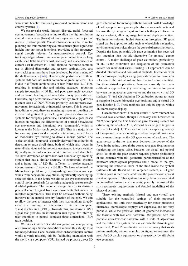
Figure 1. System overview. Hardware: ultra-low-cost head mounted binocular eye tracker built using off the shelf components includingtwo PlayStation 3 Eye cameras (10 USD each), two IR LEDs, cheap reading glasses frames and elastic headband support. The cameras aremounted on lightweight aluminium tubing. The hardware total cost is 30 USD. Software: the camera frames are streamed at 120 Hz via USBto a standard laptop computer and the pupil positions are extracted using image processing (see figure 3). A 2D user calibration allows amapping between pupil and 2D gaze position to be learnt. Using the 2D estimates from both eyes, a 3D gaze estimation can be made byestimating the vergence point.
2. Methods
Our presented system is composed of ultra-low-cost imaginghardware and stand-alone software that implements ouralgorithms and methods for 3D and 2D gaze tracking.
2.1. Ultra-low-cost binocular eye-tracking hardware
The video-based binocular eye tracker shown in figure 1 usestwo ultra-low-cost video game console cameras (PlayStation3 Eye Camera—10 USD per unit), capable of 120 Hz frame-rate, at a resolution of 320 × 240 pixels. This is the maincost-reducing step in our system, as typical machine visioncameras operating at this performance are more expensive bytwo orders of magnitude. To optimize imaging conditions, wemodified the camera optics for infrared (IR) imaging at nomaterial cost by removing the IR filter and replacing it witha piece of exposed and developed film negative which acts asa low-cost IR-pass filter. We illuminate the eyes using two IRLEDs aligned off axis to the camera, creating a dark pupil effectto enhance the contrast between the pupil and the iris. ChronicIR exposure above a certain threshold leads to retinal damageor the formation of cataracts [12]. This threshold has beenreported as being between 10 and 20 mW cm−2 [12, 13]. TheLEDs used are Optek gallium arsenide OP165D which produce
an irradiance of between 0.28 and 1.6 mW cm−2 (dependingon the forward voltage) measured at a distance of 1.5 cm.This is well below the safety parameter, especially as it willbe mounted at 10 cm from the eye. These LEDs are poweredusing a USB cable giving a 5 V supply with up to 500 mAof current to be drawn. The driver circuit provides 20 mAcurrent to each LED with a forward voltage of 1.6 V applied.The cameras are head mounted to maximize the eye imageresolution and allow unrestrained head movement followingcalibration. The camera-mounting headset shown in figure 1has been designed with off the shelf components costing 10USD in total. The system weighs in total 135 g and the camerasand their mounting arms exert a moment of approximately0.1 Nm on the nose. It has been designed to allow four degreesof freedom for adjustment to different users (shown in figure 2).The images from the cameras are streamed via two USB2.0 interfaces to a standard laptop computer facilitating anaccessible and portable system.
2.2. Eye tracking
The eye-tracking methodology applies standard image-processing methods to locate the pupil centre in each videoframe; an overview of this process can be seen in figure 3.The IR imaging system increases the contrast between the
3

J. Neural Eng. 9 (2012) 046016 W W Abbott and A A Faisal
(a)
(b)
Figure 2. Headset adjustability. Headset design allows the camera position to be adjusted with four degrees of freedom: (a) rotation andtranslation of the camera on the boom arm and (b) rotation of the boom arm itself. This allows adjustment to customize the system todifferent users.
(a) (b) (c) (d) (e)
Figure 3. Pupil extraction image processing pipe-line. Images intermediates include: (a) raw greyscale, (b) binary, (c) noise filtered,(d) shape filtered, (e) original with extracted ellipse overlaid.
pupil and iris. This allows simple intensity threshold imagesegmentation, converting the greyscale image to a binaryimage (figure 3(b)). In this single step, the data volume perframe is reduced from 230 to 9.6 kB; retaining sufficientinformation to locate the pupil but reducing the subsequentcomputational load. Due to noise effects and other darkregions in the image, such as shadows and eyelashes, a pupilclassification step is made. To reduce the complexity of theclassification process, morphological operations of erosion anddilation were applied in a sequence—first ‘opening’ the image,removing the dropout noise; and then ‘closing’ it to fill in anyholes in the pupil blob (figure 3(c)). Connected componentlabelling is then applied to assign a unique label to the pixels ofeach candidate pupil region. Subsequently, a shape-based filteris applied (figure 3(d)) to classify the pupil-based on maximumand minimum object size and elongation (axis ratio). The pupilcentre is then extracted using least-squares regression to fit anellipse to the classified pupil object contour—this ellipse isshown overlaid on the raw image in figure 3(e). The x and ycoordinates of the ellipse centre (in pixels) are extracted foreach eye ellipse as the pupil positions.
2.3. Calibration for 3D gaze estimation
The pupil positions extracted from the eye images must berelated to the gaze position. A purely explicit method requiresa rigid system setup difficult to obtain using low cost hardware,
while a purely implicit method requires more involved 3Dcalibration points. We achieve gaze estimation in the real 3Denvironment by combining an implicit step to infer the systemparameters with an explicit geometric step to transfer this to a3D gaze estimate. This involves the calibration of each pupilposition to the respective gaze positions on a computer VDU(2D calibration). From this, the 3D gaze vector of each eyecan be found (step 1) from which the 3D fixation point is thencalculated (step 2).
Step 1: Calculating 3D gaze vectors using 2D calibration.Calibration to the 2D computer monitor can be made explicitlyusing the geometry of the system [14–17] or implicitly using acalibration routine to infer a mapping between pupil position(in the eye image) and gaze position (on the computer screen)[18–20]. The implicit mapping provides a more suitablesolution because explicit methods require precise geometricknowledge of camera positions, infeasible with the low-costadjustable headset. To learn an implicit mapping, training datais acquired using a calibration routine which displays eachpoint of a 5 × 5 calibration grid that spans the computerVDU. At each calibration point, the pupil location of eacheye is extracted from a ten-frame burst and the user’s averageeye positions are recorded. This reduces noise effects of driftand micro-saccades. The calibration data points collected areused to train a Bayesian linear combination of nonlinearbasis functions. The second-order polynomial basis functionswere found to achieve an optimum trade-off between model
4
J. Neural Eng. 9 (2012) 046016 W W Abbott and A A Faisal
(a)
(c)
(b)
(d)
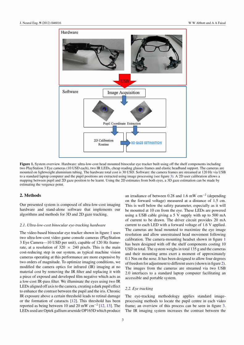
Figure 4. Illustration of our 3D gaze estimation method. (a) 2D calibration step to relate the pupil positions to their gaze positions in theVDU screen plane. The user is aligned with the horizontal screen centre and must remain stationary during calibration. The measurementsshown are required for calibration. (b) Side view of user and computer VDU screen. (c) The left and right gaze estimates on the VDU arerepresented by the two dots (xL, yL) and (xR, yR) and yield the gaze vectors shown (VL and VR). (d) The nearest point of approach on each gazevector is found.
complexity and the number of calibration points required togeneralize well. Following the 2D calibration routine, thesecond-order polynomial mapping is used to map the positionof each eye to the gaze position in the 2D plane of thecomputer monitor, at a frame rate of 120 Hz. When the userfixates in the monitor plane, the gaze estimates of each eye areapproximately superimposed as shown in figure 4(a). Whenthe user fixates outside of the monitor plane, the 2D gazeestimates diverge as shown in figure 4(c). This divergence givesdepth information as the 2D gaze estimates are effectivelythe intersection between the gaze vectors and the computermonitor plane (see figure 4(c)). The gaze vectors are calculatedfrom the 2D gaze estimates xL, yL and xR, yR (relative to thetop left corner of the screen) using equations (2.1) and (2.2).This requires the relative positions of the eyes and monitor tobe fixed during calibration and measurements of screen height(Sheight), eye level (Eheight), eye to screen (Deye-screen) and inter-eye distance (Einter) to be made (see figures 4(a) and (b)). Theeye tracker is head mounted and the system is calibrated witha head-centric coordinate system; thus, following calibrationthe user will be free to move his/her head and the gaze vectorswill be relative to the origin which lies between the eyes.
Step 2: Using the 3D gaze vectors to estimate the 3D gazeposition. We use the 3D gaze vectors to estimate the 3D gazeposition. The 3D gaze position is the vergence point of the twogaze vectors. Exact 3D vector intersection is unlikely; thus,
the nearest point of approach on each vector is found. Thesepoints are represented by IL and IR in figure 4(d) and are givenby the parametric equations (2.3) and (2.4). The positions ofthe eyes relative to the origin are represented by IL0 and IR0 asshown in figure 4(c) while SL and SR represent scalars to befound:
�VL =
⎡⎢⎣
xL − Swidth
2+ Einter
2Sheight − Eheight − yL
Deye−screen
⎤⎥⎦ (2.1)
�VR =
⎡⎢⎣
xR − Swidth
2− Einter
2Sheight − Eheight − yR
Deye−screen
⎤⎥⎦ (2.2)
IL(SL) = IL0 + SL�VL (2.3)
IR(SR) = IR0 + SR�VR. (2.4)
By definition, the nearest points of approach will be connectedby a vector that is uniquely perpendicular to both gazevectors—�W shown in figure 4(d) and equation (2.5). Tosatisfy this condition, the simultaneous equations (2.5)–(2.7)must hold. Substituting equations (2.3) and (2.4) into thesimultaneous equations and solving for the scalars SL and SR,we can then obtain the nearest points of approach—IL and IR.
5

J. Neural Eng. 9 (2012) 046016 W W Abbott and A A Faisal
0 50 100 150 200 250 300 350 400 450 5000
50
100
150
200
250
X Screen Coordinate (mm)
Y S
cree
n C
oo
rdia
nte
(m
m)
(a) (b)
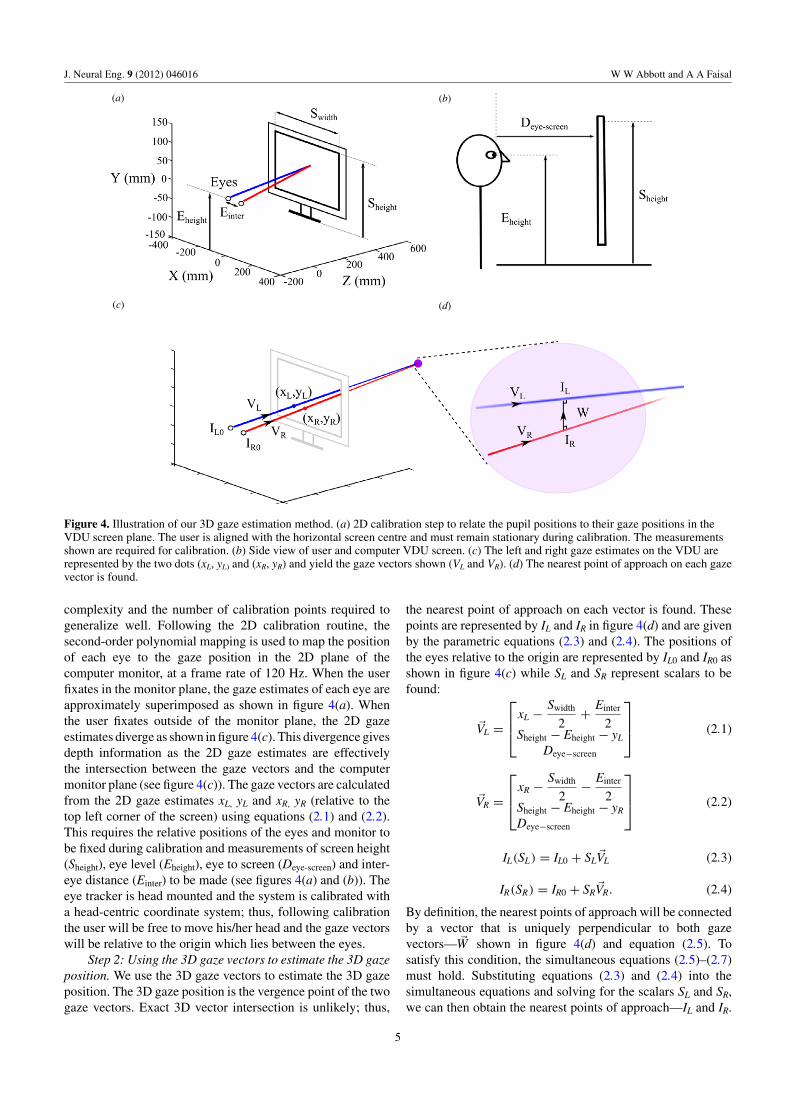
Figure 5. 2D and 3D gaze estimation test points and gaze estimates. (a) 2D gaze estimation: the circles represent the 15 randomly generatedtest positions displayed on the VDU and the squares are the gaze estimate. (b) 3D plot of 3D gaze estimation results for a calibration test runwith test points being displayed at four depths—(54, 77, 96 and 108 cm) following 2D calibration at 54 cm. The circles represent the realdisplayed positions and the squares represent the gaze estimations.
The 3D gaze estimation (G3D) is then taken as the mid-pointof these two positions as shown in equation (2.8):
�W = IL − IR (2.5)
�W · �VL = 0 (2.6)
�W · �VR = 0 (2.7)
G3D = IL(SL) + IR(SR)
2. (2.8)
This algorithm is performed for each frame in the videostreams to obtain a 3D gaze estimate at 120 Hz samplingfrequency that can be used as a volumetric cursor in thedevelopment of advanced user interfaces for neuromotorprosthetics.
2.4. Solution to the Midas touch problem
To address the Midas touch problem, the system usesnon-behavioural winks to confirm gaze commands. Winkscan be distinguished from behavioural blinks by virtue ofthe binocular eye-tracking feed allowing for much shortercommand integration times. In the filtered binary eye image(see figure 3(d)), when the eye is closed, no pupil objectis located by the eye tracker, raising a closed eye flag. Wedistinguish between a left eye wink, right eye wink andsimultaneous eye blinks using temporal logic. For examplea left wink is defined by the left eye being closed and the righteye being open simultaneously for more than 20 frames. Thehigh frame rate allows for this distinction to be made reliablywith low integration times of ∼170 ms.
3. Results
We group the three main contributions of this paper intothe following sections. (1) High performance ultra-low-costbinocular eye-tracking system: eye-tracking accuracy andprecision. (2) Solution to the Midas touch problem and
continuous control: human computer interaction and a BMIbenchmark for closed-loop control of devices. (3) Gazeestimation in the 3D environment: accuracy and precisionin 3D tasks.
3.1. Eye-tracking accuracy and precision
To precisely estimate the eye tracking system’s accuracy, asubject was calibrated and shown random test points of known3D locations in three separate trials. Each trial involved acalibration routine that cycled through a 5 × 5 calibration griddisplayed on a computer monitor 50 cm from the user’s eyes,followed by 15 randomly generated test points. The results forone trial are shown in figure 5(a). For each trial, a new setof random test points was generated. Each test point appearedin turn and the user looked at the point and hit the spacebar, at which point the gaze position was recorded from thereal-time data stream. Over all trials a mean Euclidean errorof 0.51 ± 0.41 cm (standard deviation) was achieved at adistance of 50 cm which translates into an angular error of0.58 ± 0.47 degrees.
Table 1 compares our system with a commerciallyavailable binocular eye tracking system. Our gaze angleaccuracy was 0.58 deg ± 0.47 (mean ± SD) and is definedas the eye-tracking signal accuracy, namely how precisely theviewing direction of the eye can be determined. This measureis viewing distance and application-independent but has directimplications for both 2D (monocular) and 3D (binocular) gazetarget position estimation accuracy. We achieved an average of0.58◦ while the reference system’s EyeLink II manufacturerspecifies a typical average accuracy as <0.5◦—but do notprovide more specific data or measurement approach. Oursystem can perform 2D or 3D gaze estimation, while theEyeLink II, though also a binocular eye-tracker, has softwareto perform 2D estimation only. Our system is less than one-third of the mass at 135 g compared to the 420 g commercialsystem, and less than 1/800th of the cost with a unit cost ofjust 30 USD compared to the 25 000 USD commercial system
6
J. Neural Eng. 9 (2012) 046016 W W Abbott and A A Faisal
Table 1. Comparison between our system (referred to here asGT3D) and the commercial EyeLink II. Here we make comparisonsusing the metrics in the EyeLink II technical specifications. Moredetailed analysis of the 3D performance is shown in table 3.
Metric GT3D EyeLink IIa
Gaze angle accuracy 0.58 ± 0.47◦ <0.5◦ b
Gaze estimation modes 2D, 3D 2DHorizontal range 34◦ 40◦
Vertical 20◦ 36◦
Headset mass 135 g 420 gFrame rate 120 Hz 250 HzCost 30 USD 25 000 USD
a Information is taken from the SR Research issuedtechnical specification.b For the EyeLink II the accuracy is expressed as a‘typical average’ in corneal reflection mode. No errormeasurement is given. We provide here the mean gazeangle accuracy and standard deviation for our GT3Dsystem averaged over three separate trials.
cost. Since the tracking range is less for our system—6 degreesmaller horizontally and 16 degree smaller vertically—it is animage-processing problem that needs to be solved. The framerate is also slightly lower at 120 Hz compared to the 250 Hzof the commercial system, but is sufficiently high to resolvesaccades and gives a frame rate four times that of other low-cost systems.
3.2. Human computer interaction and a BMI benchmark forclosed-loop control of devices
With the system in 2D mode, the user can operate a computer,performing such tasks as opening and browsing the weband even playing real-time games. The system does notrequire a bespoke graphical user interface, operating in awindows environment with an icon size of 3 cm2. The useof wink commands allows the integration time to be reducedto ∼170 ms of wink to make a selection. To demonstratereal-time continuous control using the eye-tracking system,we used it to play classic video game ‘Pong’. This is verysimplified computer tennis where the user has to return the ballby moving a racket to meet the approaching ball. We chose thisvery simple game because it can be used with a mouse input,played against a computer opponent and is readily availableonline. This allows it to be used as a very simple benchmarkthat other BMIs can be tested against.
We conducted a user study (six subjects, aged 22–30)to test closed-loop real-time control performance for ourinterface. Subjects (five first-time eye-tracking users) werecalibrated using our 5 × 5 grid method and then given 10 minto learn to play Pong and to get used to using their eyes as acontrol input. Subject hands asked to keep their hands foldedin their laps. The tracked gaze position (vertical component)controlled the Pong paddle position on the screen, as the paddlefollowed the movements of the mouse pointer (which wedirectly controlled through GT3D). Thereafter subjects playedfour full games of Pong against the computer (up to a score ofnine points) using our interface and then four full games usingtheir hands to control the computer mouse. The final score and
Table 2. Pong gaming performance. For each input modality themean and standard deviation for the player and computer scores,number of returned shots per game and percentage of player wins.
Score
Player ComputerReturnedshots
Total playerwins (%)
Our system 6.6 ± 2.0 8.4 ± 1.3 43 ± 16 25 ± 14Mouse input 8.3 ± 1.5 5.5 ± 2.7 53 ± 14 80 ± 22No input 0.50 ± 1.0 9.0 ± 0.0 8.0 ± 3.6 0 ± 0
Table 3. Three-dimensional gaze estimation performance for theresults shown in figure 5.
Mean absolute error (cm) Standard deviation (cm)
x 1.1 0.7y 1.2 1.1z 5.1 5.0Euclidean 5.8 4.7
number of returned shots are reported in table 2. On averagesubjects using our gaze-based approach achieved a score of6.6 ± 2.0 (mean ± SD across subjects) compared to thecomputer opponent score of 8.4 ± 1.30 (mean ± SD acrosssubjects). Subjects made 43 ± 16 successful returns per gameand on average 25% ± 14% of games were won by the player,i.e. at least one game won out of four. Using the mouse input,subjects achieved a mean score of 8.3 ± 1.5 against computeropponent 5.5 ± 2.7, with a mean of 53 ± 14 player returnedshots and 80 ± 22% of games won by the player. In addition,we compared the zero-control scores (without any user input)giving an average score of 0.5 ± 1.0 and computer opponentscore of 9.0 ± 0.0 with a mean of 8.0 ± 3.6 returned shotsper game.
These scores form the framework for our proposed newbenchmark of closed-loop real-time control for BMIs andwe make the ready-to-use browser-based game availablethrough our website to facilitate benchmarking BMI systems(http://www.FaisalLab.com/Pong). As well as the abovescoring metric, the benchmark participants should include theamount of prior training and acclimatization time of the BMIsystem (for our system this is 10 min) and system/treatmentcosts.
3.3. Accuracy and precision in 3D tasks
To assess the 3D gaze estimation, the methodology was similarto the 2D experiment but test points were also displayed atdifferent depths. Following the 5 × 5 2D calibration routineat a depth of 54 cm, five random test points were generated atfour depths: 54, 77, 96 and 108 cm by moving the computermonitor. Over this workspace, the system performed with amean Euclidian error of 5.8 cm, with a standard deviationof 4.7 cm. The results for this experiment are displayedon a 3D plot in figure 5(b). The mean absolute error andstandard deviation for each dimension is shown in table 3.The mean depth error (Z in table 3 and figure 5(b)) is5.1 cm with a standard deviation of 4.7 cm; this accuracy andprecision is four times larger than the horizontal and vertical
7
J. Neural Eng. 9 (2012) 046016 W W Abbott and A A Faisal
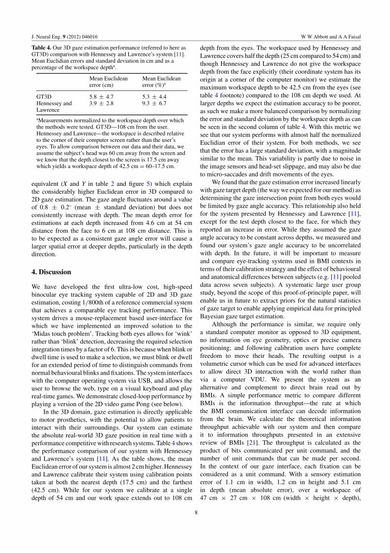
Table 4. Our 3D gaze estimation performance (referred to here asGT3D) comparison with Hennessey and Lawrence’s system [11].Mean Euclidian errors and standard deviation in cm and as apercentage of the workspace deptha.
Mean Euclideanerror (cm)
Mean Euclideanerror (%)a
GT3D 5.8 ± 4.7 5.3 ± 4.4Hennessey andLawrence
3.9 ± 2.8 9.3 ± 6.7
aMeasurements normalized to the workspace depth over whichthe methods were tested. GT3D—108 cm from the user.Hennessey and Lawrence—the workspace is described relativeto the corner of their computer screen rather than the user’seyes. To allow comparison between our data and their data, weassume the subject’s head was 60 cm away from the screen andwe know that the depth closest to the screen is 17.5 cm awaywhich yields a workspace depth of 42.5 cm = 60–17.5 cm.
equivalent (X and Y in table 2 and figure 5) which explainthe considerably higher Euclidean error in 3D compared to2D gaze estimation. The gaze angle fluctuates around a valueof 0.8 ± 0.2◦ (mean ± standard deviation) but does notconsistently increase with depth. The mean depth error forestimations at each depth increased from 4.6 cm at 54 cmdistance from the face to 6 cm at 108 cm distance. This isto be expected as a consistent gaze angle error will cause alarger spatial error at deeper depths, particularly in the depthdirection.
4. Discussion
We have developed the first ultra-low cost, high-speedbinocular eye tracking system capable of 2D and 3D gazeestimation, costing 1/800th of a reference commercial systemthat achieves a comparable eye tracking performance. Thissystem drives a mouse-replacement based user-interface forwhich we have implemented an improved solution to the‘Midas touch problem’. Tracking both eyes allows for ‘wink’rather than ‘blink’ detection, decreasing the required selectionintegration times by a factor of 6. This is because when blink ordwell time is used to make a selection, we must blink or dwellfor an extended period of time to distinguish commands fromnormal behavioural blinks and fixations. The system interfaceswith the computer operating system via USB, and allows theuser to browse the web, type on a visual keyboard and playreal-time games. We demonstrate closed-loop performance byplaying a version of the 2D video game Pong (see below).
In the 3D domain, gaze estimation is directly applicableto motor prosthetics, with the potential to allow patients tointeract with their surroundings. Our system can estimatethe absolute real-world 3D gaze position in real time with aperformance competitive with research systems. Table 4 showsthe performance comparison of our system with Hennesseyand Lawrence’s system [11]. As the table shows, the meanEuclidean error of our system is almost 2 cm higher. Hennesseyand Lawrence calibrate their system using calibration pointstaken at both the nearest depth (17.5 cm) and the farthest(42.5 cm). While for our system we calibrate at a singledepth of 54 cm and our work space extends out to 108 cm
depth from the eyes. The workspace used by Hennessey andLawrence covers half the depth (25 cm compared to 54 cm) andthough Hennessey and Lawrence do not give the workspacedepth from the face explicitly (their coordinate system has itsorigin at a corner of the computer monitor) we estimate themaximum workspace depth to be 42.5 cm from the eyes (seetable 4 footnote) compared to the 108 cm depth we used. Atlarger depths we expect the estimation accuracy to be poorer,as such we make a more balanced comparison by normalizingthe error and standard deviation by the workspace depth as canbe seen in the second column of table 4. With this metric wesee that our system performs with almost half the normalizedEuclidian error of their system. For both methods, we seethat the error has a large standard deviation, with a magnitudesimilar to the mean. This variability is partly due to noise inthe image sensors and head-set slippage, and may also be dueto micro-saccades and drift movements of the eyes.
We found that the gaze estimation error increased linearlywith gaze target depth (the way we expected for our method) asdetermining the gaze intersection point from both eyes wouldbe limited by gaze angle accuracy. This relationship also heldfor the system presented by Hennessey and Lawrence [11],except for the test depth closest to the face, for which theyreported an increase in error. While they assumed the gazeangle accuracy to be constant across depths, we measured andfound our system’s gaze angle accuracy to be uncorrelatedwith depth. In the future, it will be important to measureand compare eye-tracking systems used in BMI contexts interms of their calibration strategy and the effect of behaviouraland anatomical differences between subjects (e.g. [11] pooleddata across seven subjects). A systematic large user groupstudy, beyond the scope of this proof-of-principle paper, willenable us in future to extract priors for the natural statisticsof gaze target to enable applying empirical data for principledBayesian gaze target estimation.
Although the performance is similar, we require onlya standard computer monitor as opposed to 3D equipment,no information on eye geometry, optics or precise camerapositioning; and following calibration users have completefreedom to move their heads. The resulting output is avolumetric cursor which can be used for advanced interfacesto allow direct 3D interaction with the world rather thanvia a computer VDU. We present the system as analternative and complement to direct brain read out byBMIs. A simple performance metric to compare differentBMIs is the information throughput—the rate at whichthe BMI communication interface can decode informationfrom the brain. We calculate the theoretical informationthroughput achievable with our system and then compareit to information throughputs presented in an extensivereview of BMIs [21]. The throughput is calculated as theproduct of bits communicated per unit command, and thenumber of unit commands that can be made per second.In the context of our gaze interface, each fixation can beconsidered as a unit command. With a sensory estimationerror of 1.1 cm in width, 1.2 cm in height and 5.1 cmin depth (mean absolute error), over a workspace of47 cm × 27 cm × 108 cm (width × height × depth),
8
J. Neural Eng. 9 (2012) 046016 W W Abbott and A A Faisal
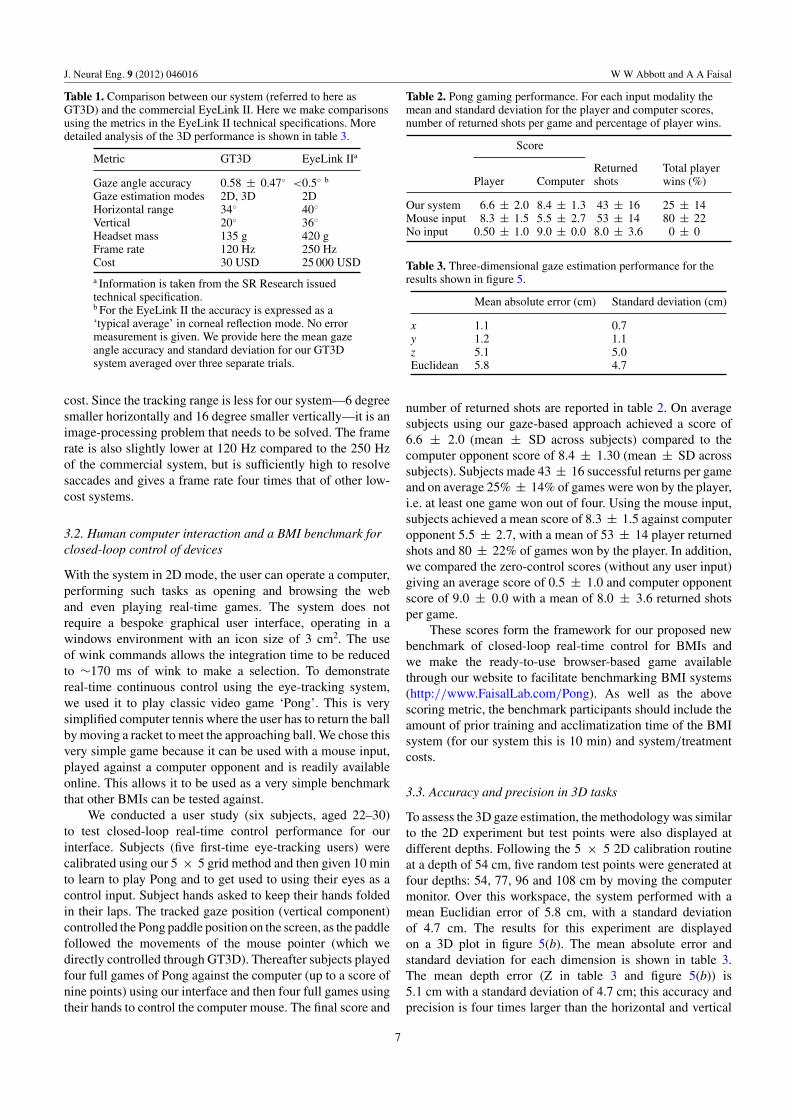
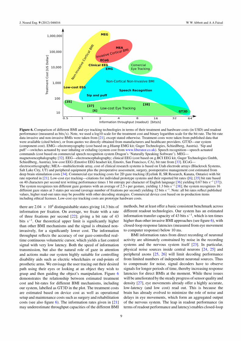
Figure 6. Comparison of different BMI and eye tracking technologies in terms of their treatment and hardware costs (in USD) and readoutperformance (measured as bits/s). Note, we used a log10 scale for the treatment cost and binary logarithm scale for the bit rate. The bit-ratedata invasive and non-invasive BMIs were taken from [21], except stated otherwise. Treatment costs were taken from published data thatwere available (cited below), or from quotes we directly obtained from manufacturers and healthcare providers. GT3D—our system(component cost). EMG—electromyography (cost based on g.Hiamp EMG kit; Guger Technologies, Schiedlberg, Austria). ‘Sip andpuff’—switches actuated by user inhaling or exhaling (system cost from www.liberator.co.uk). Speech recognition—speech actuatedcommands (cost based on commercial speech recognition system Dragon’s ‘Naturally Speaking Software’). MEG—magnetoencephalography [32]. EEG—electroencephalography; clinical EEG (cost based on g.BCI EEG kit, Guger Technologies Gmbh,Schiedlberg, Austria), low-cost EEG (Emotive EEG headset kit, Emotiv, San Francisco, CA), bit rate from [33]. ECoG—electrocorticography; MEA—multielectrode array, cost of clinical research systems is based on Utah electrode arrays (Blackrock Systems,Salt Lake City, UT) and peripheral equipment plus the preoperative assessment, surgery, postoperative management cost estimated fromdeep brain stimulation costs [34]. Commercial eye tracking costs for 2D gaze tracking (Eyelink II, SR Research, Kanata, Ontario) with bitrate reported in [21]. Low-cost eye tracking—citations for individual prototype systems and their reported bit rates ([6]; [35] bit rate basedon 40 characters per second text writing performance times 1 bit entropy per character of English language [36] yielding 0.67 bits s−1 [37]).The system recognizes ten different gaze gestures with an average of 2.5 s per gesture, yielding 1.3 bits s−1 [38]; the system recognizes 16different gaze states at 3 states per second (average number of fixations per second) yielding 12 bits s−1. Note: all bit rates reflect publishedvalues, higher read-out rates may be possible with other decoding strategies. Commercial device cost based on in-production itemsincluding ethical licenses. Low-cost eye tracking costs are prototype hardware costs.
there are 2.04 × 10⁴ distinguishable states giving 14.3 bits ofinformation per fixation. On average, we fixate with a rateof three fixations per second [22]; giving a bit rate of 43bits s−1. Our theoretical upper limit is significantly higherthan other BMI mechanisms and the signal is obtained non-invasively, for a significantly lower cost. The informationthroughput reflects the accuracy of our gaze-controlled real-time continuous volumetric cursor, which yields a fast controlsignal with very low latency. Both the speed of informationtransmission, but also the natural role of gaze in attentionand actions make our system highly suitable for controllingdisability aids such as electric wheelchairs or end-points ofprosthetic arms. We envisage the user tracing out their desiredpath using their eyes or looking at an object they wish tograsp and then guiding the object’s manipulation. Figure 6demonstrates the relationship between estimated treatmentcost and bit-rates for different BMI mechanisms, includingour system, labelled as GT3D in the plot. The treatment costsare estimated based on device cost as well as operationalsetup and maintenance costs such as surgery and rehabilitationcosts (see also figure 6). The information rates given in [21]may underestimate throughput capacities of the different BMI
methods, but at least offer a basic consistent benchmark acrossdifferent readout technologies. Our system has an estimatedinformation transfer capacity of 43 bits s−1, which is ten timeshigher than other invasive BMI approaches (see figure 6), withclosed-loop response latencies (measured from eye movementto computer response) below 10 ms.
BMI information rates from direct recording of neuronalactivity are ultimately constrained by noise in the recordingsystems and the nervous system itself [23]. In particular,physical noise sources inside central neurons [24, 25] andperipheral axons [25, 26] will limit decoding performancefrom limited numbers of independent neuronal sources. Thusto compensate for noise, signal decoders have to observesignals for longer periods of time, thereby increasing responselatencies for direct BMIs at the moment. While these issueswill be ameliorated by the steady progress of sensor quality anddensity [27], eye movements already offer a highly accurate,low-latency (and low cost) read out. This is because thebrain has already evolved to minimize the role of noise anddelays in eye movements, which form an aggregated outputof the nervous system. The leap in readout performance (interms of readout performance and latency) enables closed-loop
9

J. Neural Eng. 9 (2012) 046016 W W Abbott and A A Faisal
real-time control of rehabilitative and domotic devicesbeyond what is achievable by current BMIs: for exampleit was estimated that powered wheelchair control requires,on average, 15.3 bits s−1 and full-finger hand prostheticsrequire 54.2 bits s−1 [21]. Our system demonstrated a clearimprovement on low-level measures of BMI performance, butsuch technical measures mask the complexities of learningto use and operating BMIs in the clinic and daily-life.Therefore, we also introduce a real-world, closed-loop controlbenchmark—playing an arcade video game—as a high-level,behaviour-based measure for BMI performance. We reportedthe performance for both normal (mouse-based) use andusing our GT3D system in our subject study to establish thebenchmark and make its software available to the community.On average, naı̈ve users of our gaze-based system achieveda game score within 12.5% of their own score when playingthe game directly with a computer mouse, demonstrating thatsubjects achieved near-normal closed-loop real-time control.This is also reflected in the mean number of successfullyreturned shots per game using our system (average of 43against the computer-mouse score of 53) despite the novelcontrol modality and very short training time (10 min from firstuse). We, thus, demonstrated how ultra-low cost, non-invasiveeye-tracking approach can form the basis of a real-timecontrol interface for rehabilitative devices, making it a low-cost complement or alternative to existing BMI technologies.
Eye movements are vital for motor planning; we lookwhere we are going, reaching and steering [28], and therefore3D gaze information is highly correlated with user intentions inthe context of navigation and manipulation of our surroundings[29, 30]. Our approach, unlike other BMI technologies, enablesus to use gaze information to infer user intention in the contextof its natural occurrence, e.g. steering a wheel chair ‘by eye’gaze, as we are already looking where we are going. Thisapproach drastically reduces training time and boost patient’sadherence. Moreover, the structured statistics of human eyemovements in real-world tasks enables us to build Bayesiandecoders to further boost decoding accuracy, reliability andspeed even in complex environments [31]. Our 3D gazetracking approach lends itself ideally to complement, or whentreatment costs are at a premium even replace, conventionalBMI approaches.
Acknowledgments
The authors acknowledge financial support from the EPSRC.Early results have been presented as a TED talk in May2010 (London, UK), as a poster presentation at CNS 2011(Stockholm, Sweden) [39] and as a TEDx Imperialtalk in February 2012 (http://www.youtube.com/watch?v=6ZteM65b76Y). They acknowledge the early technicalcontributions of Ian Beer, Aaron Berk, Oliver Rogers andTimothy Treglown for a Linux and 2D version of the system.
References
[1] Hochberg L, Nurmikko A and Donoghue J E 2012 Brainmachine interface Annu. Rev. Biomed. Eng. 14 at press
[2] Kaminski H J, Richmonds C R, Kusner L L and Mitsumoto H2002 Differential susceptibility of the ocular motor systemto disease Ann. New York Acad. Sci. 956 42–54
[3] Kaminski H J, Al-Hakim M, Leigh R J, Bashar M Kand Ruff R L 1992 Extraocular muscles are spared inadvanced Duchenne dystrophy Ann. Neurol. 32 586–88
[4] Jordansen I K, Boedeker S, Donegan M, Oosthuizen L, diGirolamo M and Hansen J P 2005 D7.2 Report on a marketstudy and demographics of user population Communicationby Gaze Interaction (COGAIN) IST-2003-511598 (availableat http://www.cogain.org/results/reports/COGAIN-D7.2.pdf)
[5] Schneider N, Bex P, Barth E and Dorr M 2011 An open-sourcelow-cost eye-tracking system for portable real-time andoffline tracking Proc. 1st Conf. on Novel Gaze-ControlledApplications (Karlskrona Sweden: ACM) pp 1–4
[6] San Agustin J, Skovsgaard H, Hansen J P and Hansen D W2009 Low-cost gaze interaction: ready to deliver thepromises Proc. 27th Int. Conf. Extended Abstracts onHuman Factors in Computing Systems. CHI EA ’09(New York: ACM) pp 4453–58
[7] Li D, Babcock J and Parkhurst D J 2006 OpenEyes: a low-costhead-mounted eye-tracking solution Proc. Symp. EyeTracking Research and Applications. ETRA ’06 (New York:ACM) pp 95–100
[8] Jacob R J K 1990 What you look at is what you get: eyemovement-based interaction techniques Proc. SIGCHIConf. on Human Factors in Computing Systems:Empowering People. CHI ’90 (New York: ACM) pp 11–8
[9] Duchowski A T, Medlin E, Cournia N and Gramopadhye A2002 3D eye movement analysis for VR visual inspectiontraining Proc. Symp. Eye tracking research & applications.ETRA ’02 (New York: ACM) pp 103–10
[10] Ki J and Kwon Y-M 2008 3D gaze estimation and interactionConf. on 3DTV: The True Vision-Capture, Transmission andDisplay of 3D Video pp 373–6
[11] Hennessey C and Lawrence P 2009 Noncontact binoculareye-gaze tracking for point-of-gaze estimation in threedimensions IEEE Trans. Biomed. Eng. 56 790–99
[12] Sliney D H and Freasier B C 1973 Evaluation of opticalradiation hazards App. Opt. 12 1–24
[13] Sliney D et al 2005 Adjustment of guidelines for exposure ofthe eye to optical radiation from ocular instruments:statement from a task group of the InternationalCommission on Non-Ionizing Radiation Protection(ICNIRP) App. Opt. 44 2162–76
[14] Lee E C and Park K R 2008 A robust eye gaze trackingmethod based on a virtual eyeball model Mach. Vis. Appl.20 319–37
[15] Sheng-Wen S and Jin L 2004 A novel approach to 3D gazetracking using stereo cameras IEEE Trans. Syst. ManCybern. B 34 234–45
[16] Sheng-Wen S, Yu-Te W and Jin L 2000 A calibration-free gazetracking technique Proc. 15th Int. Conf. on Pattern Recogn.(IEEE) 4 pp 201–4
[17] Hennessey C A and Lawrence P D 2009 Improving theaccuracy and reliability of remote system-calibration-freeeye-gaze tracking IEEE Trans. Biomed. Eng. 56 1891–900
[18] Faisal A A, Fislage M, Pomplun M, Rae R and Ritter H 1998Observation of human eye movements to simulate visualexploration of complex scenes Technical Report Universityof Bielefeld http://citeseerx.ist.psu.edu/viewdoc/summary?doi=10.1.1.38.8855
[19] Morimoto C H and Mimica M R M 2005 Eye gaze trackingtechniques for interactive applications Comput. Vis. ImageUnderst. 98 4–24
[20] Brolly X L C and Mulligan J B 2004 Implicit calibration of aremote raze tracker Proc. Int. Conf. Computer Vision and
10

J. Neural Eng. 9 (2012) 046016 W W Abbott and A A Faisal
Pattern Recognition Workshop CVPRW ’04 (WashingtonDC: IEEE Comp. Soc.) vol 8 p 134
[21] Tonet O, Marinelli M, Citi L, Rossini P M, Rossini L,Megali G and Dario P 2008 Defining brain-machineinterface applications by matching interface performancewith device requirements J. Neurosci. Methods 167 91–104
[22] Land M F and Tatler B W 2009 Looking and Acting: Visionand Eye Movements in Natural Behaviour (New York:Oxford University Press)
[23] Faisal A A, Selen L P J and Wolpert D M 2008 Noise in thenervous system Nature Rev. Neurosci. 9 292–303
[24] Faisal A A, Laughlin S B and White J A 2002 How reliable isthe connectivity in cortical neural networks? Proc. IEEEInt. J. Conf. on Neural Networks ’02 (IJCNN) pp 1661–6(available at http://ieeexplore.ieee.org/xpl/articleDetails.jsp?tp=&arnumber=1007767&contentType=Conference+Publications&sortType%3Dasc_p_Sequence%26filter%3DAND%28p_IS_Number%3A21694%29)
[25] Faisal A 2010 Stochastic simulation of neurons, axons andaction potentials Stochastic Methods in Neuroscience(Oxford: Oxford University Press) pp 297–343
[26] Faisal A A, White J A and Laughlin S B 2005 Ion-channelnoise places limits on the miniaturization of the brain’swiring Curr. Biol. 15 1143–9
[27] Stevenson I H and Kording K P 2011 How advances inneural recording affect data analysis Nature Neurosci.14 139–42
[28] Land M F and Lee D N 1994 Where we look when we steerNature 6483 742
[29] Hwang A D, Wang H-C and Pomplun M 2011 Semanticguidance of eye movements in real-world scenes Vis. Res.51 1192–205
[30] Land M F, Mennie N and Rusted J 1999 The roles of visionand eye movements in the control of activities of dailyliving Perception 28 1311–28
[31] Wang H-C, Hwang A D and Pomplun M 2010 Objectfrequency and predictability effects on eye fixationdurations in real-world scene viewing J. Eye Mov. Res.3 1–10
[32] Ray A and Bowyer S M 2010 Clinical applications ofmagnetoencephalography in epilepsy Ann. Indian Acad.Neurol. 13 14–22
[33] Bobrov P, Frolov A, Cantor C, Fedulova I, Bakhnyan Mand Zhavoronkov A 2011 Brain-computer interface basedon generation of visual images PLoS One 6 e20674
[34] McIntosh E, Gray A and Aziz T 2003 Estimating the costs ofsurgical innovations: the case for subthalamic nucleusstimulation in the treatment of advanced Parkinson’sdisease Mov. Disord. 18 993–9
[35] Lemahieu W and Wyns B 2011 Low cost eye tracking forhuman-machine interfacing J. Eyetracking, Vis. Cogn.Emotion 1 1–12
[36] Shannon C 1951 Prediction and Entropy of Printed English(Shannon: Collected Papers) (Piscataway, NJ: IEEE)
[37] Rozado D, Rodriguez F B and Varona P 2012 Low cost remotegaze gesture recognition in real time Appl. Soft Comput.12 2072–84
[38] Topal C, Gerek N and Dogan A 2008 A head-mountedsensor-based eye tracking device: eye touch system Proc.2008 Symp. on Eye Tracking Research & Applications(ETRA ’08) ACM (New York, NY, USA) pp 87–90
[39] Abbott W W and Faisal A A 2011 Ultra-low cost eyetrackingas an high-information throughput alternative to BMIs BMCNeurosci. 12 103
11