Ultra-High Packing Density Next Generation Microtube Array ...
21
membranes Article Ultra-High Packing Density Next Generation Microtube Array Membrane for Absorption Based Applications Chee Ho Chew 1 , Wan-Ting Huang 1 , Tzu-Sen Yang 2 , Amanda Chen 3 , Yun Ming Wu 1 , Mai-Szu Wu 4,5,6,7,8 and Chien-Chung Chen 1,8,9,10,11, * Citation: Chew, C.H.; Huang, W.-T.; Yang, T.-S.; Chen, A.; Wu, Y.M.; Wu, M.-S.; Chen, C.-C. Ultra-High Packing Density Next Generation Microtube Array Membrane for Absorption Based Applications. Membranes 2021, 11, 273. https:// doi.org/10.3390/membranes11040273 Academic Editors: Mike Barbeck and Sabrina Morelli Received: 4 March 2021 Accepted: 28 March 2021 Published: 8 April 2021 Publisher’s Note: MDPI stays neutral with regard to jurisdictional claims in published maps and institutional affil- iations. Copyright: © 2021 by the authors. Licensee MDPI, Basel, Switzerland. This article is an open access article distributed under the terms and conditions of the Creative Commons Attribution (CC BY) license (https:// creativecommons.org/licenses/by/ 4.0/). 1 Graduate Institute of Biomedical Materials & Tissue Engineering, College of Biomedical Engineering, Taipei Medical University, Taipei 11052, Taiwan; [email protected] (C.H.C.); [email protected] (W.-T.H.); [email protected] (Y.M.W.) 2 Graduate Institute of Biomedical Optomechatronics, Taipei Medical University, Taipei 11052, Taiwan; [email protected] 3 Department of Biology, University of Washington, Seattle, WA 98195, USA; [email protected] 4 Division of Nephrology, Taipei Medical University Shuang Ho Hospital, New Taipei City 23561, Taiwan; [email protected] 5 Research Center of Urology and Kidney, Taipei Medical University, Taipei 11052, Taiwan 6 Masters and Ph.D. Programs of Mind Brain and Consciousness, College of Humanities and Social Sciences, Taipei Medical University, Taipei 11052, Taiwan 7 Center for Cell Therapy and Regeneration Medicine, Taipei Medical University, Taipei 11052, Taiwan 8 The Ph.D. Program for Translational Medicine, College of Medical Science and Technology, Taipei Medical University, Taipei 11052, Taiwan 9 College of Biomedical Engineering, Taipei Medical University, Taipei 11052, Taiwan 10 College of Medicine, Taipei Medical University, Taipei 11052, Taiwan 11 College of Pharmacy, Taipei Medical University, Taipei 11052, Taiwan * Correspondence: [email protected]; Tel.: +886-911-455-155 Abstract: Previously, we successfully developed an extracorporeal endotoxin removal device (EERD) that is based on the novel next generation alternating microtube array membrane (MTAM-A) that was superior to the commercial equivalent. In this article, we demonstrated multiple different parameter modifications that led to multiple different types of novel new MTAM structures, which ultimately led to the formation of the MTAM-A. Contrary to the single layered MTAM, the MTAM-A series consisted of a superior packing density fiber connected in a double layered, alternating position which allowed for the greater fiber count to be packed per unit area. The respective MTAM variants were electrospun by utilizing our internally developed tri-axial electrospinning set up to produce the novel microstructures as seen in the respective MTAM variants. A key uniqueness of this study is the ability to produce self-arranged fibers into the respective MTAM variants by utilizing a single spinneret, which has not been demonstrated before. Of the MTAM variants, we observed a change in the microstructure from a single layered MTAM to the MTAM-A series when the ratio of surfactant to shell flow rate approaches 1:1.92. MTAM-A registered the greatest surface area of 2.2 times compared to the traditional single layered MTAM, with the greatest tensile strength at 1.02 ± 0.13 MPa and a maximum elongation of 57.70 ± 9.42%. The MTAM-A was selected for downstream immobilization of polymyxin B (PMB) and assembly into our own internally developed and fabricated dialyzer housing. Subsequently, the entire setup was tested with whole blood spiked with endotoxin; and benchmarked against commercial Toraymyxin fibers of the same size. The results demonstrated that the EERD based on the MTAM-A performed superior to that of the commercial equivalent, registering a rapid reduction of 73.18% of endotoxin (vs. Toraymyxin at 38.78%) at time point 15 min and a final total endotoxin removal of 89.43% (vs. Toraymyxin at 65.03%). Keywords: ultra-high packing density; microtube array membrane (MTAM); triaxial electrospinning; polymyxin B; sepsis Membranes 2021, 11, 273. https://doi.org/10.3390/membranes11040273 https://www.mdpi.com/journal/membranes
-
Upload
khangminh22 -
Category
Documents
-
view
4 -
download
0
Transcript of Ultra-High Packing Density Next Generation Microtube Array ...

membranes
Article
Ultra-High Packing Density Next Generation Microtube ArrayMembrane for Absorption Based Applications
Chee Ho Chew 1, Wan-Ting Huang 1, Tzu-Sen Yang 2, Amanda Chen 3 , Yun Ming Wu 1, Mai-Szu Wu 4,5,6,7,8 andChien-Chung Chen 1,8,9,10,11,*
�����������������
Citation: Chew, C.H.; Huang, W.-T.;
Yang, T.-S.; Chen, A.; Wu, Y.M.;
Wu, M.-S.; Chen, C.-C. Ultra-High
Packing Density Next Generation
Microtube Array Membrane for
Absorption Based Applications.
Membranes 2021, 11, 273. https://
doi.org/10.3390/membranes11040273
Academic Editors: Mike Barbeck and
Sabrina Morelli
Received: 4 March 2021
Accepted: 28 March 2021
Published: 8 April 2021
Publisher’s Note: MDPI stays neutral
with regard to jurisdictional claims in
published maps and institutional affil-
iations.
Copyright: © 2021 by the authors.
Licensee MDPI, Basel, Switzerland.
This article is an open access article
distributed under the terms and
conditions of the Creative Commons
Attribution (CC BY) license (https://
creativecommons.org/licenses/by/
4.0/).
1 Graduate Institute of Biomedical Materials & Tissue Engineering, College of Biomedical Engineering, TaipeiMedical University, Taipei 11052, Taiwan; [email protected] (C.H.C.);[email protected] (W.-T.H.); [email protected] (Y.M.W.)
2 Graduate Institute of Biomedical Optomechatronics, Taipei Medical University, Taipei 11052, Taiwan;[email protected]
3 Department of Biology, University of Washington, Seattle, WA 98195, USA; [email protected] Division of Nephrology, Taipei Medical University Shuang Ho Hospital, New Taipei City 23561, Taiwan;
[email protected] Research Center of Urology and Kidney, Taipei Medical University, Taipei 11052, Taiwan6 Masters and Ph.D. Programs of Mind Brain and Consciousness, College of Humanities and Social Sciences,
Taipei Medical University, Taipei 11052, Taiwan7 Center for Cell Therapy and Regeneration Medicine, Taipei Medical University, Taipei 11052, Taiwan8 The Ph.D. Program for Translational Medicine, College of Medical Science and Technology, Taipei Medical
University, Taipei 11052, Taiwan9 College of Biomedical Engineering, Taipei Medical University, Taipei 11052, Taiwan10 College of Medicine, Taipei Medical University, Taipei 11052, Taiwan11 College of Pharmacy, Taipei Medical University, Taipei 11052, Taiwan* Correspondence: [email protected]; Tel.: +886-911-455-155
Abstract: Previously, we successfully developed an extracorporeal endotoxin removal device (EERD)that is based on the novel next generation alternating microtube array membrane (MTAM-A) that wassuperior to the commercial equivalent. In this article, we demonstrated multiple different parametermodifications that led to multiple different types of novel new MTAM structures, which ultimatelyled to the formation of the MTAM-A. Contrary to the single layered MTAM, the MTAM-A seriesconsisted of a superior packing density fiber connected in a double layered, alternating positionwhich allowed for the greater fiber count to be packed per unit area. The respective MTAM variantswere electrospun by utilizing our internally developed tri-axial electrospinning set up to produce thenovel microstructures as seen in the respective MTAM variants. A key uniqueness of this study isthe ability to produce self-arranged fibers into the respective MTAM variants by utilizing a singlespinneret, which has not been demonstrated before. Of the MTAM variants, we observed a change inthe microstructure from a single layered MTAM to the MTAM-A series when the ratio of surfactant toshell flow rate approaches 1:1.92. MTAM-A registered the greatest surface area of 2.2 times comparedto the traditional single layered MTAM, with the greatest tensile strength at 1.02 ± 0.13 MPa and amaximum elongation of 57.70 ± 9.42%. The MTAM-A was selected for downstream immobilizationof polymyxin B (PMB) and assembly into our own internally developed and fabricated dialyzerhousing. Subsequently, the entire setup was tested with whole blood spiked with endotoxin; andbenchmarked against commercial Toraymyxin fibers of the same size. The results demonstratedthat the EERD based on the MTAM-A performed superior to that of the commercial equivalent,registering a rapid reduction of 73.18% of endotoxin (vs. Toraymyxin at 38.78%) at time point 15 minand a final total endotoxin removal of 89.43% (vs. Toraymyxin at 65.03%).
Keywords: ultra-high packing density; microtube array membrane (MTAM); triaxial electrospinning;polymyxin B; sepsis
Membranes 2021, 11, 273. https://doi.org/10.3390/membranes11040273 https://www.mdpi.com/journal/membranes

Membranes 2021, 11, 273 2 of 21
1. Introduction
Sepsis is a debilitating, life threatening disease that is common within Intensive CareUnits (ICU)s. This disease is one of the leading causes of death within ICU, accounting forup to 30% of the total deaths [1–4]. In the United States alone, this number accounted for200,000 lives and an economic loss of US$ 20 billion per annum [5]. Etiological speaking,sepsis is a highly complex systemic disease that is caused by the dysfunction and dys-regulation of the host immune system towards an infection, which results in multi-organfailure [6–8]. Within the highly complex inter-related factors, endotoxin is the principalcausative agent in the etiology of sepsis [9–11]. Clinically, high levels of endotoxin withinthe human body are often associated with poor clinical outcome [12,13].
Endotoxins naturally occur within the outer membrane layer of Gram-negative bacte-ria, and they are released into the surrounding upon the death or bacteria cell lysis [14–16].The majority of sepsis sources within ICUs originate from respiratory tract infections whichaccount for 67.4% of all ICU related sepsis cases, followed by abdomen related infectionsor translocation of bacteria which accounts for 21.8% of cases [17–19]. The presence ofendotoxin within the bloodstreams of patients results in symptoms such as fever, nausea,hypotension, shivering, and ultimately shock [14]. With increasing concentrations of en-dotoxin within the blood of the patients, complications such as endotoxin shock, adultrespiratory distress syndrome (ARDS), and disseminated intravascular coagulation (DIC)begin to appear [14,20,21]. In addition, high concentrations of endotoxin are known tobe a powerful activator of the kinin system, endothelial cells, leukocytes, and platelets,resulting in the dysregulation of the inflammatory response of the patient and ultimatelythe above outlined complications [14,22]. Therefore, considering that endotoxin moleculesare a powerful trigger for systemic inflammation, which potentially leads to the develop-ment of cytokine storm and septic shock [23–25]. Consequently, the removal of endotoxinmolecules for a patient suffering from sepsis represents one of the latest approaches for themanagement of sepsis.
Currently, one of the leading commercially available endotoxin removal products ishemoperfusion, an endotoxin removal system known as Toraymyxin. This hemoperfusionsystem utilizes polymyxin B (PMB), which is an antibiotic with a cationic cyclic polypep-tide that has a high selective affinity to endotoxin molecules; that were immobilized viacovalent bonding onto the surfaces of polystyrene fibers [26,27]. The PMBs interacted andneutralized the bioactivity of Lipid A that is found on endotoxin molecules by interactingwith the amino groups and the phosphate group via ionic and hydrophobic bonds [9,27–29].By effectively binding to endotoxin molecules, it interrupts the biological cascade andeffectively arrests the development of sepsis/septic shock.
In Japan, Toraymyxin has been approved for clinical use since 1993 and approved forclinical use in Europe since 1998 [26]. Systemic reviews have suggested that the clinicaluse of Toraymyxin significantly reduced the mortality of sepsis patients from 61.5% inconventional therapies to 33.5% in Toraymyxin groups [9,30]. In a separate study, theprolonged use of Toraymyxin (median: 5.5 h vs. 2.0 h) significantly reduced the mortalityrate of patients from 31.8 to 0.0% (p = 0.019) [31]. However, with all the advantages,especially in the significant reduction in mortality associated with the use of Toraymyxin,it is a prohibitively expensive medical device that is not covered by insurers in severalcountries [1]. Current estimates of the treatment cost for a single sepsis patient are at US$20,000 (two units of Toraymyxin/patient), thereby resulting in a large number of patientssuffering from sepsis being unable to receive this life-saving therapy [32].
To address this, in our previous work, we developed a new generation of microtubearray membrane (MTAM) as a novel new platform solution for the removal of endotoxin [1].Traditional MTAMs are based on the development carried out in 2012, where we observed,contrary to traditional electrospinning, randomly nonaligned fibers [33,34]. During thedevelopment of traditional MTAMs, we observed that when the fibers were collected beforethe electrospun fibers enter the instability region, and in combination with a rotating drum,it allowed us to produced highly aligned, and one-to-one connected fibers as described

Membranes 2021, 11, 273 3 of 21
previously [35]. Microstructurally, the MTAMs consist of one-to-one connected ultra-thin, individually connected hollow fibers that are arranged in an arrayed formation andwith superior surface area for diffusion/absorption [36,37]. The unique microstructuretranslated to an excellent packing density, short perfusion distance, ease of handling on amacro scale, which allowed this platform technology to be applied in multiple areas rangingfrom anticancer drug screening [38], endotoxin removal [1], tissue regeneration [39–41],microbial fuel cell [42], encapsulated cell therapy [43], and fermentation [44–46]. To furtherimprove on the capability of MTAMs, we successfully developed the next generationMTAMs known as MTAM-Alternating (MTAM-A), which has a superior surface area of upto 2.3–2.5 times when compared to traditional MTAMs [1]. Furthermore, the high packingdensity allowed for significant reduction in the final hemoperfusion device size whichcould potentially benefit patients, especially in infants and underweight cases through thereduction in extracorporeal blood [1,47,48]. Through the immobilization of PMB onto thesurfaces of the MTAM-As (MTAM-A-PMB), we successfully demonstrated the MTAM-A-PMB as a hemoperfusion device for the removal of endotoxins. When compared toToraymyxin, MTAM-A-PMB hemoperfusion devices demonstrated a significantly faster(15 min) and a higher total endotoxin removal, achieving 89.33% (MTAM-A-PMB) versus65.52% (Toraymyxin) [1].
In view of the significant advantage conferred by the microstructures of the novelnew generation MTAM-A, we strive to demonstrate the precise control and fabricationof several variants of MTAMs (including MTAM-A), which led to the development andapplication of MTAM-A as a hemoperfusion device.
2. Materials and Methods2.1. Tri-Axial Electrospinning of MTAM Variants
The solution for the tri-axial electrospinning of the MTAM variants consisted of 3 so-lutions; namely, a core solution which consisted of 10 wt% polyethylene glycol (PEG, Mw:35,000; Sigma–Aldrich, Taipei, Taiwan) and polyethylene oxide (PEO, Mw: 900,000; Sigma–Aldrich, Taipei, Taiwan) dissolved in double distilled water (ddH2O) until a homogenoussolution was obtained. As for the 2 shell solutions, they were similar content wise andwere prepared by dissolving 18 wt% polysulfones (PSF, Mw: 35,000; Sigma–Aldrich, Taipei,Taiwan) in a co-solvent of tetrahydrofuran (THF; Sigma–Aldrich, Taipei, Taiwan) anddimethylacetamide (DMAC; Sigma–Aldrich, Taipei, Taiwan) at a solvent ratio of 8:2, underambient conditions. The resulting solutions were tri-axially electrospun with 3 distinctivespinnerets designed and fabricated internally with varying clearance between the layers of0.5 mm, 0.8 mm, and 1.0 mm (Figure 1).
The fabrication parameters of the respective MTAM variants were obtained by vary-ing the electrospinning voltage between 4.5–8.5 kV, a spinneret to collector distance of1.0–3.0 cm, and a collector rotation speed of 60–150 rounds per minute (RPM) underambient conditions. The resulting fibers (traditional single layered MTAM: PSF MTAM;alternating MTAM: MTAM-A; and double layered MTAM: MTAM-D) were carefully re-trieved and transferred into ddH2O and soaked for 24 h under ambient conditions. Finally,the respective fibers were air dried for 48 h under ambient conditions and stored at 4degrees Celsius.
In the case of hairy MTAM (MTAM-H), the introduction of nano-scaled hairy struc-tures into the respective lumens of the MTAM-H was achieved by modifying the coresolution. Instead of the core solution outlined above, a modified core solution whichconsisted of 6 wt% PSF (Mw: 35,000; Sigma–Aldrich, Taipei, Taiwan), a surfactant (PEG40; Sigma–Aldrich, Taipei, Taiwan); and the core solution outlined at a ratio of 1:5:10 thatwas sonicated for 2 h and electrospun immediately. The remainder of the solution andfabrication parameters were similar to those outlined above.

Membranes 2021, 11, 273 4 of 21Membranes 2021, 11, x FOR PEER REVIEW 4 of 22
Figure 1. Illustration of the tri-axial electrospinning spinneret (A); and the bottom view of the
spinneret (B). The clearance between layers of 1.0 mm was utilized in this study and indicated in
(B) as red and black arrows. Schematic illustration of the longitudinal section of the spinneret (C).
The fabrication parameters of the respective MTAM variants were obtained by vary-
ing the electrospinning voltage between 4.5–8.5 kV, a spinneret to collector distance of
1.0–3.0 cm, and a collector rotation speed of 60–150 rounds per minute (RPM) under am-
bient conditions. The resulting fibers (traditional single layered MTAM: PSF MTAM; al-
ternating MTAM: MTAM-A; and double layered MTAM: MTAM-D) were carefully re-
trieved and transferred into ddH2O and soaked for 24 h under ambient conditions. Finally,
the respective fibers were air dried for 48 h under ambient conditions and stored at 4 de-
grees Celsius.
In the case of hairy MTAM (MTAM-H), the introduction of nano-scaled hairy struc-
tures into the respective lumens of the MTAM-H was achieved by modifying the core
solution. Instead of the core solution outlined above, a modified core solution which con-
sisted of 6 wt% PSF (Mw: 35,000; Sigma–Aldrich, Taipei, Taiwan), a surfactant (PEG 40;
Sigma–Aldrich, Taipei, Taiwan); and the core solution outlined at a ratio of 1:5:10 that was
sonicated for 2 h and electrospun immediately. The remainder of the solution and fabri-
cation parameters were similar to those outlined above.
2.2. Microstructure Analysis of the Respective MTAM Variants.
The respective variants of MTAMs were soaked in liquid nitrogen for 300 s and
freeze-fractured with the sharp edge of a razor. Next, the respective membranes were
sputter coated with 99.0% gold for 160 s. The resulting sputter coated membranes were
characterized via scanning electron microscopy (SEM; S-2400 Hitachi, Tokyo, Japan) at 15
kV, and microstructures were analyzed via Image J analytical software (NIH, Bethesda,
MD, USA). To determine the surface area of the respective MTAM variants, the outline of
the inner lumen was selected and quantified. The resulting area was then multiplied by
the number of lumen counts per 200 µm, and the resulting area per 200 µm was deter-
mined and cross compared against the respective variants of MTAMs.
Figure 1. Illustration of the tri-axial electrospinning spinneret (A); and the bottom view of the spinneret (B). The clearancebetween layers of 1.0 mm was utilized in this study and indicated in (B) as red and black arrows. Schematic illustration ofthe longitudinal section of the spinneret (C).
2.2. Microstructure Analysis of the Respective MTAM Variants
The respective variants of MTAMs were soaked in liquid nitrogen for 300 s and freeze-fractured with the sharp edge of a razor. Next, the respective membranes were sputtercoated with 99.0% gold for 160 s. The resulting sputter coated membranes were character-ized via scanning electron microscopy (SEM; S-2400 Hitachi, Tokyo, Japan) at 15 kV, andmicrostructures were analyzed via Image J analytical software (NIH, Bethesda, MD, USA).To determine the surface area of the respective MTAM variants, the outline of the innerlumen was selected and quantified. The resulting area was then multiplied by the numberof lumen counts per 200 µm, and the resulting area per 200 µm was determined and crosscompared against the respective variants of MTAMs.
2.3. Contact Angle Determination of Double Distilled Water (ddH2O) on the Surfaces of theRespective MTAM Variants
The MTAM variants were cut into dimensions of 1 cm × 3 cm. Next, the cut mem-branes were carefully adhered to standard microscope slides (Biomann Scientific, Taipei,Taiwan) with double sided tape. The entire setup was placed onto the stage of the anglegoniometer (Digidrop PROD, GBX, Paris, France) and secured in place. Next, 5 µL ofddH2O was carefully extruded from the in-built glass syringe to form a droplet on the tipof the syringe needle, and the automated measuring system was engaged, resulting in thetransfer of the ddH2O droplet from the syringe needle tip onto the surface of the respectivemembranes. The image of the resulting water droplet on the surface of the membranes wascaptured via the in-built camera, and the contact angle measured and analyzed via Image Janalytical software (NIH, MD, USA)
2.4. Mechanical Properties of the MTAM Variants
Samples of the respective membranes were cut into rectangular dimensions measuring1 cm × 6 cm. The short edges of the membranes were securely clamped in the holder of

Membranes 2021, 11, 273 5 of 21
the universal testing machine (LF Plus Testing Machine; LLYOD Company, West Sussex,UK), and the automated testing was engaged under constant load. Based on the obtaineddata, a stress–strain (SS) curve was plotted for each of the respective membranes, and themaximum tensile strength and Young’s modulus were determined accordingly.
2.5. Immobilization of the Polymyxin B (PMB) onto the Surfaces of PSF MTAM-A and theDetermination of Degree of Immobilization Rate of PMB
The immobilization process was conducted as previously described [1,49,50]. PrecutPSF MTAMs were treated with acetic acid (AA; Sigma–Aldrich, Taipei, Taiwan) plasmaat 100 millitorr (mTorr), at a power of 10 watts (W) for 5 min. Next, the AA treatedPSF MTAM-A were soaked in 10 wt% acrylic and ammonium persulfate (APS; Sigma–Aldrich, St. Louis, MO, USA) solution and subsequently treated with 4 mL of VitaminB2 (antioxidant; Sigma–Aldrich, St. Louis, MO, USA). The treated PSF MTAM-As werethen transferred into internally developed grafting equipment developed by ProfessorKo-Shao Chen of the Institute of Materials Engineering, Tatung University, Taiwan, whichwas followed by a system purge with nitrogen gas for 10 min (Shen-Yi, Taipei, Taiwan).Next, 12 min of UV irradiation (365 nm) at 2000 W was administered; and upon completionof irradiation, the respective PSF MTAM-As were transferred into ddH2O for a 10-minsoak. After which, the PSF MTAM-As were soaked in 1-Ethyl-3-(3-dimethylaminopropyl)carbodiimide (EDC; Sigma–Aldrich, St. Louis, MO, USA)/N-Hydroxysuccinimide (NHS;Sigma–Aldrich, St. Louis, MO, USA) solution (pH: 5.5–5.9) for 2 h; and finally, in a PMBsolution for 10 min. The resulting crosslinked membranes were air-dried under ambientconditions and stored at 4 degrees Celsius for downstream use.
To determine the degree of immobilization of PMB, pre- and post-treated PSF MTAMswere freeze-dried for 24 h (Kingmech, Taipei, Taiwan). The freeze-dried membranes wereweighed, and the degree of immobilization of PMBs was determined as follows:
I =[
Wb − WaWa
]× 100%
where,I = Immobilization rate of polymyxin B (PMB)Wb = Weight of PSF MTAM-A-PMB membranes after crosslinkingWa = Weight of PSF MTAM-A membrane before crosslinkingNext, Fourier transform infrared (FTIR; ThermoFisher, Waltham, MA, USA) tests were
carried out to confirm the successful crosslinking of PMB onto PSF MTAM-As, with thetransmission spectra scanned from the wavelength 400 cm−1–4000 cm−1
2.6. Design, Fabrication, and Assembly of the PSF MTAM-A-PMB Based Hemoperfusion Unit
Internally designed housing of the hemoperfusion device was carried out with In-ventor 2019 (Autodesk, Mill Valley, CA, USA). Briefly, the designed housing consistedof 2 inlets for the entry and exit of blood, with the center wall intentionally removed toprovide a window view measuring 1 cm × 1.5 cm of the PSF MTAM-A-PMB when thedynamic absorption test was carried out. The resulting design was 3D printed (Form 2,Formlab, Taipei, Taiwan), followed by a downstream UV curing treatment for 15 min and a15 minutes’ soak in -sopropyl alcohol (IPA, Sigma–Aldrich, St. Louis, MO, USA) to removeexcessive resin residues.
Next, varying quantities of PSF MTAM-A-PMBs were precut into a dimension of1 cm × 8 cm and staked into a bundle. Epoxy putty (Slink, ECP-1305, Boston, MA, USA)was carefully spread at the edges, between the layers of the bundle of PSF-MTAM-PMB.Finally, the entire membrane bundle was introduced into the above designed and fabricatedhousing, and with the aid of an internally designed centrifugal device, potted with addi-tional epoxy putty. The cured ends of the hemoperfusion device were then cleanly cut offwith a fresh blade to ensure a smooth and consistent opening at the ends of the membranebundle. Finally, the respective end caps of the hemoperfusion unit were attached.

Membranes 2021, 11, 273 6 of 21
2.7. Dynamic Adsorption Testing of the Removal of Endotoxin with the PSF MTAM-A-PMBHemoperfusion Device
To dynamically test the performance of the PSF MTAM-A-PMB hemoperfusion unit, acircuit was prepared. Briefly, the hemoperfusion unit was attached via standard silicontubing (Biomann Scientific, Taipei, Taiwan) to a rotary pump (Biomann Scientific, Taipei,Taiwan) and blood reservoir to mimic the body of the patient, forming a closed loop. Next,the entire system was primed with a sterile saline solution that was spiked with heparin(10 wt%, Sigma–Aldrich, St. Louis, MO, USA) and completely drained. Whole bloodcontaining 100 EU/mL of endotoxin (Sigma–Aldrich, St. Louis, MO, USA) was transferredto the blood reservoir in the above circuit. The rotary pump was turned on at set as a flowrate of 2 mL/minute, and whole blood samples were collected at the predetermined timepoints for limulus amebocyte lysate (LAL) and hematological studies.
To quantify the quantity of endotoxin in any given sample, the ETOXATE kit (Sigma–Aldrich, St. Louis, MO, USA) was utilized. One hundred microliters of plasma for thecollected samples was transferred into a depyrogenated test tube that was validated to befree from endotoxin (Techno Plastic Products, Trasadingen, Switzerland) that containedan equal volume of working reagent. Next, the respective test tubes were incubated at37 degrees Celsius in an undisturbed water bath (Biomann Scientific, Taipei, Taiwan) andallowed to sit undisturbed for 60 min. Next, the respective test tubes were gently invertedand left to stand on their caps. Positive gelation was indicated by the ability of the gel toadhere to the top of the inverted test tube, indicating the presence of endotoxins.
For hematological studies, 3 mL of whole blood samples were collected at the pre-determined time points and immediately delivered to Union Clinical Laboratory (UCL;Taipei, Taiwan) and/or the Pathology Department of Taipei Medical University Hospital(Taipei, Taiwan) for analysis.
3. Results
Three distinctive variants of MTAMs were successfully obtained as seen inFigure 2; namely, the traditional single layered PSF MTAM (Figure 2A–C); alternatinglayered MTAM (PSF MTAM-A) with trapezium shaped lumens arranged in an alternatingarrayed formation (Figure 2D–F); and the single layered MTAM with hairy nanostructuresintroduced (Figure 2G–K). Of the respective MTAM variants, the PSF MTAM-H registeredthe lowest total area occupied by lumens per 200 µm of 9408.56 ± 544.34 µm2. On thecontrary, the MTAM variant with the greatest total volume occupied by lumen per 200 µmwas PSF MTAM-A, which registered a value of 62,254.51 ± 1636.62 µm2 which was statisti-cally greater than those of the traditional single layered PSF MTAM at 20,644.13 ± 1325.39µm2. Next, we discovered that the formation of the novel new microstructure appearedto be directly tied to the percentage of surfactant utilized in the solution parameter. Atlow concentrations of < 2.5 wt%, the single layered MTAM variant was obtained, althoughwith some degree of variation in terms of the integrity of the individual lumen, whichfared better at lower surfactant wt% as seen in Figure 3A–C as opposed to those seenin Figure 3D–F. Interestingly, at the surfactant concentration of 2.5 wt% and a flow rateof 16.5 mL/h, the pseudo-alternating MTAM was obtained, which possessed regions ofimproperly formed alternating microstructures (Figure 3D). True PSF MTAM-As wereobtained when the surfactant concentration of >7.0 wt% was utilized, in combinationwith the high shell flow rate (Figure 3G–I). If the concentration of surfactant (<8.0 wt%)and in combination with a high total shell flow rate of >17 mL/h was utilized, a newvariant of MTAM without vertical walls and potentially a solid center mass was obtained(Figure 3J–K). Interestingly, the size of this solid center mass appeared to be proportionalto the flow rate, which was extremely evident in the case of Figure 3J.

Membranes 2021, 11, 273 7 of 21
Membranes 2021, 11, x FOR PEER REVIEW 7 of 23
was PSF MTAM-A, which registered a value of 62,254.51 ± 1636.62 µm2 which was statis-tically greater than those of the traditional single layered PSF MTAM at 20,644.13 ± 1325.39 µm2.
Figure 2. (A–C) Scanning electron micrograph of the traditional single layered polysulfone microtube array membranes (PSF MTAMs); (D–F) the novel new alternating layered polysulfone alternating microtube array membranes (PSF MTAM-A); andthe single layered PSF MTAM with nano-hair structure introduced into the respective lumens (G–I). The respective microstructures of the MTAM variants were presented in (J) lumen wall thickness; and (K) the mean lumen dimension. (L). The total area occupied by lumens (M) The novel new PSF MTAM-A was found to have a significantly higher surface area when compared to the traditional PSF MTAMs. For the downstream toxin removal from whole blood applications, the polysulfone hairy microtube array membranes (PSF MTAM-H) will not be considered as the lumen dimension was simply too narrow for red blood cells to pass through unharmed. Parts of the figure reproduced with permission from John Wiley and Sons. (Scale Bar: Yellow 500 µm, Red 200 µm, and Orange 100 µm). Statistical definition: p-value ≤ 0.001 (****)
Next, we discovered that the formation of the novel new microstructure appeared to be directly tied to the percentage of surfactant utilized in the solution parameter. At low concentrations of < 2.5 wt%, the single layered MTAM variant was obtained, although with some degree of variation in terms of the integrity of the individual lumen, which fared better at lower surfactant wt% as seen in Figure 3A–C as opposed to those seen in Figure 3D–F. Interestingly, at the surfactant concentration of 2.5 wt% and a flow rate of 16.5 mL/h, the pseudo-alternating MTAM was obtained, which possessed regions of im-properly formed alternating microstructures (Figure 3D). True PSF MTAM-As were ob-tained when the surfactant concentration of >7.0 wt% was utilized, in combination with the high shell flow rate (Figure 3G–I). If the concentration of surfactant ( < 8.0 wt%) and in combination with a high total shell flow rate of >17 mL/h was utilized, a new variant of MTAM without vertical walls and potentially a solid center mass was obtained (Figure 3J–K). Interestingly, the size of this solid center mass appeared to be proportional to the flow rate, which was extremely evident in the case of Figure 3J.
Figure 2. (A–C) Scanning electron micrograph of the traditional single layered polysulfone microtube array membranes(PSF MTAMs); (D–F) the novel new alternating layered polysulfone alternating microtube array membranes (PSF MTAM-A);and the single layered PSF MTAM with nano-hair structure introduced into the respective lumens (G–I). The respectivemicrostructures of the MTAM variants were presented in (J) lumen wall thickness; and (K) the mean lumen dimension. (L)The total area occupied by lumens (M) The novel new PSF MTAM-A was found to have a significantly higher surface areawhen compared to the traditional PSF MTAMs. For the downstream toxin removal from whole blood applications, thepolysulfone hairy microtube array membranes (PSF MTAM-H) will not be considered as the lumen dimension was simplytoo narrow for red blood cells to pass through unharmed. Parts of the figure reproduced with permission from John Wileyand Sons. (Scale Bar: Yellow 500 µm, Red 200 µm, and Orange 100 µm). Statistical definition: p-value ≤ 0.001 (****).

Membranes 2021, 11, 273 8 of 21
Membranes 2021, 11, x FOR PEER REVIEW 8 of 22
(Figure 3J–K). Interestingly, the size of this solid center mass appeared to be proportional
to the flow rate, which was extremely evident in the case of Figure 3J.
Based on the outcome in the difference in microstructures for the respective variants
of MTAMs as seen in Figure 3, we discovered a trend in which the ratio of the surfactant
concentration to the total shell flow rate appeared to change from single layered MTAMs
to alternating layered MTAMs when the ratio decreased (Table 1). Hence, we also ana-
lyzed the effect of the ratio of the surfactant weight percentage to the total shell flow rate
on the surface area of the respective variants of MTAMs, and we discovered that for the
respective MTAM variants, the surface area appeared to decrease (Figure 3M and Table 1).
Figure 3. Scanning electron microscopy (SEM) of the respective membranes obtained through the modification of the total
shell flow rate versus the weight percentage of surfactant. Respective parameters are found in Table 1. All membranes
were tri-axially electrospun under ambient conditions with a spinneret to distance collector of 3 cm and collected by a
rotating drum set at 90 ± 10 rpm. Generally speaking, at a low surfactant concentration and an increasing total shell flow
rate, the lumen wall thickness increased (A–C); when the surfactant concentration increased, a set of membranes with
‘soft’ and unstable microstructures was observed (D–F). Above a certain threshold of surfactant concentration, the alter-
nating PSF MTAM-A was obtained with the respective thickness of the lumen wall registering a higher reading as the
total shell flow rate was increased (G–I). Ultimately, when the surfactant concentration was increased beyond the stable
PSF MTAM-A forming formulation, membranes without vertical walls were observed along with a center mass, which
increased with increasing flow rate (J–L). The total surface area of lumens per 200 µm and the corresponding surfactant to
Figure 3. Scanning electron microscopy (SEM) of the respective membranes obtained through the modification of the totalshell flow rate versus the weight percentage of surfactant. Respective parameters are found in Table 1. All membraneswere tri-axially electrospun under ambient conditions with a spinneret to distance collector of 3 cm and collected by arotating drum set at 90 ± 10 rpm. Generally speaking, at a low surfactant concentration and an increasing total shellflow rate, the lumen wall thickness increased (A–C); when the surfactant concentration increased, a set of membraneswith ‘soft’ and unstable microstructures was observed (D–F). Above a certain threshold of surfactant concentration, thealternating PSF MTAM-A was obtained with the respective thickness of the lumen wall registering a higher reading as thetotal shell flow rate was increased (G–I). Ultimately, when the surfactant concentration was increased beyond the stablePSF MTAM-A forming formulation, membranes without vertical walls were observed along with a center mass, whichincreased with increasing flow rate (J–L). The total surface area of lumens per 200 µm and the corresponding surfactant tototal shell flow rate as seen in Table 1 (M). Based on the two distinct membrane groups, namely A–C and G–I, internallywithin the respective groups, the reducing surfactant to total shell flow rate ratio translated to a reduction in the totalsurface area occupied by the respective lumens. Red colored bars are the membranes produced with the core flow rate of7.0 mL/h, while blue colored bars are the membranes produced with the core flow rate of 8.0 mL/hr. Parts of the figurereproduced with permission from John Wiley and Sons. (Scale bar in red: 200 µm). Statistical definition: p-value ≤ 0.05 (***);p-value ≤ 0.001 (****).

Membranes 2021, 11, 273 9 of 21
Table 1. The critical solution and fabrication parameters of the respective membrane groups in Figure 3. An interestingtrend where the reduction in the surfactant weight percentage to the total shell flow rate ratio appeared to correlate to thechanges in the microstructure of the microtube array membranes (MTAMs) from the traditional single layered MTAM to thenovel new alternating MTAM.
MembraneGroupc
PolysulfoneConcentration
(wt%)
SurfactantConcentration(PEG 40, wt%)
Core Flow Rate(mL/h)
Total ShellFlow Rate
(mL/h)
Core Flow Rateto Total Shell
Flow RateRatio
Surfactant toTotal ShellFlow Rate
Ratio
A 20.0 1.3 7.0 17.0 1.0:2.43 1.0: 13.08
B 20.0 1.3 7.0 15.0 1.0:2.41 1.0:11.50
C 20.0 1.3 7.0 8.0 1.0:1.14 1.0:6.15
D 20.0 2.5 8.0 16.5 1.0:2.06 1.0:6.60
E 20.0 2.5 8.0 14.0 1.0:1.75 1.0:5.60
F 20.0 2.5 8.0 13.0 1.0:1.62 1.0:5.20
G 20.0 7.0 8.0 17.0 1.0:2.22 1.0:2.43
H 20.0 7.0 8.0 15.0 1.0:1.88 1.0:2.14
I 20.0 7.0 8.0 13.5 1.0:1.68 1.0:1.92
J 20.0 8.5 9.0 20.0 1.0:2.22 1.0:2.35
K 20.0 8.0 9.0 18.5 1.0:2.06 1.0:2.32
L 20.0 8.0 9.0 17.0 1.0:1.88 1.0:2.12
Based on the outcome in the difference in microstructures for the respective variantsof MTAMs as seen in Figure 3, we discovered a trend in which the ratio of the surfactantconcentration to the total shell flow rate appeared to change from single layered MTAMsto alternating layered MTAMs when the ratio decreased (Table 1). Hence, we also analyzedthe effect of the ratio of the surfactant weight percentage to the total shell flow rate on thesurface area of the respective variants of MTAMs, and we discovered that for the respectiveMTAM variants, the surface area appeared to decrease (Figure 3M and Table 1).
Within the parameters for the fabrication of the PSF MTAM-As, several variants ofit were obtained through the manipulation of spinneret height to collector and voltage(Figure 4). Based on these data, it was observed that the PSF MTAM-A that was fabricatedat a spinneret height of 3.0 cm and a voltage of 5.0 kV under ambient conditions pro-duced the best membranes with excellent evenness and consistent trapezium shaped fibers(Figure 4A). At a lower spinneret height, the respective lumens of the membrane lostthe trapezium shape and were replaced with wavy, vertical walls (Figure 4D). At highervoltages, the consistency of the lumen width began to vary, as seen in the top view ofthe respective SEMs (Figure 4B,C,E,F). Furthermore, fine random fibers existed for themembrane fabrication at a spinneret height of 1.0 cm and a voltage of 5.5 kV (Figure 4E).Rouge side arching of fibers was observed at Taylor’s cone, as seen in Figure 4H,I.
Mechanically, the PSF MTAM-A registered the greatest degree of tensile strength at avalue of 1.02 ± 0.13 MPa (Figure 5A). This was statistically greater than those of the PSFMTAM at 0.22 ± 0.01 MPa. In terms of Young’s modulus, no significant differences wereobserved between the respective variants of the MTAMs, with the PSF MTAM registeringa value at 0.92 ± 0.16 MPa, and PSF MTAM-A at 0.93 ± 0.12 MPa. Interestingly, thePSF MTAM-A also registered the greatest degree of elongation of up to 57.70 ± 9.42%(Figure 5C) despite having the total area occupied by polymer, which was load bearingsomewhat similar to those of PSF MTAM and PSF MTAM-A (Figure 5D) and equal Young’smoduli (Figure 5B).

Membranes 2021, 11, 273 10 of 21Membranes 2021, 11, x FOR PEER REVIEW 10 of 22
Figure 4. Effects of the voltage and the corresponding Taylor’s cone. (A) the optimum PSF MTAM-
A with trapezium shaped lumens arranged in an arrayed formation. (B–F) PSF MTAM-A that are
beyond the stable range of the formation of PSF MTAM. With increasing voltage, the ‘flight time’
of polymers during electrospinning are significantly reduced and resulting in less time for solvent
to evaporate and thereby resulting in wavy vertical lumen walls. In addition, beyond the stable
formation of PSF MTAM-A (A), the top view of the respective fibers began to lose its consistency
in terms of fiber diameter, which was extremely evident in (B,C,E,F). (G–I) Through the increase
in voltage, the formation of rouge fibers was observed (red arrows), which separated from the
main Taylor’s cone, potentially resulting in fibers seen in the top view of the SEMs (E,F). Parts of the
figure reproduced with permission from John Wiley and Sons. (Scale bar in red: 200 µm).
Mechanically, the PSF MTAM-A registered the greatest degree of tensile strength at
a value of 1.02 ± 0.13 MPa (Figure 5A). This was statistically greater than those of the PSF
MTAM at 0.22 ± 0.01 MPa. In terms of Young’s modulus, no significant differences were
observed between the respective variants of the MTAMs, with the PSF MTAM registering
a value at 0.92 ± 0.16 MPa, and PSF MTAM-A at 0.93 ± 0.12 MPa. Interestingly, the PSF MTAM-
A also registered the greatest degree of elongation of up to 57.70 ± 9.42 % (Figure 5C) despite
having the total area occupied by polymer, which was load bearing somewhat similar to those
of PSF MTAM and PSF MTAM-A (Figure 5D) and equal Young’s moduli (Figure 5B).
Figure 4. Effects of the voltage and the corresponding Taylor’s cone. (A) the optimum PSF MTAM-A with trapeziumshaped lumens arranged in an arrayed formation. (B–F) PSF MTAM-A that are beyond the stable range of the formation ofPSF MTAM. With increasing voltage, the ‘flight time’ of polymers during electrospinning are significantly reduced andresulting in less time for solvent to evaporate and thereby resulting in wavy vertical lumen walls. In addition, beyond thestable formation of PSF MTAM-A (A), the top view of the respective fibers began to lose its consistency in terms of fiberdiameter, which was extremely evident in (B,C,E,F). (G–I) Through the increase in voltage, the formation of rouge fiberswas observed (red arrows), which separated from the main Taylor’s cone, potentially resulting in fibers seen in the top viewof the SEMs (E,F). Parts of the figure reproduced with permission from John Wiley and Sons. (Scale bar in red: 200 µm).
Membranes 2021, 11, x FOR PEER REVIEW 11 of 22
Figure 5. Mechanical properties of the respective MTAM variants (Maximum tensile strength, A; Young’s modulus, B;
Percentage of elongation, C; and total area occupied by polymer per 200 µm). PSF MTAM-A registered the highest maxi-
mum tensile strength (1.02 ± 0.13 MPa) that was superior to PSF MTAM (A). No significant differences in terms of Young’s
modulus were observed between the respective MTAM variants (B); while the PSF MTAM-A registered a greater degree
of elongation before failure when compared to the respective MTAM variants (C). Interestingly, the total area occupied
by polymer per transverse section that was subjected to stress during the mechanical testing registered no significant dif-
ference between the traditional PSF MTAM and PSF MTAM-A (D); while the PSF MTAM-H registered the greatest value
in part due to the narrow lumens which were not beneficial for our downstream applications (D). Statistical definition:
not significant (n.s); p-value ≤0.5 (*); p-value ≤ 0.05 (***).
In terms of the double-distilled water contact angle, there was a significant difference in
terms of the value of PSF MTAM and PSF MTAM-A (61.0 ± 3.4° vs. 41.6 ± 3.1°) (Figure 6A).
Comparatively, the surface roughness (Ra) of the PSF MTAM-H registered the highest
value at 16.53 ± 0.68 µm, as opposed to PSF MTAM-A, which registered a value of 12.63 ±
0.67 µm (Figure 6B). These readings were statistically significant when compared to those of
PSF MTAM at 11.07 ± 0.21 µm, respectively. Additionally, this finding appeared to correlate
to the top view of the SEM of the respective MTAM variants seen in Figure 2A–I, which re-
vealed excellent consistency of fibers for both PSF MTAM and PSF MTAM-A; while PSF
MTAM-H revealed highly narrowed, inconsistent, and rough surfaces (Figure 2G–H)
Figure 5. Mechanical properties of the respective MTAM variants (Maximum tensile strength, A; Young’s modulus, B;Percentage of elongation, C; and total area occupied by polymer per 200 µm). PSF MTAM-A registered the highest maximumtensile strength (1.02 ± 0.13 MPa) that was superior to PSF MTAM (A). No significant differences in terms of Young’smoduluswere observed between the respective MTAM variants (B); while the PSF MTAM-A registered a greater degree of

Membranes 2021, 11, 273 11 of 21
elongation before failure when compared to the respective MTAM variants (C). Interestingly, the total area occupied bypolymer per transverse section that was subjected to stress during the mechanical testing registered no significant differencebetween the traditional PSF MTAM and PSF MTAM-A (D); while the PSF MTAM-H registered the greatest value in part dueto the narrow lumens which were not beneficial for our downstream applications (D). Statistical definition: not significant(n.s); p-value ≤ 0.5 (*); p-value ≤ 0.05 (***).
In terms of the double-distilled water contact angle, there was a significant differencein terms of the value of PSF MTAM and PSF MTAM-A (61.0 ± 3.4◦ vs. 41.6 ± 3.1◦)(Figure 6A). Comparatively, the surface roughness (Ra) of the PSF MTAM-H registeredthe highest value at 16.53 ± 0.68 µm, as opposed to PSF MTAM-A, which registered avalue of 12.63 ± 0.67 µm (Figure 6B). These readings were statistically significant whencompared to those of PSF MTAM at 11.07 ± 0.21 µm, respectively. Additionally, this findingappeared to correlate to the top view of the SEM of the respective MTAM variants seen inFigure 2A–I, which revealed excellent consistency of fibers for both PSF MTAM and PSFMTAM-A; while PSF MTAM-H revealed highly narrowed, inconsistent, and rough surfaces(Figure 2G–H)
Membranes 2021, 11, x FOR PEER REVIEW 12 of 22
Figure 6. Contact angle of double distilled water on the respective MTAM variants (A); and the surface roughness of the
surfaces of MTAM variants (B). Macroscopic images of the respective double distilled water droplet on the surfaces of the
MTAM variants (C–E); and the corresponding surface plot generated by the Image J analytical software (F–H). The PSF
MTAM-H was observed to have the surface with the greatest roughness (E,H), and as well as a significantly higher fre-
quency of ‘peaks’ and ‘valleys’ (H), resulting in the lowest contact angle among the respective MTAM variants. Statistical
definition: p-value ≤ 0.05 (***).
As the PSF MTAM-A registered the greatest surface area (Figure 2N) and excellent
microstructural properties, PSF MTAM-As were selected for downstream immobilization
with PMB and testing for the ability/performance of endotoxin removal. Fourier transform
infrared spectroscopy (FTIR) analysis of both the PSF MTAM-A and PSF MTAM-A-PMB
revealed a distinct peak at 1724 cm−1, which was known to be the amidoxime bond (-
CONH) of EDC and polymyxin B (PMB). As the key endotoxin absorbing molecule, PMB
is relatively costly. It is of utmost importance that the minimal amount of it is used while
maximizing the performance of the endotoxin removal capacity. We determined that the
highest immobilization efficiency was at 10 mg/mL of PMB with the crosslinking UV ex-
posure duration of 12 min (Figure 7B). The resulting membranes (PSF MTAM-A-PMB) were
assembled via epoxy potting into our own internally designed and 3D printed (Figure 7D)
housing (hereinafter known as ‘hemoperfusion unit’). SEM examination of the potted
ends of the hemoperfusion unit, as seen in Figure 7E, were defect free, which ensured that
all blood flowed into the respective lumens during testing, as seen in Figure 7G. A further
confirmation that the blood only flowed inside the lumens of the PSF MTAM-A-PMBs
was obtained when the dynamic absorption of endotoxins via the hemoperfusion unit was
carried out, which revealed no blood on the outside of the fibers in the center regions of
the hemoperfusion units (center housing wall intentionally removed for easy observation;
Figure 7G).
Figure 6. Contact angle of double distilled water on the respective MTAM variants (A); and the surface roughness of thesurfaces of MTAM variants (B). Macroscopic images of the respective double distilled water droplet on the surfaces ofthe MTAM variants (C–E); and the corresponding surface plot generated by the Image J analytical software (F–H). ThePSF MTAM-H was observed to have the surface with the greatest roughness (E,H), and as well as a significantly higherfrequency of ‘peaks’ and ‘valleys’ (H), resulting in the lowest contact angle among the respective MTAM variants. Statisticaldefinition: p-value ≤ 0.05 (***).
As the PSF MTAM-A registered the greatest surface area (Figure 2N) and excellentmicrostructural properties, PSF MTAM-As were selected for downstream immobilizationwith PMB and testing for the ability/performance of endotoxin removal. Fourier transform

Membranes 2021, 11, 273 12 of 21
infrared spectroscopy (FTIR) analysis of both the PSF MTAM-A and PSF MTAM-A-PMBrevealed a distinct peak at 1724 cm−1, which was known to be the amidoxime bond (-CONH) of EDC and polymyxin B (PMB). As the key endotoxin absorbing molecule, PMBis relatively costly. It is of utmost importance that the minimal amount of it is used whilemaximizing the performance of the endotoxin removal capacity. We determined thatthe highest immobilization efficiency was at 10 mg/mL of PMB with the crosslinkingUV exposure duration of 12 min (Figure 7B). The resulting membranes (PSF MTAM-A-PMB) were assembled via epoxy potting into our own internally designed and 3D printed(Figure 7D) housing (hereinafter known as ‘hemoperfusion unit’). SEM examinationof the potted ends of the hemoperfusion unit, as seen in Figure 7E, were defect free,which ensured that all blood flowed into the respective lumens during testing, as seen inFigure 7G. A further confirmation that the blood only flowed inside the lumens of thePSF MTAM-A-PMBs was obtained when the dynamic absorption of endotoxins via thehemoperfusion unit was carried out, which revealed no blood on the outside of the fibers inthe center regions of the hemoperfusion units (center housing wall intentionally removedfor easy observation; Figure 7G).
To demonstrate the reproducibility of the capability of the respective hemoperfusionunit in the absorption removal of endotoxin, three hemoperfusion units were subjected todynamic testing with whole blood spiked with endotoxin. Consistent across all three units,a significant drop in endotoxin levels was observed at time point 15 min, which registereda significant drop of 77.70% to 22.31 ± 7.38 EU/mL, and this number continued to dropto 8.95 ± 1.53 EU/mL at time point 120 min (Figure 8A). This trend was similar when acomparison between endotoxin performance removal between the commercially availableToraymyxin and our PSF MTAM-A-PMB hemoperfusion unit was made (Figure 8B). At15 min, the endotoxin removal of Toraymyxin was 38.78% as opposed to the PSF MTAM-A-PMB based hemoperfusion unit, which registered a rapid reduction in endotoxin level of73.18%. Ultimately, the system developed in this study registered a total endotoxin removalcapacity of 89.43%, as opposed to those of Toraymyxin, which registered a reduction of65.03%.
Hematologically speaking, the reduction in red blood cells (RBC), white blood cells(WBC), platelet, and hemoglobulin registered a reduction of 4.42% from 5.23 ± 0.02 ×10⁶/µL to 5.01 ± 0.01 × 10⁶/µL; 3.86% from 6.73 ± 0.02 × 10³/µL to 6.47 ± 0.01 × 10³/µL;4.53% from 264.33 ± 1.52 × 10³/µL to 252.33 ± 0.57 × 10³/µL; and 7.4% from 15.70 ±0.26 g/dL to 14.63 ± 0.15 g/dL (Figure 8C); which were well within the safety limits.Analysis of the RBC morphology by the Union Clinical Laboratory found no abnormalities.
4. Discussion
In this work, the primary goal was to develop a new generation of MTAM variantswith superior surface area for immobilization of absorbing molecules for the removal ofendotoxin, which served as a model. Unlike our previous work and also other core shellelectrospinning, which utilized the coaxial electrospinning system [51], we utilized thetri-axial electrospinning spinneret (Figure 1) as the high flow rate required to fabricatethese novel new microstructures is simply limited by the clearance of the spinneret, whichbecame a limiting factor at higher flow rates thereby limiting the flow rate at the spinnerettip [52].

Membranes 2021, 11, 273 13 of 21Membranes 2021, 11, x FOR PEER REVIEW 13 of 22
Figure 7. Fourier transform infrared spectroscopy (FTIR) of the PSF MTAM-A and PSF MTAM-A-PMB with a distinctive
peak at the amidoxime bond between PMB and 1-ethyl-3-(3-dimethylaminopropyl) carbodiimide (EDC) clearly observed
at spectra wavelength 1724 cm−1 (A). Immobilization efficiency of PMB at various concentrations versus UV exposure time
(B). The highest immobilization efficiency of PMB was found to be at 10 mg/mL at 12 min of UV exposure, achieving
Figure 7. Fourier transform infrared spectroscopy (FTIR) of the PSF MTAM-A and PSFMTAM-A-PMB with a distinctive peak at the amidoxime bond between PMB and 1-ethyl-3-(3-dimethylaminopropyl) carbodiimide (EDC) clearly observed at spectra wavelength 1724 cm−1 (A).Immobilization efficiency of PMB at various concentrations versus UV exposure time (B). The highest

Membranes 2021, 11, 273 14 of 21
immobilization efficiency of PMB was found to be at 10 mg/mL at 12 min of UV exposure, achieving11.90%. Schematic illustration of the PSF MTAM-A-PMB (C). Image of the assembled PSF MTAM-A-PMB based hemoperfusion unit (D) and the corresponding SEM of the potting end indicated nomicroscopic pores, which might potentially serve as leakage sites (E). Image of the actual dynamicdialysis process with whole blood spiked with 100 EU endotoxin (F,G). Parts of the figures reproducedwith permission from John Wiley and Sons.
Membranes 2021, 11, x FOR PEER REVIEW 14 of 22
11.90%. Schematic illustration of the PSF MTAM-A-PMB (C). Image of the assembled PSF MTAM-A-PMB based
hemoperfusion unit (D) and the corresponding SEM of the potting end indicated no microscopic pores, which might po-
tentially serve as leakage sites (E). Image of the actual dynamic dialysis process with whole blood spiked with 100 EU
endotoxin (F,G). Parts of the figures reproduced with permission from John Wiley and Sons.
To demonstrate the reproducibility of the capability of the respective hemoperfusion
unit in the absorption removal of endotoxin, three hemoperfusion units were subjected to
dynamic testing with whole blood spiked with endotoxin. Consistent across all three
units, a significant drop in endotoxin levels was observed at time point 15 min, which
registered a significant drop of 77.70% to 22.31 ± 7.38 EU/mL, and this number continued to
drop to 8.95 ± 1.53 EU/mL at time point 120 min (Figure 8A). This trend was similar when a
comparison between endotoxin performance removal between the commercially available
Toraymyxin and our PSF MTAM-A-PMB hemoperfusion unit was made (Figure 8B). At 15
min, the endotoxin removal of Toraymyxin was 38.78% as opposed to the PSF MTAM-A-
PMB based hemoperfusion unit, which registered a rapid reduction in endotoxin level of
73.18%. Ultimately, the system developed in this study registered a total endotoxin re-
moval capacity of 89.43%, as opposed to those of Toraymyxin, which registered a reduc-
tion of 65.03%.
Figure 8. Endotoxin levels across different time points of three samples of the PSF MTAM-A-PMB based hemoperfusion
unit (A); n = 3 for each sample point). Comparison between the performance of the commercially available Toraymyxin Figure 8. Endotoxin levels across different time points of three samples of the PSF MTAM-A-PMB based hemoperfusion unit(A); n = 3 for each sample point). Comparison between the performance of the commercially available Toraymyxin endotoxinremoval system versus the PSF MTAM-A-PMB based hemoperfusion unit (internally conducted). (B) The performanceof the PSF MTAM-A-PMB hemoperfusion system achieved a rapid removal of up to 73.18%, while the commercial latterregistered a value of 38.78%. The total removal capacity of the PSF MTAM-A-PMB hemoperfusion system was 89.43%,compared to the commercial latter, which was 65.03%. Changes in blood components across time (C). Pathological analysisconducted at Union Clinical Laboratory (UCL) of the red blood cell morphology per and post absorption (D,E). Statisticaldefinition: p-value ≤ 0.05 (***).
Based on tri-axial electrospinning, we successfully obtained three variants of MTAMs:the traditional single layered PSF MTAM, which was similar to those reported in ourprevious works [36,38,42]; the novel new alternating PSF MTAM-A; and the new PSFMTAM-H (Figure 2). Among these MTAM variants, the novel new PSF MTAM-A registered

Membranes 2021, 11, 273 15 of 21
the greatest total area occupied by lumen per 200 µm, which was extremely beneficial in thisseries of work (Figure 2N). A direct comparison between PSF MTAM-A and PSF MTAMrevealed a superior surface area of up to 2.2×, which was consistent with our previouswork [1]. By maximizing the amount of surface area that is functional for downstreamapplications, the PSF MTAM-A provided an unprecedentedly high amount of packingdensity, which is beneficial in medical applications, especially in this series of work ofendotoxin removal where the minimization of extracorporeal blood is beneficial for patients,minimizing the risk of shock or sudden rapid changes to blood parameters [53]. On theother hand, the PSF MTAM-H is uniquely novel but unsuitable in the downstream goal ofthis series of studies where the PSF MTAM-H was unsuitable for downstream dynamicabsorption applications as it potentially results in greater sheer force which will cause RBCrupture (Figure 4J–L) [54–56]. This, in turn, will result in the triggering of the coagulationcascade procoagulant state, and hence PSF MTAM-H was excluded from downstreamapplications [57,58].
Based on the solution parameters in Table 1, we observed a trend in which as theratio of surfactant weight percentage to the total shell flow rate reduced, the resultingmicrostructure changed from the traditional single layered PSF MTAM (Figure 3A–C)to the novel new PSF MTAM-A (Figure 3G–I) and beyond. When the concentration ofthe surfactant approached 7.0 wt%, the novel new PSF MTAM-A was obtained, and wepostulated that this was the result of the formation of critical micelle concentration (CMC),which ultimately formed tubular micelles that were arranged in alternating configurationsas seen in previous works [59,60]. When the concentration of surfactant was furtherincreased, and in combination with an even higher total shell flow rate, a huge center massresulted, as seen in Figure 3J–L.
The size of this center mass was proportional to the total shell flow rate and incombination with the increasing percentage of surfactant [51,53]. In addition, from therespective SEMs, we observed that at higher shell flow rates, the resulting lumen wallthickness of the respective MTAMs was thicker, and this coincided with previous works,which correlated the increase in fiber lumen thickness to the flow rate utilized [61,62]. Anillustration of the postulated formation of the respective MTAM variants can be seen inFigure 9. Furthermore, we observed that within the respective sets of MTAMs, whichwere fabricated using the same core flow rate (Table 1), the relationship of the surfactantweight percentage to the total shell flow rate ratio was proportional to the resulting lumensurface area per 200 µm; within the respective membrane series, the lower the ratio of thesurfactant weight percentage to total shell flow ratio resulted in lower functional surfacearea (Figure 3M).
As seen in Figure 4, several variants of PSF MTAM-A with microstructural differencesthat corresponded to the changes in the spinneret height and voltage were observed. Theoptimum shaped PSF MTAM-As were those of trapezium shaped lumens (Figure 4A)that were produced at a voltage of 5.0 kV and a spinneret height of 3 cm. At a lowerspinneret height, the vertical walls changed to a wavy-like structure (Figure 4D), and thiswas mainly due to the reduced spinneret height, which increased the electrostatic force onthe polymer, thereby reducing the ‘time in flight’. Consequently, there was a significantreduction in drying duration, thereby impacting the drum collector while the polymer wasstill relatively soft [63,64]. By increasing the voltage, the individual fibers began to lose theirconsistency (Figure 4B,C), and when the spinneret height was reduced, the compoundedeffects resulted in electrostatic potential on the polymers at Taylor’s cone were higherthan those required for stable electrospinning; as seen in the formation of rouge fibers(Figure 4H,I) which resulted in random nanofiber on the top of the PSF MTAM-A(Figure 4E). This observation can be explained by the combination of the above elec-trostatic potential that was above the stable fabrication parameter, which resulted in arouge electric field; and also the ultra-fast formation of axis oscillation of Coulombic forceat different regions of the spinning solution in flight which exerted inertial effect whichresulted in the loss of consistency in individual fibers [65–69].

Membranes 2021, 11, 273 16 of 21
Membranes 2021, 11, x FOR PEER REVIEW 16 of 22
of the respective MTAMs was thicker, and this coincided with previous works, which
correlated the increase in fiber lumen thickness to the flow rate utilized [61,62]. An illustration
of the postulated formation of the respective MTAM variants can be seen in Figure 9. Further-
more, we observed that within the respective sets of MTAMs, which were fabricated using
the same core flow rate (Table 1), the relationship of the surfactant weight percentage to
the total shell flow rate ratio was proportional to the resulting lumen surface area per 200
µm; within the respective membrane series, the lower the ratio of the surfactant weight
percentage to total shell flow ratio resulted in lower functional surface area (Figure 3M).
Figure 9. Illustration of the potential formation mechanisms of the respective MTAM variants.
Traditional single layered PSF MTAM (A–D). PSF MTAM-As were primarily formed through the
combination of a high flow rate, in conjunction with a high wt% of surfactants, in which the criti-
cal micelle concentration was achieved, resulting in rearrangement and self-assembled into tubule-
like micelle structures microemulsion (E–G). If the concentration of the surfactant and flow rate
was further increased, the vertical walls collapsed, and formed into a large single mass in the cen-
ter (H,I).
As seen in Figure 4, several variants of PSF MTAM-A with microstructural differ-
ences that corresponded to the changes in the spinneret height and voltage were observed.
The optimum shaped PSF MTAM-As were those of trapezium shaped lumens (Figure 4A)
that were produced at a voltage of 5.0 kV and a spinneret height of 3 cm. At a lower spin-
neret height, the vertical walls changed to a wavy-like structure (Figure 4D), and this was
mainly due to the reduced spinneret height, which increased the electrostatic force on the
polymer, thereby reducing the ‘time in flight’. Consequently, there was a significant re-
duction in drying duration, thereby impacting the drum collector while the polymer was
still relatively soft [63,64]. By increasing the voltage, the individual fibers began to lose
their consistency (Figure 4B,C), and when the spinneret height was reduced, the com-
pounded effects resulted in electrostatic potential on the polymers at Taylor’s cone were
higher than those required for stable electrospinning; as seen in the formation of rouge
Figure 9. Illustration of the potential formation mechanisms of the respective MTAM variants.Traditional single layered PSF MTAM (A–D). PSF MTAM-As were primarily formed through thecombination of a high flow rate, in conjunction with a high wt% of surfactants, in which the criticalmicelle concentration was achieved, resulting in rearrangement and self-assembled into tubule-likemicelle structures microemulsion (E–G). If the concentration of the surfactant and flow rate wasfurther increased, the vertical walls collapsed, and formed into a large single mass in the center (H,I).
Mechanically, the PSF MTAM-A registered the highest maximum tensile strength(Figure 5A). We postulate that the excellent tensile strength was the result of the alternatingformation which redirected that stress/load on the membrane along the diagonally shapedlumen, thereby dividing the force along two intersecting, overlapping lumens, as opposedto those which have either vertical wall (PSF MTAM] [70]. In terms of elongation, thePSF MTAM-A registered the greatest degree of elongation (Figure 5C). Interestingly, thecorresponding area occupied by the polymer that was load bearing revealed no significantdifference, and Young’s modulus between the PSF MTAM-A and the other MTAM variantsrevealed no significant differences (Figure 5B,C). This led us to believe the excellent elon-gation and tensile strength of the PSF MTAM-A was the result of the unique intersectingmicrostructure which distributed the load, as described earlier, and the result of goodcrystallization due to stable electrospinning parameters and sufficient evaporation time(outlined above) [71–73].
In Figure 6, it was observed that the greatest degree of water contact angle was inthe PSF MTAM variant at 61.1 ± 3.5◦, and this value coincided with the value found inwork by other groups [74]. On the contrary, PSF MTAM-A and PSF MTAM-H registereda significantly lower water contact angle despite being made of the same material. Suchfindings could be because of the significantly rougher surface of PSF MTAM-A and PSFMTAM-H (Figure 6B), which might be the result of the rounder lumens on the outersurfaces (Figure 3I) and in the case of PSF MTAM-H, a very rough and uneven surfacewhich will cause the water droplet to come into contact with the surrounding ‘protruding’

Membranes 2021, 11, 273 17 of 21
microstructure, and the surface tension will pull the water droplet outwards, therebyresulting in the reduced water contact angle [75–77].
As the PSF MTAM-A registered the greatest surface area, it was selected for down-stream immobilization of PMB and endotoxin absorption testing. The FTIR analysis ofthe PSF MTAM-A-PMB revealed a distinctive peak at 1724 cm−1, which coincided withthe amidoxime bond of EDC molecule the PMB molecule on the surfaces (Figure 7A) [78].The crosslinking of PMB resulted in the reduction in the water contact angle as reported inprevious work [1], which improves the wettability of polysulfone through the presence ofhydroxyl chains on the PMB molecule. Ultimately, this will allow for better contact of thewhole blood with the endotoxin absorbing molecules in the downstream application. Inthe degree of immobilization, it was of utmost importance that parameters be optimizedconsidering that the PMBs are extremely expensive, which will directly impact any futuremedical devices developed based on this study. To optimize the parameters, we identifiedthat the PMB at a concentration of 10 mg/mL (Figure 7B) with a UV exposure durationof 12 min registered the greatest degree of immobilization. It should be noted that theshortest possible UV exposure must be utilized considering that the 2000 W, high powerUV was observed to be capable of damaging the PSF MTAM-A with long term exposure(data not shown).
We designed the housing of the 3D hemoperfusion unit with the walls intentionallyremoved to allow us to observe for any extra-luminal blood leakage (Figure 7F). To ensurethat there were no leaks between the bundles of PSF MTAM-A-PMBs, special care waspaid in applying a generous amount of epoxy to these regions. The entire membranebundles potted and cut in a swift stroke of the blade, and this retained the openings andintegrity of ends of the potted PSF MTAM-A-PMB (Figure 7E). The lack of microscopicdefects as seen here was of utmost importance to ensure whole blood only traveled throughthe luminal space of the respective PSF MTAM-A-PMBs. Compared to a conventionalhemoperfusion unit, the PSF MTAM-A-PMB system was intentionally designed to besmall so as to minimize the extracorporeal blood of future patients, which will reduceincidences of thermal imbalances and hypotension [79,80]. In the actual dynamic endotoxinabsorption process, it was critical that the entire system be primed with sterile saline spikedwith 10% heparin as this reduced the amount of blood component loss in the wetting ofthe material and well as incidences of hemolysis [81,82] and clot buildups that were theresult of intraluminal sheer stress [83,84]. At time point 120 min, the absence of bloodpooling in the extraluminal chamber of the hemoperfusion system suggested that the PSFMTAM-A-PMBs remained intact, and the potted epoxy was free from defects therebypreventing leakages into this chamber (Figure 7G).
To demonstrate consistency, we prepared three individual hemoperfusion units(Figure 8A). In the dynamic absorption of endotoxin, it was observed that a significantdrop in endotoxin levels was recorded with the first 15 min and tapered off from this pointonwards, which was similar to other works [85,86]. As the endotoxin molecules beganto occupy the binding sites of PMB, it created a repulsive effect on any free, unboundedendotoxin molecules due to the hydrophobic and ionic forces of the amino groups on thePMB [78,85,87,88]. Comparing the commercially available Toraymyxin and the hemoper-fusion system developed in this study, the removal rate and total removal capacity of thePSF MTAM-A-PMB hemoperfusion system was superior (Figure 8B). Clinically, the rapidremoval of endotoxin in future patients will significantly arrest the development of sepsis,systemic inflammation [89,90], disseminated intravascular coagulation (DIC) [91], adult res-piratory distress syndrome (ARDS) [92], which were often mediated by pro-inflammatoryand pro-apoptotic molecules that are released in the presence of endotoxin [14,93]. Finally,the blood component loss post-dynamic absorption, majority of the blood components fellwithin the acceptable safe limit of 5% [94]. Furthermore, the RBC morphology analysisby the pathology center revealed no abnormality (Figure 8D,E), which suggested thatthere lumen size of the respective PSF MTAM-A-PMB were sufficiently large to prevent
Membranes 2021, 11, 273 18 of 21
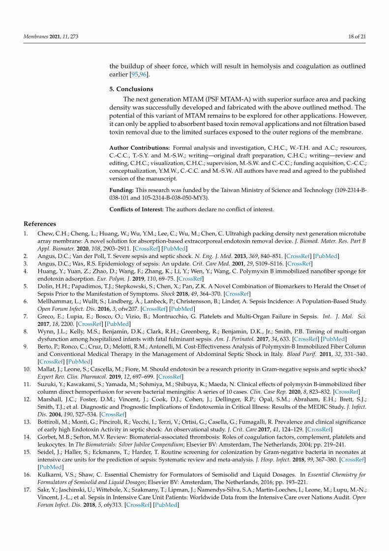
the buildup of sheer force, which will result in hemolysis and coagulation as outlinedearlier [95,96].
5. Conclusions
The next generation MTAM (PSF MTAM-A) with superior surface area and packingdensity was successfully developed and fabricated with the above outlined method. Thepotential of this variant of MTAM remains to be explored for other applications. However,it can only be applied to absorbent based toxin removal applications and not filtration basedtoxin removal due to the limited surfaces exposed to the outer regions of the membrane.
Author Contributions: Formal analysis and investigation, C.H.C., W.-T.H. and A.C.; resources,C.-C.C., T.-S.Y. and M.-S.W.; writing—original draft preparation, C.H.C.; writing—review andediting, C.H.C.; visualization, C.H.C.; supervision, M.-S.W. and C.-C.C.; funding acquisition, C.-C.C.;conceptualization, Y.M.W., C.-C.C. and M.-S.W. All authors have read and agreed to the publishedversion of the manuscript.
Funding: This research was funded by the Taiwan Ministry of Science and Technology (109-2314-B-038-101 and 105-2314-B-038-050-MY3).
Conflicts of Interest: The authors declare no conflict of interest.
References1. Chew, C.H.; Cheng, L.; Huang, W.; Wu, Y.M.; Lee, C.; Wu, M.; Chen, C. Ultrahigh packing density next generation microtube
array membrane: A novel solution for absorption-based extracorporeal endotoxin removal device. J. Biomed. Mater. Res. Part BAppl. Biomater. 2020, 108, 2903–2911. [CrossRef] [PubMed]
2. Angus, D.C.; Van der Poll, T. Severe sepsis and septic shock. N. Eng. J. Med. 2013, 369, 840–851. [CrossRef] [PubMed]3. Angus, D.C.; Wax, R.S. Epidemiology of sepsis: An update. Crit. Care Med. 2001, 29, S109–S116. [CrossRef]4. Huang, Y.; Yuan, Z.; Zhao, D.; Wang, F.; Zhang, K.; Li, Y.; Wen, Y.; Wang, C. Polymyxin B immobilized nanofiber sponge for
endotoxin adsorption. Eur. Polym. J. 2019, 110, 69–75. [CrossRef]5. Dolin, H.H.; Papadimos, T.J.; Stepkowski, S.; Chen, X.; Pan, Z.K. A Novel Combination of Biomarkers to Herald the Onset of
Sepsis Prior to the Manifestation of Symptoms. Shock 2018, 49, 364–370. [CrossRef]6. Mellhammar, L.; Wullt, S.; Lindberg, Å.; Lanbeck, P.; Christensson, B.; Linder, A. Sepsis Incidence: A Population-Based Study.
Open Forum Infect. Dis. 2016, 3, ofw207. [CrossRef] [PubMed]7. Greco, E.; Lupia, E.; Bosco, O.; Vizio, B.; Montrucchio, G. Platelets and Multi-Organ Failure in Sepsis. Int. J. Mol. Sci.
2017, 18, 2200. [CrossRef] [PubMed]8. Wynn, J.L.; Kelly, M.S.; Benjamin, D.K.; Clark, R.H.; Greenberg, R.; Benjamin, D.K., Jr.; Smith, P.B. Timing of multi-organ
dysfunction among hospitalized infants with fatal fulminant sepsis. Am. J. Perinatol. 2017, 34, 633. [CrossRef] [PubMed]9. Berto, P.; Ronco, C.; Cruz, D.; Melotti, R.M.; Antonelli, M. Cost-Effectiveness Analysis of Polymyxin-B Immobilized Fiber Column
and Conventional Medical Therapy in the Management of Abdominal Septic Shock in Italy. Blood Purif. 2011, 32, 331–340.[CrossRef] [PubMed]
10. Mallat, J.; Leone, S.; Cascella, M.; Fiore, M. Should endotoxin be a research priority in Gram-negative sepsis and septic shock?Expert Rev. Clin. Pharmacol. 2019, 12, 697–699. [CrossRef]
11. Suzuki, Y.; Kawakami, S.; Yamada, M.; Sohmiya, M.; Shibuya, K.; Maeda, N. Clinical effects of polymyxin B-immobilized fibercolumn direct hemoperfusion for severe bacterial meningitis: A series of 10 cases. Clin. Case Rep. 2020, 8, 823–832. [CrossRef]
12. Marshall, J.C.; Foster, D.M.; Vincent, J.; Cook, D.J.; Cohen, J.; Dellinger, R.P.; Opal, S.M.; Abraham, E.H.; Brett, S.J.;Smith, T.J.; et al. Diagnostic and Prognostic Implications of Endotoxemia in Critical Illness: Results of the MEDIC Study. J. Infect.Dis. 2004, 190, 527–534. [CrossRef]
13. Bottiroli, M.; Monti, G.; Pinciroli, R.; Vecchi, I.; Terzi, V.; Ortisi, G.; Casella, G.; Fumagalli, R. Prevalence and clinical significanceof early high Endotoxin Activity in septic shock: An observational study. J. Crit. Care 2017, 41, 124–129. [CrossRef]
14. Gorbet, M.B.; Sefton, M.V. Review: Biomaterial-associated thrombosis: Roles of coagulation factors, complement, platelets andleukocytes. In The Biomaterials: Silver Jubilee Compendium; Elsevier BV: Amsterdam, The Netherlands, 2004; pp. 219–241.
15. Seidel, J.; Haller, S.; Eckmanns, T.; Harder, T. Routine screening for colonization by Gram-negative bacteria in neonates atintensive care units for the prediction of sepsis: Systematic review and meta-analysis. J. Hosp. Infect. 2018, 99, 367–380. [CrossRef][PubMed]
16. Kulkarni, V.S.; Shaw, C. Essential Chemistry for Formulators of Semisolid and Liquid Dosages. In Essential Chemistry forFormulators of Semisolid and Liquid Dosages; Elsevier BV: Amsterdam, The Netherlands, 2016; pp. 193–221.
17. Sakr, Y.; Jaschinski, U.; Wittebole, X.; Szakmany, T.; Lipman, J.; Ñamendys-Silva, S.A.; Martin-Loeches, I.; Leone, M.; Lupu, M.-N.;Vincent, J.-L.; et al. Sepsis in Intensive Care Unit Patients: Worldwide Data from the Intensive Care over Nations Audit. OpenForum Infect. Dis. 2018, 5, ofy313. [CrossRef] [PubMed]

Membranes 2021, 11, 273 19 of 21
18. Ikeda, M.; Shimizu, K.; Ogura, H.; Kurakawa, T.; Umemoto, E.; Motooka, D.; Nakamura, S.; Ichimaru, N.; Takeda, K.;Takahara, S.; et al. Hydrogen-Rich Saline Regulates Intestinal Barrier Dysfunction, Dysbiosis, and Bacterial Translocationin a Murine Model of Sepsis. Shock 2018, 50, 640–647. [CrossRef] [PubMed]
19. Assimakopoulos, S.F.; Triantos, C.; Thomopoulos, K.; Fligou, F.; Maroulis, I.; Marangos, M.; Gogos, C.A. Gut-origin sepsis in thecritically ill patient: Pathophysiology and treatment. Infection 2018, 46, 751–760. [CrossRef]
20. Englert, J.A.; Bobba, C.; Baron, R.M. Integrating molecular pathogenesis and clinical translation in sepsis-induced acute respiratorydistress syndrome. JCI Insight 2019, 4. [CrossRef]
21. Iba, T.; Levy, J.H.; Warkentin, T.E.; Thachil, J.; Van Der Poll, T.; Levi, M. Diagnosis and management of sepsis-induced coagulopathyand disseminated intravascular coagulation. J. Thromb. Haemost. 2019, 17, 1989–1994. [CrossRef]
22. Putzu, A.; Schorer, R.; Lopez-Delgado, J.C.; Cassina, T.; Landoni, G. Blood purification and mortality in sepsis and septic shock: Asystematic review and meta-analysis of randomized trials. Anesthesiology 2019, 131, 580–593. [CrossRef] [PubMed]
23. Schedlowski, M.; Engler, H.; Grigoleit, J.-S. Endotoxin-induced experimental systemic inflammation in humans: A model todisentangle immune-to-brain communication. Brain Behav. Immun. 2014, 35, 1–8. [CrossRef]
24. Kiers, D.; Koch, R.M.; Hamers, L.; Gerretsen, J.; Thijs, E.J.M.; Van Ede, L.; Riksen, N.P.; Kox, M.; Pickkers, P. Characterizationof a model of systemic inflammation in humans in vivo elicited by continuous infusion of endotoxin. Sci. Rep. 2017, 7, 40149.[CrossRef] [PubMed]
25. Lepper, P.; Held, T.; Schneider, E.; Bölke, E.; Gerlach, H.; Trautmann, M. Clinical implications of antibiotic-induced endotoxinrelease in septic shock. Intensiv. Care Med. 2002, 28, 824–833. [CrossRef]
26. Chang, T.M.S.; Endo, Y.; Nikolaev, V.G.; Tani, T.; Yu, Y.; Zheng, W.-H. Hemoperfusion, Plasmaperfusion and Other Clinical Uses ofGeneral, Biospecific, Immuno and Leucocyte Adsorbents; World Scientific Pub Co Pte Lt: Singapore, 2015.
27. Shimokawa, K.I.; Takakuwa, R.; Taya, K.; Wada, Y.; Yamazaki, N.; Murata, M.; Hirata, K.; Masuno, T.; Yokota, H.; Ishii, F.Adsorption of various antimicrobial agents to endotoxin removal polymyxin-B immobilized fiber (Toraymyxin®). Colloids Surf. BBiointerfaces 2012, 90, 58–61. [CrossRef]
28. Tani, T.; Shimizu, T.; Tani, M.; Shoji, H.; Endo, Y. Anti-endotoxin Properties of Polymyxin B-immobilized Fibers. In Advances inExperimental Medicine and Biology; Metzler, J.B., Ed.; Springer: New York, NY, USA, 2019; Volume 1145, pp. 321–341.
29. Shoji, H. Extracorporeal Endotoxin Removal For The Treatment of Sepsis:Endotoxin Adsorption Cartridge (Toraymyxin). Ther.Apher. Dial. 2003, 7, 108–114. [CrossRef]
30. Cruz, D.N.; Perazella, M.A.; Bellomo, R.; De Cal, M.; Polanco, N.; Corradi, V.; Lentini, P.; Nalesso, F.; Ueno, T.; Ranieri, V.M.;et al. Effectiveness of polymyxin B-immobilized fiber column in sepsis: A systematic review. Crit. Care 2007, 11, R47. [CrossRef][PubMed]
31. Kawazoe, Y.; Sato, T.; Miyagawa, N.; Yokokawa, Y.; Kushimoto, S.; Miyamoto, K.; Ohta, Y.; Morimoto, T.; Yamamura, H. MortalityEffects of Prolonged Hemoperfusion Therapy Using a Polymyxin B-Immobilized Fiber Column for Patients with Septic Shock: ASub-Analysis of the DESIRE Trial. Blood Purif. 2018, 46, 309–314. [CrossRef] [PubMed]
32. Jason, N. Developing a Treatment for Septic Shock; Initiating coverage of Spectral Medical, Inc.: Toronto, ON, Canada, 2015.33. Xia, H.; Xia, Y. An in vitro study of non-aligned or aligned electrospun poly(methyl methacrylate) nanofibers as primary rat
astrocytes-loading scaffold. Mater. Sci. Eng. C 2018, 91, 228–235. [CrossRef]34. Orr, S.B.; Chainani, A.; Hippensteel, K.J.; Kishan, A.; Gilchrist, C.; Garrigues, N.W.; Ruch, D.S.; Guilak, F.; Little, D. Aligned
multilayered electrospun scaffolds for rotator cuff tendon tissue engineering. Acta Biomater. 2015, 24, 117–126. [CrossRef]35. Yang, J.-C.; Lee, S.-Y.; Tseng, W.-C.; Shu, Y.-C.; Lu, J.-C.; Shie, H.-S.; Chen, C.-C. Formation of Highly Aligned, Single-Layered,
Hollow Fibrous Assemblies and the Fabrication of Large Pieces of PLLA Membranes. Macromol. Mater. Eng. 2011, 297, 115–122.[CrossRef]
36. Lin, L.-C.; Shu, Y.-C.; Yang, J.-C.; Shie, H.-S.; Lee, S.-Y.; Chen, C.-C. Nano-porous Poly-L-lactic Acid Microtube Array Membranes.Curr. Nanosci. 2014, 10, 227–234. [CrossRef]
37. Hung, W.-C.; Lin, L.-H.; Tsen, W.-C.; Shie, H.-S.; Chiu, H.-L.; Yang, T.C.; Chen, C.-C. Permeation of biological compounds throughporous poly(l-lactic acid) (PLLA) microtube array membranes (MTAMs). Eur. Polym. J. 2015, 67, 166–173. [CrossRef]
38. Tseng, C.-H.; Huang, W.-T.; Chew, C.H.; Lai, J.-K.; Tu, S.-H.; Wei, P.-L.; Lee, K.-Y.; Lai, G.-M.; Chen, C.-C. Electrospun Poly-lactic Acid (PLLA) Microtube Array Membrane (MTAM)—An Advanced Substrate for Anticancer Drug Screening. Materials2019, 12, 569. [CrossRef]
39. Tseng, V.C.-H.; Chew, C.H.; Huang, W.-T.; Wang, Y.-K.; Chen, K.-S.; Chou, S.-Y.; Chen, C.-C. An Effective Cell Coculture PlatformBased on the Electrospun Microtube Array Membrane for Nerve Regeneration. Cells Tissues Organs 2017, 204, 179–190. [CrossRef][PubMed]
40. Morelli, S.; Piscioneri, A.; Salerno, S.; Chen, C.-C.; Chew, C.H.; Giorno, L.; Drioli, E.; De Bartolo, L. Microtube array membranebioreactor promotes neuronal differentiation and orientation. Biofabrication 2017, 9, 025018. [CrossRef] [PubMed]
41. Morelli, S.; Piscioneri, A.; Curcio, E.; Salerno, S.; Chen, C.-C.; De Bartolo, L. Membrane bioreactor for investigation of neurodegen-eration. Mater. Sci. Eng. C 2019, 103, 109793. [CrossRef]
42. Chew, C.; Wu, C.; Chen, C. A novel electrospun Microtube Array Membrane (MTAM) based low cost conceptual tubular MicrobialFuel Cell (MFC). Eur. Polym. J. 2016, 83, 138–147. [CrossRef]
43. Chew, C.H.; Lee, C.-W.; Huang, W.-T.; Cheng, L.-W.; Chen, A.; Cheng, T.-M.; Liu, Y.-L.; Chen, C.-C. Microtube Array Membrane(MTAM)-Based Encapsulated Cell Therapy for Cancer Treatment. Membrances 2020, 10, 80. [CrossRef]

Membranes 2021, 11, 273 20 of 21
44. Chen, C.-C.; Lan, C.-C.; Pan, C.-L.; Huang, M.-Y.; Chew, C.-H.; Hung, C.-C.; Chen, P.-H.; Lin, H.-T.V. Repeated-batch lacticacid fermentation using a novel bacterial immobilization technique based on a microtube array membrane. Process. Biochem.2019, 87, 25–32. [CrossRef]
45. Chen, C.-C.; Lin, H.-J.; Lu, W.-J.; Wu, J.-J.; Chew, C.-H.; Wong, C.-H.; Yang, C.-Y.; Lin, H.-T.V. Enhanced Repeated-Batch BioethanolFermentation of Red Seaweeds Hydrolysates Using Microtube Array Membrane-Encapsulated Yeast. J. Biobased Mater. Bioenergy2020, 14, 138–145. [CrossRef]
46. Chen, C.-C.; Wu, C.-H.; Wu, J.-J.; Chiu, C.-C.; Wong, C.-H.; Tsai, M.-L.; Lin, H.-T.V. Accelerated bioethanol fermentation by usinga novel yeast immobilization technique: Microtube array membrane. Process. Biochem. 2015, 50, 1509–1515. [CrossRef]
47. Bartlett, R.H.; Gazzaniga, A.B.; Jefferies, M.R.; Huxtable, R.F.; Haiduc, N.J.; Fong, S.W. Extracorporeal membrane oxygenation(ECMO) cardiopulmonary support in infancy. Trans. Am. Soc. Artif. Intern. Organs 1976, 22, 80–93.
48. Tiruvoipati, R.; Botha, J.; Peek, G. Effectiveness of extracorporeal membrane oxygenation when conventional ventilation fails:Valuable option or vague remedy? J. Crit. Care 2012, 27, 192–198. [CrossRef]
49. Lin, F.-H.; Tsai, J.-C.; Chen, T.-M.; Chen, K.-S.; Yang, J.-M.; Kang, P.-L.; Wu, T.-H. Fabrication and evaluation of auto-strippedtri-layer wound dressing for extensive burn injury. Mater. Chem. Phys. 2007, 102, 152–158. [CrossRef]
50. Chou, H.-C.; Yan, T.-R.; Chen, K.-S.J.C.; Biointerfaces, S.B. Detecting cells on the surface of a silver electrode quartz crystalmicrobalance using plasma treatment and graft polymerization. Colloids Surf. B Biointerfaces 2009, 73, 244–249. [CrossRef][PubMed]
51. Yarin, A.L. Coaxial electrospinning and emulsion electrospinning of core–shell fibers. Polym. Adv. Technol. 2011, 22, 310–317.[CrossRef]
52. Haider, S.; Haider, A. Electrospinning and Electrospraying: Techniques and Applications; IntechOpen: London, UK, 2019.53. Pstras, L.; Waniewski, J.; Wojcik-Zaluska, A.; Zaluska, W. Relative blood volume changes during haemodialysis estimated from
haemoconcentration markers. Sci. Rep. 2020, 10, 1–9. [CrossRef]54. Yang, M.C.; Lin, C.C.J.A.J. In vitro characterization of the occurrence of hemolysis during extracorporeal blood circulation using
a mini hemodialyzer. Asaio J. 2000, 46, 293–297. [CrossRef] [PubMed]55. De Wachter, D.S.; Verdonck, P.R.; Verhoeven, R.F.; Hombrouckx, R.O. Red cell injury assessed in a numeric model of a peripheral
dialysis needle. Asaio J. 1996, 42, M524–M529. [CrossRef] [PubMed]56. Beissinger, R.L.; Williams, M.C. A dual mechanism for low-stress hemolysis in laminar blood flow. AIChE J. 1984, 30, 569–577.
[CrossRef]57. Litvinov, R.I.; Weisel, J.W. Role of red blood cells in haemostasis and thrombosis. ISBT Sci. Ser. 2016, 12, 176–183. [CrossRef]58. Weisel, J.W.; Litvinov, R.I. Red blood cells: The forgotten player in hemostasis and thrombosis. J. Thromb. Haemost.
2019, 17, 271–282. [CrossRef] [PubMed]59. Compendium, S. Solubility Enhancement with BASF Pharma Polymers; Pharma Ingredients & Services: Lampertheim, Germany, 2011.60. Beck, J.S.; Vartuli, J.C.; Roth, W.J.; Leonowicz, M.E.; Kresge, C.T.; Schmitt, K.D.; Chu, C.T.W.; Olson, D.H.; Sheppard, E.W.;
McCullen, S.B.; et al. A new family of mesoporous molecular sieves prepared with liquid crystal templates. J. Am. Chem. Soc.1992, 114, 10834–10843. [CrossRef]
61. Lee, G.H.; Song, J.-C.; Yoon, K.-B. Controlled wall thickness and porosity of polymeric hollow nanofibers by coaxial electrospin-ning. Macromol. Res. 2010, 18, 571–576. [CrossRef]
62. Awad, N.K.; Niu, H.; Ali, U.; Morsi, Y.S.; Lin, T. Electrospun Fibrous Scaffolds for Small-Diameter Blood Vessels: A Review.Membranes 2018, 8, 15. [CrossRef]
63. Ding, B.; Wang, X.; Yu, J. Electrospinning: Nanofabrication and Applications; William Andrew, Elsevier: Burlington, MA, USA, 2018.64. Mehta, P.P.; Pawar, V.S. Electrospun nanofiber scaffolds: Technology and applications. In Applications of Nanocomposite Materials in
Drug Delivery; Elsevier: Amsterdam, The Netherlands, 2018; pp. 509–573.65. Sener, A.G.; Altay, A.S.; Altay, F. (Eds.) Effect of voltage on morphology of electrospun nanofibers. In Proceedings of the 2011 7th
International Conference on Electrical and Electronics Engineering (ELECO), Bursa, Turkey, 1–4 December 2011.66. Garg, K.; Bowlin, G.L. Electrospinning jets and nanofibrous structures. Biomicrofluidics 2011, 5, 013403. [CrossRef] [PubMed]67. Xue, J.; Wu, T.; Dai, Y.; Xia, Y. Electrospinning and Electrospun Nanofibers: Methods, Materials, and Applications. Chem. Rev.
2019, 119, 5298–5415. [CrossRef]68. King, S.G.; Stolojan, V.; Silva, S.R.P. Large area uniform electrospun polymer nanofibres by balancing of the electrostatic field.
React. Funct. Polym. 2018, 129, 89–94. [CrossRef]69. Viswanadam, G.; Chase, G.G. Modified electric fields to control the direction of electrospinning jets. Polymers 2013, 54, 1397–1404.
[CrossRef]70. Gu, H.; Pavier, M.; Shterenlikht, A. Experimental study of modulus, strength and toughness of 2D triangular lattices. Int. J. Solids
Struct. 2018, 152, 207–216. [CrossRef]71. Maleki, H.; Gharehaghaji, A.A.; Moroni, L.; Dijkstra, P.J. Influence of the solvent type on the morphology and mechanical
properties of electrospun PLLA yarns. Biofabrication 2013, 5, 035014. [CrossRef] [PubMed]72. Kim, G.H.; Yoon, H.J.A.P.L. Effect of an auxiliary electrode on the crystalline morphology of electrospun nanofibers. Appl. Phys.
Lett. 2008, 93, 023127. [CrossRef]73. Chu, C.C. Hydrolytic degradation of polyglycolic acid: Tensile strength and crystallinity study. J. Appl. Polym. Sci.
1981, 26, 1727–1734. [CrossRef]

Membranes 2021, 11, 273 21 of 21
74. Kim, K.; Lee, K.; Cho, K.; Park, C. Surface modification of polysulfone ultrafiltration membrane by oxygen plasma treatment. J.Membr. Sci. 2002, 199, 135–145. [CrossRef]
75. Wei, A.; Wang, J.; Wang, X.; Hou, D.; Wei, Q. Morphology and Surface Properties of Poly (L-lactic acid)/Captopril CompositeNanofiber Membranes. J. Eng. Fibers Fabr. 2012, 7. [CrossRef]
76. Hong, K.T.; Imadojemu, H.; Webb, R. Effects of oxidation and surface roughness on contact angle. Exp. Therm. Fluid Sci.1994, 8, 279–285. [CrossRef]
77. Wenzel, R.N. Surface roughness and contact angle. J. Phys. Chem. 1949, 53, 1466–1467. [CrossRef]78. Xu, X.; Zhang, H.; Ao, J.; Xu, L.; Liu, X.; Guo, X.; Li, J.; Zhang, L.; Li, Q.; Zhao, X.; et al. 3D hierarchical porous amidoxime fibers
speed up uranium extraction from seawater. Energy Environ. Sci. 12.6 2019, 12, 1979–1988. [CrossRef]79. Fromes, Y.; Gaillard, D.; Ponzio, O.; Chauffert, M.; Gerhardt, M.-F.; Deleuze, P.; Bical, O.M. Reduction of the inflamma-
tory response following coronary bypass grafting with total minimal extracorporeal circulation. Eur. J. Cardio-Thoracic Surg.2002, 22, 527–533. [CrossRef]
80. Maggiore, Q.; Dattolo, P.; Piacenti, M.; Morales, M.A.; Pelosi, G.; Pizzarelli, F.; Cerrai, T. Thermal balance and dialysis hypotension.Int. J. Artif. Organs 1995, 18, 518–525. [CrossRef]
81. Ecker, E.E.; Gross, P. Anticomplementary power of heparin. J. Infect. Dis. 1929, 250, 3. [CrossRef]82. Hou, C.; Yuan, Q.; Huo, D.; Zheng, S.; Zhan, D. Investigation on clotting and hemolysis characteristics of heparin-immobilized
polyether sulfones biomembrane. J. Biomed. Mater. Res. Part A 2008, 85, 847–852. [CrossRef]83. Chesebro, J.H. Direct thrombin inhibition superior to heparin during and after thrombolysis: Dose, duration, and drug. Circulation
1997, 96, 2118–2120. [CrossRef]84. Heinzelmann, M.; Bosshart, H. Heparin Binds to Lipopolysaccharide (LPS)-Binding Protein, Facilitates the Transfer of LPS to
CD14, and Enhances LPS-Induced Activation of Peripheral Blood Monocytes. J. Immunol. 2005, 174, 2280–2287. [CrossRef]85. Shoji, H.; Tani, T.; Hanasawa, K.; Kodama, M. Extracorporeal Endotoxin Removal by Polymyxin B Immobilized Fiber Cartridge:
Designing and Antiendotoxin Efficacy in the Clinical Application. Ther. Apher. 1998, 2, 3–12. [CrossRef]86. Ma, R.; Zhao, J.; Du, H.C.; Tian, S.; Li, L.W. Removing endotoxin from plasmid samples by Triton X-114 isothermal extraction.
Anal. Biochem. 2012, 424, 124–126. [CrossRef] [PubMed]87. Novelli, G.; Ferretti, G.; Poli, L.; Pretagostini, R.; Ruberto, F.; Perrella, S.; Levi, S.; Morabito, V.; Berloco, P. Clinical Re-
sults of Treatment of Postsurgical Endotoxin-Mediated Sepsis with Polymyxin-B Direct Hemoperfusion. Transplant. Proc.2010, 42, 1021–1024. [CrossRef] [PubMed]
88. Vesentini, S.; Soncini, M.; Fiore, G.B.; Redaelli, A. Mechanisms of polymyxin B endotoxin removal from extracorporeal bloodflow: Molecular interactions. Contrib. Nephrol. 2010, 167, 45–54. [CrossRef] [PubMed]
89. Cai, B.; Deitch, E.A.; Ulloa, L. Novel Insights for Systemic Inflammation in Sepsis and Hemorrhage. Mediat. Inflamm.2010, 2010, 1–10. [CrossRef] [PubMed]
90. Paulus, P.; Jennewein, C.; Zacharowski, K. Biomarkers of endothelial dysfunction: Can they help us deciphering systemicinflammation and sepsis? Biomarkers 2011, 16, S11–S21. [CrossRef]
91. Zeerleder, S.; Hack, C.E.; Wuillemin, W.A. Disseminated Intravascular Coagulation in Sepsis. Chest 2005, 128, 2864–2875.[CrossRef] [PubMed]
92. Browdie, D.A.; Deane, R.; Shinozaki, T.; Morgan, J.; DeMeules, J.E.; Coffin, L.H.; Davis, J.H. Adult respiratory distress syndrome(ARDS), sepsis, and extracorporeal membrane oxygenation (ECMO). J. Traum. 1977, 17, 579–586. [CrossRef] [PubMed]
93. Virzì, G.M.; Clementi, A.; Brocca, A.; Ronco, C. Endotoxin Effects on Cardiac and Renal Functions and Cardiorenal Syndromes.Blood Purif. 2017, 44, 314–326. [CrossRef]
94. Vos, F.E.; Schollum, J.B.; Coulter, C.V.; Doyle, T.C.; Duffull, S.B.; Walker, R.J. Red Blood Cell Survival in Long-term DialysisPatients. Am. J. Kidney Dis. 2011, 58, 591–598. [CrossRef]
95. Hakim, Y.A.; Abbas, A.; Khalil, A.; Mustafa, H.I.A.; Sciences, H. The effect of hemodialysis on hemoglobin concentration, plateletscount and white blood cells count in end stage renal failure. Int. J. Med. Res. Health Sci. 2016, 5, 22–35.
96. Wenz, L.M.; Merritt, K.; Brown, S.A.; Moet, A.; Steffee, A.D. In vitro biocompatibility of polyetheretherketone and polysulfonecomposites. J. Biomed. Mater. Res. 1990, 24, 207–215. [CrossRef]